The influence of thermal expansion of a composite material on embedded polarimetric sensors
7
IOP PUBLISHING SMART MATERIALS AND STRUCTURES Smart Mater. Struct. 20 (2011) 125002 (7pp) doi:10.1088/0964-1726/20/12/125002 The influence of thermal expansion of a composite material on embedded polarimetric sensors Manjusha Ramakrishnan 1 , Ginu Rajan 1 , Yuliya Semenova 1 , Piotr Lesiak 2 , Andrzej Domanski 2 , Tomasz Wolinski 2 , Anna Boczkowska 3 and Gerald Farrell 1 1 Photonics Research Centre, School of Electronic and Communications Engineering, Dublin Institute of Technology, Kevin Street, Dublin 8, Ireland 2 Faculty of Physics, Warsaw University of Technology, Warszawa, Poland 3 Faculty of Materials Science and Engineering, Warsaw University of Technology, Warszawa, Poland E-mail: [email protected] and [email protected] Received 19 July 2011, in final form 21 September 2011 Published 4 November 2011 Online at stacks.iop.org/SMS/20/125002 Abstract Some of the most critical issues of the influence of the thermal expansion of composite materials on embedded polarimetric sensors for measurements of strain and temperature are studied in this paper. A composite material sample with polarimetric fiber sensors embedded in two distinct layers of a multi-layer composite structure is fabricated and characterized. The polarimetric fiber sensors used in this study are based on Panda type fiber and polarization maintaining photonic crystal fiber (PM-PCF). The temperature sensitivities of polarimetric fiber sensors with acrylate buffer coated and buffer stripped polarization maintaining optical fibers are measured in free space and compared with those for sensors embedded in the composite material. It is found that a polarimetric fiber sensor with an acrylate coating embedded in the composite material shows the same response as the one in free space while the coating stripped fiber polarimetric sensor shows significant temperature sensitivity when embedded in the composite material. This is due to the stress induced change in birefringence created by the thermal expansion of the composite material, while in the case of a buffer coated fiber, the effect is considerably reduced as the thermal stress is largely eliminated by the buffer coating. The results obtained in this study demonstrated that thermal expansion of the composite material is the main source of error in strain and temperature measurement using embedded polarimetric fiber sensors and that more accurate strain and temperature measurements can be obtained with buffer coated polarimetric fiber sensors. (Some figures may appear in colour only in the online journal) 1. Introduction Composite material structures are widely used in the aerospace, marine, aviation and civil engineering industries, because of their superior properties [1, 2]. Continuous fiber reinforced composite structures [3, 4] have attractive properties such as low density, high strength and high stiffness. Additionally, composite materials offer the potential to utilize embedded fiber optic sensors (FOSs) which make them suitable candidates for smart materials for various applications in aerospace components and civil engineering structures. One or more FOSs embedded in a composite material can be used to monitor the condition of the material during the manufacturing process or alternatively to monitor the structural health of the composite part over its operational lifetime and thereby can enhance the reliability and safety of many advanced structures. Embedding FOSs in composite materials is possible because their size and weight are comparable to 0964-1726/11/125002+07$33.00 © 2011 IOP Publishing Ltd Printed in the UK & the USA 1
Transcript of The influence of thermal expansion of a composite material on embedded polarimetric sensors
IOP PUBLISHING SMART MATERIALS AND STRUCTURES
Smart Mater. Struct. 20 (2011) 125002 (7pp) doi:10.1088/0964-1726/20/12/125002
The influence of thermal expansion of acomposite material on embeddedpolarimetric sensorsManjusha Ramakrishnan1, Ginu Rajan1, Yuliya Semenova1,Piotr Lesiak2, Andrzej Domanski2, Tomasz Wolinski2,Anna Boczkowska3 and Gerald Farrell1
1 Photonics Research Centre, School of Electronic and Communications Engineering, DublinInstitute of Technology, Kevin Street, Dublin 8, Ireland2 Faculty of Physics, Warsaw University of Technology, Warszawa, Poland3 Faculty of Materials Science and Engineering, Warsaw University of Technology, Warszawa,Poland
E-mail: [email protected] and [email protected]
Received 19 July 2011, in final form 21 September 2011Published 4 November 2011Online at stacks.iop.org/SMS/20/125002
AbstractSome of the most critical issues of the influence of the thermal expansion of compositematerials on embedded polarimetric sensors for measurements of strain and temperature arestudied in this paper. A composite material sample with polarimetric fiber sensors embedded intwo distinct layers of a multi-layer composite structure is fabricated and characterized. Thepolarimetric fiber sensors used in this study are based on Panda type fiber and polarizationmaintaining photonic crystal fiber (PM-PCF). The temperature sensitivities of polarimetric fibersensors with acrylate buffer coated and buffer stripped polarization maintaining optical fibersare measured in free space and compared with those for sensors embedded in the compositematerial. It is found that a polarimetric fiber sensor with an acrylate coating embedded in thecomposite material shows the same response as the one in free space while the coating strippedfiber polarimetric sensor shows significant temperature sensitivity when embedded in thecomposite material. This is due to the stress induced change in birefringence created by thethermal expansion of the composite material, while in the case of a buffer coated fiber, the effectis considerably reduced as the thermal stress is largely eliminated by the buffer coating. Theresults obtained in this study demonstrated that thermal expansion of the composite material isthe main source of error in strain and temperature measurement using embedded polarimetricfiber sensors and that more accurate strain and temperature measurements can be obtained withbuffer coated polarimetric fiber sensors.
(Some figures may appear in colour only in the online journal)
1. Introduction
Composite material structures are widely used in theaerospace, marine, aviation and civil engineering industries,because of their superior properties [1, 2]. Continuousfiber reinforced composite structures [3, 4] have attractiveproperties such as low density, high strength and high stiffness.Additionally, composite materials offer the potential to utilizeembedded fiber optic sensors (FOSs) which make them
suitable candidates for smart materials for various applicationsin aerospace components and civil engineering structures.One or more FOSs embedded in a composite material canbe used to monitor the condition of the material during themanufacturing process or alternatively to monitor the structuralhealth of the composite part over its operational lifetimeand thereby can enhance the reliability and safety of manyadvanced structures. Embedding FOSs in composite materialsis possible because their size and weight are comparable to
0964-1726/11/125002+07$33.00 © 2011 IOP Publishing Ltd Printed in the UK & the USA1

Smart Mater. Struct. 20 (2011) 125002 M Ramakrishnan et al
those of the composite fiber reinforcement fabric, allowingthem to act as a form of ‘nervous system’ for a composite fibermatrix structure. Integrated FOSs offer many advantages overtraditional nondestructive evaluation techniques and surfacebonded sensors, such as more reliable data about matrix cracks,point damage and thermo-mechanical behavior.
The fiber optic sensor technology most widely usedfor structural health monitoring is fiber Bragg grating(FBG) sensing [5]. However, the cross-sensitivity betweentemperature and strain is a serious disadvantage for many real-life applications. Polarimetric fiber sensing [6] technologyis a promising candidate for sensing in composites as itoffers temperature independence. Additionally, given theavailability of an extensive variety of polarization maintaining(PM) fibers and micro-structured highly birefringent (HB)polarization maintaining fibers, such sensors possess a widerange of sensitivities and are suitable for sensing a varietyof parameters, such as strain, temperature, displacement,humidity, etc independently. In comparison with previouslyreported methods for resolving the strain and temperaturecross-sensitivity issue with polarimetric sensors, such as thefiber optic differential heterodyne sensing scheme [7], andthe fiber optic dual-technique sensor [8], the hybrid sensingapproach described in [9] based on temperature insensitivePM-PCF offers the advantage of simplicity.
For composite structures most research reports haveconcentrated on the use of FBGs to measure the temperatureand strain during the curing process and during structuraltests. A few authors have reported interferometric [10] andpolarimetric sensors [11] embedded in composite materials.What has not been well examined in the previous researchstudies is the impact of the characteristic properties of thecomposite materials and also the effect of the fiber buffercoating on the characteristics of the embedded fiber sensors. Inthis paper a detailed investigation is carried out on the influenceof the thermo-mechanical properties of composite materials onthe embedded polarimetric fiber sensors in order to explorethe most suitable approach to embedding such sensors incomposites. The objective of this research is to ensureconsistent and accurate temperature or strain measurementsfor applications such as wind rotor blades and helicopterrotor blades which operate in varying atmospheric temperatureconditions from −20 to 40 ◦C. The polarimetric fiber sensorsused are based on polarization maintaining photonic crystalfiber (PM-PCF) and Panda fibers with and without an acrylatefiber buffer coating.
2. Temperature sensitivity of polarimetric sensors
In a polarimetric sensor [12], symmetric deformation orvariation in the refractive index induced by temperatureinfluences the propagation constant for every mode becauseof the changes in the fiber length and the refractive indices ofthe core and the cladding. This in turn leads to changes inthe phase difference between the two orthogonal polarizationstates of the fundamental mode.
We can calculate the temperature sensitivity (S) of an HBfiber section with a length L as follows:
S = 2π
TT L[rad (◦C m)−1] (1)
where TT is the temperature change required to induce a2π phase difference between the two polarizations of thefundamental mode.
The value of the parameter TT multiplied by the length ofthe fiber L is a wavelength-dependent constant:
LTT = const(λ). (2)
This dependence previously established for strain mea-surements using HB bow-tie fibers, enables a range of possibleapproaches to realizing polarimetric temperature and strainsensors by utilizing a variety of HB-PM and PM-PCF fibersthat are specifically tailored to particular applications.
The two types of polarization maintaining (PM) fibersused in this study are Panda fiber and photonic crystal fiber(PM-PCF). In the case of the Panda fiber both temperatureand strain lead to a phase difference between the orthogonalpolarizations of the fundamental mode LP01, while in the caseof PM-PCF the phase difference arises only from strain as PM-PCF is proven to have a very low temperature sensitivity [9, 13]in free space, due to the pure silica structure of PCF.
3. Fabrication of composite samples with embeddedoptical fiber sensors
The fiber glass reinforced composite materials for thisstudy were fabricated by the hand lay-up method, withwoven glass fiber fabric as reinforcement bound together byresin. The samples were prepared with Synolite 1066-P-1, a pre-accelerated, thixotropic, unsaturated polyester resinmanufactured by DSM Netherlands, having a viscosity of400 mPa s, and with a specific gravity of 1.29 at 25 ◦C.Plain woven fiberglass fabric from JPS Composite MaterialsCorporation with a density of 280 g m−2 was used. Thedimension of each layer of fabric was 215 mm × 120 mm.The fabrication process is as follows: the mould surface iscoated with a release agent of an anti-adhesive agent poly vinylchloride, to prevent sticking of the moulded part to the mouldsurface. The catalyst used is Luperox K1 manufactured byArkema-France, which is added at a 100:1 resin:catalyst-mixratio for the hardening process. The first piece of glass fiberreinforcing fabric is placed on the mould and using a brushthe fiber fabric is impregnated with the resin. Then the secondlayer of fiber reinforcing fabric is put in place after applying theresin and the process is repeated with subsequent stacked layersuntil the sample has eight layers of liquid resin and wovenreinforcing glass fiber fabric. The orientation of the fiber glassreinforcement was chosen to provide a 0–0 ply unidirectionalconfiguration. The fabrication process is shown in figure 1.
The fifth and the first layers are chosen as the locationsfor the optical fibers placed at a distance of 2 mm apart fromeach other. As we had previously observed that the fibercoating may influence the operation of the sensor, the sensing
2

Smart Mater. Struct. 20 (2011) 125002 M Ramakrishnan et al
Figure 1. (a) Pre-strained optical fiber sensors. (b) Fiber sensors atlayers 1 and 5 of the composite material. (c) Composite material withembedded sensors just after fabrication. (d) Cured compositematerial sample trimmed to the desired shape.
Figure 2. Cross sectional views of highly birefringent fibers.(a) Panda fiber. (b) PM-PCF.
optical fibers are embedded with and without fiber coating forcomparison purposes. During the process of embedding andcomposite curing, a pre-strain is applied to the optical fiberspositioned between the composite layers to make sure that thefibers remain straight. The composite material sample is curedat 25 ◦C for about 20 h. The composite material samples areuniformly cured and then post-cured [14] at a temperature of60 ◦C for about 8 h to eliminate the presence of any excessmoisture or solvents. The sample is then removed from themould surface. After curing, the samples are trimmed so that
they all have common dimensions of 215 mm×40 mm and are1.8 mm thick.
The polarimetric fiber sensors are realized based on twotypes of highly birefringent fiber: polarization maintainingPanda fiber (PM–1500–HP) and polarization maintainingphotonic crystal fiber (PM–1500–01), having beat lengths of5.0 mm and <4 mm respectively at an operating wavelength of1500 nm. Both types of fiber have identical acrylate coatingswith geometrical parameters as shown in figures 2(a) and (b)respectively.
The embedded positions for the fiber optic sensors withinthe composite sample layers are shown in cross section infigure 3. The PM-PCF polarimetric sensor fiber without acoating is positioned 17 mm from the left side of the sample.The PM-PCF with a coating is positioned 19 mm from the leftside of the sample. The Panda polarimetric sensor fiber withouta coating is positioned 21 mm from the left side. Finally thePanda fiber with a coating is positioned 23 mm from the leftside. Two such sets of identical sensor fiber sets are placed inlayers 1 and 5 in order to study the influence of placing theoptical sensors in different layers of the composite sample onthe sensors’ performance. Layers 1 and 5 were chosen becausethey represent the layers closest to the sample surface and thesample center respectively.
4. Experimental arrangement
To extract the phase difference between the two orthogonalpolarizations, the experimental setup shown in figure 4 is used.A tunable laser source with a wavelength of 1550 nm is used asan input source. The temperature sensitivity of the polarimetricsensors is measured by using a polarimeter and polarizationcontrol system, TXP 5004 from Thorlabs. The output ofthe laser source is fed to the polarization controller, so thatpolarized light is launched into the inputs of the optical fibersensors. Polarization variations at the outputs are observedby using the polarimeter. It is well known that fiber splicingcan induce changes in the polarization state and therefore theresponse of a polarimetric sensor. Therefore the PM fibersare connected without the use of splices, with their free ends
Figure 3. Schematic (cross sectional view) of sensors positioned in layers 1 and 5 of the eight-layer composite material sample.
3

Smart Mater. Struct. 20 (2011) 125002 M Ramakrishnan et al
Figure 4. Schematic of the experimental arrangement for thecomposite material sample with embedded polarimetric sensors.
connected to the polarization control system by means ofpolarization maintaining connector ferrules.
To study the influence of the thermal expansion of thecomposite material on the embedded polarimetric fiber sensors,the sample is subjected to temperature variations over a rangefrom 0 to 65 ◦C, by using a Peltier cooler (Model No. PE-127-20-15-U from Radionics Ltd) and the experimental setup asshown in figure 5. To increase the surface area of the Peltiercooler to match that of the composite sample, a thermallyconductive aluminum plate with dimensions of 210 mm ×100 mm × 1.5 mm is placed on top of the Peltier cooler,which has a surface area of 62 mm × 62 mm, attached witha thermally conducting paste. A time interval of 20 min is usedbetween each 5 ◦C step temperature variation in order to ensurea uniform temperature distribution in the composite sample.The Peltier cooler temperature is controlled using a ThorlabsITC510 temperature controller with the thermistor feedbacksensor attached to the surface of the aluminum plate. Thetemperature controller offers stability over 0 to 70 ◦C operationrange, with an accuracy of 0.1 ◦C. The sample is placed on thealuminum plate so that layer 1 is in contact with the plate.
The strain or temperature induced polarization variationis measured using a polarization controller and polarimeter.The state of polarization (SOP) [15] at the input to thepolarimetric sensors is adjusted by changing the azimuth andellipticity at the polarization controller. Initially these valuesare set so as to achieve the maximum optical power at thepolarimeter input. The Poincare sphere is used as a way tographically represent the polarization transformations. ThePoincare sphere is a graphical tool in real, three-dimensionalspace in which the polarization can be uniquely representedby a point on or within a unit sphere centered in a rectangular(x , y, z) coordinate system. The coordinates of the point arethe three normalized Stokes parameters describing the state ofpolarization. Because a state of polarization is representedby a point, a continuous change in the polarization state canbe represented as a continuous path on the surface of thePoincare sphere. Thus the strain and temperature response of
Figure 5. Experimental setup to apply temperature changes to thecomposite material sample.
the polarimetric sensor can be determined by the evaluation ofthe Poincare sphere.
The polarized light from the source is launched with itspolarization at an angle of 45◦ to the optical axis of the PMfiber to ensure equal distribution of optical intensity betweenthe two orthogonal polarizations. The polarimeter providesreal time information about the SOP of the polarimetricsensor output, presented graphically as a circular trace on aPoincare sphere with phase change and also numerical valuesfor measurands such as azimuth, ellipticity, Stokes parametersand the intensity of the optical power. The temperatureis varied in equal steps, and the variations of the Poincaresphere trace and Stokes parameters are recorded for eachstep change. The polarization induced phase shift for anapplied temperature change is calculated from the Poincaresphere. By extrapolating from the recorded results, the appliedtemperature needed to obtain one complete circular path on thePoincare sphere (exactly 2π radians) is determined and thusthe temperature sensitivity can be estimated.
5. Results and discussion
5.1. Temperature responses of the embedded PM-PCF sensors
The temperature responses of both coated and coating strippedPM-PCF polarimetric sensors embedded in the compositematerial sample are presented in this section. For comparisonthe temperature responses of the coating stripped PM-PCF infree space were found before embedding, when subjected to atemperature variation from 0 to 65 ◦C, and, as expected, thesensor is found to be effectively temperature insensitive, asshown in figure 6(a).
However the coating stripped PM-PCF embedded in layer1 of the composite material shows a phase shift of 3.6028 radfor a temperature variation of 65 ◦C, as shown in figure 6(b),resulting in a sensitivity of 0.2578 rad (m ◦C)−1, and for layer5 a sensitivity of 0.2247 rad (m ◦C)−1 is found. Since coatingstripped PM-PCF proved to be insensitive to temperaturein free space, it is concluded that the sensitivity whenembedded in a composite must be due to strain/stress inducedby temperature variations within the composite material orthermal expansion of the composite material.
4

Smart Mater. Struct. 20 (2011) 125002 M Ramakrishnan et al
Figure 6. Observed phase shift in coating stripped PM-PCF for atemperature variation from 0 to 65 ◦C: (a) in free space, (b) afterembedding.
The process followed above for the coating stripped fiberwas then repeated for the coated PM-PCF. The temperatureresponse of the coated PM-PCF in free space subjected to atemperature variation of 0–65 ◦C was first determined and isshown in figure 7(a). In the coated PM-PCF, a phase shift of0.1548 rad is observed for a temperature variation of 65 ◦C,yielding an estimated sensitivity of 0.011 08 rad (m ◦C)−1.While this value for free space is low, it is non-zero, unlikethe coating stripped PM-PCF. When the coated PM-PCF isembedded in layer 1 of the composite material sample (andtherefore is in direct contact with the heat source) and issubjected to a temperature variation of 65 ◦C it shows a phaseshift of 0.1518 rad (figure 7(b)), equivalent to a sensitivity of0.010 86 rad (m ◦C)−1. For a coated PM-PCF embedded inlayer 5 the temperature sensitivity also yields a comparablylow value of 0.0185 rad (m ◦C)−1. Comparing the free spaceand embedded sensitivities it is clear that for a coated PM-PCF the sensitivity is not unduly affected by embedding, avery different conclusion in comparison to that for the coatingstripped case, where the sensitivity increases dramatically afterembedding.
It should be noted that by comparing the performanceof coating stripped and coated PM-PCF in free space fromfigures 6(a) and 7(a), it is observed that there is a minordependence on temperature for the buffer coated PM-PCF,which we believe arises due to the temperature sensitive natureof the acrylate coating of the PM-PCF.
We believe that the difference in the fiber sensortemperature sensitivity between coating stripped PM-PCF andcoated PM-PCF when embedded in the composite is due to thehigher tolerance of the coated PM-PCF to the dominant formof thermal expansion in a composite material, that is transverseexpansion. During cooling and heating cycles the SOPfollowed the same trace, indicating the absence of a hysteresisphenomenon, confirming also that the 0–65 ◦C experimentaltemperature range lies in the linear thermal expansion regionof the composite material, which is reasonable given that theglass transition temperature of the particular cured resin isabove 150 ◦C. It is identified in [16] that composite materialshave both longitudinal and transverse expansions, but thatthe coefficient of transverse thermal expansion is many timeshigher than that for longitudinal expansion.
The thermal expansion induced stress and the strain causesa change in the birefringence of the PM-PCF and as a result
Figure 7. Observed phase shift in coated PM-PCF for a temperaturevariation from 0 to 65 ◦C: (a) in free space, (b) after embedding.
a phase shift between the guiding modes can occur in thecase of a buffer stripped PM-PCF embedded in the compositematerial. However for the coated PM-PCF sensor, the impactof the thermal expansion of the composite material has a muchlower effect, as seen in figure 7, and as a consequence thetemperature sensitivity of the sensor by comparison to the freespace sensitivity does not vary significantly after embedding inthe composite material. This immunity to thermal expansionin a buffer coated PM-PCF is due to two reasons: (i) theimpact of transverse thermal expansion is eliminated due tostrain tolerance provided by the coating material, thus no stressinduced birefringence change arises; (ii) the coefficient oflongitudinal thermal expansion of the glass reinforced generalpurpose resin based composite is very low [17].
5.2. Temperature responses of the embedded Panda fibersensors
The temperature responses of both coated and coating strippedPanda fiber polarimetric sensors embedded in the compositematerial sample are presented in this section. A Panda fiberbased polarimetric sensor is sensitive to both temperatureand strain. To analyze temperature sensitivity the Pandafiber samples are subjected to temperature variations withoutapplying any strain.
For the buffer coating stripped case, the temperatureresponses of the Panda fiber in free space and embedded inlayer 1 of the composite material were measured and showphase shifts of 3.1605 rad and 6.175 rad respectively, whensubjected to a temperature variation of 0–7 ◦C, as shown infigures 8(a) and (b). Note that since Panda type fibers aremore sensitive compared to PM-PCF, in order achieve a phasevariation within one complete circuit of a Poincare spherethe smaller temperature range of 0–7 ◦C is used to enable amore direct comparison with the PM-PCF case. A significantchange in temperature sensitivity is observed before and afterembedding of coating stripped Panda fibers into compositematerials similar to that of the PM-PCF. The magnitude oftemperature sensitivity increased from 2.1 to 4.1 rad (m ◦C)−1.The coating stripped Panda fiber that was embedded in thecomposite layer 5 yielded a temperature sensitivity value of3.56 rad (m ◦C)−1. This difference in the magnitude of thetemperature sensitivity before and after embedding confirmsthe dependence of the coating stripped Panda fiber temperatureresponse on the composite material thermal expansion.
5
Smart Mater. Struct. 20 (2011) 125002 M Ramakrishnan et al
Figure 8. Observed phase shift in coating stripped Panda fiber for atemperature variation from 0 to 7 ◦C: (a) in free space, (b) afterembedding.
Figure 9. Observed phase shift in coated Panda fiber for atemperature variation from 0 to 7 ◦C: (a) in free space, (b) afterembedding.
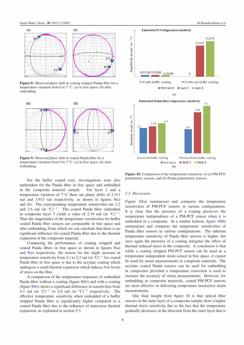
For the buffer coated case, investigations were alsoundertaken for the Panda fiber in free space and embeddedin the composite material sample. For layer 1 and atemperature variation of 7 ◦C there are phase shifts of 3.311rad and 3.913 rad respectively, as shown in figures 9(a)and (b). The corresponding temperature sensitivities are 2.2and 2.6 rad (m ◦C)−1. The coated Panda fiber embeddedin composite layer 5 yields a value of 2.34 rad (m ◦C)−1.Thus the magnitudes of the temperature sensitivities for buffercoated Panda fiber sensors are comparable in free space andafter embedding, from which we can conclude that there is nosignificant influence for coated Panda fiber due to the thermalexpansion of the composite material.
Comparing the performance of coating stripped andcoated Panda fibers in free space as shown in figures 8(a)and 9(a) respectively, the reason for the slight increase intemperature sensitivity from 2.1 to 2.2 rad (m ◦C)−1 for coatedPanda fiber in free space is due to the acrylate coating whichundergoes a small thermal expansion which induces low levelsof stress on the fiber.
A comparison of the temperature responses of embeddedPanda fiber without a coating (figure 8(b)) and with a coating(figure 9(b)) shows a significant difference in sensitivities from4.1 rad (m ◦C)−1 to 2.6 rad (m ◦C)−1 respectively. Theeffective temperature sensitivity when embedded of a bufferstripped Panda fiber is significantly higher compared to acoated Panda fiber due to the influence of transverse thermalexpansion, as explained in section 5.3.
(a)
(b)
Figure 10. Comparison of the temperature sensitivity of (a) PM-PCFpolarimetric sensors, and (b) Panda polarimetric sensors.
5.3. Discussion
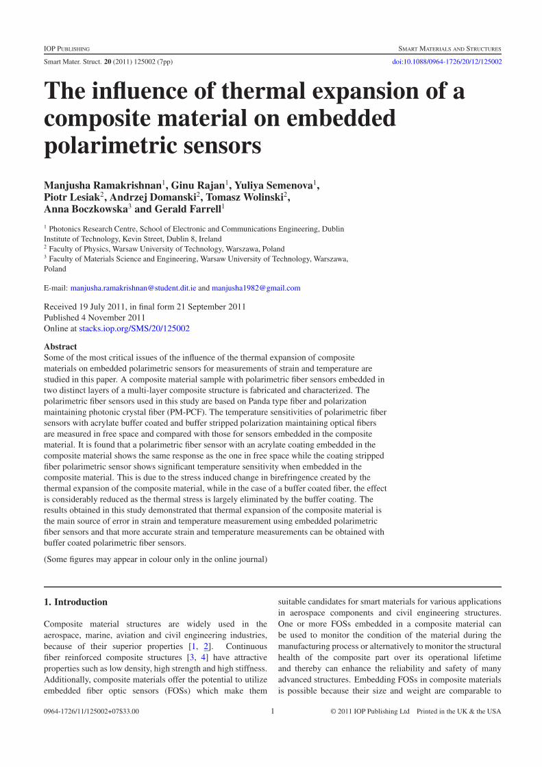
Figure 10(a) summarizes and compares the temperaturesensitivities of PM-PCF sensors in various configurations.It is clear that the presence of a coating preserves thetemperature independence of a PM-PCF sensor when it isembedded in a composite. In a similar fashion, figure 10(b)summarizes and compares the temperature sensitivities ofPanda fiber sensors in various configurations. The inherenttemperature sensitivity of Panda fiber sensors is higher, butonce again the presence of a coating mitigates the effect ofthermal induced stress in the composite. A conclusion is thatwhile a coating stripped PM-PCF sensor can be used as atemperature independent strain sensor in free space, it cannotbe used for strain measurements in composite materials. Theacrylate coated Panda sensors can be used for embeddingin composites provided a temperature correction is used toincrease the accuracy of strain measurements. However, forembedding in composite materials, coated PM-PCF sensorsare most effective in delivering temperature insensitive strainmeasurements.
One final insight from figure 10 is that optical fibersensors in the outer layer of a composite sample show a higherthermal stress sensitivity due to the fact that the temperaturegradually decreases in the direction from the outer layer that is
6

Smart Mater. Struct. 20 (2011) 125002 M Ramakrishnan et al
contact with the heat source toward layer 5, with a consequentreduction in the thermally induced stress.
6. Conclusion
The vital issues of the influence of composite materialthermal expansion on embedded polarimetric sensors formeasurements of strain and temperature are studied in thispaper. Glass fiber reinforced general purpose resin basedcomposite samples are fabricated and characterized, withpolarimetric sensors embedded in two distinct layers of themulti-layer composite structure. The two types of polarimetricsensors studied are based on polarization maintaining photoniccrystal fiber and Panda fiber. The temperature sensitivitiesof coated and coating stripped PM-PCF and Panda fiberpolarimetric sensors are calculated in free space and comparedto those of sensors embedded in the composite material. Fromthe results it is concluded that a polarimetric sensor withan acrylate coated fiber embedded in the composite materialshows the same response as one in free space, while acoating stripped fiber polarimetric sensor shows a significantincrease in temperature sensitivity when embedded in thecomposite material, which is due to the stress induced changein birefringence created by thermally induced strain. In thecase of coated fiber, the effect is eliminated by the coating.For Panda fibers the magnitude of the dependence on thermalexpansion of the composite material is many times higherthan for PM-PCF, because of the cross-sensitivity betweentemperature and thermal induced strain. From the analysis it isconcluded that thermal expansion induced drifts are the mainsources or errors during temperature and strain measurementsusing embedded polarimetric sensors. To improve the sensorsystem accuracy in real-world applications, it is concluded thatbuffer coated polarimetric fiber sensors are a better choice thanbuffer stripped fiber sensors.
Acknowledgment
This research is supported by Enterprise Ireland under theinternational research grant MATERA ERA-NET.
References
[1] Chung D D L 2010 Composite Materials: Science andApplications 2nd edn (Berlin: Springer)
[2] Grassi M, Zhang X and Meo M 2002 Prediction of stiffness andstresses in Z-fiber reinforced composite laminates CompositeA 33 1653–64
[3] Kim J K, Wo D Z, Zhou L M, Huang H T, Lau K T andWang M 2007 Advances Composite Materials andStructures (Key Engineering Materials) vol 334–5
[4] Garg D P, Zikry M A, Anderson G L and Gros X E 2001Current and potential future research activities in adaptivestructures: an ARO perspective Smart Mater. Struct.10 610–23
[5] Dewynter-Marty V, Ferdinand P, Bocherens E, Carbone R,Beranger H, Bourasseau S, Dupont M and Balageas D 1998Embedded fiber Bragg gratingsensors for industrialcomposite cure monitoring J. Intell. Mater. Syst. Struct.9 785–7
[6] Murukeshan V M, Chan P Y, Seng O L and Asundi A 1999On-line health monitoring of smart composite structuresusing fiber polarimetric sensor Smart Mater. Struct. 8 544–8
[7] Yoshino T, Hashimoto T, Nara M and Kurosawa K 1992Common path heterodyne optical fiber sensors J. LightwaveTechnol. 10 503–13
[8] Vengsarkar A M, Craig M W, Ljilja J, Brian C andRichard O C 1994 Fiber-optic dual-technique sensor forsimultaneous measurement of strain and temperatureJ. Lightwave Technol. 12 171–7
[9] Rajan G, Milenko K, Lesiak P, Semenova Y, Boczkowska A,Ramakrishnan M, Jedrzejewski K, Domanski A,Wolinski T and Farrell G 2010 A hybrid fiber optic sensingsystem for simultaneous strain and temperature measurementand its applications Photon. Lett. Poland 2 46–8
[10] Villatoro J, Finazzi V, Minkovich V P, Pruneri V andBadenes G 2009 Highly sensitive sensors based on photoniccrystal fiber modal interferometers J. Sensors 2009 747803
[11] Domanski A W et al 2009 Comparison of Bragg andpolarimetric optical fiber sensors for stress monitoring incomposite materials Acta Phys. Pol. 116 294
[12] Wolinski T R, Lesiak P and Domanski A W 2008 Polarimetricoptical fiber sensors of a new generation for industrialapplications Bull. Polish Acad. Sci. Tech. Sci. 56 2
[13] Dong X and Tam H Y 2007 Temperature-insensitive strainsensor with polarization maintaining photonic crystal fiberbased Sagnac interferometer Appl. Phys. Lett. 90 151113
[14] Delaye N and Marais S 1998 Characterization of unsaturatedpolyester resin cured with styrene J. Appl. Polym. Sci.67 695–703
[15] Collett E 2005 Field Guide to Polarization (SPIE Field Guides)(Bellingham, WA: SPIE)
[16] Reid S R and Zhou G 2000 Impact Behaviour ofFibre-reinforced Composite Materials and Structures(Boca Raton, FL: CRC Press)
[17] Karadeniz Z H and Kumlutas D 2007 A numerical study on thecoefficients of thermal expansion of fiber reinforcedcomposite materials Compos. Struct. 78 1–10
7