An introduction to spread tow reinforcements: Part 1 [11_TD ...
Upload
independentCategory
view
1download
0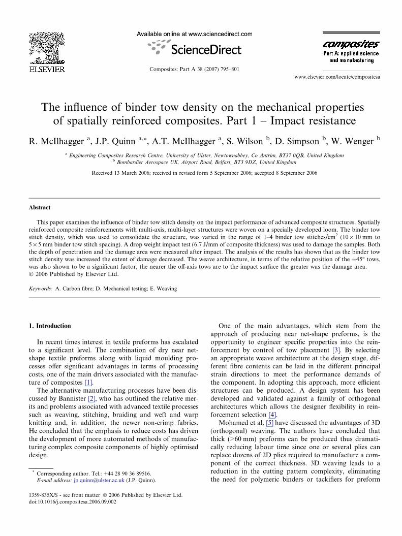
www.elsevier.com/locate/compositesa
Composites: Part A 38 (2007) 795–801
The influence of binder tow density on the mechanical propertiesof spatially reinforced composites. Part 1 – Impact resistance
R. McIlhagger a, J.P. Quinn a,*, A.T. McIlhagger a, S. Wilson b, D. Simpson b, W. Wenger b
a Engineering Composites Research Centre, University of Ulster, Newtownabbey, Co Antrim, BT37 0QB, United Kingdomb Bombardier Aerospace UK, Airport Road, Belfast, BT3 9DZ, United Kingdom
Received 13 March 2006; received in revised form 5 September 2006; accepted 8 September 2006
Abstract
This paper examines the influence of binder tow stitch density on the impact performance of advanced composite structures. Spatiallyreinforced composite reinforcements with multi-axis, multi-layer structures were woven on a specially developed loom. The binder towstitch density, which was used to consolidate the structure, was varied in the range of 1–4 binder tow stitches/cm2 (10 · 10 mm to5 · 5 mm binder tow stitch spacing). A drop weight impact test (6.7 J/mm of composite thickness) was used to damage the samples. Boththe depth of penetration and the damage area were measured after impact. The analysis of the results has shown that as the binder towstitch density was increased the extent of damage decreased. The weave architecture, in terms of the relative position of the ±45� tows,was also shown to be a significant factor, the nearer the off-axis tows are to the impact surface the greater was the damage area.� 2006 Published by Elsevier Ltd.
Keywords: A. Carbon fibre; D. Mechanical testing; E. Weaving
1. Introduction
In recent times interest in textile preforms has escalatedto a significant level. The combination of dry near net-shape textile preforms along with liquid moulding pro-cesses offer significant advantages in terms of processingcosts, one of the main drivers associated with the manufac-ture of composites [1].
The alternative manufacturing processes have been dis-cussed by Bannister [2], who has outlined the relative mer-its and problems associated with advanced textile processessuch as weaving, stitching, braiding and weft and warpknitting and, in addition, the newer non-crimp fabrics.He concluded that the emphasis to reduce costs has driventhe development of more automated methods of manufac-turing complex composite components of highly optimiseddesign.
1359-835X/$ - see front matter � 2006 Published by Elsevier Ltd.
doi:10.1016/j.compositesa.2006.09.002
* Corresponding author. Tel.: +44 28 90 36 89516.E-mail address: [email protected] (J.P. Quinn).
One of the main advantages, which stem from theapproach of producing near net-shape preforms, is theopportunity to engineer specific properties into the rein-forcement by control of tow placement [3]. By selectingan appropriate weave architecture at the design stage, dif-ferent fibre contents can be laid in the different principalstrain directions to meet the performance demands ofthe component. In adopting this approach, more efficientstructures can be produced. A design system has beendeveloped and validated against a family of orthogonalarchitectures which allows the designer flexibility in rein-forcement selection [4].
Mohamed et al. [5] have discussed the advantages of 3D(orthogonal) weaving. The authors have concluded thatthick (>60 mm) preforms can be produced thus dramati-cally reducing labour time since one or several plies canreplace dozens of 2D plies required to manufacture a com-ponent of the correct thickness. 3D weaving leads to areduction in the cutting pattern complexity, eliminatingthe need for polymeric binders or tackifiers for preform
10 x 10 mmbinder tow spacing
-- binder stitch in insertion
5 x 10 mm binder tow spacing
5 x 5 mm binder tow spacing
10 mm
10 mm
10 mm 10 mm
10 mm
warp
weft
Fig. 1. Binder tow spacing.
796 R. McIlhagger et al. / Composites: Part A 38 (2007) 795–801
stabilisation and reduces waste of a high value-added mate-rial such as prepreg.
3D woven reinforcements have also been shown to havesuperior mechanical performance in comparison to plied or2D woven composites [6]. Significant improvements inimpact resistance, compression-after-impact performance,reduced damage area and hence greater damage tolerancehave been demonstrated. It was concluded that thisimprovement in performance was as a result of thethrough-the-thickness or z reinforcement minimising theextent of delamination due to the crack bridging.
While composites manufactured from 3D woven rein-forcements go some way towards the improvement inmechanical properties and reduced manufacturing costs,these composites are compromised to some extent in theirin-plane shear characteristics due to the lack of off-axis(±45�) tow alignment. To overcome this limitation, a weav-ing machine has been developed to manufacture multi-axis,multi-layer reinforcements for composite applications [7].These Spatially Reinforced Composites (SpaRC) aredesigned to have tows oriented in 5 axes, viz. 0�, 90�,±45� (off axis) and through-the thickness (or z) directions.
A study has performed an initial assessment of themechanical properties of these multi-axis, multi-layer rein-forced composites [8]. In this investigation the binder towshave been used to consolidate the reinforcement at10 · 10 mm spacing and the properties of these compositeshave been compared with similar 3D reinforced compos-ites. This work has shown that, by increasing the amountof through-the-thickness tow binder (up to 0.2% by weight)in 3D (orthogonal) structures, the damage area afterimpact was reduced, although the extent of the damagewas influenced by the structure of the face away from theimpacted face (the distal face). In addition it has beenshown that low-crimp, multi-axis, multi-layer woven struc-tures offer significant potential for improved damage toler-ance [8]. The work presented here extends the initial studycompleted in [8], utilising a higher binder density i.e.5 mm · 5 mm spacing.
The compression after impact (CAI) strength and mod-ulus for multi-axis, multi-layer structures were comparableto those of both multi-layer (3D) and plied lay-up arrange-ments. However the multi-axis, multi-layer structures, in anumber of cases, showed improved damage tolerance.
As a consequence of the work of Mohamed et al. [5],who suggested that composites having around 2% of ztow content improved the mechanical properties, a furthermodification to the SpaRC machine was undertaken. Thisdevelopment was specifically to accommodate a greatervariation (up 0.6% by weight) of the through-the-thicknessreinforcement, comparing 10 · 10, 5 · 10 and 5 · 5 bindertow spacing giving 1, 2 and 4 binder tow stitches per squarecentimetre, respectively, (Fig. 1). This paper examines theeffect of the binder tow spacing on the impact propertiesof multi-axis, multi-layer (SpaRC) composites.
Hence the aim of this paper was to examine the impactdamage of complex woven reinforcements, which removethe need for prepregging and minimise the extent of handlay-up and edge trimming by producing near nett-shapewoven preforms for composite materials.
2. Experimentation
2.1. Preform manufacture
A complex weaving (SpaRC) machine was used to pro-duce a range of advanced reinforcements for composites[8]. Samples of low-crimp, multi-axis, multi-layer wovenfabric, 315 mm wide with different binder tow densitieswere produced. The binder tow spacing was reduced from10 mm to 5 mm in both the warp (longitudinal) and weft(transverse) directions, giving binder tow densities in therange of 1–4 binder tows (stitches) per square centimetre.This machine has been completely automated being con-trolled by a computer-aided design and manufacturing sys-tem in conjunction with an electronic Jacquard.
This facility has the capability of binding the structuretogether with different binder tow stitch densities. It shouldbe noted that this process ‘weaves’ the binder tows into thestructure rather than stitching through a fabric assembly,which inevitably causes tow damage.
2.2. Materials used
24k tows of Tenax HTS 5631 carbon fibre were used forthe 0� and ±45� tows, while the weft tow material was

111098
76
5
432
R. McIlhagger et al. / Composites: Part A 38 (2007) 795–801 797
2 · 6k tows of Tenax HTS carbon fibre. Notation for theuse of two or more tows is taken as 90(2) indicating a90� or weft tow and the number of them indicated in thebrackets e.g. (2).
The structures were bound together during the weavingprocess using Kevlar� K129 tows (109 tex – S150 twist) asbinders.
5 mm
+45º Warp 0º Warp Tows
-45º Warp Tows 90º Weft Tows 2x6k
Binder
1
Fig. 2. Multi-axis multi-layer structure architecture (BL407) with ±45�tows at mid point.
2.3. Weave architecture design
Design of nine specific architectures has taken place;these were woven and cut for flat plaque sample manufac-ture. These textile structures represent a variation around atheme of quasi-isotropic preform design. Variation is incor-porated into the designs in a number of ways including –layer sequence (see Table 1), % fibre in each direction,and spacing of the binders i.e., a change in binder fre-quency, but no change in actual architecture. Table 1 sum-maries the structures’ design, which have been used in thetest programme and which were subsequently impregnatedwith an aerospace certified resin system (RTM6). Thearchitecture can be interpreted from this table in conjunc-tion with Fig. 2 for sample number 5 (BL407). In summaryfor Figs. 5 and 6 the ‘‘mid’’ ‘‘centre’’ and ‘‘outer’’ termsindicate the placement of the ±45� tows, i.e., centre indi-cates the ±45� tows are around the centre line of the per-form when viewed in cross-section. Mid indicates the±45� tows lie between the centre and the outer layers andout indicates the ±45� tows lie on the outer layers (surface)of the preform.
All of these structures were designed to be balancedstructures, the main differences being the position of the±45� tows, some being placed near to the neutral axis inthe structure (centre) while in other cases they were posi-tioned closer to the surface layers (outer). In addition arange of binder tow densities was also examined.
It should be noted that all samples are quasi-isotropicwith the exception of samples 4 and 5, which have a higherpercentage of carbon fibre in the 0� (warp) direction.
The architecture of a typical design (BL407) is shown inFig. 2. It can bee seen that the ‘‘layup’’ for the structurefollows the coding – 90(2)/45/45/0/90(4)/0/45/45/90(2). Inthis case the ±45� tows are said to lie on the ‘‘mid’’ plane,
Table 1Weave structures (design and architecture) used for testing with RTM6 resin
Sample no. Weavecode
Warp tow(%)
±45 tow(%)
Weft tow(%)
Binder de(Stitch/cm
1 BL401 24.3 51.5 24.2 42 BL402 24.3 51.5 24.2 43 BL403 24.3 51.5 24.2 44 BL405 34.4 48.4 17.2 45 BL407 34.4 48.4 17.2 46 BL411 24.3 51.5 24.2 27 BL412 24.3 51.5 24.2 28 BL415 24.3 51.5 24.2 19 BL416 24.3 51.5 24.2 1
see Figs. 5 and 6, i.e., between the centre line of the preformand the outer faces.
3. Fabric analysis
A series of tests has been conducted on the dry preformsto determine the properties of the fabric structures. A typ-ical micrograph of the cross section of a multi-axis, multi-layer structure is shown in Fig. 3.
The design parameters for the dry preforms are pre-sented in Table 2. The figures for weft, warp and binderdensity are given in terms of number of tows per 10 mmand are taken on a layer basis, i.e. no of wefts per 10 mmper layer.
The areal density is predicted on the basis of preformarchitecture (as shown in Table 1), the fabric set (as shownin Table 2) and the tow count (tex) by summing the constit-uent elements making up the fabric structure on a weightbasis.
The areal density and thickness were measured for eachpreform using the appropriate standard test method [9,10].These results are presented in Table 3.
It is apparent that there is good agreement between thepredicted (3.74 kg/m2) and actual areal density values.The fibre volume fractions were in the region of 30–35%off the loom.
nsity2)
Binder towspacing (mm)
Architecture
5 · 5 90(2)/0/45/45/90(4)/0/90(4)/45/45/0/90(2)5 · 5 90(2)/0/90(4)/45/45/0/45/45/90(4)/0/90(2)5 · 5 90(2)/45/45/0/90(4)/0/90(4)/0/45/45/90(2)5 · 5 90(2)/45/45/0/0/90(4)/0/0/45/45/90(2)5 · 5 90(2)/0/45/45/0/90(4)/0/45/45//0/90(2)5 · 10 90(1)/0/90(5)/45/45/0//45/45/90(5)/0/90(1)5 · 10 90(1)/45/45/0/90(5)/0/90(5)/0/45/45/90(1)
10 · 10 90(1)/0/90(5)/45/45/0//45/45/90(5)/0/90(1)10 · 10 90(1)/45/45/0/90(5)/0/90(5)/0/45/45/90(1)

Binder tow
90° tows
±45° tows
BL401-2A
90(2)/0/45/45/90(4)/0/90(4)/45/45/0/90(2)
Fig. 3. Micrograph section of Fabric BL401 (Note the 0� tows are not visible since the section is through the binder tows).
Table 2Design parameters of the dry preforms
Test BL401 BL402 BL403 BL405 BL407 BL411 BL412 BL415 BL416
Warp density (No. of warp tows/10 mm) 2 2 2 2 2 2 2 2 2Weft density on surface (No. of weft tows/10 mm) 2 2 2 2 2 1 1 1 1Binder tow density (No. of binders/10 mm) 2 2 2 2 2 1 2 1 1Areal density (kg/m2) 3.75 3.75 3.75 3.75 3.75 3.75 3.75 3.74 3.74
Table 3Actual dry preform analysis
Test BL401 BL402 BL403 BL405 BL407 BL411 BL412 BL415 BL416
Areal density (kg/m2) 3.83 3.85 3.90 3.88 3.76 3.77 3.91 3.67Preform thickness (mm) 6.57 6.68 5.98 7.02 6.05 6.08 6.97 6.80Fibre volume fraction off the loom (%) 33.1 32.8 37.0 31.4 35.3 35.3 31.8 30.7CV (%) 0.12 0.40 0.04 0.68 0.53 1.72 4.47 3.02
798 R. McIlhagger et al. / Composites: Part A 38 (2007) 795–801
4. Resin transfer moulding (RTM)
All the above preforms were impregnated with a singlecomponent epoxy (RTM6) resin, using a 2040 · 600 mmfixed-cavity tool. A cavity thickness of 3.8 mm was usedso that a fibre volume fraction of approximately 55%was achieved. Multiple preforms were impregnatedsimultaneously.
The tool, used to impregnate the preforms, was heatedin an electrically-heated computer-controlled press. Thepreforms were compressed in the fixed cavity tool underan air pressure of 8.4 bar. Table 4 gives details of the injec-tion cycle used for resin impregnation.
The typical cure cycle used during the impregnation isshown in Fig. 4.
5. Composite analysis
5.1. Thermal analysis
After processing, the degree of resin cure was deter-mined using a TA Instruments DSC10 Differential Scan-ning Calorimeter. This analysis was undertaken to ensurethat the composite manufacturing process produced com-posite samples cured to the same state. These tests were
conducted at a heating rate of 10 �C/min in a nitrogenatmosphere (50 ml/min) over the temperature range fromroom temperature to 275 �C. The glass transition tempera-ture (Tg) was determined from the resulting trace. Theresults indicted that each of the composite plaques hadTg values in the range of 209–212 �C. This demonstratedthat all the composite plaques were cured to the same resincure state and, based on published literature for this resinsystem [11], this value indicated ‘‘full’’ cure.
5.2. Fibre volume fraction
The fibre volume fractions (vf) of all the composite lam-inates produced were measured using a density measure-ment method [12]. The density of the fibre was taken asthe value supplied by the manufacturer, while the densityof resin was measured by the liquid displacement methodof a cured sample [12]. The measured and predicted valuesof fibre volume fraction are shown in Table 5.
It can be seen that there is reasonable agreementbetween the measured values and the predicted valuesbased on the measured areal densities of the multi-axis,multi-layer structures.
Since the degree of cure and the carbon fibre contentof all the fully cured samples are very similar, a direct
Table 4Resin transfer moulding set conditions for RTM6
Vacuum level in tool at injection 5 mbarTool temperature at injection 116–121 �CResin temperature at injection 78 �CResin pressure at injection 1.7 barInjection time <1 minInjection pressure increase to compensate for
shrinkage (Pressure and Time)5.5 bar
Amount of resin consumed (in total) 2.95–3 kgStart of ramp up to cure temperature 20 min after start of
injectionTime taken for tool to reach cure temperature 40 minCure 1 h 40 min @ 176–
180 �C and 2 bar
R. McIlhagger et al. / Composites: Part A 38 (2007) 795–801 799
comparison of test results can be made for each of the dif-ferent samples produced.
6. Composite testing
6.1. Methodology
One of the most significant limitations of compositematerials is their response to localised impact loading ascaused by, for example, a dropped tool or runway debris.After damage, the deterioration of in-plane and inter-lam-
Resin Transfer Mou(RTM
-100
-50
0
50
100
150
200
250
0 20 40 60 80 100
Processing Ti
Pro
cess
ing
tem
per
atu
re d
egre
e C
temperature
Fig. 4. RTM 6 cure cycle for
Table 5Fibre volume fraction for various SpaRC woven composites
Density of carbon fibreDensity of aramid fibreDensity of resin
Fibre volume fraction BL401 BL402 BL403 BL405
vf Measured (%) 55.1 57.7 57.6 54.2S.D. (%) 0.88 0.77 0.34 0.47CV (%) 1.60 1.33 0.60 0.86vf Predicted (%) 57.3 57.6 58.3
inar properties is the deciding factor on whether or not awoven composite structure is suitable to be used for loadbearing applications. Impact and post-Impact behaviourare considered to be the most appropriate test methodsto assess these composite structures. In this present paperit is the former property which is under consideration.
6.1.1. Impact test
The drop weight impact test has been chosen to be mostsuitable. The test specimens were impacted using a dropweight impact tester (Rosand IFW Type 5), with impactenergy of 6.7 J/mm of specimen thickness. The impactindenter used had a hemispherical nose shape with a diam-eter of 16.875 mm (5/8 in.). The impact velocity was inthe range of 9–10 m/s, striking the centre of a100 mm · 150 mm (400 · 600) specimen, in accordance withthe SACMA SRM 2R-94 test specification [13]. Afterimpact the depth of penetration of the impactor into thesample was recorded.
6.1.2. Specimen preparation
The specimen size was 400 · 600 as required by SACMA.The test specimens were prepared according to the teststandard within the tolerance limits provided in the stan-dard. The specimens were cut by a 1.75 mm thick diamond
lding Cure Cycle6)
120 140 160 180 200
me (minutes)
-150
-100
-50
0
50
100
150
200
250
Inje
ctio
np
ress
ure
(x1
00)
bar
pressure
composite manufacture.
1760 kg/m3 (Supplied by manufacturer)1440 kg/m3 (Supplied by manufacturer)1397 kg/m3 (Measured by liquid displacement method)
BL407 BL411 BL412 BL415 BL416
56.5 58.3 55.8 57.0 57.61.06 0.73 0.29 0.99 2.411.88 1.26 0.53 1.74 4.18
58.0 56.3 56.4 58.4 54.9
800 R. McIlhagger et al. / Composites: Part A 38 (2007) 795–801
cutting wheel and then surface ground to give smooth andparallel edges. A total of six specimens were tested for allthe weave structures.
Damage Area The damage area was determined using aflat bed ultrasonic C-scan system to measure the extent ofdamage after impact. A minimum of four samples served toobtain a mean damage area value for each structure type.
7. Results and discussion
7.1. Impact test
All tests were conducted at room temperature.
7.1.1. Indentation depth
Fig. 5 shows the depth of indentation after impact mea-sured for the various samples. The arrow heads indicate thestandard deviations.
The depths of indentation of the structures with the±45� tows in the outer layers (BL403, BL405, BL412 andBL416) were higher in comparison to the comparablestructures with 0�/90� tows towards the outside (BL402
Impact - Indentati
0.00
0.20
0.40
0.60
0.80
1.00
1.20
BL401 BL402 BL403 BL405 BL
We
Inde
ntat
ion
Dep
th (
mm
)
mean+s.d. m
5x5 5x5 5x5 5x5 5x mid centre outer outer m
Quasi-isotropic
Fig. 5. Depth of Indentation for various SpaRC woven composites (Note mi
Impact - Dama
0
200
400
600
800
1000
1200
1400
1600
1800
2000
BL401 BL402 BL403 BL405 B
W
Dam
age
Are
a (m
m2 )
mean+s.d.
5x5 5x5 5x5 5x5 mid centre outer outer m
Quasi-isotropic
Fig. 6. Damage area for various
and particularly BL411 and BL415). This suggests thatthe inclusion of the ±45� tows in the outer layers has alarge effect on the indentation depth and hence damageinduced in the composite, further study of this is required.The difference in the mean values for the 5 · 5 mm bindertow spacing is marginal and within the standard deviation.However the difference becomes more significant at the lar-ger binder tow spacing. There is an indication that sampleswith off-axis tows sandwiched near to the centre of thestructure showed less damage. Compare samples BL411& BL412 and BL415 & BL416.
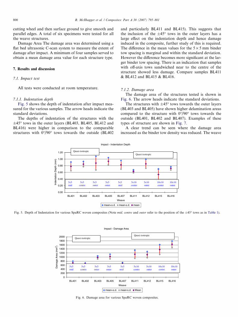
7.1.2. Damage area
The damage area of the structures tested is shown inFig. 6. The arrow heads indicate the standard deviations.
The structures with ±45� tows towards the outer layers(BL403 and BL405) have shown higher delamination areascompared to the structure with 0�/90� tows towards theoutside (BL401, BL402 and BL407). Examples of thesetypes of structure are shown in Fig. 7.
A clear trend can be seen where the damage areaincreased as the binder tow density was reduced. The weave
on Depth
407 BL411 BL412 BL415 BL416
ave
ean-s.d. mean
5 5x10 5x10 10x10 10x10 id centre outer centre outer
Quasi-isotropic
d, centre and outer refer to the position of the ±45� tows as in Table 1).
ge Area
L407 BL411 BL412 BL415 BL416
eave
mean-s.d. Mean
5x5 5x10 5x10 10x10 10x10 id centre outer centre outer
Quasi-isotropic
SpaRC woven composites.

BL 405
BL 402
5mm
1110987
6
54321
5mm
1110987
654321
Fig. 7. Architecture showing the relative positions of the ±45� tows(BL405 – outer, BL 402 – centre).
R. McIlhagger et al. / Composites: Part A 38 (2007) 795–801 801
architecture BL402 (4) has a similar architecture to BL411(2) and BL415 (1) but each had a different binder tow den-sity (the number in parenthesis next to the weave code rep-resents the number of binder tows per cm2). It is apparentthat the damage area has increased progressively from sam-ple BL402, through BL411 to BL415. A similar trend canbe seen for samples BL403, BL412 and BL 416, wherethe ±45� were placed closer to the surface. It should benoted that these results do not correlate with the depthof penetration of the impactor.
It is postulated that when the ±45� degree tows wereclose to the surface, the tension on the binder tows tendedto compress the off-axis tows at the cross over points caus-ing localised stress concentrations. In situations where the±45� degree tows were positioned in the body of the rein-forcement any potential stress concentrations were redis-tributed locally, along with any displacement of thebinder tow.
8. Conclusions
The following conclusions are drawn from thisinvestigation:
� after impact, the depths of indentation of the impactorinto the structures with the ±45� tows in the outer layerswere higher in comparison to the comparable structureswith 0�/90� tows on the outside.� after impact, the depths of indentation of the impactor
into the structures with 5 · 5 mm binder tow density(4 binder tow stitches/cm2) were slightly greater thanthose with lower stitch densities.
� after impact, the damage areas within the structureswith the ±45� binder tows in the outer layers were signif-icantly greater in comparison to comparable structureswith the 0/90 tows on the outside.� after impact, the damage areas within the structures
with 5 · 5 mm binder tow spacing (4 binder towstitches/cm2) were significantly less than those withlower stitch densities (both 5 · 10 mm and 10 · 10 mmbinder tow spacings).
A clear trend was apparent where the damage areaincreased as the binder tow density was reduced. The nextphase of this work will be to examine the influence of bin-der tow density on a range of performance indicators forthese multi-axis, multi-layer (SpaRC) composite materials.
Acknowledgements
The authors wish to acknowledge support for thisproject from both the UK DTI Aeronautics ResearchProgramme and Bombardier Aerospace UK, Belfast.
References
[1] Miravete A. Introduction: Why are 3-D textile technologies appliedto composite materials. 3-D reinforcements in composite materials.In: Miravete A, editor. Cambridge: Woodhead Publishing Ltd.;1999. p. 1–2.
[2] Bannister M. Challenges for composites into the next millennium – areinforcement perspective. Composites A 2001;32A(7):901–11.
[3] Limmer L, Weissenbach G, Brown D, McIlhagger R, Wallace E.3-D woven composites for lower leg prosthesis. Composites A1996;27A(4):271–8.
[4] Quinn J, McIlhagger R, McIlhagger AT. A modified system fordesign and analysis of 3D woven preforms. Composites A2003;34A(6):503–10.
[5] Mohamed MH, Bogdanovitch AH, Habil R, Dickinson LC, Singl-etary JN, Bradley Lienhart R. A new generation of 3D woven fabricpreforms and composites. SAMPE J 2001;37(3):8–17.
[6] Brandt J, Dreschler K, Mohamed M, Gu P. Manufacture of andperformance of carbon/epoxy 3D woven composites, In: Proceedingsof 37th int SAMPE symp, Anaheim, CA, 1992. p. 864–77.
[7] Wilson S, Wenger W, Simpson D, Addis S, In: Proceedings of the43rd international SAMPE symposium, Anaheim ,1998. p. 1330.
[8] Ganeshmal M, Wang L, Brown D, McIlhagger R, Wilson S, SimpsonD, Wenger W. Performance analysis of ‘SpaRC’, 5 axis, 3D wovencarbon composites. In: Proceedings of 36th int SAMPE technicalconference – materials & processing: sailing into the future, SanDiego, CA, 2004.
[9] ASTM Standard D3776: Standard Test Methods for Mass Per UnitArea (Weight) of Fabric – Year 1996.
[10] ISO 4603: 1993 Textile Glass – Woven Fabrics – determination ofthickness.
[11] Product Data Sheet Hexflow� RTM6.[12] Weissenbach G. Determination of the composite fibre volume
fraction with the density method using liquid displacement. Engi-neering Composites Research Centre, University of Ulster atJordanstown, 1998, Internal Report.
[13] SRM 2R-94: SACMA recommended test method for the compressionafter impact properties of oriented fibre-resin composites SRM2-94(SACMA – Suppliers of Advanced Composite MaterialsAssociation).
Copyright © 2022 FDOKUMEN