Sexual Assault in Jail and Juvenile Facilities - Office of Justice ...
Upload
khangminh22Category
view
0download
0
�������� ��� ������� �� ������ ��
��������������������� ������������ ���������
��������������������� ���������������� ������������ ��� �� ��� ���� � ����
�������������������� �� ��� ����
��������� �� ��� ��� �����

���������� ������ �� ������������ ���� �������������� ������������ �� ��������� ��� ��������������� ���� !"#$!%���
14 April 2000
������������������ �������� ������� ��������� ���� ������
����� �����������
��������
������������ ���
������� ���� ����� �
����� �� ���������� ������������������������������������������������������������������������������������������������������� ��� ���� ����� ��� ���������������������������������������������������������������������������������������������
�������� �������� ����� ����������������������������� ����
��������� �������� ��� !���"#��$ �%��##�&�#�� ������ '��� �
�
������ ������������������ ������������������������������������������������������������������������������������� ��! ��� ����" �����#��� �����������������������������������������������������������������������������������������$%& ������"�& ��� �������������������������������������������������������������������������������������������������'
���������� ��������� ���##�&�#�� ������ '��� �(�'��)�*�&����"��'%'�!
����� �� �����#��� ����������������������������������������������������������������������������������������������������" �� ��������������(�� �������������������������������������������������������������������������������������������������� ������������������ �������������������������������������������������������������������������������������� ��! ��� ����" �����#��� ������������������������������������������������������������������������������������������)%& ������"�& ��� �������������������������������������������������������������������������������������������������)
����� �� �����#��� ���������������������������������������������������������������������������������������������������" �� ��������������(��� �����������������������������������������������������������������������������������������
���*"�(+*�,-�"%�*"��*�,-.���������������� ������������ ��� �� ��� ���� � ����
/�*� ����� ��� ������������0 ��'�1�$2*,��3�4��'��4�5��6�,������5��$76

����������� ����������##�&� *�'! �+#�� ������ '��� �(�'���,�*�&����"��'%'�!
����� �� �����#��� ���������������������������������������������������������������������������������������������������1" �� ��������������(�� �������������������������������������������������������������������������������������������1������ ������������������ �������������������������������������������������������������������������������������1 ��! ��� ����" �����#��� ������������������������������������������������������������������������������������������$%& ������"�& ��� �������������������������������������������������������������������������������������������������'
�������- �������� �����������./�� ����� �������� �� ��0�� ��������� �
����� �� �����#��� ������������������������������������������������������������������������������������������������3�������� ���������� ��������������������������������������������������������������������������������������������������3�����8 �����������9 ��� #��� ���������������������������������������������������������������������������������3�3���� ���:���9���������!���������� �������*�� ��� ����������������������������������������������3�7#��� ���*�� ��� ��������������������������������������������������������������������������������������������������������3�$������� ��� ������ ����� ��� ����������������������������������������������������������������������������������3��'������� �����������������������"��������������9 ��������������������������������������������3���������� ���%;����� ����9���� ������������������������������������������������������������������������������������3���������� ���%;����� ����������� �������������������������������������������������������������������������������3��3������� ������� � ���� ���%�������9�"����� ��� ������������������������������������������������������3��3 ��! ���" ����� #��� ���������������������������������������������������������������������������������������������3��3%& ������"�& ��� ����������������������������������������������������������������������������������������������3��3
�������/ �������� ������������ 1�� �����0����� ��� �� ��0�� ��������� �
��������� ���������##�&�#������� '��� �#�� �"!�0�& �(�'$(�'��)�*�&����"��'%'�!
����� �� �����#��� ������������������������������������������������������������������������������������������������)�������� ���������� ��������������������������������������������������������������������������������������������������)��( �� ����������� ���:���9���������!� ��������������������������������������������������������������)�3���� ��� �� ���� �������������(��� ���������������������������������������������������������������������)�)���� ��� �� ���� �������������(�������������� �������������������������������������������������)�4#��� ��� #��� ����������������������������������������������������������������������������������������������������������)�7������� ��� ������ ����� ��� ����������������������������������������������������������������������������������)��'������� ������������������ �����������������������������������������������������������������������������������)���������� ���"��������9���� ��������������������������������������������������������������������������������������)���������� ���%;����� ����9���� ������������������������������������������������������������������������������������)��3������� ���%;����� ����������� �������������������������������������������������������������������������������)��)������� ������� � ���� ���%�������9�"����� ��� ������������������������������������������������������)��) ��! ���" ����� #��� ���������������������������������������������������������������������������������������������)��)%& ������"�& ��� ����������������������������������������������������������������������������������������������)��)
���������� ���������##�&�#�� �"!�0�& �(�'$(�'��)�*�&����"��'%'�!
����� �� �����#��� ������������������������������������������������������������������������������������������������)��7������ ���������� ��������������������������������������������������������������������������������������������������)��7( �� ����������� ���:���9���������!� ��������������������������������������������������������������)��'���� ��� �� ���(�;������������� �������������������������������������������������������������������������)���
����
��

�������2 ����������� 0��� �������������3����4��������0����5� �� ��0�� ��������� �
����� �� �����#��� ������������������������������������������������������������������������������������������������1�������� ����������5�:���9����5�����*��! �����������������������������������������������������������1��" �� ����*��� ��: <=�*��! ������������������������������������������������������������������������������1��������� ��� ���� #��� ����������������������������������������������������������������������������������������������1��
�������6 ��������7668�9-68������ ���������� �� ��0�� ��������� � ������0����� ��
����� �� �����#��� ������������������������������������������������������������������������������������������������6�������� ���������� ��������������������������������������������������������������������������������������������������6�������� ���������� � �� ���:���9���������!� ������������������������������������������������������6�������� ���*��! �������������������������������������������������������������������������������������������������������6�����8 �����������9 ���#������������ �������� �����������������������������������������������6��# � ���������� � �� ���*��!������������ ����� ������ �� �������������������������������������6�$#��� ���*��! ����������������������������������������������������������������������������������������������������������6�$������� ��� ��������9 ��������� ����� ��� �����������������������������������������������������������6�$���8 ������������������ ������������������������������������������������������������������������������������6�$������� ��� ���������"������ ���������������������������������������������������������������������������������6�$������� ���%;����� ����9���� ������������������������������������������������������������������������������������6�$������� ������� � ���� ���%�������9�"����� ��� ������������������������������������������������������6�$���� ���%;����� ����������� ���������������������������������������������������������������������������������6�$ ��! ���" ����� #��� ���������������������������������������������������������������������������������������������6��'%& ������"�& ��� ����������������������������������������������������������������������������������������������6��'
>������9 ��������������������������������������������������������������������������������������������������������������������������������������9��
"�������� ������������������������������������������������������������������������������������������������������������������������������������������
#��� ��� #��� ����������������������������������������������������������������������������������������������������������)��6������� ��� ������ ����� ��� ����������������������������������������������������������������������������������)�3'������� ������������������ �����������������������������������������������������������������������������������)�3�������� ���"��������9���� ��������������������������������������������������������������������������������������)�3�������� ���%;����� ����9���� ������������������������������������������������������������������������������������)�33������� ���%;����� ����������� �������������������������������������������������������������������������������)�33������� ������� � ���� ���%�������9�"����� ��� ������������������������������������������������������)�33 ��! ���" ����� #��� ���������������������������������������������������������������������������������������������)�33%& ������"�& ��� ����������������������������������������������������������������������������������������������)�33
����
���

�� ��+�!,�-�#(--���!)���$.���$.�#$�/ "�����.(�'$!��0�#(+���!)�+ �� -(�1���(�����2�!�3(�-$.�4(-$2 #0�� /)/$''()�5/$+���%�����%������%��!)����6��� /2/�5#1+',#(�2�/"$�'�/�2�,#(�/(7, /(
��� �����������
��(�'/$'$!(!#�$5�#� ��',3- 2�# $!� ������ ����1��$,��/(�(!2$,/�"()�#$�/('$/#��!0�(//$/��$/$+ �� $!���!)�#$��,""(�#�.�0��$5�+�8 !"�#� ����3(##(/�+�!,�-1
�/+0�'(/�$!!(-%��(!)�0$,/�2$++(!#��$!�����$/+����9�) /(2#-0�#$:�������������������� /(2#$/
�(/ �-��(- 4(/0��!)�� (-)��(/4 2(���('�/#+(!#����,�/#(/+��#(/��(!#(/��!)��2�$$-�������$'� $�)�$/#��((%�; /" ! ����9�������
� /��$/2(�'(/�$!!(-%��(!)�0$,/�/('$/#��$!�������$/+����#�/$,"�:�(�)7,�/#(/�� /��$3 - #0��$++�!)�&���<��=�*6����2$##��/ 4(%�! #�����2$##���>%��-- !$ ��?���������
� /��$/2(�'(/�$!!(-� !��'(2 �-��'(/�# $!���$++�!)%��(!)�0$,/�/('$/#���$!������$/+����#�/$,"�:
��������<��@�����>�/#-(0��#/((#%��, #(��?��,/-3,/#�� (-)%�������66�����
#$:� /(2#$/�(/ �-��(- 4(/0��!)�� (-)��(/4 2(���('�/#+(!#����,�/#(/+��#(/��(!#(/��!)��2�$$-�������$'� $�)�$/#��((%�; /" ! ����9�������
�-�$��(!)��!� !5$/+�# $!�2$'0�$5�������$/+����#$:������<�����69���,(!# !� $$�(4(-#� $�)=(--0���>%��(A����9�6������
�����
���
��

������� �
�� ����� ���
��������������� �
���1���(�)(�2/ '# $!�$5�#�(� #(+��2$4(/()� !�#� ��+�!,�-� ��" 4(!�3(-$.:���������������� ��������������������������� ���� �������� !�����"�� ���� �����!������"������ ������ ����!������� ����+ �� -(���/(/ ""()� !�$4(/'�28�� !������2$!#� !(/�� !�#�/((�2$!5 ",/�# $!�%� !�#�(��6�?%�<6�#$!�#/� -(/%��!)�$!�#0'(�;�'-�#5$/+�1�����#$�%"�� $& ��� �������� ��������������������������"���'�������� ����'(����������"�%������������"�����$$�����������������#(%%�)##�*&����� ������� ���+���������"� ����������" ������������ "��������������, ����������"���'��������� �����'���������"��������������"�������%(��������������������������-����� �����������������������������., ���/���.0�����1���1 � � ���-��� �����������, ������ �������1������� ���#(%%����#��!�� ������� ������2222��������������� ��-� ��� ������������ "�1� ��,������������"�-������ ����1, ��"����� ���� ���3��� ������� ��1, ���
������������������
���1��'(2 �-�2$!� )(/�# $!��5$/�#� ��+�!,�-��/(�)(�2/ 3()�3(-$.1
���(�-$�)��2$4(/()� !�#� ��+�!,�-�+�0� !2-,)(���B�/)$,��+�#(/ �-����)(5 !()� !���C����6���6<����9����1��5� !2-,)()%�#�(���B�/)�$,��+�#(/ �-��+,�#�3(�'�28�"()%�+�/8()%��!)�-�3(-()����/(7, /()�30���C����6���6<����9����1
�>(��,/(�#��#���4(� 2-(�/ ""()�,� !"�#�(�(�'/$2(),/(�� ��#�(���+(�4(� 2-(���$.!��!)�)(�2/ 3()� !�#� ��+�!,�-1�>(��,/(�#��#��!0�(7, '+(!#�/ ""()� !� )(�#�(�4(� 2-(� ��/(�#/� !()��!)�'/$#(2#()1
���2$'0�$5�#� ��+�!,�-�+,�#�3(��4� -�3-(�#$�#�(�D$ !#�� /)/$'� !�'(2#$/��),/ !"�#�(�3(5$/(���!)��5#(/�-$�) !"� !�'(2# $!�1
���

FM 10-500-29/TO 13C7-10-171
2-1
Chapter 2
Rigging TOW Weapon Systems and Missiles in A-22 Cargo Bags
SECTION I- RIGGING TOW WEAPON SYSTEM AND MISSILES IN ANA-22 CARGO BAG FOR LOW-VELOCITY AIRDROP
DESCRIPTION OF LOAD
2-1. The TOW weapon system consists of the launcher, launch tube, and powerpack. It can be rigged with eight missiles in an A-22 cargo bag for low-velocityairdrop. The load requires one G-12E or three G-14 cargo parachutes.
RIGGING A-22 CARGO BAG
2-2. Rig the TOW weapon system and eight missiles in the A-22 cargo bag asdescribed below.
a. Prepare the skid board as shown in Figures 2-1 and 2-2.b. Lay out the A-22 cargo bag as shown in Figure 2-3.c. Pack the TOW weapon system and missiles as shown in Figures 2-4 through2-7.
ATTACHING CARGO PARACHUTES
2-3. Prepare and install one G-12E cargo parachute or three G-14 cargo parachutesto the A-22 cargo bag according to FM 10-500-3/TO 13C7-1-11, and as shown inFigure 2-8.

FM 10-500-29/TO 13C7-10-171
2-2
1 Center and drill four 1/2-inch holes two inches on center from each edge of the skid board asshown. Cut the corners of the skidboard as shown in FM 10-500-3/TO 13C7-1-11.
Note: The distances between holes are measured on center.
2 Install an 8-foot length on 1/2inch tubular nylon webbing through each pair of holes.
Figure 2-1. Skid Prepared
2
53 1/2 “
48”
1
25 53
3

FM 10-500-29/TO 13C7-10-171
2-3
1 Make six three-layer stacks of honeycomb from eighteen 9- by 9-inch pieces. Glue the layerstogether. Place a stack of honeycomb at each corner of the plywood 3 inches from each edge.
2 Center the two remaining stacks of honeycomb on the plywood 10 inches from each long edge.
Figure 2-2. Honeycomb Positioned on the Skid
1 Lay the A-22 sling assembly on the honeycomb stacks.
2 Center the A-22 cover, outside down, on the sling assembly, with the long panel over the longtie-down strap.
3 Center a 3/4- by 48- by 58-inch piece of plywood on the A-22 cover.
4 Make a 30-foot lashing according to FM 10-500-2/TO 13C7-1-5, and lay it across the plywood.
Figure 2-3. A-22 Cargo bag Prepared for the TOW Missile System
12
3
4
1
1
53 1/2 “
48”
48”
48”
58”
2

FM 10-500-29/TO 13C7-10-171
2-4
1 Set two boxed missiles on the plywood, one even with each 58-inch edge.
2 Lay a 24- by 58-inch piece of honeycomb between the missiles.
3 Place a 12- by 58-inch piece of honeycomb on each boxed missile and one against the insideof each box.
4 Wrap the sight in cellulose wadding and place it in its case, if available (inset above). Lay it onthe honeycomb between the missiles.
5 Set the power pack and sight traversing unit on the honeycomb with the sight.
Figure 2-4. Missiles, Sight Traversing Unit, Sight, and Power Pack Stowed
12
3
4
5

FM 10-500-29/TO 13C7-10-171
2-5
1 Place a 48- by 58-inch layer of honeycomb on top of the load.
2 Make a 6- by 18-inch cutout in the honeycomb to keep the honeycomb from touching the sight.
3 Place a piece of honeycomb, cut to fit, at each end of the equipment.
Figure 2-5. Honeycomb Placed on Top of the Load
12
3

FM 10-500-29/TO 13C7-10-171
2-6
1 Set the two boxed missiles on the honeycomb even with each 58-inch edge.
2 Lay the tripod and launch tube between the missiles. Place a 12- by 52-inch piece of honey-comb between them.
3 Tie the tripod, launch tube, and honeycomb together with 1/2-inch tubular nylon webbing.
Figure 2-6. Missiles, Tripod, and Launch Tube Stowed
1
2
3

FM 10-500-29/TO 13C7-10-171
2-7
1 Place a piece of honeycomb, cut to fit, at each end of the equipment.
2 Place a 48- by 58-inch layer of honeycomb on top of the load.
3 Set four boxed missiles on the honeycomb.
4 Bind the load together with the 30-foot lashing, two D-rings, and a load binder.
Figure 2-7. Load Completed and Bound Together
1
2
3
4

FM 10-500-29/TO 13C7-10-171
2-8
1 Bring the A-22 cover up over the load, and fold excess material under as necessary.
2 Pass the A-22 tie-down straps up over the load. Fasten and tighten the straps.
3 Lace each corner of the cover through the lacing loops with type III nylon cord to form a figureeight.
4 Fasten the lateral straps together around the A-22 cover. Pass the upper lateral straps aroundthe top of the corners.
5 Attach the suspension webs to the D-rings of the support webs with the open side of the snapsfacing inward. Tape the snaps to the D-rings.
6 Adjust all straps to make the sling assembly fit snugly. Pull the suspension webs to their fullheight. Adjust the upper lateral straps to prevent binding the upper part of the support web.Fold all excess straps and tie the folds with type I, 1/4-inch cotton webbing.
7 Make the skidboard ties according to FM 10-500-3/TO 13C7-1-11.
8 Prepare, attach, and safety one G-12E cargo parachute (with a 68-inch pilot parachute), orthree G-14 cargo parachutes to the load according to FM 10-500-3/TO 13C7-1-11.
Figure 2-8. A-22 Cargo Bag Secured and Parachutes Installed
8
1 25
463
7

FM 10-500-29/TO 13C7-10-171
2-9
MARKING THE RIGGED LOAD
2-4. Mark the rigged load as described in Chapter 1, FM 10-500-3/TO 13C7-1-11,using the data given in Figure 2-9. Complete the Shipper’s Declaration for Dangerous Goods.
CAUTIONMake the final inspection required by Chapter 1, FM 10-500-3/TO 13C7-1-11
before the load leaves the rigging site.
Figure 2-9. TOW Weapon System and Missiles Rigged in an A-22 Cargo Bag for Low-velocityAirdrop
Weight....................................................................................................................1,217 poundsWidth...........................................................................................................................48 inchesHeight..........................................................................................................................72 inchesLength..........................................................................................................................58 inches
RIGGED LOAD DATA

FM 10-500-29/TO 13C7-10-171
2-10
EQUIPMENT REQUIRED
2-5. The equipment required to rig this load is listed in Table 2-1.
Table 2-1. Equipment Required to Rig the TOW Weapon Sysytem and Eight Missiles in A-22Cargo Bag
kcotSlanoitaNrebmuN
metI ytitnauQ
3178-372-00-0408 lag-1,etsap,evisehdA deriuqersA
1243-785-00-0761 22-A,yreviledlairea,ograc,gaB 1
6412-042-00-0204 bl-055,IIIepyt,nolyn,droC deriuqersA
8293-357-00-0761 bmocyenoh,gnitapissid-ygrene,daP steehs3
1573-560-10-0761 E21-G,maidtf-46,ograc,etuhcaraP ro 1
8562-999-00-0761 41-G,ograc,etuhcaraP 3
7927-612-00-0761 maidni-86,tolip,etuhcaraP 1
8115-419-00-0355 kcihtni-1,doowylPni-2/135yb-84
ni-85yb-841
6105-662-00-0157 ni-2,evisehda,epaT deriuqersA
5493-719-00-0138 )5rntekcit(7/8rebmuntekcit,nottoc,daerhT deriuqersA
1720-739-00-0761 tf-51,ylbmessanwod-eiT 2
1142-862-00-5038 ni-4/1,nottoc,Iepyt,gnibbeW deriuqersA
2575-280-00-5038 ni-2/1,ralubut,nolyn,gnibbeW deriuqersA

FM 10-500-29/TO 13C7-10-171
2-11
DESCRIPTION OF LOAD
2-6. This load consists of 12 TOW missiles in overpacks. The 12 missiles are riggedin a standard A-22 cargo bag. The load requires one G-12E or three G-14 cargoparachutes.
RIGGING A-22 CARGO BAG
2-7. Rig 12 TOW missiles in the A-22 cargo bag as described below.a. Prepare the skid board and A-22 cargo bag as shown in Figures 2-1 and 2-2 ofSection I.b. Pack the missiles as shown in Figure 2-10.c. Close and secure the A-22 cargo bag as shown in Figure 2-11.
ATTACHING CARGO PARACHUTES
2-8. Prepare and attach one G-12E cargo parachute or three G-14 cargo parachutesas shown in Figure 2-11, and according to FM 10-500-3/TO 13C7-1-11.
SECTION II - RIGGING 12 TOW MISSILES IN AN A-22 CARGO BAGFOR LOW-VELOCITY AIRDROP

FM 10-500-29/TO 13C7-10-171
2-12
1 Place the twelve TOW missiles as shown on the A-22 cargo bag. Place a 48- by 58-inch layerof 3/4-inch plywood or honeycomb between each layer of missiles. Figure 2-10 showsboth honeycomb and plywood. Do not use both honeycomb and plywood between thelayers in the same A-22 bag.
2 Bind the missiles together with a 30-foot lashing, two D-rings, and a load binder.
Figure 2-10. Twelve TOW Missiles Loaded on the A-22 Cargo Bag
1
2

FM 10-500-29/TO 13C7-10-171
2-13
1 Bring the A-22 cover up over the load, and fold excess material under as necessary.
2 Pass the A-22 tie-down straps up over the load. Fasten and tighten the straps.
3 Lace each corner of the cover through the lacing loops with type III nylon cord to form a figureeight.
4 Fasten the lateral straps together around the A-22 cover. Pass the upper lateral straps aroundthe top of the corners.
5 Attach the suspension webs to the D-rings of the support webs with the open side of thesnaps facing inward. Tape the snaps to the D-rings.
6 Adjust all straps to make the sling assembly fit snugly. Pull the suspension webs to their fullheight. Adjust the upper lateral straps to prevent binding the upper part of the support web.Fold all excess straps and tie the folds with type I, 1/4-inch cotton webbing.
7 Make the skidboard ties according to FM 10-500-3/TO 13C7-1-11.
8 Prepare, attach, and safety one G-12E cargo parachute (with a 68-inch pilot parachute), orthree G-14 cargo parachutes to the load according to FM 10-500-3/TO 13C7-1-11.
Figure 2-11. A-22 Cargo Bag Secured
3 4
2
8
1
7
5
6

FM 10-500-29/TO 13C7-10-171
2-14
EQUIPMENT REQUIRED
2-10. The equipment required to rig this load is listed in Table 2-2.
Table 2-2. Equipment Required to Rig TwelveTOW Missiles in an A-22 Cargo Bag for Low-velocityAirdrop
RIGGED LOAD DATA
Weight....................................................................................................................1,394 poundsWidth...........................................................................................................................48 inchesHeight...........................................................................................................................69 inchesLength..........................................................................................................................58 inches
Figure 2-12. Twelve TOW Missiles Rigged in an A-22 Cargo Bag for Low-Velocity Airdrop
MARKING THE RIGGED LOAD
2-9. Mark the rigged load as described in Chapter 1, FM 10-500-3/TO 13C7-1-11.Complete the Shipper’s Declaration for Dangerous Goods.
CAUTIONMake the rigger inspection
described in Chapter 1, FM 10-500-3/TO 13C7-1-11 before the load
leaves the rigging site.
kcotSlanoitaNrebmuN
metI ytitnauQ
3178-372-00-0408 lag-1,etsap,evisehdA deriuqersA
1243-785-00-0761 22-A,yreviledlairea,ograc,gaB 1
6412-042-00-0204 bl-055,IIIepyt,nolyn,droC deriuqersA
8293-357-00-0761 bmocyenoh,gnitapissid-ygrene,daP steehs2
1573-560-10-0761 E21-G,maidtf-46,ograc,etuhcaraP ro 1
8562-999-00-0761 41-G,ograc,etuhcaraP 3
7927-612-00-0761 maidni-86,tolip,etuhcaraP 1
8115-419-00-03551894-821-00-0355
ni-2/135yb-84yb-1,doowylPtonsibmocyenohfiowtdda(ni-85yb-84yb-4/3,doowylP
)desu
1
6105-662-00-0157 ni-2,evisehda,epaT deriuqersA
5493-719-00-0138 )5rntekcit(7/8rebmuntekcit,nottoc,daerhT deriuqersA
1720-739-00-0761 tf-51,ylbmessanwod-eiT 2
1142-862-00-5038 ni-4/1,nottoc,Iepyt,gnibbeW deriuqersA
2575-280-00-5038 ni-2/1,ralubut,nolyn,gnibbeW deriuqersA

FM 10-500-29/TO 13C7-10-171
2-15
DESCRIPTION OF LOAD
2-11. This load consists of 12 TOW missiles in overpacks. The 12 missiles are rigged in a standard A-22 cargo bag. The load requires one 26-foot, high-velocity cargoparachute.
RIGGING A-22 CARGO BAG
2-12. Rig the A-22 cargo bag as described below.a. Prepare the skid and honeycomb as shown in Figure 2-13.b. Position and secure the missiles as shown in Figure 2-14.c. Finish rigging the A-22 cargo bag as shown in Figure 2-15 and according to FM 10-500-3/TO 13C7-1-11.
ATTACHING CARGO PARACHUTE
2-13. Prepare and attach one 26-foot, high-velocity cargo parachute as shown inFigure 2-16, and according to FM 10-500-3/TO 13C7-1-11.
SECTION III - RIGGING 12 MISSILE OVERPACKS IN AN A-22 CARGOBAG FOR HIGH-VELOCITY AIRDROP

FM 10-500-29/TO 13C7-10-171
2-16
1 Use one 8- by 48-inch and one 36- by 48-inch piece of honeycomb to form a layer of 44- by 48-inch honeycomb. Center the honeycomb on the skidboard with the 44-inch edges along the 48-inch sides of the skidboard.
2 Use one 12- by 48-inch and one 36- by 48-inch piece of honeycomb to form a layer of 48-by 48-inch honeycomb. Center and glue this layer on the layer made in step 1 above.
3 Glue four 9- by 9-inch pieces of honeycomb together to make each of six stacks. Glue four ofthese stacks three inches from the ends, and flush with the left and right sides of the base.
4 Center two 9- by 9-inch stacks along the left and right sides, 10 inches from the left and rightedges of the base.
Figure 2-13. Skid and Honeycomb Prepared
2
3
1
FRONT
4
48”

FM 10-500-29/TO 13C7-10-171
2-17
5 Center and glue two 24- by 48-inch pieces of honeycomb on top of the 9- by 9-inch stacks.
6 Center a 3/4- by 48- by 58-inch piece of plywood on top of the honeycomb. Place the the 58-inch side of the plywood parallel to the 53 1/2-inch side of the skid board.
7 Lay an A-7A strap along each side of the plywood, 6 inches from each edge.
8 Set the sling assembly on the plywood and the A-7A straps.
Figure 2-14. Skid and Honeycomb Prepared (Continued)
5
6
8
7

FM 10-500-29/TO 13C7-10-171
2-18
1 Place four missiles on the scuff pad.
2 Place two layers of honeycomb on the missiles. Use a 36- by 48-inch and a 22- by 48-inchpiece of honeycomb to form each layer.
3 Place four missiles on the layers of honeycomb.
4 Place one 48- by 58-inch layer of honeycomb on the missiles.
5 Place four missiles on the layer of honeycomb.
6 Place one 48- by 58-inch layer of honeycomb over the missiles.
7 Place a 48- by 58-inch piece of plywood on top of the load.
8 Secure the four A-7A straps from under the scuff pad on top of the load.
9 Close the A-22 cargo bag according to FM 10-500-3/TO 13C7-1-11.
Figure 2-15. Missiles Positioned and Secured
1
2
3
4
5
6
7
8 89

FM 10-500-29/TO 13C7-10-171
2-19
Weight....................................................................................................................1,359 poundsWidth...........................................................................................................................48 inchesHeight..........................................................................................................................83 inchesLength.........................................................................................................................58 inches
Figure 2-16. Twelve TOW Missiles Rigged in an A-22 Cargo Bag for High-Velocity Airdrop
CAUTIONMake the final inspection required by Chapter 1, FM 10-500-3/TO 13C7-1-11
before the load leaves the rigging site.
RIGGED LOAD DATA
MARKING THE RIGGED LOAD
2-14. Mark the rigged load as described in Chapter 1, FM 10-500-3/TO 13C7-1-11,using the data given in Figure 2-16. Complete the Shipper’s Declaration for Dangerous Goods.

FM 10-500-29/TO 13C7-10-171
2-20
EQUIPMENT REQUIRED
2-15. The equipment required to rig this load is listed in Table 2-3.
Table 2-3. Equipment required to Rig Twelve TOW Missiles in Overpacks in an A-22 Cargo Bag forHigh-Velocity Airdrop
kcotSlanoitaNrebmuN
metI ytitnauQ
3178-372-00-0408 lag-1,etsap,evisehdA deriuqersA
1243-785-00-0761 22-A,yreviledlairea,ograc,gaB 1
8293-357-00-0761 bmocyenoh,gnitapissid-ygrene,daP steehs5
9016-278-00-0761 tf-62,yticolev-hgih,ograc,etuhcaraP 1
8115-419-00-03551894-821-00-0355
ni-2/135yb-84yb-1,doowylPni-85yb-84yb-4/3,doowylP
12
3511-152-00-0761 A7-A,partS 4
6105-662-00-0157 ni-2,evisehda,epaT deriuqersA
5493-719-00-0138 )5rntekcit(7/8rebmuntekcit,nottoc,daerhT deriuqersA
1142-862-00-5038 ni-4/1,nottoc,Iepyt,gnibbeW deriuqersA
2575-280-00-5038 ni-2/1,ralubut,nolyn,gnibbeW deriuqersA

3-1
FM 10-500-29/TO 13C7-10-171
Chapter 3
Rigging TOW Missiles in 1/4-ton Cargo Trailerfor Low-velocity Airdrop
DESCRIPTION OF LOAD
3-1.The M416, 1/4-ton cargo trailer with eight boxed missiles is rigged on an 8-foot,type V airdrop platform for low-velocity airdrop. The load requires one G-11 cargo
parachute. Each missile in its box weighs 87 pounds, and is 57 1/2 inches long, 12inches high and 12 inches wide. The M416 with missiles weighs 1170 pounds. Itis 109 inches long, 61 inches wide, and 44 inches high. The accompanying loadconsists of eight boxes of 105-millimeter ammunition. It weighs 588 pounds.
PREPARING PLATFORM
3-2. Prepare an 8-foot, type V airdrop platform as shown in Figure 3-1.a. Inspecting Platform. Inspect, or, assemble and inspect, the platformaccording to TM 10-1670-268-20&P/TO 13C7-52-22.b. Installing Tandem Links. Install tandem links as shown in Figure 3-1.c. Attaching and Numbering Clevises. Attach and number 24 clevis assemblies as shown in Figure 3-1.
NOTES:1. The nose bumper may or may not be installed.2. Measurements given in this load are from the front edge of the platform,NOT from the front edge of the nose bumper.

3-2
FM 10-500-29/TO 13C7-10-171
Step:
1. Install a tandem link to the front of each platform side rail using holes 1, 2, and 3.
2. Install a tandem link to the rear of each platform side rail using holes 14, 15, and 16.
3. Install a clevis on bushings 1, 2 and 3 on each front tandem link.
4. Install a clevis on bushings 1, 3, and 4 on each rear tandem link.
5. Starting at the front of each platform side rail, install clevises on the bushings boltedon holes 4, 5, 6, 8, 11, and 12.
6. Starting at the front of the platform, number the clevises 1 through 12 on the right sideand 1A through 12A on the left side.
Figure 3-1. Platform Prepared
LEFT
RIGHT
FRONTREAR
CLEVISES 12 THROUGH 1
CLEVISES 12A THROUGH 1A

3-3
FM 10-500-29/TO 13C7-10-171
Stowing Accompanying Load
3-3. Place the honeycomb and stow the accompanying load as shown in Figure 3-2.
1 Position one piece of 18- by 86-inch honeycomb and one piece of 36- by 86-inch honeycombside- by side to form one layer on the front edge of the platform.
2 Position two 15-foot lashings on the honeycomb as shown for use as binding lashings.
Figure 3-2. Accompanying Load Stowed
12

3-4
FM 10-500-29/TO 13C7-10-171
3 Position eight boxes on the honeycomb as shown so that the four rearmost boxes are flushwith the rear edge of the honeycomb. Secure the binding lashings placed in step 2 around theboxes.
4 Run a 15-foot lashing through clevis 5 and through its own D-ring. Bring the lashing throughthe front box carrying handles and fasten it to clevis 5A with a D-ring and a load binder.
5 Run a 15-foot lashing through clevis 6A and through its own D-ring. Bring the lashing over thetop of the front boxes and fasten it to clevis 6 with a D-ring and a load binder.
6 Run a 15-foot lashing through clevis 9 and through its own D-ring. Bring the lashing throughthe rear box carrying handles and fasten it to clevis 9A with a D-ring and a load binder.
7 Run a 15-foot lashing through clevis 8 and through its own D-ring. Bring the lashing over thetop of the rear boxes and fasten it to clevis 8A with a D-ring and a load binder.
8 Evenly space and glue three two-layer stacks of 12- by 12-inch honeycomb to the front edge of the base honeycomb.
Figure 3-2. Accompanying Load Stowed (continued)
Note: Other boxed ammunition may be used for this load.Adapt the honeycomb and lashings for the ammunition rigged.
9 8
568
7
6
3
4
5
Notice of Exception: Exception to FM 10-500-2/TO 13C7-1-5 isgranted to rig ammunition on one layer of honeycomb.

3-5
FM 10-500-29/TO 13C7-10-171
9 Center one boxed TOW missile on the 12- by 12-inch stacks of honeycomb.
10 Center the D-rings of a 30-foot lashing on top of the box. Run a free end of the lashing throughclevis 4, around the front of the box, over the center of the box, and around the back of the boxto clevis 1A. Run the other free end of the lashing through clevis 1A. Secure the ends of thelashing with two D-rings and a load binder on the left side .
11 Run a 15-foot lashing through clevis 1 and through its own D-ring, around the rear of the box,over the center of the box,and around the front of the box to clevis 4A. Fasten the lashing toclevis 4A with a D-ring and a load binder.
Figure 3-2. Accompanying Load Stowed (continued)
9
1110
14

3-6
FM 10-500-29/TO 13C7-10-171
Preparing Missiles and Trailer
3-4. Prepare the missiles and trailer as shown in Figure 3-3.
1 Tie the hand brake in the unlocked position with type III nylon cord. Cover the brake with a 14-by 24-inch piece of honeycomb, and tie it in place with type III nylon cord.
2 Fold the intervehicular cable. Tie the cable and chains to the drawbar with type III nylon cord.Pad the drawbar with cellulose wadding, and tape the wadding in place.
3 Place a 3/4- by 36- by 70-inch piece of plywood in the trailer bed.
4 Place three boxed missiles against the rear wall of the trailer.
5 Place one 11- by 57-inch piece of honeycomb along one side of the missiles.
6 Set four 18- by 42-inch pieces of honeycomb in front of the missiles.
Figure 3-3. Missiles and Trailer Prepared
1
2
3
6
5
4

3-7
FM 10-500-29/TO 13C7-10-171
Figure 3-3. Missiles and Trailer Prepared (continued)
7 Place one 36- by 57-inch and one 12- by 57-inch piece of honeycomb on top of the missiles.
8 Set four boxed missiles on top of the honeycomb against the rear wall of the trailer.
9 Bind the top four missiles together with a 30-foot lashing.
10 Pass a 15-foot lashing around the front of the missiles and under the trailer just ahead of thefront spring brackets. Fasten the lashing with a D-ring and a load binder on the side of thetrailer.
11 Pass a 15-foot lashing around the rear of the missiles and under the trailer just behind therear spring brackets. Fasten the lashing with a D-ring and a load binder on the side of thetrailer.
78
9
10
9
1011
11

3-8
FM 10-500-29/TO 13C7-10-171
Placing Honeycomb Stacks and Placing the Trailer
3-5. Place the honeycomb stacks on the accompanying load, and place the traileron the stacks as shown in Figure 3-4.
1 Glue together two nine-layer stacks of 42- by 12-inch honeycomb.
2 Set the stacks centered at each end of the ammunition boxes, flush with the front and rearedges. Make indentations in the bottom of the honeycomb, if necessary, to allow for the cleatson the box tops.
Note: The boxes may vary from those shown. The distance between the front edge of the frontstack and the rear edge of the rear stack should be 72 inches.
3 Set the trailer on the stacks so that the rear edge of the trailer is 15 inches from the front edgeof the platform. Be sure that the trailer rests squarely on the stacks as shown.
Figure 3-4. Honeycomb Stacks Placed and the Trailer Placed on the Stacks
2
3

3-9
FM 10-500-29/TO 13C7-10-171
Lashing Trailer
3-6. Lash the trailer to the platform as shown in Figure 3-5.
Figure 3-5. Lashings Installed
gnihsaLrebmuN
nwod-eiTsivelC
rebmuN snoitcurtsnI
1234567890111
2A23A3
A7dna701A0111A1121A21
:gnihsalssaP.eldnahraerthgirhguorhT
.eldnahraertfelfhguorhT.tekcarbgnirpsraerhguorhT.tekcarbgnirpsraerhguorhT
.7sivelcot,seldnahraerhtobhguorht,A7sivelchguorhT.ettenulhguorhT.ettenulhguorhT
).gninepoleehwehtdaP(.leehwtfelhguorhT).gninepoleehwehtdaP(.leehwthgirhguorhT
.tekcarbgnirpstnorfhguorhT
.tekcarbgnirpstnorfhguorhT
12 11 107
23
1
3
56
8
10

3-10
FM 10-500-29/TO 13C7-10-171
Installing Suspension Slings
3-7. Install four 12-foot, 2-loop, type XXVI nylon webbing slings according to FM10-500-2/TO 13C7-1-5, and as shown in Figure 3-6.
1 Place a 36- by 56-inch piece of honeycomb on top of the missiles in the trailer. Tape theedges of the honeycomb. Tie the honeycomb in place with type III nylon cord.
2 Attach a 12-foot, (2-loop), type XXVI nylon webbing sling to each tandem link with a largeclevis.
3 Tie the right front and left rear slings together with type III nylon cord. Tie the right rear andleft front slings together in the same way.
4 Raise the suspension slings and install the deadman’s tie according to FM 10-500-2/TO13C7-1-5.
Figure 3-6. Suspension Slings Installed
1
22
3
4

3-11
FM 10-500-29/TO 13C7-10-171
Installing Cargo Parachute and Release Assembly
3-8. Install one G-11 cargo parachute and an M-1 cargo parachute release accord-ing to FM 10-500-2/TO 13C7-1-5, and as shown in Figure 3-7.
1 Install one G-11 cargo parachute on the rear part of the honeycomb installed in Figure 3-6.
2 Center an M-1 cargo parachute release in front of the parachute, and attach the parachuteriser and suspension slings.
3 Fold any excess parachute riser, and tie the folds with type I, 1/4-inch cotton webbing.
4 Fold any excess suspension sling, and tie the folds with type I, 1/4-inch cotton webbing.
Figure 3-7. G-11 Cargo Parachute and M-1 Release Installed
1
2
3
4

3-12
FM 10-500-29/TO 13C7-10-171
Installing Extraction System
3-9. Install the EFTC extraction system according to FM 10-500-2/TO 13C7-1-5,and as shown in Figure 3-8.
1 Bolt the EFTC mounting brackets in the front mounting holes on the left platform rail.
2 Install a 12-foot cable to the actuator. Install the actuator to the brackets.
3 Attach the latch assembly to the extraction bracket. Attach the cable to the latch assembly.
4 Install a 9-foot, (2-loop), type XXVI nylon webbing sling as the deployment line. S-fold theexcess and tie it in two places with type I, 1/4-inch cotton webbing.
Figure 3-8. EFTC Installed
1
2
3 4

3-13
FM 10-500-29/TO 13C7-10-171
Installing Extraction Parachute
3-10. Select the extraction line and extraction parachute needed using the extraction line requirements table in FM 10-500-2/TO 13C7-1-5. Place the extractionparachute and extraction line on the load for installation in the aircraft.
Installing Provisions for Emergency Restraints
3-11. Select and install provisions for emergency restraints according to the emer-gency aft restraints requirements table in FM 10-500-2/TO 13C7-1-5.
Marking Rigged Load
3-12. Mark the rigged load according to FM 10-500-2/TO 13C7-1-5, and as shownin Figure 3-9. Complete the Shipper’s Declaration for Dangerous Goods. If theload varies from the one shown, the weight, height, tip-off curve, CB, and parachute requirements must be recomputed.
Equipment Required
3-13. Use the equipment listed in Table 3-1 to rig this load.

3-14
FM 10-500-29/TO 13C7-10-171
Rigged Load Data
Weight: Load shown 3,480 poundsMaximum 5,250 pounds
Height 87 inchesWidth 108 inchesLength 124 inchesOverhang: Front 0 inches
Rear 25 inchesCB (from front edge of platform) 51 inchesExtraction System (adds 18 inches to length of platform) EFTC
CAUTIONMake the final rigger inspection required by FM 10-500-2/
13C7-1-5 before the load leaves the rigging site.
Figure 3-9. M416 Trailer with Eight TOW Missiles Rigged for Low-Velocity Airdrop
CB

3-15
FM 10-500-29/TO 13C7-10-171
Table 3-1. Equipment required for rigging the M416 trailer with eight TOW missiles for low-velocity airdrop
kcotSlanoitaN kcotSlanoitaN kcotSlanoitaN kcotSlanoitaN kcotSlanoitaNrebmuN
metI metI metI metI metI ytitnauQ ytitnauQ ytitnauQ ytitnauQ ytitnauQ
3178-372-00-0408 lag-1,etsapevisehdA deriuqersA
4535-090-00-0304 )egral(ni-1,noisnepsus,sivelC 5
2658-876-00-0304 )muidem(ni-4/3,noisnepsus,sivelC 2
6412-042-00-0204 bl-055,IIIepyt,nolyn,droC deriuqersA
3875-434-00-0761 tf-21,elbachtiwrefsnartecrofnoitcartxe,pordria,gnilpuoC 1
8230-063-00-07619230-063-00-0761
:revoCegral,sivelCVIepyt,kniL
11
8596-466-00-5318 gniddawesolullec,lairetamgninoihsuC deriuqersA
8762-381-10-0761 )gabenil(enilnoitcartxe,faeL 3
2544-460-10-0761)71-Crof(eugord,eniL
IVXXepyt,)pool-1(tf-06 1
2544-460-10-07612567-701-10-0761
2567-701-10-07612567-701-10-0761
noitcartxe,eniLIVXXepyt,)pool-1(tf-06:031-CroF
IVXXepyt,)pool-1(tf-061:141-CroF:5-CroF
IVXXepyt,)pool-1(tf-061IVXXepyt,)pool-1(tf-061:71-CroF
11
11
8895-387-00-0761
4998-534-00-60355615-232-00-01353591-300-00-07614143-700-00-5635
:ylbmessakniL)71-Crof(VIepyTni-4/33,tniop-owT
gnolni4,maidni-1,tloBlanogaxeh,ni-1,tuN
ni-4/33,edis,etalPegral,recapS
11)2()2()2()2(

3-16
FM 10-500-29/TO 13C7-10-171
Table 3-1. Equipment required for rigging the M416 trailer with eight TOW missiles for low-velocity airdrop (continued)
kcotSlanoitaN kcotSlanoitaN kcotSlanoitaN kcotSlanoitaN kcotSlanoitaNrebmuN metI metI metI metI metI ytitnauQ ytitnauQ ytitnauQ ytitnauQ ytitnauQ
8293-357-00-0761 ni-69yb-63yb-3,bmocyenoh,gnitapissid-ygrene,daP steehs8
1487-610-10-07615173-360-10-07615173-360-10-0761
:etuhcaraPB11-G,ograC
tf-51,noitcartxeograC)71-Crof(tf-51,eugorD
111
5248-353-10-07612732-261-10-07614248-353-10-07611832-261-10-0761
toof-8,Vepyt,pordria,mroftalPgnilpuoc,ylbmessatekcarB
Vepyt,ylbmessasivelCylbmessatekcarbnoitcartxE
ylbmessaknilnoisnepsus,mednat,kniL
)1()42()1()4(
1894-821-00-0355 ni-69yb-84yb-4/3,doowylP teehs1
6188-790-10-0761 1-M,etuhcarapograc,esaeleR 1
3036-260-10-0761
4036-260-10-0761
pordriaograc,gnilS:noisnepsusroF
gnibbewnolynIVXXepyt,)pool-2(tf-21:tnemyolpedroF
gnibbewnolynIVXXepyt,)pool-2(tf-9
4
1
6110-899-00-0761 elgnis,esaeleretuhcarap,partS 1
6105-662-00-0157 ni-2,evisehda,epaT deriuqersA
1720-739-00-0761 tf-51,ylbmessanwod-eiT 92
1142-862-00-50382575-280-00-50385858-162-00-5038
:gnibbeWepyt,ni-4/1,nottoC
ni-2/1,ralubut,nolyNIIIVepyT
deriuqersAderiuqersAderiuqersA

FM 10-500-29/TO 13C7-10-171
4-1
Chapter 4
Rigging TOW Missiles in Boxes on Type V Platform for Low-velocity Airdrop
SECTION I- RIGGING MISSILES IN A-22 CARGO BAGSON A TYPE V PLATFORM FOR LOW-VELOCITY AIRDROP
DESCRIPTION OF LOAD
4-1. Forty-eight boxed missiles are rigged twelve each in four A-22 cargo bags on a12-foot, type V airdrop platform. Each boxed missile weighs 87 pounds and is 57 1/2inches long, 12 inches high, and 12 inches wide.This load requires two G-11 cargoparachutes.
PREPARING PLATFORM
4-2. Prepare a 12-foot, type V airdrop platform as described below.a. Inspecting Platform. Inspect, or, assemble and inspect, the platformaccording to TM 10-1670-268-20&P/TO 13C7-52-22.b. Installing Tandem Links. Install tandem links as shown in Figure 4-1.c. Attaching and Numbering Clevises. Attach and number 20 clevis assemblies as shown in Figure 4-1.
NOTES:1. The nose bumper may or may not be installed.2. Measurements given in this load are from the front edge of the platform,NOT from the front edge of the nose bumper.

FM 10-500-29/TO 13C7-10-171
4-2
Step:
1. Install a tandem link to the front of each platform side rail using holes 1, 2, and 3.
2. Install a tandem link to the rear of each platform side rail using holes 22, 23, and 24
3. Install a clevis on bushing 4 on each front tandem link.
4. Install a clevis on bushing 1 on each rear tandem link.
5. Starting at the front of each platform side rail, install clevises on the bushings boltedon holes 5, 6, 7, 8, 17, 18, 19, and 20.
6. Starting at the front of the platform, number the clevises 1 through 10 on the right sideand 1A through 10A on the left side.
Figure 4-1. Platform Prepared
FRONTREAR
RIGHT
LEFT
CLEVISES10A THROUGH 1A
CLEVISES10 THROUGH 1

FM 10-500-29/TO 13C7-10-171
4-3
BUILDING AND PLACING HONEYCOMB STACKS
4-3. Build the honeycomb stacks and place them on the platform as shown in Figure4-2.
Figure 4-2. Honeycomb Stacks Prepared and Positioned
kcatS kcatS kcatS kcatS kcatSrebmuN
seceiP seceiP seceiP seceiP seceiP htdiW htdiW htdiW htdiW htdiW)sehcnI(
htgneL htgneL htgneL htgneL htgneL)sehcnI(
lairetaM lairetaM lairetaM lairetaM lairetaM snoitcurtsnI snoitcurtsnI snoitcurtsnI snoitcurtsnI snoitcurtsnI
1 2 69 01 bmocyenoH egdetnorfehtmorfsehcni41eceipenoecalPsehcni41eceiprehtonaecalP.mroftalpehtfo
morf .eceiptsrifeht
2 01 43 bmocyenoH esabowtehtfodnehcaerevoeceipenoecalP.egdirbasaseceip
2 67 01 bmocyenoH ehtgnillif,eceipesabhcaerevohsulfecalP.seceipegdirbowtehtneewtebecaps
2 69 01 bmocyenoH .kcatsehtfodnehcaerevohsulfecalP
2 3 69 02 bmocyenoH sehcni41retnecdnarehtegothsulfsreyaleulG.1kcatsmorf
3 2 69 01 bmocyenoH ecalP.2kcatsmorfsehcni41eceipenoecalP.eceiptsrifehtmorfsehcni41eceiprehtona
2 01 43 bmocyenoH esabowtehtfodnehcaerevoeceipenoecalP.egdirbasaseceip
2 67 01 bmocyenoH ehtgnillif,eceipesabhcaerevohsulfecalP.seceipegdirbowtehtneewtebecaps
2 69 01 bmocyenoH .kcatsehtfodnehcaerevohsulfecalP
STACK1
STACK2
STACK3
14”14”14”14”
FRONT
FM 10-500-29/TO 13C7-10-171
4-4
PLACING MISSILES IN A-22 CARGO BAGS
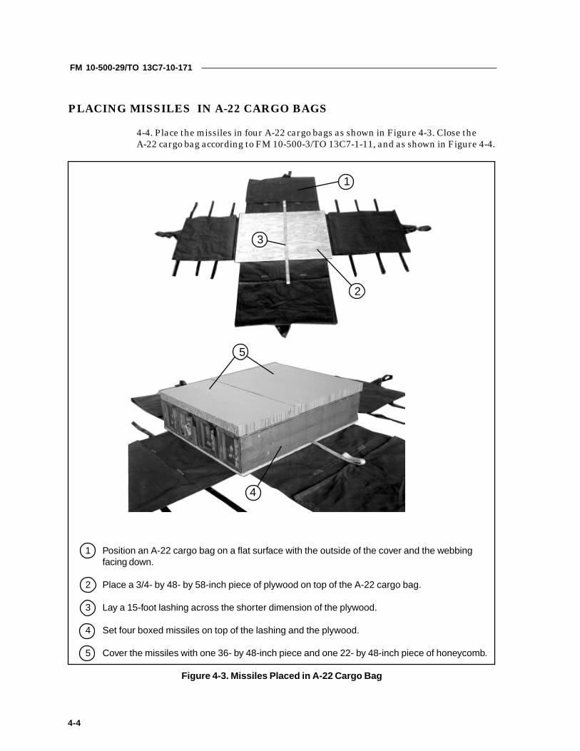
4-4. Place the missiles in four A-22 cargo bags as shown in Figure 4-3. Close theA-22 cargo bag according to FM 10-500-3/TO 13C7-1-11, and as shown in Figure 4-4.
1 Position an A-22 cargo bag on a flat surface with the outside of the cover and the webbingfacing down.
2 Place a 3/4- by 48- by 58-inch piece of plywood on top of the A-22 cargo bag.
3 Lay a 15-foot lashing across the shorter dimension of the plywood.
4 Set four boxed missiles on top of the lashing and the plywood.
5 Cover the missiles with one 36- by 48-inch piece and one 22- by 48-inch piece of honeycomb.
Figure 4-3. Missiles Placed in A-22 Cargo Bag
1
2
3
4
5

FM 10-500-29/TO 13C7-10-171
4-5
6 Place four boxed missiles on top of the honeycomb.
7 Form another layer of honeycomb as was done in step 5 above.
8 Place four boxed missiles on top of the second layer of honeycomb.
9 Bind the missiles together with the lashing positioned in step 3 above, using a D-ring and aload binder.
Figure 4-3. Missiles Placed in A-22 Cargo Bag (continued)
6
7
89

FM 10-500-29/TO 13C7-10-171
4-6
Figure 4-4. A-22 cargo bag closed
1 Close the A-22 cover, and secure the corners with 1/2-inch tubular nylon webbing.
2 Secure the A-22 cargo net at each corner and on top of the load. Fold any excess webbing, andtie it with type I, 1/4-inch cotton webbing.
3 Attach a medium clevis to the suspension web D-rings. Secure the clevis to the top centerstraps of the A-22 with 1/2-inch tubular nylon webbing.
4 Tape the suspension webs together, and secure them to the top center strap with 1/2-inchtubular nylon webbing.
1
2
34

FM 10-500-29/TO 13C7-10-171
4-7
PLACING MISSILES IN A-22 CARGO BAGS ON PLATFORM
4-5. Place the A-22 cargo bags on the honeycomb stacks as shown in Figure 4-5.
1 Center the A-22 cargo bags on the platform with their 58-inch sides parallel to the platform siderails.
Figure 4-5. Missiles in A-22 Cargo Bags Positioned on Platform
1

FM 10-500-29/TO 13C7-10-171
4-8
LASHING LOAD
4-6. Lash the A-22 cargo bags to the platform as shown in Figures 4-6 and 4-7.
gnihsaL gnihsaL gnihsaL gnihsaL gnihsaLrebmuN
nwod-eiT nwod-eiT nwod-eiT nwod-eiT nwod-eiTsivelC
srebmuN snoitcurtsnI snoitcurtsnI snoitcurtsnI snoitcurtsnI snoitcurtsnI
1
2
3
4
5
6
A4dna4
A9dna2
A3dna3
A5dna5
dna01A01
A1dna1
:gnihsalssaPhguorhtgnihsaldnocesassaP.gnir-Dnwostihguorhtdna4sivelchguorhT
rednu(daolehtfopotehtrevosgnihsalehtssaP.gnir-DnwostidnaA4sivelc-DowthtiwsgnihsalehteruceS.sivelcmuidemehthguorhtdna)gnibbeweht
.daolehtfopotnorednibdaoladnasgnirhguorhtgnihsaldnocesassaP.gnir-Dnwostihguorhtdna2sivelchguorhT
ehtrednudaolehtrevosgnihsalehtetuoR.gnir-DnwostidnaA9sivelcdaoladnasgnir-DowthtiwdaolehtfopotnosgnihsalehteruceS.gnibbew
.rednibehtfotnorfehtdnuoragnihsalehtssaP.gnir-Dnwostidna3sivelchguorhT
daoladnagnir-DahtiwA3sivelcotgnihsalehthcattA.gnibbewehtrednudaol.rednib
ehtfotnorfehtdnuoragnihsalehtssaP.gnir-DnwostidnaA5sivelchguorhTdaoladnagnir-Dahtiw5sivelcotgnihsalehthcattA.gnibbewehtrednudaol
.rednibhguorhtgnihsaldnocesassaP.gnir-Dnwostihguorhtdna01sivelchguorhT
daolehtfotnorfehtdnuorasgnihsalehtssaP.gnir-DnwostidnaA01sivelc.rednibdaoladnasgnir-DowthtiwsgnihsalehteruceS.gnibbewehtrednuhguorhtgnihsaldnocesassaP.gnir-Dnwostihguorhtdna1sivelchguorhT
daolehtforaerehtdnuorasgnihsalehtssaP.gnir-DnwostidnaA1sivelc.rednibdaoladnasgnir-DowthtiwsgnihsalehteruceS.gnibbewehtrednu
Figure 4-6. Lashings 1 Through 6 Installed
10
45 3 2 1
1
2
3
4
5
6

FM 10-500-29/TO 13C7-10-171
4-9
gnihsaL gnihsaL gnihsaL gnihsaL gnihsaLrebmuN
nwod-eiT nwod-eiT nwod-eiT nwod-eiT nwod-eiTsivelC
srebmuN snoitcurtsnI snoitcurtsnI snoitcurtsnI snoitcurtsnI snoitcurtsnI
7
8
9
01
A7dna7
A6dna6
A8dna8
A2dna9
:gnihsalssaPA7sivelchguorhtgnihsaldnocesassaP.gnir-Dnwostidna7sivelchguorhT
ehtrednu(daolehtfopotehtrevosgnihsalehtssaP.gnir-Dnwostidnasgnir-DowthtiwsgnihsalehteruceS.sivelcmuidemehthguorhtdna)gnibbew
.daolehtfopotnorednibdaoladnaehtforaerehtdnuoragnihsalehtssaP.gnir-Dnwostidna6sivelchguorhT
daoladnagnir-DahtiwA6sivelcotgnihsalehthcattA.gnibbewehtrednudaol.rednib
ehtforaerehtdnuoragnihsalehtssaP.gnir-Dnwostidna8sivelchguorhTdaoladnagnir-DahtiwA8sivelcotgnihsalehthcattA.gnibbewehtrednudaol
.rednibA2sivelchguorhtgnihsaldnocesassaP.gnir-Dnwostidna9sivelchguorhTehtfopotehtrevodnadneehtdnuorasgnihsalehtssaP.gnir-Dnwostidna
rednibdaoladnasgnir-DowthtiwsgnihsalehteruceS.gnibbewehtrednudaol.daolehtfopotno
Figure 4-7. Lashings 7 Through 10 Installed
6789
78
9
10

FM 10-500-29/TO 13C7-10-171
4-10
INSTALLING SUSPENSION SLINGS
4-7. Install four 12-foot (2-loop), type XXVI nylon webbing slings as suspensionslings. Install and safety the slings according to FM 10-500-2/TO 13C7-1-5, and asshown in Figure 4-8.
1 Attach a 12-foot (2-loop), type XXVI nylon webbing sling to each of the four tandem links usinga large clevis.
2 Raise the suspension slings above the load and install the deadman’s tie as outlined in FM 10-500-2/TO 13C7-1-5.
Figure 4-8. Suspension Slings Installed
1 1
2

FM 10-500-29/TO 13C7-10-171
4-11
INSTALLING CARGO PARACHUTES
4-8. Install two G-11 cargo parachutes according to FM 10-500-2/TO 13C7-1-5, andas shown in Figure 4-9.
1 Secure a 36- by 96-inch piece of honeycomb along the rear edge of the load with type III nyloncord. Tape the honeycomb where the type III nylon cord touches.
2 Place two G-11 cargo parachutes on the parachute stowage platform.
3 Restrain the parachutes with type VIII nylon webbing to clevises 8 and 8A.
4 Install the parachute release straps according to FM 10-500-2/TO 13C7-1-5.
Figure 4-9. G-11 Cargo Parachutes Installed
41
2
3

FM 10-500-29/TO 13C7-10-171
4-12
Installing Release System
4-9. Install the M-1 cargo parachute release assembly according to FM 10-500-2/TO13C7-1-5, and as shown in Figure 4-10.
1 Center a piece of honeycomb on top of the load, and place an M-1 cargo parachute release onthe honeycomb. Attach the parachute riser extension and suspension slings.
2 Fold any excess parachute riser, and tie the folds with type I, 1/4-inch cotton webbing.
3 Fold any excess suspension sling, and tie the folds with type I, 1/4-inch cotton webbing.
4 Safety the release to the load with type III nylon cord.
Figure 4-10. M-1 Cargo Parachute Release Installed
1
4
3
2

FM 10-500-29/TO 13C7-10-171
4-13
Installing Extraction System
4-10. Install the EFTC extraction system according to FM 10-500-2/TO 13C7-1-5,and as shown in Figure 4-11.
1 Bolt the EFTC mounting brackets in the rear mounting holes on the left platform rail.
2 Install a 12-foot cable to the actuator. Install the actuator to the brackets.
3 Attach the latch assembly to the extraction bracket. Attach the cable to the latch assembly.
4 Install a 9-foot, (2-loop), type XXVI nylon webbing sling as the deployment line. S-fold theexcess and tie it in two places with type I, 1/4-inch cotton webbing.
Figure 4-11. EFTC Installed
1
2
4
3

FM 10-500-29/TO 13C7-10-171
4-14
Installing Extraction Parachute
4-11. Select the extraction line and extraction parachute needed using the extractionline requirements table in FM 10-500-2/TO 13C7-1-5. Place the extraction parachuteand extraction line on the load for installation in the aircraft.
Installing Provisions for Emergency Restraints
4-12. Select and install provisions for emergency restraints according to the emer-gency aft restraints requirements table in FM 10-500-2/TO 13C7-1-5.
Marking Rigged Load
4-13. Mark the rigged load according to FM 10-500-2/TO 13C7-1-5, and as shown inFigure 4-12. Complete the Shipper’s Declaration for Dangerous Goods. If the loadvaries from the one shown, the weight, height, tip-off curve, CB, and parachuterequirements must be recomputed.
Equipment Required
4-14. Use the equipment listed in Table 4-1 to rig this load.

FM 10-500-29/TO 13C7-10-171
4-15
Rigged Load Data
Weight: Load shown 6,600 poundsMaximum 7,100 pounds
Height 75 inchesWidth 108 inchesLength 165 inchesOverhang: Front 0 inches
Rear 18 inchesCB (from front edge of platform) 77 inchesExtraction System (adds 18 inches to length of platform) EFTC
Make the final rigger inspection required by FM 10-500-2/TO 13C7-1-5 before the load leaves the rigging site.
CB
Figure 4-12. TOW Missiles Rigged in A-22 Cargo Bags on a 12-foot Type V Platform for Low-velocity Airdrop

FM 10-500-29/TO 13C7-10-171
4-16
Table 4-1. Equipment Required for Rigging TOW Missiles in A-22 Cargo Bags on a 12-foot Type VPlatform for Low-velocity Airdrop
kcotSlanoitaN kcotSlanoitaN kcotSlanoitaN kcotSlanoitaN kcotSlanoitaNrebmuN
metI metI metI metI metI ytitnauQ ytitnauQ ytitnauQ ytitnauQ ytitnauQ
3178-372-00-0408 lag-1,etsapevisehdA deriuqersA
1243-785-00-0761 22-A,ograc,gaB 4
4535-090-00-03042658-876-00-0304
,noisnepsus,sivelC)egral(ni-1
muidem,ni-4/376
6412-042-00-0204 bl-055,IIIepyt,nolyn,droC deriuqersA
3875-434-00-0761 tf-21,elbachtiwrefsnartecrofnoitcartxe,pordria,gnilpuoC 1
8230-063-00-07619230-063-00-0761
:revoCegral,sivelCVIepyt,kniL
13
8762-381-10-0761 )gabenil(enilnoitcartxe,faeL 3
2544-460-10-0761)71-Crof(eugord,eniL
IVXXepyt,)pool-1(tf-06 1
2544-460-10-07612567-701-10-0761
2567-701-10-07612567-701-10-0761
noitcartxe,eniLIVXXepyt,)pool-1(tf-06:031-CroF
IVXXepyt,)pool-1(tf-061:141-CroF:5-CroF
IVXXepyt,)pool-1(tf-061IVXXepyt,)pool-1(tf-061:71-CroF
11
11
8895-387-00-0761
4998-534-00-60355615-232-00-01353591-300-00-07614143-700-00-5635
:ylbmessakniLVIepyT
)71-Crof(ni-4/33,tniop-owTgnolni4,maidni-1,tloB
lanogaxeh,ni-1,tuNni-4/33,edis,etalP
egral,recapS
31)2()2()2()2(

FM 10-500-29/TO 13C7-10-171
4-17
Table 4-1. Equipment Required for Rigging TOW Missiles in A-22 Cargo Bags on a 12-foot Type VPlatform for Low-velocity Airdrop (continued)
kcotSlanoitaN kcotSlanoitaN kcotSlanoitaN kcotSlanoitaN kcotSlanoitaNrebmuN
metI metI metI metI metI ytitnauQ ytitnauQ ytitnauQ ytitnauQ ytitnauQ
8293-357-00-0761 ni-69yb-63yb-3,bmocyenoh,gnitapissid-ygrene,daP steehs61
1487-610-10-07615173-360-10-07615173-360-10-0761
:etuhcaraPB11-G,ograC
tf-51,noitcartxeograC)71-Crof(tf-51,eugorD
211
5248-353-10-07612732-261-10-07614248-453-10-07611832-261-10-0761
tf-21,Vepyt,pordria,mroftalPgnilpuoc,ylbmessatekcarB
Vepyt,ylbmessasivelCylbmessatekcarbnoitcartxE
ylbmessaknilnoisnepsus,mednat,kniL
)1()02(
)1()4(
6188-790-10-0761 1-M,etuhcarapograc,esaeleR 1
3036-260-10-0761
4036-260-10-0761
2036-260-10-0761
pordriaograc,gnilS:noisnepsusroF
gnibbewnolynIVXXepyt,)pool-2(tf-21:tnemyolpedroF
gnibbewnolynIVXXepyt,)pool-2(tf-9:noisnetxeresirroF
gnibbewnolynIVXXepyt,)pool-2(tf-02
4
1
2
6110-899-00-07619128-040-00-0435
roelgnis,esaeleretuhcarap,partStucitlum,esaeleretuhcarap,partS
12
6105-662-00-0157 ni-2,evisehda,epaT deriuqersA
1720-739-00-0761 tf-51,ylbmessanwod-eiT 12
1142-862-00-50382575-280-00-50385858-162-00-5038
:gnibbeWIepyt,ni-4/1,nottoC
ni-2/1,ralubut,nolyNIIIVepyT
deriuqersAderiuqersAderiuqersA

FM 10-500-29/TO 13C7-10-171
4-18
SECTION II- RIGGING MISSILES ON A TYPE V PLATFORMFOR LOW-VELOCITY AIRDROP
DESCRIPTION OF LOAD
4-15. Forty-eight boxed missiles are rigged on a 12-foot, type V airdrop platform.Each boxed missile weighs 87 pounds and is 57 1/2 inches long, 12 incheshigh, and 12 inches wide.This load requires two G-11 cargo parachutes.
PREPARING PLATFORM
4-16. Prepare a 12-foot, type V airdrop platform as described below.a. Inspecting Platform. Inspect, or, assemble and inspect, the platformaccording to TM 10-1670-268-20&P/TO 13C7-52-22.b. Installing Tandem Links. Install tandem links as shown in Figure 4-13.c. Attaching and Numbering Clevises. Attach and number 24 clevis assemblies as shown in Figure 4-13.
NOTES:1. The nose bumper may or may not be installed.2. Measurements given in this load are from the front edge of the platform,NOT from the front edge of the nose bumper.

FM 10-500-29/TO 13C7-10-171
4-19
Step:
1. Install a tandem link to the front of each platform side rail using holes 1, 2, and 3.
2. Install a tandem link to the rear of each platform side rail using holes 22, 23, and 24.
3. Starting at the front of each platform side rail, install clevises on the bushings boltedon holes 5, 6, 7, 9, 10, 11, 14, 15, 16, 18, 19, and 20.
4. Starting at the front of the platform, number the clevises 1 through 12 on the right sideand 1A through 12A on the left side.
Figure 4-13. Platform Prepared
FRONTREAR
RIGHT
LEFT
CLEVISES12A THROUGH 1A
CLEVISES12 THROUGH 1

FM 10-500-29/TO 13C7-10-171
4-20
BUILDING AND PLACING HONEYCOMB STACKS
4-17. Build the honeycomb stacks and place them on the platform as shown inFigure 4-14.
Figure 4-14. Honeycomb Stacks Prepared and Positioned
kcatS kcatS kcatS kcatS kcatSrebmuN seceiP seceiP seceiP seceiP seceiP
htdiW htdiW htdiW htdiW htdiW)sehcnI(
htgneL htgneL htgneL htgneL htgneL)sehcnI( lairetaM lairetaM lairetaM lairetaM lairetaM snoitcurtsnI snoitcurtsnI snoitcurtsnI snoitcurtsnI snoitcurtsnI
1 2 69 01 bmocyenoH egdetnorfehtmorfsehcni41eceipenoecalPsehcni41eceiprehtonaecalP.mroftalpehtfo
morf .eceiptsrifeht
2 01 43 bmocyenoH esabowtehtfodnehcaerevoeceipenoecalP.egdirbasaseceip
2 67 01 bmocyenoH ehtgnillif,eceipesabhcaerevohsulfecalP.seceipegdirbowtehtneewtebecaps
2 69 01 bmocyenoH .kcatsehtfodnehcaerevohsulfecalP
2 3 69 02 bmocyenoH sehcni41retnecdnarehtegothsulfsreyaleulG.1kcatsmorf
3 2 69 01 bmocyenoH ecalP.2kcatsmorfsehcni41eceipenoecalP.eceiptsrifehtmorfsehcni41eceiprehtona
2 01 43 bmocyenoH esabowtehtfodnehcaerevoeceipenoecalP.egdirbasaseceip
2 67 01 bmocyenoH ehtgnillif,eceipesabhcaerevohsulfecalP.seceipegdirbowtehtneewtebecaps
2 69 01 bmocyenoH .kcatsehtfodnehcaerevohsulfecalP
STACK1
STACK2
STACK3
14”14”14”14”
FRONT

FM 10-500-29/TO 13C7-10-171
4-21
PLACING MISSILE BOXES ON PLATFORM
4-18. Place the missiles on the honeycomb stacks as shown in Figure 4-15. Placesix 15-foot lashings over the stacks of boxes as shown in Figure 4-16.
1 Place a 3/4- by 48- by 58-inch piece of plywood on top of stacks 1 and 2 so that it is flush withthe front and left sides of stack 1.
2 Lay a 15-foot lashing across the plywood.
3 Set four boxed missilies on the plywood.
Figure 4-15. Missile Boxes Placed on Honeycomb
1
2
3

FM 10-500-29/TO 13C7-10-171
4-22
Figure 4-15. Missile Boxes Placed on Honeycomb (continued)
4 Form a layer of honeycomb on top of the missiles with one 36- by 48-inch piece of honeycomb and one 22- by 48-inch piece of honeycomb.
5 Place four boxed missiles on the honeycomb.
6 Cover the boxes with a layer of honeycomb constructed as in step 4 above.
7 Place four boxed missiles on the second layer of honeycomb.
8 Bind the missiles together with the lashing prepositioned in step 2 on the previous page.
8
6
4
5
7

FM 10-500-29/TO 13C7-10-171
4-23
Figure 4-15. Missile Boxes Placed on Honeycomb (continued)
9 Place a 3/4- by 48- by 58-inch piece of plywood on top of stacks 1 and 2 so that it is flush withthe front and right side of stack 1.
10 Repeat steps 2 through 8 to position another twelve boxed missiles on the platform.
10
9

FM 10-500-29/TO 13C7-10-171
4-24
11 Place a 3/4- by 42- by 96-inch piece of plywood on edge on top of honeycomb stack 2 againstthe rear of the first two stacks of boxes.
12 Adapt steps 1 through 10 to rig the two rear stacks of 12 missiles each on the rear ofthe platform.
Figure 4-15. Missile Boxes Placed on Honeycomb (continued)
11
12
11

FM 10-500-29/TO 13C7-10-171
4-25
Figure 4-16. Lashings Placed on Missile Boxes
1 Place a 3/4- by 48- by 96-inch piece of plywood against the front edge of honeycomb stack 1and the boxes. Place another 3/4- by 48- by 96-inch piece of plywood against the rear edge ofhoneycomb stack 3 and the boxes.
2 Lay three 15-foot lashings side-by-side across the front edges of the boxes. Lay three 15-footlashings side-by-side across the rear edges of the boxes.
3 Fit a D-ring onto the free end of each lashing. Adjust the D-rings on each side of the load sothat a D-ring is at the center of each layer of boxes.
2
13
FM 10-500-29/TO 13C7-10-171
4-26
LASHING LOAD
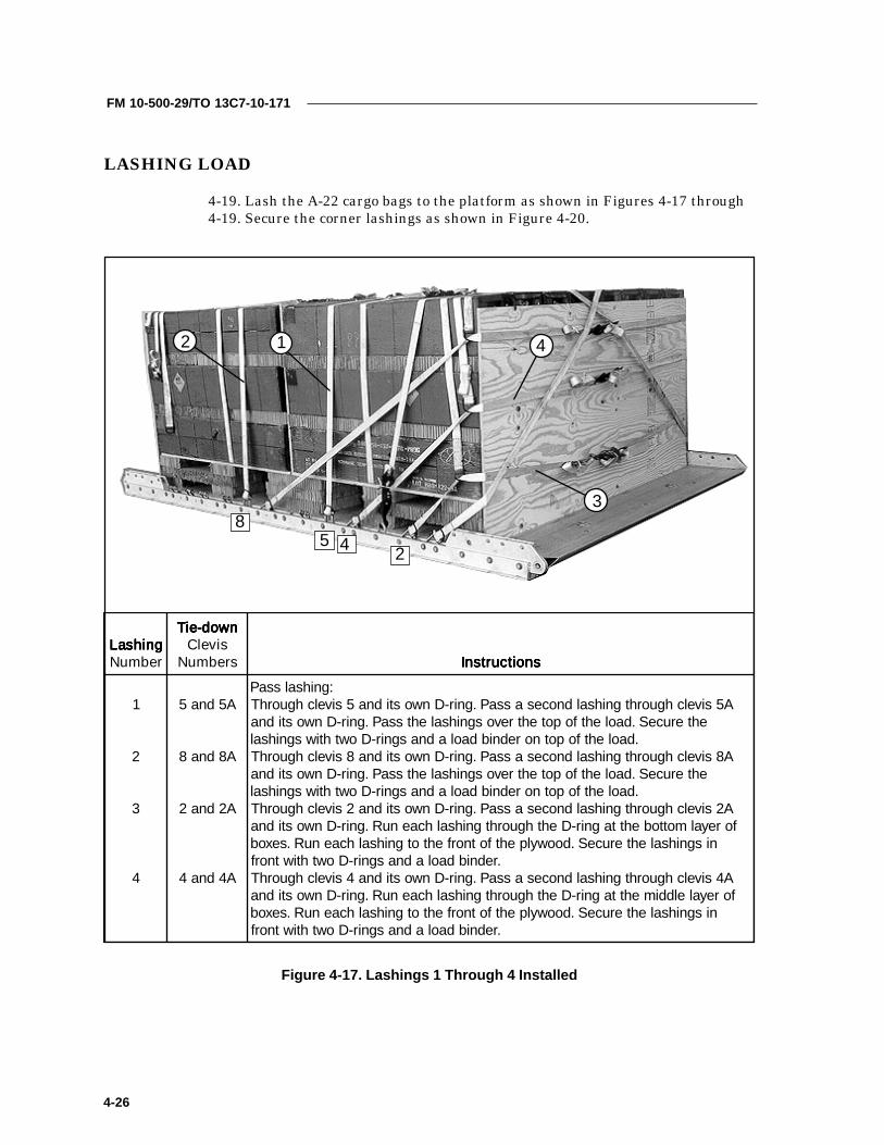
4-19. Lash the A-22 cargo bags to the platform as shown in Figures 4-17 through4-19. Secure the corner lashings as shown in Figure 4-20.
Figure 4-17. Lashings 1 Through 4 Installed
5 4 2
8
12
3
4
gnihsaL gnihsaL gnihsaL gnihsaL gnihsaLrebmuN
nwod-eiT nwod-eiT nwod-eiT nwod-eiT nwod-eiTsivelC
srebmuN snoitcurtsnI snoitcurtsnI snoitcurtsnI snoitcurtsnI snoitcurtsnI
1
2
3
4
A5dna5
A8dna8
A2dna2
A4dna4
:gnihsalssaPA5sivelchguorhtgnihsaldnocesassaP.gnir-Dnwostidna5sivelchguorhT
ehteruceS.daolehtfopotehtrevosgnihsalehtssaP.gnir-Dnwostidna.daolehtfopotnorednibdaoladnasgnir-Dowthtiwsgnihsal
A8sivelchguorhtgnihsaldnocesassaP.gnir-Dnwostidna8sivelchguorhTehteruceS.daolehtfopotehtrevosgnihsalehtssaP.gnir-Dnwostidna
.daolehtfopotnorednibdaoladnasgnir-DowthtiwsgnihsalA2sivelchguorhtgnihsaldnocesassaP.gnir-Dnwostidna2sivelchguorhT
foreyalmottobehttagnir-DehthguorhtgnihsalhcaenuR.gnir-DnwostidnanisgnihsalehteruceS.doowylpehtfotnorfehtotgnihsalhcaenuR.sexob
.rednibdaoladnasgnir-DowthtiwtnorfA4sivelchguorhtgnihsaldnocesassaP.gnir-Dnwostidna4sivelchguorhTforeyalelddimehttagnir-DehthguorhtgnihsalhcaenuR.gnir-Dnwostidna
nisgnihsalehteruceS.doowylpehtfotnorfehtotgnihsalhcaenuR.sexob.rednibdaoladnasgnir-Dowthtiwtnorf

FM 10-500-29/TO 13C7-10-171
4-27
Figure 4-18. Lashings 5 Through 7 Installed
137
7 5
6
gnihsaL gnihsaL gnihsaL gnihsaL gnihsaLrebmuN
nwod-eiT nwod-eiT nwod-eiT nwod-eiT nwod-eiTsivelC
srebmuN snoitcurtsnI snoitcurtsnI snoitcurtsnI snoitcurtsnI snoitcurtsnI
5
6
7
A7dna7
A3dna1
3dnaA1
:gnihsalssaPA7sivelchguorhtgnihsaldnocesassaP.gnir-Dnwostidna7sivelchguorhT
foreyalpotehttagnir-DehthguorhtgnihsalhcaenuR.gnir-DnwostidnanisgnihsalehteruceS.doowylpehtfotnorfehtotgnihsalhcaenuR.sexob
.rednibdaoladnasgnir-DowthtiwtnorftnorfehtdnuoragnihsalehtnuR.gnir-Dnwostihguorhtdna1sivelchguorhT
fodneeerfehtotgnir-DahcattA.sexobehtfopotehtrevodnadoowylpehtfo.rednibdaolahtiwA3sivelcottierucesdnagnihsaleht
tnorfehtdnuoragnihsalehtnuR.gnir-DnwostihguorhtdnaA1sivelchguorhTfodneeerfehtotgnir-DahcattA.sexobehtfopotehtrevodnadoowylpehtfo
.rednibdaolahtiw3sivelcottierucesdnagnihsaleht

FM 10-500-29/TO 13C7-10-171
4-28
Figure 4-19. Lashings 8 Through 12 Installed
12 11 10 9
6
1210
11
9
8
gnihsaL gnihsaL gnihsaL gnihsaL gnihsaLrebmuN
nwod-eiT nwod-eiT nwod-eiT nwod-eiT nwod-eiTsivelC
srebmuN snoitcurtsnI snoitcurtsnI snoitcurtsnI snoitcurtsnI snoitcurtsnI
8
9
01
11
21
dna11A11
A9dna9
A6dna6
dna21A01
dna01A21
:gnihsalssaPA11sivelchguorhtgnihsaldnocesassaP.gnir-Dnwostidna11sivelchguorhT
foreyalmottobehttagnir-DehthguorhtgnihsalhcaenuR.gnir-DnwostidnaehtnisgnihsalehteruceS.doowylpehtforaerehtotgnihsalhcaenuR.sexob
.rednibdaoladnasgnir-DowthtiwraerA9sivelchguorhtgnihsaldnocesassaP.gnir-Dnwostidna9sivelchguorhTforeyalelddimehttagnir-DehthguorhtgnihsalhcaenuR.gnir-DnwostidnaehtnisgnihsalehteruceS.doowylpehtforaerehtotgnihsalhcaenuR.sexob
.rednibdaoladnasgnir-DowthtiwraerA6sivelchguorhtgnihsaldnocesassaP.gnir-Dnwostidna6sivelchguorhT
foreyalpotehttagnir-DehthguorhtgnihsalhcaenuR.gnir-DnwostidnaehtnisgnihsalehteruceS.doowylpehtforaerehtotgnihsalhcaenuR.sexob
.rednibdaoladnasgnir-DowthtiwraerraerehtdnuoragnihsalehtnuR.gnir-Dnwostihguorhtdna21sivelchguorhTfodneeerfehtotgnir-DahcattA.sexobehtfopotehtrevodnadoowylpehtfo
.rednibdaolahtiwA01sivelcottierucesdnagnihsalehtraerehtdnuoragnihsalehtnuR.gnir-DnwostihguorhtdnaA21sivelchguorhT
fodneeerfehtotgnir-DahcattA.sexobehtfopotehtrevodnadoowylpehtfo.rednibdaolahtiw01sivelcottierucesdnagnihsaleht
FM 10-500-29/TO 13C7-10-171
4-29
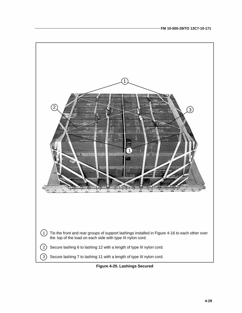
Figure 4-20. Lashings Secured
1 Tie the front and rear groups of support lashings installed in Figure 4-16 to each other overthe top of the load on each side with type III nylon cord.
2 Secure lashing 6 to lashing 12 with a length of type III nylon cord.
3 Secure lashing 7 to lashing 11 with a length of type III nylon cord.
1
1
2 3

FM 10-500-29/TO 13C7-10-171
4-30
INSTALLING SUSPENSION SLINGS
4-20. Install four 12-foot (2-loop), type XXVI nylon webbing slings as suspensionslings. Install and safety the slings according to FM 10-500-2/TO 13C7-1-5, and asshown in Figure 4-21.
1 Attach a 12-foot (2-loop), type XXVI nylon webbing sling to each of the four tandem linksusing a large clevis.
2 Raise the suspension slings above the load and install the deadman’s tie as outlined in FM10-500-2/TO 13C7-1-5.
Figure 4-21. Suspension Slings Installed
1 1
2

FM 10-500-29/TO 13C7-10-171
4-31
INSTALLING CARGO PARACHUTES
4-21. Install two G-11 cargo parachutes according to FM 10-500-2/TO 13C7-1-5,and as shown in Figure 4-22.
1 Secure a 36- by 96-inch piece of honeycomb along the rear edge of the load with type IIInylon cord. Tape the honeycomb where the type III nylon cord touches.
2 Place two G-11 cargo parachutes on the parachute stowage platform.
3 Restrain the parachutes with type VIII nylon webbing to clevises 8 and 8A.
4 Install the parachute release straps according to FM 10-500-2/TO 13C7-1-5.
Figure 4-22. G-11 Cargo Parachutes Installed
1
2
3
4

FM 10-500-29/TO 13C7-10-171
4-32
1 Center a piece of honeycomb on top of the load, and place an M-1 cargo parachute releaseon the honeycomb. Attach the parachute riser extension and suspension slings.
2 Fold any excess suspension sling, and tie the folds with type I, 1/4-inch cotton webbing.
3 Safety the release to the load with type III nylon cord.
Figure 4-23. M-1 Cargo Parachute Release Installed
Installing Release System
4-22. Install the M-1 cargo parachute release assembly according to FM 10-500-2/TO 13C7-1-5, and as shown in Figure 4-23.
12
3

FM 10-500-29/TO 13C7-10-171
4-33
Installing Extraction System
4-23. Install the EFTC extraction system according to FM 10-500-2/TO 13C7-1-5,and as shown in Figure 4-11. Use the front mounting holes in the left platformside rail to install the EFTC actuator mounting brackets. Install a 12-foot cable,and a 9-foot, (2-loop), type XXVI sling as a deployment line.
Installing Extraction Parachute
4-24. Select the extraction line and extraction parachute needed using the extraction line requirements table in FM 10-500-2/TO 13C7-1-5. Place the extractionparachute and extraction line on the load for installation in the aircraft.
Installing Provisions for Emergency Restraints
4-25. Select and install provisions for emergency restraints according to the emer-gency aft restraints requirements table in FM 10-500-2/TO 13C7-1-5.
Marking Rigged Load
4-26. Mark the rigged load according to FM 10-500-2/TO 13C7-1-5, and as shownin Figure 4-24. Complete the Shipper’s Declaration for Dangerous Goods. If theload varies from the one shown, the weight, height, tip-off curve, CB, and parachute requirements must be recomputed.
Equipment Required
4-27. Use the equipment listed in Table 4-2 to rig this load.

FM 10-500-29/TO 13C7-10-171
4-34
Rigged Load Data
Weight: Load shown 6,650 poundsMaximum 7,100 pounds
Height 75 inchesWidth 108 inchesLength 165 inchesOverhang: Front 0 inches
Rear 18 inchesCB (from front edge of platform) 77 inchesExtraction System (adds 18 inches to length of platform) EFTC
Make the final rigger inspection required by FM 10-500-2/TO 13C7-1-5 before the load leaves the rigging site.
CB
Figure 4-24. TOW Missiles Rigged on a 12-foot Type V Platform for Low-velocity Airdrop

FM 10-500-29/TO 13C7-10-171
4-35
Table 4-2. Equipment Required for Rigging TOW Missiles on a 12-foot Type V Platform for Low-velocity Airdrop
kcotSlanoitaN kcotSlanoitaN kcotSlanoitaN kcotSlanoitaN kcotSlanoitaNrebmuN
metI metI metI metI metI ytitnauQ ytitnauQ ytitnauQ ytitnauQ ytitnauQ
3178-372-00-0408 lag-1,etsapevisehdA deriuqersA
4535-090-00-03042658-876-00-0304
,noisnepsus,sivelC)egral(ni-1
muidem,ni-4/372
6412-042-00-0204 bl-055,IIIepyt,nolyn,droC deriuqersA
3875-434-00-0761 tf-21,elbachtiwrefsnartecrofnoitcartxe,pordria,gnilpuoC 1
8230-063-00-07619230-063-00-0761
:revoCegral,sivelCVIepyt,kniL
33
8762-381-10-0761 )gabenil(enilnoitcartxe,faeL 3
2544-460-10-0761)71-Crof(eugord,eniL
IVXXepyt,)pool-1(tf-06 1
2544-460-10-07612567-701-10-0761
2567-701-10-07612567-701-10-0761
noitcartxe,eniLIVXXepyt,)pool-1(tf-06:031-CroF
IVXXepyt,)pool-1(tf-061:141-CroF:5-CroF
IVXXepyt,)pool-1(tf-061IVXXepyt,)pool-1(tf-061:71-CroF
11
11
8895-387-00-0761
4998-534-00-60355615-232-00-01353591-300-00-07614143-700-00-5635
:ylbmessakniLVIepyT
)71-Crof(ni-4/33,tniop-owTgnolni4,maidni-1,tloB
lanogaxeh,ni-1,tuNni-4/33,edis,etalP
egral,recapS
31)2()2()2()2(

FM 10-500-29/TO 13C7-10-171
4-36
Table 4-2. Equipment Required for Rigging TOW Missiles on a 12-foot Type V Platform for Low-velocity Airdrop (continued)
kcotSlanoitaN kcotSlanoitaN kcotSlanoitaN kcotSlanoitaN kcotSlanoitaNrebmuN
metI metI metI metI metI ytitnauQ ytitnauQ ytitnauQ ytitnauQ ytitnauQ
8293-357-00-0761 ni-69yb-63yb-3,bmocyenoh,gnitapissid-ygrene,daP steehs81
1487-610-10-07615173-360-10-07615173-360-10-0761
:etuhcaraPB11-G,ograC
tf-51,noitcartxeograC)71-Crof(tf-51,eugorD
211
5248-353-10-07612732-261-10-07614248-453-10-07611832-261-10-0761
tf-21,Vepyt,pordria,mroftalPgnilpuoc,ylbmessatekcarB
Vepyt,ylbmessasivelCylbmessatekcarbnoitcartxE
ylbmessaknilnoisnepsus,mednat,kniL
)1()42(
)1()4(
1894-821-00-0355 ni-69yb-84yb-4/3,doowylP steehs7
6188-790-10-0761 1-M,etuhcarapograc,esaeleR 1
3036-260-10-0761
4036-260-10-0761
2036-260-10-0761
pordriaograc,gnilS:noisnepsusroF
gnibbewnolynIVXXepyt,)pool-2(tf-21:tnemyolpedroF
gnibbewnolynIVXXepyt,)pool-2(tf-9:noisnetxeresirroF
gnibbewnolynIVXXepyt,)pool-2(tf-02
4
1
2
6110-899-00-07619128-040-00-0435
roelgnis,esaeleretuhcarap,partStucitlum,esaeleretuhcarap,partS
12
6105-662-00-0157 ni-2,evisehda,epaT deriuqersA
1720-739-00-0761 tf-51,ylbmessanwod-eiT 03
1142-862-00-50382575-280-00-50385858-162-00-5038
:gnibbeWIepyt,ni-4/1,nottoC
ni-2/1,ralubut,nolyNIIIVepyT
deriuqersAderiuqersAderiuqersA

FM 10-500-29/TO 13C7-10-171
5-1
Chapter 5
Rigging the Improved Target Acquisition System (ITAS) inM1121 HMMWV Truck for Low-velocity Airdrop
DESCRIPTION OF LOAD
5-1. The ITAS is an aiming system for the TOW missile. Another aimingsystem is shown in Chapter 6. The ITAS consists of the Fire Control Subsystem (FCS), Traversing Unit (TU), Target Acquisition Subsystem(TAS), and Battery Power Source (BPS). Rig the ITAS in the M1121 orM966 HMMWV truck as shown in this chapter. Use FM 10-517/TO 13C7-1-111 to rig the truck on a 16-foot, type V airdrop platform.
PREPARING PLATFORM, HONEYCOMB, AND TRUCK
5-2. Prepare the platform, three honeycomb stacks, and the M966 or M1211truck as shown in Chapters 2 and 3 of FM 10-517/TO 13C7-1-111.
a. Inspect, assemble, and install clevises on a 16-foot, type V airdrop plat-form according to TM 10-1670-268-20&P/TO 13C7-52-22, and as shown inFigure 2-2, FM 10-517/TO 13C7-1-111.b.Prepare three honeycomb stacks as shown in Figures 2-3 and 2-4, FM 10-
517/TO 13C7-1-111.c. Prepare the truck as shown in Figures 3-2 and 3-3, FM 10-517/TO 13C7-
1-111.
RIGGING ITAS IN HMMWV TRUCK
5-3. Rig the components of the ITAS in the truck as shown in Figure 5-1.
COMPLETING THE LOAD
5-4. Finish rigging the M966 or M1121 HMMWV truck as shown in Chapter 3,FM 10-517/ TO 13C7-1-111.

FM 10-500-29/TO 13C7-10-171
5-2
1 Place the FCS upside down in its storage bag.
2 Place the FCS in its bag flush on the gunner’s stand and secure it in place with thestraps provided.
Figure 5-1. ITAS components rigged in truck
1
2

FM 10-500-29/TO 13C7-10-171
5-3
Figure 5-1. ITAS components rigged in truck (continued)
3 Position the TU in its mounting bracket and secure it with the clips provided.
3

FM 10-500-29/TO 13C7-10-171
5-4
Figure 5-1. ITAS components rigged in truck (continued)
4 Position the TAS into its mounting bracket, being sure that the biocular subassemblyfits into its protective housing. Secure the TAS with the two straps provided.
5 Place the rubber mounts on the BPS. Position it on its mounting bracket, and secure itwith the two straps provided.
4
4
5
5

FM 10-500-29/TO 13C7-10-171
6-1
CHAPTER 6
RIGGING M966, M1036, AND M1121 TOW CARRIERS FORLOW-VELOCITY AIRDROP ON A TYPE V PLATFORM
Figure 6-1. M966 TOW carrier
requires two G-11 cargo parachutes. The M1036 is the same truck with theaddition of a winch, and is rigged the same as the M966. The M1121 is a heavierversion of the TOW carrier, but is rigged in the same way as the M966 and M1036.
Preparing Platform
6-2. Prepare a 16-foot, type V airdrop platform according to TM 10-1670-268-20&P/TO 13C7-52-22. Install four tandem links and 18 load tie-down clevises accordingto FM 10-500-2/TO 13C7-1-5, and as shown in FM 10-517/TO 13C7-1-111, Figure2-2.
NOTES: 1. You will need FM 10-517/TO 13C7-1-111 to rig this load. 2. The nose bumper may or may not be installed. 3. Measurements given in this chapter are from the front edge of the platform, NOT from the front edge of the nose bumper.
Description of Load
6-1. The unrigged M966 TOW carrier (Figure 6-1) is described in FM 10-517/TO13C7-1-111, Chapter 1. The truck is rigged on a 16-foot, type V airdrop platformfor low-velocity airdrop. An accompanying load weighing a minimum of 800pounds and a maximum of 2,000 pounds must be rigged in the truck. The load

FM 10-500-29/TO 13C7-10-171
6-2
Figure 6-2. TOW Equipment Prepared and Stowed
1 Disconnect the TOW system power cables, roll them, and tie them with type III nylon cord to convenient places in the truck.
1
Preparing and Positioning Honeycomb Stacks
6-3. Build the honeycomb stacks as shown in FM 10-517/TO 13C7-1-111, Figures2-3 and 2-4. Position the stacks on the platform as shown in FM 10-517/TO 13C7-1-111, Figure 2-5.
Preparing Truck
6-4. Prepare the truck as described in FM 10-517/TO 13C7-1-111, Paragraphs 2-4a through e, g, and h, and as shown in Figures 2-6 and 2-7, 2-8 (omit steps 1and 3), 2-9, 2-11, and 2-12. Use the closed-body preparation procedures given inFM 10-517/TO 13C7-1-111, Figures 3-2 and 3-3.
Stowing Accompanying Load andSecuring Doors
6-5. Prepare and stow the TOW equipment as shown in Figure 6-2 below. Securethe hatch cover as shown in FM 10-517/TO 13C7-1-111, Figure 3-4, step 11.

FM 10-500-29/TO 13C7-10-171
6-3
2 Place the traversing unit on its stand. Fasten the securing straps provided, and safety thelatches with type III nylon cord.
3 Place the missile guidance system box in its rack, and secure it with the straps provided.
Figure 6-2. TOW Equipment Prepared and Stowed (continued)
2
3

FM 10-500-29/TO 13C7-10-171
6-4
Figure 6-2. TOW Equipment Prepared and Stowed (continued)
4 Place the boresight collimator on the shelf in the right rear part of the truck. Secure thecollimator with the retainer straps.
5 Place the infrared nightsight set on the shelf in the right rear part of the truck next to theboresight collimator. Secure the nightsight set with the retainer straps.
6 Place the nightsight battery set on the floor in the right rear part of the truck. Secure thebattery set with the retainer straps.
7 Place the battery power conditioner on the floor in the right rear part of the truck. Secure thebattery power conditioner with the retainer straps.
Note: Pad the equipment shown above, as necessary, with cellulose wadding to prevent the equipment from rubbing against the body of the truck.
4
5
6
7

FM 10-500-29/TO 13C7-10-171
6-5
8
9
10
8 Place the highway emergency kit in the left rear part of the truck. Tie the kit in place withtype III nylon cord.
9 Pad the M13 decontamination apparatus with felt or cellulose wadding. Tape the padding inplace. Place the decontamination apparatus in its rack, and fasten the retainer straps.
10 Place the missile guidance system battery packs in their racks. Secure them in place withtheir fasteners.
11 Position a 15-foot lashing under the rear of the TOW missile rack.
12 Position a 15-foot lashing under the front of the TOW missile rack, and in front of the racksupport.
Figure 6-2. TOW Equipment Prepared and Stowed (continued)
11
12

FM 10-500-29/TO 13C7-10-171
6-6
Figure 6-2. TOW Equipment Prepared and Stowed (continued)
13 Place six TOW missiles in the rack with their nose ends to the front. Secure them with thestraps provided.
14 Wrap the radio antenna with cellulose wadding, and place it between the top two missiles.
15 Fasten the pre-positioned lashings over the missiles. Pad the missiles with felt under the loadbinders.
16 Pad the optical sight generously with cellulose wadding and place it in its bag.
17 Cut a piece of honeycomb to fit in the sight bracket. Place the sight bag in the bracket, andsecure it with the straps provided.
18 Run two 15-foot lashings around the right three missiles.
17
16
17
18
13
14
15
15

FM 10-500-29/TO 13C7-10-171
6-7
Figure 6-2. TOW Equipment Prepared and Stowed (continued)
19 Place the missile launcher tube in its rack on the hatch cover. Secure it with the strap provided.
20 Lay the camouflage net bags to the right of the missiles.
21 Secure the camouflage net bags to the missiles with the lashings pre-positioned in step 18above. Fasten the load binders against the bags, and not against the missiles.
19
21
20
19

FM 10-500-29/TO 13C7-10-171
6-8
Figure 6-2. TOW Equipment Prepared and Stowed (continued)
22 Pad the tripod storage area with cellulose wadding.
23 Place the tripod in its storage rack. Pad the legs with cellulose wadding where they touch thebattery power conditioner.
24 Secure the tripod in place with the retainer strap and a length of 1/2-inch tubular nylonwebbing.
22
24 23

FM 10-500-29/TO 13C7-10-171
6-9
Lifting and Positioning Truck andInstalling Drive-Off Aids
6-6. If drive-off aids are to be used, install them on the platform as shown in FM10-517/TO 13C7-1-111, Figure 2-16. Install lifting slings on the truck and positionthe truck on the honeycomb stacks as shown in FM 10-517/TO 13C7-1-111, Figure2-17. Install the drive-off aids to the rear wheels of the truck as shown in FM 10-517/TO 13C7-1-111, Figure 2-18.
Lashing Truck
6-7. Lash the truck to the platform with fifteen 15-foot tie-down assemblies asshown in FM 10-517/TO 13C7-1-111, Figures 2-19 and 2-20, and according to FM10-500-2/TO 13C7-1-5.
Installing and Safetying Suspension Slings
6-8. Install and safety four 16-foot (2-loop), type XXVI nylon suspension slings asshown in FM 10-517/TO 13C7-1-111, Figure 3-5.
Stowing Cargo Parachutes
6-9. Stow two G-11 cargo parachutes on the load according to FM 10-500-2/TO13C7-1-5, and as shown in FM 10-517/TO 13C7-1-111, Figure 2-22.
Installing Parachute Release
6-10. Prepare and install an M-1 cargo parachute release according to FM 10-500-2/TO 13C7-1-5, and as shown in FM 10-517/TO 13C7-1-111, Figure 3-6.
Installing Extraction System
6-11. Install the EFTC extraction system according to FM 10-500-2/TO 13C7-1-5,and as shown in FM 10-517/TO 13C7-1-111, Figure 2-24.
Installing Provisions for Emergency Restraints
6-12. Install provisions for emergency restraints according to FM 10-500-2/TO13C7-1-5.
Placing Extraction Parachute
6-13. Select the extraction parachute and extraction line needed, using theextraction line requirements table in FM 10-500-2/TO 13C7-1-5. Rig the extrac-tion line in a line bag according to TM 10-1670-286-20/TO 13C5-41. Place theextraction parachute and extraction line on the load for installation in the aircraft.

FM 10-500-29/TO 13C7-10-171
6-10
Marking Rigged Load
CAUTION: Make the final rigger inspection required by FM 10-500-2/TO 13C7-1-5 before the load leaves the rigging site.
CB
RIGGED LOAD DATA
Weight: Load shown.......................................................................................................8,810 pounds Maximum load allowed...................................................................................10,500 pounds
Height (with two G-11 parachutes).......................................................................................91 inchesWidth...................................................................................................................................108 inchesLength.................................................................................................................................215 inchesOverhang: Front.....................................................................................................................0 inches
Rear.............................................................................................................18 inchesCB (from front edge of platform).........................................................................................102 inches
Figure 4-3. M966 TOW carrier rigged for low-velocity airdrop
6-14. Mark the rigged load according to FM 10-500-2/TO 13C7-1-5, and as shownin Figure 6-3. Complete Shipper's Declaration for Dangerous Goods. If the loadvaries from the one shown, the weight, height, CB, and parachute requirementsmust be recomputed.
Equipment Required
6-15. Use the equipment listed in Table 6-1 to rig this load. The equipment forrigging the accompanying load is included in Table 6-1.

FM 10-500-29/TO 13C7-10-171
6-11
Table 6-1. Equipment required for rigging the M966 TOW carrier for low-velocity airdrop
kcotSlanoitaN kcotSlanoitaN kcotSlanoitaN kcotSlanoitaN kcotSlanoitaNrebmuN metI metI metI metI metI ytitnauQ ytitnauQ ytitnauQ ytitnauQ ytitnauQ
3178-372-00-0408 lag-1,etsap,evisehdA deriuqersA
4535-090-00-0304 )egral(ni-1,noisnepsus,sivelC 8
6412-042-00-0204 bl-055,IIIepyt,nolyn,droC deriuqersA
5875-434-00-0761 tf-61,elbachtiwrefsnartecrofnoitcartxe,pordria,gnilpuoC 1
8230-063-00-07619230-063-00-0761
:revoCegral,sivelCVIepyt,kniL
13
8596-466-00-5318 gniddawesolullec,gnigakcap,lairetamgninoihsuC deriuqersA
5863-859-00-5038 kcihtni-2/1,tleF deriuqersA
8762-381-10-0761 )gabenil(enilnoitcartxe,faeL 2
2544-460-10-0761)71-Crof(eugord,eniL
IVXXepyt,)pool-1(tf-06 1
3136-260-10-07611567-701-10-0761
:noitcartxe,eniL)5-Croftf-041/wesU()031-Crof(IVXXepyt,)pool-3(tf-06
)71-Cro,5-C,B141-Crof(IVXXepyt,)pool-3(tf-04111
:ylbmessakniL
8895-387-00-0761 VIepyT 3
4998-534-00-60355615-232-00-01353591-300-00-07614143-700-00-5635
ni-4/3,tniop-owTgnolni-4,maidni-1,tloB
lanogaxeh,ni-1,tuNni-4/33,edis,etalP
egral,recapS
)1(2222
6416-022-00-01558446-022-00-01554726-022-00-0155
:rebmuLni-4yb-2ni-6yb-2ni-4yb-4
deriuqersAderiuqersAderiuqersA
9564-010-00-5135 d8,eriwleets,liaN deriuqersA

FM 10-500-29/TO 13C7-10-171
6-12
Table 6-1. Equipment required for rigging the M966 TOW carrier for low-velocity airdrop(continued)
kcotSlanoitaN kcotSlanoitaN kcotSlanoitaN kcotSlanoitaN kcotSlanoitaNrebmuN metI metI metI metI metI ytitnauQ ytitnauQ ytitnauQ ytitnauQ ytitnauQ
8293-357-00-0761 )bmocyenoh(gnitapissid-ygrene,daPni-69yb-63yb-3 steehs11
1487-610-10-0761
6173-360-10-07615173-360-10-0761
:etuhcaraP:ograCB11-G
:noitcartxeograCtf-22
tf-51)71-Crof(eugorD
2
11
5248-353-10-07612732-261-10-07614248-453-10-07611832-261-10-0761
tf-61,Vepyt,pordria,mroftalPgnilpuoc,ylbmessatekcarB
Vepyt,ylbmessasivelCylbmessatekcarbnoitcartxE
)knilesoprupitluM(ylbmessaknilmednaT
)1()02(
)1()4(
1894-821-00-0355 ni-4/3,doowylP steehs3
6188-790-10-0761 1-M,etuhcarapograc,esaeleR 1
1677-360-10-0761
4036-260-10-07613036-260-10-0761
4036-260-10-0761
2036-260-10-0761
pordria,ograc,gnilS:noisnepsusroF
gnibbewnolynIVXXepyt,)pool-2(tf-61:gnitfilroF
gnibbewnolynIVXXepyt,)pool-2(tf-9gnibbewnolynIVXXepyt,)pool-2(tf-21
:tnemyolpedroFgnibbewnolynIVXXepyt,)pool-2(tf-9
:noisnetxeresirroFgnibbewnolynIVXXepyt,)pool-2(tf-02
4
22
1
2
9128-040-00-0435 sevink3/wsemoc,tuc-itlum,esaeleretuhcarap,partS 2
6105-662-00-0157 ni-2,evisehda,epaT deriuqersA
1720-739-00-0761 toof-51,ylbmessanwod-eiT 72
6848-134-00-0761 sdiaffo-evirdelciheV 1
1142-862-00-50382575-280-00-50381953-362-00-5038
:gnibbeWIepyt,ni-4/1,nottoC
ni-2/1,ralubut,nolyNIIIVepyT
deriuqersAderiuqersAderiuqersA

ACB attitude control barAD airdrop
AFB Air Force base AFJMAN Air Force Joint Manual AFR Air Force regulation AFTO Air Force technical order ALC Airlift Logistics Center attn attention BPS battery power source
C changecap capacityCB center of balance
chap chapter d pennyDA Department of the ArmyDC District of ColumbiaDD Department of Defense
diam diameter EFTC extraction force transfer coupling
fig figure FCS fire control subsystem
FM field manual ft foot/feetgal gallonHQ headquarters
HMMWV high-mobility, multipurpose, wheeled vehicle in inch
ITAS improved target acquisition systemJAI joint airdrop inspector lb pound LV low-velocity
Glossary-1
GLOSSARY
MCRP Marine Corps Reference Publicationmm millimeter
NSN national stock number OVE on-vehicular equipment TAS target acquisition subsystem
TM technical manualTO technical order
TOW tube launched, optically-tracked, wire-guided TRADOC US Army Training and Doctrine Command
TU traversing unit US United States w with yd yard

REFERENCES
AFR 55-40/AR 59-4. Joint Airdrop Inspection Records, Malfunction Investigationsand Activity Reporting. 27 November 1984.
*AFJMAN 24-204/TM 38-250. Preparing Hazardous Materials for Military Air Shipments. 25 November 1994.
FM 10-500-2/TO 13C7-1-5. Airdrop of Supplies and Equipment: Rigging AirdropPlatforms. 1 November 1990.
FM 10-500-3/TO 13C7-1-11. Airdrop of Supplies and Equipment: Rigging Containers.16 October 1996.
FM 10-500-53/TO 13C7-18-41. Airdrop of Supplies and Equipment: RiggingAmmunition. 1 March 1996.
TM 9-2320-280-10/TO 36A-12-1A-2091-1/TM 2320-10/6. Operator's Manual for Truck,1 1/4-ton. April 1985
TM 10-1670-268-20&P/TO 13C7-52-22. Organizational Maintenance Manual WithRepair Parts and Special Tools List: Type V Airdrop Platform. 1 June 1986.
TM 10-1670-276-23&P/TO 13C5-29-2. Unit and Intermediate Direct Support (DS)Maintenance Manual (Including Repair Parts and Special Tools List) forParachute, Cargo-Type: 26-foot Diameter, High-Velocity Cargo Parachute.28 September 1990.
TM 10-1670-278-23&P/TO 13C5-26-2/NAVAIR 13-1-27/TM 01109C-23&P/1. Unit andIntermediate DS Maintenance Manual Including Repair Parts and SpecialTools List for Parachute, Cargo Type, 15-ft Diam, Cargo Extraction.6 November 1989.
TM 10-1670-279-23&P/TO 13C5-27-2/NAVAIR 13-1-28. Unit and Intermediate DSMaintenance Manual Including Repair Parts and Special Tools List forParachute, Cargo Type, 22-ft Diam, Cargo Extraction. 30 August 1989.
TM 10-1670-280-23&P/TO 13C5-31-2/NAVAIR 13-1-31. Unit and Intermediate DSMaintenance Manual Including Repair Parts and Special Tools List forParachute, Cargo Type, G-11A, G-11B, and G-11C. 5 August 1991.
TM 10-1670-281-23&P/TO 13C5-32-2. Unit and Intermediate DS MaintenanceManual Including Repair Parts and Special Tools List for Parachute, CargoType: 64-foot Diameter, Model G-12D and Model G-12E. 12 October 1990.
References-1

TM 10-1670-282-23&P/TO 13C5-30-2. Unit and Intermediate DS MaintenanceManual Including Repair Parts and Special Tools List for Parachute, CargoType: 34-foot Diameter, Model G-14, Low-Velocity Cargo Parachute. 12October 1990.
TM 10-1670-286-20/TO 13C5-2-41. Unit Maintenance Manual for Sling/ExtractionLine Panel (Including Stowing Procedures). 1 April 1986.
TM 10-1670-298-20&P. Unit Maintenance Manual (Including Repair Parts andSpecial Tools List) Container Delivery System. 15 September 1995.
AFTO Form 22. Technical Order Publication Improvement Report
DA Form 2028. Recommended Changes to Publication and Blank Forms. February1974.
* Shipper’s Declaration for Dangerous Goods. Locally procured form
*AFJMAN24-204/TM 38-250 has superseded AFR 71-4/TM 38-250 (15 January 1988).This revision reflects this change.
* Shipper’s Declaration for Dangerous Goods has superseded DD Form 1387-2(February 1982.) This revision reflects this change.
References-2

FM 10-500-29TO 13C7-10-171
14 APRIL 2000
By Order of the Secretary of the Army:
Official:
ERIC K. SHINSEKIGeneral, United States Army
Chief of Staff
Administrative Assistant to theSecretary of the Army 005602
DISTRIBUTION:
Active Army, Army National Guard, and U.S. Army Reserve: To be distributed inaccordance with the initial distribution number 115784, requirements forFM 10-500-29.
MICHAEL E. RYANGeneral, USAFChief of Staff
GEORGE T. BABBITTGeneral, USAFCommander, AFMC
Copyright © 2022 FDOKUMEN