Spectroscopy of the hyperfine structure of antiprotonic 4 He and 3 He
Upload
khangminh22Category
view
1download
0
U.S. DEPARTMENT Of COMMERCENAtiou~I technical Intormutim Sorvmu
AD-A 02 4 262
.i T CONCEPTS FOR DESIGN OF LIGHTWEIGHT 'RACK FORi---HE U.S. MARINE LAND3ING VEHICLE ASSAULT (LVA)
ALUMINUM COMPANY OF AMERICA
PREPARED FOR
---DAVID W. TAYLOR NAVAL SHIP
RESEARCH AND DEVELOPMENT CENTER
120 FEBRUARY 1976'

hMAW
"CONCEPTS FOR DESIGN OF LIGH] EIHT TRACK FOR THE
U. S. M.ARINE LANDINI VEHICLE ASSAULT (LVA)"
FINAL REPORT
PREPARED FOR
DAVID IAYLOR NAVAL SHIP RESEARCH DEVELOPMENT CENTER
CARDEROCK, MD
BY
W, J. LANE
M. V. STAURSKY
ALUMINUM COMPANY OF AMERICA
ALCOA CENTER, PA
CONTRACT N00167-76-C-09
A
1 0-~

ABST RA CT
Future military vehicles require signifcant attention to vehicle
%Cight If the aesired advantages of battlefield moility are to be
achieved. Advancements in power-train and mnterial technology will con-
tribute to the design improvements netessary for these vehicles. Use
of high strength to weight ratio nterials is being stressed, %,nerever
technically advisable and econonically cost effective.
As part of the design considerations for a future U. S. Marine
Corps amphibious personnel carrier type vehicle, Lacjing Vehiche Assault
(L-VA), the feasibility of using a ligjin.weight a'oninum track has been
examined Fnir ronreprt for a [VA track th;% O,!uj dchiee si nfirAnt
weight savings compared to existing steel 'racks are examined. Two
concepts are suggested for further evaluation, prototyping, and vehicle
testing. Preliminary weight and r.-jduction price estimates are made. ,
I
!I

This P'ftort is in support of the Landing Ve cIle Assault ([VA)
Development Program under the management of tne Naval Sea Systems Comand,
Code 03221. The work was done under contrdct to the David Taylor Naval
Ship Research and Development Center, with technical !i.Onitorin by DTNSRDC,
Code 112.
WI

TABL OF CONTENT
UCTION PAGL
introduction to LVA Vehicle And Track Requirements 1
IL, Basis for Track Design Concepts .............
II, . Track Concepts
Concept 1. Single pin with end arive ........... 6
Concept 2. Single pin with end drive, modified.. 7
Conce.t 3. Double pin with end drive............ 8
Concept 4, Single pin with track body drive..... 9
IV. Aluminum Alloy Docume-suation;
Weight ard Production Cost Lstimatts .............. 10
V, Reco nendations .... .............................. I1
VI. References ........................................ 13
VII. Appendices
A. Centerguide Load Analysis ..................... .14
B. Section Properties ............................ 16
C. Drive Load Anav. ........................... 33
iii

LIST OF FIGURES
1. Aluminum T-142 Double-Pin Track. Single piece alloy20"4 -161 forgings replace the standard production
three piCe steel track bluks at a weight savings of16.7 lbs. per pitch (assembled track shoe), a reduc-Ition of 22 percent. The production pins, end connec-
tors, centarguide, and pads are used; the track iscompletely interchangeable wit', the steel T-142 andT-97 tracks p-esently used on the M48 and M60 vehicles.
One Complete Pitch (Treck Shoe Assembly) of the Alumi-num T-142 Track. Track width, 28 inches; pitch, 6.937inches; weight, 59.9 lbs. Roadwheel side rubber ismolded to the aluminum blocks; road surface pads arereplaceable ............................................
3. Half Section of the T-144 Double-Pin Track used on MSOHawk Missile Loader Vehicle (sectioned through thecenterguide). Track block is 2014-T6 aluminum forging
integral centerguide is bonded to the aluminum "horn'by the rubber casing ...................................
4. Sinale-Pin T-130 Track (MI13 Personnel Carrier). Shownis an aluminum casting for laboratory stress analysisof the production steel T-130 track shoe body. The in-tegral centerguide and drive area in the track body aretypical of single-pin designs ..........................
5. Forging Alloys - Characteristics and Uses ..............
6. Alloy Data - Die Forgings ..............................
7. Wetght Estimates of Proposed Desigi Concepts ...........
8- Estimated Production Price of Recommended Concepts .....
TRACK CONCEPT DRAWINGS
Concept 1. B-100504-AE, Single pin with end drive
Concept 2. b-1005OS-AE, Single pir, with end drive, modified
Concept 3. P-00513-A[, Dotble pin with end drive
Concept 4. B-100514-AF, Single pin with track body drive
(Drawings in pocket, Lack cover)iv

IM IUCL1I (I l L ON.al JI Nt TY\Q RN Ui ClW
A future nix ft U. S. military -o,]bat veIiiv.es is now beln,
proposed iOr limited warfare scenarios that rvuuire lhigh bttlelIeld
mobility. These vehicles must also provide increased armor protection and
battlefield firepower effectiveness to combat the increased threats of
future enemy hardware High vehicle mobility will be achieved by adance-
ments in power-train technology and use of high strength, low weight materials
where they are most cost-effective. Throughout these designs there is a
simply stated, but not so simply achieved, necessity to minimwize gross vehi-
cle weight. Proper choice and practical utilization of lightweight materials
is essential if the advantages of battlefield mobility are to be achieved.
The U. S. Marine Corps has identified the operational need tar
a.n amphibious vehicle that will Pmeet the surface mobility and combat support
requirements of the post-1980 time frame. Development 01 this vehicle, the
Landing Vehicle Assault (LV4), is to includ; examination o designs that
will be capable of transporting and supportinu assault forces during "over
the horizon" aphibious landings and subsequent operations ashore.
As part of th,' LVA design considerations, the feasibility of
usiing an aluminum track has herein been examined. Aluminum tracks have
been proposed, tested, c.d used on several production vehicles since the
late 1950's. Recent programs have demonst-ated the advantage of lighter-)
weight aluminum tracks for heavy battle-tark type vchicles.. The eftort
under this David Taylor Naval Ship Research and Development Center cotract
has been to examine concepts for a Landing Vehicle Asstult track that will
achieve significant w it savings compared to existing stcel tracks used
= ] -
on this type of tracd v The t'.- and SuSFensiut stem of the
present vehijle, tfc LVh-7. 2sU u d the jtli t(r thes2 dusliqn conL&tS:
The goal ot this stud, was to suggest tfle design(s) or the lightest wum'flt
aluminum track that might r.x-et tht' track reiuirements of a vehicle in the
bweight and pertormance classitication of tn LVTP-; this dcSign(s) concept
could then be further develoied and evaluated for tre LVA. A- suCh the
follow'.,g general guidelines vre followed:
1. 21" track width
2. 50,000 it? class vehicle
3. Track performance equal to LVTP-7 track
4. Replaceablc road surface pads
5. lntercnangeabilitv of component parts with existingtracks where possible (wi thout i 1creasi ny : ight oidegrading performance)
,Th study fotuse1d On those areas that hdve historicelly beri
identified as possiblh deficiencies in the operation of a single-pin aluminum
track. Special attention was given to field and/or depot replacement of
critical wear areas, particularly the sprocket engayement and centerguide
areas of the track shoe body. lhis replacement of selected, preldcntiliv d.
life-1 imited track components would extend the operational uss f the basic
track shoe body to its maximumj life (determined by netal fatigue limit or
failure/hear of rubber components).russauc :.u:,O01-:, pr-yrgur'm utiii0 $11 ! cperi1,'nII strcss dnlils
and labcratory testing of actual prutotype hardware to more ful ly examine
and refine the most promising design(s) are identified in Secition V.
SZ11 OL1
BASIS FOR EACK UESIC LQLPIS
Historically there have been several concern|s with alumimnum trati.
isy sterns:
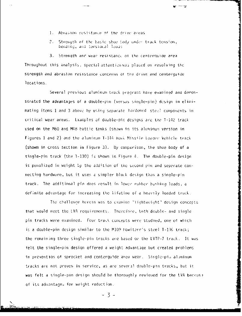
I. Ab, a-1o,, C5i1t31, of tne drive aeds
-Strerqth or thu basic shoe - od und-'r traik tenson
3. Strength anc wtar resi Sac r. C he 0t enb6 et:rquiadt area
Throughout this analysis, secial attent I1was iaced on resolvin the
strength and abrasion resistance concerns or toe drive and centerquide
locations-
Several previous aluminum track programs have examined ana demon-
strated the advantages of a double-pin (versus singie-pin) design in elimi-
nating items I and 3 above by using separate hardened steel components in
critical wear areas. Lxamples of double-Din designs are toe T-142 track
used on the M60 and M48 battle tanks (shown in its aluminum:i version in
Figures 1 and 2) and the aluminum 1-144 Ha-..k Missile Loader Vehicle track
(shown in cross section in Figure 3). By comparison, the shoe body of a
single-pin track (the 1-130' is shown in Figure ". The double-pin design
is penalized in weight by the aidition of the second pin and separate con-
necting hardware, but it uses a simpler block design than a single-pin
track. The additional pin does result in lowe.r rubber bushing loads, a
definite advantage for increasing the lifetime of a heavily loaded truck.
The challenge herein was to examine "ightwei qht" design concepts
that would meet the LVA requirements Therefnre, both double- and single-
pin tracks were examined. Four track concepts were studied, one of which
is a double-pin design similar to the M109 lowitzer's steel T-136 track;
the remaining three single-pin tracks are based on the LVTP-7 track. It was
felt the single-pin design offered a weight advantage but created problems
in prevention of sprocket and centerguide area wear. Single-pi, aliminum
tracks are not prover in service, as are several double-pin tracks, but it
was felt a single-pin design should be thoroughly reviewed for the LVA bec,-us
of its advantages for weight reduction.
-3-1

teI sa C-- 0Ce
to toe jn, s I LC the T- q4n-
' 36, 1-1 1, ad , ti LV ' t 1 -i -e _ e__Ct i u a u nu,
"hOrn w Ith tVie steel rc~ ' yrlc~cnshcben I, xLd anWdn proven
SuccessrulI over tne yiea;rs. PCtured 1 10 C-liu I 3 o cross Se ti1onj of the-u
alIumi num Hawk MtieCdr eil -144' track,t' tr~euilei ue
gral to the track body -ud its steel] protectior; i, n-~'ze oto w
b)y ru.bber'. Tris concept !',S vorked 111 PrvoctiOf, ind the UHid hvas prow;;r
to be dvrable in vehic>It Operxition. This ruilber bonded ca; cnept, it
restricted to the ,e-er-all dimensions Of the LVTP - 7 t rack 0uui dvC, woulId tic, t
pro v ide s uffi c ient la teralI s tren t h m, t ne uideI and ;.ould osb, y ev er;
be too thin to force economiCal ly i n a typ i Cal forc n(: o-pera1tj On. Thi
type of protective cap coujld bie used su, ceS fol if on, the LVA it theoad e
whe-el guide artfa were -widened to permiJ-t a thicLker anileU horn1, particularly
at the horn base. A disadvantage of the rubber bondrid -teel]a is that it A
cannot be replaced without reroIbbelizing" the en--ti4re trac k bodY. It 61-ouui
not be field repairable arid therefore is not felt to be cosit tffectivc. ii
ext?1hr le Over-all trafck life.
Through-out thris it tort, cont opts tLo fully on i ize cc;"'poneentsj
that could he replace-a not unly fo r rout Ine rualuter,'Ctnc but alSO forC0 u -
gency field repair wer~e stressed. Therefore, a centerguide toricept wasj
envi-jioned in which the centernuido wiould be made of a steel C351 ;nq or
forging anid held in place by bolts through; the aliuvi b'ock. Thi 5con1-I
cept could )e made to tne diniensions of the existirq) IVTP-7 and would allow
the des (red field replacement of worn cowmponents. In econ 0f the four
basic designis evaluated under tis ce'tratA. the rol:e cl enterquideu
4I

concept is suggasted. I!' all Gesigns, the centerguide location has been
toward the torward area of the body so that the track centerguide coies
into contact with the roadwheel prior to application of the full weight of
the wheel on the track, thus providing a better aiignm..nt, of the track
system and less wear. Worst-case centerguide side loads have been computed
and are included in Appendix A. Some consideration might be given to using
the same bolt assembly io, retaining both the track pad and the centerguide
as a possible step to further reduce weight and the number of hardw'are parts.
The other track area requiring abrasion resistance, i;amely the
sprocket enqagement bocation, was likewise considered for a repl2eable,
easy main ;enance compone nt. ifl the case of the duble-pin design, the
drive system utilizes "end connctors" of harde-ed steel that codld be
replaced as required. In the case of a single-piii design such as used on
Ur LVTP-7, the replacement, of sprocket wear areas requires replacement of
the entire shoe. In fact, the U. S. Marine Corps has said that the aindin
reason: for replacement of the LTVP.-7 track is wear of the track body sprocket
drive area. .erefore, . counter the known prob;le's wit: ai aiuminum forg-
ing in this application, and also to provide the desired ease of maintenance,
a separate body insert or end drive system was included in each o the lour
designs considered. (Note that the insert corlcct ,Nuube: 41 would require
minimum alteration to the existing LVIP-7 suspension.) By careful considera-
tion. the anticipated Problem- with wear have beei, overcm:ne in thesc designs
through utilization of replaceable steel components.
The basic track block concept is a redesign of the existing steel
LVTP-7 track (single pin) or the T-136 track, (double pin). It is assumed
that the LVA as it is finally designed will be o the sare weight Class and
have similar 1ard performance requirements as the existinj [I"V-7, Aft tnut s
were not. made under this contract to descrihe a general purpose track but
• F

rather to refine the existi ng t nck and dr ve systems so that a 1 ighter
weight track rould be used successfully. A basic consideration in the
design philosophy was also that the vehicle never will be operated with-
out the road surface pads, and that the replaceable feature of the pad is
for sim:)le replacement of worn out pads (as opposed to providing a combat
configuration; i.e., without pads). Therefore, all designs have included
a replaceable road surface pad that will be in place at all times. Track
loads are also assumed to be essentially the same as that of the existing
tracks sincC the vehicle weight and performance requirements have not been
appreciably changed. in all cases, hardware components such as the pins,
pads, bushings, and nuts and bolts have been designed, wherever possible,
to be the same as those used ir existinfg, fielded trdcks. Itn cases where
it was felt additional strength or dimensional changes were required, new
hardware components have been suggested, aithough detailed specitic designs
are beyond the scope of tiis effort.
SECI ION 4I1
I2RACK C ON EPTS
Conc t - Sinie-i with end d ye(Drawi - ___. R-. _-OO4-A[).
This design was the first considcred, and was derived from the LVTP-7 track
by nwjdifying the s-ctoM joYt',.uerties where nceUssary. The sectUet property
analysi. of this redesign is contained in Appendix B. Basically, this
design utilizes a replaceabic steel centerguide in conjunction with sprocket
a stcY e'.e ever the end of tire shoe bedy. In this concept
the steel sleeve drive area is tut truly replaceable although the shoe
could b refurbished in a maintenance depot. The steel sleeve could fit
either over the forging itself or ride on a separate bushing assemnbly. As
-C -
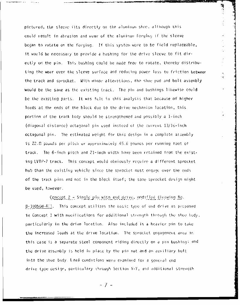
pictured, tl.e sleeve fits directly on the oniminu shoe, although this
could result in abrasion and wear of the aluminum forging if the sleeve Ibegan to rotate on the forging. If this system were to be field replaceable,
it would be necessary to provide a bushing for the drive sleeve to fit dir-
ectly or the pin. This bushing could be made free to rotate, thereby distribu- Iting the wear over the sleeve surface and reducing power loss to friction betweer
the track and sprocket. With minor alterations, the shoe pad and bolt assembly
would be the same as the existing track. The pin and bushings likewise could Ibe the existing parts. It was felt in this analysis that because of higher
loads at the ends of the block due to the drive mechanism location, this
portion of the track b.,ody should be strengthened and possibly a 1-inch
(diagonal distance) octagonal pin used inslcad of the current 13/16-inch
octagonal pin. The estimated weight for this desitn in a complete assembly
is 2.0 U pounds pef pittuh or ippruxi moLeiy 45.6 pounos per running root ot
track. The 6-inch pitch and 21-inch width have been retained from the exist-
ing LVTP-7 track. This concept would obviously require' a different sprocket
hub than the existing vehicle since the sprocket must engage over the ends
of the track pins and not in the block itsef; the same sprocket design might
be used, however.Conc ( t 2 - Sinje.yin witn end drive, modified (jraitq No.
U- O5O08-AEJ. This concept usi I i zes the bassic type of end drive as p;cposed
in Concept 1 with muoifications for additional stregrti through tht- shulce lody.
particularly in the drive location. Also included is a heavier pin to toke
the increased toads at the drive location. The sprocket engagemenit area in
this case is a separate steel component riding directly on a pin bushirg, and
the drive assembly is held in place by the pin nut dnd an eu-iliary bolt
into the shoe body. Load conditions were examined for a (eneval end
drive type desi p, particulary through Section Y-Y, and additiondl strenoth7 -

was soggested to mOintair a satisfactory design miargin. These analyses
are shown in Appcndix C. The ctnterguidu used in this concept is the sarrs
as that proposed in Concept 1. An alternate guide proposal is shown in
View 2 that uses a single 1/2-inch bolt for attachment of the centerg,,ide
(as opposed to using two 1/4-inch bolts). This charge was for case of
handling during assembly and naintenance of the track, and to strengthen
tne assembly. The end drive component for the drive sprocket engagement
is essentially the same physical size as the existing er:gagemert area cn
the LVTP-7 so that, other than sprocket location, the same sprocket could
be used (as also indicated for Concept 1). Use of the l-.inch pin causes
a weight increase ot approxiately 1-1/2 pounds over thc existing 13/16-inch
pir but it is felt that it will be required because of the increased load
on the pin at the drive location. Additional analysis may reduc;e this
weight penalty by demonstratinq that a hollow or smallJe:r npin is adequate.
Concept 2 as shown uses a three-lobe track body as opposed to the ive-lobe
body of the LTVP-7; the change is to pennit strengthering the body at the
end drive location. The road surface pad, as in the preceding concept, is
replaceable and bolted through the center of the track block. The pad con-
figuration has iot been specifically defined but is expected to be similar
to the LVITP-7. In both of these drive systems, the existing type of octagonal
pin and separate rubber buchings is retained.
Concept 2 is essentially a refinenient of Conept I improving the
areas identified as having possible weaknesses. This traci would require
slight suspension redesign from the LVTP-7 (drive sprockets), ar:.n would not
use existing pin or bushing hardware. The estimated weight for Concept 2
is 25.6 pounds per shoe, or 51.2 poujnds per foot.
or tzS- 4-±P with end driwv, (Urawinq No. B-]OU513-AF).
This double-pin track coILept is basically a revisior, ut the 15-.inch T-13.
-2-

track used on the M108/M109 self-propelled huwitzer. lhe track body com-
tains an integral centerguide. The track width would be extended to the
total 21-inches suggested for the LVA and the pitch open d to 6-inches.
As opposed to T-142 double-pin t~ack (Figures 1 and 2), this concept uses
a single block with a centerguide directly attached to the treck block
itself. The centerguide arrangement is basically that suggested on the
previous,y described single-pin designs. The track pad, like the other
designs, is replaceable and held in place by a nut and bolt through the
track body. As this is a more extensive redesign of the T-136, the hard-
ware (i.e. the pads and pins) would not be those used in production for
the current track. The double-pin design does have an advantage in being
driven off the steel end connectors and it has been proven in actual field
use of aluminum tracks. Also, the track body geometry is less susceptible
to stress concentrators that couid cause tailures. -;us, this track is a
lower risk development than the single-pin track although it does weigh
more due to its double pin and more massibe block arran.gement. The center-
guide concept here shown in Section AA and BB could use a riveted steel
cap as an alternate method of providing protection to the aluminum horn.
The centerguide would then not be replaceable except by refurbishment in
a maintenance depot, although a weignt reduction and simplification of track
parts would result. This concept is estimated to wcigh 32.8 pounds per shoe
or 65.6 pounds per foot.Concejt 4 - Single.,in with track hodj drive (DrawingqNo. B-1OO514-AL).
This design physically is the closest to the existing IVTP-7 track, and
retains the bdsic five-lobe design with chevron-type grouserr and replaceable
rubber pads. The same octagonal pin and bushing arrargeme.;L is also retamieo.
The block design and section propurties are nascally th sa-me as tho-se
-9-_

proposed In Cirncept 1. The centercjuide would th ttic bonided or riveted
cap" or the bol ted design discussed previously. The significance differ-
encein hisconeptis the use of e' replaceable steel insert in the track
block drive area. These steel inserts are held in place by a retaining
strap bolt-ed into the body, As opposed to the previous concepts, and more
like a conventional single-pin track, the area of sprocket engagemenrt is
in the track block. To prevent possible ;entraprtenit of fore-ign Pratter that
would create Sprocket/track block interferetcc and MiStjUiding, the blockA
is open through the engagement area. Peca-ise of the drive location, the
grouser sectional area ray be imited relative to that suggested in
Concepts 1-3. This could restrict enlarging the rubber Pod (to reduce
the vehicle ground pressure); larger pad,, would be possible in the other
concepts. However, the track would te directlj replaceable on the LTVP-7
ii +h t, i f Can c u I rh u:ti y venrflce Ic tie tel d 1rive
inserts a re t hei-isel yes a wei ght penalty of appruxinoately two to thre
pounds per block. Weight reduction in] this area might be achieved by
hollowing a portion of thc. steel inserts, and providing a single bolt
attaChrrent fcr the rctoinino strap. The drive area is slightly smaller
than that of the existing traclk but is iarqe mnough to acconriodatle the
sprocket as currently designeed- As shown, this design would weigh 25.7
pounds per shoe or 51.4 pounds per toot of track.
A-LUM! NUM -ALLOY DOCUMENTAl ION;EM~T. AK PO)U CT IOiN- fiT-U-1lAI S
The four designs considered are based on use of the niecha:rucal
prolperties of 2014-T61 die forqings. Thle alloy, as crarac.terized in,
Figure 5, has seen wide nuse in dircraft and ordricrnce ladrts where high
- 10 -

tensile and yield strengths are required. It is a good, economical forg-
ing alloy and has good machir.ability with acceptable resistance to corro-
sion for this application. The T1-14 and T-14? tracks have been made in
2014 with resulting excellent field performance. Figures 5 and 6 summarize
the characterstics and typical mechanical properties of die forgings in
a nu.nber of aluminum alloys. Higher strength alloys, such as 7075 are
available and might provide a higher margin in the design and/or allow
weight reduction in the track body, but at a higher cost. Additional
analysis is required on actual hardware (Section V) to define specific
stress levels before making alloy or design refinements.
A weight surmnary of the four proposed concepts is included in
Figure 7. This surmnary shows Concept 1. the single-pin with end drive
is the ligntest of the four concepts at 45.6 pounds per foot. The double-
pin track, Concept 3, is the heaviest at 65.6 pounds per foot. Inter--
mediate are the modified single pin, Concept 2, at 51.2 pounds per foot,
and the tr3ck body drive s-ngle pin, Concept 4, at 51.4 pounds per foot.
Recommendations included in Section V stigoests Concepts 2 and
4 be pursued for hardware analysis and prototype testing. Production
cost estimates have been made for these concepts, and are given in
Figure 8. It should be noted that these estimates are made without com-
plete details of the actual finished designs, and are in 1976 dollars.
-L WILN V
RLQNMLNDMIDS'
Three of the four concepts evaluated involve several distinc-
tively different approaches to a lighter weight track for a future venicle.
(Note that Concupt 2 is an evolution of Concept I that incorporates modi-
ficationsaimed at eliminating weaknesses). Because of the emphasis on
- 11 -

lightr eight, and the weight classification of the vehicle, a single-pin
design offers over-all advantages and possible commonality of hardware
with other vehicle tracks. The primary emphasis herein has been to reduce
weight while maintaining the same perfortmnce level designed in'o present
tracks. In addition, considerable attention has been placed or, replacenient
of wear areas (the centerguide and track drive locations) to achieve maxi-
mum track life, and therefore cost effectiveness of the indivdual track
components. The double-pin track represc less of i technical risk in
that this type of track has been designed, tested, and p-oduced for vehicle
use and has per- :. satisfactorily. However the heavier weight is not
desirable. The iie-pin design is therefore not recommended for further
evaluation. The single-pin designs described in Concepts 2 and 4 offer the
best combination of weight savings, chance for technical success, potential
cost effectiveness, and commonality with existing hardware that is desired
for the LVA and other future vehicles.
Additional stress analysis of the basic track body is required
before either of these design: 1e carried further, It is recommended
that laboratory analysis of hardware (i.e. castings) be carried net to
refine these designs and that the resultant final concept be made into
prototype track for further qualification testing. This would include
verification laboratory tests of actual production produced die foroings,
aid to be followd -by assertly inLo track sections for vehicle testing.
:I
-.12-

SECT ION VI
I- Tentative Specific Operational Requirement, (iOB-I.05T) Lancing VehicleAss ,ult (LVA).
2 "The Development and Use of Aluminum Track for Military Vehicles,"W. J. Lane, September 1975.
3. "Proposal for a Design Study of Lightweight Track for the U. S. MarineCorps Landing Vehicle Assault (LVA)."May 23, 1975.
4. "Mechanical Engineering Design," J. E. Shigley, McGraw Hill, 1963, pp1.58, i83-
)1
__ _ __-5-*

APPENDIX A
CENTERGUIDE LOAD ANALYSIS
Assumptions:
I. Maxim vehicle roll angle (side slope) is 400
2. There are six road wheels on each side
3. The equivalent of at least one centerguide is in contact with each whLfel(at any one time)
4. The worst possible case is for six centerguides to hold tthe maximum vehicle
side load (ignores friction between roadwheel and track body)
5. Maximum vehicle weight is 50,000 pounds
6. The load on each centerguide is concen trated at a toint 1-1/2 inchesfrom the guide tip (center of observed wear pattei-n on LVTP-7 track)
Then:
The side load or, each guide is given by
Fs fi5P,0o lb. 'cos 5006
FS = 5,356 lbs.
The centerguide sections are shown:
7.T" TF.91" Section A-A
t l-- .7'!---4I
2. 5" 3.5" M (2.5) (5356) = 13,400 -1 .-lb.
I BH3A A xx - 2 I bolt hole, 9i'16'
~ jA - (.7)- (. 9)3 00-.98 in.4- 12
14-

Appendix A - Continued
The maximum stress at the ouide base is given by
0 = Mc M = 13,400 in.-lb.max I c .45 in.
1 .098 in.4
0 =61,500 psi
ma x
2014--'61 Typical Properties (from Figure 6)
Tensile strength 68,000 psiYield strength 56,000 psi
The above analysis depicts a suggested rare worst case situation, and doesshow yielding ef the centerguiding area could occur. The centerguide areaof the track block will, however, provide sufficient strength for generallyencountered field conditions.
- 15-

APPENDIX B
SECT ION PROPER] IES
SUMMARY OF COe"CEPTS 1 AND 2
CONCEPT 1 - Sinqie pin with end drive; Drawing No. B-100504,.AE
Ixx I 2 syy Syy Sxx Sxx Area JzSection Lx vj Left Riaht lop Bot.
Steel 1.12 r.43 2.18 3.31 .29 .78 2.85 6.55"X-X Alum. 1.61 6.80 2.69 3.80 1.34 1.13 3.86 8.41
% inc- 44 25, 23- 15- 35 45 35
Steel .33 .32 .55 .256 .400 .315 1.30 .65"Y-Y" Alum. .43 .45 .67 .38 .52 .41 1.71 .88
Z inc. 30. 41 22 6 P,. 30_ 30 31-
Steel .156 .09 .1i .1i4 .207 .201 1.03 .215"Z-Z" Alum. .254 .083 .1? .145 .287 .330 1.26 .337
% inc. 63, 40. 2t., 38-- 6479 2?;
Steel .012 124.38 11.85 ]1.85 .082 .015 2.62 124.4"0-0" Alum. .028 164.31 15.65 15.65 .182 .033 3.51 164.3% in;. 1331 32% 329 324F 120 120- 34
Steel .010 16.43 3.46 3.46 .084 .012 2-18 1644"B-B" Alum. .024 22.29 4.69 4.69 .159 .028 2.96 22.3
% inc. 140- 35' 35: 35, 83 133 369;
Steel 1.87 160.07 20.29 20.29 1.6k 1.34 6.68 161.9"A-A" Alum. 2.84 271.51 34.21 34.21 2.33 2.02 10.67 274.3
% inc. 52 70 69" 69- 45- 51 60
CONCEPT 2 - Single pin with end drive, modified; Dra.ing No. B-I00508-ME
Sctnx Ix IVy Syy Syy Sxx sxx hrea 1Section Lett Riqht lop Bet.
'A-A" Steel 1.87 160.07 20.29 20.29 1.61 1.34 6.68 161.9Alum. 2.70 311.33 38.58 38.58, 2.25 1.89 11.05 314.03,Q in.. 44" 94>- 90-1 909 40-, 41 65
X2-X? Steel 1.12 5.43 2.19 3.31 .989 76 2.85 6.55Alum. 1.5Y 12.20 5.53 5.40 i.424 1.34 4. 2 13.77
% inc. 40. 1259 154t 631 44:. 72" f
"Y-Y' Steel .33 .3 .55 .256 .400 .315 1.30 .65Alum. .678 5.50 3.36 2.40 -653 .761 3-.16 6. 178Z 4nc. 105 141,- 5111 8371 63 141 15]
-16-

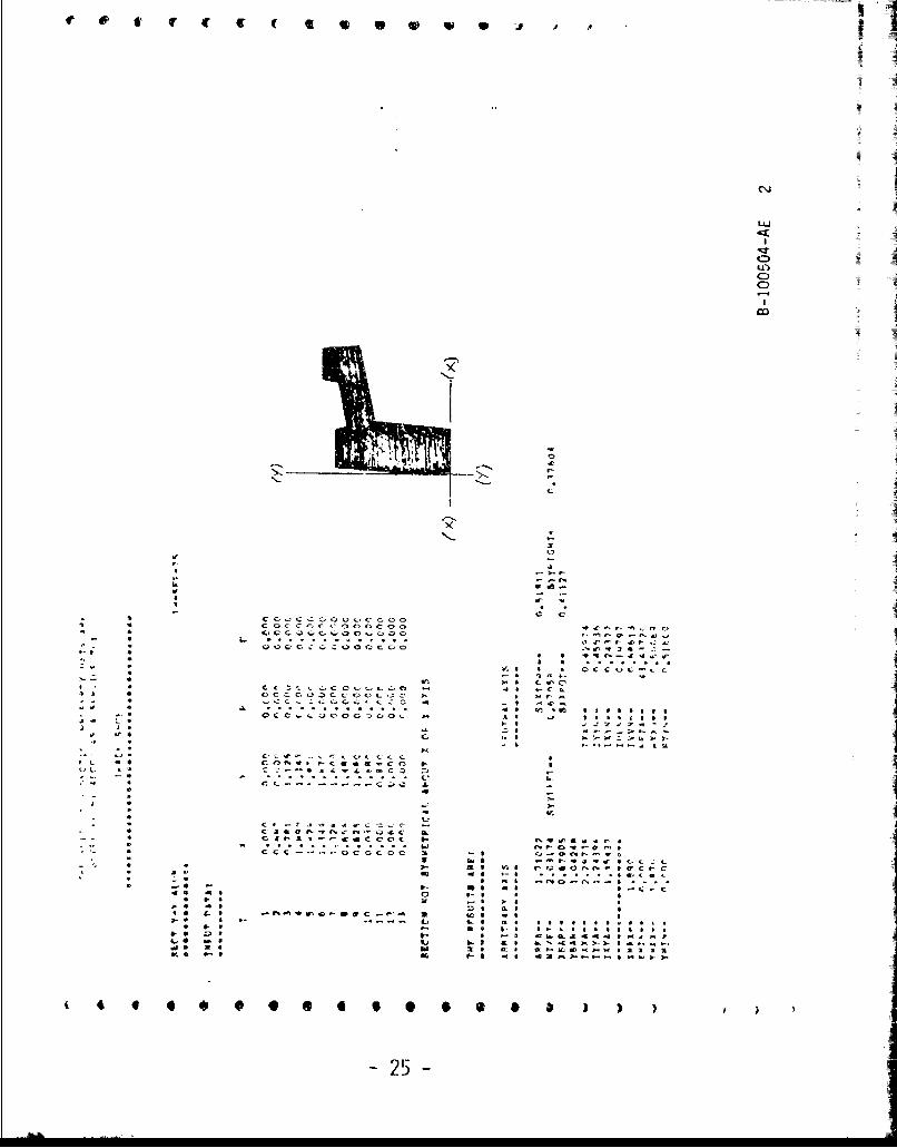
SECTION PROPERTY DATA
DEFINI"ION OF RESULTS :
ARBITRARY AXIS
AR A-- AREA OF THE SECTION IN IN 2 .
WT/FT- WEIGHT PER LINEAL FOOT IP OUNDS.XBAR-- DISTANCE ALONG THE ARBITRAn--KIS FROM ITS OtIGIN TO THE NEuTRA'L
Y-AXIS IN INCHES.'BAR-- DISTANCE AL"-TIE ARBITRARY Y-AXIS FROM ITS ORIGIN TO THE NEUTRAL
X-AXIS IN INCIIES.IXXA-- MOMLNT OF Tr7A ABOUT TILE ARBITRARY X-AXIS IN IN 4 .IYYA-- MOMENT OF INERTIA ABOUT T11' ARJIPRARY Y-AXIS IN IN".IXYA-- PRODUC'T OF INERTIA ABOUT THE ABITRARY ORIGIN IN T9q4 .
NEUTIAl. AXES
FOUR VAL!JES OF SE(-TION MODULUS IN IN3 .SM.TOP---IYXN!DISTANCF< FROM AXIS X.XN TO E TRTEME FIBER AT TOP OF SECTION.SXXECOT---IXXN/DISTANCE FROM AXIS XXXN TO EXTREME FIBER AT 13OTT'OM OF SECTION.SYYLEFT--IYN/DISTANCE FROM AXIS Y YN TO EXTREAE FIBER AT LEFT SIDE OF SECTh.)N.SYYRIGHT-IYYN/DISTANCE FROM AXIS YYN TO EXTREME FIBER AT RIG:T SIDE OF SECTION.
IXXN-- MOMENT OF INERTIA ABOUT THE NEUTRAL X-AXIS (XV.) IN IN 4 .IYYN-- MOMENT OF INERiTIA ABOUT TIlE NEUTRAL Y-AXIS ,(YN) 1N _N
.
IXY N-- PRODUCT OF INERTIA ABOUT 1tE CLNTROID IN INN.
liUiN-- A PRINCIPAL (MIN. OR MAX. ) MOMENT 2 F INERTIA, AXIS UUN BEING TIlEROTATED NEFTRAL X-AXIS (XXN) IN IN.
IVYN--- A PR1INCIPAL (,IN. OR MAX.) MO.ENrF INERTIA, AXIS VVN BEING THEROTATI-", i tTRA Y-AXIS (YYN) IN IN4
BETA-- fill- ANGLE LILTWEEN THE U-AXIS (UU -- ANT) THE NEUTRAL X-AMIS (XXN),k!EASUR.D FRUM Till NE 'TRAl. X-AXIS (XXN) IN DFGRFFS(s COINTERCLCCKWISE)
RXXN-- RADIUS 01 GYLATION W Il~ RESPECT 1O 'n{E NEUTRAL X-AXIS (XXX) IN INCHES,RYYN-- RADIUS OF GYRATION WITl RESPECT TO THE NEUTRAL Y-AXIS (YYN) IN T-',I-tS.
FOR FURTiLER LXPLANATION OF TILSE PROPERTIES SEE:
1. "FORMULAS FOR STRESS AND STRAIN" BY RAYMOND J. ROARK. PUB.McGRAW-HILL BOOK COMPANY, INCORPORATED.
2. "MECHANICS" BY J. L. MERIAM. PB. JOHN WILLY & SONS, INCORPORATED.
3. "ALOA STRUCTURAL HANDIJOOK".
-17

I' I I
,L Tz L40.
fC,'l r0 j - r -W.cC, 49M - W 1
:K 40
a ILa , c m % t, M
PC* ~C ccZ S 0O v ~ c c co Q-
m * C. 0 C CC O J C0 O . I .w - C V 4I.e0 fS ,7 U
o 0 w- t c
C . vp '0 W, Lao 0 I: a
tis 5 .00000 -- - -.O -C -Oc. C CL *.
aft~~~~~~~o . Io c.orfocsoo ~ r I*~aMike~ ~~~~~~~ IC nC0 ~ C fO0 C~,0 C I ~ a
&w * . . ~ *.. 18
we O OCCO - 00 0CC -CO o~t. I'. s r.a ajab

- -, -. - - fl .~uu~'~tIin~mu
* I I II j 1IJ
* I
* I'I
* I II I
* I I
* I CM
I * -J
N
.5
C
3---a 3-2W
* 01- ~'C0~ ~-
a' a c *. a c r~ C- C' C' 0 0 0 0 - -.4 3- Ocot t'U'.( 3-0CC-C 4W' 03'4''Cv,
* I. - - - - C, ar-,--C-
.. C * cC 4t5'. C~C3 000.~ e'..-'a C 4.400
4-I-- * 3 - r'm-a ---- V
- * ".3 I 3 CC'-CC 4CC
C) 3- 0* 4
4-.' 3- U. 443 COO 3
U I -I, cc''ccC'~CflC 3--. .43 3-44
CO * COOC'. 0C.CCC'CO' 3') 3 .4.r,-3- C C..t CtJCCC.UCOC .~ I 3'gr>'
1-" * Cl 41 V~ 3-) 34333333
C C* CCcC'..0CCOC"~ZC C- as c. 33333133
a- C 3-3 '74,'J
3, (4 ~- N k3 ,-~-a: >L3'-4'.
- Us ~,'''. '.I cICOC,'.. 3.44 CC'.333 J'-C~4CC I
3- 4- . I-
411 CC.'~3OCC cL
- 1--
4' .3 11.-C 3- 3.* - a C ,rC'.-.CC'CCCrt
* L C.3 3 4 '~P'04YC £3-
* * C. ti- *j'-~'r'0Cc'C I- Ct as itoh
* CCC-.-.-.'--.--'-CCO0(- I -,
U ~3-- W~3 4'3-i., 3-3 3- 3
* , - .43 >. 3- 3fr -b we a. 3
g. cm .- 1N3''CV.&t *U0-C41 2 V3 -* 3
3** * - -a--. - U I. 0 ft* 33333334333,* 3-3 i.3 *3 4-3 31-3333333343
3-. Z 3 * 3 3 ~ ~
L'S 03 1-, 33 ~3 I-".4d) 34.-.-~ 73 j 4 . mi
t
~* -. 3, 3-4 .43 ~Mk'3.3'~ 33-44>-I--'
# 4 *@ S * 9 0 1 0 3 9 3 I I J ) P
- j9 - I

" r 1 4' c e c c o '. , A
rr-
o LI..-, i.-, -r -+
9". .. .. .. 40,-..
-,,..-..4c -0-.C Ct.C-.i0 ..-. C C. .
" 4 S I I ,. * * .- .- c- : ,
-- S -

fr wet tt t@@**@# 3
A
ii
JI I 0
7-'0 -Jto
4010Ni ~'
I -,
-A -----b--s -i
0(N.
I-
V '0
0 0%-C.
'I a -
I C 4-~
C- ~t
a * ~ 0-to 0% UrI .1 -
* 4 . -r.t ~cf C.
* COO-CC OCCC CCC. -~ ~.-* Cd.-~
* ,. * 0 0 *ZCCUCU
t. : .~. S. cr-c -'Oct
-- * 0.4 0.0-C
* CC Coc ~~.ecc..;z-c ~o .' .~
14 0 CCCZc.OCOflOC C 0 ?-wOi
* , 4 C'0C'.~C CC ~C CCC. .,0 0-at!
tr S ft O( *~ *0000000
* VCOQC Z'CiCZC'C a. - .0.000000-S -
Wv
C ~tCr-, r r-r Cr-Cc 0.CO-C -I - 4C C'~C ~ S
0. 0.:c.'),..O~~Qc:c .4
V L 0-or N
9 -
4, S CC C C C C ., C C t .t SCcCccUCcr-rCO .3Ccrv-cC.CC-.-CC - C xC-''C 0
.4 0 1,) s' iwcca tots* -~ . ooccc~,r r-4-0oCC a-- .4 *4C--r .-. o a
V ----. a to0
.- I-Cc-u nOICOeC.V A .30 9- aS 0~0 C4Ctr v~ou04tC
4 0 *9 to Ct 0 ~ COC
* .. * N 0 04* IN.tZO- t...
V It N -. 0 0 00%-tic'*40 .- 0--' 0 .-
* 00 C) .30 0-0 0
C S t0 C- 0 00
* . tag -. ro--ow .Atra.Q c-n N .00 *0 0
04 0 ..-.-. (70 ~0 LL0SO~0* 4-0 ~. a. 00 09. ttOOOSOO 0
4- ,. 0- 0 r- * .a0e o,,o .(j-~. a * 0.. gO. £0 h~'-~'~-)- t----~tOO 4' hi 40 ES &ISIS%->0 01124
V.a 0-00 to 1-'o -to .41W2-0.--.-.094140-4-
( I. C 6 6 4 ( 00 ) ) S S
-21 -

- - - - -
t tree ccc (060,00~ ;
I I
2
I
I II u-I
ii '-N AC-
ZrI--. i
'1 C
4
I
-j=4
* ii
'3I -a
3- - -hi ~N..r x
a - OS-Ci,.
CCC 000000 00000 00020 000 CCC 000 1cCCCCoC-oc-0' c-cCc~0Concoocncc.oc,
*S S CCCC.C00000C0000DC0000i)000C-0c* - 4, OCocoDCoccc .~c 005-c 000V0C4cco0d a a . - . ~ .~ .C L* CCOiCOOOOOCOCOOOOoCCOCJO0CC.oo 3-h ~ . . ii . .
-1 i.. A i% r - -a * * - ., a
- os ifl hi
t A: ~ £4 --. * 000 ccq.c-. c'0Ccoccoooccooo -I-C - gttCcarraoh-.0ttac,.-.~c~-~.rc, -
'3 oNr.C ~5,- .*........................* A1a. - o--00--.---c C-e.r.I.13r..-...t h0
* I
* z IC. - ~.-tCL~ .- '..,=--= GCOCCCCCCCCCcrs- * a- c .- c,-r~ C -- -' h~ 4 C~ C - S~ 3- - C. a A'. eh o I- .J
* '. C tctr,.-(.ri - ratWtCPflC.r.-rCcc - U-c u~hI~ -
Ch a - . C) C CC..- C~- A
- I .0 a S or'. '.=ww4tt,..=.-r=,~vrhtVi0w.0o00oc - "A C 4~-- : :; ~ ni a c~-*u* C'3A
I.- hi * -
- S Oh .. C.r'vicC QI0-C494r..rC -A--yaiA- C - A - i* A .-.-- *-r--....A'.CJr. U Sli a .
*0 .-. a. a- * as-tm I50 3-3 A- - a a-
* -* . ~. .. -s-a--
~ ~ 0 * C ~ ~ * 0 S S S S b 1 ) )
~aprodUC~ Iro~
- 22 - L best available copY.

C4.etc ~ ~ ov #t ( g cS ~
at a
I"C~ r-
0 u -
o4
of - b-es A
no I- s d

ItI
In
on 42 4.19 4 f-oam 44 : : : 1 * I0
4L #--s
IL &
i. ,- -'
*9 a'. -:n: l -- = co -D
too lo*54
aa. : =p
bi 4, hoih0. cco~gonss.q~ee~enn~oO . -
~ S KWI~fflr.~ 24
e i f ~ 6 C £ 9 W@ W e .u ' .. --.---
Cxi
Lii
C
0LA00
':1-.--
xtS5.5
F a.* .'- I.. rI. - ciS. a
8 4,
C C* I CC..,CC~Ooc.coooa Coccnc coooeoo wca--.cn 8~'- 4 ~
4 1., .
1~ : QOC'CC...~COCcoo . r.-J q.,g'4 9
- - ~* S S OCCOCtC- S - * r5 a 9-.* Vi 118* 8 CISc... ..... C~.c.u4.O 5-. .JI -c a.I i B CCCCO3CCOCCCZ 1~ S 11~* .sC-.COOCLCZZ ~ U* a . - * >.~ ~ Si* .. ' OCC,.L-jC*00.CjO.. . .45 ..i USSS 4.5,
a- 8 9-S .22 .~a Ja I. a 5 - - - - ~ S-. - -"-4 1 11c.bZ.SL, ~8.
-4 .-.- 4.-.-..-. .A ja* 8*1
* L C S CONS -C C.'cO 5.- sUL &~ ~Z-S'a *~LtaCo za- -. S r S..i 4 CI.~ CJC A.
* C
5 S 1-
- S 4.-*- S CF-ta-..jtc Z..-C -* CJaor--tri~i'.-~oLc &
* C~I1 *'CCCCOC 5 xwtas a r *- *. a . 64* . 8 CCC -.- ~.-oCCCoe ~ - U .s.-onS--~.* . S S~9 -~.--j -V. S(--L St- .. * . a. at vie rcedv..c.r S WC-£ S JO m ~S -g.....OS-cat
* SC S MI ci0.-.rt.... 5 5 -a .,S - F- *S .044 CS 0 S-U 9 0
* F 9 X .. 9 >5 5*0 9 ZU &S 9is g.~ S .- r''w.~.-w~c...--.. S .03 -* S~ C. LI U SOSSiS'. ** S
a 5.5 5 SU 5.5 US-k SOS SSSSSSS-S )S 5.. 5 -i CLa4~.49j~tO .. S Li LI ti &~aM>-)-S.....-,es WI 0.5 re t* ftS-.~WiIiM '£311
W.di PS. P-I C S C31.fr..F.b-.OUih.U.-a.
II-14 0 * * 9064 90 6* S C ) ) ) , ) ) J
-25-

V I irrc '~ (COO 000 ~
I. ' I
71 I
* I
* I LaC
0a,0
- 0%.-.
I a
2C
I-.
'a
4~ C* al-f.a S )- em- r V~ 0
* 4~ I*~a'
c' C-.1 * OCtC)COCC.Ot~C.3 4 enncc-CnCr.c'fl sJ.t,,-nmv,-
* * 00CC-CC-C CC-CC 'C
- 4 6.iC. 0 CL.CCCC'C0Q0 VtLt.fld,
'-1- S 1 I I 0Ncc4C~hI'- '0 6C.- 4 U) C I I CCCC.c.&C~
- a ar-C-' -0 *0 141 CCC I* CC-CC . acoco -. C I 1.1K
~0 4 oocccoCoonC 54 C ~-- 4 .COCC')CCC CC. 4 ...0 14.fl
g.g, 0 0 * -e em .* las I.S.O- .g CCOCC'SCOCCC 0, 0 ImlImlulCU c~0 U-. I S 747743.13- .3. a , I ,- I- C. -. I-t.
C 6.1- ~ C amC bO -
Ct ecoccoeoccc3c-~a-JlCt4tC I'
p.. C.' * C) b''1 S CCC- tG 4 61
* - .24 5-.
--. 3 4 1.Ca C.* C-Cttii.d Ct flC)C
- - S ow-v-c sacoco S-- S Zr-s.C-bc 0000 0' ~~I%0'.40 Ir ~ a - * a sosecer I
t I CCCCC--.-OOO 1 -, -tGrr'sz I* V ~. I 'C eaceac. a C C C' C
-- ., . ~. ftC 101 IN4*rS~t
U'Pc'~S1C
'6 S 20 10 Cl .4 . *00~C.- S I 110 .00000*
* .. ). - I- KU 4* I-C-C40 46 C C-I U I
C--. S ..2. b-I C
$1 CU rSI CI Ito CI ~rircrin7Ofl.' a am u.J* I -. C hiC SI **IUIII#IslU
0 1.0 14 ftP 4.0 I~,lIIt #50490-0 Dl I-' I '40 .ktS , 4~ It *t.9 am Li 61 ftI 0-'.CCMb-I.' l4.4.-.u-jo a. a z m as ag-aC .txt ~U)5 146 ~ a- * am ~ IC4W1.0'
004 0060ft **t*** b ) 3
- 26 -

ini
400
aF 0i> Co0 e
0t W3- ,
-, 0C 0 0
hO S 0000 00,
ot SS0*at 4C0.K
ta
0~~~2 IsCo~ o tC,*a 0 S 0 4. oopiooop
ra toOpw no
0-0 0 op. dl l 40
C~ MS
.0.3 CS c r-c' rr-e o 27

L±J
C
ID
Iz 1
2. a, o-f
0C0 0 00 C. t 00 0 0000 cco
0~ b,
-3 ~~00 000 .c. .c .c 0 .0 .0 .. 0 -oo -o
@@.,01* 0 0- WOOW OOOOOI-O on In IL V
,a*2W a w c.-
a, t. I 0
3* 0 a0 0-4 a ai aP9L

err;f c c cce e 0
C
LO
c, .C cIli CI C 1 1
a 0 0 0C, C, t -: 1,
fx0
c0
ms:5
tN
w W. x a xx 9
w~a
ig h
4. .4529

4 l 4 CC C ** O y9 ,P * t * * * I t
/ to71 to
!C| ^--
7 C
l,- .
I cl
r 4'
. _________.. .. J............-............... ,. .- ,.
*- -0

c1
C5
-~> i -
If rI
/V I4- .
0c -m C- c4.;Z.Tcc
c~ t-
*C t-a a
.- ~~o 6 '
N OC CCC.~c C DCO OCCC - .3 ~Za ~ COC CCC c co cooc oo ILI
-'c IS i a a '' - a.
OC C ~w fl~r a* -a-,31-

a L,0Qa ! C 'V Ic0C,0c44,4.
C. 7
c-r
I C, t-_r-
4. 1 4-
I: a.4 15 C
.4 C
1~~~~3 3 OO O O O C O O - Ar
V S CCCC C)C. CCOC CC32
IL. * ** *** * 4. .. u v c c

4V
APPEND IX C
DRIVE LOAD ANALYSIS
I. SINGLE PIN, CONCEMPS 1 AND 4
"Ihis analysis specifically addresses Concept 1, single pin with end drive(Drawirg B-1005O4-AE). The section properties are ,hose described inAppendix B. Because of block design similarity with the drive insert single-pin concept (4), this analysis generally applies to both single-pin concepts1 and 4, except for the drive area itself.
A. Track Tension Loading
TraLk operating conditions:
20,000 lbs. tension67,000 in.-lb. torsion
Tension loading:
1852 lb./in. 1852 lb./in. 1852 lb./in.
2).74 lb./in. 2174 lb./in.
These loads are analyzed by assuming concentrated loads applied at tht-"hinge" locations, as below:
A 5,740 lbs. at P = 1.55"B - 10,000 lbs. at t = 5.61"C - 8,520 lbs. at t = 10.42'D - 10,000 lbs. at X. = 15.23'E - 5,740 lbs. at 9. = 19.29"
-33-
LI

Appendix C - Continued
B. Track Torsional Loading
3776 lb. 6965 lb.
___ _,__ '- -- Pin
6965 lb. 3776 lb.
Assume the 67,000 in.-lb. mnoment about the track certer is composed ofconcentrated ioads acting at same locations as tensile Ictads, as indicatedbe low.
3,776 lbs. at k = 1.55' and i9.?9"6,965 lbs. at Z, = 5.61" and 15.23'
C. Stress on End Drive Location of Track Body, Section Y-Y, Concept I
Refer to drawing B-iOO504-AE. Section Y-Y is included at an angle of25.50 to the pin as shown in the sketch below:
Y
IM 5180 lb. 3776 lb. --- ml
Llb#J.4 135
. " ",/x, YX 1 4 W y 3,4 -

Appendix C - Continued
Stress conditions for the 67,000 in.-lb. torsional loads applied positive(as shown) and negative are calculated below:
+ 67,000 in.-lb. Torsion:
Mx = 3,776 (.4) + 2,470 (.275)= 2,190 in.-Ib.
My = 3,776 (1.5) -5,180 (.275)= 4,240 in.-lb.
Mz = -2,470 (1.5) -5,180 (.4)= -5,777 in.-lb.
Rx = 5,180 lb.Ry = 2,470 lb.Rz = 3,776 lb.
- 67,000 in.-lb. Torsion:
Mx -3,776 (.4) + 2,470 (.275)= - 830 in.-lb.
My = -3,776 (1.5) -5,180 (.275)- -7,090 in.-lb.
Mz = -2,470 (1.5) -5,180 (.4)= -5,777 in.-Ib.
Bending a.d tensile stresses are then determined using the section prop-erties shown in Appendix B for Section Y-Y.
Mc Po Bending = G Tensile n
+ 67,000 ir.-lb. Torsion:
o B-Top -4,240I.87-1.042) = -8,190 psi: 428Y:iL-
o B Bottom =4,240 (1.042 1,30_s042 = 10,300 psi
.42874
o B-Inside = 5,77 (.68) -8,630 psi.45536
B.utsde=-5,777 (.68-1.89) _1 ,5 ~Butside= ~.45536 5,350 psi
a Tensile 5,180 3,030 psi1.710?
- 35-

Appendix C - Continued
- 67,000 in.-lb. Torsion:o B-Top - -7.090 (1.042-1.87) 13,690 psi
.42874 1 0
o B-Bottom -090 (1-042) -17,230 psi
o B-Inside = -5,7.7 (.681 = -8,630 osi.45536
c B-Outside= -5,1777(.68-1.89) = 15,350 psi.45536
I: 5,5 s
o Tensile = 5,_180 = ,030 psi127102
The worst stress condition in this section is then at the top, outsideelement where
o Maximum = 3,030 + 15,350 + 1.3,690-32,070 lbs.
This results in a factor of safety of 1.75 based on the typical yieldstrenyLh of 2014-T6 die forgings. The iife of tfis design is not infiniteas indicated by this stress condition above the material's endurancelimit (18,000 psi). Estimates of lifetime are not felt to be accuratewithin the scope of this analysis and are not made. Additional strengthen-ing of this design might be indicated after a more precise determinationof stress patterns (particularly stress concentrations) is made (e.g.by laboratory stress analysis as suggested in Section V).
D. Stresses Through Track Block, Section X-X
5,740 lb. 5,740 lb
-6.47
2T~r6.96 lb.3,776 lb.
+ -- - Y Z
3 .33"1
IX10,000 lb. 3610,000 lb.
- 36 -I

Appendix U Continued 1'
Mx = ±3,776 (6.47) ;6,965 (2.41)±7,645 in.-lb. (± torsion load)
My = 5,740 (.182) ±3,776 (2.67) ±6,965 (3.33) -10,000 (.182) 1 == 32,500 in.-Ib. (+ torsion)=-34,050 in.-lb. (- torsion) 41
Mz = 10,000 (2.41) -5,740 (6.47)=-13,040 in.-Ib.
Rx 5,740- 10,000= -4,260 lb.
Ry =0
Rz = 3,776 - 6,965 -3,190 (± torsion)
I :IMCoi Bending T
B-Top 7,645 (1.202'
= ±5,7i0 psi (± torsion) £
o -BotLom 7,645 (1'421)1.609
= :j6,760 psi (r torsion)
-13,040 (1.789)o B-Front - 6-4 J
- -3,430psi (± torsion) I13,040 (2.523)
o B-Rear - 6.794
= 4,840 psi (± torsion)
Tension loads normal to track surface are zero so that the worst stressesare at the top rear surface of the block, and are 10,550 psi; a safetyfactor of nore than 5 over the typical yield strength of 2014-T61. IThus, Section X-X is adequate from the standpoint of gross stress levels;possible stress concentrations should be defined in laboratory tests ofprototype hardware.
E. Stress throug) track block assuming one block supports the entire vehicle
weight (Section A-A).
Beam Loading:PI_
M maximum = 4--_ IL(5o, o10oo)0
4
75,000 in..-lb.
7

Appendix C - Continued
MCa Bending -
a B-Bottoii 2 -36=-18,600 psi
a B-Top - ± ) (1.21§1=16,100 psi
Stresses are well within 2014-T61 yield strength with a safety factorof approximately 3 for thiis extreme loading condition.
11. Single Pin, Concept 2
Refer to Drawing B-100508-A[
A. Track Tension Loading
Track operating~ conditions:
20,000 lbs. tILension67,000 in-lb. torSkion
Tension loading:
1,961 lb./in.
2,660 lb./in. 2.660 lb./in.
k
Assume concentrOAted loads at "hinge" locations:
A - 10,000 lbs. at 9 =1.966- 10,000 lbs. at k2= 6.67
C - 10,0 ?)0 lbs. at X 11.77D - 10,000 lbs. at k. = 16.48
38
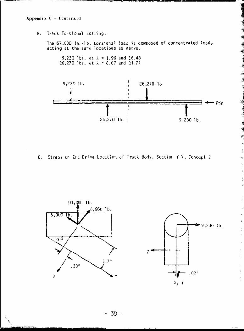
Appendix C - Ccntinued
B. Track Torsional Loading.
The 67,000 in.-lb. torsional load is composed of concentrated loadsacting at the sare locations as above.
9,230 Ibs. at 2. = 1.96 and 16.4826,270 lbs. at k = 6.67 and 11.77
9,239 lb. 26,270 lb.
26,270 lb. 9,230 lb.
i -u tj ILI ' I N u Uint
10,000 lb.
5, W75 8,666 l b.
9,230 1b.
/~zj
1.7'
X ' .02"
X, Y
- 39-

Appendix C - Continued
Rx = 8,660 psi
Ry 5,000 psi
Rz = ±9,230 psi (± torsion)
Mx = -9,230 (.33) = T11,710 psi (± torsion)
My = 9,230 (1.7) = t15,690 psi (+ torsion)
Mz = 8,660 (.33) -5,000 (1.7) -5,640 psi
P 8,660o Tension A 3.259 = 2,660 psi
o Top ( Mc ±(15.69)K1.0_j ±24,000 psiT .678
o Bottom Mc - ( 15.69)_(__111 = ±20,620 psi1 .678
o Front =Mc cL 64 (1.636) -1,680 psiF 5.5057
Mc (5.64) (2.294) =
1 5.5057
The worst stress condition is at top, rear
7 = 2,660 + 24,000 + 2,350 = 29,010 psi
This is a safety factor of approximately 1.9 on yielding for typical2014-T61 properties, but as in the case of Concept 1, the life of thedesigr is not infinite. Further fatigue evaluation is left to labora-tory stress analysis.
General comment -- Caution is advised in the interpretation of the calcula-1ons shown In-this Appendix.. The bending forula o = !L- assumes that thecross sectional dimensions of the beams are small compared to their lengths.Stresses could be largcr than indicated, pdrticuiariy 3t stress concentrations.These values are shown to suggest areas (such as the centerguide and end drivelocation) that might require additional strengthening. The sections are basedon the LVTP-7 track (Appendix B) and are general1; such that the aluminumtrack will be equal to the existing steel track. Final design refinement bylaboratory stress analysis should be completed, as indicated in Section V.
- 4I i

MU -in
ro>4-S4-i -
u fl-a
- D 0Lv
Ci t
GoW LW
r-.la)
- CC'Nu
QJ > 00
rCy ,J
~) FL C
0i L r-
C) 04
a *Qt 4-3
-tn U$-
%. (1) 4-)
IC

co QU
DC.)
c c
-0
a)-G
cuU OLLX- S-
L-)

41L
St -AIVw
0W
(A
fal-
.0 C4c--
- )
-II
CLO
'r-

it! 0
cw
o 40
.- -c
-t - A
&nI
-'9a)

FORGING ALLOYS - CHARACIERISTICS AND USES -
TempersAlloy generally General Characteristics Typical Usesused
1100 -0 Commercially ue aluminum not sus- Cooking utensil components; pipe
ceptible to heat treatment. Easily fittings and other Darts for Chem-forged. Excellent resistance to ical equipment. Catle clamps forcorrosion, electrical industry.
2014 -T6 High tensile and yield strength Widcly used for aircraft and-T61 combined with good ductility. Good other heavy-duty structural uses.
machinabilty. Fair forging charac- For foroins of very large crossteristics, section, the alloy can b- rough
machined in F temper and thenheat treated to obtain somewhathiqher properties and alleviatedistortion problems. Actu,1 usesinclude airframe components , ,ir-craft landinq gear parts, truck Iwheel hubs, equalizer beams fortrucks, ordnance and missileparts.
2024 -T Special purpose alloy not used for Aircraft propellers.general forqing applicationis. Highstrength but relatively poc,r forgingcharacteristics.
2219 -T6 Good mechanical properties at room Tankage tor liquid fuel rockets.-T852 temperatures. Ability to retain Structural parts which must 3per-
strength after prolonged exposure ate at elevated teperature forat elevated tempcrature. Very good prolonged periods. Structuralweldability arid joint efficiency. parts to be welded-
2618 -T61 Good nechanicai properties .:t ele- fkivraft cylinder heads andvated temperature. Freedom from pisLlrls. Tire molds. Jet enginegrowth. accessories.
4032 -T6 Good elevated temperature strength. FoItjed pistons.Lowest coefficient of ey,)ansion offorging alloys.
5083 -Hill High strength nonheat treatable Ballistic parts for military vehi--H112 alloy. Strengthened by cold work- clus. keldcd hi-h strength struc--HIll7 in. Good for ballistic applica- ures. , ahie applications.-H131 tions. Very good weldability.-H321 Good corrosion resistance.
5456 -Hill Similar to 5033. Ballistic parts for military vehi--H1212 Slightly higher strength, cles. Ikelded high strength struc--H116/117 tures. arine applications.-V131-H3?]
Figure 5
-Vr-"

TempersAlloy general ly General Characteristics Typical Uses
used
6061 -T6 Moderate yield and tensile strength Transportation equipment such asJ652 combined with good ductility. Ex- truck parts and automotive wheels,
cellent forging characteristics, pipe flanges; chemical industryand water heater hardware requi'-ing assembly by welding or braz-ing.
6151 -T6 Moderate mechanical properties. Intricate parts, aircraft engines,-T652 Good machining characteristics and crankcases, auontive parts and
resistance to corrosion. Excel- hadware, machinery parts suchlent forging charicteristics. as spool heads dnd spinning
buckets for textile industry,trowei handles.
7075 -T6 High strength aluminum forging Aeroispace applications. Typical-T652 alloy. Close control -equired in uses are airframe parts, landing-T73 fabrication. Overayed (-T7) tern.- gear and undercarriage partz-T7352 pers have high resistance to Structural parts requiring ngh
stress-corrosion cracking. Ten- resistance to stress corrosionsile and yield strengths are about cracking use overaged tempers.10% less than 7075-T6.
Figure 5 - Continued

ALCOA FORO ING ALI.OY DATA
TYPICAL PHYSICAL PROP.RTILS- ALUMINUM FORGING ALLOYS
Electrical
condtctivity Therma lA]l oy Me! ti no percent of conductivityand Density range internLi onaI at 25CC,
temper Ib/cu in. approximate 0p Airwaled Copper CGS unitsStandard
2014-T4 0.1012 950-1180 34 0.322014-T6 0.1012 950-1180 40 0.372014-T61 0.1012 950-1180 40 0.372024-T852 0. 1005 935-1180 38 0.36
2219-T6 0.1023 1010-1190 32 0.302219-T852 0.1023 1010-1190 32 0.30
2618-161 0.0999 1040-1 I,185 39 0. 36
4032-T6 0.0966 990-!060 35 0.335083-Hill 0.0961 1075---18f 29 0.285083-HI12 0.0961 1075-1185 29 0.28
5083-H131 0.0961 1075-]!85 29 0.28-06 i- 6 6.0976 i00-1205UI 43 U.406061-T652 0.0976 1300-1205 43 G.406051-16 0.0977 1090-1200 45 0.41
615 1 -T652 0.0977 1090-1200 45 0.4]7075-T6 0.1013 890-1175 33 0.317075-1'652 0.1013 890--1 17r 33 0.317075-173 0. 1013 890-1175 40 0.33
7075-T7352 0.1013 890- i 175 40 0.36
Average Coefficient of Ther] Lxpal sic,-Alull ,uT orgi g A1l1oys ]
Alloy Tei'ipe ra ture Lanne-- --- 58 _-_ _ _ _ __' .. . .. _ ___:/ {L o . ) -C U ---- 72,FAlloy ~ ~ ~ ~ ~ ~ , Lstm Tr Ftni9T__
I'014 -1 .7 12.5 13.1 13.62024 11.7 12.7 13.2 13.8
2219 13.7 12.5 13.1 !3.6
2618 IU.5 12. 4 12.9 13.44032 10.1 10.8 1.3 11-75083 12.3 ? .2 13.8 14.3
6061 12.! 1 3.0 13.6 14.1
6151 12.0 12.9 13.5 14.07075 12.1 13.0 13.6 14.1
I iu-e 6
-9€7- I

00
v - 4 -4 .- 1 4-i t -4A - -- 1 -4 -- 4 - 4 -i- -- 4 a-- ri
Lr r ~ o %0000 '00 0000 000 C D rC:g4:-' C 000 0000 - * ICD* 0000 000 C, C3
Cr)O C\D.- CD4a- CD-ri--4C C.)-4D--. CD CD CD CDUC)ICJ
LI -I
I-- m- ,;T a- T a - I- a- m- M *l a' a -
LL.
U/)
0)
4
< 4J- .D4-C) O - L
0--- .-- ClC. ) f: -)C. CC C ) C D C)C ) n C
Q) (z- 4..)1 1 . I
4- * n aDL)q0 t L) n(, z
c-h CY 'a I I
Cn vi' LuL L)rl0 c-C All.,Cdr 0CIO OC.0 k --- 0 .r- r- . r-Lo tljc n
LI- C- r0M C)0CLJC C : - r .7 DC
c4C -44- , - U)*0 V 10 k - IF-r

W 0) 04C Q C i a) Q Q04 cC (1' 0
'U 7) L0b 't1 7: 0 "i-U C)a W Q 0) W1 'l 1) a) U 4-'
(LO tn
000 000 00) LAD LO 0l - nL r
4-) ~ -i nLnI n in in 0 V-(D 0 .CD C) -irD-4 ( CD. CUC
ro .. o aj.
La ' CDn(0 C)LC)L (D C)S) 0 CU 4
0 (3)
rn In .r u^ C- kC) -Y C - - .C 4 04--- ~ ~ l S.ri inu c 21
rz Cj C) C) C:) 4- ~
tin L.) Cl
C\J~~flI)> 4-')if ft) E3CC)C 4' 0
ILI) S. *. C) I t 4 04 c nI- j 0 -. LCc C 00 .0 E ro
4--
Ma a_ 0 1+.-
Q) U n i
O 5 2
o. - - - "oCCf000 (NiC0
0'0 CL (L- C S. )
1* -4 - 4 *. ,t3 0
II I~ If)4 i W V W~
0: Ij (Z 5r - -
'U, <-Qc -). -. :(D - > ruZWOO
Lfli3~tfl~xJ __3 (,1) V)J(- 5-t1) C (\Z0C Ifif) - -L. C-) _Z t 4 i(r -
(D iA I (D 000 C 4-aE000 '
4r3 C-) CDu CE < 40
0U Qj~ 0 -4'Q(0Q -0 C:C 4
Lf I o0 ' J 00) >4j 0 W) -0 (1
I wcn 0'i-'V 00
C51.~~---o oo 00044Lr ciC1-
Ir Il 4 t C C- - -.-i 1.(LI ~ ~ ~ ~ ~ ~ t 5 ~ tn 0 0 C --- i - n n
'i L)C' ( CD4'44 C) '-A t0 U Q 1) -- -- C- -'t -: c 04-J 0" n 0 0--r)
0 0 0 C--00 CC) 0 2 C:) -- 4-E 'u
LD C-4.-_ C --- ci'-; 4.- EL S2 CjCI~ Ci (0 ci *I 2- 4~4 0 1
CD u. C'; if) C ) if, l C- rC. c
C.,1I O Cm) Ot o' C) C) C)C)U m c .

WEIGHT ESTIMATES OF PROPOSED DESIGN CONCEPTSWITH COMPARISON TO EXISTING TRACKS
CONCEPT _
1 2 3 4Part Single Pin Sinle Pin Double Pin Single Pin
Pin(s) and Nuts 3.3 4.8 9.6 3.3
Bushings 2.4 2.7 2.7 2.4
Pad 2.8 2.8 2.8 2.8
Body Rubber 1.0 1.0 1.0 1.0
Body 10.4 10.4 12.3 11.3
Centerguide .9 .9 .9 .9
Drive Assembly 2.0 3.0 3.5 4.0
Total Weight 22.8 25.6 32.8 25.7Per Shoe
Weight per Foot 45.6 51.2 65.6 51.4of Track
Weight per foot of LVTP-7 Track 62.8 Lbs.(Per NAVSHIPS LVTP-7 CharacteristicData Sheet, May 1974)
Weight per foot of modified LVTP-7 66.0 Lbs.
Track for MICV (per U. S. Army Tank-Automotive Command Drawing 12250718,December 13, 1974
Figure 7

T
ESTIMATED PRODUCTION PRICE OFRECOMMENDED CONCEPTS
Concept 2 Concpt-4
Production Forging Dies $22,250 $32,750
Production price (10,000 quatity) 78 $ 88per pitch, assembled in sections,rpackaged for shipment
F
I
FigureI
-- .5-J
==r
ESIAE\RDCINPIEO

* - r
H C I F ________
8 /00504_AG
~
A
* -r*1~fl C//tN Y I'
U-fl___-A
- --------------- -- - - -~ (
-- i 6 -
/ - LITh -- <~> 7HVjJ~r I ___1--~--
-,
ct~hrt > ~ /-) -. 10
I-, *1
/ A ~~"' ~: :~' ' I / -
~ A ~ -600
I ~-" 2 r~_____ ___ __________ 'I
I I\II,:/
t 771.~, ~-]II
St cr/lw
-- it --- i -___ -1 -~&. _/ 12 /IA~ *1
-- Il A.-,it 'I
-: /1 __
I 2C1/ON iN. -J'vjtk _ 0
I -so'.
-- ,
NC' __________ -.-~ ___
___ £ 2.~I A
H .J c--i--
* p1 ci

,
ta6 NO
IIOP~Z-X-- IV VA> SNI R6
0 0 l- 4-A

i5S_100506- [
SECTIO)N 'Y- y
F-7I
I n
' K* .
At / mr ii10lW ,L,(,fewi-:1 2ON Z, -

4, Tf -~
~J _ _7
U I SA
L,~ - *1W-A.
00
4<~,'YP -- F J j
RfS. JIZA of 2YtI hC -- - ~l-LA. sdh
ti

I I I r
_________________________________________ MAY________
_ -Trz-- 4-T - - - - -A-

- -- --- 1.14 a&O - - - -
*LME No v--_ _ _ _ mmm
t'wYl \/' -
.AIV A

* 8-1000-§ ANN7
ItI
itt
Z4-o/ C- C "PipI

I
0 C I I AV ___________________________-..----~~~~~-------~~~~~~~~j~~~~~~~.~ - ~
A d
Njr
*1*
VC~T.O4 X X
-b
r I A -
/'.-* -.vku ~ '
(i-----~..ii
- - 4 1K -~ I
-~ ----r sj'~t **~
U I I
'C-- d - I
'F1 KI
*9p j*tjs ~f- 4 1*
1' - 1 '4
'4. K qA~
2 ~ ~ 2
CiflY NOT cOmfl at: -.
A
71
C- !U#144 at' ~ 06 C5, 40'jCt'. -. _____-
* - - a N S flfl fl
it.: I-- . .
I -- 1~ * --- ' -I -t rff~ $S~~ ~rt. 44 vAt &flP
~J~ZUvei_______ B-/c
C a
IN
Copyright © 2022 FDOKUMEN