Airdrop of Supplies and Equipment: Rigging Potable Water ...
210
TM 4-48.01 MCRP 4-11.3N TO 13C7-2-1001 Airdrop of Supplies and Equipment: Rigging Potable Water and Water Purification Units MARCH 2016 DISTRIBUTION RESTRICTION: Approved for public release; distribution is unlimited. This publication supersedes FM 10-522/TO 13C7-2-1001 dated 3 June 1985; FM 4-20.158/TO 13C7- 7-61, dated 11 May 2005.
-
Upload
khangminh22 -
Category
Documents
-
view
3 -
download
0
Transcript of Airdrop of Supplies and Equipment: Rigging Potable Water ...

TM 4-48.01 MCRP 4-11.3N
TO 13C7-2-1001
Airdrop of Supplies and Equipment: Rigging Potable Water and Water Purification Units
MARCH 2016
DISTRIBUTION RESTRICTION: Approved for public release; distribution is unlimited.
This publication supersedes FM 10-522/TO 13C7-2-1001 dated 3 June 1985; FM 4-20.158/TO 13C7-7-61, dated 11 May 2005.

This publication is available at Army Knowledge Online
(https://armypubs.us.army.mil/doctrine/index.html).
To receive publishing updates, please subscribe at
http://www.apd.army.mil/AdminPubs/new_subscribe.asp.
This publication is also available through the
Marine Corps Doctrine website (https://www.doctrine.usmc.mil),
and the Air Force Publishing website (www.e-publishing.af.mil).
*TM 4-48.01/MCRP 4-11.3N/TO 13C7-2-1001(FM 10-522/TO 13C7-2-1001; FM 4-20.158/TO 13C7-7-61)
Distribution Restriction: Approved for public release: distribution is unlimited.
*This publication supersedes FM 10-522/TO 13C7-2-1001, 3 June 1985; FM 4-20.158/TO 13C7-7-61, 11 May2005.
i
Technical Manual (TM)
No. 4-48-.01
Headquarters
Department of the Army
Washington, DC
Marine Corps Reference Publication (MCRP)
No. 4-11.3N
United States Marine Corps
Combat Development Command
Quantico, VA
Technical Order (TO)
No. 13C7-2-1001
Headquarters
Department of the Air Force
Washington, DC
15 March 2016
Airdrop of Supplies and Equipment: Rigging Potable Water and Water Purification Units
Contents
Page
PREFACE.............................................................................................................. vi
INTRODUCTION ................................................................................................. viii
Chapter 1 Rigging Small Containers for Free Drop ........................................................ 1-1
Section I: Rigging Twenty-Four 1-Quart Plastic Canteens .......................... 1-1 Description of Load ............................................................................................. 1-1 Preparing Inner Container .................................................................................. 1-1 Packaging Canteens .......................................................................................... 1-1 Marking Rigged Load ......................................................................................... 1-5 Equipment Required ........................................................................................... 1-5
Section II rigging Twenty-Four 16-Ounce Cans ............................................ 1-6 Description of Load ............................................................................................. 1-6 Reinforcing Packing Case .................................................................................. 1-6 Positioning Honeycomb ..................................................................................... 1-6 Prepare and Pack the Outer Container .............................................................. 1-6 Marking Rigged Load ......................................................................................... 1-9 Equipment Required ........................................................................................... 1-9
Section III rigging fifty 10-Ounce Cans ........................................................ 1-10 Description of Load ........................................................................................... 1-10

Contents
ii TM 4-48.01/MCRP 4-11.3N/TO 13C7-2-1001 15 March 2016
Reinforcing Packing Case ................................................................................. 1-10 Positioning Honeycomb ................................................................................... 1-10 Prepare and Pack the Outer Container............................................................. 1-10 Marking Rigged Load ........................................................................................ 1-13 Equipment Required ......................................................................................... 1-13
Chapter 2 Rigging Milk Dispensing Containers .............................................................. 2-1
Section I: Rigging Milk Dispensing Containers ............................................. 2-1 Description of Load ............................................................................................. 2-1 Preparing Containers .......................................................................................... 2-1 Rigging Load ....................................................................................................... 2-2 Closing Cargo Bag .............................................................................................. 2-5 Installing Parachute............................................................................................. 2-5 Rigged Load data ................................................................................................ 2-5 Equipment Required ........................................................................................... 2-5
Section II: Rigging 40 Milk Dispensing Containers in an A-22 Cargo Bag . 2-7 Description of Load ............................................................................................. 2-7 Preparing Containers .......................................................................................... 2-7 Rigging Load ....................................................................................................... 2-8 Closing Cargo Bag ............................................................................................ 2-10 Installing Parachute........................................................................................... 2-10 Rigged Load dATA ............................................................................................ 2-10 Equipment Required ......................................................................................... 2-10
Chapter 3 Rigging 55-Gallon Collapsible Water Drums in an A-22 Cargo Bag for Low-Velocity Airdrop ................................................................................................ 3-1 Description of Load ............................................................................................. 3-1 Preparing and Securing Load ............................................................................. 3-1 Preparing Skid board .......................................................................................... 3-9 Securing Skid Board to the A-22 Cargo Bag .................................................... 3-10 Installing Parachute........................................................................................... 3-10 Marking Rigged Load ........................................................................................ 3-11 Equipment Required ......................................................................................... 3-11
Chapter 4 Rigging 55-Gallon Collapsible Water Drum in Four A-22 Cargo Bags on an 8-Foot, Type V platform for Low-Velocity Airdrop ............................................ 4-1 Description of Load ............................................................................................. 4-1 Rigging Procedures............................................................................................. 4-1
Chapter 5 Rigging Three 250-Gallon Collapsible Water Drums on an 8-Ft, Type V platform for Low-Velocity Airdrop .................................................................................. 5-1 Description of Load ............................................................................................. 5-1 Preparing Platform .............................................................................................. 5-2 Preparing and Positioning Honeycomb .............................................................. 5-3 Installing Lifting Slings ........................................................................................ 5-4 Positioning and Lashing Drums .......................................................................... 5-4 Positioning Drums ............................................................................................... 5-4 Lashing Drums Together .................................................................................... 5-4 Lashing Drums to the Platform ........................................................................... 5-6 Installing and Safetying Suspension Slings ........................................................ 5-9

Contents
15 March 2016 TM 4-48.01/MCRP 4-11.3N/TO 13C7-2-1001 iii
Stowing Cargo Parachutes ............................................................................... 5-10 Installing Parachute Release System ............................................................... 5-12 Installing Extraction System ............................................................................. 5-13 Placing Extraction Parachute ........................................................................... 5-15 Marking Rigged Load ....................................................................................... 5-15 Equipment Required ......................................................................................... 5-17
Chapter 6 Rigging Three 250-Gallon Collapsible Water Drums on a 12-Ft, Type V platform for Low-Velocity Airdrop .................................................................................. 6-1 Description of Load ............................................................................................. 6-1 Preparing Platform .............................................................................................. 6-1 Preparing and Positioning Honeycomb .............................................................. 6-2 Installing Lifting Slings ........................................................................................ 6-3 Positioning and Lashing Drums Together .......................................................... 6-3 Lashing Drums to the Platform ........................................................................... 6-4 Installing and Safetying Suspension Slings........................................................ 6-6 Stowing Cargo Parachutes ................................................................................. 6-7 Installing Parachute Release System ................................................................. 6-9 Installing Extraction System ............................................................................. 6-10 Placing Extraction Parachute ........................................................................... 6-12 Marking Rigged Load ....................................................................................... 6-12 Equipment Required ......................................................................................... 6-14
Chapter 7 Rigging 600-GPH ROWPU on a 20-Foot, Type V Platform for Low-Velocity Airdrop ............................................................................................................... 7-1 Description of Load ............................................................................................. 7-1 Preparing Platform .............................................................................................. 7-2 Preparing and Positioning HOneycomb Stacks ................................................. 7-3 Preparing ROWPU ........................................................................................... 7-11 Preparing and Securing Control Panel ............................................................. 7-15 Preparing and Securing Pulse Dampener ........................................................ 7-16 Preparing and Vehicular Cables, Straps, Chains, Jacks and the Jack Handles............................................................................................................. 7-17 Preparing the Generator ................................................................................... 7-17 Preparing and Stowing Raw Water Pumps ...................................................... 7-18 Preparing, Stowing, and Securing Backwash Pumps ...................................... 7-19 Preparing and Stowing Canvas Hoses ............................................................. 7-21 Preparing, Stowing and Securing Storage Chests ........................................... 7-22 Stowing and Securing Wooden Staves ............................................................ 7-22 Stowing and Securing Sledgehammer ............................................................. 7-22 Stowing and Securing paddle and Float ........................................................... 7-23 Stowing and Securinge Water Containers ....................................................... 7-23 Preparing and Stowing Rubber Hoses ............................................................. 7-23 Preparing, Stowing and Securing Water Tanks ............................................... 7-24 Installing and Securing Cross Braces .............................................................. 7-25 Preparing, Stowing and Securing Distribution Pump ....................................... 7-26 Lifting and Positioning Load ............................................................................. 7-27 Installing Lashings ............................................................................................ 7-30 Constructing Endboards ................................................................................... 7-33
Contents
iv TM 4-48.01/MCRP 4-11.3N/TO 13C7-2-1001 15 March 2016
Positioning and Securing End Boards and Stowing Tires ................................ 7-34 Securing Tires ................................................................................................... 7-35 Preparing, Constructing and Positioning Parachute Stowage Position ............ 7-36 Construct the Parachute Stowage Platform ...................................................... 7-37 Securing Parachute Stowage Platform ............................................................. 7-38 Installing Load Cover, Suspension Slings and Safety Tie ................................ 7-39 Preparing and Stowing Cargo Parachutes ....................................................... 7-40 Installing Parachute Release System ............................................................... 7-41 Installing Extraction System .............................................................................. 7-42 Placing Extraction Parachute ............................................................................ 7-43 Installing Provisions for Emergency Restraints ................................................ 7-43 Marking Rigged Load ........................................................................................ 7-43 Equipment Required ......................................................................................... 7-43
Chapter 8 Rigging Lightweight Water Purifier (LWP) on a 12-Foot, Type V platform for Low-Velocity Airdrop ........................................................................................ 8-1 Description of Load ............................................................................................. 8-1 Preparing Platform .............................................................................................. 8-2 Preparing and Positioning Honeycomb Stack 1 ................................................. 8-3 Positioning Honeycomb Stack 1 ......................................................................... 8-5 Constructing and Positioning Equipment Box 1 .................................................. 8-6 Preparing and Stowing the Equipment for Equipment Box 1 ........................... 8-10 Preparing Reverse Osmosis Element Module .................................................. 8-10 Preparing Chemical Injection Cleaning Module ................................................ 8-11 Preparing Pump Module ................................................................................... 8-14 Stowing Cold Weather Kit (CWK) 2 Box and CWK 3 Box ................................ 8-16 Stowing 1,000-Gallon Collapsible Raw Water and Product Fabric Tanks ........ 8-18 Stowing High Pressure Hose, Backwash Hoses, Reject Hoses, Tube Raw Water Hoses and Product Water Hoses ........................................................... 8-19 Closing and Securing Equipment Box 1 ........................................................... 8-20 Preparing and Positioning Honeycomb Stack 2 ............................................... 8-22 Constructing and Positioning Equipment Box 2 ................................................ 8-25 Preparing and Stowing the Equipment for Equipment Box 2 ........................... 8-28 Preparing Control Module Ultra-Filtration Module, and High-Pressure Pump Module .............................................................................................................. 8-28 Stowing 3 Kilowatt Generator ........................................................................... 8-33 Closing and Securing Equipment Box 2 ........................................................... 8-34 Preparing and Positioning Honeycomb Stack 3 ............................................... 8-35 Constructing and Positioning Equipment Box 3 ................................................ 8-37 Constructing and Positioning Equipment Box 3 ................................................ 8-40 Preparing and Stowing the Equipment for Equipment Box 3 ........................... 8-41 Preparing Secure Pump Skid Cover (Contamination Avoidance) .................... 8-41 Preparing Basic Issue Items (BII) Box, Components of End Items (COEI) Box and COEI Cable ................................................................................................ 8-43 Preparing CWK 1 Box and Loading Truck ........................................................ 8-47 Closing and Securing Equipment Box 3 ........................................................... 8-49 Installing Lashings............................................................................................. 8-50 Positioning the Attitude Control Bar and Installing Suspension Slings and Safety Ties ........................................................................................................ 8-55

Contents
15 March 2016 TM 4-48.01/MCRP 4-11.3N/TO 13C7-2-1001 v
Building and Positioning Parachute Stowage Platform .................................... 8-57 Preparing and Stowing Cargo Parachutes ....................................................... 8-58 Installing Parachute Release System ............................................................... 8-59 Installing Extraction System ............................................................................. 8-60 Placing Extraction Parachute ........................................................................... 8-61 Installing Provisions for Emergency Restraints ................................................ 8-61 Marking Rigged Load ....................................................................................... 8-61 Equipment Required ......................................................................................... 8-63
Appendix A Installing Suspension Sling Safety Ties ........................................................ A-1
GLOSSARY .......................................................................................... Glossary-1
REFERENCES .................................................................................. References-1
INDEX .......................................................................................................... Index-1

vi TM 4-48.01/MCRP 4-11.3N/TO 13C7-2-1001 15 March 2016
Preface
TM 4-48.01/MCRP 4-11.3N/TO 13C7-2-1001 provides doctrinal guidance and direction for United States Army,
United States Marine Corps, and United States Air Force units conducting aerial delivery operations. This manual
provides information on how to rig configurations of the following: 55-gallon and 250-gallon collapsible water
drums, 600-gallons per hour Reverse Osmosis Water Purification Unit (ROWPU), and the Lightweight Water
Purifier (LWP). These loads are rigged for low-velocity airdrop from a C-130 or C-17 aircraft.
The principal audience for TM 4-48.01/MCRP 4-11.3N/TO 13C7-2-1001 is all members of the profession of
arms. Commanders and staffs of Army, Marine Corps, and Air Force headquarters serving as joint task force or
multinational headquarters should also refer to applicable joint or multinational doctrine concerning the range of
military operations and joint or multinational forces. Trainers and educators throughout the Army, Marine Corps,
and Air Force will also use this publication.
Commanders, staffs, and subordinates ensure that their decisions and actions comply with applicable United
States, international, and in some cases host-nation laws and regulations. Commanders at all levels ensure that
their Soldiers, Marines, and Airmen operate in accordance with the law of war and the rules of engagement. (See
FM 27-10).
TM 4-48.01/MCRP 4-11.3N/TO 13C7-2-1001 does not implement any STANAGs.
TM 4-48.01/MCRP 4-11.3N/TO 13C7-2-1001 uses joint terms where applicable. Selected joint and Army terms
and definitions appear in both the glossary and the text. Terms for which TM 4-48.01/MCRP 4-11.3N/TO 13C7-
2-1001 is the proponent publication (the authority) are italicized in the text and marked with an asterisk (*) in the
glossary. Terms and definitions for which TM 4-48.01/MCRP 4-11.3N/TO 13C7-2-1001 is the proponent
publication are boldfaced in the text. For other definitions shown in the text, the term is italicized and the number
of the proponent publication follows the definition.
TM 4-48.01/MCRP 4-11.3N/TO 13C7-2-1001 applies to the Active Army, Army National Guard/Army National
Guard of the United States, United States Army Reserve, the total force Marine Corps, and United States Airforce
units unless otherwise stated.
The proponent of TM 4-48.01/MCRP 4-11.3N/TO 13C7-2-1001 is the United States Army Quartermaster School.
The preparing agency is the G-3 Doctrine Division, USACASCOM. Send comments and recommendations on
DA Form 2028 (Recommended Changes to Publications and Blank Forms) to Commander, United States Army
Combined Arms Support Command and Fort Lee, ATTN: ATCL-TS, 2221 A Avenue, Fort Lee, Virginia 23801
or submit an electronic DA Form 2028 by e-mail to: [email protected]. In
addition to submission of DA Form 2028, provide same comments and recommendations in MilWiki for rapid
dissemination to doctrine authors and for universal review at https://www.milsuite.mil.
Marine Corps readers of this publication are encouraged to submit suggestions and changes through the Universal
Need Statement (UNS) process. The UNS submission process is delineated in Marine Corps Order 3900.15A,
Marine Corps Expeditionary Force Development System, which can be obtained from the Marine Corps
Publication Electronic Library Online (universal reference locator:
http://www.usmc.mil/directiv.nsf/web+orders).
Marine Corps Combat Development Command will consolidate changes and forward to:
Director
Aerial Delivery and Field Services Department
U.S. Army Quartermaster School
710 Adams Avenue
Fort Lee, Virginia 23801-1502
Air Force personnel will route reports on Air Force technical order (AFTO) Form 22, Technical Manual (TM)
Change Recommendation and Reply through your respective command Weapons and Tactics to:

Preface
15 March 2016 TM 4-48.01/MCRP 4-11.3N/TO 13C7-2-1001 vii
Headquarters
Air Mobility Command (AMC/A3DT)
402 Scott Drive, Unit 3AI
Scott Air Force Base, Illinois 62225-5302
Headquarters AMC/A3DT will consolidate and forward changes to:
Director
Aerial Delivery and Field Services Department
U.S. Army Quartermaster School
710 Adams Avenue
Fort Lee, Virginia 23801-1502
Send an information copy of AFTO Form 22, Technical Manual (TM) Change Recommendation and Reply to:
406 SCMS/GULAC
460 Richard Ray Blvd STE 200
Robins Air Force Base, Georgia 31098-1813

viii TM 4-48.01/MCRP 4-11.3N/TO 13C7-2-1001 15 March 2016
Introduction
Publication of TM 4-48.01/MCRP 4-11.3N/TO 13C7-2-1001, supersedes FM 10-522/TO 13C7-2-1001,
Airdrop of Supplies and Equipment Rigging Potable Water, 3 June 1985; FM 4-20.158/TO 13C7-7-61,
Airdrop of Supplies and Equipment Rigging Water Purification Units, 11 May 2005. This special revision to
the technical manual (TM) publishing medium/nomenclature has been accomplished to comply with the U.S.
Army Training and Doctrine Command doctrine restructuring requirements. The title and content of TM 4-
48.01/MCRP 4-11.3N/TO 13C7-2-1001 is identical to that of the superseded FM 10-522/TO 13C7-2-1001
and FM 4-20.158/TO 13C7-7-61. The grouping of the manuals has produced excess multi-service publication
numbers. A single multi-service publication number will be retained on the new manual and the following
remainder multi-service publication numbers will not be required/used: (TO 13C7-7-61).
This revision does not integrate any changes in Army doctrine since 27 October 1997 and does alter the
publication’s original references. For the status of official Department of the Army (DA) publications, consult
DA Pam 25-30, Consolidated Index of Army Publications and Blank Forms, at
http://armypubs.army.mil/2530.html. DA Pam 25-30 is updated as new and revised publications, as well as
changes to publications are published. For the content/availability of specific subject matter, contact the
appropriate proponent.
DESCRIPTION OF ITEMS
The descriptions of the items rigged in this manual are given below.
Plastic canteens: twenty-four 1-quart plastic canteens filled with 6 gallons of water weight 54 pounds.
Zip-top water cans: one case of zip-top water cans weighs 39 pounds.
10-ounce water can: one case of 10-ounce water cans weighs 44.25 pounds.
Milk-dispensing container: milk-dispensing container filled with 5 gallons of water weighs 42 pounds. It
is 10 inches square and 17 inches high. Forty containers can be delivered in one A-22 cargo bag, eight
containers can be delivered in one A-21 cargo bag, and 160 containers can be delivered in four A-22 cargo
bags
55-gallon collapsible water drum: The water drum is a durable, non-vented, cylindrically shaped, rubber
container fitted with a faucet valve. Filled with 50-gallons of potable water, each drum weighs 465 pounds.
250-gallon collapsible water drum: The water drum is a durable, non-vented, cylindrically shaped, rubber
container fitted with a faucet valve. Filled with 240 gallons of potable water, each drum weighs 2,197 pounds.
500-gallon drum: The 500-gallon drum filled with 432 gallons of water weighs 3,835 pounds. It is 62 inches
long and 53 inches in diameter. Empty, the drum weighs 250 pounds. A pumping assembly can be rigged
with the load as an accompanying load.
600-gallons per hour (GPH) reverse osmosis water purification unit (ROWPU): The ROWPU consists
of a water purification unit and a 30-kilowatt (KW) generator mounted on a 5-ton, four wheel cargo trailer.
The ROWPU with supporting equipment weighs 21,780 pounds rigged. It is 230 inches long and 96 inches
wide. Its height is 97 inches (reducible to 91 inches.)
Lightweight Water Purifier (LWP): The lightweight water purifier consists of a loading truck, ultra-
filtration module, control module, high-pressure pump module, chemical injection cleaning module, reverse
osmosis element module, pump module, 3- KW generator, loading ramps, 1,000 gallon collapsible fabric
tank (raw water and product), hose (raw water, back-wash, high-pressure and reject), pump skid cover,
components of end items (COEI) box, basic issue items (BII) box, cold weather kit, (CWK) 1 box, CWK 2
box, CWK 3 box and the COEI cable box. The total weight of the LWP is approximately 6,140 pounds.

Introduction
15 March 2016 TM 4-48.01/MCRP 4-11.3N/TO 13C7-2-1001 ix
SPECIAL CONSIDERATIONS
Special considerations for this manual are given below.
Components of the pumping assembly that have been used to deliver petroleum products must not be used
to pump water for human use.
The 600-GPH ROWPU is technically approved for airdrop from C-130 and C-17 aircraft.
The overall rigged height of the 600-GPH ROWPU will not exceed 101 inches for a distance of not more
than 40 inches aft of the center of balance (CB). All high points should be verified each time this load is
placed on the aircraft.
A copy of this manual must be available to the joint airdrop inspectors during the before- and after- loading
inspections.
Check fuel levels to ensure that they do not exceed the fuel level of the specific rigging chapter.
Receive, storage, and handling of hazardous materials and waste according to DLAI 4145.11/TM 38-
410/NAVSUP PUB 573/AFJMAN 23-209/MCO 4450.12A/DLSC-LDD.
Package, mark, and labeling of hazardous materials according to AFMAN 24-204/TM 38-250/ NAVSUP
PUB 505; MCO P4030.19I; DLAI 4145.3 DCMAD1, CH3.4 (HM24).

This page intentionally left blank.

15 March 2016 TM 4-48.01/MCRP 4-11.3N/TO 13C7-2-1001 1-1
Chapter 1
Rigging Small Containers for Free Drop
SECTION I: RIGGING TWENTY-FOUR 1-QUART PLASTIC CANTEENS
DESCRIPTION OF LOAD
1-1. The twenty-four 1-quart plastic canteens are rigged inside two cardboard containers.
Honeycomb is placed between the inner and outer containers. Figure 1-1 through 1-3b in this
section display the process for rigging twenty four 1-quart plastic canteens.
PREPARING INNER CONTAINER
1-2. Expand the 30-inch-long inner card board container. Close one end by folding the end flaps. Seal the
closed end with 3·inch tape. Make sure that the tape extends at least 6 inches down the sides of the container.
1-3. Expand the cardboard separator assembly.
PACKAGING CANTEENS
1-4. Check the canteens to make sure that the tops are tightly sealed. Package the canteens as shown in
figure 1·1.

Chapter 1
1-2 TM 4-48.01/MCRP 4-11.3N/TO 13C7-2-1001 15 March 2016
① Position the inner container and insert the four canteens as shown
② Insert the cardboard separator into the container until the first row of the separator is inside.
③ Place four canteens in the second row of the separator. Insert the separator until the canteens
in the second row are inside the container.
④ Repeat 3 until rows 3, 4, 5, and 6 are filled
⑤ Position the filled container with the open end up, and close the flaps. Seal the container with
3-inch tape.
⑥ Make sure that the tape extends at least 6 inches down the sides of the container.
Figure 1-1. Canteens paced in the inner container
CUTAWAY VIEW
CUTAWAY VIEW

Rigging Small Containers for Free Drop
15 March 2016 TM 4-48.01/MCRP 4-11.3N/TO 13C7-2-1001 1-3
① Tape the inner contain with 1-inch filament-reinforced tape.
② Position the honeycomb around the inner container.
③ Tape the honeycomb with the filament reinforced tape so it is secured around the inner
container.
Figure 1-2. Inner container reinforced
HONEYCOMB 12 ½ X 8 ½
HONEYCOMB 36 X 8 ½
HONEYCOMB 36 X 18 ½

Chapter 1
1-4 TM 4-48.01/MCRP 4-11.3N/TO 13C7-2-1001 15 March 2016
① Expand the 36½ inch-long outer container. Close one end by folding the end flap. Seal the
closed end with 3-inch tape. Make sure that the tape
② Slide the honeycomb-protected inner container into the outer container.
Figure 1-3. Inner container prepared
① Position the container with the open end up, and close the end flaps. Seal the container with 3-
inch tape.
② Make sure the tape extends at least 6 inches down both sides of the container.
③ Reinforce the outer container with 1-inch filament–reinforced tape.
Figure 1-3b. Outer container prepared

Rigging Small Containers for Free Drop
15 March 2016 TM 4-48.01/MCRP 4-11.3N/TO 13C7-2-1001 1-5
MARKING RIGGED LOAD
1-5. The rigged container is 36½ inches long, 15¼ inches high and 19 inches wide. Stencil the following
information on the outer container: Water, drinking , twenty-four 1 –quart plastic canteens, weight: 66
pounds, cube: 8.3 feet
EQUIPMENT REQUIRED
1-6. Equipment required to rig twenty-four 1-quart plastic canteens for free drop is listed in table 1-1.
Table 1-1. Equipment required for rigging small containers for free drop
National Stock Number (NSN)
Item Quantity
No NSN
No NSN
No NSN
1670-00-753-3928
7510-00-266-6710
7510-00-582-4772
Container, cardboard, 36½ -by 18 7/8- by 15-inch (in) (expanded size)
Container, cardboard, 30- by 12½ -by 8 5/8- by 15- inch (expanded size)
Separator assembly, cardboard
Pad, energy-dissipating, honeycomb, 3- by 36- by 96-in
12½- by 8½-in
36- by 8½-in
36- by 18¼-in
Tape:
Adhesive, 3-in
Filament, reinforced, 1-in
1
1
1
1
2
2
2
As required
As required

Chapter 1
1-6 TM 4-48.01/MCRP 4-11.3N/TO 13C7-2-1001 15 March 2016
SECTION II RIGGING TWENTY-FOUR 16-OUNCE CANS
DESCRIPTION OF LOAD
1-7. One case of twenty four 16-ounce zip-top cans of water is rigged in a cardboard container.
Honeycomb is placed between the case and outer container. Figure 1-4 through 1-7 in this section
display the process for rigging twenty-four 16-ounce cans.
REINFORCING PACKING CASE
1-8. Reinforce the packing case with 1-inch filament reinforced tape as shown in figure 1-4.
POSITIONING HONEYCOMB
1-9. Position honeycomb as shown in Figure 1-5
PREPARE AND PACK THE OUTER CONTAINER
1-10. Prepare and pack the outer container as shown in figure 1-6.
① Reinforce the packing case with 1-inch filament- reinforced tape.
Figure 1-4. Packing case reinforced

Rigging Small Containers for Free Drop
15 March 2016 TM 4-48.01/MCRP 4-11.3N/TO 13C7-2-1001 1-7
① Position two 6½ by 22·inch pieces of honeycomb on the sides. Place two l7¾- by 22-inch
pieces of honeycomb on the top and bottom and two 11 1/2· by 6½-inch pieces of honeycomb on each end. around the packing case and secure the honeycomb with 1-inch filament-reinforced tape
② Secure the honeycomb with 1-inch filament-reinforced tape
③ Tape the honeycomb with the filament reinforced tape so it is secured around the inner
container.
Legend: “ = inches
Figure 1-5. Honeycomb placed

Chapter 1
1-8 TM 4-48.01/MCRP 4-11.3N/TO 13C7-2-1001 15 March 2016
① Expand the 22 ¼-inch-long outer container. Close one end by folding the end flap. Seal the
closed end with 3-inch tape.
② Make sure that the tape extends at least 6 inches down the sides of the container.
③ Slide the packing case protected with honeycomb, into the outer container.
Figure 1-6. Preparing the outer container
① Position the container with the open end up, and close the end flaps. Seal the container with 3-
inch tape.
② Make sure the tape extends at least 6 inches down both sides of the container.
③ Reinforce the outer container with 1-inch filament–reinforced tape.
Figure 1-7. One case of zip-top cans of water prepared.

Rigging Small Containers for Free Drop
15 March 2016 TM 4-48.01/MCRP 4-11.3N/TO 13C7-2-1001 1-9
MARKING RIGGED LOAD
1-11. The rigged container is 22¼ inches long, 13¾ inches high and 17¾ inches wide. Stencil the
following information on the outer container: Water, drinking , 16-ounce zip-top cans, weight: 39 pounds,
cube: 3.2 feet
EQUIPMENT REQUIRED
1-12. Equipment required to rig 16 ounce zip top cans for free drop is listed in table 1-2.
Table 1-2. Equipment required for rigging small containers for free drop
National Stock Number (NSN)
Item Quantity
No NSN
No NSN
1670-00-753-3928
7510-00-266-6710
7510-00-582-4772
Container, cardboard, 22¼ -by 17¾- by 13¾-inch (in) (expanded size)
Separator assembly, cardboard
Pad, energy-dissipating, honeycomb, 3- by 36- by 96-in
6½- by 22-in
11½- by 6½-in
17¾- by 22-in
Tape:
Adhesive, 3-in
Filament, reinforced, 1-in
1
1
1
2
2
2
As required
As required

Chapter 1
1-10 TM 4-48.01/MCRP 4-11.3N/TO 13C7-2-1001 15 March 2016
SECTION III RIGGING FIFTY 10-OUNCE CANS
DESCRIPTION OF LOAD
1-13. One case of fifty 10-ounce cans of water is rigged in a cardboard container. Honeycomb is
placed between the case and outer container. Figure 1-8 through 1-10 in this section display the
process for rigging fifty 10-ounce cans.
REINFORCING PACKING CASE
1-14. Reinforce the packing case with 1-inch filament reinforced tape as shown in figure 1-8.
POSITIONING HONEYCOMB
1-15. Position two 11- by 21-inch, two 11- by 15-inch, and two 21- by 21-inch pieces of honeycomb as
shown in figure 1-9.
PREPARE AND PACK THE OUTER CONTAINER
1-16. Prepare and pack the outer container as shown in figure 1-10.
① Reinforce the packing case with 1-inch filament- reinforced tape.
Figure 1-8. Packing case reinforced

Rigging Small Containers for Free Drop
15 March 2016 TM 4-48.01/MCRP 4-11.3N/TO 13C7-2-1001 1-11
① Position the honeycomb around the packing case.
② Secure the honeycomb with 1-inch filament-reinforced tape
Legend: “ = inches
Figure 1-9. Honeycomb positioned

Chapter 1
1-12 TM 4-48.01/MCRP 4-11.3N/TO 13C7-2-1001 15 March 2016
① Expand the 21 1/ 2-inch-long outer container. Close one end of the container by folding the f
laps closed. Seal the closed end with 3-inch tape. Make sure that the tape extends at least 6 inches down the sides of the container.
② Slide the packing case, protected by honeycomb, into the outer container, and fold the end
flaps down. Seal the outer container with 3-inch tape.
③ Reinforce the packing case with 1-inch filament- reinforced tape.
Figure 1-10. One case of l0 ounce cans of water prepared

Rigging Small Containers for Free Drop
15 March 2016 TM 4-48.01/MCRP 4-11.3N/TO 13C7-2-1001 1-13
MARKING RIGGED LOAD
1-17. The rigged load is 21½ inches long, 17½ inches high and 21½ inches wide. Stencil the following
information on the outer container: Emergency drinking water, fifty 10-ounce cans, Weight: 59 pounds,
Cube: 4.3 feet
EQUIPMENT REQUIRED
1-18. Equipment required to rig fifty 10-ounce cans for free drop is listed in table 1-3.
Table 1-3. Equipment required for rigging small containers for free drop
National Stock Number (NSN)
Item Quantity
No NSN
No NSN
1670-00-753-3928
7510-00-266-6710
7510-00-582-4772
Container, cardboard, 21¼ -by 21¼- by 17-inch (in) (expanded size)
Separator assembly, cardboard
Pad, energy-dissipating, honeycomb, 3- by 36- by 96-in
11- by 15-in
21 by 11-in
21- by 21-in
Tape:
Adhesive, 3-in
Filament, reinforced, 1-in
1
1
1
2
2
2
As required
As required

This page intentionally left blank.

15 March 2016 TM 4-48.01/MCRP 4-11.3N/TO 13C7-2-1001 2-1
Chapter 2
Rigging Milk Dispensing Containers
SECTION I: RIGGING MILK DISPENSING CONTAINERS
DESCRIPTION OF LOAD
2-1. The 6-gallon milk-dispensing container is used as an expandable container for potable water.
It is made up of a fiberboard box and a plastic bag insert. Eight containers are rigged in an A-21
cargo bag. Each cargo bag can be rigged for drop from a door, ramp, or G-13 or one G-14 cargo
parachute and a skid and honeycomb kit.
PREPARING CONTAINERS
2-2. Prepare eight milk-dispensing containers as shown in Figure 2-1
① Insert the plastic bag into the fiberboard box. Remove the cap, and fill the plastic bag with 5
gallons of potable water.
② Push down slowly on the plastic bag to squeeze out all of the air. Replace the cap on the bag.
③ Use nylon-reinforced tape to close the container. Wrap four bands of tape twice around each
container as shown
Figure 2-1. Milk dispensing container prepared

Chapter 2
2-2 TM 4-48.01/MCRP 4-11.3N/TO 13C7-2-1001 15 March 2016
RIGGING LOAD
2-3. Rig eight water containers in an A-21 cargo bag as shown in figures 2-2, 2-3, and 2-4.
① Cut a 3/4-inch-thick sheet of plywood to the correct size: for ramp use -32 by 42 inches, for door
use -27 by 42 inches, and for wedge use-27 by 42 inches.
② Drill two 1/ 2-inch holes at each corner of the plywood as shown on the insert.
③ Drill a 1-inch hole centered and 1inch from each long side of the skid (for wedge use only).
④ Run an 8-foot length of 1/2-inch tubular nylon through the holes as shown.
Figure 2-2. Skidboard prepared

Rigging Milk Dispensing Containers
15 March 2016 TM 4-48.01/MCRP 4-11.3N/TO 13C7-2-1001 2-3
① Glue two 4- by 24-inch pieces of honeycomb together. Glue the honeycomb stack to the skid,
2 inches in from the side and centered between the front and rear edges.
② Follow step 1, but center the honeycomb stack on the skid.
③ Follow step 1.
④ Center a 24-by 42-inch piece of honeycomb on the three honeycomb stacks and glue it.
Figure 2-3. Outer container prepared

Chapter 2
2-4 TM 4-48.01/MCRP 4-11.3N/TO 13C7-2-1001 15 March 2016
Note: Before doing step 1, install the restraint strap for wedge use only according to TO 13C7-1-11.
① Prepare the A-21 cargo bag cover according to FM 4-20.103. Center it over the honeycomb kit
② Center eight prepared water containers on the cover.
③ Place a 17·by 19-inch piece of honeycomb on each end of the water containers.
④ Bind the water containers together with either two A-7A sling straps or two 15-foot tiedown
straps heavy duty D-rings and load binders.
⑤ Set a 19- by 45-inch piece of honeycomb on top of the water containers.
Figure 2-4. Outer container prepared

Rigging Milk Dispensing Containers
15 March 2016 TM 4-48.01/MCRP 4-11.3N/TO 13C7-2-1001 2-5
CLOSING CARGO BAG
2-4. Close the A-21 cargo bag according to the steps in FM 4-20.103/TO 13C7-1-11.
INSTALLING PARACHUTE
2-5. Prepare and stow either one G-13 or G-14 cargo parachute according to FM 4-20.103/TO 13C7-1-11.
RIGGED LOAD DATA
2-6. The rigged load data are listed in figure 2-5
EQUIPMENT REQUIRED
2-7. Equipment required to rig twenty-four 1-quart plastic canteens for free drop is listed in table 2-2.
RIGGED LOAD DATA
Weight 401 pounds
Width 42 Inches
Height 43 inches
Length 27 inches
Figure 2-5. Milk dispensing containers rigged in a-21 cargo bag for low velocity airdrop
CAUTION
Make the final rigger inspection required by AR 59-4 (Using DD Form 1748, Joint Airdrop Inspection Record (Platforms), or appropriateDD Form 1748-1, Joint Airdrop Inspection Record (Containers),DD Form 1748-2, Airdrop Malfunction Report (Personnel-Cargo), andDD Form 1748-3, Joint Airdrop Summary Report).

Chapter 2
2-6 TM 4-48.01/MCRP 4-11.3N/TO 13C7-2-1001 15 March 2016
Table 2-1. Equipment required
National Stock Number
Item Quantity
8040-00-273-8713
1670-00-242-9173
1670-00- 753-3928
1670-00-984-3535
1670-00-999-2658
5530-00-128-4981
1670-00-251-1153
7510·00-266-5016
7510-00·582-4772
1670-00-937-0271
8305-00-268-2411
8305-00-082-5752
Adhesive, paste, 1-gallon
Bag, cargo. type A-21
Pad, energy. Dissipating, honeycomb,
3·by 36·by 96-inch (in):
4- by 24-in
17- by 19-in
19- by 45-ln
24- by 42 -in
Parachute, cargo, G-13 or
Parachute. cargo, G-14
Plywood, 3/4- by:
27- by 42-in or
32·by 42-in
Sling, cargo, airdrop, type A-7A
Tape:
Adhesive, 2-in
Filament, reinforced, 1·in
Tiedown assembly
Webbing,cotton.80-pound
Webbing. nylon, tubular, 1/ 2 -in
As required
1
2 Sheets 6 2 1 1
1
1
1
1
1
As required
As required
2
As required
As required

Rigging Milk Dispensing Containers
15 March 2016 TM 4-48.01/MCRP 4-11.3N/TO 13C7-2-1001 2-7
SECTION II: RIGGING 40 MILK DISPENSING CONTAINERS IN AN A-22 CARGO BAG
DESCRIPTION OF LOAD
2-8. The milk-dispensing container is used as an expendable container for potable water. It is made
up of a fiberboard box and a plastic bag insert. Forty containers are rigged in an A-22 cargo bag
on a standard skid, NSN 1670-00-883-1654. The load is rigged with one G-12D cargo parachute.
PREPARING CONTAINERS
2-9. Prepare 40 milk-dispensing containers as shown in Figure 2-6
① Run and 8-foot length of ½-inch tubular nylon webbing through each pair of holes at the four
corners of the Skid. Place the skid on a level surface.
② Glue four 6- by 48-inch pieces of honeycomb to the skid. Place the two outside pieces 2¾ -inches
in from the 48-inch side, and glue them. Space the inner pieces 8 inches from the outside piecesand glue them.
③ Cross stack and glue the second layer of four 6- by 48-inch pieces of honeycomb. Center the
outside pieces flush with the ends of the first layer .Space the inner pieces 8 inches from theoutside pieces, and glue them.
④ Place the third layer of four 6- by 48-inch pieces of honeycomb directly above the first layer, and
glue it.
Figure 2-6. Skid prepared and honeycomb stacks placed

Chapter 2
2-8 TM 4-48.01/MCRP 4-11.3N/TO 13C7-2-1001 15 March 2016
RIGGING LOAD
2-10. Rig 40 containers in an A-22 cargo bag as shown in figures 2-7, through 2-9.
① Center the A-22 sling assembly on the stacks with the outside of the slings down.
② Center the A- 22 cover on the sling assembly with the outside of the cover down.
③ Center a 3/4- by 40- by 63-inch piece of plywood on the cover.
Figure 2-7. Cargo bag and plywood placed
Rigging Milk Dispensing Containers
15 March 2016 TM 4-48.01/MCRP 4-11.3N/TO 13C7-2-1001 2-9
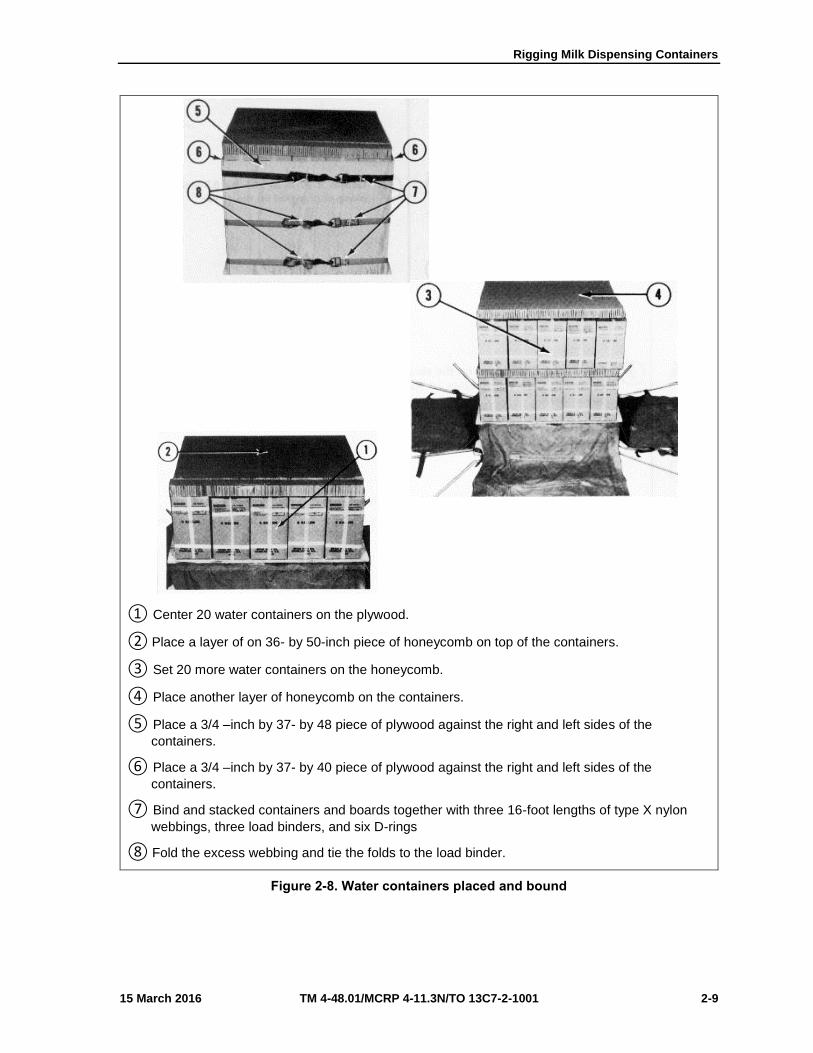
① Center 20 water containers on the plywood.
② Place a layer of on 36- by 50-inch piece of honeycomb on top of the containers.
③ Set 20 more water containers on the honeycomb.
④ Place another layer of honeycomb on the containers.
⑤ Place a 3/4 –inch by 37- by 48 piece of plywood against the right and left sides of the
containers.
⑥ Place a 3/4 –inch by 37- by 40 piece of plywood against the right and left sides of the
containers.
⑦ Bind and stacked containers and boards together with three 16-foot lengths of type X nylon
webbings, three load binders, and six D-rings
⑧ Fold the excess webbing and tie the folds to the load binder.
Figure 2-8. Water containers placed and bound

Chapter 2
2-10 TM 4-48.01/MCRP 4-11.3N/TO 13C7-2-1001 15 March 2016
CLOSING CARGO BAG
2-11. Close the A-21 cargo bag according to the steps in FM 4-20.103/TO 13C7-1-11.
INSTALLING PARACHUTE
2-12. Prepare and stow either one G-12D cargo parachute with a 68-inch pilot parachute according to FM 4-
20.103/TO 13C7-1-11.
RIGGED LOAD DATA
2-13. The rigged load data are listed in figure 2-9
EQUIPMENT REQUIRED
2-14. Equipment required to rig twenty-four 1-quart plastic canteens for free drop is listed in table 1-1.
RIGGED LOAD DATA
Weight 2030 pounds
Width 53½ Inches
Height 65 inches
Length 48 inches
Figure 2-9. Milk dispensing containers rigged in A-22 cargo bag for low velocity airdrop
CAUTION
Make the final rigger inspection required by AR 59-4 (Using DD Form 1748, Joint Airdrop Inspection Record (Platforms), or appropriateDD Form 1748-1, Joint Airdrop Inspection Record (Containers),DD Form 1748-2, Airdrop Malfunction Report (Personnel-Cargo), andDD Form 1748-3, Joint Airdrop Summary Report).

Rigging Milk Dispensing Containers
15 March 2016 TM 4-48.01/MCRP 4-11.3N/TO 13C7-2-1001 2-11
Table 2-2. Equipment required
National Stock Number
Item Quantity
8040-00-273-8713
1670-00-587-3421
1670-00-937-0272
4020-00-240-2146
5365-00-753-3928
1670-00-753-3928
1670-00-216-7297
1670-00-893-2371
5530-00-128-4981
1670-00-883-1654
7510·00-266-5016
7510-00·582-4772
1670-00-937-0271
8305-00-268-2411
8305-00-082-5752
Adhesive, paste, 1-gallon
Bag, cargo. type A-21
Binder, load, 10,000-pound-capacity
Cord, nylon, type III, 550-lbenergy
D-ring, heavy-duty
Pad, Dissipating, honeycomb,
3·by 36·by 96-inch (inch):
4- by 40-inch
6- by 48-inch
36- by 50 -inch
Parachute, pilot, 68-inch diameter
Parachute. cargo, 64-foot, G-12D
Plywood, 3/4- by:
37- by 40-inch
37·by 48-inch
40- by 53-inch
Skid, cargo bag, platform
Tape:
Adhesive, 2-inch
Filament, reinforced, 1·inch
Webbing:
Cotton.80-pound
Nylon, tubular, 1/ 2 –inch
Nylon, type X, 16-foot
As required
1
3
As required
6
5 Sheets
2
12
2
1
1
2
2
1
1
As required
As required
As required
As required
3

This page intentionally left blank.

15 March 2016 TM 4-48.01/MCRP 4-11.3N/TO 13C7-2-1001 3-1
Chapter 3
Rigging 55-Gallon Collapsible Water Drums in an A-22 Cargo Bag for Low-Velocity Airdrop
DESCRIPTION OF LOAD
3-1. The 55-gallon collapsible water drum is a durable, non-vented, cylindrically shaped, rubber container
fitted with a faucet valve. Four drums are rigged in an A-22 cargo bag for low-velocity airdrop. Filled with
50-gallons of water, each drum weighs 465 pounds. Any parts or other information needed on the drums can
be found in TM 10-8110-201-14&P.
PREPARING AND SECURING LOAD
3-2. Prepare and secure the A-22 aerial delivery cargo bag and load items as shown in Figure 3-1 through
3-6 and according to TM 4-48.02/MCRP 4-11.3J/NAVSEA SS400-AB-MMO-010 REV 1/TO 13C7-1-5.

Chapter 3
3-2 TM 4-48.01/MCRP 4-11.3N/TO 13C7-2-1001 15 March 2016
Notes. 1. All measurements are given in inches. 2. This drawing is not drawn to scale.
① Lay out a sling assembly with cover according to FM 4-20.103/MCRP 4-11.3C /TO 13C7-1-11.
② Drill two ½-inch holes in each corner of a ¾- by 48- by 48-inch piece of plywood or skid board.
Place the holes 9 inches from each corner and 3 inches from the edge.
③ Position the plywood inside the cover. Pass a 15-foot length of ½-inch tubular nylon webbing
through the holes in each corner of the plywood.
Figure 3-1. A-22 cargo bag prepared
1 3
2

Rigging 55-Gallon Collapsible Water Drums in an A-22 Cargo Bag for Low-Velocity Airdrop
15 March 2016 TM 4-48.01/MCRP 4-11.3N/TO 13C7-2-1001 3-3
① Center four 55-gallon collapsible water drums on the 48- by 48-inch plywood with the valves
facing into the center.
Figure 3-2. Drums positioned
1

Chapter 3
3-4 TM 4-48.01/MCRP 4-11.3N/TO 13C7-2-1001 15 March 2016
Note. Pad the load binders and D-rings with cellulose wadding.
① Pad the faucet valves with cellulose wadding and tape.
② Pass one 15-foot tie-down lashing around the lower half of the drums, and secure with a load
binder and D-ring.
③ Repeat step 2 for the upper half of the drums.
Figure 3-3. Drums secured together
1
2
3

Rigging 55-Gallon Collapsible Water Drums in an A-22 Cargo Bag for Low-Velocity Airdrop
15 March 2016 TM 4-48.01/MCRP 4-11.3N/TO 13C7-2-1001 3-5
① Center a layer of 48- by 48-inch honeycomb on top of the drums (one piece is 48 by 36 inches
and another is 48 by 12 inches.
② Mark where the valves contact the 48- by 48-inch layer of honeycomb. Cut holes 5 inches
larger than the valves at each mark.
Figure 3-4. Honeycomb positioned
2
1

Chapter 3
3-6 TM 4-48.01/MCRP 4-11.3N/TO 13C7-2-1001 15 March 2016
① Place a second 48- by 48-inch layer of honeycomb on top of the first layer by positioning the
48- by 12-inch piece on the side opposite the same piece of the first layer. Complete thesecond layer by placing the 48- by 36-inch piece next to the 48- by 12-inch piece.
Figure 3-4. Honeycomb positioned (continued)
3

Rigging 55-Gallon Collapsible Water Drums in an A-22 Cargo Bag for Low-Velocity Airdrop
15 March 2016 TM 4-48.01/MCRP 4-11.3N/TO 13C7-2-1001 3-7
① Position a ¾- by 48- by 48-inch piece of plywood or skid board, with holes drilled as described
in Figure 1-1 on top of the 48- by 48-inch layers of honeycomb.
② Secure the two pieces of plywood together by passing the ½-inch tubular nylon from each
corner of the lower piece of plywood to the same corner of the upper piece of plywood. Tie theends together with a surgeon’s knot and a locking know according to TM 4-48.02/MCRP 4-11.3J/NAVSEA SS400-AB-MMO-010 REV 1/TO 13C7-1-5.
Figure 3-5. Plywood and honeycomb secured
2
1
2

Chapter 3
3-8 TM 4-48.01/MCRP 4-11.3N/TO 13C7-2-1001 15 March 2016
① Close the A-22 container (sling assembly and cover) according to FM 4-20.103/MCRP 4-
11.3C/TO 13C7-1-11.
② Attach the suspension webs to the A-22 container according to FM 4-20.103/MCRP 4-
11.3C/TO 13C7-1-11 (not shown).
Figure 3-6. A-22 container closed
1

Rigging 55-Gallon Collapsible Water Drums in an A-22 Cargo Bag for Low-Velocity Airdrop
15 March 2016 TM 4-48.01/MCRP 4-11.3N/TO 13C7-2-1001 3-9
PREPARING SKID BOARD
3-3. Prepare a skid board according to FM 4-20.103/MCRP 4-11.3C/TO 13C7-1-11.
3-4. Building and Positioning Honeycomb on Skid Board
3-5. Build the honeycomb as shown in Figure 3-7. Position the honeycomb on the skid board according to
FM 4-20.103/MCRP 4-11.3C/TO 13C7-1-11.
Note. The honeycomb stack should be glued together. It is not required to glue the stack to the skid board.
① Cut a 44- by 36-inch and a 44- by 8-inch piece of honeycomb to form the 44- by 44-inch bottom
layer.
② Cut four 44- by 8-inch pieces of honeycomb. Place one piece on each end, flush with the
edges of the bottom (first) layer. Evenly space the other two pieces between the end pieces toform the second layer.
③ Cut three 44- by 11-inch pieces of honeycomb. Place one piece on each end, flush with the
edges, but running in the opposite direction of the second layer. Center the third piecebetween the end pieces to form the third layer.
④ Cut a 44- by 36-inch and a 44- by 8-inch piece of honeycomb to form the 44- by 44-inch top
(fourth) layer.
Figure 3-7. Building honeycomb layers
2
4
1
3

Chapter 3
3-10 TM 4-48.01/MCRP 4-11.3N/TO 13C7-2-1001 15 March 2016
SECURING SKID BOARD TO THE A-22 CARGO BAG
3-6. Secure the skid board to the container according to FM 4-20.103/MCRP 4-11.3C/TO 13C7-1-11.
INSTALLING PARACHUTE
3-7. Attach and secure the parachute according to FM 4-20.103/MCRP 4-11.3C/TO 13C7-1-11.

Rigging 55-Gallon Collapsible Water Drums in an A-22 Cargo Bag for Low-Velocity Airdrop
15 March 2016 TM 4-48.01/MCRP 4-11.3N/TO 13C7-2-1001 3-11
MARKING RIGGED LOAD
3-8. Mark the rigged load according to FM 4-20.103/MCRP 4-11.3C/TO 13C7-1-11, and as shown in Figure
3-8. Comply with the Shipper's requirements for Declaration of Dangerous/Hazardous Goods in accordance
with AFMAN 24-204/TM 38-250/ NAVSUP PUB 505; MCO P4030.19I; DLAI 4145.3 DCMAD1, CH3.4
(HM24). If the load varies from the one shown, the weight, height, CB, and parachute requirements must be
recomputed.
EQUIPMENT REQUIRED
3-9. Use the equipment listed in the Table in FM 4-20.103/MCRP 4-11.3C/TO 13C7-1-11 (rigging an A-22
container load for low-velocity airdrop) to rig four 55-gallon collapsible water drums in an A-22 cargo bag
for low-velocity airdrop.
Rigged load data must be verified.
NOT SHOWN PHOTO NOT AVAILABLE
RIGGED LOAD DATA
Weight………….………………………………..………..………..1,980 pounds Height…………………………………………………………………..52 inches Length…………………………………………………………..……..48 inches Width…………………………………………………………………...48 inches Center of Balance………………………………………………….…24 inches
Figure 3-8. Four 55-gallon collapsible water drums in an A-22 container rigged for low-velocity airdrop
CAUTION
Make the final rigger inspection required by AR 59-4 (Using DD Form 1748-1, Joint Airdrop Inspection Record (Containers), or appropriateDD Form 1748, Joint Airdrop Inspection Record (Platforms),DD Form 1748-2, Airdrop Malfunction Report (Personnel-Cargo), andDD Form 1748-3, Joint Airdrop Summary Report).

This page intentionally left blank.

15 March 2016 TM 4-48.01/MCRP 4-11.3N/TO 13C7-2-1001 4-1
Chapter 4
Rigging 55-Gallon Collapsible Water Drum in Four A-22 Cargo Bags on an 8-Foot, Type V platform for Low-Velocity
Airdrop
DESCRIPTION OF LOAD
4-1. The 55-gallon collapsible water drum is a durable, non-vented, cylindrically shaped rubber container
fitted with a faucet valve. Four drums are rigged in an A-22 cargo bag, and four A-22 containers are rigged
on an 8-foot, type V platform for low-velocity airdrop. Filled with 50 gallons of water, each drum weighs
465 pounds. Any parts or other information needed on the drums can be found in TM 10-8110-201-14 & P.
RIGGING PROCEDURES
4-2. If A-22 containers with 55-gallon collapsible water drums are to be rigged on an 8-foot, type V
platform, rig four A-22 cargo bags according to paragraphs 1-2 and 1-7. Do NOT add the 48-by48-inch skid
boards, the four layers of honeycomb, and the G-12 parachutes. Rig the platform load according to TM 4-
48.12/MCRP 4-11.3K/TO 13C7-1-8 using the procedures for rigging bulk supplies in A-22 cargo bags on an
8-foot type V platform.

This page intentionally left blank.

15 March 2016 TM 4-48.01/MCRP 4-11.3N/TO 13C7-2-1001 5-1
Chapter 5
Rigging Three 250-Gallon Collapsible Water Drums on an 8-Ft, Type V platform for Low-Velocity Airdrop
DESCRIPTION OF LOAD
5-1. Three drums are rigged on an 8-foot, type V platform with two G-11B cargo parachutes. Filled with
240 gallons of potable water, each drum weighs 2,197 pounds and is 60 inches long and 40 inches in diameter.
Each drum weighs 205 pounds when empty. Any parts or other information needed on the drums can be
found in TM 10-8110-201-14 & P.

Chapter 5
5-2 TM 4-48.01/MCRP 4-11.3N/TO 13C7-2-1001 15 March 2016
PREPARING PLATFORM
5-2. Three drums are rigged on an 8-foot, type V platform with two G-11B cargo parachutes. Filled with
240 gallons of potable water, each drum weighs 2,197 pounds and is 60 inches long and 40 inches in diameter.
Each drum weighs 205 pounds when empty. Any parts or other information needed on the drums can be
found in TM 10-8110-201-14 & P. Figure 5-1 displays platform preparation requirements.
Note. 1. The nose bumper may or may not be installed. 2. Measurements are given in this section are from the front edge of the platform, NOT from the front edge of the
nose bumper.
Step:
1. Inspect, or assemble and inspect, the platform according to TM 10-1670-268-20&P/TO13C7-52-22.
2. Install a tandem link on the front of each platform side rail using holes 1, 2, and 3.
3. Install a tandem link on the rear of each platform side rail using holes 14, 15, and 16.
4. Install a tie-down clevis on bushings 1, 2, 3, and 4 on each front tandem link.
5. Starting at the front of each platform side rail, install a tie-down clevis to the bushings boltedto holes 4, 5, 6, 11, 12, and 13.
6. Install a tie-down clevis to bushings 1, 2, 3, and 4 on each rear tandem link.
7. Starting at the front of the platform, number the clevises bolted to the right side from 1through 14 and those bolted to the left side from 1A through 14A.
8. Label the tie-down rings according to TM 4-48.02/MCRP 4-11.3J/NAVSEA SS400-AB-MMO-010 REV 1/TO 13C7-1-5.
Figure 5-1. Platform prepared
CLEVISES 14A THROUGH 1A
CLEVISES14 THROUGH 1
RIGHT
FRONT
LEFT
REAR

Rigging Three 250-Gallon Collapsible Water Drums on an 8-Ft, Type V platform for Low-Velocity Airdrop
15 March 2016 TM 4-48.01/MCRP 4-11.3N/TO 13C7-2-1001 5-3
PREPARING AND POSITIONING HONEYCOMB
5-3. Prepare and position the honeycomb on the platform as shown in Figure 5-2.
① Cut two 72- by 36-inch pieces of honeycomb. Center stack 1 flush with the front edge of the
platform.
② Cut two 72- by 24-inch pieces of honeycomb. Center stack 2 flush with the rear edge of stack
1.
③ Cut two 72- by 36-inch pieces of honeycomb. Center stack 3 flush with the rear edge of the
platform.
Figure 5-2. Honeycomb placed on platform
2 1 3 FRONT
REAR
STACK 3 STACK 2 STACK 1

Chapter 5
5-4 TM 4-48.01/MCRP 4-11.3N/TO 13C7-2-1001 15 March 2016
INSTALLING LIFTING SLINGS
5-4. Install the lifting slings to each drum using two 3-foot (2-loop) and two 9-feet (2-loop), type XXVI
nylon webbing slings.
POSITIONING AND LASHING DRUMS
5-5. Position and lash the drums as shown in Figures 5-3.
POSITIONING DRUMS
5-6. Position the drums on the platform as shown in Figures 5-3 and 5-4.
LASHING DRUMS TOGETHER
5-7. Lash the drums together as shown in Figure 5-3.
① Center a drum on the front pieces of honeycomb.
② Center a drum on the rear pieces of honeycomb.
Note. Remove all lifting slings.
③ Bolt a load tie-down clevis to the bottom shackle of each drum.
④ Lash the two drums together with a 15-foot tie-down assembly on each side. Pass the lashing
through the inside shackles of the drums on each side.
Figure 5-3. Drums positioned and lashed together
1 2 4
3
FRONT REAR
RIGHT

Rigging Three 250-Gallon Collapsible Water Drums on an 8-Ft, Type V platform for Low-Velocity Airdrop
15 March 2016 TM 4-48.01/MCRP 4-11.3N/TO 13C7-2-1001 5-5
① Pass a 15-foot tie-down assembly through clevis 1 and then through the right front shackle of
the front drum.
② Pass a 15-foot tie-down assembly through clevis 1A and then through the left front shackle of
the front drum (not shown).
③ Pass a 15-foot tie-down assembly through clevis 14 and then through the right rear shackle of
the rear drum.
④ Pass a 15-foot tie-down assembly through clevis 14A and then through the left rear shackle of
the rear drum (not shown).
⑤ Center a drum on top of the first two drums, and remove slings.
Note. Make sure the shackles on the drums are parallel to the platform before installing.
Figure 5-4. Center drum positioned
3
5
1 REAR
FRONT
RIGHT

Chapter 5
5-6 TM 4-48.01/MCRP 4-11.3N/TO 13C7-2-1001 15 March 2016
LASHING DRUMS TO THE PLATFORM
5-8. Use twenty-eight 15-foot tie-down assemblies to lash the drums to the platform as shown in Figures 5-
5, through Figure 5-7 according to TM 4-48.02/MCRP 4-11.3J/NAVSEA SS400-AB-MMO-010 REV 1/TO
13C7-1-5.
Lashing Number Clevis Number Instructions
Pass lashing:
1 and 2 5 and 5A Through the bottom of the clevis of the front drum.
3 and 4 10 and 10A Through the bottom clevis of the rear drum.
*5 and 6 1 and 1A Through the front shackle of the front drum.
*7 and 8 14 and 14A Through the rear shackle of the rear drum.
*Lashings were previously installed.
Figure 5-5. Lashings 1 through 8 installed
7
3 1
REAR FRONT
5
5 10
1 14

Rigging Three 250-Gallon Collapsible Water Drums on an 8-Ft, Type V platform for Low-Velocity Airdrop
15 March 2016 TM 4-48.01/MCRP 4-11.3N/TO 13C7-2-1001 5-7
Lashing Number
Clevis Number Instructions
Pass lashing:
9 and 10 2 and 2A Through the front shackle of the front drum.
11 and 12 8 and 8A Through the rear shackle of the front drum.
13 and 14 9 and 9A Through the rear shackle of the front drum.
15 and 16 6 and 6A Through the front shackle of the rear drum.
17 and 18 7 and 7A Through the front shackle of the rear drum.
19 and 20 13 and 13A Through the rear shackle of the rear drum.
Figure 5-6. Lashings 9 through installed
13 17
9 19
REAR
FRONT
11 15
9 8 2
7
13
6

Chapter 5
5-8 TM 4-48.01/MCRP 4-11.3N/TO 13C7-2-1001 15 March 2016
Note. Secure the ends of the lashings with D-rings and load binders according to TM 4-48.02/MCRP 4-11.3J/NAVSEA SS400-AB-MMO-010 REV 1/TO 13C7-1-5.
Lashing Number
Clevis Number
Instructions
21 and 22
23 and 24
25 and 26
27 and 28
3 and 3A
4 and 4A
11 and 11A
12 and 12A
Pass lashing:
Through the front shackle of the center drum.
Through the front shackle of the center drum.
Through the rear shackle of the center drum.
Through the rear shackle of the center drum.
Figure 5-7. Lashings 21 through 28 installed
REAR FRONT 27 25 23 21
12 11 4 3

Rigging Three 250-Gallon Collapsible Water Drums on an 8-Ft, Type V platform for Low-Velocity Airdrop
15 March 2016 TM 4-48.01/MCRP 4-11.3N/TO 13C7-2-1001 5-9
INSTALLING AND SAFETYING SUSPENSION SLINGS
5-9. Install four large suspension clevises and four 12-foot (2-loop), type XXVI nylon webbing slings to
the tandem links as shown in Figure 5-8.
① Bolt a 12-foot sling to each tandem link using a large suspension clevis
② Raise the suspension slings to their full length using a lifting provision (not shown).
③ Safety the slings with a dead man’s tie according to TM 4-48.02/MCRP 4-11.3J/NAVSEA
SS400-AB-MMO-010 REV 1/TO 13C7-1-5.
Figure 5-8. Suspension slings installed
1
3

Chapter 5
5-10 TM 4-48.01/MCRP 4-11.3N/TO 13C7-2-1001 15 March 2016
STOWING CARGO PARACHUTES
5-10. Prepare, place, and restrain two G-11B cargo parachutes according to TM 4-48.02/MCRP 4-
11.3J/NAVSEA SS400-AB-MMO-010 REV 1/TO 13C7-1-5 and as shown in Figures 5-9 and 5-10.
① Place the cargo parachutes on top of the rear drum.
NOTICE OF EXCEPTION
As an exception to TM 4-48.02/MCRP 4-11.3J/NAVSEA SS400-AB-MMO-010 REV 1/TO 13C7-1-5 parachute restraint system, two
restraints will be on this load.
② Restrain the parachutes according to TM 4-48.02/MCRP 4-11.3J/NAVSEA SS400-AB-MMO-010
REV 1/TO 13C7-1-5 using two lengths of type VIII nylon webbing. Attach one length of webbingto clevises 4 and 4A.
③ Attach the second length of webbing as shown above and according to TM 4-48.02/MCRP 4-
11.3J/NAVSEA SS400-AB-MMO-010 REV 1/TO 13C7-1-5 to bushings 9 and 9A.
Figure 5-9. Parachute restraint straps installed
REAR FRONT
3
2
1
4 9
Rigging Three 250-Gallon Collapsible Water Drums on an 8-Ft, Type V platform for Low-Velocity Airdrop
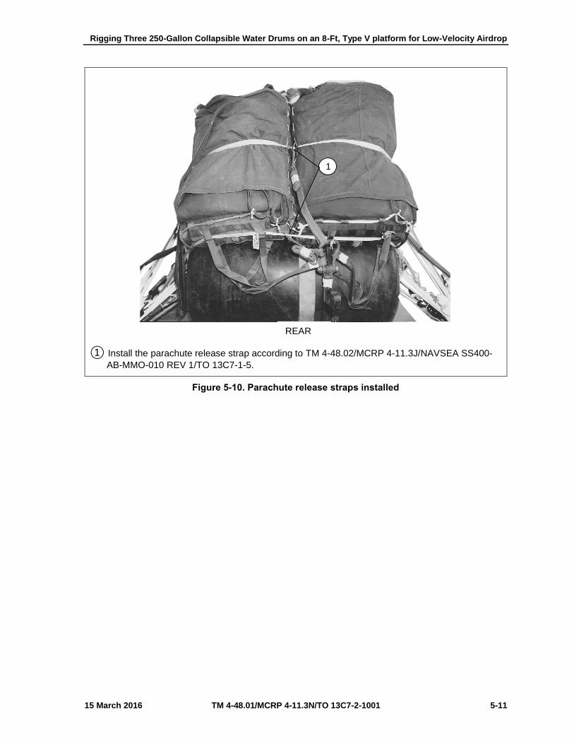
15 March 2016 TM 4-48.01/MCRP 4-11.3N/TO 13C7-2-1001 5-11
① Install the parachute release strap according to TM 4-48.02/MCRP 4-11.3J/NAVSEA SS400-
AB-MMO-010 REV 1/TO 13C7-1-5.
Figure 5-10. Parachute release straps installed
1
REAR

Chapter 5
5-12 TM 4-48.01/MCRP 4-11.3N/TO 13C7-2-1001 15 March 2016
INSTALLING PARACHUTE RELEASE SYSTEM
5-11. Prepare and attach an M-1 cargo parachute release according to TM 4-48.02/MCRP 4-11.3J/NAVSEA
SS400-AB-MMO-010 REV 1/TO 13C7-1-5 and as shown in Figure 5-11.
① Place the M-1 cargo parachute release on top of the drum as shown, and attach it according to
TM 4-48.02/MCRP 4-11.3J/NAVSEA SS400-AB-MMO-010 REV 1/TO 13C7-1-5. S-fold andtape or tie the slings with type I, ¼-inch cotton webbing.
② Secure the M-1 cargo parachute release according to TM 4-48.02/MCRP 4-11.3J/NAVSEA
SS400-AB-MMO-010 REV 1/TO 13C7-1-5 with a length of type III nylon cord.
Figure 5-11. Parachute release attached
1
2
REAR

Rigging Three 250-Gallon Collapsible Water Drums on an 8-Ft, Type V platform for Low-Velocity Airdrop
15 March 2016 TM 4-48.01/MCRP 4-11.3N/TO 13C7-2-1001 5-13
INSTALLING EXTRACTION SYSTEM
5-12. Install the extraction force transfer coupling system according to TM 4-48.02/MCRP 4-
11.3J/NAVSEA SS400-AB-MMO-010 REV 1/TO 13C7-1-5 and as shown in Figures 5-12a and 5-12b.
① Install the actuator mounting brackets to the front extraction force transfer coupling system
mounting holes on the left platform side rail.
② Install a 12-foot cable to the actuator assembly.
③ Attach the actuator assembly to the mounting brackets.
Figure 5-12a. Extraction force transfer coupling system installed
REAR FRONT 3
LEFT
2 1

Chapter 5
5-14 TM 4-48.01/MCRP 4-11.3N/TO 13C7-2-1001 15 March 2016
① Secure the cable to the inside of the lashings and tie-down ring D4 with type I, ¼-inch cotton
webbing.
② Use a 9-foot (2-loop), type XXVI nylon webbing sling for the deployment line. S-fold the excess
line, and tie with type I, ¼-inch cotton webbing.
Figure 5-12b. Extraction force coupling system installed (continued)
4 5
D4
REAR

Rigging Three 250-Gallon Collapsible Water Drums on an 8-Ft, Type V platform for Low-Velocity Airdrop
15 March 2016 TM 4-48.01/MCRP 4-11.3N/TO 13C7-2-1001 5-15
PLACING EXTRACTION PARACHUTE
5-13. Place the extraction parachute as described below.
C-130 AIRCRAFT. Place a 22-foot cargo extraction parachute and a 60-foot (3-loop), type xxvi
nylon webbing extraction line on the load for installation in the aircraft.
C-17 AIRCRAFT. Place a 22-foot cargo extraction parachute and a 140-foot (3-loop), type XXVI
nylon webbing extraction line on the load for installation in the aircraft.
CAUTION
The extraction line will be a continuous 140-foot (3-loop), type XXVI nylon webbing extraction line. Shorter lines will not be used to form the 140-foot extraction line.
Note. Sling/extraction line bags must be used.
MARKING RIGGED LOAD
5-14. Mark the rigged load according to FM4-20.102/MCRP 4-11.3J/NAVSEA SS400-AB-MMO-010 REV
1/TO 13C7-1-5, and as shown in Figure 5-13. Comply with the Shipper's requirements for Declaration of
Dangerous/Hazardous Goods in accordance with AFMAN 24-204/TM 38-250/ NAVSUP PUB 505; MCO
P4030.19I; DLAI 4145.3 DCMAD1, CH3.4 (HM24). If the load varies from the one shown, the weight,
height, CB, and parachute requirements must be recomputed.

Chapter 5
5-16 TM 4-48.01/MCRP 4-11.3N/TO 13C7-2-1001 15 March 2016
RIGGED LOAD DATA
Weigh
t
Load shown……………….. 8,300 pounds
Maximum Load Allowed…. 9,000 pounds
Height ……………………………….
77 inches
Width ……………………………….
108 inches
Overhang: Front…………………………
None
Rear………………………….
None
Center of balance ……………………………….
50 inches
Figure 5-13. Three 250-gallon water drums rigged on an 8-foot, type V platform for low-velocity airdrop
FRONT REAR
Center of balance
CAUTION
Make the final rigger inspection required by AR 59-4 (Using DD Form 1748, Joint Airdrop Inspection Record (Platforms), or appropriateDD Form 1748-1, Joint Airdrop Inspection Record (Containers),DD Form 1748-2, Airdrop Malfunction Report (Personnel-Cargo), andDD Form 1748-3, Joint Airdrop Summary Report).

Rigging Three 250-Gallon Collapsible Water Drums on an 8-Ft, Type V platform for Low-Velocity Airdrop
15 March 2016 TM 4-48.01/MCRP 4-11.3N/TO 13C7-2-1001 5-17
EQUIPMENT REQUIRED
5-15. Use the equipment listed in Table 5-1 to rig this load.
Table 5-1. Equipment required for rigging three 250-gallon water drums for low-velocity airdrop on a 8-foot, type V platform
National Stock Number
Item Quantity
040-00-273-8713
4030-00-678-8562
4030-00-090-5354
4020-00-240-2146
1670-00-434-5783
1670-00-360-0328
1670-00-360-0329
8135-00-664-6958
5306-00-435-8994
5310-00-232-5165
1670-00-003-1953
5365-00-007-3414
1670-00-783-5988
1670-00-753-3928
1670-01-016-7841
1670-01-063-3716
Adhesive, Paste, 1-gallon
Clevis, Suspension:
¾-inch (Medium)
1-inch (Large)
Cord, Nylon, Type III, 550-pound
Coupling:
Airdrop, Extraction Force Transfer with cable:
12-feet
Cover:
Clevis, Large
Link Assembly, Type IV
Cushioning Material, Packaging, Cellulose Wadding
Link Assembly:
Two Point:
Bolt, 1-inch diameter, 4-inch long
Nut, 1-inch
w/Plate, Side, 3 ¾-inch
Spacer, Large
Type IV
Pad, Energy-Dissipating, Honeycomb
3- by 36- by 96-inch:
24- by 72-inch
36- by 72-inch
Parachute:
Cargo:
G-11B
Cargo Extraction:
22-feet
Platform, Air drop, Type V, 8-feet
As Required
2
5
As Required
1
2
1
As Required
(2)
(2)
(2)
(2)
1
6
(2)
(4)
2
1

Chapter 5
5-18 TM 4-48.01/MCRP 4-11.3N/TO 13C7-2-1001 15 March 2016
Table 5-1. Equipment required for rigging three 250-gallon water drums for low-velocity airdrop on a 8-foot, type V platform (continued)
National Stock Number
Item Quantity
1670-01-162-2375
1670-01-162-2374
1670-01-162-2372
1670-01-162-2376
1670-01-162-2381
1670-01-097-8816
1670-01-062-6304
1670-01-062-6313
1670-01-107-7651
1670-01-062-6301
1670-01-062-6304
1670-01-062-6303
1670-01-062-6302
1670-01-998-0116
7510-00-266-6710
1670-00-937-0271
8305-00-268-2411
8305-00-082-5752
8305-00-268-2453
8305-00-263-3591
Bracket:
Inside Extraction Force Transfer Coupling (EFTC)
Outside EFTC
Clevis Assembly (Type V)
Extraction Bracket Assembly
Tandem Link (Multi-purpose)
Release, Cargo Parachute:
M-1
Sling, Cargo Airdrop:
For Deployment Line:
9-foot (2-loop), Type XXVI Nylon Webbing
For Extraction:
60-foot (3-loop), type XXVI Nylon Webbing
(Use with 22-foot parachute for C-130)
140-foot (3-loop), Type XXVI Nylon Webbing
(Use with 22-foot parachute for C-17)
For Lifting and for Suspension:
3-foot (2-loop), Type XXVI Nylon Webbing
9-foot (2-loop), Type XXVI Nylon Webbing
12-foot (2-loop), Type XXVI Nylon Webbing
For Riser Extensions:
20-foot (2-loop), Type XXVI Nylon Webbing
Strap, Multi-Knife Parachute Release
Tape, Adhesive, pressure sensitive adhesive, Cloth Back, 2-inch
Tape, Masking
Tie-Down Assembly, 15-foot
Webbing:
Cotton, ¼-inch, Type I
Nylon:
Tubular:
½-inch, Natural
½-inch, Olive Drab
Type VIII
1
(1)
(1)
(32)
(1)
(4)
1
1
1
1
2
2
4
2
2
As Required
As Required
30
As Required
As Required
As Required
As Required

15 March 2016 TM 4-48.01/MCRP 4-11.3N/TO 13C7-2-1001 6-1
Chapter 6
Rigging Three 250-Gallon Collapsible Water Drums on a 12-Ft, Type V platform for Low-Velocity Airdrop
DESCRIPTION OF LOAD
6-1. Three drums are rigged on a 12-foot, type V platform with two G-11B cargo parachutes. Filled with
240 gallons of potable water, each drum weighs 2,197 pounds and is 60 inches long and 40 inches in diameter.
Each drum weighs 205 pounds when empty. Any parts or other information needed on the drums can be
found in TM 10-8110-201-14&P.
PREPARING PLATFORM
6-2. Prepare a 12-foot, type V platform using four tandem links and 24 clevises as shown in Figure 6-1.
Step: 1. Inspect, or assemble and inspect, the platform according to TM 10-1670-268-20&P/TO 13C7-
52-22.
2. Install a tandem link on the front of each platform side rail using holes 1, 2, and 3.
3. Install a tandem link on the rear of each platform side rail using holes 22, 23, and 24.
4. Install a tie-down clevis on bushings 1 and 2 on each front tandem link.
5. Starting at the front of each platform side rail, install a tie-down clevis to the bushings bolted to holes 5, 6, 10, 11, 14, 15, 19, and 20.
6. Install a tie-down clevis to bushings 3 and 4 on each rear tandem link.
7. Starting at the front of the platform, number the clevises bolted to the right side from 1 through 12 and those bolted to the left side from 1A through 12A.
8. Label the tie-down rings according to TM 4-48.02/MCRP 4-11.3J/NAVSEA SS400-AB-MMO-010 REV 1/TO 13C7-1-5.
Figure 6-1. Platform prepared
CLEVISES12 THROUGH 1
FRONT
CLEVISES 12A THROUGH 1A
REAR
LEFT
RIGHT

Chapter 6
6-2 TM 4-48.01/MCRP 4-11.3N/TO 13C7-2-1001 15 March 2016
PREPARING AND POSITIONING HONEYCOMB
6-3. Prepare and position the honeycomb on the platform as shown in Figure 6-2.
① Cut two 72- by 36-inch pieces of honeycomb for stack 1. Center the stack 11 inches from the
front edge of the platform.
② Cut two 72- by 36-inch pieces of honeycomb for stack 2. Center the stack 7 inches from stack
1.
③ Cut two 72- by 36-inch pieces of honeycomb for stack 3. Center the stack 11 inches from the
rear edge of the platform.
Figure 6-2. Honeycomb prepared and positioned
FRONT REAR
STACK 3 STACK 2 STACK 1
2 3 1

Rigging Three 250-Gallon Collapsible Water Drums on a 12-Ft, Type V platform for Low-Velocity Airdrop
15 March 2016 TM 4-48.01/MCRP 4-11.3N/TO 13C7-2-1001 6-3
INSTALLING LIFTING SLINGS
6-4. Install the lifting slings to each drum using two 3-foot (2-loop) and two 9-foot (2-loop), type XXVI
nylon webbing slings as shown in Figure 6-3.
POSITIONING AND LASHING DRUMS TOGETHER
6-5. Position and lash the drums as described below.
POSITIONING DRUMS
6-6. Position the drums on the platform as shown in Figure 6-3.
LASHING DRUMS TOGETHER
6-7. Lash the drums together as shown in Figure 6-3.
① Center a drum on honeycomb stack 2, and remove the slings.
② Center a drum on honeycomb stack 1.
③ Center a drum on honeycomb stack 3.
Note. Make sure the shackles on the drums are parallel to the platform before installing the lashings.
④ Lash the three drums together with four 15-foot tie-down assemblies. Pass the lashings
through the inboard shackles of the outside drums and the shackles of the center drum.
Figure 6-3. Drums positioned and lashed together
3 1
4
2

Chapter 6
6-4 TM 4-48.01/MCRP 4-11.3N/TO 13C7-2-1001 15 March 2016
LASHING DRUMS TO THE PLATFORM
6-8. Use twenty-four 15-foot tie-down assemblies to lash the drums to the platform as shown in Figures 6-
4 and 6-5 and according to TM 4-48.02/MCRP 4-11.3J/NAVSEA SS400-AB-MMO-010 REV 1/TO 13C7-
1-5.
Lashing Number Clevis Number Instructions
1 and 2
3 and 4
5 and 6
7 and 8
9 and 10
11 and 12
1 and 1A
2 and 2A
5 and 5A
6 and 6A
3 and 3A
4 and 4A
Pass lashing:
FIRST DRUM
Through the front shackle of the first drum.
Through the front shackle of the first drum.
Through the rear shackle of the first drum.
Through the rear shackle of the first drum.
SECOND DRUM
Through the front shackle of the second drum.
Through the front shackle of the second drum.
Figure 6-4. Lashings 1 through 12 installed
REAR
3 2 1
4 5 6
7 5 11
9
3 1
FRONT
Rigging Three 250-Gallon Collapsible Water Drums on a 12-Ft, Type V platform for Low-Velocity Airdrop
15 March 2016 TM 4-48.01/MCRP 4-11.3N/TO 13C7-2-1001 6-5
Lashing Number Clevis Number Instructions
13 and 14
15 and 16
17 and 18
19 and 20
21 and 22
23 and 24
9 and 9A
10 and 10A
7 and 7A
8 and 8A
11 and 11A
12 and 12A
Pass Lashing:
SECOND DRUM (Continued)
Through the rear shackle of the second drum.
Through the rear shackle of the second drum.
THIRD DRUM
Through the front shackle of the third drum.
Through the front shackle of the third drum.
Through the rear shackle of the third drum.
Through the rear shackle of the third drum.
Figure 6-5. Lashings 13 through 24 installed
REAR
11
10 9 8 7
12
19 13
11 15
23
FRONT
21
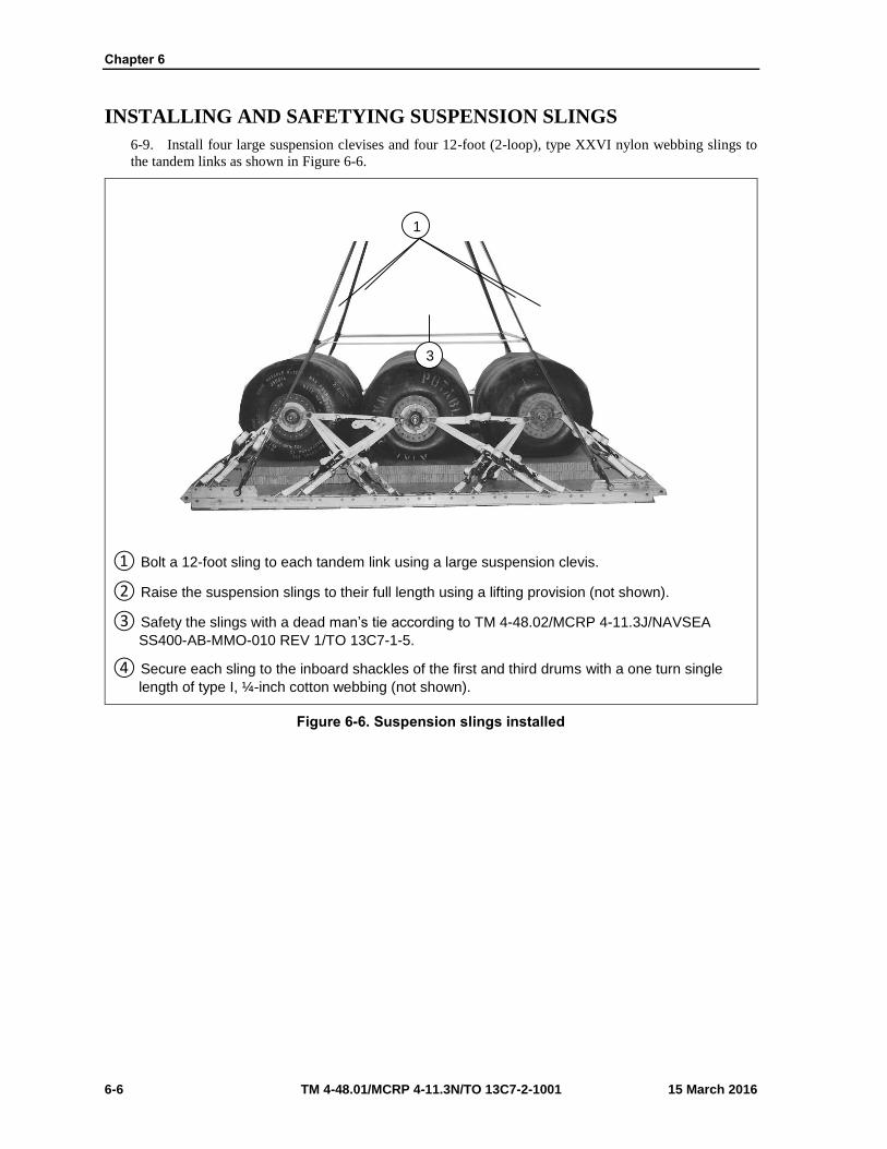
Chapter 6
6-6 TM 4-48.01/MCRP 4-11.3N/TO 13C7-2-1001 15 March 2016
INSTALLING AND SAFETYING SUSPENSION SLINGS
6-9. Install four large suspension clevises and four 12-foot (2-loop), type XXVI nylon webbing slings to
the tandem links as shown in Figure 6-6.
① Bolt a 12-foot sling to each tandem link using a large suspension clevis.
② Raise the suspension slings to their full length using a lifting provision (not shown).
③ Safety the slings with a dead man’s tie according to TM 4-48.02/MCRP 4-11.3J/NAVSEA
SS400-AB-MMO-010 REV 1/TO 13C7-1-5.
④ Secure each sling to the inboard shackles of the first and third drums with a one turn single
length of type I, ¼-inch cotton webbing (not shown).
Figure 6-6. Suspension slings installed
1
3
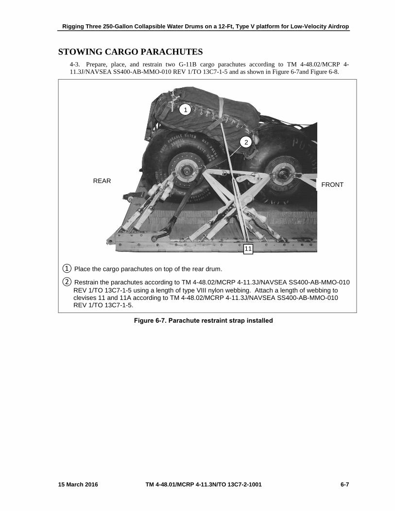
Rigging Three 250-Gallon Collapsible Water Drums on a 12-Ft, Type V platform for Low-Velocity Airdrop
15 March 2016 TM 4-48.01/MCRP 4-11.3N/TO 13C7-2-1001 6-7
STOWING CARGO PARACHUTES
4-3. Prepare, place, and restrain two G-11B cargo parachutes according to TM 4-48.02/MCRP 4-
11.3J/NAVSEA SS400-AB-MMO-010 REV 1/TO 13C7-1-5 and as shown in Figure 6-7and Figure 6-8.
① Place the cargo parachutes on top of the rear drum.
② Restrain the parachutes according to TM 4-48.02/MCRP 4-11.3J/NAVSEA SS400-AB-MMO-010
REV 1/TO 13C7-1-5 using a length of type VIII nylon webbing. Attach a length of webbing toclevises 11 and 11A according to TM 4-48.02/MCRP 4-11.3J/NAVSEA SS400-AB-MMO-010REV 1/TO 13C7-1-5.
Figure 6-7. Parachute restraint strap installed
REAR FRONT
11
1
2

Chapter 6
6-8 TM 4-48.01/MCRP 4-11.3N/TO 13C7-2-1001 15 March 2016
① Install a parachute release strap according to TM 4-48.02/MCRP 4-11.3J/NAVSEA SS400-AB-
MMO-010 REV 1/TO 13C7-1-5.
Figure 6-8. Parachute release strap installed
1
REAR

Rigging Three 250-Gallon Collapsible Water Drums on a 12-Ft, Type V platform for Low-Velocity Airdrop
15 March 2016 TM 4-48.01/MCRP 4-11.3N/TO 13C7-2-1001 6-9
INSTALLING PARACHUTE RELEASE SYSTEM
6-10. Prepare and attach an M-1 cargo parachute release according to TM 4-48.02/MCRP 4-11.3J/NAVSEA
SS400-AB-MMO-010 REV 1/TO 13C7-1-5 and as shown in Figure 6-9.
① Place the M-1 cargo parachute release on top of the drum as shown, and attach it according to
TM 4-48.02/MCRP 4-11.3J/NAVSEA SS400-AB-MMO-010 REV 1/TO 13C7-1-5. S-fold and tapeor tie the slings with type I, ¼-inch cotton webbing.
② Secure the M-1 cargo parachute release according to TM 4-48.02/MCRP 4-11.3J/NAVSEA
SS400-AB-MMO-010 REV 1/TO 13C7-1-5 with a length of type III nylon cord.
Figure 6-9. Parachute release attached
1
2

Chapter 6
6-10 TM 4-48.01/MCRP 4-11.3N/TO 13C7-2-1001 15 March 2016
INSTALLING EXTRACTION SYSTEM
6-11. Install the extraction force transfer coupling system according to TM 4-48.02/MCRP 4-
11.3J/NAVSEA SS400-AB-MMO-010 REV 1/TO 13C7-1-5 and as shown in Figures 6-10a and 6-10b.
① Install the components of the extraction force transfer coupling system according to TM 4-
48.02/MCRP 4-11.3J/NAVSEA SS400-AB-MMO-010 REV 1/TO 13C7-1-5. Use the frontmounting holes on the left side of the platform for the extraction force transfer coupling systembrackets.
② Install a 12-foot extraction force transfer coupling system cable according to TM 4-48.02/MCRP
4-11.3J/NAVSEA SS400-AB-MMO-010 REV 1/TO 13C7-1-5 and safety the cable to convenientplaces on the platform with one turn of type I, ¼-inch cotton webbing.
Figure 6-10a. Extraction force transfer coupling system installed
FRONT REAR
1
LEFT 2

Rigging Three 250-Gallon Collapsible Water Drums on a 12-Ft, Type V platform for Low-Velocity Airdrop
15 March 2016 TM 4-48.01/MCRP 4-11.3N/TO 13C7-2-1001 6-11
① Secure the cable to tie-down ring D6 with type I, ¼-inch cotton webbing.
② Attach a 9-foot (2-loop) type XXVI nylon sling according to TM 4-48.02/MCRP 4-
11.3J/NAVSEA SS400-AB-MMO-010 REV 1/TO 13C7-1-5 to be used as a deployment line. S-fold the excess and tie it in two places with type I, ¼-inch cotton webbing
Figure 6-10b. Extraction force transfer coupling system installed (continued)
3
4
REAR
D6

Chapter 6
6-12 TM 4-48.01/MCRP 4-11.3N/TO 13C7-2-1001 15 March 2016
PLACING EXTRACTION PARACHUTE
6-12. Place the extraction parachute as described below.
C-130 AIRCRAFT
6-13. Place a 22-foot cargo extraction parachute and a 60-foot (3-loop), type XXVI nylon webbing extraction
line on the load for installation in the aircraft.
C-17 AIRCRAFT
6-14. Place a 22-foot cargo extraction parachute and a 140-foot (3-loop), type XXVI nylon webbing
extraction line on the load for installation in the aircraft.
CAUTION
The extraction line will be a continuous 140-foot (3-loop), type XXVI nylon webbing extraction line. Shorter lines will not be used to form the 140-foot extraction line.
Note: Sling/extraction line bags must be used.
MARKING RIGGED LOAD
6-15. Mark the rigged load according to FM 4-20.102/MCRP 4-11.3J/NAVSEA SS400-AB-MMO-010 REV
1/TO 13C7-1-5, and as shown in Figure 6-11. Comply with the Shipper's requirements for Declaration of
Dangerous/Hazardous Goods in accordance with AFMAN 24-204/TM 38-250/ NAVSUP PUB 505; MCO
P4030.19I; DLAI 4145.3 DCMAD1, CH3.4 (HM24). If the load varies from the one shown, the weight,
height, CB, and parachute requirements must be recomputed.

Rigging Three 250-Gallon Collapsible Water Drums on a 12-Ft, Type V platform for Low-Velocity Airdrop
15 March 2016 TM 4-48.01/MCRP 4-11.3N/TO 13C7-2-1001 6-13
RIGGED LOAD DATA
Weight Load Shown……………………….… 8,760 pounds
Maximum Load Allowed…………… 9,500 pounds
Height ………………………………………. 60 inches
Width ……………………………………… 108 inches
Length ……………………………………… 162 inches
Overhang: Front………………………………… None
Rear…………………………………. None
Center of balance ……………………………………… 73 inches
Figure 6-11. Three 250-gallon water drums rigged on a 12-foot, type V platform for low-velocity airdrop
Center of balance
CAUTION
Make the final rigger inspection required by AR 59-4 (Using DD Form 1748, Joint Airdrop Inspection Record (Platforms), or appropriateDD Form 1748-1, Joint Airdrop Inspection Record (Containers),DD Form 1748-2, Airdrop Malfunction Report (Personnel-Cargo), andDD Form 1748-3, Joint Airdrop Summary Report).

Chapter 6
6-14 TM 4-48.01/MCRP 4-11.3N/TO 13C7-2-1001 15 March 2016
EQUIPMENT REQUIRED
6-16. Use the equipment listed in Table 6-1 to rig this load.
Table 6-1. Equipment required for rigging three 250-gallon water drums for low-velocity airdrop on a 12-foot, type V platform
National Stock Number
Item Quantity
40-00-273-8713
4030-00-678-8562
4030-00-910-8354
4020-00-240-2146
1670-00-434-5783
1670-00-360-0328
1670-00-360-0329
8135-00-664-6958
5306-00-435-8994
5310-00-232-5165
1670-00-003-1953
5365-00-007-3414
1670-00-783-5988
1670-00-753-3928
1670-01-016-7841
1670-01-063-3716
Adhesive, Paste, 1-Gallon
Clevis, Suspension:
¾-inch (Medium)
1-inch (Large)
Cord, Nylon, Type III, 550-pound
Coupling:
Airdrop, Extraction Force Transfer with Cable
12-foot
Cover:
Clevis, Large
Link Assembly, Type IV
Cushioning Material, Packaging, Cellulose Wadding
Link Assembly:
Two-Point:
Bolt, 1-inch diameter, 4-inch long
Nut, 1-inch, Hexagon
Plate, Side, 3 ¾-inch
Spacer, Large
Type IV
Pad, Energy-Dissipating, Honeycomb
3- by 36- by 96-inch:
36- by 72-inch
Parachute:
Cargo:
G-11B
Cargo Extraction:
22-foot
Platform, AIR DROP, Type V, 12-foot
As Required
2
5
As Required
1
2
1
As Required
1
(2)
(2)
(2)
(2)
1
6
(6)
2
1
1

Rigging Three 250-Gallon Collapsible Water Drums on a 12-Ft, Type V platform for Low-Velocity Airdrop
15 March 2016 TM 4-48.01/MCRP 4-11.3N/TO 13C7-2-1001 6-15
Table 6-1. Equipment required for rigging three 250-gallon water drums for low-velocity airdrop on a 12-foot, type V platform (continued)
National Stock Number
Item Quantity
1670-01-162-2375
1670-01-162-2374
1670-01-162-2372
1670-01-162-2376
1670-01-162-2381
1670-01-097-8816
1670-01-062-6304
1670-01-062-6313
1670-01-107-7651
1670-01-062-6301
1670-01-062-6304
1670-01-062-6303
1670-01-062-6302
1670-00-998-0116
1670-00-998-5116
7510-00-266-5016
7510-00-266-6710
1670-00-937-0271
8305-00-268-2411
8305-00-082-5752
8305-00-268-2453
8305-00-263-3591
Bracket:
Inside Extraction Force Transfer Coupling (EFTC)
Outside EFTC
Clevis, Assembly (Type V)
Extraction Bracket Assembly
Tandem Link (Multi-purpose)
Release, Cargo Parachute:
M-1
Sling, Cargo Airdrop:
For Deployment Line:
9-foot (2-loop), Type XXVI Nylon Webbing
For Extraction:
60-foot (3-loop), Type XXVI Nylon Webbing
(Use with 22-foot parachute for C-130)
140-foot (3-loop), Type XXVI Nylon Webbing
(Use with 22-foot parachute for C-141)
For lifting and suspension:
3-foot (2-loop), Type XXVI Nylon Webbing
9-foot (2-loop), Type XXVI Nylon Webbing
12-foot (2-loop), Type XXVI Nylon Webbing
For Riser Extensions:
20-foot (2-loop), Type XXVI Nylon Webbing
Strap, Parachute Release
with V-Knife or
with Fastener and Knife (Guillotine)
Tape, Adhesive, pressure sensitive adhesive, Cloth Back, 2-inch
Tape, Masking, 2-inch
Tie-Down Assembly, 15-foot
Webbing:
Cotton, ¼-inch, Type I
Tubular:
½-inch, Natural
½-inch, Olive Drab
Type VIII
(1)
(1)
(44)
(1)
(4)
1
1
1
1
2
2
4
2
1
1
As Required
As Required
28
As Required
As Required
As Required
As Required

This page intentionally left blank.

15 March 2016 TM 4-48.01/MCRP 4-11.3N/TO 13C7-2-1001 7-1
Chapter 7
Rigging 600-GPH ROWPU on a 20-Foot, Type V Platform for Low-Velocity Airdrop
DESCRIPTION OF LOAD
7-1. The 600-GPH ROWPU, Figure 7-1, is rigged on a 20-foot, type V platform. The 600-GPH ROWPU
consists of the equipment shown in Figure 7-1. The total rigged weight of the load is 21,780 pounds. The
load is 101 inches high, 108 inches wide, 275 inches long, and the center of balance is 130 inches from the
front edge of the platform. Refer to TM 4-48.02/MCRP 4-11.3J/NAVSEA SS400-AB-MMO-010 REV 1/TO
13C7-1-5 for the weight limitations and for the number of parachutes to be used.
Figure 7-1 ROWPU
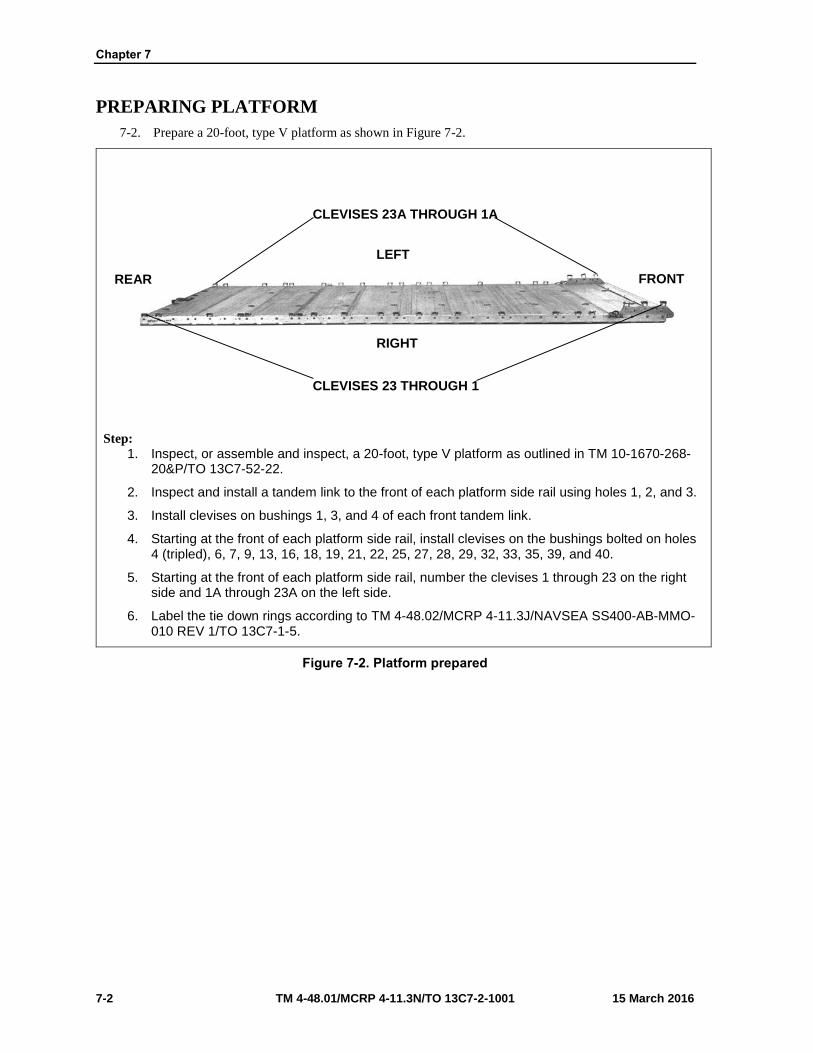
Chapter 7
7-2 TM 4-48.01/MCRP 4-11.3N/TO 13C7-2-1001 15 March 2016
PREPARING PLATFORM
7-2. Prepare a 20-foot, type V platform as shown in Figure 7-2.
Step:
1. Inspect, or assemble and inspect, a 20-foot, type V platform as outlined in TM 10-1670-268-20&P/TO 13C7-52-22.
2. Inspect and install a tandem link to the front of each platform side rail using holes 1, 2, and 3.
3. Install clevises on bushings 1, 3, and 4 of each front tandem link.
4. Starting at the front of each platform side rail, install clevises on the bushings bolted on holes4 (tripled), 6, 7, 9, 13, 16, 18, 19, 21, 22, 25, 27, 28, 29, 32, 33, 35, 39, and 40.
5. Starting at the front of each platform side rail, number the clevises 1 through 23 on the rightside and 1A through 23A on the left side.
6. Label the tie down rings according to TM 4-48.02/MCRP 4-11.3J/NAVSEA SS400-AB-MMO-010 REV 1/TO 13C7-1-5.
Figure 7-2. Platform prepared
REAR FRONT
RIGHT
LEFT
CLEVISES 23 THROUGH 1
CLEVISES 23A THROUGH 1A

Rigging 600-GPH ROWPU on a 20-Foot, Type V Platform for Low-Velocity Airdrop
15 March 2016 TM 4-48.01/MCRP 4-11.3N/TO 13C7-2-1001 7-3
PREPARING AND POSITIONING HONEYCOMB STACKS
7-3. Prepare five honeycomb stacks according to TM 4-48.02/MCRP 4-11.3J/NAVSEA SS400-AB-MMO-
010 REV 1/TO 13C7-1-5 and as shown in Figures 7-3 through 7-9. Position the honeycomb stacks on the
platform as shown in Figure 7-9.
Notes. 1. All dimensions are in inches. 2. Use 8-penny Nails.
Stack Number
Pieces Width (inches)
Length (inches)
Material Instructions
1 7 18 96 Honeycomb Use honeycomb as the base layers
2 18 96 Plywood Place ¾-inch plywood on top of the honeycomb base. Cut a 4- by 10-inch cutout in the rear corners of both pieces of plywood. Cut a 9 ½- by 6-inch cutout 13 inches from each end on the front sides of both pieces of plywood (clearance for trailer lights).
2 4 14 Lumber Nail lumber to each 14-inch edge of plywood (between the sheets of plywood).
6 4 18 Lumber Nail two pieces of lumber flush to each 6-inch of plywood. Space the remaining lumber evenly between the two sheets of plywood, nail it to the plywood.
Figure 7-3. Honeycomb stack 1 prepared
9 ½ X 6 9 ½ X 6
4 X 14 LUMBER
4 X 14 LUMBER
4 X 10 CUTOUTS
9 1/2 9 1/2
4 X 18 LUMBER

Chapter 7
7-4 TM 4-48.01/MCRP 4-11.3N/TO 13C7-2-1001 15 March 2016
Note. All dimensions are in inches.
Stack Number
Pieces Width (inches)
Length (inches)
Material Instructions
2 8 34 48 Honeycomb Use honeycomb as base layers. Cut a 10- by 16-inch cutout on the rear edges of the top three layers, starting 16 inches from the left side.
Figure 7-4. Honeycomb stack 2 prepared
16
10
REAR
LEFT RIGHT
FRONT

Rigging 600-GPH ROWPU on a 20-Foot, Type V Platform for Low-Velocity Airdrop
15 March 2016 TM 4-48.01/MCRP 4-11.3N/TO 13C7-2-1001 7-5
Note. All dimensions are in inches.
Stack Numbe
r
Pieces
Width (inches)
Length (inches
)
Material Instructions
3 2 24 52 Honeycomb Use honeycomb as the base layers on the right side of the platform.
1 12 52 Honeycomb Place a piece on top of the base on the inside edge.
1 12 52 Plywood Place ¾-inch plywood on top of the 12- by 52-inch honeycomb.
4 12 23 Plywood Place two pieces of ¾-inch plywood flush with the front edge and two pieces flush with the rear edge of the 12- by 52-inch piece of plywood.
4 10 12 Honeycomb Place two pieces 11 inches from the front edge and two pieces 11 inches from the rear edge of the plywood.
4 6 12 Honeycomb Place pieces on top of the base layers. Place one piece on the rear outside corner, one piece 4 inches from the rear piece, one piece on the front outside corner, and one piece 4 inches from the front piece.
Figure 7-5. Honeycomb stack 3 prepared
12
10
11
4
11
REAR FRONT

Chapter 7
7-6 TM 4-48.01/MCRP 4-11.3N/TO 13C7-2-1001 15 March 2016
Stack Numbe
r
Pieces
Width (inches
)
Length (inches
)
Material
Instructions
4 Same as stack 3 but placed on the left side of the platform.
Figure 7-6. Honeycomb stack 4 prepared
FRONT REAR

Rigging 600-GPH ROWPU on a 20-Foot, Type V Platform for Low-Velocity Airdrop
15 March 2016 TM 4-48.01/MCRP 4-11.3N/TO 13C7-2-1001 7-7
Notes. 1. This drawing is not to scale. 2. All dimensions are in inches. 3. Use 8-penny nails.
Stack Number
Pieces
Width (inches)
Length (inches)
Material Instructions
5 5 36 88 Honeycomb Use honeycomb as the base layers.
5 12 88 Honeycomb Use honeycomb as the base layers. Place pieces next to the 36- by 88-inch pieces and stagger.
2 36 58 Honeycomb Place the pieces on top at the rear edges of the base layers.
2 12 58 Honeycomb Place the pieces next to the 36- by 58-inch pieces of honeycomb and stagger.
1 44 58 Plywood Place ¾-inch plywood on top of the 48- by 58-inch honeycomb and center.
4 2 58 Lumber Place one piece of 2-inch lumber 2 inches from the right edge and one piece 2 inches from the left edge of the plywood. Place the other two pieces of lumber 8 inches from the pieces on the edge.
1 44 58 Plywood Place ¾-inch plywood on top of the lumber. Nail the plywood and lumber together.
Figure 7-7. Honeycomb stack 5 prepared
REAR
88
48
FRONT

Chapter 7
7-8 TM 4-48.01/MCRP 4-11.3N/TO 13C7-2-1001 15 March 2016
Notes. 1. This drawing is not to scale. 2. All dimensions are in inches. 3. Use 8-penny nails. 4. Lumber is stood on edge.
Stack Numbe
r
Pieces
Width (inches
)
Length (inches
)
Material
Instructions
5 2 30 48 Plywood
Use two pieces of ¾-inch plywood as the base for the box. Cut an 8- by 8-inch cutout in both pieces of plywood 3 inches from the 48-inch rear edge and centered between the 30-inch edges.
2 8 48 Lumber Nail the lumber on each 48-inch edge of the plywood.
2 8 27 Lumber Nail the lumber 3 inches from each 30-inch edge of the plywood.
Figure 7-8. Box for honeycomb stack 5 prepared

Rigging 600-GPH ROWPU on a 20-Foot, Type V Platform for Low-Velocity Airdrop
15 March 2016 TM 4-48.01/MCRP 4-11.3N/TO 13C7-2-1001 7-9
Stack Numbe
r
Pieces
Width (inches
)
Length (inches
)
Material
Instructions
5 Place the completed box from Figure 3-8 on top of the 48- by 88-inch honeycomb at the front of honeycomb stack 5.
Figure 7-8. Box for honeycomb stack 5 prepared (continued)
FRONT
REAR

Chapter 7
7-10 TM 4-48.01/MCRP 4-11.3N/TO 13C7-2-1001 15 March 2016
Stack Number Position on Platform
1
2
3
4
5
Place stack:
Centered and 35 inches from the front edge of the platform.
Centered and flush against stack 1
Flush against stack 2 and 22 inches from the right side rail.
Flush against stack 2 and 22 inches from the left side rail.
Centered and 4 inches from the rear of stacks 3 and 4.
Figure 7-9. Honeycomb stacks positioned on platform
FRONT REAR
LEFT
RIGHT
STACK 1 STACK 2
STACK 3
STACK 4 STACK 5

Rigging 600-GPH ROWPU on a 20-Foot, Type V Platform for Low-Velocity Airdrop
15 March 2016 TM 4-48.01/MCRP 4-11.3N/TO 13C7-2-1001 7-11
PREPARING ROWPU
7-4. Prepare the ROWPU as described below. Secure all lashings and safety them according to TM 4-
48.02/MCRP 4-11.3J/NAVSEA SS400-AB-MMO-010 REV 1/TO 13C7-1-5.
7-5. Pad the top corners of the ROWPU frame and the top corners of the generator using cellulose wadding
and 2-inch adhesive tape (not shown).
7-6. Pad and tape the trailer lights using cellulose wadding and 2-inch adhesive tape (not shown).
7-7. Prepare and lash the control box assembly as shown in Figures 7-10 through 7-12, and secure the
lashings as shown in Figure 7-13.
① Open the control assembly cover.
② Position a 6- by 26-inch piece of honeycomb between the bottom of the circuit breaker plate
and the bottom of the control box.
Figure 7-10. Control box assembly prepared
1
2

Chapter 7
7-12 TM 4-48.01/MCRP 4-11.3N/TO 13C7-2-1001 15 March 2016
① Place a 2- by 6- by 26-inch piece of lumber between the honeycomb and the edge of the
control panel.
② Tape the lumber in place using 2-inch adhesive tape.
Figure 7-11. Control box assembly secured
7
5
6
1 2

Rigging 600-GPH ROWPU on a 20-Foot, Type V Platform for Low-Velocity Airdrop
15 March 2016 TM 4-48.01/MCRP 4-11.3N/TO 13C7-2-1001 7-13
① Close the control box assemblies cover and secure it with the screws provided.
② Close the circuit breaker plate cover. Secure it with the twist locks provided, and tape the twist
locks using 2-inch adhesive tape.
③ Use two 15-foot lashings to secure the control box assembly to the top frame. Pass the
lashings around the front panel and over the frame.
Figure 7-12. Control box assembly secured
3
2
1

Chapter 7
7-14 TM 4-48.01/MCRP 4-11.3N/TO 13C7-2-1001 15 March 2016
① Secure each lashing on the inside of the ROWPU using two D-rings and a load binder.
Figure 7-13. . Control box assembly prepared
1

Rigging 600-GPH ROWPU on a 20-Foot, Type V Platform for Low-Velocity Airdrop
15 March 2016 TM 4-48.01/MCRP 4-11.3N/TO 13C7-2-1001 7-15
PREPARING AND SECURING CONTROL PANEL
7-8. Prepare and secure the control panel as shown in Figure 7-14.
① Tape all lights, switches and gauges on the control panel with 2-inch adhesive tape.
② Secure the ground rods in the carrying racks on the bottom of the control panel and tape the
latches in place using 2-inch adhesive tape.
③ Use two 15-foot lashings to secure the operational control panel to the top of the frame.
Secure each lashing on the inside of the ROWPU using two D-rings and a load binder.
Figure 7-14. Control panel prepared and secured
3
1
2

Chapter 7
7-16 TM 4-48.01/MCRP 4-11.3N/TO 13C7-2-1001 15 March 2016
PREPARING AND SECURING PULSE DAMPENER
7-9. Secure the pulse dampener as shown in Figure 7-15.
① Route two 15-foot lashings around the pulse dampener and the top of the ROWPU frame.
Secure each lashing with two D-rings and a load binder.
② Secure the 3/8-inch vent lines to the top of the ROWPU frame using type III nylon cord.
Note. When securing the 3/8-inch vent lines ensure that safety ties are made around the top of the ROWPU frame.
Figure 7-15. Pulse dampener prepared and secured
1
2

Rigging 600-GPH ROWPU on a 20-Foot, Type V Platform for Low-Velocity Airdrop
15 March 2016 TM 4-48.01/MCRP 4-11.3N/TO 13C7-2-1001 7-17
PREPARING AND VEHICULAR CABLES, STRAPS, CHAINS, JACKS
AND THE JACK HANDLES
7-10. Secure the inter-vehicular cables and chains to the trailer using type III nylon cord (not shown).
7-11. Fold the pump tie down straps and tape them to the floor of the ROWPU (not shown).
7-12. Stow the jacks and the jack handles on their support brackets, and secure them using type III nylon
cord (not shown).
PREPARING THE GENERATOR
7-13. Make sure the generator’s fuel tank is at least ½ but no more than ¾ full. Ensure hazardous materials
are packaged, marked, and labeled as required by AFMAN(I) 24-204/TM 38-250 (not shown).
7-14. Prepare the generator as shown in Figure 7-16.
① Glue a ¾- by 19- by 34- inch piece of plywood to a 19- by 34-inch piece of honeycomb.
Position the plywood and honeycomb with the honeycomb against one end of the generator atthe top.
② Repeat step 1 for the other end of the generator.
Note. Tape the edges of the plywood where the lashing is routed over the edge.
③ Form a 30-foot lashing according to TM 4-48.02/MCRP 4-11.3J/NAVSEA SS400-AB-MMO-
010 REV 1/TO 13C7-1-5 and route it around the end protectors and generator. Secure thelashing in the front using two D-rings and a load binder.
Figure 7-16. Generator prepared
2
1
3

Chapter 7
7-18 TM 4-48.01/MCRP 4-11.3N/TO 13C7-2-1001 15 March 2016
PREPARING AND STOWING RAW WATER PUMPS
7-15. Prepare and stow the raw water pumpers on the ROWPU as shown in Figure 7-17.
① Secure two pieces of 8- by 13-inch honeycomb to the bottom frame of each of the two raw
water pumps using type III nylon cord.
② Cover the pumps with their covers.
③ Secure the covers using type III nylon cord.
④ Stow the raw water pumps inside the ROWPU along the right side as viewed from the rear of
the load.
Figure 7-17. Raw water pumps prepared and stowed
4 4
2 2
3 3
1 1
CAUTION
Make the final rigger inspection required by AR 59-4 (Using DD Form 1748, Joint Airdrop Inspection Record (Platforms), or appropriateDD Form 1748-1, Joint Airdrop Inspection Record (Containers),DD Form 1748-2, Airdrop Malfunction Report (Personnel-Cargo), andDD Form 1748-3, Joint Airdrop Summary Report).

Rigging 600-GPH ROWPU on a 20-Foot, Type V Platform for Low-Velocity Airdrop
15 March 2016 TM 4-48.01/MCRP 4-11.3N/TO 13C7-2-1001 7-19
PREPARING, STOWING, AND SECURING BACKWASH PUMPS
7-16. Prepare and stow the backwash pumps on the ROWPU as shown in Figures 7-18 and 7-19.
① Secure three 8- by 16-inch pieces of honeycomb to the bottom frame of the backwash pump
using type III nylon cord.
② Place one 10- by 13-inch piece of honeycomb on top of the motor of the backwash pump.
③ Position the pump strainer on the previously positioned honeycomb, and secure it to the top
frame of the pump using type III nylon cord.
④ Secure the end of the hose to the frame to prevent the hose from unraveling.
Figure 7-18. Backwash pump prepared, stowed and secured
1
2
4
3

Chapter 7
7-20 TM 4-48.01/MCRP 4-11.3N/TO 13C7-2-1001 15 March 2016
① Place the cover on the backwash pump and secure it using type III nylon cord. Set the pump
inside the ROWPU between the raw water pumps and the ROWPU motor.
② Pass one 15-foot lashing to the inside vertical brace of the ROWPU, around the frame and
through its own D-ring.
③ Pass another 15-foot lashing to the third vertical brace of the ROWPU in the same manner as
step 6.
④ Pass the straps around the three pumps and secure with two D-rings and a load binder.
Figure 7-19. Backwash pump prepared, stowed and secured
6
8
7
5

Rigging 600-GPH ROWPU on a 20-Foot, Type V Platform for Low-Velocity Airdrop
15 March 2016 TM 4-48.01/MCRP 4-11.3N/TO 13C7-2-1001 7-21
PREPARING AND STOWING CANVAS HOSES
7-17. Prepare and stow the canvas hoses as shown in Figure 7-20.
① Roll up each canvas hose section and tie it using type III nylon cord.
② Stow the canvas hoses behind the pumps
Figure 7-20. Canvas hose prepared and stowed
1
1

Chapter 7
7-22 TM 4-48.01/MCRP 4-11.3N/TO 13C7-2-1001 15 March 2016
PREPARING, STOWING AND SECURING STORAGE CHESTS
7-18. Prepare, stow and secure the two storage chests as shown in Figure 7-21.
① Pad the contents inside the two storage chests using cellulose wadding. Secure the chest
closed using type III nylon cord (not shown).
② Stow the two storage chests on top of the three pumps.
③ Attach a tie down clevis to the center tie down hole on the floor of the ROWPU.
④ Prepare and route a 30-foot lashing around the third inside vertical brace of the ROWPU. Pass
the free end of the lashing over the chests and through the tie down clevis. Secure the lashingusing two D-rings and a load binder.
Figure 7-21. Storage chests prepared, stowed and secured
STOWING AND SECURING WOODEN STAVES
7-19. Place the wooden staves of the water tank beside the ROWPU pump and motor. Secure the staves to
the floor using type III nylon cord (not shown).
STOWING AND SECURING SLEDGEHAMMER
7-20. Set the sledgehammer next to the third inside vertical brace. Secure it to the brace using type III nylon
cord (not shown)
4
2
3

Rigging 600-GPH ROWPU on a 20-Foot, Type V Platform for Low-Velocity Airdrop
15 March 2016 TM 4-48.01/MCRP 4-11.3N/TO 13C7-2-1001 7-23
STOWING AND SECURING PADDLE AND FLOAT
7-21. Set the paddle and the float behind the inside storage chest and secure them together using type III
nylon cord (not shown).
STOWING AND SECURINGE WATER CONTAINERS
7-22. Stack the five gallon plastic water containers behind the ROWPU pump and tie them to a convenient
point using type III nylon cord (not shown).
PREPARING AND STOWING RUBBER HOSES
7-23. Prepare and stow the rubber hoses as shown in Figure 7-22.
① Roll up each 10-foot section of rubber hose and secure it using type III nylon cord. Stow the
rubber hoses on top of the ROWPU pump.
Figure 7-22. Rubber hoses prepared and stowed
1

Chapter 7
7-24 TM 4-48.01/MCRP 4-11.3N/TO 13C7-2-1001 15 March 2016
PREPARING, STOWING AND SECURING WATER TANKS
7-24. Prepare, stow and secure the water tanks as shown in Figure 7-23.
① Fold each water tank and tie it using type III nylon cord (not shown).
② Cover the water tanks with canvas and secure the canvas using type III nylon cord. Stow the
water tanks and the ROWPU cover on top of the rubber hoses.
③ Route a 15-foot lashing around the tie down provision and back through itself on the third
vertical brace on the right side. Pass the lashing over the tanks and secure it to the left bottom corner tie down provision using a single D-ring and load binder.
④ Route a 15-foot lashing around the center rear tie down provision and back through itself.
Pass the lashing over the tanks and to the center floor tie down provision and secure it using a single D-ring and load binder.
⑤ Route a 15-foot lashing around the tie down provision and back through itself on the third
inside vertical brace on the left side. Pass the lashing over the tanks and secure it to the right bottom corner tie down provision using a single D-ring and load binder.
Figure 7-23. Water tanks prepared stowed and secured
5
2
3
4

Rigging 600-GPH ROWPU on a 20-Foot, Type V Platform for Low-Velocity Airdrop
15 March 2016 TM 4-48.01/MCRP 4-11.3N/TO 13C7-2-1001 7-25
INSTALLING AND SECURING CROSS BRACES
7-25. Install and secure cross braces as shown in Figure 7-24.
① Install the cross braces on the ROWPU frame.
② Secure the cross braces using the locking pins provided.
Figure 7-24. Cross braces installed and secured
2
1
2
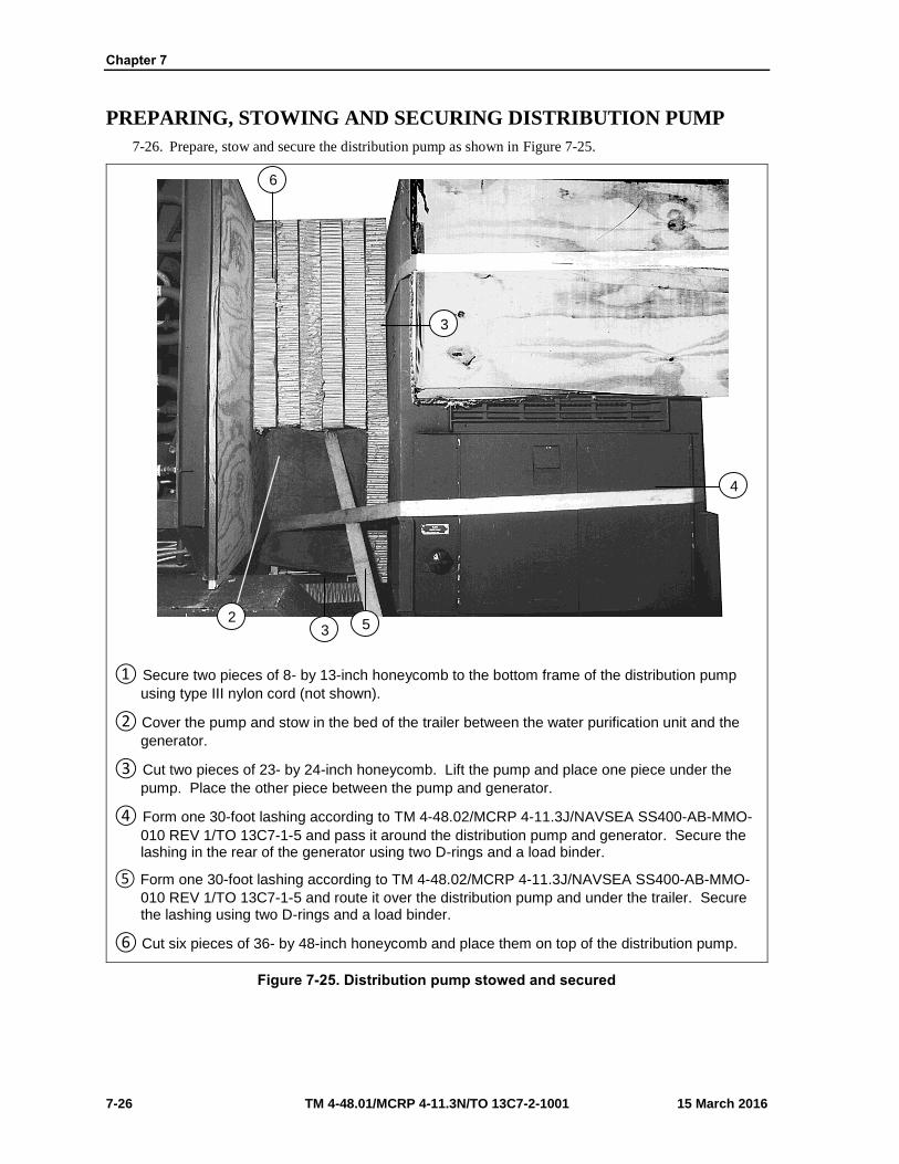
Chapter 7
7-26 TM 4-48.01/MCRP 4-11.3N/TO 13C7-2-1001 15 March 2016
PREPARING, STOWING AND SECURING DISTRIBUTION PUMP
7-26. Prepare, stow and secure the distribution pump as shown in Figure 7-25.
① Secure two pieces of 8- by 13-inch honeycomb to the bottom frame of the distribution pump
using type III nylon cord (not shown).
② Cover the pump and stow in the bed of the trailer between the water purification unit and the
generator.
③ Cut two pieces of 23- by 24-inch honeycomb. Lift the pump and place one piece under the
pump. Place the other piece between the pump and generator.
④ Form one 30-foot lashing according to TM 4-48.02/MCRP 4-11.3J/NAVSEA SS400-AB-MMO-
010 REV 1/TO 13C7-1-5 and pass it around the distribution pump and generator. Secure the lashing in the rear of the generator using two D-rings and a load binder.
⑤ Form one 30-foot lashing according to TM 4-48.02/MCRP 4-11.3J/NAVSEA SS400-AB-MMO-
010 REV 1/TO 13C7-1-5 and route it over the distribution pump and under the trailer. Secure the lashing using two D-rings and a load binder.
⑥ Cut six pieces of 36- by 48-inch honeycomb and place them on top of the distribution pump.
Figure 7-25. Distribution pump stowed and secured
3
6
2 5 3
4

Rigging 600-GPH ROWPU on a 20-Foot, Type V Platform for Low-Velocity Airdrop
15 March 2016 TM 4-48.01/MCRP 4-11.3N/TO 13C7-2-1001 7-27
LIFTING AND POSITIONING LOAD
7-27. Use available slings to lift the ROWPU. After lifting the ROWPU, prepare it for positioning as shown
in Figure 7-26 through Figure 7-27. Position the ROWPU as shown in Figure 7-28.
① Remove the four wheels and the spare from the ROWPU. They will be stored on the platform
after the lashings are installed (not shown).
② Place the lug nuts back on the lugs and tape them in place using 2-inch adhesive tape.
Figure 7-26. ROWPU prepared for positioning
2
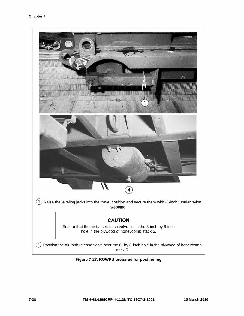
Chapter 7
7-28 TM 4-48.01/MCRP 4-11.3N/TO 13C7-2-1001 15 March 2016
① Raise the leveling jacks into the travel position and secure them with ½-inch tubular nylon
webbing.
CAUTION
Ensure that the air tank release valve fits in the 8-inch by 8-inch hole in the plywood of honeycomb stack 5.
② Position the air tank release valve over the 8- by 8-inch hole in the plywood of honeycomb
stack 5.
Figure 7-27. ROWPU prepared for positioning

Rigging 600-GPH ROWPU on a 20-Foot, Type V Platform for Low-Velocity Airdrop
15 March 2016 TM 4-48.01/MCRP 4-11.3N/TO 13C7-2-1001 7-29
① Set the ROWPU on the honeycomb stacks with the rear of the trailer 3 ½ inches from the front
edge of honeycomb stack 1.
② Allow the drawbar to overhang the rear edge of the platform by 35 inches.
③ Tie down provisions 1, 2, 3 and 4 are built into the trailer along its length under the frame.
Figure 7-28. ROWPU positioned on platform
3
1
4 1
2 3
FRONT REAR
RIGHT
2

Chapter 7
7-30 TM 4-48.01/MCRP 4-11.3N/TO 13C7-2-1001 15 March 2016
INSTALLING LASHINGS
7-28. Lash the ROWPU to the platform according to TM 4-48.02/MCRP 4-11.3J/NAVSEA SS400-AB-
MMO-010 REV 1/TO 13C7-1-5 and as shown in Figures 7-29 through 7-31.
Note. When routing lashings ensure all suspension and lifting points are padded and taped.
Lashing Number Tie down Clevis Number
Instructions
1
2
3
4
5
6
7
8
1
1A
6
6A
8
8A
9
9A
Pass lashing through:
Left rear tie down eye of the ROWPU.
Right rear tie down eye of the ROWPU.
Right rear tie down eye of the ROWPU.
Left rear tie down eye of the ROWPU.
Around rear axle.
Around rear axle.
Tie down provision number 4 right side.
Tie down provision number 4 left side.
Figure 7-29. Lashings 1 through 8 installed
2
5
7
3 4
1 9
8
6
6A 1A
1 RIGHT
FRONT

Rigging 600-GPH ROWPU on a 20-Foot, Type V Platform for Low-Velocity Airdrop
15 March 2016 TM 4-48.01/MCRP 4-11.3N/TO 13C7-2-1001 7-31
Note. When routing lashings ensure all suspension and lifting points are padded and taped.
Lashing Number
Tie down Clevis Number
Instructions
9
10
11
12
13
14
15
16
17
18
19
20
21
22
23
24
10
10A
11
11A
12
12A
13
13A
14
14A
15
15A
16
16A
17
17A
Pass lashing through:
Tie down provision number 3 right side.
Tie down provision number 3 left side.
Rear lifting eye.
Rear lifting eye.
Tie down provision number 4 right side.
Tie down provision number 4 left side.
Around leaf spring.
Around leaf spring.
Tie down provision number 2 right side.
Tie down provision number 2 left side.
Tie down provision number 1 right side.
Tie down provision number 1 left side.
Front lifting eye.
Front lifting eye.
Tie down provision number 2 right side.
Tie down provision number 2 left side.
Figure 7-30. Lashings 9 through 24 installed
21
23
13 12 11 10 14 17 16 15
19
17 15 11 13 9
RIGHT
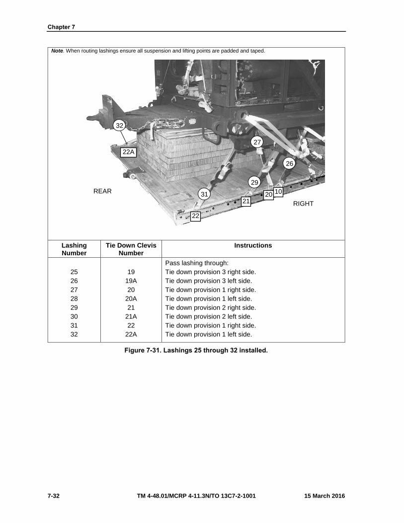
Chapter 7
7-32 TM 4-48.01/MCRP 4-11.3N/TO 13C7-2-1001 15 March 2016
Note. When routing lashings ensure all suspension and lifting points are padded and taped.
Lashing Number
Tie Down Clevis Number
Instructions
25
26
27
28
29
30
31
32
19
19A
20
20A
21
21A
22
22A
Pass lashing through:
Tie down provision 3 right side.
Tie down provision 3 left side.
Tie down provision 1 right side.
Tie down provision 1 left side.
Tie down provision 2 right side.
Tie down provision 2 left side.
Tie down provision 1 right side.
Tie down provision 1 left side.
Figure 7-31. Lashings 25 through 32 installed.
26
31
22A
22
21 20 10
29
32
27
REAR
RIGHT

Rigging 600-GPH ROWPU on a 20-Foot, Type V Platform for Low-Velocity Airdrop
15 March 2016 TM 4-48.01/MCRP 4-11.3N/TO 13C7-2-1001 7-33
CONSTRUCTING ENDBOARDS
7-29. Construct two end boards as shown in Figure 7-32.
Notes. 1. This drawing is not to scale. 2. All dimensions are in inches.
① Cut two pieces of ¾- by 36- by 48-inch plywood. Cut four 3- by 3-inch notches in each end
board. Make the notches 8 inches from the top and bottom of the board.
Figure 7-32. End boards constructed
1

Chapter 7
7-34 TM 4-48.01/MCRP 4-11.3N/TO 13C7-2-1001 15 March 2016
POSITIONING AND SECURING END BOARDS AND STOWING
TIRES
7-30. Position and secure the end boards, stow the tires as shown in Figure 7-33.
① Position one end board against the rear of the ROWPU and honeycomb stack 1.
② Stow the five tires on the front of the platform against the end board. Ensure the spare tire is
placed and centered on top.
③ Pass a 15-foot lashing through the centers of the four tires and secure on top of the spare
using a single D-ring and load binder. Ensure that the lashing is routed through the side rings of all four tires.
④ Position the second end board against the front of the tires.
Figure 7-33. End boards positioned and tires stowed
4
2
2
3
1
FRONT
RIGHT

Rigging 600-GPH ROWPU on a 20-Foot, Type V Platform for Low-Velocity Airdrop
15 March 2016 TM 4-48.01/MCRP 4-11.3N/TO 13C7-2-1001 7-35
SECURING TIRES
7-31. Lash the tires as shown in Figure 7-34.
Lashing Number
Tie down Clevis Number
Instructions
1
2
3
4
5
2 to 2A
4 to 4A
3 to 3A
7 to 7A
5 to 5A
Pass lashing through:
Its own D-ring through the rear bottom cutouts to clevis 2A.
Its own D-ring through the front bottom cutouts to clevis 4A.
Its own D-ring through the rear top cutouts to clevis 3A.
Its own D-ring through the front top cutouts to clevis 7A.
Clevis 5 and its own D-ring and run over the top of the tire. Pass the second lashing through clevis 5A and its own D-ring and run over the top of the tires. Secure to lashing from clevis 5 on top of the tires with two D-rings and a load binder.
Figure 7-34. Lashings 1 through 5 installed
2 1
2 34 5 7
5
4
3
FRONT RIGHT

Chapter 7
7-36 TM 4-48.01/MCRP 4-11.3N/TO 13C7-2-1001 15 March 2016
PREPARING, CONSTRUCTING AND POSITIONING PARACHUTE
STOWAGE POSITION
7-32. Prepare the honeycomb stacks for the parachute stowage platform as shown in Figure 7-35.
Note. 1. This drawing is not to scale. 2. All dimensions are in inches.
① Cut 28 pieces of 13- by 34- inch honeycomb. Place 14 pieces of honeycomb in each stack
and glue them together.
② Set each stack on the rear of the platform inside the trailer’s front tie down eyes and flush with
the front of the trailer (not shown).
③ Center the stowage platform on top of each of the honeycomb stacks (not shown).
Figure 7-35. Honeycomb stacks for parachute platform prepared
1

Rigging 600-GPH ROWPU on a 20-Foot, Type V Platform for Low-Velocity Airdrop
15 March 2016 TM 4-48.01/MCRP 4-11.3N/TO 13C7-2-1001 7-37
CONSTRUCT THE PARACHUTE STOWAGE PLATFORM
7-33. Construct the parachute stowage platform as shown in Figure 7-36.
Note. 1. This drawing is not to scale. 2. All dimensions are in inches. 3. All nailing is done from the plywood side to maintain a smooth surface using 8-penny nails.
① Start construction of the parachute stowage platform using a ¾- by 48- by 96-inch piece of
plywood.
② Nail a 2- by 6- by 48-inch piece of lumber along each 48-inch side of the plywood.
③ Nail a 2- by 6- by 85-inch piece of lumber along each 96-inch side of the plywood.
④ Center a 2- by 6- by 85-inch of lumber between the other two 2- by 6- by 85-inch pieces of
lumber and nail it to the plywood.
⑤ Drill 2-inch holes 3 inches from each corner.
⑥ Drill one 2-inch hole centered between the corner holes on each 48-inch side of the plywood.
Figure 7-36. Parachute stowage platform constructed
1
2
5
6
4 2
5
3
3
3/4

Chapter 7
7-38 TM 4-48.01/MCRP 4-11.3N/TO 13C7-2-1001 15 March 2016
SECURING PARACHUTE STOWAGE PLATFORM
7-34. Lash the parachute stowage platform as shown in Figure 7-37.
Note. Tape all cutouts in the stowage in the stowage platform prior to routing lashings.
Lashing Number
Tie Down Clevis Number
Instructions
Pass lashing through:
1 18 Clevis 18, up through the right center hole, down through the right front hole. Secure with a D-ring and load binder.
2 18A Repeat for the left side using clevis 18A.
3 23 Clevis 23, up through the right rear hole, down through the right center hole. Secure with a D-ring and load binder.
4 23A Repeat for the left side using clevis 23A.
Figure 7-37. Parachute stowage platform constructed
3 1
23 18
REAR

Rigging 600-GPH ROWPU on a 20-Foot, Type V Platform for Low-Velocity Airdrop
15 March 2016 TM 4-48.01/MCRP 4-11.3N/TO 13C7-2-1001 7-39
INSTALLING LOAD COVER, SUSPENSION SLINGS AND SAFETY
TIE
7-35. Cover the load; install the suspension slings and safety tie as shown in Figure 7-38.
① Place a 17- by 35-foot canvas cover over the load from the generator to the front of the
ROWPU. Secure the cover in place using type III nylon cord.
② Attach a 16-foot (4-loop), type XXVI nylon suspension sling to each lifting point with a large
clevis. Attach the clevis with the bell of the clevis through the lifting point and secure the bolt through the plies of the sling.
③ Pad the front and rear suspension slings using four 36- by 10-inch pieces of felt and tape in
place. Place the felt where the slings come in contact with the top of the ROWPU. Extend the tape beyond the top and bottom of the felt to secure it in place.
④ Raise the suspension slings and install the deadman’s tie according to TM 4-48.02/MCRP 4-
11.3J/NAVSEA SS400-AB-MMO-010 REV 1/TO 13C7-1-5.
Figure 7-38. Load cover, suspension sings and safety tie installed
3
2
1
3 4
2 2

Chapter 7
7-40 TM 4-48.01/MCRP 4-11.3N/TO 13C7-2-1001 15 March 2016
PREPARING AND STOWING CARGO PARACHUTES
7-36. Prepare and stow the cargo parachutes as shown in Figure 7-39.
① Prepare, position and stow five G-11C cargo parachutes on the parachute stowage platform
according to TM 4-48.02/MCRP 4-11.3J/NAVSEA SS400-AB-MMO-010 REV 1/TO 13C7-1-5.
② Using type VIII nylon webbing install the cargo parachute restraint through the front carrying
handles to clevises 22 and 22A according to TM 4-48.02/MCRP 4-11.3J/NAVSEA SS400-AB-MMO-010 REV 1/TO 13C7-1-5.
③ Using type VIII nylon webbing install the cargo parachute restraint through the center carrying
handles to clevises 21 and 21A according to TM 4-48.02/MCRP 4-11.3J/NAVSEA SS400-AB-MMO-010 REV 1/TO 13C7-1-5.
④ Install the parachute release straps according to TM 4-48.02/MCRP 4-11.3J/NAVSEA SS400-
AB-MMO-010 REV 1/TO 13C7-1-5.
Figure 7-39. Cargo parachutes prepared and stowed
1 2
3 4
21
22

Rigging 600-GPH ROWPU on a 20-Foot, Type V Platform for Low-Velocity Airdrop
15 March 2016 TM 4-48.01/MCRP 4-11.3N/TO 13C7-2-1001 7-41
INSTALLING PARACHUTE RELEASE SYSTEM
7-37. Prepare, attach and safety an M-2 cargo parachute release according to TM 4-48.02/MCRP 4-
11.3J/NAVSEA SS400-AB-MMO-010 REV 1/TO 13C7-1-5 and as shown in Figure 7-40.
① Center a 24- by 24-inch piece of honeycomb on the front of the ROWPU. Tape the edges of
the honeycomb and secure using type III cord.
② Prepare and install the M-2 cargo parachute release according to TM 4-48.02/MCRP 4-
11.3J/NAVSEA SS400-AB-MMO-010 REV 1/TO 13C7-1-5. Center the assembly on top ofhoneycomb.
③ S-fold and tie any excess in the suspension slings using one turn single type I, ¼-inch cotton
webbing.
④ Safety the M-2 cargo parachute release to a convenient point on the load using type III nylon
cord according to TM 4-48.02/MCRP 4-11.3J/NAVSEA SS400-AB-MMO-010 REV 1/TO 13C7-1-5.
Note. All slings must be made safety in such a manner as not to increase the height of the load.
Figure 7-40. Cargo parachute release installed
2
1
4
3
3 4

Chapter 7
7-42 TM 4-48.01/MCRP 4-11.3N/TO 13C7-2-1001 15 March 2016
INSTALLING EXTRACTION SYSTEM
7-38. Install the extraction system as shown in Figure 7-41.
① Install the components of the extraction force transfer coupling system according to TM 4-
48.02/MCRP 4-11.3J/NAVSEA SS400-AB-MMO-010 REV 1/TO 13C7-1-5. Use the rearmounting holes on the left side of the platform for the extraction force transfer coupling systembrackets.
② Install a 20-foot extraction force transfer coupling system cable according to TM 4-48.02/MCRP
4-11.3J/NAVSEA SS400-AB-MMO-010 REV 1/TO 13C7-1-5. Safety tie the cable to convenientplaces on the platform with one turn of type I, ¼-inch cotton webbing.
Note. Safety the cable to tie down ring C10 using type I, ¼-inch cotton webbing.
③ Attach a 9-foot (2-loop) type XXVI nylon sling according to be used as a deployment line. S-
fold the excess and tie it in two places with type I, ¼-inch cotton webbing.
Figure 7-41. Extraction system installed
2
1
3
REAR
LEFT
C10
2

Rigging 600-GPH ROWPU on a 20-Foot, Type V Platform for Low-Velocity Airdrop
15 March 2016 TM 4-48.01/MCRP 4-11.3N/TO 13C7-2-1001 7-43
PLACING EXTRACTION PARACHUTE
7-39. Select the extraction parachute and extraction line needed using the extraction line requirements table
in TM 4-48.02/MCRP 4-11.3J/NAVSEA SS400-AB-MMO-010 REV 1/TO 13C7-1-5. Place the extraction
parachute and line on the load for installation in the aircraft.
INSTALLING PROVISIONS FOR EMERGENCY RESTRAINTS
7-40. Select and install the provisions for the emergency aft restraints according to the emergency aft
restraint requirements table in TM 4-48.02/MCRP 4-11.3J/NAVSEA SS400-AB-MMO-010 REV 1/TO
13C7-1-5.
MARKING RIGGED LOAD
7-41. Mark the rigged load according FM4-20.102/MCRP 4-11.3J/NAVSEA SS400-AB-MMO-010 REV
1/TO 13C7-1-5, and as shown in Figure 7-42. Comply with the Shipper's requirements for Declaration of
Dangerous/Hazardous Goods in accordance with AFMAN 24-204/TM 38-250/ NAVSUP PUB 505; MCO
P4030.19I; DLAI 4145.3 DCMAD1, CH3.4 (HM24). If the load varies from the one shown, the weight,
height, CB, and parachute requirements must be recomputed.
EQUIPMENT REQUIRED
7-42. Use the equipment listed in Table 7-1 to rig this load.

Chapter 7
7-44 TM 4-48.01/MCRP 4-11.3N/TO 13C7-2-1001 15 March 2016
NOTICE OF EXCEPTION
The height limitation of this load is greater than what is authorized in TM 4-48.02/MCRP 4-11.3J/NAVSEA SS400-AB-
MMO-010 REV 1/TO 13C7-1-5. The overall rigged height of the 600-GPH ROWPU will not exceed 101 inches for a distance of not more than 40 inches aft of the center of balance. All high points should be verified each time this load is placed on the aircraft. An exception to TM 4-48.02/MCRP 4-11.3J/NAVSEA
SS400-AB-MMO-010 REV 1/TO 13C7-1-5 is granted. The procedures in this paragraph must be followed.
RIGGED LOAD
Weight:
Height:
Width:
Length:
Overhang:
Center of balance:
Load shown…………………………:.
Maximum weight…………………….
…………………………………………
…………………………………………
…………………………………………
Front………………………………….
Rear…………………………………...
…………………………………………
21,780 pounds
23,030 pounds
101 inches
108 inches
275 inches
5 inches
35 inches
130 inches
Figure 7-42. ROWPU rigged on a 20-foot, type V platform for low-velocity airdrop
Center of balance
CAUTION
Make the final rigger inspection required by AR 59-4 (Using DD Form 1748, Joint Airdrop Inspection Record (Platforms), or appropriateDD Form 1748-1, Joint Airdrop Inspection Record (Containers),DD Form 1748-2, Airdrop Malfunction Report (Personnel-Cargo), andDD Form 1748-3, Joint Airdrop Summary Report).

Rigging 600-GPH ROWPU on a 20-Foot, Type V Platform for Low-Velocity Airdrop
15 March 2016 TM 4-48.01/MCRP 4-11.3N/TO 13C7-2-1001 7-45
Table 7-1. Equipment required for rigging a ROWPU on a 20-foot, type V platform for low-velocity airdrop
National Stock Number
Items Quantity
8040-00-273-8713
4030-00-678-8562
4030-00-090-5354
4020-00-240-2146
1670-00-434-5783
1670-00-360-0328
8135-00-664-6958
8305-00-958-3685
1670-01-183-2678
1670-01-183-2678
1670-00-003-4391
1670-01-062-6313
1670-01-107-7651
1670-01-064-4452
1670-01-493-6420
1670-01-493-6418
5510-00-220-6146
5510-00-220-6148
5510-00-220-6246
5315-00-010-4659
1670-00-753-3928
Adhesive Paste, 1-Gallon
Clevis, ¾-inch medium
Clevis, 1-inch large
Cord, Nylon, Type III, 550-pound
Coupling, Airdrop Extraction Force Transfer, w 20-foot cable
Cover, Clevis
Cushioning Material (Cellulose Wadding)
Felt, ½-inch thick
Leaf, Extraction Line (Line Bag) (for C-130)
Leaf, Extraction Line (Line Bag) (for C-17)
Knife, Parachute Bag (for C-17)
Line Extraction:
60-foot (3-loop), Type XXVI (for C-130)
140-foot (3-loop), Type XXVI (for C-17)
60-foot (1-loop), Type XXVI (for C-17), (Drogue Line)
Link Assembly:
Two-Point, 5 ½-inch (for C-130 and C-17)
Two-Point, 3 ¾-inch (for C-17), Drogue Line
Lumber:
2- by 4- by 96-inch
2- by 6-inch
2- by 8-inch
Nail, Steel Wire, Common, 8-penny
Pad, Energy Dissipating, Honeycomb, 3- by 36- by 96-inch
As Required
6
7
As Required
1
5
As Required
As Required
1
2
1
1
1
1
2
1
As Required
As Required
As Required
As Required
40 Sheets

Chapter 7
7-46 TM 4-48.01/MCRP 4-11.3N/TO 13C7-2-1001 15 March 2016
Table 7-1. Equipment required for rigging a ROWPU on a 20-foot, type V platform for low-velocity airdrop (continued)
National Stock Number
Items Quantity
1670-01-016-7841
1670-00-040-8135
1670-00-040-8135
1670-00-063-3715
1670-01-162-2372
1670-01-353-8424
1670-01-162-2381
1670-01-097-8817
1670-01-062-6304
1670-01-062-6308
1670-01-062-6311
1670-01-062-6301
1670-00-040-8219
7510-00-266-5016
8305-00-433-5986
8310-00-917-3945
1670-00-937-0271
1670-01-483-8259
8305-00-268-2411
8305-00-082-5752
8305-00-261-8585
Parachute:
Cargo:
G-11C
Parachute, Cargo Extraction:
28-foot (for C-130)
28-foot (C-17)
15-foot (for C-17), (Drogue Parachute)
Platform, Airdrop, Type V, 20-feet:
Clevis Assembly
Extraction Bracket Assembly
Tandem Link Assembly (Multipurpose Link)
Plywood, ¾-inch
Release, Cargo, Airdrop:
Sling, Cargo, Airdrop:
9 foot (2-loop), Type XXVI
16-foot (4-loop), Type XXVI
120-foot (2-loop), Type XXVI
3 foot (2-loop), Type XXVI
Strap, Parachute Release, Multicut
Tape, Adhesive, 2-inch
Textile:
Cloth, Cotton Muslin, Type III (for C-17)
Thread, Cotton, Ticket Number 8/7 (for C-17)
Tie down Assembly, 15-foot
Tow plate Release Mechanism (H-Block) (C-17 only)
Webbing:
Cotton, ¼-inch, Type I
Nylon, Tubular, ½-inch
Type VIII Nylon
5
1
1
1
46
1
2
As Required
1
1
4
5
2
2
As Required
As Required
As Required
60
1
As Required
As Required
As Required
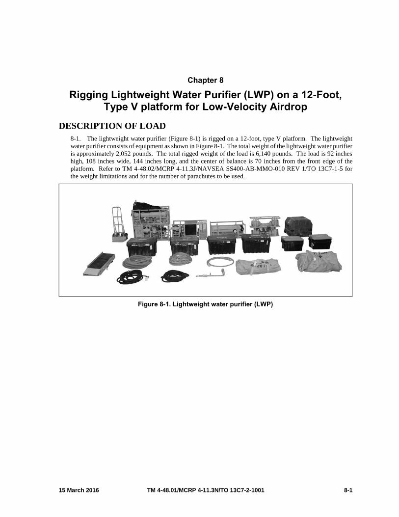
15 March 2016 TM 4-48.01/MCRP 4-11.3N/TO 13C7-2-1001 8-1
Chapter 8
Rigging Lightweight Water Purifier (LWP) on a 12-Foot, Type V platform for Low-Velocity Airdrop
DESCRIPTION OF LOAD
8-1. The lightweight water purifier (Figure 8-1) is rigged on a 12-foot, type V platform. The lightweight
water purifier consists of equipment as shown in Figure 8-1. The total weight of the lightweight water purifier
is approximately 2,052 pounds. The total rigged weight of the load is 6,140 pounds. The load is 92 inches
high, 108 inches wide, 144 inches long, and the center of balance is 70 inches from the front edge of the
platform. Refer to TM 4-48.02/MCRP 4-11.3J/NAVSEA SS400-AB-MMO-010 REV 1/TO 13C7-1-5 for
the weight limitations and for the number of parachutes to be used.
Figure 8-1. Lightweight water purifier (LWP)

Chapter 8
8-2 TM 4-48.01/MCRP 4-11.3N/TO 13C7-2-1001 15 March 2016
PREPARING PLATFORM
8-2. Prepare a 12-foot, type V platform as shown in Figure 8-2.
Step:
1. Inspect, or assemble and inspect, a 12-foot, type V platform as outlined in TM 10-1670-268-20&P/TO 13C7-52-22.
2. Inspect and install a tandem link to the front of each platform side rail using holes 1, 2 and 3.
3. Inspect and install a tandem link to the rear of each platform side rail using holes 22, 23, and 24.
4. Install clevises on bushings 1 and 3 of each front tandem link.
5. Starting at the front of each platform side rail, install clevises on the bushings bolted on holes 6, 8, 9 (tripled), 10 (tripled), 11, 12, 13, 14, 15, 17, 18, and 21.
6. Starting at the front of each platform side rail, number the clevises 1 through 16 on the right side and 1A through 16A on the left side.
7. Label the tie down rings according to TM 4-48.02/MCRP 4-11.3J/NAVSEA SS400-AB-MMO-010 REV 1/TO 13C7-1-5.
Figure 8-2. Platform prepared
LEFT
RIGHT
CLEVISES 16A THROUGH 1A
CLEVISES 16 THROUGH 1
FRONT
REAR

Rigging Lightweight Water Purifier (LWP) on a 12-Foot, Type V platform for Low-Velocity Airdrop
15 March 2016 TM 4-48.01/MCRP 4-11.3N/TO 13C7-2-1001 8-3
PREPARING AND POSITIONING HONEYCOMB STACK 1
8-3. Prepare honeycomb stack 1 as shown in Figure 8-3
Notes. 1. This drawing is not to scale. 2. All dimensions are in inches.
① Cut nine pieces of 7- by 12-inch honeycomb. Place the honeycomb to form three rows of
three. Leave 9 ½ inches between the pieces from front to rear and 28 inches between pieces from right to left.
② Cut two pieces of 20- by 92-inch honeycomb. Place the pieces side by side to form a 40- by 92-
inch piece of honeycomb. Glue the pieces to the honeycomb placed in step 1.
③ Cut and glue eighteen pieces of 7- by 12-inch honeycomb to form nine two layer stacks.
Position and glue the honeycomb on top of the 40- by 92-inch piece of honeycomb as described in step 1.
Figure 8-3. Honeycomb stack 1 prepared
REAR
FRONT
3
1
2
28
28
9 1/2 9 1/2

Chapter 8
8-4 TM 4-48.01/MCRP 4-11.3N/TO 13C7-2-1001 15 March 2016
Notes. 1. This drawing is not to scale. 2. All dimensions are in inches. 3. Use 8-penny nails.
① Cut a 40- by 92- by ¾-inch piece of plywood to form the base for the strong back.
② Position and nail five 2- by 4- by 92-inch pieces of lumber evenly spaced on top of the plywood
in step 4.
③ Cut a 40- by 92- by ¾-inch piece of plywood and place on top of the 2- by 4-inch lumber
placed in step 5. Nail flush in place with 8-penny nails.
④ Position and glue the strong back built in steps 4, 5, and 6 on top of the honeycomb stack built
in step 3.
Figure 8-3. Honeycomb stack 1 prepared (continued)
REAR
FRONT
5
4
6
7
92
40

Rigging Lightweight Water Purifier (LWP) on a 12-Foot, Type V platform for Low-Velocity Airdrop
15 March 2016 TM 4-48.01/MCRP 4-11.3N/TO 13C7-2-1001 8-5
POSITIONING HONEYCOMB STACK 1
8-4. Position stack 1 on the platform as shown in Figure 8-4.
① Position the front edge of stack one 13 inches from the front edge of the platform and
centered.
Figure 8-4. Honeycomb stack 1 positioned platform
1

Chapter 8
8-6 TM 4-48.01/MCRP 4-11.3N/TO 13C7-2-1001 15 March 2016
CONSTRUCTING AND POSITIONING EQUIPMENT BOX 1
8-5. Construct the individual components of equipment box 1 as shown in Figures 8-5a, 8-5b and 8-6.
Notes. 1. This drawing is not to scale.2. All dimensions are in inches.
① Cut two ¾- by 12- by 96-inch pieces of plywood. Face the finished side of the plywood up.
② Cut two ¾- by 48- by 96-inch pieces of plywood. Face the finished side of the plywood up.
③ Make 2- by 2-inch cutouts as shown in the plywood previously cut in step 2.
④ Lay the plywood previously cut in steps 1, 2, and 3 flush lengthwise to form two 60- by 96-inch
pieces of plywood. Face the finished sides of the plywood up.
Figure 8-5a. Equipment box 1 front and rear constructed
2
4 1
2
1
3
4

Rigging Lightweight Water Purifier (LWP) on a 12-Foot, Type V platform for Low-Velocity Airdrop
15 March 2016 TM 4-48.01/MCRP 4-11.3N/TO 13C7-2-1001 8-7
Notes. 1. This drawing is not to scale. 2. All dimensions are in inches. 3. Use 8-penny nails.
⑤ Cut six 2- by 4- by 60-inch pieces of lumber. Nail four of the pieces 2 ¾ inches from the edge
of the plywood positioned in step 4. Nail the remaining two pieces centered between the previously nailed pieces. Ensure there are 40 inches between pieces.
⑥ Cut eight 2- by 4- by 40-inch pieces of lumber. Nail the pieces flush between the pieces
positioned in step 5. Ensure the lumber is aligned along the top and bottom exterior edges of the plywood.
Figure 8-5b. Equipment box 1 front and rear constructed (continued)
5
6
6 6
6
6
6 6
6
5

Chapter 8
8-8 TM 4-48.01/MCRP 4-11.3N/TO 13C7-2-1001 15 March 2016
Notes. 1. This drawing is not to scale. 2. All dimensions are in inches. 3. Use 8-penny nails.
① Cut two ¾- by 41- by 60-inch pieces of plywood to make the sides of the equipment box.
② Nail a 2- by 4- by 38-inch piece of lumber along the top and bottom edges of each of the two
side pieces with 8-penny nails as shown. Allow the plywood to extend past the lumber 1 ½ inches on each side.
③ Cut two ¾- by 42 ½- by 92-inch pieces of plywood to make the top and bottom of equipment
box 1.
Figure 8-6. Equipment box 1 sides, top and bottom constructed
1
2
3
2

Rigging Lightweight Water Purifier (LWP) on a 12-Foot, Type V platform for Low-Velocity Airdrop
15 March 2016 TM 4-48.01/MCRP 4-11.3N/TO 13C7-2-1001 8-9
8-6. Assemble and position equipment box 1 as shown in Figure 8-7.
Notes. 1. This drawing is not to scale. 2. Use 8-penny nails.
Note. The side boards are transparent for clarity during construction.
① Assemble the box. When positioning the ends, ensure that the 20-inch cutout is positioned at
the front bottom and the 34-inch cutout is positioned at the rear bottom portion of the box.
② Nail the pieces positioned in step 1 together with 8-penny nails through the sides of the box and
into the vertical lumber pieces in the front and rear of the box.
③ Position and center the plywood for the bottom of the box on the horizontal lumber supports
and nail in place with 8-penny nails.
④ Position and center equipment box 1 on top of honeycomb stack 1 as shown.
Figure 8-7. Equipment box 1 partially assembled and positioned for loading
2 2
1 1
3
4
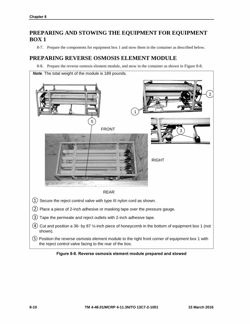
Chapter 8
8-10 TM 4-48.01/MCRP 4-11.3N/TO 13C7-2-1001 15 March 2016
PREPARING AND STOWING THE EQUIPMENT FOR EQUIPMENT
BOX 1
8-7. Prepare the components for equipment box 1 and stow them in the container as described below.
PREPARING REVERSE OSMOSIS ELEMENT MODULE
8-8. Prepare the reverse osmosis element module, and stow in the container as shown in Figure 8-8.
Note. The total weight of the module is 189 pounds.
① Secure the reject control valve with type III nylon cord as shown.
② Place a piece of 2-inch adhesive or masking tape over the pressure gauge.
③ Tape the permeate and reject outlets with 2-inch adhesive tape.
④ Cut and position a 36- by 87 ½-inch piece of honeycomb in the bottom of equipment box 1 (not
shown).
⑤ Position the reverse osmosis element module to the right front corner of equipment box 1 with
the reject control valve facing to the rear of the box.
Figure 8-8. Reverse osmosis element module prepared and stowed
2
1
5
3
REAR
FRONT
RIGHT

Rigging Lightweight Water Purifier (LWP) on a 12-Foot, Type V platform for Low-Velocity Airdrop
15 March 2016 TM 4-48.01/MCRP 4-11.3N/TO 13C7-2-1001 8-11
PREPARING CHEMICAL INJECTION CLEANING MODULE
8-9. Prepare the chemical injection cleaning module and stow in the container as shown in Figure 8-9a and
8-9b.
Note. The total weight of the module is 124 pounds.
① Secure the cleaning tank to the module frame using ½-inch tubular nylon webbing.
② Pad each top corner of the cleaning tank with felt and tape in place with 2-inch adhesive tape.
③ Secure the three tanks (anti-sealant, coagulant, and hypochlorite) and the plastic storage box
using inch tubular nylon webbing to the module frame so they will not move.
Figure 8-9a. Chemical injection cleaning module prepared and stowed
3
1
2

Chapter 8
8-12 TM 4-48.01/MCRP 4-11.3N/TO 13C7-2-1001 15 March 2016
① Secure the hose from the diverter valve to the frame using type III nylon cord.
② Tape the three injection pumps (anti-sealant, coagulant, and hypochlorite) with 2-inch
adhesive tape.
③ Tape the pressure gauge on the cleaning tank with 2-inch adhesive tape.
④ Secure the hose from the junction box to the frame using type III nylon cord.
⑤ Tape the product water-in valve using 2-inch adhesive tape.
⑥ Tape the cleaning inlet valve on the cleaning tank using 2-inch adhesive tape.
Figure 8-9b. Chemical injection cleaning module prepared and stowed (continued)
8
9
4
7
6
5

Rigging Lightweight Water Purifier (LWP) on a 12-Foot, Type V platform for Low-Velocity Airdrop
15 March 2016 TM 4-48.01/MCRP 4-11.3N/TO 13C7-2-1001 8-13
① Tape the product water-out valve with 2-inch adhesive tape.
② Tape the drain outlet valve with 2-inch adhesive tape.
③ Secure any loose hoses to the frame using type III nylon cord.
④ Position the chemical injection cleaning module on top of the reverse osmosis element module
and ensure the product water-in valve faces to the right side of equipment box 1.
Figure 8-9. Chemical injection cleaning module prepared and stowed (continued)
11
10
13
12
FRONT
RIGHT
REAR
LEFT

Chapter 8
8-14 TM 4-48.01/MCRP 4-11.3N/TO 13C7-2-1001 15 March 2016
PREPARING PUMP MODULE
8-10. Prepare the pump module and stow in the container as shown in Figures 8-10a and 8-10b.
Note. The total weight of the module is 152 pounds.
① Secure each individual pump to the module frame using two lengths of ½-inch tubular nylon
webbing.
② Tape all valves with 2-inch adhesive tape.
③ Secure two A-7A straps vertically around the center of the module frame.
Note. Ensure the fraction adapter of the A-7A strap is positioned at the bottom of the module frame and secure the excess webbing to the bottom inside vales using type I, ¼-inch cotton webbing.
④ Tape the male portions of the frame using 2-inch masking tape.
Figure 8-10a. Pump module prepared and stowed
1
2
4
1
1
1
2
3
4

Rigging Lightweight Water Purifier (LWP) on a 12-Foot, Type V platform for Low-Velocity Airdrop
15 March 2016 TM 4-48.01/MCRP 4-11.3N/TO 13C7-2-1001 8-15
① Position the pump module to the rear of the reverse osmosis element module and flush
against the right rear corner of equipment box 1.
Figure 8-10b. Pump module prepared and stowed (continued)
5 REAR
RIGHT
FRONT
LEFT

Chapter 8
8-16 TM 4-48.01/MCRP 4-11.3N/TO 13C7-2-1001 15 March 2016
STOWING COLD WEATHER KIT (CWK) 2 BOX AND CWK 3 BOX
8-11. Stow the CWK 2 box and the CWK 3 box in the container as shown in Figures 8-11a and 8-11b.
Note. The components listed below are stored inside the over pack kit box of cold weather kit 2. The total weight of the cold weather kit 2 box is 64 pounds
Item Description Quantity
Thermal Blanket, 10-feet, 0.75-inch hose
Thermal Blanket, 20-feet, 0.75-inch hose
2
4
Note. Ensure the cold weather kit 2 box is flush against the front and left side of the container.
① Position the cold weather kit 2 box to the left front of the container.
Figure 8-11a. CWK 2 box and Cold weather 3 box stored
1
RIGHT
FRONT
REAR
LEFT

Rigging Lightweight Water Purifier (LWP) on a 12-Foot, Type V platform for Low-Velocity Airdrop
15 March 2016 TM 4-48.01/MCRP 4-11.3N/TO 13C7-2-1001 8-17
Note. The components listed below are stored inside the over pack kit box of cold weather kit 3. The total weight of the cold weather kit box is 61 pounds.
Item Description Quantity
Thermal Blanket, 10-feet, 1.5-inch hose
Thermal Blanket, 20-feet, 1.5 inch hose
Thermal Blanket, 10-feet, 1-inch hose
Thermal Blanket, 20-feet, 1-inch hose
1
2
1
2
① Position the cold weather kit 3 box on top of the cold weather kit 2 box.
Figure 8-11b. CWK 2 box and CWK 3 box stowed (continued)
2
REAR
FRONT
RIGHT LEFT

Chapter 8
8-18 TM 4-48.01/MCRP 4-11.3N/TO 13C7-2-1001 15 March 2016
STOWING 1,000-GALLON COLLAPSIBLE RAW WATER AND
PRODUCT FABRIC TANKS
8-12. Stow the 1,000-gallon collapsible raw water and product fabric tanks in the container as shown in
Figure 8-12.
Note. The total weight of the 1,000 gallon collapsible raw water fabric tank is 59 pounds.
Note. The total weight of the 1,000 gallon collapsible product fabric tank is 50 pounds.
① Position the 1,000-gallon collapsible raw water fabric tank to the rear of the cold weather kit 2
box and the cold weather kit box.
② Position the 1,000-gallon collapsible product fabric tank on top of the 1,000-gallon collapsible
raw water fabric tank.
Figure 8-12. 1,000-gallon collapsible raw water and product fabric tank stowed
2
1

Rigging Lightweight Water Purifier (LWP) on a 12-Foot, Type V platform for Low-Velocity Airdrop
15 March 2016 TM 4-48.01/MCRP 4-11.3N/TO 13C7-2-1001 8-19
STOWING HIGH PRESSURE HOSE, BACKWASH HOSES, REJECT
HOSES, TUBE RAW WATER HOSES AND PRODUCT WATER HOSES
8-13. Stow the high pressure hose, backwash hoses; reject hoses, raw water hoses and product hoses in the
container as shown in Figure 8-13.
Note. The components listed below are stored on the cold weather kits and two fabric tanks. The combined weight of the hose is 238 pounds.
Item Description Quantity
High-pressure hose (orange code)
Backwash hose (yellow code)
Reject hose (red code)
Tube, raw water hose
Product water hose
1
2
2
2
3
① Position the high pressure hose (orange code) (1 each), backwash hose (yellow code) (2
each), reject hose (red code) (2 each), tube, raw water hose (2 each), and product hose (3 each) on top of the cold weather kits and two fabric tanks.
Figure 8-13. High pressure hose, backwash hoses, reject hoses, tube raw water hoses and product water hoses stowed
1

Chapter 8
8-20 TM 4-48.01/MCRP 4-11.3N/TO 13C7-2-1001 15 March 2016
CLOSING AND SECURING EQUIPMENT BOX 1
8-14. Close and secure equipment box 1 as shown in Figures 8-14a and 8-14b.
Note. Ensure the lashings placed in steps 3 and 4 are routed under the strong back and between the spaces of honeycomb stack 1.
① Fill the remaining space of the container with honeycomb and place a full sheet on top.
② Nail the plywood top (built in Figure 4-6, step 3) to the container using 8-penny nails.
③ Form one 30-foot lashing and route it around the container widthwise and centered. Secure it
on top of the container using two D-rings and a load binder.
④ Form two 30-foot lashings and route them around the box lengthwise. Secure each lashing on
top of the container using two D-rings and a load binder.
Figure 8-14a. Equipment box 1 closed and secured
4 3
2
1
FRONT

Rigging Lightweight Water Purifier (LWP) on a 12-Foot, Type V platform for Low-Velocity Airdrop
15 March 2016 TM 4-48.01/MCRP 4-11.3N/TO 13C7-2-1001 8-21
Note: Pad and tape all cutouts prior to routing lashings.
① Pass a 15-foot lashing through clevis 5 and through its own D-ring. Route the lashing across
the rear of the equipment box 1 and through the left cutout. Temporarily tape in place using 2-inch masking tape.
② Pass a 15-foot lashing through clevis 5A and through its own D-ring. Route the lashing across
the rear of equipment box 1 and through the right cutout. Temporarily tape in place using a 2-inch masking tape.
Figure 8-14b. Equipment box 1 closed and secured (continued)
6
LEFT
RIGHT
REAR
5
5
5A

Chapter 8
8-22 TM 4-48.01/MCRP 4-11.3N/TO 13C7-2-1001 15 March 2016
PREPARING AND POSITIONING HONEYCOMB STACK 2
8-15. Prepare honeycomb stack 2 as shown in Figures 8-15a and 8-15b. Position stack 2 as shown in Figure
8-16.
Notes. 1. This drawing is not to scale. 2. All dimensions are in inches.
① Cut nine pieces of 7 ½- by 12-inch honeycomb. Place the honeycomb to form three rows of
three. Leave 4 ½ inches between the pieces from front to rear and 28 inches between pieces from right to left.
② Cut two pieces of 15 ¾- by 92-inch honeycomb. Place the pieces side by side to form a 31 ½-
by 92-inch piece. Glue the pieces to the honeycomb placed in step 1.
③ Cut and glue eighteen pieces of 7 ½- by 12-inch honeycomb to form nine two layer stacks.
Position and glue the honeycomb on top of the 31 ½- by 92-inch piece of honeycomb as described in step 1.
Figure 8-15a. Honeycomb stack 2 prepared
FRONT
REAR
3
2
1

Rigging Lightweight Water Purifier (LWP) on a 12-Foot, Type V platform for Low-Velocity Airdrop
15 March 2016 TM 4-48.01/MCRP 4-11.3N/TO 13C7-2-1001 8-23
Notes. 1. This drawing is not to scale. 2. All dimensions are in inches. 3. Use 8-penny nails.
① Cut a 31 ½- by 92- by ¾-inch piece of plywood to form the base for the strongback.
② Position and nail four 2- by 4- by 92-inch pieces of lumber evenly spaced on top of the
plywood in step 4.
③ Cut a 31 ½- by 92- by ¾-inch piece of plywood and place on top of the 2- by 4-inch lumber
placed in step 5. Nail flush in place with 8-penny nails.
Figure 8-15b. Honeycomb stack 2 prepared (continued)
6
5
4

Chapter 8
8-24 TM 4-48.01/MCRP 4-11.3N/TO 13C7-2-1001 15 March 2016
① Position and center honeycomb stack 2 one-inch from the rear of honeycomb stack 1.
② Form two 30-foot lashings. Position and center a lashing lengthwise between the spaces of
honeycomb stack 2 on the right and left. Ensure the sewn D-rings are positioned in the center of the stack.
③ Position and glue the strongback (built in Figure 4-15, steps 4, 5, and 6) flush on top of the
honeycomb stack 2.
Figure 8-16. Honeycomb stack 2 positioned
1
3
1
2
REAR
LEFT RIGHT

Rigging Lightweight Water Purifier (LWP) on a 12-Foot, Type V platform for Low-Velocity Airdrop
15 March 2016 TM 4-48.01/MCRP 4-11.3N/TO 13C7-2-1001 8-25
CONSTRUCTING AND POSITIONING EQUIPMENT BOX 2
8-16. Construct the individual components of equipment box 2 as shown in Figures 8-17 and 8-18. Assemble
and position the equipment box 2 as shown in Figure 8-19.
Notes. 1. This drawing is not to scale.2. All dimensions are in inches.3. Use 8-penny nails.
① Cut two ¾- by 12- by 96-inch pieces of plywood. Face the finished side of the plywood up.
② Cut two ¾- by 48- by 96-inch pieces of plywood. Face the finished side of the plywood up.
③ Make 2- by 2-inch cutouts as shown in the plywood previously cut in step 2.
④ Lay the plywood previously cut in steps 1, 2 and 3 flush lengthwise to form two 60- by 96-inch
pieces. Face the finished sides of the plywood up.
⑤ Cut six 2- by 4- by 60-inch pieces of lumber. Nail four of the pieces 2 ¾ inches from the edge
of the plywood positioned in step 4. Nail the remaining two pieces centered between thepreviously nailed pieces. Ensure there are 40 inches between pieces.
⑥ Cut eight 2- by 4- by 40-inch pieces of lumber. Nail the pieces flush between the pieces
positioned in step 5. Ensure the lumber is aligned along the top and bottom exterior edges ofthe plywood.
Figure 8-17. Equipment box 2 front and rear constructed
6 6
6 6
5 1
5
4

Chapter 8
8-26 TM 4-48.01/MCRP 4-11.3N/TO 13C7-2-1001 15 March 2016
Notes.
1. This drawing is not to scale. 2. All dimensions are in inches. 3. Use 8-penny nails.
① Cut two ¾- by 31- by 60-inch pieces of plywood to make the sides of the equipment box.
② Nail a 2- by 4- by 28-inch piece of lumber along the top and bottom edges of each of the two
side pieces with 8-penny nails as shown. Allow the plywood to extend past the lumber 1 ½ inches on each side.
③ Cut two ¾- by 32 ½- by 92-inch pieces of plywood to make the top and bottom of equipment
box 2.
Figure 8-18. Equipment box 2 sides, top and bottom constructed
2
2
1
3
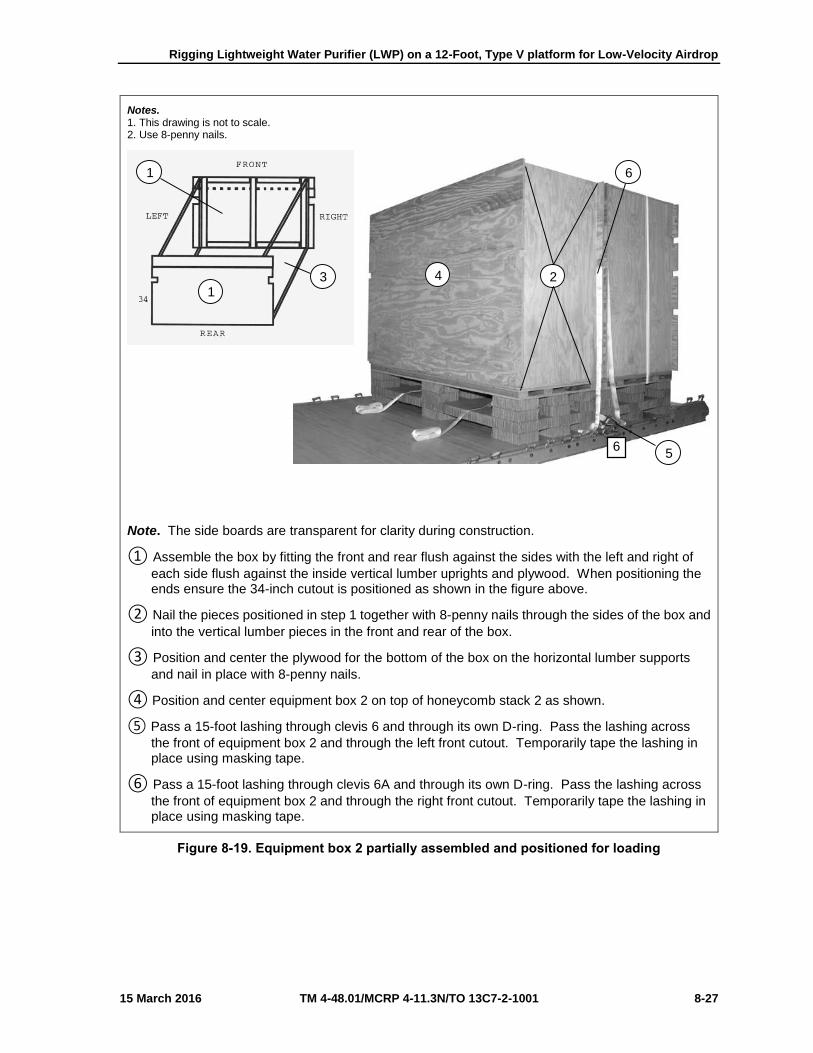
Rigging Lightweight Water Purifier (LWP) on a 12-Foot, Type V platform for Low-Velocity Airdrop
15 March 2016 TM 4-48.01/MCRP 4-11.3N/TO 13C7-2-1001 8-27
Notes. 1. This drawing is not to scale.2. Use 8-penny nails.
Note. The side boards are transparent for clarity during construction.
① Assemble the box by fitting the front and rear flush against the sides with the left and right of
each side flush against the inside vertical lumber uprights and plywood. When positioning theends ensure the 34-inch cutout is positioned as shown in the figure above.
② Nail the pieces positioned in step 1 together with 8-penny nails through the sides of the box and
into the vertical lumber pieces in the front and rear of the box.
③ Position and center the plywood for the bottom of the box on the horizontal lumber supports
and nail in place with 8-penny nails.
④ Position and center equipment box 2 on top of honeycomb stack 2 as shown.
⑤ Pass a 15-foot lashing through clevis 6 and through its own D-ring. Pass the lashing across
the front of equipment box 2 and through the left front cutout. Temporarily tape the lashing inplace using masking tape.
⑥ Pass a 15-foot lashing through clevis 6A and through its own D-ring. Pass the lashing across
the front of equipment box 2 and through the right front cutout. Temporarily tape the lashing inplace using masking tape.
Figure 8-19. Equipment box 2 partially assembled and positioned for loading
2
5
4
6
6
1
3 1

Chapter 8
8-28 TM 4-48.01/MCRP 4-11.3N/TO 13C7-2-1001 15 March 2016
PREPARING AND STOWING THE EQUIPMENT FOR EQUIPMENT
BOX 2
8-17. Prepare the components for equipment box 2 and stow them in the container as described below.
PREPARING CONTROL MODULE ULTRA-FILTRATION MODULE,
AND HIGH-PRESSURE PUMP MODULE
8-18. Prepare the control module, ultra-filtration module, and high-pressure pump module as shown in
Figures 8-20a-d. Stow them in the container as shown in Figure 8-21.
① Position the control module, ultra-filtration module, and high-pressure pump module as shown
above. The control module and high-pressure pump module are on the bottom with the ultra-filtration module on the top.
② Secure the frames of the control module and high-pressure pump module together using ½-
inch tubular nylon webbing.
③ Route an A-7A strap vertically around the high-pressure pump module and ultra-filtration
module and secure on top.
Figure 8-20a. Control module, ultra-filtration module, and high-pressure pump module prepared
1
2
3

Rigging Lightweight Water Purifier (LWP) on a 12-Foot, Type V platform for Low-Velocity Airdrop
15 March 2016 TM 4-48.01/MCRP 4-11.3N/TO 13C7-2-1001 8-29
④ Route an A-7A strap horizontally around the control module and high-pressure pump module
and secure on the side.
⑤ Route an A-7A strap under the top bar of the control module frame and vertically around the
top of the ultra-filtration module. Secure it on top of the ultra-filtration module.
⑥ Route an A-7A strap between the frame and fuel tank of the high-pressure pump module, and
vertically around the ultra-filtration module. Secure it on top of the ultra-filtration module.
⑦ Tape the back wash pressure gauge, differential gauge, and the feed pressure gauge on the
ultra-filtration mode.
⑧ Tape the back wash-in valve and feed-in valve on the ultra-filtration module.
Figure 8-20b. Control module, ultra-filtration module, and high-pressure pump module prepared (continued)
4
7
5 6 8

Chapter 8
8-30 TM 4-48.01/MCRP 4-11.3N/TO 13C7-2-1001 15 March 2016
⑨ Secure the hose from the junction box of the ultra-filtration module using type III nylon cord.
⑩ Secure the hose by the protection grill on the ultra-filtration module using type III nylon cord.
⑪ Tape the feed water-in valve of the high-pressure pump module with 2-inch adhesive tape.
Figure 8-20c. Control module, ultra-filtration module, and high-pressure pump module prepared (continued)
9
10
11

Rigging Lightweight Water Purifier (LWP) on a 12-Foot, Type V platform for Low-Velocity Airdrop
15 March 2016 TM 4-48.01/MCRP 4-11.3N/TO 13C7-2-1001 8-31
⑫ Tape the thermometer on the ultra-filtration module using 2-inch adhesive tape.
⑬ Tape the reject out valve of the ultra-filtration modeling using 2-inch adhesive tape.
⑭ Tape the diesel engine shut-off device air tank gauge on the high-pressure pump module using
2-inch adhesive tape.
⑮ Tape the hour meter of the control module using 2-inch adhesive tape.
Figure 8-20d. Control module, ultra-filtration module, and high-pressure pump module prepared (Continued)
15
14
12
138
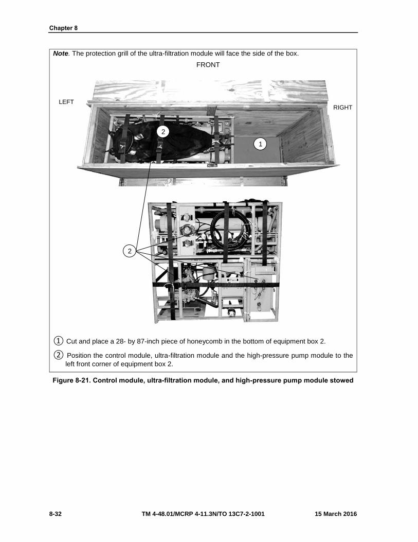
Chapter 8
8-32 TM 4-48.01/MCRP 4-11.3N/TO 13C7-2-1001 15 March 2016
Note. The protection grill of the ultra-filtration module will face the side of the box.
① Cut and place a 28- by 87-inch piece of honeycomb in the bottom of equipment box 2.
② Position the control module, ultra-filtration module and the high-pressure pump module to the
left front corner of equipment box 2.
Figure 8-21. Control module, ultra-filtration module, and high-pressure pump module stowed
1
2
LEFT RIGHT
FRONT
2

Rigging Lightweight Water Purifier (LWP) on a 12-Foot, Type V platform for Low-Velocity Airdrop
15 March 2016 TM 4-48.01/MCRP 4-11.3N/TO 13C7-2-1001 8-33
STOWING 3 KILOWATT GENERATOR
8-19. Make sure the 3 KW generator is no more than 75% full. Stow the 3 KW generator in the equipment
box as shown in Figure 8-22.
CAUTION
A full tank does not allow for expansion, and is a danger to aircraft and air crew. Ensure the 3 KW generator complies with AFMAN 24-204/TM
38-250.
Note. Ensure the controls of the 3 kilowatt generator face towards the center of the box.
① Position the 3kw generator at the right front corner inside equipment box 2.
Figure 8-22. 3 KW generator stowed
1
LEFT
FRONT
RIGHT

Chapter 8
8-34 TM 4-48.01/MCRP 4-11.3N/TO 13C7-2-1001 15 March 2016
CLOSING AND SECURING EQUIPMENT BOX 2
8-20. Close and secure equipment box 2 as shown in Figure 8-23.
Note. Use 8-penny nails.
Note. Pad and tapes all cutouts prior to routing lashings.
① Fill the remaining space with honeycomb to the top of the box. Place the plywood lid on top of
equipment box 2 and nail together using 8-penny nails (not shown).
② Form a 30-foot lashing and route it around equipment box 2 widthwise. Secure the lashing on
top using two D-rings and a load binder. Ensure the lashing is routed under the strongback.
③ Route the two pre-positioned 30-foot lashings around equipment box 2 lengthwise. Secure
each lashing on top using two D-rings and a load binder.
④ Pass a 15-foot lashing through clevis 12 and through its own D-ring. Route the lashing across
the rear of the equipment box 2 and through the left bottom cutout. Temporarily tape in placingusing 2-inch masking tape. Repeat for clevis 12A to the right bottom cutout.
⑤ Pass a 15-foot lashing through clevis 13 and through its own D-ring. Route the lashing across
the rear of equipment box 2 and through the left top cutout. Temporarily tape in place using 2-inch masking tape. Repeat for clevis 13A to the right top cutout.
Figure 8-23. Equipment box 2 closed and secured
2
3
4
5
4
5
13A 12A
13 12

Rigging Lightweight Water Purifier (LWP) on a 12-Foot, Type V platform for Low-Velocity Airdrop
15 March 2016 TM 4-48.01/MCRP 4-11.3N/TO 13C7-2-1001 8-35
PREPARING AND POSITIONING HONEYCOMB STACK 3
8-21. Prepare honeycomb stack 3 as shown in Figure 8-24. Position honeycomb stack 3 as shown in Figure
8-25.
Notes: 1. This drawing is not to scale. 2. All measurements are in inches.
① Cut nine pieces of 7- by 12-inch honeycomb. Place the honeycomb to form three rows of
three. Leave 9 ½ inches between the pieces from front to rear and 28 inches between pieces from right to left.
② Cut two pieces of 20- by 92-inch honeycomb. Place the pieces side by side to form a 40- by 92-
inch piece of honeycomb. Glue the pieces to the honeycomb placed in step 1.
③ Cut and glue eighteen pieces of 7- by 12-inch honeycomb to form nine two layer stacks.
Position and glue the honeycomb on top of the 40- by 92-inch piece of honeycomb as described in step 1.
Figure 8-24. Honeycomb stack 3 prepared
REAR
FRONT
3
1
2
28
28
9 1/2 9 1/2

Chapter 8
8-36 TM 4-48.01/MCRP 4-11.3N/TO 13C7-2-1001 15 March 2016
① Position and center honeycomb stack 3 one-inch from the rear of honeycomb stack 2.
② Form two 30-foot lashings. Position and center a lashing lengthwise between each space of
honeycomb stack 3 on the right and left. Ensure the sewn D-rings are positioned in the center of the stack.
③ Cut and position a 40- by 92- by ¾-inch piece of plywood on top of honeycomb stack 3.
Figure 8-25. Honeycomb stack 3 positioned
2
3
1
1

Rigging Lightweight Water Purifier (LWP) on a 12-Foot, Type V platform for Low-Velocity Airdrop
15 March 2016 TM 4-48.01/MCRP 4-11.3N/TO 13C7-2-1001 8-37
CONSTRUCTING AND POSITIONING EQUIPMENT BOX 3
8-22. Construct the individual components of equipment box 3 as shown in Figures 8-26a, 8-26b, and 8-27.
Notes: 1. This drawing is not to scale. 2. All measurements are in inches.
① Cut two ¾- by 48- by 96-inch pieces of plywood. Face the finished side of the plywood up.
② Make 2- by 2-inch cutouts as shown in the plywood previously cut in step 1.
Figure 8-26a. Equipment box 3 front and rear constructed
1
1
2
2

Chapter 8
8-38 TM 4-48.01/MCRP 4-11.3N/TO 13C7-2-1001 15 March 2016
Notes: 1. This drawing is not to scale.2. All measurements are in inches
③ Cut six 2- by 4- by 48-inch pieces of lumber. Nail four of the pieces 2 ¾ inches from the edge
of the plywood cut in step 1. Nail one of the remaining two pieces centered between thepreviously nailed pieces. Ensure there are 40 inches between pieces.
④ Cut eight 2- by 4- by 40-inch pieces of lumber. Nail the pieces flush between the pieces
positioned in step 3. Ensure the lumber is aligned along the top and bottom exterior edges ofthe plywood.
Figure 8-26b. Equipment box 3 front and rear constructed (continued)
3
4
4 4
4 4
4
4
4

Rigging Lightweight Water Purifier (LWP) on a 12-Foot, Type V platform for Low-Velocity Airdrop
15 March 2016 TM 4-48.01/MCRP 4-11.3N/TO 13C7-2-1001 8-39
Notes: 1. This drawing is not to scale. 2. All measurements are in inches.
① Cut two ¾- by 41- by 48-inch pieces of plywood to make the sides of the equipment box.
② Nail a 2- by 4- by 38-inch piece of lumber along the top and bottom edges of each of the two
side pieces with 8-penny nails as shown. Allow the plywood to extend past the lumber 1 ½ inches on each side.
③ Cut two ¾- by 42 ½- by 92-inch pieces of lumber to make the top and bottom of the equipment
box.
Figure 8-27. Equipment box 3 sides, top and bottom constructed
1
2
3

Chapter 8
8-40 TM 4-48.01/MCRP 4-11.3N/TO 13C7-2-1001 15 March 2016
CONSTRUCTING AND POSITIONING EQUIPMENT BOX 3
8-23. Assemble and position the equipment box 3 as shown in Figure 8-28.
Notes: 1. This drawing is not to scale. 2. All measurements are in inches.
Note. The side boards are transparent for clarity during construction.
① Assemble the box. When positioning the ends ensure that the 34-inch cutout is positioned at
the front bottom and the 20-inch cutout is positioned at the rear bottom portion of the box.
② Nail the pieces positioned in step 1 together with 8-penny nails through the sides of the box
and into the vertical lumber pieces in the front and rear of the box.
③ Position and center the plywood for the bottom of the box on the horizontal lumber supports
and nail in place with 8-penny nails.
④ Position and center equipment box 3 on top of honeycomb stack 3 as shown.
Figure 8-28. Equipment box 3 partially assembled and positioned for loading
4 2 2
1
3
1
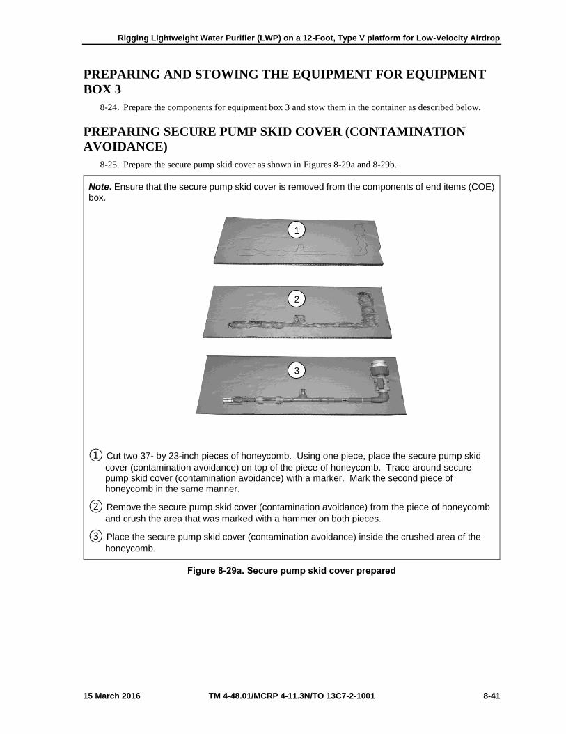
Rigging Lightweight Water Purifier (LWP) on a 12-Foot, Type V platform for Low-Velocity Airdrop
15 March 2016 TM 4-48.01/MCRP 4-11.3N/TO 13C7-2-1001 8-41
PREPARING AND STOWING THE EQUIPMENT FOR EQUIPMENT
BOX 3
8-24. Prepare the components for equipment box 3 and stow them in the container as described below.
PREPARING SECURE PUMP SKID COVER (CONTAMINATION
AVOIDANCE)
8-25. Prepare the secure pump skid cover as shown in Figures 8-29a and 8-29b.
Note. Ensure that the secure pump skid cover is removed from the components of end items (COE) box.
① Cut two 37- by 23-inch pieces of honeycomb. Using one piece, place the secure pump skid
cover (contamination avoidance) on top of the piece of honeycomb. Trace around securepump skid cover (contamination avoidance) with a marker. Mark the second piece ofhoneycomb in the same manner.
② Remove the secure pump skid cover (contamination avoidance) from the piece of honeycomb
and crush the area that was marked with a hammer on both pieces.
③ Place the secure pump skid cover (contamination avoidance) inside the crushed area of the
honeycomb.
Figure 8-29a. Secure pump skid cover prepared
2
3
1

Chapter 8
8-42 TM 4-48.01/MCRP 4-11.3N/TO 13C7-2-1001 15 March 2016
① Place the second piece of 37- by 23- inch honeycomb on top of the piece with the secure
pump skid cover (contamination avoidance) inside it.
② Cut two ¾- by 37- by 23- inch piece so plywood. Place one piece under and one piece over
the honeycomb housing the secure pump skid cover (contamination avoidance). Secure the pieces together with three lengths of type III nylon cord.
Figure 8-29b. Secure pump skid cover (continued)
4
5

Rigging Lightweight Water Purifier (LWP) on a 12-Foot, Type V platform for Low-Velocity Airdrop
15 March 2016 TM 4-48.01/MCRP 4-11.3N/TO 13C7-2-1001 8-43
PREPARING BASIC ISSUE ITEMS (BII) BOX, COMPONENTS OF
END ITEMS (COEI) BOX AND COEI CABLE
8-26. Prepare the BII box, COEI box and COEI cable box, and stow in the container as shown in Figures 8-
30a-d.
Note. The components listed below are stored inside issue items box. The total weight is 100 pounds.
Item Description Quantity
Instrument Case
Fire Extinguisher
Apron
Gloves
Pipe Repair System
Sand Bags
Small Funnel
Large Funnel
Goggles
Dust Masks
Rope
Flotation Device
Retaining Rings
Chlorine Photometer
Utility Pail, 5-Quart
Hearing Protection
Tool Kit
Ultra-Filtration Cleaning Outlet
Stirring Paddle
Cleaning Adapter
Flushing Adapter
Textile Hose, 3/8-inch
End Cap Removal Tool
Pipe Wrench, Adjustable Strap
Over-Pack Kit Box
Fabric-Tank Repair Kit
1
1
2
2
1
20
1
1
2
25
50-feet
1
7
1
1
1
1
1
1
1
1
1
1
1
1
1
Figure 8-30a. BII box, COEI box and COEI cable box prepared and stowed
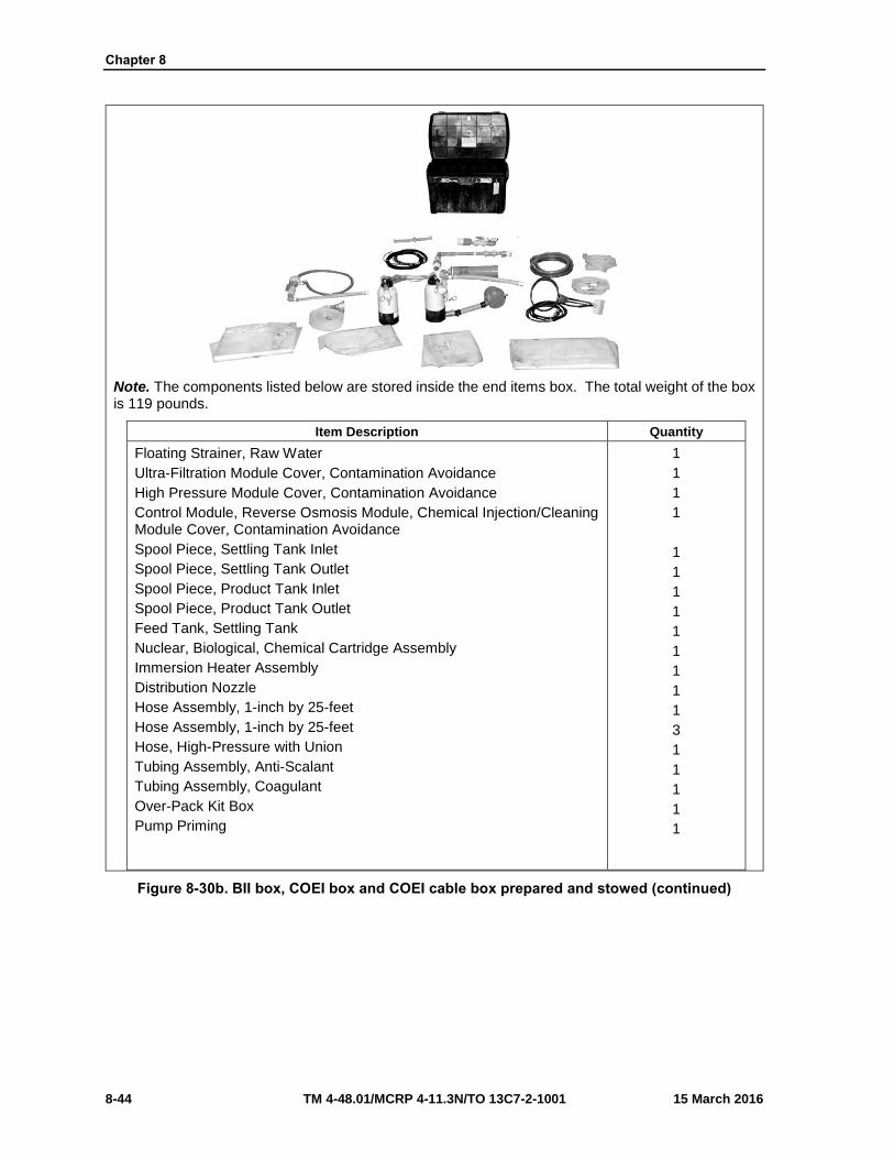
Chapter 8
8-44 TM 4-48.01/MCRP 4-11.3N/TO 13C7-2-1001 15 March 2016
Note. The components listed below are stored inside the end items box. The total weight of the box is 119 pounds.
Item Description Quantity
Floating Strainer, Raw Water
Ultra-Filtration Module Cover, Contamination Avoidance
High Pressure Module Cover, Contamination Avoidance
Control Module, Reverse Osmosis Module, Chemical Injection/Cleaning Module Cover, Contamination Avoidance
Spool Piece, Settling Tank Inlet
Spool Piece, Settling Tank Outlet
Spool Piece, Product Tank Inlet
Spool Piece, Product Tank Outlet
Feed Tank, Settling Tank
Nuclear, Biological, Chemical Cartridge Assembly
Immersion Heater Assembly
Distribution Nozzle
Hose Assembly, 1-inch by 25-feet
Hose Assembly, 1-inch by 25-feet
Hose, High-Pressure with Union
Tubing Assembly, Anti-Scalant
Tubing Assembly, Coagulant
Over-Pack Kit Box
Pump Priming
1
1
1
1
1
1
1
1
1
1
1
1
1
3
1
1
1
1
1
Figure 8-30b. BII box, COEI box and COEI cable box prepared and stowed (continued)

Rigging Lightweight Water Purifier (LWP) on a 12-Foot, Type V platform for Low-Velocity Airdrop
15 March 2016 TM 4-48.01/MCRP 4-11.3N/TO 13C7-2-1001 8-45
Note. The components listed below are stored inside the components of the items cable box. The total weight of the box is 79 pounds.
Item Description Quantity
Cable 1, 40-feet, Generator to Control Module
Cable 2, 100-feet, Raw Water Service Pump to Control Module
Cable 3, 50-feet, Booster Service Pump to Control Module
Cable 4, 20-feet, Backwash Service Pump to Control Module
Cable 5, 30-feet, Distribution Service Pump to Control Module
Cable 11, 40-feet, Ground Cable, Control Module to Grounding Rod
Storage Container
1
1
1
1
1
1
1
Figure 8-30c. BII box, COEI box and COEI cable box prepared and stowed (continued)
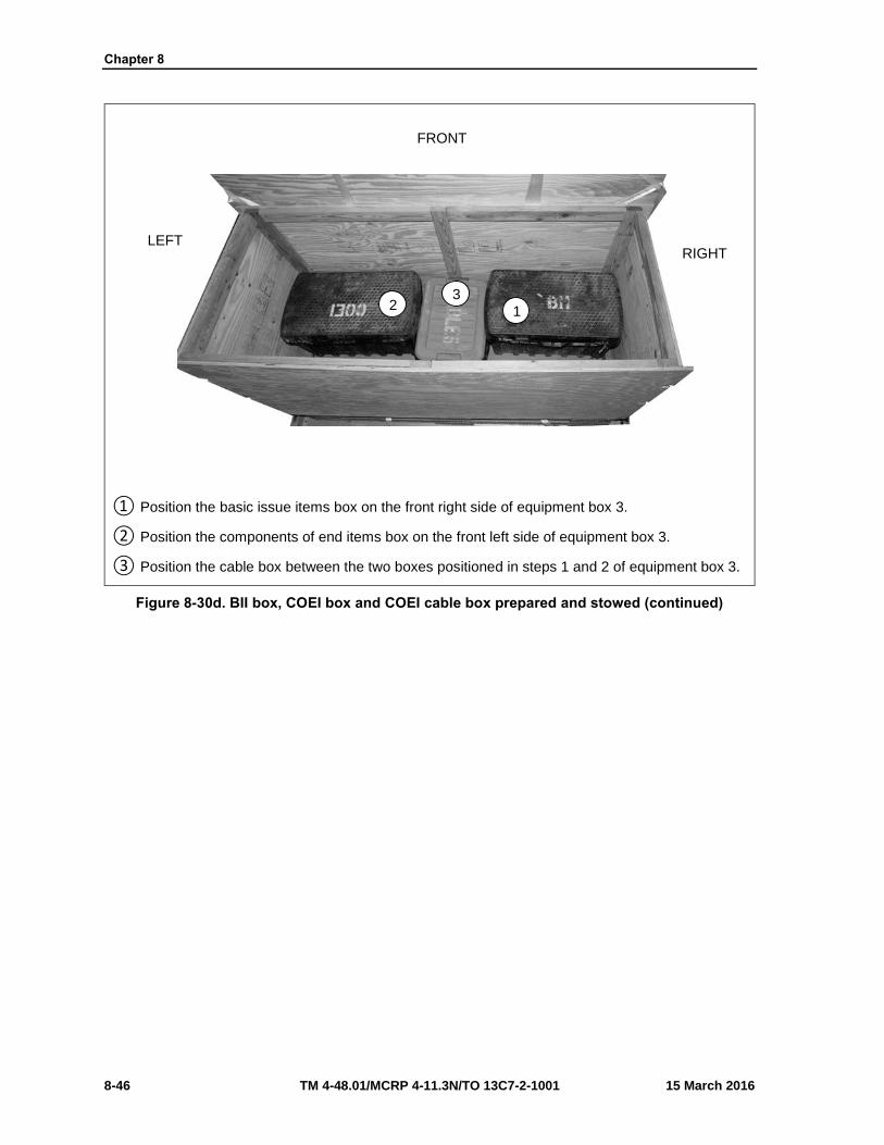
Chapter 8
8-46 TM 4-48.01/MCRP 4-11.3N/TO 13C7-2-1001 15 March 2016
① Position the basic issue items box on the front right side of equipment box 3.
② Position the components of end items box on the front left side of equipment box 3.
③ Position the cable box between the two boxes positioned in steps 1 and 2 of equipment box 3.
Figure 8-30d. BII box, COEI box and COEI cable box prepared and stowed (continued)
LEFT RIGHT
2 1
3
FRONT

Rigging Lightweight Water Purifier (LWP) on a 12-Foot, Type V platform for Low-Velocity Airdrop
15 March 2016 TM 4-48.01/MCRP 4-11.3N/TO 13C7-2-1001 8-47
PREPARING CWK 1 BOX AND LOADING TRUCK
8-27. Prepare the CWK 1 box and loading truck, and stow in the container as shown in Figures 8-31a and 8-
31b.
Note. The components listed are stored inside the cold weather kit 1 box. The total weight of the box is 56 pounds.
Item Description Quantity
Power Distribution Panel
Cable Assembly, Extension, 15 feet
Service Pump Thermal Blanket
Exhaust hose, 6 feet
Carbon Monoxide Detector
Exhaust Adapter
Hose Clamp, 2 to 3 inches
Hose Clamp, 1.25 inches
Storage Container
1
5
1
1
1
1
1
1
1
Figure 8-31a. CWK 1 box and loading truck prepared and stowed

Chapter 8
8-48 TM 4-48.01/MCRP 4-11.3N/TO 13C7-2-1001 15 March 2016
① Place the cold weather kit box on top of the basic issue items box.
② Place the loading truck on top of the components of end items box with the wheels facing the
left side of equipment box 3.
③ Fill the remaining empty spaces with honeycomb leaving enough space to place the prepared
secure pump skid cover (contamination avoidance) (Figure 6-29, steps 1 through 5) in the front right top corner of equipment box 3.
Figure 8-31b. CWK 1 box and loading truck prepared and stowed (continued)
3
LEFT RIGHT
1 2

Rigging Lightweight Water Purifier (LWP) on a 12-Foot, Type V platform for Low-Velocity Airdrop
15 March 2016 TM 4-48.01/MCRP 4-11.3N/TO 13C7-2-1001 8-49
CLOSING AND SECURING EQUIPMENT BOX 3
8-28. Close and secure equipment box 3 as shown in Figure 8-32.
Note. Use 8-penny nails.
① Place the plywood lid on top of equipment box 3 and nail in place using 8-penny nails.
② Form a 30-foot lashing. Route the 30-foot lashing around box 3 widthwise. Secure the lashing
on top using two D-rings and a load binder. Ensure the lashing is routed under the strongback.
③ Route the two pre-positioned 30-foot lashings around equipment box 3 lengthwise. Secure
each lashing on top using two D-rings and a load binder.
Figure 8-32. Equipment box 3 closed and secured
1
2
3
REAR FRONT
2

Chapter 8
8-50 TM 4-48.01/MCRP 4-11.3N/TO 13C7-2-1001 15 March 2016
INSTALLING LASHINGS
8-29. Lash the load to the platform according to TM 4-48.02/MCRP 4-11.3J/NAVSEA SS400-AB-MMO-
010 REV 1/TO 13C7-1-5, and as shown in Figures 8-33a-e.
Notes. 1. This load requires lashings over 30 feet in length. Lashings must be positioned through clevises before sections are joined together. 2. Pad and tape all cutouts prior to routing lashings.
Lashing Number
Tie Down Clevis Number
Instructions
1
2
2 and 5
2A and 5A
Route a 15-foot lashing through clevis 2 and through its own D-ring. Route the lashing across the front of equipment box 1 to the left middle cutout. Secure the lashing to the pre-routed lashing from clevis 5 centered on the left side of equipment box 1 with two D-rings and load binder.
Route a 15-foot lashing through clevis 2A and through its own D-ring. Route the lashing across the front of equipment box 1 to the right middle cutout. Secure the lashing to the pre-routed lashing from clevis 5A centered on the right side of equipment box 1 with two D-rings and load binder.
Figure 8-33a. Lashings Installed
2
1
2A
2
RIGHT
LEFT
FRONT
5

Rigging Lightweight Water Purifier (LWP) on a 12-Foot, Type V platform for Low-Velocity Airdrop
15 March 2016 TM 4-48.01/MCRP 4-11.3N/TO 13C7-2-1001 8-51
Lashing Number Tie Down Clevis Number
Instructions
3
4
5
3 and 3A
4 and 4A
7 and 7A
Route a 15-foot lashing through clevis 3 and through its own D-ring. Route it to the top of equipment box 1. Route a 15-foot lashing through clevis 3A and through its own D-ring. Route it to the top of equipment box 1. Secure the lashing with the lashing from clevis 3 on top of equipment box 1 with two D-rings and a load binder.
Route a 15-foot lashing through clevis 4 and through its own D-ring. Route the lashing to the front right bottom cutout of equipment box 1. Route a 15-foot lashing through clevis 4A and through its own D-ring. Route the lashing to the front left bottom cutout of equipment box 1. Secure the lashing with the lashing from clevis 4 centered on the front of equipment box 1 with two D-rings and a load binder.
Form a 45-foot lashing. Route a free end through clevis 7 and the other free end through clevis 7A. Route the lashing through the front top cutouts of equipment box 1. Secure the lashing centered on the front of equipment box 1 with two D-rings and a load binder.
Figure 8-33b. Lashings installed (continued)
REAR FRONT
5
4
3
7 4 3
RIGHT

Chapter 8
8-52 TM 4-48.01/MCRP 4-11.3N/TO 13C7-2-1001 15 March 2016
Lashing Number Tie Down Clevis Number
Instructions
6
7
8
6 and 12
6A and 12A
10 and 10A
Using the 15-foot lashing on clevis 6, secure the lashing from clevis 12, centered on the left side of equipment box 2 with two D-rings and load binder.
Using the 15-foot lashing on clevis 6A, secure the lashing to the pre-routed lashing from clevis 12A, centered on the right side of equipment box 2 with two D-rings and load binder.
Route a 15-foot lashing through clevis 10 and through its own D-ring. Route it to the top of equipment box 2. Route a 15-foot lashing through clevis 10A and through its own D-ring. Route it to the top of equipment box 2. Secure the lashing with the lashing from clevis 10 on top of equipment box 2 with two D-rings and a load binder.
Figure 8-33c. Lashings Installed (Continued)
REAR FRONT
7
8
6
12 10 6
6
RIGHT

Rigging Lightweight Water Purifier (LWP) on a 12-Foot, Type V platform for Low-Velocity Airdrop
15 March 2016 TM 4-48.01/MCRP 4-11.3N/TO 13C7-2-1001 8-53
Lashing Number Tie Down Clevis Number
Instructions
9
10
13 and 16
13A and 16A
Route a 15-foot lashing through clevis 16 and through its own D-ring. Route the lashing across the rear of equipment box 3 to the rear left top cutout. Secure the lashing to the pre-routed lashing from clevis 13, centered on the left side of equipment box 3 with two D-rings and load binder.
Route a 15-foot lashing through clevis 16A and through its own D-ring. Route the lashing across the rear of equipment box 3 to the rear right top cutout. Secure the lashing to the pre-routed lashing from clevis 13A, centered on the right side of equipment box 3 with two D-rings and load binder.
Figure 8-33d. Lashings installed (continued)
REAR
RIGHT
10 9
16A
16
13

Chapter 8
8-54 TM 4-48.01/MCRP 4-11.3N/TO 13C7-2-1001 15 March 2016
Lashing Number
Tie Down Clevis Number
Instructions
11
12
13
15 and 15A
11 and 11A
8 and 8A
Route a 15-foot lashing through clevis 15 and through its own D-ring. Route it to the top of equipment box 3. Route a 15-foot lashing through clevis 15A and through its own D-ring. Route it to the top of equipment box 3. Secure the lashing with the lashing from clevis 15 on top of equipment box 3 with two D-rings and a load binder.
Route a 15-foot lashing through clevis 11 and through its own D-ring. Route the lashing to the rear right bottom cutout of equipment box 3. Route a 15-foot lashing through clevis 11A and through its own D-ring. Route the lashing to the rear left bottom cutout of equipment box 3. Secure the lashing with the lashing from clevis 11 centered on the rear of equipment box 3 with two D-rings and a load binder.
Form a 45-foot lashing. Route a free end through clevis 8 and the other free end through clevis 8A. Route the lashing through the rear top cutouts of equipment box 3. Secure the lashing centered on the rear of equipment box 3 with two D-rings and a load binder.
Figure 8-33e. Lashings installed (continued)
REAR
13
12
11
RIGHT

Rigging Lightweight Water Purifier (LWP) on a 12-Foot, Type V platform for Low-Velocity Airdrop
15 March 2016 TM 4-48.01/MCRP 4-11.3N/TO 13C7-2-1001 8-55
POSITIONING THE ATTITUDE CONTROL BAR AND INSTALLING
SUSPENSION SLINGS AND SAFETY TIES
8-30. Position the attitude control bar (ACB) and install the suspension slings and safety tie as shown in
Figures 8-34a and 8-34b.
① Position and center the attitude control bar (ACB) on top of equipment box 1 with the attaching
holes facing toward the rear of the platform.
② Attach a 16-foot (2-loop), type XXVI nylon suspension sling to each tandem link with a large
clevis. Route the opposite end of the front slings up through the ACB ends. Extend the slings upward to position the ACB.
③ Pad the front suspension slings with felt and tape in place 24 inches below the ACB to a point
6 inches above the top of the ACB. Extend the tape beyond the top and bottom of the felt to secure in place.
Figure 8-34a. Attitude control bar, suspension slings and safety tie positioned and installed
FRONTT REAR
3 2
1
RIGHT

Chapter 8
8-56 TM 4-48.01/MCRP 4-11.3N/TO 13C7-2-1001 15 March 2016
① Route a 15-foot lashing through clevis 1, up through the front inside of the hole of the attitude
control bar (ACB), around the front, and back to clevis 1. Connect the lashing using a D-ring and load binder but do not tighten at this time. Repeat for clevis 1A on the left side.
② Route a 15-foot lashing through clevis 9, up through the rear inside of the hole of the ACB,
around the rear, and back to clevis 9. Connect the lashing using a D-ring and load binder but do not tighten at this time. Repeat for clevis 9A on the left side.
③ At this point tighten all lashings at the same time.
④ Safety tie each front suspension sling to the ACB using type III nylon cord.
⑤ Make a suspension sling safety tie between the rear suspension slings only using ½-inch
tubular nylon webbing according to the appendix at the rear of this manual.
Figure 8-34b. Attitude control bar, suspension slings and safety tie positioned and installed (continued)
REAR FRONTT
5
4
4
8
7
5 6 6
1 9

Rigging Lightweight Water Purifier (LWP) on a 12-Foot, Type V platform for Low-Velocity Airdrop
15 March 2016 TM 4-48.01/MCRP 4-11.3N/TO 13C7-2-1001 8-57
BUILDING AND POSITIONING PARACHUTE STOWAGE
PLATFORM
8-31. Build and position the parachute stowage platform as shown in Figure 8-35.
Note. Make sure the safety tie and suspension slings are on top the parachute stowage platform.
① Prepare a parachute platform by cutting and positioning a 36- by 96-inch piece of honeycomb
on top of equipment box 3 flush with the rear edge. Make cutouts in this piece where it comesin contact with the lashings on top of equipment box 3. Place three additional pieces of 36- by96-inch pieces on top of the first piece. Tape the 36-inch side with 2-inch adhesive tape.
② Cut and position four 6- by 96-inch pieces of honeycomb to the front of the 36- by 96-inch
pieces of honeycomb previously placed. Tape the 6-inch side with 2-inch adhesive tape.
③ Secure the parachute platform to the bushings on the type V platform on each side using type
III nylon cord.
Figure 8-35. Parachute stowage platform built and positioned
REAR FRONT
2
1
3
RIGHT

Chapter 8
8-58 TM 4-48.01/MCRP 4-11.3N/TO 13C7-2-1001 15 March 2016
PREPARING AND STOWING CARGO PARACHUTES
8-32. Prepare and stow the cargo parachutes as shown in Figure 8-36.
① Prepare, position and stow two G-11B cargo parachutes on the parachute stowage platform
according to TM 4-48.02/MCRP 4-11.3J/NAVSEA SS400-AB-MMO-010 REV 1/TO 13C7-1-5.
② Using type VIII nylon webbing install the cargo parachute restraint to clevises 14 and 14A
according to TM 4-48.02/MCRP 4-11.3J/NAVSEA SS400-AB-MMO-010 REV 1/TO 13C7-1-5.
③ Install the parachute release straps according to TM 4-48.02/MCRP 4-11.3J/NAVSEA SS400-
AB-MMO-010 REV 1/TO 13C7-1-5.
Figure 8-36. Cargo parachutes prepared and stowed
REAR RIGHT
2
3
14
3
1

Rigging Lightweight Water Purifier (LWP) on a 12-Foot, Type V platform for Low-Velocity Airdrop
15 March 2016 TM 4-48.01/MCRP 4-11.3N/TO 13C7-2-1001 8-59
INSTALLING PARACHUTE RELEASE SYSTEM
8-33. Prepare, attach and safety an M-1 cargo parachute release according to TM 4-48.02/MCRP 4-
11.3J/NAVSEA SS400-AB-MMO-010 REV 1/TO 13C7-1-5 and as shown in Figure 8-37.
① Center a 15- by 18-inch piece of honeycomb to the rear of the attitude control bar. Tape the
edges of the piece of honeycomb. Secure the honeycomb to the load using two lengths of type III cord.
② Prepare and install the M-1 cargo parachute release according to TM 4-48.02/MCRP 4-
11.3J/NAVSEA SS400-AB-MMO-010 REV 1/TO 13C7-1-5. Center the assembly on top of honeycomb.
③ S-fold and tie any excess in the suspension slings using one turn single type I, ¼-inch cotton
webbing.
④ Safety tie the M-1 cargo parachute release to convenient bushings on the type V platform
using type III nylon cord according to TM 4-48.02/MCRP 4-11.3J/NAVSEA SS400-AB-MMO-010 REV 1/TO 13C7-1-5.
Figure 8-37. Cargo parachute release installed
2
4 1
3
4
3
4 4

Chapter 8
8-60 TM 4-48.01/MCRP 4-11.3N/TO 13C7-2-1001 15 March 2016
INSTALLING EXTRACTION SYSTEM
8-34. Install the extraction system as shown in Figure 8-38.
① Install the components of the extraction force transfer coupling system according to TM 4-
48.02/MCRP 4-11.3J/NAVSEA SS400-AB-MMO-010 REV 1/TO 13C7-1-5. Use the frontmounting holes on the left side of the platform for the extraction force transfer coupling systembrackets.
② Install a 12-foot extraction force transfer coupling system cable according to TM 4-48.02/MCRP
4-11.3J/NAVSEA SS400-AB-MMO-010 REV 1/TO 13C7-1-5 and safety the cable toconvenient places on the platform with one turn of type I, ¼-inch cotton webbing.
③ Attach a 9-foot (2-loop) type XXVI nylon sling according to TM 4-48.02/MCRP 4-
11.3J/NAVSEA SS400-AB-MMO-010 REV 1/TO 13C7-1-5to be used as a deployment line. S-fold the excess and tie it in two places with type I, ¼-inch cotton webbing.
Figure 8-38. Extraction system installed
LEFT
REAR
3
2
1
1

Rigging Lightweight Water Purifier (LWP) on a 12-Foot, Type V platform for Low-Velocity Airdrop
15 March 2016 TM 4-48.01/MCRP 4-11.3N/TO 13C7-2-1001 8-61
PLACING EXTRACTION PARACHUTE
8-35. Select the extraction parachute and extraction line needed using the extraction line requirements table
in TM 4-48.02/MCRP 4-11.3J/NAVSEA SS400-AB-MMO-010 REV 1/TO 13C7-1-5. Place the extraction
parachute and line on the load for installation in the aircraft.
INSTALLING PROVISIONS FOR EMERGENCY RESTRAINTS
8-36. Select and install the provisions for the emergency aft restraints according to the emergency aft
restraint requirements table in TM 4-48.02/MCRP 4-11.3J/NAVSEA SS400-AB-MMO-010 REV 1/TO
13C7-1-5.
MARKING RIGGED LOAD
8-37. Mark the rigged load according to TM 4-48.02 (FM4-20.102)/MCRP 4-11.3J/NAVSEA SS400-AB-
MMO-010 REV 1/TO 13C7-1-5, and as shown in Figure 8-39. Comply with the Shipper's requirements for
Declaration of Dangerous/Hazardous Goods in accordance with AFMAN 24-204/TM 38-250/ NAVSUP
PUB 505; MCO P4030.19I; DLAI 4145.3 DCMAD1, CH3.4 (HM24). If the load varies from the one shown,
the weight, height, CB, and parachute requirements must be recomputed.

Chapter 8
8-62 TM 4-48.01/MCRP 4-11.3N/TO 13C7-2-1001 15 March 2016
RIGGED LOAD
Weight
Height:
Width:
Length:
Overhang:
Center of balance
Load shown…………………………………..
Maximum weight……………………………..
………………………………………………….
………………………………………………….
………………………………………………….
Front…………………………………………..
Rear…………………………………………...
…………………………………………………...
6,140 pounds
6,700 pounds
92 inches
108 inches
144 inches
N/A
18 inches
70 inches
Figure 8-39. Lightweight water purifier rigged on a 12-foot, type V platform for low-velocity airdrop
Center of balance
CAUTION
Make the final rigger inspection required by AR 59-4 (Using DD Form 1748, Joint Airdrop Inspection Record (Platforms), or appropriateDD Form 1748-1, Joint Airdrop Inspection Record (Containers),DD Form 1748-2, Airdrop Malfunction Report (Personnel-Cargo), andDD Form 1748-3, Joint Airdrop Summary Report).
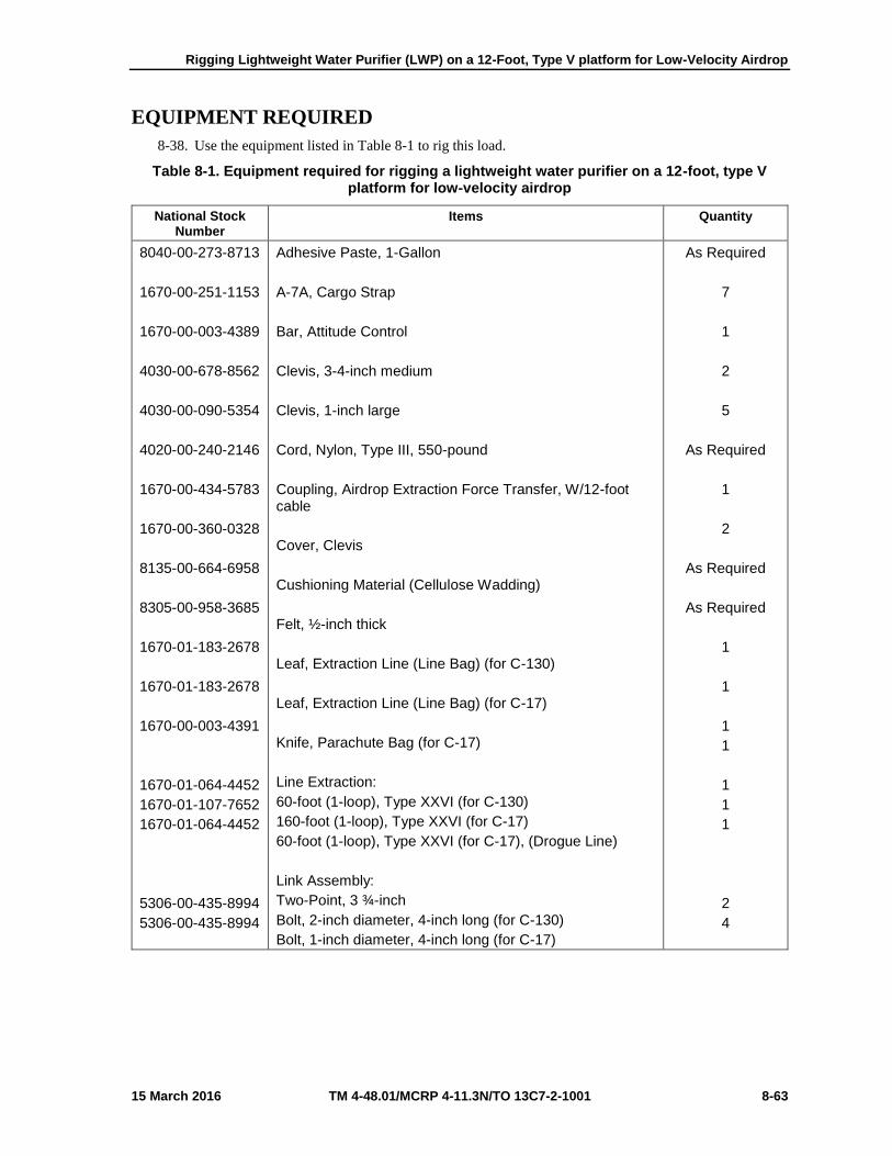
Rigging Lightweight Water Purifier (LWP) on a 12-Foot, Type V platform for Low-Velocity Airdrop
15 March 2016 TM 4-48.01/MCRP 4-11.3N/TO 13C7-2-1001 8-63
EQUIPMENT REQUIRED
8-38. Use the equipment listed in Table 8-1 to rig this load.
Table 8-1. Equipment required for rigging a lightweight water purifier on a 12-foot, type V platform for low-velocity airdrop
National Stock Number
Items Quantity
8040-00-273-8713
1670-00-251-1153
1670-00-003-4389
4030-00-678-8562
4030-00-090-5354
4020-00-240-2146
1670-00-434-5783
1670-00-360-0328
8135-00-664-6958
8305-00-958-3685
1670-01-183-2678
1670-01-183-2678
1670-00-003-4391
1670-01-064-4452
1670-01-107-7652
1670-01-064-4452
5306-00-435-8994
5306-00-435-8994
Adhesive Paste, 1-Gallon
A-7A, Cargo Strap
Bar, Attitude Control
Clevis, 3-4-inch medium
Clevis, 1-inch large
Cord, Nylon, Type III, 550-pound
Coupling, Airdrop Extraction Force Transfer, W/12-foot cable
Cover, Clevis
Cushioning Material (Cellulose Wadding)
Felt, ½-inch thick
Leaf, Extraction Line (Line Bag) (for C-130)
Leaf, Extraction Line (Line Bag) (for C-17)
Knife, Parachute Bag (for C-17)
Line Extraction:
60-foot (1-loop), Type XXVI (for C-130)
160-foot (1-loop), Type XXVI (for C-17)
60-foot (1-loop), Type XXVI (for C-17), (Drogue Line)
Link Assembly:
Two-Point, 3 ¾-inch
Bolt, 2-inch diameter, 4-inch long (for C-130)
Bolt, 1-inch diameter, 4-inch long (for C-17)
As Required
7
1
2
5
As Required
1
2
As Required
As Required
1
1
1
1
1
1
1
2
4

Chapter 8
8-64 TM 4-48.01/MCRP 4-11.3N/TO 13C7-2-1001 15 March 2016
Table 8-1. Equipment required for rigging a lightweight water purifier on a 12-foot, type V platform for low-velocity airdrop (continued)
National Stock Number
Items Quantity
5310-00-232-5165
5310-00-232-5165
1670-00-003-1953
1670-00-003-1953
5365-00-007-3414
5365-00-007-3414
5510-00-220-6146
5315-00-010-4659
5530-00-618-8073
1670-00-753-3928
1670-01-016-7841
1670-00-063-3715
1670-00-063-3715
1670-01-162-2372
1670-01-353-8424
1670-01-162-2381
1670-01-097-8816
1670-01-062-6304
1670-01-063-7761
1670-01-062-6302
1670-00-040-8219
7510-00-266-5016
7510-00-266-6710
Nut, 1-inch, hexagonal (for C-130)
Nut, 1-inch, hexagonal (for C-17
Plate, Side, 3 ¾-inch (for C-130)
Plate, Side, 3 ¾-inch (for C-17)
Spacer, Large(for C-130)
Spacer, Large(for C-17)
Lumber:
2- by 4- by 96-inch
Nail, Steel Wire, Common, 8-penny
Plywood, ¾-inch
Pad, Energy Dissipating, Honeycomb, 3- by 36- by 96-inch
Parachute:
Cargo:
G-11B
Parachute:, Cargo Extraction
15-foot (for C-130)
15-foot (for C-17)
Platform, Airdrop, Type V, 12-foot:
Clevis Assembly
Extraction Bracket Assembly
Tandem Link Assembly (Multipurpose link)
Release, Cargo Parachute, M-1
Sling, Cargo, Airdrop:
9-foot, (2-loop), Type XXVI
16-foot (2-loop), Type XXVI
20-foot (2-loop), Type XXVI
Strap, Parachute Release, Multicut
Tape, Adhesive, 2-inch
Tape, Masking
2
4
2
4
2
4
As Required
As Required
As Required
As Required
2
1
2
32
1
4
1
1
4
2
2
As Required
As Required

Rigging Lightweight Water Purifier (LWP) on a 12-Foot, Type V platform for Low-Velocity Airdrop
15 March 2016 TM 4-48.01/MCRP 4-11.3N/TO 13C7-2-1001 8-65
Table 8-1. Equipment required for rigging a lightweight water purifier on a 12-foot, type V platform for low-velocity airdrop (continued)
National Stock Number
Items Quantity
8305-00-433-5986
8310-00-917-3945
1670-00-937-0271
1670-01-483-8259
8305-00-268-2411
8305-00-082-5752
8305-00-268-2455
8305-00-261-8585
Textile:
Cloth, Cotton Muslin, Type III (for C-17)
Thread, Cotton, Ticket Number 8/7 (for C-17)
Tie down Assembly, 15-foot
Tow plate Release Mechanism (H-Block) (C-17 only)
Webbing:
Cotton, ¼-inch, Type I
Nylon, Tubular, ½-inch
Nylon, Tubular, 1-inch
Type VIII Nylon
As Required
As Required
55
1
As Required
As Required
As Required
As Required

This page intentionally left blank.

15 March 2016 TM 4-48.01/MCRP 4-11.3N/TO 13C7-2-1001 A-1
Appendix A
Installing Suspension Sling Safety Ties
A-1. Installing the suspension sling safety ties keeps the suspension slings from making contact with the
load. The procedures in this Appendix are different from those in TM 4-48.02/MCRP 4-11.3J/NAVSEA
SS400-AB-MMO-010 REV 1/TO 13C7-1-5. An exception to TM 4-48.02/MCRP 4-11.3J/NAVSEA SS400-
AB-MMO-010 REV 1/TO 13C7-1-5 is granted. The procedures in this Appendix must be followed. Safety
tie the rear suspension slings according to instructions shown below.
① Cut two lengths of ½-inch tubular nylon webbing, making each long enough to reach from the
left rear suspension sling to the right rear suspension sling plus 8 feet. Split the plies of the left rear suspension sling. Route two lengths of the ½-inch tubular webbing through the plies of the sling from inboard to outboard about 3 feet.
② Route the 3 foot running end from outboard to inboard around the inside plies and around the
outboard plies from inboard to outboard. Tie it in place on the inboard side with three alternating half-hitches with an overhand knot in the running end.
1
2

Appendix A
A-2 TM 4-48.01/MCRP 4-11.3N/TO 13C7-2-1001 15 March 2016
① Split the plies of the right rear suspension sling and route the running ends of the two lengths
of ½-inch tubular nylon webbing through the plies of the sling from inboard to outboard. Pass enough of the webbing through the sling to take the slack out, but not enough to keep the slings from hanging in their natural position.
② Route the running end from outboard to inboard around the inside plies and around the
outboard plies from inboard to outboard. Tie it in place on the inboard side with three alternating half-hitches with an overhand knot in the running end.
③ Tape the webbing to the slings with masking tape.
④ When using four-loop, type XXVI suspension slings, wrap each four plies with a 10-by 10-
inch piece of cotton muslin. Secure each wrap with one single turn of ¼-inch cotton webbing (not shown).
3
4
4
4
5

15 March 2016 TM 4-48.01/MCRP 4-11.3N/TO 13C7-2-1001 Glossary-1
Glossary
SECTION I – ACRONYMS AND ABBREVIATIONS
ACB attitude control bar
AFMAN Air Force manual
AFTO Air Force technical order
AMC Air Mobility Command
AR Army regulation
BII basic issue items
CB center of balance
COEI components of end item
CWK cold weather kit
DA Department of the Army
DD Department of Defense
DLAI Defense Logistics Agency instruction
FM field manual
KW kilowatt
LWP lightweight water purifier
MCO Marine Corps order
MCRP Marine Corps reference publication
NAVSEA Naval Sea Systems Command
NAVSUP Naval Supply Systems Command
ROWPU reverse osmosis water purification unit
TM technical manual
TO technical order

This page intentionally left blank.

15 March 2016 TM 4-48.01/MCRP 4-11.3N/TO 13C7-2-1001 References-1
References
REQUIRED PUBLICATIONS These documents must be available to intended users of this publication.
ADRP 1-02. Terms and Military Symbols. 7 December 2015.
JP 1-02. Department of Defense Dictionary of Military and Associated Terms. 8 November 2010.
MCRP 5-12C. Marine Corps Supplement to the Department of Defense Dictionary of Military and
Associated Terms. 23 July 1998.
RELATED PUBLICATIONS These documents contain relevant supplemental information.
U.S. ARMY PUBLICATIONS
Most Army doctrinal publications are available online: http://www.apd.army.mil.
TM 10-8110-201-14&P. Operator, Organizational, Direct Support and General Support Maintenance
Manual (Including Repair Parts and Special Tools List) for Drums, Fabric Collapsible Non-
Vented; 500 Gallon, Liquid Fuel, Part No. 13216E9172, NSN 8110-753-4892, 500 Gallon,
Liquid Fuel, Part No. 13216E9170 NSN 8110-753-4892, 250 Gallon, Potable Water Part No.
5-13-1681-1 NSN 8110-00-900-8328: 55 Gallon, Potable Water Part No. 5-13-2061 NSN
8110-00-089-4505,Changes 1 through 11, 10 February 1983.
MULTI-SERVICE PUBLICATIONS
Most Army doctrinal publications are available online: http://www.apd.army.mil.
Most Air Force doctrinal publications are available online: http://www.e-publishing.af.mil/
AR 59-4/OPNAVINST 4630.24D/AFJ 13-210(I)/MCO 13480.1D, Joint Airdrop Inspection Records,
Malfunction/Incident Investigations, and Activity Reporting, 8 May 2008.
AFMAN 24-204/TM 38-250/ NAVSUP PUB 505; MCO P4030.19I; DLAI 4145.3 DCMAD1, CH3.4
(HM24), Preparing Hazardous Materials for Military Air Shipments, 03 December 2012.
TM 4-48.02(FM 4-20.102)/MCRP-11.3J/NAVSEA SS400-AB-MMO-010 REV 1/TO 13C7-1-5.,
Airdrop of Supplies and Equipment: Rigging Airdrop Platforms, 15 March 2016.
TM 4-48.03(FM 4-20.103)/MCRP 4-11.3C/TO 13C7-1-11, Airdrop of Supplies and Equipment:
Rigging Containers, 15 March 2016.
TM 4-48.12(FM 4-20.112)/MCRP 4-11.3K/TO 13C7-1-8, Airdrop of Supplies and Equipment:
Rigging Typical Supply Loads, 5 July 2013.
TM 10-1670-268-20&P/ TO 13C7-52-22. Organizational Maintenance Manual Including Repair Parts and
Special Tools List for Type V Airdrop Platform and Dual Row Airdrop. 15 September 2002.
PRESCRIBED FORMS None.
REFERENCED FORMS Unless otherwise indicated, DA Forms are available on the Army Publishing Directorate (APD) web
site: www.apd.army.mil.
DD forms are available on the OSD web site: http://www.dtic.mil/whs/directives/infomgt/forms/
Unless otherwise indicated, AF Forms are available on the Air Force e-Publishing web site:
http://www.e-publishing.af.mil.
AFTO Form 22. Technical Order Publication Improvement Report
DA Form 2028. Recommended Changes to Publication and Blank Forms

References
References-2 TM 4-48.01/MCRP 4-11.3N/TO 13C7-2-1001 15 March 2016
DD Form 1748. Joint Airdrop Inspection Record (Platforms)
DD Form 1748-1. Joint Airdrop Inspection Record (Containers)
DD Form 1748-2. Joint Airdrop Malfunction Report (Personnel–Cargo)
DD Form 1748-3. Joint Airdrop Summary Report

15 March 2016 TM 4-48.01/MCRP 4-11.3N/TO 13C7-2-1001 Index-1
Index
Entries are by page number unless otherwise indicated.
B
Building and Positioning Parachute Stowage Platform, 8-58
C
C-130 Aircraft, 5-15, 6-12
C-17 Aircraft, 5-15, 6-12
Closing and Securing Equipment Box 1, 8-20
Closing and Securing Equipment Box 2, 8-34
Closing and Securing Equipment Box 3, 8-50
Closing Cargo Bag, 2-5, 2-10
Construct the parachute stowage platform, 7-37
Constructing and Positioning Equipment Box 1, 8-6
Constructing and Positioning Equipment Box 2, 8-25
Constructing and Positioning Equipment Box 3, 8-37, 8-40
Constructing Endboards, 7-33
D
Description of Load, 1-1, 1-6, 1-10, 2-1, 2-7, 3-1, 4-1, 5-1, 6-1, 7-1, 8-1
E
Equipment Required, 1-5, 1-9, 1-13, 2-5, 2-10, 3-11, 5-17, 6-14, 7-43, 8-64
I
Installing and Safetying Suspension Slings, 5-9, 6-6
installing and Securing cross braces, 7-25
Installing Extraction System, 5-13, 6-10, 7-42, 8-61
Installing Lashings, 7-30, 8-51
Installing Lifting Slings, 5-4, 6-3
Installing Load Cover, Suspension Slings and Safety Tie, 7-39
Installing parachute, 2-5, 2-10
Installing Parachute, 3-10
Installing Parachute Release System, 5-12, 6-9, 7-41, 8-60
Installing Provisions for Emergency Restraints, 7-43, 8-62
L
Lashing Drums to the Platform, 5-6, 6-4
Lashing Drums Together, 5-4, 6-3
Lifting and Positioning Load, 7-27
M
Marking Rigged Load, 1-5, 1-9, 1-13, 3-11, 5-15, 6-12, 7-43, 8-62
P
Packaging Canteens, 1-1
Placing Extraction Parachute, 5-15, 6-12, 7-43, 8-62
Positioning Honeycomb, 1-6, 1-10
Positioning and Lashing Drums, 5-4
Positioning and Lashing Drums Together, 6-3
Positioning and Securing End Boards and Stowing Tires, 7-34
Positioning Drums, 5-4, 6-3
Positioning Honeycomb Stack 1, 8-5
Positioning the Attitude Control Bar and Installing Suspension Slings and Safety Ties, 8-56
Prepare and Pack the Outer Container, 1-6, 1-10
Preparing and Positioning Honeycomb, 5-3, 6-2
Preparing and Positioning Honeycomb Stack 1, 8-3
Preparing and Positioning Honeycomb Stack 2, 8-22
Preparing and Positioning Honeycomb Stack 3, 8-35
Preparing and Positioning HOneycomb Stacks, 7-3
Preparing and Securing Control Panel, 7-15
Preparing and Securing Load, 3-1
Preparing and Securing Pulse Dampener, 7-16
Preparing and Stowing canvas hoses, 7-21
Preparing and Stowing Cargo Parachutes, 7-40, 8-59
Preparing and Stowing Raw Water Pumps, 7-18
Preparing and Stowing rubber hoses, 7-23
Preparing and Stowing the Equipment for Equipment Box 1, 8-10
Preparing and Stowing the Equipment for Equipment Box 2, 8-28
Preparing and Stowing the Equipment for Equipment Box 3, 8-41
Preparing and vehicular cables, straps, chains, and jacks and the jack handles, 7-17
Preparing Basic Issue Items Box, Components of End Items Box and Components of End Items Cable, 8-43
Preparing Chemical Injection Cleaning Module, 8-11
Preparing Cold Weather Kit 1 Box and Loading Truck, 8-48
Preparing Containers, 2-1, 2-7
Preparing Control Module Ultra-Filtration Module, and High-Pressure Pump Module, 8-28
Preparing Inner Container, 1-1
Preparing platform, 7-2
Preparing Platform, 5-2, 6-1, 8-2
Preparing Pump Module, 8-14
Preparing Reverse Osmosis Element Module, 8-10
Preparing Reverse Osmosis Water Purification Unit, 7-11
Preparing Secure Pump Skid Cover (Contamination Avoidance), 8-41
Preparing Skid board, 3-9
Preparing the generator, 7-17
Preparing, Constructing and Positioning Parachute Stowage Position, 7-36

Index
Index-2 TM 4-48.01/MCRP 4-11.3N/TO 13C7-2-1001 15 March 2016
Preparing, Stowing and securing distribution pump, 7-26
Preparing, Stowing and securing storage chests, 7-22
Preparing, Stowing and securing water tanks, 7-24
Preparing, Stowing, and Securing backwash Pumps, 7-19
R
Reinforcing Packing Case, 1-6, 1-10
Rigged Load data, 2-5
Rigged Load dATA, 2-10
Rigging Load, 2-2, 2-8
Rigging Procedures, 4-1
S
Securing Parachute Stowage Platform, 7-38
Securing Skid Board to the A-22 Cargo Bag, 3-10
securing Tires, 7-35
Stowing 1,000-Gallon Collapsible Raw Water and Product Fabric Tanks, 8-18
Stowing 3 kilowatt generator, 8-33
stowing and Securing paddle and Float, 7-23
Stowing and securing sledgehammer, 7-23
Stowing and securing wooden staves, 7-22
stowing and Securinge water containers, 7-23
Stowing Cargo Parachutes, 5-10, 6-7
Stowing Cold Weather Kit 2 Box and Cold Weather Kit 3 Box, 8-16
Stowing High Pressure Hose, Backwash Hoses, Reject Hoses, Tube Raw Water Hoses and Product Water Hoses, 8-19

TM 4-48.01/MCRP 4-11.3N/TO 13C7-2-1001 (FM 10-522/TO 13C7-2-1001;
FM 4-20.158/TO 13C7-7-61)15 March 2016
By Order of the Secretary of the Army:
Official:
By Direction of the Commandant of the Marine Corps:
Robert S. Walsh
Lieutenant General, United States Marine Corps
Deputy Commandant for Combat Development and Integration
By order of the Secretary of the Air Force
ELLEN M. PAWLIKOWSKI MARK A. WELSH III
General, United States Air Force General, United States Air Force
Commander, AFMC Chief of Staff
MARK A. MILLEYGeneral, United States Army
Chief of Staff
GERALD B. O’KEEFEAdministrative Assistant to the
Secretary of the Army 1606104
DISTRIBUTION: Active Army, Army National Guard, and United States Army Reserve: Distributed in electronic media only (EMO).

This page intentionally left blank.


PIN: 106137-000