
Table of Contents - Delta Rigging & Tools
264
Table of Contents Hand Tools . . . . . . . . . . . . . . . . . . . . . . . . . . . . . . . . .2-47 Hammers . . . . . . . . . . . . . . . . . . . . . . . . . . . . . . . . . .2-4 Wrenches . . . . . . . . . . . . . . . . . . . . . . . . . . . . . . . . .5-12 Impact Sockets and Accessories . . . . . . . . . . . . . . .13-35 1-1/2" Drive Accessories . . . . . . . . . . . . . . . . . . . . . . .36 2-1/2" Drive Impact Sockets and Accessories . . . .37-40 3-1/2" Drive Impact Sockets and Accessories . . . .41-43 #5 Spline Impact Sockets and Accessories . . . . . . .44-46 Socket Retaining Rings . . . . . . . . . . . . . . . . . . . . . . . .47 Torque Tools . . . . . . . . . . . . . . . . . . . . . . . . . . . . . . .48-57 Torque Multipliers . . . . . . . . . . . . . . . . . . . . . . . . . .48-49 Torque Wrenches . . . . . . . . . . . . . . . . . . . . . . . . . .50-51 Pneumatic Torque Control Wrenches . . . . . . . . . . .52-55 Hydraulic Torque Wrenches . . . . . . . . . . . . . . . . . .56-57 Air Tools . . . . . . . . . . . . . . . . . . . . . . . . . . . . . . . . .58-119 Impact Wrenches . . . . . . . . . . . . . . . . . . . .58-64, 66-67 Drills . . . . . . . . . . . . . . . . . . . . . . . . . . . . . . . . . . .65, 68 Grinders . . . . . . . . . . . . . . . . . . . . . . . . . . . . . . . . .69-73 Chipping Hammers . . . . . . . . . . . . . . . . . . . . . . . . .74-76 Oilers . . . . . . . . . . . . . . . . . . . . . . . . . . . . . . . . . . . . . .77 Breakers . . . . . . . . . . . . . . . . . . . . . . . . . . . . . . . . . . .78 Rock Drills . . . . . . . . . . . . . . . . . . . . . . . . . . . . . . . . . .79 Rivet Busters . . . . . . . . . . . . . . . . . . . . . . . . . . . . . . . .80 Tampers . . . . . . . . . . . . . . . . . . . . . . . . . . . . . . . . . . . .81 Clay Diggers . . . . . . . . . . . . . . . . . . . . . . . . . . . . . .82-83 Scalers . . . . . . . . . . . . . . . . . . . . . . . . . . . . . . . . .84,105 Pumps . . . . . . . . . . . . . . . . . . . . . . . . . . . . . . . . . . . . .85 Movers . . . . . . . . . . . . . . . . . . . . . . . . . . . . . . . . . . . . .86 Air Drills . . . . . . . . . . . . . . . . . . . . . . . . . . . .87, 106-108 Air Impacts . . . . . . . . . . . . . . . . . . . . . . . . . . . . . . .88-89 Die Grinders . . . . . . . . . . . . . . . . . . . . . . . . . . . . . .90-93 Wheel Grinders . . . . . . . . . . . . . . . . . . . . . . . . . . . .94-95 Angle Grinders . . . . . . . . . . . . . . . . . . . . . . . . . . . .96-98 Extended Angle Grinders . . . . . . . . . . . . . . . . . . . .99-100 Collet Grinders . . . . . . . . . . . . . . . . . . . . . . . . . .101-102 Extended Collet Grinders . . . . . . . . . . . . . . . . . . . . . .103 Marking Pens . . . . . . . . . . . . . . . . . . . . . . . . . . . . . . .104 Air Nutrunners . . . . . . . . . . . . . . . . . . . . . . . . . . . . . .109 Air Saws and Accessories . . . . . . . . . . . . . . . . . .110-119 Magnetic Drills/Cutters . . . . . . . . . . . . . . . . . . . .120-137 Portable Magnetic Drills . . . . . . . . . . . . . . . . . . .120-122 Magnetic Drills and Accessories . . . . . . . . . . . . .123-128 Annular Cutters/Pilots . . . . . . . . . . . . . . . . . . . . .129-137 Portable Hydraulics . . . . . . . . . . . . . . . . . . . . . . .138-179 Cylinders . . . . . . . . . . . . . . . . . . . . . . . . . . . . . .138-145 Cylinder Pump Set . . . . . . . . . . . . . . . . . . . . . . .146-147 Cylinder Accessories . . . . . . . . . . . . . . . . . . . . . .148-153 Gauges . . . . . . . . . . . . . . . . . . . . . . . . . . . . . . . .154-156 Hoses . . . . . . . . . . . . . . . . . . . . . . . . . . . . . . . . .157-158 Nut Splitters . . . . . . . . . . . . . . . . . . . . . . . . . . . . . . . .159 Pumps . . . . . . . . . . . . . . . . . . . . . . . . . . . . . . . .160-170 Presses . . . . . . . . . . . . . . . . . . . . . . . . . . . . . . .171-173 Punches . . . . . . . . . . . . . . . . . . . . . . . . . . . . . . .174-177 Wedges/Spreaders . . . . . . . . . . . . . . . . . . . . . . .178-179 Tube Removal/Assembly Tools . . . . . . . . . . . . . .180-208 Beveling Machines . . . . . . . . . . . . . . . . . . . . . . .180-189 Tube Pullers . . . . . . . . . . . . . . . . . . . . . . . . . . . .190-193 Tube Expanders . . . . . . . . . . . . . . . . . . . . . . . . .194-203 Grooving Tools . . . . . . . . . . . . . . . . . . . . . . . . . . . . . .204 Tube Cutters . . . . . . . . . . . . . . . . . . . . . . . . . . . .205-208 Tube Expanders . . . . . . . . . . . . . . . . . . . . . . . . . .209-232 Tube Expanders . . . . . . . . . .209-210, 216-221, 227-232 Standard Models . . . . . . . . . . . . . . . . .211-215, 222-226 Consumables . . . . . . . . . . . . . . . . . . . . . . . . . . . .233-256 Abrasives . . . . . . . . . . . . . . . . . . . . . . . . . . . . . .233-244 Grinding Wheels . . . . . . . . . . . . . . . . . . . . . . . . .245-253 Wire Cup Brushes . . . . . . . . . . . . . . . . . . . . . . . . . . .254 Wire Wheels . . . . . . . . . . . . . . . . . . . . . . . . . . . . . . . .255 Wire Brushes . . . . . . . . . . . . . . . . . . . . . . . . . . . . . . .256 INDUSTRIAL TOOLS & SUPPLIES
-
Upload
khangminh22 -
Category
Documents
-
view
2 -
download
0
Transcript of Table of Contents - Delta Rigging & Tools

Table of Contents
Hand Tools . . . . . . . . . . . . . . . . . . . . . . . . . . . . . . . . .2-47
Hammers . . . . . . . . . . . . . . . . . . . . . . . . . . . . . . . . . .2-4
Wrenches . . . . . . . . . . . . . . . . . . . . . . . . . . . . . . . . .5-12
Impact Sockets and Accessories . . . . . . . . . . . . . . .13-35
1-1/2" Drive Accessories . . . . . . . . . . . . . . . . . . . . . . .36
2-1/2" Drive Impact Sockets and Accessories . . . .37-40
3-1/2" Drive Impact Sockets and Accessories . . . .41-43
#5 Spline Impact Sockets and Accessories . . . . . . .44-46
Socket Retaining Rings . . . . . . . . . . . . . . . . . . . . . . . .47
Torque Tools . . . . . . . . . . . . . . . . . . . . . . . . . . . . . . .48-57
Torque Multipliers . . . . . . . . . . . . . . . . . . . . . . . . . .48-49
Torque Wrenches . . . . . . . . . . . . . . . . . . . . . . . . . .50-51
Pneumatic Torque Control Wrenches . . . . . . . . . . .52-55
Hydraulic Torque Wrenches . . . . . . . . . . . . . . . . . .56-57
Air Tools . . . . . . . . . . . . . . . . . . . . . . . . . . . . . . . . .58-119
Impact Wrenches . . . . . . . . . . . . . . . . . . . .58-64, 66-67
Drills . . . . . . . . . . . . . . . . . . . . . . . . . . . . . . . . . . .65, 68
Grinders . . . . . . . . . . . . . . . . . . . . . . . . . . . . . . . . .69-73
Chipping Hammers . . . . . . . . . . . . . . . . . . . . . . . . .74-76
Oilers . . . . . . . . . . . . . . . . . . . . . . . . . . . . . . . . . . . . . .77
Breakers . . . . . . . . . . . . . . . . . . . . . . . . . . . . . . . . . . .78
Rock Drills . . . . . . . . . . . . . . . . . . . . . . . . . . . . . . . . . .79
Rivet Busters . . . . . . . . . . . . . . . . . . . . . . . . . . . . . . . .80
Tampers . . . . . . . . . . . . . . . . . . . . . . . . . . . . . . . . . . . .81
Clay Diggers . . . . . . . . . . . . . . . . . . . . . . . . . . . . . .82-83
Scalers . . . . . . . . . . . . . . . . . . . . . . . . . . . . . . . . .84,105
Pumps . . . . . . . . . . . . . . . . . . . . . . . . . . . . . . . . . . . . .85
Movers . . . . . . . . . . . . . . . . . . . . . . . . . . . . . . . . . . . . .86
Air Drills . . . . . . . . . . . . . . . . . . . . . . . . . . . .87, 106-108
Air Impacts . . . . . . . . . . . . . . . . . . . . . . . . . . . . . . .88-89
Die Grinders . . . . . . . . . . . . . . . . . . . . . . . . . . . . . .90-93
Wheel Grinders . . . . . . . . . . . . . . . . . . . . . . . . . . . .94-95
Angle Grinders . . . . . . . . . . . . . . . . . . . . . . . . . . . .96-98
Extended Angle Grinders . . . . . . . . . . . . . . . . . . . .99-100
Collet Grinders . . . . . . . . . . . . . . . . . . . . . . . . . .101-102
Extended Collet Grinders . . . . . . . . . . . . . . . . . . . . . .103
Marking Pens . . . . . . . . . . . . . . . . . . . . . . . . . . . . . . .104
Air Nutrunners . . . . . . . . . . . . . . . . . . . . . . . . . . . . . .109
Air Saws and Accessories . . . . . . . . . . . . . . . . . .110-119
Magnetic Drills/Cutters . . . . . . . . . . . . . . . . . . . .120-137
Portable Magnetic Drills . . . . . . . . . . . . . . . . . . .120-122
Magnetic Drills and Accessories . . . . . . . . . . . . .123-128
Annular Cutters/Pilots . . . . . . . . . . . . . . . . . . . . .129-137
Portable Hydraulics . . . . . . . . . . . . . . . . . . . . . . .138-179
Cylinders . . . . . . . . . . . . . . . . . . . . . . . . . . . . . .138-145
Cylinder Pump Set . . . . . . . . . . . . . . . . . . . . . . .146-147
Cylinder Accessories . . . . . . . . . . . . . . . . . . . . . .148-153
Gauges . . . . . . . . . . . . . . . . . . . . . . . . . . . . . . . .154-156
Hoses . . . . . . . . . . . . . . . . . . . . . . . . . . . . . . . . .157-158
Nut Splitters . . . . . . . . . . . . . . . . . . . . . . . . . . . . . . . .159
Pumps . . . . . . . . . . . . . . . . . . . . . . . . . . . . . . . .160-170
Presses . . . . . . . . . . . . . . . . . . . . . . . . . . . . . . .171-173
Punches . . . . . . . . . . . . . . . . . . . . . . . . . . . . . . .174-177
Wedges/Spreaders . . . . . . . . . . . . . . . . . . . . . . .178-179
Tube Removal/Assembly Tools . . . . . . . . . . . . . .180-208
Beveling Machines . . . . . . . . . . . . . . . . . . . . . . .180-189
Tube Pullers . . . . . . . . . . . . . . . . . . . . . . . . . . . .190-193
Tube Expanders . . . . . . . . . . . . . . . . . . . . . . . . .194-203
Grooving Tools . . . . . . . . . . . . . . . . . . . . . . . . . . . . . .204
Tube Cutters . . . . . . . . . . . . . . . . . . . . . . . . . . . .205-208
Tube Expanders . . . . . . . . . . . . . . . . . . . . . . . . . .209-232
Tube Expanders . . . . . . . . . .209-210, 216-221, 227-232
Standard Models . . . . . . . . . . . . . . . . .211-215, 222-226
Consumables . . . . . . . . . . . . . . . . . . . . . . . . . . . .233-256
Abrasives . . . . . . . . . . . . . . . . . . . . . . . . . . . . . .233-244
Grinding Wheels . . . . . . . . . . . . . . . . . . . . . . . . .245-253
Wire Cup Brushes . . . . . . . . . . . . . . . . . . . . . . . . . . .254
Wire Wheels . . . . . . . . . . . . . . . . . . . . . . . . . . . . . . . .255
Wire Brushes . . . . . . . . . . . . . . . . . . . . . . . . . . . . . . .256
INDUSTRIAL TOOLS & SUPPLIES
Green2010TableOfContents.qxd 4/5/10 4:52 PM Page 1

2
HAN
D T
OO
LSHammers
BALL HAMMERS, SUPER HEAVY DUTY INDUSTRIAL, POLISHED HEADFIBERGLASS HANDLE
CODEHEAD WEIGHTOZ GRS
TOTAL LENGTH LIN MM
HEAD DIAMETERIN
WEIGHTGRS LBS
STRESS RESISTANCEASME/ANSI B173.2 LBF LB-IN.
1308FV 8 226.8 11-1/4 285.7 1.00 226.8 1.65 750
1312FV 12 340.2 12 304.8 1.15 340.2 1.65 750
1316FV 16 454 12-3/4 323.8 1.31 454 4.96 2250
1324FV 24 681 14-1/4 361.9 1.43 681.8 4.96 2250
1332FV 32 908 14-1/2 368.3 1.62 908 4.96 2250
1340FV 40 1,135 16-1/2 419.1 1.68 1135 4.96 2250
CODE °RC HARDNESS LBF STRESS LBF BENDING STRIKING TYPE
1308FV 45-60 750 40 20 PLUS
1312FV 45-60 750 60 20 PLUS
1316FV 45-60 2250 80 20 PLUS
1324FV 45-60 2250 150 20 PLUS
1332FV 45-60 2250 150 20 PLUS
1340FV 45-60 2250 175 20 PLUS
• Fiberglass handle with rubber coverminimizes hand vibration.
• Forged steel alloy head, temperedand annealed to prevent fracturesand distortion of the striking faces,polished finish.
DATA SHEET FOR BALL PEIN HAMMERS
STANDARD ANSI B 173.2
STANDARDS: FEDERAL:GGG-H-86C ANSI/ASME B173.2 NOM-0-103
13XXFVL
Urrea_p2-4 final.qxd 3/31/10 5:12 PM Page 2

Hammers
3
HAN
D TO
OLS
OCTAGONAL SLEDGES HAMMERS
NON SPARKING SLEDGE HAMMERS WITH FIBER GLASS HANDLES
14XXG
UHXXFG
• Wood handle with compact structureproviding high impact resistance.
• Octagonal design that distributes theload and equalizes stress.
• Alloyed steel head, press forged andheat treated.
• Beveled and machined striking faceto prevent accidents due to metalshards.
• Non sparking: Comply with all U.S.Government specifications for nonsparking hand tools in hazardous orvolatile work environments.
• Non magnetic: Allows use in all suchcritical environments.
• Corrosion resistance: Are resistant toindustrial and hazardous chemicalsand are easily cleaned of volatileresiduals.
• Fiberglass handles: Provide superiortolerance and breaking stress foradverse environmental conditions.
CODEHEADLBS OZ GRS
HEAD DIAMETERIN MM
HEAD LENGTHIN MM
TOTAL LENGTHIN MM
WEIGHTGRS LBS
1433G 2 32 907 1-41/64 41.7 4-35/64 115.5 12 304.8 1135 2.50
1434G 3 48 1,360 1-23/32 43.7 5-9/64 130.6 12 304.8 1620 3.57
1435G 4 64 1,814 2-3/64 52 5-39/64 142.5 12 304.8 2200 4.85
1436G 6 96 2,721 2-1/8 53.9 6 152.4 36 914.4 3100 6.83
1437G 8 128 3,628 2-3/8 60.3 6-3/8 161.9 36 914.4 4190 9.23
1438G 10 160 4,536 2-1/2 63.5 7 177.8 36 914.4 5275 11.62
1439G 12 192 5,443 2-11/16 68.2 7-3/8 187.3 36 914.4 6300 13.88
1440G 16 256 7,257 2-7/8 73.0 8-1/8 206.3 36 914.4 8250 18.18
CODEHEADLBS OZ GRS
HEAD DIAMETERIN MM
HEAD LENGTHIN MM
TOTAL LENGTHIN MM
WEIGHTGRS LBS
UH71FG 7.5 120 3,402 2.11 54 6-1/8 15.5 34-1/4 864 4400 9.7
UH72FG 10 160 4,536 2.20 56 7-3/16 18.2 34-1/4 864 5500 12.2
UH73FG 15 240 6,804 2.45 62 8-1/8 20.6 34-1/4 864 7800 17.2
STANDARDS: ANSI/ASME B173.3 FEDERAL GGG-H-86
STANDARDS: MIL-H-1874C, ASME B107.53M, B107.54, B107.56
L
L
Urrea_p2-4 final.qxd 3/31/10 5:12 PM Page 3

4
HammersH
AND
TO
OLS
DATA SHEET FOR BALL PEIN HAMMERS
STANDARD ANSI B 173.2
BALL HAMMERS, EXTRA HEAVY DUTY INDUSTRIAL, POLISHED HEAD• Wood handle with compact structure
providing high impact resistance.• Forged and tempered steel alloy
head, polished and varnished.
CODEHEAD WEIGHTOZ GRS
TOTAL LENGTHLIN MM
HEADDIAMETERIN
WEIGHTGRS LBS
STRESS RESISTANCEASME/ANSI B173.2 LBFLB-IN.
1308P 8 226.8 11-5/8 295.2 1.00 327 0.72 750
1312P 12 340.2 13-5/8 346.0 1.15 422 0.93 750
1316P 16 454 13-3/4 349.2 1.31 630 1.38 2250
1324P 24 681 15-5/8 396.8 1.43 828 1.82 2250
1332P 32 908 15-7/8 403.2 1.62 1,050 2.31 2250
1340P 40 1,135 17-1/4 438.1 1.68 1,210 2.66 2250
1348P 48 1,361 17-1/4 438.1 1.87 2,231 4.91 1000
CODE °RC HARDNESS LBF STRESS LBF BENDING STRIKING TYPE
1308P 45-60 400 40 20 PLUS
1312P 45-60 400 60 20 PLUS
1316P 45-60 400 80 20 PLUS
1324P 45-60 1000 150 20 PLUS
1332P 45-60 1000 150 20 PLUS
1340P 45-60 1000 175 20 PLUS
1348P 45-60 1000 175 20 PLUS
13XXP
STANDARDS: FEDERAL GGG-H-86C ANSI/ASME B173.2 NOM-0-103
L
Urrea_p2-4 final.qxd 3/31/10 5:12 PM Page 4

5
HAN
D TO
OLS
Wrenches
STANDARD FEDERAL GGG-W-651
CODE
MAX.PIPE SIZEINCHES MM
BMM
CMM
LENGTHINCHES MM
WEIGHTGRS LBS
808HD 1 25 16.5 14.0 8 200.0 340 .75
810HD 1-1/2 40 21.5 17.0 10 250.0 770 1.70
812HD 2 50 23.0 21.0 12 300.0 1,100 2.43
814HD 2 50 26.0 21.0 14 350.0 1,500 3.31
818HD 2-1/2 65 29.0 26.0 18 450.0 2,400 5.29
824HD 3 80 33.0 28.0 24 600.0 4,000 8.82
836HD 5 125 44.0 32.5 36 900.0 7,400 16.31
848HD 6 167 58.0 36.0 48 1200.0 8,700 19.18
860HD 9 228 83.0 41.0 60 1524.0 19,700 43.43
8XXHD
MALLEABLE IRON PIPE WRENCHES
MALLEABLE IRON PIPE WRENCHESPipe wrenches are ideal for all heavy work, such as oil refinery platforms, high-pressure pneumatic installations, etc.Mouth opening can be changed, with the movable jaw opened or closed by an adjustable worm-gear system with a springthat tightens when leverage is applied.
• Super-reinforced jaw mounting.• Knurled roller (nut) with tough finish turns easily in the hook jaw.• Handle designed for efficient grip and use of force without
excessive weight.• The classic pipe wrench for heavy-duty use, with the right sizes
and materials for every application.• Malleable iron body.• Replaceable jaws made of heat-treated alloy steel.• Jaw system with spring for good grip and quick release.
STANDARD: GGG-W-651E
FIGURE(IRON)
SIZEIN
MINIMUM SPREAD RANGE (IN)
HARDNESS °RCBODY MOVABLE FIXED(IRON) JAW JAW NUT
TORQUELOAD, LBS.(IRON)
808HD 8 1/4-3/4 25-40 55-60 55-60 32-48 3,300
810HD 10 1/4-1 25-40 55-60 55-60 32-48 7,000
812HD 12 1/2-1 1/4 25-40 55-60 55-60 32-48 10,000
814HD 14 1/2-1 1/2 25-40 55-60 55-60 32-48 13,000
818HD 18 1-2 25-40 55-60 55-60 32-48 20,000
824HD 24 1/2-2 1/2 25-40 55-60 55-60 32-48 28,000
836HD 36 2 1/2-3 1/2 25-40 55-60 55-60 32-48 45,500
848HD 48 3- 5 25-40 55-60 55-60 32-48 50,000
860HD 60 3- 5 25-40 55-60 55-60 32-48 126,000
Urrea_p5 final.qxd 4/1/10 5:36 PM Page 5

6
WrenchesH
AND
TO
OLS
ADJUSTABLE WRENCHES
CHROME ADJUSTABLE WRENCHES
widening handle
narrowinghandle
CODE
DIMENSIONS OF OPENINGIN MM
LENGTHIN MM
WEIGHTGRS LBS
TORQUEASME/ANSI B107.8LB-IN
710P 1-5/16 33.3 10 254.0 440 0.970 4500
712P 1-1/2 38.1 12 304.8 753 1.660 7650
Adjustable Wrenches with rubber grip for greater grip comfort.
7XXP
7XXG
STANDARDS: FEDERAL GGG-W-631 ASME B 107.8 NOM-0.106
STANDARDS: FEDERAL GGG-W-631B ASME/ANSI B 107.8 NOM-0.106
• Wider aperture for larger fastener.• Measurement scale for more
precision.• Ergonomic handle is wider for more
comfortable grip.
Adjustable wrench TYPE 1
Adjustable wrench TYPE 2
CODE
DIMENSIONS OFOPENINGIN MM
LENGTHIN MM
WEIGHTGRS LBS
TORQUEASME/ANSIB107.8 LB-IN TYPE
704G 1/2 12.7 4 101.6 57.4 0.13 600 1
706G 15/16 23.8 6 152.4 123.4 0.27 1450 1
708G 1 25.4 8 203.2 437.0 0.96 2700 1
710G 1-1/8 28.5 10 254.0 700.0 1.54 4500 1
712G 1-5/16 33.3 12 304.8 800.0 1.76 7650 1
715G 1-11/16 42.8 15 381.0 1575.0 3.47 15000 2
718G 2-1/16 52.3 18 457.2 2370.0 5.22 20000 2
724G 2-7/16 61.9 24 609.6 3425.0 7.55 25000 2
Urrea_p6-10 final.qxd 4/1/10 5:37 PM Page 6

Wrenches
7
HAN
D TO
OLS
7XX
CHROME ADJUSTABLE WRENCHES
710
715
• Opening with rounded edges for avoiding stressconcentration and providing better adjustment
• Slimmer jaws for access in narrower spaces• Thumbwheel manufactured from high quality alloy steel• Extra-wide jaws permit use on a wide variety of nuts
and bolts• Nickel-chrome plated for corrosion resistance.• The arrow indicates the direction of the turn when
applying force• Hot forged body with high strength steel and maximum
ergonomics
widening handle
narrowinghandle
Adjustable wrench TYPE 1
Adjustable wrench TYPE 2
CODE
DIMENSIONS OFOPENINGIN MM
LENGTHIN MM
WEIGHTGRS LBS
TORQUEASME/ANSI B107.8LB-IN TYPE
704 1/2 12.7 4 101.6 50 0.11 600 1
706 15/16 23.8 6 152.4 109 0.24 1450 1
708 1 25.4 8 203.2 244 0.54 2700 1
710 1-1/8 28.5 10 254.0 380 0.84 4500 1
712 1-5/16 33.3 12 304.8 660 1.46 7650 1
715 1-11/16 42.8 15 381.0 1483 3.27 15000 2
718 2-1/16 52.3 18 457.2 2309 5.09 20000 2
724 2-7/16 61.9 24 609.6 3392 7.48 25000 2
STANDARDS: FEDERAL GGG-W-631 ASME/ANSI B 107.8 NOM-0.106
Urrea_p6-10 final.qxd 4/1/10 5:37 PM Page 7

8
WrenchesH
AND
TO
OLS
27XXSW
12-POINT FRACTIONAL BLACK FLAT STRIKING WRENCHES
BLACK STRIKING WRENCHESThis wrench consists of a box end and a striking area. Unlike a box end, obstruction or combination wrench, this wrench isdesigned to be struck. Its primary applications are manufacturing and maintenance operations involving heavy machineryand highly corrosive environments, which affect nut and bolt threads. The handle has a convenient radius that holds thestriking area on a higher plane than the box end plane, making it more comfortable and safe to strike the wrench. TheBLACK finish protects the wrench from corrosion and prevents the eventual loss of chrome particles when subjected tocontinuous striking.
STANDARD: FEDERAL GGG-W-636
CODE
DIMENSIONOF OPENINGIN MM
LENGTHLIN MM
CIN MM
DIN MM
WEIGHTGRS LBS
2717SW 1-1/16 26.97 9-1/2 241.3 2-15/64 56.9 55/64 22.0 1100 1.322718SW 1-1/8 28.57 9-1/2 241.3 2-15/64 56.9 55/64 22.0 1100 1.322720SW 1-1/4 31.75 9-1/2 241.3 2-15/64 56.9 55/64 22.0 1100 1.322721SW 1-5/16 33.33 9-1/2 241.3 2-15/64 56.9 55/64 22.0 1100 1.322722SW 1-3/8 34.92 9-1/2 241.3 2-15/64 56.9 55/64 22.0 1100 1.322723SW 1-7/16 36.49 11-21/64 287.7 3 76.2 63/64 25.1 1950 1.762724SW 1-1/2 38.10 11-21/64 287.7 3 76.2 63/64 25.1 1950 1.762726SW 1-5/8 41.27 11-21/64 287.7 3 76.2 63/64 25.1 1950 1.762727SW 1-11/16 42.86 11-21/64 287.7 3 76.2 63/64 25.1 1950 1.762728SW 1-3/4 44.45 11-21/64 287.7 3 76.2 63/64 25.1 1950 2.562729SW 1-13/16 46.03 11-21/64 287.7 3 76.2 63/64 25.1 1950 2.562730SW 1-7/8 47.62 11-21/64 287.7 3 76.2 63/64 25.1 1950 2.562732SW 2 50.08 13-31/64 342 3-47/64 94.9 1-31/64 37.8 4150 3.312734SW 2-1/8 53.97 13-31/64 342 3-47/64 94.9 1-31/64 37.8 4150 3.312735SW 2-3/16 55.56 13-31/64 342 3-47/64 94.9 1-31/64 37.8 4150 3.312736SW 2-1/4 57.15 13-31/64 342 3-47/64 94.9 1-31/64 37.8 4150 3.312737SW 2-5/16 58.73 13-31/64 342 3-47/64 94.9 1-31/64 37.8 4150 3.482738SW 2-3/8 60.32 14-51/64 376 4-7/64 104.4 1-31/64 37.8 4700 5.222740SW 2-1/2 63.50 14-51/64 376 4-7/64 104.4 1-31/64 37.8 4700 5.512741SW 2-9/16 65.07 14-51/64 376 4-7/64 104.4 1-31/64 37.8 4700 5.512742SW 2-5/8 66.67 14-51/64 376 4-7/64 104.4 1-31/64 37.8 4700 5.512744SW 2-3/4 69.85 13 330 4-5/16 110 1-5/16 33 3540 7.802747SW 2-15/16 74.61 13 330 4-5/16 110 1-5/16 33 3540 7.802748SW 3 76.20 13 330 4-5/16 110 1-5/16 33 3540 7.802750SW 3-1/8 79.37 14-3/16 360 4-15/16 126 1-7/16 36 3900 8.602754SW 3-3/8 87.72 14-3/16 360 4-15/16 126 1-7/16 36 3900 8.602756SW 3-1/2 88.90 14-3/16 360 4-15/16 126 1-7/16 36 3900 8.602760SW 3-3/4 95.25 15-3/8 390 5-9/16 142 1-9/16 40 6100 13.452762SW 3-7/8 98.42 15-3/8 390 5-9/16 142 1-9/16 40 6100 13.452766SW 4-1/8 104.77 16-9/16 420 6-1/8 155 1-3/4 45 7000 15.432768SW 4-1/4 107.95 17-11/16 450 6-11/16 170 1-7/8 48 9500 20.942772SW 4-1/2 114.30 17-11/16 450 6-11/16 170 1-7/8 48 9500 20.942774SW 4-5/8 117.47 17-11/16 450 6-11/16 170 1-7/8 48 9500 20.942776SW 4-3/4 120.65 18-11/16 475 7-1/4 185 2-1/8 54 11500 25.352780SW 5 127 18-11/16 475 7-1/4 185 2-1/8 54 11500 25.352786SW 5-3/8 136.52 20-11/16 525 8 202 2-5/16 58 13000 28.662792SW 5-3/4 146.05 22-13/16 580 8-7/8 225 2-1/2 64 19000 41.892796SW 6 152.4 22-13/16 580 8-7/8 225 2-1/2 64 19000 41.89
• Twelve-point designed for perfectadjustment between the nut and thetool.
• Uniform molecular structure toprovide greater strength.
Urrea_p6-10 final.qxd 4/1/10 5:37 PM Page 8

Wrenches
9
HAN
D TO
OLS
26XXSW
Code 2732SW
• When the wrench is struck, a vibration runs through the body of thebolt releasing the residues that cause the nut to stick, freeing it.
• The Offset design of these wrenches in particular (wrench end in linewith respect to the wrench pin) permits their use in places where thereare no objects or obstacles in the way.
• Their constitution and structure permit them to be struck hard in orderto loosen nuts.
CODE
DIMENSIONOF OPENINGIN MM
LENGTHIN MM
CIN MM
DIN MM
EIN MM
WEIGHTGRS LBS
2617SW 1-1/16 26.9 8-1/2 215.9 1-45/64 43.2 5/8 16.0 15/16 23.8 790 1.74
2618SW 1-1/8 28.5 8-1/2 215.9 1-45/64 43.2 5/8 16.0 15/16 23.8 778 1.72
2620SW 1-1/4 31.7 10-3/4 273.0 1-7/8 47.8 13/16 20.6 1-3/16 30.2 1304 2.87
2621SW 1-5/16 33.3 10-3/4 273.0 1-7/8 47.8 13/16 20.6 1-3/16 30.2 1287 2.84
2622SW 1-3/8 34.9 10-3/4 273.0 1-7/8 47.8 13/16 20.6 1-3/16 30.2 1708 3.77
2623SW 1-7/16 36.5 12 304.8 2-3/16 55.6 1 25.4 1-1/2 38.1 1708 3.77
2624SW 1-1/2 38.1 12 304.8 2-3/16 55.6 1 25.4 1-1/2 38.1 1685 3.71
2626SW 1-5/8 41.2 12-1/4 311.1 2-13/32 61.2 1-1/8 28.7 1-1/2 38.1 1970 4.34
2627SW 1-11/16 42.8 12-1/4 311.1 2-13/32 61.2 1-1/8 28.7 1-1/2 38.1 1940 4.28
2628SW 1-3/4 44.4 13-7/16 341.3 2-21/32 67.6 1-3/16 30.2 1-9/16 39.6 2697 5.95
2629SW 1-13/16 46.0 13-7/16 341.3 2-27/32 72.1 1-1/4 31.8 1-21/32 42.2 2664 5.87
2630SW 1-7/8 47.6 13-7/16 341.3 2-27/32 72.1 1-1/4 31.8 1-21/32 42.2 3041 6.70
2632SW 2 50.8 13-7/16 341.3 2-27/32 72.1 1-1/4 31.8 1-21/32 42.2 2965 6.54
2634SW 2-1/8 53.9 13-1/2 342.9 3-3/8 85.7 1-3/8 34.9 2-1/8 54.0 3492 7.70
2635SW 2-3/16 55.5 13-1/2 342.9 3-3/8 85.7 1-3/8 34.9 2-1/8 54.0 3492 7.70
2636SW 2-1/4 57.1 13-1/2 342.9 3-3/8 85.7 1-3/8 34.9 2-1/8 54.0 3447 7.60
2637SW 2-5/16 58.7 14 355.6 3-11/16 93.7 1-1/2 38.1 2-1/4 57.2 3991 8.80
2638SW 2-3/8 60.3 14 355.6 3-11/16 93.7 1-1/2 38.1 2-1/4 57.2 3900 8.60
2640SW 2-1/2 63.5 15-1/4 387.3 4-5/16 109.5 1-3/4 44.5 2-1/2 63.5 6486 14.30
2641SW 2-9/16 65.0 15-1/4 387.3 4-5/16 109.5 1-3/4 44.5 2-1/2 63.5 6395 14.10
2642SW 2-5/8 66.6 15-1/4 387.3 4-5/16 109.5 1-3/4 44.5 2-1/2 63.5 6305 13.90
2644SW 2-3/4 69.8 15-1/4 387.3 4-5/16 109.5 1-3/4 44.5 2-1/2 63.5 6168 13.60
2647SW 2-15/16 74.6 16-1/2 419.1 4-13/16 122.2 2 50.8 2-1/2 63.5 8436 18.60
2648SW 3 76.2 16-1/2 419.1 4-13/16 122.2 2 50.8 2-1/2 63.5 8164 18.00
2650SW 3-1/8 79.3 16-1/2 419.1 4-13/16 122.2 2 50.8 2-1/2 63.5 8028 17.70
STANDARD: FEDERAL GGG-W-636
12-POINT FRACTIONAL BLACK OFFSET STRIKING WRENCHES
CODE 2732SW
URREA Black flat striking wrenchesIn order to avoid stripping nuts stuck in heavy industry machinery or equipment, URREAStriking Wrenches are recommended, providing greater advantages such as:• Their constitution and structure permit them to be struck hard in order to loosen nuts.• When the wrench is struck, a vibration runs through the body of the bolt releasing the
residues that cause the nut to stick, freeing it.• The Flat design of these wrenches in particular (wrench end in line with respect to the
wrench pin) permits their use in places where there are no objects or obstacles in the way.
Urrea_p6-10 final.qxd 4/1/10 5:37 PM Page 9

10
WrenchesH
AND
TO
OLS
12-POINT METRIC BLACK OFFSET STRIKING WRENCHES
26XXSWM
CODE
DIMENSIONOF OPENINGMM
LENGTHIN MM
CMM
DMM
EMM
WEIGHTGRS LBS
2632SWM 32 10-3/4 273.0 47.8 20.6 30.2 1,304 2.87
2633SWM 33 10-3/4 273.0 47.8 20.6 30.2 1,304 2.87
2634SWM 34 10-3/4 273.0 47.8 20.6 30.2 1,287 2.84
2636SWM 36 12 304.8 55.6 25.4 38.1 1,708 3.77
2641SWM 41 12-1/4 311.1 61.2 28.7 38.1 1,970 4.34
2646SWM 46 13-7/16 341.3 67.5 30.2 39.6 2,664 5.87
2650SWM 50 13-7/16 341.3 72.1 31.7 42.1 2,965 6.54
2655SWM 55 13-1/2 342.9 85.7 34.9 53.7 3,492 7.70
2660SWM 60 14 355.6 94.4 38.1 56.1 3,900 8.60
2665SWM 65 15-1/4 387.3 109.5 44.4 63.8 6,395 14.10
2670SWM 70 15-1/4 387.3 109.5 44.4 63.8 6,168 13.60
2675SWM 75 16-1/2 419.1 122.2 50.8 66.0 8,028 17.70
2680SWM 80 16-1/2 419.1 122.2 50.8 66.0 8,028 17.70
Code 2632SW
CODE 2632SW
URREA Black offset striking wrenchesIn order to avoid stripping nuts stuck in heavy industrymachinery or equipment, URREA Striking Wrenches arerecommended.
STANDARD: FEDERAL GGG-W-636
COMBINATION WRENCHES• Box end with Superdrive design• Available in standard and metric sizes to fit a
wide variety of bolts and nuts.• Oval body for a more comfortable grip.• Narrow ends for better access in tight areas.• Precision machined ends for a perfect fit on
nuts and bolts.chart on next page
Urrea_p6-10 final.qxd 4/1/10 5:37 PM Page 10

Wrenches
11
HAN
D TO
OLS
STANDARD COMBINATION WRENCHES
12XX / 121XX
TYPE OF FINISH CODE
DIMENSIONS OF OPENINGSIN MM
BIN
CIN
DIN
C1IN
D1IN
LENGTHIN MM
WEIGHTGRS LBS
TORQUE STRENGTHASME/ANSI B107.6LB-IN.OPEN END BOX END
A 1208* 1/4 6.3 19/64 39/64 11/64 27/64 15/64 5 127.0 31 0.07 67 220A 1210 5/16 7.9 3/8 45/64 3/16 35/64 17/64 5-1/2 139.7 31 0.07 138 275A 1212 3/8 9.5 7/16 51/64 13/64 19/32 5/16 6 152.4 40 0.09 275 605A 1214 7/16 11.1 33/64 59/64 15/64 11/16 21/64 6-1/2 165.1 55 0.12 413 715A 1216 1/2 12.7 19/32 1-3/32 1/4 49/64 11/32 7 177.8 74 0.16 550 1020A 1218 9/16 14.2 11/16 1-13/64 17/64 27/32 23/64 7-1/2 190.5 95 0.21 770 1500A 1220 5/8 15.8 49/64 1-21/64 19/64 15/16 25/64 8-1/16 204.7 115 0.25 1100 2200A 1222 11/16 17.4 13/16 1-29/64 5/16 1-1/32 27/64 8-7/8 225.4 151 0.33 1375 2640A 1224 3/4 19.0 7/8 1-37/64 21/64 1-3/32 29/64 9 3/4 247.6 186 0.41 1650 2860A 1226 13/16 20.6 61/64 1-11/16 11/32 1-3/16 31/64 10-5/8 269.8 253 0.56 2200 3300A 1228 7/8 22.2 1-1/32 1-51/64 3/8 1-5/16 33/64 11-1/2 292.1 302 0.67 2475 3630A 1230 15/16 23.8 1-7/64 1-29/32 25/64 1-25/64 35/64 12-3/8 314.3 340 0.75 3025 4510A 1232 1 25.4 1-3/16 2-1/64 13/32 1-1/2 37/64 13-1/4 336.5 417 0.92 3575 5390A 1234 1-1/16 26.9 1-17/64 2-9/64 27/64 1-39/64 39/64 14-1/8 358.7 516 1.14 3850 5940A 1236 1-1/8 28.5 1-11/32 2-17/64 15/32 1-11/16 41/64 15-3/8 390.5 558 1.23 4400 6490A 1240 1-1/4 31.7 1-31/64 2-33/64 31/64 1-55/64 45/64 16-3/4 425.4 780 1.72 5775 7925B 1242 1-5/16 33.3 1-33/64 2-41/64 33/64 1-15/16 47/64 17-5/8 447.6 1,000 2.20 6600 8800B 1244 1-3/8 34.9 1-19/32 2-49/64 17/32 2-1/64 49/64 18-1/2 469.9 1,130 2.49 7425 8975B 1246 1-7/16 36.5 1-43/64 2-57/64 35/64 2-1/8 25/32 19-3/8 492.1 1,380 3.04 8250 9240B 1248 1-1/2 38.1 1-47/64 3-1/64 9/16 2-11/64 51/64 20-1/4 514.3 1,620 3.57 8500 11495B 1250 1-9/16 39.6 1-61/64 3-19/64 4-1/64 2-25/64 57/64 23 584.2 1,980 4.37 9000 12800B 1252 1-5/8 41.2 1-61/64 3-19/64 41/64 2-25/64 57/64 23 584.2 1,980 4.37 9000 12800B 1254 1-11/16 42.8 1-61/64 3-19/64 41/64 2-25/64 57/64 23 584.2 1,930 4.25 10500 13570B 1256 1-3/4 44.4 2-7/64 3-41/64 43/64 2-3/4 61/64 25 635.0 2,400 5.29 11100 14300B 1258 1-13/16 46.0 2-7/64 3-41/64 43/64 2-3/4 61/64 25 635.0 2,360 5.20 11750 15100C 1260 1-7/8 47.6 2-1/8 3-7/8 47/64 3-9/64 1-11/16 28 711.2 3,311 7.30 12400 15900C 1264 2 50.8 2-1/4 4-1/8 47/64 3-9/64 1-11/16 28 711.2 3,129 6.90 13650 17400C 1266 2-1/16 52.39 2-1/4 4-1/2 1 3-1/4 1-9/16 30 762 5,902 13.01 14300 18200C 1268 2-1/8 53.98 2-1/4 4-1/2 1 3-1/4 1-9/16 30 762 5,902 13.01 14900 19000C 1270 2-3/16 55.56 2-1/4 4-1/2 1 3-1/4 1-9/16 30 762 5,902 13.01 15500 19700C 1272 2-1/4 57.15 2-1/4 4-1/2 1 3-1/2 1-9/16 30 762 5,902 13.01 16200 20500C 1274 2-5/16 58.74 2-1/4 4-1/2 1 3-1/2 1-9/16 30-1/2 775 5,902 13.01 NE NEC 1276 2-3/8 60.33 2-1/4 4-1/2 1 3-1/2 1-9/16 30-1/2 775 5,902 13.01 NE NEC 1278 2-7/16 61.91 2-5/16 4-1/2 1 3-1/2 1-9/16 30-1/2 775 5,902 13.01 NE NEC 1280 2-1/2 63.5 2-5/16 4-1/2 1 3-1/2 1-9/16 30-1/2 775 5,902 13.01 NE NEC 1282 2-9/16 65.09 2-1/2 4-1/2 1-1/8 4-1/4 1-11/16 31 787 8,172 18.02 NE NEC 1284 2-5/8 66.68 2-1/2 5-1/2 1-1/8 4-1/4 1-11/16 31-1/2 800 8,172 18.02 NE NEC 1286 2-11/16 68.26 2-3/4 5-1/2 1-1/8 4-1/4 1-11/16 32 813 8,172 18.02 NE NEC 1288 2-3/4 69.85 2-3/4 5-1/2 1-1/8 4-1/4 1-11/16 32-1/2 825 8,172 18.02 NE NEC 1290 2-13/16 71.44 2-3/4 5-1/2 1-1/8 4-1/4 1-11/16 33 838 8,354 18.42 NE NEC 1292 2-7/8 73.03 3 5-1/2 1-3/16 4-3/4 1-11/16 33-1/2 850 8,354 18.42 NE NEC 1294 2-15/16 74.61 3 5-1/2 1-3/16 4-3/4 1-11/16 34 863 8,354 18.42 NE NEC 1296 3 76.2 3 5-1/2 1-3/16 4-3/4 1-11/16 34-1/2 876 8,354 18.42 NE NEC 1298 3-1/16 77.79 3-1/8 5-1/2 1-3/16 4-3/4 1-11/16 35 889 8,354 18.42 NE NEC 1299 3-1/8 79.38 3-1/8 5-1/2 1-3/16 4-3/4 1-11/16 35-1/2 918 8,354 18.42 NE NEC 12104 3-1/4 82 3-5/16 6-1/4 1-1/2 5 1-1/2 36-1/16 918 9,230 20.35 NE NEC 12108 3-3/8 85 3-1/2 6-1/4 1-1/2 5 1-1/2 37 939 9,420 20.77 NE NEC 12112 3-1/2 89 3-5/8 6-1/4 1-1/2 5 1-1/2 37-5/8 956 9,632 21.23 NE NEC 12116 3-5/8 92 3-3/4 6-1/4 1-1/2 5 1-1/2 38 965 9,750 21.50 NE NEC 12120 3-3/4 95 3-7/8 6-1/4 1-1/2 5 1-1/2 38-1/16 966 9,830 21.67 NE NEC 12124 3-7/8 98 4 6-1/4 1-1/2 5 1-1/2 38-3/4 984 10,312 22.73 NE NEC 12128 4 101 4-1/16 6-1/4 1-1/2 5 1-1/2 39-1/8 993 10,500 23.15 NE NE
* 6 point STANDARDS: FEDERAL GGG-W-636 ASME/ANSI B 107.9M Y B 107.39M SAE A S954
Urrea_p11. final.qxd 4/1/10 5:42 PM Page 11

12
WrenchesH
AND
TO
OLS
ALUMINUM PIPE WRENCHESWorks just like the iron pipe wrench but with the advantage of weighing less. Provides the same strength because its bodyis made from a single piece of aluminum, which together its design offers hardness similar to that of iron.
STANDARD FEDERAL GGG-W-651
8XXA
ALUMINUM PIPE WRENCHES
STANDARDS: FEDERAL GGG-W-631B ASME/ANSI B 107.8 NOM-0.106
CODE 824A
Aluminum pipe wrenchWith all the advantages of a conventional pipe wrench, but with the extraadvantage of being 40% lighter, URREA aluminum pipe wrenches areinvaluable for heavy work.
URREA aluminum pipe wrenches also have an anti-sparking system, so theycan be used for heavy jobs in the petrochemical, electrical, and otherindustries without incurring unnecessary risks.
• Adjustable tempered and threaded nutwith springs seated in flat so it gives thewrench its grip and perfect ratchetingaction.
• Forged upper jaw, double heat-treated.• Lower jaw is seated so as to prevent
overload on the pin.• The ultimate pipe wrench, functions like a
conventional pipe wrench but with theadded advantage of being 40% lighter.
• The body is made from a single piece ofhigh-strength aluminum alloy.
CODE
MAX. PIPE SIZEINCHES MM
BMM
CMM
LENGTHINCHES MM
WEIGHTGRS LBS
810A 1-1/2 49 22 17.0 10 250 490 1.08
814A 2 60 26 21.0 14 350 930 2.05
818A 2-1/2 63 29 26.0 18 450 1,570 3.46
824A 3 76 33 28.0 24 600 2,600 5.73
836A 5 127 44 32.5 36 900 5,000 11.02
ALUMINUM PIPE WRENCH
(40% lighter)
FIGURE(ALUMINUM) SIZE
MINIMUM SPREADRANGEIN
HARDNESS, °RCMOVABLEJAW FIXED JAW NUT
TORQUELOAD, LBS.(ALUMINUM)
810A 10 1/2 – 1-1/4 55-60 55-60 32-48 6,000
814A 14 1 – 2 55-60 55-60 32-48 11,500
818A 18 1/2 – 2-1/2 55-60 55-60 32-48 18,000
824A 24 2-1/2 – 3-1/2 55-60 55-60 32-48 25,000
836A 36 3 – 5 55-60 55-60 32-48 40,500
Urrea_p12 final.qxd 4/1/10 5:49 PM Page 12

Impact Sockets and Accessor ies
13
HAN
D TO
OLS
1/2" DRIVE IMPACT ADAPTERS
1/2" DRIVE IMPACT EXTENSIONS
CODEDRIVE SIZEIN MM
LENGTHIN MM
WEIGHTGRS LBS
TORQUE STRENGTHASME/ANSI B107.2LB-IN
7180P 1/2 12.7 2 50.8 240 0.52 3500
7181P 1/2 12.7 5 127 450 0.99 3500
7184P 1/2 12.7 8-3/4 222 750 1.65 3500
CODEDESCRIPTIONIN
LENGTHIN MM
SQUARE DRIVE SIZEF M
WEIGHTGRS LBS
7652 1/2 F x 3/4 M 1-7/8 48 1/2 3/4 159 0.35
7651 1/2 F x 3/8 M 1-1/2 38 1/2 3/8 82 0.18
These accessories let you workwith 3/8" or 3/4" square drivesockets using 1/2" handles.
718XP
765X
ASME/ANSI B107.4 FEDERAL GGG-W-660 ISO 1174 and 2725 DIN 3129
This accessory lets you workon screws in tight or deepspaces where an impactwrench can’t reach, available ina variety of lengths. Themaximum recommendedtorque for a 1/2" extension ofany length is 3500 in-lbs.• Made of high-quality, high
strength micro-alloy steelwith black finish to preventcorrosion and no risk ofsurface chipping or flaking.
• To achieve the right balancebetween hardness andstrength, extensions are heattreated in controlled-atmosphere furnaces.
7652
7180P 7181P
7184P
7651
Urrea_p13-22 final.qxd 4/1/10 5:52 PM Page 13

14
Impact Sockets and Accessor iesH
AND
TO
OLS
1/2" DRIVE 12-POINT IMPACT SOCKETS IN FRACTIONAL SIZES
The line of 1/2" impact sockets, like the 3/8" line, is used primarily for automotive maintenance and general mechanicalwork. It can handle higher torques and requires more work space, with wider application ranges:• Socket hex size: 3/8" - 1-1/2" and 8-36 mm.• Torque applications for sockets, handles, and accessories: 1100-5000 in-lbs
74XX
CODEHEX SIZEIN MM
LENGTHIN MM
OUTER DIAMETERHEX- DRIVE-END ENDIN IN
HEX-ENDDEPTHIN TYPE
WEIGHTGRS LBS
TORQUE STRENGTHASME/ANSI B107.2LB-IN
7412 3/8 9.5 1-1/2 38.1 5/8 7/8 1/2 I 72 0.159 1110
7414 7/16 11.1 1-1/2 38.1 11/16 7/8 1/2 I 66 0.146 1500
7416 1/2 12.7 1-1/2 38.1 13/16 15/16 1/2 I 77 0.170 2000
7418 9/16 14.3 1-1/2 38.1 7/8 15/16 1/2 I 79 0.174 2600
7420 5/8 15.9 1-1/2 38.1 1 1 1/2 II 90 0.198 3300
7422 11/16 17.5 1-1/2 38.1 1-1/16 1-1/16 1/2 II 204 0.450 4100
7424 3/4 19.1 1-1/2 38.1 1-1/8 1-1/8 1/2 II 111 0.245 5000
7426 13/16 20.6 1-1/2 38.1 1-3/16 1-3/16 1/2 II 123 0.271 5000
7428 7/8 22.2 1-1/2 38.1 1-5/16 1-5/16 1/2 II 165 0.364 5000
7430 15/16 23.8 1-1/2 38.1 1-3/8 1-3/8 1/2 II 197 0.434 5000
7432 1 25.4 1-1/2 38.1 1-7/16 1-7/16 9/16 II 215 0.474 5000
7434 1-1/16 26.9 1-17/32 39.7 1-1/2 1-1/2 5/8 II 570 1.25 5000
7436 1-1/8 28.5 1-17/32 39.7 1-9/16 1-9/16 5/8 II 820 1.80 5000
7438 1-3/16 30.1 1-17/32 39.7 1-5/8 1-5/8 5/8 II 850 1.87 5000
7440 1-1/4 31.7 1-17/32 39.7 1-3/4 1-3/4 5/8 II 870 1.91 5000
7442 1-5/16 33.3 1-11/16 43.0 1-3/4 1-3/4 3/4 II 920 2.02 5000
7444 1-3/8 34.9 1-15/16 49.2 1-7/8 1-3/4 15/16 II 960 2.11 5000
7446 1-7/16 36.5 1-15/16 49.2 2 1-3/4 15/16 II 1010 2.22 5000
7448 1-1/2 38.1 1-15/16 49.2 2-1/8 1-3/4 15/16 II 1090 2.40 5000
STANDARDS: ASME B107.2 FEDERAL GGG-W-660
ISO 1174 and 2725 DIN 3129
Type I Type II
Urrea_p13-22 final.qxd 4/1/10 5:52 PM Page 14

Impact Sockets and Accessor ies
15
HAN
D TO
OLS
1/2" DRIVE 6-POINT IMPACT SOCKETS IN FRACTIONAL SIZES
74XXH
CODEHEX SIZEIN MM
LENGTHIN MM
OUTER DIAMETERHEX- DRIVE-END ENDIN IN
HEX-ENDDEPTHIN TYPE
WEIGHTGRS LBS
TORQUESTRENGTHASME/ANSIB107.2 LB-IN
7412H 3/8 9.5 1-1/2 38.1 5/8 7/8 7/16 I 150 0.33 1100
7414H 7/16 11.1 1-1/2 38.1 11/16 7/8 7/16 I 150 0.33 1500
7416H 1/2 12.7 1-1/2 38.1 3/4 7/8 7/16 I 180 0.40 2000
7418H 9/16 14.3 1-1/2 38.1 7/8 15/16 7/16 I 180 0.40 2600
7420H 5/8 15.9 1-1/2 38.1 1 1 7/16 II 210 0.46 3300
7422H 11/16 17.5 1-1/2 38.1 1-1/16 1-1/16 1/2 II 230 0.51 4100
7424H 3/4 19.1 1-1/2 38.1 1-1/8 1-1/8 1/2 II 250 0.55 5000
7426H 13/16 20.6 1-1/2 38.1 1-3/16 1-3/16 1/2 II 270 0.60 5000
7428H 7/8 22.2 1-1/2 38.1 1-1/4 1-1/4 1/2 II 350 0.77 5000
7430H 15/16 23.8 1-1/2 44.4 1-5/16 1-5/16 1/2 II 450 0.99 5000
7432H 1 25.4 1-1/2 44.4 1-3/8 1-3/8 9/16 II 490 1.08 5000
7434H 1-1/16 27.0 1-9/16 50.8 1-1/2 1-1/2 5/8 II 570 1.26 5000
7436H 1-1/8 28.5 1-9/16 50.8 1-9/16 1-9/16 5/8 II 820 1.81 5000
7438H 1-3/16 30.1 1-9/16 50.8 1-5/8 1-5/8 5/8 II 850 1.87 5000
7440H 1-1/4 31.7 1-9/16 50.8 1-3/4 1-3/4 5/8 II 870 1.92 5000
7442H 1-5/16 33.3 1-11/16 50.8 1-3/4 1-3/4 3/4 II 920 2.03 5000
7444H 1-3/8 34.9 1-15/16 50.8 1-7/8 1-7/8 15/16 III 960 2.12 5000
7446H 1-7/16 36.5 1-15/16 50.8 2 2 15/16 III 1010 2.23 5000
7448H 1-1/2 38.1 1-15/16 50.8 2-1/16 2-1/16 15/16 III 1090 2.40 5000
STANDARDS: ASME/ANSI B107.4 FEDERAL GGG-W-660
ISO 1174 and 2725 DIN 3129
Type I Type II Type III
Urrea_p13-22 final.qxd 4/1/10 5:52 PM Page 15

16
Impact Sockets and Accessor iesH
AND
TO
OLS
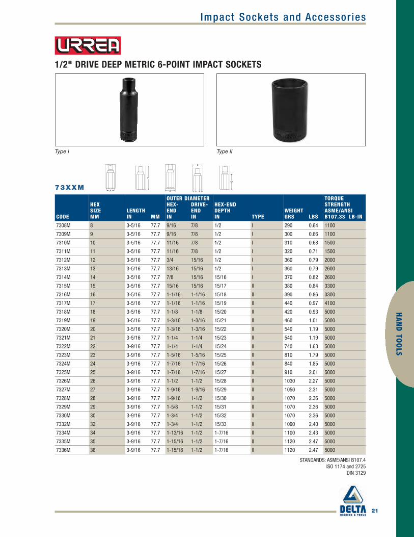
1/2" DRIVE DEEP 6-POINT IMPACT SOCKETS IN FRACTIONAL SIZES
73XXH
STANDARDS: ASME/ANSI B107.4 FEDERAL GGG-W-660
ISO 1174 and 2725 DIN 3129
CODEHEX SIZEIN MM
LENGTHIN MM
OUTER DIAMETERHEX- DRIVE-END ENDIN IN
HEX-ENDDEPTHIN TYPE
WEIGHTGRS LBS
TORQUESTRENGTHASME/ANSIB107.2 LB-IN
7312H 3/8 9.5 3-1/4 77.7 5/8 7/8 9/16 I 160 0.35 1100
7314H 7/16 11.1 3-1/4 77.7 11/16 7/8 9/16 I 160 0.35 1500
7316H 1/2 12.7 3-1/4 77.7 3/4 7/8 9/16 I 180 0.40 2000
7318H 9/16 14.2 3-1/4 77.7 7/8 15/16 15/16 I 180 0.40 2600
7320H 5/8 15.8 3-1/4 77.7 15/16 15/16 15/16 II 200 0.44 3300
7322H 11/16 17.4 3-1/4 77.7 1-1/16 1-1/16 15/16 II 200 0.44 4100
7324H 3/4 19.0 3-1/4 77.7 1-1/8 1-1/8 15/16 II 330 0.73 5000
7326H 13/16 20.6 3-1/4 77.7 1-3/16 1-3/16 15/16 II 440 0.97 5000
7328H 7/8 22.2 3-9/16 77.7 1-1/4 1-1/4 15/16 II 440 0.97 5000
7330H 15/16 23.8 3-9/16 77.7 1-5/16 1-5/16 15/16 II 450 0.99 5000
7332H 1 25.4 3-9/16 77.7 1-3/8 1-3/8 15/16 II 520 1.15 5000
7334H 1-1/16 26.9 3-9/16 77.7 1-1/2 1-1/2 15/16 II 710 1.57 5000
7336H 1-1/8 28.5 3-9/16 77.7 1-9/16 1-1/2 15/16 II 800 1.76 5000
7340H 1-1/4 31.8 3-1/2 88.9 1 1-3/4 15/16 II 820 1.80 5000
Type I Type II
Urrea_p13-22 final.qxd 4/1/10 5:52 PM Page 16

Impact Sockets and Accessor ies
17
HAN
D TO
OLS
1/2" DRIVE DEEP 12-POINT IMPACT SOCKETS IN FRACTIONAL SIZES
73XX
STANDARDS: ASME B107.2 FEDERAL GGG-W-660
ISO 1174 and 2725 DIN 3129
CODE
HEXSIZEIN MM
LENGTHIN MM
OUTER DIAMETERHEX- DRIVE-END ENDIN IN
HEX-END DEPTHIN TYPE
WEIGHTGRS LBS
TORQUESTRENGTHASME/ANSIB107.2 LB-IN
7312 3/8 9.5 3-1/4 82.5 5/8 7/8 9/16 I 146 0.32 1100
7314 7/16 11.1 3-1/4 82.5 11/16 7/8 9/16 I 146 0.32 1500
7316 1/2 12.7 3-1/4 82.5 13/16 7/8 9/16 I 150 0.33 2000
7318 9/16 14.2 3-1/4 82.5 7/8 15/16 15/16 I 180 0.39 2600
7320 5/8 15.8 3-1/4 82.5 15/16 15/16 15/16 II 180 0.39 3300
7322 11/16 17.4 3-1/4 82.5 1 1 15/16 II 200 0.44 4100
7324 3/4 19.0 3-1/4 82.5 1-1/8 1-1/8 1 II 240 0.52 5000
7326 13/16 20.6 3-1/4 82.5 1-3/16 1-3/16 1 II 240 0.52 5000
7328 7/8 22.2 3-1/4 82.5 1-1/4 1-1/4 1 II 240 0.52 5000
7330 15/16 23.8 3-9/16 90.0 1-3/8 1-3/8 1 II 364 0.80 5000
7332 1 25.4 3-9/16 90.0 1-7/16 1-7/16 1 II 364 0.80 5000
7334 1-1/16 26.9 3-9/16 90.0 1-1/2 1-1/2 1 II 498 1.09 5000
7336 1-1/8 28.5 3-9/16 90.0 1-9/16 1-9/16 1 II 404 0.89 5000
7338 1-3/16 30.1 3-9/16 90.0 1-3/16 1-5/8 15/16 III 890 1.96 5000
7340 1-1/4 31.7 3-9/16 90.0 1-1/4 1-3/4 15/16 III 980 2.16 5000
7342 1-5/16 33.3 3-9/16 90.0 1-5/16 1-13/16 15/16 III 1070 2.35 5000
7344 1-3/8 34.9 3-9/16 90.0 1-3/8 1-15/16 15/16 III 1160 2.55 5000
7346 1-7/16 36.5 3-9/16 90.0 1-7/16 2 15/16 III 1250 2.75 5000
7348 1-1/2 38.1 3-9/16 90.0 1-1/12 2 1/16 15/16 III 1340 2.95 5000
Type I Type II Type III
Urrea_p13-22 final.qxd 4/1/10 5:52 PM Page 17

18
Impact Sockets and Accessor iesH
AND
TO
OLS
1/2" DRIVE METRIC 12-POINT IMPACT SOCKETS
74XXMT
STANDARDS: ASME/ANSI B107.4 ISO 1174 and 2725 DIN 3129
CODEHEX SIZEMM
LENGTHIN MM
OUTER DIAMETERHEX- DRIVE-END ENDMM MM
HEX-END DEPTHMM TYPE
WEIGHTGRS LBS
TORQUESTRENGTHASME/ANSIB107.33 LB-IN
7410MT 10 1-1/2 38 17 22 12.7 I 64 0.141 1354
7411MT 11 1-1/2 38 18 22 12.7 I 64 0.141 1505
7412MT 12 1-1/2 38 19 22 12.7 I 79 0.174 1797
7413MT 13 1-1/2 38 20 24 12.7 I 74 0.163 2204
7414MT 14 1-1/2 38 22 24 12.7 I 76 0.168 2496
7415MT 15 1-1/2 38 23 25 12.7 I 94 0.207 3000
7416MT 16 1-1/2 38 25 25 12.7 II 90 0.198 3602
7417MT 17 1-1/2 38 27 27 12.7 II 104 0.229 4204
7418MT 18 1-1/2 38 28 28 12.7 II 117 0.258 4797
7419MT 19 1-1/2 38 28 28 12.7 II 110 0.243 5001
7420MT 20 1-1/2 38 33 33 12.7 II 130 0.287 5045
7421MT 21 1-1/2 38 33 33 12.7 II 168 0.370 5045
7422MT 22 1-1/2 38 33 33 12.7 II 156 0.344 5045
7423MT 23 1-1/2 38 35 35 19.0 II 205 0.452 5045
7424MT 24 1-1/2 38 35 35 19.0 II 200 0.441 5045
7425MT 25 1-1/2 38 37 37 25.4 II 200 0.441 5045
7426MT 26 1-1/2 38 38 38 25.4 II 250 0.551 5045
7427MT 27 1-9/16 40 38 38 25.4 II 252 0.556 5045
7428MT 28 1-9/16 40 40 40 25.4 II 244 0.538 5045
7429MT 29 1-9/16 40 40 40 25.4 II 236 0.520 5045
7430MT 30 1-9/16 40 42 42 25.4 II 260 0.573 5045
7432MT 32 2 50.8 44 38 16.0 II 3750 8.267 5045
Type I Type II
Urrea_p13-22 final.qxd 4/1/10 5:52 PM Page 18

Impact Sockets and Accessor ies
19
HAN
D TO
OLS
1/2" DRIVE METRIC 6-POINT IMPACT SOCKETS
74XXM
STANDARDS: ASME/ANSI B107.4 ISO 1174 and 2725
DIN 3129
CODEHEX SIZEMM
LENGTHIN MM
OUTER DIAMETERHEX- DRIVE-END ENDIN IN
HEX-END DEPTHIN TYPE
WEIGHTGRS LBS
TORQUESTRENGTHASME/ANSIB107.33 LB-IN
7409M 9 1-1/2 38.1 9/16 7/8 1/2 I 150 0.33 1100
7410M 10 1-1/2 38.1 5/8 7/8 1/2 I 150 0.33 1500
7411M 11 1-1/2 38.1 11/16 7/8 1/2 I 150 0.33 1500
7412M 12 1-1/2 38.1 3/4 7/8 1/2 I 180 0.40 2000
7413M 13 1-1/2 38.1 13/16 15/16 1/2 I 180 0.40 2600
7414M 14 1-1/2 38.1 7/8 15/16 1/2 I 180 0.40 2600
7415M 15 1-1/2 38.1 7/8 1 1/2 II 220 0.49 3300
7416M 16 1-1/2 38.1 1 1 1/2 II 220 0.49 3300
7417M 17 1-1/2 38.1 1-1/16 1-1/16 1/2 II 250 0.55 4100
7418M 18 1-1/2 38.1 1-1/16 1-1/16 1/2 II 270 0.60 5000
7419M 19 1-1/2 38.1 1-1/8 1-1/8 1/2 II 270 0.60 5000
7420M 20 1-1/2 38.1 1-3/16 1-3/16 1/2 II 260 0.57 5000
7421M 21 1-1/2 38.1 1-3/16 1-3/16 1/2 II 390 0.86 5000
7422M 22 1-1/2 38.1 1-1/4 1-1/4 1/2 II 390 0.86 5000
7423M 23 1-1/2 38.1 1-1/4 1-1/4 1/2 II 490 1.08 5000
7424M 24 1-1/2 38.1 1-5/16 1-5/16 1/2 II 490 1.08 5000
7425M 25 1-1/2 38.1 1-7/16 1-7/16 1/2 II 540 1.19 5000
7426M 26 1-1/2 38.1 1-7/16 1-7/16 1/2 II 630 1.39 5000
7427M 27 1-9/16 39.6 1-1/2 1-1/2 5/8 II 630 1.39 5000
7428M 28 1-9/16 39.6 1-9/16 1-9/16 5/8 II 730 1.61 5000
7429M 29 1-9/16 39.6 1-9/16 1-9/16 5/8 II 760 1.68 5000
7430M 30 1-9/16 39.6 1-5/8 1-5/8 5/8 II 830 1.83 5000
7432M 32 1-9/16 39.6 1-11/16 1-11/16 5/8 II 850 1.87 5000
7433M 33 1-9/16 41.2 1-3/4 1-3/4 5/8 II 870 1.92 5000
7434M 34 1-11/16 41.2 1-3/4 1-3/4 3/4 II 930 2.05 5000
7436M 36 2 50.8 1-15/16 1-15/16 15/16 II 1080 2.38 5000
Type I Type II
Urrea_p13-22 final.qxd 4/1/10 5:52 PM Page 19

20
Impact Sockets and Accessor iesH
AND
TO
OLS
1/2" DRIVE DEEP METRIC 12-POINT IMPACT SOCKETS
73XXMT
STANDARDS: ASME/ANSI B107.4 ISO 1174 and 2725
DIN 3129
CODE
HEXSIZEMM
LENGTHIN MM
OUTER DIAMETERHEX- DRIVE-END ENDMM MM
HEX-END DEPTHMM TYPE
WEIGHTGRS LBS
TORQUESTRENGTHASME/ANSIB107.33M LB-IN
7310MT 10 3-1/4 83 17 22 15.9 I 148 0.326 1354
7311MT 11 3-1/4 83 18 22 15.9 I 150 0.331 1505
7312MT 12 3-1/4 83 19 22 15.9 I 160 0.353 1797
7313MT 13 3-1/4 83 20 24 15.9 I 160 0.353 2204
7314MT 14 3-1/4 83 22 24 23.8 I 170 0.375 2496
7315MT 15 3-1/4 83 24 24 25.4 II 170 0.375 3000
7316MT 16 3-1/4 83 24 24 25.4 II 180 0.397 3602
7317MT 17 3-1/4 83 26 26 25.4 II 180 0.397 4204
7318MT 18 3-1/4 83 26 26 25.4 II 200 0.441 4792
7319MT 19 3-1/4 83 28 28 25.4 II 200 0.441 5001
7320MT 20 3-1/4 83 30 30 25.4 II 278 0.613 5045
7321MT 21 3-1/4 83 30 30 25.4 II 278 0.613 5045
7322MT 22 3-9/16 90.4 32 32 25.4 II 192 0.423 5045
7323MT 23 3-9/16 90.4 32 32 25.4 II 270 0.595 5045
7324MT 24 3-9/16 90.4 34 34 25.4 II 320 0.705 5045
7325MT 25 3-9/16 90.4 36 36 25.4 II 372 0.820 5045
7326MT 26 3-9/16 90.4 36 36 25.4 II 362 0.798 5045
7327MT 27 3-9/16 90.4 38 38 25.4 II 401 0.884 5045
7328MT 28 3-9/16 90.4 40 38 25.4 III 411 0.906 5045
7329MT 29 3-9/16 90.4 40 38 25.4 III 406 0.895 5045
7330MT 30 3-9/16 90.4 42 38 34.9 III 451 0.994 5045
7332MT 32 3-1/2 88.9 44 38 16.0 III 1090 2.403 5045
Type I Type II Type III
Urrea_p13-22 final.qxd 4/1/10 5:52 PM Page 20
Impact Sockets and Accessor ies
21
HAN
D TO
OLS
1/2" DRIVE DEEP METRIC 6-POINT IMPACT SOCKETS
73XXM
STANDARDS: ASME/ANSI B107.4 ISO 1174 and 2725
DIN 3129
CODE
HEXSIZEMM
LENGTHIN MM
OUTER DIAMETERHEX- DRIVE-END ENDIN IN
HEX-END DEPTHIN TYPE
WEIGHTGRS LBS
TORQUESTRENGTHASME/ANSIB107.33 LB-IN
7308M 8 3-5/16 77.7 9/16 7/8 1/2 I 290 0.64 1100
7309M 9 3-5/16 77.7 9/16 7/8 1/2 I 300 0.66 1100
7310M 10 3-5/16 77.7 11/16 7/8 1/2 I 310 0.68 1500
7311M 11 3-5/16 77.7 11/16 7/8 1/2 I 320 0.71 1500
7312M 12 3-5/16 77.7 3/4 15/16 1/2 I 360 0.79 2000
7313M 13 3-5/16 77.7 13/16 15/16 1/2 I 360 0.79 2600
7314M 14 3-5/16 77.7 7/8 15/16 15/16 I 370 0.82 2600
7315M 15 3-5/16 77.7 15/16 15/16 15/17 II 380 0.84 3300
7316M 16 3-5/16 77.7 1-1/16 1-1/16 15/18 II 390 0.86 3300
7317M 17 3-5/16 77.7 1-1/16 1-1/16 15/19 II 440 0.97 4100
7318M 18 3-5/16 77.7 1-1/8 1-1/8 15/20 II 420 0.93 5000
7319M 19 3-5/16 77.7 1-3/16 1-3/16 15/21 II 460 1.01 5000
7320M 20 3-5/16 77.7 1-3/16 1-3/16 15/22 II 540 1.19 5000
7321M 21 3-5/16 77.7 1-1/4 1-1/4 15/23 II 540 1.19 5000
7322M 22 3-9/16 77.7 1-1/4 1-1/4 15/24 II 740 1.63 5000
7323M 23 3-9/16 77.7 1-5/16 1-5/16 15/25 II 810 1.79 5000
7324M 24 3-9/16 77.7 1-7/16 1-7/16 15/26 II 840 1.85 5000
7325M 25 3-9/16 77.7 1-7/16 1-7/16 15/27 II 910 2.01 5000
7326M 26 3-9/16 77.7 1-1/2 1-1/2 15/28 II 1030 2.27 5000
7327M 27 3-9/16 77.7 1-9/16 1-9/16 15/29 II 1050 2.31 5000
7328M 28 3-9/16 77.7 1-9/16 1-1/2 15/30 II 1070 2.36 5000
7329M 29 3-9/16 77.7 1-5/8 1-1/2 15/31 II 1070 2.36 5000
7330M 30 3-9/16 77.7 1-3/4 1-1/2 15/32 II 1070 2.36 5000
7332M 32 3-9/16 77.7 1-3/4 1-1/2 15/33 II 1090 2.40 5000
7334M 34 3-9/16 77.7 1-13/16 1-1/2 1-7/16 II 1100 2.43 5000
7335M 35 3-9/16 77.7 1-15/16 1-1/2 1-7/16 II 1120 2.47 5000
7336M 36 3-9/16 77.7 1-15/16 1-1/2 1-7/16 II 1120 2.47 5000
Type I Type II
Urrea_p13-22 final.qxd 4/1/10 5:52 PM Page 21
22
Impact Sockets and Accessor iesH
AND
TO
OLS
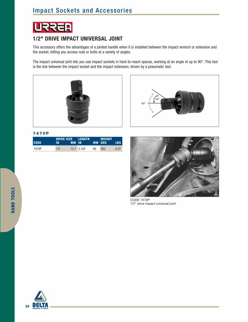
CODE 7470P 1/2" drive impact universal joint
1/2" DRIVE IMPACT UNIVERSAL JOINTThis accessory offers the advantages of a jointed handle when it is installed between the impact wrench or extension andthe socket, letting you access nuts or bolts at a variety of angles.
The impact universal joint lets you use impact sockets in hard-to-reach spaces, working at an angle of up to 90°. This toolis the link between the impact socket and the impact extension, driven by a pneumatic tool.
7470P
45O
90O
CODEDRIVE SIZEIN MM
LENGTHIN MM
WEIGHTGRS LBS
7470P 1/2 12.7 2-3/8 60 263 0.57
Urrea_p13-22 final.qxd 4/1/10 5:52 PM Page 22

Impact Sockets and Accessor ies
23
HAN
D TO
OLS
3/4" DRIVE IMPACT ADAPTERS
3/4" DRIVE IMPACT EXTENSIONS
CODEDRIVE SIZEIN MM
LENGTHIN MM
WEIGHTGRS LBS
TORQUE STRENGTHASME/ANSI B107.2LB-IN
7567 3/4 19.0 7-1/8 181.0 200 0.44 9000
7568 3/4 19.0 10-1/8 257.2 250 0.55 9000
7569 3/4 19.0 13 330.2 320 0.70 9000
CODE DESCRIPTIONLENGTHIN MM
SQUARE DRIVE SIZEF M
WEIGHTGRS LBS
7655 3/4 F x 1 M 2-1/2 63 3/4 1 399 0.87
7653 3/4 F x 1/2 M 2-3/16 56 3/4 1/2 159 0.35
These accessories let you workwith 1/2" or 1" square drivesockets using 3/4" handles.
75XX
765X
STANDARDS: ASME/ANSI B107.4 FEDERAL GGG-W-660 ISO 1174 and 2725 DIN 3129
This accessory lets you workon screws in tight or deepspaces where an impactwrench can’t reach, available ina variety of lengths. Themaximum recommendedtorque for a 3/4" extension ofany length is 9000 in-lbs.• To achieve the right balance
between hardness andstrength, extensions are heattreated in controlled-atmosphere furnaces.
• Manufactured from high-quality, high-strength micro-alloy steel. Black finishprevents corrosion andpresents no risk of surfacechipping or flaking.
7655
7567
7568
7569
7653
Urrea_p23-28 final.qxd 4/1/10 5:55 PM Page 23

24
Impact Sockets and Accessor iesH
AND
TO
OLS
75XX
3/4" DRIVE 6-POINT IMPACT SOCKETS IN FRACTIONAL SIZES
STANDARDS: ASME B107.4 FEDERAL GGG-W-660 ISO 1174 and 2725 DIN 3129
CODE
HEXSIZEIN
LENGTHIN MM
OUTER DIAMETERHEX- DRIVE-END ENDIN MM IN
HEX-END DEPTHIN TYPE
WEIGHTGRS LBS
TORQUESTRENGTHASME/ANSIB107.2 LB-IN
7508 1/2 1-15/16 49.2 1 12.7 1-5/8 9/16 I 570 1.26 3000
7509 9/16 1-15/16 49.2 1 14.2 1-5/8 9/16 I 650 1.43 3700
7510 5/8 1-15/16 49.2 1-1/16 15.8 1-5/8 5/8 I 690 1.52 4400
7511 11/16 1-15/16 49.2 1-1/8 17.4 1-5/8 5/8 I 730 1.54 5100
7512 3/4 1-15/16 49.2 1-1/4 19.0 1-5/8 11/16 I 700 1.61 6000
7513 13/16 1-15/16 49.2 1-3/8 20.6 1-5/8 11/16 I 710 1.62 6800
7514 7/8 2 49.2 1-1/2 22.2 1-5/8 3/4 I 780 1.72 7700
7515 15/16 2 50.8 1-5/8 23.8 1-5/8 3/4 II 780 1.72 8700
7516 1 2-1/16 50.8 1-5/8 25.4 1-5/8 3/4 II 920 2.03 9700
7517 1-1/16 2-1/16 52.4 1-11/16 26.9 1-11/16 3/4 II 920 2.03 10800
7518 1-1/8 2-3/16 55.5 1-3/4 28.5 1-3/4 7/8 II 880 1.94 9700
7519 1-3/16 2-3/16 54.0 1-13/16 30.1 1-3/4 1-1/16 III 1030 2.27 10800
7520 1-1/4 2-3/16 55.5 2 31.7 1-3/4 1-1/16 III 1150 2.54 11900
7521 1-5/16 2-3/16 55.5 2-1/16 33.3 1-3/4 1-1/16 III 1180 2.60 13050
7522 1-3/8 2-1/4 57.2 2-1/16 34.9 1-3/4 1-1/8 III 1310 2.89 14200
7523 1-7/16 2-5/16 58.8 2-1/4 36.5 1-3/4 1-1/8 III 1440 3.17 15400
7524 1-1/2 2-5/16 57.2 2-1/4 38.1 1-3/4 1-1/8 III 1520 3.35 16700
7525 1-9/16 2-5/16 66.6 2-5/16 39.6 1-3/4 1-3/16 III 1670 3.68 18000
7526 1-5/8 2-5/16 66.6 2-3/8 41.2 1-3/4 1-3/16 III 1780 3.92 18000
7527 1-11/16 2-1/2 66.6 2-1/2 42.8 1-3/4 1-3/8 III 1860 4.10 18000
7528 1-3/4 2-1/2 66.6 2-1/2 44.4 1-3/4 1-3/8 III 1920 4.23 18000
7529 1-13/16 2-3/4 66.6 2-9/16 46.0 1-3/4 1-9/16 III 2040 4.50 18000
7530 1-7/8 2-3/4 66.8 2-5/8 47.6 1-3/4 1-9/16 III 2110 4.65 18000
7531 1-15/16 2-3/4 66.8 2-5/8 49.2 1-3/4 1-9/16 III 2190 4.83 18000
7532 2 2-3/4 66.8 2-3/4 66.8 1-3/4 1-1/4 III 1007 2.25 18000
7533 2-1/16 2-13/16 72.0 2-15/16 74.6 2-1/8 1-3/8 III 7350 16.17 18000
7534 2-1/8 2-13/16 72.0 3 76.2 2-1/8 1-3/8 III 7350 16.17 18000
7535 2-3/16 2-29/32 74.0 3 76.2 2-1/8 1-13/32 III 7350 16.17 18000
7536 2-1/4 2-29/32 74.0 3-1/8 79.4 2-1/8 1-13/32 III 8250 18.15 18000
7538 2-3/8 2-15/16 75.0 3-5/16 84.1 2-1/8 1-13/32 III 8250 18.15 18000
Type I Type II Type III
Urrea_p23-28 final.qxd 4/1/10 5:55 PM Page 24

Impact Sockets and Accessor ies
25
HAN
D TO
OLS
3/4" DRIVE DEEP 6-POINT IMPACT SOCKETS IN FRACTIONAL SIZES
75XXL
CODEHEX SIZEIN MM
LENGTHIN MM
OUTER DIAMETER EXTERIOR EXTERIORHEX HEXIN IN
HEX-END DEPTHIN TYPE
WEIGHTGRS LBS
TORQUESTRENGTHASME/ANSIB107.2 LB-IN
7508L 1/2 12.7 3 76.2 15/16 1-1/2 1-3/16 I 518 1.14 3000
7509L 9/16 14.2 3 76.2 1 1-1/2 1-3/16 I 506 1.12 3700
7510L 5/8 15.8 3 76.2 1-1/8 1-1/2 1-3/16 I 526 1.16 4400
7511L 1-1/16 17.4 3 76.2 1-3/16 1-1/2 1-3/16 I 508 1.12 5100
7512L 3/4 19.0 3 76.2 1-1/4 1-1/2 1-3/16 I 494 1.09 6000
7513L 13/16 20.6 3 76.2 1-3/8 1-1/2 1-3/16 I 458 1.01 6800
7514L 7/8 22.2 3 76.2 1-9/16 1-9/16 1-3/16 I 446 0.98 7700
7515L 15/16 23.8 3 76.2 1-9/16 1-9/16 1-3/16 I 447 0.99 8700
7516L 1 25.4 3 76.2 1-5/8 1-5/8 1-3/16 I 490 1.08 9700
7517L 1-1/16 26.9 3 76.2 1-5/8 1-5/8 1-3/16 I 547 1.21 10800
7518L 1-1/8 28.5 3 76.2 1-7/8 1-7/8 1-11/16 I 560 1.23 10800
7519L 1-3/16 30.1 3-1/4 82.5 2 2 1-3/4 II 858 1.89 11900
7520L 1-1/4 31.7 3-1/4 82.5 2 2 1-3/4 III 1100 2.43 13050
7521L 1-5/16 33.3 3-1/4 82.5 2 2 1-3/4 III 801 1.77 14200
7522L 1-3/8 34.9 3-1/4 82.5 2 2 1-3/4 III 749 1.65 15400
7523L 1-7/16 36.5 3-1/4 82.5 2 2 1-3/4 III 769 1.70 16700
7524L 1-1/2 38.1 3-1/2 88.9 2-1/4 2-1/4 1-3/4 III 1010 2.23 18000
7525L 1-9/16 39.6 3-1/2 88.9 2-1/4 2-1/4 1-3/4 III 1032 2.28 18000
7526L 1-5/8 41.2 3-1/2 88.9 2-5/16 2-5/16 1-3/4 III 1054 2.32 18000
7527L 1-11/16 42.8 3-1/2 88.9 2-1/2 1-3/4 1-3/4 III 994 2.19 18000
7528L 1-3/4 44.4 3-1/2 88.9 2-1/2 1-3/4 1-3/4 III 979 2.16 18000
7529L 1-13/16 46.0 3-1/2 88.9 2-5/8 1-3/4 1-3/4 III 994 2.19 18000
7530L 1-7/8 47.6 3-3/4 95.2 2-11/16 1-3/4 1-3/4 III 1136 2.50 18000
7531L 1-15/16 49.2 3-3/4 95.2 2-3/4 1-3/4 1-3/4 III 982 2.16 18000
7532L 2 50.8 4-1/16 103.1 2-7/8 1-3/4 1-1/4 III 1443 3.18 18000
STANDARDS: ASME/ANSI B107.4 FEDERAL GGG-W-660 ISO 1174 and 2725 DIN 3129
Type I Type II Type III
Urrea_p23-28 final.qxd 4/1/10 5:55 PM Page 25

26
Impact Sockets and Accessor iesH
AND
TO
OLS
3/4" DRIVE METRIC 6-POINT IMPACT SOCKETS
75XXM
CODE
HEXSIZEMM
LENGTHIN MM
OUTER DIAMETERHEX- DRIVE-END ENDMM MM
HEX-END DEPTHMM TYPE
WEIGHTGRS LBS
TORQUESTRENGTHASME/ANSIB107.33 LB-IN
7517M 17 1-15/16 49.3 29.3 41.2 19.0 I 700 1.54 5100
7519M 19 1-15/16 49.3 31.7 41.2 19.0 I 820 1.81 6000
7520M 20 1-15/16 53.9 34.9 41.2 19.0 I 900 1.98 6800
7521M 21 1-15/16 53.9 34.9 41.2 19.0 I 960 2.12 6800
7522M 22 2 53.9 36.5 41.2 19.0 I 1030 2.27 7700
7523M 23 2 53.9 36.5 44.4 19.0 I 1090 2.40 8700
7524M 24 2 60.3 38.1 44.4 25.4 I 1150 2.54 9700
7525M 25 2-1/16 60.3 38.1 44.4 25.4 I 1210 2.67 9700
7526M 26 2-1/16 60.3 41.2 44.4 25.4 I 1270 2.80 10800
7527M 27 2-1/16 60.3 41.2 44.4 25.4 I 1330 2.93 10800
7528M 28 2-3/16 63.5 44.4 44.4 28.5 II 1400 3.09 11900
7529M 29 2-3/16 63.5 44.4 44.4 28.5 II 1460 3.22 11900
7530M 30 2-3/16 63.5 47.6 47.6 28.5 II 1500 3.31 14200
7531M 31 2-3/16 63.5 47.6 47.6 28.5 II 1580 3.48 14200
7532M 32 2-3/16 63.5 47.6 47.6 28.5 II 1620 3.57 14200
7533M 33 2-3/16 63.5 52.3 47.6 28.5 III 1680 3.70 16700
7534M 34 2-3/16 66.6 53.9 47.6 31.7 III 1720 3.79 16700
7535M 35 2-1/4 66.6 53.9 47.6 31.7 III 1780 3.92 16700
7536M 36 2-5/16 66.6 57.1 47.6 31.7 III 1850 4.08 18000
7538M 38 2-1/4 66.6 60.3 60.3 25.4 III 712 1.57 18000
7540M 40 2-5/8 66.6 61.9 61.9 34.9 III 771 1.70 24000
7541M 41 2-7/8 73.0 61.9 61.9 34.9 III 885 1.95 24000
7542M 42 2-7/8 73.0 63.5 63.5 38.5 III 909 2.00 24000
7543M 43 2-7/8 73.0 63.5 63.5 38.5 III 934 2.05 24000
7546M 46 3 76.2 69.8 69.8 41.2 III 1184 2.61 28000
7550M 50 3-1/4 82.5 71.34 71.34 41.2 III 1520 3.35 28000
Type I Type II Type III
STANDARDS: ASME/ANSI B107.4 ISO 1174 and 2725 DIN 3129
Urrea_p23-28 final.qxd 4/1/10 5:55 PM Page 26

Impact Sockets and Accessor ies
27
HAN
D TO
OLS
3/4" DRIVE DEEP METRIC 6-POINT IMPACT SOCKETS
75XXML
STANDARDS: ASME/ANSI B107.4 ISO 1174 and 2725 DIN 3129
CODE
HEXSIZEMM
LENGTHIN MM
OUTER DIAMETERHEX- DRIVE-END ENDIN IN
HEX-END DEPTHIN TYPE
WEIGHTGRS LBS
TORQUESTRENGTHASME/ANSI B107.33LB-IN
7519ML 19 3 76.2 1-1/4 1-1/2 1-7/16 I 1260 2.78 6000
7520ML 20 3 76.2 1-3/8 1-1/2 1-7/16 I 1320 2.91 6800
7521ML 21 3 76.2 1-3/8 1-1/2 1-7/16 I 1450 3.20 6800
7522ML 22 3 76.2 1-9/16 1-9/16 1-7/16 I 1500 3.31 7700
7523ML 23 3 76.2 1-9/16 1-9/16 1-7/16 I 1620 3.57 8700
7524ML 24 3 76.2 1-9/16 1-9/16 1-7/16 I 1740 3.84 9700
7525ML 25 3 76.2 1-5/8 1-5/8 1-7/16 I 1830 4.03 9700
7526ML 26 3 76.2 1-5/8 1-5/8 1-7/16 I 1920 4.23 10800
7527ML 27 3 76.2 1-7/8 1-7/8 1-5/8 I 1980 4.37 10800
7530ML 30 3-1/4 82.5 2 2 1-5/8 III 2100 4.63 14200
7532ML 32 3-1/4 82.5 2 2 1-5/8 III 2190 4.83 14200
7533ML 33 3-1/4 82.5 2 2 1-5/8 III 2230 4.92 16700
7534ML 34 3-1/4 82.5 2 2 1-5/8 III 2350 5.18 16700
7535ML 35 3-1/4 82.5 2 2 1-5/8 III 2400 5.29 16700
7536ML 36 3-1/4 82.5 2 2 1-5/8 III 2480 5.47 18000
7537ML 37 3-1/4 82.5 2 2 1-5/8 III 2530 5.58 18000
7538ML 38 3-1/2 88.9 2-1/4 2-1/4 1-3/4 III 2640 5.82 18000
7541ML 41 3-1/2 88.9 2-7/16 2-7/16 1-1/8 III 844 1.86 24000
7543ML 43 3-1/2 88.9 2-9/16 2-9/16 1-1/8 III 935 2.06 24000
Type I Type III
Urrea_p23-28 final.qxd 4/1/10 5:55 PM Page 27

3/4" DRIVE IMPACT UNIVERSAL JOINTThis accessory offers the advantages of a jointed handle when it is installed between the impact wrench or extension andthe socket, letting you access nuts or bolts at a variety of angles.
7570
CODEDRIVE SIZEIN MM
LENGTHIN MM
WEIGHTGRS LBS
7570 3/4 19.0 4-1/8 105 712 1.56
28
Impact Sockets and Accessor iesH
AND
TO
OLS
1" DRIVE IMPACT SOCKET SET10000L
12 PIECES1" drive 12 pc fractional impactsocket set 6 point in cardboard box
CODE SIZE
10022L 1-3/8
10023L 1-7/16
10024L 1-1/2
10025L 1-9/16
10026L 1-5/8
10028L 1-3/4
10029L 1-13/16
10030L 1-7/8
10031L 1-15/16
10032L 2
10034L 2-1/8
10035L 2-3/16
Urrea_p23-28 final.qxd 4/1/10 5:55 PM Page 28

Impact Sockets and Accessor ies
29
HAN
D TO
OLS
1" DRIVE IMPACT ADAPTERS
1" DRIVE IMPACT EXTENSIONS
CODEDRIVE SIZEIN MM
LENGTHIN MM
WEIGHTGRS LBS
TORQUE STRENGTHASME/ANSI B107.2LB-IN
10607 1 25.4 7 17.8 1652 3.64 15000
10609 1 25.4 10 254 2696 5.94 15000
CODE SIZELENGTHIN MM
WEIGHTGRS LBS
7656 1 F x 3/4 M 2-15/16 75 640 1.41
15007 1 F x 1-1/2 M 3-25/46 90 4177 9.21
These accessories let you workwith 3/4" square drive socketsusing 1" handles.
1060X
7656 / 15007
STANDARDS:ASME/ANSI B107.4 FEDERAL GGG-W-660 ISO 1174 and 2725 DIN 3129
This accessory lets you workon screws in tight or deepspaces where an impactwrench can’t reach, available ina variety of lengths. Themaximum recommendedtorque for a 1" extension of anylength is 15,000 in-lbs.• To achieve the right balance
between hardness andstrength, extensions are heattreated in controlled-atmosphere furnaces.
• Made of high-quality, highstrength micro-alloy steelwith black finish to preventcorrosion and no risk ofsurface chipping or flaking.
7656
10607
10609
15007
Urrea_p29-32 final.qxd 4/1/10 5:58 PM Page 29

30
Impact Sockets and Accessor iesH
AND
TO
OLS
100XX
1" DRIVE 6-POINT IMPACT SOCKETS IN FRACTIONAL SIZES
STANDARDS: ASME/ANSI B107.4 FEDERAL GGG-W-660 ISO 1174 and 2725 DIN 3129
Type I Type II Type III
CODE
HEXSIZEIN MM
LENGTHIN MM
OUTER DIAMETERHEX- DRIVE-END ENDIN IN
HEX-END DEPTHIN TYPE
WEIGHTGRS LBS
TORQUESTRENGTHASME/ANSIB107.2 LB-IN
10012 3/4 19.0 2-7/16 60.3 1-3/8 2 11/16 I 644 1.42 640010013 13/16 20.6 2-7/16 60.3 1-7/16 2 11/16 I 636 1.40 740010014 7/8 22.2 2-7/16 60.3 1-7/16 2 11/16 I 630 1.39 840010015 15/16 23.8 2-1/2 63.5 1-9/16 2 3/4 I 624 1.38 940010016 1 25.4 2-1/2 63.5 1-9/16 2 3/4 I 594 1.31 1050010017 1-1/16 26.9 2-1/2 66.6 1-5/8 2 3/4 I 674 1.49 1170010018 1-1/8 28.5 2-1/2 66.6 1-11/16 2 3/4 I 616 1.36 1280010019 1-3/16 30.1 2-3/4 66.6 1-13/16 2 15/16 II 730 1.61 1410010020 1-1/4 31.7 2-3/4 66.6 1-15/16 2 15/16 II 708 1.56 1540010021 1-5/16 33.3 2-13/16 69.8 2 2 15/16 II 678 1.49 1670010022 1-3/8 34.9 2-13/16 73.0 2-1/4 2-1/4 1 II 944 2.08 1800010023 1-7/16 36.5 2-13/16 73.0 2-1/4 2-1/4 1 II 920 2.03 1950010024 1-1/2 38.1 2-7/8 73.0 2-5/16 2-5/16 1-5/16 II 870 1.92 2100010025 1-9/16 39.6 3-1/16 73.0 2-5/16 2-5/16 1-5/16 II 926 2.04 2200010026 1-5/8 41.2 3-1/16 73.0 2-5/16 2-5/16 1-3/8 II 892 1.97 2400010027 1-11/16 42.8 3-1/4 76.2 2-1/2 2-1/2 1-1/2 II 1252 2.76 2600010028 1-3/4 44.4 3-1/4 76.2 2-1/2 2-1/2 1-1/2 II 1168 2.58 2700010029 1-13/16 46.0 3-1/4 76.2 2-5/8 2-5/8 1-1/2 II 1330 2.93 2800010030 1-7/8 47.6 3-1/4 76.2 2-11/16 2-11/16 1-1/2 II 1364 3.01 2800010031 1-15/16 49.2 3-1/4 82.5 2-13/16 2-13/16 1-1/2 III 1652 3.64 2800010032 2 50.8 3-1/4 82.5 2-15/16 2-15/16 1-1/4 III 1450 3.20 2800010033 2-1/16 52.3 2-3/4 82.5 2-15/16 2-5/16 1-1/4 III 1142 2.52 2800010034 2-1/8 53.9 2-3/4 82.5 3-1/16 2-5/16 1-1/4 III 1220 2.69 2800010035 2-3/16 55.5 2-11/16 82.5 3-1/8 2-7/16 1-1/4 III 1356 2.99 2800010036 2-1/4 57.1 2-15/16 88.9 3-5/16 2-7/16 1-3/8 III 1634 3.60 2800010037 2-5/16 58.7 2-15/16 88.9 3-3/8 2-7/16 1-3/8 III 1624 3.58 2800010038 2-3/8 60.3 3-1/16 88.9 3-7/16 2-7/16 1-3/8 III 1752 3.86 2800010039 2-7/16 61.9 3-1/16 95.2 3-1/2 2-7/16 1-3/8 III 1752 3.86 2800010040 2-1/2 63.5 3-1/8 95.2 3-9/16 2-7/16 1-7/16 III 1896 4.18 2800010041 2-9/16 65.0 3-1/8 95.2 3-5/8 2-7/16 1-7/16 III 1940 4.28 2800010042 2-5/8 66.6 3-1/4 95.2 3-3/4 2-7/16 1-1/2 III 2026 4.47 2800010043 2-11/16 68.2 3-1/4 101.6 3-13/16 2-7/16 1-1/2 III 2100 4.63 2800010044 2-3/4 69.8 3-5/16 101.6 3-7/8 2-7/16 1-9/16 III 2118 4.67 2800010045 2-13/16 71.4 3-7/16 101.6 3-15/16 2-7/16 1-5/8 III 2274 5.01 2800010046 2-7/8 73.0 3-7/16 107.9 4-1/16 2-7/16 1-5/8 III 2346 5.17 2800010047 2-15/16 74.6 3-3/4 107.9 4-1/8 3-3/8 1-15/16 III 3320 7.32 2800010048 3 76.2 3-7/8 107.9 4-1/16 3-3/8 2-1/16 III 3444 7.59 2800010050 3-1/8 79.3 4 101.6 4-1/4 3-3/8 2 III 3444 7.59 2800010052 3-1/4 82.5 4-1/4 107.9 4-1/2 3-3/8 2-3/8 III 3444 7.59 2800010054 3-3/8 85.7 4-7/16 112.7 4-9/16 3-3/8 2-3/8 III 3444 7.59 2800010056 3-1/2 88.9 4-1/2 114.3 4-3/4 3-3/8 2-1/2 III 3659 8.06 2800010058 3-5/8 92.0 4-3/4 120.6 4-7/8 3-3/8 2-1/2 III 4063 8.95 2800010062 3-7/8 98.4 5 127.0 5-1/16 3-3/8 2-1/2 III 4095 9.02 2800010064 4 101.6 5-1/2 139.7 5-3/4 3-3/8 2-1/2 III 6837 15.06 2800010066 4-1/8 104.7 5-1/2 139.7 6 3-3/8 2-3/4 III 7745 17.06 2800010068 4-1/4 107.9 5-1/2 139.7 6 3-3/8 2-3/4 III 7246 15.96 2800010072 4-1/2 114.3 6 152.4 6 1/4 3-3/8 3 III 7891 17.38 28000
The line of 1" impact sockets is for heavy mechanical work,primarily in the petrochemical, extraction, mining, andsimilar industries. The application ranges are as follows:• Socket hex size: 3/4" to 4-1/2" and 19 to 65 mm.• Torque applications for sockets, handles, and
accessories: 6400-28,000 in-lbs
Urrea_p29-32 final.qxd 4/1/10 5:58 PM Page 30

Impact Sockets and Accessor ies
31
HAN
D TO
OLS
1" DRIVE 6-POINT DEEP IMPACT SOCKETS IN FRACTIONAL SIZES
100XXL
Type I Type II Type III
CODEHEX SIZEIN MM
LENGTHIN MM
OUTER DIAMETERHEX- DRIVE-END ENDIN IN
HEX-ENDDEPTHIN TYPE
WEIGHTGRS LBS
TORQUESTRENGTHASME/ANSIB107.2 LB-IN
10014L 7/8 22.2 3-1/8 79.3 1-9/16 2-1/16 1-1/16 I 1112.3 2.45 8400
10015L 15/16 23.8 3-1/8 79.3 1-5/8 2-1/16 1-1/16 I 1198.6 2.64 9400
10016L 1 25.4 3-1/8 79.3 1-11/16 2-1/16 1-1/16 I 1207.6 2.66 10500
10017L 1-1/16 26.9 3-1/16 79.3 1-5/8 2 1-1/16 I 2480 5.47 11700
10018L 1-1/8 28.5 3-1/16 79.3 1-11/16 2 1-1/16 I 2530 5.58 12800
10019L 1-3/16 30.1 3-1/16 79.3 1-13/16 2 1-1/16 I 2760 6.08 14100
10020L 1-1/4 31.7 3-1/16 79.3 1-15/16 2 1-1/16 I 2760 6.08 15400
10021L 1-5/16 33.3 3-1/2 82.5 2 2 1-1/16 II 2920 6.44 16700
10022L 1-3/8 34.9 3-1/2 82.5 2-1/4 2-1/4 1-1/16 II 3150 6.94 18000
10023L 1-7/16 36.5 3-1/2 82.5 2-1/4 2-1/4 1-1/16 II 3160 6.97 19500
10024L 1-1/2 38.1 3-9/16 92.0 2-5/16 2-5/16 1-11/16 II 3300 7.28 21000
10025L 1-9/16 39.6 3-9/16 92.0 2-5/16 2-5/16 1-11/16 II 3450 7.61 22000
10026L 1-5/8 41.2 3-9/16 92.0 2-5/16 2-5/16 1-11/16 II 3470 7.65 24000
10027L 1-11/16 42.8 3-9/16 92.0 2-1/2 2-1/2 1-11/16 II 3670 8.09 27000
10028L 1-3/4 44.4 3-9/16 92.0 2-1/2 2-1/2 1-11/16 II 3680 8.11 28000
10029L 1-13/16 46.0 3-5/8 92.0 2-5/8 2-5/8 1-11/16 II 3680 8.11 28000
10030L 1-7/8 47.6 3-5/8 92.0 2-11/16 2-11/16 1-11/16 II 3820 8.42 28000
10031L 1-15/16 49.2 3-5/8 95.2 2-13/16 2-13/16 1-11/16 II 3820 8.42 28000
10032L 2 50.8 3-3/4 95.2 2-15/16 2-15/16 1-11/16 II 4000 8.82 28000
10034L 2-1/8 53.9 3-15/16 101.6 3-1/16 2-5/16 1-11/16 III 4350 9.59 28000
10035L 2-3/16 55.5 3-15/16 101.6 3-1/8 2-7/16 1-11/16 III 4350 9.59 28000
10036L 2-1/4 57.1 3-15/16 100.0 3-5/16 2-7/16 2-3/8 III 2261 4.98 28000
10037L 2-5/16 58.73 4-1/8 104.7 3-3/8 2-7/16 2-9/16 III 2688 5.92 28000
10038L 2-3/8 60.3 4-1/8 104.7 3-7/16 2-7/16 2-7/16 III 2751 6.06 28000
10041L 2-9/16 65.0 4-3/4 120.6 3-11/16 2-7/16 3 III 2874 6.33 28000
10044L 2-3/4 69.8 4-7/8 123.8 3-7/8 2-7/16 3-1/8 III 3223 7.10 28000
STANDARDS: ASME/ANSI B107.4 FEDERAL GGG-W-660 ISO 1174 and 2725 DIN 3129
Urrea_p29-32 final.qxd 4/1/10 5:58 PM Page 31

1" DRIVE IMPACT UNIVERSAL JOINTThis accessory offers the advantages of a jointed handle when it is installed between the impact wrench or extension andthe socket, letting you access nuts or bolts at a variety of angles.
10670
CODEDRIVE SIZEIN MM
LENGTHIN MM
WEIGHTGRS LBS
10670 1 25.4 5-1/4 133 1806 3.98
32
Impact Sockets and Accessor iesH
AND
TO
OLS
1" DRIVE METRIC 6-POINT IMPACT SOCKETS
100XXM
CODE
HEXSIZEMM
LENGTHIN MM
OUTER DIAMETERHEX- DRIVE-END ENDIN IN
HEX-END DEPTHIN TYPE
WEIGHTGRS LBS
TORQUE STRENGTHASME/ANSI B107.33 LB - IN
10019M 19 2-7/16 61.9 1-3/8 2 5/8 I 626 1.38 6400
10024M 24 2-1/2 63.5 1-1/2 2 3/4 I 636 1.40 9506
10027M 27 2-1/2 63.5 1-5/8 2 7/8 I 614 1.35 11700
10030M 30 2-13/16 71.4 1-13/16 2 1-1/8 I 706 1.56 14002
10032M 32 2-13/16 71.4 1-15/16 2 1-1/8 I 702 1.55 15604
10033M 33 2-13/16 71.4 2 2 1 II 700 1.54 16400
10036M 36 2-13/16 71.4 2-1/2 2-1/2 1 II 957 2.11 22392
10041M 41 2-15/16 74.6 2-5/16 2-5/16 1-1/4 II 868 1.91 24959
10046M 46 3-1/8 79.3 2-5/8 2-5/8 1-7/16 II 1226 2.70 27968
10050M 50 3-1/4 82.5 2-13/16 2-13/16 1-7/16 II 1458 3.21 27968
10055M 55 3-1/4 82.5 3-1/8 2-7/16 1-7/16 III 1589 3.50 27968
10060M 60 3-1/4 82.5 3-7/16 2-7/16 1-7/16 III 1720 3.79 27968
10065M 65 3-1/4 82.5 3-11/16 2-7/16 1-7/16 III 1910 4.21 27968
Type I Type II Type III
STANDARDS: ASME B107.33M ISO 1174 and 2725 DIN 3129
Urrea_p29-32 final.qxd 4/1/10 5:58 PM Page 32

Impact Sockets and Accessor ies
33
HAN
D TO
OLS
1-1/2" DRIVE IMPACT ADAPTERS
1-1/2" DRIVE IMPACT EXTENSIONS
CODESIZEIN
LENGTHIN MM
WEIGHTGRS LBS
15097 1-1/2 8-27/32 225 2304 5.08
CODE SIZELENGTHIN MM
WEIGHTGRS LBS
10004 1-1/2 F x 1 M 3-1/2 90 4177 9.21
These accessories let you work with 1" square drive sockets using 1-1/2"handles.
15097
10004
STANDARDS:ASME/ANSI B107.4 FEDERAL GGG-W-660 ISO 1174 and 2725 DIN 3129
This accessory lets you workon screws in tight or deepspaces where an impactwrench can’t reach, availablein a variety of lengths.
To achieve the right balancebetween hardness andstrength, extensions are heattreated in controlled-atmosphere furnaces.
Urrea_p33-34 final.qxd 4/1/10 5:59 PM Page 33

34
Impact Sockets and Accessor iesH
AND
TO
OLS
150XX
1-1/2" DRIVE 6-POINT IMPACT SOCKETS IN FRACTIONAL SIZES
STANDARDS: ASME B107.2
Type I Type II
CODE
HEXSIZEIN MM
LENGTHIN MM
OUTER DIAMETERHEX- DRIVE-END ENDIN MM IN MM
HEX-END DEPTHIN MM TYPE
WEIGHTGRS LBS
15022 1-3/8 34.9 2-15/16 75 2-3/8 60 3-7/16 86 3/4 19 I 1993 4.4
15023 1-7/16 36.5 3-1/8 80 2-1/2 64 3-7/16 86 3/4 19 I 2020 4.46
15024 1-1/2 38.1 3-1/8 80 2-1/2 64 3-7/16 86 7/8 22 I 1971 4.35
15026 1-5/8 41.3 3-1/8 80 2-3/4 70 3-7/16 86 7/8 22 I 2084 4.6
15027 1-11/16 42.9 3-1/8 80 2-15/16 75 3-7/16 86 1 25 I 2116 4.67
15029 1-13/16 46.0 3-1/8 80 2-15/16 75 3-7/16 86 1 25 I 2229 4.92
15030 1-7/8 47.6 3-3/16 82 3-1/8 80 3-7/16 86 1-1/16 27 I 2188 4.83
15032 2 50.8 3-3/16 82 3-1/8 80 3-7/16 86 1-1/16 27 I 2464 5.44
15033 2-1/16 52.4 3-1/2 89 3-3/8 86 3-7/16 86 1-1/8 30 III 2414 5.33
15034 2-1/8 54.0 3-1/2 89 3-7/16 86 3-7/16 86 1-1/8 30 III 2899 6.4
15035 2-3/16 55.6 3-5/8 92 3-7/16 86 3-7/16 86 1-1/4 32 III 2550 5.63
15036 2-1/4 57.2 3-5/8 92 3-7/16 86 3-7/16 86 1-5/16 33 III 2777 6.13
15038 2-3/8 60.3 3-3/4 96 3-5/8 92 3-7/16 86 1-3/8 35 III 2940 6.49
15039 2-7/16 61.9 3-3/4 96 3-13/16 96 3-7/16 86 1-3/8 35 III 3008 6.64
15040 2-1/2 63.5 3-3/4 96 4 100 3-7/16 86 1-3/8 35 III 3022 6.67
15041 2-9/16 65.1 3-3/4 96 4 100 3-7/16 86 1-3/8 35 III 3787 8.36
15042 2-5/8 66.7 4 101 4 100 3-7/16 86 1-1/2 38 III 3887 8.58
15044 2-3/4 69.9 4 101 4 100 3-7/16 86 1-1/2 38 III 3909 8.63
15046 2-7/8 73.0 4-1/16 103 4-1/4 108 3-7/16 86 1-13/16 46 III 4426 9.77
15047 2-15/16 74.6 4-1/16 103 4-5/16 110 3-7/16 86 1-13/16 46 III 4340 9.58
15048 3 76.2 4-1/16 103 4-5/16 110 3-7/16 86 1-13/16 46 III 4892 10.8
15050 3-1/8 79.4 4-5/16 110 4-9/16 116 3-7/16 86 2 51 III 4924 10.87
15054 3-3/8 85.7 4-5/16 110 4-15/16 125 3-7/16 86 2-1/16 52 III 5382 11.88
15056 3-1/2 88.9 4-5/16 110 5-1/8 130 3-7/16 86 2-1/16 52 III 5712 12.61
15058 3-5/8 92.1 5-11/16 145 5-1/8 130 3-7/16 86 2-1/16 52 III 6170 13.62
15060 3-3/4 95.3 5-11/16 145 5-3/8 137 3-3/4 95 2-1/16 52 III 5980 13.2
15062 3-7/8 98.4 5-15/16 150 5-1/2 140 3-3/4 95 2-5/16 59 III 6097 13.46
15064 4 101.6 5-15/16 150 5-1/2 140 3-3/4 95 2-5/16 59 III 7366 16.26
15066 4-1/8 104.8 6-1/8 155 5-15/16 150 3-3/4 95 2-5/16 59 III 8054 17.78
15068 4-1/4 108.0 6-5/16 160 5-15/16 150 3-3/4 95 2-5/16 59 III 7846 17.32
15072 4-1/2 114.3 6-1/2 165 6-5/16 160 3-3/4 95 2-5/8 67 III 8548 18.87
15074 4-5/8 117.5 6-11/16 170 6-1/2 165 3-3/4 95 2-5/8 67 III 9450 20.86
15080 5 127.0 6-7/8 175 7-1/16 179 5 127 2-13/16 72 III 10115 22.33
D
C
BA
L
Urrea_p33-34 final.qxd 4/1/10 5:59 PM Page 34

Impact Sockets and Accessor ies
35
HAN
D TO
OLS
250XX
2-1/2" DRIVE 6-POINT IMPACT SOCKETS IN FRACTIONAL SIZES
STANDARDS: ASME B107.2
CODE
HEXSIZEIN MM
LENGTHIN MM
OUTER DIAMETERHEX- DRIVE-END ENDIN MM IN MM
HEX-END DEPTHIN MM TYPE
WEIGHTGRS LBS
25032 2 50.9 4-3/4 121 3-7/16 87.3 5 127 1-1/4 31.7 I 12600 27.72
25034 2-1/8 54.1 4-3/4 121 3-9/16 90.4 5 127 1-1/4 31.7 I 11200 24.64
25036 2-1/4 57.3 4-15/16 125.25 3-1/2 88.9 5 127 1-3/8 34.9 I 13500 29.70
25038 2-3/8 60.4 4-15/16 125.25 3-7/8 98.4 5 127 1-7/16 36.5 I 11700 25.74
25042 2-5/8 66.8 5-7/64 130 4-7/32 107.1 5 127 1-9/16 39.6 I 15455 34.00
25044 2-3/4 70.0 5-7/64 130 4-5/16 109.5 5 127 1-9/16 39.6 II 14800 32.56
25048 3 76.4 5-1/2 140 4-23/32 119.8 5 127 1-7/8 47.6 III 16350 35.97
25050 3-1/8 79.5 5-1/2 140 4-7/8 123.8 5 127 2-3/32 53.1 III 16550 36.41
25052 3-1/4 82.7 5-1/2 140 5 127.0 5 127 2-3/32 53.1 III 16000 35.20
25056 3-1/2 89.1 5-1/2 140 5-5/16 134.9 5 127 2-3/32 53.1 III 17900 39.38
25058 3-5/8 92.3 5-11/16 145 5-1/2 139.7 5 127 2-3/16 55.5 III 17600 38.72
25060 3-3/4 95.4 5-11/16 145 5-5/8 142.8 5 127 2-3/16 55.5 III 19500 42.90
25062 3-7/8 98.6 5-29/32 150 5-25/32 146.8 5 127 2-5/16 58.7 III 20010 44.02
25064 4 101.8 5-29/32 150 5-15/16 150.8 5 127 2-5/16 58.7 III 21400 47.08
25066 4-1/8 105.0 6-3/32 155 6-1/8 155.5 5 127 2-1/2 63.5 III 11300 24.86
25068 4-1/4 108.2 6-5/16 160 6-1/4 158.7 5 127 2-19/32 65.8 III 12650 27.83
25070 4-3/8 111.3 6-1/2 165 6-7/16 163.5 5 127 2-11/16 68.2 III 13200 29.04
25072 4-1/2 114.5 6-1/2 165 6-9/16 166.6 5 127 2-11/16 68.2 III 13900 30.58
25074 4-5/8 117.7 6-11/16 170 6-3/4 171.4 5 127 2-7/8 73.0 III 15050 33.11
25076 4-3/4 120.9 6-11/16 170 6-15/16 176.2 5 127 2-7/8 73.0 III 15700 34.54
25078 4-7/8 124.1 6-7/8 175 7-1/8 180.9 5 127 3-1/32 76.9 III 17250 37.95
25080 5 127.3 6-7/8 175 7-1/4 184.1 5 127 3-1/32 76.9 III 17100 37.62
Type I Type II Type III
D
C
BA
L
Urrea_p35 final.qxd 4/1/10 6:01 PM Page 35

36
1-1/2" Dr ive Accessor iesH
AND
TO
OLS
1-1 ⁄ 2" SQUARE DRIVE
ADAPTERS
PART# FEMALE MALE L
A2416 1-1/2 1 3.75
A2440 1-1/2 2-1/2 3.50
A2495 1-1/2 #5 Spline 4.33
DOUBLE ENDED FEMALE ADAPTERS
PART# D1 D2 L
AN2416 1-1/2 1 3.27
AN2424 1-1/2 1-1/2 3.35
AN4024 1-1/2 2-1/2 4.53
PART# D1 L
Z2404 1.93 4
Z2405 1.93 5
Z2410 1.93 10
Z2420 1.93 20
DOUBLE ENDED MALE ADAPTERS
EXTENSIONS
PART# L
E2406 6
E2412 12
UNIVERSAL JOINT
SIZE PART#
1-1/2 U2424
SPECIAL HOPPER CAR GATE SOCKETS
PART# FEMALE (IN.) MALE TAPER (IN.)
HEX-3 1-1/2 sq. 3/4 sq. to 1-7/8 sq
HEX-12 2-1/2 sq. 3/4 sq. to 1-7/8 sq
AN 2424Hex 3
Z 2410
ATP_p36 final.qxd 4/1/10 6:08 PM Page 36

37
HAN
D TO
OLS
2-1/2" Dr ive Impact Socket and Accessor ies
2-1/2" SQUARE DRIVE Six Point Impact Sockets
STANDARD FRACTIONAL SIZES
SIZE PART# D1 D2 L T C1-5/8 Z-4026 4.094 5.000 4.485 0.846 2.3491-11/16 Z-4027 4.094 5.000 4.485 0.984 2.3491-3/4 Z-4028 4.094 5.000 4.485 1.000 2.3491-13/16 Z-4029 4.094 5.000 4.485 1.000 2.3491-7/8 Z-4030 4.094 5.000 4.485 1.062 2.3491-15/16 Z-4031 4.094 5.000 4.485 1.062 2.3492 Z-4032 4.094 5.000 4.485 1.062 2.3492-1/16 Z-4033 4.094 5.000 4.485 1.181 2.3492-1/8 Z-4034 4.094 5.000 4.485 1.181 2.3492-3/16 Z-4035 4.094 5.000 4.485 1.260 2.3492-1/4 Z-4036 4.094 5.000 4.485 1.280 2.3492-5/16 Z-4037 4.094 5.000 4.485 1.299 2.3492-3/8 Z-4038 4.094 5.000 4.485 1.378 2.3492-7/16 Z-4039 4.094 5.000 4.485 1.378 2.3492-1/2 Z-4040 4.094 5.000 4.485 1.378 2.3492-9/16 Z-4041 4.094 5.000 4.485 1.378 2.3492-5/8 Z-4042 4.094 5.000 4.485 1.496 2.3492-11/16 Z-4043 4.094 5.000 4.485 1.496 2.3492-3/4 Z-4044 4.094 5.000 4.485 1.496 2.3492-13/16 Z-4045 4.094 5.000 4.870 1.575 2.3492-7/8 Z-4046 4.094 5.000 4.870 1.614 2.3492-15/16 Z-4047 4.094 5.000 4.870 1.614 2.3493 Z-4048 4.094 5.000 4.870 1.732 2.3493-1/16 Z-4049 4.094 5.000 4.870 1.732 2.3493-1/8 Z-4050 4.094 5.000 4.870 1.732 2.3493-3/16 Z-4051 5.000 5.000 5.070 1.850 2.7433-1/4 Z-4052 5.000 5.000 5.070 1.850 2.7433-5/16 Z-4053 5.000 5.000 5.070 1.850 2.7433-3/8 Z-4054 5.000 5.000 5.070 1.930 2.7433-7/16 Z-4055 5.315 5.000 5.140 1.930 2.8223-1/2 Z-4056 5.315 5.000 5.140 1.930 2.8223-9/16 Z-4057 5.315 5.000 5.140 1.930 2.8223-5/8 Z-4058 5.315 5.000 5.140 1.930 2.8223-11/16 Z-4059 5.315 5.000 5.140 1.930 2.8223-3/4 Z-4060 5.512 5.000 5.140 1.930 2.8223-13/16 Z-4061 5.709 5.000 5.500 2.125 3.1373-7/8 Z-4062 5.709 5.000 5.500 2.125 3.1373-15/16 Z-4063 5.709 5.000 5.500 2.125 3.1374 Z-4064 5.906 5.000 5.500 2.125 3.1374-1/16 Z-4065 5.906 5.000 5.500 2.125 3.1374-1/8 Z-4066 6.102 5.000 5.500 2.125 3.1374-3/16 Z-4067 6.102 5.000 5.850 2.440 3.4914-1/4 Z-4068 6.102 5.000 5.850 2.440 3.4914-5/16 Z-4069 6.299 5.000 5.850 2.440 3.494-3/8 Z-4070 6.299 5.000 5.850 2.440 3.4914-7/16 Z-4071 6.496 5.000 5.850 2.440 3.494-1/2 Z-4072 6.496 5.000 5.850 2.440 3.4914-5/8 Z-4074 6.693 5.000 6.160 2.640 3.8064-3/4 Z-4076 6.693 5.000 6.160 2.640 3.8064-7/8 Z-4078 6.693 5.000 6.160 2.640 3.8065 Z-4080 7.087 5.000 6.435 2.830 4.1215-1/8 Z-4082 7.087 5.000 6.430 2.990 4.4365-3/16 Z-4083 7.087 5.000 6.780 2.909 4.436
SIZE PART# D1 D2 L T C5-1/4 Z-4084 7.480 5.000 6.780 2.99 4.4365-3/8 Z-4086 7.480 5.000 6.780 2.99 4.4365-1/2 Z-4088 7.480 5.000 6.860 3.11 4.7905-5/8 Z-4090 7.874 5.906 7.090 3.27 4.7905-3/4 Z-4092 7.874 5.906 7.090 3.27 4.7905-7/8 Z-4094 8.268 5.906 7.410 3.46 5.1056 Z-4096 8.268 5.906 7.410 3.46 5.1056-1/8 Z-4098 8.268 5.906 7.410 3.46 5.1056-1/4 Z-40100 8.661 5.906 7.560 3.58 5.2636-3/8 Z-40102 8.661 5.906 7.560 3.58 5.2636-1/2 Z-40104 9.055 6.890 7.830 3.70 5.7356-5/8 Z-40106 9.055 6.890 7.830 3.70 5.7356-3/4 Z-40108 9.055 6.8900 8.110 3.90 5.7356-7/8 Z-40110 9.449 6.890 8.110 3.90 5.7357 Z-40112 9.449 6.890 8.340 4.09 6.0507-1/8 Z-40114 9.843 6.890 8.340 4.09 6.0507-1/4 Z-40116 9.843 6.890 8.340 4.09 6.0507-3/8 Z-40118 9.843 6.890 8.500 4.21 6.2087-1/2 Z-40120 10.236 6.890 8.500 4.21 6.2087-5/8 Z-40122 10.236 6.890 8.650 4.29 6.3657-3/4 Z-40124 10.630 6.890 8.810 4.41 6.5237-13/16 Z-40125 10.630 6.890 8.810 4.41 6.5237-7/8 Z-40126 10.630 6.890 8.810 4.41 6.5238 Z-40128 10.630 6.890 9.040 4.53 7.0348-1/8 Z-40130 11.024 6.890 9.040 4.53 7.0348-1/4 Z-40132 11.024 6.890 9.040 4.53 7.0348-3/8 Z-40134 11.417 6.890 9.320 4.72 7.0348-1/2 Z-40136 11.417 6.890 9.750 4.80 7.7828-3/4 Z-40140 11.811 6.890 9.870 4.88 7.7828-7/8 Z-40142 11.811 6.890 10.062 4.96 7.7829 Z-40144 12.205 6.890 10.062 5.04 7.7829-1/8 Z-40146 12.205 6.890 10.062 5.16 7.7829-1/4 Z-40148 12.205 6.890 10.725 5.24 9.515
D1
D2
L
TC
Table continued next column
ATP_p37-39 final.qxd 4/1/10 6:10 PM Page 37

38
HAN
D T
OO
LS2-1/2" Dr ive Impact Socket and Accessor ies
2-1/2" SQUARE DRIVE Six Point Impact Sockets
DEEP FRACTIONAL SIZES
D1
D2
L
TC
Table continued next column
SIZE PART# D1 D2 L T C1-5/8 Z-4026L 4.094 5.000 7.480 0.846 5.1841-11/16 Z-4027L 4.094 5.000 7.480 0.984 5.1841-3/4 Z-4028L 4.094 5.000 7.480 1.000 5.1841-13/16 Z-4029L 4.094 5.000 7.480 1.000 5.1841-7/8 Z-4030L 4.094 5.000 7.480 1.062 5.1841-15/16 Z-4031L 4.094 5.000 7.480 1.062 5.1842 Z-4032L 4.094 5.000 7.480 1.062 5.1842-1/16 Z-4033L 4.094 5.000 7.480 1.181 5.1842-1/8 Z-4034L 4.094 5.000 7.480 1.181 5.1842-3/16 Z-4035L 4.094 5.000 7.480 1.260 5.1842-1/4 Z-4036L 4.094 5.000 7.480 1.280 5.1842-5/16 Z-4037L 4.094 5.000 7.480 1.299 5.1842-3/8 Z-4038L 4.094 5.000 7.480 1.378 5.1842-7/16 Z-4039L 4.094 5.000 7.480 1.378 5.1842-1/2 Z-4040L 4.094 5.000 7.480 1.378 5.1842-9/16 Z-4041L 4.094 5.000 7.480 1.378 5.1842-5/8 Z-4042L 4.094 5.000 7.480 1.496 5.1842-11/16 Z-4043L 4.094 5.000 7.480 1.496 5.1842-3/4 Z-4044L 4.094 5.000 7.480 1.496 5.1842-13/16 Z-4045L 4.094 5.000 7.480 1.575 5.1842-7/8 Z-4046L 4.094 5.000 7.480 1.614 5.1842-15/16 Z-4047L 4.094 5.000 7.480 1.614 5.1843 Z-4048L 4.094 5.000 7.480 1.732 5.1843-1/16 Z-4049L 4.094 5.000 7.480 1.732 5.1843-1/8 Z-4050L 4.094 5.000 7.480 1.732 5.1843-3/16 Z-4051L 5.000 5.000 7.480 1.850 5.1843-1/4 Z-4052L 5.000 5.000 7.480 1.850 5.1843-5/16 Z-4053L 5.000 5.000 7.480 1.850 5.1843-3/8 Z-4054L 5.000 5.000 7.480 1.930 5.1843-7/16 Z-4055L 5.315 5.000 7.480 1.930 5.1843-1/2 Z-4056L 5.315 5.000 7.480 1.930 5.1843-9/16 Z-4057L 5.315 5.000 7.480 1.930 5.1843-5/8 Z-4058L 5.315 5.000 7.480 1.930 5.1843-11/16 Z-4059L 5.315 5.000 7.480 1.930 5.1843-3/4 Z-4060L 5.512 5.000 7.480 1.930 5.1843-13/16 Z-4061L 5.709 5.000 7.720 2.125 5.4203-7/8 Z-4062L 5.709 5.000 7.720 2.125 5.4203-15/16 Z-4063L 5.709 5.000 7.720 2.125 5.4204 Z-4064L 5.906 5.000 7.720 2.125 5.4204-1/16 Z-4065L 5.906 5.000 7.720 2.125 5.4204-1/8 Z-4066L 6.102 5.000 7.720 2.125 5.4204-3/16 Z-4067L 6.102 5.000 8.070 2.440 5.7754-1/4 Z-4068L 6.102 5.000 8.070 2.440 5.7754-5/16 Z-4069L 6.299 5.000 8.070 2.44 5.7754-3/8 Z-4070L 6.299 5.000 8.070 2.44 5.7754-7/16 Z-4071L 6.496 5.000 8.070 2.44 5.7754-1/2 Z-4072L 6.496 5.000 8.070 2.44 5.7754-5/8 Z-4074L 6.693 5.000 8.380 2.64 6.0904-3/4 Z-4076L 6.693 5.000 8.380 2.64 6.0904-7/8 Z-4078L 6.693 5.000 8.380 2.64 6.0905 Z-4080L 7.087 5.000 8.700 2.83 6.4055-1/8 Z-4082L 7.087 5.000 9.000 2.99 6.7195-3/16 Z-4083L 7.087 5.000 9.000 2.99 6.719
SIZE PART# D1 D2 L T C5-1/4 Z-4084L 7.480 5.000 9.000 2.99 6.7195-3/8 Z-4086L 7.480 5.000 9.000 2.99 6.7195-1/2 Z-4088L 7.480 5.000 9.120 3.110 7.0745-5/8 Z-4090L 7.874 5.906 9.360 3.270 7.0745-3/4 Z-4092L 7.874 5.906 9.360 3.270 7.0745-7/8 Z-4094L 8.268 5.906 9.670 3.460 7.3896 Z-4096L 8.268 5.906 9.670 3.460 7.3896-1/8 Z-4098L 8.268 5.906 9.670 3.460 7.3896-1/4 Z-40100L 8.661 5.906 9.820 3.580 7.5466-3/8 Z-40102L 8.661 5.906 9.820 3.580 7.5466-1/2 Z-40104L 9.055 6.890 10.140 3.7000 8.0196-5/8 Z-40106L 9.055 6.890 10.140 3.700 8.0196-3/4 Z-40108L 9.055 6.890 10.300 3.900 8.0196-7/8 Z-40110L 9.449 6.890 10.300 3.900 8.0197 Z-40112L 9.449 6.890 10.600 4.090 8.3347-1/8 Z-40114L 9.843 6.890 10.600 4.090 8.3347-1/4 Z-40116L 9.843 6.890 10.600 4.090 8.3347-3/8 Z-40118L 9.843 6.890 10.760 4.210 8.4917-1/2 Z-40120L 10.236 6.890 10.760 4.210 8.4917-5/8 Z-40122L 10.236 6.890 10.920 4.290 8.6497-3/4 Z-40124L 10.630 6.890 10.070 4.410 8.8067-13/16 Z-40125L 10.630 6.890 10.070 4.410 8.8067-7/8 Z-40126L 10.630 6.890 10.070 4.410 8.8068 Z-40128L 10.630 6.890 11.310 4.530 9.3188-1/8 Z-40130L 11.024 6.890 11.310 4.530 9.3188-1/4 Z-40132L 11.024 6.890 11.310 4.530 9.3188-3/8 Z-40134L 11.417 6.890 11.580 4.720 9.3188-1/2 Z-40136L 11.417 6.890 12.320 4.800 10.0668-3/4 Z-40140L 11.811 6.890 12.320 4.880 10.0668-7/8 Z-40142L 11.811 6.890 12.320 4.960 10.0669 Z-40144L 12.205 6.890 12.320 5.040 10.0669-1/8 Z-40146L 12.205 6.890 12.320 5.160 10.0669-1/4 Z-40148L 12.205 6.890 12.980 5.240 11.798
ATP_p37-39 final.qxd 4/1/10 6:10 PM Page 38

39
HAN
D TO
OLS
2-1/2" Dr ive Impact Socket and Accessor ies
DEEP METRIC SIZESSIZE PART# D1 D2 L T C41 Z-40M41 104 127 115 21.5 6042 Z-40M42 104 127 115 21.5 6043 Z-40M43 104 127 115 25 6044 Z-40M44 104 127 115 21.5 6045 Z-40M45 104 127 115 21.5 6046 Z-40M46 104 127 115 25.5 6047 Z-40M47 104 127 115 23.5 6048 Z-40M48 104 127 115 23.5 6049 Z-40M49 104 127 115 27 6050 Z-40M50 104 127 115 23.5 6051 Z-40M51 104 127 115 27 6052 Z-40M52 104 127 115 27 6054 Z-40M54 104 127 115 30 6055 Z-40M55 104 127 115 27 6056 Z-40M56 104 127 115 28 6057 Z-40M57 104 127 115 32.5 6058 Z-40M58 104 127 115 28 6059 Z-40M59 104 127 115 33 6060 Z-40M60 104 127 115 28 6061 Z-40M61 104 127 115 28 6062 Z-40M62 104 127 115 35 6065 Z-40M65 104 127 115 35 6067 Z-40M67 104 127 115 38 6070 Z-40M70 104 127 115 38 6073 Z-40M73 115 127 125 41 7075 Z-40M75 115 127 125 41 7076 Z-40M76 115 127 125 44 7080 Z-40M80 115 127 125 37 7085 Z-40M85 127 127 130 40 7586 Z-40M86 127 127 130 49 7590 Z-40M90 135 127 132 43 7795 Z-40M95 140 127 132 49 77100 Z-40M100 145 127 141 54 86105 Z-40M105 150 127 141 54 86110 Z-40M110 160 127 150 62 95115 Z-40M115 165 127 158 57 103120 Z-40M120 170 127 158 67 103125 Z-40M125 170 127 158 67 103130 Z-40M130 180 127 174 76 119135 Z-40M135 190 127 174 76 119140 Z-40M140 190 127 176 79 121145 Z-40M145 200 150 182 83 127150 Z-40M150 210 150 190 88 135155 Z-40M155 210 150 190 88 135160 Z-40M160 220 150 194 91 139165 Z-40M165 230 175 201 94 146170 Z-40M170 230 175 201 94 146175 Z-40M175 240 175 208 99 153180 Z-40M180 240 175 214 104 159185 Z-40M185 250 175 214 104 159190 Z-40M190 260 175 218 107 163195 Z-40M195 260 175 222 109 167200 Z-40M200 270 175 226 112 171210 Z-40M210 280 175 232 115 177215 Z-40M215 290 175 239 120 184225 Z-40M225 300 175 258 126 203235 Z-40M235 310 175 275 131 220
SIZE PART# D1 D2 L T C41 Z-40M41L 104 127 192 21.5 13242 Z-40M42L 104 127 192 21.5 13243 Z-40M43L 104 127 192 25 13244 Z-40M44L 104 127 192 21.5 13245 Z-40M45L 104 127 192 21.5 13246 Z-40M46L 104 127 192 25.5 13247 Z-40M47L 104 127 192 23.5 13248 Z-40M48L 104 127 192 23.5 13249 Z-40M49L 104 127 192 27 13250 Z-40M50L 104 127 192 23.5 13251 Z-40M51L 104 127 192 27 13252 Z-40M52L 104 127 192 27 13254 Z-40M54L 104 127 192 30 13255 Z-40M55L 104 127 192 27 13256 Z-40M56L 104 127 192 28 13257 Z-40M57L 104 127 192 32.5 13258 Z-40M58L 104 127 192 28 13259 Z-40M59L 104 127 192 33 13260 Z-40M60L 104 127 192 28 13261 Z-40M61L 104 127 192 28 13262 Z-40M62L 104 127 192 35 13265 Z-40M65L 104 127 192 35 13267 Z-40M67L 104 127 192 38 13270 Z-40M70L 104 127 192 38 13273 Z-40M73L 115 127 192 41 13275 Z-40M75L 115 127 192 41 13276 Z-40M76L 115 127 192 44 13280 Z-40M80L 115 127 192 37 13285 Z-40M85L 127 127 192 40 13286 Z-40M86L 127 127 192 49 13290 Z-40M90L 135 127 192 43 13295 Z-40M95L 140 127 192 49 132100 Z-40M100L 145 127 198 54 138105 Z-40M105L 150 127 198 54 138110 Z-40M110L 160 127 207 62 147115 Z-40M115L 165 127 207 57 147120 Z-40M120L 170 127 215 67 155125 Z-40M125L 170 127 215 67 155130 Z-40M130L 180 127 223 76 163135 Z-40M135L 190 127 231 76 151140 Z-40M140L 190 127 234 79 174145 Z-40M145L 200 150 240 83 180150 Z-40M150L 210 150 248 88 188155 Z-40M155L 210 150 248 88 188160 Z-40M160L 220 150 252 91 192165 Z-40M165L 230 175 260 94 200170 Z-40M170L 230 175 260 94 200175 Z-40M175L 240 175 264 99 204180 Z-40M180L 240 175 272 104 212185 Z-40M185L 250 175 272 104 212190 Z-40M190L 260 175 276 107 216195 Z-40M195L 260 175 280 109 220200 Z-40M200L 270 175 284 112 224210 Z-40M210L 280 175 290 115 230215 Z-40M215L 290 175 316 120 256225 Z-40M225L 300 175 316 126 256235 Z-40M235L 310 175 333 131 273
2-1/2" SQUARE DRIVE Six Point Impact Sockets
STANDARD METRIC SIZES
ATP_p37-39 final.qxd 4/1/10 6:10 PM Page 39

40
2-1/2" Dr ive Impact Socket and Accessor iesH
AND
TO
OLS
2-1 ⁄ 2" SQUARE DRIVENo one offers a broader line of 2-1/2" drive sockets than ATP for the heaviest bolting applications in construction, plantmaintenance, power generation, shipbuilding, and refining, OZAT sockets prove their value. They are guaranteed forhydraulic bolting jobs as well as for large impact wrenches, OZAT has a socket to exactly match your application. If notavailable from our standard product range, we’ll custom design one for you.
ADAPTERS
PART# FEMALE MALE L
A402 2-1/2 1-1/2 5.380
A4056 2-1/2 3-1/2 5.538
DOUBLE ENDED FEMALE ADAPTERS
PART# D1 D2 L
AN4024 2-1/2 1-1/2 4.53
AN4040 2-1/2 2-1/2 4.61
AN5640 2-1/2 3-1/2 6.34
DOUBLE ENDED MALE ADAPTERS
UNIVERSAL JOINT
SIZE PART#
2-1/2 U4040
PART# D1 L
Z4005 3.31 5
Z4006 3.31 6
Z4008 3.31 8
Z4010 3.31 10
Z4015 3.31 15
Z4020 3.31 20
Z4026 3.31 26
ATP_p40 final.qxd 4/1/10 6:11 PM Page 40

41
HAN
D TO
OLS
3-1/2" Dr ive Impact Socket and Accessor ies
3-1/2" SQUARE DRIVE Six Point Impact Sockets
STANDARD FRACTIONAL SIZES
SIZE PART# D1 D2 L T C3-7/8 Z-5662 6.890 6.890 6.435 2.125 3.3713-15/16 Z-5663 6.890 6.890 6.435 2.125 3.7254 Z-5664 6.890 6.890 6.435 2.125 3.7254-1/16 Z-5665 6.890 6.890 6.435 2.125 3.7254-1/8 Z-5666 6.890 6.890 6.435 2.125 3.7254-3/16 Z-5667 6.890 6.890 6.786 2.440 3.7254-1/4 Z-5668 6.890 6.890 6.786 2.440 3.7254-5/16 Z-5669 6.890 6.890 6.786 2.440 4.0404-3/8 Z-5670 6.890 6.890 6.786 2.440 4.0404-7/16 Z-5671 6.890 6.890 6.786 2.440 4.0404-1/2 Z-5672 6.890 6.890 6.786 2.440 4.0404-5/8 Z-5674 6.890 6.890 7.100 2.640 4.0404-3/4 Z-5676 6.890 6.890 7.100 2.640 4.3554-7/8 Z-5678 6.890 6.890 7.100 2.640 4.3555 Z-5680 7.480 6.890 7.722 2.830 4.3555-1/8 Z-5682 7.480 6.890 7.722 3.000 4.3555-3/16 Z-5683 7.480 6.890 7.722 3.000 4.6705-1/4 Z-5684 7.480 6.890 7.722 3.000 4.6705-3/8 Z-5686 7.874 6.890 7.722 3.000 4.6705-1/2 Z-5688 7.874 6.890 8.000 3.110 5.3005-5/8 Z-5690 8.268 6.890 8.270 3.270 5.3005-3/4 Z-5692 8.268 6.890 8.270 3.270 5.3005-7/8 Z-5694 8.268 6.890 8.270 3.460 5.3006 Z-5696 8.661 6.890 8.350 3.460 5.3006-1/8 Z-5698 8.661 6.890 8.350 3.460 5.3006-1/4 Z-56100 9.055 6.890 8.500 3.580 5.4586-3/8 Z-56102 9.055 6.890 8.500 3.580 5.4586-1/2 Z-56104 9.055 6.890 8.970 3.700 5.9306-5/8 Z-56106 9.449 6.890 8.970 3.700 5.9306-3/4 Z-56108 9.449 6.890 8.970 3.900 5.9306-7/8 Z-56110 9.843 6.890 8.970 3.900 5.9307 Z-56112 9.843 6.890 9.250 4.090 6.2067-1/8 Z-56114 9.843 6.890 9.250 4.090 6.2067-1/4 Z-56116 10.236 6.890 9.250 4.090 6.2067-3/8 Z-56118 10.236 6.890 9.438 4.210 6.3637-1/2 Z-56120 10.630 6.890 9.438 4.210 6.3637-5/8 Z-56122 10.630 6.890 9.600 4.290 6.5217-3/4 Z-56124 10.630 6.890 9.710 4.410 6.6787-13/16 Z-56125 11.024 6.890 9.710 4.410 6.6787-7/8 Z-56126 11.024 6.890 9.710 4.410 6.6788 Z-56128 11.024 6.890 10.000 4.530 7.2298-1/8 Z-56130 11.417 6.890 10.000 4.530 7.2298-1/4 Z-56132 11.417 6.890 10.000 4.530 7.2298-3/8 Z-56134 11.417 6.890 10.250 4.720 7.2298-1/2 Z-56136 11.811 6.890 10.410 4.800 7.8598-3/4 Z-56140 12.205 6.890 10.530 4.880 7.8598-7/8 Z-56142 12.205 6.890 10.640 4.960 7.8599 Z-56144 12.205 6.890 10.760 5.040 7.8599-1/8 Z-56146 12.598 6.890 10.880 5.160 7.8599-1/4 Z-56148 12.598 6.890 11.110 5.240 9.198
D1
D2
L
TC
ATP_p41-42 final.qxd 4/1/10 6:13 PM Page 41

42
HAN
D T
OO
LS3-1/2" Dr ive Impact Socket and Accessor ies
3-1/2" SQUARE DRIVE Six Point Impact Sockets
DEEP FRACTIONAL SIZES
D1
D2
L
TC
SIZE PART# D1 D2 L T C3-7/8 Z-5662L 6.890 6.890 10.800 2.125 7.7813-15/16 Z-5663L 6.890 6.890 10.800 2.125 7.7814 Z-5664L 6.890 6.890 10.800 2.125 7.7814-1/16 Z-5665L 6.890 6.890 10.800 2.125 7.7814-1/8 Z-5666L 6.890 6.890 10.800 2.125 7.7814-3/16 Z-5667L 6.890 6.890 10.800 2.440 7.7814-1/4 Z-5668L 6.890 6.890 10.800 2.440 7.7814-5/16 Z-5669L 6.890 6.890 10.800 2.440 7.7814-3/8 Z-5670L 6.890 6.890 10.800 2.440 7.7814-7/16 Z-5671L 6.890 6.890 10.800 2.440 7.7814-1/2 Z-5672L 6.890 6.890 10.800 2.440 7.7814-5/8 Z-5674L 6.890 6.890 10.800 2.640 7.7814-3/4 Z-5676L 6.890 6.890 10.800 2.640 7.7814-7/8 Z-5678L 6.890 6.890 10.800 2.640 7.7815 Z-5680L 7.480 6.890 10.800 2.830 7.7815-1/8 Z-5682L 7.480 6.890 10.920 3.000 7.7815-3/16 Z-5683L 7.480 6.890 10.920 3.000 7.8995-1/4 Z-5684L 7.480 6.890 10.920 3.000 7.8995-3/8 Z-5686L 7.874 6.890 10.920 3.000 7.8995-1/2 Z-5688L 7.874 6.890 11.230 3.110 8.5685-5/8 Z-5690L 8.268 6.890 11.500 3.270 8.5685-3/4 Z-5692L 8.268 6.890 11.500 3.270 8.5685-7/8 Z-5694L 8.268 6.890 11.500 3.460 8.5686 Z-5696L 8.661 6.890 11.580 3.460 8.5686-1/8 Z-5698L 8.661 6.890 11.580 3.460 8.5686-1/4 Z-56100L 9.055 6.890 11.740 3.580 8.7256-3/8 Z-56102L 9.055 6.890 11.740 3.580 8.7256-1/2 Z-56104L 9.055 6.890 12.220 3.700 9.1986-5/8 Z-56106L 9.449 6.890 12.220 3.700 9.1986-3/4 Z-56108L 9.449 6.890 12.220 3.900 9.1986-7/8 Z-56110L 9.843 6.890 12.220 3.900 9.1987 Z-56112L 9.843 6.890 12.480 4.090 9.4737-1/8 Z-56114L 9.843 6.890 12.480 4.090 9.4737-1/4 Z-56116L 10.236 6.890 12.480 4.090 9.4737-3/8 Z-56118L 10.236 6.890 12.630 4.210 9.6317-1/2 Z-56120L 10.630 6.890 12.630 4.210 9.6317-5/8 Z-56122L 10.630 6.890 12.800 4.290 9.7887-3/4 Z-56124L 10.630 6.890 12.950 4.410 9.9467-13/16 Z-56125L 11.024 6.890 12.950 4.410 9.9467-7/8 Z-56126L 11.024 6.890 12.950 4.410 9.9468 Z-56128L 11.024 6.890 13.220 4.530 10.4978-1/8 Z-56130L 11.417 6.890 13.220 4.530 10.4978-1/4 Z-56132L 11.417 6.890 13.220 4.530 10.4978-3/8 Z-56134L 11.417 6.890 13.500 4.720 10.4978-1/2 Z-56136L 11.811 6.890 13.650 4.800 11.1278-3/4 Z-56140L 12.205 6.890 13.800 4.880 11.1278-7/8 Z-56142L 12.205 6.890 13.920 4.960 11.1279 Z-56144L 12.205 6.890 14.000 5.040 11.1279-1/8 Z-56146L 12.598 6.890 14.110 5.160 11.1279-1/4 Z-56148L 12.598 6.890 14.430 5.240 12.426
ATP_p41-42 final.qxd 4/1/10 6:13 PM Page 42

43
HAN
D TO
OLS
3-1/2" Dr ive Impact Socket and Accessor ies
ADAPTERS
PART# FEMALE MALE L
A5640 3-1/2 2-1/2 7.137
PART# D1 L
AN5640 3-1/2 2-1/2
AN5656 3-1/2 3-1/2
PART# D1 L
Z5610 4.685 10
Z5620 4.685 20
Z5640 4.685 40
DOUBLE ENDED MALE EXTENSIONS
SIZE PART# D1 D2 L T C100 Z-56M100 175 175 165 54 95105 Z-56M105 175 175 165 54 94110 Z-56M110 175 175 174 62 103115 Z-56M115 175 175 174 57 103120 Z-56M120 175 175 182 67 111125 Z-56M125 175 175 182 67 111130 Z-56M130 190 175 198 76 111135 Z-56M135 190 175 198 76 119140 Z-56M140 200 175 205 79 135145 Z-56M145 210 175 212 83 135150 Z-56M150 210 175 212 88 135155 Z-56M155 220 175 214 88 135160 Z-56M160 220 175 218 91 139165 Z-56M165 230 175 230 94 151170 Z-56M170 240 175 230 94 151175 Z-56M175 250 175 230 99 151180 Z-56M180 250 175 237 104 158185 Z-56M185 260 175 237 104 158190 Z-56M190 260 175 242 107 162195 Z-56M195 270 175 246 109 166200 Z-56M200 280 175 249 112 170210 Z-56M210 290 175 256 115 184215 Z-56M215 300 175 263 120 220225 Z-56M225 310 175 273 126 200230 Z-56M230 310 175 276 128 200235 Z-56M235 320 175 279 131 200
3-1/2" SQUARE DRIVE Six Point Impact Sockets
STANDARD METRIC SIZES
SIZE PART# D1 D2 L T C100 Z-56M100L 175 175 277 54 198105 Z-56M105L 175 175 277 54 198110 Z-56M110L 175 175 277 62 198115 Z-56M115L 175 175 277 57 198120 Z-56M120L 175 175 277 67 198125 Z-56M125L 175 175 277 67 198130 Z-56M130L 190 175 280 76 198135 Z-56M135L 190 175 280 76 201140 Z-56M140L 200 175 288 79 218145 Z-56M145L 210 175 295 83 218150 Z-56M150L 210 175 295 88 218155 Z-56M155L 220 175 297 88 218160 Z-56M160L 220 175 301 91 222165 Z-56M165L 230 175 313 94 234170 Z-56M170L 240 175 313 94 234175 Z-56M175L 250 175 313 99 234180 Z-56M180L 250 175 320 104 241185 Z-56M185L 260 175 320 104 241190 Z-56M190L 260 175 324 107 245195 Z-56M195L 270 175 328 109 249200 Z-56M200L 280 175 332 112 253210 Z-56M210L 290 175 339 115 267215 Z-56M215L 300 175 346 120 283225 Z-56M225L 310 175 357 126 283230 Z-56M230L 310 175 359 128 283235 Z-56M235L 320 175 362 131 283
DEEP METRIC SIZES
DOUBLE ENDED FEMALE ADAPTERS
ATP_p43 final.qxd 4/1/10 6:19 PM Page 43

44
#5 Spl ine Impact Sockets and Accessor iesH
AND
TO
OLS
#5 SPLINE DRIVE Six Point Impact Sockets
STANDARD FRACTIONAL SIZES
SIZE PART# D1 D2 L T C3/4 Z-9512 1.890 2.362 2.730 0.374 1.00613/16 Z-9513 1.890 2.362 2.730 0.435 1.0067/8 Z-9514 1.890 2.362 2.730 0.512 1.00615/16 Z-9515 1.890 2.362 2.730 0.512 1.0061 Z-9516 1.929 2.362 2.730 0.512 1.0061-1/16 Z-9517 2.008 2.362 2.730 0.512 1.0061-1/8 Z-9518 2.008 2.362 2.730 0.650 1.0061-3/16 Z-9519 2.126 2.362 2.730 0.650 1.0061-1/4 Z-9520 2.362 2.362 2.925 0.669 1.2031-5/16 Z-9521 2.362 2.362 3.000 0.748 1.2811-3/8 Z-9522 2.362 2.362 3.000 0.748 1.2811-7/16 Z-9523 2.480 2.362 3.000 0.748 1.2811-1/2 Z-9524 2.480 2.362 3.125 0.866 1.4001-9/16 Z-9525 2.638 2.362 3.125 0.866 1.4001-5/8 Z-9526 2.638 2.362 3.125 0.866 1.4001-11/16 Z-9527 2.638 2.362 3.275 0.984 1.5571-3/4 Z-9528 2.874 2.362 3.275 1.000 1.5571-13/16 Z-9529 2.874 2.362 3.275 1.000 1.5771-7/8 Z-9530 2.874 2.362 3.432 1.063 1.7151-15/16 Z-9531 2.874 2.362 3.432 1.063 1.7152 Z-9532 3.228 2.362 3.432 1.063 1.7152-1/16 Z-9533 3.228 3.386 3.625 1.181 1.9112-1/8 Z-9534 3.228 3.386 3.625 1.181 1.9112-3/16 Z-9535 3.228 3.386 3.740 1.260 2.0302-1/4 Z-9536 3.465 3.386 3.740 1.299 2.0302-5/16 Z-9537 3.465 3.386 3.740 1.299 2.0302-3/8 Z-9538 3.465 3.386 3.822 1.378 2.1082-7/16 Z-9539 3.465 3.386 3.900 1.378 2.1082-1/2 Z-9540 3.937 3.386 3.900 1.378 2.1082-9/16 Z-9541 3.937 3.386 3.900 1.378 2.1082-5/8 Z-9542 3.937 3.386 3.978 1.496 2.2662-11/16 Z-9543 3.937 3.386 3.978 1.496 2.2662-3/4 Z-9544 3.937 3.386 3.978 1.496 2.2662-13/16 Z-9545 4.134 3.386 4.210 1.575 2.5022-7/8 Z-9546 4.134 3.386 4.210 1.614 2.5022-15/16 Z-9547 4.134 3.386 4.210 1.614 2.5023 Z-9548 4.291 3.386 4.446 1.732 2.7383-1/16 Z-9549 4.291 3.386 4.446 1.732 2.7383-1/8 Z-9550 4.291 3.386 4.446 1.732 2.7383-1/4 Z-9552 5.062 3.386 4.909 2.106 2.7813-5/16 Z-9553 5.062 3.386 4.909 2.106 2.7813-3/8 Z-9554 5.062 3.386 4.909 2.106 2.7813-1/2 Z-9556 5.129 3.386 4.909 2.106 2.7813-5/8 Z-9558 5.256 3.386 4.909 2.106 2.7813-3/4 Z-9560 5.309 3.386 4.909 2.106 2.7813-7/8 Z-9562 5.442 3.386 4.909 2.106 2.7814 Z-9564 5.511 3.386 4.909 2.106 2.781
SIZE PART# D1 D2 L T C3/4 Z-9512L 1.890 2.362 6.240 0.374 4.54913/16 Z-9513L 1.890 2.362 6.240 0.435 4.5497/8 Z-9514L 1.890 2.362 6.240 0.512 4.54915/16 Z-9515L 1.890 2.362 6.240 0.512 4.5491 Z-9516L 1.929 2.362 6.240 0.512 4.5491-1/16 Z-9517L 2.008 2.362 6.240 0.512 4.5491-1/8 Z-9518L 2.008 2.362 6.240 0.650 4.5491-3/16 Z-9519L 2.126 2.362 6.240 0.650 4.5491-1/4 Z-9520L 2.362 2.362 6.240 0.669 4.5491-5/16 Z-9521L 2.362 2.362 6.240 0.748 4.5491-3/8 Z-9522L 2.362 2.362 6.240 0.748 4.5491-7/16 Z-9523L 2.480 2.362 6.240 0.748 4.5491-1/2 Z-9524L 2.480 2.362 6.240 0.866 4.5491-9/16 Z-9525L 2.638 2.362 6.240 0.866 4.5491-5/8 Z-9526L 2.638 2.362 6.240 0.866 4.5491-11/16 Z-9527L 2.638 2.362 6.240 0.984 4.5491-3/4 Z-9528L 2.874 2.362 6.240 1.000 4.5491-13/16 Z-9529L 2.874 2.362 6.240 1.000 4.5491-7/8 Z-9530L 2.874 2.362 6.240 1.063 4.5491-15/16 Z-9531L 2.874 2.362 6.240 1.063 4.5492 Z-9532L 3.228 2.362 6.240 1.063 4.5492-1/16 Z-9533L 3.228 3.386 6.240 1.181 4.5492-1/8 Z-9534L 3.228 3.386 6.240 1.181 4.5492-3/16 Z-9535L 3.228 3.386 6.240 1.260 4.5492-1/4 Z-9536L 3.465 3.386 6.240 1.299 4.5492-5/16 Z-9537L 3.465 3.386 6.240 1.299 4.5492-3/8 Z-9538L 3.465 3.386 6.240 1.373 4.5492-7/16 Z-9539L 3.465 3.386 6.240 1.378 4.5492-1/2 Z-9540L 3.937 3.386 6.240 1.378 4.5492-9/16 Z-9541L 3.937 3.386 6.240 1.378 4.5492-5/8 Z-9542L 3.937 3.386 6.240 1.496 4.5492-11/16 Z-9543L 3.937 3.386 6.240 1.496 4.5492-3/4 Z-9544L 3.937 3.386 6.240 1.496 4.5492-13/16 Z-9545L 4.134 3.386 6.240 1.575 4.5492-7/8 Z-9546L 4.134 3.386 6.240 1.614 4.5492-15/16 Z-9547L 4.134 3.386 6.240 1.614 4.5493 Z-9548L 4.291 3.386 6.240 1.732 4.6283-1/16 Z-9549L 4.291 3.386 6.310 1.732 4.6283-1/8 Z-9550L 4.291 3.386 6.310 1.732 4.628
DEEP FRACTIONAL SIZES
ATP_p44-45 final.qxd 4/1/10 6:20 PM Page 44

#5 Spl ine Impact Sockets and Accessor ies
45
HAN
D TO
OLS
#5 SPLINE DRIVE Six Point Impact Sockets
STANDARD METRIC SIZES DEEP METRIC SIZES
SIZE PART# D1 D2 L T C19 Z-95M19 48 60 70 0.374 2620 Z-95M20 48 60 70 0.394 2621 Z-95M21 48 60 70 0.394 2622 Z-95M22 48 60 70 0.394 2623 Z-95M23 48 60 70 0.472 2624 Z-95M24 49 60 70 0.472 2625 Z-95M25 49 60 70 0.512 2626 Z-95M26 51 60 70 0.512 2627 Z-95M27 51 60 70 0.512 2628 Z-95M28 51 60 70 0.551 2629 Z-95M29 54 60 70 0.551 2630 Z-95M30 54 60 70 0.650 2631 Z-95M31 60 60 75 0.650 3132 Z-95M32 60 60 75 0.650 3133 Z-95M33 60 60 75 0.669 3134 Z-95M34 60 60 77 0.669 3335 Z-95M35 60 60 77 0.748 3336 Z-95M36 63 60 77 0.748 3337 Z-95M37 63 60 77 0.748 3338 Z-95M38 63 60 80 0.866 3639 Z-95M39 67 60 80 0.866 3640 Z-95M40 67 60 80 0.866 3641 Z-95M41 67 60 80 0.866 3642 Z-95M42 67 60 80 0.846 3643 Z-95M43 67 60 84 0.984 4044 Z-95M44 73 60 84 0.846 4045 Z-95M45 73 60 84 0.846 4046 Z-95M46 73 60 84 1.004 4047 Z-95M47 73 60 84 0.925 4048 Z-95M48 73 60 88 0.925 4449 Z-95M49 73 60 88 1.063 4450 Z-95M50 82 60 88 0.925 4451 Z-95M51 82 60 88 1.063 4452 Z-95M52 82 60 88 1.063 4454 Z-95M54 82 60 93 1.181 4955 Z-95M55 82 60 93 1.063 4956 Z-95M56 88 86 96 1.102 5257 Z-95M57 88 76 96 1.299 5258 Z-95M58 88 86 96 1.102 5259 Z-95M59 88 86 96 1.299 5260 Z-95M60 88 86 96 1.102 5261 Z-95M61 88 86 98 1.102 5462 Z-95M62 88 86 100 1.378 5665 Z-95M65 100 86 100 1.378 5667 Z-95M67 100 86 102 1.496 5870 Z-95M70 100 86 102 1.496 5873 Z-95M73 105 86 108 1.614 6475 Z-95M75 105 86 108 1.614 6476 Z-95M76 109 86 114 1.732 7080 Z-95M80 115 86 114 1.457 70
SIZE PART# D1 D2 L T C19 Z-95M19L 48 60 160 0.374 11620 Z-95M20L 48 60 160 0.394 11621 Z-95M21L 48 60 160 0.394 11622 Z-95M22L 48 60 160 0.394 11623 Z-95M23L 48 60 160 0.472 11624 Z-95M24L 49 60 160 0.472 11625 Z-95M25L 49 60 160 0.512 11626 Z-95M26L 51 60 160 0.512 11627 Z-95M27L 51 60 160 0.512 11628 Z-95M28L 51 60 160 0.551 11629 Z-95M29L 54 60 160 0.551 11630 Z-95M30L 54 60 160 0.650 11631 Z-95M31L 60 60 160 0.650 11632 Z-95M32L 60 60 160 0.650 11633 Z-95M33L 60 60 160 0.669 11634 Z-95M34L 60 60 160 0.669 11635 Z-95M35L 60 60 160 0.748 11636 Z-95M36L 63 60 160 0.748 11637 Z-95M37L 63 60 160 0.748 11638 Z-95M38L 63 60 160 0.866 11639 Z-95M39L 67 60 160 0.866 11640 Z-95M40L 67 60 160 0.866 11641 Z-95M41L 67 60 160 0.866 11642 Z-95M42L 67 60 160 0.846 11643 Z-95M43L 67 60 160 0.984 11644 Z-95M44L 73 60 160 0.846 11645 Z-95M45L 73 60 160 0.846 11646 Z-95M46L 73 60 160 1.004 11647 Z-95M47L 73 60 160 0.925 11648 Z-95M48L 73 60 160 0.925 11649 Z-95M49L 73 60 160 1.063 11650 Z-95M50L 82 60 160 0.925 11651 Z-95M51L 82 60 160 1.063 11652 Z-95M52L 82 60 160 1.063 11654 Z-95M54L 82 60 160 1.181 11655 Z-95M55L 82 60 160 1.063 11656 Z-95M56L 88 86 160 1.102 11657 Z-95M57L 88 76 160 1.299 11658 Z-95M58L 88 86 160 1.102 11659 Z-95M59L 88 86 160 1.299 11660 Z-95M60L 88 86 160 1.102 11661 Z-95M61L 88 86 160 1.102 11662 Z-95M62L 88 86 160 1.378 11665 Z-95M65L 100 86 160 1.378 11667 Z-95M67L 100 86 160 1.496 11670 Z-95M70L 100 86 160 1.496 11673 Z-95M73L 105 86 160 1.614 11675 Z-95M75L 105 86 162 1.614 11676 Z-95M76L 109 86 162 1.732 11880 Z-95M80L 115 86 162 1.457 118
ATP_p44-45 final.qxd 4/1/10 6:21 PM Page 45

46
#5 Spl ine Impact Sockets and Accessor iesH
AND
TO
OLS
ACCESSORIES FOR #5 SPLINE DRIVE
EXTENSIONS
PART# L
E9508 8
E9515 15
ADAPTERS
PART# FEMALE MALE
A9516 #5 1 in.
A9524 #5 1-1/2 in.
A2495 1-1/2 in. #5
UNIVERSAL JOINT REPAIR KITS
PART # DESCRIPTION
95UK1 Retainer Kit Contents: Hex Plunger, Lock Button, Inner & Outer Springs
95UK2 Pin Kit Contents: Drive Pin, Trunions, Spiral Pins
95UK3 Retrofit Kit Contents: All Parts From the Above 2 Kits
UNIVERSAL JOINT
SIZE PART#
#5 Spline Drive U9595
ATP_p46 final.qxd 4/1/10 6:21 PM Page 46

47
HAN
D TO
OLS
Socket Reta in ing Rings
RETAINING RING®
Steel Insert Encapsulated To Reinforce Stress Point
RET RING® SOCKET RETAINER FOR IMPACT WRENCHES
RET RING® W/STEEL INSERTS RET RING® DIAMETER (INCHES) FOR USE ON SQUARE DRIVE (INCHES)
RR10005S 1-1/4 3/4
RR10032S 1-7/16 3/4
RR18708S 1-3/4 3/4
RR18710S 2 3/4
RR18716S 2-1/4 3/4
RR10008S 1-3/4 1
RR10015S 2-1/8 1
RR10016S 2-1/4 1
RR10019S 2-5/8 1
RR10020S 2-7/8 1
RR10030S 3-7/8 1-1/2
RR10035S 4-3/8 1-1/2
ATP_p47 final.qxd 4/1/10 6:22 PM Page 47

48
TORQ
UE T
OO
LSTorque Mult ip l iers
A torque multiplier is a tool used to increase an applied torque value by a specific amount. It functions on a principlesimilar to the gearing in a transmission gearbox or the chain and sprockets on a bicycle. It has a female drive handle thatreceives the input torque and a male drive handle that is normally larger, into which a socket is inserted to fit the size ofthe nut or bolt to be torqued. When the female drive is turned, usually with a torque wrench, the gearing system turns andmoves the male drive at a slower speed, with the resulting increase in torque.
Multipliers are classified as follows, by type of reaction system:• Multipliers with slave reaction system, consisting of a plate with a sliding anchorage.• Multipliers with free reaction system, consisting of a tubular bar.
CODE 62XX
Torque MultiplierTorque multipliers are very useful for building and maintaining machinery and in the automotivefield, where high torque is required and the use of long lever bars is impossible or dangerous.They are also more precise and eliminate physical effort.
CODE
MAX.INPUT TORQUEFT-LB
MAX.OUTPUTTORQUE FT-LB
TORQUE RATIO
PRECISION%
REACTIONSYSTEM
FEMALE DRIVE IN
MALE DRIVE OUT
REACH MIN. MAX.IN INMM MM OVERLOAD
DIAMETER AMM
HEIGHT BMM
LENGTH CMM
WEIGHTGRS LBS
6234 208 2500 12-1+/-5
Plate withslave drive 3/4 1
4-3/4 7-5/8 120 195 YES 89 170 270 6000 13.23
6242 121 5100 42-1 +/-7.5Plate withslave drive 3/4 1-1/2
6-3/4 10-5/8 170 270 YES 130 247 380 17000 37.48
6252 154 8000 52-1 +/-7.5Plate withslave drive 3/4 1-1/2
7-3/4 11-5/8 196 296 YES 148 256 420 22500 49.60
6262 181 11750 65-1 +/-7.5Plate withslave drive 3/4 2-1/2
8-3/4 13-5/8 223 343 YES 215 274 505 41000 90.39
TORQUE MULTIPLIERS WITH SLAVE REACTION62XX
Urrea_p48-51 final.qxd 4/1/10 6:27 PM Page 48

49
TORQ
UE TOO
LSTorque Mult ip l iers
TORQUE MULTIPLIERS WITH FREE REACTION62XX
TORQUE MULTIPLIER REPLACEMENT62XXR
CODE
MAX.INPUT TORQUE FT-LB
MAX.OUTPUTTORQUEFT-LB
TORQUERELATION
TORQUE RATIOPRECISION %
REACTIONSYSTEM
FEMALE DRIVEIN
MALE DRIVE OUT
OVERLOADPROTECTION
DIAMETER A MM
HEIGHT B MM
LENGTH C MM
WEIGHTGR LBS
6202A 168 590 1-3.5 +/-5 Tubular bar 1/2 3/4 NO 66 84 215 2000 4.40
6212 286 1000 1-3.5 +/-5 Tubular bar 3/4 3/4 NO 84 100 265 3000 6.61
6222 183 2200 1-12 +/-5 Tubular bar 3/4 1 YES 89 150 330 6000 13.22
6232 300 3600 1-12 +/-5 Tubular bar 3/4 1-1/2 YES 114 182 400 9500 20.94
6234R For model 6234
6242R For model 6242
6252R For model 6252
6262R For model 6262
6202AR For model 6202A
6212R For model 6212
6222R For model 6222
6232R For model 6232
Urrea_p48-51 final.qxd 4/1/10 6:27 PM Page 49

50
TORQ
UE T
OO
LS
On this type of torque wrench, the desired torque is set before performing the operation, and when torque is applied thereis a click that can be heard and felt, indicating that the preset torque has been reached. When you stop applying force tothe torque wrench, it is automatically ready for a new operation. It has graduated scales in the English and metric systems,laser-etched on the bar. They are horizontal on the bar and vertical on the handle.
The continuous-use design gives the user an excellent precision tool for specific torques.
All parts are made of steel and tempered to prevent wear. External parts have a nickel-chromium coating to prevent rust.The lever on the ratchet handle head has two positions, allowing ratchet action to the left or to the right, and fixed actionwith the lever in the center position.
Double structure: The exclusive internal design minimizes the amount of effort required, reduces friction, extends the life of thetorque wrench, and provides calibration precision and retention. Accuracy: ± 3% to the right, from 20 to 100% on the scale.
Torque Wrenches
MICROMETER/CLICK TORQUE WRENCHES
606XA
MICRO-ADJUSTABLE CLICK TORQUE WRENCHES, in-lb
1 2 3
Setting torque values:1. Pull the ring back as far as it will go and
hold it.2. Turn the torque wrench’s handle to the
desired torque.3. Release the ring.4. The torque wrench is ready to operate.
CODELENGTHIN MM
TORQUE RANGEDUAL SCALE
INCREMENTDUAL SCALE
TYPE OFHEAD
DRIVEIN
WEIGHTGRS LBS
6061A 9-15/16 251 10-50 in-lb1-7 Nm
1 in-lb0.1 Nm
RATCHET 1/4 380 0.83
6062A 10-1/8 258 20-150 in-lb2-17 Nm
1 in-lb0.1 Nm
RATCHET 1/4 400 0.88
6064A 11-1/4 286 30-250 in-lb3-28 Nm
1 in-lb0.1 Nm
RATCHET 3/8 430 0.94
6066A 15-1/2 394 100-750 in-lb11-85 Nm
5 in-lb0.5 Nm
RATCHET 3/8 1130 2.49
6061A
6062A
6064A
6066A
Urrea_p48-51 final.qxd 4/1/10 6:27 PM Page 50

51
TORQ
UE TOO
LS
Click torque wrenches are easy to operate and have many uses in the automotive and aviation industries, since their clicksystem reduces the possibility of error.
Torque Wrenches
60XX / 60XXX
MICRO-ADJUSTABLE CLICK TORQUE WRENCHES, ft-lb
CODELENGTH IN MM
TORQUE RANGEDUAL SCALE
INCREMENTDUAL SCALE
TYPE OF HEAD
DRIVEIN
WEIGHTGRS LBS
6006 15-1/2 394 15-75 ft-lb5-100Nm
0.5 ft-lb0.1 Nm
RATCHET 3/8 1130 2.49
6007 16-9/16 421 10-80 ft-lb10-110 Nm
2 ft-lb2 Nm
RATCHETHINGE
3/8 1130 2.49
6012A 15-3/4 400 10-100 ft-lb10-140 Nm
1 ft-lb1 Nm
RATCHET 3/8 0.920 2.02
6016 19 482 20-150 ft-lb20-210 Nm
1 ft-lb1 Nm
RATCHET 1/2 1220 2.68
60143 24-7/16 620 50-250 ft-lb40-350 Nm
1 ft-lb1 Nm
RATCHET 1/2 1330 2.93
6020 42-1/4 1073 100-600 ft-lb140-820 Nm
5 ft-lb5 Nm
RATCHET 3/4 4490 9.89
6021 70 1778 200-1000 ft-lb270-1360 Nm
5 ft-lb5 Nm
RATCHET 1 10430 22.99
6022 108-1/2 2756 300-2000 ft-lb400-2720 Nm
10 ft-lb10 Nm
RATCHET 1 22110 48.74
6006
6007
6012A
6016
60143
6020
6021
6022
Urrea_p48-51 final.qxd 4/1/10 6:27 PM Page 51

52
Pneumat ic Torque Contro l WrenchesTO
RQUE
TO
OLS CLASSIC SERIES DIMENSIONS
RAD® CLASSIC SERIESCLASSIC SERIES torque wrenches offer a reliable and dependable solution for theinstallation and removal of heavy-duty fasteners in a variety of industries that requireaccuracy, power, and safety.• PATENTED planetary gear reduction drive system delivering one of the highest power-
to-weight ratios of any pneumatic controlled bolting system• Smooth continuous flow of controlled torque eliminating destructive hammering • Lightweight ergonomic pistol grip design reducing operator strain and injury; resulting
in increased productivity• Controlled torque – accuracy of +/-5%, and repeatability of +/-2%
UNMATCHED ACCURACY THROUGH PRECISION ENGINEERING AND DESIGN
TTOORRQQUUEE TTOOOOLL –– RRAADD®
PART NUMBER
TOOLMODEL
DRIVE SIZE
TORQUE (FT. LBS.)LOW HIGH RPM
WEIGHT(LBS.)
NOISE LEVEL
DIMENSION A (IN.)
DIMENSION B (IN.)
DIMENSION C (IN.)
DIMENSION D (IN.)
12316 350SL 0.75 in. 50 350 65 6.0 80 db 6.6 2.4 2.75 8.75
12321 550SL 0.75 in. 100 550 35 6.6 80 db 7.3 2.4 2.75 8.75
12329 800NG 0.75 in. 150 800 30 9.5 85 db 7.75 2.84 3.3 9.5
12338 1400NG 1.0 in. 300 1400 15 12.5 85 db 9.0 3.0 3.3 9.5
12342 1800NG 1.0 in. 500 1800 10 12.5 85 db 9.0 3.0 3.3 9.5
12348 30 1.0 in. 1000 3000 14 20.5 85 db 13.2 3.1 3.7 10.4
12357 50 1.5 in. 1500 5000 7 28.0 85 db 13.9 4.0 3.7 10.4
RAD® 350SL RAD® 1800NG
RAD® 50
All RAD® PneumaticSeries tools includereaction arm, 12'hose & fittings,aluminum regulatorcage
RAD_p52-55 final.qxd 4/1/10 6:47 PM Page 52

53
TORQ
UE TOO
LSPneumat ic Torque Contro l Wrenches
A
B
C
D
TTOORRQQUUEE TTOOOOLL –– RRAADD®
RAD® 1400NG-2
RAD® 350SL-2
RAD® 800NG-2
RAD® HIGH SPEED SERIESIntroduced to complement the RAD® classic series torquewrenches, HIGH SPEED SERIES torque wrenches offer thesame reliable and dependable solution for the installationand removal of heavy-duty fasteners where accuracy,power, and safety are required. HIGH SPEED SERIEStorque wrenches incorporate a precision engineered highspeed gear box designed for faster run down on timesensitive bolting applications reaching speeds as high as300 rpm.
PART NUMBER
TOOL MODEL
DRIVE SIZE
TORQUE (FT. LBS.) LOW HIGH RPM
WEIGHT (LBS.)
NOISE LEVEL
DIMENSION A (IN.)
DIMENSION B (IN.)
DIMENSION C (IN.)
DIMENSION D (IN.)
12317 350SL-2 0.75 in. 100 350 300 8.3 80 db 9.0 2.4 2.75 8.75
12322 550SL-2 0.75 in. 200 550 170 9.0 80 db 9.5 2.4 2.75 8.75
12330 800NG-2 0.75 in. 300 800 170 11.5 85 db 9.75 2.84 3.3 9.5
12339 1400NG-2 1.0 in. 500 1400 69 16.0 85 db 11.5 3.0 3.3 9.5
12343 1800NG-2 1.0 in. 700 1800 53 16.0 85 db 11.5 3.0 3.3 9.5
12349 30-2 1.0 in. 1400 3000 55 25.0 85 db 15.7 3.1 3.4 10.4
EXTREME TORQUE WITH HIGH RPM PRODUCTIVITY
HIGH SPEED SERIES DIMENSIONS
Accuracy of +/-5%, Repeatability of +/-2%
TORQUE (FT. LB.) PRESSURE (PSI)
200 30
250 37
300 45
350 52
400 60
450 68
500 76
550 85
All RAD® Pneumatic Series tools include alaminated torque/PSI chart, assuring maximumaccuracy and performance
RAD_p52-55 final.qxd 4/1/10 6:47 PM Page 53

54
TORQ
UE T
OO
LSPneumat ic Torque Contro l Wrenches
TTOORRQQUUEE TTOOOOLL –– RRAADD®
RAD® GEN-X SERIESPrecision design and engineering has brought about the nextgeneration in torque wrenches – the GEN-X SERIES.Designed for extreme duty use in a variety of industriesworldwide, GEN-X SERIES torque wrenches offer:• The ultimate in power-to-weight ratio• Wide torque range to suit multiple applications• Unmatched reliability delivered by one of the most
advanced engineered gear boxes on the market
EXTREME DUTY TORQUE WRENCHES FOR HEAVY DUTY APPLICATIONS
GEN-X SERIES DIMENSIONS
All RAD® Pneumatic Seriestools include reaction arm, 12’hose & fittings, aluminumregulator cage
Accuracy of +/-5%, Repeatability of +/-2%
A
B
C
D
New
PART NUMBER
TOOL MODEL
DRIVE SIZE
TORQUE (FT. LBS.)LOW HIGH RPM
WEIGHT(LBS.)
NOISE LEVEL
DIMENSION A (IN.)
DIMENSION B (IN.)
DIMENSION C (IN.)
DIMENSION D (IN.)
12814 7GX New 0.75 in. 100 700 30 8.0 80 db 9.0 2.5 2.75 9.0
12818 10GX New 0.75 in. 200 1000 20 8.0 80 db 9.0 2.5 2.75 9.0
12377 25GX 1.0 in. 800 2500 8 13.5 85 db 9.7 3.05 3.3 9.5
12356 34GX 1.0 in. 1000 3400 12 20.0 85 db 12.8 3.4 3.7 10.4
12383 85GX New 1.5 in. 3000 8500 4.5 38.5 85 db 17.0 4.75 5.0 11.0
RAD® 10GX
RAD® 25GX
RAD® 34GX
RAD_p52-55 final.qxd 4/1/10 6:47 PM Page 54

55
TORQ
UE TOO
LS
RAD® WHEEL NUT BOLTING SERIESThe RAD® WHEEL NUT BOLTING SERIES and the OTR MININGSERIES were designed with one job in mind - wheel nut boltingfor light and heavy duty applications where torque control is amust. The extended nose with available custom reaction armsmake this tool ideal for reaching wheel nut studs that arerecessed where tool clearance is a problem.• Extend drive and reaction for safety and ergonomics• Removable custom reaction arms designed to fit virtually
any wheel configuration
Pneumat ic Torque Contro l Wrenches
TTOORRQQUUEE TTOOOOLL –– RRAADD®
A
B C
D
E
The RAD® OTR MINING SERIESof wheel nut bolting systemswas developed exclusively forextreme duty maintenance ofmining haul trucks from 50-400ton capacities and front endloaders. The extended noseallows safe access of virtuallyall wheel configurations foundon today’s heavy equipment.
PARTNUMBER
TOOL MODEL
DRIVE SIZE
TORQUE (FT. LBS.)LOW HIGH RPM
WEIGHT(LBS.)
NOISE LEVEL
DIMENSIONA (IN.)
DIMENSIONB (IN.)
DIMENSIONC (IN.)
DIMENSIOND (IN.)
13495 7GX-R 0.75 in. 150 700 115 12.0 80 db 14.5 2.50 2.75 9.0
GX-R SERIES DIMENSIONS
OTR MINING SERIES
#1 Choice for Mines Worldwide
NewCustom ReactionArms Available
Custom Reaction Arms Available
Accuracy of +/-5%, Repeatability of +/-2%
RAD® 1400NGX-R
RAD® 7GX-R
PART NUMBER
TOOL MODEL
DRIVE SIZE
TORQUE (ft. lbs.)LOW HIGH RPM
WEIGHT (LBS.)
NOISE LEVEL
DIMENSION A (IN.)
DIMENSION B (IN.)
DIMENSION C (IN.)
DIMENSION D (IN.)
DIMENSION E (IN.)
13478 1400NGX-R 1.0 in. 300 1400 14 27.5 85 db 21.5 3.0 2.0 3.3 9.5
13477 1800NGX-R 1.0 in. 500 1800 10 27.5 85 db 21.5 3.0 2.0 3.3 9.5
RAD_p52-55 final.qxd 4/1/10 6:47 PM Page 55

TTOORRQQUUEE TTOOOOLL –– WWRREENN
56
Hydraul ic Torque WrenchesTO
RQUE
TO
OLS
WHTW SERIESSQUARE DRIVE TORQUE WRENCHES
WHTW Series Square Drive Torque Wrenches offer a compact design,constructed of aluminum-titanium alloy and super high strength steel alloyfor increased strength and durability while minimizing the weight. The WHTWseries is available in a 120 ft-lbs. to 34,000 ft-lbs. torque range.
ISO 9001:2000 Certified
DFTW SERIESLOW PROFILE TORQUE WRENCHES
DFTW Series Low Profile Wrenches are an essential tool for limited clearanceapplications. The versatile DFTW series supports an extensive range ofinterchangeable hexagon ratchet links that deliver a torque range of 150 ft-lbs. to 30,000 ft-lbs.
WHTW Series
DFTW Series
Wren_p56 final.qxd 4/1/10 6:36 PM Page 56

Hydraul ic Torque Wrenches
57
TYPE 2DFTW 4DFTW 8DFTE 14DFTW 30DFTW
Torque Range (ft-lbs.) 150–1500 400–4000 800–8000 1300–13,000 3000–30,000
Ratchet Link size Range (inches) 3/4–2-3/8 1–3-1/8 1-7/8–3-7/8 2-1/2–4-5/8 3-1/8–6-1/8
Weight of the Powers Unit (lbs.) 2.50 4.00 7.00 12.0 25.0
Avg. Weight of the Ratchet Link (lbs.) 3.30 7.50 13.9 25.1 45.2
L (inches) 6.30 8.39 10.5 12.6 16.8
H1 (inches) 5.24 7.20 8.39 9.69 12.3
H2 (inches) 4.02 5.39 6.69 7.99 10.7
W1 (inches) 1.26 1.61 2.09 2.57 3.27
W2 (inches) 1.97 2.60 3.27 3.90 5.20
TYPE 2WHTW 3WHTW 5WHTW 8WHTW 10WHTW 20WHTW 25WHTW 35WHTW
Torque Range (ft-lbs.) 120-1300 320-3200 550-5500 800-8000 1110-11,100 1950-19,500 2450-24,500 3400-34,000
Square Drive (inches) 0.75 1.00 1.50 1.50 1.50 2.50 2.50 2.50
L1 (inches) 4.80 6.14 7.09 8.27 8.82 11.2 12.6 13.9
L2 (inches) 7.00 9.06 10.6 11.7 13.9 17.5 18.3 19.3
H1 (inches 1.97 2.64 3.15 3.54 3.94 4.72 5.39 6.02
H2 (inches) 2.83 3.70 4.80 5.28 5.59 7.13 7.36 8.43
H3 (inches) 3.62 4.80 5.75 6.46 7.20 8.78 10.2 11.1
H4 (inches) 4.69 6.73 7.76 8.27 9.13 10.2 12.4 13.0
R1 (inches) 0.98 1.26 1.46 1.77 1.97 2.32 2.80 2.99
R2 (inches) 3.82 5.12 6.10 7.40 7.60 9.84 9.88 10.7
Weight (lbs.) 4.80 9.80 18.6 24.8 31.6 55.1 77.6 99.2
WHTW SERIESSQUARE DRIVE TORQUE WRENCHES
DFTW SERIESLOW PROFILE TORQUE WRENCHES
ISO 9001:2000 Certified
TTOORRQQUUEE TTOOOOLL –– WWRREENN
TORQ
UE TOO
LS
Power Head Lock Pin Rachet Link
Wren_p57 final.qxd 4/1/10 6:53 PM Page 57

58
Impact WrenchesAI
R TO
OLS
HEAVY DUTY IMPACT TOOLSATP 5040 Impact Wrench
ATP’s “new” 1/2" ATP-5040 Impact Wrench is ideally suited for the heavy duty maintenance and assembly applications.The “rocking dog” clutch is designed for either soft or hard pull-up conditions, with a super fast run down. The three piecehousing provides access to all moving parts while the oil bath clutch provides for constant lubrication for added durability.
APPLICATIONS
• Auto/Truck/Tractor sub assembly• Drilling• Wooden beams and poles• Lag screw driving• General equipment maintenance
ATP 50401/2" Bolt Capacity
1/2" BOLT CAPACITY (13MM)
MODEL# ATP 5040 PT-RR ATP 5040 PT-PR ATP 5040 PT-QC
Torque Working Ft-Lb 250 (340 Nm) 250 (340 Nm) 250 (340 Nm)
Shank Size In. 1/2 in. Square 1/2 in. Square 7/16 in. Female Hex
Retainer Ring Retainer Pin Retainer Quick Change Chuck
Overall Length (Inches) 6-7/8 6-7/8 8-1/8
Net Weight 6 lb. (2.7 kg) 6 lb. (2.7 kg) 6.25 lb. (2.8 kg)
Hose Size (Inches) 1/2 1/2 1/2
Equivalent To CP6440-RSR CP6440-RS CP6440-RSS
Max Torque 320 ft. lbs.
ATP_p58-68 final.qxd 4/5/10 11:03 AM Page 58
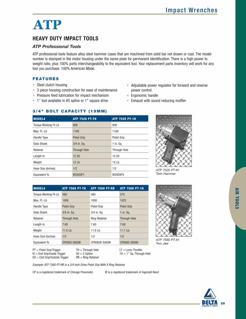
59
AIR TOO
LS
HEAVY DUTY IMPACT TOOLSATP Professional Tools
ATP 7520 PT-IHTwin Hammer
PT = Pistol Grip/Trigger TH = Through Hole LT = Lever ThrottleEI = End Grip/Inside Trigger 5S = 5 Spline 1H = 1" Sq. Through HoleEO = End Grip/Outside Trigger RR = Ring Retainer
Example: ATP 7560 PT-RR is a 3/4 Inch Drive Pistol Grip With A Ring Retainer
CP is a registered trademark of Chicago Pneumatic IR is a registered trademark of Ingersoll Rand
ATP professional tools feature alloy steel hammer cases that are machined from solid bar not drawn or cast. The modelnumber is stamped in the motor housing under the name plate for permanent identification. There is a high power toweight ratio, plus 100% parts interchangeability to the equivalent tool. Your replacement parts inventory will work for anytool you purchase. 100% American Made.
MODEL# ATP 7560 PT-TH ATP 7560 PT-RR ATP 7560 PT-1H
Torque Working Ft-Lb 560 560 575
Max. Ft.-Lb 1000 1000 1025
Handle Type Pistol Grip Pistol Grip Pistol Grip
Data Shank 3/4 in. Sq. 3/4 in. Sq. 1 in. Sq.
Retainer Through Hole Ring Retainer Through Hole
Length In. 7.60 7.60 7.60
Weight 11.6 Lb. 11.6 Lb. 11.7 Lb.
Hose Size (Inches) 1/2 1/2 1/2
Equivalent To CP6060 SASAB CP60600 SASAR CP6060 SASAKATP 7560 PT-IHTwo Jaw
3/4" BOLT CAPACITY (19MM)
MODEL# ATP 7520 PT-TH ATP 7520 PT-1H
Torque Working Ft-Lb 800 800
Max. Ft.-Lb 1100 1100
Handle Type Pistol Grip Pistol Grip
Data Shank 3/4 in. Sq. 1 in. Sq.
Retainer Through Hole Through Hole
Length In. 12.50 12.50
Weight 12 Lb. 12 Lb.
Hose Size (Inches) 1/2 1/2
Equivalent To IR2920P1 IR2920P3
FEATURES
• Steel clutch housing • 3 piece housing construction for ease of maintenance • Pressure feed lubrication for impact mechanism • 1" tool available in #5 spline or 1" square drive
• Adjustable power regulator for forward and reversepower control
• Ergonomic handle• Exhaust with sound reducing muffler
Impact Wrenches
ATP_p58-68 final.qxd 4/5/10 11:03 AM Page 59

60
Impact WrenchesAI
R TO
OLS
HEAVY DUTY IMPACT TOOLS1-1/4" – 1-3/8" Bolt Capacity
ATP 1034 EI-IHTwin Hammer
1-1/4" BOLT CAPACITY (32MM)
MODEL# ATP 1040 EI-TH ATP 1040 EI-5S
Torque Working Ft.-Lb 1600 1600
Max. Ft.-Lb 2000 2000
Handle Type End Grip I-T End Grip I-T
Data Shank 1 in. Sq. #5 Spine
Retainer Through Hole Button
Length In. 12.40 12.40
Weight 22.0 Lb. 22.0 Lb.
Hose Size (Inches) 3/4 3/4
Equivalent To IR2940B2 IR2940B1
MODEL# ATP 1034 EI-5S ATP 1034 EO-TH ATP 1034 EO-5S
Torque Working Ft.-Lb 1100 1100 1100
Max. Ft.-Lb 1500 1500 1500
Handle Type End Grip I-T End Grip O-T End Grip O-T
Data Shank #5 Spine 1 in. Sq. #5 Spine
Retainer Button Through Hole Button
Length In. 11.25 11.25 11.25
Weight 19.0 Lb. 19.0 Lb. 19.0 Lb.
Hose Size (Inches) 3/4 3/4 3/4
Equivalent To IR2934B1 IR2934A2 IR2934A1
MODEL# ATP 1040 EO-5S ATP 1044 EO-5S ATP 1034 EI-TH
Torque Working Ft.-Lb 1600 1000 1100
Max. Ft.-Lb 2000 1350 1500
Handle Type End Grip O-T End Grip O-T End Grip I-T
Data Shank #5 Spine #5 Spine 1 in. Sq.
Retainer Button Button Through Hole
Length In. 12.40 11.25 11.25
Weight 22.0 Lb. 19.0 Lb. 19.0 Lb.
Hose Size (Inches) 3/4 3/4 3/4
Equivalent To IR2940A1 IR1734A1 IR2934B2
ATP 1040 EO-5STwin Hammer
1-1/4" BOLT CAPACITY (32MM)
ATP 1011 EI-5STwo Jaw
1-1/4" BOLT CAPACITY (25MM-32MM)
*Also available with6" extended anvil
I-T = Inside TriggerO-T = Outside Trigger
ATP_p58-68 final.qxd 4/5/10 11:03 AM Page 60

Impact Wrenches
61
AIR TOO
LS
HEAVY DUTY IMPACT TOOLS1-1/4" – 1-3/8" Bolt Capacity
I-T = Inside TriggerO-T = Outside Trigger
MODEL# ATP 1012 EO-TH ATP 1012 EI-TH
Torque Working Ft.-Lb 1000 1000
Max. Ft.-Lb 1350 1350
Handle Type End Grip O-T End Grip I-T
Data Shank 1 in. Sq. 1 in. Sq.
Retainer Through Hole Through Hole
Length In. 11.25 11.25
Weight 19.0 Lb. 19.0 Lb.
Hose Size (Inches) 3/4 3/4
Equivalent To IR1712A2 IR1712B1
MODEL# ATP 1011 EO-TH ATP 1011 EO-5S ATP 1011 EI-TH ATP 1011 EI-5S
Torque Working Ft.-Lb 1800 1800 1800 1800
Max. Ft.-Lb 2800 2800 2800 2800
Handle Type End Grip O-T End Grip O-T End Grip I-T End Grip I-T
Data Shank 1 in. Sq. #5 Spine 1 in. Sq. #5 Spline
Retainer Through Hole Button Through Hole Button
Length In. 12.50 12.50 12.50 12.50
Weight 22.5 Lb. 22.5 Lb. 22.5 Lb. 22.5 Lb.
Hose Size (Inches) 3/4 3/4 3/4 3/4
Equivalent To CP0611GASED CP0611GASEL CP0611PASED CP0611PASEL
1-1/4" BOLT CAPACITY (25MM-32MM)
1-3/8" BOLT CAPACITY (35MM)
ATP_p58-68 final.qxd 4/5/10 11:03 AM Page 61

62
Impact WrenchesAI
R TO
OLS
HEAVY DUTY IMPACT TOOLSATP 7506
The ATP 7506 is a powerful heavy duty 3/4" wrench. It is compact and easy to handle, suited for continuous duty cycles.
5/8"–3/4" BOLT CAPACITY (16MM-19MM)
FEATURES
• 3 Jaw Clutch for quick run down and fast torque build-up• 3 piece housing construction for ease of maintenance• Oil lubricated clutch for long life• Teasing throttle for easy bolt starting• Excellent choice for soft pull-up jobs
ATP 7506 Three Jaw
ATP 7506 EO-TH
MODEL# ATP 7506 PT-TH ATP 7506 PT-RR ATP 7506 EO-TH
Torque Working Ft.-Lb 390 390 390
Max. Ft.-Lb 650 650 650
Handle Type Pistol Grip Pistol Grip End Grip Outside Trigger
Data Shank 3/4 in. Sq. 3/4 in. Sq. *3/4 in.
Retainer Through Hole Ring Retainer *Through Hole
Length (Inches) 8.75 8.75 11.5
Weight 12.0 Lb. 12.0 Lb. 12.75 Lb.
Hose Size (Inches) 1/2 1/2 1/2
Equivalent To CP0606SASAB CP060SASAR CP0606-GASAB
*Also available with 1" Square Drive Anvil CO43682, #4 Spline Anvil C-054202 or 3/4" Anvil C04664 with Ring Retainer
APPLICATIONS
• Petrochemical industry• Metals• Motor vehicles• Construction and machinery/ equipment• Disassembly, maintenance and repair
ATP_p58-68 final.qxd 4/5/10 11:03 AM Page 62

63
AIR TOO
LSImpact Wrenches
MODEL# ATP 1010 EO-TH ATP 1010 EO-5S ATP 1010 EI-TH
Torque Working Ft.-Lb 950 950 950
Max. Ft.-Lb 1350 1350 1350
Handle Type End Grip O-T End Grip O-T End Grip I-T
Data Shank 1 in. Sq. #5 Spine 1 in. Sq.
Retainer Through Hole Button Through Hole
Length (Inches) 13.5 14 13.5
Weight 20.5 Lb. 20.5 Lb. 20.5 Lb.
Hose Size (Inches) 3/4 3/4 3/4
Equivalent To CP610GALED CP610GALEL CP610PALED
HEAVY DUTY IMPACT TOOLSATP 1010
The ATP 1010 is a heavy duty tool for high volume, heavy production.
FEATURES
• 3 Jaw Clutch for quick run down and fast torque build-up• 3 piece housing construction for ease of maintenance• Oil lubricated clutch for long life• Teasing throttle for easy bolt starting• Excellent choice for soft pull-up jobs
APPLICATIONS
• Steel erection• Heavy assembly/disassembly,• Mining and construction equipment maintenance• General MRO applications found in foundries,
petrochemical plants, mills, railroads, and heavy motorvehicle assembly plants.
ATP 1010 Three Jaw
1-1/4" BOLT CAPACITY (32MM)
ATP_p58-68 final.qxd 4/5/10 11:03 AM Page 63

64
AIR
TOO
LSImpact Wrenches
ATP 1017 Three Jaw
HEAVY DUTY IMPACT TOOLSATP 1017
The ATP 1017 is a powerful heavy duty 1" or 5 spline (6" extended anvil optional) impact wrench. It’s single jumbo hammerand steel clutch housing make it a rugged tool ideally suited for truck and off road equipment repairs and tire work.
FEATURES
• 3 Jaw Clutch for quick run down and fast torque build-up• 3 piece housing construction for ease of maintenance• Oil lubricated clutch for long life• Teasing throttle for easy bolt starting• Excellent choice for soft pull-up jobs
MODEL# ATP1017 EO/EI TH ATP1017 EO/EI-6 ATP1017 EO/EI 5S
Torque Working Ft.-Lb 1000 1000 1000
Max. Ft.-Lb 1600 1600 1600
Handle Type End Grip EO-EI End Grip EO-EI End Grip EO-EI
Data Shank 1 in. Sq. 1in. Sq. 6 in. Ext. #5 Spline 6 in. Ext.
Retainer Through Hole Through Hole Button
Length (Inches) 11.25 17.25 17.25
Weight 18.25 Lb. 21.5 Lb. 21.5 Lb.
Hose Size (Inches) 3/4 3/4 3/4
Equivalent To IR280 IR280-6 IR-2805S
1-1/4" BOLT CAPACITY (32MM)
APPLICATIONS
• Truck and equipment repairs• Tire changing• MRO applications• Railroad and heavy vehicle assembly
ATP_p58-68 final.qxd 4/5/10 11:03 AM Page 64

65
AIR TOO
LSDri l ls
AIR DRILLSATP 2122-725WB Drill
The ATP 2122-725WB drills are designed for RUGGED, HEAVY DUTY drilling and reaming operations in the railroad,truck/tractor, petrochemical, machinery and construction industries. This heavy-duty drill is ideally suited for the heavy-duty MRO user.
FEATURES
• Ball bearing support for long life and smooth operation• Roll throttle for excellent speed control• Governor-controlled motor conserves air at light loads, holds
speed at peak horse power under heavy loading• Internal Oil Reservoir reduces “downtime”• External Grease fitting for easy lubrication• Self closing roll throttle with independent reverse
STANDARD EQUIPMENT
• Breast Plate, assist handle, 1/2" shank, wood bore chuck
OPTIONAL EQUIPMENT
• #2 Morse Taper Spindle or, 1/2" drill chuck
ATP 2122-725WB*Shown with optional 1/2" Drill Chuck and Morse Taper Spindle.
ATP 2122-725WB DRILL
MODEL #FREE SPEEDRPM
WEIGHTLB KG
HEIGHT OVER SPINDLEIN. MM
SIDE TO CENTER DISTANCEIN. MM CFM
SPINDLE ANDSPINDLE CHUCK
ATP 2122-725WB 725 14.4 6.46 17.25 438 1-7/16 36 50Threaded, 1/2 in.ShankWood Bit Chuck
ATP_p58-68 final.qxd 4/5/10 11:03 AM Page 65

66
Impact WrenchesAI
R TO
OLS
SUPER DUTY IMPACT TOOLS
MODEL# ATP 1550 EI-TH ATP 1550 EI-5S ATP 1550 EO-TH
Torque Working Ft.-Lb 2500 2500 2500
Max. Ft.-Lb 3000 3000 3025
Handle Type End Grip I-T End Grip I-T End Grip O-T
Data Shank 1-1/2 in. Sq. #5 Spine 1-1/2 in. Sq.
Retainer Through Hole Button Through Hole
Length In. 14.50 14.50 14.50
Weight 33.0 Lb. 33.0 Lb. 33.0 Lb.
Hose Size (Inches) 3/4 3/4 3/4
Equivalent To IR2950B7 IR2950 W/#5SP IR2950A7
1-1/2" BOLT CAPACITY (38MM)
ATP 1550 EO-THTwin Hammer
PT = Pistol Grip/Trigger LT = Lever Throttle RR = Ring RetainerEI = End Grip/Inside Trigger TH = Through Hole 1H = 1" Sq. Through HoleEO = End Grip/Outside Trigger 5S = 5 Spline
Example: ATP 7560 PT-RR is a 3/4 Inch Drive Pistol Grip With A Ring Retainer
1-1/2" BOLT CAPACITY (38MM)
ATP 1520 EI-5STwo Jaw
MODEL# ATP 1550 EO -5S ATP 1520 EI-5S ATP 1520 EI-TH
Torque Working Ft.-Lb 2500 2500 2500
Max. Ft.-Lb 3000 3500 3500
Handle Type End Grip O-T End Grip I-T End Grip I-T
Data Shank #5 Spline #5 Spine 1-1/2 in. Sq.
Retainer Button Button Through Hole
Length In. 14.50 14.70 14.70
Weight 33.0 lbs. 33.7 Lb. 33.7 Lb.
Hose Size (Inches) 3/4 3/4 3/4
Equivalent To IR2950 W/#5SP CP6120PASEL CP6120PASED
1-1/2"–2" BOLT CAPACITY (38MM-51MM)
ATP 1578 LT-THBall and Cam
MODEL# ATP 1578 LT -TH ATP 1580 LT -TH
Torque Working Ft.-Lb 5500 5900
Max. Ft.-Lb 10000 13,560
Handle Type Lever Type Lever Type
Data Shank 1-1/2 in. Sq. 1-1/2 in. Sq.
Retainer Through Hole Through Hole
Length In. 23.00 23.00
Weight 86.0 Lb. 88.0 Lb.
Hose Size (Inches) 3/4 3/4
Equivalent To IR578A1 IR5980A1
ATP_p58-68 final.qxd 4/5/10 11:03 AM Page 66

Impact Wrenches
67
AIR TOO
LS
2"–4" BOLT CAPACITY (51MM-102MM)
ATP 2588 LT-TH
SUPER DUTY IMPACT TOOLS
MODEL# ATP 2582 LT-TH ATP 2588 LT-TH
Torque Working Ft.-Lb 10,000 25,000
Max. Ft.-Lb 20,000 50,000
Handle Type Lever Lever
Data Shank 2-1/2 in. Sq. 2-1/2 in. Sq.
Retainer Through Hole Through Hole
Length (Inches) 25-3/8 25-3/8
Weight 120 Lb. (54.5 kg) 215 Lb. (676 kg)
Hose Size 1 in. (25mm) 1 in. (25mm)
Equivalent To IR5982A1** IR588A1*
CP is a registered trademark of Chicago Pneumatic
IR is a registered trademark of Ingersoll Rand
* 1" NPT Air Inlet, ** 3/4" NPT Air Inlet
PT = Pistol Grip/Trigger LT = Lever Throttle RR = Ring RetainerEI = End Grip/Inside Trigger TH = Through Hole 1H = 1" Sq. Through HoleEO = End Grip/Outside Trigger 5S = 5 Spline
Example: ATP 7560 PT-RR is a 3/4 Inch Drive Pistol Grip With A Ring Retainer
ATP_p58-68 final.qxd 4/5/10 11:03 AM Page 67

68
AIR
TOO
LSDri l ls
AIR DRILLSATP 3500 Drills
ATP 3500 Drills are used for extra-heavy duty drilling, reaming, tapping and tube rolling for truck, tractor, railroad, shipbuilding, petrochemical machinery, building construction, equipment and the general construction industries.
FEATURES
• Reversible self-closing roll throttle for one-hand throttle control and reversing.
• Governor controlled motor conserves air at light loads,holds speed at heavier loads while increasing power
• Heavy-duty Ball Bearings for long life• 5.9 Horse power motor and rugged gearing provides
maximum power output• Integral #5 Morse Taper female socket for fast, easy
change overs and positive drill bit retention
ATP 3500-100ATP 3500-60
ATP 3500 AIR DRILL
MODEL#FREE SPEED RPM
WEIGHTLB. (KG)
HEIGHT OVER SPINDLEIN. MM
SIDE TO CENTERIN. MM CFM SPINDLE SIZE
ATP 3500-100 100 69 (31.4) 23-1/4 (591) 2-3/4 (69.9) 165 #5MT
ATP 3500-60 60 69 (31.4) 23-1/4 (591) 2-3/4 (69.9) 165 #5MT
ATP_p58-68 final.qxd 4/5/10 11:03 AM Page 68

Grinders
69
AIR TOO
LS
ATP GRINDERS
Vertical Models ATP 356 & 466
STANDARD EQUIPMENT
All VSL models include:• Safety Lock-off Lever Throttle• Wheel Flange (2") and Spindle Nut• Wheel Guard (as specified by model)• Spindle Wrench 1100-200 (2") and 1102-015 (5/32") Allen Type Wrench
EXTRA COST EQUIPMENT
• Spindle/Wheel Retention Screw and Retention Screw Collar 650-50• Optional wheel guards
ATP 356VSL-45-7Vertical Safety Lever3 hp, 4500 rpm7" Guard
*Equivalent to Top Cat’s† 56VS Series †Top Cat is a Registered Trademark of TC Services Co.
3 HP VERTICAL GRINDERS
MODEL #WHEELGUARD
WHEELCAPACITYDIAMETERIN. (MM)
WEIGHTLESSGUARD
HEIGHT TO BOTTOM OFFLANGE
SIDE TOCENTERDISTANCE
SPINDLETHREAD(INCH)
AIR INLETTHREAD
HOSE SIZE (ID)
FREESPEEDRPM
RATED HP
*ATP 356VSL-45-7 Type 27 7 (178)7-3/8 lbs.3.3 Kg
5-1/2 in.145mm
1-11/16 in.43mm 5/8-11 1/2 NPT
1/2 in.13mm 4500
32.2kW
*ATP 356VSL-60-66 in. Cup/ Wire Brush 6 (152)
7-3/8 lbs.3.3 Kg
5-1/2 in.145mm
1-11/16 in.43mm 5/8-11 1/2 NPT
1/2 in.13mm 6000
32.2kW
*ATP 356VSL-60-7 Type 27 7 (178)7-3/8 lbs.3.3 Kg
5-1/2 in.145mm
1-11/16 in.43mm 5/8-11 1/2 NPT
1/2 in.13mm 6000
32.2kW
*ATP 356VSL-60-9 Type 27 9 (229)7-3/8 lbs.3.3 Kg
5-1/2 in.145mm
1-11/16 in.43mm 5/8-11 1/2 NPT
1/2 in.13mm 6000
32.2kW
ATP 356VSL-60-6Vertical Safety Lever3 hp, 6000 rpm6" Cup/Wire Brush
ATP 356VSL-60-7Vertical Safety Lever3 hp, 6000 rpm7" Guard
ATP 356VSL-60-9Vertical Safety Lever3 hp, 6000 rpm9" Guard
ATP_p69-73 final.qxd 4/5/10 11:08 AM Page 69

70
GrindersAI
R TO
OLS
ALL 3 HP AND 4 HP ATP GRINDERSFEATURES
• 12+ models to choose from• Built in lubricator• Stainless steel corrosion resistant governors• Speeds From 4,500 - 6,000 RPM’s• Ergonomic user friendly and easy to service• “Techalloy” housing provides the Ultimate in Strength in a light-weight casting
ATP 466VSL-45-7Vertical Safety Lever4 hp, 4500 rpm7" Guard
ATP 466VSL-60-6Vertical Safety Lever4 hp, 6000 rpm6" Cup/Wire Brush
ATP 466VSL-60-7Vertical Safety Lever4 hp, 6000 rpm7" Guard
ATP 466VSL-60-9Vertical Safety Lever4 hp, 6000 rpm9" Guard
4 HP VERTICAL GRINDERS
MODEL#WHEEL GUARD
WHEEL CAPACITYDIAMETER IN. (MM)
WEIGHT LESS GUARD
HEIGHT TOBOTTOM OF FLANGE
SIDE TOCENTERDISTANCE
SPINDLETHREAD (INCH)
AIR INLET THREAD
HOSE SIZE (ID)
FREE SPEED RPM
RATEDHP
*ATP 466VSL-45-7 Type 27 7 (178)
9-1/2 lbs.4.3 Kg
6-7/16 in.174mm
1-7/8 in.48mm 5/8-11 1/2 in. NPT
1/2 in.13mm 4500
43kW
*ATP 466VSL-60-6
6 in. Cup/Wire Brush 6 (152)
9-1/2 lbs.4.3 Kg
6-7/16 in.174mm
1-7/8 in.48mm 5/8-11 1/2 in. NPT
1/2 in.13mm 6000
43kW
*ATP 466VSL-60-7 Type 27 7 (178)
9-1/2 lbs.4.3 Kg
6-7/16 in.174mm
1-7/8 in.48mm 5/8-11 1/2 in. NPT
1/2 in.13mm 6000
43kW
*ATP 466VSL-60-9 Type 27 9 (229)
9-1/2 lbs.4.3 Kg
6-7/16 in.174mm
1-7/8 in.48mm 5/8-11 1/2 in. NPT
1/2 in.13mm 6000
43kW
ATP_p69-73 final.qxd 4/5/10 11:08 AM Page 70

Grinders
71
AIR TOO
LS
ATP GRINDERSHorizontal Models ATP 356 & 466
STANDARD EQUIPMENT
All HSL models include:• Safety Lock-off Lever Throttle• Wheel Flange (2") and Spindle Nut• Wheel Guard (as specified by model)• Spindle Wrench 1100-200 (2") and 1102-015 (5/32") Allen Type Wrench
EXTRA COST EQUIPMENT
• Spindle/Wheel Retention Screw and Retention Screw Collar 650-50• Optional wheel guards
ATP 356HSL-45-8Horizontal Safety Lever3 hp, 4500 rpm8" Guard
3 HP & 4 HP HORIZONTAL GRINDERS
ATP 356HSL-60-6Horizontal Safety Lever3 hp, 6000 rpm6" Guard
ATP 465HSL-45-8Horizontal Safety Lever4 hp, 4500 rpm8" Guard
ATP 465HSL-60-6Horizontal Safety Lever4 hp, 6000 rpm6" Guard
MODEL# WHEEL GUARD
WHEEL CAPACITYDIAMETER IN. (MM)
WEIGHT LESS GUARD
HEIGHT TOBOTTOM OFFLANGE
SIDE TOCENTERDISTANCE
SPINDLETHREAD (INCH)
AIRINLETTHREAD
HOSE SIZE(ID)
FREE SPEED RPM
RATED HP
*ATP 356HSL-45-8 8 in.8 in. Straight Wheels or Wire Brush
10-1/2 lbs.4.8 Kg
20-1/8 in.524mm
1-1/4 in.32mm 5/8-11 1/2 in. NPT
1/2 in.13mm 4500
32.2kW
*ATP 356HSL-60-6 6 in.6 in. Straight Wheels or Wire Brush
10-1/2 lbs.4.8 Kg
20-1/8 in.524mm
1-1/46 in.32mm 5/8-11 1/2 in. NPT
1/2 in.13mm 6000
32.2kW
*ATP 465HSL-45-8 8 in.8 in. Straight Wheels or Wire Brush
12-1/2 lbs.5.67 Kg
20-7/8 in.530mm
1-1/4 in.32mm 5/8-11 1/2 in. NPT
1/2 in.13mm 4500
43.3kW
*ATP 465HSL-60-6 6 in.6 in. Straight Wheels or Wire Brush
12-1/2 lbs.5.67 Kg
20-7/8 in.530mm
1-1/4 in.32mm 5/8-11 1/2 in. NPT
1/2 in.13mm 6000
43.3kW
*Equivalent to Top Cat’s† 56 H & 65H Series †Top Cat is a Registered Trademark of TC Services Co.
ATP_p69-73 final.qxd 4/5/10 11:08 AM Page 71

72
GrindersAI
R TO
OLS
ANGLE GRINDERSATP 9940
These Angle Grinders with their rugged .6 hp motors are primarilyused with 3" and 4" Type 27 grinding wheels. They can be usedfor many cleaning, deburring, blending and smoothingapplications found at ship yards, foundries, refineries, fabricationshops, power plants and a variety of other industries.
FEATURES
• 13,500 rpm free speed• Short or Long Models• 1/2" Side-to-Center distance for work in close quarters• Adjustable side exhaust deflector — directs exhaust away from
operators and the work area.• Interchangeable parts with the ATP Die Grinder 9913 to reduce
your spare parts inventory
ATP 9940-3
ATP 9940 ANGLE GRINDERSATP 9940L-4
MODEL#ANGLE HOUSING
FREE SPEED RPM
WHEEL GUARD DIA. IN. (MM)
SPINDLE THREAD IN.
OVERALL LENGTH IN. (MM)
NET WEIGHT LB. (KG)
MOTOR HOUSING
ATP 9940-3 Short 13,500 3 in. (76mm) 3/8 - 24 7-5/8 in. (194mm) 3 lbs. 1.4 kg Steel
ATP 9940-4 Short 13,500 4 in. (102mm) 3/8 - 24 7-5/8 in. (194mm) 3 lbs. 1.4 kg Steel
ATP 9940L-3 Long 13,500 3 in. (76mm) 3/8 - 24 10 in. (254mm) 3.3 lbs. 1.5 kg Steel
ATP 9940L-4 Long 13,500 4 in. (102mm) 3/8 - 24 10 in. (254mm) 3.3 lbs. 1.5 kg Steel
Optional Safety Lock-off Throttle – Specify ST-ATP 9940-3-ST
ATP_p69-73 final.qxd 4/5/10 11:08 AM Page 72

Grinders
73
AIR TOO
LS
DIE GRINDERSSTANDARD EQUIPMENT
ATP 9913 is built for the long haul. Encased in a ruggedsteel housing the ATP 9913’s 1hp motor runs at 25,000rpm’s. Equipped with an Erickson 1/4" (6.4 mm) ColletChuck for precise work and extra holding power for thosetough jobs. The ATP 9913 is ideally suited for use withMounted Points and Carbide Burrs.
With power to spare the ATP 9913 is at home in the DieShop, Foundry, Shipyard, Construction, Petrochemical,Machinery and Equipment Shop and Fabrication Shop. Itsuses include die contouring, die repairing, weld cleaning,casting and forging clean-up, deburring, blending andsmoothing of rubber, plastics, composites, fiberglass, steel,brass, bronze, cast iron and aluminum materials.
ATP 4420 is a rugged 1/2 HP air motor encased in steel forheavy duty use and longer service life. Unique 3 ballbearing design reduces vibration for better ergonomics.One piece hardened and chromed plated spindel comesstandard with 1/4" collet; 6 mm, 1/8", and 5/16" collets areavailable as optional collets.
ATP 9913 (top image)ATP 9913LS (bottom image)
ATP 9913 DIE GRINDERS
ATP 4420
Also available with Safety Lock-off Lever. Specify 9913 ST or 9913 LS-ST for models with Safety Lock-off Lever.Standard Equipment: Erickson 1/4" (6.4mm) Chuck*Optional Side Exhaust Model available as ATP 9913R - For use as a Router or Side Exhaust Tool.Collet Wrenches for 9913 9/16" C116858, 5/8" x 3/4" C119327
MODEL#THROTTLE TYPE
FREE SPEED RPM
SPINDLE THREAD IN.
OVERALL LENGTH IN. (MM)
OUTSIDE DIAMETER IN. (MM)
NET WEIGHTLB. (KG)
MOTOR HOUSING EXHAUST
ATP 9913 Lever 25,000 3/8-24 x 9/16 6-1/4 (158mm) 1-3/4 (44mm) 2 lbs. 0.9 kg Steel Front*
ATP 9913LS Lever 25,000 Special 1/4 collet 11-1/8 (283mm) 1-3/4 (44mm) 3 lbs. 1.4 kg Steel Front
ATP 9913ST Safety 25,000 3/8-24 x 9/16 6-1/4 (158mm) 1-3/4 (44mm) 2 lbs. 0.9 kg Steel Front
ATP 9913LS-ST Safety 25,000 Special 1/4 collet 11-1/8 (283mm) 1-3/4 (44mm) 3 lbs. 1.4 kg Steel Front
ATP 9913-18 Lever 18,000 3/8-24 x 9/16 6-1/4 (158mm) 1-3/4 (44mm) 2 lbs. 0.9 kg Steel Front
ATP 4420 Lever 23,000 Special 6.8 (173 mm) 1-7/16 1.7 lbs. 0.76 kg Steel Front
ATP_p69-73 final.qxd 4/5/10 11:08 AM Page 73

74
Chipping HammersAI
R TO
OLS
HEAVY DUTY CHIPPING HAMMERSATP Chippers are ergonomically advanced in design, with a “HEAVY DUTY” alloy aluminum handle. Our chipping hammer’scrisp smooth valve operation produces extra hard hitting power, while our heat treated alloy steel cylinder and piston provide long life. Available in the popular 2"-3"-4" stroke versions with either Hex or Round chisel bushing and in eitherAlloy Aluminum or Steel Handle. The closed grip handle design locates the operator’s arm in-line with the chisel formaximum effectiveness and comfort.
Favored by contractors and Industrial users alike, this new ATP Chipper sets new standards for American made pneumatictools. Available in either Round or Hex chisel bushings, and in either Alloy Aluminum or Steel Handles. If you need aRUGGED, RELIABLE PERFORMER on your job site, you can’t do better than the new ATP ERGONOMIC CHIPPING HAMMER.
STANDARD EQUIPMENT
• Oval Collar Retainer P/N 250012-525• Spring P/N 250012-529
OPTIONAL EQUIPMENT
• Nozzle Bushing Removal Tool P/N 3CH-931 • Exhaust Deflector Extension Tool P/N 3CH-932 • 1/2" Hose Barb Swivel Assembly P/N 3CH-A165 (3/8" NPT)• 1/2" Hose Barb Swivel Assembly P/N 3CH-3388 (7/8" x 24)• Long Reach Handle Conversion Kit P/N LCH-1A• 1/2" Hose Barb Inlet P/N 3CH-46
ATP CHIPPING HAMMERS
To order with aluminum handle add A after stroke, ex. ATP-2AHB
MODEL#WEIGHTALUMINUM STEEL
LENGTH LESS RETAINER (IN.) BPM
BORE X STROKE(INCHES)
CHISEL BUSHING
AIR CONSUMPTION
ATP-2HB 13.3 lbs 17 lbs. 14 2300 1-1/8 x 3 .580 Hex 26 cfm
ATP-2RB 13.3 lbs 17 lbs. 14 2300 1-1/8 x 3 .680 Round 26 cfm
ATP-3HB 14.8 lbs 18.5 lbs. 15.25 2100 1-1/8 x 3.75 .580 Hex 30 cfm
ATP-3RB 14.8 lbs 18.5 lbs. 15.25 2100 1-1/8 x 3.75 .680 Round 30 cfm
ATP-4HB 15.8 lbs 19.5 lbs. 16.5 1700 1-1/8 x 4.25 .580 Hex 33 cfm
ATP-4RB 15.8 lbs 19.5 lbs. 16.5 1700 1-1/8 x 4.25 .680 Round 33 cfm
ATP-2LRHB — 24.1 lbs. 50 2300 1-1/8 x 3 .580 Hex 26 cfm
ATP-2LRRB — 24.1 lbs. 50 2300 1-1/8 x 3 .680 Round 26 cfm
ATP-3LRHB — 25.6 lbs. 51.4 2100 1-1/8 x 3.75 .580 Hex 30 cfm
ATP-3LRRB — 25.6 lbs. 51.4 2100 1-1/8 x 3.75 .680 Round 30 cfm
ATP-4LRHB — 26.6 lbs. 52.5 1700 1-1/8 x 4.25 .580 Hex 33 cfm
ATP-4LRRB — 26.6 lbs. 52.5 1700 1-1/8 x 4.25 .680 Round 33 cfm
ATP_p74-76 final.qxd 4/5/10 11:10 AM Page 74

Chipping Hammers
75
AIR TOO
LS
HEAVY DUTY CHIPPING HAMMERSATP 4 BOLT CHIPPING HAMMER WITH THREAD ON RETAINER
The 3" stroke versions of the ATP Heavy Duty Chipping Hammers are now available with Rubber Buffered Thread onRetainer for Round Collar Chisels. The ATP Chipping Hammer is ideally suited for chipping of steel castings, concreteroughing and chipping heavy duty weld seams. ATP’s new Ergonomically designed Alloy Aluminum “Heavy Duty” Handleeliminates 3.68 lbs. of total tool weight. Our crisp smooth valve operation produces extra hard hitting power, while our heattreated alloy steel cylinder and piston provide long life. Favored by contractors and Industrial users alike, this new ATPChipper sets new standards for American made pneumatic tools. Available in either Round or Hex chisel bushings, and ineither Alloy Aluminum or Steel Handles. If you need a RUGGED, RELIABLE PERFORMER on your job site, you can’t do betterthan the new ATP ERGONOMIC CHIPPING HAMMER.
STANDARD EQUIPMENT
• Thread on Retainer, buffer and spring on Thread on Barrel model only.
ATP CHIPPING HAMMERS
ATP 3AHBTR Optional Thread on RetainerAvailable on 3" Stroke only
WEIGHT LENGTH LESS BORE X STROKE CHISEL AIRMODEL# ALUMINUM STEEL RETAINER BMP (INCHES) BUSHING CONSUMPTION
ATP 3AHBTR 14.8 lbs — 15 in. 2100 1-1/8 x 3.75 Hex 30 cfm
ATP 3HBTR — 18.5 lbs 15 in. 2100 1-1/8 x 3.75 Hex 30 cfm
ATP 3ARBTR 14.8 lbs — 15 in. 2100 1-1/8 x 3.75 Round 30 cfm
ATP 3RBTR — 18.5 lbs 15 in. 2100 1-1/8 x 3.75 Round 30 cfm
ATP Chippers are Ergonomically Advanced in Design, the Ergonomic Closed Grip Handle locates the operator’s hand andarm in-line with the chisel for maximum effectiveness and operator comfort. This makes the ATP Chipper much easier tohandle and less fatiguing when used over long periods of time.
ATP_p74-76 final.qxd 4/5/10 11:10 AM Page 75

76
Chipping HammersAI
R TO
OLS
ATP RAMMERSATP rammers ensure more uniform sand compaction in the mold. Keeping foundry production rates high. Choose the ATPBench Rammers (2BA) for small to medium size castings and the ATP Floor Rammer (P-150) for medium to large castings.
FEATURES
• Smooth contours and slim design• Gives good clearance in mold area• High power for fast sand distribution and compaction. Improved
wiper glands for minimum maintenance
ATP 3347-5XB
ATP 3347-5XBRIVETING HAMMER
The ATP 3347-5XB Riveting Hammer is used to drive 3/16" Dural and1/4" Steel rivets used in aircraft maintenance and manufacturing andother assembly operations. This hammer can be used for a variety ofmetal cutting, peening, chipping and driving applications (includinglarge nails). The Aero Cycling valve delivers slow, heavy blowsnecessary to drive medium-size rivets.
FEATURES
• Teasing Throttle for quick easy starts and precise control• Heat treated steel piston and cylinder for maximum durability• Acoustically designed muffler-reduces sound level
ATP RAMMERS
ATP 3347-5XB RIVETING HAMMER
BORE X STROKE LENGTH WEIGHTMODEL# IN. (MM) X IN. (MM) BPM IN. MM LB. KG INLET SIZE
2BA 1 (25.4) x 2-1/2 (64.1) 1100 15-3/4 (403mm) 9 lbs. (4.8 kg) 1/4 in. NPT
P-150 1-1/8 (28.8) x 4 (102) 760 42-1/2 (1089mm) 15 lbs. (6.81 kg) 1/4 in. NPT
AIRFRAME CAPACITY LENGTH OVERALL NET WEIGHTMODEL# NUMBER DURAL STEEL BORE X STROKE CHISEL SIZE BPM'S IN. (MM) LB. (KG)
ATP 3347-5XB 5XB 3/16 in. 1/4 in. 3/4 x 2-11/16 in. .498 1560 8-5/16 (227) 4.75 (2.2)
ATP_p74-76 final.qxd 4/5/10 11:10 AM Page 76

77
AIR TOO
LSOi lers
AIR TOOL ACCESSORIESATP AUTOMATIC IN-LINE OILERS
ATP Automatic In-line Oilers, (football type). The ATP AutomaticIn-line Oilers are designed to supply oil for tool lubricationanywhere stationary lubricators are not feasible to use.Automatic In-line Oilers should be installed as close to the airtool as possible. The ATP Automatic In-line Oilers have anadjustable needle valve flow control to permit easy regulationof oil flow. Oil flow while using ATP’s Ice Free “Blue Magic" airtool lubricant should be set at approximately one drop perminute. The rugged cast housing provides long service lifeunder the most severe service conditions.
IN-L INE OILER
WHIP HOSES
ATP recommends the use of whip hoses to prolong tool life.The use of whip hoses will reduce the stress and strain on theair inlet and live air handle of air tools where quickdisconnects or heavy fittings are some- times attached directlyto the tool. Use of a whip hose will eliminate this stress on theinlet and the handle.
WHIP HOSES
PART#
THREAD NPT/HOSE BARB PIPE SIZE (IN.)
MAX. WORKING PRESSURES (PSI)
RECOMMENDED OILWT./CAPACITY (FL. OZ.)
ATP-0L 1/2 NPT 500 ATP Blue Magic/5 Wt. 1.4 Fl. Oz.
ATP-1L 3/4 NPT 260 ATP Blue Magic/5 Wt. 4.0 Fl. Oz.
ATP-2L 3/4 NPT 300 ATP Blue Magic/5 Wt. 11.0 Fl. Oz.
ATP-3L 1 NPT 250 ATP Blue Magic/5 Wt. 16.0 Fl. Oz.
PART# HOSE ID (IN.) OVERALL LENGTH (FT.)NPT MALE THREADON EACH END (IN.)
CA046270 1/4 6 (183 cm) 1/4
CA047271 3/8 6 (183 cm) 1/4
CA049271 1/2 3 (91 cm) 3/8 in. 3/8
CA049270 1/2 2 (61 cm) 1/2
CA049272 1/2 4 (122 cm) 1/2
Repair kit for In-line Oiler ATP-LRK
ATP_p77 final.qxd 4/5/10 11:13 AM Page 77

78
BreakersAI
R TO
OLS
THOR BREAKERSThor Breakers, available in the 30, 60 and 90 lb Class, are “Tools as Tough as their name”. The 30 lb. class Thor 17Breakers are light weight rugged tools designed for light to medium construction and plant maintenance work such asdemolition of floors, pavement, masonry walls, black top and frozen dirt. The 17 is also an excellent choice for bridge deckdemolition work. The Thor 234 60 lb. Class and Thor 125 90 lb. Class Breakers are designed to deliver the performanceand endurance necessary for a variety of heavy duty construction and plant maintenance applications, such as breakingrock, concrete, reinforced concrete, frozen earth and pavement.
FEATURES
• Alloy steel forgings• Precision American machined parts for long life• Rugged 4 bolt design for extra duty service.• Continuous lubrication provided by internal oilers for long service life• Air inlet swivel for maneuverability.
1717-1(30lb Weight Class)
125-1.125125-1.25(90lb Weight Class)
234-1.125234-1.25(60lb Weight Class)
MODEL# AIR INLET (IN.)CHUCK SIZE (IN.)
BORE X STROKE IN. (MM) X IN. (MM) BPM
LENGTH IN. MM
WEIGHT LB. KG CFM
17 3/8 NPT, male 7/8 x 3-1/4 1-3/4 (44) x 3-3/8 (86) 1550 22-1/2 (572mm) 32 lbs. (14.5 kg) 46
17-1 3/8 NPT, male 1 x 4-1/4 1-3/4 (44) x 3-3/8 (86) 1550 22-1/2 (572mm) 32 lbs. (14.5 kg) 46
ATP 234-1.125 3/4 NPT, male 1-1/8 x 6 2-1/4 (57) x 4.0937 (104) 1400 25-5/8 (651mm) 67 lbs. (30 kg) 60
ATP 234-1.25 3/4 NPT, male 1-1/4 x 6 2-1/4 (57) x 4.0937 (104) 1400 25-5/8 (651mm) 67 lbs. (30 kg) 60
ATP 125-1.125 3/4 NPT, male 1-1/8 x 6 2-5/8 (66.67) x 6-1/16 (154) 1250 28-3/4 (730mm) 92 lbs. (42 kg) 80
ATP 125-1.25 3/4 NPT, male 1-1/4 x 6 2-5/8 (66.67) x 6-1/16 (154) 1250 28-3/4 (730mm) 92 lbs. (42 kg) 80
THOR BREAKERS
ATP_p78-80 final.qxd 4/5/10 11:14 AM Page 78

Rock Dr i l ls
79
AIR TOO
LS
THOR ROCK DRILLThe Thor 38 originally designed for blast hole drilling in mine and highway construction.The hard hitting Thor 38 has a wide range of applications in the construction field forrapid drilling shallow holes (10-12') of various rock bit diameters in rock, masonry andconcrete. Applications include anchor hole drilling, through wall drilling for pipes andwiring conduit and blast hole drilling in rock.
The Thor 75 RD-8 will outdrill any Rock Drill in its class. The 75 is designed for deephole (20') drilling, shaft sinking, quarrying, road building, and general construction work.Drop forged steel construction for hard, long service life with minimum down time.
The Thor 14 Hammer Drill is designed for a wide variety of construction and MROmaintenance applications such as drilling or setting masonry anchors and drilling holesin rock, concrete or brick. With its excellent weight to power ratio, the Thor 14 drillsholes faster and easier than comparable electric roto-hammers.
FEATURES
• Blower level for deep hole cleaning.• Air inlet swivel for easy maneuverability.• Cushioned piston to reduce shock to the operator.• Forged steel housing to withstand rugged use.• Internal oiler provides continuous lubrication.
THOR ROCK DRILL (15 LB. & 30 LB. CLASS)
THOR 38RD-74THOR 38RD-73THOR 38RD-84(45lb Weight Class)
THOR 75RD-.875THOR 75RD-.875x3.25THOR 75RD-1(55lb Weight Class)
THOR 14D(14lb Weight Class)
MODEL# AIR INLET (IN.)CHUCK SIZE (IN.)
BORE X STROKEIN. (MM) X IN. (MM) BPM
LENGTHIN. MM
WEIGHTLB. KG CFM
38 RD-73 3/4 NPT, male 7/8 Hex x 3-1/4 2-5/8 (67.3) x 2 (51.2) 2900 20-1/4 (512.8mm)* 44 lbs. (19.98 kg) 45
38 RD-74 3/4 NPT, male 7/8 Hex x 4-1/4 2-5/8 (67.3) x 2 (51.2) 2900 20-1/4 (512.8mm)* 44 lbs. (19.98 kg) 45
38 RD-84 3/4 NPT, male 1 Hex x 4-1/4 2-5/8 (67.3) x 2 (51.2) 2900 20-1/4 (512.8mm)* 44 lbs. (19.98 kg) 45
75 RD-.875 3/4 NPT, male 7/8 x 4-1/4 2-5/8 (67.3) x 2-1/2 (64.1) 2900 23-3/4 (609mm) 56 lbs. (125.4 kg) 93
75 RD-1 3/4 NPT, male 1 Hex x 4-1/4 2-5/8 (67.3) x 2-1/2 (64.1) 2900 23-3/4 (609mm) 56 lbs. (125.4 kg) 93
75RD-.875X3.25 3/4 NPT, male 7/8 Hex x 3-1/4 2-5/8 (67.3) x 2-1/2 (64.1) 2900 23-3/4 (609mm) 56 lbs. (125.4 kg) 93
14D 3/8 NPT, male 7/8 Hex x 3-1/4 1-15/16 (49) x 1-7/8 (48) 2900 18-3/8 (460mm) 14.3 lbs. (7 kg) 35
ATP_p78-80 final.qxd 4/5/10 11:14 AM Page 79

80
Rivet BustersAI
R TO
OLS
THOR RB-11 DEMOLITION AND RIVET BUSTERThe Thor RB-11 Demolition Tool and Rivet Buster with its powerful 11" stroke is the idealdemolition tool for medium to heavy concrete demolition on bridge decks, parking garagecolumns, bridge pillars and large rivet and bolt cutting applications.
FEATURES
• Rugged ergonomic closed grip with inside trigger for solid comfortable grip while protectingthe trigger from external damage
• Hardened steel piston and cylinder for excellent wear resistance and long life• Uses standard 11x Jumbo steel• Teasing throttle for exceptional starting and control
THOR RB-11
THOR RB-11
MODEL# AIR INLET (IN.)BORE X STROKEIN. (MM) X IN. (MM) BPM
LENGTHIN. MM
WEIGHTLB. KG CFM
RB-11 1/2 NPT, female 1-3/16 (30) x 11 (279) 850 25-1/2 (648mm) 33 lbs. (15 kg) 50
ATP_p78-80 final.qxd 4/5/10 11:14 AM Page 80

81
AIR TOO
LSTampers
THOR 6T BACKFILL TAMPERThor’s 6T Backfill Tamper is a 40 lb. Class Tamper that has also “Stood the Test of Time”.Its slow (800 BPM) powerful blows provide a well balanced, smooth operating tool that iseasily guided by one person. Thor designed to effectively compact soil around foundationsand other structures and for compacting backfill in trenches and other construction holesrequiring compaction.
FEATURES
• High power to weight ratio, slow powerful blows quickly compact all types of backfillmaterial including clay and gravel.
• Heat treated cylinder and piston for long service life• Hex Head Bolt Clamp Screw for quick and easy butt changes, no more stripped out
screwdriver slots.
THOR 6T BACKFILL TAMPER (40 LB. CLASS)
THOR 6T
MODEL# AIR INLET(IN.)
TAPERBORE X STROKEIN. (MM) X IN. (MM)
BPMLENGTHIN.MM
WEIGHTLB.KG
CFM
6T1/2 NPT,female 804 Taper
1-1/2 (38) x 5-1/2 (140) 800
48-1/4 (1226mm)
40 lbs.(18 kg) 38
ATP_p81-83 final.qxd 4/5/10 11:16 AM Page 81

82
AIR
TOO
LSClay Diggers
THOR 18 “DIGGER”Thor 18 CD is a dropped forged clay digger recommended for digging clay inpacked soil from around footings, forms and other construction areas. Its 29 lb.weight makes it a hard hitting tool, making quick work of the task at hand.
FEATURES
• Slim design for work in tight areas.• Heat treated alloy steel components.• Latch retainers for positive retention and quick change of accessories.
THOR 18CD-6 CLAY DIGGER
THOR 18CD-.875THOR 18CD-1
MODEL# AIR INLET (IN.)CHUCK SIZE (IN.)
BOREIN. MM BMP
LENGTHIN. MM
WEIGHTLB. KG CFM
18CD-.875 3/8 NPT, male 7/8 Hex x 3-1/4 1-3/4 (44.8) 1500 22-3/4 (583mm) 29 lbs. (13 kg) 38
18CD-1 3/8 NPT, male 1 Hex x 4-1/4 1-3/4 (44.8) 1500 22-3/4 (583mm) 29 lbs. (13 kg) 38
ATP_p81-83 final.qxd 4/5/10 11:16 AM Page 82

83
AIR TOO
LSClay Diggers
40 SERIES DIGGERSThe all new ATP Diggers are ideally suited for mediumdensity soil and light demolition work. Our 2 Bolt “D-Grip” Handle keeps the operator’s hand and arm in-linewith the work, making the task at hand a little easier andmore comfortable for the operator. Available in 20 lb. and30 lb. class models.
ATP 4073
ATP 4073, 4093 & 4095 “DIGGER”
*Latch Retainers IRLAT - 3/4" square and 7/8" hex available on special order only
ATP 4093 ATP 4095
MODEL#RETAINER TYPE
SHANK SIZEHEX/COLLAR (IN.)
COLLAR DIAMETER
BORE X STROKEIN. (MM) X IN. (MM) BPM
LENGTHIN. MM
WEIGHTLB. KG CFM
ATP 4073S *Sleeve 3/4 Square x 2-3/4 1-5/8 in. 1-11/16 (43) x 2-1/2 (64) 1550 19-1/4 (493.5mm) 19 lbs. (8.85 kg) 35
ATP 4073H *Sleeve 7/8 Hex x 3-1/4 1-5/8 in. 1-11/16 (43) x 2-1/2 (64) 1550 19-1/4 (493.5mm) 19 lbs. (8.85 kg) 35
ATP 4093-7/8 *Sleeve 7/8 Hex x 3-1/4 1-5/8 in. 1-11/16 (43) x 4 (102) 1850 22 (560mm) 27 lbs. (12.3 kg) 47
ATP 4095-7/8 *Sleeve 7/8 Hex x 3-1/4 1-5/8 in. 1-11/16 (43) x 2-1/2 (64) 2350 18-7/8 (479mm) 22 lbs. (10 kg) 39
ATP_p81-83 final.qxd 4/5/10 11:16 AM Page 83

84
ScalersAI
R TO
OLS
THOR SCALERSThor Scalers are offered in a compact designfor close quarter work removing weld flux,paint, scale, weld spatter, rust and otherresidue from a variety irregular surfaces infabrication shops, shipyards, foundries,refineries, construction sites andMRO applications.
FEATURES
• Rugged design and precisionmanufacturing specifications make theseScalers last longer with low maintenancecosts. Model A-1ALT Scaler quicklyconverts to Needle Scaler for better toolutilization.
THOR SCALERS
** BPM 4600 all models. *A-A1AS has no throttle built into the tool.
Thor A-1ALTNSNeedle Scaler
Thor A-1ALTWeld Flux Scaler
Thor A-1ACOCoke Oven Scaler
Thor A-A1ASSolid BackHead Scaler
MODEL#SCALER MODEL TYPE
THROTTLE TYPE
BORE X STROKEIN. (MM) X IN. (MM)
WEIGHTLB. KG
LENGTHIN. MM
INLETSIZE (IN.)
Thor A-1ALT Weld Flux Scaler Lever 1 (25.4) x 1-1/8 (28.8) 4.5 2.17 9-1/2 243 1/4 NPT
Thor A-1ALTNS Needle Scaler Lever 1 (25.4) x 1-1/8 (28.8) 6 2.7 17-1/2 448.7 3/8 NPT
Thor A-A1AS Solid Back Head Scaler *Solid Type 1 (25.4) x 1-1/8 (28.8) 4 1.81 8-1/2 217.9 1/2 NPT
Thor A-1ACO Coke Oven Scaler Coke Oven 1 (25.4) x 1-1/8 (28.8) 5 2.27 11-5/8 298 1/2 NPT
Thor A-1APT Push Throttle Scale Push Type 1 (25.4) x 1-1/8 (28.8) 4.5 2.17 10 256.4 1/4 NPT
ATP_p84-86 final.qxd 4/5/10 11:18 AM Page 84

Pumps
85
AIR TOO
LS
ATP 551P SUMP PUMPThe new ATP-551 is a light weight portable, air operated, fullysubmersible Sump Pump with the power to pump up to 216 gallons ofwater per minute. This non-clogging, self-cleaning pump for clean ordirty water, sewage, oil and sludge is capable of handling all yourpumping requirements. The rugged cast iron housing is built to takelife’s hard knocks. The built in Oiler will handle up to 16 hours ofcontinuous Air Motor lubrication. Convenient Carry Handles make thisversatile pump easy to handle at the job site. The adjustable governorprevents “Run-away” when sump is pumped dry or if the impeller clearswater while it is in operation.
FEATURES
• Submersible, lightweight• Portable• Air Operated
STANDARD EQUIPMENT
• Built in Oiler• Extended Exhaust Pipe with check valve to prevent water from
entering the motor through the exhaust and 2-1/2" NPT male tomale pipe adapter.
OPTIONAL EQUIPMENT
• Air valve, lever type for remote operation. (at additional cost)
ATP 551P
ATP 551P
MODEL#HEIGHTIN. MM
WEIGHTLB. KG
OPENING PUMPWILL ENTER (IN.)
DISCHARGE OPENING (IN.)
AIR INLET THREAD (IN.)
PUMP HOUSINGMATERIAL CFM
ATP 551P 20 513 41 18.6 8-5/8 x 10-1/2 2-1/2 NPT female 1/2 NPT female Cast Iron 75
*interchanges with THOR 51T
PERFORMANCE DATA
Discharge (GPM) at specified air pressureTotal Head in feet 100 psi *90 psi 80 psi10 216 198 17920 191 174 15530 166 148 12840 138 120 10150 110 92 7360 83 65 4670 55 37 --*recommended operating pressure is 90 psi (6.2 bar)
ATP_p84-86 final.qxd 4/5/10 11:18 AM Page 85

86
MoversAI
R TO
OLS
ATP JA-20 HIGH PERFORMANCE AIR MOVERThe engineering of the JET AIR blades cause more air to be pulled through the fan by our trailing edge design. By using theATP JET AIR design, we are able to move more air in the forward direction like a Jet Prop, producing superior air flow witha lot less energy. The results are simple: “We move more air by design at lower fan speeds using less energy than thecompetition does!”
Note: Take a bite out of safety - always attach a grounding cable.Grounding clamp and wire must be used to prevent static electricitybuild up which could cause a spark.
FEATURES
• Dynamically balanced 4 blade design for smoother operation• High visibility orange - powder coated stainless steel fan shroud
for safety• Manufactured to air craft tolerances & specifications• Fits 20" API flange for quick and painless mounting• Moves more air by design, at air pressures between 40-110 psi
(2.75 - 7.6 bar)• Reduces air turbulence by design, smoother air flow at all RPM’s
using only 2 rotating parts• Hy-Tech bearing grease used in all high speed Jet Air Bearings.• Can be used as a blower or exhauster by turning it around
SPECIFICATIONS
• Fan assembly shaft rotates on permanently sealed ball bearings• Air consumption at 60 PSI, 115 CFM @ 2,700 RPM• Fits 20" (508 mm) API tank opening bolt circle• Delivery - up to 11,200 CFM (19,029 m3/hr)• Max 120 PSI, Working pressure 40-110 PSI• Weight 103 lbs (Shipping weight 113 lbs)• Mounting slots 1 1/8" diameter• Air inlet 3/4" NPT
JET AIR
ATP EUREKA VENTURI “AIR HORNS”• Rugged “Tech-Alloy” Aluminum Casting• No Moving Parts to Replace• Periodic Steam Cleaning for Easy Maintenance• Can Pull Air from Confined Areas or Blow Fresh Air Into Area• Grounding Wire and Clamp - Standard Equipment• Will Operate on Compressed Air or Steam
AIR HORNS
ATP_p84-86 final.qxd 4/5/10 11:18 AM Page 86

Air Dr i l ls
87
AIR TOO
LS
7802 3/8" Heavy Duty Air Drill
7803 1/2" Heavy Duty Air Drill
7803 1/2" HEAVY DUTY AIR DRILL
Here's the economical choice for power, a high quality drill designed for drilling,hole sawing, cylinder honing, and any other job that calls for a 1/2" size. Itsquality features for long life include the industrial grade 1/2" chuck, ball andneedle bearing construction, and double reduction planetary gearing.
MODEL
RATED POWERHP (KW)
MIN. HOSE SIZEIN (MM)
CHUCK SIZEIN (MM)
@LOAD CFM(L/MIN.)
OVERALLLENGTH IN(MM)
SOUND DBA(PRESSURE/POWER)
PERFORMANCERATING
FREE SPEED(RPM)
NET WEIGHTLBS (KG)
7803A .5 (.38) 3/8 (10) 1/2 (13) 21 (595) 9 (229) 88.8/101.8 Heavy Duty 500 3.2 (1.45)
7803RA .5 (.38) 3/8 (10) 1/2 (13) 27 (764) 8.7 (221) 92.9/105.9 Heavy Duty 400 3.3 (1.50)
MODEL
AVE. AIRCONSUMPTIONCFM (L/MM)
SOUND DBA(PRESSURE/POWER)
AIR INLETIN.
FREE SPEED(RPM)
NETWEIGHTLBS (KG)
RATEDPOWERHP (KW)
MIN. HOSESIZE IN (MM)
CHUCK SIZEIN (MM)
@LOAD CFM(L/MM)
7802 4 (113) 90.1/103.1 1/4 2,500 2.4(1.09) .5(.38) 3/8 (10) 3/8(10) 20(556)
7802RA 4 (113) 92.8/105.8 1/4 2,000 2.5(1.13) .5(.38) 3/8(10) 3/8(10) 26(736)
7802RKC 4 (113) 92.8/105.8 1/4 2,000 2.5(1.13) .5(.38) 3/8(10) 3/8(10) 26(736)
HEAVY DUTY AIR DRILLS
7802 3/8" HEAVY DUTY AIR DRILL
With its industrial grade 3/8" chuck, this economical choice includes highquality features for general drilling and hole sawing jobs. The planetary gearreduction balances the load on bearings and gears for increased tool life.
Ingersoll_p87-89 final.qxd 4/5/10 11:21 AM Page 87

88
Air ImpactsAI
R TO
OLS
231C 1/2" Air Impact Wrench
2135Ti MAX
2135TI MAX 1/2" T ITANIUM DUTY AIRIMPACTOOL™
The 2135Ti set the standard for performance with the best power to weight ratioon the market in its class. The new 2135TiMAX raises the bar with 780 ft. lbs.still at only 3.95 lbs. The new design includes enhanced controls for even greatercomfort and convenience. We're so confident with the durability of this tool thatwe are backing it up with a 2 year warranty at no additional cost.
MODEL
MAX TORQUE(REVERSE)FT-LB (NM)
WORKING TORQUE RANGEFT-LB (NM)
FREE SPEEDRPM
WEIGHT LB(KG)
LENGTH IN(MM)
AVERAGE AIRCONSUMPTIONCFM (L/MIN)
AVERAGE AIRCONSUMPTION@LOAD CFM(L/MIN)
231C 425(576) 25-300(34-407) 8,000 5.8(2.63) 7.3 in. (185) 4.2(119) 22(623)
MODEL DRIVEIN.
MAXTORQUE(REVERSE)FT-LB(NM)
NUT BUSTINGTORQUEFT-LB (NM)
FORWARDTORQUERANGE FT-LB(NM)
BLOWS PERMINUTE
FREE SPEED(RPM)
SOUNDPRESSURE/POWER DBA
NET WEIGHTLB (KG)
OVERALLWEIGHTIN (MM)
2135TIMAX 1/2 780(1054) 1,100(1486) 50-550(68-746) 1,250 9,800 86.0 3.95(1.79) 7.35(186.7)
AIR IMPACTS
231C 1/2" AIR IMPACT WRENCH
With its industrial grade 3/8" chuck, this economical choice includes highquality features for general drilling and hole sawing jobs. The planetary gearreduction balances the load on bearings and gears for increased tool life.
Ingersoll_p87-89 final.qxd 4/5/10 11:21 AM Page 88

Air Impacts
89
AIR TOO
LS
AIR IMPACTS
280 1" Impactool
1720 3/4" Air Impact Wrench
280 1" IMPACTOOL™ AIR IMPACT TOOL
High-production truck tire changing requires the brute force only this jumbohammer impact mechanism delivers.
1720 3/4" AIR IMPACT WRENCH
The 1720 combines compact size with high output, which makes it perfect forany tough job in small locations. The end user will have trouble-free, longerperformance aided by the pressure-feed lube system.
MODEL
MAX TORQUE(REVERSE)FT-LB (NM)
WORKING TORQUE RANGEFT-LB (NM)
FREE SPEEDRPM
WEIGHT LB(KG)
LENGTH IN(MM)
AVERAGE AIRCONSUMPTIONCFM (L/MIN)
AVERAGE AIRCONSUMPTION@LOAD CFM(L/MIN)
280 1600(2169) 150-1000(204-1360) 6,000 22(9.98) 13 in.(330) 10(283) 55(1557)
MODEL
IMPACTPERMINUTE HANDLE
LENGTH,LESSSOCKET IN.
SIZE HOSERECOMM.IN.
RECOMM.TORQUERANGE FT-LB
WEIGHT,LESSSOCKET LB. CFM
DRIVEDESCRIPTION
FREESPEED(RPM)
MAXIMUMTORQUENM
MAXIMUMTORQUEFT-LB
1720B1 1000 Grip 11-3/4 1/2 200-600 13-3/16 40 3/4 in.square 5500 1360 1000
1720P1 1000 Pistol 7-5/8 1/2 200-600 11-7/8 40 3/4 in.square 5500 1360 1000
Ingersoll_p87-89 final.qxd 4/5/10 11:21 AM Page 89

90
AIR
TOO
LS
PATCOMANUFACTURER OF QUALITY AIR TOOLS & COMPONENTS
Die Gr inders
DIE GRINDERSAPPLICATIONS
These tools are very popular, all-purpose die grinders for applications such as deburring, die contouring , flash andremoval, blending and smoothing. They are primarily used with carbide burrs and mounted points. Industries using thegrinders include: metal fab shops, die shops, foundries, steel mills, shipyards and construction.
G-3507 SERIES
• Rugged 1/3 hp motor, 35,000 rpm• Compact, lightweight, easy to handle• Steel motor housing-withstands rugged use• Shown is optional lock-off lever throttle which
prevents accidental start-up of the tool• Interchangeable with CP-9107
G-1340 SERIES
• Rugged 1 hp motor• 25,000 or 18,000 rpm• Steel motor housing to withstand heavy use• Double angle collet for extreme accuracy• Motor parts interchangeable with other 1340/1350
tools• Interchangeable with CP-9113
G-1340A SERIES
• Lightweight aluminum body for over-head work orwhere a lighter tool is needed
• Motor parts interchangeable with other 1340/1350tools
• Interchangeable with CP-9113
G-1350 SERIES
• Rugged 1 hp motor• 25,000 or 18,000 rpm• Steel motor housing to withstand heavy use• Safety lever• Motor parts interchangeable with other 1340/1350
tools• Interchangeable with CP-9113G
G-3507
G-1340
G-1340A
G-1350Now available in lightweight aluminum
Patco_p90-105 final.qxd 4/5/10 11:28 AM Page 90

91
AIR TOO
LS
PATCOMANUFACTURER OF QUALITY AIR TOOLS & COMPONENTS
Die Gr inders
PATCOMODEL NO. RPM
THROTTLETYPE
SPINDLETHREAD
COLLETSIZE (IN.)
OVERALLLENGTH (IN.) NET WEIGHT
HOUSINGTYPE AIR INLET
G3507 35,000LeverSelf Closing 5/16 - 24 x 1/2 1/4 5 1 lb. Steel 1/4 NPT
G-1340G-1340-18
25,00018,000
LeverSelf Closing 3/8 - 24 x 9/16 1/4 6-1/4 2 lbs. 4 oz. Steel 1/4 NPT
G-1340AG-1340A-18
25,00018,000
LeverSelf Closing 3/8 - 24 x 9/16 1/4 6-1/4 1 lb. 9 oz. Aluminum 1/4 NPT
G-1350G-1350-18
25,00018,000
SafetyLock Off 3/8 - 24 x 9/16 1/4 6-1/4 2 lbs. 8 oz. Steel 1/4 NPT
STANDARD EQUIPMENT
(G1340 & G1350 Series only)
• G-3327 Wrench• G-3858 Wrench• G-3729 1/4" Collet
OPTIONAL EQUIPMENT
• Various Collet sizes (see Accessories)• Safety Lever G-3781 on -1340 style housing
Patco_p90-105 final.qxd 4/5/10 11:29 AM Page 91
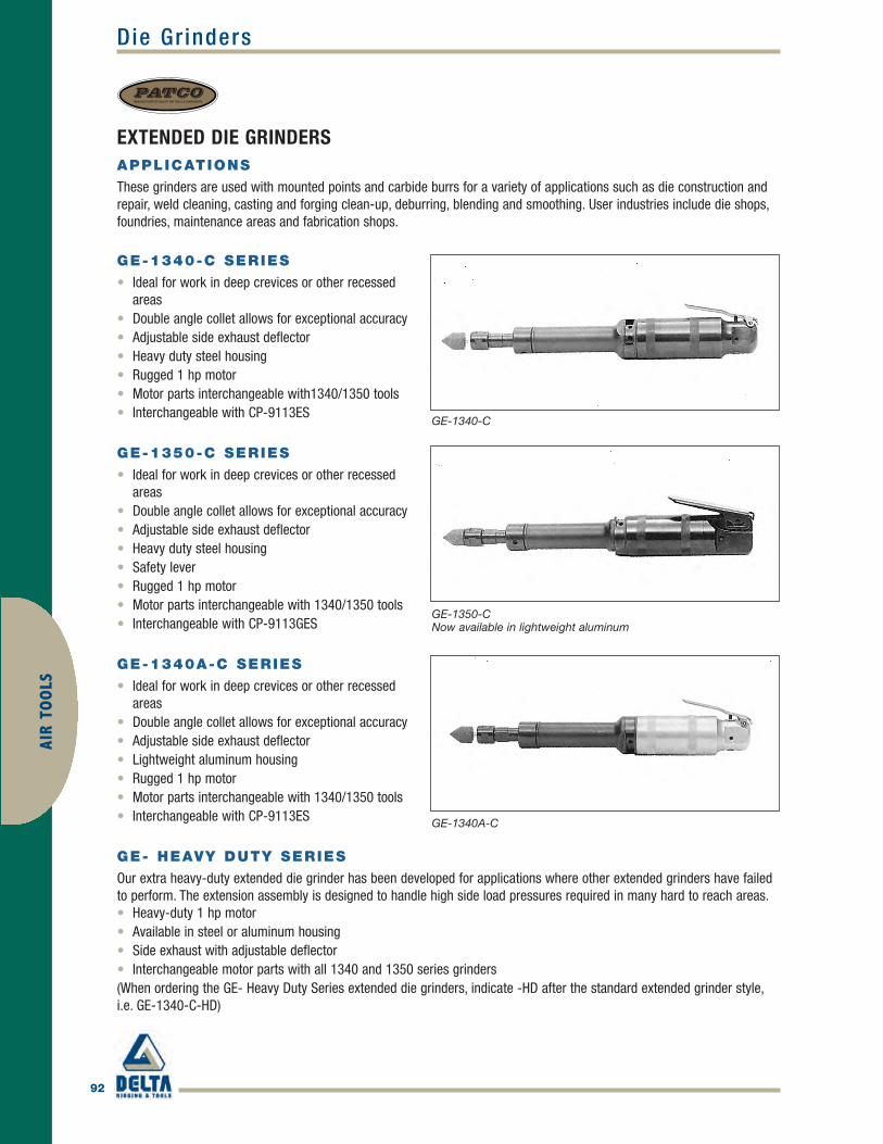
92
AIR
TOO
LS
PATCOMANUFACTURER OF QUALITY AIR TOOLS & COMPONENTS
Die Gr inders
EXTENDED DIE GRINDERSAPPLICATIONS
These grinders are used with mounted points and carbide burrs for a variety of applications such as die construction andrepair, weld cleaning, casting and forging clean-up, deburring, blending and smoothing. User industries include die shops,foundries, maintenance areas and fabrication shops.
GE-1340-C SERIES
• Ideal for work in deep crevices or other recessedareas
• Double angle collet allows for exceptional accuracy• Adjustable side exhaust deflector• Heavy duty steel housing• Rugged 1 hp motor• Motor parts interchangeable with1340/1350 tools• Interchangeable with CP-9113ES
GE-1350-C SERIES
• Ideal for work in deep crevices or other recessedareas
• Double angle collet allows for exceptional accuracy• Adjustable side exhaust deflector• Heavy duty steel housing• Safety lever• Rugged 1 hp motor• Motor parts interchangeable with 1340/1350 tools• Interchangeable with CP-9113GES
GE-1340A-C SERIES
• Ideal for work in deep crevices or other recessedareas
• Double angle collet allows for exceptional accuracy• Adjustable side exhaust deflector• Lightweight aluminum housing• Rugged 1 hp motor• Motor parts interchangeable with 1340/1350 tools• Interchangeable with CP-9113ES
GE- HEAVY DUTY SERIES
Our extra heavy-duty extended die grinder has been developed for applications where other extended grinders have failedto perform. The extension assembly is designed to handle high side load pressures required in many hard to reach areas.• Heavy-duty 1 hp motor• Available in steel or aluminum housing• Side exhaust with adjustable deflector• Interchangeable motor parts with all 1340 and 1350 series grinders(When ordering the GE- Heavy Duty Series extended die grinders, indicate -HD after the standard extended grinder style,i.e. GE-1340-C-HD)
GE-1340-C
GE-1350-CNow available in lightweight aluminum
GE-1340A-C
Patco_p90-105 final.qxd 4/5/10 11:29 AM Page 92

93
AIR TOO
LS
PATCOMANUFACTURER OF QUALITY AIR TOOLS & COMPONENTS
Die Gr inders
PATCOMODEL NO. RPM
THROTTLETYPE
SPINDLETHREAD
COLLETSIZE (IN.)
OVERALLLENGTH (IN.) NET WEIGHT
HOUSINGTYPE AIR INLET
GE-1340-C 25,000 Lever SelfClosing 3/8 x 24 1/4 11 1/8 3 lbs. 5 oz. Steel 1/4 NPT
GE-1350-C 25,000 SafetyLock Off 3/8 x 24 1/4 11 1/8 3 lbs. 9 oz. Steel 1/4 NPT
GE-1340A-C 25,000 Lever SelfClosing 3/8 x 24 1/4 11 1/8 2 lbs. 10 oz. Aluminum 1/4 NPT
STANDARD EQUIPMENT
• G-3729 1/4" collet• G-3327 Wrench• G-3858 Wrench
OPTIONAL EQUIPMENT
• Various collet sizes (see Accessories)• G-3781 Safety Lever on -1340 style housing
GE-1340-C-HD 25,000 Lever SelfClosing 3/8 x 24 1/4 11 1/8 3 lbs. 8 oz. Steel 1/4 NPT
GE-1340AC-HD 25,000 Lever SelfClosing 3/8 x 24 1/4 11 1/8 2 lbs. 13 oz. Aluminum 1/4 NPT
GE-1350-C-HD 25,000 SafetyLock Off 3/8 x 24 1/4 11 1/8 3 lbs. 12 oz. Steel 1/4 NPT
GE-1350AC-HD 25,000 SafetyLock Off 3/8 x 24 1/4 11 1/8 3 lbs. Aluminum 1/4 NPT
HEAVY-DUTY EXTENDED GRINDER
Patco_p90-105 final.qxd 4/5/10 11:29 AM Page 93

94
Wheel Gr indersAI
R TO
OLS
EXTENDED WHEEL GRINDERS
APPLICATIONS
These grinders are used for weld smoothing, casting cleanup, and burr removal in fabrication shops, die shops, shipyards,power plants, refineries and many other industries.
GE- CONE & PLUG WHEELGRINDERS
Designed for hard-to-reach surfaces in dieconstruction, castings and forgings. Also excellentwhen an extended reach is needed for weld cleaning,deburring, blending and smoothing.• Heavy-duty 1 hp motor• Available in steel or aluminum housing• Interchangeable motor parts with all 1340/1350
series tools
GE-1340-W SERIES
• Heavy duty 1 hp motor• Extended housing for better reach and control• Solid steel motor housing ensures longevity• Interchangeable wheel guards-3" and 4"• Side exhaust system directs exhaust away from
work area• 18,000 rpm• Motor parts interchangeable with 1340/1350 tools• Interchangeable with CP-3040-LANHUT
GE-1350-W SERIES
• Heavy duty 1 hp motor• Extended housing for better reach and control• Solid steel motor housing ensures longevity• Interchangeable wheel guards-3" and 4"• Side exhaust system directs exhaust away from
work area• 18,000 rpm• Safety lever• Motor parts interchangeable with 1340/1350 tools• Interchangeable with CP-3040-GANHUT
PATCOMANUFACTURER OF QUALITY AIR TOOLS & COMPONENTS
GE-1340-20
GE-1340-W
GE-1350-WNow available in lightweight aluminum
Patco_p90-105 final.qxd 4/5/10 11:29 AM Page 94

Wheel Gr inders
95
AIR TOO
LS
PATCOMANUFACTURER OF QUALITY AIR TOOLS & COMPONENTS
PATCOMODEL NO. RPM
THROTTLETYPE
SPINDLETHREAD
WHEELCAPACITY
OVERALLLENGTH (IN.) NET WEIGHT
HOUSINGTYPE AIR INLET
GE-1340-W 18,000 Lever SelfClosing 3/8 x 24 3 in. 12-1/2 3 lbs. 12 oz. Steel 1/4 NPT
GE-1350-W 18,000 SafetyLock Off 3/8 x 24 3 in. 13-1/2 4 lbs. Steel 1/4 NPT
GE-1340A-W 18,000 Lever SelfClosing 3/8 x 24 3 in. 13-1/2 3 lbs. 1 oz. Aluminum 1/4 NPT
GE-1340A-W SERIES
• Heavy duty 1 hp motor• Extended housing for better reach and control• Lightweight aluminum body• Interchangeable wheel guards-3" and 4"• Side exhaust system directs exhaust away from
work area• 18,000 rpm• Motor parts interchangeable with 1340/1350
tools• Interchangeable with CP-3040-LANHUT
STANDARD EQUIPMENT
• GE-3939 3" wheel guard• G-3858 Wrench• G-3327 Wrench
OPTIONAL EQUIPMENT
• GE-3781 Safety Lever on G-1340 style housing• GE-3764 4” Wheel Guard
GE-1340A-W
GE-1340-20 20,000 Lever SelfClosing 3/8 x 24
Cone &Plug 11 3 lbs. 4 oz. Steel 1/4 NPT
GE-1340A-20 20,000 Lever SelfClosing 3/8 x 24
Cone &Plug 11 2 lbs. 8 oz. Aluminum 1/4 NPT
GE-1350-20 20,000 SafetyLock Off 3/8 x 24
Cone &Plug 11 3 lbs. 8 oz. Steel 1/4 NPT
GE-1350A-20 20,000 SafetyLock Off 3/8 x 24
Cone &Plug 11 2 lbs. 12 oz. Aluminum 1/4 NPT
Use only reinforced Type 1 wheels. 3" dia x 1/2" max width x 3/8" center hole; wheels not included. Available in 4" wheel capacity model. When orderingspecify 4" wheel with -4, (i.e. GE-1340-4). The -4 model uses only reinforced Type 1 wheels 4" dia. x 1/4" max width x 3/8" center hole; wheels notincluded.
CONE & PLUG WHEEL GRINDERS
Patco_p90-105 final.qxd 4/5/10 11:29 AM Page 95

96
Angle Gr indersAI
R TO
OLS
PATCOMANUFACTURER OF QUALITY AIR TOOLS & COMPONENTS
RIGHT ANGLE WHEEL GRINDERSGA-RIGHT ANGLE SERIES TYPE 27 AND TYPE 1 WHEEL GRINDERS
The very popular GA-1340 and GA-1350 style Type 27 wheel tool is now also available in a Type 1 wheel design. Thespindle has been lengthened to allow a Type 1 wheel with a maximum width of 1/4". For those tight spaces, when cuttingor edge grinding is required, the GA- Series Type 1 wheel grinders can meet the challenge. Industrial applications includefoundries, welding shops, fabrication plants, steel mills and shipyards.
• Heavy duty 1 hp motor• 15,500 free speed RPM• Spiral bevel gears• Available in steel or aluminum housing• Side exhaust with adjustable deflector• Small head for easy accessibility to tight work
surfaces• Interchangeable motor parts with all 1340 and
1350 series grinders
GA-1340 SERIES
• Interchangeable with CP-3040-LABTIM
GA-1350 SERIES
• Safety Lever• Interchangeable with CP-3040-GABTIM
GA1340A SERIES
• Interchangeable with CP-3040-LABTIM
STANDARD EQUIPMENT
TYPE 1
• GA-3500 4" Wheel Guard• GA-3495-1 Wheel Spindle Nut• GA-3588-1 Wheel Nut• GA-3652 Spanner Wrench• GA-3653 Wrench• G-3858 Wrench
GA-1340
GA-1350Now available in lightweight aluminum
GA-1340A
Patco_p90-105 final.qxd 4/5/10 11:29 AM Page 96

Angle Gr inders
97
AIR TOO
LS
PATCOMANUFACTURER OF QUALITY AIR TOOLS & COMPONENTS
STANDARD EQUIPMENT
TYPE 27
• GA-3500 4" Wheel Guard• GA-3495 Wheel Adapter• GA-3588 Wheel Nut• GA-3652 Spanner Wrench• GA-3653 Wrench• G-3858 Wrench
OPTIONAL EQUIPMENT
• GA-3480 3" Guard• G-3781 Safety Lever on -1340 style housing
PATCOMODEL NO. RPM
THROTTLETYPE
SPINDLETHREAD
COLLETSIZE (IN.)
OVERALLLENGTH (IN.) NET WEIGHT
HOUSINGTYPE AIR INLET
GA-1340 13,500 Lever SelfClosing 3/8 - 24
3 and 4 in.Type 27 8 3 lbs. 2 oz. Steel 1/4 NPT
GA-1350 13,500 SafetyLock Off 3/8 - 24
3 and 4 in.Type 27 8 3 lbs. 6 oz. Steel 1/4 NPT
GA-1340A 13,500 Lever SelfClosing 3/8 - 24
3 and 4 in.Type 27 8 2 lbs. 7 oz. Aluminum 1/4 NPT
GA-1340-1 15,500 LeverSelf Closing
3/8 - 241" Long
3 and 4 in.Type 1 8 3 lbs. 2 oz. Steel 1/4 NPT
GA-1340A-1 15,500 LeverSelf Closing
3/8 - 241" Long
3 and 4 in.Type 1 8 2 lbs. 7 oz. Aluminum 1/4 NPT
GA-1350-1 15,500 SafetyLock Off
3/8 - 241" Long
3 and 4 in.Type 1 8 3 lbs. 6 oz. Steel 1/4 NPT
GA-1350A-1 15,500 SafetyLock Off
3/8 - 241" Long
3 and 4 in.Type 1 8 3 lbs. 4 oz. Aluminum 1/4 NPT
Use only reinforced Type 27 wheels; 3" or 4" dia. x 1/4" width max x 3/8" center hole; wheels not included.
IMPORTANT: Grinding wheel RPM must exceed tool RPM rating. Never mount bonded grinding wheels. Always wear eye, face and body protection. Useonly reinforced Type 1 wheels, 3" & 4" dia. x 1/4" wide max. x 3/8" center hole; wheels not included.
TYPE 1 WHEEL RIGHT ANGLE GRINDER
Patco_p90-105 final.qxd 4/5/10 11:29 AM Page 97

98
Angle Gr indersAI
R TO
OLS
PATCOMANUFACTURER OF QUALITY AIR TOOLS & COMPONENTS
RIGHT ANGLE WHEEL GRINDERSThe GA-11 Series tools are PATCO’s most durable right angle grinder. Designed for applications that other grinders cannothandle, spiral beveled gears and a wick-type lubricating system delivers the durability you need in the most challenging ofconditions. This grinder is available in a 4" - 5" Type 27 wheel, used for grinding, deburring and blending. Industrialapplications include foundries, welding shops, fabrication plants, steel mills and shipyards.
GA-11 SERIES
• Heavy Duty 1 hp motor• 11,000 free speed RPM• Spiral bevel gears• Available in steel or aluminum housing• Side exhaust with adjustable deflector• Dead handle for added stability and leverage• Interchangeable motor parts with all 1340 and 1350
series grinders
GA-11650 -1350 housing shown
PATCOMODEL NO. RPM
THROTTLETYPE
SPINDLETHREAD
WHEELCAPACITY
OVERALLLENGTH (IN.) NET WEIGHT
HOUSINGTYPE AIR INLET
GA-11625 11,000
LeverSelf Closing 5/8 - 11
4-1/2 and 5 in.Type 27 7-1/2 4 lbs. 12 oz. Steel 1/4 NPT
GA-11625A 11,000LeverSelf Closing 5/8 - 11
4-1/2 and 5 in.Type 27 7-1/2 4 lbs. Aluminum 1/4 NPT
GA-11650 11,000SafetyLock Off 5/8 - 11
4-1/2 and 5 in.Type 27 7-1/2 5 lbs. Steel 1/4 NPT
GA-11650A 11,000SafetyLock Off 5/8 - 11
4-1/2 and 5 in.Type 27 7-1/2 4 lbs. 4 oz. Aluminum 1/4 NPT
GA-11625-3/8 11,000LeverSelf Closing 3/8 - 24 4 in. Type 27 7-1/2 4 lbs. 12 oz. Steel 1/4 NPT
GA-11625A-3/8 11,000LeverSelf Closing 3/8 - 24 4 in. Type 27 7-1/2 4 lbs. Aluminum 1/4 NPT
GA-11650-3/8 11,000SafetyLock Off 3/8 - 24 4 in. Type 27 7-1/2 5 lbs. Steel 1/4 NPT
GA-11650A-3/8 11,000SafetyLock Off 3/8 - 24 4 in. Type 27 7-1/2 4 lbs. 4 oz. Aluminum 1/4 NPT
IMPORTANT: Never mount accessories that have lower maximum RPM rating than the tool, regardless of tool capacity. Never mount bonded grindingwheels. Always wear eye, face and body protection. Use only reinforced Type 27 wheels, 4" - 5" dia. x 1/4" wide max. x 3/8" center hole; wheels notincluded.
Patco_p90-105 final.qxd 4/5/10 11:29 AM Page 98

99
AIR TOO
LS
PATCOMANUFACTURER OF QUALITY AIR TOOLS & COMPONENTS
EXTENDED RIGHT ANGLE WHEEL GRINDERSGAL- EXTENDED RIGHT ANGLESERIES TYPE 1 WHEELGRINDERS
The very popular GAL-1340 and GAL-1350 style tool isnow available in a Type 1 wheel design. The spindlehas been lengthened to allow a Type 1 wheel with amaximum width of 1/4". For those hard-to-reachsurfaces, when cutting or edge grinding is required,the GAL Series Type 1 wheel grinders can meet thechallenge. Industrial applications include foundries,welding shops, fabrication plants, steel mills andshipyards.• Heavy duty 1 hp motor• 15,500 free speed RPM• Spiral bevel gears• Available in steel or aluminum housing• Side exhaust with adjustable deflector• Small head for easy accessibility to tight work
surfaces• Interchangeable motor parts with all 1340/1350
series grinders
GAL-1340 SERIES
• Extended reach keeps hands away from work• 1/2" side-to-center distance for easy accessibility
to work in tight areas
GAL-1350 SERIES
• Safety lever• Extended reach keeps hands away from work• 1/2" side-to-center distance for easy accessibility
to work in tight areas
GAL-1340A SERIES
• Lightweight aluminum body• Spiral bevel gears• Extended reach keeps hands away from work• 1/2" side-to-center distance for easy accessibility to work in tight areas
STANDARD EQUIPMENT
• GA-3500 4" Wheel guard• GA-3652 Spanner Wrench• GA-3653 Wrench• G-3858 Wrench• GA-3495 Type 27 Wheel Adapter• GA-3588 Type 27 Wheel Nut
GAL-1340
GAL-1350Now available in lightweight aluminum
GAL-1340A
Extended Angle Gr inders
Patco_p90-105 final.qxd 4/5/10 11:29 AM Page 99

100
AIR
TOO
LS
PATCOMANUFACTURER OF QUALITY AIR TOOLS & COMPONENTS
Extended Angle Gr inders
STANDARD EQUIPMENT
TYPE 1
• GA-3500 4" Wheel Guard• GA-3495-1 Wheel Spindle Nut• GA-3588-1 Wheel Nut• GA-3652 Spanner Wrench• GA-3653 Wrench• G-3858 Wrench
OPTIONAL EQUIPMENT
• GA-3480 3" Wheel guard• G-3781 Safety Lever on -1340 style housing
PATCOMODEL NO. RPM
THROTTLETYPE
SPINDLETHREAD
WHEELCAPACITY
OVERALLLENGTH (IN.)
NET WEIGHTLESS WHEEL
HOUSINGTYPE AIR INLET
GAL-1340 13,500LeverSelf Closing 3/8 - 24
3 and 4 in.Type 27 10 3 lbs. 8 oz. Steel 1/4 NPT
GAL-1350 13,500SafetyLock Off 3/8 - 24
3 and 4 in.Type 27 10 3 lbs. 12 oz. Steel 1/4 NPT
GAL-1340A 13,500LeverSelf Closing 3/8 - 24
3 and 4 in.Type 27 10 2 lbs. 13 oz. Aluminum 1/4 NPT
GAL-1340-1 15,500LeverSelf Closing
3/8 - 241" Long
3 and 4 in.Type 27 10 3 lbs. 4 oz. Steel 1/4 NPT
GAL-1340A-1 15,500LeverSelf Closing
3/8 - 241" Long
3 and 4 in.Type 27 10 2 lbs. 13 oz. Aluminum 1/4 NPT
GAL-1350-1 15,500SafetyLock Off
3/8 - 241" Long
3 and 4 in.Type 27 10 3 lbs. 8 oz. Steel 1/4 NPT
GAL-1350A-1 15,500SafetyLock Off
3/8 - 241" Long
3 and 4 in.Type 27 10 2 lbs. 12 oz. Aluminum 1/4 NPT
Use only reinforced Type 27 wheel. 3" or 4" dia. x 1/4" wide max x 3/8" center hole; wheels not included.
IMPORTANT: Grinding wheel RPM must exceed tool RPM rating. Never mount bonded grinding wheels. Always wear eye, face and body protection. Useonly reinforced Type 1 wheels, 3" or 4" dia. x 1/4" wide max x 3/8" center hole; wheels not included.
TYPE 1 WHEEL EXTENDED RIGHT ANGLE GRINDER
EXTENDED WHEEL GRINDERS
Patco_p90-105 final.qxd 4/5/10 11:29 AM Page 100

Col let Gr inders
101
AIR TOO
LS
PATCOMANUFACTURER OF QUALITY AIR TOOLS & COMPONENTS
RIGHT ANGLE COLLET GRINDERSAPPLICATIONS
These tools are excellent for applications such as die contouring, deburring, blending and smoothing in hard-to-reachareas. They are used primarily with carbide burrs and mounted points. These tools are used in foundries, refineries, metalfab shops, power plants and other industries.
GA-1340-C SERIES
• Rugged 1 hp motor• 13,500 rpm free speed• Steel motor housing withstands heavy use• Spiral beveled gears for longer life• Side exhaust with adjustable deflector• 1/2" side-to-center distance for easy accessibility
to work-piece in tight areas• Motor parts interchangeable with other 1340 /1350
tools• Interchangeable with CP-3040-LABCID
GA-1350-C SERIES
• Rugged 1 hp motor• 13,500 rpm free speed• Steel motor housing withstands heavy use• Spiral beveled gears for longer life• Side exhaust with adjustable deflector• 1/2" side-to-center distance for easy accessibility
to work-piece in tight areas• Motor parts interchangeable with other 1340/1350
tools• Safety Lever• Interchangeable with CP-3040-GABCID
GA-1340-C
GA-1350-CNow available in lightweight aluminum
Patco_p90-105 final.qxd 4/5/10 11:29 AM Page 101

102
Col let Gr indersAI
R TO
OLS
PATCOMANUFACTURER OF QUALITY AIR TOOLS & COMPONENTS
GA-1340A-C SERIES
• Rugged 1 hp motor• 13,500 rpm free speed• Lightweight aluminum body• Spiral beveled gears for longer life• Side exhaust with adjustable deflector• 1/2" side-to-center distance for easy accessibility
to work-piece in tight areas• Motor parts interchangeable with other 1340/1350
tools• Interchangeable with CP-3040-LABCID
STANDARD EQUIPMENT
• G-3327 Wrench• G-3858 Wrench
OPTIONAL EQUIPMENT
• Safety Lever• G-3781 Safety Lever on -1340 style housing
PATCOMODEL NO. RPM
THROTTLETYPE
COLLETSIZE (IN.)
OVERALLLENGTH (IN.) NET WEIGHT
HOUSINGTYPE AIR INLET
GA-1340-C 13,500LeverSelf Closing 1/4 8 2 lbs. 13 oz. Steel 1/4 NPT
GA-1350-C 13,500SafetyLock Off 1/4 8 3 lbs. 1 oz. Steel 1/4 NPT
GA-1340A-C 13,500LeverSelf Closing 1/4 8 2 lbs. 2 oz. Aluminum 1/4 NPT
GA-1340A-C
RIGHT ANGLE COLLET GRINDER
Patco_p90-105 final.qxd 4/5/10 11:29 AM Page 102

Extended Col let Gr inders
103
AIR TOO
LS
PATCOMANUFACTURER OF QUALITY AIR TOOLS & COMPONENTS
EXTENDED RIGHT ANGLE COLLET GRINDERSAPPLICATIONS
These grinders are used with mounted points and carbide burrs for a variety of applications such as die contouring andrepair, weld cleaning, casting and forging clean-up, deburring, blending and smoothing. User industries include die shops,foundries, shipyards, construction, petrochemical and fabrication shops.• Heavy duty 1 hp motor• 13,500 RPM free speed• Interchangeable motor parts with 1340/1350 tools• Spiral bevel gears• Adjustable side exhaust• Extended reach for hard-to-reach areas• 1/2" side-to-center distance for easy accessibility to
work in tight areas
GAL-1340-C SERIES
• Steel housing withstands heavy use• Interchangeable with CP-3040-LASCID
GAL-1350-C SERIES
• Safety lever• Interchangeable with CP-3040-GASCID
GAL-1340A-C
• Lightweight aluminum body• Interchangeable with CP-3040-LASCID
STANDARD EQUIPMENT
• G-3327 Wrench• G-3858 Wrench
OPTIONAL EQUIPMENT
• G-3781Safety Lever on -1340 style housing
GAL-1340A-C
GAL-1340-C
GAL-1350-CNow available in lightweight aluminum
PATCOMODEL NO. RPM
THROTTLETYPE
COLLETSIZE (IN.)
OVERALLLENGTH (IN.) NET WEIGHT
HOUSINGTYPE AIR INLET
GAL-1340-C 13,500LeverSelf Closing 1/4 10 3 lbs. 3 oz. Steel 1/4 NPT
GAL-1350-C 13,500SafetyLock Off 1/4 10 3 lbs. 7 oz. Steel 1/4 NPT
GAL-1340A-C 13,500LeverSelf Closing 1/4 10 2 lbs. 8 oz. Aluminum 1/4 NPT
Patco_p90-105 final.qxd 4/5/10 11:29 AM Page 103

104
Marking PensAI
R TO
OLS
PATCOMANUFACTURER OF QUALITY AIR TOOLS & COMPONENTS
AIR MARKING PENSAPPLICATIONS
These tools write on a variety of materials such as steel up to RC-64, glass, plastic and wood. They can be used fordeburring, trimming and are excellent for removing broken studs.
PAS-361 SERIES
• Light weight, easy to operate• Remove stylus and convert tool to chisel type scaler• Stylus will write on materials up to RC-64• Adjustable throttle for variety of jobs• Hardened piston for long life• Interchangeable with CP-9361
PAS-100 SERIES
• Stylus-only head assembly has the same greatfeatures as the PAS-361
STANDARD EQUIPMENT
• 7177 Stylus• 7381 Air Filter Assembly• 7886 Air Line• 7999 Carrying Case
OPTIONAL EQUIPMENT
• 7425 Chisel Kit (PAS-361 only)
PAS-361
The PAS-361 will continue to provide an interchangeablehead assembly. For use with the #7425 chisel kit.
Both models come with the Deluxe Carrying Case.
PAS-100
#7425 Chisel Kit• 1/4" Flat Chisel• Round Nose
Chisel• Chisel Blank• Anvil• 'O' rings
Patco_p90-105 final.qxd 4/5/10 11:29 AM Page 104

Scalers
105
AIR TOO
LS
PATCOMANUFACTURER OF QUALITY AIR TOOLS & COMPONENTS
SCALERSOur easy to use scalers feature a lever throttle with barrel andinternal parts heat treated and precision ground.
P1-B SCALERS
These tools are excellent for removing weld splatter,rust, paint and other debris from many different andunusual surfaces and in hard-to-reach places.Construction, fabrication shops, refineries, foundries,and construction jobs will find these tools to be quiteuseful.
P1-B parts are interchangeable with CP-9356 andCleco B1 style tools.
P1-B-L
This scaler has a replaceable tool nose and isavailable with needle attachment (see P-1-B-LN)
P1-B-LN
This needle scaler has a round tube end removeableneedle attachment which allows the tool to become achisel scaler. 5" hardened alloy steel needles arestandard. Optional 7" needles available.
P1-B-P
This scaler features a push-to-start handle,excellent for use in vertical positions and hard-to-reach areas. The P1-B-P is also available with the9322-needle attachment. Order as a P1-B-PN.
OPTIONAL EQUIPMENT FOR P1-B SERIES
• 9322 Needle Attachment (P1-B-L, P1-B-P)• 9024 7" Needle (P1-B-LN, P1-B-PN)• Uses #5342 thru #5351 chisels (see Chisel
Accessories)
P1-B-L
P1-B-LN
P1-B-P
PATCOMODEL NO.
BLOWS PERMINUTE
THROTTLETYPE
PISTONSTROKE (IN.)
OVERALLLENGTH (IN.)
NEWWEIGHT BORE (IN) AIR INLET
P1-B-L 4,600 Lever 1-1/8 9-1/2 4 lbs. 2 oz. 1 3/8 NPT
P1-B-LN 4,600 Lever 1-1/8 14 6 lbs. 2 oz. 1 3/8 NPT
P1-B-P 4,600 Push 1-1/8 10-1/2 6 lbs. 8 oz. 1 1/4 NPT
Patco_p90-105 final.qxd 4/5/10 11:29 AM Page 105

106
Air Dr i l lsAI
R TO
OLS
PNEUMATIC AND HYDRAULIC CORNER DRILLS AND DRIVESHIGH-TORQUE DRILLING, REAMING AND DRIVING UNITS
Corner Drills and Bridge Reamers• Small side-to-side distance for working in tight spaces• Self-closing roll throttle• Built-in oiler for motor• Ideal for bridge reaming and drilling applications• One-year warranty
Slow-speed, High-torque Straight Drive Units• Ideal for heavy-duty reaming, tube expanding and tapping• Perfect for special driving applications, including pipe tapping and
valve turningSquare Drive Accessories2 2089 7020 – 7/8" Male Square Drive to 3/4" Male Square Drive2 2089 7070 – 7/8" Male Square Drive to 1" Male Square Drive
PNEUMATIC CORNER DRILL MODEL NO.
MORSE TAPER
DRILLING (IN STEEL)
REAMING(IN STEEL)
TUBEROLLING CAP.
TORQUEOUTPUT(FT./LBS.)
LOAD SPEED (RPM)
MOTOR POWER (HP)
CFM AT90 PSI
LENGTH WEIGHT(LBS.)
Nonreversible
2 1602 0030 #1 5/8 in. 1/2 in. N/A 7 500 0.7 21 12.5 in. 7
2 1701 0030 #2 7/8 in. 5/8 in. N/A 35 270 1.8 49 20.9 in. 19
2 1801 0030 #3 1-1/4 in. 1 in. N/A 53 260 2.6 63 22.5 in. 25
Reversible
2 2104 0030 #4 2-1/8 in. 2 in. 2 in. 86 180 3.0 71 23.8 in. 37
Model No. 2 1602 0030 has a 3/8" NPT air inlet. 1/2" (13mm) hose is recommended. All other models have 3/4" NPT air inlet. A 1/2" (13mm)hose is recommended for model 2 1701 0030. A 5/8" (15mm) hose is recommended for models 2 1801 0030 and 2 2104 0030.
HYDRAULIC CORNER DRILL MODEL NO.
MORSETAPER
DRILLING (IN STEEL)
REAMING (IN STEEL)
TUBE ROLLING CAP.
TORQUE OUTPUT (FT./LBS.)
LOAD SPEED (RPM)
MOTOR POWER (HP)
OIL FLOW/ PSI LENGTH
WEIGHT (LBS.)
2 1806 0010 #3 1-1/4 in. 1 in. N/A 60 220 3.84 GPM@2000 21 in. 25
PNEUMATICDRIVE UNITMODEL NO.
SQUAREDRIVEID
TORQUEOUTPUT(FT./LBS.)
LOADSPEED(RPM) REVERSIBLE
TUBEROLLINGCAP.
TAPPINGCAP.
MOTORPOWER(HP)
CFM AT90 PSI
HEIGHT XLENGTH(IN.)
WEIGHT(LBS.)
2 2081* 13/16 in. 413 20 YES 3 in. 1-1/2 in. 1.35 53 10.9 x 26.5 29
2 2087*† 7/8 in. 413 20 YES 3 in. 1-1/2 in. 1.35 53 10.9 x 26.5 29
2 2088*† 7/8 in. 138 60 YES 2 in. 3/4 in. 1.35 53 10.9 x 26.5 29
* The last four digits of the Model No. identify the type of throttle. † Square drive accessories available (see above).Please specify the four digits when ordering: 0010 for Lever Throttle or 0030 for Safety Twist Throttle.
Model 2 1801 0030
ATEX
Model 2 2087 0010 with reverseand lever throttle
CSU_p106-108 final.qxd 4/5/10 11:32 AM Page 106

Air Dr i l ls
107
AIR TOO
LS
AIRBOR AB-4300-2 AND AB-4300-2RPNEUMATIC POWER FOR HAZARDOUSENVIRONMENTS
AIRBOR™ is inherently safer than electromagnetic drills in hazardous atmospheres and wet environments where electricity requires “hot work permits.” ATEX approved.
• Industry's first completely air-operated magnetic drill - NO ELECTRICITY!• Fail-safe permanent magnet is activated “on” and “off” by air pressure; in the
event of a loss of air flow, the magnet will not disengage• Magnet has a holding strength of 1600 lbs.• Powerful 1.6 HP drill motor• Lightweight and portable• Long drill stroke – up to 10-1/4"• Drills up to 2-1/16" dia. holes with Annular Cutters • Pressurized coolant system lubricates cutter and reduces risk of sparking
Model AB-4300-2Motor and magnet are poweredcompletely by compressed air.
AB-4300-2R shown with extra rack up (left) andextra rack down (right).
MODEL AB-4300-2 AND AB-4300-2R
Motor Power (Pneumatic) 1.6 HP
Hole Capacity 2-1/16 in. dia.
Twist Drill Capacity 1/2 in. dia.
No Load Speed 400 RPM
Air Consumption @ 90 PSI 64 CFM
Magnet Base Size 8-3/4 in. L x 3-1/2 in. W
Dimensions 13-1/2 in. H x 12-1/2 in. L x 4-3/4 in. W
Magnetic Force (1 in. plate) 1600 lbs.
Arbor Bore 3/4 in.
Automatic Lubrication Included
Stroke Length: 4-7/8 in. Order Model AB-4300-2
Stroke Length: 10-1/4 in. Order Model AB-4300-2R
MODEL COMPARISON
AB-4300-2R AB-4300-2
DRILL STROKE
w/cutters w/chuck w/cutters w/chuck
10-1/4 in. 7-1/2 in. 4-7/8 in. 1-3/4 in.
HEIGHT
closed open closed open
13-1/2 in. 22 in. 13-1/2 in. 17-1/2 in.
WEIGHT
lbs. kg lbs. kg
43 20 38 18
With a geared chuck adapter (PartNo. IBK-18) and extra rack (ModelNo. AB-4300-2R), AIRBOR™ easilyconverts to a standard drill presswith a 7-1/2" stroke.
Cutter capacity up to 3 3/16" dia., stroke: 10"Twist drill capacity up to 1 1/4" dia., stroke: 61/2" w/chuck
CSU_p106-108 final.qxd 4/5/10 11:32 AM Page 107

SDS Max – Modes of Operation 2" bit capacity for drilling concrete and masonry
108
Air Dr i l lsAI
R TO
OLS
PNEUMATIC AND HYDRAULIC ROTARY HAMMER DRILLSPOWERFUL PERCUSSION DRILLING FOR CONCRETE AND MASONRY
• Holes cost less with SDS drill bits • Safety clutch protects against overloading and jamming Hammer
drill holes in concrete, brick and masonry • Rotary drilling mode for straight drilling of steel and wood
PNEUMATIC HAMMER DRILL MODEL NO.
BLOWS/ MINUTE (BPM)
DRILL SPEED (RPM)
SOLID BIT CAPACITY (CONCRETE)
CORE BIT CAPACITY (CONCRETE)
TWIST DRILL (WOOD)
POWER AT 90 PSI
AIR CONSUM-PTION AT 90 PSI
TOOL SYSTEM
DIMENSIONS (INCHES)
WEIGHT (LBS.)
2 2404 0010 0-3000 0-625 1 in. dia. 3 in. dia. 3/4 in. dia. 0.7 HP 21 CFM SDS Plus 16 x 8-1/2 x 4 11
2 2404 0030* 0-3000 0-625 1 in. dia. 3 in. dia. 3/4 in. dia. 0.7 HP 21 CFM SDS Plus 16 x 8-1/2 x 4 11
2 2414 0010 0-2500 0-250 2 in. dia. 6 in. dia. 1-1/4in.dia. 1.6 HP 53 CFM SDS Max 19-1/2 x 9.8 x 4-1/2 26
HYDRAULIC HAMMER DRILL MODEL NO.
BLOWS/ MINUTE (BPM)
DRILL SPEED (RPM)
SOLID BIT CAPACITY (CONCRETE)
CORE BIT CAPACITY (CONCRETE)
TWIST DRILL (WOOD)
POWER AT 2000 PSI
FLOWRANGEAT 1450 PSI (GPM)
TOOL SYSTEM
DIMENSIONS (INCHES)
WEIGHT (LBS.)
2 2406 0010 0-3400 0-625 1 in. dia. 3 in. dia. 3/4 in. dia. 0.8 HP 5.8-13.2 SDS Plus 18 x 10-1/4 x 4 15
2 2410 0010 0-2500 0-250 2 in. dia. 6 in. dia. 1-1/4 dia. 1.8 HP 2.6-13.2 SDS Max 19-1/2 x 11-1/8 x 7-1/2 25
* Underwater model – Optional underwater air tool line conditioner to displace moisture, Part No. MS 9105.
Hydraulic Hammer Drills operate at hydraulic pressures of 1,450 - 2,000 PSI
SDS Drill Bits and Chisels
Small Masonry Bits SDS Plus up to 1" dia
Large Masonry Bits SDS Max up to 2" dia
Auger Drill Bit for wood Chisel for demolition
Air Model 2 2414 0010 SDS Max
SDS Plus – Hammer and Drill 1" bit capacity for drilling concrete and masonry.
Hydraulic Model 2 2406 0010 SDS Plus
Air Model 2 2404 0010 SDS Plus up to 1" dia.
SAE #8 oil port
Hammer with rotationIdeal for concrete drilling.
Rotation onlyIdeal for drilling wood and steel.
Drill concrete anchor holes, thru holes, piping and mechanical openings andother construction and repair work. Switches to rotary drilling mode forsteel and wood.
Hydraulic Model 2 2410 0010 SDS Max
SAE #8 port for hydraulic hose connection
Second handleposition
CSU_p106-108 final.qxd 4/5/10 11:32 AM Page 108

109
AIR TOO
LSAir Nutrunners
PNEUMATICNUTRUNNERMODEL NO.
SQUARE DRIVE F=FEMALE M=MALE
STALL TORQUE AT 90 PSI (FT-LBS.)
FREE SPEED (RPM)
LOAD SPEED (RPM)
POWER (HP)
CFM AT 90 PSI
SIDE TO CENTER DISTANCE (INCHES)
LENGTH (INCHES)
WEIGHT (LBS.)
AIR CONNECTION (INCHES)
HOSE ID (INCHES)
6 1014 0010 3/4 in. F 100 180 100 0.9 42 1 16 10 NPT 3/8 1/2
6 1014 0075 3/4 in. M 100 180 100 0.9 42 1 16 11 NPT 3/8 1/2
6 1014 0099 1/2 in. M 100 180 100 0.9 42 1 16 11 NPT 3/8 1/2
6 1015 0010 3/4 in. F 423 44 22 0.9 45 1 21 10 NPT 3/8 1/2
6 1015 0075 3/4 in. M 423 44 22 0.9 45 1 21 10 NPT 3/8 1/2
6 1015 0099 1/2 in. M 423 44 22 0.9 45 1 21 10 NPT 3/8 1/2
6 1016 0010 3/4 in. F 141 120 67 0.9 42 1 21 10 NPT 3/8 1/2
6 1016 0075 3/4 in. M 141 120 67 0.9 42 1 21 11 NPT 3/8 1/2
6 1016 0099 1/2 in. M 141 120 67 0.9 42 1 21 11 NPT 3/8 1/2
6 1017 0010 3/4 in. F 60 260 125 0.9 46 1 21 11 NPT 3/8 1/2
6 1017 0075 3/4 in. M 60 260 125 0.9 46 1 21 11 NPT 3/8 1/2
6 1017 0099 1/2 in. M 60 260 125 0.9 46 1 21 11 NPT 3/8 1/2
6 1021 0010 7/8 in. F 423 44 22 0.9 45 1 21 11 NPT 3/8 1/2
HYDRAULIC NUT RUNNER MODEL NO.
SQUARE DRIVE F=FEMALE M=MALE
STALL TORQUE AT 90 PSI (FT-LBS.)
FREE SPEED (RPM)
LOAD SPEED (RPM)
POWER (HP)
OIL FLOW (GPM)
OIL PRESSURE (GPM)
SIDE TO CENTER DISTANCE (INCHES)
LENGTH (INCHES)
WEIGHT (LBS.)
CONNECTION QUICK COUPLERS
3 6242 0010 3/4 in. F 554 44 22 1.6 4 - 13 1000 1 20 22 1/2 in. FF
3 6242 0075 3/4 in. M 554 44 22 1.6 4 - 13 1000 1 20 22 1/2 in. FF
3 6242 0099 1/2 in. M 554 44 22 1.6 4 - 13 1000 1 20 22 1/2 in. FF
PNEUMATIC AND HYDRAULIC NUT RUNNERSIDEAL FOR TURNING VALVES, T IGHTENING, TAPPING, REAMING, PIPEBEVELING, EXPANDING AND MORE
• Worm gear drive provides high torque – up to 554 ft.-lbs.• Lightweight and reversible • Compact angle head allows access to confined spaces • Both Pneumatic and Hydraulic models available • One-year warranty
Square Drive Accessory 6 1015 7030 3/4" Male Square Drive (included with model numbers 6 1014 0075, 6 1015 0075 and 6 1016 0075) 6 1015 7020 1/2" Male Square Drive (included with model numbers 6 1014 0099, 6 1015 0099 and 6 1016 0099)
Available with Male or Female Square Drives, in a variety of sizes
Model 6 1015 0075
Model numbers pictured above (listedfrom top to bottom): 6 1015 0075 (withmale drive), 6 1015 0010 (female), 61014 0075 (with male drive)
Male Sq. Drive Head1/2" or 3/4"
Female Sq. DriveHead 3/4" or 7/8"(7/8" pneumatic only)
Square Drive Accessory
ATEX
CSU_p109 final.qxd 4/5/10 11:34 AM Page 109

110
AIR
TOO
LS
4 HP PNEUMATIC CHAIN SAWPOWERFUL, EFFICIENT CUTTING OFWOOD AND PLASTIC
Used successfully for many years in polyethylene plants,petrochemical industries, utilities, underground mines andmarine applications • Ideal for use in polyethylene plants, petrochemical
industries, utilities, underground mines and marineapplications
• Pneumatic power is safer than gas or electric in hazardousatmospheres and wet environments, including underwaterapplications
• Low maintenance and easy startup – saw chain and motorare automatically oiled by two separate lubricating systems
• Powerful 4 HP motor at 90 PSI air pressure and 92 CFM • Chain guard to protect operator • Available with 15", 17", 21" and 25" cutting capacity • .404 pitch Super Chisel saw chain is standard • Carbide-tipped and Ripping saw chain are optional
Air Saws and Accessor ies
MODEL NO. POWERCUTTING CAPACITY PSI CFM
LENGTH WITH BAR
WEIGHT (LBS.)
AIR CONNECTION
HOSE ID
General Use
5 1007 0003 4 HP 15 in. 90 92 31 in. 16 3/4" NPT (ID) 5/8 in.
5 1007 0010 4 HP 17 in. 90 92 33 in. 18 3/4" NPT (ID) 5/8 in.
5 1007 0020 4 HP 21 in. 90 92 37 in. 19 3/4" NPT (ID) 5/8 in.
5 1007 0040 4 HP 25 in. 90 92 41 in. 20 3/4" NPT (ID) 5/8 in.
Underwater Use*
5 1008 0030 4 HP 21 in. 90 92 37 in. 19 3/4" NPT (ID) 5/8 in.
5 1008 0040 4 HP 25 in. 90 92 41 in. 20 3/4" NPT (ID) 5/8 in.
Model 5 1007 0040 25" cutting capacity
Model Series 5 1008 Underwater chain saw shown with exhaust valve.
* Pneumatic Chain Saws with 15" and 17" cutting capacity are also available for underwater applications.
CSU_p110 final.qxd 4/5/10 11:36 AM Page 110

111
AIR TOO
LSAir Saws and Accessor ies
PNEUMATIC PORTABLE BAND SAWSIDEAL FOR HAZARDOUS ATMOSPHERES ANDWET ENVIRONMENTS
• Fast, on-site cutting • Safer in hazardous atmospheres than electric saws • Ideal for process shutdowns and turnarounds • Reduces need for "hot work permits" • No fear of electric shock or blown circuitry in wet environments • AirBand™ models with aluminum housing cut up to 43/4" OD • Deep Throat™ models with planetary gearbox cut up to 7" OD
AirBand™ Model 5 6003 0010 4 3/4" OD cutting capacity
Deep Throat™ AirBand Model 5 6031 0010 7" OD cutting capacity
MODEL NO.
MOTOR POWER AND SPECS.
BLADE SPEED (RPM)
CAPACITY
ROUND RECTANGULARBLADE SIZE (IN.) HOUSING
OVERALLLENGTH(IN.)
AIRCONNEC-TION (IN.)
WEIGHT(LBS.)
AirBand
5 6003 0010 0.7 HP, 90 PSI,20 CFM
Variable 130-220 4-3/4 in. 4-1/2 in. x 4-3/4 in.
44-7/8 x 1/2 Aluminum 21-1/2
1/4 NPT (ID) 14
Deep Throat™ AirBand
5 6031 0010 1.3 HP, 90 PSI,43 CFM
Variable 240-295 7 in. 7 x 7 in.
66 x 5/8
StainlessSteel 28-3/4
1/2 NPT (ID) 28
Vise Clamps for Straight Cutting Securely clamp to round, square and angular materials for accurate cuts
Model No. 5 6003 9000Clamp-on vise for 4 3/4" Band Saw (Models 5 6003/5 6043/5 6046) Rounds: 4 1/2" (115mm);Squares: 3" (75mm); Angles: 3" (75mm)
Model No. 5 6031 9400Clamp-on vise for 7" Band Saw (Models 5 6031/5 6041/5 6047) Rounds: 7" (180mm); Squares:5" (125mm); Angles: 5" (125mm)
CSU_p111-112 final.qxp 4/5/10 11:46 AM Page 111

112
AIR
TOO
LSAir Saws and Accessor ies
BAND SAW BLADES AND ACCESSORIESM42 COBALT STEEL SUPERBAND™ SAW BLADES
CS Unitec's SuperBand™ saw blades are made of tough M42 steel. 8% cobalt gives ourblades the highest heat resistance and wear resistance of all portable band saw blades.The hardness is Rc 67-69.
SuperBand™ saw blades easily cut most ferrous and nonferrous metals, including steel,stainless steel, Inconel, chrome, Hastelloy, tool steels, "super" alloys and other materials.Longer life, fewer blade changes and the fastest cutting rates result in SuperBand™providing the lowest cost per cut.
BLADES FOR STANDARD SAWS (MODEL NOS. 5 6003 0010, 5 6046 0010 AND 5 6043 0010)
BLADES FOR DEEP THROAT™ SAWS (MODEL NOS. 5 6031 0010, 5 6047 0010 AND 5 6041 0010)
No. 9 2506 0010 18 TPI Cuts material 1/8 - 1/4 in. thick 44-7/8 L x 1/2 W x .025 in. T
No. 9 2506 0020 14 TPI Cuts material 3/16 - 1/2 in. thick 44-7/8 L x 1/2 W x .025 in. T
No. 9 2506 0030 10/14 TPI* Cuts material 3/16 - 1/2 in. thick 44-7/8 L x 1/2 W x .025 in. T
No. 9 2506 0040 8/12 TPI* Cuts material 1/2 in. and thicker 44-7/8 L x 1/2 W x .025 in. T
No. 9 2506 0220 14 TPI Cuts material 3/16 - 1/2 in. thick 66 L x 5/8 W x .025 in. T
No. 9 2506 0230 10/14 TPI* Cuts material 3/16 - 1/2 in. thick 66 L x 5/8 W x .025 in. T
No. 9 2506 0240 8/12 TPI* Cuts material 1/2 in. and thicker 66 L x 5/8 W x .025 in. T
No. 9 2506 0200 8 TPI Cuts material 3/4 in. and thicker 66 L x 5/8 W x .025 in. T
* Variable tooth pitch (10/14 TPI and 8/12 TPI) saw blades cut faster and last longer than standard pitch blades.Varying tooth size and gullet depth reduce harmonic vibration for quieter, more efficient cutting.
VISE CLAMPS FOR ACCURATE CUTS• Securely clamp to round, square and
angular materials for straight cutting• Easily attach to all CS Unitec Portable
Band Saws
Model 5 6031 9400 with Band Saw
Model 5 6003 9000
Model No. 5 6003 9000Clamp-on vise for standard 4-3/4" Band Saw Maximummaterial size – rounds: 4-1/2"; squares: 3"; angles: 3"
Model No. 5 6031 9400Clamp-on vise for 7" Deep Throat™ Band Saw Maximummaterial size – rounds: 7"; squares: 5"; angles: 5"
CSU_p111-112 final.qxp 4/5/10 11:46 AM Page 112
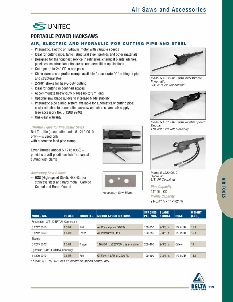
Air Saws and Accessor ies
113
AIR TOO
LS
PORTABLE POWER HACKSAWSAIR, ELECTRIC AND HYDRAULIC FOR CUTTING PIPE AND STEEL
• Pneumatic, electric or hydraulic motor with variable speeds• Ideal for cutting pipe, tanks, structural steel, profiles and other materials• Designed for the toughest service in refineries, chemical plants, utilities,
pipelines, construction, offshore oil and demolition applications• Cut pipe up to 24" OD in one pass• Chain clamps and profile clamps available for accurate 90° cutting of pipe
and structural steel• 2-3/8" stroke for heavy-duty cutting• Ideal for cutting in confined spaces• Accommodate heavy-duty blades up to 37" long• Optional saw blade guides to increase blade stability• Pneumatic pipe clamp system available for automatically cutting pipe;
easily attaches to pneumatic hacksaw and shares same air supply (see accessory No. 5 1208 9940)
• One-year warranty
Throttle Types for Pneumatic SawsRoll Throttle (pneumatic model 5 1212 0010only) – is used onlywith automatic feed pipe clamp
Lever Throttle (model 5 1212 0050) – provides on/off paddle switch for manualcutting with clamp
Accessory Saw Blade
MODEL NO. POWER THROTTLE MOTOR SPECIFICATIONSSTROKESPER MIN.
BLADESTROKE HOSE
WEIGHT(LBS.)
Pneumatic - 3/4" ID NPT Air Connection
5 1212 0010 1.5 HP Roll Air Consumption: 51CFM 100-350 2-3/8 in. 1/2 in. ID 15.4
5 1212 0050 1.5 HP Lever Air Pressure: 90 PSI 100-350 2-3/8 in. 1/2 in. ID 15.4
Electric
5 1215 0070* 1.5 HP Trigger 110V/60 Hz (220V/50Hz is available) 200-400 2-3/8 in. Cable 13
Hydraulic- 3/8" FF (HTMA) Couplings
5 1220 0010 3.8 HP Roll Oil Flow: 4 GPM at 2000 PSI 100-500 2-3/8 in. 1/2 in. ID 13.5
Model 5 1220 0010Hydraulic3/8" FF Couplings
* Model 5 1215 0070 has an electronic speed control dial.
Accessory Saw Blades• HSS (High-speed Steel), HSS-SL (for
stainless steel and hard metal), CarbideCoated and Boron Coated Pipe Capacity
24" Dia. ODProfile Capacity21-3/4" h x 11-1/2" w
Model 5 1215 0070 with variable speedElectric110 Volt (220 Volt Available)
Model 5 1212 0050 with lever throttlePneumatic3/4" NPT Air Connection
CSU_p113-119 final.qxd 4/5/10 11:48 AM Page 113

114
Air Saws and Accessor iesAI
R TO
OLS
PORTABLE HACKSAWS FOR TOUGH DUTYON-SITE CUTTING OF PIPE UP TO 24" ODAND STRUCTURAL STEEL
Pneumatic • Electric • HydraulicCS Unitec's power hacksaws offer a wide range of options for portablecutting of pipe, structural steel, tanks and other materials. Our saws aredesigned for the toughest service in refineries, power plants, utilities, offshoreoil, construction and demolition applications and are ideal for shutdowns andturnarounds in process piping industries. CS Unitec's Pneumatic Saws aresafer than cutting with a welding torch in hazardous areas or confinedspaces.• Compact size, ideal for cutting in confined spaces• 2-3/8" blade stroke• Pipe clamps for 90° cutting of up to 24" OD pipe• Profile clamps for structural steel• Wide variety of blades and accessories for cutting steel, stainless steel,
aluminum, plastic, wood and ductile iron• Optional blade guide to ensure right-angle cuts• Automatically cut pipe with our optional self-feeding, pneumatic-powered
pipe clamp system
Assorted pipe clamps forpipes up to 24" OD or profileclamps for structural steel
Heavy-duty saw blades from 8" to 37" long
HSS, HSS-SL, carbide coated and boron coatedblades available.
Twist or lever throttle
Pneumatic, electric or hydraulic motor
Pneumatic:3/4" NPT ConnectionElectric:110 Volt (220V available)Hydraulic:3/8" FF (HTMA) Couplings
Optional saw blade guide foradded blade stability – ensuresstraight cutting!
Two sizes available.
CSU_p113-119 final.qxd 4/5/10 11:49 AM Page 114

115
AIR TOO
LSAir Saws and Accessor ies
HACKSAW BLADES- 8" UP TO 37" LONGHEAVY-DUTY CUTTING OF PIPE AND STRUCTURAL STEEL EXTRA THICKFOR 90°CUTTING
Use ProLube™ Specialty Lubricants with your Hacksaw Blades to help your tools workcooler, longer and moreefficiently. ProLube Lubricants are non-toxic and ideal for stainless steel and hard metal cutting applications.
ORDER NO.LENGTH(INCHES)
DIMENSIONSTEETH/INCH
THICKNESS(INCHES)
STEEL ANDNONFERROUS METAL
PLASTICAND WOOD
DUCTILE/CAST IRONAND MASONRY
MAX.DIA.OF CUT(IN)
Z22-9 HSS 8 8 1/16 Steel/Aluminum Plastics – 3-1/8
Z22-10 HSS 8 16 1/16 Steel – – 3-1/8
Z22-11 HSS 8 24 1/16 Sheet Metal – – 3-1/8
Z22-6 HSS 12 16 1/16 Steel – – 6-5/8
Z22-6 HSS-SL* 12 16 1/16 Stainless Steel – – 6-5/8
Z22-6 Carbide 12 Coated 3/16 – – Masonry 6-5/8
Z22-31 HSS 12 12 1/16 Steel – – 6-5/8
Z22-71 HSS 12 4 1/16 – Plastics/Wood – 6-5/8
Z22-83 TDS 12 Coated 3/32 – – Ductile Iron 6-5/8
Z22-7 HSS 16 16 1/16 Steel – – 10-5/8
Z22-7 Carbide 16 16 1/16 – – Masonry 10-5/8
Z22-29 HSS 16 8 1/16 Steel/Aluminum Plastics – 10-5/8
Z22-72 WS 16 4 1/16 – Plastics/Wood – 10-5/8
Z22-86 TDS 19 Coated 7/64 – – Ductile Iron 13
Z22-72 HSS 20 14 5/64 Steel – – 14-5/8
Z22-72 Carbide 20 Coated 3/16 – – Masonry 14-5/8
Z22-30 HSS 21 12 1/16 Steel – – 15-5/8
Z22-30 HSS-SL* 21 12 1/16 Stainless Steel – – 15-5/8
Z22-40 HSS 21 4 1/16 – Plastics/Wood – 15-5/8
Z22-73 HSS 24 14 5/64 Steel – – 18-1/2
Z22-73 Carbide 24 Coated 3/16 – – Masonry 18-1/2
Z22-74 HSS 24 8 5/64 Steel/Aluminum Plastic – 18-1/2
Z22-75 HSS 30 12 5/64 Steel – – 24-7/8
Z22-75 HSS-SL* 30 12 5/64 Stainless Steel – – 24-7/8
Z22-37 HSS 37 12 5/64 Steel – – 31-7/8
* Use HSS-SL Blades for best cutting performance on stainless steel and hard metal.
HSS or HSS-SL Saw Blade Shown
CSU_p113-119 final.qxd 4/5/10 11:49 AM Page 115

116
AIR
TOO
LSAir Saws and Accessor ies
HACKSAW ACCESSORIESAUTOMATIC FEED PIPE CLAMP FOR PNEUMATIC SAWS
Model No.5 1208 9940• Save time and effort by automatically cutting pipe up to 12-3/4" OD
(up to 24" OD with extension chain)• Self-feeding device saves operator time and makes work easier• Easily attaches to CS Unitec pneumatic hacksaw and shares same 90 PSI
air supply (Pipe clamp for use only with CS Unitec pneumatic hacksaw Model No.5 1212 0010)
• Blade guide is optional (see below)
Clamps for Pipes and ProfilesEnsure 90° cuts through pipe and profiles
Model No. 5 1207 9910 6" OD pipe clampModel No. 5 1202 9960 up to 12-3/4" OD pipe clamp(up to 24" OD with extension chain shown below)Model No. 5 1207 8970 21-5/8" x 11-3/8" profile clamp
Extension Chains for Pipe Clamps• Extend capacity of pipe clamps 5 1202 9960 and 5 1208 9940 for
large-diameter pipes
Model No.5 1201 9010– 17-3/4" chain extensionModel No.5 1201 9030– 39-3/8" chain extension (allows pipe clamp Nos.5 1202 9960 and 5 1208 9940 to fit 24" OD pipe)
Blade Guides – with two roller bearings• Ensure straight cutting through pipe and difficult materials• Easily attach to CS Unitec portable hacksaws
Model No.5 1207 9970 for pipes up to 13" (20" min. blade length required)Model No.5 1207 8910 for pipes up to 21" (30" min. blade length required)
Small PipeClamp, Model 5 1207 9910 Up to 6" pipe dia.
Profile Clamp,Model 5 1207 8970
Large Pipe Clamp, Model 5 1202 9960
CSU_p113-119 final.qxd 4/5/10 11:49 AM Page 116

Air Saws and Accessor ies
117
AIR TOO
LS
1.3 HP PNEUMATIC RECIPROCATING SAWIDEAL FOR CUTTING PIPES, STRUCTURAL STEEL, PALLETS AND MORE
• Cuts steel pipe and channel 1/2" to 4" dia.,plastic pipe to 8" dia.
• Ideal for the toughest use in refineries, chemical plants, gas utilities, construction, offshore oil,mining, marine and demolition industries
• 1.3 HP air motor provides more power than conventional air saws
• 1-1/8" blade stroke for fast, efficient cutting• Can be mounted on a pipe clamp to make 90° cuts• Variable speed of 0-1800 strokes per minute• Accepts universal saw blades or thicker, double-tang
heavy-duty saw blades• Molded rubber boot for ergonomic grip• One-year warranty
Reciprocating Saw Blades andAccessories• Universal saw blades• Thicker, double-tang heavy-duty
blades for 90° cuts• M-Tooth blades to cut on
forward and back stroke
Pipe Clamps for Straight Cutting up to 6" dia.• Increase leverage 5x for faster cutting• Safely secure the saw while cutting
Model 5 1217 0020 includes carrying case and two No. 1001 heavy-duty blades.
Model 5 1217 0020 Use hand-held or with a clamp
Saw Kit (5 1217 0060)includes saw, 6" pipeclamp, case and five No.1001 heavy-duty blades.
MODEL 5 1217 0020
Motor Power 1.3 HP
Stroke Length 1-1/8 in.
Strokes per Min. 0-1800
Weight 9 lbs.
Length 15-7/8 in.
Air Consumption 46 CFM
Air Pressure 90 PSI
Air Connection 1/2 in. NPT (ID)
Saw Kit Order Model 5 1217 0060
The CAT
CSU_p113-119 final.qxd 4/5/10 11:49 AM Page 117

Reciprocating Saw Blades and Accessories• Universal saw blades• Thicker, double-tang heavy-duty blades
for 90° cuts• M-Tooth blades to cut onforward and
back stroke
Pipe Clamps for Straight Cutting up to 6" dia.• Increase leverage 5x for faster cutting• Safely secure the saw while cutting
118
Air Saws and Accessor iesAI
R TO
OLS
1.6 HP PNEUMATIC RECIPROCATING SAWIDEAL FOR CUTTING PIPE, STRUCTURAL STEEL AND OTHER MATERIALS
• Cuts steel pipe and channel 1/2" to 6" dia.,plastic pipe to 8" dia.
• Powerful 1.6 HP motor with reciprocating action for steel and long orbital stroke for cutting soft materials including wood, plastic and aluminum
• Can be mounted on a pipe clamp to make 90° cuts• 1-1/8" blade stroke for fast, efficient cutting• Selector switch changes stroke setting to either
straight or orbital• Variable speed from 0-2200 strokes per minute• Accepts universal saw blades or thicker, double-tang
heavy-duty saw blades • Molded rubber boot for ergonomic grip; side
handle included• One-year warranty
MODEL 5 6005 0010
Motor Power 1.6 HP
Stroke Length 1-1/8 in.
Strokes per Min. 0-2200
Weight 10-3/4 lbs.
Length 17-3/4 in.
Air Consumption 51 CFM
Air Pressure 90 PSI
Air Connection 1/2 in. NPT (ID)
Saw Kit Order Model 5 6005 0060
Shown with side handle
Model 5 6005 0010Use hand-held or with a clamp
Saw Kit (5 6005 0060)includes saw, 6"pipeclamp, case, sidehandle and five No. 1001heavy-duty blades.
Selector switch for straightor orbital strokeThe WOLF
CSU_p113-119 final.qxd 4/5/10 11:49 AM Page 118

119
AIR TOO
LSAir Saws and Accessor ies
PROLUBE™ IDEAL FOR CUTTING STEEL,STAINLESS STEEL AND HARD METALSYOUR CUTTING TOOLS WILL WORK COOLER, LONGER AND MOREEFFICIENTLY WITH PROLUBE™ LUBRICANTS FROM CS UNITEC.
• Improve cutting tool output and performance• Prolong tool life by reducing friction and wear• Unique composition provides excellent adhesion to cutting tools for maximum lubrication• Corrosion inhibitor• Ideal for saw blades and drill bits• Non-toxic
ProLube LiquidWater soluble 16:1CS 7010-5041 gal.bottle
ProLube SolidCS 7020-0131.6 oz.push tube
CS 7020-00014.5 oz.push tube
ProLube PasteCS 7030-71212 oz.tub
High film strength – stayson for the cut!
CSU_p113-119 final.qxd 4/5/10 11:49 AM Page 119

Includesone-yearwarranty
120
Portable Magnet ic Dr i l lsM
AGNE
TIC
DRIL
LS/C
UTTE
RS
ECO-80AKPOWERFUL HIGH-TORQUE MOTOR WITHMULTIPLE SPEEDS
• Robust, high-torque 15 Amp motor with four-speed gearbox (100 / 175 / 245 / 385 RPM)
• Multiple speeds match cutter diameter to correct RPM to provideincreased tool life and reduced cutter breakage
• High-density dual-coil magnet has holding strength of 7040 lbs.• Drills up to 3-3/16" diameter holes with annular cutters and
1-1/4" with twist drills• Keyless arbor for annular cutters• Mechanical slip clutch disconnects the transmission in case
of overload• Automatic lubrication system• MT3 output spindle has 11-1/4" max. stroke• Optional Power Assist to maintain maximum RPM under full load
(Part No. 020.0336)
With a 3/4" chuck (Part No. IBK-21) or MT3, thismodel easily converts to a standard drill press witha stroke of 6-1/2".
Standard equipment includesAuto Chuck cutter holder,carrying case, safety chain andcarabin hook.
Model ECO-80AK with keyless chuck cutter holder
Cutter capacity up to 3-3/16"dia., stroke: 10"Twist drillcapacity up to 1-1/4" dia.,stroke: 6-1/2"w/chuck
MODEL ECO-80AK
Motor Power 15 Amp / 110 Volt*
Weight 57 lbs.
Hole Capacity 3-3/16 in. dia.
Twist Drill Capacity 1-1/4 in. dia.
Speeds 100 / 175 / 245 / 385 RPM (4 gears)
Magnet Base Size 9 in. L x 4-3/8 in. W
Dimensions 19-1/2 in. H x 13-3/8 in. L x 7-1/2 in. W
Magnetic Force (1 in. plate) 7040 lbs.
Arbor Bore 3/4 in. **
Automatic Lubrication Included
* 220 Volt / 50 Hz also available ** 1-1/4" also available*** Power Assist Part No. 020.0336
CSU_p120-122 final.qxd 4/5/10 11:50 AM Page 120

Includesone-yearwarranty
Portable Magnet ic Dr i l ls
121
ECO-100/3AK AND ECO-100/3DAK POWERFUL REVERSIBLE MOTOR FORDRILLING AND TAPPING
• Variable-speed, high-torque 16 Amp motor with 2 gears (40-140and 120-480 RPM)
• Multiple speeds match cutter dia. to correct RPM to increase life• Robust machine with 10" stroke is ideal for drilling structural steel• High-density dual-coil magnet has holding strength of 6600 lbs.• Drills up to 4" diameter holes with Annular Cutters• Mechanical slip clutch disconnects the transmission in case
of overload• Variable torque control regulates power output• Automatic lubrication system• Optional arbor available for cutters with 1-1/4" Weldon shanks• MT3 output spindle; 11-1/4" max. stroke• Optional Power Assist to maintain maximum RPM under full load
(Part No. 020.0336)
Optional Swivel Base (Model ECO-100/3DAK) provides movementthrough 30˚ and 3/4".
Twist Drilling ReamingTapping
Standard equipmentincludes Auto Chuck cutterholder, carrying case, safetychain, carabin hook and allenkeys.
Model ECO-100/3AK with keyless chuckcutter holder
Cutter capacity up to 4" dia.stroke: 10"
Twist drill capacity up to 1-1/4" dia.stroke: 6-1/2" w/chuck
Tapping capacityup to 1-1/8" dia.
MODEL ECO-100/3AK AND ECO-100/3DAK
Motor Power 16 Amp / 110 Volt*
Weight 57 lbs.
Hole Capacity 4 in. dia.
Twist Drill Capacity 1-1/4 in. dia.
Tapping Capacity 3/16 in.-1-1/8 in. dia.
Speeds 40-140 and 120-480 RPM
Magnet Base Size 9 in. L x 4 in. W
Dimensions 19-1/2 in. H x 13-3/8 in. L x 7-1/2 in. W
Magnetic Force (1 in. plate) 6600 lbs.
Arbor Bore 3/4 in. **
Automatic Lubrication Included
Swivel Base Order Model ECO-100/3DAK
* 220 Volt / 50 Hz also available ** 1-1/4" also available*** Power Assist Part No. 020.0336
30˚
30˚
3/4"
5/8"
MAGNETIC
DRILLS/CUTTERS
CSU_p120-122 final.qxd 4/5/10 11:50 AM Page 121

122
Portable Magnet ic Dr i l lsM
AGNE
TIC
DRIL
LS/C
UTTE
RS
HB-4400HYDRAULIC FOR MARINE ANDCONSTRUCTION – WORKS UNDERWATER
• Ideal for industrial, construction, marine and mining applications• Hydraulic motor safe for underwater use • Drill structural steel and other metals• Stainless steel construction resists corrosion• Manually operated permanent magnet with ratchet control has
holding strength of 1300 lbs.• Lightweight, rugged machine for cutting up to 2-1/16" diameter
holes with Annular Cutters• Easily converts to a standard drill press with a chuck for
conventional twist drills up to 1/2" dia.• Includes automatic lubrication
Cutter capacity up to 2-1/16" dia.stroke: 3-3/4"
Twist drill capacity up to 1/2" dia.stroke: 3"
Standard equipmentincludes safety straps,allen keys and operatinginstructions.
With a 3/4" chuck (Part No. 602045A), this model easily convertsto a standard drill press with a3" stroke.
Ratchet manuallyoperates magnet
Hoses notincluded
MODEL HB-4400
Motor Power (Hydraulic) 1.5 HP
Weight 48-1/2 lbs.
Hole Capacity 2-1/16 in. dia.
Twist Drill Capacity 1/2 in. dia.
No Load Speed, Variable 0-630 RPM
Hydraulic Supply Flow 6.5 GPM @ 2000 PSI
Magnetic Force (1 in. plate) 1300 lbs.
Automatic Lubrication Included
CSU_p120-122 final.qxd 4/5/10 11:50 AM Page 122

123
MAGN
ETICD
RILLS/CUTTERSMagnet ic Dr i l ls & Accessor ies
HOUGEN® PORTABLE MAGNETIC DRILLSThe HMD115 is an ultra-low profile, lightweight drill with apatented quill feed arbor. At only 21.3 lbs., the HMD115 can betucked behind the wheel for drilling on a truck frame or carriedhigh up a ladder for maintenance work. It uses Hougen RotaLoc™Annular Cutters with shanks that require no tools for mounting. Thefeed handles may be operated from either side of the drill, and withthe handles removed, the exposed hex head on the feed gearallows for use of a socket wrench for ratcheting the feed inextremely confined spaces. The feed handles also lock, doubling ascarrying handles. For safety, the motor switch must be continuouslypressed during operation and the motor will not run without themagnet switch “on”. Rear mounted controls optimize ergonomics.Equipped with positive slug ejection. Carrying case included.HMD111 is 230V model.
HMD115
HMD115 SPECIFICATIONS
Electrical System 120V, 50/60 Hz, 8A, 960W
Motor 7.2A, 450 RPM
Hole Capacity
DiameterDepth
1/2 in. - 1-1/16 in. (12mm - 27mm)3/4 in. (19mm)
Cutter / Mount RotaLoc™with push & turn style shank
Dimensions (Inches) 6-11/16 H x 8-1/2 W x 11-5/8 L
Magnet Base 4 in. W x 7 in. L
Strength1 in. Plate
Dead Lift2080 lb
Drillpoint Breakaway849 lb.
3/8 in. Plate 1283 lb. 535 lb.
Net Weight 21.3 lb.
Shipping Weight 27.8 lb.
Hougen_p123-137 final.qxd 4/5/10 11:53 AM Page 123
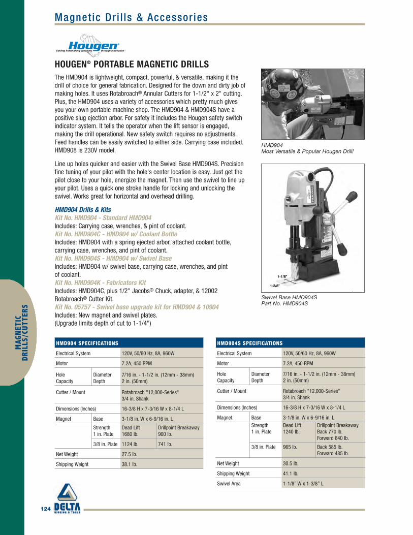
124
MAG
NET
ICD
RILL
S/CU
TTER
SMagnet ic Dr i l ls & Accessor ies
HOUGEN® PORTABLE MAGNETIC DRILLSThe HMD904 is lightweight, compact, powerful, & versatile, making it thedrill of choice for general fabrication. Designed for the down and dirty job ofmaking holes. It uses Rotabroach® Annular Cutters for 1-1/2" x 2" cutting.Plus, the HMD904 uses a variety of accessories which pretty much givesyou your own portable machine shop. The HMD904 & HMD904S have apositive slug ejection arbor. For safety it includes the Hougen safety switchindicator system. It tells the operator when the lift sensor is engaged,making the drill operational. New safety switch requires no adjustments.Feed handles can be easily switched to either side. Carrying case included.HMD908 is 230V model.
Line up holes quicker and easier with the Swivel Base HMD904S. Precisionfine tuning of your pilot with the hole's center location is easy. Just get thepilot close to your hole, energize the magnet. Then use the swivel to line upyour pilot. Uses a quick one stroke handle for locking and unlocking theswivel. Works great for horizontal and overhead drilling.
HMD904 Drills & KitsKit No. HMD904 - Standard HMD904 Includes: Carrying case, wrenches, & pint of coolant.Kit No. HMD904C - HMD904 w/ Coolant Bottle Includes: HMD904 with a spring ejected arbor, attached coolant bottle,carrying case, wrenches, and pint of coolant.Kit No. HMD904S - HMD904 w/ Swivel BaseIncludes: HMD904 w/ swivel base, carrying case, wrenches, and pint of coolant.Kit No. HMD904K - Fabricators Kit Includes: HMD904C, plus 1/2" Jacobs® Chuck, adapter, & 12002Rotabroach® Cutter Kit.Kit No. 05757 - Swivel base upgrade kit for HMD904 & 10904 Includes: New magnet and swivel plates.(Upgrade limits depth of cut to 1-1/4")
HMD904 SPECIFICATIONS
Electrical System 120V, 50/60 Hz, 8A, 960W
Motor 7.2A, 450 RPM
HoleCapacity
DiameterDepth
7/16 in. - 1-1/2 in. (12mm - 38mm)2 in. (50mm)
Cutter / Mount Rotabroach "12,000-Series"3/4 in. Shank
Dimensions (Inches) 16-3/8 H x 7-3/16 W x 8-1/4 L
Magnet Base 3-1/8 in. W x 6-9/16 in. L
Strength1 in. Plate
Dead Lift 1680 lb.
Drillpoint Breakaway900 lb.
3/8 in. Plate 1124 lb. 741 lb.
Net Weight 27.5 lb.
Shipping Weight 38.1 lb.
HMD904S SPECIFICATIONS
Electrical System 120V, 50/60 Hz, 8A, 960W
Motor 7.2A, 450 RPM
HoleCapacity
DiameterDepth
7/16 in. - 1-1/2 in. (12mm - 38mm) 2 in. (50mm)
Cutter / Mount Rotabroach "12,000-Series" 3/4 in. Shank
Dimensions (Inches) 16-3/8 H x 7-3/16 W x 8-1/4 L
Magnet Base 3-1/8 in. W x 6-9/16 in. LStrength1 in. Plate
Dead Lift1240 lb.
Drillpoint BreakawayBack 770 lb.Forward 640 lb.
3/8 in. Plate 965 lb. Back 585 lb.Forward 485 lb.
Net Weight 30.5 lb.
Shipping Weight 41.1 lb.
Swivel Area 1-1/8” W x 1-3/8” L
Swivel Base HMD904SPart No. HMD904S
HMD904Most Versatile & Popular Hougen Drill!
Hougen_p123-137 final.qxd 4/5/10 11:53 AM Page 124

125
MAGN
ETICD
RILLS/CUTTERSMagnet ic Dr i l ls & Accessor ies
HOUGEN® PORTABLE MAGNETIC DRILLSHMD925 POWER FEED
Take the effort out of holemaking with the powerfeed HMD925. With exceptional performance andreliability, it uses Rotabroach
®Annular Cutters to
produce holes from 7/16" to 1-1/4" diameter thrumaterials up to 2" thick in power feed mode. TheHMD925 is compact and lightweight at only 37 lbs.The HMD925 incorporates smart technology thatmonitors and adjusts the self-feed action tocontinuously maintain optimum drilling performancethroughout the cut, providing consistent productivity,long tool life and excellent hole quality. HMD928 is230V model.
HMD914
The HMD914 is the long standing powerful andversatile workhorse that offers a built in 16 oz.gravity feed coolant bottle. This model powersthrough holes up to 2-1/16" diameter and 3" deepwithout bogging down. Making the drill even betterare the many accessories available. Hougen® safetyfeatures include the lift detector, and the noadjustment safety switch. LED indicator is built in tothe control panel. Equipped with positive slugejection. HMD909 is 230V model.
HMD914K Fabricator's KitIncludes HMD914 w/ Carrying Case, Jacobs® Chuck,Adapter, & 12002 Rotabroach® Cutter Kit
HMD925 New Improved Control Panel
HMD925 SPECIFICATIONS
Electrical System 120V, 50/60 Hz, 8A, 960W
Motor 7.2A, 450 RPM
ManualCapacity
DiameterDepth
7/16 in. - 1-1/2 in. (12mm - 38mm)2 in. (50mm)
7/16 in. - 1-1/4 in. (12mm - 32mm)2 in. (50mm)
Power FeedCapacity
DiameterDepth
Cutter / Mount Rotabroach "12,000-Series"3/4 in. Shank
Dimensions (Inches) 17-1/8 H x 10-13/16 W x 11-3/16 L
Magnet Base 3-1/8 W x 6-9/16 L
Strength1 in. Plate
Dead Lift 1680 lb.
Drillpoint Breakaway900 lb.
3/8 in. Plate 1124 lb. 741 lb.
Net Weight 37 lb.
Shipping Weight Approx. 47 lb.
HMD914 SPECIFICATIONS
Electrical System 120V, 50/60 Hz, 11.2A, 1344W
Motor 10.5A, 350 RPM
HoleCapacity
DiameterDepth
7/16 in. - 2-1/16 in. (12mm - 52mm)3 in. (76mm)
Cutter / Mount Rotabroach "12,000-Series"3/4 in. Shank
Dimensions (Inches) 20-1/2 H x 8-3/16 W x 13-3/4 L
Magnet Base 3-1/2 W x 7 L
Strength1 in. Plate
Dead Lift 2500 lb.
Drillpoint Breakaway1065 lb.
3/8 in. Plate 1400 lb. 880 lb.
Net Weight 44 lb.
Shipping Weight 53.3 lb.
HMD925 Power Feed
HMD914Variety of AccessoriesAvailable
HMD914
Hougen_p123-137 final.qxd 4/5/10 11:53 AM Page 125
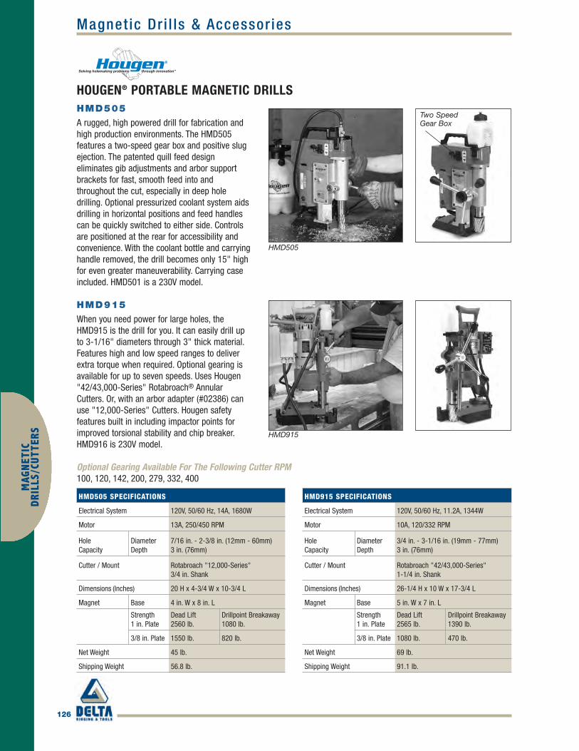
126
MAG
NET
ICD
RILL
S/CU
TTER
SMagnet ic Dr i l ls & Accessor ies
HOUGEN® PORTABLE MAGNETIC DRILLSHMD505
A rugged, high powered drill for fabrication andhigh production environments. The HMD505features a two-speed gear box and positive slugejection. The patented quill feed designeliminates gib adjustments and arbor supportbrackets for fast, smooth feed into andthroughout the cut, especially in deep holedrilling. Optional pressurized coolant system aidsdrilling in horizontal positions and feed handlescan be quickly switched to either side. Controlsare positioned at the rear for accessibility andconvenience. With the coolant bottle and carryinghandle removed, the drill becomes only 15" highfor even greater maneuverability. Carrying caseincluded. HMD501 is a 230V model.
HMD915
When you need power for large holes, theHMD915 is the drill for you. It can easily drill upto 3-1/16" diameters through 3" thick material.Features high and low speed ranges to deliverextra torque when required. Optional gearing isavailable for up to seven speeds. Uses Hougen"42/43,000-Series" Rotabroach® AnnularCutters. Or, with an arbor adapter (#02386) canuse "12,000-Series" Cutters. Hougen safetyfeatures built in including impactor points forimproved torsional stability and chip breaker.HMD916 is 230V model.
Optional Gearing Available For The Following Cutter RPM100, 120, 142, 200, 279, 332, 400
HMD505
HMD915
HMD505 SPECIFICATIONS
Electrical System 120V, 50/60 Hz, 14A, 1680W
Motor 13A, 250/450 RPM
HoleCapacity
DiameterDepth
7/16 in. - 2-3/8 in. (12mm - 60mm) 3 in. (76mm)
Cutter / Mount Rotabroach "12,000-Series"3/4 in. Shank
Dimensions (Inches) 20 H x 4-3/4 W x 10-3/4 L
Magnet Base 4 in. W x 8 in. L
Strength1 in. Plate
Dead Lift2560 lb.
Drillpoint Breakaway1080 lb.
3/8 in. Plate 1550 lb. 820 lb.
Net Weight 45 lb.
Shipping Weight 56.8 lb.
HMD915 SPECIFICATIONS
Electrical System 120V, 50/60 Hz, 11.2A, 1344W
Motor 10A, 120/332 RPM
HoleCapacity
DiameterDepth
3/4 in. - 3-1/16 in. (19mm - 77mm) 3 in. (76mm)
Cutter / Mount Rotabroach "42/43,000-Series"1-1/4 in. Shank
Dimensions (Inches) 26-1/4 H x 10 W x 17-3/4 L
Magnet Base 5 in. W x 7 in. L
Strength1 in. Plate
Dead Lift 2565 lb.
Drillpoint Breakaway1390 lb.
3/8 in. Plate 1080 lb. 470 lb.
Net Weight 69 lb.
Shipping Weight 91.1 lb.
Two SpeedGear Box
Hougen_p123-137 final.qxd 4/5/10 11:53 AM Page 126

127
MAGN
ETICD
RILLS/CUTTERSMagnet ic Dr i l ls & Accessor ies
HOUGEN® MAGNETIC DRILL ACCESSORIES
Vac-Pad™ works with ModelsHMD904 and HMD925 on non-ferrous materials, diamond plate andmaterials with surface imperfectionsup to 3mm deep. Standard shop airprovides 761 lbf surface holdingpower at 85 kpa. Safety switch shutsoff drill motor if air pressure drops.
With the RotaLoc™ Spindle Adapteryou can take advantage of the fastchange out of RotaLoc™ or RotaLocPlus™ Annular Cutters in virtually allHougen® Portable Magnetic Drills orany other drill that also acceptsRotabroach® "12,000-Series"Cutters.
When extended reach is necessary,Hougen offers 1" and 2" ArborExtenders with a 1.310" outsidediameter that fit arbors usingRotabroach® "12,000-Series"Cutters. Contact Hougen’s CustomerService Department for moreinformation about how the ArborExtenders may help in yourapplication.
1/2" Chuck requires 05536 SpindleAdapter for Model HMD904 andHMD925. Model HMD914 requiresSpindle Adapter 40341 for eitherchuck size.
These kits let you drill pipe andtubing with a minimum 3" diameterand some convex surfaces. Kitsquickly attach to your Hougen®
Magnetic Drill and positive non-slippositioning assures centered holelocation.*Minimum 3" dia. schedule 160,maximum 12" dia. schedule 160.
VAC-PAD™
Part No. Description
05000 Vacuum Base Attachment
ROTALOC™ SPINDLE ADAPTER
Part No. Description
17680 RotaLoc Adapter Assembly
04778 Replacement Adapter
04780 Replacement Pilot
ARBOR EXTENDERS
Part No. Description
10100 1 in Arbor Extender Assembly
10200 2 in Arbor Extender Assembly
PIPE ADAPTER KIT
Part No. Description
02564* Chain Mount for use withHMD904, HMD914 & HMD505
10726 Bracket Mount for use withHMD915 & HMD916
DRILL CHUCKS
Part No. Description
10731 1/2 in. Low Buck Chuck with Key(HMD904 & HMD914)
10737 5/8 in. Low Buck Chuck with Key(HMD914 )
10732 1/2 in. Jacobs® Chuck with Key(HMD904 & HMD914)
10738 5/8 in. Jacobs® Chuck with Key(HMD914 )
82º CARBIDE-INSERT COUNTERSINK KIT
Part No. Description
12965 (1) 82° Countersink (double fluted)with carbide inserts, (4) Pilots -9/16 in., 11/16 in., 13/16 in., 15/16in., plus a Torx Wrench
12960 9/16 in. Pilot
12961 11/16 in. Pilot
12962 13/16 in. Pilot
12963 15/16 in. Pilot
12966 Countersink Ass’y w/Carbide Inserts
05465 Replacement Torx Wrench
05467 Carbide Inserts (10 pieces)
Hougen_p123-137 final.qxd 4/5/10 11:53 AM Page 127

128
MAG
NET
ICD
RILL
S/CU
TTER
SMagnet ic Dr i l ls & Accessor ies
ARBORS FOR STATIONARY TOOLSYou can also use Rotabroach® Cutters with stationary tools and drill presses. Triple flatted shank fits 1/2" drill chucks.Uses 1" depth of cut "12,000-Series" Cutters for materials up to 1/2" thick maximum.
PART NO. DESCRIPTION
11016 Arbor Assembly (with set screws and spring) for 3/4 in.Shank Cutters up to 1/2 in. D.O.C.
Optional & Replacement Arbor Parts11041 Arbor Body11054 1/4-28 Soc. Hd. Cap Screw11069 Ejector Spring40222 7/16-14 Soc. Hd. Cap ScrewPilots11022 Starter Pilot for 7/16 in. &
12mm Dia. Cutters11023 Piercer Pilot for 7/16 in. &
12mm Dia. Cutters11024 Piercer Pilot for 3/4 in.- 2-1/16 in. & 19mm-
52mm Dia. Cutters11031 Starter Pilot for 3/4 in.- 2-1/16 in. & 19mm-
52mm Dia. Cutters11032 Starter Pilot for 1/2 in.-11/16 in. & 13mm-18mm
Dia. Cutters11033 Piercer Pilot for 1/2 in.-11/16 in. & 13mm-18mm
Dia. Cutters
ARBORS FOR MACHINE TOOLSConvert CNC machines such as drill presses or mills into fast hole makers. 3 styles of holders, R-8, Straight, and Morsetaper accommodate "12,000-Series" Cutters.
PART NO. SHANK HOLE CAPACITYSIZE DIAMETER (IN.) DEPTH (IN.)
Arbor Assembly with Oil Inducer
10804 #2 Morse 1 1-1/2
10806 #3 Morse 2-3/8 1-1/2
49849 R8 2-3/8 2
49850 1” Straight 2-3/8 2
Arbor Assembly without Oil Inducer
10814 #2 Morse 1 1-1/2
10816 #3 Morse 2-3/8 1-1/2
49853 R8 2-3/8 2
49851 1" Straight 2-3/8 2
Arbors with Coolant Inducers Pictured
#2 Morse
#3 Morse
R8
Straight
Hougen_p123-137 final.qxd 4/5/10 11:53 AM Page 128

ROTABROACH®
129
MAGN
ETICD
RILLS/CUTTERS
CUTTER DIA. DECIMAL PART NO.(METRIC) EQUIVALENT 1" D.O.C. 2" D.O.C. 3" D.O.C.
Use with Pilot 10531 1053212mm .4724 12312 12412 ----Use with Pilot 10533 1053413mm .5118 12313 12413 ----14mm .5512 12314 12414 ----15mm .5906 12315 12415 ----16mm .6299 12316 12416 ----17mm .6693 12317 12417 ----18mm .7087 12318 12418 ----Use with Pilot 10527 10528 24131
19mm .7480 12319 12419 1251920mm .7874 12320 12420 1252021mm .8268 12321 12421 1252122mm .8661 12322 12422 1252223mm .9055 12323 12423 1252324mm .9449 12324 12424 1252425mm .9843 12325 12425 1252526mm 1.0236 12326 12426 1252627mm 1.0630 12327 12427 1252728mm 1.1024 12328 12428 1252829mm 1.1417 12329 12429 1252930mm 1.1811 12330 12430 1253031mm 1.2205 12331 12431 1253132mm 1.2598 12332 12432 1253233mm 1.2992 12333 12433 1253334mm 1.3386 12334 12434 1253435mm 1.3779 12335 12435 1253536mm 1.4173 12336 12436 1253637mm 1.4567 12337 12437 1253738mm 1.4961 12338 12438 1253839mm 1.5354 12339 12439 1253940mm 1.5743 12340 12440 1254041mm 1.6142 12341 12441 1254142mm 1.6535 12342 12442 1254243mm 1.6929 12343 12443 1254344mm 1.7323 12344 12444 1254445mm 1.7717 12345 12445 1254546mm 1.8110 12346 12446 1254647mm 1.8504 12347 12447 1254748mm 1.8898 12348 12448 1254849mm 1.9291 12349 12449 1254950mm 1.9685 12350 12450 1255051mm 2.0079 12351 12451 12551 52mm 2.0472 12352 12452 12552
CUTTER DIA. DECIMAL PART NO.(INCHES) EQUIVALENT 1" D.O.C. 2" D.O.C. 3" D.O.C.Use with Pilot 10531 105327/16 .4375 12114 12214 ----Use with Pilot 10533 105341/2 .5000 12116 12216 ---- 9/16 .5625 12118 12218 ---- 5/8 .6250 12120 12220 ---- 11/16 .6875 12122 12222 ----Use with Pilot 10527 10528 241313/4 .7500 12124 12224 3-1222413/16 .8125 12126 12226 3-122267/8 .8750 12128 12228 3-1222815/16 .9375 12130 12230 3-122301 1.0000 12132 12232 3-122321-1/16 1.0625 12134 12234 3-122341-1/8 1.1250 12136 12236 3-122361-3/16 1.1875 12138 12238 3-122381-1/4 1.2500 12140 12240 3-122401-5/16 1.3125 12142 12242 3-122421-3/8 1.3750 12144 12244 3-122441-7/16 1.4375 12146 12246 3-122461-1/2 1.5000 12148 12248 3-122481-9/16 1.5625 12150 12250 3-122501-5/8 1.6250 12152 12252 3-122521-11/16 1.6875 12154 12254 3-122541-3/4 1.7500 12156 12256 3-122561-13/16 1.8125 12158 12258 3-122581-7/8 1.8750 12160 12260 3-122601-15/16 1.9375 12162 12262 3-122622 2.0000 12164 12264 3-122642-1/16 2.0625 ---- 12266 ----2-1/8 2.1250 ---- 12268 ----2-3/16 2.1875 ---- 12270 ----2-1/4 2.2500 ---- 12272 ----2-5/16 2.3125 ---- 12274 ----2-3/8 2.3750 ---- 12276 ----
Annular Cutters / P i lots
ROTABROACH® "12,000-SERIES" ANNULAR CUTTERSFor use with Hougen® Portable Magnetic Drills and many competitive models on materials up to 275 BHN. They are made ofhardened high speed tool steel and are precision ground for excellent performance throughout the cut and long tool life. Theyrequire less horsepower and thrust to cut, and last much longer than traditional holemaking methods. Rotabroach® cuttersfeature a 3/4" diameter double-flatted shank and are available in1, 2, and 3" D.O.C. Modified endtooth geometry is also availablefor drilling in stacked plateapplications. For extended tool lifeand lower cost per holeRotabroach® Cutters areresharpenable.
Hougen_p123-137 final.qxd 4/5/10 11:53 AM Page 129

130
MAG
NET
ICD
RILL
S/CU
TTER
SAnnular Cutters / P i lots
ROTABROACH® CUTTERSROTABROACH® M2 CUTTERS TiN COATED
Rotabroach® cutters with TiN Coating increase tool life, reduce friction, and operate at cooler temperatures. For materialsup to 325 BHN or gummy materials.
ROTABROACH® M42PREMIUM CUTTERS
Rotabroach® Premium Steel Cutters with TiNCoating extend tool life, reduce friction, andoperate at cooler temperatures. They're madefrom M42 high speed steel for cuttingmaterials up to 350 BHN or gummy materials.These tools are specifically designed to staycool throughout the cut. For materials up to 2" thick.
SHARPENING MACHINE
The Model 10950 Sharpening Machine has been specifically designed for resharpeningRotabroach®, RotaLoc™, and RotaLoc Plus™Annular Cutters. It provides ease of operationwhile restoring factory specified tooth geometry.• 110-120V, 2.5 Amps, max. 26,000 RPM,
double insulated motor with spindle lock.• Improved holders and fasteners allow easier
changes and tool sharpening.• Holder bushing is more accurate for precise tooth height.
CUTTER DIA. DECIMAL PART NO.(INCHES) EQUIV. 1" D.O.C. 2" D.O.C.Use with Pilot 10531 105327/16 .4375 12614 12714Use with Pilot 10533 105341/2 .5000 12616 127169/16 .5625 12618 127185/8 .6250 12620 1272011/16 .6875 12622 12722Use with Pilot 10527 105283/4 .7500 12624 1272413/16 .8125 12626 127267/8 .8750 12628 1272815/16 .9375 12630 127301 1.0000 12632 12732
CUTTER DIA. DECIMAL PART NO.(INCHES) EQUIV. 1" D.O.C. 2" D.O.C.Use with Pilot 10527 105281-1/16 1.0625 12634 127341-1/8 1.1250 12636 127361-3/16 1.1875 12638 127381-1/4 1.2500 12640 127401-5/16 1.3125 12642 127421-3/8 1.3750 12644 127441-7/16 1.4375 12646 127461-1/2 1.5000 12648 127481-9/16 1.5625 12650 127501-5/8 1.6250 12652 127521-11/16 1.6875 12654 127541-3/4 1.7500 12656 127561-13/16 1.8125 12658 127581-7/8 1.8750 12660 127601-15/16 1.9375 12662 127622 2.0000 12664 127642-1/16 2.0625 ---- 127662-1/8 2.1250 ---- 127682-3/16 2.1875 ---- 127702-1/4 2.2500 ---- 127722-5/16 2.3125 ---- 127742-3/8 2.3750 ---- 12776
CUTTER DIA.(INCHES)
DECIMALEQUIV.
PART NO.
Use with Pilot 105287/8 .8750 0135415/16 .9375 013551 1.0000 013561-1/16 1.0625 013571-1/8 1.1250 013581-3/16 1.1875 013591-1/4 1.2500 013601-5/16 1.3125 013611-3/8 1.3750 013621-7/16 1.4375 013631-1/2 1.5000 01364
PART NO. DESCRIPTION10950 Sharpening Machine03983 Borazon® Cup Wheel04049 Tool holder - “12,000-Series”04072 Borazon Gullet Wheel10747 Dressing Stick10779 7/32" Hex Wrench for #04049Optional Accessories04147 Tool Holder - RotaLoc™ Cutters04118 Work Stand
Hougen_p123-137 final.qxd 4/5/10 11:53 AM Page 130

131
MAGN
ETICD
RILLS/CUTTERSAnnular Cutters / P i lots
COPPERHEAD™ CARBIDE TIP CUTTERSCopperhead™ Carbide Tip Cutters feature a brazed-in durable grade carbide insert for extended tool life when used withHougen® Mag Drills on abrasive and tough-to-cut materials and applications. The unique Hougen design also includes aspecial tool geometry that helps maintain better chip flow than other brands. All diameters in 2" D.O.C.
CUTTER DIA.(METRIC)
DECIMALEQUIV.
PART NO.
Use with Pilot 1053014mm .5512 1841415mm .5906 1841516mm .6299 1841618mm .7087 1841820mm .7874 1842022mm .8661 1842224mm .9449 1842425mm .9843 1842526mm 1.0236 1842628mm 1.1024 1842830mm 1.1811 1843032mm 1.2598 1843234mm 1.3386 1843436mm 1.4173 1843638mm 1.4961 1843840mm 1.5743 18440
CUTTER DIA.(INCHES)
DECIMALEQUIV.
PART NO.
Use with Pilot 105309/16 .5625 1821811/16 .6875 1822213/16 .8125 182267/8 .8750 1822815/16 .9375 182301 1.0000 182321-1/16 1.0625 182341-1/8 1.1250 182361-3/16 1.1875 182381-1/4 1.2500 182401-5/16 1.3125 182421-3/8 1.3750 182441-1/2 1.5000 18248
KIT NO. DESCRIPTION
18002 Fractional Kit contains (5) cutters,9/16", 11/16", 13/16", 15/16" 1-1/16”, 2 Pilots & Hex Wrenches
18004 Metric Kit contains (5) cutters,14, 16, 18, 20, & 22mm, 2 Pilots &Hex Wrenches
Hougen_p123-137 final.qxd 4/5/10 11:54 AM Page 131

132
MAG
NET
ICD
RILL
S/CU
TTER
SAnnular Cutters / P i lots
ROTALOC™ & ROTALOC PLUS™ ANNULAR CUTTERS AND KITSRotaLoc™ Annular Cutters are designed for use with the Hougen®
HMD115 Ultra-Low Profile Truck Frame Drill. They're made of M42high speed steel and feature Stack Cut geometry for penetratingmultiple plates in a single pass, up to 3/4" depth of cut. RotaLocPlus™ Annular Cutters are designed for the Hougen® HMD150 LowProfile Drill. They're made of M2 high speed steel and are designedfor a full 1" D.O.C. Both series feature a bayonet-style shankmounting for fast change out, with no other tools required to install inthe drill spindle, and can be as easily removed. For optimum cuttertool life and cutter efficiency use Hougen® Slick-Stik™ Lubricant.
CUTTER DIA.(INCHES)
DECIMALEQUIV.
PART NO.
Use with Pilot 174701/2 .5000 172169/16 .5625 172185/8 .6250 1722011/16 .6875 172223/4 .7500 1722413/16 .8125 172267/8 .8750 1722815/16 .9375 172301 1.0000 172321-1/16 1.0625 172341-1/8 1.1250 172361-3/16 1.1875 172381-1/4 1.2500 172401-5/16 1.3125 172421-3/8 1.3750 17244CUTTER DIA.(METRIC)
DECIMALEQUIV. PART NO.
Use with Pilot 1747012mm .4724 1740013mm .5118 1740214mm .5512 1740415mm .5906 1740616mm .6299 1740817mm .6693 1741018mm .7087 1741219mm .7480 1741420mm .7874 1741621mm .8268 1741822mm .8661 1742023mm .9055 1742224mm .9449 1742424.5mm .9645 1742525mm .9843 1742626mm 1.0236 1742827mm 1.0630 1743028mm 1.1024 1743229mm 1.1417 1743430mm 1.1811 1743631mm 1.2205 1743832mm 1.2598 1744033mm 1.2992 1744234mm 1.3386 1744435mm 1.3779 17446
ROTALOC PLUS™ANNULAR CUTTERSM2 HSS-1" D.O.C.
CUTTER DIA.(INCHES)
DECIMALEQUIV.
PART NO.
Use with Pilot 17100 or 171011/2 .5000 171169/16 .5625 171185/8 .6250 1712011/16 .6875 171223/4 .7500 1712413/16 .8125 171267/8 .8750 1712815/16 .9375 171301 1.0000 171321-1/16 1.0625 17134CUTTER DIA.(METRIC)
DECIMALEQUIV.
PART NO.
Use with Pilot 17100 or 1710112mm .4724 1730013mm .5118 1730214mm .5512 1730415mm .5906 1730616mm .6299 1730817mm .6693 1731018mm .7087 1731219mm .7480 1731420mm .7874 1731621mm .8268 1731822mm .8661 1732023mm .9055 1732224mm .9449 1732424.5mm .9645 1732525mm .9843 1732626mm 1.0236 1732827mm 1.0630 17330
ROTALOC™ ANNULARCUTTERS M42 HSS-3/4"D.O.C. - STACK CUT
KIT NO. DESCRIPTIONFor HMD115 and HMD150
17001 Kit contains (10) cutters, 3/4" D.O.C. -1/2, 9/16, 5/8, 11/16, 3/4, 13/16,7/8, 15/16, 1 & 1-1/16" dia, plus (2) Pilots in a sturdy plastic case.
17700 Kit contains (3) cutters, 3/4" D.O.C. -1/2, 5/8, 3/4" dia, plus (3) Pilots in a sturdy plastic case.
17701 Kit contains (3) cutters, 3/4" D.O.C.-9/16, 11/16, 13/16" dia, plus (3)Pilots in a sturdy plastic case.
17704 Kit contains (3) cutters, 3/4" D.O.C.-13mm, 15mm, 18mm dia, plus (3)Pilots in a sturdy plastic case.
For HMD150
17800 Kit contains (3) cutters, 1" D.O.C. -1/2, 5/8, 3/4" dia, plus (3) Pilots in a sturdy plastic case.
17801 Kit contains (3) cutters, 1" D.O.C. -9/16, 11/16, 13/16" dia, plus (3)Pilots in a sturdy plastic case.
17804 Kit contains (3) cutters, 1" D.O.C. -14mm, 16mm, 18mm dia, plus (3)Pilots in a sturdy plastic case.
ROTALOC™ &ROTALOC PLUS™CUTTER KITS
PART NO. DESCRIPTION17100 Standard Pilot for HMD11517101 Spring Ejection Pilot for HMD11517470 For use with HMD150
ROTALOC™ & ROTALOCPLUS™ PILOTS
Hougen_p123-137 final.qxd 4/5/10 11:54 AM Page 132

133
MAGN
ETICD
RILLS/CUTTERSAnnular Cutters / P i lots
ROTABROACH® "42/43,000-SERIES" ANNULAR CUTTERSYou can produce holes up to 3-1/16" diameter thru 3" material with the Hougen® HMD915 portable magnetic drill using Rotabroach®
"42/43,000-Series" Annular Cutters. The heavy duty "42/43,000-Series"Annular Cutters handle the most demanding hole production jobs requiring portability for drilling large, deep holes. "42,000-Series" Cuttersfeature a 3/4" or 1-1/4" Weldon Shank mounting (depending on cutterdiameter) which also provides for convenient use in stationary machine tools.
For added wear resistance, Hougen® also offers the TiN coated"22/23,000-Series" Annular Cutters, with the same features as the"42/43,000-Series" Cutters but for use on materials up to 325 BHN.Modified end tooth geometry for drilling stacked plate is available uponrequest. Intermediate sizes can be made available as "grind downs" fromthe next larger size. Maximum grind down varies from 0.010" to 0.020" off the initial diameter. Consult Hougen Technical Service for details.
CUTTER DIA. DECIMAL PART NO.(INCHES) EQUIV. M2 M2 TiN COATED3/4" Weldon Shank - 2" D.O.C.3/4 .7500 42024 2202413/16 .8125 42026 220267/8 .8750 42028 2202815/16 .9375 42030 220301 1.0000 42032 220321-1/16 1.0625 42034 220341-1/8 1.1250 42036 220361-3/16 1.1875 42038 220381-1/4 1.2500 42040 220401-5/16 1.3125 42042 220421-3/8 1.3750 42044 220441-7/16 1.4375 42046 220461-1/4" Weldon Shank - 2" D.O.C.1-1/2 1.5000 42048 220481-9/16 1.5625 42050 220501-5/8 1.6250 42052 220521-11/16 1.6875 42054 220541-3/4 1.7500 42056 220561-13/16 1.8125 42058 220581-7/8 1.8750 42060 220601-15/16 1.9375 42062 220622 2.0000 42064 220641-1/4" Weldon Shank - 3" D.O.C.2-1/16 2.0625 43066 230662-1/8 2.1250 43068 230682-3/16 2.1875 43070 230702-1/4 2.2500 43072 230722-5/16 2.3125 43074 230742-3/8 2.3750 43076 230762-7/16 2.4375 43078 230782-1/2 2.5000 43080 230802-9/16 2.5625 43082 230822-5/8 2.6250 43084 230842-11/16 2.6875 43086 230862-3/4 2.7500 43088 230882-13/16 2.8125 43090 230902-7/8 2.8750 43092 230922-15/16 2.9375 43094 230943 3.0000 43096 230963-1/16 3.0625 43098 23098
ROTABROACH®
42/43,000-Series - M2 HSS22/23,000-Series - M2 HSS TiN Coated
Hougen_p123-137 final.qxd 4/5/10 11:54 AM Page 133

134
Annular Cutters / P i lotsM
AGN
ETIC
DRI
LLS/
CUTT
ERS
ROTACUT™ SHEET METALHOLE CUTTERSHolemaking – faster and easier than withconventional twist drills and hole saws – insheet metal, plate materials, and plastics upto 1/2" thick. RotaCut™ Cutters areprecision-ground and produce clean, burr-free, round holes without deforming thesurrounding material. For use in hand helddrills with either 3/8" or 1/2" diameterchucks, and in air feed drill spindles forproduction work. Cutters last 10x longer andcut 3x faster than twist drills or hole saws.
CUTTER DIA.(METRIC)
DECIMALEQUIV. PART NO.
3/8"-24 Thread Mount & 1/4" D.O.C.Use with Arbor 11088 or 110066mm .2362 112067mm .2756 112078mm .3150 112089mm .3543 11209Use with Arbor 11088, 11089, or 1100610mm .3937 1121011mm .4331 1121112mm .4724 1121213mm .5118 1121314mm .5512 1121415mm .5906 1121516mm .6299 1121617mm .6693 1121718mm .7087 1121819mm .7480 1121920mm .7874 112201/2"-20 Thread Mount & 1/2" D.O.C.Use with Arbor 11005 or 1101221mm .8268 1122122mm .8661 1122223mm .9055 1122324mm .9449 1122425mm .9843 11225
ROTACUT™ KITSHougen® offers kits packaged insturdy cases for keeping handy themost often used sizes of RotaCut™Annular Cutters. They help keepcutters easy to find and protect thecutting edges from damage.
PART NO. DESCRIPTION
11075CKit contains an 11088 Arbor Assembly,Center Punch, extra Pilot, and (7) Cutters:5/16, 3/8, 7/16, 1/2, 9/16, 5/8, & 3/4 in.
11075-12 Contains (12) 11075 Kits in a pop up display box
11077 Kit contains an 11088 Arbor Assembly,Center Punch, extra Pilot, and (7) MetricCutters: 8, 10, 12, 14, 16, 18, & 20mm
11078 Kit contains an 11005 Arbor Assembly,Center Punch, extra Pilot, and (6) Cutters:7/8, 1, 1-1/8, 1-1/4, 1-3/8, & 1-1/2 in.
CUTTER DIA.(INCHES)
DECIMALEQUIV. PART NO.
3/8"-24 Thread Mount & 1/4" D.O.C.Use with Arbor 11088 or 110061/4 .2500 111009/32 .2812 111025/16 .3125 1110411/32 .3438 11106Use with Arbor 11088, 11089, or 110063/8 .3750 1110813/32 .4062 1111027/64 .4219 111117/16 .4375 1111215/32 .4688 111141/2 .5000 1111617/32 .5312 111189/16 .5625 111205/8 .6250 1112411/16 .6875 1112823/32 .7188 111303/4 .7500 111321/2"-20 Thread Mount & 1/2" D.O.C.Use with Arbor 11005 or 1101213/16 .8125 111367/8 .8750 1114015/16 .9375 111441 1.0000 111481-1/16 1.0625 111521-1/8 1.1250 111561-3/16 1.1875 111601-1/4 1.2500 111641-5/16 1.3125 111651-3/8 1.3750 111661-7/16 1.4375 111671-1/2 1.5000 11168
ROTACUT™ SPOTWELD CUTTERRemove spotwelds in auto body andrestoration work quickly with theRotaCut™ Premium Spotweld Cutter.Heavy cutter wall and fast cuttingaction that can last for hundreds orthousands of spotwelds.
PART NO. DESCRIPTION
11200C Package includes 3/8 in. RotaCut p/n 11108, Arbor p/n 11088, and instructions.
Compare the Quality
RotaCut™ • Hole Saw • Twist Drill
Hougen_p123-137 final.qxd 4/5/10 11:54 AM Page 134
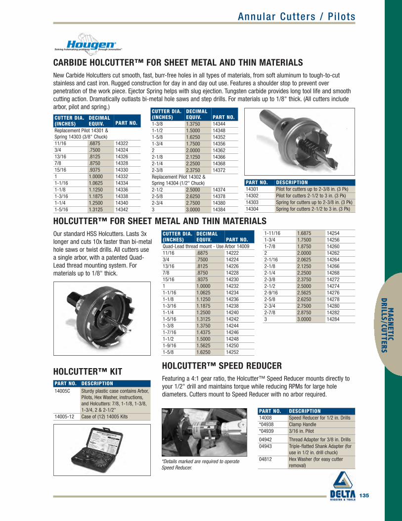
Annular Cutters / P i lots
135
MAGN
ETICD
RILLS/CUTTERS
CARBIDE HOLCUTTER™ FOR SHEET METAL AND THIN MATERIALSNew Carbide Holcutters cut smooth, fast, burr-free holes in all types of materials, from soft aluminum to tough-to-cutstainless and cast iron. Rugged construction for day in and day out use. Features a shoulder stop to prevent overpenetration of the work piece. Ejector Spring helps with slug ejection. Tungsten carbide provides long tool life and smoothcutting action. Dramatically outlasts bi-metal hole saws and step drills. For materials up to 1/8" thick. (All cutters includearbor, pilot and spring.)
CUTTER DIA.(INCHES)
DECIMALEQUIV. PART NO.
Replacement Pilot 14301 & Spring 14303 (3/8" Chuck)11/16 .6875 143223/4 .7500 1432413/16 .8125 143267/8 .8750 1432815/16 .9375 143301 1.0000 143321-1/16 1.0625 143341-1/8 1.1250 143361-3/16 1.1875 143381-1/4 1.2500 143401-5/16 1.3125 14342
PART NO. DESCRIPTION14301 Pilot for cutters up to 2-3/8 in. (3 Pk)14302 Pilot for cutters 2-1/2 to 3 in. (3 Pk)14303 Spring for cutters up to 2-3/8 in. (3 Pk)14304 Spring for cutters 2-1/2 to 3 in. (3 Pk)
CUTTER DIA.(INCHES)
DECIMALEQUIV. PART NO.
1-3/8 1.3750 143441-1/2 1.5000 143481-5/8 1.6250 143521-3/4 1.7500 143562 2.0000 143622-1/8 2.1250 143662-1/4 2.2500 143682-3/8 2.3750 14372Replacement Pilot 14302 & Spring 14304 (1/2" Chuck)2-1/2 2.5000 143742-5/8 2.6250 143782-3/4 2.7500 143803 3.0000 14384
HOLCUTTER™ FOR SHEET METAL AND THIN MATERIALSOur standard HSS Holcutters. Lasts 3xlonger and cuts 10x faster than bi-metalhole saws or twist drills. All cutters use a single arbor, with a patented Quad-Lead thread mounting system. Formaterials up to 1/8" thick.
1-11/16 1.6875 142541-3/4 1.7500 142561-7/8 1.8750 142602 2.0000 142622-1/16 2.0625 142642-1/8 2.1250 142662-1/4 2.2500 142682-3/8 2.3750 142722-1/2 2.5000 142742-9/16 2.5625 142762-5/8 2.6250 142782-3/4 2.7500 142802-7/8 2.8750 142823 3.0000 14284
HOLCUTTER™ KITPART NO. DESCRIPTION14005C Sturdy plastic case contains Arbor,
Pilots, Hex Washer, instructions,and Holcutters: 7/8, 1-1/8, 1-3/8,1-3/4, 2 & 2-1/2"
14005-12 Case of (12) 14005 Kits
HOLCUTTER™ SPEED REDUCERFeaturing a 4:1 gear ratio, the Holcutter™ Speed Reducer mounts directly toyour 1/2" drill and maintains torque while reducing RPMs for large holediameters. Cutters mount to Speed Reducer with no arbor required.
PART NO. DESCRIPTION14008 Speed Reducer for 1/2 in. Drills*04938 Clamp Handle*04939 3/16 in. Pilot
04942 Thread Adapter for 3/8 in. Drills04943 Triple-flatted Shank Adapter (for
use in 1/2 in. drill chuck)04812 Hex Washer (for easy cutter
removal)
CUTTER DIA.(INCHES)
DECIMALEQUIV. PART NO.
Quad-Lead thread mount - Use Arbor 1400911/16 .6875 142223/4 .7500 1422413/16 .8125 142267/8 .8750 1422815/16 .9375 142301 1.0000 142321-1/16 1.0625 142341-1/8 1.1250 142361-3/16 1.1875 142381-1/4 1.2500 142401-5/16 1.3125 142421-3/8 1.3750 142441-7/16 1.4375 142461-1/2 1.5000 142481-9/16 1.5625 142501-5/8 1.6250 14252
*Details marked are required to operateSpeed Reducer.
Hougen_p123-137 final.qxd 4/5/10 11:54 AM Page 135

136
Annular Cutters / P i lotsM
AGN
ETIC
D
RILL
S/CU
TTER
S
ROTACUT™ SHEET METAL ARBORS AND PARTSHougen Manufacturing maintains a complete stock of replacementparts for the Sheet Metal Arbors listed below. Our computerized orderentry system means your required parts are often processed andshipped the same day that the order is received.
PART NO. DESCRIPTIONWith 3/8 in.-24 Mounting Thread11088 Arbor with Pilot Pin11089 Arbor with Pilot Drill (For use
with 3/8 in. thru 3/4 in. dia.)11006 Arbor with Pilot Pin for use
in 5/8 in. Drill Bushing
ARBORS FOR 3/8"CHUCKS
PART NO. DESCRIPTIONWith 1/2 in.-20 Mounting Thread11005 Arbor with Pilot Pin
11012 Arbor with Pilot Pin (For usewith 13/16 thru 1-1/2 in. dia.)
ARBORS FOR 1/2"CHUCKS
REPLACEMENT ARBOR PARTSPartDesc.
Arbor Assembly / Component Part No.11088 11089 11005 11006 11012
Arbor Body 90224 90225 11074 11035 11038Pilot 11083 03913C 11027 11083 11084Ejector Spring 11034 11049 11047 11045 11048Set Screw 11050 11051 11052 11050 11052Hex Washer ---- ---- 03996 ---- 03996Spacer Washer 11056 11056 ---- 11056 ----Stop Washer 11055 11055 ---- ---- ----Button Screw ---- 11053 ---- ---- ----Stop Rod ---- 11064 ---- ---- ----Ejector Collar ---- ---- ---- 11059 11061Roll Pin ---- ---- ---- 11062 11063Plunger ---- ---- ---- 11058 ----Misc. 11260
Ball---- 11050
Screw---- ----
EXTENDED REACH CUTTERSHougen® Extended Reach Cutters are designed for applications whereadditional reach and a shallow depth of cut is required. They're ideally suited for trailer hitch installations, or single pass through holes in square and rectangular pipe and tubing. The cutter and arbor are a single-piececonstruction and include a spring loaded ejector for "popping out" the slug at the end of the cut. For use in 3/8" or larger drill chucks.
PART NO. DESCRIPTION16005 Kit contains (4) Cutters: 3/8,
7/16, 1/2, & 9/16 in., (2) extra Pilots, and a Hex Wrench
CUTTER DIA.(INCHES)
DECIMALEQUIV. PART NO.
Triple Flat Arbor with .80 in. flute & 1/4 in. D.O.C.3/8 .3750 161127/16 .4375 161141/2 .5000 161169/16 .5625 16118
Hougen_p123-137 final.qxd 4/5/10 11:54 AM Page 136

Annular Cutters / P i lots
137
MAGN
ETICD
RILLS/CUTTERS
PART NO. DESCRIPTION13007C Pilot for 14009 Arbor (3 Pk)14009 Arbor (3/8 in. Chuck) for Quad-
Lead Threaded CuttersArbors for Discontinued Holcutters14001 Arbor for 3/8 in. Threaded Cutters14002 Arbor for older style Double
"D" Holcutters14004 Arbor for Double "D" Cutters
SLICK-STIK™ LUBRICANT & ROTAMAGIC™ CUTTING FLUID
PART NO. DESCRIPTION11741-12 (12) 1 Pint Bottles - makes
1 pint each, 12 pints total11742-4 (4) 1 Gallon Bottles - makes
11 gallons each, 44 gallons total11743 (1) 5 Gallon Pail - makes
55 gallons total
11745-6 (6) 16 oz. Slick-Stik™ Lubricant11746-12 (12) 1.68 oz. Slick-Stik™
Lubricant11746-24 (24) 1.68 oz. Slick-Stik™
Lubricant in display box
Slick-Stik™ is softer than other stick lubricants for easy application, superioradhesion to the tool, assuring thorough coverage. Use with ferrous or non-ferrousmaterials. RotaMagic™ Concentrated Cutting Fluid is water soluble and yields a10:1 ratio when mixed with water. (Biodegradable)
Hougen_p123-137 final.qxd 4/5/10 11:54 AM Page 137
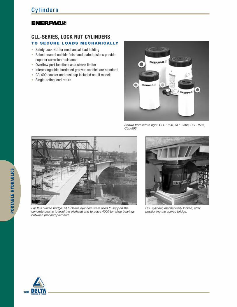
138
PORT
ABLE
HYD
RAUL
ICS
Cyl inders
Shown from left to right: CLL-1006, CLL-2506, CLL-1506,CLL-506
For this curved bridge, CLL-Series cylinders were used to support theconcrete beams to level the pierhead and to place 4000 ton slide bearingsbetween pier and pierhead.
CLL cylinder, mechanically locked, afterpositioning the curved bridge.
• Safety Lock Nut for mechanical load holding• Baked enamel outside finish and plated pistons provide
superior corrosion resistance• Overflow port functions as a stroke limiter• Interchangeable, hardened grooved saddles are standard• CR-400 coupler and dust cap included on all models• Single-acting load return
CLL-SERIES, LOCK NUT CYLINDERSTO SECURE LOADS MECHANICALLY
Enerpac_p138-139 final.qxd 4/5/10 11:57 AM Page 138

139
PORTABLE H
YDRAULICS
Cyl inders
SINGLE-ACTING, LOCK NUT CYLINDER
CLL
SERIES
Capacity:50-1,000 tonsStroke:1.97-11.81 inchesMaximum Operating Pressure:10,000 psi
CYLINDERCAPACITY(TONS)[MAXIMUM]
STROKE(IN)
MODELNUMBER
CYLINDEREFFECTIVEAREA(IN2)
OILCAPACITY(IN3)
COLLAPSEDHEIGHT(IN)
WEIGHT(LBS)
50[59.1]
1.97 CLL-502 10.99 21.63 6.46 353.94 CLL-504 10.99 43.25 8.43 465.91 CLL-506 10.99 64.88 10.39 577.87 CLL-508 10.99 86.51 12.36 689.84 CLL-5010 10.99 108.14 14.33 7911.81 CLL-5012 10.99 129.76 16.30 90
100[102.9]
1.97 CLL-1002 20.57 40.50 7.36 683.94 CLL-1004 20.57 81.00 9.33 875.91 CLL-1006 20.57 121.50 11.30 1067.87 CLL-1008 20.57 162.00 13.27 1259.84 CLL-10010 20.57 202.50 15.24 14311.81 CLL-10012 20.57 242.99 17.20 162
150[153.9]
1.97 CLL-1502 30.78 60.58 8.23 1173.94 CLL-1504 30.78 121.17 10.20 1465.91 CLL-1506 30.78 181.75 12.17 1747.87 CLL-1508 30.78 242.33 14.13 2039.84 CLL-15010 30.78 302.92 16.10 23111.81 CLL-15012 30.78 363.50 18.07 260
200[206.1]
1.97 CLL-2002 41.17 81.04 9.57 1835.91 CLL-2006 41.17 243.13 13.50 26011.81 CLL-20012 41.17 486.27 19.41 376
250[284.0]
1.97 CLL-2502 56.75 111.70 9.80 2565.91 CLL-2506 56.75 335.11 13.74 35911.81 CLL-25012 56.75 670.22 19.65 515
300[353.6]
1.97 CLL-3002 70.71 139.19 11.61 3825.91 CLL-3006 70.71 417.56 15.55 51411.81 CLL-30012 70.71 835.11 21.46 712
400[433.9]
1.97 CLL-4002 86.79 170.84 13.19 5535.91 CLL-4006 86.79 512.51 17.13 72111.81 CLL-40012 86.79 1025.02 23.03 972
500[566.3]
1.97 CLL-5002 113.25 222.99 14.76 8095.91 CLL-5006 113.25 668.77 18.70 102911.81 CLL-50012 113.25 1337.55 24.61 1360
600[662.9]
1.97 CLL-6002 132.57 260.97 15.55 9855.91 CLL-6006 132.57 782.90 19.49 124111.81 CLL-60012 132.57 1565.81 25.39 1625
800[911.6]
1.97 CLL-8002 182.42 359.09 17.91 15655.91 CLL-8006 182.42 1077.27 21.85 191811.81 CLL-80012 182.42 2154.55 27.76 2446
1000[1136]
1.97 CLL-10002 227.30 447.43 19.49 20945.91 CLL-10006 227.30 1342.30 23.43 251711.81 CLL-100012 227.30 2684.59 29.33 3151
Enerpac_p138-139 final.qxd 4/5/10 11:57 AM Page 139
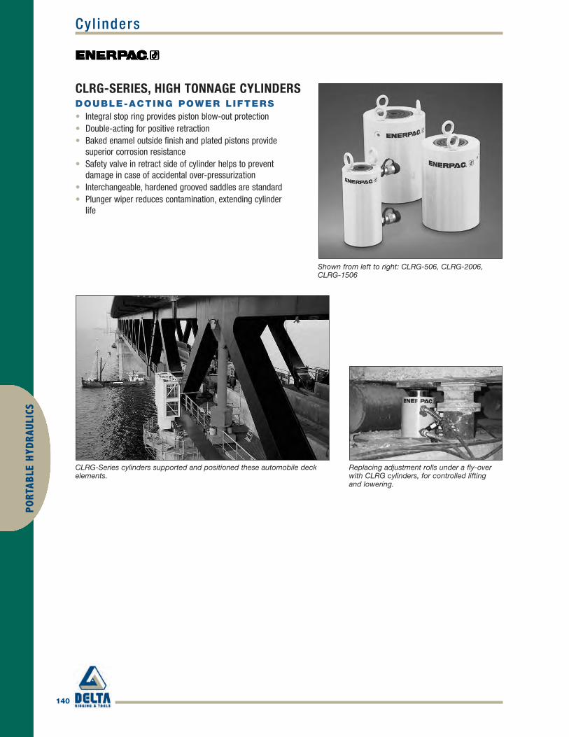
140
PORT
ABLE
HYD
RAUL
ICS
Cyl inders
Shown from left to right: CLRG-506, CLRG-2006,CLRG-1506
CLRG-Series cylinders supported and positioned these automobile deckelements.
Replacing adjustment rolls under a fly-overwith CLRG cylinders, for controlled liftingand lowering.
• Integral stop ring provides piston blow-out protection• Double-acting for positive retraction• Baked enamel outside finish and plated pistons provide
superior corrosion resistance• Safety valve in retract side of cylinder helps to prevent
damage in case of accidental over-pressurization• Interchangeable, hardened grooved saddles are standard• Plunger wiper reduces contamination, extending cylinder
life
CLRG-SERIES, HIGH TONNAGE CYLINDERSDOUBLE-ACTING POWER LIFTERS
Enerpac_p140-141 final.qxd 4/5/10 11:59 AM Page 140

141
PORTABLE H
YDRAULICS
Cyl inders
DOUBLE-ACTING, HIGH TONNAGE CYLINDERS
CLRG
SERIES
Capacity:50-1,000 tonsStroke:1.97-11.81 inchesMaximum Operating Pressure:10,000 psi
CYLINDERCAPACITY(TONS)
STROKE(IN)
MODELNUMBER
CYLINDEREFFECTIVE AREA
(IN2)PUSH PULL
OILCAPACITY
(IN3)PUSH PULL
COLLAPSEDHEIGHT(IN)
50
1.97 CLRG-502 11.81 5.85 23.25 11.51 6.383.94 CLRG-504 11.81 5.85 46.50 23.02 8.355.91 CLRG-506 11.81 5.85 69.75 34.52 10.317.87 CLRG-508 11.81 5.85 93.00 46.03 12.289.84 CLRG-5010 11.81 5.85 116.25 57.54 14.2511.81 CLRG-5012 11.81 5.85 139.50 69.05 16.22
100
1.97 CLRG-1002 20.57 9.59 40.50 18.87 7.163.94 CLRG-1004 20.57 9.59 81.00 37.74 9.135.91 CLRG-1006 20.57 9.59 121.50 56.61 11.097.87 CLRG-1008 20.57 9.59 162.00 75.49 13.069.84 CLRG-10010 20.57 9.59 202.50 94.36 15.0311.81 CLRG-10012 20.57 9.59 242.99 113.23 17.00
150
1.97 CLRG-1502 30.78 14.96 60.58 29.44 7.723.94 CLRG-1504 30.78 14.96 121.17 58.88 9.695.91 CLRG-1506 30.78 14.96 181.75 88.32 11.657.87 CLRG-1508 30.78 14.96 242.33 117.76 13.629.84 CLRG-15010 30.78 14.96 302.92 147.20 15.5911.81 CLRG-15012 30.78 14.96 363.50 176.64 17.56
2001.97 CLRG-2002 41.22 19.68 81.13 38.74 8.505.91 CLRG-2006 41.22 19.68 243.40 116.23 12.4411.81 CLRG-20012 41.22 19.68 486.79 232.46 18.35
2501.97 CLRG-2502 56.80 23.65 111.81 46.56 9.255.91 CLRG-2506 56.80 23.65 335.42 139.69 13.1911.81 CLRG-25012 56.80 23.65 670.84 279.39 19.09
300
1.97 CLRG-3002 70.71 23.46 139.19 46.18 12.285.91 CLRG-3006 70.71 23.46 417.56 138.55 16.2211.81 CLRG-30012 70.71 23.46 835.11 277.10 22.13
400
1.97 CLRG-4002 86.79 29.99 170.84 59.03 14.745.91 CLRG-4006 86.79 29.99 512.51 177.09 18.6811.81 CLRG-40012 86.79 29.99 1,025 354.18 24.59
500
1.97 CLRG-5002 113.25 38.37 222.92 75.54 16.505.91 CLRG-5006 113.25 38.37 668.77 226.61 20.4311.81 CLRG-50012 113.25 38.37 1,338 453.22 26.34
600
1.97 CLRG-6002 132.57 45.79 260.97 90.13 16.895.91 CLRG-6006 132.57 45.79 782.90 270.39 20.8311.81 CLRG-60012 132.57 45.79 1,566 540.79 26.73
800
1.97 CLRG-8002 182.32 59.99 358.91 118.09 18.665.91 CLRG-8006 182.32 59.99 1,077 354.28 22.6011.81 CLRG-80012 182.32 59.99 2,153 708.57 28.50
1000
1.97 CLRG-10002 227.19 83.97 447.23 165.29 22.205.91 CLRG-10006 227.19 83.97 1,342 495.87 26.1411.81 CLRG-100012 227.19 83.97 2,683 991.75 32.05
Enerpac_p140-141 final.qxd 4/5/10 11:59 AM Page 141

142
PORT
ABLE
HYD
RAUL
ICS
Cyl inders
Shown from left to right: RC-506, RC-50, RC-2510,RC-154, RC-10010, RC-55, RC-1010
Stage lifting set up in Greece, where assembled pipes, 82 feet in length,were stage lifted with six RC-2514 cylinders.
RC cylinder mounting attachments greatlyextend the application possibilities (availablefor 5,10,15 and 25 ton cylinders).
• Collar threads, plunger threads and base mounting holesenable easy fixturing (on most models)
• Designed for use in all positions• Removable strap handles for unobstructed fixturing
(RC-5013, RC-7513 and both 100 ton models)• High strength alloy steel for durability• Nickel plating available on most models (contact Enerpac
for details)• Heavy-duty return springs• Baked enamel finish for increased corrosion resistance• CR-400 coupler and dust cap included on all models• Plunger wiper reduces contamination, extending
cylinder life
RC-SERIES, SINGLE-ACTING CYLINDERSTHE INDUSTRY STANDARD GENERAL
PURPOSE CYLINDER
Enerpac_p142-143 final.qxd 4/5/10 12:01 PM Page 142
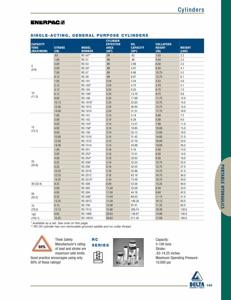
143
PORTABLE H
YDRAULICS
Cyl inders
SINGLE-ACTING, GENERAL PURPOSE CYLINDERS
RC
SERIES
Capacity:5-100 tonsStroke:.63-14.25 inchesMaximum Operating Pressure:10,000 psi
Think SafetyManufacturer’s ratingof load and stroke aremaximum safe limits.
Good practice encourages using only80% of these ratings!
CAPACITYTONS(MAXIMUM)
STROKE(IN)
MODELNUMBER
CYLINDEREFFECTIVEAREA(IN2)
OILCAPACITY(IN3)
COLLAPSEDHEIGHT(IN)
WEIGHT(LBS)
5(4.9)
.63 RC-50** .99 .62 1.63 2.21.00 RC-51 .99 .99 4.34 2.33.00 RC-53 .99 2.98 6.50 3.35.00 RC-55* .99 4.97 8.50 4.17.00 RC-57 .99 6.96 10.75 5.39.13 RC-59 .99 9.07 12.75 6.1
10(11.2)
1.00 RC-101 2.24 2.24 3.53 4.02.13 RC-102* 2.24 4.75 4.78 5.14.13 RC-104 2.24 9.23 6.75 7.26.13 RC-106* 2.24 13.70 9.75 9.88.00 RC-108 2.24 17.89 11.75 12.010.13 RC-1010* 2.24 22.65 13.75 14.012.00 RC-1012 2.24 26.84 15.75 15.014.00 RC-1014 2.24 31.31 17.75 18.0
15(15.7)
1.00 RC-151 3.14 3.14 4.88 7.22.00 RC-152 3.14 6.28 5.88 9.04.00 RC-154* 3.14 12.57 7.88 11.06.00 RC-156* 3.14 18.85 10.69 15.08.00 RC-158 3.14 25.13 12.69 18.010.00 RC-1510 3.14 31.42 14.69 21.012.00 RC-1512 3.14 37.70 16.69 24.014.00 RC-1514 3.14 43.98 18.69 26.0
25(25.8)
1.00 RC-251 5.16 5.16 5.50 13.02.00 RC-252* 5.16 10.31 6.50 14.04.00 RC-254* 5.16 20.63 8.50 18.06.25 RC-256* 5.16 32.23 10.75 22.08.25 RC-258 5.16 42.55 12.75 27.010.25 RC-2510 5.16 52.86 14.75 31.012.25 RC-2512 5.16 63.18 16.75 36.014.25 RC-2514* 5.16 73.49 18.75 39.0
30 (32.4) 8.25 RC-308 6.49 53.56 15.25 40.0
50(55.2)
2.00 RC-502 11.04 22.09 6.94 33.04.00 RC-504 11.04 44.18 8.94 42.06.25 RC-506* 11.04 69.03 11.13 51.013.25 RC-5013 11.04 146.34 18.13 83.0
75 (79.5)
6.13 RC-756 15.90 97.41 11.25 65.013.13 RC-7513 15.90 208.74 19.38 130.0
100(103.1)
6.63 RC-1006 20.63 136.67 14.06 130.010.25 RC-10010 20.63 211.45 17.69 160.0
* Available as a set. See note on this page.** RC-50 cylinder has non-removable grooved saddle and no collar thread.
Enerpac_p142-143 final.qxd 4/5/10 12:01 PM Page 143

144
PORT
ABLE
HYD
RAUL
ICS
Cyl inders
Shown from left to right: RR-10013, RR-1502, RR-20013, RR-1010, RR-7513
These long stroke RR-cylinders are attached to asliding and guiding system pulling the archedroof assembly of Athens' Olympic Stadium stepby step into the final position.
RR-cylinders provide power and precision ina special hydraulic press.
• Collar threads, plunger threads and base mounting holesfor easy fixturing (on most models)
• Baked enamel finish for increased corrosion resistance• Removable hardened saddles protect plunger during
lifting and pressing• Built-in safety valve prevents accidental
over-pressurization• CR-400 couplers included on all models• Plunger wiper reduces contamination,
extending cylinder life
RR-SERIES, DOUBLE-ACTING CYLINDERSMOST VERSATILE PERFORMERS
Rugged enough for the toughest job site uses andprecision designed for high-cycle industrial uses.
Enerpac_p144-145 final.qxd 4/5/10 12:03 PM Page 144

145
PORTABLE H
YDRAULICS
Cyl inders
DOUBLE-ACTING, LONG STROKE CYLINDERS
RR
SERIES
Capacity:10-500 tonsStroke:2.25-48.00 inchesMaximum Operating Pressure:10,000 psi
CYLINDERCAPACITY(TONS)
STROKE(IN)
MODELNUMBER
CYLINDER EFFECTIVE AREA(IN2)
PUSH PULL
OIL CAPACITY(IN3)
PUSH PULL
COLLAP.HEIGHT(IN)
1010.00 RR-1010* 2.23 .80 22.33 8.00 16.1312.00 RR-1012* 2.23 .80 26.80 9.00 18.00
308.25 RR-308* 6.51 3.00 53.67 25.00 15.2514.50 RR-3014* 6.51 3.00 92.70 43.00 21.63
506.13 RR-506 11.06 3.40 67.77 21.00 13.0613.13 RR-5013 11.06 3.40 145.17 44.00 20.0620.13 RR-5020 11.06 3.40 222.56 68.00 28.88
756.13 RR-756 15.92 4.90 97.58 29.00 13.6913.13 RR-7513 15.92 4.90 209.00 64.00 20.69
1006.63 RR-1006 20.65 9.60 136.93 63.00 14.0613.13 RR-10013 20.65 9.60 271.17 126.00 20.6318.13 RR-10018 20.65 9.60 374.44 174.00 27.06
1502.25 RR-1502 30.71 14.80 69.11 33.00 7.726.13 RR-1506 30.71 14.80 188.28 91.00 15.1913.13 RR-15013 30.71 14.80 403.27 194.00 22.2032.13 RR-15032 30.71 14.80 986.84 475.00 43.94
200
6.00 RR-2006 44.21 22.50 265.28 135.00 16.9413.00 RR-20013 44.21 22.50 574.78 293.00 23.9418.00 RR-20018 44.21 22.50 795.85 396.00 30.1324.00 RR-20024 44.21 22.50 1,061 528.00 36.1336.00 RR-20036 44.21 22.50 1,592 792.00 48.1348.00 RR-20048 44.21 22.50 2,122 1,056 60.13
300
6.00 RR-3006 70.93 38.00 425.56 228.00 19.1312.00 RR-30012 70.93 38.00 851.12 456.00 25.1318.00 RR-30018 70.93 38.00 1,277 684.00 31.1324.00 RR-30024 70.93 38.00 1,702 912.00 37.1336.00 RR-30036 70.93 38.00 2,553 1,368 49.1348.00 RR-30048 70.93 38.00 3,405 1,824 61.13
400
6.00 RR-4006 95.09 51.00 570.51 306.00 21.1912.00 RR-40012 95.09 51.00 1,141 612.00 27.1918.00 RR-40018 95.09 51.00 1,712 918.00 33.1924.00 RR-40024 95.09 51.00 2,282 1,224 39.1936.00 RR-40036 95.09 51.00 3,423 1,836 51.1948.00 RR-40048 95.09 51.00 4,564 2,448 63.19
500
6.00 RR-5006 113.15 63.00 678 378.00 22.7512.00 RR-50012 113.15 63.00 1,358 756.00 28.7518.00 RR-50018 113.15 63.00 2,037 1,134 34.7524.00 RR-50024 113.15 63.00 2,716 1,512 40.7536.00 RR-50036 113.15 63.00 4,074 2,264 52.7548.00 RR-50048 113.15 63.00 5,431 3,024 64.75
* For RR-1010 and RR-1012: N = 1.26 inch; for RR-308 and RR-3014: N = 2.20 inch.
Enerpac_p144-145 final.qxd 4/5/10 12:03 PM Page 145

146
PORT
ABLE
HYD
RAUL
ICS
Cyl inder Pump Set
Shown cylinder-pump set: SCR-1010H
SINGLE-ACTING, CYLINDER PUMP SETSThe Quickest and Easiest Way to Start Working Right Away• Optimum match of individual
components• Sets include 6 ft. safety
hose, calibrated gauge withgauge adaptor
• All hand pumps are two-speed
CYLINDER SELECTION
NOMINAL SETCAPACITY(TON)
CYLINDERMODEL NO.
STROKE(IN)
COLLAPSEDHEIGHT(IN)
Single-acting, General Purpose Cylinders:For maximum versatility.RC-Series
5 RC-55 5.00 8.50
10RC-102 2.13 4.78
RC-106 6.13 9.75
RC-1010 10.13 13.75
15
RC-154 4.00 7.88
RC-156 6.00 10.69
25
RC-252 2.00 6.50
RC-254 4.00 8.50
RC-256 6.25 10.75
RC-2514 14.25 18.75
50 RC-506 6.25 11.13
Single-acting, Low Height Cylinders:Ideal where space is restricted.RCS-Series
10 RCS-101 1.50 3.47
20 RCS-201 1.75 3.88
30 RCS-302 2.44 4.63
50 RCS-502 2.38 4.81
100 RCS-1002 2.25 5.56
Single-acting, Hollow Cylinders:For pushing and pulling applications.RCH-Series
12 RCH-121 1.63 4.75
20 RCH-202 2.00 6.31
30 RCH-302 2.50 7.03
60 RCH-603 3.00 9.75
100 RCH-1003 3.00 10.00
Pull Cylinders:The ultimate in pulling power.BRP-Series
10
BRP-106C 5.95 23.11
BRP-106L 5.95 21.33
30 BRP-306 6.10 42.72
60 BRP-606 5.98 28.34
– – – –
Enerpac_p146-147 final.qxd 4/5/10 12:04 PM Page 146

147
PORTABLE H
YDRAULICS
Cyl inder Pump Set
SC SERIESCapacity:5-100 tonsStroke:1.50-14.25 inchesMaximum Operating Pressure:10,000 psi
SINGLE-ACTING, CYLINDER PUMP SETSSELECTION EXAMPLESelected cylinder:• RC-106, Single-acting cylinder with
6.13" strokeSelected pump:• P-392, Lightweight hand pumpSet model number:• SCR-106HIncluded:• HC-7206 hose• GF-10P gauge• GA-2 adaptor
SET SELECTION:
1 Select the cylinder
2 Select the pump
3 Find the set model number
in the blue field of the matrix
PUMP SELECTION ACCESSORIES INCLUDED
Hand PumpP-142
Hand PumpP-392
Hand PumpP-80
Foot PumpP-392FP
Turbo II Air PumpPATG-1102N
HoseModelNo.
GaugeModelNo.
GaugeAdaptorModel No.
SCR-55H – – – – HC-7206 GP-10S GA-4
– SCR-102H – SCR-102FP SCR-102A HC-7206 GF-10P GA-2
– SCR-106H – SCR-106FP SCR-106A HC-7206 GF-10P GA-2
– SCR-1010H – SCR-1010FP SCR-1010A HC-7206 GF-10P GA-2
– SCR-154H – SCR-154FP SCR-154A HC-7206 GP-10S GA-2
– SCR-156H – SCR-156FP SCR-156A HC-7206 GP-10S GA-2
– SCR-252H – SCR-252FP SCR-252A HC-7206 GF-20P GA-2
– SCR-254H – SCR-254FP SCR-254A HC-7206 GF-20P GA-2
– SCR-256H – SCR-256FP SCR-256A HC-7206 GF-20P GA-2
– – SCR-2514H – SCR-2514A HC-7206 GF-20P GA-2
– – SCR-506H – SCR-506A HC-7206 GF-50P GA-2
– SCL-101H – SCL-101FP SCL-101A HC-7206 GF-10P GA-2
– SCL-201H – SCL-201FP SCL-201A HC-7206 GF-230P GA-2
– SCL-302H – SCL-302FP SCL-302A HC-7206 GF-230P GA-2
– SCL-502H – SCL-502FP SCL-502A HC-7206 GF-510P GA-2
– – SCL-1002H – – HC-7206 GF-510P GA-2
SCH-121H – – – – HB-7206 GF-120P GA-4
– SCH-202H – SCH-202FP SCH-202A HC-7206 GF-813P GA-3
– SCH-302H – SCH-302FP SCH-302A HC-7206 GF-813P GA-3
– – SCH-603H – SCH-603A HC-7206 GF-813P GA-3
– – SCH-1003H – – HC-7206 GP-10S GA-2
– SCP-106CH – SCP-106CFP – HC-7206 GP-10S GA-2
– SCP-106LH – SCP-106LFP – HC-7206 GP-10S GA-2
– – SCP-306H – – HC-7206 GP-10S GA-2
– – SCP-606H – – HC-7206 GP-10S GA-2
– – – – – – – –
Enerpac_p146-147 final.qxd 4/5/10 12:04 PM Page 147

148
Cyl inder Accessor iesPO
RTAB
LE H
YDRA
ULIC
S
HYDRAULIC OIL, MANIFOLDS AND FITTINGS
HF Oil• Specially formulated for
power pumps- high viscosity index- maximum volumetric
efficiency- maximum heat transfer- prevents cavitation- anti-sludge, anti-rust,
anti-foam additives• Maximum film protective
lubricity- anti-oxidation additives
LX Hand Pump Oil• Specially formulated for
hand pumps- anti-sludge, anti-rust
additives• Reduced handle effort over
HF oil- medium viscosity index- good low temperature
performance• Not for use in power pumps
GENUINE ENERPAC SYSTEM
COMPONENTS
Shown top to bottom: HF-101, HF-100, HF-102, LX-101, A65, and FZ1055
* Packed in two 2-1/2 gallon cans.** Hand pump oil.
Oil Specification Chart
MANIFOLDS
DESCRIPTIONMODELNO. DIMENSIONS (IN)
7" Long Manifold with 7female ports.
A-64
14" Long Manifold thatallows direct mounting ofcontrol valves to themanifold. 7 female ports.
A-65
6-Port Hexagon ManifoldPlugs furnished for allports3/8"-18 NPTF.
A-66
Premounted ManifoldFunctions as split-flowvalve to control 2 to 4single-acting cylinderssimultaneously.All ports 3/8"-18 NPTF.
AM-21AM-41
HYDRAULIC OIL
ContentsModelNumber
Use only genuineEnerpac HydraulicOil. The use of anyother fluid willrender yourEnerpac warrantynull and void.
1 Quart HF-100
1 Gallon HF-101
5 Gallons* HF-102
55 Gallons HF-104
1 Gallon** LX-101
LX OIL HF OIL
ISO Grade 15 32
Viscosity Index 101 min 100 min
Viscosity at 210 °F 3.2/3.7 S.U.S. 42/45 S.U.S.
Viscosity at 100 °F 13.5/16.5 S.U.S 150/165 S.U.S.
Viscosity at 0 °F <2100 S.U.S. <12000 S.U.S.
API Gravity 31.0/35.0 31.0/33.0
Flash, C.O.C. °F 370 400
Pour Point, °F -30 -25
Paraffinic Base Color Yellow Blue
Enerpac_p148-153 final.qxd 4/5/10 5:15 PM Page 148

Cyl inder Accessor ies
149
PORTABLE H
YDRAULICS
HYDRAULIC OIL, MANIFOLDS AND FITTINGSRecommended Tubing for Hand Plumbing Applications
Enerpac does not supply high-pressure pipe or tubing but recommends the use of cold drawn steel tubinginstead of regular pipe in the following dimensions:In place of 1/4" pipe, use 3/8" tubing with a 0.065" minimum wall thickness.For 3/8" pipe, use schedule 80 as a minimum or 1/2" with a 0.095" minimum wall thickness.For 1/2" pipe, use schedule 80 as a minimum or 3/4" tubing with a 0.135" minimum wall thickness.All tubing wall thicknesses based on a 55,000 psi minimum tensile strength.
A, AM, FZ, HF, LX Series
Enerpac_p148-153 final.qxd 4/5/10 5:15 PM Page 149

150
Cyl inder Accessor iesPO
RTAB
LE H
YDRA
ULIC
S
HYDRAULIC COUPLERSF-SERIES
Flush-faced couplers provide reduced pressure drop versusother types and are preferred in dirty, grimy construction andmining environments due to easy clean, not dirt trapping faces.
A C F SERIES
Maximum Flow Capacity:2,500 in3/min.Thread:1/4" and 3/8" NPTFMaximum Operating Pressure:10,000 psi
METAL DUST CAPS
• Steel dust caps are availablefor the C-604 series couplers.
• Order model number:CD-411M for female halfCD-415M for male half
MAXIMUMFLOWCAPACITY(IN3/MIN) COUPLER TYPE
MODEL NUMBERS
COMPLETE FEMALE MALESET HALF HALF
DIMENSIONS (IN)A* B C D E F G
DUSTCAP(S)
2,500High Flow Coupler
C-604 CR-400 CH-604 3.26 2.87 3/8NPTF
1.38 1.38 1.25 ˆ1.00 (2x)CD-411Included
2,500Flush-face coupler
F-604 FR-400 FH-604 4.36 2.85 3/8NPTF
1.23 1.23 1.06 1.12 --
462Regular Spee-D-Coupler®
A-604 AR-400 AH-604 3.09 2.533/8NPTF 1.12 .94 .94 .73
Z-410female onlyIncluded
462
Regular Coupler
A-630 AR-630 AH-630 2.61 1.721/4NPTF .87 .81 .75 .57 Z-640
female onlyIncluded
* Value A is total length when male and female halves are connected.
Enerpac_p148-153 final.qxd 4/5/10 5:15 PM Page 150
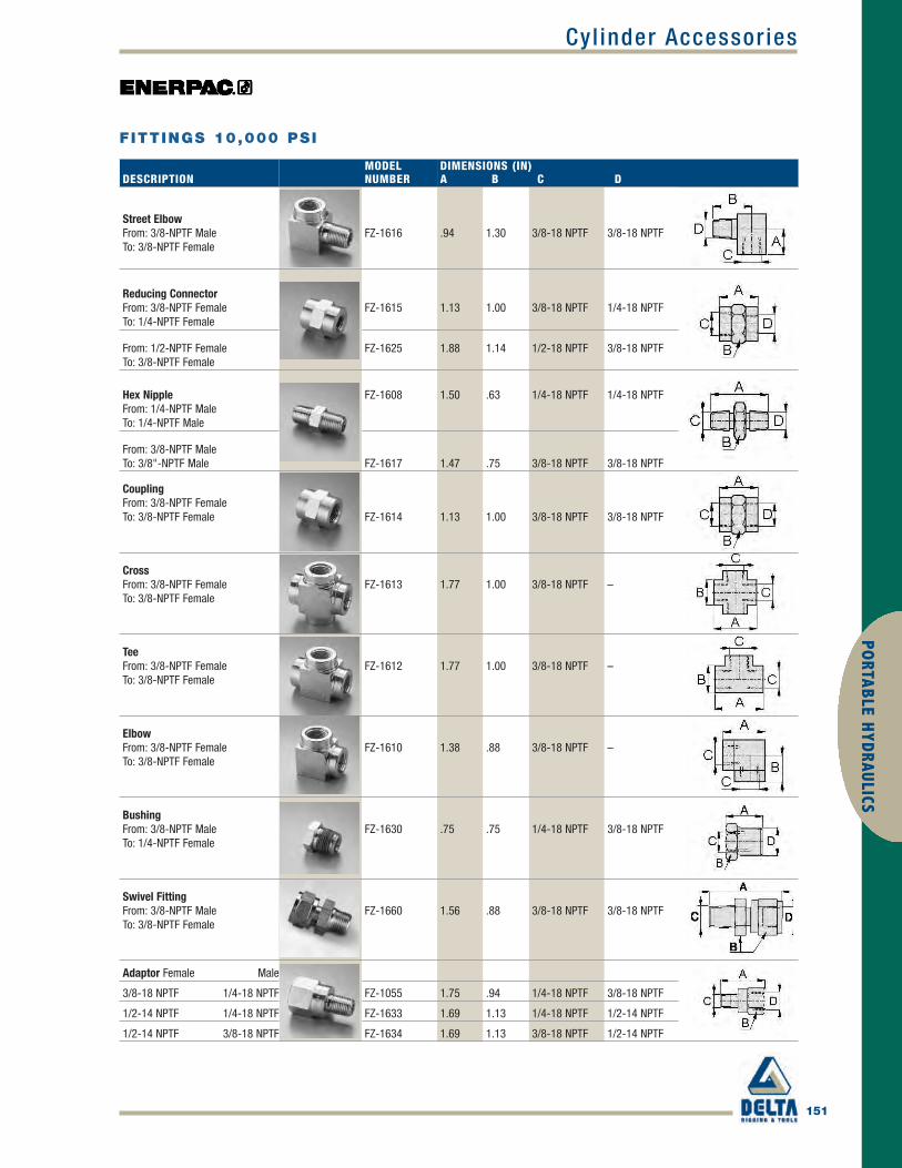
Cyl inder Accessor ies
151
PORTABLE H
YDRAULICS
DESCRIPTIONMODELNUMBER
DIMENSIONS (IN)A B C D
Street ElbowFrom: 3/8-NPTF MaleTo: 3/8-NPTF Female
FZ-1616 .94 1.30 3/8-18 NPTF 3/8-18 NPTF
Reducing ConnectorFrom: 3/8-NPTF FemaleTo: 1/4-NPTF Female
FZ-1615 1.13 1.00 3/8-18 NPTF 1/4-18 NPTF
From: 1/2-NPTF FemaleTo: 3/8-NPTF Female
FZ-1625 1.88 1.14 1/2-18 NPTF 3/8-18 NPTF
Hex NippleFrom: 1/4-NPTF MaleTo: 1/4-NPTF Male
FZ-1608 1.50 .63 1/4-18 NPTF 1/4-18 NPTF
From: 3/8-NPTF MaleTo: 3/8"-NPTF Male FZ-1617 1.47 .75 3/8-18 NPTF 3/8-18 NPTF
CouplingFrom: 3/8-NPTF FemaleTo: 3/8-NPTF Female FZ-1614 1.13 1.00 3/8-18 NPTF 3/8-18 NPTF
CrossFrom: 3/8-NPTF FemaleTo: 3/8-NPTF Female
FZ-1613 1.77 1.00 3/8-18 NPTF –
TeeFrom: 3/8-NPTF FemaleTo: 3/8-NPTF Female
FZ-1612 1.77 1.00 3/8-18 NPTF –
ElbowFrom: 3/8-NPTF FemaleTo: 3/8-NPTF Female
FZ-1610 1.38 .88 3/8-18 NPTF –
BushingFrom: 3/8-NPTF MaleTo: 1/4-NPTF Female
FZ-1630 .75 .75 1/4-18 NPTF 3/8-18 NPTF
Swivel FittingFrom: 3/8-NPTF MaleTo: 3/8-NPTF Female
FZ-1660 1.56 .88 3/8-18 NPTF 3/8-18 NPTF
Adaptor Female Male
3/8-18 NPTF 1/4-18 NPTF FZ-1055 1.75 .94 1/4-18 NPTF 3/8-18 NPTF
1/2-14 NPTF 1/4-18 NPTF FZ-1633 1.69 1.13 1/4-18 NPTF 1/2-14 NPTF
1/2-14 NPTF 3/8-18 NPTF FZ-1634 1.69 1.13 3/8-18 NPTF 1/2-14 NPTF
FITTINGS 10,000 PSI
Enerpac_p148-153 final.qxd 4/5/10 5:15 PM Page 151

GAUGE ADAPTORS (GA-SERIES)
• For easy mounting of a pressure gauge into your system• Male end screws into pump or cylinder port, female end accepts
hose or coupler, third port is for gauge connection• GA-918 provides for swivel connection• Simplifies gauge installation and reading
MODELNUMBER
GAUGEPORT(NPTF)
MALEEND(NPTF)
FEMALEEND(NPTF)
DIMENSIONS (IN)A B C D E F
GA-1 1/2 3/8
3/8
2.81 1.24 1/2 NPTF 3/8 NPTF 3/8 NPTF 1.25
GA-2 1/2 3/8 6.10 1.38 1/2 NPTF 3/8 NPTF 3/8 NPTF 1.25
GA-3 1/4 3/8 5.25 1.38 1/4 NPTF 3/8 NPTF 3/8 NPTF 1.25
GA-4 1/2 1/4 4.38 1.38 1/2 NPTF 1/4 NPTF 3/8 NPTF 1.25
152
Cyl inder Accessor iesPO
RTAB
LE H
YDRA
ULIC
S
Shown left to right: GA-3, V-91, GA-1, GA-2, GA-4, NV-251, GA-918
SWIVEL ADAPTOR (GA-918)
• Simplifies gauge installation and reading
NEEDLE VALVES (NV- AND V-SERIES)
• Both NV-251 and V-91 provide positive shut-off• 316 stainless steel stem, 24 threads/in
A gauge is easily installed into yourhydraulic system using a gauge adaptor.
GAUGE ACCESSORIESGA, NV, V SERIES
Operating Pressure:10,000 psi
MODELNUMBER
DIMENSIONS (IN)A B C D E S S1
GA-918 4.62 1.72 1/2 NPTF 1.30 1/2 NPTF 1.13 1.50
MODELNUMBER ORIFICE
THREADSIZE (IN)
DIMENSIONS (IN)A B C D E F G
NV-251 .17 1/4 NPT 2.22 .75 .38 1.81 2.25 1.13 .72
V-91 .19 1/2 NPT 3.50 1.44 .63 1.25 2.50 1.25 –
Enerpac_p148-153 final.qxd 4/5/10 5:16 PM Page 152

Cyl inder Accessor ies
153
PORTABLE H
YDRAULICS
FLOW AND PRESSURE CONTROL VALVESPREMOUNTEDMANIFOLD
For two or four portmanifold with integralflow control valves, seethe manifold page ofthe SystemComponents section.
FITTINGS
For additionalfittings see thefitting page of the SystemComponentssection.
V SERIES
MaximumOperatingPressure:10,000 psi
VALVE TYPE ANDMODEL NUMBER DESCRIPTION
HYDRAULICSYMBOL
Needle ValveV-82V-182FV-8F
V-82: To control cylinder speed.Can also be used as shut-off valvefor temporary load holding.3/8 NPTF female ports.V-182: Same as V-82, but with
1/4" NPTF female ports. Also suitablefor gauge snubbing.V-8F: Similar to V-82, but with veryfine metering for precise flow control.Not recommended as shut-off valve.
SnubberValveV-91
V-91: Adjustable for metering oil outof a gauge to prevent snapping ofgauge pointer when load or pressureis suddenly released. Also suitableas shut-off valve to protect the
gauge during high cyclingapplications. 1/2" NPTF male andfemale threads for use with GA-1,GA-2 or GA-4 gauge adaptors.
AutoDamper®
ValveV-10
V-10: To be used when gaugepressure must be monitored duringhigh cycle applications. Creates aflow resistance when load isreleased suddenly.
No adjustments are necessary.1/2" NPTF male and female threadsfor use with GA-1, GA-2 or GA-4gauge adaptors.
CheckValveV-17
V-17: Ruggedly built to resist shockand operate with low pressure drop.Closes smoothly without pounding.3/8" NPTF female ports.
Pilot OperatedCheck ValveV-42
V-42: Can be mounted at thecylinder to hold the load in case ofsystem pressure loss. Normallyused with double-acting cylinderswhere pilot port receives pressure
from a Tee-fitting in the cylinderretract line.3/8" NPTF female ports.Pilot pressure ratio 14% (6.5:1).
Manually OperatedCheck ValveV-66V-66F
V-66: Used for load holdingapplications with single and doubleacting cylinders. Valve is manuallyopened to allow oil to flow back totank when cylinder retracts.
V-66F: Similar to V-66, but with veryfine metering capability for preciseflow control.Not designed for load holdingapplications.
Pressure ReliefValveV-152
V-152: Limits pressure developedby the pump in hydraulic circuit, thuslimiting the force created by othercomponents. Valve opens wheneverpreset pressure is reached.
To increase pressure setting, turnhandle clockwise. Includes:• 3 ft return line hose kit• ±3% repeatability• 800-10,000 psi adjustment range.
Sequence ValveV-161V-161
V-161: To control oil flow to asecondary circuit. Flow is blockeduntil system pressure rises to theV-161 setting. When this pressurelevel is reached, the V-161 opens to
allow flow to the secondary circuit.A pressure differential is alwaysmaintained between the primaryand secondary circuit.Min. operating pressure: 2000 psi.
Enerpac_p148-153 final.qxd 4/5/10 5:16 PM Page 153

154
GaugesPO
RTAB
LE H
YDRA
ULIC
S
HYDRAULIC FORCE AND PRESSURE GAUGES
Auto-Damper ValveFor automatic controlof gauge fluctuations,the V-10 Auto-DamperValve controls themovement of thegauge needle by
restricting oil flow in and out of thegauge. No adjustments needed.
Snubber ValveInfinitely adjustable formetering oil out of agauge. The V-91Snubber Valve is alsosuitable as a shut-offvalve to protect the
gauge during high cycle applications.
Shown: GF-871P, GP-10S
A GP-10S gauge is used on this press to check the hydraulic pressure requiredto bend flat steel bar.
VISUAL REFERENCES FOR SYSTEM PRESSURE AND FORCE
• GF-Series gauges are calibrated with dual scalereading for pressure and force
• Excellent readability; 4 inch diameter gauge face• Fast, easy installation• GF-Series gauges are glycerine filled• Stainless steel gauge cases for corrosion resistance• GP-Series gauges are calibrated with dual scale
reading for psi and bar
USED WITH
All Cylinders
All Cylinders
All 5 ton RC Cylinders
All 10 ton RC Cylinders
All 25 ton RC Cylinders
RC and RR 50 ton Cylinders
12 ton RCH-Series
RCH/RRH-20, 30 and 60 ton
RCS-201, 302
RCS-502, 1002
25 ton Presses
50 ton Presses
25-50 ton Presses
100 ton Presses
150-200 ton Presses
Enerpac_p154-156 final.qxd 4/5/10 5:23 PM Page 154

Gauges
155
PORTABLE H
YDRAULICS
HYDRAULIC FORCE AND PRESSURE GAUGES
MAXIMUM INDICATOR
POINTER
Indicator retains peak readings ofpressure or force generated by thesystem.Order model number: H-4000G.Can easily be installed on GP-Series drygauges.
LOAD GAUGES
To measure external load supported by acylinder or jack. For pressing partstogether under pre-determined loads,weighing, testing, etc.
PRESSURE GAUGES
To measure the input pressure intocylinders, jacks or high pressuresystems. Also for all testing applications.GP-Series gauges are dry gauges.GF-Series gauges are glycerine filled.
GF GP SERIES
Pressure Range:0-15,000 psiFace Diameter:4 inchAccuracy, % of full scale:± 1%
GAUGE TYPE AND CALIBRATION
PSI BAR PSI LBS TONS UNITS PER DIVISIONMODELNUMBER*
THREADC
(IN)
GAUGE ADAPTOR
REQUIREDGA-1 GA-2 GA-3
0-10,000 0-700 – – – 100 psi, 10 bar GP-10S 1/2 NPTF • •
0-15,000 0-1000 – – – 200 psi, 10 bar GP-15S 1/2 NPTF • •
– – 0-10,000 0-10,000 0-5 100 psi, 100 lbs, .1 ton GF-5P 1/2 NPTF • •
– – 0-10,000 0-22,200 0-11 100 psi, 200 lbs, .2 ton GF-10P 1/2 NPTF • •
– – 0-10,000 0-51,500 0-25.5 100 psi, 500 lbs, .5 ton GF-20P 1/2 NPTF • •
– – 0-10,000 0-110,000 0-55 100 psi, 1000 lbs, 1 ton GF-50P 1/2 NPTF • •
– – 0-10,000 0-27,000 0-13.5 100 psi, 200 lbs, .25 ton GF-120P 1/2 NPTF • •
– – 0-10,000 – 0-23.5/36/65 100 psi, .5/.5/1 ton GF-813P 1/4 NPTF •
– – 0-10,000 – 0-22/32 100 psi, .5/.5 GF-230P 1/2 NPTF • •
– – 0-10,000 – 0-50/100 100 psi, 1/1 ton GF-510P 1/2 NPTF • •
– – 0-10,000 0-51,500 0-25.5 100 psi, 500 lbs, .5 ton GF-20P 1/2 NPTF • •
– – 0-10,000 0-11,000 0-55 100 psi, 1000 lbs, 1 ton GF-50P 1/2 NPTF • •
– – 0-10,000 – 0-25.5/32.5/55 100 psi, .5/.5/.5 ton GF-835P 1/4 NPTF •
– – 0-10,000 – 0-79/103 100 psi, 1/1 ton GF-871P 1/4 NPTF •
– – 0-10,000 – 0-150/200 100 psi, 5/5 ton GF-200P 1/4 NPTF •
All Models
* Metric scale Force Gauges are available by changing the "P" suffix to "B."
Enerpac_p154-156 final.qxd 4/5/10 5:23 PM Page 155

156
GaugesPO
RTAB
LE H
YDRA
ULIC
S
HYDRAULIC PRESSURE GAUGES
MAXIMUMINDICATING
POINTER
Indicator retains peakreadings of pressure or
force generated by the system.Order model number: H-4000G.Note: For use on H-Series gauges only.
GH
SERIES
Pressure Range:0-15,000 psiFace Diameter:2.5-4 inchesAccuracy, % of full scale:±1% and 1-1/2%
FACE DIMENSIONS (IN)DIAM. CONNECTION A B C D E
2.5 Lower Mount 2.50 1.46 1/4 NPTF 3.31 –
2.5 Center Rear 2.50 1.46 1/4 NPTF – 2.48
4.0 Lower Mount 4.0 1.15 1/4 NPTF 4.80 –
4.0 Lower Mount 4.0 1.93 1/2 NPTF 5.38 –
Note: dimensions for reference only.
SELECTION CHART
GAUGESERIES
PRESSURERANGE(PSI) (BAR)
FACE Ø2.5"
1/4 NPTFLOWERMOUNT
ACCURACY±1-1/2%
FACE Ø2.5"
1/4 NPTFCENTER
REARACCURACY±1-1/2%
FACE Ø4"
1/4 NPTFLOWERMOUNT
ACCURACY±1%
FACE Ø4"
1/2 NPTFLOWERMOUNT
ACCURACY±1%
MAJORGRADUATIONPSI(2.5") (4")
MINORGRADUATIONPSI(2.5") (4")
MAJORGRADUATIONBAR(2.5") (4")
MINORGRADUATIONBAR(2.5") (4")
G-Series
0-100 0-7 G2509L – – – 10 – 2 – 1 – .01 –
0-160 0-11 G2510L – – – 10 – 2 – 1 – .02 –
0-200 0-14 G2511L – – – 50 – 5 – 1 – .02 –
0-300 0-20 G2512L – – – 50 – 5 – 5 – .50 –
0-600 0-40 G2513L – – – 100 – 10 – 10 – 1 –
0-1,000 0-70 G2514L G2531R – – 100 – 20 – 10 – 1 –
0-2,000 0-140 G2515L – – – 500 – 50 – 10 – 2 –
0-3,000 0-200 G2516L – – – 500 – 50 – 50 – 5 –
0-6,000 0-400 G2517L G2534R – – 1000 – 100 – 100 – 10 –
0-10,000 0-700 G2535L G2537R G4088L G4039L 2000 1000 200 100 100 100 10 10
0-15,000 0-1000 G2536L G2538R G4089L G4040L 3000 3000 200 200 100 100 20 20
H-Series 0-10,000 0-700 – – H4049L H4071L – 1000 – 100 – 100 – 10
MODEL NUMBER
Enerpac_p154-156 final.qxd 4/5/10 5:23 PM Page 156

1/4" NPTF
3/8" NPTF
A-604
A-630
AH-604
AH-630
C-604
CH-604
157
PORTABLE H
YDRAULICS
Hoses
HIGH PRESSURE HYDRAULIC HOSES
Shown from top to bottom: HC-7206, HC-7210, HC-9206
Crimped-on rubber strain relief for improved life anddurability on all models.Thermo-plastic Hoses (700-Series)• For demanding applications, featuring a 4:1 design factor• Maximum working pressure of 10,000 psi• Two layers of steel wire braids• Outside jacket is polyurethane, to provide maximum abrasion resistance• Exhibits low volumetric expansion under pressure to enhance overall
system efficiencyHeavy-duty Rubber Hoses (900-Series)• The most complete offering: 35 models up to 50 feet in length• Rubber coated with two layers of steel wire braids• Designed to comply with Material Handling Institute IJ-100 hose
specification• Flexible, with little “memory,” is the best choice for long hose runs
To prevent back pressure and to increase cylinder retractionspeed, when using long hoses, the Enerpac HC-7300 rangeof hoses with increased internal diameter is the best choice.
EMPHASIZE SAFETY
AND QUALITY
To ensure the integrity of yoursystem, specify only Enerpachydraulic hoses.
WARNING !• Do not exceed 10,000 psi
maximum pressure.• Do not handle hoses while
under pressure.
HOSE END COUPLINGS
Enerpac_p157-158 final.qxd 4/5/10 12:18 PM Page 157

158
PORT
ABLE
HYD
RAUL
ICS
FittingsFor additional fittingssee the fitting page
of the System Components section.
Hoses
HIGH PRESSURE HYDRAULIC HOSES
INTERNALDIA.(IN)
HOSE ENDASSEMBLIES ANDCOUPLERSEND ONE END TWO
HOSELENGTH(FT)
700-SERIESTHERMO-PLASTICMODELNUMBER WT.(LBS)
900-SERIESHEAVY-DUTY RUBBERMODEL NUMBER WT.(LBS)
.25
1/4"NPTF
1/4" NPTF 6 – H-9206Q 2.63/8" NPTF 6 – H-9206S 2.6A-630 6 HB-7206QB 2.4 HB-9206QB 3.1AH-630 6 – HB-9206Q 2.9CH-604 6 HC-7206Q 2.3 HC-9206Q 3.0
3/8"NPTF
3/8" NPTF
2 H-7202 1.2 H-9202 1.63 H-7203 1.5 H-9203 1.96 H-7206 2.0 H-9206 2.610 H-7210 3.0 H-9210 3.920 H-7220 6.2 H-9220 8.030 H-7230 10.0 H-9230 13.050 H-7250 15.4 H-9250 22.0
A-604– –
6 HA-7206B 2.5 HA-9206B 3.210 – HA-9210B 4.5
AH-604
– –3 – HA-9203 2.16 HA-7206 2.2 HA-9206 2.910 HA-7210 3.2 HA-9210 4.2
AH-630 6 HB-7206 2.2 HB-9206 2.9
C-6043 HC-7203B 2.2 HC-9203B 2.96 HC-7206B 2.8 HC-9206B 3.710 HC-7210B 3.9 HC-9210B 5.0
CH-604
3 HC-7203 1.7 HC-9203 2.26 HC-7206 2.3 HC-9206 3.010 HC-7210 3.3 HC-9210 4.320 HC-7220 6.4 HC-9220 8.3
CH-604 CH-6046 HC-7206C 2.4 HC-9206C 3.150 HC-7250C 15.4 HC-9250C 20.0
.38 3/8" NPT
3/8" NPTF
6 H-7306 3.5 H-9306 4.610 H-7310 5.4 H-9310 7.020 H-7320 10.0 H-9320 13.030 H-7330 16.2 H-9330 21.050 – H-9350 33.0
CH-6046 HC-7306 3.4 HC-9306 4.9
– HC-9308 6.210 HC-7310 5.6 HC-9310 7.320 HC-7320 11.2 HC-9320 14.6
700
900
SERIES
Inside Diameter:.25 and .38 inchLength:2-50 feetMaximum Operating Pressure:10,000 psi
Hose Oil CapacityWhen using long hose lengths, it issometimes necessary to fill the pumpreservoir after filling the hoses. Todetermine the hose oil capacity, usethe following:
For .25" internal diameter hoses:Capacity (in3) = .5892 x Length (ft)
For .38" internal diameter hoses:Capacity (in3) = 1.3608 x Length (ft)
Enerpac_p157-158 final.qxd 4/5/10 12:18 PM Page 158

Nut Spl i t ters
159
PORTABLE H
YDRAULICS
HYDRAULIC NUT SPLITTERS
Shown from left to right: NC-3241, NC-1319, NC-1924
• Compact and ergonomic design, easy to use• Unique angled head allows flush access• Single-acting, spring return cylinder• Heavy-duty chisels can be reground• Applications include servicing trucks, piping industry, tank
cleaning, petrochemical, steel construction and mining
Easily removing rusty nuts during railroadconstruction is just one of many applicationexamples for the Enerpac Nut Splitter.
NCSERIES
Capacity:5-90 tonsHexagon Nut Range:0.5-2.88 inchesMaximum Operating Pressure:10,000 psiEnerpac Nut SplittersNut Splitters include a spare chisel, aspare set screw and the wrench usedto secure the chisel. A CR-400coupler is standard.
SET MODELNUMBER
SPLITTERMODELNUMBER
PUMPMODELNUMBER
STN-1924H NC-1924 P-392
STN-2432H NC-2432 P-392
STN-3241H NC-3241 P-392
Nutsplitter SetsHydraulic Nutsplitters are available assets (pump, tool and hose).
HEXAGONNUT RANGE(IN)
BOLTRANGE(IN)
CAPACITY(TON)
OILCAPACITY(IN3)
MODELNUMBER
DIMENSIONS (IN)A B C D F H J
WEIGHT(LBS)
REPLACEMENTCHISELMODELNUMBER
.50-.75 .31-.50 5 .92 NC-1319 1.57 7.87 .24 .75 1.10 1.89 .83 1.8 NCB-1319
.75-.94 .50-.63 10 1.22 NC-1924 2.17 8.94 .32 .98 1.50 2.80 1.00 4.4 NCB-1924
.94-1.13 .63-.88 15 3.66 NC-2432 2.60 10.24 .39 1.22 1.93 2.99 1.30 6.6 NCB-2432
1.13-1.56 .88-1.13 20 4.88 NC-3241 2.95 11.26 .59 1.38 2.60 3.50 1.69 9.7 NCB-3241
1.56-2.00 1.13-1.38 35 9.46 NC-4150 3.78 12.80 .83 1.77 2.87 4.29 2.13 18.0 NCB-4150
2.00-2.25 1.38-1.50 50 14.64 NC-5060 4.17 14.41 1.06 2.13 3.63 4.96 2.38 26.0 NCB-5060
2.38-2.88 1.50-1.88 90 30.00 NC-6075 6.14 14.43 1.06 2.95 4.33 7.09 3.07 75.1 NCB-6075
Ordering Notes: Maximum allowable hardness to split is HRc-44. Not to be used on square nuts.
Enerpac_p159 final.qxd 4/5/10 12:19 PM Page 159

160
PumpsPO
RTAB
LE H
YDRA
ULIC
S
P-SERIES, LIGHTWEIGHT HAND PUMPS
Pumps shown, from top to bottom: P-802, P-842, P-202, P-142
P-392 in action with RSM-500 cylinders.
EXCLUSIVELY FROM ENERPAC
• Lightweight and compact design• Durable glass-filled nylon reservoir and nylon encapsulated
aluminum pump base for maximum corrosion resistance• Two-speed operation on most models reduces handle
strokes by as much as 78% over single speed pumps• Lower handle effort to minimize operator fatigue• Integral 4-way valve on P-842 for operation of double-
acting cylinders• Handle lock and lightweight construction for easy carrying• Large oil capacities to power a wide range of cylinders or
tools• Non-conductive fiberglass handle for operator safety• Internal pressure relief valve for overload protection
PUMPTYPE
USABLE OILCAPACITY(IN3)
MODELNUMBER
PRESSURE RATING(PSI)*
1ST STAGE 2ND STAGE
OIL DISPLACEMENTPER STROKE
(IN3)1ST STAGE 2ND STAGE
MAX.HANDLEEFFORT(LBS)
Single-speed
20 P-141 N/A 10,000 N/A .055 72
55 P-391 N/A 10,000 N/A .151 85
Two-speed
20 P-142** 200 10,000 .221 .055 78
55 P-202 200 10,000 .221 .055 63
55 P-392** 200 10,000 .687 .151 93
155 P-802 400 10,000 2.40 .151 95
155 P-842*** 400 10,000 2.40 .151 95
* Contact Enerpac for applications where operating pressure is less than 10% of pressure rating.** Available as set. *** For use with double-acting cylinders.
Enerpac_p160-161 final.qxd 4/5/10 12:21 PM Page 160

Pumps
161
PORTABLE H
YDRAULICS
LIGHTWEIGHT HAND PUMPS
PISTONSTROKE(IN)
DIMENSIONS (IN)A B C D E G H J L M N P Q S
WEIGHT(LBS)
MODELNUMBER
.50 7.31 13.25 1.13 3.37 1.13 1/4-18 NPTF 12.56 .75 5.63 – 3.75 3.18 – .28 5.3 P-141
1.00 13.56 21.00 1.44 3.93 1.31 3/8-18 NPTF 20.56 1.19 7.00 .63 4.75 – – – 9.0 P-391
.50 7.31 13.25 1.13 3.37 1.13 1/4-18 NPTF 12.56 .75 5.63 – 3.75 3.18 – .28 5.3 P-142**
.50 13.56 20.06 1.44 3.37 1.13 1/4-18 NPTF 15.75 .75 5.69 .63 3.75 – – – 7.5 P-202
1.00 13.56 21.00 1.44 3.93 1.31 3/8-18 NPTF 20.56 1.19 7.00 .63 4.75 – – – 9.0 P-392**
1.00 13.30 21.75 1.78 5.25 1.39 3/8-18 NPTF 20.75 2.19 9.00 – 7.12 4.75 1.40 .41 18.0 P-802
1.00 13.30 21.75 1.78 5.25 .81 3/8-18 NPTF 20.75 2.19 9.00 – 7.12 4.75 1.44 .41 22.0 P-842
PSERIES
Reservoir Capacity:20-155 in3
Flow at Rated Pressure:.055-.15 in3/strokeMaximum Operating Pressure:10,000 psi
** Available as set.
Enerpac_p160-161 final.qxd 4/5/10 12:21 PM Page 161

162
PumpsPO
RTAB
LE H
YDRA
ULIC
S
P-SERIES, STEEL HAND PUMPS
Shown from left to right: P-462, P-84, P-801, P-77, P-80, P-39
In the absence of a power supply, the P-80 HandPump offers a powerful solution.
THE SOLUTION FOR TOUGH JOBS
• Two-speed operation for reduced operator fatigue(except P-39)
• 4-way valving on the P-84 and P-464 for operationof double-acting cylinders
• External load release valve on remaining modelsfor single-acting cylinder operation
• Internal pressure relief valve for overload protection• Large oil capacity to power a wide range of cylinders
or tools
PUMPTYPE
USABLE OILCAPACITY(IN3)
MODELNUMBER
PRESSURE RATING*(PSI)
1ST STAGE 2ND STAGE
OIL DISPLACEMENTPER STROKE
(IN3)1ST STAGE 2ND STAGE
MAX.HANDLEEFFORT(LBS)
Single40 P-39 N/C 10,000 N/C .16 111
47 P-77 200 10,000 .97 .15 94
Two-speed
134 P-80** 350 10,000 .99 .15 104
249 P-801 350 10,000 .99 .15 104
134 P-84*** 350 10,000 .99 .15 104
453 P-462 200 10,000 7.69 .29 110
453 P-464*** 200 10,000 7.69 .29 110
* Contact Enerpac for applications where operating pressure is less than 10% of pressure rating.** Available as set. *** For use with double-acting cylinders.
Enerpac_p162-163 final.qxd 4/5/10 12:23 PM Page 162

Pumps
163
PORTABLE H
YDRAULICS
STEEL HAND PUMPS
PISTONSTROKE(IN)
DIMENSIONS (IN)A B C D E F H J L M N P Q R S T
WEIGHT(LBS.)
MODELNUMBER
.81 15.5 20.47 1.28 1.50 1.25 – 18.25 1.18 4.69 2.56 5.25 – – – – – 13 P-39
1.00 16.46 20.67 1.30 1.57 2.04 – 22.04 1.34 4.57 1.97 4.72 – – – – – 15 P-77
1.00 16.75 21.22 1.00 1.75 2.13 – 20.75 1.14 6.88 .75 5.75 4.76 – .83 .31 – 24 P-80**
1.00 25.94 30.78 1.00 1.75 2.13 – 30.43 1.14 6.88 – 5.75 4.76 – .83 .31 – 31 P-801
1.00 16.75 21.22 1.00 1.75 – 2.52 20.75 1.14 6.88 .75 5.75 4.76 1.50 1.69 .31 2.64 29 P-84***
1.50 8.25 12.13 6.42 12.63 7.68 – 26.44 .98 10.63 6.89 25.6 3.63 – – 3.13 – 61 P-462
1.50 8.35 12.13 6.42 12.63 7.68 – 26.44 .98 10.63 6.89 25.6 3.63 3.50 2.68 3.13 – 61 P-464***
PSERIES
Reservoir Capacity:40-453 in3
Flow at Rated Pressure:.15-.29 in3/strokeMaximum Operating Pressure:10,000 psi
** Available as set.*** For use with double-acting cylinders.
Enerpac_p162-163 final.qxd 4/5/10 12:23 PM Page 163

164
PumpsPO
RTAB
LE H
YDRA
ULIC
S
AIR HYDRAULIC PUMPS
Shown: PAM-1041
• Twin air motor configuration delivers high-flow performance in firststage, up to 200 psi, for rapid cylinder advance
• 1 and 2 gallon reservoirs for use with a wide range of cylinders• Integral shroud protects air motors and provides easy portability
PAMSERIES
Reservoir Capacity:1.0-2.0 gal.Flow at Rated Pressure:9 in3/min.Maximum Operating Pressure:10,000 psi
USEDWITHCYLINDER
USABLEOILCAPACITY(GAL)
MODELNUMBER(WITHSHROUD)
PRESSURERATING(PSI)
OUTPUT FLOW RATE(IN3/MIN)1ST STAGE 2ND STAGE
VALVEFUNCTION
VALVEMODEL
AIRPRESSURERANGE*(PSI)
AIRCONSUMP-TION(SCFM)
SOUNDLEVEL(DBA)
WEIGHT(LBS)
Single -acting
0.7 PAM-1021 10,000 650 9 Adv/Hold/Ret VM-2 60-120 18 87 50
2.0 PAM-1022 10,000 650 9 Adv/Hold/Ret VM-2 60-120 18 87 60Double-acting
0.7 PAM-1041 10,000 650 9 Adv/Hold/Ret VM-4 60-120 18 87 50
2.0 PAM-1042 10,000 650 9 Adv/Hold/Ret VM-4 60-120 18 87 60
Flow Chart
* Recommended Regulator-Filter-Lubricator: RFL-102
Enerpac_p164-170 final.qxd 4/5/10 12:25 PM Page 164

Pumps
165
PORTABLE H
YDRAULICS
RFL-102Regulator-Filter-LubricatorRecommended foruse with all air
pumps. Provides clean, lubricatedair and allows for air pressureadjustment. Steel bowl guards arestandard.
TURBO II AIR HYDRAULIC PUMPS
Large ReservoirModelsThe Turbo II AirPump is alsoavailable with a
larger reservoir: PATG-1105N,PAMG-1405N, and PARG-1105N.
Shown left to right: PAMG-1402N, PATG-1102N, PARG-1102N, PATG-1105N
Easily operated by hand or by foot.
SETTING NEW STANDARDS
• High efficiency cast aluminum air motor for increased life and reduced airconsumption
• Fully serviceable air motor assembly• Reinforced heavy-duty reservoir for applications in tough environments• New generation air saver piston with rugged one-piece design reduces air
consumption and operating costs• Return-to-tank port for use in remote valve applications• Quiet – only 76 dBA with low air consumption of 12 scfm• Operating air pressure: 25-125 psi, enables pump to start at extremely low
pressure• Internal pressure relief valve provides overload protection
USEDWITHCYLINDER
USABLEOILCAPACITY(IN3)
MODELNUMBER
Single -acting
127 PATG-1102N*
230 PATG-1105N
127 PARG-1102N
230 PARG-1105NDouble -actingUSABLE
127 PAMG-1402N
230 PAMG-1405N
* Available as set.
Enerpac_p164-170 final.qxd 4/5/10 12:25 PM Page 165
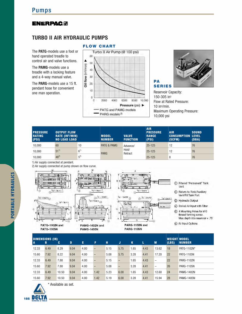
166
PumpsPO
RTAB
LE H
YDRA
ULIC
S
TURBO II AIR HYDRAULIC PUMPS
PASERIES
Reservoir Capacity:150-305 in3
Flow at Rated Pressure:10 in3/min.Maximum Operating Pressure:10,000 psi
The PATG-models use a foot orhand operated treadle tocontrol air and valve functions.
The PAMG-models use atreadle with a locking featureand a 4-way manual valve.
The PARG-models use a 15 ft.pendant hose for convenientone man operation.
DIMENSIONS (IN)A B C D E F H J K L M
WEIGHT(LBS)
MODELNUMBER
12.33 6.49 8.29 9.04 4.00 – 5.15 5.75 1.65 4.43 13.62 18 PATG-1102N*
15.60 7.92 8.22 9.04 4.00 – 5.08 5.75 3.28 4.41 17.20 22 PATG-1105N
12.33 6.49 7.88 9.04 4.00 – 5.15 – 1.65 4.43 – 22 PARG-1102N
15.60 7.92 7.88 9.04 4.00 – 5.08 – 3.28 4.41 – 26 PARG-1105N
12.33 6.49 10.50 9.04 4.00 1.42 5.23 6.00 1.65 4.43 12.60 24 PAMG-1402N
15.60 7.92 10.50 9.04 4.00 1.42 5.19 6.00 3.28 4.41 15.94 28 PAMG-1405N
PRESSURERATING(PSI)
OUTPUT FLOWRATE (IN3/MIN)NO LOAD LOAD
MODELNUMBER
VALVEFUNCTION
AIRPRESSURERANGE(PSI)
AIRCONSUMPTION(SCFM)
SOUNDLEVEL(DBA)
10,000 60 10 PATG & PAMG Advance/Hold/Retract
25-125 12 76
10,000 511) 61)
PARG25-125 12 76
10,000 482) 52) 25-125 8 76
* Available as set.
FLOW CHART
1) Air supply connected at pendant.2) Air supply connected at pump shown on flow curve.
Enerpac_p164-170 final.qxd 4/5/10 12:25 PM Page 166

Pumps
167
PORTABLE H
YDRAULICS
ATEX CertifiedSee explanation of ATEXcertification in the “Yellow Pages”.
Speed ChartTo determine how a ZA Seriespump will operate your cylinder,see the Pump/Cylinder Speed Chartin the “Yellow Pages”.
HosesEnerpac offers a
complete line of high-quality hydraulichoses. To ensure theintegrity of your
system, specify only genuineEnerpac hydraulic hoses.
ZA-SERIES AIR HYDRAULIC PUMPS
Shown: ZA4208MX, ZA4420MX
• Features Z-Class high efficiency pump design, higher oil flow and bypasspressure
• Two-speed operation and high by-pass pressure reduces cycle time forimproved productivity
• Internal relief valves. One is factory set for overload protection while thesecond is user adjustable for pre-setting maximum system pressure
• Sight gauge on 1 and 2 gallon and level gauge on 2.5, 5 and 10 gallonreservoirs allow quick and easy oil level monitoring
• Optional heat exchanger warms exhaust air to preventfreezing and cools the oil
ZA4 PERFORMANCE
DYNAMICAIR PRESSURERANGE(PSI)
AIRCONSUMPTION(SCFM)
SOUNDLEVEL(DBA)
60-100 20-100 85-90
USEDWITHCYLINDER
USABLEOILCAPACITY(GAL)
VALVEMODELNUMBER2)
VALVEFUNCTION
MODELNUMBER
OUTPUT FLOW RATE1)
(IN3/MIN)100 PSI 700 PSI 5,000 PSI 10,000 PSI
Single - acting
1.0 ManualVM32
Advance/Retract
ZA4204MX 850 675 110 80
2.0 ZA4208MX 850 675 110 80
5.0 ZA4220MX 850 675 110 80
Double - acting
1.0
ManualVM43
Advance/Hold/Retract
ZA4404MX 850 675 110 80
2.0 ZA4408MX 850 675 110 80
2.5 ZA4410MX 850 675 110 80
5.0 ZA4420MX 850 675 110 80
10.0 ZA4440MX 850 675 110 80
1) Actual flow will vary with air supply.2) See valve section for hydraulic symbols and details.
Enerpac_p164-170 final.qxd 4/5/10 12:25 PM Page 167

168
PumpsPO
RTAB
LE H
YDRA
ULIC
S
ZA-SERIES AIR HYDRAULIC PUMP ORDERING MATRIXCUSTOM BUILD YOUR ZA4 AIR PUMP
This is how a ZA-Series Pump model number is built up:
Z A 4 2 08 M X - F H K1
ProductType
2MotorType
3Flowgroup
4ValveType
5Usable
oilcapacity
6Valve
Operation
7Voltage
8Options
8Options
8Options
8Options
1 Product TypeZ = Pump class
2 Motor TypeA = Air motor
3 Flow Group4 = 80 in3/min@10,000 psi
4 Valve Type0 = No valve with coverplate2 = 3-way, 2-position (VM32)3 = 3-way, 3-position (VM33)4 = 4-way, 3-position (VM43)6 = 3-way, 3-position, locking
(VM33L)8 = 4-way, 3-position, locking
(VM43L)
5 Usable Oil Capacity04 = 1.0 gallon08 = 2.0 gallon10 = 2.5 gallon20 = 5.0 gallon40 = 10.0 gallon
6 Valve OperationM = Manual valveN = No valve
7 VoltageX = Not applicable
8 Options(Specify in alphabetical order)
F = FilterG = 0-15,000 psi gauge
(2-1/2")H = Heat exchangerK = Skidbar (1 and 2
gallon reservoirs only)N = No reservoir handles
(includes lifting eyes;2.5, 5, 10 gallon only)
R = Roll bars
Ordering ExampleModel Number: ZA4208MX-FHK
ZA4208MX-FHK is an air operated pump with a3-way, 2-position manual valve, a 2.0 gallonreservoir, filter, heat exchanger and skid bar.
FLOW CHARTDIMENSIONS (IN)
A B C D E F G
WEIGHT(INCL. OIL)(LBS)
11.6 5.6 11.0 6.0 16.9 - - 65.5
14.0 8.0 11.3 6.6 19.3 - - 75.7
13.0 7.1 16.3 16.6 15.6 15.6 18.4 112.7
11.6 5.6 11.0 6.0 16.9 - - 66.7
14.0 8.0 11.3 6.6 19.3 - - 76.9
12.0 6.1 16.5 12.0 17.4 11.0 15.1 87.1
13.0 7.1 16.3 16.6 15.6 15.6 18.4 113.9
16.5 10.6 15.7 19.9 21.9 18.9 23.0 164.6
ZA4SERIES
Reservoir Capacity:1.0-10.0 gal.Flow at Rated Pressure:80 in3/min.Maximum OperatingPressure:10,000 psi
Enerpac_p164-170 final.qxd 4/5/10 12:25 PM Page 168

Pumps
169
PORTABLE H
YDRAULICS
ZU-SERIES, ELECTRIC PUMPS
Shown from left to right: ZU4108DB-T, ZU4420SB-H, ZU4304ME-K
• Features Z-Class high-efficiency pump design; higher oil flow andbypass pressure, cooler running and requires 18% less currentdraw than comparable pumps
• Powerful 1.7 hp universal electric motor provides high power-to-weight ratio and excellent low-voltage operating characteristics
• High-strength, molded composite shroud protects motor andelectronics, while providing an ergonomic, non-conductive handlefor easy transport
• Low-voltage pendant provides additional safety for the operator(remote control units)
• LCD readout provides a number of diagnostic and readoutcapabilities never before offered on a portable electric pump(included with electric valves, optional with manual valves)
BASIC PUMP TYPESSELECT THE MODEL THAT SUITS YOURAPPLICATION.FOR SPECIAL REQUIREMENTS CONTACT YOURENERPAC OFFICE.
Manual Valve• Ideal choice for most applications• Manual valve control, for single-acting or
double-acting applications• Motor control on shroud
Manual Valve with Pendant• For light production and lifting applications• Manual valve control for single-acting or
double-acting cylinders• Low-voltage control pendant with 10-ft.
cord for remote motor operation
Dump Valve• Ideal for punching, crimping and cutting• For use when load-holding is not required• Low-voltage control pendant with 10-ft.
cord controls valve and motor
Solenoid Valve• Ideal for lifting applications and where
remote control is required• Motor runs continuously on pumps with
VE33 and VE43 valves. With VE32 valve,motor only runs during the advancefunction, while holding and retracting, themotor is off
• Low-voltage control pendant with 10 ft.cord for remote motor and valve operation
COMMON PUMP MODELS
For technical information and otheroptions see next page.
Designed to be tough, theZU4-Series with steelreservoirs will take theabuse of today’sconstruction sites.TheZU4908JE is the idealpump for post tensioningapplications.
Enerpac_p164-170 final.qxd 4/5/10 12:25 PM Page 169

170
PumpsPO
RTAB
LE H
YDRA
ULIC
S
ZU-SERIES, ELECTRIC PUMPS
ZU4 PUMPAPPLICATIONThe ZU4 pump is best suited to powermedium to large size cylinders orhydraulic tools, or wherever highspeed, intermittent duty cycle isneeded.
Patented Z-Class technology provideshigh by-pass pressures for increasedproductivity, specifically inapplications using long hose runs andhigh-pressure drop circuits like heavy
lifting or certain double-acting tools.
Its lightweight and compact designmake it ideal for applications whichrequire easy transport of the pump. Itutilizes a universal motor which willwork well on long extension cords orgenerator driven electrical powersupplies.
For further application assistancecontact your local Enerpac office.
ZUSERIES
ReservoirCapacity:1.0-10.0 gal.Flow at Rated Pressure:60 in3/min.– Motor Size: 1.7 hpMaximum Operating Pressure:10,000 psi
PUMP TYPE USED WITHCYLINDER
VALVE FUNCTION VALVETYPE2)
PUMPCONTROL
USABLE OILCAPACITY(GAL)
MODEL NUMBER115 VAC3)
1 PHASE
STD ELEC LCD ELEC
LCDPRODUCTWEIGHTW/OIL4)
(LBS)
• • • VM32 Manual 1.0 ZU4204MB ZU4204LB 59
• • • VM32 Manual 2.0 ZU4208MB ZU4208LB 69
• • • • VM33 Manual 2.0 ZU4308MB ZU4308LB 70
• • • • VM33 Manual 5.0 ZU4320MB ZU4320LB 109
• • • • VM43 Manual 2.0 ZU4408MB ZU4408LB 70
• • • • VM43 Manual 5.0 ZU4420MB ZU4420LB 109
• • • VM32 Remote (Man.) 1.0 ZU4204JB ZU4204KB 60
• • • VM32 Remote (Man.) 2.0 ZU4208JB ZU4208KB 70
• • • VM32 Remote (Man.) 5.0 ZU4220JB ZU4220KB 109
• • • • VM33 Remote (Man.) 2.0 ZU4308JB ZU4308KB 71
• • • • VM43 Remote (Man.) 2.0 ZU4408JB ZU4408KB 71
• • • • VM43 Remote (Man.) 5.0 ZU4420JB ZU4420KB 110
• • • VE32D Remote 1.0 N/A ZU4104DB 63
• • • VE32D Remote 2.0 N/A ZU4108DB 73
• • • VE32D Remote 5.0 N/A ZU4120DB 112
- - - - - -
- - - - - -
- - - - - -
• • • VE32 Remote 1.0 N/A ZU4204SB 63
• • • VE32 Remote 2.0 N/A ZU4208SB 73
• • • • VE33 Remote 2.0 N/A ZU4308SB 85
• • • • VE43 Remote 2.0 N/A ZU4408SB 85
• • • • VE43 Remote 5.0 N/A ZU4420SB 124
- - - - - -
- - - - - -
- - - - - -
- - - - - -
1) All models meet CE safety requirements. “E” voltage versions also meet all requirements of the European EMC-Directive.2) See valves section for technical information on valve types.3) See custom order matrix for other voltage options.4) Subtract 3 lbs. for STD Electric models.
Enerpac_p164-170 final.qxd 4/5/10 12:25 PM Page 170

Presses
171
PORTABLE H
YDRAULICS
Cylinder Mounting BlockAllows cylinder mounting intoa press frame, while alsoallowing side to sideadjustment of cylinder
position.
IP-SERIES, H-FRAME PRESSES
Hydra-LiftAllows easy, effortless daylightadjustment. Standard on mostH-Frame presses.
Pump Mounting BracketHeavy-duty steel bracketsallow mounting of one of theEnerpac Power Sources topower your press.
Gauge IncludedAll standard press modelsinclude a gauge and gaugeadaptor, matching the presscapacity.
V-BlocksThese optional V-Blocks aredesigned for easy fixturing ofround stock and other non-uniform materials. Featuring
precise fit into the press bolster.
Press shown: IPE-5060
An Enerpac H-Framepress quickly removesthe shaft from thisassembly.
SETTING THE INDUSTRY STANDARD
• Quality welded frame for maximum strength and long life• Exclusive “Hydra-Lift” bed for effortless adjustment of the vertical
daylight (10-ton models are manual)• Roller head design is standard to allow movement and locking of
the cylinder from side to side (10-ton, 25-ton and 30-ton aremanual)
• All models in the Quick Selection Chart have been matched to apump, cylinder, hoses and gauge, offering the complete package
Enerpac_p171-173 final.qxd 4/5/10 5:26 PM Page 171

172
PressesPO
RTAB
LE H
YDRA
ULIC
S
H-FRAME PRESSES, IP SERIES IPSERIES
Capacity:10-200 tonsMaximum Daylight& Width:54.50 & 48.00inchesMaximum Operating Pressure:10,000 psi
Cylinder Types
= Single-acting,Spring Return
= Double-acting,Hydraulic Return
PRESSCAPACITY(TONS)
MAXIMUMVERTICALDAYLIGHT(IN)
MAXIMUMBEDWIDTH(IN)
POWER SOURCETYPE VALVE
MAN. ELEC. AIR MAN. ELEC.
PRESSMODELNUMBER
CYLINDER
STROKE(IN)
SPEED(SEC/IN)*RAPIDADVANCE PRESSING
10
40.00 18.63 • • IPE-1215 • 10 0.90 6.70
40.00 18.63 • • IPA-1220 • 10 2.20 13.40
40.00 18.63 • • IPH-1240 • 10 {4} {15}
40.00 18.63 • • IPH-1234 • 10 {2} {15}
40.00 18.63 • • IPA-1244 • 10 2.20 13.40
25
54.50 29.00 • • IPE-2505 • 6 1.50 15.40
54.50 29.00 • • IPE-2510 • 14 .70 7.70
54.50 29.00 • • IPA-2520 • 14 5.20 30.90
54.50 29.00 • • IPH-2531 • 14 {5} {34}
30
54.50 29.00 • • IPA-3071 • 14 .60 43.00
54.50 29.00 • • IPE-3060 • 14 .90 9.80
54.50 29.00 • • IPH-3080 • 14 {7} {34}
50
48.56 28.75 • • IPE-5010 • 13 1.02 11.04
48.56 28.75 • • IPA-5021 • 6 1.00 74.00
48.56 28.75 • • IPH-5030 • 6 {2} {38}
48.56 28.75 • • IPH-5031 • 6 {11} {73}
48.56 28.75 • • IPE-5005 • 6 2.90 28.90
48.56 28.75 • • IPA-5073 • 13 1.00 22.20
48.56 28.75 • • IPE-5060 • 13 1.00 11.00
48.56 28.75 • • IPH-5080 • 13 {2} {38}
100
42.50 35.00 • • IPA-10023 • 10 1.90 41.20
42.50 35.00 • • IPE-10010 • 10 1.90 20.60
42.50 35.00 • • IPH-10030 • 10 {3} {70}
42.50 35.00 • • IPE-10060 • 13 1.90 20.60
42.50 35.00 • • IPH-10080 • 6 {3} {70}
150 48.50 48.00 • • IPE-15065 • 13 2.20 15.40
200 48.50 48.00 • • IPE-20065 • 13 3.10 22.10
* {--} Speed in strokes per inch plunger travel
QUICK SELECTION CHART
For more technical information see next page.
Enerpac_p171-173 final.qxd 4/5/10 5:26 PM Page 172

Presses
173
PORTABLE H
YDRAULICS
H-FRAME PRESSES, IP-SERIES
The moveable “cylindermounting block” allows the user to quickly adaptthe press to a specific job.
PRESSCAPACITY(TONS)
PRESSMODELNUMBER
PUMPMODELNUMBER
CYLINDERMODELNUMBER
H-FRAME PRESS DIMENSIONS (IN)A A(MAX) (MIN) B C D E
10
IPE-1215 PEM-1201B RC-1010 40.00 2.44 – 46.75 5.00 18.63IPA-1220 PATG-1102N RC-1010 40.00 2.44 – 46.75 5.00 18.63IPH-1240 P-392 RC-1010 40.00 2.44 – 46.75 5.00 18.63IPH-1234 P-84 RR-1010 40.00 2.44 – 46.75 5.00 18.63IPA-1244 PAMG-1402N RR-1010 40.00 2.44 – 46.75 5.00 18.63
25
IPE-2505 PUJ-1200B RC-256 54.50 7.00 – 57.00 11.88 29.00IPE-2510 ZE3310SB-N RC-2514 54.50 7.00 – 57.00 11.88 29.00IPA-2520 PATG-1102N RC-2514 54.50 7.00 – 57.00 11.88 29.00IPH-2531 P-80 RC-2514 54.50 7.00 – 57.00 11.88 29.00
30
IPA-3071 PAM-1042 RR-3014 54.50 7.00 – 57.00 11.88 29.00IPE-3060 ZE3410SB-N RR-3014 54.50 7.00 – 57.00 11.88 29.00IPH-3080 P-84 RR-3014 54.50 7.00 – 57.00 11.88 29.00
50
IPE-5010 ZE4320SB-N RC-5013 48.56 7.06 18.76 54.00 10.38 28.75IPA-5021 PAM-1022 RC-506 48.56 7.06 18.76 54.00 10.38 28.75IPH-5030 P-462 RC-506 48.56 7.06 18.76 54.00 10.38 28.75IPH-5031 P-80 RC-506 48.56 7.06 18.76 54.00 10.38 28.75IPE-5005 PUJ-1200B RC-506 48.56 7.06 18.76 54.00 10.38 28.75IPA-5073 ZA4208MX RR-5013 48.56 7.06 18.76 54.00 10.38 28.75IPE-5060 ZE4420SG-N RR-5013 48.56 7.06 18.76 54.00 10.38 28.75IPH-5080 P-464 RR-5013 48.56 7.06 18.76 54.00 10.38 28.75
100
IPA-10023 ZA4208MX RC-10010 42.50 7.00 20.00 51.00 11.69 35.00IPE-10010 ZE4320SB-N RC-10010 42.50 7.00 20.00 51.00 11.69 35.00IPH-10030 P-462 RC-10010 42.50 7.00 20.00 51.00 11.69 35.00IPE-10060 ZE4420SB-N RR-10013 42.50 7.00 20.00 51.00 11.69 35.00IPH-10080 P-464 RR-1006 42.50 7.00 20.00 51.00 11.69 35.00
150 IPE-15065 ZE5420SG-N RR-15013 48.50 12.50 28.00 54.50 10.00 48.00200 IPE-20065 ZE5420SG-N RR-20013 48.50 12.50 28.00 54.50 10.00 48.00
For full features see previous page
Enerpac_p171-173 final.qxd 4/5/10 5:26 PM Page 173

174
PunchesPO
RTAB
LE H
YDRA
ULIC
S
SP-SERIES, LIGHTWEIGHT HYDRAULIC PUNCH
Shown: SP-35S
This PUD-1100B is shown with the 35-ton punch andoptional gauge.
MUCH FASTER THAN DRILLING
• .50" thick mild steel maximum capacity• Round, oblong and square punches and dies are
available to solve your punching applications• Long life Enerpac single-acting, spring return design• Durable steel case keeps tools and dies together and
provides for easy carrying and storage• CR-400 female coupler included
Tool Kit SPK-10Included with all 35-ton punches, this toolkit is used to removeand install the punchinto the head. Can be
ordered as a replacement undermodel number SPK-10.
Ordering InformationThe 35-ton hydraulic punch may beordered by itself or as a set,including an electric, air or handpump.Please refer to the Quick SelectionChart information on next page.A punch and die may also beordered as a matched set.
HOLESHAPE
IMPERIAL* HOLE BOLTSIZE SIZE(IN) (IN)
METRIC*HOLE BOLTSIZE SIZE(MM) MM
.31 1/4 7,9 –
.38 5/16 9,5 M8
.44 3/8 11,1 M10
.53 7/16 13,5 M12
.56 1/2 14,3 –
.69 5/8 17,5 M16
.78 – 19,8 M18
.81 3/4 20,6 –
.31 1/4 7,9 –
.38 5/16 9,5 M8
.44 3/8 11,1 M10
.50 7/16 12,7 M12
.31 x .75 1/4 7,9 x 19 –
.38 x .75 5/16 9,5 x 19 M8
.44 x .75 3/8 11,1 x 19 M10
.50 x .75 7/16 12,7 x 19 M12
STANDARD PUNCH AND DIE SETS
SELECTION CHART
* Material thickness should not exceed hole diameter
Enerpac_p174-177 final.qxd 4/5/10 5:28 PM Page 174

Punches
175
PORTABLE H
YDRAULICS
SINGLE-ACTING, SPRING RETURN HYDRAULIC PUNCH
SPSERIES
Capacity:35 tonsHole Sizes:0.31-0.81 inchMaximum Operating Pressure:10,000 psi
PUNCH &DIE SET
PUMPPUMPTYPE HOSE
MODELNUMBER
WEIGHT(LBS)
SP-35 – – – – SP-35 35
SP-35 Standard** – – – SP-35S 40
SP-35 Standard** PUD-1100B E HC-7206 SP-35SP 70
SP-35 Metric*** – – – MSP-351 40
SP-35 Standard** P-392 H HC-7206 STP-35H 55
SP-35 Standard** PATG-1102N A HC-7206 STP-35A 63
* Punch oil capacity: 4.58 in3
Includes the following punch and die sets:** SPD-438, SPD-688, SPD-563 and SPD-813*** SPD-375, SPD-531, SPD-438 and SPD-688
E = ElectricH = HandA = Air operated
QUICK SELECTION CHART
STANDARDPUNCH &DIE SET
MODEL NO.
MAXIMUM ALLOWABLE MATERIAL THICKNESSTO BE PUNCHED (IN)
1) 2) 3) 4) 5) 6) 7) 8) 9) 10) 11)
SPD-313 .31 .31 .25 .25 .25 .25 .13 .19 .25 .25 .25
SPD-375 .38 .38 .31 .31 .31 .31 .19 .25 .31 .31 .31
SPD-438 .44 .44 .38 .38 .38 .31 .19 .31 .31 .31 .31
SPD-531 .50 .50 .44 .44 .44 .38 .25 .31 .38 .38 .38
SPD-563 .50 .50 .50 .44 .50 .44 .25 .38 .44 .44 .44
SPD-688 .50 .50 .50 .44 .50 .40 .25 .31 .40 .40 .40
SPD-781 .50 .50 .50 .44 .50 .38 .25 .31 .38 .39 .38
SPD-813 .50 .50 .50 .44 .50 .31 .19 .31 .31 .31 .31
SPD-458 .31 .31 .25 .25 .25 .25 .13 .19 .25 .25 .25
SPD-549 .38 .38 .31 .31 .31 .31 .19 .25 .31 .31 .31
SPD-639 .44 .44 .38 .38 .38 .31 .19 .31 .31 .31 .31
SPD-728 .50 .50 .44 .44 .44 .38 .25 .31 .38 .38 .34
SPD-106 .31 .31 .25 .25 .25 .25 .13 .19 .25 .25 .25
SPD-125 .38 .38 .31 .31 .31 .31 .19 .25 .31 .31 .31
SPD-188 .44 .44 .38 .38 .38 .31 .19 .31 .31 .31 .31
SPD-250 .50 .50 .44 .44 .44 .38 .25 .31 .38 .38 .38
INCLUDED
Steel Qualities (see table):1) Mild A-72) Boiler Plate3) Structural A-364) Struct Corten (ASTM A242)5) Cold Rolled C-10186) Hot Rolled C-10507) Hot Rolled C-10958) Hot Rolled C-1095 Annealed9) Stainless Annealed10) Stainless 304 Hot Rolled11) Stainless 316 Cold Rolled
CAUTION
Chart below is for reference only! Maximum allowable materialthickness to be punched varies with set wear.
CAUTION
Material thickness should not exceed hole diameter.
Enerpac_p174-177 final.qxd 4/5/10 5:28 PM Page 175

176
PunchesPO
RTAB
LE H
YDRA
ULIC
S
SP SERIES, 50-TON HYDRAULIC PUNCH
Shown: SP-50100
CUTS THE TIME SPENT FORMING HOLES
• Available as a complete set including electric pump and hoses• Double-acting cylinder design for fast cycle times• Punch and die changeover tools included• Lifting handle for easy carrying• Adjustable power stripper prevents movement of the metal during
stripping• CR-400 female couplers included
Save time using this 50-ton Enerpac Punch.
Shown above is the 50-ton punch with SP-120and SP-110 assembled.
Depth StopFor simplified repetitivepunching applications anadjustable Depth Stop isavailable.Order model number:SP-110
Foot Mounting KitA foot mounting kit for easymounting of the 50-tonpunch to workbench orfixture is available.Please order: SP-120
Ordering InformationThe 50-ton Hydraulic Punch may be orderedby itself or as a set with an electric pump. Apunch and die may be ordered as a matchedset. Please refer to the selection chartinformation.
Enerpac_p174-177 final.qxd 4/5/10 5:28 PM Page 176

Punches
177
PORTABLE H
YDRAULICS
50-TON HYDRAULIC PUNCH
SPSERIES
Capacity:50 tonsHole Sizes:0.53-1.03 inchesMaximum Operating Pressure:10,000 psi
INCLUDEDSET MODELNUMBER
WEIGHT(LBS)
MODELNUMBERPUNCH*
PUNCH &DIE SETS
PUMP HOSE(2X)
SP-50 All** – – SP-50100 255
SP-50 All** ZE4410SB HC-7206 SP-5000 384
* Punch Oil Capacity:Advance: 17 in3
Retract: 14 in3
** All standard sets from chart below.
QUICK SELECTION CHART PUNCH SETS
HOLESHAPE
HOLESIZE(IN)
BOLTSIZE(IN)
STANDARDPUNCH ANDDIE SET
MODEL NUMBERS
MAXIMUM ALLOWABLE MATERIAL THICKNESSTO BE PUNCHED (IN)
1) 2) 3) 4) 5) 6) 7) 8) 9) 10) 11)
.53 1⁄2 SP-150 .53 .53 .53 .53 .53 .49 .32 .40 .49 .49 .49
.66 5⁄8 SP-170 .56 .56 .56 .50 .56 .51 .32 .40 .51 .51 .51
.78 3⁄4 SP-190 .56 .56 .56 .50 .56 .49 .32 .40 .49 .50 .49
.91 7⁄8 SP-121 .56 .56 .56 .50 .56 .35 .22 .35 .35 .35 .35
1.03 1 SP-123 .56 .56 .56 .44 .56 .31 .19 .31 .31 .31 .31
STANDARD PUNCH AND DIE SELECTION CHART
CAUTION
Material thickness should notexceed hole diameter.
CAUTION
Chart below is for referenceonly! Maximum allowablematerial thickness to bepunched varies with set wear.
Steel Qualities (see table below):1) Mild A-72) Boiler Plate3) Structural A-364) Struct Corten (ASTM A242)5) Cold Rolled C-10186) Hot Rolled C-10507) Hot Rolled C-10958) Hot Rolled C-1095 Annealed9) Stainless Annealed10) Stainless 304 Hot Rolled11) Stainless 316 Cold Rolled
Enerpac_p174-177 final.qxd 4/5/10 5:28 PM Page 177
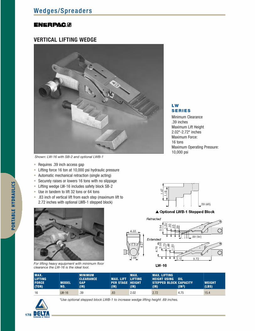
178
Wedges/SpreadersPO
RTAB
LE H
YDRA
ULIC
S
VERTICAL LIFTING WEDGE
Shown: LW-16 with SB-2 and optional LWB-1
For lifting heavy equipment with minimum floorclearance the LW-16 is the ideal tool.
• Requires .39 inch access gap• Lifting force 16 ton at 10,000 psi hydraulic pressure• Automatic mechanical retraction (single acting)• Securely raises or lowers 16 tons with no slippage• Lifting wedge LW-16 includes safety block SB-2• Use in tandem to lift 32 tons or 64 tons• .83 inch of vertical lift from each step (maximum lift to
2.72 inches with optional LWB-1 stepped block)
*Use optional stepped block LWB-1 to increase wedge lifting height .69 inches.
LWSERIES
Minimum Clearance.39 inchesMaximum Lift Height2.02*-2.72* inchesMaximum Force:16 tonsMaximum Operating Pressure:10,000 psi
MAX.LIFTINGFORCE(TON)
MODELNO.
MINIMUMCLEARANCEGAP(IN)
MAX. LIFTPER STAGE(IN)
MAX.LIFTINGHEIGHT(IN)
MAX. LIFTINGHEIGHT USINGSTEPPED BLOCK(IN)
OILCAPACITY(IN3)
WEIGHT(LBS)
16 LW-16 .39 .83 2.02 2.72 4.75 15.4
Enerpac_p178-179 final.qxd 4/5/10 12:32 PM Page 178

Wedges/Spreaders
179
PORTABLE H
YDRAULICS
HYDRAULIC WEDGIE AND SPREAD CYLINDERS
A, WRSERIES
Capacity:0.75-1 tonTip Clearance:0.50-1.38 inchesMaximum Spread Range:3.70-11.50 inchesMaximum Operating Pressure:10,000 psi
Shown clockwise from top: WR-15, WR-5, A-92
• Single-acting, spring return• WR-15: For long stroke spreading applications• WR-5: For use in very confined work areas• A-92: Spreader attachment screws onto RC-Series 10-ton
cylinders (except RC-101)
SPREADERCAPACITY(TONS)
TIPCLEARANCE(IN)
MODELNUMBER
MAXIMUMSPREAD(IN)
CYLINDEREFFECTIVEAREA(IN2)
OILCAPACITY(IN3)
WT.(LBS)
1.00 .50 WR-5 3.70 1.00 .61 5.0
.75 1.26 WR-15 11.50 2.25 3.91 25.0
1.00 1.38 A-92 6.25 – – 8.0
RC-Series Cylinders10 ton RC-Seriescylinders (except RC-101) fit into A-92Spreader Attachment.
Best Match Hand PumpTo power your Wedgieand Spreader Attachmentthe P-392 hand pump is
an ideal choice.
Right: A WR-5 wedgie cylinder is used toposition a concrete block on a constructionsite.
Enerpac_p178-179 final.qxd 4/5/10 12:32 PM Page 179

180
Bevel ing MachinesTU
BE R
EMOV
AL/
ASSE
MBL
Y TO
OLS
COBRA 100The Cobra 100 is a lightweight, high power tube-prepping machine, designed to simultaneously bevel, face and counterbore most types of tube and pipe work, as well as tube seal weld removal and J-preparation.
This versatile machine uses the option of three different torque reacted shafts to cover a size range of 12 mm (1/2") ID to64 mm (2-1/2") ID.
Each shaft locks into the bore of the work piece and self-centers for accurate and quick repeat cutting.
The Cobra 100 has also been designed for Water Wall Boiler membrane tube end preparation, able to squeeze betweentube spacing of only 60 mm.
Available with the option of 110v or 240v single-phase electric power.
Each machine comes complete with tool case, tools and operation and maintenance instructions.
PORTABLE PIPE BEVELLING MACHINE
• CUTTING RANGE:METRIC: 12 mm ID TO 64 mm OD.IMPERIAL: 1/2" ID to 2-1/2" OD.
• POWER OPTIONS:ELECTRIC: 110/240V
• PREPARATIONS:BEVELFACECOUNTER BOREJ-PREP WELD REMOVALBEVEL AND FACE IN ONEBOILER MEMBRANE END PREP
BSA_p180-208 final.qxd 4/5/10 1:26 PM Page 180

Bevel ing Machines
181
TUBE REMOVAL/
ASSEMBLY TO
OLS
COBRA 100SPECIFICATIONS
Tube Cutting Range
RANGE: 12.5 mm UP TO 64 mm OD.1/2" UP TO 2-1/2" OD.
SHAFT 1:METRIC: 12 mm UP TO 19 mm ID.INCH: 1/2" UP TO 3/4" ID.
SHAFT 2:METRIC: 19 mm UP TO 25 mm ID.INCH: 3/4" UP TO 1" ID.
SHAFT 3:METRIC: 25 mm UP TO 63 mm ID.INCH: 1" UP TO 2-1/2" ID.
Power
ELECTRIC: 620 Watts 0.83 hp
Dimensions
ELECTRIC: 190 x 445 mm 7-1/2" x 17-1/2"
WEIGHT: 6.4 Kg 14 lbs
CUTTER FEED: 40 mm 1-1/2"
The COBRA 100's Low Clearance Head
The COBRA 100 Carrying Case & Tools
Shaft 3 Bore Locking System
Short Locking Shaft Options For Use OnShort Parallel Sections, Elbows & Fittings
BSA_p180-208 final.qxd 4/5/10 1:26 PM Page 181

182
Bevel ing MachinesTU
BE R
EMOV
AL/
ASSE
MBL
Y TO
OLS
COBRA 200The COBRA 200 is a lightweight, high power tube-prepping machine, designed to simultaneously bevel, face and counterbore most types of tube and pipe work, as well as tube seal weld removal and J-preparation.
This versatile machine uses the option of three different torque reacted shafts to cover a size range of 12mm (1/2") ID to102 mm (4") ID and cut up to 115 mm (4-1/2") OD.
Each shaft locks into the bore of the work piece and self-centers for accurate and quick repeat cutting.
The Cobra 200 can also be used for Water Wall Boiler membrane tube preparation. With the option of a small cutter head,the 200 is able to squeeze between tube spacing of only 60 mm.
Available with the option of 110v or 240v single-phase electric power.
Each machine comes complete with tool case, tools and operation and maintenance instructions.
PORTABLE PIPE BEVELLING MACHINE
• CUTTING RANGE:METRIC: 12 mm ID -115 mm OD.IMPERIAL: 1/2" ID to 4-1/2" OD.
• POWER OPTIONS:ELECTRIC: 110/240V
• PREPARATIONS:BEVEL FACE COUNTER BORE J-PREP WELD REMOVAL BEVEL AND FACE IN ONE BOILER MEMBRANE END PREP
BSA_p180-208 final.qxd 4/5/10 1:26 PM Page 182

Bevel ing Machines
183
TUBE REMOVAL/
ASSEMBLY TO
OLS
COBRA 200SPECIFICATIONS
Tube Cutting Range
RANGE: 12.5 mm UP TO 115 mm OD.1/2" UP TO 4-1/2" OD.
SHAFT 1:METRIC: 12 mm UP TO 19 mm ID.INCH: 1/2" UP TO 3/4" OD.
SHAFT 2:METRIC: 19 mm UP TO 25 mm ID.INCH: 3/4" UP TO 1" ID.
SHAFT 3:METRIC: 25 mm UP TO 103 mm ID.INCH: 1" UP TO 4" ID.
Power
ELECTRIC: 700 Watts 0.9 hp
Dimensions
ELECTRIC: 190 x 560 mm 7-1/2" x 22"
WEIGHT: 7.5 Kg 16.5 lbs
CUTTER FEED: 40 mm 1-1/2"
The COBRA 200 Carrying Case & Tools
The Bore Locking System
The New 4 Slot Cutter Head
BSA_p180-208 final.qxd 4/5/10 1:26 PM Page 183

184
Bevel ing MachinesTU
BE R
EMOV
AL/
ASSE
MBL
Y TO
OLS
HORNETThe HORNET is a lightweight, high power tube-prepping machine, designed to simultaneously bevel, face and counter bore most types of pipe and tubing.
This versatile machine utilizes torque reacted integrated mandrels which align themselves on the inside of the work piece enabling the Standard Hornet machine to cover a range of 25 mm (1") to 85 mm (3.3") OD.
The machine has optional mandrels which enable the Hornet to machine tubes down to 12 mm (1/2") ID.
The Hornet can be used for boiler membrane wall tube end preparation, being able to work between tube spacing of only 68mm.
The machine is also designed for application on condenser and heat exchanger tube seal weld removal and J-preparations.
The Hornet is fitted with 0.8 HP pneumatic motor enabling it to withstand a tough working environment.
TUBE & PIPE BEVELLING MACHINE
• CUTTING RANGE:METRIC: 12.5 mm ID - 85 mm OD.IMPERIAL: 1/2" ID to 3.3" OD.
• POWER OPTIONS:PNEUMATIC: 0.80 HP
• PREPARATIONS:
BEVEL FACE COUNTER BORE J-PREP BEVEL AND FACE IN ONE BOILER MEMBRANE END PREP
BSA_p180-208 final.qxd 4/5/10 1:26 PM Page 184

Bevel ing Machines
185
TUBE REMOVAL/
ASSEMBLY TO
OLS
HORNETSPECIFICATIONS
Tube Cutting Range
RANGE: 12.5 mm UP TO 85 mm OD.1/2" UP TO 3.3" OD.
STANDARD SHAFT:METRIC: 25 mm UP TO 80 mm ID.INCH: 1" UP TO 3.15" ID.
OPTIONAL SHAFT 1:METRIC: 12 mm UP TO 19 mm ID.INCH: 1/2" UP TO 3/4" ID.
OPTIONAL SHAFT 2:METRIC: 19 mm UP TO 25 mm ID.INCH: 3/4" UP TO 1" ID.
Power
PNEUMATIC: 600 Watts 0.80 hp
Dimensions
PNEUMATIC: 360 x 400 mm 14-1/2" x 16"
WEIGHT: 6.5 Kg 14.5 lbs
CUTTER FEED: 40 mm 1-1/2"
Air Requirements
AIR FLOW: 936 l/min 34 cfm AIR PRESSURE: 6 bar 90 psi HOSE SIZE: 12.5 mm 1/2"
The Hornet Shaft & 2 Slot Cutter Head
The Hornet Carrying Case & Tools
BSA_p180-208 final.qxd 4/5/10 1:26 PM Page 185

186
Bevel ing MachinesTU
BE R
EMOV
AL/
ASSE
MBL
Y TO
OLS
SUPER HORNETThe SUPER HORNET machine is a lightweight, high power tube-prepping machine; designed to simultaneously bevel,face and counter bore most types of pipe and tubing.
This versatile machine utilizes torque reacted integrated mandrels which align themselves on the inside of the work piece enabling the Super Hornet machine to cover a range of 25 mm (1") to 115 mm (4-1/2") OD.
The machine has optional mandrels which enable the Super Hornet to machine tubes down to 12mm (1/2") ID.
The Super Hornet is a more powerful alternative to the Standard Hornet, with the versatility to cut larger diameter and thick wall tubes and still be used for boiler membrane wall tube end preparation, with tube spacing of only 68 mm (2.7").
The machine is also designed for application on condenser and heat exchanger tube seal weld removal and J-preparations.
The Super Hornet is fitted with 1.5 HP pneumatic enabling the Hornet machines to withstand a tough working environment.
TUBE & PIPE BEVELLING MACHINE
• CUTTING RANGE:METRIC: 12.5 mm ID -115 mm OD.IMPERIAL: 1/2" ID to 4-1/2" OD.
• POWER OPTIONS:PNEUMATIC: 1.5 HP
• PREPARATIONS:
BEVEL FACE COUNTER BORE J-PREP BEVEL AND FACE IN ONE BOILER MEMBRANE END PREP
BSA_p180-208 final.qxd 4/5/10 1:26 PM Page 186

Bevel ing Machines
187
TUBE REMOVAL/
ASSEMBLY TO
OLS
SUPER HORNETSPECIFICATIONS
Tube Cutting Range
RANGE: 12.5 mm UP TO 115 mm OD.1/2" UP TO 4-1/2" OD.
STANDARD SHAFT:METRIC: 25 mm UP TO 103 mm ID.INCH: 1" UP TO 4" OD.
OPTIONAL SHAFT 1:METRIC: 12 mm UP TO 19 mm ID.INCH: 1/2" UP TO 3/4" ID.
OPTIONAL SHAFT 2:METRIC: 19 mm UP TO 25 mm ID.INCH: 3/4" UP TO 1" ID.
Power
PNEUMATIC: 1125 Watts 1.5 hp
ELECTRIC AVAILABLE ON REQUEST
Dimensions
PNEUMATIC: 360 x 400 mm 14-1/2" x 16"
WEIGHT: 8 Kg 22 lbs
CUTTER FEED: 40 mm 1-1/2"
Air Requirements
AIR FLOW: 1350 l/min 50 cfm AIR PRESSURE: 6 bar 90 psi HOSE SIZE: 12.5 mm 1/2”
The Bore Locking Collet & Shaft Assembly& Standard 4 Slot Cutter Head
The Super Hornet Carrying Case & Tool Kit
BSA_p180-208 final.qxd 4/5/10 1:26 PM Page 187
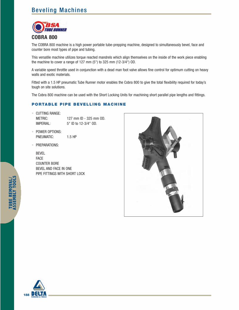
188
Bevel ing MachinesTU
BE R
EMOV
AL/
ASSE
MBL
Y TO
OLS
COBRA 800The COBRA 800 machine is a high power portable tube-prepping machine, designed to simultaneously bevel, face andcounter bore most types of pipe and tubing.
This versatile machine utilizes torque reacted mandrels which align themselves on the inside of the work piece enablingthe machine to cover a range of 127 mm (5") to 325 mm (12-3/4") OD.
A variable speed throttle used in conjunction with a dead man foot valve allows fine control for optimum cutting on heavywalls and exotic materials.
Fitted with a 1.5 HP pneumatic Tube Runner motor enables the Cobra 800 to give the total flexibility required for today’stough on site solutions.
The Cobra 800 machine can be used with the Short Locking Units for machining short parallel pipe lengths and fittings.
PORTABLE PIPE BEVELLING MACHINE
• CUTTING RANGE:METRIC: 127 mm ID - 325 mm OD.IMPERIAL: 5" ID to 12-3/4" OD.
• POWER OPTIONS:PNEUMATIC: 1.5 HP
• PREPARATIONS:
BEVEL FACE COUNTER BORE BEVEL AND FACE IN ONE PIPE FITTINGS WITH SHORT LOCK
BSA_p180-208 final.qxd 4/5/10 1:26 PM Page 188

Bevel ing Machines
189
TUBE REMOVAL/
ASSEMBLY TO
OLS
COBRA 800SPECIFICATIONS
Tube Cutting Range
RANGE: 127 mm UP TO 325 mm OD.5" UP TO 12-3/4" OD.
OPTIONAL SHAFT 1:METRIC: 127 mm UP TO 191 mm ID.INCH: 5" UP TO 7-1/2" ID.
OPTIONAL SHAFT 2:METRIC: 191 mm UP TO 255 mm ID.INCH: 7-1/2" UP TO 10" ID.
OPTIONAL SHAFT 2:METRIC: 241 mm UP TO 306 mm ID.INCH: 9-1/2" UP TO 12" ID.
Power
PNEUMATIC: 1125 Watts 1.5 hp
Dimensions
PNEUMATIC: 405 x 650 mm 16" x 26"
Weight
PNEUMATIC: 19 Kg 42 lbs
CUTTER FEED: 40 mm 1-1/2"
Air Requirements
AIR FLOW: 1300 l/min 46 cfm AIR PRESSURE: 6 bar 90 psi HOSE SIZE: 12.5 mm 1/2"
The Shaft Assembly For Short ParallelSection Tubes and Fittings
The Torque Reaction Splines
BSA_p180-208 final.qxd 4/5/10 1:26 PM Page 189

190
Tube Pul lersTU
BE R
EMOV
AL/
ASSE
MBL
Y TO
OLS
JAVELINBSA Tube Runner is pleased to introduce the new JAVELIN Tube Puller. This compact and dependable tube pulling machineis designed for continuous and stub removal of tubes from heat exchangers, condensers and boilers. The JAVELIN hasbeen designed for use where access is tight, ideal for squeezing down ships gangways, but without compromising poweror pulling capacity.
Using our tried and tested extraction system, JAVELIN can pull tubes continuously from between 12.5mm OD. (1/2") and50.8mm OD. (2")** with a choice of 30 & 60 ton pulling gun options.
Easily adapted for stub pulling, the JAVELIN uses simple attachments to remove tube stubs where access or tube diameterprevents continuous tube removal.
Whatever your working environment we have a Powerpack option to suit. We offer a choice of Electric Powerpacks in arange of voltages for workshop and low hazard areas, or a Fully Pneumatic Powerpack, designed especially for use inhazardous environments, like petrochemical refineries, where spark risks are present.
The JAVELIN is a truly versatile machine; essential equipment for contractors with tight access jobs or sample extraction,without compromising reliability and capacity.
TUBE PULLING MACHINE
• TUBE EXTRACTION RANGE:30 TON: 12.5 mm – 32 mm (1/2" – 1-1/4") OD.60 TON: 38 mm – 51 mm (1-1/2" – 2") OD.
• POWER OPTIONS:ELECTRIC: 220 – 330V 3 PHASE
110 V OR 240 V SINGLE PHASE
• PNEUMATIC: 3 hp 90 cfm
* Achieved with the 30 Ton Pulling Gun ** Achieved with the 60 Ton Pulling Gun
BSA_p180-208 final.qxd 4/5/10 1:26 PM Page 190

Tube Pul lers
191
TUBE REMOVAL/
ASSEMBLY TO
OLS
JAVELINSPECIFICATIONS
30 Ton Pulling Gun
Min Tube Size OD 12.5 mm (1/2") Max Tube Size OD 32 mm (1-1/4") Max Pull Force 30,000 Kg Weight 26 Kg (57 lbs) Pulling Stroke 125 mm (5")
60 Ton Pulling Gun
Min Tube Size OD 38 mm (1-1/2") Max Tube Size OD 51 mm (2") Max Pull Force 60,000 Kg Weight 31 Kg (68 lbs) Pulling Stroke 102 mm (4")
Powerpack Options
DIMENSIONS 300 X 600 X 650 mm OPERATING PRESSURE HIGH POWER 680 bar @ 1 l/min HIGH PRESSURE 55 bar @ 7 l/min
Electric
POWER 1125W 1.5hp VOLTAGE 220-330 Volt 3 PHASE
110-240 Volt 1 PHASE
Pneumatic
POWER 2.25 Kw 3 hp AIR REQUIREMENTS 2430 l/min 90 cfm
6 bar 90 Psi
The 60 Ton Capacity Pulling gun
The 30 Ton Capacity Pulling Gun
The Javelin Tool Kit
The Javelin with Castor Trolly Option
BSA_p180-208 final.qxd 4/5/10 1:27 PM Page 191

192
Tube Pul lersTU
BE R
EMOV
AL/
ASSE
MBL
Y TO
OLS
TRIDENTBSA Tube Runner is pleased to introduce the new TRIDENT tube puller. This fast and dependable automatic tube pullingmachine is designed for continuous and stub removal of tubes from heat exchangers, condensers and boilers.
Using our tried and tested extraction system, tubes can be continuously pulled from between 12.5 mm OD. (1/2") and 76mm OD. (3")** at up to 5 m/Min*, a choice of 15, 30 & 45 ton pulling gun options are available.
Easily adapted for stub pulling, TRIDENT uses simple attachments to remove tube stubs where access or tube diameterprevents continuous tube removal.
Whatever your working environment we have a Powerpack option to suit. We offer a 380 – 415 Volt 3 Phase ElectricPowerpack for workshop and low hazard areas, or Fully Pneumatic 6.5HP Powerpack, designed especially for use inhazardous environments, like petrochemical refineries, where spark risks are present. A Pneumatic machine with 24 Voltelectric controls is also available for semi-hazardous or humid environments.
TRIDENT is truly essential equipment for fast turnaround jobs where time is money and reliability is essential.
TUBE PULLING MACHINE
• TUBE EXTRACTION RANGE:15 TON: 12.5 mm – 25 mm (1/2" – 1") OD.30 TON: 12.5 mm – 38 mm (1/2" – 1-1/2") OD.45 TON: 38 mm – 76 mm (1-1/2" – 3") OD.
• POWER OPTIONS:ELECTRIC: 380 – 415V 3 PHASE PNEUMATIC: 6.5hp PNEUMATIC ELECTRIC: 6.5hp with 24V Controls
* Achieved with the 15 Ton Pulling Gun ** Achieved with the 45 Ton Pulling Gun
BSA_p180-208 final.qxd 4/5/10 1:27 PM Page 192

Tube Pul lers
193
TUBE REMOVAL/
ASSEMBLY TO
OLS
TRIDENTSPECIFICATIONS
15 Ton Pulling Gun
Min Tube Size OD 12.5 mm (1/2") Max Tube Size OD 25 mm (1") Free Pull Speed 5 M/Min Max Pull Force 15,000 Kg Weight 26 Kg (57 lbs) Pulling Stroke 125 mm (5")
30 Ton Pulling Gun
Min Tube Size OD 12.5 mm (1/2") Max Tube Size OD 38 mm (1-1/2") Free Pull Speed 3 M/Min Max Pull Force 30,000 Kg Weight 52 Kg (114 lbs) Pulling Stroke 150 mm (6")
45 Ton Pulling Gun
Min Tube Size OD 38 mm (1-1/2") Max Tube Size OD 76 mm (3") Free Pull Speed 1.5 M/Min Max Pull Force 45,000 Kg Weight 67 Kg (145 lbs) Pulling Stroke 75 mm (3")
Powerpack Options
DIMENSIONS 980 X 740 X 1150 mm OPERATING PRESSURE HIGH SPEED 1350 PSI @ 28 l/min HIGH PRESSURE 4500 PSI @ 8 l/min
Electric
POWER 4 Kw 5.5hp VOLTAGE 380–415 Volt 3 PHASE OPERATING SPEED 1500 RPM
Pneumatic
POWER 5.5 Kw 6.5hp AIR REQUIREMENTS 3400 l/min 120 cfm
6 bar 90 Psi
The 45 Ton Pulling Gun
The 30 Ton Pulling Gun
Consumable Items Needed To Pull Tubes
BSA_p180-208 final.qxd 4/5/10 1:27 PM Page 193

194
Tube ExpandersTU
BE R
EMOV
AL/
ASSE
MBL
Y TO
OLS
TUBE EXPANDERS800 SERIES
• Range covers tube sizes from 12.7 mm (1/2") OD up to 38.1 mm (1-1/2") OD.
• Available with 38.1 mm (1-1/2") or 57.1 mm (2-1/4") roll lengths for tube
sheet thickness from 12.7 mm (1/2") to 57.1 mm (2-1/4").
• Each expander features a reversible collar flush one side, recessed by 3.2
mm (1/8") on the reverse side.
• Totally interchangeable with Airetool, Wicksteed and Teco 800 expanders. 5 roll expanders also available.
EXPANSION RANGE 38.1 MM 57.1MM1-1/2" ROLLS 2-1/4" ROLLS
MM INCH MANDRELMIN ID MAX MIN ID MAX EXPANDER ROLL SET EXPANDER ROLL SET 9.5MM (3/8")
TUBE OD. & BWG. EXPANSION EXPANSION SQUARE DRIVE
1/2" 12.7mm14 8.23 9.50 .324 .374 TR-797 TRR-797 - - TRM-797 15 8.86 10.11 .349 .398 TR-799 TRR-1 - - TRM-79916 9.14 10.41 .360 .410 TR-801 TRR-1 - - TRM-117 9.50 10.77 .374 .424 TR-803 TRR-2 - - TRM-118 9.96 11.35 .392 .447 TR-805 TRR-3 - - TRM-2
5/8" 15.88mm 12 9.96 11.35 .392 .447 TR-805 TRR-3 - - TRM-2 13 10.79 12.19 .425 .480 TR-807 TRR-4 - - TRM-3 14 11.40 12.73 .499 .509 TR-809 TRR-4 TR-810 TRR-4-A TRM-415 11.96 13.61 .471 .536 TR-811 TRR-5 TR-812 TRR-5-A TRM-5 16 12.32 13.97 .485 .550 TR-813 TRR-6 TR-814 TRR-7-A TRM-517 12.67 14.32 .499 .564 TR-815 TRR-6 TR-816 TRR-6-A TRM-6 18 13.13 14.53 .517 .572 TR-817 TRR-7 TR-818 TRR-7-A TRM-7
3/4" 19.05mm 10 11.96 13.61 .471 .536 TR-811 TRR-5 TR-812 TRR-5-A TRM-5 11 12.67 14.32 .499 .564 TR-815 TRR-6 TR-816 TRR-6-A TRM-6 12 13.26 14.78 .522 .582 TR-819 TRR-7 TR-820 TRR-7-A TRM-613 13.97 15.62 .550 .615 TR-821 TRR-8 TR-822 TRR-8-A TRM-8 14 14.58 16.23 .574 .639 TR-823 TRR-9 TR-824 TRR-9-A TRM-815 15.14 16.79 .596 .661 TR-825 TRR-10 TR-826 TRR-10-A TRM-8 16 15.37 17.40 .605 .685 TR-827 TRR-10 TR-828 TRR-10-A TRM-917 15.72 17.75 .619 .699 TR-829 TRR-11 TR-830 TRR-11-A TRM-9 18 15.72 17.75 .619 .699 TR-829 TRR-11 TR-830 TRR-11-A TRM-9
7/8" 22.23mm 10 15.14 16.79 .596 .661 TR-825 TRR-10 TR-826 TRR-10-A TRM-811 15.72 17.75 .619 .699 TR-829 TRR-11 TR-830 TRR-11-A TRM-9 12 16.31 18.34 .642 .722 TR-831 TRR-12 TR-832 TRR-12-A TRM-9 13 17.02 19.05 .670 .750 TR-833 TRR-13 TR-834 TRR-13-A TRM-10 14 17.40 19.66 .685 .774 TR-835 TRR-14 TR-836 TRR-14-A TRM-11 15 18.08 20.34 .712 .801 TR-837 TRR-15 TR-838 TRR-15-A TRM-11 16 18.44 20.70 .726 .815 TR-839 TRR-15 TR-840 TRR-15-A TRM-12 17 18.80 21.06 .740 .829 TR-843 TRR-16 TR-844 TRR-16-A TRM-12 18 18.80 21.06 .740 .829 TR-843 TRR-16 TR-844 TRR-16-A TRM-12
1" 25.4mm 08 16.64 18.67 .655 .735 TR-841 TRR-13 TR-842 TRR-13-A TRM-9 09 17.40 19.66 .685 .774 TR-835 TRR-14 TR-836 TRR-14-A TRM-11 10 18.08 20.34 .712 .801 TR-837 TRR-15 TR-838 TRR-15-A TRM-11 11 18.80 21.06 .740 .829 TR-843 TRR-16 TR-844 TRR-16-A TRM-12 12 19.38 21.64 .763 .852 TR-845 TRR-17 TR-846 TRR-17-A TRM-12 13 20.09 22.35 .791 .880 TR-847 TRR-18 TR-848 TRR-18-A TRM-12 14 20.57 23.09 .810 .909 TR-849 TRR-18 TR-850 TRR-18-A TRM-13 15 21.26 23.77 .837 .936 TR-851 TRR-19 TR-852 TRR-19-A TRM-13 16 21.26 23.77 .837 .936 TR-851 TRR-19 TR-852 TRR-19-A TRM-13 17 21.97 24.48 .865 .964 TR-855 TRR-21 TR-856 TRR-21-A TRM-13 18-20 21.97 24.48 .865 .964 TR-855 TRR-21 TR-856 TRR-21-A TRM-13
BSA_p180-208 final.qxd 4/5/10 1:27 PM Page 194

Tube Expanders
195
TUBE REMOVAL/
ASSEMBLY TO
OLS
TUBE EXPANDERS800 SERIES
EXPANSION RANGE 38.1 MM 57.1MM1-1/2" ROLLS 2-1/4" ROLLS
MM INCH MANDRELMIN ID MAX MIN ID MAX EXPANDER ROLL SET EXPANDER ROLL SET 9.5MM (3/8")
TUBE OD. & BWG. EXPANSION EXPANSION SQUARE DRIVE
1-1/8" 28.58mm 08 19.71 22.22 .766 .875 TR-853 TRR-20 TR-854 TRR-20-A TRM-13
09 20.57 23.09 .810 .909 TR-849 TRR-18 TR-850 TRR-18-A TRM-13
10 21.26 23.77 .837 .936 TR-851 TRR-19 TR-852 TRR-19-A TRM-13
11 21.97 24.48 .865 .964 TR-855 TRR-21 TR-856 TRR-21-A TRM-13
12 22.43 24.94 .883 .982 TR-857 TRR-21 TR-858 TRR-21-A TRM-14
13 23.57 25.78 .916 1.015 TR-859 TRR-22 TR-860 TRR-22-A TRM-14MANDREL
Expanders from this size onward use a 12.7mm (1/2") Square Drive. 12.7mm (1/2")Square Drive
14 23.75 26.52 .835 1.044 TR-861 TRR-23 TR-862 TRR-23-A TRM-15
15 24.43 27.20 .962 1.071 TR-863 TRR-24 TR-864 TRR-24-A TRM-15
16 24.43 27.20 .962 1.071 TR-863 TRR-24 TR-864 TRR-24-A TRM-15
17 25.15 27.91 .990 1.099 TR-867 TRR-26 TR-868 TRR-26-A TRM-16
18 25.15 27.91 .990 1.099 TR-867 TRR-26 TR-868 TRR-26-A TRM-16
1-1/4" 31.75mm 08 22.88 26.65 .901 1.010 TR-865 TRR-25 TR-866 TRR-25-A TRM-15
09 23.75 26.52 .935 1.044 TR-861 TRR-23 TR-862 TRR-23-A TRM-15
10 24.43 27.20 .962 1.071 TR-863 TRR-24 TR-864 TRR-24-A TRM-15
11 25.15 27.91 .990 1.099 TR-867 TRR-26 TR-868 TRR-26-A TRM-16
12 25.73 28.50 1.013 1.122 TR-869 TRR-27 TR-870 TRR-27-A TRM-16
13 26.44 29.21 1.041 1.150 TR-871 TRR-28 TR-872 TRR-28-A TRM-17
14 26.92 29.69 1.060 1.169 TR-873 TRR-29 TR-874 TRR-29-A TRM-17
15 27.61 30.38 1.087 1.196 TR-875 TRR-30 TR-876 TRR-30-A TRM-17
16 27.61 30.38 1.087 1.196 TR-875 TRR-30 TR-876 TRR-30-A TRM-17
1-3/8" 34.90mm 08 26.06 28.83 1.026 1.135 TR-877 TRR-31 TR-878 TRR-31-A TRM-17
09 26.92 29.69 1.060 1.169 TR-873 TRR-29 TR-874 TRR-29-A TRM-17
10 27.61 30.38 1.087 1.196 TR-875 TRR-30 TR-876 TRR-30-A TRM-17
11 28.32 31.09 1.115 1.224 TR-879 TRR-30 TR-880 TRR-30-A TRM-18
12 28.78 31.55 1.133 1.242 TR-881 TRR-32 TR-882 TRR-32-A TRM-18
13 29.46 32.38 1.160 1.275 TR-883 TRR-33 TR-884 TRR-33-A TRM-19
14 29.95 32.87 1.179 1.294 TR-885 TRR-34 TR-886 TRR-34-A TRM-20
15 30.63 33.55 1.206 1.321 TR-887 TRR-35 TR-888 TRR-35-A TRM-20
16 30.63 33.55 1.206 1.321 TR-887 TRR-35 TR-888 TRR-35-A TRM-20
1-1/2" 38.10mm 08 29.08 32.00 1.145 1.260 TR-889 TRR-34 TR-890 TRR-34-A TRM-19
09 29.95 32.87 1.179 1.294 TR-885 TRR-34 TR-886 TRR-34-A TRM-20
10 30.63 33.55 1.206 1.321 TR-887 TRR-35 TR-888 TRR-35-A TRM-20
11 31.37 34.29 1.235 1.350 TR-891 TRR-36 TR-892 TRR-36-A TRM-20
12 31.93 34.85 1.257 1.372 TR-893 TRR-37 TR-894 TRR-37-A TRM-20
13 32.64 35.56 1.285 1.400 TR-895 TRR-37 TR-896 TRR-37-A TRM-21
14 32.64 35.56 1.285 1.400 TR-895 TRR-37 TR-896 TRR-37-A TRM-21
15 33.81 36.73 1.331 1.446 TR-897 TRR-38 TR-898 TRR-38-A TRM-21
BSA_p180-208 final.qxd 4/5/10 1:27 PM Page 195
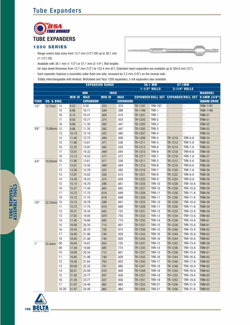
196
Tube ExpandersTU
BE R
EMOV
AL/
ASSE
MBL
Y TO
OLS
TUBE EXPANDERS1200 SERIES
• Range covers tube sizes from 12.7 mm (1/2") OD up to 38.1 mm
(1-1/2") OD.
• Available with 38.1 mm (1-1/2") or 57.1 mm (2-1/4"). Roll lengths
for tube sheet thickness from 12.7 mm (1/2") to 152.4 mm (6"). Extended reach expanders are available up to 304.8 mm (12").
• Each expander features a reversible collar flush one side, recessed by 3.2 mm (1/8") on the reverse side.
• Totally interchangeable with Airetool, Wicksteed and Teco 1200 expanders. 5 roll expanders also available.
EXPANSION RANGE 38.1 MM 57.1MM1-1/2" ROLLS 2-1/4" ROLLS
MM INCH MANDRELMIN ID MAX MIN ID MAX EXPANDER ROLL SET EXPANDER ROLL SET 9.5MM (3/8")
TUBE OD. & BWG. EXPANSION EXPANSION SQUARE DRIVE1/2" 12.7mm 14 8.23 9.50 .324 .374 TR-1197 TRR-797 - - TRM-1197
15 8.86 10.11 .349 .398 TR-1199 TRR-1 - - TRM-1199 16 9.14 10.41 .360 .410 TR-1201 TRR-1 - - TRM-51 17 9.50 10.77 .374 .424 TR-1203 TRR-2 - - TRM-51 18 9.96 11.35 .392 .447 TR-1205 TRR-3 - - TRM-52
5/8" 15.88mm 12 9.96 11.35 .392 .447 TR-1205 TRR-3 - - TRM-52 13 10.79 12.19 .425 .480 TR-1207 TRR-4 - - TRM-53 14 11.40 12.73 .499 .509 TR-1209 TRR-4 TR-1210 TRR-4-A TRM-54 15 11.96 13.61 .471 .536 TR-1211 TRR-5 TR-1212 TRR-5-A TRM-55 16 12.32 13.97 .485 .550 TR-1213 TRR-6 TR-1214 TRR-7-A TRM-55 17 12.67 14.32 .499 .564 TR-1215 TRR-6 TR-1216 TRR-6-A TRM-56 18 13.13 14.53 .517 .572 TR-1217 TRR-7 TR-1218 TRR-7-A TRM-57
3/4" 19.05mm 10 11.96 13.61 .471 .536 TR-1211 TRR-5 TR-1212 TRR-5-A TRM-55 11 12.67 14.32 .499 .564 TR-1215 TRR-6 TR-1216 TRR-6-A TRM-56 12 13.26 14.78 .522 .582 TR-1219 TRR-7 TR-1220 TRR-7-A TRM-56 13 13.97 15.62 .550 .615 TR-1221 TRR-8 TR-1222 TRR-8-A TRM-58 14 14.58 16.23 .574 .639 TR-1223 TRR-9 TR-1224 TRR-9-A TRM-58 15 15.14 16.79 .596 .661 TR-1225 TRR-10 TR-1226 TRR-10-A TRM-58 16 15.37 17.40 .605 .685 TR-1227 TRR-10 TR-1228 TRR-10-A TRM-59 17 15.72 17.75 .619 .699 TR-1229 TRR-11 TR-1230 TRR-11-A TRM-59 18 15.72 17.75 .619 .699 TR-1229 TRR-11 TR-1230 TRR-11-A TRM-59
7/8" 22.23mm 10 15.14 16.79 .596 .661 TR-1225 TRR-10 TR-1226 TRR-10-A TRM-58 11 15.72 17.75 .619 .699 TR-1229 TRR-11 TR-1230 TRR-11-A TRM-59 12 16.31 18.34 .642 .722 TR-1231 TRR-12 TR-1232 TRR-12-A TRM-59 13 17.02 19.05 .670 .750 TR-1233 TRR-13 TR-1234 TRR-13-A TRM-60 14 17.40 19.66 .685 .774 TR-1235 TRR-14 TR-1236 TRR-14-A TRM-61 15 18.08 20.34 .712 .801 TR-1237 TRR-15 TR-1238 TRR-15-A TRM-61 16 18.44 20.70 .726 .815 TR-1239 TRR-15 TR-1240 TRR-15-A TRM-62 17 18.80 21.06 .740 .829 TR-1243 TRR-16 TR-1244 TRR-16-A TRM-62 18 18.80 21.06 .740 .829 TR-1243 TRR-16 TR-1244 TRR-16-A TRM-62
1" 25.4mm 08 16.64 18.67 .655 .735 TR-1241 TRR-13 TR-1242 TRR-13-A TRM-59 09 17.40 19.66 .685 .774 TR-1235 TRR-14 TR-1236 TRR-14-A TRM-61 10 18.08 20.34 .712 .801 TR-1237 TRR-15 TR-1238 TRR-15-A TRM-61 11 18.80 21.06 .740 .829 TR-1243 TRR-16 TR-1244 TRR-16-A TRM-62 12 19.38 21.64 .763 .852 TR-1245 TRR-17 TR-1246 TRR-17-A TRM-62 13 20.09 22.35 .791 .880 TR-1247 TRR-18 TR-1248 TRR-18-A TRM-62 14 20.57 23.09 .810 .909 TR-1249 TRR-18 TR-1250 TRR-18-A TRM-63 15 21.26 23.77 .837 .936 TR-1251 TRR-19 TR-1252 TRR-19-A TRM-63 16 21.26 23.77 .837 .936 TR-1251 TRR-19 TR-1252 TRR-19-A TRM-63 17 21.97 24.48 .865 .964 TR-1255 TRR-21 TR-1256 TRR-21-A TRM-63 18-20 21.97 24.48 .865 .964 TR-1255 TRR-21 TR-1256 TRR-21-A TRM-63
BSA_p180-208 final.qxd 4/5/10 1:27 PM Page 196

Tube Expanders
197
TUBE REMOVAL/
ASSEMBLY TO
OLS
TUBE EXPANDERS1200 SERIES
EXPANSION RANGE 38.1 MM 57.1MM1-1/2" ROLLS 2-1/4" ROLLS
MM INCH MANDRELMIN ID MAX MIN ID MAX EXPANDER ROLL SET EXPANDER ROLL SET 9.5MM (3/8")
TUBE OD. & BWG. EXPANSION EXPANSION SQUARE DRIVE
1-1/8" 28.58mm 08 19.71 22.22 .766 .875 TR-1253 TRR-20 TR-1254 TRR-20-A TRM-63
09 20.57 23.09 .810 .909 TR-1249 TRR-18 TR-1250 TRR-18-A TRM-63
10 21.26 23.77 .837 .936 TR-1251 TRR-19 TR-1252 TRR-19-A TRM-63
11 21.97 24.48 .865 .964 TR-1255 TRR-21 TR-1256 TRR-21-A TRM-63
12 22.43 24.94 .883 .982 TR-1257 TRR-21 TR-1258 TRR-21-A TRM-64
13 23.57 25.78 .916 1.015 TR-1259 TRR-22 TR-1260 TRR-22-A TRM-64MANDREL
Expanders from this size onward use a 12.7mm (1/2") Square Drive. 12.7mm (1/2")Square Drive
14 23.75 26.52 .835 1.044 TR-1261 TRR-23 TR-1262 TRR-23-A TRM-65
15 24.43 27.20 .962 1.071 TR-1263 TRR-24 TR-1264 TRR-24-A TRM-65
16 24.43 27.20 .962 1.071 TR-1263 TRR-24 TR-1264 TRR-24-A TRM-65
17 25.15 27.91 .990 1.099 TR-1267 TRR-26 TR-1268 TRR-26-A TRM-66
18 25.15 27.91 .990 1.099 TR-1267 TRR-26 TR-1268 TRR-26-A TRM-66
1-1/4" 31.75mm 08 22.88 26.65 .901 1.010 TR-1265 TRR-25 TR-1266 TRR-25-A TRM-65
09 23.75 26.52 .935 1.044 TR-1261 TRR-23 TR-1262 TRR-23-A TRM-65
10 24.43 27.20 .962 1.071 TR-1263 TRR-24 TR-1264 TRR-24-A TRM-65
11 25.15 27.91 .990 1.099 TR-1267 TRR-26 TR-1268 TRR-26-A TRM-66
12 25.73 28.50 1.013 1.122 TR-1269 TRR-27 TR-1270 TRR-27-A TRM-66
13 26.44 29.21 1.041 1.150 TR-1271 TRR-28 TR-1272 TRR-28-A TRM-67
14 26.92 29.69 1.060 1.169 TR-1273 TRR-29 TR-1274 TRR-29-A TRM-67
15 27.61 30.38 1.087 1.196 TR-1275 TRR-30 TR-1276 TRR-30-A TRM-67
16 27.61 30.38 1.087 1.196 TR-1275 TRR-30 TR-1276 TRR-30-A TRM-67
1-3/8" 34.90mm 08 26.06 28.83 1.026 1.135 TR-1277 TRR-31 TR-1278 TRR-31-A TRM-67
09 26.92 29.69 1.060 1.169 TR-1273 TRR-29 TR-1274 TRR-29-A TRM-67
10 27.61 30.38 1.087 1.196 TR-1275 TRR-30 TR-1276 TRR-30-A TRM-67
11 28.32 31.09 1.115 1.224 TR-1279 TRR-30 TR-1280 TRR-30-A TRM-68
12 28.78 31.55 1.133 1.242 TR-1281 TRR-32 TR-1282 TRR-32-A TRM-68
13 29.46 32.38 1.160 1.275 TR-1283 TRR-33 TR-1284 TRR-33-A TRM-69
14 29.95 32.87 1.179 1.294 TR-1285 TRR-34 TR-1286 TRR-34-A TRM-70
15 30.63 33.55 1.206 1.321 TR-1287 TRR-35 TR-1288 TRR-35-A TRM-70
16 30.63 33.55 1.206 1.321 TR-1287 TRR-35 TR-1288 TRR-35-A TRM-70
1-1/2" 38.10mm 08 29.08 32.00 1.145 1.260 TR-1289 TRR-34 TR-1290 TRR-34-A TRM-69
09 29.95 32.87 1.179 1.294 TR-1285 TRR-34 TR-1286 TRR-34-A TRM-70
10 30.63 33.55 1.206 1.321 TR-1287 TRR-35 TR-1288 TRR-35-A TRM-70
11 31.37 34.29 1.235 1.350 TR-1291 TRR-36 TR-1292 TRR-36-A TRM-70
12 31.93 34.85 1.257 1.372 TR-1293 TRR-37 TR-1294 TRR-37-A TRM-70
13 32.64 35.56 1.285 1.400 TR-1295 TRR-37 TR-1296 TRR-37-A TRM-71
14 32.64 35.56 1.285 1.400 TR-1295 TRR-37 TR-1296 TRR-37-A TRM-71
15 33.81 36.73 1.331 1.446 TR-1297 TRR-38 TR-1298 TRR-38-A TRM-71
BSA_p180-208 final.qxd 4/5/10 1:27 PM Page 197

198
Tube ExpandersTU
BE R
EMOV
AL/
ASSE
MBL
Y TO
OLS
TUBE EXPANDERS900 SERIES
• Range covers tube sizes from 6.35 mm (1/4") OD up to 9.53 mm (3/8") OD.• Available with 19 mm (3/4") or 32 mm (1-1/4") roll lengths for tube sheet thickness from 3.18 mm (1/8")
to 29 mm (1.14").
EXPANSION RANGE 19 MM 32MM3/4" ROLLS 1-1/4" ROLLS
MM INCH MANDRELTUBE OD. & MIN ID MAX MIN ID MAX EXPANDER ROLL SET EXPANDER ROLL SET 6.35MM (1/4")BWG. EXPANSION EXPANSION SQUARE DRIVE
1/4" 6.35 mm 20 4.44 5.21 0.175 0.205 TR-923 TRR-923 - - TRM-40
21 4.57 5.38 0.180 0.212 TR-924 TRR-924 - - TRM-40
22 4.83 5.59 0.190 0.220 TR-925 TRR-925 - - TRM-41
23 4.95 5.74 0.195 0.226 TR-926 TRR-926 - - TRM-41
24 5.10 5.92 0.201 0.232 TR-927 TRR-927 - - TRM-41
3/8" 9.53 mm 14 5.05 5.88 0.199 0.232 TR-914 TRR-914 - - TRM-35
15 5.84 6.73 0.230 0.265 TR-915 TRR-915 - - TRM-36
16 6.15 6.98 0.242 0.275 TR-916 TRR-916 - - TRM-36
17 6.48 7.34 0.255 0.289 TR-918 TRR-903 - - TRM-37
18 6.85 7.80 0.272 0.307 TR-901 TRR-903 TR-902 TRR-904 TRM-30
19 7.26 8.12 0.286 0.320 TR-903 TRR-903 TR-904 TRR-904 TRM-31
20 7.62 8.48 0.300 0.334 TR-905 TRR-907 TR-906 TRR-908 TRM-32
21 7.77 8.61 0.306 0.340 TR-907 TRR-907 TR-908 TRR-908 TRM-33
22 7.98 8.86 0.314 0.349 TR-909 TRR-909 TR-910 TRR-910 TRM-34
23 8.13 9.08 0.320 0.357 TR-911 TRR-911 TR-912 TRR-912 TRM-34
24 8.13 9.08 0.320 0.357 TR-911 TRR-911 TR-912 TRR-912 TRM-34
BSA_p180-208 final.qxd 4/5/10 1:27 PM Page 198

Tube Expanders
199
TUBE REMOVAL/
ASSEMBLY TO
OLS
TUBE EXPANDERS1300 SERIES
• Range covers tube sizes from 6.35 mm (1/4") OD up to 9.53 mm (3/8") OD.• Available with 19 mm (3/4") or 32 mm (1-1/4") roll lengths for tube sheet thickness from 3.18 mm (1/8") to 84.9 mm
(3.35").
EXPANSION RANGE 19 MM 32MM3/4" ROLLS 1-1/4" ROLLS
MM INCH MANDRELTUBE OD. & MIN ID MAX MIN ID MAX EXPANDER ROLL SET EXPANDER ROLL SET 6.35MM (1/4")BWG. EXPANSION EXPANSION SQUARE DRIVE
3/8" 9.53mm 15 5.84 6.73 0.230 0.265 - - TR-1316 TRR-1316 TRM-86
18 6.85 7.80 0.272 0.307 TR-1301 TRR-903 TR-1302 TRR-902 TRM-80
19 7.26 8.12 0.286 0.320 TR-1303 TRR-903 TR-1304 TRR-904 TRM-81
20 7.62 8.48 0.300 0.334 TR-1305 TRR-907 TR-1306 TRR-908 TRM-82
21 7.77 8.61 0.306 0.340 TR-1307 TRR-907 TR-1308 TRR-908 TRM-83
22 7.98 8.86 0.314 0.349 TR-1309 TRR-909 TR-1310 TRR-910 TRM-84
23 8.13 9.08 0.320 0.357 TR-1311 TRR-911 TR-1312 TRR-912 TRM-84
24 8.13 9.08 0.320 0.357 TR-1311 TRR-911 TR-1312 TRR-912 TRM-84
BSA_p180-208 final.qxd 4/5/10 1:27 PM Page 199
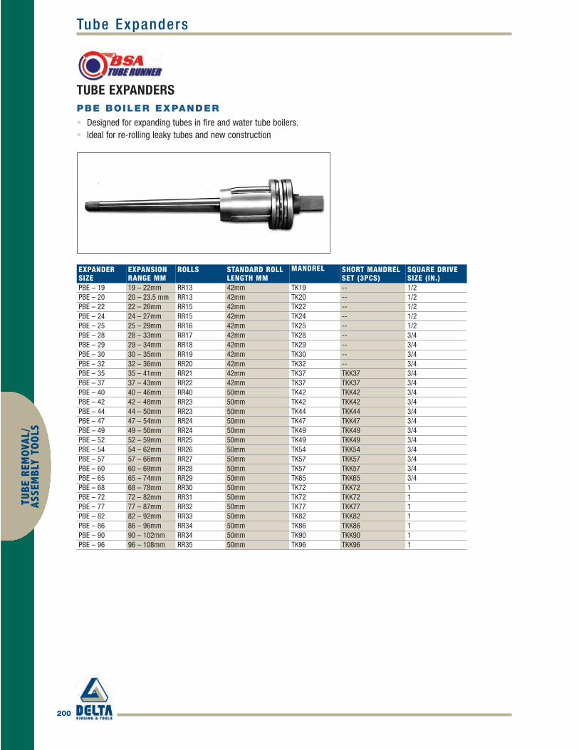
200
Tube ExpandersTU
BE R
EMOV
AL/
ASSE
MBL
Y TO
OLS
TUBE EXPANDERSPBE BOILER EXPANDER
• Designed for expanding tubes in fire and water tube boilers.• Ideal for re-rolling leaky tubes and new construction
EXPANDER SIZE
EXPANSION RANGE MM
ROLLS STANDARD ROLL LENGTH MM
MANDREL SHORT MANDREL SET (3PCS)
SQUARE DRIVESIZE (IN.)
PBE – 19 19 – 22mm RR13 42mm TK19 -- 1/2PBE – 20 20 – 23.5 mm RR13 42mm TK20 -- 1/2PBE – 22 22 – 26mm RR15 42mm TK22 -- 1/2PBE – 24 24 – 27mm RR15 42mm TK24 -- 1/2PBE – 25 25 – 29mm RR16 42mm TK25 -- 1/2PBE – 28 28 – 33mm RR17 42mm TK28 -- 3/4PBE – 29 29 – 34mm RR18 42mm TK29 -- 3/4PBE – 30 30 – 35mm RR19 42mm TK30 -- 3/4PBE – 32 32 – 36mm RR20 42mm TK32 -- 3/4PBE – 35 35 – 41mm RR21 42mm TK37 TKK37 3/4PBE – 37 37 – 43mm RR22 42mm TK37 TKK37 3/4PBE – 40 40 – 46mm RR40 50mm TK42 TKK42 3/4PBE – 42 42 – 48mm RR23 50mm TK42 TKK42 3/4PBE – 44 44 – 50mm RR23 50mm TK44 TKK44 3/4PBE – 47 47 – 54mm RR24 50mm TK47 TKK47 3/4PBE – 49 49 – 56mm RR24 50mm TK49 TKK49 3/4PBE – 52 52 – 59mm RR25 50mm TK49 TKK49 3/4PBE – 54 54 – 62mm RR26 50mm TK54 TKK54 3/4PBE – 57 57 – 66mm RR27 50mm TK57 TKK57 3/4PBE – 60 60 – 69mm RR28 50mm TK57 TKK57 3/4 PBE – 65 65 – 74mm RR29 50mm TK65 TKK65 3/4PBE – 68 68 – 78mm RR30 50mm TK72 TKK72 1PBE – 72 72 – 82mm RR31 50mm TK72 TKK72 1PBE – 77 77 – 87mm RR32 50mm TK77 TKK77 1PBE – 82 82 – 92mm RR33 50mm TK82 TKK82 1PBE – 86 86 – 96mm RR34 50mm TK86 TKK86 1PBE – 90 90 – 102mm RR34 50mm TK90 TKK90 1PBE – 96 96 – 108mm RR35 50mm TK96 TKK96 1
BSA_p180-208 final.qxd 4/5/10 1:27 PM Page 200

Tube Expanders
201
TUBE REMOVAL/
ASSEMBLY TO
OLS
TUBE EXPANDERSKBE FLARING BOILER EXPANDER
• Designed for expanding and flaring tubes in boilers, superheaters, waterwalls and economizers.
EXPANDER SIZE
EXPANSION RANGE MM
ROLLS STANDARD ROLL LENGTH MM
MANDREL SHORT MANDREL SET (3PCS)
SQUARE DRIVESIZE (IN.)
KBE–19 19 – 22mm RR12RK5 42mm TK19 -- 1/2KBE–20 20 – 23mm RR12RK5 42mm TK20 -- 1/2KBE–22 22 – 25mm RR12RK5 42mm TK22 -- 1/2KBE–23 23 – 26mm RR13RK6 42mm TK23 -- 1/2KBE–24 24 – 27mm RR13RK6 42mm TK24 -- 1/2KBE–25 25 – 28mm RR13RK6 42mm TK25 -- 1/2KBE–27 27 – 30mm RR15RK7 42mm TK27 -- 1/2KBE–28 28 – 33mm RR16RK8 42mm TK28 TKK28 3/4KBE–29 29 – 33mm RR16RK8 42mm TK29 TKK29 3/4KBE–30 30 – 34mm RR16RK8 42mm TK30 TKK30 3/4KBE–32 32 – 36mm RR17RK9 42mm TK32 TKK32 3/4KBE–35 35 – 41mm RR21RK10 42mm TK37 TKK37 3/4KBE–37 37 – 43mm RR22RK10 42mm TK37 TKK37 3/4KBE–40 40 – 46mm RR40RK40 50mm TK42 TKK42 3/4KBE–42 42 – 48mm RR23RK11 50mm TK42 TKK42 3/4KBE–44 44 – 50mm RR23RK11 50mm TK44 TKK44 3/4KBE–47 47 – 54mm RR24RK12 50mm TK47 TKK47 3/4KBE–49 49 – 56mm RR24RK12 50mm TK49 TKK49 3/4KBE–52 52 – 59mm RR25RK13 50mm TK49 TKK49 3/4KBE–54 54 – 62mm RR26RK14 50mm TK54 TKK54 3/4KBE–57 57 – 66mm RR27RK15 50mm TK57 TKK57 3/4KBE–60 60 – 69mm RR28RK16 50mm TK57 TKK57 3/4KBE–65 65 – 74mm RR29RK17 50mm TK65 TKK65 3/4KBE–68 68 – 78mm RR30RK18 50mm TK72 TKK72 1KBE–72 72 – 82mm RR31RK19 50mm TK72 TKK72 1KBE–77 77 – 87mm RR32RK20 50mm TK77 TKK77 1KBE–82 82 – 92mm RR33RK21 50mm TK82 TKK82 1KBE–86 86 – 96mm RR34RK22 50mm TK86 TKK86 1KBE–90 90 – 102mm RR34RK22 50mm TK90 TKK90 1KBE–96 96 – 108mm RR35RK23 50mm TK96 TKK96 1
BSA_p180-208 final.qxd 4/5/10 1:27 PM Page 201

202
Tube ExpandersTU
BE R
EMOV
AL/
ASSE
MBL
Y TO
OLS
TUBE EXPANDERS8012 EXPANDERS
• Expanders for larger heat exchangers and condenser tube up to 76.2 mm (3") OD• Minimum tube sheet thickness 12 mm or 1⁄2"• Maximum tube sheet thickness 102 mm or 4"
EXPANSION RANGE EXPANDER WITH 2-1/4" (57.1MM)ROLLS
MM INCH MANDRELTUBE OD. & MIN ID MAX MIN ID MAX EXPANDER NO. ROLL SET NO. 3/4" SQUAREBWG. EXPANSION EXPANSION DRIVE1-3/4" 44.4 8 34.75 39.37 1.368 1.550 TR-8012–1-3/4–8 TRR-33-A TRM-90
10 36.07 40.82 1.420 1.607 TR-8012–1-3/4–10 TRR-37-A TRM-9011 36.93 41.53 1.454 1.635 TR-8012–1-3/4–11 TRR-42 TRM-9012 37.64 42.09 1.482 1.657 TR-8012–1-3/4–12 TRR-44 TRM-9013 38.35 42.80 1.510 1.685 TR-8012–1-3/4–13 TRR-46 TRM-9014 38.91 43.41 1.532 1.709 TR-8012–1-3/4–14 TRR-48 TRM-90
2" 50.8 8 40.51 45.59 1.595 1.795 TR-8012–2–8 TRR-48 TRM-9110 41.66 47.17 1.640 1.857 TR-8012–2–10 TRR-50 TRM-9111 42.42 47.88 1.670 1.885 TR-8012–2-11 TRR-52 TRM-9112 43.28 48.44 1.704 1.907 TR-8012–2-12 TRR-54 TRM-9113–18 43.99 49.68 1.732 1.956 TR-8012–2-13-18 TRR-56 TRM-91
2-1/4" 57.1 10 48.01 53.52 1.890 2.107 TR-8012–2-1/4-10 TRR-56 TRM-9211 48.77 54.23 1.920 2.135 TR-8012–2-1/4-11 TRR-58 TRM-9212 49.63 54.79 1.954 2.157 TR-8012–2-1/4-12 TRR-60 TRM-9213–16 50.34 55.50 1.982 2.185 TR-8012–2-1/4-13-16 TRR-62 TRM-92
2-1/2" 63.5 10–12 54.36 61.14 2.140 2.407 TR-8012–2-1/2-10-16 TRR-64 TRM-9613–18 56.69 62.23 2.232 2.450 TR-8012–2-1/2-13-18 TRR-64 TRM-94
1" SQ Drive2-3/4" 69.8 10-16 60.71 68.63 2.390 2.702 TR-8012–2-3/4-10-16 TRR-66 TRM-96
3" 76.2 8-9 65.02 71.86 2.560 2.829 TR-8012–3-8-9 TRR-67 TRM-9710-18 67.06 74.98 2.640 2.952 TR-8012–3-10-18 TRR-67 TRM-96
BSA_p180-208 final.qxd 4/5/10 1:27 PM Page 202

Tube Expanders
203
TUBE REMOVAL/
ASSEMBLY TO
OLS
TUBE EXPANDERSP2 BOILER EXPANDERS
• Heavier duty expanders for heat exchangers and condenser tube up to 101.6 mm (4") OD.• Adjustable for tube sheet thickness from 12 mm or 1/2" up to 120 mm or 4-3/4".
EXPANSION RANGE 1/2 IN. TO 4-3/4 IN.TUBE SHEET THICKNESS
MM INCHTUBE OD. & MIN ID MAX MIN ID MAX EXPANDER NO. 60MM ROLLS MANDRELBWG. EXPANSION EXPANSION1-1/4" 16 27.80 33.00 1.120 1.290 P2-280 998 T-290
1-1/2" 7-11 28.80 34.00 1.140 1.330 P2-290 1048 T-290 10-12 29.80 35.00 1.173 1.337 P2-300 1089 T-290 13-16 31.80 37.00 1.251 1.456 P2-320 1143 T-320
Above Expanders fitted with a 1/2" / 12.7mm Square Drive ^ 1-3/4" 8-9 34.80 41.00 1.370 1.614 P2-350 RR21A T-370
10-16 36.80 43.00 1.448 1.692 P2-370 RR22A T-370
2" 7-10 39.80 46.00 1.566 1.811 P2-400 RR40A T-420 1-12 41.80 48.00 1.645 1.889 P2-420 RR23A T-420 13-15 43.80 50.00 1.724 1.968 P2-440 RR23A T-440 16 46.80 54.00 1.842 2.125 P2-470 RR24A T-470
2-1/4" 10-12 48.80 56.00 1.921 2.204 P2-490 RR24A T-49014-16 51.80 59.00 2.039 2.332 P2-490 RR25A T-490
2-1/2" 11-12 53.80 62.00 2.118 2.440 P2-540 RR26A T-54013-16 56.80 66.00 2.236 2.598 P2-570 RR27A T-570
2-3/4" 7-11 59.80 69.00 2.354 2.716 P2-600 RR28A T-570Above Expanders fitted with a 3/4" / 19mm Square Drive ^
3" 7-11 64.80 75.00 2.551 2.952 P2-650 RR29A T-65013-15 67.80 78.00 2.669 3.070 P2-680 RR30A T-720
3-1/4" 7-12 72.00 82.00 2.834 3.228 P2-720 RR31A T-72013-16 77.00 87.00 3.030 3.430 P2-770 RR32A T-720
3-1/2" 10-16 82.00 92.00 3.228 3.622 P2-820 RR34A T-820 3-3/4" 7-12 86.00 96.00 3.385 3.779 P2-860 RR34A T-860 4" 8-12 90.00 102.00 3.543 4.015 P2-900 RR34A T-900
13-16 96.00 112.00 3.779 4.409 P2-960 RR35A T-960Above Expanders fitted with a 1" / 25.4mm Square Drive ^
BSA_p180-208 final.qxd 4/5/10 1:27 PM Page 203

204
Grooving ToolsTU
BE R
EMOV
AL/
ASSE
MBL
Y TO
OLS
HEAT EXCHANGER, CONDENSER & BOILER TOOLINGGROOVING TOOLS
• The grooving tool allows the cutting of grooves in tube sheet holes. Cutting depth can be adjusted from 12.5 mm to 54 mm.
• Standard grooving configuration of 3-6-3. 3 mm groove, 6mm space then another 3 mm groove. Other configurations are available as a special order.
• Features circumference rollers to keep the hole free from burrs and flashes.
HOLE SIZE (IN.)
COMPLETE TOOL
MORSE TAPER
GROOVINGBLADES
CUTTER RETAINER SPRING
3/8 42.GT0375 3 42.3753-S 19.0018 1/2 42.GT0500 3 42.5003-S 19.00215/8 42.GT0625 3 42.6203-S 19.0019 3/4 42.GT0750 3 42.7503-S 19.00207/8 42.GT0875 3 42.7503-S 19.0020 1 42.GT1000 3 42.7503-S 19.00201-1/8 42.GT1125 4 42.7503-S 19.0020 1-1/4 42.GT1250 4 42.7503-S 19.00201-1/2 42.GT1500 4 42.7503-S 19.0020 1-3/4 42.GT1750 4 42.7503-S 19.00202 42.GT2000 5 42.7503-S 19.0020 2-1/4 42.GT2250 5 42.7503-S 19.00202-1/2 42.GT2500 5 42.7503-S 19.0020
Tools available for tube sizes up to 4" and for metric size tubes, please ask for details.
BSA_p180-208 final.qxd 4/5/10 1:27 PM Page 204

Tube Cutters
205
TUBE REMOVAL/
ASSEMBLY TO
OLS
TUBE CUTTERSTUBE END FACER
• Used for facing back the ends of tubes after expansion.• The Tube End Facer can be driven with a pneumatic or electric drill motor.• The tool uses various pilots to match tube gauge thickness.• Cutters available for use on stainless steel.
TUBE SIZE (OD.) PART NUMBERMM INCH PILOT RANGE COMPLETE TOOL CUTTER BIT
9.5 3/8 16-20g 42.EF0375 42.EFC037512.5 1/2 16-20g 42.EF0500 42.EFC050015.8 5/8 14-18g 42.EF0625 42.EFC062519.0 3/4 10-18g 42.EF0750 42.EFC075022.2 7/8 14-18g 42.EF0875 42.EFC087525.4 1 10-18g 42.EF1000 42.EFC100031.7 1-1/4 10-18g 42.EF1250 42.EFC125038.1 1-1/2 10-18g 42.EF1500 42.EFC150050.8 2 10-18g 42.EF2000 42.EFC200063.5 2-1/2 10-18g 42.EF2500 42.EFC2500
BSA_p180-208 final.qxd 4/5/10 1:27 PM Page 205

206
Tube CuttersTU
BE R
EMOV
AL/
ASSE
MBL
Y TO
OLS
TUBE CUTTERSONE REVOLUTION CUTTERS
• The One Revolution type cutter is suitable for cutting steel and non-ferrous tubes used in condensers, heat exchangersand boilers.
• The tool is adjustable to tube sheet thickness from 2" to 6" (50.8 mm – 152.4 mm), extended tools up to 24" (610 mm)reach available on request.
• The tool is designed for hand operation using either a ratchet or hand wrench to fit the driving shank. It is not suitablefor use with a power tool.
• The tool operates by turning the tool clockwise. This brings the cutter tip into contact with inside of the tube. The tippunctures the tube and locks in position to sever the tube as it turns.
TUBE OD.MM IN. TUBE GAUGE
TUBE ID COVER (MM)
TOOL DIAMETER (MM) TOOL NUMBER CUTTER BIT
12.7 1/2 18 -19 g 10.2-10.7 10 ORTC – 100 N – 625 – 112.7 1/2 20 g 11-11.3 10.5 ORTC – 108 N – 625 – 415.8 5/8 14 g 11.4-11.9 11.2 ORTC – 113 N – 625 – 315.8 5/8 15 -16 g 12-12.9 11.7 ORTC – 119 N – 625 – 315.8 5/8 17 -18 g 12.7 -13.5 12.3 ORTC – 123 N – 625 – 215.8 5/8 19 -20 g 13.5 – 14.2 13.1 ORTC – 131 N – 625 – 215.8 5/8 22 g 14 – 14.7 13.6 ORTC – 139 N – 750 – 219 3/4 14 -15 g 14.7 – 15.5 14.3 ORTC – 145 N – 750 – 219 3/4 16 g 15.2 – 16.5 14.8 ORTC – 151 N – 750 – 219 3/4 17 -18 g 15.9 – 16.5 15.3 ORTC – 153 N – 750 – 219 3/4 19 -20 g 16.7 – 17.5 16.3 ORTC – 163 N – 1000 – 122.2 7/8 14 -15 g 17.8 – 18.5 17.4 ORTC – 174 N – 1000 – 122.2 7/8 16 -17 g 18.8 – 19.5 18.4 ORTC – 184 N – 1000 – 122.2 7/8 18 g 19.3 – 20 19 ORTC – 190 N – 1000 – 122.2 7/8 19 -20 g 19.8 – 20.6 19.3 ORTC – 193 N – 1000 – 125.4 1 12 g 19.8 – 20.6 19.3 ORTC – 193 N – 1000 – 125.4 1 13 g 20.8 – 21.6 20.5 ORTC – 205 N – 1000 – 225.4 1 14 g 21.3 – 22.1 21 ORTC – 210 N – 1000 – 225.4 1 16 -17 g 21.8 – 22.6 21.5 ORTC – 215 N – 1000 – 225.4 1 18 -20 g 22.6 – 23.1 22.3 ORTC – 223 N – 1000 – 225.4 1 22 g 23.9 – 24.6 23.2 ORTC – 232 N – 1000 – 2
BSA_p180-208 final.qxd 4/5/10 1:27 PM Page 206

Tube Cutters
207
TUBE REMOVAL/
ASSEMBLY TO
OLS
TUBE CUTTERS
TUBE OD. (MM) TUBE OD. (IN.) TUBE GAUGETUBE ID
COVER (MM)TOOL DIAMETER (MM) TOOL NUMBER CUTTER BIT
31.75 1-1/4 10 -11 g 24.9 – 25.6 24.5 ORTC – 245 N – 1000 – 231.75 1-1/4 12 g 25.9 – 26.7 25.5 ORTC – 255 N – 1000 – 231.75 1-1/4 13 -14 g 26.7 – 27.4 26.4 ORTC – 264 N – 1000 – 231.75 1-1/4 15 -16 g 27.9 – 28.7 27.5 ORTC – 274 N – 1000 – 231.75 1-1/4 17 -19 g 28.7 – 29.6 28.3 ORTC – 283 N – 1000 – 238.1 1-1/2 10 -11 g 31.3 – 32.1 30.9 ORTC – 309 N – 1500 – 138.1 1-1/2 12 -13 g 32.5 – 33.3 32 ORTC – 320 N – 1500 – 138.1 1-1/2 14 -15 g 33.8 – 34.5 33.3 ORTC – 333 N – 1500 – 138.1 1-1/2 16 -17 g 34.5 – 35.3 34 ORTC – 339 N – 1500 – 138.1 1-1/2 18 -19 g 35.3 – 36.1 34.9 ORTC – 350 N – 1500 – 144.45 1-3/4 10 -11 g 37 – 38.5 36.9 ORTC – 369 N – 1500 – 144.45 1-3/4 12 -14 g 38.8 – 40.3 38.3 ORTC – 383 N – 1500 – 144.45 1-3/4 15 -16 g 40.8 – 41.2 40.3 ORTC – 403 N – 1500 – 144.45 1-3/4 17 -18 g 41.3 – 42 41 ORTC – 410 N – 1500 – 150.8 2 10 g 44 43.5 ORTC – 435 N – 1500 – 150.8 2 11 g 51 44.2 ORTC – 442 N – 1500 – 150.8 2 12 -13 g 45 – 46 44.7 ORTC – 447 N – 1500 – 150.8 2 14 -15 g 46.2 – 48.2 45.7 ORTC – 457 N – 1500 – 150.8 2 16 -17 g 47.2 – 48.2 46.8 ORTC – 468 N – 1500 – 150.8 2 18 -19 g 48 – 49 47.6 ORTC – 476 N – 1500 – 157.15 2-1/4 10 g 50.3 49.7 ORTC – 497 N – 2250 – 157.15 2-1/4 11 g 51 50.5 ORTC – 505 N – 2250 – 157.15 2-1/4 12 -13 g 51.6 – 52.3 51.1 ORTC – 511 N – 2250 – 157.15 2-1/4 14 -15 g 52.9 – 53.5 52.4 ORTC – 524 N – 2250 – 157.15 2-1/4 16 -17 g 53.8 – 54.8 53.3 ORTC – 533 N – 2250 – 157.15 2-1/4 18 -19 g 54.6 – 55.6 54.1 ORTC – 541 N – 2250 – 163.5 2-1/2 10 g 56.7 56.2 ORTC – 562 N – 2250 – 163.5 2-1/2 11 g 57.4 56.9 ORTC – 569 N – 2250 – 163.5 2-1/2 12 -13 g 57.6 – 58.6 57.2 ORTC – 572 N – 2250 – 163.5 2-1/2 14 -15 g 58.9 – 60 58.5 ORTC – 585 N – 2250 – 163.5 2-1/2 16 -17 g 60 – 61 58.6 ORTC – 588 N – 2250 – 163.5 2-1/2 18 -19 g 60.7 – 61.7 60.2 ORTC – 602 N – 2250 – 1
BSA_p180-208 final.qxd 4/5/10 1:27 PM Page 207

208
Tube CuttersTU
BE R
EMOV
AL/
ASSE
MBL
Y TO
OLS
TUBE CUTTERSPUSH CUTTERS
• The Push Type Cutter can be driven with a pneumatic or electric drill motor.• The tool uses spring-loaded cutters, which are adjustable for depth and cut when pressure is applied during use.• Each tool is suitable for most tube wall thicknesses.• Two cutter tips as standard on tube sizes from 1".
TUBE SIZE (OD.) PART NUMBERMM INCH PILOT RANGE COMPLETE TOOL CUTTER BIT
9.5 3/8 22-24g 42.PC-95 42.PCB2521012.7 1/2 14-17g 42.PC-127 42.PCB25211/1215.8 5/8 19-22g 42.PC-158 42.PCB2518619.0 3/4 14-22g 42.PC-190 42.PCB2518622.2 7.8 11-22g 42.PC-222 42.PCB2519425.4 1 11-13g 42.PC-222 42.PCB25194
Twin Blade Cutters �25.4 1 11-22g 42.PC-254 42.PCB2519931.7 1-1/4 14-22g 42.PC-317 42.PCB2520638.1 1-1/2 14-20g 42.PC-381 42.PCB2520650.8 2 8-20g 42.PC-508 42.PCB2522163.5 2-1/2 8-12g 42.PC-635 42.PCB25223
BSA_p180-208 final.qxd 4/5/10 1:27 PM Page 208
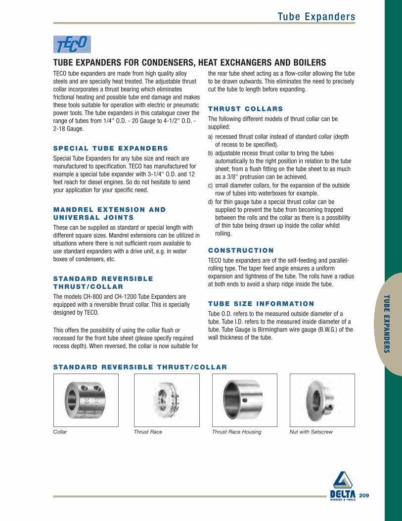
Tube Expanders
209
TUBE EXPAND
ERS
TUBE EXPANDERS FOR CONDENSERS, HEAT EXCHANGERS AND BOILERSTECO tube expanders are made from high quality alloysteels and are specially heat treated. The adjustable thrustcollar incorporates a thrust bearing which eliminatesfrictional heating and possible tube end damage and makesthese tools suitable for operation with electric or pneumaticpower tools. The tube expanders in this catalogue cover therange of tubes from 1/4" O.D. - 20 Gauge to 4-1/2" O.D. -2-18 Gauge.
SPECIAL TUBE EXPANDERS
Special Tube Expanders for any tube size and reach aremanufactured to specification. TECO has manufactured forexample a special tube expander with 3-1/4" O.D. and 12feet reach for diesel engines. So do not hesitate to sendyour application for your specific need.
MANDREL EXTENSION ANDUNIVERSAL JOINTS
These can be supplied as standard or special length withdifferent square sizes. Mandrel extensions can be utilized insituations where there is not sufficient room available touse standard expanders with a drive unit, e.g. in waterboxes of condensers, etc.
STANDARD REVERSIBLETHRUST/COLLAR
The models CH-800 and CH-1200 Tube Expanders areequipped with a reversible thrust collar. This is speciallydesigned by TECO.
This offers the possibility of using the collar flush orrecessed for the front tube sheet (please specify requiredrecess depth). When reversed, the collar is now suitable for
the rear tube sheet acting as a flow-collar allowing the tubeto be drawn outwards. This eliminates the need to preciselycut the tube to length before expanding.
THRUST COLLARS
The following different models of thrust collar can besupplied:
a) recessed thrust collar instead of standard collar (depthof recess to be specified).
b) adjustable recess thrust collar to bring the tubesautomatically to the right position in relation to the tubesheet; from a flush fitting on the tube sheet to as muchas a 3/8" protrusion can be achieved.
c) small diameter collars, for the expansion of the outsiderow of tubes into waterboxes for example.
d) for thin gauge tube a special thrust collar can besupplied to prevent the tube from becoming trappedbetween the rolls and the collar as there is a possibilityof thin tube being drawn up inside the collar whilstrolling.
CONSTRUCTION
TECO tube expanders are of the self-feeding and parallel-rolling type. The taper feed angle ensures a uniformexpansion and tightness of the tube. The rolls have a radiusat both ends to avoid a sharp ridge inside the tube.
TUBE SIZE INFORMATION
Tube O.D. refers to the measured outside diameter of atube. Tube I.D. refers to the measured inside diameter of atube. Tube Gauge is Birmingham wire gauge (B.W.G.) of thewall thickness of the tube.
STANDARD REVERSIBLE THRUST/COLLAR
Collar Thrust Race Thrust Race Housing Nut with Setscrew
Teco_p209-219 final.qxd 4/5/10 5:40 PM Page 209

210
Tube ExpandersTU
BE E
XPAN
DER
S
TUBE EXPANDERS FOR CONDENSERS, HEAT EXCHANGERS AND BOILERSLUBRICATION, CARE ANDMAINTENANCE OF TUBEEXPANDERS
The type of use demanded of tube expanders is severe andtherefore these precision tools should be given areasonable amount of care. For long, trouble-free andeconomical service the following is suggested:
1. Remove all rust, mill scale and other foreign matter fromthe inside and outside of the tube. Foreign matter on theinside of the tube will tend to become embedded into thetube wall and being abrasive may cause the rolls andmandrel of the tube expander to start breaking up. Mill scaleor dirt left on the outer wall of the tube can cause damageto the tube seat and prevent the formation of a pressure-tight joint. Cleaning of the tube ends may be bestaccomplished by wire brushing or polishing. Remove anyprotective coating by washing with light oil or other solvents.
NB: DO NOT LEAVE A RESIDUE OF LIGHT OIL ON THEOUTSIDE OF THE TUBE AS THIS MAY ALSO PREVENT APRESSURE-TIGHT JOINT.
2. Before using, the expander should be washed in anycommercial solvent to remove protective coatings, dirt,grease and other foreign matter. Make sure that the rollsand mandrel are in good condition and working correctly.
3. Before using, expander should be properly lubricatedwith a pressure-resistant lubricant. We recommend usingTECO 'Lube-A-Tube'. This water-soluble lubricant wasdeveloped for tube rolling and may be mixed with water tothe desired consistency. For small diameter and light tubegauges immerse the expander in TECO 'Lube-A-Tube' orlight oil such as SAE 10 or 20.
For large diameter and heavy gauge tubes, brush the expanderwith TECO 'Lube-A-Tube' or mixture of SAE 40 oil and graphite.
4. Expanders should be rotated at a speed proportionate to thetube size, gauge and length of tube seat. Tube materials mustalso be taken into consideration. The proper speed will providea safe cold working of tube metal without crystallization orsurface damage. Speed is also a major factor in expander lifeand if correctly set will prevent undue roller or mandrelbreakdown. Ideal speed will keep to a minimum mandrel slipand the heat generated in mandrels and rolls when working.
5. After rolling each tube, clean and cool the expander insolvent or light oil and then properly lubricate the expanderagain. It is good practice to use two expanders so that one canbe cooling whilst the clean expander is being used.
6. Inspect the rolls and the mandrel after rolling each tube.Replace any chipped rolls or mandrels immediately. A smallchip in a roll can damage the entire expander, rolls or
mandrel if not replaced at once. It can also damage the tubecausing marks in the expanded area which may necessitatetube removal.
7. After the job has been completed, the expander should becleaned thoroughly with a commercial solvent or a light oil andstored in a manner which will avoid possibility of parts rusting.
NB: DO NOT LEAVE A RESIDUE OF LIGHT OIL ON THEOUTSIDE OF THE TUBE AS THIS MAY ALSO PREVENT APRESSURE-TIGHT JOINT.
SOME GUIDELINES FOR TUBEEXPANSION
Improperly rolled joints create additional expense to rectify.Under-rolling can be easily corrected merely by re-rolling, butover-rolling will require complete tube replacement. Theoptimum joint is one that develops a leak-tight joint withadequate strength for the service intended with the minimumamount of cold working or reduction of the tube wall thickness.
Experience indicates that joints of this type can be obtainedwith non-ferrous tubes in surface condensers by expandingto a wall reduction of 5% to 6%. This wall reduction is onlyachieved after metal-to-metal contact between the tubeO.D. and the tube sheet hole. Steel tubes in heatexchangers may require wall reductions of 4% to 6%; softcopper and aluminum tubes in heat exchangers alsorequire larger wall reductions in the area of 7% to 10%.
A typical example of the application of this method is indicatedfor 3/4" x 18 gauge (19.05 x 1.24 mm) tube in a condenser.
1. Tube Sheet Hole = 19.30 mm (.760")Tube O.D. = -19.05 mm (.750")Clearance 0.25 mm (.010")
2. Tube I.D. = 16.56 mm (.652")Clearance = +0.25 mm (.010")I.D. Metal to Metal 16.81 mm (.662")
3. 6% of 1.24 mm x 2 = 0.14 mm (.006")Tube I.D. Metal to Metal = +16.81 mm (.662")Expanded Tube I.D. 16.95 mm (.668")
LUBE-A-TUBE
TECO Lube-A-Tube is a water-soluble lubricant especiallycompounded for use with tube expanders. When rollinglarge or small, ferrous or non-ferrous tubes, use TECOLube-A-Tube for smoother rolling and longer expander life.For clean tube ends after rolling simply wash with water.
Teco_p209-219 final.qxd 4/5/10 5:40 PM Page 210

211
TUBE EXPAND
ERSStandard Models
TUBE EXPANDERS FOR CONDENSERS AND HEAT EXCHANGERSMODEL CH-900
Tube range: 1/4" to 3/8" O.D. (6.35 to 9.52 mm) O.D.
Expander with 3/4" (19.05 mm) long rolls suitable for tube sheetthicknesses from 1/8" to 3/4" (3.175 mm to 19.05 mm).
Expander with 1-1/4" (31.75 mm) long rolls suitable for tube sheetthicknesses from 1/2" to 1-1/4" (12.70 mm to 31.75 mm).
MODEL CH-1300
Tube range: 3/8" (9.52 mm) O.D.
Expander with 3/4" (19.05 mm) long rolls suitable for tube sheetthicknesses from 1/4" to 3" (6.35 mm to 76.20 mm).
Expander with 1-1/4" (31.75 mm) long rolls suitable for tube sheetthicknesses from 3/4" to 3-1/2" (19.05 mm to 88.90 mm).
MODEL CH-800
Tube range: 1/2" to 1-3/4" O.D. (12.70 to 44.45 mm) O.D.
Expander with 1-1/2" (38.10 mm) long rolls suitable for tube sheetthicknesses from 1/4" to 1-1/2" (6.35 mm to 38.10 mm).
Expander with 2-1/4" (57.15 mm) long rolls suitable for tube sheetthicknesses from 1" to 2-1/4" (25.40 mm to 57.15 mm).
Special 4 or 5 roll models available.
MODEL CH-1200
Tube range: 1/2" to 1-3/4" O.D. (12.70 to 44.45 mm) O.D.
Expander with 1-1/2" (38.10 mm) long rolls suitable for tube sheetthicknesses from 3/4" to 5-7/8" (19.05 mm to 149.09 mm).
Expander with 2-1/4" (57.15 mm) long rolls suitable for tube sheetthicknesses from 1-1/2" to 6-1/2" (38.10 mm to 165.10 mm).
Special 4 or 5 roll models available.
MODEL CH-1200
Long reach with 1-1/2" or 2-1/4" rolls.
Tool reach standard 10"(B) or 12"(C)
Longer reaches available upon request.
Tube range: 1/2" to 1-3/4" (12.70 to 44.45 mm) O.D.
Special 4 or 5 roll models available.
MODEL CH-8012
Tube range: 1-3/4" to 4-1/2" O.D. (44.45 to 114.30 mm) O.D.
Expander with 2-1/4" (57.15 mm) long rolls suitable for tube sheetthicknesses from 1/2" to 4" (12.70 mm to 101.60 mm).
CH-900
CH-1300
CH-800
CH-1200
CH-1200-2
CH-8012
Teco_p209-219 final.qxd 4/5/10 5:40 PM Page 211

212
TUBE
EXP
AND
ERS
Standard Models
TUBE EXPANDERS FOR CONDENSERS AND HEAT EXCHANGERSMODEL: CH 800
Tube Size I.D. .335" - 1.457" (8.5 - 37.0 mm)
Tubesheet
Tubesheet
A
B
TUBE SHEET THICKNESS
A MINIMUM B MAXIMUMTUBE EXPANDER WITH 1-1/2" ROLL LENGTH
1/4"(6.35 mm)
1-1/4"(31.75 mm)
TUBE EXPANDER WITH 2-1/4" ROLL LENGTH
1" (25.40 mm)
2"(50.80 mm)
TUBE O.D.AND G.A.
MIN. I.D. TUBE TOOL ENTERS MAX. TOOL EXPANSION
SIZESQUARE ONMANDREL
EXPANDER WITH 1-1/2"(38.1MM) ROLLS
EXPANDER WITH 2-1/4"(57.1 MM) ROLLS
MANDRELNO.INCH MM INCH MM
EXPANDERNO.
ROLL SETNO.
EXPANDERNO.
ROLL SETNO.
1/2"-14 .324 8.23 .374 9.50 CH-797 TR-797 MT-7971/2"-15 .349 8.86 .398 10.11 CH-799 TR-1 MT-7991/2"-16 .360 9.14 .410 10.41 3/8" CH-801 TR-1 MT-11/2"-17 .374 9.50 .424 10.77 CH-803 TR-2 MT-11/2"-18 .392 9.96 .447 11.35 CH-805 TR-3 MT-25/8"-12 .392 9.96 .447 11.35 CH-805 TR-3 MT-25/8"-13 .425 10.79 .480 12.19 CH-807 TR-4 MT-35/8"-14 .449 11.40 .509 12.73 CH-809 TR-4 CH-810 TR-4-A MT-45/8"-15 .471 11.96 .536 13.61 3/8" CH-811 TR-5 CH-812 TR-5-A MT-55/8"-16 .485 12.32 .550 13.97 CH-813 TR-6 CH-814 TR-6-A MT-55/8"-17 .499 12.67 .564 14.32 CH-815 TR-6 CH-816 TR-6-A MT-65/8"-18 .517 13.13 .572 14.53 CH-817 TR-7 CH-818 TR-7-A MT-73/4"-10 .471 11.96 .536 13.61 CH-811 TR-5 CH-812 TR-5-A MT-53/4"-11 .499 12.67 .564 14.32 CH-815 TR-6 CH-816 TR-6-A MT-63/4"-12 .522 13.30 .582 15.20 CH-819-N TR-7 CH-820-N TR-7-A MT-83/4"-13 .550 13.97 .615 15.62 CH-821 TR-8 CH-822 TR-8-A MT-83/4"-14 .574 14.58 .639 16.23 3/8" CH-823 TR-9 CH-824 TR-9-A MT-83/4"-15 .596 15.14 .661 16.79 CH-825 TR-10 CH-826 TR-10-A MT-83/4"-16 .605 15.37 .685 17.40 CH-827 TR-10 CH-828 TR-10-A MT-93/4"-17 .619 15.72 .699 17.75 CH-829 TR-11 CH-830 TR-11-A MT-93/4"-18 .619 15.72 .699 17.75 CH-829 TR-11 CH-830 TR-11-A MT-97/8"-10 .596 15.14 .661 16.79 CH-825 TR-10 CH-826 TR-10-A MT-87/8"-11 .619 15.72 .699 17.75 CH-829 TR-11 CH-830 TR-11-A MT-97/8"-12 .642 16.31 .722 18.34 CH-831 TR-12 CH-832 TR-12-A MT-97/8"-13 .670 17.02 .750 19.05 CH-833 TR-13 CH-834 TR-13-A MT-107/8"-14 .685 17.40 .774 19.66 CH-835 TR-14 CH-836 TR-14-A MT-117/8"-15 .712 18.08 .801 20.34 3/8" CH-837 TR-15 CH-838 TR-15-A MT-117/8"-16 .726 18.44 .815 20.70 CH-839 TR-15 CH-840 TR-15-A MT-127/8"-17 .740 18.80 .829 21.06 CH-843 TR-16 CH-844 TR-16-A MT-127/8"-18 .740 18.80 .829 21.06 CH-843 TR-16 CH-844 TR-16-A MT-12
Note: Expander CH 800 is also available as four or five roll expander. continued on next page
Teco_p209-219 final.qxd 4/5/10 5:40 PM Page 212

213
TUBE EXPAND
ERSStandard Models
TUBE EXPANDERS FOR CONDENSERS AND HEAT EXCHANGERSTUBE O.D.AND G.A.
MIN. I.D. TUBE TOOL ENTERS MAX. TOOL EXPANSION
SIZESQUARE ONMANDREL
EXPANDER WITH 1-1/2"(38.1MM) ROLLS
EXPANDER WITH 2-1/4"(57.1 MM) ROLLS
MANDRELNO.INCH MM INCH MM
EXPANDERNO.
ROLL SETNO.
EXPANDERNO.
ROLL SETNO.
1"-8 .655 16.64 .735 18.67 CH-841 TR-13 CH-842 TR-13-A MT-91"-9 .685 17.40 .774 19.66 CH-835 TR-14 CH-836 TR-14-A MT-111"-10 .712 18.08 .801 20.34 CH-837 TR-15 CH-838 TR-15-A MT-111"-11 .740 18.80 .829 21.06 CH-843 TR-16 CH-844 TR-16-A MT-121"-12 .763 19.38 .852 21.64 CH-845 TR-17 CH-846 TR-17-A MT-121"-13 .791 20.09 .880 22.35 3/8" CH-847 TR-18 CH-848 TR-18-A MT-121"-14 .810 20.57 .909 23.09 CH-849 TR-18 CH-850 TR-18-A MT-131"-15 .837 21.26 .936 23.77 CH-851 TR-19 CH-852 TR-19-A MT-131"-16 .837 21.26 .936 23.77 CH-851 TR-19 CH-852 TR-19-A MT-131"-17 .865 21.97 .964 24.48 CH-855 TR-21 CH-856 TR-21-A MT-131"-18-20 .865 21.97 .964 24.48 CH-855 TR-21 CH-856 TR-21-A MT-131-1/8"-8 .776 19.71 .875 22.22 CH-853 TR-20 CH-854 TR-20-A MT-131-1/8"-9 .810 20.57 .909 23.09 3/8" CH-849 TR-18 CH-850 TR-18-A MT-131-1/8"-10 .837 21.26 .936 23.77 CH-851 TR-19 CH-852 TR-19-A MT-131-1/8"-11 .865 21.97 .964 24.48 CH-855 TR-21 CH-856 TR-21-A MT-131-1/8"-12 .883 22.43 .982 24.94 CH-857 TR-21 CH-858 TR-21-A MT-141-1/8"-13 .916 23.57 1.015 25.78 CH-859 TR-22 CH-860 TR-22-A MT-141-1/8"-14 .835 23.75 1.044 26.52 CH-861 TR-23 CH-862 TR-23-A MT-151-1/8"-15 .962 24.43 1.071 27.20 1/2" CH-863 TR-24 CH-864 TR-24-A MT-151-1/8"-16 .962 24.43 1.071 27.20 CH-863 TR-24 CH-864 TR-24-A MT-151-1/8"-17 .990 25.15 1.099 27.91 CH-867 TR-26 CH-868 TR-26-A MT-161-1/8"-18 .990 25.15 1.099 27.91 CH-867 TR-26 CH-868 TR-26-A MT-161-1/4"-8 .901 22.88 1.010 25.60 CH-865 TR-25 CH-866 TR-25-A MT-151-1/4"-9 .935 23.75 1.044 26.52 CH-861 TR-23 CH-862 TR-23-A MT-151-1/4"-10 .962 24.43 1.071 27.20 CH-863 TR-24 CH-864 TR-24-A MT-151-1/4"-11 .990 25.15 1.099 27.91 CH-867 TR-26 CH-868 TR-26-A MT-161-1/4"-12 1.013 25.73 1.122 28.50 1/2" CH-869 TR-27 CH-870 TR-27-A MT-161-1/4"-13 1.041 26.44 1.150 29.21 CH-871 TR-28 CH-872 TR-28-A MT-171-1/4"-14 1.060 26.92 1.169 29.69 CH-873 TR-29 CH-874 TR-29-A MT-171-1/4"-15 1.087 27.61 1.196 30.38 CH-875 TR-30 CH-876 TR-30-A MT-171-1/4"-16 1.087 27.61 1.196 30.38 CH-875 TR-30 CH-876 TR-30-A MT-171-3/8"-8 1.026 26.06 1.135 28.83 CH-877 TR-31 CH-878 TR-31-A MT-171-3/8"-9 1.060 26.92 1.169 29.69 CH-873 TR-29 CH-874 TR-29-A MT-171-3/8"-10 1.087 27.61 1.196 30.38 CH-875 TR-30 CH-876 TR-30-A MT-171-3/8"-11 1.115 28.32 1.224 31.09 CH-879 TR-30 CH-880 TR-30-A MT-181-3/8"-12 1.133 28.78 1.242 31.55 1/2" CH-881 TR-32 CH-882 TR-32-A MT-181-3/8"-13 1.160 29.46 1.275 32.38 CH-883 TR-33 CH-884 TR-33-A MT-191-3/8"-14 1.179 29.95 1.294 32.87 CH-885 TR-34 CH-886 TR-34-A MT-201-3/8"-15 1.206 30.63 1.321 33.55 CH-887 TR-35 CH-888 TR-35-A MT-201-3/8"-16 1.206 30.63 1.321 33.55 CH-887 TR-35 CH-888 TR-35-A MT-201-1/2"-8 1.145 29.08 1.260 32.00 CH-889 TR-34 CH-890 TR-34-A MT-191-1/2"-9 1.179 29.95 1.294 32.87 CH-885 TR-34 CH-886 TR-34-A MT-201-1/2"-10 1.206 30.63 1.321 33.55 CH-887 TR-35 CH-888 TR-35-A MT-201-1/2"-11 1.235 31.37 1.350 34.29 CH-891 TR-36 CH-892 TR-36-A MT-201-1/2"-12 1.257 31.93 1.372 34.85 1/2" CH-893 TR-37 CH-894 TR-37-A MT-201-1/2"-13 1.285 32.64 1.400 35.56 CH-895 TR-37 CH-896 TR-37-A MT-211-1/2"-14 1.285 32.64 1.400 35.56 CH-895 TR-37 CH-896 TR-37-A MT-211-1/2"-15 1.331 33.81 1.446 36.73 CH-897 TR-38 CH-898 TR-38-A MT-211-1/2"-16 1.331 33.81 1.446 36.73 CH-897 TR-38 CH-898 TR-38-A MT-211-3/4"-8 1.406 35.70 1.531 38.90 1/2" CH-899 TR-38 CH-899RL TR-38-A MT-22
Note: Expander CH 800 is also available as four or five roll expander.
continued from previous page
Teco_p209-219 final.qxd 4/5/10 5:40 PM Page 213

214
TUBE
EXP
AND
ERS
Standard Models
TUBE EXPANDERS FOR CONDENSERS AND HEAT EXCHANGERSMODEL : CH 800 FIVE ROLL TYPE EXPANDER
Tube Size I.D. .500" - 1.457" (12.7 - 37.0 mm)
Tubesheet
Tubesheet
A
B
TUBE SHEET THICKNESS
A MINIMUM B MAXIMUMTUBE EXPANDER WITH 1-1/2" ROLL LENGTH
1/4"(6.35 mm)
1-1/4"(31.75 mm)
TUBE EXPANDER WITH 2-1/4" ROLL LENGTH
1"(25.40 mm)
2"(50.80 mm)
TUBE O.D.AND G.A.
MIN. I.D. TUBE TOOL ENTERS
MAX. TOOL EXPANSION
SIZESQUARE ONMANDREL
EXPANDER WITH 1-1/2" (38.1MM)ROLLS
EXPANDER WITH 2-1/4" (57.1 MM)ROLLS
MANDRELNO.INCH MM INCH MM
EXPANDER NO.
ROLL SET NO.
EXPANDER NO.
ROLL SET NO.
5/8"-17-19 .499 12.67 .578 14.69 CH-815-5 TR-4-5 CH-816-5 TR-4-A-5 MT-9
5/8"-20-22 .539 13.70 .601 15.27 3/8" CH-819-SP-5 TR-4-5 CH-820-SP-5 TR-4-A-5 MT-11
5/8"-23-24 .550 13.97 .627 15.93 CH-821-5 TR-5-5 CH-822-5 TR-5-A-5 MT-12
3/4"-13-14 .550 13.97 .627 15.93 CH-821-5 TR-5-5 CH-822-5 TR-5-A-5 MT-12
3/4"-15-16 .596 15.14 .688 17.21 3/8" CH-827-5 TR-8-5 CH-828-5 TR-8-A-5 MT-12
3/4"-17-18 .619 15.72 .706 17.94 CH-829-5 TR-8-5 CH-830-5 TR-8-A-5 MT-13
3/4"-19-21 .642 16.31 .730 18.56 CH-831-5 TR-9-5 CH-832-5 TR-9-A-5 MT-13
3/4"-22-24 .670 17.02 .750 19.05 1/2" CH-833-5 TR-9-5 CH-834-5 TR-9-A-5 MT-14
7/8"-13 .670 17.02 .750 19.05 CH-833-5 TR-9-5 CH-834-5 TR-9-A-5 MT-14
7/8"-14 .685 17.40 .770 19.56 CH-835-5 TR-10-5 CH-836-5 TR-10-A-5 MT-14
7/8"-15-16 .712 18.08 .807 20.50 1/2" CH-837-5 TR-11-5 CH-838-5 TR-11-A-5 MT-16
7/8"-17-18 .740 18.80 .826 20.98 CH-843-5 TR-11-5 CH-844-5 TR-11-A-5 MT-17
7/8"-19-22 .763 19.38 .848 21.65 CH-845-5 TR-12-5 CH-846-5 TR-12-A-5 MT-17
7/8"-23-24 .791 20.09 .892 22.65 CH-847-5 TR-13-5 CH-848-5 TR-13-A-5 MT-18
continued on next pageNOTE: for TECO four and five roll expanders we recommend a thin wall thrust collar, especially for 19-24 Gauge wall.
Teco_p209-219 final.qxd 4/5/10 5:40 PM Page 214

215
TUBE EXPAND
ERSStandard Models
TUBE O.D.AND G.A.
MIN. I.D. TUBE TOOL ENTERS
MAX. TOOLEXPANSION
SIZESQUAREONMANDREL
EXPANDER WITH 1-1/2" (38.1MM)ROLLS
EXPANDER WITH 2-1/4" (57.1 MM)ROLLS
MANDRELNO.INCH MM INCH MM
EXPANDERNO.
ROLL SETNO.
EXPANDERNO.
ROLL SETNO.
1"-12 .763 19.38 .848 21.65 CH-845-5 TR-12-5 CH-846-5 TR-12-A-5 MT-17
1"-13 .791 20.09 .892 22.65 CH-847-5 TR-13-5 CH-848-5 TR-13-A-5 MT-18
1"-14 .810 20.57 .904 22.97 1/2" CH-849-5 TR-14-5 CH-850-5 TR-14-A-5 MT-18
1"-15-16 .837 21.26 .933 23.69 CH-851-5 TR-15-5 CH-852-5 TR-15-A-5 MT-18
1"-17-20 .865 21.97 .971 24.67 CH-855-5 TR-15-5 CH-856-5 TR-15-A-5 MT-20
1"-21-24 .883 22.43 .999 25.38 CH-857-5 TR-15-5 CH-858-5 TR-15-A-5 MT-21
1-1/8"-11 .865 21.97 .971 24.67 CH-855-5 TR-15-5 CH-856-5 TR-15-A-5 MT-20
1-1/8"-12 .883 22.43 .999 25.38 CH-857-5 TR-15-5 CH-858-5 TR-15-A-5 MT-21
1-1/8"-13-14 .916 23.57 1.013 25.74 1/2" CH-859-5 TR-16-5 CH-860-5 TR-16-A-5 MT-21
1-1/8"-15-16 .962 24.43 1.064 27.02 CH-863-5 TR-18-5 CH-864-5 TR-18-A-5 MT-21
1-1/8"-17-20 .990 25.15 1.091 27.72 CH-867-5 TR-19-5 CH-868-5 TR-19-A-5 MT-21
1-1/8"-21-24 1.013 25.73 1.118 28.40 CH-869-5 TR-21-5 CH-870-5 TR-21-A-5 MT-21
1-1/4"-10 .962 24.43 1.064 27.02 CH-863-5 TR-18-5 CH-864-5 TR-18-A-5 MT-21
1-1/4"-11 .990 25.15 1.091 27.72 CH-867-5 TR-19-5 CH-868-5 TR-19-A-5 MT-21
1-1/4"-12 1.013 25.73 1.118 28.40 1/2" CH-869-5 TR-21-5 CH-870-5 TR-21-A-5 MT-21
1-1/4"-15-16 1.087 27.61 1.204 30.58 CH-875-5 TR-21-5 CH-876-5 TR-21-A-5 MT-22
1-1/4"-17-22 1.115 28.32 1.259 31.98 CH-879-5 TR-23-5 CH-880-5 TR-23-A-5 MT-22
1-1/4"-23-25 1.133 28.78 1.285 32.64 CH-881-5 TR-24-5 CH-882-5 TR-24-A-5 MT-22
1-3/8"-12 1.133 28.78 1.285 32.64 1/2" CH-881-5 TR-24-5 CH-882-5 TR-24-A-5 MT-22
1-3/8"-14 1.179 29.95 1.294 32.88 CH-885-5 TR-23-5 CH-886-5 TR-23-A-5 MT-23
1-1/2"-12 1.257 31.93 1.375 34.92 1/2" CH-893-5 TR-26-5 CH-894-5 TR-26-A-5 MT-24
1-1/2"-17-24 1.374 34.90 1.505 38.22 CH-899-5 TR-29-5 CH-899-RL-5 TR-29-A-5 MT-25
TUBE EXPANDERS FOR CONDENSERS AND HEAT EXCHANGERScontinued from previous page
Also available as four roll expander, sizes as five roll expanders.
NOTE: for TECO four and five roll expanders we recommend a thin wall thrust collar, especially for 19-24 Gauge wall.
Teco_p209-219 final.qxd 4/5/10 5:40 PM Page 215

216
Tube ExpandersTU
BE E
XPAN
DER
S
TUBE EXPANDERS FOR CONDENSERS AND HEAT EXCHANGERSMODEL: CH 1200
Tube Size I.D. .335" - 1.457" (8.5 - 37.0 mm)
Minimum Tubesheet
Maximum Tubesheet
A
B
Expanders with 1-1/2" (38.1mm) long rolls will accommodate tubesheet thickness as follows:
STANDARD REACH.... 3/4" to 5-7/8" (19.05 mm to 149.22 mm)"B" REACH.... 3/4" to 10" (19.05 mm to 254.00 mm)"C" REACH.... 3/4" to 12" (19.05 mm to 304.80 mm)
Expanders with 2-1/4" (57.1mm) long rolls will accommodate tubesheet thickness as follows:
STANDARD REACH.... 1-1/2" to 6-1/2" (38.1 mm to 165.10 mm)"B" REACH.... 1-1/2" to 10-3/4" (38.1 mm to 273.05 mm)"C" REACH.... 1-1/2" to 12-3/4" (38.1 mm to 323.85 mm)Longer reaches available upon request in 2-inch (50.8 mm) increments.
TUBE O.D.ANDG.A.
MIN. I.D. TUBE TOOLENTERS MAX. TOOL EXPANSION
SIZESQUARE ONMANDREL
EXPANDER WITH 1-1/2"(38.1MM) ROLLS
EXPANDER WITH 2-1/4"(57.1 MM) ROLLS
MANDRELNO.INCH MM INCH MM
EXPANDERNO.
ROLL SETNO.
EXPANDERNO.
ROLL SETNO.
1/2"-14 .324 8.23 .374 9.50 CH-1197 TR-797 MT-11971/2"-15 .349 8.86 .398 10.11 CH-1199 TR-1 MT-11991/2"-16 .360 9.14 .410 10.41 3/8" CH-1201 TR-1 MT-511/2"-17 .374 9.50 .424 10.77 CH-1203 TR-2 MT-511/2"-18 .392 9.96 .447 11.35 CH-1205 TR-3 MT-525/8"-12 .392 9.96 .447 11.35 CH-1205 TR-3 MT-525/8"-13 .425 10.79 .480 12.19 CH-1207 TR-4 MT-535/8"-14 .449 11.40 .509 12.73 CH-1209 TR-4 CH-1210 TR-4-A MT-545/8"-15 .471 11.96 .536 13.61 3/8" CH-1211 TR-5 CH-1212 TR-5-A MT-555/8"-16 .485 12.32 .550 13.97 CH-1213 TR-6 CH-1214 TR-6-A MT-555/8"-17 .499 12.67 .564 14.32 CH-1215 TR-6 CH-1216 TR-6-A MT-565/8"-18 .517 13.13 .572 14.53 CH-1217 TR-7 CH-1218 TR-7-A MT-573/4"-10 .471 11.96 .536 13.61 CH-1211 TR-5 CH-1212 TR-5-A MT-553/4"-11 .499 12.67 .564 14.32 CH-1215 TR-6 CH-1216 TR-6-A MT-563/4"-12 .522 13.30 .582 15.20 CH-1219-N TR-7 CH-1220-N TR-7-A MT-583/4"-13 .550 13.97 .615 15.62 CH-1221 TR-8 CH-1222 TR-8-A MT-583/4"-14 .574 14.58 .639 16.23 3/8" CH-1223 TR-9 CH-1224 TR-9-A MT-583/4"-15 .596 15.14 .661 16.79 CH-1225 TR-10 CH-1226 TR-10-A MT-583/4"-16 .605 15.37 .685 17.40 CH-1227 TR-10 CH-1228 TR-10-A MT-593/4"-17 .619 15.72 .699 17.75 CH-1229 TR-11 CH-1230 TR-11-A MT-593/4"-18 .619 15.72 .699 17.75 CH-1229 TR-11 CH-1230 TR-11-A MT-597/8"-10 .596 15.14 .661 16.79 CH-1225 TR-10 CH-1226 TR-10-A MT-587/8"-11 .619 15.72 .699 17.75 CH-1229 TR-11 CH-1230 TR-11-A MT-597/8"-12 .642 16.31 .722 18.34 CH-1231 TR-12 CH-1232 TR-12-A MT-597/8"-13 .670 17.02 .750 19.05 CH-1233 TR-13 CH-1234 TR-13-A MT-607/8"-14 .685 17.40 .774 19.66 3/8" CH-1235 TR-14 CH-1236 TR-14-A MT-617/8"-15 .712 18.08 .801 20.34 CH-1237 TR-15 CH-1238 TR-15-A MT-617/8"-16 .726 18.44 .815 20.70 CH-1239 TR-15 CH-1240 TR-15-A MT-627/8"-17 .740 18.80 .829 21.06 CH-1243 TR-16 CH-1244 TR-16-A MT-627/8"-18 .740 18.80 .829 21.06 CH-1243 TR-16 CH-1244 TR-16-A MT-62
continued on next pageNote : Expander CH 1200 is also available as four or five roll expander.
Teco_p209-219 final.qxd 4/5/10 5:40 PM Page 216

Tube Expanders
217
TUBE EXPAND
ERS
continued from previous page
TUBE O.D.AND G.A.
MIN. I.D. TUBE TOOLENTERS MAX. TOOL EXPANSION
SIZESQUARE ONMANDREL
EXPANDER WITH 1-1/2"(38.1MM) ROLLS
EXPANDER WITH 2-1/4"(57.1 MM) ROLLS
MANDRELNO.INCH MM INCH MM
EXPANDERNO.
ROLL SETNO.
EXPANDERNO.
ROLL SETNO.
1"-8 .655 16.64 .735 18.67 CH-1241 TR-13 CH-1242 TR-13-A MT-591"-9 .685 17.40 .774 19.66 CH-1235 TR-14 CH-1236 TR-14-A MT-611"-10 .712 18.08 .801 20.34 CH-1237 TR-15 CH-1238 TR-15-A MT-611"-11 .740 18.80 .829 21.06 CH-1243 TR-16 CH-1244 TR-16-A MT-621"-12 .763 19.38 .852 21.64 CH-1245 TR-17 CH-1246 TR-17-A MT-621"-13 .791 20.09 .880 22.35 3/8" CH-1247 TR-18 CH-1248 TR-18-A MT-621"-14 .810 20.57 .909 23.09 CH-1249 TR-18 CH-1250 TR-18-A MT-631"-15 .837 21.26 .936 23.77 CH-1251 TR-19 CH-1252 TR-19-A MT-631"-16 .837 21.26 .936 23.77 CH-1251 TR-19 CH-1252 TR-19-A MT-631"-17 .865 21.97 .964 24.48 CH-1255 TR-21 CH-1256 TR-21-A MT-631"-18-20 .865 21.97 .964 24.48 CH-1255 TR-21 CH-1256 TR-21-A MT-631-1/8"-8 .776 19.71 .875 22.22 CH-1253 TR-20 CH-1254 TR-20-A MT-631-1/8"-9 .810 20.57 .909 23.09 3/8" CH-1249 TR-18 CH-1250 TR-18-A MT-631-1/8"-10 .837 21.26 .936 23.77 CH-1251 TR-19 CH-1252 TR-19-A MT-631-1/8"-11 .865 21.97 .964 24.48 CH-1255 TR-21 CH-1256 TR-21-A MT-631-1/8"-12 .883 22.43 .982 24.94 CH-1257 TR-21 CH-1258 TR-21-A MT-641-1/8"-13 .916 23.57 1.015 25.78 CH-1259 TR-22 CH-1260 TR-22-A MT-641-1/8"-14 .835 23.75 1.044 26.52 CH-1261 TR-23 CH-1262 TR-23-A MT-651-1/8"-15 .962 24.43 1.071 27.20 1/2" CH-1263 TR-24 CH-1264 TR-24-A MT-651-1/8"-16 .962 24.43 1.071 27.20 CH-1263 TR-24 CH-1264 TR-24-A MT-651-1/8"-17 .990 25.15 1.099 27.91 CH-1267 TR-26 CH-1268 TR-26-A MT-661-1/8"-18 .990 25.15 1.099 27.91 CH-1267 TR-26 CH-1268 TR-26-A MT-661-1/4"-8 .901 22.88 1.010 25.60 CH-1265 TR-25 CH-1266 TR-25-A MT-651-1/4"-9 .935 23.75 1.044 26.52 CH-1261 TR-23 CH-1262 TR-23-A MT-651-1/4"-10 .962 24.43 1.071 27.20 CH-1263 TR-24 CH-1264 TR-24-A MT-651-1/4"-11 .990 25.15 1.099 27.91 CH-1267 TR-26 CH-1268 TR-26-A MT-661-1/4"-12 1.013 25.73 1.122 28.50 1/2" CH-1269 TR-27 CH-1270 TR-27-A MT-661-1/4"-13 1.041 26.44 1.150 29.21 CH-1271 TR-28 CH-1272 TR-28-A MT-671-1/4"-14 1.060 26.92 1.169 29.69 CH-1273 TR-29 CH-1274 TR-29-A MT-671-1/4"-15 1.087 27.61 1.196 30.38 CH-1275 TR-30 CH-1276 TR-30-A MT-671-1/4"-16 1.087 27.61 1.196 30.38 CH-1275 TR-30 CH-1276 TR-30-A MT-671-3/8"-8 1.026 26.06 1.135 28.83 CH-1277 TR-31 CH-1278 TR-31-A MT-671-3/8"-9 1.060 26.92 1.169 29.69 CH-1273 TR-29 CH-1274 TR-29-A MT-671-3/8"-10 1.087 27.61 1.196 30.38 CH-1275 TR-30 CH-1276 TR-30-A MT-671-3/8"-11 1.115 28.32 1.224 31.09 CH-1279 TR-30 CH-1280 TR-30-A MT-681-3/8"-12 1.133 28.78 1.242 31.55 1/2" CH-1281 TR-32 CH-1282 TR-32-A MT-681-3/8"-13 1.160 29.46 1.275 32.38 CH-1283 TR-33 CH-1284 TR-33-A MT-691-3/8"-14 1.179 29.95 1.294 32.87 CH-1285 TR-34 CH-1286 TR-34-A MT-701-3/8"-15 1.206 30.63 1.321 33.55 CH-1287 TR-35 CH-1288 TR-35-A MT-701-3/8"-16 1.206 30.63 1.321 33.55 CH-1287 TR-35 CH-1288 TR-35-A MT-701-1/2"-8 1.145 29.08 1.260 32.00 CH-1289 TR-34 CH-1290 TR-34-A MT-691-1/2"-9 1.179 29.95 1.294 32.87 CH-1285 TR-34 CH-1286 TR-34-A MT-701-1/2"-10 1.206 30.63 1.321 33.55 CH-1287 TR-35 CH-1288 TR-35-A MT-701-1/2"-11 1.235 31.37 1.350 34.29 CH-1291 TR-36 CH-1292 TR-36-A MT-701-1/2"-12 1.257 31.93 1.372 34.85 1/2" CH-1293 TR-37 CH-1294 TR-37-A MT-701-1/2"-13 1.285 32.64 1.400 35.56 CH-1295 TR-37 CH-1296 TR-37-A MT-711-1/2"-14 1.285 32.64 1.400 35.56 CH-1295 TR-37 CH-1296 TR-37-A MT-711-1/2"-15 1.331 33.81 1.446 36.73 CH-1297 TR-38 CH-1298 TR-38-A MT-711-1/2"-16 1.331 33.81 1.446 36.73 CH-1297 TR-38 CH-1298 TR-38-A MT-711-3/4"-8 1.406 35.70 1.531 38.90 1/2" CH-1299 TR-38 CH-1299RL TR-38-A MT-72
TUBE EXPANDERS FOR CONDENSERS AND HEAT EXCHANGERS
Note : Expander CH 1200 is also available as four or five roll expander.
Teco_p209-219 final.qxd 4/5/10 5:40 PM Page 217

218
Tube ExpandersTU
BE E
XPAN
DER
S
TUBE EXPANDERS FOR CONDENSERS AND HEAT EXCHANGERSMODEL: CH 1200 FIVE ROLL TYPE EXPANDER
Tube Size I.D. .500" - 1.457" (12.7 - 37.0 mm)
Minimum Tubesheet
Maximum Tubesheet
Expanders with 1-1/2" (38.1mm) long rolls will accommodate tubesheet thickness as follows:
STANDARD REACH.... 3/4" to 5-7/8" (19.05 mm to 149.22 mm)"B" REACH.... 3/4" to 10" (19.05 mm to 254.00 mm)"C" REACH.... 3/4" to 12" (19.05 mm to 304.80 mm)
Expanders with 2-1/4" (57.1mm) long rolls will accommodate tubesheet thickness as follows:
STANDARD REACH.... 1-1/2" to 6-1/2" (38.1 mm to 165.10 mm)"B" REACH.... 1-1/2" to 10-3/4" (38.1 mm to 273.05 mm)"C" REACH.... 1-1/2" to 12-3/4" (38.1 mm to 323.85 mm)Longer reaches available upon request in 2 inch (50.8 mm) increments.
TUBE O.D.
AND G.A.
MIN. I.D. TUBE TOOLENTERS
MAX. TOOL EXPANSION
SIZESQUARE ONMANDREL
EXPANDER WITH 1-1/2"(38.1MM) ROLLS
EXPANDER WITH 2-1/4"(57.1 MM) ROLLS
MANDRELNO.INCH MM INCH MM
EXPANDER NO.
ROLL SETNO.
EXPANDER NO.
ROLL SETNO.
5/8"-17-19 .499 12.67 .578 14.69 CH-1215-5 TR-4-5 CH-1216-5 TR-4-A-5 MT-59
5/8"-20-22 .539 13.70 .601 15.27 3/8" CH-1219-SP-5 TR-4-5 CH-1220-SP-5 TR-4-A-5 MT-61
5/8"-23-24 .550 13.97 .627 15.93 CH-1221-5 TR-5-5 CH-1222-5 TR-5-A-5 MT-62
3/4"-13-14 .550 13.97 .627 15.93 CH-1221-5 TR-5-5 CH-1222-5 TR-5-A-5 MT-62
3/4"-15-16 .596 15.14 .688 17.21 3/8" CH-1227-5 TR-8-5 CH-1228-5 TR-8-A-5 MT-62
3/4"-17-18 .619 15.72 .706 17.94 CH-1229-5 TR-8-5 CH-1230-5 TR-8-A-5 MT-63
3/4"-19-21 .642 16.31 .730 18.56 CH-1231-5 TR-9-5 CH-1232-5 TR-9-A-5 MT-63
3/4"-22-24 .670 17.02 .750 19.05 1/2" CH-1233-5 TR-9-5 CH-1234-5 TR-9-A-5 MT-64
7/8"-13 .670 17.02 .750 19.05 CH-1233-5 TR-9-5 CH-1234-5 TR-9-A-5 MT-64
7/8"-14 .685 17.40 .770 19.56 CH-1235-5 TR-10-5 CH-1236-5 TR-10-A-5 MT-64
7/8"-15-16 .712 18.08 .807 20.50 1/2" CH-1237-5 TR-11-5 CH-1238-5 TR-11-A-5 MT-66
7/8"-17-18 .740 18.80 .826 20.98 CH-1243-5 TR-11-5 CH-1244-5 TR-11-A-5 MT-67
7/8"-19-22 .763 19.38 .848 21.65 CH-1245-5 TR-12-5 CH-1246-5 TR-12-A-5 MT-67
7/8"-23-24 .791 20.09 .892 22.65 CH-1247-5 TR-13-5 CH-1248-5 TR-13-A-5 MT-68
NOTE: for TECO four and five roll expanders we recommend a thin wall thrust collar, especially for 19-24 Gauge wall. continued on next page
Teco_p209-219 final.qxd 4/5/10 5:40 PM Page 218

Tube Expanders
219
TUBE EXPAND
ERS
TUBE EXPANDERS FOR CONDENSERS AND HEAT EXCHANGERScontinued from previous page
Also available as four roll expander, sizes as five roll expander.
NOTE: for TECO four and five roll expanders we recommend a thin wall thrust collar, especially for 19-24 Gauge wall.
TUBE O.D.AND G.A.
MIN. I.D. TUBE TOOLENTERS MAX. TOOL EXPANSION
SIZESQUARE ONMANDREL
EXPANDER WITH 1-1/2"(38.1 MM) ROLLS
EXPANDER WITH 2-1/4"(57.1 MM) ROLLS
MANDRELNO.INCH MM INCH MM
EXPANDERNO.
ROLL SETNO.
EXPANDERNO.
ROLL SETNO.
1"-12 .763 19.38 .848 21.65 CH-1245-5 TR-12-5 CH-1246-5 TR-12-A-5 MT-67
1"-13 .791 20.09 .892 22.65 CH-1247-5 TR-13-5 CH-1248-5 TR-13-A-5 MT-68
1"-14 .810 20.57 .904 22.97 1/2" CH-1249-5 TR-14-5 CH-1250-5 TR-14-A-5 MT-68
1"-15-16 .837 21.26 .933 23.69 CH-1251-5 TR-15-5 CH-1252-5 TR-15-A-5 MT-68
1"-17-20 .865 21.97 .971 24.67 CH-1255-5 TR-15-5 CH-1256-5 TR-15-A-5 MT-70
1"-21-24 .883 22.43 .999 25.38 CH-1257-5 TR-15-5 CH-1258-5 TR-15-A-5 MT-71
1-1/8"-11 .865 21.97 .971 24.67 CH-1255-5 TR-15-5 CH-1256-5 TR-15-A-5 MT-70
1-1/8"-12 .883 22.43 .999 25.38 CH-1257-5 TR-15-5 CH-1258-5 TR-15-A-5 MT-71
1-1/8"-13-14 .916 23.57 1.013 25.74 1/2" CH-1259-5 TR-16-5 CH-1260-5 TR-16-A-5 MT-71
1-1/8"-15-16 .962 24.43 1.064 27.02 CH-1263-5 TR-18-5 CH-1264-5 TR-18-A-5 MT-71
1-1/8"-17-20 .990 25.15 1.091 27.72 CH-1267-5 TR-19-5 CH-1268-5 TR-19-A-5 MT-71
1-1/8"-21-24 1.013 25.73 1.118 28.40 CH-1269-5 TR-21-5 CH-1270-5 TR-21-A-5 MT-71
1-1/4"-10 .962 24.43 1.064 27.02 CH-1263-5 TR-18-5 CH-1264-5 TR-18-A-5 MT-71
1-1/4"-11 .990 25.15 1.091 27.72 CH-1267-5 TR-19-5 CH-1268-5 TR-19-A-5 MT-71
1-1/4"-12 1.013 25.73 1.118 28.40 1/2" CH-1269-5 TR-21-5 CH-1270-5 TR-21-A-5 MT-71
1-1/4"-15-16 1.087 27.61 1.204 30.58 CH-1275-5 TR-21-5 CH-1276-5 TR-21-A-5 MT-72
1-1/4"-17-22 1.115 28.32 1.259 31.98 CH-1279-5 TR-23-5 CH-1280-5 TR-23-A-5 MT-72
1-1/4"-23-25 1.133 28.78 1.285 32.64 CH-1281-5 TR-24-5 CH-1282-5 TR-24-A-5 MT-72
1-3/8"-12 1.133 28.78 1.285 32.64 1/2" CH-1281-5 TR-24-5 CH-1282-5 TR-24-A-5 MT-72
1-3/8"-14 1.179 29.95 1.294 32.88 CH-1285-5 TR-23-5 CH-1286-5 TR-23-A-5 MT-73
1-1/2"-12 1.257 31.93 1.375 34.92 1/2" CH-1293-5 TR-26-5 CH-1294-5 TR-26-A-5 MT-74
1-1/2"-17-24 1.374 34.90 1.505 38.22 CH-1299-5 TR-29-5 CH-1299-RL-5 TR-29-A-5 MT-75
Teco_p209-219 final.qxd 4/5/10 5:41 PM Page 219

220
Tube ExpandersTU
BE E
XPAN
DER
S
TUBE EXPANDERS FOR CONDENSERS AND HEAT EXCHANGERSMODEL: CH 8012
Tube Size I.D. 1.431" - 4.000" (36.5 - 101.6 mm)
A Tubesheet
B Tubesheet
TUBE O.D.AND G.A.
MIN. I.D. TUBE TOOL ENTERS
MAX. TOOL EXPANSION
SIZE SQUARE ON MANDREL
EXPANDER WITH 2-1/4" (57.1MM) ROLLSMANDREL NO.INCH MM INCH MM
EXPANDER NO.
ROLL SETNO.
1-3/4"- 9-10 1.420 36.10 1.617 41.08
3/4"
CH-8012–1-3/4- 10 TR-37-A MT-90
1-3/4"-11 1.452 36.90 1.637 41.58 CH-8012–1-3/4- 11 TR-42 MT-90
1-3/4"-12 1.480 37.60 1.659 42.14 CH-8012–1-3/4- 12 TR-44 MT-90
1-3/4"-13 1.507 38.30 1.687 42.84 CH-8012–1-3/4- 13 TR-46 MT-90
1-3/4"-14 1.532 38.90 1.711 43.46 CH-8012–1-3/4- 14 TR-48 MT-90
2"- 6-7 1.563 39.70 1.791 45.51
3/4"
CH-8012–2-6-7 TR-48 MT-91
2"- 8-10 1.625 41.30 1.859 47.23 CH-8012–2-8-10 TR-50 MT-91
2"-11 1.662 42.00 1.888 47.95 CH-8012–2-11 TR-52 MT-91
2"-12 1.685 42.80 1.910 48.51 CH-8012–2-12 TR-54 MT-91
2"-13-16 1.724 43.80 1.949 49.51 CH-8012–2-13-16 TR-56 MT-91
2-1/4"- 5 1.788 45.40 2.019 51.28
3/4"
CH-8012–2-1/4- 5 TR-50 MT-92
2-1/4"- 6- 7 1.839 46.70 2.069 52.56 CH-8012–2-1/4- 6- 7 TR-54 MT-92
2-1/4"- 8-10 1.882 47.80 2.109 53.56 CH-8012–2-1/4- 8-10 TR-56 MT-92
2-1/4"-11 1.921 48.50 2.137 54.28 CH-8012–2-1/4- 11 TR-58 MT-92
2-1/4"-12 1.933 49.10 2.159 54.84 CH-8012–2-1/4- 12 TR-60 MT-92
2-1/4"-13-16 1.936 49.80 2.187 55.56 CH-8012–2-1/4- 13-16 TR-62 MT-92
Note: Expander CH 8012 is also available as four or five roll expander.
A
B
TUBE SHEETTHICKNESS
AMinimum
BMaximum
TUBE EXPANDER WITH2-1/4" ROLL LENGTH
1/4"(6.35 mm)
3-3/4"(95.25 mm)
continued on next page
Teco_p220-232 final.qxd 4/5/10 1:37 PM Page 220

Tube Expanders
221
TUBE EXPAND
ERS
TUBE O.D.AND G.A.
MIN. I.D. TUBE TOOL ENTERS
MAX. TOOL EXPANSION
SIZE SQUARE ON MANDREL
EXPANDER WITH 2-1/4" (57.1MM)ROLLS
MANDREL NO.INCH MM INCH MMEXPANDER NO.
ROLL SETNO.
2-1/2"-5-7 2.043 51.90 2.348 59.64 1" CH-8012–2-1/2- 5- 7 TR-62 MT-96
2-1/2"-8-12 2.134 54.20 2.409 61.20 3/4" CH-8012–2-1/2- 8-12 TR-64 MT-93
2-1/2"-13-16 2.232 56.70 2.437 61.90 CH-8012–2-1/2-13-16 TR-64 MT-94
2-3/4"-5-7 2.291 58.20 2.598 65.98 1" CH-8012–2-3/4- 5- 7 TR-64 MT-96
2-3/4"-8-14 2.366 60.10 2.673 67.90 CH-8012–2-3/4- 8-14 TR-66 MT-96
3"-3-4 2.449 62.20 2.752 69.90 CH-8012–3-3-4 TR-64 MT-97-SP
3"-5 2.478 62.90 2.791 70.90 1" CH-8012–3-5 TR-64 MT-98
3"-6-7 2.547 64.70 2.867 72.82 CH-8012–3-6-7 TR-66 MT-98
3"-8-14 2.618 66.50 2.924 74.26 CH-8012–3-8-14 TR-67 MT-96
3-1/4"-5-9 2.744 69.70 3.045 77.35 1" CH-8012–3-1/4- 5- 9 TR-67 MT-97
3-1/4"-7-14 2.871 72.90 3.174 80.63 CH-8012–3-1/4- 7-14 TR-68 MT-97
3-1/2"-7-13 3.043 77.30 3.361 85.38 CH-8012–3-1/2- 7-13 TR-69 MT-98
3-1/2"-8-14 3.122 79.30 3.440 87.38 1" CH-8012–3-1/2- 8-14 TR-69 MT-99
3-1/2"-11-18 3.224 81.90 3.543 89.98 CH-8012–3-1/2-11-18 TR-70 MT-99
4"-6-11 3.575 90.80 3.898 99.00 CH-8012–4-6-11 TR-71 MT-99
4"-10-16 3.701 94.00 4.014 100.96 1" CH-8012–4-10-16 TR-72 MT-99
4"-12-18 3.732 94.80 4.050 102.86 CH-8012–4-12-18 TR-71 MT-100
4-1/4"-8-12 3.851 97.80 4.179 105.76 1" CH-8012–4-1/4- 8-12 TR-72 MT-100
4-1/2"-2-3 3.851 97.80 4.179 105.76 1" CH-8012–4-1/2- 2- 3 TR-72 MT-100
continued from previous page
TUBE EXPANDERS FOR CONDENSERS AND HEAT EXCHANGERS
Note: Expander CH 8012 is also available as four or five roll expander.
Teco_p220-232 final.qxd 4/5/10 1:37 PM Page 221

222
TUBE
EXP
AND
ERS
Standard Models
TBE SERIES BOILER TUBE EXPANDERSMODEL: TBE
Tube Size I.D. 0.75" - 3.78" (19 - 96 mm)
Extra roll length:TBE-19 up to TBE-27, 30 mm (1.18") OR 50 mm (1.97").TBE-28 up to TBE-37, 30 mm (1.18") OR 50 mm (1.97") OR 60 mm (2.36") OR 70 mm (2.76").TBE-40 up to TBE-96, 40 mm (1.57") OR 60 mm (2.36") OR 70 mm (2.76") OR 80 mm (3.15") OR 90 mm (3.54") OR 100 mm (3.94").
Expanders from TBE-35 to TBE-96 have metal roll retainer.Expanders from TBE-19 to TBE-32 have pin hole rather than metal roll retainer.
If you order expander TBE-54 with rolls of 50 mm you should specify TBE-5450, with 60 mm TBE-5460.
Short mandrel set with shorter length on request.
Designed for flaring and expanding of tubes inBoilers, Superheaters, Waterwalls andEconomizers.
TOOLNO.
MIN. I.D.TUBE TOOL
MAX.TOOLEXPANSION
STD. ROLL LENGTHO.A.L.
ROLLEXPANSION& FLARE
MANDREL NO.
MANDREL O.A.L.
SHORTMANDRELSET (3 PCS)
SMS O.A.L.
SIZESQUAREONMANDRELMM INCH MM INCH MM INCH MM INCH MM INCH
TBE-19 19 0.75 22 0.87 42 1.65 TBR-12 TBM-19 195 7.68 1/2"
TBE-20 20 0.79 23 0.91 42 1.65 TBR-12 TBM-20 195 7.68 1/2"
TBE-22 22 0.87 25 0.98 42 1.65 TBR-12 TBM-22 195 7.68 1/2"
TBE-23 23 0.91 26 1.02 42 1.65 TBR-13 TBM-23 195 7.68 1/2"
TBE-24 24 0.94 27 1.06 42 1.65 TBR-13 TBM-24 195 7.68 1/2"
TBE-25 25 0.98 28 1.10 42 1.65 TBR-13 TBM-25 195 7.68 1/2"
TBE-27 27 1.06 30 1.18 42 1.65 TBR-15 TBM-27 200 7.87 1/2"
TBE-28 28 1.10 32 1.26 42 1.65 TBR-16 TBM-28 260 10.24 TBMS-28 175 6.89 3/4"
TBE-29 29 1.14 33 1.30 42 1.65 TBR-16 TBM-29 260 10.24 TBMS-29 175 6.89 3/4"
TBE-30 30 1.18 34 1.34 42 1.65 TBR-16 TBM-30 260 10.24 TBMS-30 175 6.89 3/4"
TBE-32 32 1.26 36 1.42 42 1.65 TBR-17 TBM-32 260 10.24 TBMS-32 175 6.89 3/4"
TBE-35 35 1.38 41 1.61 42 1.65 TBR-21 TBM-37 310 12.20 TBMS-37 188 7.40 3/4"
TBE-37 37 1.46 43 1.69 42 1.65 TBR-22 TBM-37 310 12.20 TBMS-37 188 7.40 3/4"
TBE-40 40 1.57 46 1.81 50 1.97 TBR-40 TBM-42 310 12.20 TBMS-42 205 8.07 3/4"
TBE-42 42 1.65 48 1.89 50 1.97 TBR-23 TBM-42 310 12.20 TBMS-42 205 8.07 3/4"
TBE-44 44 1.73 50 1.97 50 1.97 TBR-23 TBM-44 310 12.20 TBMS-44 205 8.07 3/4"
TBE-47 47 1.85 54 2.13 50 1.97 TBR-24 TBM-47 338 13.31 TBMS-47 218 8.58 3/4"
TBE-49 49 1.93 56 2.20 50 1.97 TBR-24 TBM-49 338 13.31 TBMS-49 218 8.58 3/4"
TBE-52 52 2.05 59 2.32 50 1.97 TBR-25 TBM-49 338 13.31 TBMS-49 218 8.58 3/4"
TBE-54 54 2.13 62 2.44 50 1.97 TBR-26 TBM-54 375 14.76 TBMS-54 230 9.06 3/4"
TBE-57 57 2.24 66 2.60 50 1.97 TBR-27 TBM-57 395 15.55 TBMS-57 235 9.25 3/4"
TBE-60 60 2.36 69 2.72 50 1.97 TBR-28 TBM-57 395 15.55 TBMS-57 235 9.25 3/4"
TBE-65 65 2.56 74 2.91 50 1.97 TBR-29 TBM-65 395 15.55 TBMS-65 235 9.25 3/4"
TBE-68 68 2.68 78 3.07 50 1.97 TBR-30 TBM-72 425 16.73 TBMS-72 255 10.04 1"
TBE-72 72 2.83 82 3.23 50 1.97 TBR-31 TBM-72 425 16.73 TBMS-72 255 10.04 1"
TBE-77 77 3.03 87 3.43 50 1.97 TBR-32 TBM-77 425 16.73 TBMS-77 255 10.04 1"
TBE-82 82 3.23 92 3.62 50 1.97 TBR-33 TBM-82 425 16.73 TBMS-82 255 10.04 1"
TBE-86 86 3.39 96 3.78 50 1.97 TBR-34 TBM-86 425 16.73 TBMS-86 255 10.04 1"
TBE-90 90 3.54 102 4.02 50 1.97 TBR-34 TBM-90 485 19.09 TBMS-90 275 10.83 1"
TBE-96 96 3.78 108 4.25 50 1.97 TBR-35 TBM-96 485 19.09 TBMS-96 275 10.83 1"
Teco_p220-232 final.qxd 4/5/10 1:37 PM Page 222

223
TUBE EXPAND
ERSStandard Models
ROLL-A-MOTOR COUPLINGSSelection Guide:
MOTOR COUPLING WITH QUICKCHANGE CHUCK
Model Suitable for Roll-A-MotorMT-2 x 3/8" I.D. Sq. model 1000 & TC-3MT-2 x 1/2" I.D. Sq. model 1000 & TC-3MT-3 x 3/8" I.D. Sq. model 1200 & TC-4 & TC-4/1MT-3 x 1/2" I.D. Sq. model 1200 & TC-4 & TC-4/1MT-4 x 3/8" I.D. Sq. model TC-5MT-4 x 1/2" I.D. Sq. model TC-5
Model Suitable for Roll-A-MotorB12 x 1/4" I.D. Sq. model 400 & 500 & TC-1B12 x 3/8" I.D. Sq. model 400 & 500 & TC-1B16 x 3/8" I.D. Sq. model 875B16 x 1/2" I.D. Sq. model 875
MOTOR COUPLING FIXED MODEL
Model Suitable for Roll-A-MotorMT-2 x 3/4" I.D. Sq. model 1000 & TC-3MT-3 x 3/4" I.D. Sq. model 1200 & TC-4 & TC-4/1MT-4 x 3/4" I.D. Sq. model TC-5MT-2 x 1" I.D. Sq. model 1000 & TC-3MT-3 x 1" I.D. Sq. model 1200 & TC-4 & TC-4/1MT-4 x 1" I.D. Sq. model TC-5
MOTOR COUPLING FIXED MODEL
3/4" I.D. Sq. x 3/4" I.D. Sq.
1" I.D. Sq. x 1" I.D. Sq.
ROLL-A-MOTOR UNIVERSAL JOINTSSelection Guide:
UNIVERSAL JOINT WITH QUICKCHANGE CHUCK
Model Overall Length3/8" O.D. Sq. x 3/8" I.D. Sq. 4" LongMT-2 or MT-3 x 3/8" I.D. Sq. 4" Long1/2" O.D. Sq. x 1/2" I.D. Sq. 4" LongMT-2 or MT-3 x 1/2" I.D. Sq. 4" Long
UNIVERSAL JOINT FIXED MODELModel Overall Length3/4" O.D. Sq. x 3/4" I.D. Sq. 8" or 12" Long1" O.D. Sq. x 1" I.D. Sq. 8" or 12" Long
DOUBLE UNIVERSAL JOINT WITHQUICK CHANGE CHUCKboth sides with quick change chuck
3/8" I.D. Sq. x 3/8" I.D. Sq.1/2" I.D. Sq. x 1/2" I.D. Sq.
DOUBLE UNIVERSAL JOINT (WITHFIXED CHUCK)3/4" Internal Square x 3/4" Internal Square1" Internal Square x 1" Internal Square
MANDREL EXTENSIONS
Model Overall Length3/8" O.D. Sq. x 3/8" I.D. Sq.Quick Change Chuck 8" or 12" Long1/2" O.D. Sq. x 1/2" I.D. Sq.Quick Change Chuck 8" or 12" Long
3/4" O.D. Sq. x 3/4"Internal Square 8" or 12" Long1" O.D. Sq. x 1"Internal Square 8" or 12" Long
Model Overall Length3/8" O.D. Sq. x 3/8" O.D. Sq. 8" or 12" Long1/2" O.D. Sq. x 1/2" O.D. Sq. 8" or 12" Long
Teco_p220-232 final.qxd 4/5/10 1:37 PM Page 223

224
TUBE
EXP
AND
ERS
Standard Models
TUBE INSTALLATION TOOLSFLARING AND BELLING TOOL
Special tool for flaring tube ends. Available for tubes from 1/2" to 1-1/2" (12.7 mm to 38.1 mm) O.D.
TUBE GUIDE
Ideal for piloting tubes through tube sheet baffles, andsupport plates.
Available for tubes from 3/8" to 2" (9.5 mm to 50.8 mm)O.D.
COMBINED TUBE-END MILL ANDFACER
This tool is adjustable according to diameter and gauge ofthe tube. Used for simltaneous end milling and beveling ofI.D. and O.D. of tube.
DESCRIPTION
MODELNO.PREFIX
MODEL SIZETUBEGAUGE SHANK1/2" 5/8" 3/4" 7/8" 1"
Flaring tool TFT 500 625 750 875 1000
SpecifyGauge No. 01
Bellingtool TBT 500 625 750 875 1000
SpecifyGauge No. 01
TUBE O.D.INCH MM GAUGE MODEL NO.
3/8 9.5 18-20 TTG- 01/2 12.7 16-18
19-20TTG- 1TTG- 2
5/8 15.8 12-1314-1617-20
TTG- 3TTG- 4TTG- 5
3/4 19.05 10-1213-1617-20
TTG- 6TTG- 7TTG- 8
7/8 22.2 10-1213-1617-20
TTG- 9TTG-10TTG-11
1" 25.4 10-1213-1617-20
TTG-12TTG-13TTG-14
Standard shank is no. 01, other shank types on request Larger sizes on request
Minimum order quantity 10 pcs. Larger sizes on request
Larger sizes on request
MODEL NO. TUBE O.D. TUBE I.D.SHANKDIAMETER
TMF-01 .237"-.473"6.0-12.0 mm
.079"-.213"2.0-5.4 mm
.492"12.5 mm
TMF-02 .276"-.552"7.0-14.0 mm
.102"-.307"2.6-7.8 mm
.492"12.5 mm
TMF-03 .355"-.788"9.0-20.0 mm
.142"-.504"3.6-12.8 mm
.630"16 mm
TMF-04 .630"-1.063"16.0-27.0 mm
.181"-.945"4.6-24.0 mm
.630"16 mm
TMF-05 .984"-1.732"25.0-44.0 mm
.788"-1.535"20.0-39.0 mm
MT-2
TMF-06 1.614"-2.363"41.0-60.0 mm
1.417"-2.165"36.0-55.0 mm
MT-2
TMF-07 2.244"-3.000"57.0-76.0 mm
2.047"-2.795"52.0-71.0 mm
MT-2
TMF-08 2.875"-3.625"73.0-92.0 mm
2.677"-3.425"68.0-87.0 mm
MT-2
In Aluminium, Steel and Stainless Steel with fittedreplaceable nylon or Stainless Steel brush.
Teco_p220-232 final.qxd 4/5/10 1:37 PM Page 224

225
TUBE EXPAND
ERSStandard Models
TUBE INSTALLATION TOOLSGROOVING TOOL
A fast and accurate tool for cutting grooves in the tubesheets to lock rolled tubes firmly into position. May beused with 300/400 rpm pneumatic or electric motor.
There are two replaceable tool bits and the tool hasample reach from 0" to 1-1/2" (0 to 38.10 mm). Availablewith morse taper shank No. 2, No. 3 or No. 4, for tubesheet holes 5/8" to 1" (15.8 mm to 25.4 mm). Largersizes on request.
TUBE-END FACERS
For facing ends of tubes in heat exchangers andcondensers.
It has one replaceable tool bit and a set of rotating pilotbushes. Fitted with an adjustable thrust collar the unitincorporates a depth gauge which accurately controls theamount of tube projection.
An important safety feature is the left-hand threadedadjustment of this part to prevent accidental self feeding ofthe cutter.
Available for tubes from 5/8" to 1-1/4" (15.8 mm to 31.75mm) O.D.
MODEL NO. TUBESHEET I.D. DEPTH GROOVE SPACING GROOVE WIDTH SHANK
TGT- 625 5/8" (15.8 mm) 0"to 1-1/2"0 mmto38.1 mm
1/4"or3/8"6.3 mmor9.4 mm
1/8"
3 mm
MT-2 orMT-3
TGT- 750 3/4" (19.05 mm)
TGT- 875 7/8" (22.22 mm)
TGT-1000 1" (25.40 mm)
TUBE O.D.AND GAUGE
MODEL NO.
CUTTER BODY
CUTTER BITCARBONSTEEL
CUTTER BIT NON-FERROUSS. STEEL
COLLAR HOUSING
THRUST NUT BEARING
PILOT ROLLS (SET)
SHANKHEXAGON
1/2" O.D.-12-20 G.A. NTEF- 500 11710500 11720500 11730500 11760500 11770500 1201101 GR-500-12-20 7/16" (11.1mm)
5/8" O.D.-11-19 G.A. NTEF- 625 11710625 11720625 11730625 11760625 11770625 1201103 GR- 625-11-19 7/16" (11.1mm)
3/4" O.D.-10-19 G.A. NTEF- 750 11710750 11720750 11730750 11760750 11770625 1201103 GR- 750-10-19 7/16" (11.1mm)
7/8" O.D.-8-24 G.A. NTEF- 875 11710750 11720750 11730750 11760750 11770625 1201103 GR- 875- 8-24 7/16" (11.1mm)
1" O.D.-8-19 G.A. NTEF-1000 11711000 11721000 11731000 11761000 11770750 1201104 GR-1000- 8-19 7/16" (11.1mm)
1-1/8" O.D.-8-19 G.A. NTEF-1125 11711000 11721000 11731000 11761000 11770750 1201104 GR-1125- 8-19 7/16" (11.1mm)
1-1/4" O.D.-8-19 G.A. NTEF-1250 11711250 11721250 11731250 11761250 11770750 1201104 GR-1250- 8-19 7/16" (11.1mm)
Larger sizes on request
Larger sizes on request
Teco_p220-232 final.qxd 4/5/10 1:37 PM Page 225

226
TUBE
EXP
AND
ERS
Standard Models
TUBE REMOVAL TOOLSONE REVOLUTION TUBE CUTTER NEW MODEL
Suitable for cutting steel and non-ferrous tubes incondensers, heat exchangers and boilers.
Adjustable for tube sheet thickness from 2" to 6" (50.8mm to 152.4 mm).
Available for tubes from 1/2" to 2-1/2" (12.7 to 63.3 mm)O.D.
The TECO one revolution tube cutter is designed for handoperation using a ratchet or hand wrench of proper size tofit the drive shank of the tool. The cutter bit operates on aneccentric principle. With the cutter bit in the closed
position, insert the cutter into the tube to be cut. Applywrench and turn in a clockwise direction. The tool bit willmove out and pierce the tube wall. Continue turning andcut the tube off in one revolution. The cutter is then turnedcounterclockwise slightly to close in the bit allowing thecutter to be removed from the tube.
The TECO one revolution tube cutter can also be used topuncture the tube before plugging. This ensures thatpressure cannot build up in the tube and cause the plug tobecome loose or blow out.
TWO-PIECE TUBE PLUGS
For sealing off leaky condenser and heat exchanger tubeswithout damaging tube sheets. Tapered pin is driven intoring, which is tapered on the inside and is parallel to tube onthe outside. This gives even expansion to the ring and a longcontact to the seal. Available in a variety of metals. SpecifyTube O.D. and Gauge.
TAPERED TUBE PLUGS
Ideal for sealing leaky tubes in condensers or heatexchangers. Just drive a plug into each end of leaky tube.
Available in a variety of metals.
Specify Tube O.D. and Gauge.
Note: puncture the tube to ensure that pressure cannot build up in the tube and cause the plugs to loosen or blow out.
TUBE O.D. 10 GAUGE 11 GAUGE 12 GAUGE 13 GAUGE 14 GAUGE 15 GAUGE
16 AND 17GAUGE
18 AND 19GAUGE
CUTTER BIT
1/2" (12.70 mm) TCOR-500-18 CB-625N
5/8" (15.87 mm) TCOR-625-10 TCOR-625-11 TCOR-625-12 TCOR-625-13 TCOR-625-14 TCOR-625-15 TCOR-625-16 TCOR-625-18 CB-625N
3/4" (19.05 mm) TCOR-750-10 TCOR-750-11 CB-750-7-11N
3/4" (19.05 mm) TCOR-750-12 TCOR-750-13 TCOR-750-14 TCOR-750-15 TCOR-750-16 TCOR-750-18 CB-750-12-19N
7/8" (22.22 mm) TCOR-875-10 TCOR-875-11 TCOR-875-12 TCOR-875-13 TCOR-875-14 TCOR-875-15 TCOR-875-16 TCOR-875-18 CB-1000-7-11N
1" (25.40 mm) TCOR-1000-10 TCOR-1000-11 CB-1000-7-11N
1" (25.40 mm) TCOR-1000-12 TCOR-1000-13 TCOR-1000-14 TCOR-1000-15 TCOR-1000-16 TCOR-1000-18 CB-1000-12-19N
1-1/4" (31.75 mm) TCOR-1250-10 TCOR-1250-11 TCOR-1250-12 TCOR-1250-13 TCOR-1250-14 TCOR-1250-15 TCOR-1250-16 TCOR-1250-18 CB-1000-12-19N
1-1/2" (38.10 mm) TCOR-1500-10 TCOR-1500-11 TCOR-1500-12 TCOR-1500-13 TCOR-1500-14 TCOR-1500-15 TCOR-1500-16 TCOR-1500-18 CB-1500-10-19N
1-3/4" (44.45 mm) TCOR-1750-10 TCOR-1750-11 TCOR-1750-12 TCOR-1750-13 TCOR-1750-14 TCOR-1750-15 TCOR-1750-16 TCOR-1750-18 CB-1500-10-19N
2" (50.80 mm) TCOR-2000-10 TCOR-2000-11 TCOR-2000-12 TCOR-2000-13 TCOR-2000-14 TCOR-2000-15 TCOR-2000-16 TCOR-2000-18 CB-1500-10-19N
2-1/4" (57.15 mm) TCOR-2250-10 TCOR-2250-11 TCOR-2250-12 TCOR-2250-13 TCOR-2250-14 TCOR-2250-15 TCOR-2250-16 TCOR-2250-18 CB-2250-10-19N
2-1/2" (63.50 mm) TCOR-2500-10 TCOR-2500-11 TCOR-2500-12 TCOR-2500-13 TCOR-2500-14 TCOR-2500-15 TCOR-2500-16 TCOR-2500-18 CB-2250-10-19N
Teco_p220-232 final.qxd 4/5/10 1:37 PM Page 226

Tube Expanders
227
TUBE EXPAND
ERS
PART LIST TUBE CUTTER TYPE PTC
Available for tube sizes 5/8" – 1-1/8" OD (16 – 28 mm).Standard adjustable reach of 4-7/16" (110 mm) with optional longer reaches available.
"A" Reach = 7-7/16" (188 mm),
"C" Reach = 10-15/16" (277 mm).
Two-piece body and mandrel construction allow for quickand easy tool bit replacement. Optimum tube cuttingperformance and tooling life are obtained when employed
by the TECO Cutter Feed Assist. Cutter Bits are nowstandard with Tin coating, increasing the cutter bit life.TECO PTC tube cutters are sold with a complete set ofpilots.
5/8" OD (16MM) 16-21 GA.
3/4"OD (19MM) 14-22 GA.
7/8"OD (22MM) 16-22 GA.
1"OD (25MM) 12-22 GA.
1-1/8"OD (28MM)12-22 GA.
NO. PART NAME PART NO. PART NO. PART NO. PART NO. PART NO.
Complete PTC Cutter
PTC-62517000625
PTC-75017000750
PTC-87517000875
PTC-100017001000
PTC-112517001125
1.B Pilot
11490616 11490714 11490816 11491012 1149111211490617 11490715 11490817 11491013 1149111311490618 11490716 11490818 11491014 1149111411490619 11490717 11490819 11491015 1149111511490620 11490718 11490820 11491016 1149111611490621 11490719 11490822 11491017 11491117
11490720 11491018 1149111811490721 11491019 11491119
11491020 1149112011491022 11491122
1.A Pilot Body 17100625 17100750 17100875 17101000 171011252. Body Tip 17200625 17200750 17200875 17201000 17201125
Tool Bit (Non ferrous) PTC-43 PTC-3 PTC-53 PTC-33 PTC-333. Tool Bit (Ferrous) PTC-43-S PTC-3-S PTC-53-S PTC-33-S PTC-33-S
Tool Bit (Stainless) PTC-43-SS PTC-3-SS PTC-53-SS PTC-33-SS PTC-33-SS4. Mandrel Tip 17400625 17400750 17400875 17400875 174011255. Body Extension 17500625 17500750 17500875 17501000 175011256. Mandrel Extension 17600625 17600625 17600875 17600875 176008757. Thrust Body 17700625 17700750 17700875 17701000 177011258. Bearing 1201102 1201102 1201104 1201104 12011059. Thrust Spring J-28-V. J-28-V J-35-V J-35-V J-42-V10. Set Screw M5x5 M5x5 M5x5 M5x5 M5x511. Thrust Nut 17110625 17110750 17110875 17111000 1711112512. Spring Housing 17120625 17120625 17120625 17120625 1712062513. Spring PTC-625-13 PTC-625-13 PTC-625-13 PTC-625-13 PTC-625-1314. Driver 17140625 17140625 17140625 17140625 1714062515. Trim Thrust Body 17150625 17150750 17150875 17151000 1715112516. Trim Collar 17160625 17160750 17160875 17161000 1716112517. Trim Attachment 17170625 17170750 17170875 17171000 17171125
TUBE REMOVAL TOOLSTECO PTC INTERNAL TUBE CUTTERS
Teco_p220-232 final.qxd 4/5/10 1:37 PM Page 227

228
Tube ExpandersTU
BE E
XPAN
DER
S
FEATURES
• Easy to use• No external power necessary• Can be used with an impact wrench in combination
with drive socket (1).
TUBE REMOVAL TOOLSMANUAL TUBE PULLER
This newly designed tool is used for extracting tubes fromthe tube sheet holes without damaging the tube sheetholes. Available for tubes from 1/2" to 1-1/2" (12.7 mm to38.1 mm) O.D.
Larger sizes on request
TUBE SIZE O.D.AND GA
MODEL NO.
SPEAR NO.
DIAMETERSMALLEND
DIAMETERLARGEEND
SQUARE ONSPEAR
COLLAR NO.
NUT HEX1-5/16 (IN.)
SOCKET HEX 1-5/16"SQUARE 5/8"
1/2"-14-20 MTP-1/2"-14-20 MTPS-1/2"-14-20 .315"8 mm
.472"12 mm
5/8" MPC-1/2" MPN MPS
5/8"-11-14 MTP-5/8"-11-14 MTPS-5/8"-11-14 .354" 9 mm
.512" 13 mm
5/8" MPC-5/8" MPN MPS
5/8"-14-20 MTP-5/8"-14-20 MTPS-5/8"-14-20 .453" 11.5 mm
.610" 15.5 mm
5/8" MPC-5/8" MPN MPS
3/4"-10-13 MTP-3/4"-10-13 MTPS-5/8"-14-20 .453" 11.5 mm
.610" 15.5 mm
5/8" MPC-3/4" MPN MPS
3/4"-14-20 MTP-3/4"-14-20 MTPS-3/4"-14-20 .571" 14.5 mm
.728" 18.5 mm
5/8" MPC-3/4" MPN MPS
7/8"-14-19 MTP-7/8"-14-19 MTPS-7/8"-14-19 .689" 17.5 mm
.846" 21.5 mm
5/8" MPC-7/8" MPN MPS
1"-9-13 MTP-1"-9-13 MTPS-7/8"-14-19 .689" 17.5 mm
.846" 21.5 mm
5/8" MPC-1" MPN MPS
1"-14-20 MTP-1"-14-20 MTPS-1"-14-20 .823" 20.9 mm
.980" 24.9 mm
5/8" MPC-1" MPN MPS
1"-17-24 MTP-1"-17-24 MTPS-1"-17-24 .866" 22 mm
1.024" 6 mm
5/8" MPC-1" MPN MPS
1-1/8"-11-15 MTP-1-1/8"-11-15 MTPS-1"-17-24 .866" 22 mm
1.024" 26 mm
5/8" MPC-1-1/8" MPN MPS
1-1/8"-15-23 MTP-1-1/8"-15-23 MTPS-1-1/8"-15-23 .965" 24.5 mm
1.122" 28.5 mm
5/8" MPC-1-1/8" MPN MPS
1-1/4"-10-13 MTP-1-1/4"-10-13 MTPS-1-1/8"-15-23 .965" 24.5 mm
1.122" 28.5 mm
5/8" MPC-1-1/4" MPN MPS
1-1/4"-14-19 MTP-1-1/4"-14-19 MTPS-1-1/4"-14-19 1.063" 27 mm
1.220" 31 mm
5/8" MPC-1-1/4" MPN MPS
1-1/2"-12-17 MTP-1-1/2"-12-17 MTPS-1-1/2"-12-17 1.268" 32.2 mm
1.425" 36.2 mm
5/8" MPC-1-1/2" MPN MPS
Teco_p220-232 final.qxd 4/5/10 1:37 PM Page 228

Tube Expanders
229
TUBE EXPAND
ERS
HYDRAULIC-OPERATED GRIPPER TYPE TUBE PULLER FOR CONDENSER TUBESVERY FAST - EASY TO USE - L IGHT TOOL (PATENTED)
Larger sizes on request
When re-tubing condenser and other similar types of unitscontaining non-ferrous tubes this specially developedHydraulic Gripper Tube Puller removes tubes or tube stubswithout damaging the tube sheet holes. This unit can pullup to 4 to 6 tubes per minute. The hydraulic ram has asingle cycle stroke of 6 inches and a pulling power of 7 or11 tons. The hydraulic pump operates at a pressure of 700Bar and has high-flow quick couplings.
• Gripper tube puller unit (Patented) containing:1. Stop nut2. Replaceable gripper shells3. Bushing4. Puller mandrel
• Hydraulic Ram either: 7 or 11 tons pulling power with collar.• Hydraulic Pump (electric or pneumatic).• Hand or foot-switch, pump will only run when switch is
operated.• Connection hose with high-flow quick couplings.
THE HYDRAULIC GRIPPER TUBE PULLER CONSISTS OF
TUBE SIZE MODEL NO.GRIPPERS SET
PULLER MANDREL STOP-NUT BUSHING
5/8" O.D.-16-18 Gauge CTP-625-16-18 GCTP-625-16-18 MCTP-625-16-18 SCTP-3/8"-24 BCTP-7/16"-2016 mm O.D. to 12.70-13.50 mm I.D.5/8" O.D.-19-22 Gauge CTP-625-19-22 GCTP-625-19-22 MCTP-625-19-22 SCTP-3/8"-24 BCTP-7/16"-2016 mm O.D. to 13.90-14.60 mm I.D.3/4" O.D.-16-18 Gauge CTP-750-16-18 GCTP-750-16-18 MCTP-750-16-18 SCTP-7/16"-20 BCTP-7/16"-2019.05 mm O.D. to 15.75-16.60 mm I.D.3/4" O.D.-19-22 Gauge CTP-750-19-22 GCTP-750-19-22 MCTP-750-19-22 SCTP-7/16"-20 BCTP-1/2"-2019.05 mm O.D. to 16.90-17.65 mm I.D.7/8" O.D.-16-18 Gauge CTP-875-16-18 GCTP-875-16-18 MCTP-875-16-18 SCTP-1/2"-20 BCTP-1/2"-2022.20 mm O.D. to 18.90-19.70 mm I.D.7/8" O.D.-19-22 Gauge CTP-875-19-22 GCTP-875-19-22 MCTP-875-19-22 SCTP-1/2"-20 BCTP-1/2"-2022.20 mm O.D. to 20.10-20.80 mm I.D.1" O.D.-16-18 Gauge CTP-1000-16-18 GCTP-1000-16-18 MCTP-1000-16-18 SCTP-1/2"-20 BCTP-1/2"-2025.40 mm O.D. to 22.00-22.90 mm I.D.1" O.D.-19-22 Gauge CTP-1000-19-22 GCTP-1000-19-22 MCTP-1000-19-22 SCTP-1/2"-20 BCTP-1/2"-2025.40 mm O.D. to 23.30-24.00 mm I.D.1-1/8" O.D.-16-18 Gauge CTP-1125-16-18 GCTP-1125-16-18 MCTP-1125-16-18 SCTP-1/2"-20 BCTP-1/2"-2028.50 mm O.D. to 25.20-26.00 mm I.D.1-1/8" O.D.-19-22 Gauge CTP-1125-19-22 GCTP-1125-19-22 MCTP-1125-19-22 SCTP-5/8"-18 BCTP-5/8"-1828.50 mm O.D. to 26.40-27.10 mm I.D.1-1/4" O.D.-16-18 Gauge CTP-1250-16-18 GCTP-1250-16-18 MCTP-1250-16-18 SCTP-5/8"-18 BCTP-5/8"-1831.75 mm O.D. to 28.45-29.30 mm I.D.1-1/4" O.D.-19-22 Gauge CTP-1250-19-22 GCTP-1250-19-22 MCTP-1250-19-22 SCTP-5/8"-18 BCTP-5/8"-1831.75 mm O.D. to 29.65-30.35 mm I.D.
Teco_p220-232 final.qxd 4/5/10 1:37 PM Page 229

230
Tube ExpandersTU
BE E
XPAN
DER
S
TUBE PULLING SYSTEMSHYDRAULIC RAM FOR GRIPPER TYPE TUBE PULLER
Model no.: RD-96-155-SP-7Lightweight Hydraulic Double Acting Ram
Capacity: 7-ton pulling power at 700 bar.Stroke: 155 mm (6")Cylinder O.D.: 65 mm (2-1/2")Length: 600 mm (23-1/2")Weight: 9 kg (20 lbs)
COLLAR TUBING COLLAR HOUSING ADAPTER GRIPPER
Model no.: BRD-166-155-SP-11Lightweight Hydraulic Double Acting Ram
Capacity: 11-ton pulling power at 700 bar.Stroke: 155 mm (6")Cylinder O.D.: 80 mm (3-1/8")Length: 630 mm (25")Weight: 13 kg (28 lbs)
TUBE SIZE MODEL NO.
5/8" O.D. CTTP-625
3/4" O.D. CTTP-750
7/8" O.D. CTTP-875
1" O.D. CTTP-1000
1-1/8" O.D. CTTP-1125
1-1/4" O.D. CTTP-1250
RAM MODEL NO. MODEL NO.
RD-96-155-SP-7 CHTP-96
BRD-166-155-SP-11 CHTP-166
RAM MODEL NO. MODEL NO.
RD-96 & BRD-166 ACTP-7/16"-20
RD-96 & BRD-166 ACTP-1/2"-20
RD-96 & BRD-166 ACTP-5/8"-20
Teco_p220-232 final.qxd 4/5/10 1:37 PM Page 230

Tube Expanders
231
TUBE EXPAND
ERS
HYDRAULIC-OPERATED SPEAR TYPE TUBE PULLER FOR CONDENSER TUBESThe hydraulic spear model tube puller is used to removetubes from heat exchangers before re-tubing withoutdamaging the tube sheet holes.
The spear is screwed into the relevant tube by means ofan impact wrench or slow running nutrunner motor.
The hydraulic cylinder with collar and quick action chuck isplaced over the puller mandrel. The jaws are then closedaround the thread on the puller mandrel by manualoperation.
The tube is now ready to be removed by actuating thehydraulic ram.
SPEAR TYPE TUBE PULLERTUBE SIZE O.D.AND GA
MODEL SPEAR NO.
COLLAR NO.
DIAMETER SMALL END
DIAMETER LARGE END SQUARE
THREAD ONREAR END OF SPEAR
JAWNO.
ADAPTER
1/2"-12-20 HTP-1/2"-12-20 HPC-1/2" .276" 7 mm .472" 12 mm 5/8" M19x2 M19x2
3/4" x 5/8"or1" x 5/8"
5/8"-10-16 HTP-5/8"-10-16 HPC-5/8" .354" 9 mm .551" 14 mm 5/8" M19x2 M19x2
5/8"-13-24 HTP-5/8"-13-24 HPC-5/8" .433" 11 mm .630" 16 mm 5/8" M19x2 M19x2
3/4"-12-18 HTP-3/4"-12-18 HPC-3/4" .531" 13.5 mm .728" 18.5 mm 5/8" M19x2 M19x2
7/8"-11-18 HTP-7/8"-11-18 HPC-7/8" .630" 16 mm .827" 21 mm 3/4" M25x2 M25x2
3/4" x 3/4"or1" x 3/4"
1"-8-11 HTP-7/8"-11-18 HPC-1" .630" 16 mm .827" 21 mm 3/4" M25x2 M25x2
1"-11-18 HTP-1"-11-18 HPC-1" .748" 19 mm .945" 24 mm 3/4" M25x2 M25x2
1-1/8"-8-11 HTP-1"-11-18 HPC-1-1/8" .748" 19 mm .945" 24 mm 3/4" M25x2 M25x2
1-1/8"-12-18 HTP-1-1/8"-12-18 HPC-1-1/8" .906" 23 mm 1.102" 28 mm 3/4" M25x2 M25x2
1" x 3/4"1-1/4"-8-12 HTP-1-1/8"-12-18 HPC-1-1/4" .906" 23 mm 1.102" 28 mm 3/4" M25x2 M25x2
1-1/4"-12-18 HTP-1-1/4"-12-18 HPC-1-1/4" 1.024" 26 mm 1.220" 31 mm 3/4" M25x2 M25x2
1-1/2"-9-13 HTP-1-1/2"-9-13 HPC-1-1/2" 1.200" 30.5 mm 1.398" 35.5 mm 1" M30x2 M30x2 1" x 1"or1-1/2" x 1"1-1/2"-13-18 HTP-1-1/2"-13-18 HPC-1-1/2" 1.299" 33 mm 1.496" 38 mm 1" M30x2 M30x2
Larger sizes on request
ADAPTER JAW COLLAR
Teco_p220-232 final.qxd 4/5/10 1:37 PM Page 231

232
Tube ExpandersTU
BE E
XPAN
DER
S
TUBE PULLING SYSTEMSHYDRAULIC RAM FOR SPEAR TYPE TUBE PULLER
Model no. : RRH-306-155-SP-30Lightweight Hydraulic Double Acting Ram
Capacity : 30-ton pulling power at 700 bar.Stroke : 155 mm (6")Cylinder O.D. : 120 mm (4-3/8")Length : 440 mm (17-3/8")Weight : 25 kg (55 lbs)
Teco_p220-232 final.qxd 4/5/10 1:37 PM Page 232

Abrasives
233
CON
SUMABLES
FIBER DISCS – COATED ABRASIVESPearl fiber discs have been engineered using the latest in electrostatic grain placement technology. Designed for blending,sanding and finish work. Pearl fiber discs are available in a variety of grits, grains and sizes. These discs feature a specialmix of grain for high performance and life.
METALFerrous Metals, Iron, Steel, Non-FerrousMetals, Sheet Metals, Fiberglass
ALUMINUM OXIDE PREMIUMPT. NUMBER SPECS GRIT MAX RPM PCS/BOXFD4016G 4 x 5/8 A16 15,000 25FD4024G 4 x 5/8 A24 15,000 50FD4036G 4 x 5/8 A36 15,000 50FD4050G 4 x 5/8 A50 15,000 50FD4060G 4 x 5/8 A60 15,000 50FD4080G 4 x 5/8 A80 15,000 50FD4100G 4 x 5/8 A100 15,000 25FD4120G 4 x 5/8 A120 15,000 25FD4516G 4-1/2 x 7/8 A16 13,000 25FD4524G 4-1/2 x 7/8 A24 13,000 50FD4536G 4-1/2 x 7/8 A36 13,000 50FD4550G 4-1/2 x 7/8 A50 13,000 50FD4560G 4-1/2 x 7/8 A60 13,000 50FD4580G 4-1/2 x 7/8 A80 13,000 50FD45100G 4-1/2 x 7/8 A100 13,000 25FD45120G 4-1/2 x 7/8 A120 13,000 25FD5024G 5 x 7/8 A24 11,900 50FD5036G 5 x 7/8 A36 11,900 50FD5050G 5 x 7/8 A50 11,900 50FD5060G 5 x 7/8 A60 11,900 50FD5080G 5 x 7/8 A80 11,900 50FD5100G 5 x 7/8 A100 11,900 50FD5120G 5 x 7/8 A120 11,900 25FD7016G 7 x 7/8 A16 8,550 25FD7024G 7 x 7/8 A24 8,550 50FD7036G 7 x 7/8 A36 8,550 50FD7050G 7 x 7/8 A50 8,550 50FD7060G 7 x 7/8 A60 8,550 50FD7080G 7 x 7/8 A80 8,550 50FD7100G 7 x 7/8 A100 8,550 25FD7120G 7 x 7/8 A120 8,550 25FD9016G 9 x 7/8 A16 6,500 25FD9024G 9 x 7/8 A24 6,500 50FD9036G 9 x 7/8 A36 6,500 50FD9050G 9 x 7/8 A50 6,500 50FD9060G 9 x 7/8 A60 6,500 50FD9080G 9 x 7/8 A80 6,500 50FD9100G 9 x 7/8 A100 6,500 25FD9120G 9 x 7/8 A120 6,500 25
Pearl_233-240 final.qxd 4/5/10 1:40 PM Page 233
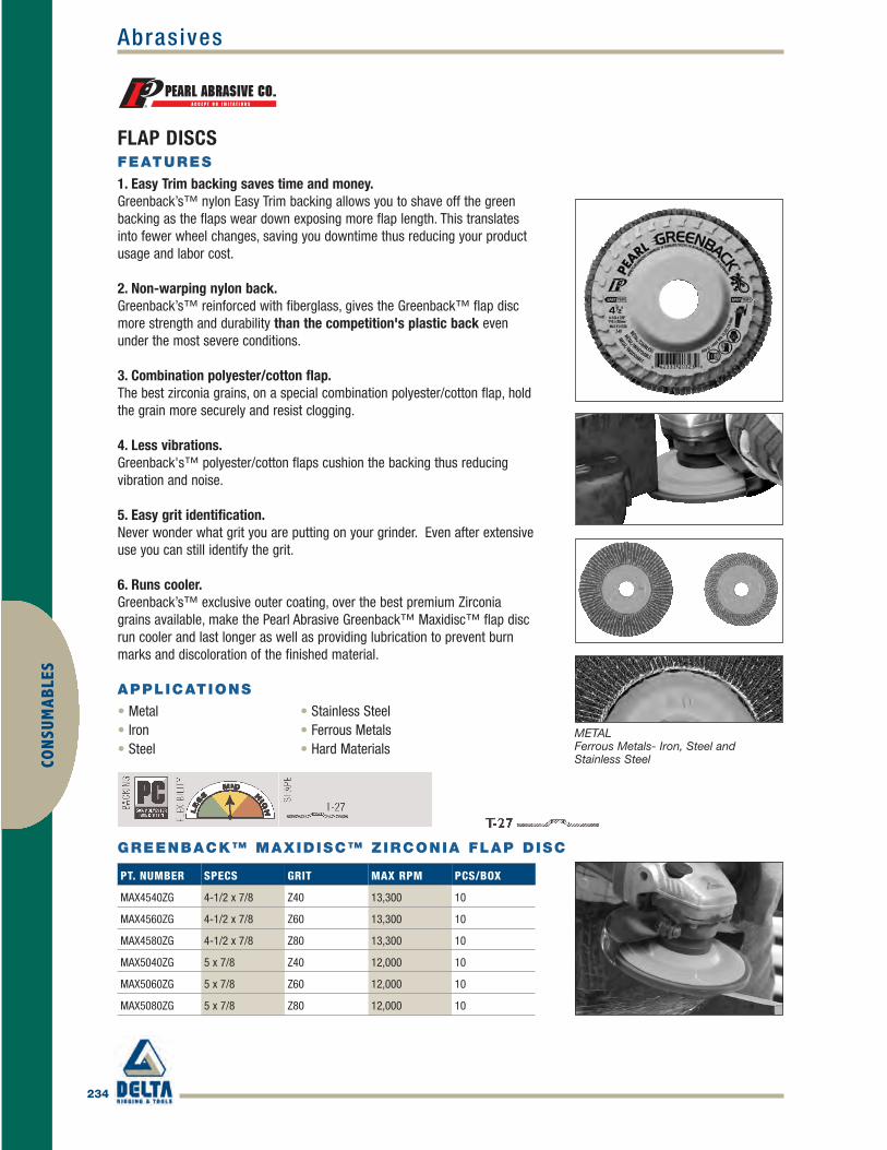
234
AbrasivesCO
NSU
MAB
LES
FLAP DISCS
GREENBACK™ MAXIDISC™ ZIRCONIA FLAP DISC
METALFerrous Metals- Iron, Steel andStainless Steel
FEATURES
1. Easy Trim backing saves time and money.Greenback’s™ nylon Easy Trim backing allows you to shave off the greenbacking as the flaps wear down exposing more flap length. This translatesinto fewer wheel changes, saving you downtime thus reducing your productusage and labor cost.
2. Non-warping nylon back.Greenback’s™ reinforced with fiberglass, gives the Greenback™ flap discmore strength and durability than the competition's plastic back evenunder the most severe conditions.
3. Combination polyester/cotton flap.The best zirconia grains, on a special combination polyester/cotton flap, holdthe grain more securely and resist clogging.
4. Less vibrations.Greenback's™ polyester/cotton flaps cushion the backing thus reducingvibration and noise.
5. Easy grit identification.Never wonder what grit you are putting on your grinder. Even after extensiveuse you can still identify the grit.
6. Runs cooler.Greenback’s™ exclusive outer coating, over the best premium Zirconiagrains available, make the Pearl Abrasive Greenback™ Maxidisc™ flap discrun cooler and last longer as well as providing lubrication to prevent burnmarks and discoloration of the finished material.
APPLICATIONS
• Metal • Stainless Steel• Iron • Ferrous Metals• Steel • Hard Materials
PT. NUMBER SPECS GRIT MAX RPM PCS/BOX
MAX4540ZG 4-1/2 x 7/8 Z40 13,300 10
MAX4560ZG 4-1/2 x 7/8 Z60 13,300 10
MAX4580ZG 4-1/2 x 7/8 Z80 13,300 10
MAX5040ZG 5 x 7/8 Z40 12,000 10
MAX5060ZG 5 x 7/8 Z60 12,000 10
MAX5080ZG 5 x 7/8 Z80 12,000 10
Pearl_233-240 final.qxd 4/5/10 1:40 PM Page 234
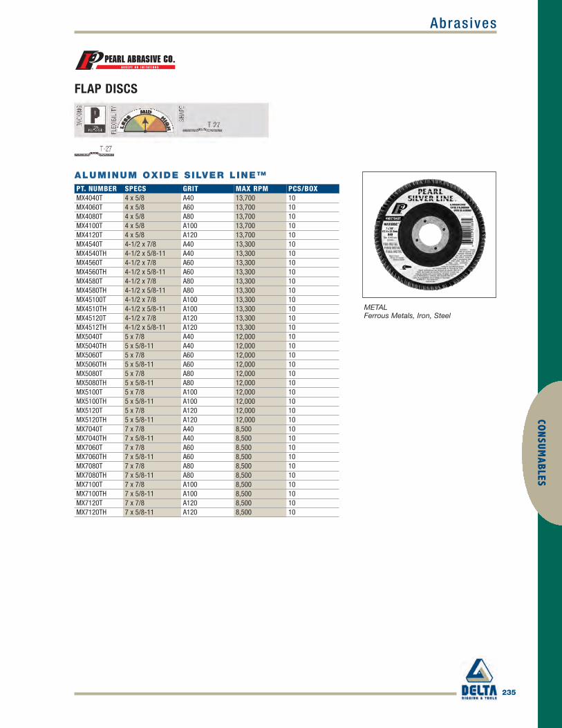
Abrasives
235
CON
SUMABLES
ALUMINUM OXIDE SILVER LINE™
FLAP DISCS
METALFerrous Metals, Iron, Steel
PT. NUMBER SPECS GRIT MAX RPM PCS/BOXMX4040T 4 x 5/8 A40 13,700 10MX4060T 4 x 5/8 A60 13,700 10MX4080T 4 x 5/8 A80 13,700 10MX4100T 4 x 5/8 A100 13,700 10MX4120T 4 x 5/8 A120 13,700 10MX4540T 4-1/2 x 7/8 A40 13,300 10MX4540TH 4-1/2 x 5/8-11 A40 13,300 10MX4560T 4-1/2 x 7/8 A60 13,300 10MX4560TH 4-1/2 x 5/8-11 A60 13,300 10MX4580T 4-1/2 x 7/8 A80 13,300 10MX4580TH 4-1/2 x 5/8-11 A80 13,300 10MX45100T 4-1/2 x 7/8 A100 13,300 10MX4510TH 4-1/2 x 5/8-11 A100 13,300 10MX45120T 4-1/2 x 7/8 A120 13,300 10MX4512TH 4-1/2 x 5/8-11 A120 13,300 10MX5040T 5 x 7/8 A40 12,000 10MX5040TH 5 x 5/8-11 A40 12,000 10MX5060T 5 x 7/8 A60 12,000 10MX5060TH 5 x 5/8-11 A60 12,000 10MX5080T 5 x 7/8 A80 12,000 10MX5080TH 5 x 5/8-11 A80 12,000 10MX5100T 5 x 7/8 A100 12,000 10MX5100TH 5 x 5/8-11 A100 12,000 10MX5120T 5 x 7/8 A120 12,000 10MX5120TH 5 x 5/8-11 A120 12,000 10MX7040T 7 x 7/8 A40 8,500 10MX7040TH 7 x 5/8-11 A40 8,500 10MX7060T 7 x 7/8 A60 8,500 10MX7060TH 7 x 5/8-11 A60 8,500 10MX7080T 7 x 7/8 A80 8,500 10MX7080TH 7 x 5/8-11 A80 8,500 10MX7100T 7 x 7/8 A100 8,500 10MX7100TH 7 x 5/8-11 A100 8,500 10MX7120T 7 x 7/8 A120 8,500 10MX7120TH 7 x 5/8-11 A120 8,500 10
Pearl_233-240 final.qxd 4/5/10 1:40 PM Page 235

236
AbrasivesCO
NSU
MAB
LES
ALUMINUM OXIDE PREMIUM
FLAP DISCS
PT. NUMBER SPECS GRIT MAX RPM PCS/BOXMAX4040 4 x 5/8 A40 13,700 10/100MAX4060 4 x 5/8 A60 13,700 10/100MAX4080 4 x 5/8 A80 13,700 10/100MAX4100 4 x 5/8 A100 13,700 10/100MAX4120 4 x 5/8 A120 13,700 10/100MAX4540 4-1/2 x 7/8 A40 11,000 10/100MAX4540H 4-1/2 x 5/8-11 A40 11,000 10MAX4560 4-1/2 x 7/8 A60 11,000 10/100MAX4560H 4-1/2 x 5/8-11 A60 11,000 10MAX4580 4-1/2 x 7/8 A80 11,000 10/100MAX4580H 4-1/2 x 5/8-11 A80 11,000 10MAX45100 4-1/2 x 7/8 A100 11,000 10/100MAX4510H 4-1/2 x 5/8-11 A100 11,000 10MAX45120 4-1/2 x 7/8 A120 11,000 10/100MAX45120H 4-1/2 x 5/8-11 A120 11,000 10MAX5040 5 x 7/8 A40 11,000 10/100MAX5040H 5 x 5/8-11 A40 11,000 10MAX5060 5 x 7/8 A60 11,000 10/100MAX5060H 5 x 5/8-11 A60 11,000 10MAX5080 5 x 7/8 A80 11,000 10/100MAX5080H 5 x 5/8-11 A80 11,000 10MAX5100 5 x 7/8 A100 11,000 10/100MAX5100H 5 x 5/8-11 A100 11,000 10MAX5120 5 x 7/8 A120 11,000 10/100MAX5120H 5 x 5/8-11 A120 11,000 10MAX7040 7 x 7/8 A40 6,000 10/100MAX7040H 7 x 5/8-11 A40 6,000 10MAX7060 7 x 7/8 A60 6,000 10/100MAX7060H 7 x 5/8-11 A60 6,000 10MAX7080 7 x 7/8 A80 6,000 10/100MAX7080H 7 x 5/8-11 A80 6,000 10MAX7100 7 x 7/8 A100 6,000 10/100MAX7100H 7 x 5/8-11 A100 6,000 10
METALFerrous Metals, Iron, Steel, Non-ferrous,Aluminum, Brass, Copper
Pearl_233-240 final.qxd 4/5/10 1:40 PM Page 236

Abrasives
237
CON
SUMABLES
METALFerrous Metals – Iron, Steel andStainless Steel
PT. NUMBER SPECS GRIT MAX RPM PCS/BOXMAX4536Z 4-1/2 x 7/8 Z36 13,300 10MAX4536ZH 4-1/2 x 5/8-11 Z36 13,300 10MAX4540Z 4-1/2 x 7/8 Z40 13,300 10MAX454ZH 4-1/2 x 5/8-11 Z40 13,300 10
ZIRCONIA TUFF MAX™
FLAP DISCS
PT. NUMBER SPECS GRIT MAX RPM PCS/BOXT-27
MX4040ZT 4 x 5/8 Z40 13,700 10
MX4060ZT 4 x 5/8 Z60 13,700 10
MX4080ZT 4 x 5/8 Z80 13,700 10
MX4540ZT 4-1/2 x 7/8 Z40 13,300 10
MX454ZTH 4-1/2 x 5/8-11 Z40 13,300 10
MX4560ZT 4-1/2 x 7/8 Z60 13,300 10
MX456ZTH 4-1/2 x 5/8-11 Z60 13,300 10
MX4580ZT 4-1/2 x 7/8 Z80 13,300 10
MX458ZTH 4-1/2 x 5/8-11 Z80 13,300 10
MX5040ZT 5 x 7/8 Z40 12,000 10
MX540ZTH 5 x 5/8-11 Z40 12,000 10
MX5060ZT 5 x 7/8 Z60 12,000 10
MX560ZTH 5 x 5/8-11 Z60 12,000 10
MX5080ZT 5 x 7/8 Z80 12,000 10
MX580ZTH 5 x 5/8-11 Z80 12,000 10
MX7040ZT 7 x 7/8 Z40 8,500 10
MX740ZTH 7 x 5/8-11 Z40 8,500 10
MX7060ZT 7 x 7/8 Z60 8,500 10
MX760ZTH 7 x 5/8-11 Z60 8,500 10
MX7080ZT 7 x 7/8 Z80 8,500 10
MX780ZTH 7 x 5/8-11 Z80 8,500 10
T-29
MX454Z9T 4-1/2 x 7/8 Z40 13,300 10
MX454Z9TH 4-1/2 x 5/8-11 Z40 13,300 10
MX456Z9T 4-1/2 x 7/8 Z60 13,300 10
MX456Z9TH 4-1/2 x 5/8-11 Z60 13,300 10
MX458Z9T 4-1/2 x 7/8 Z80 13,300 10
MX458Z9TH 4-1/2 x 5/8-11 Z80 13,300 10
ZIRCONIA SILVER LINE™
METALFerrous Metals – Iron, Steel andStainless Steel
Pearl_233-240 final.qxd 4/5/10 1:40 PM Page 237

238
AbrasivesCO
NSU
MAB
LES
STAINLESS STEEL
PT. NUMBER SPECS GRIT MAX RPM PCS/BOXMAX4540ZS 4-1/2 x 7/8 Z40 13,300 10MAX4540ZSH 4-1/2 x 5/8-11 Z40 13,300 10MAX4560ZS 4-1/2 x 7/8 Z60 13,300 10MAX4560ZSH 4-1/2 x 5/8-11 Z60 13,300 10MAX4580ZS 4-1/2 x 7/8 Z80 13,300 10MAX4580ZSH 4-1/2 x 5/8-11 Z80 13,300 10
SPECIAL COAT ZIRCONIA STAINLESS MAX™
FLAP DISCS
PT. NUMBER SPECS GRIT MAX RPM PCS/BOXT-27MAX4040Z 4 x 5/8 Z40 13,700 10/100MAX4060Z 4 x 5/8 Z60 13,700 10/100MAX4080Z 4 x 5/8 Z80 13,700 10/100MAX4560Z 4-1/2 x 7/8 Z60 13,300 10/100MAX456ZH 4-1/2 x 5/8-11 Z60 13,300 10MAX4580Z 4-1/2 x 7/8 Z80 13,300 10/100MAX458ZH 4-1/2 x 5/8-11 Z80 13,300 10MAX5040Z 5 x 7/8 Z40 12,000 10/100MAX504ZH 5 x 5/8-11 Z40 12,000 10MAX5060Z 5 x 7/8 Z60 12,000 10/100MAX506ZH 5 x 5/8-11 Z60 12,000 10MAX5080Z 5 x 7/8 Z80 12,000 10/100MAX508ZH 5 x 5/8-11 Z80 12,000 10MAX7040Z 7 x 7/8 Z40 8,500 10/100MAX704ZH 7 x 5/8-11 Z40 8,500 10MAX7060Z 7 x 7/8 Z60 8,500 10/100MAX706ZH 7 x 5/8-11 Z60 8,500 10MAX7080Z 7 x 7/8 Z80 8,500 10/100MAX708ZH 7 x 5/8-11 Z80 8,500 10T-29MAX4540Z9 4-1/2 x 7/8 Z40 13,300 10MAX4540Z9H 4-1/2 x 5/8-11 Z40 13,300 10MAX4560Z9 4-1/2 x 7/8 Z60 13,300 10MAX4560Z9H 4-1/2 x 5/8-11 Z60 13,300 10MAX4580Z9 4-1/2 x 7/8 Z80 13,300 10MAX4580Z9H 4-1/2 x 5/8-11 Z80 13,300 10
ZIRCONIA PREMIUM
METALFerrous Metals – Iron, Steel andStainless Steel
Pearl_233-240 final.qxd 4/5/10 1:40 PM Page 238

Abrasives
239
CON
SUMABLES
METALFerrous Metals – Iron, Steel andStainless Steel
PT. NUMBER SPECS GRIT MAX RPM PCS/BOXMAX4540ZJ9 4-1/2 x 7/8 Z40 13,300 10MAX4560ZJ9 4-1/2 x 5/8-11 Z60 13,300 10MAX4580ZJ9 4-1/2 x 7/8 Z80 13,300 10
ZIRCONIA FATMAX™
FLAP DISCS
PT. NUMBER SPECS GRIT MAX RPM PCS/BOXMX4540ZYK 4-1/2 x 7/8 Z40 11,000 10/100MX454ZYKH 4-1/2 x 5/8-11 Z40 11,000 10MX4560ZYK 4-1/2 x 7/8 Z60 11,000 10/100MX456ZYKH 4-1/2 x 5/8-11 Z60 11,000 10MX4580ZYK 4-1/2 x 7/8 Z80 11,000 10/100MX458ZYKH 4-1/2 x 5/8-11 Z80 11,000 10
ZIRCONIA XTRA EDGE
METALFerrous Metals, Iron, Steel, StainlessSteel and Other High Tensile Alloys
PT. NUMBER SPECS GRIT MAX RPM PCS/BOXMAX4040K 4 x 5/8 A40 13,700 10MAX4060K 4 x 5/8 A60 13,700 10MAX4080K 4 x 5/8 A80 13,700 10MAX4100K 4 x 5/8 A100 13,700 10MAX4540K 4-1/2 x 7/8 A40 11,000 10MAX4540KH 4-1/2 x 5/8-11 A40 11,000 10MAX4560K 4-1/2 x 7/8 A60 11,000 10MAX4560KH 4-1/2 x 5/8-11 A60 11,000 10MAX4580K 4-1/2 x 7/8 A80 11,000 10MAX4580KH 4-1/2 x 5/8-11 A80 11,000 10MAX45100K 4-1/2 x 7/8 A100 11,000 10MAX4510KH 4-1/2 x 5/8-11 A100 11,000 10
ALUMINUM OXIDE CLASSIC™
METALFerrous Metals, Iron, Steel
Pearl_233-240 final.qxd 4/5/10 1:40 PM Page 239

240
AbrasivesCO
NSU
MAB
LES
STONE/GLASSMarble, Granite, Concrete, Glass,Cast Iron, Non-Ferrous Metals
PART NO. SIZE (IN.) MAX SPD.FPD40 4 13,700FPD50 4-1/2 13,300FPD70 7 8,500FPD90 9 6,500
PLASTIC BACKUP PADS FOR MAXIDISCS™
FLAP DISCS
PT. NUMBER SPECS GRIT MAX RPM PCS/BOXMAX4080C 4 x 5/8 C80 13,700 10/100MAX4120C 4 x 5/8 C120 13,700 10/100MAX4240C 4 x 5/8 C240 13,700 10/100MAX4320C 4 x 5/8 C320 13,700 10/100MAX4400C 4 x 5/8 C400 13,700 10/100MAX4600C 4 x 5/8 C600 13,700 10/100MAX4580C 4-1/2 x 7/8 C80 13,300 10/100MX4580CH 4-1/2 x 5/8-11 C80 13,300 10MAX4512C 4-1/2 x 7/8 C120 13,300 10/100MX4512CH 4-1/2 x 5/8-11 C120 13,300 10MAX4524C 4-1/2 x 7/8 C240 13,300 10/100MX4524CH 4-1/2 x 5/8-11 C240 13,300 10MAX4532C 4-1/2 x 7/8 C320 13,300 10/100MX4532CH 4-1/2 x 5/8-11 C320 13,300 10MAX4540C 4-1/2 x 7/8 C400 13,300 10/100MX4540CH 4-1/2 x 5/8-11 C400 13,300 10MAX4560C 4-1/2 x 7/8 C600 13,300 10/100MX4560CH 4-1/2 x 5/8-11 C600 13,300 10MAX7080C 7 x 7/8 C80 8,500 10/100MX7080CH 7 x 5/8-11 C80 8,500 10MAX7120C 7 x 7/8 C120 8,500 10/100MX7120CH 7 x 5/8-11 C120 8,500 10MAX7240C 7 x 7/8 C240 8,500 10/100MX7240CH 7 x 5/8-11 C240 8,500 10MAX7320C 7 x 7/8 C320 8,500 10/100MX7320CH 7 x 5/8-11 C320 8,500 10MAX7400C 7 x 7/8 C400 8,500 10/100MX7400CH 7 x 5/8-11 C400 8,500 10MAX7600C 7 x 7/8 C600 8,500 10/100MX7600CH 7 x 5/8-11 C600 8,500 10
SILICON CARBIDE
PART NO. SIZE (IN.)MAX5838 5/8 to 3/8, for 4 in. Maxidisc™
MAXIDISC™ ADAPTER
Pearl_233-240 final.qxd 4/5/10 1:41 PM Page 240

Abrasives
241
CON
SUMABLES
FLAPPER WHEELALUMINUM OXIDE FLAP WHEELS
METALFerrous Metals, Iron, Steel, StainlessSteel, Aluminum, Copper, Wood,Plastic and Fiberglass
PT. NUMBER SPECS GRIT MAX RPM PCS/BOXFL13460* 1 x 3/4 A60 25,000 20FL13480* 1 x 3/4 A80 25,000 20FL134120* 1 x 3/4 A120 25,000 20FL134180* 1 x 3/4 A180 25,000 20FL11060* 1 x 1 A60 25,000 20FL11080* 1 x 1 A80 25,000 20FL110120* 1 x 1 A120 25,000 20FL110180* 1 x 1 A180 25,000 20FL11260* 1-1/2 x 1 A60 25,000 20FL11280* 1-1/2 x 1 A80 25,000 20FL112120* 1-1/2 x 1 A120 25,000 20FL112180* 1-1/2 x 1 A180 25,000 20FL21060* 2 x 1 A60 25,000 20FL21080* 2 x 1 A80 25,000 20FL210120* 2 x 1 A120 25,000 20FL210180* 2 x 1 A180 25,000 20FL21260* 2-1/2 x 1 A60 20,000 20FL21280* 2-1/2 x 1 A80 20,000 20FL212120* 2-1/2 x 1 A120 20,000 20FL212180* 2-1/2 x 1 A180 20,000 20FL31060* 3 x 1 A60 20,000 20FL31080* 3 x 1 A80 20,000 20FL310120* 3 x 1 A120 20,000 20FL310180* 3 x 1 A180 20,000 20FL61060 6 x 1 x 1 A60 6,000 20FL61080 6 x 1 x 1 A80 6,000 20FL610120 6 x 1 x 1 A120 6,000 20FL62060 6 x 2 x 1 A60 6,000 10FL62080 6 x 2 x 1 A80 6,000 10FL620120 6 x 2 x 1 A120 6,000 10
*With 1/4 shank
Pearl_241-244 final.qxd 4/5/10 1:43 PM Page 241

242
AbrasivesCO
NSU
MAB
LES
QUICK MOUNT – SANDING
PART NO. SIZEBPMX02Q 2 in. Backup PadBPMX03Q 3 in. Backup PadBPMXSHNK Shank for Backup Pad
QUICK MOUNT™ BACKUP PADS FORCONDITIONING DISCS WITH 1/4 SHANK
ALUMINUM OXIDE QUICK MOUNT™ MINI CONDITIONING DISCS
METALFerrous Metals, Iron, Steel, StainlessSteel
PT. NUMBER SPECS (IN.) GRIT MAX RPMP PCS/BOXNON-WOVEN DISCSNW2CQ 2 Coarse/Brown 20,000 50NW2MQ 2 Medium/Maroon 20,000 50NW2FQ 2 Fine/Blue 20,000 50NW3CQ 3 Coarse/Brown 18,000 25NW3MQ 3 Medium/Maroon 18,000 25NW3FQ 3 Fine/Blue 18,000 25LAMINATED CLOTH DISCSCD2024Q 2 A24 20,000 50CD2036Q 2 A36 20,000 50CD2050Q 2 A50 20,000 50CD2060Q 2 A60 20,000 50CD2080Q 2 A80 20,000 50CD2100Q 2 A100 20,000 50CD2120Q 2 A120 20,000 50CD3024Q 3 A24 18,000 25CD3036Q 3 A36 18,000 25CD3050Q 3 A50 18,000 25CD3060Q 3 A60 18,000 25CD3080Q 3 A80 18,000 25CD3100Q 3 A100 18,000 25CD3120Q 3 A120 18,000 25
Pearl_241-244 final.qxd 4/5/10 1:43 PM Page 242

Abrasives
243
CON
SUMABLES
SHOP ROLLSThe Pearl shop roll is for use on a variety of small sanding jobs. Premium quality grains and J-weight cloth backing havebeen designed for long lasting performance. Use on ferrous metals, high tensile steel, iron, non-ferrous metals, aluminumand copper. Also use on wood and fiberglass.
ALUMINUM OXIDE SILVER LINE™
METALFerrous Metals, Iron, Steel
PT. NUMBER SPECS GRITSR3060T 2 x 50 yds. A60SR3080T 2 x 50 yds. A80SR3100T 2 x 50 yds. A100SR3120T 2 x 50 yds. A120SR3150T 2 x 50 yds. A150SR3180T 2 x 50 yds. A180SR3240T 2 x 50 yds. A240SR3320T 2 x 50 yds. A320
ALUMINUM OXIDE PREMIUM
PT. NUMBER SPECS GRITSR1060 1 x 50 yds. A60SR1080 1 x 50 yds. A80SR1100 1 x 50 yds. A100SR1120 1 x 50 yds. A120SR1150 1 x 50 yds. A150SR1180 1 x 50 yds. A180SR1240 1 x 50 yds. A240SR1320 1 x 50 yds. A320SR2060 1-1/2 x 50 yds. A60SR2080 1-1/2 x 50 yds. A80SR2100 1-1/2 x 50 yds. A100SR2120 1-1/2 x 50 yds. A120SR2150 1-1/2 x 50 yds. A150SR2180 1-1/2 x 50 yds. A180SR2220 1-1/2 x 50 yds. A220SR2240 1-1/2 x 50 yds. A240SR2280 1-1/2 x 50 yds. A280SR2320 1-1/2 x 50 yds. A320SR2400 1-1/2 x 50 yds. A400SR3050 2 x 50 yds. A50SR3060 2 x 50 yds. A60SR3080 2 x 50 yds. A80SR3100 2 x 50 yds. A100SR3120 2 x 50 yds. A120SR3150 2 x 50 yds. A150SR3180 2 x 50 yds. A180SR3220 2 x 50 yds. A220SR3240 2 x 50 yds. A240SR3280 2 x 50 yds. A280SR3320 2 x 50 yds. A320SR3400 2 x 50 yds. A400
METALFerrous Metals, Iron, Steel
Pearl_241-244 final.qxd 4/5/10 1:43 PM Page 243

244
AbrasivesCO
NSU
MAB
LES
CONCRETEStone, Cast Iron and Non-Ferrous Metals
SILICON CARBIDE STRIPPING (NON-WOVEN DISC)
SURFACE PREPARATION
PT. NUMBER SPECS GRIT MAX RPM PCS/BOXFSP4516 4-1/2 x 7/8 C16 13,300 25/400FSP7016 7 x 7/8 C16 8,500 25/200
SILICON CARBIDE TURBO CUT™ DISC
Ferrous Metals – Iron, Steel, Paint, Rust and Stain Removal
PT. NUMBER SPECS MAX RPM PCS/BOXSTRIP40 4 x 5/8 13,100 10STRIP45 4-1/2 x 7/8 11,000 10STRIP70 7 x 7/8 6,500 5
HEAVY DUTY RUBBER BACKUP PADS FOR TURBO CUT™ DISCSBPFTC45 4-1/2 x 5/8-11 Center nut 13,300BPFTC70 7 x 5/8-11 Center nut 8,600
Pearl_241-244 final.qxd 4/5/10 1:43 PM Page 244

Grinding Wheels
245
CON
SUMABLES
PT. NUMBER SPECS GRIT MAX RPM PCS/BOX
CSA416 4 x 2 x 5/8-11 A16Q 9,000 10
CSA516 5 x 2 x 5/8-11 A16Q 7,200 10
CSA616 6 x 2 x 5/8-11 A16Q 6,000 10
PT. NUMBER SPECS GRIT MAX RPM PCS/BOX
CSC416 4 x 2 x 5/8-11 C16Q 9,000 10
CSC516 5 x 2 x 5/8-11 C16Q 7,200 10
CSC616 6 x 2 x 5/8-11 C16Q 6,000 10
CUP ROCKPearl Abrasive Co.’s maximum value Type II Cup Stones were developed for both grinding performance and quality. Unlikecompetitor’s inferior imports, Pearl’s Cup Stones utilize the highest quality abrasive grain and resin bond to ensure that thestone will withstand the toughest grinding applications.
FEATURES
• Pearl quality, proven performance and priced right• Improved resin bonding of abrasives for longer life• 6" cup wheels feature metal backing• Meets or exceeds safety requirement
METALFerrous Metals, Iron, Steel
CONCRETEStone, Cast Iron and Non-FerrousMetals
ALUMINUM OXIDE
SILICON CARBIDE
Pearl_245-251 final.qxd 4/5/10 5:50 PM Page 245

246
Grinding WheelsCO
NSU
MAB
LES
BENCH WHEELSPearl’s bench grinding wheels are designed for use on work benches or floor standing machines. Wheels are not affectedby water, oils or acids. Each wheel is balanced and ring tested. One size wheel can fit several different machines using theincluded bushing set. Use Aluminum Oxide bench grinding wheels for general purpose tool sharpening, light to heavy stockremoval on ferrous metals – carbon steel, steel and iron. Use Green Silicon Carbide bench grinding wheels for fast burrfree grinding of tungsten carbide-tipped tools, ferrous and non-ferrous metals.
ALUMINUM OXIDE
METALFerrous Metals, Iron, Steel
PT. NUMBER SPECS GRIT MAX RPMBA612036 6 x 1/2 x 1 A36 4,140BA612060 6 x 1/2 x 1 A60 4,140BA634024 6 x 3/4 x 1 A24 4,140BA634036 6 x 3/4 x 1 A36 4,140BA634046 6 x 3/4 x 1 A46 4,140BA634060 6 x 3/4 x 1 A60 4,140BA634080 6 x 3/4 x 1 A80 4,140BA610024 6 x 1 x 1 A24 4,140BA610036 6 x 1 x 1 A36 4,140BA610046 6 x 1 x 1 A46 4,140BA610060 6 x 1 x 1 A60 4,140BA610080 6 x 1 x 1 A80 4,140BA710024 7 x 1 x 1 A24 3,600BA710036 7 x 1 x 1 A36 3,600BA710046 7 x 1 x 1 A46 3,600BA710060 7 x 1 x 1 A60 3,600BA710080 7 x 1 x 1 A80 3,600BA810024 8 x 1 x 1 A24 3,600BA810036 8 x 1 x 1 A36 3,600BA810046 8 x 1 x 1 A46 3,600BA810060 8 x 1 x 1 A60 3,600BA810080 8 x 1 x 1 A80 3,600BA101024 10 x 1 x 1-1/4 A24 2,485BA101036 10 x 1 x 1-1/4 A36 2,485BA101060 10 x 1 x 1-1/4 A60 1,800BA122024 12 x 2 x 1-1/4 A24 1,800BA122036 12 x 2 x 1-1/4 A36 1,800BA122060 12 x 2 x 1-1/4 A60 1,800
Each Bench Wheel Includes a Nested Reducing Bushing Set
Pearl_245-251 final.qxd 4/5/10 5:50 PM Page 246

Grinding Wheels
247
CON
SUMABLES
BENCH WHEELSPearl’s bench grinding wheels are designed for use on work benches or floor standing machines. Wheels are not affectedby water, oils or acids. Each wheel is balanced and ring tested. One size wheel can fit several different machines using theincluded bushing set. Use Aluminum Oxide bench grinding wheels for general purpose tool sharpening, light to heavy stockremoval on ferrous metals – carbon steel, steel and iron. Use Green Silicon Carbide bench grinding wheels for fast burrfree grinding of tungsten carbide-tipped tools, ferrous and non-ferrous metals.
Tungsten Carbide-Tipped Tools,Ferrous and Non-Ferrous Metals
GREEN SIL ICON CARBIDE
PT. NUMBER SPECS GRIT MAX RPMBG612060 6 x 1/2 x 1 C60 4,140BG612080 6 x 1/2 x 1 C80 4,140BG612120 6 x 1/2 x 1 C120 4,140BG634060 6 x 3/4 x 1 C60 4,140BG634080 6 x 3/4 x 1 C80 4,140BG634120 6 x 3/4 x 1 C120 4,140BG610060 6 x 1 x 1 C60 4,140BG610080 6 x 1 x 1 C80 4,140BG610120 6 x 1 x 1 C120 4,140BG710060 7 x 1 x 1 C60 3,600BG710080 7 x 1 x 1 C80 3,600BG710120 7 x 1 x 1 C120 3,600BG810060 8 x 1 x 1 C60 3,600BG810080 8 x 1 x 1 C80 3,600BG810120 8 x 1 x 1 C120 3,600BG101060 10 x 1 x 1-1/4 C60 2,485BG101080 10 x 1 x 1-1/4 C80 2,485BG101120 10 x 1 x 1-1/4 C120 2,485BG122060 12 x 2 x 1-1/4 C60 1,800BG122080 12 x 2 x 1-1/4 C80 1,800BG122120 12 x 2 x 1-1/4 C120 1,800
Each Bench Wheel Includes a Nested Reducing Bushing Set
Pearl_245-251 final.qxd 4/5/10 5:50 PM Page 247

248
Grinding WheelsCO
NSU
MAB
LES
PT. NUMBER SPECS GRIT MAX RPM PCS/BOXCW201638 2 x 1/16 x 3/8 A54T 38,200 200CW201814 2 x 1/8 x 1/4 A54T 38,200 100CW201838 2 x 1/8 x 3/8 A54T 38,200 100CW251614 2-1/2 x 1/16 x 1/4 A54T 29,300 200CW251638 2-1/2 x 1/16 x 3/8 A54T 29,300 200CW251838 2-1/2 x 1/8 x 3/8 A54T 29,300 100CW0310 3 x 1/16 x 3/8 A46T 25,000 100CW0320 3 x 1/8 x 3/8 A46T 25,000 50CW0330 3 x 1/16 x 1/4 A46T 25,000 100CW0340 3 x 1/8 x 1/4 A46T 25,000 50CW0350 3 x 1/32 x 3/8 A60T 25,000 100CW0410 4 x 1/16 x 3/8 A46T 18,000 100CW0420 4 x 1/8 x 3/8 A46T 18,000 50CW0430 4 x 1/16 x 5/8 A46T 18,000 100CW0440 4 x 1/8 x 5/8 A46T 18,000 50CW0450 4 x 1/16 x 1/4 A46T 18,000 100CW0460 4 x 1/8 x 1/4 A46T 18,000 50CW0470 4 x 1/16 x 7/8 A46T 18,000 100CW0480 4 x 1/8 x 7/8 A46T 18,000 50CW0490 4 x 1/32 x 3/8 A60T 18,000 100CW049A 4 x 1/32 x 5/8 A60T 18,000 100CW4510 4-1/2 x 1/16 x 7/8 A46T 13,300 100CW4520 4-1/2 x 1/8 x 7/8 A46S 13,300 50CW061D 6 x 1/8 x ◊, 5/8 A36R 10,100 25CW0710D 7 x 1/8 x ◊, 5/8 A36R 8,500 25CW0716A 7 x 1/16 x 7/8 A60T 8,500 50CW0810D 8 x 1/8 x ◊, 5/8 A36R 6,800 25CW1010 10 x 1/16 x 1 A36R 6,100 25CW1020 10 x 1/8 x 1 A36T 6,100 25CW1020A 10 x 1/8 x 5/8 A36T 6,100 25CW12MA 12 x 7/64 x 1 A36P 5,100 5/25CW1220 12 x 1/8 x 1 A36T 5,100 5/25CW122G* 12 x 1/8 x 1** A36T 6,300 5/25CW1222G* 12 x 1/8 x 20mm** A36T 6,300 5/25CW14MA 14 x 7/64 x 1 A36P 4,400 5/25CW1420 14 x 1/8 x 1 A36S 4,400 5/25CW142G* 14 x 1/8 x 1** A36S 5,400 5/25CW1422G* 14 x 1/8 x 20mm** A36S 5,400 5/25CW1610 16 x 1/8 x 1 A36S 3,800 20CW1630 16 x 5/32 x 1 A36S 3,800 20CW1810 18 x 1/8 x 1 A36S 3,380 10CW201G 20 x 1/8 x 1 A30S 3,000 10CW201GE 20 x 1/8 x 1 A30P 3,000 10CW202G 20 x 5/32 x 1 A30S 3,000 10CW202GE 20 x 5/32 x 1 A30P 3,000 10CWX20 20 x 5/32 x 1 A30T 3,000 10CW2201 22 x 5/32 x 1 A30T 2,730 10
METALFerrous Metals, Iron, Steel, Angle Iron,Rebar, Pipes
ALUMINUM OXIDE PREMIUM
*For High Speed Machines **Triple Reinforced
CUT-OFF WHEEL
Pearl_245-251 final.qxd 4/5/10 5:50 PM Page 248

Grinding Wheels
249
CON
SUMABLES
SYNTHETIC RESINOID TECHNOLOGY™
CUT-OFF WHEEL
PT. NUMBER SPECS GRIT MAX RPM PCS/BOXCW310SRT 3 x 1/16 x 3/8 SRT46 25,000 100CW330SRT 3 x 1/16 x 1/4 SRT46 25,000 100CW350SRT 3 x 1/32 x 3/8 SRT60 25,000 100CW410SRT 4 x 1/16 x 3/8 SRT46 18,000 100CW430SRT 4 x 1/16 x 5/8 SRT46 18,000 100CW490SRT 4 x 1/32 x 3/8 SRT60 18,000 100CW071DSR 7 x 1/8 x ◊, 5/8 SRT36 8,500 25/100CW1020SR 10 x 1/8 x 1 SRT36 6,100 25/50CW12MASR 12 x 7/64 x 1 SRT36 5,100 5/25CW1220SR 12 x 1/8 x 1 SRT36 5,100 5/25CW12GSR* 12 x 1/8 x 1 SRT36 6,300 5/25CW122GSR* 12 x 1/8 x 20mm SRT36 6,300 5/25CW14MASR 14 x 7/64 x 1 SRT36 4,400 5/25CW1420SR 14 x 1/8 x 1 SRT36 4,400 5/25CW14GSR* 14 x 1/8 x 1 SRT36 5,400 5/25CW142GSR* 14 x 1/8 x 20mm SRT36 5,400 5/25CW1610SR 16 x 1/8 x 1 SRT36 3,800 10/40CW1630SR 16 x 5/32 x 1 SRT36 3,800 10/40
*For High Speed Machines
METALFerrous Metals – Iron, Steel,Tube, Pipe, and Light GaugeMetals
STUD CUTTING
MANDRELS
PT. NUMBER SPECS GRIT MAX RPM PCS/BOXCW14STUD 14 x 3/32 x 1 A46S 4,400 25
PART NO. SIZEADM25 1/4 and 3/8 combination mandrel 1/4 shank
PART NO. SIZECAD158 1 to 5/8 AdapterCAD178 1 to 7/8 AdapterCAD120 1 to 20mm AdapterCADD58 ◊ to 5/8 Adapter
ADAPTERS
Mandrels and adapters for cut-off wheels
STAINLESS STEELFerrous Metals – Iron, Steel, and OtherHigh Tensile Alloys
Pearl_245-251 final.qxd 4/5/10 5:50 PM Page 249

250
Grinding WheelsCO
NSU
MAB
LES
CUT-OFF WHEELSType I Slimcut40™ and Type 27 Slimcut45™ are thin cut-off wheels from Pearl. Pearl Abrasive has an expanded line ofthin cut-off wheels that meet a variety of performance standards and price demands.
ALUMINUM OXIDE TYPE I SLIMCUT40™
METALFerrous Metals, Iron, Steel,Non-Ferrous, Sheet Metals,Copper, Stainless Steel
PT. NUMBER SPECS GRIT MAX RPM PCS/BOXCW4532A 4-1/2 x .040 x 7/8 A46 13,500 50CW0532A 5 x .040 x 7/8 A46 12,200 50CW0532B 5 x .040 x 5/8 A46 12,200 50CW0632A 6 x .040 x 7/8 A46 10,200 50CW0632B 6 x .040 x 5/8 A46 10,200 50CW0632C 6 x .040 x 1/2 A46 10,200 50CW0632D 6 x .040 x 3/8 A46 10,200 50CW0732A 7 x .040 x 7/8 A46 8,500 50
PT. NUMBER SPECS GRIT MAX RPM PCS/BOXDCW04A 4 x .045 x 5/8 A46 13,700 50DCW45A 4-1/2 x .045 x 7/8 A46 13,500 50DCW05A 5 x .045 x 7/8 A46 12,200 50DCW06A 6 x .045 x 7/8 A46 10,200 50DCW07A 7 x .045 x 7/8 A46 8,500 50
ALUMINUM OXIDE TYPE 27 SLIMCUT45™
PT. NUMBER SPECS GRIT MAX RPM PCS/BOXCWRED4532A 4-1/2 x .040 x 7/8 A46 13,500 50CWRED0532A 5 x .040 x 7/8 A46 12,200 50CWRED0632A 6 x .040 x 7/8 A46 10,200 50
ALUMINUM OXIDE TYPE I SLIMCUT 40™REDLINE™ MAX-A.O.™
PT. NUMBER SPECS GRIT MAX RPM PCS/BOXDCWRED45A 4-1/2 x .045 x 7/8 A46 13,500 50DCWRED05A 5 x .045 x 7/8 A46 12,200 50DCWRED06A 6 x .045 x 7/8 A46 10,200 50
ALUMINUM OXIDE TYPE 27 SLIMCUT 45™REDLINE™ MAX-A.O.™
METALFerrous Metals, Iron, Steel,Non-Ferrous, Sheet Metals,Copper, Stainless Steel
METALFerrous Metals, Iron, Steel,Non-Ferrous, Sheet Metals,Copper, Stainless Steel
METALFerrous Metals, Iron, Steel,Non-Ferrous, Sheet Metals,Copper, Stainless Steel
Pearl_245-251 final.qxd 4/5/10 5:50 PM Page 250

Grinding Wheels
251
CON
SUMABLES
DEPRESSED CENTERPearl Abrasive Co.’s maximum value Type II Cup Stones were developed for both grinding performance and quality. Unlikecompetitor’s inferior imports, Pearl’s Cup Stones utilize the highest quality abrasive grain and resin bond to ensure that thestone will withstand the toughest grinding applications.
SILICON CARBIDE SILVER LINE™
MASONRYConcrete, Stone, Cast Iron, andNon-Ferrous Metals
MASONRYConcrete, Stone, Cast Iron, andNon-Ferrous Metals
SILICON CARBIDE PREMIUM
PT. NUMBER SPECS GRIT MAX RPM PCS/BOX
DM4030T 4 x 1/4 x 5/8 C24S 13,700 25
DM4510T 4-1/2 x 1/4 x 7/8 C24S 13,300 25
DM4510TH 4-1/2 x 1/4 x 5/8-11 C24S 13,300 20
DM5010T 5 x 1/4 x 7/8 C24S 12,000 25
DM5010TH 5 x 1/4 x 5/8-11 C24S 12,000 20
DM7010T 7 x 1/4 x 7/8 C24S 8,500 25
DM7010TH 7 x 1/4 x 5/8-11 C24S 8,500 25
DM9010T 9 x 1/4 x 7/8 C24S 6,500 25
DM9010TH 9 x 1/4 x 5/8-11 C24S 6,500 20
PT. NUMBER SPECS GRIT MAX RPM PCS/BOX
DM4030 4 x 1/4 x 5/8 C24S 13,700 25
DM4510 4-1/2 x 1/4 x 7/8 C24S 13,300 25
DM4510H 4-1/2 x 1/4 x 5/8-11 C24S 13,300 20
DM5010 5 x 1/4 x 7/8 C24S 12,000 25
DM5010H 5 x 1/4 x 5/8-11 C24S 12,000 20
DM7010 7 x 1/4 x 7/8 C24S 8,500 10
DM7010H 7 x 1/4 x 5/8-11 C24S 8,500 25
DM9010 9 x 1/4 x 7/8 C24S 6,500 10
DM9010H 9 x 1/4 x 5/8-11 C24S 6,500 20
Pearl_245-251 final.qxd 4/5/10 5:50 PM Page 251

252
Grinding WheelsCO
NSU
MAB
LES
DEPRESSED CENTER
WHITE ALUMINUM OXIDE
SYNTHETIC RESINOID TECHNOLOGY™
PT. NUMBER SPECS GRIT MAX RPM PCS/BOX
DC705S 7 x 1/4 x 7/8 WA24R 8,500 10
DC705SH 7 x 1/4 x 5/8-11 WA24R 8,500 25
PT. NUMBER SPECS GRIT MAX RPM PCS/BOX
DCSRT40 4 x 1/4 x 5/8 SRT24 13,700 25
DCSRT45 4-1/2 x 1/4 x 7/8 SRT24 13,300 25
DCSRT45H 4-1/2 x 1/4 x 5/8-11 SRT24 13,300 20
DCSRT50 5 x 1/4 x 7/8 SRT24 12,000 25
DCSRT50H 5 x 1/4 x 5/8-11 SRT24 12,000 20
DCSRT70 7 x 1/4 x 7/8 SRT24 8,500 10
DCSRT70H 7 x 1/4 x 5/8-11 SRT24 8,500 25
DCSRT90 9 x 1/4 x 7/8 SRT24 6,500 10
DCSRT90H 9 x 1/4 x 5/8-11 SRT24 6,500 20
ZIRCONIA
PT. NUMBER SPECS GRIT MAX RPM PCS/BOX
DC4030Z 4 x 1/4 x 5/8 Z24T 13,700 25
DC4510Z 4-1/2 x 1/4 x 7/8 Z24T 13,300 25
DC4510ZH 4-1/2 x 1/4 x 5/8-11 Z24T 13,300 20
DC5010Z 5 x 1/4 x 7/8 Z24T 12,000 25
DC5010ZH 5 x 1/4 x 5/8-11 Z24T 12,000 20
DC703Z 7 x 1/4 x 7/8 Z24T 8,500 10
DC703ZH 7 x 1/4 x 5/8-11 Z24T 8,500 25
DC903Z 9 x 1/4 x 7/8 Z24T 6,500 10
DC903ZH 9 x 1/4 x 5/8-11 Z24T 6,500 20
STAINLESS STEELOther High Tensile Alloys
METALFerrous Metals- Iron, Steeland Stainless Steel
ALUMINUMSoft Non-Ferrous Metals,Copper, Brass, Bronze etc.
STAINLESS STEELOther High Tensile Alloys
D.A. SERIES ALUMINUM
PT. NUMBER SPECS GRIT MAX RPM PCS/BOX
DA4030 4 x 1/4 x 5/8 AL24M 13,700 25
DA4510 4-1/2 x 1/4 x 7/8 AL24M 13,300 25
DA4510H 4-1/2 x 1/4 x 5/8-11 AL24M 13,300 20
DA5010 5 x 1/4 x 7/8 AL24M 12,000 25
DA5010H 5 x 1/4 x 5/8-11 AL24M 12,000 20
DA7020 7 x 1/4 x 7/8 AL24M 8,500 10
DA7020H 7 x 1/4 x 5/8-11 AL24M 8,500 25
Pearl_252-253 final.qxd 4/5/10 5:54 PM Page 252

Grinding Wheels
253
CON
SUMABLES
DEPRESSED CENTER
PT. NUMBER SPECS GRIT MAX RPM PCS/BOXFWA7024 7 x 1/8 x 7/8 WA24 8,500 10FWA7024H 7 x 1/8 x 5/8-11 WA24 8,500 25FWA7036 7 x 1/8 x 7/8 WA36 8,500 10FWA7036H 7 x 1/8 x 5/8-11 WA36 8,500 25FWA7046 7 x 1/8 x 7/8 WA46 8,500 10FWA7046H 7 x 1/8 x 5/8-11 WA46 8,500 25
WHITE ALUMINUM OXIDE
STAINLESS STEELOther High Tensile Alloys
PT. NUMBER SPECS GRIT MAX RPM PCS/BOXFCC7036 7 x 1/8 x 7/8 CC36 8,500 10FCC7036H 7 x 1/8 x 5/8-11 CC36 8,500 25FCC7046 7 x 1/8 x 7/8 CC46 8,500 10FCC7046H 7 x 1/8 x 5/8-11 CC46 8,500 25
SILICON CARBIDE
STAINLESS STEELFerrous Metals- Iron, Steeland Other High Tensile Alloys
PART NO. SIZE MAX RPMFPD40 4" 13,700FPD50 4-1/2" 13,300FPD70 7" 8,500FPD90 9" 6,500
PLASTIC BACKUP PADSFOR FLEX WHEELS ANDPEARL NET™
PT. NUMBER SPECS GRIT MAX RPM PCS/BOXFLEX4036 4 x 1/8 x 5/8 SRT36 13,700 25/200FLEX4046 4 x 1/8 x 5/8 SRT46 13,700 25/200FLEX4060 4 x 1/8 x 5/8 SRT60 13,700 25/200FLEX4080 4 x 1/8 x 5/8 SRT80 13,700 25/200FLEX4120 4 x 1/8 x 5/8 SRT120 13,700 25/200FLEX4536 4-1/2 x 1/8 x 7/8 SRT36 13,300 25/200FLEX453H 4-1/2 x 1/8 x 5/8-11 SRT36 13,300 20FLEX4546 4-1/2 x 1/8 x 7/8 SRT46 13,300 25/200FLEX454H 4-1/2 x 1/8 x 5/8-11 SRT46 13,300 20FLEX4560 4-1/2 x 1/8 x 7/8 SRT60 13,300 25/200FLEX456H 4-1/2 x 1/8 x 5/8-11 SRT60 13,300 20FLEX4580 4-1/2 x 1/8 x 7/8 SRT80 13,300 25/200FLEX458H 4-1/2 x 1/8 x 5/8-11 SRT80 13,300 20FLEX4512 4-1/2 x 1/8 x 7/8 SRT120 13,300 25/200FLEX451H 4-1/2 x 1/8 x 5/8-11 SRT120 13,300 20FLEX7036 7 x 1/8 x 7/8 SRT36 8,500 10FLEX736H 7 x 1/8 x 5/8-11 SRT36 8,500 25FLEX7046 7 x 1/8 x 7/8 SRT46 8,500 10FLEX746H 7 x 1/8 x 5/8-11 SRT46 8,500 25FLEX7060 7 x 1/8 x 7/8 SRT60 8,500 10FLEX760H 7 x 1/8 x 5/8-11 SRT60 8,500 25FLEX7080 7 x 1/8 x 7/8 SRT80 8,500 10FLEX780H 7 x 1/8 x 5/8-11 SRT80 8,500 25FLEX7120 7 x 1/8 x 7/8 SRT120 8,500 10FLEX712H 7 x 1/8 x 5/8-11 SRT120 8,500 25
SYNTHETIC RESINOID TECHNOLOGY™
ALUMINUM & STONEConcrete, Stone, Cast Ironand Non-Ferrous Metals
Pearl_252-253 final.qxd 4/5/10 5:54 PM Page 253

254
Wire Cup BrushesCO
NSU
MAB
LES
TEMPERED WIREPearl has developed a line of wire brushes with the professional in mind. Our brushes have been engineered to achievemaximum performance and life. Developed for use in a wide variety of applications including welding, paint and rustremoval as well as surface conditioning.
CRIMPED CUP TEMPERED WIRE
PT. NUMBER SPECS MAX RPMCLWBC210 2-3/4 x .015 x M10 x 1.25 12,500CLWBC214 2-3/4 x .015 x M14 x 2.0 12,500CLWBC258 2-3/4 x .015 x 5/8-11 12,500CLWBC458 4 x .020 x 5/8-11 8,500CLWBC658 6 x .020 x 5/8-11 6,000
PT. NUMBER SPECS MAX RPMCLWBK210 2-3/4 x .020 x M10 x 1.25 12,500CLWBK214 2-3/4 x .020 x M14 x 2.0 12,500CLWBK258 2-3/4 x .020 x 5/8-11 12,500CLWBK458 4 x .020 x 5/8-11 8,500CLWBK658 6 x .020 x 5/8-11 6,000
KNOT CUP TEMPERED WIRE
CLWBK210S 2-3/4 x .020 x M10 x 1.25 12,500CLWBK214S 2-3/4 x .020 x M14 x 2.0 12,500CLWBK258S 2-3/4 x .020 x 5/8-11 12,500CLWBK458S 4 x .020 x 5/8-11 8,500CLWBK658S 6 x .020 x 5/8-11 6,000
STAINLESS WIRE
12" CRACK CLEANING BRUSH TEMPERED WIRE
PT. NUMBER SPECS MAX RPM
CLWBK12 12 x .025 x 1 8,500
Removes fillings from expansion joints. Longer wire to getdeeper into crevices. Number of knots-34. Excellent forworking on concrete or asphalt.
Pearl_254-256 final.qxd 4/5/10 1:51 PM Page 254

Wire Wheels
255
CON
SUMABLES
KNOT WHEELS/CRIMPED WHEEL TEMPERED WIREKNOT WHEEL REGULAR TWISTTEMPERED WIRE
PT. NUMBER SPECS MAX RPMCLWBK410T 4 x .020 x M10 x 1.25 20,000CLWBK414T 4 x .020 x M14 x 2.0 20,000CLWBK458T 4 x .020 x 5/8-11 20,000PIPELINERCLWBP658 6 x .020 x 5/8-11 9,000
CLWBK410TS 4 x .020 x M10 x 1.25 20,000CLWBK414TS 4 x .020 x M14 x 2.0 20,000CLWBK458TS 4 x .020 x 5/8-11 20,000
STAINLESS WIRE
PT. NUMBER SPECS MAX RPMCLWBCW410 4 x .015 x M10 x 1.25 12,500CLWBCW414 4 x .015 x M14 x 2.0 12,500CLWBCW458 4 x .015 x 5/8-11 12,500
KNOT WHEEL STRINGER BEADTWIST TEMPERED WIRE
CRIMPED WHEEL TEMPERED WIRE
PT. NUMBER SPECS MAX RPMCLWBK410B 4 x .020 x M10 x 1.25 20,000CLWBK414B 4 x .020 x M14 x 2.0 20,000CLWBK458B 4 x .020 x 5/8-11 20,000CLWBK658B 6 x .020 x 5/8-11 12,000
CLWBK410BS 4 x .020 x M10 x 1.25 20,000CLWBK414BS 4 x .020 x M14 x 2.0 20,000CLWBK458BS 4 x .020 x 5/8-11 20,000CLWBK658BS 6 x .020 x 5/8-11 12,000
STAINLESS WIRE
Pearl_254-256 final.qxd 4/5/10 1:51 PM Page 255
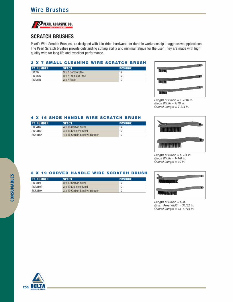
256
Wire BrushesCO
NSU
MAB
LES
SCRATCH BRUSHESPearl’s Wire Scratch Brushes are designed with kiln-dried hardwood for durable workmanship in aggressive applications.The Pearl Scratch brushes provide outstanding cutting ability and minimal fatigue for the user. They are made with highquality wire for long life and excellent performance.
PT. NUMBER SPECS PCS/BOXSCB37 3 x 7 Carbon Steel 12SCB37S 3 x 7 Stainless Steel 12SCB37B 3 x 7 Brass 12
3 X 7 SMALL CLEANING WIRE SCRATCH BRUSH
Length of Brush = 1-7/16 in.Block Width = 7/16 in.Overall Length = 7-3/4 in.
4 X 16 SHOE HANDLE WIRE SCRATCH BRUSH
Length of Brush = 5-1/4 in.Block Width = 1-1/8 in.Overall Length = 10 in.
3 X 19 CURVED HANDLE WIRE SCRATCH BRUSH
Length of Brush = 6 in.Brush Area Width = 31/32 in.Overall Length = 13-11/16 in.
PT. NUMBER SPECS PCS/BOXSCB416 4 x 16 Carbon Steel 12SCB416S 4 x 16 Stainless Steel 12SCB416K 4 x 16 Carbon Steel w/ scraper 12
PT. NUMBER SPECS PCS/BOXSCB319 3 x 19 Carbon Steel 12SCB319S 3 x 19 Stainless Steel 12SCB319K 3 x 19 Carbon Steel w/ scraper 12
Pearl_254-256 final.qxd 4/5/10 1:52 PM Page 256
IndexIN
DEX
Air Tools . . . . . . . . . . . . . . . . . . . . . . . . . . . . . . . . .58-119
Air Drills (Heavy Duty) . . . . . . . . . . . . . . . . . . . . . . . . .87
Air Drills (Pneumatic/Hydraulic) . . . . . . . . . . . . .106-108
Air Impacts . . . . . . . . . . . . . . . . . . . . . . . . . . . . . . .88-89
Air Nutrunners . . . . . . . . . . . . . . . . . . . . . . . . . . . . . .109
Air Saws and Accessories . . . . . . . . . . . . . . . . . .110-119
Angle Grinders . . . . . . . . . . . . . . . . . . . . . . . . . . . .96-98
Breakers . . . . . . . . . . . . . . . . . . . . . . . . . . . . . . . . . . .78
Chipping Hammers . . . . . . . . . . . . . . . . . . . . . . . . .74-76
Clay Diggers . . . . . . . . . . . . . . . . . . . . . . . . . . . . . .82-83
Collet Grinders . . . . . . . . . . . . . . . . . . . . . . . . . .101-102
Die Grinders . . . . . . . . . . . . . . . . . . . . . . . . . . . . . .90-93
Drills . . . . . . . . . . . . . . . . . . . . . . . . . . . . . . . . . . .65, 68
Extended Angle Grinders . . . . . . . . . . . . . . . . . . . .99-100
Extended Collet Grinders . . . . . . . . . . . . . . . . . . . . . .103
Grinders . . . . . . . . . . . . . . . . . . . . . . . . . . . . . . . . .69-73
Impact Wrenches . . . . . . . . . . . . . . . . . . . . .58-64, 66-67
Marking Pens . . . . . . . . . . . . . . . . . . . . . . . . . . . . . . .104
Movers . . . . . . . . . . . . . . . . . . . . . . . . . . . . . . . . . . . . .86
Oilers . . . . . . . . . . . . . . . . . . . . . . . . . . . . . . . . . . . . . .77
Pumps . . . . . . . . . . . . . . . . . . . . . . . . . . . . . . . . . . . . .85
Rivet Busters . . . . . . . . . . . . . . . . . . . . . . . . . . . . . . . .80
Rock Drills . . . . . . . . . . . . . . . . . . . . . . . . . . . . . . . . . .79
Scalers . . . . . . . . . . . . . . . . . . . . . . . . . . . . . . . . .84,105
Tampers . . . . . . . . . . . . . . . . . . . . . . . . . . . . . . . . . . . .81
Wheel Grinders . . . . . . . . . . . . . . . . . . . . . . . . . . . .94-95
Consumables . . . . . . . . . . . . . . . . . . . . . . . . . . . .233-256
Abrasives . . . . . . . . . . . . . . . . . . . . . . . . . . . . . .233-244
Grinding Wheels . . . . . . . . . . . . . . . . . . . . . . . . .245-253
Wire Brushes . . . . . . . . . . . . . . . . . . . . . . . . . . . . . . .256
Wire Cup Brushes . . . . . . . . . . . . . . . . . . . . . . . . . . .254
Wire Wheels . . . . . . . . . . . . . . . . . . . . . . . . . . . . . . . .255
Hand Tools . . . . . . . . . . . . . . . . . . . . . . . . . . . . . . . . .2-47
1-1/2" Drive Accessories . . . . . . . . . . . . . . . . . . . . . . .36
2-1/2" Drive Impact Sockets and Accessories . . . .37-40
3-1/2" Drive Impact Sockets and Accessories . . . .41-43
#5 Spline Impact Sockets and Accessories . . . . . . .44-46
Hammers . . . . . . . . . . . . . . . . . . . . . . . . . . . . . . . . . .2-4
Impact Sockets and Accessories . . . . . . . . . . . . . . .13-35
Socket Retaining Rings . . . . . . . . . . . . . . . . . . . . . . . .47
Wrenches . . . . . . . . . . . . . . . . . . . . . . . . . . . . . . . . .5-12
Magnetic Drills/Cutters . . . . . . . . . . . . . . . . . . . .120-137
Annular Cutters/Pilots . . . . . . . . . . . . . . . . . . . . .129-137
Portable Magnetic Drills . . . . . . . . . . . . . . . . . . .120-122
Magnetic Drills and Accessories . . . . . . . . . . . . .123-128
Portable Hydraulics . . . . . . . . . . . . . . . . . . . . . . .138-178
Cylinders . . . . . . . . . . . . . . . . . . . . . . . . . . . . . .138-145
Cylinder Accessories . . . . . . . . . . . . . . . . . . . . . .148-153
Cylinder Pump Set . . . . . . . . . . . . . . . . . . . . . . .146-147
Gauges . . . . . . . . . . . . . . . . . . . . . . . . . . . . . . . .154-156
Hoses . . . . . . . . . . . . . . . . . . . . . . . . . . . . . . . . .157-158
Nut Splitters . . . . . . . . . . . . . . . . . . . . . . . . . . . . . . . .159
Pumps . . . . . . . . . . . . . . . . . . . . . . . . . . . . . . . .160-170
Presses . . . . . . . . . . . . . . . . . . . . . . . . . . . . . . .171-173
Punches . . . . . . . . . . . . . . . . . . . . . . . . . . . . . . .174-177
Wedges/Spreaders . . . . . . . . . . . . . . . . . . . . . . .178-179
Torque Tools . . . . . . . . . . . . . . . . . . . . . . . . . . . . . . .48-57
Hydraulic Torque Wrenches . . . . . . . . . . . . . . . . . .56-57
Pneumatic Torque Control Wrenches . . . . . . . . . . .52-55
Torque Multipliers . . . . . . . . . . . . . . . . . . . . . . . . . .48-49
Torque Wrenches . . . . . . . . . . . . . . . . . . . . . . . . . .50-51
Tube Expanders . . . . . . . . . . . . . . . . . . . . . . . . . .209-232
Standard Models . . . . . . . . . . . . . . . . .211-215, 222-226
Tube Expanders . . . . . . . . . .209-210, 216-221, 227-232
Tube Removal/Assembly Tools . . . . . . . . . . . . . .180-208
Beveling Machines . . . . . . . . . . . . . . . . . . . . . . .180-189
Grooving Tools . . . . . . . . . . . . . . . . . . . . . . . . . . . . . .204
Tube Cutters . . . . . . . . . . . . . . . . . . . . . . . . . . . .205-208
Tube Expanders . . . . . . . . . . . . . . . . . . . . . . . . .194-203
Tube Pullers . . . . . . . . . . . . . . . . . . . . . . . . . . . .190-193
Green_Index2010.qxd 4/5/10 3:00 PM Page 257

WEI
GHTS
AN
DM
EASU
REM
ENTS
Weights and Measurements
LINEAR MEASURE
10 millimeters = 1 centimeter10 centimeters = 1 decimeter10 decimeters = 1 meter10 meters = 1 dekameter10 dekameters = 1 hectometer10 hectometers = 1 kilometer
AREA MEASURE
100 sq. millimeters = 1 sq. centimeter10,000 sq. centimeters = 1 sq. meter1,000,000 sq. millimeters = 1 sq. meter100 sq. meters = 1 are (a)100 ares = 1 hectare (ha)100 hectares = 1 sq. kilometer1,000,000 sq. meters = 1 sq. kilometer
VOLUME MEASURE
1 liter = 0.001 cubic meter10 milliliters = 1 centiliter10 centiliters = 1 deciliter10 deciliters = 1 liter10 liters = 1 dekaliter10 dekaliters = 1 hectoliter10 hectoliters = 1 kiloliter
WEIGHT
10 milligrams = 1 centigram10 centigrams = 1 decigram10 decigrams = 1 gram10 grams = 1 dekagram10 dekagrams = 1 hectogram10 hectograms = 1 kilogram1,000 kilograms = 1 metric ton
METRIC SYSTEM US CUSTOMARY SYSTEMLINEAR MEASURE
12 inches = 1 foot3 feet = 1 yard5-1/2 yards = 1 rod40 rods = 1 furlong8 furlongs = 1 mile3 miles = 1 league
AREA MEASURE
144 sq. inches = 1 sq. foot9 sq. feet = 1 sq. yard30-1/4 sq. yards = 1 sq. rod160 sq. rods = 1 acre640 acres = 1 sq. mile1 sq. mile = 1 section36 sections = 1 township
LIQUID MEASURE
4 gills (2 cups) = 1 pint2 pints = 1 quart4 quarts = 1 gallon
DRY MEASURE
2 pints = 1 quart8 quarts = 1 peck4 pecks = 1 bushel
WEIGHT
27-11/32 grains = 1 dram16 drams = 1 ounce16 ounces = 1 pound100 pounds = 1 hundredweight20 hundredweight = 1 ton
US CUSTOMARY SYSTEM CONVERSIONS TO METRIC SYSTEMLINEAR MEASURE
Inch = 2.54 centimeters Centimeter = 0.39 inchesFoot = 30.48 centimeters Meter = 3.28 feetYard = 0.91 meters Meter = 1.09 yardsMile = 1.61 kilometers Kilometer = 0.62 miles
WEIGHT
Ounce = 28.35 grams Gram = 0.035 ouncesPound = 0.45 kilograms Kilogram = 2.21 poundsUK Ton (2240 pounds) = 1.02 metric tons Metric ton (1000 kg.) = 0.98 UK tonsUS Ton (2000 pounds) = 0.91 metric tons Metric ton (1000 kg.) = 1.10 US tons
Green_Index2010.qxd 4/5/10 3:00 PM Page 258

2010CALEN
DAR
S M T W TH F SA1 2
3 4 5 6 7 8 9
10 11 12 13 14 15 16
17 18 19 20 21 22 23
24 25 26 27 28 29 30
31
JANUARY
S M T W TH F SA1 2 3 4 5 6
7 8 9 10 11 12 13
14 15 16 17 18 19 20
21 22 23 24 25 26 27
28
S M T W TH F SA1 2 3 4 5 6
7 8 9 10 11 12 13
14 15 16 17 18 19 20
21 22 23 24 25 26 27
28 29 30 31
S M T W TH F SA1 2 3
4 5 6 7 8 9 10
11 12 13 14 15 16 17
18 19 20 21 22 23 24
25 26 27 28 29 30
S M T W TH F SA1
2 3 4 5 6 7 8
9 10 11 12 13 14 15
16 17 18 19 20 21 22
23 24 25 26 27 28 29
30 31
S M T W TH F SA1 2 3 4 5
6 7 8 9 10 11 12
13 14 15 16 17 18 19
20 21 22 23 24 25 26
27 28 29 30
S M T W TH F SA1 2 3
4 5 6 7 8 9 10
11 12 13 14 15 16 17
18 19 20 21 22 23 24
25 26 27 28 29 30 31
S M T W TH F SA1 2 3 4 5 6 7
8 9 10 11 12 13 14
15 16 17 18 19 20 21
22 23 24 25 26 27 28
29 30 31
S M T W TH F SA1 2 3 4
5 6 7 8 9 10 11
12 13 14 15 16 17 18
19 20 21 22 23 24 25
26 27 28 29 30
S M T W TH F SA1 2
3 4 5 6 7 8 9
10 11 12 13 14 15 16
17 18 19 20 21 22 23
24 25 26 27 28 29 30
31
S M T W TH F SA1 2 3 4 5 6
7 8 9 10 11 12 13
14 15 16 17 18 19 20
21 22 23 24 25 26 27
28 29 30
S M T W TH F SA1 2 3 4
5 6 7 8 9 10 11
12 13 14 15 16 17 18
19 20 21 22 23 24 25
26 27 28 29 30 31
FEBRUARY
MARCH APRIL
MAY JUNE
JULY AUGUST
SEPTEMBER OCTOBER
NOVEMBER DECEMBER
Green_Index2010.qxd 4/5/10 3:00 PM Page 259

CALE
NDA
R
S M T W TH F SA1
2 3 4 5 6 7 8
9 10 11 12 13 14 15
16 17 18 19 20 21 22
23 24 25 26 27 28 29
30 31
JANUARY
S M T W TH F SA1 2 3 4 5
6 7 8 9 10 11 12
13 14 15 16 17 18 19
20 21 22 23 24 25 26
27 28
S M T W TH F SA1 2 3 4 5
6 7 8 9 10 11 12
13 14 15 16 17 18 19
20 21 22 23 24 25 26
27 28 29 30 31
S M T W TH F SA1 2
3 4 5 6 7 8 9
10 11 12 13 14 15 16
17 18 19 20 21 22 23
24 25 26 27 28 29 30
S M T W TH F SA1 2 3 4 5 6 7
8 9 10 11 12 13 14
15 16 17 18 19 20 21
22 23 24 25 26 27 28
29 30 31
S M T W TH F SA1 2 3 4
5 6 7 8 9 10 11
12 13 14 15 16 17 18
19 20 21 22 23 24 25
26 27 28 29 30
S M T W TH F SA1 2
3 4 5 6 7 8 9
10 11 12 13 14 15 16
17 18 19 20 21 22 23
24 25 26 27 28 29 30
31
S M T W TH F SA1 2 3 4 5 6
7 8 9 10 11 12 13
14 15 16 17 18 19 20
21 22 23 24 25 26 27
28 29 30 31
S M T W TH F SA1 2 3
4 5 6 7 8 9 10
11 12 13 14 15 16 17
18 19 20 21 22 23 24
25 26 27 28 29 30
S M T W TH F SA1
2 3 4 5 6 7 8
9 10 11 12 13 14 15
16 17 18 19 20 21 22
23 24 25 26 27 28 29
30 31
S M T W TH F SA1 2 3 4 5
6 7 8 9 10 11 12
13 14 15 16 17 18 19
20 21 22 23 24 25 26
27 28 29 30
S M T W TH F SA1 2 3
4 5 6 7 8 9 10
11 12 13 14 15 16 17
18 19 20 21 22 23 24
25 26 27 28 29 30 31
FEBRUARY
MARCH APRIL
MAY JUNE
JULY AUGUST
SEPTEMBER OCTOBER
NOVEMBER DECEMBER
2011
Green_Index2010.qxd 4/5/10 3:00 PM Page 260

NotesN
OTES
Green_Index2010.qxd 4/5/10 3:00 PM Page 261

NotesN
OTES
Green_Index2010.qxd 4/5/10 3:00 PM Page 262

NotesN
OTES
Green_Index2010.qxd 4/5/10 3:00 PM Page 263

NotesN
OTES
Green_Index2010.qxd 4/5/10 3:00 PM Page 264