Delta Linear Motion Products
88
Automation for a Changing World www.deltaww.com Delta Linear Motion Products
-
Upload
khangminh22 -
Category
Documents
-
view
2 -
download
0
Transcript of Delta Linear Motion Products
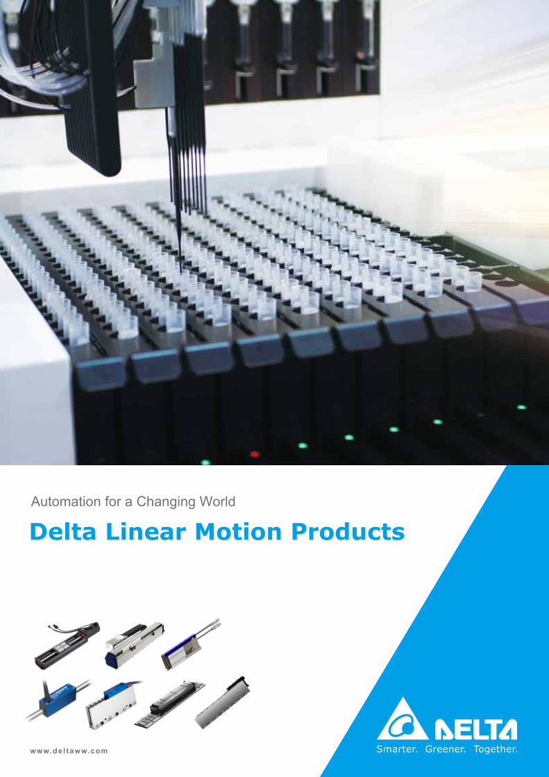
Automation for a Changing World
www.del taww.com
Delta Linear Motion Products

1
Delta Linear Motion Product IntroductionDelta's linear motion products provide the perfect combination of mechanism, drives andmotor system which not only offer immediate use, quick installation and high precision, but also feature high performance and robust control of motion. These products deliver automation solutions that include single-axis, gantries (dual-axis), and multiaxis linear systems for a variety of applications and industries to help customers save on labor costs, shorten development time, and optimize use of resources.
To satisfy full application requirements, Delta's linear motion products are designed with highaccuracy, fast response and compact size. These high quality devices can significantly enhance the stability of the system and easily achieve precise positioning control for equipment upgrades and improvements along with Delta's professional technical support and service.
Delta's linear motion products feature designs for applications in all fields, including electronics, food packaging, metal processing, semiconductors and more.
Delta's linear motion products provide a complete solution for your automated applications.
Pro
duct
Lin
e-up
Linear Stage Mini Actuator
LU LA-S LPL
Ball Screw Driven Linear Motor Driven Linear Motor Driven
P3 P16 P45

2
Pro
duct
Lin
e-up
Direct Drive Motor Series
ECML-U ECML-S
U Shaped Coreless Linear Shaft Motor
ECM-LU ECM-LF
Ironless Linear Motor Ironcore Linear Motor
IndexLinear Motion Products Introduction
1
Linear Stage LU Series 3
Linear Stage LA-S Series 16
Linear Shaft Motor ECML-S Series
22
Coreless U-shaped Linear Motor ECML-U Series
38
Linear Pocket Actuator - LPL 45
Delta-PBA Series
Ironless Linear Motor ECM-LU Series
46
Ironcore Linear Motor ECM-LF Series
66
Parameter Explanation 72
Product Selection Table 74
Servo Drive Specifications 81
Global Operations 85
P46
P38
P66
P22

3
Linear Stage LU Series Product Features
Characteristic Analysis
• Non-coupling installation design
• Compact size for space saving
• High rigidity and high accuracy
• Fast response
• Low inertia ratio
Data Measured by Laser Interferometer
-0.007
20msec
Conventional actuator
LU actuator
-0.006
-0.005
-0.004
-0.003
-0.002
-0.001
0.000
0.001
0.002
0.003
0.004
Following error 0.005mm
2.94 2.95 2.96 2.97 2.98 2.99 3 3.01 3.02
Pos
itio
n (m
m)
Time (sec)
Test condition (without load)• Motor speed: 3,000 rpm
• Acceleration time: 50 ms
• No Load
LU actuator
Conventional actuator0.004
0.003
0.002
0.001
0.000
-0.001
-0.002
-0.003
-0.004
-0.005
-0.006
-0.007
Pos
itio
n (m
m)
Time (sec)2.94 2.95 2.96 2.97 2.98 2.99 3 3.01 3.02
Following error 0.005 mm
20 msec
Conventional Linear Stage (with coupling)
Delta LU Series (without coupling)

4
LU Series and Servo Drive Selection Table
Part Number of LU Series Servo DrivesMotor Output
(W)
Lead(mm)
Rated Torque(N-m)
Max. Torque(N-m)
LU-26111 ASD-A3-0121-ASD-A2-0121-ASD-B2-0121-
100 2/ 6 0.32 0.96
LU-33111 100 5 / 10 0.32 0.96
LU-46214 ASD-A3-0421-ASD-A2-0421-ASD-B2-0421-
400 10 / 20 1.27 3.82
*The boxes ( ) at the end of the servo drive model names are codes for the ASDA Series. For more detailed information, please refer to the catalogues for the ASDA Series servo drives.
Ballscrew
Block
Encoder
Motor Stator
Motor Rotor
Rail
Internal Structure
LULA
-SE
CM
L-SE
CM
L-ULP
L

5
Performance
Effective Stroke Range (Unit: mm)
LU-46 (400W / Lead 10)
LU-46 (400W / Lead 20)
LU-33 (100W / Lead 5)
LU-33(100W / Lead 10)
LU-26 (100W / Lead 2)
LU-26 (100W / Lead 6)
LU-26
LU-33
LU-46
Continuous Thrust
Peak Thrust
0 100 200 500 600 700 800 900300 400
Thrust Range (N)
55 ~220
54 ~ 528
100 ~ 844
Ordering Information
1 2 3 4 5 6 7 8 9 10
LU - 33 1 1 1 15 0 A P 0 S
LU Product Linear Stage LU Series
1 33 Nominal Width 26, 33, 46
2 1 Motor Frame Size and Input Voltage 1: F40 220 V 2: F60 220 V
3 1 Encoder Type 1: Incremental Encoder, 20-bit
4 1 Motor OutputModel No. Code Watt
LU-26 1 100 W
Model No. Code Watt
LU-33 1 100 W
Model No. Code Watt
LU-46 4 400 W
5 15 U-rail Length
Model No. Units: mm
LU-26Code 15 20 25 30
Length 150 200 250 300
LU-33Code 15 20 30 40 50 60
Length 150 200 300 400 500 600
LU-46Code 34 44 54 64 74 94
Length 340 440 540 640 740 940
6 0 LeadModel No. Units: mm
LU-26Code 2 6
Length 2 6
Model No. Units: mm
LU-33Code 5 0
Length 5 10
Model No. Units: mm
LU-46Code 0 A
Length 10 20
7 A Block Type A: 1 Normal Type Block (Please contact regional offices or distributors for other block requirements)
8 P Accuracy Grade N: Normal P: Precision
9 0 Cover 0: Standard Type, Without Cover 1: With Cover C: Fully Enclosed (Please contact regional offices or distributors for Fully Enclosed cover)
10 S Special Order S: Delta Standard Product
0 500 1000 1500 2000 2500 3000
302 905
905 2714
181 543
362 1086
359 1080
718 2160

6
Specifications Basic specifications
Ballscrew Specifications Maximum Stroke (mm)Screw Overall Length
Screw Shaft Diameter
Model No. Rail Length (mm) A B C D L (mm) D (mm)
LU-26
150 70 - - - 191 8
200 120 55 - - 241 8
250 170 105 - - 291 8
300 220 155 - - 341 8
LU-33
150 54.5 - 78.8 26.6 194 12
200 104.5 - 128.8 76.6 244 12
300 204.5 128 228.8 176.6 344 12
400 304.5 228 328.8 276.6 444 12
500 404.5 328 428.8 376.6 544 12
600 504.5 428 528.8 476.6 644 12
LU-46
340 208.2 100.4 244.7 173.4 399 15
440 308.2 200.4 344.7 273.4 499 15
540 408.2 300.4 444.7 373.4 599 15
640 508.2 400.4 544.7 473.4 699 15
740 608.2 500.4 644.7 573.4 799 15
940 808.2 700.4 844.7 773.4 999 15
LULA
-SE
CM
L-SE
CM
L-ULP
L
7
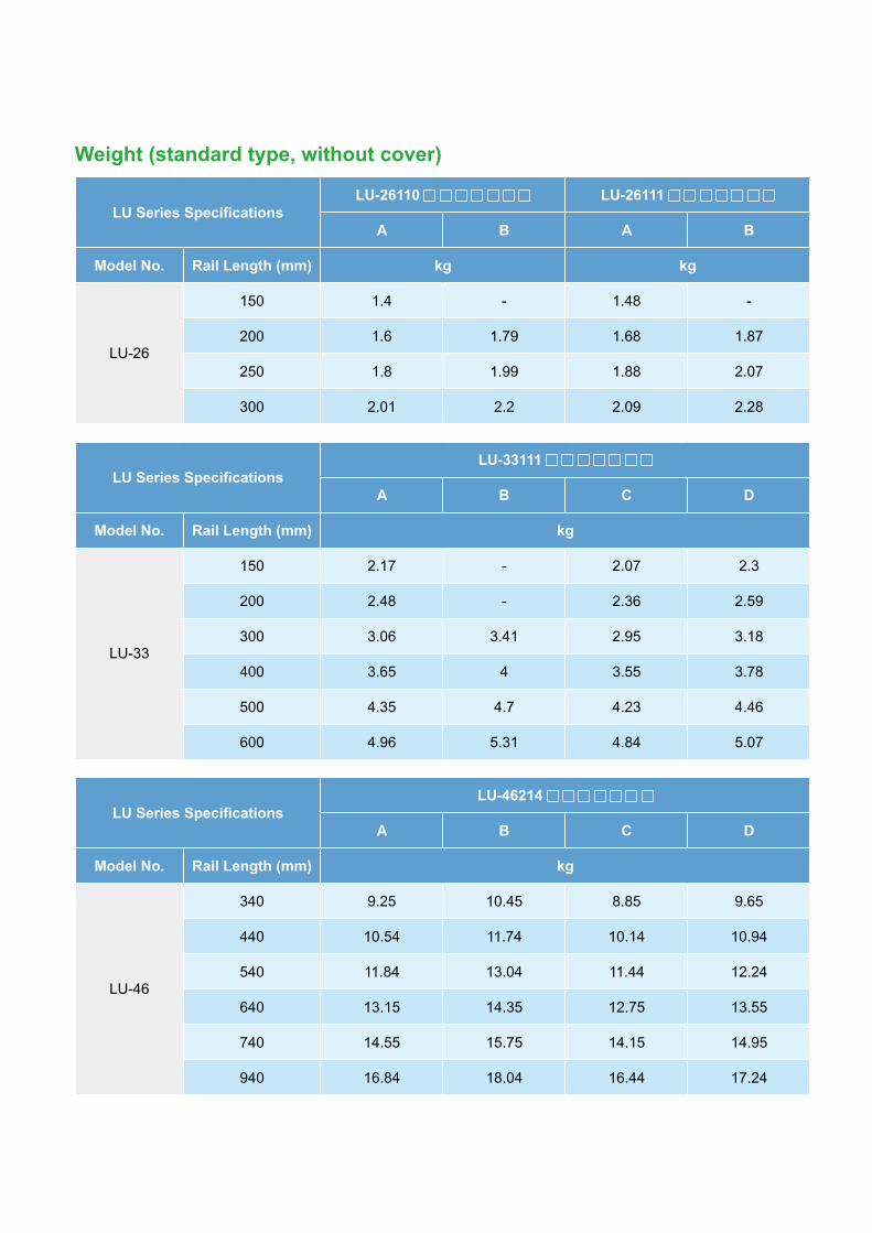
Weight (standard type, without cover)
LU Series SpecificationsLU-26110 LU-26111
A B A B
Model No. Rail Length (mm) kg kg
LU-26
150 1.4 - 1.48 -
200 1.6 1.79 1.68 1.87
250 1.8 1.99 1.88 2.07
300 2.01 2.2 2.09 2.28
LU Series SpecificationsLU-33111
A B C D
Model No. Rail Length (mm) kg
LU-33
150 2.17 - 2.07 2.3
200 2.48 - 2.36 2.59
300 3.06 3.41 2.95 3.18
400 3.65 4 3.55 3.78
500 4.35 4.7 4.23 4.46
600 4.96 5.31 4.84 5.07
LU Series SpecificationsLU-46214
A B C D
Model No. Rail Length (mm) kg
LU-46
340 9.25 10.45 8.85 9.65
440 10.54 11.74 10.14 10.94
540 11.84 13.04 11.44 12.24
640 13.15 14.35 12.75 13.55
740 14.55 15.75 14.15 14.95
940 16.84 18.04 16.44 17.24

8
Weight (with cover)
Ballscrew SpecificationsLU-26110 LU-26111
A B A B
Model No. Rail Length (mm) kg kg
LU-26
150 1.48 - 1.56 -
200 1.68 1.87 1.76 1.95
250 1.88 2.07 1.96 2.15
300 2.09 2.28 2.17 2.36
Ballscrew SpecificationsLU-33111
A B C D
Model No. Rail Length (mm) kg
LU-33
150 2.36 - 2.18 2.43
200 2.68 - 2.49 2.74
300 3.26 3.71 3.12 3.37
400 3.88 4.33 3.76 4.01
500 4.59 5.04 4.49 4.74
600 5.21 5.66 5.14 5.39
Ballscrew SpecificationsLU-46214
A B C D
Model No. Rail Length (mm) kg
LU-46
340 9.85 11.25 9.05 10.05
440 11.14 12.54 10.34 11.34
540 12.44 13.84 11.64 12.64
640 13.75 15.15 12.95 13.95
740 15.15 16.55 14.35 15.35
940 17.44 18.84 16.64 17.64
LULA
-SE
CM
L-SE
CM
L-ULP
L
9
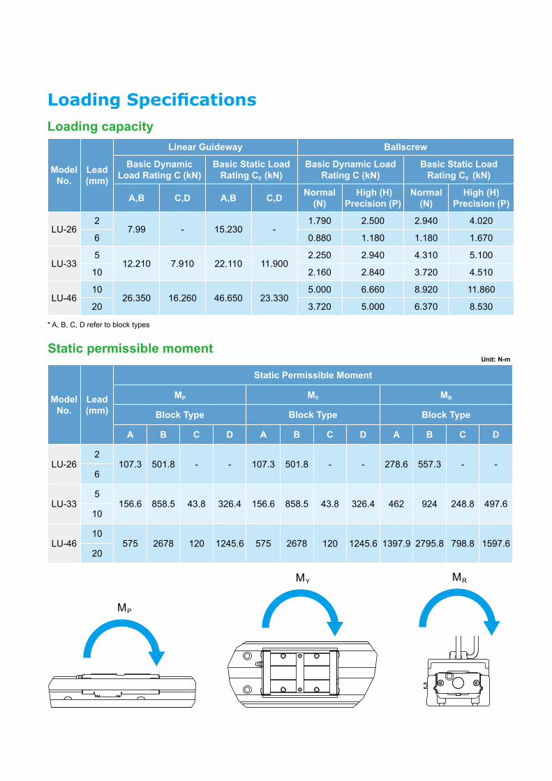
Loading SpecificationsLoading capacity
Model No.
Lead(mm)
Linear Guideway Ballscrew
Basic Dynamic Load Rating C (kN)
Basic Static Load Rating C0 (kN)
Basic Dynamic Load Rating C (kN)
Basic Static Load Rating C0 (kN)
A,B C,D A,B C,D Normal (N)
High (H) Precision (P)
Normal (N)
High (H) Precision (P)
LU-262
7.99 - 15.230 -1.790 2.500 2.940 4.020
6 0.880 1.180 1.180 1.670
LU-335
12.210 7.910 22.110 11.9002.250 2.940 4.310 5.100
10 2.160 2.840 3.720 4.510
LU-4610
26.350 16.260 46.650 23.3305.000 6.660 8.920 11.860
20 3.720 5.000 6.370 8.530
* A, B, C, D refer to block types
Static permissible momentUnit: N-m
Model No.
Lead(mm)
Static Permissible Moment
MP MY MR
Block Type Block Type Block Type
A B C D A B C D A B C D
LU-262
107.3 501.8 - - 107.3 501.8 - - 278.6 557.3 - -6
LU-335
156.6 858.5 43.8 326.4 156.6 858.5 43.8 326.4 462 924 248.8 497.610
LU-4610
575 2678 120 1245.6 575 2678 120 1245.6 1397.9 2795.8 798.8 1597.620
MP
MY MR

10
Max. Travel SpeedBallscrew Specifications (mm) Maximum Travel Speed (mm/s) / Maximum Motor RPM
Model No. Ballscrew Lead Rail Length Normal (N) Precision (P)
LU-26
2
150
167 / 5000 167 / 5000200250300
6
150
500 / 5000 500 / 5000200250300
LU-33
5
150
390 / 4680 417 / 5000200300400500600 340 / 4080 340 / 4080
10
150
790 / 4740 833 / 5000200300400500600 650 / 3900 650 / 3900
LU-46
10
340
520 / 3120740 / 4440
440540640740 730 / 4380940 430 / 2580 600 / 3600
20
340
1050 / 31501480 / 4440
440540640740 1440 / 4320940 840 / 2520 1200 / 3600
Accuracy GradeUnit: mm
Ballscrew Specifications
Positioning Repeatability Positioning Accuracy Running of Parallelism Backlash
Model No.
Rail Length
Normal (N)
Precision(P)
Normal (N)
Precision(P)
Normal (N)
Precision(P)
Normal (N)
Precision(P)
LU-26
150
±0.01 ±0.003 - 0.02 - 0.01 0.02 0.003200250300
LU-33
150
±0.01 ±0.003 -0.02
-0.01
0.02 0.003
200300400500
0.025 0.015600
LU-46
340
±0.01 ±0.003 -0.025
-0.015
0.02 0.003
440540640740 0.03 0.02940 0.04 0.03
LULA
-SE
CM
L-SE
CM
L-ULP
L

11
1 2
H
G
3 4
CONFIDENTIAL
5 6 7 8
H
G
F
E
D
C
B
A
1 2 3 4 5 6 7 8
F
E
D
C
B
A
PROJECTION
THIRD ANGLE
SIZE
A2
FRAME NAME: DF-MEA2H-2R02.FRM
REV. ECN NO.
00 -----------
Signal Cable Power Cable
Sensor Rail Dimension
Carrier-Nut Type
A: Use one carrier nut with standard length
B: Use two carrier nuts with standard length
Sensor Rail Dimension
LU Series Specifications Maximum Stroke (mm) Overall Length L
(mm) E n E1 n1 F
Model No.
Rail Length L1
(mm)A B C D 100W mm - mm - mm
LU-26
150 70 - - - 278.6 35 2 35 - 80
200 120 55 - - 328.6 20 3 20 - 160
250 170 105 - - 378.6 45 3 45 - 160
300 220 155 - - 428.6 30 4 30 - 240
Dimensions of the LU SeriesLU-26
LU-26111 0 (100 W servo motor, without cover)
LU-26111 1 (100 W servo motor, with cover)
ENCODER CONNECTORPIN No. FUNCTION COLOR
1 T+ WHT2 ---- ----3 ---- ----4 T- WHT/RED5 ---- ----6 ---- ----7 DC+5V BRN8 GND BLU9 SHIELD SHIELD
ENCODER CONNECTORPIN No. FUNCTION COLOR
1 T+ WHT2 ---- ----3 ---- ----4 T- WHT/RED5 ---- ----6 ---- ----7 DC+5V BRN8 GND BLU9 SHIELD SHIELD
MOTOR CONNECTOR
PIN No. FUNCTION COLOR
1 U RED
2 V WHT
3 W BLK
4 GND GRN / YEL
MOTOR CONNECTOR
PIN No. FUNCTION COLOR
1 U RED
2 V WHT
3 W BLK
4 GND GRN / YEL
1 2
H
G
3 4
CONFIDENTIAL
5 6 7 8
H
G
F
E
D
C
B
A
1 2 3 4 5 6 7 8
F
E
D
C
B
A
PROJECTION
THIRD ANGLE
SIZE
A2
FRAME NAME: DF-MEA2H-2R02.FRM
REV. ECN NO.
00 -----------
Signal Cable Power Cable
Sensor Rail Dimension
Carrier-Nut Type
A: Use one carrier nut with standard length
B: Use two carrier nuts with standard length
Sensor Rail Dimension

12
LULA
-SE
CM
L-SE
CM
L-ULP
L
LU Series Specifications Maximum Stroke (mm) Total Length L (mm) E n E1 n1 F
Model No.
Rail Length L1
(mm)A B C D 100W mm - mm - mm
LU-33
150 54.5 - 78.8 26.6 282.5 25 2 25 2 100
200 104.5 - 128.8 76.6 332.5 50 2 50 2 100
300 204.5 128 228.8 176.6 432.5 50 3 50 2 200
400 304.5 228 328.8 276.6 532.5 50 4 100 2 200
500 404.5 328 428.8 376.6 632.5 50 5 50 3 200
600 504.5 428 528.8 476.6 732.5 50 6 100 3 200
LU-33
LU-33111 0 (without cover)
LU-33111 1 (with cover)
ENCODER CONNECTORPIN No. FUNCTION COLOR
1 T+ WHT2 ---- ----3 ---- ----4 T- WHT/RED5 ---- ----6 ---- ----7 DC+5V BRN8 GND BLU9 SHIELD SHIELD
ENCODER CONNECTORPIN No. FUNCTION COLOR
1 T+ WHT2 ---- ----3 ---- ----4 T- WHT/RED5 ---- ----6 ---- ----7 DC+5V BRN8 GND BLU9 SHIELD SHIELD
MOTOR CONNECTOR
PIN No. FUNCTION COLOR
1 U RED
2 V WHT
3 W BLK
4 GND GRN / YEL
MOTOR CONNECTOR
PIN No. FUNCTION COLOR
1 U RED
2 V WHT
3 W BLK
4 GND GRN / YEL
1 2
H
G
3 4
CONFIDENTIAL
5 6 7 8
H
G
F
E
D
C
B
A
1 2 3 4 5 6 7 8
F
E
D
C
B
A
PROJECTION
THIRD ANGLE
SIZE
A2
FRAME NAME: DF-MEA2H-2R02.FRM
REV. ECN NO.
00 -----------
Signal Cable Power Cable
Sensor Rail Dimension
Carrier-Nut Type
A: Use one carrier nut with standard length
B: Use two carrier nuts with standard length
C: Use one carrier nut with short length
D: Use two carrier nuts with short length
Sensor Rail Dimension
1 2
H
G
3 4
CONFIDENTIAL
5 6 7 8
H
G
F
E
D
C
B
A
1 2 3 4 5 6 7 8
F
E
D
C
B
A
PROJECTION
THIRD ANGLE
SIZE
A2
FRAME NAME: DF-MEA2H-2R02.FRM
REV. ECN NO.
00 -----------
Signal Cable Power Cable
Sensor Rail Dimension
Carrier-Nut Type
A: Use one carrier nut with standard length
B: Use two carrier nuts with standard length
C: Use one carrier nut with short length
D: Use two carrier nuts with short lengthSensor Rail Dimension

13
LU Series Specifications Maximum Stroke (mm) Total Length L (mm) E n E1 n1 F
Model No.
Rail Length L1
(mm)A B C D 400W mm - mm - mm
LU-46
340 208.2 100.4 244.7 173.4 506.9 70 3 70 2 -
440 308.2 200.4 344.7 273.4 606.9 70 4 20 3 -
540 408.2 300.4 444.7 373.4 706.9 70 5 70 3 -
640 508.2 400.4 544.7 473.4 806.9 70 6 20 4 -
740 608.2 500.4 644.7 573.4 906.9 70 7 70 4 -
940 808.2 700.4 844.7 773.4 1106.9 70 9 70 5 -
LU-46
LU-46214 0 (without cover)
LU-46214 1 (with cover)
ENCODER CONNECTORPIN No. FUNCTION COLOR
1 T+ WHT2 ---- ----3 ---- ----4 T- WHT/RED5 ---- ----6 ---- ----7 DC+5V BRN8 GND BLU9 SHIELD SHIELD
ENCODER CONNECTORPIN No. FUNCTION COLOR
1 T+ WHT2 ---- ----3 ---- ----4 T- WHT/RED5 ---- ----6 ---- ----7 DC+5V BRN8 GND BLU9 SHIELD SHIELD
MOTOR CONNECTOR
PIN No. FUNCTION COLOR
1 U RED
2 V WHT
3 W BLK
4 GND GRN / YEL
MOTOR CONNECTOR
PIN No. FUNCTION COLOR
1 U RED
2 V WHT
3 W BLK
4 GND GRN / YEL
1 2
H
G
3 4
CONFIDENTIAL
5 6 7 8
H
G
F
E
D
C
B
A
1 2 3 4 5 6 7 8
F
E
D
C
B
A
PROJECTION
THIRD ANGLE
SIZE
A2
FRAME NAME: DF-MEA2H-2R02.FRM
X.XX : 0.1 >200~ : 0.2% >200~ : 0.25% >200~ : 0.3% X.X : 0.2 >100~200 : 0.2 >100~200 : 0.25 >100~200 : 0.3 >60 ~90 : 0.5 X : 0.3 >50~100 : 0.15 >50~100 : 0.2 >50~100 : 0.25 >30 ~60 : 0.3 DECIMALS <50 : 0.1 <50 : 0.15 <50 : 0.2 <30 : 0.1 ( V ) ( ) ( ) ( ) ANGLES DIMENSIONAL TOLERANCES
DESCRIPTION: PART NO.:
LU-4621474ABP0S LU-46 Series
DRAWN: Mike Chu DESIGN: Mike Chu APPROVE: Kevin Chung DATE: 20141008
REV. ECN NO.
00 -----------
REV.
X0
THESE DRAWINGS AND SPECIFICATIONS ARE THE PROPERTY OF DELTA ELECTRONICS, INC. AND SHALLNOT BE REPRODUCED OR USED AS THE BASIS FOR THE MANUFACTURE OR SELL OF APPARATUSES OR DEVICES WITHOUT PERMISSION.
USED ON LU-46 0 UNIT mm SCALE 0.300 SHEET 1 OF 1
Signal Cable Power Cable
Sensor Rail Dimension
Carrier-Nut Type
A: Use one carrier nut with standard length
B: Use two carrier nuts with standard length
C: Use one carrier nut with short length
D: Use two carrier nuts with short length
Sensor Rail Dimension
1 2
H
G
3 4
CONFIDENTIAL
5 6 7 8
H
G
F
E
D
C
B
A
1 2 3 4 5 6 7 8
F
E
D
C
B
A
PROJECTION
THIRD ANGLE
SIZE
A2
FRAME NAME: DF-MEA2H-2R02.FRM
X.XX : 0.1 >200~ : 0.2% >200~ : 0.25% >200~ : 0.3% X.X : 0.2 >100~200 : 0.2 >100~200 : 0.25 >100~200 : 0.3 >60 ~90 : 0.5 X : 0.3 >50~100 : 0.15 >50~100 : 0.2 >50~100 : 0.25 >30 ~60 : 0.3 DECIMALS <50 : 0.1 <50 : 0.15 <50 : 0.2 <30 : 0.1 ( V ) ( ) ( ) ( ) ANGLES DIMENSIONAL TOLERANCES
DESCRIPTION: PART NO.:
LU-46 Assembly LU-46 Series
DRAWN: Mike Chu DESIGN: Mike Chu APPROVE: Kevin Chung DATE: 20141001
REV. ECN NO.
00 -----------
REV.
X0
THESE DRAWINGS AND SPECIFICATIONS ARE THE PROPERTY OF DELTA ELECTRONICS, INC. AND SHALLNOT BE REPRODUCED OR USED AS THE BASIS FOR THE MANUFACTURE OR SELL OF APPARATUSES OR DEVICES WITHOUT PERMISSION.
USED ON LU-46 1 UNIT mm SCALE 0.300 SHEET 1 OF 1
Signal Cable Power Cable
Sensor Rail Dimension
Carrier-Nut Type
A: Use one carrier nut with standard length
B: Use two carrier nuts with standard length
C: Use one carrier nut with short length
D: Use two carrier nuts with short length
Sensor Rail Dimension

14
LULA
-SE
CM
L-SE
CM
L-ULP
L
LU Series Recommended Sensor ModelInstallation dimensions for detecting plate & mounting plate
Panasonic GX-F12A / GX-F12B
Omron EE-SX671 / SX971
Omron EE-SX671 / SX971
Model No. a b c d
LU-26 38.9 7.9 6.2 6.2
LU-33 44 1 9.2 10
LU-46 57 1 22.2 23
Model No. a b c d e f g h
LU-26 46 15 2 2 58.5 27.5 10.5 10.5
LU-33 50.9 7.9 5 5 63.4 20.4 13.8 15
LU-46 63.9 7.9 18 18 76.4 20.4 26.5 28
Model No. a b c d e f g h
LU-26 43.7 12.7 1.8 1.8 50 19 10.8 10.8
LU-33 48.6 5.6 4.8 4.8 54.9 11.9 13.8 14
LU-46 61.6 5.6 17.8 17.8 67.9 11.9 26.8 28.1
b
d
c
a
c
ae
g
d h
bf
d
fb
h
g
ae
c
Unit: mm
Unit: mm
Unit: mm

15
Product Features
Internal Structure
• Direct driving with zero backlashDirectly driven by a Delta linear motor, without backlash and alignment issues
• High speed and high precision- Provides high-precision and high-stability motion operation: high speed capability of up to 4m/sec.- Integrates with linear motor and optical linear encoder for direct driving and preventing backlash and accumulated offsets caused by changing machines
• Cog-free design with low thrust rippleAdopts an ironless forcer for zero cogging and low thrust ripple to perform smooth motion, even at low speed
• Long travel distance with multiple sliders- Long travel distance (up to 1.5m) for various positioning applications- Single-axis platform supports more than 2 linear motors, creating multiple sliders within one stage unit for efficient space savings and independent operation
Motor Coil (Forcer)
Optical ReadheadLinear Guide
Scale (Optical Encoder)* Optical readhead specification: RENISHAW RH200
Motor Magnetic Way (Stator)
Linear Stage LA-S Series
*

16
LULA
-SE
CM
L-SE
CM
L-ULP
L
Ordering Information
1 2 3 4 5 6 7
LA - S5 1 012 D 1 M S00
LA Product Linear Stage LA-S Series
1 S5 Linear Motor Model
S4: ECML-S 2004S5: ECML-S 2005
S6: ECML-S 2504S7: ECML-S 2506
S8: ECML-S 2508SA: ECML-S 3206
SB: ECML-S 3208
2 1 Q 'ty of Linera Motors
Motors on single axis1: one motorPlease contact regional sales for two or more (2, 3, 4 and more) motor requirements
3 012 Travel E.g. 052: 520 mm 034: 340 mm 106: 1060 mm 206: 2060 mm
4 D Encoder Type D: REINSHAW RH200, digital output, resolution 1μm
5 1 Mounting Direction
1: Horizontal Mounting (Vertical Cable Chains) 2: Horizontal Mounting (Horizontal Cable Chains)
3: Lateral Mounting (Vertical Cable Chains) 4: Lateral Mounting (Horizontal Cable Chains)
5: Upside-down Mounting (Vertical Cable Chains) 6: Upside-down Mounting (Horizontal Cable Chains)
6 M Cover M: Aluminum Extrusion
7 S00 Special Order S00: Delta Standard Product
* LA-S standard cable length is 5m. Please contact Delta sales offices or distributors for other customized requirements** LA-S Standard equipment include 2 optical sensors (Brand and Model Name: Omron EE-SX672+2m cable)
LA-S Series and Servo Drive Selection TableModel No. Servo Drive Motor Output (W)
LA-S4 ASD-A3-0221-
ASD-A2R-0221-200 W
LA-S5
LA-S6 ASD-A3-0421-
ASD-A2R-0421-400 W
LA-S7LA-S8 ASD-A3-0721-
ASD-A2R-0721-750 WLA-SA
LA-SB*The boxes ( ) at the end of the servo drive model names are codes for the ASDA-A2R Series. For more information, please see the ASDA Series servo drive catalogues

17
LULA
-SE
CM
L-SE
CM
L-ULP
L
Performance
LA-S4 LA-S5 LA-S6 LA-S7 LA-S8 LA-SA LA-SB
Peak Thrust N 177 221 257 386 525 555 740
Continuous Thrust N 44 55 64 96 131 138 185
Maximum Speed*1 m/s 4
Resolution μm 1
Repeatability μm ±1
Moving Part Weight*2 kg 2.9 3.3 3.9 4.7 5.7 5.8 6.9
*1 Maximum speed will be different based on the load and stroke of applications*2 The moving part weight only includes motor and slider
Effective Stroke Range (Unit: mm)
LA-S4
LA-S5
LA-S6
LA-S7
LA-S8
LA-SA
LA-SB
LA-S4
LA-S5
LA-S6
LA-S7
LA-S8
LA-SA
LA-SB
Continuous Thrust
Peak Thrust
0
0
100
200
200
400
300
1000
400
1200
500
1400 1600 1800 2000
600
600
700
2200
800
800
150 ~ 990
180 ~ 960
100 ~ 1300
120 ~ 1260
120 ~ 1200
140 ~ 2060
140 ~ 2000
Thrust Range (N)
44 177
55 221
64 257
96 386
131 525
138 555
185 740

18
LULA
-SE
CM
L-SE
CM
L-ULP
L
Dimensions of the LA-S SeriesLA-S4 / LA-S5ø20 Magnetic way / Effective stroke range: 150 ~ 990 mm
95(87)
114
A50 B (n-1)x120 B 50
1639
90
80 80
L1L
C
Detail View C
∅4H7 slot, depth 81
2(n+1)-M4x0.7P depth 9(下鎖孔) nx120 A
2(n+2)-∅4.5 THRU,∅8 depth 5(上鎖孔)
∅4H7, depth 8
62.5 F
F2F1
S (stroke) 62.581
8-M5x0.8P depth 10
2-∅4H7 depth 8
130
112(87)
60 B (n-1)x120 B 60
L1
60
A nx120 A
2552
L
80 80
2(n+1)-M5x0.8P depth 10(下鎖孔)
2(n+2)-∅4.5 THRU,∅8 depth 5(上鎖孔)
∅4H7, depth 8
C
97
87.5 F
F2F1
106
HOME
(13)
(1)
S (stroke) 87.5
8-M4x0.7P depth 10
2-∅5H7 depth 10
120(87)
143
116
-+
106
F2F1F81
-+
-+
65 B (n-1)x120 B 65
70
2758
A nx120 AL1L
80
C
80
2(n+1)-M5x0.8P depth 10(下鎖孔)
2(n+2)-∅5.5 THRU,∅9 depth 6(上鎖孔)
∅5H7, depth 8
S (stroke) 81
8-M5x0.8P depth 12
2-∅5H7 depth 10
HOME
HOME
50
Detail View C
∅4H7 slot, depth 81
Detail View C
∅5H7 slot, depth 81
Slider dimensions (Unit: mm)
Model No.
Slider Total Length F F1 F2
LA-S4 165 135 67
LA-S5 195 165 75
Stroke and base mounting dimensions (Unit: mm)
LA-S4Stroke (S) 150 210 270 330 390 450 510 570 630 690 750 810 870 930 990
Total Weight (kg) 11.2 11.9 12.6 13.3 13.9 14.6 15.3 15.9 16.6 17.3 18 18.7 19.4 20 20.7
LA-S5Stroke (S) – 180 240 300 360 420 480 540 600 660 720 780 840 900 960
Total Weight (kg) – 12.2 12.8 13.6 14.3 14.9 15.6 16.3 16.9 17.6 18.3 19 19.7 20.4 21
Stage Total Length (L) 492 552 612 672 732 792 852 912 972 1032 1092 1152 1212 1272 1332
L1 440 500 560 620 680 740 800 860 920 980 1040 1100 1160 1220 1280
A 40 10 40 10 40 10 40 10 40 10 40 10 40 10 40
B 50 20 50 20 50 20 50 20 50 20 50 20 50 20 50
n 3 4 4 5 5 6 6 7 7 8 8 9 9 10 10
(Bottom mounting hole)
(Top mounting hole)

19
LULA
-SE
CM
L-SE
CM
L-ULP
L
Dimensions of the LA-S SeriesLA-S6 / LA-S7 / LA-S8ø25 Magnetic way / Effective stroke range: 100 ~ 1300 mm
95(87)
114
A50 B (n-1)x120 B 50
1639
90
80 80
L1L
C
Detail View C
∅4H7 slot, depth 81
2(n+1)-M4x0.7P depth 9(下鎖孔) nx120 A
2(n+2)-∅4.5 THRU,∅8 depth 5(上鎖孔)
∅4H7, depth 8
62.5 F
F2F1
S (stroke) 62.5
81
8-M5x0.8P depth 10
2-∅4H7 depth 8
130
112(87)
60 B (n-1)x120 B 60
L1
60
A nx120 A
2552
L
80 80
2(n+1)-M5x0.8P depth 10(下鎖孔)
2(n+2)-∅4.5 THRU,∅8 depth 5(上鎖孔)
∅4H7, depth 8
C
97
87.5 F
F2F1
106
HOME
(13)
(1)
S (stroke) 87.5
8-M4x0.7P depth 10
2-∅5H7 depth 10
120(87)
143
116
-+
106
F2F1F81
-+
-+
65 B (n-1)x120 B 65
70
2758
A nx120 AL1L
80
C
80
2(n+1)-M5x0.8P depth 10(下鎖孔)
2(n+2)-∅5.5 THRU,∅9 depth 6(上鎖孔)
∅5H7, depth 8
S (stroke) 81
8-M5x0.8P depth 12
2-∅5H7 depth 10
HOME
HOME
50
Detail View C
∅4H7 slot, depth 81
Detail View C
∅5H7 slot, depth 81
Stroke and base mounting dimensions (Unit: mm)
LA-S6Stroke (S) 100 160 220 280 340 400 460 520 580 640 700 760 820 880 940 1000 1060 1120 1180 1240 1300
Total Weight (kg) 13.6 14.5 15.5 16.5 17.4 18.4 19.3 20.3 21.3 22.2 23.2 24.1 25.1 26.1 27 27.9 28.9 29.9 30.8 31.8 32.8
LA-S7Stroke (S) – 120 180 240 300 360 420 480 540 600 660 720 780 840 900 960 1020 1080 1140 1200 1260
Total Weight (kg) – 15.6 16.5 17.5 18.5 19.4 20.4 21.3 22.3 23.3 24.2 25.2 26.1 27.1 28.1 29 29.9 30.9 31.8 32.8 33.8
LA-S8Stroke (S) – – 120 180 240 300 360 420 480 540 600 660 720 780 840 900 960 1020 1080 1140 1200
Total Weight (kg) – – 17.6 18.6 19.6 20.5 21.5 22.4 23.4 24.4 25.3 26.3 27.2 28.2 29.2 30.1 31.1 32 33 33.9 34.9
Stage Total Length (L) 512 572 632 692 752 812 872 932 992 1052 1112 1172 1232 1292 1352 1412 1472 1532 1592 1652 1712
L1 460 520 580 640 700 760 820 880 940 1000 1060 1120 1180 1240 1300 1360 1420 1480 1540 1600 1660
A 50 20 50 20 50 20 50 20 50 20 50 20 50 20 50 20 50 20 50 20 50
B 50 20 50 20 50 20 50 20 50 20 50 20 50 20 50 20 50 20 50 20 50
n 3 4 4 5 5 6 6 7 7 8 8 9 9 10 10 11 11 12 12 13 13
Slider dimensions (Unit: mm)
Model No.
Slider Total Length F F1 F2
LA-S6 185 165 85
LA-S7 225 205 85
LA-S8 285 265 145
(Bottom mounting hole)
(Top mounting hole)

20
LULA
-SE
CM
L-SE
CM
L-ULP
L
LA-SAStroke (S) 1160 1220 1280 1340 1400 1460 1520 1580 1640 1700 1760 1820 1880 1940 2000 2060
Total Weight (kg) 37.2 38.4 39.7 40.9 42.1 43.3 44.6 45.8 47.1 48.3 49.5 50.7 51.9 53.2 54.5 55.7
LA-SBStroke (S) 1100 1160 1220 1280 1340 1400 1460 1520 1580 1640 1700 1760 1820 1880 1940 2000
Total Weight (kg) 38.9 40.2 41.4 42.6 43.9 45.1 46.3 47.5 48.8 50 51.2 52.5 53.7 54.9 56.1 57.4
Stage Total Length (L) 1592 1652 1712 1772 1832 1892 1952 2012 2072 2132 2192 2252 2312 2372 2432 2492
L1 1540 1600 1660 1720 1780 1840 1900 1960 2020 2080 2140 2200 2260 2320 2380 2440A 50 20 50 20 50 20 50 20 50 20 50 20 50 20 50 20B 45 15 45 15 45 15 45 15 45 15 45 15 45 15 45 15n 12 13 13 14 14 15 15 16 16 17 17 18 18 19 19 20
Dimensions of the LA-S SeriesLA-SA / LA-SB ø32 Magnetic way / Effective stroke range: 140 ~ 2060 mm
95(87)
114
A50 B (n-1)x120 B 50
1639
90
80 80
L1L
C
Detail View C
∅4H7 slot, depth 81
2(n+1)-M4x0.7P depth 9(下鎖孔) nx120 A
2(n+2)-∅4.5 THRU,∅8 depth 5(上鎖孔)
∅4H7, depth 8
62.5 F
F2F1
S (stroke) 62.5
81
8-M5x0.8P depth 10
2-∅4H7 depth 8
130
112(87)
60 B (n-1)x120 B 60
L1
60
A nx120 A
2552
L
80 80
2(n+1)-M5x0.8P depth 10(下鎖孔)
2(n+2)-∅4.5 THRU,∅8 depth 5(上鎖孔)
∅4H7, depth 8
C
97
87.5 F
F2F1
106
HOME
(13)
(1)
S (stroke) 87.5
8-M4x0.7P depth 10
2-∅5H7 depth 10
120(87)
143
116
-+
106
F2F1F81
-+
-+
65 B (n-1)x120 B 65
70
2758
A nx120 AL1L
80
C
80
2(n+1)-M5x0.8P depth 10(下鎖孔)
2(n+2)-∅5.5 THRU,∅9 depth 6(上鎖孔)
∅5H7, depth 8
S (stroke) 81
8-M5x0.8P depth 12
2-∅5H7 depth 10
HOME
HOME
50
Detail View C
∅4H7 slot, depth 81
Detail View C
∅5H7 slot, depth 81
Slider dimensions (Unit: mm)
Model No.
Slider Total Length F F1 F2
LA-SA 223 201 91
LA-SB 278 256 116
Stroke and base mounting dimensions (Unit: mm)
LA-SAStroke (S) 140 200 260 320 380 440 500 560 620 680 740 800 860 920 980 1040 1100
Total Weight (kg) 16.3 17.5 18.7 19.9 21.2 22.4 23.7 24.9 26.1 27.4 28.6 29.4 30.7 31.9 33.2 34.4 35.7
LA-SBStroke (S) – 140 200 260 320 380 440 500 560 620 680 740 800 860 920 980 1040
Total Weight (kg) – 19.3 20.5 21.7 22.9 24.2 25.4 26.6 27.9 29.1 30.3 31.6 32.8 34 35.3 36.5 37.7Stage Total Length
(L) 572 632 692 752 812 872 932 992 1052 1112 1172 1232 1292 1352 1412 1472 1532
L1 520 580 640 700 760 820 880 940 1000 1060 1120 1180 1240 1300 1360 1420 1480A 20 50 20 50 20 50 20 50 20 50 20 50 20 50 20 50 20B 15 45 15 45 15 45 15 45 15 45 15 45 15 45 15 45 15n 4 4 5 5 6 6 7 7 8 8 9 9 10 10 11 11 12
(Bottom mounting hole)
(Top mounting hole)

21
LULA
-SE
CM
L-SE
CM
L-ULP
L
Linear Shaft Motor ECML-S SeriesProduct Features• Simple mechanism structure for quick installation
• Direct driving mechanism, easy to replace ballscrew mechanism
• No cogging forces, low thrust ripple
• Excellent dynamic response
• No backlash
• Built-in temperature sensor and hall sensor units
• Large air gap for easy installation
• Installation holes on both sides in the coil assembly for easy mounting
S Series and Servo Drive Selection TableCoil Assembly Magnetic Way Servo Drive Model No. Drive Output (W)
ECML-S1606A2DNSECML-SM16 ASD-A3-0121-
ASD-A2R-0121- 100 WECML-S1608A2DNS
ECML-S2003A2DNS
ECML-SM20 ASD-A3-0221- ASD-A2R-0221- 200 WECML-S2004A2DNS
ECML-S2005A2DNS
ECML-S2504A2DNSECML-SM25 ASD-A3-0421-
ASD-A2R-0421- 400 WECML-S2506A2DNS
ECML-S3204A2DNS ECML-SM32
ECML-S2508A2DNS ECML-SM25
ASD-A3-0721- ASD-A2R-0721- 750 WECML-S3206A2DNS
ECML-SM32 ECML-S3208A2DNS
ECML-S3505A2DNSECML-SM35
ASD-A3-0721- ASD-A2R-0721- 750W
ECML-S3506A2DNS ASD-A3-1021- ASD-A2R-1021- 1 kW
*The boxes ( ) at the end of the servo drive model names are codes for the ASDA-A3/A2R Series. For more detailed information, please refer to the catalogues of the ASDA-A2R Series servo drives.

22
LULA
-SE
CM
L-SE
CM
L-ULP
L
Ordering Information Coil assembly
1 2 3 4 5 6 7
ECML - S 1608 A 2 D N S
ECML Product ECML: Linear Motor
1 S Linear Motor Type S: Shaft Type Coreless
2 1608 Magnetic Way Dimensions
Magnetic Way Diameter (mm) Ø16 Ø20 Ø25 Ø32 Ø35
Codes1606 2003 2504 3204 35051608 2004 2506 3206 3506
2005 2508 3208
3 A Wiring Method A: Wiring Method A
4 2 Input Voltage 2: 220 V
5 D Hall Sensor Type D: Digital
6 N Cooling Type N: N/A
7 S Special Order Delta Standard Product
Magnetic way
1 2 3
ECML - SM 16 1000
ECML Product ECML: Linear Motor
1 SM Linear Motor Type S: Shaft Type Coreless
2 16 Magnetic Way Diameter
16: Ø16 mm 20: Ø20 mm
25: Ø25 mm32: Ø32 mm
35: Ø35 mm
3 1000 Magnetic Way Length
Range: 250~2310 mm
E.g.0340: 340 mm 0520: 520 mm 1060: 1060 mm
23
LULA
-SE
CM
L-SE
CM
L-ULP
L
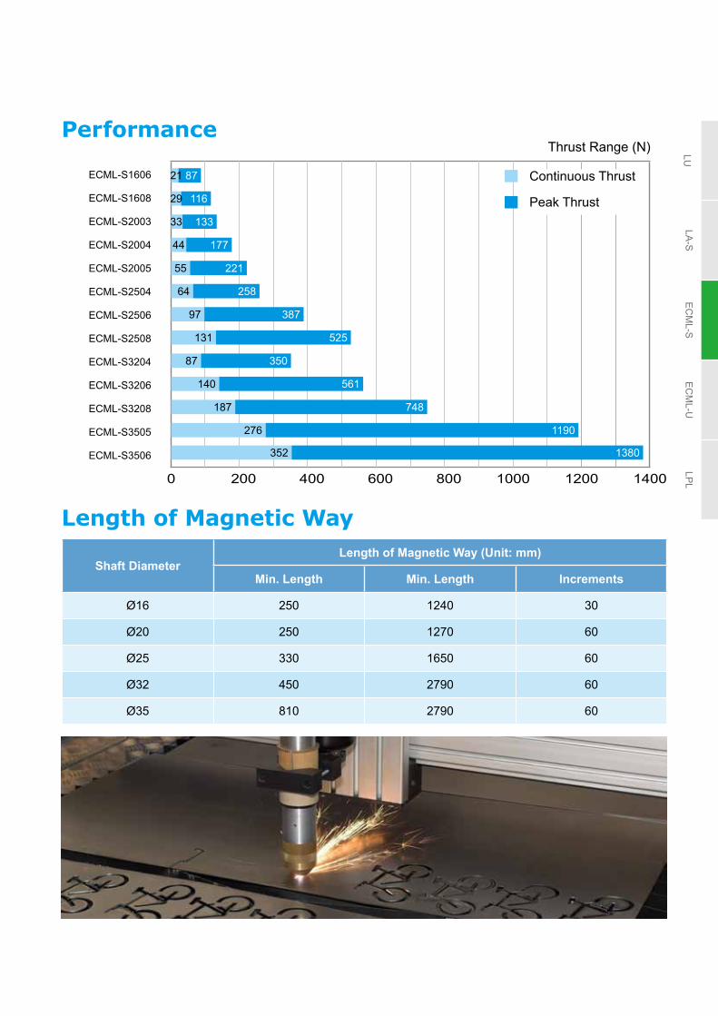
Performance
Length of Magnetic Way
Shaft DiameterLength of Magnetic Way (Unit: mm)
Min. Length Min. Length Increments
Ø16 250 1240 30
Ø20 250 1270 60
Ø25 330 1650 60
Ø32 450 2790 60
Ø35 810 2790 60
Thrust Range (N)
0 200 400 600 800 1000 1200 1400
87
116
133
177
55 221
64 258
97 387
131 525
140 561
187 748
276 1190
352 1380
87 350
ECML-S1606
ECML-S1608
ECML-S2003
ECML-S2004
ECML-S2005
ECML-S2504
ECML-S2506
ECML-S2508
ECML-S3204
ECML-S3206
ECML-S3208
ECML-S3505
ECML-S3506
44
33
29
21 Continuous Thrust
Peak Thrust

24
LULA
-SE
CM
L-SE
CM
L-ULP
L
Specifications
ECMLS16 S20 S25 S32 S35
06 08 03 04 05 04 06 08 04 06 08 05 06
Continuous Force (N) 21.8 29 33.2 44.3 55.3 64.4 96.7 131.3 87.4 140.3 187.1 276.2 352.8
Peak. Force (N) 87.12 116.16 132.8 177.3 221.3 257.7 386.9 525 349.6 561.3 748.4 1190 1379.7
Continuous Current (Arms) 0.66 0.66 1.1 1.1 1.1 1.7 1.7 2.5 1.9 2.7 2.7 2.8 5.6
Peak Current (Arms) 2.64 2.64 4.4 4.4 4.4 6.8 6.8 10.0 7.6 10.8 10.8 11.2 21.9
Force Constant (N/Arms) 33 44 30.2 40.3 50.3 37.9 56.9 52.5 46 51.9 69.3 106.24 63
BEMF Constant (Vrms/(m/s)) 11 14.7 10.1 13.4 16.8 12.6 19 17.5 15.3 17.3 23.1 35.4 21.0
Armature Resistance (Ohm) 55.7 74.2 15.5 21.6 25.9 11.6 17.4 12.6 13.36 10.7 14.3 18 5.3
Armature Inductance (mH) 10.5 14 7 9 11 14.6 22 23 16 12.5 16.6 38.32 11.54
Rated Power (W) 47 62.6 46.9 62.3 78 64.9 97.4 152.5 93.4 151 201.8 273.24 321.82
Max. Instantaneous Power (W) 751.7 1001.3 749.7 997.1 1248.3 1038.6 1557.8 2439.6 1494.1 2416.5 3229.5 4371.85 4921.77
Motor Constant (N/ W ) 3.2 4.6 4.3 5 5.6 8.0 9.8 10.6 9.0 11.4 13.2 18 19.7
Electric Constant (ms) 0.19 0.19 0.35 0.34 0.33 1.26 1.26 1.83 1.2 1.17 1.16 2.13 2.18
Thermal Resistance (˚C / W) 1.6 1.2 1.6 1.2 0.96 1.16 0.77 0.49 0.8 0.5 0.37 0.27 0.23
Weight of Coil Assembly (kg) 0.35 0.45 0.65 0.83 1.0 1.1 1.6 2.1 1.5 2.2 2.8 3.2 3.84
Length of Coil Assembly (mm) 108 138 108 138 168 138 198 258 138 198 258 318 378
Vertical Attraction Force (N) 0 0 0 0 0 0 0 0 0 0 0 0 0
Magnetic Pole Pitch (mm) 30 60 60 60 120 120
Air Gap (mm) 0.75 1 1.75 3 3
Allowable Winding Temp. (˚C) 130
Insulation Resistance >10 MΩ, DC 500 V
Withstand Voltage 1500 VAC, 60 sec
Operating Ambient Temperature 0 ̊ C ~ 40 ̊ C
Storage Temperature -10 ̊ C ~ 80 ̊ C
Operating Relative Humidity 20 ~ 80% RH (non-condensing)
Storage Humidity 20 ~ 80% RH (non-condensing)
Approvals
Electrical specifications

25
LULA
-SE
CM
L-SE
CM
L-ULP
L
Thrust-speed curve
• ECML-S1606A2DNS
• ECML-S2003A2DNS
Speed (m/s)
4.5
4.0
3.5
3.0
2.5
2.0
1.5
1.0
0.5
0
Force (N) Force (N)10 1020 2030 3040 4050 5060 6070 7080 8090 90100 100110 110120 120130 130
ECML-S1606
ECML-S2003
• ECML-S1608A2DNS
Speed (m/s)
4.0
3.0
2.0
1.0
0
ECML-S1608
• ECML-S2005A2DNS
ECML-S2005
Speed (m/s)
4.0
3.0
2.0
1.0
0
• ECML-S2004A2DNS
ECML-S2004
Speed (m/s)
4.0
3.0
2.0
1.0
0
Continuous area Acceleration / Deceleration area
Continuous area Acceleration / Deceleration area
Continuous area Acceleration / Deceleration area
Continuous area Acceleration / Deceleration area
Continuous area Acceleration / Deceleration area
Continuous area Acceleration / Deceleration area
Continuous area Acceleration / Deceleration area
Continuous area Acceleration / Deceleration area
Speed (m/s)
4.0
3.0
2.0
1.0
020 20 20Force (N) Force (N) Force (N)40 40 4060 60 6080 80 80100 100 100140 140 140120 120 120160 160 160180 180 180200 200 200220 220 220240 240 240260 260 260
Speed (m/s)
4.0
3.0
2.0
1.0
0
Speed (m/s)
4.0
3.0
2.0
1.0
0
Speed (m/s)
4.0
3.0
2.0
1.0
050 50 50Force (N) Force (N) Force (N)100 100 100150 150 150200 200 200250 250 250350 350 350300 300 300400 400 400450 450 450500 500 500550 550 550
• ECML-S2504A2DNS
ECML-S2504 ECML-S2506 ECML-S2508
• ECML-S2506A2DNS • ECML-S2508A2DNS

26
LULA
-SE
CM
L-SE
CM
L-ULP
L
Thrust-speed curve
• ECML-S3204A2DNS • ECML-S3206A2DNS • ECML-S3208A2DNS
Continuous area Acceleration / Deceleration area
Continuous area Acceleration / Deceleration area
Continuous area Acceleration / Deceleration area
Continuous area Acceleration / Deceleration area
Continuous area Acceleration / Deceleration area
4.0
3.0
2.0
1.0
0
4.0
3.0
2.0
1.0
0
4.0
3.0
2.0
1.0
0100 100 100200 200 200300 300 300400 400 400500 500600 600 700
ECML-S3204 ECML-S3206 ECML-S3208
Speed (m/s)
2.5
2
1.5
1
0.5
0
Speed (m/s)
4
3
2
1
0
ECML-S3505 ECML-S3506
• ECML-S3505A2DNS • ECML-S35062DNS
Force (N)
Force (N) Force (N) Force (N)
Force (N)200 200400 400600 600800 8001000 10001200 1200 1400 1600
Speed (m/s)
Speed (m/s)
Speed (m/s)

27
LULA
-SE
CM
L-SE
CM
L-ULP
L
Coil assembly dimensions
• ECML-S1606ECML-S1608ECML-S2003ECML-S2004ECML-S2005
• ECML-S2504ECML-S2506ECML-S2508
(Unit: mm)
Model S1606 S1608 S2003 S2004 S2005 S2504 S2506 S2508 S3204 S3206 S3208 S3505 S3506
CH 42 42 52 52 52 62 62 62 70 70 70 70 70
CW 32 32 42 42 42 52 52 52 60 60 60 60 60
CD 17.5 17.5 21.5 21.5 21.5 27 27 27 35.5 35.5 35.5 38 38
CL 108 138 108 138 168 138 198 258 138 198 258 318 378
P1 29 29 29 29 29 37 37 37 37 37 37 37 37
n × P2 50 80 50 80 110 64 124 2×92 64 124 2×92 122 × 2 76 × 4
P3 21 21 21 21 21 27 27 27 27 27 27 27 27
n × P4 66 96 66 96 126 84 144 3×68 84 144 3×68 88 × 3 108 × 3
T1 3.5 3.5 3.5 3.5 3.5 5 5 5 5 5 5 5 5
T2 25 25 35 35 35 42 42 42 50 50 50 50 50
T3 3.5 3.5 3.5 3.5 3.5 5 5 5 5 5 5 5 5
T4 25 25 35 35 35 42 42 42 50 50 50 50 50
M1 × L1 M4×4.5 M4×4.5 M4×7 M4×7 M4×7 M5×8 M5×8 M5×8 M6×10 M6×10 M6×10 M6 × 9 M6 × 9
M2 × L2 M4×4.5 M4×4.5 M4×7 M4×7 M4×7 M5×8 M5×8 M5×8 M6×10 M6×10 M6×10 M6 × 9 M6 × 9
W1 16 16 21 21 21 26 26 26 30 30 30 30 30
W2 1.5 1.5 1.5 1.5 1.5 1.5 1.5 1.5 1.5 1.5 1.5 1.5 1.5
W3 17 17 17 17 17 21 21 21 21 21 21 21 21
W4 9 9 11 11 11 11 11 11 13 13 13 13 13
W5 14 14 20 20 20 30 30 30 34 34 34 34 34
PD 6 6 6 6 6 7 7 7 7 7 7 7 7
SD 6 6 6 6 6 6 6 6 6 6 6 6 6
P1 n × P2
CL
T2T1
M1 x L1
T3T4
n × P4P3
W4
W5
SD
PD
W3CH W2
W1
CW
W1 CD
M2 x L2• ECML-S3204ECML-S3206ECML-S3208
• ECML-S3505ECML-S3506

28
LULA
-SE
CM
L-SE
CM
L-ULP
L
Magnetic Shaft Dimensions
(Unit: mm)
Model: SM16 L1 L2 L3 L4 L5 Approx. Mass(kg)
250 250 35 180 25 200 0.37 280 280 35 210 25 230 0.42 310 310 35 240 25 260 0.46 340 340 35 270 25 290 0.51370 370 35 300 25 320 0.55 400 400 35 330 40 320 0.60 430 430 35 360 40 350 0.64 460 460 35 390 40 380 0.69 490 490 35 420 40 410 0.73 520 520 35 450 40 440 0.78550 550 35 480 40 470 0.82 580 580 35 510 40 500 0.87 610 610 35 540 40 530 0.91 640 640 35 570 40 560 0.96 670 670 35 600 40 590 1.00 700 700 35 630 40 620 1.05730 730 35 660 40 650 1.09 760 760 35 690 40 680 1.14 790 790 35 720 40 710 1.18 820 820 35 750 60 700 1.23 850 850 35 780 60 730 1.27 880 880 35 810 60 760 1.32910 910 35 840 60 790 1.36 940 940 35 870 60 820 1.41 970 970 35 900 60 850 1.45 1000 1000 35 930 60 880 1.50 1030 1030 35 960 60 910 1.54 1060 1060 35 990 60 940 1.591090 1090 35 1020 60 970 1.63 1120 1120 35 1050 60 1000 1.68 1150 1150 35 1080 60 1030 1.72 1180 1180 35 1110 60 1060 1.77 1210 1210 35 1140 60 1090 1.81 1240 1240 35 1170 60 1120 1.86
• Ø16 Magnetic shaft dimensions
L4 L5 L4
L1
L2 L3 L2
(總長)
(有效作動區域)
(夾持長度) (夾持長度)(Shaft Support Length) (Shaft Support Length)
(Movable Section Working Area)
(Overall Length)

29
LULA
-SE
CM
L-SE
CM
L-ULP
L
L4 L5 L4
L1
L2 L3 L2
(總長)
(有效作動區域)
(夾持長度) (夾持長度)
(Unit: mm)
Model: SM20 L1 L2 L3 L4 L5 Approx. Mass (kg)
250 250 35 180 35 180 0.59
310 310 35 240 35 240 0.73
370 370 35 300 35 300 0.87
430 430 35 360 35 360 1.01
490 490 35 420 35 420 1.15
550 550 35 480 50 450 1.29
610 610 35 540 50 510 1.43
670 670 35 600 50 570 1.57
730 730 35 660 50 630 1.71
790 790 35 720 50 690 1.85
850 850 35 780 50 750 1.99
910 910 35 840 60 790 2.13
970 970 35 900 60 850 2.27
1030 1030 35 960 60 910 2.41
1090 1090 35 1020 60 970 2.55
1150 1150 35 1080 60 1030 2.69
1210 1210 35 1140 60 1090 2.83
1270 1270 35 1200 60 1150 2.97
• Ø20 Magnetic shaft dimensions
(Shaft Support Length) (Shaft Support Length)
(Movable Section Working Area)
(Overall Length)

30
LULA
-SE
CM
L-SE
CM
L-ULP
L
Magnetic Shaft Dimensions
• Ø25 Magnetic shaft dimensions (Unit: mm)
Model: SM25 L1 L2 L3 L4 L5 Approx. Mass (kg)
330 330 45 240 45 240 1.21
390 390 45 300 45 300 1.43
450 450 45 360 45 360 1.65
510 510 45 420 45 420 1.87
570 570 45 480 45 480 2.08
630 630 45 540 45 540 2.30
690 690 45 600 60 570 2.52
750 750 45 660 60 603 2.74
810 810 45 720 60 690 2.96
870 870 45 780 60 750 3.18
930 930 45 840 60 810 3.4
990 990 45 900 60 870 3.62
1050 1050 45 960 60 930 3.84
1110 1110 45 1020 60 990 4.06
1170 1170 45 1080 60 1050 4.28
1230 1230 45 1140 60 1110 4.50
1290 1290 45 1200 60 1170 4.72
1350 1350 45 1260 70 1210 4.94
1410 1410 45 1320 70 1270 5.16
1470 1470 45 1380 70 1330 5.38
1530 1530 45 1440 70 1390 5.60
1590 1590 45 1500 70 1450 5.81
1650 1650 45 1560 70 1510 6.03

31
LULA
-SE
CM
L-SE
CM
L-ULP
L
(Unit: mm)
Model: SM32 L1 L2 L3 L4 L5 Approx. Mass(kg)450 450 45 360 60 330 2.70 510 510 45 420 60 390 3.06 570 570 45 480 60 450 3.42 630 630 45 540 60 510 3.77690 690 45 600 60 570 4.13 750 750 45 660 60 630 4.49 810 810 45 720 60 690 4.85870 870 45 780 60 750 5.21 930 930 45 840 90 750 5.57 990 990 45 900 60 810 5.93
1050 1050 45 960 90 870 6.29 1110 1110 45 1020 90 930 6.65 1170 1170 45 1080 90 990 7.011230 1230 45 1140 90 1050 7.37 1290 1290 45 1200 90 1110 7.73 1350 1350 45 1260 90 1170 8.091410 1410 45 1320 90 1230 8.45 1470 1470 45 1380 90 1290 8.81 1530 1530 45 1440 90 1350 9.17 1590 1590 45 1500 100 1390 9.53 1650 1650 45 1560 100 1450 9.89 1710 1710 45 1620 100 1510 10.25 1770 1770 45 1680 100 1570 10.61 1830 1830 45 1740 100 1630 10.96 1890 1890 45 1800 100 1690 11.32 1950 1950 45 1860 100 1750 11.68 2010 2010 45 1920 100 1810 12.04 2070 2070 45 1980 100 1870 12.40 2130 2130 45 2040 100 1930 12.76 2190 2190 45 2100 100 1990 13.12 2250 2250 45 2160 100 2050 13.48 2310 2310 45 2220 100 2110 13.84
• Ø32 Magnetic shaft dimensions
L4 L5 L4
L1
L2 L3 L2
(總長)
(有效作動區域)
(夾持長度) (夾持長度)(Shaft Support Length) (Shaft Support Length)
(Movable Section Working Area)
(Overall Length)

32
LULA
-SE
CM
L-SE
CM
L-ULP
L
Magnetic Shaft DimensionsUnit: mm
Model: SM35 L1 L2 L3 L4 L5 Approx. Mass (kg)
810 810 45 720 60 690 5.81
930 930 45 840 90 750 6.67
1050 1050 45 960 90 870 7.53
1170 1170 45 1080 90 990 8.39
1290 1290 45 1200 90 1110 9.25
1410 1410 45 1320 90 1230 10.11
1530 1530 45 1440 100 1330 10.97
1650 1650 45 1560 100 1450 11.83
1770 1770 45 1680 100 1570 12.69
1890 1890 45 1800 100 1690 13.55
2010 2010 45 1920 100 1810 14.41
2130 2130 45 2040 100 1930 15.27
2250 2250 45 2160 100 2050 16.13
2370 2370 45 2280 100 2170 16.99
2490 2490 45 2400 100 2290 17.85
• Ø35 Magnetic shaft dimensions

33
LULA
-SE
CM
L-SE
CM
L-ULP
L
WiringEncoder Cable
Motor Power Cable
Contains 7 core cables for Hall Sensorand NTC thermistor to connect to CN2 or CN5
Contains 4 core cables for U, V, W and ground wire to connect to output port of the servo drive and ground terminal
Motor Model Power Cable Definition Color AWG
ECML-S16 SECML-S20 S
U Red 20
V White 20
W Black 20
CASE GROUND Green 20
ECML-S25 SECML-S32 SECML-S35 S
U Red 18
V White 18
W Black 18
CASE GROUND Green 18
• U, V, W are bare wire, which has no connector and terminal• The total length of standard cable is 500 mm• The cover of the green grounding cable is heat-shrink tubing. If the grounding cable is cut off, please reconnect it to the
shielded net for better noise separation
Motor Model Motor Signal Cable Definition Color AWG
ECML-S16 SECML-S20 SECML-S25 SECML-S32 SECML-S35 S
Hall sensor 5 V Black 26
Hall sensor 0 V Black / Red 26
U phase signal of hall sensor White 26
V phase signal of hall sensor Brown 26
W phase signal of hall sensor Blue 26
Temperature signal + Orange 26
Temperature signal - Orange / Red 26
• U, V, W are bare wire, which has no connector and terminal• The total length of standard cable is 500 mm• The cover of the green grounding cable is heat-shrink tubing. If the grounding cable is cut off, please reconnect it to the
shielded net for better noise separation

34
LULA
-SE
CM
L-SE
CM
L-ULP
L
Installation of Linear Shaft Motor• When installing a linear shaft motor, please ensure the coil assembly and magnet shaft make no
contact to avoid intermittent friction and errors during the setup and adjustment of the system
• When the magnet shaft is fixed on two sides, the magnet shaft might be bent due to gravitational force or the magnetic attraction caused by the base, especially during long distance operation as shown in Figure 1
• When the magnet shaft bends out of tolerance, it may touch the coil assembly and cause intermittent friction. Please insert two pieces of sheet metal to the fixed points of the shaft or adjust the fixed angle of the shaft on two sides to offset the bending deformation
Magnet Shaft
Magnet shaft might be bent due to gravitational force or the force of magnetic attraction
Figure 1
Magnet Shaft
Adjust the bending shape of the shaft with a piece of sheet metal
Adjust the bending shape of the shaft with a piece of sheet metal
Figure 2

35
LULA
-SE
CM
L-SE
CM
L-ULP
L
Linear Motor System Configuration
A linear motor system consists of
A Servo drive E Load table: connects load and linear motor
B Linear motor: composed of coil assembly and magnetic shaft F Shaft support: holds the magnetic shaft
C Linear position sensor: optical or magnetic sensing G Base
D Linear bearing: linear ball rail (the most common employment) H Cable carrier
Basic elements
A
E
F
G
D
H
B Coil Assembly
C
C
B Magnetic ShaftLinear Scale
Read Head

36
LULA
-SE
CM
L-SE
CM
L-ULP
L
A linear motor system consists of
A Servo drive E Load table: connects load and linear motor
B Linear motor: composed of coil assembly and magnetic shaft F Shaft support: holds the magnetic shaft
C Linear position sensor: optical or magnetic sensing G Base
D Linear bearing: linear ball rail (the most common employment) H Cable carrier
Linear Motor System ConfigurationApplications• Multiple Slider Operation
Multiple coil assemblies controlled by independent motor drives are used on a single magnetic axis as shown in Figure 1
• Gantry Systems
A gantry architecture comprises two sets of linear motors in parallel architecture. By using dual-drive or a single drive controlling two parallel motors, it is able to simultaneously control 2 axes motion as shown in Figure 2
Figure 2. Gantry System
Figure 1. Coil assemblies operate independently

37
LULA
-SE
CM
L-SE
CM
L-ULP
L
Linear U-Shape Motor ECML-U Series
ECML-U Series and Servo Drive Selection Table
Coil Assembly
Magnet Track
Servo Drive Model
Drive Output
(W)
ECML-U1202A2NNS
ECML-UM120126LECML-UM120126T
ASD-A3-0121-
ASD-A2R-0121- 100 W
ECML-U1501A2NNS
ECML-UM150072SECML-UM150108SECML-UM150252S
ECML-U1502A2NNS
ECML-U1503A2NNS
* The boxes ( ) at the end of the servo drive model names are codes for the ASDA-A3/A2R Series. For more detailed information, please refer to the catalogues for the ASDA-A3/A2R Series servo drives.
Z Axis Application: Linear & Rotary
Product Features• Design for Z axis application Mechanism Design for Nozzle joints, Linear Guideway, Linear Scale
• Compact and space-saving Measured width: 12 & 15 mm, light weight: 50 g
• High speed, high acceleration• Zero backlash, low speed / force ripple, and fast dynamic response
Linear guideway
Read head
Coil assy
Nozzle joints
Linear scale
Spring
Motor
Belt
Gear
Coil assy
Linearguideway
Linearscale
Readhead Nozzle
joints
Spring
Belt
Gear
Motor

38
LULA
-SE
CM
L-SE
CM
L-ULP
L
Magnetic shaft
ECML Product ECML: Linear Motor
1 UM Linear Motor Type UM: U Shape Coreless Magnet Track
2 15 Motor Spec.Width of Motor 12 = 12 mm 15 = 15 mm
3 0072 Magnetic Way Length0072: 72 mm0108: 108 mm0252: 252 mm
Ordering InformationCoil assembly
ECML Product ECML: Linear Motor
1 U Linear Motor Type U: U Shape Coreless
2 1501 Motor Spec.
Width of Motor 12 (mm) 15 (mm)
Codes1202 1501
15021503
3 A Wiring Method A: Wiring Method A
4 2 Input Voltage 2: 220V
5 N Hall Sensor Type N: N/A
6 N Cooling Type N: N/A
7 S Special Order Delta Standard Product
Performance
0 10 20 30 40 50 60 70 80 90
ECML-U1202A2NNS
ECML-U1501A2NNS
ECML-U1502A2NNS
ECML-U1503A2NNS
13 44.8
5.5 18.7
12.0 41.2
18.2 62.5
ECML - U 15 01 A N N S1 2 3 4 5 6 7
ECML - UM 15 00721 2 3
Continuous Thrust
Peak Thrust
Thrust Range (N)

39
LULA
-SE
CM
L-SE
CM
L-ULP
L
ECMLU12 U15
02 01 02 03
Continuous Force (N) 13.08 5.46 12.03 18.25
Peak Force (N) 44.86 18.74 41.24 62.57
Continuous Current (Arms) 0.70 0.70 0.70 0.70
Peak Current (Arms) 2.40 2.40 2.40 2.40
Force Constant (N/Arms) 18.69 7.81 17.18 26.07
BEMF Constant-KE (Vrms/(m/s)) 15.26 6.37 14.03 21.29
Armature Resistance (Ohm) 13.46 6.37 13.34 20.10
Armature Inductance (mH) 2.38 1.17 2.34 3.52
Rated Power (W) 12.03 5.69 11.92 17.97
Max. Instantaneous Power (W) 141.43 66.92 140.17 211.20
Motor Constant (N/√W) 3.77 2.29 3.48 4.31
Electric Constant (ms) 5.66 5.44 5.70 5.71
Thermal Resistance (˚C/W) 6.23 12.47 6.26 4.17
Weight of Coil Assembly (Kg) 0.12 0.05 0.09 0.13
Vertical Attraction Force (N) 0 0 0 0
Magnetic Pole Pitch (mm) 18 18 18 18
Air Gap (mm) 0.5 0.5 0.5 0.5
Allowable Winding Temp. (˚C) 100 100 100 100
Insulation Resistance >10 MΩ, 500 VDC
Withstand Voltage 1500 VAC, 60 sec
Operating Ambient Temperature 0 ~ 40˚C
Storage Temperature -10 ~ 80˚C
Operating Relative Humidity 20 ~ 80% RH (non-condensing)
Approvals
SpecificationsElectrical specifications

40
LULA
-SE
CM
L-SE
CM
L-ULP
L
Thrust-speed curve
• ECML-U1502A2NNS • ECML-U1503A2NNS
Speed (m/s)
4.5
4.0
3.5
3.0
2.5
2.0
1.5
1.0
0.5
0
Speed (m/s)
4.5
4.0
3.5
3.0
2.5
2.0
1.5
1.0
0.5
0Force (N) Force (N)
Continuous area Acceleration / Deceleration area
Continuous area Acceleration / Deceleration area
ECML-U1502 ECML-U1503
0 5 10 15 20 25 30 35 40 45 50 55 60 0 5 10 15 20 25 30 35 40 45 50 55 60
• ECML-U1501A2NNS
Force (N)
Continuous area Acceleration / Deceleration area
ECML-U1501
0 5 10 15 20 25 30 35 40 45 50 55 60
• ECML-U1202A2NNS
Speed (m/s)
4.5
4.0
3.5
3.0
2.5
2.0
1.5
1.0
0.5
0Force (N)
Continuous area Acceleration / Deceleration area
ECML-U1202
0 5 10 15 20 25 30 35 40 45 50 55 60
Speed (m/s)
4.5
4.0
3.5
3.0
2.5
2.0
1.5
1.0
0.5
0
41
LULA
-SE
CM
L-SE
CM
L-ULP
L
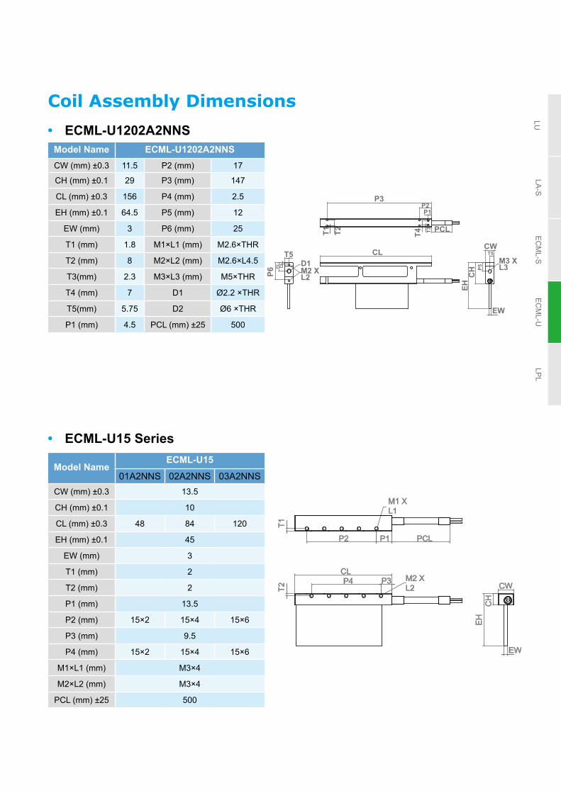
Coil Assembly Dimensions
Model Name ECML-U1202A2NNSCW (mm) ±0.3 11.5 P2 (mm) 17
CH (mm) ±0.1 29 P3 (mm) 147
CL (mm) ±0.3 156 P4 (mm) 2.5
EH (mm) ±0.1 64.5 P5 (mm) 12
EW (mm) 3 P6 (mm) 25
T1 (mm) 1.8 M1×L1 (mm) M2.6×THR
T2 (mm) 8 M2×L2 (mm) M2.6×L4.5
T3(mm) 2.3 M3×L3 (mm) M5×THR
T4 (mm) 7 D1 Ø2.2 ×THR
T5(mm) 5.75 D2 Ø6 ×THR
P1 (mm) 4.5 PCL (mm) ±25 500
Model NameECML-U15
01A2NNS 02A2NNS 03A2NNSCW (mm) ±0.3 13.5
CH (mm) ±0.1 10
CL (mm) ±0.3 48 84 120
EH (mm) ±0.1 45
EW (mm) 3
T1 (mm) 2
T2 (mm) 2
P1 (mm) 13.5
P2 (mm) 15×2 15×4 15×6
P3 (mm) 9.5
P4 (mm) 15×2 15×4 15×6
M1×L1 (mm) M3×4
M2×L2 (mm) M3×4
PCL (mm) ±25 500
• ECML-U1202A2NNS
• ECML-U15 Series
CH
EH
CWCL
EW
P1P2
P3
T1 T3T4T2 PCL
P5
T5
P6P4P5
T5M3 X L3D1
M2 X L2
CW
CH
EH
EW
CL
T1
P2 P1 PCL
T2
P4 P3 M2 XL2
M1 XL1

42
LULA
-SE
CM
L-SE
CM
L-ULP
L
Magnet Shaft Dimensions(Unit: mm)
Model NameECML-UM12
0126T 0126L
ML (mm) ±0.1 126 126
MH (mm) ±0.1 45 45
MW (mm) ±0.2 8.2 7.6
T1 (mm) 3.5 4.1
A1 (mm) 9 9
A2 (mm) 18×6 18×6
A3 (mm) 9 9
M1×L1 M3×5 M3×5
Mass (Kg) 0.28 0.3
(Unit: mm)
Model NameECML-UM15
0072 0108 0252
ML (mm) ±0.1 72 108 252
MH (mm) ±0.1 42.5
MW (mm) ±0.2 14.8
A1 (mm) 12
A2 (mm) 24
A3 (mm) 36×1 36×2 36×6
B1 (mm) 18
B2 (mm) 36×1 36×2 36×6
T1 (mm) 7.4
T2 (mm) 4.5
Mass (Kg) 0.24 0.36 0.84
• ECML-UM15
• ECML-UM120126T
• ECML-UM120126L
ML
ML
A2
A2
A3
A1
A1
A1
T1
T1
T2
B1 B2
T1
M1 x L1
M1 x L1
MH
MH
MH
6
6
7
7
MW
MW
MW
ML
A3
A3
A2
43
LULA
-SE
CM
L-SE
CM
L-ULP
L
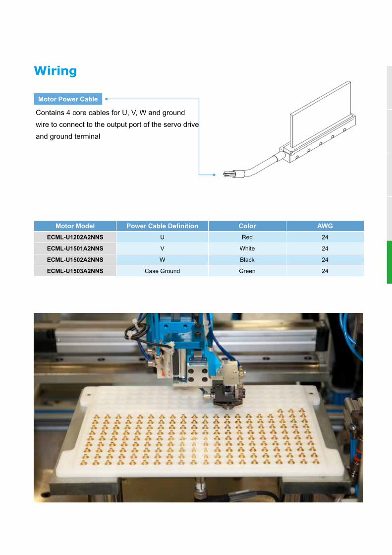
Wiring
Motor Power Cable
Contains 4 core cables for U, V, W and ground wire to connect to the output port of the servo drive and ground terminal
Motor Model Power Cable Definition Color AWGECML-U1202A2NNS U Red 24
ECML-U1501A2NNS V White 24
ECML-U1502A2NNS W Black 24
ECML-U1503A2NNS Case Ground Green 24

44
LPL -Linear Pocket Actuator
Features• Linear motor driven• High speed and acceleration• Compact size and light-weighted design• Micro force control• Multi-axis application• Easy installation
10-axis Application
12 cm only
LULA
-SE
CM
L-SE
CM
L-ULP
L
Delta's Linear Pocket Actuator LPL Series is suitable for high-speed motion applications with short distance and high space demands. Integrating ironless Linear Motor ECML-U Series, linear guide and linear scale, it can be installed directly without additional mechanical design. The LPL Series features compact design, quick response speed and high precision to enhance productivity and efficiency.
Specifications
* For LPL with different specifications, please contact branch offices or regional distributors for customized solutions
Motor Specification
Continuous Force (N) 4.6Peak Force (N) 15.83
Rated Power (W) 12.98Peak Power (W) 152.57
Rated Current (Arms) 0.70Peak Current (Arms) 2.40Max. Velocity (m/s) 1
Force Constant (N/Arms) 6.6BEMF - KE (Vpeak/(m/s)) 5.39
Resistance (Ohm) 12.77Inductance (mH) 1.98
Motor Constant (N/ √W) 1.28Forcer - Coil Weight (Kg) 0.09
Stator - Magnet Weight (Kg) 0.15Resolution (μm) 1
Repeatability (μm) ±3Distance (mm) 20
Vibration Resistance 2.5G

45
force (N)
spee
d (m
/ s)
1.2
1
0.8
0.6
0.4
0.2
00 5 10 15 20
S-F curve
Dimensions
* For LPL with different specifications, please contact branch offices or regional distributors for customized solutions
Product Specifications
Environmental Specifications
Max. Winding Temperature (℃ ) 100Operating Temperature (℃ ) 0 ~ 40Storage Temperature (℃ ) -10 ~ 80Operating Humidity (%RH) 20 ~ 80Storage Humidity (%RH) 20 ~ 80
Speed - Force Curve

46
Ironless Linear Motor ECM-LU SeriesECM-LU Series' ironless patented overlapping winding forcers provide excellent force density Vs coil size ratio resulting in high force and acceleration generation. The ECM-LU Series coil's overlapping manufacturing technology allows for the selection of smaller size motors in comparison to the competition due to its higher force density and further improved heat dissipation achieved through optional forced air-cooling methods.
All ECM-LU Series are designed with high flex cables, embedded hall effect sensors and over temperature protection (thermostats or PT100) that makes it the ideal choice for the most demanding applications. The Modular U-channel Magnet tracks available in 60 mm length increments allows for easy assembly of un-restricted stroke length.
• Low speed/torque ripple• Fast dynamic response• Zero backlash• Maintenance free• High acceleration • Long strokes without performance loss• Easy assembly over long stroke lengths
Applications• Laser Trimming• Precise Positioning• Linear Stages• Photonics• Biotech Handlers
• Fpd / Lcd Transfer• Wire And Die Bonding• Microscope Stages• Semiconductor • Industrial Machinery
• Diamond Cutting• Micro Precision• Manufacturing• Precision Stamping
Model Peak Force (N) ContinuousForce AC (N)
PeakCurrent (Apk)
ContinuousCurrent AC (Apk)
CoilLength (mm)
ECM-LU22 63.3 12.7 14.01 2.8 22-85
ECM-LU22H 229 60 21 5.46 61-151
ECM-LU36 724 188 47.25 12.29 61-301
ECM-LU39 1339 348 52.50 13.65 61-361
ECM-LU50 5191 1247 93.75 22.50 121-901
ECM-LU54 5366 1234 67.50 15.53 121-721
LULA-S
ECM
L-SEC
ML-U
LPLEC
M-LU
ECM
-LF

47
Ordering Information Coil assembly
ECM-L Product ECM-L Linear Motor Series (Delta-PBA)
1 U Linear Motor Type U : U Shape Coreless
2 22 Motor Spec.Width of Motor (mm)
Codes 22 22H 36 39 50 54
3 1 Coil Assembly Specification 1 , 2 , 3 , 4 , 5 …..
4 S Wiring Method S: Serial; P: Parallel
5 2 Input Voltage 2: 220 V
6 C Temperature Sensor Specification
C = PT 100 Sensor M: Thermostat (U22 & U22H Excluded)
7 N Cooling TypeN: StandardA: Air Cooling (Customized) W: Water Cooling (Customized)
8 1 Cable LengthD: 0.5 m (Standard)1 = 1 m; 3 =3 m; 5 = 5 m
9 B Connector Type B = 9 Pin D-SUB Male (For Hall Sensor)
10 S Special Order S = Delta-PBA Standard Product
ECM-L UM 22 1201 2 3
ECM-L Product ECM-L Linear Motor Series (Delta-PBA)
1 UM Linear Motor Type UM: U Shape Coreless Magnet Track
2 22 Motor Spec.Width of Motor (mm)
Codes 22 22H 36 39 50 54
3 120 Magnet Way Length063 = 63 mm 240 = 240 mm 084 = 84 mm 600 = 600 mm
105 = 105 mm 300 = 300 mm 120 = 120 mm 660 = 660 mm
180 = 180 mm 360 = 360 mm 480 = 480 mm 900 = 900 mm
Magnet track
ECM-L U 22 1 S 2 C N 1 B S1 2 3 4 5 6 7 8 9 10
48
LULA-S
ECM
L-SEC
ML-U
LPLEC
M-LU
ECM
-LF
Ironless Linear Motor
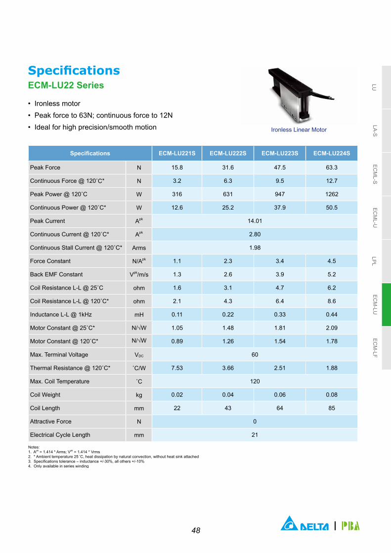
SpecificationsECM-LU22 Series
• Ironless motor• Peak force to 63N; continuous force to 12N• Ideal for high precision/smooth motion
Specifications ECM-LU221S ECM-LU222S ECM-LU223S ECM-LU224S
Peak Force N 15.8 31.6 47.5 63.3
Continuous Force @ 120˚C* N 3.2 6.3 9.5 12.7
Peak Power @ 120˚C W 316 631 947 1262
Continuous Power @ 120˚C* W 12.6 25.2 37.9 50.5
Peak Current Apk 14.01
Continuous Current @ 120˚C* Apk 2.80
Continuous Stall Current @ 120˚C* Arms 1.98
Force Constant N/Apk 1.1 2.3 3.4 4.5
Back EMF Constant Vpk/m/s 1.3 2.6 3.9 5.2
Coil Resistance L-L @ 25˚C ohm 1.6 3.1 4.7 6.2
Coil Resistance L-L @ 120˚C* ohm 2.1 4.3 6.4 8.6
Inductance L-L @ 1kHz mH 0.11 0.22 0.33 0.44
Motor Constant @ 25˚C* N/√W 1.05 1.48 1.81 2.09
Motor Constant @ 120˚C* N/√W 0.89 1.26 1.54 1.78
Max. Terminal Voltage VDC 60
Thermal Resistance @ 120˚C* ˚C/W 7.53 3.66 2.51 1.88
Max. Coil Temperature ˚C 120
Coil Weight kg 0.02 0.04 0.06 0.08
Coil Length mm 22 43 64 85
Attractive Force N 0
Electrical Cycle Length mm 21
Notes: 1. Apk = 1.414 * Arms; Vpk = 1.414 * Vrms 2. * Ambient temperature 25 ̊ C, heat dissipation by natural convection, without heat sink attached3. Specifications tolerance – inductance +/-30%, all others +/-10% 4. Only available in series winding

49
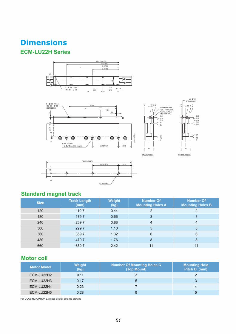
Standard magnet trackSize Track Length
(mm)Weight
(kg)Number Of
Mounting Holes ANumber Of
Mounting Holes B63 62.7 0.15 2 3
84 83.7 0.20 3 4
105 104.7 0.25 4 5
Motor coilMotor Model Weight
(kg)Number Of Mounting Holes C
(Top Mount)Mounting HolePitch D (mm)
ECM-LU221S 0.02 4 12.0
ECM-LU222S 0.04 6 16.0
ECM-LU223S 0.06 8 16.0
ECM-LU224S 0.08 10 16.0
For COOLING OPTIONS, please ask for detail drawing
DimensionsECM-LU22 Series

50
LULA-S
ECM
L-SEC
ML-U
LPLEC
M-LU
ECM
-LF
Ironless Linear Motor
SpecificationsECM-LU22H Series
• Ironless motor• Peak force to 229N; continuous force to 60N• Integrated hall sensor
Specifications ECM-LU22H2 ECM-LU22H3 ECM-LU22H4 ECM-LU22H5
Connection Type N S P S P S P S P
Peak Force N 92 137 183 229
Continuous Force @ 120˚C* N 18 27 37 46
Continuous Force AC @ 120˚C^ N 24 36 48 60
Peak Power @ 120˚C W 744 1116 1488 1860
Continuous Power @ 120˚C* W 30 45 60 74
Continuous Power AC @ 120˚C^ W 50 75 101 126
Peak Current Apk 10.50 21.00 10.50 21.00 10.50 21.00 10.50 21.00
Continuous Current @ 120˚C* Apk 2.10 4.20 2.10 4.20 2.10 4.20 2.10 4.20
Continuous Current AC @ 120˚C^ Apk 2.73 5.46 2.73 5.46 2.73 5.46 2.73 5.46
Continuous Stall Current @ 120˚C* Arms 1.40 2.80 1.40 2.80 1.40 2.80 1.40 2.80
Force Constant N/Apk 8.70 4.40 13.10 6.50 17.40 8.70 21.80 10.9
Back EMF Constant Vpk/m/s 10.0 5.0 15.0 7.50 20.1 10.0 25.10 12.5
Coil Resistance L-L @ 25˚C ohm 6.5 1.6 9.8 2.4 13.0 3.3 16.3 4.1
Coil Resistance L-L @ 120˚C* ohm 9.0 2.2 13.5 3.4 18.0 4.5 22.5 5.6
Inductance L-L @ 1kHz mH 1.53 0.38 2.30 0.57 3.06 0.77 3.83 0.96
Motor Constant @ 25˚C* N/√W 3.95 4.84 5.59 6.24
Motor Constant @ 120˚C* N/√W 3.36 4.11 4.75 5.31
Max. Terminal Voltage VDC 400
Thermal Resistance @ 120˚C* ˚C/W 3.19 2.13 1.60 1.28
Thermal Resistance AC @ 120˚C^ ˚C/W 1.89 1.26 0.94 0.76
Max. Coil Temperature ˚C 120
Coil Weight kg 0.11 0.17 0.23 0.28
Coil Weight AC^ kg 0.11 0.17 0.23 0.28
Coil Length mm 61 91 121 151
Attractive Force N 0
Electrical Cycle Length mm 30
Notes: 1. Apk = 1.414 * Arms; Vpk = 1.414 * Vrms 2. * Ambient temperature 25 ̊ C, heat dissipation by natural convection, without heat sink attached3. Specifications tolerance – inductance +/-30%, all others +/-10%
51
Standard magnet trackSize Track Length
(mm)Weight
(kg)Number Of
Mounting Holes ANumber Of
Mounting Holes B120 119.7 0.44 2 2180 179.7 0.66 3 3240 239.7 0.88 4 4300 299.7 1.10 5 5360 359.7 1.32 6 6480 479.7 1.76 8 8660 659.7 2.42 11 11
Motor coilMotor Model Weight
(kg)Number Of Mounting Holes C
(Top Mount)Mounting HolePitch D (mm)
ECM-LU22H2 0.11 3 2ECM-LU22H3 0.17 5 3ECM-LU22H4 0.23 7 4ECM-LU22H5 0.28 9 5
For COOLING OPTIONS, please ask for detailed drawing
DimensionsECM-LU22H Series

52
LULA-S
ECM
L-SEC
ML-U
LPLEC
M-LU
ECM
-LF
Ironless Linear Motor
SpecificationsECM-LU36 Series
• Ironless motor• Peak force to 724N; continuous force to 188N• Integrated hall sensor
Specifications ECM-LU361 ECM-LU362 ECM-LU363
Connection Type N S P S P Q S P
Peak Force N 145 289 434
Continuous Force @ 120˚C* N 29 58 87
Continuous Force AC @ 120˚C^ N 38 75 113
Peak Power @ 120˚C W 695 1390 2086
Continuous Power @ 120˚C* W 28 56 83
Continuous Power AC @ 120˚C^ W 47 94 141
Peak Current Apk 11.81 23.63 11.81 23.63 47.25 11.81 23.63
Continuous Current @ 120˚C* Apk 2.36 4.73 2.36 4.73 9.45 2.36 4.73
Continuous Current AC @ 120˚C^ Apk 3.07 6.14 3.07 6.14 12.29 3.07 6.14
Continuous Stall Current @ 120˚C* Arms 1.75 3.50 1.75 3.50 7.00 1.75 3.50
Force Constant N/Apk 12.3 6.1 24.5 12.3 6.1 36.8 18.4
Back EMF Constant Vpk/m/s 14.1 7.0 28.2 14.1 7.0 42.3 21.1
Coil Resistance L-L @ 25˚C ohm 4.8 1.2 9.6 2.4 0.6 14.4 3.6
Coil Resistance L-L @ 120˚C* ohm 6.6 1.7 13.3 3.3 0.8 19.9 5.0
Inductance L-L @ 1kHz mH 3.00 0.75 6.00 1.50 0.38 9.00 2.25
Motor Constant @ 25˚C* N/√W 6.46 9.13 11.18
Motor Constant @ 120˚C* N/√W 5.49 7.76 9.51
Max. Terminal Voltage VDC 400
Thermal Resistance @ 120˚C* ˚C/W 3.42 1.71 1.14
Thermal Resistance AC @ 120˚C^ ˚C/W 2.02 1.01 0.67
Max. Coil Temperature ˚C 120
Coil Weight kg 0.21 0.41 0.43 0.62
Coil Weight AC^ kg 0.23 0.46 0.48 0.69
Coil Length mm 61 121 181
Attractive Force N 0
Electrical Cycle Length mm 60
Notes: 1. Apk = 1.414 * Arms; Vpk = 1.414 * Vrms 2. * Ambient temperature 25 ̊ C, heat dissipation by natural convection, without heat sink attached3. ^ Air cool (AC), 6mm/4mm (OD/ID) 2m long air hose, pressure >2bar 4. Specifications tolerance – inductance +/-30%, all others +/-10%

53
Ironless Linear Motor
SpecificationsECM-LU36 Series
• Ironless notor• Peak force to 724N; continuous force to 188N• Integrated hall sensor
Specifications ECM-LU364 ECM-LU365
Connection Type N S P Q S P
Peak Force N 579 724
Continuous Force @ 120˚C* N 116 145
Continuous Force AC @ 120˚C^ N 150 188
Peak Power @ 120˚C W 2781 3476
Continuous Power @ 120˚C* W 111 139
Continuous Power AC @ 120˚C^ W 188 235
Peak Current Apk 11.81 23.63 47.25 11.81 23.63
Continuous Current @ 120˚C* Apk 2.36 4.73 9.45 2.36 4.73
Continuous Current AC @ 120˚C^ Apk 3.07 6.14 12.29 3.07 6.14
Continuous Stall Current @ 120˚C* Arms 1.75 3.50 7.00 1.75 3.50
Force Constant N/Apk 49.0 24.5 12.3 61.3 30.6
Back EMF Constant Vpk/m/s 56.4 28.2 14.1 70.4 35.2
Coil Resistance L-L @ 25˚C ohm 19.2 4.8 1.2 24.0 6.0
Coil Resistance L-L @ 120˚C* ohm 26.6 6.6 1.7 33.2 8.3
Inductance L-L @ 1kHz mH 12.00 3.00 0.75 15.00 3.75
Motor Constant @ 25˚C* N/√W 12.91 14.44
Motor Constant @ 120˚C* N/√W 10.98 12.27
Max. Terminal Voltage VDC 400
Thermal Resistance @ 120˚C* ˚C/W 0.85 0.68
Thermal Resistance AC @ 120˚C^ ˚C/W 0.51 0.40
Max. Coil Temperature ˚C 120
Coil Weight kg 0.83 0.88 1.04
Coil Weight AC^ kg 0.93 0.97 1.16
Coil Length mm 241 301
Attractive Force N 0
Electrical Cycle Length mm 60
Notes: 1. Apk = 1.414 * Arms; Vpk = 1.414 * Vrms 2. * Ambient temperature 25 ̊ C, heat dissipation by natural convection, without heat sink attached3. ^ Air cool (AC), 6mm/4mm (OD/ID) 2m long air hose, pressure >2bar4. Specifications tolerance – inductance +/-30%, all others +/-10%

54
LULA-S
ECM
L-SEC
ML-U
LPLEC
M-LU
ECM
-LF
Standard magnet track
Size Track Length(mm)
Weight(kg)
Number Of Mounting Holes A
Number Of Mounting Holes B
120 119.7 1.14 2 2
180 179.7 1.71 3 3
240 239.7 2.28 4 4
300 299.7 2.85 5 5
360 359.7 3.42 6 6
480 479.7 4.56 8 8
Motor coil
Motor Model Weight (kg)
Number Of Mounting Holes C(Top Mount)
Mounting HolePitch D (mm)
ECM-LU361 0.21 0.23 3
ECM-LU362 0.41 0.46 7
ECM-LU363 0.62 0.69 11
ECM-LU364 0.83 0.93 15
ECM-LU365 1.04 1.16 19
DimensionsECM-LU36 Series

55
Ironless Linear Motor
SpecificationsECM-LU39 Series
• Ironless motor• Peak force to 1339N; continuous force to 348N• Integrated hall sensor
Specifications ECM-LU391 ECM-LU392 ECM-LU393
Connection Type N S P S P Q S P
Peak Force N 223 446 669
Continuous Force @ 120˚C* N 45 89 134
Continuous Force AC @ 120˚C^ N 58 116 174
Peak Power @ 120˚C W 751 1502 2253
Continuous Power @ 120˚C* W 30 60 90
Continuous Power AC @ 120˚C^ W 51 102 152
Peak Current Apk 13.13 26.25 13.13 26.25 52.50 13.13 26.25
Continuous Current @ 120˚C* Apk 2.63 5.25 2.63 5.25 10.50 2.63 5.25
Continuous Current AC @ 120˚C^ Apk 3.41 6.83 3.41 6.83 13.65 3.41 6.83
Continuous Stall Current @ 120˚C* Arms 2.10 4.20 2.10 4.20 8.40 2.10 4.20
Force Constant N/Apk 17.0 8.5 34.0 17.0 8.5 51.0 25.5
Back EMF Constant Vpk/m/s 19.6 9.8 39.1 19.6 9.8 58.7 29.3
Coil Resistance L-L @ 25˚C ohm 4.2 1.1 8.4 2.1 0.5 12.6 3.2
Coil Resistance L-L @ 120˚C* ohm 5.8 1.5 11.6 2.9 0.7 17.4 4.4
Inductance L-L @ 1kHz mH 3.11 0.78 6.22 1.56 0.39 9.33 2.33
Motor Constant @ 25˚C* N/√W 9.58 13.55 16.59
Motor Constant @ 120˚C* N/√W 8.14 11.51 14.10
Max. Terminal Voltage VDC 400
Thermal Resistance @ 120˚C* ˚C/W 3.16 1.58 1.05
Thermal Resistance AC @ 120˚C^ ˚C/W 1.87 0.94 0.62
Max. Coil Temperature ˚C 120
Coil Weight kg 0.25 0.52 0.54 0.76
Coil Weight AC^ kg 0.28 0.57 0.60 0.85
Coil Length mm 61 121 181
Attractive Force N 0
Electrical Cycle Length mm 60
Notes: 1. Apk = 1.414 * Arms; Vpk = 1.414 * Vrms 2. * Ambient temperature 25 ̊ C, heat dissipation by natural convection, without heat sink attached3. ^ Air cool (AC), 6mm/4mm (OD/ID) 2m long air hose, pressure >2bar4. Specifications tolerance – inductance +/-30%, all others +/-10%

56
LULA-S
ECM
L-SEC
ML-U
LPLEC
M-LU
ECM
-LF
Ironless Linear Motor
SpecificationsECM-LU39 Series
• Ironless motor• Peak force to 1339N; continuous force to 348N• Integrated hall sensor
Specifications ECM-LU394 ECM-LU394 ECM-LU395 ECM-LU396
Connection Type N S P Q S P S P
Peak Force N 893 1116 1339
Continuous Force @ 120˚C* N 179 223 268
Continuous Force AC @ 120˚C^ N 232 290 348
Peak Power @ 120˚C W 3004 3755 4506
Continuous Power @ 120˚C* W 120 150 180
Continuous Power AC @ 120˚C^ W 203 254 305
Peak Current Apk 13.13 26.25 52.50 13.13 26.25 52.50
Continuous Current @ 120˚C* Apk 2.63 5.25 10.50 2.63 5.25 10.50
Continuous Current AC @ 120˚C^ Apk 3.41 6.83 13.65 3.41 6.83 13.65
Continuous Stall Current @ 120˚C* Arms 2.10 4.20 8.40 2.10 4.20 8.40
Force Constant N/Apk 68.0 34.0 17.0 85.0 42.5 25.5
Back EMF Constant Vpk/m/s 78.2 39.1 19.6 97.8 48.9 29.3
Coil Resistance L-L @ 25˚C ohm 16.8 4.2 1.1 21.0 5.3 1.6
Coil Resistance L-L @ 120˚C* ohm 23.2 5.8 1.5 29.1 7.3 2.2
Inductance L-L @ 1kHz mH 12.44 3.11 0.78 15.55 3.89 1.17
Motor Constant @ 25˚C* N/√W 19.16 21.42 23.46
Motor Constant @ 120˚C* N/√W 16.28 18.21 19.94
Max. Terminal Voltage VDC 400
Thermal Resistance @ 120˚C* ˚C/W 0.79 0.63 0.53
Thermal Resistance AC @ 120˚C^ ˚C/W 0.47 0.37 0.31
Max. Coil Temperature ˚C 120
Coil Weight kg 1.07 1.05 1.25 1.58
Coil Weight AC^ kg 1.19 1.17 1.40 1.75
Coil Length mm 241 301 361
Attractive Force N 0
Electrical Cycle Length mm 60
Notes: 1. Apk = 1.414 * Arms; Vpk = 1.414 * Vrms. 2. * Ambient temperature 25˚C, heat dissipation by natural convection, without heat sink attached.3. ^ Air cool (AC), 6mm/4mm (OD/ID) 2m long air hose, pressure >2bar. 4. Specifications tolerance – inductance +/-30%, all others +/-10%.

57
Standard magnet trackSize Track Length
(mm)Weight
(kg)Number Of
Mounting Holes ANumber Of
Mounting Holes B120 119.5 1.73 2 2
180 179.5 2.60 3 3
240 239.5 3.46 4 4
300 299.5 4.33 5 5
360 359.5 5.20 6 6
480 479.5 6.92 10 10
Motor coilMotor Model Weight
(kg)Weight
Air Cooling (kg)Number of mounting holes C
(Top mount)ECM-LU391 0.25 0.28 3
ECM-LU392 0.52 0.57 7
ECM-LU393 0.76 0.85 11
ECM-LU394 1.07 1.19 15
ECM-LU395 1.25 1.40 19
ECM-LU396 1.58 1.75 23
DimensionsECM-LU39 Series

58
LULA-S
ECM
L-SEC
ML-U
LPLEC
M-LU
ECM
-LF
Ironless Linear Motor
SpecificationsECM-LU50 Series
• Ironless motor• Peak force to 5191N; continuous force to 1038n• Integrated hall sensor
Specifications ECM-LU502 ECM-LU503 ECM-LU504 ECM-LU505
Connection Type N S P S P S P S P
Peak Force N 692 1038 1384 1730
Continuous Force @ 120˚C* N 138 208 277 346
Continuous Force AC @ 120˚C^ N 173 260 346 415
Peak Power @ 120˚C W 1951 2927 3902 4878
Continuous Power @ 120˚C* W 78 117 156 195
Continuous Power AC @ 120˚C^ W 122 183 244 281
Peak Current Apk 15.63 31.25 15.63 31.25 15.63 31.25 15.63 31.25
Continuous Current @ 120˚C* Apk 3.13 6.25 3.13 6.25 3.13 6.25 3.13 6.25
Continuous Current AC @ 120˚C^ Apk 3.91 7.81 3.91 7.81 3.91 7.81 3.75 7.50
Continuous Stall Current @ 120˚C* Arms 2.50 5.00 2.50 5.00 2.50 5.00 2.50 5.00
Force Constant N/Apk 44.3 22.2 66.5 33.2 88.6 44.3 110.8 55.4
Back EMF Constant Vpk/m/s 50.9 25.5 76.4 38.2 101.9 50.9 127.4 63.7
Coil Resistance L-L @ 25˚C ohm 7.7 1.9 11.6 2.9 15.4 3.9 19.3 4.8
Coil Resistance L-L @ 120˚C* ohm 10.7 2.7 16.0 4.0 21.3 5.3 26.6 6.7
Inductance L-L @ 1kHz mH 9.11 2.28 13.67 3.42 18.22 4.56 22.78 5.69
Motor Constant @ 25˚C* N/√W 18.4 22.6 26.1 29.1
Motor Constant @ 120˚C* N/√W 15.7 19.2 22.2 24.8
Max. Terminal Voltage VDC 600
Thermal Resistance @ 120˚C* ˚C/W 1.22 0.81 0.61 0.49
Thermal Resistance AC @ 120˚C^ ˚C/W 0.78 0.52 0.39 0.34
Max. Coil Temperature ˚C 120
Coil Weight kg 1.05 1.57 2.09 2.61
Coil Weight AC^ kg 1.13 1.69 2.25 2.81
Coil Length mm 121 181 241 301
Attractive Force N 0
Electrical Cycle Length mm 60
Notes: 1. Apk = 1.414 * Arms; Vpk = 1.414 * Vrms 2. * Ambient temperature 25˚C, heat dissipation by natural convection, without heat sink attached3. ^ Air cool (AC), 6mm/4mm (OD/ID) 2m long air hose, pressure >2bar4. Specifications tolerance – inductance +/-30%, all others +/-10%

59
Ironless Linear Motor
SpecificationsECM-LU50 Series
• Ironless motor• Peak force to 5191N; continuous force to 1038n• Integrated hall sensor
Specifications ECM-LU506 ECM-LU506 ECM-LU508 ECM-LU508
Connection Type N S P Q S P S PPeak Force N 2077 2769Continuous Force @ 120˚C* N 415 554Continuous Force AC @ 120˚C^ N 498 -Peak Power @ 120˚C W 5854 7805Continuous Power @ 120˚C* W 234 312Continuous Power AC @ 120˚C^ W 337 -Peak Current Apk 15.63 31.25 62.5 15.63 15.63 15.63Continuous Current @ 120˚C* Apk 3.13 6.25 12.5 3.13 3.13 3.13Continuous Current AC @ 120˚C^ Apk 3.75 7.50 15.00 - - -Continuous Stall Current @ 120˚C* Arms 2.50 5.00 10.00 2.50 2.50 2.50Force Constant N/Apk 132.9 66.5 33.2 177.2 177.2 177.2Back EMF Constant Vpk/m/s 152.8 76.4 38.2 203.8 203.8 203.8Coil Resistance L-L @ 25˚C ohm 23.1 5.8 1.4 30.8 30.8 30.8Coil Resistance L-L @ 120˚C* ohm 32.0 8.0 2.0 42.6 42.6 42.6Inductance L-L @ 1kHz mH 27.33 6.83 1.71 36.44 36.44 36.44Motor Constant @ 25˚C* N/√W 31.9 36.9Motor Constant @ 120˚C* N/√W 27.1 31.3Max. Terminal Voltage VDC 600Thermal Resistance @ 120˚C* ˚C/W 0.41 0.30Thermal Resistance AC @ 120˚C^ ˚C/W 0.28 -Max. Coil Temperature ˚C 120Coil Weight kg 3.13 3.23 4.36 4.43Coil Weight AC^ kg 3.37 3.47 - -Coil Length mm 361 481Attractive Force N 0Electrical Cycle Length mm 60
Notes: 1. Apk = 1.414 * Arms; Vpk = 1.414 * Vrms 2. * Ambient temperature 25˚C, heat dissipation by natural convection, without heat sink attached3. ^ Air cool (AC), 6mm/4mm (OD/ID) 2m long air hose, pressure >2bar 4. Specifications tolerance – inductance +/-30%, all others +/-10%
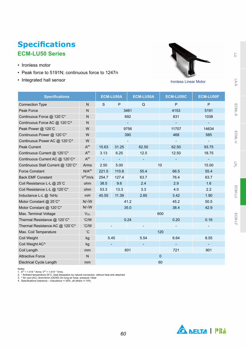
60
LULA-S
ECM
L-SEC
ML-U
LPLEC
M-LU
ECM
-LF
Ironless Linear Motor
SpecificationsECM-LU50 Series
• Ironless motor• Peak force to 5191N; continuous force to 1247n• Integrated hall sensor
Specifications ECM-LU50A ECM-LU50A ECM-LU50C ECM-LU50F
Connection Type N S P Q P PPeak Force N 3461 4153 5191Continuous Force @ 120˚C* N 692 831 1038Continuous Force AC @ 120˚C^ N - - -Peak Power @ 120˚C W 9756 11707 14634Continuous Power @ 120˚C* W 390 468 585Continuous Power AC @ 120˚C^ W - - -Peak Current Apk 15.63 31.25 62.50 62.50 93.75Continuous Current @ 120˚C* Apk 3.13 6.25 12.5 12.50 18.75Continuous Current AC @ 120˚C^ Apk - - - - -Continuous Stall Current @ 120˚C* Arms 2.50 5.00 10 15.00Force Constant N/Apk 221.5 110.8 55.4 66.5 55.4Back EMF Constant Vpk/m/s 254.7 127.4 63.7 76.4 63.7Coil Resistance L-L @ 25˚C ohm 38.5 9.6 2.4 2.9 1.6Coil Resistance L-L @ 120˚C* ohm 53.3 13.3 3.3 4.0 2.2Inductance L-L @ 1kHz mH 45.55 11.39 2.85 3.42 1.90Motor Constant @ 25˚C* N/√W 41.2 45.2 50.5Motor Constant @ 120˚C* N/√W 35.0 38.4 42.9Max. Terminal Voltage VDC 600Thermal Resistance @ 120˚C* ˚C/W 0.24 0.20 0.16Thermal Resistance AC @ 120˚C^ ˚C/W - - - -Max. Coil Temperature ˚C 120Coil Weight kg 5.45 5.54 6.64 8.55Coil Weight AC^ kg - - - -Coil Length mm 601 721 901Attractive Force N 0Electrical Cycle Length mm 60
Notes: 1. Apk = 1.414 * Arms; Vpk = 1.414 * Vrms 2. * Ambient temperature 25˚C, heat dissipation by natural convection, without heat sink attached3. ^ Air cool (AC), 6mm/4mm (OD/ID) 2m long air hose, pressure >2bar4. Specifications tolerance – inductance +/-30%, all others +/-10%
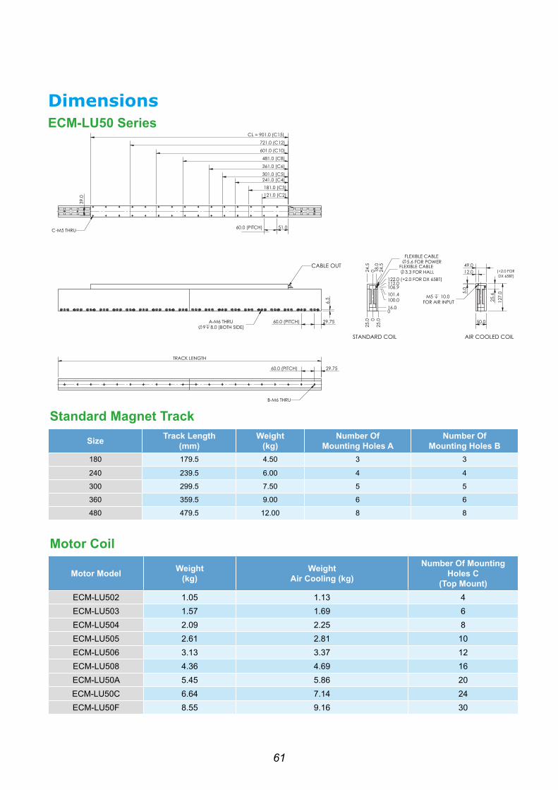
61
Standard Magnet TrackSize Track Length
(mm)Weight
(kg)Number Of
Mounting Holes ANumber Of
Mounting Holes B180 179.5 4.50 3 3
240 239.5 6.00 4 4
300 299.5 7.50 5 5
360 359.5 9.00 6 6
480 479.5 12.00 8 8
Motor Coil
Motor Model Weight (kg)
Weight Air Cooling (kg)
Number Of Mounting Holes C
(Top Mount)ECM-LU502 1.05 1.13 4ECM-LU503 1.57 1.69 6ECM-LU504 2.09 2.25 8ECM-LU505 2.61 2.81 10ECM-LU506 3.13 3.37 12ECM-LU508 4.36 4.69 16ECM-LU50A 5.45 5.86 20ECM-LU50C 6.64 7.14 24ECM-LU50F 8.55 9.16 30
CABLE OUT
60.0 (PITCH)
TRACK LENGTH
STANDARD COIL AIR COOLED COIL
DimensionsECM-LU50 Series

62
LULA-S
ECM
L-SEC
ML-U
LPLEC
M-LU
ECM
-LF
Ironless Linear Motor
SpecificationsECM-LU54 Series
• Ironless motor• Peak force to 5366N; continuous force to 1234N• Integrated hall sensor
Specifications ECM-LU542 ECM-LU543 ECM-LU544 ECM-LU546 ECM-LU546
Connection Type N S P S P S P S P PPeak Force N 894 1342 1789 2683Continuous Force @ 120˚C* N 179 268 358 537Continuous Force AC @ 120˚C^ N 215 322 429 617Peak Power @ 120˚C W 2217 3325 4433 6650Continuous Power @ 120˚C* W 89 133 177 266Continuous Power AC @ 120˚C^ W 128 192 255 352Peak Current Apk 16.88 33.75 16.88 33.75 16.88 33.75 16.88 33.75 67.50Continuous Current @ 120˚C* Apk 3.38 6.75 3.38 6.75 3.38 6.75 3.38 6.75 13.50Continuous Current AC @ 120˚C^ Apk 4.05 8.10 4.05 8.10 4.05 8.10 3.88 7.76 15.53Continuous Stall Current @ 120˚C* Arms 2.70 5.40 2.70 5.40 2.70 5.40 2.70 5.40 10.80Force Constant N/Apk 53.0 26.5 79.5 39.8 106.0 53.0 159.0 79.5 39.8Back EMF Constant Vpk/m/s 61.0 30.5 91.4 45.7 121.9 61.0 182.9 91.4 45.7Coil Resistance L-L @ 25˚C ohm 7.5 1.9 11.3 2.8 15.0 3.8 22.5 5.6 1.4Coil Resistance L-L @ 120˚C* ohm 10.4 2.6 15.6 3.9 20.8 5.2 31.1 7.8 1.9Inductance L-L @ 1kHz mH 8.51 2.13 12.77 3.19 17.03 4.26 25.54 6.39 1.60Motor Constant @ 25˚C* N/√W 22.3 27.4 31.6 38.7Motor Constant @ 120˚C* N/√W 19.0 23.3 26.9 32.9Max. Terminal Voltage VDC 600Thermal Resistance @ 120˚C* ˚C/W 1.07 0.71 0.54 0.36Thermal Resistance AC @ 120˚C^ ˚C/W 0.74 0.50 0.37 0.27Max. Coil Temperature ˚C 120Coil Weight kg 1.30 1.95 2.56 3.90 4.00Coil Weight AC^ kg 1.39 2.08 2.74 4.16 4.27Coil Length mm 121 181 241 361Attractive Force N 0Electrical Cycle Length mm 60
Notes: 1. Apk = 1.414 * Arms; Vpk = 1.414 * Vrms 2. * Ambient temperature 25˚C, heat dissipation by natural convection, without heat sink attached3. ^ Air cool (AC), 6mm/4mm (OD/ID) 2m long air hose, pressure >2bar4. Specifications tolerance – inductance +/-30%, all others +/-10%

63
Ironless Linear Motor
SpecificationsECM-LU54 Series
• Ironless motor• Peak force to 5366N; continuous force to 1234n• Integrated hall sensor
Specifications ECM-LU548 ECM-LU548 ECM-LU54A ECM-LU54A ECM-LU54C
Connection Type N S P Q S P Q QPeak Force N 3578 4472 5366Continuous Force @ 120˚C* N 716 894 1073Continuous Force AC @ 120˚C^ N - - -Peak Power @ 120˚C W 8867 11084 13300Continuous Power @ 120˚C* W 355 443 532Continuous Power AC @ 120˚C^ W - - -Peak Current Apk 16.88 33.75 67.50 16.88 33.75 67.50Continuous Current @ 120˚C* Apk 3.38 6.75 13.50 3.38 6.75 13.50Continuous Current AC @ 120˚C^ Apk - - - - - -Continuous Stall Current @ 120˚C* Arms 2.70 5.40 10.80 2.70 5.40 10.80Force Constant N/Apk 212.0 106.0 53.0 265.0 132.5 66.3 79.5Back EMF Constant Vpk/m/s 243.8 121.9 61.0 304.8 152.4 76.2 91.4Coil Resistance L-L @ 25˚C ohm 30.0 7.5 1.9 37.5 9.4 2.3 2.8Coil Resistance L-L @ 120˚C* ohm 41.5 10.4 2.6 51.9 13.0 3.2 3.9Inductance L-L @ 1kHz mH 34.06 8.51 2.13 42.57 10.64 2.66 3.19Motor Constant @ 25˚C* N/√W 44.7 50.0 54.7Motor Constant @ 120˚C* N/√W 38.0 42.5 46.5Max. Terminal Voltage VDC 600Thermal Resistance @ 120˚C* ˚C/W 0.27 0.21 0.18Thermal Resistance AC @ 120˚C^ ˚C/W - - -Max. Coil Temperature ˚C 120Coil Weight kg 5.17 5.31 6.46 6.63 7.96Coil Weight AC^ kg - - - - -Coil Length mm 481 601 721Attractive Force N 0Electrical Cycle Length mm 60
Notes: 1. Apk = 1.414 * Arms; Vpk = 1.414 * Vrms 2. * Ambient temperature 25˚C, heat dissipation by natural convection, without heat sink attached3. ^ Air cool (AC), 6mm/4mm (OD/ID) 2m long air hose, pressure >2bar4. Specifications tolerance – inductance +/-30%, all others +/-10%

64
LULA-S
ECM
L-SEC
ML-U
LPLEC
M-LU
ECM
-LF
Standard magnet track
Size Track length(mm)
Weight(kg)
Number of Mounting Holes A
Number ofMounting Holes B
TL 240 239.5 8.50 4 4
TL 300 299.5 10.50 5 5
TL 360 359.5 12.50 6 6
TL 480 479.5 16.80 8 8
Motor coil
Motor Model Weight (kg) Weight Air Cooling (kg)
Number of Mounting Holes C(Top mount)
ECM-LU542 1.30 1.39 4
ECM-LU543 1.95 2.08 6
ECM-LU544 2.56 2.74 8
ECM-LU546 3.90 4.16 12
ECM-LU548 5.17 5.52 16
ECM-LU54A 6.46 6.90 20
ECM-LU54C 7.96 8.48 24
CABLE OUT
TRACK LENGTH
STANDARD COIL AIR COOLED COIL
DimensionsECM-LU54 Series

65
Applications

66
Ironcore Linear Motor ECM-LF SeriesECM-LF Ironcore motors offer an affordable high force solution to demanding linear applications with minimal cogging effect that is associated with traditional iron core linear motors.
Our Ironcore design provides for optimal dissipation of heat and is thus capable of extremely high forces (>9000N). These motor coils are manufactured with high flex cables and optional external hall effect attachments widely used in multiple general automation applications.
Modular Flat Magnet tracks are available in different length increments to complete this product selection and allow for easy assembly of unrestricted effective strokes by butting tracks of different lengths together.
• High force / thrust• Maintenance free• High stiffness• Compact size• Minimal cogging
Applications• Material Transfer / Pick And Place• Laser Cutting• Extruders
• Machine Tools• Large Format Printing• Textile Printing
• Digital Printing
Motor Model Peak Force (N) Continuous Force AC (N) Compatible Magnet Track Length (mm)
ECM-LF542 542 108
64-320
ECM-LF54H2 943 189
ECM-LF742 893 179
ECM-LF74H2 1515 303
ECM-LFA42 1393 279
ECM-LF54H2 2307 461
LULA-S
ECM
L-SEC
ML-U
LPLEC
M-LU
ECM
-LF

67
Ordering Information Coil assembly
ECM-L Product Series ECM-L Linear Motor Series (Delta-PBA)
1 F Linear Motor Type F: Flat Iron core
2 54 Motor Spec.
Width of Motor (mm)
Codes54 74 A4 (104)
54H 74H A4H (104)
3 2 Coil Assembly Specification 2
4 S Wiring Method S: Serial; P: Parallel
5 2 Input Voltage 2: 220 V
6 N Temperature Sensor Specification
C = PT 100 Sensor (Standard)M: Thermostat
7 N Cooling TypeN: Standard A: Air Cooling (Customized) W: Water Cooling (Customized)
8 1 Cable Length D: 0.5 m (Standard); 1 = 1 m; 3 =3 m; 5 = 5 m
9 B Connector Type B = 9 Pin D-SUB Male (For Hall Sensor)
10 S Special Order S = Delta-PBA Standard Product
Magnet track
ECM-L FM 54 0641 2 3
ECM-L Product Series ECM-L Linear Motor Series (Delta-PBA)
1 FM Linear Motor Type F: Flat type Iron core
2 54 Motor Spec.Width of Motor (mm)
Codes 54 74 A4 (104)
3 064 Magnetic Way Length Codes064 = 64 mm 128 = 128 mm
192 = 192 mm 320 = 320 mm
ECM-L F 54 2 S 2 N N D B S1 2 3 4 5 6 7 8 9 10

68
LULA-S
ECM
L-SEC
ML-U
LPLEC
M-LU
ECM
-LF
Ironcore Linear Motor
SpecificationsECM-LF Series
• Peak force to 1393N; continuous force to 279N• Hall ensor
Specifications ECM-LF54 ECM-LF74 ECM-LFA4
Connection Type N S P S P S P
Peak Force N 542 893 1393
Continuous Force @ 120˚C* N 108 179 279
Continuous Stall Force @ 120˚C* N 77 126 197
Peak Power @ 120˚C W 1823 2323 2932
Continuous Power @ 120˚C* W 73 93 117
Peak Current Apk 30.4 60.8 29.3 58.7 27.9 55.7
Continuous Current @ 120˚C* Apk 6.1 12.2 5.9 11.7 5.6 11.1
Continuous Stall Current @ 120˚C* Arms 4.30 8.60 4.15 8.30 3.94 7.88
Force Constant N/Apk 17.8 8.9 30.4 15.2 50.0 25.0
Back EMF Constant Vpk/m/s 20.5 10.3 35 17.5 57.5 28.8
Coil Resistance L-L @ 25˚C ohm 1.9 0.5 2.6 0.7 3.6 0.9
Coil Resistance L-L @ 120˚C* ohm 2.6 0.7 3.6 0.9 5.0 1.3
Inductance L-L @ 1kHz mH 4.8 1.2 7.0 1.8 10.5 2.6
Motor Constant @ 25˚C* N/√W 14.9 21.8 30.3
Motor Constant @ 120˚C* N/√W 12.7 18.5 25.7
Max. Terminal Voltage VDC 600
Thermal Resistance @ 120˚C* ˚C/W 1.3 1.02 0.81
Max. Coil Temperature ˚C 120
Coil Weight kg 1.3 2.0 3.1
Attractive Force N 1560 2600 4160
Electrical Cycle Length mm 32
Notes: 1. Apk = 1.414 * Arms; Vpk = 1.414 * Vrms 2. * Ambient temperature 25 ̊ C, heat dissipation by natural convection, without heat sink attached3. Specifications tolerance – inductance +/-30%, all others +/-10%4. Peak force and current - 4% duty ratio and 1 second duration

69
Motor Model W (mm) Y (mm) Number Of Mounting Holes Z Compatible Track
ECM-LF542 54 16 4 ECM-LFM54XXX
ECM-LF742 74 36 4 ECM-LFM74XXX
ECM-LFA42 104 66 6 ECM-LFMA4XXX
Magnet Track L (mm) S (mm) R (mm) N M Weight (g) Motor Model
ECM-LFM54
M064 64
54 44
1 4 207.6
ECM-LF54HM128 128 3 8 415.2
M192 192 5 12 622.8
M320 320 9 20 1038
ECM-LFM74
M064 64
74 64
1 4 300.3
ECM-LF74HM128 128 3 8 600.6
M192 192 5 12 901
M320 320 9 20 1501.6
ECM-LFMA4
M064 64
104 94
1 4 439.4
ECM-LFA4HM128 128 3 8 878.8
M192 192 5 12 1318.2
M320 320 9 20 2197
OPTIONAL HALL SENSOR
DimensionsECM-LF Series
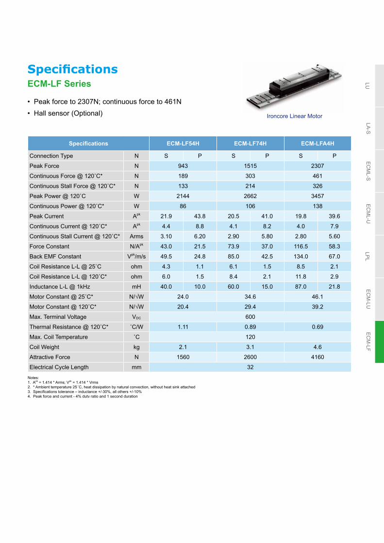
70
LULA-S
ECM
L-SEC
ML-U
LPLEC
M-LU
ECM
-LF
SpecificationsECM-LF Series
• Peak force to 2307N; continuous force to 461N• Hall sensor (Optional)
Specifications ECM-LF54H ECM-LF74H ECM-LFA4H
Connection Type N S P S P S P
Peak Force N 943 1515 2307
Continuous Force @ 120˚C* N 189 303 461
Continuous Stall Force @ 120˚C* N 133 214 326
Peak Power @ 120˚C W 2144 2662 3457
Continuous Power @ 120˚C* W 86 106 138
Peak Current Apk 21.9 43.8 20.5 41.0 19.8 39.6
Continuous Current @ 120˚C* Apk 4.4 8.8 4.1 8.2 4.0 7.9
Continuous Stall Current @ 120˚C* Arms 3.10 6.20 2.90 5.80 2.80 5.60
Force Constant N/Apk 43.0 21.5 73.9 37.0 116.5 58.3
Back EMF Constant Vpk/m/s 49.5 24.8 85.0 42.5 134.0 67.0
Coil Resistance L-L @ 25˚C ohm 4.3 1.1 6.1 1.5 8.5 2.1
Coil Resistance L-L @ 120˚C* ohm 6.0 1.5 8.4 2.1 11.8 2.9
Inductance L-L @ 1kHz mH 40.0 10.0 60.0 15.0 87.0 21.8
Motor Constant @ 25˚C* N/√W 24.0 34.6 46.1
Motor Constant @ 120˚C* N/√W 20.4 29.4 39.2
Max. Terminal Voltage VDC 600
Thermal Resistance @ 120˚C* ˚C/W 1.11 0.89 0.69
Max. Coil Temperature ˚C 120
Coil Weight kg 2.1 3.1 4.6
Attractive Force N 1560 2600 4160
Electrical Cycle Length mm 32
Notes: 1. Apk = 1.414 * Arms; Vpk = 1.414 * Vrms 2. * Ambient temperature 25 ̊ C, heat dissipation by natural convection, without heat sink attached3. Specifications tolerance – inductance +/-30%, all others +/-10%4. Peak force and current - 4% duty ratio and 1 second duration
Ironcore Linear Motor

71
Motor Model W (mm) Y (mm) Number Of Mounting Holes Z Compatible Track
ECM-LF54H 54 16 4 ECM-LFM54XXX
ECM-LF74H 74 36 4 ECM-LFM74XXX
ECM-LFA4H 104 66 6 ECM-LFMA4XXX
Magnet Track L (mm) S (mm) R (mm) N M Weight (g) Motor Model
ECM-LFM54
M064 64
54 44
1 4 207.6
ECM-LF54HM128 128 3 8 415.2
M192 192 5 12 622.8
M320 320 9 20 1038
ECM-LFM74
M064 64
74 64
1 4 300.3
ECM-LF74HM128 128 3 8 600.6
M192 192 5 12 901
M320 320 9 20 1501.6
ECM-LFMA4
M064 64
104 94
1 4 439.4
ECM-LFA4HM128 128 3 8 878.8
M192 192 5 12 1318.2
M320 320 9 20 2197
OPTIONAL HALL SENSOR
DimensionsECM-LF Series

72
Parameter ExplanationTechnical terms
• Back EMF ConstantThe induced voltage in motor coils under a permanent magnetic field is defined as the back EMF constant which is the ratio of induced voltage and motor rotational speed (rpm) or linear speed (m/s). The back EMF constant is used to measure how many volts the motor may generate if it is driven as a generator
• Torque Constant and Thrust Constant Kt is called torque constant (N-m/A) which is defined as the ratio of electromagnetic torque or thrust (in N-m)generated by a motor and the motor input current (in A)
• Continuous Current The continuous current is the rated current, or operational current, which is the value of amperes intended to flow through the motor
• Max. Current The maximum current is defined as the output current of the motor when it reaches to the maximum thrust or the maximum torque. It works under the temperature when the permanent magnet is not degaussed. The maximum current is related to the coils: the initial temperature of coils will affect the output time of the maximum current
• Rated Torque and Rated Thrust Rated torque or thrust is the maximum torque or thrust that the motor can safely apply continuously to the load at any speed within the rated speed range of the motor
• Max. Torque and Maximum ThrustAt maximum current, the maximum torque or maximum thrust generated by the motor is generally used as the limit for instant motor acceleration and deceleration
• Positioning Accuracy Definition of Positioning Accuracy of the LU Series:The maximum deviation between the actual distance and the desired distance (reaching distance) when moving from the original position in the same direction
Desired Distance (Reaching Distance)
Maximum Deviation
Posi
tioni
ng D
evia
tion

73
Technical terms• Positioning Repeatability
Definition of Positioning Repeatability of the LU Series:Choose a desired position. Then approach the desired positionin a constant direction seven times repeatedly. Then measure the maximum positioning deviation. The positioning repeatability is measured as the half maximum positioning deviation with plus-minus sign (±) in the overall travel length
• Running Parallelism Definition of Running Parallelism of the LU Series:Position a gauge at the center of the datum surface of the blocks. The running parallelism is measured and defined as the maximum deviation of parallelism between the datum surface of the blocks and the surface of the linear stage when the blocks are moving over the overall travel length
• Backlash After traveling a certain distance, stop the movement of the blocks and use the stop position as the reference datum. The backlash is defined as the deviation value in positioning caused by the reversal of travel direction after applying a force to the block from the same direction and releasing it
Force
P1
P2
P7
Parameter Explanation

74
Choosing a Delta linear motion product
• Choose suitable linear motion product and drive
• Calculate maximum and average thrust
• Trapezoidal motion profile
• Triangular motion profile
• Rotary Motor (Ball Screw)
• Linear Motor
Drive Type Motion Profile
Thrust Calculation
Matching Model No.
Drive TypeDelta's Linear Motion Products
Rotary Motor (Ball Screw) Linear Motor

75
Trapezoidal motion profile
(1/3)T
Velocity
Distance = S
Time
T
V
(1/3)T (1/3)T
KnownObtained
Stroke S (m)Time T (sec)
Velocity V (m/sec)Time T (sec)
Acceleration A (m/sec2)Time T (sec)
Acceleration A (m/sec2)Velocity V (m/sec)
Stroke S (m) S = ( S = ( 1/4.5 ) A S = 2 ( / A)
Velocity V (m/s) V = 1.5 ( S / T ) V= ( A ) / 3 V =
Acceleration A (m/sec2) A = 4.5 ( S / ) A = 3 ) A = 2 ( / S)
Triangular motion profile
Distance = S
Velocity
Time
T
V
T/2T/2
KnownObtained
Stroke S (m)Time T (sec)
Velocity V (m/sec)Time T (sec)
Acceleration A (m/sec2)Time T (sec)
Acceleration A (m/sec2)Velocity V (m/sec)
Stroke S (m) S = (1/2 S = ( 1/4 ) A S = / A
Velocity V (m/s) V = 2 ( S / T ) V= ( A ) / 2 V =
Acceleration A (m/sec2) A = 4 ( S / ) A = 2 ) A = / S
Motion CurveBased on the motion profile information, calculation data include: 1. Moving speed; 2. Moving time; 3. Moving distance (The calculation only requires two of the above data types)

76
Thrust CalculationFormula
Formula
Required thrust for acceleration section
= + m x a
Required thrust for constant velocity section
= μ x m x g
Required thrust for deceleration section
= m x a -
RMS Thrust (rms)
μ: coefficient of sliding friction (e.g coefficient of friction of bearings, linear guideways)m: moving mass and external payload g: 9.81 m/s2
a: acceleration m/s2
t1acceleration
time
t2constant velocity
t3deceleration
time
t4settling
time
T
V
F1 F2 F3 F4
T
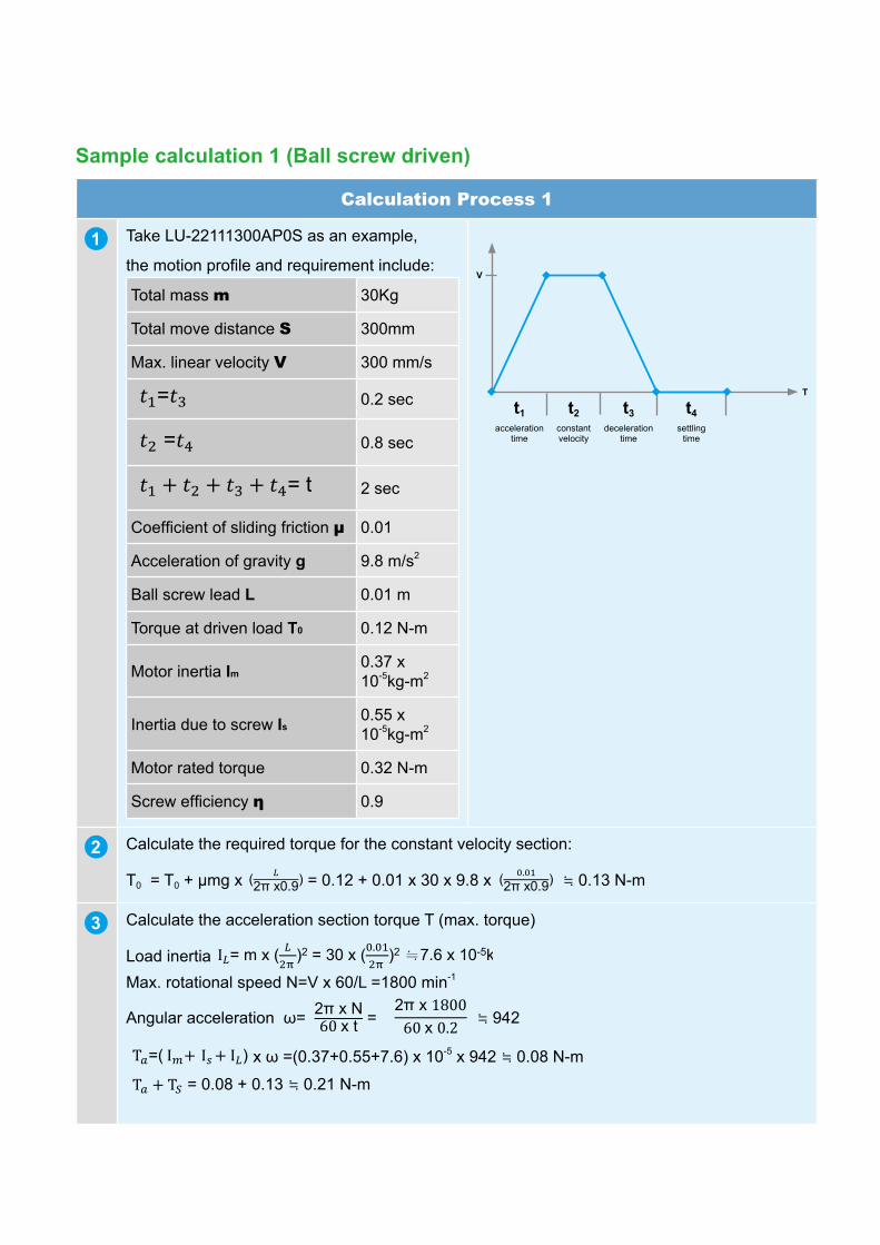
77
Sample calculation 1 (Ball screw driven)
Calculation Process 1
1 Take LU-22111300AP0S as an example,
the motion profile and requirement include:
Total mass m 30Kg
Total move distance S 300mm
Max. linear velocity V 300 mm/s
= 0.2 sec
= 0.8 sec
= t 2 sec
Coefficient of sliding friction μ 0.01
Acceleration of gravity g 9.8 m/s2
Ball screw lead L 0.01 m
Torque at driven load Τ0 0.12 N-m
Motor inertia Ιm0.37 x 10-5kg-m2
Inertia due to screw Ιs0.55 x 10-5kg-m2
Motor rated torque 0.32 N-m
Screw efficiency η 0.9
t1acceleration
time
t2constant velocity
t3deceleration
time
t4settling
time
T
V
2 Calculate the required torque for the constant velocity section:
Τ0 = T0 + μmg x ( ) = 0.12 + 0.01 x 30 x 9.8 x ( ) ≒ 0.13 N-m
3 Calculate the acceleration section torque T (max. torque)
Load inertia = m x ( )2 = 30 x ( )2 ≒7.6 x 10⁻⁵kg-m2
Max. rotational speed N=V x 60/L =1800 min-1
Angular acceleration ω= = = ≒ 942
=( ) x ω =(0.37+0.55+7.6) x 10-5 x 942 ≒ 0.08 N-m
= 0.08 + 0.13 ≒ 0.21 N-m
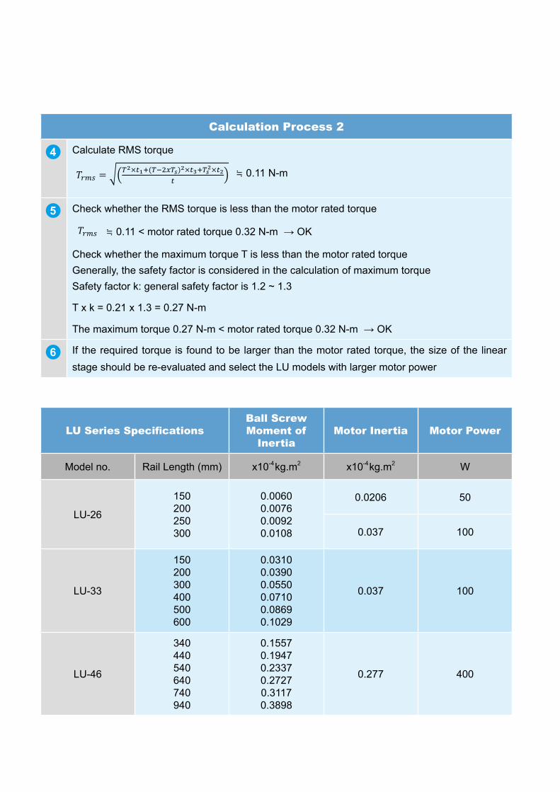
78
Calculation Process 2
4 Calculate RMS torque
≒ 0.11 N-m
5 Check whether the RMS torque is less than the motor rated torque
≒ 0.11 < motor rated torque 0.32 N-m → OK
Check whether the maximum torque T is less than the motor rated torque Generally, the safety factor is considered in the calculation of maximum torque Safety factor k: general safety factor is 1.2 ~ 1.3
T x k = 0.21 x 1.3 = 0.27 N-m
The maximum torque 0.27 N-m < motor rated torque 0.32 N-m → OK
6 If the required torque is found to be larger than the motor rated torque, the size of the linear stage should be re-evaluated and select the LU models with larger motor power
LU Series SpecificationsBall Screw Moment of
InertiaMotor Inertia Motor Power
Model no. Rail Length (mm) x10-4 kg.m2 x10-4 kg.m2 W
LU-26
150200250300
0.0060 0.0076 0.0092 0.0108
0.0206 50
0.037 100
LU-33
150200300400500600
0.0310 0.0390 0.0550 0.0710 0.0869 0.1029
0.037 100
LU-46
340440540640740940
0.1557 0.1947 0.2337 0.2727 0.3117 0.3898
0.277 400

79
Sample calculation 2 (Linear motor driven)
Calculation Process 1
1 Given motion profile:
Applied in pick-and-place machines (horizontal
movement)
Total mass m:10 kg
Total move distance S: 300 mm
t1 = t2 = t3 = t4 = 0.1 sec
T = t1 + t2 + t3 = 0.3μ: Coefficient of sliding friction = 0.005
g: 9.81 m/s2
t1acceleration
time
t2constant velocity
t3deceleration
time
t4settling
time
T
V
2 Calculate the maximum thrust:
S= 0.3 m= (2/3) x V x T=(2/3) x V x 0.3→ V=1.5 m/s
a = V / t1 = 1.5 / .01 = 15 m / sz
Required thrust for acceleration section = F1 = F2 + m x a = 0.49 +10 x 15 = 150.49 N
Required thrust for constant velocity section = F2 = μ x m x g = 0.005 x 10 x 9.81 = 0.49 N
Required thrust for deceleration section = F3 = m x a - F2 = 10 x 15 -0.49 = 149.51 N
Required thrust for settling section = F4 = 0 N
→ Fmax = F1 = 150.49
3 Calculate the RMS thrust:
Frms = = 106 N
4 Safety factor: general safety factor is 1.2 ~ 1.3
Fmax = 150.49 x Safety factor = 150.49 x1.2 = 180.59 N
Frms = 106 x Safety factor = 106 x1.2 = 127.2 N
5 Refer to LA-S thrust range, rated thrust > Fmax and Frms
Suggested linear stage model: LA-SB
Refer to LA-S Series and Servo Drive Selection Table: 750 W

80
Linear Stage Request FormDate:
Company Name:
Product required Specification
Industry of the company
Equipment application
Max. velocity (m/s)
Max. acceleration and deceleration (m/s2)
Stroke (mm)
Load (mm)
Repeatability ± (μm)
Multiple rotors in single axis Yes ( pcs / axis) No
Vertical application Yes No
Stage mounting direction horizontal lateral upside down
Total amount required
Drive voltage
Request for external electricity regeneration (To be confirmed with electrical control personnel)
Yes No
Speed Curve Velocity (m/s)
Vmax: ________
T1: _______
acceleration time
T2: _______
constant velocity
T3: _______
deceleration time
T4: _______
settling time
Time (sec)
Special requirements and notes (e.g. high temperature or clean room operation or others)

81
Servo Drive ASDA-A2 Series Specifications (Ball Screw Driven)
ASDA-A2 Series100 W 200 W 400 W 750 W
01 02 04 07
Pow
er
Supp
ly
Phase / Voltage Three-phase / Single-phase 220 VAC
Permissible Voltage Range 1-phase / 3-phase 200 ~ 230 VAC, -15% ~ 10%
Input Current (3PH) (Units: Arms) 0.39 1.11 1.86 3.66
Input Current (1PH) (Units: Arms) 0.69 1.92 3.22 6.78
Continuous Output Current (Units: Arms) 0.9 1.55 2.6 5.1
Cooling System Natural Air Circulation Fan Cooling
Encoder Resolution / Feedback Resolution Incremental encoder: 20-bit (1280000 p/rev); Absolute encoder: 17-bit
Control of Main Circuit SVPWM (Space Vector Pulse Width Modulation) Control
Tuning Modes Auto / Manual
Regenerative Resistor None Built-in
Posi
tion
Con
trol
Mod
e Max. Input Pulse Frequency (Only for Non-DMCNET mode)
Max. 500 Kpps / 4 Mpps (Line driver), Max. 200 Kpps (Open collector)
Pulse Type (Only for Non-DMCNET mode) Pulse + Direction, A phase + B phase, CCW pulse + CW pulse
Command Source External pulse train (PT mode) (For non-DMCNET mode only) / Internal parameters (PR mode)
Smoothing Strategy Low-pass and P-curve filter
Electronic Gear Electronic gear N/M multiple N: 1~32767, M: 1:32767 (1/50<N/M<25600)
Torque Limit Operation Set by parameters
Feed Forward Compensation Set by parameters
Spee
d C
ontr
ol M
ode
Analog Input Command(Only for Non-DMCNET mode)
Voltage Range 0 ~ ±10 VDC
Input Resistance 10 KΩ
Time Constant 2.2 μs
Speed Control Range *1 1: 5000
Command Source External analog signal (For non-DMCNET mode only) / Internal parameters
Smoothing Strategy Low-pass and S-curve filter
Torque Limit Operation Set by parametersor via analog input (For non-DMCNET mode only)
Frequency Response Characteristic Maximum 1 kHz
Speed Accuracy*2
(At rated rotation speed)
0.01% or less at 0 to 100% load fluctuation0.01% or less at ±10% power fluctuation
0.01% or less at 0˚C to 50˚C ambient temperature fluctuation
Torq
ue C
ontr
ol
Mod
e
Analog Input Command(Only for Non-DMCNET mode)
Voltage Range 0 ~ ±10 VDC
Input Resistance 10 KΩ
Time Constant 2.2 μs
Command Source External analog signal (For non-DMCNET mode only) / Internal parameters
Smoothing Strategy Low-pass filter
Speed Limit Operation Set by parameters or via analog input (For non-DMCNET mode only)
Analog Monitor Output Monitor signal can set by parameters (Output voltage range: ±8 V)
Dig
ital I
nput
s / O
utpu
ts
Inputs
Servo on, Reset, Gain switching, Pulse clear, Zero speed CLAMP, Command input reverse control, Command triggered, Speed/Torque limit enabled, Position command selection, Motor stop, Speed position selection, Position / Speed mode switching, Speed / Torque mode switching, Torque / Position mode switching, PT / PR command switching, Emergency stop, Forward / Reverse inhibit
limit, Reference "Home" sensor, Forward / Reverse operation torque limit, Move to "Home", Electronic Cam (E-Cam), Forward / Reverse JOG input, Event trigger PR command, Electronic gear ratio (Numerator) selection and Pulse inhibit input
* Please note that the above digital signals and inputs are available only for Non-DMCNET mode. In DMCNET mode, it is recommended to write the digital inputs which only supports Emergency Stop, Forward / Reverse Inhibit limit and Reference "Home" sensor only, into the servo drives via DMCNET communication
Outputs
Encoder signal output (A, B, Z Line Driver and Z Open Collector )Servo ready, Servo on, At Zero speed, At Speed reached, At Positioning completed, At Torques limit, Servo alarm (Servo fault)
activated, Electromagnetic brake control, Homing completed, Output overload warning, Servo warning activated, Position command overflow, Forward / Reverse software limit, Internal position command completed, Capture operation completed output., Motion
control completed output., Master position of E-Cam (Electronic Cam)
Protective FunctionsOvercurrent, Overvoltage, Undervoltage, Motor overheated, Regeneration error, Overload, Overspeed, Abnormal pulse control
command, Excessive deviation, Encoder error, Adjustment error, Emergency stop activated, Reverse/ Forward limit switch error, Position excessive deviation of full-close control loop, Serial communication error, Input power phase loss, Serial communication
time out, short circuit protection of U, V, W, and CN1, CN2, CN3 terminalsCommunication Interface RS-232 / RS-485 / CANopen / USB / DMCNET
Envi
ronm
ent
Installation Site Indoor location (free from direct sunlight), no corrosive liquid and gas (far away from oil mist, flammable gas, dust)
Altitude Altitude 1000 m or lower above sea level
Atmospheric Pressure 86 kPa ~ 106 kPa
Operating Temperature 0 ̊ C ~ 55 ̊ C (If operating temperature is above 45 ̊ C, forced cooling will be required)
Storage Temperature -20 ̊ C ~ 65 ̊ C (-4 ºF to 149 ºF)
Humidity 0 ~ 90% RH (non-condensing)
Vibration 9.80665m/s2 (1G) less than 20 Hz, 5.88 m/s2 (0.6G) 20 to 50 Hz
IP Rating IP20
Power System TN System*3
Certifications IEC/EN 61800-5-1, UL 508C, C-tick
Notes:*1. When the loading is rated, the speed ratio is: the minimum speed (without pausing) / the rated rotation speed*2. In the speed mode and the command is rated speed, the speed fluctuation rate is: (Empty load rotation - speed Full load rotation speed) / Rated rotation speed*3. TN system: The neutral point of an electrical supply system is directly connected to the earth ground; the exposed conductive parts of the installation is connected to the earth ground via protective earth conductor

82
Full-closed loop or position feedback connectorCN5: Supports models including ASDA-A2-L, M, U(Please refer to model description in Section 1.2.2.)
CN7: Supports ASDA-A2-U (Please refer to the description of section 1.2.2)
CN6: Supports ASDA-A2-M (Please refer to the description of section 1.2.2)
CN1 I/OConnector
Uses MODBUS communication to support RS-485/RS232
1. Connects to personal computer via USB cable2. Uses ASDA-SOFT for tuning, parameter setting and control
Transmits signals from CN1 50pin to the controller
Connects to Delta’s PLCcontroller or the other NC controllers
To prevent the energy from flowing back which caused by motor brake and result in error, please connect the PC end of the servo drive to external regenerative resistor and open the contact of PD end. When using the internal regenerative resistor, please make sure the contact of PD end is closed and the contact of PC end is opened
100W~1.5kW Single-/Three-phase 200~230V2kW~15kW Three-phase 200~230V
Prevents servo drive from being damaged by instantaneous excessive current due to short-circuit or turning on/ off the power
P
C
Power
No Fuse Breaker (NFB)
Host Controller
Terminal Block Module (ASD-BM-50A)(Accessories)
P,D,C
Electromagnetic Contactor (MC)
Regenerative Resistor (Accessories)
CN5 Connector (Accessories)
CN6 Connector (Accessories)
CN7 Connector (Accessories)
CN2 Connector
CN4 Connector (Accessories)
Servo Motor
Motor power output
CN3 Connector(Accessories)
L1c,L2c,Θ,R,S,T
ASDA-A2 Series Wiring Diagram of Peripheral Devices

83
Servo Drive ASDA-A2R Series Specifications (Linear Motor Driven)
ASDA-A2R Series100 W 200 W 400 W 750 W
01 02 04 07
Pow
er
Supp
ly
Phase / Voltage Three-phase / Single-phase 220 VAC
Permissible Voltage Range 1-phase / 3-phase 200 ~ 230 VAC, -15% ~ 10%
Input Current (3PH) (Units: Arms) 0.39 1.11 1.86 3.66
Input Current (1PH) (Units: Arms) 0.69 1.92 3.22 6.78
Continuous Output Current (Units: Arms) 0.9 1.55 2.6 5.1
Max. Output Current (Units: Arms) 7.07 10.61 10.61 14.14
Cooling System Natural Air Circulation Fan Cooling
Encoder Resolution / Feedback Resolution 20-bit (1280000 p/rev)
Control of Main Circuit SVPWM (Space Vector Pulse Width Modulation) Control
Tuning Modes Auto / Manual
Regenerative Resistor None Built-in
Posi
tion
Con
trol
M
ode
Max. Input Pulse Frequency (Only for Non-DMCNET mode)
Max. 500 Kpps / 4Mpps (Line driver), Max. 200Kpps (Open collector)
Pulse Type (Only for Non-DMCNET mode) Pulse + Direction, A phase + B phase, CCW pulse + CW pulse
Command Source External pulse train (PT mode) (For non-DMCNET mode only) / Internal parameters (PR mode)
Smoothing Strategy Low-pass and P-curve filter
Electronic Gear Electronic gear N/M multiple N: 1~32767, M: 1:32767 (1/50<N/M<25600)
Torque Limit Operation Set by parameters
Feed Forward Compensation Set by parameters
Spee
d C
ontr
ol M
ode
Analog Input Command(Only for Non-DMCNET mode)
Voltage Range 0 ~ ±10 VDC
Input Resistance 10 KΩ
Time Constant 2.2 μs
Speed Control Range *1 1: 5000
Command Source External analog signal (For non-DMCNET mode only) / Internal parameters
Smoothing Strategy Low-pass and S-curve filter
Torque Limit Operation Set by parameters or via analog input (For non-DMCNET mode only)
Frequency Response Characteristic Maximum 1 kHz
Speed Accuracy*2
(At rated rotation speed)
0.01% or less at 0 to 100% load fluctuation0.01% or less at ±10% power fluctuation
0.01% or less at 0˚C to 50˚C ambient temperature fluctuation
Torq
ue C
ontr
ol
Mod
e
Analog Input Command(Only for Non-DMCNET mode)
Voltage Range 0 ~ ±10 VDC
Input Resistance 10 KΩ
Time Constant 2.2 μs
Command Source External analog signal (For non-DMCNET mode only) / Internal parameters
Smoothing Strategy Low-pass filter
Speed Limit Operation Set by parameters or via analog input (For non-DMCNET mode only)
Analog Monitor Output Monitor signal can be set by parameters (Output voltage range: ±8V)
Dig
ital I
nput
s / O
utpu
ts
Inputs
Servo on, Reset, Gain switching, Pulse clear, Zero speed CLAMP, Command input reverse control, Command triggered, Speed/Torque limit enabled, Position command selection, Motor stop, Speed position selection, Position / Speed mode switching, Speed / Torque mode switching, Torque / Position mode switching, PT / PR command switching, Emergency stop, Forward / Reverse inhibit
limit, Reference "Home" sensor, Forward / Reverse operation torque limit, Move to "Home", Electronic Cam (E-Cam), Forward / Reverse JOG input, Event trigger PR command, Electronic gear ratio (Numerator) selection and Pulse inhibit input
* Please note that the above digital signals and inputs are available only for Non-DMCNET mode. In DMCNET mode, it is recommended to write the digital inputs which only supports Emergency Stop, Forward / Reverse Inhibit limit and Reference "Home" sensor only, into the servo drives via DMCNET communication
Outputs
Encoder signal output (A, B, Z Line Driver and Z Open Collector )Servo ready, Servo on, At Zero speed, At Speed reached, At Positioning completed, At Torques limit, Servo alarm (Servo fault)
activated, Electromagnetic brake control, Homing completed, Output overload warning, Servo warning activated, Position command overflow, Forward / Reverse software limit, Internal position command completed, Capture operation completed output., Motion
control completed output., Master position of E-Cam (Electronic Cam)
Protective FunctionsOvercurrent, Overvoltage, Undervoltage, Motor overheated, Regeneration error, Overload, Overspeed, Abnormal pulse control
command, Excessive deviation, Encoder error, Adjustment error, Emergency stop activated, Reverse/ Forward limit switch error, Position excessive deviation of full-close control loop, Serial communication error, Input power phase loss, Serial communication
time out, short circuit protection of U, V, W, and CN1, CN2, CN3 terminalsCommunication Interface RS-232 / RS-485 / CANopen / USB / DMCNET
Envi
ronm
ent
Installation Site Indoor location (free from direct sunlight), no corrosive liquid and gas (keep far away from oil mist, flammable gas, dust)
Altitude Altitude 1000 m or lower above sea level
Atmospheric Pressure 86 kPa ~ 106 kPa
Operating Temperature 0˚C ~ 55˚C (If operating temperature is above 45 ̊ C, forced cooling will be required)
Storage Temperature -20 ̊ C ~ 65 ̊ C
Humidity 0 ~ 90% RH (non-condensing)
Vibration 9.80665 m/s (1G) less than 20 Hz, 5.88 m/s (0.6G) 20 to 50 Hz
IP Rating IP20
Power System TN System*3
Certifications IEC/EN 61800-5-1, UL 508C, C-tick
Notes:*1. When the loading is rated, the speed ratio is: the minimum speed (without pausing) / the rated rotation speed*2. In the speed mode and the command is rated speed, the speed fluctuation rate is: (Empty load rotation - speed Full load rotation speed) / Rated rotation speed*3. TN system: The neutral point of an electrical supply system is directly connected to the earth ground; the exposed conductive parts of the installation is connected to the earth ground via protective earth conductor
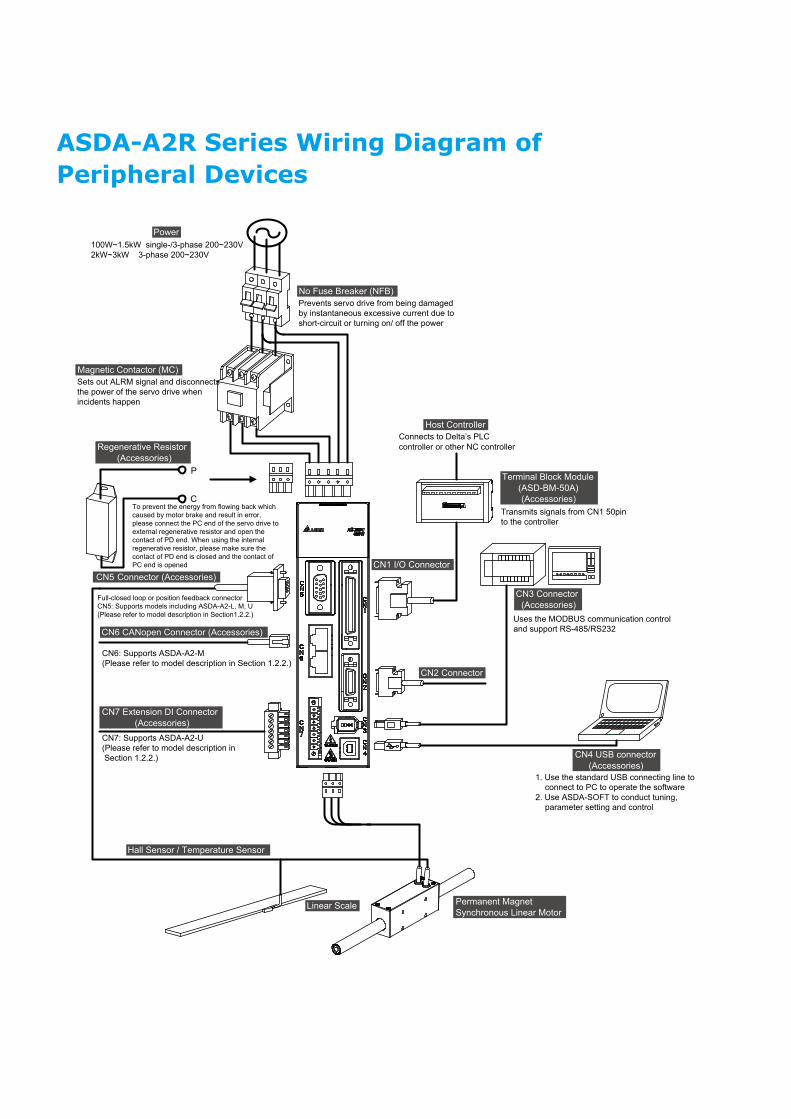
84
Power100W~1.5kW single-/3-phase 200~230V2kW~3kW 3-phase 200~230V
Full-closed loop or position feedback connectorCN5: Supports models including ASDA-A2-L, M, U(Please refer to model description in Section1.2.2.)
CN7: Supports ASDA-A2-U(Please refer to model description in Section 1.2.2.)
CN6: Supports ASDA-A2-M(Please refer to model description in Section 1.2.2.)
CN7 Extension DI Connector (Accessories)
CN5 Connector (Accessories)
CN6 CANopen Connector (Accessories)
CN2 Connector
CN1 I/O Connector
Host Controller
Permanent Magnet Synchronous Linear Motor
CN4 USB connector (Accessories)
CN3 Connector(Accessories)
Terminal Block Module (ASD-BM-50A)(Accessories)
Uses the MODBUS communication control and support RS-485/RS232
1. Use the standard USB connecting line to connect to PC to operate the software
2. Use ASDA-SOFT to conduct tuning, parameter setting and control
Transmits signals from CN1 50pin to the controller
Connects to Delta’s PLCcontroller or other NC controllerRegenerative Resistor
(Accessories)
Magnetic Contactor (MC)Sets out ALRM signal and disconnects the power of the servo drive when incidents happen
To prevent the energy from flowing back which caused by motor brake and result in error,please connect the PC end of the servo drive toexternal regenerative resistor and open the contact of PD end. When using the internalregenerative resistor, please make sure thecontact of PD end is closed and the contact of PC end is opened
No Fuse Breaker (NFB)Prevents servo drive from being damaged by instantaneous excessive current due to short-circuit or turning on/ off the power
P
C
Linear Scale
Hall Sensor / Temperature Sensor
ASDA-A2R Series Wiring Diagram of Peripheral Devices

85
Global Operations
Taoyuan Plant 1
(Diamond-rated Green Building)Tainan Plant
6 Factories 117 Branch Offices 13 R&D Centers 915 Distributors
Shanghai Office Amsterdam, the Netherlands Research Triangle Park, U.S.A.
12
34
7 89
1011 12
1314
151617
18
23
1920
21
22
56
1
7 10
11
12
13
14
15
16
17
18
19
20
21
22
8
9
2
3
4
5
6
ChinaHeilongjiangHarbin
HebeiShijiazhuangQinhuangdaoTangshan
ShanghaiJiadingSongjiang
AnhuiHefei
ZhejiangHangzhouNinggboWenzhouJiaxingShaoxing
FujianXiamenFuzhouQuanzhou
JiangxiNanchang
GuangdongShenzhenGuangzhouFoshanGuangxiNanningGuilinLiuzhou
YunnanKunming
SichuanChengdu
ShaanxiXian
HenanZhengzhouLuoyangChangyuan
HubeiWuhanXiangfan
HunanChangshaHengyang
ShandongQingdaoJinanYantaiJiangsuYangzhouNanjingNantongChangzhouWuxiSuzhouKunshanXuzhou
JilinChangchun
LiaoningShenyangDalian
ShanxiTaiyuan
Beijing
Tianjin
NetherlandsAmsterdamEindhoven
GermanySust
FranceParis
SpainBarcelonaMadrid
CanadaEdmonton
KitchenerUSA
RaleighItalyMilanRome
Fremont
Puebla
Chicago Boston
Queretaro
Brasil
Colombia
Argentina
Sao Paulo
Paraná
TurkeyIstanbul
UAEDubaiOman
MalaysiaVietnam
Philippines
Thailand
IndonesiaSingapore
Wujiang (Wujiang Plant 3 & Wujiang Motor Plant )
Shanghai
Taoyuan (Technology Center & Plant 1)
Zhong liTaichungTainan
JapanTokyoOsaka
KoreaSeoulDaegu
IndiaChandigarhGurgaonKolkataAhmedabadMumbaiPuneHyderabadBangaloreChennaiCoimbatoreVisakhapatnamChhattisgarh
EgyptCairo
RussiaMoscowTashkent
AustraliaMelbourne
Mexico City
Santa Catarina
Dalian
Dongguan Nuevo LeonJalisco
Bela Vista
Zurich
Sonoma
23 Inner MongoliaBaotou
24 GuizhouGuiyang
25 GansuLanzhou
26 XinjiangUrumqi
27 AnhuiWuhu
25
24
26
27
Belarus
RomaniaMoldavia
FinlandEstoniaLatviaLithuaniaSwedenDenmarkIceland
Northern Europe
NetherlandsGermanyCzechAustriaSlovenia CroatiaPolandHungary Switzerland
Central Europe
Bulgaria
GreeceCyprusAlbania
LebanonJordan
IraqQatar
IsraelLibya
Tunisia
Malta
Spain
FranceItaly
Nigeria
Kenya
Tanzania
Senegal
Morocco
South Africa
Saudi Arabia
Armenia
Uzbekistan
Sri Lanka
Mexico
Bolivia
Peru
Ecuador
Chile
Uruguay
H
I
J
K
L
M
N
O
AE
F
H IJK
LM
NO
BCD
A
B
C
D
E
F
G
Japan
Korea
PanamaCosta Rica
El SalvadorNicaragua
Guatemala
R. DominicanaBrit.Virgin Is.
Paraguay
Ireland
UnitedKingdom
Los Angeles
Plano San Diego
Taiwan
SerbiaGeorgia
Belgium
Benin
Congo
Ethiopia
Kazakhstan
Kosovo
P
P
Tadzhikistan
Togo
Zambia
Malaga

86
Taoyuan Plant 1
(Diamond-rated Green Building)Tainan Plant
6 Factories 117 Branch Offices 13 R&D Centers 915 Distributors
Shanghai Office Amsterdam, the Netherlands Research Triangle Park, U.S.A.
12
34
7 89
1011 12
1314
151617
18
23
1920
21
22
56
1
7 10
11
12
13
14
15
16
17
18
19
20
21
22
8
9
2
3
4
5
6
ChinaHeilongjiangHarbin
HebeiShijiazhuangQinhuangdaoTangshan
ShanghaiJiadingSongjiang
AnhuiHefei
ZhejiangHangzhouNinggboWenzhouJiaxingShaoxing
FujianXiamenFuzhouQuanzhou
JiangxiNanchang
GuangdongShenzhenGuangzhouFoshanGuangxiNanningGuilinLiuzhou
YunnanKunming
SichuanChengdu
ShaanxiXian
HenanZhengzhouLuoyangChangyuan
HubeiWuhanXiangfan
HunanChangshaHengyang
ShandongQingdaoJinanYantaiJiangsuYangzhouNanjingNantongChangzhouWuxiSuzhouKunshanXuzhou
JilinChangchun
LiaoningShenyangDalian
ShanxiTaiyuan
Beijing
Tianjin
NetherlandsAmsterdamEindhoven
GermanySust
FranceParis
SpainBarcelonaMadrid
CanadaEdmonton
KitchenerUSA
RaleighItalyMilanRome
Fremont
Puebla
Chicago Boston
Queretaro
Brasil
Colombia
Argentina
Sao Paulo
Paraná
TurkeyIstanbul
UAEDubaiOman
MalaysiaVietnam
Philippines
Thailand
IndonesiaSingapore
Wujiang (Wujiang Plant 3 & Wujiang Motor Plant )
Shanghai
Taoyuan (Technology Center & Plant 1)
Zhong liTaichungTainan
JapanTokyoOsaka
KoreaSeoulDaegu
IndiaChandigarhGurgaonKolkataAhmedabadMumbaiPuneHyderabadBangaloreChennaiCoimbatoreVisakhapatnamChhattisgarh
EgyptCairo
RussiaMoscowTashkent
AustraliaMelbourne
Mexico City
Santa Catarina
Dalian
Dongguan Nuevo LeonJalisco
Bela Vista
Zurich
Sonoma
23 Inner MongoliaBaotou
24 GuizhouGuiyang
25 GansuLanzhou
26 XinjiangUrumqi
27 AnhuiWuhu
25
24
26
27
Belarus
RomaniaMoldavia
FinlandEstoniaLatviaLithuaniaSwedenDenmarkIceland
Northern Europe
NetherlandsGermanyCzechAustriaSlovenia CroatiaPolandHungary Switzerland
Central Europe
Bulgaria
GreeceCyprusAlbania
LebanonJordan
IraqQatar
IsraelLibya
Tunisia
Malta
Spain
FranceItaly
Nigeria
Kenya
Tanzania
Senegal
Morocco
South Africa
Saudi Arabia
Armenia
Uzbekistan
Sri Lanka
Mexico
Bolivia
Peru
Ecuador
Chile
Uruguay
H
I
J
K
L
M
N
O
AE
F
H IJK
LM
NO
BCD
A
B
C
D
E
F
G
Japan
Korea
PanamaCosta Rica
El SalvadorNicaragua
Guatemala
R. DominicanaBrit.Virgin Is.
Paraguay
Ireland
UnitedKingdom
Los Angeles
Plano San Diego
Taiwan
SerbiaGeorgia
Belgium
Benin
Congo
Ethiopia
Kazakhstan
Kosovo
P
P
Tadzhikistan
Togo
Zambia
Malaga

DELTA_IA-ASM_LU-ECML_C_EN_20200818
Industrial Automation HeadquartersDelta Electronics, Inc. Taoyuan Technology CenterNo.18, Xinglong Rd., Taoyuan District, Taoyuan City 33068, TaiwanTEL: 886-3-362-6301 / FAX: 886-3-371-6301
AsiaDelta Electronics (Shanghai) Co., Ltd.No.182 Minyu Rd., Pudong Shanghai, P.R.C.Post code : 201209 TEL: 86-21-6872-3988 / FAX: 86-21-6872-3996Customer Service: 400-820-9595
Delta Electronics (Japan), Inc.Tokyo Office Industrial Automation Sales Department 2-1-14 Shibadaimon, Minato-kuTokyo, Japan 105-0012TEL: 81-3-5733-1155 / FAX: 81-3-5733-1255
Delta Electronics (Korea), Inc.Seoul Office1511, 219, Gasan Digital 1-Ro., Geumcheon-gu, Seoul, 08501 South KoreaTEL: 82-2-515-5305 / FAX: 82-2-515-5302
Delta Energy Systems (Singapore) Pte Ltd.4 Kaki Bukit Avenue 1, #05-04, Singapore 417939TEL: 65-6747-5155 / FAX: 65-6744-9228
Delta Electronics (India) Pvt. Ltd.Plot No.43, Sector 35, HSIIDC Gurgaon, PIN 122001, Haryana, IndiaTEL: 91-124-4874900 / FAX : 91-124-4874945
Delta Electronics (Thailand) PCL. 909 Soi 9, Moo 4, Bangpoo Industrial Estate (E.P.Z), Pattana 1 Rd., T.Phraksa, A.Muang, Samutprakarn 10280, ThailandTEL: 66-2709-2800 / FAX : 662-709-2827
Delta Electronics (Australia) Pty Ltd.Unit 20-21/45 Normanby Rd., Notting Hill Vic 3168, AustraliaTEL: 61-3-9543-3720
AmericasDelta Electronics (Americas) Ltd.Raleigh OfficeP.O. Box 12173, 5101 Davis Drive, Research Triangle Park, NC 27709, U.S.A.TEL: 1-919-767-3813 / FAX: 1-919-767-3969
Delta Electronics Brazil São Paulo Sales Office Rua Itapeva, 26 - 3°, andar Edificio Itapeva, One - Bela Vista 01332-000 - São Paulo - SP - Brazil TEL: 55-12-3932-2300 / FAX: 55-12-3932-237
Delta Electronics International Mexico S.A. de C.V.Mexico OfficeGustavo Baz No. 309 Edificio E PB 103Colonia La Loma, CP 54060Tlalnepantla, Estado de MéxicoTEL: 52-55-3603-9200
*We reserve the right to change the information in this catalogue without prior notice.
EMEAHeadquarters: Delta Electronics (Netherlands) B.V. Sales: [email protected] Marketing: [email protected] Technical Support: [email protected] Customer Support: [email protected] Service: [email protected]: +31(0)40 800 3900
BENELUX: Delta Electronics (Netherlands) B.V.De Witbogt 20, 5652 AG Eindhoven, The Netherlands Mail: [email protected]: +31(0)40 800 3900
DACH: Delta Electronics (Netherlands) B.V.Coesterweg 45, D-59494 Soest, GermanyMail: [email protected]: +49(0)2921 987 0
France: Delta Electronics (France) S.A.ZI du bois Challand 2, 15 rue des Pyrénées, Lisses, 91090 Evry Cedex, France Mail: [email protected]: +33(0)1 69 77 82 60
Iberia: Delta Electronics Solutions (Spain) S.L.UCtra. De Villaverde a Vallecas, 265 1º Dcha Ed. Hormigueras – P.I. de Vallecas 28031 Madrid TEL: +34(0)91 223 74 20
Carrer Llacuna 166, 08018 Barcelona, SpainMail: [email protected]
Italy: Delta Electronics (Italy) S.r.l.Via Meda 2–22060 Novedrate(CO) Piazza Grazioli 18 00186 Roma ItalyMail: [email protected]: +39 039 8900365
Russia: Delta Energy System LLC Vereyskaya Plaza II, office 112 Vereyskaya str. 17 121357 Moscow Russia Mail: [email protected]: +7 495 644 3240
Turkey: Delta Greentech Elektronik San. Ltd. Sti. (Turkey) Şerifali Mah. Hendem Cad. Kule Sok. No:16-A 34775 Ümraniye – İstanbulMail: [email protected]: + 90 216 499 9910
GCC: Delta Energy Systems AG (Dubai BR)P.O. Box 185668, Gate 7, 3rd Floor, Hamarain Centre Dubai, United Arab Emirates Mail: [email protected]: +971(0)4 2690148
Egypt + North Africa: Delta ElectronicsUnit 318, 3rd Floor, Trivium Business Complex, North 90 street, New Cairo, Cairo, Egypt Mail: [email protected]