The effect of electrolyte strength and grain size on the transient current response in Fe-Cr-Ni...
8
ELSEVIER Wear 178 (1994) 101-108 WEAR The effect of electrolyte strength and grain size on the transient current response in Fe-Cr-Ni alloys during a scratch test S.K. Varma, Monica M. de Lugo, Veronica Caballero Department of Metallurgical and Materials Engineering, The University of Texas at El Paso, El Paso, TX 79968-0520, USA Received 1 March 1994; accepted 30 June 1994 Abstract Two alloys, Fe-16%Cr-16%Ni (16/16) and Fe-25%Cr-25%Ni (25/25), from the Fe-Cr-Ni system have been used to study the effect of electrolyte strength on the depassivation and repassivation kinetics and the development of near surface microstructures using a scratch technique. The concentration of sulfuric acid in the solution 0.01 M H2SO4-0.01 M KC1 was varied and the transient current response for different electrolytes shows that it increases systematically with increasing load in 16/16 alloy while the values at lower concentrations of sulfuric acid remain almost unaffected in the case of 25/25 alloy. The electrolyte strength effect is manifested in the form of strain rate during the process of scratching in an electrolyte (corrosive wear). The decrease in deformation band widths, after scratching, as a function of increase in concentration of the sulfuric acid in the electrolyte has been observed in 16/16 alloy. In contrast, the 25/25 alloy, with a higher stacking fault energy, shows long planar array of parallel dislocations at higher concentrations. The scatter in the data for the transient current response usually associated with this technique has been also studied. Keywords: Electrolyte strength; Grain size; Scratch test; Iron alloys; Transient current 1. Introduction The scratch technique has been used to study the effect of load, grain size and type of indenter on the transient current response of some of the Fe-Cr-Ni alloys in the past [1-7]. The corrosive wear deformation process involved in the scratch technique has not re- ceived much attention with the result that the influence of microstructure on the corrosion behavior is not very clear at this time. The purpose of this paper is to present the results of some of the experimental work done to study the influence of the corrosive wear process on the near surface microstructures in two Fe-Cr-Ni alloys. In particular the effect of electrolyte strength and grain size has been investigated. A stylus containing a diamond tip is dropped on to a rotating cylindrical electrode immersed in an elec- trolyte and the transient current is recorded in the scratch technique [1-15]. The effect of load on the transient current values has been found to be directly related to each other by these authors. It appears that the sensitivity to load values for the transient current values decreases when it is in excess of 15 N. However, it still increases at higher load but with a smaller slope when the transient current is plotted against load [3]. The scratch technique has been also used to determine the effect of two microconstituents on the depassivation and repassivation kinetics in Fe-Ni-Cr alloys [16]. It was observed that the transient current response for the austenitic alloys was quite different from that of the alloy containing austenite and martensite. It was shown that within a single phase (austenite) alloy classification, two alloys of different compositions were used, the alloy containing higher volume fraction of deformation twins produced higher transient current. On the other hand two alloys of different compositions which belong to two phase microstructures (austenite and martensite) produced transient current response in such a way that the alloy containing higher volume fraction of martensite crystallites has higher transient current values. Obviously the study was performed with the help of transmission electron microscopy near the scratches. It must be noted that there is a controversy over the scratch technique in the literature. It appears that the biggest concern lies in the positioning of the probe and the ratio of the total passive film area to the scratch area as suggested by Wei and his coworkers [17,18]. Their claim is that the peak current values are functions of both of these experimental parameters. However, in a companion paper, Burstein and Gao 0043-1648/94/$07.00 © 1994 Elsevier Science S.A. All rights reserved SSDI 0043-1648 (94)06490- 3
-
Upload
independent -
Category
Documents
-
view
0 -
download
0
Transcript of The effect of electrolyte strength and grain size on the transient current response in Fe-Cr-Ni...
ELSEVIER Wear 178 (1994) 101-108
WEAR
The effect of electrolyte strength and grain size on the transient current response in Fe-Cr-Ni alloys during a scratch test
S.K. Varma, Monica M. de Lugo, Veronica Caballero Department of Metallurgical and Materials Engineering, The University of Texas at El Paso, El Paso, TX 79968-0520, USA
Received 1 March 1994; accepted 30 June 1994
Abstract
Two alloys, F e - 1 6 % C r - 1 6 % N i (16/16) and F e - 2 5 % C r - 2 5 % N i (25/25), f rom the F e - C r - N i system have been used to study the effect of electrolyte strength on the depassivation and repassivation kinetics and the development of near surface microstructures using a scratch technique. The concentrat ion of sulfuric acid in the solution 0.01 M H2SO4-0.01 M KC1 was varied and the transient current response for different electrolytes shows that it increases systematically with increasing load in 16/16 alloy while the values at lower concentrations of sulfuric acid remain almost unaffected in the case of 25/25 alloy. The electrolyte strength effect is manifested in the form of strain rate during the process of scratching in an electrolyte (corrosive wear). The decrease in deformation band widths, after scratching, as a function of increase in concentrat ion of the sulfuric acid in the electrolyte has been observed in 16/16 alloy. In contrast, the 25/25 alloy, with a higher stacking fault energy, shows long planar array of parallel dislocations at higher concentrations. The scatter in the data for the transient current response usually associated with this technique has been also studied.
Keywords: Electrolyte strength; Grain size; Scratch test; Iron alloys; Transient current
1. Introduction
The scratch technique has been used to study the effect of load, grain size and type of indenter on the transient current response of some of the Fe-Cr-Ni alloys in the past [1-7]. The corrosive wear deformation process involved in the scratch technique has not re- ceived much attention with the result that the influence of microstructure on the corrosion behavior is not very clear at this time. The purpose of this paper is to present the results of some of the experimental work done to study the influence of the corrosive wear process on the near surface microstructures in two Fe-Cr-Ni alloys. In particular the effect of electrolyte strength and grain size has been investigated.
A stylus containing a diamond tip is dropped on to a rotating cylindrical electrode immersed in an elec- trolyte and the transient current is recorded in the scratch technique [1-15]. The effect of load on the transient current values has been found to be directly related to each other by these authors. It appears that the sensitivity to load values for the transient current values decreases when it is in excess of 15 N. However, it still increases at higher load but with a smaller slope when the transient current is plotted against load [3].
The scratch technique has been also used to determine the effect of two microconstituents on the depassivation and repassivation kinetics in Fe-Ni-Cr alloys [16]. It was observed that the transient current response for the austenitic alloys was quite different from that of the alloy containing austenite and martensite. It was shown that within a single phase (austenite) alloy classification, two alloys of different compositions were used, the alloy containing higher volume fraction of deformation twins produced higher transient current. On the other hand two alloys of different compositions which belong to two phase microstructures (austenite and martensite) produced transient current response in such a way that the alloy containing higher volume fraction of martensite crystallites has higher transient current values. Obviously the study was performed with the help of transmission electron microscopy near the scratches.
It must be noted that there is a controversy over the scratch technique in the literature. It appears that the biggest concern lies in the positioning of the probe and the ratio of the total passive film area to the scratch area as suggested by Wei and his coworkers [17,18]. Their claim is that the peak current values are functions of both of these experimental parameters. However, in a companion paper, Burstein and Gao
0043-1648/94/$07.00 © 1994 Elsevier Science S.A. All rights reserved SSDI 0043-1648 (94)06490- 3
102 S.BL karma et al. I Wear
[19] have shown that peak current values are not affected by the ratios of the areas of the total film to that of scratch up to a value of nearly 1000.
2. Experimental details
Two alloys from Fe-Cr-Ni system were fabricated by the Ames Laboratory of the Iowa State University by melting high purity metals in an induction heating unit. The compositions, in weight percents, of the alloys were as follows: Fe-25%Cr-25%Ni (25/25) and Fe-16%Cr-16%Ni (16/16). The 13.5 mm diameter rods of this alloy were annealed at 1100 °C after encapsulating them in a quartz tube filled with purified argon gas. Grain sizes of 120, 200, 280 and 330 /zm could be obtained by varying the time of annealing in 16/16 alloy while similar treatments resulted in grain sizes of 100, 150, 180 and 240 /zm in 25/25 alloy.
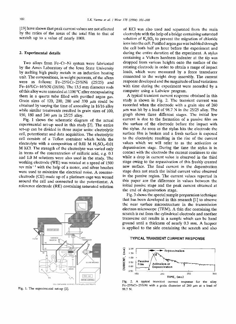
Fig. 1 shows the schematic diagram of the actual experimental set-up used in this study [2]. The entire set-up can be divided in three major units: electrolytic cell, potentiostat and data acquisition. The electrolytic cell consists of a Teflon container which holds the electrolyte with a composition of 0.01 M H2SO4-0.01 M KC1. The strength of the electrolyte was varied only in terms of the concentration of sulfuric acid, e.g. 0.1 and 1.0 M solutions were also used in the study. The working electrode (WE) was rotated at a speed of 1500 rev min-a with the help of a motor, and silver brushes were used to minimize the electrical noise. A counter- electrode (CE) made up of a platinum cage was wound around the cell and connected to the potentiostat. A reference electrode (RE) containing saturated solution
178 (1994) 101-108
of KC1 was also used and separated from the main electrolyte with the help of a bridge containing saturated solution of K2SO4 to prevent the migration of chloride ions into the cell. Purified argon gas was bubbled through the cell both half an hour before the experiment and during the entire duration of the experiment. A stylus containing a Vickers hardness indenter at the tip was dropped from various heights onto the surface of the rotating electrode in order to obtain a range of impact loads, which were measured by a force transducer connected to the weight drop assembly. The current response developed and the magnitude of load variations with time during the experiment were recorded by a computer using a Labview program.
A typical transient current response obtained in this study is shown in Fig. 2. The transient current was recorded when the electrode with a grain size of 260 /zm was hit by a load of 98.7 N in the 25/25 alloy. The graph shows three different stages. The initial low current is due to the formation of a passive film on the surface of the electrode before the impact with the stylus. As soon as the stylus hits the electrode the surface film is broken and a fresh surface is exposed to the electrolyte resulting in the rise of the current values which we will refer to as the activation or depassivation stage. During the time the stylus is in contact with the electrode the current continues to rise while a drop in current value is observed in the third stage owing to the repassivation of this freshly created new surface. The final current in the depassivation stage does not reach the initial current value observed in the passive region. The current values reported in this paper are the difference in values between the initial passive stage and the peak current obtained at the end of depassivation stage.
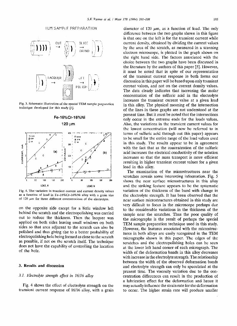
Fig. 3 shows the special sample preparation technique that has been developed in this research [1] to observe the near surface microstructure in the transmission electron microscope (TEM). A thin disc containing the scratch is cut from the cylindrical electrode and another transverse cut results in a sample which can be hand ground until a thickness of nearly 0.3 mm. A lacquer is applied to the side containing the scratch and also
TYPICALTRANSIENTCURRENT RESPONSE
Fig. 1. The experimental set-up [2].
~" 2.00 1.50
I--" 1.00 Z 050
rv 0.00 (,J
-0.50
I ~i ~ Repassivation
L P a s s i v ~ ~ ~_~.~ ADC~l~atsi?¢a ~i ~ n "~"I ~ .....
150 200 250 300
TIME. (ms) Fig. 2. A typical transient current response for the alloy Fe-25%Cr-25%Ni with a grain diameter of 260 /~m at a load of 98.7 N.
S.K. Varma et al. / Wear 178 (1994) 101-108 103
TEM SAMPLE PREPARATION
i,j ] i
\ / "i
i L A C Q U E R ~ J E T 'l "
..i> .i.> ' ~ POLISH /'
Fig. 3. Schematic illustration of the special T E N sample preparation technique developed for this study [1].
Fe-16%Cr-16%Ni
120 lam
DIo, . . . . . . . o y o , , A OlM 0 /
/ (a) ~E
400
300
200
100
D O.OI M / / &O,1M
01a O ~ -
0
' ' s ; ' ' ' , ; o ' ' ' , go ' ' ' ,oo
LOAD, N LOAD, N Fig. 4. The variation in transient current and current density values as a function of load in Fe-16%Cr-16%Ni alloy with a grain size of 120 p.m for three different concentrations of the electrolyte.
on the opposite side except for a little window left behind the scratch and the electropolishing was carried out to reduce the thickness. Then the lacquer was applied on both sides leaving small windows on both sides so that area adjacent to the scratch can also be polished and thus giving rise to a better probability of electropolishing hole being formed as close to the scratch as possible, if not on the scratch itself. The technique does not have the capability of controlling the location of the hole.
3. Results and discussion
3.1. Electrolyte strength effect in 16/16 alloy
Fig. 4 shows the effect of electrolyte strength on the transient current response of 16/16 alloy, with a grain
diameter of 120 /xm, as a function of load. The only difference between the two graphs shown in this figure is that one on the left is for the transient current while current density, obtained by dividing the current values by the area of the scratch, as measured in a scanning electron microscope, is plotted in the graph shown on the right hand side. The factors associated with the choice between the two graphs have been discussed in the literature by the authors of this paper [5]. However, it must be noted that in spite of our representation of the transient current response in both forms our discussion in this paper will be based upon only transient current values, and not on the current density values. The data clearly indicates that increasing the molar concentration of the sulfuric acid in the electrolyte increases the transient current value at a given load in this alloy. The physical meaning of the intersection of the lines in these graphs are not understood at the present time. But it must be noted that the intersections only occur in the extreme ends for the loads values. Also, the variations in the transient current values for the lowest concentration (will now be referred to in terms of sulfuric acid through out this paper) appears to be small for the entire range of the load values used in this study. The results appear to be in agreement with the fact that as the concentration of the sulfuric acid increases the electrical conductivity of the solution increases so that the mass transport is more efficient resulting in higher transient current values for a given load in this alloy.
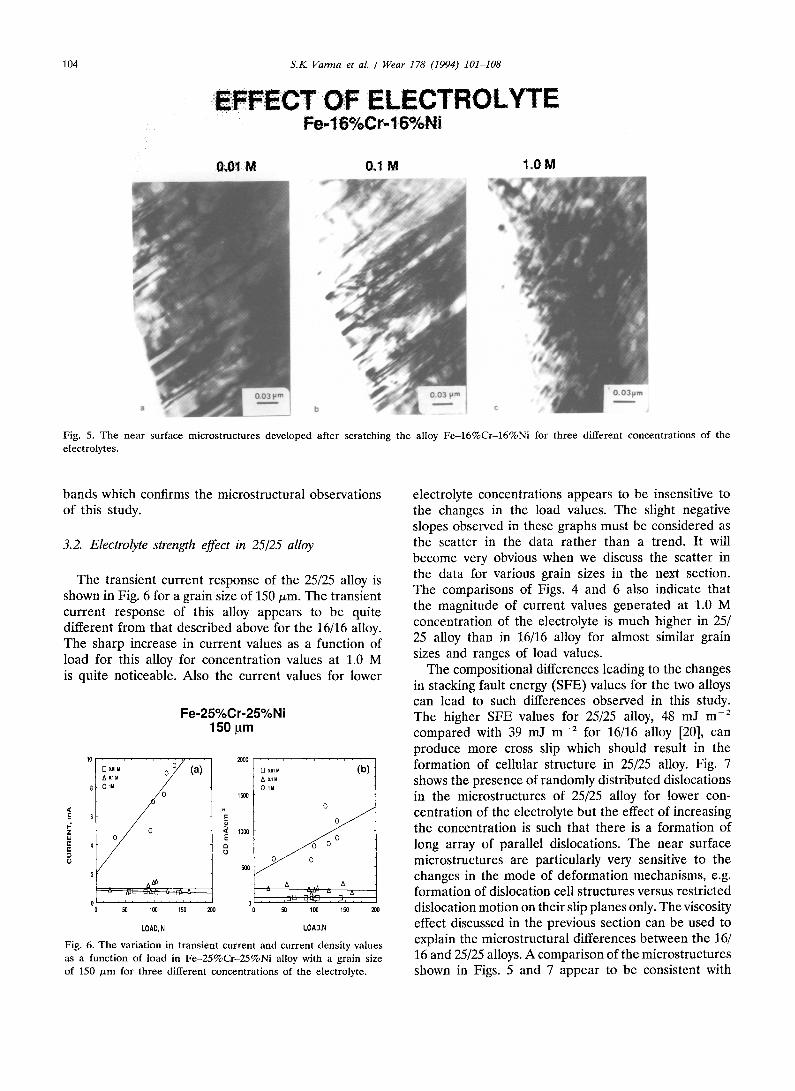
The examination of the microstructures near the scratches reveals some interesting information. Fig. 5 shows the near surface microstructures in this alloy and the striking feature appears to be the systematic variation of the thickness of the band with change in the electrolyte strength. It has been observed that the near surface microstructures obtained in this study are very difficult to focus in the microscope perhaps due to the considerable variations in the thickness of the sample near the scratches. Thus the poor quality of the micrographs is the result of perhaps the special TEM sample preparation technique used in this study. However, the features associated with the microstruc- tures in both alloys are easily recognized in the TEM micrographs shown in this paper. The edges of the scratches and the electropolishing holes can be seen at the lower left hand corner of each micrograph. The width of the deformation bands in this alloy decreases with increase in the electrolyte strength. The relationship between the width of the observed deformation bands and electrolyte strength can only be speculated at the present time. The viscosity variation due to the con- centration differences can result in the production of a lubrication effect for the deformation and hence it may actually influence the strain rate for the deformation to occur. The higher strain rate will produce smaller
104 S.K. Varma et al. / Wear 178 (1994) 101-108
EFFECT OF :E LECT R O LYT E Fe-16%Cr-16%Ni
x
:;0~01 M 0.1 M 1.0 M
a
Fig. 5. The near surface microstructures developed after scratching the alloy Fe-16%Cr-16%Ni for three different concentrations of the electrolytes.
bands which confirms the microstructural observations of this study.
3.2. Electrolyte strength effect in 25/25 alloy
The transient current response of the 25/25 alloy is shown in Fig. 6 for a grain size of 150 tzm. The transient current response of this alloy appears to be quite different from that described above for the 16/16 alloy. The sharp increase in current values as a function of load for this alloy for concentration values at 1.0 M is quite noticeable. Also the current values for lower
Fe-25%Cr-25%Ni 150 lum
D:.oM . . . . . . o o / ( a ) , /
/ AN
-4~ N u ~
, , , i , , , i , , , i , , ,
50 100 150 200
LOAD, N
2OOO
1500
~ 10~
D ..... (b) OIM
OIM
°
A A ,,, , . , A
100 150 200
LOAD,N
Fig. 6. The variation in transient current and current density values as a function of load in Fe-25%Cr-25%Ni alloy with a grain size of 150 Izm for three different concentrations of the electrolyte.
electrolyte concentrations appears to be insensitive to the changes in the load values. The slight negative slopes observed in these graphs must be considered as the scatter in the data rather than a trend. It will become very obvious when we discuss the scatter in the data for various grain sizes in the next section. The comparisons of Figs. 4 and 6 also indicate that the magnitude of current values generated at 1.0 M concentration of the electrolyte is much higher in 25/ 25 alloy than in 16/16 alloy for almost similar grain sizes and ranges of load values.
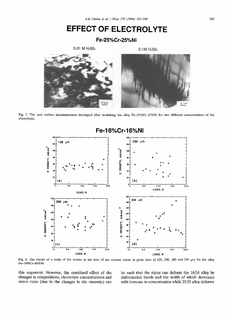
The compositional differences leading to the changes in stacking fault energy (SFE) values for the two alloys can lead to such differences observed in this study. The higher SFE values for 25/25 alloy, 48 mJ m -2 compared with 39 mJ m -2 for 16/16 alloy [20], can produce more cross slip which should result in the formation of cellular structure in 25/25 alloy. Fig. 7 shows the presence of randomly distributed dislocations in the microstructures of 25/25 alloy for lower con- centration of the electrolyte but the effect of increasing the concentration is such that there is a formation of long array of parallel dislocations. The near surface microstructures are particularly very sensitive to the changes in the mode of deformation mechanisms, e.g. formation of dislocation cell structures versus restricted dislocation motion on their slip planes only. The viscosity effect discussed in the previous section can be used to explain the microstructural differences between the 16/ 16 and 25/25 alloys. A comparison of the microstructures shown in Figs. 5 and 7 appear to be consistent with
S.K. Varma et al. / Wear 178 (1994) 101-108
EFFECT OF ELECTROLYTE Fe-25%Cr-25%Ni
0,01 M H2S0~ 0.1M H~S0,
105
Fig. 7. The near surface microstructures developed after scratching the alloy Fe -25%Cr-25%Ni for two different concentrations of the electrolytes.
,<
E
>- I -
,,=, CI
O
~E < E >- I-
Z w CI
O
140
120 I~m 120
100
80
60 l i B e [] II
l i [ ] II B
40 B
20
(a) o , , 610
140
280 Am 120 []
IO0 [ ]
m []
80
6 0 [ ]
2O
(c) 0 I SI0
[]
[ ] a m m []
n n • g [ ]
m []
I
100
LOAD, N
I I 150 200
•
[ ] [ ]
B • B•
•U = , []" B [ ]
Fe-16%Cr-16%Ni
120
~ E 100
<
E 8o
I -
Z ul
4o
2o
o
2 0 0 ~ m
m m
m m [] m
m
m m B m
m [] [ ]
m
(b) , 5 1 0 , I , ~ ,
1 0 0 1 5 0
L O A D , N
180
330 ~m [] 160
[ ]
140
E 120 a B
< E ~ B" 100
--_. 8o a oO • m Z • B W SO []e II []e [] [] e~ [] [][]
~ 4O []
2O (d)
, i , i i 0 i 5 1 0 , i i i i 1 oo 150 200 1 oo 1 50 2 0 0
LOAD, N LOAD, N
Fig. 8. The results of a study of the scatter in the data of the current values at grain sizes of 120, 200, 280 and 330 txm for the alloy Fe-16%Cr-16%Ni .
this argument. However, the combined effect of the changes in compositions, electrolyte concentrations and strain rates (due to the changes in the viscosity) can
be such that the stylus can deform the 16/16 alloy by deformation bands and the width of which decreases with increase in concentration while 25/25 alloy deforms
106 S.K Varma et al. / Wear 178 (1994) 101-108
by long array of parallel dislocation at high concen- trations. It appears that the 25/25 alloy may be, perhaps, more strain rate sensitive and thus has less time de- pendent deformational features than would be expected based on the SFE consideration alone.
3.3. Study of the scatter in the data for the transient currents
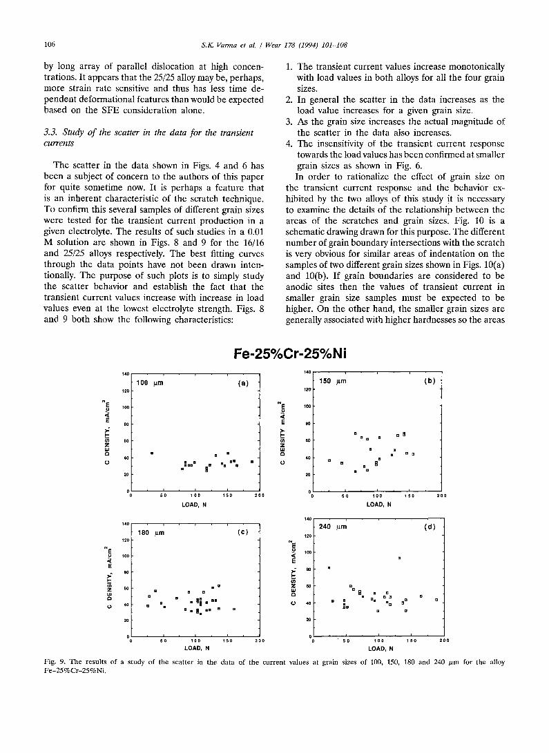
The scatter in the data shown in Figs. 4 and 6 has been a subject of concern to the authors of this paper for quite sometime now. It is perhaps a feature that is an inherent characteristic of the scratch technique. To confirm this several samples of different grain sizes were tested for the transient current production in a given electrolyte. The results of such studies in a 0.01 M solution are shown in Figs. 8 and 9 for the 16/16 and 25/25 alloys respectively. The best fitting curves through the data points have not been drawn inten- tionally. The purpose of such plots is to simply study the scatter behavior and establish the fact that the transient current values increase with increase in load values even at the lowest electrolyte strength. Figs. 8 and 9 both show the following characteristics:
1. The transient current values increase monotonically with load values in both alloys for all the four grain sizes.
2. In general the scatter in the data increases as the load value increases for a given grain size.
3. As the grain size increases the actual magnitude of the scatter in the data also increases.
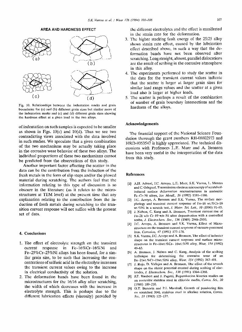
4. The insensitivity of the transient current response towards the load values has been confirmed at smaller grain sizes as shown in Fig. 6. In order to rationalize the effect of grain size on
the transient current response and the behavior ex- hibited by the two alloys of this study it is necessary to examine the details of the relationship between the areas of the scratches and grain sizes. Fig. 10 is a schematic drawing drawn for this purpose. The different number of grain boundary intersections with the scratch is very obvious for similar areas of indentation on the samples of two different grain sizes shown in Figs. 10(a) and 10(b). If grain boundaries are considered to be anodic sites then the values of transient current in smaller grain size samples must be expected to be higher. On the other hand, the smaller grain sizes are generally associated with higher hardnesses so the areas
Fe-25%Cr-25%Ni
~E < E
l -
Z W 0
140
120
100
80
60
40
20
0
120
lOO
E >: 8o
u) ~. 60 LU
40
100 p.m (a )
[]
[]~=" l" []El "El"
510 I I 1 0 0 1 5 0
LOAD, N
180 p.m (c )
B El [] • El
• []
B BI I [] O l [] n[ ] [] [] =111 I I I El
140
150 gm (b) 120
~ E 100
<
E eo
~ 60 [] ~ n Z uJ El [] a n n []
40 , = 0 [] RI
[] ElB
2O
0 510 I I 2 0 0 1 0 0 1 5 0 2 0 0
LOAD, N
140
240 p.m ( d ) 120
~E o loo ,<
E >: 8o I -
W a Jl m n N
~ []B mB []
[] B
510 I I 00 510 ; I 1 0 0 1 5 0 2 0 0 "~00 1 5 0 2 0 0
LOAD, N LOAD, N
Fig. 9. The results of a study of the scatter in the data of the current values at grain sizes of 100, 150, 180 and 240 /xm for the alloy Fe-25%Cr-25%Ni.
S.I~ Varma et al. Wear 178 (1994) 101-108 t07
AREA AND HARDNESS EFFECT
(c) (d)
Fig. 10. Relat ionships between the indentat ion marks and gram boundar ies for (a) and (b) different grain sizes but similar areas of the indentat ion marks and (e) and (d) different grain sizes showing the hardness effect at a given load in the two alloys.
of indentation on such samples is expected to be smaller as shown in Figs. 10(c) and 10(d). Thus we see two contradicting views associated with the data involved in such studies. We speculate that a given combination of the two mechanisms may be actually taking place in the corrosive wear behavior of these two alloys. The individual proportions of these two mechanisms cannot be predicted from the observations of this study.
Another important factor affecting the scatter in the data can be the contribution from the induction of the fresh metals in the form of slip steps and/or the plowed material during scratching. The authors feel that the information relating to this type of discussion is so obscure in the literature (as it relates to the micro- structures at TEM level) at the present time that any explanation relating to the contribution from the in- duction of fresh metals during scratching to the tran- sition current response will not suffice with the present set of data.
4. Conclusions
1. The effect of electrolyte strength on the transient current response in Fe-16%Cr-16%Ni and Fe-25%Cr-25%Ni alloys has been found, for a sim- ilar grain size, to be such that increasing the con- centrations of sulfuric acid in the electrolyte increases the transient current values owing to the increase in electrical conductivity of the solution.
2. The deformation bands have been found in the microstructures for the 16/16 alloy after scratching, the width of which decreases with the increase in electrolyte strength. This is perhaps due to the different lubrication effects (viscosity) provided by
the different electrolytes and the effect is manifested in the strain rate for the deformation.
3. The higher stacking fault energy of the 25/25 alloy shows strain rate effect, caused by the lubrication effect described above, in such a way that the de- formation bands have not been observed after scratching. Long straight, almost, parallel dislocations are the result of scribing in the corrosive atmosphere in this alloy.
4. The experiments performed to study the scatter in the data for the transient current values indicate that the scatter is larger at larger grain sizes for similar load range values and the scatter at a given load also is larger at higher loads.
5. The scatter is perhaps a result of the combination of number of grain boundary intersections and the hardness of the alloys.
Acknowledgements
The financial support of the National Science Foun- dation thorough the grant numbers RII-08802973 and HRD-9353547 is highly appreciated. The technical dis- cussions with Professors L.E. Murr and A. Bronson have been very useful in the interpretation of the data from this study.
References
[1] A.H. Advani, J.C. Arroyo, L.E. Murr, S.K. Varma, L. Montes and C. Odegard, Transmission electron microscopy of scratched- induced surface deformation microstructures in austenitie Fe -Cr -N i alloys, Scr. Metall., 26 (1992) 1181-1186.
[2] J.C. Arroyo, A. Bronson and S.K. Varma, The surface mor- phology and transient current response of Fe-16 wt .%Cr-16 wt.%Ni in a scratch test, J. Mater. Sei. Lett., 10 (1990) 91-95.
[3] J. Nelson, C. Kang and A. Bronson, Transient current rise of Fe-21 w/o Cr-19 w/o Ni after depassivation with a controlled scribe, Z Electrochem. Soc., 136 (1989) 2948-2950.
[4] J.C. Arroyo, A. Bronson and S.K. Varma, Effect of Micro- structure on the transient current response of vacuum-processed iron, Corrosion, 47 (1991) 177-178.
[5] S.K. Varma, J.C. Arroyo and A. Bronson, The effect of indenter shape on the transient current response and surface micro- structures in Fe-16wt .%Cr- 16wt.%Ni alloy, Wear, 154 (1992) 49-63.
[6] A. Bronson, J. Nelson and C. Kang, Analysis of the scribing technique for determining the corrosive wear of an Fe-21wt.%Cr-19wt.%Ni alloy, Wear, 154 (1992) 387-401.
[7] J. Rojo, D. Vallejos and A. Bronson, The effect of the scratch shape on the ohmic potential created during scribing of elec- trodes, J. Electrochem. Soc., 138 (1991) 1364-1368.
[8] J.F. Rimbert and J. Pagetti, Repassivation kinetics studies on an austenitic stainless steel in chloride media, Corros. Sci, 20 (1980) 189-210.
[9] G.T. Burstein and P.I. Marshall, Growth of passivating film on scratched 304L stainless steel in alkaline solution, Corros. Sci., 23 (1983) 125-137.
108 S.IC Varma et al. / Wear 178 (1994) 101-108
[10] G.T. Burstein, Reactivity of scratched cadmium electrodes in alkaline solution, J. Electrochem. Soc., 130 (1983) 2133- 2138.
[11] G.T. Burstein and G.W. Ashley, Early steps in anodic oxidation of iron in aqueous solution, Corrosion, 39 (1983) 241-247.
[12] G.T. Burstein and G.W. Ashley, Kinetics of repassivation of scratched scars generated on iron in aqueous solutions, Cor- rosion, 40 (1984) 110-115.
[13] G.O.H. Whillock and G.T. Burstein, The dissolution and re- passivation of new t i tanium surfaces in alkaline solution, J. Electrochem. Soc., 136 (1989) 1320-1327.
[14] G.T. Burstein and G.O.H. WhiUock, The dissolution and re- passivation of new t i tanium surfaces in alkaline methanolic solution, J. Electrochem. Soc., 136 (1989) 1313-1319.
[15] M. Barbosa, A model for the kinetics of repassivation II: scratching electrodes, Corrosion, 44 (1988) 149-153.
[16] S.K. Varma, M.M. de Lugo, A.H. Advani and A. Bronson, Influence of near surface microstructures on the t ransient current response in F e - C r - N i alloys during scratch tests, Metall. Mater. Trans A. , 75A (1994) 1325-1331.
[17] R.P. Wei, M. Gao and P.Y. Xu, Peak bare-surface current densities overest imated in straining and scratching electrode experiments, J. Electrochem. Soc., 136 (1989) 1835-1836.
[18] R.P. Wei and M. Gao, Fur ther observations on the validity of bare surface current densities determined by the scratched electrode technique, J. Electrochem. Soc., 138 (1991) 2601-2606.
[19] G.T. Burstein and G. Gao, Verification of the validity of peak bare surface current densities obtained from scratched electrode, J. Electrochem. Soc., 138 (1991) 2627-2630.
[20] C.G. Rhodes and A.W. Thompson , Tlae composition dependence of stacking fault energy in austenitic stainless steels, Metall. Trans., 8A (1977) 1901-1906.