Weld Formation Mechanism and Microstructural Evolution of ...

consequences for testing proceduress. smlfh (1), N.J. den lJiit (1), H. Nishibata (2), T. Okada (2), T. van der veldt (1),M. uchihara
(2) & K. Fukui (3)
(1)CorusRD&T;P.o.Boxlo.ooo,lg7oCAlJmuiden,TheNetherlands.(2) Sumitomo Metat lndustries; 1-8 Fuso-Cho, Amagasaki, Hyogo, 660-0891, Japan.
(3) Sumitomo Metal I ndustries; 8- 1 1 H arumi 1 -chome, chuo-ku,Tokyo, 1 04-61 1 1' J apan.
sullivan. [email protected]
ß/4Fr Ur*' ( Õ4)l. lntroductionTwo trends have been dominating design and manufacturing in the automotive industry. On
one side there is a trend to reduce the weight of vehicles driven by the desire to decrease
fuel consumption and release of green house gasses. On the other side there is a trend to
improve the structural rigidity (especially the crash performance) of vehicles driven by
regulations and consumèr demands. Advanced High Strength Steels (AHSS) offer the
automotive industry options to achieve both these goals [1 & 2]'
AHSS combine high strength with good formability. This is achieved by balanced chemical
composition and thermo-mechanical treatment during production of these steels' However
there are issues reported concerning the weldability of AHSS in production' Key to the
weldability are the mechanical strength of the welds and the adjacent heat affected zone
(HAZ) anà the failure mode under different loading conditions [3, 4 & 5].
ihe strength of AHSS is key to achieve structural rigidity' The failure mode of welds
determines the absorption of energy in the construction under dynamic loading, as
experienced in crash. A lot of reseàrch has been published on the subject of improved
weldability of AHSS [5, 6, 7, 8, I & 10]'
Much lesi publicised is the time dependency of the mechanical properties of welds in certain
classes of AHSS. Both strength and failure mode depend upon the time delay between
production of the welds and mechanical testing of these welds. The most sensitive grades
demonstrate strength variations of up to 100% that take place within 24 hours of welding'
Such a time dependant weld performance has very significant implications for the
classification of weldability of these materials.
This paper summarises the initial findings of work carried out by Corus and Sumitomo Metals
lndustry (SMl) studying the time dependant weld properties of certain AHSS' For the purpose
of this iaper, time depãndant changes in weld properties are termed "Ageing".
2. Background
2.1 Strength and failure rnodes of weldsThe increased strength levels of Advanced High Strength Steels (AHSS) are the result of
careful alloying and thermo-mechanical heat treatment during production of the steel sheets'
Both aspects ãre affected by welding. The carefully designed microstructure is destroyed
during welding. ln the fusion zone (FZ) the melting and subsequent solidification of the
material will wipe out all traces of the thermo-mechanical history of the material prior to

welding. ln the Heat Affected Zone (HAZ) the material characteristics change due to phase
transformations, recrystallisation, grain growth, tempering, precipitation, etcetera' Which
effects will take place and to what extent they will affect the material is dependent upon the
thermo-mechanical history of the material prior to welding (e.g. cold rolled vs' annealed
material) and the thermal load of the material during welding [11]'
The amount of alloying in steels influences the hardenability of the material. This is often
expressed in a Carbon Equivalence (CE) number' There are various CE numbers published
for different steels, accounting for different ranges of chemical composition of welds and
cooling rates (e.g. different welding processes) t12 & 131. Most famous of all cE numbers is
proUabty the Carbon Equivalence number commonly referred to as the llW CE number'
CE(llW=C+ Mn/6+(Cr+Mo+V)/5+(Ni+Cu)/1S (Eq'1)
This Carbon Equivalence number was published in 1967 [1a]. The llW CE number is usually
used for steels with Carbon levels exceeding 0,18 wt% C, as it was found that other carbon
equivalent numbers worked better for steels with lower carbon content. ln 1968 lto & Bessyo
published a paper in which a more complete relation was derived to predict post weld
hardness of steels containing Carbon levels of less or equalto 0,12\Ì'tt% [15]' The chemical
portion of this formula (Pcmfis commonly used as a Carbon Equivalence number for steels
with [C] < 0,18 wt%.
cE(Pcm) = C+ Si/30 + (Mn + ÇLr+cr)/20+ Ni/60+ Mo/15*y719 + 58 (Eq.2)
The hardenability is increased in two ways: the minimum cooling rate to form harder
microstructural phases (especially martensite and sometimes bainite) is decreased and the
hardness of the resultant phases after cooling is increased'
Based upon work done by Blondeau et al [16 & 17], Chaillet et al. [18] obtained equations
that link the critical coolin! rate for the formation of phases after welding to the chemical
composition of High Strength Steels:
Martensite:log V",. = 7,42- 3,13C -O,71Mn - 0,37Ni - 0'34Cr - 0,45Mo (Eq. 3)
Bainite:log V.,.. = 6,33 - 2,91C - 0,73Mn - 0,53Ni - 0,41Cr - 1'37Mo
Where V", is the critical cooling rate at 700 'C in 'C/hour'
The element content is expressed in wt%'
Also equations were derived that link the post weld hardness of the resultant phases after
welding to the chemicalcomposition of High Strength Steels:
Martensite:Hv = 97 + 949C + 27Si + 11Mn + 8Ni + 16Cr + 20logV"". (Eq. 5)
BainiteHv= -348 + 185C + 330Si + 153Mn + 66Ni + 144Cr+ 191Mo
+ logV"o,(89 + 54C - 55Si - 22Mn - 1ONi - 20Cr - 33Mo)
(Eq. 4)
Where V... is the critical cooling rate at 700 "C in 'C/hour
(Eq. 6)

The element content is expressed in wt%.
The martensitic transformation is not time independent. lnstead it is temperature dependent.
At certain temperature, M, (martensite start temperature), austenite will transform into
martensite. The driving force for nucleation of martensite at M" is given by [19]:
AGY-. = AHY-o(To-M")/To (Eq. 7)
Where To is the temperature where the free energy of the q' phase starts to exceed the free
energy of the y phase.
The temperature at which martensite starts to form is dependent upon the chemical
composition of the material. Andrews [20] drew up an empirical equation relating the
temperature at which martensite starts to form, M", to the chemical composition of the
material.
M" = 539 -423C-30,4Mn - 17,7Ni -12,1Cr- 11Si-7Mo (Eq'8)
Martensite will form directly, as it is a military transformation, without delay' Thus at fixed
temperature, fixed amounts of martensite have been formed. This will continue until another
transition temperature, M'(martensite finish temperature), is reached and martensitic
transformation stop altogether. M¡ ma! not respond to 100% martensite as some retained
austenite can be left below Mr. The retention of austenite may be due to high elastic stresses
between the last martensite plates that are formed'
The formed phase proportion, p, during madensite transformations can be described by the
Koistinen-Marburger model [21 ]:
p(0) = P[1-exp(b-(0-M.))] (Eq' 9)
For 0<M". P represents the proportion obtained at infinitely low temperatures (usually
associated with 1), and b characterises the transformation rate.
Steven el al.l22lrelated fraction of martensite formed directly to the temperature below M",
with Mr being 215 oC below M. (see figure 1)'
Growth of martensiteMartensiteformed [%]
70
60
50
40
30
20
10
0100500
Temperature below M" ["Cl
Figure 2.1.1: Grovvth of martensite with cooling below Ms [22]

It is not the hardness of the post weld micro-structure that determines the performance of the
weld, but there appears to be a relation between the hardness of a weld and its mechanical
characteristics. Chaillet et al. [18] empirically relate the hardness to the tensile strength:
F = 1,9S x 10{ Hrl + 0,193 Hv + 18,5 (Eq. 10)
With tFl = kgf/mm2 and Hv the measured Vickers hardness'
Gould et al. [23] state that martensite, particularly with increasing carbon contents, results in
weld zones with hardness levels sufficient to fail in a brittle manner. ln another report [24]
such failure mode is attributed to solidification-related porosity which can contribute to the
formation of critical sized flaws that can eventually propagate down the faying surface'
Harder microstructures then allow easier propagation of these flaws into cracks'
It has been tried to relate weld failure mode directly to post weld hardness and even
chemicalcomposition. Many studies on High Strength Steels in the 1980s attempted to
derive a modified carbon equivalent formula to define weldability, in particular the borderline
of potential interface failures, for resistance spot welds. While reasonable correlation was
acñieved, no universal relationship was found. ln addition, there is the question whether a
maximum weld hardness value could be specified to define the limit of suitable weldability'
Although hardness levels around 4ooHV and above are certainly more likely to give interface
failure, there appears to no ideal answer, as materialthickness and materialtype can also
have an effect [25].Mimer et al. state that generally, welds with hardness exceeding 400450 HV caused
unstable fractures, anJ interfacial failures were seen in spots with weld hardness exceeding
450 HV [26]. Radaj [27] even mentions a general desire to aim for degrees of hardness
below 350 HV in general in welding, He states that the problem is aggravated by diffusible
hydrogen in martensite hardened zones, leading to brittle fracture.
lnternal research at Corus and SMI indicates a direct relation between hardness and failure
mode in resistance spot welded joints. lt is found that peel type loading of resistance spot
welded joints (e.g. coach peel, cross tension tensile and chisel testing) begins to produce
partialjlug and interfacialfailures at hardness levels exceeding 450 HV, corresponding with
the published reports mentioned above.
The approximate relationship between post weld hardness and resistance spot weld failure
mode in peeltype loading as found by Corus and SMI is illustrated in figure 2' lt can be seen
that there are no set levels of hardness where one type of failure mode changes to another
type of failure mode, lnstead there is the hardness levels where
specific failure mode types occur, ag he published reports mentioned
above. This indicates ihat post weld factor determining failure mode
lndeed it is likely that other chemical and mechanicalfactors play important roles'

Full plug basematerial failure
1al -g
Schematic relationship of spot weld hardness to fa¡lure mode
Full plug weldedge failure Partial plug l
4oo 425 450 475 500
Measured weld Peak hardness (HV)
lntedace
350 375 525 550
Figure 2.1.2: Schematic relationship between resistance spotweld hardness and failure load
ín peeltype loading.
2.2 Ageing"Ageing is a change in a meta! by which its structure recovers from an unstable condition
prAuõ"a by quenching (quench ageing) or by cotd working (strain ageing)" [28]. Or "a
change in the properties of ce¡tain metals and alloys that occurs at ambient or moderate
elevated temperatures after hot working of a heat treatment, or after a cold working
operation. The change in propefties is often, but not always, due to phase change
(precipitation), but never involves a change in chemical composition of the metal or allof'
[29]. ln this report "ageing" is used to describe the improvement in mechanical performance
of resistance spot welds over time.
The ageing effect in the resistance spot welded materials described in this report was first
noted in 2004 within the framework of the cooperative research project between Corus and
SMl. After resistance spot welding samples showed partial plug failure at low tensile strength
when tested immediately after welding. However a second batch of test specimen tested the
next day showed full plug failure and much increased strength levels' The weld hardness
measured around SO5 HV and therefore the joints were expected to show partial plug or
interfacial weld failure. lnstead full plug failure was observed after delayed testing' Further
investigation confirmed a time dependant behaviour of the mechanical properties of the
welds, figure2.2.1.
TR|PSOO A - Effect of weld ageing on cross tension strength
zl¿Eo)coL
U'
0)Fo
5
4
3
2
1
0
Time delayuntil testing
o5min*1hro24 hr
3 3,5 44,55Weld interface diameter (mm)
5,5 6
Figure 2.2.1: The effect of ageìng on cross tension strength in TR|P800 A

The ageing effect has been observed before. Sawhill et al. reported an "ageing" like effect in
1g7g [30]. Their observations were made peel testing plain carbon and re-phosphorised
steels. lt was noted that welds made in oiled material and tested immediately after welding
showed partial plug failure with a small interfacial zone surrounding the weld nugget. Welds
tested one hour after welding showed full plug failure. Welds made in material where the oil
was removed prior to welding also showed full plug failure. lt was concluded that probably
weld fracture was assisted by hydrogen present in the weld and that the effect was
reversible. However this effect was not elaborated upon'
Mohrbacher t31 & 32] discussed the causes and mechanisms of hydrogen cracking in steels
with post weld hardness exceeding 350 HV. Hydrogen absorption is caused by corrosion of
steel in a promoter containing solution. Various promoters of hydrogen pick-up during
welding were identified:. anticorrosive oils, lubricants and coolants;e pollution and residues of packing materials;. moisture;. welding atmosphere and shielding gasses;
. weld filler material.The latter promoters are not of importance in resistance spot welding, which was not the
specific suo¡ect of the presentation. H and Hz is supposed to recombine at internal surfaces
between the matrix and inclusions. This leads to a build up of gas pressure in the defective
area. Subsequent generation of tensile and shear stresses in the surrounding steel matrix
may then lead to crack initiation. lt was shown that the Erichsen index number for laser
welded TRlp steels increased over a period of 72 hours. This improvement was attributed to
"effusion of hydrogen".
lmprovement of mechanical characteristics in steels after hardening has been known for a
long time. Bain [33] explained an increase of hardness in quenched steels due to
transformation of austenite at low temperatures. "The product immediately after the quench
is by no means necessarily at a standstill." He also proposed a slight hardening effect of an,,aging period" upon freshly quenched steel due to a slight reduction of stress due to slight
mõvements within the metal relieving stress and thus raising the yield point'
The occurrence of austenite after quènching in TRIP steels is likely because these steels
have been alloyed to contain (retained) austenite at room temperature' There are several
elements that influence the occurrence of retained austenite at room temperature. The Ms -
Mf range can be lowered. Pickering [34] reports values of a change of 450 oC per wt%
carbon or nitrogen in Ms. Other elements are reported lower Ms, though not with the same
amount (see table 1), Some of these elements are added in much larger quantities than
carbon and can thus still play a very important role in the stabilisation of austenite.
CNAIS¡VMoWCu-450 450 -53 -50 -46 -45 -36 -35
Tabte 1: Change of Ms in oC per vvt% of various elements'
Local differences in chemical composition in the welds allow for the occurrence of retained
austenite after quenching. Another cause for the occurrence of retained austenite are local
stress concentrations, wñi"h do not allow for the formation of martensite. The transformation
form austenite to marteniste is associated with -4% expansion. This causes stresses which
suppress further growth of martensite in an austenite grain t191. lf possible retained austenite
decomposes at lower temperatures in fine carbides [35], or (at slightly elevated
temperatures) into cementite and ferrite [36]. Decomposition rates are dependent upon
Mn-30
N¡
-20Cr-20
Co+10

chemical composition (there is diffusion of elements at room temperature), temperature and
stress levels (relaxation).
3. Outline
The ageing effect gave rise to several questions:
. Why do the weld properties change over 24 hours?
. What changes occur in the weld microstructure?o Does something in the welding process trigger this effect?
. Does this effect occur in other materials?
. ls there something in the alloy composition that causes this effect?
To investigate the ageing effect a joint research project was set-up by Corus and SMl, The
initial goal of the study was to determine what exactly is the ageing effect and how the weld
properties change over time. This was done in a series of steps investigat ing various asPects
of the ageing respon se. The results and discussion of the results are reported in this paper:
r Mapping the ageing effecto What exac¡y is the ageing effect and how do weld characteristics change over
time?. Process parameters
o what are the effects of various process settings on weld ageing?
. Materialso What is the ageing response of different material types?
. Mechanismso What is the effect of oil on ageing of spot welds?
o Does hydrogen affect the ageing response?
o Do phase changes affect the ageing response?
The report concludes with a hypothesis explaining the weld ageing mechanism in advanced
high strength steels. Also the ímplications of the weld ageing effect for standardised testing
of weldability of advanced high strength steels is discussed'
4. Materials
Several materials were used to investigate the ageing phenomena (see table 4'1)' The
materials were chosen to represent a cross section of AHSS currently used for automotive
applications. The materials differ in type (DP, TRIP and Boron-steel), chemical composition
(TRIPSOO A & TRlP800 B) and strength levels (DP600 and DP800)'
DP6OO
DPsOO
TRIPSOO ATRIPSOO B
t[mml
1,5
1,21,2
1,2
coating clwtTol0,0950,1 35
0,1850,17
Mn
[wtYd
S¡
fwtTol0,350,31,8
1,70,25
P
twt7"l0,0170,0140,0080,01
0,016
B
t1/"t
0,0017
1,7
2,1
1,5
1,51,3
GI
:,
oil
Fuchs RP4107SQuaker N6130
s550s550
Boron 1,6 GA 5550 0'22
Tabte 4.1: Materiats used in weld ageing experiments'

The critical cooling rates at 7OO "C to form martensite and bainite have been calculated for
these steels according to equations 3 & 4. The results can be seen in table 4.2. The cooling
rate at in resistance spot welding has been measured and calculated and for similar material
thickness t12 & 131. lt was found to be far higher than the calculated values for critical
cooling rate for martensite. lt can therefore be assumed that the welds formed in the
experiments are predominantly martensitic welds'
1 V"r, martensito Vcr, þainlte
lmml ['C/s] ['C/s]DP600 1,5 229 21
DP800 1,2 89 ITR|P800 A 1,2 166 18
TR|P800 B 1,2 185 19
Boron 1,6 179 21
Tabte 4.2: Critical cooling rates at 700 t.
DP6OO DPSOO TRIPSOO A TRIPSOO B Boron
Machine MFDC lOOOHZ 50HZ AC
Electrode: lso 5E21 'B' A21216/6mm F'M1216l6mm
Water cooling: inute 4Umin
Weld time: 400ms 400ms 400ms 400ms S
Weld current: 7.3k4 varied 6.0k4 varied 7
Welcl nugget Ø 5.1mm varied 5.8mm varied varied
Hold time: 150 / 1000ms 1000ms 150 / 1000ms l000ms 1000ms
Tabte 5.1: Welding parameter settings used
5. Experimental Procedures
Resistance spot welding tests were performed on the 5 AHSS materials using the parameter
settings shown in tableã.1 below. The spot welds were opened by use of cross tension
(cTSior coach peel (LTS) testing using sample dimensions shown in figure 5'1.
The weld failure loads were recorded and the weld interface and nugget diameters were
measured according to ISO 14329 [5].

500,1
30mm
55mm
20mm
Figure5.1: Cross fension specímen (tSO 14272-2OOO t6l) and SMI standard coach peel
úesf sample (LIS)
6. Experimental work
6.1 Mapping the ageing effectlnitial results had shown a very real effect of ageing upon the mechanical properties of welds,
but the tests were not detailed. lt was decided to map clearly and carefully the full ageing
response by testing many samples at close intervals over an extended time period' To
achieve this, welds were made at constant parameter settings, to obtain equal weld nugget
diameters and prevent this factor from influencing the results. Welding was carried out on
material TRIPSOO A (in as received condition, 1g/m2 5550 oil), the welding parameters used
are given in table 5.1 . A hold time of 1000ms was chosen for this research, which is longer
than typically used bY most OEMs.
After welding, cross tension testing was carried out at time intervals ranging from 30 seconds
up to 28 hours. Figure 6.1.1 shows the measured ageing response, despite some small
amount of scatter in the results, trends were observed. lnitially weld strength was low,
increasing to a peak at around 3 - 5 minutes (-180 - 300 sec), then dropping away to a dip
at around t hour (-3600 seconds). The weld strength then increased again up to a final level
at around 24 hours (-90000 sec).
,ol\

TR|P800 A - Aging of spot welds in cross tension
5
4
5 min t hour 24 hours
La
aa a
oaa'l
a
a
aa ¡
a'a
zl¿
U)Fo3
2
1
1,0E+00 1,0E+01 '1,0E+02 1,0E+03 1,gf+04 1,0E+05 1,0E+06
time delay until test (Log sec)
Figure 6.1.1: Ageing response of 5.8mm spot welding TR\P800 A
When the weld failure mode is examined similar trends are observed (figure 6'1.2)' Under
the welding conditions used in this test, ageing did not lead to full plug failures, but it did have
an effect upon the size of the partial plug which was pulled in cross tension testing. After 30
seconds large partial plugs were pulled, which rapidly deteriorated to small partial plugs by 1
minute, but increased rapidly to larger partial plugs again by 5 minutes. After t hour the
partial plug size had again become smaller, at around 3 - 4 hours the partial plug size
increased again only to decrease again by 24 hours. The influence of ageing upon weld
cross tension strength and failure mode are closely linked, as the initial peaks and dips
correspond to the same time delay. Although the finalweld partial plug size did not
correspond to the strength levels reached after 24 hours.
Figure 6.4: Ageing response of 5.8mm spof welds in TR|P800 A
6.2 Effect of process parameters on weld ageingSpot weld ageing was known to occur over a range of weld nugget sizes, as can be seen in
figure2.2.1. ln this investigation the effect of cooling rate on the ageing response was
examined.
t hour ãl min 5 min
4 hours 24 hoursr,5.8mnWeld interface diamet,
¡I
la l ¡It ¡l
'I
I
I
7
6
5
4
3
2
TR|PSOO A - Aging of spot welds in cross tension
1,0E+06'l 0E+011,0E+00
(¡)
(¡)
E.g^oEorc
:voÞ(l)
=I,OE+02 1,0E+03 '1,0E+04 1,0E+05
time delay untiltest (Log sec)
interface

Welding was carried out on material TRlPSOO A (in as received condition, tg/mz SSSO oit¡,
the welding parameters used are given in table 5.1. The weld hold time was reduced to
150ms, which is more typical of automotive spot welding standards'As before the welds were opened by cross tension testing at time intervals up to 24 hours
after welding, the resulting cross tension strengths are compared to the 1000ms hold time
results in figure 6.2,1 The shape of the ageing response for the 150ms hold test is similar to
the result for 1000ms, although higher weld strengths are obtained. Both tests reach an initial
peak weld strength after 5 minutes, however the shorter hold time leads to a dip in weld
strength after only 15 minutes, significantly sooner than when 1000ms hold is applied' After 1
hour the weld strength has increased again, and it continues to increase up to 24 hours after
welding. This explains why in initial testing (hold time 150ms) higher weld strengths were
measured after t hour (figure 2:2.1),while when 1000ms hold was used the weld strength
dropped after t hour, as hold time influenced the time untilthe strength dip occurred.
The level of weld strength increase is roughly the same for both hold times; 150ms hold
increases from 3.8kN at 30 seconds up to 4,75kN afler 24 hours and 1000ms hold increases
from 3,4kN after 30 seconds up to 4,2kN after 25 hours. But the weld strength in the "dip" is
lower for 1000ms hold, 2,7kN, where as with 150ms hold the weld strength only dips down to
3,8kN.
Figure 6.2.1: Effect of hotd time on ageing response of 5.8mm spof welds in TR|P800 A
The weld failures modes of 150ms and 1000ms hold were compared in figure 6.2.2 As with
weld cross tension strength, the short hold time of 150ms also lead to improved weld failure
mode and more consistent partial plug size. 150ms hold gave full plug failure after 24 hours
and very nearly full plug failure at the initial 5 minute peak.
o 150ms hold o 1000ms hold
TR|PSOO A - Aging of spot welds in cross tension, effect of
5
4,5
43,5
3
2,5
2
1,0E+00 1,oE+01 1,OE+021,0E+03 1,0E+04 l,0E+05 1,0E+06
time delay untiltest (Log sec)
hold time
z.Y(/)t-o

o 1000ms holdo 150ms hold
TRIPSOO A - {ging of spot welds in cross tension, effect of hold time
6
E u,u
bbõ 4.sE.s4Eg 3,5-cL 3E
9,,,1,0E+04 1,0E+05 1,0E+061,0E+00 l,0E+01 1,08+02 1,0E+03
time delay untiltest (Log sec)
Figure6.2.2: Effectof hotdtimeonageingrasponse of S.SmmspotweldingTR|PS)1A
When the hardness of the welds produced at differing hold times in were compared (figuÌe
6i2.3), very little difference is seen. lndeed the average hardness over the weld zone is
SlgHVfor 150ms hold and 524HV for 1000ms hold, this difference is not really enough to
separate from inherent measurement error'
It appears that although hold time has an influence on the ageing response, that influence
cannot be satisfactorily explained by a simple increase in weld hardness.
Effect of hold time on weld hardness
tI
atU'ocEL(ItxU'Lot¿.9
600
500
400
300
200
100
0
0 10 20 30
Position in weld
40 50
- 150ms hold
- 1000ms hold
Figure 6.2.3: Effect of hotd time on weld zone hardness for 5.8mm welds in TR|P800 A
(samp/es taken 48 hours after wetding and mounted in epoxy at room temperature)
6.3 Ageing response in different materialsA DP6O0 steel was tested for ageing response with hold times of 150m and 1000ms' Two
weld samples were also baked with a typical automotive baking cycle (180"C 20 minutes)'
The welding parameter settings used can be found in table5.1, the DP600 materialwas
welded in as received condition with 1g/m2 Fuchs RP4107S oil)'

Figure 6.3.1 shows how the cross tension strength of the welded joints varied with time.
When a hold time of 150ms was used the weld strength did not show an ageing effect and
the two baked weld samples also showed no ageing. However in the case of the welds made
with 1000ms hold time an ageing response was indeed found. An initial strength peak
occurred between 1 and 5 minutes and a strength "dip" occurred between 1 and 3 hours after
welding, with a final strength increase at -24 hours, Additionally, the 1000ms hold baked
sample showed a further increase in strength'
Figure 6.3.1: Effect of hotd time on ageing in DP600G| welds
TRIPSOO B, and DPSOOGI were also tested for ageing and baking responses, both were
welded in as received condition (oiled), with the parameters given in table 5.1. ln figure 6.3'2
it can be seen that both materials showed ageing and baking related strengthening in the
welds. ln previous testing TRIPSOO B had also demonstrated ageing when welded with
conventional hold times (-1 00ms).
Figure 6.3.2: Ageing effect in TR\P800 B and DP800G|
The spot weld ageing response of Boron steel was also tested. The materialwas welded in
as received condition using the parameters given in table 5.1. Welds were opened by coach
peel testing, figure 6.3.3. fhe results do not indicate that ageing takes place in the Boron
steel. Furthermore, baking tests were also carried out on the Boron steel at temperatures up
o 150ms hold
I 150ms hold - Bake
o 1000ms hold
I 1000ms hold - Bake
DP600G|- Effect of hold time on ageing
zl¿
U)l-o
akedples
time delay to test sec)
1,0E+00 1,0E+01
I
7
6
5
4
1,0E+02 1,9f +03 1,0E+04 1,0E+05 1,0E+06
¡ 24 hour c Bakeo5min
TR|P800 B - Ageing of spot welds in crosstension
63
10
28IAy)4õ2
0
45IVlean weld diameter (mm)
eSmin ç 24hour o Bake
DPSOOG| - Ageing of spot welds in crosstension
zl¿U)Fo
$¡þan4weld diamet3r63
10
I6
42
0

to 300oG, with no strength increase occurring (fìgure 6.3.4), it seems that the Boron steel
does not age or bake.
Ageing in Boron steel3
55mm
20mm0
L-shape tensile test 1.0E+01 1.0E+03Time (sec)
1.0E+05
Figure 6.3.3: Ageing testing of spot wetds in Boron steel (coach peel test)
Open : As-weldedSolid : Heat treatment
1500MPa Boron steel {quenched)
af .60kN 1.60kN.
1.55kN
20 40
Time (min)60
Figure 6.3.4: Effect of baking temperature and time on coach peel strength of Boron steel
6.4 Effect of ageing on weld microstructure
Under normal welding conditions (hold 150ms) spot welds in TRlP800 A gave partial plug
failure modes in cross tension testing immediately after welding and 24 hours later failed as
full plugs. The failed samples were examined by optical microscopy, to study the fracture
path through the weld microstructure. lmmediately after welding failure occurred along grain
boundaries, or to be more specific along the boundaries of the first dendrites to form in the
solidification structure. 24 hours after welding the same welds no longer broke on the
dendrite boundaries, but outside the weld in the HAZ (heat affected zone), figure 6'4'1'
230n
?.t>
51
500C)
E 400Jã 300oÊ zooot-
100
00
bF 2sheets
ND:4-4mmHold:10cyc
aa
1.67kN
^,- 1.36kN

Fracturesurface
Figure 6.4.1: Fracture su¡'face of aged spot welds in TR|P800 A
An EPMA analysis was performed to find the elements located on the dendrite boundaries.
Figure 6.4.2 shows the EPMA maps produced in TRlP800 A. The dendrite boundaries can
be clearly seen by heavy segregation of manganese and silicon. No significant phosphor
segregation was found, even when a higher resolution line-scan was performed. When an
EPMA map was performed in the Boron steel a very definite phosphor segregation pattern
on the dendrite boundaries was observed (figure 6.4.3).
Figure 6.4.2: EPMA anatysis of TR|P800 A welds (cotour intensity shows elemental peak
count, each map has a different intensity level)
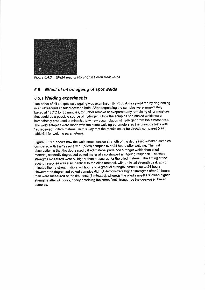
Figure 6.4.3: EPMA map of Phoshor in Boron sÚee/ welds
6.5 Effect of oil on ageing of spot welds
6.5.1 Welding experimentsThe effect of oil on spot weld ageing was examined. TRlP800 A was prepared by degreasing
in an ultrasound agitated acetone bath. After degreasing the samples were immediately
baked at 180"C for 30 minutes, to further remove or evaporate any remaining oil or moisture
that could be a possible source of hydrogen. Once the samples had cooled welds were
immediately produced to minimise any new accumulation of hydrogen from the atmosphere.
The weld samples were made with the same welding parameters as the previous tests with
"as received" (oiled) material, in this way that the results could be directly compared (see
table 5.1 forwelding parameters).
Figure 6.5,1.1 shows how the weld cross tension strength of the degreased - baked samples
compared with the "as received" (oiled) samples over 24 hours after welding. The first
observation is that the degreased baked material produced stronger welds than oiled
material, secondly degreased baked material also showed an ageing response' The weld
strengths measured were all higher than measured for the oiled material. The timing of the
ageing response was also identical to the oiled material, with an initial strength peak at -5minutes then a strength dip at -1 hour and a gradual strength increase up lo 24 hours.
However the degreased baked samples did not demonstrate higher strengths after 24 hours
than were measured at the first peak (5 minutes), whereas the oiled samples showed higher
strengths after 24 hours, nearly obtaining the same final strength as the degreased baked
samples.

TRIP800 A - Ageing of oiled and degreased - baked material
1,0E+02 1,0E+03 1,0E+04 1,0E+05 1,0E+06
Log time (seconds)
z.Y
Øo
5
4
3,5
3
4,5
1,0E+00 1,0E+01
o Degrease bake CTSo Oiled CTS
Figure 6.5.1.1:TRIPSOO A, ageing of degreased - baked samp/es compared to as received
material
Samples of oiled and degreased TRlP800 A were examined using optical microscopy,
hardness profiles were also produced, figure 6;5.1.2. When the Picral etched samples were
examined it was found that the degreased sample contained many finely dispersed
inclusions, located at along dendrite boundaries. The as received (oiled) sample contained
fewer inclusions, although their size was very large. An initial EPMA study of the samples
indicated that the large inclusions in the degreased sample were actually oxide inclusions,
although this work is ongoing and full analysis is not yet available'
A secoid significant difference between the two samples was the weld zone hardness, the
as received (oiled) sample was harder than the degreased sample. Weld zone hardness
could increase if components from the oil such as carbon dissolved into the weld [16,17 &
181.

As received (1glm2 5550 oil) De greased - baked
Sam cra etched for 30 seco
Figure 6.5.1.2:30 second Picral etched welds in TR\P800 A and hardness proÍ7es
6.5.2 Cathodic charging experimentsln order to test the theory that hydrogen can reduce the strength of welded joints a simple
experiment was performed. Spot welds were made in TR|P800 B and allowed to age, after
24 hours the peel strength had increased. A second batch of welds was charged with
hydrogen (figure 6.5.2.1), when these welds were tested the peel strength was greatly
reduced, with higher hydrogen levels giving the lowest weld strengths. Although this
experiment does not prove hydrogen is behind weld ageing, it demonstrates that higher
hydrogen levels do reduce spot weld strength.
- As recieved
600
? 500
oci loofeo.9 300
200
Effect of oil on weld hardness
10 50400 20 30Position in u¡eld

Cathodic charging method
0.03 0 06 0.09
Current (A)
z.Y
ØI
2.O
1.0
.51
ECLo-Ê0,IL!I
5
4
3
2
1
0 0.5480 0 24
Time (hr)
steel
Figure 6.5.2.1:Demonstration of how hydrogen charging can reduce weld strength in
TRIPSOO B
Oil on the sheet surface was tested as a possible source of hydrogen by thermal desorption
analysis, the hydrogen gas evolved was measured by mass spectrometry. Figure 6.5'2'2
shows the evolution of ãiffusible hydrogen for material TRlP800 B, in "as received" (1gm2
5550 oil), degreased (with acetone) and re-coated with a thick oil layer.
ln the degreased sample very little diffusible hydrogen was evolved, where-as the "as
received" sample contained a lot of diffusible hydrogen. The sample which was first
degreased then re-oiled contained even higher levels of hydrogen'
Oil on the suffaceoil oi
+As-received Oilremoved Oil coatecl again
(-)rl coirtÌr r¡t a,¡tiiti
As-received
Oil remove<l
300 600
Temperture (C)
0 300 600
TeÍperture (C)
Figure 6.5.2.2:Hydrogen measurements in TRlP800 B base material (unwelded)
Spot weld samples were produced "as received" (oiled) condition, then degreased after
welding. The hydrogen evolved was measured immediately after welding and24 hours later,
tgure é.S.2.3. 1t can be seen that immediately after welding much hydrogen is evolved and
aiter 2+ hours a decrease in hydrogen evolution was measured. The base material
measurement demonstrates that the hydrogen does indeed come from the weld'
t-0
0.8
c
-ä o.t6Ð o.r
å0.2
0.0
0.0010
0 fino
0.mo6
0.ün4
0.mo2
0-fino
Bùggoc
_o¡ob
Fttr
s{Ðo
estimatiotr
a
Solid : Cathodic chargingAs-welded
Hold
780T-1.6tND:5.0mm
a
0oo
charged after ageing joint.
steel steel

Just after welding
24hr after welding
[Ja;e nttr[¿rl
g
/
0,m10
0.00ß
0.00m
0.0004
0,00()2
0.00m
eøIÈÀõEg
_a3ôc,c$!È
o 300 600 900
Temperah,¡re (C)
Figure 6.5.2.3:Hydrogen evolved from spot wetds in TR\P800 B, welds degreased afterwelding
6.6 X-ray diffraction measurement of phases in weld zoneA weld sample was produced in TRlP800 A in "as received" condition, a cross section was
prepared at room temperature and submitted for micro X-ray diffraction measurement with an
area sensitive detector. A number of scans were made across the weld zone (resolution
800p), performed at0,2,4, 6 and 24 hours after welding.
The phases measured in the weld were identified on the 2 theta scale as predominantly
Ferrite (actually martensite as the diffraction signal is the same), some FesSi eutectic phase
and austenite, figure 6.6.1, The measurements taken between 0 and24 hours show no
difference in the proportion of each phase measured.
A further measurement was taken 20 days later, figure 6.6.2. After 20 days no austenite was
found and in its place tetragonal martensite had formed. This phase change is a further effect
that could influence weld ageing,
Unfortunately the X-ray measurements do not show if the transformation of austenite to
martensite occurred immediately after welding or very slowly over a long period of time. This
is because the procedure for preparing the samples for X-ray analysis is likely to have
influenced the results of the earlier measurements. The welds samples were cut open with a
water cooled rotating disk cutter (at a low rotation speed), then polished slowly by hand. The
sample preparation was performed in such a way as not to bring too much heat or strain into
the microstructure, as heat and strain could easily trigger phase transformations.
ln reality it was not possible to prepare the sample quickly enough in a manner that would
not trigger some transformation, which means that the initial phase measurements were
probably not consistent with what would normally occur in a weld'

' dllformco due to 6mllsr X-rôy Epot
Figure 6.6.1: Phases identified by X-ray diffraction in TR\P800 A
Measuring date:6.10.200626.10.2006
l"etra gona I rra rtensite
Austenite
I48
2-Theta - Scale
Fe3Si
Figure 6.6.2: Phases in TR\P800 A after welding and 20 days later
7. Discussion
7.1 The ageing responseWhen the ageing response of AHSS spot welds was studied in detail it became clear that
ageing was not simply an increase in weld strength with time. A reoccurring pattern was
observed in all tests, regardless of material type or welding conditions used (figures 6.1'1,
6.2.1, 6.2.2, 6.3.1 & 6.5.1.1):. lmmediately after welding the cross tension strength was low
. After 3 - 5 minutes the cross tension strength had increased to an 'initial' peak
. Afier the 'initial' peak, the strength had reduced, this was named a strength 'dip'
. By 24 hours the strength had increased to its maximum value
The weld failure mode followed the same time related pattern as weld cross tension strength,
although some exceptions were observed. An ageing response was measured in spot welds
in a vaiiety of AHSS materials, DP6OO, DP8O0 and TRlP800. When weld ageing was found,
the same welds also demonstrated an improvement in mechanical properties after baking
[37].
8(

7.2 The effect of hold timeCeñain process parameters were able to influence the weld ageing response. Longer hold
times reduced the cross tension strength achieved, regardless of ageing (figure 6.2.1).
Longer hold times were also able to promote ageing in a DP600 material where no ageing
occurred with conventional holding times (figure 6.3.1). Hold time influenced the ageing
response, but had no measurable effect on the weld zone hardness (figure 6.2.3). Previous
investigation had shown that increasing spot weld hold time beyond standard settings did not
have an effect upon the spot weld cooling rate through solidification [5]. Although it is
possible that longer hold times increase the amount of under-cooling and the level of internal
stresses.
7.3 The effect of alloying elemenús on ageingWeld ageing was only observed in AHSS, where spot weld microstructures are
predominantly very hard martensite [22]. The link between alloying elements and martensite
hardness was discussed by Blondeau et al [16 & 17]. ln order for ageing to have a
measurable effect on weld strength, a weld microstructure must be dominated by very hard
martensite. The chemical composition is an important factor to determine the occurrence of
hard martensite.DP6O0 is less heavily alloyed compared to DP800 and TRlP800, the latter having an alloy
content designed to retain some austenite at room temperature. DP600 showed no weld
ageing when conventional weld settings were used, suggesting that this material is not highly
alloyed enough to age. But when an extended hold time (1000ms) was used an ageing
response was observed.As with DP6O0, ageing was measured in DP800 when 1000ms hold time was used. The
TRIP steels demonstrated an ageing effect when welded with conventional hold times
(150ms). The higher alloy content of the TRIP steels leads to the formation of a harder
martensite phase in the weld and an increased chance of retained austenite at room
temperature.No measurable ageing response was observed in Boron steel, despite high level of alloying
additions (higher than TRIP steels). Spot welds in Boron steels always failed at low loads
with poor failure modes. The weld hardness of Boron steel is higher than DP or TRIP steels
resulting in a harder and more brittle martensite phase, it is possible that this phase is too
brittle to benefit from an ageing response.
Optical microscopy of failed welds revealed that fracture occurred along dendrite boundaries
in the weld zone before ageing and in the HAZ after ageing had taken place. Ageing is an
effect that occurs on dendrite boundaries, which means it could potentially be influenced by
segregation on those boundaries. EPMA analysis of Boron steelwelds showed heavy
phosphor segregation on dendrite boundaries in the weld zone. Phosphor segregation
reduces grain boundary fracture toughness [] and could negate any positive effect of ageing
in Boron steels.
7.4 The influence of oil (hydrogen) on weld ageingThe cathodic charging experiments were able to show that increasing the hydrogen level in
spot welds decreased the weld failure strength (figure 6.5.2.1). The link between hydrogen
and weld performance was demonstrated, with the highest hydrogen levels leading to the
lowest weld strengths. lt was also demonstrated that surface oil was the greatest source of
diffusible hydrogen with the potential to dissolve in the weld zone (figure 6.5'2'2).ln a

martensitic microstructure the areas most susceptible to hydrogen related cracking are prior
austenite grain boundaries [36], which is precisely where failure occurs immediately after
welding (figure 6.4.1 ).When welds were examined it was shown that the highest level of diffusible hydrogen could
be evolved immediately after welding , afler 24 hours the level of hydrogen evolved had
decreased (figure 6.5.2.3). These experiments demonstrate that hydrogen is indeed picked
up during welding and over a24 hour period diffuses out of the weld zone. The reduction in
diffused hydrogen lead to increased weld strength. There is a strong relationship between
hydrogen diffusion and weld ageing and a likely of hydrogen is surface oil'
When the influence of oil was tested experimentally it was observed that oiled welds had
lower weld strengths than degreased welds (figure 6.5.1.1). The time delay to the peaks and
dips of the ageing response was not affected by the presence or absence of oil. After 24
hours the strength of the oiled welds had increased up to almost the same level as the
degreased welds. This agrees very well with the hydrogen measurement results, which show
that hydrogen levels were much lower after 24 hours and lower hydrogen levels meant
higher weld strengths.The fact that the time delay to the peaks and dips of the ageing response was not affected by
the presence of oil in the welds (diffusible hydrogen), demonstrates that hydrogen is not the
only mechanism of weld ageing. The ageing effect is probably the result of an interaction of
two or more mechanisms.
Hydrogen is not the only component from oil that has a measurable effect upon the weld
zone. Optical microscopy revealed that degreased welds had a fine dispersion of inclusions
located on the dendrite boundaries, Oiled welds had fewer, but much larger inclusions [figure
6.S.1.21. Additionally the hardness of oiled welds was higher than that of degreased welds.
The study of the effects of oil is ongoing, but it appears that the components of surface oils
contribute more than just hydrogen to the weld zone. The hardness increase resulting from
oil dissolution in the weld is also likely to increase a steels susceptibility to ageing.
7.5 The role of phase changes ,n ageingln X-ray diffraction measurements of welds in TRlP800 B, a small fraction of retained
austenite was found immediately after welding (figure 6.6.1). When the same welds were
tested 20 days later the retained austenite had disappeared, to be replaced by a tetragonal
martensite phase (figure 6.6.2). Although the results do not show that austenite transformed
to martensite immediately after welding, it is expected that that was the case. Bain [32]
explained that indeed some meta-stable austenite can be present at room temperature after
welding and that this phase transforms over time.
8. Proposed mechanisms of ageingFrom the results of this investigation it is concluded that there is a link between the presence
of hydrogen in the weld zone and the cross tensile strength of a welded joint. lt appears that
the level of hydrogen in the weld decreases over time, causing an improvement in the cross
tensile strength of the welded joint. Not only does the cross tensile strength of the joint
improve; but the weld failure mode improves too. Just after welding the welds containing
hydrogen fail in a brittle manner leaving a partial plug. Over time the failure mode improves
and the plug size grows. Eventually full plug failure can be achieved.

Possible sources of hydrogen have been identified in literature. A likely candidate in
resistance spot welding for automotive applications appear to be oils and lubricants, which
are present on the materials as residues from previous production stages (protection against
corrosion, packing and forming operations). The experiments reported in this paper do
indicate a strong influence of oils on the surface to weld ageing. Of course there are other
possible sources for hydrogen (e.9. moisture on the surface).
It is not sure in what way the presence of hydrogen affects the welds capability to bear a
load. lt has been suggested that the hydrogen concentrates around defects in the matrix of
the welded joints (e.g. inclusions, grain boundaries). Even minor lattice defects (e.9.
vacancies and dislocations) have been identified as possible hydrogen traps. There the
concentrations of hydrogen atoms collapse into micro-voids which both can serve as crack
initiation points and propagators of cracks.Another mechanism can be found in the solubility of hydrogen in the matrix itself. The
solubility of hydrogen in the liquid phase is far higher than it is in solid steel [38]. After
solidification the decrease in solubility of hydrogen in austenite (TRIP) or ô-ferrite (DP) leads
to supersaturation. On further cooling the solubility of hydrogen in the matrix decreases (on
transformation of ô-ferrite to austenite in DP steels the solubility of hydrogen increases, but it
decreases again with decreasing temperature). When austenite transforms into martensite
the solubility of hydrogen decreases even further. The mobility of hydrogen in steel matrix at
elevated temperatures is high, and it can be assumed that much of the hydrogen can escape
from the matrix. But as the weld cools to room temperature, the mobility of hydrogen
decreases.After cooling retained austenite will be supersaturated with hydrogen, because of the
hydrogen trapped at higher temperatures. This hydrogen cannot escape immediately at
lower temperatures due to decreased mobility and the fact that the retained austenite is
surrounded by hydrogen-saturated martensite, blocking the escape routes for hydrogen.park et al. identify these islands of retained austenite in a martensite matrix as bulk hydrogen
traps [39]. Upon loading plastic strains force the retained austenite to transform into
martensite, releasing hydrogen to initiate cracks and cause undesired failure modes'
Although the mobility of hydrogen at room temperature is much lower than it is at elevated
temperatures, over time hydrogen would be able to leave the weld, thus reducing its
detrimental effect upon the performance of the welds in loading'
The experiments indicate that hydrogen is not the only cause of the ageing effect. Another
likely source is the decomposition of retained austenite. Retained austenite is always present
after the formation of martensite, but in TRIP steels the occurrence of retained austenite after
welding (and the amount of austenite present) is even more likely due to their chemical
composition. The retained austenite forms pockets of decreased mechanical performance in
the martensitic welds leading to low weld strengths and undesirable failure modes'
The retained austenite is not stable. There is diffusion of elements, changing local chemical
composition and there is relaxation of local stress levels allowing for the decomposition of
austenite into bcc iron phases. Over time the weld will thus gain in strength and lose certain
possible paths for crack-propagation.
9. The implications of weld age¡ng for standardised testingUnder normal practices welds are mechanically tested soon after welding, whereas in reality
no automobile is sold onto the open market until more than 24 hours after welding.
Although not all AHSS materials exhibit the phenomena of weld ageing, the effect can be
seen in a significant portion of AHSS grades.

When weld ageing does occur, the weld mechanical properties vary significantly over the first
24 hours after the weld was made. This time related behaviour has very serious implications
for standardised testing procedures. A weld tested immediately after welding may produce
low weld strengths and poor failure modes leading to the conclusion that the material does
not have an adequate weld performance. Where-as the same welds tested 24 hours later
would have been accepted.The problem is that most welding standards do not specify a time scale between welding and
mechanical testing. Many standards do not specify if a material should be welded in as
received (oiled), condition or degreased, but oil has a very significant effect on weld
performance in ageing sensitive materials.The weld schedule used is also of great importance, if very long hold times are applied then
ageing can be induced in materials where no ageing effect would normally be found (such as
DP60O). lf the weld schedule used for material acceptance is not the same as the one
applied in production then further disparities could occur between measured results.
The weld properties of ageing sensitive materials also significantly improve when a baking
cycle is applied [37].
10. ConclusionsThe ageing effect is a very real phenomena. ln ageing sensitive materials the weld
mechanical properties can fluctuate significantly within 24 hours of welding. ln general weld
ageing leads to an improvement in mechanical properties'
Although much is still unknown about the mechanisms of ageing and what really happens
within the weld microstructure after welding, some conclusions could still be drawn from the
investigation:. Ageing is an effect that increases grain boundary fracture toughness in the weld zone
. The ageing response is leads to an initial peak in weld strength, followed by a dip and
a final strength increase at around 24 hours after welding. Welds which demonstrate an ageing behaviour also showed improved mechanical
properties when exposed to a baking cycle [37]. Ageing occurs in certain highly alloyed steels and appears to be related to a high
weld zone hardness and low phosphor content. Oil on the sheet surface acts to increase the level of the weld ageing response
. Oil has a negative influence on weld properties
. Hydrogen coming from oil contributes to weld ageing
. Other components of oils also effect the weld microstructure by increasing the weld
hardness and influencing the size and distribution of inclusions. This investigation allowed a hypothesis to be developed to explain the ageing
phenomena. The implications of weld ageing on standardised testing was discussed
11. AcknowledgementsThe authors would like to thank David Hanlon, Steven Celotto and Murugaiyan
Almithalingam for their Advice. Tom Moolevliet, Gabe van de Zwaag and Stefan Meltzer for
their experimental contributions and technical assistance.

12. References
1. G. S. Vasilash: Better car building through steel - But not the material you're familiar
with - On Materials;Automotive Design & Production; March, 2002.
2. G.S. Vasilash: Better vehicles through steel: advances are being made in steel that
can lead to better, safer, more fuel-efficient vehicles-without taking a huge economic
hit - Materials; Automotive Design & Production;April 2003.
3. N.J. den Uijl: Post Weld Heat Treatment of Advanced High Strength Steel for
Automotive Joining; 8th lnternational Seminar "Numerical Analysis of Weldability";
Seggau; 2006.4. Y.J. Chao: Failure mode of spot welds: interfacial vs pullout; Science and Technology
of Welding and Joining; Vol. 8, No. 2; 2003.
S. N.J. den Uijl & S. Smith: Resistance Spot Welding of Advanced High Strength Steels
for the Automotive lndustry; 4th international seminar on advances in resistance
welding; Wels, Austria; 2006.
6. G. Shi & S. A. Westgate: Resistance spot welding of high strength steels; JoM -Eleventh lnternational Conference on the Joining of Materials; May 25-28, 2003;
Helsingor, Denmark.7. G. Shi & S. A, Westgate: TRIP steel - better weldability using resistance spot
welding; TWI bulletin; 2007.L M.Marya & X.Q. Gayden: Development of Requirements for Resistance Spot Welding
Dual-phase (DP6O0) Steels Part 1: The Causes of lnterfacial Fracture; Welding
Journal; November 2005.g. M.Marya & X.Q. Gayden: Development of Requirements for Resistance Spot Welding
Dual-phase (DP6OO) Steels Parl2: Statistical Analyses and Process Maps; Welding
Journal; December 2005.10.8. Verstraeten & J. Feyaerts: Weerstandslassen van hogesterkte staalsoorten;
Lastechniek; December 2006.
11. K. Easterling: lntroduction to the Physical Metallurgy of Welding 2nd ed.; Butterworth
Heinemann; ISBN 0 7506 0394 1;1992'12. N.J. den Uijl: Modelling the lnfluence of Resistance Spot Welding on Material
properties; 3rd lnternational Conference on Mathematical Modelling and lnformation
Technologies in Welding and Related Processes; Kiev; 2006.
13. N.J. Oen U¡t, H. Nishibata, s. smith, T. okada, T. van derVeldt, M. uchihara & K.
Fukui: Prediction of post weld hardness of advanced high strength steels for
automotive application using a dedicated carbon equivalent number; llW Doc. lll-
1444-07; Presented at the Annual Assembly 2007, Commission lll Resistance
welding, solid state welding and allied joining processes; Dubrovnik, Croatia, 24 July,
2007.14. llW: Technical Report, 1969, llW doc' lX-535-67
1S.y. lto & K. Bessyo: "Weldability Formula of High Strength Steel related to Heat
Affected Zone cracking", Journalof Japanesewelding society, 1968,37, (9),938
16. R. Blondeau, Ph. Maynier & J. Dollet: "Prévision de la dureté et de la résistance des
aciers au carbone et failblement alliés d'après leur structure et leur composition.";
Mémoirs Scientifiques Revue Métallurgie, LXX, No 12' 1973'
17. R. Blondeau, Ph. Maynier, J. Dollet & B. Vieillard-Baron: "Prévision de la dureté et de
la résistance des aciers au carbone et failblement alliés d'après leur composition et
leur traitement thermique ; Mémoirs Scientifiques Revue Métallurgie, Novembre
1975.

18. J.M. Chaillet, F, Chevet, P. Bocquet & J. Dollet: "Prediction of the Microstructure and
Tensile Properties of Weld Metal Deposits"; Welding of HSLIA (Microalloyed)
Structural Steels; Proceedings of an lnternational Conference; 9-12 November 1976;
Rome, ltaly p.p.298-321.
19. D.A. Porter & K.E. Easterling: Phase Transformations in Metals and Alloys; Van
Nostrand Reinhold; 1981.
20. K.W. Andrews: Empirical Formulae for the Calculation of Some Transformation
Temperatures; Journal of the lron and Steel lnstitute, 203, Part 7, 1965.
21.D.P. Koistinen & R. E. Marburger: A general equation prescribing the extent of the
austenite-martensite transformation in pure iron-carbon alloys and plain carbon
steels;Acta Metall.; vol. 7, pp. 59{0; 1959.
22.W. Steven & A.G. Haynes; Journal of the lron and steel lnstitute, 183, 1956.
23. J.E. Gould, S.E. Khurana, & T. Li: "Predictions of microstructures when welding
automotive advanced high-strength sfee/s"; Welding Journal Research Supplement,
85(5):1 1 1 s-1 I 6s; 2006.24. J. E. Gould: 'Weld Process Effects Cracking - Hold Time Sensitivity and RSW of
High Strengfh Steel';Welding Design and Fabrication, (8):48-49; 1999.
25. S. Westgate: The Resistance Spot Welding of High and Ultra-high Strength Steels;
Proceedings of the 3rd lnternational Seminar on Advances in Resistance Welding;
Berlin; 2004.26. M. Mimer, L-E. Svensson & R. Johansson: Possibilities to lmprove Fracture
Behaviour in Resistance Spot Welds of EHSS and UHSS by Process Modifications;
Proceedings of the 3rd lnternational Seminar on Advances in Resistance Welding;
Berlin; 2004.27.D. Rada¡: Heat Effects of Welding - Temperature Field, Residual Stress, Distortion;
ISB N 0-387- 54820-3; Springer-Verlag; 1 992'
28. C.L. Mantell(ed.): Engineering Materials Handbook 1st ed.; Mc Graw-Hill; 1958.
29. H. Chandler: Metallurgy for the Nion-Metallurgist; ASM lnternational; ISBN 0-87170-
652-0;1998.30. J.M, Sawhill Jr. & J.C. Baker: Spot weldability of high strength sheet steels; AWS
annual meeting; Detroit; 1979.
31. H, Mohrbacher: Welding of automotive high strength steel from a Nb microalloying
point of view; Automotive Circle lnternational - Conference, Bad Nauheim/Frankfurt,
Germany; 2006.32.H. Mohrbacher: Joining state-of-the-art high strength steels - lnfluences and
optimisation from a metallurgical poit of view; Automotive Circle lnternational -Conference, Bad Nauheim/Frankfurt, Germany; 2007'
33. E.C. Bain: Functions of the alloying elements in steel; A series of five educational
lectures on the functions of the alloying elements in steel presented to members of
the A.S.M. during the twenty first national metal congress and exposition, Chicago,
lllinois, October 23lo 27, 1939.
34. F.B. Pickering: Physical metallurgy of stainless steeldevelopments; lnt. Met. Rev. 21;
227-268;1976.35. J. Neely: Practical Metallurgy and Materials of lndustry; John Wiley and Sons; 1979.
36. H. K. D, H. Bhadeshia: Tempered Martensite; www. msm.cam'ac, uUphase-
trans/2gg4/Tempered.Mar.tensite/tempered.martensite.html; accessed June 8, 2008.
37. T Okada et al. "Baking.... Get title" Japan Welding Society Conference in November
2008,38. Failure analysis and prevention, volume 8; Metal handbook volume 10; H.E. Boyer'
ASM Handbook committee 1975

39. Y.D. Park, l.S. Maroef, A. Landau & L. Olson: Retained Austenite as a Hydrogen Trap
in Steel Welds; Welding Journal Research Supplement; February,2002.
Copyright © 2022 FDOKUMEN