
Target tracking using DMLC for volumetric modulated arc therapy: A simulation study
9
Target tracking using DMLC for volumetric modulated arc therapy: A simulation study Baozhou Sun and Dharanipathy Rangaraj a Department of Radiation Oncology, School of Medicine, Washington University, 4921 Parkview Place, St. Louis, Missouri 63110 Lech Papiez Department of Radiation Oncology, Southwestern Medical Center, University of Texas, Dallas, Texas 75390 Swetha Oddiraju, Deshan Yang, and H. Harold Li b Department of Radiation Oncology, School of Medicine, Washington University, 4921 Parkview Place, St. Louis, Missouri 63110 Received 8 June 2010; revised 6 October 2010; accepted for publication 11 October 2010; published 8 November 2010 Purpose: Target tracking using dynamic multileaf collimator DMLC is a promising approach for intrafraction motion management in radiation therapy. The purpose of this work is to develop a DMLC tracking algorithm capable of delivering volumetric-modulated arc therapy VMAT to the targets that experience two-dimensional 2D rigid motion in the beam’s eye view. Methods: The problem of VMAT delivery to moving targets is formulated as a control problem with constraints. The relationships between gantry speed, gantry acceleration, MLC leaf-velocity, dose rate, and target motion are derived. An iterative search algorithm is developed to find numeri- cal solutions for efficient delivery of a specific VMAT plan to the moving target using 2D DMLC tracking. The delivery of five VMAT lung plans is simulated. The planned and delivered fluence maps in the target-reference frame are calculated and compared. Results: The simulation demonstrates that the 2D tracking algorithm is capable of delivering the VMAT plan to a moving target fast and accurately without violating the machine constraints and the integrity of the treatment plan. The average delivery time is only 29 s longer than that of no- tracking delivery, 101 versus 72 s, respectively. The fluence maps are normalized to 200 MU and the average root-mean-square error between the desired and the delivered fluence is 2.1 MU, compared to 14.8 MU for no-tracking and 3.6 MU for one-dimensional tracking. Conclusions: A locally optimal MLC tracking algorithm for VMAT delivery is proposed, aiming at shortest delivery time while maintaining treatment plan invariant. The inconsequential increase of treatment time due to DMLC tracking is clinically desirable, which makes VMAT with DMLC tracking attractive in treating moving tumors. © 2010 American Association of Physicists in Medi- cine. DOI: 10.1118/1.3511516 Key words: VMAT, DMLC, motion management, IMRT I. INTRODUCTION Internal respiratory organ motion is one of the main concerns for lung and upper-abdominal cancer radiation therapy treatments. 1 The classical approach to manage such intrafrac- tion motion is to add a large margin to ensure that the mov- ing target is covered at all times throughout the delivery. However, this approach increases the volume of healthy tis- sue that receives significant doses, which is undesirable par- ticularly when the target is located close to an organ at risk. 2 One solution without this burden is to gate the radiation beam within a specified time/phase window so that dose is delivered only during a certain part of the respiratory cycle. 3,4 However, respiratory gating significantly increases the treatment time, thereby compromising patient comfort and consequently increasing likelihood of patient body movement. 1,5 The third and a distinctive approach is real time tumor tracking where the radiation beam is automati- cally repositioned to follow the tumor’s changing position. Recent studies 6–14 have shown that this technique provides a promising solution to the tumor motion problem by dynami- cally adapting multileaf collimator MLC-shaped beam ap- erture to track the target displacement. This method can, un- der ideal conditions, eliminate the need for a large tumor motion margin while maintaining 100% efficiency in deliv- ery. However, the reliable use of this technique in static, fixed field intensity modulated radiation therapy IMRT is still a concern due to static IMRT’s often extended delivery time. Recently a new IMRT treatment technique, volumetric- modulated arc therapy VMAT has gained widespread inter- est in the radiation therapy community. 15–25 VMAT features simultaneous variations in MLC aperture shape, dose rate, and gantry rotation speed with the radiation continuously on. Compared to static IMRT, one of the most significant ben- efits of VMAT lies in the much shorter delivery time. For instance, a single-arc VMAT treatment can be completed less than 2 min. This feature would make VMAT valuable in 6116 6116 Med. Phys. 37 „12…, December 2010 0094-2405/2010/37„12…/6116/9/$30.00 © 2010 Am. Assoc. Phys. Med.
Transcript of Target tracking using DMLC for volumetric modulated arc therapy: A simulation study

Target tracking using DMLC for volumetric modulated arc therapy:A simulation study
Baozhou Sun and Dharanipathy Rangaraja�
Department of Radiation Oncology, School of Medicine, Washington University, 4921 Parkview Place,St. Louis, Missouri 63110
Lech PapiezDepartment of Radiation Oncology, Southwestern Medical Center, University of Texas, Dallas, Texas 75390
Swetha Oddiraju, Deshan Yang, and H. Harold Lib�
Department of Radiation Oncology, School of Medicine, Washington University, 4921 Parkview Place,St. Louis, Missouri 63110
�Received 8 June 2010; revised 6 October 2010; accepted for publication 11 October 2010;published 8 November 2010�
Purpose: Target tracking using dynamic multileaf collimator �DMLC� is a promising approach forintrafraction motion management in radiation therapy. The purpose of this work is to develop aDMLC tracking algorithm capable of delivering volumetric-modulated arc therapy �VMAT� to thetargets that experience two-dimensional �2D� rigid motion in the beam’s eye view.Methods: The problem of VMAT delivery to moving targets is formulated as a control problemwith constraints. The relationships between gantry speed, gantry acceleration, MLC leaf-velocity,dose rate, and target motion are derived. An iterative search algorithm is developed to find numeri-cal solutions for efficient delivery of a specific VMAT plan to the moving target using 2D DMLCtracking. The delivery of five VMAT lung plans is simulated. The planned and delivered fluencemaps in the target-reference frame are calculated and compared.Results: The simulation demonstrates that the 2D tracking algorithm is capable of delivering theVMAT plan to a moving target fast and accurately without violating the machine constraints and theintegrity of the treatment plan. The average delivery time is only 29 s longer than that of no-tracking delivery, 101 versus 72 s, respectively. The fluence maps are normalized to 200 MU andthe average root-mean-square error between the desired and the delivered fluence is 2.1 MU,compared to 14.8 MU for no-tracking and 3.6 MU for one-dimensional tracking.Conclusions: A locally optimal MLC tracking algorithm for VMAT delivery is proposed, aiming atshortest delivery time while maintaining treatment plan invariant. The inconsequential increase oftreatment time due to DMLC tracking is clinically desirable, which makes VMAT with DMLCtracking attractive in treating moving tumors. © 2010 American Association of Physicists in Medi-cine. �DOI: 10.1118/1.3511516�
Key words: VMAT, DMLC, motion management, IMRT
I. INTRODUCTION
Internal respiratory organ motion is one of the main concernsfor lung and upper-abdominal cancer radiation therapytreatments.1 The classical approach to manage such intrafrac-tion motion is to add a large margin to ensure that the mov-ing target is covered at all times throughout the delivery.However, this approach increases the volume of healthy tis-sue that receives significant doses, which is undesirable par-ticularly when the target is located close to an organ at risk.2
One solution without this burden is to gate the radiationbeam within a specified time/phase window so that dose isdelivered only during a certain part of the respiratorycycle.3,4 However, respiratory gating significantly increasesthe treatment time, thereby compromising patient comfortand consequently increasing likelihood of patient bodymovement.1,5 The third and a distinctive approach is realtime tumor tracking where the radiation beam is automati-
cally repositioned to follow the tumor’s changing position.6116 Med. Phys. 37 „12…, December 2010 0094-2405/2010/37
Recent studies6–14 have shown that this technique provides apromising solution to the tumor motion problem by dynami-cally adapting multileaf collimator �MLC�-shaped beam ap-erture to track the target displacement. This method can, un-der ideal conditions, eliminate the need for a large tumormotion margin while maintaining 100% efficiency in deliv-ery. However, the reliable use of this technique in static,fixed field intensity modulated radiation therapy �IMRT� isstill a concern due to static IMRT’s often extended deliverytime.
Recently a new IMRT treatment technique, volumetric-modulated arc therapy �VMAT� has gained widespread inter-est in the radiation therapy community.15–25 VMAT featuressimultaneous variations in MLC aperture shape, dose rate,and gantry rotation speed with the radiation continuously on.Compared to static IMRT, one of the most significant ben-efits of VMAT lies in the much shorter delivery time. Forinstance, a single-arc VMAT treatment can be completed less
than 2 min. This feature would make VMAT valuable in6116„12…/6116/9/$30.00 © 2010 Am. Assoc. Phys. Med.
6117 Sun et al.: Target tracking using dynamic MLC for VMAT 6117
treating moving tumors aided by dynamic multileaf collima-tor �DMLC� tracking as motion-compensation strategy.
Several DMLC tracking algorithms have been reportedfor commonly used radiation therapy treatmentmodalities.10,12,13 However, a robust and optimal solutionspecifically designed for VMAT is yet to be developed. Com-pared to static IMRT, VMAT delivery in single arc or mul-tiple arcs is more complex due to additional degrees of free-dom. VMAT delivery involves continuously rotating gantryand widely varying gantry rotation speed, dose rate, andMLC leaf position. When target motion compensation is in-corporated, these delivery parameters require interactivemodulations. To ensure that the treatment plan can be deliv-ered without violating limitations of hardware parameters ofa linear accelerator �linac�, a tracking solution needs to con-sider a number of machine constraints such as maximal per-missible gantry speed, dose rate, and MLC leaf-velocity. Inaddition, as VMAT often requires the gantry to accelerateand decelerate frequently to deliver a treatment plan, gantryacceleration constraint should also be taken into account.
In this paper, a DMLC tracking algorithm is developedcapable of delivering VMAT to targets that experience two-dimensional �2D� motions in the beam’s eye view �BEV�.The VMAT plan is optimized based on patient’s anatomy atone particular phase of the respiratory cycle using a commer-cial treatment planning software. The interdependence be-tween several linac parameters, such as dose rate, gantry an-gular speed, gantry acceleration and MLC leaf-velocity, andtarget motion is investigated to formulate the VMAT deliveryproblem for moving targets. An iterative search algorithm isdesigned with hardware constraints included to determine thelocally optimal delivery parameters for 2D DMLC tracking.The goal is to achieve optimal delivery efficiency, i.e., theshortest delivery time while minimizing delivery error re-sulted from target motion.
II. MATERIALS AND METHODS
II.A. VMAT plans
Five RapidArc �Varian Medical Systems, Palo Alto, CA�plans are created to treat a 62 cc spherical tumor �5 cmdiameter� in a lung phantom.24 The complexity of each fieldis controlled by adjusting the monitor unit �MU� �312–900MU� while maintaining the same daily tumor dose of 200cGy. The planning machine is a Varian Novalis Tx linearaccelerator with 2.5 mm leaf-width high resolution multileafcollimator. The treatment plan is optimized with gantry anglerunning counterclockwise from 179.9° to 180.1° �IEC con-vention� in a single arc. The plan information, includingMLC leaf sequence, gantry angle and MUs is stored as dis-crete control points and exported in a DICOM file. Note thatgantry speed, dose rate, and MLC leaf-velocity are not speci-fied in the control points and will be determined later at thelinac console by the VMAT delivery software once the planhas been transferred.17 Each plan consists of 177 controlpoints, and the interval between any two consecutive controlpoints is called a segment in this paper, thus totaling 176
segments. To deliver the VMAT plan to a moving target us-Medical Physics, Vol. 37, No. 12, December 2010
ing DMLC tracking, the planned MUs in each segment arekept as invariant so that the integrity of the planned confor-mal dose distribution will not be compromised.
II.B. Motion model
The target is assumed to be a rigid body so that its trans-lational movements in three-dimensional space can be de-fined by target center’s trajectory in the BEV plane.10 A BEVplane at gantry angle g is defined as a plane that is perpen-dicular to the beam central-axis and passes through the linacisocenter. Target motion relative to the treatment beam iseliminated in a VMAT delivery by moving the apertures ateach gantry angle g in synchrony with the target motion sothat the beam portals remain spatially unchanged relative tothe target in the BEV plane. In this work, the motion trajec-tory of a target is assumed to be known prior to the treat-ment. This assumption is made for simplicity but the algo-rithm is readily adaptable for real time motion tracking.9,12
The 2D BEV projection of the target motion can be di-vided into two components: One describes the motion alongthe x axis �parallel to MLC leaf travel direction�, X�t�, andthe other describes the motion along the y axis �perpendicu-lar to MLC leaf travel direction�, Y�t�. Lujan’s respiratorymotion model1,26 is used, and defined as the following:
x�t� = Ax sin4��t/� + �x� , �1�
y�t� = Ay sin4��t/� + �y� , �2�
where Ax and Ay are the motion amplitudes along the x-axisand y-axis, respectively, � is the period, �x and �y are theinitial phases. A phase difference between the motion alongx- and y-axis is deliberately set to 0.1�, thus producing anelliptical trajectory in the BEV to simulate commonly ob-served hysteresis. The magnitude of x motion is set to 2 cm,which is along the patient’s superior-inferior direction and istherefore gantry angle independent, while the amplitude of ycomponent is gantry angle dependent, given by Ay
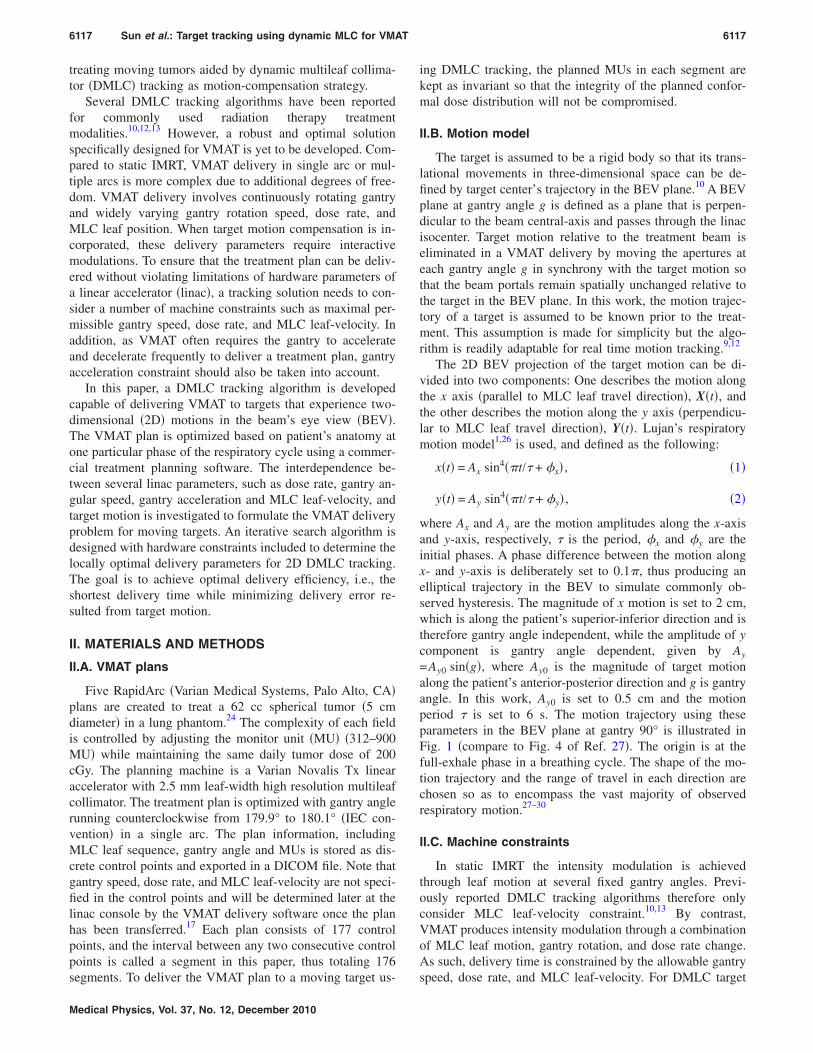
=Ay0 sin�g�, where Ay0 is the magnitude of target motionalong the patient’s anterior-posterior direction and g is gantryangle. In this work, Ay0 is set to 0.5 cm and the motionperiod � is set to 6 s. The motion trajectory using theseparameters in the BEV plane at gantry 90° is illustrated inFig. 1 �compare to Fig. 4 of Ref. 27�. The origin is at thefull-exhale phase in a breathing cycle. The shape of the mo-tion trajectory and the range of travel in each direction arechosen so as to encompass the vast majority of observedrespiratory motion.27–30
II.C. Machine constraints
In static IMRT the intensity modulation is achievedthrough leaf motion at several fixed gantry angles. Previ-ously reported DMLC tracking algorithms therefore onlyconsider MLC leaf-velocity constraint.10,13 By contrast,VMAT produces intensity modulation through a combinationof MLC leaf motion, gantry rotation, and dose rate change.As such, delivery time is constrained by the allowable gantry
speed, dose rate, and MLC leaf-velocity. For DMLC target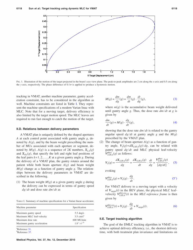
6118 Sun et al.: Target tracking using dynamic MLC for VMAT 6118
tracking in VMAT, another machine parameter, gantry accel-eration constraint, has to be considered in the algorithm aswell. Machine constraints are listed in Table I. They repre-sent the machine specifications of a modern Varian linac withMLC. Note that for a moving target, delivery efficiency isalso limited by the target motion speed. The MLC leaves arerequired to run fast enough to catch the motion of the target.
II.D. Relations between delivery parameters
A VMAT plan is uniquely defined by the shaped aperturesA at each control point associated with gantry angle g, de-noted by A�g�, and by the beam weight prescribing the num-ber of MUs associated with each aperture or segment, de-noted by M�g�. A�g� is a sequence of 2K numbers, XL,k�g�and XR,k�g�, that specify the left and right leaf positions ofthe leaf pairs k=1,2 , . . . ,K at a given gantry angle g. Duringthe delivery of a VMAT plan, the gantry rotates around thepatient while both beam aperture A�g� and beam weightM�g� change as a function of gantry angle g. The relation-ships between the delivery parameters in VMAT are de-scribed in the following.
�1� The beam weight M�g� at a given gantry angle g duringthe delivery can be expressed in terms of gantry speeddg /dt and dose rate dm /dt as
FIG. 1. Illustration of the motion of the target projected in the beam’s eye viethe y-axis, respectively. The phase difference of 0.1� is applied to produce
TABLE I. Summary of machine specifications for a Varian linear accelerator.
Machine parameter Specification
Maximum gantry speed 5.5 deg/sMaximum MLC leaf-velocity 3.5 cm/sa
Maximum dose rate 600 MU/minMaximum gantry acceleration 1.8° /s2 b
aReference 31.b
Reference 37.Medical Physics, Vol. 37, No. 12, December 2010
M�g� =dm
dg�g� =
dm
dt�g� ·
dt
dg�g� , �3�
where m�g� is the accumulative beam weight delivereduntil gantry angle g. Thus, the dose rate dm /dt at g isgiven by
dm
dt�g� = M�g� ·
dg
dt�g� , �4�
showing that the dose rate dm /dt is related to the gantryangular speed dg /dt at gantry angle g and the M�g�prescribed by the VMAT plan.
�2� The change of beam aperture A�g� as a function of gan-try angle, Vk�g�=dXL�R�,k�g� /dg, can be related withgantry speed dg /dt and MLC physical leaf-velocityVL�R�,k
phys �g� as follows:
Vk�g� =dXL�R�,k�g�
dg=
dXL�R�,k�g�
dt·
dt
dg=
VL�R�,kphys �g�
�dg/dt�, �5�
evoking
VL�R�,kphys �g� = Vk�g� ·
dg
dt. �5��
For VMAT delivery to a moving target with a velocityof Vtarget�t� in the BEV plane, the physical MLC leaf-velocity VL�R�,k
phys,m�t� in the MLC-reference frame is thengiven by
VL�R�,kphys,m�t� = Vk�g� ·
dg
dt+ Vtarget�t� . �6�
II.E. Target tracking algorithm
The goal of the DMLC tracking algorithm in VMAT is toachieve optimal delivery efficiency, i.e., the shortest delivery
ne. The peak-to-peak amplitudes are 2 cm along the x-axis and 0.5 cm alongteresis motion.
w plaa hys
time, with both treatment plan invariance and limitations on
6119 Sun et al.: Target tracking using dynamic MLC for VMAT 6119
delivery parameters kept in mind. As the delivery time tm foreach segment m is mainly governed by gantry speed, we aimto achieve maximum gantry speed at each segment. The de-livery time, gantry speed, MLC leaf-velocity, dose rate, andmotion trajectory are strongly correlated in the VMAT deliv-ery, and the hardware parameters are further constrained bytheir respective limits. Thus, the problem of optimal deliveryof VMAT to a moving target using DMLC tracking can besolved through an iterative search process aiming at localminimization of the delivery time for each segment. Theoverall logic flow of the DMLC tracking algorithm is shownin Fig. 2 and described next in detail.
II.E.1. VMAT plan extraction
The MLC leaf positions and number of monitor units as afunction of gantry angle are derived from the DICOM files.The dynamics of an arc delivery to a moving target isequivalent to a continuous evolution of an open area A�t�with time t, which is made of strip openings formed by theedges between opposing left and right leaves of each pair,Ak�t�. Index k=1,2 , . . . ,K enumerates the leaf pair and k�denotes the leaf position along the y axis �� is the leaf-width�. For a given t, the leaf aperture A�t� can be defined bythe leaf position Xm
L �k�� and XmR�k��, where L and R denote
left and right leaf banks, respectively.
II.E.2. Iterative search process
�i� Initialize the values of delivery duration tm for the seg-ment m, where m=1,2 . . .176.
�ii� Determine the gantry speed for segment m. The gantryspeed �m is given by �m=�g / tm, where �g is the gan-try angle interval at each segment �approximately 2°
495
500
505
510
Loop for eachcontrol point
Read MLC leafpositions and MU
Calculate new leafpositions at segment m
Within machinelimits?
Obtain gantry speed, MLCvelocity, dose rate
Obtain gantry speed atthe segment m+1
(m+1)= (m)+ amax tm+1
Set initialvalue of tm
Within [ (m) -amax tm+1, (m)+ amax tm+1]?
Yes
No increase tm
< (m)- amax tm+1
Record deliveryparameters
> (m)+amaxtm+1
increase tm, thusdecrease (m)
Fluence Error
Obtain targetposition
FIG. 2. Logic flow of the DMLC tracking algorithm for VMAT delivery totargets moving in 2D in beam’s eye view.
for the VMAT plan used in this study�.
Medical Physics, Vol. 37, No. 12, December 2010
�iii� Determine the target position x��i=1m ti� and y��i=1
m ti�from Eqs. �1� and �2�.
�iv� Calculate new leaf positions. The new leaf positionsare calculated to account for the changes in target po-sition. For the x motion component, the new leaf posi-tions at tm are
XmL�R��k���new = Xm
L�R��k���plan + x��i=1
m
ti� . �7�
For the y motion component, an appropriate leaf “shift-ing” is made. Similar techniques have been recently de-scribed by several groups.10,12,13 The shifting technique fol-lows the y component in discrete increments of the leaf-width, i.e., 2.5 mm. When the displacement along the y-axisis more than one leaf-width, the leaf pair k �k=1,2 , . . . ,K�moves rightward to the current position of leaf pair k+1 orleftward to the current position of leaf pair k−1, dependingon the target moving direction. As a result, the spatial posi-tion of the aperture is shifted by a leaf-width � along they-axis while the shape is preserved. Note that the leaf shiftcan be performed whenever the target’s y-displacement ismore than �k� and is not restricted to shifting single leaf-pair if the y-component motion is greater or equal to twoleaf-widths.
�v� Apply machine constraints to each delivery parameterat the segment m. The dose rate dm /dt is calculated byEq. �4�. The planned leaf positions determine VL�R�,k
phys �g�using Eq. �5��, which, in turn, gives the physical MLCleaf-velocity for a moving target using Eq. �6�. Gantryspeed, dose rate, and MLC leaf-velocity all have to fallwithin respective limits listed in Table I. If any of thesethree parameters is larger than the specification, theroutine loops back to step �i�, increases tm by a smallstep of 0.02 s, and continues to step �v� until all themachine constraints are satisfied. The delivery param-eters for segment m are now temporarily determined.
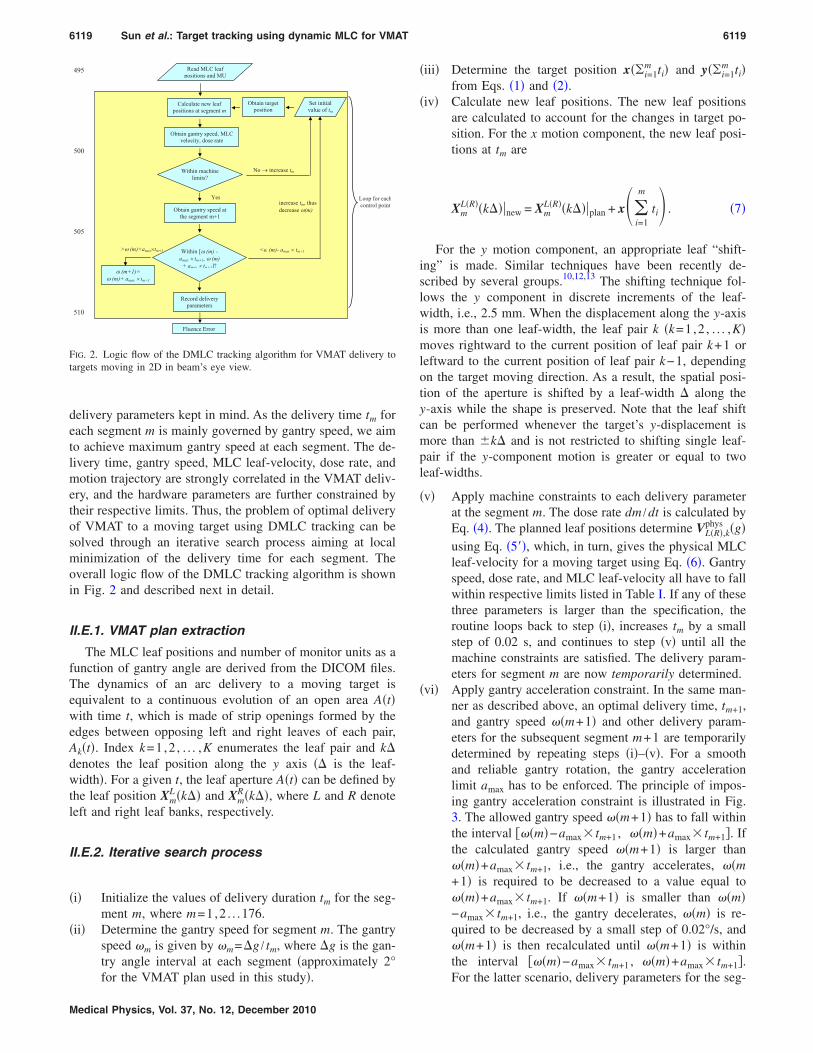
�vi� Apply gantry acceleration constraint. In the same man-ner as described above, an optimal delivery time, tm+1,and gantry speed ��m+1� and other delivery param-eters for the subsequent segment m+1 are temporarilydetermined by repeating steps �i�–�v�. For a smoothand reliable gantry rotation, the gantry accelerationlimit amax has to be enforced. The principle of impos-ing gantry acceleration constraint is illustrated in Fig.3. The allowed gantry speed ��m+1� has to fall withinthe interval ���m�−amax� tm+1 , ��m�+amax� tm+1�. Ifthe calculated gantry speed ��m+1� is larger than��m�+amax� tm+1, i.e., the gantry accelerates, ��m+1� is required to be decreased to a value equal to��m�+amax� tm+1. If ��m+1� is smaller than ��m�−amax� tm+1, i.e., the gantry decelerates, ��m� is re-quired to be decreased by a small step of 0.02°/s, and��m+1� is then recalculated until ��m+1� is withinthe interval ���m�−amax� tm+1 , ��m�+amax� tm+1�.
For the latter scenario, delivery parameters for the seg-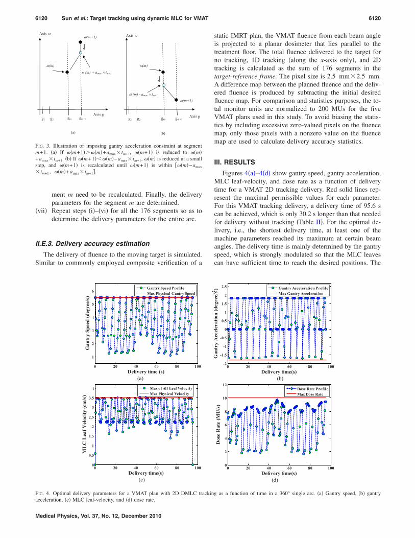
6120 Sun et al.: Target tracking using dynamic MLC for VMAT 6120
ment m need to be recalculated. Finally, the deliveryparameters for the segment m are determined.
�vii� Repeat steps �i�–�vi� for all the 176 segments so as todetermine the delivery parameters for the entire arc.
II.E.3. Delivery accuracy estimation
The delivery of fluence to the moving target is simulated.Similar to commonly employed composite verification of a
(a) (b)
gm gm+1
(m)
g1 g2Axis g
Axis
(m+1) (m) - amax tm+1
gm gm+1
(m)
g1 g2Axis g
Axis (m+1)
(m) + amax tm+1
FIG. 3. Illustration of imposing gantry acceleration constraint at segmentm+1. �a� If ��m+1����m�+amax� tm+1, ��m+1� is reduced to ��m�+amax� tm+1. �b� If ��m+1���m�−amax� tm+1, ��m� is reduced at a smallstep, and ��m+1� is recalculated until ��m+1� is within ���m�−amax
� tm+1 , ��m�+amax� tm+1�.
0 20 40 60 80 100
1
2
3
4
5
6
Delivery time (s)
GantrySpeed(degree/s)
Gantry Speed ProfileMax Physical Gantry Speed
(a)
0 20 40 60 80 1000
0.5
1
1.5
2
2.5
3
3.5
4
Delivery time(s)
MLCLeafVelocity(cm/s)
Max of All Leaf VelocityMax Physical Velocity
(c)
FIG. 4. Optimal delivery parameters for a VMAT plan with 2D DMLC tra
acceleration, �c� MLC leaf-velocity, and �d� dose rate.Medical Physics, Vol. 37, No. 12, December 2010
static IMRT plan, the VMAT fluence from each beam angleis projected to a planar dosimeter that lies parallel to thetreatment floor. The total fluence delivered to the target forno tracking, 1D tracking �along the x-axis only�, and 2Dtracking is calculated as the sum of 176 segments in thetarget-reference frame. The pixel size is 2.5 mm�2.5 mm.A difference map between the planned fluence and the deliv-ered fluence is produced by subtracting the initial desiredfluence map. For comparison and statistics purposes, the to-tal monitor units are normalized to 200 MUs for the fiveVMAT plans used in this study. To avoid biasing the statis-tics by including excessive zero-valued pixels on the fluencemap, only those pixels with a nonzero value on the fluencemap are used to calculate delivery accuracy statistics.
III. RESULTS
Figures 4�a�–4�d� show gantry speed, gantry acceleration,MLC leaf-velocity, and dose rate as a function of deliverytime for a VMAT 2D tracking delivery. Red solid lines rep-resent the maximal permissible values for each parameter.For this VMAT tracking delivery, a delivery time of 95.6 scan be achieved, which is only 30.2 s longer than that neededfor delivery without tracking �Table II�. For the optimal de-livery, i.e., the shortest delivery time, at least one of themachine parameters reached its maximum at certain beamangles. The delivery time is mainly determined by the gantryspeed, which is strongly modulated so that the MLC leavescan have sufficient time to reach the desired positions. The
0 20 40 60 80 100-2
-1.5
-1
-0.5
0
0.5
1
1.5
2
2.5
Delivery time(s)
GantryAcceleration(degree/s2 )
Gantry Acceleration ProfileMax Gantry Acceleration
(b)
0 20 40 60 80 1000
2
4
6
8
10
12
Delivery time(s)
DoseRate(MU/s)
Dose Rate ProfileMax Dose Rate
(d)
g as a function of time in a 360° single arc. �a� Gantry speed, �b� gantry
ckin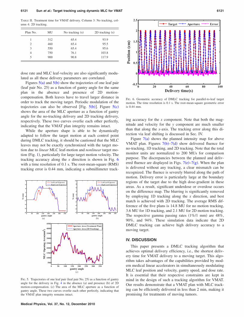
6121 Sun et al.: Target tracking using dynamic MLC for VMAT 6121
dose rate and MLC leaf-velocity are also significantly modu-lated as all these delivery parameters are correlated.
Figures 5�a� and 5�b� show the trajectories of one leaf pair�leaf pair No. 25� as a function of gantry angle for the sameplan in the absence and presence of 2D motion-compensation. Both leaves have to travel larger distance inorder to track the moving target. Periodic modulation of thetrajectories can also be observed �Fig. 5�b��. Figure 5�c�shows the area of the MLC aperture as a function of gantryangle for the no-tracking delivery and 2D tracking delivery,respectively. These two curves overlie each other perfectly,indicating that the VMAT plan integrity remains intact.
While the aperture shape is able to be dynamicallyadapted to follow the target motion at each control pointduring DMLC tracking, it should be cautioned that the MLCleaves may not be exactly synchronized with the target mo-tion due to linear MLC leaf-motion and nonlinear target mo-tion �Fig. 1�, particularly for large target motion velocity. Thetracking accuracy along the x direction is shown in Fig. 6with a time resolution of 0.1 s. The root-mean-square �RMS�tracking error is 0.44 mm, indicating a submillimeter track-
TABLE II. Treatment time for VMAT delivery. Column 3: No tracking, col-umn 4: 2D tracking.
Plan No. MU No tracking �s� 2D tracking �s�
1 312 65.4 93.92 460 65.4 95.53 550 65.4 95.64 750 76.1 103.85 900 90.8 117.9
0 50 100 150 200 250 300 350-8
-6
-4
-2
0
2
4
6
8
gantry angle
X(cm)
Left Leaf TrajectoryRight Leaf Trajectory
(a)
0 50 100 150 200 250 300 350-8
-6
-4
-2
0
2
4
6
8
10
gantry angle
X(cm)
Left Leaf TrajectoryRight Leaf Trajectory
(b)
0 50 100 150 200 250 300 350
500
1000
1500
2000
2500
3000
3500
4000
4500
gantry angle
MLCOpeningArea(mm2 )
Aperture Area (Treatment Plan)Aperture Area (2D Tracking)
(c)
FIG. 5. Trajectories of one leaf pair �leaf pair No. 25� as a function of gantryangle for the delivery in Fig. 4 in the absence �a� and presence �b� of 2Dmotion-compensation. �c� The area of the MLC aperture as a function ofgantry angle. These two curves overlie each other perfectly, indicating that
the VMAT plan integrity remains intact.Medical Physics, Vol. 37, No. 12, December 2010
ing accuracy for the x component. Note that both the mag-nitude and velocity for the y component are much smallerthan that along the x-axis. The tracking error along this di-rection via leaf shifting is discussed in Sec. IV.
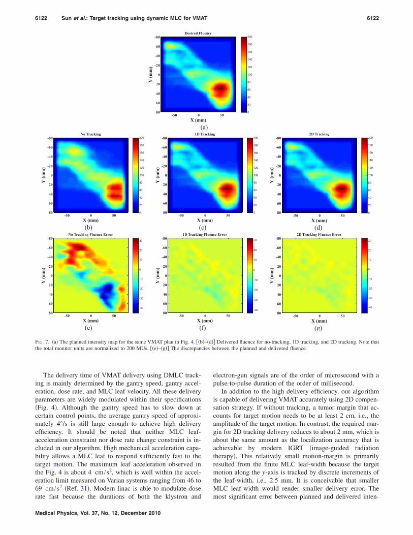
Figure 7�a� shows the planned intensity map for aboveVMAT plan. Figures 7�b�–7�d� show delivered fluence forno-tracking, 1D tracking, and 2D tracking. Note that the totalmonitor units are normalized to 200 MUs for comparisonpurpose. The discrepancies between the planned and deliv-ered fluence are displayed in Figs. 7�e�–7�g�. When the planis delivered without any tracking, a clear mismatch can berecognized. The fluence is severely blurred along the path ofmotion. Delivery error is particularly large at the boundaryregions of the target due to the high dose-gradient in theseareas. As a result, significant underdose or overdose occurson the difference map. The blurring is significantly removedby employing 1D tracking along the x direction, and bestmatch is achieved with 2D tracking. The average RMS dif-ference of the five plans is 14.8 MU for no motion tracking,3.6 MU for 1D tracking, and 2.1 MU for 2D motion tracking.The respective gamma passing rates �1%/1 mm� are 48%,90%, and 94%. These simulation data indicate that 2DDMLC tracking can achieve high delivery accuracy to amoving target.
IV. DISCUSSION
This paper presents a DMLC tracking algorithm thatachieves optimal delivery efficiency, i.e., the shortest deliv-ery time for VMAT delivery to a moving target. This algo-rithm takes advantages of the capabilities provided by mod-ern medical linear accelerators in simultaneously modulatingMLC leaf position and velocity, gantry speed, and dose rate.It is essential that their respective constraints are kept inmind in the design of such a tracking algorithm for VMAT.Our results demonstrate that a VMAT plan with MLC track-ing can be efficiently delivered in less than 2 min, making it
0 20 40 60 80 100-0.5
0
0.5
1
1.5
2
2.5
Delivery time(s)
Position(cm)
Target Aperture Error
FIG. 6. Geometric accuracy of DMLC tracking for parallel-to-leaf targetmotion. The time resolution is 0.1 s. The root-mean-square geometric erroris 0.44 mm.
promising for treatments of moving tumors.
cies b
6122 Sun et al.: Target tracking using dynamic MLC for VMAT 6122
The delivery time of VMAT delivery using DMLC track-ing is mainly determined by the gantry speed, gantry accel-eration, dose rate, and MLC leaf-velocity. All these deliveryparameters are widely modulated within their specifications�Fig. 4�. Although the gantry speed has to slow down atcertain control points, the average gantry speed of approxi-mately 4°/s is still large enough to achieve high deliveryefficiency. It should be noted that neither MLC leaf-acceleration constraint nor dose rate change constraint is in-cluded in our algorithm. High mechanical acceleration capa-bility allows a MLC leaf to respond sufficiently fast to thetarget motion. The maximum leaf acceleration observed inthe Fig. 4 is about 4 cm /s2, which is well within the accel-eration limit measured on Varian systems ranging from 46 to69 cm /s2 �Ref. 31�. Modern linac is able to modulate dose
X (mm
Y(mm)
Desired Fl
-50 0
-80
-60
-40
-20
0
20
40
60
80
(
X (mm)
Y(mm)
No Tracking
-50 0 50
-80
-60
-40
-20
0
20
40
60
80 0
20
40
60
80
100
120
140
160
180
200
(b)X
Y(mm)
1D T
-50
-80
-60
-40
-20
0
20
40
60
80
(c
X (mm)
Y(mm)
No Tracking Fluence Error
-50 0 50
-80
-60
-40
-20
0
20
40
60
80-40
-30
-20
-10
0
10
20
30
(e)X
Y(mm)
1D Tracking
-50
-80
-60
-40
-20
0
20
40
60
80
(
FIG. 7. �a� The planned intensity map for the same VMAT plan in Fig. 4. ��bthe total monitor units are normalized to 200 MUs. ��e�–�g�� The discrepan
rate fast because the durations of both the klystron and
Medical Physics, Vol. 37, No. 12, December 2010
electron-gun signals are of the order of microsecond with apulse-to-pulse duration of the order of millisecond.
In addition to the high delivery efficiency, our algorithmis capable of delivering VMAT accurately using 2D compen-sation strategy. If without tracking, a tumor margin that ac-counts for target motion needs to be at least 2 cm, i.e., theamplitude of the target motion. In contrast, the required mar-gin for 2D tracking delivery reduces to about 2 mm, which isabout the same amount as the localization accuracy that isachievable by modern IGRT �image-guided radiationtherapy�. This relatively small motion-margin is primarilyresulted from the finite MLC leaf-width because the targetmotion along the y-axis is tracked by discrete increments ofthe leaf-width, i.e., 2.5 mm. It is conceivable that smallerMLC leaf-width would render smaller delivery error. The
500
20
40
60
80
100
120
140
160
180
200
g
500
20
40
60
80
100
120
140
160
180
200
X (mm)
Y(mm)
2D Tracking
-50 0 50
-80
-60
-40
-20
0
20
40
60
80 0
20
40
60
80
100
120
140
160
180
200
(d)ce Error
50-40
-30
-20
-10
0
10
20
30
X (mm)
Y(mm)
2D Tracking Fluence Error
-50 0 50
-80
-60
-40
-20
0
20
40
60
80-40
-30
-20
-10
0
10
20
30
(g)
� Delivered fluence for no-tracking, 1D tracking, and 2D tracking. Note thatetween the planned and delivered fluence.
)
uence
a)
(mm)
rackin
0
)
(mm)
Fluen
0
f)
�–�d�
most significant error between planned and delivered inten-
6123 Sun et al.: Target tracking using dynamic MLC for VMAT 6123
sities appears in the boundary regions of a moving target.This agrees with an intuitive perception that errors are preva-lent in the regions where the fluence gradient is the largest.
A variety of approaches have been proposed to improveDMLC tracking efficiency and accuracy for static IMRT.10,12
These approaches also apply to VMAT delivery improve-ment. One approach, for example, is to design a MLC withfaster moving leaves. This will enable the leaves to reach thedesired positions quickly so as to minimize potential under-dose or overdose. This will also reduce gantry modulation sothat the gantry does not have to slow down frequently. Lessgantry modulation and faster leaf-velocity will lead to bothfaster treatment and less dosimetric uncertainty. Another ap-proach is to include a leaf-position gradient constraint forany two adjacent MLC leaves in the static VMAT plan opti-mization. For example, we observe that in one segment of aVMAT plan, two neighboring leaves differ by as much as 2.5cm in spatial position. In order to accomplish leaf-shiftingfor y component compensation, one leaf is required to reachthe other leaf’s position. To ensure that this shifting has suf-ficient time, the gantry has to slow down in a short period oftime from maximum gantry speed of 5.5°/s to about 1°/s. Analternative approach would be to develop a MLC assemblywith movable carriages that can move along the y-axis �per-pendicular to MLC leaf travel direction�, thereby being ableto compensate for the y-axis motion. This solution will notonly avoid the need of shifting MLC leaves but also reducethe delivery error caused by finite MLC leaf-width.
Current algorithm assumes the known target motion priorto the treatment. The motion model is reasonably assumedfor the purpose of future real time clinical implementation.12
A modification of the motion model used in this study mayresult in different delivery efficiencies and accuracies. Forexample, smaller amplitudes in both directions will result inimproved delivery efficiency and accuracy. If the motionalong the y-axis is less than the leaf-width, it will becomeunnecessary to shift the MLC leaves, which avoids largegantry deceleration. As a result, higher efficiency is ex-pected. Delivery efficiency and accuracy also depend ontarget-motion period. For example, if the period decreasesfrom 6 to 3 s, the delivery time will be reduced from 96 to 87s for the VMAT delivery presented in Fig. 4. In addition, thereference phase in our algorithm is assumed to be at thefull-exhale position in a breathing cycle. For different refer-ence phase positions, the delivery time and RMS differencein the fluence map are found to vary less than 10 s and 1.5MU, respectively. Note that the combination of the plannedleaf-velocity and the moving-tumor’s velocity rarely exceedsmaximal permissible MLC leaf-velocity of 3.5 cm/s. If itdoes occur, the VMAT plan with DMLC tracking may not bedeliverable without violating the integrity of a VMAT plan.Analysis of this issue is beyond the scope of this work.
It should be noted that the VMAT plans used in this studyare created based on patient’s anatomy at one particularphase of the respiratory cycle. Relative motion is possiblebetween the target and surrounding normal tissues fromphase to phase. A future refinement would be the design of a
“deliverable” optimized VMAT tracking plan based on aMedical Physics, Vol. 37, No. 12, December 2010
planning 4D CT that accounts for the phase-to-phase posi-tional changes of critical organs with respect to the tumorand deformation of targets.32,33
Finally, the purpose of this study is to develop a DMLCtracking method for VMAT delivery and to illustrate thecomplex interdependence of a number of delivery param-eters. It is not intended as a report on the development of asystem ready for clinical implementation. Although the workpresented in this paper is merely an early study and prelimi-nary in nature, it serves our purpose of deriving a novelsolution for managing the intrafraction motion in the VMATdelivery and is the first step toward the realistic clinicalstudy. Future clinical feasibility and verification studies willinvolve the implementation of this method in the VMAT de-livery software on a linac, a phantom that incorporates a realtime, high resolution three-dimensional dosimeter, and a realtime respiration monitoring device. The realistic systemlatency,12,34 a motion prediction method,35,36 and a “beamhold” mechanism for anomalous conditions will also be in-cluded for experimental demonstration. The experimentalVMAT delivery efficiency and accuracy on a moving targetwill be compared to the results presented in this paper.
V. CONCLUSION
An algorithm for compensating the 2D target motion inthe beam’s eye view has been developed for the VMAT de-livery aiming at the shorted delivery time. The simulationdemonstrates that VMAT treatment to a moving target using2D DMLC motion tracking can be accurately and efficientlydelivered with only half a minute increase in delivery timecompared to delivery without motion-tracking. The deliveryerrors arise mainly from the finite MLC leaf-width, whiledelivery efficiency is mainly determined by the maximumallowed MLC leaf-velocity and by gantry acceleration limit.
ACKNOWLEDGMENTS
The authors thank Dr. Laurence Court for providing Rapi-dArc lung plans. B.S. and H.H.L. are supported in part byNIH Grant Nos. R21CA131690 and R01CA148853.
a�Electronic mail: [email protected]�Electronic mail: [email protected]. J. Keall, G. S. Mageras, J. M. Balter, R. S. Emery, K. M. Forster, S. B.Jiang, J. M. Kapatoes, D. A. Low, M. J. Murphy, B. R. Murray, C. R.Ramsey, M. B. Van Herk, S. S. Vedam, J. W. Wong, and E. Yorke, “Themanagement of respiratory motion in radiation oncology report of AAPMTask Group 76,” Med. Phys. 33, 3874–3900 �2006�.
2C. C. Ling, E. Yorke, H. Amols, J. Mechalakos, Y. Erdi, S. Leibel, K.Rosenzweig, and A. Jackson, “High-tech will improve radiotherapy ofNSCLC: A hypothesis waiting to be validated,” Int. J. Radiat. Oncol.,Biol., Phys. 60, 3–7 �2004�.
3R. Wagman, E. Yorke, E. Ford, P. Giraud, G. Mageras, B. Minsky, and K.Rosenzweig, “Respiratory gating for liver tumors: Use in dose escala-tion,” Int. J. Radiat. Oncol., Biol., Phys. 55, 659–668 �2003�.
4Z. Wang, C. G. Willett, and F. F. Yin, “Reduction of organ motion bycombined cardiac gating and respiratory gating,” Int. J. Radiat. Oncol.,Biol., Phys. 68, 259–266 �2007�.
5S. S. Korreman, A. N. Pedersen, M. Josipovic, L. R. Aarup, T. Juhler-Nottrup, L. Specht, and H. Nystrom, “Cardiac and pulmonary complica-tion probabilities for breast cancer patients after routine end-inspirationgated radiotherapy,” Radiother. Oncol. 80, 257–262 �2006�.
6
P. J. Keall, V. R. Kini, S. S. Vedam, and R. Mohan, “Motion adaptive
6124 Sun et al.: Target tracking using dynamic MLC for VMAT 6124
x-ray therapy: A feasibility study,” Phys. Med. Biol. 46, 1–10 �2001�.7L. Papież, “DMLC leaf-pair optimal control of IMRT delivery for a mov-ing rigid target,” Med. Phys. 31, 2742–2754 �2004�.
8L. Papiez and D. Rangaraj, “DMLC leaf-pair optimal control for mobile,deforming target,” Med. Phys. 32, 275–285 �2005�.
9L. Papiez, D. Rangaraj, and P. Keall, “Real-time DMLC IMRT deliveryfor mobile and deforming targets,” Med. Phys. 32, 3037–3048 �2005�.
10D. Rangaraj, G. Palaniswaamy, and L. Papiez, “DMLC IMRT delivery totargets moving in 2D in beam’s eye view,” Med. Phys. 35, 3765–3778�2008�.
11D. Rangaraj and L. Papiez, “Synchronized delivery of DMLC intensitymodulated radiation therapy for stationary and moving targets,” Med.Phys. 32, 1802–1817 �2005�.
12A. Sawant, R. Venkat, V. Srivastava, D. Carlson, S. Povzner, H. Cattell,and P. Keall, “Management of three-dimensional intrafraction motionthrough real-time DMLC tracking,” Med. Phys. 35, 2050–2061 �2008�.
13D. McQuaid and S. Webb, “IMRT delivery to a moving target by dynamicMLC tracking: Delivery for targets moving in two dimensions in thebeam’s eye view,” Phys. Med. Biol. 51, 4819–4839 �2006�.
14D. McQuaid, M. Partridge, J. R. Symonds-Tayler, P. M. Evans, and S.Webb, “Target-tracking deliveries on an Elekta linac: A feasibility study,”Phys. Med. Biol. 54, 3563–3578 �2009�.
15K. Otto, “Volumetric modulated arc therapy: IMRT in a single gantryarc,” Med. Phys. 35, 310–317 �2008�.
16W. F. Verbakel, J. P. Cuijpers, D. Hoffmans, M. Bieker, B. J. Slotman, andS. Senan, “Volumetric intensity-modulated arc therapy vs. conventionalIMRT in head-and-neck cancer: A comparative planning and dosimetricstudy,” Int. J. Radiat. Oncol., Biol., Phys. 74, 252–259 �2009�.
17V. Feygelman, G. Zhang, and C. Stevens, “Initial dosimetric evaluation ofSmartArc—A novel VMAT treatment planning module implemented in amulti-vendor delivery chain,” J. Appl. Clin. Med. Phys. 11, 3169 �2010�.
18D. Palma, E. Vollans, K. James, S. Nakano, V. Moiseenko, R. Shaffer, M.McKenzie, J. Morris, and K. Otto, “Volumetric modulated arc therapy fordelivery of prostate radiotherapy: Comparison with intensity-modulatedradiotherapy and three-dimensional conformal radiotherapy,” Int. J. Ra-diat. Oncol., Biol., Phys. 72, 996–1001 �2008�.
19G. Tang, M. A. Earl, S. Luan, C. Wang, M. M. Mohiuddin, and C. X. Yu,“Comparing radiation treatments using intensity-modulated beams, mul-tiple arcs, and single arcs,” Int. J. Radiat. Oncol., Biol., Phys. 76, 1554–1562 �2010�.
20S. Ulrich, F. Sterzing, S. Nill, K. Schubert, K. K. Herfarth, J. Debus, andU. Oelfke, “Comparison of arc-modulated cone beam therapy and helicaltomotherapy for three different types of cancer,” Med. Phys. 36, 4702–4710 �2009�.
21Q. J. Wu, F. F. Yin, R. McMahon, X. Zhu, and S. K. Das, “Similaritiesbetween static and rotational intensity-modulated plans,” Phys. Med.Biol. 55, 33–43 �2010�.
22T. Bortfeld and S. Webb, “Single-arc IMRT?,” Phys. Med. Biol. 54, N9–N20 �2009�.
23C. C. Ling, P. Zhang, Y. Archambault, J. Bocanek, G. Tang, and T.Losasso, “Commissioning and quality assurance of RapidArc radio-therapy delivery system,” Int. J. Radiat. Oncol., Biol., Phys. 72, 575–581�2008�.
Medical Physics, Vol. 37, No. 12, December 2010
24L. Court, M. Wagar, R. Berbeco, A. Reisner, B. Winey, D. Schofield, D.Ionascu, A. M. Allen, R. Popple, and T. Lingos, “Evaluation of the inter-play effect when using RapidArc to treat targets moving in the craniocau-dal or right-left direction,” Med. Phys. 37, 4–11 �2010�.
25M. Rao, W. Yang, F. Chen, K. Sheng, J. Ye, V. Mehta, D. Shepard, and D.Cao, “Comparison of Elekta VMAT with helical tomotherapy and fixedfield IMRT: Plan quality, delivery efficiency and accuracy,” Med. Phys.37, 1350–1359 �2010�.
26A. E. Lujan, J. M. Balter, and R. K. Ten Haken, “A method for incorpo-rating organ motion due to breathing into 3D dose calculations in theliver: Sensitivity to variations in motion,” Med. Phys. 30, 2643–2649�2003�.
27Y. Seppenwoolde, H. Shirato, K. Kitamura, S. Shimizu, M. van Herk, J.V. Lebesque, and K. Miyasaka, “Precise and real-time measurement of3D tumor motion in lung due to breathing and heartbeat, measured duringradiotherapy,” Int. J. Radiat. Oncol., Biol., Phys. 53, 822–834 �2002�.
28M. B. Tacke, S. Nill, A. Krauss, and U. Oelfke, “Real-time tumor track-ing: Automatic compensation of target motion using the Siemens 160MLC,” Med. Phys. 37, 753–761 �2010�.
29R. George, S. S. Vedam, T. D. Chung, V. Ramakrishnan, and P. J. Keall,“The application of the sinusoidal model to lung cancer patient respira-tory motion,” Med. Phys. 32, 2850–2861 �2005�.
30E. Weiss, K. Wijesooriya, S. V. Dill, and P. J. Keall, “Tumor and normaltissue motion in the thorax during respiration: Analysis of volumetric andpositional variations using 4D CT,” Int. J. Radiat. Oncol., Biol., Phys. 67,296–307 �2007�.
31K. Wijesooriya, C. Bartee, J. V. Siebers, S. S. Vedam, and P. J. Keall,“Determination of maximum leaf velocity and acceleration of a dynamicmultileaf collimator: Implications for 4D radiotherapy,” Med. Phys. 32,932–941 �2005�.
32Y. Suh, E. Weiss, H. Zhong, M. Fatyga, J. V. Siebers, and P. J. Keall, “Adeliverable four-dimensional intensity-modulated radiation therapy-planning method for dynamic multileaf collimator tumor tracking deliv-ery,” Int. J. Radiat. Oncol., Biol., Phys. 71, 1526–1536 �2008�.
33M. Gui, Y. Feng, B. Yi, A. A. Dhople, and C. Yu, “Four-dimensionalintensity-modulated radiation therapy planning for dynamic tracking us-ing a direct aperture deformation �DAD� method,” Med. Phys. 37, 1966–1975 �2010�.
34L. Santanam, C. Noel, T. R. Willoughby, J. Esthappan, S. Mutic, E. E.Klein, D. A. Low, and P. J. Parikh, “Quality assurance for clinical imple-mentation of an electromagnetic tracking system,” Med. Phys. 36, 3477–3486 �2009�.
35S. S. Vedam, P. J. Keall, A. Docef, D. A. Todor, V. R. Kini, and R.Mohan, “Predicting respiratory motion for four-dimensional radio-therapy,” Med. Phys. 31, 2274–2283 �2004�.
36G. C. Sharp, S. B. Jiang, S. Shimizu, and H. Shirato, “Prediction ofrespiratory tumour motion for real-time image-guided radiotherapy,”Phys. Med. Biol. 49, 425–440 �2004�.
37Y. Song, P. Zhang, C. Obcemea, B. Mueller, C. Chandra, and B. Mychal-czak, “Dosimetric effects of gantry angular acceleration and decelerationin volumetric modulated radiation therapy,” International Federation forMedical and Biological Engineering �IFMBE� Proceedings, 2009, Vol.25, pp. 1046–1050.


![[- 200 [ PROVIDING MODULATED COMMUNICATION SIGNALS ]](https://static.fdokumen.com/doc/165x107/6328adc85c2c3bbfa804c60f/-200-providing-modulated-communication-signals-.jpg)


