T-Server for Avaya Communication Manager Deployment Guide
278
Framework 8.0 T-Server for Avaya Communication Manager Deployment Guide
-
Upload
khangminh22 -
Category
Documents
-
view
7 -
download
0
Transcript of T-Server for Avaya Communication Manager Deployment Guide

Framework 8.0
T-Server for Avaya Communication Manager
Deployment Guide

The information contained herein is proprietary and confidential and cannot be disclosed or duplicated without the prior written consent of Genesys Telecommunications Laboratories, Inc.
Copyright © 2001–2009 Genesys Telecommunications Laboratories, Inc. All rights reserved.
About GenesysGenesys Telecommunications Laboratories, Inc., a subsidiary of Alcatel-Lucent, is 100% focused on software for contact centers. Genesys recognizes that better interactions drive better business and build company reputations. Customer service solutions from Genesys deliver on this promise for Global 2000 enterprises, government organizations, and telecommunications service providers across 80 countries, directing more than 100 million customer interactions every day. Sophisticated routing and reporting across voice, e-mail, and Web channels ensure that customers are quickly connected to the best available resource—the first time. Genesys offers solutions for customer service, help desks, order desks, collections, outbound telesales and service, and workforce management. Visit www.genesyslab.com for more information.
Each product has its own documentation for online viewing at the Genesys Technical Support website or on the Documentation Library DVD, which is available from Genesys upon request. For more information, contact your sales representative.
NoticeAlthough reasonable effort is made to ensure that the information in this document is complete and accurate at the time of release, Genesys Telecommunications Laboratories, Inc., cannot assume responsibility for any existing errors. Changes and/or corrections to the information contained in this document may be incorporated in future versions.
Your Responsibility for Your System’s SecurityYou are responsible for the security of your system. Product administration to prevent unauthorized use is your responsibility. Your system administrator should read all documents provided with this product to fully understand the features available that reduce your risk of incurring charges for unlicensed use of Genesys products.
TrademarksGenesys, the Genesys logo, and T-Server are registered trademarks of Genesys Telecommunications Laboratories, Inc. All other trademarks and trade names referred to in this document are the property of other companies. The Crystal monospace font is used by permission of Software Renovation Corporation, www.SoftwareRenovation.com.
Technical Support from VARsIf you have purchased support from a value-added reseller (VAR), please contact the VAR for technical support.
Technical Support from GenesysIf you have purchased support directly from Genesys, please contact Genesys Technical Support at the regional numbers provided on page 13. For complete contact information and procedures, refer to the Genesys Technical Support Guide.
Ordering and Licensing InformationComplete information on ordering and licensing Genesys products can be found in the Genesys Licensing Guide.
Released by
Genesys Telecommunications Laboratories, Inc. www.genesyslab.com
Document Version: 80fr_dep-ts_avayag3_11-2009_v8.0.002.00

T-Server—Deployment Guide 3
Table of ContentsList ofProcedures ................................................................................................................... 9
Preface ................................................................................................................. 11
About T-Server for Avaya Communication Manager ............................... 11Intended Audience................................................................................... 12
Reading Prerequisites ........................................................................ 13Making Comments on This Document .................................................... 13Contacting Genesys Technical Support................................................... 13Document Change History ...................................................................... 14
Part 1 Common Functions and Procedures ........................ 15
New for All T-Servers in 8.0..................................................................... 15
Chapter 1 T-Server Fundamentals........................................................................ 17
Learning About T-Server ......................................................................... 18Framework and Media Layer Architecture.......................................... 18T-Server Requests and Events ........................................................... 20
Advanced Disconnect Detection Protocol ............................................... 23Redundant T-Servers .............................................................................. 24Multi-Site Support .................................................................................... 28Agent Reservation ................................................................................... 28Client Connections .................................................................................. 29Next Steps ............................................................................................... 29
Chapter 2 T-Server General Deployment ............................................................. 31
Prerequisites............................................................................................ 31Software Requirements ...................................................................... 32Hardware and Network Environment Requirements .......................... 33Licensing Requirements ..................................................................... 33About Configuration Options............................................................... 35
Deployment Sequence ............................................................................ 36

Table of Contents
4 Framework 8.0
Wizard Deployment of T-Server .............................................................. 36Wizard Configuration of T-Server ....................................................... 37Wizard Installation of T-Server............................................................ 37
Manual Deployment of T-Server.............................................................. 39Manual Configuration of Telephony Objects ....................................... 40Manual Configuration of T-Server....................................................... 42Manual Installation of T-Server ........................................................... 44
Next Steps ............................................................................................... 46
Chapter 3 High-Availability Deployment.............................................................. 49
Warm Standby Redundancy Type ........................................................... 50Hot Standby Redundancy Type ............................................................... 51Prerequisites............................................................................................ 53
Requirements...................................................................................... 53Synchronization Between Redundant T-Servers ................................ 53
Warm Standby Deployment ..................................................................... 54General Order of Deployment............................................................. 54Manual Modification of T-Servers for Warm Standby.......................... 55Warm Standby Installation of Redundant T-Servers ........................... 56
Hot Standby Deployment......................................................................... 56General Order of Deployment............................................................. 56Manual Modification of T-Servers for Hot Standby.............................. 57Hot Standby Installation of Redundant T-Servers ............................... 60
Next Steps ............................................................................................... 60
Chapter 4 Multi-Site Support................................................................................. 61
Multi-Site Fundamentals.......................................................................... 62ISCC Call Data Transfer Service ............................................................. 63
ISCC Call Flows.................................................................................. 64ISCC Transaction Types ..................................................................... 70T-Server Transaction Type Support .................................................... 78Transfer Connect Service Feature...................................................... 82
ISCC/Call Overflow Feature .................................................................... 83Number Translation Feature.................................................................... 87
Number Translation Rules .................................................................. 88Network Attended Transfer/Conference Feature..................................... 95Event Propagation Feature...................................................................... 97
User Data Propagation ....................................................................... 98Party Events Propagation ................................................................... 99Switch Partitioning ............................................................................ 100Event Propagation Configuration ...................................................... 101
ISCC Transaction Monitoring Feature ................................................... 104
T-Server—Deployment Guide 5
Table of Contents
Configuring Multi-Site Support............................................................... 104Applications ...................................................................................... 105Switches and Access Codes ............................................................ 106DNs................................................................................................... 112Configuration Examples.................................................................... 117
Next Steps ............................................................................................. 118
Chapter 5 Start and Stop T-Server Components .............................................. 119
Command-Line Parameters .................................................................. 119Starting and Stopping with the Management Layer ............................... 121Starting with Startup Files ...................................................................... 122Starting Manually ................................................................................... 123
HA Proxy........................................................................................... 126T-Server ............................................................................................ 127
Verifying Successful Startup .................................................................. 129Stopping Manually ................................................................................. 129Starting and Stopping with Windows Services Manager ....................... 130Next Steps ............................................................................................. 130
Part 2 Reference Information .............................................. 131
New in T-Server for Avaya Communication Manager ........................... 132
Chapter 6 Switch-Specific Configuration .......................................................... 133
Known Limitations ................................................................................. 133Setting DN Types .................................................................................. 135Configuring Links and Switches ............................................................ 136
Configuring the CTI Link ................................................................... 136Configuring the ASAI Link................................................................. 137Configuring an ASAI Station ............................................................. 139Configuring TACW ............................................................................ 140
Configuring AES connections................................................................ 142ISDN Network Redirection..................................................................... 143Avaya Communication Manager Requirements .................................... 144
Configuring an ASAI Split ................................................................. 145Genesys Requirements for Avaya Communication Manager................ 146
Chapter 7 Supported Functionality .................................................................... 149
T-Library Functionality ........................................................................... 149Support for Agent Work Modes ............................................................. 158Support for Replacing Calling Party Number......................................... 159

Table of Contents
6 Framework 8.0
Support for Real-Time Agent State Using Device, Media and Call Control API .................................................................................................... 159
Support for Notification of Failed Routing Attempts............................... 160Use of the Extensions Attribute ............................................................. 161Use of the UserData Attribute................................................................ 172Error Messages ..................................................................................... 173Avaya Enterprise Survivable Server (ESS) ........................................... 179
Avaya ESS Architecture.................................................................... 180Typical ESS Failure Support Scenarios............................................ 182
Avaya Switch Partitioning ...................................................................... 185
Chapter 8 Common Configuration Options....................................................... 187
Setting Configuration Options................................................................ 188Mandatory Options ................................................................................ 188Log Section............................................................................................ 188
Log Output Options........................................................................... 194Examples .......................................................................................... 199Debug Log Options........................................................................... 200
Log-Extended Section ........................................................................... 202Log-Filter Section .................................................................................. 204Log-Filter-Data Section.......................................................................... 205SML Section .......................................................................................... 205Common Section ................................................................................... 205Changes from 7.6 to 8.0 ........................................................................ 206
Chapter 9 T-Server Common Configuration Options ....................................... 207
Setting Configuration Options................................................................ 207Mandatory Options ................................................................................ 208T-Server Section.................................................................................... 208License Section ..................................................................................... 213Agent-Reservation Section.................................................................... 216Multi-Site Support Section ..................................................................... 217
ISCC Transaction Options ................................................................ 219Transfer Connect Service Options.................................................... 223ISCC/COF Options ........................................................................... 224Event Propagation Options ............................................................... 226Number Translation Option............................................................... 227
Translation Rules Section...................................................................... 227Backup-Synchronization Section........................................................... 228Call-Cleanup Section............................................................................. 229Security Section..................................................................................... 231

T-Server—Deployment Guide 7
Table of Contents
Timeout Value Format ........................................................................... 231Changes from Release 7.6 to 8.0.......................................................... 232
Chapter 10 T-Server-Specific Configuration Options......................................... 233
Mandatory Options ................................................................................ 233T-Server Section.................................................................................... 234
Predictive Dialing Options................................................................. 250Avaya Communication Manager Ethernet Option............................. 252Flow Control Options ........................................................................ 252
Query-Agent-State Section.................................................................... 253CTI-Link Section .................................................................................... 256DN-Specific Options .............................................................................. 257CTI-Link Section for DMCC................................................................... 258Changes from Release 7.6 to 8.0.......................................................... 259
Chapter 11 Supported High-Availability Configurations.................................... 261
HA Default Configuration....................................................................... 261Examples of Warm Standby Configurations .......................................... 262
Supplements Related Documentation Resources ................................................... 265
Document Conventions ...................................................................... 267
Index ............................................................................................................... 269

Table of Contents
8 Framework 8.0

T-Server—Deployment Guide 9
List of ProceduresInstalling T-Server on UNIX using Wizard . . . . . . . . . . . . . . . . . . . . . . . 38
Installing T-Server on Windows using Wizard . . . . . . . . . . . . . . . . . . . . 39
Configuring T-Server manually. . . . . . . . . . . . . . . . . . . . . . . . . . . . . . . . 42
Configuring multiple ports . . . . . . . . . . . . . . . . . . . . . . . . . . . . . . . . . . . 43
Installing T-Server on UNIX manually . . . . . . . . . . . . . . . . . . . . . . . . . . 44
Installing T-Server on Windows manually . . . . . . . . . . . . . . . . . . . . . . . 45
Verifying the manual installation of T-Server . . . . . . . . . . . . . . . . . . . . . 46
Modifying the primary T-Server configuration for warm standby . . . . . . 55
Modifying the backup T-Server configuration for warm standby . . . . . . 56
Modifying the primary T-Server configuration for hot standby . . . . . . . . 57
Modifying the backup T-Server configuration for hot standby . . . . . . . . 59
Activating Transfer Connect Service . . . . . . . . . . . . . . . . . . . . . . . . . . . 82
Configuring Number Translation. . . . . . . . . . . . . . . . . . . . . . . . . . . . . . . 95
Activating Event Propagation: basic configuration . . . . . . . . . . . . . . . . 102
Modifying Event Propagation: advanced configuration . . . . . . . . . . . . 102
Configuring T-Server Applications . . . . . . . . . . . . . . . . . . . . . . . . . . . . 105
Configuring Default Access Codes. . . . . . . . . . . . . . . . . . . . . . . . . . . . 107
Configuring Access Codes . . . . . . . . . . . . . . . . . . . . . . . . . . . . . . . . . . 108
Configuring access resources for the route transaction type . . . . . . . . 112
Configuring access resources for the dnis-pool transaction type . . . . . 114
Configuring access resources for direct-* transaction types . . . . . . . . 114
Configuring access resources for ISCC/COF. . . . . . . . . . . . . . . . . . . . 115
Configuring access resources for non-unique ANI . . . . . . . . . . . . . . . . 115
Modifying DNs for isolated switch partitioning . . . . . . . . . . . . . . . . . . . 116
Configuring T-Server to start with the Management Layer. . . . . . . . . . 121
Starting T-Server on UNIX with a startup file . . . . . . . . . . . . . . . . . . . . 122
Starting T-Server on Windows with a startup file . . . . . . . . . . . . . . . . . 123
Starting HA Proxy on UNIX manually . . . . . . . . . . . . . . . . . . . . . . . . . . 127
Starting HA Proxy on Windows manually . . . . . . . . . . . . . . . . . . . . . . . 127

List of Procedures
10 Framework 8.0
Starting T-Server on UNIX manually . . . . . . . . . . . . . . . . . . . . . . . . . . 128
Starting T-Server on Windows manually . . . . . . . . . . . . . . . . . . . . . . . 128
Stopping T-Server on UNIX manually . . . . . . . . . . . . . . . . . . . . . . . . . 129
Stopping T-Server on Windows manually . . . . . . . . . . . . . . . . . . . . . . 129
Configuring the CTI Link. . . . . . . . . . . . . . . . . . . . . . . . . . . . . . . . . . . . 137

T-Server—Deployment Guide 11
PrefaceWelcome to the Framework 8.0 T-Server for Avaya Communication Manager. This document introduces you to the concepts, terminology, and procedures relevant to T-Servers® in general and provides detailed reference information about T-Server for Avaya Communication Manager. The reference information includes, but is not limited to, configuration options, limitations, and switch-specific functionality. You must configure the configuration objects and options described in this document in the Framework Configuration Layer.
Use this document only after you have read through the Framework 8.0 Deployment Guide, and the Release Note for your T-Server.
This document is valid only for the 8.0 release of this product.
Note: For releases of this document created for other releases of this product, please visit the Genesys Technical Support website, or request the Documentation Library CD, which you can order by e-mail from Genesys Order Management at [email protected].
This preface provides an overview of this document, identifies the primary audience, introduces document conventions, and lists related reference information: About T-Server for Avaya Communication Manager, page 11 Intended Audience, page 12 Making Comments on This Document, page 13 Contacting Genesys Technical Support, page 13 Document Change History, page 14
About T-Server for Avaya Communication Manager
T-Server is the Genesys software component that provides an interface between your telephony hardware and the rest of the Genesys software components in your enterprise. It translates and keeps track of events and requests that come from, and are sent to, the CTI (computer-telephony

12 Framework 8.0
Preface Intended Audience
integration) link in the telephony device. T-Server is a TCP/IP-based server that can also act as a messaging interface between T-Server clients. It is the critical point in allowing your Genesys solution to facilitate and track the contacts that flow through your enterprise.
Note that the T-Server name has changed over the course of previous releases for various reasons (including, but not limited to, changes in vendor name or in Genesys policy). The former names include:
• T-Server for Lucent DEFINITY G3.
• T-Server for Avaya DEFINITY ECS (G3).
• T-Server for Avaya DEFINITY ECS (MV).
The current name is T-Server for Avaya Communication Manager.
Intended AudienceThis guide is intended primarily for system administrators, both those who are new to T-Server and those who are familiar with it.
• If you are new to T-Server, read the Framework 8.0 Deployment Guide and the Release Note, and then read all of the sections of this document that apply to your software and its accompanying components. Refer back to the Framework 8.0 Deployment Guide as needed.
• If you are an experienced T-Server user—someone with computer expertise, who is used to installing, configuring, testing, or maintaining Genesys software—you may find it more time efficient to go to the Index to see what is new or different in T-Server release 8.0. If you take that approach, please also read Release Notes and refer to other related resources, such as the Genesys 7Events and Models Reference Manual and Voice Platform SDK 8.0 .NET (or Java) API Reference for complete information on the T-Server events, call models, and requests.
In general, this document assumes that you have a basic understanding of, and familiarity with:
• Computer-telephony integration concepts, processes, terminology, and applications.
• Network design and operation.
• Your own network configurations.
• Your telephony hardware and software.
• Genesys Framework architecture and functions.
• Configuration Manager interface and object-managing operations.
Based on your specific contact center environment and your responsibilities in it, you may need to be familiar with a much wider range of issues as you deploy T-Server.

T-Server—Deployment Guide 13
Preface Making Comments on This Document
Reading Prerequisites
You must read the Framework 8.0 Deployment Guide before using this T-Server Deployment Guide. The Framework 8.0 Deployment Guide contains information about the Genesys software you must deploy before deploying T-Server.
Making Comments on This DocumentIf you especially like or dislike anything about this document, please feel free to e-mail your comments to [email protected].
You can comment on what you regard as specific errors or omissions, and on the accuracy, organization, subject matter, or completeness of this document. Please limit your comments to the information in this document only and to the way in which the information is presented. Speak to Genesys Technical Support if you have suggestions about the product itself.
When you send us comments, you grant Genesys a nonexclusive right to use or distribute your comments in any way it believes appropriate, without incurring any obligation to you.
Contacting Genesys Technical SupportIf you have purchased support directly from Genesys, contact Genesys Technical Support at the following regional numbers:
Region Telephone E-Mail
North and Latin America +888-369-5555 (toll-free)+506-674-6767
Europe, Middle East, and Africa
+44-(0)-1276-45-7002 [email protected]
Asia Pacific +61-7-3368-6868 [email protected]
Malaysia 1-800-814-472 (toll-free)+61-7-3368-6868
India 1-800-407-436379 (toll-free)+91-(022)-3918-0537
Japan +81-3-6361-8950 [email protected]
Before contacting technical support, refer to the Genesys Technical Support Guide for complete contact information and procedures.

14 Framework 8.0
Preface Document Change History
Document Change HistoryThis section lists topics that are new or that have changed significantly since the first release of this document.
• Added the UCID key to the Extension attributes to the following table: Table 15 on page 161.
• Added section on Avaya Switch Partitioning. See “Avaya Switch Partitioning” on page 185.
• Added enable-dmcc option. See “enable-dmcc” on page 257.

T-Server—Deployment Guide 15
Part
1 Common Functions and ProceduresPart One of this T-Server Deployment Guide familiarizes the reader with T-Server in general. It addresses architectural, functional, and procedural information common to all T-Servers.
The information in Part One is divided into the following chapters:
• Chapter 1, “T-Server Fundamentals,” on page 17, describes T-Server, its place in the Framework 8 architecture, T-Server redundancy, and multi-site issues. It stops short of providing configuration and installation information.
• Chapter 2, “T-Server General Deployment,” on page 31, presents configuration and installation procedures for all T-Servers.
• Chapter 3, “High-Availability Deployment,” on page 49, addresses high availability (HA).
• Chapter 4, “Multi-Site Support,” on page 61, details the variations available for T-Server implementations across geographical locations.
• Chapter 5, “Start and Stop T-Server Components,” on page 119, describes how, and in what order, to start up T-Server among other Framework components. It also provides possible stopping commands.
New for All T-Servers in 8.0Before looking at T-Server’s place in Genesys solutions and in the architecture of the Genesys Framework, note the following general changes that have been implemented in the 8.0 release of T-Server:
• Enhanced Event Propagation support for switch partitioning. T-Server now supports the Event Propagation feature in deployments that use switch partitioning or intelligent trunks. See “Switch Partitioning” on page 100.

16 Framework 8.0
Part 1: Common Functions and Procedures New for All T-Servers in 8.0
• Enhanced ISCC Transaction Monitoring support. T-Server now supports new key-value pairs in AttributeExtensions with ISCC transaction data requested using TGetAccessNumber in the following requests: TMakeCall, TRouteCall, TSingleStepTransfer, TInitiateTransfer, TInitiateConference, and TMuteTransfer. The ISCC Transaction Monitoring allows T-Server clients to monitor ISCC transactions of the call data transfer between T-Servers in a multi-site environment. See “ISCC Transaction Monitoring Feature” on page 104 and the Genesys 7 Events and Models Reference Manual for details about key-value pairs in AttributeExtensions.
• Enhanced Agent Reservation support. T-Server now supports Agent Reservation failure optimization, to ensure that only agent reservation requests of the highest priority are collected. This functionality can now be controlled with the collect-lower-priority-requests configuration option. See “Agent Reservation” on page 28 for details.
• Link bandwidth reporting support. T-Server now supports notification of link bandwidth utilization. The following two new log events have been introduced: 20009|STANDARD|MSG_TS_COMMON_LINK_ALARM_HIGH
20010|STANDARD|MSG_TS_COMMON_LINK_ALARM_LOW
Refer to Framework 8.0 Combined Log Events Help for information about the log events.
• Notification of failed routing attempts and failed ISCC transactions. T-Server now supports notification of failed routing attempts and failed ISCC transactions. The following new log events have been introduced: 20011|STANDARD|MSG_TS_COMMON_ALARM_ROUTE_FAILURE_HIGH_WATER_MARK
20012|STANDARD|MSG_TS_COMMON_ALARM_ROUTE_FAILURE_LOW_WATER_MARK
21019|STANDARD|ISCC_LOGMSG_TRANSACTION_FAILED
Refer to Framework 8.0 Combined Log Events Help for information about the log events.
• Real-time SDN licenses query support. T-Server can now report how many SDN licenses are currently available and in use, using the following key-value pairs in AttributeExtensions in EventServerInfo messages: sdn-licenses-in-use and sdn-licenses-available. See Part Two of this document for details on the use of AttributeExtensions in a particular T-Server.
Notes: Configuration option changes common to all T-Servers are described in “Changes from Release 7.6 to 8.0” on page 232.
For information about the new features that are available in your T-Server in the initial 8.0 release, see Part Two of this document.

T-Server—Deployment Guide 17
Chapter
1 T-Server FundamentalsThis chapter provides general information about T-Server features and functionality and about its configuration and installation. For reference information about your specific T-Server and about options for all T-Servers, see “Part Two: Reference Information.”
This chapter has various levels of information, some of it intended for people who have configured, installed, and used previous releases of T-Server, and some of it aimed at those less familiar with such T-Server operations. That means some sections will not necessarily be relevant for you.
• If you are an experienced user of T-Server, start with “New for All T-Servers in 8.0” on page 15, and then move to the chapters comprising Part Two of this document, where specific information about your T-Server is available.
• If you are new to T-Server, begin with “Learning About T-Server.” Once you have read through that and subsequent sections, you are ready for the other chapters in Part One that go into detail about T-Server configuration and installation.
Generally, this chapter presents overview information that applies to all T-Servers (and Network T-Servers) and their deployment. This chapter is divided into the following sections: Learning About T-Server, page 18 Advanced Disconnect Detection Protocol, page 23 Redundant T-Servers, page 24 Multi-Site Support, page 28 Agent Reservation, page 28 Client Connections, page 29 Next Steps, page 29

18 Framework 8.0
Chapter 1: T-Server Fundamentals Learning About T-Server
Learning About T-ServerThe Framework 8.0 Deployment Guide provides you with a high-level introduction to the role that T-Server plays in the Genesys Framework. If you have already looked through that guide, you may recall that T-Server is the most important component of the Framework Media Layer (the other two components are Load Distribution Server (LDS) and HA Proxy). The Media Layer enables Genesys solutions to communicate with various media, including traditional telephony systems, voice over IP (VoIP), e-mail, and the Web. This layer also provides the mechanism for distributing interaction-related business data, also referred to as attached data, within and across solutions.
Framework and Media Layer Architecture
Figure 1 illustrates the position Framework holds in a Genesys solution.
Figure 1: Framework in a Genesys Solution
Moving a bit deeper, Figure 2 presents the various layers of the Framework architecture.
GenesysFramework
Agent Desktop
Genesys Applications
Switch
IVR

Chapter 1: T-Server Fundamentals Learning About T-Server
T-Server—Deployment Guide 19
Figure 2: The Media Layer in the Framework Architecture
T-Server is the heart of the Media Layer—translating the information of the media-device realm into information that Genesys solutions can use. It enables your contact center to handle the computer-based form of the interactions that arrive and it translates the information surrounding a customer contact into reportable and actionable data.
Figure 3 presents the generalized architecture of the Media Layer.
Figure 3: Media Layer Architecture
In addition to being the most important component of the Media Layer, T-Server plays the most significant role in making information about telephony traffic and its data available to Framework as a whole.
One or more components in practically every solution are T-Server clients. Solutions comprise a number of different Genesys software packages, from collections of components for various types of routing to those that allow for
Services Layer
Media Layer(includingT-Server)
Routing Services
Reporting Services
Framework
Management Layer
Configuration Layer
SOLUTIONS
Internet Media
Traditional Telephony
VoIP Telephony
Interaction Server
T-Servers for IP SolutionsT-Servers

20 Framework 8.0
Chapter 1: T-Server Fundamentals Learning About T-Server
outbound dialing to still others. Framework in general, and T-Server in particular, enable these solutions to function in your enterprise.
T-Server has several typical clients: Stat Server, Call Concentrator, Universal Routing Server, and agent desktop applications. T-Server gets the information it needs about the enterprise from Configuration Server. Additionally, if you use the Management Layer, T-Server provides its ongoing status and various other log messages to server components of the Management Layer (for instance, allowing you to set alarms).
T-Server Requests and Events
This section outlines the roles that T-Server plays in a contact center. While it is possible to describe roles for all T-Servers, at a detailed level, T-Server’s functionality depends on the hardware to which it is connected. (For example, when connected to a traditional switch, it performs CTI functions, but when connected to a VOIP-based telephony device, it controls IP traffic.) The CTI connection is only for the switch.
Details of T-Server Functionality
T-Server is a TCP/IP server that enables intelligent communication between media-specific protocols (such as the various CTI protocols, including CSTA and ASAI) and TCP/IP-based clients of T-Server. Applications that are clients to T-Server use the T-Library format to transmit requests to T-Server through a TCP/IP socket. T-Server can then either translate those requests to CTI protocol for switch use or relay them directly to other TCP/IP clients.
T-Server performs three general functions in the contact center: Bridging, Messaging, and Interaction Tracking.
Bridging
T-Server acts as a platform-independent interface between media devices and business applications. In the case of a telephony device, for instance, it receives messages from and sends commands to the telephony equipment using either CTI links provided by the switch manufacturer or interface protocols provided by telephony network vendors.
On the client-application end, T-Server offers three models (call model, agent model, and device model) unified for all switches. The core functionality (such as processing an inbound call, an agent login, or a call-forwarding request) translates into a unified application programming interface (API) called T-Library, so that applications do not need to know what specific switch model they are dealing with. On the other hand, T-Library accommodates many functions that are unique to a specific switch, so that client applications are able to derive the maximum functionality offered by a particular switch.
Refer to the Genesys 7 Events and Models Reference Manual for complete information on all T-Server events and call models and to the

Chapter 1: T-Server Fundamentals Learning About T-Server
T-Server—Deployment Guide 21
TServer.Requests portion of the Voice Platform SDK 8.0 .NET (or Java) API Reference for technical details of T-Library functions.
Messaging
In addition to translating requests and events for the client application involved in an interaction, T-Server:
• Provides a subscription mechanism that applications can use to receive notifications about interaction-related and non-interaction-related events within the contact center.
• Broadcasts messages of major importance (such as a notification that the link is down) to all clients.
• Broadcasts messages originated by a T-Server client to other T-Server clients.
The subscription mechanism consists of two parts, the DN subscription and event-type masking. Applications must register for a DN or a set of DNs to receive notifications about all events that occur in association with each registered DN. For example, when two softphone applications are registered for the same DN, and the first application initiates a call from the DN, T-Server notifies both applications that the call is initiated from the DN.
Client applications can also specify one or more types of events, and T-Server will filter out events of the non-specified types and only send events of the requested types. For example, if agent supervisors are interested in receiving agent-related events, such as AgentLogin and AgentLogout, they have to mask EventAgentLogin and EventAgentLogout, provided that a particular T-Server supports these events.
The combination of each client’s subscription for DNs and masking of event types defines what messages T-Server distributes to what client.
Interaction Tracking
T-Server maintains call information for the life of the call (or other T-Server-supported media type) and enables client applications to attach user data to the call. Call information includes:
• A unique identifier, connection ID, that T-Server assigns when creating the call.
• Automatic Number Identification (ANI) and Dialed Number Identification Service (DNIS), if reported by the CTI link.
• User data that a client application (such as an Interactive Voice Response unit or Genesys Universal Routing Server) provides.
Difference and Likeness Across T-Servers
Although Figure 3 on page 19 (and other figures) depicts T-Server that works with telephony systems as a single product, this is a simplification. Because

22 Framework 8.0
Chapter 1: T-Server Fundamentals Learning About T-Server
almost every traditional telephony device has its own characteristics and communication protocols, Genesys makes different T-Servers for different telephony systems. (That means your T-Server will not work with another switch.) Thus, all T-Servers play a common role in the architecture, but their specific features differ from implementation to implementation, based on the media device in use.
Despite their switch-based differences, T-Servers for telephony systems are similar to one another in at least one important respect: they are all built with a certain amount of shared software code. This shared code is rolled into a single unit and is called T-Server Common Part (TSCP). TSCP is the central, common component for all T-Servers and has its own Release Note, which is accessible via a hyperlink from your T-Server’s Release Note.
T-Server Functional Steps During a Sample Call
The following example, Figure 4, outlines some basic steps that T-Server might take when a call arrives from outside the contact center. In this scenario, T-Server starts tracking the call even before it is delivered to the agent. T-Server then informs the selected agent that a call has arrived. When the switch delivers the call to the agent’s extension, T-Server presents account information, collected at an Interactive Voice Response (IVR) unit, to the agent at the agent desktop application.
Figure 4: Functional T-Server Steps
Note: This document separates common-code features based on TSCP into separate sections and chapters, such as the “T-Server Common Configuration Options” chapter. These are the options for all T-Servers that TSCP makes available for configuration.
1. Switch notifiesT-Server of call arrival. T-Server assigns ConnID.
3. IVR asks T-Server to attach the account number to the call.2. Switch delivers a call to
IVR for automated service.
4. IVR sends the call to an ACD queue.
5. ACD diverts the call to an agent DN.
6. T-Server notifies the agent application of the call.
7. T-Server delivers the call data to the desktop.
Agent DNSwitch
T-Server Agent Desktop Application
IVR

Chapter 1: T-Server Fundamentals Advanced Disconnect Detection Protocol
T-Server—Deployment Guide 23
Step 1
When the call arrives at the switch, T-Server creates a call in its internal structure. T-Server assigns the call a unique identifier, connection ID.
Step 2
The switch delivers the call to an Interactive Voice Response (IVR) unit, which begins automated interactions with the caller.
Step 3
IVR acquires user information from the caller through prompts and requests T-Server to attach that information to the call. T-Server updates the call with the user information.
Step 4
IVR sends the call to an ACD (Automated Call Distribution) queue.
Step 5
The ACD unit distributes the call to an available agent logged in to a particular DN (directory number).
Step 6
T-Server notifies the agent desktop application that the call is ringing on the agent DN. The notification event contains call data including ANI, DNIS, and account information that the IVR has collected.
Step 7
The agent desktop application presents the account information, including the name of the person whose account this is, on the agent’s screen, so that the agent answering the call has all the relevant information.
These seven steps illustrate just a small part of T-Server’s bridging, messaging, and interaction-processing capabilities.
Advanced Disconnect Detection ProtocolSince the 6.0 release of T-Server, the Advanced Disconnect Detection Protocol (ADDP) has replaced the Keep-Alive Protocol (KPL) as the method to detect
24 Framework 8.0
Chapter 1: T-Server Fundamentals Redundant T-Servers
failures for certain T-Server connections, including connections between two T-Servers and between a T-Server and its clients.
With ADDP, protocol activation and initialization is made on the client’s side and you can change these parameters. No additional messages are sent when there is existing activity over the connection. T-Server client applications and the remote T-Server (if any) must be listening to the socket and respond promptly to the polling signal for the connection to be preserved.
If you are going to enable ADDP, you must do it using the protocol, addp-timeout, addp-remote-timeout, and addp-trace configuration options. When configuring a timeout, consider the following issues:
• The configured timeout must be at least twice as long as the maximum network latency.
• There may be an interval when T-Server does not check for network activity.
• If the link connection fails but the client is not notified (for example, because the host is turned off, or because a network cable is unplugged), the maximum reaction time to a link-connection failure is equal to double the configured timeout plus the established network latency.
Also keep in mind that the T-Server receiving the polling signal may not respond immediately, and that a delay occurs after the polling signal, while the response travels from one T-Server to another. If you do not account for these contingencies when configuring a timeout, the connection that ADDP is monitoring will be dropped periodically.
Redundant T-ServersT-Servers can operate in a high-availability (HA) configuration, providing you with redundant systems. The basics of each T-Server’s redundant capabilities differ from T-Server to T-Server. One basic principle of redundant T-Servers is the standby redundancy type, which dictates how quickly a backup T-Server steps in when the primary T-Server goes down.
The Framework Management Layer currently supports two types of redundant configurations: warm standby and hot standby. All T-Servers offer the warm standby redundancy type and, starting with release 7.1, the hot standby redundancy type is implemented in T-Servers for most types of switches. (See Table 1 on page 25.)
Notes: Starting with release 7.5, the KPL backward-compatibility feature is no longer supported.
ADDP applies only to connections between Genesys software components.

Chapter 1: T-Server Fundamentals Redundant T-Servers
T-Server—Deployment Guide 25
Instructions for configuring T-Server redundancy are available in Chapter 3, “High-Availability Configuration and Installation.” Specifics on your T-Server’s HA capabilities are outlined in Part Two of this document.
Support for Hot Standby Redundancy in Various T-Servers
Use Table 1 to determine whether your T-Server supports the hot standby redundancy type. The table also indicates whether HA Proxy components are required for this support, and, if so, how many are required per pair of redundant T-Servers (or per link if so noted).
Table 1 only summarizes hot standby redundancy support in various T-Servers. For detailed, up-to-date information on the subject, see the Genesys Supported Media Interfaces white paper located on the Technical Support website at http://genesyslab.com/support/dl/retrieve/default.asp?item=A9CB309AF4DEB8127C5640A3C32445A7&view=item.
Notes: IVR Server and some Network T-Servers can be configured for load sharing or warm or hot standby; however, they do not support any combination of these redundancy types. Details of your component’s HA capabilities are discussed in Part Two of this document.
Table 1: T-Server Support of the Hot Standby Redundancy Type
T-Server Type Hot Standby Supported
HA Proxy Required
Number of HA Proxy Components
Alcatel A4200/OXO Yes No —
Alcatel A4400/OXE Yes No —
Aspect ACD Yes No —
Avaya Communication Manager Yes Noa —
Avaya INDeX Yes No —
Avaya TSAPI Yes No —
Cisco Unified Communications Manager Yes No —
DataVoice Dharma Yes No —
Digitro AXS/20 Yes No —
EADS Intecom M6880 Yes No —
EADS Telecom M6500 Yes No —

26 Framework 8.0
Chapter 1: T-Server Fundamentals Redundant T-Servers
eOn eQueue Yes No —
Ericsson MD110 Yes No —
Fujitsu F9600 Yes No —
Huawei C&C08 Yes No —
Huawei NGN Yes No —
Mitel SX-2000/MN-3300 Yes No —
NEC NEAX/APEX Yes No —
Nortel Communication Server 2000/2100 Yes Yesb, Noc 1 per link
Nortel Communication Server 1000 with SCCS/MLS
Yes No —
Philips Sopho iS3000 Yes Nod 1
Radvision iContact No — —
Rockwell Spectrum Yes No —
Samsung IP-PCX IAP Yes No —
Siemens Hicom 300/HiPath 4000 CSTA I Yes No —
Siemens HiPath 3000 Yes No —
Siemens HiPath 4000 CSTA III Yes No —
Siemens HiPath DX Yes No —
SIP Server Yes No —
Tadiran Coral Yes No —
Teltronics 20-20 Yes Yes 1
Tenovis Integral 33/55 Yes No —
Network T-Serverse
AT&T No — —
Concert No — —
Table 1: T-Server Support of the Hot Standby Redundancy Type (Continued)
T-Server Type Hot Standby Supported
HA Proxy Required
Number of HA Proxy Components

Chapter 1: T-Server Fundamentals Redundant T-Servers
T-Server—Deployment Guide 27
CRSP No — —
DTAG No — —
GenSpec No — —
ISCP No — —
IVR Server, using network configuration Yes — —
KPN No — —
MCI No — —
NGSN No — —
Network SIP Server No — —
Sprint No — —
SR3511 No — —
Stentor No — —
a. With release 7.1, T-Server for Avaya Communication Manager no longer uses HA Proxy for its support of hot standby. Earlier releases of this T-Server require two HA Proxies (for which there is a Configuration Wizard) to support hot standby.
b. For T-Server for Nortel Communication Server 2000/2100 in high-availability (hot standby) configuration, Genesys recommends that you use link version SCAI14 or above with call-progress and noncontroller-re-leased messages enabled. See the switch-specific information in Part 2 of this Deployment Guide for addi-tional information on HA configurations.
c. Starting with release 7.5, T-Server for Nortel Communication Server 2000/2100 supports HA without HA Proxy when operating in Dual CTI Links mode. See the switch-specific information in Part 2 of this De-ployment Guide for additional information on HA configurations.
d. Starting with release 6.5.3, T-Server for Philips Sopho iS3000 supports HA both with and without HA Proxy.
e. Although they do not support high availability per se, Network T-Servers do support a load-sharing schema.
Table 1: T-Server Support of the Hot Standby Redundancy Type (Continued)
T-Server Type Hot Standby Supported
HA Proxy Required
Number of HA Proxy Components

28 Framework 8.0
Chapter 1: T-Server Fundamentals Multi-Site Support
Multi-Site SupportMulti-site configuration implies the existence of two or more switches that belong to the same enterprise or service provider, and that share the Genesys Configuration Database. (In some cases this may include isolated partitions on a given switch served by different T-Servers.) The main goal of T-Server support for multi-site operations is to maintain critical information about a call as it travels from one switch to another.
For instructions on installing and configuring a multi-site environment, including information on the Inter Server Call Control (ISCC) features, please see Chapter 4, “Multi-Site Support,” on page 61.
Agent ReservationT-Server provides support for clients to invoke the agent reservation function, TReserveAgent(). This function allows a server application that is a client of T-Server to reserve a DN along with an agent, a Place, or both, so that no other T-Server client can route calls to it during a specified reservation interval. Alternatively, when clients use the ISCC feature (see “ISCC Call Data Transfer Service” on page 63), they can use an agent reservation embedded in an ISCC request. (To do so, clients have to specify a certain Extensions attribute in an ISCC request when initiating an ISCC transaction. See page 70 for the list of ISCC requests.)
The reservation does not currently prevent the reserved objects from receiving direct calls or calls distributed from ACD Queues; agent reservation is intended as a way of synchronizing the operation of several clients. See RequestReserveAgent in the Voice Platform SDK 8.0 .NET (or Java) API Reference for more details on this function from the client’s point of view.
In addition to invoking the TReserveAgent function, you can customize the Agent Reservation feature by configuring options in the T-Server Application object. See“Agent-Reservation Section” on page 216 in the “T-Server Common Configuration Options” chapter in Part Two for more details.
Starting with version 8.0, T-Server supports Agent Reservation failure optimization, to ensure that only agent reservation requests of the highest priority are collected. T-Server responds immediately with the EventError message to existing or new reservation requests of a lower priority while collecting the agent reservation requests of the highest priority only. This functionality is controlled with the collect-lower-priority-requests configuration option (see page 216).

Chapter 1: T-Server Fundamentals Client Connections
T-Server—Deployment Guide 29
Client ConnectionsThe number of connections T-Server can accept from its clients depend on the operating system that T-Server runs. Table 2 illustrates the number of client connections that T-Server support.
Next StepsNow that you have gained a general understanding of the roles and features available with T-Servers, you are ready to learn how T-Servers are installed and configured. That information is presented in the next few chapters of this Deployment Guide. So unless you are already familiar with T-Server deployment and operation procedures, continue with Chapter 2, “T-Server General Deployment,” on page 31. Otherwise, you may want to jump to Part Two of this Deployment Guide, where you will find information about your specific T-Server.
Table 2: Number of T-Server’s Client Connections
Operating System Number of Connections
AIX 32-bit mode(versions 5.1, 5.2, 5.3)
32767
AIX 64-bit mode (versions 5.1, 5.2, 5.3, 6.1)
32767
HP-UX 32-bit mode (versions 11.11, 11i v2)
2048
HP-UX 64-bit mode (versions 11.11, 11i v2, 11i v3)
2048
Linux 32-bit mode (versions RHEL 3.0, RHEL 4.0, RHEL 5.0)
32768
Solaris 32-bit mode(versions 8, 9)
4096
Solaris 64-bit mode(versions 8, 9, 10)
65536
Tru64 UNIX (versions 4.0F, 5.1, 5.1B)
4096
Windows Server 2003, 2008 4096

30 Framework 8.0
Chapter 1: T-Server Fundamentals Next Steps

T-Server—Deployment Guide 31
Chapter
2 T-Server General DeploymentThis chapter contains general information for the deployment, configuration, and installation of your T-Server. You may have to complete additional configuration and installation steps specific to your T-Server and switch. You will find these steps in Part Two of this document.
This chapter contains these sections: Prerequisites, page 31 Deployment Sequence, page 36 Wizard Deployment of T-Server, page 36 Manual Deployment of T-Server, page 39 Next Steps, page 46
PrerequisitesT-Server has a number of prerequisites for deployment. Read through this section before deploying your T-Server.
Note: You must read the Framework 8.0 Deployment Guide before proceeding with this T-Server guide. That book contains information about the Genesys software you must deploy before deploying T-Server.

32 Framework 8.0
Chapter 2: T-Server General Deployment Prerequisites
Software Requirements
Framework Components
You can only configure T-Server after you have deployed the Configuration Layer of Genesys Framework. This layer contains DB Server, Configuration Server, Configuration Manager, and, at your option, Deployment Wizards. If you intend to monitor or control T-Server through the Management Layer, you must also install and configure components of this Framework layer, such as Local Control Agent (LCA), Message Server, Solution Control Server (SCS), and Solution Control Interface (SCI), before deploying T-Server.
Refer to the Framework 8.0 Deployment Guide for information about, and deployment instructions for, these Framework components.
Media Layer and LCA
To monitor the status of components in the Media Layer through the Management Layer, you must load an instance of LCA on every host running Media Layer components. Without LCA, Management Layer cannot monitor the status of any of these components. If you do not use the Management Layer, LCA is not required.
Supported Platforms
Refer to the Genesys Supported Operating Environment Reference Manual for the list of operating systems and database systems supported in Genesys releases 6.x, 7.x, and 8.x. You can find this document on the Genesys Technical Support website at http://genesyslab.com/support/dl/retrieve/default.asp?item=B6C52FB62DB42BB229B02755A3D92054&view=item.
For UNIX-based (UNIX) operating systems, also review the list of patches Genesys uses for software product builds, and upgrade your patch configuration if necessary. A description of patch configuration is linked to installation read_me.html files for the Genesys applications that operate on UNIX, and is available within the installation packages.
Security
Starting with release 7.5, T-Server supports the Genesys Transport Layer Security (TLS) and can be configured for secure data exchange with the other Genesys components that support this functionality.
The Genesys TLS is not supported on all operating systems that T-Server itself supports. For information about the supported operating systems, see the Genesys 8.0 Security Deployment Guide.
Chapter 2: T-Server General Deployment Prerequisites
T-Server—Deployment Guide 33
Hardware and Network Environment Requirements
Hosting
Genesys recommends that you or your IT specialist assign host computers to Genesys software before you start Genesys installation. Remember the following restrictions:
• Do not install all the Genesys server applications on the same host computer.
• When installing a few server applications on the same host computer, prevent them (except for Configuration Server) from using the swap area.
Installation Privileges
During deployment, be sure to log in with an account that will permit you to perform administrative functions—that is, one that has root privileges.
Server Locations
Refer to the “Network Locations for Framework Components” chapter of the Framework 8.0 Deployment Guide for recommendations on server locations.
Supported Platforms
Refer to the Genesys Supported Media Interfaces white paper for the list of supported switch and PABX versions. You can find this document on the Genesys Technical Support website at http://genesyslab.com/support/dl/retrieve/default.asp?item=A9CB309AF4DEB8127C5640A3C32445A7&view=item.
Licensing Requirements
All Genesys software is licensed—that is, it is not shareware. Genesys products are protected through legal license conditions as part of your purchase contract. However, the level of technical license-control enforcement varies across different solutions and components.
Before you begin to install T-Server, remember that, although you may not have had to use technical licenses for your software when you deployed the Configuration and Management Layers in their basic configurations, this is not the case with the Media Layer.
T-Server requires seat-related DN technical licenses to operate even in its most basic configuration. Without appropriate licenses, you cannot install and start T-Server. If you have not already done so, Genesys recommends that you install License Manager and configure a license file at this point. For complete

34 Framework 8.0
Chapter 2: T-Server General Deployment Prerequisites
information on which products require what types of licenses, and on the installation procedure for License Manager, refer to the Genesys Licensing Guide available on the Genesys Documentation Library DVD.
The sections that follow briefly describe the T-Server license types.
Note: Starting with release 7.2, the licensing requirements for T-Server have changed from previous releases. Please read this section carefully and refer to the Genesys Licensing Guide for complete licensing information.
Licensing Basic Implementations
A stand-alone T-Server serving a single site requires licenses to register all DNs it monitors. DNs that agents use in day-to-day contact center operations, such as Extensions and ACD Positions, have to be registered using licenses that control agent seats.
Note: Configure all seat DNs that agents use (Extensions and ACD Positions) in the Configuration Layer. This enables detailed call monitoring through Genesys reporting, and generally allows you to control access to individual DNs.
Licensing HA Implementations
T-Servers operating with the hot standby redundancy type require a special CTI HA technical license, which allows for high-availability implementations, in addition to regular T-Server licenses. Neither T-Server in a redundant pair configured for hot standby starts if this license is unavailable. Moreover, the primary and backup T-Servers must use the same licenses to control the same pool of DNs. If your T-Servers are configured with the hot standby redundancy type, order licenses for CTI HA support.
Licensing Multi-Site Implementations
T-Servers performing multi-site operations require licenses that allow for such operations, in addition to regular T-Server licenses. If some of your T-Servers are configured for multi-site routing while others are not, either order licenses for multi-site support for all T-Servers or install an additional License Manager to handle the T-Servers involved in multi-site routing.
Note: You do not need licenses for multi-site support if some T-Server clients include the local location as the location attribute value in their requests for routing within the same site.

Chapter 2: T-Server General Deployment Prerequisites
T-Server—Deployment Guide 35
Configuring License Files
You need a license to configure and install Media Layer components. Genesys recommends that, if you have not already done so, at this point you:
1. Install License Manager.
2. Configure license files.
Note: If you use the <port>@<server> format when entering the name of the license server during installation, remember that some operating systems use @ as a special character. In this case, the installation routine is unable to write license information for T-Server to the Configuration Layer or the run.sh file. Therefore, when you use the <port>@<server> format, you must manually modify the command-line license parameter after installing T-Server.
For information about which products require what types of licenses and for the installation procedure for License Manager, refer to the Genesys Licensing Guide available on the Genesys Documentation Library DVD.
About Configuration Options
Configuring T-Server is not a onetime operation. It is something you do at the time of installation and then in an ongoing way to ensure the continued optimal performance of your software. You must enter values for T-Server configuration options in the relevant Wizard screens or on the Options tab of your T-Server Application object in Configuration Manager. The instructions for configuring and installing T-Server that you see here are only the most rudimentary parts of the process. You must refer extensively to the configuration options chapters located in Part Two of this book. Pay particular attention to the configuration options specific to your own T-Server.
Configuration options common to all T-Servers, independent of switch type, are described in Chapter 9, “T-Server Common Configuration Options,” on page 207. Switch-specific configuration options are described in a separate chapter. T-Server also supports unified Genesys log options, as described in the “Common Configuration Options” chapter.
Options that configure values for the TSCP software in your T-Server are common to all T-Servers. Options based on the custom features of your switch apply to your T-Server only. Familiarize yourself with both types of options. You will want to adjust them to accommodate your production environment and the business rules that you want implemented there.

36 Framework 8.0
Chapter 2: T-Server General Deployment Deployment Sequence
Deployment SequenceGenesys recommends deploying T-Server by using the Media Configuration Wizard. However, if for some reason you must manually deploy T-Server, you will also find instructions for doing that in this chapter.
This is the recommended sequence to follow when deploying T-Server.
Wizard Deployment of T-ServerConfiguration Wizards facilitate component deployment. T-Server configuration and installation involves many steps, and Genesys strongly recommends that you set up T-Server using the Wizard rather than manually. T-Server Wizard guides you through a series of steps and options to customize your deployment of T-Server.
Task Summary: T-Server Deployment Sequence
Objective Related Procedures and Actions
1. Deploy Configuration Layer objects and ensure Configuration Manager is running.
See the Framework 8.0 Deployment Guide for details.
2. Deploy Network objects (such as Host objects).
See the Framework 8.0 Deployment Guide for details.
3. Deploy the Management Layer. See the Framework 8.0 Deployment Guide for details.
4. Deploy T-Server using the Wizard (recommended), or manually.
See “Wizard Deployment of T-Server” on page 36.
If you are deploying T-Server manually, see “Manual Deployment of T-Server” on page 39.
5. Test your configuration and installation.
See Chapter 5, “Start and Stop T-Server Components,” on page 119.
Note: If, during the installation procedure for any of the Genesys applications, the script warns you that Configuration Server is unavailable and that the configuration cannot be updated, continue with the installation. Following the installation, you must complete the information on the Start Info tab to ensure that T-Server will run.

Chapter 2: T-Server General Deployment Wizard Deployment of T-Server
T-Server—Deployment Guide 37
Wizard Configuration of T-Server
The first step to take for a Wizard-based configuration is to install and launch Genesys Wizard Manager. (Refer to the Framework 8.0 Deployment Guide for instructions.) When you first launch Genesys Wizard Manager, it suggests that you set up the Management Layer and then the Framework. The Framework setup begins with configuring and creating the objects related to T-Server, starting with the Switch and Switching Office objects, and the T-Server’s Application object itself.
During creation of the Switch object, you also have an opportunity to run the Log Wizard to set up T-Server logging. Then, you can specify values for the most important T-Server options. Finally, you can create contact center objects related to T-Server, such as DNs, Agent Logins, and some others.
After you complete the Framework configuration, the Genesys Wizard Manager screen no longer prompts you to set up the Framework. Instead, it suggests that you set up your solutions or add various contact center objects to the Framework configuration, including the Switch, DNs and Places, Agent Logins, Agent Groups, Place Groups, and, in a multi-tenant environment, a Tenant. In each case, click the link for the object you wish to create. Again, you create a new T-Server Application object in the course of creating a new Switch object.
Wizard Installation of T-Server
After creating and configuring your T-Server and its related components with the Wizard, proceed to T-Server installation. That installation process is similar to that of previously installed components.
Note: With the Wizard, you create your T-Server Application object in the course of creating your Switch object.
Note: During configuration of a Switch object, the Wizard prompts you to copy a T-Server installation package to an assigned computer. After that package is copied to the destination directory on the T-Server host, complete the last steps of the T-Server configuration. Then, install T-Server on its host.
Note: Certain Wizard-related procedures are not described in this document. Refer to the Framework 8.0 Deployment Guide for general instructions.
38 Framework 8.0
Chapter 2: T-Server General Deployment Wizard Deployment of T-Server
Procedure:Installing T-Server on UNIX using Wizard
Start of procedure
1. In the directory to which the T-Server installation package was copied during Wizard configuration, locate a shell script called install.sh.
2. Run this script from the command prompt by typing sh and the file name. For example: sh install.sh.
3. When prompted, confirm the host name of the computer on which you are installing T-Server.
4. When prompted, confirm the application name of the T-Server that you are installing.
5. Specify the destination directory into which you are installing T-Server, with the full path to it.
6. If the target installation directory has files in it, do one of the following:• Type 1 to back up all the files in the directory (recommended).• Type 2 to overwrite only the files in this installation package. Use this
option only if the installation being upgraded operates properly. • Type 3 to erase all files in this directory before continuing with the
installation.
The list of file names will appear on the screen as the files are copied to the destination directory.
7. If asked which version of the product to install, the 32-bit or the 64-bit, choose the one appropriate to your environment.
8. If asked, specify the license information that T-Server is to use.
9. As soon as the installation process is finished, a message appears announcing that installation was successful. The process places T-Server in the directory with the name specified during the installation.
End of procedure
Next Steps
• To test your configuration and installation, go to Chapter 5, “Start and Stop T-Server Components,” on page 119, and try it out.
• To configure and install redundant T-Servers, see Chapter 3, “High-Availability Deployment,” on page 49.
Warning! Genesys does not recommend installation of its components using a Microsoft Remote Desktop connection. The installation should be performed locally

Chapter 2: T-Server General Deployment Manual Deployment of T-Server
T-Server—Deployment Guide 39
• To install T-Servers for a multi-site environment, proceed to Chapter 4, “Multi-Site Support,” on page 61.
Procedure:Installing T-Server on Windows using Wizard
Start of procedure
1. Open the directory to which the T-Server installation package was copied during Wizard configuration.
2. Locate and double-click Setup.exe to start the installation. The Welcome screen launches.
3. When prompted, specify the connection parameters to the Configuration Server associated with this T-Server.
4. Identify the T-Server Application object in the Configuration Layer to be used by this T-Server.
5. Specify the license information that T-Server is to use.
6. Specify the destination directory into which you are installing T-Server.
7. Click Install to begin the installation.
8. Click Finish to complete the installation.
By default, T-Server is installed as a Genesys service (Windows Services) with Automatic startup type.
End of procedure
Next Steps
• To test your configuration and installation, go to Chapter 5, “Start and Stop T-Server Components,” on page 119, and try it out.
• To configure and install redundant T-Servers, see Chapter 3, “High-Availability Deployment,” on page 49.
• To install T-Servers for a multi-site environment, proceed to Chapter 4, “Multi-Site Support,” on page 61.
Manual Deployment of T-ServerDeploying T-Server manually requires that you configure a number of different objects in the Configuration Layer prior to setting up your T-Server
40 Framework 8.0
Chapter 2: T-Server General Deployment Manual Deployment of T-Server
objects and then install T-Server. This section describes the manual deployment process.
Manual Configuration of Telephony Objects
This section describes how to manually configure T-Server Telephony objects if you are using Configuration Manager.
Recommendations
Genesys recommends registering (configuring) only those entities you plan to use in the current configuration. The more data there is in the Configuration Database, the longer it takes for the CTI setup to start, and the longer it will take to process configuration data. Remember that adding configuration objects to the Genesys Configuration Database does not cause any interruption in contact center operation.
Depending on how much work is required to manually configure all applications and objects, consider registering more Person objects first, with a set of privileges that lets them perform configuration tasks.
Switching Offices
Your telephony network may contain many switching offices, but you should only configure those that are involved with customer interactions.
Using Configuration Manager, be sure to register a Switching Office object that accommodates your Switch object under Environment. Until you have done this, you cannot register a Switch object under Resources (single-tenant environment) or a Tenant (multi-tenant environment).
Switches
1. Configure a Switch object for each switch on your telephony network. Assign each Switch object to the appropriate T-Server object.
2. If implementing the multi-site configuration, specify access codes for all switches on the network so that the call-processing applications can route and transfer calls between switches.
Two types of access codes exist in a Genesys configuration: Default access codes that specify how to reach this switch from any
other switch in the Genesys environment.
Note: The value for the switching office name must not have spaces in it.

Chapter 2: T-Server General Deployment Manual Deployment of T-Server
T-Server—Deployment Guide 41
Switch-to-switch access codes that specify how to reach a particular switch from any other switch. Use this type when either a nondefault dial number or routing type is required between any two locations. When a switch-to-switch access code is configured, its value has a higher priority than that of a default access code.
See Chapter 4, “Multi-Site Support,” on page 61, for step-by-step instructions.
DNs and Agent Logins
For each T-Server for which you are configuring DNs, you must configure all DNs that agents and their supervisors use in day-to-day contact center operation—so-called seat-related DNs—such as Extensions and ACD Positions. Otherwise, T-Server does not register such DNs.
1. To configure Telephony objects within each switch, consult the switch documentation. Information specific to your T-Server in Part Two of this document contains tables that indicate how to set DN types in the Genesys Configuration Database depending on the switch DN types and configuration.
2. Check the numbering plan for different types of DNs, to see if you can save time by registering Ranges of DNs. Usually, DNs of the same type have consecutive numbers, which will make an otherwise tedious configuration task easy. Agent Login objects almost always have consecutive numbers, which means you can register them through the Range of Agent Logins feature as well.
3. If you plan to use Virtual Queues and Virtual Routing Points in the contact center operation, Genesys recommends registering them after you have outlined the call-processing algorithms and identified your reporting needs.
Note: When the numbering plan uses unique directory number (DN) assignment across sites and multi-site routing is not used, you do not have to configure access codes.
Note: Starting with release 7.2, the requirements for configuring DNs in the Configuration Layer have changed. Refer to Part Two of this guide for information about the requirements on configuring specific DN types for your T-Server.
Note: Remember that CTI applications, not the switch, generate telephony events for DNs of these types.

42 Framework 8.0
Chapter 2: T-Server General Deployment Manual Deployment of T-Server
Multi-Site Operations
See the section, “Configuring Multi-Site Support” on page 104, for information on setting up DNs for multi-site operations.
Manual Configuration of T-Server
Use the Framework 8.0 Deployment Guide to prepare accurate configuration information. You may also want to consult Configuration Manager Help, which contains detailed information about configuring objects.
Recommendations
Genesys recommends using an Application Template when you are configuring your T-Server application. The Application Template for your particular T-Server contains the most important configuration options set to the values recommended for the majority of environments. When modifying configuration options for your T-Server application later in the process, you can change the values inherited from the template rather than create all the options by yourself.
Procedure:Configuring T-Server manually
Start of procedure
1. Follow the standard procedure for configuring all Application objects to begin configuring your T-Server Application object. Refer to the Framework 8.0 Deployment Guide for instructions.
2. In a Multi-Tenant environment, specify the Tenant to which this T-Server belongs on the General tab of the Properties dialog box.
Warning! When setting the Register flag for a DN, make sure you select the value according to your needs. The Register flag values are as follows: • False—T-Server processes this DN locally, and never registers
it on the switch. • True—T-Server always registers this DN on the switch during
T-Server startup or CTI link reconnect. • On Demand—T-Server registers this DN on the switch only if a
T-Server client requests that it be registered.

Chapter 2: T-Server General Deployment Manual Deployment of T-Server
T-Server—Deployment Guide 43
3. On the Connections tab: Add all Genesys applications to which T-Server must connect.
4. On the Options tab, specify values for configuration options as appropriate for your environment.
5. In a multi-site environment, you must complete additional T-Server configuration steps to support multi-site operations; see Chapter 4, “Multi-Site Support,” on page 61.
End of procedure
Next Steps
• See “Manual Installation of T-Server” on page 44.
Procedure:Configuring multiple ports
Purpose: To configure multiple ports in T-Server for its client connections.
Start of procedure
1. Open the T-Server Application Properties dialog box.
2. Click the Server Info tab.
3. In the Ports section, click Add Port.
4. In the Port Properties dialog box, on the Port Info tab:
a. In the Port ID text box, enter the port ID.
b. In the Communication Port text box, enter the number of the new port.
c. In the Connection Protocol box, select the connection protocol, if necessary.
d. Select the Listening Mode option.
Note: For multi-site deployments you should also specify T-Server connections on the Connections tab for any T-Servers that may transfer calls directly to each other.
Note: For T-Server option descriptions, see Part Two of this document.
Note: For more information on configuring secure connections between Framework components, see Genesys 8.0 Security Deployment Guide.
44 Framework 8.0
Chapter 2: T-Server General Deployment Manual Deployment of T-Server
e. Click OK.
5. Click OK to save the new configuration.
End of procedure
Manual Installation of T-Server
The following directories on the Genesys 8.0 Media product DVD contain T-Server installation packages:
• media_layer/<switch>/<platform> for UNIX installations, where <switch> is your switch name and <platform> is your operating system.
• media_layer\<switch>\windows for Windows installations, where <switch> is your switch name.
Procedure:Installing T-Server on UNIX manually
Start of procedure
1. In the directory to which the T-Server installation package was copied, locate a shell script called install.sh.
2. Run this script from the command prompt by typing sh and the file name. For example: sh install.sh.
3. When prompted, confirm the host name of the computer on which T-Server is to be installed.
4. When prompted, specify the host and port of Configuration Server.
5. When prompted, enter the user name and password to access Configuration Server.
6. When prompted, select the T-Server application you configured in “Configuring T-Server manually” on page 42 from the list of applications.
7. Specify the destination directory into which T-Server is to be installed, with the full path to it.
8. If the target installation directory has files in it, do one of the following:• Type 1 to back up all the files in the directory (recommended).• Type 2 to overwrite only the files in this installation package. Use this
option only if the installation being upgraded operates properly.
Note: During installation on UNIX, all files are copied into the directory you specify. No additional directories are created within this directory. Therefore, do not install different products into the same directory.

Chapter 2: T-Server General Deployment Manual Deployment of T-Server
T-Server—Deployment Guide 45
• Type 3 to erase all files in this directory before continuing with the installation.
The list of file names will appear on the screen as the files are copied to the destination directory.
9. If asked which version of the product to install, the 32-bit or the 64-bit, choose the one appropriate to your environment.
10. If asked about the license information that T-Server is to use: specify either the full path to, and the name of, the license file, or the license server parameters.
11. As soon as the installation process is finished, a message appears announcing that installation was successful. The process places T-Server in the directory with the name specified during the installation.
End of procedure
Next Steps
• To verify manual installation, go to “Verifying the manual installation of T-Server” on page 46.
• To test your configuration and installation, go to Chapter 5, “Start and Stop T-Server Components,” on page 119, and try it out.
• To configure and install redundant T-Servers, see Chapter 3, “High-Availability Deployment,” on page 49.
• To install T-Servers for a multi-site environment, proceed to Chapter 4, “Multi-Site Support,” on page 61.
Procedure:Installing T-Server on Windows manually
Start of procedure
1. In the directory to which the T-Server installation package was copied, locate and double-click Setup.exe to start the installation.
2. When prompted, specify the connection parameters to the Configuration Server associated with this T-Server.
3. When prompted, select the T-Server Application you configured in “Configuring T-Server manually” on page 42 from the list of applications.
4. Specify the license information that T-Server is to use: either the full path to, and the name of, the license file, or the license server parameters.
5. Specify the destination directory into which T-Server is to be installed.
6. Click Install to begin the installation.
7. Click Finish to complete the installation.
46 Framework 8.0
Chapter 2: T-Server General Deployment Next Steps
By default, T-Server is installed as a Genesys service (Windows Services) with Automatic startup type.
End of procedure
Next Steps
• To verify manual installation, go to “Verifying the manual installation of T-Server” on page 46.
• To test your configuration and installation, go to Chapter 5, “Start and Stop T-Server Components,” on page 119, and try it out.
• To configure and install redundant T-Servers, see Chapter 3, “High-Availability Deployment,” on page 49.
• To install T-Servers for a multi-site environment, proceed to Chapter 4, “Multi-Site Support,” on page 61.
Procedure:Verifying the manual installation of T-Server
Purpose: To verify the completeness of the manual installation of T-Server to ensure that T-Server will run.
Prerequisites
• Procedure: Installing T-Server on UNIX manually, on page 44
• Procedure: Installing T-Server on Windows manually, on page 45
Start of procedure
1. Open the Properties dialog box for a corresponding Application object in Configuration Manager.
2. Verify that the State Enabled check box on the General tab is selected.
3. Verify that the Working Directory, command-line, and Command-Line Arguments are specified correctly on the Start Info tab.
4. Click Apply and OK to save any configuration updates.
End of procedure
Next StepsAt this point, you have either used the Wizard to configure and install T-Server, or you have done it manually, using Configuration Manager. In either case, if you want to test your configuration and installation, go to Chapter 5,

Chapter 2: T-Server General Deployment Next Steps
T-Server—Deployment Guide 47
“Start and Stop T-Server Components,” on page 119, and try it out. Otherwise, if you want to configure and install redundant T-Servers, see Chapter 3, “High-Availability Deployment,” on page 49. If you want to install T-Servers for a multi-site environment, proceed to Chapter 4, “Multi-Site Support,” on page 61.

48 Framework 8.0
Chapter 2: T-Server General Deployment Next Steps

T-Server—Deployment Guide 49
Chapter
3 High-Availability DeploymentThis chapter describes the general steps for setting up a high-availability (HA) environment for your T-Server. The high-availability architecture implies the existence of redundant applications, a primary and a backup. These are monitored by a management application so that, if one application fails, the other can take over its operations without any significant loss of contact center data.
Every switch/T-Server combination offers different high-availability options. The Framework Management Layer currently supports two types of redundant configurations: warm standby and hot standby. All T-Servers offer the warm standby redundancy type and, starting with release 7.1, the hot standby redundancy type is implemented in T-Servers for most types of switches. Some T-Servers support a switch’s ability to provide two CTI links to two T-Servers or even one CTI link to two T-Servers. Other T-Servers require Genesys’s HA Proxy in order to support the hot standby redundancy type. See Table 1 on page 25 and the T-Server-specific information later in this document for details on your T-Server.
This chapter describes the redundant architecture and how to configure T-Server so that it operates with either type. Information in this chapter is divided into the following sections: Warm Standby Redundancy Type, page 50 Hot Standby Redundancy Type, page 51 Prerequisites, page 53 Warm Standby Deployment, page 54 Hot Standby Deployment, page 56 Next Steps, page 60

50 Framework 8.0
Chapter 3: High-Availability Deployment Warm Standby Redundancy Type
Warm Standby Redundancy TypeGenesys uses the expression warm standby to describe the redundancy type in which a backup server application remains initialized and ready to take over the operations of the primary server. The warm standby redundancy type reduces to a minimum the inability to process interactions that may have originated during the time it took to detect the failure. It also eliminates the need to bring a standby server online, thereby increasing solution availability.
Warm Standby Redundancy Architecture
Figure 5 illustrates the warm standby architecture. The standby server recognizes its role as a backup and does not process client requests until the Management Layer changes its role to primary. When a connection is broken between the primary server and the Local Control Agent (LCA, not shown in the diagram) running on the same host, a failure of the primary process is reported, and the switchover occurs; or, if the host on which the T-Server is running fails, the switchover also occurs. (See the Framework 8.0 Deployment Guide for information on LCA.) As a result:
1. The Management Layer instructs the standby process to change its role from backup to primary.
2. A client application reconnects to the new primary.
3. The new primary (former backup) starts processing all new requests for service.
Figure 5: Warm Standby Redundancy Architecture
CTI Gate to SwitchingHardware
T-Server 1 (Primary)
T-Server 2 (Backup)
Management Layer
Client Application
Legend:Runtime Client Connection
Runtime Connection to Management Layer
Runtime Connection to Backup
Runtime Connection to CTI Link
Chapter 3: High-Availability Deployment Hot Standby Redundancy Type
T-Server—Deployment Guide 51
Although normal operations are restored as soon as the backup process takes over, the fault management effort continues. That effort consists of repeated attempts to restart the process that failed. Once successfully restarted, the process is assigned the backup role.
Hot Standby Redundancy TypeGenesys uses the expression hot standby to describe the redundancy type in which a backup server application remains initialized, clients connect to both the primary and backup servers at startup, and the backup server data is synchronized from the primary server. Data synchronization and existing client connections to the backup guarantee higher availability of a component. (See Figure 6 on page 52.)
Starting with release 7.1, the hot standby redundancy type is implemented in T-Servers for most types of switches. However, for some switches, you must compensate for the lack of link redundancy by using an additional Genesys component called HA Proxy.
Hot Standby Redundancy Architecture
Figure 6 illustrates the switch-independent side of a hot standby implementation. Here, T-Servers start simultaneously and connect to the switch. At T-Server startup, the Management Layer assigns the role of the primary server to T-Server 1, and the role of backup to T-Server 2. T-Server clients register with both T-Servers, but only the primary T-Server handles client requests other than the registration requests. The internal T-Server information, such as a DN status, ConnID, UserData, and Call Type, is synchronized between the primary and backup T-Servers. Therefore, the backup T-Server has the same information as the primary T-Server.
If T-Server 1 fails, the Management Layer makes T-Server 2 the new primary server, and it starts processing client requests. The Management Layer attempts to restart T-Server 1, and if it is successful, it makes T-Server 1 the new backup server.
The details of hot standby redundancy implementation between T-Servers and their switches vary depending on switch support for multiple CTI links. If your T-Server supports hot standby (see Table 1 on page 25), refer to Part Two for detailed information on the available hot standby schema.
Note: You can find full details on the role of the Management Layer in redundant configurations in the Framework 8.0 Deployment Guide.

52 Framework 8.0
Chapter 3: High-Availability Deployment Hot Standby Redundancy Type
Figure 6: Hot Standby Redundancy Architecture
Benefits of Hot Standby Redundancy
The hot standby redundancy type provides the following benefits over the warm standby type:
• Using hot standby ensures the processing of interactions in progress if a failure occurs. After the primary T-Server (T-Server 1) fails, T-Server 2 handles all new interactions and takes over the processing of interactions that are currently in progress.
• T-Servers perform one-way (from primary to backup) synchronization of call-associated data, including, but not limited to: Connection IDs. Attached user data. Inter Server Call Control (ISCC; formerly called External Routing) call
references to another site in a multi-site environment (to support the ISCC/COF feature).
• Allocation of ISCC-controlled resources.
CTI Gate to SwitchingHardware
T-Server 1 (Primary)
T-Server 2 (Backup)
Management Layer
Client Application
Legend:
Runtime Connection to Primary
Runtime Connection to Management Layer
Runtime Connection to CTI Link
Runtime Connection to Backup
Data Synchronization
Note: Refer to “ISCC Call Data Transfer Service” on page 63 for ISCC feature descriptions.

Chapter 3: High-Availability Deployment Prerequisites
T-Server—Deployment Guide 53
• When mirrored links are not available, HA Proxy helps T-Server synchronize the current states of agents, calls, parties, and devices between the primary and backup T-Servers.
However, keep the following hot standby limitations in mind:
• Client requests sent during the failure and switchover may be lost.
• Routing requests sent by the switch during the failure and switchover may be lost.
• T-Server does not synchronize interactions that begin before it starts.
• Some T-Library events might be duplicated or lost.
• Reference IDs from client requests can be lost in events.
PrerequisitesThis section presents basic requirements and recommendations for configuring and using redundant T-Servers.
Requirements
You must install the Management Layer if you are installing redundant T-Server applications. In particular, install Local Control Agent (LCA) on each computer that runs T-Server.
Synchronization Between Redundant T-Servers
When T-Servers operate in a high-availability environment, the backup T-Server must be ready to take on the primary role when required. For this purpose, both T-Servers must be running and must have the same information. When you configure redundant T-Servers to operate with the hot standby type, the primary T-Server uses the connection to the backup to deliver synchronization updates. Genesys recommends that you enable the Advanced Disconnect Detection Protocol (ADDP), described in Chapter 1, for this connection. Do so using the configuration options in the “Backup-Synchronization Section” section. Refer to the “T-Server Common Configuration Options” chapter for option descriptions.
Configuration Warnings
When configuring T-Servers to support either the warm standby or hot standby redundancy type, remember:
Warning! Genesys strongly recommends that you install the backup and primary T-Servers on different host computers.

54 Framework 8.0
Chapter 3: High-Availability Deployment Warm Standby Deployment
1. When at least one of the two T-Servers that operate in a redundant mode is running, do not change a redundancy type, host, or port in either T-Server configuration.
2. When both the primary and backup T-Servers are running, do not remove the backup T-Server Application object from the configuration.
You are responsible for the option synchronization in the configuration of the primary and backup T-Servers; Configuration Server does not synchronize either options or their values in different T-Server Application objects. That is, you must configure both T-Servers to have the same options with the same values. If you change a value in one T-Server configuration, you must change it in the other T-Server configuration manually. The log options in the primary T-Server can differ from those in the backup T-Server configuration. The link configuration options in the primary T-Server can also differ from those in the backup T-Server configuration.
Warm Standby DeploymentThis section describes how to configure redundant T-Servers to work with the warm standby redundancy type, including details on their connections and settings.
General Order of Deployment
The general guidelines for T-Server warm standby configuration are:
WizardDeployment
• If you used wizards to configure T-Servers and selected the warm standby redundancy type, no additional configuration is required for your T-Servers.
ManualDeployment
• If you did not use wizards to configure T-Servers:
a. Manually configure two T-Server Application objects as described in “Manual Configuration of T-Server” on page 42.
b. Make sure the Switch object is configured for the switch these T-Servers should serve, as described in “Manual Configuration of T-Server” on page 42.
c. Modify the configuration of the primary and backup T-Servers as instructed in the following sections.
After completing the configuration steps, ensure that both T-Servers are installed (see page 56).

Chapter 3: High-Availability Deployment Warm Standby Deployment
T-Server—Deployment Guide 55
Manual Modification of T-Servers for Warm Standby
Modify the configuration of both the primary and backup T-Server Application objects as described in the following sections.
Procedure:Modifying the primary T-Server configuration for warm standby
Start of procedure
1. Stop both the primary and backup T-Servers if they are already running.
2. Open the Configuration Manager main window.
3. Open the Properties dialog box of the Application object for the T-Server that you want to configure as a primary server.
4. Click the Switches tab.
5. Ensure that it specifies the Switch that this T-Server Application should serve. If necessary, select the correct Switch using the Browse button.
6. Click Apply to save the configuration changes.
7. Click the Server Info tab.
8. Specify the T-Server Application you want to use as the backup server. Use the Browse button next to the Backup Server field to locate the backup T-Server Application object.
9. Select Warm Standby as the Redundancy Type.
10. Click Apply to save the configuration changes.
11. Click the Start Info tab.
12. Select Auto-Restart.
13. Click Apply and OK to save the configuration changes.
End of procedure
Next Steps
• Procedure: Modifying the backup T-Server configuration for warm standby, on page 56
Note: Starting with release 7.5, you can configure multiple ports for any application of type server. When multiple ports are configured for a server in a warm standby redundancy pair, the number of ports, their Port IDs, and the Listening Mode settings of the primary and backup servers must match respectively.

56 Framework 8.0
Chapter 3: High-Availability Deployment Hot Standby Deployment
Procedure:Modifying the backup T-Server configuration for warm standby
Start of procedure
1. Make sure the two T-Servers are not running.
2. Open the Configuration Manager main window.
3. Open the Properties dialog box of the Application object for the T-Server that you want to configure as a backup server.
4. Click the Switches tab.
5. Using the Browse button, select the same Switch object you associated with the primary T-Server Application object.
6. Click Apply to save the configuration changes.
7. Click the Start Info tab.
8. Select Auto-Restart.
9. Click Apply and OK to save the configuration changes.
End of procedure
Warm Standby Installation of Redundant T-Servers
The installation of a redundant T-Server is the same as that for the stand-alone T-Server. If you have not installed the primary and backup T-Servers yet, follow the instructions in “Manual Installation of T-Server” on page 44 for both installations.
Hot Standby DeploymentThis section describes how to configure redundant T-Servers to work with the hot standby redundancy type, including details on their connections and settings.
General Order of Deployment
The general guidelines for T-Server hot standby configuration are:
WizardDeployment
• If you used wizards to configure T-Servers and selected the hot standby redundancy type, no additional configuration is required for your T-Servers.

Chapter 3: High-Availability Deployment Hot Standby Deployment
T-Server—Deployment Guide 57
ManualDeployment
• If you did not use wizards to configure T-Servers:
a. Manually configure two T-Server Applications objects as described in “Configuring T-Server manually” on page 42.
b. Make sure the Switch object is configured for the switch these T-Servers should serve, as described in “Manual Configuration of Telephony Objects” on page 40.
c. Modify the configuration of the primary and backup T-Servers as instructed in the following sections.
After completing the configuration steps, ensure that both T-Servers are installed (see page 60).
Table 1 on page 25 summarizes hot standby redundancy support in various T-Servers. For detailed, up-to-date information on the subject, see the Genesys Supported Media Interfaces white paper located on the Technical Support website at http://genesyslab.com/support/dl/retrieve/default.asp?item=A9CB309AF4DEB8127C5640A3C32445A7&view=item.
Manual Modification of T-Servers for Hot Standby
Modify the configuration of both the primary and backup T-Server Application objects for hot standby redundancy as described in the following sections.
Procedure:Modifying the primary T-Server configuration for hot standby
Start of procedure
1. Stop both primary and backup T-Servers if they are already running.
2. Open the Configuration Manager main window.
3. Open the Properties dialog box of the Application object for the T-Server that you want to configure as a primary server.
4. Click the Switches tab.
5. Ensure that it specifies the Switch that this T-Server Application should serve. If necessary, select the correct Switch using the Browse button.
Note: Starting with release 7.5, you can configure multiple ports for any application of type server. When multiple ports are configured for a server in a hot standby redundancy pair, the number of ports, their Port IDs, and the Listening Mode settings of the primary and backup servers must match respectively.

58 Framework 8.0
Chapter 3: High-Availability Deployment Hot Standby Deployment
6. Click Apply to save the configuration changes.
7. Click the Server Info tab.
8. In the Ports section, select the port to which the backup server will connect for HA data synchronization and click Edit Port.
a. In the Port Properties dialog box, on the Port Info tab, select the HA sync check box.
b. Click OK.
9. Specify the T-Server Application you want to use as the backup server. Use the Browse button next to the Backup Server field to locate the backup T-Server Application object.
10. Select Hot Standby as the Redundancy Type.
11. Click Apply to save the configuration changes.
12. Click the Start Info tab.
13. Select Auto-Restart.
14. Click Apply to save the configuration changes.
15. To enable ADDP between the primary and backup T-Servers, click the Options tab. Open or create the backup-sync section and configure corresponding options.
16. Click Apply and OK to save the configuration changes.
End of procedure
Next Steps
• Procedure: Modifying the backup T-Server configuration for hot standby, on page 59
Note: For information on adding multiple ports, see “Configuring multiple ports” on page 43.
Note: If the HA sync check box is not selected, the backup T-Server will connect to the default port of the primary T-Server.
Note: For a list of options and valid values, see the “Backup-Synchronization Section” section of “T-Server Common Configuration Options” chapter in Part Two of this document.

Chapter 3: High-Availability Deployment Hot Standby Deployment
T-Server—Deployment Guide 59
Procedure:Modifying the backup T-Server configuration for hot standby
Start of procedure
1. Make sure the two T-Servers are not running.
2. Open the Configuration Manager main window.
3. Open the Properties dialog box of the Application object for the T-Server that you want to configure as a backup server.
4. Click the Switches tab.
5. Using the Browse button, select the same Switch object you associated with the primary T-Server Application.
6. Click the Server Info tab.
7. In the Ports section, select the port to which the primary server will connect for HA data synchronization and click Edit Port.
a. In the Port Properties dialog box, on the Port Info tab, select the HA sync check box.
b. Click OK.
8. Click Apply to save the configuration changes.
9. Click the Start Info tab.
10. Select Auto-Restart.
11. Click the Options tab.
12. Modify the values for all necessary configuration options. Genesys recommends that you set all configuration options for the backup T-Server to the same values as for the primary T-Server; the only exceptions are the log options and the server-id option.
13. Click Apply and OK to save the configuration changes.
End of procedure
Note: For information on adding multiple ports, see “Configuring multiple ports” on page 43.
Note: If the HA sync check box is not selected, the primary T-Server will connect to the default port of the backup T-Server.

60 Framework 8.0
Chapter 3: High-Availability Deployment Next Steps
Hot Standby Installation of Redundant T-Servers
The installation of a redundant T-Server is the same as that for the stand-alone T-Server. If you have not installed the primary and backup T-Servers yet, follow instructions in “Manual Installation of T-Server” on page 44 for both installations.
Next StepsAt this point, you have learned how to configure and install redundant T-Servers. Go to Chapter 5, “Start and Stop T-Server Components,” on page 119, to test your configuration and installation, or continue with Chapter 4, “Multi-Site Support,” on page 61, for more possibilities.

T-Server—Deployment Guide 61
Chapter
4 Multi-Site SupportThis chapter contains general information about multi-site environments, as well as information on deploying a multi-site environment for your T-Server.
This chapter is divided into the following sections: Multi-Site Fundamentals, page 62 ISCC Call Data Transfer Service, page 63 ISCC/Call Overflow Feature, page 83 Number Translation Feature, page 87 Network Attended Transfer/Conference Feature, page 95 Event Propagation Feature, page 97 ISCC Transaction Monitoring Feature, page 104 Configuring Multi-Site Support, page 104 Next Steps, page 118
The following instructions apply to both local and remote switches and T-Servers. Because different vendor switches can be installed at the local and remote locations, this chapter covers several, but not all, possible configurations. To help determine which sections of this chapter apply to your situation, refer to Table 3 on page 79 and Table 4 on page 84.
For more information on your specific switch/T-Server environment, refer to the multi-site topics in Part Two of this guide.
Note: Each switch/T-Server combination offers different multi-site options. For details describing your specific switch/T-Server environment, refer to Chapter 9, “T-Server Common Configuration Options,” on page 207.

62 Framework 8.0
Chapter 4: Multi-Site Support Multi-Site Fundamentals
Multi-Site FundamentalsA multi-site configuration has two or more switches that belong to the same enterprise or service provider and that share the Genesys Configuration Database. (In some cases, this may include isolated partitions on a given switch served by different T-Servers.) The main goal of T-Server support for multi-site operations is to maintain critical information about a call as it travels from one switch to another.
T-Server supports multi-site operations using its Inter Server Call Control (ISCC; formerly called External Routing), which supports the following functions:
• Call matching—To link instances of a call distributed across multiple sites and to re-attach essential data associated with the call (ConnID, UserData, CallType, and CallHistory). The following T-Server features support this capability: ISCC Call Data Transfer Service (active external routing)—when
requested by a T-Server client by specifying the desired destination in the location parameter, and also with various ISCC strategies performed by direct dial or by using the Transfer Connect Service. See “ISCC Transaction Types” on page 70 and “Transfer Connect Service Feature” on page 82.
Inter Server Call Control/Call Overflow (ISCC/COF) feature (passive external routing)—applicable when calls are overflowed to another site either directly or manually (see page 83).
Number Translation feature (see page 87). Network Attended Transfer/Conference (NAT/C) feature (see page 95).
• Call data synchronization between associated call instances (ISCC Event Propagation)—To provide the most current data to call instances residing on remote T-Servers. The following T-Server features support this capability: User Data propagation (see page 98) Party Events propagation (see page 99)
Note: When ISCC detects call instance reappearance on a given site, the call is assigned a unique ConnID and the user data is synchronized with the previous call instances. This ensures that ConnIDs assigned to different instances of the same call on a given site are unique.
Note: ISCC automatically detects topology loops and prevents continuous updates.

Chapter 4: Multi-Site Support ISCC Call Data Transfer Service
T-Server—Deployment Guide 63
The T-Server configuration contains information about other T-Servers with which it will communicate. T-Server uses this information to connect with the other T-Servers. During this “handshake” process, T-Servers exchange information about the following parameters:
• Protocol type
• Switch type
• Server name
• Location name (switch name)
• T-Server role (primary or backup)
To complete the handshake process, T-Servers exchange messages about the current condition of the links to their switches. After the handshake process is complete, T-Server is ready to support a multi-site operation.
ISCC Call Data Transfer ServiceBecause ISCC supports active external routing, T-Servers that serve different switches (usually on different sites) can exchange call data when a call is passed from one switch to another. With this functionality, T-Server provides its clients with the following additional information about each call received from another switch:
• The connection identifier of the call (attribute ConnID).
• Updates to user data attached to the call at the previous site (attribute UserData).
• The call type of the call (attribute CallType)—In multi-site environments the CallType of the call may be different for each of its different legs. For example, one T-Server may report a call as an Outbound or Consult call, but on the receiving end this call may be reported as Inbound.
• The call history (attribute CallHistory)—Information about transferring/routing of the call through a multi-site contact center network.
Note: In distributed networks, Genesys recommends using call flows that prevent call topology loops and multiple reappearances of the same call instance. This approach ensures that all T-Servers involved with the call report the same ConnID, and also optimizes telephony trunk allocation by preventing trunk tromboning.
Note: Load-sharing IVR Servers and Network T-Servers cannot be designated as the destination location for ISCC, except when cast-type is set to dnis-pool. Consult the Universal Routing Deployment Guide for specific configuration details.

64 Framework 8.0
Chapter 4: Multi-Site Support ISCC Call Data Transfer Service
Figure 7 shows the steps that occur during a typical external routing (ISCC) transaction. Note that the location where a call is initially processed is called the origination location, and the location to which the call is passed is called the destination location.
Figure 7: Steps in the ISCC Process
ISCC Call Flows
The following section identifies the steps (shown in Figure 7) that occur during an ISCC transfer of a call.
Step 1
A client connected to the T-Server at the origination location requests this T-Server to pass a call with call data to another location. For this purpose, the client must specify the location parameter (Attribute Location) when calling a corresponding T-Library function. ISCC processes the following T-Library requests:
• TInitiateConference
• TInitiateTransfer
• TMakeCall
• TMuteTransfer
• TRouteCall
• TSingleStepTransfer
T-Server
3. Routing serviceavailability check
10. EventRemote-Connection -Success/Failure
5. Telephony Request to move a call to a destination location
6. Call Passing
7. Alerting eventprocessing
8. Call arrival processing
2. Routing serviceavailability request
1. T-Library request for ISCC routing
T-Server9. Processing result notification
4. Routing serviceavailability response
Origination Location
Destination Location
Origination Switch Destination Switch
T-Server Client

Chapter 4: Multi-Site Support ISCC Call Data Transfer Service
T-Server—Deployment Guide 65
Step 2
Upon receiving a client’s request, the origination T-Server checks that the:
1. Connection to the destination T-Server is configured in the origination T-Server Properties dialog box.
2. The connection to the destination T-Server is active.
3. The destination T-Server is connected to its link.
4. The origination T-Server is connected to its link.
If these four conditions are met, the origination T-Server determines the transaction type that will be used for passing call data to another location in this transaction. The following possibilities exist:
• The client can request what ISCC transaction type (or simply transaction type) to use by specifying an appropriate key-value pair in the Extensions attribute of the request. The key-value pair must have a key equal to iscc-xaction-type and either an integer value as specified in the TXRouteType enumeration (see the Voice Platform SDK 8.0 .NET (or Java) API Reference) or a string value equal to one of the following: default, route, direct (or direct-callid), direct-network-callid, direct-notoken, direct-ani, direct-uui, direct-digits, reroute,
dnis-pool, pullback, or route-uui.
• If the client does not specify the transaction type in the request or specifies the default transaction type, T-Server checks the Switch configuration for the transaction type configured in the Access Code (or Default Access Code) properties: If the Route Type property of the Access Code is set to any value other
than default, T-Server uses the specified value as the transaction type. If the Route Type property of the Access Code is set to the default
value, T-Server uses the first value from the list specified in the cast-type configuration option configured for the destination T-Server. If no value has been specified for the cast-type option, the default value of route is used as the transaction type.
After the origination T-Server determines the requested transaction type, it determines if the destination T-Server supports this transaction type.
You must list the transaction types T-Server supports in the cast-type configuration option.
The origination T-Server issues a request for routing service availability and sends it to the destination T-Server. The T-Server request contains data that should be passed along with the call to the destination location. This data includes the transaction type, ConnID, UserData, CallType, and CallHistory.
Note: For more information on Access Codes and Default Access Code, see “Switches and Access Codes” on page 106.

66 Framework 8.0
Chapter 4: Multi-Site Support ISCC Call Data Transfer Service
The timer specified by the request-tout configuration option is set when the origination T-Server sends the request. If either the specified timeout expires or the call is abandoned before the origination T-Server receives a response from the destination T-Server, the operation is considered failed. In this scenario, the origination T-Server:
1. Generates a request to the destination T-Server to cancel the request for routing service.
2. Sends EventError to the client that requested the service.
3. Deletes information about the request.
Step 3
The destination T-Server receives the request for routing service availability and checks the requested type of routing. Depending on the ISCC transaction type, it stores the request information and, when appropriate, allocates access resources for the coming call. For example, an External Routing Point is allocated when the transaction type is route, and an Access Resource of type dnis is allocated when the transaction type is dnis-pool.
If resources are unavailable, the request is queued at the destination location until a resource is free or the origination T-Server cancels the request. If the request is canceled, the destination T-Server deletes all information about the request.
If resources are unavailable because of incorrect configuration, the destination T-Server returns an error event to the origination T-Server.
Step 4
If resources are available, the destination T-Server generates a positive response and the timer is started for the interval specified by the timeout configuration option of the destination T-Server.
Step 5
If the origination T-Server receives a negative response, it sends an EventError message to the client and clears all data about the request.
If the origination T-Server receives the confirmation about routing service availability, it processes the client’s request and sends a corresponding message to the switch. The timer on the origination T-Server is also started for the interval specified by the timeout configuration option of the destination T-Server.
Note: The resource-allocation-mode and resource-load-maximum configuration options determine how resources are allocated. For option descriptions, refer to Chapter 9, “T-Server Common Configuration Options,” on page 207 for option descriptions.

Chapter 4: Multi-Site Support ISCC Call Data Transfer Service
T-Server—Deployment Guide 67
Step 6
The origination switch processes the T-Server request and passes the call to the destination switch.
Step 7
If the call arrives at the destination switch, the switch generates an alerting event.
The destination T-Server waits for the call no longer than the interval specified by the timeout configured on the destination T-Server. If the call is not received at the destination location within this interval, the destination T-Server issues a failure notification to the origination T-Server, deletes all data about the request, and, when appropriate, frees the resources previously allocated for the request.
If either the specified timeout expires or the call is abandoned before the origination T-Server receives a response from the destination T-Server, the operation is considered failed. In this case, the origination T-Server:
1. Generates a request to the destination T-Server to cancel the request for routing service.
2. Responds to the client that requested the service in one of the following ways: If the origination T-Server has already sent a response to the request
the client sent in Step 1, the origination T-Server supplements its response with EventRemoteConnectionFailed.
If the origination T-Server has not yet sent a response to the client, the origination T-Server sends EventError.
3. Deletes information about the request.
Step 8
If the destination T-Server matches the arrived call, it updates the ConnID, UserData, CallType, and CallHistory attributes with the data received in the request for routing service availability. The connection ID is updated as follows:
The arrived call is assigned the ConnID that is specified in the request for routing service availability, but only if this ConnID does not coincide with the ConnID of a call that has existed at the destination site. If two such ConnIDs are identical, the arrived call is assigned a new unique ConnID.
For direct-* transaction types (where the asterisk stands for a callid, uui, ani, or digits extension), the call reaches the destination DN directly.
For the transaction types route and route-uui, the call first arrives at an External Routing Point from which it is routed to the destination DN. The call info is updated when the call reaches the External Routing Point. An External

68 Framework 8.0
Chapter 4: Multi-Site Support ISCC Call Data Transfer Service
Routing Point is considered free when the first alerting event (EventQueued or EventRouteRequest) is distributed.
Please keep the following issues in mind when using the ISCC feature:
• If routing from a dedicated External Routing Point to the destination DN fails, T-Server considers the transaction failed. However, the ConnID, UserData, CallType, and CallHistory attributes are updated. Then, T-Server attempts to route the call to one of the Default DNs configured for this External Routing Point.
• If the destination T-Server did not receive a request for routing service availability, but a call arrives at an External Routing Point, T-Server considers the call to be unexpected and routes the call to the DN specified by the dn-for-unexpected-calls configuration option. When no alternative targets are defined, the call remains at the External Routing Point until diverted by the switch or abandoned by the caller.
For reroute and pullback transaction types, the call returns to the network location. For the dnis-pool transaction type, the call reaches the destination DN directly.
Step 9
If, in Step 8, the call does not arrive within the configured timeout, or the transaction fails, the destination T-Server sends a notification of failure to the origination T-Server.
Otherwise, the destination T-Server notifies the origination T-Server that the routing service was successful and deletes all information about the request.
Step 10
The origination T-Server notifies the client that the routing service was successful (or failed) and deletes all information about the request.
Client-Controlled ISCC Call Flow
The following section identifies the steps that occur during a client-controlled ISCC transfer of a call.
Step 1
A client, such as Universal Routing Server (URS), that is connected to the T-Server at the origination location detects a call to be delivered to another destination location.

Chapter 4: Multi-Site Support ISCC Call Data Transfer Service
T-Server—Deployment Guide 69
Step 2
The client chooses a destination location and the target DN for the call. Then, it sends the TGetAccessNumber request to the destination T-Server for routing service availability, indicating the target DN and other call context (ConnID, UserData, and CallHistory attributes).
Step 3
The destination T-Server receives the request for routing service availability. Depending on the ISCC transaction type, it stores the request information, including the call context. When appropriate, it allocates access resources for the coming call, such as External Routing Point.
If resources are unavailable, the request is queued at the destination T-Server until an appropriate ISCC resource is free or the client cancels the request. If the request is canceled, the destination T-Server deletes all information about the request.
If resources are unavailable because of incorrect configuration, the destination T-Server returns an EventError message to the client.
Step 4
The destination T-Server replies to the client with the EventAnswerAccessNumber message, which contains the allocated ISCC resource.
Step 5
The client requests that the origination T-Server delivers the call to the destination location using the allocated access resource.
Step 6
The origination T-Server receives and processes the client’s request, and then sends a corresponding message to the switch.
Step 7
The call arrives at the destination switch and is reported to the destination T-Server via CTI. The call is matched by means of ISCC, based on the specified cast-type setting and allocated resource, and then the call is assigned a requested call context (such as ConnID or call data). Upon successful transaction completion, the destination T-Server notifies the client by sending EventRemoteConnectionSuccess.
The destination T-Server waits for the call no longer than the interval specified by the timeout that is configured on the destination T-Server. If the call is not received at the destination location within this interval, the destination T-Server issues a failure notification to the client by sending

70 Framework 8.0
Chapter 4: Multi-Site Support ISCC Call Data Transfer Service
EventRemoteConnectionFailed, deletes all data about the request, and, when appropriate, frees the resources previously allocated for the request.
The destination T-Server notifies the client whether the routing service succeeded or failed by sending either the EventRemoteConnectionSuccess or EventRemoteConnectionFailure, respectively.
ISCC Transaction Types
As switches of different types provide calls with different sets of information parameters, a single mechanism for passing call data between the switches is not feasible in some cases. Therefore, the ISCC feature supports a number of mechanisms for passing call data along with calls between locations. This section describes ISCC transaction type principles, identifies which transaction types are supported for each T-Server, and defines each transaction type (beginning with “direct-ani” on page 71).
It is important to distinguish the two roles that T-Servers play in an external routing (ISCC) transaction—namely origination T-Server and destination T-Server.
• The origination T-Server initiates an ISCC transaction. It prepares to send the call to another T-Server and coordinates the process.
• The destination T-Server receives call data from an origination T-Server and matches this data to a call that will arrive at some time in the future.
The distinction between these roles is important because the range of telephony-hardware functionality often requires T-Servers to support two entirely different sets of ISCC transactions based on which of the two roles they play. For instance, it is very common for a particular T-Server to support many types of ISCC transactions when it takes on the origination role, but fewer when it takes on the role of a destination T-Server.
The ISCC transaction type reroute is a good example. Most T-Servers support Reroute as origination T-Servers, but very few support Reroute as destination T-Servers.
Determining and Configuring Transaction Type Support
You can find descriptions of these transaction types starting on page 71. Use Table 3 on page 79 to identify the transaction types your destination T-Server supports. A blank table cell indicates that T-Server does not support a certain transaction type.
You can configure the transaction types specific to your T-Server as values of the cast-type configuration option specified in the ISCC configuration section extrouter. Refer to Chapter 9, “T-Server Common Configuration Options,” on page 207 for the option description.
Chapter 4: Multi-Site Support ISCC Call Data Transfer Service
T-Server—Deployment Guide 71
ISCC Transaction Type General Principles
Generally, since most of the ISCC implementation is done at the T-Server Common Part (TSCP) code level, all T-Servers support certain ISCC transaction types. Any T-Server can act as the origination T-Server for the following transaction types:
• direct-ani, page 71
• direct-notoken, page 73
• dnis-pool, page 74
• pullback, page 75
• reroute, page 76
• route (aliased as route-notoken), the default transaction type, page 77
The following transaction types are unevenly supported for both the origination and destination T-Server roles:
• direct-callid (aliased as direct), page 72
• direct-digits (reserved for Genesys Engineering)
• direct-network-callid, page 72
• direct-uui, page 73
• route-uui, page 78
The reroute and pullback transaction types are supported only for selected T-Servers in the destination role. However, if you implement this support, other transaction types require additional configuration and testing—even those that would normally be supported by default.
direct-ani
With the transaction type direct-ani, the ANI call attribute is taken as the parameter for call matching. Properly configured switches and trunks can keep the ANI attribute when a call is transferred over the network. T-Server can use this network feature for call matching.

72 Framework 8.0
Chapter 4: Multi-Site Support ISCC Call Data Transfer Service
direct-callid
With the transaction type direct-callid, the call reaches the destination DN directly from another location, and the CallID of the call is taken as the attribute for call matching. When a call arrives at the final destination, the destination T-Server identifies its CallID, and updates the call info if the CallID matches.
Use this transaction type when the destination switch has the capability to assign to an incoming call the same network-wide unique CallID that the origination switch has already assigned to that call.
direct-network-callid
With the transaction type direct-network-callid, the call reaches the destination DN directly from another location, and the NetworkCallID of the call is taken as the attribute for call matching. When a call arrives at the final destination, the destination T-Server identifies its NetworkCallID, and updates the call info if the NetworkCallID matches.
Warning! Depending on the switch platform, it may be possible to inherit the ANI attribute after routing a call to a remote destination, and after performing a single-step transfer and other telephone actions. However, ISCC only works properly in scenarios where the ANI attribute on the destination T-Server is represented by exactly the same digit string as on the origination T-Server.
Typically, the ANI attribute represents the original call identifier (customer phone number), which guarantees that the attribute remains unique. However, you can use the non-unique-ani resource type to block ISCC from matching calls based on an ANI that is known to be non-unique. (See “Configuring access resources for non-unique ANI” on page 115 for details.)
Notes: The direct-callid transaction type is used only in conjunction with the TRouteCall and TSingleStepTransfer function calls. It is applied only to the call that is in progress, and does not apply to functions that involve in the creation of a new call, such as TMakeCall.
For T-Server for Nortel Communication Server 2000/2100, the direct-callid transaction type is also applied to the TMuteTransfer function.

Chapter 4: Multi-Site Support ISCC Call Data Transfer Service
T-Server—Deployment Guide 73
Use this transaction type when the destination switch has the capability to assign to an incoming call the same network-wide unique NetworkCallID that the origination switch has already assigned to that call.
direct-uui
With the transaction type direct-uui, so-called user-to-user information (UUI) is taken as the attribute for call matching. Some switches make it possible to send a small data packet along with a call. T-Server can use this data to recognize a call passed from one switch to another. The destination T-Server generates a local unique value for UUI, and then notifies the origination T-Server. The origination T-Server uses a provided value to mark the call coming from the origination location. The destination T-Server receives a call and checks whether it is marked with an exact UUI value. If so, the call is considered to be matched.
On the Avaya Communication Manager and the Aspect ACD, UUI is referred to as “user-to-user information.” On the Siemens Hicom 300 switch with CallBridge, UUI is referred to as “Private User Data.” On the Alcatel A4400/OXE switch, UUI is referred to as “correlator data.”
direct-notoken
With the transaction type direct-notoken, T-Server expects a call to arrive from another location to the destination DN specified in the request for routing service availability. When a call reaches the specified DN, T-Server processes the call as the expected externally-routed call.
Note: To support this transaction type, you must configure Target Type and ISCC Protocol Parameters fields of the corresponding Switch Access Code in the Configuration Layer. For information about settings that are specific for your T-Server type, refer to Part Two of this document.
Note: To support this transaction type, you must configure your switches to pass the UUI provided by your T-Server. You must also ensure that the trunks involved do not drop this data.

74 Framework 8.0
Chapter 4: Multi-Site Support ISCC Call Data Transfer Service
dnis-pool
With the dnis-pool transaction type, T-Server reserves one of its DNIS access resources and waits for the call that has the same DNIS attribute as the name of the reserved DNIS access resource.
If the arrived call is matched successfully, the destination T-Server may update the value of the DNIS attribute of the call (along with ConnID, UserData, CallType, and CallHistory) with the value of the DNIS attribute of the original call. This occurs when the value of the DNIS attribute of the original call is specified as a value of the key-value pair _ISCC_TRACKING_NUMBER_ in the Extensions attribute of the original client request.
The DNIS matching can be based on any number of digits out of all the digits that comprise the DNIS attribute. The number of digits that T-Server should use for DNIS matching is specified for the destination switch as the ISCC Protocol Parameters property of the Switch Access Code. The value syntax should be as follows:
dnis-tail=<number-of-digits>
For example, if this property is set to the dnis-tail=7 value, ISCC matches only the last seven digits of a DNIS.
You must configure DNIS access resources in the switch; otherwise, ISCC fails to use this transaction type and sends EventError in response to the client application request.
Notes: This matching criterion is weak because any call that reaches the specified DN is considered to be the expected call. Genesys recommends that you use this transaction type only in a contact center subdivision that can only be reached from within the contact center (such as the second line of support, which customers cannot contact directly).
When using direct transaction types, Network T-Servers and load-sharing IVR Servers are not meant to act as destination T-Servers for call routing. Using Network T-Server with these transaction types requires special architecture.
Note: The dnis-pool transaction type is typically used for networks that employ a “behind the SCP” architecture, such as network IVR. Network T-Server for GenSpec and IServer are two examples of this, but other Network T-Servers might also be used in this architecture.

Chapter 4: Multi-Site Support ISCC Call Data Transfer Service
T-Server—Deployment Guide 75
In Load-Balancing Mode
When T-Server uses load balancing for call routing with the dnis-pool transaction type, the following processes occur:
1. A client of the origination T-Server sends a request to pass a call to the location with a DNIS access resource specified in the key-value pair iscc-selected-dnis.
2. The origination T-Server distributes the request for a routing service to all destination T-Servers.
3. The destination T-Servers receive the request and check that the specified DNIS is not being used by another routing service request.
4. The origination T-Server expects to receive a positive response from each destination T-Server. If the origination T-Server receives a negative response from at least one T-Server, it sends an EventError to the client and clears all data about the request. If the origination T-Server receives the confirmation about routing service availability from all destination T-Servers, it processes the client’s request and sends a corresponding message to the switch.
5. The origination switch processes the T-Server request and passes the call to the destination switch.
6. The call arrives at the destination switch, which generates an alerting event to one of the corresponding load-balanced destination T-Servers.
7. That destination T-Server processes the call and notifies the origination T-Server that the routing service was successful and deletes all information about the request.
8. The origination T-Server sends a routing service request cancellation to all other destination T-Servers.
9. The origination T-Server notifies the client that the routing service has been successful and deletes all information about the request.
pullback
Pullback is used in the following scenario, for those T-Servers that support it:
1. A call arrives at Site A served by a Network T-Server.
2. At Site A, a Network T-Server client requests to pass the call by means of ISCC routing to Site B served by a premise T-Server. Any transaction type except reroute or pullback can be specified in this request.
3. The call arrives at Site B and is either answered by an agent or delivered to a routing point.
4. A client of the premise T-Server at Site B sends a TRouteCall or TSingleStepTransfer request to transfer the call to the network.
76 Framework 8.0
Chapter 4: Multi-Site Support ISCC Call Data Transfer Service
5. The Site B premise T-Server notifies the Network T-Server about this request.
6. The network T-Server receives the notification and issues an EventRouteRequest to obtain a new destination.
7. After receiving the new destination information, the Network T-Server disconnects the call from its current premise location at Site B and attempts to route the call to the new destination.
8. The Site B premise T-Server stops tracking the call, which has disconnected from the premise’s agent DN or routing point and is delivered to the network.
9. The network T-Server completes routing the call to its new destination.
reroute
Reroute is used in the following scenario, for those T-Servers that support it:
1. A call arrives at Site A served by a Network T-Server.
2. At Site A, a Network T-Server client requests to pass the call by means of ISCC to Site B served by a premise T-Server. Any transaction type except reroute or pullback can be specified in this request.
3. An agent at Site B answers the call.
4. A client of the premise T-Server at Site B sends a TSingleStepTransfer or TRouteCall request to transfer the call elsewhere (to a PSTN, to an agent, or to a routing point).
5. The Site B premise T-Server notifies the Network T-Server about this request and releases the call leg that resides at the agent’s phone (using TReleaseCall) or at the Routing Point (using TRouteCall with the parameter RouteTypeCallDisconnect).
6. The Network T-Server receives the notification and reroutes the call to the requested destination by sending EventRouteRequest and attaching the call’s user data.
Note: The transaction type pullback can only be used to return a call from a premise T-Server to the Network T-Server that serves the site from which the call was previously transferred.
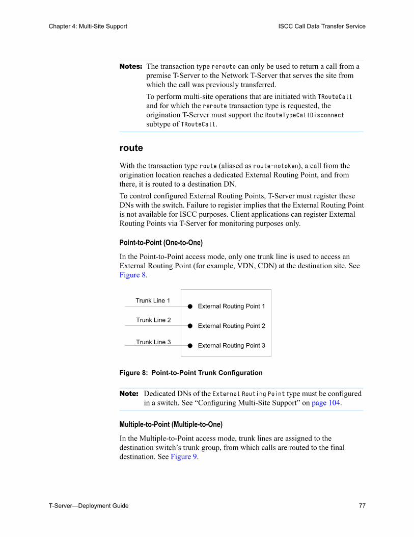
Chapter 4: Multi-Site Support ISCC Call Data Transfer Service
T-Server—Deployment Guide 77
route
With the transaction type route (aliased as route-notoken), a call from the origination location reaches a dedicated External Routing Point, and from there, it is routed to a destination DN.
To control configured External Routing Points, T-Server must register these DNs with the switch. Failure to register implies that the External Routing Point is not available for ISCC purposes. Client applications can register External Routing Points via T-Server for monitoring purposes only.
Point-to-Point (One-to-One)
In the Point-to-Point access mode, only one trunk line is used to access an External Routing Point (for example, VDN, CDN) at the destination site. See Figure 8.
Figure 8: Point-to-Point Trunk Configuration
Multiple-to-Point (Multiple-to-One)
In the Multiple-to-Point access mode, trunk lines are assigned to the destination switch’s trunk group, from which calls are routed to the final destination. See Figure 9.
Notes: The transaction type reroute can only be used to return a call from a premise T-Server to the Network T-Server that serves the site from which the call was previously transferred.
To perform multi-site operations that are initiated with TRouteCall and for which the reroute transaction type is requested, the origination T-Server must support the RouteTypeCallDisconnect subtype of TRouteCall.
Note: Dedicated DNs of the External Routing Point type must be configured in a switch. See “Configuring Multi-Site Support” on page 104.
Trunk Line 1
Trunk Line 2
Trunk Line 3
External Routing Point 1
External Routing Point 2
External Routing Point 3

78 Framework 8.0
Chapter 4: Multi-Site Support ISCC Call Data Transfer Service
Figure 9: Multiple-to-Point Trunk Configuration
With this configuration, all calls reach the same External Routing Point. The DNIS attribute of a specific call differs from that of other calls and uniquely identifies the trunk from which the call arrived.
route-uui
The route-uui transaction type employs the dedicated External Routing Point feature of the route transaction type (page 77) and the UUI matching feature of the direct-uui transaction type (page 73). This transaction type accommodates those switches that require a designated External Routing Point even though they use UUI for tracking.
T-Server Transaction Type Support
Table 3 shows which transaction types are supported by a specific T-Server. Use this table to determine the transaction types that are available for use with your T-Server. This applies both to the cast-type you specify in the configuration options for your T-Server, and to any client-designated route-type requests specified for transfers of calls. A blank table cell indicates that T-Server does not support a certain transaction type.
Note: To switch to this operating mode, you must configure the route-dn configuration option for T-Server.
Note: To support this transaction type, you must configure your switches to pass the UUI provided by your T-Server. You must also ensure that the trunks involved do not drop this data.
Trunk Line 1
External Routing PointTrunk Line 2
Trunk Line 3

Chapter 4: Multi-Site Support ISCC Call Data Transfer Service
T-Server—Deployment Guide 79
Table 3: T-Server Support of Transaction Types
T-ServerType
Transaction Type
route re-route
direct-callid
direct-uui /
route-uui
direct-no-
token
direct-ani
direct-digits
direct-network-
callid
dnis-pool
pull-back
one-to-one
multiple-to-one
Alcatel A4200/OXO
Yes Yes Yes Yes
Alcatel A4400/OXE
Yes Yesa,b,c Yesd Yes Yesa Yese
Aspect ACD Yes Yes Yes Yesf Yesf
Avaya Communica- tion Manager
Yes Yes Yes Yes
Avaya INDeX Yes Yes Yes
Avaya TSAPI Yes Yes Yes Yes
Cisco Unified Communica- tions Manager
Yes Yes Yes Yes
DataVoice Dharma
Yes Yes Yes Yes
Digitro AXS/20
Yes Yes Yes
EADS Intecom M6880
Yes Yes Yes Yes
EADS Telecom M6500
Yes Yes Yes Yes
eOn eQueue Yes Yes Yes
Ericsson MD110
Yes Yesa Yes Yesa
Fujitsu F9600 Yes Yes
Huawei C&C08
Yes Yes

80 Framework 8.0
Chapter 4: Multi-Site Support ISCC Call Data Transfer Service
Huawei NGN Yes Yes Yes
Mitel SX-2000/MN3300
Yes Yes Yes Yes
NEC NEAX/APEX
Yes Yes Yes Yes
Nortel Communica- tion Server 2000/2100
Yes Yesf Yesf Yesf
Nortel Communica- tion Server 1000 with SCCS/MLS
Yes Yes Yes Yes Yes
Philips Sopho iS3000
Yes Yes Yes Yes
Radvision iContact
Yes Yes Yes
Rockwell Spectrum
Yes Yes Yes Yesf Yesf
Samsung IP-PCX IAP
Yes Yes Yes
Siemens Hicom 300/HiPath 4000 CSTA I
Yes Yes Yesd Yes Yes
Siemens HiPath 3000
Yes Yes Yes
Siemens HiPath 4000 CSTA III
Yes Yesd Yes Yes
Table 3: T-Server Support of Transaction Types (Continued)
T-ServerType
Transaction Type
route re-route
direct-callid
direct-uui /
route-uui
direct-no-
token
direct-ani
direct-digits
direct-network-
callid
dnis-pool
pull-back
one-to-one
multiple-to-one

Chapter 4: Multi-Site Support ISCC Call Data Transfer Service
T-Server—Deployment Guide 81
Siemens HiPath DX
Yes Yes Yes Yes Yes
SIP Server Yes Yes Yesg Yes Yes
Tadiran Coral Yes Yes Yes Yes
Teltronics 20-20
Yes Yes Yes Yes
Tenovis Integral 33/55
Yes Yes Yes Yes
Network T-Servers
AT&T
Concert
CRSP Yes
DTAG Yes
GenSpec Yes Yes Yes Yes
IVR Server, using network configuration
Yes Yes Yes Yes Yes
KPN Yes
ISCP
MCI
NGSN Yes Yes
Network SIP Server
Yes Yes Yes Yes
Sprint Yes
SR-3511
Stentor
Table 3: T-Server Support of Transaction Types (Continued)
T-ServerType
Transaction Type
route re-route
direct-callid
direct-uui /
route-uui
direct-no-
token
direct-ani
direct-digits
direct-network-
callid
dnis-pool
pull-back
one-to-one
multiple-to-one

82 Framework 8.0
Chapter 4: Multi-Site Support ISCC Call Data Transfer Service
Transfer Connect Service Feature
The Transfer Connect Service (TCS) feature supports transfer connect services available on some telephony networks. When this feature is enabled, ISCC passes user data to remote locations to which calls are transferred or conferenced using transfer connect services.
Procedure:Activating Transfer Connect Service
Start of procedure
1. Open the T-Server Application’s Properties dialog box.
2. Click the Options tab.
3. Set the tcs-use configuration option to always.
4. Set the tcs-queue configuration option to the number of a DN on the origination switch.
ISCC uses this DN as an intermediate step when sending calls to the remote location. The DN that is configured as tcs-queue receives attached data indicating the Feature Access Code (FAC) needed to reach the remote site. After a call is directed to the DN with data, a monitoring application takes the data and generates the required DTMF (dual-tone multifrequency) tones to redirect the call through the network to the remote location.
5. When you are finished, click Apply.
a. Not supported in the case of function TRequestRouteCall on a virtual routing point: a routing point can be simu-lated using a hunt group with calls being deflected or transferred from the hunt-group member when routing. When a two-step (typically mute) transfer is used on such a hunt-group member, CallID and ANI usually change; thus, the direct-callid and direct-ani types do not work.
b. Not supported in the case of function TSingleStepTransfer when the T-Server service is simulated using a two-step transfer to the switch. In this case, CallID and ANI change; thus, the direct-callid and direct-ani types do not work.
c. Not supported if two T-Servers are connected to different nodes.
d. There are some switch-specific limitations when assigning CSTA correlator data UUI to a call.
e. Supported only on ABCF trunks (Alcatel internal network).
f. To use this transaction type, you must select the Use Override check box on the Advanced tab of the DN Properties dialog box.
g. SIP Server supports the direct-uui type.

Chapter 4: Multi-Site Support ISCC/Call Overflow Feature
T-Server—Deployment Guide 83
6. Click OK to save your changes and exit the Properties dialog box.
End of procedure
ISCC/Call Overflow FeatureThe Inter Server Call Control/Call Overflow (ISCC/COF) feature of T-Server, that supports passive external routing, is specifically designed to handle calls delivered between sites by means other than ISCC. Such scenarios include contact center overflows and manual call transfers.
An overflow situation occurs when a call comes into a contact center where all agents are currently busy. In this situation, the switch can transfer (overflow) the incoming call to another site where there is an available agent.
T-Server uses two methods to handle call overflow and manual transfer scenarios. The first method is based on NetworkCallID matching and the second method is based on ANI/OtherDN matching.
When connected to each other via switch-specific networks, switches of some types can pass additional information along with transferred calls. This information may contain the NetworkCallID of a call, which is a networkwide unique identifier of the call.
When connected via a regular PSTN, switches of all types can send the ANI and/or OtherDN attributes to the destination switch during any call transfer operation.
While all T-Servers support the ISCC/COF feature using the ANI and/or OtherDN attributes, only a few support this feature using the NetworkCallID
Note: With T-Server for Avaya Communication Manager, you can use RequestRouteCall with RouteTypeOverwriteDNIS to initiate the playing of DTMF tones. This is done through the use of another intermediate DN (typically, an announcement port configured to give the silent treatment), to which the call is routed. When the call is established on this DN, T-Server requests that the digits sent in the DNIS field of the TRequestRouteCall be played by using the ASAI-send-DTMF-single procedure.

84 Framework 8.0
Chapter 4: Multi-Site Support ISCC/Call Overflow Feature
attribute. Table 4 shows the T-Server types that provide the NetworkCallID of a call.
The ISCC/COF feature can use any of the three attributes (NetworkCallID, ANI, or OtherDN) as criteria for matching the arriving call with an existing call at another location. Consequently, the attribute that is used determines what ConnID, UserData, CallType, and CallHistory are received for the matched call from the call’s previous location.
Table 4: T-Server Support of NetworkCallID for ISCC/COF Feature
T-Server Type Supported NetworkCallID Attribute
Alcatel A4400/OXE Yes
Aspect ACD Yes
Avaya Communication Manager Yes
Avaya TSAPI Yes
Nortel Communication Server 2000/2100 Yes
Nortel Communication Server 1000 with SCCS/MLS
Yes
Rockwell Spectrum Yes
SIP Server Yes
Warning! Depending on the switch platform, it may be possible to inherit the ANI attribute after routing a call to a remote destination, and after performing a single-step transfer and other telephone actions. However, ISCC/COF works properly only in scenarios where the ANI attribute on the destination T-Server is represented by exactly the same unique digit string as on the origination T-Server.
Typically, the ANI attribute represents the original call identifier (customer phone number), which guarantees that the attribute remains unique.
Note: When the ISCC/COF feature is in use, the Number Translation feature becomes active. For more information on feature configuration, see “Number Translation Feature” on page 87.

Chapter 4: Multi-Site Support ISCC/Call Overflow Feature
T-Server—Deployment Guide 85
ISCC/COF Call Flow
Figure 10 shows the sequence of steps that occur in an ISCC/COF scenario when a call is made or transferred by an agent at Site A to a DN at Site B, or when a call is overflowed from Site A to Site B.
Figure 10: Steps in the ISCC/COF Process
Step 1
An agent makes or transfers a call manually to another location or a call is overflowed from Site A (origination location) to Site B (destination location).
Step 2
Switch A (the origination switch) passes the call to Switch B (the destination switch).
Step 3
The call reaches the destination switch, which notifies the destination T-Server about the arrived call.
Step 4
The destination T-Server verifies with remote locations whether the call was overflowed from any of them.
To determine which calls to check as possibly overflowed, T-Server relies on the Switch object configuration:
• If no COF DNs (that is, DNs of the Access Resources type with the Resource Type set to cof-in or cof-not-in) are configured for the destination switch, the ISCC/COF feature of the destination T-Server checks all arriving calls.
2. Call passing
Site A Site B
Agent1. Call made/transferred to
another location3. Arrived call
notification
5. Call data waiting7. Call data update
9. Info clearing
T-Server Client
8. Event distribution
4. Call data request
6. Call data passing
T-Server T-Server
Origination Switch Destination Switch

86 Framework 8.0
Chapter 4: Multi-Site Support ISCC/Call Overflow Feature
• If a number of COF DNs are configured for the destination switch, one of three scenarios occurs: If the COF DNs with the cof-in setting for the Resource Type property
are configured, the ISCC/COF checks for overflow only those calls that arrive to those cof-in DNs that are Enabled.
If no DNs with the cof-in setting for the Resource Type property are configured, but some DNs have the cof-not-in setting for the Resource Type property, the ISCC/COF checks for overflow only those calls that arrive to those cof-not-in DNs that are Disabled.
If no DNs with the cof-in setting for the Resource Type property are configured, some DNs have the cof-not-in setting for the Resource Type property, and some other DNs do not have any setting for the Resource Type property, the ISCC/COF checks for overflow only those calls that arrive to the DNs without any setting for the Resource Type property.
• In all other cases, no calls are checked for overflow.
To determine which location the call arrived from, T-Server checks the call type and checks whether the call has the NetworkCallID, ANI, or OtherDN attribute:
• If the call is not an inbound call, the request for call data is sent to all remote locations except those whose Switch Access Code has the ISCC Call Overflow Parameters property set to inbound-only=true.
• If the call of any type has the NetworkCallID attribute, the destination T-Server sends a request for call data to the remote locations of the same switch type as the destination location if their Switch Access Codes have the ISCC Call Overflow Parameters property set to match-callid.
• If the call of any type has the ANI or OtherDN attribute, the request for call data is sent to remote locations whose Switch Access Code has the ISCC Call Overflow Parameters property set to match-ani.
Step 5
The destination T-Server waits (suspending events related to that call) for the call data from the remote T-Server for the time interval specified in the cof-ci-req-tout configuration option. Within this interval, T-Server holds any events related to the call. In addition, the cof-ci-defer-delete option on the origination T-Server establishes the time interval only after which that T-Server deletes the call information. And the cof-ci-wait-all, if set to true, forces the origination T-Server to wait for responses related to possible call overflow situations before updating call data.
Step 6
The T-Server at the location from which the call was transferred or overflowed sends call data to the requesting T-Server.

Chapter 4: Multi-Site Support Number Translation Feature
T-Server—Deployment Guide 87
Step 7
If a positive response to the call-data request is received, T-Server updates ConnID, UserData, CallType, and CallHistory, distributes all suspended events related to that call, and deletes all information regarding the transaction (Step 9).
Step 8
If the timeout set by cof-ci-req-tout expires, T-Server distributes all suspended events, and starts the timeout specified by the cof-rci-tout option. If a positive response is received within the timeout set by cof-rci-tout, T-Server updates the ConnID, UserData, CallType, and CallHistory, and notifies client applications by distributing EventPartyChanged.
Step 9
T-Server deletes all information regarding the transaction when one of these results occurs:
• The first positive response to the call-data request is received.
• Negative responses from all queried locations are received.
• The timeout specified by the cof-rci-tout option expires.
Number Translation FeatureThe Number Translation feature of T-Server extends the ISCC/COF and direct-ani transaction type functions to provide more flexibility for handling calls distributed across multiple sites. T-Server translates the input string (ANI string) into a number defined by the translation rules. This processing is called number translation. T-Servers participating in handling calls at multiple sites exchange the translated numbers in order to match the call instances.
The translation process involves two algorithms, one for rule selection and the other for the actual translation. Through the first algorithm, T-Server selects a rule that will be used for number translation. Through the second algorithm, T-Server translates the number according to the selected rule definition. See “Number Translation Rules” on page 88 for more information on configuring rules for your environment.
Number translation occurs as follows:
1. The switch reports a number, typically via AttributeANI.
2. T-Server evaluates all configured inbound rules to determine which one is the best fit for the received number. The best fit is determined by comparing the length of, and the specific digits in, the input number with the inbound pattern of each configured rule. See “Rule Examples” on page 93 for specific examples.

88 Framework 8.0
Chapter 4: Multi-Site Support Number Translation Feature
3. T-Server translates the number according to the selected rule.
To enable T-Server to translate numbers, you must perform specific configuration tasks that are associated with translation. See “Configuring Number Translation” on page 95.
Number Translation Rules
T-Server uses the number translation rules that you define in the T-Server configuration object in two ways:
• Rule selection—To determine which rule should be used for number translation
• Number translation—To transform the number according to the selected rule
Using ABNF for Rules
The number translation rules must conform to the following syntax, represented using Augmented Backus-Naur Form (ABNF) notation. For more information about ABNF, see RFC 2234, “Augmented BNF for Syntax Specifications: ABNF.”
Common Syntax Notations
Syntax notations common to many of these rules include:
• *—Indicates that 0 to an infinite number of the item following this symbol are acceptable.
• 1*—Indicates that one repetition is required. For T-Server, only one instance is acceptable.
• /—Indicates that any of the items mentioned, or a combination of those items, is acceptable.
Component Notations
Component notations include:
• dialing-plan = *dialing-plan-rule
where:
Note: The following notation explanations begin with the highest level notation. Each explanation includes the name of a component notation and a basic definition of each component that it contains. Some components require more detailed definitions, which are included later in this section.

Chapter 4: Multi-Site Support Number Translation Feature
T-Server—Deployment Guide 89
dialing-plan-rule represents the name of the rule. Each rule must have a unique name. There are no other naming restrictions, and you do not need to model your names according to the examples in this chapter.
The rules are represented as separate options in the configuration. Also, fields from a rule are represented as parameters in a single option string.
• rule = [name] in-pattern [out-pattern]
where: [name] is the name for the rule option, for example, rule-01. In ABNF
notation, the brackets [] indicate that 0 or 1 instance of the component is required. However, for T-Server, a name is required.
in-pattern is the part of the rule to which T-Server looks when attempting to match the input number.
[out-pattern] is the part of the rule that instructs T-Server on how to translate the input number into the required format. The brackets indicate that either 0 or 1 instance is required. You must create an out-pattern for number translation rules.
• name = *( ALPHA / DIGIT / "-")
where: ALPHA indicates that letters can be used in the name for the rule option. DIGIT indicates that numbers can be used in the name for the rule
option. “-” indicates that a dash (-) can also be used in the option name, for
example, rule-01.
• in-pattern = 1*(digit-part / abstract-group)
where: digit-part represents numbers. T-Server uses this when selecting the
most appropriate rule from the entire dialing plan. abstract-group represents one or more letters with each letter
representing one or more numbers. T-Server uses this when transforming a dial string.
For example, [1-9] is the digit-part (representing a range of numbers) and ABBB is the abstract-group for in-pattern=[1-9]ABBB.
• out-pattern = 1*(symbol-part / group-identifier) *param-part
where: symbol-part represents digits, symbols, or a combination. Symbols are
rarely used. They are not used in the United States. group-identifier are letters that represent groups of numbers. A letter
in the out-pattern represents one or more digits, based on the number of times the letter is used in the in-pattern.

90 Framework 8.0
Chapter 4: Multi-Site Support Number Translation Feature
*param-part represents an additional parameter, such as phone-context. Reminder: an asterisk means that 0 to an infinite number of these are acceptable.
For example, in rule-04; in-pattern=1AAABBBCCC;out-pattern=91ABC, 91 is the symbol-part; A, B, and C are group-identifiers in the out-pattern, each representing three digits, since there are three instances of each in the in-pattern.
• digit-part = digits / range / sequence
where: digits are numbers 0 through 9. range is a series of digits, for example, 1-3. sequence is a set of digits.
• symbol-part = digits / symbols
where: digits are numbers 0 through 9. symbols include such characters as +, -, and so on.
• range = "[" digits "-" digits "]" group-identifier
where: "[" digits "-" digits "]" represents the numeric range, for
example, [1-2]. group-identifier represents the group to which the number range is
applied.
For example, [1-2] applies to group identifier A for in-pattern=[1-2]ABBB. When T-Server evaluates the rule to determine if it matches the number, it examines whether the first digit of the number, identified as group-identifier A, is 1 or 2.
• sequence = "[" 1*(digits [","] ) "]" group-identifier
where: "[" 1*(digits [","] ) "]" represents a sequence of digits, separated
by commas, and bracketed. T-Server requires that each digit set have the same number of digits. For example, in [415,650] the sets have three digits.
group-identifier represents the group to which the number sequence is applied.
For example, in in-pattern=1[415,650]A*B, [415,650] applies to group-identifier A. When T-Server evaluates the rule to determine if it matches the number, it examines whether the three digits (group-identifier A) following the 1 in the number are 415 or 650.
Note: Prefix an out-pattern value with a plus sign (+) for the inbound rule when the output must be in a global form (E.164 format).

Chapter 4: Multi-Site Support Number Translation Feature
T-Server—Deployment Guide 91
• abstract-group = fixed-length-group / flexible-length-group / entity
where: fixed-length-group specifies a group composed of a specific number
of digits and determined by how many times the group identifier is included in the in-pattern. For example, for in-pattern=1AAABBBCCCC, there are three digits in group A and B but four in group C.
When you create an out-pattern, you include the group identifier only once because the in-pattern tells T-Server how many digits belong in that group. For example, rule-04 (see page 93) is in-pattern=1AAABBBCCCC; out-pattern=91ABC.
flexible-length-group specifies a group composed of 0 or more digits in the group represented by the group-identifier. For example, in in-pattern=1[415,650]A*B, *B represents the flexible length group containing the remaining digits in the number.
entity represents digits defined for a specific purpose, for example, country code.
The component abstract-group is used only for the in-pattern.
• fixed-length-group = 1*group-identifier
See the earlier explanation under abstract-group.
• flexible-length-group = "*" group-identifier
See the earlier explanation under abstract-group.
• entity = "#" entity-identifier group-identifier
where: “#” indicates the start of a Country Code entity-identifier. entity-identifier must be the letter C which represents Country Code
when preceded by a pound symbol (#). Any other letter following the # causes an error.
group-identifier represents the Country Code group when preceded by #C.
The entity component is a special group that assumes some kind of predefined processing, such as the Country Code detection.
• param-part = ";" param-name "=" param-value
where: “;” is a required separator element. param-name is the name of the parameter. “=” is the next required element.
• param-value represents the value for param-name.
• param-name = "ext" / "phone-context" / "dn"
where: “ext” refers to extension.

92 Framework 8.0
Chapter 4: Multi-Site Support Number Translation Feature
“phone-context” represents the value of the phone-context option configured on the switch.
“dn” represents the directory number.
• param-value = 1*ANYSYMBOL
where: ANYSYMBOL represents any number, letter, or symbol with no restrictions.
• group-identifier = ALPHA
• entity-identifier = ALPHA
• digits = 1*DIGIT
• symbols = 1*("-" / "+" / ")" / "(" / ".")
Recommendations for Rule Configuration
The configuration of rules for inbound numbers usually depends on the settings in the corresponding PBX. These settings often define the form in which the PBX notifies its client applications about the number from which an inbound call is coming.
As a general guideline, configure rules that define how to process calls from:
• Internal numbers.
• External numbers within the same local dialing area.
• External numbers within the same country.
• International numbers.
Rules for inbound numbers, typically for North American locations, might look like this:
1. Two rules to transform internal numbers (extensions): name=rule-01;in-pattern=[1-9]ABBB;out-pattern=AB
name=rule-02;in-pattern=[1-9]ABBBB;out-pattern=AB
2. A rule to transform local area code numbers (in 333-1234 format in this example):name=rule-03;in-pattern=[1-9]ABBBBBB;out-pattern=+1222AB
3. A rule to transform U.S. numbers (in +1(222)333-4444 format):name=rule-04;in-pattern=1AAAAAAAAAA;out-pattern=+1A
4. A rule to transform U.S. numbers without the +1 prefix (in (222)333-4444 format):name=rule-05;in-pattern=[2-9]ABBBBBBBBB;out-pattern=+1AB
5. A rule to transform U.S. numbers with an outside prefix (in 9 +1(222)333-4444 format):name=rule-06;in-pattern=91AAAAAAAAAA;out-pattern=+1A

Chapter 4: Multi-Site Support Number Translation Feature
T-Server—Deployment Guide 93
6. A rule to transform international numbers with an IDD (international dialing digits) prefix (in 011 +44(111)222-3333 format):name=rule-07;in-pattern=011*A;out-pattern=+A
7. A rule to transform international numbers without an IDD prefix (in +44(111)222-3333 format):name=rule-08;in-pattern=[2-9]A*B;out-pattern=+AB
Rule Examples
This section provides examples of six rules that are configured as options in the Genesys Configuration Database. It also provides examples of how T-Server applies rules to various input numbers.
Rules
rule-01 in-pattern=[1-8]ABBB;out-pattern=AB
rule-02 in-pattern=AAAA;out-pattern=A
rule-03 in-pattern=1[415,650]A*B;out-pattern=B
rule-04 in-pattern=1AAABBBCCCC;out-pattern=91ABC
rule-05 in-pattern=*A913BBBB;out-pattern=80407913B
rule-06 in-pattern=011#CA*B;out-pattern=9011AB
Examples
Here are examples of how T-Server applies configured above rules to various input numbers.
Example 1 T-Server receives input number 2326.
As a result of the rule selection process, T-Server determines that the matching rule is rule-01:
name=rule-01;in-pattern=[1-8]ABBB;out-pattern=AB
The matching count for this rule is 1, because Group A matches the digit 2.
As a result of the parsing process, T-Server detects two groups: Group A = 2 and Group B = 326.
T-Server formats the output string as 2326.
Example 2 T-Server receives input number 9122.
As a result of the rule selection process, T-Server determines that the matching rule is rule-02:
name=rule-02;in-pattern=AAAA;out-pattern=A
The matching count for this rule is 0; however, the overall length of the input number matches that of the in-pattern configuration.

94 Framework 8.0
Chapter 4: Multi-Site Support Number Translation Feature
As a result of the parsing process, T-Server detects one group: Group A = 9122.
T-Server formats the output string as 9122.
Example 3 T-Server receives input number 16503222332.
As a result of the rule selection process, T-Server determines that the matching rule is rule-03:
name=rule-03;in-pattern=1[415,650]A*B;out-pattern=B
The matching count for this rule is 4, because the first digit matches and all three digits in Group A match.
As a result of the parsing process, T-Server detects two groups: Group A = 650 and Group B = 3222332.
T-Server formats the output string as 3222332.
Example 4 T-Server receives input number 19253227676.
As a result of the rule selection process, T-Server determines that the matching rule is rule-04:
name=rule-04;in-pattern=1AAABBBCCCC;out-pattern=91ABC
The matching count for this rule is 1, because the first digit matches.
As a result of parsing process, T-Server detects three groups: Group A = 925, Group B = 322, and Group C = 7676.
T-Server formats the output string as 919253227676.
Example 5 T-Server receives input number 4089137676.
As a result of rule selection process, T-Server determines that the matching rule is rule-05:
name=rule-05;in-pattern=*A913BBBB;out-pattern=80407913B
The matching count for this rule is 3, because three digits match.
As a result of the parsing process, T-Server detects two groups: Group A = 408 and Group B = 7676.
T-Server formats the output string as 804079137676.
Example 6 T-Server receives input number 011441112223333.
As a result of the rule selection process, T-Server determines that the matching rule is rule-06:
name=rule-06;in-pattern=011#CA*B;out-pattern=9011AB
The matching count for this rule is 3, because three digits match.
As a result of the parsing process, T-Server detects two groups: Group A = 44 and Group B = 1112223333.
T-Server formats the output string as 9011441112223333.

Chapter 4: Multi-Site Support Network Attended Transfer/Conference Feature
T-Server—Deployment Guide 95
Procedure:Configuring Number Translation
Purpose: To configure the Number Translation feature in T-Server to provide more flexibility for handling calls distributed across multiple sites.
Overview
• The Number Translation feature becomes active when the ISCC/COF feature and/or the direct-ani transaction type are used.
• This configuration procedure must be completed within the T-Server Application object corresponding to your T-Server.
Start of procedure
1. Open the T-Server Application’s Properties dialog box.
2. Click the Options tab.
3. Create a new section called extrouter or open an existing section with this name.
4. Create a new option called inbound-translator-<n>. This option points to another section that describes the translation rules for inbound numbers.
5. In this section, create one configuration option for each rule. Specify the rule name as the option name. The values of these options are the rules for the number translation.
For the option description and its valid values, see Chapter 9, “T-Server Common Configuration Options,” on page 207.
6. When you are finished, click Apply.
7. Click OK to save your changes and exit the Properties dialog box.
End of procedure
Network Attended Transfer/Conference Feature
The Network Attended Transfer/Conference (NAT/C) feature is designed to enable agents working in multi-site contact centers to consult with each other before making call transfers or conferences, regardless of whether both agents work at the same or different sites. It also enables the agent who requests a consultation to maintain his or her conversation with the customer while the system is looking for an available agent and setting up the consultation call.

96 Framework 8.0
Chapter 4: Multi-Site Support Network Attended Transfer/Conference Feature
The NAT/C feature does not rely on the call transfer capabilities of the local switch.
There are two modes in which the network attended transfer/conference can be performed: direct and URS-controlled. Figure 11 shows the sequence of steps that occur in URS-controlled mode, when Agent A, who is handling a customer call, requests a consultation with another agent, and URS (Universal Routing Server) selects Agent B, who is working at another site. The direct mode is similar to the URS-controlled mode, with the difference that URS is not involved in the process (Step 2 and Step 3 are omitted).
Figure 11: Steps in the NAT/C Process in URS-Controlled Mode
Step 1
Agent A makes a request for a consultation with another agent. A TNetworkConsult request is relayed to the Network T-Server. Depending on the parameter settings of the TNetworkConsult request, the NAT/C feature will operate in either direct or URS-controlled mode. For more information, see the Voice Platform SDK 8.0 .NET (or Java) API Reference.
Step 2
(URS-controlled mode only.) The Network T-Server sends EventRouteRequest to URS.
Step 3
(URS-controlled mode only.) URS locates an available agent at Site B and instructs the Network T-Server to route the call to Agent B. The Network
Network T-Server
SCP
2. EventRoute-Request
5. Consultation request and confirmation
Site BT-Server B
3. Routing call to Agent B
Agent B
6. Consultation with Agent B
4. Call data passing
Site AT-Server A
Agent A
1. TNetworkConsultrequest
Switch A Switch B
URS
Chapter 4: Multi-Site Support Event Propagation Feature
T-Server—Deployment Guide 97
T-Server confirms the initiation of the network transfer by sending EventNetworkCallStatus to T-Server A, which then relays it to Agent A.
Step 4
The Network T-Server proceeds to obtain the access number from T-Server B, and passes the call data to T-Server B. (See “ISCC Call Data Transfer Service” on page 63 for details.)
Step 5
The Network T-Server instructs the Service Control Point (SCP) to initiate a new voice path with Agent B. Once the connection is confirmed, the Network T-Server distributes EventNetworkCallStatus to both T-Server A and T-Server B, which then relay it to Agent A and Agent B respectively, to indicate that the consultation call is being established.
The Network T-Server also distributes EventRouteUsed to URS to confirm successful routing of the call to the selected agent.
Step 6
At this point, the customer is on hold, and Agent A is consulting with Agent B. Agent A can do one of the following:
• End the consultation and retrieve the original customer call
• Alternate between Agent B and the customer
• Set up a conference call with Agent B and the customer
• Transfer the customer call to Agent B
Event Propagation FeatureThe Event Propagation feature complements the ISCC and ISCC/COF features by distributing updated user data and party-related events to remote T-Servers. This feature is used when a call is being made, transferred, or conferenced to another location, and when, as a result, one or more instances of the call reside at one location while other call instances reside at another location. In this scenario, when a client at one location makes changes to user data, updated user data is passed (propagated) to T-Servers at other locations.
Note: All T-Servers support NAT/C requests with AttributeHomeLocation provided that this attribute identifies a network location that is capable of processing such requests. Refer to the Network T-Server Deployment Guides to determine whether a specific Network T-Server can process these requests.

98 Framework 8.0
Chapter 4: Multi-Site Support Event Propagation Feature
The Event Propagation feature consists of User Data update propagation and Party Events propagation.
User Data Propagation
User data propagation takes place when a client at one location makes changes to user data associated with a call that was made, transferred, conferenced, or routed to other locations. The remote clients involved with the call are notified about the changes with EventAttachedDataChanged.
When T-Server receives a local update to user data (that is, when a client of this T-Server has changed the call’s user data), T-Server determines if parties at remote locations are involved with the call and, if so, sends (propagates) the updated user data to the T-Servers at remote locations.
When T-Server receives a remote update to user data (that is, when a client of a remote T-Server has changed the call’s user data and the remote T-Server has used the Event Propagation feature to send the updated user data), T-Server:
1. Updates the user data of the corresponding local call.
2. Determines if parties at other remote locations are involved with the call and, if so, propagates the updated user data to T-Servers at other remote locations.
The locations to which user data is propagated are selected based on a call distribution topology. That is, the updated user data is passed directly to the location to which a call was sent and to the location from which the call was received, excluding the location from which the update was received.
For example, consider a call made from location A to location B, and then conferenced from location B to location C. The three instances of the call reside at different locations: the first instance is at location A, the second instance is at location B, and the third instance is at location C. The Event Propagation feature is employed in the following scenarios:
• When T-Server at location A receives a local update to user data, it notifies T-Server at location B (to which it sent the call) about changes to the call’s user data. Thus, T-Server at location B receives a remote update to user data and, in turn, notifies T-Server at location C (to which it sent the call) about these changes.
Although T-Server at location C receives a remote update to user data, it does not pass the notification to any other T-Servers, because it did not send the call to any other locations. As mentioned earlier, T-Servers at locations B and C update the user data of the corresponding local calls and notify their clients about the changes with EventAttachedDataChanged.
• When T-Server at location B receives a local update to user data, it notifies T-Server at location C (to which it sent the call) and T-Server at location A (from which it received the call) about changes to the call’s user data. Thus, T-Servers at locations C and A receive a remote update to user data.

Chapter 4: Multi-Site Support Event Propagation Feature
T-Server—Deployment Guide 99
Because T-Server at location C did not send the call to any other locations, and T-Server at location A originated the call, neither of these T-Servers passes the notification to any other T-Servers. T-Servers at locations C and A update the user data of the corresponding local calls and notify their clients about the changes with EventAttachedDataChanged.
• When T-Server at location C receives a local update to user data, it notifies T-Server at location B (from which it received the call) about changes to the call’s user data. Thus, T-Server at location B receives a remote update to user data and, in turn, notifies T-Server at location A (from which it received the call) about these changes.
Although T-Server at location A receives a remote update to user data, it does not pass the notification to any other T-Servers, because it originated the call. T-Servers at locations B and A update the user data of the corresponding local calls and notify their clients about the changes with EventAttachedDataChanged.
When a call is distributed between location A and location C using location B, and is then deleted on location B, propagation between locations A and C still occurs through the transit node at location B.
Party Events Propagation
Party events propagation takes place when a transfer or a conference is completed for a call that was made to or from one or more remote locations, or when a conference party is removed from the conference.
In these cases, the Event Propagation feature distributes party events, such as EventPartyChanged, EventPartyAdded, and EventPartyDeleted, to remote locations involved with the call, according to appropriate call model scenarios.
For example, consider a call made from DN 1 to DN 2 on location A. A TInitiateConference request is then issued for DN 2 to transfer the call to external DN 3 on location B. That transfer is made by means of ISCC routing. When this conference is completed on location A, the Event Propagation feature sends EventPartyChanged to location B and distributes this event to involved client applications that are connected to location B and registered for DN 3. After that, if a party of the conference is removed from the conference (for example, a party on DN 2), the Event Propagation feature sends EventPartyDeleted to location B and distributes this event to client applications registered for DN 3.
If a call involved in the propagation has no local parties but has two or more remote parties, the party events propagation is processed in the same manner as the propagation of user data updates.
For a complete event flow in such scenarios, refer to the Genesys 7 Events and Models Reference Manual.

100 Framework 8.0
Chapter 4: Multi-Site Support Event Propagation Feature
Switch Partitioning
A multi-site environment with switch partitioning or intelligent trunks can be defined as a configuration of multiple virtual switches (or Switch objects) that are defined in Configuration Manager under a single Switching Office object representing a physical switch. Each Switch object has its own instance of a T-Server application. All T-Server applications connect to the switch via the same or different CTI link or a gateway. (See Figure 12.)
When the Event Propagation feature is active, updated user data and party-related events—EventPartyChanged, EventPartyDeleted, and EventPartyAdded—are propagated to T-Servers that are involved in call transactions, such as transfer or conference. However, with switch partitioning, the call instances may reside at one partition or at different partitions.
Figure 12: Switch Partitioning Architecture
Starting with version 8.0, in addition to ConnIDs and UserData, T-Server can now synchronize the CallType attribute. Each T-Server is required to register all DNs it monitors. In a multi-partitioned environment, when configured, calls between partitions are reported as internal (CallTypeInternal). In a non-partitioned environment, such calls are reported as inbound (CallTypeInbound) and/or outbound (CallTypeOutbound), depending on the direction of a call. In order for T-Servers to report calls between specified partitions as internal, registered DNs of these partitions must be assigned to a Switch (T-Server), Switching Office, or Tenant, using the dn-scope configuration option. If DNs that are involved in calls are not in the T-Server scope, those DNs will be reported as inbound or outbound.
In addition, T-Server supports LocalCallType and PropagatedCallType attributes, which depend on the propagated-call-type configuration option setting for reporting. See the option description on page 212.
Site A
T-Server ClientT-Server
T-Server
Switch
T-Server Client

Chapter 4: Multi-Site Support Event Propagation Feature
T-Server—Deployment Guide 101
To control race conditions that may occur in the switch-partitioned environment, use the epp-tout configuration option (see page 226).
Table 5 shows the T-Server types that support switch partitioning.
Event Propagation Configuration
The basic Event Propagation feature configuration includes a setting of specific configuration options at a T-Server Application level. The advanced feature configuration allows you to customize the feature at a Switch level.
When determining whether to notify other T-Servers of changes to user data, or to distribute party events, T-Server checks:
1. Call topology (what location a call came from and to what location the call was then transferred or conferenced).
2. Outbound parameters of the Switch this T-Server relates to (whether propagation parameters are configured for the access codes this switch uses to reach the switch at the location a call came from and the switch at the location to which the call was then transferred or conferenced).
Notes: Because of possible delays in TCP/IP connections, a sequence of events sent for the same call by two or more T-Servers to clients may appear in an unexpected order. For example, in a simple call scenario with two partitions, EventRinging and EventEstablished messages may both arrive before EventDialing.
Genesys switch partitioning does not apply to hardware partitioning functionality that is supported on some switches.
Table 5: T-Server Support for Switch Partitioning
T-Server Type Supported
Alcatel A4400/OXE Yes
Avaya Communication Manager Yes
Avaya TSAPI Yes
Cisco Unified Communications Manager Yes
Warning! The direction of user-data or party-events propagation does not necessarily match the direction of call distribution. Therefore, the access code used to deliver the call can differ from the access code used for the purpose of Event Propagation.

102 Framework 8.0
Chapter 4: Multi-Site Support Event Propagation Feature
If one of the T-Servers along the call distribution path has the Event Propagation feature disabled, that T-Server does not distribute events to remote locations.
Procedure:Activating Event Propagation: basic configuration
Purpose: To activate the Event Propagation feature for User Data updates and call-party–associated events (Party Events) distribution.
Start of procedure
1. Open the T-Server Application’s Properties dialog box.
2. Click the Options tab.
3. Open the extrouter section.
4. Set the event-propagation option to the list value.
This setting enables User Data propagation. If you need to enable Party Events propagation, perform Step 5.
5. Set the use-data-from option to the current value.
This setting enables Party Events propagation.
For the option description and its valid values, see Chapter 9, “T-Server Common Configuration Options,” on page 207.
6. When you are finished, click Apply.
7. Click OK to save your changes and exit the Properties dialog box.
End of procedure
Next Steps
• For advanced feature configuration, do the following procedure:
Procedure: Modifying Event Propagation: advanced configuration, on page 102
Procedure:Modifying Event Propagation: advanced configuration
Purpose: To modify access codes for advanced Event Propagation configuration.

Chapter 4: Multi-Site Support Event Propagation Feature
T-Server—Deployment Guide 103
Prerequisites
• Procedure: Activating Event Propagation: basic configuration, on page 102
Overview
You can set Event Propagation parameters using:
• The Default Access Code properties of the Switch that receives an ISCC-routed call (the destination switch).
• The Access Code properties of the Switch that passes an ISCC-routed call (the origination switch).
If you do not set up Event Propagation parameters for a given Access Code, T-Server uses corresponding settings configured for the Default Access Code of the destination switch.
The procedures for modifying Default Access Codes and Access Codes are very similar to each other.
Start of procedure
1. Among configured Switches, select the Switch that the configured T-Server relates to.
2. Open the Switch’s Properties dialog box and click either the Default Access Codes tab or the Access Codes tab.
3. Select a configured Default Access Code or configured Access Code and click Edit.
4. In the Switch Access Code Properties dialog box that opens, specify a value for the ISCC Protocol Parameters field as follows: To enable distribution of both user data associated with the call and
call-party–associated events1, type:
propagate=yes
which is the default value. To enable distribution of user data associated with the call and disable
distribution of call-party–associated events, type:
propagate=udata
To disable distribution of user data associated with the call and enable distribution of call-party–associated events, type:
Note: If no Default Access Code is configured, see page 107 for instructions. If no Access Codes are configured, see page 108 for instructions.
1. The following are call-party–associated events: EventPartyChanged, EventPartyDe-leted, and EventPartyAdded.

104 Framework 8.0
Chapter 4: Multi-Site Support ISCC Transaction Monitoring Feature
propagate=party
To disable distribution of both user data associated with the call and call-party–associated events, type:propagate=no
5. Click OK to save configuration updates and close the Switch Access Code Properties dialog box.
6. Click Apply and OK to save configuration updates and close the Switch Properties dialog box.
End of procedure
ISCC Transaction Monitoring FeatureThis feature allows T-Server clients to monitor ISCC transactions that occur during the call data transfer between T-Servers in a multi-site environment.
In order to be able to monitor ISCC messaging, a T-Server client must subscribe to the ISCC Transaction Monitoring. Once a subscription request is confirmed, a client will receive updates about all multi-site operations of this T-Server.
The TTransactionMonitoring request is used to instruct T-Server to start, stop, or modify a client’s subscription to Transaction Monitoring feature notifications by setting the TSubscriptionOperationType parameter to SubscriptionStart, SubscriptionStop, or SubscriptionModify respectively. The transaction status is reported in EventTransactionStatus messages to the subscribed clients.
To determine whether the Transaction Monitoring feature is supported by a specific T-Server, a T-Server client may query T-Server’s capabilities. For more information about support of this feature, see Genesys 7 Events and Models Reference Manual and Voice Platform SDK 8.0 .NET (or Java) API Reference.
Configuring Multi-Site SupportPrior to configuring T-Server to support multi-site operation, you must read the “Licensing Requirements” on page 33, as well as previous sections of this chapter on multi-site deployment. In particular, Table 3 on page 79 shows which transaction types are supported by a specific T-Server, while Table 4 on page 84 shows whether your T-Server supports the NetworkCallID attribute for

Chapter 4: Multi-Site Support Configuring Multi-Site Support
T-Server—Deployment Guide 105
the ISCC/COF feature. Use this information as you follow the instructions in this chapter.
For T-Server to support multi-site operation, you must create and configure three types of objects in the Configuration Layer:
1. Applications
2. Switches, including Access Codes
3. DNs
You must configure these objects for origination and destination locations. Multi-site support features activate automatically at T-Server startup. See “DNs” on page 112 for details.
Applications
Ensure that T-Server Application objects, and their corresponding Host objects, exist and are configured for origination and destination locations.
Once you’ve done that, use Configuration Manager to add this configuration to a T-Server Application.
Procedure:Configuring T-Server Applications
Purpose: To configure T-Server Application objects for multi-site operation support.
Start of procedure
1. Open the T-Server Application’s Properties dialog box.
2. Click the Connections tab and click Add to add a connection to the appropriate T-Server. The Connection Info Properties dialog box displays.
3. Use the Browse button to search for the T-Server you want to connect to, and fill in the following values: Port ID
Note: Before attempting to configure a multi-site environment, Genesys recommends that you plan the changes you want to make to your existing contact centers. You should then gather the configuration information you will need (such as the name of each T-Server application, port assignments, and switch names), and use Configuration Manager to create and partially configure each T-Server object. Review multi-site option values in the “Multi-Site Support Section” on page 217 and determine what these values need to be, based on your network topology.
106 Framework 8.0
Chapter 4: Multi-Site Support Configuring Multi-Site Support
Connection Protocol Local Timeout Remote Timeout Trace Mode
4. Click the Options tab. Create a new section called extrouter or open an existing section with this name.
5. Open the extrouter section. Configure the options used for multi-site support.
6. When you are finished, click Apply.
7. Repeat this procedure for all T-Servers for origination and destination locations that are used for multi-site operations.
End of procedure
Next Steps
• See “Switches and Access Codes.”
Switches and Access Codes
Ensure that Switching Office and Switch objects are configured for both origination and destination locations.
You configure Access Codes to a destination switch in the origination Switch’s Properties dialog box. The only exception is the Default Access Code, which is configured at the destination Switch’s Properties dialog box.
You can configure two types of switch Access Codes in the Switch’s Properties dialog box:
• A Default Access Code (for inbound calls)—Specifies the access code that other switches can use to access this switch when they originate a multi-site transaction.
• An Access Code (for outbound calls)—Specifies the access code that this switch can use when it originates a multi-site transaction to access another switch.
Note: If you do not create the extrouter section, T-Server uses the default values of the corresponding configuration options.
Note: For a list of options and valid values, see “Multi-Site Support Section” on page 217, in the “T-Server Common Configuration Options” chapter in Part Two of this document.

Chapter 4: Multi-Site Support Configuring Multi-Site Support
T-Server—Deployment Guide 107
When the origination T-Server processes a multi-site transaction, it looks for an access code to the destination switch. First, T-Server checks the Access Code of the origination Switch:
• If an access code to the destination switch is configured with the target type Target ISCC and with any transaction type except Forbidden, T-Server uses this access code to dial the destination switch.
• If the access code to the destination switch is not configured on the Access Code tab of the origination switch, the origination T-Server checks the Default Access Code tab of the destination switch. If an access code is configured there with the target type Target ISCC and with any transaction type except Forbidden, T-Server uses this access code to dial the destination switch.
• If no access code with the required properties is found, T-Server rejects the transaction.
Procedure:Configuring Default Access Codes
Purpose: To configure the Default Access Codes (one per Switch object) to be used by other switches to access this switch when they originate a multi-site transaction.
Prerequisites
• Ensure that Switching Office and Switch objects are configured for both origination and destination locations.
Start of procedure
1. Among configured Switches, select the Switch that the configured T-Server relates to.
2. Open the Switch Properties dialog box and click the Default Access Codes tab.
3. Click Add to open the Access Code Properties dialog box.
Note: When migrating from previous releases of T-Servers to 8.0, or when using T-Servers of different releases (including 8.0) in the same environment, see “Compatibility Notes” on page 111.

108 Framework 8.0
Chapter 4: Multi-Site Support Configuring Multi-Site Support
4. In the Code field, specify the access code used by remote switches to reach a DN at this switch. An access code is used as a prefix to the remote switch numbers.
5. In the Target Type field, select Target ISCC.
6. In the Route Type field, select a value corresponding to the transaction type you want to use (given that it is supported for your switch type).
7. When you are finished, click Apply.
End of procedure
Next Steps
• See “Configuring Access Codes.”
Procedure:Configuring Access Codes
Purpose: To configure the Access Codes (one or more per Switch object) that this switch can use when it originates a multi-site transaction to access another switch.
Prerequisites
• Ensure that Switching Office and Switch objects are configured for both origination and destination locations.
Start of procedure
1. Among configured Switches, select the Switch that the configured T-Server relates to.
2. Open the Switch Properties dialog box and click the Access Codes tab.
3. Click Add to open the Access Code Properties dialog box.
4. In the Switch field, specify the switch that this switch can reach using this access code. Use the Browse button to locate the remote switch.
Note: If no prefix is needed to dial to the configured switch, you can leave the Code field blank.

Chapter 4: Multi-Site Support Configuring Multi-Site Support
T-Server—Deployment Guide 109
5. In the Code field, specify the access code used to reach a DN at the remote switch from this switch. An access code is used as a prefix to the remote switch numbers.
6. In the Target Type field, select Target ISCC.
When you select Target ISCC as your target type, the Properties dialog box changes its lower pane to the Sources pane. It is here that you enter the extended parameters for your access codes, by specifying the ISCC Protocol and ISCC Call Overflow Parameters.
To set these parameters, locate the two drop-down boxes that appear below the Target Type field in the Sources pane of that Properties dialog box.
a. In the ISCC Protocol Parameters drop-down box, enter the appropriate ISCC Protocol parameter, as a comma-separated list of one or more of the following items shown in Table 6:
b. In the ISCC Call Overflow Parameters drop-down box, enter call overflow parameters, as a comma-separated list of one or more of the following items shown in Table 7:
Note: If no prefix is needed to dial from one switch to another, you can leave the Code field blank.
Table 6: Target Type: ISCC Protocol Parameters
ISCC Protocol Parameters Description
dnis-tail=<number-of-digits> Where number-of-digits is the number of significant DNIS digits (last digits) used for call matching. 0 (zero) matches all digits.
propagate=<yes, udata, party, no> Default is yes. For more information, see “Modifying Event Propagation: advanced configuration” on page 102.
direct-network-callid=<> For configuration information, see Part Two of this document. (Use Table 4 on page 84 to determine if your T-Server supports the direct-network-callid transaction type.)

110 Framework 8.0
Chapter 4: Multi-Site Support Configuring Multi-Site Support
7. In the Route Type field, select a value corresponding to the transaction type you want to use (given that it is supported for your switch type). Table 8 contains cross-reference information on transaction types that the Configuration Layer and T-Server use.
Table 7: Target Type: ISCC Call Overflow Parameters
ISCC Call Overflow Parameters Description
match-callid Matches calls using network CallID.
match-ani Matches calls using ANI.
Note: When using match-ani, the match-flexible parameter must be set to false.
match-flexible Supports flexible call matching based on the following values:
Default Value: true
Valid Values: true, false, and [matching-context-type], where [matching-context-type] is the switch-specific value, which must be the same as the value of the default-network-call-id-matching configuration option of the corresponding T-Server.
inbound-only=<boolean> Default is true. Setting inbound-only to true disables COF on consultation and outbound calls.
Table 8: Route Type and ISCC Transaction Type Cross-Reference
Route Type Field Value ISCC Transaction Type
Default The first value from the list of values specified in the cast-type option for the T-Server at the destination site
Direct direct-callid
Direct ANI direct-ani
Direct Digits direct-digits
Direct DNIS and ANI Reserved

Chapter 4: Multi-Site Support Configuring Multi-Site Support
T-Server—Deployment Guide 111
8. When you are finished, click Apply.
End of procedure
Next Steps
• After configuring a switch for multi-site support, proceed with the configuration of DNs assigned to this switch.
Compatibility Notes
When migrating from previous releases of T-Servers to 8.0, or when using T-Servers of different releases (including 8.0) in the same environment, keep in mind the following compatibility issues:
• The Target External Routing Point value of the Target Type field is obsolete and provided only for backward compatibility with T-Servers of releases 5.1 and 6.0. When two access codes for the same switch are configured, one with the Target ISCC target type and the other with the Target External Routing Point target type, T-Servers of releases 8.x, 7.x, 6.5, and 6.1: Use the Target ISCC access code for transactions with T-Servers of
releases 8.x, 7.x, 6.5, and 6.1. Use the Target External Routing Point access code for transactions
with T-Servers of releases 5.1 and 6.0.
Direct Network Call ID direct-network-callid
Direct No Token direct-notoken
Direct UUI direct-uui
DNIS Pooling dnis-pooling
Forbidden External routing to this destination is not allowed
ISCC defined protocol Reserved
PullBack pullback
Re-Route reroute
Route route
Table 8: Route Type and ISCC Transaction Type Cross-Reference (Continued)
Route Type Field Value ISCC Transaction Type

112 Framework 8.0
Chapter 4: Multi-Site Support Configuring Multi-Site Support
When the only access code configured for a switch has the Target External Routing Point target type, T-Server uses this access code for all transactions.
• When the Target External Routing Point value of the Target Type field is configured, you must set the Route Type field to one of the following: Default to enable the route transaction type Label to enable the direct-ani transaction type Direct to enable the direct transaction type
UseExtProtocol to enable the direct-uui transaction type PostFeature to enable the reroute transaction type
These values are fully compatible with the transaction types supported in T-Server release 5.1.
• For successful multi-site operations between any two locations served by release 5.1 T-Servers, identical Route Type values must be set in the Switch’s Access Code Properties dialog boxes for both the origination and destination switches.
DNs
Use the procedures from this section to configure access resources for various transaction types.
Procedure:Configuring access resources for the route transaction type
Purpose: To configure dedicated DNs required for the route transaction type.
Prerequisites
• Ensure that Switching Office and Switch objects are configured for both origination and destination locations.
Note: The direct transaction type in releases 5.1 and 6.0 corresponds to the direct-callid transaction type in releases 6.1 and later.
Chapter 4: Multi-Site Support Configuring Multi-Site Support
T-Server—Deployment Guide 113
Start of procedure
1. Under a configured Switch, select the DNs folder. From the main menu, select File > New > DN to create a new DN object.
2. On the General tab of the DN’s Properties dialog box, specify the number of the configured DN as the value of the Number field. This value must correspond to the Routing Point number on the switch.
3. Select External Routing Point as the value of the Type field.
4. If a dialable number for that Routing Point is different from its DN name, specify the number in the Association field.
5. Click the Access Numbers tab. Click Add and specify these access number parameters: Origination switch. Access number that must be dialed to reach this DN from the
origination switch.
In determining an access number for the Routing Point, T-Server composes it of the values of the following properties (in the order listed):
a. Access number (if specified).
b. Switch access code from the switch of the origination party to the switch to which the Routing Point belongs, concatenated with its Association (if the Association value is specified).
c. Switch access code from the switch of the origination party to the switch to which the Routing Point belongs, concatenated with the number for the DN.
d. Default access code of the switch to which the Routing Point belongs, concatenated with its Association (if the Association value is specified).
e. Default access code of the switch to which the Routing Point belongs, concatenated with the number for the DN.
6. When you are finished, click Apply.
End of procedure
Note: If option use-implicit-access-numbers is set to true, the access number composed of switch access code and DN can be used for external transfers of calls originating at switches for which an access number is not specified.

114 Framework 8.0
Chapter 4: Multi-Site Support Configuring Multi-Site Support
Procedure:Configuring access resources for the dnis-pool transaction type
Purpose: To configure dedicated DNs required for the dnis-pool transaction type.
Start of procedure
1. Under a configured Switch, select the DNs folder. From the main menu, select File > New > DN to create a new DN object.
2. On the General tab of the DN’s Properties dialog box, specify the number of the configured DN as the value of the Number field. This value must be a dialable number on the switch.
3. Select Access Resource as the Type field and type dnis as the value of the Resource Type field on the Advanced tab.
4. Click the Access Numbers tab. Click Add and specify these Access Number parameters: Origination switch. Access number that must be dialed to reach this DN from the
origination switch.
An access number for the access resource is determined in the same manner as for the route access resource.
5. When you are finished, click Apply.
End of procedure
Procedure:Configuring access resources for direct-* transaction types
Overview
You can use any configured DN as an access resource for the direct-* transaction types. (The * symbol stands for any of the following: callid, uui, notoken, ani, or digits.)
You can select the Use Override check box on the Advanced tab to indicate whether the override value should be used instead of the number value to dial to the DN. You must specify this value if the DN has a different DN name and dialable number. In fact, this value is required for T-Servers for some switch types—such as Aspect ACD, Nortel Communication Server 2000/2100, and Spectrum.

Chapter 4: Multi-Site Support Configuring Multi-Site Support
T-Server—Deployment Guide 115
Procedure:Configuring access resources for ISCC/COF
Purpose: To configure dedicated DNs required for the ISCC/COF feature.
Start of procedure
1. Under a configured Switch, select the DNs folder. From the main menu, select File > New > DN to create a new DN object.
2. On the General tab of the DN Properties dialog box, specify the number of the configured DN as the value for the Number field.
3. Select Access Resource as the value for the Type field.
4. On the Advanced tab, type cof-in or cof-not-in as the value for the Resource Type field.
5. When you are finished, click Apply.
End of procedure
Procedure:Configuring access resources for non-unique ANI
Purpose: To configure dedicated DNs required for the non-unique-ani resource type.
The non-unique-ani resource type is used to block direct-ani and COF/ani from relaying on ANI when it matches configured/enabled resource digits. Using non-unique-ani, T-Server checks every ANI against a list of non-unique-ani resources.
Note: Use Table 4 on page 84 to determine if your T-Server supports the ISCC/COF feature.
Note: The number of the access resource must match the name of a DN configured on the switch (usually, an ACD Queue) so that T-Server can determine whether the calls arriving to this DN are overflowed calls.
Note: Calls coming to DNs with the cof-not-in value for the Resource Type are never considered to be overflowed.

116 Framework 8.0
Chapter 4: Multi-Site Support Configuring Multi-Site Support
Start of procedure
1. Under a configured Switch, select the DNs folder. From the main menu, select File > New > DN to create a new DN object.
2. On the General tab of the DN Properties dialog box, specify the ANI digits that need to be excluded from normal processing.
3. Select Access Resource as the value for the Type field.
4. On the Advanced tab, specify the Resource Type field as non-unique-ani.
5. When you are finished, click Apply.
End of procedure
Procedure:Modifying DNs for isolated switch partitioning
Purpose: To modify DNs that belong to a particular partition where switch partitioning is used.
This configuration instructs T-Server to select an External Routing Point that has the same partition as the requested destination DN.
Start of procedure
1. Under a Switch object, select the DNs folder.
2. Open the Properties dialog box of a particular DN.
3. Click the Annex tab.
4. Create a new section named TServer.
5. Within that section, create a new option named epn. Set the option value to the partition name to which the DN belongs.
6. Repeat Steps 1–5 for all DNs, including DNs of the External Routing Point type, that belong to the same switch partition.
7. When you are finished, click Apply.
End of procedure
Note: When a target DN is not configured or has no configured partition name, T-Server allocates a DN of the External Routing Point type that belongs to any partition.

Chapter 4: Multi-Site Support Configuring Multi-Site Support
T-Server—Deployment Guide 117
Configuration Examples
This section provides two configuration examples and describes how the configuration settings affect T-Server’s behavior.
Multiple Transaction Types
This example demonstrates the difference in how ISCC directs a call when you specify two different transaction types (route and direct-ani).
In this example, you configure an origination and a destination switch for as described in “Switches and Access Codes” on page 106.
1. Among configured Switches, select the origination Switch.
2. Open the Switch Properties dialog box and click the Default Access Codes tab.
3. Click Add to open the Access Code Properties dialog box.
4. Set the Access Code field to 9.
5. When you are finished, click Apply.
6. Among configured Switches, select the destination Switch.
7. Under the destination Switch, configure a DN as described in “Configuring access resources for the route transaction type” on page 112.
8. Set the DN Number field to 5001234567.
9. Click the Advanced tab of this DN’s Properties dialog box.
10. Select the Use Override check box and enter 1234567 in the Use Override field.
11. When you are finished, click Apply or Save.
12. Use a T-Server client application to register for this new DN with the destination T-Server and, therefore, with the switch.
13. Request to route a call from any DN at the origination switch to the destination DN you have just configured: If you are using the route ISCC transaction type, the client requests
that T-Server deliver a call to a destination location using the DN number 5001234567. ISCC requests that the switch dial one of the external routing points at the destination location, using the value either of the Access Number field or of the Access Code field, which is 9, concatenated with the external routing point at the destination location. The call is routed to the DN number 5001234567.
If you are using the direct-ani ISCC transaction type, the client requests that T-Server deliver a call to a destination location using the DN number 1234567, which is the Use Override value. ISCC requests

118 Framework 8.0
Chapter 4: Multi-Site Support Next Steps
that the switch dial 91234567, which is a combination of the Switch Access Code value and the Use Override value. The destination T-Server is waiting for the call to directly arrive at DN number 5001234567.
Call Overflow Methods
This section demonstrates how to indicate which overflow methods a switch supports.
In this example, for T-Server to use ANI/OtherDN matching in call overflow and manual transfer scenarios, set the ISCC Call Overflow Parameters to:
match-ani, inbound-only=true
when configuring Switch Access Codes as described on page 108.
With this setting, the switch’s location is queried for call data each time the destination T-Server receives an inbound call with the ANI or OtherDN attribute.
For T-Server to use NetworkCallID matching in call overflow and manual transfer scenarios, set the ISCC Call Overflow Parameters to (for example):
match-callid, inbound-only=false
when configuring Switch Access Codes as described on page 108.
With this setting, the switch’s location is queried for call data each time the destination T-Server receives a call of any type (including inbound) with the NetworkCallID attribute.
Next StepsContinue with Chapter 5, “Start and Stop T-Server Components,” on page 119 to test your configuration and installation.

T-Server—Deployment Guide 119
Chapter
5 Start and Stop T-Server ComponentsThis chapter describes methods for stopping and starting T-Server, focusing on manual startup for T-Server and HA Proxy for all switches. It includes these sections: Command-Line Parameters, page 119 Starting and Stopping with the Management Layer, page 121 Starting with Startup Files, page 122 Starting Manually, page 123 Verifying Successful Startup, page 129 Stopping Manually, page 129 Starting and Stopping with Windows Services Manager, page 130 Next Steps, page 130
Command-Line ParametersYou can start and stop Framework components using the Management Layer, a startup file, a manual procedure, or the Windows Services Manager.
With all these methods, command-line parameters are usually required for a server application in addition to an executable file name.
Common command-line parameters are as follows:
-host The name of the host on which Configuration Server is running.
-port The communication port that client applications must use to connect to Configuration Server.
-app The exact name of an Application object as configured in the Configuration Database.

120 Framework 8.0
Chapter 5: Start and Stop T-Server Components Command-Line Parameters
-l The license address. Use for the server applications that check out technical licenses. Can be either of the following:
• The full path to, and the exact name of, the license file used by an application. For example, -l /opt/mlink/license/license.dat.
• The host name and port of the license server, as specified in the SERVER line of the license file, in the port@host format. For example, -l 7260@ctiserver.
Note: Specifying the License Manager’s host and port parameter eliminates the need to store a copy of a license file on all computers running licensed applications.
-V The version of a Framework component. Note that specifying this parameter does not start an application, but returns its version number instead. You can use either uppercase or lowercase.
-nco X/Y The Nonstop Operation feature is activated; X exceptions occurring within Y seconds do not cause an application to exit. If the specified number of exceptions is exceeded within the specified number of seconds, the application exits or, if so configured, the Management Layer restarts the application. If the -nco parameter is not specified, the default value of 6 exceptions handled in 10 seconds applies. To disable the Nonstop Operation feature, specify -nco 0 when starting the application.
-lmspath The full path to log messages files (the common file named common.lms and the application-specific file with the extension *.lms) that an application uses to generate log events. This parameter is used when the common and application-specific log message files are located in a directory other than the application’s working directory, such as when the application’s working directory differs from the directory to which the application is originally installed.
Note that if the full path to the executable file is specified in the startup command-line (for instance, c:\gcti\multiserver.exe), the path specified for the executable file is used for locating the *.lms files, and the value of the lmspath parameter is ignored.
- transport-port <port number>
<port number> is the port number that a client will use for its TCP/IP connection to Configuration Server. See the Client-Side Port Definition section in the Genesys 8.0 Security Deployment Guide for more information.
- transport-address <IP address>
<IP address> is the IP address that a client will use for its TCP/IP connection to Configuration Server. See the Client-Side Port Definition section in the Genesys 8.0 Security Deployment Guide for more information.

Chapter 5: Start and Stop T-Server Components Starting and Stopping with the Management Layer
T-Server—Deployment Guide 121
Starting and Stopping with the Management Layer
Procedure:Configuring T-Server to start with the Management Layer
Start of procedure
1. Open the T-Server Application’s Properties dialog box.
2. Click the Start Info tab.
3. Specify the directory where the application is installed and/or is to run as the Working Directory.
4. Specify the name of the executable file as the command-line.
5. Specify command-line parameters as the Command–Line Arguments.
The command-line parameters common to Framework server components are described on page 119.
6. When you are finished, click Apply.
7. Click OK to save your changes and exit the Properties dialog box.
End of procedure
After its command-line parameters are correctly specified in the Properties dialog box, you can start and stop T-Server from Solution Control Interface (SCI), which is the graphical interface component of the Management Layer. (The starting procedure for SCI is described in the Framework 8.0 Deployment Guide.) Framework 8.0 Solution Control Interface Help provides complete instructions on starting and stopping applications.
You can also use the Management Layer to start a T-Server that has failed. To enable T-Server’s autorestart functionality, select the corresponding check box in the Application’s Properties dialog box.
Note: In the command-line examples in this document, angle brackets indicate variables that must be replaced with appropriate values.
Note: Before starting an application with the Management Layer, make sure the startup parameters of the application are correctly specified in the application’s Properties dialog box in Configuration Manager.

122 Framework 8.0
Chapter 5: Start and Stop T-Server Components Starting with Startup Files
Note that when you start (or restart) an application via the Management Layer, the application inherits environment variables from Local Control Agent (LCA), which executes the startup command. Therefore, you must also set the environment variables required by the application for the account that runs LCA.
Starting with Startup FilesStartup files are files with the extension run.sh (on UNIX) or startServer.bat (on Windows), which installation scripts create and place into the applications’ directories during the installations. These files are created for all Framework server applications except:
• Configuration Server (primary or backup) running on Windows.
• Backup Configuration Server running on UNIX.
• DB Server running on Windows.
• LCA running on either Windows or UNIX.
When using a startup file, verify that the startup parameters the installation script inserted in the startup file are correct. Use the following instructions for UNIX and Windows to start those application for which startup files are created. See the appropriate sections in “Starting Manually” on page 123 to identify which applications should be running for a particular application to start.
Procedure:Starting T-Server on UNIX with a startup file
Start of procedure
1. Go to the directory where an application is installed.
2. Type the following command line: sh run.sh
End of procedure
Warning! Stopping an application via the Management Layer is not considered an application failure. Therefore, the Management Layer does not restart applications that it has stopped unless an appropriate alarm condition and alarm reaction are configured for these applications.

Chapter 5: Start and Stop T-Server Components Starting Manually
T-Server—Deployment Guide 123
Procedure:Starting T-Server on Windows with a startup file
Start of procedure
To start T-Server on Windows with a startup file, use either of these methods:
• Go to the directory where an application is installed and double-click the startServer.bat icon.
Or
• From the MS-DOS window, go to the directory where the application is installed and type the following command-line:startServer.bat
End of procedure
Starting ManuallyWhen starting an application manually, you must specify the startup parameters at the command prompt, whether you are starting on UNIX or Windows. At the command prompt, command-line parameters must follow the name of the executable file. On the Shortcut tab of the Program Properties dialog box, command-line parameters must also follow the name of the executable file.
The command-line parameters common to Framework server components are described on page 119.
If an Application object name, as configured in the Configuration Database, contains spaces (for example, T-Server Nortel), the Application name must be surrounded by quotation marks in the command-line:-app “T-Server Nortel”
You must specify the rest of the command-line parameters as for any other application.
The following sections provide general instructions for starting HA Proxy and T-Server manually. Along with these instructions, refer to Table 9, which lists T-Servers and HA Proxy executable file names for supported switches for Windows and UNIX operating systems.

124 Framework 8.0
Chapter 5: Start and Stop T-Server Components Starting Manually
Table 9: T-Server and HA Proxy Executable Names
Switch Type T-Server Executable File Name HA Proxy Executable File Name
UNIX Windows UNIX Windows
Alcatel A4200/OXO a4200_server a4200_server.exe Not Applicable
Alcatel A4400/OXE a4400_server a4400_server.exe Not Applicable
Aspect ACD aspect_server aspect_server.exe Not Applicable
Avaya Communication Manager
avayacm_server avayacm_server.exe Not Applicablea
Avaya INDeX Not Applicable index_server.exe Not Applicable
Avaya TSAPI avayatsapi_server avayatsapi_server.exe Not Applicable
Cisco Unified Communications Manager
ciscocm_server ciscocm_server.exe Not Applicable
DataVoice Dharma Dharma_server Dharma_server.exe Not Applicable
Digitro AXS/20 digitro_server digitro_server.exe Not Applicable
EADS Intecom M6880 intecom_server intecom_server.exe Not Applicable
EADS Telecom M6500 m6500_server m6500_server.exe Not Applicable
eOn eQueue eon_server eon_server.exe Not Applicable
Ericsson MD110 md110_server md110_server.exe Not Applicable
Fujitsu F9600 Not Applicable F9600_server.exe Not Applicable
Huawei C&C08 cc08_server cc08_server.exe Not Applicable
Huawei NGN huaweingn_server huaweingn_server.exe Not Applicable
Mitel SX-2000/MN 3300
SX2000_server SX2000_server.exe Not Applicable
NEC NEAX/APEX neax_server neax_server.exe Not Applicable
Nortel Communication Server 2000/2100
ncs2000_server ncs2000_server.exe ha_proxy_dms
ha_proxy_dms.exe

Chapter 5: Start and Stop T-Server Components Starting Manually
T-Server—Deployment Guide 125
Nortel Communication Server 1000 with SCSS/MLS
succession_server succession_server.exe
Not Applicable
Philips Sopho iS3000 iS3000_server iS3000_server.exe ha_proxy_iS3000
ha_proxy_iS3000.exe
Radvision iContact nts_server nts_server.exe Not Applicable
Rockwell Spectrum spectrum_server spectrum_server.exe Not Applicable
Samsung IP-PCX IAP samsung_server samsung_server.exe Not Applicable
Siemens Hicom 300/HiPath 400 CSTA I
rolmcb4_server rolmcb4_server.exe Not Applicable
Siemens HiPath 3000 HiPath3000_server HiPath3000_server.exe Not Applicable
Siemens HiPath 4000 CSTA III
HiPath4000_server HiPath4000_server.exe Not Applicable
Siemens HiPath DX iCCL
RealitisDX-iCCL_server RealitisDX-iCCL_server.exe
Not Applicable
SIP Server sip_server sip_server.exe Not Applicable
Tadiran Coral Coral_server Coral_server.exe Not Applicable
Teltronics 20-20 Teltronics2020_server Teltronics2020_server.exe
ha_proxy_teltronics2020
ha_proxy_teltronics2020.exe
Tenovis Integral 33/55 Tenovis_server Tenovis_server.exe Not Applicable
Network T-Servers
AT&T nts_server nts_server.exe Not Applicable
Concert nts_server nts_server.exe Not Applicable
CRSP nts_server nts_server.exe Not Applicable
DTAG dtag_server dtag_server.exe Not Applicable
GenSpec genspec_server genspec_server.exe Not Applicable
Table 9: T-Server and HA Proxy Executable Names (Continued)
Switch Type T-Server Executable File Name HA Proxy Executable File Name
UNIX Windows UNIX Windows

126 Framework 8.0
Chapter 5: Start and Stop T-Server Components Starting Manually
HA Proxy
If you do not use HA Proxy in your Genesys implementation, proceed to “T-Server” on page 127.
If one or more HA Proxy components are required for the T-Server connection, start HA Proxy before starting T-Server.
Before starting HA Proxy, be sure that the following components are running:
• DB Server that provides access to the Configuration Database
• Configuration Server
The command-line parameters common to Framework server components are described on page 119.
ISCP nts_server nts_server.exe Not Applicable
IVR Server, using network configuration
nts_server nts_server.exe Not Applicable
KPN kpn_server kpn_server.exe Not Applicable
MCI mci800_server mci800_server.exe Not Applicable
NGSN nts_server nts_server.exe Not Applicable
Network SIP Server tsip_server tsip_server.exe Not Applicable
Sprint sprint_server sprint_server.exe Not Applicable
SR3511 sr3511_server sr3511_server.exe Not Applicable
Stentor stentor_server stentor_server.exe Not Applicable
a. For releases prior to 7.1, this T-Server has an HA Proxy available: ha_proxy_g3tcp (UNIX) or ha_proxy_g3tcp.exe (Windows).
Table 9: T-Server and HA Proxy Executable Names (Continued)
Switch Type T-Server Executable File Name HA Proxy Executable File Name
UNIX Windows UNIX Windows
Chapter 5: Start and Stop T-Server Components Starting Manually
T-Server—Deployment Guide 127
Procedure:Starting HA Proxy on UNIX manually
Start of procedure
1. Go to the directory where HA Proxy is installed and type the following command-line: ha_proxy_<switch> -host <Configuration Server host> -port <Configuration Server port> -app <HA Proxy Application>
2. Replace ha_proxy_<switch> with the correct HA Proxy executable name, which depends on the type of the switch used.
Table 9 on page 124 lists HA Proxy executable names for supported switches.
End of procedure
Procedure:Starting HA Proxy on Windows manually
Start of procedure
1. Start HA Proxy from either the Start menu or the MS-DOS window. If using the MS-DOS window, go to the directory where HA Proxy is installed and type the following command-line:ha_proxy_<switch>.exe -host <Configuration Server host> -port <Configuration Server port> -app <HA Proxy Application>
2. Replace ha_proxy_<switch>.exe with the correct HA Proxy executable name, which depends on the type of the switch used.
Table 9 on page 124 lists HA Proxy executable names for supported switches.
End of procedure
T-Server
Before starting T-Server, be sure that the following components are running:
• DB Server that provides access to the Configuration Database
• Configuration Server
• License Manager
Note: If an HA Proxy component is required for the T-Server connection, HA Proxy must be started before T-Server.
128 Framework 8.0
Chapter 5: Start and Stop T-Server Components Starting Manually
The command-line parameters common to Framework server components are described on page 119.
Procedure:Starting T-Server on UNIX manually
Start of procedure
1. Go to the directory where T-Server is installed and type the following command-line:
<switch>_server -host <Configuration Server host>
-port <Configuration Server port> -app <T-Server Application>
-l <license address> -nco [X]/[Y]
2. Replace <switch>_server with the correct T-Server executable name, which depends on the type of the switch used.
Table 9 on page 124 lists T-Server executable names for supported switches.
End of procedure
Procedure:Starting T-Server on Windows manually
Start of procedure
1. Start T-Server from either the Start menu or the MS-DOS window. If using the MS-DOS window, go to the directory where T-Server is installed and type the following command-line:
<switch>_server.exe -host <Configuration Server host>
-port <Configuration Server port> -app <T-Server Application>
-l <license address> -nco [X]/[Y]
2. Replace <switch>_server.exe with the correct T-Server executable name, which depends on the type of the switch used.
Table 9 on page 124 lists T-Server executable names for supported switches.
End of procedure

Chapter 5: Start and Stop T-Server Components Verifying Successful Startup
T-Server—Deployment Guide 129
Verifying Successful StartupAfter executing the startup command, you might want to check whether it was successful.
If you used the Management Layer to start either T-Server or HA Proxy, check whether Solution Control Interface displays Started or Service Unavailable status for the corresponding application. Refer to the “Troubleshooting” section of the Framework 8.0 Management Layer User’s Guide if the startup command does not result in either Started or Service Unavailable status for some period of time.
If you start your T-Server or HA Proxy with startup files or manually, and if you have configured logging to console or a log file, check the log for messages similar to the following:
• T-Server log file: Link connected
• HA Proxy log file: Link connected
Stopping ManuallyThe following stopping procedures apply to Genesys server applications, such as DB Server, Configuration Server, Message Server, Local Control Agent, Solution Control Server, HA Proxy, T-Server, and Stat Server.
Procedure:Stopping T-Server on UNIX manually
Start of procedure
To stop a server application from its console window on UNIX, use either of these commands:
• Ctrl+C
• kill <process number>
End of procedure
Procedure:Stopping T-Server on Windows manually
Start of procedure
To stop a server application on Windows, use either of these commands:

130 Framework 8.0
Chapter 5: Start and Stop T-Server Components Starting and Stopping with Windows Services Manager
• To stop a server application from its console window on Windows, use the Ctrl+C command.
• To stop a server application on Windows, use the End Task button on the Windows Task Manager.
End of procedure
Starting and Stopping with Windows Services Manager
When starting an application installed as a Windows Service, make sure the startup parameters of the application are correctly specified in the ImagePath in the Application folder in the Registry Editor. The ImagePath must have the following value data:<full path>\<executable file name> -service <Application Name as Service> -host <Configuration Server host> -port <Configuration Server port> -app <Application Name> -l <license address>
where the command-line parameters common to Framework server components are described on page 119 and
-service The name of the Application running as a Windows Service; typically, it matches the Application name specified in the -app command-line parameter.
Framework components installed as Windows Services with the autostart capability are automatically started each time a computer on which they are installed is rebooted.
You can start Framework components installed as Windows Services with the manual start capability with the Start button in Services Manager.
Regardless of a component’s start capability, you can stop Framework components installed as Windows Services with the Stop button in Services Manager.
Next StepsThis chapter concludes Part One of this document—the set of general instructions for deploying any T-Server. Refer to subsequent chapters in this guide for detailed reference information and any special procedural instructions that pertain to your particular T-Server.
Note: Use the Windows Services window to change the startup mode from Automatic to Manual and vice versa.
T-Server—Deployment Guide 131
Part
2 Reference InformationPart Two of this T-Server Deployment Guide contains reference information specific to your T-Server. However, it also contains information on all T-Server options, both those specific to your T-Server and those common to all T-Servers. The information is divided among these chapters:
• Chapter 6, “Switch-Specific Configuration,” on page 133, provides compatibility and configuration information specific to this T-Server, including instructions for setting the DN properties and recommendations for the switch configuration.
• Chapter 7, “Supported Functionality,” on page 149, describes the features that are supported by this T-Server, including T-Library functionality, use of the Extensions attribute, and error messages.
• Chapter 8, “Common Configuration Options,” on page 187, describes the log configuration options common to all Genesys server applications.
• Chapter 9, “T-Server Common Configuration Options,” on page 207, describes the configuration options common to all T-Server types, including options for multi-site configuration.
• Chapter 10, “T-Server-Specific Configuration Options,” on page 233, describes the configuration options specific to this T-Server, including the link-related options—those that address the interface between T-Server and the switch.
• Chapter 11, “Supported High-Availability Configurations,” on page 261, provides high-availability (HA) configuration notes specific to T-Server for Avaya Communication Manager.

132 Framework 8.0
Part 2: Reference Information New in T-Server for Avaya Communication Manager
New in T-Server for Avaya Communication Manager
The following new features are available in the initial 8.0 release of T-Server for Avaya Communication Manager:
• Switch Partitioning. Multiple T-Servers can now connect to the same physical switch. See page 185 for details.
• DN over DMCC Link Support. T-Server now supports the enable-dmcc option to register a DN over the DMCC link. See page 257 for details.
Notes:• Configuration option changes that apply to T-Server for Avaya
Communication Manager are described in “Changes from Release 7.6 to 8.0” on page 259”.
• For a list of new features common to all T-Servers, see Part One of this document.

T-Server—Deployment Guide 133
Chapter
6 Switch-Specific ConfigurationThis chapter presents switch-specific reference information for configuring T-Server for Avaya Communication Manager. It includes these sections: Known Limitations, page 133 Setting DN Types, page 135 Configuring Links and Switches, page 136 Configuring AES connections, page 142 ISDN Network Redirection, page 143 Avaya Communication Manager Requirements, page 144 Genesys Requirements for Avaya Communication Manager, page 146
Known LimitationsSeveral known limitations exist in the current T-Server for Avaya Communication Manager environment:
1. For DNs not configured in the Configuration Layer, DN queries for dynamic DN registration are performed on the primary T-Server, however, synchronization of all DN states is not guaranteed. When performing a first time registration of a DN that is not in the Configuration Layer, and in the case where there is an active call on this DN, T-Server does not pass call information (in extensions) to the registering TClient on the initial EventDNBackInService.
2. T-Server does not support switch partitioned configurations.
3. When T-Server has the option second-call-as-consult set to true, T-Server considers any manual second call made from a given DN as a consultation call to the first call. This may not always be desirable, especially in cases of manual calls where the second call is not intended to
134 Framework 8.0
Chapter 6: Switch-Specific Configuration Known Limitations
be a consultation call of the first. Further, in an HA environment, where backup T-Server has the option second-call-as-consult set to true, backup T-Server considers any second call made from the same DN as the first call as a consultation call of the first call. In cases of two independent CTI calls on the primary T-Server, the second call is not considered a consultation of the first call in the primary T-Server. However, in this scenario, backup T-Server represents the second call as a consultation call of the first. This has the potential of causing differences in data representation between the primary T-Server and the backup T-Server (see the consult-user-data option).
4. Currently, in an HA environment, call type is not automatically propagated to the backup T-Server. This potential call type difference between primary and backup is only reflected in TEvents after a switchover.
5. Currently, the PBX does not notify T-Server when the agent changes state using the standard buttons on the physical phoneset. To ensure proper agent synchronization, Genesys suggests using either a softphone for all agent state changes, or feature access codes. In addition, the configuration option query-agent-work-mode, with its value set to on-timer, can be used to request agent states for all properly configured agents who are logged in but who are not on calls. See “query-agent-work-mode” on page 243.
6. T-Server does not attempt to connect to a backup Configuration Server in a switchover scenario where the backup Configuration Server was configured for the primary Configuration Server after T-Server was started. In this scenario, you must manually restart T-Server to establish the connection to the backup Configuration Server.
7. To enable multi-site functionality, restart all T-Servers after adding the extrouter External Routing feature in the T-Server license file. T-Server verifies any modification to the license file at startup.
8. During installation, configure T-Server as case sensitive, to match the configuration of other Genesys products.
9. If Local Control Agent starts as a Windows Service or as a UNIX background process, do not use console output for the Application log.
10. T-Server might incorrectly generate events in the following scenario:
a. DN1 on Site 1 uses the External Routing feature to place a call to DN2 on remote Site 2.
b. DN2 answers the call sent from DN1.c. DN2 uses the External Routing feature to perform a call transfer to
DN3 at Site 1.d. DN3 answers the call sent from DN2.e. With the call answered, DN2 completes the transfer.f. DN1 releases the call.
In this scenario, the T-Server at Site 1 might incorrectly generate events for the call and report an incorrect status of DN1 to T-Server clients.

T-Server—Deployment Guide 135
Chapter 6: Switch-Specific Configuration Setting DN Types
11. If the former primary T-Server’s link is still active during switchover, there is a delay before the new primary T-Server takes control of all calls. The length of the delay depends on the number of active calls and the value set for the use-link-bandwidth option (see “use-link-bandwidth” on page 253).
12. No information that is passed by the Avaya PBX across the ASAI link allows T-Server to identify the agent skill level or skill preference. T-Server is unable to distinguish between agent skill levels for any logic on the PBX that uses agent skill level (for example, Advocate primary/reserve skills). As a result, only skill membership can be distinguished.
13. Any call that is redirected back to the same queue from which it previously passed will not generate a second EventQueued/EventDiverted event within 2.5 seconds after being diverted from the queue.
Setting DN Types This section describes how to set the DN types that are required to use this T-Server with Avaya Communication Manager. See Table 10 for details.
Table 10: Setting DN Types for Avaya Communication Manager
Domain Type Possible Types for the DN
DN Typesa Comments
VDNs External Routing Point Any VDNs with a corresponding “adjunct-route” programming script. External Routing Points are used on T-Server exclusively for Inter Server Call Control (ISCC) functionality.
VDNs Routing Point Any VDNs with a corresponding “adjunct-route” programming script.
VDNs ACD Queue (Switch-specific Type 2)
Any VDNs without an “adjunct-route” programming script.
ACD Splits ACD Queue (Switch-specific Type 3)

136 Framework 8.0
Chapter 6: Switch-Specific Configuration Configuring Links and Switches
Configuring Links and Switches
Configuring the CTI Link
You must configure the CTI link (between T-Server and Avaya Communication Manager) properly; otherwise, T-Server sends Connection Rejected: Invalid link to the switch.
You can configure the link from within the MAPD (Multiapplication Platform for Avaya Communication Manager) interface by selecting DLG Administration.
Phone Set (station) DNs
ACD Position Used for receiving/initiating calls with agent logged in.
Extension Used for receiving/initiating calls.
Voice Treatment Port Used for IVR (Interactive Voice Response) and other audio equipment.
Voice Mail Used for voice mail.
Mixed Reserved for Genesys Engineering.
a. You must specify the same value for the Switch-Specific Type property (on the Advanced tab of the DN Properties dialog box) for the DN for the ACD Queue type. For Avaya Communication Manager, use one of the following values:
1—Default (not specified)
2—VDN
3—ACD Split/Skill/Hunt Group
Table 10: Setting DN Types for Avaya Communication Manager (Continued)
Domain Type Possible Types for the DN
DN Typesa Comments
Warning! Contact the switch vendor before changing the switch configuration.

T-Server—Deployment Guide 137
Chapter 6: Switch-Specific Configuration Configuring Links and Switches
Procedure:Configuring the CTI Link
Start of procedure
1. Select DLG Administration from the main administration menu. Figure 13 shows what is displayed after DLG Administration is selected.
Figure 13: DLG Administration Menu
2. Enter the host name or IP address into the table. You must specify the same value for the Client Link field in the table that you specify for the link-number option of the T-Server configuration.
End of procedure
Configuring the ASAI Link
An Avaya representative must activate the necessary ASAI options. To determine whether this has been done, enter the following command on the Avaya switch console: Display System-Parameters Customer-Options
In PBX versions prior to R010, the response should resemble the OPTIONAL FEATURES screen shown in Figure 14. The ASAI Interface option must be set to y.
Port Client Name or IP Address Client Link
Client Status
1 192.168.1.215 1 in use
2 viva 2 idle
3 192.168.31.322 3 in use
4 casa 4 idle
5 casa 5 in use
6 192.168.2.65 6 idle
7 192.168.1.326 7 idle
8 moza 8 idle
Press DELETE to delete this entry or ADD to add a new entry.

138 Framework 8.0
Chapter 6: Switch-Specific Configuration Configuring Links and Switches
Figure 14: Optional Features Screen with ASAI Interface
The screen that displays ASAI CAPABILITY GROUPS and ASAI OPTIONAL FEATURES (shown in Figure 15) contains the message option packages that must be turned on (by setting the values to y) for the ASAI link.
Figure 15: ASAI Capability Groups and ASAI Optional Features
display system-parameters customer-options page 2 of 7
display system-parameters customer-options page 7 of 7

T-Server—Deployment Guide 139
Chapter 6: Switch-Specific Configuration Configuring Links and Switches
In version R0101 and later of the Avaya switch, these features are combined into two packaged groups, and the response to the command you typed should resemble Figure 16. Both ASAI Link Core Capabilities and ASAI Link Plus Capabilities should be set to y.
Figure 16: Optional Features with ASAI Core and Plus Capabilities
Configuring an ASAI Station
The ASAI link requires a MAPD circuit pack, TN801, with an available port. To verify whether an ASAI station has been configured, list the station ports by entering the list station type ASAI value at the command prompt.
Note: In version MV1.2, the object of this command has been changed to CTI-Link, so your input should be list CTI-Link.
If no ASAI station or CTI link is programmed, you must add one, using the add station [ext #] command or the add CTI-Link [#] command. Figure 17 shows how to program the ASAI station. The Extension and Name fields can be assigned as required by the customer. If heavy traffic (exceeding one call per second) is expected over the CTI link, set Event Minimization to y. All other parameters should be set as indicated in Figure 17.
Note: The CRV Length parameter must be set to 2 (bytes) when configuring MAPD-based links.
display system-parameters customer-options page 3 of 11

140 Framework 8.0
Chapter 6: Switch-Specific Configuration Configuring Links and Switches
Figure 17: The Add ASAI Station Screens
Configuring TACW
The TimedAfterCallWork (TACW) option, when enabled, starts a timer after the Disconnect message is received from the ASAI link. Avaya Communication Manager automatically puts an agent into TACW after an ACD call release in the following scenarios:
• The agent is in the Ready/AutoIn state at the moment of release.
• TACW is administered for the VDN or the ACD Split that the call went through.
• When using the TACW functionality, the predict-agent-work-mode option must be set to true. See “predict-agent-work-mode” for details.
After the timer expires, T-Server sends a query to the switch for agent status. If the agent state has changed, T-Server updates the agent state accordingly (and sends an appropriate event to clients). However, if the response from the switch indicates that the agent is still in the AfterCallWork state (because, for example, he or she has manually pressed a key to stay in this state), T-Server does not perform any additional actions.
Note that T-Server monitors events from the desktop application and the phone set. All agent state changes (as well as Logout) are monitored. Upon receiving any such request and/or message, T-Server changes the agent state, without waiting for the timeout.
When working with the Configuration Layer, you must configure the TACW timeout on the Annex tab of DN Properties dialog box: in the TServer section, set the tacw configuration option with an integer value. The values specified in the Configuration Layer must correspond to the values configured on the switch as shown in Figure 18.

T-Server—Deployment Guide 141
Chapter 6: Switch-Specific Configuration Configuring Links and Switches
Note: If the Annex tab does not appear in the DN Properties dialog box, select View > Options from the Configuration Manager main menu, select the Show Annex tab in object properties check box, and then click OK.
Figure 18: Example of TACW Configuration
In addition to the T-Server configuration, you must set the Allow VDN Override parameter on the switch to Y. See “Avaya Communication Manager Requirements” on page 144.
Note: According to Avaya specifications, the interval for the VDN overrides the TACW interval for the hunt group. Therefore, if a call passes through a VDN having a TACW value of 10 seconds, and it is queued through a vector step to a split/skill having a TACW value of 20 seconds, the VDN timer takes precedence.

142 Framework 8.0
Chapter 6: Switch-Specific Configuration Configuring AES connections
Configuring AES connections The CLAN IPs listed here should match the CLAN cards set up for AESVCS in the ip-services form as shown in Figure 19.
Figure 19: CLAN IPs
The switch password should match the password set up for this server on the ip-services page. The server name on the ip-services page must match the internal AES server name. See Figure 20.
Figure 20: Set Password
On the DLG Links screen:
• The Switch Connection column refers to the switch connection name.
• The Switch CTI Link refers to the CTI Link object as configured on the S87xx.

T-Server—Deployment Guide 143
Chapter 6: Switch-Specific Configuration ISDN Network Redirection
• The Client Host Name or IP Address refers to the name or IP of the TServer host.
• The Client Link Number refers to the link number that T-Server is configured to pass. This must be unique for a particular Client Host Name or IP Address. The example in Figure 21 is for links 13 and 16.
Figure 21: DLG Links
Enter the DLG information on the Add/Edit DLG Links screen as shown in Figure 22.
Figure 22: DLG Information
ISDN Network RedirectionStarting with release 7.5, T-Server for Avaya Communication Manager supports the ASAI feature ISDN Network Redirection.
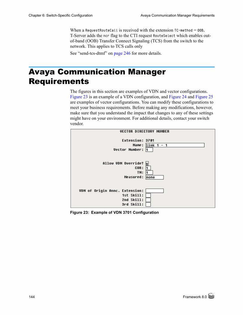
144 Framework 8.0
Chapter 6: Switch-Specific Configuration Avaya Communication Manager Requirements
When a RequestRouteCall is received with the extension TC-method = OOB, T-Server adds the ncr flag to the CTI request RouteSelect which enables out- of-band (OOB) Transfer Connect Signaling (TCS) from the switch to the network. This applies to TCS calls only
See “send-tcs-dtmf” on page 246 for more details.
Avaya Communication Manager Requirements
The figures in this section are examples of VDN and vector configurations. Figure 23 is an example of a VDN configuration, and Figure 24 and Figure 25 are examples of vector configurations. You can modify these configurations to meet your business requirements. Before making any modifications, however, make sure that you understand the impact that changes to any of these settings might have on your environment. For additional details, contact your switch vendor.
Figure 23: Example of VDN 3701 Configuration

T-Server—Deployment Guide 145
Chapter 6: Switch-Specific Configuration Avaya Communication Manager Requirements
Figure 24: Example of Call Vector 1 Configuration
Figure 25: Example of Call Vector 9 Configuration
Configuring an ASAI Split
Enter display hunt-group # at the command prompt to display the Hunt-Group/Split Setup screen (see Figure 26). To force all agent control of the phone from the ASAI link, set Controlling Adjunct to asai; otherwise, set it to none. To change this entry, enter change hunt-group # at the command prompt. Tab to the entry and type in the correct response. If you change the value to asai, a prompt requests either the Adjunct Link Extension or CTI

146 Framework 8.0
Chapter 6: Switch-Specific Configuration Genesys Requirements for Avaya Communication Manager
link #, depending on the PBX software version. Enter the extension number that was assigned earlier for the ASAI station.
Figure 26: ASAI Link, Hunt Group Configuration
Genesys Requirements for Avaya Communication Manager
The following are the Genesys requirements for Avaya Communication Manager:
• Call Center Deluxe or Elite software package
• 1273-MPDA–MAPD BOARD (requires three consecutive card slots), or C-LAN with Co-Resident DLG and DLG software
• Additional software (see Table 11)
Table 11: Software Requirements
Switch ASAI Core PEC ASAI Plusa PEC
a. ASAI Plus is also known as Host-Based Routing.
G3s 1273-AS3 1273-AT3
G3i 1273-AS2 1273-AT2
G3r 1273-AS1 1273-AT1

T-Server—Deployment Guide 147
Chapter 6: Switch-Specific Configuration Genesys Requirements for Avaya Communication Manager
Note: This Genesys T-Server does not require the ASAI CallVisor feature (hardware or software), because it interfaces directly with the MAPD ASAI.
Table 12 lists the various ASAI capabilities, and indicates which package contains each one. For additional details, contact your switch vendor
You must place any outbound calls over ISDN trunks. This ensures generation of proper call progress messages during the dialing process.
Table 12: Supported Features
Feature ASAI Core ASAI Plusa
a. ASAI Plus is also known as Host-Based Routing.
Adjunct Call Control Group Y
Domain Control Group Y
Event Notification Group Y
Request Feature Group Y
Value Query Group Y
Selective Listening Y
Set Value Group Y
Adjunct Routing Group Y
Answering Machine Detect Y
Sw Class Calls/Pred Dialing Y
II Digits Y
Classification After Ans Y
Notes: • ASAI Plus software is required only for Genesys routing products, outbound applications, and multi-site configurations.
• Adjunct Routing is now a separate billable feature from Avaya.

148 Framework 8.0
Chapter 6: Switch-Specific Configuration Genesys Requirements for Avaya Communication Manager

T-Server—Deployment Guide 149
Chapter
7 Supported FunctionalityThis chapter describes the telephony functionality supported by the T-Server for Avaya Communication Manager. It includes these sections: T-Library Functionality, page 149 Support for Agent Work Modes, page 158 Support for Replacing Calling Party Number, page 159 Support for Real-Time Agent State Using Device, Media and Call Control
API, page 159 Support for Notification of Failed Routing Attempts, page 160 Use of the Extensions Attribute, page 161 Use of the UserData Attribute, page 172 Error Messages, page 173 Avaya Enterprise Survivable Server (ESS), page 179 Avaya Switch Partitioning, page 185
T-Library FunctionalityThe tables in this section present the T-Library functionality supported in Avaya Communication Manager. The table entries use these notations:
N—Not supported
Y—Supported
E—Event only is supported
I—Supported, but reserved for Genesys Engineering
In Table 13 on page 150, events in a set are listed in an arbitrary order when the set of events is sent in response to a single request. An asterisk (*) indicates the event that contains the same ReferenceID as the request. For more information, refer to the Genesys 7 Events and Models Reference Manual and Voice Platform SDK 8.0.NET (or Java) API Reference.
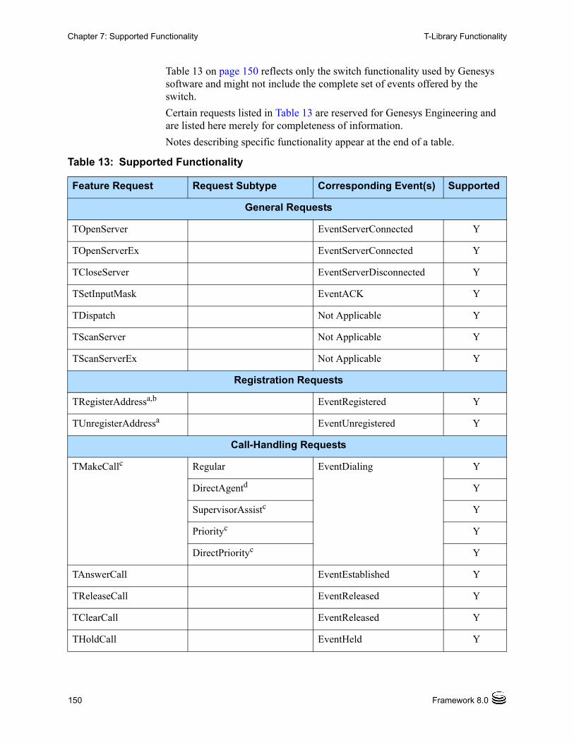
150 Framework 8.0
Chapter 7: Supported Functionality T-Library Functionality
Table 13 on page 150 reflects only the switch functionality used by Genesys software and might not include the complete set of events offered by the switch.
Certain requests listed in Table 13 are reserved for Genesys Engineering and are listed here merely for completeness of information.
Notes describing specific functionality appear at the end of a table.
Table 13: Supported Functionality
Feature Request Request Subtype Corresponding Event(s) Supported
General Requests
TOpenServer EventServerConnected Y
TOpenServerEx EventServerConnected Y
TCloseServer EventServerDisconnected Y
TSetInputMask EventACK Y
TDispatch Not Applicable Y
TScanServer Not Applicable Y
TScanServerEx Not Applicable Y
Registration Requests
TRegisterAddressa,b EventRegistered Y
TUnregisterAddressa EventUnregistered Y
Call-Handling Requests
TMakeCallc Regular EventDialing Y
DirectAgentd Y
SupervisorAssistc Y
Priorityc Y
DirectPriorityc Y
TAnswerCall EventEstablished Y
TReleaseCall EventReleased Y
TClearCall EventReleased Y
THoldCall EventHeld Y

T-Server—Deployment Guide 151
Chapter 7: Supported Functionality T-Library Functionality
TRetrieveCall EventRetrieved Y
TRedirectCall EventReleased Y
TMakePredictiveCalle EventDialing*, EventQueued Y
Transfer/Conference Requests
TInitiateTransferb EventHeld, EventDialing* Y
TCompleteTransferf EventReleased*, EventPartyChanged
Y
TInitiateConferenceb EventHeld, EventDialing* Y
TCompleteConferenceg EventReleased*, EventRetrieved, EventPartyChanged, EventPartyAdded
Y
TDeleteFromConference EventPartyDeleted*, EventReleased
Y
TReconnectCall EventReleased, EventRetrieved*
Y
TAlternateCall EventHeld*, EventRetrieved Y
TMergeCalls ForTransfer EventReleased*, EventPartyChanged
Y
ForConference EventReleased*, EventRetrieved, EventPartyChanged, EventPartyAdded
Y
TMuteTransfer EventHeld, EventDialing, EventReleased, EventPartyChanged
Y
TSingleStepTransfer EventReleased, EventPartyChanged
N
TSingleStepConference EventRinging, EventEstablished
Y
Table 13: Supported Functionality (Continued)
Feature Request Request Subtype Corresponding Event(s) Supported

152 Framework 8.0
Chapter 7: Supported Functionality T-Library Functionality
Call-Routing Requests
TRouteCallb Unknown EventRouteUsed I
Default I
Label N
OverwriteDNISh I
DDD N
IDDD N
Direct N
Reject I
Announcement N
PostFeature N
DirectAgenti I
Priorityj I
DirectPriorityh I
AgentID N
CallDisconnect N
Call-Treatment Requests
TApplyTreatment Unknown (EventTreatmentApplied+
EventTreatmentEnd)/EventTreatmentNotApplied
N
IVR N
Music N
RingBack N
Silence N
Busy N
CollectDigits N
PlayAnnouncement N
Table 13: Supported Functionality (Continued)
Feature Request Request Subtype Corresponding Event(s) Supported

T-Server—Deployment Guide 153
Chapter 7: Supported Functionality T-Library Functionality
PlayAnnouncementAnd-Digits
N
VerifyDigits N
RecordUserAnnouncement N
DeleteUserAnnouncement N
CancelCall N
PlayApplication N
SetDefaultRoute N
TextToSpeech N
TextToSpeechAndDigits N
FastBusy N
RAN N
TGiveMusicTreatment EventTreatmentApplied N
TGiveRingBackTreatment EventTreatmentApplied N
TGiveSilenceTreatment EventTreatmentApplied N
DTMF (Dual-Tone Multifrequency) Requests
TCollectDigits EventDigitsCollected N
TSendDTMF EventDTMFSent Y
Voice-Mail Requests
TOpenVoiceFile EventVoiceFileOpened N
TCloseVoiceFile EventVoiceFileClosed N
TLoginMailBox EventMailBoxLogin N
TLogoutMailBox EventMailBoxLogout N
TPlayVoice EventVoiceFileEndPlay N
Agent and DN Feature Requests
TAgentLogink EventAgentLogin Y
Table 13: Supported Functionality (Continued)
Feature Request Request Subtype Corresponding Event(s) Supported
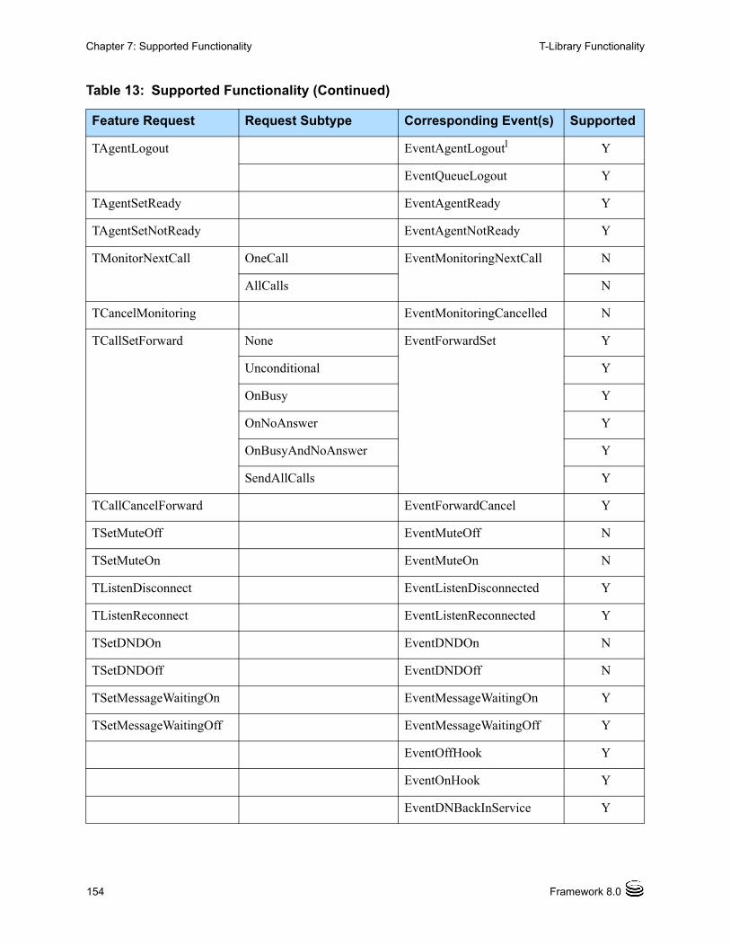
154 Framework 8.0
Chapter 7: Supported Functionality T-Library Functionality
TAgentLogout EventAgentLogoutl Y
EventQueueLogout Y
TAgentSetReady EventAgentReady Y
TAgentSetNotReady EventAgentNotReady Y
TMonitorNextCall OneCall EventMonitoringNextCall N
AllCalls N
TCancelMonitoring EventMonitoringCancelled N
TCallSetForward None EventForwardSet Y
Unconditional Y
OnBusy Y
OnNoAnswer Y
OnBusyAndNoAnswer Y
SendAllCalls Y
TCallCancelForward EventForwardCancel Y
TSetMuteOff EventMuteOff N
TSetMuteOn EventMuteOn N
TListenDisconnect EventListenDisconnected Y
TListenReconnect EventListenReconnected Y
TSetDNDOn EventDNDOn N
TSetDNDOff EventDNDOff N
TSetMessageWaitingOn EventMessageWaitingOn Y
TSetMessageWaitingOff EventMessageWaitingOff Y
EventOffHook Y
EventOnHook Y
EventDNBackInService Y
Table 13: Supported Functionality (Continued)
Feature Request Request Subtype Corresponding Event(s) Supported

T-Server—Deployment Guide 155
Chapter 7: Supported Functionality T-Library Functionality
EventDNOutOfService Y
Query Requests
TQuerySwitcha DateTime EventSwitchInfo Y
ClassifierStat Y
TQueryCalla PartiesQuery EventPartyInfo Y
StatusQuery Y
TQueryAddressa AddressStatus EventAddressInfo Y
MessageWaitingStatus Y
AssociationStatus N
CallForwardingStatus Y
AgentStatus Y
NumberOfAgentsInQueue Y
NumberOfAvailableAgents-InQueue
Y
NumberOfCallsInQueue Y
AddressType Y
CallsQuery Y
SendAllCallsStatus Y
QueueLoginAudit Y
NumberOfIdleTrunks Y
NumberOfTrunksInUse Y
DatabaseValue Y
DNStatus Y
QueueStatus Y
Table 13: Supported Functionality (Continued)
Feature Request Request Subtype Corresponding Event(s) Supported

156 Framework 8.0
Chapter 7: Supported Functionality T-Library Functionality
TQueryLocationa AllLocations EventLocationInfom I
LocationData I
MonitorLocation I
CancellMonitorLocation I
MonitorAllLocations I
CancelMonitorAllLocations I
TQueryServera EventServerInfo Y
User-Data Requests
TAttachUserData
[Obsolete]
EventAttachedDataChanged Y
TUpdateUserData EventAttachedDataChanged Y
TDeleteUserData EventAttachedDataChanged Y
TDeleteAllUserData EventAttachedDataChanged Y
ISCC (Inter Server Call Control) Requests
TGetAccessNumberb EventAnswerAccessNumber I
TCancelReqGetAccess-Numberb
EventReqGetAccessNumberCanceled
I
Special Requests
TReserveAgent EventAgentReserved Y
TSendEvent EventACK I
TSendEventEx EventACK I
TSetCallAttributes EventCallInfoChanged I
TSendUserEvent EventACK Y
TPrivateService EventPrivateInfo N
Network Attended Transfer Requestsn
TNetworkConsult EventNetworkCallStatus Y
Table 13: Supported Functionality (Continued)
Feature Request Request Subtype Corresponding Event(s) Supported

T-Server—Deployment Guide 157
Chapter 7: Supported Functionality T-Library Functionality
TNetworkAlternate EventNetworkCallStatus Y
TNetworkTransfer EventNetworkCallStatus Y
TNetworkMerge EventNetworkCallStatus Y
TNetworkReconnect EventNetworkCallStatus Y
TNetworkSingleStep-Transfer
EventNetworkCallStatus Y
TNetworkPrivateService EventNetworkPrivateInfo Y
ISCC Transaction Monitoring Requests
TTransactionMonitoring EventACK Y
EventTransactionStatus E
a. Only the requester is notified of the event associated with this request.
b. If a link goes down, T-Server issues EventDNOutOfService for all DNs that were assigned to that link at startup unless such DNs were also assigned to another link (within the same T-Server), which remains active. When the status of the link goes back to normal, T-Server generates EventDNBackInService for every DN which was previously reported as out of service due to the link failure.
c. Since this feature request can be made across locations in a multi-site environment, if the location attribute of the request contains a value relating to any location other than the local site—except when the response to this request is EventError—T-Server sends a second event response that contains the same ReferenceID as the first event. This second event is either EventRemoteConnectionSuccess or EventRemoteConnectionFailed.
d. See ASAI Direct Agent, Supervisor Assist, and Priority Calling options. For additional details, contact your switch vendor.
e. The DN parameter of the request must be a VDN programmed as a Routing Point. Queuing and routing of calls answered by a fax machine is not supported.
f. Starting with 7.5, T-Server sends an EventPartyChanged message after a TCompleteTransfer T-Library request for each of the parties that are moved to the original call which had initially been part of the call.
g. Starting with 7.5, T-Server sends an EventPartyAdded message after a TCompleteConference T-Library request for each of the parties that are moved to the original call which had initially been part of the call.
h. Used for TransfConnect switched virtual circuits (SVCs).
i. See ASAI option direct_agent_call.
j. See ASAI option priority_calling.
Table 13: Supported Functionality (Continued)
Feature Request Request Subtype Corresponding Event(s) Supported
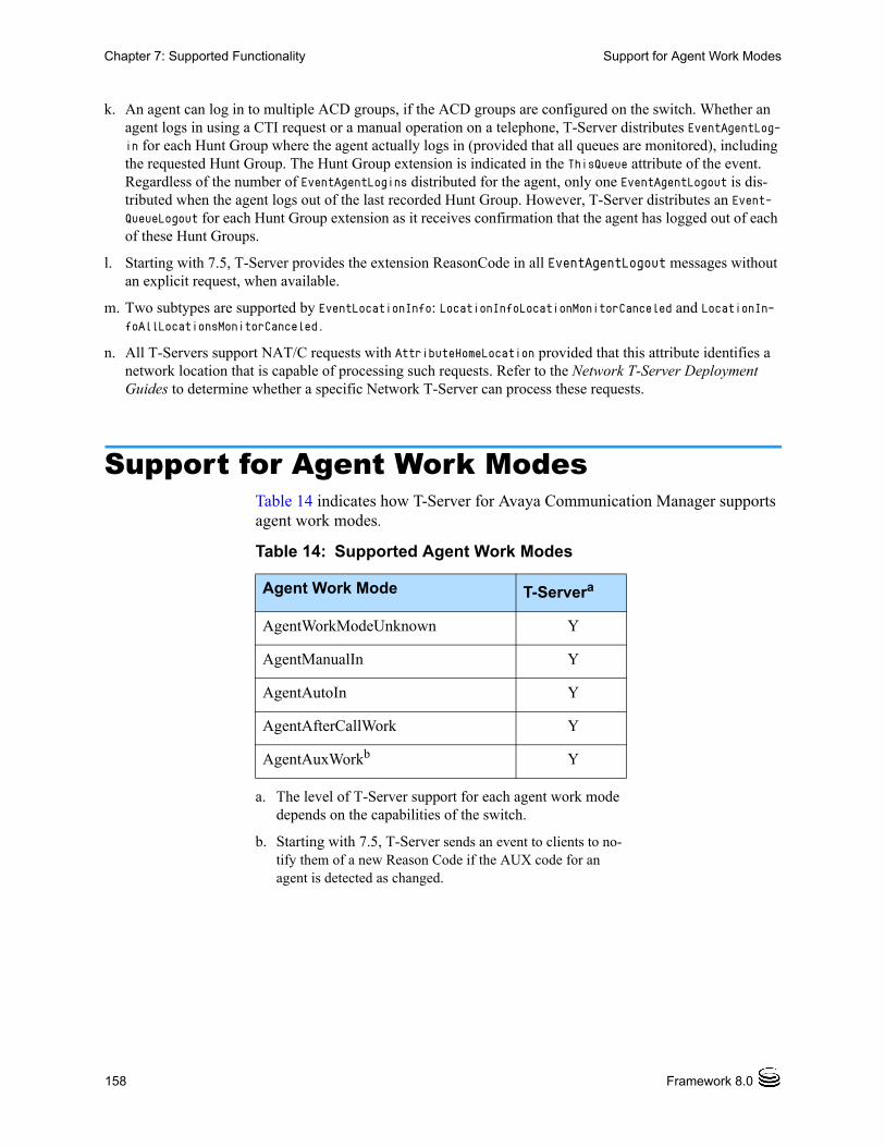
158 Framework 8.0
Chapter 7: Supported Functionality Support for Agent Work Modes
Support for Agent Work ModesTable 14 indicates how T-Server for Avaya Communication Manager supports agent work modes.
k. An agent can log in to multiple ACD groups, if the ACD groups are configured on the switch. Whether an agent logs in using a CTI request or a manual operation on a telephone, T-Server distributes EventAgentLog-in for each Hunt Group where the agent actually logs in (provided that all queues are monitored), including the requested Hunt Group. The Hunt Group extension is indicated in the ThisQueue attribute of the event. Regardless of the number of EventAgentLogins distributed for the agent, only one EventAgentLogout is dis-tributed when the agent logs out of the last recorded Hunt Group. However, T-Server distributes an Event-QueueLogout for each Hunt Group extension as it receives confirmation that the agent has logged out of each of these Hunt Groups.
l. Starting with 7.5, T-Server provides the extension ReasonCode in all EventAgentLogout messages without an explicit request, when available.
m. Two subtypes are supported by EventLocationInfo: LocationInfoLocationMonitorCanceled and LocationIn-foAllLocationsMonitorCanceled.
n. All T-Servers support NAT/C requests with AttributeHomeLocation provided that this attribute identifies a network location that is capable of processing such requests. Refer to the Network T-Server Deployment Guides to determine whether a specific Network T-Server can process these requests.
Table 14: Supported Agent Work Modes
Agent Work Mode T-Servera
a. The level of T-Server support for each agent work mode depends on the capabilities of the switch.
AgentWorkModeUnknown Y
AgentManualIn Y
AgentAutoIn Y
AgentAfterCallWork Y
AgentAuxWorkb
b. Starting with 7.5, T-Server sends an event to clients to no-tify them of a new Reason Code if the AUX code for an agent is detected as changed.
Y

T-Server—Deployment Guide 159
Chapter 7: Supported Functionality Support for Replacing Calling Party Number
Support for Replacing Calling Party Number
Avaya Communication Manager provides the capability to replace a calling number through the CTI request.
In order for T-Server to support the ASAI green feature Replace Calling Party Number, it must be activated on the switch by using the system-parameters special-applications form. To replace the calling party number for the RequestMakeCall and RequestMakePredictive requests, T-Clients should use TKVList extension data with the keys described in the “Hardware Reasons in Extensions” section of the “Extensions” portion in the Genesys 7 Events and Models Reference Manual and Voice Platform SDK 8.0 .NET (or Java) API Reference.
If you need predictive call dialing is needed while using this feature, set the match-calls-by option to ucid (see the option description on page 250.)
Warning! The UU_DATA key of UserData is used to support this feature. However, any other T-Server feature that also uses UU_DATA takes priority over the Replacing Calling Party Number feature. (That is, if UU_DATA is used by other features for the same call, then the Replacing Calling Party Number feature is not used.)
Note: The Replacing Calling Party Number feature is supported for switch versions R010 or later.
Support for Real-Time Agent State Using Device, Media and Call Control API
T-Server uses the Device, Media and Call Control API (DMCC) link to monitor lamp state changes on the physical telephone. The lamp state changes are mapped to physical button functions (AgentAutoIn, AgentManualIn, AgentAfterCallWork, and AgentAuxWork). T-Server uses this information to generate Agent State events that provides notification about the agent state changes.
T-Server generates EventAgentReady/EventAgentNotReady when T-Server detects a LampMode state change on the corresponding agent state button (on the physical set).
The DMCC link does not send notification when the button information is changed on the physical set. T-Server can utilize a query to obtain (or refresh) button information—the update-button-info option is used to obtain this button information.
160 Framework 8.0
Chapter 7: Supported Functionality Support for Notification of Failed Routing Attempts
Since the DMCC link does not report the AUX Reason Code, T-Server uses a query to obtain the Reason Code when it detects an AUX state change.
The session-duration option can be used to request a specific session duration with the DMCC link. T-Server will maintain this active session with periodic requests to the DMCC link to reset the application session timer. Additionally, T-Server will consider any failed response by DMCC, to this request, as a link drop.
Use of AttributeExtensions
T-Server supports the DmccPassword key in AttributeExtensions, which enables RequestRegisterAddress to set the DMCC password for a DN that is not registered in Configuration Manager. The password is assigned to the specific device and administered on Avaya Communication Manager. If no password is provided, the password is assumed to be the same digits as the associated DN.
Note: The required DMCC password field on the Switch is called Security Code.
High-Availability
T-Server does not register DNs over the DMCC link if it is running in backup mode. Also, T-Server forces the DMCC link to shut down when it switches from primary to backup mode of operation.
Support for Notification of Failed Routing Attempts
An alarm reaction in Solution Control Interface (SCI) can be triggered when a call has not successfully routed. See the following related options for more details:
• route-failure-alarm-high-wm
• route-failure-alarm-low-wm
• route-failure-alarm-period
Note: When running in an HA environment, to eliminate the possibility of the backup T-Server clearing an alarm condition that was set by the primary T-Server, all alarm generation in the backup T-Server is disabled.

T-Server—Deployment Guide 161
Chapter 7: Supported Functionality Use of the Extensions Attribute
Use of the Extensions AttributeTable 15 indicates how T-Server for Avaya Communication Manager supports the use of the Extensions attribute.
Table 15: Use of the Extensions Attribute
Request/Event Attribute Extensions
Key Value Type
Value Description
TAgentLogout or TAgentNotReady with WorkMode = AgentAuxWork
ReasonCode integer Can be used to send Reason Code to the switch (valid values are 1-99; Logout Reason Codes in the switch configuration must be set to forced or requested).
TMakeCall, with call_type = MakeCallDirectAgent, MakeCallDirectPriority, or MakeCallSupervisorAssist or TRouteCall, with route_type = RouteTypeDirectAgent or RouteTypeDirectPriority
AgentQueue string Must contain the queue for the agent (the ACD Split/Skill where agent is logged in).
TMakeCall Trunk string Can be used to pass TAC/ARS/AAR information for off-PBX destinations.
CPNOptions TKVList To replace the calling party number (CPN) for the RequestMakeCall, T-Clients should use TKVList extension data with the keys that are described in the “Hardware Reasons in Extensions” section of the “Extensions” portion in the Genesys 7 Events and Models Reference Manual and the Voice Platform SDK 8.0 .NET (or Java) API Reference.
Note: The TKVList is optional.

162 Framework 8.0
Chapter 7: Supported Functionality Use of the Extensions Attribute
TMakePredictiveCall AMD string Used to change default Answering Machine Detection (AMD) treatment for one particular call and specified by the use-am-detection option.
no—AMD is not enabled. (This value matches false in the use-am-detection option.).
drop—AMD is enabled and drops the call when an answering machine is detected. (This value matches true in the use-am-detection option.)
connect—AMD is enabled but processes the call attaching AnswerClass=AM as user data when an answering machine is detected. (This value matches connect in the use-am-detection option.)
Table 15: Use of the Extensions Attribute (Continued)
Request/Event Attribute Extensions
Key Value Type
Value Description

T-Server—Deployment Guide 163
Chapter 7: Supported Functionality Use of the Extensions Attribute
TMakePredictiveCall CPNOptions TKVList To replace the calling party number (CPN) for the RequestMakePredictive, T-Clients should use TKVList extension data with the keys that are described in the “Hardware Reasons in Extensions” section of the “Extensions” portion in the Genesys 7 Events and Models Reference Manual and the Voice Platform SDK 8.0 .NET (or Java) API Reference.
Note: The TKVList is optional.
VoiceDest Any valid ACD Queue or Routing Point
A Queue or Routing Point to which an outbound call answered by a live voice will be transferred.
AnsMachine Any valid ACD Queue or Routing Point
A Queue or Routing Point to which an outbound call answered by an answering machine will be transferred.
Table 15: Use of the Extensions Attribute (Continued)
Request/Event Attribute Extensions
Key Value Type
Value Description

164 Framework 8.0
Chapter 7: Supported Functionality Use of the Extensions Attribute
TRouteCall CollectDigits integer Used for ASAI-Requested Digit Collection, where the value (1-24) specifies the number of digits to be collected. See Avaya specifications for details.
CollectedDigits string ASAI-Provided Digits. See Avaya specifications for details.
NO_ANSWER_TIMEOUTa
string Calls ringing on an agent's telephone that were distributed from an ACD Queue or a Routing Point wait for the telephone to ring for this timeout period (in seconds) before performing the actions described by the NO_ANSWER_ACTION Key and redirect the call to the destination described in the NO_ANSWER_OVERFLOW Key.
NO_ANSWER_ACTION
string Specifies the agent state (none, notready, walkaway) to which T-Server will be set to after the time period for the NO_ANSWER_TIMEOUT Key has expired. A value of none means that the agent will remain in its current state.
NO_ANSWER_OVERFLOW
string After the time period for the NO-ANSWER-TIMEOUT key has expired, T-Server will redirect the ringing call to the destination described with this Key. If set to recall the call will be redirected back to the Routing Point or the ACD Queue. If set to none the call will continue ringing. Otherwise provided digits for a valid destination (a Queue or Routing Point on the local switch is recommended).
Table 15: Use of the Extensions Attribute (Continued)
Request/Event Attribute Extensions
Key Value Type
Value Description

T-Server—Deployment Guide 165
Chapter 7: Supported Functionality Use of the Extensions Attribute
TListenDisconnect orTListenReconnect
TalkerDN string Specifies the party that should no longer be heard by the listener (in case of the ListenDisconnect request), or the party that should be reconnected. If you do not specify a value, the switch defaults to all the parties currently on the call.
TRegisterAddress DropCRV integer For troubleshooting use only. When used, T-Server drops either a particular Call Reference Value (CRV), or the current CRV if the value is 0, and creates a new one.
Note: Do not use this extension unless directed to do so by Genesys Technical Support.
DMCCPassword string Assigned to the specific device and administered on Avaya Communication Manager. If no password is provided, the password is assumed to be the same digits as the associated DN.
TInitiateConference ConsultUser
Data
string Used to specify the method of handling user data in a consultation call. Valid values are default, separate, inherited, and joint.
TInitiateTransfer ConsultUser
Data
string Used to specify the method of handling user data in a consultation call. Valid values are default, separate, inherited, and joint.
TMuteTransfer ConsultUser
Data
string Used to specify the method of handling user data in a consultation call. Valid values are default, separate, inherited, and joint.
Table 15: Use of the Extensions Attribute (Continued)
Request/Event Attribute Extensions
Key Value Type
Value Description

166 Framework 8.0
Chapter 7: Supported Functionality Use of the Extensions Attribute
TSendDTMF ToneDuration integer Used to specify the duration of each tone, in .01 second increments. The valid range of values accepted by the switch for this parameter is from 6 to 35 (0.06 to 0.35 seconds).
Note: T-Server does not validate the range for the ToneDuration attribute.
PauseDuration integer Used to specify the duration of the pause in between tones, in .01 second increments. The valid range of values accepted by the switch for this parameter is from 4 to 10 (0.04 to 0.10 seconds).
Note: T-Server does not validate the range for the PauseDuration attribute.
Table 15: Use of the Extensions Attribute (Continued)
Request/Event Attribute Extensions
Key Value Type
Value Description

T-Server—Deployment Guide 167
Chapter 7: Supported Functionality Use of the Extensions Attribute
TSingleStepConference AlertingOrder integer 0—Add station without alerting the station.1—Alert the station before adding.
Use of this option specifies whether the calling endpoint should be signaled before the party is added.
Use of this key supports the Third-Party Single-Step Conference feature, which allows a station to be conferenced into an existing call.
Visibilityb integer 0—Listen only (no visibility).
1—Talk and listen (full visibility).
Use of this option specifies whether the conferencing party should be muted or an active participant in the call.
Use of this key supports the Third-Party Single-Step Conference feature, which allows a station to be conferenced into an existing call.
Events T-Server sends to the parties in a conference call: EventPartyChanged/ EventPartyAdded/EventEstablished
NumOfOrig-DNs integer The number of DNs on an original call (excluding the party already reported as ThisDN) and all other DNs. n is the number of the DN in question.
OrigDN-n string
NumOfConsult-DNs
integer The number of DNs on a consultation call and all other DNs (is present in EventPartyAdded only). n is the number of the DN in question.
ConsultDN-n string
Table 15: Use of the Extensions Attribute (Continued)
Request/Event Attribute Extensions
Key Value Type
Value Description

168 Framework 8.0
Chapter 7: Supported Functionality Use of the Extensions Attribute
EventAddressInfo with AddressInfoType = AddressInfoNumberOfAgentsInQueue/AvailableAgentsInQueue/CallsInQueue
AgentsInQueue integer The requested number is returned in the AddressInfoStatus attribute and contains all three of the keys.
Available-Agents integer
CallsInQueue integer
EventAddressInfo with AddressInfoType = AddressInfoCallsQuery
Call-n integer The CallID of a call on the DN, where n is the call number, which can be 1, 2, and so on.
Conn-n string Text representation of the ConnID for a call, where n is the call number, which can be 1, 2, and so on.
State-n integer The state of ThisDN as of a party in the call, where n is the call number, which can be 1, 2, and so on. (See AddressStatusInfo-Type in the Genesys 7 Events and Models Reference Manual and Voice Platform SDK 8.0 .NET (or Java) API Reference for value meanings.)
EventAddressInfo with AddressInfoType = AddressInfoQueueLoginAudit
<DN-n> <Agent-ID-n>
The AgentID of an agent that is logged on the DN specified by the key. n is the number of the DN in question.
EventAddressInfo with AddressInfoType = AddressInfoNumberOfIdleClassifiers/AddressInfoNumberOfClassifiersInUse
Idle integer The number of idle classifiers.
InUse integer The number of classifiers in use.
EventAddressInfo ForwardTo string The DN to which a call was forwarded, as reported in the Redirection_Number attribute of the switch message.
Table 15: Use of the Extensions Attribute (Continued)
Request/Event Attribute Extensions
Key Value Type
Value Description

T-Server—Deployment Guide 169
Chapter 7: Supported Functionality Use of the Extensions Attribute
EventSwitchInfo with SwitchInfoType = SwitchInfoClassifierStat
Idle integer The number of idle classifiers.
InUse integer The number of classifiers in use.
EventAddressInfo with AddressInfoType = AddressInfoNumberOfIdleTrunks/AddressInfoNumberOfTrunksInUse
Idle integer The number of idle trunks.
InUse integer The number of trunks in use.
EventAddressInfo with AddressInfoType = AddressInfoDatabaseValue
ID string The database value associated with the DN in question.
Table 15: Use of the Extensions Attribute (Continued)
Request/Event Attribute Extensions
Key Value Type
Value Description

170 Framework 8.0
Chapter 7: Supported Functionality Use of the Extensions Attribute
EventAddressInfo with AddressInfoType = AddressInfoDNStatus/AddressInfoQueueStatus
status integer 0 (idle) or the DN state as of a party in the call.
AgentStatus integer <0 (Unknown)0 (LoggedOut)1 (LoggedIn)2 (Ready) 3 (NotReady) 4 (AfterCallWork)5 (WalkAway)
queue-n string A queue where the agent is logged in, where n is the number of the queue, which can be 1, 2, and so on.
conn-n string Text representation of the ConnID for a call (if applicable), where n is the number of the call, which can be 1, 2, and so on.
ct-%d integer The call type (taken from TCallType) of the call reported by conn-%d (%d is an index).
mt-%d integer The call type taken from TMediaType of the media type information.
fwdc string The destination DN.
Not present if T-Server has no information about Forward status.
mwl integer The Message Waiting Lamp statuses:
0—MWL off
1—MWL on
Not present if T-Server has no information about MWL status.
Table 15: Use of the Extensions Attribute (Continued)
Request/Event Attribute Extensions
Key Value Type
Value Description

T-Server—Deployment Guide 171
Chapter 7: Supported Functionality Use of the Extensions Attribute
EventNetworkReached NetworkState integer The key where the value can be represented as an enumeration defined as the following:
• NetworkStateNone=0,
• NetworkStateSeized=1,
• NetworkStateCutThru=2,
• NetworkStateAlerting=3,
• NetworkStateBusy=4
EventPartyInfo party-n string The DN of a party, where n is the number of the party, which can be 1, 2, and so on.
EventRouteUsed G3Cause integer The key representing the G3 coding standard and cause pair that maps directly to a T-Server error code starting with TERR_ASAI_START.
EventDialing/ EventHeld/ EventRetrieved/ EventRinging/ EventEstablished/ EventReleased/ EventRouteRequest/ EventQueued/ EventAbandoned/ EventDiverted/ EventPartyChanged/ EventPartyDeleted/ EventPartyAdded/ EventRouteUsed/ EventListenDisconnected/ EventListenReconnected/ EventDigitsCollected/ EventDTMFSent/ EventPartyInfo/
EventNetworkReached
UCID binary UCID (Universal Call ID) is provided by Avaya Communication Manager and is included as an binary value (8 bytes) in the attribute extension of call-related events.
T-Server Common Part Extensions
EventServerInfo sdn-licenses-in-use
integer Specifies how many SDN licenses are currently in use.
sdn-licenses-available
integer Specifies how many SDN licenses are currently available.
Table 15: Use of the Extensions Attribute (Continued)
Request/Event Attribute Extensions
Key Value Type
Value Description

172 Framework 8.0
Chapter 7: Supported Functionality Use of the UserData Attribute
Use of the UserData AttributeTable 16 indicates how T-Server for Avaya Communication Manager supports the use of the UserData attribute.
a. If NO_ANSWER_TIMEOUT is specified, the action and overflow values will be taken from the NO_ANSWER_ACTION and NO_ANSWER_OVERFLOW keys. If the action and overflow keys are missing then the default value is used (not the value from the configuration options on page 236).
b. Starting with 7.5, T-Server sets the AttributeOtherDNRole attribute to RoleObserver in the EventPartyAdded event for scenarios where a supervisor silently joins a call by initiating a SingleStepConference with the exten-sion Visibility set to 0.
c. For an option description, see “use-old-fwd-key” on page 249.
Table 16: Use of the UserData Attribute
Request/Event UserData Attribute
Key Value Type Value Description
TMakeCallwithUserData
UU_DATA stringorbinary
Can be used to pass data between ASAI applications.
TRouteCallwithUserData (present on the call)
UU_DATA stringorbinary
Can be used to pass data between ASAI applications.
TReleaseCallwithUserData (present on the call)
UU_DATA stringorbinary
Can be used to pass data between ASAI applications.
TInitiateConferencewithUserData
UU_DATA stringorbinary
Can be used to pass data between ASAI applications.
TInitiateTransferwithUserData
UU_DATA stringorbinary
Can be used to pass data between ASAI applications.
TMuteTransferwithUserData
UU_DATA stringorbinary
Can be used to pass data between ASAI applications.
TMakePredictiveCallwithUserData
UU_DATA stringorbinary
Can be used to pass data between ASAI applications.

T-Server—Deployment Guide 173
Chapter 7: Supported Functionality Error Messages
Error MessagesTable 17 presents the complete set of error messages that T-Server distributes in EventError.
Table 17: Error Messages for T-Server for Avaya Communication Manager
T-Server Code
Symbolic Name Description Switch Code
40 TERR_NOMORE_LICENSE No more licenses.
41
TERR_NOT_REGISTERED
The DN client is trying to manipulate, but it has not yet been registered by that client.
42
TERR_RESOURCE_SEIZED
Client application is requesting registration of a DN, but another client has already registered it in Private mode. Only one application can have a DN registered in Private mode at any one time.
43 TERR_IN_SAME_STATE Object is already in requested state.
50 TERR_UNKNOWN_ERROR Unspecified error in client’s request.
51 TERR_UNSUP_OPER Client application is requesting a function that is not supported by this T-Server.
52 TERR_INTERNAL Internal error (contact Genesys Technical Support).
53 TERR_INVALID_ATTR Invalid attribute value in request.
54 TERR_NO_SWITCH Client application is requesting a function that requires a switch connection, but the link is not in a connected state.
55 TERR_PROTO_VERS Invalid authorization request: RequestRegisterClient has an incorrect protocol version (the client was built with a T-Library that is incompatible with T-Server).
56 TERR_INV_CONNID Client application is requesting a function and specifying an invalid connectionID.
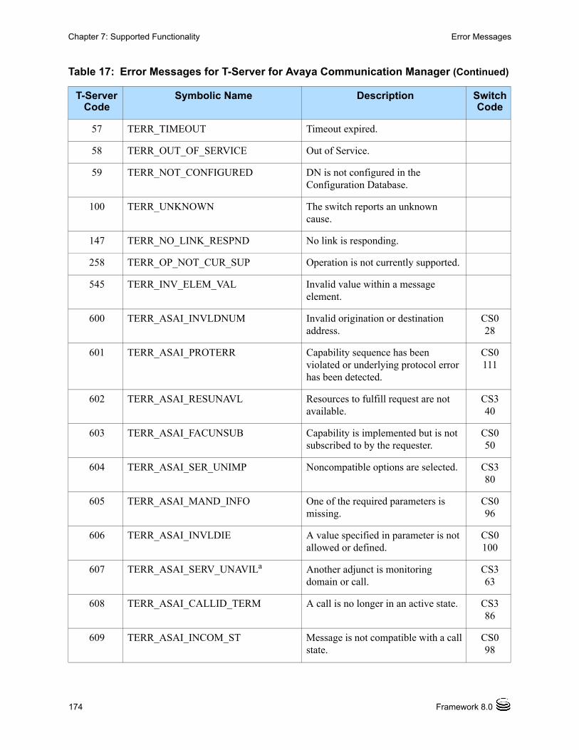
174 Framework 8.0
Chapter 7: Supported Functionality Error Messages
57 TERR_TIMEOUT Timeout expired.
58 TERR_OUT_OF_SERVICE Out of Service.
59 TERR_NOT_CONFIGURED DN is not configured in the Configuration Database.
100 TERR_UNKNOWN The switch reports an unknown cause.
147 TERR_NO_LINK_RESPND No link is responding.
258 TERR_OP_NOT_CUR_SUP Operation is not currently supported.
545 TERR_INV_ELEM_VAL Invalid value within a message element.
600 TERR_ASAI_INVLDNUM Invalid origination or destination address.
CS028
601 TERR_ASAI_PROTERR Capability sequence has been violated or underlying protocol error has been detected.
CS0111
602 TERR_ASAI_RESUNAVL Resources to fulfill request are not available.
CS340
603 TERR_ASAI_FACUNSUB Capability is implemented but is not subscribed to by the requester.
CS050
604 TERR_ASAI_SER_UNIMP Noncompatible options are selected. CS380
605 TERR_ASAI_MAND_INFO One of the required parameters is missing.
CS096
606 TERR_ASAI_INVLDIE A value specified in parameter is not allowed or defined.
CS0100
607 TERR_ASAI_SERV_UNAVILa Another adjunct is monitoring domain or call.
CS363
608 TERR_ASAI_CALLID_TERM A call is no longer in an active state. CS386
609 TERR_ASAI_INCOM_ST Message is not compatible with a call state.
CS098
Table 17: Error Messages for T-Server for Avaya Communication Manager (Continued)
T-Server Code
Symbolic Name Description Switch Code

T-Server—Deployment Guide 175
Chapter 7: Supported Functionality Error Messages
610 TERR_ASAI_INVALID_CRV Invalid call identifier is used or a call does not exist.
CS081
611 TERR_ASAI_INCOM_OPT Incompatible options are used to establish the call.
CS380
612 TERR_ASAI_REC_TIMER Timer has expired. CS0102
613 TERR_ASAI_NOLOGIN Agent is not logged in to a split. CS315
614 TERR_ASAI_NOSPLIT_MEM Agent is not a member of the specified split or the split number has been specified incorrectly.
CS311
615 TERR_ASAI_USER_BUSY User is busy. CS017
616 TERR_ASAI_NOUSE_RESP Origination address does not respond to service.
CS018
617 TERR_ASAI_PERM_DENIED Permission checks for service have failed.
CS343
618 TERR_ASAI_CLUST_TERM Association terminated because the service is not active.
619 TERR_ASAI_OUT_OF_SERV Administration has removed the domain.
CS327
620 TERR_ASAI_INCS_AGT_ST Agent is not in a compatible state. CS312
621 TERR_ASAI_MAXLOGIN Agent logged in to the maximum number of splits.
CS313
622 TERR_ASAI_INC_PASWD Invalid login password. CS314
623 TERR_ASAI_AGT_STATE Request to put agent in same state the agent is already in.
CS316
624 TERR_ASAI_BAD_ADMIN Hunt/split group is not being administered properly.
CS341
Table 17: Error Messages for T-Server for Avaya Communication Manager (Continued)
T-Server Code
Symbolic Name Description Switch Code

176 Framework 8.0
Chapter 7: Supported Functionality Error Messages
625 TERR_ASAI_NORMAL Normal termination; call routed successfully.
CS016
626 TERR_ASAI_NETCONJ Association terminated because of network congestion.
CS042
627 TERR_ASAI_BAD_IE Unknown information element detected.
CS099
628 TERR_ASAI_QUEFULL Queue is full. CS322
629 TERR_ASAI_REORDER_DENIAL Reorder/denial. CS342
630 TERR_ASAI_ADMIN_PROGRESS A request cannot be processed because testing is in progress.
CS346
631 TERR_ASAI_FEATURE_REJECTED
The switch has rejected a request from the adjunct.
CS353
632 TERR_ASAI_UNASSIGNED_NUM Unassigned number. CS01
633 TERR_ASAI_CALL_REJECTED A call has been rejected. CS021
634 TERR_ASAI_NUM_CHANGED Number has been changed. CS022
635 TERR_ASAI_NORMAL_UNSPECIF Normal, unspecified. CS0127
636 TERR_ASAI_NO_CIRCUIT No circuit or channel is available. CS034
637 TERR_ASAI_TEMP_FAILURE Temporary failure. CS041
638 TERR_ASAI_BEARER_CAP_UNAVAIL
Bearer capability is not currently available.
CS058
639 TERR_ASAI_INCOMPAT_DESTINATION
Incompatible destination. CS088
640 TERR_ASAI_INVALID_MESSAGE Invalid message, unspecified (backward compatibility).
CS095
Table 17: Error Messages for T-Server for Avaya Communication Manager (Continued)
T-Server Code
Symbolic Name Description Switch Code

T-Server—Deployment Guide 177
Chapter 7: Supported Functionality Error Messages
641 TERR_ASAI_NON_EXIST_MESSAGE
Message is nonexistent/not implemented.
CS097
642 TERR_ASAI_UNSPECIFIED Unspecified. CS031
643 TERR_ASAI_NO_ANSWER No answer. CS319
644 TERR_ASAI_NO_TRUNKS Trunks are not available. CS320
645 TERR_ASAI_NO_CLASSIFIERS Classifiers are not available. CS321
646 TERR_ASAI_REDIRECT A call has been redirected. CS330
647 TERR_ASAI_NETWORK_OUT_OF_ORDER
Network is out of order. CS3
38
648 TERR_ASAI_CAUSE_UNKNOWN Undefined value returned from the switch.
CS310
649 TERR_ASAI_OUT_CALL_BARRED Outgoing call has been barred. CS052
650 TERR_ASAI_REMAINS_IN_Q A call remains in queue. CS323
651 TERR_ASAI_BEARER_SVC_NOT_IMPL
Bearer service not implemented.
652 TERR_ASAI_TIMED_ANSWER Assumed answer is based on the internal timer.
CS3
17
653 TERR_ASAI_VOICE_ENERGY_ANSWER
Voice energy is detected by the switch.
CS3
18
654 TERR_ASAI_NO_TONE_CHANNEL
Channel/tone does not exist (no tone connected to the special call).
CS082
655 TERR_ASAI_ANSWERING_MACHINE
Answering machine detected. CS324
Table 17: Error Messages for T-Server for Avaya Communication Manager (Continued)
T-Server Code
Symbolic Name Description Switch Code
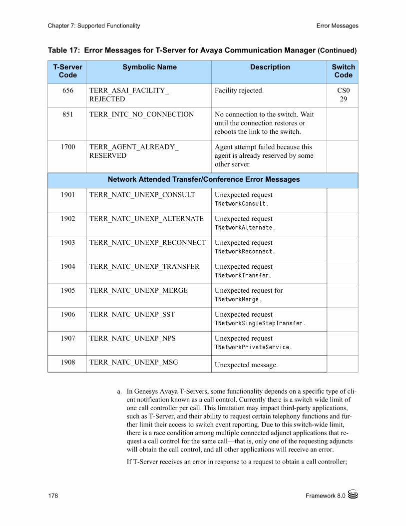
178 Framework 8.0
Chapter 7: Supported Functionality Error Messages
a. In Genesys Avaya T-Servers, some functionality depends on a specific type of cli-ent notification known as a call control. Currently there is a switch wide limit of one call controller per call. This limitation may impact third-party applications, such as T-Server, and their ability to request certain telephony functions and fur-ther limit their access to switch event reporting. Due to this switch-wide limit, there is a race condition among multiple connected adjunct applications that re-quest a call control for the same call—that is, only one of the requesting adjuncts will obtain the call control, and all other applications will receive an error.
If T-Server receives an error in response to a request to obtain a call controller;
656 TERR_ASAI_FACILITY_REJECTED
Facility rejected. CS029
851 TERR_INTC_NO_CONNECTION No connection to the switch. Wait until the connection restores or reboots the link to the switch.
1700 TERR_AGENT_ALREADY_RESERVED
Agent attempt failed because this agent is already reserved by some other server.
Network Attended Transfer/Conference Error Messages
1901 TERR_NATC_UNEXP_CONSULT Unexpected request TNetworkConsult.
1902 TERR_NATC_UNEXP_ALTERNATE Unexpected request TNetworkAlternate.
1903 TERR_NATC_UNEXP_RECONNECT Unexpected request TNetworkReconnect.
1904 TERR_NATC_UNEXP_TRANSFER Unexpected request TNetworkTransfer.
1905 TERR_NATC_UNEXP_MERGE Unexpected request for TNetworkMerge.
1906 TERR_NATC_UNEXP_SST Unexpected request TNetworkSingleStepTransfer.
1907 TERR_NATC_UNEXP_NPS Unexpected request TNetworkPrivateService.
1908 TERR_NATC_UNEXP_MSG Unexpected message.
Table 17: Error Messages for T-Server for Avaya Communication Manager (Continued)
T-Server Code
Symbolic Name Description Switch Code

T-Server—Deployment Guide 179
Chapter 7: Supported Functionality Avaya Enterprise Survivable Server (ESS)
T-Server generates either an EventError or an EventHardware error (depending on the context of the request). In both cases, the ErrorCode in the event will be set to 607 (indicating that the domain or call is being monitored by another adjunct). Under some conditions this error may inhibit T-Server functionality.
Because the activation of a call controller depends on information received over another communication channel on the switch—domain/event notification, it may be helpful to know which associations are active on what links for a specific DN resource. By using Avaya Site Administration (GEDI), it is possible to obtain in-formation about which link a specific DN resource is actively monitoring, along with its association. For example, if a T-Client is receiving multiple instances of EventHardwareError on a specific DN, using list mon on this specific DN pro-vides information about which links this DN is actively monitoring. This may help to pinpoint the specific CTI applications that are also requesting a call control to the Avaya switch.
Avaya Enterprise Survivable Server (ESS) Avaya Enterprise Survivable Server (ESS) provides enhanced availability and survivability for T-Server for Avaya Communication Manager. It achieves this by separating the Avaya Media Server (switching) elements from the port network (facilities) elements, and providing the capability for the port networks to fail over to a different Avaya Media Server in the event of a failure.
CTI Requests Failure
Call control-dependent CTI requests may fail if another T-Server has an outstanding call control. This can be a problem in switch partitioning environments that have multiple T-Servers on the same switch, which may require a call control for some CTI functions which will fail if another T-Server already has an active call control.
The following T-Server Section configuration options add support for minimizing call control use in T-Server:• follow-calls
• use-auto-dial
If you are performing feature requests, (such as TSingleStepConference, TDeleteFromConference, TClearCall, TListenDisconnect, TListenReconnect,
or SendDTMF), or if you are using the RouteTypeOverwriteDNIS attribute, you must set the values of the configuration options as follows:
• follow-calls = false
• use-auto-dial = true.
If follow-calls is set to false, and use-auto-dial is set to true, T-Server will relinquish call control in the following scenarios:

180 Framework 8.0
Chapter 7: Supported Functionality Avaya Enterprise Survivable Server (ESS)
• After any initiating request that requires a TP (third-party) Take Control request to be sent to the link
• After any connected event report, if there is at least one other active monitor on the call, and T-Server is not already configured to preserve call control
Avoiding Direct Transfers to Automatic Call Distribution (ACD)
To help avoid losing call visibility, which can occur when no active monitors persist after transferring a call to a queue, it is recommended to avoid direct transfers to ACD queues and to instead ensure that all transfers of that type first pass through a Vector Directory Number (VDN).
Bandwidth Considerations
Due to overall switch wide limits on bandwidth usage, careful consideration and planning should be given to the following configuration options in all T-Servers in switch partitioning environments:• use-link-bandwidth
• use-link-bandwidth-backup
Avaya ESS Architecture
In Genesys 8.0 architecture for support of Avaya ESS, each Services Site on a switch is seen as a separate switch, and is therefore assigned to a dedicated T-Server (see Figure 27).

T-Server—Deployment Guide 181
Chapter 7: Supported Functionality Avaya Enterprise Survivable Server (ESS)
Figure 27: Avaya ESS Reference Architecture
This architecture helps to minimize the impact of the total loss of a single site by splitting Genesys components across two types of sites:
• Management Site—Houses Genesys Management applications
• Services Site—Houses Avaya switches and associated Genesys components
Figure 27 displays a typical configuration with a single Management Site and two Services Sites. Each Services Site is associated with a single Avaya switch, and can function as a self-contained contact center.
Each DN is associated with a single switch, and there is no duplication of DNs between switches. Therefore all T-Servers in an ESS environment must set the following configuration option:
• dn-scope = tenant.
Additional Services Sites, each associated with a different switch, can be added to this architecture according to the customer’s need.
Or as an alternative, the Management Site components could be deployed at one of the Services Sites.
PortNetwork 1
ISCC
Agent 1Services Site 1
Avaya PrimaryMedia Server
AES 1
Services Site 2
Avaya BackupMedia Server
PortNetwork 2
Configuration Proxy Server
1
PSTN
Message Server 1
License Manager 1
Solution Control Server 1
Universal Routing Server 1
Management Site
Stat Server 1T-Server 1
Configuration Proxy Server
2
Solution Control Server 2
Message Server 2
Universal Routing Server 2
Stat Server 2T-Server 2
License Manager 2
Configuration Server
Message Server
Solution Control Server 3
License Manager
AES 2
Agent 2

182 Framework 8.0
Chapter 7: Supported Functionality Avaya Enterprise Survivable Server (ESS)
Typical ESS Failure Support Scenarios
Failure of the Avaya Primary Media Server
Failure of the Avaya Primary Media Server results when the backup Avaya Media Server is promoted to Avaya Primary Media Server. T-Server 1 and T-Server 2 temporarily (for approximately 3.5 minutes) loses the Application Enablement Services (AES) Server link. After the Avaya Backup Media Server assumes control of the Port Networks, T-Server 1 and T-Server 2 automatically reconnect to the links. Avaya Primary Media Server failure results in the complete reset of CTI resources, resulting in dropped calls and logout of agents. (See Figure 28.)
Figure 28: Avaya Primary Media Server Failure
Isolation of the Management Site During Failure
Failure of the Management Site does not impact call handling at the Services Sites. Configuration Server Proxies at the Services Sites continue to provide read-only access to configuration data. After network connectivity is restored, configuration updates made at the Management Site during the outage are propagated to the Services Sites. (See Figure 29.)
PortNetwork 1
ISCC
Agent 1Services Site 1
Avaya PrimaryMedia Server
AES 1
Services Site 2
Avaya BackupMedia Server
PortNetwork 2
Configuration Proxy Server
1
PSTN
Message Server 1
License Manager 1
Solution Control Server 1
Universal Routing Server 1
Management Site
Stat Server 1T-Server 1
Configuration Proxy Server
2
Solution Control Server 2
Message Server 2
Universal Routing Server 2
Stat Server 2T-Server 2
License Manager 2
Configuration Server
Message Server
Solution Control Server 3
License Manager
AES 2
Agent 2
X broken connection
— new connection
XX

T-Server—Deployment Guide 183
Chapter 7: Supported Functionality Avaya Enterprise Survivable Server (ESS)
Figure 29: Management Site Isolation Failure
Isolation of a Single Services Site During Failure
The failure of a network causes a total network isolation of Services Site 1. Services Site 1 continues to process calls. Configuration Server Proxy 1 continues to function, providing read-only configuration data to Service Site 1 applications. The network isolation of the Avaya Primary Media Server results in Port Network 2 changing its connection to the Avaya Backup Media Server. T-Server 2 temporarily loses the AES Server link connection. This failure results in the complete reset of the CTI resources. Due to network isolation, site-to-site ISCC calls are not possible (see Figure 30 on page 184.)
PortNetwork 1
ISCC
Agent 1Services Site 1
Avaya PrimaryMedia Server
AES 1
Services Site 2
Avaya BackupMedia Server
PortNetwork 2
Configuration Proxy Server
1
PSTN
Message Server 1
License Manager 1
Solution Control Server 1
Universal Routing Server 1
Management Site
Stat Server 1T-Server 1
Configuration Proxy Server
2
Solution Control Server 2
Message Server 2
Universal Routing Server 2
Stat Server 2T-Server 2
License Manager 2
Configuration Server
Message Server
Solution Control Server 3
License Manager
AES 2
Agent 2
X broken connection
— non-responsive services site
X
X

184 Framework 8.0
Chapter 7: Supported Functionality Avaya Enterprise Survivable Server (ESS)
Figure 30: Single Services Site Isolation Failure
Total Network Failure
The failure of a network causes total network isolation of both Services Sites and the Management Site. The Services Sites continue to process calls, and the Configuration Server Proxies continue to function, providing access to read-only configuration data. The network isolation of the Avaya Primary Media Server results in Port Network 2 changing its connection to the Avaya Backup Media Server. T-Server 2 temporarily (for approximately 3.5 minutes) loses its connection to the AES Server link. This failure results in the complete reset of CTI resources, resulting in dropped calls and logout of agents on Service Site 2. The network isolation prevents site-to-site ISCC calls. (See Figure 31 on page 185.)
PortNetwork 1
ISCC
Agent 1Services Site 1
Avaya PrimaryMedia Server
AES 1
Services Site 2
Avaya BackupMedia Server
PortNetwork 2
Configuration Proxy Server
1
PSTN
Message Server 1
License Manager 1
Solution Control Server 1
Universal Routing Server 1
Management Site
Stat Server 1T-Server 1
Configuration Proxy Server
2
Solution Control Server 2
Message Server 2
Universal Routing Server 2
Stat Server 2T-Server 2
License Manager 2
Configuration Server
Message Server
Solution Control Server 3
License Manager
AES 2
Agent 2
X broken connection
— non-responsive services site
X
XX X

T-Server—Deployment Guide 185
Chapter 7: Supported Functionality Avaya Switch Partitioning
Figure 31: Total Network Failure
Avaya Switch PartitioningSwitch partitioning is a configuration of multiple virtual switches that are defined in Configuration Manager under a single Switching Office object that represents a physical switch.
The following T-Server Section configuration options are common to all T-Server types and add support for switch partitioning in T-Server:• dn-scope
• propagated-call-type
See “Switch Partitioning” on page 100 for more information about these configuration options.
The following T-Server Section configuration options are specific to T-Server and add support for minimizing call control use in T-Server:• follow-calls
• use-auto-dial.
See “CTI Requests Failure” on page 179 for more information about these configuration options.
PortNetwork 1
ISCC
Agent 1Services Site 1
Avaya PrimaryMedia Server
AES 1
Services Site 2
Avaya BackupMedia Server
PortNetwork 2
Configuration Proxy Server
1
PSTN
Message Server 1
License Manager 1
Solution Control Server 1
Universal Routing Server 1
Management Site
Stat Server 1T-Server 1
Configuration Proxy Server
2
Solution Control Server 2
Message Server 2
Universal Routing Server 2
Stat Server 2T-Server 2
License Manager 2
Configuration Server
Message Server
Solution Control Server 3
License Manager
AES 2
Agent 2
X broken connection
— non-responsive services site
X
XX X
X

186 Framework 8.0
Chapter 7: Supported Functionality Avaya Switch Partitioning

T-Server—Deployment Guide 187
Chapter
8 Common Configuration OptionsUnless otherwise noted, the common configuration options that this chapter describes are common to all Genesys server applications and applicable to any Framework server component. This chapter includes the following sections: Setting Configuration Options, page 188 Mandatory Options, page 188 Log Section, page 188 Log-Extended Section, page 202 Log-Filter Section, page 204 Log-Filter-Data Section, page 205 SML Section, page 205 Common Section, page 205 Changes from 7.6 to 8.0, page 206
Note: Some server applications also support log options that are unique to them. For descriptions of a particular application’s unique log options, refer to the chapter/document about that application.

188 Framework 8.0
Chapter 8: Common Configuration Options Setting Configuration Options
Setting Configuration OptionsUnless specified otherwise, set common configuration options in the Application object, using the following navigation path:
• In Configuration Manager—Application object > Properties dialog box > Options tab
Mandatory OptionsYou do not have to configure any common options to start Server applications.
Log SectionThis section must be called log.
verbose Default Value: allValid Values:
Changes Take Effect: Immediately
Determines whether a log output is created. If it is, specifies the minimum level of log events generated. The log events levels, starting with the highest
Warning! Configuration section names, configuration option names, and predefined option values are case-sensitive. Type them in Configuration Manager exactly as they are documented in this chapter.
all All log events (that is, log events of the Standard, Trace, Interaction, and Debug levels) are generated.
debug The same as all.trace Log events of the Trace level and higher (that is, log events of
the Standard, Interaction, and Trace levels) are generated, but log events of the Debug level are not generated.
interaction Log events of the Interaction level and higher (that is, log events of the Standard and Interaction levels) are generated, but log events of the Trace and Debug levels are not generated.
standard Log events of the Standard level are generated, but log events of the Interaction, Trace, and Debug levels are not generated.
none No output is produced.

T-Server—Deployment Guide 189
Chapter 8: Common Configuration Options Log Section
priority level, are Standard, Interaction, Trace, and Debug. See also “Log Output Options” on page 194.
bufferingDefault Value: trueValid Values:
Changes Take Effect: Immediately
Turns on/off operating system file buffering. The option is applicable only to the stderr and stdout output (see page 194). Setting this option to true increases the output performance.
segment Default Value: falseValid Values:
Changes Take Effect: Immediately
Specifies whether there is a segmentation limit for a log file. If there is, sets the mode of measurement, along with the maximum size. If the current log segment exceeds the size set by this option, the file is closed and a new one is created. This option is ignored if log output is not configured to be sent to a log file.
Note: For definitions of the Standard, Interaction, Trace, and Debug log levels, refer to the Framework 8.0 Management Layer User’s Guide or to Framework 8.0 Solution Control Interface Help.
true Enables buffering.false Disables buffering.
Note: When buffering is enabled, there might be a delay before log messages appear at the console.
false No segmentation is allowed.<number> KB or <number>
Sets the maximum segment size, in kilobytes. The minimum segment size is 100 KB.
<number> MB Sets the maximum segment size, in megabytes.<number> hr Sets the number of hours for the segment to stay open. The
minimum number is 1 hour.
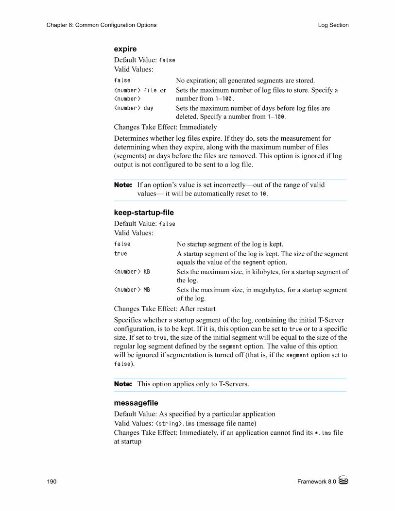
190 Framework 8.0
Chapter 8: Common Configuration Options Log Section
expire Default Value: falseValid Values:
Changes Take Effect: Immediately
Determines whether log files expire. If they do, sets the measurement for determining when they expire, along with the maximum number of files (segments) or days before the files are removed. This option is ignored if log output is not configured to be sent to a log file.
keep-startup-fileDefault Value: falseValid Values:
Changes Take Effect: After restart
Specifies whether a startup segment of the log, containing the initial T-Server configuration, is to be kept. If it is, this option can be set to true or to a specific size. If set to true, the size of the initial segment will be equal to the size of the regular log segment defined by the segment option. The value of this option will be ignored if segmentation is turned off (that is, if the segment option set to false).
messagefile Default Value: As specified by a particular applicationValid Values: <string>.lms (message file name)Changes Take Effect: Immediately, if an application cannot find its *.lms file at startup
false No expiration; all generated segments are stored.<number> file or <number>
Sets the maximum number of log files to store. Specify a number from 1–100.
<number> day Sets the maximum number of days before log files are deleted. Specify a number from 1–100.
Note: If an option’s value is set incorrectly—out of the range of valid values— it will be automatically reset to 10.
false No startup segment of the log is kept.true A startup segment of the log is kept. The size of the segment
equals the value of the segment option.<number> KB Sets the maximum size, in kilobytes, for a startup segment of
the log.<number> MB Sets the maximum size, in megabytes, for a startup segment
of the log.
Note: This option applies only to T-Servers.

T-Server—Deployment Guide 191
Chapter 8: Common Configuration Options Log Section
Specifies the file name for application-specific log events. The name must be valid for the operating system on which the application is running. The option value can also contain the absolute path to the application-specific *.lms file. Otherwise, an application looks for the file in its working directory.
message_format Default Value: shortValid Values:
Changes Take Effect: Immediately
Specifies the format of log record headers that an application uses when writing logs in the log file. Using compressed log record headers improves application performance and reduces the log file’s size.
With the value set to short:
• A header of the log file or the log file segment contains information about the application (such as the application name, application type, host type, and time zone), whereas single log records within the file or segment omit this information.
• A log message priority is abbreviated to Std, Int, Trc, or Dbg, for Standard, Interaction, Trace, or Debug messages, respectively.
• The message ID does not contain the prefix GCTI or the application type ID.
A log record in the full format looks like this:2002-05-07T18:11:38.196 Standard localhost cfg_dbserver GCTI-00-05060 Application started
A log record in the short format looks like this:2002-05-07T18:15:33.952 Std 05060 Application started
Warning! An application that does not find its *.lms file at startup cannot generate application-specific log events and send them to Message Server.
short An application uses compressed headers when writing log records in its log file.
full An application uses complete headers when writing log records in its log file.
Note: Whether the full or short format is used, time is printed in the format specified by the time_format option.
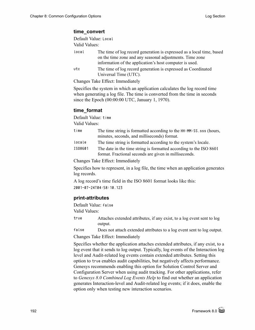
192 Framework 8.0
Chapter 8: Common Configuration Options Log Section
time_convert Default Value: LocalValid Values:
Changes Take Effect: Immediately
Specifies the system in which an application calculates the log record time when generating a log file. The time is converted from the time in seconds since the Epoch (00:00:00 UTC, January 1, 1970).
time_format Default Value: timeValid Values:
Changes Take Effect: Immediately
Specifies how to represent, in a log file, the time when an application generates log records.
A log record’s time field in the ISO 8601 format looks like this:2001-07-24T04:58:10.123
print-attributes Default Value: falseValid Values:
Changes Take Effect: Immediately
Specifies whether the application attaches extended attributes, if any exist, to a log event that it sends to log output. Typically, log events of the Interaction log level and Audit-related log events contain extended attributes. Setting this option to true enables audit capabilities, but negatively affects performance. Genesys recommends enabling this option for Solution Control Server and Configuration Server when using audit tracking. For other applications, refer to Genesys 8.0 Combined Log Events Help to find out whether an application generates Interaction-level and Audit-related log events; if it does, enable the option only when testing new interaction scenarios.
local The time of log record generation is expressed as a local time, based on the time zone and any seasonal adjustments. Time zone information of the application’s host computer is used.
utc The time of log record generation is expressed as Coordinated Universal Time (UTC).
time The time string is formatted according to the HH:MM:SS.sss (hours, minutes, seconds, and milliseconds) format.
locale The time string is formatted according to the system’s locale.ISO8601 The date in the time string is formatted according to the ISO 8601
format. Fractional seconds are given in milliseconds.
true Attaches extended attributes, if any exist, to a log event sent to log output.
false Does not attach extended attributes to a log event sent to log output.

T-Server—Deployment Guide 193
Chapter 8: Common Configuration Options Log Section
check-point Default Value: 1Valid Values: 0–24Changes Take Effect: Immediately
Specifies, in hours, how often the application generates a check point log event, to divide the log into sections of equal time. By default, the application generates this log event every hour. Setting the option to 0 prevents the generation of check-point events.
memory Default Value: No default valueValid Values: <string> (memory file name)Changes Take Effect: Immediately
Specifies the name of the file to which the application regularly prints a snapshot of the memory output, if it is configured to do this (see “Log Output Options” on page 194). The new snapshot overwrites the previously written data. If the application terminates abnormally, this file will contain the latest log messages. Memory output is not recommended for processors with a CPU frequency lower than 600 MHz.
memory-storage-size Default Value: 2 MBValid Values:
Changes Take Effect: When memory output is created
Specifies the buffer size for log output to the memory, if configured. See also “Log Output Options” on page 194.
spool Default Value: The application’s working directoryValid Values: <path> (the folder, with the full path to it)Changes Take Effect: Immediately
Specifies the folder, including full path to it, in which an application creates temporary files related to network log output. If you change the option value while the application is running, the change does not affect the currently open network output.
Note: If the file specified as the memory file is located on a network drive, an application does not create a snapshot file (with the extension *.memory.log).
<number> KB or <number> The size of the memory output, in kilobytes. The minimum value is 128 KB.
<number> MB The size of the memory output, in megabytes. The maximum value is 64 MB.

194 Framework 8.0
Chapter 8: Common Configuration Options Log Section
compatible-output-priority Default Value: falseValid Values:
Changes Take Effect: Immediately
Specifies whether the application uses 6.x output logic. For example, you configure the following options in the log section for a 6.x application and for a 7.x application:[log]
verbose = all
debug = file1
standard = file2
The log file content of a 6.x application is as follows:
• file1 contains Debug messages only.
• file2 contains Standard messages only.
The log file content of a 7.x application is as follows:
• file1 contains Debug, Trace, Interaction, and Standard messages.
• file2 contains Standard messages only.
If you set compatible-output-priority to true in the 7.x application, its log file content will be the same as for the 6.x application.
Log Output Options
To configure log outputs, set log level options (all, alarm, standard, interaction, trace, and/or debug) to the desired types of log output (stdout, stderr, network, memory, and/or [filename], for log file output).
You can use:
• One log level option to specify different log outputs.
• One log output type for different log levels.
• Several log output types simultaneously, to log events of the same or different log levels.
true The log of the level specified by “Log Output Options” is sent to the specified output.
false The log of the level specified by “Log Output Options” and higher levels is sent to the specified output.
Warning! Genesys does not recommend changing the default value of the this option unless you have specific reasons to use the 6.x log output logic—that is, to mimic the output priority as implemented in releases 6.x. Setting this option to true affects log consistency.

T-Server—Deployment Guide 195
Chapter 8: Common Configuration Options Log Section
You must separate the log output types by a comma when you are configuring more than one output for the same log level. See “Examples” on page 199.
allDefault Value: No default valueValid Values (log output types):
Changes Take Effect: Immediately
Specifies the outputs to which an application sends all log events. The log output types must be separated by a comma when more than one output is configured. For example:all = stdout, logfile
Note: The log output options are activated according to the setting of the verbose configuration option.
Warnings! • If you direct log output to a file on the network drive, an application does not create a snapshot log file (with the extension *.snapshot.log) in case it terminates abnormally.
• Directing log output to the console (by using the stdout or stderr settings) can affect application performance. Avoid using these log output settings in a production environment.
stdout Log events are sent to the Standard output (stdout).stderr Log events are sent to the Standard error output (stderr).network Log events are sent to Message Server, which can reside
anywhere on the network. Message Server stores the log events in the Log Database.
Setting the all log level option to the network output enables an application to send log events of the Standard, Interaction, and Trace levels to Message Server. Debug-level log events are neither sent to Message Server nor stored in the Log Database.
memory Log events are sent to the memory output on the local disk. This is the safest output in terms of the application performance.
[filename] Log events are stored in a file with the specified name. If a path is not specified, the file is created in the application’s working directory.
Note: To ease the troubleshooting process, consider using unique names for log files that different applications generate.

196 Framework 8.0
Chapter 8: Common Configuration Options Log Section
alarmDefault Value: No default valueValid Values (log output types):
Changes Take Effect: Immediately
Specifies the outputs to which an application sends the log events of the Alarm level. The log output types must be separated by a comma when more than one output is configured. For example:standard = stderr, network
standardDefault Value: No default valueValid Values (log output types):
Changes Take Effect: Immediately
Specifies the outputs to which an application sends the log events of the Standard level. The log output types must be separated by a comma when more than one output is configured. For example:standard = stderr, network
interactionDefault Value: No default valueValid Values (log output types):
stdout Log events are sent to the Standard output (stdout).stderr Log events are sent to the Standard error output (stderr).network Log events are sent to Message Server, which resides anywhere
on the network, and Message Server stores the log events in the Log Database.
memory Log events are sent to the memory output on the local disk. This is the safest output in terms of the application performance.
[filename] Log events are stored in a file with the specified name. If a path is not specified, the file is created in the application’s working directory.
stdout Log events are sent to the Standard output (stdout).stderr Log events are sent to the Standard error output (stderr).network Log events are sent to Message Server, which can reside
anywhere on the network. Message Server stores the log events in the Log Database.
memory Log events are sent to the memory output on the local disk. This is the safest output in terms of the application performance.
[filename] Log events are stored in a file with the specified name. If a path is not specified, the file is created in the application’s working directory.
stdout Log events are sent to the Standard output (stdout).stderr Log events are sent to the Standard error output (stderr).

T-Server—Deployment Guide 197
Chapter 8: Common Configuration Options Log Section
Changes Take Effect: Immediately
Specifies the outputs to which an application sends the log events of the Interaction level and higher (that is, log events of the Standard and Interaction levels). The log outputs must be separated by a comma when more than one output is configured. For example:interaction = stderr, network
traceDefault Value: No default valueValid Values (log output types):
Changes Take Effect: Immediately
Specifies the outputs to which an application sends the log events of the Trace level and higher (that is, log events of the Standard, Interaction, and Trace levels). The log outputs must be separated by a comma when more than one output is configured. For example:trace = stderr, network
debugDefault Value: No default valueValid Values (log output types):
network Log events are sent to Message Server, which can reside anywhere on the network. Message Server stores the log events in the Log Database.
memory Log events are sent to the memory output on the local disk. This is the safest output in terms of the application performance.
[filename] Log events are stored in a file with the specified name. If a path is not specified, the file is created in the application’s working directory.
stdout Log events are sent to the Standard output (stdout).stderr Log events are sent to the Standard error output (stderr).network Log events are sent to Message Server, which can reside
anywhere on the network. Message Server stores the log events in the Log Database.
memory Log events are sent to the memory output on the local disk. This is the safest output in terms of the application performance.
[filename] Log events are stored in a file with the specified name. If a path is not specified, the file is created in the application’s working directory.
stdout Log events are sent to the Standard output (stdout).stderr Log events are sent to the Standard error output (stderr).memory Log events are sent to the memory output on the local disk. This
is the safest output in terms of the application performance.

198 Framework 8.0
Chapter 8: Common Configuration Options Log Section
Changes Take Effect: Immediately
Specifies the outputs to which an application sends the log events of the Debug level and higher (that is, log events of the Standard, Interaction, Trace, and Debug levels). The log output types must be separated by a comma when more than one output is configured—for example:debug = stderr, /usr/local/genesys/logfile
Log File Extensions
You can use the following file extensions to identify log files that an application creates for various types of output:
• *.log—Assigned to log files when you configure output to a log file. For example, if you set standard = confservlog for Configuration Server, it prints log messages into a text file called confservlog.<time_stamp>.log.
• *.qsp—Assigned to temporary (spool) files when you configure output to the network but the network is temporarily unavailable. For example, if you set standard = network for Configuration Server, it prints log messages into a file called confserv.<time_stamp>.qsp during the time the network is not available.
• *.snapshot.log—Assigned to files that contain the output snapshot when you configure output to a log file. The file contains the last log messages that an application generates before it terminates abnormally. For example, if you set standard = confservlog for Configuration Server, it prints the last log message into a file called confserv.<time_stamp>.snapshot.log in case of failure.
• *.memory.log—Assigned to log files that contain the memory output snapshot when you configure output to memory and redirect the most recent memory output to a file. For example, if you set standard = memory and memory = confserv for Configuration Server, it prints the latest memory output to a file called confserv.<time_stamp>.memory.log.
[filename] Log events are stored in a file with the specified name. If a path is not specified, the file is created in the application’s working directory.
Note: Debug-level log events are never sent to Message Server or stored in the Log Database.
Note: Provide *.snapshot.log files to Genesys Technical Support when reporting a problem.

T-Server—Deployment Guide 199
Chapter 8: Common Configuration Options Log Section
Examples
This section presents examples of a log section that you might configure for an application when that application is operating in production mode and in two lab modes, debugging and troubleshooting.
Production Mode Log Section
[log]verbose = standardstandard = network, logfile
With this configuration, an application only generates the log events of the Standard level and sends them to Message Server, and to a file named logfile, which the application creates in its working directory. Genesys recommends that you use this or a similar configuration in a production environment.
Lab Mode Log Section
[log]verbose = allall = stdout, /usr/local/genesys/logfiletrace = network
With this configuration, an application generates log events of the Standard, Interaction, Trace, and Debug levels, and sends them to the standard output and to a file named logfile, which the application creates in the /usr/local/genesys/ directory. In addition, the application sends log events of the Standard, Interaction, and Trace levels to Message Server. Use this configuration to test new interaction scenarios in a lab environment.
Failure-Troubleshooting Log Section
[log]verbose = allstandard = networkall = memorymemory = logfilememory-storage-size = 32 MB
With this configuration, an application generates log events of the Standard level and sends them to Message Server. It also generates log events of the Standard, Interaction, Trace, and Debug levels, and sends them to the memory output. The most current log is stored to a file named logfile, which the
Warning! Directing log output to the console (by using the stdout or stderr settings) can affect application performance. Avoid using these log output settings in a production environment.
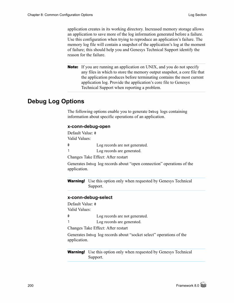
200 Framework 8.0
Chapter 8: Common Configuration Options Log Section
application creates in its working directory. Increased memory storage allows an application to save more of the log information generated before a failure. Use this configuration when trying to reproduce an application’s failure. The memory log file will contain a snapshot of the application’s log at the moment of failure; this should help you and Genesys Technical Support identify the reason for the failure.
Debug Log Options
The following options enable you to generate Debug logs containing information about specific operations of an application.
x-conn-debug-openDefault Value: 0Valid Values:
Changes Take Effect: After restart
Generates Debug log records about “open connection” operations of the application.
x-conn-debug-selectDefault Value: 0Valid Values:
Changes Take Effect: After restart
Generates Debug log records about “socket select” operations of the application.
Note: If you are running an application on UNIX, and you do not specify any files in which to store the memory output snapshot, a core file that the application produces before terminating contains the most current application log. Provide the application’s core file to Genesys Technical Support when reporting a problem.
0 Log records are not generated. 1 Log records are generated.
Warning! Use this option only when requested by Genesys Technical Support.
0 Log records are not generated. 1 Log records are generated.
Warning! Use this option only when requested by Genesys Technical Support.

T-Server—Deployment Guide 201
Chapter 8: Common Configuration Options Log Section
x-conn-debug-timersDefault Value: 0Valid Values:
Changes Take Effect: After restart
Generates Debug log records about the timer creation and deletion operations of the application.
x-conn-debug-writeDefault Value: 0Valid Values:
Changes Take Effect: After restart
Generates Debug log records about “write” operations of the application.
x-conn-debug-securityDefault Value: 0Valid Values:
Changes Take Effect: After restart
Generates Debug log records about security-related operations, such as Transport Layer Security and security certificates.
x-conn-debug-apiDefault Value: 0Valid Values:
Changes Take Effect: After restart
0 Log records are not generated. 1 Log records are generated.
Warning! Use this option only when requested by Genesys Technical Support.
0 Log records are not generated. 1 Log records are generated.
Warning! Use this option only when requested by Genesys Technical Support.
0 Log records are not generated. 1 Log records are generated.
Warning! Use this option only when requested by Genesys Technical Support.
0 Log records are not generated. 1 Log records are generated.

202 Framework 8.0
Chapter 8: Common Configuration Options Log-Extended Section
Generates Debug log records about connection library function calls.
x-conn-debug-dnsDefault Value: 0Valid Values:
Changes Take Effect: After restart
Generates Debug log records about DNS operations.
x-conn-debug-allDefault Value: 0Valid Values:
Changes Take Effect: After restart
Generates Debug log records about open connection, socket select, timer creation and deletion, write, security-related, and DNS operations, and connection library function calls. This option is the same as enabling or disabling all of the previous x-conn-debug-<op type> options.
Log-Extended SectionThis section must be called log-extended.
level-reassign-<eventID>Default Value: Default value of log event <eventID> Valid Values:
Warning! Use this option only when requested by Genesys Technical Support.
0 Log records are not generated. 1 Log records are generated.
Warning! Use this option only when requested by Genesys Technical Support.
0 Log records are not generated. 1 Log records are generated.
Warning! Use this option only when requested by Genesys Technical Support.
alarm The log level of log event <eventID> is set to Alarm. standard The log level of log event <eventID> is set to Standard.interaction The log level of log event <eventID> is set to Interaction.

T-Server—Deployment Guide 203
Chapter 8: Common Configuration Options Log-Extended Section
Changes Take Effect: Immediately
Specifies a log level for log event <eventID> that is different than its default level, or disables log event <eventID> completely. If no value is specified, the log event retains its default level. This option is useful when you want to customize the log level for selected log events.
These options can be deactivated with the option level-reassign-disable.
In addition to the preceding warning, take note of the following:
• Logs can be customized only by release 7.6 or later applications.
• When the log level of a log event is changed to any level except none, it is subject to the other settings in the [log] section at its new level. If set to none, it is not logged and is therefore not subject to any log configuration.
• Using this feature to change the log level of a log changes only its priority; it does not change how that log is treated by the system. For example, increasing the priority of a log to Alarm level does not mean that an alarm will be associated with it.
• Each application in a High Availability (HA) pair can define its own unique set of log customizations, but the two sets are not synchronized with each other. This can result in different log behavior depending on which application is currently in primary mode.
• This feature is not the same as a similar feature in Universal Routing Server (URS) release 7.2 or later. In this Framework feature, the priority of log events are customized. In the URS feature, the priority of debug messages only are customized. Refer to the Universal Routing Reference Manual for more information about the URS feature.
• You cannot customize any log event that is not in the unified log record format. Log events of the Alarm, Standard, Interaction, and Trace levels feature the same unified log record format.
trace The log level of log event <eventID> is set to Trace.debug The log level of log event <eventID> is set to Debug.none Log event <eventID> is not recorded in a log.
Warning! Use caution when making these changes in a production environment.
Depending on the log configuration, changing the log level to a higher priority may cause the log event to be logged more often or to a greater number of outputs. This could affect system performance.
Likewise, changing the log level to a lower priority may cause the log event to be not logged at all, or to be not logged to specific outputs, thereby losing important information. The same applies to any alarms associated with that log event.

204 Framework 8.0
Chapter 8: Common Configuration Options Log-Filter Section
Example
This is an example of using customized log level settings, subject to the following log configuration:
[log]verbose=interactionall=stderrinteraction=log_filestandard=network
Before the log levels of the log are changed:
• Log event 1020, with default level standard, is output to stderr and log_file, and sent to Message Server.
• Log event 2020, with default level standard, is output to stderr and log_file, and sent to Message Server.
• Log event 3020, with default level trace, is output to stderr.
• Log event 4020, with default level debug, is output to stderr.
Extended log configuration section:
[log-extended]level-reassign-1020=nonelevel-reassign-2020=interactionlevel-reassign-3020=interactionlevel-reassign-4020=standard
After the log levels are changed:
• Log event 1020 is disabled and not logged.
• Log event 2020 is output to stderr and log_file.
• Log event 3020 is output to stderr and log_file.
• Log event 4020 is output to stderr and log_file, and sent to Message Server.
level-reassign-disableDefault Value: falseValid Values: true, falseChanges Take Effect: Immediately
When this option is set to true, the original (default) log level of all log events in the [log-extended] section are restored. This option is useful when you want to use the default levels, but not delete the customization statements.
Log-Filter SectionThe log-filter section contains configuration options used to define the default treatment of filtering data in logs. This section contains one configuration option, default-filter-type. Refer to the chapter “Hide

T-Server—Deployment Guide 205
Chapter 8: Common Configuration Options Log-Filter-Data Section
Selected Data in Logs” in the Genesys 8.0 Security Deployment Guide for complete information about this option.
Log-Filter-Data SectionThe log-filter-data section contains configuration options used to define the treatment of filtering data in logs on a key-by-key basis. This section contains one configuration option in the form of <key name>. Refer to the chapter “Hide Selected Data in Logs” in the Genesys 8.0 Security Deployment Guide for complete information about this option.
SML SectionThis section must be called sml.
suspending-wait-timeoutDefault Value: 10Valid Values: 5-600Changes Take Effect: Immediately
Specifies a timeout (in seconds) after the Stop Graceful command is issued to an application during which the status of the application should change to Suspending if the application supports graceful shutdown. If the status of the application does not change to Suspending before the timeout expires, it is assumed that the application does not support graceful shutdown, and it is stopped ungracefully.
Use this option if you are unsure whether the Application supports graceful shutdown.
Common SectionThis section must be called common.
enable-async-dnsDefault Value: off
Note: This option is defined in the Application object, as follows:• in Configuration Manager— Application object > Properties
dialog box > Annex tab

206 Framework 8.0
Chapter 8: Common Configuration Options Changes from 7.6 to 8.0
Valid Values:
Changes Take Effect: Immediately
Enables the asynchronous processing of DNS requests such as, for example, host-name resolution.
rebind-delayDefault Value: 10Valid Values: 0–600Changes Take Effect: After restart
Specifies the delay, in seconds, between socket-bind operations that are being executed by the server. Use this option if the server has not been able to successfully occupy a configured port.
Changes from 7.6 to 8.0Table 18 on page 206 provides all the changes to common configuration options between release 7.6 and the latest 8.0 release.
off Disables asynchronous processing of DNS requests.on Enables asynchronous processing of DNS requests.
Warnings! • Use this option only when requested by Genesys Technical Support.
• Use this option only with T-Servers.
Warning! Use this option only when requested by Genesys Technical Support.
Table 18: Common Configuration Option Changes from 7.6 to 8.0
Option Name Option Values Type of Change
Details
log-filter Section
default-filter-type Additional option values Modified See description on page 204.
log-filter-data Section
<key-name> Additional option values Modified See description on page 205.
sml Section
suspending-wait-timeout 5-600 New See description on page 205.

T-Server—Deployment Guide 207
Chapter
9 T-Server Common Configuration OptionsThis chapter describes the configuration options that are generally common to all T-Server types, with some exceptions noted. It contains the following sections: Setting Configuration Options, page 207 Mandatory Options, page 208 T-Server Section, page 208 License Section, page 213 Agent-Reservation Section, page 216 Multi-Site Support Section, page 217 Translation Rules Section, page 227 Backup-Synchronization Section, page 228 Call-Cleanup Section, page 229 Security Section, page 231 Timeout Value Format, page 231 Changes from Release 7.6 to 8.0, page 232
T-Server also supports common log options described in Chapter 8, “Common Configuration Options,” on page 187.
Setting Configuration OptionsUnless it is specified otherwise, you set configuration options in Configuration Manager in the corresponding sections on the Options tab for the T-Server Application object.

208 Framework 8.0
Chapter 9: T-Server Common Configuration Options Mandatory Options
Mandatory OptionsExcept as noted for certain environments, the configuration of common options is not required for basic T-Server operation.
T-Server SectionThe T-Server section contains the configuration options that are used to support the core features common to all T-Servers.
TServer This section must be called TServer.
ani-distributionDefault Value: inbound-calls-onlyValid Values: inbound-calls-only, all-calls, suppressedChanges Take Effect: Immediately
Controls the distribution of the ANI information in TEvent messages. When this option is set to all-calls, the ANI attribute will be reported for all calls for which it is available. When this option is set to suppressed, the ANI attribute will not be reported for any calls. When this option is set to inbound-calls-only, the ANI attribute will be reported for inbound calls only.
background-processingDefault Value: falseValid Values: true, falseChanges Take Effect: Immediately
When set to true, T-Server processes all client requests in the background, giving higher priority to the rest of the messages. This ensures that it processes these messages without any significant delay.
With Background Processing functionality enabled, T-Server processes all switch messages immediately and waits until there are no switch messages before processing the message queue associated with T-Server client requests. T-Server reads all connection sockets immediately and places client requests in the input buffer, which prevents T-Server clients from disconnecting because of configured timeouts.
When T-Server processes client requests from the message queue, requests are processed in the order in which T-Server received them.
When set to false, T-Server processes multiple requests from one T-Server client before proceeding to the requests from another T-Server client, and so on.
Note: Use of this option can negatively impact T-Server processing speed.

Chapter 9: T-Server Common Configuration Options T-Server Section
T-Server—Deployment Guide 209
background-timeoutDefault Value: 60 msecValid Values: See “Timeout Value Format” on page 231.Changes Take Effect: Immediately
Specifies the time interval that T-Server waits before processing client requests in background mode. You must set the background-processing option to true in order for this option to take effect.
check-tenant-profileDefault Value: falseValid Values: true, falseChanges Take Effect: For the next connected client
When set to true, T-Server checks whether a client provides the correct name and password of a tenant. If it does, T-Server allows that client to register DNs that are included in the switch configuration in the Configuration Database, but it does not allow the client to register DNs that are not included in the switch configuration.
consult-user-dataDefault Value: separateValid Values:
Changes Take Effect: For the next consultation call created
separate Stores user data for original and consultation calls in separate structures. The data attached to the original call is available for review or changes only to the parties of that call. The data attached to the consultation call is available only to the parties of the consultation call.
inherited Copies user data from an original call to a consultation call when the consultation call is created; thereafter, stores user data separately for the original and the consultation call. Changes to the original call’s user data are not available to the parties of the consultation call, and vice versa.
joint Stores user data for an original call and a consultation call in one structure. The user data structure is associated with the original call, but the parties of both the original and consultation calls can see and make changes to the common user data.

210 Framework 8.0
Chapter 9: T-Server Common Configuration Options T-Server Section
Specifies the method for handling user data in a consultation call.
customer-idDefault Value: No default value. (A value must be specified for a multi-tenant environment.)Valid Values: Any character stringChanges Take Effect: Immediately
Identifies the T-Server customer. You must set this option to the name of the tenant that is using this T-Server. You must specify a value for this option if you are working in a multi-tenant environment.
dn-scopeDefault Value: undefinedValid Values: undefined, switch, office, tenant
Specifies whether DNs associated with the Switch, Switching Office, or Tenant objects will be considered in the T-Server monitoring scope, enabling T-Server to report calls to or from those DNs as internal.
With a value of tenant, all DNs associated with the switches that are within the Tenant will be in the T-Server monitoring scope. With a value of office, all DNs associated with the switches that are within the Switching Office will be in the T-Server monitoring scope. With a value of switch, all DNs associated with the Switch will be in the T-Server monitoring scope.
With a value of undefined (the default), pre-8.0 T-Server behavior applies.
Note: A T-Server client can also specify the consult-user-data mode in the Extensions attribute ConsultUserData key for a conference or transfer request. If it is specified, the method of handling user data is based on the value of the ConsultUserData key-value pair of the request and takes precedence over the T-Server consult-user-data option. If it is not specified in the client request, the value specified in the consult-user-data option applies.
Note: Do not configure the customer-id option for single-tenant environments.
Note: Setting the option to a value of office or tenant, which requires T-Server to monitor a large set of configuration data, may negatively affect T-Server performance.
Chapter 9: T-Server Common Configuration Options T-Server Section
T-Server—Deployment Guide 211
log-trace-flagsDefault Value: +iscc, +cfg$dn, -cfgserv, +passwd, +udata, -devlink, -sw,
-req, -callops, -conn, -client
Valid Values (in any combination):
Changes Take Effect: Immediately
Specifies—using a space-, comma- or semicolon-separated list—the types of information that are written to the log files.
management-portDefault Value: 0Valid Values: 0 or any valid TCP/IP portChanges Take Effect: After T-Server is restarted
Specifies the TCP/IP port that management agents use to communicate with T-Server. If set to 0 (zero), this port is not used.
merged-user-dataDefault Value: main-onlyValid Values:
Changes Take Effect: Immediately
+/-iscc Turns on/off the writing of information about Inter Server Call Control (ISCC) transactions.
+/-cfg$dn Turns on/off the writing of information about DN configuration.
+/-cfgserv Turns on/off the writing of messages from Configuration Server.
+/-passwd Turns on/off the writing of AttributePassword in TEvents.+/-udata Turns on/off the writing of attached data.+/-devlink Turns on/off the writing of information about the link used to
send CTI messages to the switch (for multilink environments).+/-sw Reserved by Genesys Engineering.+/-req Reserved by Genesys Engineering.+/-callops Reserved by Genesys Engineering.+/-conn Reserved by Genesys Engineering.+/-client Turns on/off the writing of additional information about the
client’s connection.
main-only T-Server attaches user data from the remaining call only.merged-only T-Server attaches user data from the merging call. merged-over-main T-Server attaches user data from the remaining and the
merging call. In the event of equal keys, T-Server uses data from the merging call.
main-over-merged T-Server attaches data from the remaining and the merging call. In the event of equal keys, T-Server uses data from the remaining call.

212 Framework 8.0
Chapter 9: T-Server Common Configuration Options T-Server Section
Specifies the data that is attached to the resulting call after a call transfer, conference, or merge completion.
propagated-call-typeDefault Value: falseValid Values: true, falseChanges Take Effect: Immediately
When set to false, T-Server reports a value in the CallType attribute as it did in pre-8.0 releases and extends distribution of call-related TEvents that contain the PropagatedCallType attribute (if known). This provides backward compatibility with existing T-Server clients.
When set to true, T-Server extends distribution of call-related TEvents that contain a call type value in the LocalCallType attribute (as in a single-site T-Server deployment) and replaces the value of the regular CallType attribute with the PropagatedCallType value.
server-idDefault Value: An integer equal to the value ApplicationDBID as reported by Configuration ServerValid Values: Any integer from 0–16383Changes Take Effect: Immediately
Specifies the Server ID that T-Server uses to generate Connection IDs and other unique identifiers. In a multi-site environment, you must assign each T-Server a unique Server ID, in order to avoid confusion in reporting applications and T-Server behavior.
Configuration of this option is necessary for Framework environments in which there are two or more instances of the Configuration Database.
Note: The option setting does not affect the resulting data for merging calls if the consult-user-data option is set to joint. (See “consult-user-data” on page 209.)
Note: If you do not specify a value for this option, T-Server populates it with the ApplicationDBID as reported by Configuration Server. Each data object in the Configuration Database is assigned a separate DBID that maintains a unique Server ID for each T-Server configured in the database.
Warning! Genesys does not recommend using multiple instances of the Configuration Database.

Chapter 9: T-Server Common Configuration Options License Section
T-Server—Deployment Guide 213
user-data-limitDefault Value: 16000Valid Values: 0–65535 Changes Take Effect: Immediately
Specifies the maximum size (in bytes) of user data in a packed format.
License SectionThe License section contains the configuration options that are used to configure T-Server licenses. They set the upper limit of the seat-related DN licenses (tserver_sdn) that T-Server tries to check out from a license file. See “License Checkout” on page 214.
license This section must be called license.
If you use two or more T-Servers, and they share licenses, you must configure the following options in the license section of the T-Servers.
num-of-licensesDefault Value: 0 or max (all available licenses)Valid Values: 0 or string maxChanges Take Effect: Immediately
Specifies how many DN licenses T-Server checks out. T-Server treats a value of 0 (zero) the same as it treats max—that is, it checks out all available licenses.
The sum of all num-of-licenses values for all concurrently deployed T-Servers must not exceed the number of seat-related DN licenses (tserver_sdn) in the corresponding license file. The primary and backup T-Servers share the same licenses, and therefore they need to be counted only once. T-Server checks out the number of licenses indicated by the value for this option, regardless of the number actually in use.
Note: When T-Server works in mixed 8.x/7.x/6.x environment, the value of this option must not exceed the default value of 16000 bytes; otherwise, 6.x T-Server clients might fail.
Notes: T-Server also supports the license-file option described in the Genesys Licensing Guide.
The license section is not applicable to Network T-Server for DTAG.

214 Framework 8.0
Chapter 9: T-Server Common Configuration Options License Section
num-sdn-licensesDefault Value: 0 or max (All DN licenses are seat-related)Valid Values: String max (equal to the value of num-of-licenses), or any integer from 0–9999Changes Take Effect: Immediately
Specifies how many seat-related licenses T-Server checks out. A value of 0 (zero) means that T-Server does not grant control of seat-related DNs to any client, and it does not look for seat-related DN licenses at all.
The sum of all num-sdn-licenses values for all concurrently deployed T-Servers must not exceed the number of seat-related DN licenses (tserver_sdn) in the corresponding license file. The primary and backup T-Servers share the same licenses, and therefore they need to be counted only once. T-Server checks out the number of licenses indicated by the value for this option, regardless of the number actually in use.
License Checkout
Table 19 shows how to determine the number of seat-related DN licenses that T-Server attempts to check out. See the examples on page 215.
Notes: For Network T-Servers, Genesys recommends setting this option to 0.
Be sure to configure in the Configuration Database all the DNs that agents use (Extensions and ACD Positions) and that T-Server should control. For further information, see Chapter 7, “DNs and Agent Logins,” page 41.
Table 19: License Checkout Rules
Options Settingsa License Checkoutb
num-of-licenses num-sdn-licenses Seat-related DN licenses
max (or 0) max all available
max (or 0) x x
max (or 0) 0 0
x max x
x y min (y, x)
x 0 0

Chapter 9: T-Server Common Configuration Options License Section
T-Server—Deployment Guide 215
Examples
This section presents examples of option settings in the license section.
Example 1
Example 2
Example 3
a. In this table, the following conventions are used: x and y - are positive integers; max is the maximum number of licenses that T-Server can check out; min (y, x) is the lesser of the two values defined by y and x, respectively.
b. The License Checkout column shows the number of licenses that T-Server at-tempts to check out. The actual number of licenses will depend on the licenses’ availability at the time of checkout, and it is limited to 9999.
If... Then...
Options Settings License File Settings License Checkout
num-of-licenses = max tserver_sdn = 500 500 seat-related DNs
num-sdn-licenses = max
If... Then...
Options Settings License File Settings License Checkout
num-of-licenses = 1000 tserver_sdn = 500 500 seat-related DNs
num-sdn-licenses = max
If... Then...
Options Settings License File Settings License Checkout
num-of-licenses = 1000 tserver_sdn = 600 400 seat-related DNs
num-sdn-licenses = 400

216 Framework 8.0
Chapter 9: T-Server Common Configuration Options Agent-Reservation Section
Example 4
Agent-Reservation SectionThe Agent-Reservation section contains the configuration options that are used to customize the T-Server Agent Reservation feature. See “Agent Reservation” on page 28 section for details on this feature.
agent-reservation This section must be called agent-reservation.
collect-lower-priority-requestsDefault Value: trueValid Values: true, falseChanges Take Effect: Immediately
Specifies whether an agent reservation request is collected, depending on its priority during the time interval specified by the request-collection-time configuration option. When set to false, during the request-collection-time interval T-Server collects reservation requests of the highest priority only, rejecting newly submitted requests that have a lower priority or rejecting all previously submitted requests if a request with a higher priority arrives. When set to true (the default), agent reservation requests are collected as they were in pre-8.0 releases.
reject-subsequent-requestDefault Value: trueValid Values:
Changes Take Effect: Immediately
If... Then...
Options Settings License File Settings License Checkout
num-of-licenses = max tserver_sdn = 5000 1000 seat-related DNs
num-sdn-licenses = 1000
Note: The Agent Reservation functionality is currently a software-only feature that is used to coordinate multiple client applications. This feature does not apply to multiple direct or ACD-distributed calls.
true T-Server rejects subsequent requests.false A subsequent request prolongs the current reservation made by the
same client application for the same agent.

Chapter 9: T-Server Common Configuration Options Multi-Site Support Section
T-Server—Deployment Guide 217
Specifies whether T-Server rejects subsequent requests from the same client application, for an agent reservation for the same Agent object that is currently reserved.
request-collection-timeDefault Value: 100 msecValid Values: See “Timeout Value Format” on page 231.Changes Take Effect: Immediately
Specifies the interval that agent reservation requests are collected before a reservation is granted. During this interval, agent reservation requests are delayed, in order to balance successful reservations between client applications (for example, Universal Routing Servers).
reservation-timeDefault Value: 10000 msecValid Values: See “Timeout Value Format” on page 231.Changes Take Effect: Immediately
Specifies the default interval for which a an Agent DN is reserved. During this interval, the agent cannot be reserved again.
Multi-Site Support SectionThe Multi-Site Support section contains the configuration options that are used to support multi-site environments with the Inter Server Call Control (ISCC) feature. The configuration options in this section of the document are grouped with related options that support the same functionality, as follows: ISCC Transaction Options, page 219 Transfer Connect Service Options, page 223 ISCC/COF Options, page 224 Event Propagation Options, page 226 Number Translation Option, page 227
extrouter This configuration section must be called extrouter.
Note: Genesys does not recommend setting this option to false in a multi-site environment in which remote locations use the Agent-Reservation feature.

218 Framework 8.0
Chapter 9: T-Server Common Configuration Options Multi-Site Support Section
For a description of the ways in which T-Server supports multi-site configurations and for an explanation of the configuration possibilities for a multi-site operation, see the “Multi-Site Support” chapter.
match-call-onceDefault Value: trueValid Values:
Changes Take Effect: Immediately
Specifies how many times ISCC processes an inbound call when it arrives at an ISCC resource. When set to false, ISCC processes (attempts to match) the call even if it has already been processed.
reconnect-toutDefault Value: 5 secValid Values: See “Timeout Value Format” on page 231.Changes Take Effect: At the next reconnection attempt
Specifies the time interval after which a remote T-Server attempts to connect to this T-Server after an unsuccessful attempt or a lost connection. The number of attempts is unlimited. At startup, T-Server immediately attempts the first connection, without this timeout.
report-connid-changesDefault Value: falseValid Values:
Changes Take Effect: Immediately
Note: In a multi-site environment, you must configure the timeout, cast-type, and default-dn options with the same value for both the primary and backup T-Servers. If you do not do this, the value specified for the backup T-Server overrides the value specified for the primary T-Server.
true ISCC does not process (match) an inbound call that has already been processed (matched).
false ISCC processes (attempts to match) a call as many times as it arrives at an ISCC resource or multi-site-transfer target.
Note: Genesys does not recommend changing the default value of the match-call-once option to false unless you have specific reasons. Setting this option to false may lead to excessive or inconsistent call data updates.
true EventPartyChanged is generated.false EventPartyChanged is not generated.

Chapter 9: T-Server Common Configuration Options Multi-Site Support Section
T-Server—Deployment Guide 219
Specifies whether the destination T-Server generates EventPartyChanged for the incoming call when the resulting ConnID attribute is different from the ConnID attribute of an instance of the same call at the origination location.
use-data-fromDefault Value: currentValid Values:
Changes Take Effect: Immediately
Specifies the call from which the values for the UserData and ConnID attributes are taken for a consultation call that is routed or transferred to a remote location.
ISCC Transaction Options
cast-typeDefault Value: route, route-uui, reroute, direct-callid, direct-uui,
direct-network-callid, direct-notoken, direct-digits,
direct-ani, dnis-pool, pullback
Valid Values: route, route-uui, reroute, direct-callid, direct-uui,
direct-network-callid, direct-notoken, direct-digits,
direct-ani, dnis-pool, pullback
Changes Take Effect: For the next request for the remote service
Specifies—using a space-, comma- or semicolon-separated list—the routing types that can be performed for this T-Server.
active The values of UserData and ConnID attributes are taken from the consultation call.
original The values of UserData and ConnID attributes are taken from the original call.
active-data-original-call
The value of the UserData attribute is taken from the consultation call and the value of ConnID attribute is taken from the original call.
current If the value of current is specified, the following occurs:
• Before the transfer or conference is completed, the UserData and ConnID attributes are taken from the consultation call.
• After the transfer or conference is completed, EventPartyChanged is generated, and the UserData and ConnID are taken from the original call.
Note: For compatibility with the previous T-Server releases, you can use the values consult, main, and consult-user-data for this option. These are aliases for active, original, and current, respectively.

220 Framework 8.0
Chapter 9: T-Server Common Configuration Options Multi-Site Support Section
The valid values provide for a range of mechanisms that the ISCC feature can support with various T-Servers, in order to pass call data along with calls between locations.
Because switches of different types provide calls with different sets of information parameters, some values might not work with your T-Server. See Table 3 on page 79 for information about supported transaction types by a specific T-Server. The “Multi-Site Support” chapter also provides detailed descriptions of all transaction types.
default-dnDefault Value: No default valueValid Values: Any DNChanges Take Effect: For the next request for the remote service
Specifies the DN to which a call is routed when a Destination DN (AttributeOtherDN) is not specified in the client’s request for routing. If neither this option nor the client’s request contains the destination DN, the client receives EventError.
direct-digits-keyDefault Value: CDT_Track_NumValid Values: Any valid key name of a key-value pair from the UserData attributeChanges Take Effect: For the next request for the remote service
Specifies the name of a key from the UserData attribute that contains a string of digits that are used as matching criteria for remote service requests with the direct-digits routing type.
dn-for-unexpected-callsDefault Value: No default valueValid Values: Any DNChanges Take Effect: Immediately
Notes: For compatibility with the previous T-Server releases, you can use the direct value for this option. This is an alias for direct-callid.
An alias, route-notoken, has been added to the route value.
Note: This option is used only for requests with route types route, route-uui, direct-callid, direct-network-callid, direct-uui,
direct-notoken, direct-digits, and direct-ani.
Note: For compatibility with the previous T-Server releases, this configuration option has an alias value of cdt-udata-key.
Chapter 9: T-Server Common Configuration Options Multi-Site Support Section
T-Server—Deployment Guide 221
Specifies a default DN for unexpected calls arriving on an External Routing Point.
network-request-timeoutDefault Value: 20 secValid Values: See “Timeout Value Format” on page 231.Changes Take Effect: For the next network request
For a premise T-Server, this option specifies the time interval that the premise T-Server waits for a response, after relaying a TNetwork<...> request to the Network T-Server. For a Network T-Server, this option specifies the time interval that the Network T-Server waits for a response from an SCP (Service Control Point), after initiating the processing of the request by the SCP.
When the allowed time expires, the T-Server cancels further processing of the request and generates EventError.
register-attemptsDefault Value: 5Valid Values: Any positive integerChanges Take Effect: For the next registration
Specifies the number of attempts that T-Server makes to register a dedicated External Routing Point.
register-toutDefault Value: 2 secValid Values: See “Timeout Value Format” on page 231.Changes Take Effect: For the next registration
Specifies the time interval after which T-Server attempts to register a dedicated External Routing Point. Counting starts when the attempt to register a Routing Point fails.
request-toutDefault Value: 20 secValid Values: See “Timeout Value Format” on page 231.Changes Take Effect: For the next request for remote service
Specifies the time interval that a T-Server at the origination location waits for a notification of routing service availability from the destination location. Counting starts when the T-Server sends a request for remote service to the destination site.
resource-allocation-modeDefault Value: circular

222 Framework 8.0
Chapter 9: T-Server Common Configuration Options Multi-Site Support Section
Valid Values:
Changes Take Effect: Immediately
Specifies the manner in which T-Server allocates resources (that is, DNs of the External Routing Point type and Access Resources with Resource Type dnis) for multi-site transaction requests.
resource-load-maximumDefault Value: 0Valid Values: Any positive integerChanges Take Effect: Immediately
Specifies the maximum number of ISCC routing transactions that can be concurrently processed at a single DN of the External Routing Point route type. After a number of outstanding transactions at a particular DN of the External Routing Point type reaches the specified number, T-Server considers the DN not available. Any subsequent request for this DN is queued until the number of outstanding transactions decreases. A value of 0 (zero) means that no limitation is set to the number of concurrent transactions at a single External Routing Point. In addition, the 0 value enables T-Server to perform load balancing of all incoming requests among all available External Routing Points, in order to minimize the load on each DN.
route-dnDefault Value: No default valueValid Values: Any DNChanges Take Effect: Immediately
Specifies the DN that serves as a Routing Point for the route transaction type in the multiple-to-one access mode.
timeoutDefault Value: 60 secValid Values: See “Timeout Value Format” on page 231.Changes Take Effect: For the next request for remote service
home T-Server takes an alphabetized (or numerically sequential) list of configured DNs and reserves the first available DN from the top of the list for each new request. For example, if the first DN is not available, the second DN is allocated for a new request. If the first DN is freed by the time the next request comes, the first DN is allocated for this next request.
circular T-Server takes the same list of configured DNs, but reserves a subsequent DN for each subsequent request. For example, when the first request comes, T-Server allocates the first DN; when the second request comes, T-Server allocates the second DN; and so on. T-Server does not reuse the first DN until reaching the end of the DN list.

Chapter 9: T-Server Common Configuration Options Multi-Site Support Section
T-Server—Deployment Guide 223
Specifies the time interval that the destination T-Server waits for a call routed from the origination location. Counting starts when this T-Server notifies the requesting T-Server about routing service availability. The timeout must be long enough to account for possible network delays in call arrival.
use-implicit-access-numbersDefault Value: falseValid Values: true, falseChanges Take Effect: After T-Server is restarted
Determines whether an External Routing Point in which at least one access number is specified is eligible for use as a resource for calls coming from switches for which an access number is not specified in the External Routing Point. If this option is set to false, the External Routing Point is not eligible for use as a resource for calls coming from such switches. If this option is set to true, an implicit access number for the External Routing Point, composed of the switch access code and the DN number of the External Routing Point, will be used.
Transfer Connect Service Options
tcs-queueDefault Value: No default valueValid Values: Any valid DN numberChanges Take Effect: For the next request for the remote service
Specifies the TCS DN number to which a call, processed by the TCS feature, is dialed after the originating external router obtains an access number. This option applies only if the tcs-use option is activated.
tcs-useDefault Value: neverValid Values:
Changes Take Effect: Immediately
Note: If an External Routing Point does not have an access number specified, this option will not affect its use.
never The TCS feature is not used.always The TCS feature is used for every call.app-defined In order to use the TCS feature for a multi-site call transfer
request, a client application must add a key-value pair with a TC-type key and a nonempty string value to the UserData attribute of the request.
224 Framework 8.0
Chapter 9: T-Server Common Configuration Options Multi-Site Support Section
Specifies whether the Transfer Connect Service (TCS) feature is used.
ISCC/COF Options
cof-ci-defer-createDefault Value: 0Valid Values: See “Timeout Value Format” on page 231.Changes Take Effect: Immediately
Specifies the time interval that T-Server waits for call data from the switch before generating a negative response for a call data request from a remote T-Server. If T-Server detects the matching call before this timeout expires, it sends the requested data. This option applies only if the cof-feature option is set to true.
cof-ci-defer-deleteDefault Value: 0Valid Values: See “Timeout Value Format” on page 231.Changes Take Effect: Immediately
Specifies the time interval that T-Server waits before deleting call data that might be overflowed. If set to 0, deletion deferring is disabled. This option applies only if the cof-feature option is set to true.
cof-ci-req-toutDefault Value: 500 msecValid Values: See “Timeout Value Format” on page 231.Changes Take Effect: For the next COF operation
Specifies the time interval during which T-Server will wait for call data requested with respect to a call originated at another site. After T-Server sends the call data request to remote T-Servers, all events related to this call will be suspended until either the requested call data is received or the specified timeout expires. This option applies only if the cof-feature option is set to true.
cof-ci-wait-allDefault Value: false
Note: For compatibility with the previous T-Server releases, you can use the value up-app-depended for this option. This is an alias for app-defined.
Chapter 9: T-Server Common Configuration Options Multi-Site Support Section
T-Server—Deployment Guide 225
Valid Values:
Changes Take Effect: Immediately
Specifies whether T-Server, after sending a request for matching call data, waits for responses from other T-Servers before updating the call data (such as CallHistory, ConnID, and UserData) for a potentially overflowed call. The waiting period is specified by the cof-ci-req-tout and cof-rci-tout options. This option applies only if the cof-feature option is set to true.
cof-featureDefault Value: falseValid Values: true, falseChanges Take Effect: Immediately
Enables or disables the Inter Server Call Control/Call Overflow (ISCC/COF) feature.
cof-rci-toutDefault Value: 10 secValid Values: See “Timeout Value Format” on page 231.Changes Take Effect: For the next COF operation
Specifies the time interval that T-Server waits for call data from other T-Servers’ transactions. Counting starts when cof-ci-req-tout expires. This option applies only if the cof-feature option is set to true.
local-node-idDefault Value: 0Valid Values: 0 or any positive integerChanges Take Effect: Immediately
This option, if enabled, checks all networked calls against the specified NetworkNodeID (the identity of the switch to which the call initially arrived). If the NetworkNodeID is the same as the value of this option, the request for call information is not sent. The default value of 0 disables the functionality of this option. To establish an appropriate NetworkNodeID, specify a value other than the default. This option applies only if the cof-feature option is set to true.
default-network-call-id-matchingDefault Value: No default value
true T-Server waits for responses from all T-Servers that might have the requested call data before updating the call data with the latest information.
false T-Server updates the call data with the information received from the first positive response.
Note: This option applies only to T-Server for Nortel Communication Server 2000/2100.

226 Framework 8.0
Chapter 9: T-Server Common Configuration Options Multi-Site Support Section
Valid Values: See the “T-Server-Specific Configuration Options” chapter for an option description for your T-ServerChanges Take Effect: Immediately
When a value for this option is specified, T-Server uses the NetworkCallID attribute for the ISCC/COF call matching.
To activate this feature, the cof-feature option must be set to true.
Event Propagation Options
compound-dn-representationDefault Value: trueValid Values: true, falseChanges Take Effect: Immediately
Specifies which format T-Server uses to represent a DN when reporting an OtherDN or ThirdPartyDN attribute in event propagation messages.
When set to true, the <switch>::DN (compound) format is used. This option value supports backward compatibility for pre-8.0 T-Server ISCC/EPP functionality and is provided for multi-site deployments where the same DNs are configured under several switches.
When set to false, the DN (non-compound) format is used. This option value ensures more transparent reporting of OtherDN or ThirdPartyDN attributes and is recommended for all single-site deployments, as well as for multi-site deployments that do not have the same DNs configured under several switches. This option applies only if the event-propagation option is set to list.
epp-toutDefault Value: 0 Valid Values: See “Timeout Value Format” on page 231.Changes Take Effect: Immediately
Specifies the time interval during which T-Server attempts to resolve race conditions that may occur in deployments that use switch partitioning or
Note: SIP Server and several T-Servers support the NetworkCallID attribute for the ISCC/COF call matching in a way that requires setting this option to a specific value. For information about the option value that is specific for your T-Server, see the “T-Server-Specific Configuration Options” chapter of your T-Server Deployment Guide.
Note: Local DNs are always represented in the non-compound (DN) form.
Chapter 9: T-Server Common Configuration Options Translation Rules Section
T-Server—Deployment Guide 227
intelligent trunks. This option applies only if the event-propagation option is set to list.
event-propagationDefault Value: listValid Values:
Changes Take Effect: Immediately
Specifies whether the Event Propagation feature is enabled.
Number Translation Option
inbound-translator-<n>Default Value: No default value.Valid Value: Any valid nameChanges Take Effect: Immediately
Specifies the name of another configuration section as the value for the inbound-translator option. For example, inbound-translator-1 = ani-translator
where ani-translator is the name of the configuration that describes the translation rules for inbound numbers.
Translation Rules SectionThe section name is specified by the inbound-translator-<n> option. It contains options that define translation rules for inbound numbers.
You can choose any name for this section, provided that it matches the value of the section. Every option in this section corresponds to a rule and must conform to the format described below. You can configure as many rules as necessary to accommodate your business needs.
rule-<n>Default Value: No default valueValid Value: Any valid string in the following format:in-pattern=<input pattern value>;out-pattern=<output pattern value>
Note: If the time interval is not long enough to account for possible network switching delays, T-Server may produce duplicated events, such as events that are propagated by the ISCC and generated locally.
list Changes in user data and party events are propagated to remote locations through call distribution topology.
off The feature is disabled. Changes in user data and party events are not propagated to remote locations.

228 Framework 8.0
Chapter 9: T-Server Common Configuration Options Backup-Synchronization Section
Changes Take Effect: Immediately
Defines a rule to be applied to an inbound number. The two parts of the option value describe the input and output patterns in the rule. When configuring the pattern values, follow the syntax defined in “Using ABNF for Rules” on page 88. See “Configuring Number Translation” on page 95 for examples of these rules as well as detailed instructions for creating rules for your installation. For example, a value for this configuration option might look like this:
rule-01 = in-pattern=0111#CABBB*ccD;out-pattern=ABD
Backup-Synchronization SectionThe Backup-Synchronization section contains the configuration options that are used to support a high-availability (hot standby redundancy type) configuration.
backup-sync This section must be called backup-sync.
addp-remote-timeoutDefault Value: 0Valid Values: Any integer from 0–3600Changes Take Effect: Immediately
Specifies the time interval that the redundant T-Server waits for a response from this T-Server after sending a polling signal. The default value of 0 (zero) disables the functionality of this option. To establish an appropriate timeout, specify a value other than the default. This option applies only if the protocol option is set to addp.
addp-timeoutDefault Value: 0Valid Values: Any integer from 0–3600Changes Take Effect: Immediately
Specifies the time interval that this T-Server waits for a response from another T-Server after sending a polling signal. The default value of 0 (zero) disables the functionality of this option. To establish an appropriate timeout, specify a value other than the default. This option applies only if the protocol option is set to addp.
addp-traceDefault Value: off
Note: These options apply only to T-Servers that support the hot standby redundancy type.

Chapter 9: T-Server Common Configuration Options Call-Cleanup Section
T-Server—Deployment Guide 229
Valid Values:
Changes Take Effect: Immediately
Specifies whether addp messages are traced in a log file, to what level the trace is performed, and in which direction. This option applies only if the protocol option is set to addp.
protocolDefault Value: defaultValid Values:
Changes Take Effect: When the next connection is established
Specifies the name of the method used to detect connection failures. If you specify the addp value, you must also specify a value for the addp-timeout, addp-remote-timeout, and addp-trace options.
sync-reconnect-toutDefault Value: 20 secValid Values: See “Timeout Value Format” on page 231.Changes Take Effect: Immediately
Specifies the time interval after which the backup T-Server attempts to reconnect to the primary server (for a synchronized link).
Call-Cleanup SectionThe Call-Cleanup section contains the configuration options that are used to control detection and cleanup of stuck calls in T-Server. For more information on stuck call handling, refer to the “Stuck Call Management” chapter in the Framework 8.0 Management Layer User’s Guide.
call-cleanup This section must be called call-cleanup.
cleanup-idle-toutDefault Value: 0Valid Values: See “Timeout Value Format” on page 231. Changes Take Effect: Immediately
Specifies the time interval that T-Server waits for a call to be updated from its last update. After this time elapses, if no new events about the call are received, T-Server clears this call as a stuck call, either by querying the switch
off, false, no No trace (default).local, on, true, yesTrace on this T-Server side only.remote Trace on the redundant T-Server side only.full, both Full trace (on both sides).
default The feature is not active.addp Activates the Advanced Disconnect Detection Protocol.

230 Framework 8.0
Chapter 9: T-Server Common Configuration Options Call-Cleanup Section
(if a CTI link provides such capabilities) or by deleting the call information from memory unconditionally. The default value of 0 disables the stuck calls cleanup.
notify-idle-toutDefault Value: 0Valid Values: See “Timeout Value Format” on page 231.Changes Take Effect: Immediately
Specifies the time interval that T-Server waits for a call to be updated from its last update. After this time elapses, if no new events about the call are received, T-Server reports this call as a stuck call. The default value of 0 disables the stuck calls notification.
periodic-check-toutDefault Value: 10 minValid Values: See “Timeout Value Format” on page 231.Changes Take Effect: Immediately
Specifies the time interval for periodic checks for stuck calls. These checks affect both notification and cleanup functionality, and are made by checking the T-Server’s own call information with call information available in the switch. For performance reasons, T-Server does not verify whether the notify-idle-tout or cleanup-idle-tout option has expired before performing this check.
Examples
This section presents examples of option settings in the call-cleanup section.
Example 1 cleanup-idle-tout = 0
notify-idle-tout = 0
periodic-check-tout = 10
With these settings, T-Server will not perform any checks for stuck calls.
Example 2 cleanup-idle-tout = 0
notify-idle-tout = 5 min
periodic-check-tout = 10 min
Note: If the call-cleanup functionality is enabled in T-Server for Avaya Communication Manager, the UCID (Universal Call ID) feature must be enabled on the switch as well. This allows the UCID to be generated and passed to T-Server.
Note: Setting this option to a value of less than a few seconds can affect T-Server performance.

Chapter 9: T-Server Common Configuration Options Security Section
T-Server—Deployment Guide 231
With these settings, T-Server performs checks every 10 minutes and sends notifications about all calls that have been idle for at least 5 minutes.
Example 3 cleanup-idle-tout = 20 min
notify-idle-tout = 5 min
periodic-check-tout = 10 min
With these settings, T-Server performs checks every 10 minutes, sends notifications about all calls that have been idle for at least 5 minutes, and attempts to clean up all calls that have been idle for more than 20 minutes.
Security SectionThe Security section contains the configuration options that are used to configure secure data exchange between T-Servers and other Genesys components. Refer to the Genesys 8.0 Security Deployment Guide for complete information on the security configuration.
Timeout Value FormatThis section of the document describes the values to use for those T-Server common options that set various timeouts. The current format allows you to use fractional values and various time units for timeout settings.
For timeout-related options, you can specify any value that represents a time interval, provided that it is specified in one of the following formats:
[[[hours:]minutes:]seconds][milliseconds]
or
[hours hr][minutes min][seconds sec][milliseconds msec]
Where a time unit name in italic (such as hours) is to be replaced by an integer value for this time unit.
Integer values with no measuring units are still supported, for compatibility with previous releases of T-Server. When you do not specify any measuring units, the units of the default value apply. For example, if the default value equals 60 sec, specifying the value of 30 sets the option to 30 seconds.
Example 1
The following settings result in a value of 1 second, 250 milliseconds:
sync-reconnect-tout = 1.25
sync-reconnect-tout = 1 sec 250 msec
Example 2
The following settings result in a value of 1 minute, 30 seconds:

232 Framework 8.0
Chapter 9: T-Server Common Configuration Options Changes from Release 7.6 to 8.0
timeout = 1:30
timeout = 1 min 30 sec
Changes from Release 7.6 to 8.0Table 20 lists the configuration options that:
• Are new or changed in the 8.0 release of T-Server
• Have been added or changed since the most recent 7.6 release of this document
If a configuration option has been replaced with another that enables the same functionality, the new option name and its location in this chapter are noted.
Table 20: Option Changes from Release 7.6 to 8.0
Option Name Option Values Type of Change
Details
TServer Section
dn-scope switch, office, tenant New in 8.0 See the option description on page 210.
propagated-call-type
true, false New in 8.0 See the option description on page 212.
extrouter Section
compound-dn-representation
true, false New in 8.0 See the option description on page 226.
default-network-call-id-matching
No default value See Details This option is undocumented in previous versions. See the option description on page 225.
epp-tout Timeout value format New in 8.0 See the option description on page 226.
use-data-from active, original, current, active-data-original-call
New default value
New default value: current.
Old default value: active.
See the option description on page 219.
agent-reservation Section
collect-lower-priority-requests
true, false New in 8.0 See the option description on page 216.
T-Server—Deployment Guide 233
Chapter
10 T-Server-Specific Configuration OptionsThis chapter describes the configuration options that are unique to the T-Server for Avaya Communication Manager. It includes these sections: Mandatory Options, page 233 T-Server Section, page 234 Query-Agent-State Section, page 253 DN-Specific Options, page 257 CTI-Link Section, page 256 CTI-Link Section for DMCC, page 258 Changes from Release 7.6 to 8.0, page 259
To establish a link connection, configure the link options that are applicable to the connection protocol used in your environment (for example, TCP/IP).
The options that are common to all T-Servers are described in Chapter 8, “Common Configuration Options,” on page 187 and Chapter 9, “T-Server Common Configuration Options,” on page 207.
You set configuration options in Configuration Manager in the corresponding sections on the Options tab for the T-Server Application object.
Mandatory OptionsTable 21 lists the options that you must configure for basic T-Server operation. All other options in this chapter are configured to enable T-Server to support other features.

234 Framework 8.0
Chapter 10: T-Server-Specific Configuration Options T-Server Section
To establish a link connection, simply configure the link options that are applicable to the connection protocol that is used in your environment.
T-Server SectionThis section must be called TServer.
acd-register-modeDefault Value: easValid Values:
Table 21: Mandatory Options
Option Name Default Value Details
T-Server Section
link-n-name No default value Specifies the section name containing the configuration options assigned to that link, where n is a consecutive number for a CTI link.
See the description on page 239.
CTI-Link Section
hostname No default value Specifies the host of the link according to the switch configuration.
See the description on page 256.
link-number No default value Specifies the number of the ASAI Ethernet link dedicated for this use.
See the description on page 256.
port No default value Specifies the TCP/IP port of the link according to the switch configuration.
See the description on page 256.
eas T-Server requests only Login/Logout events (DomainControl) from the switch.

T-Server—Deployment Guide 235
Chapter 10: T-Server-Specific Configuration Options T-Server Section
Changes Take Effect: On next DN registration (the prior DN is not registered)
Specifies the mode of registration in Configuration Manager for all DNs listed in the related Switch object for a specific T-Server Application object.
Note: You must set the value of this option according to the switch mode. If you have configured the switch to work in Expert Agent Selection (EAS) mode, then the only valid values are eas and local.
after-call-facDefault Value: No default valueValid Values: Any valid FAC numberChanges Take Effect: Immediately
Causes T-Server to invoke the AfterCallWork work mode when the agent presses the corresponding button on the handset.
A corresponding dialable number on the PBX (typically an announcement extension) should exist and should not be used for any other purpose than for the following options: after-call-fac, auto-in-fac, aux-work-fac, manual-in-fac.
When T-Server sees a call initiated to one of the dialable numbers from a DN that is logged in, it drops the call, and then makes a CTI request to change the state of the initiating station as appropriate.
For example, if you set auto-in-fac to 3000, and the agent station is 4000, and if T-Server sees a call initiated from 4000 to 3000, and 4000 is logged in, T-Server sends a CTI request to the link to drop the call, and then a subsequent request to change the agent state to Auto-In. Assuming that the requests are all successful, T-Server also sends appropriate T-Events.
agent-no-answer-actionDefault Value: noneValid Values: none, notready, walkawayChanges Take Effect: Immediately
Specifies the agent state to which T-Server will be set after the time period for the agent-no-answer-timeout option has expired. A value of none means that the agent will remain in its current state.
en-only T-Server requests only telephony events (EventNotification) for a particular Split/Skill from the switch.
non-eas T-Server requests telephony events and Login/Logout events from the switch.
local T-Server does not request any telephony events or Login/Logout events from the switch.

236 Framework 8.0
Chapter 10: T-Server-Specific Configuration Options T-Server Section
agent-no-answer-overflowDefault Value: noneValid Values:
Changes Take Effect: Immediately.
After the time period for the agent-no-answer-timeout option has expired, T-Server redirects the ringing call to the destination described by this option.
agent-no-answer-timeoutDefault Value: 0Valid Values: 0 to 600Changes Take Effect: Immediately
After a call that was distributed from an ACD queue or a Routing Point rings for the duration of this timeout period (in seconds), T-Server performs the actions described by the agent-no-answer-action option, and then redirects the call to the destination that is described in the agent-no-answer-overflow option. The default value of 0 (zero) disables the functionality of this option.
asai-protocol-versionDefault Value: 3Valid Values: 1, 2, 3, 4Changes Take Effect: Immediately
Specifies the ASAI protocol version running on the link.
auto-in-facDefault Value: No default valueValid Values: Any valid FAC numberChanges Take Effect: Immediately
Notes: • The walkaway value is identical to the notready value unless a non-ACD (soft agents) setup is utilized.
• If a non-ACD (soft agents) T-Server setup is not utilized, the agent-no-answer-action option may be set to notready only if the use-pending-workmode option is set to true. This will allow the agent to change to a NotReady state while the call is ringing, and before sending the redirect.
none The call will remain ringing on the agent phone.recall The call will be redirected back to the Routing Point or the
ACD Queue that delivered the call to the agent.Any destination digitsA valid destination DN must be provided (a queue or
Routing Point on the local switch is recommended).
T-Server—Deployment Guide 237
Chapter 10: T-Server-Specific Configuration Options T-Server Section
Causes T-Server to invoke the AutoIn work mode when the agent presses the corresponding button on the handset. (See “after-call-fac” on page 235 for more information).
aux-work-facDefault Value: No default valueValid Values: Any valid FAC numberChanges Take Effect: Immediately
Causes T-Server to invoke the AuxWork work mode when the agent presses the corresponding button on the handset. (See “after-call-fac” on page 235 for more information).
call-delete-delay-msecDefault Value: 7000Valid Values: Any positive integerChanges Take Effect: For a new period of time
Specifies the length of time (in milliseconds) that T-Server preserves call information (such as attached data) after all monitored parties have been dropped from the call. This feature is useful when calls are transferred from one monitored number to another through nonmonitored queues or VDNs.
create-addr-on-registerDefault Value: trueValid Values: true, falseChanges Take Effect: Immediately
When the value is set to true, clients can register and send requests for DNs that do not have an entry in Configuration Manager. When the value is set to false, clients that register for DNs not found in Configuration Manager will receive the error message DN is not configured in CME.
delay-logout-reportDefault Value: falseValid Values: true, falseChanges Take Effect: Immediately
When the value is set to true, T-Server waits for 250 milliseconds after it receives an agent logout notification from the switch before it raises EventAgentLogout. If the agent logs back in before this 250 milliseconds delay expires, EventAgentLogout is never sent and the agent remains logged-in.
This option is designed to allow an agent’s skills to be redefined by the switch, which generates a fast logout/login sequence, without Stat Server reporting the momentary agent logout.
delay-mute-transferDefault Value: false

238 Framework 8.0
Chapter 10: T-Server-Specific Configuration Options T-Server Section
Valid Values: true, falseChanges Take Effect: Immediately
Delays the last step of Mute Transfer.
Note: This option must be used if the error message TERR_ASAI_INCOM_ST (609) has been received for the Mute Transfer request.
deliver-time-in-queueDefault Value: falseValid Values:
Changes Take Effect: Immediately.
Specifies how T-Server generates the TimeInQueue parameter (the time from call creation to the event generation).
disable-digits-collectionDefault Value: trueValid Values:
Changes Take Effect: Immediately
Specifies whether T-Server enables the collection of digits (Digits Collection) after receiving RequestRouteCall. This option does not affect any digits collected previously—for example, those sent in EventRouteRequest.
For internal calls, T-Server automatically disables digit collection, but it can erroneously identify a call as inbound if th ecall arrives from a PBX number that is not registered in the Configuration Layer.
enable-ucid-swapDefault Value: trueValid Values: true, falseChanges Take Effect: Immediately
When the value is set to true, T-Server converts the UCID host-byte order to a network-byte order.
false T-Server turns off the option.true T-Server generates TimeInQueue in the AttributeExtensions
(key TimeInQueue) in the EventRinging and EventEstablished events.
ringing T-Server generates TimeInQueue only in the EventRinging event.
true Enables routing to an internal call if the Digits Collection operation fails. You can also specify Digits Collection for each individual call.
false Disables this feature.

T-Server—Deployment Guide 239
Chapter 10: T-Server-Specific Configuration Options T-Server Section
Note: You must set the value of enable-ucid-swap to true for all T-Servers using the ISCC/COF feature in a multi-site environment.
follow-callsDefault Value: trueValid Values:
Changes Take Effect: Immediately
Specifies whether T-Server initiates a TP Take Control (third-party take control) on manually initiated calls and calls that are transferred to queues when no active associations are in use.
interflow-as-dnisDefault Value: trueValid Values: true, falseChanges Take Effect: Immediately
When the value is set to true, T-Server populates the DNIS parameter with the value provided in the Interflow IE (also know as Lookahead Interflow IE), if available. If Interflow IE is not available, T-Server uses the Called Party Number IE. If the value is false, T-Server always uses the Called Party Number IE to populate DNIS.
link-n-nameDefault Value: Mandatory field; no default value.Valid Values: Any valid nameChanges Take Effect: Immediately
Specifies the section name that contains the configuration options that are assigned to that link, where n is a nonzero consecutive number for a CTI link. You must specify a value for this option.
true T-Server initiates a TP Take Control.false T-Server does not attempt a TP Take Control.
Note: When using Enterprise Survivable Server (ESS), the value of the follow-calls option must be set to false. Configuring this option as indicated helps T-Server to avoid the unnecessary holding of the call control resource, and to allow for the timely release of this resource when it is no longer needed. This helps to avoid the “loss of functionality” problem that can result when a CTI request requires a call control resource.

240 Framework 8.0
Chapter 10: T-Server-Specific Configuration Options T-Server Section
log-trace-flags (specific to this T-Server)Default Value: +asai_dump, -qassValid Values (in any combination):
These values are specific to this T-Server. For more information, See Chapter 15, “log-trace-flags,” page 211.
manual-in-facDefault Value: No default valueValid Values: Any valid FAC numberChanges Take Effect: Immediately
Causes T-Server to invoke the ManualIn work mode when the agent presses the corresponding button on the handset. (See “after-call-fac” on page 235 for more information).
max-attempts-to-registerDefault Value: 10Valid Values: Any positive integerChanges Take Effect: Immediately
Specifies the maximum number of times T-Server attempts to register the domain after the switch returns a negative acknowledgment for a registration request.
Warning! The value you specify for this option overrides any value specified in other retry options (such as retry-on-proterr). When configuring this option, specify a value that does not conflict with the values specified in other retry options.
merge-consult-dataDefault Value: false
Note: The link-n-name option name refers to the link number and the section name (for example, link-1-name).
Warning! Do not update the link configuration while T-Server is running.
+/-asai_dump Turns on or off writing of information about ASAI messages.+/-qass Turns on or off writing of information about the
synchronization queries to and from the link.

T-Server—Deployment Guide 241
Chapter 10: T-Server-Specific Configuration Options T-Server Section
Valid Values:
Changes Take Effect: Immediately
Specifies the data to attach to the resulting call on Transfer/Conference completion.
msec-wait-for-ackDefault Value: 12000Valid Values: Any integer in the range 1000-100000Changes Take Effect: For T-Server client requests received after the option’s value is changed
Specifies the interval (in milliseconds) T-Server waits for an acknowledgment before reporting an error to the client.
out-of-service-retry-intervalDefault Value: 900,000 (15 minutes)Valid Values: Any positive integerChanges Take Effect: At the beginning of the next time interval
Specifies the polling interval (in milliseconds) after which T-Server will re-attempt to register out-of-service DNs after the initial registration fails. If this option is set to 0, T-Server will not re-attempt to register out-of-service DNs. If an out-of-service DN is successfully registered after this interval, an EventBackInService message is sent for the DN and it enters back-in-service (idle) state.
predict-agent-work-modeDefault Value: trueValid Values: true, false
false T-Server attaches data from the original call only.orig-prio T-Server attaches data from the original call and the
consultation call. In the case of equal keys, T-Server uses data from the original call.
consult-prio T-Server attaches data from the original call and the consultation call. In the case of equal keys, T-Server uses data from the consultation call.
Notes: T-Server ignores this option if you set the T-Server common option consult-user-data to joint (see page 209).
This option is now an alias of the merged-user-data option (see the option description on page 211). For compatibility with the previous releases, you can use the values false, orig-prio, and consult-prio for this option. These are aliases for main-only, main-over-merged, and merged-over-main respectively.
242 Framework 8.0
Chapter 10: T-Server-Specific Configuration Options T-Server Section
Changes Take Effect: Immediately
Sends EventAgentNotReady when the switch changes the agent’s work mode to NotReady without a request from T-Server. It applies to the following scenarios:
• If an agent in AgentManualIn mode receives and releases an ACD call, the switch changes the agent work mode to AgentAfterCallWork
• If an agent in AgentManualIn (or AgentAutoIn) mode does not answer the ACD call, and the call is redirected, the switch changes the agent work mode to AgentAuxWork
• If the TimedAfterCallWork (TACW) functionality is applied to an ACD call (that is, if a call is delivered through a VDN or an ACD Split with TACW configured), and an agent in AgentAutoIn mode receives and releases this call, the switch changes the agent work mode to AgentAfterCallWork for the specified timeout.
Note: When you are using the TACW functionality, you must set predict-agent-work-mode to true.
preserve-collected-digitsDefault Value: falseValid Values:
Changes Take Effect: Immediately
Delivers collected digits to an agent application and controls how T-Server reports collected digits in user data of the call (pair with key CollectedDigits).
A client can request digit collection for a call on a VDN by sending RequestRouteCall that contains the Extension attribute CollectDigits with the
false T-Server delivers collected digits only to clients that are registered for a Routing Point and does not place digits into user data.
udata T-Server attaches collected digits to the call as user data. Each time T-Server gets collected digits information, it updates the UserData value with the digits reported in the link message. T-Server reports this user data in all events except the first event that is sent upon receipt of the link message that contains collected digits. The first event has collected digits only in AttributeCollectedDigits.
first-event T-Server attaches collected digits as user data to the very first event issued for the call (either Queued or RouteRequest). In this way, the event contains the same information in both AttributeCollectedDigits and UserData.
accumulate T-Server treats digits as a first-event, except that collected digits reported in the last link message do not overwrite the previous UserData value. Instead, the new set of digits is added at the end of the current UserData value (digits are separated by a comma from the rest of the value).

T-Server—Deployment Guide 243
Chapter 10: T-Server-Specific Configuration Options T-Server Section
integer value of the requested number of digits. T-Server then sends a RouteSelect message with collect_digits flag set and number_of_digits specified as requested by the client.
To notify clients about collected digits, T-Server sends EventDigitsCollected to all parties on the call when it receives event EnteredDigits from the link. The digits from the link event are placed into AttributeCollectedDigits and the last digit is also placed into AttributeLastDigit.
Depending on the value of option preserve-collected-digits, user data on the call (paired with key CollectedDigits) is updated with the digits from the link message. ReferenceID in the event is not set because the digits are not collected by RequestCollectDigits. Other mandatory attributes of the event are set as appropriate.
query-agent-work-modeDefault Value: on-restartValid Values:
Changes Take Effect: Immediately
Specifies when T-Server requests the agent state from the switch.
on-restart T-Server requests the agent state every time connection to the link is reestablished. T-Server generates EventAgentReady/NotReady if it finds that the work mode changed after the last event was sent.
on-release T-Server requests the agent state every time a call is released on the agent’s phone. T-Server generates EventAgentReady/NotReady if it finds that the work mode changed after the last event was sent. This option includes queries on on-restart.
on-timer T-Server queries agent states for all properly configured agents who are logged in but who are not on calls. T-Server polls a given agent state at a regular interval (in seconds) while the agent is logged in but not on a call. The default is 3 seconds. See the “Query-Agent-State Section” on page 253 for details.
To override the value on-timer for a specific DN, use the option query-on-timer, which is set on that DN. Configure query-on-timer on the Annex tab of the DN Properties dialog box in the TServer section. When the value is set to false, T-Server does not issue agent state queries to the affected DN. When the value is set to true, T-Server issues agent state queries to the affected DN. (DNs such as VTO ports or supervisors might not need to be queried, and this can preserve bandwidth resources). This option includes queries on on-release and on on-restart.
Warning! If the option is set to on-timer and the use-link-bandwidth option is set to 0, the query feature is disabled.

244 Framework 8.0
Chapter 10: T-Server-Specific Configuration Options T-Server Section
retry-on-admin-progressDefault Value: 0Valid Values: 0 or any positive integerChanges Take Effect: Immediately
Specifies how many times T-Server retries sending the request to the switch after receiving an Administration in progress error (T-Server translates that error as TERR_ASAI_ADMIN_PROGRESS (630)). If all attempts are unsuccessful, T-Server generates EventError.
retry-on-incom-stDefault Value: 0Valid Values: 0 or any positive integerChanges Take Effect: Immediately
Specifies how many times T-Server retries sending a request to the switch after receiving a Message Not Compatible with Call State error (T-Server translates that error as TERR_ASAI_INCOM_ST (609)). If all attempts are unsuccessful, T-Server generates EventError.
retry-on-netconjDefault Value: 0Valid Values: 0 or any positive integerChanges Take Effect: Immediately
Specifies how many times T-Server retries sending the request to the switch after receiving a Switching Equipment Congestion error (T-Server translates that error as TERR_ASAI_NETCONJ (626)). If all attempts are unsuccessful, T-Server generates EventError.
retry-on-proterr Default Value: 0Valid Values: 0 or any positive integerChanges Take Effect: Immediately
Specifies how many times T-Server retries sending a request to the switch after receiving a Protocol Error error (T-Server translates that error as TERR_ASAI_PROTERR (601)). If all attempts are unsuccessful, T-Server generates EventError.
retry-on-resunavlDefault Value: 0Valid Values: 0 or any positive integer
Note: When you are using the DMCC functionality, you must set the value of the query-agent-work-mode option to on-restart, or on-release=2.

T-Server—Deployment Guide 245
Chapter 10: T-Server-Specific Configuration Options T-Server Section
Changes Take Effect: Immediately
Specifies how many times T-Server retries sending the request to the switch after receiving a Resources not available error (T-Server translates that error as TERR_ASAI_RESUNAVL (602)). If all attempts are unsuccessful, T-Server generates EventError.
retry-on-temp-failureDefault Value: 0Valid Values: 0 or any positive integerChanges Take Effect: Immediately
Specifies how many times T-Server retries sending the request to the switch after receiving a Temporary Failure error (T-Server translates that error as TERR_ASAI_TEMP_FAILURE (637)). If all attempts are unsuccessful, T-Server generates EventError.
retry-timeout-msecDefault Value: 1000Valid Values: 0 or any positive integerChanges Take Effect: Immediately
Sets the interval (in milliseconds) that T-Server waits before performing a retry based on the received error message, as specified by the retry options.
route-failure-alarm-high-wmDefault Value: 10Valid Values: 0-4294967294Changes Take Effect: Immediately
Defines the high water mark which must be reached in order for alarm on route failure to be triggered, within the assigned period.
route-failure-alarm-low-wmDefault Value: 1Valid Values: 1-4294967294Changes Take Effect: Immediately
Defines the low water mark which must be reached, while under the alarm condition (alarm on route failure), within the assigned period.
route-failure-alarm-periodDefault Value: 0Valid Values:0-4294967294 Changes Take Effect: Immediately
Defines the interval in seconds during which the number of failed route requests are totaled, in order to determine a possible route alarm based on the above water marks. The default value of 0 (zero) disables the feature.

246 Framework 8.0
Chapter 10: T-Server-Specific Configuration Options T-Server Section
route-thru-queueDefault Value: falseValid Values: true, falseChanges Take Effect: Immediately
When the value is set to true, T-Server uses the DirectAgent option in the RouteSelect request that it sends to the switch when T-Server routes a call to an agent in the Ready state (either AutoIn or ManualIn). This means the call is treated as an ACD call (that is, the switch changes the agent work mode from ManualIn to AfterCallWork on release).
second-call-as-consultDefault Value: falseValid Values: true, falseChanges Take Effect: Immediately
When the value is set to true, and the agent at an extension on a pre-existing call manually initiates a consultation call, T-Server treats this second call as a consultation call for the call on hold.
This option can also be set at a DN-level (Annex tab, the TServer section). When set at a DN level, it takes precedence over the Application-level setting. For more information, see “predict-agent-work-mode” on page 241 and “Configuring TACW” on page 140.
Note: This option is applicable for manual (Non-CTI) calls only.
send-tcs-dtmfDefault Value: neverValid Values:
Changes Take Effect: Immediately
Specifies how T-Server sends DTMF.
set-call-type-on-dialingDefault Value: false
never T-Server does not send DTMF. The IVR port should be used to answer TCS (Transfer Connect Signaling) calls and outpulse DTMF.
answer T-Server automatically sends DTMF, in the same way that it does for RouteTypeOverwriteDNIS.

T-Server—Deployment Guide 247
Chapter 10: T-Server-Specific Configuration Options T-Server Section
Valid Values:
Changes Take Effect: Immediately
Specifies whether T-Server determines CallType in the EventDialing message.
set-otherdn-trunk-infoDefault Value: falseValid Values: true, falseChanges Take Effect: Immediately
If an inbound call is missing the Calling Party Number, and this option is set to true, then the AttributeOtherDN attribute is populated with the value t<trunk group number>.<trunk member number>. If this option is set to false, and the Calling Party Number is missing, the AttributeOtherDN attribute will also be missing.
Warning! This option is required for backward compatibility with legacy clients (such as Call Concentrator); however, this option and feature will be removed in a future release. Clients requiring trunk information should instead look at the AttributeThisTrunk attribute.
soft-login-supportDefault Values: falseValid Values: true, falseChanges Take Effect: After T-Server is restarted
Turns on or off the Emulated Agent States (also known as the Soft Agent) feature. If this option is set to true, T-Server processes all agent-related feature requests (TAgentLogin/Logout/SetReady/NotReady) internally, without interacting with the CTI link. T-Server accepts all client requests, provided that they do not contradict the Agent-State diagram. See the Genesys 7 Events and Models Reference Manual and Voice Platform SDK 8.0 .NET (or Java) API Reference for more information.
The following conditions must be met:
• AgentID must be configured in the Configuration Layer.
• Only one login with any given AgentID is allowed at any time.
• Only one agent login is allowed on the DN.
• If the password is configured in the Configuration Layer, it must be supplied in RequestAgentLogin (otherwise the request fails).
true T-Server assigns a CallType attribute based on a dialed number that T-Server compares to the telephony configuration.
false T-Server assigns a CallType attribute if the EventDialing message is 0 (unknown). After that, T-Server assigns a CallType attribute based on a connected number.

248 Framework 8.0
Chapter 10: T-Server-Specific Configuration Options T-Server Section
• WorkMode is not used in TAgentSetReady, but T-Server supports all NotReady substates that are shown on the Agent-State diagram.
Note: The T-Server Common Part implements the Emulated Agent States feature. When it is enabled, T-Server processes agent-related CTI messages, but it does not distribute corresponding agent-related events when an agent logs in or out manually using a phone set. To avoid desynchronization between the PBX and the reporting application, agents should not log in or out manually (a so-called “hard” login) when the soft-login-support option is enabled.
soft-wrap-up-time Default Value: 0Valid Values: See “T-Server Common Configuration Options” on page 207.Changes Take Effect: After agent logs out and then logs in again
Sets the default wrap-up time for the Soft Agent feature (you can also specify a wrap-up time for each AgentID in the AgentLogin Properties dialog box); however, it does not affect the state of the agents logged in on the PBX. If the wrap-up time is set to a nonzero value, T-Server emulates the AfterCallWork state after each call that was released when the agent was in the Ready state.
Note: You must set soft-login-support to true in order to use soft-wrap-up-time.
ts-tp-enabled Default Value: trueValid Values: true, falseChanges Take Effect: Immediately
Enables or disables the T-Server side tunnel protocol of the Heartbeat feature.
When the option is set to true and T-Server is in High-Availability mode, tunnel protocol heartbeat messages are sent for both primary and backup T-Servers.
ts-tp-heartbeat-timer Default Value: 25Valid Values: 5–60Changes Take Effect: Immediately
Specifies the time interval (in seconds) that T-Server waits for link activity, before it sends a side tunnel protocol heartbeat message to the link.
ts-tp-heartbeat-timout Default Value: 10Valid Values: 5–60

T-Server—Deployment Guide 249
Chapter 10: T-Server-Specific Configuration Options T-Server Section
Changes Take Effect: Immediately
Specifies the time interval (in seconds) that T-Server waits for link activity after sending a side tunnel protocol heartbeat, before it closes the link and restarts.
update-button-infoDefault Value: falseValid Values: true, falseChanges Take Effect: After deleting the option
Create the option with a value of true, and then apply the change. After the change has been applied, delete the option. The action of adding this option with a value of true, and then deleting it, forces a query on all DNs for button information.
use-auto-dialDefault Value: falseValid Values: true, falseChanges Take Effect: Immediately
Prevents T-Server from obtaining call-control during call initiation. If this option is set to true, then T-Server uses a TPAutoDial request instead of using a TPMakeCall request when it initiates a call request. In all call initiating requests, where the destination is a monitored queue, T-Server will not use TP auto-dial (when the option is set to true.)
use-old-fwd-keyDefault Value: falseValid Values:
Changes Take Effect: Immediately
Specifies whether T-Server enables the use of the old forwarding key for address queries of type AddressInfoCallForwardingStatus. Setting this option to false increases T-Server performance.
use-pending-work-modeDefault Value: falseValid Values: true, falseChanges Take Effect: Immediately
When the value is set to true, T-Server requests a Pending Work Mode change, for RequestAgentReady and RequestAgentNotReady, as opposed to a regular work mode change. This functionality potentially allows the switch to perform pending work mode state changes while an agent is on a call.
true Enables the use of the old forwarding key ForwardTo.false Enables the use of the new forwarding key fwd.
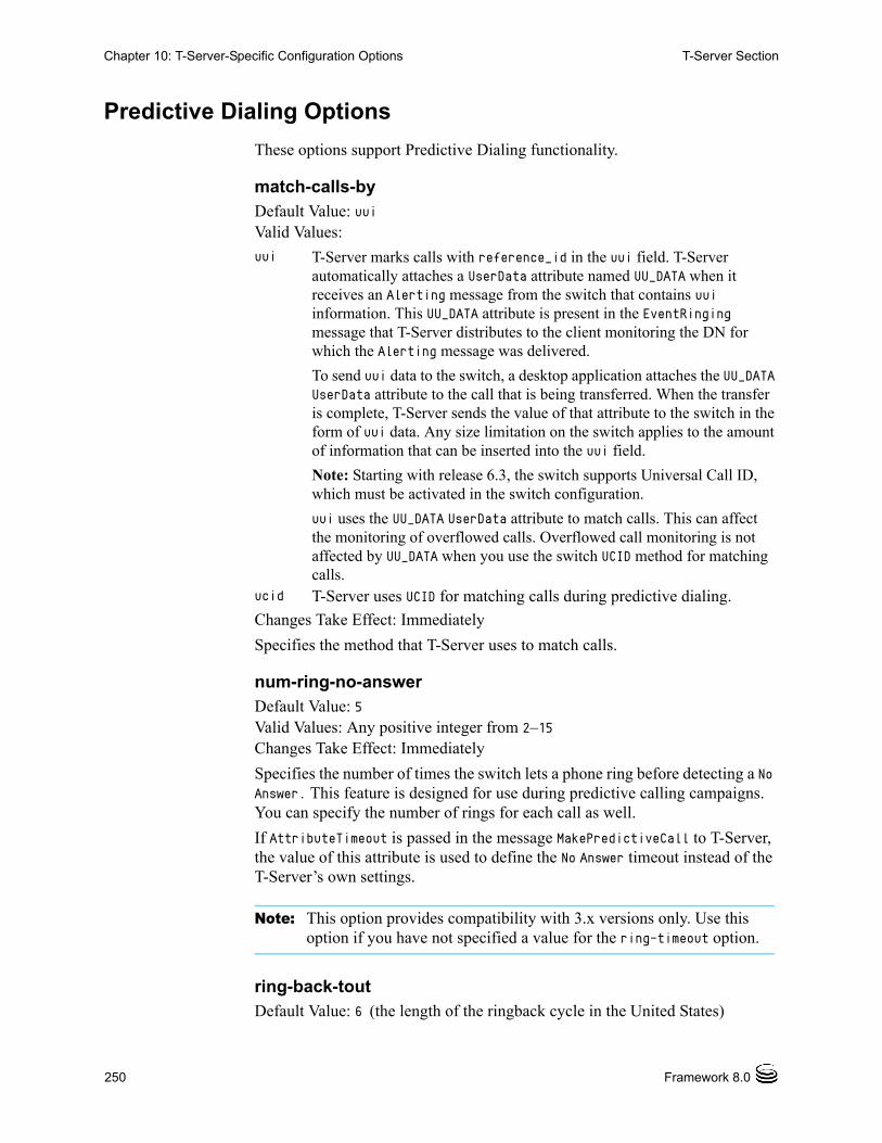
250 Framework 8.0
Chapter 10: T-Server-Specific Configuration Options T-Server Section
Predictive Dialing Options
These options support Predictive Dialing functionality.
match-calls-byDefault Value: uuiValid Values:
Changes Take Effect: Immediately
Specifies the method that T-Server uses to match calls.
num-ring-no-answerDefault Value: 5Valid Values: Any positive integer from 2–15Changes Take Effect: Immediately
Specifies the number of times the switch lets a phone ring before detecting a No Answer. This feature is designed for use during predictive calling campaigns. You can specify the number of rings for each call as well.
If AttributeTimeout is passed in the message MakePredictiveCall to T-Server, the value of this attribute is used to define the No Answer timeout instead of the T-Server’s own settings.
Note: This option provides compatibility with 3.x versions only. Use this option if you have not specified a value for the ring-timeout option.
ring-back-toutDefault Value: 6 (the length of the ringback cycle in the United States)
uui T-Server marks calls with reference_id in the uui field. T-Server automatically attaches a UserData attribute named UU_DATA when it receives an Alerting message from the switch that contains uui information. This UU_DATA attribute is present in the EventRinging message that T-Server distributes to the client monitoring the DN for which the Alerting message was delivered.
To send uui data to the switch, a desktop application attaches the UU_DATA UserData attribute to the call that is being transferred. When the transfer is complete, T-Server sends the value of that attribute to the switch in the form of uui data. Any size limitation on the switch applies to the amount of information that can be inserted into the uui field.
Note: Starting with release 6.3, the switch supports Universal Call ID, which must be activated in the switch configuration.
uui uses the UU_DATA UserData attribute to match calls. This can affect the monitoring of overflowed calls. Overflowed call monitoring is not affected by UU_DATA when you use the switch UCID method for matching calls.
ucid T-Server uses UCID for matching calls during predictive dialing.

T-Server—Deployment Guide 251
Chapter 10: T-Server-Specific Configuration Options T-Server Section
Valid Values: Any integer except 0Changes Take Effect: Immediately
Used by predictive dialing to determine the number of rings to a destination number before abandoning the call, where number of rings = ring-timeout/ring-back-tout.
ring-timeoutDefault Value: 0Valid Values: Any integerChanges Take Effect: Immediately
Specifies the length of time (in seconds) after which the switch considers the call unanswered. This feature is designed for use during predictive calling campaigns. You can specify this timeout for each call as well.
If AttributeTimeout is passed in the message MakePredictiveCall to T-Server, then the value of this attribute is used to define the No Answer timeout instead of the T-Server’s own settings.
The default value (0) means that the num-ring-no-answer option is used.
Note: You must use this option if you are also using the ring-back-tout option. The ring-timeout option overrides the num-ring-no-answer option.
use-am-detectionDefault Value: trueValid Values:
Changes Take Effect: Immediately
Specifies whether T-Server requests the switch-based Answering Machine Detection for predictive calls. This option is valid only for RequestMakePredictiveCall.
Note: You must use this option if you are also using the ring-timeout option.
true Enables this feature.false Disables this feature.connect Enables this feature, but a connection occurs even though the
answering machine has been detected (the key-value pair AnswerClass=AM is added to user data for calls with Answering Machine Detection).

252 Framework 8.0
Chapter 10: T-Server-Specific Configuration Options T-Server Section
Note: You can configure T-Server to override the default value and enable or disable Answering Machine Detection for each individual call. See the TMakePredictiveCall function in the Genesys 7 Events and Models Reference Manual and Voice Platform SDK 8.0 .NET (or Java) API Reference.
Avaya Communication Manager Ethernet Option
g3-print-heartbeatDefault Value: falseValid Values: true, falseChanges Take Effect: Immediately
Determines whether heartbeat messages (polling signals) are included in the log file. When the value is set to true, heartbeat messages are included in the log file.
Flow Control Options
Flow control options support a new flow control mechanism to ensure that ASAI message limits are not exceeded. This mechanism ensures that all requests to the link fall within a specified range within a given period.
high-water-markDefault Value: 1000Valid Values: 10–10000Changes Take Effect: Immediately
Specifies the maximum allowable number of outstanding messages in flow control before T-Server warns of a backlog. When message flow increases above the high-water-mark value, T-Server generates the LMS message Flow Control: Above high water mark (x messages buffered). When message flow drops below the high-water-mark value, T-Server generates the LMS message Flow Control: Below high water mark (x messages buffered). Note that the high-water-mark value is applicable only for use-link-bandwidth values.
link-alarm-highDefault Value: 0Valid Values: 0-100Changes Take Effect: Immediately
Specifies the percentage of the use-link-bandwidth option that must be exceeded before the LMS message LINK_ALARM_HIGH is reported. A value of 0 (zero) disables this LMS message.

T-Server—Deployment Guide 253
Chapter 10: T-Server-Specific Configuration Options Query-Agent-State Section
use-link-bandwidthDefault Value: 100 Valid Values: 0–3000 Changes Take Effect: Immediately
This option controls the number of messages that can be sent to the link within a one second period. A value of 0 (zero) disables flow control.
Note: If the use-link-bandwidth-startup option, which is now obsolete, is set to a value that is lower than the use-link-bandwidth option, the use-link-bandwidth-startup option value is used instead.
use-link-bandwidth-backupDefault Value: 0 Valid Values: 0–3000 Changes Take Effect: Immediately
Controls the number of messages that can be sent to the link within a one second period when T-Server is in backup mode. This option allows the backup T-Server to use less bandwidth preventing the combined primary and backup T-Servers from drawing too much bandwidth from the switch. A value of 0 (zero) means that the use-link-bandwidth option will be used instead.
Query-Agent-State SectionThis section defines options that control T-Server query rates for DNs in all work modes. It also describes how to configure these options to set several query rates.
These options set the query rates for 100 query timers, numbered 0 (zero) to 99. Timer 0 (zero) sets the default rate. Timers 1 to 99 represent customer-defined Reason Codes.
Using these options, you can preserve bandwidth by reducing the DN query rate.
In order to ensure that the link is not overloaded, T-Server performs only as many queries as can be accommodated within the currently available bandwidth. It does this using the value set in the use-link-bandwidth configuration option. This creates a limitation on agent state update frequency, so that when the link traffic is close to the maximum available bandwidth as set in the use-link-bandwidth option, the agent state queries decrease. That is, queries are only processed on unused bandwidth from the previous flow control timer period. DNs which are prepped for query but cannot be sent due to bandwidth restrictions are placed in a priority queue and sent in the next timer period, providing there is sufficient bandwidth.
This section must be called query-agent-state.

254 Framework 8.0
Chapter 10: T-Server-Specific Configuration Options Query-Agent-State Section
To specify a new query rate for a DN:
1. Configure use-link-bandwidth.
2. Enable agent work mode timers by setting the query-agent-work-mode option to on-timer. This sets all query rates to their default values. See “query-agent-work-mode” on page 243 for details.
3. Optionally, enable query agent options for any Reason Code by setting the enable-query-on-timer option to true. This leaves the query rate for all Reason Codes set to their default values.
4. Optionally, set a new query rate for an individual Reason Code, by setting its corresponding query-on-timer-AUX<X> option, where <X> is a number from 0 to 99 that identifies that Reason Code. Set query-on-timer-AUX0 to set a default timer rate. T-Server queries all DNs returning the Reason Code at the new rate. See query-on-timer-AUX<X> on page 255 for details.
5. Optionally, continue setting Reason Code query rates as necessary. Query rates for Reason Codes remain at their default values if they are not set individually using these options.
You can exempt individual DNs from the new query rates set by these options. See query-on-timer on page 243.
enable-query-on-timerDefault Value: falseValid Values:
Changes Take Effect: Immediately
Allows T-Server to change the DN query rate, based on the Reason Code returned by DNs logging out. This option enables 100 query-on-timer-AUX<X>
Warning! To enable the query agent states feature, the query-agent-work-mode option must be set to on-timer and the use-link-bandwidth option must be set to any value other than 0.
true Enables variable query rates to be implemented based on individual query-on-timer-AUX<X>, query-on-timer-acw, query-on-timer-auto-in, and query-on-timer-man-in option settings. T-Server queries all DNs reporting a given Reason Code, at the rate set by its corresponding option. DNs in AUX state not reporting a Reason Code are queried at the rate set by the query-on-timer-AUX0 option. Query rates that are not explicitly set by an option default to 3 seconds minimum. When changing a timer value, any timer that has already started must finish before a new value takes effect.
false Sets all query rates to their default values. When the value is set to false, this new setting does not stop timers that have previously been set.
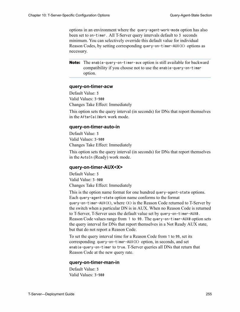
T-Server—Deployment Guide 255
Chapter 10: T-Server-Specific Configuration Options Query-Agent-State Section
options in an environment where the query-agent-work-mode option has also been set to on-timer. All T-Server query intervals default to 3 seconds minimum. You can selectively override this default value for individual Reason Codes, by setting corresponding query-on-timer-AUX<X> options as necessary.
Note: The enable-query-on-timer-aux option is still available for backward compatibility if you choose not to use the enable-query-on-timer option.
query-on-timer-acwDefault Value: 3Valid Values: 3-900Changes Take Effect: Immediately
This option sets the query interval (in seconds) for DNs that report themselves in the AfterCallWork work mode.
query-on-timer-auto-inDefault Value: 3Valid Values: 3-900Changes Take Effect: Immediately
This option sets the query interval (in seconds) for DNs that report themselves in the AutoIn (Ready) work mode.
query-on-timer-AUX<X>Default Value: 3Valid Value: 3–900Changes Take Effect: Immediately
This is the option name format for one hundred query-agent-state options. Each query-agent-state option name conforms to the format query-on-timer-AUX<X>, where <X> is the Reason Code returned to T-Server by the switch when a particular DN is in AUX. When no Reason Code is returned to T-Server, T-Server uses the default value set by query-on-timer-AUX0. Reason Code values range from 1 to 99. The query-on-timer-AUX0 option sets the query interval for DNs that report themselves in a Not Ready AUX state, but that do not report a Reason Code.
To set the query interval time for a Reason Code from 1 to 99, set its corresponding query-on-timer-AUX<X> option, in seconds, and set enable-query-on-timer to true. T-Server queries all DNs that return that Reason Code at the new query rate.
query-on-timer-man-inDefault Value: 3Valid Values: 3-900
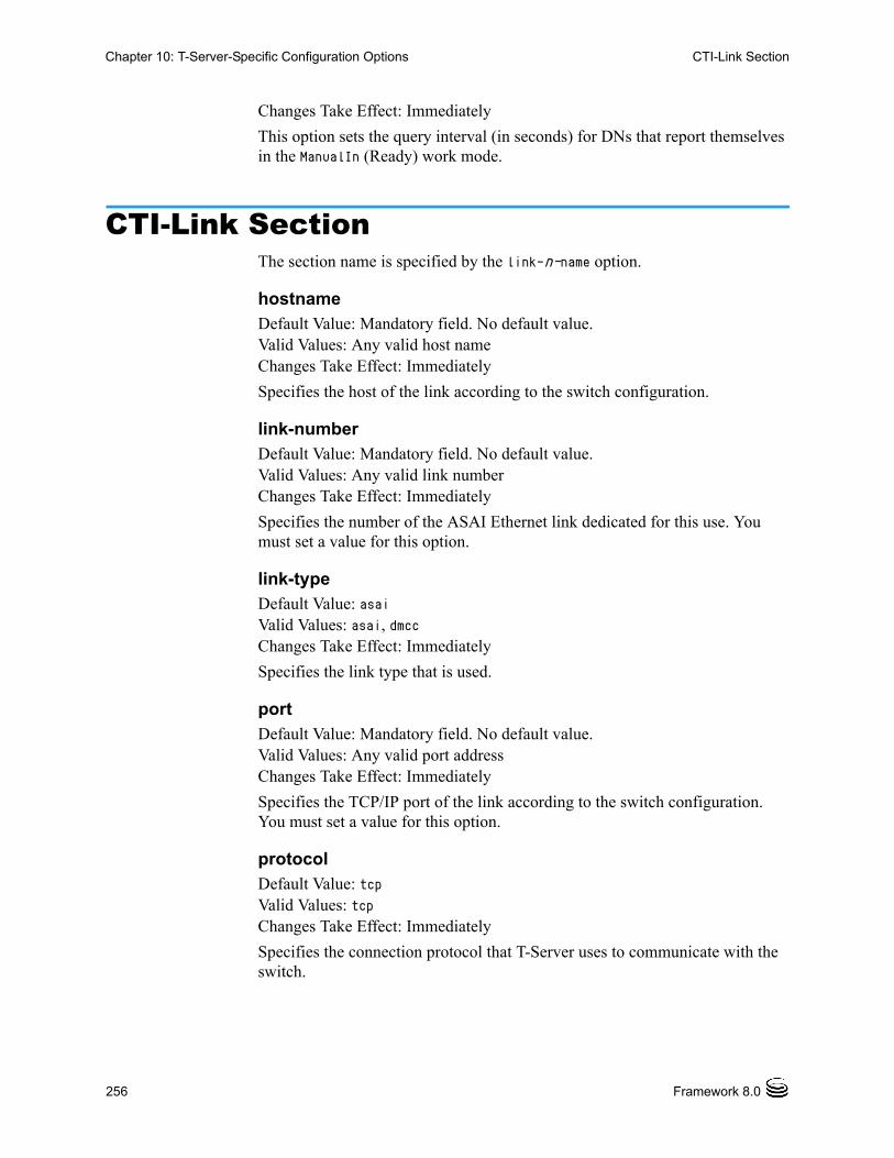
256 Framework 8.0
Chapter 10: T-Server-Specific Configuration Options CTI-Link Section
Changes Take Effect: Immediately
This option sets the query interval (in seconds) for DNs that report themselves in the ManualIn (Ready) work mode.
CTI-Link SectionThe section name is specified by the link-n-name option.
hostnameDefault Value: Mandatory field. No default value.Valid Values: Any valid host nameChanges Take Effect: Immediately
Specifies the host of the link according to the switch configuration.
link-numberDefault Value: Mandatory field. No default value.Valid Values: Any valid link numberChanges Take Effect: Immediately
Specifies the number of the ASAI Ethernet link dedicated for this use. You must set a value for this option.
link-typeDefault Value: asaiValid Values: asai, dmccChanges Take Effect: Immediately
Specifies the link type that is used.
portDefault Value: Mandatory field. No default value.Valid Values: Any valid port addressChanges Take Effect: Immediately
Specifies the TCP/IP port of the link according to the switch configuration. You must set a value for this option.
protocolDefault Value: tcpValid Values: tcpChanges Take Effect: Immediately
Specifies the connection protocol that T-Server uses to communicate with the switch.

T-Server—Deployment Guide 257
Chapter 10: T-Server-Specific Configuration Options DN-Specific Options
DN-Specific OptionsThese options are set in the TServer section on the Annex tab of a DN configuration object in Configuration Manager. Each option applies only to the DN for which it is configured.
enable-dmccDefault value: trueValid Values: true, falseChanges Take Effect: During next registration
When the value is set to true, T-Server will register the DN over the DMCC link (see “CTI-Link Section for DMCC” on page 258.) Configure enable-dmcc on the Annex tab of the DN Properties dialog box in the TServer section.
passwordDefault Value: Mandatory field. No default value.Valid Values: Any character stringChanges Take Effect: After T-Server is restarted
The password is assigned to the specific device and administered on Avaya Communication Manager. If no password is provided, the password is assumed to be the same digits as the associated DN.
query-on-timerDefault Value: not configuredValid Values: true, false, not configuredChanges Take Effect: Immediately
When the value is set to true or not configured and the query-agent-work-mode option is set to on-timer, queries are enabled for this DN. When the value is set to false and query-agent-work-mode is set to on-timer, queries are disabled for this DN. The query-on-timer option has effect only if query-agent-work-mode is set to on-timer.
second-call-as-consultDefault Value: not configuredValid Values: true, false, not configured
Note: DNs that are not DMCC-enabled on the physical switch should also be configured in Configuration Manager to disable DMCC. Each DN should be disabled by setting the Annex tab option enable-dmcc to false.
Note: The DMCC password is a required field, called Security Code, in Avaya Communication Manager.

258 Framework 8.0
Chapter 10: T-Server-Specific Configuration Options CTI-Link Section for DMCC
Changes Take Effect: Immediately
When the value is set to true, a call is on hold on an extension, and a second call is initiated from the extension, T-Server treats the second call as a consultation call to the held call. When the value is set to false, the second call is a regular call type. If the setting is not configured for this DN, then the value of the global option “second-call-as-consult” on page 246 is used.
DN for which it is configured.
tacwDefault value: 0Valid Values: Any integerChanges Take Effect: Immediately with the next call
Specifies the number of seconds that T-Server waits after this DN releases a call before querying the switch to verify that the switch TACW has updated the agent state.
Note: This value should be coordinated with the switch TACW value. See “Configuring TACW” on page 140 for details.
CTI-Link Section for DMCCThe section name is specified by the link-n-name option.
hostnameDefault Value: Mandatory field. No default value.Valid Values: Any valid host nameChanges Take Effect: Immediately
Specifies the host of the link according to the switch configuration.
link-typeDefault Value: asaiValid Values: asai, dmccChanges Take Effect: Immediately
Specifies the link type that is used.
passwordDefault Value: Mandatory field. No default value.Valid Values: Any character stringChanges Take Effect: Immediately
Specifies the DMCC password as administered on Avaya Communication Manager.
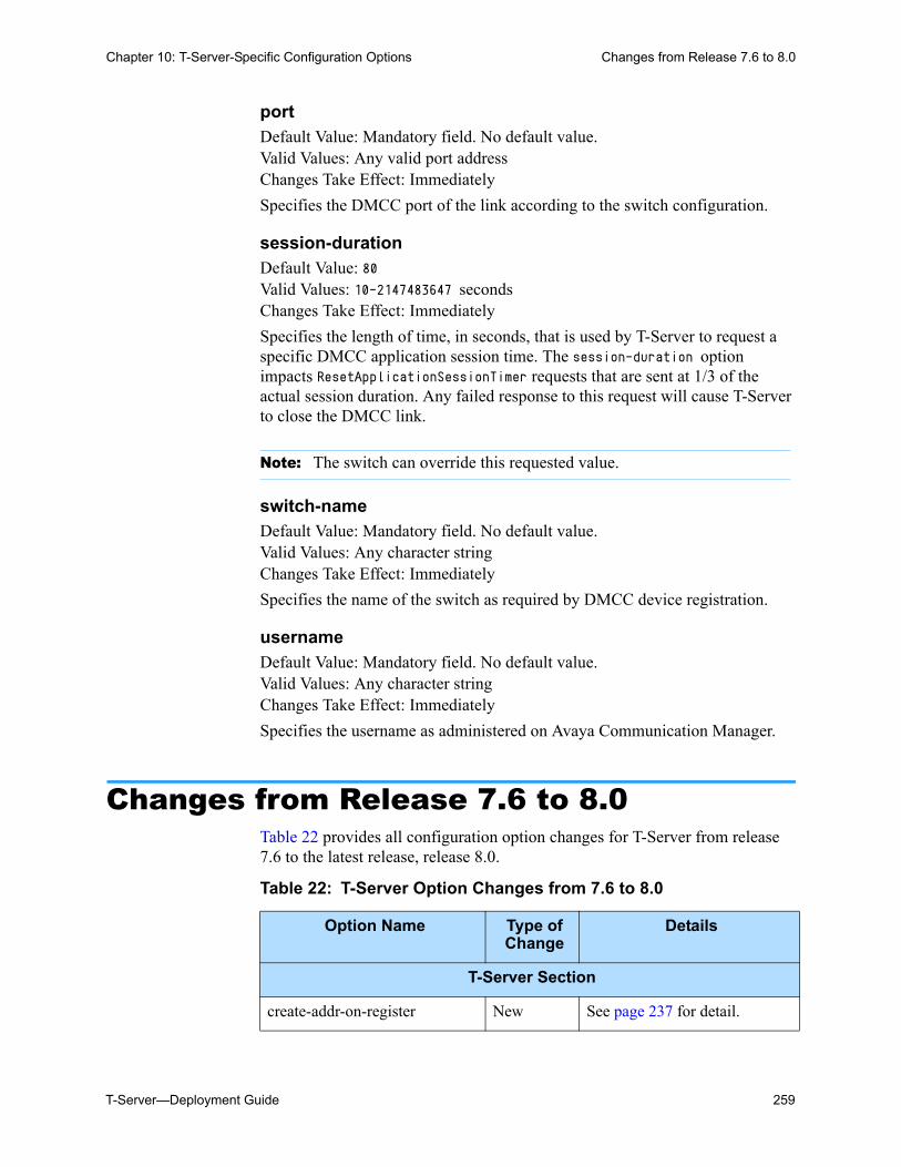
T-Server—Deployment Guide 259
Chapter 10: T-Server-Specific Configuration Options Changes from Release 7.6 to 8.0
portDefault Value: Mandatory field. No default value.Valid Values: Any valid port addressChanges Take Effect: Immediately
Specifies the DMCC port of the link according to the switch configuration.
session-durationDefault Value: 80Valid Values: 10-2147483647 seconds Changes Take Effect: Immediately
Specifies the length of time, in seconds, that is used by T-Server to request a specific DMCC application session time. The session-duration option impacts ResetApplicationSessionTimer requests that are sent at 1/3 of the actual session duration. Any failed response to this request will cause T-Server to close the DMCC link.
switch-nameDefault Value: Mandatory field. No default value.Valid Values: Any character stringChanges Take Effect: Immediately
Specifies the name of the switch as required by DMCC device registration.
usernameDefault Value: Mandatory field. No default value.Valid Values: Any character stringChanges Take Effect: Immediately
Specifies the username as administered on Avaya Communication Manager.
Changes from Release 7.6 to 8.0Table 22 provides all configuration option changes for T-Server from release 7.6 to the latest release, release 8.0.
Note: The switch can override this requested value.
Table 22: T-Server Option Changes from 7.6 to 8.0
Option Name Type of Change
Details
T-Server Section
create-addr-on-register New See page 237 for detail.

260 Framework 8.0
Chapter 10: T-Server-Specific Configuration Options Changes from Release 7.6 to 8.0
interflow-as-dnis New See page 239 for details.
link-alarm-high New See page 252 for details.
out-of-service-retry-interval New See page 241for details.
route-failure-alarm-high-wm New See page 245 for details.
route-failure-alarm-low-wm New See page 245 for details.
route-failure-alarm-period New See page 245 for details.
update-button-info New See page 249 for details.
use-link-bandwidth See details See page 253 for details.
use-link-bandwidth-backup New in 7.6
Modified in 8.0
See page 253 for details.
use-auto-dial New See page 249 for details.
high-water-mark See details See page 252 for details.
CTI-Link Section
link-type New See page 256 for details.
DN-Specific Section
enable-dmcc New See page 257 for details.
CTI-Link Section for DMCC
hostname New See page 258 for details.
link-type New See page 258 for details.
password New See page 258 for details.
port New See page 259 for details.
session-duration New See page 259 for details.
switch-name New See page 259 for details.
username New See page 259 for details.
Table 22: T-Server Option Changes from 7.6 to 8.0 (Continued)
Option Name Type of Change
Details

T-Server—Deployment Guide 261
Chapter
11 Supported High-Availability ConfigurationsThe information in this chapter is divided among the following sections: HA Default Configuration, page 261 Examples of Warm Standby Configurations, page 262
Note: Starting with release 7.1, HA Proxy is no longer supported.
HA Default Configuration In the default configuration to support high-availability, the primary T-Server connects directly to a single link. Additionally, the backup T-Server connects directly to a single link. Each link connection is supported by a separate MAPD card or AES server, to avoid single point of failure, inherent in using only one MAPD/AES server interface (see Figure 32).
Figure 32: HA Default Configuration
Link 1
PrimaryT-Server
Link 2
BackupT-Server
DN A DN A

262 Framework 8.0
Chapter 11: Supported High-Availability Configurations Examples of Warm Standby Configurations
To ensure the primary and backup T-Servers have identical DN state changes, all DNs must be registered on each link by each T-Server. If any T-Server (primary or backup) fails to obtain a domain controller due to some reason other than Invalid number domain controller, that T-Server provides an LMS warning.
Application Enablement Services (AES) Support
When using AES, Flow Control must be activated to avoid potential Login Audit Query errors. With flow Control enabled, the audit queries are serialized, which causes T-Server to send one audit at a time, and then wait for a response. If no response is received, T-Server will time out at the interval set with the msec-wait-for-ack option.
For example, if three separate clients send any Login Audit Queries for any queue, the first client's query must get a return result or timeout before the next client's request will be sent.
Note: This was tested using dual AES, where each AES was connected to one Controlled Local Area Network (CLAN). To use multiple CLAN cards with one AES, please consult Avaya to ensure that your setup will still provide the proper message order by means of AES/DLG (DEFINITY LAN Gateway).
Examples of Warm Standby ConfigurationsThis section contains examples of the warm-standby configurations for Avaya Communication Manager. The examples reflect configurations used only with Genesys software and might not represent all possible configurations.
Figure 33 and Figure 34 show two possible warm-standby configurations, and Figure 35 and Figure 36 show configurations that are not viable.
In Figure 33, the primary T-Server (TS1) is on Host1, and it connects to Link1 on Avaya Communication Manager. The backup T-Server (TS2) is on Host2 and it connects to Link2 on the switch. Both links on the switch are configured individually to connect to their respective hosts.
Figure 33: Each T-Server Connects to One Link on the Switch
Link1
Link2
192.168.21.44
192.168.11.305
TS1
TS2
Host1
Host2

T-Server—Deployment Guide 263
Chapter 11: Supported High-Availability Configurations Examples of Warm Standby Configurations
Table 23 shows the Avaya Communication Manager configuration.
In Figure 34, the primary and the backup T-Servers (TS1, TS2) are located on the same host (Host1). Each T-Server is configured to connect to a link on the switch. Both links are configured for the same host (Host1). In this case, when each T-Server starts, it uses its respective link to connect to the switch.
Figure 34: T-Servers Located on the Same Host
In Figure 35, the primary and the backup T-Servers (TS1, TS2) are located on the same host (Host1). Each T-Server is configured to connect to the same link (Link1) on the switch. The links are configured for the single host (Host1). In this case, when the T-Servers start, the primary T-Server is assigned Link1, but the backup T-Server cannot be assigned the same link number. Therefore, this configuration is not possible in warm standby mode.
Table 23: Avaya Communication Manager Configuration
DLG Administration
Port Client Name or IP Address
Client Link Client Status
1 192.168.21.44 1 idle
2 192.168.11.305 2 idle
3 192.168.22.45 3 idle
4 192.168.23.46 4 idle
5 192.168.24.47 5 idle
6 192.168.25.48 6 idle
7 192.168.26.49 7 idle
8 192.168.27.60 8 idle
Link1
Link2
192.168.21.44
TS1
TS2
Host1

264 Framework 8.0
Chapter 11: Supported High-Availability Configurations Examples of Warm Standby Configurations
Figure 35: The Backup T-Server Cannot Be Assigned the Same Link Number
Below is an example of the message you would get in the log for the backup T-Server. ** link[1] ** 10:10:23.7540
01
08/01/02 10:10:23.754 Standard smithpc TS_eng_bkp GCTI-01-31010 Connection Rejected: Link[1], reason [Unsupported ASAI-Ethernet version]
@10:10:23.7540 [31010] Connection Rejected: Link[1], reason [Unsupported ASAI-Ethernet version]
(link_stop) link [1] 'TCP-Link1' stop
(tcp_stop) closed on [148]
In Figure 36, only one link (Link1) is available, and the two T-Servers are on separate hosts. The primary T-Server (TS1) is on Host1, and the backup T-Server (TS2) is on Host2. Since a link can be configured to connect to only one host, there would be no link to connect with for Host2 for the backup T-Server (TS2). Therefore, this configuration is not possible in warm standby mode.
Figure 36: The Backup T-Server Cannot Be Connected to the Switch
Link1
TS1
TS2
192.168.21.44Host1
Link1Host1192.168.21.44
Host2192.168.11.305TS2
TS1

T-Server—Deployment Guide 265
Supplements
Related Documentation ResourcesThe following resources provide additional information that is relevant to this software. Consult these additional resources as necessary.
T-Server for Avaya Communication Manager
• The Framework 8.0 Deployment Guide, which will help you configure, install, start, and stop Framework components.
• The Framework 8.0 Configuration Options Reference Manual, which will provide you with descriptions of configuration options for other Framework components.
• The Framework 8.0 Configuration Manager Help, which will help you use Configuration Manager.
Genesys
• The Genesys Migration Guide, also on the Genesys Documentation Library CD, which contains a documented migration strategy from Genesys product releases 5.x and later to all Genesys 8.x releases. Contact Genesys Technical Support for additional information.
• The Genesys 7 Events and Models Reference Manual and Voice Platform SDK 8.0 .NET (or Java) API Reference, which contains technical details of T-Library functions.
• The Genesys Technical Publications Glossary, which ships on the Genesys Documentation Library CD and which provides a comprehensive list of the Genesys and CTI terminology and acronyms used in this document.
• The Release Notes and Product Advisories for this product, which are available on the Genesys Technical Support website at http://genesyslab.com/support.
Information on supported hardware and third-party software is available on the Genesys Technical Support website in the following documents:

266 Framework 8.0
Related Documentation Resources
• Genesys Supported Operating Environment Reference Manual
• Genesys Supported Media Interfaces Reference Manual
For additional system-wide planning tools and information, see the release-specific listings of System Level Documents on the Genesys Technical Support website, accessible from the system level documents by release tab in the Knowledge Base Browse Documents Section.
Genesys product documentation is available on the:
• Genesys Technical Support website at http://genesyslab.com/support.
• Genesys Documentation Library DVD, which you can order by e-mail from Genesys Order Management at [email protected].

T-Server—Deployment Guide 267
Document Conventions
Document ConventionsThis document uses certain stylistic and typographical conventions—introduced here—that serve as shorthands for particular kinds of information.
Document Version Number
A version number appears at the bottom of the inside front cover of this document. Version numbers change as new information is added to this document. Here is a sample version number:
80fr_ref_06-2008_v8.0.001.00
You will need this number when you are talking with Genesys Technical Support about this product.
Screen Captures Used in This Document
Screen captures from the product graphical user interface (GUI), as used in this document, may sometimes contain minor spelling, capitalization, or grammatical errors. The text accompanying and explaining the screen captures corrects such errors except when such a correction would prevent you from installing, configuring, or successfully using the product. For example, if the name of an option contains a usage error, the name would be presented exactly as it appears in the product GUI; the error would not be corrected in any accompanying text.
Type Styles
Table 24 describes and illustrates the type conventions that are used in this document.
Table 24: Type Styles
Type Style Used For Examples
Italic • Document titles
• Emphasis
• Definitions of (or first references to) unfamiliar terms
• Mathematical variables
Also used to indicate placeholder text within code samples or commands, in the special case where angle brackets are a required part of the syntax (see the note about angle brackets on page 268).
Please consult the Genesys Migration Guide for more information.
Do not use this value for this option.
A customary and usual practice is one that is widely accepted and used within a particular industry or profession.
The formula, x +1 = 7 where x stands for . . .

268 Framework 8.0
Document Conventions
Monospace font
(Looks like teletype or typewriter text)
All programming identifiers and GUI elements. This convention includes:
• The names of directories, files, folders, configuration objects, paths, scripts, dialog boxes, options, fields, text and list boxes, operational modes, all buttons (including radio buttons), check boxes, commands, tabs, CTI events, and error messages.
• The values of options.
• Logical arguments and command syntax.
• Code samples.
Also used for any text that users must manually enter during a configuration or installation procedure, or on a command line.
Select the Show variables on screen check box.
In the Operand text box, enter your formula.
Click OK to exit the Properties dialog box.
T-Server distributes the error messages in EventError events.
If you select true for the inbound-bsns-calls option, all established inbound calls on a local agent are considered business calls.
Enter exit on the command line.
Square brackets ([ ])
A particular parameter or value that is optional within a logical argument, a command, or some programming syntax. That is, the presence of the parameter or value is not required to resolve the argument, command, or block of code. The user decides whether to include this optional information.
smcp_server -host [/flags]
Angle brackets (< >)
A placeholder for a value that the user must specify. This might be a DN or a port number specific to your enterprise.
Note: In some cases, angle brackets are required characters in code syntax (for example, in XML schemas). In these cases, italic text is used for placeholder values.
smcp_server -host <confighost>
Table 24: Type Styles (Continued)
Type Style Used For Examples

T-Server—Deployment Guide 269
Index
Symbols[] (square brackets). . . . . . . . . . . . . . 268< > (angle brackets) . . . . . . . . . . . . . 268<key name>
common log option . . . . . . . . . . . . 205
AAccess Code
configuration. . . . . . . . . . . . . . . . 108defined. . . . . . . . . . . . . . . . . 40, 106
acd-register-modeconfiguration options . . . . . . . . . . . 234
ADDP. . . . . . . . . . . . . . . . . . . . . 58addp-remote-timeout
configuration option . . . . . . . . . . . . 228addp-timeout
configuration option . . . . . . . . . . . . 228addp-trace
configuration option . . . . . . . . . . . . 228Advanced Disconnect Detection Protocol . . 23after-call-fac
configuration options . . . . . . . . . . . 235Agent Login objects . . . . . . . . . . . . . 41agent reservation
defined. . . . . . . . . . . . . . . . . . . . 28agent-no-answer-action
configuration options . . . . . . . . . . . 235agent-no-answer-overflow
configuration options . . . . . . . . . . . 236agent-no-answer-timeout
configuration options . . . . . . . . . . . 236Agent-Reservation section
configuration options . . . . . . . . .216–217alarm
common log option . . . . . . . . . . . . 196all
common log option . . . . . . . . . . . . 195angle brackets . . . . . . . . . . . . . . . . 268ANI . . . . . . . . . . . . . . . . . . . . . . 71
ani-distributionconfiguration option . . . . . . . . . . . . 208
appcommand line parameter . . . . . . . . . 119
Application objectsmulti-site operation . . . . . . . . . . . . 105
ASAI Link configurationswitch configuration . . . . . . . . . . . . 137
asai-protocol-versionconfiguration options . . . . . . . . . . . 236
audiencedefining . . . . . . . . . . . . . . . . . . . 12
auto-in-facconfiguration options . . . . . . . . . . . 236
automatic call distribution (ACD). . . . 180, 185aux-work-fac
configuration options . . . . . . . . . . . 237
Bbackground-processing
configuration option . . . . . . . . . . . . 208background-timeout
configuration option . . . . . . . . . . . . 209backup servers. . . . . . . . . . . . . . . . .49backup-sync
configuration section . . . . . . . . . . . . 58Backup-Synchronization section
configuration option . . . . . . . . . . 228–229brackets
angle . . . . . . . . . . . . . . . . . . . 268square. . . . . . . . . . . . . . . . . . . 268
bufferingcommon log option . . . . . . . . . . . . 189
CCall-Cleanup section
configuration option . . . . . . . . . . 229–231call-delete-delay-msec

Index
270 Framework 8.0
configuration options . . . . . . . . . . . 237CallerID
support for . . . . . . . . . . . . . . . . . 159cast-type
configuration option . . . . . . . . . . 70, 219CDN . . . . . . . . . . . . . . . . . . . . . 77changes from 7.6 to 8.0
common configuration options . . . . . . 206configuration options . . . . . . . . . . . 232T-Server options . . . . . . . . . . . . . . 259
check-pointcommon log option . . . . . . . . . . . . 193
check-tenant-profileconfiguration option . . . . . . . . . . . . 209
cleanup-idle-toutconfiguration option . . . . . . . . . . . . 229
Code property . . . . . . . . . . . . . 108, 109cof-ci-defer-create
configuration option . . . . . . . . . . . . 224cof-ci-defer-delete
configuration option . . . . . . . . . . . . 224cof-ci-req-tout
configuration option . . . . . . . . . . 86, 224cof-ci-wait-all
configuration option . . . . . . . . . . . . 224cof-feature
configuration option . . . . . . . . . . . . 225cof-rci-tout
configuration option . . . . . . . . . . . . 225collect-lower-priority-requests
configuration option . . . . . . . . . . . . 216command line parameters . . . . . . . . . . 119
app . . . . . . . . . . . . . . . . . . . . 119host . . . . . . . . . . . . . . . . . . . . 119l . . . . . . . . . . . . . . . . . . . . . . 120lmspath . . . . . . . . . . . . . . . . . . 120nco X/Y . . . . . . . . . . . . . . . . . . 120port . . . . . . . . . . . . . . . . . . . . 119V. . . . . . . . . . . . . . . . . . . . . . 120
commenting on this document . . . . . . . . 13common configuration options . . . . . 188–206
changes from 7.6 to 8.0 . . . . . . . . . . 206common section . . . . . . . . . . . .205–206enable-async-dns . . . . . . . . . . . . . 205log section . . . . . . . . . . . . . . .188–202log-extended section . . . . . . . . .202–204log-filter section . . . . . . . . . . . .204–205log-filter-data section . . . . . . . . . . . 205mandatory . . . . . . . . . . . . . . . . . 188rebind-delay . . . . . . . . . . . . . . . . 206setting . . . . . . . . . . . . . . . . . . . 188sml section . . . . . . . . . . . . . . . . 205suspending-wait-timeout . . . . . . .205, 206
common log options . . . . . . . . . . 188–205<key name> . . . . . . . . . . . . . . . . 205alarm . . . . . . . . . . . . . . . . . . . 196
all . . . . . . . . . . . . . . . . . . . . . 195buffering. . . . . . . . . . . . . . . . . . 189check-point . . . . . . . . . . . . . . . . 193compatible-output-priority . . . . . . . . . 194debug . . . . . . . . . . . . . . . . . . . 197default-filter-type . . . . . . . . . . . . . 204expire . . . . . . . . . . . . . . . . . . . 190interaction . . . . . . . . . . . . . . . . . 196keep-startup-file . . . . . . . . . . . . . . 190level-reassign-<eventID> . . . . . . . . . 202level-reassign-disable. . . . . . . . . . . 204log section . . . . . . . . . . . . . . 188–202log-extended section . . . . . . . . . 202–204log-filter section . . . . . . . . . . . . 204–205log-filter-data section . . . . . . . . . . . 205mandatory options . . . . . . . . . . . . 188memory . . . . . . . . . . . . . . . . . . 193memory-storage-size . . . . . . . . . . . 193message_format . . . . . . . . . . . . . 191messagefile . . . . . . . . . . . . . . . . 190print-attributes. . . . . . . . . . . . . . . 192segment. . . . . . . . . . . . . . . . . . 189setting . . . . . . . . . . . . . . . . . . . 188spool . . . . . . . . . . . . . . . . . . . 193standard. . . . . . . . . . . . . . . . . . 196time_convert . . . . . . . . . . . . . . . 192time_format . . . . . . . . . . . . . . . . 192trace. . . . . . . . . . . . . . . . . . . . 197verbose . . . . . . . . . . . . . . . . . . 188x-conn-debug-all . . . . . . . . . . . . . 202x-conn-debug-api . . . . . . . . . . . . . 201x-conn-debug-dns. . . . . . . . . . . . . 202x-conn-debug-open . . . . . . . . . . . . 200x-conn-debug-security . . . . . . . . . . 201x-conn-debug-select . . . . . . . . . . . 200x-conn-debug-timers . . . . . . . . . . . 201x-conn-debug-write . . . . . . . . . . . . 201
common optionscommon log options . . . . . . . . . 188–205common section . . . . . . . . . . . 205–206mandatory options . . . . . . . . . . . . 188sml section . . . . . . . . . . . . . . . . 205
common sectioncommon options . . . . . . . . . . . 205–206
compatible-output-prioritycommon log option . . . . . . . . . . . . 194
compound-dn-representationconfiguration option . . . . . . . . . . . . 226
Configuration Managerconfiguring T-Server . . . . . . . . . . . . 42
multiple ports . . . . . . . . . . . . . .43configuration options
acd-register-mode . . . . . . . . . . . . 234addp-remote-timeout . . . . . . . . . . . 228addp-timeout . . . . . . . . . . . . . . . 228addp-trace. . . . . . . . . . . . . . . . . 228

Index
T-Server—Deployment Guide 271
after-call-fac . . . . . . . . . . . . . . . . 235agent-no-answer-action . . . . . . . . . . 235agent-no-answer-overflow. . . . . . . . . 236agent-no-answer-timeout . . . . . . . . . 236Agent-Reservation section . . . . . .216–217ani-distribution . . . . . . . . . . . . . . . 208asai-protocol-version . . . . . . . . . . . 236auto-in-fac . . . . . . . . . . . . . . . . . 236aux-work-fac. . . . . . . . . . . . . . . . 237Avaya Communication Manager Ethernet
option . . . . . . . . . . . . . . . . . . 252background-processing . . . . . . . . . . 208background-timeout . . . . . . . . . . . . 209Backup-Synchronization section . . .228–229Call-Cleanup section . . . . . . . . .229–231call-delete-delay-msec . . . . . . . . . . 237cast-type. . . . . . . . . . . . . . . . . . 219changes from 7.6 to 8.0 . . . . . . . .232, 259check-tenant-profile . . . . . . . . . . . . 209cleanup-idle-tout. . . . . . . . . . . . . . 229cof-ci-defer-create . . . . . . . . . . . . . 224cof-ci-defer-delete . . . . . . . . . . . . . 224cof-ci-req-tout . . . . . . . . . . . . . . . 224cof-ci-wait-all . . . . . . . . . . . . . . . 224cof-feature . . . . . . . . . . . . . . . . . 225cof-rci-tout . . . . . . . . . . . . . . . . . 225collect-lower-priority-requests . . . . . . . 216common log options . . . . . . . . . .188–205common options . . . . . . . . . . . .188–206compound-dn-representation . . . . . . . 226consult-user-data . . . . . . . . . . . . . 209create-addr-on-register . . . . . . . . . . 237CTI-Link section . . . . . . . . . . . . . . 256CTI-Link section for DMCC . . . . . . .258–??customer-id . . . . . . . . . . . . . . . . 210default-dn . . . . . . . . . . . . . . . . . 220default-network-call-id-matching . . . . . 225delay-logout-report . . . . . . . . . . . . 237delay-mute-transfer . . . . . . . . . . . . 237deliver-time-in-queue . . . . . . . . . . . 238direct-digits-key . . . . . . . . . . . . . . 220disable-digits-collection . . . . . . . . . . 238dn-for-unexpected-calls . . . . . . . . . . 220dn-scope. . . . . . . . . . 100, 181, 185, 210DN-Specific . . . . . . . . . . . . . . . . 257enable-query-on-timer . . . . . . . . . . . 254enable-ucid-swap . . . . . . . . . . . . . 238epp-tout . . . . . . . . . . . . . . . .101, 226event-propagation . . . . . . . . . . . . . 227Flow Control Options . . . . . . . . . . . 252follow-calls. . . . . . . . . . . . 179, 185, 239g3-print-heartbeat . . . . . . . . . . . . . 252high-water-mark . . . . . . . . . . . . . . 252hostname . . . . . . . . . . . . . . .256, 258inbound-translator-<n> . . . . . . . . . . 227interflow-as-dnis . . . . . . . . . . . . . . 239
License section . . . . . . . . . . . . 213–216link-alarm-high . . . . . . . . . . . . . . 252link-n-name . . . . . . . . . . . . . . . . 239link-number . . . . . . . . . . . . . . . . 256link-type . . . . . . . . . . . . . . . . 256, 258local-node-id . . . . . . . . . . . . . . . 225log-trace-flags. . . . . . . . . . . . . . . 211log-trace-flags (specific to this T-Server) . 240management-port . . . . . . . . . . . . . 211mandatory options . . . . . . . . . . 188, 233manual-in-fac . . . . . . . . . . . . . . . 240match-call-once . . . . . . . . . . . . . . 218match-calls-by . . . . . . . . . . . . . . 250max-attempts-to-register . . . . . . . . . 240merge-consult-data . . . . . . . . . . . . 240merged-user-data . . . . . . . . . . . . . 211msec-wait-for-ack . . . . . . . . . . . . . 241Multi-Site Support section. . . . . . . 217–227network-request-timeout . . . . . . . . . 221notify-idle-tout . . . . . . . . . . . . . . . 230num-of-licenses . . . . . . . . . . . . . . 213num-ring-no-answer . . . . . . . . . . . 250num-sdn-licenses . . . . . . . . . . . . . 214out-of-service-retry-interval . . . . . . 241, 260password . . . . . . . . . . . . . . . 257, 258periodic-check-tout . . . . . . . . . . . . 230port . . . . . . . . . . . . . . . . . . . . 259predict-agent-work-mode . . . . . . . . . 241Predictive Dialing . . . . . . . . . . . . . 250preserve-collected-digits . . . . . . . . . 242propagated-call-type . . . . . . 100, 185, 212protocol . . . . . . . . . . . . . . . . 229, 256query-agent-state section . . . . . . . 253–255query-agent-work-mode . . . . . . . . . 243query-on-timer-acw . . . . . . . . . . . . 255query-on-timer-auto-in . . . . . . . . . . 255query-on-timer-AUX. . . . . . . . . . . . 255query-on-timer-man-in . . . . . . . . . . 255reconnect-tout. . . . . . . . . . . . . . . 218register-attempts . . . . . . . . . . . . . 221register-tout . . . . . . . . . . . . . . . . 221reject-subsequent-request . . . . . . . . 216report-connid-changes . . . . . . . . . . 218request-collection-time . . . . . . . . . . 217request-tout . . . . . . . . . . . . . . . . 221reservation-time. . . . . . . . . . . . . . 217resource-allocation-mode . . . . . . . . . 221resource-load-maximum . . . . . . . . . 222retry-on-admin-progress . . . . . . . . . 244retry-on-incom-st . . . . . . . . . . . . . 244retry-on-netconj . . . . . . . . . . . . . . 244retry-on-proterr . . . . . . . . . . . . . . 244retry-on-resunavl . . . . . . . . . . . . . 244retry-on-temp-failure . . . . . . . . . . . 245retry-timeout-msec . . . . . . . . . . . . 245ring-back-tout . . . . . . . . . . . . . . . 250

Index
272 Framework 8.0
ring-timeout . . . . . . . . . . . . . . . . 251route-dn . . . . . . . . . . . . . . . . . . 222route-failure-alarm-high-wm . . . . . . . . 245route-failure-alarm-low-wm . . . . . . . . 245route-failure-alarm-period . . . . . . . . . 245route-thru-queue. . . . . . . . . . . . . . 246rule-<n> . . . . . . . . . . . . . . . . . . 227second-call-as-consult. . . . . . . . . . . 246Security section . . . . . . . . . . . . . . 231send-tcs-dtmf . . . . . . . . . . . . . . . 246server-id . . . . . . . . . . . . . . . . . . 212session-duration . . . . . . . . . . . . . . 259set-call-type-on-dialing . . . . . . . . . . 246set-otherdn-trunk-info . . . . . . . . . . . 247setting . . . . . . . . . . . . . . . . . . . 207
common . . . . . . . . . . . . . . . . 188soft-login-support . . . . . . . . . . . . . 247soft-wrap-up-time . . . . . . . . . . . . . 248switch-name . . . . . . . . . . . . . . . . 259sync-reconnect-tout . . . . . . . . . . . . 229tcs-queue . . . . . . . . . . . . . . . . . 223tcs-use. . . . . . . . . . . . . . . . . . . 223timeout. . . . . . . . . . . . . . . . . . . 222timeout value format. . . . . . . . . .231–232Translation Rules section . . . . . . . . . 227T-Server section . . . . . . 208–213, 234–253ts-tp-enabled . . . . . . . . . . . . . . . 248ts-tp-heartbeat-timer. . . . . . . . . . . . 248ts-tp-heartbeat-timout . . . . . . . . . . . 248update-button-info . . . . . . . . . . . . . 249use-am-detection . . . . . . . . . . . . . 251use-auto-dial. . . . . . . . . . . . . . . . 249use-auto-dials . . . . . . . . . . . . .179, 185use-data-from . . . . . . . . . . . . . . . 219use-implicit-access-numbers . . . . . . . 223use-link-bandwidth . . . . . . . . . .180, 253use-link-bandwidth-backup . . . . . .180, 253use-old-fwd-key . . . . . . . . . . . . . . 249use-pending-work-mode. . . . . . . . . . 249user-data-limit . . . . . . . . . . . . . . . 213username . . . . . . . . . . . . . . . . . 259
configuringhigh availability
T-Server . . . . . . . . . . . . . . .57–59multi-site operation . . . . . . . . . .105–118
steps . . . . . . . . . . . . . . . . . . 105T-Server . . . . . . . . . . . . . . . . . . . 42
multiple ports. . . . . . . . . . . . . . 43consult-user-data
configuration option . . . . . . . . . . . . 209conventions
in document . . . . . . . . . . . . . . . . 267type styles . . . . . . . . . . . . . . . . . 267
create-addr-on-register options . . . . . . . 237CTI
request . . . . . . . . . . . . . . . . . . 179
CTI Link configurationswitch configuration . . . . . . . . . . . . 136
CTI-Link sectionconfiguration options . . . . . . . . . . . 256
CTI-Link section for DMCCconfiguration options . . . . . . . . . . 258–??
customer-idconfiguration option . . . . . . . . . . . . 210
Ddebug
common log option . . . . . . . . . . . . 197Default Access Code
configuration . . . . . . . . . . . . . . . 107defined . . . . . . . . . . . . . . . . . . 106
default-dnconfiguration option . . . . . . . . . . . . 220
default-filter-typecommon log option . . . . . . . . . . . . 204
default-network-call-id-matchingconfiguration option . . . . . . . . . . . . 225
delay-logout-reportconfiguration options . . . . . . . . . . . 237
delay-mute-transferconfiguration options . . . . . . . . . . . 237
deliver-time-in-queueconfiguration options . . . . . . . . . . . 238
destination location . . . . . . . . . . . . . .64destination T-Server . . . . . . . . . . . . . .70direct-ani
ISCC transaction type. . . . . . . . . . 71, 79direct-callid
ISCC transaction type. . . . . . . . . . 72, 79direct-digits
transaction type . . . . . . . . . . . . . . . 79direct-digits-key
configuration option . . . . . . . . . . . . 220direct-network-callid
ISCC transaction type. . . . . . . . . . 72, 79direct-notoken
ISCC transaction type. . . . . . . . . . 73, 79direct-uui
ISCC transaction type. . . . . . . . . . 73, 79disable-digits-collection
configuration options . . . . . . . . . . . 238DMCC
ESS . . . . . . . . . . . . . . . . . . . . 180DN objects . . . . . . . . . . . . . . . . . . .41dn specific configuration options
enable-dmcc . . . . . . . . . . . . . . . 257query-on-timer . . . . . . . . . . . . . . 257second-call-as-consult . . . . . . . . . . 257tacw . . . . . . . . . . . . . . . . . . . . 258
dn-for-unexpected-callsconfiguration option . . . . . . . . . . . . 220

Index
T-Server—Deployment Guide 273
dnis-poolin load-balancing mode . . . . . . . . . . . 75ISCC transaction type . . . . . . . . 66, 74, 79
DNsconfiguring for multi-sites . . . . . . . . . 112
dn-scopeconfiguration option . . . . . . . . . .100, 210configuration options . . . . . . . . .181, 185
DN-Specific optionsconfiguration options . . . . . . . . . . . 257
documentchange history . . . . . . . . . . . . . . . . 14conventions . . . . . . . . . . . . . . . . 267errors, commenting on . . . . . . . . . . . 13version number . . . . . . . . . . . . . . 267
Eenable-async-dns
common configuration option . . . . . . . 205enable-dmcc
dn specific configuration options . . . . . 257enable-query-on-timer
configuration options . . . . . . . . . . . 254enable-ucid-swap
configuration options . . . . . . . . . . . 238enterprise survivable server . . . . . . . . . 179epp-tout
configuration option . . . . . . . . . .101, 226error messages
supported functionality . . . . . . . . . . 173ESS . . . . . . . . . . . . . . . . . . . . . 184
architecture . . . . . . . . . . . . . . . . 180automatic call distribution . . . . . . .180, 185bandwidth . . . . . . . . . . . . . . . . . 180DMCC . . . . . . . . . . . . . . . . . . . 180enterprise survivable server . . . . . . . . 179failure
server . . . . . . . . . . . .182, 183, 184182
Event Propagationdefined. . . . . . . . . . . . . . . . . . . . 97
EventAttachedDataChanged . . . . . . . . . 98event-propagation
configuration option . . . . . . . . . . . . 227expire
common log option . . . . . . . . . . . . 190Extensions attribute
supported functionality . . . . . . . . . . 161extrouter
configuration section . . . . . . .95, 102, 106
Ffailure
network . . . . . . . . . . . . . . . . . . 184primary media server . . . . . . . . . . . 182single services site . . . . . . . . . . . . 183
figureshot standby redundancy . . . . . . . . . . 52Multiple-to-Point mode . . . . . . . . . . . 78Point-to-Point mode. . . . . . . . . . . . . 77steps in ISCC/Call Overflow . . . . . . . . 85
follow-callsconfiguration options . . . . . . 179, 185, 239
font stylesitalic . . . . . . . . . . . . . . . . . . . . 267monospace . . . . . . . . . . . . . . . . 268
Gg3-print-heartbeat
configuration options . . . . . . . . . . . 252Genesys requirements for the switch
switch configuration . . . . . . . . . . . . 146
HHA
See also high availabilitySee hot standby
HA configuration . . . . . . . . . . . . . . 49–59HA Proxy
starting . . . . . . . . . . . . . . . . 126, 127high-availability configuration . . . . . . . 49–59high-water-mark
configuration options . . . . . . . . . . . 252host
command line parameter . . . . . . . . . 119hostname
configuration options . . . . . . . . . . . 256hostname options . . . . . . . . . . . . . . 258hot standby . . . . . . . . . . . . . . . . 24, 49
defined . . . . . . . . . . . . . . . . . . . 25figure . . . . . . . . . . . . . . . . . . . . 52T-Server configuration . . . . . . . . . . . 56
Iinbound-translator-<n>
configuration option . . . . . . . . . . . . 227Inter Server Call Control . . . . . . . . . . 64–83Inter Server Call Control/Call Overflow . . 83–87interaction
common log option . . . . . . . . . . . . 196interflow-as-dnis options . . . . . . . . . . . 239ISCC
destination T-Server . . . . . . . . . . . . 70origination T-Server . . . . . . . . . . . . . 70

Index
274 Framework 8.0
ISCC transaction types. . . . . . . . . . .65, 70direct-ani. . . . . . . . . . . . . . . . . 71, 79direct-callid . . . . . . . . . . . . . . . 72, 79direct-digits . . . . . . . . . . . . . . . . . 79direct-network-callid . . . . . . . . . . . 72, 79direct-notoken . . . . . . . . . . . . . . 73, 79direct-uui. . . . . . . . . . . . . . . . . 73, 79dnis-pool. . . . . . . . . . . . . . . . . 74, 79
in load-balancing mode . . . . . . . . 75pullback . . . . . . . . . . . . . . . . . 75, 79reroute . . . . . . . . . . . . . . . . . . 76, 79route . . . . . . . . . . . . . . . . . . . 77, 79route-uui . . . . . . . . . . . . . . . . . . . 78supported . . . . . . . . . . . . . . . . . . 79
ISCC/COFsupported . . . . . . . . . . . . . . . . . . 84
iscc-xaction-type . . . . . . . . . . . . . . . 65italics . . . . . . . . . . . . . . . . . . . . . 267
Kkeep-startup-file
common log option . . . . . . . . . . . . 190
Ll
command line parameter . . . . . . . . . 120level-reassign-<eventID>
common log option . . . . . . . . . . . . 202level-reassign-disable
common log option . . . . . . . . . . . . 204License section
configuration options . . . . . . . . .213–216link-alarm-high options . . . . . . . . . . . . 252link-n-name
configuration options . . . . . . . . . . . 239link-number
configuration options . . . . . . . . . . . 256link-type options . . . . . . . . . . . . 256, 258lmspath
command line parameter . . . . . . . . . 120local-node-id
configuration option . . . . . . . . . . . . 225location parameter . . . . . . . . . . . . . . 64log configuration options . . . . . . . . 188–194log section
common log options . . . . . . . . . .188–202log-extended section
common log options . . . . . . . . . .202–204log-filter section
common log options . . . . . . . . . .204–205log-filter-data section
common log options . . . . . . . . . . . . 205log-trace-flags
configuration option . . . . . . . . . . . . 211log-trace-flags (specific to this T-Server)
configuration options . . . . . . . . . . . 240
MManagement Layer . . . . . . . . . . . . . .36management-port
configuration option . . . . . . . . . . . . 211mandatory options
configuration options . . . . . . . . . 208, 233manual-in-fac
configuration options . . . . . . . . . . . 240match-call-once
configuration option . . . . . . . . . . . . 218match-calls-by
configuration options . . . . . . . . . . . 250max-attempts-to-register
configuration options . . . . . . . . . . . 240memory
common log option . . . . . . . . . . . . 193memory-storage-size
common log option . . . . . . . . . . . . 193merge-consult-data
configuration options . . . . . . . . . . . 240merged-user-data
configuration option . . . . . . . . . . . . 211message_format
common log option . . . . . . . . . . . . 191messagefile
common log option . . . . . . . . . . . . 190monospace font . . . . . . . . . . . . . . . 268msec-wait-for-ack
configuration options . . . . . . . . . . . 241Multiple-to-One mode . . . . . . . . . . . . .77Multiple-to-Point mode. . . . . . . . . . . 77, 78Multi-Site Support section
configuration options . . . . . . . . . 217–227
NNAT/C feature . . . . . . . . . . . . . . . . .95nco X/Y
command line parameter . . . . . . . . . 120network attended transfer/conference . . . . .95network objects . . . . . . . . . . . . . . . .36network-request-timeout
configuration option . . . . . . . . . . . . 221notify-idle-tout
configuration option . . . . . . . . . . . . 230Number Translation feature . . . . . . . . 87–95number translation rules . . . . . . . . . . . .88num-of-licenses
configuration option . . . . . . . . . . . . 213num-ring-no-answer

Index
T-Server—Deployment Guide 275
configuration options . . . . . . . . . . . 250num-sdn-licenses
configuration option . . . . . . . . . . . . 214
Oobjects
Agent Logins . . . . . . . . . . . . . . . . 41DNs . . . . . . . . . . . . . . . . . . . . . 41network . . . . . . . . . . . . . . . . . . . 36Switches . . . . . . . . . . . . . . . . . . . 40Switching Offices . . . . . . . . . . . . . . 40
One-to-One mode . . . . . . . . . . . . . . 77options . . . . . . . . . . . . . . . . . . . . 243origination location . . . . . . . . . . . . . . 64origination T-Server . . . . . . . . . . . . . 70out-of-service-retry-interval
configuration options . . . . . . . . .241, 260
Ppassword options. . . . . . . . . . . . 257, 258periodic-check-tout
configuration option . . . . . . . . . . . . 230Point-to-Point mode . . . . . . . . . . . . . 77port
command line parameter . . . . . . . . . 119T-Server configuration options . . . . . . 256
port options. . . . . . . . . . . . . . . . . . 259predict-agent-work-mode
configuration options . . . . . . . . . . . 241Predictive Dialing
configuration options . . . . . . . . . . . 250preserve-collected-digits
configuration options . . . . . . . . . . . 242primary servers. . . . . . . . . . . . . . . . 49print-attributes
common log option . . . . . . . . . . . . 192propagated-call-type
configuration option . . . . . . . . . .100, 212configuration options . . . . . . . . . . . 185
protocolconfiguration option . . . . . . . . . . . . 229configuration options . . . . . . . . . . . 256
pullbackISCC transaction type . . . . . . . . . . 75, 79
Qquery-agent-state section
configuration options . . . . . . . . .253–255query-agent-work-mode
configuration options . . . . . . . . . . . 243query-on-timer . . . . . . . . . . . . . . . . 243
dn specific configuration options . . . . . 257query-on-timer-acw
configuration options . . . . . . . . . . . 255query-on-timer-auto-in
configuration options . . . . . . . . . . . 255query-on-timer-AUX
configuration options . . . . . . . . . . . 255query-on-timer-man-in
configuration options . . . . . . . . . . . 255
Rrebind-delay
common configuration option . . . . . . . 206reconnect-tout
configuration option . . . . . . . . . . . . 218redundancy
hot standby . . . . . . . . . . . . . . . 24, 49warm standby . . . . . . . . . . . . . . 24, 49
redundancy types . . . . . . . . . . . 53, 54, 56hot standby . . . . . . . . . . . . . . . . . 25
register-attemptsconfiguration option . . . . . . . . . . . . 221
register-toutconfiguration option . . . . . . . . . . . . 221
reject-subsequent-requestconfiguration option . . . . . . . . . . . . 216
report-connid-changesconfiguration option . . . . . . . . . . . . 218
request-collection-timeconfiguration option . . . . . . . . . . . . 217
request-toutconfiguration option . . . . . . . . . . 66, 221
rerouteISCC transaction type. . . . . . . . . . 76, 79
reservation-timeconfiguration option . . . . . . . . . . . . 217
resource-allocation-modeconfiguration option . . . . . . . . . . . . 221
resource-load-maximumconfiguration option . . . . . . . . . . . . 222
retry-on-admin-progressconfiguration options . . . . . . . . . . . 244
retry-on-incom-stconfiguration options . . . . . . . . . . . 244
retry-on-netconjconfiguration options . . . . . . . . . . . 244
retry-on-proterrconfiguration options . . . . . . . . . . . 244
retry-on-resunavlconfiguration options . . . . . . . . . . . 244
retry-on-temp-failureconfiguration options . . . . . . . . . . . 245
retry-timeout-msecconfiguration options . . . . . . . . . . . 245
ring-back-tout

Index
276 Framework 8.0
configuration options . . . . . . . . . . . 250ring-timeout
configuration options . . . . . . . . . . . 251route
ISCC transaction type . . . . . .66, 77, 79, 112route-dn
configuration option . . . . . . . . . . . . 222route-failure-alarm-high-wm options . . . . . 245route-failure-alarm-low-wm options . . . . . 245route-failure-alarm-period options . . . . . . 245route-thru-queue
configuration options . . . . . . . . . . . 246route-uui
ISCC transaction type . . . . . . . . . . . . 78routing
Inter Server Call Control. . . . . . . . . 70–83rule-<n>
configuration option . . . . . . . . . . . . 227run.bat . . . . . . . . . . . . . . . . . . . . 123run.sh. . . . . . . . . . . . . . . . . . . . . 122
Ssecond-call-as-consult
configuration options . . . . . . . . . . . 246dn specific configuration options . . . . . 257
Security sectionconfiguration option . . . . . . . . . . . . 231
segmentcommon log option . . . . . . . . . . . . 189
send-tcs-dtmfconfiguration options . . . . . . . . . . . 246
serverentreprise survivable . . . . . . . . . . . 179media . . . . . . . . . . . . . . . . . . . 182
ESS . . . . . . . . . . . . . . . . . . 182server-id
configuration option . . . . . . . . . . . . 212session-duration options . . . . . . . . . . . 259set-call-type-on-dialing
configuration options . . . . . . . . . . . 246set-otherdn-trunk-info
configuration options . . . . . . . . . . . 247setting
configuration options . . . . . . . . . . . 207setting configuration options
common . . . . . . . . . . . . . . . . . . 188setting DN types
switch configuration . . . . . . . . . . . . 135simple routing . . . . . . . . . . . . . . . . 182single services . . . . . . . . . . . . . . . . 183site
management . . . . . . . . . . . . . . . 182ESS . . . . . . . . . . . . . . . . . . 182
services
ESS . . . . . . . . . . . . . . . . . . 183servicest . . . . . . . . . . . . . . . . . 183single services
ESS . . . . . . . . . . . . . . . . . . 183sml section
common options . . . . . . . . . . . . . 205soft-login-support
configuration options . . . . . . . . . . . 247soft-wrap-up-time
configuration options . . . . . . . . . . . 248spool
common log option . . . . . . . . . . . . 193square brackets . . . . . . . . . . . . . . . 268standard
common log option . . . . . . . . . . . . 196starting
HA Proxy . . . . . . . . . . . . . . . . . 126T-Server. . . . . . . . . . . . . . . . . . 127
supported agent work modessupported functionality . . . . . . . . . . 158
supported functionality . . . . . . . . . . . . 149error messages . . . . . . . . . . . . . . 173Extensions attribute . . . . . . . . . . . . 161High-Availability configurations . . . . . . 261supported agent work modes . . . . . . . 158UserData attribute. . . . . . . . . . . . . 172
supported functionality table . . . . . . . . . 150suspending-wait-timeout
common configuration option . . . . . 205, 206switch configuration . . . . . . . . . . . . . 133
ASAI Link . . . . . . . . . . . . . . . . . 137CTI Link configuration. . . . . . . . . . . 136Genesys requirements for the switch . . . 146setting DN Types . . . . . . . . . . . . . 135TACW configuration. . . . . . . . . . . . 140
Switch objects . . . . . . . . . . . . . . . . .40multi-site operation . . . . . . . . . . . . 105
switch partitioningdefined . . . . . . . . . . . . . . . . . . 100T-Server support . . . . . . . . . . . . . 101
switch requirements . . . . . . . . . . . . . 144Switching Office objects . . . . . . . . . . . .40
multi-site operation . . . . . 106, 107, 108, 112switch-name options . . . . . . . . . . . . . 259sync-reconnect-tout
configuration option . . . . . . . . . . . . 229
Ttacw
dn specific configuration options . . . . . 258Target ISCC
Access Code configuration . . . . . . . . 109Default Access Code configuration . . . . 108
tcs-queue
Index
T-Server—Deployment Guide 277
configuration option . . . . . . . . . . . . 223tcs-use
configuration option . . . . . . . . . . . . 223time_convert
common log option . . . . . . . . . . . . 192time_format
common log option . . . . . . . . . . . . 192TimedAfterCallWork (TACW) configuration
switch configuration . . . . . . . . . . . . 140timeout
configuration option . . . . . . . . . . 66, 222timeout value format
configuration option . . . . . . . . . .231–232TInitiateConference . . . . . . . . . . . . . 64TInitiateTransfer . . . . . . . . . . . . . . . 64T-Library functionality . . . . . . . . . . . . 149TMakeCall . . . . . . . . . . . . . . . . . . 64TMuteTransfer . . . . . . . . . . . . . . . . 64trace
common log option . . . . . . . . . . . . 197transaction types (ISCC) . . . . . . . . . .65, 70
supported . . . . . . . . . . . . . . . . . . 79transfer connect service . . . . . . . . . . . 82Translation Rules section
configuration option . . . . . . . . . . . . 227TRouteCall . . . . . . . . . . . . . . . . . . 64trunk lines . . . . . . . . . . . . . . . . . . 77T-Server
configuring Application objects . . . . . . . 42for multi-sites. . . . . . . . . . . . . . 105
configuring redundancy . . . . . . . . . . . 54HA . . . . . . . . . . . . . . . . . . . . . . 56high availability . . . . . . . . . . . . . . . 56hot standby . . . . . . . . . . . . . . . . . 56multi-site operation . . . . . . . . . .105–118redundancy . . . . . . . . . . . . . 53, 54, 56starting. . . . . . . . . . . . . . . . .127, 128using Configuration Manager . . . . . . . . 42
multiple ports. . . . . . . . . . . . . . 43warm standby . . . . . . . . . . . . . . . . 54
T-Server configuration optionsport . . . . . . . . . . . . . . . . . . . . 256
T-Server sectionconfiguration options . . . 208–213, 234–253
TSingleStepTransfer . . . . . . . . . . . . . 64ts-tp-enabled
configuration options . . . . . . . . . . . 248ts-tp-heartbeat-timer
configuration options . . . . . . . . . . . 248ts-tp-heartbeat-timout
configuration options . . . . . . . . . . . 248TXRouteType. . . . . . . . . . . . . . . . . 65type styles
conventions . . . . . . . . . . . . . . . . 267italic . . . . . . . . . . . . . . . . . . . . 267monospace . . . . . . . . . . . . . . . . 268
typographical styles . . . . . . . . . . . . . 267
UUNIX
installing T-Server . . . . . . . . . . . . 38, 44starting applications . . . . . . . . . . . . 123starting HA Proxy . . . . . . . . . . . . . 127starting T-Server . . . . . . . . . . . . . 128starting with run.sh . . . . . . . . . . . . 122
update-button-info options . . . . . . . . . . 249use case
failuremanagement site . . . . . . . . . . . 182servicessite . . . . . . . . . . . . . . 183
simple routing . . . . . . . . . . . . . . . 182use-am-detection
configuration options . . . . . . . . . . . 251use-auto-dial options. . . . . . . . . . . . . 249use-auto-dials
configuration options . . . . . . . . . 179, 185use-data-from
configuration option . . . . . . . . . . . . 219use-implicit-access-numbers
configuration option . . . . . . . . . . . . 223use-link-bandwidth
configuration options . . . . . . . . . 180, 253use-link-bandwidth-backup
configuration options . . . . . . . . . 180, 253use-old-fwd-key
configuration options . . . . . . . . . . . 249use-pending-work-mode
configuration options . . . . . . . . . . . 249user data propagation . . . . . . . . . . . . .98UserData attribute
supported functionality . . . . . . . . . . 172user-data-limit
configuration option . . . . . . . . . . . . 213username options . . . . . . . . . . . . . . 259
VV
command line parameters . . . . . . . . 120VDN . . . . . . . . . . . . . . . . . . . . . .77verbose
common log option . . . . . . . . . . . . 188version numbering, document . . . . . . . . 267
Wwarm standby . . . . . . . . . . . . . . . 24, 49
figure . . . . . . . . . . . . . . . . . . . . 50T-Server configuration . . . . . . . . . . . 54

Index
278 Framework 8.0
Windowsinstalling T-Server . . . . . . . . . . . . 39, 45starting applications . . . . . . . . . . . . 123starting HA Proxy . . . . . . . . . . . . . 127starting T-Server. . . . . . . . . . . . . . 128starting with run.bat . . . . . . . . . . . . 123
Xx-conn-debug-all
common log option . . . . . . . . . . . . 202x-conn-debug-api
common log option . . . . . . . . . . . . 201x-conn-debug-dns
common log option . . . . . . . . . . . . 202x-conn-debug-open
common log option . . . . . . . . . . . . 200x-conn-debug-security
common log option . . . . . . . . . . . . 201x-conn-debug-select
common log option . . . . . . . . . . . . 200x-conn-debug-timers
common log option . . . . . . . . . . . . 201x-conn-debug-write
common log option . . . . . . . . . . . . 201


![Mission Manager[1]](https://static.fdokumen.com/doc/165x107/6313fe215cba183dbf075a68/mission-manager1.jpg)