Tivoli Provisioning Manager for OS Deployment: User's Guide
356
Tivoli Provisioning Manager for OS Deployment Version 7.1.1.9 User's Guide
-
Upload
khangminh22 -
Category
Documents
-
view
0 -
download
0
Transcript of Tivoli Provisioning Manager for OS Deployment: User's Guide

Tivoli Provisioning Manager for OS DeploymentVersion 7.1.1.9
User's Guide
���


Tivoli Provisioning Manager for OS DeploymentVersion 7.1.1.9
User's Guide
���

ii Tivoli Provisioning Manager for OS Deployment: User's Guide

Contents
Chapter 1. Defining targets . . . . . . 1Adding targets. . . . . . . . . . . . . . 2
Detecting targets automatically . . . . . . . 2Adding targets to the Target Monitor manually . . 3Importing and exporting targets lists . . . . . 3Configuring new targets . . . . . . . . . 5Setting the type of target boot . . . . . . . 5Changing the default administrative group . . . 7
Requirements for VMware targets . . . . . . . 7Injecting drivers on WinPE 3.x to deploy WindowsXP guests . . . . . . . . . . . . . . 8
Booting non x86 and non x86-64 targets . . . . . 9Booting pSeries targets on the OS deploymentserver. . . . . . . . . . . . . . . . 9Booting CellBlades targets on the OS deploymentserver . . . . . . . . . . . . . . . 10Booting SPARC targets on the OS deploymentserver . . . . . . . . . . . . . . . 11
Booting on UEFI targets . . . . . . . . . . 12Organizing targets . . . . . . . . . . . . 12Configuring targets . . . . . . . . . . . . 13
Configuring multiple targets. . . . . . . . 13Configuring targets for fully unattended OSdeployments . . . . . . . . . . . . . 14Setting partition sizes on the targets . . . . . 15
Chapter 2. Provisioning Windowsoperating systems on x86 and x86-64targets . . . . . . . . . . . . . . . 17Overview of WinPE deployment engines . . . . 17
Windows Automated Installation Kit . . . . . 18Creating a WinPE 3.x deployment engine . . . 19Editing the information of a WinPE deploymentengine . . . . . . . . . . . . . . . 21Upgrading WinPE deployment engines andhardware environments . . . . . . . . . 21Adding matching target models to a WinPEdeployment engine . . . . . . . . . . . 22Binding drivers to a WinPE deployment engine 23
System profiles for Windows operating systems . . 27BitLocker compatibility . . . . . . . . . 27Enabling the BitLocker feature and creating thepartition after the deployment for Windows 7and Windows 2008 R2 . . . . . . . . . . 28Creating system profiles . . . . . . . . . 29Organizing and editing system profiles . . . . 39Updating a system profile with a Language Packor a HotFix . . . . . . . . . . . . . 39Browsing partition files . . . . . . . . . 40Changing the partition layout . . . . . . . 40Updating device mapping . . . . . . . . 42OS configurations and fixed common parameters 42Binding drivers to a Windows system profile . . 44Restoring a system profile manually . . . . . 47
Generic System Profiles (GSP) for Windowsoperating systems . . . . . . . . . . . . 49
Generating Generic System Profile. . . . . . 49Configuration file . . . . . . . . . . . 49Command line output . . . . . . . . . . 51
Software modules for Windows operating systems 52WinPE and its uses . . . . . . . . . . . 52Creating software modules . . . . . . . . 54Editing software modules . . . . . . . . 67Keeping command lines confidential . . . . . 68Keyword substitution . . . . . . . . . . 68Customizing the software page . . . . . . . 70OS configuration and software bindings . . . . 71Scheduling the application of software modulesfor Windows operating systems . . . . . . 74
Working with hardware configurations . . . . . 75Setting up your environment . . . . . . . 76Hardware configuration objects and tasks . . . 77RAID and Fiber Channel hardware capture. . . 78Creating a hardware environment . . . . . . 78Creating a hardware configuration object . . . 86Creating a hardware capture configuration . . . 87Capturing hardware information using templates 87Capturing hardware information once . . . . 88
Task templates for Windows operating systems . . 88Customizing a screen layout . . . . . . . . 89Creating and editing deployment schemes . . . 90
Creating media for deployment for Windowsoperating systems . . . . . . . . . . . . 94
Creating an OS deployment USB drive with thewizard . . . . . . . . . . . . . . . 95Creating an OS deployment USB drive withcommand lines . . . . . . . . . . . . 96Creating OS deployment CD and DVD . . . . 97
Deploying Windows operating systems. . . . . 100The deployment process. . . . . . . . . 100Deployment requirements . . . . . . . . 101Starting a one-time deployment . . . . . . 102Deploying a hardware configuration . . . . 104Redeploying. . . . . . . . . . . . . 105Monitoring deployments . . . . . . . . 113Bindings created during deployment . . . . 117
Chapter 3. Provisioning Linuxoperating systems on x86 and x86-64targets . . . . . . . . . . . . . . 119System profiles for Linux operating systems . . . 119
Creating system profiles . . . . . . . . . 120Organizing and editing system profiles . . . . 123Browsing partition files . . . . . . . . . 123Changing the partition layout . . . . . . . 124Updating device mapping . . . . . . . . 125OS configurations and fixed commonparameters . . . . . . . . . . . . . 126
Software modules for Linux operating systems . . 128
© Copyright IBM Corp. 2012 iii

Creating software modules . . . . . . . . 129Editing software modules . . . . . . . . 132Keeping command lines confidential . . . . 132Keyword substitution . . . . . . . . . 133Customizing the software page . . . . . . 134OS configuration and software bindings . . . 135Scheduling the application of software modulesfor Linux operating systems . . . . . . . 138
Working with hardware configurations . . . . . 139Setting up your environment . . . . . . . 141Hardware configuration objects and tasks . . . 141RAID and Fiber Channel hardware capture . . 142Creating a hardware environment . . . . . 142Creating a hardware configuration object . . . 151Creating a hardware capture configuration . . 151Capturing hardware information usingtemplates . . . . . . . . . . . . . . 152Capturing hardware information once . . . . 152
Task templates for Linux operating systems . . . 153Customizing a screen layout . . . . . . . 154Creating and editing deployment schemes. . . 154
Creating media for deployment for Linuxoperating systems . . . . . . . . . . . . 159
Creating an OS deployment USB drive with thewizard . . . . . . . . . . . . . . 159Creating an OS deployment USB drive withcommand lines . . . . . . . . . . . . 161Creating OS deployment CD and DVD . . . . 162
Deploying Linux . . . . . . . . . . . . 165The deployment process. . . . . . . . . 165Deployment requirements . . . . . . . . 166Starting a one-time deployment . . . . . . 167Deploying a hardware configuration . . . . 168Redeploying. . . . . . . . . . . . . 169Monitoring deployments . . . . . . . . 177Bindings created during deployment . . . . 181
Chapter 4. Provisioning VMWare ESXServer on x86 and x86-64 targets . . . 183System profiles for VMWare operating systems . . 183
Creating an unattended setup system profile forVMWare . . . . . . . . . . . . . . 184Organizing and editing system profiles . . . . 184Browsing partition files . . . . . . . . . 185Changing the partition layout . . . . . . . 185Updating device mapping . . . . . . . . 187OS configurations and fixed commonparameters . . . . . . . . . . . . . 188
Task templates for VMWare operating systems . . 189Customizing a screen layout . . . . . . . 190Creating and editing deployment schemes. . . 191
Creating media for deployment for VMWare . . . 195Creating an OS deployment USB drive with thewizard . . . . . . . . . . . . . . 196Creating an OS deployment USB drive withcommand lines . . . . . . . . . . . . 197Creating OS deployment CD and DVD . . . . 198
Deploying VMWare . . . . . . . . . . . 201The deployment process. . . . . . . . . 201Deployment requirements . . . . . . . . 202Starting a one-time deployment . . . . . . 203
Monitoring deployments . . . . . . . . 204Bindings created during deployment . . . . 208
Chapter 5. Provisioning VMWare ESXion x86-64 targets. . . . . . . . . . 209System profiles for ESXi systems . . . . . . . 209
Creating an unattended setup system profile forVMWare ESXi . . . . . . . . . . . . 209Organizing and editing system profiles . . . . 210Changing the partition layout . . . . . . . 210OS configurations and fixed commonparameters . . . . . . . . . . . . . 210
Task templates . . . . . . . . . . . . . 212Creating and editing deployment schemes. . . 213
Deploying VMWare ESXi . . . . . . . . . 216The deployment process. . . . . . . . . 216Deployment requirements . . . . . . . . 217Starting a one-time deployment . . . . . . 218Monitoring deployments . . . . . . . . 218Bindings created during deployment . . . . 222
Chapter 6. Provisioning non x86 andnon x86-64 targets . . . . . . . . . 223Provisioning Linux on PowerPC and Cell targets 223
System profiles on Linux operating systems onPowerPC . . . . . . . . . . . . . . 223Software modules for Linux operating systemson PowerPC. . . . . . . . . . . . . 229Task templates for Linux operating systems onPowerPC . . . . . . . . . . . . . . 239Deploying Linux on PowerPC . . . . . . . 246
Provisioning Solaris on SPARC targets . . . . . 251System profiles for Solaris operating systems 251Software modules for Solaris operating systems 256Task templates for Solaris operating systems 266Deploying Solaris . . . . . . . . . . . 272
Provisioning AIX on PowerPC targets . . . . . 278System profiles for AIX operating systems. . . 279Task templates for AIX operating systems . . . 282Deploying AIX . . . . . . . . . . . . 289
Chapter 7. Multiple server architecture 295Server roles . . . . . . . . . . . . . . 295OS deployment server replication . . . . . . 297
Replicating OS deployment servers with aschedule . . . . . . . . . . . . . . 300Replicating an OS deployment server oncemanually . . . . . . . . . . . . . . 300Replicating offline with the web interfaceextension . . . . . . . . . . . . . . 301Replicating one time in command line . . . . 303Server replication status and logs. . . . . . 304Switching from an ODBC to a JDBC gateway 305
Removing an OS deployment server from thehierarchy . . . . . . . . . . . . . . . 306
Chapter 8. Security . . . . . . . . . 309Security roles and access to the Web interface . . 309
Creating an HTTP authentication domain . . . 310Creating security roles . . . . . . . . . 310
iv Tivoli Provisioning Manager for OS Deployment: User's Guide

Changing the administrator password . . . . . 311Backups of server files . . . . . . . . . . 311
Importing and exporting RAD files . . . . . 311Importing and exporting targets lists . . . . 313Exporting and loading configurations . . . . 315
Fault tolerance . . . . . . . . . . . . . 315Fault tolerance at the DHCP level . . . . . 316Fault tolerance at the Tivoli ProvisioningManager for OS Deployment level . . . . . 317
Network security constraints . . . . . . . . 318Avoiding new security breaches . . . . . . . 319
Rogue PXE servers . . . . . . . . . . 319Unwanted target computers . . . . . . . 319
Security issues and the web interface . . . . . 320
Chapter 9. Booting targets withoutusing PXE. . . . . . . . . . . . . 321Creating network boot USB drive with the wizard 321Creating a network boot CD or DVD with thewizard . . . . . . . . . . . . . . . 322Creating an original WinPE 3.x network boot CDor DVD with the wizard. . . . . . . . . . 323
Using a network boot CD . . . . . . . . 324
Creating a network boot USB drive with commandlines . . . . . . . . . . . . . . . . 325Creating a network boot CD or DVD withcommand lines . . . . . . . . . . . . . 327Booting on the network when the target is missingnetwork drivers . . . . . . . . . . . . 328
Chapter 10. Tools. . . . . . . . . . 331Erasing hard disk content . . . . . . . . . 331Performing wake-up or reboot operation on targets 331Software snapshots . . . . . . . . . . . 332
Limitation of the technology . . . . . . . 332Restoring software snapshots . . . . . . . 332
Chapter 11. Migrating users . . . . . 335Capturing user settings . . . . . . . . . . 335Restoring user settings . . . . . . . . . . 335
Chapter 12. Glossary . . . . . . . . 337
Chapter 13. Notices. . . . . . . . . 343
Contents v

vi Tivoli Provisioning Manager for OS Deployment: User's Guide

Chapter 1. Defining targets
Targets are computers known to the OS deployment server. This includes the OSdeployment servers themselves, the computers on which they deploy systemprofiles, and reference computers from which cloned system profiles are created.
An OS deployment server must know its targets to be able to work with them.Therefore, any target must be added, either automatically or manually, to an OSdeployment server before it can be used.
The Target Monitor is your main interface with your targets. It allows you to viewyour targets and their status, to organize them into a hierarchical structure for easyretrieval, to create lists using a search function, and to view them sorted by subnet.The Target Monitor also allows you to select a default administrative group intowhich new targets are to be attached and assigned default settings.
Target collection types
Targets known to the OS deployment server can be sorted into administrativegroups, custom lists, and subnets.
Administrative groupsDetermine which administrators are allowed to configure which targets.
These groups can contain a hierarchy of sub-folders.Every target belongs toexactly one administrative group.
One administrative group is the default group that registers unknowntargets when they first contact the OS deployment server.
Note: Options defined for unknown targets might not be identical to thosedefined for the default group. An unknown target boots the first time usingthe options set for the unknown targets. After it is registered in the defaultgroup, it uses the options set for computers in this group for subsequentboots.
Custom target listsAre arbitrary groupings of targets built by system administrators to runtasks on several targets together. A single target can belong to severalcustom target lists.
These groups can contain a hierarchy of sub-folders.A custom target listcan be built by adding individual targets one at a time, or through a searchquery. This search query is launched through the Create a custom targetlist from a search query option that appears when a custom target listfolder is selected.
SubnetsImplicitly group targets according to their IP address. A target can onlybelong to one subnet at a time. Multi-homed targets are listed in thesubnet on which they last made a network-boot.
Target information
The following target information is readily visible in the Target Monitor:v IP address, the target IP address
© Copyright IBM Corp. 2012 1

v arch, the target platform (for example, Intel, or Sun)v model, the computer model of the targetv serial, the serial number of the targetv ?, the state of Tivoli® Provisioning Manager for OS Deployment (illustrated with
icons)v updated, the last time that the state information was updatedv status, the last deployment status of the target.
Note: You can modify the manner in which the information columns are displayedin the Target Monitor by clicking Arrange columns in the contextual menu. Youcan customize the size of the columns, their relative order, and which columns aredisplayed.
Adding targetsYou must add and configure a target, before you can start a deployment for it.
The examples for preparing targets are based on the deployment of one target ; theprocess for deploying multiple targets is similar.
Ensure you have at least one OS configuration to deploy. Having one or twosoftware modules ready makes the deployment more useful but is not mandatory.
The Target Monitor is used throughout this documentation to manage and deploytargets. To access it, click on the first item of the menu in the web interface.
Methods for adding targets
The very first step is to select the target on which you want to deploy the OSconfiguration you have created. To start the deployment, the target must be visiblein the Target Monitor. There are several ways to make the target appear in theTarget Monitor. In all cases it is important to configure your target to start on thenetwork, or to press the network boot hot-key (for example, F12) when thetargetstarts. Here are the ways that you can add the target into the Target Monitorv Let the Target Monitor detect the target. The target is started and it boots on the
network. In this case the target shows up in the targets tree on the TargetMonitor page, if the OS deployment server is not running as a closed server.
v Create the target manually. The target must be identified by either its MACaddress, its IP address, its Unique Universal Identifier (UUID), or its serialnumber.
v Use a target list. A target list file is a text file with comma separated values, witha .csv extension. Lists for targets are useful for adding large numbers of targetsto the OS deployment server without having to start them up individually onthe network.
Detecting targets automatically
The OS deployment server is configured to automatically answer every PXE targetthat requests for a network boot program. Any known PXE target is added to thetarget database.1. Turn on your target and make it start on the network. At this stage, the target
appears in the Target Monitor, in the target tree.
2 Tivoli Provisioning Manager for OS Deployment: User's Guide
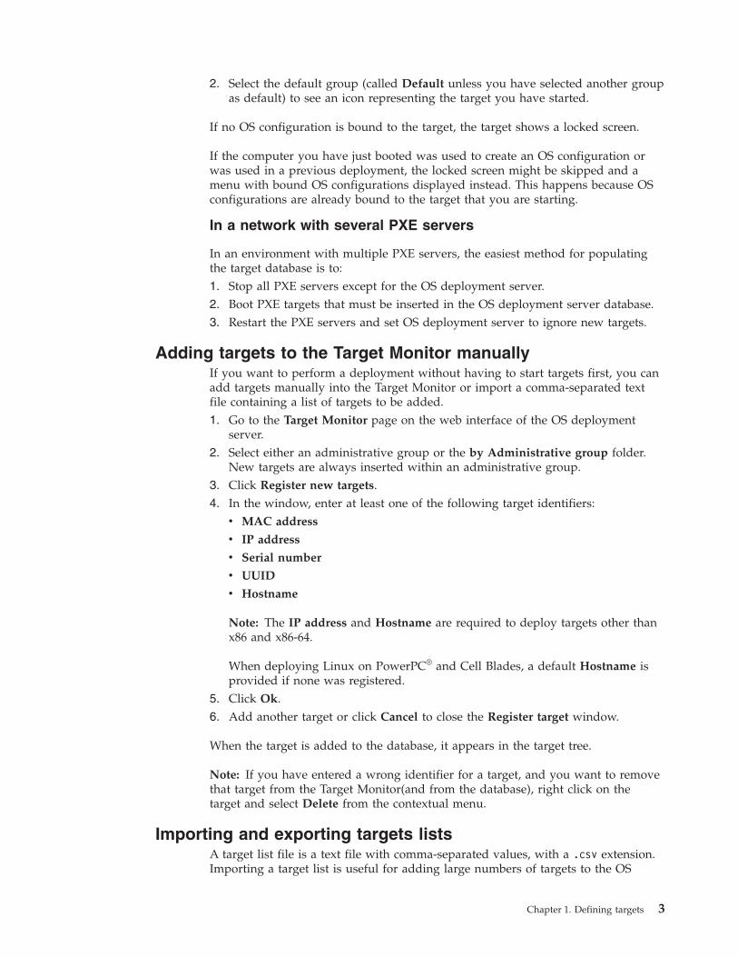
2. Select the default group (called Default unless you have selected another groupas default) to see an icon representing the target you have started.
If no OS configuration is bound to the target, the target shows a locked screen.
If the computer you have just booted was used to create an OS configuration orwas used in a previous deployment, the locked screen might be skipped and amenu with bound OS configurations displayed instead. This happens because OSconfigurations are already bound to the target that you are starting.
In a network with several PXE servers
In an environment with multiple PXE servers, the easiest method for populatingthe target database is to:1. Stop all PXE servers except for the OS deployment server.2. Boot PXE targets that must be inserted in the OS deployment server database.3. Restart the PXE servers and set OS deployment server to ignore new targets.
Adding targets to the Target Monitor manuallyIf you want to perform a deployment without having to start targets first, you canadd targets manually into the Target Monitor or import a comma-separated textfile containing a list of targets to be added.1. Go to the Target Monitor page on the web interface of the OS deployment
server.2. Select either an administrative group or the by Administrative group folder.
New targets are always inserted within an administrative group.3. Click Register new targets.4. In the window, enter at least one of the following target identifiers:
v MAC address
v IP address
v Serial number
v UUID
v Hostname
Note: The IP address and Hostname are required to deploy targets other thanx86 and x86-64.
When deploying Linux on PowerPC® and Cell Blades, a default Hostname isprovided if none was registered.
5. Click Ok.6. Add another target or click Cancel to close the Register target window.
When the target is added to the database, it appears in the target tree.
Note: If you have entered a wrong identifier for a target, and you want to removethat target from the Target Monitor(and from the database), right click on thetarget and select Delete from the contextual menu.
Importing and exporting targets listsA target list file is a text file with comma-separated values, with a .csv extension.Importing a target list is useful for adding large numbers of targets to the OS
Chapter 1. Defining targets 3

deployment server without having to start them individually on the network. Youcan also import a PCI inventory for a single target in an .ini file.
Target listBefore you can import a target list, you must either export one or create anew one.
Information about each target in a target list is a collection of more thanseventy items, including:v MAC addressv IP addressv User parametersv Motherboard informationv Processor information
To view the complete list of items, export a target list, open it and read thebeginning of the .csv file.
For the OS deployment server to successfully import targets in a list, youmust fill in at least one of the following items:v Serial numberv MAC addressv UUIDv IP address
The filled-in item can vary from target to target. Other items can remainempty.
Target lists above 1GB in size (about 1000 targets) cannot be imported intoan OS deployment server, because of browser limitations. Therefore, youcannot use target lists for more than about 1000 targets.
Note: Do not use target lists to back up target information. To back uptarget information, you must back up the database used with anappropriate tool. Lists of targets are not as complete as the database. Inparticular, target lists do not include some crucial target information foundin the database, among whichv Bindingsv Disk inventoryv PCI inventoryv Deployment history
PCI inventoryA PCI inventory is exported on a USB key or floppy disk when this mediais inserted in a target, booted through a network boot media, but whichdoes not have network drivers.
v Importing a target list
1. Go to theTarget Monitor page in the web interface.2. Click Import targets.3. Indicate the location of the .csv file.4. Click Ok.
v Exporting a target list
1. Go to theTarget Monitor page in the web interface.2. Click Export targets.
4 Tivoli Provisioning Manager for OS Deployment: User's Guide
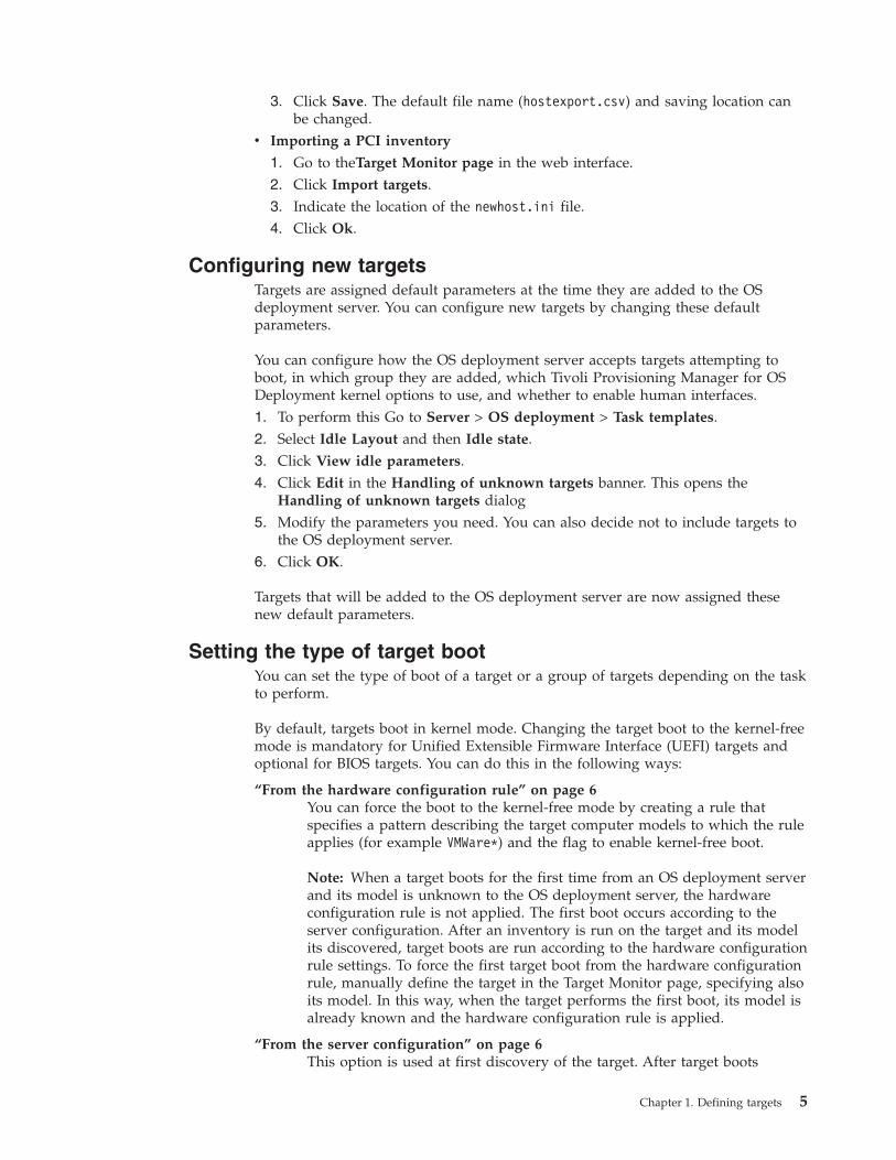
3. Click Save. The default file name (hostexport.csv) and saving location canbe changed.
v Importing a PCI inventory
1. Go to theTarget Monitor page in the web interface.2. Click Import targets.3. Indicate the location of the newhost.ini file.4. Click Ok.
Configuring new targetsTargets are assigned default parameters at the time they are added to the OSdeployment server. You can configure new targets by changing these defaultparameters.
You can configure how the OS deployment server accepts targets attempting toboot, in which group they are added, which Tivoli Provisioning Manager for OSDeployment kernel options to use, and whether to enable human interfaces.1. To perform this Go to Server > OS deployment > Task templates.2. Select Idle Layout and then Idle state.3. Click View idle parameters.4. Click Edit in the Handling of unknown targets banner. This opens the
Handling of unknown targets dialog5. Modify the parameters you need. You can also decide not to include targets to
the OS deployment server.6. Click OK.
Targets that will be added to the OS deployment server are now assigned thesenew default parameters.
Setting the type of target bootYou can set the type of boot of a target or a group of targets depending on the taskto perform.
By default, targets boot in kernel mode. Changing the target boot to the kernel-freemode is mandatory for Unified Extensible Firmware Interface (UEFI) targets andoptional for BIOS targets. You can do this in the following ways:
“From the hardware configuration rule” on page 6You can force the boot to the kernel-free mode by creating a rule thatspecifies a pattern describing the target computer models to which the ruleapplies (for example VMWare*) and the flag to enable kernel-free boot.
Note: When a target boots for the first time from an OS deployment serverand its model is unknown to the OS deployment server, the hardwareconfiguration rule is not applied. The first boot occurs according to theserver configuration. After an inventory is run on the target and its modelits discovered, target boots are run according to the hardware configurationrule settings. To force the first target boot from the hardware configurationrule, manually define the target in the Target Monitor page, specifying alsoits model. In this way, when the target performs the first boot, its model isalready known and the hardware configuration rule is applied.
“From the server configuration” on page 6This option is used at first discovery of the target. After target boots
Chapter 1. Defining targets 5

(unknown), then the flag is set also on the target specific configuration. Ifthe deployment mode kernel free is chosen, then only these options areselectable: Reboot on fatal errors, Do not reboot on errors, and Disablemulticast.
“From the target configuration”This option is set to change the default mode. It is overridden by thehardware rule, if Use kernel-free flow is set.
Note: If a target previously unknown to OS deployment server performs a UEFIPXE boot, the target boot setting Use kernel-free mode is set to Yes to completethe UEFI PXE boot, regardless the corresponding server-wide setting. If the bootsetting is manually changed, it is not reset at subsequent PXE boots.
From the hardware configuration rule
To run a target boot in kernel-free mode, create a new hardware configuration ruleor change the boot options of an existing rule as follows:1. Go to Server > Advanced features > Hardware configurations.2. Select the rule and click Edit rule.3. In the Boot engine options section select the Use kernel-free mode option.4. Follow the wizard instructions.
From the server configuration
To run a target boot in kernel-free mode, update the server configuration stored inthe rembo.conf file as follows:1. Go to Server > OS deployment > Task templates.2. Select Idle Layout and then Idle state folder.
Note: In case of a multiserver hierarchy, if you perform changes in the Idlestate layout of a parent server, when you replicate from one server to another,the Idle state changes are not replicated. Parameters with red dot will notreplicate from one server to another because these are server specificparameters.
3. Click View idle parameters.4. Click Edit in the Handling of unknown targets banner.5. Select the Use kernel-free flow option. The kernel-free mode is set for all the
targets that boot on this server.
From the target configuration
To run a target boot in kernel-free mode, update the target configuration asfollows:1. Select a single target or multiple targets on the Target Monitor page. To do this
go to Server > OS deployment > Target Monitor. . To select multiple targets ordeployment, select an administrative group, a custom list, a subnet, or click onindividual target names while holding down the Ctrl key.
2. Select Edit boot settings.3. Select the Use kernel-free flow option.4. Follow the wizard instructions.
6 Tivoli Provisioning Manager for OS Deployment: User's Guide

Changing the default administrative groupYou can change the administrative group to which new targets are automaticallyassigned. By default, new targets are assigned to the Default group.
To know which is the current default administrative group to which new targetsare assigned, select any administrative group, and read the information provided.To perform this go to Server > OS deployment > Target Monitor. .
To change the default administrative group:1. Optionally, create a new administrative group.
a. Select by Administrative group in the Target Monitorb. Click Add a new admin in the contextual menu to create a new
administrative group.2. Go to Server > OS deployment > Task templates.3. Select Idle Layout and then Idle state.4. Click View idle parameters.5. Click Edit in the Handling of unknown targets banner.6. In the second section of the new dialog, use the drop-down list to select the
new default administrative group.
Requirements for VMware targetsTo successfully deploy system profiles on VMware, it is important that yoursystem conforms to a number of requirements when setting up the VMware target.
Guest operating systemAlways set the guest operating system to Windows 2008 or Windows Vista,even when you deploy a different Windows operating system (such asWindows 2000, Windows 2003, Windows XP, or Windows 7).
Network adapter
v Windows The Intel e1000 network adapter works correctly on allWindows editions
v Windows On Windows 64-bit, the AMD Lance network adapter is notsupported. Using it results in a failed deployment with either ashutdown of the virtual machine or a blue screen.
v Linux The AMD Lance network adapter is supported for all Linuxdistributions, but it is very slow.
v Linux The Intel e1000 network adapter is supported on all Linuxdistributions, except for Red Hat Enterprise Linux (REHL5).With REHL5, the Intel e1000 card is in a dirty state when rebooting theoperating system after performing Linprep. The target can no longerconnect to the network. Therefore, the deployment stops and fails. Towork around this issue, install two network cards on your VMwaretarget:– The Intel e1000 as the primary boot device– An AMD Lance as the second boot device to use as a fallback.
With the two cards, when Linux reboots and the Intel e1000 does notanswer, the AMD Lance takes over, allowing the virtual machine bootand the deployment continue.
Chapter 1. Defining targets 7

v SUSE For cloning and Direct Migration of SuSE Linux EnterpriseServer, you must use the Intel e1000 network adapter.
SCSI controller
Paravirtual SCSI controllers are not supported.The compatibility betweenSCSI controllers and Windows operating systems on VMware targets isdescribed in Table 1.
Table 1. Compatibility between Windows operating systems and SCSI controllers
Compatibility Windows XPWindows
2003/Vista/2008/7 WinPE 3.x
BusLogic Yes No No
LSI Logic No Yes Yes
v If you intend to deploy Windows 2003/Vista/2008/7, use the LSI Logicdriver.
v If you intend to deploy Windows XP, you have two options:– Before installing Windows XP guest operating systems on a VMWare
hypervisor, with BUSLogic adapter, you must inject it offline into aWinPE deployment engine, depending on your VMware version.
– You can make a software module with the LSI Logic Parallel driver,and bind it to your Windows XP system profiles
v On all other operating systems, LSI Logic is supported.
Note: LSI Logic driver for Windows Server 2003 operating system,symmpi.inf, version 1.28.03, has been tested successfully.
Injecting drivers on WinPE 3.x to deploy Windows XP guestsBefore installing Windows XP or Windows XP guest operating systems on aVMWare hypervisor, with BUSLogic adapter on VMWare, you must inject theVMWare SCSIAdapter BusLogic drivers into the standard WinPE 3.x. These driversare not contained on the Vista 7 CD/DVD or installed with VMWare tools.v Create a virtual machine and ensure that its devices are set up correctly.v On Tivoli Provisioning Manager for OS Deployment, create the WinPE 3.x
deployment engine to contain the necessary BusLogic drivers. Assign relevantmatching models to this WinPE deployment engine, for example *VMware*4.1*.
v On VMware 4.1, disable any virus scan, to improve performance in the WinPE3.x update.
If you use VMware 3.5, you can user dynamic driver injection and bind yourdriver software modules to the WinPE deployment engine using the driver bindinggrid. If you use VMware 4.1, you must inject the VMware missing drivers offlinein the WinPE deployment engine.1. Extract the Microsoft drivers needed to run a Windows virtual machine on
VMWare on a virtual USB key or a floppy disk.a. Install a Windows virtual machine on VMware.b. From the VMware Workstation menu, select VM > Install VMware Tools,
The VMware Workstation connects the virtual machine CD drive to the ISOimage file that contains the VMware Tools installer for your guest operatingsystem. After the installation process, a new CD is bound to VMware andyou can see all the needed drivers.
2. Create software modules for the newly extracted drivers.
8 Tivoli Provisioning Manager for OS Deployment: User's Guide

3.
v With VMware 3.5, simply bind your newly created driver software modulesto the WinPE deployment engine.
v With VMware 4.1, you must inject the driver software modules offline intoan existing WinPE deployment engine.a. Go to Server > Advanced features > Deployment engines.b. Double-click the name of a deployment engine to view its details.c. Select Inject driver in the contextual menu.d. In the wizard, specify a computer running the web interface extension.e. Select the driver software modules to inject in the WinPE 3.x deployment
engine.
Note: Injected drivers cannot be removed from WinPE 3.x. These driversare started regardless of whether they are compatible with the hardware.
f. Follow the remaining instructions in the wizard.
Your BusLogic driver is now either bound to, or contained in, your WinPEdeployment engine.
You can now install Windows XP with the WinPE deployment engine on VMware,and then use your guest target like any other virtual machine.
Booting non x86 and non x86-64 targetsThis section provides information on how to boot targets which do not have anx86 or an x86-64 architecture.
Booting pSeries targets on the OS deployment serverpSeries® machines can be booted on the OS deployment server.
Before you can boot a pSeries target on the OS deployment server, you mustv Verify the network connectivity as follows:
1. From the SMS menu, test the network interfaces using the Setup Remote IPL(Initial Program Load) menu.
2. Select the interface to use for the deploy.3. Configure it and run a ping test to verify the connectivity.
Note: Ensure that the selected interface is recognized by the operatingsystem during the installation phase.
v Manually register the pSeries target in the OS deployment server, indicating atleast the MAC address and the hostname.
v Run the devalias command to select the correct boot interface and add it.v Configure the TCP/IP options.v Start a deployment task on the target. Without a task bound to it, the target
cannot boot on the OS deployment server.
How to boot a pSeries target on the OS deployment server depends on theoperating system you want to install.
v AIX SUSE To install AIX® and SuSE 101. Boot the target using the boot net command.
Chapter 1. Defining targets 9

2. Type 1 to select SMS Menu.3. Type 5 for Select Boot options.4. Type 1 for Select Install/Boot Device.5. Type 6 for Network.6. Under Select device, select the network interface that you have registered in
the OS deployment server. If you are not booting from the default networkinterface, use the alias of the interface instead of the PCI identifier.
7. Type 2 for Normal Mode Boot.8. Type 1 (Yes) to confirm the above.
Note: If the standard Linux operating system booting stops and you areusing the serial console access, to solve the problem press any key in theAutoyast boot prompt. Type linux console=hvsi0 and press enter.
v Red Hat To install RedHat1. Before booting ensure you are using the standard network card, otherwise
perform the following steps:– Switch to the OpenFirmware prompt and list the boot aliases using the
devalias command.– If the interface from which you are going to boot is listed in the aliases
you can move forward. If the interface is not included in the devalias listthen create a new alias. Run ls to list all the devices and find out thedevice address of the network card.
– Add a new alias using devalias such as: devalias net2/pci@800000020000203/ethernet@1
2. Boot the target using the boot net command.3. Press 8 when booting to reach the Open Firmware prompt.4. From an Open Firmware prompt, run boot net ks=http://
serverip:serverport/linux/ks.cfg ksdevice=eth0. serverip is the IPaddress of the OS deployment server, and serverport its port. Serverport istypically 8080. To boot from a different network card use the alias previouslydefined: boot net2 ks=http://serverip:serverport/linux/ks.cfgksdevice=eth2 The chosen interface is recognized as eth2 during theoperating system installation.
Booting CellBlades targets on the OS deployment serverCellBlades can be booted on the OS deployment server.
To boot on the OS deployment server the following steps must be followed:1. Boot the target using the boot net command.2. Press 8 when booting to reach the Open Firmware prompt.3. From an Open Firmware prompt, run boot net ks=http://
serverip:serverport/linux/ks.cfg ksdevice=eth0. serverip is the IP addressof the OS deployment server, and serverport its port. Serverport is typically8080.
If the server IP is 192.168.1.25, and the server HTTP port is 8080, type on the OpenFirmware prompt the following line: boot net ks=http://192.168.1.25:8080/linux/ks.cfg ksdevice=eth0
10 Tivoli Provisioning Manager for OS Deployment: User's Guide

Booting SPARC targets on the OS deployment serverBooting SPARC targets on the OS deployment server requires a few prerequisitesand depends on whether you are doing it from OpenBoot or from a runningoperating system.v DHCP option 66 must be set to the IP address of the OS deployment server.v DHCP option 67 must be set to rembo.fcode.v To network boot with Tivoli Provisioning Manager for OS Deployment, the SUN
SPARC target must support WAN boot. The Open Boot version of the SPARCtarget must be equal or greater than 4.17.1. To verify if a SPARC target runningunder Solaris supports WAN boot run the following command:# eeprom | grep network-boot-arguments
If the variable network-boot-arguments is displayed, or if the previous commandreturns the output network-boot-arguments: data not available, the OBPsupports WAN boot installations. You do not must update the OBP before youperform your WAN boot installation. If the previous command does not returnany output, the OBP does not support WAN boot installations. You mustperform one of the following tasks.– Update the target OBP. See your system documentation for information
about how to update the OBP.– After you complete the preparation tasks and are ready to install the target,
perform the WAN boot installation from the Solaris Software CD in a localCD drive.
For instructions about how to boot the client from a local CD drive, see,http://docs.sun.com/app/docs/doc/819-5776/6n7r9js6t?a=view. To continuepreparing for the WAN boot installation, see http://docs.sun.com/app/docs/doc/819-5776/6n7r9js5p?a=view.
v You must register your SPARC target on the OS deployment server by indicatingat least its IP address and its Hostname before it can boot on it.
v Network boot on the OS deployment server for Solaris is accepted only when adeployment task is scheduled on that target .
You can boot a SPARC target on the OS deployment server either when the targetis booting, or when the Solaris operating system is running. You can also use adynamic or a static IP address.v From the OpenBOOT monitor (Stop-A), type boot net:dhcp. To make this
change permanent, type setenv boot-device net:dhcp. Then a simple bootcommand or a cold boot are enough to boot onto the OS deployment server. Ifsetenv boot-device net:dhcp does not work, use a static IP address.
v To boot with a dynamic IP address from the OpenBOOT monitor (Stop-A), typesetenv network-boot-arguments dhcp,file=http://<OSDeploymentServerIP>:8080/sun4uboot net - install
where <OSDeploymentServerIP> is the IP address of your OS deploymentserver.
v To boot with a static IP address from the OpenBOOT monitor (Stop-A), typesetenv network-boot-arguments host-ip=<client-IP>,router-ip=<router-ip>,subnet-mask=<mask-value>,file=http://<OSDeploymentServerIP>:8080/sun4uboot net - install
where:
Chapter 1. Defining targets 11

<client-IP>Is the IP address of the target.
<router-ip>Is the IP address of the router.
<mask-value>Is the subnet mask value.
<OSDeploymentServerIP>Is the IP address of your OS deployment server.
v To force a network boot from the operating system, use/usr/platform/sun4u/sbin/eeprom boot-device=net:dhcp/usr/sbin/reboot
Alternatively, you can force a single network boot by using the following specialstring, that is recognized by the bootstrap code of the OS deployment server
/usr/platform/sun4u/sbin/eeprom boot-device="net:dhcp was: disk"/usr/sbin/reboot
Note: For architectures other than sun4u, change the path above. Use the uname-m command to check the architecture.
v If you are running the web interface extension as a service on a SUN target ,you can use the Target Monitor option to automatically reboot the target fromthe web interface. This generates the one-time change of boot device describedabove.
Booting on UEFI targetsThis section contains information on the partition layout used by UnifiedExtensible Firmware Interface (UEFI) targets.
UEFI targets can be booted on the OS deployment server.
UEFI targets use GUID Partition Table (GPT) partition layout rather than MasterBoot Record (MBR). The GPT partition layout uses the EFI System Partition (ESP)and Microsoft Reserved (MSR) partition types. If no ESP or MSR partition isspecified on the target you are deploying, then ESP and MSR are automaticallyadded on the fly.
Organizing targetsTargets in the Target Monitor are organized into administrative groups, customlists, and subnets.
An administrative group has a hierarchical, tree-like structure, and it can be usedby system administrators to grant or deny access to specific web interfaceoperators to configure particular targets groups. Custom lists are arbitrary listsbuilt by system administrators to run tasks on several targets at the same time. Acustom target list can be built by adding individual targets, or as the result of asearch query. Subnets implicitly and automatically group targets according to theirIP address. Multi-homed targets (targets with more than one network interface) arelisted as part of the subnet on which they last made a network-boot. Subnetscannot be modified by the users.
When a new computer is added to the database, either manually or because thetarget was started in network boot mode, the Target Monitor automatically places
12 Tivoli Provisioning Manager for OS Deployment: User's Guide

this target in the default administrative group. To check which group is the defaultadministrative group, select any administrative group and read the text below thetarget tree. The name of the default administrative group is listed.
You can move targets from one group or custom list to another:
Drag-and-drop the icon from one group or custom list to another. You might wantto use the pin-board in the web interface title bar, for example if the destinationfolder is not visible. You will be able to temporarily leave the dragged target onthe pin-board while you search for and open the folder into which you want todrop the target.Figure 1 illustrates this process.
Configuring targetsTargets can be configured either individually or together, using eitheradministrative groups, custom lists, subnets, or multiple selection.
To configure a single target:1. Select an individual target.2. Click View target details in the contextual menu3. In turn, click Edit in the banner of each group of parameters you want to
modify.
Configuring multiple targets1. Select multiple targets, an administrative group, a custom list, or a subnet.
v If you have selected multiple targets, edit links for each group of parametersappears at the bottom of the Target Monitor.
Figure 1. Pin-board of the Target Monitor
Chapter 1. Defining targets 13

v If you have selected an administrative group, a custom list, or a subnet, clickEdit targets in list in the contextual menu. The Target multi-edition windowappears.
2. In turn, click the edit link for each group of parameters.3. Select the options that you need. Selecting an option allows you to view and
select sub-options.4. Click Save to close Target multi-edition and return to the Target Monitor.
Configuring targets for fully unattended OS deploymentsTo run fully unattended deployments, some parameters are necessary. The numberand nature of these parameters vary according to the operating system which is tobe deployed. Configuring targets is an alternative to providing the data in OSconfigurations.
You must configure your target before you start a deployment. Some values aremandatory for a fully unattended deployment and must be filled in at the targetlevel if the information is not included in the OS configuration.
Note: If multiple targets share the same information, you can set fixed values inthe OS configuration that you are deploying on these targets. Fixed values at theOS configuration level override values entered in the Target details page, and areused by all the targets deploying the OS configuration containing the fixed values.1. Double-click on the target to access the details page for this target. The Target
details page contains all of the properties specific to this target, including thetarget name, the serial number, and the product key to use when installing anoperating system.
Windows For Windows deploymentsThe following fields are required by Sysprep and are asked during thedeployment if they are not filled in on the properties page:v target namev Product key (The key in xxxxx-xxxxx-xxxxx-xxxxx-xxxxx format can
be copied and then pasted into the first entry field at one go bypressing and holding Ctrl and then pressing V), unless you aredeploying Windows Vista/2008/7 with a Volume License.
v User full name and organizationv An administrator passwordv Workgroup or domain name
Solaris For Solaris deployments
v Solaris standard installation procedure includes checking for validcomputer name and IP that matches DNS and DHCP. Otherwise, thedeployment may fail.
v The Solaris NFS server must have name resolution properlyconfigured to know the target name of the target. Failure to do somay lead to an interruption of the installation process.
v Four name resolution methods are available with Solaris. For each ofthem, a specific set of fixed properties must be set. Failing to setthese properties results in a failed deployment.
DNS For DNS, you must enter– At least one DNS server– A DNS domain
14 Tivoli Provisioning Manager for OS Deployment: User's Guide
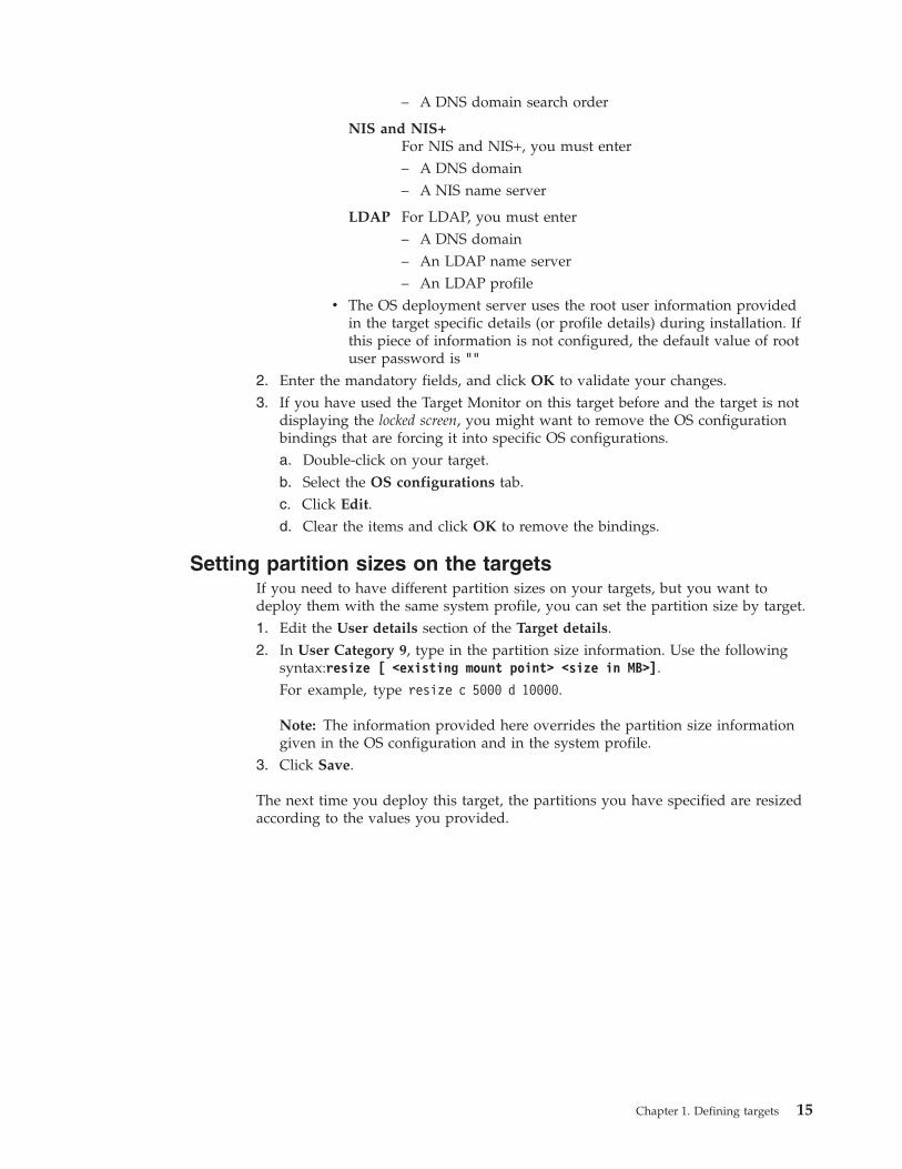
– A DNS domain search order
NIS and NIS+For NIS and NIS+, you must enter– A DNS domain– A NIS name server
LDAP For LDAP, you must enter– A DNS domain– An LDAP name server– An LDAP profile
v The OS deployment server uses the root user information providedin the target specific details (or profile details) during installation. Ifthis piece of information is not configured, the default value of rootuser password is ""
2. Enter the mandatory fields, and click OK to validate your changes.3. If you have used the Target Monitor on this target before and the target is not
displaying the locked screen, you might want to remove the OS configurationbindings that are forcing it into specific OS configurations.a. Double-click on your target.b. Select the OS configurations tab.c. Click Edit.d. Clear the items and click OK to remove the bindings.
Setting partition sizes on the targetsIf you need to have different partition sizes on your targets, but you want todeploy them with the same system profile, you can set the partition size by target.1. Edit the User details section of the Target details.2. In User Category 9, type in the partition size information. Use the following
syntax:resize [ <existing mount point> <size in MB>].For example, type resize c 5000 d 10000.
Note: The information provided here overrides the partition size informationgiven in the OS configuration and in the system profile.
3. Click Save.
The next time you deploy this target, the partitions you have specified are resizedaccording to the values you provided.
Chapter 1. Defining targets 15

16 Tivoli Provisioning Manager for OS Deployment: User's Guide

Chapter 2. Provisioning Windows operating systems on x86and x86-64 targets
This section provides information about how to work with the product to deployWindows operating systems.
Overview of WinPE deployment enginesWinPE deployment engines are a prerequisite for provisioning Windows operatingsystems.
Windows Preinstallation Environment (WinPE) is a group of files that can beloaded as a ramdisk and that allow you to perform operations on a target. WithoutWinPE, you cannot provision Windows operating systems. There are severaladvantages to using a WinPE deployment engine:v It has a small footprint.v The memory usage is at a minimum creating an optimization in the ramdisk
boot.v It contains more built-in drivers.
WinPE deployment engines are stored under Server > Advanced features >Deployment engines.
Current® version
The current version for the WinPE deployment engine is 3.x. Other versions arenot compatible. WinPE 3.x must be created from a Windows AutomatedInstallation Kit (AIK) for Windows 7 in English.
In the current version of the product, the 32-bit WinPE deployment engine is usedfor all the tasks requiring a WinPE deployment engine. In BIOS mode, the 64-bitWinPE is used to deploy Windows Vista 64-bit and Windows 2008 64-bitunattended setup system profiles. For these two operating systems, both versionsof WinPE deployment engine are used. In UEFI mode, the 64-bit WinPE is used forall the tasks requiring a WinPE deployment engine.
WinPE 32-bit and WinPE 64-bit deployment engines
Two WinPE deployment engines are extracted from Windows AIK, one 32-bitversion and one 64-bit version.
In the current version of the product, the 32-bit WinPE deployment engine is usedfor all the tasks requiring a WinPE deployment engine. The 64-bit WinPE is usedonly to deploy Windows Vista 64-bit and Windows 2008 64-bit unattended setupsystem profiles. For these two operating systems, both versions of the WinPEdeployment engine are used together.
Deployment engine creation
If your OS deployment server runs on a Windows operating system and if youhave Windows AIK installed on the server, then the OS deployment server checkswhen it starts up that there is a WinPE deployment engine on the server. If not, it
© Copyright IBM Corp. 2012 17

creates them automatically. The process takes several minutes, during which time itis not possible to log in to the web interface.
If your OS deployment server does not run on a Windows operating system, or ifyou want additional WinPE deployment engines, you can create them manually.
Working with several WinPE deployment engines
In most cases, you do not need to create additional WinPE deployment engines,because one per architecture is sufficient for most uses of the product.
When the WinPE deployment engine is transferred to a target, for example, duringa deployment, it contains all the drivers that are bound to this deployment engine,even if only those bound for the specific target model are used. If you are bindingmany drivers to account for a very large range of hardware, the size of yourWinPE deployment engine might become too large for some targets with a smallRAM. In this case, you might want to create an additional WinPE deploymentengine, match it only to the target with a small RAM, and bind to it only thedrivers needed for this specific target. The size of the new WinPE deploymentengine transferred to the target is therefore much smaller.
When you have several WinPE deployment engines for the same computerarchitecture, you must make sure that you have specified matching model patternsthat allow the OS deployment server to dispatch the WinPE deployment engines tothe correct targets.
The method uses the Microsoft drvload command to inject drivers. If thiscommand does not work, you must inject the drivers in the standard way.
Windows Automated Installation KitWindows Automated Installation Kit (AIK) is needed to perform different taskswhen provisioning Windows operating systems.
Windows AIK is needed to:v Create a WinPE deployment enginev Create an unattended setup system profile of a Windows Vista/2008/7 operating
systemv Create a cloning system profile from a Windows WIM imagev Update a Windows system profile, for example, with a HotFixv Create a Windows PE-based network boot CD/DVDv Migrate user settings
Current version
The current Windows AIK version to use with the product is Windows AIK forWindows 7 in English.
Windows Automated Installation Kit (AIK) for Windows 7 in English is distributedby Microsoft and is available on the Microsoft website from the following link atthe time of publication: http://www.microsoft.com/downloads/details.aspx?familyid=696DD665-9F76-4177-A811-39C26D3B3B34&displaylang=en.
18 Tivoli Provisioning Manager for OS Deployment: User's Guide

Best practices
Given the numerous uses of Windows AIK in the process of provisioning Windowsoperating systems, it is a good practice to perform all these tasks on one systemthat is installed with all the requirements. This target must have:v A Windows XP/2003/Vista/2008/7 operating systemv Windows AIK for Windows 7 in English installedv The web interface extension installed and started with local administrator
privileges
If your OS deployment server is on a Windows operating system, you can useyour OS deployment server as the dedicated Windows system.
Checking the version of Windows AIK
If you are unsure of the version of Windows AIK installed on a system, you canverify it.v On Windows XP and Windows 2003:
1. Open the Control Panel of your operating system.2. Select Add or Remove Programs.3. Select Windows Automated Installation Kit in the list4. Click Click here for support information.5. Check that the version number is 2.0.0.0, which corresponds to Windows
Automated Installation Kit (AIK) for Windows 7 in English.v On Windows Vista and Windows 2008:
1. Open the Control Panel of your operating system.2. If you are in the Control Panel Home view, select Programs, otherwise skip
this step.3. Select Programs and Features.4. Select Windows Automated Installation Kit in the list.5. If you cannot view the version number in the selected line, you can add a
column with this information.a. Select View and then Choose Details....b. Select Version and click OK.
6. Check that the version number is 2.0.0.0, which corresponds to WindowsAutomated Installation Kit (AIK) for Windows 7 in English.
v On Windows 2008 R2 and Windows 7:1. Open the Control Panel of your operating system.2. If you are in the Control Panel Home view, select Programs, otherwise skip
this step.3. Select Programs and Features.4. Select Windows Automated Installation Kit in the list.5. If you cannot view the version number at the bottom of the screen, select
Organize > Layout > Details pane to make it visible.6. Check that the version number is 2.0.0.0, which corresponds to Windows
Automated Installation Kit (AIK) for Windows 7 in English.
Creating a WinPE 3.x deployment engineTo create or deploy Windows profiles, you must have created a WinPE 3.xdeployment engine.
Chapter 2. Provisioning Windows operating systems on x86 and x86-64 targets 19

Ensure that the computer from which you create the WinPE 3.x deployment enginesatisfies these conditions:v Runs a Windows operating systemv Has Windows Automated Installation Kit (AIK) for Windows 7 in English
installed. Windows Automated Installation Kit (AIK) for Windows 7 in Englishis distributed by Microsoft and is available on the Microsoft website from thefollowing link at the time of publication: http://www.microsoft.com/downloads/details.aspx?familyid=696DD665-9F76-4177-A811-39C26D3B3B34&displaylang=en.
v Runs the appropriate web interface extension (rbagent). If the Windowsoperating system is 64-bit, stop the 32-bit web interface extension and start the64-bit web interface extension as follows:C:\TPMfOS Files\global\http\rbagent64.exe -d -v 4 -s <IPServer>:<PasswordServer>
where:
<IPServer>Specifies the IP address of the OS deployment server
<PasswordServer>Specifies the password that matches the super user password of the OSdeployment server to which you link the web interface extension.
The computer from which you create the WinPE 3.x deployment engine can be:v A local OS deployment server installed on a Windows operating system. This is
the recommended option.v Any computer with a Windows operating system.
From version 7.1.1.3 of the product, several WinPE 3.x deployment engines cancoexist on any OS deployment server.1. Depending on what you are doing, you can create the WinPE 3.x deployment
engine from:v The Deployment engine page:
a. Go to Server > Advanced features > Deployment engines.b. Click New deployment engine.c. Follow the instructions in the wizard.
v The Welcome page:a. Select Make one now from the For Windows scripted installation or
from the For Windows clone installation section.b. Click Next.
v The System profiles page, if you do not already have a WinPE 3.xdeployment engine:– If you run an unattended setup:
a. Go to Server > OS deployment > System profiles.b. From the contextual menu, select Add a new profile.c. Select Unattended setup (scripted install).d. Select one of the Windows operating systems as the type of system
profile to create and click Next.e. The wizard displays a warning message informing you that it did not
find a WinPE 3.x deployment engine. Click Next to create one.– If you run the capture of a cloned system profile:
a. Go to Server > OS deployment > System profiles.
20 Tivoli Provisioning Manager for OS Deployment: User's Guide

b. From the contextual menu select Add a new profile.c. Select Cloning from a reference machine.d. Enter the IP address of the target that you want to clone. Ensure that
the reference target is ready to boot into the OS deployment server andthat it is shut down.
e. The wizard displays a warning message informing you that it did notfind a WinPE 3.x deployment engine. Click Next to create one.
2. Specify the address of the computer on which you installed Windows AIK forWindows 7 in English and the web interface extension and click Next.
The resulting WinPE 3.x deployment engines, one 32-bit WinPE 3.x deploymentengine and one 64-bit WinPE 3.x deployment engine, are now shown under Server> Advanced features > Deployment engines.
You can now indicate matching target models for your WinPE 3.x deploymentengine and bind drivers to it.
After you created the WinPE 3.x deployment engines, you can create and deployWindows system profiles.
Note: During the deployment, do not edit the WinPE 3.x deployment engine thatyou are using.
Editing the information of a WinPE deployment engineYou can edit the description and the comment attached to a WinPE deploymentengine.
To edit the description and comment of a deployment engine:1. Go to Server > Advanced features > Deployment engines.2. To view the details of the deployment engine, you have two options.
v Double-click a deployment engine.v Select a deployment engine, and then select View engine details in the
contextual menu.3. Click Edit above the section Deployment engine information.4. Update the description and the comment to identify more easily how this
WinPE deployment engine is to be used.5. Click OK to save your changes and return to the Engine details page.
If you intend to use this deployment engine to deploy IBM servers, you mightwant to call your WinPE deployment engine WinPE3 for IBM servers 32-bit. Thecomment can include the server models that this WinPE deployment engine isplanned to be compatible with.
If you updated the description of your WinPE deployment engine, you probablyhave more than one deployment engine per architecture. In this case, providematching target models for your deployment engines.
Upgrading WinPE deployment engines and hardwareenvironments
When upgrading to Fix Pack 9, you must upgrade the WinPE deployment enginesand the WinPE 2.x or 3.x hardware environments.
Chapter 2. Provisioning Windows operating systems on x86 and x86-64 targets 21

If the old WinPE (deployment engines and hardware environments) engines aredetected, a warning message and an icon is displayed in the Web interface neareach object.
If the Windows Automated Installation Kit (AIK) is installed on the sameworkstation where the OS deployment server is installed, when the OSdeployment server starts up all WinPE deployment engines (not hardwareenvironments, only deployment engines) are automatically upgraded.
A wizard (and a command line with rbagent) is available to update the WinPEengines (deployment engines and hardware environments).
The following command line with rbagent is available to update the WinPEengines:rad-makewpe update=EngineItemIDrad-mkhwutils update=SoftItemID
For the EngineItemID look at the EngineItem table. For the SoftItemID, look at theSoftwareItem table.
Adding matching target models to a WinPE deploymentengine
If you have several WinPE deployment engines for the same architecture, it isimportant that you specify with which targets a given WinPE deployment enginemust be used.
If you have only one WinPE deployment engine per computer architecture, there isno reason to modify the model patterns. Only use the default * pattern, to matchany target known to the OS deployment server.
To add model patterns associated with a deployment engine:1. Go to Server > Advanced features > Deployment engines.2. To view the details of the deployment engine, you have two options.
v Double-click a deployment engine.v Select a deployment engine, and then select View engine details in the
contextual menu.3. In the Matching models section, click Add a new model pattern.4. Enter the pattern and click OK to save your new pattern. The * character is
used as a wildcard replacing any number of characters. The ? character is usedas a wildcard replacing exactly one character.
When deploying a target, if there are several WinPE deployment engines available,a search is performed in the list of model patterns for all WinPE deploymentengines available. The WinPE deployment engine selected has the most restrictivepattern matching the target model being deployed.
If there is no matching pattern, deployment cannot proceed.
Note: In a multiple server architecture, a WinPE deployment engine that is notfully replicated from a parent server is not yet available on the child server.
Consider that you have two WinPE deployment engines, WinPEa and WinPEb.WinPEa has the following patterns: IBM Server *, and lenovo *, while WinPEb haslenovo m/55 *, lenovo T*, and *.
22 Tivoli Provisioning Manager for OS Deployment: User's Guide

A target with model lenovo T61 is deployed with WinPEb because its modelmatches the lenovo T* pattern, because it is more restrictive than lenovo *.
A target with model lenovo ThinkCenter A58 is deployed with WinPEa because itsmodel matches the lenovo * pattern, because it is more restrictive than the generic* pattern.
A target with model HP Server is deployed with WinPEb because its model matchesonly the * pattern.
You can check which WinPE deployment engine is used with a given target bylooking at the Windows specific info section in Server > OS deployment > TargetMonitor > Target details. If you are dissatisfied with the selected WinPEdeployment engine, you must adapt the target models for your WinPE deploymentengines.
Binding drivers to a WinPE deployment engineWhen WinPE does not contain the drivers that you need for a specific target, youmust bind these drivers to the WinPE deployment engine to deploy the target.
Your WinPE deployment engine contains built-in drivers. Use them first.
If you encounter problems with the built-in drivers, if some drivers are not bound,or if some drivers are missing, bind other drivers to your WinPE deploymentengine in one of the following ways:v Static driver injectionv Dynamic driver injection
In the static driver injection process, you can only bind drivers, to your WinPEdeployment engine, that are driver software modules in your OS deploymentserver. You must therefore create driver software modules from the drivers thatyou want to bind to your WinPE deployment engine.
The product helps you select appropriate drivers for particular target models. Ithelps you to predict potential problems and to solve them. It does not guaranteethat a specific WinPE deployment engine, with bound drivers, works with a giventarget.
The information used by the OS deployment server to predict the compatibility ofa driver with a target model is taken from the content provided by the vendor inits driver. The OS deployment server cannot verify the accuracy of thisinformation.
The dynamic driver injection process occurs at run time and depends on the modeland PCI devices. The following is a high-level view of the dynamic driver injectionprocess:1. WinPE3 is started.2. The web interface extension is started in WinPE3.3. The web interface extension determines the list of drivers.4. The web interface extension detects the hardware on which it is running.5. The web interface extension injects only the drivers specifically bound.1. Check the compatibility of your WinPE deployment engine.
a. Go to Server > Advanced features > Deployment engine.
Chapter 2. Provisioning Windows operating systems on x86 and x86-64 targets 23

b. To view the details of the deployment engine, you have two options.v Double-click a deployment engine.v Select a deployment engine, and then select View engine details in the
contextual menu.c. Go to the section Network and mass storage drivers. A check is performed
while the page is loading. This can take a few minutes. By default, checksare performed only on network and disk drivers.If drivers are missing, or are not bound, or if several drivers are bound forthe same device, the following information is provided.
Indicates a missing critical driver, or a critical driver of the wrongarchitecture.
Indicates that a missing non-critical driver, or a non-critical driver ofthe wrong architecture.
Indicates that a required driver is present on the OS deployment server,but that it is not bound.
Indicates that there are several drivers bound for the same device, orthat there is a binding with a driver that is not known as compatible.You can expand the line to get more information.v For drivers missing on the OS deployment server, you find a suggestion
of where to look for it, including, if available, a download link and theexact directory within the downloaded archive where the driver can befound.
v When drivers are present on the OS deployment server, you findsuggestions of which driver to bind, in order of preference. If multipledrivers are known to possibly work for a device, the best choice is listedfirst. The choice is explained in the advice text, which first recommendsthe use of device-specific drivers, that is, drivers that have been specificallydesigned for the given hardware device. Then compatible device drivers,that match the device family, are recommended, even if they are not anexact rebranded variant (for example, as second choice, an Adaptec driverof the same family as an IBM® ServerRaid adapter, if it is based on thesame chipset). Finally, as third choice, generic drivers, for example,Microsoft generic AHCI driver for any AHCI controller, arerecommended.
If no error is found, you do not need to modify the bindings.2. Modify the driver bindings of the WinPE deployment engine. There are two
ways to perform this.v Use a wizard.
a. Click Fix Drivers.b. Follow the instructions in the wizard. After having selected a target
model, you must select one of these options:
Automatically fix issues that can be fixed for this model.Fixes all issues that can be automatically fixed. Such issuesinclude, for example, a missing binding to an existing driver,multiple bindings for a device, or removing a driver tagged foranother operating system.
Manually fix issues for this model.Presents you with each issue in turn. Ways to solve the issue,when available, are proposed.
24 Tivoli Provisioning Manager for OS Deployment: User's Guide

Automatically bind drivers for this model.Erases every existing binding. New bindings are thenautomatically added.
Copy driver bindings for this model from a similar engine.Copies all the bindings from a selected source engine to thecurrent engine.
Reset all drivers bindings for this model.Erases all the driver bindings, and does not create any newbinding.
v Edit the bindings manually, using the driver binding grid.a. Click Edit engine's driver bindings on the Engine details page.
A grid is loaded.Columns represent target models known to the OS deployment serverand matching the patterns provided for the WinPE deployment engine.They can be expanded to view their network and mass storage devices, ifa PCI inventory has been performed.The first line represents the WinPE deployment engine. Other linesrepresent software module folders in the OS deployment server. They canbe expanded to view individual drivers. If a driver can be used only for32-bit or 64-bit machines, a superscript x86 or x86-64 mark is written nextto the driver name. If you do not find the drivers that you need in the listprovided, create software modules for your drivers.
b. (Optional) To obtain a summary of the errors and warnings, click the linkprovided above the grid. This helps you locate the problematic areas inthe driver grid.
c. Expand the columns of problematic target models to view the individualnetwork and mass storage devices.
d. Expand software module folders containing drivers to view theindividual drivers.
Chapter 2. Provisioning Windows operating systems on x86 and x86-64 targets 25

A cell with a green background indicates that driver informationcorresponds to the device. The quality of the drivers that can be selected
is illustrated by the intensity of the green background: thebest drivers are in intense green, the family drivers are in standard green,and the generic drivers are in pale green.A cell with an orange background indicates either that the driver is not aPCI driver, or that there is no compatibility information available for thedriver.A cell with a green check mark indicates that the driver is bound tothe WinPE deployment engine for use with the specific target model anddevice.
e. Click a green or orange background cell to add or remove bindings.It is not possible to bind or unbind drivers from the WinPE deploymentengine itself, because they are built-in drivers.You should have one, and only one, check mark per column, indicatingthat you have one and only one driver for each device.
f. When you have finished modifying the bindings, click Save.g. To return to the Image details page, click Back.
Potential problems with the image are recomputed, allowing you to checkif your modifications have solved the detected problems.
When you have solved all the driver binding issues, you can deploy target modelsthat match your WinPE deployment engine.
Figure 2. Driver binding grid
26 Tivoli Provisioning Manager for OS Deployment: User's Guide

System profiles for Windows operating systemsA system profile is the partition layout and list of files to deploy an operatingsystem, either by unattended setup or by cloning, from a reference target or from areference image file.
The main purpose of Tivoli Provisioning Manager for OS Deployment is to deployan operating system on targets by replicating a reference system. However,unattended installation of operating systems is also possible. The latter case TivoliProvisioning Manager for OS Deployment does not replicate a reference system,but merely provides the correct parameters to the operating system setup for afully unattended installation.
There are a number of differences between an unattended installation and diskcloning. First, creating an unattended installation in Tivoli Provisioning Managerfor OS Deployment is straightforward. All of the necessary tasks are performed onthe server, using the Web interface. In contrast, a cloning-mode system profilerequires you to configure a target, prepare it for cloning, and run the cloningprocess directly on the target. However, the native mode of operation of theproduct is centered around cloning-mode system profiles, because this method ofdeployment is faster than unattended installation. When deploying computers on alarge scale, unattended installation is not possible. Novice users might start withcreating unattended installation profiles because this is easier than cloning-modeprofiles.
Note:
v To avoid failures in creating or deploying a system profile, clean up thetemporary directory inside the OS deployment server installation directory on aregular basis.
v To create or deploy a system profile from a physical or virtual machine at least512 GB RAM is required.
v In BIOS mode, system profiles can have a maximum of 3 primary partitions.Therefore, you cannot clone a target with 4 primary partitions.
v The exFAT filesystem is not supported.v Before deploying a system profile to a target ensure that the root partition is C.v To successfully implement the user category options, ensure that the system
profile disk layout label does not contain a semicolon ":".v It is possible to deploy a system profile captured from a BIOS machine to a UEFI
machine. During this operation, ESP and MSR are added on the fly and patchedaccordingly.This flow is not supported for Windows Vista and Windows 2008 operatingsystems. It is supported starting from Windows 2008 R2 / Windows 7 x64.
BitLocker compatibilityTivoli Provisioning Manager for OS Deployment is compatible with MicrosoftBitLocker Drive Encryption (BitLocker), which is available with some Windowsoperating systems. BitLocker is a security tool which protects data by encrypting it,rendering the content of a hard disk unreadable if stolen.
Windows 7
Chapter 2. Provisioning Windows operating systems on x86 and x86-64 targets 27

BitLocker on Windows 7 Ultimate and Enterprise operatingsystems
To operate on Windows 7 operating systems, BitLocker requires a minimum of 300MB of unallocated space (not part of a partition) on the target disk.
Vista
BitLocker on Windows Vista operating systems
To operate on Windows Vista operating systems, BitLocker requires at least twopartitions:v a boot partition containing the BitLocker tool and which must have a size of at
least 1.5 GBv an operating system partition which can be encrypted
Tivoli Provisioning Manager for OS Deployment can make a deployed target readyfor BitLocker by creating the appropriate partition scheme during the deployment.
When you create a system profile for Windows Vista/2008/7, the Profile Wizardasks you whether you want to make your profile ready for BitLocker. In case of apositive answer, the wizard asks you the relevant questions to set up the partitionscheme.
Note: When you run Microsoft System Preparation Tool (Sysprep) on a BitLockerready target, which is necessary for cloning, Sysprep deletes some vital informationabout the boot and the operating system partitions. It results in a reference targetwhich cannot boot anymore. During the cloned profile creation process, TivoliProvisioning Manager for OS Deployment can partially repair the reference targetto make it boot again. However, some manual operations with Microsoft toolsremain necessary to make it BitLocker ready again.
To create a cloning profile from a BitLocker ready reference target and have thisreference target operational and BitLocker ready again:1. Make sure that the disk is not encrypted.2. Run Sysprep on the reference target3. In the Profile Wizard, select the option to repair the reference target to enable
the target to boot again.4. Manually modify the boot and operating system partitions with Microsoft tools
to make the partition scheme BitLocker ready again.
Alternatively, if you do not want to perform manual operations to make yourreference target BitLocker ready again, you can1. Make sure that the disk is not encrypted.2. Run Sysprep on the reference target3. Create the cloned system profile4. Deploy the reference target with the newly created cloned profile which is
BitLocker ready
Enabling the BitLocker feature and creating the partition afterthe deployment for Windows 7 and Windows 2008 R2
This topic describes how to create the Bitlocker partition using Microsoft Bitlockeron Windows 7 and Windows 2008 R2 platforms.
28 Tivoli Provisioning Manager for OS Deployment: User's Guide
Scenario
For Windows 7 and Windows 2008 R2 platforms, the solution is to run theBitlocker command to create the partition using the bdehdcfg command. It isrecommended to run the bdehdcfg command after the deployment is completed.This can be done, for example, by using the runonce key in the Windows registry.To enable the BitLocker feature and have the partition created after thedeployment, perform the following procedure.
Procedure1. Create a software module that runs the command:
cmd.exe /C start c:\Windows\system32\Dism /online /enable-feature/featurename:BitLocker /NoRestart /quiet
This enables the BitLocker feature needed to run the bdehdcfg command.2. Create a .bat script (named for example bitlockerpart.bat) including the
following command:cmd.exe /C start c:\windows\system32\bdehdcfg-target c: shrink -size 300 -quiet
and create a software module that copies the .bat file onto a directory on thetarget disk, for example on the C: drive.
3. Create a software module which adds the .bat execution into the RunOnceregistries key, that is a software module running the following command:cmd.exe /C start c:\windows\system32\reg add HKEY_LOCAL_Machine\Software\Microsoft\Windows\CurrentVersion\RunOnce /v bitlocker/t REG_SZ /d "c:\bitlockerpart.bat"
The c:\bitlockerpart.bat file is run automatically at the first user logon.
All these software modules can be run during the stage when the operating systemis installed. In this way the BitLocker feature is enabled and the partition is createdat the first user logon after the deployment finishes successfully.
Creating system profilesThere are distinct types of system profiles. The profile wizard guides you throughthe creation of system profiles for each type.
Creating an unattended setup system profile for Windowsoperating systemsYou can install operating systems using standard installation processes inunattended mode. Unattended setup simplifies the task of preparing computers forthe native mode of operation of disk cloning.v To create a Windows system profile you must have a WinPE 3.x deployment
engine on your OS deployment server. If you do not have one yet, you cancreate one with the profile wizard, provided you have installed Windows AIKfor Windows 7 in English on the computer on which you create the WinPE 3.xdeployment engine.
Vista 2008 Windows 7
v To create an unattended Windows Vista/2008/7 setup system profile, you mustuse a computer running the web interface extension, where you have installedWindows AIK for Windows 7 in English, under Windows XP, Windows 2003,Windows Vista, Windows 2008, or Windows 7. You cannot run this operation on
Chapter 2. Provisioning Windows operating systems on x86 and x86-64 targets 29

a Windows 2000 or Linux operating system. The web interface extension mustbe started with local administrator privileges.
Note: For Windows Vista, Windows 2008, and Windows 7 unattended systemprofiles:
v During the various autoadminlogon, the user accessing the machine is the onespecified as administrator account at operating system configuration level. If theadministrator account is the same as the built-in administrator at operatingsystem configuration level, the built-in administrator account is enabled.If the administrator account is not specified or if the string Administrator isspecified, the autoadminlogon is executed with the built-in administrator accountwhich is enabled at the end of the deployment.For example, if your system is in Spanish and you specify the administratoraccount in one of the three different ways:– administrator account = none– administrator account = Administrador (in Spanish)– administrator account = Administrator (in English)then you can execute the autoadminlogon with the built-in administrator accountand the built-in administrator is enabled.
v Creating an unattended Windows Vista/2008/7 installation profile with multipleCDs is not supported. You are required to use a single DVD.
v You can prepare your profile to be ready for Microsoft BitLocker DriveEncryption (BitLocker).
Windows 7 Modify the partition scheme to ensure that there is at least 300 MB ofunallocated space on the disk.
Vista You must have at least two partitions:– A partition of at least 1.5 GB is necessary to hold BitLocker and to serve as a
boot partition– A second partition holds the operating system
Depending on the number of partitions already created, the Profile Wizard offersto reserve one of the existing partitions for BitLocker, or to create a new one.
2003 The Windows 2003 R2 operating system is distributed on two CDs. Tocreate a fully deployable unattended system profile of Windows 2003 R2, youmust:1. Create a system profile using the first CD only, following the steps in the
wizard;2. Create a software module with the content of the second CD (see “Creating a
software module for unattended deployment of Windows 2003 R2 operatingsystem” on page 65);
3. Bind this software module (with an automatic binding rule) to the systemprofile you just created.
To create a new system profile:1. Go to Server > OS deployment > System profiles.2. Click New Profile. A system profile wizard opens to guide you through the
steps of creating a profile.3. Select Unattended setup in the first pane of the profile wizard.4. Select your operating system from the list and click Next.
30 Tivoli Provisioning Manager for OS Deployment: User's Guide

5. Follow the instruction of the profile wizard. Vista 2008 Windows 7 If youhave a volume license, select Volume licensing, no product key required onthe product key screen of the wizard.
Note: Tivoli Provisioning Manager for OS Deployment supports the KeyManagement Service (KMS) key only. If you have a Multiple Activation Key,select Volume licensing, no product key required on the product key screen ofthe wizard. To activate your Windows license, bind the Windows ServerLicense Manager Script (slmgr.vbs) as a software module to the system profileyou just created.
When your first unattended installation profile is created, you can use it to deploytargets. Then you can create a cloning-mode system profile, because unattendedinstallation profiles have a longer deployment time than cloning-mode systemprofiles. You can use your unattended installation profile to prepare the computerthat you refer to when creating your first cloning-mode system profile.
Creating a cloning mode system profile for Windows operatingsystemTo obtain a cloning-mode system profile from a reference target you must firstprepare the reference target.
To clone a Windows operating system, your reference target must have at least 1GB RAM.
Note: For Windows Vista, Windows 2008, and Windows 7 clone system profiles:v During the various autoadminlogon, the user accessing the machine is the one
specified as administrator account at operating system configuration level. If theadministrator account is the same as the built-in administrator at operatingsystem configuration level, the built-in administrator account is enabled.If the administrator account is not specified, the autoadminlogon is executed withthe built-in administrator account which is enabled at the end of thedeployment.
To create a Windows system profile you must have a WinPE 3.x deploymentengine on your OS deployment server. If you do not have one yet, you can createone with the profile wizard, provided you have installed Windows AIK forWindows 7 in English on the computer on which you create the WinPE 3.xdeployment engine.
For the actual driver injection, you must use a computer running the web interfaceextension, where you have installed Windows AIK for Windows 7 in English,under Windows XP, Windows 2003, Windows Vista, Windows 2008, or Windows 7.You cannot run this operation on a Windows 2000 or Linux operating system. Theweb interface extension must be started with local administrator privileges.
Preparing the reference target:
To create a cloning-mode system profile, you must first create the reference OSconfiguration (called the system profile ) that you want to deploy.
You must perform this task on the reference target, not on the OS deploymentserver.
Chapter 2. Provisioning Windows operating systems on x86 and x86-64 targets 31

The OS deployment server does not perform cleanup on the reference target. Youare responsible for deleting useless files and services before creating a new imageas follows:v Delete the temporary Internet cachev Delete your temporary directories and filesv Disconnect your network drives and remote printersv Empty the recycle binv Delete partitions using a file system that is not supported by the product, or
reformat them
Additional preparation instructions:
This section describes how to extract and decrypt all files on the disk to includethem in the disk image.
When installing Windows 2000 or Windows XP on an NTFS partition, some filesare compressed by default. In particular, the dllcache hidden folder and theexplorer.exe file are usually compressed. This might prevent them to be backedup or imaged correctly. To extract and decrypt all files on your disk, perform thesesteps:1. Open a command window.2. Type the following commands:
cd \COMPACT /u /a /s /iCIPHER /d /a /i /f /h /s:\exit
The COMPACT command will automatically and recursively extract all files on thedisk, while the CIPHER command will automatically and recursively decrypt allthese files.
Running Sysprep:
Before you can create a cloning-mode system profile for Windows operatingsystem, you must run Microsoft System Preparation Tool (Sysprep). Where to findSysprep and how to use it varies slightly depending on the Windows version.
Running Sysprep on Windows Vista/2008/7 operating systems:
Before cloning your Windows Vista/2008/7 image, run Sysprep to prepare yoursystem for cloning. Tivoli Provisioning Manager for OS Deployment works withSysprep to automate the post-cloning reconfiguration.
Sysprep cannot be used on targets that are part of a domain. The system profileimage must be made on a target hat does not belong to a domain. Even if youroperating system was part of the domain before you launched Sysprep, Sysprepremoves it from the domain. Later, you can automatically join a domain during thedeployment process.
Before running Sysprep, you must configure your target to use DHCP. Go toServer > OS deployment > Target Monitor. Double-click on a target to view itsdetails. Then click on Common networking info. If your target uses a static IPaddress, you have a high risk IP conflicts when the target boots for the first timeand it has not yet applied all Sysprep settings.
32 Tivoli Provisioning Manager for OS Deployment: User's Guide

With Windows Vista/2008/7, you can run Microsoft System Preparation Tool(Sysprep) on the operating system only three times. After that, the Sysprep toolrefuses to start, therefore always start from your original reference image. To workaround this issue, you can also use a virtual machine.
Sysprep is available on every installed Windows Vista/2008/7 operating system.The Sysprep executable file is archived in c:\windows\system32\sysprep\sysprep.exe.
To start the Sysprep process, follow these instructions:1. Log on as a user with administrator privileges.2. Close any open applications and type the run command in the Windows
Vista/2008/7 Start Search command prompt.3. When the run command prompt opens, browse to the Sysprep executable file
and click OK. A System Preparation Tool page opens.4. From the System Cleanup action menu, select Enter System Out-of-Box
Experience (OOBE).5. Select the Generalize check box.6. From the Shutdown Options menu, select Shutdown.7. Click OK. After a few seconds, your system shuts down automatically.
Alternatively, you can specify these options when launching Sysprep from thecommand line prompt by running the command: c:\windows\system32\sysprep\sysprep.exe /oobe /generalize /shutdown.
Note:
v Sysprep can also be used in audit mode. In audit mode, when the user firstboots the deployed machine, the boot process does an Out-Of-BoxExperience (OOBE) stage which finalizes the OS configuration takingconnected peripherals into account. This OOBE stage takes about 10 minutes.If Sysprep is used in OOBE mode, this stage is performed duringdeployment without significantly increasing the deployment time.
v It is possible to have a partition dedicated to Microsoft BitLocker DriveEncryption (BitLocker).– If the reference computer you are cloning is BitLocker ready, running
Sysprep prevents it to boot anymore.The product can correct this errorand allow the computer to boot again by assigning the operating systempartition as boot partition. However, if you want to use BitLocker on thereference target afterward, you must manually change the boot partitionback to the BitLocker partition.The product properly configures boot androot partitions on deployed computers. Thus, computers deployed with animage cloned from a BitLocker ready computer are perfectly bootable andBitLocker ready.
– If the reference computer is not BitLocker ready, running Sysprep does notraise any difficulty. To make the cloned target BitLocker ready, modify thepartition layout of the system profile. For Windows 7 operating systems,you need at least 300 MB of unallocated disk space. For Windows Vistaoperating systems to assign or create a BitLocker partition of at least 1.5GB.
Running Sysprep on Windows XP and Windows 2003 operating systems:
Chapter 2. Provisioning Windows operating systems on x86 and x86-64 targets 33

Before cloning your Windows image, run Sysprep to prepare your system to becloned. Tivoli Provisioning Manager for OS Deployment works with Sysprep toautomate the post-cloning reconfiguration.
Sysprep cannot be used on targets that are part of a domain. The system profileimage must be made on a target hat does not belong to a domain. Even if youroperating system was part of the domain before you launched Sysprep, Sysprepremoves it from the domain. Later, you can automatically join a domain during thedeployment process.
Before running Sysprep, you must configure your target to use DHCP. Go toServer > OS deployment > Target Monitor. Double-click on a target to view itsdetails. Then click on Common networking info. If your target uses a static IPaddress, you have a high risk IP conflicts when the target boots for the first timeand it has not yet applied all Sysprep settings.
Depending on how Windows was installed, you might never have logged on as anadministrator. If this is the case, log out and log in again as an administrator toensure that the administrator profile is properly created. Otherwise, you might notbe able to create system snapshots affecting the administrator settings.
Sysprep for Windows XP is included on the Windows XP Professional CD, andarchived in the file \Support\Tools\Deploy.cab.
To run Sysprep:1. Copy all the Sysprep executable files into a folder named c:\sysprep.2. Close all your applications.3. Run the command c:\sysprep\sysprep.exe -mini -forceshutdown -reseal
from the Start > Run menu.Alternatively, you can start Sysprep with a graphical user interface bydouble-clicking on its icona. Make sure that Mini Setup is checkedb. Click Reseal.
Your system shuts down automatically after a few seconds.
Running Sysprep on Windows 2000 operating system:
Before cloning your Windows 2000 image, run Microsoft system preparation tool(Sysprep) to prepare your system to be cloned. Tivoli Provisioning Manager for OSDeployment works with Sysprep to automate the post-cloning reconfiguration.
Sysprep cannot be used on targets that are part of a domain. The system profileimage must be made on a target hat does not belong to a domain. Even if youroperating system was part of the domain before you launched Sysprep, Sysprepremoves it from the domain. Later, you can automatically join a domain during thedeployment process.
Before running Sysprep, you must configure your target to use DHCP. Go toServer > OS deployment > Target Monitor. Double-click on a target to view itsdetails. Then click on Common networking info. If your target uses a static IPaddress, you have a high risk IP conflicts when the target boots for the first timeand it has not yet applied all Sysprep settings.
34 Tivoli Provisioning Manager for OS Deployment: User's Guide

Sysprep for Windows 2000 is included in Windows 2000 Resource Kit, and is alsoavailable on the Microsoft Web site.1. Copy all the Sysprep executable files into a folder named c:\sysprep.2. Close all your applications.3. Run the command sysprep.exe from the Start > Run menu. Your system shuts
down automatically after a few seconds (if it does not, wait a minute or so andthen turn it off).
Cloning the reference computer:
When you have prepared your reference computer, you are ready to create yoursystem profile. You can create it from the web interface with the profile wizard.v The reference target must be ready to PXE-boot into the OS deployment server.v It is recommended that the reference target is shut down before starting the
cloning process. If it is not, the web interface extension must not be running.1. Go to Server > OS deployment > System Profiles.2. Click New profile
3. Select Cloning from a reference machine and click Next
4. Follow the instructions of the profile wizard. If you have a volume license,select Volume licensing, no product key required on the product key screen ofthe wizard.
Note: Tivoli Provisioning Manager for OS Deployment supports the KeyManagement Service (KMS) key only. If you have a Multiple Activation Key,select Volume licensing, no product key required on the product key screen ofthe wizard. To activate your Windows license, bind the Windows ServerLicense Manager Script (slmgr.vbs) as a software module to the system profileyou just created.
The Volume licensing, no product key required option does not work for allversions of Windows operating systems. If you are asked for a deployment keyduring deployment, go to Server > System profiles > Profile details > OSconfiguration details, click on the Windows tab and set Volume Licensing to No.You must then populate Product key. Your cloning system profile should nowdeploy without userinteraction.
Creating a system snapshot:
You can clone a computer with a Windows operating system without running theSysprep tool. Such a profile is called a system snapshot. You can create it from theweb interface.1. Go to Server > OS deployment > System Profiles.2. Click New profile.3. Enter the IP address of the target you want to clone and click Next.4. The Profile Wizard detects the operating system. Click Next.5. The Profile Wizard detects that the Windows operating system has not been
prepared with Sysprep. Review the warnings carefully and, if you still intendto create a system snapshot, select I understand these limitations but I want toproceed as is and click Next.
6. Follow the instructions of the wizard.
System snapshot:
Chapter 2. Provisioning Windows operating systems on x86 and x86-64 targets 35

You can create Windows cloning profiles without using Sysprep to prepare yourreference target. Such a profile is called a system snapshot.
The purpose of creating a system snapshot is to keep a copy of a golden parentreference target before it is altered by Sysprep, thus enabling you to restore yourgolden parent exactly as it was before the Sysprep tool was used.
Note:
1. The product had not been designed as a backup product.v Do not create and restore Windows system snapshots as a backup method.v Do not create more than a few Windows system snapshots on any OS
deployment server.2. You cannot deploy a Windows system snapshot, you can only restore it exactly
as it was created.v It is not possible to customize system snapshots.v Profile restoration does not allow the installation of software modules,
including driver packages.
Creating a system profile from a reference imageYou can create a system profile using a WIM image.v You can create system profiles from WIM image for Windows Vista/2008/7,
Windows XP and Windows 2003 operating systems.v The WIM image present on Microsoft DVD is not a complete operating system
image; therefore, it cannot be imported into Tivoli Provisioning Manager for OSDeployment to be deployed. To create a system profile from Microsoftlist DVD,use the option Unattended setup (scripted install).
v The WIM image must contain only one partition. If you have two partitions inyour WIM image, for example, a boot partition and a separate root partition,deployment of the cloning WIM system profile fails.
v To create a Windows system profile you must have a WinPE 3.x deploymentengine on your OS deployment server. If you do not have one yet, you cancreate one with the profile wizard, provided you have installed Windows AIKfor Windows 7 in English on the computer on which you create the WinPE 3.xdeployment engine.
v To create a cloning profile with a Windows WIM image, you must use acomputer running the web interface extension, where you have installedWindows AIK for Windows 7 in English, under Windows XP, Windows 2003,Windows Vista, Windows 2008, or Windows 7. You cannot run this operation ona Windows 2000 or Linux operating system. The web interface extension mustbe started with local administrator privileges.
v Creating a cloning profile from a Windows WIM image stored on multiple CDsis not supported. You are required to use a single DVD.
v You can prepare your profile to be ready for Microsoft BitLocker DriveEncryption (BitLocker).
Windows 7 Modify the partition scheme to ensure that there is at least 300 MB ofunallocated space on the disk.
Vista You must have at least two partitions:– A partition of at least 1.5 GB is necessary to hold BitLocker and to serve as a
boot partition– A second partition holds the operating system
36 Tivoli Provisioning Manager for OS Deployment: User's Guide
||||

Depending on the number of partitions already created, the Profile Wizard offersto reserve one of the existing partitions for BitLocker, or to create a new one.
To create a system profile from a reference image, you must follow these steps:1. Go to Server > OS deployment > System Profiles.2. Click New Profile. This opens a system profile wizard that guides you through
the steps of creating a profile.3. Select Cloning from a reference image file and click Next.4. Select the corresponding image format and click Next.5. Follow the instruction of the profile wizard. If you have a volume license, select
Volume licensing, no product key required on the product key screen of thewizard.
Note: Tivoli Provisioning Manager for OS Deployment supports the KeyManagement Service (KMS) key only. If you have a Multiple Activation Key,select Volume licensing, no product key required on the product key screen ofthe wizard. To activate your Windows license, bind the Windows ServerLicense Manager Script (slmgr.vbs) as a software module to the system profileyou just created.
Creating a universal system profile for Windows operatingsystemsWhen creating a software module, do not enter a hardware model because auniversal system profile must be deployable on several types of hardware. If youentered a model name in the Profile Wizard, you can delete it when you edit thefirst set of parameters of the Profile details.
To successfully deploy your universal system profile with another type of harddisk from your reference target (for example from a parallel hard disk to a SCSI oran AHCI disk), you must inject the drivers during deployment.
There are two different scenariosv In an unattended setup system profile, the driver MUST be injected as a created
by Tivoli Provisioning Manager for OS Deployment.v In a cloning system profile, the driver might be injected as a software module
created by Tivoli Provisioning Manager for OS Deployment. If this method fails,you can use the Microsoft "Sysprep" tool.
Here are the solutions for these two different scenarios.
Deploying an unattended setup:
When a driver needs to be installed during the early stages of Windowsunattended setup, you must use TEXTMODE drivers. Perform these steps:1. Ensure that the driver files are on your server. The file txtsetup.oem must be in
the driver folder. This file is provided by the hardware vendor.2. Create a software module, type driver. Typically, Tivoli Provisioning Manager
for OS Deployment recognizes that this is a TEXTMODE driver and completesthe fields automatically. The installation stage must be “When the OS isinstalled”.
3. Bind your software module to your target profile, or bind it automatically tothe hardware.
4. You can now deploy your unattended profile with the software module.
Chapter 2. Provisioning Windows operating systems on x86 and x86-64 targets 37

The above solution might not work when deploying a cloned system profilebecause Windows setup does not use the same mechanisms as Windows Sysprepfor handling mass storage drivers.
Deploying a cloning system profile:
Tip: The easiest and safest solution to deploy a system profile is to start from acomputer which has similar hardware to the target system, in particular regardingmass storage drivers. This will save you time and make the process deploymenteasier to understand and follow.
If the driver injection using the mechanism of a software module created by TivoliProvisioning Manager for OS Deployment fails, you can use the Microsoft Syspreptool.
You must inject the driver into the parent system profile, by performing some extrasteps on the source computer before running the Sysprep tool to reseal the systemprofile. Prepare the drivers that you want to inject into your clone system profile ina separate folder. Perform these steps:1. Place all the driver files on the source computer into a C:\drivers\
MyDiskController folder.2. Create a "Sysprep.inf" file that you place in the c:\Sysprep folder with the
correct settings.3. Run Sysprep.4. Capture the cloned system profile.
When deploying the system profile, the driver injected on the target system isautomatically enabled when the system starts up.
The source computer uses an EIDE controller (any type).
The target system uses an IBM ServRAID 8i controller: 0x9005(VendorID)0x0285(DeviceID)
Copy all driver files for this controller into arcsas.sys and arcsas.inf, includingall the files referenced from this file.
In your Sysprep.inf file, copy the following section:
[Sysprepmassstorage]PCI\VEN_9005&DEV_0285&SUBSYS_02f21014="%SystemDrive%\drivers\ServeRAID8i\arcsas.inf", "\", "IBM ServeRAID 8i Controller","\arcsas.sys"
Tip:
v All the PCI numbers can be found in the web interface, in the hardwareinventory tab of the target.
v To determine the appropriate driver, check the PCI_VENxxxx&DEV_xxxx stringin the driver inf file and match it with the data reported on target hardwareinventory, as reported by TPM for OS deployment. The SUBSYS_yyyyzzzz mustalso match the SubVendorID (yyyy) and SubDeviceID (zzzz).
v The PCI\... key that you add to your Sysprep.inf file must be an exact copy ofthe one used in the driver .inf file.
38 Tivoli Provisioning Manager for OS Deployment: User's Guide

Organizing and editing system profiles
After you have created a system profile, you can view it on the OS deploymentserver through the web interface. The profiles are listed on > Server > OSdeployment > Profiles page, in the System profiles pane. Each blue jacketrepresents a system profile (that is, the hard-disk partition images).
If you want to organize your system profiles, you can create subfolders byfollowing these steps:1. Select the parent folder with a left mouse click.2. Call the contextual menu with a right mouse click.3. Select the Add a new profile folder menu item.4. Enter the new folder name.5. Click OK.
You can then move profiles (by dragging-and-dropping the profile icons) from thetop folder, where they are automatically created, to the appropriate subfolder.
Editing system profiles
To display and edit the parameters associated with a given profile:1. Double-click a system profile to open the Profile details page.2. Click Edit on top of the parameter sections to edit the parameters.
Updating a system profile with a Language Pack or a HotFixVista 2008 Windows 7
Windows Vista/2008/7 system profiles can be updated to include a language packor a HotFix.
To update a system profile to include either a Language Pack, or a HotFix, or both,you need an available target on which the profile will be updated.
Note:
v To update an unattended setup profile or a WIM cloning profile, you must use acomputer running the web interface extension, where you have installedWindows AIK for Windows 7 in English, under Windows XP, Windows 2003,Windows Vista, Windows 2008, or Windows 7. You cannot run this operation ona Windows 2000 or Linux operating system. The web interface extension mustbe started with local administrator privileges.
v If you want to update a cloning system profile, the disk content of the targetyou will use for the update will be deleted. Make sure you use a bare-metaltarget or a target with no valuable content on its disks.
1. Go to Server > OS deployment > System profiles. Double-click on a profile toview the details.
2. Click Update to open the update wizard.3. Optionally, select Update similar profiles to update additional system profiles
at the same time. Only system profiles compatible with the current one areavailable for selection. Unattended setup system profiles and WIM cloningsystem profiles cannot be updated together with cloning system profiles.
4. Follow the wizard instructions. Depending on the type of system profile, thewizard analyses the state of the target to ensure that all prerequisites are met. If
Chapter 2. Provisioning Windows operating systems on x86 and x86-64 targets 39
all prerequisites are met, a new system profile is created, the old system profiletaken as basis is kept. The name of the new profile is the name of the basissystem profile with (updated) appended to it.
Browsing partition filesYou can browse partition images stored on your server.1. Go to Server > OS deployment > System profiles. Double-click on a profile to
view the details.2. In the Original partition layout section, click Browse image of primary
partition 1.3. You can expand or update the whole partition or a part of it.
v To expand the whole or part of the partition:a. Right-click the folder you want and select Expand on local disk.b. Choose the computer where you want to expand and store the files
contained in the selected partition.c. Specify the destination folder where to extract the partition files.d. Follow the instructions of the image wizard to expand the partition.
Note: You must expand the partition to an empty directory. If you selecta folder that is not empty the extraction fails.
v To update the whole or part of the partition:a. Right-click the folder you want and select Update from local disk.b. Specify the source folder of the OS deployment server where your
updated data are located.c. Specify the destination folder where to extract the partition files.d. Follow the instructions of the image wizard to update the partition.
On the Partition image explorer page, you can create a new directory by selectingAdd new directory in the contextual menu. You can also modify or add files byselecting Upload file in the contextual menu.
Note: File upload is limited to 16 MB.
Changing the partition layoutPartition layout can be updated to resize partitions, assign mount points, changethe file system.
Changing the partition layout in system profiles might render the profile unusable.It is recommended not to change the partition layout in system profiles, unless youknow that the changes you want to make have no side effect.
In any case, do not transform a primary partition into a logical partition.
Note: Changing the partition layout from both the Profile details page and the OSconfiguration details page can lead to incorrect OS configurations and prevent OSdeployment. Depending on your particular needs, choose either one or the otherentry point, and then perform all your changes from that entry point.
Editing the partition layout allows you to:v Add or delete partitions.
40 Tivoli Provisioning Manager for OS Deployment: User's Guide

Note: Adding or deleting partitions can lead to OS configuration problems,therefore this feature must only be used very carefully. To provide a betterdescription to your profile, use the Comment field to write all necessary details.
v Resize a partition by dragging sliders, or by assigning it an absolute or relativesize.
v Change the file system of a partition.v Assign a mount point to the partition.
Note: When in the disk partitioning both fixed sizes and percentage sizes areincluded, the exact reproduction is not guaranteed.1. Click Edit partition layout on either the Profile details page or the OS
configuration details page, Disks tab.2.
v To add a partition:a. Click Modify partition layout.b. Click into an existing partition.c. Click Add a partition in the contextual menu.d. Indicate the partition properties, including a mount point and click OK.
Linux In a Linux profile, do not forget to assign a mount point for thenew partition. To be valid, this mount point must reference an existingdirectory in the main image. Only starting from Fix Pack 3, the Linuxprofiles with the root partition as LVM are supported. In this case, youmust ensure that the HTTP mode is selected in the deployment schemewhen deploying the profile. With the root partition as LVM, you cannotperform the deployment using the media.
v To resize partitions with the sliders, grab the slider to the right of thepartition and drag it.
v To update all other parameters, select a partition by clicking on it, and selectEdit partition in the contextual menu.
3.
v To add a partition:a. Click Modify partition layout.b. Click into an existing partition.c. Click Add a partition in the contextual menu.d. Indicate the partition properties, including a mount point and click OK.
Windows In a Windows profile, the operating system deployed using asystem profile must be installed on C: drive. Other drive letters are notallowed for the bootable partition.
v To resize partitions with the sliders, grab the slider to the right of thepartition and drag it.
v To update all other parameters, select a partition by clicking on it, and selectEdit partition in the contextual menu.
4.
v To add a partition:a. Click Modify partition layout.b. Click into an existing partition.c. Click Add a partition in the contextual menu.d. Indicate the partition properties, including a mount point and click OK.
Chapter 2. Provisioning Windows operating systems on x86 and x86-64 targets 41

v To resize partitions with the sliders, grab the slider to the right of thepartition and drag it.
v To update all other parameters, select a partition by clicking on it, and selectEdit partition in the contextual menu.
Modified partitions are aligned on megabytes rather than on cylinders. Thefollowing warning message might appear in the logs and can be safely discarded.Warning: partition x does not end at a cylinder boundary. Aligning onmegabytes is recommended by virtualization companies because it is safer whenyou deploy on both physical targets and virtual machines. The only drawback isan incompatibility with DOS.
If you want to use the same system profile with two different partition schemes,you can also duplicate a system profile by right-clicking the profile name andselecting Duplicate profile. The copy shares the same image files, but can have adifferent partition layout.
Updating device mappingDevice mapping can be updated to force logical disks to point to specific physicaldevices.
Note: Updating device mapping from both the Profile details page and the OSconfiguration details page can lead to incorrect OS configurations and prevent OSdeployment. Depending on your particular needs, choose one or the other entrypoint, and then perform all your changes from that entry point.1. Go to Server > OS deployment > System profiles > Profile details or to
Server > OS deployment > System profiles > Profile details > OSconfiguration details, Disks tab.
2. Click Modify device mapping.3. Select to which physical device you want to map your logical disk. The column
starting with Disk 0 corresponds to an automatic detection of the first to theeighth disk, the column starting with /dev/hda corresponds to standard devicenames.
Note: Spanning a logical disk on several physical disks is not currentlyavailable.
Note: On HP servers with smart array disk controllers, disk devices are usuallynamed /dev/cciss/cxdx, where x is the disk number. Edit your devicemappings accordingly.
4. Click OK.5. Repeat step 2 to step 4 for each logical disk for which you want to update
device mapping.
If the new device mapping you selected is incorrect, you receive a warningmessage.
OS configurations and fixed common parametersA system profile is the partition layout and list of files to deploy, while OSconfigurations are operating system parameters.
At the very bottom of the Profile details page, there is a list of the OSconfigurations that correspond to your profile.
42 Tivoli Provisioning Manager for OS Deployment: User's Guide

You can define several OS configurations for each system profile and duplicatethem. These copies share the same image files, and the same partition layout, butcan have different target parameters. You must then assign new values to some ofthe OS configurations parameters to make the original OS configuration and itscopies distinct.
If you want to automate the assignment of parameters to targets, you can viewand edit the OS configuration you are about to deploy by clicking on its name inthe Profile details page. You are now in the OS configuration details page. Theinformation is divided into panels, each displaying sets of parameters. You canmodify the parameters either through the web interface or by using a parameterfile.
Editing OS configuration parameters in the web interface forWindows operating systemsThe web interface displays a number of OS configuration parameters divided intopanes. These parameters can be edited in the web interface.
To edit parameters:1. Click a tab to select the corresponding pane.2. Click Edit on the banner of the section where you want to update parameters.3. Modify the values.4. Click OK.
Editing a Windows parameter file
You can modify OS configuration parameters by editing a file. This option allowsyou to modify parameters that are not displayed in the web interface. However,you must be experienced to use this option advantageously, because TivoliProvisioning Manager for OS Deployment does not provide any syntax checking ofthe file. Information about the file format and syntax can be found in thedocumentation of the operating system itself.1. To edit the file click Edit custom 'unattend.xml' on Windows Vista, Windows
2008, Windows 7 and click Edit custom 'sysprep.inf' on Windows XP, Windows2003.
2. Type the parameters and their values in the syntax requested by the operatingsystem, or copy and paste it from another editor.
3. Click OK.
Tivoli Provisioning Manager for OS Deployment merges the information of theedited file with the information provided on the web interface (default file). Unlessotherwise specified, parameters specified in the default file override the content ofthe custom file.
Vista 2008 Windows 7 Content of this custom file overrides the default onecreated for the following parameters, which are written as tags:v NetworkLocation
v ProtectYourPC
v PersistAllDeviceInstalls
v UILanguage
v SystemLocale
v UserLocale
v InputLocale
Chapter 2. Provisioning Windows operating systems on x86 and x86-64 targets 43

Content of the custom file is integrated within the default file for the followingparameters: Value 1 is used in the default file and must not be used for these tagsand attributes combinations in the custom file.v RunSynchronousCommand, which takes a daughter tag <order>value</order>
v LocalAccount
v Interface
v PathAndCredentials, with the attribute keyValue="value"
v DomainName, with the attribute keyValue="value"
v IPAddress, with the attribute keyValue="value"
Only one tag <component> with attribute processorArchitecture is allowed. For allother tags, the values of the default file created override what the user has writtenin the custom file.
Troubleshooting:
If the OS configurations in the deployed operating system are not what youexpected, you must examine carefully the parameter files. They are the result ofthe merge between the custom file and the default file created. See the log fileWindows/Panther/unattendGC/setupact.log for problems in the file merge.
Note: Ensure you specify the full paths for the commands you use in theunattend.xml file.
Vista 2008 Windows 7 To troubleshoot OS configuration parameters after asuccessful deployment, view the two files Windows/panther/setup.xml andWindows/panther/unattend.xml which are the result of the merge between thedefault and custom parameter files. To troubleshoot OS configuration parametersafter a failed deployment, you must look for the following files in the partitioncontaining the operating system:v user_unattend.xml, which is the file you editedv setup.xml, which results from the mergev unattend.xml, which results from the merge as well
XP 2003 To troubleshoot OS configuration parameters after a faileddeployment, you must look for $WIN_NT$.~BT\winnt.sif in the partition containingthe operating system. This file contains the information merged from the customand the default files.
Binding drivers to a Windows system profileWhen a system profile does not contain the drivers needed for deployment, youmust bind these drivers to the system profile to be able to deploy it and obtain aworking operating system.
If you encounter problem with the built-in drivers contained in your systemprofile, if some drivers are not bound, or if some drivers are missing, you shouldbind other drivers to your system profile.
You can only bind drivers to your system profile that are software modules in yourOS deployment server. You must therefore create driver software modules from thedrivers that you want to bind to your system profile.
Note: There are two methods to bind driver software modules to a system profile:
44 Tivoli Provisioning Manager for OS Deployment: User's Guide

v the standard binding rule method where you can indicate profiles to bind to asoftware module.
v the driver specific binding rule method where you bind drivers per system profileand target model/device pair.
You can switch from one method to the other. In the driver specific binding rulemethod, driver bindings from the standard binding rule method are ignored, andvice-versa.
The method described here is the driver specific binding rule method.
From version 7.1.1.3 of the product onwards, it is recommended to use the driverspecific binding rule method, which is the method by default on all new Windowssystem profiles.
The product helps you select appropriate drivers for particular target models. Ithelps you to predict potential problems and to solve them. It does not guarantythat a specific system profile, with bound drivers, works with a given target.
The information used by the OS deployment server to predict the compatibility ofa driver with a target model is taken from the content provided by the vendor inits driver. The OS deployment server cannot verify the accuracy of thisinformation.1. Check the compatibility of your system profile.
a. Go to Server > OS deployment > System profiles.b. To view the details of the system profile, you have two options.
v Double-click on it.v Select a system profile, and then select View profile in the contextual
menu.c. (Optional) In the section Driver handling, click Switch to driver specific
bindings mode. You only need to perform this step if you are in the regularsoftware binding rule mode.
d. A check is performed while the page is loading. This may take a fewminutes. By default, checks are performed on all available drivers.If drivers are missing, or are not bound, or if several drivers are bound forthe same device, the following information is provided.
Indicates a missing critical driver, or a critical driver of the wrongarchitecture.
Indicates that a missing non-critical driver, or a non-critical driver ofthe wrong architecture.
Indicates that a required driver is present on the OS deployment server,but that it is not bound.
Indicates that there are several drivers bound for the same device, orthat there is a binding with a driver that is not known as compatible.You can expand the line to get more information.v For drivers missing on the OS deployment server, you find a suggestion
of where to look for it, including, if available, a download link and theexact directory within the downloaded archive where the driver can befound.
v When drivers are present on the OS deployment server, you findsuggestions of which driver to bind, in order of preference. If multipledrivers are known to possibly work for a device, the best choice is listed
Chapter 2. Provisioning Windows operating systems on x86 and x86-64 targets 45

first. The choice is explained in the advice text, which first recommendsthe use of device-specific drivers, that is, drivers that have been specificallydesigned for the given hardware device. Then compatible device drivers,that match the device family, are recommended, even if they are not anexact rebranded variant (for example, as second choice, an Adaptec driverof the same family as an IBM ServerRaid adapter, if it is based on thesame chipset). Finally, as third choice, generic drivers, for example,Microsoft generic AHCI driver for any AHCI controller, arerecommended.
If no error is found, you do not need to modify the bindings.2. Modify the driver bindings of the system profile. There are two ways to
perform this.v Use a wizard.
a. Click Fix Drivers.b. Follow the instructions of the wizard. After having selected a target
model, you have to select one of these options:
Automatically fix issues which can be fixed for this model.Fixes all issues which can be automatically fixed. Such issuesinclude a missing binding to an existing driver, or multiplebindings for a device, for example.
Manually fix issues for this model.Presents you with each issue in turn. Ways to solve the issue,when available, are proposed.
Automatically bind drivers for this model.Erases every existing binding. New bindings are thenautomatically added.
Copy driver bindings for this model from a similar profile.Copies all the bindings from a selected source system profile tothe current one.
Reset all drivers bindings for this model.Erases all the driver bindings, and does not create any newbinding.
v Edit the bindings manually.a. Click Edit profile's driver bindings on the Profile details page.
A grid is loaded.Columns represent target models known to the OS deployment server.They can be expanded to view their devices, provided an inventory hasbeen performed.The first line represents the system profile. Other lines represent softwaremodule folders in the OS deployment server. They can be expanded toview individual drivers. If a driver can be used only for 32-bit or 64-bitmachines, a superscript x86 or x86-64 mark is written next to the drivername. If you do not find the drivers that you need in the list provided,you should first create software modules for your drivers.
b. (Optional) To obtain a summary of the errors and warnings, click the linkprovided above the grid. This helps you locate the problematic areas inthe driver grid.
c. Expand the columns of problematic target models to view individualdevices.
46 Tivoli Provisioning Manager for OS Deployment: User's Guide

d. Expand software module folders containing drivers to view theindividual drivers.
A cell with a green background indicates that driver informationcorresponds to the device. The quality of the drivers that can be selected
is illustrated by the intensity of the green background: thebest drivers are in intense green, the family drivers are in standard green,and the generic drivers are in pale green.A cell with an orange background indicates either that the driver is not aPCI driver, or that there is no compatibility information available for thedriver.A cell with a green check mark indicates that the driver is bound tothe system profile for use with the specific target model and device.
e. Click on a green background cell to add or remove bindings.It is not possible to bind or unbind drivers from the system profile itself,because they are built-in drivers.You should have one, and only one, check mark per column, indicatingthat you have one and only one driver for each device.
f. When you are done modifying the bindings, click Save.g. To return to the Profile details page, click Back.
Potential problems with the image are recomputed, allowing you to checkif your modifications have solved the detected problems.
When you have solved all the driver binding issues, you can deploy targets withyour system profile.
Restoring a system profile manuallyIf you want to check that your cloning system profile contains all necessaryinformation, you can restore it manually either from the web interface, or from theclient computer.
Note:
1. You can only restore Windows cloning system profiles.
Figure 3. Driver binding grid
Chapter 2. Provisioning Windows operating systems on x86 and x86-64 targets 47

2. System profile restoration works only on targets of the same model as the oneon which the profile was created. Restoring a profile on another model oftargets might result in unexpected behaviors.
3. When you restore a system profile manually, the image is restored as-is,without any automatic parametrization. Thus, restoration cannot be unattendedas some parameter values are required and must be entered manually.
4. Creating a cloned profile and restoring it manually is not meant as a backupprocedure and it should not be used in that way.
5. A cloned profile can be restored on one target only at a time. Restorationcannot be performed on several targets together.
To perform the manual restoration:1. Select the wanted target in the Target Monitor.2. Select Deploy now in the contextual menu.3. Follow the wizard instructions.
Restoring a profile from the web interface1. Go to the Target Monitor page.2. Select a single target3. In the contextual menu, select Additional features
4. Select Restore a profile
5. Click Next and follow the instructions of the wizard.
Restoring a profile from the target1. Click the icon to restore an image.2. Click the Restore a system profile icon.
Depending on the types of images on your OS deployment server, you can alsoget icons forv Restoring a software snapshotv Restoring a virtual floppy-disk
3. Select a system profile or a software snapshot from the list provided and clickNext.
4. Optionally select options and click Next to restore the profile.
v Windows If the system profile is a Windows image, it can include theSysprep mini-setup wizard that is typically used to perform somepost-configuration on the image.
2000 2003 XP You can disable this mini-setup wizard forWindows 2000/2003/XP if you want to start the operating system and dosome modifications before reinstalling Sysprep manually. In this case, awarning message appears, telling you that some minimal post-configurationare applied anyway, to avoid the risks of potential conflicts. This option isnot available on Windows 2008/Vista.
v Some computers can have been delivered with protected partitions foremergency restore backups. At this stage, the option is given to restoreprotected partitions or not.
v Additionally, if a CMOS image was included in the system profile at the timeit was created, you can decide whether you want to restore it. Rememberthat restoring a CMOS image on a target different (or with a different BIOSversion) than the original can severely damage the target.
48 Tivoli Provisioning Manager for OS Deployment: User's Guide

Generic System Profiles (GSP) for Windows operating systemsThis section explains how to handle Generic System Profiles (GSP) for Windowsoperating systems.
Once created the GSP, if the binding flag is set to true, you can see the list of GSPthat are available for deployment when you boot on the target.
Generating Generic System ProfileThis topic describes how to use the rbagent command line to handle GenericSystem Profile.
To generate the Generic System Profile (GSP), in addition to the WIM file it isnecessary to have a configuration file called <wim_name>.settings. The.wim/.settings pair must be copied under the product server files \files\global\[GSP-folder] where GSP-folder must be manually created and named GSP.
To generate, update or delete the Generic System Profile on the product server, usethe following rbagent command line: rbagent.exe –s<OSD_server_ip_address>:<OSD_server_passwd> rad-mkgenericsysprofwhere:–s <OSD_server_ip_address>:<OSD_server_passwd>provides information on the OSD server to be contacted, if not already present inthe rbagent.conf.The algorithm of the command line works as follows:1. Scan the folder \files\global\[GSP-folder], for .wim/.settings pairs. Only
files having identical prefix names are taken into account.2. Verify that all required parameters are available, if not generate an error and
skip.3. If a valid wim/settings pair is detected, create a new System
profile/configuration in database and generate the complete rad-xxxxconfiguration file required by the product.
4. Optionally, if the section [Bindings] is defined and Rule= “true”, a groupingRule is created in the product database.
5. If a GSP profile is defined but there is no corresponding wim/settings pair,then profile/configuration/bindings are removed from the server database andconfiguration files (no deletion of the WIM or settings in GSP folder).
If a parameter in GSP settings is modified, the command line detects it andupdates the db/configuration/bindings on the product server.
Configuration fileThis section describes the configuration file to be used when you generate theGeneric System Profile.
The configuration file must have the extension .settings and is divided into threemain sections: [GSP],[Configuration] and [Bindings]. Parameters in every sectionmay be mandatory (required during syspep phase on deployment) or optional.
Structure
[GSP] This section is mandatory and contains the following parameter:v Name
Chapter 2. Provisioning Windows operating systems on x86 and x86-64 targets 49

[Configuration] This section is mandatory and contains the following parameters:v Ostype
v FullName
v OrgName
v AdminPasswd
v AdministratorName
v TimeZone
v Locale
v OSversion
v OSarchitecture
v Productkey
[Bindings] This section is optional and contains the following parameter:v Rule
Parameters
The syntax of the parameters included in the configuration file is as follows:v Name = [System profile name] - mandatory.v Ostype = [Windows [XP|Vista|2008|2008R2|7 GSP] - mandatory.
It is important to add the GSP suffix at the end of the OS type to identify aGeneric System Profile.
v FullName = [Windows User Full name] - mandatory.v OrgName = [Windows Organization name] - mandatory.v AdminPasswd = [Administrator Password] - optional.v AdministratorName = [Administrator Name] - optional.v TimeZone = [Timezone ID code hex] - mandatory.
The time zone is the standard numerical code that you find for example athttp://msdn.microsoft.com/en-us/library/ms912391(v=winembedded.11).aspx.It must always be on three digits (adding zeros in front if necessary). Forexample, if you take the time zone code for Hawai, the code must be 002 andfor W. Europe Standard Time the code must be 110.
v Locale = [Locale ID code hex] - mandatory.The locale ID must be the standard numerical HEX code that you find forexample at http://msdn.microsoft.com/en-us/goglobal/bb964664. The codemust always be on 4 digits (adding zeros in front if necessary). For example, ifyou take the locale for French-France, the code is 040c.
v OSversion = [OS name, Service Pack number, Build number] - mandatory.This parameter is split in three values separated by commas. The informationrelated to the three values can be found in OS -> System information.
v OSArchitecture = [x86, x86-64...] - mandatory.This parameter is used to distinguish between 32 and 64 bit. Used values are x86for 32 bit and x86-64 for 64 bit.
v Productkey = [Windows product key] - mandatory.v Rule = [true/false/empty] - optional.
This parameter can support three values:Empty or not exists: nothing to do.true: create a grouping rule associated to the configuration.
50 Tivoli Provisioning Manager for OS Deployment: User's Guide

false: deletes all the grouping rules associated to the configuration.
Example
Here is a typical example of GSP configuration file:[GSP]Name="GSP WIM Win7x64: Windows 7 Pro (x64)"
[Configuration]ostype="Windows 7 GSP"FullName="roro"OrgName="IBM"AdminPasswd="Password"AdministratorName=""TimeZone="110"Locale="100c"OSVersion="Windows 7 Professional, , 6.1.7600"OSArchitecture="x86-64"Productkey="FJ82H-XT6CR-J8D7P-XQJJ2-GPDD4"
[Bindings]Rule = "true"
The administrator password can be hidden using the web interface extensioncommand rad-hidepassword without option md5. Open a command prompt in thesame directory that contains the rbagent.exe executable file. On Windowsoperating systems, the path is generally C:\Program Files\Common Files\IBMTivoli\rbagent.exe.
Run the rbagent command to encrypt your chosen password: rbagent.exe –s<OSD_server_ip_address>:<OSD_server_passwd> rad-hidepassword <Password toencrypt>
Your new encrypted password is generated and can be found in the Result string.For example, an encrypted password can look like the following one:
AA42154C94B0FD323231579210233951
Command line outputThis section describes the output of the rbagent command line.
Every time a GSP command line is launched, it generates an output file calledgsp.log in the GSP folder and provides information on whether the commandgenerated a new Profile/Configuration, an update, a deletion or just an error.
For every wim/settings pair (named within curly brackets) the type of action islabeled and described:
<INSERT>: A new Generic System Profile and configuration is created on theproduct server.
<UPDATE>: A new Generic System Profile is updated (at least one parameter ofthe .settings file has changed).
<REMOVE>: The wim/settings pair no longer exists, the orphan GSP is removedtogether with the related configuration and binding.
Chapter 2. Provisioning Windows operating systems on x86 and x86-64 targets 51

<NO ACTION>: The wim/settings pair is detected but there are no differenceswith the existing GSP.
<ERROR>: The wim/settings pair is detected but a problem occurs in the .settingsfile structure (for example, a mandatory parameter is missing).
Here is a typical example of a gsp.log:*** Generic System Profile --> rad-mkgenericsysprof command output ***
[2011/10/31 17:04:11] {Win7x64} <INSERT>: new profile in db and createconfig/bindings
[2011/10/31 17:04:17] {Win2003x86} <UPDATE>: update gsp profile in db and/orassociated configuration
[2011/10/31 17:04:22] {WinVistax86} <ERROR>: parameter ostype is missing orblank in the Configuration section
[2011/10/31 17:04:24] {WinXPx64} <INSERt>: new profile in db and createconfig/bindings
[2011/10/31 17:04:26] {WinXPx86} <REMOVE>: remove profile in db andassociated config/bindings
Software modules for Windows operating systemsSoftware modules are images other than system profiles that can be created toaddress various needs.
Tivoli Provisioning Manager for OS Deployment is based on imaging technology.As administrator, you create images of components that you want to see on everytarget, and the automated deployment merges and restores these images on eachtarget, automatically, when needed.
Tivoli Provisioning Manager for OS Deployment can handle most scenarios forsoftware deployment and post-installation configuration.
Types of software modules
There are many types of software modules. Depending on the type of package andinstallation files, the wizard guides you through the different steps to achieve yoursoftware module with minimal effort. The types of software package supported bythe wizard are listed in this section.
v Vista 2008 Windows 7 Language pack
v Vista 2008 Windows 7 HotFix (MSU)
v A Windows application installation, using Microsoft Installer (MSI)
v A Windows driver to include in a deployment
v XP 2003 A Windows HAL to include in a clone deployment
v A custom action on the targets. This includes OS configuration changes such asregistry patches, commands to be run, and copying sets of files on the target.
WinPE and its usesWinPE is widely used in all the tasks pertaining to the deployment of Windowsoperating systems. The product uses two different kinds of WinPE 3.x, dependingon the tasks at hand.
52 Tivoli Provisioning Manager for OS Deployment: User's Guide

Types of WinPE
Windows Preinstallation Environment (WinPE) is a group of files which can beloaded as a ramdisk and which allows you to perform operations on a target.
WinPE 3.x deployment engineThis WinPE 3.x is a prerequisite to create Windows system profiles and todeploy them.
To create a WinPE 3.x deployment engine, you need a computer running aWindows operating system, with Windows AIK for Windows 7 in Englishinstalled and running the web interface extension.
WinPE 3.x deployment engine creation always creates a 32-bit and a 64-bitdeployment engines. In BIOS mode, the 64-bit WinPE 3.x deploymentengine is used only to deploy unattended setup of Windows 2008 64-bitGA operating system. In UEFi mode, the 64-bit WinPE 3.1 deploymentengine is used for all the tasks requiring a WinPE deployment engine.
WinPE hardware environmentThis type of WinPE is used for hardware configurations.
To create a WinPE 3.x hardware environment, you need to start the vendorcommands on a computer running a Windows operating system, withWindows AIK for Windows 7 in English installed, and the web interfaceextension running. You need to start the vendor commands before youstart the web interface extension.
It is possible to create WinPE 1 and WinPE 2 hardware environments.
In BIOS mode, you must use the 32-bit WinPE 3.x, while in UEFI modeyou must use the 64-bit WinPE 3.1.
WinPE2 ramdiskWinPE2 ramdisks are obsolete from version 7.1.1.3 of the product onwards.You may keep those that were created with an earlier version of theproduct, or safely delete them. You cannot create new ones.
WAIK
Windows Automated Installation Kit (AIK) for Windows 7 in English is distributedby Microsoft and is available on the Microsoft website from the following link atthe time of publication: http://www.microsoft.com/downloads/details.aspx?familyid=696DD665-9F76-4177-A811-39C26D3B3B34&displaylang=en.
Note: Windows Automated Installation Kit for Windows Vista and WindowsServer 2008 is not supported anymore. Use Windows Automated Installation Kit(AIK) for Windows 7 in English only.
You must restart your computer after having installed Windows AIK.
Good practice
If you deploy Windows operating systems, you need to create 32-bit and 64-bitWinPE 3.x deployment engines, and potentially WinPE 3.x hardwareconfigurations. For each of these creations, you need a computer running aWindows operating system, with Windows Automated Installation Kit (AIK) forWindows 7 in English and the web interface extension installed. The sameconfiguration is also needed to update Windows Vista/2008/7 system profiles.
Chapter 2. Provisioning Windows operating systems on x86 and x86-64 targets 53

Windows AIK for Windows 7 in English can be obtained free of charge fromMicrosoft, but it is rather heavy and cumbersome to install. Therefore, it is goodpractice to install Windows AIK and the web interface extension on a dedicatedcomputer running a Windows operating system and to perform all operationsrequiring this configuration on this dedicated computer.
If your OS deployment server runs under a Windows operating system, considermaking your OS deployment server the dedicated Windows computer.
Creating software modulesThere are distinct types of software modules which vary according to the operatingsystem being deployed. The software wizard guides you through the creation ofsoftware modules for each type.
Creating a Language Pack software module
Windows Language packs can be created only from a computer with a Windowsoperating system and running the web interface extension.
The directory containing language pack files must contain a file with a .cabextension.1. Go to Server > OS deployment > Software modules.2. Click New software to run the software wizard.3. Select Windows Vista/2008/7 and click Next.4. Select Language pack and click Next.5. Follow the instructions of the wizard to create your software module.
Parameters of the software module are pre-filled for you but they can bemodified in the appropriate step of the software wizard. These parametersinclude:v A description that identifies the software module in the software module
tree.v A comment with additional information about the software module.v A file name to store your image on the OS deployment server. Software
modules typically have a .pkg extension.v The operating system with which the software module is compatible. The
deployment wizard offers to deploy only software modules compatible withthe operating system being deployed. Moreover, this parameter prevents thedeployment of a bound software module if the it is not compatible with theoperating system. Additionally, you can also sort and filter software modulesby this parameter in list view.
You can organize your software modules by creating software modulesubfolders following the same procedure as for system profiles.
You can organize your software modules by creating software module subfoldersfollowing the same procedure as for system profiles.
Creating a HotFix software module
Windows HotFixes can be created only from a computer with a Windowsoperating system and running the web interface extension.
The directory containing the HotFix files must contain a file with a .msu extension.1. Go to Server > OS deployment > Software modules.
54 Tivoli Provisioning Manager for OS Deployment: User's Guide

2. Click New software to run the software wizard.3. Select Windows Vista/2008/7 and click Next.4. Select HotFix (MSU) and click Next.5. Follow the instructions of the wizard to create your software module.
Parameters of the software module are pre-filled for you but they can bemodified in the appropriate step of the software wizard. These parametersinclude:v A description that identifies the software module in the software module
tree.v A comment with additional information about the software module.v A file name to store your image on the OS deployment server. Software
modules typically have a .pkg extension.v The operating system with which the software module is compatible. The
deployment wizard offers to deploy only software modules compatible withthe operating system being deployed. Moreover, this parameter prevents thedeployment of a bound software module if the it is not compatible with theoperating system. Additionally, you can also sort and filter software modulesby this parameter in list view.
You can organize your software modules by creating software module subfoldersfollowing the same procedure as for system profiles.
Creating a Microsoft Software Installer (MSI) software module
MSI software modules can be created onlyv locally with a provisioning server installed on a Windows 2000/2003/2008
operating systemv from a computer with aWindows 2000/2003/2008/XP/Vista/7 operating system
and running the web interface extension.
The directory containing MSI files must contain a file with a .msi extension. If theMSI file is located on the provisioning server, you must have placed it in asubdirectory of the import directory.
Note: If the folder you are looking for is not on the local computer, theprovisioning server, or on another computer running the web interface extension,you might still be able to access the wanted resource using the followingprocedure:
Windows Windows
1. Create a .lnk.yourfilename file (where yourfilename is the name ofyour choice) that contains the path to the wanted folder (for example,\\fileserver\export\softs\).
2. In the wizard, enter .lnk.yourfilename preceded by the appropriatepath.
To create your software module1. Go to Server > OS deployment > Software modules.2. Click New software to run the software wizard.3. Select Windows Vista/2008/7 or Windows 2000/2003/XP and click Next.4. Select A Windows application installation, using Microsoft Installer (MSI)
and click Next.
Chapter 2. Provisioning Windows operating systems on x86 and x86-64 targets 55

5. Follow the instructions of the wizard to create your software module.Parameters of the software module are pre-filled for you but they can bemodified in the appropriate step of the software wizard. These parametersinclude:v A description that identifies the software module in the software module
tree.v A comment with additional information about the software module.v The stage of the deployment when your software module must be installed:
when the OS is installed, or after one or more additional reboot. Most of thetime, you must install the software module at the same time as the operatingsystem. However, you can decide to install them in a specified order to avoidsoftware-specific conflicts.
v A file name to store your image on the OS deployment server. Softwaremodules typically have a .pkg extension.
v The path to where the installation files are restored on the target. This path isrelative to the system root partition.
v An additional command line that might be necessary to install your softwaremodule. When possible, the wizard automatically suggests the appropriatecommand line to run the installation unattended. However, you might needto add some additional parameters to the command.For example, you can specify an hour parameter to cancel an activity, if theactivity does not complete before the end of the specified time. Theparameter syntax format is <=xh, where x is an integer representing thenumber of hours after which the activity is canceled. In the followingexample you can specify to cancel an application installation if theinstallation process has not completed after one hour, by adding <=1h at theend of the command line:install /sPB /rs /rps /l <=1h
v The operating system with which the software module is compatible. Thedeployment wizard offers to deploy only software modules compatible withthe operating system being deployed. Moreover, this parameter prevents thedeployment of a bound software module if the it is not compatible with theoperating system. Additionally, you can also sort and filter software modulesby this parameter in list view.
You can organize your software modules by creating software module subfoldersfollowing the same procedure as for system profiles.
Creating a driver software module for Windows operating systemA driver package is used to provide the appropriate driver files to Sysprep orWindows unattended installation to install devices that are not activated byWindows because the driver is not present in the system profile.
The directory containing the driver files must contain a file with a .inf extension.
Driver packages are best used with unattended setup profiles, because standardWindows installation files do not always contain the drivers for recent hardware,and the goal of unattended setup is to have the target fully installed at the end ofthe process. However, driver packages can also be used with cloning-mode systemprofiles, because Sysprep can use driver packages to install new devices. There isno need to run Sysprep in PnP mode to have new devices installed when Sysprepruns on the target.1. Go to Server > OS deployment > Software modules.
56 Tivoli Provisioning Manager for OS Deployment: User's Guide

2. Click New software to run the software wizard.3. Select Windows Vista/2008/7 or Windows 2000/2003/XP and click Next.4. Select A Windows driver to include in a deployment and click Next.5. Follow the instructions of the wizard to create your software module.
When you indicate the directory in which the driver files are located, if severalsub-directories contain drivers, the wizard lists all these directories. You mustthen select one or several directories. Selecting multiple directories allows youto create several driver packages at the same time with common binding rules.In case of multiple driver package creation, you can enter a folder name inwhich you want to store the new software modules. If the folder does not exist,the wizard creates it.If only one driver package is being created, the wizard presents thecharacteristics of the driver. This panel is skipped in the wizard in multipledriver package creation, but you can view the information in the softwaremodule details after the package has been created.The wizard allows you to create binding rules based on the PCI hardware ID,the baseboard ID, the computer model name, operating system architecture andtargeted operating systems. Depending on your selections, the wizard providessteps with easy-to-follow instructions to create the binding rules.
PCI hardware ID
v If you select Use this driver for the exact same device only, the PCIvendor ID, device ID, and sub-device ID must match.
v If you select Use this driver for similar devices, only the PCI vendorID and the device ID must match.
Baseboard IDYou can either type in a substring of the baseboard name or selectbaseboard names extracted from the targets known to the OSdeployment server.
Computer model nameYou can either type in a substring of the computer model name orselect model names extracted from the targets known to the OSdeployment server.
OS architectureSelect 32 bit, 64 bit, or Both if you know the architecture the driver hasbeen designed for. Select Auto to use the information contained in thedriver to define the binding rule.
OS targetedSelect for which family of Windows operating systems the driver hasbeen written for.
The number of rules created vary depending on the selections you made, butvery quickly reaches over one hundred if your rules are based on similar PCIdevice IDs.
Parameters of the software module are pre-filled for you but they can be modifiedin the appropriate step of the software wizard for single driver creation. Formultiple driver creation, the parameters are not displayed in the wizard. They canbe edited in the software details page of each driver package. These parametersinclude:v A description that identifies the package in the software module tree.
Chapter 2. Provisioning Windows operating systems on x86 and x86-64 targets 57

Note: The pre-filled description might not be informative enough for you toknow when you can use your driver. It is recommended to update thedescription and to include information such as operating system andarchitecture. You might need to use abbreviations because the description islimited to 50 characters.
v A comment with additional information about the software module.v The stage of the deployment when your software module must be installed:
when the OS is installed, or after one or more additional reboot. Most of thetime, you must install the package at the same time as the operating system.However, you can decide to install them in a specified order to avoidsoftware-specific conflicts.
v A file name to store your image on the OS deployment server. Packagestypically have a .pkg extension.
v The path to where the installation files are restored on the target. This path muststart with \drivers, because Windows unattended installation and Sysprep lookin C:\drivers when installing new devices.
Importing drivers from the IBM Web site:
You can maintain your system device drivers and firmware at the most currentlevels avoiding unnecessary outages by using a new agent command based on theIBM UpdateXpress System Pack Installer tool.
This command creates a batch file that launches the IBM UpdateXpress SystemPack Installer tool. You can use the batch file to detect current device driver andfirmware levels, remotely retrieve the device driver and firmware updates from theIBM Web site, automatically package the drivers needed, and bind them to specifichardware models.1. Run the following command to create the batch file:
rad-mkuxspbatch uxsp-path dest-path (BOM | model=<type1>[,<type2>,...]OS=<OS1>[,<OS2>...,])
where:
uxsp-pathSpecify the full path to the UpdateXpress setup utility.
dest-pathSpecify the main path where all the updates are stored together withthe UpdateXpress batch file.
BOM Specify the OS deployment server database BOM table to be scannedfor detecting the updates needed.
model=Specify the models used for manual updates by giving a list of modeltypes (such as model=4190,7971).
OS= Specify the operating systems used for manual updates.
OSx Specify the operating system types: windows, rhel3, rhel4, rhel5, sles9,sles10, all.
A batch file updatexpress.bat is created in the directory dest-path. Thegenerated batch file contains:v Commands to acquire system packs and available updates (in particular
drivers) for every model and operating system combination.v Commands to extract every software module.
58 Tivoli Provisioning Manager for OS Deployment: User's Guide

If you specified the BOM option, the agent command automatically scans theOS deployment server database for existing models and operating systems. Youcan also manually specify the models and operating systems to preloadsoftware modules of systems that currently do not exist within TivoliProvisioning Manager for OS Deployment. You can run this batch file to importthe drivers needed by using the IBM UpdateXpress System Pack Installer toollocated in the directory uxsp-path.
2. You can then run this batch file: dest-path\updatexpress.bat, whereupdatexpress.bat is the name of the batch file containing the sequence ofcommands. It acquires and extracts the drivers needed by using the IBMUpdateXpress System Pack Installer tool located in the uxsp-path directory.
3. Use the Tivoli Provisioning Manager for OS Deployment web interface to createsoftware modules of the drivers acquired and extracted in the previous step:a. Go to Server > OS deployment > Software modules.b. Click New software to run the software wizard.c. Select the relevant operating system and click Next.d. Select A Windows driver to include in a deployment and click Next.e. Select the computer and the main folder in which the driver files have been
extracted (such as..\IBM_Machine_type(7971)\OS_type(windows )). Thewizard lists all the drivers contained in this folder and its sub-folders.
f. Select the drivers you need to package according to your hardwareinventory and operating system.
g. Specify the folder name where to store all the driver packages in a softwaretree structure.
h. Select Yes, create binding rules based on: and then PCI hardware ID andTarget model name. Click Next.
i. Select Use this driver for similar devices and click Next.j. Specify the target machine model by selecting the model name is one of the
following and then the model in the list.k. For the chosen drivers select the appropriate operating system architecture
(such as 32–bit) and the targeted operating system (such as Windows Server2003 or Windows 2008) and click Next. The driver packages are created withthe specified binding rules and grouped in the folder you specified. You canalso modify the binding rules by editing the software module or you cancreate an additional software module with other drivers and add it to thesame main folder.
l. Click Finish.
Examples
Here is an example of generation of the updatexpress.bat file. It scans the BOMtable to detect current Tivoli Provisioning Manager for OS Deployment devicedriver and firmware levels, remotely retrieves the device driver and firmwareupdates from the IBM Web site, and extract them into explicit model and operatingsystem folders.
rad-mkuxspbatch d:\uxsp\uxspi300.exe d:\output BOM
Here is an example of generation of the updatexpress.bat file. It remotely retrievesthe device drivers of model 4190 and 7971, for Windows, RedHat 3, and SLES 10operating systems. It connects to the IBM Web site, to retrieve, package, and extractthe drivers into explicit model and operating system folders.
Chapter 2. Provisioning Windows operating systems on x86 and x86-64 targets 59

rad-mkuxspbatch d:\uxsp\uxspi300.exe d:\output model=4190,7971OS=windows,rhel3,sles10
Creating driver software modules for servers running Windows operatingsystems:
To deploy Windows operating systems on servers most efficiently, you needup-to-date drivers which are often not included with operating system installationfiles. These drivers can be obtained from the vendor of the server.
Before you can create your driver software modules, you must obtain theappropriate driver files.
IBM driversFor IBM drivers, download the ServerGuide. To locate the ServerGuide,search for ServerGuide download in a search engine. Copy the sguidedirectory.
Note: ServerGuide is different from the ServerGuide Toolkit.
HP driversFor HP drivers, download the SmartStart. To locate the SmartStart, searchfor SmartStart download.
Dell DriversTo locate Dell drivers, search for Dell drivers download.
The following task assumes that the drivers have been copied intoFiles/import onyour OS deployment server.
You might have to go through the driver software module creation process severaltimes, to create different driver software module directories specific for operatingsystems and their architecture.1. Go to Server > OS deployment > Software modules. Click New Software.2. Select the relevant operating system and click Next.3. Select A Windows driver and click Next.4. Select On the server itself (in the 'import' directory) and click Next.5. Select the relevant directory. For IBM drivers for a Windows 2003 operating
system, this is sguide/w2003drv/$oem$/$1/drv.6. Select all relevant drivers in the list provided and click Next. Sometimes,
several versions of the same driver are available. In this case, follow theseguidelines:v Select drivers without alternative, even if the name is misleading.v Select the appropriate Windows version when there are alternatives, for
instance select win2003 rather than win2k or winnt for a Windows 2003driver.
v Select server when the alternative is between server and pro.v Avoid selecting drivers with powerpc in their name.v Avoid selecting drivers containing hardware abstraction layer (HAL).v Avoid selecting drivers with another architecture.
Note: It is better to have a few extra drivers included in the software modulethan to miss one.
7. Give a meaningful folder name to store your drivers, for instance IBMServerGuide 2003 32–bit, and click Next.
60 Tivoli Provisioning Manager for OS Deployment: User's Guide

8. Select Yes, create binding rules based on: and PCI hardware ID. Then clickNext.
9. Select Use this driver for the exact same device only and click Next.10. Select the appropriate architecture and the targeted operating system and click
Next.11. Click Finish.
Now, you can check that targets have the correct bindings.
Checking the drivers bound to a target:
1. Go to Server > OS deployment > Target Monitor. Double-click on a target toview its details. Select the Bindings panel.
2. Check the OS configuration bound to the target. If it does not correspond to theoperating system for which you just created drivers, you must switch to a moreappropriate one.a. Select a OS configuration with the operating system you have just created
drivers for.b. Go back to the Target Monitor.c. Double-click on the target.d. Select the Bindings panel again.
3. Make sure that there is only one disk driver. If there are several, you shoulddelete outdated drivers from your software modules, modify the binding rules,or unbind the inappropriate driver from the target if it has been boundmanually. To do soa. Click Edit in the software bindings header.b. Clear any unwanted driver and click OK.
Creating a WinPE driver software module for targetsWhen the WinPE 3.x deployment engine does not contain the drivers that youneed for a specific target, you can inject these drivers into WinPE 3.x in a staticway.
In the static driver injection process, you can only bind drivers, to your WinPE 3.xdeployment engine, that are driver software modules in your OS deploymentserver. You must therefore create driver software modules from the drivers thatyou want to bind to your WinPE 3.x deployment engine.
You might have to go through the driver software module creation process severaltimes, to create different driver software module directories specific for operatingsystems and their architecture.
The following task assumes that the drivers have been copied intoFiles/import onyour OS deployment server.1. Go to Server > OS deployment > Software modules. Click New Software.2. Select the relevant operating system and click Next.3. Select A Windows PE driver and click Next.4. Specify the computer containing the drivers. You can select On the server
itself (in the 'import' directory), the local computer or another computerrunning the Web interface extension. Click Next.
5. Search the target vendor scripting toolkit for WinPE drivers. For example inthe IBM ServerGuide Scripting Toolkit, look for a zip file with a name similarto ibm_utl_tsep_2.00_winpe_i386.zip. Extract the zip file, keeping the file
Chapter 2. Provisioning Windows operating systems on x86 and x86-64 targets 61

structure. WinPE drivers are located under a path similar tosgdeploy\SGTKWinPE\Drivers\WinPE_x86_2010-06-10\
6. Select all relevant drivers in the list provided and click Next. Sometimes,several versions of the same driver are available. In this case, follow theseguidelines:v Select drivers without alternative, even if the name is misleading.v Select the appropriate Windows version when there are alternatives, for
instance select win2003 rather than win2k or winnt for a Windows 2003driver.
v Select server when the alternative is between server and pro.v Avoid selecting drivers with powerpc in their name.v Avoid selecting drivers containing hardware abstraction layer (HAL).v Avoid selecting drivers with another architecture.
Note: It is better to have a few extra drivers included in the software modulethan to miss one.
7. Give a meaningful folder name to store your drivers, for instance IBMServerGuide 2003 32–bit, and click Next.
8. Select Yes, create binding rules based on: and PCI hardware ID. Then clickNext.
9. Select Use this driver for the exact same device only and click Next.10. Select the appropriate architecture on which your driver runs. In BIOS mode,
32-bit is used for all the tasks requiring a WinPE deployment engine, 64-bit isused only to deploy Windows Vista 64-bit and Windows 2008 64-bitunattended setup system profiles. For these two operating systems, botharchitectures are required. In UEFI mode, 64-bit is used for all the tasksrequiring a WinPE deployment engine.
11. Select the targeted Windows PE3 operating system and click Next
12. Enter the description of your software module and click Next.13. When the software module is created, click Finish.
Heuristics to select drivers to work with a WinPE deployment engine:
Drivers compatible with a WinPE deployment engine are not necessarily the sameas the drivers for an operating system. In any case, software modules must becreated from the drivers before they can be used in the OS deployment server.
When you create driver software modules for use with a WinPE deploymentengine, it is sometimes difficult to know which drivers work with WinPE. Here area few heuristics to locate the appropriate drivers.v Select drivers for the appropriate operating system architecture.v Prefer monolithic drivers containing only a simple .inf file and .sys file
(without a CoInstaller DLL). This is typically the case with drivers provided in aRIS package.
v Prefer drivers for Windows 7 and Windows Server 2008 R2 operating systems. Ifthese drivers are not available, you can try drivers for other Windows operatingsystems.
v The driver must support the correct PCI device. For example, the PCI inventoryfor the target shows a network card with– VendorID: 1111– SubVendorID: 2222
62 Tivoli Provisioning Manager for OS Deployment: User's Guide

– DeviceID: 3333– SubDeviceID: 4444
Then the drivers .INF files should include a line ending withPCI\VEN_1111&DEV_3333 or a line ending with PCI\VEN_1111&DEV_3333&SUBSYS_44442222.
v If you need Broadcom NetXtreme II drivers, you must get the drivers in thespecial RIS package.
If you group your WinPE drivers within the same software module folder, it iseasier to locate them when you bind drivers to your WinPE deployment engine.
Creating a software module for HAL injection on a cloningsystem profile
2000 2003 XP
Hardware abstraction layer (HAL) can change from one computer to anotherdepending on whether it has a single or multiple processors and on, whether ituses Advanced Programmable Interrupt Controller (APIC) and AdvancedConfiguration and Power Interface (ACPI). HAL also depends on the operatingsystem. To create universal images, you might be required to have HAL versionson your system profile different from the original.
To create a HAL software module to be injected on a cloning system profile duringdeployment, you must:1. Go to Server > OS deployment > Software modules.2. Click New Software.3. Select Windows 2000 / 2003/ XP.4. Select A Windows HAL to include in a clone deployment.5. Follow the wizard instructions. Different HALs are available on Windows
installation CDs. The wizard offers you to create binding rules for this HALand pre-fills some of the data to facilitate the rule creation process.
If you did not use the wizard to create binding rules, it is recommended that youbind your HAL package now to deploy it in appropriate contexts.
Creating a software module for HAL injection on an unattended setup systemprofile:
HAL injection on an unattended setup system profile is typically only necessary onsome very specific server systems. The server vendor must then provide you withthe appropriate HAL. IBM provides HALs for its servers on the ServerGuide CD
To create a HAL software module to be injected on an unattended setup systemprofile during deployment, you must create a HAL software module and bind it tothe corresponding system profiles.
To do this:1. Go to Server > OS deployment > Software modules.2. Click New Software.3. Select Windows 2000 / 2003/ XP.4. Select A Windows driver to include in a deployment.
Chapter 2. Provisioning Windows operating systems on x86 and x86-64 targets 63

5. Follow the wizard instructions. When asked for the driver file location, providethe path to the HAL.
If you did not use the wizard to create binding rules, it is recommended that youbind your HAL package now to deploy it in appropriate contexts.
Creating a custom action software module for Windowsoperating systems
Software modules can also contain custom actions to be performed on the target.They are divided into:
v Vista 2008 Windows 7 A WinPE 2.0 ramdisk image
Note: To create a WinPE2 ramdisk, the web interface extension must be startedwith local administrator privileges.
v 2000 XP 2003 A WinPE 1.5 ramdisk imagev An OS configuration change to perform on the targetv A set of files to copy on the target
Configuration changes are further subdivided into:v Copy and run a single filev Apply a Windows registry changev Apply a Windows .ini file changev Copy a single text filev Execute a single command filev Boot a virtual floppy disk
Note: Virtual floppy disk software modules can only be created from aWindows operating system running the web interface extension.
In the OS configuration change wizard screen, you can select Activate keywordsubstitutions. If you use this option, you can specify which keywords must besubstituted in the software module details, as described in the Keywordsubstitution.1. Go to Server > OS deployment > Software modules.2. Click New software to run the software wizard.3. Select the operating system and click Next.4. Select A custom action on the target and click Next.5. Follow the instructions of the wizard to create your software module.
Parameters of the software module are pre-filled for you but they can bemodified in the appropriate step of the software wizard. These parametersinclude:v A description that identifies the software module in the software module
tree.v A comment with additional information about the software module.v The stage of the deployment when your software module must be installed:
when the OS is installed, or after one or more additional reboot. Most of thetime, you must install the software module at the same time as the operatingsystem. However, you can decide to install them in a specified order to avoidsoftware-specific conflicts.
64 Tivoli Provisioning Manager for OS Deployment: User's Guide
v A file name to store your image on the OS deployment server. Softwaremodules typically have a .pkg extension.
v The full path to where the installation files are restored on the target. Thispath is relative to the system root partition.
v An additional command line that might be necessary to install your softwaremodule. When possible, the wizard automatically suggests the appropriatecommand line to run the installation unattended. However, you might needto add some additional parameters to the command.For example, you can specify an hour parameter to cancel an activity, if theactivity does not complete before the end of the specified time. Theparameter syntax format is <=xh, where x is an integer representing thenumber of hours after which the activity is canceled. In the followingexample you can specify to cancel an application installation if theinstallation process has not completed after one hour, by adding <=1h at theend of the command line:install /sPB /rs /rps /l <=1h
v The operating system with which the software module is compatible. Thedeployment wizard offers to deploy only software modules compatible withthe operating system being deployed. Moreover, this parameter prevents thedeployment of a bound software module if the it is not compatible with theoperating system. Additionally, you can also sort and filter software modulesby this parameter in list view.
As examples are described the complete step-by-step process of creating a softwaremodule with the content of the second CD of a Windows 2003 R2 distribution (see“Creating a software module for unattended deployment of Windows 2003 R2operating system”), and of creating a ramdisk from a bootable diskette (see“Creating a ramdisk software module from a bootable diskette” on page 66).
Repeating custom actions:
Some commands must be run every time the target boots during a deployment.This is typically the case if you want to repeatedly connect a network share. Thisconnection is destroyed when rebooting. You can therefore create a single softwaremodule with a netuse command to set the network share and set this softwaremodule to run once after each reboot, starting at a specific reboot.
This option is available forv Windows registry changes.v Copying and executing a single file.v Executing a single command.1. Create your software module.2. Double-click on the software module name in the Software components page
to obtain the Software details page3. Click Edit in the title of the Package information section.4. Select the installation stage at which the software module must be applied first.5. Select Run at each software pass until end of deployment and click OK.
Creating a software module for unattended deployment of Windows 2003 R2operating system:
Chapter 2. Provisioning Windows operating systems on x86 and x86-64 targets 65

To prepare an unattended deployment of Windows 2003 R2, you must includesome of the content of the second CD of the distribution in a software module andbind this software module to the system profile created with the first CD.1. Go to Server > OS deployment > Software modules.2. Click New software.3. Select Windows 2000 / 2003 / XP.4. Select A custom action on the target.5. Select A set of files to copy on the target (with an optional command to
execute).
6. Indicate on which computer the files of the second CD are located.7. Indicate the complete path to find the files in /CMPNENTS/R2, for example
D:/CMPNENTS/R2.8. Verify the proposed description and if necessary, modify it. Optionally, enter a
comment.9. Enter the necessary parameters for this specific software module:
v Apply the software module After one additional reboot.v Enter a meaningful package file name, with a .pkg extension.v Use \install\R2 as destination pathv Do not forget the command-line to be run on the target
cmd /c \install\R2\setup2.exe /q /a /p:xxxx-xxxx-xxxx-xxxx-xxxx /cs
where xxxx-xxxx-xxxx-xxxx-xxxx is the product key.10. Wait during the package generation process and click Finish.
Do not forget to bind your software module to your Windows 2003 R2 unattendedsetup system profile.
Creating a ramdisk software module from a bootable diskette:
Creating a ramdisk software module from a bootable diskette is considered by thesoftware module wizard to be a Configuration change, which itself is included inthe Custom action.1. On the software modules page, click New software. This opens up the
software wizard.2. Select Windows 2000 / 2003 / XP.3. Select A custom action on the target.4. Select a Configuration change
5. Select Boot a virtual floppy disk.6. Specify which computer the bootable diskette must be read from. This can be
either on the local computer or on another computer running the web interfaceextension . The option On the server itself must not be used.
Note: If the diskette drive is added after the web interface extension is started(on the local or remote computer depending on your choice), it can benecessary to stop and restart the web interface extension before it can detect thediskette drive. Moreover, the diskette must not be opened by anotherapplication (such as Windows Explorer) as this can cause interference.
7. Insert the bootable diskette that you want to image and run as a ramdisk in thedisk drive and click Next.
8. Enter a software module description and click Next.
66 Tivoli Provisioning Manager for OS Deployment: User's Guide

9. Specify parameters for the package creation and click Next. The softwaremodule is created.
Creating a software groupSimplify the management of your software modules by grouping them intocontainers called software groups.
A software group is a collection of software modules that behaves as a standardsoftware module.
The advantage of software groups is to manipulate only one object instead ofseveral software modules when they should all behave in the same way. Forexample, you can select a whole software group for deployment, create a bindingrule for it, or change its software application order, instead of doing it for eachsoftware module individually.
The elements of a software group are individual software modules. You cannotnest software groups within software groups.
A software module can belong to several software groups simultaneously.
To create a software group:1. Go to Server > OS deployment > Software modules.2. Click New software.3. Select A software group and click Next.4. Select all the software modules that you want to include in your software
group and click Next.5. Follow the remaining instructions of the wizard to create your software group.
You can now create binding rules for your software group, modify its applicationorder, export it to a RAD file, or use it in a deployment, as if it were a standardsoftware module.
You can also edit the software group, for example to add or remove softwaremodules.
Editing software modulesYou can edit the basic parameters of a software module, upload new files into yoursoftware module, and update drivers.1. Go to Server > OS deployment > Software modules. Double-click on a
software module to view the details.2. From Software details page, use the links and buttons.
v To edit the base parameters of a software module, click Edit at the top of theSoftware module information section.
v To update files or add new files into the software module, click Editsoftware module files, or a link with a similar name, and select Upload filefrom the contextual menu.
Note: File upload is limited to 16 MB.v For software groups, to add or remove software modules:
a. Click Edit at the top of the Software group contents section.b. Select the software modules that you want to add.
Chapter 2. Provisioning Windows operating systems on x86 and x86-64 targets 67

c. Deselect the software modules that you want to remove.d. Click OK.
Keeping command lines confidential
When you use command lines in your software modules, their call and theiroutput are stored in deployment logs. In some circumstances, for example whenthe command line includes a password or a product key, it might be necessary tokeep the information contained in the command line confidential. Three levels ofconfidentiality are available.
No confidentialityThe command line is visible in the web interface and on the target duringthe installation, its call is logged, and its output is also logged.
The command line call is not loggedThe command line is visible in the web interface, and its output is logged,but the command line call, containing the whole command line string withall parameters, is visible in the logs neither on the web interface nor on thetarget.
To apply this level of confidentiality, you must prefix the command line byone exclamation mark (!).
The command line call and output are not loggedThe command line is visible in the web interface, but its call and outputare visible in the logs neither on the web interface nor on the target.
To apply this level of confidentiality, you must prefix the command line bytwo exclamation marks (!!).
To keep command lines confidential:v Enter the appropriate number of exclamation points in front of the command in
the Software Wizard when first creating the software module.v Edit the software module information
1. Go to Server > OS deployment > Software modules. Double-click on asoftware module to view the details.
2. Click Edit in the Software module information banner.3. Update the command line with the appropriate number of exclamation
points.4. Click OK.
Keyword substitutionYou can usefully use keyword which act as variables and are substituted with theirvalues during deployments. Keywords can either refer database values or serverspecific values, given by the user.
Syntax
Variable substitution expressions follow the syntax given here. They start with thecharacter { and end on the same line with }. Words between these two charactersare interpreted by using one of the following schemes:v {$expr$} the expression is replaced with the string resulting of the evaluation of
expr.
68 Tivoli Provisioning Manager for OS Deployment: User's Guide

v {/expr/ab} the expression is replaced with the string resulting of the evaluation ofexpr, but each occurrence of the character "a" is replaced by the character "b"(character-based substitution).
v {=expr=test content=this is a test} the text "this is a test" is included in thedestination file only if the string resulting of the evaluation of expr is equal tothe text "test content".
v {!expr!test content!this is a test} the text "this is a test" is included in thedestination file only if the string resulting of the evaluation of expr is not equalto the text "test content".
Note: If a variable does not exist (for example, it contains a typing error or it isnot described in server.ini) but it is used in a command, its value is supposed tobe empty which can result in deployment errors.
Database keywords
Within an expression, database records can be referred to. Within a record, eachfield can be accessed using the standard C notation (record.fieldname). Theexhaustive list of these fields can be obtained from the database records, with thefollowing correspondences between variable and database record names:
Table 2. Records for free-text conditions
Variable record name Database record name
Disk DiskInventory
DMI DMIInventory
Order BOM
User UserProfile
System SystemProfile
PCI PCIInventory
Below are a few examples of available fields:v Order.IP: a string, the target IP address, such as 192.168.1.2
v Order.MAC: a string, the target MAC address, such as 00:01:02:03:04:05
v Order.SN: a string, the target Serial Number, such as CH12345678
v Order.Model: a string, the computer model name, such as e-Vectra
v User.UserCateg0: a string, without any restriction, such astechniciansv DMI.Vendor: a string, the vendor name, such as Hewlett-Packard
v DMI.Product: a string, same as Order.Model
v DMI.ProcModel: a string, the processor modelv Disk[0].Type: a string, the disk 0 drive type, such as ATAPI
v Disk[0].Media: a string, the disk 0 media type, such as Disk or CD
v Disk[0].DiskSize: a number, the physical size of the disk (if detected)v PCI[0].VendorID: a string, the hexadecimal vendor ID of the devicev PCI[0].DeviceID: a string, the hexadecimal device ID of the device
For disks and PCI devices, you can use the function sizeof (sizeof(Disk) andsizeof(PCI) ) to discover the number of devices present. You can then use indexesto access these devices.
Chapter 2. Provisioning Windows operating systems on x86 and x86-64 targets 69

As an example for keyword substitution, if BomID has OrgName Rembo SaRL,RemboServer 192.168.168.16, and IP 192.168.168.32 for value 1, the followingtextBomID:{$Order.BomID$}OrgName:{$User.OrgName$}/{$StrToLower(User.OrgName)$}RemboServer:{$Order.RemboServer$}IP:{$Order.IP$}
gives the following results after keywords are substituted (note the use of aRembo-C function within the expression to be substituted):BomID:1OrgName:Rembo SaRl/rembo sarlRemboServer:192.168.168.16IP:192.168.168.32
Server specific keywords
If you want to set up server specific keywords, which are defined exclusively bythe user and per server, you must edit Files/global/rad/server.ini.
Start the file with [Custom] and add a line per keyword, in the formatkeyword=value, where keyword is a word of your choice and value the value youwant to give it.
To use the keyword in a command, type Server.keyword and activate keywordsubstitution when creating the software module.
Note: server.ini is not replicated between servers. If you use multiple servers,you must edit server.ini on each server.
Customizing the software pageYou can view the software modules in a tree viewer or in a list viewer. The listviewer allows you to customize the visible information.
You must have created at least one software module, otherwise there is nothing toview.
To customize the visible information1. Go to Server > OS deployment > Software modules. Then click List view.2. From the list view, you can
v Drag the column separator in the column heading to resize the column.v Click on the triangular arrow to the left of the column name to sort the
software modules by column criteria.v Click on the arrow on the right of the column name and select an option to
filter the information. Filtering on several columns is cumulative.3. For more options, right click anywhere to open the contextual menu and select
Arrange columns.v Select the columns you want to see and clear the others.v Click on the minus or plus icons to decrease or increase the size of a column.v Select a column and use the up and down arrows to move the column
relatively to the others.
Click OK to save your changes. The updated version of the list view is visiblein the Software modules page.
70 Tivoli Provisioning Manager for OS Deployment: User's Guide

To return to the tree view, click Tree view. You can also access the details of thesoftware modules by double-clicking on a software module name, from eitherview.
OS configuration and software bindingsOS configuration bindings determine which configurations are available to a targetwhen booting the target on the network, while software bindings correspond to thelist of software modules currently assigned to the target.
OS configuration and software bindings are created when:v The Target Monitor has been used to manually modify OS configuration and
software bindings for the targetv A deployment has been started with the Target Monitor. In this case, an OS
configuration binding is added for the corresponding OS configuration.v Automatic binding rules are configured in the Details page of OS configurations
or software modules. Some of these rules have matching values for the specifiedcriteria. These bindings cannot be modified, except by modifying the rules.
With the Target Monitor, you can browse, remove or add OS configuration andsoftware bindings to any target present in the database. Go to Server > OSdeployment > Target Monitor. Double-click on a target to view its details.
Binding software modules and OS configurations to targetsBindings link software modules and OS configurations to targets to enableautomatic deployment. When binding to targets, you explicitly provide the list ofsoftware modules and OS configurations to bind to your target.
To explicitly bind a software module or a OS configurations to a target, there aretwo methods:v From the Target Monitor pagev From the Target details page
If you want to bind software modules or OS configurations to a group of targets,you must do it through the Target Monitor.
From the Target Monitor:
1. Select a target or a group of targets2. Select Bind software or Bind OS configurations from the contextual menu3. Select the items to bind from the popup window4. Click OK
From the Target details page:
1. Go to Server > OS deployment > Target Monitor. Double-click on a target toview its details.
2. Go to the Bindings panel.3. Click Edit in the relevant section to add explicit bindings for OS configurations
and software modules.4. Select the items for which you want to add explicit bindings.5. Click OK
You can also clear items to remove their explicit bindings. To remove a binding byrule, you must modify the rule.
Chapter 2. Provisioning Windows operating systems on x86 and x86-64 targets 71

Binding software modules to a deployment schemeSoftware modules can be bound to deployment schemes.
Take a company with offices in three locations: New York, Quebec City, andMexico City. In each of these locations, the company has people in humanresources, sales, logistics, and product development. For the sake of simplicity,consider further that all the employees use either one of two types of computers: adesktop, or a notebook. All desktop computers are identical (with the samenetwork card, system board, disks, and so on) and the same applies for allnotebooks.
In this scenario, the company needs two profiles, one with the image for notebooksand one with the image for desktop computers. Three configurations per profile(six in total) are necessary to integrate the different parameters of the differentlocations, in particular language and time zone information. Finally, schemes areset according to the employees' department, with software modules specific to thedifferent departments bound directly to the deployment schemes.1. Go to Server > OS deployment > Task templates Select the Deployment
Schemes folder. Double-click on a deployment scheme to view its details.2. Click Edit on the Software bindings section of the page to open the dialog to
bind software modules to schemes.3. Select which software modules you want to bind to your deployment scheme,
in addition to software modules that can have been bound to targets.4. (Optional) If you want to use only the software checked in the window when
deploying with this scheme, select the Discard all other software binding rulescheck box.
Automatic binding rulesAutomatic binding rules are used to create bindings between OS configurationsand targets, or software modules and targets, without having to specifically bind aOS configuration or a software module on each target.
Rules are created in OS configurations and software modules to determine whichtargets are automatically bound to the OS configuration or software module.
Rules are made of criteria and values. If a target has a matching value for allcriteria in the rule, the OS configuration or software module will be bound to thattarget. The binding will be displayed with the mention by rule in the OSconfiguration panel of the target properties for targets that match the criteria. Forexample, if the criteria is the model name, and the value is Optiplex, targets with amodel name starting with Optiplex will be bound to the object where the rule hasbeen defined.
Automatic binding rules are defined in Tivoli Provisioning Manager for OSdeployment at the bottom of the OS configuration details or Software detailspage.
To create a new binding rule, click New rule located at the bottom of the Webinterface:1. The dialog displayed to create a new binding rule is different depending on
whether you are adding a rule to an OS configuration or to a software module.When adding a binding rule to a software module, you can set values for thefollowing criteria:v A deployment scheme
72 Tivoli Provisioning Manager for OS Deployment: User's Guide

v A system profilev A current OS configurationv Administrative groupv One of the system-definable and user-definable fields of the database (only
used if you have customized the database)v An operating system type, such as Windows 2000v An operating system version, such as SP2v An operating system languagev An operating system architecture, such as x86-32v A computer model namev A BIOS versionv A PCI devicev A base boardv MultiChassiv HAL Typev A free-text condition in Rembo-C; syntaxFor example, to create a binding based on the operating system type between asoftware module and targets, you must create a new rule, click OS type, andselect the operating system version that you want to limit this software moduleto.
2. When adding a binding rule to an OS configuration, you can set a condition onthe deployment scheme, and on the computer model name. The next ten fieldsare only used if you have customized your database and want to match specificuser categories.
3. Finally, you can enter a free-text condition following the Rembo-C; syntax. Theymust only be used by advanced users.The conditions determine the applicability of the rule and evaluate to true orfalse. A condition must be formed using the variables also used for keywordsubstitutions in software modules, combined with Java-like logical operators,listed by order of priority in the table:
Table 3. Logical operators for free-text conditions
Operator Meaning
< smaller than
<= smaller than or equal to
=> greater than or equal to
> greater than
== equal to
!= not equal to
&& AND operator
|| OR operator
For example, a typical condition can be:Disk[0].DiskSize > 10*1024*1024
Note: If a condition cannot be evaluated, it is considered to have the valuefalse.
Chapter 2. Provisioning Windows operating systems on x86 and x86-64 targets 73

Scheduling the application of software modules for Windowsoperating systems
Tivoli Provisioning Manager for OS Deployment provides a wide flexibility in thespecification of a deployment task. As several software modules can be deployedin conjunction with a system profile, you can schedule when they must be applied.
Windows Preinstallation Environment (WinPE) is a prerequisite to create Windowssoftware modules and to deploy them.
Tivoli Provisioning Manager for OS Deployment provides a wide flexibility in thespecification of a deployment task. As several software modules can be deployedin conjunction with a system profile, you can schedule when they must be applied.
Typical application locations for software modules include:v Sysprep and unattended setup processes are automatically run during the OS
installation phase, if required.v For other software: when the OS is installed or after additional reboots
depending on the software module needs.
Software modules are not ordered within an installation stage. If you want asoftware module to be installed before another between two specific reboots, createtwo distinct installation stages between the reboots. For example, if your firstsoftware module copies files on the target and the second one runs a command onthese files, you must place the first software module in an installation stage whichoccurs before the one in which you run the command software module.1. To schedule the application of software modules, go to Server > OS
deployment > Software modules. This opens a dialog window that allows youto order the different software modules stored on your OS deployment server.The dialog shows the different steps of a deployment with disk partitioning (ingreen), OS installation (in purple) and reboots (in red). Software componentscan be installed in between all of these steps, where they are placed inside theexpandable installation stages (in yellow).
2. You can add, move, and delete reboot sequences by using the buttons at thebottom of the dialog window. You can also rename software installation stages.
3. You can expand the software installation stages to view their content byclicking on the + icon. You can then move individual software modules fromone stage to another by drag-and-drop. The destination stage does not need tobe expanded.
Note: Drag-and-drop is limited to the Software Application Order window.You cannot drag-and-drop an item from the Software Module page.
Note: Vista 2008 Windows 7 If you have more than one HotFix (MSU)software module in stages occurring later than When the OS is installed, youmust ensure that they each have a different destination path on the target.
Starting from 7.1.1 Fix Pack 6 the capability to run a software module has beenadded before Disk partitioning and before OS installation.
Before partitioning the disk you can:v Set the working directory on other drive or network share.v Get information about the previous installation.v Update firmware.
74 Tivoli Provisioning Manager for OS Deployment: User's Guide

v In general, perform any other action that you want to run under the WinPEenvironment before the hard disk is altered.
Note: The following limitations apply to Windows software modules run beforepartitioning the disk:v Working drive is X:, software with relative paths are copied on the X: drive. It is
not possible to copy them directly on X: because of space limitation and alsobecause this is done in a different deployment phase than the one in which thecommand is running. Files on X: would be lost. It is, therefore, important tospecify the absolute path for the command line to run, for examplec:\install\folder\command line.
v No more than 32 MB can be written to the X: drive (WinPE limitation).
Before installing the operating system you can:v Use it mainly for workaround and debugging purposes.
Note: The following limitations apply to Windows software modules run beforeinstalling the operating system:v Working drive is always X:, software with relative paths are copied on the hard
disk.
When creating a recovery CD or exporting a RAD file, the software applicationorder is automatically included.
Working with hardware configurationsIt is sometimes necessary to run configuration tasks on the targets before installingthe operating system, for example to update the firmware or to configure RAIDvolumes.
To automate this kind of operation with the product, you must perform a hardwareconfiguration task, which uses a hardware configuration object stored on the OSdeployment server. To create a hardware configuration object, you must havealready created a hardware environment. This hardware environment contains WinPEor DOS files, updated with drivers specific to given hardware models andvendor-specific tools to perform hardware configuration tasks.
The hardware configuration tasks that you can perform with the product arev RAID configurationv Firmware update (BIOS and UEFI)v Firmware settings (BIOS and UEFI)v Hardware custom configuration, that is, any kind of tool that you can load into
the environment and run from a command line.
You can also perform an inventory of RAID or Fiber Channel hardware.
Hardware configuration tasks are available only for targets with an x86 or anx86-64 architecture.
Example
To configure hardware with the product, for example a BIOS update with WinPE2on an IBM target, you need to follow a number of steps.1. Create a hardware environment with drivers and tools:
Chapter 2. Provisioning Windows operating systems on x86 and x86-64 targets 75

a. Download Windows Automated Installation Kit (WAIK) from Microsoft andinstall it to have the WinPE2 files available.
b. Download the latest ServerGuide scripting toolkit from IBM and extract it,for example, in directory C:\IBM-SGTSK-WinPE2.x.
c. Run the SGTKWinPE.cmd command to prepare the WinPE2 environment withthe needed IBM drivers. It creates the .\sgdeploy\WinPE_ScenariosOutput\Local\RAID_Config_Only\ISO directory, which contains both the WinPE2binaries and the vendor-specific tools.
d. Create a hardware environment with the hardware environment wizard.2. Create a hardware configuration object with the hardware configuration
wizard:a. Select BIOS update as the type of hardware configuration to be performed.b. Associate the hardware environment of step 1 on page 75 and your
hardware model to the new hardware configuration object you are creating.c. Indicate the location of the BIOS update material, that is, a set of files
containing in particular wflash.exe.3. Perform the actual configuration task by deploying the hardware configuration
object of step 2 on your target:a. Select a target (or several) in the Target Monitor.b. Select Deploy now in the contextual menu.c. Select Perform hardware configuration tasks and optionally other
deployment tasks in the deployment wizard.d. Select the hardware configuration object that you want to apply and follow
the remaining instructions of the wizard.
The hardware environment now runs as a ramdisk on the target, and, usingvendor-specific tools, the BIOS is updated.
Setting up your environmentTo perform hardware configuration tasks, you must set up a hardware-specificenvironment containing the vendor-specific scripting toolkit tools and thenecessary drivers to run correctly (for example, network connectivity) on thetarget.
The hardware environment supported are those running scripts and tools in:v WinPE 3.xv WinPE 2.xv WinPE 1.xv DOS
Every environment is very specific to its vendor, and must be prepared with thesuitable drivers and scripting toolkit tools.
WinPE3, WinPE2, WinPE1, and DOS cannot perform hardware configuration tasks(for example, RAID configuration or BIOS setting) by themselves. They mustcontain drivers to access the hardware and tools to perform the configurations.These drivers and tools are vendor-specific and vary for each type of target model.When you create an environment with the OS deployment server, you associateeither WinPE3, WinPE2, WinPE1, or DOS, to vendor-specific drivers and tools. Youcan then associate the resulting environment to a specific set of target models anda type of hardware configuration tasks to create a hardware configuration object.
76 Tivoli Provisioning Manager for OS Deployment: User's Guide

Because a hardware environment is run as a ramdisk, it does not leave any traceon the target after the hardware configuration task is performed.
64-bit WinPE 3.1 is required for performing hardware configurations tasks in UEFImode.
Hardware configuration objects and tasksA hardware configuration object is the association, on an OS deployment server, ofa vendor-dependent environment, target models, a type of hardware configurationto be performed, and possibly some other commands. A hardware configurationtask is performed at deployment time by loading and running the associatedhardware configuration object containing a vendor-dependent environment on thetarget, before installing the operating system.
Hardware configurations tasks do not impact the following operating systemdeployment because Tivoli Provisioning Manager for OS Deployment configuresthe hardware through actions run in a ramdisk before the deployment of theoperating system.
The execution flow is similar, regardless of the environment to run, or the type ofhardware environment task:1. The environment is loaded in memory, as a ramdisk2. Any additional binary or configuration files are added to the ramdisk, based on
the selection made in the web interface when creating the hardwareconfiguration object
3. The computer boots the ramdisk4. The hardware configuration task is run5. The computer reboots6. Tivoli Provisioning Manager for OS Deployment resumes the deployment
sequence if any was selected, but a hardware configuration object can be runalso as an independent task
The following types of hardware configuration objects are available:
RAID configurationThe hardware configuration wizard allows you to create a hardwareconfiguration object to configure RAID adapters in a vendor-independentway. Tivoli Provisioning Manager for OS Deployment builds thevendor-specific configuration file.
BIOS updateThe hardware configuration wizard allows you to create a hardwareconfiguration object to update the BIOS firmware on the target.
BIOS settingsThe hardware configuration wizard allows you to create a hardwareconfiguration object to update the BIOS or BMC (baseboard managementcontroller) settings through an initialization file.
Hardware custom configurationThe hardware configuration wizard allows you to create a hardwareconfiguration object to perform any kind of hardware configuration. Anytool used for preparing the environment can be packaged in a customhardware configuration object, injected into the ramdisk and run usingcommand lines.
Chapter 2. Provisioning Windows operating systems on x86 and x86-64 targets 77

Capture hardware parametersThis option is available only if you do not already have a hardwarecapture configuration object.
The hardware configuration wizard allows you to create a hardwareconfiguration object to capture RAID and Fiber Channel information froma target.
RAID and Fiber Channel hardware captureCapturing RAID and Fiber Channel information requires the use of avendor-specific environment.
Target inventory for CPU, memory, logical disks, PCI devices, motherboard, and soon, is managed by the OS deployment engine and all information is availableimmediately if requested. To complete the hardware target inventory with RAIDand Fibre Channel information you need the vendor-specific scripting toolkit tools.The hardware capture is done in a similar way to that of the hardwareconfigurations, which means that you need to load the vendor-dependentenvironment on the target to start the specific capture tool.
The captured hardware information for Fibre Channel and RAID disks can then beseen from the web interface:
Go to Server > OS deployment > Target Monitor. Double-click on a target to viewits details.
Creating a hardware environmentTo perform hardware configuration tasks on targets, you must have a hardwareenvironment on your OS deployment server.
Before you can create your environment, you must prepare the files on the OSdeployment server.
Instructions are provided for preparing the files using scripting toolkits for IBM,Dell, or HP products. It is recommended that you download the latest WinPE 3.xcompatible scripting tool environments and use this version. However, theinstructions for WinPE 2.x, WinPE 1.x and DOS are also provided.
IBM IBM ServerGuide Scripting Toolkit WinPE 3.x basedThe following procedure is valid for BIOS targets:
1. Download the latest ServerGuide scripting toolkit from the IBMwebsite. The name of the downloaded file is similar toibm_utl_sgtkwin_2.30_windows_32-64.zip.
2. Extract the toolkit into a local directory, for example,c:\IBM-SGSTK-WinPE3.x
3. As described in the User's Guide available in c:\IBM-SGSTK-WinPE3.x/sgdeploy/SGTKWinPE/Docs/UserGuide.pdf, perform the following steps:a. Download Windows Automated Installation Kit (AIK) for Windows
7 in EnglishWindows Automated Installation Kit (AIK) for Windows7 in English is distributed by Microsoft and is available on theMicrosoft website from the following link at the time of publication:http://www.microsoft.com/downloads/details.aspx?familyid=696DD665-9F76-4177-A811-39C26D3B3B34&displaylang=en.
78 Tivoli Provisioning Manager for OS Deployment: User's Guide

b. Install Windows AIK.c. Restart your computer.d. Expand files ibm_utl_tsep_2.00_winpe_i386.zip and
ibm_utl_tsep_2.00_winpe_x86-64.zip located in.\sgdeploy\updates\uxsp into the directory in which the toolkit wasextracted, for example c:\IBM-SGSTK-WinPE3.x
e. Run InstallSEPs.cmd to install the System Enablement Pack.f. Run SGTKWinPE.cmd to create a WinPE image with the requested
drivers for IBM servers. Use the option /Image to exclude ISO andprovide ScenarioINIs\Local\Raid_Config_Only_x86.ini asproperties file to include all RAID and Fibre tools and to exclude allnetwork tools. The command finds where the Windows AIK islocated by itself.SGTKWinPE.cmd /Image ScenarioINIs\Local\Raid_Config_Only_x86.ini
A directory .\sgdeploy\WinPE_ScenarioOutput\Local_Raid_Config_Only_x86\ISO is created and contains theenvironment tools.
The following procedure is valid for UEFI targets:
1. Download the latest ServerGuide scripting toolkit from the IBMwebsite. The name of the downloaded file is similar toibm_utl_sgtkwin_2.30_windows_32-64.zip.
2. Extract the toolkit into a local directory, for example, intoc:\IBM-SGSTK-WinPE3.x
3. As described in the User's Guide in c:\IBM-SGSTK-WinPE3.x/sgdeploy/SGTKWinPE/Docs/UserGuide.pdf, you must then do the following:a. Download Windows Automated Installation Kit (AIK) for Windows
7 in EnglishWindows Automated Installation Kit (AIK) for Windows7 in English is distributed by Microsoft and is available on theMicrosoft website from the following link at the time of publication:http://www.microsoft.com/downloads/details.aspx?familyid=696DD665-9F76-4177-A811-39C26D3B3B34&displaylang=en. and http://www.microsoft.com/download/en/details.aspx?id=5188.
b. Install Windows AIK and supplements by following the Microsoftinstructions provided on the download page.
c. Restart your computer.d. Expand files ibm_utl_tsep_2.00_winpe_i386.zip and
ibm_utl_tsep_2.00_winpe_x86-64.zip located in.\sgdeploy\updates\uxsp into the directory in which the toolkit wasextracted, for example c:\IBM-SGSTK-WinPE3.x
e. Run InstallSEPs.cmd to install the System Enablement Pack.f. Run SGTKWinPE.cmd to create a WinPE image with the requested
drivers for IBM servers. Use the option /Image to exclude ISO andprovide ScenarioINIs\Local\Raid_Config_Only_x64.ini asproperties file to include all RAID and Fibre tools and to exclude allnetwork tools. The command finds where the Windows AIK islocated by itself.SGTKWinPE.cmd /Image ScenarioINIs\Local\Raid_Config_Only_x64.ini
Chapter 2. Provisioning Windows operating systems on x86 and x86-64 targets 79

A directory .\sgdeploy\WinPE_ScenarioOutput\Local_Raid_Config_Only_x64\ISO is created and contains theenvironment tools.
IBM IBM ServerGuide Scripting Toolkit WinPE 2.x based
1. Download the latest ServerGuide scripting toolkit from the IBMwebsite. The name of the downloaded file is similar toibm_sw_sgtkw_2_1_windows_i386.zip.
2. Extract the toolkit into a local directory, for example, intoc:\IBM-SGSTK-WinPE2.x
3. As described in the User's Guide in c:\IBM-SGSTK-WinPE2.x/sgdeploy/SGTKWinPE/Docs/UserGuide.pdf, you must then do the following:a. Download the Windows Automated Installation Kit (AIK) 1.1 32-bit
in English. For Windows Vista SP1 and Windows Server 2008.Windows Automated Installation Kit (AIK) 1.1 is distributed byMicrosoft and is available on the Microsoft website from thefollowing link: Windows Automated Installation Kit (AIK).
b. Install Windows AIK.c. Restart your computer.d. Expand files ibm_utl_sep_1.00_winpe_i386.zip and
ibm_utl_sep_1.00_winpe_x86-64.zip located in.\sgdeploy\updates\uxsp into the directory in which the toolkit wasextracted, for example c:\IBM-SGSTK-WinPE2.x
e. Run InstallSEPs.cmd to install the System Enablement Pack.f. Run SGTKWinPE.cmd to create a WinPE image with the requested
drivers for IBM servers. Use the option /Image to exclude ISO andprovide ScenarioINIs\Local\Raid_Config_Only_x86.ini if you use a32-bit WinPE2, or ScenarioINIs\Local\Raid_Config_Only_x64.ini ifyou use a 64-bit WinPE2, as properties file to include all RAID andFibre tools and to exclude all network tools. The command findswhere the Windows AIK is located by itself.SGTKWinPE.cmd /Image ScenarioINIs\Local\Raid_Config_Only_x86.ini
A directory .\sgdeploy\WinPE_ScenarioOutput\Local_Raid_Config_Only_x86\ISO is created and contains theenvironment tools.
IBM IBM ServerGuide Scripting Toolkit WinPE 1.x based
1. Download the latest ServerGuide scripting toolkit from the IBMwebsite.
2. Extract the toolkit into a local directory, for example,c:\IBM-SGSTK-WinPE1.x.
3. As described in the User's Guide in c:\IBM-SGSTK-WinPE1.x\sgdeploy\SGTKWinPE\Docs\UserGuide.pdf you must then complete the followingsteps:a. Download WinPE 2005.b. Run SGTKWinPE.cmd to create a WinPE image with the requested
drivers for IBM servers.
IBM IBM ServerGuide Scripting Toolkit DOS based
1. Download the latest ServerGuide scripting toolkit from the IBM website2. Extract the toolkit into a local directory, for example, c:\IBM-SGSTK-DOS.
80 Tivoli Provisioning Manager for OS Deployment: User's Guide
Note: DOS tools are deprecated. They are used only to support some olderhardware.
Dell Dell DTK Scripting Toolkit WinPE 3.x basedThe following procedure is valid for BIOS targets:
To set up the WinPE 3.x environment for your Dell servers:1. Download Windows Automated Installation Kit (AIK) for Windows 7
in English. Windows Automated Installation Kit (AIK) for Windows 7in English is distributed by Microsoft and is available on the Microsoftwebsite from the following link at the time of publication:http://www.microsoft.com/downloads/details.aspx?familyid=696DD665-9F76-4177-A811-39C26D3B3B34&displaylang=en.
2. Install Windows AIK.3. Restart your computer.4. Download the latest DTK scripting toolkit from the Dell website. The
name of the downloaded file is similar to DTK3.2.1-WINPE-22.exe.5. Extract the download file. For example, extract the file to the location
c:\ Dell-DTK-3.2.1.6. As described in the Dell User's Guide, in C:\Dell-DTK-3.2.1\Dell\
Docs\DTKUG.pdf, you must then complete the following tasks:a. Open a command prompt in the directory containing the driver
installation batch for WinPE3.x: WINPE3.0_driverinst.bat. Forexample, the directory, C:\ Dell-DTK-3.2.1\Dell\x32\Drivers\winpe3.x.
b. Launch the file called WINPE3.0_driverinst.bat <WINPEPATH><DTKPATH>, where <WINPEPATH> is the destination path to createthe directory structure for WinPE 3.0 and <DTKPATH> is the pathto the Dell drivers in the extracted DTK toolkit. For example, thefile might be called WINPE3.0_driverinst.bat C:\Dell-DTK-3.2.1\WinPE3.x_Out_x32 C:\Dell-DTK-3.2.1\Dell\x32\drivers. Launchingthis file preinstalls the Dell drivers into boot.wim.
The following procedure is valid for UEFI targets:
To set up the WinPE 3.x environment for your Dell servers:1. Download Windows Automated Installation Kit (AIK) for Windows 7
in English. Windows Automated Installation Kit (AIK) for Windows 7in English is distributed by Microsoft and is available on the Microsoftwebsite from the following link at the time of publication:http://www.microsoft.com/downloads/details.aspx?familyid=696DD665-9F76-4177-A811-39C26D3B3B34&displaylang=en. and http://www.microsoft.com/download/en/details.aspx?id=5188.
2. Install Windows AIK and supplements by following the Microsoftinstructions provided on the download page.
3. Restart your computer.4. Download the latest DTK scripting toolkit from the Dell website. The
name of the downloaded file is similar to DTK3.2.1-WINPE-22.exe.5. Extract the download file. For example, extract the file to the location
c:\ Dell-DTK-3.2.1.6. As described in the Dell User's Guide, in C:\Dell-DTK-3.2.1\Dell\
Docs\DTKUG.pdf, you must then complete the following tasks:
Chapter 2. Provisioning Windows operating systems on x86 and x86-64 targets 81

a. Open a command prompt in the directory containing the driverinstallation batch for x64 WinPE3.x: WINPE3.0_driverinst.bat. Forexample, the directory, C:\ Dell-DTK-3.2.1\Dell\x64\Drivers\winpe3.x.
b. Launch the file called WINPE3.0_driverinst.bat <WINPEPATH><DTKPATH>, where <WINPEPATH> is the destination path to createthe directory structure for WinPE 3.0 and <DTKPATH> is the pathto the Dell drivers in the extracted DTK toolkit. For example, thefile might be called WINPE3.0_driverinst.bat C:\Dell-DTK-3.2.1\WinPE3.x_Out_x64 C:\Dell-DTK-3.2.1\Dell\x32\drivers. Launchingthis file preinstalls the Dell drivers into boot.wim.
Dell Dell DTK Scripting Toolkit WinPE 2.x basedTo set up the WinPE2 environment for your Dell servers:1. Download the Windows Automated Installation Kit (AIK) 1.1 32-bit in
English. For Windows Vista SP1 and Windows Server 2008.WindowsAutomated Installation Kit (AIK) 1.1 is distributed by Microsoft and isavailable on the Microsoft website from the following link: WindowsAutomated Installation Kit (AIK).
2. Install Windows AIK.3. Restart your computer.4. Download the latest DTK scripting toolkit from the Dell website. The
name of the downloaded file is similar to DTK2.6-WINPE-56.exe.5. Extract the download file. For example, extract the file to the location
c:\ Dell-DTK-2.6 5.6. As described in the Dell User's Guide, in C:\Dell-DTK-2.6\Dell\
Toolkit\Docs\DTK25UG.pdf, you must then complete the followingtasks:a. Open a command prompt in the directory containing the driver
installation batch for WinPE2.x: VPE_driverinst.bat. For example,the directory, C:\ Dell-DTK-2.6\Dell\Drivers\winpe2.x.
b. Launch the file called VPE_driverinst.bat <WINPEPATH> <DTKPATH>,where <WINPEPATH> is the destination path to create the directorystructure for Windows PE 2.0 and <DTKPATH> is the path to theDell drivers in the extracted DTK toolkit. For example, the filemight be called VPE_driverinst.bat C:\Dell-DTK-2.6\WinPE2.x_OutC:\Dell-DTK-2.6\Dell\drivers). Launching this file preinstalls theDell drivers into winpe.wim.
7. Copy and rename the customized C:\Dell-DTK-2.6\WinPE2.x_out\winpe.wim to C:\Dell-DTK-2.6\WinPE2.x_Out\ISO\sources\boot.wim.
Dell DELL Scripting Toolkit WinPE 1.x based
Note: Windows PE 2005 must be built from a Windows 2003 server for theDell tools to work.
To set up the WinPE1 environment for your Dell servers:1. Obtain a Windows PE 2005 file structure.2. Copy it into a temporary folder, for example, c:\winpe-dell3. The Windows PE 2005 directory structure should contain a directory
named I386 or MININT. If it contains a directory named MININT, renameit to I386.
4. Download the Deployment Toolkit from Dell.
82 Tivoli Provisioning Manager for OS Deployment: User's Guide

5. Run the executable package to extract the toolkit to the disk of the OSdeployment server. In the examples, it is assumed that you haveextracted the toolkit into c:\DELL-DTK, which implies that you have afolder named C:\DELL-DTK\Dell\Toolkit.
6. To install the appropriate drivers for Dell servers in your WinPE image,follow the instructions of the DTK User Guide (Running DeploymentScripts Using DTK and Windows PE).You must:a. Install the drivers with the driverinst.bat scriptb. Modify winpeoem.sif and winbom.ini
c. Add the RPC DLLs to the Windows PE directory.
Note: Add the RPC DLLs in i386\system32 instead of those in theTools folder.
7. To verify that the drivers are installed, check for the file calledc:\temp\winpedell\i386\system32\racsvc.exe.
HP HP SmartStart Scripting Toolkit WinPE 3.x basedTo set up the WinPE 3.0environment for your HP servers:1. Download Windows Automated Installation Kit (AIK) for Windows 7
in EnglishWindows Automated Installation Kit (AIK) for Windows 7 inEnglish is distributed by Microsoft and is available on the Microsoftwebsite from the following link at the time of publication:http://www.microsoft.com/downloads/details.aspx?familyid=696DD665-9F76-4177-A811-39C26D3B3B34&displaylang=en.
2. Install Windows AIK.3. Restart your computer.4. Download the latest SmartStart Scripting Toolkit from the HP website:
http://h18013.www1.hp.com/products/servers/management/toolkit/.The name of the downloaded file is similar to SP47335.EXE.
5. Extract the file into a directory, for example, C:\HP-TK.6. As described in the HP SmartStart Scripting Toolkit Windows Edition User
Guide.pdf in C:\HP-TK\SWSetup\SP47335\ and the Windows PreinstallationEnvironment User's Guide (WinPE.chm) contained in Windows AIK, youmust then mount the WinPE3.x base image for specific customization.For example, activate extra packages, add drivers, and so on.a. From the Windows AIK tools folder, run the command to create
WinPE customization directory.C:\Program Files\Windows AIK\Tools\PETools>copype.cmd x86C:\HP-TK\SWSetup\SP47335\WinPE3.x_HP
b. Mount the base image launching Dism from the WinPE3.x_HPfolder.Dism /Mount-Wim /WimFile:.\winpe.wim /index:1 /MountDir:.\mount
c. Install the neutral WMI packages in the image.Dism /image:.\mount /Add-Package/PackagePath:"C:\Program Files\Windows AIK\Tools\PETools\x86\WinPE_FPs\winpe-wmi.cab"
Enter the command on one line, although it does not fit on thisexample.
d. Install also the language specific WMI package in the image.
Chapter 2. Provisioning Windows operating systems on x86 and x86-64 targets 83

Dism /image:.\mount /Add-Package/PackagePath:"C:\Program Files\Windows AIK\Tools\PETools\x86\WinPE_FPs\en-us\winpe-wmi_en-us.cab"
Enter the command on one line, although it does not fit on thisexample.
e. Add the required drivers (.inf files) to the base image by using the/Add-Driver option of the Dism command.Dism /image:<mounted image> /Add-Driver /Driver:<driverpath>/Recurse
Where <driverpath> is the location of the .inf files found in theextracted drivers within the hpDrivers folder and /Recurse is anoption to query all the drivers in subfolders.Dism /image:.\mount /Add-Driver/Driver:C:\HP-TK\SWSetup\SP47335\hpDrivers\Winpe30 /Recurse
Enter the command on one line, although it does not fit on thisexample.
f. Copy the hpsstkio.sys Toolkit I/O driver (required for the conrepand rbsureset utilities) from the HP driver directory to theWindows driver directory. For example:copy C:\HP-TK\SWSetup\SP47335\hpDrivers\Winpe30\system\hpsstkio\hpsstkio.sys C:\HP-TK\SWSetup\SP47335\WinPE3.x_HP\mount\Windows\System32\drivers
Enter the command on one line, although it does not fit on thisexample.
g. Unmount the customized image to build the customizedWinPE.wim:Dism /Unmount-Wim /MountDir:.\mount /Commit
Note: In RAID configuration tasks, the size specified in percentage (%) isnot supported.
HP HP SmartStart Scripting Toolkit WinPE 2.x basedTo set up the WinPE2 environment for your HP servers:1. Download the Windows Automated Installation Kit (AIK) 1.1 32-bit in
English. For Windows Vista SP1 and Windows Server 2008.WindowsAutomated Installation Kit (AIK) 1.1 is distributed by Microsoft and isavailable on the Microsoft website from the following link: WindowsAutomated Installation Kit (AIK).
2. Install Windows AIK.3. Restart your computer.4. Download the latest SmartStart Scripting Toolkit from the HP website:
http://h18013.www1.hp.com/products/servers/management/toolkit/.The name of the downloaded file is similar to SP38836.EXE.
5. Extract the file into a directory, for example, C:\HP-TK.6. As described in the HP SmartStart Scripting Toolkit Windows Edition User
Guide.pdf in C:\HP-TK\SWSetup\SP38836\ and the Windows PreinstallationEnvironment User's Guide (WinPE.chm) contained in Windows AIK, youmust then mount the WinPE2.x base image for specific customization.For example, activate extra packages, add drivers, and so on.
84 Tivoli Provisioning Manager for OS Deployment: User's Guide

a. From the Windows AIK tools folder, run the command to createWindows PE customization directory. For example: C:\ProgramFiles\Windows AIK\Tools\PETools>copype.cmd x86C:\HP-TK\SWSetup\SP38836\WinPE2.x_HP)
b. Mount the base image launching imagex from the WinPE2.x_HPfolder. For example, imagex /mountrw WinPE.wim 1 .\mount.
c. Install the WMI packages in the image: peimg /image=.\mount/install=*WMI*
d. Add the required drivers (.inf files) to the base image by using thepeimg /inf command.peimg /inf=<driverpath> .\mount
Where <driverpath> is the location of the .inf files found in theextracted drivers within the hpDrivers folder. For example, peimg/inf=c:\HP-TK\SWSetup\SP38836\hpDrivers\Extr-Drivers\nic\b06nd.\mount.
e. Repeat step d. for each additional device driver.f. Copy the hpsstkio.sys Toolkit I/O driver (required for the conrep
and rbsureset utilities) from the HP driver directory to theWindows driver directory. For example:copy C:\HP-TK\SWSetup\SP38836\hpDrivers\system\hpsstkio\hpsstkio.sysC:\HP-TK\SWSetup\SP38836\WinPE2.x_HP\mount\Windows\System32\drivers
g. When you finish customizing the image, prepare the environmentimage by using the peimg /prep command:peimg /image=.\mount /prep
h. Unmount the customized image to build the customizedWinPE.wim:imagex /unmount /commit .\mount
7. Copy and rename the customized C:\HP-TK\SWSetup\SP38836\WinPE2.x_HP\WinPE.wim file into C:\HP-TK\SWSetup\SP38836\WinPE2.x_HP\ISO\sources\boot.wim.
Note: In RAID configuration tasks, the size specified in percentage (%) isnot supported.
HP HP SmartStart Scripting Toolkit WinPE 1.x basedThe initial setup for the HP SmartStart Scripting Toolkit is similar to thesetup of the Dell Hardware Toolkit, because both Toolkits require WindowsPE. Some details are not included, but you can read them in the Dellsection.1. Download the Win32 HP SmartStart Scripting Toolkit version of the
toolkit on the HP website.2. Extract it to the disk of the OS deployment server, for example, in
c:\HP-TK.3. Create a Windows PE 2005 folder for the HP tools:
a. Copy a Windows PE file structure to a temporary folder(c:\winpe_hp)
b. Install the HP drivers in the Windows PE directory, as explained inthe User Guide for the HP Hardware Toolkit1) Run the executable file under hpDrivers2) Give the location of the i386 folder of your Windows PE folder
Chapter 2. Provisioning Windows operating systems on x86 and x86-64 targets 85

Note: In RAID configuration tasks, the size specified in percentage (%) isnot supported.
To create your environment, perform the following steps:1. Go to Server > Advanced features > Hardware configurations.2. Click New environment and follow the wizard instructions. You must
a. Ensure that the web interface extension is running on the computer whereWindows AIK and the environment tools have been prepared.
b. Provide the path of the folder in which the environment tools are located,that is where you have installed the scripting toolkit. For example:
IBM
v C:\IBM-SGSTK-WinPE3.x\sgdeploy\WinPE_ScenarioOutput\Local_Raid_Config_Only_x86\ISO (BIOS)
v C:\IBM-SGSTK-WinPE3.x\sgdeploy\WinPE_ScenarioOutput\Local_Raid_Config_Only_x64\ISO (UEFI)
Dell
v C:\Dell-DTK-3.2.1\Dell\x32 (BIOS)
v C:\Dell-DTK-3.2.1\Dell\x64 (UEFI)
HP C:\HP-TK\SWSetup\SP47335
c. Provide the path of the folder in which the environment material is located,that is the WinPE files. For example:
IBM
v C:\IBM-SGSTK-WinPE3.x\sgdeploy\WinPE_ScenarioOutput\Local_Raid_Config_Only_x86\ISO (BIOS)
v C:\IBM-SGSTK-WinPE3.x\sgdeploy\WinPE_ScenarioOutput\Local_Raid_Config_Only_x64\ISO (UEFI)
Dell
v C:\Dell-DTK-3.2.1\WinPE3.x_Out_x32\ISO (BIOS)
v C:\Dell-DTK-3.2.1\WinPE3.x_Out_x64\ISO (UEFI)
HP C:\HP-TK\SWSetup\SP47335\WinPE3.x_HP\ISO
To view the created environment go to Server > Advanced features > Hardwareconfigurations. Alternatively, you can also go to Server > OS deployment >Software modules. To view the created environment, look under a specificenvironment folder.
Now, you can create hardware configurations using this environment.
Creating a hardware configuration objectA wizard allows you to easily create hardware configuration objects.
Before you can create a hardware configuration object, you must have created theenvironments needed to later perform the hardware configuration tasks.1. Go to Server > Advanced features > Hardware configurations.2. Click New hardware config..3. Select the kind of hardware configuration that you want to create.4. Provide at least one target model and environment pair on which the hardware
configuration can apply.
86 Tivoli Provisioning Manager for OS Deployment: User's Guide

5. For BIOS update, BIOS settings, or Hardware custom configuration the specificfiles or set of files can be downloaded from the specific vendor sites.
6. Follow the wizard instructions.
To view or edit a hardware configuration, select the hardware configuration andselect View configuration details in the contextual menu. In the Hardwareconfiguration details, use the Edit buttons to update the different sections.
Creating a hardware capture configurationA wizard allows you to easily create hardware capture configuration in a waysimilar to that for hardware configurations.
Before you can create a hardware capture configuration, you must have created theenvironments needed to later run the hardware capture.v If you do not yet have a hardware capture configuration, perform the following
steps:1. Go to Server > Advanced features > Hardware configurations.2. Click New hardware config.
3. Select Hardware discovery.4. Provide at least one target model and environment pair on which the
hardware capture can apply.5. Follow the instructions of the wizard.
v If you already have a hardware capture configuration, you can add target modeland environment pairs, as follows:1. go to Server > Advanced features > Hardware configurations.2. Select Hardware discovery.3. Double-click Hardware capture configuration.4. Under Hardware environment matching, click Edit.5. Click Add a new line and select the model and environment values6. Repeat step 5 for each pair to be added.7. Click OK.8. Click Back to return to Server > OS deployment > Hardware
configurations.
To view or edit the hardware capture configuration, go to Server > Advancedfeatures > Hardware configurations. Select Hardware discovery, and double-clickthe hardware capture configuration. In the Hardware configuration details page,click Edit to update the different sections.
You can now capture RAID or Fiber Channel information.
Capturing hardware information using templatesWhen you capture hardware information with templates, this capture is doneevery time the template is used.
Capturing hardware information with templates requires an additional reboot toboot the specific hardware configuration environment (WinPE, DOS,...) and launchthe specific scripting toolkit tools.
Note: You can not capture hardware information from a target started with anetwork boot media.
Chapter 2. Provisioning Windows operating systems on x86 and x86-64 targets 87

Capturing hardware information with templates always tries to capture both RAIDand Fiber Channel. To run the capture:1. Go to Server > OS deployment > Task templates.2. Select Idle Layout or Deployment Schemes, depending on which state you
want to perform the hardware capture. If you select Deployment Schemes, thediscovery is performed at deployment time.
3. Double-click the chosen template to view its details.4. Click Edit on General settings.5. Under Perform inventory on:, select RAID. Select this option in the
deployment scheme only if you are creating a hardware configuration for thehardware capture. In this way you avoid a failure at any target PXE boot.
6. Click OK.
Capturing hardware information onceWhen you want to capture hardware information only once for a target, or a groupof targets, you do this with a specific tool.
Capturing hardware information requires an additional reboot to boot the specifichardware configuration environment (WinPE, DOS,...) and launch the specificscripting toolkit tools.
Note: You can not capture hardware information from a target started with anetwork boot media.1. Go to Server > OS deployment > Target Monitor.2. Select a target or a group of targets.3. Select Additional features from the contextual menu.4. Double-click the chosen template to view its details.5. Select Capture hardware parameters and click Next.6. Select Raid capture, Fiber channel capture, or both, and click Next.7. Follow the instructions of the wizard.
When captured, the RAID and Fiber channel information can be viewed. Go toServer > OS deployment > Target Monitor. Double-click on a target to view itsdetails. On this page look under the Inventory tab.
Task templates for Windows operating systemsTask templates group together elements that can be customized on a target. Theseelements are mostly screen layouts, which condition the appearance of the targetscreen during the different phases of its control by Tivoli Provisioning Manager forOS Deployment.
A deployment scheme is a specific type of task template. Together with the targetdisplay screen layout, it contains other parameters for customizing a deploymenton a target.
Note: Starting with Fix Pack, version 5.1.0.2, deployment schemes are consideredto be a subset of task templates. The functions of deployment schemes have notbeen altered. To access deployment schemes, go to the Task template page, andselect the deployment scheme folder.
88 Tivoli Provisioning Manager for OS Deployment: User's Guide

The task template page of the web interface contains a task template tree in the leftpane with seven folders. The content of the selected folder is displayed in the rightpane.
There are seven task template folders in the tree. They are described here.
Deployment SchemesDeployment schemes contain parameters that indicate how an OSconfiguration must be deployed on your target. The deployment Schemesfolder contains at least the Default scheme.
Idle layoutThe idle layout defines what is shown on the target when there is nopending task. The Idle Layout folder contains at least the Idle state layout.
Menu LayoutThe menu layout defines how deployment menus are shown to the users.Menus are used when an OS configuration and on deployment CDs. TheMenu Layout folder contains at least the Menu layout.
OS Detection LayoutThe operation system detection layout defines the target display when atarget is busy detecting the currently installed operating system. It is usedwhen creating a cloning profile from the web interface. The OS DetectionLayout folder contains at least the Detect operating system layout.
Profile Creation LayoutThe system profile creation layout defines the target display when a targetis busy creating a new system profile. It is used when creating a cloningprofile from the web interface. The Profile Creation Layout folder containsat least the Creating cloning profile layout.
Profile Restoration LayoutThe system profile restoration layout defines the target display during themanual restoration of a system profile by the administrator.
Note: A system profile restoration is always performed as-is and must notbe confused with an automated deployment resulting in a fully configuredoperating system installation.The Profile Restoration Layout folder contains at least the Default OSRestoration layout.
State Capture LayoutThe state capture layout defines the target display when a target is savingthe operating system state for future redeployments.
State Restoration LayoutThe state restoration layout defines the target display when a target isredeploying an operating system from a saved state.
When a task template is selected in the right hand pane, the bottom of the webinterface contains a link to Customize GUI. Follow this link to modify the look ofyour target screen . When the selected task template is a deployment scheme, thereare additional links to view and edit the current scheme.
Customizing a screen layoutYou can customize the screen layout of a target.
To customize a screen layout:
Chapter 2. Provisioning Windows operating systems on x86 and x86-64 targets 89

1. Select the layout that you want to customize in the right pane of the TaskTemplates page of the web interface page.
Note: An actual layout must be selected and not a layout folder (left pane)2. At the bottom of the page, the screen layout is shown in reduced size. Click
Customize GUI to open the screen layout editor.3. The editor is composed of a left column, containing instructions, a
What-You-See-Is-What-You-Get (WYSIWYG) view of the screen being edited anda bottom banner with action buttons.
4. Click on the action buttons or directly on the items that you want to modify tosee their editable properties displayed in the left column. Make the wantedchanges and then click Save to keep your new screen design. Return to theTask Templates page by clicking Back.
Creating and editing deployment schemesBy customizing your deployment schemes, you can adapt the way in which yourpredefined OS configurations are installed onto targets.1. The easiest way to create a new deployment scheme is to run the deployment
scheme wizard. Go to Server > OS deployment > Task templates. and clickNew deployment scheme.
2. Alternatively, you can modify an existing scheme by editing its parameters. Todo this, select a scheme and click View deployment parameters and then useEdit in the banner on top of each parameter section. Some advanceddeployment scheme features are available only in this mode and not throughthe wizard.
3. If you prefer using a wizard to edit your scheme, click Edit parameters using awizard.The following parameters apply for simple one-time deployments and forredeployment operations.
Description
The first step is to enter a name for this deployment scheme. Make itexplicit enough so that you can pick it easily when starting adeployment (the web interface does not show the settings in adeployment scheme, so the choice must be made by name only).Because deployment schemes determine how the computers areinstalled (and not what is being deployed), use a description such asMulticast 50 targets or On-site rather than the name of a OSconfiguration or of a group of computers.
When the deployment starts
You must determine if Tivoli Provisioning Manager for OS Deploymentrequires user interaction during deployment (to edit individualtargetparameters) or runs completely unattended.Select:
Always edit target-specific parametersto have the opportunity to change the target parameters atevery deployment. The parameter edition can be made eitherdirectly on the target computer or by double-clicking the targeticon in the Target Monitor.
Edit parameters for targets that are not yet in the databaseto be prompted only during the first installation of each target.Subsequent deployments for the same targets run unattended.This is the default choice.
90 Tivoli Provisioning Manager for OS Deployment: User's Guide

Never edit parametersto have unattended deployments if all BOMs have beenpreviously entered in the database. Any missing entry leads toa red banner on the target and cancels the deployment for thistarget.
You must also select how Tivoli Provisioning Manager for OSDeployment behaves when the model of the computer being deployeddoes not match the model of the computer on which the image wascreated. This feature requires DMI for hardware detection.Select:
No if you know that all your system profiles are fullyhardware-independent or for deploying universal images.
Yes, display a warningif you want to see all possible OS configurations for acomputer, but want to avoid mistakes. This choice can requireuser interaction and is therefore not appropriate for a fullyunattended deployment.
Yes, abort the deploymentif you want to prevent anyone from using an OS configurationon a computer different from the one for which it wasdesigned.
Use 'BIOS fallback MBR' to start PXE is used when PXE activation(the process of enabling PXE when booting on the hard-disk) does notwork.
The PXE boot code manages the multiple reboots needed to install acomputer. To manage these reboots, the PXE boot code must interceptthe boot process of the computer at every boot.v If the computer is configured to always start on the network (LAN
device first in the list of boot devices), there is nothing to do, becauseTivoli Provisioning Manager for OS Deployment is loaded intomemory at every boot.
v If the computer is configured to start on the hard-disk, you canchange the MBR of the hard-disk and make it point to the workpartition at the end of the hard-disk. Tivoli Provisioning Manager forOS Deployment is then loaded from the hard-disk when thecomputer starts up, instead of loading the operating system. Thedisadvantage of this method is that, because the computer did notuse the network card to boot, PXE is not available. To enablenetwork access, PXE is activated with a special function in the PXEcard that makes it behave as though the computer had booted on theLAN. However, this is not documented in PXE, and does not workon every network card. If the network does not support this, an erroris raised, and access to the OS deployment server fails (the messageNetwork started, followed by an error).When PXE activation does not work, you can write a special MBRtelling the BIOS that the hard-disk is not a valid boot device. Bydefault, the BIOS falls back to the next device in the list, which inmost computers is the network. As a result, the computer boots onthe network and has full access to the network. This is the purposeof the Use 'BIOS fallback MBR' to start PXE check box.
Data collection
Chapter 2. Provisioning Windows operating systems on x86 and x86-64 targets 91

By default, Tivoli Provisioning Manager for OS Deploymentautomatically populates the database with an inventory of thehardware setups of all deployed computers. For Windows, a softwareinventory can also be populated based on the registry. If you are notinterested in using those inventories, or if your computers do notcomply with any of the hardware detection standards, you can disablethese features. Be advised that running the hardware or softwareinventory on thousands of computers can produce a huge database.This inventory is performed on locked screen.
Tivoli Provisioning Manager for OS Deployment centrally reports thestatus of the deployment of targets to the OS deployment server and tothe server database. Additionally, if you want to keep the deploymentlogs and the list of software modules on each deployed target, you canspecify a local path where the log files are to be stored. The path thatyou specify is relative to the root of the operating system on the target,for example, / on UNIX operating systems or c:/ on Windowsoperating systems. In the deployment scheme details, the label of thisfield is Save deployment log to.
When the deployment is completed
When the deployment process is finished, you can select if you want to:v Turn off the computer automatically (if supported)v Boot the operating system automatically (this value might not make
sense with some values of the previous setting)v Display a green banner and wait for a manual shutdown
Network usage
Note: Multicast is available only if:v The targets have an Intel x86 or x86-64 architecturev Multicast is selected in the deployment schemev The subnet supports multicast trafficv Multicast is not disabled in the boot options of the targetv The target is not a VMWare 3.0 guest.
Depending on the number of targets that you are deployingsimultaneously on your infrastructure, you must select one of thefollowing networking modes:Select:
Unicastto deploy targets one by one, or if you cannot use multicast.When deploying several targets simultaneously in unicast, thedeployment time increases dramatically with the number oftargets, as the result of network saturation.
Multicast, without explicit synchronizationto use soft-synchronized multicast protocol. Using this protocol,every target independently starts downloading images at soonas it is ready, and continues with the deployment as soon as ithas downloaded all required material. When two or moretargets (using the same deployment scheme) are downloadingfiles in parallel, they automatically share the same bandwidth.The fastest target has the priority for the choice of the nextshared files to be sent by the server, but the slower targets can
92 Tivoli Provisioning Manager for OS Deployment: User's Guide

receive them if they need them. This is a scalable solution thatallows for a rolling deployment scenario.
Multicast, with the following synchronization parametersto use a classical replicated multicast method. This mode isadequate for installing computers in batches. Enter thereplication parameters (for example, the number of targets towait for before starting the download, and the maximumtimeout before starting in any case). Tivoli ProvisioningManager for OS Deployment multicast protocol can accept newdownload targets even after the initial replication period isover, and integrate them seamlessly into the transfer.
Note: In the first stage of an OS deployment, there are twotarget synchronization stages. Therefore it might seem that themaximum timeout that was set before starting the deploymentis doubled.
Vista 2008 Windows 7 You can decide to use a network shareon the server to download the files to the targets , rather thandownloading the whole image to the hard disk of the target. Using anetwork share provides a shorter installation time. To use a networkshare:v Select Download files with a network share of Linux HTTP when
applicable in the deployment scheme.v Share the files\global\partition directory and provide at least
read-only access to it.v Enter the relevant server parameter in the Network share module
section. Go to Server > Server parameters > Configuration. (SeeNetwork share module).
On-site deployment
If you are running a one-time deployment in a deployment center anddo not want to use redeployment, leave the check box blank and clickNext.
If you are running an on-site deployment, or if you plan to useredeployment, you can enable the advanced feature.
Redeployment optionIndicate if you want to keep the deployment image in a protectedpartition and the size of this partition. These options are valid only toconfigure the deployment scheme for redeployment. More informationis available in deploy/tosd_redeplscheme.dita.
Note: The following parameters cannot be modified using the wizard. Youmust edit your deployment scheme parameters.
Request user confirmationThis parameters allows you to ask for user confirmation before runninga deployment.
Unbind OS configuration at the endThis parameter, located in the General settings section, is set to No bydefault. Setting this parameter to Yes unbinds the OS configurationfrom the target at the end of the deployment. This OS configuration isnot proposed the next time the target boots and, if no other OS
Chapter 2. Provisioning Windows operating systems on x86 and x86-64 targets 93

configuration is bound, the target presents a locked screen to the user.Review the section on network boot scenario of the deployment processtopic.
Unbind software module at the endThis parameter, located in the General settings section, is set to No bydefault. Setting this parameter to Yes unbinds the software module atthe end of the deployment. This software module is not proposed andinstalled the next time a deployment is performed.
Vista 2008 Windows 7 Disable user interaction during deploymentThis parameter, located in the General settings section, is set to Yes bydefault. If you set this parameter to No, you can obtain a commandprompt by pressing Shift-F10 on the target computer during adeployment to modify deployment files.
Note: This parameter is relevant for Windows Vista/2008/7deployments only.
Send mail at endThis option can be set only if a sendmail tunnel has been created.
Send mail toThis parameter is available only if Send mail at end is not set to No.Use this field to enter the e-mail address to which information must besent at the end of the deployment.
Configure NetworkThis parameter, located in the Network settings section, is set to Beforesoftware installation by default. The network setting of the target areset before software modules are installed, enabling the product to usethe network settings during the installation of the software modules.Set the parameter to After software installation if you want thenetwork settings to be applied after software modules are installed, forexample if you intend to physically move the target after deploymentand want it to be configured with the network settings for its finallocation.
Disable cancel buttonThis parameter, located in the Client Display section, allows you toprevent users from aborting a deployment by removing the cancelbutton. Set the parameter to Yes if you want to remove the cancelbutton from the client display
You can use the newly created deployment scheme to deploy a system profile.
To delete a deployment scheme, select the scheme, then right-click it, and clickDelete.
Creating media for deployment for Windows operating systemsYou can create deployment media such as CDs, DVDs, or USB drives to installmachines without connecting them to the OS deployment server.
You can use this kind of deployment when there is no connection or connection tothe OS deployment server is very slow.
94 Tivoli Provisioning Manager for OS Deployment: User's Guide

Some typical situations are small branch offices with slow links and no localdeployment server, isolated computers with no connection to an internal network,laptop users currently away from LAN or connected using a modem.
If the data you want to use does not fit on a single CD or DVD, use a USB drive.
Note:
v You must create the deployment media from an OS deployment server or a webinterface extension installed on a computer with the same byte order (littleendian or big endian) as the one on which you want to use the deploymentmedia.
v To deploy Windows system profiles on Hyper-V, make sure that the boot orderindicates the hard drive before the CD-ROM or USB drive.
v Redeployment is not available when deploying from a deployment media.
Creating an OS deployment USB drive with the wizardTivoli Provisioning Manager for OS Deployment can automatically generatedeployment USB drives that replay the deployment process for a given systemprofile or for any kind of software modules available.
Install the rbagent, also known as web interface extension, on a Windows target.The USB drive must be formatted as FAT32 or NTFS.
Note: SuSE Linux Enterprise Desktop cloning is not supported on USB drivedeployments.
Refer to the Troubleshooting and support set of topics for information about problemsor limitations related to deployments using a network boot USB drive, and to theproduct release notes or the readme file provided with the fix pack for the mostup-to-date information related to problems or limitations.
The deployment USB drive is self-contained and can be used instead of a CD orDVD to provision a target entirely offline, without using the OS deploymentserver. These deployment USB drives can also be used to deploy computerswithout a PXE-compliant network adapter.
To create OS deployment USB drives:1. Perform one of the following operations:
v Go to Server > OS deployment > Task templates.v Go to Server > OS deployment > System Profiles.v Go to Server > OS deployment > Software modules.
2. Click Generate Media or select Create deployment media in the contextualmenu.
3. Select Create a deployment USB key to start the USB key wizard. Click Next.4. Specify the operating system for which to build the CD or DVD. Select
Windows to load a WinPE deployment engine, Linux to load a Linuxdeployment engine environment, or Both to load both.
5. If you have selected Windows or Both, and if you have more than one WinPEdeployment engine, select the target models on which you want to use yourmedia. The WinPE deployment engines matching the selected target modelsare included in the media.
Chapter 2. Provisioning Windows operating systems on x86 and x86-64 targets 95

6. (Optional) Change settings for targets running the USB key that you arecreating.
Included objectsWhen selecting objects to be included, be aware that:v The wizard displays all the deployment schemes, system profiles,
and software modules currently stored on your OS deploymentserver.
v At least one system profile and exactly one deployment schememust be included in your image.
v The software application order is automatically included.7. If your USB key has already been used as a deployment media, you might
choose to keep a shared repository of previous data to improve dataregeneration speed. If you keep the existing shared repository, you might usemore space on the USB key.
8. Plug your USB key into a machine running the web interface extensionandspecify its address.
9. Choose the drive matching your USB key.10. Click Finish to close the wizard.
Use the USB drive to deploy a given system profile or any kind of softwaremodule.
Creating an OS deployment USB drive with command linesYou can create an OS deployment USB drive that Tivoli Provisioning Manager forOS Deployment can use when a target cannot boot from the network.
Install the rbagent, also known as web interface extension, on a Windows target.The USB drive must have boot capabilities and a FAT32 or NTFS filesystem. Thedrive must be already formatted; existing files on the partition are not deleted. USBkeys already filled with a bootable operating system might not work.
Note: Refer to the Troubleshooting and support set of topics for information aboutproblems or limitations related to deployments using a network boot USB drive,and to the product release notes or the readme file provided with the fix pack forthe most up-to-date information related to problems or limitations.
The command line must be used only when the web interface is eitherinappropriate or unavailable.
Use this command line:v On Windows operating systems:
rbagent.exe -s <OSD_server_ip_address>:<OSD_server_password>rad-usbget <drive>keepshared|delshared preferwpe|prefermcp nodes
Where:
OSD_server_ip_addressIs the IP address of the OS deployment server.
OSD_server_passwordIs the password for the administrative user (typically admin) on your OSdeployment server.
drive Is a drive letter of the Windows target where you run the rbagent
96 Tivoli Provisioning Manager for OS Deployment: User's Guide

command. The rad-usbget command adds requested files to the FAT32 orNTFS partition and makes it bootable. The drive must be alreadyformatted. Existing files on the partition are not deleted.
keepsharedKeeps a shared repository of previous data to improve data regenerationspeed. If you keep the existing shared repository, you might use morespace on the USB drive.
delsharedDeletes a shared repository of previous data.
preferwpe|prefermcpDefines if the Linux deployment engine environment or WinPE is loadedfrom the USB drive, when a target boots from this USB drive, withoutaccessing the network. Only when Linux deployment engine or WinPE isrunning, does the target connect to the network and try to contact an OSdeployment server. If you deploy only Linux, specify prefermcp to skipWinPE. You can specify preferwpe only if there is a WinPE deploymentengine on the OS deployment server.
nodes Defines the deployment settings with a space-separated list of objects.Specify at least DEPLSET:Default for the deployment schema, andPROFILE:SystemID for the system profile.
You can now boot the target using the OS deployment USB drive instead of thenetwork card. To use the PXE emulation USB key, insert the USB key into the driveand restart the target. If your machine does not boot from the USB key, check theBIOS boot list to see if your optical drive is included in the boot sequence and islisted before the hard disk. Most machines also allow you to select the temporaryboot device without changing the boot sequence in BIOS.
Creating OS deployment CD and DVDTivoli Provisioning Manager for OS Deployment can automatically generatedeployment CDs and DVDs that replay the deployment process for a given systemprofile or for any kind of software modules available. You can use this feature tocreate OS deployment CDs and DVDs that can be easily sent through the Internetor by e-mail, to refresh a computer back to its initial working state afterinstallation.
The CD/DVD deployment occurs without the use of a kernel. Microsoft tools areused to build the CD/DVD. By specifying the target models, the productautomatically determines which deployment engine to use and the driverscorresponding to the specified target models are added to the CD/DVD. TheseCDs and DVDs can also be used to deploy computers without PXE compliantnetwork adapter. The creation of DVDs and media spanning is supported. Thesemedia can be protected using an activation code preventing unauthorizedpersonnel from using it.
To create OS deployment CD and DVD:1. Perform one of the following operations:
v Go to Server > OS deployment > Task templates.v Go to Server > OS deployment > System Profiles.v Go to Server > OS deployment > Software modules.
2. Click Generate Media or select Create deployment media in the contextualmenu.
Chapter 2. Provisioning Windows operating systems on x86 and x86-64 targets 97

3. Select Create a deployment CD or DVD to start the CD and DVD wizard.Click Next.
4. Specify the operating system for which to build the CD or DVD. SelectWindows to load a WinPE deployment engine, Linux to load a Linuxdeployment engine environment, or Both to load both.
5. If you have selected Windows or Both, and if you have more than one WinPEdeployment engine, select the target models on which you want to use yourmedia. The WinPE deployment engines matching the selected target models areincluded in the media.
6. Follow the wizard instructions to create an ISO image.
Included objectsWhen selecting objects to be included in the ISO image, be aware that:v The wizard displays all the deployment schemes, system profiles,
and software modules currently stored on your OS deploymentserver.
v At least one system profile and exactly one deployment scheme mustbe included in you image.
v The software application order is automatically included.
Hardware optionsIn the hardware options settings some boot options can be customized.By default the options are unchecked but some special cases can requirechanges. In particular, if the CD or DVD is to be used on a USB driveor as a secondary drive, it might be necessary to specify the option useBIOS for CD or DVD ROM access. When this option is selected, onsome hardware it might also be necessary to select disable enhanceddisk access (for IDE CD or DVD) or disable USB (for USB CD orDVD) to ensure that Tivoli Provisioning Manager for OS Deploymentuse of other IDE or USB devices does not interfere with the BIOS accessto the CD or DVD. In addition, deploying from the second CD or DVDdrive of a target only works if you can ensure that subsequent bootskeeps booting on the same CD or DVD drive.
Security issuesFor security issues, you might want to protect deployment from the CDwith an activation code. When your computer boots on the CD, theactivation code is required for the deployment to proceed.
You might also want to hide the content of the ISO image that containssensitive information such as product keys. To do this, select Hide thecontent of CD or DVD in the CD or DVD Wizard. If you then try toaccess files in your ISO image, you see the content asCDROM_content_hidden.
Size of the ISO file
The wizard allows you to choose the size of the ISO images.a. Enter the maximum size in the field displayed.b. Click Next and the wizard starts to precompute the ISO file size.
The wizard displays the results for the number of disk images and thesize required. You then have the option to:v Download it directly from the server.v Use the web interface extensionv Generate it on the server itself in the import directory.
98 Tivoli Provisioning Manager for OS Deployment: User's Guide

v Generate it on another computer running the web interface extension
Note:
v When creating the ISO files, all objects of type single file to copy, imageheaders, and WIM images (which includes Windows Vista/2008/7unattended setup profiles), are put on the first CD or DVD.Therefore, the first ISO file might grow larger than the requestedspanning size if the total size of the files to be put on the first ISOrequires it.For example, if you try to create an OS deployment DVD containingboth Windows Vista/2008/7 unattended setup profiles, both profilesmust be contained on the first ISO, but their total size is larger than 4GB. Therefore, the ISO cannot be burned into a single layer DVD. Inthis case, either use a double layer DVD, or transfer the ISO withoutburning it.
v When deciding where to generate the ISO image, be aware that:– If the estimated size is bigger that 2 GB, do not use the link to
download directly from the server, because of limitations of webbrowsers. An exception to this rule is Mozilla Firefox on Linux,which can extract files as large as 4 GB or more.
– Because of file system limitations, do not extract files bigger than4 GB on FAT32 partitions.
Use a CD creation tool to burn the ISO image onto disks.
Note: Vista 2008 Windows 7 Windows Vista/2008/7 unattended setupprofiles contain at least one file larger than 1 GB which cannot be split. Therefore,ISO files containing Windows Vista/2008/7 unattended setup profiles must beburned on a DVD.
If you encounter problems when deploying from this CD or DVD on a virtualmachine, make sure that the CD drive comes after the hard disk in the boot order.
Setting up an activation codeFor security issues, you might want to protect deployment or booting from the CDwith an activation code. When your computer boots on the CD, the activation codeis required for the deployment or the network boot to proceed.
To prevent being asked several times for the activation code during deployment:v The deployment scheme included on your deployment CD must have the
network setting Use 'BIOS fall back MBR' to start PXE set to No.v The boot order of your target must be set to hard disk first and you must boot
on the CD manually the first time.v To set up an activation code for the first time, when creating the deployment
CD:1. Select Include activation code protection in the deployment media wizard.2. Enter and confirm the chosen password. You must remember this password
if you want to obtain other activation codes for this CD.3. Set a password expiration date under Valid until.
v To obtain a new activation code, for example, if you must use the CD after thecurrent activation code expiration date:1. Click Generate Media on the Profiles page to start the deployment media
wizard.
Chapter 2. Provisioning Windows operating systems on x86 and x86-64 targets 99

2. Select Generate a new activation code.3. Click Next and follow the wizard instructions to obtain your new activation
code. You must remember the password given when creating the firstactivation code for this CD.
The wizard provides you with the generated activation code that you need whenusing the CD.
Deploying Windows operating systemsA deployment is the process of installing an operating system on a target, andconfiguring the operating system for a specific user.
The deployment processIn Tivoli Provisioning Manager for OS Deployment, a deployment is made up ofseveral steps that are automatically run in sequence without user interaction:1. Hardware configurations are optionally deployed, for example, to create RAID
volumes.2. Partitions are created on the hard disk, and then formatted according to
information contained in the system profile.3. All deployment objects (system profiles, partition files, and software modules)
are downloaded to a temporary storage location on the hard disk.4. Operating system files are written in the hard disk partitions, creating a
bootable operating system with files and applications configured by databasebindings between the target and software modules.
5. Target-specific configuration, such as the host name or the product key aregathered from the database to create a textual configuration file used by thesystem preparation tool.
6. The operating system is started, allowing Sysprep to configure the operatingsystem according to information stored in the Tivoli Provisioning Manager forOS Deployment database.
7. Additional software is optionally installed, if it must be installed after theoperating system.
8. The temporary storage location is cleaned. Installation files are removed.9. Tivoli Provisioning Manager for OS Deployment takes control again when
Sysprep has completed and rebooted the target, and displays a messageindicating the status of the deployment.
When the deployment is complete, the operating system is installed and ready tobe used by the user defined for this target in the database.
Network boot scenarios
Depending on the number of OS configurations bound to a specific target, a targetbehaves differently when it boots on the network:v If no OS configuration is bound to the target (for example, when a target starts
for the first time and has not been configured), a special screen is displayed thatasks the administrator to configure an OS configuration binding for this targeton the OS deployment server. Deployment is not possible until an OSconfiguration is bound to the target.
v If one or more OS configurations is bound to this target, but no deployment hasbeen scheduled on the server, a screen is displayed with a list of all the OS
100 Tivoli Provisioning Manager for OS Deployment: User's Guide

configurations bound to the target. Clicking on an item in the list starts aninteractive deployment for the selected OS configuration, using either theDefault deployment scheme (if no deployment scheme has been configured forthis target), or the deployment scheme used during the last deployment.
v If one or more OS configurations are bound to this target, and a deployment hasbeen scheduled on the server for a specific OS configuration, the targetimmediately starts the deployment without requiring any user intervention.
Deployment requirementsTo start a deployment on a target, several elements must be present in thedatabase.
Note:
v To deploy a Windows operating system, you must have a WinPE 3.x deploymentengine stored on your OS deployment server.
v During the deployment, do not edit the WinPE deployment engine that you areusing.
v The system profile you are deploying cannot contain partitions labelled withletter P, Q, X, or W. These letters are reserved.
The following elements are required:v A deployment scheme associated with the target to deploy. The deployment
scheme determines how to deploy the operating system on the target. If there isno association between a deployment scheme and the target to deploy, TivoliProvisioning Manager for OS Deployment automatically uses the Defaultdeployment scheme.
v An operating system configuration that is used to select which operating systemto install. If there is no OS configuration associated with the target to deploy, thedeployment does not start.
v Optional software modules to install in addition to the operating system duringthe deployment process. If there is no software module associated with thetarget to deploy, the operating system image is deployed without modification.
The OS configuration and the software modules can be considered to be the contentof the deployment. A deployment scheme is the method of deployment.
The database keeps information about associations (bindings) between targets anddeployment schemes, between targets and OS configurations, and between targetsand software modules. These bindings can be configured manually or with bindingrules (for example, deploy configuration windows XP on targets whose modelname starts with Dell).
The minimal binding required to start a deployment is an OS configuration. If noconfiguration is bound to a target, the deployment does not start. In practice,however, Tivoli Provisioning Manager for OS Deployment always asks for an OSconfiguration and deployment scheme when beginning a deployment.
Tools to start and configure deployments
Bindings between targets and deployment elements are necessary to perform adeployment. You can create and edit these bindings in the OS configurationspanel of the Target details page.
Chapter 2. Provisioning Windows operating systems on x86 and x86-64 targets 101

The Target Monitor provides functions to prepare a deployment, start adeployment, follow the progress of a deployment, and organize targets.
Binding rules are used to create permanent implicit bindings between targets anddeployment elements, without explicitly creating the binding for each target. Theyare created with the web interface. OS configurations and software modulescontain a specific section at the bottom of the Details page for creating automaticbinding rules.
Restrictions on user privileges
On Windows Vista/2008/7 cloning system profiles, it is not possible to give a useradministrator privileges if the user name existed in the reference target withoutthese administrator privileges. Trying to do so, either from the Target details pageor from the OS configuration details page, results in a failed deployment.
Starting a one-time deploymentYou start deployments in the web interface by indicating on which target or targetsthe deployment must occur.
Windows To deploy any Windows system profile, you must have a WinPE 3.xdeployment engine stored on your OS deployment server.
Vista 2008 Windows 7 Here are the requirements to deploy WindowsVista/2008/7.v To deploy an unattended setup profile for Windows Vista/2008/7 32-bit, the
minimal size of the hard drive of your target is about 10 GB.v To deploy an unattended setup profile for Windows Vista/2008/7 64-bit, the
minimal size of the hard drive of your target is about 20 GB.v If you have a Volume Licence edition, the product key field in the system profile
details must be empty for the deployment to succeed.
When you deploy a cloning system profile, you may encounter driver and/or diskmapping issues if the hardware of the reference target of the cloning system profileis significantly different from the hardware of the deployment target. This isparticularly true for 64-bit operating systems. In this case, you should try totransform your cloning system profile into a universal image.
To start a deployment:1. Select a single target or multiple targets on the Target Monitor page. To select
multiple targets or deployment, select an administrative group, a custom list, asubnet, or click on individual target names while holding down the Ctrl key.
2. In the first screen of the deployment wizard, you can choose to use the samedeployment parameters as the previous deployment.
3. In the first screen of the deployment wizard, you can choose to use the samedeployment parameters as the previous deployment.
4. If you do not choose this option, select the type or types of deployment youwant to perform. You can install additional software only if you deploy anoperating system.a. If you have selected Perform hardware configuration tasks, indicate which
hardware configurations you want to deploy.5. Select Simple deployment and click Next
102 Tivoli Provisioning Manager for OS Deployment: User's Guide

6. Follow the deployment wizard instructions to select a deployment scheme, anOS configuration and optionally software modules, and to set up deploymentoptions.Three options are available in the deployment wizard to deploy targets withoutphysically interacting with the computers.v Try to wake up targets currently powered off using WOL asks the Target
Monitor to send IBM Wake on LAN packets to wake up targets. Waking uptargets only works on carefully designed modern computers. A target canonly be woken up if its network adapter and its system board support Wakeon LAN packets, and if the network adapter has been shut down properly. Ifthe network adapter is not in the appropriate power state, Wake on LANpackets will not wake the computer up. This is not specific to TivoliProvisioning Manager for OS Deployment, but is rather a general limitationof the Wake on LAN technology.
v Try to wake up targets using management interface asks the Target Monitorto contact the targets and send a reboot request. If you are running the webinterface extension that uses specific arguments starting with rad-, you mightnot be able to reboot targets remotely. They must be rebooted manually. Youneed the web interface extension running with the correct privileges to run aremote boot.
v Try to reboot targets running theweb interface extension asks the TargetMonitor to contact the targets if they are running under Windows and send areboot request. If you are not running Windows, you cannot reboot targetsremotely. They must be rebooted manually. If you are running Windows, youneed the web interface extension running with the correct privileges to run aremote boot.
If you have not selected one of these options or if they do not work, and if thetarget you are trying to deploy is not powered on, turn it on now and make itstart on the network.
7. If your system profile uses the driver specific bindings mode, a check isperformed to warn you of potential driver issues. If your system profile usesthe regular software binding rules, this check cannot be performed and awarning message is displayed. If you want to switch from one binding mode toanother, you must do it on the system profile itself, on the Profile details page.
For a Windows cloning deployment, the target goes through the following stages:1. Prepare one partition Tivoli Provisioning Manager for OS Deployment creates
partitions on the hard-disk according to the information stored in the systemprofile associated with the OS configuration being deployed.
2. Install Operating System files Tivoli Provisioning Manager for OS Deploymentdownloads deployment files on the hard-disk and installs the operating system.
3. Generate Windows Sysprep configuration file Tivoli Provisioning Manager forOS Deployment creates the files needed by Sysprep.
4. Windows Sysprep Mini-Setup Tivoli Provisioning Manager for OSDeployment runs Sysprep Mini-Setup.
5. Install additional software Tivoli Provisioning Manager for OS Deploymentinstalls the various software modules according to their application order,handling multiple reboots if required.
6. Complete Windows post-OS configuration Tivoli Provisioning Manager for OSDeployment finalizes operating system settings not configured by Sysprep.
7. Cleanup deployment data Tivoli Provisioning Manager for OS Deploymentdeletes deployment files.
Chapter 2. Provisioning Windows operating systems on x86 and x86-64 targets 103
When the deployment is complete, the server either displays a green banner on thetarget, boots in the operating system, or powers the target off, depending on howthe deployment scheme is configured.
After deployment, the following warning message might appear in the logs andcan be safely discarded. Warning: partition x does not end at a cylinderboundary. Partitions are aligned on megabytes rather than on cylinders. Aligningon megabytes is recommended by virtualization companies because it is saferwhen you deploy on both physical targets and virtual machines. The onlydrawback is an incompatibility with DOS.
If you want to test the operating system deployed, you must first ensure that thetarget is not configured to start on the network, or you will get a menu allowingyou to run the deployment again.
Windows Vista/2008/7 offline servicingOffline servicing allows the OS deployment server to patch Windows Vista/2008/7image with HotFixes and language packs before the deployed operating systemneeds to be connected to the network, thus preventing the risk of contractingviruses before the operating system is fully functional and is patched with securityupdates.
Offline servicing also enables you to use language packs with versions of WindowsVista other than Enterprise or Ultimate.
Offline servicing is automatically performed on aWindows Vista/2008/7deployment whenv A HotFix (.msu) or a language pack is bound to the OS configuration.v The unattend.xml parameter file contains a <servicing> tag.
To perform offline servicing, you must have a WinPE 3.x deployment engine onyou server.
Deploying a hardware configurationA wizard allows you to effortlessly deploy hardware configurations.
To start a hardware configuration deployment you must first have at least ahardware configuration environment and a hardware configuration.
Note: You can not deploy a hardware configuration from a target started with anetwork boot media.1. Select a single target or multiple targets on the Target Monitor page. To do this
go to Server > OS deployment > Target Monitor. To select multiple targets ordeployment, select an administrative group , a custom list, a subnet, or clickon individual target names while holding down the Ctrl key.
2. Select Deploy now in the contextual menu.3. In the second screen of the deployment wizard, you must select at least
Perform hardware configuration tasks and if you want to proceed with theOperating System/Software deployments you can also select another option.
4. Select one or several hardware configuration(s) you want to apply on target.RAID Configurations, BIOS Settings, BIOS Updates or Hardware customconfigurations are classified in a matching folders.
5. Follow the deployment Wizard as it is described in the chapter Deployingdepending on the options you chose above.
104 Tivoli Provisioning Manager for OS Deployment: User's Guide

Every configuration you selected will automatically use the appropriateenvironment and only be applied if the model is matching the target.
RedeployingThis function is a special deployment scheme that gives you the ability to rapidlyrestore an image to a computer from a hidden partition on the computershard-disk.
During the original image deployment to the computer, Tivoli ProvisioningManager for OS Deployment creates a hidden partition on the hard-disk of thetarget computer. When it has finished deploying the master image on thecomputer, it stores a reference image into the hidden partition. It is possible tostore one or more reference images into a hidden partition on the computer.
Note: Before running a deployment task on a machine with a redeploymentpartition, ensure you remove the hard disk partition content.
Each time the system is booted, either off the hard-disk or using network boot,Tivoli Provisioning Manager for OS Deployment intercepts the boot process of thecomputer and presents a customizable menu of possible actions. Those actions are:v Boot the system off the current image on the hard-disk.v Do a quick cleanup of the currently deployed image against the reference image
and restore the image from the hidden partition.v Do a format and full restore of the reference image from the hidden partition.
Using this function, it is possible to effectively have a fresh image deploymentevery day for the optimum performance of a system.
v Choose and deploy another configuration available on the hidden partition. Thisoption takes as long as the format and restore option.
Note: Redeployment is not available when deploying from deployment media orwhen booting in kernel-free mode.
The purpose of redeploymentA computer generally works the best and the fastest on the day that it is installed.At that time, the system is completely clean, free of any undesirableprocessor-consuming gadgets, and all programs are configured for their optimaluse by the system administrator. The purpose of redeployment is to ensure that thesystem is reset to this optimal state at every boot (or at some fixed interval).
There are three categories of systems that experience the most visible need for theredeployment technology:
Public computerssuch as schools, universities, and Internet cafes, where users cannot berelied on to preserve the computer integrity, because the computer is nottheir own
Critical systemssuch as banks, insurance companies, and industrial plants, where thecompany cannot afford to risk computers being reconfigured or infected bymalicious software
Embedded systemssuch as ticket machines, airport information systems and ATMs, that mustbe quickly rebuilt to their original OS configuration, without using aspecific infrastructure
Chapter 2. Provisioning Windows operating systems on x86 and x86-64 targets 105

Because redeployment often occurs at the user's desk, it is necessary to find asolution that is quick, easy to use, does not require any significant infrastructure,and does not affect the work process of other users. This rules out standarddeployment tools, because they impose a significant load on the network and affectother users' ability to perform their tasks.
Note: The redeployment feature is not intended to be used on virtual machines.On virtual machines, you should leverage the snapshot feature of your hypervisorrather than use the redeployment feature.
The redeployment processRedeployment involves several steps, including creating a reference image of thetarget, and saving it as a redeployment partition.
Redeployment steps
Tivoli Provisioning Manager for OS Deployment addresses the challenge ofredeployment with the following steps:v At the end of a deployment, Tivoli Provisioning Manager for OS Deployment
creates a reference image of the target, and saves it into a protectedredeployment partition (invisible to the user and to the operating system itself).This increases deployment time by roughly 10% compared to a simpledeployment, as most of the files are already present as file archives on the diskat that time.
v Every time a target starts, Tivoli Provisioning Manager for OS Deploymenthooks the boot process before the operating system starts (using PXE or a specialMaster Boot Record).
v If configured to do so, Tivoli Provisioning Manager for OS Deploymentauthenticates the user of the target against the server database to restrict the useor the maintenance of the target to authorized persons only.
v If configured to do so, Tivoli Provisioning Manager for OS Deployment offersthe choice of several OS configurations available on the target (multiboot), andof several levels of "cleaning".
v Using the reference image saved during deployment, Tivoli ProvisioningManager for OS Deployment resynchronizes the hard-disk content to itsreference state. This typically takes only a few seconds, but can take up to a fewminutes if everything on the hard disk has been deleted.
Offline redeployment limitations
Offline redeployment behaves slightly differently from online redeployment as theOS deployment server cannot be contacted for information. These limitations areremoved after the target contacts the OS deployment server again. For example,interrupted tasks are not automatically resumed and changes to the partitionscheme cannot be recovered.
Moreover, authentication with offline redeployment does not work. A messagewarns the user.
Note: If you plan to use redeployment with multiple OS configurations offline,make sure that all the preloaded OS configurations have exactly the same partitionlayout (number and size), because Tivoli Provisioning Manager for OS Deploymentcannot create new partitions offline or to resize existing partitions offline. Failure todo so prevents you from redeploying offline some of the preloaded OSconfigurations.
106 Tivoli Provisioning Manager for OS Deployment: User's Guide

Redeployment with multiple operating systemsYou can preload up to three operating systems on a target, with a menu allowingthe user to select which operating system to start.
Scenario
You want to provision the computers of a classroom with two different operatingsystems (for example, Windows 2008 R2, by unattended setup, and RHEL bycloning). When entering the classroom, the student must choose between the twooperating systems. For security reasons, you want to make sure that the operatingsystem which is started is always in a clean state. You also want the selectedoperating system to install and start quickly.
Principles
To achieve this, you must install each operating system in its own partition, savethe OS configurations in a protected partition. Before you start an operatingsystem, you do a rapid verification of the operating system partition with theinformation in the protected partition.
Requirements
For you multiple operating systems to cohabit in a single target and to be able tostart them individually, you must follow these guidelines strictly:v The hard disk of the targets must be large enough to contain the three operating
systems and the protected partition.v You must create a separate system profile for each operating system.v All the profiles must have the same number of partitions, in the same format.v Each operating system must be in a distinct partition, and all other partitions
must be empty during the system profile creation.v Each operating system must be in a primary partition, and there is a maximum
of three primary partitions.v In the system profiles, partition numbers cannot be modified.v An offline refresh does not update the partition table.
Before you start, select the target machine to be used to create the system profilesneeded. For example, this procedure can be executed with a hard disk of 40 GB,and 12 GB are assigned to each operating system.
Procedure1. 1. Create your Windows 2008 R2 unattended system profile.
a. From the web interface, create a new unattended system profile with theprofile wizard, following the instructions.1) Create one primary and bootable NTFS partition for Windows 2008 R2
and determine the right size for this partition.b. Customize your OS configuration.
1) Set the administrator name in the configuration.2) Optionally, bind software modules.
c. Deploy a target with this profile.2. Create your RHEL cloning system profile.
a. Start the target where you deployed the Windows 2008 R2 with the RHELinstallation CD.
Chapter 2. Provisioning Windows operating systems on x86 and x86-64 targets 107

b. In the Linux installer, in the partitioning steps, select the option “Createcustom layout, and modify the layout as follows:1) Leave unchanged the first NTFS partition.2) Create one primary partition (EXT3) for / (partition 2) and determine
the right size for this partition.3) Create another primary partition of 1 GB for Linux swap.4) Install the GRUB loader.
c. Install RHEL in partition 2.d. Customize your installation.e. After the installation, from the web interface, clone your target to create a
new linux system profile.f. After the clone, check the partition layout retrieved by the OSD. In
particular check and correct if needed the following settings:1) For the NTFS partition:
a) Edit the size to the right value.b) Set the bootable flag to no.
2) For the Linux EXT3 partition:a) Set the bootable flag to yes.
3) For the Linux swap partition:a) Set the size to the right value (1 GB)
3. Update the two OS configurations.a. Edit the partition scheme for each OS configuration so that partitions have
the same size on each OS configuration.1) For the unattended Windows 2008 R2 system profile you must create
two Linux partitions, one EXT3 primary not bootable for / and oneLinux swap primary of 1 GB.
b. Use the best size found for each operating system.c. Set the options Must be deployed and Must be redeployed so that only the
partition containing the operating system (and also the swap partition in theLinux case) it is actually deployed or redeployed for each system profile.
4. Test each system profile. Each operating system installs in the correct partition,without impacting other partitions.
5. Create a specific deployment scheme for this redeployment.a. Export the two system profiles into a RAD file. This step in only used to
determine the partition size, as explained at step 3.c.b. With the deployment scheme wizard, create a new deployment scheme
enabling redeployment.c. For Protected redeployment partition size, give 200% of the size of the
RAD file you have just created.6. Preload the system profiles on your targets.
a. Select the targets in the web interface.b. Select Deploy now in the contextual menu.c. Select Redeployment preload in the deployment wizard.d. Select the deployment scheme you have just created.e. Select the two OS configurations that you have prepared.f. Optionally, select additional software modules.g. Click Customize GUI if you want to customize the boot menu appearing
on the target.
108 Tivoli Provisioning Manager for OS Deployment: User's Guide

Scenario
You want to perform a multi-boot installation with three operating systems whichhave all unattended deployments.
Procedure1. Create each unattended profile, and do not duplicate existing profiles. At
creation time, define in the profile wizard the partitions where you mustdeploy the different operating systems. The partition must be the same for eachprofile. For example, if you deploy the first profile in the first partition, thesecond profile in the second partition and the third profile in the third partitionyou must create each profile as follows:v Create the first profile by specifying in the profile wizard three partitions and
checking the first partition as the one on which the operating system shouldbe installed.
v Create the second profile by specifying in the profile wizard three partitions(same partition layout as in the first profile) and checking the secondpartition as the one on which the operating system should be installed.
v Create the third profile by specifying in the profile wizard three partitions(same partition layout as in the first profile) and checking the third partitionas the one on which the operating system should be installed.
In this way, the first profile has the first partition marked as bootable, thesecond profile has the second partition marked as bootable, and the thirdprofile has the third partition marked as bootable.
2. Edit each profile partition layout and set the Must be deployed and Must beredeployed options to No on the partitions where the operating system is notinstalled. Set the Must be deployed and Must be redeployed options to Yes onthe partitions where the operating system is installed. The result should be thefollowing in the three profiles:
Table 4. Partition options in the first profile
Option Partition 1 Partition 2 Partition 3
Must be deployed Yes No No
Must be redeployed Yes No No
Table 5. Partition options in the second profile
Option Partition 1 Partition 2 Partition 3
Must be deployed No Yes No
Must be redeployed No Yes No
Table 6. Partition options in the third profile
Option Partition 1 Partition 2 Partition 3
Must be deployed No No Yes
Must be redeployed No No Yes
3. Export the profiles into a single rad file and set the size of the redeploymentpartition in the scheme as 200% of the rad size at least.
Chapter 2. Provisioning Windows operating systems on x86 and x86-64 targets 109

4. Deploy the profile configurations into a single deploy now operation on thetarget specifying the redeployment. Using the profile wizard, customize theGUI to have three options with the possibility to boot on each deployedoperating system.
Configuring a deployment scheme for redeploymentRedeployment is a feature that affects how the target is being preinstalled, not whatis in the deployed OS configuration. Redeployment is enabled by customizing adeployment scheme.
Because redeployment is basically the replay of a standard deployment operation,you must first configure a regular deployment process, and try it on a testcomputer. When you have performed these two stages, follow the instructionsprovided to turn your one-time deployment OS configuration into a redeploymentOS configuration.
To customize a deployment scheme for redeployment, you canv Create a new deployment scheme with the deployment Scheme Wizardv Modify an existing deployment scheme with the deployment Wizardv Edit the parameters of an existing deployment scheme manually
The following steps are based on the first and second options, which are verysimilar.1. Follow the first alternative to create a completely new scheme, and the second
alternative to modify an existing scheme with the wizard:v Go to the Task templates page and click New deployment scheme. This
launches the deployment Scheme Wizard, which guides you through thecustomization of deployment parameters.
v Go to the Task templates page. Select a deployment scheme, and click Editparameters using a wizard.
2. Follow the instructions of the wizard in the same way as for a regulardeployment, until you reach the panel called On-site deployment features.
3. Select Enable support for quick redeployment of the same OS configurationand click Next.
4. On the next panel, Redeployment option, select Yes, keep IBM TivoliProvisioning Manager for OS Deployment images in a protected partition.Optionally modify the space that you want to allocate to this special partition,and click Next.
Note:
a. The protected partition size must be at least as large as the total size of allsystem and software images to be deployed on the computer, because itretains all these images. If you are unsure of the space required, start withapproximately 800 MB for a Windows 2000 configuration, 1500 MB for aWindows XP configuration, or 1500 MB for a Linux configuration. If youwant a more precise number, check the image sizes reported in adeployment log, and round up the total to accommodate the miscellaneousstructures used for redeployment.
b. The space that you allocate to the redeployment partition is subtracted fromthe hard-disk total capacity detected by Windows or Linux. The user cannotdetect, access, or delete this protected area from the operating system diskmanager. It is not simply a hidden partition, but a hardware-protected area,
110 Tivoli Provisioning Manager for OS Deployment: User's Guide

as defined in ATA-5 specification. If necessary, you can recover this space byrunning another deployment operation.
5. Click Finish to complete the customization process and obtain a deploymentscheme ready for redeployment.
Edit the parameters manually:
1. Go to Server > OS deployment > Task templates.2. Select a deployment scheme3. Click View deployment parameters
4. Click Edit in the section header in which you want to modify parameters.
Preloading for redeploymentBefore you can redeploy a target, you must preload one or several OSconfigurations.
For a successful redeployment, targets must not Boot on hard-disk if idle. Makesure this target parameter is not selected for the targets you want to redeploy.
After you have created an appropriate redeployment scheme, you can begin thepreload of the OS configurations of your choice on the target. This operation mustbe initiated using the Target Monitor page of the web interface.1. Select the targets to deploy and select Deploy now from the contextual menu
to start the deployment wizard.2. Select Redeployment preload and click Next.3. Follow the instructions of the deployment wizard.
Note:
a. When you select a deployment scheme, only those configured forredeployment are displayed. If you do not have any scheme ready forredeployment, a warning message appears.
b. Preloading more than one OS configuration is supported, but increases thepreload time.
The preload automatically starts when the targets boot, just like with regularone-time deployments. The process goes through the same steps, with oneexception. When Sysprep or LinPrep has completed and after all software moduleshave been installed, an image of the fully configured target is stored on theredeployment partition. If you have selected multiple OS configurations, theprocess repeats for all OS configurations in turn, until all redeployment images areready.
Customizing the redeployment menuYou can customize the menu entries that you see in the user interface whenstarting a target in redeployment mode. Each OS configuration can define one ormore menu entries, and the complete menu is the union of all entries defined byall available OS configurations.
After having selected Redeployment preload in the deployment wizard andselected the deployment objects:1. Click Customize GUI in the deployment wizard. This opens the menu
customization interface which is divided into three parts:v A left column with instructions on how to modify the menus and editable
fields
Chapter 2. Provisioning Windows operating systems on x86 and x86-64 targets 111

v A bottom banner with action buttonsv A view of the target screen as it will appear
2. Click New menu item.3. Modify the captions and actions.4. You can select one of the following actions:
v Format and restore
v Quick restore
v Boot on OS
5. If you want to protect a specific menu item from unauthorized users, you canset up a global password or user authentication for that user by selecting anappropriate value under Authentication. To make full use of this feature, youmust first have defined authentication domains in the Server parameters. Threeauthentication formalisms are available
Authenticate locally on RAD groupuses the local user database to authenticate a user. The optional groupparameter can be used to restrict the verification to a specific group ofusers. This type of domain is supported by both Windows NT andUNIX versions of the OS deployment server.
Authenticate on NT server server:groupforwards authentication requests to the NT server specified by themandatory parameter server. The optional parameter group can be usedto restrict the verification to a specific group of users. This type ofdomain is supported by the Windows implementation of the OSdeployment server only.
Authenticate on Radius server ipaddr:secretforwards authentication requests to the Radius-compliant devicespecified by the parameter ipaddr. The value of the parameter secret isused as the secret for the Radius communication, and must match thesecret stored in the configuration of the Radius device for the protocolto work.
Note: Authentication with redeployment does not work if the target is offline(the target has no network connection and boots from the hard disk). Amessage warns the user. If you plan to redeploy offline, use a global passwordrather than user authentication.
6. Click Save and then Close to exit this window.
Formatting hard disk and restoring files:
With this option, your partitions are always reformatted and all the files restoredbefore you boot into the operating system.
After your targets are preinstalled for redeployment, they always boot into the userinterface, independently of the selected boot order in the BIOS (disk or network). Ifuser authentication has been configured, targets connect to the OS deploymentserver using the PXE network adapter even if they start from the hard-disk.
On the target, select the OS configuration to be restored.
After an OS configuration has been selected, Tivoli Provisioning Manager for OSDeployment completely format the disk and then restore all files. The defaultbehavior is to:
112 Tivoli Provisioning Manager for OS Deployment: User's Guide

1. Format the disk partitions as specified in the system profile.2. Restore all the files from the hidden partition.3. Boot on the selected operating system.
Using quick redeployment:
This option is the typical way to use redeployment. A fast verification of partitionsand files is run and, fixes are performed if needed before the target boots into theoperating system.
After your targets are preinstalled for redeployment, they always boot into the userinterface, independently of the selected boot order in the BIOS (disk or network). Ifuser authentication has been configured, targets connect to the OS deploymentserver using the PXE network adapter even if they start from the hard-disk.
On the target, select the OS configuration to be restored.
After an OS configuration has been selected, Tivoli Provisioning Manager for OSDeployment automatically restores it as quickly as possible. The default behavior(which typically takes only a few seconds to run) is to:1. Verify that the disk partitions match the wanted system profile, and fix them if
needed.2. Verify that all partitions have the appropriate file content, and fix them if
needed.3. Boot on the selected operating system.
Booting on the installed operating system:
This option allows you to boot on the currently installed operating system, withoutany verification. It is fast, but it does not prevent operating system corruption.
After your targets are preinstalled for redeployment, they always boot into the userinterface, independently of the selected boot order in the BIOS (disk or network).
If user authentication has been configured, targets connect to the OS deploymentserver using the PXE network adapter even if they start from the hard-disk.
On the target, select the option that allows you to boot on the operating system.
The target boots directly in the installed operating system, without any diskpartition or file verification.
Monitoring deploymentsThere are several ways available to monitor the deployment progress.
Monitoring deployment progress with the Target MonitorYou can use the Target Monitor to monitor deployments remotely. Information islocated on the Target Monitor page and on several tabs of the Target details page.
Note: The following rules apply to the Expire field located on the Target Monitorpage:
This date, if not explicitly set, for example if specified for tasks launched with JavaAPI, is calculated as follows:
Chapter 2. Provisioning Windows operating systems on x86 and x86-64 targets 113

v ExpireDate = DoneDate + ExpirationTimeoutv DoneDate = ExecDate + DoneTimeout
where DoneDate is the date after which the targets should not start performing theactivity, but can continue if they already started performing it.
DoneTimeout is, by default, 2 days. ExpirationTimeout is, by default, 14 days. Ifyou want to change these timeout values, you can add in the config.csv file foreach server the related keywords with its values (specified in days).
Sample config.csv:HostName;DoneTimeout;ExpirationTimeoutserv-01;5;30
to set DoneDate to 5 days after ExecDate, and ExpireDate to 35 days afterExecDate.
The information in config.csv will be loaded at restart of the server, or can bereloaded, while the server is running, using the rbagent rad-configure command.The customized values affect the new activities and the deletion of existing andcompleted activities.
On the Target Monitor page, the target color changes during the deployment.When PXE is activated, targets are monitored on a regular basis. The color of theicon is updated as soon as the status changes. By pointing to the target icon, youcan get a description of the target status.
Note: A successfully deployed computer can continue to have a yellow icon(indicating that the deployment is still in progress). This reflects a PXE activationproblem. The computer, having booted on the hard disk, is not using the networkto inform the OS deployment server of its status. To remedy this, select the Use'BIOS fallback MBR' to start PXE check box in the deployment scheme wizard.This forces the computer to boot through the network first.
If the deployment scheme used is configured to collect inventory informationabout target hardware (which is the default), you can see information about targethardware in the Inventory panel of the Target details page for that target(double-click on the target to go to the details page).
At the end of the deployment, the target icon shows either a green screen (success),or a red screen (failure). The deployment logs stored on the OS deployment serverprovide information about the deployment process. They are particularly useful incase of deployment failure to track its cause. To access the logs, double-click thewanted target. This opens the Target details page. Select the Logs tab to display alist of logs. To view a specific log, click its description. To download it, clickdownload immediately after the log description.
Note: Logs are text files with UTF-8 formatting. If you are using a Windowsoperating system, you can view log files adequately by opening them in MicrosoftWordPad.
There is only one log file for each deployment. This log file contains informationabout the different stages of the deployment process, including reboots andinformation provided by the operating system being deployed.
114 Tivoli Provisioning Manager for OS Deployment: User's Guide

If any log information needs to be propagated to the OS deployment serveroutside of any task, an idle log file is created to store this information. The idle logfile is created on demand and does not therefore exist for all the targets.
Another place of interest for information about a current deployment or anothercurrent task is the Task history tab, where each task of the target is listed. For eachcurrent task, the following information is provided:v Descriptionv Statusv Scheduled datev Start datev Progress ratev End datev Download link to the log filev Download link to the task filev Download link to the bom file
Note: You must scroll to the right of the Task history tab to see all the fields.
The log file contains the target log. The task file contains all the parameters of thetask. The bom file contains target-specific parameters for the given task.
The log file, the task file, and the bom file are needed by the development team tofix defects. Make sure that you download these three files if you suspect thepresence of a defect in the software.
To cancel or destroy a task, select the task and select Cancel target task or Destroytarget task in the contextual menu. When you destroy a task, all its records andfiles are permanently deleted. Use this option with caution, especially on runningtasks, because the task destruction can cause strange behavior.
To view tasks scheduled for a later time, go to the Tasks page.
Monitoring deployment progress with the Tasks page forWindows operating systemsThe Tasks page is also a useful source of information to monitor a deployment(and other tasks). You can also cancel tasks from there.
Go to Server > Server history > Tasks. .
The description field of each deployment in the Tasks page is headed by thekeyword Deploy for easy retrieval. The information provided includes
DescriptionIs headed by specific keywords, indicating the type of task. Deploy is thekeyword for deployment tasks.
ExecutionIs the scheduled date and time for the execution of the task.
State Uses icons to represent if the task is pending, in progress, completed, andso on. If in doubt to the meaning of a state icon, browse over it to get astate name.
ProgressIndicates the rate of completion of the task as a percentage.
Chapter 2. Provisioning Windows operating systems on x86 and x86-64 targets 115

Expire Indicates when the task information is going to be removed from the page.
Tasks are expandable by clicking their + sign. An expanded task displaysinformation about its targets. The target information fields are:v IP addressv Hostnamev Start date and time of the taskv Statev Progress ratev Status date
If, for any reason, you want to cancel a running or scheduled task, you can easilydo so by following these steps:1. Expand the task2. Select the target for which you want to cancel the task3. Select Cancel task from the contextual menu4. It is also possible to destroy tasks. When you destroy a task, all its records and
files are permanently deleted. Use this option with caution, especially on arunning task, because its destruction can cause strange behavior. Topermanently delete tasks:a. Select one or several tasks. To select multiple tasks, use the Shift key for a
range of tasks and the Ctrl key for individual tasks.b. Select Destroy task from the contextual menu
Receiving an e-mail notificationTo receive an e-mail notification at the end of a deployment, you must configure aTCP tunnel called sendmail.
To receive an e-mail notification at the end of a deployment, you must haveconfigured a sendmail TCP tunnel.
Note: The OS deployment server supports only sendmail servers withoutauthentication.
There are two options to configure a deployment to receive an e-mail notification:v You can edit the deployment scheme used for deployment to include the
notification information.1. Go to Server > OS deployment > Task Templates.2. Select Deployment schemes and double-click a specific deployment scheme
name to edit it.3. Click Edit in the General settings section.4. Under Send mail at end:, select the type of notification that you want. You
can choose among:– No
– Whatever the notification is
– If deployment is successfully completed
– If deployment failed
5. If you selected a notification, you must now enter a valid e-mail address towhich the notification is sent, under Send mail to:. You can enter only onee-mail address. If you want to send the notification to several addresses, usea distribution list.
116 Tivoli Provisioning Manager for OS Deployment: User's Guide

v You can modify the settings of the deployment scheme in the deploymentwizard. Step 4 and possibly step 5 are available.
Depending on your selection, you will receive an e-mail notification at the end ofthe deployment.
The notification e-mail looks like this:
The target with MAC xxxx / IP xxx has completed an activity activity description.
You can now deploy targets with the edited deployment scheme and receive e-mailnotification at the end of the task.
Creating a sendmail TCP tunnel:
A sendmail TCP tunnel is mandatory to receive e-mail notification at the end of adeployment.
Note: OS deployment server supports only sendmail servers withoutauthentication.1. Go to Server > Server parameters > Predefined channels.2. Click New tunnel.3. In the TCP tunnel information screen enter,
a. The name of the tunnel. In this case the name is sendmail.b. The host name or IP address of the SMTP server.c. The TCP port of the SMTP server.
4. Click Save.
You can now configure deployment schemes to send an e-mail notification at theend of a deployment.
Bindings created during deploymentThe Target Monitor creates a binding between the OS configuration chosen for thedeployment and the targets being deployed. This binding is added into thedatabase and can be later removed using the Target Monitor.
Because at least one configuration binding now exists, targets that have beendeployed no longer show the locked screen. They show a boot menu with a list ofthe OS configurations that are bound to the target. This allows the target user tomanually restart the deployment of an already deployed OS configuration byclicking on the corresponding line in the menu.
What you can do
You can remove, add, or modify OS configurations and software bindings usingthe Target Monitor.
Chapter 2. Provisioning Windows operating systems on x86 and x86-64 targets 117

118 Tivoli Provisioning Manager for OS Deployment: User's Guide

Chapter 3. Provisioning Linux operating systems on x86 andx86-64 targets
This section provides information on how to work with the product to deployLinux operating systems.
System profiles for Linux operating systemsA system profile is the partition layout and list of files to deploy an operatingsystem, either by unattended setup or by cloning, from a reference target or from areference image file.
The main purpose of Tivoli Provisioning Manager for OS Deployment is to deployan operating system on targets by replicating a reference system. However,unattended installation of operating systems is also possible. The latter case TivoliProvisioning Manager for OS Deployment does not replicate a reference system,but merely provides the correct parameters to the operating system setup for afully unattended installation.
There are a number of differences between an unattended installation and diskcloning. First, creating an unattended installation in Tivoli Provisioning Managerfor OS Deployment is straightforward. All of the necessary tasks are performed onthe server, using the Web interface. In contrast, a cloning-mode system profilerequires you to configure a target, prepare it for cloning, and run the cloningprocess directly on the target. However, the native mode of operation of theproduct is centered around cloning-mode system profiles, because this method ofdeployment is faster than unattended installation. When deploying computers on alarge scale, unattended installation is not possible. Novice users might start withcreating unattended installation profiles because this is easier than cloning-modeprofiles.
Note:
v When deploying Red Hat Enterprise Linux (RHEL) Version 6, both 32- and64-bit, on IBM servers with more than one disk, you must force the diskmapping of the first disk in your profile to /dev/sda.
v To deploy a Red Hat system profile with LVM partitions on a XEN guest,modify the default device mapping of your system profile, and force the firstdisk to /dev/hdb.
v To avoid failures in creating or deploying a system profile, clean up thetemporary directory inside the OS deployment server installation directory on aregular basis.
v To create or deploy a system profile from a physical or virtual machine at least512 GB RAM is required.
v In BIOS mode, system profiles can have a maximum of 3 primary partitions.Therefore, you cannot clone a target with 4 primary partitions.
v You cannot deploy Linux profile with an LVM root partition if you usedeployment media.
© Copyright IBM Corp. 2012 119

Creating system profilesThere are distinct types of system profiles. The profile wizard guides you throughthe creation of system profiles for each type.
Creating an unattended setup system profile for Linux operatingsystemsYou can install operating systems using standard installation processes inunattended mode. Unattended setup simplifies the task of preparing computers forthe native mode of operation of disk cloning.
During deployment of a Linux unattended setup profile, /swap is used astemporary cache partition. It should be at least 2 GB to hold all the necessary files.
Note: If you are deploying Linux on machines with two disks, ensure youmodified the ks.cfg file of the OS configuration details page with one of thefollowing statements:bootloader --driveorder=sdb,sda
orbootloader --driveorder=hdb,hda
depending on the disk naming system of the machines.
To create a new system profile:1. Go to Server > OS deployment > System profiles.2. Click New Profile. A system profile wizard opens to guide you through the
steps of creating a profile.3. Select Unattended setup in the first pane of the profile wizard.4. Select your operating system from the list and click Next.5. Follow the instruction of the profile wizard.
When your first unattended installation profile is created, you can use it to deploytargets. Then you can create a cloning-mode system profile, because unattendedinstallation profiles have a longer deployment time than cloning-mode systemprofiles. You can use your unattended installation profile to prepare the computerthat you refer to when creating your first cloning-mode system profile.
Creating an unattended setup system profile for Red Hat Linux V4.9:
To install Red Hat Enterprise Linux 4.9 you must upgrade a Red Hat EnterpriseLinux 4.8 installation using the up2date command, because you cannot create aRed Hat Enterprise Linux 4.9 system profile.
Modify the sources file contained in the /etc/sysconfig/rhn/ directory of Red Hat4.8, to specify from where the up2date command downloads the upgrade files of aRed Hat 4.8 64-bit. In this example the local FTP server is myftpserver:yum rhel-os ftp://mylogin:mypassword@myftpserver/redhat/yum/4/es/os/x86_64/yum rhel-updates ftp://mylogin:mypassword@myftpserver/redhat/yum/4/es/updates/x86_64/yum rhel-extras ftp://mylogin:mypassword@myftpserver/redhat/yum/4/es/extras/x86_64/
Customize the sources file according to your environment. For more informationabout up2date, see the Red Hat documentation.
120 Tivoli Provisioning Manager for OS Deployment: User's Guide

1. Create a system profile of Red Hat 4.8 using the system profile creation wizard2. Create a Linux software module that runs the up2date command at the end of
the deployment:a. In the Software Module wizard, select: A Linux software module
b. Select A custom action on the target computer
c. Select A configuration change to perform on the target computer (acommand to execute...)
d. Select Copy a single text file
e. Choose the computer where the sources file is located.f. Select your sources fileg. At the end of the wizard, choose to apply your software module When the
OS is installed. Specify /etc/sysconfig/rhn/ as the target destination path.h. Edit the created software module by specifying in the Command line
option: rpm --import /usr/share/rhn/RPM-GPG-KEY; up2date --update <=2hThis command imports the default GPG key needed by up2date, and thenruns the up2date command with a timeout of 2 hours. You can increase thetimeout if needed.
3. Deploy your Red Hat 4.8 system profile with the software module to run theup2date command.
At the end of the deployment, you have installed Red Hat Linux 4.9.
Creating a cloning-mode system profile for Linux operatingsystemsTo obtain a cloning-mode system profile from a reference target you must firstprepare the reference target.
Note: As of version 7.1 of the product, LVM2 is supported for cloning. During thecloning process, the physical volume under LVM2 is moved to an extendedpartition.
The product supports only one volume group per disk and a volume group cannotspan over two disks.
Preparing the reference target:
To create a cloning-mode system profile, you must first create the reference OSconfiguration (called the system profile ) that you want to deploy.
You must perform this task on the reference target, not on the OS deploymentserver.
The OS deployment server does not perform cleanup on the reference target. Youare responsible for deleting useless files and services before creating a new imageas follows:v Delete the temporary Internet cachev Delete your temporary directories and filesv Disconnect your network drives and remote printersv Empty the recycle binv Delete partitions using a file system that is not supported by the product, or
reformat them
Chapter 3. Provisioning Linux operating systems on x86 and x86-64 targets 121

Note: On RHEL 6, Ext4 is supported, except for the /boot partition which mustbe in Ext3.
Linux-specific advice:
When preparing a Linux system profile, there are two main issues: the space forthe temporary cache partition and the bootloader.
You must ensure that the partitioning scheme provides enough space for thetemporary cache partition during deployment. For Linux cloning, /boot is used astemporary cache partition. It must be large enough to hold image file headers andsoftware modules. The recommended size is 256 to 512 MB, unless you have verylarge software modules and must augment this size. If you do not want to changethe /boot partition of your reference computer, you can edit the size of the /bootpartition directly in the cloned system profile.
The Linux bootloader is also important. Tivoli Provisioning Manager for OSDeployment supports only Grand Unified Bootloader (GNU GRUB). You caninstall GRUB on the bootsector of the Linux /boot partition or on the rootpartition. If you plan to use redeployment, it is mandatory to install GRUB in theboot sector of the Linux /boot partition. To start your system properly with GRUB,ensure that you have a standard MBR on the disk, with the boot partition flaggedas bootable.
You do not must run a system preparation tool for deploying Linux using TivoliProvisioning Manager for OS Deployment. Tivoli Provisioning Manager for OSDeployment automatically installs and runs its own system preparation tool,LinPrep.
The Xen virtualization package part of RHEL5 is not supported. You must removethe Xen package from your reference computer before you clone it.
NTFS and exFAT partitions are not supported in Linux system profiles. Use FAT 32partitions instead.
Cloning the reference computer:
When you have prepared your reference computer, you are ready to create yoursystem profile. You can create it from the web interface with the profile wizard.v The reference target must be ready to PXE-boot into the OS deployment server.v It is recommended that the reference target is shut down before starting the
cloning process. If it is not, the web interface extension must not be running.1. Go to Server > OS deployment > System Profiles.2. Click New profile
3. Select Cloning from a reference machine and click Next
4. Follow the instructions of the profile wizard.
Creating a universal system profile for Linux operating systemsWhen creating a software module, do not enter a hardware model because auniversal system profile must be deployable on several types of hardware. If youentered a model name in the Profile Wizard, you can delete it when you edit thefirst set of parameters of the Profile details.
To deploy your universal system profile with a type of hard disk different fromthat of your reference target (for example, going from a parallel hard disk to an
122 Tivoli Provisioning Manager for OS Deployment: User's Guide
SCSI or an AHCI disk), the system handles hardware changes by rebuilding theinitial ramdisk (or initrd) during deployment. The rebuilding of initrd is availablefor 32-bit cloned images only.
Organizing and editing system profiles
After you have created a system profile, you can view it on the OS deploymentserver through the web interface. The profiles are listed on > Server > OSdeployment > Profiles page, in the System profiles pane. Each blue jacketrepresents a system profile (that is, the hard-disk partition images).
If you want to organize your system profiles, you can create subfolders byfollowing these steps:1. Select the parent folder with a left mouse click.2. Call the contextual menu with a right mouse click.3. Select the Add a new profile folder menu item.4. Enter the new folder name.5. Click OK.
You can then move profiles (by dragging-and-dropping the profile icons) from thetop folder, where they are automatically created, to the appropriate subfolder.
Editing system profiles
To display and edit the parameters associated with a given profile:1. Double-click a system profile to open the Profile details page.2. Click Edit on top of the parameter sections to edit the parameters.
Browsing partition filesYou can browse partition images stored on your server.1. Go to Server > OS deployment > System profiles. Double-click on a profile to
view the details.2. In the Original partition layout section, click Browse image of primary
partition 1.3. You can expand or update the whole partition or a part of it.
v To expand the whole or part of the partition:a. Right-click the folder you want and select Expand on local disk.b. Choose the computer where you want to expand and store the files
contained in the selected partition.c. Specify the destination folder where to extract the partition files.d. Follow the instructions of the image wizard to expand the partition.
Note: You must expand the partition to an empty directory. If you selecta folder that is not empty the extraction fails.
v To update the whole or part of the partition:a. Right-click the folder you want and select Update from local disk.b. Specify the source folder of the OS deployment server where your
updated data are located.c. Specify the destination folder where to extract the partition files.d. Follow the instructions of the image wizard to update the partition.
Chapter 3. Provisioning Linux operating systems on x86 and x86-64 targets 123

On the Partition image explorer page, you can create a new directory by selectingAdd new directory in the contextual menu. You can also modify or add files byselecting Upload file in the contextual menu.
Note: File upload is limited to 16 MB.
Changing the partition layoutPartition layout can be updated to resize partitions, assign mount points, changethe file system.
Changing the partition layout in system profiles might render the profile unusable.It is recommended not to change the partition layout in system profiles, unless youknow that the changes you want to make have no side effect.
In any case, do not:v Transform a primary partition into a logical partition.
Note: Changing the partition layout from both the Profile details page and the OSconfiguration details page can lead to incorrect OS configurations and prevent OSdeployment. Depending on your particular needs, choose either one or the otherentry point, and then perform all your changes from that entry point.
Editing the partition layout allows you to:v Add or delete partitions.
Note: Adding or deleting partitions can lead to OS configuration problems,therefore this feature must only be used very carefully. To provide a betterdescription to your profile, use the Comment field to write all necessary details.
v Resize a partition by dragging sliders, or by assigning it an absolute or relativesize.
v Change the file system of a partition.v Assign a mount point to the partition.
Note: When in the disk partitioning both fixed sizes and percentage sizes areincluded, the exact reproduction is not guaranteed.1. Click Edit partition layout on either the Profile details page or the OS
configuration details page, Disks tab.2.
v To add a partition:a. Click Modify partition layout.b. Click into an existing partition.c. Click Add a partition in the contextual menu.d. Indicate the partition properties, including a mount point and click OK.
Linux In a Linux profile, do not forget to assign a mount point for thenew partition. To be valid, this mount point must reference an existingdirectory in the main image. Only starting from Fix Pack 3, the Linuxprofiles with the root partition as LVM are supported. In this case, youmust ensure that the HTTP mode is selected in the deployment schemewhen deploying the profile. With the root partition as LVM, you cannotperform the deployment using the media.
v To resize partitions with the sliders, grab the slider to the right of thepartition and drag it.
124 Tivoli Provisioning Manager for OS Deployment: User's Guide

v To update all other parameters, select a partition by clicking on it, and selectEdit partition in the contextual menu.
3.
v To add a partition:a. Click Modify partition layout.b. Click into an existing partition.c. Click Add a partition in the contextual menu.d. Indicate the partition properties, including a mount point and click OK.
Windows In a Windows profile, the operating system deployed using asystem profile must be installed on C: drive. Other drive letters are notallowed for the bootable partition.
v To resize partitions with the sliders, grab the slider to the right of thepartition and drag it.
v To update all other parameters, select a partition by clicking on it, and selectEdit partition in the contextual menu.
4.
v To add a partition:a. Click Modify partition layout.b. Click into an existing partition.c. Click Add a partition in the contextual menu.d. Indicate the partition properties, including a mount point and click OK.
v To resize partitions with the sliders, grab the slider to the right of thepartition and drag it.
v To update all other parameters, select a partition by clicking on it, and selectEdit partition in the contextual menu.
Modified partitions are aligned on megabytes rather than on cylinders. Thefollowing warning message might appear in the logs and can be safely discarded.Warning: partition x does not end at a cylinder boundary. Aligning onmegabytes is recommended by virtualization companies because it is safer whenyou deploy on both physical targets and virtual machines. The only drawback isan incompatibility with DOS.
If you want to use the same system profile with two different partition schemes,you can also duplicate a system profile by right-clicking the profile name andselecting Duplicate profile. The copy shares the same image files, but can have adifferent partition layout.
Updating device mappingDevice mapping can be updated to force logical disks to point to specific physicaldevices.
Note: Updating device mapping from both the Profile details page and the OSconfiguration details page can lead to incorrect OS configurations and prevent OSdeployment. Depending on your particular needs, choose one or the other entrypoint, and then perform all your changes from that entry point.1. Go to Server > OS deployment > System profiles > Profile details or to
Server > OS deployment > System profiles > Profile details > OSconfiguration details, Disks tab.
2. Click Modify device mapping.
Chapter 3. Provisioning Linux operating systems on x86 and x86-64 targets 125

3. Select to which physical device you want to map your logical disk. The columnstarting with Disk 0 corresponds to an automatic detection of the first to theeighth disk, the column starting with /dev/hda corresponds to standard devicenames.
Note: Spanning a logical disk on several physical disks is not currentlyavailable.
Note: On HP servers with smart array disk controllers, disk devices are usuallynamed /dev/cciss/cxdx, where x is the disk number. Edit your devicemappings accordingly.
4. Click OK.5. Repeat step 2 on page 125 to step 4 for each logical disk for which you want to
update device mapping.
If the new device mapping you selected is incorrect, you receive a warningmessage.
OS configurations and fixed common parametersA system profile is the partition layout and list of files to deploy, while OSconfigurations are operating system parameters.
At the very bottom of the Profile details page, there is a list of the OSconfigurations that correspond to your profile.
You can define several OS configurations for each system profile and duplicatethem. These copies share the same image files, and the same partition layout, butcan have different target parameters. You must then assign new values to some ofthe OS configurations parameters to make the original OS configuration and itscopies distinct.
If you want to automate the assignment of parameters to targets, you can viewand edit the OS configuration you are about to deploy by clicking on its name inthe Profile details page. You are now in the OS configuration details page. Theinformation is divided into panels, each displaying sets of parameters. You canmodify the parameters either through the web interface or by using a parameterfile.
Editing OS configuration parameters in the web interface forLinuxThe web interface displays a number of OS configuration parameters divided intopanes. These parameters can be edited in the web interface.
To edit parameters:1. Click a tab to select the corresponding pane.2. Click Edit on the banner of the section where you want to update parameters.3. Modify the values.4. Click OK.
Editing a Linux parameter file
Note: Since version 7.1.1 of the product, information about partitions in thecustom configuration file is not normally taken into account.
126 Tivoli Provisioning Manager for OS Deployment: User's Guide

SUSE For partitioning information in the custom configuration file to be takeninto account, and to replace any information in the default file, these conditionsmust be fulfilled:v The version of the product must be 7.1.1.3 or higherv The deployment must be performed by HTTPv The system profile must be of type unattended setup
v The operating system being deployed must be SuSE
Information in Common networking info is overwritten by the information in thecustom configuration file. However, information in the Advanced network settingsare not because they are applied in a post-configuration stage.1. On Server > OS deployment > System profiles > Profile details > OS
configuration details:
v Red Hat Click Edit custom 'ks.cfg' to edit the file.
Note: If you are deploying Linux on machines with two disks, ensure youadd one of the following statements to the ks.cfg file:bootloader --driveorder=sdb,sda
orbootloader --driveorder=hdb,hda
depending on the disk naming system of the machines.
v SUSE Click Edit custom 'autoinst.xml' to edit the file.You can use the following sections in your file:– <files>
– <groups>
– <users>
– <signature-handling>
2. Type the parameters and their values in the syntax requested by the operatingsystem, or copy and paste it from another editor.
3. Click OK.
Tivoli Provisioning Manager for OS Deployment merges the information of theedited file with the information provided on the web interface (default file). Theresulting configuration is the union of the values in the custom and default files,with the following restrictions:v The result of conflicting values between the custom and default files is
undefined.v Partition information in the custom file is taken into account only for SuSE
unattended setup by HTTP, in which case only the information in the custom fileis taken into account.
v Advanced network settings are always applied, because they are performed at alater stage.
SUSE Here is a short example of a autoinst.xml file which adds a new userduring setup.<profile xmlns="http://www.suse.com/1.0/yast2ns"
xmlns:config="http://www.suse.com/1.0/configns"><users config:type="list">
<user>
Chapter 3. Provisioning Linux operating systems on x86 and x86-64 targets 127

<username>jdoe</username><user_password>tOpsEcreT</user_password><encrypted config:type="boolean">false</encrypted><forename>John</forename><surname>Doe</surname>
</user></users></profile>
Do not omit the xmlns and xmlns:config attributes of the profile tag.
Troubleshooting:
If the OS configurations in the deployed operating system are not what youexpected, you must examine the parameter files carefully. They are the result of themerge between the custom file and the default file created.
Red Hat To troubleshoot OS configuration parameters after a failed deployment,there are two options:v Without rebooting the target:
1. Type Alt+F2 on the target. This opens a shell.2. In the opened shell, view the file /tmp/anaconda.log.
v You must look for ks.cfg at the root of the partition labeled rembo. The filecontains the information merged from the custom and the default files.
SUSE To troubleshoot OS configuration parameters after a failed deployment,there are two options:v Without rebooting the target:
1. Type Alt+F2 on the target. This opens a shell.2. In the opened shell, view the file/var/log/YaST2/y2log .
v You must look for autoinst.xml at the root of the partition labelled rembo. Thefile contains the information merged from the custom and the default files.
Software modules for Linux operating systemsSoftware modules are images other than system profiles that can be created toaddress various needs.
Tivoli Provisioning Manager for OS Deployment is based on imaging technology.As administrator, you create images of components that you want to see on everytarget, and the automated deployment merges and restores these images on eachtarget, automatically, when needed.
Tivoli Provisioning Manager for OS Deployment can handle most scenarios forsoftware deployment and post-installation configuration.
Types of software modules
There are many types of software modules. Depending on the type of package andinstallation files, the wizard guides you through the different steps to achieve yoursoftware module with minimal effort. The types of software package supported bythe wizard are listed in this section.v A Linux application installation, using RPM
128 Tivoli Provisioning Manager for OS Deployment: User's Guide

v A custom action on the target computer. This includes OS configurationchanges such as commands to be run, and copying sets of files on the target.
Creating software modulesThere are distinct types of software modules which vary according to the operatingsystem being deployed. The software wizard guides you through the creation ofsoftware modules for each type.
Creating software modules with RPM for Linux operatingsystemsUsing RPM is current for Linux software installation.1. Go to Server > OS deployment > Software modules.2. Click New software to run the software wizard.3. Select Linux and click Next.4. Select A Linux application installation, using RPM and click Next.5. Follow the instructions of the wizard to create your software module.
Parameters of the software module are pre-filled for you but they can bemodified in the appropriate step of the software wizard. These parametersinclude:v A description that identifies the software module in the software module
tree.v A comment with additional information about the software module.v The stage of the deployment when your software module must be installed:
when the OS is installed, or after one or more additional reboot. Most of thetime, you must install the software module at the same time as the operatingsystem. However, you can decide to install them in a specified order to avoidsoftware-specific conflicts.
v A file name to store your image on the OS deployment server. Softwaremodules typically have a .pkg extension.
v The path to where the installation files are restored on the target. This path isrelative to the system root partition.
v An additional command line that might be necessary to install your softwaremodule. When possible, the wizard automatically suggests the appropriatecommand line to run the installation unattended. However, you might needto add some additional parameters to the command.For example, you can specify an hour parameter to cancel an activity, if theactivity does not complete before the end of the specified time. Theparameter syntax format is <=xh, where x is an integer representing thenumber of hours after which the activity is canceled. In the followingexample you can specify to cancel an application installation if theinstallation process has not completed after one hour, by adding <=1h at theend of the command line:install /sPB /rs /rps /l <=1h
v The operating system with which the software module is compatible. Thedeployment wizard offers to deploy only software modules compatible withthe operating system being deployed. Moreover, this parameter prevents thedeployment of a bound software module if the it is not compatible with theoperating system. Additionally, you can also sort and filter software modulesby this parameter in list view.
You can organize your software modules by creating software module subfoldersfollowing the same procedure as for system profiles.
Chapter 3. Provisioning Linux operating systems on x86 and x86-64 targets 129
Creating a custom action software module for Linux operatingsystemsSoftware modules can also contain custom actions to be performed on the target.
They are divided into:v An OS configuration change to perform on the targetv A set of files to copy on the target
Configuration changes are further subdivided. Depending on the operating system,you can:v Copy a single text filev Run a single command file, this can be a batch file or a vb script file.v Boot a virtual floppy disk
In the OS configuration change wizard screen, you can select Activate keywordsubstitutions. If you use this option, you can specify which keywords must besubstituted in the software module details.1. Go to Server > OS deployment > Software modules.2. Click New software to run the software wizard.3. Select the operating system and click Next.4. Select A custom action on the target and click Next.5. Follow the instructions of the wizard to create your software module.
Parameters of the software module are pre-filled for you but they can bemodified in the appropriate step of the software wizard. These parametersinclude:v A description that identifies the software module in the software module
tree.v A comment with additional information about the software module.v The stage of the deployment when your software module must be installed:
when the OS is installed, or after one or more additional reboot. Most of thetime, you must install the software module at the same time as the operatingsystem. However, you can decide to install them in a specified order to avoidsoftware-specific conflicts.
v A file name to store your image on the OS deployment server. Softwaremodules typically have a .pkg extension.
v The full path to where the installation files are restored on the target. Thispath is relative to the system root partition.
v An additional command line that might be necessary to install your softwaremodule. When possible, the wizard automatically suggests the appropriatecommand line to run the installation unattended. However, you might needto add some additional parameters to the command.For example, you can specify an hour parameter to cancel an activity, if theactivity does not complete before the end of the specified time. Theparameter syntax format is <=xh, where x is an integer representing thenumber of hours after which the activity is canceled. In the followingexample you can specify to cancel an application installation if theinstallation process has not completed after one hour, by adding <=1h at theend of the command line:install /sPB /rs /rps /l <=1h
v The operating system with which the software module is compatible. Thedeployment wizard offers to deploy only software modules compatible with
130 Tivoli Provisioning Manager for OS Deployment: User's Guide

the operating system being deployed. Moreover, this parameter prevents thedeployment of a bound software module if the it is not compatible with theoperating system. Additionally, you can also sort and filter software modulesby this parameter in list view.
Repeating custom actions:
Some commands must be run every time the target boots during a deployment.
This is typically the case if you want to repeatedly connect a network share. Thisconnection is destroyed when rebooting. You can therefore create a single softwaremodule with a netuse command to set the network share and set this softwaremodule to run once after each reboot, starting at a specific reboot.
This option is available for executing a single command.1. Create your software module.2. Double-click on the software module name in the Software components page
to obtain the Software details page3. Click Edit in the title of the Package information section.4. Select the installation stage at which the software module must be applied first.5. Select Run at each software pass until end of deployment and click OK.
Creating a software groupSimplify the management of your software modules by grouping them intocontainers called software groups.
A software group is a collection of software modules that behaves as a standardsoftware module.
The advantage of software groups is to manipulate only one object instead ofseveral software modules when they should all behave in the same way. Forexample, you can select a whole software group for deployment, create a bindingrule for it, or change its software application order, instead of doing it for eachsoftware module individually.
The elements of a software group are individual software modules. You cannotnest software groups within software groups.
A software module can belong to several software groups simultaneously.
To create a software group:1. Go to Server > OS deployment > Software modules.2. Click New software.3. Select A software group and click Next.4. Select all the software modules that you want to include in your software
group and click Next.5. Follow the remaining instructions of the wizard to create your software group.
You can now create binding rules for your software group, modify its applicationorder, export it to a RAD file, or use it in a deployment, as if it were a standardsoftware module.
You can also edit the software group, for example to add or remove softwaremodules.
Chapter 3. Provisioning Linux operating systems on x86 and x86-64 targets 131

Editing software modulesYou can edit the basic parameters of a software module, upload new files into yoursoftware module, and update drivers.1. Go to Server > OS deployment > Software modules. Double-click on a
software module to view the details.2. From Software details page, use the links and buttons. Links vary according to
the type of software module. Not all the links listed are necessary available.v To edit the base parameters of a software module, click Edit at the top of the
Software module information section.v To update files or add new files into the software module, click Edit
software module files, or a link with a similar name, and select Upload filefrom the contextual menu.
Note: File upload is limited to 16 MB.v For software groups, to add or remove software modules:
a. Click Edit at the top of the Software group contents section.b. Select the software modules that you want to add.c. Deselect the software modules that you want to remove.d. Click OK.
Keeping command lines confidential
When you use command lines in your software modules, their call and theiroutput are stored in deployment logs. In some circumstances, for example whenthe command line includes a password or a product key, it might be necessary tokeep the information contained in the command line confidential. Three levels ofconfidentiality are available.
No confidentialityThe command line is visible in the web interface and on the target duringthe installation, its call is logged, and its output is also logged.
The command line call is not loggedThe command line is visible in the web interface, and its output is logged,but the command line call, containing the whole command line string withall parameters, is visible in the logs neither on the web interface nor on thetarget.
To apply this level of confidentiality, you must prefix the command line byone exclamation mark (!).
The command line call and output are not loggedThe command line is visible in the web interface, but its call and outputare visible in the logs neither on the web interface nor on the target.
To apply this level of confidentiality, you must prefix the command line bytwo exclamation marks (!!).
To keep command lines confidential:v Enter the appropriate number of exclamation points in front of the command in
the Software Wizard when first creating the software module.v Edit the software module information
1. Go to Server > OS deployment > Software modules. Double-click on asoftware module to view the details.
132 Tivoli Provisioning Manager for OS Deployment: User's Guide

2. Click Edit in the Software module information banner.3. Update the command line with the appropriate number of exclamation
points.4. Click OK.
Keyword substitutionYou can usefully use keyword which act as variables and are substituted with theirvalues during deployments. Keywords can either refer database values or serverspecific values, given by the user.
Syntax
Variable substitution expressions follow the syntax given here. They start with thecharacter { and end on the same line with }. Words between these two charactersare interpreted by using one of the following schemes:v {$expr$} the expression is replaced with the string resulting of the evaluation of
expr.v {/expr/ab} the expression is replaced with the string resulting of the evaluation of
expr, but each occurrence of the character "a" is replaced by the character "b"(character-based substitution).
v {=expr=test content=this is a test} the text "this is a test" is included in thedestination file only if the string resulting of the evaluation of expr is equal tothe text "test content".
v {!expr!test content!this is a test} the text "this is a test" is included in thedestination file only if the string resulting of the evaluation of expr is not equalto the text "test content".
Note: If a variable does not exist (for example, it contains a typing error or it isnot described in server.ini) but it is used in a command, its value is supposed tobe empty which can result in deployment errors.
Database keywords
Within an expression, database records can be referred to. Within a record, eachfield can be accessed using the standard C notation (record.fieldname). Theexhaustive list of these fields can be obtained from the database records, with thefollowing correspondences between variable and database record names:
Table 7. Records for free-text conditions
Variable record name Database record name
Disk DiskInventory
DMI DMIInventory
Order BOM
User UserProfile
System SystemProfile
PCI PCIInventory
Below are a few examples of available fields:v Order.IP: a string, the target IP address, such as 192.168.1.2
v Order.MAC: a string, the target MAC address, such as 00:01:02:03:04:05
Chapter 3. Provisioning Linux operating systems on x86 and x86-64 targets 133

v Order.SN: a string, the target Serial Number, such as CH12345678
v Order.Model: a string, the computer model name, such as e-Vectra
v User.UserCateg0: a string, without any restriction, such astechniciansv DMI.Vendor: a string, the vendor name, such as Hewlett-Packard
v DMI.Product: a string, same as Order.Model
v DMI.ProcModel: a string, the processor modelv Disk[0].Type: a string, the disk 0 drive type, such as ATAPI
v Disk[0].Media: a string, the disk 0 media type, such as Disk or CD
v Disk[0].DiskSize: a number, the physical size of the disk (if detected)v PCI[0].VendorID: a string, the hexadecimal vendor ID of the devicev PCI[0].DeviceID: a string, the hexadecimal device ID of the device
For disks and PCI devices, you can use the function sizeof (sizeof(Disk) andsizeof(PCI) ) to discover the number of devices present. You can then use indexesto access these devices.
As an example for keyword substitution, if BomID has OrgName Rembo SaRL,RemboServer 192.168.168.16, and IP 192.168.168.32 for value 1, the followingtextBomID:{$Order.BomID$}OrgName:{$User.OrgName$}/{$StrToLower(User.OrgName)$}RemboServer:{$Order.RemboServer$}IP:{$Order.IP$}
gives the following results after keywords are substituted (note the use of aRembo-C function within the expression to be substituted):BomID:1OrgName:Rembo SaRl/rembo sarlRemboServer:192.168.168.16IP:192.168.168.32
Server specific keywords
If you want to set up server specific keywords, which are defined exclusively bythe user and per server, you must edit Files/global/rad/server.ini.
Start the file with [Custom] and add a line per keyword, in the formatkeyword=value, where keyword is a word of your choice and value the value youwant to give it.
To use the keyword in a command, type Server.keyword and activate keywordsubstitution when creating the software module.
Note: server.ini is not replicated between servers. If you use multiple servers,you must edit server.ini on each server.
Customizing the software pageYou can view the software modules in a tree viewer or in a list viewer. The listviewer allows you to customize the visible information.
You must have created at least one software module, otherwise there is nothing toview.
To customize the visible information
134 Tivoli Provisioning Manager for OS Deployment: User's Guide

1. Go to Server > OS deployment > Software modules. Then click List view.2. From the list view, you can
v Drag the column separator in the column heading to resize the column.v Click on the triangular arrow to the left of the column name to sort the
software modules by column criteria.v Click on the arrow on the right of the column name and select an option to
filter the information. Filtering on several columns is cumulative.3. For more options, right click anywhere to open the contextual menu and select
Arrange columns.v Select the columns you want to see and clear the others.v Click on the minus or plus icons to decrease or increase the size of a column.v Select a column and use the up and down arrows to move the column
relatively to the others.
Click OK to save your changes. The updated version of the list view is visiblein the Software modules page.
To return to the tree view, click Tree view. You can also access the details of thesoftware modules by double-clicking on a software module name, from eitherview.
OS configuration and software bindingsOS configuration bindings determine which configurations are available to a targetwhen booting the target on the network, while software bindings correspond to thelist of software modules currently assigned to the target.
OS configuration and software bindings are created when:v The Target Monitor has been used to manually modify OS configuration and
software bindings for the targetv A deployment has been started with the Target Monitor. In this case, an OS
configuration binding is added for the corresponding OS configuration.v Automatic binding rules are configured in the Details page of OS configurations
or software modules. Some of these rules have matching values for the specifiedcriteria. These bindings cannot be modified, except by modifying the rules.
With the Target Monitor, you can browse, remove or add OS configuration andsoftware bindings to any target present in the database. Go to Server > OSdeployment > Target Monitor. Double-click on a target to view its details.
Binding software modules and OS configurations to targetsBindings link software modules and OS configurations to targets to enableautomatic deployment. When binding to targets, you explicitly provide the list ofsoftware modules and OS configurations to bind to your target.
To explicitly bind a software module or a OS configurations to a target, there aretwo methods:v From the Target Monitor pagev From the Target details page
If you want to bind software modules or OS configurations to a group of targets,you must do it through the Target Monitor.
From the Target Monitor:
Chapter 3. Provisioning Linux operating systems on x86 and x86-64 targets 135

1. Select a target or a group of targets2. Select Bind software or Bind OS configurations from the contextual menu3. Select the items to bind from the popup window4. Click OK
From the Target details page:
1. Go to Server > OS deployment > Target Monitor. Double-click on a target toview its details.
2. Go to the Bindings panel.3. Click Edit in the relevant section to add explicit bindings for OS configurations
and software modules.4. Select the items for which you want to add explicit bindings.5. Click OK
You can also clear items to remove their explicit bindings. To remove a binding byrule, you must modify the rule.
Binding software modules to a deployment schemeSoftware modules can be bound to deployment schemes.
Take a company with offices in three locations: New York, Quebec City, andMexico City. In each of these locations, the company has people in humanresources, sales, logistics, and product development. For the sake of simplicity,consider further that all the employees use either one of two types of computers: adesktop, or a notebook. All desktop computers are identical (with the samenetwork card, system board, disks, and so on) and the same applies for allnotebooks.
In this scenario, the company needs two profiles, one with the image for notebooksand one with the image for desktop computers. Three configurations per profile(six in total) are necessary to integrate the different parameters of the differentlocations, in particular language and time zone information. Finally, schemes areset according to the employees' department, with software modules specific to thedifferent departments bound directly to the deployment schemes.1. Go to Server > OS deployment > Task templates Select the Deployment
Schemes folder. Double-click on a deployment scheme to view its details.2. Click Edit on the Software bindings section of the page to open the dialog to
bind software modules to schemes.3. Select which software modules you want to bind to your deployment scheme,
in addition to software modules that can have been bound to targets.4. (Optional) If you want to use only the software checked in the window when
deploying with this scheme, select the Discard all other software binding rulescheck box.
Automatic binding rulesAutomatic binding rules are used to create bindings between OS configurationsand targets, or software modules and targets, without having to specifically bind aOS configuration or a software module on each target.
Rules are created in OS configurations and software modules to determine whichtargets are automatically bound to the OS configuration or software module.
136 Tivoli Provisioning Manager for OS Deployment: User's Guide

Rules are made of criteria and values. If a target has a matching value for allcriteria in the rule, the OS configuration or software module will be bound to thattarget. The binding will be displayed with the mention by rule in the OSconfiguration panel of the target properties for targets that match the criteria. Forexample, if the criteria is the model name, and the value is Optiplex, targets with amodel name starting with Optiplex will be bound to the object where the rule hasbeen defined.
Automatic binding rules are defined in Tivoli Provisioning Manager for OSdeployment at the bottom of the OS configuration details or Software detailspage.
To create a new binding rule, click New rule located at the bottom of the Webinterface:1. The dialog displayed to create a new binding rule is different depending on
whether you are adding a rule to an OS configuration or to a software module.When adding a binding rule to a software module, you can set values for thefollowing criteria:v A deployment schemev A system profilev A current OS configurationv Administrative groupv One of the system-definable and user-definable fields of the database (only
used if you have customized the database)v An operating system type, such as Windows 2000v An operating system version, such as SP2v An operating system languagev An operating system architecture, such as x86-32v A computer model namev A BIOS versionv A PCI devicev A base boardv MultiChassiv HAL Typev A free-text condition in Rembo-C; syntaxFor example, to create a binding based on the operating system type between asoftware module and targets, you must create a new rule, click OS type, andselect the operating system version that you want to limit this software moduleto.
2. When adding a binding rule to an OS configuration, you can set a condition onthe deployment scheme, and on the computer model name. The next ten fieldsare only used if you have customized your database and want to match specificuser categories.
3. Finally, you can enter a free-text condition following the Rembo-C; syntax. Theymust only be used by advanced users.The conditions determine the applicability of the rule and evaluate to true orfalse. A condition must be formed using the variables also used for keywordsubstitutions in software modules, combined with Java-like logical operators,listed by order of priority in the table:
Chapter 3. Provisioning Linux operating systems on x86 and x86-64 targets 137

Table 8. Logical operators for free-text conditions
Operator Meaning
< smaller than
<= smaller than or equal to
=> greater than or equal to
> greater than
== equal to
!= not equal to
&& AND operator
|| OR operator
For example, a typical condition can be:Disk[0].DiskSize > 10*1024*1024
Note: If a condition cannot be evaluated, it is considered to have the valuefalse.
Scheduling the application of software modules for Linuxoperating systems
Tivoli Provisioning Manager for OS Deployment provides a wide flexibility in thespecification of a deployment task. As several software modules can be deployedin conjunction with a system profile, you can schedule when they must be applied.
Tivoli Provisioning Manager for OS Deployment provides a wide flexibility in thespecification of a deployment task. As several software modules can be deployedin conjunction with a system profile, you can schedule when they must be applied.
Typical application locations for software modules include:v Sysprep and unattended setup processes are automatically run during the OS
installation phase, if required.v For other software: when the OS is installed or after additional reboots
depending on the software module needs.
Software modules are not ordered within an installation stage. If you want asoftware module to be installed before another between two specific reboots, createtwo distinct installation stages between the reboots. For example, if your firstsoftware module copies files on the target and the second one runs a command onthese files, you must place the first software module in an installation stage whichoccurs before the one in which you run the command software module.1. To schedule the application of software modules, go to Server > OS
deployment > Software modules. This opens a dialog window that allows youto order the different software modules stored on your OS deployment server.The dialog shows the different steps of a deployment with disk partitioning (ingreen), OS installation (in purple) and reboots (in red). Software componentscan be installed in between all of these steps, where they are placed inside theexpandable installation stages (in yellow).
2. You can add, move, and delete reboot sequences by using the buttons at thebottom of the dialog window. You can also rename software installation stages.
138 Tivoli Provisioning Manager for OS Deployment: User's Guide

3. You can expand the software installation stages to view their content byclicking on the + icon. You can then move individual software modules fromone stage to another by drag-and-drop. The destination stage does not need tobe expanded.
Note: Drag-and-drop is limited to the Software Application Order window.You cannot drag-and-drop an item from the Software Module page.
Starting from 7.1.1 Fix Pack 6 the capability to run a software module has beenadded before Disk partitioning and before OS installation.
Before partitioning the disk you can:v Copy the /home directory remotely.v Capture the previous disk.v Update firmware (not in scripting toolkit).v Enable swap.v In general, perform any other action that you want to run under the Linux
deployment engine environment before the hard disk is altered.
Note: The following limitations apply to Linux software modules run beforepartitioning the disk:v / folder is the ramdisk path, software with relative paths are copied on the
ramdisk.v The space available depends on the memory of the target (ramdisk limitation).
Before installing the operating system you can:v Use it mainly for workaround and debugging purposes.
Note: The following limitations apply to Linux software modules run beforeinstalling the operating system:v Working drive is always the / folder (ramdisk path), software with relative paths
are copied on the hard disk. It is not possible to copy them directly on \ ofLinux deployment engine because of space limitation and also because this isdone in a different deployment phase than the one in which the command isrunning. Files on \ of Linux deployment engine would be lost.
Note: The new stages do not work for the VMWare and HTTP unattended setup.In this case, it is recommended to use the pre and post scripts. For the setupdeployment, the after partitioning pass is displayed after a reboot.
When creating a recovery CD or exporting a RAD file, the software applicationorder is automatically included.
Working with hardware configurationsIt is sometimes necessary to run configuration tasks on the targets before installingthe operating system, for example to update the firmware or to configure RAIDvolumes.
To automate this kind of operation with the product, you must perform a hardwareconfiguration task, which uses a hardware configuration object stored on the OSdeployment server. To create a hardware configuration object, you must havealready created a hardware environment. This hardware environment contains WinPE
Chapter 3. Provisioning Linux operating systems on x86 and x86-64 targets 139

or DOS files, updated with drivers specific to given hardware models andvendor-specific tools to perform hardware configuration tasks.
The hardware configuration tasks that you can perform with the product arev RAID configurationv Firmware update (BIOS and UEFI)v Firmware settings (BIOS and UEFI)v Hardware custom configuration, that is, any kind of tool that you can load into
the environment and run from a command line.
You can also perform an inventory of RAID or Fiber Channel hardware.
Hardware configuration tasks are available only for targets with an x86 or anx86-64 architecture.
Example
To configure hardware with the product, for example a BIOS update with WinPE2on an IBM target, you need to follow a number of steps.1. Create a hardware environment with drivers and tools:
a. Download Windows Automated Installation Kit (WAIK) from Microsoft andinstall it to have the WinPE2 files available.
b. Download the latest ServerGuide scripting toolkit from IBM and extract it,for example, in directory C:\IBM-SGTSK-WinPE2.x.
c. Run the SGTKWinPE.cmd command to prepare the WinPE2 environment withthe needed IBM drivers. It creates the .\sgdeploy\WinPE_ScenariosOutput\Local\RAID_Config_Only\ISO directory, which contains both the WinPE2binaries and the vendor-specific tools.
d. Create a hardware environment with the hardware environment wizard.2. Create a hardware configuration object with the hardware configuration
wizard:a. Select BIOS update as the type of hardware configuration to be performed.b. Associate the hardware environment of step 1 and your hardware model to
the new hardware configuration object you are creating.c. Indicate the location of the BIOS update material, that is, a set of files
containing in particular wflash.exe.3. Perform the actual configuration task by deploying the hardware configuration
object of step 2 on your target:a. Select a target (or several) in the Target Monitor.b. Select Deploy now in the contextual menu.c. Select Perform hardware configuration tasks and optionally other
deployment tasks in the deployment wizard.d. Select the hardware configuration object that you want to apply and follow
the remaining instructions of the wizard.
The hardware environment now runs as a ramdisk on the target, and, usingvendor-specific tools, the BIOS is updated.
140 Tivoli Provisioning Manager for OS Deployment: User's Guide

Setting up your environmentTo perform hardware configuration tasks, you must set up a hardware-specificenvironment containing the vendor-specific scripting toolkit tools and thenecessary drivers to run correctly (for example, network connectivity) on thetarget.
The hardware environment supported are those running scripts and tools in:v WinPE 3.xv WinPE 2.xv WinPE 1.xv DOS
Every environment is very specific to its vendor, and must be prepared with thesuitable drivers and scripting toolkit tools.
WinPE3, WinPE2, WinPE1, and DOS cannot perform hardware configuration tasks(for example, RAID configuration or BIOS setting) by themselves. They mustcontain drivers to access the hardware and tools to perform the configurations.These drivers and tools are vendor-specific and vary for each type of target model.When you create an environment with the OS deployment server, you associateeither WinPE3, WinPE2, WinPE1, or DOS, to vendor-specific drivers and tools. Youcan then associate the resulting environment to a specific set of target models anda type of hardware configuration tasks to create a hardware configuration object.
Because a hardware environment is run as a ramdisk, it does not leave any traceon the target after the hardware configuration task is performed.
64-bit WinPE 3.1 is required for performing hardware configurations tasks in UEFImode.
Hardware configuration objects and tasksA hardware configuration object is the association, on an OS deployment server, ofa vendor-dependent environment, target models, a type of hardware configurationto be performed, and possibly some other commands. A hardware configurationtask is performed at deployment time by loading and running the associatedhardware configuration object containing a vendor-dependent environment on thetarget, before installing the operating system.
Hardware configurations tasks do not impact the following operating systemdeployment because Tivoli Provisioning Manager for OS Deployment configuresthe hardware through actions run in a ramdisk before the deployment of theoperating system.
The execution flow is similar, regardless of the environment to run, or the type ofhardware environment task:1. The environment is loaded in memory, as a ramdisk2. Any additional binary or configuration files are added to the ramdisk, based on
the selection made in the web interface when creating the hardwareconfiguration object
3. The computer boots the ramdisk4. The hardware configuration task is run5. The computer reboots
Chapter 3. Provisioning Linux operating systems on x86 and x86-64 targets 141

6. Tivoli Provisioning Manager for OS Deployment resumes the deploymentsequence if any was selected, but a hardware configuration object can be runalso as an independent task
The following types of hardware configuration objects are available:
RAID configurationThe hardware configuration wizard allows you to create a hardwareconfiguration object to configure RAID adapters in a vendor-independentway. Tivoli Provisioning Manager for OS Deployment builds thevendor-specific configuration file.
BIOS updateThe hardware configuration wizard allows you to create a hardwareconfiguration object to update the BIOS firmware on the target.
BIOS settingsThe hardware configuration wizard allows you to create a hardwareconfiguration object to update the BIOS or BMC (baseboard managementcontroller) settings through an initialization file.
Hardware custom configurationThe hardware configuration wizard allows you to create a hardwareconfiguration object to perform any kind of hardware configuration. Anytool used for preparing the environment can be packaged in a customhardware configuration object, injected into the ramdisk and run usingcommand lines.
Capture hardware parametersThis option is available only if you do not already have a hardwarecapture configuration object.
The hardware configuration wizard allows you to create a hardwareconfiguration object to capture RAID and Fiber Channel information froma target.
RAID and Fiber Channel hardware captureCapturing RAID and Fiber Channel information requires the use of avendor-specific environment.
Target inventory for CPU, memory, logical disks, PCI devices, motherboard, and soon, is managed by the OS deployment engine and all information is availableimmediately if requested. To complete the hardware target inventory with RAIDand Fibre Channel information you need the vendor-specific scripting toolkit tools.The hardware capture is done in a similar way to that of the hardwareconfigurations, which means that you need to load the vendor-dependentenvironment on the target to start the specific capture tool.
The captured hardware information for Fibre Channel and RAID disks can then beseen from the web interface:
Go to Server > OS deployment > Target Monitor. Double-click on a target to viewits details.
Creating a hardware environmentTo perform hardware configuration tasks on targets, you must have a hardwareenvironment on your OS deployment server.
142 Tivoli Provisioning Manager for OS Deployment: User's Guide

Before you can create your environment, you must prepare the files on the OSdeployment server.
Instructions are provided for preparing the files using scripting toolkits for IBM,Dell, or HP products. It is recommended that you download the latest WinPE 3.xcompatible scripting tool environments and use this version. However, theinstructions for WinPE 2.x, WinPE 1.x and DOS are also provided.
IBM IBM ServerGuide Scripting Toolkit WinPE 3.x basedThe following procedure is valid for BIOS targets:
1. Download the latest ServerGuide scripting toolkit from the IBMwebsite. The name of the downloaded file is similar toibm_utl_sgtkwin_2.30_windows_32-64.zip.
2. Extract the toolkit into a local directory, for example,c:\IBM-SGSTK-WinPE3.x
3. As described in the User's Guide available in c:\IBM-SGSTK-WinPE3.x/sgdeploy/SGTKWinPE/Docs/UserGuide.pdf, perform the following steps:a. Download Windows Automated Installation Kit (AIK) for Windows
7 in EnglishWindows Automated Installation Kit (AIK) for Windows7 in English is distributed by Microsoft and is available on theMicrosoft website from the following link at the time of publication:http://www.microsoft.com/downloads/details.aspx?familyid=696DD665-9F76-4177-A811-39C26D3B3B34&displaylang=en.
b. Install Windows AIK.c. Restart your computer.d. Expand files ibm_utl_tsep_2.00_winpe_i386.zip and
ibm_utl_tsep_2.00_winpe_x86-64.zip located in.\sgdeploy\updates\uxsp into the directory in which the toolkit wasextracted, for example c:\IBM-SGSTK-WinPE3.x
e. Run InstallSEPs.cmd to install the System Enablement Pack.f. Run SGTKWinPE.cmd to create a WinPE image with the requested
drivers for IBM servers. Use the option /Image to exclude ISO andprovide ScenarioINIs\Local\Raid_Config_Only_x86.ini asproperties file to include all RAID and Fibre tools and to exclude allnetwork tools. The command finds where the Windows AIK islocated by itself.SGTKWinPE.cmd /Image ScenarioINIs\Local\Raid_Config_Only_x86.ini
A directory .\sgdeploy\WinPE_ScenarioOutput\Local_Raid_Config_Only_x86\ISO is created and contains theenvironment tools.
The following procedure is valid for UEFI targets:
1. Download the latest ServerGuide scripting toolkit from the IBMwebsite. The name of the downloaded file is similar toibm_utl_sgtkwin_2.30_windows_32-64.zip.
2. Extract the toolkit into a local directory, for example, intoc:\IBM-SGSTK-WinPE3.x
3. As described in the User's Guide in c:\IBM-SGSTK-WinPE3.x/sgdeploy/SGTKWinPE/Docs/UserGuide.pdf, you must then do the following:a. Download Windows Automated Installation Kit (AIK) for Windows
7 in EnglishWindows Automated Installation Kit (AIK) for Windows
Chapter 3. Provisioning Linux operating systems on x86 and x86-64 targets 143
7 in English is distributed by Microsoft and is available on theMicrosoft website from the following link at the time of publication:http://www.microsoft.com/downloads/details.aspx?familyid=696DD665-9F76-4177-A811-39C26D3B3B34&displaylang=en. and http://www.microsoft.com/download/en/details.aspx?id=5188.
b. Install Windows AIK and supplements by following the Microsoftinstructions provided on the download page.
c. Restart your computer.d. Expand files ibm_utl_tsep_2.00_winpe_i386.zip and
ibm_utl_tsep_2.00_winpe_x86-64.zip located in.\sgdeploy\updates\uxsp into the directory in which the toolkit wasextracted, for example c:\IBM-SGSTK-WinPE3.x
e. Run InstallSEPs.cmd to install the System Enablement Pack.f. Run SGTKWinPE.cmd to create a WinPE image with the requested
drivers for IBM servers. Use the option /Image to exclude ISO andprovide ScenarioINIs\Local\Raid_Config_Only_x64.ini asproperties file to include all RAID and Fibre tools and to exclude allnetwork tools. The command finds where the Windows AIK islocated by itself.SGTKWinPE.cmd /Image ScenarioINIs\Local\Raid_Config_Only_x64.ini
A directory .\sgdeploy\WinPE_ScenarioOutput\Local_Raid_Config_Only_x64\ISO is created and contains theenvironment tools.
IBM IBM ServerGuide Scripting Toolkit WinPE 2.x based
1. Download the latest ServerGuide scripting toolkit from the IBMwebsite. The name of the downloaded file is similar toibm_sw_sgtkw_2_1_windows_i386.zip.
2. Extract the toolkit into a local directory, for example, intoc:\IBM-SGSTK-WinPE2.x
3. As described in the User's Guide in c:\IBM-SGSTK-WinPE2.x/sgdeploy/SGTKWinPE/Docs/UserGuide.pdf, you must then do the following:a. Download the Windows Automated Installation Kit (AIK) 1.1 32-bit
in English. For Windows Vista SP1 and Windows Server 2008.Windows Automated Installation Kit (AIK) 1.1 is distributed byMicrosoft and is available on the Microsoft website from thefollowing link: Windows Automated Installation Kit (AIK).
b. Install Windows AIK.c. Restart your computer.d. Expand files ibm_utl_sep_1.00_winpe_i386.zip and
ibm_utl_sep_1.00_winpe_x86-64.zip located in.\sgdeploy\updates\uxsp into the directory in which the toolkit wasextracted, for example c:\IBM-SGSTK-WinPE2.x
e. Run InstallSEPs.cmd to install the System Enablement Pack.f. Run SGTKWinPE.cmd to create a WinPE image with the requested
drivers for IBM servers. Use the option /Image to exclude ISO andprovide ScenarioINIs\Local\Raid_Config_Only_x86.ini if you use a32-bit WinPE2, or ScenarioINIs\Local\Raid_Config_Only_x64.ini ifyou use a 64-bit WinPE2, as properties file to include all RAID andFibre tools and to exclude all network tools. The command findswhere the Windows AIK is located by itself.
144 Tivoli Provisioning Manager for OS Deployment: User's Guide

SGTKWinPE.cmd /Image ScenarioINIs\Local\Raid_Config_Only_x86.ini
A directory .\sgdeploy\WinPE_ScenarioOutput\Local_Raid_Config_Only_x86\ISO is created and contains theenvironment tools.
IBM IBM ServerGuide Scripting Toolkit WinPE 1.x based
1. Download the latest ServerGuide scripting toolkit from the IBMwebsite.
2. Extract the toolkit into a local directory, for example,c:\IBM-SGSTK-WinPE1.x.
3. As described in the User's Guide in c:\IBM-SGSTK-WinPE1.x\sgdeploy\SGTKWinPE\Docs\UserGuide.pdf you must then complete the followingsteps:a. Download WinPE 2005.b. Run SGTKWinPE.cmd to create a WinPE image with the requested
drivers for IBM servers.
IBM IBM ServerGuide Scripting Toolkit DOS based
1. Download the latest ServerGuide scripting toolkit from the IBM website2. Extract the toolkit into a local directory, for example, c:\IBM-SGSTK-DOS.
Note: DOS tools are deprecated. They are used only to support some olderhardware.
Dell Dell DTK Scripting Toolkit WinPE 3.x basedThe following procedure is valid for BIOS targets:
To set up the WinPE 3.x environment for your Dell servers:1. Download Windows Automated Installation Kit (AIK) for Windows 7
in English. Windows Automated Installation Kit (AIK) for Windows 7in English is distributed by Microsoft and is available on the Microsoftwebsite from the following link at the time of publication:http://www.microsoft.com/downloads/details.aspx?familyid=696DD665-9F76-4177-A811-39C26D3B3B34&displaylang=en.
2. Install Windows AIK.3. Restart your computer.4. Download the latest DTK scripting toolkit from the Dell website. The
name of the downloaded file is similar to DTK3.2.1-WINPE-22.exe.5. Extract the download file. For example, extract the file to the location
c:\ Dell-DTK-3.2.1.6. As described in the Dell User's Guide, in C:\Dell-DTK-3.2.1\Dell\
Docs\DTKUG.pdf, you must then complete the following tasks:a. Open a command prompt in the directory containing the driver
installation batch for WinPE3.x: WINPE3.0_driverinst.bat. Forexample, the directory, C:\ Dell-DTK-3.2.1\Dell\x32\Drivers\winpe3.x.
b. Launch the file called WINPE3.0_driverinst.bat <WINPEPATH><DTKPATH>, where <WINPEPATH> is the destination path to createthe directory structure for WinPE 3.0 and <DTKPATH> is the pathto the Dell drivers in the extracted DTK toolkit. For example, thefile might be called WINPE3.0_driverinst.bat C:\Dell-DTK-3.2.1\
Chapter 3. Provisioning Linux operating systems on x86 and x86-64 targets 145

WinPE3.x_Out_x32 C:\Dell-DTK-3.2.1\Dell\x32\drivers. Launchingthis file preinstalls the Dell drivers into boot.wim.
The following procedure is valid for UEFI targets:
To set up the WinPE 3.x environment for your Dell servers:1. Download Windows Automated Installation Kit (AIK) for Windows 7
in English. Windows Automated Installation Kit (AIK) for Windows 7in English is distributed by Microsoft and is available on the Microsoftwebsite from the following link at the time of publication:http://www.microsoft.com/downloads/details.aspx?familyid=696DD665-9F76-4177-A811-39C26D3B3B34&displaylang=en. and http://www.microsoft.com/download/en/details.aspx?id=5188.
2. Install Windows AIK and supplements by following the Microsoftinstructions provided on the download page.
3. Restart your computer.4. Download the latest DTK scripting toolkit from the Dell website. The
name of the downloaded file is similar to DTK3.2.1-WINPE-22.exe.5. Extract the download file. For example, extract the file to the location
c:\ Dell-DTK-3.2.1.6. As described in the Dell User's Guide, in C:\Dell-DTK-3.2.1\Dell\
Docs\DTKUG.pdf, you must then complete the following tasks:a. Open a command prompt in the directory containing the driver
installation batch for x64 WinPE3.x: WINPE3.0_driverinst.bat. Forexample, the directory, C:\ Dell-DTK-3.2.1\Dell\x64\Drivers\winpe3.x.
b. Launch the file called WINPE3.0_driverinst.bat <WINPEPATH><DTKPATH>, where <WINPEPATH> is the destination path to createthe directory structure for WinPE 3.0 and <DTKPATH> is the pathto the Dell drivers in the extracted DTK toolkit. For example, thefile might be called WINPE3.0_driverinst.bat C:\Dell-DTK-3.2.1\WinPE3.x_Out_x64 C:\Dell-DTK-3.2.1\Dell\x32\drivers. Launchingthis file preinstalls the Dell drivers into boot.wim.
Dell Dell DTK Scripting Toolkit WinPE 2.x basedTo set up the WinPE2 environment for your Dell servers:1. Download the Windows Automated Installation Kit (AIK) 1.1 32-bit in
English. For Windows Vista SP1 and Windows Server 2008.WindowsAutomated Installation Kit (AIK) 1.1 is distributed by Microsoft and isavailable on the Microsoft website from the following link: WindowsAutomated Installation Kit (AIK).
2. Install Windows AIK.3. Restart your computer.4. Download the latest DTK scripting toolkit from the Dell website. The
name of the downloaded file is similar to DTK2.6-WINPE-56.exe.5. Extract the download file. For example, extract the file to the location
c:\ Dell-DTK-2.6 5.6. As described in the Dell User's Guide, in C:\Dell-DTK-2.6\Dell\
Toolkit\Docs\DTK25UG.pdf, you must then complete the followingtasks:
146 Tivoli Provisioning Manager for OS Deployment: User's Guide

a. Open a command prompt in the directory containing the driverinstallation batch for WinPE2.x: VPE_driverinst.bat. For example,the directory, C:\ Dell-DTK-2.6\Dell\Drivers\winpe2.x.
b. Launch the file called VPE_driverinst.bat <WINPEPATH> <DTKPATH>,where <WINPEPATH> is the destination path to create the directorystructure for Windows PE 2.0 and <DTKPATH> is the path to theDell drivers in the extracted DTK toolkit. For example, the filemight be called VPE_driverinst.bat C:\Dell-DTK-2.6\WinPE2.x_OutC:\Dell-DTK-2.6\Dell\drivers). Launching this file preinstalls theDell drivers into winpe.wim.
7. Copy and rename the customized C:\Dell-DTK-2.6\WinPE2.x_out\winpe.wim to C:\Dell-DTK-2.6\WinPE2.x_Out\ISO\sources\boot.wim.
Dell DELL Scripting Toolkit WinPE 1.x based
Note: Windows PE 2005 must be built from a Windows 2003 server for theDell tools to work.
To set up the WinPE1 environment for your Dell servers:1. Obtain a Windows PE 2005 file structure.2. Copy it into a temporary folder, for example, c:\winpe-dell3. The Windows PE 2005 directory structure should contain a directory
named I386 or MININT. If it contains a directory named MININT, renameit to I386.
4. Download the Deployment Toolkit from Dell.5. Run the executable package to extract the toolkit to the disk of the OS
deployment server. In the examples, it is assumed that you haveextracted the toolkit into c:\DELL-DTK, which implies that you have afolder named C:\DELL-DTK\Dell\Toolkit.
6. To install the appropriate drivers for Dell servers in your WinPE image,follow the instructions of the DTK User Guide (Running DeploymentScripts Using DTK and Windows PE).You must:a. Install the drivers with the driverinst.bat scriptb. Modify winpeoem.sif and winbom.ini
c. Add the RPC DLLs to the Windows PE directory.
Note: Add the RPC DLLs in i386\system32 instead of those in theTools folder.
7. To verify that the drivers are installed, check for the file calledc:\temp\winpedell\i386\system32\racsvc.exe.
HP HP SmartStart Scripting Toolkit WinPE 3.x basedTo set up the WinPE 3.0environment for your HP servers:1. Download Windows Automated Installation Kit (AIK) for Windows 7
in EnglishWindows Automated Installation Kit (AIK) for Windows 7 inEnglish is distributed by Microsoft and is available on the Microsoftwebsite from the following link at the time of publication:http://www.microsoft.com/downloads/details.aspx?familyid=696DD665-9F76-4177-A811-39C26D3B3B34&displaylang=en.
2. Install Windows AIK.3. Restart your computer.
Chapter 3. Provisioning Linux operating systems on x86 and x86-64 targets 147

4. Download the latest SmartStart Scripting Toolkit from the HP website:http://h18013.www1.hp.com/products/servers/management/toolkit/.The name of the downloaded file is similar to SP47335.EXE.
5. Extract the file into a directory, for example, C:\HP-TK.6. As described in the HP SmartStart Scripting Toolkit Windows Edition User
Guide.pdf in C:\HP-TK\SWSetup\SP47335\ and the Windows PreinstallationEnvironment User's Guide (WinPE.chm) contained in Windows AIK, youmust then mount the WinPE3.x base image for specific customization.For example, activate extra packages, add drivers, and so on.a. From the Windows AIK tools folder, run the command to create
WinPE customization directory.C:\Program Files\Windows AIK\Tools\PETools>copype.cmd x86C:\HP-TK\SWSetup\SP47335\WinPE3.x_HP
b. Mount the base image launching Dism from the WinPE3.x_HPfolder.Dism /Mount-Wim /WimFile:.\winpe.wim /index:1 /MountDir:.\mount
c. Install the neutral WMI packages in the image.Dism /image:.\mount /Add-Package/PackagePath:"C:\Program Files\Windows AIK\Tools\PETools\x86\WinPE_FPs\winpe-wmi.cab"
Enter the command on one line, although it does not fit on thisexample.
d. Install also the language specific WMI package in the image.Dism /image:.\mount /Add-Package/PackagePath:"C:\Program Files\Windows AIK\Tools\PETools\x86\WinPE_FPs\en-us\winpe-wmi_en-us.cab"
Enter the command on one line, although it does not fit on thisexample.
e. Add the required drivers (.inf files) to the base image by using the/Add-Driver option of the Dism command.Dism /image:<mounted image> /Add-Driver /Driver:<driverpath>/Recurse
Where <driverpath> is the location of the .inf files found in theextracted drivers within the hpDrivers folder and /Recurse is anoption to query all the drivers in subfolders.Dism /image:.\mount /Add-Driver/Driver:C:\HP-TK\SWSetup\SP47335\hpDrivers\Winpe30 /Recurse
Enter the command on one line, although it does not fit on thisexample.
f. Copy the hpsstkio.sys Toolkit I/O driver (required for the conrepand rbsureset utilities) from the HP driver directory to theWindows driver directory. For example:copy C:\HP-TK\SWSetup\SP47335\hpDrivers\Winpe30\system\hpsstkio\hpsstkio.sys C:\HP-TK\SWSetup\SP47335\WinPE3.x_HP\mount\Windows\System32\drivers
Enter the command on one line, although it does not fit on thisexample.
g. Unmount the customized image to build the customizedWinPE.wim:
148 Tivoli Provisioning Manager for OS Deployment: User's Guide

Dism /Unmount-Wim /MountDir:.\mount /Commit
Note: In RAID configuration tasks, the size specified in percentage (%) isnot supported.
HP HP SmartStart Scripting Toolkit WinPE 2.x basedTo set up the WinPE2 environment for your HP servers:1. Download the Windows Automated Installation Kit (AIK) 1.1 32-bit in
English. For Windows Vista SP1 and Windows Server 2008.WindowsAutomated Installation Kit (AIK) 1.1 is distributed by Microsoft and isavailable on the Microsoft website from the following link: WindowsAutomated Installation Kit (AIK).
2. Install Windows AIK.3. Restart your computer.4. Download the latest SmartStart Scripting Toolkit from the HP website:
http://h18013.www1.hp.com/products/servers/management/toolkit/.The name of the downloaded file is similar to SP38836.EXE.
5. Extract the file into a directory, for example, C:\HP-TK.6. As described in the HP SmartStart Scripting Toolkit Windows Edition User
Guide.pdf in C:\HP-TK\SWSetup\SP38836\ and the Windows PreinstallationEnvironment User's Guide (WinPE.chm) contained in Windows AIK, youmust then mount the WinPE2.x base image for specific customization.For example, activate extra packages, add drivers, and so on.a. From the Windows AIK tools folder, run the command to create
Windows PE customization directory. For example: C:\ProgramFiles\Windows AIK\Tools\PETools>copype.cmd x86C:\HP-TK\SWSetup\SP38836\WinPE2.x_HP)
b. Mount the base image launching imagex from the WinPE2.x_HPfolder. For example, imagex /mountrw WinPE.wim 1 .\mount.
c. Install the WMI packages in the image: peimg /image=.\mount/install=*WMI*
d. Add the required drivers (.inf files) to the base image by using thepeimg /inf command.peimg /inf=<driverpath> .\mount
Where <driverpath> is the location of the .inf files found in theextracted drivers within the hpDrivers folder. For example, peimg/inf=c:\HP-TK\SWSetup\SP38836\hpDrivers\Extr-Drivers\nic\b06nd.\mount.
e. Repeat step d. for each additional device driver.f. Copy the hpsstkio.sys Toolkit I/O driver (required for the conrep
and rbsureset utilities) from the HP driver directory to theWindows driver directory. For example:copy C:\HP-TK\SWSetup\SP38836\hpDrivers\system\hpsstkio\hpsstkio.sysC:\HP-TK\SWSetup\SP38836\WinPE2.x_HP\mount\Windows\System32\drivers
g. When you finish customizing the image, prepare the environmentimage by using the peimg /prep command:peimg /image=.\mount /prep
h. Unmount the customized image to build the customizedWinPE.wim:imagex /unmount /commit .\mount
Chapter 3. Provisioning Linux operating systems on x86 and x86-64 targets 149

7. Copy and rename the customized C:\HP-TK\SWSetup\SP38836\WinPE2.x_HP\WinPE.wim file into C:\HP-TK\SWSetup\SP38836\WinPE2.x_HP\ISO\sources\boot.wim.
Note: In RAID configuration tasks, the size specified in percentage (%) isnot supported.
HP HP SmartStart Scripting Toolkit WinPE 1.x basedThe initial setup for the HP SmartStart Scripting Toolkit is similar to thesetup of the Dell Hardware Toolkit, because both Toolkits require WindowsPE. Some details are not included, but you can read them in the Dellsection.1. Download the Win32 HP SmartStart Scripting Toolkit version of the
toolkit on the HP website.2. Extract it to the disk of the OS deployment server, for example, in
c:\HP-TK.3. Create a Windows PE 2005 folder for the HP tools:
a. Copy a Windows PE file structure to a temporary folder(c:\winpe_hp)
b. Install the HP drivers in the Windows PE directory, as explained inthe User Guide for the HP Hardware Toolkit1) Run the executable file under hpDrivers2) Give the location of the i386 folder of your Windows PE folder
Note: In RAID configuration tasks, the size specified in percentage (%) isnot supported.
To create your environment, perform the following steps:1. Go to Server > Advanced features > Hardware configurations.2. Click New environment and follow the wizard instructions. You must
a. Ensure that the web interface extension is running on the computer whereWindows AIK and the environment tools have been prepared.
b. Provide the path of the folder in which the environment tools are located,that is where you have installed the scripting toolkit. For example:
IBM
v C:\IBM-SGSTK-WinPE3.x\sgdeploy\WinPE_ScenarioOutput\Local_Raid_Config_Only_x86\ISO (BIOS)
v C:\IBM-SGSTK-WinPE3.x\sgdeploy\WinPE_ScenarioOutput\Local_Raid_Config_Only_x64\ISO (UEFI)
Dell
v C:\Dell-DTK-3.2.1\Dell\x32 (BIOS)
v C:\Dell-DTK-3.2.1\Dell\x64 (UEFI)
HP C:\HP-TK\SWSetup\SP47335
c. Provide the path of the folder in which the environment material is located,that is the WinPE files. For example:
IBM
v C:\IBM-SGSTK-WinPE3.x\sgdeploy\WinPE_ScenarioOutput\Local_Raid_Config_Only_x86\ISO (BIOS)
v C:\IBM-SGSTK-WinPE3.x\sgdeploy\WinPE_ScenarioOutput\Local_Raid_Config_Only_x64\ISO (UEFI)
150 Tivoli Provisioning Manager for OS Deployment: User's Guide
Dell
v C:\Dell-DTK-3.2.1\WinPE3.x_Out_x32\ISO (BIOS)
v C:\Dell-DTK-3.2.1\WinPE3.x_Out_x64\ISO (UEFI)
HP C:\HP-TK\SWSetup\SP47335\WinPE3.x_HP\ISO
To view the created environment go to Server > Advanced features > Hardwareconfigurations. Alternatively, you can also go to Server > OS deployment >Software modules. To view the created environment, look under a specificenvironment folder.
Now, you can create hardware configurations using this environment.
Creating a hardware configuration objectA wizard allows you to easily create hardware configuration objects.
Before you can create a hardware configuration object, you must have created theenvironments needed to later perform the hardware configuration tasks.1. Go to Server > Advanced features > Hardware configurations.2. Click New hardware config..3. Select the kind of hardware configuration that you want to create.4. Provide at least one target model and environment pair on which the hardware
configuration can apply.5. For BIOS update, BIOS settings, or Hardware custom configuration the specific
files or set of files can be downloaded from the specific vendor sites.6. Follow the wizard instructions.
To view or edit a hardware configuration, select the hardware configuration andselect View configuration details in the contextual menu. In the Hardwareconfiguration details, use the Edit buttons to update the different sections.
Creating a hardware capture configurationA wizard allows you to easily create hardware capture configuration in a waysimilar to that for hardware configurations.
Before you can create a hardware capture configuration, you must have created theenvironments needed to later run the hardware capture.v If you do not yet have a hardware capture configuration, perform the following
steps:1. Go to Server > Advanced features > Hardware configurations.2. Click New hardware config.
3. Select Hardware discovery.4. Provide at least one target model and environment pair on which the
hardware capture can apply.5. Follow the instructions of the wizard.
v If you already have a hardware capture configuration, you can add target modeland environment pairs, as follows:1. go to Server > Advanced features > Hardware configurations.2. Select Hardware discovery.3. Double-click Hardware capture configuration.
Chapter 3. Provisioning Linux operating systems on x86 and x86-64 targets 151

4. Under Hardware environment matching, click Edit.5. Click Add a new line and select the model and environment values6. Repeat step 5 for each pair to be added.7. Click OK.8. Click Back to return to Server > OS deployment > Hardware
configurations.
To view or edit the hardware capture configuration, go to Server > Advancedfeatures > Hardware configurations. Select Hardware discovery, and double-clickthe hardware capture configuration. In the Hardware configuration details page,click Edit to update the different sections.
You can now capture RAID or Fiber Channel information.
Capturing hardware information using templatesWhen you capture hardware information with templates, this capture is doneevery time the template is used.
Capturing hardware information with templates requires an additional reboot toboot the specific hardware configuration environment (WinPE, DOS,...) and launchthe specific scripting toolkit tools.
Note: You can not capture hardware information from a target started with anetwork boot media.
Capturing hardware information with templates always tries to capture both RAIDand Fiber Channel. To run the capture:1. Go to Server > OS deployment > Task templates.2. Select Idle Layout or Deployment Schemes, depending on which state you
want to perform the hardware capture. If you select Deployment Schemes, thediscovery is performed at deployment time.
3. Double-click the chosen template to view its details.4. Click Edit on General settings.5. Under Perform inventory on:, select RAID. Select this option in the
deployment scheme only if you are creating a hardware configuration for thehardware capture. In this way you avoid a failure at any target PXE boot.
6. Click OK.
Capturing hardware information onceWhen you want to capture hardware information only once for a target, or a groupof targets, you do this with a specific tool.
Capturing hardware information requires an additional reboot to boot the specifichardware configuration environment (WinPE, DOS,...) and launch the specificscripting toolkit tools.
Note: You can not capture hardware information from a target started with anetwork boot media.1. Go to Server > OS deployment > Target Monitor.2. Select a target or a group of targets.3. Select Additional features from the contextual menu.
152 Tivoli Provisioning Manager for OS Deployment: User's Guide

4. Double-click the chosen template to view its details.5. Select Capture hardware parameters and click Next.6. Select Raid capture, Fiber channel capture, or both, and click Next.7. Follow the instructions of the wizard.
When captured, the RAID and Fiber channel information can be viewed. Go toServer > OS deployment > Target Monitor. Double-click on a target to view itsdetails. On this page look under the Inventory tab.
Task templates for Linux operating systemsTask templates group together elements that can be customized on a target. Theseelements are mostly screen layouts, which condition the appearance of the targetscreen during the different phases of its control by Tivoli Provisioning Manager forOS Deployment.
A deployment scheme is a specific type of task template. Together with the targetdisplay screen layout, it contains other parameters for customizing a deploymenton a target.
Note: Starting with Fix Pack, version 5.1.0.2, deployment schemes are consideredto be a subset of task templates. The functions of deployment schemes have notbeen altered. To access deployment schemes, go to the Task template page, andselect the deployment scheme folder.
The task template page of the web interface contains a task template tree in the leftpane with seven folders. The content of the selected folder is displayed in the rightpane.
There are seven task template folders in the tree. They are described here.
Deployment SchemesDeployment schemes contain parameters that indicate how an OSconfiguration must be deployed on your target. The deployment Schemesfolder contains at least the Default scheme.
Idle layoutThe idle layout defines what is shown on the target when there is nopending task. The Idle Layout folder contains at least the Idle state layout.
Menu LayoutThe menu layout defines how deployment menus are shown to the users.Menus are used when an OS configuration and on deployment CDs. TheMenu Layout folder contains at least the Menu layout.
OS Detection LayoutThe operation system detection layout defines the target display when atarget is busy detecting the currently installed operating system. It is usedwhen creating a cloning profile from the web interface. The OS DetectionLayout folder contains at least the Detect operating system layout.
Profile Creation LayoutThe system profile creation layout defines the target display when a targetis busy creating a new system profile. It is used when creating a cloningprofile from the web interface. The Profile Creation Layout folder containsat least the Creating cloning profile layout.
Chapter 3. Provisioning Linux operating systems on x86 and x86-64 targets 153

Profile Restoration LayoutThe system profile restoration layout defines the target display during themanual restoration of a system profile by the administrator.
Note: A system profile restoration is always performed as-is and must notbe confused with an automated deployment resulting in a fully configuredoperating system installation.The Profile Restoration Layout folder contains at least the Default OSRestoration layout.
State Capture LayoutThe state capture layout defines the target display when a target is savingthe operating system state for future redeployments.
State Restoration LayoutThe state restoration layout defines the target display when a target isredeploying an operating system from a saved state.
When a task template is selected in the right hand pane, the bottom of the webinterface contains a link to Customize GUI. Follow this link to modify the look ofyour target screen . When the selected task template is a deployment scheme, thereare additional links to view and edit the current scheme.
Customizing a screen layoutYou can customize the screen layout of a target.
To customize a screen layout:1. Select the layout that you want to customize in the right pane of the Task
Templates page of the web interface page.
Note: An actual layout must be selected and not a layout folder (left pane)2. At the bottom of the page, the screen layout is shown in reduced size. Click
Customize GUI to open the screen layout editor.3. The editor is composed of a left column, containing instructions, a
What-You-See-Is-What-You-Get (WYSIWYG) view of the screen being edited anda bottom banner with action buttons.
4. Click on the action buttons or directly on the items that you want to modify tosee their editable properties displayed in the left column. Make the wantedchanges and then click Save to keep your new screen design. Return to theTask Templates page by clicking Back.
Creating and editing deployment schemesBy customizing your deployment schemes, you can adapt the way in which yourpredefined OS configurations are installed onto targets.1. The easiest way to create a new deployment scheme is to run the deployment
scheme wizard. Go to Server > OS deployment > Task templates. and clickNew deployment scheme.
2. Alternatively, you can modify an existing scheme by editing its parameters. Todo this, select a scheme and click View deployment parameters and then useEdit in the banner on top of each parameter section. Some advanceddeployment scheme features are available only in this mode and not throughthe wizard.
3. If you prefer using a wizard to edit your scheme, click Edit parameters using awizard.
154 Tivoli Provisioning Manager for OS Deployment: User's Guide

The following parameters apply for simple one-time deployments and forredeployment operations.
Description
The first step is to enter a name for this deployment scheme. Make itexplicit enough so that you can pick it easily when starting adeployment (the web interface does not show the settings in adeployment scheme, so the choice must be made by name only).Because deployment schemes determine how the computers areinstalled (and not what is being deployed), use a description such asMulticast 50 targets or On-site rather than the name of a OSconfiguration or of a group of computers.
When the deployment starts
You must determine if Tivoli Provisioning Manager for OS Deploymentrequires user interaction during deployment (to edit individualtargetparameters) or runs completely unattended.Select:
Always edit target-specific parametersto have the opportunity to change the target parameters atevery deployment. The parameter edition can be made eitherdirectly on the target computer or by double-clicking the targeticon in the Target Monitor.
Edit parameters for targets that are not yet in the databaseto be prompted only during the first installation of each target.Subsequent deployments for the same targets run unattended.This is the default choice.
Never edit parametersto have unattended deployments if all BOMs have beenpreviously entered in the database. Any missing entry leads toa red banner on the target and cancels the deployment for thistarget.
You must also select how Tivoli Provisioning Manager for OSDeployment behaves when the model of the computer being deployeddoes not match the model of the computer on which the image wascreated. This feature requires DMI for hardware detection.Select:
No if you know that all your system profiles are fullyhardware-independent or for deploying universal images.
Yes, display a warningif you want to see all possible OS configurations for acomputer, but want to avoid mistakes. This choice can requireuser interaction and is therefore not appropriate for a fullyunattended deployment.
Yes, abort the deploymentif you want to prevent anyone from using an OS configurationon a computer different from the one for which it wasdesigned.
Use 'BIOS fallback MBR' to start PXE is used when PXE activation(the process of enabling PXE when booting on the hard-disk) does notwork.
Chapter 3. Provisioning Linux operating systems on x86 and x86-64 targets 155
The PXE boot code manages the multiple reboots needed to install acomputer. To manage these reboots, the PXE boot code must interceptthe boot process of the computer at every boot.v If the computer is configured to always start on the network (LAN
device first in the list of boot devices), there is nothing to do, becauseTivoli Provisioning Manager for OS Deployment is loaded intomemory at every boot.
v If the computer is configured to start on the hard-disk, you canchange the MBR of the hard-disk and make it point to the workpartition at the end of the hard-disk. Tivoli Provisioning Manager forOS Deployment is then loaded from the hard-disk when thecomputer starts up, instead of loading the operating system. Thedisadvantage of this method is that, because the computer did notuse the network card to boot, PXE is not available. To enablenetwork access, PXE is activated with a special function in the PXEcard that makes it behave as though the computer had booted on theLAN. However, this is not documented in PXE, and does not workon every network card. If the network does not support this, an erroris raised, and access to the OS deployment server fails (the messageNetwork started, followed by an error).When PXE activation does not work, you can write a special MBRtelling the BIOS that the hard-disk is not a valid boot device. Bydefault, the BIOS falls back to the next device in the list, which inmost computers is the network. As a result, the computer boots onthe network and has full access to the network. This is the purposeof the Use 'BIOS fallback MBR' to start PXE check box.
Data collection
By default, Tivoli Provisioning Manager for OS Deploymentautomatically populates the database with an inventory of thehardware setups of all deployed computers. For Windows, a softwareinventory can also be populated based on the registry. If you are notinterested in using those inventories, or if your computers do notcomply with any of the hardware detection standards, you can disablethese features. Be advised that running the hardware or softwareinventory on thousands of computers can produce a huge database.This inventory is performed on locked screen.
Tivoli Provisioning Manager for OS Deployment centrally reports thestatus of the deployment of targets to the OS deployment server and tothe server database. Additionally, if you want to keep the deploymentlogs and the list of software modules on each deployed target, you canspecify a local path where the log files are to be stored. The path thatyou specify is relative to the root of the operating system on the target,for example, / on UNIX operating systems or c:/ on Windowsoperating systems. In the deployment scheme details, the label of thisfield is Save deployment log to.
When the deployment is completed
When the deployment process is finished, you can select if you want to:v Turn off the computer automatically (if supported)v Boot the operating system automatically (this value might not make
sense with some values of the previous setting)v Display a green banner and wait for a manual shutdown
156 Tivoli Provisioning Manager for OS Deployment: User's Guide
Network usage
Note: Multicast is available only if:v The targets have an Intel x86 or x86-64 architecturev Multicast is selected in the deployment schemev The subnet supports multicast trafficv Multicast is not disabled in the boot options of the targetv The target is not a VMWare 3.0 guest.
Depending on the number of targets that you are deployingsimultaneously on your infrastructure, you must select one of thefollowing networking modes:Select:
Unicastto deploy targets one by one, or if you cannot use multicast.When deploying several targets simultaneously in unicast, thedeployment time increases dramatically with the number oftargets, as the result of network saturation.
Multicast, without explicit synchronizationto use soft-synchronized multicast protocol. Using this protocol,every target independently starts downloading images at soonas it is ready, and continues with the deployment as soon as ithas downloaded all required material. When two or moretargets (using the same deployment scheme) are downloadingfiles in parallel, they automatically share the same bandwidth.The fastest target has the priority for the choice of the nextshared files to be sent by the server, but the slower targets canreceive them if they need them. This is a scalable solution thatallows for a rolling deployment scenario.
Multicast, with the following synchronization parametersto use a classical replicated multicast method. This mode isadequate for installing computers in batches. Enter thereplication parameters (for example, the number of targets towait for before starting the download, and the maximumtimeout before starting in any case). Tivoli ProvisioningManager for OS Deployment multicast protocol can accept newdownload targets even after the initial replication period isover, and integrate them seamlessly into the transfer.
Note: In the first stage of an OS deployment, there are twotarget synchronization stages. Therefore it might seem that themaximum timeout that was set before starting the deploymentis doubled.
Vista 2008 Windows 7 You can decide to use a network shareon the server to download the files to the targets , rather thandownloading the whole image to the hard disk of the target. Using anetwork share provides a shorter installation time. To use a networkshare:v Select Download files with a network share of Linux HTTP when
applicable in the deployment scheme.v Share the files\global\partition directory and provide at least
read-only access to it.
Chapter 3. Provisioning Linux operating systems on x86 and x86-64 targets 157

v Enter the relevant server parameter in the Network share modulesection. Go to Server > Server parameters > Configuration. (SeeNetwork share module).
On-site deployment
If you are running a one-time deployment in a deployment center anddo not want to use redeployment, leave the check box blank and clickNext.
If you are running an on-site deployment, or if you plan to useredeployment, you can enable the advanced feature.
Redeployment optionIndicate if you want to keep the deployment image in a protectedpartition and the size of this partition. These options are valid only toconfigure the deployment scheme for redeployment. More informationis available in deploy/tosd_redeplscheme.dita.
Note: The following parameters cannot be modified using the wizard. Youmust edit your deployment scheme parameters.
Request user confirmationThis parameters allows you to ask for user confirmation before runninga deployment.
Unbind OS configuration at the endThis parameter, located in the General settings section, is set to No bydefault. Setting this parameter to Yes unbinds the OS configurationfrom the target at the end of the deployment. This OS configuration isnot proposed the next time the target boots and, if no other OSconfiguration is bound, the target presents a locked screen to the user.Review the section on network boot scenario of the deployment processtopic.
Unbind software module at the endThis parameter, located in the General settings section, is set to No bydefault. Setting this parameter to Yes unbinds the software module atthe end of the deployment. This software module is not proposed andinstalled the next time a deployment is performed.
Vista 2008 Windows 7 Disable user interaction during deploymentThis parameter, located in the General settings section, is set to Yes bydefault. If you set this parameter to No, you can obtain a commandprompt by pressing Shift-F10 on the target computer during adeployment to modify deployment files.
Note: This parameter is relevant for Windows Vista/2008/7deployments only.
Send mail at endThis option can be set only if a sendmail tunnel has been created.
Send mail toThis parameter is available only if Send mail at end is not set to No.Use this field to enter the e-mail address to which information must besent at the end of the deployment.
Configure NetworkThis parameter, located in the Network settings section, is set to Beforesoftware installation by default. The network setting of the target are
158 Tivoli Provisioning Manager for OS Deployment: User's Guide

set before software modules are installed, enabling the product to usethe network settings during the installation of the software modules.Set the parameter to After software installation if you want thenetwork settings to be applied after software modules are installed, forexample if you intend to physically move the target after deploymentand want it to be configured with the network settings for its finallocation.
Disable cancel buttonThis parameter, located in the Client Display section, allows you toprevent users from aborting a deployment by removing the cancelbutton. Set the parameter to Yes if you want to remove the cancelbutton from the client display
You can use the newly created deployment scheme to deploy a system profile.
To delete a deployment scheme, select the scheme, then right-click it, and clickDelete.
Creating media for deployment for Linux operating systemsYou can create deployment media such as CDs, DVDs, or USB drives to installmachines without connecting them to the OS deployment server.
You can use this kind of deployment when there is no connection or connection tothe OS deployment server is very slow.
Some typical situations are small branch offices with slow links and no localdeployment server, isolated computers with no connection to an internal network,laptop users currently away from LAN or connected using a modem.
If the data you want to use does not fit on a single CD or DVD, use a USB drive.
Note:
v You must create the deployment media from an OS deployment server or a webinterface extension installed on a computer with the same byte order (littleendian or big endian) as the one on which you want to use the deploymentmedia.
v To deploy Windows system profiles on Hyper-V, make sure that the boot orderindicates the hard drive before the CD-ROM or USB drive.
v Redeployment is not available when deploying from a deployment media.
Deploying Linux from a deployment mediav When you use a deployment media to deploy a Linux operating system, the
target keyboard layout cannot be changed.v When you use a deployment media containing both Windows and Linux system
profiles and you want to deploy a Linux system profile, you are asked twice toselect your system profile.
Creating an OS deployment USB drive with the wizardTivoli Provisioning Manager for OS Deployment can automatically generatedeployment USB drives that replay the deployment process for a given systemprofile or for any kind of software modules available.
Chapter 3. Provisioning Linux operating systems on x86 and x86-64 targets 159

Install the rbagent, also known as web interface extension, on a Windows target.The USB drive must be formatted as FAT32 or NTFS.
Note: SuSE Linux Enterprise Desktop cloning is not supported on USB drivedeployments.
Refer to the Troubleshooting and support set of topics for information about problemsor limitations related to deployments using a network boot USB drive, and to theproduct release notes or the readme file provided with the fix pack for the mostup-to-date information related to problems or limitations.
The deployment USB drive is self-contained and can be used instead of a CD orDVD to provision a target entirely offline, without using the OS deploymentserver. These deployment USB drives can also be used to deploy computerswithout a PXE-compliant network adapter.
To create OS deployment USB drives:1. Perform one of the following operations:
v Go to Server > OS deployment > Task templates.v Go to Server > OS deployment > System Profiles.v Go to Server > OS deployment > Software modules.
2. Click Generate Media or select Create deployment media in the contextualmenu.
3. Select Create a deployment USB key to start the USB key wizard. Click Next.4. Specify the operating system for which to build the CD or DVD. Select
Windows to load a WinPE deployment engine, Linux to load a Linuxdeployment engine environment, or Both to load both.
5. If you have selected Windows or Both, and if you have more than one WinPEdeployment engine, select the target models on which you want to use yourmedia. The WinPE deployment engines matching the selected target modelsare included in the media.
6. (Optional) Change settings for targets running the USB key that you arecreating.
Included objectsWhen selecting objects to be included, be aware that:v The wizard displays all the deployment schemes, system profiles,
and software modules currently stored on your OS deploymentserver.
v At least one system profile must be included in your image.v One, and only one, deployment scheme must be included in your
image. In this deployment scheme, do not select the Downloadfiles with a network share when applicable option in the Networksettings section, because HTTP deployment is not available offline.
v The software application order is automatically included.7. If your USB key has already been used as a deployment media, you might
choose to keep a shared repository of previous data to improve dataregeneration speed. If you keep the existing shared repository, you might usemore space on the USB key.
8. Plug your USB key into a machine running the web interface extensionandspecify its address.
9. Choose the drive matching your USB key.
160 Tivoli Provisioning Manager for OS Deployment: User's Guide

10. Click Finish to close the wizard.
Use the USB drive to deploy a given system profile or any kind of softwaremodule.
Creating an OS deployment USB drive with command linesYou can create an OS deployment USB drive that Tivoli Provisioning Manager forOS Deployment can use when a target cannot boot from the network.
Install the rbagent, also known as web interface extension, on a Windows target.The USB drive must have boot capabilities and a FAT32 or NTFS filesystem. Thedrive must be already formatted; existing files on the partition are not deleted. USBkeys already filled with a bootable operating system might not work.
Note: Refer to the Troubleshooting and support set of topics for information aboutproblems or limitations related to deployments using a network boot USB drive,and to the product release notes or the readme file provided with the fix pack forthe most up-to-date information related to problems or limitations.
The command line must be used only when the web interface is eitherinappropriate or unavailable.
Use this command line:v On Windows operating systems:
rbagent.exe -s <OSD_server_ip_address>:<OSD_server_password>rad-usbget <drive>keepshared|delshared preferwpe|prefermcp nodes
Where:
OSD_server_ip_addressIs the IP address of the OS deployment server.
OSD_server_passwordIs the password for the administrative user (typically admin) on your OSdeployment server.
drive Is a drive letter of the Windows target where you run the rbagentcommand. The rad-usbget command adds requested files to the FAT32 orNTFS partition and makes it bootable. The drive must be alreadyformatted. Existing files on the partition are not deleted.
keepsharedKeeps a shared repository of previous data to improve data regenerationspeed. If you keep the existing shared repository, you might use morespace on the USB drive.
delsharedDeletes a shared repository of previous data.
preferwpe|prefermcpDefines if the Linux deployment engine environment or WinPE is loadedfrom the USB drive, when a target boots from this USB drive, withoutaccessing the network. Only when Linux deployment engine or WinPE isrunning, does the target connect to the network and try to contact an OSdeployment server. If you deploy only Linux, specify prefermcp to skipWinPE. You can specify preferwpe only if there is a WinPE deploymentengine on the OS deployment server.
Chapter 3. Provisioning Linux operating systems on x86 and x86-64 targets 161

nodes Defines the deployment settings with a space-separated list of objects.Specify at least DEPLSET:Default for the deployment schema, andPROFILE:SystemID for the system profile.
You can now boot the target using the OS deployment USB drive instead of thenetwork card. To use the PXE emulation USB key, insert the USB key into the driveand restart the target. If your machine does not boot from the USB key, check theBIOS boot list to see if your optical drive is included in the boot sequence and islisted before the hard disk. Most machines also allow you to select the temporaryboot device without changing the boot sequence in BIOS.
Creating OS deployment CD and DVDTivoli Provisioning Manager for OS Deployment can automatically generatedeployment CDs and DVDs that replay the deployment process for a given systemprofile or for any kind of software modules available. You can use this feature tocreate OS deployment CDs and DVDs that can be easily sent through the Internetor by e-mail, to refresh a computer back to its initial working state afterinstallation.
The CD/DVD deployment occurs without the use of a kernel. Microsoft tools areused to build the CD/DVD. By specifying the target models, the productautomatically determines which deployment engine to use and the driverscorresponding to the specified target models are added to the CD/DVD. TheseCDs and DVDs can also be used to deploy computers without PXE compliantnetwork adapter. The creation of DVDs and media spanning is supported. Thesemedia can be protected using an activation code preventing unauthorizedpersonnel from using it.
To create OS deployment CD and DVD:1. Perform one of the following operations:
v Go to Server > OS deployment > Task templates.v Go to Server > OS deployment > System Profiles.v Go to Server > OS deployment > Software modules.
2. Click Generate Media or select Create deployment media in the contextualmenu.
3. Select Create a deployment CD or DVD to start the CD and DVD wizard.Click Next.
4. Specify the operating system for which to build the CD or DVD. SelectWindows to load a WinPE deployment engine, Linux to load a Linuxdeployment engine environment, or Both to load both.
5. If you have selected Windows or Both, and if you have more than one WinPEdeployment engine, select the target models on which you want to use yourmedia. The WinPE deployment engines matching the selected target models areincluded in the media.
6. Follow the wizard instructions to create an ISO image.
Included objectsWhen selecting objects to be included in the ISO image, be aware that:v The wizard displays all the deployment schemes, system profiles,
and software modules currently stored on your OS deploymentserver.
v At least one system profile must be included in your image.
162 Tivoli Provisioning Manager for OS Deployment: User's Guide

v One, and only one, deployment scheme must be included in yourimage. In this deployment scheme, do not select the Download fileswith a network share when applicable option in the Networksettings section, because HTTP deployment is not available offline.
Note: You can deploy a Linux system profile using a network bootmedia only if the root partition is not LVM.
v The software application order is automatically included.
Hardware optionsIn the hardware options settings some boot options can be customized.By default the options are unchecked but some special cases can requirechanges. In particular, if the CD or DVD is to be used on a USB driveor as a secondary drive, it might be necessary to specify the option useBIOS for CD or DVD ROM access. When this option is selected, onsome hardware it might also be necessary to select disable enhanceddisk access (for IDE CD or DVD) or disable USB (for USB CD orDVD) to ensure that Tivoli Provisioning Manager for OS Deploymentuse of other IDE or USB devices does not interfere with the BIOS accessto the CD or DVD. In addition, deploying from the second CD or DVDdrive of a target only works if you can ensure that subsequent bootskeeps booting on the same CD or DVD drive.
Security issuesFor security issues, you might want to protect deployment from the CDwith an activation code. When your computer boots on the CD, theactivation code is required for the deployment to proceed.
You might also want to hide the content of the ISO image that containssensitive information such as product keys. To do this, select Hide thecontent of CD or DVD in the CD or DVD Wizard. If you then try toaccess files in your ISO image, you see the content asCDROM_content_hidden.
Size of the ISO file
The wizard allows you to choose the size of the ISO images.a. Enter the maximum size in the field displayed.b. Click Next and the wizard starts to precompute the ISO file size.
The wizard displays the results for the number of disk images and thesize required. You then have the option to:v Download it directly from the server.v Use the web interface extensionv Generate it on the server itself in the import directory.v Generate it on another computer running the web interface extension
Note:
v When creating the ISO files, all objects of type single file to copy, imageheaders, and WIM images (which includes Windows Vista/2008/7unattended setup profiles), are put on the first CD or DVD.Therefore, the first ISO file might grow larger than the requestedspanning size if the total size of the files to be put on the first ISOrequires it.For example, if you try to create an OS deployment DVD containingboth Windows Vista/2008/7 unattended setup profiles, both profilesmust be contained on the first ISO, but their total size is larger than 4
Chapter 3. Provisioning Linux operating systems on x86 and x86-64 targets 163

GB. Therefore, the ISO cannot be burned into a single layer DVD. Inthis case, either use a double layer DVD, or transfer the ISO withoutburning it.
v When deciding where to generate the ISO image, be aware that:– If the estimated size is bigger that 2 GB, do not use the link to
download directly from the server, because of limitations of webbrowsers. An exception to this rule is Mozilla Firefox on Linux,which can extract files as large as 4 GB or more.
– Because of file system limitations, do not extract files bigger than4 GB on FAT32 partitions.
Use a CD creation tool to burn the ISO image onto disks.
Note: Vista 2008 Windows 7 Windows Vista/2008/7 unattended setupprofiles contain at least one file larger than 1 GB which cannot be split. Therefore,ISO files containing Windows Vista/2008/7 unattended setup profiles must beburned on a DVD.
If you encounter problems when deploying from this CD or DVD on a virtualmachine, make sure that the CD drive comes after the hard disk in the boot order.
Setting up an activation codeFor security issues, you might want to protect deployment or booting from the CDwith an activation code. When your computer boots on the CD, the activation codeis required for the deployment or the network boot to proceed.
To prevent being asked several times for the activation code during deployment:v The deployment scheme included on your deployment CD must have the
network setting Use 'BIOS fall back MBR' to start PXE set to No.v The boot order of your target must be set to hard disk first and you must boot
on the CD manually the first time.v To set up an activation code for the first time, when creating the deployment
CD:1. Select Include activation code protection in the deployment media wizard.2. Enter and confirm the chosen password. You must remember this password
if you want to obtain other activation codes for this CD.3. Set a password expiration date under Valid until.
v To obtain a new activation code, for example, if you must use the CD after thecurrent activation code expiration date:1. Click Generate Media on the Profiles page to start the deployment media
wizard.2. Select Generate a new activation code.3. Click Next and follow the wizard instructions to obtain your new activation
code. You must remember the password given when creating the firstactivation code for this CD.
The wizard provides you with the generated activation code that you need whenusing the CD.
164 Tivoli Provisioning Manager for OS Deployment: User's Guide

Deploying LinuxA deployment is the process of installing an operating system on a target, andconfiguring the operating system for a specific user.
The deployment processIn Tivoli Provisioning Manager for OS Deployment, a deployment is made up ofseveral steps that are automatically run in sequence without user interaction:1. Hardware configurations are optionally deployed, for example, to create RAID
volumes.2. Partitions are created on the hard disk, and then formatted according to
information contained in the system profile.3. All deployment objects (system profiles, partition files, and software modules)
are downloaded to a temporary storage location on the hard disk.4. Operating system files are written in the hard disk partitions, creating a
bootable operating system with files and applications configured by databasebindings between the target and software modules.
5. Target-specific configuration, such as the host name or the product key aregathered from the database to create a textual configuration file used by thesystem preparation tool.
6. The operating system is started, allowing LinPrep to configure the operatingsystem according to information stored in the Tivoli Provisioning Manager forOS Deployment database.
7. Additional software is optionally installed, if it must be installed after theoperating system.
8. The temporary storage location is cleaned. Installation files are removed.9. Tivoli Provisioning Manager for OS Deployment takes control again when
LinPrep has completed and rebooted the target, and displays a messageindicating the status of the deployment.
When the deployment is complete, the operating system is installed and ready tobe used by the user defined for this target in the database.
HTTP deployment
From version 7.1.1.3 of the product, the deployment of Linux system profiles inunicast can be performed through HTTP. By default, Linux setup deployment isperformed using HTTP. Booting the Linux kernel, the kernel downloads thepackages using HTTP. This results in a faster deployment and no third party isinvolved. In this way you also avoid that unallocated space is left on the targetdisk equal in size to the rembo cache used by the deployment. In non-HTTPdeployment this space is not added to the partition defined as the 100% of theremaining disk space.
To activate or deactivate HTTP downloads in unicast, change the value ofDownload files with a network share or Linux HTTP when applicable in theNetwork settings section of your deployment scheme. By default, the value is setto Yes.
The deployment of Linux system profiles in multicast remains unchanged.
Chapter 3. Provisioning Linux operating systems on x86 and x86-64 targets 165

Network boot scenarios
Depending on the number of OS configurations bound to a specific target, a targetbehaves differently when it boots on the network:v If no OS configuration is bound to the target (for example, when a target starts
for the first time and has not been configured), a special screen is displayed thatasks the administrator to configure an OS configuration binding for this targeton the OS deployment server. Deployment is not possible until an OSconfiguration is bound to the target.
v If one or more OS configurations is bound to this target, but no deployment hasbeen scheduled on the server, a screen is displayed with a list of all the OSconfigurations bound to the target. Clicking on an item in the list starts aninteractive deployment for the selected OS configuration, using either theDefault deployment scheme (if no deployment scheme has been configured forthis target), or the deployment scheme used during the last deployment.
v If one or more OS configurations are bound to this target, and a deployment hasbeen scheduled on the server for a specific OS configuration, the targetimmediately starts the deployment without requiring any user intervention.
Deployment requirementsTo start a deployment on a target, several elements must be present in thedatabase.
The following elements are required:v A deployment scheme associated with the target to deploy. The deployment
scheme determines how to deploy the operating system on the target. If there isno association between a deployment scheme and the target to deploy, TivoliProvisioning Manager for OS Deployment automatically uses the Defaultdeployment scheme.
v An operating system configuration that is used to select which operating systemto install. If there is no OS configuration associated with the target to deploy, thedeployment does not start.
v Optional software modules to install in addition to the operating system duringthe deployment process. If there is no software module associated with thetarget to deploy, the operating system image is deployed without modification.
The OS configuration and the software modules can be considered to be the contentof the deployment. A deployment scheme is the method of deployment.
The database keeps information about associations (bindings) between targets anddeployment schemes, between targets and OS configurations, and between targetsand software modules. These bindings can be configured manually or with bindingrules (for example, deploy configuration windows XP on targets whose modelname starts with Dell).
The minimal binding required to start a deployment is an OS configuration. If noconfiguration is bound to a target, the deployment does not start. In practice,however, Tivoli Provisioning Manager for OS Deployment always asks for an OSconfiguration and deployment scheme when beginning a deployment.
Note: For Linux deployments on HP servers with two RAID arrays, edit theks.cfg file and add the following entries:clearpart --all --drives=cciss/c0d1zerombr yes
166 Tivoli Provisioning Manager for OS Deployment: User's Guide

Tools to start and configure deployments
Bindings between targets and deployment elements are necessary to perform adeployment. You can create and edit these bindings in the OS configurationspanel of the Target details page.
The Target Monitor provides functions to prepare a deployment, start adeployment, follow the progress of a deployment, and organize targets.
Binding rules are used to create permanent implicit bindings between targets anddeployment elements, without explicitly creating the binding for each target. Theyare created with the web interface. OS configurations and software modulescontain a specific section at the bottom of the Details page for creating automaticbinding rules.
Starting a one-time deploymentYou start deployments in the web interface by indicating on which target or targetsthe deployment must occur.
When your target has different network card interfaces, before deploying a systemprofile, ensure you define the target network configuration by performing thefollowing steps:1. Go to Server > OS deployment > Target Monitor. Double-click on a target to
view its details. Click Switch to Advanced IP settings mode in the Commonnetworking info section.
2. Click Edit.3. Set the connection name in the Connection name field.
To start a deployment:1. Select a single target or multiple targets on the Target Monitor page. To select
multiple targets or deployment, select an administrative group, a custom list, asubnet, or click on individual target names while holding down the Ctrl key.
2. Select Deploy now in the contextual menu.3. In the first screen of the deployment wizard, you can choose to use the same
deployment parameters as the previous deployment.4. If you do not choose this option, select the type or types of deployment you
want to perform. You can install additional software only if you deploy anoperating system.a. If you have selected Perform hardware configuration tasks, indicate which
hardware configurations you want to deploy.5. Select Simple deployment and click Next
6. Follow the deployment wizard instructions to select a deployment scheme, anOS configuration and optionally software modules, and to set up deploymentoptions.Three options are available in the deployment wizard to deploy targets withoutphysically interacting with the computers.v Try to wake up targets currently powered off using WOL asks the Target
Monitor to send IBM Wake on LAN packets to wake up targets. Waking uptargets only works on carefully designed modern computers. A target canonly be woken up if its network adapter and its system board support Wakeon LAN packets, and if the network adapter has been shut down properly. Ifthe network adapter is not in the appropriate power state, Wake on LAN
Chapter 3. Provisioning Linux operating systems on x86 and x86-64 targets 167
packets will not wake the computer up. This is not specific to TivoliProvisioning Manager for OS Deployment, but is rather a general limitationof the Wake on LAN technology.
v Try to wake up targets using management interface asks the Target Monitorto contact the targets and send a reboot request. If you are running the webinterface extension that uses specific arguments starting with rad-, you mightnot be able to reboot targets remotely. They must be rebooted manually. Youneed the web interface extension running with the correct privileges to run aremote boot.
v Try to reboot targets running theweb interface extension asks the TargetMonitor to contact the targets if they are running under Windows and send areboot request. If you are not running Windows, you cannot reboot targetsremotely. They must be rebooted manually. If you are running Windows, youneed the web interface extension running with the correct privileges to run aremote boot.
If you have not selected one of these options or if they do not work, and if thetarget you are trying to deploy is not powered on, turn it on now and make itstart on the network.
When the deployment is complete, the server either displays a green banner on thetarget, boots in the operating system, or powers the target off, depending on howthe deployment scheme is configured.
After deployment, the following warning message might appear in the logs andcan be safely discarded. Warning: partition x does not end at a cylinderboundary. Partitions are aligned on megabytes rather than on cylinders. Aligningon megabytes is recommended by virtualization companies because it is saferwhen you deploy on both physical targets and virtual machines. The onlydrawback is an incompatibility with DOS.
Deploying a hardware configurationA wizard allows you to effortlessly deploy hardware configurations.
To start a hardware configuration deployment you must first have at least ahardware configuration environment and a hardware configuration.
Note: You can not deploy a hardware configuration from a target started with anetwork boot media.1. Select a single target or multiple targets on the Target Monitor page. To do this
go to Server > OS deployment > Target Monitor. To select multiple targets ordeployment, select an administrative group , a custom list, a subnet, or clickon individual target names while holding down the Ctrl key.
2. Select Deploy now in the contextual menu.3. In the second screen of the deployment wizard, you must select at least
Perform hardware configuration tasks and if you want to proceed with theOperating System/Software deployments you can also select another option.
4. Select one or several hardware configuration(s) you want to apply on target.RAID Configurations, BIOS Settings, BIOS Updates or Hardware customconfigurations are classified in a matching folders.
5. Follow the deployment Wizard as it is described in the chapter Deployingdepending on the options you chose above.
168 Tivoli Provisioning Manager for OS Deployment: User's Guide

Every configuration you selected will automatically use the appropriateenvironment and only be applied if the model is matching the target.
RedeployingThis function is a special deployment scheme that gives you the ability to rapidlyrestore an image to a computer from a hidden partition on the computershard-disk.
During the original image deployment to the computer, Tivoli ProvisioningManager for OS Deployment creates a hidden partition on the hard-disk of thetarget computer. When it has finished deploying the master image on thecomputer, it stores a reference image into the hidden partition. It is possible tostore one or more reference images into a hidden partition on the computer.
Note: Before running a deployment task on a machine with a redeploymentpartition, ensure you remove the hard disk partition content.
Each time the system is booted, either off the hard-disk or using network boot,Tivoli Provisioning Manager for OS Deployment intercepts the boot process of thecomputer and presents a customizable menu of possible actions. Those actions are:v Boot the system off the current image on the hard-disk.v Do a quick cleanup of the currently deployed image against the reference image
and restore the image from the hidden partition.v Do a format and full restore of the reference image from the hidden partition.
Using this function, it is possible to effectively have a fresh image deploymentevery day for the optimum performance of a system.
v Choose and deploy another configuration available on the hidden partition. Thisoption takes as long as the format and restore option.
Note: Redeployment is not available when deploying from deployment media orwhen booting in kernel-free mode.
The purpose of redeploymentA computer generally works the best and the fastest on the day that it is installed.At that time, the system is completely clean, free of any undesirableprocessor-consuming gadgets, and all programs are configured for their optimaluse by the system administrator. The purpose of redeployment is to ensure that thesystem is reset to this optimal state at every boot (or at some fixed interval).
There are three categories of systems that experience the most visible need for theredeployment technology:
Public computerssuch as schools, universities, and Internet cafes, where users cannot berelied on to preserve the computer integrity, because the computer is nottheir own
Critical systemssuch as banks, insurance companies, and industrial plants, where thecompany cannot afford to risk computers being reconfigured or infected bymalicious software
Embedded systemssuch as ticket machines, airport information systems and ATMs, that mustbe quickly rebuilt to their original OS configuration, without using aspecific infrastructure
Chapter 3. Provisioning Linux operating systems on x86 and x86-64 targets 169

Because redeployment often occurs at the user's desk, it is necessary to find asolution that is quick, easy to use, does not require any significant infrastructure,and does not affect the work process of other users. This rules out standarddeployment tools, because they impose a significant load on the network and affectother users' ability to perform their tasks.
Note: The redeployment feature is not intended to be used on virtual machines.On virtual machines, you should leverage the snapshot feature of your hypervisorrather than use the redeployment feature.
The redeployment processRedeployment involves several steps, including creating a reference image of thetarget, and saving it as a redeployment partition.
Redeployment steps
Tivoli Provisioning Manager for OS Deployment addresses the challenge ofredeployment with the following steps:v At the end of a deployment, Tivoli Provisioning Manager for OS Deployment
creates a reference image of the target, and saves it into a protectedredeployment partition (invisible to the user and to the operating system itself).This increases deployment time by roughly 10% compared to a simpledeployment, as most of the files are already present as file archives on the diskat that time.
v Every time a target starts, Tivoli Provisioning Manager for OS Deploymenthooks the boot process before the operating system starts (using PXE or a specialMaster Boot Record).
v If configured to do so, Tivoli Provisioning Manager for OS Deploymentauthenticates the user of the target against the server database to restrict the useor the maintenance of the target to authorized persons only.
v If configured to do so, Tivoli Provisioning Manager for OS Deployment offersthe choice of several OS configurations available on the target (multiboot), andof several levels of "cleaning".
v Using the reference image saved during deployment, Tivoli ProvisioningManager for OS Deployment resynchronizes the hard-disk content to itsreference state. This typically takes only a few seconds, but can take up to a fewminutes if everything on the hard disk has been deleted.
Offline redeployment limitations
Offline redeployment behaves slightly differently from online redeployment as theOS deployment server cannot be contacted for information. These limitations areremoved after the target contacts the OS deployment server again. For example,interrupted tasks are not automatically resumed and changes to the partitionscheme cannot be recovered.
Moreover, authentication with offline redeployment does not work. A messagewarns the user.
Note: If you plan to use redeployment with multiple OS configurations offline,make sure that all the preloaded OS configurations have exactly the same partitionlayout (number and size), because Tivoli Provisioning Manager for OS Deploymentcannot create new partitions offline or to resize existing partitions offline. Failure todo so prevents you from redeploying offline some of the preloaded OSconfigurations.
170 Tivoli Provisioning Manager for OS Deployment: User's Guide

Redeployment with multiple operating systemsYou can preload up to three operating systems on a target, with a menu allowingthe user to select which operating system to start.
Scenario
You want to provision the computers of a classroom with two different operatingsystems (for example, Windows 2008 R2, by unattended setup, and RHEL bycloning). When entering the classroom, the student must choose between the twooperating systems. For security reasons, you want to make sure that the operatingsystem which is started is always in a clean state. You also want the selectedoperating system to install and start quickly.
Principles
To achieve this, you must install each operating system in its own partition, savethe OS configurations in a protected partition. Before you start an operatingsystem, you do a rapid verification of the operating system partition with theinformation in the protected partition.
Requirements
For you multiple operating systems to cohabit in a single target and to be able tostart them individually, you must follow these guidelines strictly:v The hard disk of the targets must be large enough to contain the three operating
systems and the protected partition.v You must create a separate system profile for each operating system.v All the profiles must have the same number of partitions, in the same format.v Each operating system must be in a distinct partition, and all other partitions
must be empty during the system profile creation.v Each operating system must be in a primary partition, and there is a maximum
of three primary partitions.v In the system profiles, partition numbers cannot be modified.v An offline refresh does not update the partition table.
Before you start, select the target machine to be used to create the system profilesneeded. For example, this procedure can be executed with a hard disk of 40 GB,and 12 GB are assigned to each operating system.
Procedure1. 1. Create your Windows 2008 R2 unattended system profile.
a. From the web interface, create a new unattended system profile with theprofile wizard, following the instructions.1) Create one primary and bootable NTFS partition for Windows 2008 R2
and determine the right size for this partition.b. Customize your OS configuration.
1) Set the administrator name in the configuration.2) Optionally, bind software modules.
c. Deploy a target with this profile.2. Create your RHEL cloning system profile.
a. Start the target where you deployed the Windows 2008 R2 with the RHELinstallation CD.
Chapter 3. Provisioning Linux operating systems on x86 and x86-64 targets 171

b. In the Linux installer, in the partitioning steps, select the option “Createcustom layout, and modify the layout as follows:1) Leave unchanged the first NTFS partition.2) Create one primary partition (EXT3) for / (partition 2) and determine
the right size for this partition.3) Create another primary partition of 1 GB for Linux swap.4) Install the GRUB loader.
c. Install RHEL in partition 2.d. Customize your installation.e. After the installation, from the web interface, clone your target to create a
new linux system profile.f. After the clone, check the partition layout retrieved by the OSD. In
particular check and correct if needed the following settings:1) For the NTFS partition:
a) Edit the size to the right value.b) Set the bootable flag to no.
2) For the Linux EXT3 partition:a) Set the bootable flag to yes.
3) For the Linux swap partition:a) Set the size to the right value (1 GB)
3. Update the two OS configurations.a. Edit the partition scheme for each OS configuration so that partitions have
the same size on each OS configuration.1) For the unattended Windows 2008 R2 system profile you must create
two Linux partitions, one EXT3 primary not bootable for / and oneLinux swap primary of 1 GB.
b. Use the best size found for each operating system.c. Set the options Must be deployed and Must be redeployed so that only the
partition containing the operating system (and also the swap partition in theLinux case) it is actually deployed or redeployed for each system profile.
4. Test each system profile. Each operating system installs in the correct partition,without impacting other partitions.
5. Create a specific deployment scheme for this redeployment.a. Export the two system profiles into a RAD file. This step in only used to
determine the partition size, as explained at step 3.c.b. With the deployment scheme wizard, create a new deployment scheme
enabling redeployment.c. For Protected redeployment partition size, give 200% of the size of the
RAD file you have just created.6. Preload the system profiles on your targets.
a. Select the targets in the web interface.b. Select Deploy now in the contextual menu.c. Select Redeployment preload in the deployment wizard.d. Select the deployment scheme you have just created.e. Select the two OS configurations that you have prepared.f. Optionally, select additional software modules.g. Click Customize GUI if you want to customize the boot menu appearing
on the target.
172 Tivoli Provisioning Manager for OS Deployment: User's Guide

Scenario
You want to perform a multi-boot installation with three operating systems whichhave all unattended deployments.
Procedure1. Create each unattended profile, and do not duplicate existing profiles. At
creation time, define in the profile wizard the partitions where you mustdeploy the different operating systems. The partition must be the same for eachprofile. For example, if you deploy the first profile in the first partition, thesecond profile in the second partition and the third profile in the third partitionyou must create each profile as follows:v Create the first profile by specifying in the profile wizard three partitions and
checking the first partition as the one on which the operating system shouldbe installed.
v Create the second profile by specifying in the profile wizard three partitions(same partition layout as in the first profile) and checking the secondpartition as the one on which the operating system should be installed.
v Create the third profile by specifying in the profile wizard three partitions(same partition layout as in the first profile) and checking the third partitionas the one on which the operating system should be installed.
In this way, the first profile has the first partition marked as bootable, thesecond profile has the second partition marked as bootable, and the thirdprofile has the third partition marked as bootable.
2. Edit each profile partition layout and set the Must be deployed and Must beredeployed options to No on the partitions where the operating system is notinstalled. Set the Must be deployed and Must be redeployed options to Yes onthe partitions where the operating system is installed. The result should be thefollowing in the three profiles:
Table 9. Partition options in the first profile
Option Partition 1 Partition 2 Partition 3
Must be deployed Yes No No
Must be redeployed Yes No No
Table 10. Partition options in the second profile
Option Partition 1 Partition 2 Partition 3
Must be deployed No Yes No
Must be redeployed No Yes No
Table 11. Partition options in the third profile
Option Partition 1 Partition 2 Partition 3
Must be deployed No No Yes
Must be redeployed No No Yes
3. Export the profiles into a single rad file and set the size of the redeploymentpartition in the scheme as 200% of the rad size at least.
Chapter 3. Provisioning Linux operating systems on x86 and x86-64 targets 173

4. Deploy the profile configurations into a single deploy now operation on thetarget specifying the redeployment. Using the profile wizard, customize theGUI to have three options with the possibility to boot on each deployedoperating system.
Configuring a deployment scheme for redeploymentRedeployment is a feature that affects how the target is being preinstalled, not whatis in the deployed OS configuration. Redeployment is enabled by customizing adeployment scheme.
Because redeployment is basically the replay of a standard deployment operation,you must first configure a regular deployment process, and try it on a testcomputer. When you have performed these two stages, follow the instructionsprovided to turn your one-time deployment OS configuration into a redeploymentOS configuration.
To customize a deployment scheme for redeployment, you canv Create a new deployment scheme with the deployment Scheme Wizardv Modify an existing deployment scheme with the deployment Wizardv Edit the parameters of an existing deployment scheme manually
The following steps are based on the first and second options, which are verysimilar.1. Follow the first alternative to create a completely new scheme, and the second
alternative to modify an existing scheme with the wizard:v Go to the Task templates page and click New deployment scheme. This
launches the deployment Scheme Wizard, which guides you through thecustomization of deployment parameters.
v Go to the Task templates page. Select a deployment scheme, and click Editparameters using a wizard.
2. Follow the instructions of the wizard in the same way as for a regulardeployment, until you reach the panel called On-site deployment features.
3. Select Enable support for quick redeployment of the same OS configurationand click Next.
4. On the next panel, Redeployment option, select Yes, keep IBM TivoliProvisioning Manager for OS Deployment images in a protected partition.Optionally modify the space that you want to allocate to this special partition,and click Next.
Note:
a. The protected partition size must be at least as large as the total size of allsystem and software images to be deployed on the computer, because itretains all these images. If you are unsure of the space required, start withapproximately 800 MB for a Windows 2000 configuration, 1500 MB for aWindows XP configuration, or 1500 MB for a Linux configuration. If youwant a more precise number, check the image sizes reported in adeployment log, and round up the total to accommodate the miscellaneousstructures used for redeployment.
b. The space that you allocate to the redeployment partition is subtracted fromthe hard-disk total capacity detected by Windows or Linux. The user cannotdetect, access, or delete this protected area from the operating system diskmanager. It is not simply a hidden partition, but a hardware-protected area,
174 Tivoli Provisioning Manager for OS Deployment: User's Guide

as defined in ATA-5 specification. If necessary, you can recover this space byrunning another deployment operation.
5. Click Finish to complete the customization process and obtain a deploymentscheme ready for redeployment.
Edit the parameters manually:
1. Go to Server > OS deployment > Task templates.2. Select a deployment scheme3. Click View deployment parameters
4. Click Edit in the section header in which you want to modify parameters.
Preloading for redeploymentBefore you can redeploy a target, you must preload one or several OSconfigurations.
For a successful redeployment, targets must not Boot on hard-disk if idle. Makesure this target parameter is not selected for the targets you want to redeploy.
LVM partitions are not supported for redeployment. Make sure the OSconfiguration you want to redeploy does not contain an LVM partition.
After you have created an appropriate redeployment scheme, you can begin thepreload of the OS configurations of your choice on the target. This operation mustbe initiated using the Target Monitor page of the web interface.1. Select the targets to deploy and select Deploy now from the contextual menu
to start the deployment wizard.2. Select Redeployment preload and click Next.3. Follow the instructions of the deployment wizard.
Note:
a. When you select a deployment scheme, only those configured forredeployment are displayed. If you do not have any scheme ready forredeployment, a warning message appears.
b. Preloading more than one OS configuration is supported, but increases thepreload time.
The preload automatically starts when the targets boot, just like with regularone-time deployments. The process goes through the same steps, with oneexception. When Sysprep or LinPrep has completed and after all software moduleshave been installed, an image of the fully configured target is stored on theredeployment partition. If you have selected multiple OS configurations, theprocess repeats for all OS configurations in turn, until all redeployment images areready.
Customizing the redeployment menuYou can customize the menu entries that you see in the user interface whenstarting a target in redeployment mode. Each OS configuration can define one ormore menu entries, and the complete menu is the union of all entries defined byall available OS configurations.
After having selected Redeployment preload in the deployment wizard andselected the deployment objects:
Chapter 3. Provisioning Linux operating systems on x86 and x86-64 targets 175

1. Click Customize GUI in the deployment wizard. This opens the menucustomization interface which is divided into three parts:v A left column with instructions on how to modify the menus and editable
fieldsv A bottom banner with action buttonsv A view of the target screen as it will appear
2. Click New menu item.3. Modify the captions and actions.4. You can select one of the following actions:
v Format and restore
v Quick restore
v Boot on OS
5. If you want to protect a specific menu item from unauthorized users, you canset up a global password or user authentication for that user by selecting anappropriate value under Authentication. To make full use of this feature, youmust first have defined authentication domains in the Server parameters. Threeauthentication formalisms are available
Authenticate locally on RAD groupuses the local user database to authenticate a user. The optional groupparameter can be used to restrict the verification to a specific group ofusers. This type of domain is supported by both Windows NT andUNIX versions of the OS deployment server.
Authenticate on NT server server:groupforwards authentication requests to the NT server specified by themandatory parameter server. The optional parameter group can be usedto restrict the verification to a specific group of users. This type ofdomain is supported by the Windows implementation of the OSdeployment server only.
Authenticate on Radius server ipaddr:secretforwards authentication requests to the Radius-compliant devicespecified by the parameter ipaddr. The value of the parameter secret isused as the secret for the Radius communication, and must match thesecret stored in the configuration of the Radius device for the protocolto work.
Note: Authentication with redeployment does not work if the target is offline(the target has no network connection and boots from the hard disk). Amessage warns the user. If you plan to redeploy offline, use a global passwordrather than user authentication.
6. Click Save and then Close to exit this window.
Formatting hard disk and restoring files:
With this option, your partitions are always reformatted and all the files restoredbefore you boot into the operating system.
After your targets are preinstalled for redeployment, they always boot into the userinterface, independently of the selected boot order in the BIOS (disk or network). Ifuser authentication has been configured, targets connect to the OS deploymentserver using the PXE network adapter even if they start from the hard-disk.
176 Tivoli Provisioning Manager for OS Deployment: User's Guide

Note: Before redeploying Linux profiles, assign a label to the each profile partitionor define a corresponding device name in the /etc/fstab file.
On the target, select the OS configuration to be restored.
After an OS configuration has been selected, Tivoli Provisioning Manager for OSDeployment completely format the disk and then restore all files. The defaultbehavior is to:1. Format the disk partitions as specified in the system profile.2. Restore all the files from the hidden partition.3. Boot on the selected operating system.
Using quick redeployment:
This option is the typical way to use redeployment. A fast verification of partitionsand files is run and, fixes are performed if needed before the target boots into theoperating system.
After your targets are preinstalled for redeployment, they always boot into the userinterface, independently of the selected boot order in the BIOS (disk or network). Ifuser authentication has been configured, targets connect to the OS deploymentserver using the PXE network adapter even if they start from the hard-disk.
On the target, select the OS configuration to be restored.
After an OS configuration has been selected, Tivoli Provisioning Manager for OSDeployment automatically restores it as quickly as possible. The default behavior(which typically takes only a few seconds to run) is to:1. Verify that the disk partitions match the wanted system profile, and fix them if
needed.2. Verify that all partitions have the appropriate file content, and fix them if
needed.3. Boot on the selected operating system.
Booting on the installed operating system:
This option allows you to boot on the currently installed operating system, withoutany verification. It is fast, but it does not prevent operating system corruption.
After your targets are preinstalled for redeployment, they always boot into the userinterface, independently of the selected boot order in the BIOS (disk or network).
If user authentication has been configured, targets connect to the OS deploymentserver using the PXE network adapter even if they start from the hard-disk.
On the target, select the option that allows you to boot on the operating system.
The target boots directly in the installed operating system, without any diskpartition or file verification.
Monitoring deploymentsThere are several ways available to monitor the deployment progress.
Chapter 3. Provisioning Linux operating systems on x86 and x86-64 targets 177

Monitoring deployment progress with the Target MonitorYou can use the Target Monitor to monitor deployments remotely. Information islocated on the Target Monitor page and on several tabs of the Target details page.
Note: The following rules apply to the Expire field located on the Target Monitorpage:
This date, if not explicitly set, for example if specified for tasks launched with JavaAPI, is calculated as follows:v ExpireDate = DoneDate + ExpirationTimeoutv DoneDate = ExecDate + DoneTimeout
where DoneDate is the date after which the targets should not start performing theactivity, but can continue if they already started performing it.
DoneTimeout is, by default, 2 days. ExpirationTimeout is, by default, 14 days. Ifyou want to change these timeout values, you can add in the config.csv file foreach server the related keywords with its values (specified in days).
Sample config.csv:HostName;DoneTimeout;ExpirationTimeoutserv-01;5;30
to set DoneDate to 5 days after ExecDate, and ExpireDate to 35 days afterExecDate.
The information in config.csv will be loaded at restart of the server, or can bereloaded, while the server is running, using the rbagent rad-configure command.The customized values affect the new activities and the deletion of existing andcompleted activities.
On the Target Monitor page, the target color changes during the deployment.When PXE is activated, targets are monitored on a regular basis. The color of theicon is updated as soon as the status changes. By pointing to the target icon, youcan get a description of the target status.
Note: A successfully deployed computer can continue to have a yellow icon(indicating that the deployment is still in progress). This reflects a PXE activationproblem. The computer, having booted on the hard disk, is not using the networkto inform the OS deployment server of its status. To remedy this, select the Use'BIOS fallback MBR' to start PXE check box in the deployment scheme wizard.This forces the computer to boot through the network first.
If the deployment scheme used is configured to collect inventory informationabout target hardware (which is the default), you can see information about targethardware in the Inventory panel of the Target details page for that target(double-click on the target to go to the details page).
At the end of the deployment, the target icon shows either a green screen (success),or a red screen (failure). The deployment logs stored on the OS deployment serverprovide information about the deployment process. They are particularly useful incase of deployment failure to track its cause. To access the logs, double-click thewanted target. This opens the Target details page. Select the Logs tab to display alist of logs. To view a specific log, click its description. To download it, clickdownload immediately after the log description.
178 Tivoli Provisioning Manager for OS Deployment: User's Guide
Note: Logs are text files with UTF-8 formatting. If you are using a Windowsoperating system, you can view log files adequately by opening them in MicrosoftWordPad.
There is only one log file for each deployment. This log file contains informationabout the different stages of the deployment process, including reboots andinformation provided by the operating system being deployed.
If any log information needs to be propagated to the OS deployment serveroutside of any task, an idle log file is created to store this information. The idle logfile is created on demand and does not therefore exist for all the targets.
Another place of interest for information about a current deployment or anothercurrent task is the Task history tab, where each task of the target is listed. For eachcurrent task, the following information is provided:v Descriptionv Statusv Scheduled datev Start datev Progress ratev End datev Download link to the log filev Download link to the task filev Download link to the bom file
Note: You must scroll to the right of the Task history tab to see all the fields.
The log file contains the target log. The task file contains all the parameters of thetask. The bom file contains target-specific parameters for the given task.
The log file, the task file, and the bom file are needed by the development team tofix defects. Make sure that you download these three files if you suspect thepresence of a defect in the software.
To cancel or destroy a task, select the task and select Cancel target task or Destroytarget task in the contextual menu. When you destroy a task, all its records andfiles are permanently deleted. Use this option with caution, especially on runningtasks, because the task destruction can cause strange behavior.
To view tasks scheduled for a later time, go to the Tasks page.
Monitoring deployment progress with the Tasks page for LinuxThe Tasks page is also a useful source of information to monitor a deployment(and other tasks). You can also cancel tasks from there.
Go to Server > Server history > Tasks. .
The description field of each deployment in the Tasks page is headed by thekeyword Deploy for easy retrieval. The information provided includes
DescriptionIs headed by specific keywords, indicating the type of task. Deploy is thekeyword for deployment tasks.
Chapter 3. Provisioning Linux operating systems on x86 and x86-64 targets 179

ExecutionIs the scheduled date and time for the execution of the task.
State Uses icons to represent if the task is pending, in progress, completed, andso on. If in doubt to the meaning of a state icon, browse over it to get astate name.
ProgressIndicates the rate of completion of the task as a percentage.
Expire Indicates when the task information is going to be removed from the page.
Tasks are expandable by clicking their + sign. An expanded task displaysinformation about its targets. The target information fields are:v IP addressv Hostnamev Start date and time of the taskv Statev Progress ratev Status date
If, for any reason, you want to cancel a running or scheduled task, you can easilydo so by following these steps:1. Expand the task2. Select the target for which you want to cancel the task3. Select Cancel task from the contextual menu4. It is also possible to destroy tasks. When you destroy a task, all its records and
files are permanently deleted. Use this option with caution, especially on arunning task, because its destruction can cause strange behavior. Topermanently delete tasks:a. Select one or several tasks. To select multiple tasks, use the Shift key for a
range of tasks and the Ctrl key for individual tasks.b. Select Destroy task from the contextual menu
Receiving an e-mail notificationTo receive an e-mail notification at the end of a deployment, you must configure aTCP tunnel called sendmail.
To receive an e-mail notification at the end of a deployment, you must haveconfigured a sendmail TCP tunnel.
Note: The OS deployment server supports only sendmail servers withoutauthentication.
There are two options to configure a deployment to receive an e-mail notification:v You can edit the deployment scheme used for deployment to include the
notification information.1. Go to Server > OS deployment > Task Templates.2. Select Deployment schemes and double-click a specific deployment scheme
name to edit it.3. Click Edit in the General settings section.4. Under Send mail at end:, select the type of notification that you want. You
can choose among:
180 Tivoli Provisioning Manager for OS Deployment: User's Guide

– No
– Whatever the notification is
– If deployment is successfully completed
– If deployment failed
5. If you selected a notification, you must now enter a valid e-mail address towhich the notification is sent, under Send mail to:. You can enter only onee-mail address. If you want to send the notification to several addresses, usea distribution list.
v You can modify the settings of the deployment scheme in the deploymentwizard. Step 4 and possibly step 5 are available.
Depending on your selection, you will receive an e-mail notification at the end ofthe deployment.
The notification e-mail looks like this:
The target with MAC xxxx / IP xxx has completed an activity activity description.
You can now deploy targets with the edited deployment scheme and receive e-mailnotification at the end of the task.
Creating a sendmail TCP tunnel:
A sendmail TCP tunnel is mandatory to receive e-mail notification at the end of adeployment.
Note: OS deployment server supports only sendmail servers withoutauthentication.1. Go to Server > Server parameters > Predefined channels.2. Click New tunnel.3. In the TCP tunnel information screen enter,
a. The name of the tunnel. In this case the name is sendmail.b. The host name or IP address of the SMTP server.c. The TCP port of the SMTP server.
4. Click Save.
You can now configure deployment schemes to send an e-mail notification at theend of a deployment.
Bindings created during deploymentThe Target Monitor creates a binding between the OS configuration chosen for thedeployment and the targets being deployed. This binding is added into thedatabase and can be later removed using the Target Monitor.
Because at least one configuration binding now exists, targets that have beendeployed no longer show the locked screen. They show a boot menu with a list ofthe OS configurations that are bound to the target. This allows the target user tomanually restart the deployment of an already deployed OS configuration byclicking on the corresponding line in the menu.
What you can do
Chapter 3. Provisioning Linux operating systems on x86 and x86-64 targets 181

You can remove, add, or modify OS configurations and software bindings usingthe Target Monitor.
182 Tivoli Provisioning Manager for OS Deployment: User's Guide

Chapter 4. Provisioning VMWare ESX Server on x86 andx86-64 targets
This section provides information on how to work with the product to deployVMWare ESX Server.
System profiles for VMWare operating systemsA system profile is the partition layout and list of files to deploy an operatingsystem, either by unattended setup or by cloning, from a reference target or from areference image file.
The main purpose of Tivoli Provisioning Manager for OS Deployment is to deployan operating system on targets by replicating a reference system. However,unattended installation of operating systems is also possible. The latter case TivoliProvisioning Manager for OS Deployment does not replicate a reference system,but merely provides the correct parameters to the operating system setup for afully unattended installation.
There are a number of differences between an unattended installation and diskcloning. First, creating an unattended installation in Tivoli Provisioning Managerfor OS Deployment is straightforward. All of the necessary tasks are performed onthe server, using the Web interface. In contrast, a cloning-mode system profilerequires you to configure a target, prepare it for cloning, and run the cloningprocess directly on the target. However, the native mode of operation of theproduct is centered around cloning-mode system profiles, because this method ofdeployment is faster than unattended installation. When deploying computers on alarge scale, unattended installation is not possible. Novice users might start withcreating unattended installation profiles because this is easier than cloning-modeprofiles.
Note:
v When deploying an ESX 3.5 u5 system profile on HP servers with two RAIDarrays, you must manually add the following commands in the ks.cfgconfiguration file:clearpart --all --drives=cciss/c0d1zerombr yes
v When deploying an ESX 4 system profile on an HP server with an HP P400smart array disk controller, you must force the device mapping of the first diskto /dev/cciss/c0d0.
v When deploying an ESX 4 system profile on an HP server with an HP P410smart array disk controller, you must force the device mapping of the first diskto/dev/sda or /dev/sdb.
v Disk cloning is not supported for ESX systems. Only unattended setup issupported.
v To avoid failures in creating or deploying a system profile, clean up thetemporary directory inside the OS deployment server installation directory on aregular basis.
v To create or deploy a system profile from a physical or virtual machine at least512 GB RAM is required.
© Copyright IBM Corp. 2012 183

v In BIOS mode, system profiles can have a maximum of 3 primary partitions.Therefore, you cannot clone a target with 4 primary partitions.
v The exFAT filesystem is not supported.v Before deploying a system profile to a target ensure that the root partition is C.v You cannot deploy Linux profile with an LVM root partition if you use
deployment media.
Creating an unattended setup system profile for VMWare
VMWare unattended system profiles must be created on a target, running the webinterface extension. It can either be the OS deployment server itself, or a remotetarget whose IP address must be entered in the profile wizard.
To create an unattended setup system profile for VMWare ESX 3.5, you mustdownload the binary file named ESX Server 3.5 Update 2 CD image (596 MB).Creating the profile from ESX Server 3i U2 Installable (238 MB) results in a faileddeployment.
To create a new system profile:1. Go to Server > OS deployment > System profiles.2. Click New Profile. A system profile wizard opens to guide you through the
steps of creating a profile.3. Select Unattended setup in the first pane of the profile wizard.4. Select your operating system from the list and click Next.5. Follow the instruction of the profile wizard.
On VMware ESX 4.0, the service console runs in a virtual machine. When youview the partitions of your system profile, this virtual machine is shown as alogical disk named esx console, which is not mapped to any physical device. Youcan therefore deploy the profile on a target with only one disk. Do not edit the esxconsole logical disk.
When your first unattended installation profile is created, you can use it to deploytargets.
Organizing and editing system profiles
After you have created a system profile, you can view it on the OS deploymentserver through the web interface. The profiles are listed on > Server > OSdeployment > Profiles page, in the System profiles pane. Each blue jacketrepresents a system profile (that is, the hard-disk partition images).
If you want to organize your system profiles, you can create subfolders byfollowing these steps:1. Select the parent folder with a left mouse click.2. Call the contextual menu with a right mouse click.3. Select the Add a new profile folder menu item.4. Enter the new folder name.5. Click OK.
You can then move profiles (by dragging-and-dropping the profile icons) from thetop folder, where they are automatically created, to the appropriate subfolder.
184 Tivoli Provisioning Manager for OS Deployment: User's Guide
Editing system profiles
To display and edit the parameters associated with a given profile:1. Double-click a system profile to open the Profile details page.2. Click Edit on top of the parameter sections to edit the parameters.
Browsing partition filesYou can browse partition images stored on your server.1. Go to Server > OS deployment > System profiles. Double-click on a profile to
view the details.2. In the Original partition layout section, click Browse image of primary
partition 1.3. You can expand or update the whole partition or a part of it.
v To expand the whole or part of the partition:a. Right-click the folder you want and select Expand on local disk.b. Choose the computer where you want to expand and store the files
contained in the selected partition.c. Specify the destination folder where to extract the partition files.d. Follow the instructions of the image wizard to expand the partition.
Note: You must expand the partition to an empty directory. If you selecta folder that is not empty the extraction fails.
v To update the whole or part of the partition:a. Right-click the folder you want and select Update from local disk.b. Specify the source folder of the OS deployment server where your
updated data are located.c. Specify the destination folder where to extract the partition files.d. Follow the instructions of the image wizard to update the partition.
On the Partition image explorer page, you can create a new directory by selectingAdd new directory in the contextual menu. You can also modify or add files byselecting Upload file in the contextual menu.
Note: File upload is limited to 16 MB.
Changing the partition layoutPartition layout can be updated to resize partitions, assign mount points, changethe file system.
Changing the partition layout in system profiles might render the profile unusable.It is recommended not to change the partition layout in system profiles, unless youknow that the changes you want to make have no side effect.
In any case, do not:v Add or remove a partition before the root partition.v Transform a primary partition into a logical partition.v Move a primary partition before boot or root to LVM.
Note: Changing the partition layout from both the Profile details page and the OSconfiguration details page can lead to incorrect OS configurations and prevent OS
Chapter 4. Provisioning VMWare ESX Server on x86 and x86-64 targets 185
deployment. Depending on your particular needs, choose either one or the otherentry point, and then perform all your changes from that entry point.
Editing the partition layout allows you to:v Add or delete partitions.
Note: Adding or deleting partitions can lead to OS configuration problems,therefore this feature must only be used very carefully. To provide a betterdescription to your profile, use the Comment field to write all necessary details.
v Resize a partition by dragging sliders, or by assigning it an absolute or relativesize.
v Change the file system of a partition.v Assign a mount point to the partition.
Note: When in the disk partitioning both fixed sizes and percentage sizes areincluded, the exact reproduction is not guaranteed.1. Click Edit partition layout on either the Profile details page or the OS
configuration details page, Disks tab.2.
v To add a partition:a. Click Modify partition layout.b. Click into an existing partition.c. Click Add a partition in the contextual menu.d. Indicate the partition properties, including a mount point and click OK.
Linux In a Linux profile, do not forget to assign a mount point for thenew partition. To be valid, this mount point must reference an existingdirectory in the main image. Only starting from Fix Pack 3, the Linuxprofiles with the root partition as LVM are supported. In this case, youmust ensure that the HTTP mode is selected in the deployment schemewhen deploying the profile. With the root partition as LVM, you cannotperform the deployment using the media.
v To resize partitions with the sliders, grab the slider to the right of thepartition and drag it.
v To update all other parameters, select a partition by clicking on it, and selectEdit partition in the contextual menu.
3.
v To add a partition:a. Click Modify partition layout.b. Click into an existing partition.c. Click Add a partition in the contextual menu.d. Indicate the partition properties, including a mount point and click OK.
Windows In a Windows profile, the operating system deployed using asystem profile must be installed on C: drive. Other drive letters are notallowed for the bootable partition.
v To resize partitions with the sliders, grab the slider to the right of thepartition and drag it.
v To update all other parameters, select a partition by clicking on it, and selectEdit partition in the contextual menu.
4.
186 Tivoli Provisioning Manager for OS Deployment: User's Guide

v To add a partition:a. Click Modify partition layout.b. Click into an existing partition.c. Click Add a partition in the contextual menu.d. Indicate the partition properties, including a mount point and click OK.
v To resize partitions with the sliders, grab the slider to the right of thepartition and drag it.
v To update all other parameters, select a partition by clicking on it, and selectEdit partition in the contextual menu.
Modified partitions are aligned on megabytes rather than on cylinders. Thefollowing warning message might appear in the logs and can be safely discarded.Warning: partition x does not end at a cylinder boundary. Aligning onmegabytes is recommended by virtualization companies because it is safer whenyou deploy on both physical targets and virtual machines. The only drawback isan incompatibility with DOS.
If you want to use the same system profile with two different partition schemes,you can also duplicate a system profile by right-clicking the profile name andselecting Duplicate profile. The copy shares the same image files, but can have adifferent partition layout.
Updating device mappingDevice mapping can be updated to force logical disks to point to specific physicaldevices.
Note: Updating device mapping from both the Profile details page and the OSconfiguration details page can lead to incorrect OS configurations and prevent OSdeployment. Depending on your particular needs, choose one or the other entrypoint, and then perform all your changes from that entry point.1. Go to Server > OS deployment > System profiles > Profile details or to
Server > OS deployment > System profiles > Profile details > OSconfiguration details, Disks tab.
2. Click Modify device mapping.3. Select to which physical device you want to map your logical disk. The column
starting with Disk 0 corresponds to an automatic detection of the first to theeighth disk, the column starting with /dev/hda corresponds to standard devicenames.
Note: Spanning a logical disk on several physical disks is not currentlyavailable.
Note: On HP servers with smart array disk controllers, disk devices are usuallynamed /dev/cciss/cxdx, where x is the disk number. Edit your devicemappings accordingly.
4. Click OK.5. Repeat step 2 to step 4 for each logical disk for which you want to update
device mapping.
If the new device mapping you selected is incorrect, you receive a warningmessage.
Chapter 4. Provisioning VMWare ESX Server on x86 and x86-64 targets 187

OS configurations and fixed common parametersA system profile is the partition layout and list of files to deploy, while OSconfigurations are operating system parameters.
At the very bottom of the Profile details page, there is a list of the OSconfigurations that correspond to your profile.
You can define several OS configurations for each system profile and duplicatethem. These copies share the same image files, and the same partition layout, butcan have different target parameters. You must then assign new values to some ofthe OS configurations parameters to make the original OS configuration and itscopies distinct.
If you want to automate the assignment of parameters to targets, you can viewand edit the OS configuration you are about to deploy by clicking on its name inthe Profile details page. You are now in the OS configuration details page. Theinformation is divided into panels, each displaying sets of parameters. You canmodify the parameters either through the web interface or by using a parameterfile.
Note: For VMWare ESX platforms, it is impossible to set the host name of theoperating system if the network configuration is dynamic (DHCP). Setting up thetarget host name is only supported with static TCP/IP settings.
Editing OS configuration parameters in the web interface forVMWareThe web interface displays a number of OS configuration parameters divided intopanes. These parameters can be edited in the web interface.
To edit parameters:1. Click a tab to select the corresponding pane.2. Click Edit on the banner of the section where you want to update parameters.3. Modify the values.4. Click OK.
Editing a VMWare parameter file
You can modify OS configuration parameters by editing a file. This option allowsyou to modify parameters that are not displayed in the web interface. However,you must be experienced to use this option advantageously, because TivoliProvisioning Manager for OS Deployment does not provide any syntax checking ofthe file. Information about the file format and syntax can be found in thedocumentation of the operating system itself.1. Click Edit custom 'ks.cfg' to edit the file to modify the size of the VMFS and
VMKcore partitions if needed and to define a custom partitioning scheme wheninstalling VMWare with scripted installation.
Note: Information about partitions in the ks.cfg custom configuration file isnot normally taken into account.
2. Type the parameters and their values in the syntax requested by the operatingsystem, or copy and paste it from another editor.
3. Click OK.
188 Tivoli Provisioning Manager for OS Deployment: User's Guide

Tivoli Provisioning Manager for OS Deployment merges the information of theedited file with the information provided on the web interface (default file). Unlessotherwise specified, parameters specified in the default file override the content ofthe custom file.
In the following example, the following partitions are created:v A ext3 partition of 900 KB on the sda disk.v A vmfs3 partition of 50 MB is created on the sda disk.v A vmkcore partition of 94 KB on the sda disk.part /var --fstype ext3 --size=900 --ondisk sdapart None --fstype vmfs3 --size=50000 --grow --ondisk sdapart None --fstype vmkcore --size=94 --ondisk sda
Troubleshooting:
If the OS configurations in the deployed operating system are not what youexpected, you must examine carefully the parameter files. They are the result ofthe merge between the custom file and the default file created. See the log fileWindows/Panther/unattendGC/setupact.log for problems in the file merge.
Note: Ensure you specify the full paths for the commands you use in theunattend.xml file.
To troubleshoot OS configuration parameters after a failed deployment, see the/tmp/anaconda.log file.
Task templates for VMWare operating systemsTask templates group together elements that can be customized on a target. Theseelements are mostly screen layouts, which condition the appearance of the targetscreen during the different phases of its control by Tivoli Provisioning Manager forOS Deployment.
A deployment scheme is a specific type of task template. Together with the targetdisplay screen layout, it contains other parameters for customizing a deploymenton a target.
Note: Starting with Fix Pack, version 5.1.0.2, deployment schemes are consideredto be a subset of task templates. The functions of deployment schemes have notbeen altered. To access deployment schemes, go to the Task template page, andselect the deployment scheme folder.
The task template page of the web interface contains a task template tree in the leftpane with seven folders. The content of the selected folder is displayed in the rightpane.
There are seven task template folders in the tree. They are described here.
Deployment SchemesDeployment schemes contain parameters that indicate how an OSconfiguration must be deployed on your target. The deployment Schemesfolder contains at least the Default scheme.
Idle layoutThe idle layout defines what is shown on the target when there is nopending task. The Idle Layout folder contains at least the Idle state layout.
Chapter 4. Provisioning VMWare ESX Server on x86 and x86-64 targets 189

Menu LayoutThe menu layout defines how deployment menus are shown to the users.Menus are used when an OS configuration and on deployment CDs. TheMenu Layout folder contains at least the Menu layout.
OS Detection LayoutThe operation system detection layout defines the target display when atarget is busy detecting the currently installed operating system. It is usedwhen creating a cloning profile from the web interface. The OS DetectionLayout folder contains at least the Detect operating system layout.
Profile Creation LayoutThe system profile creation layout defines the target display when a targetis busy creating a new system profile. It is used when creating a cloningprofile from the web interface. The Profile Creation Layout folder containsat least the Creating cloning profile layout.
Profile Restoration LayoutThe system profile restoration layout defines the target display during themanual restoration of a system profile by the administrator.
Note: A system profile restoration is always performed as-is and must notbe confused with an automated deployment resulting in a fully configuredoperating system installation.The Profile Restoration Layout folder contains at least the Default OSRestoration layout.
State Capture LayoutThe state capture layout defines the target display when a target is savingthe operating system state for future redeployments.
State Restoration LayoutThe state restoration layout defines the target display when a target isredeploying an operating system from a saved state.
When a task template is selected in the right hand pane, the bottom of the webinterface contains a link to Customize GUI. Follow this link to modify the look ofyour target screen . When the selected task template is a deployment scheme, thereare additional links to view and edit the current scheme.
Customizing a screen layoutYou can customize the screen layout of a target.
To customize a screen layout:1. Select the layout that you want to customize in the right pane of the Task
Templates page of the web interface page.
Note: An actual layout must be selected and not a layout folder (left pane)2. At the bottom of the page, the screen layout is shown in reduced size. Click
Customize GUI to open the screen layout editor.3. The editor is composed of a left column, containing instructions, a
What-You-See-Is-What-You-Get (WYSIWYG) view of the screen being edited anda bottom banner with action buttons.
4. Click on the action buttons or directly on the items that you want to modify tosee their editable properties displayed in the left column. Make the wantedchanges and then click Save to keep your new screen design. Return to theTask Templates page by clicking Back.
190 Tivoli Provisioning Manager for OS Deployment: User's Guide

Creating and editing deployment schemesBy customizing your deployment schemes, you can adapt the way in which yourpredefined OS configurations are installed onto targets.1. The easiest way to create a new deployment scheme is to run the deployment
scheme wizard. Go to Server > OS deployment > Task templates. and clickNew deployment scheme.
2. Alternatively, you can modify an existing scheme by editing its parameters. Todo this, select a scheme and click View deployment parameters and then useEdit in the banner on top of each parameter section. Some advanceddeployment scheme features are available only in this mode and not throughthe wizard.
3. If you prefer using a wizard to edit your scheme, click Edit parameters using awizard.The following parameters apply for simple one-time deployments and forredeployment operations.
Description
The first step is to enter a name for this deployment scheme. Make itexplicit enough so that you can pick it easily when starting adeployment (the web interface does not show the settings in adeployment scheme, so the choice must be made by name only).Because deployment schemes determine how the computers areinstalled (and not what is being deployed), use a description such asMulticast 50 targets or On-site rather than the name of a OSconfiguration or of a group of computers.
When the deployment starts
You must determine if Tivoli Provisioning Manager for OS Deploymentrequires user interaction during deployment (to edit individualtargetparameters) or runs completely unattended.Select:
Always edit target-specific parametersto have the opportunity to change the target parameters atevery deployment. The parameter edition can be made eitherdirectly on the target computer or by double-clicking the targeticon in the Target Monitor.
Edit parameters for targets that are not yet in the databaseto be prompted only during the first installation of each target.Subsequent deployments for the same targets run unattended.This is the default choice.
Never edit parametersto have unattended deployments if all BOMs have beenpreviously entered in the database. Any missing entry leads toa red banner on the target and cancels the deployment for thistarget.
You must also select how Tivoli Provisioning Manager for OSDeployment behaves when the model of the computer being deployeddoes not match the model of the computer on which the image wascreated. This feature requires DMI for hardware detection.Select:
No if you know that all your system profiles are fullyhardware-independent or for deploying universal images.
Chapter 4. Provisioning VMWare ESX Server on x86 and x86-64 targets 191

Yes, display a warningif you want to see all possible OS configurations for acomputer, but want to avoid mistakes. This choice can requireuser interaction and is therefore not appropriate for a fullyunattended deployment.
Yes, abort the deploymentif you want to prevent anyone from using an OS configurationon a computer different from the one for which it wasdesigned.
Use 'BIOS fallback MBR' to start PXE is used when PXE activation(the process of enabling PXE when booting on the hard-disk) does notwork.
The PXE boot code manages the multiple reboots needed to install acomputer. To manage these reboots, the PXE boot code must interceptthe boot process of the computer at every boot.v If the computer is configured to always start on the network (LAN
device first in the list of boot devices), there is nothing to do, becauseTivoli Provisioning Manager for OS Deployment is loaded intomemory at every boot.
v If the computer is configured to start on the hard-disk, you canchange the MBR of the hard-disk and make it point to the workpartition at the end of the hard-disk. Tivoli Provisioning Manager forOS Deployment is then loaded from the hard-disk when thecomputer starts up, instead of loading the operating system. Thedisadvantage of this method is that, because the computer did notuse the network card to boot, PXE is not available. To enablenetwork access, PXE is activated with a special function in the PXEcard that makes it behave as though the computer had booted on theLAN. However, this is not documented in PXE, and does not workon every network card. If the network does not support this, an erroris raised, and access to the OS deployment server fails (the messageNetwork started, followed by an error).When PXE activation does not work, you can write a special MBRtelling the BIOS that the hard-disk is not a valid boot device. Bydefault, the BIOS falls back to the next device in the list, which inmost computers is the network. As a result, the computer boots onthe network and has full access to the network. This is the purposeof the Use 'BIOS fallback MBR' to start PXE check box.
Data collection
By default, Tivoli Provisioning Manager for OS Deploymentautomatically populates the database with an inventory of thehardware setups of all deployed computers. For Windows, a softwareinventory can also be populated based on the registry. If you are notinterested in using those inventories, or if your computers do notcomply with any of the hardware detection standards, you can disablethese features. Be advised that running the hardware or softwareinventory on thousands of computers can produce a huge database.This inventory is performed on locked screen.
Tivoli Provisioning Manager for OS Deployment centrally reports thestatus of the deployment of targets to the OS deployment server and tothe server database. Additionally, if you want to keep the deploymentlogs and the list of software modules on each deployed target, you can
192 Tivoli Provisioning Manager for OS Deployment: User's Guide

specify a local path where the log files are to be stored. The path thatyou specify is relative to the root of the operating system on the target,for example, / on UNIX operating systems or c:/ on Windowsoperating systems. In the deployment scheme details, the label of thisfield is Save deployment log to.
When the deployment is completed
When the deployment process is finished, you can select if you want to:v Turn off the computer automatically (if supported)v Boot the operating system automatically (this value might not make
sense with some values of the previous setting)v Display a green banner and wait for a manual shutdown
Network usage
Note: Multicast is available only if:v The targets have an Intel x86 or x86-64 architecturev Multicast is selected in the deployment schemev The subnet supports multicast trafficv Multicast is not disabled in the boot options of the targetv The target is not a VMWare 3.0 guest.
Depending on the number of targets that you are deployingsimultaneously on your infrastructure, you must select one of thefollowing networking modes:Select:
Unicastto deploy targets one by one, or if you cannot use multicast.When deploying several targets simultaneously in unicast, thedeployment time increases dramatically with the number oftargets, as the result of network saturation.
Multicast, without explicit synchronizationto use soft-synchronized multicast protocol. Using this protocol,every target independently starts downloading images at soonas it is ready, and continues with the deployment as soon as ithas downloaded all required material. When two or moretargets (using the same deployment scheme) are downloadingfiles in parallel, they automatically share the same bandwidth.The fastest target has the priority for the choice of the nextshared files to be sent by the server, but the slower targets canreceive them if they need them. This is a scalable solution thatallows for a rolling deployment scenario.
Multicast, with the following synchronization parametersto use a classical replicated multicast method. This mode isadequate for installing computers in batches. Enter thereplication parameters (for example, the number of targets towait for before starting the download, and the maximumtimeout before starting in any case). Tivoli ProvisioningManager for OS Deployment multicast protocol can accept newdownload targets even after the initial replication period isover, and integrate them seamlessly into the transfer.
Chapter 4. Provisioning VMWare ESX Server on x86 and x86-64 targets 193
Note: In the first stage of an OS deployment, there are twotarget synchronization stages. Therefore it might seem that themaximum timeout that was set before starting the deploymentis doubled.
Vista 2008 Windows 7 You can decide to use a network shareon the server to download the files to the targets , rather thandownloading the whole image to the hard disk of the target. Using anetwork share provides a shorter installation time. To use a networkshare:v Select Download files with a network share of Linux HTTP when
applicable in the deployment scheme.v Share the files\global\partition directory and provide at least
read-only access to it.v Enter the relevant server parameter in the Network share module
section. Go to Server > Server parameters > Configuration. (SeeNetwork share module).
On-site deployment
If you are running a one-time deployment in a deployment center anddo not want to use redeployment, leave the check box blank and clickNext.
If you are running an on-site deployment, or if you plan to useredeployment, you can enable the advanced feature.
Redeployment optionIndicate if you want to keep the deployment image in a protectedpartition and the size of this partition. These options are valid only toconfigure the deployment scheme for redeployment. More informationis available in deploy/tosd_redeplscheme.dita.
Note: The following parameters cannot be modified using the wizard. Youmust edit your deployment scheme parameters.
Request user confirmationThis parameters allows you to ask for user confirmation before runninga deployment.
Unbind OS configuration at the endThis parameter, located in the General settings section, is set to No bydefault. Setting this parameter to Yes unbinds the OS configurationfrom the target at the end of the deployment. This OS configuration isnot proposed the next time the target boots and, if no other OSconfiguration is bound, the target presents a locked screen to the user.Review the section on network boot scenario of the deployment processtopic.
Unbind software module at the endThis parameter, located in the General settings section, is set to No bydefault. Setting this parameter to Yes unbinds the software module atthe end of the deployment. This software module is not proposed andinstalled the next time a deployment is performed.
Vista 2008 Windows 7 Disable user interaction during deploymentThis parameter, located in the General settings section, is set to Yes bydefault. If you set this parameter to No, you can obtain a command
194 Tivoli Provisioning Manager for OS Deployment: User's Guide

prompt by pressing Shift-F10 on the target computer during adeployment to modify deployment files.
Note: This parameter is relevant for Windows Vista/2008/7deployments only.
Send mail at endThis option can be set only if a sendmail tunnel has been created.
Send mail toThis parameter is available only if Send mail at end is not set to No.Use this field to enter the e-mail address to which information must besent at the end of the deployment.
Configure NetworkThis parameter, located in the Network settings section, is set to Beforesoftware installation by default. The network setting of the target areset before software modules are installed, enabling the product to usethe network settings during the installation of the software modules.Set the parameter to After software installation if you want thenetwork settings to be applied after software modules are installed, forexample if you intend to physically move the target after deploymentand want it to be configured with the network settings for its finallocation.
Disable cancel buttonThis parameter, located in the Client Display section, allows you toprevent users from aborting a deployment by removing the cancelbutton. Set the parameter to Yes if you want to remove the cancelbutton from the client display
You can use the newly created deployment scheme to deploy a system profile.
To delete a deployment scheme, select the scheme, then right-click it, and clickDelete.
Creating media for deployment for VMWareYou can create deployment media such as CDs, DVDs, or USB drives to installmachines without connecting them to the OS deployment server.
You can use this kind of deployment when there is no connection or connection tothe OS deployment server is very slow.
Some typical situations are small branch offices with slow links and no localdeployment server, isolated computers with no connection to an internal network,laptop users currently away from LAN or connected using a modem.
If the data you want to use does not fit on a single CD or DVD, use a USB drive.
Note:
v You must create the deployment media from an OS deployment server or a webinterface extension installed on a computer with the same byte order (littleendian or big endian) as the one on which you want to use the deploymentmedia.
v To deploy Windows system profiles on Hyper-V, make sure that the boot orderindicates the hard drive before the CD-ROM or USB drive.
Chapter 4. Provisioning VMWare ESX Server on x86 and x86-64 targets 195

v Redeployment is not available when deploying from a deployment media.
Creating an OS deployment USB drive with the wizardTivoli Provisioning Manager for OS Deployment can automatically generatedeployment USB drives that replay the deployment process for a given systemprofile or for any kind of software modules available.
Install the rbagent, also known as web interface extension, on a Windows target.The USB drive must be formatted as FAT32 or NTFS.
Note: SuSE Linux Enterprise Desktop cloning is not supported on USB drivedeployments.
Refer to the Troubleshooting and support set of topics for information about problemsor limitations related to deployments using a network boot USB drive, and to theproduct release notes or the readme file provided with the fix pack for the mostup-to-date information related to problems or limitations.
The deployment USB drive is self-contained and can be used instead of a CD orDVD to provision a target entirely offline, without using the OS deploymentserver. These deployment USB drives can also be used to deploy computerswithout a PXE-compliant network adapter.
To create OS deployment USB drives:1. Perform one of the following operations:
v Go to Server > OS deployment > Task templates.v Go to Server > OS deployment > System Profiles.v Go to Server > OS deployment > Software modules.
2. Click Generate Media or select Create deployment media in the contextualmenu.
3. Select Create a deployment USB key to start the USB key wizard. Click Next.4. Specify the operating system for which to build the CD or DVD. Select
Windows to load a WinPE deployment engine, Linux to load a Linuxdeployment engine environment, or Both to load both.
5. If you have selected Windows or Both, and if you have more than one WinPEdeployment engine, select the target models on which you want to use yourmedia. The WinPE deployment engines matching the selected target modelsare included in the media.
6. (Optional) Change settings for targets running the USB key that you arecreating.
Included objectsWhen selecting objects to be included, be aware that:v The wizard displays all the deployment schemes, system profiles,
and software modules currently stored on your OS deploymentserver.
v At least one system profile and exactly one deployment schememust be included in your image.
v The software application order is automatically included.7. If your USB key has already been used as a deployment media, you might
choose to keep a shared repository of previous data to improve dataregeneration speed. If you keep the existing shared repository, you might usemore space on the USB key.
196 Tivoli Provisioning Manager for OS Deployment: User's Guide

8. Plug your USB key into a machine running the web interface extensionandspecify its address.
9. Choose the drive matching your USB key.10. Click Finish to close the wizard.
Use the USB drive to deploy a given system profile or any kind of softwaremodule.
Creating an OS deployment USB drive with command linesYou can create an OS deployment USB drive that Tivoli Provisioning Manager forOS Deployment can use when a target cannot boot from the network.
Install the rbagent, also known as web interface extension, on a Windows target.The USB drive must have boot capabilities and a FAT32 or NTFS filesystem. Thedrive must be already formatted; existing files on the partition are not deleted. USBkeys already filled with a bootable operating system might not work.
Note: Refer to the Troubleshooting and support set of topics for information aboutproblems or limitations related to deployments using a network boot USB drive,and to the product release notes or the readme file provided with the fix pack forthe most up-to-date information related to problems or limitations.
The command line must be used only when the web interface is eitherinappropriate or unavailable.
Use this command line:v On Windows operating systems:
rbagent.exe -s <OSD_server_ip_address>:<OSD_server_password>rad-usbget <drive>keepshared|delshared preferwpe|prefermcp nodes
Where:
OSD_server_ip_addressIs the IP address of the OS deployment server.
OSD_server_passwordIs the password for the administrative user (typically admin) on your OSdeployment server.
drive Is a drive letter of the Windows target where you run the rbagentcommand. The rad-usbget command adds requested files to the FAT32 orNTFS partition and makes it bootable. The drive must be alreadyformatted. Existing files on the partition are not deleted.
keepsharedKeeps a shared repository of previous data to improve data regenerationspeed. If you keep the existing shared repository, you might use morespace on the USB drive.
delsharedDeletes a shared repository of previous data.
preferwpe|prefermcpDefines if the Linux deployment engine environment or WinPE is loadedfrom the USB drive, when a target boots from this USB drive, withoutaccessing the network. Only when Linux deployment engine or WinPE isrunning, does the target connect to the network and try to contact an OS
Chapter 4. Provisioning VMWare ESX Server on x86 and x86-64 targets 197

deployment server. If you deploy only Linux, specify prefermcp to skipWinPE. You can specify preferwpe only if there is a WinPE deploymentengine on the OS deployment server.
nodes Defines the deployment settings with a space-separated list of objects.Specify at least DEPLSET:Default for the deployment schema, andPROFILE:SystemID for the system profile.
You can now boot the target using the OS deployment USB drive instead of thenetwork card. To use the PXE emulation USB key, insert the USB key into the driveand restart the target. If your machine does not boot from the USB key, check theBIOS boot list to see if your optical drive is included in the boot sequence and islisted before the hard disk. Most machines also allow you to select the temporaryboot device without changing the boot sequence in BIOS.
Creating OS deployment CD and DVDTivoli Provisioning Manager for OS Deployment can automatically generatedeployment CDs and DVDs that replay the deployment process for a given systemprofile or for any kind of software modules available. You can use this feature tocreate OS deployment CDs and DVDs that can be easily sent through the Internetor by e-mail, to refresh a computer back to its initial working state afterinstallation.
The CD/DVD deployment occurs without the use of a kernel. Microsoft tools areused to build the CD/DVD. By specifying the target models, the productautomatically determines which deployment engine to use and the driverscorresponding to the specified target models are added to the CD/DVD. TheseCDs and DVDs can also be used to deploy computers without PXE compliantnetwork adapter. The creation of DVDs and media spanning is supported. Thesemedia can be protected using an activation code preventing unauthorizedpersonnel from using it.
To create OS deployment CD and DVD:1. Perform one of the following operations:
v Go to Server > OS deployment > Task templates.v Go to Server > OS deployment > System Profiles.v Go to Server > OS deployment > Software modules.
2. Click Generate Media or select Create deployment media in the contextualmenu.
3. Select Create a deployment CD or DVD to start the CD and DVD wizard.Click Next.
4. Specify the operating system for which to build the CD or DVD. SelectWindows to load a WinPE deployment engine, Linux to load a Linuxdeployment engine environment, or Both to load both.
5. If you have selected Windows or Both, and if you have more than one WinPEdeployment engine, select the target models on which you want to use yourmedia. The WinPE deployment engines matching the selected target models areincluded in the media.
6. Follow the wizard instructions to create an ISO image.
Included objectsWhen selecting objects to be included in the ISO image, be aware that:
198 Tivoli Provisioning Manager for OS Deployment: User's Guide

v The wizard displays all the deployment schemes, system profiles,and software modules currently stored on your OS deploymentserver.
v At least one system profile and exactly one deployment scheme mustbe included in you image.
v The software application order is automatically included.
Hardware optionsIn the hardware options settings some boot options can be customized.By default the options are unchecked but some special cases can requirechanges. In particular, if the CD or DVD is to be used on a USB driveor as a secondary drive, it might be necessary to specify the option useBIOS for CD or DVD ROM access. When this option is selected, onsome hardware it might also be necessary to select disable enhanceddisk access (for IDE CD or DVD) or disable USB (for USB CD orDVD) to ensure that Tivoli Provisioning Manager for OS Deploymentuse of other IDE or USB devices does not interfere with the BIOS accessto the CD or DVD. In addition, deploying from the second CD or DVDdrive of a target only works if you can ensure that subsequent bootskeeps booting on the same CD or DVD drive.
Security issuesFor security issues, you might want to protect deployment from the CDwith an activation code. When your computer boots on the CD, theactivation code is required for the deployment to proceed.
You might also want to hide the content of the ISO image that containssensitive information such as product keys. To do this, select Hide thecontent of CD or DVD in the CD or DVD Wizard. If you then try toaccess files in your ISO image, you see the content asCDROM_content_hidden.
Size of the ISO file
The wizard allows you to choose the size of the ISO images.a. Enter the maximum size in the field displayed.b. Click Next and the wizard starts to precompute the ISO file size.
The wizard displays the results for the number of disk images and thesize required. You then have the option to:v Download it directly from the server.v Use the web interface extensionv Generate it on the server itself in the import directory.v Generate it on another computer running the web interface extension
Note:
v When creating the ISO files, all objects of type single file to copy, imageheaders, and WIM images (which includes Windows Vista/2008/7unattended setup profiles), are put on the first CD or DVD.Therefore, the first ISO file might grow larger than the requestedspanning size if the total size of the files to be put on the first ISOrequires it.For example, if you try to create an OS deployment DVD containingboth Windows Vista/2008/7 unattended setup profiles, both profilesmust be contained on the first ISO, but their total size is larger than 4
Chapter 4. Provisioning VMWare ESX Server on x86 and x86-64 targets 199

GB. Therefore, the ISO cannot be burned into a single layer DVD. Inthis case, either use a double layer DVD, or transfer the ISO withoutburning it.
v When deciding where to generate the ISO image, be aware that:– If the estimated size is bigger that 2 GB, do not use the link to
download directly from the server, because of limitations of webbrowsers. An exception to this rule is Mozilla Firefox on Linux,which can extract files as large as 4 GB or more.
– Because of file system limitations, do not extract files bigger than4 GB on FAT32 partitions.
Use a CD creation tool to burn the ISO image onto disks.
Note: Vista 2008 Windows 7 Windows Vista/2008/7 unattended setupprofiles contain at least one file larger than 1 GB which cannot be split. Therefore,ISO files containing Windows Vista/2008/7 unattended setup profiles must beburned on a DVD.
If you encounter problems when deploying from this CD or DVD on a virtualmachine, make sure that the CD drive comes after the hard disk in the boot order.
Setting up an activation codeFor security issues, you might want to protect deployment or booting from the CDwith an activation code. When your computer boots on the CD, the activation codeis required for the deployment or the network boot to proceed.
To prevent being asked several times for the activation code during deployment:v The deployment scheme included on your deployment CD must have the
network setting Use 'BIOS fall back MBR' to start PXE set to No.v The boot order of your target must be set to hard disk first and you must boot
on the CD manually the first time.v To set up an activation code for the first time, when creating the deployment
CD:1. Select Include activation code protection in the deployment media wizard.2. Enter and confirm the chosen password. You must remember this password
if you want to obtain other activation codes for this CD.3. Set a password expiration date under Valid until.
v To obtain a new activation code, for example, if you must use the CD after thecurrent activation code expiration date:1. Click Generate Media on the Profiles page to start the deployment media
wizard.2. Select Generate a new activation code.3. Click Next and follow the wizard instructions to obtain your new activation
code. You must remember the password given when creating the firstactivation code for this CD.
The wizard provides you with the generated activation code that you need whenusing the CD.
200 Tivoli Provisioning Manager for OS Deployment: User's Guide

Deploying VMWareA deployment is the process of installing an operating system on a target, andconfiguring the operating system for a specific user.
The deployment processIn Tivoli Provisioning Manager for OS Deployment, a deployment is made up ofseveral steps that are automatically run in sequence without user interaction:
Deployment process1. Hardware configurations are potentially deployed, for example to create RAID
volumes.2. Partitions are created on the hard-disk, and then formatted according to
information contained in the System profile.3. All deployment objects (system profiles partition files, and software modules)
are downloaded to a temporary storage location on the hard-disk.4. Operating system files are written in the hard-disk partitions, creating a
bootable operating system with files and applications configured by databasebindings between the target and software modules.
5. Target specific configuration, such as the host name or the product key aregathered from the database to create a textual configuration file used by thesystem preparation tool.
6. The operating system is started, allowing Sysprep or LinPrep to configure theoperating system according to information stored in the Tivoli ProvisioningManager for OS Deployment database.
7. Additional software are optionally installed, if they need to be installed afterthe operating system.
8. The temporary storage location is cleaned. Installation files are removed.9. Tivoli Provisioning Manager for OS Deployment takes control again when
Sysprep or LinPrep has completed and rebooted the target, and displays amessage indicating the status of the deployment.
When the deployment is complete, the operating system is installed and ready tobe used by the end-user defined for this target in the database.
HTTP deployment
From version 7.1.1.3 of the product, the deployment of Linux system profiles inunicast can be performed through HTTP. By default, Linux setup deployment isperformed using HTTP. Booting the Linux kernel, the kernel downloads thepackages using HTTP. This results in a faster deployment and no third party isinvolved. In this way you also avoid that unallocated space is left on the targetdisk equal in size to the rembo cache used by the deployment. In non-HTTPdeployment this space is not added to the partition defined as the 100% of theremaining disk space.
To activate or deactivate HTTP downloads in unicast, change the value ofDownload files with a network share or Linux HTTP when applicable in theNetwork settings section of your deployment scheme. By default, the value is setto Yes.
The deployment of Linux system profiles in multicast remains unchanged.
Chapter 4. Provisioning VMWare ESX Server on x86 and x86-64 targets 201

Network boot scenarios
Depending on the number of OS configurations bound to a specific target, a targetbehaves differently when it boots on the network:v If no OS configuration is bound to the target (for example, when a target starts
for the first time and has not been configured), a special screen is displayed thatasks the administrator to configure an OS configuration binding for this targeton the OS deployment server. Deployment is not possible until an OSconfiguration is bound to the target.
v If one or more OS configurations is bound to this target, but no deployment hasbeen scheduled on the server, a screen is displayed with a list of all the OSconfigurations bound to the target. Clicking on an item in the list starts aninteractive deployment for the selected OS configuration, using either theDefault deployment scheme (if no deployment scheme has been configured forthis target), or the deployment scheme used during the last deployment.
v If one or more OS configurations are bound to this target, and a deployment hasbeen scheduled on the server for a specific OS configuration, the targetimmediately starts the deployment without requiring any user intervention.
Deployment requirementsTo start a deployment on a target, several elements must be present in thedatabase.
The following elements are required:v A deployment scheme associated with the target to deploy. The deployment
scheme determines how to deploy the operating system on the target. If there isno association between a deployment scheme and the target to deploy, TivoliProvisioning Manager for OS Deployment automatically uses the Defaultdeployment scheme.
v An operating system configuration that is used to select which operating systemto install. If there is no OS configuration associated with the target to deploy, thedeployment does not start.
v Optional software modules to install in addition to the operating system duringthe deployment process. If there is no software module associated with thetarget to deploy, the operating system image is deployed without modification.
The OS configuration and the software modules can be considered to be the contentof the deployment. A deployment scheme is the method of deployment.
The database keeps information about associations (bindings) between targets anddeployment schemes, between targets and OS configurations, and between targetsand software modules. These bindings can be configured manually or with bindingrules (for example, deploy configuration windows XP on targets whose modelname starts with Dell).
The minimal binding required to start a deployment is an OS configuration. If noconfiguration is bound to a target, the deployment does not start. In practice,however, Tivoli Provisioning Manager for OS Deployment always asks for an OSconfiguration and deployment scheme when beginning a deployment.
202 Tivoli Provisioning Manager for OS Deployment: User's Guide

Tools to start and configure deployments
Bindings between targets and deployment elements are necessary to perform adeployment. You can create and edit these bindings in the OS configurationspanel of the Target details page.
The Target Monitor provides functions to prepare a deployment, start adeployment, follow the progress of a deployment, and organize targets.
Binding rules are used to create permanent implicit bindings between targets anddeployment elements, without explicitly creating the binding for each target. Theyare created with the web interface. OS configurations and software modulescontain a specific section at the bottom of the Details page for creating automaticbinding rules.
Starting a one-time deploymentYou start deployments in the web interface by indicating on which target or targetsthe deployment must occur.
VMWare ESX 4.XThe DHCP server must be configured to give a new IP address to thetarget on which you deploy the VMWare ESX 4.0 system profile, differentfrom the one used for network booting. This second IP address is used bythe console virtual machine within the hypervisor. You can use an openDHCP server, or a DHCP server with a range of free IP addresses in thepool, for example.
It is not possible to use reservations, as the MAC address of the consolevirtual machine cannot be known in advance.
When you deploy a cloning system profile, you may encounter driver and/or diskmapping issues if the hardware of the reference target of the cloning system profileis significantly different from the hardware of the deployment target.
To start a deployment:1. Select a single target or multiple targets on the Target Monitor page. To select
multiple targets or deployment, select an administrative group, a custom list, asubnet, or click on individual target names while holding down the Ctrl key.
2. Select Deploy now in the contextual menu.3. In the first screen of the deployment wizard, you can choose to use the same
deployment parameters as the previous deployment.4. Select Simple deployment and click Next
5. Follow the deployment wizard instructions to select a deployment scheme, anOS configuration and optionally software modules, and to set up deploymentoptions.
Note: The Wake on LAN options are available only on Intel targets.
During the deployment of VMWare ESX 4.0, soon after the first boot into the ESXoperating system, errors may show on the screen of the target.[ERROR] open: no such file or directory[ERROR] rtkh_open: cannot open /etc/rbotmp/rbagent.trc[ERROR] rtkh_open: cannot open /etc/rbotmp/rbagent.log
These errors are normal and can safely be ignored.
Chapter 4. Provisioning VMWare ESX Server on x86 and x86-64 targets 203

When the deployment is complete, the server either displays a green banner on thetarget, boots in the operating system, or powers the target off, depending on howthe deployment scheme is configured.
After deployment, the following warning message might appear in the logs andcan be safely discarded. Warning: partition x does not end at a cylinderboundary. Partitions are aligned on megabytes rather than on cylinders. Aligningon megabytes is recommended by virtualization companies because it is saferwhen you deploy on both physical targets and virtual machines. The onlydrawback is an incompatibility with DOS.
Monitoring deploymentsThere are several ways available to monitor the deployment progress.
Monitoring deployment progress with the Target MonitorYou can use the Target Monitor to monitor deployments remotely. Information islocated on the Target Monitor page and on several tabs of the Target details page.
Note: The following rules apply to the Expire field located on the Target Monitorpage:
This date, if not explicitly set, for example if specified for tasks launched with JavaAPI, is calculated as follows:v ExpireDate = DoneDate + ExpirationTimeoutv DoneDate = ExecDate + DoneTimeout
where DoneDate is the date after which the targets should not start performing theactivity, but can continue if they already started performing it.
DoneTimeout is, by default, 2 days. ExpirationTimeout is, by default, 14 days. Ifyou want to change these timeout values, you can add in the config.csv file foreach server the related keywords with its values (specified in days).
Sample config.csv:HostName;DoneTimeout;ExpirationTimeoutserv-01;5;30
to set DoneDate to 5 days after ExecDate, and ExpireDate to 35 days afterExecDate.
The information in config.csv will be loaded at restart of the server, or can bereloaded, while the server is running, using the rbagent rad-configure command.The customized values affect the new activities and the deletion of existing andcompleted activities.
On the Target Monitor page, the target color changes during the deployment.When PXE is activated, targets are monitored on a regular basis. The color of theicon is updated as soon as the status changes. By pointing to the target icon, youcan get a description of the target status.
Note: A successfully deployed computer can continue to have a yellow icon(indicating that the deployment is still in progress). This reflects a PXE activationproblem. The computer, having booted on the hard disk, is not using the networkto inform the OS deployment server of its status. To remedy this, select the Use'BIOS fallback MBR' to start PXE check box in the deployment scheme wizard.This forces the computer to boot through the network first.
204 Tivoli Provisioning Manager for OS Deployment: User's Guide
If the deployment scheme used is configured to collect inventory informationabout target hardware (which is the default), you can see information about targethardware in the Inventory panel of the Target details page for that target(double-click on the target to go to the details page).
At the end of the deployment, the target icon shows either a green screen (success),or a red screen (failure). The deployment logs stored on the OS deployment serverprovide information about the deployment process. They are particularly useful incase of deployment failure to track its cause. To access the logs, double-click thewanted target. This opens the Target details page. Select the Logs tab to display alist of logs. To view a specific log, click its description. To download it, clickdownload immediately after the log description.
Note: Logs are text files with UTF-8 formatting. If you are using a Windowsoperating system, you can view log files adequately by opening them in MicrosoftWordPad.
There is only one log file for each deployment. This log file contains informationabout the different stages of the deployment process, including reboots andinformation provided by the operating system being deployed.
If any log information needs to be propagated to the OS deployment serveroutside of any task, an idle log file is created to store this information. The idle logfile is created on demand and does not therefore exist for all the targets.
Another place of interest for information about a current deployment or anothercurrent task is the Task history tab, where each task of the target is listed. For eachcurrent task, the following information is provided:v Descriptionv Statusv Scheduled datev Start datev Progress ratev End datev Download link to the log filev Download link to the task filev Download link to the bom file
Note: You must scroll to the right of the Task history tab to see all the fields.
The log file contains the target log. The task file contains all the parameters of thetask. The bom file contains target-specific parameters for the given task.
The log file, the task file, and the bom file are needed by the development team tofix defects. Make sure that you download these three files if you suspect thepresence of a defect in the software.
To cancel or destroy a task, select the task and select Cancel target task or Destroytarget task in the contextual menu. When you destroy a task, all its records andfiles are permanently deleted. Use this option with caution, especially on runningtasks, because the task destruction can cause strange behavior.
To view tasks scheduled for a later time, go to the Tasks page.
Chapter 4. Provisioning VMWare ESX Server on x86 and x86-64 targets 205

Monitoring deployment progress with the Tasks page forVMWareThe Tasks page is also a useful source of information to monitor a deployment(and other tasks). You can also cancel tasks from there.
Go to Server > Server history > Tasks. .
The description field of each deployment in the Tasks page is headed by thekeyword Deploy for easy retrieval. The information provided includes
DescriptionIs headed by specific keywords, indicating the type of task. Deploy is thekeyword for deployment tasks.
ExecutionIs the scheduled date and time for the execution of the task.
State Uses icons to represent if the task is pending, in progress, completed, andso on. If in doubt to the meaning of a state icon, browse over it to get astate name.
ProgressIndicates the rate of completion of the task as a percentage.
Expire Indicates when the task information is going to be removed from the page.
Tasks are expandable by clicking their + sign. An expanded task displaysinformation about its targets. The target information fields are:v IP addressv Hostnamev Start date and time of the taskv Statev Progress ratev Status date
If, for any reason, you want to cancel a running or scheduled task, you can easilydo so by following these steps:1. Expand the task2. Select the target for which you want to cancel the task3. Select Cancel task from the contextual menu4. It is also possible to destroy tasks. When you destroy a task, all its records and
files are permanently deleted. Use this option with caution, especially on arunning task, because its destruction can cause strange behavior. Topermanently delete tasks:a. Select one or several tasks. To select multiple tasks, use the Shift key for a
range of tasks and the Ctrl key for individual tasks.b. Select Destroy task from the contextual menu
Receiving an e-mail notificationTo receive an e-mail notification at the end of a deployment, you must configure aTCP tunnel called sendmail.
To receive an e-mail notification at the end of a deployment, you must haveconfigured a sendmail TCP tunnel.
206 Tivoli Provisioning Manager for OS Deployment: User's Guide

Note: The OS deployment server supports only sendmail servers withoutauthentication.
There are two options to configure a deployment to receive an e-mail notification:v You can edit the deployment scheme used for deployment to include the
notification information.1. Go to Server > OS deployment > Task Templates.2. Select Deployment schemes and double-click a specific deployment scheme
name to edit it.3. Click Edit in the General settings section.4. Under Send mail at end:, select the type of notification that you want. You
can choose among:– No
– Whatever the notification is
– If deployment is successfully completed
– If deployment failed
5. If you selected a notification, you must now enter a valid e-mail address towhich the notification is sent, under Send mail to:. You can enter only onee-mail address. If you want to send the notification to several addresses, usea distribution list.
v You can modify the settings of the deployment scheme in the deploymentwizard. Step 4 and possibly step 5 are available.
Depending on your selection, you will receive an e-mail notification at the end ofthe deployment.
The notification e-mail looks like this:
The target with MAC xxxx / IP xxx has completed an activity activity description.
You can now deploy targets with the edited deployment scheme and receive e-mailnotification at the end of the task.
Creating a sendmail TCP tunnel:
A sendmail TCP tunnel is mandatory to receive e-mail notification at the end of adeployment.
Note: OS deployment server supports only sendmail servers withoutauthentication.1. Go to Server > Server parameters > Predefined channels.2. Click New tunnel.3. In the TCP tunnel information screen enter,
a. The name of the tunnel. In this case the name is sendmail.b. The host name or IP address of the SMTP server.c. The TCP port of the SMTP server.
4. Click Save.
You can now configure deployment schemes to send an e-mail notification at theend of a deployment.
Chapter 4. Provisioning VMWare ESX Server on x86 and x86-64 targets 207

Bindings created during deploymentThe Target Monitor creates a binding between the OS configuration chosen for thedeployment and the targets being deployed. This binding is added into thedatabase and can be later removed using the Target Monitor.
Because at least one configuration binding now exists, targets that have beendeployed no longer show the locked screen. They show a boot menu with a list ofthe OS configurations that are bound to the target. This allows the target user tomanually restart the deployment of an already deployed OS configuration byclicking on the corresponding line in the menu.
What you can do
You can remove, add, or modify OS configurations and software bindings usingthe Target Monitor.
208 Tivoli Provisioning Manager for OS Deployment: User's Guide

Chapter 5. Provisioning VMWare ESXi on x86-64 targets
This section provides information on how to work with the product to deployVMWare ESXi.
VMWare ESXi is supported from version 4.1.Version 5.0 and 5.1 have been testedand are also supported.
Note: Previous version of ESXi (3.5 and earlier) have never been supported.
System profiles for ESXi systemsA system profile is the partition layout and list of files to deploy an operatingsystem.
The main purpose of Tivoli Provisioning Manager for OS Deployment is to deployan operating system on targets by replicating a reference system. However,unattended installation of operating systems is also possible. The latter case TivoliProvisioning Manager for OS Deployment does not replicate a reference system,but merely provides the correct parameters to the operating system setup for afully unattended installation.
There are a number of differences between an unattended installation and diskcloning. First, creating an unattended installation in Tivoli Provisioning Managerfor OS Deployment is straightforward. All of the necessary tasks are performed onthe server, using the Web interface. In contrast, a cloning-mode system profilerequires you to configure a target, prepare it for cloning, and run the cloningprocess directly on the target. However, the native mode of operation of theproduct is centered around cloning-mode system profiles, because this method ofdeployment is faster than unattended installation. When deploying computers on alarge scale, unattended installation is not possible. Novice users might start withcreating unattended installation profiles because this is easier than cloning-modeprofiles.
Note:
v To avoid failures in creating or deploying a system profile, clean up thetemporary directory inside the OS deployment server installation directory on aregular basis.
v To create or deploy a system profile from a physical or virtual machine at least512 GB RAM is required.
v The exFAT filesystem is not supported.
Creating an unattended setup system profile for VMWare ESXi
VMWare ESXi is supported from version 4.1.Version 5.0 and 5.1 have been testedand are also supported (previous versions of ESXi, 3.5 and earlier, have never beensupported). VMWare ESXi unattended system profiles must be created either on aLinux or a Windows target. The target must be running the web interfaceextension.
It can either be the OS deployment server itself, or a remote target whose IPaddress must be entered in the profile wizard.
© Copyright IBM Corp. 2012 209
||
|
|||||

To create a new system profile:1. Go to Server > OS deployment > System profiles.2. Click New Profile. A system profile wizard opens to guide you through the
steps of creating a profile.3. Select Unattended setup in the first pane of the profile wizard.4. Select your operating system from the list and click Next.5. Follow the instruction of the profile wizard.
When your first unattended installation profile is created, you can use it to deploytargets.
Organizing and editing system profiles
After you have created a system profile, you can view it on the OS deploymentserver through the web interface. The profiles are listed on > Server > OSdeployment > Profiles page, in the System profiles pane. Each blue jacketrepresents a system profile (that is, the hard-disk partition images).
If you want to organize your system profiles, you can create subfolders byfollowing these steps:1. Select the parent folder with a left mouse click.2. Call the contextual menu with a right mouse click.3. Select the Add a new profile folder menu item.4. Enter the new folder name.5. Click OK.
You can then move profiles (by dragging-and-dropping the profile icons) from thetop folder, where they are automatically created, to the appropriate subfolder.
Editing system profiles
To display and edit the parameters associated with a given profile:1. Double-click a system profile to open the Profile details page.2. Click Edit on top of the parameter sections to edit the parameters.
Changing the partition layoutPartition layout cannot be updated to resize partitions, assign mount points,change the file system.
The partition editor is disabled for VMWare ESXi system profiles, because it isimpossible to modify the default partition scheme of the VMWare ESXi installer.
To add a new disk during a VMWare ESXi deployment, you must edit the customks.cfg file in the operating system configuration details of the profile. For moredetails about how to edit the custom ks.cfg file, see “Editing a VMWare ESXiparameter file” on page 211.
OS configurations and fixed common parametersA system profile is the partition layout and list of files to deploy, while OSconfigurations are operating system parameters.
210 Tivoli Provisioning Manager for OS Deployment: User's Guide

At the very bottom of the Profile details page, there is a list of the OSconfigurations that correspond to your profile.
You can define several OS configurations for each system profile and duplicatethem. These copies share the same image files, but can have different targetparameters. You must then assign new values to some of the OS configurationsparameters to make the original OS configuration and its copies distinct.
If you want to automate the assignment of parameters to targets, you can viewand edit the OS configuration you are about to deploy by clicking on its name inthe Profile details page. You are now in the OS configuration details page. Theinformation is divided into panels, each displaying sets of parameters. You canmodify the parameters either through the web interface or by using a parameterfile.
Note: For VMWare ESXi platforms, it is impossible to set the host name of theoperating system if the network configuration is dynamic (DHCP). Setting up thetarget host name is only supported with static TCP/IP settings.
Editing OS configuration parameters in the web interface forVMWare ESXiThe web interface displays a number of OS configuration parameters divided intopanes. These parameters can be edited in the web interface.
To edit parameters:1. Click a tab to select the corresponding pane.2. Click Edit on the banner of the section where you want to update parameters.3. Modify the values.4. Click OK.
Editing a VMWare ESXi parameter file
To add a new disk during a VMWare ESXi deployment, you must edit the customks.cfg file in the operating system configuration details of the profile.1. Click Edit custom 'ks.cfg' to add a partition as in the following example. If you
want to add a partition named datastore2, on the disk namednaa.5000c50007bd5c73, with a default size of 20 GB, add into the custom ks.cfgfile the following line:part datastore2 --fstype=vmfs3 --size=20000 --grow--ondisk="naa.5000c50007bd5c73"
Note: It is possible to use keyword substitution in the custom ks.cfg file. Inthe following example, the User Category0 variable, defined at theconfiguration or target level, is used to replace the disk name:part datastore2 --fstype=vmfs3 --size=20000--grow --ondisk="{$User.UserCateg0$}"
2. Type the parameters and their values in the syntax requested by the operatingsystem, or copy and paste it from another editor.
3. Click OK.
Tivoli Provisioning Manager for OS Deployment merges the information of theedited file with the information provided on the web interface (default file). Unlessotherwise specified, parameters specified in the default file override the content ofthe custom file.
Chapter 5. Provisioning VMWare ESXi on x86-64 targets 211

Troubleshooting:
If the OS configurations in the deployed operating system are not what youexpected, you must examine the parameter files carefully. They are the result of themerge between the custom file and the default file created.
Task templatesTask templates group together elements that can be customized on a target. Theseelements are mostly screen layouts, which condition the appearance of the targetscreen during the different phases of its control by Tivoli Provisioning Manager forOS Deployment.
A deployment scheme is a specific type of task template. Together with the targetdisplay screen layout, it contains other parameters for customizing a deploymenton a target.
Note: Starting with Fix Pack, version 5.1.0.2, deployment schemes are consideredto be a subset of task templates. The functions of deployment schemes have notbeen altered. To access deployment schemes, go to the Task template page, andselect the deployment scheme folder.
The task template page of the web interface contains a task template tree in the leftpane with seven folders. The content of the selected folder is displayed in the rightpane.
There are seven task template folders in the tree. They are described here.
Deployment SchemesDeployment schemes contain parameters that indicate how an OSconfiguration must be deployed on your target. The deployment Schemesfolder contains at least the Default scheme.
Idle layoutThe idle layout defines what is shown on the target when there is nopending task. The Idle Layout folder contains at least the Idle state layout.
Menu LayoutThe menu layout defines how deployment menus are shown to the users.Menus are used when an OS configuration and on deployment CDs. TheMenu Layout folder contains at least the Menu layout.
OS Detection LayoutThe operation system detection layout defines the target display when atarget is busy detecting the currently installed operating system. It is usedwhen creating a cloning profile from the web interface. The OS DetectionLayout folder contains at least the Detect operating system layout.
Profile Creation LayoutThe system profile creation layout defines the target display when a targetis busy creating a new system profile. It is used when creating a cloningprofile from the web interface. The Profile Creation Layout folder containsat least the Creating cloning profile layout.
Profile Restoration LayoutThe system profile restoration layout defines the target display during themanual restoration of a system profile by the administrator.
212 Tivoli Provisioning Manager for OS Deployment: User's Guide

Note: A system profile restoration is always performed as-is and must notbe confused with an automated deployment resulting in a fully configuredoperating system installation.The Profile Restoration Layout folder contains at least the Default OSRestoration layout.
State Capture LayoutThe state capture layout defines the target display when a target is savingthe operating system state for future redeployments.
State Restoration LayoutThe state restoration layout defines the target display when a target isredeploying an operating system from a saved state.
When a task template is selected in the right hand pane, the bottom of the webinterface contains a link to Customize GUI. Follow this link to modify the look ofyour target screen . When the selected task template is a deployment scheme, thereare additional links to view and edit the current scheme.
Creating and editing deployment schemesBy customizing your deployment schemes, you can adapt the way in which yourpredefined OS configurations are installed onto targets.1. The easiest way to create a new deployment scheme is to run the deployment
scheme wizard. Go to Server > OS deployment > Task templates. and clickNew deployment scheme.
2. Alternatively, you can modify an existing scheme by editing its parameters. Todo this, select a scheme and click View deployment parameters and then useEdit in the banner on top of each parameter section. Some advanceddeployment scheme features are available only in this mode and not throughthe wizard.
3. If you prefer using a wizard to edit your scheme, click Edit parameters using awizard.
Description
The first step is to enter a name for this deployment scheme. Make itexplicit enough so that you can pick it easily when starting adeployment (the web interface does not show the settings in adeployment scheme, so the choice must be made by name only).Because deployment schemes determine how the computers areinstalled (and not what is being deployed), use a description such asMulticast 50 targets or On-site rather than the name of a OSconfiguration or of a group of computers.
When the deployment starts
You must determine if Tivoli Provisioning Manager for OS Deploymentrequires user interaction during deployment (to edit individualtargetparameters) or runs completely unattended.Select:
Always edit target-specific parametersto have the opportunity to change the target parameters atevery deployment. The parameter edition can be made eitherdirectly on the target computer or by double-clicking the targeticon in the Target Monitor.
Chapter 5. Provisioning VMWare ESXi on x86-64 targets 213

Edit parameters for targets that are not yet in the databaseto be prompted only during the first installation of each target.Subsequent deployments for the same targets run unattended.This is the default choice.
Never edit parametersto have unattended deployments if all BOMs have beenpreviously entered in the database. Any missing entry leads toa red banner on the target and cancels the deployment for thistarget.
You must also select how Tivoli Provisioning Manager for OSDeployment behaves when the model of the computer being deployeddoes not match the model of the computer on which the image wascreated. This feature requires DMI for hardware detection.Select:
No if you know that all your system profiles are fullyhardware-independent or for deploying universal images.
Yes, display a warningif you want to see all possible OS configurations for acomputer, but want to avoid mistakes. This choice can requireuser interaction and is therefore not appropriate for a fullyunattended deployment.
Yes, abort the deploymentif you want to prevent anyone from using an OS configurationon a computer different from the one for which it wasdesigned.
Use 'BIOS fallback MBR' to start PXE is used when PXE activation(the process of enabling PXE when booting on the hard-disk) does notwork.
The PXE boot code manages the multiple reboots needed to install acomputer. To manage these reboots, the PXE boot code must interceptthe boot process of the computer at every boot.v If the computer is configured to always start on the network (LAN
device first in the list of boot devices), there is nothing to do, becauseTivoli Provisioning Manager for OS Deployment is loaded intomemory at every boot.
v If the computer is configured to start on the hard-disk, you canchange the MBR of the hard-disk and make it point to the workpartition at the end of the hard-disk. Tivoli Provisioning Manager forOS Deployment is then loaded from the hard-disk when thecomputer starts up, instead of loading the operating system. Thedisadvantage of this method is that, because the computer did notuse the network card to boot, PXE is not available. To enablenetwork access, PXE is activated with a special function in the PXEcard that makes it behave as though the computer had booted on theLAN. However, this is not documented in PXE, and does not workon every network card. If the network does not support this, an erroris raised, and access to the OS deployment server fails (the messageNetwork started, followed by an error).When PXE activation does not work, you can write a special MBRtelling the BIOS that the hard-disk is not a valid boot device. Bydefault, the BIOS falls back to the next device in the list, which inmost computers is the network. As a result, the computer boots on
214 Tivoli Provisioning Manager for OS Deployment: User's Guide

the network and has full access to the network. This is the purposeof the Use 'BIOS fallback MBR' to start PXE check box.
Data collection
By default, Tivoli Provisioning Manager for OS Deploymentautomatically populates the database with an inventory of thehardware setups of all deployed computers. For Windows, a softwareinventory can also be populated based on the registry. If you are notinterested in using those inventories, or if your computers do notcomply with any of the hardware detection standards, you can disablethese features. Be advised that running the hardware or softwareinventory on thousands of computers can produce a huge database.This inventory is performed on locked screen.
Tivoli Provisioning Manager for OS Deployment centrally reports thestatus of the deployment of targets to the OS deployment server and tothe server database. Additionally, if you want to keep the deploymentlogs and the list of software modules on each deployed target, you canspecify a local path where the log files are to be stored. The path thatyou specify is relative to the root of the operating system on the target,for example, / on UNIX operating systems or c:/ on Windowsoperating systems. In the deployment scheme details, the label of thisfield is Save deployment log to.
When the deployment is completed
When the deployment process is finished, you can select if you want to:v Turn off the computer automatically (if supported)v Boot the operating system automatically (this value might not make
sense with some values of the previous setting)v Display a green banner and wait for a manual shutdown
Network usage
Note: For VMWare ESXi deployment, downloading files by HTTP is arequirement. Moreover, HTTP deployment is only available in unicastmode.v Select Unicast (no bandwidth sharing).v Select Download files with a network share or Linux HTTP when
applicable.
On-site deployment
Redeployment is not available for VMWare ESXi. Leave the check boxblank and click Next.
Note: The following parameters cannot be modified using the wizard. Youmust edit your deployment scheme parameters.
Unbind OS configuration at the endThis parameter, located in the General settings section, is set to No bydefault. Setting this parameter to Yes unbinds the OS configurationfrom the target at the end of the deployment. This OS configuration isnot proposed the next time the target boots and, if no other OSconfiguration is bound, the target presents a locked screen to the user(see Network boot scenarios).
Unbind software module at the endThis parameter, located in the General settings section, is set to No by
Chapter 5. Provisioning VMWare ESXi on x86-64 targets 215

default. Setting this parameter to Yes unbinds the software module atthe end of the deployment. This software module is not proposed andinstalled the next time a deployment is performed.
Vista 2008 Windows 7 Disable user interaction during deploymentThis parameter, located in the General settings section, is set to Yes bydefault. If you set this parameter to No, you can obtain a commandprompt by pressing Shift-F10 on the target computer during adeployment to modify deployment files.
Note: This parameter is relevant for Windows Vista/2008/7deployments only.
Configure NetworkThis parameter, located in the Network settings section, is set to Beforesoftware installation by default. The network setting of the target areset before software modules are installed, enabling the product to usethe network settings during the installation of the software modules.Set the parameter to After software installation if you want thenetwork settings to be applied after software modules are installed, forexample if you intend to physically move the target after deploymentand want it to be configured with the network settings for its finallocation.
Disable cancel buttonThis parameter, located in the Client Display section, allows you toprevent users from aborting a deployment by removing the cancelbutton. Set the parameter to Yes if you want to remove the cancelbutton from the client display
You can use the newly created deployment scheme to deploy a system profile.
To delete a deployment scheme, select the scheme, then right-click it, and clickDelete.
Deploying VMWare ESXiA deployment is the process of installing an operating system on a target, andconfiguring the operating system for a specific user.
The deployment processIn Tivoli Provisioning Manager for OS Deployment, a deployment is made up ofseveral steps that are automatically run in sequence without user interaction:
VMWare ESXi deployment is performed using the kernel-free flow anddownloading files by HTTP.1. The installer is downloaded from the OS deployment server by TFTP.2. The installer is started.3. The installer downloads by HTTP all the installation files stored on the OS
deployment server.4. The installer installs VMWare ESXi on the target.5. The OS deployment server takes control again to display the result of the
deployment.
When the deployment is complete, VMWare ESXi is installed and ready to be used.
216 Tivoli Provisioning Manager for OS Deployment: User's Guide

Network boot scenarios
Depending on the number of OS configurations bound to a specific target, a targetbehaves differently when it boots on the network:v If no OS configuration is bound to the target (for example, when a target starts
for the first time and has not been configured), a special screen is displayed thatasks the administrator to configure an OS configuration binding for this targeton the OS deployment server. Deployment is not possible until an OSconfiguration is bound to the target.
v If one or more OS configurations is bound to this target, but no deployment hasbeen scheduled on the server, a screen is displayed with a list of all the OSconfigurations bound to the target. Clicking on an item in the list starts aninteractive deployment for the selected OS configuration, using either theDefault deployment scheme (if no deployment scheme has been configured forthis target), or the deployment scheme used during the last deployment.
v If one or more OS configurations are bound to this target, and a deployment hasbeen scheduled on the server for a specific OS configuration, the targetimmediately starts the deployment without requiring any user intervention.
Deployment requirementsTo start a deployment on a target, several elements must be present in thedatabase.
Note:
v To deploy VMWare ESXi, you must use the kernel-free flow and download filesthrough HTTP.
v Make sure the target on which you want to deploy your system profile iscompatible with VMWare ESXi. VMWare provides a tool to check hardwarecompatibility. At the time of writing, this tool is available athttp://www.vmware.com/resources/compatibility/search.php.
The following elements are required:v A deployment scheme associated with the target to deploy. The deployment
scheme determines how to deploy the operating system on the target. If there isno association between a deployment scheme and the target to deploy, TivoliProvisioning Manager for OS Deployment automatically uses the Defaultdeployment scheme.
v An operating system configuration that is used to select which operating systemto install. If there is no OS configuration associated with the target to deploy, thedeployment does not start.
The OS configuration and the software modules can be considered to be the contentof the deployment. A deployment scheme is the method of deployment.
The database keeps information about associations (bindings) between targets anddeployment schemes, between targets and OS configurations. These bindings canbe configured manually or with binding rules .
The minimal binding required to start a deployment is an OS configuration. If noconfiguration is bound to a target, the deployment does not start. In practice,however, Tivoli Provisioning Manager for OS Deployment always asks for an OSconfiguration and deployment scheme when beginning a deployment.
Chapter 5. Provisioning VMWare ESXi on x86-64 targets 217

Tools to start and configure deployments
Bindings between targets and deployment elements are necessary to perform adeployment. You can create and edit these bindings in the OS configurationspanel of the Target details page.
The Target Monitor provides functions to prepare a deployment, start adeployment, follow the progress of a deployment, and organize targets.
Binding rules are used to create permanent implicit bindings between targets anddeployment elements, without explicitly creating the binding for each target. Theyare created with the web interface. OS configurations and software modulescontain a specific section at the bottom of the Details page for creating automaticbinding rules.
Starting a one-time deploymentYou start deployments in the web interface by indicating on which target or targetsthe deployment must occur.
To start a deployment:1. Select a single target or multiple targets on the Target Monitor page. To select
multiple targets or deployment, select an administrative group, a custom list, asubnet, or click on individual target names while holding down the Ctrl key.
2. Select Deploy now in the contextual menu.3. In the first screen of the deployment wizard, you can choose to use the same
deployment parameters as the previous deployment.4. Select Simple deployment and click Next
5. Follow the deployment wizard instructions to select a deployment scheme andan OS configuration, and to set up deployment options.
Note: The Wake on LAN options are available only on Intel targets.
When the deployment is complete, the server either displays a green banner on thetarget, boots in the operating system, or powers the target off, depending on howthe deployment scheme is configured.
After deployment, the following warning message might appear in the logs andcan be safely discarded. Warning: partition x does not end at a cylinderboundary. Partitions are aligned on megabytes rather than on cylinders. Aligningon megabytes is recommended by virtualization companies because it is saferwhen you deploy on both physical targets and virtual machines. The onlydrawback is an incompatibility with DOS.
Monitoring deploymentsThere are several ways available to monitor the deployment progress.
Monitoring deployment progress with the Target MonitorYou can use the Target Monitor to monitor deployments remotely. Information islocated on the Target Monitor page and on several tabs of the Target details page.
Note: The following rules apply to the Expire field located on the Target Monitorpage:
218 Tivoli Provisioning Manager for OS Deployment: User's Guide

This date, if not explicitly set, for example if specified for tasks launched with JavaAPI, is calculated as follows:v ExpireDate = DoneDate + ExpirationTimeoutv DoneDate = ExecDate + DoneTimeout
where DoneDate is the date after which the targets should not start performing theactivity, but can continue if they already started performing it.
DoneTimeout is, by default, 2 days. ExpirationTimeout is, by default, 14 days. Ifyou want to change these timeout values, you can add in the config.csv file foreach server the related keywords with its values (specified in days).
Sample config.csv:HostName;DoneTimeout;ExpirationTimeoutserv-01;5;30
to set DoneDate to 5 days after ExecDate, and ExpireDate to 35 days afterExecDate.
The information in config.csv will be loaded at restart of the server, or can bereloaded, while the server is running, using the rbagent rad-configure command.The customized values affect the new activities and the deletion of existing andcompleted activities.
On the Target Monitor page, the target color changes during the deployment.When PXE is activated, targets are monitored on a regular basis. The color of theicon is updated as soon as the status changes. By pointing to the target icon, youcan get a description of the target status.
Note: A successfully deployed computer can continue to have a yellow icon(indicating that the deployment is still in progress). This reflects a PXE activationproblem. The computer, having booted on the hard disk, is not using the networkto inform the OS deployment server of its status. To remedy this, select the Use'BIOS fallback MBR' to start PXE check box in the deployment scheme wizard.This forces the computer to boot through the network first.
If the deployment scheme used is configured to collect inventory informationabout target hardware (which is the default), you can see information about targethardware in the Inventory panel of the Target details page for that target(double-click on the target to go to the details page).
At the end of the deployment, the target icon shows either a green screen (success),or a red screen (failure). The deployment logs stored on the OS deployment serverprovide information about the deployment process. They are particularly useful incase of deployment failure to track its cause. To access the logs, double-click thewanted target. This opens the Target details page. Select the Logs tab to display alist of logs. To view a specific log, click its description. To download it, clickdownload immediately after the log description.
Note: Logs are text files with UTF-8 formatting. If you are using a Windowsoperating system, you can view log files adequately by opening them in MicrosoftWordPad.
If any log information needs to be propagated to the OS deployment serveroutside of any task, an idle log file is created to store this information. The idle logfile is created on demand and does not therefore exist for all the targets.
Chapter 5. Provisioning VMWare ESXi on x86-64 targets 219

Another place of interest for information about a current deployment or anothercurrent task is the Task history tab, where each task of the target is listed. For eachcurrent task, the following information is provided:v Descriptionv Statusv Scheduled datev Start datev Progress ratev End datev Download link to the log filev Download link to the task filev Download link to the bom file
Note: You must scroll to the right of the Task history tab to see all the fields.
The log file contains the target log. The task file contains all the parameters of thetask. The bom file contains target-specific parameters for the given task.
For VMWare ESXi 4.1, 5.0 and 5.1 a log file might not exist, while a task file and abom file are always available.
The log file, the task file, and the bom file are needed by the development team tofix defects. Make sure that you download these three files if you suspect thepresence of a defect in the software.
To cancel or destroy a task, select the task and select Cancel target task or Destroytarget task in the contextual menu. When you destroy a task, all its records andfiles are permanently deleted. Use this option with caution, especially on runningtasks, because the task destruction can cause strange behavior.
To view tasks scheduled for a later time, go to the Tasks page.
Monitoring deployment progress with the Tasks page forVMWare ESXiThe Tasks page is also a useful source of information to monitor a deployment(and other tasks). You can also cancel tasks from there.
Go to Server > Server history > Tasks. .
The description field of each deployment in the Tasks page is headed by thekeyword Deploy for easy retrieval. The information provided includes
DescriptionIs headed by specific keywords, indicating the type of task. Deploy is thekeyword for deployment tasks.
ExecutionIs the scheduled date and time for the execution of the task.
State Uses icons to represent if the task is pending, in progress, completed, andso on. If in doubt to the meaning of a state icon, browse over it to get astate name.
ProgressIndicates the rate of completion of the task as a percentage.
220 Tivoli Provisioning Manager for OS Deployment: User's Guide
||

Expire Indicates when the task information is going to be removed from the page.
Tasks are expandable by clicking their + sign. An expanded task displaysinformation about its targets. The target information fields are:v IP addressv Hostnamev Start date and time of the taskv Statev Progress ratev Status date
If, for any reason, you want to cancel a running or scheduled task, you can easilydo so by following these steps:1. Expand the task2. Select the target for which you want to cancel the task3. Select Cancel task from the contextual menu4. It is also possible to destroy tasks. When you destroy a task, all its records and
files are permanently deleted. Use this option with caution, especially on arunning task, because its destruction can cause strange behavior. Topermanently delete tasks:a. Select one or several tasks. To select multiple tasks, use the Shift key for a
range of tasks and the Ctrl key for individual tasks.b. Select Destroy task from the contextual menu
Receiving an e-mail notificationTo receive an e-mail notification at the end of a deployment, you must configure aTCP tunnel called sendmail.
To receive an e-mail notification at the end of a deployment, you must haveconfigured a sendmail TCP tunnel.
Note: The OS deployment server supports only sendmail servers withoutauthentication.
There are two options to configure a deployment to receive an e-mail notification:v You can edit the deployment scheme used for deployment to include the
notification information.1. Go to Server > OS deployment > Task Templates.2. Select Deployment schemes and double-click a specific deployment scheme
name to edit it.3. Click Edit in the General settings section.4. Under Send mail at end:, select the type of notification that you want. You
can choose among:– No
– Whatever the notification is
– If deployment is successfully completed
– If deployment failed
5. If you selected a notification, you must now enter a valid e-mail address towhich the notification is sent, under Send mail to:. You can enter only onee-mail address. If you want to send the notification to several addresses, usea distribution list.
Chapter 5. Provisioning VMWare ESXi on x86-64 targets 221

v You can modify the settings of the deployment scheme in the deploymentwizard. Step 4 and possibly step 5 are available.
Depending on your selection, you will receive an e-mail notification at the end ofthe deployment.
The notification e-mail looks like this:
The target with MAC xxxx / IP xxx has completed an activity activity description.
You can now deploy targets with the edited deployment scheme and receive e-mailnotification at the end of the task.
Creating a sendmail TCP tunnel:
A sendmail TCP tunnel is mandatory to receive e-mail notification at the end of adeployment.
Note: OS deployment server supports only sendmail servers withoutauthentication.1. Go to Server > Server parameters > Predefined channels.2. Click New tunnel.3. In the TCP tunnel information screen enter,
a. The name of the tunnel. In this case the name is sendmail.b. The host name or IP address of the SMTP server.c. The TCP port of the SMTP server.
4. Click Save.
You can now configure deployment schemes to send an e-mail notification at theend of a deployment.
Bindings created during deploymentThe Target Monitor creates a binding between the OS configuration chosen for thedeployment and the targets being deployed. This binding is added into thedatabase and can be later removed using the Target Monitor.
Because at least one configuration binding now exists, targets that have beendeployed no longer show the locked screen. They show a boot menu with a list ofthe OS configurations that are bound to the target. This allows the target user tomanually restart the deployment of an already deployed OS configuration byclicking on the corresponding line in the menu.
What you can do
You can remove, add, or modify OS configurations and software bindings usingthe Target Monitor.
222 Tivoli Provisioning Manager for OS Deployment: User's Guide

Chapter 6. Provisioning non x86 and non x86-64 targets
This section provides information on how to provision targets which do not followan x86 or an x86-64 architecture.
Provisioning Linux on PowerPC and Cell targetsTo work with Linux system profiles on PowerPC and Cell targets, you must takeinto account some specificities of these targets.
DHCP specificities
There are specific considerations for setting Dynamic Host Configuration Protocol(DHCP) options. Make sure you set them appropriately.
Note: Microsoft DHCP server does not work well with somePowerPC firmware.Use IBM recommended DHCP servers.
Registering new targets
You must add targets manually into the Target Monitor or import acomma-separated text file containing a list of targets to be added.
PReP boot and /boot partitions
The PReP boot partition is mandatory to deploy Linux on PowerPC. It must be thefirst partition of the disk. If your profile contains a /boot partition, this partitionmust be the second partition. Set both partitions to a fixed size in MB and not inpercentage of the total disk size.
System profiles on Linux operating systems on PowerPCA system profile is the partition layout and list of files to deploy an operatingsystem, either by unattended setup or by cloning, from a reference target or from areference image file.
The main purpose of Tivoli Provisioning Manager for OS Deployment is to deployan operating system on targets by replicating a reference system. However,unattended installation of operating systems is also possible. The latter case TivoliProvisioning Manager for OS Deployment does not replicate a reference system,but merely provides the correct parameters to the operating system setup for afully unattended installation.
There are a number of differences between an unattended installation and diskcloning. First, creating an unattended installation in Tivoli Provisioning Managerfor OS Deployment is straightforward. All of the necessary tasks are performed onthe server, using the Web interface. In contrast, a cloning-mode system profilerequires you to configure a target, prepare it for cloning, and run the cloningprocess directly on the target. However, the native mode of operation of theproduct is centered around cloning-mode system profiles, because this method ofdeployment is faster than unattended installation. When deploying computers on a
© Copyright IBM Corp. 2012 223

large scale, unattended installation is not possible. Novice users might start withcreating unattended installation profiles because this is easier than cloning-modeprofiles.
Note:
v Disk cloning is not supported for Linux PowerPC and Cell targets. Onlyunattended setup is supported.
v To avoid failures in creating or deploying a system profile, clean up thetemporary directory inside the OS deployment server installation directory on aregular basis.
v To create or deploy a system profile from a physical or virtual machine at least512 GB RAM is required.
v In BIOS mode, system profiles can have a maximum of 3 primary partitions.Therefore, you cannot clone a target with 4 primary partitions.
v You cannot deploy Linux profile with an LVM root partition if you usedeployment media.
Creating an unattended setup system profile for Linux onPowerPC
SUSE
SuSE Linux Enterprise Server (SLES) 10 unattended system profiles for PowerPCmust be created on a Linux target, running the web interface extension. It caneither be the OS deployment server itself, or a remote target which IP addressmust be entered in the profile wizard.
You can install operating systems using standard installation processes inunattended mode.
To create a new system profile:1. Go to Server > OS deployment > System profiles.2. Click New Profile. A system profile wizard opens to guide you through the
steps of creating a profile.3. Select Unattended setup in the first pane of the profile wizard.4. Select your operating system from the list and click Next.5. Follow the instruction of the profile wizard.
When your first unattended installation profile is created, you can use it to deploycomputers. The profile wizard for a Linux unattended installation helps you tocreate a partition layout for this profile. Mandatory partitions are:v PReP Boot
v Boot
v Swap
v Root
The PReP Boot partition has a size of 256 MB, the Boot partition of 100 MB. Swapand Root partition sizes are editable. The suggested settings in the profile wizardshould be kept if there is any doubt in the allocation of disk space.
Organizing and editing system profiles
After you have created a system profile, you can view it on the OS deploymentserver through the web interface. The profiles are listed on > Server > OS
224 Tivoli Provisioning Manager for OS Deployment: User's Guide

deployment > Profiles page, in the System profiles pane. Each blue jacketrepresents a system profile (that is, the hard-disk partition images).
If you want to organize your system profiles, you can create subfolders byfollowing these steps:1. Select the parent folder with a left mouse click.2. Call the contextual menu with a right mouse click.3. Select the Add a new profile folder menu item.4. Enter the new folder name.5. Click OK.
You can then move profiles (by dragging-and-dropping the profile icons) from thetop folder, where they are automatically created, to the appropriate subfolder.
Editing system profiles:
To display and edit the parameters associated with a given profile:1. Double-click a system profile to open the Profile details page.2. Click Edit on top of the parameter sections to edit the parameters.
Changing the partition layoutPartition layout can be updated to resize partitions, assign mount points, changethe file system.
Changing the partition layout in system profiles might render the profile unusable.It is recommended not to change the partition layout in system profiles, unless youknow that the changes you want to make have no side effect.
In any case, do not:v Add or remove a partition before the root partition.v Transform a primary partition into a logical partition.v Move a primary partition before boot or root to LVM.
Note: Changing the partition layout from both the Profile details page and the OSconfiguration details page can lead to incorrect OS configurations and prevent OSdeployment. Depending on your particular needs, choose either one or the otherentry point, and then perform all your changes from that entry point.
Editing the partition layout allows you to:v Add or delete partitions.
Note: Adding or deleting partitions can lead to OS configuration problems,therefore this feature must only be used very carefully. To provide a betterdescription to your profile, use the Comment field to write all necessary details.
v Resize a partition by dragging sliders, or by assigning it an absolute or relativesize.
v Change the file system of a partition.v Assign a mount point to the partition.
Note: When in the disk partitioning both fixed sizes and percentage sizes areincluded, the exact reproduction is not guaranteed.
Chapter 6. Provisioning non x86 and non x86-64 targets 225

1. Click Edit partition layout on either the Profile details page or the OSconfiguration details page, Disks tab.
2.
v To add a partition:a. Click Modify partition layout.b. Click into an existing partition.c. Click Add a partition in the contextual menu.d. Indicate the partition properties, including a mount point and click OK.
Linux In a Linux profile, do not forget to assign a mount point for thenew partition. To be valid, this mount point must reference an existingdirectory in the main image. Only starting from Fix Pack 3, the Linuxprofiles with the root partition as LVM are supported. In this case, youmust ensure that the HTTP mode is selected in the deployment schemewhen deploying the profile. With the root partition as LVM, you cannotperform the deployment using the media.
v To resize partitions with the sliders, grab the slider to the right of thepartition and drag it.
v To update all other parameters, select a partition by clicking on it, and selectEdit partition in the contextual menu.
3.
v To add a partition:a. Click Modify partition layout.b. Click into an existing partition.c. Click Add a partition in the contextual menu.d. Indicate the partition properties, including a mount point and click OK.
Windows In a Windows profile, the operating system deployed using asystem profile must be installed on C: drive. Other drive letters are notallowed for the bootable partition.
v To resize partitions with the sliders, grab the slider to the right of thepartition and drag it.
v To update all other parameters, select a partition by clicking on it, and selectEdit partition in the contextual menu.
4.
v To add a partition:a. Click Modify partition layout.b. Click into an existing partition.c. Click Add a partition in the contextual menu.d. Indicate the partition properties, including a mount point and click OK.
v To resize partitions with the sliders, grab the slider to the right of thepartition and drag it.
v To update all other parameters, select a partition by clicking on it, and selectEdit partition in the contextual menu.
Modified partitions are aligned on megabytes rather than on cylinders. Thefollowing warning message might appear in the logs and can be safely discarded.Warning: partition x does not end at a cylinder boundary. Aligning onmegabytes is recommended by virtualization companies because it is safer whenyou deploy on both physical targets and virtual machines. The only drawback isan incompatibility with DOS.
226 Tivoli Provisioning Manager for OS Deployment: User's Guide

If you want to use the same system profile with two different partition schemes,you can also duplicate a system profile by right-clicking the profile name andselecting Duplicate profile. The copy shares the same image files, but can have adifferent partition layout.
Updating device mappingDevice mapping can be updated to force logical disks to point to specific physicaldevices.
Note: Updating device mapping from both the Profile details page and the OSconfiguration details page can lead to incorrect OS configurations and prevent OSdeployment. Depending on your particular needs, choose one or the other entrypoint, and then perform all your changes from that entry point.1. Go to Server > OS deployment > System profiles > Profile details or to
Server > OS deployment > System profiles > Profile details > OSconfiguration details, Disks tab.
2. Click Modify device mapping.3. Select to which physical device you want to map your logical disk. The column
starting with Disk 0 corresponds to an automatic detection of the first to theeighth disk, the column starting with /dev/hda corresponds to standard devicenames.
Note: Spanning a logical disk on several physical disks is not currentlyavailable.
Note: On HP servers with smart array disk controllers, disk devices are usuallynamed /dev/cciss/cxdx, where x is the disk number. Edit your devicemappings accordingly.
4. Click OK.5. Repeat step 2 to step 4 for each logical disk for which you want to update
device mapping.
If the new device mapping you selected is incorrect, you receive a warningmessage.
OS configurations and fixed common parametersA system profile is the partition layout and list of files to deploy, while OSconfigurations are operating system parameters.
At the very bottom of the Profile details page, there is a list of the OSconfigurations that correspond to your profile.
You can define several OS configurations for each system profile and duplicatethem. These copies share the same image files, and the same partition layout, butcan have different target parameters. You must then assign new values to some ofthe OS configurations parameters to make the original OS configuration and itscopies distinct.
If you want to automate the assignment of parameters to targets, you can viewand edit the OS configuration you are about to deploy by clicking on its name inthe Profile details page. You are now in the OS configuration details page. Theinformation is divided into panels, each displaying sets of parameters. You canmodify the parameters either through the web interface or by using a parameterfile.
Chapter 6. Provisioning non x86 and non x86-64 targets 227

Editing OS configuration parameters in the web interface for Linux onPowerPC:
The web interface displays a number of OS configuration parameters divided intopanes. These parameters can be edited in the web interface.
To edit parameters:1. Click a tab to select the corresponding pane.2. Click Edit on the banner of the section where you want to update parameters.3. Modify the values.4. Click OK.
Editing a Linux parameter file for Linux on PowerPC:
Note: Since version 7.1.1 of the product, information about partitions in thecustom configuration file is not normally taken into account.
SUSE For partitioning information in the custom configuration file to be takeninto account, and to replace any information in the default file, these conditionsmust be fulfilled:v The version of the product must be 7.1.1.3 or higherv The deployment must be performed by HTTPv The system profile must be of type unattended setup
v The operating system being deployed must be SuSE
Information in Common networking info is overwritten by the information in thecustom configuration file. However, information in the Advanced network settingsare not because they are applied in a post-configuration stage.1. On Server > OS deployment > System profiles > Profile details > OS
configuration details:
v Red Hat Click Edit custom 'ks.cfg' to edit the file.
Note: If you are deploying Linux on machines with two disks, ensure youadd one of the following statements to the ks.cfg file:bootloader --driveorder=sdb,sda
orbootloader --driveorder=hdb,hda
depending on the disk naming system of the machines.
v SUSE Click Edit custom 'autoinst.xml' to edit the file.You can use the following sections in your file:– <files>
– <groups>
– <users>
– <signature-handling>
2. Type the parameters and their values in the syntax requested by the operatingsystem, or copy and paste it from another editor.
3. Click OK.
228 Tivoli Provisioning Manager for OS Deployment: User's Guide

Tivoli Provisioning Manager for OS Deployment merges the information of theedited file with the information provided on the web interface (default file). Theresulting configuration is the union of the values in the custom and default files,with the following restrictions:v The result of conflicting values between the custom and default files is
undefined.v Partition information in the custom file is taken into account only for SuSE
unattended setup by HTTP, in which case only the information in the custom fileis taken into account.
v Advanced network settings are always applied, because they are performed at alater stage.
SUSE Here is a short example of a autoinst.xml file which adds a new userduring setup.<profile xmlns="http://www.suse.com/1.0/yast2ns"
xmlns:config="http://www.suse.com/1.0/configns"><users config:type="list">
<user><username>jdoe</username><user_password>tOpsEcreT</user_password><encrypted config:type="boolean">false</encrypted><forename>John</forename><surname>Doe</surname>
</user></users></profile>
Do not omit the xmlns and xmlns:config attributes of the profile tag.
Troubleshooting:
If the OS configurations in the deployed operating system are not what youexpected, you must examine the parameter files carefully. They are the result of themerge between the custom file and the default file created.
Red Hat To troubleshoot OS configuration parameters after a failed deployment,there are two options:v Without rebooting the target:
1. Type Alt+F2 on the target. This opens a shell.2. In the opened shell, view the file /tmp/anaconda.log.
v You must look for ks.cfg at the root of the partition labeled rembo. The filecontains the information merged from the custom and the default files.
SUSE To troubleshoot OS configuration parameters after a failed deployment,there are two options:v Without rebooting the target:
1. Type Alt+F2 on the target. This opens a shell.2. In the opened shell, view the file/var/log/YaST2/y2log .
v You must look for autoinst.xml at the root of the partition labelled rembo. Thefile contains the information merged from the custom and the default files.
Software modules for Linux operating systems on PowerPCSoftware modules are images other than system profiles that can be created toaddress various needs.
Chapter 6. Provisioning non x86 and non x86-64 targets 229
Tivoli Provisioning Manager for OS Deployment is based on imaging technology.As administrator, you create images of components that you want to see on everytarget, and the automated deployment merges and restores these images on eachtarget, automatically, when needed.
Tivoli Provisioning Manager for OS Deployment can handle most scenarios forsoftware deployment and post-installation configuration.
Types of software modules
There are many types of software modules. Depending on the type of package andinstallation files, the wizard guides you through the different steps to achieve yoursoftware module with minimal effort. The types of software package supported bythe wizard are listed in this section.v A Linux application installation, using RPM
v A custom action on the target computer. This includes OS configurationchanges such as commands to be run, and copying sets of files on the target.
Creating software modulesThere are distinct types of software modules which vary according to the operatingsystem being deployed. The software wizard guides you through the creation ofsoftware modules for each type.
Creating software modules with RPM for Linux operating systems:
Using RPM is current for Linux software installation.1. Go to Server > OS deployment > Software modules.2. Click New software to run the software wizard.3. Select Linux and click Next.4. Select A Linux application installation, using RPM and click Next.5. Follow the instructions of the wizard to create your software module.
Parameters of the software module are pre-filled for you but they can bemodified in the appropriate step of the software wizard. These parametersinclude:v A description that identifies the software module in the software module
tree.v A comment with additional information about the software module.v The stage of the deployment when your software module must be installed:
when the OS is installed, or after one or more additional reboot. Most of thetime, you must install the software module at the same time as the operatingsystem. However, you can decide to install them in a specified order to avoidsoftware-specific conflicts.
v A file name to store your image on the OS deployment server. Softwaremodules typically have a .pkg extension.
v The path to where the installation files are restored on the target. This path isrelative to the system root partition.
v An additional command line that might be necessary to install your softwaremodule. When possible, the wizard automatically suggests the appropriatecommand line to run the installation unattended. However, you might needto add some additional parameters to the command.For example, you can specify an hour parameter to cancel an activity, if theactivity does not complete before the end of the specified time. The
230 Tivoli Provisioning Manager for OS Deployment: User's Guide

parameter syntax format is <=xh, where x is an integer representing thenumber of hours after which the activity is canceled. In the followingexample you can specify to cancel an application installation if theinstallation process has not completed after one hour, by adding <=1h at theend of the command line:install /sPB /rs /rps /l <=1h
v The operating system with which the software module is compatible. Thedeployment wizard offers to deploy only software modules compatible withthe operating system being deployed. Moreover, this parameter prevents thedeployment of a bound software module if the it is not compatible with theoperating system. Additionally, you can also sort and filter software modulesby this parameter in list view.
You can organize your software modules by creating software module subfoldersfollowing the same procedure as for system profiles.
Creating a custom action software module for Linux operating systems:
Software modules can also contain custom actions to be performed on the target.
They are divided into:v An OS configuration change to perform on the targetv A set of files to copy on the target
Configuration changes are further subdivided. Depending on the operating system,you can:v Copy a single text filev Run a single command file, this can be a batch file or a vb script file.v Boot a virtual floppy disk
In the OS configuration change wizard screen, you can select Activate keywordsubstitutions. If you use this option, you can specify which keywords must besubstituted in the software module details.1. Go to Server > OS deployment > Software modules.2. Click New software to run the software wizard.3. Select the operating system and click Next.4. Select A custom action on the target and click Next.5. Follow the instructions of the wizard to create your software module.
Parameters of the software module are pre-filled for you but they can bemodified in the appropriate step of the software wizard. These parametersinclude:v A description that identifies the software module in the software module
tree.v A comment with additional information about the software module.v The stage of the deployment when your software module must be installed:
when the OS is installed, or after one or more additional reboot. Most of thetime, you must install the software module at the same time as the operatingsystem. However, you can decide to install them in a specified order to avoidsoftware-specific conflicts.
v A file name to store your image on the OS deployment server. Softwaremodules typically have a .pkg extension.
Chapter 6. Provisioning non x86 and non x86-64 targets 231

v The full path to where the installation files are restored on the target. Thispath is relative to the system root partition.
v An additional command line that might be necessary to install your softwaremodule. When possible, the wizard automatically suggests the appropriatecommand line to run the installation unattended. However, you might needto add some additional parameters to the command.For example, you can specify an hour parameter to cancel an activity, if theactivity does not complete before the end of the specified time. Theparameter syntax format is <=xh, where x is an integer representing thenumber of hours after which the activity is canceled. In the followingexample you can specify to cancel an application installation if theinstallation process has not completed after one hour, by adding <=1h at theend of the command line:install /sPB /rs /rps /l <=1h
v The operating system with which the software module is compatible. Thedeployment wizard offers to deploy only software modules compatible withthe operating system being deployed. Moreover, this parameter prevents thedeployment of a bound software module if the it is not compatible with theoperating system. Additionally, you can also sort and filter software modulesby this parameter in list view.
Repeating custom actions:
Some commands must be run every time the target boots during a deployment.
This is typically the case if you want to repeatedly connect a network share. Thisconnection is destroyed when rebooting. You can therefore create a single softwaremodule with a netuse command to set the network share and set this softwaremodule to run once after each reboot, starting at a specific reboot.
This option is available for executing a single command.1. Create your software module.2. Double-click on the software module name in the Software components page
to obtain the Software details page3. Click Edit in the title of the Package information section.4. Select the installation stage at which the software module must be applied first.5. Select Run at each software pass until end of deployment and click OK.
Creating a software group:
Simplify the management of your software modules by grouping them intocontainers called software groups.
A software group is a collection of software modules that behaves as a standardsoftware module.
The advantage of software groups is to manipulate only one object instead ofseveral software modules when they should all behave in the same way. Forexample, you can select a whole software group for deployment, create a bindingrule for it, or change its software application order, instead of doing it for eachsoftware module individually.
The elements of a software group are individual software modules. You cannotnest software groups within software groups.
232 Tivoli Provisioning Manager for OS Deployment: User's Guide

A software module can belong to several software groups simultaneously.
To create a software group:1. Go to Server > OS deployment > Software modules.2. Click New software.3. Select A software group and click Next.4. Select all the software modules that you want to include in your software
group and click Next.5. Follow the remaining instructions of the wizard to create your software group.
You can now create binding rules for your software group, modify its applicationorder, export it to a RAD file, or use it in a deployment, as if it were a standardsoftware module.
You can also edit the software group, for example to add or remove softwaremodules.
Editing software modulesYou can edit the basic parameters of a software module, upload new files into yoursoftware module, and update drivers.1. Go to Server > OS deployment > Software modules. Double-click on a
software module to view the details.2. From Software details page, use the links and buttons. Links vary according to
the type of software module. Not all the links listed are necessary available.v To edit the base parameters of a software module, click Edit at the top of the
Software module information section.v To update files or add new files into the software module, click Edit
software module files, or a link with a similar name, and select Upload filefrom the contextual menu.
Note: File upload is limited to 16 MB.v For software groups, to add or remove software modules:
a. Click Edit at the top of the Software group contents section.b. Select the software modules that you want to add.c. Deselect the software modules that you want to remove.d. Click OK.
Keeping command lines confidential
When you use command lines in your software modules, their call and theiroutput are stored in deployment logs. In some circumstances, for example whenthe command line includes a password or a product key, it might be necessary tokeep the information contained in the command line confidential. Three levels ofconfidentiality are available.
No confidentialityThe command line is visible in the web interface and on the target duringthe installation, its call is logged, and its output is also logged.
The command line call is not loggedThe command line is visible in the web interface, and its output is logged,but the command line call, containing the whole command line string withall parameters, is visible in the logs neither on the web interface nor on thetarget.
Chapter 6. Provisioning non x86 and non x86-64 targets 233

To apply this level of confidentiality, you must prefix the command line byone exclamation mark (!).
The command line call and output are not loggedThe command line is visible in the web interface, but its call and outputare visible in the logs neither on the web interface nor on the target.
To apply this level of confidentiality, you must prefix the command line bytwo exclamation marks (!!).
To keep command lines confidential:v Enter the appropriate number of exclamation points in front of the command in
the Software Wizard when first creating the software module.v Edit the software module information
1. Go to Server > OS deployment > Software modules. Double-click on asoftware module to view the details.
2. Click Edit in the Software module information banner.3. Update the command line with the appropriate number of exclamation
points.4. Click OK.
Keyword substitutionYou can usefully use keyword which act as variables and are substituted with theirvalues during deployments. Keywords can either refer database values or serverspecific values, given by the user.
Syntax
Variable substitution expressions follow the syntax given here. They start with thecharacter { and end on the same line with }. Words between these two charactersare interpreted by using one of the following schemes:v {$expr$} the expression is replaced with the string resulting of the evaluation of
expr.v {/expr/ab} the expression is replaced with the string resulting of the evaluation of
expr, but each occurrence of the character "a" is replaced by the character "b"(character-based substitution).
v {=expr=test content=this is a test} the text "this is a test" is included in thedestination file only if the string resulting of the evaluation of expr is equal tothe text "test content".
v {!expr!test content!this is a test} the text "this is a test" is included in thedestination file only if the string resulting of the evaluation of expr is not equalto the text "test content".
Note: If a variable does not exist (for example, it contains a typing error or it isnot described in server.ini) but it is used in a command, its value is supposed tobe empty which can result in deployment errors.
Database keywords
Within an expression, database records can be referred to. Within a record, eachfield can be accessed using the standard C notation (record.fieldname). Theexhaustive list of these fields can be obtained from the database records, with thefollowing correspondences between variable and database record names:
234 Tivoli Provisioning Manager for OS Deployment: User's Guide

Table 12. Records for free-text conditions
Variable record name Database record name
Disk DiskInventory
DMI DMIInventory
Order BOM
User UserProfile
System SystemProfile
PCI PCIInventory
Below are a few examples of available fields:v Order.IP: a string, the target IP address, such as 192.168.1.2
v Order.MAC: a string, the target MAC address, such as 00:01:02:03:04:05
v Order.SN: a string, the target Serial Number, such as CH12345678
v Order.Model: a string, the computer model name, such as e-Vectra
v User.UserCateg0: a string, without any restriction, such astechniciansv DMI.Vendor: a string, the vendor name, such as Hewlett-Packard
v DMI.Product: a string, same as Order.Model
v DMI.ProcModel: a string, the processor modelv Disk[0].Type: a string, the disk 0 drive type, such as ATAPI
v Disk[0].Media: a string, the disk 0 media type, such as Disk or CD
v Disk[0].DiskSize: a number, the physical size of the disk (if detected)v PCI[0].VendorID: a string, the hexadecimal vendor ID of the devicev PCI[0].DeviceID: a string, the hexadecimal device ID of the device
For disks and PCI devices, you can use the function sizeof (sizeof(Disk) andsizeof(PCI) ) to discover the number of devices present. You can then use indexesto access these devices.
As an example for keyword substitution, if BomID has OrgName Rembo SaRL,RemboServer 192.168.168.16, and IP 192.168.168.32 for value 1, the followingtextBomID:{$Order.BomID$}OrgName:{$User.OrgName$}/{$StrToLower(User.OrgName)$}RemboServer:{$Order.RemboServer$}IP:{$Order.IP$}
gives the following results after keywords are substituted (note the use of aRembo-C function within the expression to be substituted):BomID:1OrgName:Rembo SaRl/rembo sarlRemboServer:192.168.168.16IP:192.168.168.32
Server specific keywords
If you want to set up server specific keywords, which are defined exclusively bythe user and per server, you must edit Files/global/rad/server.ini.
Chapter 6. Provisioning non x86 and non x86-64 targets 235

Start the file with [Custom] and add a line per keyword, in the formatkeyword=value, where keyword is a word of your choice and value the value youwant to give it.
To use the keyword in a command, type Server.keyword and activate keywordsubstitution when creating the software module.
Note: server.ini is not replicated between servers. If you use multiple servers,you must edit server.ini on each server.
Customizing the software pageYou can view the software modules in a tree viewer or in a list viewer. The listviewer allows you to customize the visible information.
You must have created at least one software module, otherwise there is nothing toview.
To customize the visible information1. Go to Server > OS deployment > Software modules. Then click List view.2. From the list view, you can
v Drag the column separator in the column heading to resize the column.v Click on the triangular arrow to the left of the column name to sort the
software modules by column criteria.v Click on the arrow on the right of the column name and select an option to
filter the information. Filtering on several columns is cumulative.3. For more options, right click anywhere to open the contextual menu and select
Arrange columns.v Select the columns you want to see and clear the others.v Click on the minus or plus icons to decrease or increase the size of a column.v Select a column and use the up and down arrows to move the column
relatively to the others.
Click OK to save your changes. The updated version of the list view is visiblein the Software modules page.
To return to the tree view, click Tree view. You can also access the details of thesoftware modules by double-clicking on a software module name, from eitherview.
OS configuration and software bindingsOS configuration bindings determine which configurations are available to a targetwhen booting the target on the network, while software bindings correspond to thelist of software modules currently assigned to the target.
OS configuration and software bindings are created when:v The Target Monitor has been used to manually modify OS configuration and
software bindings for the targetv A deployment has been started with the Target Monitor. In this case, an OS
configuration binding is added for the corresponding OS configuration.v Automatic binding rules are configured in the Details page of OS configurations
or software modules. Some of these rules have matching values for the specifiedcriteria. These bindings cannot be modified, except by modifying the rules.
236 Tivoli Provisioning Manager for OS Deployment: User's Guide

With the Target Monitor, you can browse, remove or add OS configuration andsoftware bindings to any target present in the database. Go to Server > OSdeployment > Target Monitor. Double-click on a target to view its details.
Binding software modules and OS configurations to targets:
Bindings link software modules and OS configurations to targets to enableautomatic deployment. When binding to targets, you explicitly provide the list ofsoftware modules and OS configurations to bind to your target.
To explicitly bind a software module or a OS configurations to a target, there aretwo methods:v From the Target Monitor pagev From the Target details page
If you want to bind software modules or OS configurations to a group of targets,you must do it through the Target Monitor.
From the Target Monitor:
1. Select a target or a group of targets2. Select Bind software or Bind OS configurations from the contextual menu3. Select the items to bind from the popup window4. Click OK
From the Target details page:
1. Go to Server > OS deployment > Target Monitor. Double-click on a target toview its details.
2. Go to the Bindings panel.3. Click Edit in the relevant section to add explicit bindings for OS configurations
and software modules.4. Select the items for which you want to add explicit bindings.5. Click OK
You can also clear items to remove their explicit bindings. To remove a binding byrule, you must modify the rule.
Binding software modules to a deployment scheme:
Software modules can be bound to deployment schemes.
Take a company with offices in three locations: New York, Quebec City, andMexico City. In each of these locations, the company has people in humanresources, sales, logistics, and product development. For the sake of simplicity,consider further that all the employees use either one of two types of computers: adesktop, or a notebook. All desktop computers are identical (with the samenetwork card, system board, disks, and so on) and the same applies for allnotebooks.
In this scenario, the company needs two profiles, one with the image for notebooksand one with the image for desktop computers. Three configurations per profile(six in total) are necessary to integrate the different parameters of the differentlocations, in particular language and time zone information. Finally, schemes areset according to the employees' department, with software modules specific to thedifferent departments bound directly to the deployment schemes.
Chapter 6. Provisioning non x86 and non x86-64 targets 237

1. Go to Server > OS deployment > Task templates Select the DeploymentSchemes folder. Double-click on a deployment scheme to view its details.
2. Click Edit on the Software bindings section of the page to open the dialog tobind software modules to schemes.
3. Select which software modules you want to bind to your deployment scheme,in addition to software modules that can have been bound to targets.
4. (Optional) If you want to use only the software checked in the window whendeploying with this scheme, select the Discard all other software binding rulescheck box.
Automatic binding rules:
Automatic binding rules are used to create bindings between OS configurationsand targets, or software modules and targets, without having to specifically bind aOS configuration or a software module on each target.
Rules are created in OS configurations and software modules to determine whichtargets are automatically bound to the OS configuration or software module.
Rules are made of criteria and values. If a target has a matching value for allcriteria in the rule, the OS configuration or software module will be bound to thattarget. The binding will be displayed with the mention by rule in the OSconfiguration panel of the target properties for targets that match the criteria. Forexample, if the criteria is the model name, and the value is Optiplex, targets with amodel name starting with Optiplex will be bound to the object where the rule hasbeen defined.
Automatic binding rules are defined in Tivoli Provisioning Manager for OSdeployment at the bottom of the OS configuration details or Software detailspage.
To create a new binding rule, click New rule located at the bottom of the Webinterface:1. The dialog displayed to create a new binding rule is different depending on
whether you are adding a rule to an OS configuration or to a software module.When adding a binding rule to a software module, you can set values for thefollowing criteria:v A deployment schemev A system profilev A current OS configurationv Administrative groupv One of the system-definable and user-definable fields of the database (only
used if you have customized the database)v An operating system type, such as Windows 2000v An operating system version, such as SP2v An operating system languagev An operating system architecture, such as x86-32v A computer model namev A BIOS versionv A PCI devicev A base boardv MultiChassi
238 Tivoli Provisioning Manager for OS Deployment: User's Guide

v HAL Typev A free-text condition in Rembo-C; syntaxFor example, to create a binding based on the operating system type between asoftware module and targets, you must create a new rule, click OS type, andselect the operating system version that you want to limit this software moduleto.
2. When adding a binding rule to an OS configuration, you can set a condition onthe deployment scheme, and on the computer model name. The next ten fieldsare only used if you have customized your database and want to match specificuser categories.
3. Finally, you can enter a free-text condition following the Rembo-C; syntax. Theymust only be used by advanced users.The conditions determine the applicability of the rule and evaluate to true orfalse. A condition must be formed using the variables also used for keywordsubstitutions in software modules, combined with Java-like logical operators,listed by order of priority in the table:
Table 13. Logical operators for free-text conditions
Operator Meaning
< smaller than
<= smaller than or equal to
=> greater than or equal to
> greater than
== equal to
!= not equal to
&& AND operator
|| OR operator
For example, a typical condition can be:Disk[0].DiskSize > 10*1024*1024
Note: If a condition cannot be evaluated, it is considered to have the valuefalse.
Scheduling the application of software modulesIt is not possible to schedule the application of software modules for this operatingsystem and hardware.
All software modules are applied When the OS is installed, regardless of the setstage in the Software application order window. Reboots are not handled either.
Task templates for Linux operating systems on PowerPCTask templates group together elements that can be customized on a target. Theseelements are mostly screen layouts, which condition the appearance of the targetscreen during the different phases of its control by Tivoli Provisioning Manager forOS Deployment.
A deployment scheme is a specific type of task template. Together with the targetdisplay screen layout, it contains other parameters for customizing a deploymenton a target.
Chapter 6. Provisioning non x86 and non x86-64 targets 239

Note: Starting with Fix Pack, version 5.1.0.2, deployment schemes are consideredto be a subset of task templates. The functions of deployment schemes have notbeen altered. To access deployment schemes, go to the Task template page, andselect the deployment scheme folder.
The task template page of the web interface contains a task template tree in the leftpane with seven folders. The content of the selected folder is displayed in the rightpane.
There are seven task template folders in the tree. They are described here.
Deployment SchemesDeployment schemes contain parameters that indicate how an OSconfiguration must be deployed on your target. The deployment Schemesfolder contains at least the Default scheme.
Idle layoutThe idle layout defines what is shown on the target when there is nopending task. The Idle Layout folder contains at least the Idle state layout.
Menu LayoutThe menu layout defines how deployment menus are shown to the users.Menus are used when an OS configuration and on deployment CDs. TheMenu Layout folder contains at least the Menu layout.
OS Detection LayoutThe operation system detection layout defines the target display when atarget is busy detecting the currently installed operating system. It is usedwhen creating a cloning profile from the web interface. The OS DetectionLayout folder contains at least the Detect operating system layout.
Profile Creation LayoutThe system profile creation layout defines the target display when a targetis busy creating a new system profile. It is used when creating a cloningprofile from the web interface. The Profile Creation Layout folder containsat least the Creating cloning profile layout.
Profile Restoration LayoutThe system profile restoration layout defines the target display during themanual restoration of a system profile by the administrator.
Note: A system profile restoration is always performed as-is and must notbe confused with an automated deployment resulting in a fully configuredoperating system installation.The Profile Restoration Layout folder contains at least the Default OSRestoration layout.
State Capture LayoutThe state capture layout defines the target display when a target is savingthe operating system state for future redeployments.
State Restoration LayoutThe state restoration layout defines the target display when a target isredeploying an operating system from a saved state.
When a task template is selected in the right hand pane, the bottom of the webinterface contains a link to Customize GUI. Follow this link to modify the look ofyour target screen . When the selected task template is a deployment scheme, thereare additional links to view and edit the current scheme.
240 Tivoli Provisioning Manager for OS Deployment: User's Guide
Creating and editing deployment schemesBy customizing your deployment schemes, you can adapt the way in which yourpredefined OS configurations are installed onto targets.
Deployment schemes are not linked to architecture of the target or the operatingsystem. Therefore, the deployment scheme wizard always offers to set allmodifiable parameters. When deploying, parameters incompatible with either thearchitecture of the target or the operating system being deployed are not taken intoaccount.1. The easiest way to create a new deployment scheme is to run the deployment
scheme wizard, by clicking New deployment scheme from the Task templatespage.
2. Alternatively, you can modify an existing scheme by editing its parameters. Todo this, select a scheme and click View deployment parameters and then useEdit in the banner on top of each parameter section.
3. If you prefer using a wizard to edit your scheme, click Edit parameters using awizard.The following parameters apply for simple one-time deployments and forredeployment operations.
Description
The first step is to enter a name for this deployment scheme. Make itexplicit enough so that you can pick it easily when starting adeployment (the web interface does not show the settings in adeployment scheme, therefore the choice must be made by name only).Because deployment schemes determine how the computers areinstalled (and not what is being deployed), use a description such asMulticast 50 targets or On-site rather than the name of a OSconfiguration or of a group of computers.
When the deployment starts
Note: These parameters have no effect on PowerPC, Cell, and SPARCtargets.
You must determine if Tivoli Provisioning Manager for OS Deploymentrequires user interaction during deployment (to edit individualtargetparameters) or runs completely unattended.Select:
Always edit target-specific parametersto have the opportunity to change the target parameters atevery deployment. The parameter edition can be made eitherdirectly on the target computer or by double-clicking the targeticon in the Target Monitor.
Edit parameters for targets that are not yet in the databaseto be prompted only during the first installation of each target.Subsequent deployments for the same targets run unattended.This is the default choice.
Never edit parametersto have unattended deployments if all BOMs have beenpreviously entered in the database. Any missing entry leads toa red banner on the target and cancels the deployment for thistarget.
You must also select how Tivoli Provisioning Manager for OSDeployment behaves when the model of the computer being deployed
Chapter 6. Provisioning non x86 and non x86-64 targets 241

does not match the model of the computer on which the image wascreated. This feature requires DMI for hardware detection.Select:
No if you know that all your system profiles are fullyhardware-independent or for deploying universal images.
Yes, display a warningif you want to see all possible OS configurations for acomputer, but want to avoid mistakes. This choice can requireuser interaction and is therefore not appropriate for a fullyunattended deployment.
Yes, abort the deploymentif you want to prevent anyone from using an OS configurationon a computer different from the one for which it wasdesigned.
Use 'BIOS fallback MBR' to start PXE is used when PXE activation(the process of enabling PXE when booting on the hard-disk) does notwork.
The PXE boot code manages the multiple reboots needed to install acomputer. To manage these reboots, the PXE boot code must interceptthe boot process of the computer at every boot.v If the computer is configured to always start on the network (LAN
device first in the list of boot devices), there is nothing to do,becauseTivoli Provisioning Manager for OS Deployment is loadedinto memory at every boot.
v If the computer is configured to start on the hard-disk, you canchange the MBR of the hard-disk and make it point to the workpartition at the end of the hard-disk. Tivoli Provisioning Manager forOS Deployment is then loaded from the hard-disk when thecomputer starts up, instead of loading the operating system. Thedisadvantage of this method is that, because the computer did notuse the network card to boot, PXE is not available. To enablenetwork access, PXE is activated with a special function in the PXEcard that makes it behave as though the computer had booted on theLAN. However, this is not documented in PXE, and does not workon every network card. If the network does not support this, an erroris raised, and access to the OS deployment server fails (the messageNetwork started, followed by an error).When PXE activation does not work, you can write a special MBRtelling the BIOS that the hard-disk is not a valid boot device. Bydefault, the BIOS falls back to the next device in the list, which inmost computers is the network. As a result, the computer boots onthe network and has full access to the network. This is the purposeof the Use 'BIOS fallback MBR' to start PXE check box.
Data collection
Note: These parameters have no effect on PowerPC and Cell targets.
By default, Tivoli Provisioning Manager for OS Deploymentautomatically populates the database with an inventory of thehardware setups of all deployed computers. For Windows, a softwareinventory can also be populated based on the registry. If you are notinterested in using those inventories, or if your computers do notcomply with any of the hardware detection standards, you can disablethese features. Be advised that running the hardware or software
242 Tivoli Provisioning Manager for OS Deployment: User's Guide

inventory on thousands of computers can produce a huge database.This inventory is performed on locked screen.
Tivoli Provisioning Manager for OS Deployment centrally reports thestatus of the deployment of target computers to the OS deploymentserver and to the server database. Additionally, if you want to keep thedeployment logs and the list of software modules on each deployedcomputer, you can specify a local path where the log files are to bestored. The path that you specify is relative to the root of the operatingsystem on the target, for example, /. In the deployment scheme details,the label of this field is Save deployment log to.
When the deployment is completed
Note: These parameters have no effect on PowerPC, Cell, and SPARCtargets.
When the deployment process is finished, you can select if you want to:v Turn off the computer automatically (if supported)v Boot the operating system automatically (this value might not make
sense with some values of the previous setting)v Display a green banner and wait for a manual shutdown
Network usage
Note: These parameters have no effect on PowerPC, Cell, and SPARCtargets.
Note: Multicast is available only ifv The targets have an Intel x86 or x86-64 architecturev Multicast is selected in the deployment schemev The subnet supports multicast trafficv Multicast is not disabled in the boot options of the targetv The target is not a VMWare 3.0 guest.
Depending on the number of computers that you are deployingsimultaneously on your infrastructure, you must select one of thefollowing networking modes:Select:
Unicastto deploytargets one by one, or if you cannot use multicast.When deploying several targets simultaneously in unicast, thedeployment time increases dramatically with the number oftargets, as the result of network saturation.
Multicast, without explicit synchronizationto use soft-synchronized multicast protocol. Using this protocol,every target independently starts downloading images at soonas it is ready, and continues with the deployment as soon as ithas downloaded all required material. When two or moretargets (using the same deployment scheme) are downloadingfiles in parallel, they automatically share the same bandwidth.The fastest target has the priority for the choice of the nextshared files to be sent by the server, but the slower targets canreceive them if they need them. This is a scalable solution thatallows for a rolling deployment scenario.
Chapter 6. Provisioning non x86 and non x86-64 targets 243

Multicast, with the following synchronization parametersto use a classical replicated multicast method. This mode isadequate for installing computers in batches. Enter thereplication parameters (for example, the number of targets towait for before starting the download, and the maximumtimeout before starting in any case). Tivoli ProvisioningManager for OS Deployment multicast protocol can accept newdownload targets even after the initial replication period isover, and integrate them seamlessly into the transfer.
Note: In the first stage of an OS deployment, there are twotarget synchronization stages. Therefore it might seem that themaximum timeout that was set before starting the deploymentis doubled.
You can use a network share or Linux HTTP protocol on the server todownload the files to the target computers, rather than downloadingthe whole image to the hard disk of the target. Using a network shareor Linux HTTP protocol provides a shorter operating systeminstallation time. To use a network share or Linux HTTP protocol:v Select Download files with a network share or Linux HTTP when
applicable in the deployment scheme.v Share the files\global\partition directory and provide at least
read-only access to it.v Enter the relevant server parameter. Go to Server > Server
parameters > Configuration. (See Network share module). .
On-site deployment
Note: These parameters have no effect on PowerPC, Cell, and SPARCtargets.
If you are running a one-time deployment in a deployment center anddo not want to use redeployment, leave the check box blank and clickNext.
If you are running an on-site deployment, or if you plan to useredeployment, you can enable the advanced feature.
Redeployment parameters
Note: These parameters have no effect on PowerPC, Cell, and SPARCtargets.Indicate if you want to keep the deployment image in a protectedpartition and the size of this partition.
Note: The following parameters cannot be modified using the wizard. Youmust edit your deployment scheme parameters.
Request user confirmationThis parameters allows you to ask for user confirmation before runninga deployment.
Unbind OS configuration at the end
Note: These parameters have no effect on PowerPC, Cell, and SPARCtargets.This parameter, located in the General settings section, is set to No bydefault. Setting this parameter to Yes unbinds the OS configuration
244 Tivoli Provisioning Manager for OS Deployment: User's Guide

from the target at the end of the deployment. This OS configuration isnot proposed the next time the target boots and, if no other OSconfiguration is bound, the target presents a locked screen to the user.
Unbind software module at the end
Note: These parameters have no effect on PowerPC, Cell, and SPARCtargets.This parameter, located in the General settings section, is set to No bydefault. Setting this parameter to Yes unbinds the software module atthe end of the deployment. This software module is not proposed andinstalled the next time a deployment is performed.
Vista 2008 Windows 7 Disable user interaction during deployment
Note: These parameters have no effect on PowerPC, Cell, and SPARCtargets.This parameter, located in the General settings section, is set to Yes bydefault. If you set this parameter to No, you can obtain a commandprompt by pressing Shift-F10 on the target computer during adeployment to modify deployment files.
Note: This parameter is currently relevant forWindowsVista/2008/7deployments only.
Send mail at endThis option can be set only if a sendmail tunnel has been created.
Send mail toThis parameter is available only if Send mail at end is not set to No.Use this field to enter the e-mail address to which information must besent at the end of the deployment.
Configure Network
Note: This parameter has no effect on PowerPC, Cell, and SPARCtargets.This parameter, located in the Network settings section, is set to Beforesoftware installation by default. The network setting of the target areset before software modules are installed, enabling the product to usethe network settings during the installation of the software modules.Set the parameter to After software installation if you want thenetwork settings to be applied after software modules are installed, forexample if you intend to physically move the target after deploymentand want it to be configured with the network settings for its finallocation.
Disable cancel buttonThis parameter, located in the Client Display section, allows you toprevent users from aborting a deployment by removing the cancelbutton. Set the parameter to Yes if you want to remove the cancelbutton from the client display
You can use the newly created deployment scheme to deploy a system profile.
To delete a deployment scheme, select the scheme, then right-click it, and clickDelete.
Chapter 6. Provisioning non x86 and non x86-64 targets 245

Deploying Linux on PowerPCA deployment is the process of installing an operating system on a target, andconfiguring the operating system for a specific user.
Deployment requirementsTo start a deployment on a target, several elements must be present in thedatabase.
The following elements are required:v A deployment scheme associated with the target to deploy. The deployment
scheme determines how to deploy the operating system on the target. If there isno association between a deployment scheme and the target to deploy, TivoliProvisioning Manager for OS Deployment automatically uses the Defaultdeployment scheme.
v An operating system configuration that is used to select which operating systemto install. If there is no OS configuration associated with the target to deploy, thedeployment does not start.
v Optional software modules to install in addition to the operating system duringthe deployment process. If there is no software module associated with thetarget to deploy, the operating system image is deployed without modification.
The OS configuration and the software modules can be considered to be the contentof the deployment. A deployment scheme is the method of deployment.
The database keeps information about associations (bindings) between targets anddeployment schemes, between targets and OS configurations, and between targetsand software modules. These bindings can be configured manually or with bindingrules (for example, deploy configuration windows XP on targets whose modelname starts with Dell).
The minimal binding required to start a deployment is an OS configuration. If noconfiguration is bound to a target, the deployment does not start. In practice,however, Tivoli Provisioning Manager for OS Deployment always asks for an OSconfiguration and deployment scheme when beginning a deployment.
Tools to start and configure deployments
Bindings between targets and deployment elements are necessary to perform adeployment. You can create and edit these bindings in the OS configurationspanel of the Target details page.
The Target Monitor provides functions to prepare a deployment, start adeployment, follow the progress of a deployment, and organize targets.
Binding rules are used to create permanent implicit bindings between targets anddeployment elements, without explicitly creating the binding for each target. Theyare created with the web interface. OS configurations and software modulescontain a specific section at the bottom of the Details page for creating automaticbinding rules.
Starting a one-time deploymentYou start deployments in the web interface by indicating on which target or targetsthe deployment must occur.
246 Tivoli Provisioning Manager for OS Deployment: User's Guide

When you deploy a cloning system profile, you may encounter driver and/or diskmapping issues if the hardware of the reference target of the cloning system profileis significantly different from the hardware of the deployment target. This isparticularly true for Linux operating systems where driver binding is not available.
To start a deployment:1. Select a single target or multiple targets on the Target Monitor page. To select
multiple targets or deployment, select an administrative group, a custom list, asubnet, or click on individual target names while holding down the Ctrl key.
2. Select Deploy now in the contextual menu.3. In the first screen of the deployment wizard, you can choose to use the same
deployment parameters as the previous deployment.4. Select Simple deployment and click Next
5. Follow the deployment wizard instructions to select a deployment scheme, anOS configuration and optionally software modules, and to set up deploymentoptions.
Note: The Wake on LAN options are available only on Intel targets.
When the deployment is complete, the server either displays a green banner on thetarget, boots in the operating system, or powers the target off, depending on howthe deployment scheme is configured.
After deployment, the following warning message might appear in the logs andcan be safely discarded. Warning: partition x does not end at a cylinderboundary. Partitions are aligned on megabytes rather than on cylinders. Aligningon megabytes is recommended by virtualization companies because it is saferwhen you deploy on both physical targets and virtual machines. The onlydrawback is an incompatibility with DOS.
Monitoring deploymentsThere are several ways available to monitor the deployment progress.
Monitoring deployment progress with the Target Monitor:
You can use the Target Monitor to monitor deployments remotely. Information islocated on the Target Monitor page and on several tabs of the Target details page.
Note: The following rules apply to the Expire field located on the Target Monitorpage:
This date, if not explicitly set, for example if specified for tasks launched with JavaAPI, is calculated as follows:v ExpireDate = DoneDate + ExpirationTimeoutv DoneDate = ExecDate + DoneTimeout
where DoneDate is the date after which the targets should not start performing theactivity, but can continue if they already started performing it.
DoneTimeout is, by default, 2 days. ExpirationTimeout is, by default, 14 days. Ifyou want to change these timeout values, you can add in the config.csv file foreach server the related keywords with its values (specified in days).
Sample config.csv:
Chapter 6. Provisioning non x86 and non x86-64 targets 247
HostName;DoneTimeout;ExpirationTimeoutserv-01;5;30
to set DoneDate to 5 days after ExecDate, and ExpireDate to 35 days afterExecDate.
The information in config.csv will be loaded at restart of the server, or can bereloaded, while the server is running, using the rbagent rad-configure command.The customized values affect the new activities and the deletion of existing andcompleted activities.
On the Target Monitor page, the target color changes during the deployment.When PXE is activated, targets are monitored on a regular basis. The color of theicon is updated as soon as the status changes. By pointing to the target icon, youcan get a description of the target status.
Note: A successfully deployed computer can continue to have a yellow icon(indicating that the deployment is still in progress). This reflects a PXE activationproblem. The computer, having booted on the hard disk, is not using the networkto inform the OS deployment server of its status. To remedy this, select the Use'BIOS fallback MBR' to start PXE check box in the deployment scheme wizard.This forces the computer to boot through the network first.
If the deployment scheme used is configured to collect inventory informationabout target hardware (which is the default), you can see information about targethardware in the Inventory panel of the Target details page for that target(double-click on the target to go to the details page).
At the end of the deployment, the target icon shows either a green screen (success),or a red screen (failure). The deployment logs stored on the OS deployment serverprovide information about the deployment process. They are particularly useful incase of deployment failure to track its cause. To access the logs, double-click thewanted target. This opens the Target details page. Select the Logs tab to display alist of logs. To view a specific log, click its description. To download it, clickdownload immediately after the log description.
Note: Logs are text files with UTF-8 formatting. If you are using a Windowsoperating system, you can view log files adequately by opening them in MicrosoftWordPad.
There is only one log file for each deployment. This log file contains informationabout the different stages of the deployment process, including reboots andinformation provided by the operating system being deployed.
If any log information needs to be propagated to the OS deployment serveroutside of any task, an idle log file is created to store this information. The idle logfile is created on demand and does not therefore exist for all the targets.
Another place of interest for information about a current deployment or anothercurrent task is the Task history tab, where each task of the target is listed. For eachcurrent task, the following information is provided:v Descriptionv Statusv Scheduled datev Start date
248 Tivoli Provisioning Manager for OS Deployment: User's Guide

v Progress ratev End datev Download link to the log filev Download link to the task filev Download link to the bom file
Note: You must scroll to the right of the Task history tab to see all the fields.
The log file contains the target log. The task file contains all the parameters of thetask. The bom file contains target-specific parameters for the given task.
The log file, the task file, and the bom file are needed by the development team tofix defects. Make sure that you download these three files if you suspect thepresence of a defect in the software.
To cancel or destroy a task, select the task and select Cancel target task or Destroytarget task in the contextual menu. When you destroy a task, all its records andfiles are permanently deleted. Use this option with caution, especially on runningtasks, because the task destruction can cause strange behavior.
To view tasks scheduled for a later time, go to the Tasks page.
Monitoring deployment progress with the Tasks page for Linux on PowerPC:
The Tasks page is also a useful source of information to monitor a deployment(and other tasks). You can also cancel tasks from there.
Go to Server > Server history > Tasks. .
The description field of each deployment in the Tasks page is headed by thekeyword Deploy for easy retrieval. The information provided includes
DescriptionIs headed by specific keywords, indicating the type of task. Deploy is thekeyword for deployment tasks.
ExecutionIs the scheduled date and time for the execution of the task.
State Uses icons to represent if the task is pending, in progress, completed, andso on. If in doubt to the meaning of a state icon, browse over it to get astate name.
ProgressIndicates the rate of completion of the task as a percentage.
Expire Indicates when the task information is going to be removed from the page.
Tasks are expandable by clicking their + sign. An expanded task displaysinformation about its targets. The target information fields are:v IP addressv Hostnamev Start date and time of the taskv Statev Progress ratev Status date
Chapter 6. Provisioning non x86 and non x86-64 targets 249

If, for any reason, you want to cancel a running or scheduled task, you can easilydo so by following these steps:1. Expand the task2. Select the target for which you want to cancel the task3. Select Cancel task from the contextual menu4. It is also possible to destroy tasks. When you destroy a task, all its records and
files are permanently deleted. Use this option with caution, especially on arunning task, because its destruction can cause strange behavior. Topermanently delete tasks:a. Select one or several tasks. To select multiple tasks, use the Shift key for a
range of tasks and the Ctrl key for individual tasks.b. Select Destroy task from the contextual menu
Receiving an e-mail notification:
To receive an e-mail notification at the end of a deployment, you must configure aTCP tunnel called sendmail.
To receive an e-mail notification at the end of a deployment, you must haveconfigured a sendmail TCP tunnel.
Note: The OS deployment server supports only sendmail servers withoutauthentication.
There are two options to configure a deployment to receive an e-mail notification:v You can edit the deployment scheme used for deployment to include the
notification information.1. Go to Server > OS deployment > Task Templates.2. Select Deployment schemes and double-click a specific deployment scheme
name to edit it.3. Click Edit in the General settings section.4. Under Send mail at end:, select the type of notification that you want. You
can choose among:– No
– Whatever the notification is
– If deployment is successfully completed
– If deployment failed
5. If you selected a notification, you must now enter a valid e-mail address towhich the notification is sent, under Send mail to:. You can enter only onee-mail address. If you want to send the notification to several addresses, usea distribution list.
v You can modify the settings of the deployment scheme in the deploymentwizard. Step 4 and possibly step 5 are available.
Depending on your selection, you will receive an e-mail notification at the end ofthe deployment.
The notification e-mail looks like this:
The target with MAC xxxx / IP xxx has completed an activity activity description.
250 Tivoli Provisioning Manager for OS Deployment: User's Guide

You can now deploy targets with the edited deployment scheme and receive e-mailnotification at the end of the task.
Creating a sendmail TCP tunnel:
A sendmail TCP tunnel is mandatory to receive e-mail notification at the end of adeployment.
Note: OS deployment server supports only sendmail servers withoutauthentication.1. Go to Server > Server parameters > Predefined channels.2. Click New tunnel.3. In the TCP tunnel information screen enter,
a. The name of the tunnel. In this case the name is sendmail.b. The host name or IP address of the SMTP server.c. The TCP port of the SMTP server.
4. Click Save.
You can now configure deployment schemes to send an e-mail notification at theend of a deployment.
Provisioning Solaris on SPARC targetsDeploying Solaris operating systems has a number of specificities andprerequisites.
Note: Tivoli Provisioning Manager for OS Deployment does not support theoperating system deployment on Fujitsu SPARC targets.
To deploy Solaris, you must have installed a Solaris install server which is alsorunning the web interface extension.1. Set up and configure a Solaris install server.
a. Set up a Solaris install serverb. Configure it for operating system content.c. Configure it for Flash Archive content.d. Install the web interface extension on the Solaris install server.
2. Register new targets. You must add SPARC targets manually into the TargetMonitor or import a comma-separated text file containing a list of targets to beadded.
3. Setup the specific SPARC DHCP options for these targets.
You can then create your Solaris system profiles and software modules.
You can then also boot SPARC targets on the OS deployment server.
System profiles for Solaris operating systemsA system profile is the partition layout and list of files to deploy an operatingsystem, either by unattended setup or by cloning, from a reference target or from areference image file.
The main purpose of Tivoli Provisioning Manager for OS Deployment is to deployan operating system on targets by replicating a reference system. However,
Chapter 6. Provisioning non x86 and non x86-64 targets 251

unattended installation of operating systems is also possible. The latter case TivoliProvisioning Manager for OS Deployment does not replicate a reference system,but merely provides the correct parameters to the operating system setup for afully unattended installation.
There are a number of differences between an unattended installation and diskcloning. First, creating an unattended installation in Tivoli Provisioning Managerfor OS Deployment is straightforward. All of the necessary tasks are performed onthe server, using the Web interface. In contrast, a cloning-mode system profilerequires you to configure a target, prepare it for cloning, and run the cloningprocess directly on the target. However, the native mode of operation of theproduct is centered around cloning-mode system profiles, because this method ofdeployment is faster than unattended installation. When deploying computers on alarge scale, unattended installation is not possible. Novice users might start withcreating unattended installation profiles because this is easier than cloning-modeprofiles.
Note:
v Disk cloning is not supported for Linux PowerPC and Cell targets. Onlyunattended setup is supported.
v To avoid failures in creating or deploying a system profile, clean up thetemporary directory inside the OS deployment server installation directory on aregular basis.
v To create or deploy a system profile from a physical or virtual machine at least512 GB RAM is required.
v In BIOS mode, system profiles can have a maximum of 3 primary partitions.Therefore, you cannot clone a target with 4 primary partitions.
v You cannot deploy Linux profile with an LVM root partition if you usedeployment media.
Creating an unattended setup system profile for Solarisoperating systemYou can install operating systems using standard installation processes inunattended mode.v You must have set up a Solaris install server, as described in the Installation
Guide, Chapter 6, sectioninstall/tosd_solariscontent.dita.v If you want to create a system profile from Solaris 10 Update 6 or higher, do not
forget to modify the wanboot directory.– Create a directory named interim_dir by running:
mkdir /export/install/sol10-miniroot/interim_dir
– Copy the platform subdirectory from Solaris_10/Tools/Boot into the/sol10-miniroot/interim_dir directory as follows:(cd /export/install/Solaris_10/Tools/Boot ; tar cf - platform) |(cd /export/install/sol10-miniroot/interim_dir ; tar xvf - )
v You must create your system profile from a Solaris target and the NFS servermust also reside on a Solaris target.
v Make sure the web interface extension is running.1. Go to Server > OS deployment > System profiles.2. Click New Profile. A system profile wizard opens to guide you through the
steps of creating a profile.3. Select Unattended setup in the first pane of the profile wizard.4. Select A Solaris system profile.
252 Tivoli Provisioning Manager for OS Deployment: User's Guide
5. Follow the instruction of the profile wizard.
When your first unattended installation profile is created, you can use it to deploytargets.
Now that you have created your Solaris unattended profile, you can optionallymove your Solaris install server to a UNIX target with an NFS server compatiblewith Solaris targets. In this case, you must edit your profile configuration toupdate the value of NFS install source to the new NFS server.
Note: When using a Linux NFS server, the NFS share should force to NFS 3 sinceNFS 4 from Solaris is not compatible with NFS 4 from Linux.
Creating a system profile from a Solaris Flash archiveYou can create a cloning system profile from a Solaris Flash archive (a file with a.flar extension).
To be able to create your system profile, you need not only the Solaris Flasharchive on your NFS server, but also the complete installation files for a Solarisoperating system. The Profile Wizard asks you first for the directory in which theoperating system installation files are located. It checks whether the .cdtoc hiddenfile is present before asking you for the exact location of the Flash Archive youwant to use for your system profile creation.
To create a system profile from a reference image, you must follow these steps:1. Go to Server > OS deployment > System Profiles.2. Click New Profile. This opens a system profile wizard that guides you through
the steps of creating a profile.3. Select Cloning from a reference image file and click Next.4. Select the corresponding image format and click Next.5. Follow the instruction of the profile wizard.
Creating Flash archives:
Although Tivoli Provisioning Manager for OS Deployment is not involved in thecreation of Flash archives, the process is described for convenience.
For more information, see the SUN Solaris documentation.
Creating flash archives in Solaris is a relatively simple process.1. Mount the flash archive directory on the install server.
a. Create a local mount point, a directory that you can reference locally.mkdir /export/flash
b. Mount the remote flash archive directorymount certdev-sun2:/export/flars /export/flash
2. Run the flash archive creation commandflarcreate -n flarname.flar -x /export/flash -c /export/flash/flarname.flar
3. Restart the computer to make sure that all unnecessary file handles are closed.4. Check that the new flash archive is created and sent to the Flash directory of
the Solaris install Server.
Chapter 6. Provisioning non x86 and non x86-64 targets 253

Note: There can be installation specific issues with Flash archives. In particular,some symbolic links may prevent flash archives to be restored properly. As aworkaround, remove the symbolic links and copy the actual files in theappropriate directory.
Organizing and editing system profiles
After you have created a system profile, you can view it on the OS deploymentserver through the web interface. The profiles are listed on > Server > OSdeployment > Profiles page, in the System profiles pane. Each blue jacketrepresents a system profile (that is, the hard-disk partition images).
If you want to organize your system profiles, you can create subfolders byfollowing these steps:1. Select the parent folder with a left mouse click.2. Call the contextual menu with a right mouse click.3. Select the Add a new profile folder menu item.4. Enter the new folder name.5. Click OK.
You can then move profiles (by dragging-and-dropping the profile icons) from thetop folder, where they are automatically created, to the appropriate subfolder.
Editing system profiles:
To display and edit the parameters associated with a given profile:1. Double-click a system profile to open the Profile details page.2. Click Edit on top of the parameter sections to edit the parameters.
Updating device mappingDevice mapping can be updated to force logical disks to point to specific physicaldevices.
Note: Updating device mapping from both the Profile details page and the OSconfiguration details page can lead to incorrect OS configurations and prevent OSdeployment. Depending on your particular needs, choose one or the other entrypoint, and then perform all your changes from that entry point.1. Go to Server > OS deployment > System profiles > Profile details or to
Server > OS deployment > System profiles > Profile details > OSconfiguration details, Disks tab.
2. Click Modify device mapping.3. Select to which physical device you want to map your logical disk. The column
starting with Disk 0 corresponds to an automatic detection of the first to theeighth disk, the column starting with /dev/hda corresponds to standard devicenames.
Note: Spanning a logical disk on several physical disks is not currentlyavailable.
Note: On HP servers with smart array disk controllers, disk devices are usuallynamed /dev/cciss/cxdx, where x is the disk number. Edit your devicemappings accordingly.
4. Click OK.
254 Tivoli Provisioning Manager for OS Deployment: User's Guide

5. Repeat step 2 on page 254 to step 4 on page 254 for each logical disk for whichyou want to update device mapping.
If the new device mapping you selected is incorrect, you receive a warningmessage.
OS configurations and fixed common parametersA system profile is the partition layout and list of files to deploy, while OSconfigurations are operating system parameters.
At the very bottom of the Profile details page, there is a list of the OSconfigurations that correspond to your profile.
You can define several OS configurations for each system profile and duplicatethem. These copies share the same image files, and the same partition layout, butcan have different target parameters. You must then assign new values to some ofthe OS configurations parameters to make the original OS configuration and itscopies distinct.
If you want to automate the assignment of parameters to targets, you can viewand edit the OS configuration you are about to deploy by clicking on its name inthe Profile details page. You are now in the OS configuration details page. Theinformation is divided into panels, each displaying sets of parameters. You canmodify the parameters either through the web interface or by using a parameterfile.
Editing OS configuration parameters in the web interface for Solaris:
The web interface displays a number of OS configuration parameters divided intopanes. These parameters can be edited in the web interface.
To edit parameters:1. Click a tab to select the corresponding pane.2. Click Edit on the banner of the section where you want to update parameters.3. Modify the values.4. Click OK.
Editing a Solaris parameter file:
You can modify OS configuration parameters by editing a file. This option allowsyou to modify parameters that are not displayed in the web interface. However,you must be experienced to use this option advantageously, because TivoliProvisioning Manager for OS Deployment does not provide any syntax checking ofthe file. Information about the file format and syntax can be found in thedocumentation of the operating system itself.1. Click Edit custom 'solaris.profile' to edit the file.2. Type the parameters and their values in the syntax requested by the operating
system, or copy and paste it from another editor.3. Click OK.
Tivoli Provisioning Manager for OS Deployment merges the information of theedited file with the information provided on the web interface (default file). Unlessotherwise specified, parameters specified in the default file override the content ofthe custom file.
Chapter 6. Provisioning non x86 and non x86-64 targets 255

Here is an example of a disk layout described in a solaris.profile file:partitioning explicitfilesys rootdisk.s0 free /filesys rootdisk.s1 2048 swapcluster SUNWCpm deletecluster SUNWCpmx deletecluster SUNWCdial deletecluster SUNWCdialx deletecluster SUNWCadmcluster SUNWCcpc
By default the deployment provides its own pre-installation and post-installationscripts for generating profiles dynamically and installing software modulesspecified in the database.
If you want to add your own code in the pre-installation and post-installationscripts, you can do so by adding sections in the custom profile configuration filesolaris.profile.SI_BEGIN:echo ’This is the pre-installation script’...SI_PROFILE:echo ’This is the profile configuration’partitioning explicitfilesys rootdisk.s0 free /filesys rootdisk.s1 2048 swapcluster SUNWCpm deletecluster SUNWCpmx deletecluster SUNWCdial deletecluster SUNWCdialx deletecluster SUNWCadmcluster SUNWCcpcSI_FINISH:echo ’This is the post-installation script’...
Note: The cluster command is not supported in solaris.profile files attached tocloning system profiles.
Software modules for Solaris operating systemsSoftware modules are images other than system profiles that can be created toaddress various needs.
Tivoli Provisioning Manager for OS Deployment is based on imaging technology.As administrator, you create images of components that you want to see on everytarget, and the automated deployment merges and restores these images on eachtarget, automatically, when needed.
Tivoli Provisioning Manager for OS Deployment can handle most scenarios forsoftware deployment and post-installation configuration.
Types of software modules
There are many types of software modules. Depending on the type of package andinstallation files, the wizard guides you through the different steps to achieve yoursoftware module with minimal effort. The types of software package supported bythe wizard are listed in this section.v A Solaris package installation, using pkgadd
256 Tivoli Provisioning Manager for OS Deployment: User's Guide
v A custom action on the target computer. This includes OS configurationchanges such as commands to be run, and copying sets of files on the target.
Creating software modulesThere are distinct types of software modules which vary according to the operatingsystem being deployed. The software wizard guides you through the creation ofsoftware modules for each type.
Creating Solaris software modules with pkgadd:
1. Go to Server > OS deployment > Software modules.2. Click New software to run the software wizard.3. Select Solaris and click Next.4. Select A Solaris package installation, using pkgadd and click Next.5. Follow the instructions of the wizard to create your software module
Note: Make sure the folder containing Solaris package also includes thecorresponding pkginfo. The software module cannot be created if pkginfo isnot found in the folder.Parameters of the software module are pre-filled for you but they can bemodified in the appropriate step of the software wizard. These parametersinclude:v A description that identifies the software module in the software module
tree.v A comment with additional information about the software module.v The stage of the deployment when yoursoftware module must be installed.
Solaris software modules must always be installed with the operatingsystem.
v A file name to store your image on the OS deployment server. Softwaremodules typically have a .pkg extension.
v The path to where the installation files are restored on the target. This path isrelative to the system root partition.
v An additional command line that might be necessary to install your softwaremodule. When possible, the wizard suggests automatically the appropriatecommand line to run the installation unattended. However, you might mustadd some additional parameters to the command.All software packages executed during installation run in a specificenvironment where the newly installed system is mounted under directory/a. To write a file in the root directory, you must use the /a path. The /aprefix is automatically added to the destination path when copying packages,so this only applies to command lines referring to specific paths on thenewly installed system
v The operating system with which the software module is compatible. Thedeployment wizard offers to deploy only software modules compatible withthe operating system being deployed. Moreover, this parameter prevents thedeployment of a bound software module if the it is not compatible with theoperating system. Additionally, you can also sort and filter software modulesby this parameter in list view.
You can organize your software modules by creating software module subfoldersfollowing the same procedure as for system profiles.
Creating a custom action software module for Solaris operating systems:
Chapter 6. Provisioning non x86 and non x86-64 targets 257

Software modules can also contain custom actions to be performed on the target.
They are divided into:v An OS configuration change to perform on the targetv A set of files to copy on the target
Configuration changes are further subdivided. Depending on the operating system,you can:v Copy a single text filev Run a single command file.
In the OS configuration change wizard screen, you can select Activate keywordsubstitutions. If you use this option, you can specify which keywords must besubstituted in the software module details.1. Go to Server > OS deployment > Software modules.2. Click New software to run the software wizard.3. Select the operating system and click Next.4. Select A custom action on the target and click Next.5. Follow the instructions of the wizard to create your software module.
Parameters of the software module are pre-filled for you but they can bemodified in the appropriate step of the software wizard. These parametersinclude:v A description that identifies the software module in the software module
tree.v A comment with additional information about the software module.v The stage of the deployment when yoursoftware module must be installed.
Solaris software modules must always be installed with the operatingsystem.
v A file name to store your image on the OS deployment server. Softwaremodules typically have a .pkg extension.
v The full path to where the installation files are restored on the target. Thispath is relative to the system root partition.
v An additional command line that might be necessary to install your softwaremodule. When possible, the wizard suggests automatically the appropriatecommand line to run the installation unattended. However, you might mustadd some additional parameters to the command.All software packages executed during installation run in a specificenvironment where the newly installed system is mounted under directory/a. To write a file in the root directory, you must use the /a path. The /aprefix is automatically added to the destination path when copying packages,so this only applies to command lines referring to specific paths on thenewly installed system
v The operating system with which the software module is compatible. Thedeployment wizard offers to deploy only software modules compatible withthe operating system being deployed. Moreover, this parameter prevents thedeployment of a bound software module if the it is not compatible with theoperating system. Additionally, you can also sort and filter software modulesby this parameter in list view.
Repeating custom actions:
Some commands must be run every time the target boots during a deployment.
258 Tivoli Provisioning Manager for OS Deployment: User's Guide

This is typically the case if you want to repeatedly connect a network share. Thisconnection is destroyed when rebooting. You can therefore create a single softwaremodule with a netuse command to set the network share and set this softwaremodule to run once after each reboot, starting at a specific reboot.
This option is available for executing a single command.1. Create your software module.2. Double-click on the software module name in the Software components page
to obtain the Software details page3. Click Edit in the title of the Package information section.4. Select the installation stage at which the software module must be applied first.5. Select Run at each software pass until end of deployment and click OK.
Creating a software group:
Simplify the management of your software modules by grouping them intocontainers called software groups.
A software group is a collection of software modules that behaves as a standardsoftware module.
The advantage of software groups is to manipulate only one object instead ofseveral software modules when they should all behave in the same way. Forexample, you can select a whole software group for deployment, create a bindingrule for it, or change its software application order, instead of doing it for eachsoftware module individually.
The elements of a software group are individual software modules. You cannotnest software groups within software groups.
A software module can belong to several software groups simultaneously.
To create a software group:1. Go to Server > OS deployment > Software modules.2. Click New software.3. Select A software group and click Next.4. Select all the software modules that you want to include in your software
group and click Next.5. Follow the remaining instructions of the wizard to create your software group.
You can now create binding rules for your software group, modify its applicationorder, export it to a RAD file, or use it in a deployment, as if it were a standardsoftware module.
You can also edit the software group, for example to add or remove softwaremodules.
Editing software modulesYou can edit the basic parameters of a software module, upload new files into yoursoftware module, and update drivers.1. Go to Server > OS deployment > Software modules. Double-click on a
software module to view the details.
Chapter 6. Provisioning non x86 and non x86-64 targets 259

2. From Software details page, use the links and buttons. Links vary according tothe type of software module. Not all the links listed are necessary available.v To edit the base parameters of a software module, click Edit at the top of the
Software module information section.v To update files or add new files into the software module, click Edit
software module files, or a link with a similar name, and select Upload filefrom the contextual menu.
Note: File upload is limited to 16 MB.v For software groups, to add or remove software modules:
a. Click Edit at the top of the Software group contents section.b. Select the software modules that you want to add.c. Deselect the software modules that you want to remove.d. Click OK.
Keeping command lines confidential
When you use command lines in your software modules, their call and theiroutput are stored in deployment logs. In some circumstances, for example whenthe command line includes a password or a product key, it might be necessary tokeep the information contained in the command line confidential. Three levels ofconfidentiality are available.
No confidentialityThe command line is visible in the web interface and on the target duringthe installation, its call is logged, and its output is also logged.
The command line call is not loggedThe command line is visible in the web interface, and its output is logged,but the command line call, containing the whole command line string withall parameters, is visible in the logs neither on the web interface nor on thetarget.
To apply this level of confidentiality, you must prefix the command line byone exclamation mark (!).
The command line call and output are not loggedThe command line is visible in the web interface, but its call and outputare visible in the logs neither on the web interface nor on the target.
To apply this level of confidentiality, you must prefix the command line bytwo exclamation marks (!!).
To keep command lines confidential:v Enter the appropriate number of exclamation points in front of the command in
the Software Wizard when first creating the software module.v Edit the software module information
1. Go to Server > OS deployment > Software modules. Double-click on asoftware module to view the details.
2. Click Edit in the Software module information banner.3. Update the command line with the appropriate number of exclamation
points.4. Click OK.
260 Tivoli Provisioning Manager for OS Deployment: User's Guide

Keyword substitutionYou can usefully use keyword which act as variables and are substituted with theirvalues during deployments. Keywords can either refer database values or serverspecific values, given by the user.
Syntax
Variable substitution expressions follow the syntax given here. They start with thecharacter { and end on the same line with }. Words between these two charactersare interpreted by using one of the following schemes:v {$expr$} the expression is replaced with the string resulting of the evaluation of
expr.v {/expr/ab} the expression is replaced with the string resulting of the evaluation of
expr, but each occurrence of the character "a" is replaced by the character "b"(character-based substitution).
v {=expr=test content=this is a test} the text "this is a test" is included in thedestination file only if the string resulting of the evaluation of expr is equal tothe text "test content".
v {!expr!test content!this is a test} the text "this is a test" is included in thedestination file only if the string resulting of the evaluation of expr is not equalto the text "test content".
Note: If a variable does not exist (for example, it contains a typing error or it isnot described in server.ini) but it is used in a command, its value is supposed tobe empty which can result in deployment errors.
Database keywords
Within an expression, database records can be referred to. Within a record, eachfield can be accessed using the standard C notation (record.fieldname). Theexhaustive list of these fields can be obtained from the database records, with thefollowing correspondences between variable and database record names:
Table 14. Records for free-text conditions
Variable record name Database record name
Disk DiskInventory
DMI DMIInventory
Order BOM
User UserProfile
System SystemProfile
PCI PCIInventory
Below are a few examples of available fields:v Order.IP: a string, the target IP address, such as 192.168.1.2
v Order.MAC: a string, the target MAC address, such as 00:01:02:03:04:05
v Order.SN: a string, the target Serial Number, such as CH12345678
v Order.Model: a string, the computer model name, such as e-Vectra
v User.UserCateg0: a string, without any restriction, such astechniciansv DMI.Vendor: a string, the vendor name, such as Hewlett-Packard
v DMI.Product: a string, same as Order.Model
Chapter 6. Provisioning non x86 and non x86-64 targets 261

v DMI.ProcModel: a string, the processor modelv Disk[0].Type: a string, the disk 0 drive type, such as ATAPI
v Disk[0].Media: a string, the disk 0 media type, such as Disk or CD
v Disk[0].DiskSize: a number, the physical size of the disk (if detected)v PCI[0].VendorID: a string, the hexadecimal vendor ID of the devicev PCI[0].DeviceID: a string, the hexadecimal device ID of the device
For disks and PCI devices, you can use the function sizeof (sizeof(Disk) andsizeof(PCI) ) to discover the number of devices present. You can then use indexesto access these devices.
As an example for keyword substitution, if BomID has OrgName Rembo SaRL,RemboServer 192.168.168.16, and IP 192.168.168.32 for value 1, the followingtextBomID:{$Order.BomID$}OrgName:{$User.OrgName$}/{$StrToLower(User.OrgName)$}RemboServer:{$Order.RemboServer$}IP:{$Order.IP$}
gives the following results after keywords are substituted (note the use of aRembo-C function within the expression to be substituted):BomID:1OrgName:Rembo SaRl/rembo sarlRemboServer:192.168.168.16IP:192.168.168.32
Server specific keywords
If you want to set up server specific keywords, which are defined exclusively bythe user and per server, you must edit Files/global/rad/server.ini.
Start the file with [Custom] and add a line per keyword, in the formatkeyword=value, where keyword is a word of your choice and value the value youwant to give it.
To use the keyword in a command, type Server.keyword and activate keywordsubstitution when creating the software module.
Note: server.ini is not replicated between servers. If you use multiple servers,you must edit server.ini on each server.
Customizing the software pageYou can view the software modules in a tree viewer or in a list viewer. The listviewer allows you to customize the visible information.
You must have created at least one software module, otherwise there is nothing toview.
To customize the visible information1. Go to Server > OS deployment > Software modules. Then click List view.2. From the list view, you can
v Drag the column separator in the column heading to resize the column.v Click on the triangular arrow to the left of the column name to sort the
software modules by column criteria.
262 Tivoli Provisioning Manager for OS Deployment: User's Guide

v Click on the arrow on the right of the column name and select an option tofilter the information. Filtering on several columns is cumulative.
3. For more options, right click anywhere to open the contextual menu and selectArrange columns.v Select the columns you want to see and clear the others.v Click on the minus or plus icons to decrease or increase the size of a column.v Select a column and use the up and down arrows to move the column
relatively to the others.
Click OK to save your changes. The updated version of the list view is visiblein the Software modules page.
To return to the tree view, click Tree view. You can also access the details of thesoftware modules by double-clicking on a software module name, from eitherview.
OS configuration and software bindingsOS configuration bindings determine which configurations are available to a targetwhen booting the target on the network, while software bindings correspond to thelist of software modules currently assigned to the target.
OS configuration and software bindings are created when:v The Target Monitor has been used to manually modify OS configuration and
software bindings for the targetv A deployment has been started with the Target Monitor. In this case, an OS
configuration binding is added for the corresponding OS configuration.v Automatic binding rules are configured in the Details page of OS configurations
or software modules. Some of these rules have matching values for the specifiedcriteria. These bindings cannot be modified, except by modifying the rules.
With the Target Monitor, you can browse, remove or add OS configuration andsoftware bindings to any target present in the database. Go to Server > OSdeployment > Target Monitor. Double-click on a target to view its details.
Binding software modules and OS configurations to targets:
Bindings link software modules and OS configurations to targets to enableautomatic deployment. When binding to targets, you explicitly provide the list ofsoftware modules and OS configurations to bind to your target.
To explicitly bind a software module or a OS configurations to a target, there aretwo methods:v From the Target Monitor pagev From the Target details page
If you want to bind software modules or OS configurations to a group of targets,you must do it through the Target Monitor.
From the Target Monitor:
1. Select a target or a group of targets2. Select Bind software or Bind OS configurations from the contextual menu3. Select the items to bind from the popup window4. Click OK
Chapter 6. Provisioning non x86 and non x86-64 targets 263

From the Target details page:
1. Go to Server > OS deployment > Target Monitor. Double-click on a target toview its details.
2. Go to the Bindings panel.3. Click Edit in the relevant section to add explicit bindings for OS configurations
and software modules.4. Select the items for which you want to add explicit bindings.5. Click OK
You can also clear items to remove their explicit bindings. To remove a binding byrule, you must modify the rule.
Binding software modules to a deployment scheme:
Software modules can be bound to deployment schemes.
Take a company with offices in three locations: New York, Quebec City, andMexico City. In each of these locations, the company has people in humanresources, sales, logistics, and product development. For the sake of simplicity,consider further that all the employees use either one of two types of computers: adesktop, or a notebook. All desktop computers are identical (with the samenetwork card, system board, disks, and so on) and the same applies for allnotebooks.
In this scenario, the company needs two profiles, one with the image for notebooksand one with the image for desktop computers. Three configurations per profile(six in total) are necessary to integrate the different parameters of the differentlocations, in particular language and time zone information. Finally, schemes areset according to the employees' department, with software modules specific to thedifferent departments bound directly to the deployment schemes.1. Go to Server > OS deployment > Task templates Select the Deployment
Schemes folder. Double-click on a deployment scheme to view its details.2. Click Edit on the Software bindings section of the page to open the dialog to
bind software modules to schemes.3. Select which software modules you want to bind to your deployment scheme,
in addition to software modules that can have been bound to targets.4. (Optional) If you want to use only the software checked in the window when
deploying with this scheme, select the Discard all other software binding rulescheck box.
Automatic binding rules:
Automatic binding rules are used to create bindings between OS configurationsand targets, or software modules and targets, without having to specifically bind aOS configuration or a software module on each target.
Rules are created in OS configurations and software modules to determine whichtargets are automatically bound to the OS configuration or software module.
Rules are made of criteria and values. If a target has a matching value for allcriteria in the rule, the OS configuration or software module will be bound to thattarget. The binding will be displayed with the mention by rule in the OSconfiguration panel of the target properties for targets that match the criteria. For
264 Tivoli Provisioning Manager for OS Deployment: User's Guide
example, if the criteria is the model name, and the value is Optiplex, targets with amodel name starting with Optiplex will be bound to the object where the rule hasbeen defined.
Automatic binding rules are defined in Tivoli Provisioning Manager for OSdeployment at the bottom of the OS configuration details or Software detailspage.
To create a new binding rule, click New rule located at the bottom of the Webinterface:1. The dialog displayed to create a new binding rule is different depending on
whether you are adding a rule to an OS configuration or to a software module.When adding a binding rule to a software module, you can set values for thefollowing criteria:v A deployment schemev A system profilev A current OS configurationv Administrative groupv One of the system-definable and user-definable fields of the database (only
used if you have customized the database)v An operating system type, such as Windows 2000v An operating system version, such as SP2v An operating system languagev An operating system architecture, such as x86-32v A computer model namev A BIOS versionv A PCI devicev A base boardv MultiChassiv HAL Typev A free-text condition in Rembo-C; syntaxFor example, to create a binding based on the operating system type between asoftware module and targets, you must create a new rule, click OS type, andselect the operating system version that you want to limit this software moduleto.
2. When adding a binding rule to an OS configuration, you can set a condition onthe deployment scheme, and on the computer model name. The next ten fieldsare only used if you have customized your database and want to match specificuser categories.
3. Finally, you can enter a free-text condition following the Rembo-C; syntax. Theymust only be used by advanced users.The conditions determine the applicability of the rule and evaluate to true orfalse. A condition must be formed using the variables also used for keywordsubstitutions in software modules, combined with Java-like logical operators,listed by order of priority in the table:
Table 15. Logical operators for free-text conditions
Operator Meaning
< smaller than
<= smaller than or equal to
Chapter 6. Provisioning non x86 and non x86-64 targets 265

Table 15. Logical operators for free-text conditions (continued)
Operator Meaning
=> greater than or equal to
> greater than
== equal to
!= not equal to
&& AND operator
|| OR operator
For example, a typical condition can be:Disk[0].DiskSize > 10*1024*1024
Note: If a condition cannot be evaluated, it is considered to have the valuefalse.
Scheduling the application of software modulesIt is not possible to schedule the application of software modules for this operatingsystem and hardware.
All software modules are applied When the OS is installed, regardless of the setstage in the Software application order window. Reboots are not handled either.
Task templates for Solaris operating systemsTask templates group together elements that can be customized on a target. Theseelements are mostly screen layouts, which condition the appearance of the targetscreen during the different phases of its control by Tivoli Provisioning Manager forOS Deployment.
A deployment scheme is a specific type of task template. Together with the targetdisplay screen layout, it contains other parameters for customizing a deploymenton a target.
Note: Starting with Fix Pack, version 5.1.0.2, deployment schemes are consideredto be a subset of task templates. The functions of deployment schemes have notbeen altered. To access deployment schemes, go to the Task template page, andselect the deployment scheme folder.
The task template page of the web interface contains a task template tree in the leftpane with seven folders. The content of the selected folder is displayed in the rightpane.
There are seven task template folders in the tree. They are described here.
Deployment SchemesDeployment schemes contain parameters that indicate how an OSconfiguration must be deployed on your target. The deployment Schemesfolder contains at least the Default scheme.
Idle layoutThe idle layout defines what is shown on the target when there is nopending task. The Idle Layout folder contains at least the Idle state layout.
Menu LayoutThe menu layout defines how deployment menus are shown to the users.
266 Tivoli Provisioning Manager for OS Deployment: User's Guide

Menus are used when an OS configuration and on deployment CDs. TheMenu Layout folder contains at least the Menu layout.
OS Detection LayoutThe operation system detection layout defines the target display when atarget is busy detecting the currently installed operating system. It is usedwhen creating a cloning profile from the web interface. The OS DetectionLayout folder contains at least the Detect operating system layout.
Profile Creation LayoutThe system profile creation layout defines the target display when a targetis busy creating a new system profile. It is used when creating a cloningprofile from the web interface. The Profile Creation Layout folder containsat least the Creating cloning profile layout.
Profile Restoration LayoutThe system profile restoration layout defines the target display during themanual restoration of a system profile by the administrator.
Note: A system profile restoration is always performed as-is and must notbe confused with an automated deployment resulting in a fully configuredoperating system installation.The Profile Restoration Layout folder contains at least the Default OSRestoration layout.
State Capture LayoutThe state capture layout defines the target display when a target is savingthe operating system state for future redeployments.
State Restoration LayoutThe state restoration layout defines the target display when a target isredeploying an operating system from a saved state.
When a task template is selected in the right hand pane, the bottom of the webinterface contains a link to Customize GUI. Follow this link to modify the look ofyour target screen . When the selected task template is a deployment scheme, thereare additional links to view and edit the current scheme.
Creating and editing deployment schemesBy customizing your deployment schemes, you can adapt the way in which yourpredefined OS configurations are installed onto targets.
Deployment schemes are not linked to architecture of the target or the operatingsystem. Therefore, the deployment scheme wizard always offers to set allmodifiable parameters. When deploying, parameters incompatible with either thearchitecture of the target or the operating system being deployed are not taken intoaccount.1. The easiest way to create a new deployment scheme is to run the deployment
scheme wizard, by clicking New deployment scheme from the Task templatespage.
2. Alternatively, you can modify an existing scheme by editing its parameters. Todo this, select a scheme and click View deployment parameters and then useEdit in the banner on top of each parameter section.
3. If you prefer using a wizard to edit your scheme, click Edit parameters using awizard.The following parameters apply for simple one-time deployments and forredeployment operations.
Chapter 6. Provisioning non x86 and non x86-64 targets 267

Description
The first step is to enter a name for this deployment scheme. Make itexplicit enough so that you can pick it easily when starting adeployment (the web interface does not show the settings in adeployment scheme, therefore the choice must be made by name only).Because deployment schemes determine how the computers areinstalled (and not what is being deployed), use a description such asMulticast 50 targets or On-site rather than the name of a OSconfiguration or of a group of computers.
When the deployment starts
Note: These parameters have no effect on PowerPC, Cell, and SPARCtargets.
You must determine if Tivoli Provisioning Manager for OS Deploymentrequires user interaction during deployment (to edit individualtargetparameters) or runs completely unattended.Select:
Always edit target-specific parametersto have the opportunity to change the target parameters atevery deployment. The parameter edition can be made eitherdirectly on the target computer or by double-clicking the targeticon in the Target Monitor.
Edit parameters for targets that are not yet in the databaseto be prompted only during the first installation of each target.Subsequent deployments for the same targets run unattended.This is the default choice.
Never edit parametersto have unattended deployments if all BOMs have beenpreviously entered in the database. Any missing entry leads toa red banner on the target and cancels the deployment for thistarget.
You must also select how Tivoli Provisioning Manager for OSDeployment behaves when the model of the computer being deployeddoes not match the model of the computer on which the image wascreated. This feature requires DMI for hardware detection.Select:
No if you know that all your system profiles are fullyhardware-independent or for deploying universal images.
Yes, display a warningif you want to see all possible OS configurations for acomputer, but want to avoid mistakes. This choice can requireuser interaction and is therefore not appropriate for a fullyunattended deployment.
Yes, abort the deploymentif you want to prevent anyone from using an OS configurationon a computer different from the one for which it wasdesigned.
Use 'BIOS fallback MBR' to start PXE is used when PXE activation(the process of enabling PXE when booting on the hard-disk) does notwork.
268 Tivoli Provisioning Manager for OS Deployment: User's Guide

The PXE boot code manages the multiple reboots needed to install acomputer. To manage these reboots, the PXE boot code must interceptthe boot process of the computer at every boot.v If the computer is configured to always start on the network (LAN
device first in the list of boot devices), there is nothing to do,becauseTivoli Provisioning Manager for OS Deployment is loadedinto memory at every boot.
v If the computer is configured to start on the hard-disk, you canchange the MBR of the hard-disk and make it point to the workpartition at the end of the hard-disk. Tivoli Provisioning Manager forOS Deployment is then loaded from the hard-disk when thecomputer starts up, instead of loading the operating system. Thedisadvantage of this method is that, because the computer did notuse the network card to boot, PXE is not available. To enablenetwork access, PXE is activated with a special function in the PXEcard that makes it behave as though the computer had booted on theLAN. However, this is not documented in PXE, and does not workon every network card. If the network does not support this, an erroris raised, and access to the OS deployment server fails (the messageNetwork started, followed by an error).When PXE activation does not work, you can write a special MBRtelling the BIOS that the hard-disk is not a valid boot device. Bydefault, the BIOS falls back to the next device in the list, which inmost computers is the network. As a result, the computer boots onthe network and has full access to the network. This is the purposeof the Use 'BIOS fallback MBR' to start PXE check box.
Data collection
Note: These parameters have no effect on PowerPC and Cell targets.
By default, Tivoli Provisioning Manager for OS Deploymentautomatically populates the database with an inventory of thehardware setups of all deployed computers. For Windows, a softwareinventory can also be populated based on the registry. If you are notinterested in using those inventories, or if your computers do notcomply with any of the hardware detection standards, you can disablethese features. Be advised that running the hardware or softwareinventory on thousands of computers can produce a huge database.This inventory is performed on locked screen.
Tivoli Provisioning Manager for OS Deployment centrally reports thestatus of the deployment of target computers to the OS deploymentserver and to the server database. Additionally, if you want to keep thedeployment logs and the list of software modules on each deployedcomputer, you can specify a local path where the log files are to bestored. The path that you specify is relative to the root of the operatingsystem on the target, for example, /. In the deployment scheme details,the label of this field is Save deployment log to.
When the deployment is completed
Note: These parameters have no effect on PowerPC, Cell, and SPARCtargets.
When the deployment process is finished, you can select if you want to:v Turn off the computer automatically (if supported)
Chapter 6. Provisioning non x86 and non x86-64 targets 269

v Boot the operating system automatically (this value might not makesense with some values of the previous setting)
v Display a green banner and wait for a manual shutdown
Network usage
Note: These parameters have no effect on PowerPC, Cell, and SPARCtargets.
Note: Multicast is available only ifv The targets have an Intel x86 or x86-64 architecturev Multicast is selected in the deployment schemev The subnet supports multicast trafficv Multicast is not disabled in the boot options of the targetv The target is not a VMWare 3.0 guest.
Depending on the number of computers that you are deployingsimultaneously on your infrastructure, you must select one of thefollowing networking modes:Select:
Unicastto deploytargets one by one, or if you cannot use multicast.When deploying several targets simultaneously in unicast, thedeployment time increases dramatically with the number oftargets, as the result of network saturation.
Multicast, without explicit synchronizationto use soft-synchronized multicast protocol. Using this protocol,every target independently starts downloading images at soonas it is ready, and continues with the deployment as soon as ithas downloaded all required material. When two or moretargets (using the same deployment scheme) are downloadingfiles in parallel, they automatically share the same bandwidth.The fastest target has the priority for the choice of the nextshared files to be sent by the server, but the slower targets canreceive them if they need them. This is a scalable solution thatallows for a rolling deployment scenario.
Multicast, with the following synchronization parametersto use a classical replicated multicast method. This mode isadequate for installing computers in batches. Enter thereplication parameters (for example, the number of targets towait for before starting the download, and the maximumtimeout before starting in any case). Tivoli ProvisioningManager for OS Deployment multicast protocol can accept newdownload targets even after the initial replication period isover, and integrate them seamlessly into the transfer.
Note: In the first stage of an OS deployment, there are twotarget synchronization stages. Therefore it might seem that themaximum timeout that was set before starting the deploymentis doubled.
You can use a network share or Linux HTTP protocol on the server todownload the files to the target computers, rather than downloadingthe whole image to the hard disk of the target. Using a network share
270 Tivoli Provisioning Manager for OS Deployment: User's Guide

or Linux HTTP protocol provides a shorter operating systeminstallation time. To use a network share or Linux HTTP protocol:v Select Download files with a network share or Linux HTTP when
applicable in the deployment scheme.v Share the files\global\partition directory and provide at least
read-only access to it.v Enter the relevant server parameter. Go to Server > Server
parameters > Configuration. (See Network share module). .
On-site deployment
Note: These parameters have no effect on PowerPC, Cell, and SPARCtargets.
If you are running a one-time deployment in a deployment center anddo not want to use redeployment, leave the check box blank and clickNext.
If you are running an on-site deployment, or if you plan to useredeployment, you can enable the advanced feature.
Redeployment parameters
Note: These parameters have no effect on PowerPC, Cell, and SPARCtargets.Indicate if you want to keep the deployment image in a protectedpartition and the size of this partition.
Note: The following parameters cannot be modified using the wizard. Youmust edit your deployment scheme parameters.
Request user confirmationThis parameters allows you to ask for user confirmation before runninga deployment.
Unbind OS configuration at the end
Note: These parameters have no effect on PowerPC, Cell, and SPARCtargets.This parameter, located in the General settings section, is set to No bydefault. Setting this parameter to Yes unbinds the OS configurationfrom the target at the end of the deployment. This OS configuration isnot proposed the next time the target boots and, if no other OSconfiguration is bound, the target presents a locked screen to the user.
Unbind software module at the end
Note: These parameters have no effect on PowerPC, Cell, and SPARCtargets.This parameter, located in the General settings section, is set to No bydefault. Setting this parameter to Yes unbinds the software module atthe end of the deployment. This software module is not proposed andinstalled the next time a deployment is performed.
Vista 2008 Windows 7 Disable user interaction during deployment
Note: These parameters have no effect on PowerPC, Cell, and SPARCtargets.This parameter, located in the General settings section, is set to Yes by
Chapter 6. Provisioning non x86 and non x86-64 targets 271

default. If you set this parameter to No, you can obtain a commandprompt by pressing Shift-F10 on the target computer during adeployment to modify deployment files.
Note: This parameter is currently relevant forWindowsVista/2008/7deployments only.
Send mail at endThis option can be set only if a sendmail tunnel has been created.
Send mail toThis parameter is available only if Send mail at end is not set to No.Use this field to enter the e-mail address to which information must besent at the end of the deployment.
Configure Network
Note: This parameter has no effect on PowerPC, Cell, and SPARCtargets.This parameter, located in the Network settings section, is set to Beforesoftware installation by default. The network setting of the target areset before software modules are installed, enabling the product to usethe network settings during the installation of the software modules.Set the parameter to After software installation if you want thenetwork settings to be applied after software modules are installed, forexample if you intend to physically move the target after deploymentand want it to be configured with the network settings for its finallocation.
Disable cancel buttonThis parameter, located in the Client Display section, allows you toprevent users from aborting a deployment by removing the cancelbutton. Set the parameter to Yes if you want to remove the cancelbutton from the client display
You can use the newly created deployment scheme to deploy a system profile.
To delete a deployment scheme, select the scheme, then right-click it, and clickDelete.
Deploying SolarisA deployment is the process of installing an operating system on a target, andconfiguring the operating system for a specific user.
Deployment requirementsTo start a deployment on a target, several elements must be present in thedatabase.
The following elements are required:v A deployment scheme associated with the target to deploy. The deployment
scheme determines how to deploy the operating system on the target. If there isno association between a deployment scheme and the target to deploy, TivoliProvisioning Manager for OS Deployment automatically uses the Defaultdeployment scheme.
v An operating system configuration that is used to select which operating systemto install. If there is no OS configuration associated with the target to deploy, thedeployment does not start.
272 Tivoli Provisioning Manager for OS Deployment: User's Guide

v Optional software modules to install in addition to the operating system duringthe deployment process. If there is no software module associated with thetarget to deploy, the operating system image is deployed without modification.
The OS configuration and the software modules can be considered to be the contentof the deployment. A deployment scheme is the method of deployment.
The database keeps information about associations (bindings) between targets anddeployment schemes, between targets and OS configurations, and between targetsand software modules. These bindings can be configured manually or with bindingrules (for example, deploy configuration windows XP on targets whose modelname starts with Dell).
The minimal binding required to start a deployment is an OS configuration. If noconfiguration is bound to a target, the deployment does not start. In practice,however, Tivoli Provisioning Manager for OS Deployment always asks for an OSconfiguration and deployment scheme when beginning a deployment.
Tools to start and configure deployments
Bindings between targets and deployment elements are necessary to perform adeployment. You can create and edit these bindings in the OS configurationspanel of the Target details page.
The Target Monitor provides functions to prepare a deployment, start adeployment, follow the progress of a deployment, and organize targets.
Binding rules are used to create permanent implicit bindings between targets anddeployment elements, without explicitly creating the binding for each target. Theyare created with the web interface. OS configurations and software modulescontain a specific section at the bottom of the Details page for creating automaticbinding rules.
Starting a one-time deploymentYou start deployments in the web interface by indicating on which target or targetsthe deployment must occur.
When deploying a Solaris system profile, you must have set the following targetproperties:
IP addressTo edit this field, go to Server > OS deployment > Target Monitor.Double-click on a target to view its details. Click Switch to Advanced IPsettings mode in the Common networking info section.
Network maskTo edit this field, go to Server > OS deployment > Target Monitor.Double-click on a target to view its details. Click Switch to Advanced IPsettings mode in the Common networking info section.
Default GatewayTo edit this field, go to Server > OS deployment > Target Monitor.Double-click on a target to view its details. Click Switch to Advanced IPsettings mode in the Common networking info section.
Name resolution methodTo edit this field, go to Server > OS deployment > Target Monitor.
Chapter 6. Provisioning non x86 and non x86-64 targets 273

Double-click on a target to view its details. Click Edit in the UNIX-specificinfo section. If you use DNS, then you must also setv DNS serverv DNS domainv DNS domain search order
in the Common networking info section.
Moreover, the target must already be registered in the DNS server. The target name(unqualified) entered in the OS deployment server database must match the DNSrecord.
If these requirements are not met, Jumpstart switches to interactive mode.
If you want to use DHCP, you must have set a DHCP reservation on your DHCPserver to ensure a coherent name and IP address for your target duringdeployment.
To deploy Solaris system profiles, the OS deployment server must have access tothe NFS share where the content of the installation CDs have been copied, becausethe content of the system profile is not stored on the OS deployment server. Forthe deployment, the NFS share can be on a Solaris target or they can have beenmoved to a UNIX target compatible with the Solaris targets
When you deploy a cloning system profile, you may encounter driver and/or diskmapping issues if the hardware of the reference target of the cloning system profileis significantly different from the hardware of the deployment target.
To start a deployment:1. Select a single target or multiple targets on the Target Monitor page. To select
multiple targets or deployment, select an administrative group, a custom list, asubnet, or click on individual target names while holding down the Ctrl key.
2. Select Deploy now in the contextual menu.3. In the first screen of the deployment wizard, you can choose to use the same
deployment parameters as the previous deployment.4. Select Simple deployment and click Next
5. Follow the deployment wizard instructions to select a deployment scheme, anOS configuration and optionally software modules, and to set up deploymentoptions.
Note: The Wake on LAN options are available only on Intel targets.
When the deployment is complete, the target boots into the operating system.
After deploying a Solaris unattended setup profile, you might see the followingmessage:sunablade0 console login: line 24: WARNING: loghost could not be resolved
This is standard Jumpstart behavior, allowing you to redirect loghost to a separatecomputer provided by DNS.
After deployment, the following warning message might appear in the logs andcan be safely discarded. Warning: partition x does not end at a cylinderboundary. Partitions are aligned on megabytes rather than on cylinders. Aligning
274 Tivoli Provisioning Manager for OS Deployment: User's Guide

on megabytes is recommended by virtualization companies because it is saferwhen you deploy on both physical targets and virtual machines. The onlydrawback is an incompatibility with DOS.
Monitoring deploymentsThere are several ways available to monitor the deployment progress.
Monitoring deployment progress with the Target Monitor:
You can use the Target Monitor to monitor deployments remotely. Information islocated on the Target Monitor page and on several tabs of the Target details page.
Note: The following rules apply to the Expire field located on the Target Monitorpage:
This date, if not explicitly set, for example if specified for tasks launched with JavaAPI, is calculated as follows:v ExpireDate = DoneDate + ExpirationTimeoutv DoneDate = ExecDate + DoneTimeout
where DoneDate is the date after which the targets should not start performing theactivity, but can continue if they already started performing it.
DoneTimeout is, by default, 2 days. ExpirationTimeout is, by default, 14 days. Ifyou want to change these timeout values, you can add in the config.csv file foreach server the related keywords with its values (specified in days).
Sample config.csv:HostName;DoneTimeout;ExpirationTimeoutserv-01;5;30
to set DoneDate to 5 days after ExecDate, and ExpireDate to 35 days afterExecDate.
The information in config.csv will be loaded at restart of the server, or can bereloaded, while the server is running, using the rbagent rad-configure command.The customized values affect the new activities and the deletion of existing andcompleted activities.
On the Target Monitor page, the target color changes during the deployment.When PXE is activated, targets are monitored on a regular basis. The color of theicon is updated as soon as the status changes. By pointing to the target icon, youcan get a description of the target status.
Note: A successfully deployed computer can continue to have a yellow icon(indicating that the deployment is still in progress). This reflects a PXE activationproblem. The computer, having booted on the hard disk, is not using the networkto inform the OS deployment server of its status. To remedy this, select the Use'BIOS fallback MBR' to start PXE check box in the deployment scheme wizard.This forces the computer to boot through the network first.
If the deployment scheme used is configured to collect inventory informationabout target hardware (which is the default), you can see information about targethardware in the Inventory panel of the Target details page for that target(double-click on the target to go to the details page).
Chapter 6. Provisioning non x86 and non x86-64 targets 275

At the end of the deployment, the target icon shows either a green screen (success),or a red screen (failure). The deployment logs stored on the OS deployment serverprovide information about the deployment process. They are particularly useful incase of deployment failure to track its cause. To access the logs, double-click thewanted target. This opens the Target details page. Select the Logs tab to display alist of logs. To view a specific log, click its description. To download it, clickdownload immediately after the log description.
Note: Logs are text files with UTF-8 formatting. If you are using a Windowsoperating system, you can view log files adequately by opening them in MicrosoftWordPad.
There is only one log file for each deployment. This log file contains informationabout the different stages of the deployment process, including reboots andinformation provided by the operating system being deployed.
If any log information needs to be propagated to the OS deployment serveroutside of any task, an idle log file is created to store this information. The idle logfile is created on demand and does not therefore exist for all the targets.
Another place of interest for information about a current deployment or anothercurrent task is the Task history tab, where each task of the target is listed. For eachcurrent task, the following information is provided:v Descriptionv Statusv Scheduled datev Start datev Progress ratev End datev Download link to the log filev Download link to the task filev Download link to the bom file
Note: You must scroll to the right of the Task history tab to see all the fields.
The log file contains the target log. The task file contains all the parameters of thetask. The bom file contains target-specific parameters for the given task.
The log file, the task file, and the bom file are needed by the development team tofix defects. Make sure that you download these three files if you suspect thepresence of a defect in the software.
To cancel or destroy a task, select the task and select Cancel target task or Destroytarget task in the contextual menu. When you destroy a task, all its records andfiles are permanently deleted. Use this option with caution, especially on runningtasks, because the task destruction can cause strange behavior.
To view tasks scheduled for a later time, go to the Tasks page.
Monitoring deployment progress with the Tasks page for Solaris:
The Tasks page is also a useful source of information to monitor a deployment(and other tasks). You can also cancel tasks from there.
276 Tivoli Provisioning Manager for OS Deployment: User's Guide

Go to Server > Server history > Tasks. .
The description field of each deployment in the Tasks page is headed by thekeyword Deploy for easy retrieval. The information provided includes
DescriptionIs headed by specific keywords, indicating the type of task. Deploy is thekeyword for deployment tasks.
ExecutionIs the scheduled date and time for the execution of the task.
State Uses icons to represent if the task is pending, in progress, completed, andso on. If in doubt to the meaning of a state icon, browse over it to get astate name.
ProgressIndicates the rate of completion of the task as a percentage.
Expire Indicates when the task information is going to be removed from the page.
Tasks are expandable by clicking their + sign. An expanded task displaysinformation about its targets. The target information fields are:v IP addressv Hostnamev Start date and time of the taskv Statev Progress ratev Status date
If, for any reason, you want to cancel a running or scheduled task, you can easilydo so by following these steps:1. Expand the task2. Select the target for which you want to cancel the task3. Select Cancel task from the contextual menu4. It is also possible to destroy tasks. When you destroy a task, all its records and
files are permanently deleted. Use this option with caution, especially on arunning task, because its destruction can cause strange behavior. Topermanently delete tasks:a. Select one or several tasks. To select multiple tasks, use the Shift key for a
range of tasks and the Ctrl key for individual tasks.b. Select Destroy task from the contextual menu
Receiving an e-mail notification:
To receive an e-mail notification at the end of a deployment, you must configure aTCP tunnel called sendmail.
To receive an e-mail notification at the end of a deployment, you must haveconfigured a sendmail TCP tunnel.
Note: The OS deployment server supports only sendmail servers withoutauthentication.
There are two options to configure a deployment to receive an e-mail notification:
Chapter 6. Provisioning non x86 and non x86-64 targets 277

v You can edit the deployment scheme used for deployment to include thenotification information.1. Go to Server > OS deployment > Task Templates.2. Select Deployment schemes and double-click a specific deployment scheme
name to edit it.3. Click Edit in the General settings section.4. Under Send mail at end:, select the type of notification that you want. You
can choose among:– No
– Whatever the notification is
– If deployment is successfully completed
– If deployment failed
5. If you selected a notification, you must now enter a valid e-mail address towhich the notification is sent, under Send mail to:. You can enter only onee-mail address. If you want to send the notification to several addresses, usea distribution list.
v You can modify the settings of the deployment scheme in the deploymentwizard. Step 4 and possibly step 5 are available.
Depending on your selection, you will receive an e-mail notification at the end ofthe deployment.
The notification e-mail looks like this:
The target with MAC xxxx / IP xxx has completed an activity activity description.
You can now deploy targets with the edited deployment scheme and receive e-mailnotification at the end of the task.
Creating a sendmail TCP tunnel:
A sendmail TCP tunnel is mandatory to receive e-mail notification at the end of adeployment.
Note: OS deployment server supports only sendmail servers withoutauthentication.1. Go to Server > Server parameters > Predefined channels.2. Click New tunnel.3. In the TCP tunnel information screen enter,
a. The name of the tunnel. In this case the name is sendmail.b. The host name or IP address of the SMTP server.c. The TCP port of the SMTP server.
4. Click Save.
You can now configure deployment schemes to send an e-mail notification at theend of a deployment.
Provisioning AIX on PowerPC targetsTo work with AIX system profiles on PowerPC targets, you must take into accountsome specificities of these targets.
278 Tivoli Provisioning Manager for OS Deployment: User's Guide

Types of system profiles
Only unattended system profiles are supported on AIX. Cloning system profilesare not supported.
DHCP specificities
There are specific considerations for setting Dynamic Host Configuration Protocol(DHCP) options. Make sure you set them appropriately.
Note: Microsoft DHCP server does not work well with somePowerPC firmware.Use IBM recommended DHCP servers.
Registering new targets
You must add targets manually into the Target Monitor or import acomma-separated text file containing a list of targets to be added.
System profiles for AIX operating systemsA system profile is the partition layout and list of files to deploy an operatingsystem.
The main purpose of Tivoli Provisioning Manager for OS Deployment is to deployan operating system on targets by replicating a reference system. However,unattended installation of operating systems is also possible. The latter case TivoliProvisioning Manager for OS Deployment does not replicate a reference system,but merely provides the correct parameters to the operating system setup for afully unattended installation.
There are a number of differences between an unattended installation and diskcloning. First, creating an unattended installation in Tivoli Provisioning Managerfor OS Deployment is straightforward. All of the necessary tasks are performed onthe server, using the Web interface. In contrast, a cloning-mode system profilerequires you to configure a target, prepare it for cloning, and run the cloningprocess directly on the target. However, the native mode of operation of theproduct is centered around cloning-mode system profiles, because this method ofdeployment is faster than unattended installation. When deploying computers on alarge scale, unattended installation is not possible. Novice users might start withcreating unattended installation profiles because this is easier than cloning-modeprofiles.
Note:
v Disk cloning is not supported for Linux PowerPC and Cell targets. Onlyunattended setup is supported.
v To avoid failures in creating or deploying a system profile, clean up thetemporary directory inside the OS deployment server installation directory on aregular basis.
v To create or deploy a system profile from a physical or virtual machine at least512 GB RAM is required.
v In BIOS mode, system profiles can have a maximum of 3 primary partitions.Therefore, you cannot clone a target with 4 primary partitions.
v You cannot deploy Linux profile with an LVM root partition if you usedeployment media.
Chapter 6. Provisioning non x86 and non x86-64 targets 279

Creating an unattended setup system profile for AIX operatingsystemAn unattended setup system profile allows you to install operating systems usingstandard installation processes in unattended mode.
To create an AIX unattended system profile, you must work on an AIX operatingsystem of the same version as the profile you want to create, and the web interfaceextension must be running.
Note: Using AIX NFS is not an easy process: if you have no DNS and no entryinside /etc/hosts, another computer can never mount the exported path. This mayprevent a target to access the installation source during deployment. After profilecreation, it is recommended to move the installation file to another NFS server.1. Copy the AIX installation CD or DVD on the hard disk.2. Export the path of the folder in which you have copied the installation files by
NFS. This folder must have write permissions.a. Verify that NFS is already running by typing the command lssrc -g nfs.
The output should indicate that the nfsd and the rpc.mountd daemons areactive. If they are not, you must start the NFS daemons.
b. At a command line, enter smit mknfsexp.c. Specify appropriate values in the fields
v Pathname of directory to export
v Mode to export directory
v Export directory now, system restart or both
d. Specify any other optional characteristics you want, or accept the defaultvalues by leaving the remaining fields as they are.
e. When you have finished making your changes, SMIT updates the/etc/exports file. If the /etc/exports file does not exist, it is created.
f. Repeat steps a through e for each directory you want to export.3. Open the web interface, go to the menu and select Profiles.4. Click New Profile. A system profile wizard opens to guide you through the
steps of creating a profile.5. Select Unattended setup in the first pane of the profile wizard.6. Select your operating system from the list and click Next.7. Follow the instructions of the wizard.
When an AIX 6.11 profile is created, an lpp directory is created in the directorywhere the image was created. The RPMS and installp directories are moved tolpp, and the usr/swlag directory is moved to lpp/usr. The same principleapplies also for AIX 5.3 system profiles. However, the directory names are notthe same.
v When your first unattended installation profile is created, you can use it todeploy targets.
v If you want to create a new system profile, you must copy the AIX CD or DVDagain, as indicated in step 1.
Note: Copy the files in the same directory as previously only when you create anew profile, because otherwise deployment will not find the necessary files andfail.
v Although all the files on the installation media were necessary for the profilecreation, only some are needed at deployment time. If you want to deletesuperfluous files:
280 Tivoli Provisioning Manager for OS Deployment: User's Guide

for AIX 5L™ 5.3make sure NFS_install points to install/ppc. You can then delete thecontent of other installation directories.
for AIX 6.11make sure NFS_install points to lpp. You must keep the lpp directoryand all its sub directories, but you can delete the content of otherinstallation directories.
v Because AIX NFS server is not easy to use, it is recommended to move the AIXinstallation content on a Linux or Solaris NFS server. You must also edit the OSconfiguration to update NFS installation source to the new value.
Organizing and editing system profiles
After you have created a system profile, you can view it on the OS deploymentserver through the web interface. The profiles are listed on > Server > OSdeployment > Profiles page, in the System profiles pane. Each blue jacketrepresents a system profile (that is, the hard-disk partition images).
If you want to organize your system profiles, you can create subfolders byfollowing these steps:1. Select the parent folder with a left mouse click.2. Call the contextual menu with a right mouse click.3. Select the Add a new profile folder menu item.4. Enter the new folder name.5. Click OK.
You can then move profiles (by dragging-and-dropping the profile icons) from thetop folder, where they are automatically created, to the appropriate subfolder.
Editing system profiles:
To display and edit the parameters associated with a given profile:1. Double-click a system profile to open the Profile details page.2. Click Edit on top of the parameter sections to edit the parameters.
Updating device mappingDevice mapping can be updated to force logical disks to point to specific physicaldevices.
Note: Updating device mapping from both the Profile details page and the OSconfiguration details page can lead to incorrect OS configurations and prevent OSdeployment. Depending on your particular needs, choose one or the other entrypoint, and then perform all your changes from that entry point.1. Go to Server > OS deployment > System profiles > Profile details or to
Server > OS deployment > System profiles > Profile details > OSconfiguration details, Disks tab.
2. Click Modify device mapping.3. Select to which physical device you want to map your logical disk. The column
starting with Disk 0 corresponds to an automatic detection of the first to theeighth disk, the column starting with /dev/hda corresponds to standard devicenames.
Chapter 6. Provisioning non x86 and non x86-64 targets 281

Note: Spanning a logical disk on several physical disks is not currentlyavailable.
Note: On HP servers with smart array disk controllers, disk devices are usuallynamed /dev/cciss/cxdx, where x is the disk number. Edit your devicemappings accordingly.
4. Click OK.5. Repeat step 2 on page 281 to step 4 for each logical disk for which you want to
update device mapping.
If the new device mapping you selected is incorrect, you receive a warningmessage.
OS configurations and fixed common parametersA system profile is the partition layout and list of files to deploy, while OSconfigurations are operating system parameters.
At the very bottom of the Profile details page, there is a list of the OSconfigurations that correspond to your profile.
You can define several OS configurations for each system profile and duplicatethem. These copies share the same image files, and the same partition layout, butcan have different target parameters. You must then assign new values to some ofthe OS configurations parameters to make the original OS configuration and itscopies distinct.
If you want to automate the assignment of parameters to targets, you can viewand edit the OS configuration you are about to deploy by clicking on its name inthe Profile details page. You are now in the OS configuration details page. Theinformation is divided into panels, each displaying sets of parameters. You canmodify the parameters either through the web interface or by using a parameterfile.
Editing OS configuration parameters in the web interface for AIX:
The web interface displays a number of OS configuration parameters divided intopanes. These parameters can be edited in the web interface.
To edit parameters:1. Click a tab to select the corresponding pane.2. Click Edit on the banner of the section where you want to update parameters.3. Modify the values.4. Click OK.
Task templates for AIX operating systemsTask templates group together elements that can be customized on a target. Theseelements are mostly screen layouts, which condition the appearance of the targetscreen during the different phases of its control by Tivoli Provisioning Manager forOS Deployment.
A deployment scheme is a specific type of task template. Together with the targetdisplay screen layout, it contains other parameters for customizing a deploymenton a target.
282 Tivoli Provisioning Manager for OS Deployment: User's Guide

Note: Starting with Fix Pack, version 5.1.0.2, deployment schemes are consideredto be a subset of task templates. The functions of deployment schemes have notbeen altered. To access deployment schemes, go to the Task template page, andselect the deployment scheme folder.
The task template page of the web interface contains a task template tree in the leftpane with seven folders. The content of the selected folder is displayed in the rightpane.
There are seven task template folders in the tree. They are described here.
Deployment SchemesDeployment schemes contain parameters that indicate how an OSconfiguration must be deployed on your target. The deployment Schemesfolder contains at least the Default scheme.
Idle layoutThe idle layout defines what is shown on the target when there is nopending task. The Idle Layout folder contains at least the Idle state layout.
Menu LayoutThe menu layout defines how deployment menus are shown to the users.Menus are used when an OS configuration and on deployment CDs. TheMenu Layout folder contains at least the Menu layout.
OS Detection LayoutThe operation system detection layout defines the target display when atarget is busy detecting the currently installed operating system. It is usedwhen creating a cloning profile from the web interface. The OS DetectionLayout folder contains at least the Detect operating system layout.
Profile Creation LayoutThe system profile creation layout defines the target display when a targetis busy creating a new system profile. It is used when creating a cloningprofile from the web interface. The Profile Creation Layout folder containsat least the Creating cloning profile layout.
Profile Restoration LayoutThe system profile restoration layout defines the target display during themanual restoration of a system profile by the administrator.
Note: A system profile restoration is always performed as-is and must notbe confused with an automated deployment resulting in a fully configuredoperating system installation.The Profile Restoration Layout folder contains at least the Default OSRestoration layout.
State Capture LayoutThe state capture layout defines the target display when a target is savingthe operating system state for future redeployments.
State Restoration LayoutThe state restoration layout defines the target display when a target isredeploying an operating system from a saved state.
When a task template is selected in the right hand pane, the bottom of the webinterface contains a link to Customize GUI. Follow this link to modify the look ofyour target screen . When the selected task template is a deployment scheme, thereare additional links to view and edit the current scheme.
Chapter 6. Provisioning non x86 and non x86-64 targets 283

Creating and editing deployment schemesBy customizing your deployment schemes, you can adapt the way in which yourpredefined OS configurations are installed onto targets.
Deployment schemes are not linked to architecture of the target or the operatingsystem. Therefore, the deployment scheme wizard always offers to set allmodifiable parameters. When deploying, parameters incompatible with either thearchitecture of the target or the operating system being deployed are not taken intoaccount.1. The easiest way to create a new deployment scheme is to run the deployment
scheme wizard, by clicking New deployment scheme from the Task templatespage.
2. Alternatively, you can modify an existing scheme by editing its parameters. Todo this, select a scheme and click View deployment parameters and then useEdit in the banner on top of each parameter section.
3. If you prefer using a wizard to edit your scheme, click Edit parameters using awizard.The following parameters apply for simple one-time deployments and forredeployment operations.
Description
The first step is to enter a name for this deployment scheme. Make itexplicit enough so that you can pick it easily when starting adeployment (the web interface does not show the settings in adeployment scheme, therefore the choice must be made by name only).Because deployment schemes determine how the computers areinstalled (and not what is being deployed), use a description such asMulticast 50 targets or On-site rather than the name of a OSconfiguration or of a group of computers.
When the deployment starts
Note: These parameters have no effect on PowerPC, Cell, and SPARCtargets.
You must determine if Tivoli Provisioning Manager for OS Deploymentrequires user interaction during deployment (to edit individualtargetparameters) or runs completely unattended.Select:
Always edit target-specific parametersto have the opportunity to change the target parameters atevery deployment. The parameter edition can be made eitherdirectly on the target computer or by double-clicking the targeticon in the Target Monitor.
Edit parameters for targets that are not yet in the databaseto be prompted only during the first installation of each target.Subsequent deployments for the same targets run unattended.This is the default choice.
Never edit parametersto have unattended deployments if all BOMs have beenpreviously entered in the database. Any missing entry leads toa red banner on the target and cancels the deployment for thistarget.
You must also select how Tivoli Provisioning Manager for OSDeployment behaves when the model of the computer being deployed
284 Tivoli Provisioning Manager for OS Deployment: User's Guide

does not match the model of the computer on which the image wascreated. This feature requires DMI for hardware detection.Select:
No if you know that all your system profiles are fullyhardware-independent or for deploying universal images.
Yes, display a warningif you want to see all possible OS configurations for acomputer, but want to avoid mistakes. This choice can requireuser interaction and is therefore not appropriate for a fullyunattended deployment.
Yes, abort the deploymentif you want to prevent anyone from using an OS configurationon a computer different from the one for which it wasdesigned.
Use 'BIOS fallback MBR' to start PXE is used when PXE activation(the process of enabling PXE when booting on the hard-disk) does notwork.
The PXE boot code manages the multiple reboots needed to install acomputer. To manage these reboots, the PXE boot code must interceptthe boot process of the computer at every boot.v If the computer is configured to always start on the network (LAN
device first in the list of boot devices), there is nothing to do,becauseTivoli Provisioning Manager for OS Deployment is loadedinto memory at every boot.
v If the computer is configured to start on the hard-disk, you canchange the MBR of the hard-disk and make it point to the workpartition at the end of the hard-disk. Tivoli Provisioning Manager forOS Deployment is then loaded from the hard-disk when thecomputer starts up, instead of loading the operating system. Thedisadvantage of this method is that, because the computer did notuse the network card to boot, PXE is not available. To enablenetwork access, PXE is activated with a special function in the PXEcard that makes it behave as though the computer had booted on theLAN. However, this is not documented in PXE, and does not workon every network card. If the network does not support this, an erroris raised, and access to the OS deployment server fails (the messageNetwork started, followed by an error).When PXE activation does not work, you can write a special MBRtelling the BIOS that the hard-disk is not a valid boot device. Bydefault, the BIOS falls back to the next device in the list, which inmost computers is the network. As a result, the computer boots onthe network and has full access to the network. This is the purposeof the Use 'BIOS fallback MBR' to start PXE check box.
Data collection
Note: These parameters have no effect on PowerPC and Cell targets.
By default, Tivoli Provisioning Manager for OS Deploymentautomatically populates the database with an inventory of thehardware setups of all deployed computers. For Windows, a softwareinventory can also be populated based on the registry. If you are notinterested in using those inventories, or if your computers do notcomply with any of the hardware detection standards, you can disablethese features. Be advised that running the hardware or software
Chapter 6. Provisioning non x86 and non x86-64 targets 285

inventory on thousands of computers can produce a huge database.This inventory is performed on locked screen.
Tivoli Provisioning Manager for OS Deployment centrally reports thestatus of the deployment of target computers to the OS deploymentserver and to the server database. Additionally, if you want to keep thedeployment logs and the list of software modules on each deployedcomputer, you can specify a local path where the log files are to bestored. The path that you specify is relative to the root of the operatingsystem on the target, for example, /. In the deployment scheme details,the label of this field is Save deployment log to.
When the deployment is completed
Note: These parameters have no effect on PowerPC, Cell, and SPARCtargets.
When the deployment process is finished, you can select if you want to:v Turn off the computer automatically (if supported)v Boot the operating system automatically (this value might not make
sense with some values of the previous setting)v Display a green banner and wait for a manual shutdown
Network usage
Note: These parameters have no effect on PowerPC, Cell, and SPARCtargets.
Note: Multicast is available only ifv The targets have an Intel x86 or x86-64 architecturev Multicast is selected in the deployment schemev The subnet supports multicast trafficv Multicast is not disabled in the boot options of the targetv The target is not a VMWare 3.0 guest.
Depending on the number of computers that you are deployingsimultaneously on your infrastructure, you must select one of thefollowing networking modes:Select:
Unicastto deploytargets one by one, or if you cannot use multicast.When deploying several targets simultaneously in unicast, thedeployment time increases dramatically with the number oftargets, as the result of network saturation.
Multicast, without explicit synchronizationto use soft-synchronized multicast protocol. Using this protocol,every target independently starts downloading images at soonas it is ready, and continues with the deployment as soon as ithas downloaded all required material. When two or moretargets (using the same deployment scheme) are downloadingfiles in parallel, they automatically share the same bandwidth.The fastest target has the priority for the choice of the nextshared files to be sent by the server, but the slower targets canreceive them if they need them. This is a scalable solution thatallows for a rolling deployment scenario.
286 Tivoli Provisioning Manager for OS Deployment: User's Guide

Multicast, with the following synchronization parametersto use a classical replicated multicast method. This mode isadequate for installing computers in batches. Enter thereplication parameters (for example, the number of targets towait for before starting the download, and the maximumtimeout before starting in any case). Tivoli ProvisioningManager for OS Deployment multicast protocol can accept newdownload targets even after the initial replication period isover, and integrate them seamlessly into the transfer.
Note: In the first stage of an OS deployment, there are twotarget synchronization stages. Therefore it might seem that themaximum timeout that was set before starting the deploymentis doubled.
You can use a network share or Linux HTTP protocol on the server todownload the files to the target computers, rather than downloadingthe whole image to the hard disk of the target. Using a network shareor Linux HTTP protocol provides a shorter operating systeminstallation time. To use a network share or Linux HTTP protocol:v Select Download files with a network share or Linux HTTP when
applicable in the deployment scheme.v Share the files\global\partition directory and provide at least
read-only access to it.v Enter the relevant server parameter. Go to Server > Server
parameters > Configuration. (See Network share module). .
On-site deployment
Note: These parameters have no effect on PowerPC, Cell, and SPARCtargets.
If you are running a one-time deployment in a deployment center anddo not want to use redeployment, leave the check box blank and clickNext.
If you are running an on-site deployment, or if you plan to useredeployment, you can enable the advanced feature.
Redeployment parameters
Note: These parameters have no effect on PowerPC, Cell, and SPARCtargets.Indicate if you want to keep the deployment image in a protectedpartition and the size of this partition.
Note: The following parameters cannot be modified using the wizard. Youmust edit your deployment scheme parameters.
Request user confirmationThis parameters allows you to ask for user confirmation before runninga deployment.
Unbind OS configuration at the end
Note: These parameters have no effect on PowerPC, Cell, and SPARCtargets.This parameter, located in the General settings section, is set to No bydefault. Setting this parameter to Yes unbinds the OS configuration
Chapter 6. Provisioning non x86 and non x86-64 targets 287

from the target at the end of the deployment. This OS configuration isnot proposed the next time the target boots and, if no other OSconfiguration is bound, the target presents a locked screen to the user.
Unbind software module at the end
Note: These parameters have no effect on PowerPC, Cell, and SPARCtargets.This parameter, located in the General settings section, is set to No bydefault. Setting this parameter to Yes unbinds the software module atthe end of the deployment. This software module is not proposed andinstalled the next time a deployment is performed.
Vista 2008 Windows 7 Disable user interaction during deployment
Note: These parameters have no effect on PowerPC, Cell, and SPARCtargets.This parameter, located in the General settings section, is set to Yes bydefault. If you set this parameter to No, you can obtain a commandprompt by pressing Shift-F10 on the target computer during adeployment to modify deployment files.
Note: This parameter is currently relevant forWindowsVista/2008/7deployments only.
Send mail at endThis option can be set only if a sendmail tunnel has been created.
Send mail toThis parameter is available only if Send mail at end is not set to No.Use this field to enter the e-mail address to which information must besent at the end of the deployment.
Configure Network
Note: This parameter has no effect on PowerPC, Cell, and SPARCtargets.This parameter, located in the Network settings section, is set to Beforesoftware installation by default. The network setting of the target areset before software modules are installed, enabling the product to usethe network settings during the installation of the software modules.Set the parameter to After software installation if you want thenetwork settings to be applied after software modules are installed, forexample if you intend to physically move the target after deploymentand want it to be configured with the network settings for its finallocation.
Disable cancel buttonThis parameter, located in the Client Display section, allows you toprevent users from aborting a deployment by removing the cancelbutton. Set the parameter to Yes if you want to remove the cancelbutton from the client display
You can use the newly created deployment scheme to deploy a system profile.
To delete a deployment scheme, select the scheme, then right-click it, and clickDelete.
288 Tivoli Provisioning Manager for OS Deployment: User's Guide

Deploying AIXA deployment is the process of installing an operating system on a target, andconfiguring the operating system for a specific user.
Deployment requirementsTo start a deployment on a target, several elements must be present in thedatabase.
The following elements are required:v A deployment scheme associated with the target to deploy. The deployment
scheme determines how to deploy the operating system on the target. If there isno association between a deployment scheme and the target to deploy, TivoliProvisioning Manager for OS Deployment automatically uses the Defaultdeployment scheme.
v An operating system configuration that is used to select which operating systemto install. If there is no OS configuration associated with the target to deploy, thedeployment does not start.
v Optional software modules to install in addition to the operating system duringthe deployment process. If there is no software module associated with thetarget to deploy, the operating system image is deployed without modification.
The OS configuration and the software modules can be considered to be the contentof the deployment. A deployment scheme is the method of deployment.
The database keeps information about associations (bindings) between targets anddeployment schemes, between targets and OS configurations, and between targetsand software modules. These bindings can be configured manually or with bindingrules (for example, deploy configuration windows XP on targets whose modelname starts with Dell).
The minimal binding required to start a deployment is an OS configuration. If noconfiguration is bound to a target, the deployment does not start. In practice,however, Tivoli Provisioning Manager for OS Deployment always asks for an OSconfiguration and deployment scheme when beginning a deployment.
Tools to start and configure deployments
Bindings between targets and deployment elements are necessary to perform adeployment. You can create and edit these bindings in the OS configurationspanel of the Target details page.
The Target Monitor provides functions to prepare a deployment, start adeployment, follow the progress of a deployment, and organize targets.
Binding rules are used to create permanent implicit bindings between targets anddeployment elements, without explicitly creating the binding for each target. Theyare created with the web interface. OS configurations and software modulescontain a specific section at the bottom of the Details page for creating automaticbinding rules.
Starting a one-time deploymentYou start deployments in the web interface by indicating on which target or targetsthe deployment must occur.
Chapter 6. Provisioning non x86 and non x86-64 targets 289
When you deploy a cloning system profile, you may encounter driver and/or diskmapping issues if the hardware of the reference target of the cloning system profileis significantly different from the hardware of the deployment target.
To start a deployment:1. Select a single target or multiple targets on the Target Monitor page. To select
multiple targets or deployment, select an administrative group, a custom list, asubnet, or click on individual target names while holding down the Ctrl key.
2. Select Deploy now in the contextual menu.3. In the first screen of the deployment wizard, you can choose to use the same
deployment parameters as the previous deployment.4. Select Simple deployment and click Next
5. Follow the deployment wizard instructions to select a deployment scheme, anOS configuration and optionally software modules, and to set up deploymentoptions.
Note: The Wake on LAN options are available only on Intel targets.
When the deployment is complete, the server either displays a green banner on thetarget, boots in the operating system, or powers the target off, depending on howthe deployment scheme is configured.
After deployment, the following warning message might appear in the logs andcan be safely discarded. Warning: partition x does not end at a cylinderboundary. Partitions are aligned on megabytes rather than on cylinders. Aligningon megabytes is recommended by virtualization companies because it is saferwhen you deploy on both physical targets and virtual machines. The onlydrawback is an incompatibility with DOS.
Monitoring deploymentsThere are several ways available to monitor the deployment progress.
Monitoring deployment progress with the Target Monitor:
You can use the Target Monitor to monitor deployments remotely. Information islocated on the Target Monitor page and on several tabs of the Target details page.
Note: The following rules apply to the Expire field located on the Target Monitorpage:
This date, if not explicitly set, for example if specified for tasks launched with JavaAPI, is calculated as follows:v ExpireDate = DoneDate + ExpirationTimeoutv DoneDate = ExecDate + DoneTimeout
where DoneDate is the date after which the targets should not start performing theactivity, but can continue if they already started performing it.
DoneTimeout is, by default, 2 days. ExpirationTimeout is, by default, 14 days. Ifyou want to change these timeout values, you can add in the config.csv file foreach server the related keywords with its values (specified in days).
Sample config.csv:HostName;DoneTimeout;ExpirationTimeoutserv-01;5;30
290 Tivoli Provisioning Manager for OS Deployment: User's Guide

to set DoneDate to 5 days after ExecDate, and ExpireDate to 35 days afterExecDate.
The information in config.csv will be loaded at restart of the server, or can bereloaded, while the server is running, using the rbagent rad-configure command.The customized values affect the new activities and the deletion of existing andcompleted activities.
On the Target Monitor page, the target color changes during the deployment.When PXE is activated, targets are monitored on a regular basis. The color of theicon is updated as soon as the status changes. By pointing to the target icon, youcan get a description of the target status.
Note: A successfully deployed computer can continue to have a yellow icon(indicating that the deployment is still in progress). This reflects a PXE activationproblem. The computer, having booted on the hard disk, is not using the networkto inform the OS deployment server of its status. To remedy this, select the Use'BIOS fallback MBR' to start PXE check box in the deployment scheme wizard.This forces the computer to boot through the network first.
If the deployment scheme used is configured to collect inventory informationabout target hardware (which is the default), you can see information about targethardware in the Inventory panel of the Target details page for that target(double-click on the target to go to the details page).
At the end of the deployment, the target icon shows either a green screen (success),or a red screen (failure). The deployment logs stored on the OS deployment serverprovide information about the deployment process. They are particularly useful incase of deployment failure to track its cause. To access the logs, double-click thewanted target. This opens the Target details page. Select the Logs tab to display alist of logs. To view a specific log, click its description. To download it, clickdownload immediately after the log description.
Note: Logs are text files with UTF-8 formatting. If you are using a Windowsoperating system, you can view log files adequately by opening them in MicrosoftWordPad.
There is only one log file for each deployment. This log file contains informationabout the different stages of the deployment process, including reboots andinformation provided by the operating system being deployed.
If any log information needs to be propagated to the OS deployment serveroutside of any task, an idle log file is created to store this information. The idle logfile is created on demand and does not therefore exist for all the targets.
Another place of interest for information about a current deployment or anothercurrent task is the Task history tab, where each task of the target is listed. For eachcurrent task, the following information is provided:v Descriptionv Statusv Scheduled datev Start datev Progress ratev End date
Chapter 6. Provisioning non x86 and non x86-64 targets 291

v Download link to the log filev Download link to the task filev Download link to the bom file
Note: You must scroll to the right of the Task history tab to see all the fields.
The log file contains the target log. The task file contains all the parameters of thetask. The bom file contains target-specific parameters for the given task.
The log file, the task file, and the bom file are needed by the development team tofix defects. Make sure that you download these three files if you suspect thepresence of a defect in the software.
To cancel or destroy a task, select the task and select Cancel target task or Destroytarget task in the contextual menu. When you destroy a task, all its records andfiles are permanently deleted. Use this option with caution, especially on runningtasks, because the task destruction can cause strange behavior.
To view tasks scheduled for a later time, go to the Tasks page.
Monitoring deployment progress with the Tasks page for AIX:
The Tasks page is also a useful source of information to monitor a deployment(and other tasks). You can also cancel tasks from there.
Go to Server > Server history > Tasks. .
The description field of each deployment in the Tasks page is headed by thekeyword Deploy for easy retrieval. The information provided includes
DescriptionIs headed by specific keywords, indicating the type of task. Deploy is thekeyword for deployment tasks.
ExecutionIs the scheduled date and time for the execution of the task.
State Uses icons to represent if the task is pending, in progress, completed, andso on. If in doubt to the meaning of a state icon, browse over it to get astate name.
ProgressIndicates the rate of completion of the task as a percentage.
Expire Indicates when the task information is going to be removed from the page.
Tasks are expandable by clicking their + sign. An expanded task displaysinformation about its targets. The target information fields are:v IP addressv Hostnamev Start date and time of the taskv Statev Progress ratev Status date
If, for any reason, you want to cancel a running or scheduled task, you can easilydo so by following these steps:
292 Tivoli Provisioning Manager for OS Deployment: User's Guide
1. Expand the task2. Select the target for which you want to cancel the task3. Select Cancel task from the contextual menu4. It is also possible to destroy tasks. When you destroy a task, all its records and
files are permanently deleted. Use this option with caution, especially on arunning task, because its destruction can cause strange behavior. Topermanently delete tasks:a. Select one or several tasks. To select multiple tasks, use the Shift key for a
range of tasks and the Ctrl key for individual tasks.b. Select Destroy task from the contextual menu
Receiving an e-mail notification:
To receive an e-mail notification at the end of a deployment, you must configure aTCP tunnel called sendmail.
To receive an e-mail notification at the end of a deployment, you must haveconfigured a sendmail TCP tunnel.
Note: The OS deployment server supports only sendmail servers withoutauthentication.
There are two options to configure a deployment to receive an e-mail notification:v You can edit the deployment scheme used for deployment to include the
notification information.1. Go to Server > OS deployment > Task Templates.2. Select Deployment schemes and double-click a specific deployment scheme
name to edit it.3. Click Edit in the General settings section.4. Under Send mail at end:, select the type of notification that you want. You
can choose among:– No
– Whatever the notification is
– If deployment is successfully completed
– If deployment failed
5. If you selected a notification, you must now enter a valid e-mail address towhich the notification is sent, under Send mail to:. You can enter only onee-mail address. If you want to send the notification to several addresses, usea distribution list.
v You can modify the settings of the deployment scheme in the deploymentwizard. Step 4 and possibly step 5 are available.
Depending on your selection, you will receive an e-mail notification at the end ofthe deployment.
The notification e-mail looks like this:
The target with MAC xxxx / IP xxx has completed an activity activity description.
You can now deploy targets with the edited deployment scheme and receive e-mailnotification at the end of the task.
Chapter 6. Provisioning non x86 and non x86-64 targets 293

Creating a sendmail TCP tunnel:
A sendmail TCP tunnel is mandatory to receive e-mail notification at the end of adeployment.
Note: OS deployment server supports only sendmail servers withoutauthentication.1. Go to Server > Server parameters > Predefined channels.2. Click New tunnel.3. In the TCP tunnel information screen enter,
a. The name of the tunnel. In this case the name is sendmail.b. The host name or IP address of the SMTP server.c. The TCP port of the SMTP server.
4. Click Save.
You can now configure deployment schemes to send an e-mail notification at theend of a deployment.
294 Tivoli Provisioning Manager for OS Deployment: User's Guide

Chapter 7. Multiple server architecture
A key with parent and child servers is keeping them replicated in order forindividual targets to be deployed with the appropriate content.
When building a multiple server architecture, there are two main design choicesv Several OS deployment servers connected to a single, centralized database.v Several OS deployment servers connected to several databases.
Setting up the architecture and then replicating the information from one server toanother depends on these options. More details on the two different architecturesand how to set them can be found in the Tivoli Provisioning Manager for OSDeployment Installation Guide, in appendix A.
It is important to remember the following points when performing replicationonline:v Each subordinate server needs to download files from its parent server. This
means that the parent server must be up and running during the wholereplication process.
v Replication can be scheduled for a specific time and repeated at an intervalspecified in days. These settings are set on the subordinate server. When set, thereplication process becomes autonomous and can be performed without humanintervention. Drawbacks to this are the relative loss of control over the process,and network and processor usage.
v Server replication is performed by copying files from the parent server to thesubordinate server. A selection can be performed on the kind of information thatmust be replicated. Files that have been modified are copied over.
Note: If you use the config.csv configuration file to setup your server architectureand its options, do not use the links provided on the Server > Server parameters >Server replication page to create your architecture. Contradicting informationprovided on the web interface and through the config.csv file leads to unexpectedbehavior.
Note: If you work with a multiple server architecture, you must be aware that the\TPMfOS Files\tftp folder is not replicated from parent to child servers. Therefore,if a task is triggered on the parent server but the target boots on the child, youmust use an external replication mechanism to ensure that the parent and childversions of this folder are synchronized.
Server rolesIn a multiserver architecture, roles are associated with OS deployment servers.
The server role of an OS deployment server in a multiserver hierarchy depends onwhether the server has its own database and whether targets are replicated.
Server role information is displayed in Server > Server parameter > Serverreplication when a server is selected in the hierarchy.
© Copyright IBM Corp. 2012 295

Single database architecture and multiple database architecture must be consideredseparately. In the diagrams, servers are grouped according to the database theyuse.
Single database architecture
In a single database architecture, there are only two possible server roles asexemplified in Figure 4:
Head serverThe server at the top of the hierarchy.
Child All other servers.
Multiple database architecture
The structure of a multiple database architecture is more complex and more rolescan enter into play, as exemplified in Figure 5 on page 297.
Child Child Child
Headserver
Database
Figure 4. Single database architecture
296 Tivoli Provisioning Manager for OS Deployment: User's Guide

Top parentThe server at the top of the hierarchy. It manages its database and does nothave a parent database.
Target managerA replicated server, with its own database, and which manages its targets,that is, it does not report target status to a parent server.
Child A server without its own database, as in the single database architecture.
Child (with cache)A server with its own database, with full replication, and at the bottom ofthe hierarchy.
OS deployment server replicationReplication is the means to keep databases, files, and information up-to-date fromparent to child servers. It can be performed through several mechanisms.
Replicated objects
The objects that are replicated from a parent to a child OS deployment server arethe following:v Deployment schemesv Hardware configurationsv Software modules
Database
Targetmanager
Database
Database
Child Child
Targetmanager
DatabaseDatabase
Child(with cache)
Child(with cache)
Topparent
Figure 5. Multiple database architecture
Chapter 7. Multiple server architecture 297

v System profiles
Targets and server tasks are not normally replicated.
Main steps in server replication
Database replication for multiple database architecture onlyA verification is performed on a regular basis between parent and childdatabases. Any discrepancy in the databases indicates that the files on thechild server are not up-to-date. The child database must be updated. Thedefault interval between two verifications is one minute, by default, butthis can be configured in the config.csv file.
File checking against the databaseA verification is performed between the files on the OS deployment serverand the database. The web interface reflects any need of file replication.
File replicationOnce the database verification has uncovered file discrepancies, the newand updated files must be downloaded from the parent server to the childserver.
Server replication techniques
There are several ways to perform server replication depending on whether youuse a single database or multiple databases, the type of network connectivitybetween the servers and the databases, and if you keep a strict top-down hierarchybetween your servers.
Online, with a single databaseIf you have a single database and a good network connection betweenyour servers and your database, you can opt for one of the followingreplication mechanisms:v Automatically each time needed, with a config.csv filev Automatically at scheduled timesv Manually using the web interface or a command-line (web interface
extension).
Online, with multiple databasesIf you have multiple databases and good network connectivity betweenyour servers, you can set up replication through the config.csv file.
Offline, with the web interface extensionIf you cannot ensure that your servers are always connected, you canreplicate with the web interface extension and a specific package called,sync.pak. This method assumes a strict top-down hierarchy between yourservers. All the deployment objects located on the parent server arereplicated down to the children.
Offline, with RAD filesIf you cannot ensure that your servers are always connected, but want toreplicate only some objects from one server to another, you can exportRAD files from one server and import them onto another.
Online, one time replicationIn some cases, you can perform a one-time replication between servers, forexample, if you want to change the database, or if you want to make acopy of a production server to perform tests on the copy. This requiresreliable network connectivity.
298 Tivoli Provisioning Manager for OS Deployment: User's Guide

Online, with the Java APITo replicate specific objects from one OS deployment server to another, youcan use the Java API. See the documentation on using the Java API in theproduct in the sectionJava API.
Multiple server architecture considerations
If you delete an object from a child server, the parent server is not aware of thedeletion. When you replicate, the object is recreated on the child server.
Replication is performed top-down, from parent servers to child servers.
Tasks must be started at the appropriate level in the server architecture. A taskcannot normally be initiated on a parent to be performed on a child server.
To keep production servers in a clean state, it is recommended to create and test allreplicated objects on a dedicated test server. When an object is ready forproduction, export it to a RAD archive and import it at the right level of theproduction hierarchy.
Multiple database architecture considerations
When an object is created, modified, or deleted on a parent server, one PollIntervalshould elapse to allow for the propagation of the changes to the database beforereplication is triggered. If the database is updated during the replication, thereplication tasks fails.
When a child server is stopped for longer than three times the PollInterval(PollInterval is 1 minute by default), it performs a full refresh, checking thedatabase, all objects, and all files when restarting.
The value of PollInterval can be updated in config.csv.
If you delete an object from a child server, the parent server is not aware of thedeletion. When you replicate, the object is recreated on the child server.
Targets known to a child server are unknown from its parent because targetinformation is stored in separate databases and is normally not replicated. Thisimplies that you cannot capture an image or clone a system profile from a parentserver if the reference target is known only by the child server.
Building a hierarchy between two or more servers withheterogeneous databases
When you build a hierarchy between two or more servers with heterogeneousdatabases, such as a Windows parent with a DB2 database and a Linux or UNIXchild with an Apache Derby database, ensure that the database replication isperformed using the JDBC gateway instead of the ODBC gateway. Use the ODBCgateway only if all servers run on Windows.
Moreover, all databases must use the same collation.
Chapter 7. Multiple server architecture 299

Exceptions to the replication flow and to the replicated objects
Under specific circumstances, it is possible to replicate some target informationfrom parent to child servers, and from child to parent servers. In the samecircumstances, it is also possible to replicate a deployment task. For this, you mustdo the following:v Set up replication for a child (with cache) server. This server is at the bottom of
a multiple database architecture, it has its own database which it does not sharewith another server. For details about the child (with cache) server, see “Serverroles” on page 295.
v Use a text file (config.csv) to configure the replication.v Set flag h in AutoSync, in the configuration text file.
In this particular configuration, target information is replicated top-down andbottom-up. A target added to a child server can therefore be known to its parentserver. Moreover, a deployment task can be started on a parent server to be run bya child.
Important:
In a Multiserver hierarchy, the database names must be different, even if ondifferent database servers.
Replicating OS deployment servers with a scheduleTo replicate your OS deployment servers regularly, you can set up a replicationschedule, indicating the frequency of the replication
If you have a hierarchy of more than two levels of parent and child servers, thescheduling must match the hierarchy. Top servers must be replicated first, andchild servers after.v With a multiple database infrastructure, edit the config.csv file to include the
new schedule.v With a single database infrastructure, use the web interface to set up a
replication schedule. For each child server in the hierarchy1. Go to Server > Server parameters > Server replication.2. Click Set up a replication schedule.3. Enter the start date and time, and the frequency of the replications. As child
servers must be replicated after their parents, you must use the same or alower frequency than the replication schedule on the parent server.
4. Click OK.
Replicating an OS deployment server once manuallyReplicating OS deployment servers can be done manually with the web interfaceor with the web interface extension.v With the web interface:
1. Go to Server > Server parameters > Server replication.2. Select the OS deployment server you want to replicate.3. Click on the link to replicate the server. The exact wording of the link
depends on whether the server needs to replicate, and on the position of theserver in the hierarchy.
v With a command line and the web interface extension:
300 Tivoli Provisioning Manager for OS Deployment: User's Guide
||

1. On the child server, open a command line shell.2. Go to the directory where rbagent is located.3. Run rbagent rad-srvsync.
Note: The rbagent rad-srvsync command has the following usage:rad-srvsync [cascade] [children]
The command used without options, triggers a file replication on the server itconnects to (local server). cascade is an optional keyword that triggers a filereplication on the local server and recursively on all the servers below the localserver. children is an optional keyword that triggers a file replication on all thechildren of the local server (just one level).
Now, you can replicate the children of this OS deployment server. You can alsosetup a replication schedule.
Replicating offline with the web interface extension
Replication with the web interface extension (RbAgent) relies on the sync.pakpackage. This package must be located with the other .pak files, in C:\ProgramFiles\Common Files\IBM Tivoli\packages for Windows, on both parent and childservers. servers. The compiling process generates and stores the sync.pak packageunder the C:\p4\rbo\bin\packages\sync directory.
The main concept behind this replication process is to keep a list of importantparent server states and to create differentials between states. These differentialscan then be transferred from parent to child to update the child server.
Attention: Between the creation of a checkpoint and the end of the creationprocess of the corresponding differential, steps 1 and 2 of the procedure, theobjects on the parent server must not be modified. It is prohibited to create ormodify any deployment object including, but not limited to, system profiles,software modules, deployment schemes, and hardware configurations.
Note: When you perform a replication using sync.pak, for example creating adifferential .rad file, the .rad file gets renamed to rad.ok. But the server statusunder Server parameter > Server replication is still yellow because the value usedto display the yellow triangle is not updated by sync.pak.
To perform replication with RbAgent:1. Create a new checkpoint on the parent server when it is in a stable state. A new
checkpoint must be created after major changes on the parent server.Checkpoint 0 (zero) refers to the initial state of the server and is alwayspresent. For more details about how to create a check point, see “SpecificRbAgent commands” on page 302
2. Create a differential between a chosen checkpoint state and the latestcheckpoint state of the parent server. This builds a .rad file (or several .datfiles if you have indicated a file size limit) in the TPMfOS Files\importdirectory.You can perform this step synchronously (RbAgent waits until the task iscomplete before returning control) or asynchronously (RbAgent returns controlimmediately). In the asynchronous mode Tivoli Provisioning Manager for OSDeployment prevents you from launching two .rad file creation processesconcurrently.
Chapter 7. Multiple server architecture 301

Note: If changes have been made on the parent server since the lastcheckpoint, you cannot create a differential with the last checkpoint asendpoint. You must first create a new checkpoint reflecting the current state ofthe parent server.
3. Transfer the .rad file from the parent server to the child server. TivoliProvisioning Manager for OS Deployment does not interfere in this transferprocess.
4. To replicate your child server, copy your differential file from its currentlocation (either the parent server or a local directory) to the specific TPMfOSFiles\import\auto directory. This directory is automatically created when thesync.pak package is present. Tivoli Provisioning Manager for OS Deploymentchecks for changes in the TPMfOS Files\import\auto directory automatically.Whenever a new file is found, it is checked for coherence (if it is a .rad file), orrecomposed as a .rad file (if it is a series of .dat files). The file is renamed witha .ok extension if the process succeeded, or with a .err extension in case oferror.
5. The contents of the .rad.ok file are automatically replicated with the sharedrepository if the checking process is successful.
The checkpoint-based replication ensures that server files are up to date. This isenough if both OS deployment servers share the same database. If the OSdeployment servers are using separate databases, it is necessary to replicate thedatabase records as well. This can be achieved through export files as well ifneeded, using the web interface extension command-lines rad-exportdb andrad-importdb.
You can customize the files that are replicated by indicating which folders areconcerned. To do so, edit the [RSyncConf] section of the TPMfOSFiles\global\serverstate\sequence.ini file where the list of folders has beeninitially populated. Subfolders are recursively and automatically included.
Replication with the web interface extensionThe replication process has been redesigned for improved performances in branchoffice scenarios. Instead of file copies, replication of shared repository files ispossible with the web interface extension (RbAgent) and a specific packageimplementing specialized command-lines for RbAgent (sync.pak).
The load on the parent server is reduced. Control over the performance of thereplication process is split into operations on the parent and those on thesubordinate server. The parent server does not must be running when asubordinate server is replicating itself.
Specific RbAgent commandsThe sync.pak package implements several RbAgent commands that you must usefor this specific replication process. With these commands, you can export andimport a database content, create new checkpoints, list existing ones, and create.rad files.
Database replication commands
rad-exportdb filenameExports a RAD file named filename. This command dumps a single file ofall database records that describe the deployment objects in a server at agiven time. The file name is the only argument that is required to exportthe database. The database is exported to global/rad/.
302 Tivoli Provisioning Manager for OS Deployment: User's Guide

rad-importdb filenameImports a database dump file. This command imports the database dumpfile generated by rad-exportdb on a remote server so that the local servercan be upgraded to the exact same content. The file name is the onlyargument that is required to import the database. The file must be locatedin TPMfOS Files/global/rad/.
File replication commands
sync-seqidlistReturns the list of all valid checkpoints. These checkpoints are extractedfrom the server file system. The command typically exits with the status 0.If the command exits with status 1, an error has occurred and is describedin the standard output.
sync-newseqid new-sequence-id | auto [force ] [TaskID=n Description=d]Creates a new checkpoint. new-sequence-id is a string identifying the newcheckpoint; auto is the keyword that generates a new sequence IDautomatically; force is an optional keyword that overrides an existingcheckpoint; n is an unsigned 64-bit integer in decimal form used for statusreports; d is a freely usable string, used for status reports. The commandtypically exits with the status 0. If the command exits with the status 1, anerror has occurred and is described in the standard output. Checkpointinformation is stored in TPMfOS Files/global/serverstate.
sync-radget newdiff.rad from-seqid | 0 [-split n ] [TaskID=m Description=d ]Synchronously creates a differential RAD file. newdiff.rad is a RbAgentURL. For example, local://root/c$/temp/diff-0-1.rad; from-seqid is thereference checkpoint from where files can be omitted; 0 is the initialcheckpoint; -split n optionally forces splitting the file into fragments of nMB. m is an unsigned 64-bit integer in decimal form used for status reports;d is a freely usable string, used for status reports. The command typicallyexits with the status 0. If the command exits with the status 1, an error hasoccurred and is described in the standard output. The command creates anewdiff.rad file. With option Split, several files can be created. They areautomatically renamed. For example, newdiff.rad becomesnewdiff-rad-x-of-y.dat. Each fragment finishes with an MD5 and asignature (20 bytes). With the option Split, newdiff-rad.dsc is adescription of the fragments. The command cannot start if the server filesdo not match the last checkpoint. Running sync-newseqid beforesync-radget is a prerequisite.
sync-srvradget newdiff.rad from-seqid | 0 [Split=n ] [TaskID=m Description=d ]Asynchronously creates a differential RAD file. This is the asynchronousversion of the sync-radget command. Another important difference is inthe definition of the parameter newdiff.rad which is here a path relative toc:\TPMfOS Files\import. If the command returns after several minutes, theOS deployment server is not responding. Although asynchronous, two ormore sync-srvradget commands cannot run concurrently.
Replicating one time in command lineIn some cases, you must replicate your server once, for example if you want tochange your server hardware or your database, or if you want to make a copy of aproduction server to run tests on it.
One time replication is available from a parent version equal or lower than thechild version, namely
Chapter 7. Multiple server architecture 303

v from version 5.1.1 interim fix to version 5.1.1 interim fix,v from version 5.1.1 interim fix to version 7.1v from version 7.1 to version 7.1.v from version 7.1 to version 7.1.1v from version 7.1.1 to version 7.1.1v from version 7.1.1 to version 7.1.1.1
You must be aware that one time replication deletes the content of the server onwhich the operation is performed. Take all precautions to ensure that you havenothing valuable on the OS deployment server from which the command is run oron its database.
The command line must be run on the receiving (child) server.1. Open a command line shell.2. Go to the directory where rbagent is located.3. Run rbagent rad-replicate <parent-ip> where <parent-ip> is the IP address
of the parent server you want to replicate.
Now, you can use your newly replicated server to run tests without impactingyour production server, or to replace obsolete hardware.
Server replication status and logsYou can see the server replication status from the Web interface. Go to Server >Server parameters > Server replication. The icons on this page inform youvisually of the replication status of your servers. Logs also contain informationabout the replication process.
Statusv On the lower left hand-side of a server icon, the up/down indicator is
displayed. The status indicator can take two different values:–
A blue circle with a light center, indicating that the OS deployment server isup and running.
–
A black dot, indicating that the OS deployment server is down.v On the lower right side of a child server icon, the replication status indicator is
displayed. The status indicator can take three different values:–
A cross in a red dot indicates that the selected child server is not up-to-datewith its parent. Files are missing on the child server; the child server must bereplicated with its parent before any action is performed.
–
304 Tivoli Provisioning Manager for OS Deployment: User's Guide

A yellow triangle with an exclamation point indicates a warning. Adiscrepancy was discovered between the child and the server files. Some filescan have been updated or added on the parent server.Click Object version to view which deployment objects are not up-to-date. Ifyou plan to use any of these objects, you must replicate your server first. Thispage contains yellow triangles if SSL is not disabled or if the servers aretemporarily unresponsive.
–
A green dot with a white check mark indicates that the child server isup-to-date with its parent.
Note: When a server is down, it keeps the replication status indicator it had whenit was last running. Replicating while a server is down is not possible.
Logs
Whether server replication is activated manually (using the replication link in theweb interface or using the web interface extension), through scheduling in the webinterface, or with the config.csv file, server replication corresponds to a set oftasks. Several logs are available to monitor the replication process and these tasks.
Sync log file or files/logs/sync.logThis log file contains information specific on replication: checking files,finding them or not, copying them, and so on. Its content can be viewed inthe Server log files page of the web interface.
files/global/hostactivitiesThis directory contains the list of all target tasks. The content is mergedwith the information provided by activities.log and can be viewed fromthe Tasks page of the Server history: select the task and choose Show logfile.
Switching from an ODBC to a JDBC gatewayIn a server hierarchy with heterogeneous databases, the replication process worksonly if you use the JDBC gateway instead of the ODBC gateway.
To switch from an ODBC to a JDBC gateway, you must perform the followingsteps:1. Create a database and ODBC source.2. Install Tivoli Provisioning Manager for OS Deployment.3. Run net stop remboserver to stop both server and database gateway.4. Run regedit to modify the registries:
a. Delete the SubService entry that starts the ODBC gateway. An example is:[HKEY_LOCAL_MACHINE\SYSTEM\CurrentControlSet\Services\RemboServer\Parameters\_SubServices]"RemboODBC"=dword:00000000
b. Add the SubRun entry that automatically starts the JDBC gateway. Anexample is:[HKEY_LOCAL_MACHINE\SYSTEM\CurrentControlSet\Services\RemboServer\Parameters\_SubRun]"dbgw"="\"C:\\Program Files\\Java\\jre1.5.0_11\\bin\\java.exe\" -Xrs
-cp \"C:\\Program Files\\Common Files\\IBM
Chapter 7. Multiple server architecture 305

Tivoli\\dbgw.jar;C:\\ProgramFiles\\derby\\db-derby-10.2.2.0-bin\\lib\\derbyclient.jar\"-Djdbc.drivers=org.apache.derby.jdbc.ClientDrivercom.rembo.dbgw.Dbgw"
5. Create or update the config.csv file to use the JDBC syntax.6. Copy all jars needed for accessing the remote databases into the ..\\Common
Files\IBM Tivoli directory.7. Run net start remboserver to start both server and database gateway.8. Check that the JDBC gateway is started automatically according to the SubRun
registry entry.
Removing an OS deployment server from the hierarchyRemoving an OS deployment server from a multiserver hierarchy depends onwhether you are using a single database or a multiple databases infrastructure.v In a single database infrastructure
Note: Removing a running OS deployment server from the database in a singledatabase infrastructure can lead to unknown side-effects.1. Make sure the OS deployment server you want to remove does not have any
child. If it has any, assign it a new parent.2. Go to Server > Server parameters > Server replication.3. Select the child to be removed.4. Click Make this OS deployment server a standalone OS deployment
server.5. On the former child, run the rbagent rad-resetscope command to set the
scope of all the objects on the server to local. Otherwise all replicated objectsremain read-only.
v In a multiple database architecture, with a running OS deployment server to beremoved1. Edit the config.csv file of the OS deployment server you want to remove.
Change the MasterIP value to SELF and AutoSync to an empty string. Do notchange the value of MasterDbName.
2. Restart the OS deployment server. The OS deployment server sees thechanges in its config.csv files and updates the database of its former parentto indicate that it is not its child anymore.
3. On the parent server, go to Server > Server parameters > Server replication.4. Select the child being removed and click Make this OS deployment server a
stand-alone OS deployment server. The child moves to the Standalone OSdeployment servers section.
5. Select the child again and click Remove this OS deployment server fromdatabase.
6. On the former child, run the rbagent rad-resetscope command to set thescope of all the objects on the server to local. Otherwise all replicated objectsremain read-only.
The OS deployment server is now detached from its parent but it keeps anychild it might have had.
v In a multiple database architecture, when the OS deployment server to beremoved is not working (if it crashed, for example)1. Make sure the OS deployment server you want to remove does not have any
child. If it has any, assign it a new parent.
306 Tivoli Provisioning Manager for OS Deployment: User's Guide

2. Go to Server > Server parameters > Server replication on an OS deploymentserver parent to the one that you want to remove.
3. Select the OS deployment server to be removed and click Make this OSdeployment server a stand-alone OS deployment server. The child moves tothe Standalone OS deployment servers section.
4. Select the OS deployment server again and click Remove this OSdeployment server from database.
The information about the OS deployment server is removed from the databaseof its parent.
If the OS deployment server you have removed does not have any child, you cansafely shut it down or uninstall it.
Chapter 7. Multiple server architecture 307

308 Tivoli Provisioning Manager for OS Deployment: User's Guide

Chapter 8. Security
This section provides the user with information regarding security issues.
Security roles and access to the Web interfaceSecurity roles allows you to create groups of users with restricted privileges toaccess the web interface, thus enhancing the overall security of your OSdeployment server.
Administrator name and password
There is a unique administrator name and password for each OS deploymentserver. These name and password must be used first to create an authenticationdomain and create security roles. Afterwards, they must be stored in a safe placefor reference. Instead, users must type their own user names and passwords toconnect themselves to the web interface, as defined in the HTTP authenticationdomain.
Security roles
Security roles allows you to define groups of users with specific privileges on theOS deployment server. For each role, you can define which pages of the webinterface they can view, which administrative groups of targets they can act upon,and which tasks they are allowed to perform. Preexisting roles are Administratorsand Operators. However, any role can be created. Each user must be assigned toone or several security roles.
Note: Users belonging to several roles cumulate their privileges. You musttherefore edit the two predefined roles which give overall control to all users.
HTTP authentication domain
Authentication domains determine how user and password information areverified, either locally or remotely. Users authenticated in the HTTP authenticationdomain and which belong to a security role gain access to the web interface,according to the privileges of the role. The specific HTTP authentication domain isa prerequisite to create security roles.
Connections to the web interface
You can monitor who is connected to the web interface on the page Server >Server status > Network connections page, under Web interface sessions.
Examplev John is a user of the computer on which the OS deployment server is installed.v The HTTP authentication domain is set to local. Therefore, users trying to
connect to the web interface must be users of the computer on which the OSdeployment server is installed.
v A security role called Rome Operators with restricted privileges has been created.Members of this role can view all pages of the web interface, but only the Rome
© Copyright IBM Corp. 2012 309

administrative group. Moreover, they are denied any action which would changedeployment objects or server parameters.
v John is assigned as a member of the security role Rome Operators.
In this configuration, user John can log into the web interface using his localpassword. Once logged in, he can deploy targets from the Rome administrativegroup. But he needs to ask an administrator if he wants to create a new softwaremodule and bind it to a profile, as he does not have the necessary privileges.
Creating an HTTP authentication domainThe HTTP authentication domain is a prerequisite for using security roles tocontrol access to the OS deployment server through the web interface.1. Go to Server > Server parameters > Predefined channels.2. Click New auth. domain.3. Type HTTP as domain name. Case matters.4. Select the type of domain you want. There are three possibilities: local, remote
NT and RADIUS.5. Optionally, enter a user group to restrict access only to the users of this group.6. Click Save.
You can now create security roles.
Creating security rolesCreating security roles allows you to provide access to the web interface for usersbesides the administrator, to restrict access to some pages and some features, andmonitor who is currently logged in.
Before you can create valid security roles, you must have created an HTTPauthentication domain.1. Go to Server > Server parameters > HTTP console security.2. Click on New security role.3. Provide a name for the new role.4. Edit the role parameters.
a. Deselect web interface pages to which role members must not have access.b. Deselect administrative groups to which role members must not have
access.c. Select features that you want to deny access to.
5. Click the available links to remove and add members to the role. Whenentering a user or group name, it must correspond to a name which can beidentified in the HTTP authentication domain.
Note: Users who are members of several roles cumulate the privileges of alltheir roles.
6. Click Save.
You can now log into the web interface using the username and password of a rolemember.
To edit the role at a later time, to change privileges, or to add or remove members,go to Server > Server parameters > HTTP console security and click on the rolename.
310 Tivoli Provisioning Manager for OS Deployment: User's Guide

Changing the administrator passwordTo change the server administrator password you have two different options.
Modifying a server administrator password impacts on communication with allcomponents. For example, if you have a synchronized server or rbagentcomponents running, you must update their passwords as well.
To change the server administrator password, perform one of the following actions:v On the server console, go to Server > Server Parameters > HTTP Console
security and click Edit in the yellow header to modify the administratorpassword.
v Modify the rembo.conf file as follows:1. Export your current server parameters by clicking Export Configuration on
the server console. An updated rembo.conf file is provided.2. Modify your rembo.conf file with any text editor.3. Stop the Rembo service or deamon.4. Reload the configuration with the command:
rembo -d -v 3 -c rembo.conf -exit
5. Restart the service or deamon.
You can use plain text or MD5 encrypted passwords. Ensure that you enter onlythe MD5 string, without any line feed or carriage return.You must change therbagent.conf files located on all computers running the Rembo agent so that theRembo agents can contact the server.
Backups of server filesTivoli Provisioning Manager for OS Deployment operating system images andother files are stored in a folder, and are accessible using file browsing tools. All ofthese files are stored in the data directory (typically C:\TPMfOS Files forWindows).
This directory contains regular files and control files, with .md5, .dir and .inodesextensions. These special files contain information about the file system structure,including the internal file number used by the provisioning server to identify a file.
When backing up files, it is important that you include both regular files and theprovisioning server special files. When restoring files (or adding individual files),the provisioning server automatically detects new files and creates associatedcontrol files. Adding a file does not necessarily mean that the file will be usable bythe provisioning server. A database entry is typically needed to describe what thefile is used for. Therefore, it is also crucial to backup the database at the same timeyou backup the server files.
If you only want to back up a specific deployment scheme, system profile, orsoftware module, it is easier to use RAD files.
Importing and exporting RAD filesTivoli Provisioning Manager for OS Deployment allows you to export and importdifferent types of objects if has created.
Chapter 8. Security 311

Some objects are exported and imported imbedded in a RAD file, others in a targetlist.
RAD files (with a .rad extension) can contain a single object or multiples objects. ARAD file can contain:v WinPE deployment enginesv deployment schemesv hardware configurationsv software modulesv system profiles
With RAD files, you can:v move objects between OS deployment servers that do not have a good network
connection between themv archive objects without a running OS deployment server
Note: A RAD file can only be imported on a computer with the same byte order(little endian or big endian) as the computer on which the OS deployment serveror web interface extension used for the export was installed.
Importing RAD files
To import RAD files in an OS deployment server:1. Click RAD Import on the Task templates, Profiles, or Software modules page
of the web interface.2. Follow the instructions of the RAD Import Wizard.
Note:
a. When selecting the objects you want to import from the RAD file, you havethe option to import the software application order (Software stages). Usethis option carefully as the imported software application order overwritesthe order present on your OS deployment server.
b. When importing deployment objects from a RAD archive, the byte orderingof the importing server must be the same as the one used by the exportingserver. To be able to import a RAD archive created on a server using a byteordering different than the importing server, you must perform the importusing the web interface extension, running on a platform with the originalbyte ordering.
c. When importing a Windows 2008 or Windows Vista system profile in aRAD file created with version 7.1.1.2 of the product, you also need toimport the corresponding WinPE 2 ramdisk. If you do not, your systemprofiles cannot be upgraded and your system profiles are tagged as too old.If the necessary WinPE 2 ramdisk is not present in the RAD file, you needto export it again from your 7.1.1.2 OS deployment server.
d. When importing a WinPE deployment engine or a system profile, you alsoimport the associated driver bindings. A check is then performed to find theassociated driver software modules.
The driver software module is present in the RAD fileThe binding is fully restored.
312 Tivoli Provisioning Manager for OS Deployment: User's Guide

The driver is found on the OS deployment serverIf the driver software module is not in the RAD file, a search isperformed on the OS deployment server to look for the softwaremodule.
The search is performed on the software module ID. Therefore, amatch occurs only if the software module was exported from thesame server. In some rare cases, the driver software module cannotbe found although it is present because its ID has changed.
If the driver software module is located at the time the WinPEdeployment engine or the system profile is imported, the binding isfully restored.
This implies that driver software modules must be imported before,or at the same time as, WinPE deployment engines and systemprofiles for the bindings to be restored.
The driver is not foundIf the driver software module is found neither on the RAD file, noron the OS deployment server, the driver binding cannot be restored.
Exporting RAD files
To export a RAD file:1. Click RAD Export on the Task templates, Profiles, or Software modules page
of the web interface.2. Follow the instructions of the RAD Export Wizard.v When exporting a RAD file, the software application order is automatically
included.v When exporting a RAD file, driver bindings associated with exported WinPE
deployment engines and system profiles are automatically exported. However,the software modules associated with these bindings are not exported, unlessthey have been individually selected.
v When deciding where to generate the RAD file, be aware that the option todownload it directly from the server is not available if the estimated size of the.rad file is bigger than 2GB, because of web browsers limitations.
Note: If you export a RAD file by running the rbagent rad-radget commandfrom a remote machine different from the OS deployment server and with theweb interface extension installed, ensure that the local temporary directory,where the RAD file is temporarily copied, has enough space. For example, if therbagent runs on UNIX, and the /tmp directory does not have enough space tocontain the RAD file, then the rad-radget command fails. To avoid this problemyou can either add more space to your temporary directory or change thetemporary directory, as follows:1. Stop the OS deployment server.2. Define a new temporary directory. For example on UNIX, enter: export
TEMP=/root/temp.3. Start the OS deployment server and enter the rbagent rad-radgetcommand
again.
Importing and exporting targets listsA target list file is a text file with comma-separated values, with a .csv extension.Importing a target list is useful for adding large numbers of targets to the OS
Chapter 8. Security 313

deployment server without having to start them individually on the network. Youcan also import a PCI inventory for a single target in an .ini file.
Target listBefore you can import a target list, you must either export one or create anew one.
Information about each target in a target list is a collection of more thanseventy items, including:v MAC addressv IP addressv User parametersv Motherboard informationv Processor information
To view the complete list of items, export a target list, open it and read thebeginning of the .csv file.
For the OS deployment server to successfully import targets in a list, youmust fill in at least one of the following items:v Serial numberv MAC addressv UUIDv IP address
The filled-in item can vary from target to target. Other items can remainempty.
Target lists above 1GB in size (about 1000 targets) cannot be imported intoan OS deployment server, because of browser limitations. Therefore, youcannot use target lists for more than about 1000 targets.
Note: Do not use target lists to back up target information. To back uptarget information, you must back up the database used with anappropriate tool. Lists of targets are not as complete as the database. Inparticular, target lists do not include some crucial target information foundin the database, among whichv Bindingsv Disk inventoryv PCI inventoryv Deployment history
PCI inventoryA PCI inventory is exported on a USB key or floppy disk when this mediais inserted in a target, booted through a network boot media, but whichdoes not have network drivers.
v Importing a target list
1. Go to theTarget Monitor page in the web interface.2. Click Import targets.3. Indicate the location of the .csv file.4. Click Ok.
v Exporting a target list
1. Go to theTarget Monitor page in the web interface.2. Click Export targets.
314 Tivoli Provisioning Manager for OS Deployment: User's Guide

3. Click Save. The default file name (hostexport.csv) and saving location canbe changed.
v Importing a PCI inventory
1. Go to theTarget Monitor page in the web interface.2. Click Import targets.3. Indicate the location of the newhost.ini file.4. Click Ok.
Exporting and loading configurationsYou can export the configuration of the OS deployment server or loadconfiguration settings that you have previously exported.
Exporting a configuration
To export the current configuration of your OS deployment server, click Exportconfiguration. The button and the contextual menu item are present on thefollowing pages of the web interface:v Server > Server parameters > Configuration
v Server > Server parameters > HTTP Console Security
v Server > Server parameters > Predefined channels
Loading a configuration
To load a server configuration stored in the rembo.conf file, follow these steps:1. Stop the OS deployment server.
v On Windows operating systems, type net stop remboserver in a DOSwindow.
v On UNIX operating systems, see "Startup scripts" in the Installation Guide.2. Load the new configuration by typing
rembo -d -c rembo.conf -exit
3. Restart the database gateway and OS deployment server.v On Windows operating systems, type net start remboserver in a DOS
window to start both services.v On UNIX operating systems, see the Installation Guide.
Fault toleranceA system is fault-tolerant if it can continue to perform despite parts failing. Faulttolerance helps to make your remote-boot infrastructure more robust.
In the case of OS deployment servers, the whole system is fault-tolerant if the OSdeployment servers back up each other. When a server fails, other servers handlethe requests from the down server.
Implementing fault tolerance at the Tivoli Provisioning Manager for OSDeployment level does not mean that your whole network infrastructure isfault-tolerant. You can implement fault-tolerances at all levels:v At the physical level, by having redundant power sources (if all OS deployment
servers are out of power at the same time, fault-tolerance at the product level isuseless)
Chapter 8. Security 315

v At the network level, by having backup network links, and backup activeelements (the backup server must be able to reach remote-boot targets)
v At the network operating system level, by having multiple network domains, orby running OS deployment servers outside of your domain architecture (OSdeployment servers should not be all linked to the same NT PDC, or the sameNFS server)
v At the DHCP level, by having multiple DHCP servers on the same subnetv At the Tivoli Provisioning Manager for OS Deployment level, by implementing
the fault-tolerance instructions.v At the operating system level. If Tivoli Provisioning Manager for OS
Deployment is able to survive to a severe problem, but then the operatingsystem cannot find its network server, fault tolerance is useless
The following sections present information about how to implement fault toleranceat the DHCP and Tivoli Provisioning Manager for OS Deployment levels. Otherlevels are beyond the scope of this document.
Fault tolerance at the DHCP levelThe DHCP protocol allows the implementation of fault tolerance andload-balancing very easily. If you connect two DHCP servers to the same IPsubnet, and both servers are configured to serve IP addresses on this subnet, theprotocol handles all conflicts between the two servers. A system is fault-tolerant ifit can continue to perform despite parts failing. Load balancing specifies themaximum number of DHCP/BINL requests to a OS deployment server in oneminute.
When a remote-boot target requests an IP address, the request packet is sent to thelocal broadcast address, that is, to all targets connected to the same IP subnet asthe remote-boot target. If one or more DHCP servers are connected to the subnet,they send a DHCP offer packet to the remote-boot target, containing an IP addressthat has either been allocated in the server pool or administratively assigned to theremote-boot target (in case of statical binding between the hardware address andan IP address in the DHCP configuration, also called a reservation). If more thanone DHCP offer packet is received by the remote-boot target, only the mostinformative offer is kept by the target.
When the remote-boot target has selected a valid offer, it replies to the server fromwhere the offer originated with a broadcast packet. This packet is received by allthe targets connected to the local subnet, including the DHCP servers. This packetis used by DHCP servers to know if their offer was accepted or refused by theremote-boot target. If the target accepts, the IP address is locked in the DHCPserver database, and the DHCP process can continue in unicast mode between theremote-boot target and the DHCP server. If the reply is for another offer, the serverreleases the IP address for its offer (which has been ignored by the target), andlocks the IP address seen in the offer reply, to mark the IP address as used on thislocal subnet (even if the IP address has been allocated by another DHCP server).
Because of this, you can implement fault-tolerance by configuring multiple DHCPserver for the same subnet. If the DHCP servers are identically configured, then theremote-boot targets always select the offer coming from the fastest server. Use thisoffer to implement load-balancing at the same time as fault-tolerance: the fastestserver is always selected, and if the fastest server becomes overloaded, anotherserver can send its offer first, and then it becomes the fastest server.
316 Tivoli Provisioning Manager for OS Deployment: User's Guide

Fault tolerance at the Tivoli Provisioning Manager for OSDeployment level
Fault tolerance helps to make your remote-boot infrastructure more robust. Asystem is fault-tolerant if it can continue to perform despite parts failing. Faulttolerance at the product level is implemented with two configuration parameters:Backup and BootReplyDelay.
The boot process is made of several phases:v DHCP discoveryv PXE discoveryv MTFTP downloadv The product
Understanding these phases is key to understanding fault tolerance. Fault toleranceat the DHCP level is described in the previous section. You can implement faulttolerance at the PXE discovery level by using multipleOS deployment servers inProxy DHCP mode (there is no OS deployment server on the DHCP server target,but all OS deployment servers are connected to the subnet). In Proxy DHCP mode,OS deployment servers send PXE reply packets to DHCP discovery packet initiallysent by the remote-boot target. Because DHCP discovery packets are sent to thebroadcast address, all OS deployment servers receive the discovery, and all send areply packet, with the following considerations:v The remote-boot target must be known by the OS deployment server (either by
being a member of a target group in the server OS configuration, or if the OSconfiguration allows unknown targets to connect);
v The server does not answer immediately if the parameter BootReplyDelay is set.
You can use BootReplyDelay to introduce a preference order between the OSdeployment servers on a same subnet. The server with the lowest BootReplyDelayis the first to answer DHCP discovery packets. All remote-boot targets areredirected to this server. If this server fails, the server with the second lowest valuefor BootReplyDelay then answers, and so on. Fault tolerance at the PXE discoverylevel is in place.
If several OS deployment servers have the same value for the BootReplyDelayparameter, they all send the PXE reply at the same time, and the remote-boottarget selects the fastest server. This specific environment implementsload-balancing at the product level.
When the remote-boot target has selected its DHCP and PXE servers, the productbootstrap downloads from the PXE server (OS deployment server), and the targetside is started. You can implement fault tolerance inside the product by using theBackup parameter for specifying a backup server. This value is sent to theremote-boot target during the initial startup of the target computer, and is used asa backup server if the primary server fails. The internal network protocols used inthe product have been designed to enable the target to switch from the primary tothe backup server in the middle of a file transfer. This only works under thefollowing considerations:v Files opened in write mode (upload to the product) cannot switch to a backup
server. This could corrupt data on the OS deployment server, because one partof the file could be written on the primary server, and the other part on thebackup server.
v The file system structure on the primary and backup servers must be strictlyidentical (that is, the same content under the files directory of the server).
Chapter 8. Security 317

Use backup servers at the product level (with the Backup parameter) when youstabilize your system (hard disk images are built, scripts are ready). After youstabilize the primary server, copy the files directory from primary to backupserver, and set the Backup parameter on primary server.
Network security constraintsIn many enterprise environments, an administrator must consider network securityconstraints.
For example, some ports can be unavailable to secure network traffic in and out ofthe enterprise.
By default, Tivoli Provisioning Manager for OS Deployment uses the followingports on the OS deployment server for communication:v DHCP : port 67 UDP
v PXE BINL : port 4011 UDP
v TFTP : port 69 UDP
v MTFTP : port 4015 UDP
v NBP : port 4012 UDP
v FILE : port 4013 UDP & TCP
v MCAST : port 10000-10500 UDP Address: 239.2.0.1-239.2.255.255v HTTP (web interface) : port 8080 TCPv HTTPS : 443 TCPv Database gateway : port 2020 TCP
On targets, the default ports are:v DHCP : port 68 UDP
v MTFTP : port 8500-8510 Address: 232.1.0.1 UDP
v MCAST : port 9999 UDP
v Remote control (web interface extension) : port 4014 UDP
All of these ports can be modified, with the exception of port 69 for TFTP. Port 69is part of the PXE specification, independent from Tivoli Provisioning Manager forOS Deployment, and cannot be modified. Any product using PXE boot needs tohave this port open to permit PXE boot. This port needs to be open only on the OSdeployment server, not on the target computers.
If you must modify ports (server or target) to conform to your network securityconstraints, you can use the web interface or edit the rembo.conf configuration file(and stop and restart your OS deployment server with option -c rembo.conf).
Make sure the necessary ports are open in both directions on both the OSdeployment server and the targets to use all the features of the product. Forexample, to use multicast, MCAST and MTFTP ports, among others, must be openin both directions on the OS deployment server and on the targets.
Note: If you do not want to use PXE to remote boot targets, you can create anetwork boot media.
318 Tivoli Provisioning Manager for OS Deployment: User's Guide

Avoiding new security breachesAfter you have installed the OS deployment server on your network while takinginto account network security constraints, you still must ensure that using TivoliProvisioning Manager for OS Deployment does not create new security breaches.1. Protect your network against rogue PXE servers that can have access to your
network. Otherwise, target computers can boot on the rogue server instead ofthe legitimate PXE server.
2. Prevent unwanted target computers from booting on your PXE server, unlessyou want to risk transferring sensitive information to unsecure computers.
Rogue PXE serversA rogue PXE server is a server on a network which is not under the administrativecontrol of the network staff.
By default, the PXE protocol is not protected against rogue PXE servers when it isworking in boot discovery mode. There are ways to prevent this type of breach.
The target sends broadcast packets to the network requesting a PXE answer. Thefirst PXE server to respond to the request takes control of the target computer. Arogue PXE server answering the request faster than the legitimate TivoliProvisioning Manager for OS Deployment PXE server can take control ofcomputers booting onto the network.
Using PXE in boot discovery mode is a well known security breach, independentfrom Tivoli Provisioning Manager for OS Deployment. While DHCP discoverymust broadcast requests (the target does not yet possess any network information),there are ways to prevent the PXE security breach and permit only authorized PXEservers to answer requests from targets.
Using DHCP options to close the breach
Deactivate boot discovery mode for PXE targets. After this is done, computerstrying to contact a PXE server must know the specific address and can no longersend broadcast packets. Information is transferred at the DHCP stage, by usingoptions 60 and 43. Using these options, the DHCP server returns the target its IPaddress and the IP address of the authorized PXE server. If necessary, option 43can contain several IP addresses for backup servers.
information about how to configure the DHCP server is located in the TivoliProvisioning Manager for OS Deployment7.1.1.1 Installation Guide, Chapter 4.
Unwanted target computersYou must ensure that target computers are legitimate in order not to distributesensitive information outside of appropriate computers.
To achieve this with Tivoli Provisioning Manager for OS Deployment, set the OSdeployment server to closed mode. In closed mode, the OS deployment serverdoes not accept new targets and sends boot information aboutly to the targetslisted in its database. To activate this parameter,1. Go to Server > OS deployment > Task templates.2. Select Idle Layout and double click Idle state.3. Click Edit for the section Handling of unknown targets.
Chapter 8. Security 319

4. Select Completely ignore unknown targets (closed OS deployment server)
In closed mode, the OS deployment server (PXE server) checks the MAC addressand the IP address of potential targets and sends the Tivoli Provisioning Managerfor OS Deployment bootstrap only if these addresses belong to a known target.
The bootstrap is sent by TFTP, which is a non-secured protocol. However, thisbootstrap is very small (around 300 KB) and does not contain any criticalinformation. After the bootstrap runs on the Tivoli Provisioning Manager for OSDeployment target, all other transfers are performed using secure protocols. Whenthe bootstrap is in place, the OS deployment server checks the UUID and the serialnumber of the Tivoli Provisioning Manager for OS Deployment target for beforetransferring any other data. This ensures that the MAC and IP addresses to whichthe bootstrap was sent were not faked.
If no rogue server can interfere between your targets and the OS deploymentserver and no unknown target can boot from your OS deployment server withoutauthorization, you have ensured that Tivoli Provisioning Manager for OSDeployment does not add security breaches to your network environment.
Security issues and the web interfaceSessions on web interface have been made as secure as possible. However, securityrelies also on users and the way they use the product.
To ensure the highest possible level of security using the web interface, thefollowing features have been implemented:v Connections are made using the encrypted HTTPS protocol.v Sessions on the web interface are identified by a unique session identification
number. If you need a second web interface, you must log on to a new one toensure having distinct session identifiers. If you open a new window orcut-and-paste the URL without logging in again, it can result strange webinterface behavior.
v Sessions expire after a given delay, automatically logging users out if they forgetto click Logout at the end of their session. To modify the length of this delay, seeweb interface parameters .
320 Tivoli Provisioning Manager for OS Deployment: User's Guide
Chapter 9. Booting targets without using PXE
For BIOS targets, if you do not want to use PXE on your network, you can useTivoli Provisioning Manager for OS Deployment to create a network boot CD,DVD, or USB drive. For UEFI targets, only PXE booting is supported.
With network boot media, your target can boot and connect to the TivoliProvisioning Manager for OS Deployment server in a PXE-less environment. Usethis kind of deployment when it is not possible to use PXE to boot the target.
Some typical situations are network card without PXE support, firewallspreventing PXE traffic, non-allowed PXE boot, or an unavailable DHCP server. Inparticular use the original Windows PE-based network boot CD to minimize targethardware compatibility issues.
To create the network boot media, you can either use the wizard or run commandlines from a computer with the web interface extension installed.
Note:
v Network boot media must be updated every time the OS deployment server isupdated or upgraded to ensure compatibility with the OS deployment server.
v If your network boot media is optimized for Windows operating systems, youmust create the media from an OS deployment server or a web interfaceextension installed on a computer with the same byte order (little endian or bigendian) as the one on which you want to use the network boot media.
v You cannot capture hardware information or deploy a hardware configurationfrom a target started with a network boot media.
v Before you create your network boot media, make sure that the DisableDHCP/BINL module parameter is set to no.
Creating network boot USB drive with the wizardTivoli Provisioning Manager for OS Deployment can automatically generatebootable USB drives that connect the target to an OS deployment server, withoutusing DHCP or PXE, to perform deployments.
Install the rbagent, also known as web interface extension, on a Windows target.The USB drive must be formatted as FAT32 or NTFS. USB keys already filled witha bootable operating system might not work.
Note: SuSE Linux Enterprise Desktop cloning is not supported on USB drivedeployments
These bootable USB drives can also be used to deploy computers without a PXEcompliant network adapter.
To create OS bootable USB drives:1. Perform one of the following steps:
v Go to Server > OS deployment > Task templates.v Go to Server > OS deployment > System Profiles.v Go to Server > OS deployment > Software modules.
© Copyright IBM Corp. 2012 321

2. Click Generate media.3. Select Create a network boot USB key to start the USB key wizard. Click
Next.4. Specify the operating system on which to boot the target. Select Linux to load
a Linux deployment engine environment, Windows to load a WinPEdeployment engine, or Both to have the two.
Note:
v If you use a network boot media to deploy Linux profiles, you cannot usethe HTTP protocol. For this reason when you create a deployment schemeensure you do not select the Download files with a network share whenapplicable option in the Network settings section.
v If you use a network boot media and want to erase hard disk content, yourmedia must contain a WinPE deployment engine. Therefore, you mustselect either Windows or Both.
5. If you have selected Windows or Both, and if you have more than one WinPEdeployment engine, select the target models on which you want to use yourmedia. The WinPE deployment engines matching the selected target modelsare included in the media.
6. If you want to obtain the target IP address through DHCP, select Dynamic IPaddress with DHCP, and click Next.If you want to use a fixed IP address for your target instead of having it go tothe DHCP server, select Static IP address, and click Next.a. Enter the target IP address, gateway, and network mask.b. (Optional) Select Allow IP address override at runtime to be able to
modify the target IP address when starting up the target.c. Click Next.
7. Enter the IP address of the OS deployment server.8. (Optional) Select Allow server IP address override at runtime to be able to
modify the IP address of the OS deployment server when starting up thetarget.
9. Plug your USB key into a machine running the Web interface extension andspecify its address.
10. Choose the drive matching your USB key.11. Click Finish to close the wizard.
Use the USB drive to boot the target.
Creating a network boot CD or DVD with the wizard1. Go to the Task templates, the System Profiles, or the software modules page.2. Click Generate media at the bottom of the page.3. Select Create a network boot CD/DVD and click Next.4. Specify the operating system on which to boot the target. Select Linux to load
a Linux deployment engine environment, Windows to load a WinPEdeployment engine, or Both to have the two.
Note:
v If you use a network boot media to deploy Linux profiles, you cannot usethe HTTP protocol. For this reason when you create a deployment scheme
322 Tivoli Provisioning Manager for OS Deployment: User's Guide

ensure you do not select the Download files with a network share whenapplicable option in the Network settings section.
v If you use a network boot media and want to erase hard disk content, yourmedia must contain a WinPE deployment engine. Therefore, you mustselect either Windows or Both.
5. If you have more than one WinPE deployment engine, select the target modelson which you want to use your media. The WinPE deployment enginesmatching the selected target models are included in the media.
6. If you want to obtain the target IP address through DHCP, select Dynamic IPaddress with DHCP, and click Next.If you want to use a fixed IP address for your target instead of having it go tothe DHCP server, select Static IP address, and click Next.a. Enter the target IP address, gateway, and network mask.b. (Optional) Select Allow IP address override at runtime to be able to
modify the target IP address when starting up the target.c. Click Next.
7. Enter the IP address of the OS deployment server.8. (Optional) Select Allow server IP address override at runtime to be able to
modify the IP address of the OS deployment server when starting up thetarget.
Note: When you create the network boot CD or DVD in a multiserverinfrastructure, ensure that the OS deployment servers share the samepassword and port number. The network boot CD or DVD works only if youspecify the IP address of a OS deployment server having the same passwordand port number of the OS deployment server that generated the ISO file.
9. Click here to download the ISO file.10. Click Finish to close the wizard.
The generated ISO file can be burned to create the network boot CD.
To start a target over the network using your OS deployment server withoutbooting through PXE, start the target on the network boot CD and the targetautomatically connects to the OS deployment server.
Creating an original WinPE 3.x network boot CD or DVD with thewizard
Before creating the Windows PE-based network boot CD or DVD, ensure that youhave configured your WinPE 3.x deployment engines to match your target modelsand to contain the critical drivers for the specific target hardware.
Create this CD/DVD if you want to deploy Windows operating systems withoutusing PXE, minimizing hardware compatibility issues.1. Go to the Task templates, the System Profiles, or the Software modules page.2. Click Generate media at the bottom of the page.3. Select Create an original Windows PE-based network boot CD/DVD and
click Next.4. If you have more than one WinPE 3.x deployment engine, select the target
models on which you want to use your media. The WinPE 3.x deploymentengines matching the selected target models are included in the media.
Chapter 9. Booting targets without using PXE 323

5. If you want your WinPE 3.x deployment engine to use a dynamic IP addressthrough DHCP for your target during the provisioning, select Dynamic IPaddress with DHCP, and click Next.If you want your WinPE 3.x deployment engine to use a fixed IP address foryour target instead of having it go to the DHCP server, select Static IPaddress, and click Next.a. Enter the target IP address, gateway, and network mask.b. (Optional) Select Allow IP address override at runtime to modify the
target IP address when starting up the target.c. Click Next.
6. Enter the IP address of the OS deployment server.7. (Optional) Select Allow server IP address override at runtime to modify the
IP address of the OS deployment server when starting up the target.
Note: When you create the network boot CD or DVD in a multiserverinfrastructure, ensure that the OS deployment servers share the samepassword and port number. The network boot CD or DVD works only if youspecify the IP address of a OS deployment server having the same passwordand port number of the OS deployment server that generated the ISO file.
8. If your target startup sequence is first CD or DVD and second hard disk,make sure that CD/DVD will boot at user request only is selected to bootfrom the network boot CD/DVD only after user interaction. This is becausethe deployment flow must first start with a boot from the WinPE 3.xdeployment engine available in the network boot CD/DVD while successiveboots must be performed from the hard disk where the WinPE 3.x deploymentengine was cached. For this reason, the first time that the target boots, youmust press any key to boot from the CD/DVD and start the deployment.Successive unattended reboots fall back to hard disk until the deployment iscompleted.
9. Specify the path of the .ISO file that will contain the deployment engine.10. After a few minutes the CD/DVD media is created. Click Finish to close the
wizard. In the specified directory you can see the .ISO file.
The generated ISO file can be mounted on the target or burned to create thenetwork boot CD.
To start a target over the network using your OS deployment server withoutbooting through PXE, start the target on the network boot CD and the targetautomatically connects to the OS deployment server.
Using a network boot CDWhen PXE network boot is not available in your network, use a network boot CDto start up your target.
From the OS deployment server create an ISO image of a network boot CD.1. To boot virtual machines, mount the ISO image. To boot target computers, burn
a CD/DVD from the ISO image and use it on your targets.2. If you are using an original WinPE 3.x network boot CD during the first target
boot, press any key to boot from the network boot CD and run the WinPE 3.xdeployment engine.
3. The target connects to the network and contacts the OS deployment server.From the OS deployment server you can now submit any task on the targets.
324 Tivoli Provisioning Manager for OS Deployment: User's Guide

Creating a network boot USB drive with command linesYou can create a network boot USB drive, which Tivoli Provisioning Manager forOS Deployment can use when a target cannot boot from the network.
Install the rbagent, also known as web interface extension, on a Windows target.The USB drive must be formatted as FAT32 or NTFS. Existing files on the USBdrive are not deleted. USB keys already filled with a bootable operating systemmight not work.
The command line must be used only when the web interface is eitherinappropriate or unavailable.v If you want to obtain the target IP address through DHCP, use this command
line:
– Windows On Windows operating systemsrbagent.exe -s <OSD_server_ip_address>:<OSD_server_password>rad-mkbootusb <drive><USB_OSD_server_ip_address> <USB_OSD_server_password>[allowsrvipoverload] [nowpe|preferwpe][bootopt nnn] [clearcmos]
where:
OSD_server_ip_addressIs the IP address of the OS deployment server.
OSD_server_passwordIs the password for the administrative user (typically admin) on your OSdeployment server.
drive Is a drive letter of the Windows target where you run the rbagentcommand. The rad-mkbootusb command adds the requested files to theFAT32 or NTFS partition and makes it bootable. The drive must bealready formatted. Existing files on the partition are not deleted.
USB_OSD_server_ip_addressIs the IP address of the OS deployment server that the target mustcontact, when it boots from the USB drive.
USB_OSD_server_passwordIs the password of the OS deployment server that the target mustcontact, when it boots from the USB drive.
allowsrvipoverloadAllows you to choose an OS deployment server later, from the target.
nowpe|preferwpeDefines if a Linux deployment engine environment or WinPEenvironment is loaded from the USB drive, when a target boots fromthis USB drive, without accessing the network. Only when Linuxdeployment engine or WinPE is running, does the target connect to thenetwork and try to contact an OS deployment server. If you deploy onlyLinux, specify prefermcp to skip the WinPE deployment engine. You canspecify preferwpe only if there is a WinPE deployment engine on the OSdeployment server.
bootopt nnnAllows you to specify additional flags before the boot.
clearcmosResets the CMOS alarm fields if they are in an invalid state.
Chapter 9. Booting targets without using PXE 325

For example:> C:\TPMfOSd Files\global\http\agents\rbagent.exe-s 10.10.10.10:abcd rad-mkbootusb C: 10.10.10.10 abcd
v If you want to use a fixed IP address for your target instead of having it go tothe DHCP server, use this command line:– On Windows operating systems:
rbagent.exe -s <OSD_server_ip_address>:<OSD_server_password>rad-mkbootusb <drive><USB_OSD_server_ip_address> <USB_OSD_server_password>fixed [fixed_ip_address] [fixed_netmask] [fixed_gateway_ip_address][allowsrvipoverload] [nowpe|preferwpe][allowipoverload] [bootopt nnn] [clearcmos]
where:
OSD_server_ip_addressis the IP address of the OS deployment server.
OSD_server_passwordis the password for the administrative user (typically admin) on your OSdeployment server.
drive is a drive letter of the Windows target where you run the rbagentcommand. The rad-mkbootusb command adds the requested files to theFAT32 or NTFS partition and makes it bootable. The drive must bealready formatted. Existing files on the partition are not deleted.
USB_OSD_server_ip_addressIs the IP address of the OS deployment server that the target mustcontact, when it boots from the USB drive.
USB_OSD_server_passwordIs the password of the OS deployment server that the target mustcontact, when it boots from the USB drive.
fixed_ip_addressIs the static IP address of the target you boot using the USB drive.
fixed_netmaskIs the netmask of the target you boot using the USB drive.
fixed_gateway_ip_addressIs the IP address of the gateway that the target uses.
nowpe|preferwpeDefines if a Linux deployment engine environment or WinPE is loadedfrom the USB drive, when a target boots from this USB drive, withoutaccessing the network. Only when Linux deployment engine or WinPEis running, does the target connect to the network and try to contact anOS deployment server. If you deploy only Linux, specify nowpe to skipthe WinPE software module. You can specify preferwpe only if there is aWinPE software module on the OS deployment server.
allowipoverloadAllows you to define IP settings manually on the target.
bootopt nnnAllows you to specify additional flags before the boot.
clearcmosResets the CMOS alarm fields if they are in an invalid state.
326 Tivoli Provisioning Manager for OS Deployment: User's Guide

You can now boot the target using the network boot USB drive instead of thenetwork card. To use the PXE emulation USB key, insert the USB key into the driveand restart the target. If your machine does not boot from the USB key, check theBIOS boot list to see if your USB drive is included in the boot sequence and islisted before the hard disk. Most machines also allow you to select the temporaryboot device without changing the boot sequence in BIOS.
Creating a network boot CD or DVD with command lines
This mode must be used only when the web interface is either inappropriate orunavailable.
Note: When you create the network boot CD or DVD in a multiserverinfrastructure, ensure that the OS deployment servers share the same passwordand port number. The network boot CD or DVD works only if you specify the IPaddress of a OS deployment server having the same password and port number ofthe OS deployment server that generated the ISO file.v If you want to obtain the target IP address through DHCP, use these command
lines:
– UNIX Linux On UNIX and Linux operating systems#./rbagent -s <target_ip_address>:<target_password>rad-mkbootcd <full_path_to_boot_iso><target_ip_address> <target_password>
– Windows On Windows operating systemsrbagent.exe -s <target_ip_address>:<target_password> rad-mkbootcd<full_path_to_boot_iso> <target_ip_address> <target_password>
where:
target_ip_addressIs the IP address of the OS deployment server.
target_passwordIs the password for the administrative user (typically admin) on your OSdeployment server.
full_path_to_boot_isoIs the full path to the .iso file you want to create on the target whereyou run the rbagent command.
For example:> C:\TPMfOSd Files\global\http\agents\rbagent.exe-s 10.10.10.10:abcd rad-mkbootcd C:\boot.iso 10.10.10.10 abcd
This creates a file called boot.iso in c:\ which can be burned onto a CD.v If you want to use a fixed IP address for your target instead of having it go to
the DHCP server, use these command lines:
– UNIX Linux On UNIX or Linux operating systems:#./rbagent -s <target_ip_address>:<target_password> rad-mkbootcd<full_path_to_boot_iso> <target_ip_address><target_password> [fixed_ip_address][fixed_netmask] [fixed_gateway_ip_address]
– On Windows operating systems:
Chapter 9. Booting targets without using PXE 327

> rbagent.exe -s <target_ip_address>:<target_password> rad-mkbootcd<full_path_to_boot_iso><target_ip_address> <target_password>[fixed_ip_address] [fixed_netmask] [fixed_gateway_ip_address]
where:
fixed_ip_addressIs the static IP address of the target you boot using the CD.
fixed_netmaskIs the netmask of the target you boot using the CD.
fixed_gateway_ip_addressIs the IP address of the gateway the target uses.
The generated ISO file can be burned to create the network boot CD.
To start a target over the network using your OS deployment server withoutbooting through PXE, start the target on the network boot CD and the targetautomatically connects to the OS deployment server.
Booting on the network when the target is missing network driversUsing Tivoli Provisioning Manager for OS Deployment you can boot on thenetwork even if your target is missing network drivers and its model is unknownto the OS deployment server.
You are attempting to boot, through a network boot media, a new target that has amodel unknown to the OS deployment server. Your target is missing networkdrivers and cannot therefore boot on the network as intended. Because the targetmodel is unknown to the OS deployment server, you cannot bind the necessarydrivers in the network boot media.
The solution is to import the PCI inventory of the target on the OS deploymentserver, to bind the needed drivers to the model, to recreate a network boot media,and to use this media to boot the target on the network successfully.1. Export the PCI inventory of the target on a USB key or on a floppy disk.
a. Create a network boot media.b. Boot your target with this media.c. If there are any missing drivers, and if you do not have a USB key already
plugged in, the target waits until you have inserted a floppy disk or a USBkey.1) If a file called newhost.ini already exists on the media, it is renamed.2) A file called newhost.ini is created on the media containing the PCI
inventory of the target.2. Import the PCI inventory of the target on the OS deployment server.
a. Insert your media in the server.b. Go to Server > OS deployment > Target Monitor.c. Click Import targets.d. Type in the location of the newhost.ini file and its name, or browse to
locate it, and click OK.3. Re-create you network boot media
328 Tivoli Provisioning Manager for OS Deployment: User's Guide

a. If you have more than one WinPE deployment engine per architecture,check with which WinPE deployment engine your new target modelmatches.
b. Bind the necessary network drivers to this WinPE deployment engine.c. Re-create a network boot media, selecting at least the WinPE deployment
engine to which you have bound the drivers, and selecting Optimized forWindows.
4. Boot your target with the newly-created network boot media.
Because the target now has the appropriate drivers, it can connect to the networkand contact the OS deployment server.
You can now use your target like any other target that is booted through anetwork boot media.
Chapter 9. Booting targets without using PXE 329

330 Tivoli Provisioning Manager for OS Deployment: User's Guide

Chapter 10. Tools
This section provides information the disk content blanking feature and on thedeprecated software snapshots.
Erasing hard disk contentPermanently erasing the content of a hard disk can prove necessary forconfidentiality reasons.
To erase the content of a hard diskt, you must have a WinPE deployment engineon your OS deployment server. For BIOS targets you need a 32-bit WinPE, whilefor UEFI targets you need a 64-bit WinPE. If you booted your target with anetwork boot media, the WinPE deployment engine must be present on thenetwork boot media. In this case only BIOS targets are currently supported.
When a computer changes hands or purpose, you might have to make sure thatthe new user cannot recover data previously stored on the hard disk. To do so, thehard disk is completely written over with meaningless data, thus permanentlyerasing all previously stored data. The process can take up to a few hours, as everybit on the disk is written over.
Note: Erasing the content of the hard disk is a non reversible process which mustbe used with caution.
To erase the hard disk content of a target:1. Go to the Target Monitor page2. Select the targetor targets on which you want to erase the hard disk3. In the contextual menu, select Additional features
4. In the Additional feature wizard, select Destroy hard disk contents
5. Follow the instructions of the wizard. It displays five disposal methods.Depending on the method you choose, you get a description of how theselected method erases the contents of the hard disk.
Performing wake-up or reboot operation on targetsThe same deployment options are also available from the Additional featurewizard of the target monitor page.
Using the advanced features wizard from the target monitor page, select one ormultiple targets and specify if you want to perform a wake-up or reboot operation.1. Go to the Target Monitor page2. Select the target or targets on which you want to perform the wake-up or
reboot operation.3. In the contextual menu, select Additional features
4. In the Additional feature wizard, select Run Wake-up or reboot. Follow theinstructions of the wizard.
5. You can choose to:v Try to wake- up the targets currently switched off using WOL.v Try to wake- up the targets using the management interface.
© Copyright IBM Corp. 2012 331

v Try to reboot the targets running the Web interface extension.6. You can choose to:
v Start the activity immediately.v Start the activity at scheduled time by specifying some scheduling options.
7. Click Next to start the activity.
Software snapshotsUsing software snapshots is strongly discouraged. Current versions of the productcan redeploy software snapshots which were created with older versions of theproduct. Software snapshot redeployment is supported for compatibility withearlier versions only. Creation of software snapshots is deprecated.
Limitation of the technologyInstalling software by software snapshot is not intended as a general alternative forsoftware installers. It is only safe when used in the correct environment, and whenthe software snapshots have been created carefully.
The difference between a real installer and a software snapshot is that whereas theinstaller can be aware of the present state of the computer and can act accordingly,the software snapshot is applied blindly and will therefore only do the correctwork if the computer is in a similar state as the reference image on which thesoftware snapshot was created.
The good point with the use of software snapshots is that as they are applied aspart of a complete installation process, the environment is precisely known anddoes not depend on any previous user interaction or any past action performed onthe target. The initial computer state is completely under control. It is thereforepossible to safely use software snapshots.
The purpose of creating software snapshots is obviously to reuse them in severaldifferent circumstances, or to combine them in several ways. However, when doingthese combinations, you must keep in mind that if some of the software snapshotsare not fully independent one of the other (which is the ideal case, but which isnot always possible), you must apply them in the correct order so as to reproducethe same environment originally present when each software snapshot was created.
Special care must be taken if software snapshots are used to handlehardware-related components. The binding of hardware drivers into the operatingsystem can be tricky, and installing the same device in two different computermodels can lead to very different registry keys, which can in some case make itimpossible to use a common software snapshot.
When using software snapshots, you must also be aware of the fact that NTFSsecurity attributes associated with files are also part of the software snapshot.However, the definition of users is typically not part of the software snapshot, butof the reference image. Therefore, you must avoid creating software snapshots withspecial user-related permissions, as it might lead to permissions problems if theuser does not exist in the system profile being used for the final deployment.
Restoring software snapshotsYou can only restore software snapshot which were created with old versions ofthe product. This feature is maintained only for backward compatibility.
332 Tivoli Provisioning Manager for OS Deployment: User's Guide

Before restoring a software snapshot, you must ensure that you have an operatingsystem properly installed on your hard disk. You might want to restore a systemprofile first.1. Go to Server > OS deployment > Target Monitor.2. Select the target on which you want to restore the software snapshot.3. In the contextual menu, select Additional features.4. Select Restore a profile and click Next.5. Select the software snapshot and click Next.6. Follow the remaining instructions of the wizard.
Chapter 10. Tools 333

334 Tivoli Provisioning Manager for OS Deployment: User's Guide

Chapter 11. Migrating users
When an operating system needs to be upgraded to a newer version or whenhardware needs to be changed to newer material, users like to keep their settingsand files and to have them available on their renewed computer. This is thepurpose of user migration.
Basic operations for user migration are:1. Performing an inventory of computer settings;2. Capturing user settings to be migrated;3. Reinstalling (or installing on a bare-metal computer) the operating system;4. Restoring the computer and user settings on the target.
Tivoli Provisioning Manager for OS Deployment facilitates steps 1, 3, and 4 of thismigration process.
Capturing user settingsData to be captured on a computer for user migration includes, among others, usersettings (user name, time zone, keyboard information), user files, and the list ofinstalled software. The data needs to be retrieved and then stored outside of thesource computer, typically on a network, in prevision of a future restoration.
Some of the needed data (including user accounts, users' files, desktop settings)can be captured with tools broadly available..
Other data (such as the list of installed software) can be captured through acommand-line. The information thus obtained is then stored in the OS deploymentserver. The following command must be run on the source target.rbagent -s serverIPaddress:NetPassword rad-hostinventory updatebom
where serverIPaddress is the IP address of the OS deployment server, NetPasswordis the superuser password allowing the web interface extension to be connected tothe OS deployment server. The password can naturally be provided in the sameencrypted format as found in the configuration file rembo.conf. rad-hostinventoryperforms the inventory itself, while uploadbom modifies the target record on the OSdeployment server.
Restoring user settings
Tivoli Provisioning Manager for OS Deployment enables you to restore previouslycaptured user settings during a deployment task, with the help of softwaremodules. The migration tool and the stored settings are included in softwaremodules which are bound to a deployment scheme. The necessary softwaremodules can be of several types, including registry changes and files copies. Acareful ordering of the software modules is necessary as they are interdependent:the migration tool must obviously be installed and the setting files copied beforethe restoration operation is performed on the target.
© Copyright IBM Corp. 2012 335

336 Tivoli Provisioning Manager for OS Deployment: User's Guide

Chapter 12. Glossary
A
administrative groupA group of related computers. An administrator can create administrativegroups to organize target systems into meaningful categories, and tofacilitate deployment of software to multiple targets.
B
bare metal computerA computer on which there is nothing reliable but the hardware. It can becoming straight from factory without any data on its hard disk (out of thebox) or it can contain a possibly damaged operating system.
Basic Input/Output System (BIOS)The code that controls basic hardware operations, such as interactions withdiskette drives, hard disk drives, and the keyboard.
BIOS See Basic Input/Output System.
blacklistIn Tivoli Provisioning Manager for OS Deployment, a list of PCI devices orof computer models which are known to raise issues, accompanied byhardware settings which must be used to work around the issues.
C
child An OS deployment server that is a subordinate of another OS deploymentserver in a replication tree structure. Only the top-level parent OSdeployment server is not a child. See also parent.
clone To prepare a reference computer and create a system profile ready fordeployment.
D
database serverThe computer on which the database application and database areinstalled.
DeploymentA process which installs an operating system, and possibly otherapplications and files, on a target computer. During a deployment, datapreviously stored on the hard drives of the target is deleted.
Deployment schemeA specific type of task template. A deployment scheme contains parametersfor customizing a deployment on a target, and the target display screenlayout. See also task template.
DHCP See Dynamic Host Configuration Protocol.
Dynamic Host Configuration Protocol (DHCP)A communications protocol that is used to centrally manage configurationinformation. For example, DHCP automatically assigns IP addresses tocomputers in a network.
© Copyright IBM Corp. 2012 337

F
free-text conditionIn Tivoli Provisioning Manager for OS Deployment, a condition written inRembo-C; syntax, using variables and Java-like logical operators, andwhich evaluates to true or false.
H
hardware configurationA set of parameters used to configure hardware before an operating systeminstallation. It includes RAID settings, BIOS update information, BIOSsettings, and custom hardware configuration parameters.
M
MCASTA proprietary transfer protocol of Tivoli Provisioning Manager for OSDeployment computers using multicast. Contrast with unicast and PCAST.
MTFTPSee Multicast Trivial File Transfer Protocol.
multicastBandwidth-conserving technology that reduces traffic by simultaneouslydelivering a single stream of information to many computers.
Multicast Trivial File Transfer Protocol (MTFTP)Multicast TFTP.
N
network bootThe process of starting up a computer directly over the network ratherthan on a disk.
O
OS configurationThe operating system parameters of a system profile .
OS deployment serverThe computer on which the Tivoli Provisioning Manager for OSDeployment application and files are installed.
P
parent An OS deployment server in a replication tree structure that has at leastone dependent OS deployment server. See also child.
PCASTA proprietary transfer protocol of Tivoli Provisioning Manager for OSDeployment that delivers non-identical sets of files to several targetcomputers using multicast. Contrast with MCAST and unicast.
PCI See Peripheral Component Interconnect.
Peripheral Component InterconnectA local bus that provides a high-speed data path between the processorand attached devices.
Preboot Execution Environment (PXE)PXE is an industry standard target/server interface that allows networked
338 Tivoli Provisioning Manager for OS Deployment: User's Guide

computers that are not yet loaded with an operating system to beconfigured and booted remotely. PXE is based on Dynamic HostConfiguration Protocol (DHCP). Using the PXE protocol, targets canrequest configuration parameter values and startable images from theserver. The PXE process consists of the system initiating the protocol bybroadcasting a DHCPREQUEST containing an extension that identifies therequest as coming from a target that uses PXE. The server sends the targeta list of OS deployment servers that contain the operating systemsavailable. The target then selects and discovers an OS deployment serverand receives the name of the executable file on the chosen OS deploymentserver. The target downloads the file using Trivial File Transfer Protocol(TFTP) and runs it, which loads the operating system.
PXE See Preboot Execution Environment.
R
RAD fileA file containing deployment objects such as task templates, systemprofiles, and software modules used to archive data or to transfer databetween two OS deployment servers. A RAD file has a .rad extension.
RAID See Redundant Array of Independent Disks.
redeploymentThe process of synchronizing a hard-disk content to its reference imagestored on a hidden and protected redeployment partition.
redeployment preloadThe process of creating a reference image of a computer at the end of adeployment, and saving this reference image into a protectedredeployment partition (invisible to the user and to the operating systemitself).
Redundant Array of Independent Disks (RAID)RAID is a way of storing the same data in different places (thus,redundantly) on multiple hard disks. By placing data on multiple disks,I/O operations can overlap in a balanced way, improving performance.Multiple disks increase the mean time between failure (MTBF) and storingdata redundantly increases fault-tolerance.
Rembo-C;A programming language, descendant of the C language combined withtraces of JavaScript and Java.
replicated serverAn OS deployment server which shares data with one or several other OSdeployment servers. The servers are hierarchically structured with a parentand child servers. A child child can act as parent to replicated serversfurther down in the hierarchy.
replicationThe process of copying files from a parent server to a child server. Aselection can be performed on the kind of information that must bereplicated. Files that have been modified are copied over.
S
shared repositoryIn Tivoli Provisioning Manager for OS Deployment, a repository of server
Chapter 12. Glossary 339

objects where each file is stored only once, even if it belongs to severalobjects. The shared repository reduces the storage space necessary to holdall server objects.
software moduleA group of files, and potentially command lines, packaged together underone name. A software module can be installed on a target during adeployment.
software snapshotA differential image of software installed on top of a running operatingsystem. Software snapshot creation is deprecated. Any previously createdsoftware snapshots can be deployed for compatibility with earlier versions.
system profileThe partition layout and list of files for deployment of an operatingsystem, either by unattended setup or by cloning. A system profile canhave several configurations.
system snapshotFor Windows only. The partition layout and list of files for deployment ofan operating system, created by cloning without using Sysrep. A systemsnapshot cannot be parametrized and can only be restored, not deployed.
T
target A computer that is known to an OS deployment server.
target listA comma-separated-value list of targets used for adding large numbers oftargets to the OS deployment server without having to start the targets upindividually on the network.
task A set of actions designed to achieve a particular result. A task is performedon a set of targets on a specific schedule.
task templateA group of elements which can be customized on a target computer. Theseelements are mostly screen layouts which condition the appearance of thetarget computer screen during the different phases of its control by TivoliProvisioning Manager for OS Deployment. See also Deployment scheme.
TCP tunnelA way to provide TCP connectivity to target computers.
TFTP See Trivial File Transfer Protocol.
Trivial File Transfer Protocol (TFTP)In Internet communications, a set of conventions that transfers filesbetween targets using minimal protocol.
U
unattended setupOperating system installation on a target, using original installation filesand parameters contained in a script defined on the OS deployment server.Contrast with clone.
unicastTransmission of data to a single destination. In Tivoli ProvisioningManager for OS Deployment, a transfer protocol that delivers a stream offiles to a single target. Based on TCP, this protocol is faster when there are
340 Tivoli Provisioning Manager for OS Deployment: User's Guide

only a few target computers on the receiving end of the transfer. Thisprotocol can also be used in networks where multicast traffic is notproperly handled. Contrast with MCAST and PCAST.
universal imageA cloned system profile that has been prepared with all drivers for disktypes and hardware abstraction layer variants encountered in the pool oftargets to be deployed.
W
Wake on LANA technology that enables a user to remotely turn on systems for off-hoursmaintenance. A result of the Intel-IBM Advanced Manageability Allianceand part of the Wired for Management Baseline Specification, users of thistechnology can remotely turn on a server and control it across the network,thus saving time on automated software installations, upgrades, diskbackups, and virus scans.
Web interfaceA user interface for one or more administrative tasks.
Web interface extensionAn agent that allows the web interface to have access to the content of thetarget on which it is running. For example, to browse disks and read andwrite files.
Z
zone An IP range or domain that is used to logically group computers intoregions. You can define one or more zones for each region.
Chapter 12. Glossary 341

342 Tivoli Provisioning Manager for OS Deployment: User's Guide
Chapter 13. Notices
This information was developed for products and services offered in the U.S.A.IBM may not offer the products, services, or features discussed in this document inother countries. Consult your local IBM representative for information on theproducts and services currently available in your area. Any reference to an IBMproduct, program, or service is not intended to state or imply that only that IBMproduct, program, or service may be used. Any functionally equivalent product,program, or service that does not infringe any IBM intellectual property right maybe used instead. However, it is the user's responsibility to evaluate and verify theoperation of any non-IBM product, program, or service.
IBM may have patents or pending patent applications covering subject matterdescribed in this document. The furnishing of this document does not give youany license to these patents. You can send license inquiries, in writing, to:
IBM Director of LicensingIBM CorporationNorth Castle DriveArmonk, NY 10504-1785 U.S.A.
For license inquiries regarding double-byte (DBCS) information, contact the IBMIntellectual Property Department in your country or send inquiries, in writing, to:
Intellectual Property LicensingLegal and Intellectual Property LawIBM Japan, Ltd.1623-14, Shimotsuruma, Yamato-shiKanagawa 242-8502 Japan
The following paragraph does not apply to the United Kingdom or any othercountry where such provisions are inconsistent with local law:
INTERNATIONAL BUSINESS MACHINES CORPORATION PROVIDES THISPUBLICATION "AS IS" WITHOUT WARRANTY OF ANY KIND, EITHEREXPRESS OR IMPLIED, INCLUDING, BUT NOT LIMITED TO, THE IMPLIEDWARRANTIES OF NON-INFRINGEMENT, MERCHANTABILITY OR FITNESSFOR A PARTICULAR PURPOSE.
Some states do not allow disclaimer of express or implied warranties in certaintransactions, therefore, this statement might not apply to you.
This information could include technical inaccuracies or typographical errors.Changes are periodically made to the information herein; these changes will beincorporated in new editions of the publication. IBM may make improvementsand/or changes in the product(s) and/or the program(s) described in thispublication at any time without notice.
Any references in this information to non-IBM Web sites are provided forconvenience only and do not in any manner serve as an endorsement of those Websites. The materials at those Web sites are not part of the materials for this IBMproduct and use of those Web sites is at your own risk.
© Copyright IBM Corp. 2012 343

IBM may use or distribute any of the information you supply in any way itbelieves appropriate without incurring any obligation to you.
Licensees of this program who wish to have information about it for the purposeof enabling: (i) the exchange of information between independently createdprograms and other programs (including this one) and (ii) the mutual use of theinformation which has been exchanged, should contact:
IBM Corporation2Z4A/10111400 Burnet RoadAustin, TX 78758 U.S.A.
Such information may be available, subject to appropriate terms and conditions,including in some cases payment of a fee.
The licensed program described in this document and all licensed materialavailable for it are provided by IBM under terms of the IBM Customer Agreement,IBM International Program License Agreement or any equivalent agreementbetween us.
Information concerning non-IBM products was obtained from the suppliers ofthose products, their published announcements or other publicly available sources.IBM has not tested those products and cannot confirm the accuracy ofperformance, compatibility or any other claims related to non-IBM products.Questions on the capabilities of non-IBM products should be addressed to thesuppliers of those products.
This information contains examples of data and reports used in daily businessoperations. To illustrate them as completely as possible, the examples include thenames of individuals, companies, brands, and products. All of these names arefictitious and any similarity to the names and addresses used by an actual businessenterprise is entirely coincidental.
COPYRIGHT LICENSE:
This information contains sample application programs in source language, whichillustrate programming techniques on various operating platforms. You may copy,modify, and distribute these sample programs in any form without payment toIBM, for the purposes of developing, using, marketing or distributing applicationprograms conforming to the application programming interface for the operatingplatform for which the sample programs are written. These examples have notbeen thoroughly tested under all conditions. IBM, therefore, cannot guarantee orimply reliability, serviceability, or function of these programs. You may copy,modify, and distribute these sample programs in any form without payment toIBM for the purposes of developing, using, marketing, or distributing applicationprograms conforming to IBM‘s application programming interfaces.
Each copy or any portion of these sample programs or any derivative work, mustinclude a copyright notice as follows:
© (your company name) (year). Portions of this code are derived from IBM Corp.Sample Programs. © Copyright IBM Corp. _enter the year or years_. All rightsreserved.
344 Tivoli Provisioning Manager for OS Deployment: User's Guide

If you are viewing this information in softcopy form, the photographs and colorillustrations might not be displayed.
Notice for Windows Automated Installation Kit (AIK)
Windows Automated Installation Kit (AIK) for Windows 7 in English is distributedby Microsoft and is available on the Microsoft website from the following link atthe time of publication: http://www.microsoft.com/downloads/details.aspx?familyid=696DD665-9F76-4177-A811-39C26D3B3B34&displaylang=en.
The Windows AIK is licensed to you by the code's owner and not by IBM it isyour responsibility to determine whether the license terms offered by the code'sowner are acceptable to you.
YOUR USE OF THE WAIK AND ANY URL'S OR MATERIALS ON THIRD PARTYWEBSITES ("THIRD PARTY MATERIALS") IS "AS IS", WITHOUT WARRANTYFROM IBM OF ANY KIND, EXPRESS OR IMPLIED, INCLUDING THE IMPLIEDWARRANTIES OF MERCHANTABILITY, FITNESS FOR A PARTICULARPURPOSE AND NON-INFRINGEMENT. TO THE EXTENT PERMITTED BY LAW,IBM DISCLAIMS ALL LIABILITY FOR ANY CLAIMS ARISING OUT OF USE OFTHE THIRD PARTY MATERIALS.
Trademarks
IBM, the IBM logo, and ibm.com® are trademarks or registered trademarks ofInternational Business Machines Corporation in the United States, other countries,or both. If these and other IBM trademarked terms are marked on their firstoccurrence in this information with a trademark symbol ( or ™), these symbolsindicate U.S. registered or common law trademarks owned by IBM at the time thisinformation was published. Such trademarks may also be registered or commonlaw trademarks in other countries. A current list of IBM trademarks is available onthe Web at Copyright and trademark information at www.ibm.com/legal/copytrade.shtml
Adobe is either a registered trademark or trademark of Adobe SystemsIncorporated in the United States, other countries, or both.
Intel and Pentium are trademarks or registered trademarks of Intel Corporation orits subsidiaries in the United States, other countries, or both.
Java and all Java-based trademarks and logos are trademarks or registeredtrademarks of Sun Microsystems, Inc. in the United States, other countries, or both.
Linux is a trademark of Linus Torvalds in the United States, other countries, orboth.
Microsoft, Windows , and Windows NT are trademarks or registered trademarks ofMicrosoft Corporation in the United States, other countries, or both.
UNIX is a registered trademark of The Open Group in the United States, othercountries, or both.
Other company, product and service names may be trademarks or service marks ofothers.
Chapter 13. Notices 345

Copyrights
© Copyright IBM Corporation 2009, 2010. All rights reserved.
U.S. Government Users Restricted Rights - Use, duplication or disclosure restrictedby GSA ADP Schedule Contract with IBM Corp.
IBM web site pages may contain other proprietary notices and copyrightinformation which should be observed.
Portions of third-party software included in this IBM product is used withpermission and is covered under the following copyright attribution statements:v Copyright (c) 1998-2005, The OpenSSL Project. All rights reserved.v Copyright (c) 1995-2005 Jean-loup Gailly and Mark Adler, the ZLIB data
compression library.v Copyright 1994-2006, The FreeBSD Project. All rights reserved.
The MD5 Message-Digest Algorithm was developed by Ron Rivest. The publicdomain C language implementation used in this program was written by ColinPlumb in 1993. Permission to use, copy, modify, and distribute this software and itsdocumentation for any purpose and without fee is hereby granted, without anyconditions or restrictions. This software is provided "as is" without express orimplied warranty.
Portions include cryptographic software written by Eric Young(<([email protected])> ). This product may include software written by TimHudson ( <([email protected])>).
346 Tivoli Provisioning Manager for OS Deployment: User's Guide


����
Printed in USA