Study of photoluminescence properties of nanoscale systems ...

lable at ScienceDirect
Materials Chemistry and Physics xxx (2015) 1e11
Contents lists avai
Materials Chemistry and Physics
journal homepage: www.elsevier .com/locate/matchemphys
Synthesis and photoluminescence properties of in-situ synthesizedcoreeshell (m-VC@C) nanocomposites
Mani Mahajan a, N.P. Lalla b, K. Singh a, O.P. Pandey a, *
a School of Physics and Materials Science, Thapar University, Patiala 147004, Indiab UGC-DAE Consortium for Scientific Research, University Campus, Indore 452017, India
h i g h l i g h t s
* Corresponding author.E-mail address: [email protected] (O.P. Pande
http://dx.doi.org/10.1016/j.matchemphys.2015.04.0040254-0584/© 2015 Published by Elsevier B.V.
Please cite this article in press as: M. Mahajananocomposites, Materials Chemistry and P
g r a p h i c a l a b s t r a c t
� VC@C nanocomposite has been syn-thesized using in situ chemical-reduction route.
� The synthesis of VC@C powderthrough this technique is our firstreporting.
� The VC@C is stable at higher tem-peratures than the reported ones.
� PL emission intensity shows that theVC@C is luminescent material.
a r t i c l e i n f o
Article history:Received 16 August 2014Received in revised form14 March 2015Accepted 6 April 2015Available online xxx
Keywords:CarbidesChemical-synthesisElectron microscopyLuminescence
a b s t r a c t
Coreeshell structure of mesoporous vanadium carbide nanoparticles encapsulated with carbon layers(m-VC@C) have been successfully synthesized by single-step, non-toxic and economical route. Thetexture, morphology and optical properties of the obtained product were studied by various character-ization techniques. X-ray diffraction analysis shows that the optimization of reaction time facilitates thereduction process of the precursor and hence carburization. High resolution transmission electron mi-croscopy analysis reveals that the synthesized vanadium carbide nanoparticles with average size of 30e40 nmwere encapsulated in 20e22 layers of carbon. High thermal stability of the obtained product wasfound at high temperatures. N2 adsorption/desorption isotherm shows that the sample has a specificsurface area of 62.4560 m2/g and pore volume 0.30 cm3/g with pore size in the mesoporous range (3e14 nm). The formation mechanism of carbide and carbon layer has been explained on the basis ofexperimental results. The as-obtained m-VC@C shows good absorption and luminescence properties. Itsapplication in photocatalytic degradation of the organic pollutant has been studied.
© 2015 Published by Elsevier B.V.
1. Introduction
Since last few years, coreeshell nanostructures of transitionmetal carbides (TMC, M ¼ V, W, Ta) have attracted the attention ofthe scientific community because of their enhanced mechanical,electronic, optical and catalytic properties [1]. Transition metal
y).
n, et al., Synthesis and photohysics (2015), http://dx.doi.o
carbides are now extensively used in many devices because of theirexcellent properties such as high refractive character, good thermalconductivity, high wear and oxidation resistance [2]. However,because of the inherent brittle nature of these materials, their ap-plications become limited. This problem can be resolved bydecreasing the size of the crystallites to nano range. However, theuse of bare nanoparticles creates some problems like instability inharsh environments where oxidation and agglomeration become acommon phenomenon [3]. It restricts the material suitability as anactive source for reactions like in lithium-ion batteries [4].
luminescence properties of in-situ synthesized coreeshell (m-VC@C)rg/10.1016/j.matchemphys.2015.04.004

M. Mahajan et al. / Materials Chemistry and Physics xxx (2015) 1e112
Therefore, it is necessary to preserve the properties of metal car-bides by coating them with a protective shell forming a coreeshellstructure. In this, the core includes the easily oxidized material, andthe shell includes less reactive materials like carbon, silica orpolymers. Among these, carbon is an excellent candidate to coat thematerial because of its good chemical inertness even under adverseenvironmental conditions [3]. This further enables to use of thesematerials even in corrosive and CO atmosphere where its me-chanical strength and stability are retained in many organic andinorganic media [5,6]. Because of the above properties, carbon-coated materials can be used in many optical and electronic de-vices, as controlled release, catalysis, energy storage and conversionsystems, fuel cell electrodes and in many other bio-engineeringapplications [6e9]. As a result, researchers are focusing on to syn-thesize carbon encapsulated materials by adopting different pro-cedures for better and new applications of the synthesized product.
Among the transition metal carbides, vanadium carbide (VC) isbeing a hard refractory material that is used in various applicationslike in cutting tools, as a grain growth inhibitor in WC-Co com-posite, as an electrode in supercapacitors [2,10e13]. It can replacePt/Pd metals in electrocatalysis as its electronic structure is similarto Pt [14]. Moreover, VC offers high ion storage capability because ofthe broad range of their oxidation states. Therefore, coating of anelectronic-conductive matrix (carbon) on these materials also en-hances the charge storage capacity to produce high-power capac-itor electrodes, as well as the electrochemical activity of thesematerials [15,16]. Considering these aspects, there is a need todevelop coreeshell composites to get the better surface activitieswhere the properties of both core and shells can be used simulta-neously for future applications.
Generally, coreeshell nanostructures are synthesized bychemical vapor deposition, arc discharge, ionic exchange process,pyrolysis of metal complexes, and high-temperature carbonizationat temperatures ranging from 1100 to 1500 �C in a gaseous atmo-sphere [3,9,16e19]. However, all of these are high-temperaturemethods and produce low yield, complex monitoring, includingmulti-steps to remove impurity phases [13,18,19].
In the present approach, mesoporous VC encapsulated ingraphitic carbon (m-VC@C) has been synthesized by a single-step,cost-effective and environment-friendly route. Although there aresignificant reports on the synthesis of carbon encapsulated tung-sten carbide [19e21], not much work has been explored in the areaof carbon encapsulated vanadium carbide (VC@C) except few re-ports which are with different precursors using different carbonsources [9,13,18]. Moreover, Ar/N2 gas is supplied from outside toprevent the oxidation of the material [9,13,18,19]. To the best of ourknowledge, this is the first report using cost-effective acetone as acarbon source to synthesize VC@C at a relatively low temperature.
2. Experimental
2.1. Synthesis procedure
In the present set of experiments, the initial ingredients with thefixed amount of V2O5 (1 g): Mg (1.5 g): C3H6O (20 ml) was put in anindigenously designed autoclave of 35 ml capacity. After propersealing, the autoclave was heated up to 800 �C, and held at thistemperature for different time intervals. After completion of thereaction, the dark solid powder was taken out from the autoclave.For removing the impurity phases, the obtained powder was dis-solved in (1:1) HCl solution i.e. diluted with water half to half.Therefore, in terms of molarity, 6.05 M solution of HCl was pre-pared. After dissolving the solution in (1:1) HCl, the solutionchanges the color gradually from blue to green. After severalwashings with water, finally a black solid in the transparent
Please cite this article in press as: M. Mahajan, et al., Synthesis and photonanocomposites, Materials Chemistry and Physics (2015), http://dx.doi.o
solution settled down as shown in Fig. 1. It shows the reductionkinetics of higher oxides of vanadium to lower oxides in acidicsolutions as the color of V4þ ion is blue and of V3þ ion is green [22].
After that, it was filtered and washed with ethanol to eliminatethe water adsorbed in the powder. The filtered powder was finallydried at 100 �C for 12 h.
2.2. Characterization
The X-ray diffraction (XRD) analysis of the obtained product wasperformed by Philips X'Pert e PRO PANalytical using CuKa radia-tion of wavelength 1.54 Å between the diffraction angles2q¼ 20e80� with a step size of 0.013 and scanning speed of 5�/min.The field emission scanning electron microscopy (FESEM) of thesample was done using Zeiss Supra 55 equipment. Energy disper-sive spectroscopy (EDS) was done by Oxford Instruments INCA-ActEnergy 200. The microstructural features and growth mechanismwas examined by using a TECHNAI G transmission electron mi-croscope (TEM) at an applied voltage of 200 kV. For TEM study, thesynthesized samples were suspended in ethanol. One drop of thesuspension was dropped on carbon e coated copper grid andethanol was allowed to evaporate. Raman spectrum of the samplewas recorded by Renishaw Raman spectrometer with Ar ion laser of514.5 nm wavelength at 20 mW power. Differential thermal andthermo-gravimetric analyses (DTA/TG) were carried out in theheating cycle mode at 5�/min using Perkin e Elemer, diamond TGthermal analyzer. The spectrum was obtained in the temperaturerange of 0e1000 �C in N2 atmosphere. The specific surface area andporosity of the obtained product were examined by Bru-nauereEmmetteTeller (BET) N2 adsorption/desorption isotherm at77 K by Micromeritics Gas Adsorption Analyser (Model: Tristar3000). UVeVis absorption spectrumwas recorded with UVeVisiblespectrophotometer (Model: Shimadzu UV-2600) in the range250e600 nm. Photoluminescence (PL) emission spectra of thesamples were recorded by Edinburgh Instruments FS920 spec-trometer equipped with 450W Xe arc lamp and a cooled singlephoton counting photo-multiplier (Hamamatsu R2658P).
2.3. Photocatalytic study
Photocatalytic activity of the VC@C was studied for the photo-degradation of salicylic acid (SA) under UV-light irradiation of254 nm wavelength. In a typical experiment, aqueous solution of5 ml (0.5 mM) SA with 10 mg catalyst (VC@C) was taken in a testtube under UV-light irradiation (125WHg arc having 10.4mW/cm2
intensity) with constant magnetic stirring for different time pe-riods. The suspensions were magnetically stirred in the dark for60 min to ensure for adsorption/desorption behavior. In order todetermine the degradation of SA under UV-light, the reaction wasfurther monitored by collecting the sample at regular intervals oftime and centrifuged to separate the solution from the catalyst. Thereaction sample was then analyzed by UVeVis spectrophotometer(lmax ~ 296 nm for SA).
3. Results and discussion
3.1. X-ray diffraction analysis
Fig. 2 shows the XRD pattern of the sample heated for differenttime intervals before acid treatment. It shows the presence of VC,VO2, V2O3, V2C, MgO and C phases. From the XRD pattern, it is clearthat reduction of V2O5 is not a direct process. It follows the multi-steps as per the following equation [23]:
V2O5/V6O13/V2O4/VO2/V2O3 (1)
luminescence properties of in-situ synthesized coreeshell (m-VC@C)rg/10.1016/j.matchemphys.2015.04.004

Fig. 1. Change in color of the sample during acid treatment.
M. Mahajan et al. / Materials Chemistry and Physics xxx (2015) 1e11 3
Because of the continuous reduction phenomenon at highpressure, other intermediate phases do not appear in this reaction.There is some amount of VO2 that remained in the reaction whichcould not be reduced to V2O3. In order to remove the small impu-rities and by-products that are produced in the reduction process,all samples were acid treated with (1:1) HCl. Fig. 3 shows the XRDpattern of the samples after acid treatment. It was observed thatthe intensity of V2O3 peaks got further increased after acid treat-ment. It might be possible that during acid treatment, the remainedV4þ is further reduced to lower oxides (V3þ) which is furtherconfirmed by changes in color of the samples as shown in Fig. 1.
It is clear from Fig. 3 that V2O5 reduced to V2O3 after 5 h and alsocarburized to some extent. There are only small peaks of VCshowing the initiation of carburization after 5 h. With the increasein reaction time to 10 h, there is no noticeable change in the for-mation of VC and further reduction of lower oxides. The percentageof VC has increased with the increase in reaction time to 15 h,where the intensity of VC peaks increases and V2O3 decreases.However, the presence of V2O3 peaks showed that reaction time isnot sufficient enough to convert entire V2O3 to VC. With the furtherincrease in reaction time to 20 h, a stage is reached where entireV2O3 is converted to VC phase with no other impurities. There arefive diffraction peaks observed in VC phase for the planes (111),(200), (220), (311) and (222) (ICDD Card No. 01e073 e 0476). Thesepeaks belong to cubic structure with the space group Fm-3m [24].From the XRD pattern, the cell parameter as calculated is, a¼ 4.15 Å,which is very close to the standard value (4.16 Å) as reported in the
Fig. 2. XRD patterns of the prepared samples before acid treatment.
Please cite this article in press as: M. Mahajan, et al., Synthesis and photonanocomposites, Materials Chemistry and Physics (2015), http://dx.doi.o
literature [24]. The slight decrement in lattice parameter is due tothe presence of compressive strain in VC lattice, which is due tosome interstitial sites occupied by the oxygen instead of carbon[25]. Crystallite size and strain analysis of the sample are doneusing WilliamsoneHall equation [26].
b Cos q ¼ klD
þ 4h Sin q (2)
where D is the crystallite size, K is shape factor and taken as 0.9, l iswavelength of CuKa radiation (1.54 Å), b is the FWHM of plane hkl.By using WilliamsoneHall plot analysis (Fig. 4), the average crys-tallite size (D) and strain produced (h) was found to be 56 nm ande
0.00027 respectively. The negative value of the slope correspondsto lattice shrinkage that was also observed from lattice parametercalculations. Instead of VC peaks, a broadened crystalline peak at26.5� corresponds to the graphitic carbon (ICDD Card No. 00e041e
1487). These results clearly showed that the composite of vana-dium carbide nanoparticles on carbon matrix have been success-fully synthesized with the optimized reaction conditions. With thefurther increase of reaction time to 25 h, intensity of V2O3 peaksfurther increased with decreased intensity of VC. Also, anotherextra peak of V2C appeared in the system, which shows that withthe increase of reaction time, a reverse reaction occurs in which VCis converted to V, which reacts with other VC particles to form V2Cphase and also V2O3 [27]. Therefore, XRD analysis indicates that theformation of VC is a time-dependent phenomenon where the in-crease of reaction time facilitates the reduction phenomenon and
Fig. 3. XRD patterns of the prepared samples after acid treatment.
luminescence properties of in-situ synthesized coreeshell (m-VC@C)rg/10.1016/j.matchemphys.2015.04.004
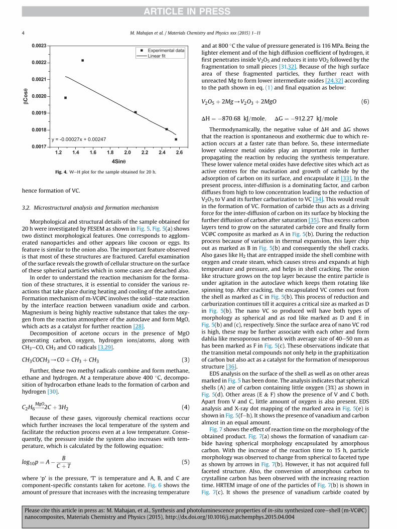
Fig. 4. WeH plot for the sample obtained for 20 h.
M. Mahajan et al. / Materials Chemistry and Physics xxx (2015) 1e114
hence formation of VC.
3.2. Microstructural analysis and formation mechanism
Morphological and structural details of the sample obtained for20 h were investigated by FESEM as shown in Fig. 5. Fig. 5(a) showstwo distinct morphological features. One corresponds to agglom-erated nanoparticles and other appears like cocoon or eggs. Itsfeature is similar to the onion also. The important feature observedis that most of these structures are fractured. Careful examinationof the surface reveals the growth of cellular structure on the surfaceof these spherical particles which in some cases are detached also.
In order to understand the reaction mechanism for the forma-tion of these structures, it is essential to consider the various re-actions that take place during heating and cooling of the autoclave.Formationmechanism of m-VC@C involves the solidestate reactionby the interface reaction between vanadium oxide and carbon.Magnesium is being highly reactive substance that takes the oxy-gen from the reaction atmosphere of the autoclave and form MgO,which acts as a catalyst for further reaction [28].
Decomposition of acetone occurs in the presence of MgOgenerating carbon, oxygen, hydrogen ions/atoms, along withCH3eCO, CH3 and CO radicals [3,29].
CH3COCH3/COþ CH3 þ CH3 (3)
Further, these two methyl radicals combine and form methane,ethane and hydrogen. At a temperature above 400 �C, decompo-sition of hydrocarbon ethane leads to the formation of carbon andhydrogen [30].
C2H6�!MgO
2C þ 3H2 (4)
Because of these gases, vigorously chemical reactions occurwhich further increases the local temperature of the system andfacilitate the reduction process even at a low temperature. Conse-quently, the pressure inside the system also increases with tem-perature, which is calculated by the following equation:
log10p ¼ A� BC þ T
(5)
where ‘p’ is the pressure, ‘T’ is temperature and A, B, and C arecomponent-specific constants taken for acetone. Fig. 6 shows theamount of pressure that increases with the increasing temperature
Please cite this article in press as: M. Mahajan, et al., Synthesis and photonanocomposites, Materials Chemistry and Physics (2015), http://dx.doi.o
and at 800 �C the value of pressure generated is 116 MPa. Being thelighter element and of the high diffusion coefficient of hydrogen, itfirst penetrates inside V2O5 and reduces it into VO2 followed by thefragmentation to small pieces [31,32]. Because of the high surfacearea of these fragmented particles, they further react withunreacted Mg to form lower intermediate oxides [24,32] accordingto the path shown in eq. (1) and final equation as below:
V2O5 þ 2Mg/V2O3 þ 2MgO (6)
DH ¼ �870:68 kJ=mole; DG ¼ �912:27 kJ=mole
Thermodynamically, the negative value of DH and DG showsthat the reaction is spontaneous and exothermic due to which re-action occurs at a faster rate than before. So, these intermediatelower valence metal oxides play an important role in furtherpropagating the reaction by reducing the synthesis temperature.These lower valence metal oxides have defective sites which act asactive centres for the nucleation and growth of carbide by theadsorption of carbon on its surface, and encapsulate it [33]. In thepresent process, inter-diffusion is a dominating factor, and carbondiffuses from high to low concentration leading to the reduction ofV2O3 to V and its further carburization to VC [34]. This would resultin the formation of VC. Formation of carbide thus acts as a drivingforce for the inter-diffusion of carbon on its surface by blocking thefurther diffusion of carbon after saturation [35]. Thus excess carbonlayers tend to grow on the saturated carbide core and finally formVC@C composite as marked as A in Fig. 5(b). During the reductionprocess because of variation in thermal expansion, this layer chipout as marked as B in Fig. 5(b) and consequently the shell cracks.Also gases like H2 that are entrapped inside the shell combine withoxygen and create steam, which causes stress and expands at hightemperature and pressure, and helps in shell cracking. The onionlike structure grows on the top layer because the entire particle isunder agitation in the autoclave which keeps them rotating likespinning top. After cracking, the encapsulated VC comes out fromthe shell as marked as C in Fig. 5(b). This process of reduction andcarburization continues till it acquires a critical size as marked as Din Fig. 5(b). The nano VC so produced will have both types ofmorphology as spherical and as rod like marked as D and E inFig. 5(b) and (c), respectively. Since the surface area of nano VC rodis high, these may be further associate with each other and formdahlia like mesoporous network with average size of 40e50 nm ashas been marked as F in Fig. 5(c). These observations indicate thatthe transition metal compounds not only help in the graphitizationof carbon but also act as a catalyst for the formation of mesoporousstructure [36].
EDS analysis on the surface of the shell as well as on other areasmarked in Fig. 5 has been done. The analysis indicates that sphericalshells (A) are of carbon containing little oxygen (3%) as shown inFig. 5(d). Other areas (E & F) show the presence of V and C both.Apart from V and C, little amount of oxygen is also present. EDSanalysis and X-ray dot mapping of the marked area in Fig. 5(e) isshown in Fig. 5(feh). It shows the presence of vanadium and carbonalmost in an equal amount.
Fig. 7 shows the effect of reaction time on themorphology of theobtained product. Fig. 7(a) shows the formation of vanadium car-bide having spherical morphology encapsulated by amorphouscarbon. With the increase of the reaction time to 15 h, particlemorphology was observed to change from spherical to faceted typeas shown by arrows in Fig. 7(b). However, it has not acquired fullfaceted structure. Also, the conversion of amorphous carbon tocrystalline carbon has been observed with the increasing reactiontime. HRTEM image of one of the particles of Fig. 7(b) is shown inFig. 7(c). It shows the presence of vanadium carbide coated by
luminescence properties of in-situ synthesized coreeshell (m-VC@C)rg/10.1016/j.matchemphys.2015.04.004

Fig. 5. (a) FESEM images for VC@C nanoparticles, (b, c) high magnification FESEM images showing the different morphologies for VC@C, (d) EDS spectra of marked portion in (c),and (f, g, h) are the EDX spectra and X-ray dot mapping of the marked area in (e).
M. Mahajan et al. / Materials Chemistry and Physics xxx (2015) 1e11 5
Please cite this article in press as: M. Mahajan, et al., Synthesis and photoluminescence properties of in-situ synthesized coreeshell (m-VC@C)nanocomposites, Materials Chemistry and Physics (2015), http://dx.doi.org/10.1016/j.matchemphys.2015.04.004

500 550 600 650 700 750 800
40
60
80
100
120
Pres
sure
(MPa
)
Temperature (oC)
Fig. 6. Graph of pressure generated with increasing temperature.
M. Mahajan et al. / Materials Chemistry and Physics xxx (2015) 1e116
carbon layers. However, the outer carbon is still amorphous. Withthe further increase in the reaction time to 20 h, the structure of thevanadium carbide becomes completely faceted and encapsulatedcarbon changes from amorphous to crystalline carbon as shown inFig. 8.
In order to estimate the size of VC@C and thickness of carbonlayer, the obtained product (20 h) was investigated under TEM asshown in Fig. 8. Fig. 8(a) shows the rod like morphology of theobtained sample coated by carbon layer. Dark contrast in Fig. 8(a)corresponds to the VC and that of light contrast corresponds tocarbon. Fig. 8(b) shows the corresponding dark field fringe image.The corresponding selective area electron diffraction (SAED)pattern is also shown in the inset of Fig. 8(b) and confirms thepresence of VC. Since the growth of carbides occurs as faceted typeto have high stability as predicted by Jackson and Hunt model[27,37], these structures get aligned because of high surface areaand acquire large facets. However, with due course of time, all finecrystal structures existing within the boundary merge with eachother and finally grow as single particle as shown in Fig. 8(c) wherea faceted morphology of fully grown crystal embedded in the car-bonmatrix can be seen. The HRTEM image reveals that carbon shellcontains about 20e22 layers with an average thickness of 6e7 nmcontaining fully grown core particle with average size of 32 nm(Fig. 8(c)). The D-spacing (0.34 nm) of these layers corresponds tothe (002) plane of the graphitic carbon and that of the core particlecorresponds to the (200) plane of VC (Fig. 8(d)). However, thecarbon is not purely graphitic. It contains some amorphous char-acter as has been marked as a circle in Fig. 8(d). The reason of itmight be the presence of some oxygen atoms in the graphite layerwhich creates defects in the structure. This observation agrees withthe EDS analysis.
The structural features reveal that this entire process is very fastand occurs in segments. The support of the above-mentionedreduction process is based on observation of the structural fea-tures observed in the micrographs. Schematic representation of theformation mechanism of VC@C has been shown in Fig. 9.
3.3. Raman spectroscopy
The graphitic carbon on the surface was further confirmed from
Please cite this article in press as: M. Mahajan, et al., Synthesis and photonanocomposites, Materials Chemistry and Physics (2015), http://dx.doi.o
the Raman spectra of the sample (20 h) as shown in Fig. 10(a).Raman spectra of the obtained sample exhibit two common bandscalled D (disordered) and G (graphitic) at ~ 1355 and 1578 cm�1,which are the D and G band of graphite [38]. The G e band isassociated with the first-order scattering of the E2g mode ofgraphite and is related to the vibrations of sp2 e bonded carbonatoms in a two e dimensional hexagonal lattice, i.e. diagnostic ofthe structural order. The D e band is associated with the structuraldefects or amorphous carbon [3]. The relatively high intensity andnarrow width of G-peak as compared to D-peak shows the well-oriented graphitic material [3] whereas broad D-band might bebecause of the disordered carbon or the presence of oxygen orhydrogen atoms into the graphite layer [3,39] which is alsoconfirmed fromXRD and SEM results. The intensity ratio of D to Ge
band provides the useful information on the degree of crystallinityof various carbon materials. A smaller ratio of ID/IG, would a highercrystallinity and hence ordering. The calculated value of ID/IG forthe obtained sample is 0.86, and represents the partially graphiticnature of the carbon [4].
3.4. TG/DTA analysis
To check the thermal stability at different temperatures, TG/DTAof the synthesized powder was done in nitrogen and the result isshown in Fig. 10(b). From the TGA curve, it is clear that there is acontinuous decrease in the sample weight during heating. Initially,at around 300e450 �C, the 5.79% weight loss corresponds to theoxidation of amorphous or very fine carbon layer [32]. A weakexothermic peak in this range shows that the amount of free carbonis very less. The suddenweight loss from 450 to 700 �C is due to theoxidation of outer graphitic carbon layer, which reacts with oxygenand release CO2, and further decreases the sample weight by 55%[32]. The DTG curve also shows that the onset of the oxidation ofcarbon starts at about 450 �C and becomes the maximum at about615 �C which shows the complete oxidation of outer graphiticcarbonwith the corresponding exothermic peak in DTA curve. Afterthe loss of outer carbon, the oxidation of vanadium carbide to VOxoccurs above 675 �C with the release of COx gas as [40]:
VC þ xO2/VOx þ COx½x ¼ 1;2� (7)
Since the oxidation of VC will increase the sample weight,therefore, a broad hump in the TGA curve at 675 �C (shown in theinset of Fig. 10(b)) indicates the oxidation of VC, which is higherthan the reported value (350 �C) [18,24]. Therefore, the TGA anal-ysis shows the carbon coating prevents the VC from oxidation andmaintains its thermal stability at higher temperatures.
3.5. BET surface area and pore size distribution
In order to study the textural characteristics of m-VC@C, nitro-gen adsorption/desorption measurements were carried out at 77 K.Fig. 11(a) shows the typical type IV isotherm profile according toIUPAC classifications along with hysteresis at the relative pressurefrom 0.4 to 1.0 [5,41]. The adsorption capacity increases withincreasing relative pressures. It directly indicates the presence ofmesopores in the nanocomposite [19]. The isotherm exhibitsadsorption and desorption with hysteresis that shows capillarycondensation and evaporation, which also indicate the hierarchicalarrangement of the pores [42]. The pore size distribution and cu-mulative pore volume obtained from the desorption isotherm usingBarretteJoynereHalenda method is shown in Fig. 11(b) and inset ofFig. 11(b), respectively. The pore size distribution shows two peakscentred at about 3.8 and 14 nm which indicates two types ofmesopores in the composite. The two different morphologies of
luminescence properties of in-situ synthesized coreeshell (m-VC@C)rg/10.1016/j.matchemphys.2015.04.004

Fig. 7. TEM images of vanadium carbide obtained for the reaction time of (a) 5 h, (b) 15 h, and (c) HRTEM of 7(b) showing the lattice fringes VC@C.
M. Mahajan et al. / Materials Chemistry and Physics xxx (2015) 1e11 7
VC@C nanoparticles observed in the SEMmicrographs might be thereason of it. The specific surface area and total pore volume of VC@Cobtained by this method are 62.4560 ± 0.2 m2/g and 0.30 cm3/g,respectively.
The hierarchical arrangement of mesopores, high surface areaand pore volume of the VC@C structure, indicates its better po-tential applications in electrocatalysis, energy storage and insensors.
3.6. Optical properties and photoluminescence
Optical properties of the obtained sample were investigated byUVeVis spectroscopy in the range of 250e600 nm. The inset ofFig. 12(a) shows the UVeVis spectra of sample obtained for 20 h. Itexhibits absorption bands at a wavelength of 243 and 293 nm and abroad band from 375 to 425 nm without any noticeable change atlonger wavelengths. According to the previous reports, absorptionband at 243 nm is because of the p-p* transition of C]C bond and ashoulder band at 293 nm belongs to the n-p* transition of C]Obonds [43,44]. Obviously, these bands are slightly blue shifted ascompared to the reported one which is because of the presence ofoxygen defects or compressive strain in the nanoparticles whichhas also been confirmed and discussed in the previous sections.Another absorption band at 375e425 nm might be because of thecarbide linkage (VeC). The absorption coefficient ‘a’ in UVeVisspectra is explained by ‘‘Tauc law’’ as [45]:
Please cite this article in press as: M. Mahajan, et al., Synthesis and photonanocomposites, Materials Chemistry and Physics (2015), http://dx.doi.o
ahy ¼ B2�hy� Eg
�r (8)
where, hy is the photon energy, Eg is the optical band gap, r is theindex which has different values (2, 3, 1/2, 3/2) depending on thedifferent interband transition for indirect allowed, indirectforbidden, direct allowed and direct forbidden transitions respec-tively and B is constant called band tailing parameter. Based on theabsorption data, the curve of (ahy)2 vs energy (hy) is plotted and isshown in Fig. 12(a). From this, the band gap is calculated byextrapolating linear region of the curve to meet the hy axis at(ahy)2 ¼ 0. It comes out to be 2.98 eV. The wide-band gap observedin the UVeVis spectroscopy shows the potential of obtained ma-terial to be used in numerous optical applications [43,46]. The ab-sorption band at around 400 nm indicated that the sample canserve as a photocatalyst driven by visible region [47].
Photoluminescence (PL) spectra of all the samples were recor-ded at the excitation wavelength of 335 nm as shown in Fig. 12(b).PL spectra of the sample obtained for 5 and 10 h shows no signif-icant emission peaks. This is because of the higher fraction of V2O3as compared to VC phase, which is already discussed in the XRDresults. This is associated with the lack of the luminescent prop-erties of V2O3 [48]. However, with the increase in the reaction timeto 15 h, the appearance of emission peaks centred at 368.67 and375.92 nm is related to the VC as major phase in the obtainedproduct. Further, the emission peaks of the sample obtained for
luminescence properties of in-situ synthesized coreeshell (m-VC@C)rg/10.1016/j.matchemphys.2015.04.004

Fig. 8. TEM images of vanadium carbide obtained for the reaction time of 20 h (a) VC@C showing the rod-like morphology, (b) corresponding dark field TEM image of (a), (c) HRTEMimage for VC@C showing faceted morphology, and (d) HRTEM image for the core particle of (c).
Fig. 9. Schematic representation of formation mechanism of VC@C.
M. Mahajan et al. / Materials Chemistry and Physics xxx (2015) 1e118
Please cite this article in press as: M. Mahajan, et al., Synthesis and photoluminescence properties of in-situ synthesized coreeshell (m-VC@C)nanocomposites, Materials Chemistry and Physics (2015), http://dx.doi.org/10.1016/j.matchemphys.2015.04.004

Fig. 10. (a) Raman spectra, and (b) DTG/DTA plot of the sample obtained for 20 h.
M. Mahajan et al. / Materials Chemistry and Physics xxx (2015) 1e11 9
20 h shows the maximum emission intensity because of the pureVC phase in the material. It shows the emission peaks in the region360e380 nm. The intensity of the emission peaks gets minimisedfurther with the increase in the reaction time to 25 h. Therefore, PLemission clearly indicates that the quenching of emission peaksoccur because of the presence of the impurity phases. The emissionpeak at ~375 nm might be because of the VC luminescent centres,whereas the small emission peaks could be the result of thedifferent size and morphology of m-VC nanoparticles. The origin ofPL emission peaks could be related to the presence of unfilled d-electron shell and filled energy levels of vanadium carbide as wellas empty orbitals of graphitic carbon, which interact and couplewith each other and generate PL emission when excited under ul-traviolet radiation [3]. Also oxide-related defects at the nano-crystal/oxide interface [3,49,50] might be the reason for PLemission at ~ 375 and 360 nm which is also confirmed from ourTEM/EDS and Raman analysis. However, the detailed emission
Fig. 11. (a) N2 adsorptionedesorption curve, (b) Pore size distribution curv
Please cite this article in press as: M. Mahajan, et al., Synthesis and photonanocomposites, Materials Chemistry and Physics (2015), http://dx.doi.o
mechanism is not fully understood and needs further investigation.This emission behavior of refractory carbides may be of great
interest as there is no report so far on the optical and luminescenceproperties of VC@C prepared by chemical-reduction route. There-fore, because of the chemical inertness and thermal stability, thesehard materials can be one of the best candidates for the mechano-luminescent applications. Enhancement of luminescence emissionin the visible region opens up new doors for many photochemicalapplications [46].
3.7. Photocatalytic degradation of salicylic acid
Photocatalytic degradation of salicylic acid (SA) was studied toinvestigate the catalytic activity of the obtained product. There areinsignificant changes in the absorption spectra of the acid in theabsence of light as shown in the inset of Fig. 13(a). Under the effectof UV-light, the reaction accelerates and degradation of SA occurs
e, and inset of (b) cumulative pore volume of the desorption branch.
luminescence properties of in-situ synthesized coreeshell (m-VC@C)rg/10.1016/j.matchemphys.2015.04.004

Fig. 12. (a) Band gap graph and UVeVis absorption spectra (Inset), and (b) PL spectrumof the samples excited at the wavelength of 335 nm.
Fig. 13. (a) Absorbance spectra of salicylic acid degraded under UV-light and in theabsence of light (Inset), and (b) Decrease in the concentration of SA during photo-catalysis at different time intervals.
M. Mahajan et al. / Materials Chemistry and Physics xxx (2015) 1e1110
with the time interval of 30 min Fig. 13(a) shows the absorptionspectra of the SA during photocatalysis with the time interval of30 min Fig. 13(b) shows the timeecourse graph for the degradationof SA. It shows that the concentration of SA decreases exponentiallywith the increasing time. Concentration of the SA decreases upto31.2% with respect to initial concentration after the reaction time of180 min.
4. Conclusion
Coreeshell composite of vanadium carbide nanoparticlesencapsulated into carbon (VC@C) has been successfully synthesizedby single-step chemical-reduction route. Increase of reaction timefacilitates the in-situ reduction and carburization simultaneous inmulti-steps. Vanadium carbide thus formed acts as a catalyst forgraphitization and also for the formation of a porous structure. Theobtained product (m-VC@C) is mesoporous in nature with pore sizein the range of 3.8 and 14 nm. Encapsulation of VC nanoparticlesinside carbon shells makes the obtained product thermally stableup to 675 �C. Because of the mesoporous structure, good thermalstability and significant absorption and luminescence characteris-tics, these unique nanostructures of m-VC@C could be the prom-ising candidate for use in hydrogen storage, sensors, and in opto-electronic devices. The present work also shows that the VC@C isphoto-active and can be used as a catalyst in the photo-degradation
Please cite this article in press as: M. Mahajan, et al., Synthesis and photonanocomposites, Materials Chemistry and Physics (2015), http://dx.doi.o
of the various organic pollutants which is of great industrialimportance.
Acknowledgments
The authors are thankful to UGC-DAE Consortium for ScientificResearch, Indore, letter no. CSR-I/CRS-65/2012-13/271 for financialsupport and assistance. Authors are also thankful to Dr. GajenderSaini, AIRF, JNU for TEM studies. Authors are also thankful to Mr.Gourav Singla, Research scholar, SPMS, and Miss Anila Monga,Research Scholar, SCBC, Thapar University, Patiala for their consis-tent help in TGA/DTA and photocatalytic analysis. Authors are verygrateful to Dr. Manoj Sharma, Assistant Professor, Sri Guru GranthSahibWorld University, Fatehgarh Sahib, Punjab for consistent helpin Photoluminescence measurements.
References
[1] W. Zhu, J. Ren, X. Gu, M.U. Azmat, G. Lu, Y. Wang, Synthesis of hermatically-sealed graphite-encapsulated metallic cobalt (alloy) core/shell nano-structures, Carbon 49 (2011) 1462e1472.
[2] W. Oelerich, T. Klassen, R. Bormann, Comparison of the catalytic effects of V,V2O5, VN and VC on the hydrogen sorption of nanocrystalline Mg, J. Alloy
luminescence properties of in-situ synthesized coreeshell (m-VC@C)rg/10.1016/j.matchemphys.2015.04.004

M. Mahajan et al. / Materials Chemistry and Physics xxx (2015) 1e11 11
Compd. 322 (2001) L5eL9.[3] H. Zhang, C. Liang, J. Liu, Z. Tain, G. Shao, The formation of onion-like carbon-
encapsulated cobalt carbide core/shell nanoparticles by the laser ablation ofmetallic cobalt in acetone, Carbon 55 (2013) 108e115.
[4] N. Zhao, S. Wu, C. He, Z. Wang, C. Shi, E. Liu, J. Li, One-pot synthesis of uniformFe3O4 nanocrystals encapsulated in interconnected carbon nanospheres forsuperior lithium storage capability, Carbon 57 (2013) 130e138.
[5] B. Wang, C. Tian, L. Wang, R. Wang, H. Fu, Chitosan: a green carbon source forthe synthesis of graphitic nanocarbon, tungsten carbide and graphitic nano-carbon/tungsten carbide composites, Nanotechnology 21 (2010) 025606, 9pp.
[6] K. Wenelska, K. Kierzek, R.J. Kalenczuk, X. Chen, E. Mijowska, Nanoconfine-ment induced formation of core/shell structured mesoporous carbon spherescoated with solid carbon shell, Appl. Mater. Interfaces 5 (2013) 3042e3047.
[7] Y. Ouyang, H. Shi, R. Fu, D. Wu, Highly monodisoerse microporous polymericand carbonaceous nanospheres with multifunctional properties, Sci. Reports(2013), http://dx.doi.org/10.1038/srep01430.
[8] J.B. Joo, J.S. Kim, P. Kim, J. Yi, Simple preparation of tungsten carbide supportedon carbon for use as a catalyst support in a methanol electro-oxidation, Mater.Lett. 62 (2008) 3497e3499.
[9] Z. Yan, M. Zhang, J. Xie, P.K. Shen, Vanadium carbide and graphite promotedPd electrocatalyst for ethanol oxidation in alkaline media, J. Power Sources243 (2013) 336e342.
[10] P. Cholsong, L. Ji, G. Zhimeng, Microstructure and properties of ultrafine WC-10Co composites with chemically doped VC, Rare Met. 30 (2011) 183e188.
[11] A.J. Brungs, P.E. York, L.H. Green, Comparison of the group V and VI transitionmetal carbides for methane dry reforming and thermodynamic prediction oftheir relative stabilities, Catal. Lett. 57 (1999) 65e69.
[12] D.J. Ham, J.S. Lee, Transition metal carbides and nitrides as electrode materialsfor low temperature fuel cells, Rev. Energies 2 (2009) 873e899.
[13] Z. Hu, C. Chen, H. Meng, R. Wang, P.K. Shen, H. Fu, Oxygen reduction elec-trocatalysis enhanced by nanosized cubic vanadium carbide, Electrochem.Commun. 13 (2011) 763e765.
[14] P. Rodriguez, J.L. Brito, A. Albornoz, M. Labadi, C. Pfaff, S. Marrero, D. Moronta,P. Betancourt, Comparison of vanadium carbide and nitride catalysts forhydrotreating, Catal. Commun. 5 (2004) 79e82.
[15] K. Wang, X. Ma, Z. Zhang, M. Zheng, Z. Geng, Z. Wang, Indirect transformationof coordination-polymer particles into magnetic carbon-coated Mn3O4(Mn3O4@C) nanowires for supercapacitor electrodes with good cycling per-formance, Chem. Eur. J. 19 (2013) 7084e7089.
[16] L. Su, Z. Zhou, P. Shen, Coreeshell Fe@Fe3C/C nanocomposites as anode ma-terials for Li ion batteries, Electrochim. Acta 87 (2013) 180e185.
[17] E. Flahaut, F. Agnoli, J. Sloan, C. O'Connor, M.L.H. Green, CCVD synthesis andcharacterization of cobalt-encapsulated nanoparticles, Chem. Mater. 14(2002) 2553e2558.
[18] Y. Zhang, J. Zhang, M. Fan, Y. Long, Y. Zhong, X. Liu, C. Huang, Exploring a novelapproach to fabricate vanadium carbide encapsulated into carbon nanotube(VC@C) with large specific surface area, Bull. Mater. Sci. 36 (2013) 345e351.
[19] L. Jiang, H. Fu, L. Wang, G. Mu, B. Jiang, W. Zhou, R. Wang, Nanocrystallinetungsten carbide/graphitic carbon composite: synthesis, characterization, andits application as an effective Pt catalyst support for methanol oxidation,J. Solid State Electrochem 18 (2014) 2225e2232.
[20] G. Zhong, H. Wang, H. Yu, F. Peng, A novel carbon-encapsulated cobalt-tungsten carbide as electrocatalyst for oxygen reduction reaction in alkalinemedia, Fuel Cells 13 (2013) 387e391.
[21] G. Li, C. Ma, J. Tang, J. Sheng, Preparation and electrocatalytic property of WC/carbon nanotube composite, Electrochim. Acta 52 (2007) 2018e2023.
[22] S. Youn, S. Jeong, D.H. Kim, Effect of oxidation states of vanadium precursorsolution in V2O5/TiO2 catalysts for low temperature NH3 selective catalyticreduction, Catal. Today 232 (2014) 185e191.
[23] R. Kapoor, S.T. Oyama, Synthesis of vanadium carbide by temperature pro-grammed reaction, J. Solid State Chem. 120 (1995) 320e326.
[24] J. Ma, M. Wu, Y. Du, S. Chen, J. Ye, L. Jin, Low temperature synthesis of va-nadium carbide (VC), Mater. Lett. 63 (2009) 905e907.
[25] G.S. Upadhyaya, Nature and Properties of Refractory Carbides, Nova SciencePublishers, New York, 1996.
[26] A.K. Zak, W.A. Majid, M.E. Abrishami, R. Yousefi, X-ray analysis of ZnOnanoparticles by WilliamsoneHall and size-strain plot methods, Solid StateSci. 13 (2011) 251e256.
[27] A. Kumar, K. Singh, O.P. Pandey, Optimization of processing parameters for the
Please cite this article in press as: M. Mahajan, et al., Synthesis and photonanocomposites, Materials Chemistry and Physics (2015), http://dx.doi.o
synthesis of tungsten carbide (WC) nanoparticles through solvothermal route,Phys. E 42 (2010) 2477e2483.
[28] V.K. Díez, C.R. Apesteguía, J.I. DI Cosimo, Effect of the acid-base properties ofMg-Al mixed oxides on the catalyst deactivation during aldol condensationreactions, Latin Am. Appl. Res. 33 (2003) 79e86.
[29] F.O. Rice, R.E. Vollrath, Thermal decomposition of acetone in the gaseous state,Proc. N. A. S 15 (1929) 702e705.
[30] A. Meier, V.A. Kirillov, G.G. Kuvshinov, Y.I. Mogilnykh, A. Reller, A. Steinfeld,A. Weidenkaff, Solar thermal decomposition of hydrocarbons and carbonmonoxide for the production of catalytic filamentous carbon, Chem. Eng. Sci.54 (1999) 3341e3348.
[31] �Z. Kamberovi�c, D. Filipovi�c, K. Rai�c, M. Tasi�c, Z. AnCi�c, M. Gavrilovski, Reduc-tion of ultra-fine tungsten powder with tungsten (VI)-oxide in a vertical tubereactor, Mater. Technol. 45 (2011) 27e32.
[32] G. Singla, K. Singh, O.P. Pandey, Structural and thermal analysis of in situsynthesized C-WC nanocomposites, Ceram. Int. 40 (2014) 5157e5164.
[33] X. Li, A. Westwood, A. Brown, R. Brydson, B. Rand, A convenient, generalsynthesis of carbide nanofibres via templated reactions of carbon nanotubesin molten salt media, Carbon 47 (2009) 201e208.
[34] S. Gomari, S. Sharafi, Microstructural characterization of nanocrystallinechromium carbides synthesized by high energy ball milling, J. Alloys Compd.490 (2010) 26e30.
[35] V. Stolojan, Y. Tison, G.Y. Chen, R. Silva, Controlled growth-reversal of catalyticcarbon nanotubes under electron-beam irradiation, Nano Lett. 6 (2006)1837e1841.
[36] D. Yuan, X. Yuan, W. Zou, F. Zeng, X. Huang, S. Zhou, Synthesis of graphiticmesoporous carbon from sucrose as a catalyst support for ethanol electro-oxidation, J. Mater. Chem. 22 (2012) 17820e17826.
[37] K.A. Jackson, J.D. Hunt, Transparent compounds that freeze like metals, ActaMetall. 13 (1965) 1212e1215.
[38] S. Urbonaite, L. Halldahl, G. Svensson, Raman spectroscopy studies of carbidederived carbons, Carbon 46 (2008) 1942e1947.
[39] S.P. Somani, P.R. Somani, M. Noda, M. Umeno, Carbon nanocapsules encap-sulating cobalt nanoparticles by pulsed discharge plasma chemical vapourdeposition, Diam. Relat. Mater. 17 (2008) 576e580.
[40] M.D. Antonik, R.J. Lad, Clean surface and oxidation behaviour of vanadiumcarbide VC0.75(100), Surf. Interface Anal. 24 (1996) 681e686.
[41] R. Prakash, A.K. Mishra, A. Roth, C. Kubel, T. Scherer, M. Ghafari, H. Hahn,M. Fichtner, A ferrocene-based carbon-iron lithium fluoride nanocomposite asa stable electrode material in lithium batteries, J. Mater. Chem. 20 (2010)1871e1876.
[42] B.H. Jones, T.P. Lodge, Nanocasting nanoporous inorganic and organic mate-rials from polymeric bicontinuous microemulsion templates, Polym. J. 44(2012) 131e146.
[43] P. Yu, X. Wen, Y.R. Toh, Y.C. Lee, K.Y. Huang, S. Huang, S. Shrestha, G. Conibeer,J. Tang, Efficient electron transfer in carbon nanodot-graphene oxide nano-composites, J. Mater. Chem. 2 (2014) 2894e2901.
[44] Y. Liang, P. Liu, J. Xiao, H. Li, C. Wang, G. Yang, A microfibre assembly of aniron-carbon composite with giant magnetisation, Sci. Reports (2013), http://dx.doi.org/10.1038/srep03051.
[45] A.B. Murphy, Band gap determination from diffuse reflectance measurementsof semiconductor films and application to photoelectrochemical water-split-ting, Sol. Energy Mater. Sol. Cells 91 (2007) 1326e1337.
[46] S. Kuriakose, B. Satpati, S. Mohapatra, Enhanced photocatalytic activity of Codoped ZnO nanodisks and nanorods prepared by a facile wet chemicalmethod, Phys. Chem. Chem. Phys. 16 (2014) 12741e12749.
[47] Y. Liu, R. Zuo, Morphology and optical absorption of Bi2Fe4O9 crystals viamineralizer-assisted hydrothermal synthesis, Particuology 11 (2013)581e587.
[48] V.G. Pol, S.V. Pol, J.M.C. Moreno, A. Gedanken, Coreeshell vanadium oxide-carbon nanoparticles: synthesis, characterization, and luminescence proper-ties, J. Phys. Chem. C 113 (2009) 10500e10504.
[49] P.K. Giri, K. Das, S.K. Roy, Defect contribution to the photoluminescence fromembedded germanium nanocrystals prepared by ion implantation and sputterdeposition methods, Mater. Res. Soc. Symp. Proc. 994 (2007) 1e6.
[50] L.P. Ginzburg, A.A. Gordeev, A.P. Gorchakov, A.P. Jilinsky, Some features of theblue luminescence in v-Si(1�X)Ge(X)O2, J. Non-Cryst. Solids 183 (1995)234e242.
luminescence properties of in-situ synthesized coreeshell (m-VC@C)rg/10.1016/j.matchemphys.2015.04.004
Copyright © 2022 FDOKUMEN