standard specifications for water distribution system construction
Upload
khangminh22Category
view
0download
0
SUMMARY OF SIGNIFICANT CHANGES OF SURFACE FORCES LOGISTICS CENTER (SFLC) STANDARD SPECIFICATIONS
FROM 2012 EDITIONS TO 2014 EDITIONS
This document contains summaries of significant changes made to each of the previous editions of SFLC Standard Specifications. This summary includes all of the major changes including those required by formally submitted and approved feedback recorded in the DeSpecC generated General Requirement Item as exceptions to the 2012 editions of applicable Standard Specifications as well as changes to clarify or correct existing requirements or meet requirements of SFLC Technical Standards.
SFLC Std Spec 0000, 2014, General Requirements SFLC Std Spec 0450, 2014, Electrical Power for Contractor’s Tools & Equipment SFLC Std Spec 0740, 2014, Welding and Allied Processes SFLC Std Spec 0850, 2014, General Requirements for Drawing Preparation SFLC Std Spec 0860, 2014, General Requirements for Technical Publication SFLC Std Spec 2350, 2014, Inspect, Test and Recondition DC Propulsion Generators & Motors In-Place SFLC Std Spec 2351, 2014, Overhaul DC Generators & Motors SFLC Std Spec 3020, 2014, Overhaul AC Electrical Motors SFLC Std Spec 3041, 2014, Shipboard Electrical Cable Test SFLC Std Spec 3042, 2014, Shipboard Electrical Cable Removal, Relocation, Splice, Repair, and Installation SFLC Std Spec 3100, 2014, Inspect, Test and Recondition AC Synchronous Machines In-Place SFLC Std Spec 3101, 2014, Overhaul AC Synchronous Machines SFLC Std Spec 5000, 2014, Auxiliary Machine Systems SFLC Std Spec 5100, 2014, Clean Shipboard Ventilation Systems SFLC Std Spec 6310, 2014, Requirements for Preservation of Ship Structures SFLC Std Spec 6341, 2014, Install Interior Deck Covering Systems SFLC Std Spec 8634, 2014, Drydocking SFLC Std Spec 8635, 2014, Temporary Services SFLC Std Spec 8636, 2014, Temporary Hull Accesses
NOTICE
All paragraph references correspond to the applicable 2014 Edition of the Standard Specifications.
SFLC 2014 STD SPEC SUMMARY OF CHANGES 1

Summary of changes to SFLC Standard Specification 0000 General Requirements
Revision of the 2012 General Requirements Standard Specification includes format changes, including but not limited to Other Reference version/dates, paragraph renaming, re-formatting, as well as changes documented below. All references to prior editions of SFLC Standard Specifications were updated to 2014 editions.
1. SCOPE
1.2 Added Appendix A, Requirements For Environmental Protection At Contractor Operated (Non USCG) Facilities. All contents of this Appendix were moved from prior approved and published stand-alone portion of the 2012 Standard Specification.
1.2 Added Appendix B, Requirements For Environmental Protection At USCG Facilities. All contents of this Appendix were moved from prior approved and published stand-alone portion of the 2012 Standard Specification.
1.3 Added or re-described acronyms for Contracting Officer’s Representative, Critical Coated Surfaces, Fastener, Licensed Tech Rep, NDE (non-destructive examination), OEM, OEM Authorized Tech Rep, PCL (Paint Containing Lead), Qualified Tech Rep, and Safety Data Sheet.
2. REFERENCES
Added US Code, Title 15, (15 USC), Jan 2012, Commerce and Trade
3. REQUIREMENTS
3.2.4.2.4 Added Note Box stating the NACE Inspector must remain onsite, to fulfill the tasked duties listed above - unless otherwise approved by the KO.
3.2.5 Added two new characteristics to the Planning document list including; Identifies the “critical paths” for the project. Shows calculations for the “float” along the critical paths and labels the critical paths with the number of delay days the critical paths can absorb without affecting the final delivery date. Added the Note Box stating “Float is the number of days that the critical paths can be delayed without affecting the final delivery date”.
3.2.5.4 Added new paragraph stating; When the critical path extends beyond or encroaches upon the final delivery date, provide a resource constraint and scheduling evaluation of the critical path before any request for extension will be entertained. Submit the resource constraint and scheduling evaluation via a CFR. New Note Box states; The intent of the resource constraint and scheduling evaluation is to identify the resources necessary to ‘crash’ the critical path or make adjustments to the production
SFLC 2014 STD SPEC SUMMARY OF CHANGES 2

schedule to meet the delivery date in lieu of a project extension.
3.3.1 Deleted references to MSDS and replaced with Safety Data Sheet (SDS)/ Material Safety Data Sheet (MSDS).
3.3.3.1 Revised Note Box to include ‘flame-retardant polyethylene deck plate with a non-slip diamond pattern from 10 to 40 mil thickness’.
3.3.13.2 thru 3.3.13.2.2. Added paragraphs. Dock and sea trials. The Contractor shall conduct dock trials to test the work performed during the contract when required by individual work items (see 3.3.13 Tests and Inspections). This shall include operational tests or inspections, as appropriate, of all machinery, piping, wiring, insulation, preservation work, deck coverings, and any other article removed, moved, disturbed, or damaged by the Contractor in accomplishing the work outlined in the specification. Schedule for these specific dockside tests or inspections shall be included within the planning document (see 3.2.5 Planning document). The Contractor shall provide a pier facility or allow the vessel to move to a Coast Guard pier to support dock trials. The Contractor shall not conduct trials that require the vessel to be waterborne while the vessel is floating inside a dock (e.g., graving dock, floating drydock). Sea trials to conduct equipment operational tests are not required unless a Sea Trial Performance work item is specifically included within the specification.
.
SFLC 2014 STD SPEC SUMMARY OF CHANGES 3
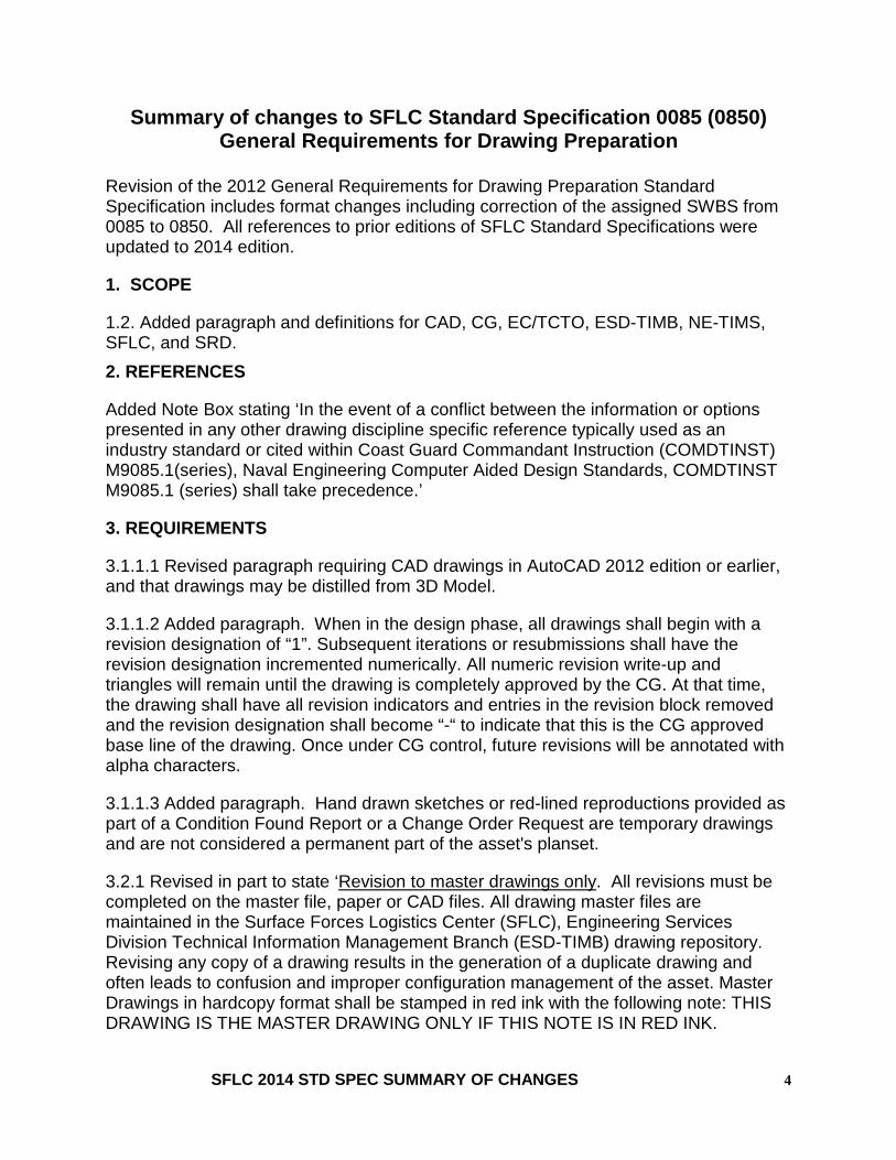
Summary of changes to SFLC Standard Specification 0085 (0850) General Requirements for Drawing Preparation
Revision of the 2012 General Requirements for Drawing Preparation Standard Specification includes format changes including correction of the assigned SWBS from 0085 to 0850. All references to prior editions of SFLC Standard Specifications were updated to 2014 edition.
1. SCOPE
1.2. Added paragraph and definitions for CAD, CG, EC/TCTO, ESD-TIMB, NE-TIMS, SFLC, and SRD. 2. REFERENCES
Added Note Box stating ‘In the event of a conflict between the information or options presented in any other drawing discipline specific reference typically used as an industry standard or cited within Coast Guard Commandant Instruction (COMDTINST) M9085.1(series), Naval Engineering Computer Aided Design Standards, COMDTINST M9085.1 (series) shall take precedence.’
3. REQUIREMENTS
3.1.1.1 Revised paragraph requiring CAD drawings in AutoCAD 2012 edition or earlier, and that drawings may be distilled from 3D Model.
3.1.1.2 Added paragraph. When in the design phase, all drawings shall begin with a revision designation of “1”. Subsequent iterations or resubmissions shall have the revision designation incremented numerically. All numeric revision write-up and triangles will remain until the drawing is completely approved by the CG. At that time, the drawing shall have all revision indicators and entries in the revision block removed and the revision designation shall become “-“ to indicate that this is the CG approved base line of the drawing. Once under CG control, future revisions will be annotated with alpha characters.
3.1.1.3 Added paragraph. Hand drawn sketches or red-lined reproductions provided as part of a Condition Found Report or a Change Order Request are temporary drawings and are not considered a permanent part of the asset's planset.
3.2.1 Revised in part to state ‘Revision to master drawings only. All revisions must be completed on the master file, paper or CAD files. All drawing master files are maintained in the Surface Forces Logistics Center (SFLC), Engineering Services Division Technical Information Management Branch (ESD-TIMB) drawing repository. Revising any copy of a drawing results in the generation of a duplicate drawing and often leads to confusion and improper configuration management of the asset. Master Drawings in hardcopy format shall be stamped in red ink with the following note: THIS DRAWING IS THE MASTER DRAWING ONLY IF THIS NOTE IS IN RED INK.
SFLC 2014 STD SPEC SUMMARY OF CHANGES 4

Additionally added Note Box stating ‘Not all Master Drawings in the Coast Guard's files have the Red Ink stamp yet.’
3.2.2 Added last sentence stating ‘It is not necessary to hatch out deleted geometry and data. All historical versions of a drawing are maintained by SFLC-ESD-TIMB. Original drawings and prior revisions can be viewed in Naval Engineering Technical Information Management System (NE-TIMS) to ascertain previous configurations.’
3.2.3 Added last sentence stating ‘Additional cross-reference information supporting the reason for revision (Contract, CLIN, Activity, Project #, Service Bulletin, etc), is encouraged to also be entered in revision history.’
3.5.1 Revised paragraph to state ‘A single, new Master Drawing for each appropriate set of drawings shall be created, which may be based from current, but un-editable vendor drawings, for the purpose of documenting needed changes. This drawing will have a special branching drawing number, issued by ESD-TIMB, which identifies it as an addendum to the original vendor’s master drawing. This new Master Drawing will be available for depicting various needed changes until the complete Master Drawings are received from the shipyard. At such time, the two drawings shall be incorporated back into one class SRD drawing per Section 3.5.4 below.’
3.5.4. Added paragraph. When the (previously-absent) Master SRD Drawing becomes available, it is mandatory to revise the vendor’s master class drawing with the addendum drawing. The applicable Product Line will be responsible to fund the maintenance/repair contractor to modify the SRD drawing if it becomes available during the availability timeframe. However, once the maintenance/repair contract is complete, the PL will be responsible to incorporate the changes, to contract work to outside vendors qualified to perform the work, or to initiate and negotiate activities with SFLC-ESD-NAME to perform the required engineering/CAD services.
SFLC 2014 STD SPEC SUMMARY OF CHANGES 5

Summary of changes to SFLC Standard Specification 0450 Electrical Power for Contractor’s Tools & Equipment
Revision of the 2012 Electrical Power for Contractor’s Tools & Equipment Standard Specification includes format changes, including but not limited to paragraph re-formatting, as well as changes documented below. All references to prior editions of SFLC Standard Specifications were updated to 2014 edition.
1. SCOPE
1.1 Added sentence; Stray current protection for welding equipment is covered in SFLC Standard Specification 0740, Welding and Allied Processes, Appendix E.
2. REFERENCES
None.
3. REQUIREMENTS
3.4 Added sentence; Stray current protection for welding equipment is covered in SFLC Standard Specification 0740, Welding and Allied Processes, Appendix E.
3.4.1.4 Deleted ‘Arc welders with the common return conductor bonded to the grounded frame of the machine instead of insulated from earth. Figure 5a shows two unacceptable examples. Two ships sharing the same arc welder. Figure 5b shows the unacceptable current flowing between the underwater bodies.’ Deleted Figure 5, and renumbered all subsequent Figures.
.
SFLC 2014 STD SPEC SUMMARY OF CHANGES 6

Summary of changes to SFLC Standard Specification 0740 Welding and Allied Processes
Revision of the 2012 Welding and Allied Processes Standard Specification includes reference updates and format changes, including but not limited to paragraph renaming and renumbering, replacement of NDI with NDE as well as changes documented below. All references to prior editions of SFLC Standard Specifications were updated to 2014 edition.
1. SCOPE
1.2 Re-titled Appendix B ‘Welding and Inspection – Military Standards’
1.2 Added Appendix E, Stray Current Protection.
1.3.5. Added Brazer definition as ‘A person who performs manual or semiautomatic brazing. In this specification, any reference to a brazer is also applicable to a brazing operator.’
1.3.6 Revised Critical Weld definition as ‘Critical welds include welds on primary structure (including hull plate, tank tops, structural decks and bulkheads, transverse frames), watertight closures on the bulkhead deck and below, load bearing members, life saving equipment, weight handling equipment, tank and void boundaries, pressurized vessels (including piping, tubing and fittings), machinery that transmit thrust or torque, foundations, propulsion shafting, propellers, water jets, special purpose (including flight deck, buoy deck), special materials (including high yield, monel), and ordnance.’
1.3.7 Added Certified definition as ‘The term “certified” indicates that there is written proof of qualification.
1.3.8 Added Continuity definition as ‘Documentation for each welder that their certification has been properly maintained in accordance with the appropriate welding code or military standard.’
1.3.12 Added Nondestructive Examination (NDE) as ‘The act of determining the suitability of a material or a component for its intended purpose using techniques not affecting its serviceability. NDE is the standard term used by AWS. Nondestructive inspection (NDI), nondestructive testing (NDT), and nondestructive evaluation are interchangeable terms for NDE.’
1.3.13 Revised Procedure qualification definition as ‘The demonstration that the use of prescribed joining processes, materials, and techniques will result in a joint exhibiting specified soundness and mechanical properties, and evaluated either by destructive or nondestructive tests or both.’
1.3.14 Added Procedure qualification record (PQR) definition as ‘A document providing
SFLC 2014 STD SPEC SUMMARY OF CHANGES 7
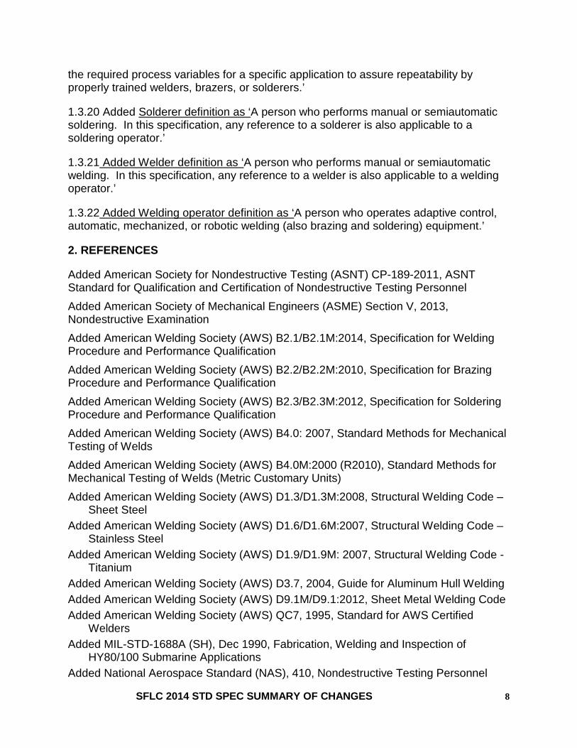
the required process variables for a specific application to assure repeatability by properly trained welders, brazers, or solderers.’
1.3.20 Added Solderer definition as ‘A person who performs manual or semiautomatic soldering. In this specification, any reference to a solderer is also applicable to a soldering operator.’
1.3.21 Added Welder definition as ‘A person who performs manual or semiautomatic welding. In this specification, any reference to a welder is also applicable to a welding operator.’
1.3.22 Added Welding operator definition as ‘A person who operates adaptive control, automatic, mechanized, or robotic welding (also brazing and soldering) equipment.’
2. REFERENCES
Added American Society for Nondestructive Testing (ASNT) CP-189-2011, ASNT Standard for Qualification and Certification of Nondestructive Testing Personnel Added American Society of Mechanical Engineers (ASME) Section V, 2013, Nondestructive Examination Added American Welding Society (AWS) B2.1/B2.1M:2014, Specification for Welding Procedure and Performance Qualification Added American Welding Society (AWS) B2.2/B2.2M:2010, Specification for Brazing Procedure and Performance Qualification Added American Welding Society (AWS) B2.3/B2.3M:2012, Specification for Soldering Procedure and Performance Qualification Added American Welding Society (AWS) B4.0: 2007, Standard Methods for Mechanical Testing of Welds Added American Welding Society (AWS) B4.0M:2000 (R2010), Standard Methods for Mechanical Testing of Welds (Metric Customary Units) Added American Welding Society (AWS) D1.3/D1.3M:2008, Structural Welding Code –
Sheet Steel Added American Welding Society (AWS) D1.6/D1.6M:2007, Structural Welding Code –
Stainless Steel Added American Welding Society (AWS) D1.9/D1.9M: 2007, Structural Welding Code -
Titanium Added American Welding Society (AWS) D3.7, 2004, Guide for Aluminum Hull Welding Added American Welding Society (AWS) D9.1M/D9.1:2012, Sheet Metal Welding Code Added American Welding Society (AWS) QC7, 1995, Standard for AWS Certified
Welders Added MIL-STD-1688A (SH), Dec 1990, Fabrication, Welding and Inspection of
HY80/100 Submarine Applications Added National Aerospace Standard (NAS), 410, Nondestructive Testing Personnel
SFLC 2014 STD SPEC SUMMARY OF CHANGES 8

Qualification and Certification, Revision 3, March 2008. Added Naval Sea Systems Command (NAVSEA) T9074-BD-GIB-010/0300, Aug 2002,
Base Materials for Critical Applications: Requirements for Low Alloy Steel Plate, Forgings, Castings, Shapes, Bars, and Heads of HY-80/100/130 and HSLA-80/100
3. REQUIREMENTS
3.1.1 Added paragraph stating ‘The Contractor shall perform all welding on cutters and boats, including any associated system, equipment or part, whether permanently attached or not, using certified welders and approved welding procedure specifications.’
3.1.2 Added paragraph stating ‘Any requirement for certified welders and welding procedure specifications (WPS) is also applicable to certified brazers and solders and to brazing and soldering procedure specifications (BPS and SPS).’
3.1.4 Revised Welding documentation requirements to state ‘The Contractor shall provide to the KO copies of the following information for all intended work to be performed: All welding procedure specifications (WPS) applicable to the solicitation, along with a summary list and current revision dates. Welder certification documentation, including at a minimum welder name and WPS(s) certified to perform. Welder continuity documentation which provides proof of proper certification maintenance. Supporting PQRs if requested by the KO.’
NOTE Continuity periodicity for welder certification is dictated by commercial welding codes and military welding standards. The Contractor shall ensure welder certifications are maintained to the applicable code.
3.1.5 Revised Stray current protection to state ‘The Contractor shall meet all requirements for stray current protection as specified in Appendix E - Stray Current Protection.’, with appropriate references within sub-paragraphs.
3.6 Added E6011 to Filler material restrictions.
3.15.1 Added HY-130 material substitution. The Contractor shall be aware that HY-130 steel plating is no longer commercially available. For the purpose of performing flight deck repairs on US Coast Guard WMEC-270 “B-Class” cutters, Weldox 900 steel has been approved as a replacement for HY-130. Due to the similarity in material properties and weldability of HY-130 and Weldox 900, all welding procedures and welder qualifications for welding Weldox 900 shall be the same as those outlined in MIL-STD-1688A as applicable for welding HY-130
SFLC 2014 STD SPEC SUMMARY OF CHANGES 9

3.15.2 Added Standard specification modification. For any welding involving HY-130 on the flight deck of WMEC-270 “B-Class” cutters, perform all welding and allied processes, and non-destructive evaluation (NDE) in accordance with MIL-STD-1688A
3.15.3 Added Approval to weld HY-130. To obtain Coast Guard approval to weld on HY-130 steel for WMEC-270 “B-Class” cutters, the Contractor shall provide written Performance Qualification Records (PQR’s) for each process to be used. The PQR’s shall be approved by one of the regulatory agencies affirming that the WPS meets the welding requirements of MIL-STD-1688A. In addition, the Contractor shall ensure that all subcontractors, prior to performing welding operations, have qualified procedures by meeting all the requirements set forth in this document.
NOTE NAVSEA approval is NOT required for welding procedures submitted but the procedures must be reviewed and shown to satisfy the requirements set forth in MIL-STD-1688A, by a welding regulatory agency. The requirements for welding Weldox 900 shall be considered the same as those for welding HY-130.
3.17 Added Fuel/ water stops. For new or replaced structural members that penetrate tanks that contain liquids, the Contractor shall install fuel/water stops within 12 inches of the tank bulkhead on the outside of the tank.
A2.1.4 Revised ABS documentation to state ‘When ABS approved welding procedure specifications and welder certifications are to be used, the Contractor shall ensure that all documents are approved by the ABS Technical Office (located in Houston), or other ABS subject matter expert authorized by the ABS Technical Office. Be aware that the Coast Guard reserves the right for final approval of ABS approved documents.’
A2.2.2 Revised Prequalified welding procedures to state ‘Welding procedures developed as AWS “Prequalified Welding Procedure Specifications” are authorized without procedure qualification only if prepared and approved by a welding engineering, AWS CWI, or AWS SCWI, except as amended by 3.6 (Filler material restrictions), 3.8 (Process restrictions), and all other applicable sections of this document. These AWS “PreQualified” processes shall not be used on critical welds unless tested in accordance with the code.
A2.2.3 Revised Standard weld procedures to state ‘Welding procedures developed and identified by AWS as “Standard Welding Procedures” are authorized without procedure re-qualification, except as amended by 3.6 (Filler material restrictions), 3.8 (Process restrictions), and all other applicable sections of this document.
A2.4 Added paragraph. Underwater welding. Contractor shall perform underwater welding and cutting in accordance with AWS D3.6.
A2.5.4 Deleted ‘Individual qualification record (IQR). IQR certification and
SFLC 2014 STD SPEC SUMMARY OF CHANGES 10

documentation shall be maintained by the Contractor for each welder in accordance with requirements of the certifying regulatory agency.
B2.1.4 Deleted ‘AWS D10.12 provides additional guidance for welding mild steel pipe’
B2.2 Added
High Yield Strength Steel HY
High Strength Low Alloy Steel HSLA
B2.4 Deleted ‘IQR. IQR certification and documentation shall be maintained by the Contractor for each welder in accordance with requirements of NAVSEA S9074-AQ-GIB-010/248. All records of qualification shall be made available to the government inspector prior to production welding.
B2.5 Revised last bullet of Brazed joint requirements to read ‘Face-fed fittings shall not be used in other applications without specific approval of the KO.’
B2.7 Revised Quality assurance to state;
B2.7.1 General. All inspections of ship structures shall be performed in accordance with MIL-STD-1689A except as modified in this appendix. All inspections for boat structures shall be performed in accordance with NAVSEA 0900-060-4010 except as modified in this appendix. All inspections of welded joints in machinery, piping and pressure vessels shall be performed in accordance with NAVSEA S9074-AR-GIB-010/278 except as modified in this appendix. All inspections of brazed joints shall be conducted in accordance with NAVSEA 0900-LP-001-7000 except as modified in this appendix.
B2.7.2 Qualification. Testing requirements for conducting NDE and qualification requirements for NDE personnel, procedures and NDE test equipment shall be in accordance with NAVSEA T9074-AS-GIB-010/271. NDE personnel may also be qualified in accordance with NAS 410.
B2.7.4 Added’ Underwater inspections shall be in accordance with NAVSEA S0600-AA-PRO-070.’
C2.1 Added ‘The Contractor shall ensure that all testing equipment is current with respect to calibration. Documentation of calibrations shall be provided to the KO upon request.’
C2.2.1.4 Revised paragraph to state’ Pressurization. Apply a 2.0 psig test pressure (+0.25/-0.0 psig) for 10 minutes. Observe the allowable pressure drop specified in Table C1. Hold the test pressure in the space for at least 15 minutes to allow the temperature to stabilize prior to conducting the 10 minute test. For the purpose of air testing, the allowable pressure drop for tight appendages such as rudders, bilge keels and skegs, shall be the same as voids.’
C2.2.5.1 Revised paragraph to state ‘Welded piping system and pressure vessel
SFLC 2014 STD SPEC SUMMARY OF CHANGES 11

hydrostatic tests. The Contractor shall hydrostatically test welded piping systems and pressure vessels to 135% of the system operating pressure, but not less than 50 psi, for at least 30 minutes using clean, fresh water, except where specified in Table C2, with no allowable leakage or permanent deformation of pressure-containing parts. Operating pressure test shall not be less than the pressure at the most severe condition of coincidental internal or external pressure and temperature (maximum or minimum) expected during service.’
C2.2.5.2 Revised requirements of Refrigeration system tests to include ‘A preliminary pressure test shall be done at 25 psig as a means of locating major leaks. The pressure test of the system shall be at 75% of the pressure relief or 115% of the high side discharge pressure for all refrigerant types. The pressure shall be held for a minimum of 15 minutes.’
D2.1 Added paragraph stating ‘The Contractor shall perform all welding on bimetallic bonded joints in accordance with the requirements of this standard specification and appropriate appendices. All welding procedure specifications using bimetallic bonded joints shall be qualified through testing. Use of prequalified or standard welding procedure specifications for bimetallic joints is prohibited.
D2.2 Added paragraph stating ‘Use of bimetallic bonded joints, other than a joint comprised of aluminum and carbon steel, shall be approved for use by the KO on a case by case basis.
D2.3.1 Revised Shielding gas requirements to state ‘For welding aluminum on the bimetallic bonded joint, use either AWS 5356 alloy or AWS 5556 alloy electrode material depending on the base metal. The filler metal shall comply with AWS D1.2.’
Added Appendix E, Stray Current Protection. See Surface Forces Logistics Center Standard Specification 0740 (SFLC Std Spec 0740), 2014, Welding and Allied Processes for content of the 11 page addition.
SFLC 2014 STD SPEC SUMMARY OF CHANGES 12

Summary of changes to SFLC Standard Specification 2350 Inspect, Test and Recondition DC Propulsion Generators & Motors In-
Place
Revision of the 2012 Inspect, Test and Recondition DC Propulsion Generators & Motors In-Place Standard Specification includes format changes, as well as changes documented below. All references to prior editions of SFLC Standard Specifications were updated to 2014 edition.
1. SCOPE
None.
2. REFERENCES
None.
3. REQUIREMENTS
None.
SFLC 2014 STD SPEC SUMMARY OF CHANGES 13

Summary of changes to SFLC Standard Specification 2351 Overhaul DC Generators & Motors
Revision of the 2012 Overhaul DC Generators & Motors Standard Specification includes format changes as well as changes documented below. All references to prior editions of SFLC Standard Specifications were updated to 2014 edition.
1. SCOPE
None.
2. REFERENCES
None.
3. REQUIREMENTS
None.
SFLC 2014 STD SPEC SUMMARY OF CHANGES 14

Summary of changes to SFLC Standard Specification 3020 Overhaul AC Electrical Motors
Revision of the 2012 Overhaul AC Electrical Motors Standard Specification includes format changes as well as changes documented below. All references to prior editions of SFLC Standard Specifications were updated to 2014 edition.
1. SCOPE
None.
2. REFERENCES
None.
3. REQUIREMENTS
None.
SFLC 2014 STD SPEC SUMMARY OF CHANGES 15

Summary of changes to SFLC Standard Specification 3041 Shipboard Electrical Cable Test
Revision of the 2012 Shipboard Electrical Cable Test Standard Specification includes update of references and format changes, as well as changes documented below. All references to prior editions of SFLC Standard Specifications were updated to 2014 edition.
1. SCOPE
None.
2. REFERENCES
None.
3. REQUIREMENTS
3.2.1.2 Added paragraph stating’ After final installation, take a precision low resistance reading from each cable lug to the corresponding switchboard terminal or load terminal to verify that a good clean terminal connection has been achieved.’
3.3.2.3 Revised Table 3, Minimum Acceptable Insulation Resistance, to rename Audio & Telephone cell Sound Powered Telephone (with telephone disconnect) and added Interior Communications as follow;
Circuit Total
Resistance (MΩ)
Resistivity (MΩ-ft)
40ºF 70ºF 140ºF
Interior Communications 0.2 3300 380 40
SFLC 2014 STD SPEC SUMMARY OF CHANGES 16

Summary of changes to SFLC Standard Specification 3042 Shipboard Electrical Cable Removal, Relocation, Splice, Repair, and
Installation
Notice: Revision of the 2012 Shipboard Electrical Cable Removal, Relocation, Splice, Repair, and Installation Standard Specification includes format changes, as well as changes documented below. All references to prior editions of SFLC Standard Specifications were updated to 2014 edition.
1. SCOPE
None.
2. REFERENCES
None.
3. REQUIREMENTS
None.
SFLC 2014 STD SPEC SUMMARY OF CHANGES 17

Summary of changes to SFLC Standard Specification 3100 Inspect, Test and Recondition AC Synchronous Machines In-Place
Revision of the 2012 Inspect, Test and Recondition AC Synchronous Machines In-Place Standard Specification limited to format updates.
1. SCOPE
None.
2. REFERENCES
None.
3. REQUIREMENTS
None.
SFLC 2014 STD SPEC SUMMARY OF CHANGES 18

Summary of changes to SFLC Standard Specification 3101 Overhaul AC Synchronous Machines
Revision of the 2012 Overhaul AC Synchronous Machines Standard Specification includes reference updates, as well as changes documented below. All references to prior editions of SFLC Standard Specifications were updated to 2014 edition.
1. SCOPE
None.
2. REFERENCES
None.
3. REQUIREMENTS
None.
SFLC 2014 STD SPEC SUMMARY OF CHANGES 19

Summary of changes to SFLC Standard Specification 5000 Auxiliary Machine Systems
Revision of the 2012 Auxiliary Machine Systems Standard Specification includes reference updates and format changes, as well as changes documented below. All references to prior editions of SFLC Standard Specifications were updated to 2014 edition.
1. SCOPE
1.3.20 Revised Software definition as “The term “software” includes seals, gaskets, o-rings, backing rings for o-rings, lip seals, v-ring packing, flax packing, and mechanical packing seals as part of a component union.”
2. REFERENCES
Added Manufacturers Standardization Society of the Valve and Fittings Industry, Inc. (MSS), SP-58, 2009, Pipe Hangers and Supports – Materials, Design, Manufacture, Selection, Application, and Installation
Deleted Manufacturers Standardization Society of the Valve and Fittings Industry, Inc. (MSS), SP-89, 2003, Standard Practice for Pipe Hangers and Supports - Fabrication and Installation Practices
3. REQUIREMENTS
3.1.5 Revised Mandatory renewals. Deleted sentence “Unless otherwise specified in the work item, no material shall be pre-priced in the work item unless explicitly stated. “ Added sentence “If during disassembly of any component software or self-locking fasteners are disturbed, renew them. If during the performance of work hydraulic fluid or lube oil is lost, renew it. Submit a CFR.”
3.1.6 Revised Turn-in or disposal of renewed components. Deleted bullets - If, during disassembly of any component, software is disturbed, renew it. Submit CFR. If, during disassembly of any component, a self-locking fastener is disturbed, renew it. Submit CFR. If, during the performance of work hydraulic fluid or lube oil is lost or contaminated, renew it. The Contractor shall be responsible for all associated costs.
Added sentence “Turn in components being renewed to the Coast Guard Property Administrator when specified in the work item. Otherwise dispose of components being renewed in accordance with all applicable Federal, state, and local regulations.” 3.2 Added sentence “As defined within the requiring work item, submit a CIR or CFR for all completed tests, inspections and flushing.”
SFLC 2014 STD SPEC SUMMARY OF CHANGES 20

3.2.4 Deleted Preservation paragraph and sub-paragraphs, and replaced with the following;
3.2.4 Preservation: Perform the following when “Partially Preserve” and “Preserve” tasks are specified in work items for all previously coated surfaces of the specified equipment or components:
NOTE
Deck machinery equipment is considered “critical-coated surfaces”, as defined in SFLC Std Spec 0000.
3.2.4.1 Fresh water wash. Low-pressure (less than 5,000 psi) fresh water wash all affected equipment/component surfaces, to remove soluble chlorides and other surface contaminants.
NOTE
Freshwater wash is applicable only to in-service equipment.
3.2.4.1.1 Ensure that the water utilized for the low-pressure wash is of sufficient purity and quality that it does not prevent the surface being preserved from achieving the required degree of surface cleanliness or nonvisible contamination criteria.
3.2.4.1.2 Capture, contain, and dispose of wash water for proper disposal in accordance with all Federal, state and local regulations.
3.2.4.2 Disassembly and protective measures.
3.2.4.2.1 For equipment or components not specified to be disassembled in the work item, ensure that equipment or components are disassembled to the extent necessary (e.g.: uncoupling of gear box, hydraulic motor, DCV block, sheaves, etc.) to facilitate surface preparation and coating of inaccessible surfaces. Some examples of surfaces requiring disassembly for access include, but are not limited to the following: Crevices around sheaves. Protective boxes around hose manifolds. Deck grates and platforms. Faying surfaces.
3.2.4.2.2 Ensure that all surfaces not designed to be coated (e.g.: sensitive hydraulics and oil seals, non-ferrous surfaces, etc.) are protected from contaminants.
3.2.4.3 Surface preparation. Accomplish surface preparation/coating removal, using one or a combination of the following cleaning methods: Waterjet to a SSPC-SP WJ-2 (M)/NACE WJ-2 (M) standard.
SFLC 2014 STD SPEC SUMMARY OF CHANGES 21

Abrasive-blast to SSPC-SP10/NACE No. 2, using grit conforming to MIL-A-22262 (1.5 to 2.5 mil anchor profile). Power tool clean to a SSPC-SP 11 (1.0 mil anchor profile).
NOTE
Working surfaces of winches and capstan drums require abrasive-blasting to SSPC-SP10/NACE No. 2.
3.2.4.3.1 When “Preserve” is specified in a task description, prepare 100% of all surfaces designed to be coated.
3.2.4.3.2 When “Partially-Preserve” is specified in a task description, do the following: Remove coatings only in areas in which mechanical damage extends into the substrate, or where there is evidence of corrosion (see 3.2.4.3 (Surface preparation)). Roughen/abrade all surfaces of the entire assembly where existing top-coating is intact with 100-grit paper, to provide a suitable surface profile. Feather edges of topcoating into adjacent bare areas, to create a smooth transition.
3.2.4.3.3 When “Establish profile” is specified in a task description, ensure that designated/specified equipment or component is abrasive-blasted, to SSPC-SP10/NACE No. 2, to achieve an anchor tooth profile of 1.5 to 2.5 mils on all previously coated surfaces.
NOTE
Typically “establish profile” will be specified in the task description when a component or area is known to have a corrosion problem that can be attributed to previous improper surface preparation.
3.2.4.4 Post-surface preparation cleaning. Perform solvent cleaning of all prepared surfaces, in accordance with SSPC-SP 1, prior to coating application.
3.2.4.5 Surface coating.
3.2.4.5.1 “Partially-preserve” task. For the “Partially-preserve” task, do the following: Spot coat/prime all bare areas with an “Epoxy Primer/Mid-Coat - Polysiloxane Sys” coating as defined in SFLC Std Spec 6310, Appendix C, to a thickness matching that of existing adjacent undercoating (approximately 10-12 mils DFT). Ensure that the primer coating extends over the feathered edges of the sound/intact coating to minimize edge lifting and provide a better appearance. Top-coat all primed and abraded surfaces, with a “Polysiloxane Sys” coating as defined in SFLC Std Spec 6310, Appendix C, to ensure a uniform thickness throughout. Select Spar (10371), unless specified otherwise in the work item.
3.2.4.5.2 “Preserve” task. For the “Preserve” task, do the following:
SFLC 2014 STD SPEC SUMMARY OF CHANGES 22

Prime and coat all prepared surfaces in accordance with SFLC Std Spec 6310, using the coatings specified for “Machinery, Deck” in Appendix A (Cutter and Boat Exterior Paint Systems). Select Spar (10371) as the top/finish coat color, unless specified otherwise in the work item.
3.2.4.5.3 Coat the working surfaces of machinery and the surfaces of winch and capstan drums that contact line with an Inorganic Zinc (3.0-4.0 mils) in accordance with SFLC Std Spec 6310, Appendix A, Note 12.
NOTE
Authorized coatings are listed in SFLC Std Spec 6310 Appendix C (Authorized Coatings For Use On Cutters and Boats).
3.2.4.6 When “Inspect and Preserve” is specified in the task description, inspect the area specified. If a Change Request has been authorized, prepare and coat the surface as specified in the Change Request.
3.2.4.7 When preserving or partially-preserving an equipment foundation, ensure that all previously coated surfaces of the foundation, including deck and bulkhead areas enclosed within a perimeter two inches out from the foundation’s footprint are also included.
CAUTIONS
Unless a containment system is used to contain surface preparation dust, debris, and coating application overspray during pier side/dockside preservation, the following must be adhered to: 1. All surface preparation tools/equipment must be vacuum-shrouded. 2. Coatings must be applied by brushing or rolling, which may require additional coats to obtain required dry film thickness.
3.2.5 NDE. Revised paragraph to state “When “NDE” is specified in a task description, perform nondestructive examination of the specified component(s) and/or weld(s) in accordance with SFLC Std Spec 0740, Appendix C.” Deleted “assembly, or area using inspection method 1 and/or inspection method 2 below, in conjunction with all other work specified. Deleted subparagraphs titled Inspection method 1 and Inspection method 2.
3.2.9 Added bullet to list stating “Allow the CG Inspector to inspect and approve all temporary rigging gear, prior to being utilized.
NOTE
SFLC 2014 STD SPEC SUMMARY OF CHANGES 23

An external lifting device may not be required if using a water bag to conduct Static Load tests if it can be gradually filled to prevent shock loading of the equipment.
4.1 Revised Work item interpretation to state “Work items that reference this standard may contain a table similar below sample.”
SAMPLE TABLE
ADDITION REQUIREMENTS
# TASK TYPE QTY
COMPONENT OR
ASSEMBLY
APPENDIX AND PARA. FROM SFLC STD SPEC
5000
OTHER
1 Operate and Inspect
2 Mechanical Chain Stopper
Assembly
3.2.1 (Operate and Inspect)
Submit a CIR
2 Disassemble, Inspect, and
Preserve
2 Mechanical Chain Stopper
Assembly
3.2.3 (Disassembly and inspect)
3.2.4 (Preservation)
Submit a CIR. Reassemble chain
stoppers with repair listed GFP
3 NDE 2 Mechanical Chain Stopper
Assembly
3.2.5 (NDE) NDE task is limited to Chain stopper welds.
4 Preserve 2 Mechanical Chain Stopper Assembly and
foundation
3.2.4 (Preservation)
Select the following top coating colors:
- Black (17038) for the chain stopper surfaces. - Gray (16099) for the foundation surfaces.
5 Groom and Lubricate
2 Mechanical Chain Stopper
Assembly
3.2.6 (Groom and lubricate)
6 Weight Test 2 Mechanical Chain Stopper
Assemblies
B2.1(Mechanical Chain Stoppers)
Static Load Test Weight: 24,750#
Dynamic Load Test
SFLC 2014 STD SPEC SUMMARY OF CHANGES 24

Weight: N/A Rated Load Test Weight:
N/A
7 Fabricate and Install
2 Label plate B2.9 (Label plates)
4.2 Added Standard task types. High Turbulent Flush. Standard Flush or Flush. Weatherize. B1.1 Intent. Added sentence “Tests shall be conducted in the order listed”.
B2.3.1 Revised title from Functional/no-load operational test to Functional/no-load test.
B2.3.3 Revised first bullet under Static Load test from “Using an external lifting device, suspend the static load test weight specified in the work item from the winch wire rope assembly and hold for a minimum of 10 minutes.” to “Using an external lifting device, suspend the static load test weight specified in the work item from the winch structure and hold for a minimum of 10 minutes.”
Added paragraph B2.3.5 and B2.3.6 as follows;
B2.3.5 Winch Brake / Modified static load test. The Contractor shall: Using an external lifting device, suspend the static load test weight specified in the work item for each hoist from the applicable wire rope assembly and hold for a minimum of 10 minutes.
Verify the winch brake holds without slipping. Remove the test weight. Verify no permanent deformation or damage to any components.
B2.3.6 Dynamic Overload test. While the Coast Guard inspector raises and lowers each dynamic load specified in the work item a minimum of three complete cycles and through as wide a range as practicable; stopping the winch at least twice in each direction every cycle, the Contractor shall verify the following as applicable: The winch lifts the dynamic load. The winch brake stops and holds the dynamic load without slipping. No permanent deformation, damage to, or overheating of any components. Proper operation of all controls and sensors. No unusual vibration or noise is emitted from any component (e.g., winch, actuator, shaft assembly, pin assembly, etc.) and there is no binding or misalignment. Verify no leakage from hydraulic components.
SFLC 2014 STD SPEC SUMMARY OF CHANGES 25

NOTE
Relief valve and pressure compensator settings shall not require adjustment in order to conduct this test.
B2.4.1 Revised title from Functional/no-load operational test to Functional/no-load test. and revised first bullet from “All controls and sensors are operating properly.” to “All controls, sensors and alarms are operating properly.
B2.4.2 Revised Static load test to split requirements into static load test and separate paragraph for Winch Brake / Modified load test. Revised requirements state;
B2.4.2 Static load test. The Contractor shall: Using an external lifting device, suspend the static load test weight specified in the work item from the boom or crane structure and hold for a minimum of 10 minutes.
Remove the test weight. Verify no permanent deformation or damage to any components.
B2.4.3 Winch Brake / Modified static load test. The Contractor shall: Using an external lifting device, suspend the static load test weight specified in the work item for each hoist from the applicable wire rope assembly and hold for a minimum of 10 minutes.
Verify that each hoist brake holds without slipping. Remove the test weight. Verify no permanent deformation or damage to any components.
B2.4.4 Revised title from Dynamic load test to Dynamic Overload test, and added note box.
NOTE
Relief valve and pressure compensator settings shall not require adjustment in order to conduct this test.
B2.7.1.3 Added Winch Brake / Modified static load test.. The Contractor shall: Using an external lifting device, suspend the static load test weight specified in the work item from the davit wire rope assembly and hold for a minimum of 10 minutes.
Verify that the davit hoist brake holds without slipping. Remove the test weight from the davit wire rope assembly. Verify no permanent deformation or damage to any components. Verify no leakage from hydraulic components.
B2.7.2 Added Dual point davits. Contractor shall not use a USCG small boat for operational, dynamic or static load tests of davits.
SFLC 2014 STD SPEC SUMMARY OF CHANGES 26

B2.7.2.3 Added Winch Brake / Modified static load test.. The Contractor shall: Using an external lifting device, suspend the static load test weight specified in the work item from the davit wire rope assembly and hold for a minimum of 10 minutes.
Verify that the davit hoist brake holds without slipping. Remove the test weight from the davit wire rope assembly. Verify no permanent deformation or damage to any components. Verify no leakage from hydraulic components.
B2.9 Label plates. Revised format of Figure B-2 and Figure B-3, Operational n Weight Test plates.
C1.2 Requirements. Added Hydraulic system flushing.
TITLE PARAGRAPH Hydraulic system flushing C2.8
C2.1.4 Acceptable contamination level. Revised particle count to meet ISO requirements. First bullet revised to state “A particulate count of 20/18/15 in accordance with ISO 4406 (Max 10000 particles per milliliter ≥ 4 μm max 2500 particles per milliliter ≥ 6μm, max 320 particles per milliliter ≥ 14μm).” C2.2.1.2.2 Weatherization. Re-titled paragraph.
C2.7.3 Revised title from Systems Reassembly to Reassembly. and added “Reassemble coolers hat have been coolers; renew the following components, as applicable, in accordance with the equipment manufacturer’s recommendations: Fasteners (shall be stainless steel).
Threaded fittings. O-rings, gaskets, and seals. Hoses between cooler and piping systems, and associated hose clamps. Thermostats. “
C2.8.Revised Hydraulic system flushing and all subparagraphs to state;
C2.8 Hydraulic system flushing. The Contractor shall conform to the following requirements when working on entire hydraulic systems:
C2.8.1 Flushing. When “high turbulent flush” or “flush” or “standard flush” is specified in a task description for a hydraulic system, note that the “system” includes piping, pumps, valves, motors, cylinders, etc, and includes pressure, return and drainage piping.
C2.8.1.1 Flushing plan. Prepare and submit a written Flushing Plan, as follows: Identify and list all piping runs, tubing runs, hose assemblies, etc. in the system that cannot be disassembled and cleaned. Grouping those components together, to the extent practical, identify a series of flushing circuits and describe how each will be
SFLC 2014 STD SPEC SUMMARY OF CHANGES 27

connected to a flushing rig; some piping may be part of multiple flushing circuits. Identify the end points of each circuit, and where jumper hoses will be installed around cleanable components within the circuit. List fluid flow rate in gallons per minute (GPM) for each flushing circuit to meet minimum flow rate specified below. Estimate the pressure drops which will occur in each circuit. Identify the proposed flushing rig pump capability, and verify that it can support the intended actions. Turbulent flow shall be established and maintained in all piping sections, unless approved by the KO. Identify and list each component in the system (pumps, valves, motors, cylinders, hoses, tubing, etc.) which will be disassembled and cleaned. Identify how each component will be cleaned (e.g. cleaned in place, removed for bench cleaning, sent to a subcontractor for cleaning, cleaned with a (hose) pig, flushed as an independent item, etc.) When listing components, group components serving dedicated sections of the hydraulic circuit together. The list shall be in a format which can be used as a check-off sheet. Identify how the Contractor intends to ensure cleanliness of components and circuits once cleaned.
C2.8.1.2 Flushing particulars. After the Flushing Plan approval by the COR, flush each circuit using Contractor furnished flushing rig, hoses and adaptors. Clean each component as specified.
C2.8.1.2.1 Circuit flushing. Provide a flushing rig/components and fittings necessary to connect to the piping to be flushed. Provide calibrated flow measuring devices, gages and test equipment. Provide at least one flow measuring device for each flushing circuit where the circuit has multiple branches with concurrent flow. The flow in the primary or most critical branch shall be monitored. If multiple circuits are flushed concurrently, each circuit shall have flow measuring device. Flow meter calibrations shall be provided to the COR prior to flushing. Pressure gages, differential pressure, or duplex pressure gage shall be provided at all output and return ends of installed piping of each flushing circuit, including the ends of all branches to validate the actual pressure drop during flushing. Pressure gages, differential pressure, or duplex pressure gage shall be across flushing rig filters or strainers to determine differential pressure. ASTM D4174 shall be used for flushing guidance, except as follows: For central hydraulic systems, or extensive piping networks, temperature and flushing flow rate shall be maintained until the desired minimum fluid contamination level has been reached and remained stable (or decreasing) for at least 10 minutes. Contamination level shall be checked at least once every 10 minutes using calibrated particle counting test equipment. The circuit shall be flushed for a minimum of 1 hour.
SFLC 2014 STD SPEC SUMMARY OF CHANGES 28

For simple hydraulic circuits serving one function, and a relatively low total fluid piping volume, temperature and flow rate shall be maintained until the desired fluid minimum contamination level has been reached and remained stable (or decreasing) for at least 10 minutes. Contamination level shall be checked at least once every 5 minutes using calibrated particle counting test equipment. The circuit shall be flushed for a minimum of 20 minutes. All flushing fluid which has gone through the piping to be flushed shall pass through return filters prior to going into the flushing reservoir. Contamination samples shall be taken at a joint just prior to this return filter. Contamination levels shall be identified by ISO 4406 cleanliness code, based on averaged particle counts at 3 different particle sizes (4, 6 and 14 micron). Unless otherwise directed, the target minimum contaminant code level for an operating system shall be to Code 19/17/14. Systems and equipment shall be flushed to a lower contamination level of 18/16/13 or better in order to permit the operating hydraulic system to generate some contaminants. Note that contamination codes shall not be determined or reported in other formats and then “converted” by estimation into ISO 4406 code. The condition of flushing unit filters and strainers shall be continuously observed. Whenever a noticeable increase in the pressure drop across filters or strainers is observed, the filter media shall be changed immediately.
C2.8.1.2.2 Flushing fluid minimum flow rate requirements – for a “high turbulent flush”. When “high turbulent flush” is required in a work item, ensure the minimum flow rates provided in Table C-3-1 are maintained for each piping leg within a flushing
TABLE C-3-1. MINIMUM FLOW RATE FOR “HIGH TURBULENT FLUSH”
Pipe Size inside diameter (Inch) Gal/Min
To 0.5 18
0.5 to 0.75 34
0.75 to 1.0 56
1.0 to 1.25 100
1.25 to 1.5 138
1.5 to 2.0 230
2.0 to 2.5 330
2.5 to 3.0 420
SFLC 2014 STD SPEC SUMMARY OF CHANGES 29

NOTES
1. Table C-3-1 is based on the interior diameter of the piping, and not on the nominal pipe size. Flow rates represent minimum flow needed to achieve a turbulent flow condition and maximize benefits of flushing effort. Flow rates are based on a flow velocity of 25 ft/second – used for removing scale from the walls of carbon steel pipes. 2. If there is a conflict between the pressure and flow rate requirements of this specification, the minimum flow rates shall be governing, unless the design pressure of the piping is exceeded. 3. The use of by-pass (flow control) valves is not allowed downstream of the flow meters. 4. Where a section of piping is fabricated with a larger diameter pipe and is welded to smaller diameter pipe, use the smaller pipe minimum flow rate for flushing.
C2.8.1.2.3 Flushing fluid minimum flow rate requirements – for a “standard flush”. When “flush” or “standard flush” is required in a work item, ensure the minimum flow rates provided in Table C-3-2 are maintained for each piping leg within a flushing.
TABLE C-3-2. MINIMUM FLOW RATE FOR “FLUSH” OR “STANDARD FLUSH” (ISO 32 HYDRAULIC FLUID)
Nom Sch 40 Pipe Size
(inches)
Pipe or Tube ID
(inches)
Min Flow Rate (GPM)
150°F
cSt ~ 22.6
180°F
cSt ~ 14.2
Up to 1/8 0.269 or less 8 5
>1/8 thru 1/4 0.270 - 0.364 10 7
>1/4 thru 3/8 0.365 - 0.493 14 9
>3/8 thru 1/2 0.494 - 0.622 18 11
>1/2 thru 3/4 0.623 - 0.824 24 15
>3/4 thru 1 0.825 - 1.049 30 19
>1 thru 1-1/4 1.050 - 1.380 39 25
>1-1/4 thru 1-1/2 1.381 - 1.610 46 29
>1-1/2 thru 2 1.611 - 2.067 59 38
SFLC 2014 STD SPEC SUMMARY OF CHANGES 30

>2 thru 2-1/2 2.068 - 2.469 71 45
>2-1/2 thru 3 2.470 - 3.068 88 56
NOTES
1. Table C-3-2 lists minimum flushing fluid flow rates for "various inner diameters of pipe or tube" at required temperature range to achieve turbulent flow; it does not mandate a specific flow rate for each pipe size; rather it provides a reference for the flow rate deemed adequate to achieve the desired end result of a standard flush. 2. Table C-3-2 is based on the interior diameter of the piping, and not on the nominal pipe size. Flow rates represent flow needed to achieve a minimum turbulent flow condition. Flow rates are based on a flow velocity of 12 ft/second – with the express purpose of removing loose contaminates from the walls of pipes. 3. If there is a conflict between the pressure and flow rate requirements of this specification, the minimum flow rates shall be governing, unless the design pressure of the piping is exceeded. 4. The use of by-pass (flow control) valves is not allowed downstream of the flow meters. 5. Where a section of piping is fabricated with a larger diameter pipe and is welded to smaller diameter pipe, use the smaller pipe minimum flow rate for flushing.
C2.8.1.3 Cleaning:
C2.8.1.3.1 Components which are not part of the flushing loop circuits shall be cleaned. They shall be disassembled, inspected, cleaned, repaired, and reassembled with fresh seals. Particular attention shall be paid to last chance filters, internal strainers, internal orifices, pilot piping, and valve spools which may have trapped contamination from the distribution systems; these areas shall be cleaned by hand. Particular attention shall be paid to first components upstream and downstream of the ends of the flushing circuits. After cleaning, the component shall be sealed from re-contamination by cap, plug, plate or appropriate sealing method; rags and duct-taped light-weight plastic are not acceptable. If significant damage is found as part of the inspection and cleaning process, a CFR shall document the damage and request direction for further cleaning, repair or replacement. The status of components cleaned in place shall be tracked. The status of components being removed and shop cleaned shall be tracked. The status of components being removed and sent to an outside facility shall be tracked. The “cleaning” seals of components being returned for installation shall be reviewed, and appropriate action taken if seal has been voided.
SFLC 2014 STD SPEC SUMMARY OF CHANGES 31

Determination of ISO 4406 contamination codes and recording of same is not required.
C2.8.1.4 Hoses may be flushed, similar to the flushing circuits but with a small flushing pump, or may be cleaned by alternate appropriate methods. Such methods include cleaning with a compressed air pig system. The status of hoses being flushed shall be tracked. Hoses shall be inspected for condition. Where hoses are cleaned by flushing, at least 40 times the fluid volume of the hose shall be pumped through the hose at high velocity (25 fps). Where hoses are cleaned with a compressed air pig system, and a significant amount of contaminate is removed, a second pig may be required. Where hoses are not properly installed (too short, too tight radius, with chaffing, etc.) consideration shall be made to replacement in lieu of cleaning, and installation issues corrected. Poor installation practices shall not be repeated. Submit a CFR. Replacement shall be at the direction of the Contacting Officer’s Representative. Where hoses have achieved at least ½ of their service life, consideration shall be made to replacement in lieu of cleaning. Service life of each hose shall be checked using the Unit’s Hose Log database or hose tracking system. Submit a CFR. Replacement shall be at the direction of the Contracting Officer’s Representative. Where replacement hoses are provided, all of the hose construction data shall be provided in hard copy. See paragraph C2.2 Hoses shall be capped or plugged to prevent re-contamination, and shall be tagged with the assigned Hose Log database tag id number. Determination of ISO 4406 contamination codes and recording of same is not required.
C2.8.1.5 Tubing sections may be flushed, similar to the flushing circuits but with a small flushing pump, or may be replaced. The status of tubing sections shall be tracked. Particular attention shall be paid to the cleanliness of tubing in case drainage systems, which see little flow and may have accumulated significant silt. During flushing, at least 40 times the fluid volume of the tube shall be pumped through the tubing at high speed (25 fps). After forming or bending, tubing shall be flushed or may be cleaned by alternate appropriate methods. Cleaned tubing shall be capped or plugged to prevent re-contamination. During reinstallation, tubing shall be installed with new seals or ferrules. Installation processes shall ensure that tubing sections are fully seated. Determination of ISO 4406 contamination codes and recording of same is not required.
C3. Notes.
SFLC 2014 STD SPEC SUMMARY OF CHANGES 32

C3.1 Revised Fluid contamination code conversion. Deleted “NAS 1638 classification can be converted to ISO 4066 code using the” and added “The following table is provided for historical information only; NAS 1638 is no longer active and shall not be referenced.”
C3.2 Petroleum wax tape vendors. Added “Known vendors for the petroleum wax tape coating may be reached via the below links:
VENDOR
CONTACT INFORMATION
Denso North
America
Tel: 281-821-3355; Fax: 281-821-0304 Web link: http://www.densona.com/pdfs/DensoPetrolatumTapes/Denso-
Densyl-Tape.pdf
Specialty
Polymer Coating
s
Tel: (604) 514-9711; Fax: (604) 514-9722 Web link: http://www.spc-
net.com/pdfs/Product%20Data%20Sheet%20Petrolatum%20Tape%20System.pdf
Hisco Tel: 877.447.2650 Web link: http://www.hisco.com/products
NRI: Tel: 561-683-6992; Fax: 561-683-8366 Web link: http://www.neptuneresearch.com/products/petrolatum-tape.html
D2.2.1.1 Construction type and dimensions. Added “or Dyform-18, rotation resistant wire rope” to end of first bullet.
Table D-1. Renamed table to add Dyform-18.
.
SFLC 2014 STD SPEC SUMMARY OF CHANGES 33

Summary of changes to SFLC Standard Specification 5100 Clean Shipboard Ventilation Systems
Revision of the 2012 Clean Shipboard Ventilation Systems Standard Specification limited to reference updates. All references to prior editions of SFLC Standard Specifications were updated to 2014 edition.
1. SCOPE
None.
2. REFERENCES
None.
3. REQUIREMENTS
None
SFLC 2014 STD SPEC SUMMARY OF CHANGES 34

Summary of changes to SFLC Standard Specification 6310 Requirements for Preservation of Ship Structures
Revision of the 2012 Requirements for Preservation of Ship Structures Standard Specification includes reference updates and format changes including but not limited to re-formatting, paragraph numbering changes and consolidation, as well as changes documented below. All references to prior editions of SFLC Standard Specifications were updated to 2014 edition. As this Standard is the only USCG directive for preservation of ship structures, and referenced outside of USCG cutter/boat repair specifications, critical information as a stand-alone Standard Specification has been added to ensure new construction applications are appropriately defined.
1. SCOPE
1.3 Acronyms and term definitions. Deleted acronyms defined in SFLC Std Spec 0000, 2014, General Requirements, redefined “Critical-coated surfaces” and repeated definitions for “Partial Preservation” and “Touch-up” from SFLC Std Spec 0000.
2. REFERENCES
Deleted Coast Guard Commandant Instruction (COMDTINST) M9000.6 (series), Naval Engineering Manual
Deleted ASTM International (ASTM) G53, 1996G154, 2012, Standard Practice for Operating Light- and Water-Exposure Apparatus (Fluorescent UV-Condensation Type) for Exposure of Nonmetallic Materials
Added Surface Forces Logistics Center Standard Specification 0000 (SFLC Std Spec 0000), 2014, General Requirements
Added ASTM International (ASTM) G154, 2012, Standard Practice for Fluorescent Ultraviolet (UV) Lamp Apparatus for Exposure of Nonmetallic Materials
Added CID A-A-50433, Aug 1989, Grease, Sea Water Wash Resistant
3. REQUIREMENTS
3.1.6.4. Surface contaminant removal. Added “Ensure that water in all surface preparation tasks, including pre-surface preparation wash and water-jetting is of sufficient purity and quality that it does not prevent the surface being cleaned from achieving the required degree of surface cleanliness or non-visible contamination criteria. Ensure that surface preparation water does not contain sediments or other impurities that are destructive to the proper functioning of the cleaning equipment.”
3.1.6.5 Preconstruction primers. Added “Also known as shop primers, preconstruction primers are used as a temporary coating to protect steel from corrosion during welding, storage, and fabrication. Preconstruction primers shall be removed prior to applying the
SFLC 2014 STD SPEC SUMMARY OF CHANGES 35

permanent coating system on all critical coated surfaces. Preconstruction primers may be left in place in other interior areas (such as machinery spaces, habitability spaces, etc.) if they are intact, uncontaminated, and compatible with the overcoating system.”
Appendix A
A2.1 Vessel coating systems – exterior. Added “n. U/W Body Propulsion Shaft Outboard Bearing Void” to Underwater Body/Boot-top. Revision of subsequent tables required coatings for various exterior areas and components of Coast Guard cutters and boats includes;
Update of Contractor product names.
Deleting of Note 9 requirement from superstructure, freeboard, inaccessible areas, deck machinery, and smoke stack surfaces.
Change of Spud Well Coating System to “High Build Epoxy” and change of DFT (Mils) from 6.0 - 7.0 to 5.0 – 6.0.
Update of U/W Body and Boot-Top Coating System to add “MIL-PRF-24647 Anticorrosive Epoxy, Grade A or B “ and “MIL-PRF-24647 Copper Ablative, Type II, Class 1, Grade A or B (Boot-Top only)”, revise DFT (Mils) for Coatings 1), 2) and 4), and delete Notes 9 and 10.
Added U/W Body Propulsion Shaft Outboard Bearing Void (internal surfaces of strut and stern tube in way of outboard bearings). Surface Preparation SSPC-SP 10/NACE NO. 2 using grit conforming to MIL-A-22262 / (1.5-3.5) - or -SSPC-SP WJ-2(L)/NACE WJ-2(L), Coating System 1) MIL-PRF-24647 Anticorrosive Epoxy, Grade A or B and 2) MIL-PRF-24647 Anticorrosive Epoxy, Grade A or B, with both DFT (Mils) at 5.0-6.0.
Addition of FRP Wrap to U/W Body Shafts. Surface Preparation FRP Wrap: Roughen surface with 120 grit paper and wash with Adhesion Promoter/Cleaner. Coating System 1) MIL-PRF-24647 Anticorrosive Epoxy, Grade A or B and 2) Follow with same number coats of antifoulant used for the rest of the underwater body with DFT (Mils) at 5.0-6.0.
Revised Weather Deck Slip Resistant Sheets (Peel ‘n’ Stick). Surface Preparation Aluminum Coating System to delete 1) Slip Resistant Sheet and replace with 1) MIL-PRF-24667 Type XI, Comp. PS Non-skid. Added Surface Preparation “Painted Aluminum: Abrasive blast to bare metal with clean, fine aluminum oxide, garnet or equivalent inert material conforming to CID A-A-59316, Type I & IV / (1.5-2.5) - or -SSPC-SP WJ-2/NACE WJ-2, Coating System 1) Epoxy Primer/Mid-Coat - Polysiloxane Sys 2) Polysiloxane 3) MIL-PRF-24667 Type XI, Comp. PS Non-skid 4) Edge Sealing Compound with DFT (Mils) at 5.0-6.0.
Deleted Note 9. “Water-based inorganic zinc may only be applied when ambient air and substrate temperature are above 50 degrees F, in order for the water to evaporate completely and form a continuous coating. Water based coatings will not dry at relative humidity above 80 percent.”
SFLC 2014 STD SPEC SUMMARY OF CHANGES 36

Deleted Note 50. “Stripe coat is required on all edges, welds, corners, crevices, etc. after the initial primer coat.”
Added Note 53 “Fill bearing void with sea water wash resistant grease CID A-A-50433 (Termalene #2 or equal) after each bearing shell installation.”
Added Note 54 “Follow manufacturer’s instructions when applying the MIL-PRF-24647 anti-corrosive epoxy and ablative copper antifouling coating to the Anti-Abrasion Coating, Ice Breaking Capable Vessels, <235'. “
Appendix B
B1.1 Vessel coating systems – interior. Added item 17) Shafting, Inboard
Changed DOD-E-24607 to MIL-PRF-24607 throughout the Table.
Added Shafting, Inboard, Non –machined areas, Surface Preparation SSPC-SP2, Coating System 1) High Build Epoxy with DFT (Mils) at 5.0-6.0.
Revised Tanks and Voids Coating System from MIL-PRF-23236 Fuel and/or Seawater Tanks to MIL-PRF-23236 Fuel and/or Ballast Tanks.
Deleted Note 14 ““Stripe coat is required on all edges, welds, corners, crevices, etc. after the initial primer coat.”
Added Note 21 “NSF/ANSI 61 qualified epoxy patching materials are allowed for use as a temporary repair of potable water tanks when deemed necessary. The patching material should be removed and full repairs performed at the next availability.”
Added Note 22 “Corrosion resistant materials such as monel or Aquamet should not be painted. “
Appendix C
C4.2 Revised Anti-Abrasion coating, ice breaking capable vessels, <235'. Revision deleted requirements for “Proven record (at least three years) of usage as an underwater coating for non-polar icebreakers”, revised “Abrasion resistant, anticorrosive epoxy, with a minimum of 50% solids” to 85% solids, revised “thickness of not less than 14 mils mean” to a total dry film thickness of 16-20 mils, and deleted Other salient characteristics:
1. Abrasion resistance, Taber (ASTM D4060, 1 kg, CS-17 wheel): 50 mg weight loss max.
2. Adhesion, Elcometer (ASTM D4541): 1000 psi min
Revised requirement states Anti-Abrasion coating, ice breaking capable vessels, <235'. A coating with extremely high resistance to abrasion that is intended for use on the bow and forward portions of ice breaking capable hulls and is suitable for use in salt and fresh water. An equivalent coating to the products specified herein shall meet the following criteria:
SFLC 2014 STD SPEC SUMMARY OF CHANGES 37

3. Must be listed on Lloyds’ Register Recognised Abrasion Resistant Ice Coatings.
4. Abrasion resistant, anticorrosive epoxy, with a minimum of 85% solids. 5. Available in black and red. 6. Applicable in a single coat, with a total dry film thickness of 16-20 mils. 7. Must be able to apply MIL-PRF-24647 Type II ablative copper antifoulant by
using a tie coat of MIL-PRF-24647 Type II anti-corrosive epoxy. a) The tie coat must be a MIL-PRF-24647 anti-corrosive epoxy. b) All components (anti-abrasion epoxy/epoxy tie coat/ablative copper
antifoulant) must be from the same manufacturer
C5.1 ANTI-ABRASION COATING, ICE BREAKING CAPABLE VESSELS, <235’. Deleted PPG Amerlock 400, and added coatings International Intershield 163 Inerta 160 (ERA163/ERA 160) and PPG/Sigma Sigmashield 1200.
C5.1 BILGE EPOXY COATING SYSTEM. Added Primer/Topcoat, Coating PPG Amercoat 240, Fed-Std-595 Color Off-White, Buff, Haze Gray, Oxide Red, Pastel Green.
C5.1 HIGH TURBULENCE COATING. Added Coating International Intershield 803, Fed-Std-595 Color Gray / Red.
C5.1 INORGANIC ZINC. Deleted Hempel Galvosil 15680-19830, and revised Sherwin-Williams Zinc Clad II Plus/B69VZ12/ B69VZ13/B69D11 to state Sherwin-Williams Zinc Clad II Plus B69VZ12/B69VZ15/B69D11.
C5.1 Epoxy Primer / Mid-Coat. Added Coating PPG Amercoat 235, Fed-Std-595 Color Various.
C5.2 Military/federal specification. Revised MIL-PRF-16173 CORROSION PREVENTION COMPOUNDS, SOLVENT CUTBACK, COLD APPLICATION, THIN FILM heading to add (Class II, Grade 3).
C5.2 Military/federal specification. Revised Fuel and/or Seawater Tanks, High Solids, Edge-Retentive (applied at temperatures > 50oF) (Type VII/Class 5 /Grade C), to Fuel and/or Ballast Tanks, High Solids, Edge-Retentive (applied at temperatures > 50oF) (Type VII/Class 5 /Grade C)
C5.2 Military/federal specification. Revised Sherwin-Williams Coatings to match current manufacturer part numbers throughout the Table.
C5.2 Military/federal specification. Grey Water, Sewage, and CHT Tanks High Solids, Edge-Retentive (applied at temperatures > 50oF) (Type VII/Class 13/Grade C). Added Coatings Sherwin-Williams Primer (@ 4-8 mils DFT): Fast Clad Primer B62L245/B62V245, Sherwin-Williams Topcoat (@ 16-22 mils DFT): Fast Clad ER, B62W230/B62V230 : Fast Clad ER, and B62W230/B62GV230 Fast Clad ER.
C5.2 Military/federal specification. Added Potable Water Tank (applied at temperatures > 50oF) (Type VII, Class 9/18, Grade C) [Single Coat – Optically Active Pigment (OAP) only]. Coating Sherwin-Williams Sher-Plate PW White, B62W260/B62V265 Sher-Plate PW,B62L260/B62V265, Blue.
SFLC 2014 STD SPEC SUMMARY OF CHANGES 38

C5.2 Military/federal specification. MIL-PRF-24176 CEMENT, EPOXY, METAL REPAIR & HULL SMOOTHING. Added Chesterton ARC 10, Gray, Chesterton ARC 858, Gray, ITW Devcon Ceramic Repair Putty, Dark Blue, ITW Devcon Plastic Steel Putty (A), Gray, and ITW Devcon Titanium Putty, Gray.
C5.2 Military/federal specification. MIL-PRF-24596 NONFLAMING FIRE-PROTECTIVE COATING COMPOUNDS. Added Bennette MIL-PRF-24596B F-25A
C5.2 Military/federal specification. MIL-PRF-24635 SILICONE ALKYD ENAMEL [Use following NSNs or procure directly from manufacturer listed on most current QPL-24635-(series). Colors without NSNs are available through GSA on demand]. Added PPG Amercoat 8431A/8432A/8433A and Hempel 539 US.
C5.2 Military/federal specification. Anticorrosives (Grade B – VOC level does not exceed 250 g/l)). Added Sherwin-Williams SeaVoyage Copper Free N51R301.
C5.2 Military/federal specification. MIL-PRF-24667 NON-SKID COATING SYSTEM, Type I, Comp G - High Durability, Rollable Deck Coating. Added International Interbond 998, Randolph Navy Metal Primer, AST MS-440G-LR (Spray Only), Randolph Randogrip Navy G.
C5.2 Military/federal specification. MIL-PRF-24667 NON-SKID COATING SYSTEM, Type V, Comp G – Extended Durability, Rollable Deck Coating. Added AST MS-9CZ and International Interbond 998.
C5.2 Military/federal specification. MIL-PRF-24667 NON-SKID COATING SYSTEM, Type VIII, Comp G – Low Temperature Cure, Rollable Deck Coating. Added AST MS-8000L LT International Intershield 9G.
C5.2 Military/federal specification. MIL-PRF-24667 NON-SKID COATING SYSTEM, Types I, III, V, and VIII – Color Toppings. Added Randolph Randocoat-865 Series.
C5.2 Military/federal specification. MIL-PRF-24667 NON-SKID COATING SYSTEM, Type XI, Comp PS. Added (only dark gray or aluminum color is authorized), and Jessup 3820 Safety Track (Black 3810 is not authorized), and Jessup Safety Track Edge Sealer.
C6.2 Vendor Information. Revised address of AST – American Safety Technologies, deleted A & E Systems LLC, added Chesterton Company, deleted Crawford Laboratories Incorporated, added Enviropeel-USA, deleted F & L Company, Inc, added Jessup Manufacturing Company.
SFLC 2014 STD SPEC SUMMARY OF CHANGES 39

Summary of changes to SFLC Standard Specification 6341 Install Interior Deck Covering Systems
Revision of the 2012 Install Interior Deck Covering Systems Standard Specification includes reference updates and format changes as well as changes documented below. All references to prior editions of SFLC Standard Specifications were updated to 2014 edition.
1. SCOPE
1.2 Appendices. Added Authorized Products List for Epoxy Underlayment, Appendix F.
2. REFERENCES
None.
3. REQUIREMENTS
3.2.1.3 Underlay material. Added “See Appendix F (Authorized Products List for Epoxy Underlayment).” to General application.
Appendix A.
A2.1.1 Cove base. Added “using the same epoxy resin deck covering system material,”.
A2.1.2.2 Type III system. Revised Note Box to include prior paragraph A2.1.2.3 “Additional slip resistance can be provided to all cosmetic polymeric resin systems by adding an aggregate (e.g. white aluminum oxide or glass beads) to the final seal coat per the deck covering system manufacturer’s recommendation.”
A3. NOTES. Added Authorized product list A3.1.
A3.1 Authorized product list. The following products are authorized for use.
TABLE A-2 – MIL-PRF-24613 QUALIFIED PRODUCTS
TYPE AND CLASS
MANUFACTURER DESIGNATION SOURCE
Type I, Class 1
Dex-O-Tex Terrazzo "M" Fine Crossfield Products Corp. / Dex-O-Tex Floor Coverings
Polyspec Twede Epoxy Underlayment
Illinois Tool Works Inc. Polymer Technologies
Polyspec Twede Levelite Latex Underlayment
Illinois Tool Works Inc. Polymer Technologies
SFLC 2014 STD SPEC SUMMARY OF CHANGES 40

TABLE A-2 – MIL-PRF-24613 Qualified Products (Continued)
Stonhard HF I (TM4, BQ4, PR4, QS4)
Stoncor Group, Inc. Stonhard
Type I, Class 2
CF-100 Illinois Tool Works Inc. Polymer Technologies
American Oceanic Coatings Corp.
Dex-O-Tex Colorflake "M" Crossfield Products Corp./ Dex-O-Tex Floor Coverings
Polyspec Flex Fr Illinois Tool Works Inc. Polymer Technologies
Polyspec Flor Epoxy Underlayment Illinois Tool Works Inc. Polymer Technologies
Polyspec Flor Levelite Latex Underlayment
Illinois Tool Works Inc. Polymer Technologies
SS1290 Ultra Lightweight Deco System
Epmar Corporation
TYPE AND CLASS
MANUFACTURER DESIGNATION SOURCE
Type I, Class 3
Dex-O-Tex Terrazzo 'M' Crossfield Products Corp./ Dex-O-Tex Floor Coverings
Coloron Marine Terrazzo-Plate 101 Kish, S. P. Industries, Inc.
American Oceanic Coatings Corp.
Dex-O-Tex Terracolor Crossfield Products Corp./ Dex-O-Tex Floor Coverings
Phoenix Epoxy Two-Step Deck Covering
American Hi-Tech Flooring Company
Polyspec Lux Illinois Tool Works Inc.
SFLC 2014 STD SPEC SUMMARY OF CHANGES 41

Appendix B. Added B3. Notes.
B3. NOTES
B3.1 Authorized product list. Most major ceramic tile manufacturers provide acceptable products that meet the requirements of ANSI A137.1.
Appendix C. Added C3. Notes.
C3. NOTES
C3.1 Authorized product list. The following products are authorized for use.
TABLE C-2 – AUTHORIZED PRODUCTS
TILE TYPE MANUFACTURER DESIGNATION
SOURCE
Vinyl Composition Tile (ASTM F1066) or Vinyl Tile
(ASTM F1700)
No Qualified Products List (QPL) exists for this type of tile. Most major vinyl tile manufacturers provide products that will meet the requirements of the
standard.
Wear Resistant Deck Tile (MIL-PRF-32170, Type I,
Class 1)
Stratica® Tiles (discontinued)
Amtico International Inc.
Spacia Tiles (temporarily approved for use until the
Amtico International Inc.
Polymer Technologies
ST-100 Illinois Tool Works Inc. Polymer Technologies
American Oceanic Coatings Corp.
Type III Phoenix Epoxy One-Step Deck Covering
American Hi-Tech Flooring Company
Dex-O-Tex Terrazo "M" (Quick-Step)
Crossfield Products Corp./ Dex-O-Tex Floor Coverings
ST-100 Illinois Tool Works Inc. Polymer Technologies
American Oceanic Coatings Corp.
SFLC 2014 STD SPEC SUMMARY OF CHANGES 42

QPL for MIL-PRF-32170 is repopulated).
Rubber (Fatigue Reducing) Deck Tile (MIL-PRF-32170,
Type I, Class 2)
Norament 992 And 992 Grano Tiles
Nora Systems, Inc.
Freudenberg Bausysteme Kg
TABLE C-3 AUTHORIZED ADHESIVES
ADHESIVE TYPE MANUFACTURER DESIGNATION
SOURCE
Latex Adhesive (MIL-A-21016) – Dry Areas
No QPL exists for this type of adhesive. Most major adhesive manufacturers provide products that will meet
the requirements of the standard.
Epoxy Adhesive (MIL-24456) – Wet , Damp, and
Dry Areas
Lord 306 Lord Corporation Chemical Products
Division
ML-D2 Illinois Tool Works Inc. Polymer Technologies
Phillybond TA-30 Illinois Tool Works Inc. Polymer Technologies
Appendix D. Added D3. Notes.
D3. NOTES
D3.1 Authorized product list. There is no Qualified Products List. Use products that comply with MIL-DTL-15562, Type I.
Appendix E.
E2.1 General. Added “No padding shall be applied under carpet.”
E3. NOTES. Revised supplier addresses, and deleted supplier Fleming and Sheely.
Appendix F. AUTHORIZED Products List for Epoxy Underlayment. Added in entirety.
SFLC 2014 STD SPEC SUMMARY OF CHANGES 43

Summary of changes to SFLC Standard Specification 8634 Drydocking
Revision of the 2012 Drydocking Standard Specification includes changes documented below. All references to prior editions of SFLC Standard Specifications were updated to 2014 edition.
1. SCOPE
None.
2. REFERENCES
Deleted MIL-STD-1625, Aug 2009, Safety Certification Program for Drydocking Facilities and Shipbuilding Ways for U.S. Navy Ships
Revised The Society for Protective Coatings (SSPC)/NACE International (NACE) Joint Surface Preparation Standard SSPC-SP WJ-4/NACE WJ-4, 2012, Waterjet Cleaning of Metals – Light Cleaning.
Added MIL-STD-1625, 2009, Safety Certification Program for Drydocking Facilities and Shipbuilding Ways for U.S. Navy Ships
3. REQUIREMENTS
3.2.2 Drydock certification. Added requirement for drydock capability to be “based on third party inspection and certification,”
3.2.3 Deleted “Block/Cradle foundation certification. If the final docking location of the vessel on blocks/cradle is not on the dock floor of a certified graving dock, floating drydock, marine railway, or vertical lift, the block/cradle foundation site shall be certified separately by a Professional Engineer (see 3.2.3.2 (Clarification for drydock certification methods)).
3.2.3 Drydock Certification method. Revised Table 1 to include (See 3.2.3.1.x) for each of the 5 certification types.
3.2.3.1 Added Required documentation.
3.2.3.1.1 Added “This information shall accompany the required certification documents but is not required to be part of the formal certification; the information may be taken from the contractor’s standard operating procedures, drawings, or other documents.”
3.2.3.1.2 Added Required Documentation for NAVSEA Certification: The Facility must provide the NAVSEA certificate showing certified capacity and dock ratings, the NAVSEA certification letter, and any status updates for scheduled maintenance items required by the certification.
SFLC 2014 STD SPEC SUMMARY OF CHANGES 44

3.2.3.1.3 Added Required Documentation for Professional Engineer Certification: Facility must provide the certification form and inspection checklists that are found in Appendix B. Each certification must include the checklist signature cover page; the checklist for all facilities types (see Appendix B3-B5), and the checklist specific to the type of facility certified (See appendix B6-B24 – as required.) The foundation checklist (see Appendix B-25) must be included for all facilities where the final blocking location is not an integral part of the drydock (required for crane and travel lift facilities).
3.2.3.1.4 Added Required Documentation for Lloyds Register Certification: Facility must provide documentation of the most recent Lloyds Register condition survey and documentation from surveyor or original drawings indicating the certified capacity and load ratings as approved and certified by Lloyds Register.
3.2.3.1.5 Added Required Documentation for ABS Certification: Facility must provide documentation of the most recent ABS classed vessel condition survey and documentation from surveyor or original drawings indicating the certified capacity and load ratings as approved and certified by ABS.
3.2.3.1.6 Added Required Documentation for OSHA Certification: Facility must provide the most recent annual certification from OSHA (Form 71), most recent quadrennial survey with proof weight test results, and any supplemental findings of deficient items as reported to OSHA (Form 72). Since the OSHA inspections/certification is limited to the lifting equipment, a Professional Engineer’s certification is also required for the pier structure and blocking foundation portions of the facility (see 3.2.3.1.3).
3.2.3.1.7 Added Block/Cradle Foundation Certification: If the final docking location of the vessel on blocks/cradle is not on the dock floor of a certified graving dock, floating drydock, marine railway, or vertical lift, the block/cradle foundation site shall be certified separately by a Professional Engineer (see 3.2.3.2 Clarification for drydock certification methods). All facilities using a crane or travel lift, with or without a lifting cradle, must also include a certification of the final block/cradle foundation site. Permanent transfer tracks, build and used exclusively with a drydock facility, may be certified along with the facility they service, no separate certification is required.
3.2.3.2.3 Validation of operational test. Added “Each method of certification must include an operational test of the facility. If an operational test requirement is specified by the certification method (NAVSEA, ABS, OSHA, etc…) those methods must be followed. If no other operational test requirements are specified (PE certification) the following guidance must be followed.” Added “For cranes, this test should be completed at a lift radius suitable for docking the intended USCG asset. For floating docks, graving docks, vertical lifts, and marine railway facilities the operational test should be completed with an appropriately sized vessel (or other weight) to show all aspects of the facility are operational. The details and results of the load test should be reflected in the facility certification.”
3.4 Added Safety.
SFLC 2014 STD SPEC SUMMARY OF CHANGES 45

3.4.1 Added “All drydockings of cutters and boats shall require safety measures in accordance with this Standard Specification and its referenced documents.” 3.4.2 Added “While docked there shall be no shifting of weights, fuel, fresh water or ballast without the express permission of the Dockmaster.”
3.5.1.2 Pre-award calculations. Added “As applicable, the contractor shall also submit an alternate blocking arrangement with the pre-award calculations which consists of any changes from the CG docking plan provided in the work package.’
3.5.1.2.3 Review of contractor’s requirement. Added “If an alternate blocking plan is required, the specific details of that plan, including the vertical block offsets and positioning, must be provided for every block that does not fall in a location defined by the USCG standard docking plan. “
3.5.2.2 Block construction. Deleted from second bullet on soft caps “with a thickness minimum of 2” and a maximum of 6”. The keel line soft caps shall not be thicker than those on the bilge blocks.” Added to same bullet “Keel block soft caps shall measure 2 inches minimum to 6 inches maximum in thickness. Side block soft caps shall measure 2 inches minimum to 6 inches maximum in thickness at their shortest (inboard) corner. To allow side blocks to be fitted to a curving bilge, side blocks have no maximum thickness limitation at their longest (outboard) corners. To prevent overloading the side/bilge blocks from keel block compression, the keel blocks soft caps shall not be thicker than the shortest corner of the side blocks.”
Revised 7th and 8th bullets by moving requirements and adding clarification.
3.5.2.3 Deleted Access to hull fittings. While constructing the block build, according to the docking plan provided in the work package, the Contractor shall ensure that no obstructions exist between the drydock surface and hull openings or fittings” Remainder of requirements moved to bullets above.
3.5.2.5.1 Block inspection. Added “If a lifting cradle is used, that cradle shall be inspected on its final foundation. The cradle foundation shall not affect the final block height due to any induced twisting or bending from an unlevel or uneven grade.“
3.5.3.1 Docking evolution. Added “If drydocking is required outside of normal daylight hours, a request for approval must be sent to KO via the COR. A request for night dockings should include documentation of adequate lighting and safety procedures and justification for the need for docking at night.”
3.5.3.7.1 Added bullet. When alternate blocking plans are used and a diver is determined to be necessary by the Coast Guard. 3.5.3.7.2 Added “Divers are not required if the Coast Guard determines that conditions, such as diver visibility and/or safety, during the dive will render the divers inspection impractical and not beneficial to the Coast Guard. If divers will not be used in conditions that would typically require them; an alternate means of verifying block placement and
SFLC 2014 STD SPEC SUMMARY OF CHANGES 46

contact must be discussed in the docking calculations.”
3.5.6 Fleeting. Added “Calculations for planned fleeting evolutions (undocking and re-docking) shall be submitted along with the initial docking calculations, prior to docking the vessel be undocked. If the fleeting evolution is not determined to be required until after docking is complete, the calculations shall be submitted at least three (3) business days before fleeting. The calculations should be completed using an estimated loading condition for the vessel at time of fleeting and include the block details for the second blocking position.”
3.5.7.4 Twelve hours before undocking. Added “and the COR shall verify these items prior to undocking:”
3.5.8.1 Undocking evolution. Added “If undocking is required outside of normal daylight hours, a request for approval must be sent to the KO via the COR. A request for night dockings should include documentation of adequate lighting and safety procedures, and justification for the need for undocking at night.”
3.6 Documentation of drydocking significant events.
Figure 1 Side/bilge block construction revised in entirety.
Appendix A
A2.4.2 Deleted “Dock loading. At pre-award, the calculation for trapezoidal block loading shall be submitted. These calculations shall address the total dead load lifting capacity of the drydock in units of Long Tons (L Tons) and the distributed structural load capacity for the dock floor in units of Long Tons per foot (L Tons/ft).”
A2.5 Docking calculations. Revised terminology and grammar.
A2.6 Undocking calculations. Revised terminology and grammar. Added ‘The Facility shall ensure that work performed while in the dock which affects the stability condition prior to undocking is accounted for in the undocking calculations.”.
Revised Table A1 Drydocking Calculation Requirements to include reference to clarifying paragraphs (A2.7.x) for 8 of the Calculations listed, and added Stability at landing (A2.7.2.2).
A2.7.1.1 Trapezoidal (L Tons / ft). Revised Note box to add “built per USCG Drawings” and “and knuckle loading.”
A2.7.2.6.1 Added “In-Water overturning: When the vessel is moored to a movable cradle; the stabilizing moment due to the cradle must exceed the overturning force of the vessel prior to mooring (See Figure A3 for illustration). Calculation must include both the wind and current forces. If the vessel is lifted by a cradle; but the vessel is moored to a fixed pier or other structure; this calculation is not required.”, and revised Overturning Moment on Cradle (in-Water) formula.
SFLC 2014 STD SPEC SUMMARY OF CHANGES 47

A2.7.2.6.2 Added “Out-Of-Water overturning: Once the vessel is lifted and if the vessel is blocked on a moveable cradle, the stabilizing moment due to the cradle must exceed the overturning force of the wind when.”
A2.8.1 Deleted “As a safety precaution, for conditions other than planned, the ship-dock system shall have a minimum GM of 2 feet with a level trim condition with the pontoon deck below the water surface.”
A2.8.2 Preparation of a pumping plan. Added “The pumping plan shall be developed for, at minimum, all five stages shown in Figure A1.”
A2.8.2.1 Proper pumping plans. Deleted Critical stages. The Contractor shall develop and submit a pumping plan to determine the tank levels for the five phases of operation on Figure A1. Special attention shall be given to the following stages: The vessel touches the blocks. Stability of the vessel becomes critical. Stability of vessel-dock system becomes critical. A2.8.2.3 Plan content. Added bullet “Tank water levels and dock drafts should represent with the values that will be observed at the time of docking; for example: tank sounding depths instead of % full or water volumes.” A2.8.2.5 Distribution of lifting capacity (pumping plan). Deleted “A properly prepared pumping plan typically results in a safer docking operation.”
Figure A1 Phases in the Docking Evolution for Stability Calculation. Added “ Phase 1 – Fully ballasted down condition. In this phase the ship is floating
independently and the drydock is in the submerged condition before the ship bears on the blocks.
Phase 2 – Partial liftoff. This phase begins as the ship starts bearing on the blocks and part of the ships weight is supported by the floating dock.
Phase 3 – Ship keel at water level. This phase begins when the ship’s keel is about to leave the water plane.
Phase 4 – Top of pontoon at water level. This phase is when the water level between the wing walls is just above the top of the pontoon.
Phase 5 – Normal operating condition. Top of the pontoon is above the water level. Liquid Ballast is at a minimum.”
Figure A2 Vessel Key Dimensions. Added “ LBP = Length Between Perpendiculars of ship SRP = Distance from after perpendicular (AP) to the point from which distance to
the keel blocks is referenced. LCG = distance from forward perpendicular (FP) to ship’s longitudinal center of
gravity OHA = length of overhang from SRP to first keel block LK = Length of Keel Block Cb = Lk/2 = Distance from the end of the keel blocking to the center of blocking.
SFLC 2014 STD SPEC SUMMARY OF CHANGES 48

e = CB-(LBP – SRP – LCG - OHA) = Eccentricity (Distance from ship’s LCG to the center of blocking).”
Figure A3 – Forces On Cradle During Docking On Marine Railway/Syncrolift. Added “ h - Height of breast lines above top of tracks b - Width of track W - Weight of cradle F - Wind load P - Current load F + P - Total load, assumed to be acting at the breast line.”
Figure A4 – Sample Table For Water To Be Removed From Tank For Lifting A Vessel. Revised entire Table and added Notes 1, 2, 3 and 4.
Appendix B
B2.3 Cycle for certification. Added “These periods should be considered maximums; the certifying Professional Engineer may specify a shorter period if facility conditions warrant more frequent inspections.”
Inspection Checklist For Floating Drydock. General Description. Added “Electronic geometry files showing the drydock geometry, including tanks, are acceptable. Examples of acceptable files include but are not limited to: AutoCAD, GHS, SHCP or HECSALV models.”
Inspection Checklist For Graving Drydocks. General Description. Added “Attach a drawing or sketch of the dock showing general construction, arrangement, and facility layout of the drydock with relationship to other major landmarks.”
Inspection Checklist For Marine Railway. General Description. Added ‘Attach a drawing or sketch of the dock showing general construction, arrangement, and facility layout of the drydock with relationship to other major landmarks.”
Inspection Checklist For Vertical Lifts. General Description. Added “Attach a drawing or sketch of the dock showing arrangement and facility layout of the drydock in relationship to other major landmarks.”
Inspection Checklist For Travel Lifts/Cranes. Added “General Description. Attach a drawing or sketch of the dock showing arrangement and facility layout of the drydock in relationship to other major landmarks, including the lifting location and final blocking location.” and “NOTE: Certified Rated Capacity should represent the capacity acceptable for USCG dockings (see Validation of operational test, Section 3.2.3.2.3).”
Appendix C.
C1.1 Intent. Deleted “110/87-foot” and added “and small cutters”.
C2.1.1 Docking cradle. Added “according to the applicable Coast Guard drawing
SFLC 2014 STD SPEC SUMMARY OF CHANGES 49

indicated in Table C1. When compared to lifting cradles, docking cradles may have less supporting structure as they are supported by the dock floor. Drawings specified as docking cradles cannot be used for lifting application.”
C2.1.2 Added Lifting cradle: The lifting cradle is similar to the docking cradle with additional pad eyes added to the structure to enable the cradle to be lifted with a crane or travel lift. The lifting cradle shall be constructed, according to the applicable Coast Guard Drawing as indicated in Table C1. Cradles listed as lifting cradles may be used for either docking or lifting. Docking cradles, however can be used for docking only- not for lifting.
C2.1.3 Added Portable cradles: If a cradle is designed to break into smaller pieces for transport of the cradle to another location, all structural mounting hardware must be replaced at time of assembly. This applies to initial assembly and every future assembly; once the hardware is used for lifting and removed, it shall not be re-used. Hardware used for non-structural fastening (example: guide post mounting) may be re-used.
C2.1.4 Added Transport cradle: Cradles intended for ship deck, or similar transport, must be reviewed and approved by the Technical Warrant Holder on a per-case basis due to the interface required between the cradle and the transport vessel. Drawings of the cradle to be used, principle characteristics of the transport vessel, and limiting environmental conditions during the transport, as well as the proposed arrangement on the transport vessel must be provided at the time of review. Additional information may also be required on a per case basis.
Deleted “Lifting cradle. The lifting cradle is similar to the docking cradle with additional pad eyes added to the structure to enable the cradle to be lifted with a crane or travel lift. The lifting cradle shall be constructed, as shown on the applicable Coast Guard Drawing”
Added Note:
NOTE After construction, the lifting or docking cradle must be certified by a third party
according to an approved method as indicated in Section 3.2 of this Standard Specification.
C2.1.6 Added “Variations in lifting arrangement: If the contractor intends to lift a cradle using an alternate lifting arrangement, including number of lifting devices, or sling configurations. The contractor shall submit construction and arrangement drawings for the lifting design as well as either hand or finite element analysis calculations analyzing the structure and lifting gear. These drawings and calculations shall be signed and sealed by a Professional Engineer. The drawings shall indicate all test requirements and load ratings. The contractor shall submit lifting arrangement drawings, supporting calculations and certification of the lifting devices to the KO no later than seven days before the docking day for review.”
SFLC 2014 STD SPEC SUMMARY OF CHANGES 50

C2.2. Added Cradle testing and revised various requirements within sub-paragraphs. Added paragraph C2.2.1, added last sentence to paragraph C2.2.2, revised Note, revised paragraphC2.2.2.1 and bullets, added new bullets, and added C2.2.2.3, C2.3, C2.3.1 and C2.3.2. New requirements are:
C2.2.1 Verification of cradle construction: After completion of cradle fabrication and prior to proof testing, cradle key dimensions shall be verified against the design drawing. Cradle shall be straight, level, and free of any deformations that prevent the final block heights from falling within the required tolerances (section 3.5.2.2 ). Material conditions shall be documented for comparison post proof test.
C2.2.2 Proof testing of cradles: After completion of cradle fabrication and prior to docking/lifting the vessel, a proof test of the cradle shall be completed, as outlined below, in the presence of the certifying agent. Proof testing of cradles: After completion of cradle fabrication and prior to docking/lifting the vessel, a proof test of the cradle shall be completed, as outlined below, in the presence of the certifying agent.
NOTE The portion of the proof test involving weights must only be performed for initial
certification following original fabrication of cradles, or upon modifications to the original cradle. NDI testing of welds shall be performed at each certification interval (initial
certification and re-certification).
C2.2.2.1 Docking cradle proof test: The contractor shall simulate the trapezoidal loading condition (see A2.7.1.1 (Trapezoidal)) by distributing verified concrete weights along the cradle. The required proof test weights shall be distributed evenly from side to side. The cradle shall remain loaded for 1 hour before weights are removed. After weight removal, the cradle shall be thoroughly inspected for deformation of structure/joints and cracking in any welds. Following the weighted proof test, the Contractor shall perform NDI of the cradle structural welds, as designated by the certifying agent and those designated on construction drawing.
Lifting cradle proof test: The contractor shall proof test a lifting cradle by accomplishing the following:
• Using the lifting sling arrangement shown on applicable Coast Guard Drawing, lift the cradle with verified concrete weights positioned above or suspended below it, to simulate the loading conditions that will exist when lifting the vessel. The required proof test weights for the forward and aft portions of the cradle shall be distributed evenly from side to side, and the cradle shall be loaded according to Table C2.
Table C2: CRADLE DESIGN LOAD DISTRIBUTION Vessel Class LOAD FORWARD LOAD AFT
154 WPC TBD TBD
SFLC 2014 STD SPEC SUMMARY OF CHANGES 51
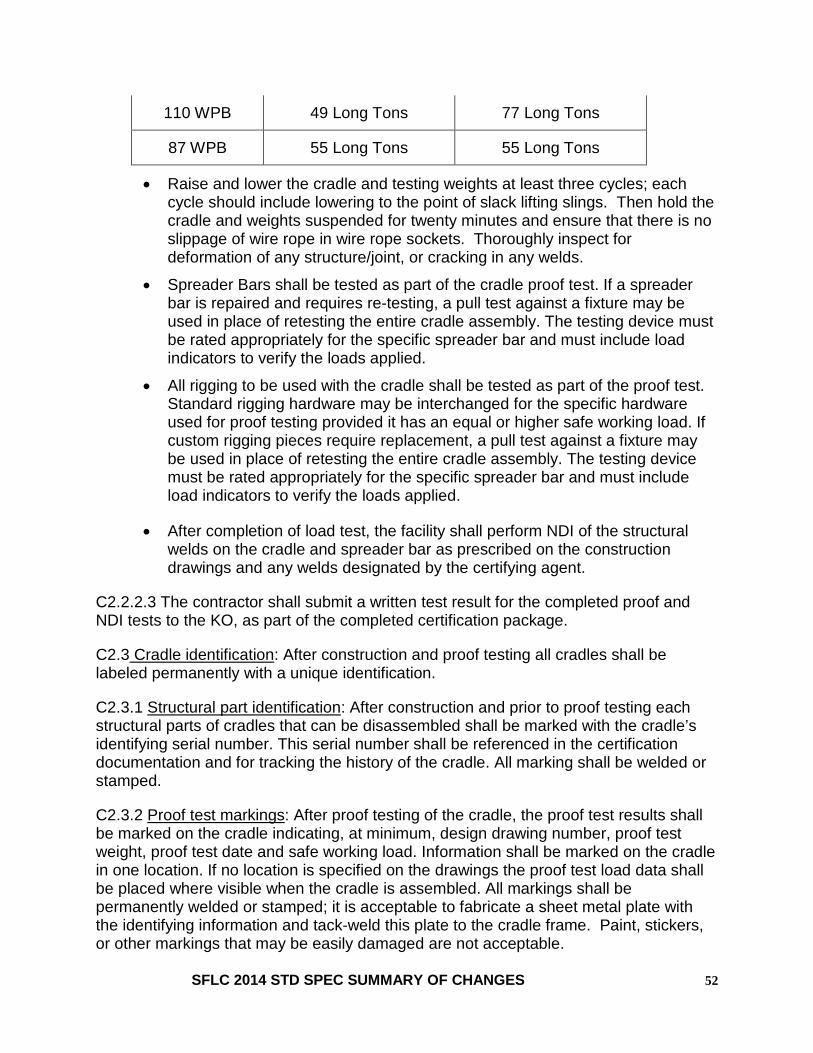
110 WPB 49 Long Tons 77 Long Tons
87 WPB 55 Long Tons 55 Long Tons
• Raise and lower the cradle and testing weights at least three cycles; each cycle should include lowering to the point of slack lifting slings. Then hold the cradle and weights suspended for twenty minutes and ensure that there is no slippage of wire rope in wire rope sockets. Thoroughly inspect for deformation of any structure/joint, or cracking in any welds.
• Spreader Bars shall be tested as part of the cradle proof test. If a spreader bar is repaired and requires re-testing, a pull test against a fixture may be used in place of retesting the entire cradle assembly. The testing device must be rated appropriately for the specific spreader bar and must include load indicators to verify the loads applied.
• All rigging to be used with the cradle shall be tested as part of the proof test. Standard rigging hardware may be interchanged for the specific hardware used for proof testing provided it has an equal or higher safe working load. If custom rigging pieces require replacement, a pull test against a fixture may be used in place of retesting the entire cradle assembly. The testing device must be rated appropriately for the specific spreader bar and must include load indicators to verify the loads applied.
• After completion of load test, the facility shall perform NDI of the structural welds on the cradle and spreader bar as prescribed on the construction drawings and any welds designated by the certifying agent.
C2.2.2.3 The contractor shall submit a written test result for the completed proof and NDI tests to the KO, as part of the completed certification package.
C2.3 Cradle identification: After construction and proof testing all cradles shall be labeled permanently with a unique identification.
C2.3.1 Structural part identification: After construction and prior to proof testing each structural parts of cradles that can be disassembled shall be marked with the cradle’s identifying serial number. This serial number shall be referenced in the certification documentation and for tracking the history of the cradle. All marking shall be welded or stamped.
C2.3.2 Proof test markings: After proof testing of the cradle, the proof test results shall be marked on the cradle indicating, at minimum, design drawing number, proof test weight, proof test date and safe working load. Information shall be marked on the cradle in one location. If no location is specified on the drawings the proof test load data shall be placed where visible when the cradle is assembled. All markings shall be permanently welded or stamped; it is acceptable to fabricate a sheet metal plate with the identifying information and tack-weld this plate to the cradle frame. Paint, stickers, or other markings that may be easily damaged are not acceptable.
SFLC 2014 STD SPEC SUMMARY OF CHANGES 52

Summary of changes to SFLC Standard Specification 8635 Temporary Services
Revision of the 2012 Temporary Services Standard Specification includes reference updates, format changes, and changes documented below. All references to prior editions of SFLC Standard Specifications were updated to 2014 edition.
1. SCOPE
None
2. REFERENCES
None
3. REQUIREMENTS
3.3.2 Telephone and internet access. Added “The Coast Guard Inspector will define the split of these telephone and internet access lines between the office space and to the cutter point of service. The cutter point of service is defined as the telecommunications space(s) containing the ship's telephone switch and connectivity equipment, unless otherwise identified by the Coast Guard Inspector.“ Revised requirement for a minimum of one line shall be HDSL to two lines shall be HDSL. Deleted “from the local telephone company’s entrance facility demarcation point to the” and deleted” One line, other than that for the Watchstander, shall be suitable for connecting to a facsimile machine”.
3.3.2.2 Deleted Note “One line shall be capable of facsimile transmission and one shall be set up for HDSL”
3.3.5.3.2 Table III Electrical Capabilities. Added Note “Cutter has capability to support 3x400 A, which may be required as designated by the specification.”
.
SFLC 2014 STD SPEC SUMMARY OF CHANGES 53

Summary of changes to SFLC Standard Specification 8636 Temporary Hull Access
Revision of the 2012 Temporary Hull Access Standard Specification includes reference updates, format changes, and changes documented below. All references to prior editions of SFLC Standard Specifications were updated to 2014 edition.
1. SCOPE
None.
2. REFERENCES
Added NAVSEA S0600-AA-PRO-160/CH16, Nov 2011, Underwater Ship Husbandry Manual, Chapter 16 Cofferdams
Added MIL-C-20079, July 1987, Cloth, Glass; Tape, Textile Glass; and Thread, Glass and Wire-Reinforced Glass
3. REQUIREMENTS
3.1 Prior Approval. Revised to state “Holes or openings, except those shown or indicated by drawings or specifications must not be cut in any watertight bulkhead, deck, or shell plating except as approved by the KO. No cuts shall be made in sheer, stringer or bilge strakes, or in the flat keel unless approved by the KO, on a case-by-case basis. “
3.2 Drawing submission. Revised added bullets; • Welding details and procedures for removal and reinstallation of access
closure plates (including weld sequence, design and material of closure plate(s), and indication of any permanent or temporary weld backing straps, or ceramic backing materials).
• Indication of any cutback of existing welds forming the boundary of the access cuts and the welding sequence for (re)installation of the closure plate.
• Nondestructive inspections and Structural Boundary tests for completed installations.
3.3.1 Added “Location of boundaries. Boundaries of access cuts and closure plates shall, in general, be located between principal ship framing, bulkheads, and other structural members and shall be at least three inches from any of these members or from the toes of other welds. A reduction in this three inch minimum may be approved by the KO on a case by case basis provided sufficient clearance is maintained for welding and inspection requirements. The boundaries of access cuts and closure plates should land on existing butts or seams, wherever practicable. The boundaries of prior access cuts should be utilized wherever possible. Boundaries may extend across one or more frames as required for the size of the opening.
SFLC 2014 STD SPEC SUMMARY OF CHANGES 54

Added 3.3.2 Access hole dimensions and arrangements. Holes or access cuts shall be the minimum size necessary and shall be in accordance with the following:
• Rectangular access cuts and closure plates welded into primary hull structure shall be at least 12 inches wide in the lesser dimension.
• For circular access cuts, the minimum diameter shall be 4T, where T = thickness of the involved structural member, but not less than three inches.
• Circular closure plates for access cuts less than two feet in diameter shall be dished 1/16 to 1/8 inch to allow for shrinkage when welded.
• Corners of rectangular access cuts and closure plates shall have a minimum radius of 6 inches except when a boundary lands on an existing hull longitudinal seam or transverse butt weld.
• Corners at an existing seam or butt shall intersect at a 90 degree angle. • Cuts that are to cross existing butts or seams shall do so at an angle of 90
degrees plus or minus 15 degrees. • In primary hull structure, existing welds forming the boundary of a cut shall be
cut back 3 inches beyond the toe of the access cut, except that the cut back shall not intersect or cross an existing weld, frame, or structural member. In which case, the cut back may be reduced to a minimum of two inches in length.
• Existing welds crossed by the cut shall not be cut back.
Added 3.3.3 Primary hull structure. Primary Hull Structure includes the shell, main strength decks, principal longitudinal bulkheads, vertical keel, deep web girders and stiffeners designed to withstand the ship bending stress.
Added 3.3.4 Mechanically fastened joints. Welding closer than six inches to a mechanically fastened joint should be avoided. When access cuts cross or come within six inches of a mechanically fastened joint, the fasteners shall be checked for tightness and if necessary, loose fasteners shall be seal welded or removed, and replaced for a distance of 6 inches beyond the edge of the cut. When a cut crosses a mechanically fastened seam the cut plates shall be repaired using single V welds backed with glass tape (MIL-C-20079) to prevent fusion between the mechanically fastened plates. 3.4 Ship integrity maintenance. Added “For shell plating cuts made at or below the waterline where temporary closures are impractical, the Contractor shall secure each vulnerable compartment and subdivision to minimize potential damage to the extent permitted by the scope and urgency of the work.”
3.4.2 Coaming. Revised to state “Ensure that in areas where flammable liquids may be stored, a 4 inch high metal coaming shall be installed on the surface of the deck with tack welds and fully sealed with caulking compound. The coaming shall encircle the access cut in the deck.’
3.4.3 Weathertight and contamination closures. Added “(shall include a coaming or dam on the deck to redirect rain runoff away from the opening). “ to first bullet, and added new bullet “Where the access opening is in way of a removed hatch, scuttle or door, the closure shall be configured to allow normal passage of ship’s personnel and equipment.”
SFLC 2014 STD SPEC SUMMARY OF CHANGES 55

3.4.4 Watertight closures. Revised Note by deleting “Watertight closures may include a watertight box patch with strongback.” and stating “NAVSEA S0600-AA-PRO-160/CH16 provides requirements for design, fabrication, and installation of temporary watertight closures.” 3.5 Closure plate restoration. Added “Access closure weld joints shall be full penetration. Welds in primary hull structure or in watertight boundaries, shall be full penetration welds without permanent backing straps”.
Added 3.6 Testing and inspection. Nondestructive examination (NDE) and compartment/boundary testing shall be in accordance with SFLC Std Spec 0740, Appendix C.
Deleted Section 4. Notes.
Deleted Informational guidance for access boundaries. The following informational guidance is provided to assist the Contractor during the performance of the work specified herein:
Deleted Location of boundaries. Boundaries should be between ship framing, bulkheads, and other structural members. When use of existing seams is not practical, cuts should be at least two inches from these members and the toes of other butt welds. Joints within critical welds (watertight boundaries) shall be full penetration welds without permanent backing straps.
Deleted Extent of boundaries. Boundaries may extend across one or more frames as required for the size of opening.
Deleted Boundary restrictions. Access cut boundaries should not be made in the sheer, stringer, or bilge strakes, or in the flat keel unless specifically approved by the KO.
Deleted Cross welds. Access cuts should intersect or cross existing butts at right angles. Cut back intersecting welds six inches beyond the weld toe of the access cut. The cut back must not intersect or cross an existing weld, frame, or structural member, and may be reduced to a minimum length of two inches if needed to prevent such an intersection.
SFLC 2014 STD SPEC SUMMARY OF CHANGES 56
Copyright © 2022 FDOKUMEN