PREFACE The Standard Specifications have been prepared ...
32
PREFACE The Standard Specifications have been prepared to complement and include by reference the Standard Detail Drawings and to provide the qualitative requirements for products, materials and workmanship for construction of additions to and replacements of the water distribution system which is to be operated by, or is to be assured by a trust indenture with, the Board of Commissioners, Lowndes County, Georgia as well as the requirements for products, materials and workmanship for construction of additions to and replacements of the wastewater collection and transfer system which is to be operated by, or to be assured by a trust indenture. These Standard Specifications are only to be used for projects with Drawings which have been approved by the Georgia Environmental Protection Division, as prepared by the County's design consultant, or by a developer's engineer, whose Drawings must first be approved by Lowndes County. All references to "Project" shall mean the work being constructed under the jurisdiction of these Standard Specifications. All references to "Contractor" shall mean the individual, company or corporation constructing work under the jurisdiction of these Standard Specifications. All references to "Drawings" shall include, by reference, the Standard Detail Drawings accompanying these Standard Specifications. These Standard Specifications are subject to revision for a specific project, with such revisions noted on the Drawings approved by Lowndes County. Revised June 2009 BP Barber Project No.: 07606
-
Upload
khangminh22 -
Category
Documents
-
view
2 -
download
0
Transcript of PREFACE The Standard Specifications have been prepared ...

PREFACE The Standard Specifications have been prepared to complement and include by reference the Standard Detail Drawings and to provide the qualitative requirements for products, materials and workmanship for construction of additions to and replacements of the water distribution system which is to be operated by, or is to be assured by a trust indenture with, the Board of Commissioners, Lowndes County, Georgia as well as the requirements for products, materials and workmanship for construction of additions to and replacements of the wastewater collection and transfer system which is to be operated by, or to be assured by a trust indenture. These Standard Specifications are only to be used for projects with Drawings which have been approved by the Georgia Environmental Protection Division, as prepared by the County's design consultant, or by a developer's engineer, whose Drawings must first be approved by Lowndes County. All references to "Project" shall mean the work being constructed under the jurisdiction of these Standard Specifications. All references to "Contractor" shall mean the individual, company or corporation constructing work under the jurisdiction of these Standard Specifications. All references to "Drawings" shall include, by reference, the Standard Detail Drawings accompanying these Standard Specifications. These Standard Specifications are subject to revision for a specific project, with such revisions noted on the Drawings approved by Lowndes County.
Revised June 2009 BP Barber Project No.: 07606

Table of Contents
1-1 STANDARD SPECIFICATIONS Division 0 – Bidding and Contract Requirements Section Title 00005 Table of Contents 00100 Information for Bidders 00350 Bid Bond 00500 Contract 00600 Performance Bond 00601 Payment Bond 00602 Notice of Award 00603 Contract Change Order 00606 Notice to Proceed 00690 Contractor's Affidavit 00851 Drawings Index Division 1 - General Requirements 01569 Safety in Wastewater Works 01740 Warranties and Bonds Division 2 - Sitework 02110 Clearing and Grubbing 02125 Erosion, Sedimentation and Pollution Control 02200 Basic Pipeline Construction 02225 Trench Excavation and Backfill 02229 Bore and Jack Casings 02575 Removing and Replacing Pavement 02665 Water Mains and Accessories 02668 Water Service Connections 02669 Pumping Station Water Service 02730 Sewers and Accessories 02731 Force Mains 02732 Low Pressure Force Mains and Service Connections 02735 Sewer Service Connections 02831 Chain Link Fences and Gates Division 11 - Equipment 11245 Submersible Pumps
Revised June 2009 BP Barber Project No.: 07606

Table of Contents
1-2 11250 Semi-positive Displacement Type Grinder Pump Station Division 16 - Electrical 16000 Electrical Power and Systems 16050 Basic Electrical Material and Methods 16111 Conduit 16120 Wire and Cable 16130 Boxes 16160 Cabinets and Enclosures 16455 Grounding 16622 Package Engine Generator Set STANDARD DETAIL DRAWINGS LC - 1 Sediment Barrier - Silt Fence LC - 2 Sediment Barrier - Hay Bale LC - 3 Storm Drain Outlet Protection LC - 4 Stone Check Dam LC - 5 Construction Exit LC - 6 Trench Terminology LC - 7 Pipe Bedding and Haunching – Water Main LC - 8 Pipe Bedding and Haunching - Gravity Sewer LC - 9 Pipe Bedding and Haunching - Force Main LC - 10 Concrete Encasement LC - 11 Concrete Pavement Replacement LC - 12 Asphalt Pavement Replacement LC - 13 Waterstop Collar LC - 14 Typical Blocking LC - 15 Chain-Link Fence Elevation LC - 16 Bollard LC - 17 Ditch, Creek and River Crossing Detail LC - 19 Highway Bore and Jacking LC - 20 Railroad Bore and Jacking LC - 21 Casing Spacers LC - 22 Water Main Termination LC - 23 Fire Hydrant LC - 24 2" Flushing Hydrant LC - 25 Butterfly Valve Installation LC - 26 Gate Valve Installation LC - 27 Extension Stem LC - 28 Water Valve Marker LC - 29 Valve Box for Underground Valve
Revised June 2009 BP Barber Project No.: 07606

Table of Contents
1-3
Revised June 2009 BP Barber Project No.: 07606
LC - 30 Manual Air Release Valve LC - 31 Water Services - Single Service LC - 32 Water Service & Meter Connection LC - 33 Backflow Preventer LC - 34 Wastewater Combination Air Valve Manhole LC – 34A Wastewater Combination Air Valve Manhole in Floodplain LC - 35 Concrete Force Main Marker Post LC - 36 Force Main Discharge Manhole Type 1 LC - 37 Force Main Discharge Manhole Type 2 LC - 38 Typical Manhole Frame & Cover LC - 39 Precast Concrete Manhole LC - 40 Standard Manhole LC - 41 Rubber Boot LC - 42 Precast Concrete Shallow Manhole LC - 43 Precast Manhole Over Existing Sewer LC - 44 Concrete Pier LC - 45 Concrete Pier LC - 46 Pipe Anchorage LC - 47 Pipe Strap LC - 48 Service Connection LC - 49 Cleanout LC - 50 Pumping Station (6' Diameter Wetwell) LC - 51 Pumping Station (8' Diameter Wetwell) LC - 52 Pumping Station Emergency Bypass Piping LC - 53 Non-Freeze Post Hydrant LC - 54 Precast Concrete Interceptor LC - 55 MultiTrode Level Sensor Support LC - 56 Pressure Gauge Mounting Detail LC - 57 Dual Support Stand Detail LC - 58 Generator Pad DetailLC - 59 E-One: Typical Lateral Installation LC - 60 E-One: Typical Outdoor Installation LC - 61 E-One: Semi-positive Displacement Type Grinder Pump Station LC - 62 E-One: Plastic Lateral Assembly LC - 63 E-One: Typical Flushing Connection on LPSS Main LC - 64 E-One: Typical One Directional Flushing Connection LC - 65 E-One: Typical Drop Connection LPSS in Existing Manhole LC - 66 E-One: Control Panel STANDARD FORMS Pipeline Testing Forms

Table of Contents
1
Section 1 Policies and Procedures Section 2 Applicable Water and Wastewater Standards Section 3 Water Supply, Treatment and Distribution System - Design Requirements Section 4 Sanitary Sewage System - Design Requirements Section 5 Wastewater Pumping - Design Requirements
Revised June 2009 BP Barber Project No.: 07606

Policies and Procedures - Section 1
1-1
1.01 SCOPE AND INTENT The intent of these Policies and Procedures is to establish minimum requirements and
guidelines for water and sanitary sewer projects constructed in Lowndes County. The procedures will apply to all water and sewer development and construction projects, both public and private, within the jurisdiction of Lowndes County. The procedures shall also apply to all existing water and sanitary sewer facilities including septic tanks which are being upgraded or have failed and are being corrected, both public and private, within the jurisdiction of Lowndes County.
1.02 PURPOSE The Lowndes County Board of Commissioners recognizes that water is a natural
resource of limited supply and sewage treatment and disposal is a necessity for public health. Thus, the water supply must be regulated and controlled and subjected only to reasonable and beneficial use to assure an adequate supply of water and adequate sewage treatment capacity for all members of the public served by the Lowndes County Utility System. Therefore, the supply of water and sewage disposal service by the Lowndes County Utility System to any development is subject to regulation, prohibition, limitation and restriction by local, state and federal governmental agencies, including the board of health, as well as Lowndes County.
1.03 DEFINITIONS A. County: Board of County Commissioners, Lowndes County, Georgia or its authorized
representative. B. County Utility System: The Lowndes County public water and sewer system.
C. Developer: Any person, firm, corporation, association or partnership or any agent thereof who undertakes or proposes to undertake the development of land so as to constitute a residential subdivision, apartment complex, condominium, or commercial/industrial/institutional establishment.
D. Contractor: Agent of developer or developer that will construct water and/or sewer
infrastructure. 1.04 VARIANCES Under special conditions with specific applications the procedures and policies may be
altered to meet certain conditions that are beyond the control of the Developer, provided
Revised June 2009 BP Barber Project No.: 07606

Policies and Procedures - Section 1
1-2
such alterations or deviations are acceptable to the County. Final decisions concerning such alterations shall be made by the Board of County Commissioners or its designee.
1.05 PRE-DESIGN CONFERENCE It is recommended that each Developer initiate a pre-design conference between
himself, his Engineer, and the County. 1.06 TRUST INDENTURE A. To assure continuity of maintenance and operation of a non-governmentally owned
community water and/or sewerage system, the Developer shall file a trust indenture or other legal contract or agreement with the Georgia State Department of Natural Resources (DNR), Environmental Protection Division (EPD) for their review and approval. For new or proposed systems, the legal document shall be submitted with the plans and specifications in accordance with DNR Rules for Safe Drinking Water, Rule 391-3-5-.04(3) and DNR Rules and Regulations for Water Quality Control, Rule 391-3-6-.06(13). The County's participation in and supporting of any non-county owned utility system as trustee, is conditioned on:
1. The proposed water and sewer system being planned and designed in accordance
with these County standards and specifications. 2. A trust deed or other legal contract being prepared by the Developer(s) in form
and content acceptable to the County. 3. All costs associated with preparation of plans and specifications (including
reviews by the County or its designated representative) and the trust deed or legal contract, being borne by the Developer.
1.07 CONNECTION TO EXISTING SYSTEM New connections to the existing County Utility System are subject to all County
standards, specifications, codes, and ordinances as they pertain to water and sewer systems and/or facilities.
1.08 EXISTING SUBDIVISION REGULATIONS The requirements of these Policies and Procedures for water and sewer systems shall be
in addition to the requirements of the "Subdivision Regulations for Lowndes County, Georgia", printed 1980, and all amendments thereto.
Revised June 2009 BP Barber Project No.: 07606

Policies and Procedures - Section 1
1-3
1.09 CONVEYANCE OF EXTENSION TO COUNTY UTILITY SYSTEM The Developer shall construct and convey to the County, free and clear of all
encumbrances and at no cost to the County, the extension to the County Utility System and the complete water and/or sewer system on the Developer's property. Developer shall submit to the County, engineering plans and specifications for the proposed extension prepared by the Developer's Engineer, which shall be approved in writing by the County prior to any construction work being done. Following conveyance by the Developer, the extension and any additions, repairs and replacements thereto shall at all times remain the sole, complete and exclusive property of and under the control of the County, and the Developer shall have no right or claim in or to the Developer's extension; provided, however, that the extension shall be used for providing service to the development.
1.10 FEES A. Capacity and Other Fees: Water and/or sewer fees shall be charged for each
establishment, structure and use added to the County Utility System. Prior to receiving final approval from the County, the Developer will pay the current fees presently charged for connections to the County Utility System as stipulated in the pertinent County code establishing rates, charges and regulations for water and/or sewer systems.
B. Planning and Inspection Fees: The Developer shall pay a planning, inspection and
review fee in order to defray all actual costs to the County, including any attorneys' fees, of:
1. Conducting the review of the engineering plans and specifications; 2. Conducting the inspection and testing of the installation of the water and/or sewer
extension; and 3. All other administrative costs incident to either accepting the extension into the
County Utility System or becoming trustee of a non-county-owned system. C. Fees shall be paid in full prior to receiving County approval of plans and specifications. 1.11 GRANT OF EASEMENT RIGHTS Developer shall grant to County, its successors and assigns, the exclusive, perpetual
right, privilege and easement to construct, reconstruct, operate, maintain, repair, replace, improve, alter, remove, relocate and inspect water transmission and distribution mains, sewage collection mains, sewage lift stations, water wells, water plants, sewage
Revised June 2009 BP Barber Project No.: 07606

Policies and Procedures - Section 1
1-4
treatment plants, pipelines, lateral lines, valves, connections and appurtenant equipment over, across and under the strip of land wherein system lies on the Developer's property, together with the right of ingress and egress to each of the building sites on Developer's property which are to be served by the County Utility System. The easement rights granted with respect to public places shall be subject to the authority of the public authority having jurisdiction over such public places. Prior to the County Utility System providing service to the development, the Developer shall execute a grant or grants of easement, in recordable form to be approved by the County, specifically granting to the County the above rights necessary, in the discretion of the County to provide water and/or sewer utility service to the Developer's property. The County shall not be obligated to furnish any water or sewer service to any building which may be built on Developer's property to which it does not have access.
1.12 DEVELOPER'S RIGHT TO CONNECT Provided that the Developer has complied with the terms of these Policies and
Procedures and provided that the Developer's extension is installed with the approval of the County and in compliance with the requirements of all public, governmental or other agencies having supervision, regulation, direction or control of such water and sewage utility systems, the County shall allow the Developer or its successor-in-title to connect the Developer's extension into the County Utility System.
1.13 UNDERGROUND UTILITY CONTRACTOR A. All extensions and additions to the County Utility System shall be performed by a
Georgia Licensed Utility Contractor, or by the County's own work force. B. The County reserves the right to approve in writing the underground utility contractor
and/or his subcontractor installing utility lines for the Developer under the terms of these Policies and Procedures.
1.14 DEVELOPER'S PLANS AND SPECIFICATIONS A. All engineering plans and specifications prepared by Developer's Engineer, as provided
in Article 1.09 above, shall be reviewed and approved by the County prior to Developer submitting plans and specifications to any other governmental agencies. The Developer's Engineer shall include, explicitly or by reference, into the Developer's engineering design, plans and specifications, the applicable standards and specifications of Lowndes County.
B. As a minimum, for the following types of facilities, include the indicated information:
Revised June 2009 BP Barber Project No.: 07606

Policies and Procedures - Section 1
1-5
1. Gravity Sewers a. Plan and Profile at a scale no smaller than 1 inch = 100 feet horizontal and 1
inch = 10 feet vertical. b. Stations on manholes or distances between manholes. c. Deflection angles between manholes or coordinates of manholes. 2. Force Mains a. Plan and Profile at a scale no smaller than 1 inch = 100 feet horizontal and 1
inch = 10 feet vertical. b. Locations of air release valves. 3. Water Mains a. Plan at a scale no smaller than 1 inch = 100 feet. b. Location of valves, hydrants and service lines. 4. Pump Stations a. Site Plan at scale no smaller that 1 inch = 20 feet. b. Location of wetwell, valve vault, generator, by-pass valve, access road,
parking area, and fence. 1.15 INSTALLATION AND INSPECTION The Developer's water and/or sewer systems shall be installed in accordance with the
Engineering plans and specifications approved by the County. The County shall have the right, but not the obligation, to make inspections as installation progresses. The County shall not accept Developer's water and/or sewer systems and will issue no certifications until all manhole covers and valve boxes are exposed at proper finish grade and valves are operational and all other pertinent County generated punch list items are complete. Failure to contact the County for inspection before construction begins will result in additional testing and or verifications that utilities have been installed as to the construction plans and specifications; and at the Contractors expense. On County funded projects, Contractor will be subject to non-payment of utilities placed prior to notification.
1.16 TEST OF DEVELOPER'S SYSTEM The County will not accept Developer's water and/or sewer system until new facilities
have passed all pre-determined tests, including bacteriological tests for water systems, arranged by the Developer and witnessed by the County, or its representative, to
Revised June 2009 BP Barber Project No.: 07606

Policies and Procedures - Section 1
1-6
determine whether the facilities are constructed in accordance with the approved engineering plans and specifications. Developer will pay all costs of locating leaks and their repairs deemed necessary by the County as a result of said tests.
1.17 CONDITIONS PRECEDENT TO SYSTEM USAGE A. Prior to the County accepting the water and/or sewer systems, Developer shall comply
with all terms of these Policies and Procedures and shall: 1. Provide to the County releases of liens received by the Developer, or its agent, in
connection with the construction of the facilities. 2. Furnish the County with Record Drawings as specified in Article 1.36. 3. Furnish, in form and substance acceptable to the County, all of the following
relating to the facilities: a. All permits and governmental approvals obtained by the Developer, its
contractors and agents. b. Certification by Developer's Engineer that the facilities have been
constructed substantially in accordance with approved plans and specifications.
c. As-constructed drawings certified by the Developer's Engineer. 1.18 CONSTRUCTION UTILITY SERVICE The County shall not provide water or sewer service for construction on an unmetered
basis, and Developer agrees that all charges, including all minimum charges for water and sewer service, shall be paid from the date of meter installation in accordance with County's approved rate schedule.
1.19 RIGHT OF TERMINATION OF SERVICE The County shall refuse to provide service and reserves the right to terminate service to
any lot or building within Developer's property, in the event Developer defaults or fails to comply with any of the terms and conditions of these Policies and Procedures in a timely manner and fails to cure such default or fails to comply
within 30 consecutive calendar days following the receipt by Developer of County's
notice of such default or failure to comply. 1.20 LIMITATION OF LIABILITY OF COUNTY
Revised June 2009 BP Barber Project No.: 07606

Policies and Procedures - Section 1
1-7
The County shall not be liable or responsible to the Developer as a result of injury to
property or person, which injury was created by acts of God, strikes, lockouts, or other industrial disturbances, acts of public enemy, wars, blockades, riots, acts of armed forces, epidemics, delays by carriers, inability to obtain materials or right-of-way on reasonable terms, acts of public authorities, acts of vandals or other third parties, or any other causes whether or not of the same kind as enumerated herein. In no event shall the County be liable to Developer or any customer for any consequential, incidental or punitive damages as a result of injury to property or person, regardless of whether said injury was the result of acts of or within the control of the County.
1.21 APPROVAL BY GOVERNMENTAL AGENCIES The County's obligations are contingent upon Developer obtaining all necessary
approvals for water and/or sewer systems from all concerned governmental agencies. Developer assumes the risk of loss as a result of the denial or withdrawal of the approval of any concerned governmental agency, or caused by an act of any governmental agency which affects the ability of the County to provide water and sewer service to Developer not within the sole control of the County and which, by exercise of due diligence, it is unable to overcome.
1.22 NO PROHIBITION OF FURTHER EXTENSION These Policies and Procedures shall not prohibit or prevent the County from extending
the County Utility System in or to other areas to serve other Developers or customers, so long as extensions and the furnishing of services do not interfere with the furnishing of the services to the Developer's establishment.
1.23 FINAL ACCEPTANCE BY COUNTY Final acceptance by the County of the completed water and/or sewer system shall occur
at such time that the Developer/Contractor has met all of the terms and conditions of these “General Requirements for Water and Wastewater System”, latest edition, all engineering test and evaluations have been completed, passed and approved by the County, all punch-list items have been addressed to the County’s satisfactions and Record Drawings have been submitted and approved by the County. Once Record Drawings have been approved, final payment will be issued on County funded projects. The warranty period shall be considered in effect from the approval date marked on the Record Drawings.
1.24 WARRANTY AND SECURITY
Revised June 2009 BP Barber Project No.: 07606
Policies and Procedures - Section 1
1-8
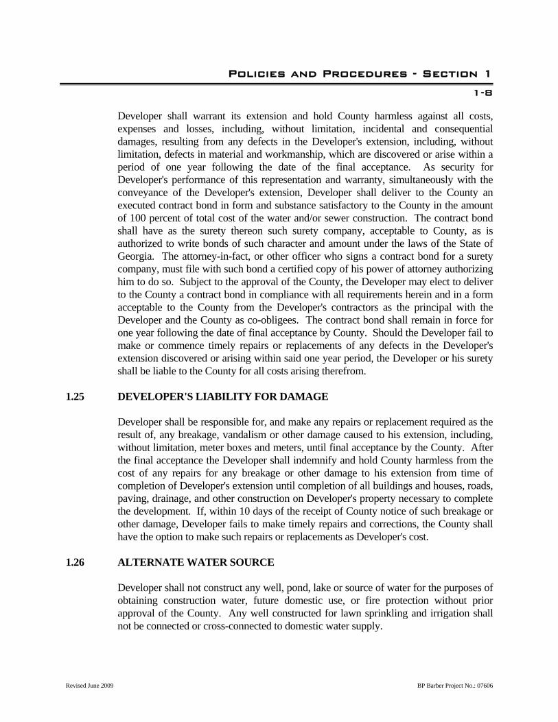
Developer shall warrant its extension and hold County harmless against all costs, expenses and losses, including, without limitation, incidental and consequential damages, resulting from any defects in the Developer's extension, including, without limitation, defects in material and workmanship, which are discovered or arise within a period of one year following the date of the final acceptance. As security for Developer's performance of this representation and warranty, simultaneously with the conveyance of the Developer's extension, Developer shall deliver to the County an executed contract bond in form and substance satisfactory to the County in the amount of 100 percent of total cost of the water and/or sewer construction. The contract bond shall have as the surety thereon such surety company, acceptable to County, as is authorized to write bonds of such character and amount under the laws of the State of Georgia. The attorney-in-fact, or other officer who signs a contract bond for a surety company, must file with such bond a certified copy of his power of attorney authorizing him to do so. Subject to the approval of the County, the Developer may elect to deliver to the County a contract bond in compliance with all requirements herein and in a form acceptable to the County from the Developer's contractors as the principal with the Developer and the County as co-obligees. The contract bond shall remain in force for one year following the date of final acceptance by County. Should the Developer fail to make or commence timely repairs or replacements of any defects in the Developer's extension discovered or arising within said one year period, the Developer or his surety shall be liable to the County for all costs arising therefrom.
1.25 DEVELOPER'S LIABILITY FOR DAMAGE Developer shall be responsible for, and make any repairs or replacement required as the
result of, any breakage, vandalism or other damage caused to his extension, including, without limitation, meter boxes and meters, until final acceptance by the County. After the final acceptance the Developer shall indemnify and hold County harmless from the cost of any repairs for any breakage or other damage to his extension from time of completion of Developer's extension until completion of all buildings and houses, roads, paving, drainage, and other construction on Developer's property necessary to complete the development. If, within 10 days of the receipt of County notice of such breakage or other damage, Developer fails to make timely repairs and corrections, the County shall have the option to make such repairs or replacements as Developer's cost.
1.26 ALTERNATE WATER SOURCE Developer shall not construct any well, pond, lake or source of water for the purposes of
obtaining construction water, future domestic use, or fire protection without prior approval of the County. Any well constructed for lawn sprinkling and irrigation shall not be connected or cross-connected to domestic water supply.
Revised June 2009 BP Barber Project No.: 07606

Policies and Procedures - Section 1
1-9
1.27 LIMITED RESERVATION OF TREATMENT CAPACITY The reservation of water and/or sewage treatment capacity will be limited to the actual
number of equivalent residential units (ERU's) committed by the County to the development pursuant to preconstruction approval of the water and/or sewage system facilities.
1.28 PERIOD OF CONSTRUCTION Developer must begin construction of water and/or sewer facilities within 360
consecutive calendar days from the date of final County approval of drawings and specifications, and shall not cease for a continuing period of 360 consecutive calendar days or until final completion and acceptance of the constructed facilities, whichever is sooner. Should the Developer not strictly adhere to these time frames, then any obligations or duties of the County shall be null and void.
1.29 MODIFICATION OF DEVELOPMENT PLANS Should the Developer modify his development plans which would require greater water
usage, greater fire flows, additional water facilities, greater sewage flows, or additional sewage facilities than the water and sewage service demands designed and approved under the engineering plans and specifications, then Developer shall enter into a new agreement with the County providing for the construction of such additional water and/or sewer facilities meeting all County and governmental design requirements and shall pay all additional contributions and fees as may be required.
1.30 NOTICE OF CONNECTION TO COUNTY UTILITY SYSTEM Developer shall deliver to the County written notice that he will be connecting the water
or sewer facilities to the County utility water or sewer system no less than 24 hours prior to said connection to allow time for County inspection. If Developer fails to provide timely written notice, the County may require Developer to uncover and expose connection for inspection, at the sole cost of Developer.
1.31 INTERRUPTION OF FACILITY OPERATIONS A. The Developer shall provide the County with written notice at least five days prior to
any proposed interruption in facility operations required by construction activity. The notice shall include the date and time of the scheduled interruption; the length of time the interruption will be in effect; the procedures to be followed in effecting the interruption; a complete identification of all those processes, equipment and operations to be affected; and all other information the County may require. The Developer shall
Revised June 2009 BP Barber Project No.: 07606
Policies and Procedures - Section 1
1-10
provide all equipment, piping, auxiliary power or other means necessary to sustain facility operations or function for the planned interruptions.
B. The County must approve all proposed interruptions in facility operations. Such
approval will be provided by the County to the Developer in writing. C. The Developer shall conduct operations in a manner and sequence which will provide
for the continued transportation of wastewater flows during construction of the Developer's project. The Developer shall take all actions required to prevent discharge of sewer flow from the system to the ground or stream. Any construction actions that impede or interrupt flow shall be carefully executed and monitored to prevent surcharging and overflow.
D. Any damages resulting from surcharging, overflow or back-up caused by the
Developer's operations shall be the Developer's responsibility. Fines charged the County for overflows caused by the Developer shall be paid for by the Developer.
1.32 CROSS CONNECTIONS There shall be no cross connections between the County Utility System water system
and any possible source of contamination such as non-potable water system or non-permitted water system, sewer, drain, conduit, pool, storage reservoir, plumbing fixture, sprinkler system, etc. In addition, there shall be no connection between the County Utility System water system and any privately owned water system.
1.33 CONNECTION OF BUILDINGS The Developer shall at his sole cost and expense connect the private property water
pipes and the private property sewer pipes of each dwelling or other building constructed on Developer's property to the meters and sewer laterals of Developer's extension as reflected in plans and specifications approved by the County. Any water line which serves a sprinkler fire line must have a backflow prevention device installed on the downstream side of the water meter. The backflow prevention device and its installation shall be as approved by the County.
1.34 APPLICATION FOR SERVICE Developer, his successors, or the occupant(s) of the developer's property, shall make
written application to the County for the opening of an account(s) for service. Application is to be made only after the payment of all water and/or sewer fees. At the time of making application for service, the applicant shall pay all service charges as set forth in the current County code(s) establishing rates, charges and regulations pertaining
Revised June 2009 BP Barber Project No.: 07606

Policies and Procedures - Section 1
1-11
to the County water and/or sewer systems. 1.35 NOTICE OF TRANSFER OF DEVELOPER'S PROPERTY Developer agrees to provide proper written notice to County of the actual date of the
legal transfer of water and/or sewer services from Developer to any third party. Developer shall remain responsible for all costs and expenses, including utility bills, which arise as a result of Developer's failure to notify or improper notification to the County.
1.36 RECORD DRAWINGS A. Record Drawings shall be submitted in the following format: 1. Reproducible mylars, 2. Two sets of blueline prints, and 3. Electronic format, AutoCAD Release 14 or later, on 3-1/2-inch disks or CD-
ROM. B. Record Drawings shall be reproducible, shall have a title block indicating that the
drawings are Record Drawings, the name of the company preparing the Record Drawings, and the date the Record Drawings were prepared. A separate title block for Record Drawing Approval by the Lowndes County Utility Division shall also be provided.
C. Legibly mark drawings to record actual construction, including: 1. All Construction a. Changes of dimension and detail. b. Changes made by Requests for Information (RFI), field order, clarification
memorandums or by change order. c. Details not on original Drawings. 2. Underground Utilities a. Horizontal and vertical locations of all exposed and underground utilities
and appurtenances, both new facilities constructed and those utilities
Revised June 2009 BP Barber Project No.: 07606

Policies and Procedures - Section 1
1-12
Revised June 2009 BP Barber Project No.: 07606
encountered, referenced to permanent surface improvements. This shall include, but not be limited to, all mains, valves, water service locations, sewer lateral locations, manholes, fittings, fire hydrants, piping arrangements, and electrical conduits within the completed facilities.
b. Location of and dimensions of roadways and parking areas, providing dimensions to back of curb when present.
c. The locations shall be referenced to at least two easily identifiable, permanent landmarks (e.g., power poles, valve markers, etc.) or benchmarks.
d. Depths of various elements of foundation in relation to finish first floor datum or top of wall.
e. Location of internal and buried utilities and appurtenances concealed in the construction, referenced to visible and accessible features of the structure.
f. For sewers, the Record Drawings shall include the horizontal angle and distance between manhole covers.
g. For force mains, the profile of the top of the pipe shall be provided. Elevations, not depths, shall be provided at a minimum 100-foot interval and at all bends, high points, low points, air valves, and where elevations are called out on the Drawings.
D. Precision 1. Unless noted otherwise, Record Drawings shall provide horizontal dimensions,
distances and coordinates to the nearest 0.1 foot. 2. Unless noted otherwise, Record Drawings shall provide elevations to the nearest
0.01 foot for all pertinent items constructed by the Contractor. 3. For gravity sewers, the Contractor shall employ a currently registered surveyor to
prepare the Record Drawings from a post-construction, field run survey. The Record Drawings shall provide elevations to the nearest 0.01 foot for all manhole inverts, manhole frames and other pertinent items constructed by the Contractor. The Record Drawings shall provide dimensions, distances, and coordinates to the nearest 0.01 foot and horizontal angles to the nearest 10 seconds.
END OF SECTION

Applicable Water and Wastewater Standards - Section 2
1 2.01 APPLICABLE STANDARDS A. It is intended that the Developer be responsible for the design of an adequate water
and/or wastewater system as necessary for the development. The methods of design and construction shall be governed by the applicable standards listed hereinafter. By reference, the standards are made a part of these specifications and standards.
1. Georgia State Department of Natural Resources (DNR), Environmental Protection
Division (EPD), Rules for Safe Drinking Water, Chapter 391-3-5, latest effective date. 2. Georgia State Department of Natural Resources (DNR), Environmental Protection
Division (EPD), Rules and Regulations for Water Quality Control, Chapter 391-3-6, latest effective date.
3. Water Environment Federation (WEF), Regulation of Sewer Use, WEF Manual of
Practice No. 3, latest edition. 4. Recommended Standards for Wastewater Facilities, 1990 edition, Policies for the
Review and Approval of Plans and Specifications for Wastewater Facilities, A report of the Committee of the Great Lakes-Upper Mississippi River Board of State Public Health and Environmental Managers, generally referred to as the "Ten (10) States Standards for Sewage Works".
5. Recommended Standards for Water Works, 1987 edition, Policies for the Review
and Approval of Plans and Specifications for Public Water Supplies, A report of the Committee of the Great Lakes-Upper Mississippi River Board of Sanitary Engineers, generally referred to as the "Ten (10) States Standards for Water Works".
6. Gravity Sanitary Sewer Design and Construction, American Society of Civil
Engineers (ASCE) Manuals and Reports on Engineering Practice No. 60, Water Environment Federal (WEF) Manual of Practice No.
FD-5, revised April 1982. 7. Criteria for Slow Rate Land Treatment and Urban Water Reuse, State of Georgia
Department of Natural Resources, Environmental Protection Division, March, 1992.
8. Utility Accommodations Policy and Standards, Georgia Department of
Transportation, Office of Utilities, 1988 edition. 9. Soils Survey of Lowndes County, Georgia, issued August 1979, by the United
Revised June 2009 BP Barber Project No.: 07606

Applicable Water and Wastewater Standards - Section 2
2
Revised June 2009 BP Barber Project No.: 07606
States Department of Agriculture, Soil Conservation Service, in cooperation with the University of Georgia College of Agriculture, Agriculture Experiment Stations.
10. American Water Works Association (AWWA) Standards, latest editions. 11. American National Standards Institute (ANSI) Standards, latest editions. 12. American Society for Testing and Materials (ASTM) Standards, latest editions. END OF SECTION
Water Supply, Treatment & Distribution System
Design Requirements - Section 3
3-1
3.01 GENERAL A. The Developer shall be responsible for the design of an adequate system of water
supply, treatment, transmission, and distribution facilities as necessary for the development. The methods of design and construction shall be in accordance with all County codes, accepted engineering practices, and this Section.
B. A public water system shall be provided in each new development; however, the may
determine that conditions are such that a private water system is acceptable. It is the Developer's responsibility to contact the County for this determination. The County will advise the Developer as to the proper procedures for connecting to the County Utility System.
C. If it is determined that the Developer may utilize a private water system, it is the
responsibility of the Developer to coordinate with the private utility company for approval of the connection. Plans, specifications, and design calculations must be submitted to the County for approval, whether the system is public or private. Public systems shall be located entirety within rights-of-way or dedicated permanent easements. Private system shall be located entirely within perpetual easements and/or rights-of-way.
3.02 DESIGN FLOWS A. All new water systems shall be sized to provide peak domestic requirements at residual
pressures of not less than 30 psi at all points in the system. B. Average Residential Demand Rates: In the absence of data to the contrary, the
following shall be used: 1. 110 gallons per capita per day (gpcd) 2. 300 gallons per day per connection (single-family) 3. Basis for design flows must be clearly stated in the Developer's submittal to the
County. C. Commercial and Industrial: Actual flow or estimated for each individual case in
accordance with the Water and Sewer Code of Lowndes County, Georgia. Basis for design estimate must be clearly stated in the Developer's submittal to the County.
D. Peak Demand Rates: In the absence of data to the contrary, peak demand rates for
Revised June 2009 BP Barber Project No.: 07606

Water Supply, Treatment & Distribution System
Design Requirements - Section 3
3-2
domestic usage by residential, commercial and industrial users shall be taken as follows: 1. Maximum Day Demand Rate: 175 percent of average day demand rate. Provide
water supply and treatment capacity adequate to meet maximum day demand. 2. Maximum Hour Demand Rate: 350 percent of average day demand rate. Provide
combination of water supply, treatment and storage capacities adequate to maintain, for four hours, the greater of:
a. Maximum hour demand; or b. Average day demand plus fire flow (as established in Paragraph E. below). E. Fire Flows 1. Residential: Fire flows of at least 500 gpm in single-family residential
developments and at least 1,500 gpm from at least two fire hydrants in multi-family residential developments at a residual pressure of at least 20 psi at the hydrant shall be provided.
2. Commercial and Industrial: Fire flow minimum requirements are the same as for
multi-family residential requirements. 3.03 DESIGN PERIOD All transmission and distribution lines shall be sized for the ultimate population density
(50 years); pumping stations and storage facilities may be designed on a 20-year population prediction, with expansion by modules considered.
3.04 HYDRAULIC DESIGN A. Velocities: Velocities shall normally be less than 5 fps. B. "C" Factors: The following Hazen-Williams roughness coefficients shall be used for
new construction: 1. 16-Inch Diameter and Larger Cement-Lined Ductile Iron Pipe: 140 2. Less than 16-Inch Diameter Cement-Lined Ductile Iron Pipe: 130
3. PVC Pipe (All Sizes): 140 4. HDPE (all sizes): Per manufactures Specifications.
Revised June 2009 BP Barber Project No.: 07606

Water Supply, Treatment & Distribution System
Design Requirements - Section 3
3-3
C. Review Submittal Requirements: Include with submittal hydraulic analyses of the
planned water transmission/principal distribution main system. Either manual (Hardy Cross Method) or computerized analyses will be acceptable. Balance heads to within 1 psi. As a minimum, submit:
1. Analysis at maximum hour demand rate demonstrating maintenance of residual
pressure not less than 30 psi at each junction or node for four (4) hours. 2. Analysis at average day demand rate plus fire flow (at one or more locations
located remotely with respect to water source) demonstrating maintenance of residual pressure not less than 25 psi at each junction or node (which will be accepted as assurance that 20 psi minimum is maintained at all hydrants, per Article 3.02, Paragraph E.) for four (4) hours.
3.05 LOCATION CRITERIA A. Mains: Water mains within County rights-of-way, private roads and easement shall not
be located under pavement if at all possible. B. Water and Sewer Separation 1. Horizontal separation shall be a minimum of 10 feet. If this is not possible, a
water main may be laid closer than 10 feet to, or in the same trench, or on an undisturbed earth shelf located to one side of the sewer and at such an elevation that the bottom of the water main is as least 18-inches above the top of the sewer.
2. Vertical separation shall be a minimum of 18-inches where a water main crosses a
sewer. This vertical separation shall be maintained for that portion of the water main located within 10 feet, horizontally, of any sewer to be crossed. If this vertical separation cannot be met, the sewer line must be encased as per County Standard Detail, shown elsewhere in these Specifications.
3. Water mains shall be installed above sewer mains.
4. Special Cases: a. Water mains may not be placed in contaminated areas unless piping material
is adequate to protect the water quality. b. A blow-off must be provided on the side opposite the supply service.Water
mains may not be less than 25 feet from any waste water tile field or spray field.
Revised June 2009 BP Barber Project No.: 07606
Water Supply, Treatment & Distribution System
Design Requirements - Section 3
3-4
c. There may not be any connection between the distribution system and any pipes, pumps, hydrants, or tanks whereby unsafe water or other contaminated materials may be discharged or drawn into the system.
d. Neither stream condensate nor cooling water from jackets or other heat exchange devices may be returned to the potable water supply.
5. Sewer and storm drainage system interference a. No water pipe shall pass through or come in contact with any part of a sewer
manhole or storm drainage pipe or structure. 6. Exception
a. The Department must specifically approve any variance from any requirements when it is impossible to obtain the specified distances.
C. Fire Hydrants: Fire hydrants in single-family residential areas shall be not more than
600 feet apart when measured along streets or acceptable accessways, except in a cul-de-sac or dead-end street where a fire hydrant shall be located not more than 600 feet from the center of the turnaround. Fire hydrants in commercial, industrial, and multi-family residential areas shall be not more than 500 feet apart when measured along streets or acceptable accessways. All fire hydrants and independent valves shall be located within the street rights-of-way or easements.
D. Meters: Each commercial, industrial and single family customer shall be provided with
a meter. All RV parks, campgrounds, mobile home parks, and multi-family residences, except duplexes, shall be provided with only a single master meter.
E. Valves: Valves shall be installed at a maximum spacing of 1,200 feet on long
extensions in single-family residential areas, and 1,000 feet in multi-family residential, industrial and commercial areas. There shall be a sufficient number of valves so that single lines in the network may be isolated from the remainder of the system. Valves shall be installed in two directions on a tee; three directions on a cross.
F. Flushing Hydrants: Flushing hydrants or fire hydrants shall be installed at the dead-ends
of all non-circulating mains. G. Surface Water And Wetlands Crossings
1. Surface water and wetland crossings, whether over or under water, present special problems. The Department should be consulted before plans are prepared. Water mains crossing surface waters must be adequately supported and anchored, protected from damage and freezing, and be accessible for repair or replacement. Maintain a minimum cover of 2 feet for water mains crossing under water. When crossing water courses which are greater than 15 feet in width, the following must be provided.
Revised June 2009 BP Barber Project No.: 07606

Water Supply, Treatment & Distribution System
Design Requirements - Section 3
3-5
a. The pipe material and joints shall be designed appropriately. b. Valves must be located so that the section can be isolated for testing or
repair; the valves must be easily accessible, and not subject to flooding; and c. A blow-off must be provided on the side opposite the supply service. d. All surface water and wetlands crossings must be made by horizontal
directional drill using HDPE pipe. 3.06 THRUST BLOCK DESIGN
A. The Department will approve the use of thrust block on a case by case basis.
B. Maximum soil pressure: 2000 lbs/sq ft. Minimize the use of thrust blocking by installing thrust restraint fittings when possible.
C. Minimum water pressure: 150 psi.
D. Safety factor: 2
E. Concrete: 3000 psi.
3.07 SERVICES A. A separate service connection shall be provided for each lot. The minimum size service
allowable for new single-family residences shall be 3/4-inch. B. Service Line Sizing 1. For Single Family, Residential Service: a. Single Service not Crossing Street: 3/4-inch pipe. b. Single Service Crossing Street: 1-inch pipe. 2. For Remaining Services:
Meter Size
Corporation Cock
Size
Service Line Size
Curb Stop Size
5/8" 3/4" 3/4" 3/4"
1" 1" 1" 1"
Revised June 2009 BP Barber Project No.: 07606

Water Supply, Treatment & Distribution System
Design Requirements - Section 3
3-6
Revised June 2009 BP Barber Project No.: 07606
1-1/2" 1-1/2" 1-1/2" 1-1/2"
2" 2" 2" 2" 3.08 WATER TREATMENT PLANTS Water treatment plants to be dedicated to the County will be considered on an individual
basis. It is the Developer's responsibility to contact the County early in the planning stage for direction.
3.09 WATER WELLS Water wells will be considered on an individual basis. It is the Developer's
responsibility to contact the County early in the planning stage for direction. All new water wells must be approved by the Georgia Department of Natural Resources, Environmental Protection Division and shall meet the requirements of American Water Works Association (AWWA) A100, latest edition, The Ten States Standards for Water Works, and all applicable standards listed in Section 2 of these Specifications.
3.10 FIRE PROTECTION REQUIREMENTS All water systems shall be capable of maintaining fire flows in accordance with Article
3.02 of this Section. The system shall consist of, but not be limited to, a 6-inch minimum size main; fire hydrants; isolation valves; etc. The fire main and water main shall be a common pipeline.
3.11 RECORD DRAWINGS When completed, Record Drawings shall be submitted to the County for all systems,
whether public or private, for review and approval. END OF SECTION

Sanitary Sewerage System Design Requirements - Section 4
4-1 4.01 GENERAL The Developer shall be responsible for the design of an adequate sewage collection
system and/or treatment facilities where necessary. The methods of design and construction shall be in accordance with all county codes, accepted engineering practices, and this Section. When the Developer of a parcel of land desires to connect to the County Utility System, it shall be his (their) responsibility to contact the County. The Developer is responsible for the coordination of connection to a privately owned system. Public systems shall be located entirely within rights-of-way or dedicated easements.
4.02 DESIGN FLOWS A. Average Residential Flow Rates, Single-Family and Multi-Family: In the absence of
data to the contrary, the following shall be used: 1. 100 gallons per capita per day (gpcd) 2. 280 GPD/per connection 3. 1,500 GPD/per acre (based on 15 persons per acre), multi-family B. All Others: Actual flow or estimated for each individual case in accordance with the
Water and Sewer Code of Lowndes County, Georgia. C. Design Wastewater Peak Flow Factors
Tributary Population
Ratio of Peak Instantaneous Flow Rate to Average Daily Flow Rate
< 3,000 4.0
3,000 - 4,000 3.8
4,000 - 6,000 3.6
6,000 - 8,000 3.4
8,000 - 10,000 3.2
10,000 - 15,000 3.0
15,000 - 20,000 2.8
20,000 - 30,000 2.6
D. Design all sewers to carry peak design flow when flowing full (no hydraulic head
allowed).
Revised June 2009 BP Barber Project No.: 07606

Sanitary Sewerage System Design Requirements - Section 4
4-2 4.03 DESIGN PERIOD A. Gravity Sewers: 25 years minimum, 50 years preferred. B. Force Mains: 20 years. C. Pumping Stations: 20 years. D. Treatment Facilities: 20 years. 4.04 HYDRAULIC DESIGN A. Mains, submains and lateral sewers, 8-inch pipe, minimum; actual as based on hydraulic
computations. B. House service connection, 6-inch pipe, minimum. C. When increasing size of gravity sewer piping, pipe crowns shall be matched at
manholes. D. Force Main Manifolding: Force main shall not be manifolded with new or existing
force mains. 4.05 LOCATION A. Mains and Submains: On centerline of street or easement. B. Force Mains: Outside of pavements and on opposite side of street or easement from
water main. C. Easements: Minimum 20-foot width for sewer only; minimum 30-foot width for water
and sewer. Easements will be allowed only when there is no other way to service development.
D. Pumping Stations: Located outside of street or easement right-of-way on a parcel of
land no smaller than 30 x 30 feet. 4.06 SERVICE CONNECTIONS A. All service connections shall be 6-inch minimum size with a separate service connection
to each lot.
Revised June 2009 BP Barber Project No.: 07606

Sanitary Sewerage System Design Requirements - Section 4
4-3 B. Service connections are not permitted to 24-inch diameter or larger trunk sewers. C. Inline manhole service connections shall be limited to two, one from each side of the
street. Invert of service connection shall be installed at an elevation not greater than two feet above the invert of the sewer main. A maximum of three may be installed in any terminal manhole, provided the crown of the service connection and lateral sewer line are at the same elevation.
D. Vertical risers are not permitted within street rights-of-way.
E. Clean-outs are not permitted within street rights-of-way, except for service laterals; in such case the clean-out shall be located at the right-of-way line.
F. Connection to an existing manhole shall be made by mechanically coring into the wall
structure of the manhole. Cored opening shall be sized to properly accommodate a rubber boot seal as specified in this section.
4.07 VELOCITIES A. Gravity Sewers: When flow is full or one-half full, minimum velocity shall be 2.0 feet
per second; maximum velocity shall be 4.0 feet per second. B. Force Mains: minimum velocity shall be 2.0 feet per second; maximum velocity shall
be 5.0 feet per second. 4.08 MINIMUM GRAVITY SEWER PIPE SLOPE
Diameter, Inches Slopes, %
8 0.40
10 0.28
12 0.22
15 0.15
16 0.14
18 0.12
21 0.11
24 0.08
4.09 MANHOLES A. Location: At all changes in pipe grade, pipe size, alignment, intersections, and at the
end of a pipe run.
Revised June 2009 BP Barber Project No.: 07606
Sanitary Sewerage System Design Requirements - Section 4
4-4 B. Spacing 1. Pipe 15-Inches and Smaller: 400 feet maximum. 2. Pipe 18 to 30-Inches: 500 feet maximum, except with approval, 600 feet. 3. Pipe Larger than 30-Inches: As approved by EPD and the County. C. Steps and rungs are not allowed in manholes. D. Linings and Coatings: Manholes shall be lined on the interior and coated on the exterior
in accordance with the requirements in the Standard Specifications for Wastewater Construction.
E. An outside drop pipe shall be provided at manholes where the influent sewer enters the
manhole at a height of two pipe diameters plus 12 inches or greater above the outgoing pipe.
F. All holes for discharge pipes coming into manholes must be cored in accordance to
details shown on the drawing (LC-36) and 4.06(F). G. For manholes containing 16-inch or larger pipes (entering or exiting), the base section
shall be a minimum of 5 feet in diameter or as required for the largest pipe. 4.10 INTERCEPTORS A. Grease, oil, flammable liquid, and/or sand interceptors shall be provided at all vehicle
service stations, commercial or industrial food-handling establishments, and at any other commercial or industrial establishment or institution at which such devices are necessary for the proper handling of liquid wastes containing grease, oil, flammable liquids, or sand.
B. Such interceptors shall be of a type and size approved by the County and shall be
located as to be readily and easily accessible for cleaning and inspection. C. Such interceptor shall be properly maintained by the sewer service customer.
Maintenance shall include periodic removal of the contents of the interceptor with no reintroduction of any portion of the waste into the interceptor or introduction into the County's sewer system. The County may require interceptor maintenance based upon the observation of material build-up in the interceptor.
Revised June 2009 BP Barber Project No.: 07606

Sanitary Sewerage System Design Requirements - Section 4
4-5
Revised June 2009 BP Barber Project No.: 07606
D. Food-handling establishments with no inside cooking may install an inside/under-the-counter type interceptor. All other establishments where interceptors are required shall install an outside interceptor with a capacity of at least 1,000 gallons.
4.11 SEWAGE TREATMENT PLANTS/PUMPING STATIONS Sewage treatment plants and pumping stations to be dedicated to the County will be
considered on an individual basis. It is the Developer's responsibility to contact the County Utility System early in the planning stage for direction.
4.12 RECORD DRAWINGS When completed, Record Drawings shall be submitted for all systems, whether public or
private, for review and approval. END OF SECTION

Wastewater Pumping Design Requirements - Section 2
1
5.01 GENERAL A. Sewage pumping stations shall be a duplex submersible type. Pumping station shall
have an access road located between the adjacent public road and the pumping station. B. The method of design and construction shall be in accordance with Standard
Specifications for Wastewater System Construction and Article 5.02 below. The system shall be designed with considerations for future expansion and maintenance.
C. Pump manufacturers shall be in accordance with Standard Specifications for
Wastewater System Construction. Selection of pump manufacturers shall be reviewed with the County and approved by the County prior to the start of project design.
5.02 PUMPING SYSTEM EQUIPMENT AND APPURTENANCES A. Pumps: Duplex system mounted on guide rails. B. Emergency Power: On-site generator capable of sustaining operation of pumping
station with automatic transfer switch. C. Controls: Controls shall meet the requirements of Standard Specifications for
Wastewater System Construction. D. Air Release Valves: As required at high points in force main. E. Force Main Marker Posts: Concrete force main marker posts are to be placed at all air
valve manholes as required in the Standard Specifications for Wastewater System Construction.
F. Piping: Meet requirements of Standard Specifications for Wastewater System
Construction. G. Valves: Located outside of wetwell in a valve vault with aluminum cover. Discharge
line for each pump shall have a check valve and plug valve. H. Ancillary components include: 1. Emergency by-pass valve 2. Multi Trode level sensor 3. Audible alarm with silencer
Revised June 2009 BP Barber Project No.: 07606

Wastewater Pumping Design Requirements - Section 2
2
Revised June 2009 BP Barber Project No.: 07606
4. Telemetry system 5. Gauges on discharge piping 6. Site light 7. Elapsed time meter, each pump
8. Washdown water service 9. Visual Alarm
5.03 WETWELLS AND VALVE VAULTS A. Construction: Precast reinforced concrete in accordance with Standard Specifications
for Wastewater System Construction. B. Access Cover: Aluminum, lockable access hatch with stainless steel hardware. C. Vent: Wetwells require a vent pipe in accordance with Standard Specifications for
Wastewater Construction. D. High Water Level: High water level within the wetwell shall be a minimum of five feet
below the lowest floor slab of all houses, apartments, buildings, businesses, etc. being served.
E. Linings and Coatings: Wetwells and valve vaults shall be lined on the interior and
coated on the exterior in accordance with the requirements in the Standard Specifications for Wastewater Construction.
5.04 SECURITY FENCE Provide chain link fence in accordance with Standard Specifications for Wastewater
System Construction. 5.05 PARKING FACILITY Provide driveway and parking facility for maintenance vehicles. Driveway and parking
areas shall be paved with a minimum of 1.5” of Type “E” asphalt and a minimum of 6” graded aggregate base or approved equal.
END OF SECTION