Performance of a 2D-3D Image Registration System using (Lossy) Compressed X-ray CT
Upload
khangminh22Category
view
0download
0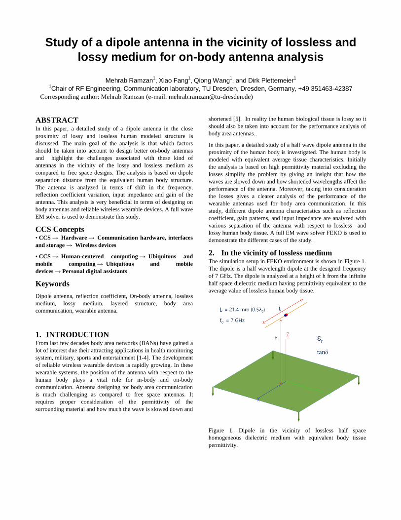
Study of a dipole antenna in the vicinity of lossless and
lossy medium for on-body antenna analysis
Mehrab Ramzan1, Xiao Fang
1, Qiong Wang
1, and Dirk Plettemeier
1
1Chair of RF Engineering, Communication laboratory, TU Dresden, Dresden, Germany, +49 351463-42387
Corresponding author: Mehrab Ramzan (e-mail: [email protected])
ABSTRACT
In this paper, a detailed study of a dipole antenna in the close
proximity of lossy and lossless human modeled structure is
discussed. The main goal of the analysis is that which factors
should be taken into account to design better on-body antennas
and highlight the challenges associated with these kind of
antennas in the vicinity of the lossy and lossless medium as
compared to free space designs. The analysis is based on dipole
separation distance from the equivalent human body structure.
The antenna is analyzed in terms of shift in the frequency,
reflection coefficient variation, input impedance and gain of the
antenna. This analysis is very beneficial in terms of designing on
body antennas and reliable wireless wearable devices. A full wave
EM solver is used to demonstrate this study.
CCS Concepts
• CCS → Hardware → Communication hardware, interfaces
and storage → Wireless devices
• CCS → Human-centered computing → Ubiquitous and
mobile computing → Ubiquitous and mobile
devices → Personal digital assistants
Keywords
Dipole antenna, reflection coefficient, On-body antenna, lossless
medium, lossy medium, layered structure, body area
communication, wearable antenna.
1. INTRODUCTION From last few decades body area networks (BANs) have gained a
lot of interest due their attracting applications in health monitoring
system, military, sports and entertainment [1-4]. The development
of reliable wireless wearable devices is rapidly growing. In these
wearable systems, the position of the antenna with respect to the
human body plays a vital role for in-body and on-body
communication. Antenna designing for body area communication
is much challenging as compared to free space antennas. It
requires proper consideration of the permittivity of the
surrounding material and how much the wave is slowed down and
shortened [5]. In reality the human biological tissue is lossy so it
should also be taken into account for the performance analysis of
body area antennas..
In this paper, a detailed study of a half wave dipole antenna in the
proximity of the human body is investigated. The human body is
modeled with equivalent average tissue characteristics. Initially
the analysis is based on high permittivity material excluding the
losses simplify the problem by giving an insight that how the
waves are slowed down and how shortened wavelengths affect the
performance of the antenna. Moreover, taking into consideration
the losses gives a clearer analysis of the performance of the
wearable antennas used for body area communication. In this
study, different dipole antenna characteristics such as reflection
coefficient, gain patterns, and input impedance are analyzed with
various separation of the antenna with respect to lossless and
lossy human body tissue. A full EM wave solver FEKO is used to
demonstrate the different cases of the study.
2. In the vicinity of lossless medium The simulation setup in FEKO environment is shown in Figure 1.
The dipole is a half wavelength dipole at the designed frequency
of 7 GHz. The dipole is analyzed at a height of h from the infinite
half space dielectric medium having permittivity equivalent to the
average value of lossless human body tissue.
Figure 1. Dipole in the vicinity of lossless half space
homogeneous dielectric medium with equivalent body tissue
permittivity.

Table 1. Different cases of dipole antenna in the vicinity of
lossless and lossy medium.
Number Permittivity
(εr)
tanδ Separation
distance (h)
Case 1 50 0 1 → λ
Case 2 50 0 1 → 3 mm
Case 3 1 → 4 0 0
Case 4 1 → 45 0 0
Case 5 1 → 45 0 1 mm
Case 6 5 0 → 0.1 0
Case 7 5 0 → 0.1 1 mm
Figure 2. Simulated reflection coefficient results for case 1.
Figure 3. Simulated real part of input impedance results for case
1.
Figure 4. Simulated imaginary part of input impedance results for
case 1.
Figure 5. Simulated realized gain pattern results for case 1.
Table 1 shows different cases of the study. Initial five cases are
related to lossless infinite half space medium and last two cases
are related to lossy medium. In case 1, the dipole height is varied
in terms of λ with respect to the plane of dielectric substrate.
Figure 2 shows the reflection coefficient results of the dipole with
different separation distances from the surface of the medium for
case 1. As dipole gets closer, the resonant frequency shifts to
lower frequencies. A significant resonance shift is observed when
the dipole becomes in contact with the medium. Figure 3 and
Figure 4 show the real and imaginary part of the input impedance
of the dipole, respectively, with different separation heights from
the surface of the lossless medium. In the case of full contact with
the body, the imaginary values of dipole input impedance show
multiple resonances due to shortening effect. Figure 5 shows the
gain pattern of the dipole antenna. In the free space it is observed
that patterns are showing constructive interference when the
height is λ/4 and 3λ/4 and destructive interference are observed
when it is λ/2 and λ. Due to shortening effect in the medium much
of the dipole gain is reduced and distributed among the side lobes.

As the dipole gets far away from the body surface the gain of the
dipole shows an increasing pattern.
Figure 6. Simulated reflection coefficient results for case 2.
Figure 7. Simulated gain of dipole antenna for case 2.
Figure 8. Simulated gain of dipole antenna for case 2.
In case 2, the permittivity is kept same, however, the separation
distance is varied in a smaller step near the surface of the lossless
medium. Figure 6, Figure 7 and Figure 8 show the reflection
coefficient, gain and gain pattern of the dipole antenna with
different distance near the surface of the body. Even near to the
surface the antenna resonance frequency shifts only too much
when the dipole is in the direct contact with the surface. The side
lobes start to form when the antenna is directly connected to the
surface and gain starts to increase as it starts to move away from
the surface.
Figure 9. Simulated reflection coefficient of dipole antenna for
case 3.
Figure 10. Simulated gain of dipole antenna for case 3.
In case 3, the dipole is in contact with the lossless half space
homogeneous dielectric medium whose permittivity is varied
from 1 to 4 and its influence was observed on the performance of
the antenna in terms of shift in the frequency, gain, and
impedance, respectively. Figure 9 shows result of this case that as
the permittivity value is increasing, the resonance frequency of
antenna shifts to lower frequency due to wave shortening effect.
The effect of permittivity variance on the gain of the dipole
antenna is shown in Figure 10, which implies an increasing gain
inside the medium as the permittivity value is increasing.

Moreover, in case 4 and case 5 the relative permittivity was varied
from free space to 45 and a comparison was made between the
dipole being direct contact with the surface and dipole at a
distance of 1 mm from the surface. Figure 11 and Figure 12
show the reflection coefficient results of the two cases,
respectively. In case of direct contact the shift in the reflection is
more prominent at different values of relative permittivity,
however, in case of 1 mm distance from the surface the shift is
insignificant. Figure 13 and Figure 14 show the simulated gain
pattern of the dipole in direct contact and 1 mm away from the
surface, respectively. In case of direct contact, as the permittivity
is increasing the side lobes starts to form more prominently in the
medium. Whereas in the case of 1 mm distance from the surface
the main lobe is preserved inside the medium and its directivity
increases more as value of relative permittivity is increased.
Figure 11. Simulated reflection coefficient of the dipole antenna
for case 4.
Figure 12. Simulated reflection coefficient of the dipole antenna
for case 5.
Figure 13. Simulated gain of the dipole antenna for case 4.
Figure 14. Simulated gain of the dipole antenna for case 5.
3. In the vicinity of lossy medium
Figure 15. Simulated reflection coefficient of the dipole antenna
for case 6.
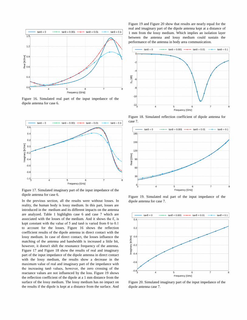
Figure 16. Simulated real part of the input impedance of the
dipole antenna for case 6.
Figure 17. Simulated imaginary part of the input impedance of the
dipole antenna for case 6.
In the previous section, all the results were without losses. In
reality, the human body is lossy medium. In this part, losses are
introduced in the medium and its different impacts on the antenna
are analyzed. Table 1 highlights case 6 and case 7 which are
associated with the losses of the medium. And it shows the Ԑr is
kept constant with the value of 5 and tanδ is varied from 0 to 0.1
to account for the losses. Figure 16 shows the reflection
coefficient results of the dipole antenna in direct contact with the
lossy medium. In case of direct contact, the losses influence the
matching of the antenna and bandwidth is increased a little bit,
however, it doesn't shift the resonance frequency of the antenna.
Figure 17 and Figure 18 show the results of real and imaginary
part of the input impedance of the dipole antenna in direct contact
with the lossy medium, the results show a decrease in the
maximum value of real and imaginary part of the impedance with
the increasing tanδ values, however, the zero crossing of the
reactance values are not influenced by the loss. Figure 19 shows
the reflection coefficient of the dipole at a 1 mm distance from the
surface of the lossy medium. The lossy medium has no impact on
the results if the dipole is kept at a distance from the surface. And
Figure 19 and Figure 20 show that results are nearly equal for the
real and imaginary part of the dipole antenna kept at a distance of
1 mm from the lossy medium. Which implies an isolation layer
between the antenna and lossy medium could sustain the
performance of the antenna in body area communication.
Figure 18. Simulated reflection coefficient of dipole antenna for
case 7.
Figure 19. Simulated real part of the input impedance of the
dipole antenna for case 7.
Figure 20. Simulated imaginary part of the input impedance of the
dipole antenna case 7.
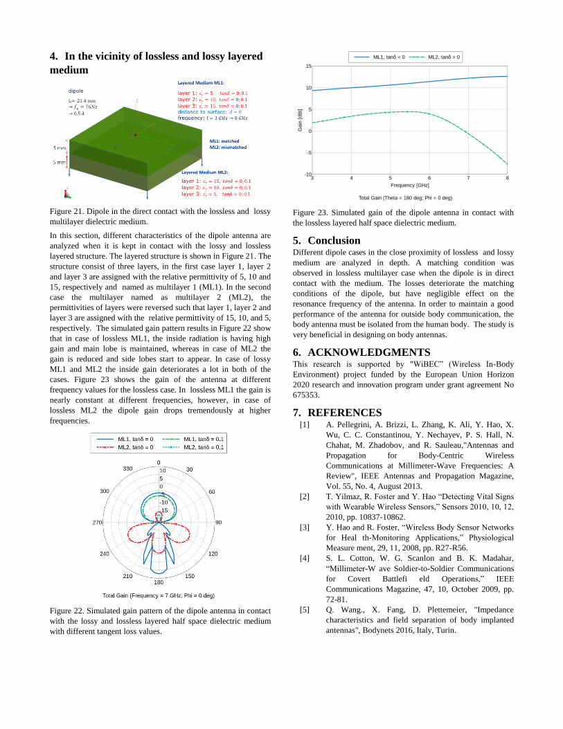
4. In the vicinity of lossless and lossy layered
medium
Figure 21. Dipole in the direct contact with the lossless and lossy
multilayer dielectric medium.
In this section, different characteristics of the dipole antenna are
analyzed when it is kept in contact with the lossy and lossless
layered structure. The layered structure is shown in Figure 21. The
structure consist of three layers, in the first case layer 1, layer 2
and layer 3 are assigned with the relative permittivity of 5, 10 and
15, respectively and named as multilayer 1 (ML1). In the second
case the multilayer named as multilayer 2 (ML2), the
permittivities of layers were reversed such that layer 1, layer 2 and
layer 3 are assigned with the relative permittivity of 15, 10, and 5,
respectively. The simulated gain pattern results in Figure 22 show
that in case of lossless ML1, the inside radiation is having high
gain and main lobe is maintained, whereas in case of ML2 the
gain is reduced and side lobes start to appear. In case of lossy
ML1 and ML2 the inside gain deteriorates a lot in both of the
cases. Figure 23 shows the gain of the antenna at different
frequency values for the lossless case. In lossless ML1 the gain is
nearly constant at different frequencies, however, in case of
lossless ML2 the dipole gain drops tremendously at higher
frequencies.
Figure 22. Simulated gain pattern of the dipole antenna in contact
with the lossy and lossless layered half space dielectric medium
with different tangent loss values.
Figure 23. Simulated gain of the dipole antenna in contact with
the lossless layered half space dielectric medium.
5. Conclusion Different dipole cases in the close proximity of lossless and lossy
medium are analyzed in depth. A matching condition was
observed in lossless multilayer case when the dipole is in direct
contact with the medium. The losses deteriorate the matching
conditions of the dipole, but have negligible effect on the
resonance frequency of the antenna. In order to maintain a good
performance of the antenna for outside body communication, the
body antenna must be isolated from the human body. The study is
very beneficial in designing on body antennas.
6. ACKNOWLEDGMENTS This research is supported by "WiBEC” (Wireless In-Body
Environment) project funded by the European Union Horizon
2020 research and innovation program under grant agreement No
675353.
7. REFERENCES [1] A. Pellegrini, A. Brizzi, L. Zhang, K. Ali, Y. Hao, X.
Wu, C. C. Constantinou, Y. Nechayev, P. S. Hall, N.
Chahat, M. Zhadobov, and R. Sauleau,"Antennas and
Propagation for Body-Centric Wireless
Communications at Millimeter-Wave Frequencies: A
Review", IEEE Antennas and Propagation Magazine,
Vol. 55, No. 4, August 2013.
[2] T. Yilmaz, R. Foster and Y. Hao “Detecting Vital Signs
with Wearable Wireless Sensors,” Sensors 2010, 10, 12,
2010, pp. 10837-10862.
[3] Y. Hao and R. Foster, “Wireless Body Sensor Networks
for Heal th-Monitoring Applications,” Physiological
Measure ment, 29, 11, 2008, pp. R27-R56.
[4] S. L. Cotton, W. G. Scanlon and B. K. Madahar,
“Millimeter-W ave Soldier-to-Soldier Communications
for Covert Battlefi eld Operations,” IEEE
Communications Magazine, 47, 10, October 2009, pp.
72-81.
[5] Q. Wang., X. Fang, D. Plettemeier, "Impedance
characteristics and field separation of body implanted
antennas", Bodynets 2016, Italy, Turin.
Copyright © 2022 FDOKUMEN