Downlink queuing model and packet scheduling for providing lossless handoff and QoS in AG mobile...
33
Downlink Queuing Model and Packet Scheduling for Providing Lossless Handoff and QoS in 4G Mobile Networks by LaHoang Nam Nguyen and Iwao Sasase, Senior Member, IEEEptop McMaster University Network QoS: Routing, Switching, Scheduling IEEE TRANSACTIONS ON MOBILE COMPUTING, VOL. 5, NO. 5, MAY 2006 Prepared by Viktor Nikitin MEng ECE
-
Upload
independent -
Category
Documents
-
view
0 -
download
0
Transcript of Downlink queuing model and packet scheduling for providing lossless handoff and QoS in AG mobile...

Downlink Queuing Model and Packet
Scheduling for Providing Lossless Handoff
and QoS in 4G Mobile Networksby LaHoang Nam Nguyen and Iwao Sasase, Senior Member, IEEEptop
McMaster UniversityNetwork QoS: Routing, Switching, Scheduling
IEEE TRANSACTIONS ON MOBILE COMPUTING, VOL. 5, NO. 5, MAY 2006
Prepared by Viktor Nikitin MEng ECE
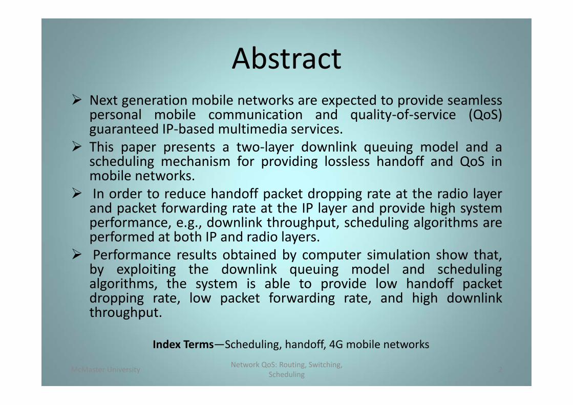
Abstract Next generation mobile networks are expected to provide seamless
personal mobile communication and quality‐of‐service (QoS)guaranteed IP‐based multimedia services.
This paper presents a two‐layer downlink queuing model and ascheduling mechanism for providing lossless handoff and QoS inmobile networks.
In order to reduce handoff packet dropping rate at the radio layerand packet forwarding rate at the IP layer and provide high systemperformance, e.g., downlink throughput, scheduling algorithms areperformed at both IP and radio layers.
Performance results obtained by computer simulation show that,by exploiting the downlink queuing model and schedulingalgorithms, the system is able to provide low handoff packetdropping rate, low packet forwarding rate, and high downlinkthroughput.
McMaster University Network QoS: Routing, Switching, Scheduling 2
Index Terms—Scheduling, handoff, 4G mobile networks

Contents Directory Section 1. Introduction Section 2. This section consists of the description and
assumptions of the system model used in thispaper.
Section 3. A novel node queuing architecture and a two‐layer downlink queuing.
Section 4. Proposed scheduling algorithms for IP andradio layers.
Section 5. Performance results obtained by computersimulation.
Section 6. Conclusion. Section 7. Limitations, Search, and Taxonomy of
Presentation
McMaster University Network QoS: Routing, Switching, Scheduling 3

Introduction IN the current third generation (3G) mobile system
architecture, real‐time (RT) and non real‐time (NRT)services are provided to mobile users by using circuitswitched and packet‐switched transport technologiesseparately.
The next generation, that is so‐called the fourth generation(4G), of mobile communication systems, has to resolvecurrent limitations of 3G and provide global multimediapersonal mobile communications.
As IP packet processing and routing are performed withinthe 4G mobile networks, technical challenges arise in termsof mobility management, routing, resource management,and security.
McMaster University Network QoS: Routing, Switching, Scheduling 4

Introduction cont. When a user switches from one access point (base station)
to another, in‐queue packets in the previous base stationmight be dropped.
In recent studies, the minimization of handoff packetdropping probability and issues of queuing managementfor practical mobile networks were not well investigated.
In the proposed two‐layer downlink queuing model,handoff tables are exploited to monitor handoff states offlows. Based on the information stored in handoff tables,different handoff state‐based priority levels, which are usedfor resource management functions such as scheduling, areset for active flows.
Scheduling algorithms are performed at IP and radio layerswith different properties aiming at providing QoS, losslesshandoff, and high system performance.
McMaster University Network QoS: Routing, Switching, Scheduling 5

2. System model 2.1 Network Architecture
McMaster University Network QoS: Routing, Switching, Scheduling 6
INTERNET
PLMNPSTN
GGNS
GMSN MSCVLR
SGSN RNC
RNC
External networks Core Network Radio Access Network
PLMN: Public Land Mobil Networks PSTN: Public Switched Tel Networks GPRS: General Packet Radio Service GGSN: Gateway GPRS Support Node SGSN: Serving GPRS Support Node
GMSC: Gateway MSC MSC: Mobil Switching Center RNC: Radio Network Controller VLR: Visitor Location Register HLR: Home Location Register
Fig. 1. UMTS network architecture.
HLR

2. System model 2.1 Network Architecture
7
HA
CH1
PSTN
ER1
IWU
Inter clusterhandoff
Intra clusterhandoff
4G RAN Core BS
Core BS
Leaf BS
RAN: Radio Access Network PSTN: Public Switched Tel. Net.WLAN: Wireless Area NetworkIWU: Inter working UnitER: Edge Router
GTW: GatewayBS: Base StationHA: Home AgentMH: Mobil HostCH: Corresponding Host
Fig. 2. Next generation mobile network architecture.

2. System model 2.2 Mobility Management Issues
8
HA
CH1
PSTN
ER1
IWU
Inter clusterhandoff
Intra clusterhandoff
4G RAN Core BS
Core BS
Leaf BS
RAN: Radio Access Network PSTN: Public Switched Tel. Net.WLAN: Wireless Area NetworkIWU: Inter working UnitER: Edge Router
GTW: GatewayBS: Base StationHA: Home AgentMH: Mobil HostCH: Corresponding Host
Fig. 2. Next generation mobile network architecture.

Handoff procedure.
McMaster University Network QoS: Routing, Switching, Scheduling 9
Handoff StartHandoff Warning
Handoff ReplyHandoff Request
New Chanel Access
Channel Release Confirm
Old Channel Release
Forwarding Request
Binding Update
Channel Access Confirm
MH BS1 BS2 ERHACH
Fig. 3. Handoff procedure.
Handoff procedure
Soft handoff
Hard handoff

3 Node Architecture and Queuing model3.1 Node Architecture
McMaster University Network QoS: Routing, Switching, Scheduling 10
Input queue
Input queue
Input queue
Input queue
Input queue
Input queue
Forwarding Buffer
I I I
I I I
I I I
I I I
I I I
I I I
BS1Routing Table
Inter BSoutput link
Downlink queue
Inter‐BS queue
Classifier
Classifier
Inter‐BSInput Link
Tx
Fig. 4. Node architecture.
A node (base station‐BS) is modeled as a queuing system including three queuing components as shown in Fig. 4: Input Queue, Downlink Queue Inter‐BS Queue

3 Node Architecture and Queuing model3.1 Node Architecture
McMaster University Network QoS: Routing, Switching, Scheduling 11
Input queue
Input queue
Input queue
Input queue
Input queue
Input queue
Forwarding Buffer
I I I
I I I
I I I
I I I
I I I
I I I
BS1Routing Table
Inter BSoutput link
Downlink queue
Inter‐BS queue
Classifier
Classifier
Inter‐BSInput Link
Tx
Fig. 4. Node architecture.
A node (base station‐BS) is modeled as a queuing system including three queuing components as shown in Fig. 4: Input Queue, Downlink Queue Inter‐BS Queue

3.2 Downlink Queuing Model
McMaster University Network QoS: Routing, Switching, Scheduling 12
C l a s sI f I e r
WIP‐class 1
WIP‐class N
HandoffTable
Soutput
Forw
ForwardHandoffPacketTo inputQueue
Fragmen
tatio
n‐Mapping
I I I II
I I I I
I I I I
IP Layer
Tx
Radio Layer
DedicatedChannels
HandoffTable
SharedChannel
Channel MonitorResource & Handoff Control Module
Information to/from
Other leaf BSs
Fig. 5. Downlink queuing modelA two‐layer queuing model is shown in Fig. 5, where interlayer information exchangebetween IP and radio layers is exploited. Different from all existing queuing models[14], our model takes into account the impacts of handoff and the forwardingprocess by monitoring the handoff status of the flows and using the information fordownlink scheduling.

3.2 Downlink Queuing Model
13
C l a s si f I e r
WIP‐class 1
WIP‐class N
HandoffTable
Soutput
Forw
ForwardHandoffPacketTo inputQueue
Fragmen
tatio
n‐Mapping
I I I II
I I I I
I I I I
IP Layer
Tx
Radio Layer
DedicatedChannels
HandoffTable
SharedChannel
Channel Monitor
Resource & Handoff Control ModuleInformation to/from
Other leaf BSs
Fig. 5. Downlink queuing modelA two‐layer queuing model is shown in Fig. 5, where interlayer information exchangebetween IP and radio layers is exploited. Different from all existing queuing models[14], our model takes into account the impacts of handoff and the forwarding processby monitoring the handoff status of the flows and using the information for downlinkscheduling.

4.1 Scheduling Algorithm for the Downlink Shared Channel at the Radio Layer
At the radio layer, the scheduling algorithm carried out by the radio scheduler isto select packets of data NRT flows for transmission on the downlink shared channel. Wepropose a fast scheduling algorithm operating as follows:
4.1.1 Normal Mode Step 1. Eliminate users whose queues are empty. Active users having packets for
transmission are taken into the selection procedure. Based on SIR values updatedby users, requested rates of users are calculated.
Step 2. Check queue occupancies of the active users and then classify them into twogroups: over_threshold and non_over_threshold. In the over_threshold group,the queue sizes of these users exceed their threshold.
Step 3: Select a user for transmission IF. There are several users belonging to the over_threshold group. THEN. Choose the user who has the maximum value of qi. ELSE. Among users belonging to the non_over_threshold group, choose
the user having maximum value of qi = ri.4.1.2 Handoff Mode
Handoff‐state‐based priority scheduling is applied in order to transmit packets of flowsexperiencing handoff before the flows are switched to the new access point. Flows havinghandoff processing states obtain the highest priority for transmission. Handoff warning flowshave lower priority and flows having normal states have the lowest priority. If a flow has ahandoff‐warning state and if the buffer size is larger than the threshold, the radio layer informsthe IP scheduler not to select its IP packets.
McMaster University Network QoS: Routing, Switching, Scheduling 14

4.2 Scheduling Algorithm of the IP SchedulerAt the IP layer, the scheduling algorithm performed by the IP scheduler selects packets ofboth RT and NRT flows and operates as follows: 4.2.1 Normal ModeService priority scheduling is applied, i.e., RT services are always served before NRT services.The packets of NRT flows are transmitted if all RT flows are empty. To provide the requireddelay of RT flows, the early deadline first (EDF) scheduling [16] is applied. If a flow has a fullbuffer at the radio layer, its IP packets are not selected. 4.2.2 Handoff ModeService priority scheduling is applied as described above, i.e., RT flows are always selectedwith higher priority than NRT flows. Within a service class, in order to minimize the numberof forwarding packets, handoff‐state‐based scheduling is applied. Within RT flows,handoff_processing flows have the highest priority for transmitting, whereashandoff_warning and normal_state flows have equal priorities. For NRT flows,handoff_processing IP flows obtain the highest priority and handoff_warning flows areassigned higher priority than normal flows When users have handoff warning states, theyare normally located in the edges of cells and their channel quality might be only goodenough for transmission at the minimum data rate of the shared channel. Therefore, weestimate the buffer threshold as following:
McMaster University Network QoS: Routing, Switching, Scheduling 15
qith = T_h*min_shared_channel_rate (1)

5 Performance Results 5.1 Simulation Model
McMaster University Network QoS: Routing, Switching, Scheduling 16
Co
Fig. 6. The cell layout of simulation experiments.
A discrete event simulation program written in C++ hasbeen created for simulating mobile networks. Theprogram is developed based on the described systemmodel and details of the simulation model aresummarized as follows:
5.1.1 Cell LayoutOmni‐cells are used in the simulation experiments. Acluster of a mobile network is simulated consisting of 25cells as shown in Fig. 6. The center cell C0 is observedwhereas other cells are interference sources to thecenter cell.
5.1.2 Propagation Model
The relative propagation loss is as follows:
L= / (2)

5.1.3 Mobility ModelSystem Parameters
Number of cells 25Cell radius 500mFrame period 2msTime slot per frame 3Spreading factor 16 (with QPSK ½,data
rate is 0.237 Mbps/code)
Number of multi codes
10
Power allocated to DSCH
80%
Path loss factor ( ) 3.8Standard deviation of shadowing
8 dB
McMaster University 17
TABLE 1 Simulation Parameters
Modulation Coding schemes for SF=16
MCS Data rate per code
Minimum required SIR
QPSK ½ 0.237 Mbps ‐20 dB
QPSK ¾ 0.356 Mbps ‐16 dB
16 QAM ½ 0.477 Mbps ‐9 dB
16 QMA ¾ 0.716 Mbps ‐4 dB
64 QAM ¾ 1.076 Mbps 6 dB
TABLE 2 Selected MCS and Their Parameters
Simulation parameters for radio propagation andhigh speed shared channels taken from [9] areshown in Table 1 and Table 2. HSDPA uses 10codes with the spreading factor of 16. Five AMCschemes are used with the required SIR and thetransmission rate per code as shown in Table 2.

5.1.4 Traffic Model
18
Packet Interval TimePacket sizeIP Packet
Packet Call Reading Time
Time
Fig. 7. Traffic model for non‐real‐time services.A traffic model for NRT services based on the UMTS proposal for WWW traffic model [17]is shown in Fig. 7. The normal Pareto distribution with cut‐off has the probability densityfunction (pdf):
(3)
where is the shape of the distribution, k is the minimum value, and m is the maximumvalue. The mean value is calculated as follows:
(4)
The number of packets (NP) in a packet call is geometrically distributed with amean Np . The packet inter arrival time (DP) is geometrically distributed with amean Dp . The reading time (DPC), i.e., the inter arrival time of packet calls, isgeometrically distributed with a mean Dpc . Parameters of traffic generators areshown in Table 3.
Fp(x) =
/
1

5.1.4 Traffic Model
19
(3)
where is the shape of the distribution, k is theminimum value, and m is the maximum value.The mean value is calculated as follows:
(4)
The number of packets (NP) in a packet call isgeometrically distributed with a mean Np . Thepacket inter arrival time (DP) is geometricallydistributed with a mean Dp . The reading time(DPC), i.e., the inter arrival time of packet calls,is geometrically distributed with a mean Dpc .Parameters of traffic generators are shown inTable 3.
On Time Negative exponential distribution,mean 2 sec
Off Time Negative exponential distribution,mean 24sec
Bit Rate 40 Kbits/sec
Packet size
Pareto distribution with cut off. : . :
Dp Geometrical distribution
Np Geometrical distribution (mean 25 packets)
Dps Geometrical distribution (mean 10 sec)
Realtime traffic model on‐off model
Nonrealtime traffic model
TABLE 3 Parameters of Traffic Generators
Fp(x) =
/
1

5.2 Performance ComparisonIn this section, performance results obtained by computer simulationunder different simulation scenarios are shown and discussed. Schedulingschemes are compared. At the radio layer, different scheduling algorithmsare applied for these scheduling schemes:
MLDROP scheme (Mobility supported LDROP) MCIR scheme (Maximum Carrier Interference Ratio) PF scheme (Proportional Fairness )
The average rate ri(t) is defined as follows:
McMaster University Network QoS: Routing, Switching, Scheduling 20
(5)
where tc is set to 1,000 time slots. The average rate ri(t) is updated everytransmission frame. If a user does not get transmission, thecurrent_transmission_rate is set to zero. The performance of this heuristicapproach depends on the value of tc. The efficient value of this parameter isselected equal 1,000 time slots according to recent studies [11].
ri(t+1) = (1‐1/tc)ri(t)+1/tc *current_transmission_rate

5.2 Performance Comparison cont.For every time interval T ј 5s, performance results are updated and, at the
end of simulation program, the mean value is calculated. As in the paper, weparticularly investigate the impacts of scheduling algorithms to handoff packet loss ofNRT connections, packet forwarding rate, and the throughput of the downlink sharedchannel. The following performances are evaluated. The mean throughput of thedownlink shared channel (DL_throughput) is the ratio of the total transmitted dataduring the duration T and the time interval value:
McMaster University Network QoS: Routing, Switching, Scheduling 21
(6)
We focus on the impact of the handoff‐based scheduling scheme to NRT services interms of packet dropping rate caused by handoff at the radio layer (Phandoff dropping) andpacket forwarding rate (Rforw) at the IP layer. The two parameters are defined as follows:
(7)
(8)
Total_transmitted_dataT
DL_throughput =
Phandoff_dropping = Number_of_dropping_packetsArriving_packets_at_radio_layer
Rforw = Number_of_forwarding_packetsNumber_of_handoffs

5.2.1 Simulation Scenarios
22
00.0020.0040.0060.0080.010.012
6 9 12 15 18 21
MCIR MLDROP PF
Phando
ff_drop
ping
Mean reading time (second)
0
0.005
0.01
0.015
50 57 64 71 78
MCIRMLDROPPF
Phando
ff_drop
ping
Number of users
Fig. 8. Handoff packet dropping rate at the radio layer.
As described above, networkcoverage of 25 cells with two arraygeographical cell layout is simulatedwhere the traffic of center cell C0 isobserved and describedperformance parameters aremeasured. Assume that the centercell is providing 50 fixed real‐timeand N mobile nonreal‐timeconnections. In the first simulation scenario,
there is a fixed number of N ј 60nonreal‐time mobile users.
In the second scenario, the meanreading time is a fixed value of6s, whereas the number ofnonreal‐time mobile users isvaried.

5.2.1 Simulation Scenarios
McMaster University Network QoS: Routing, Switching, Scheduling 23
0
0.002
0.004
0.006
0.008
0.01
0.012
6 9 12 15 18 21
MCIRMLDROPPF
Phando
ff_drop
ping
Mean reading time (second)
0
0.005
0.01
0.015
50 57 64 71 78
MCIRMLDROPPF
Phando
ff_drop
ping
Number of users
Fig. 8. Handoff packet dropping rate at the radio layer.Fig. 8 shows the performance of
the handoff packet dropping rate at theradio layer. Generally, the MLDROPalgorithm outperforms the MCIR and PFalgorithms in both simulation scenarios. Inthe first simulation scenario, when themean reading time increases, the packetdropping rate is decreased.
In the second simulation scenario,when the instantaneous number ofNRT mobile users increases, morehandoff requests occur.

5.2.1 Simulation Scenarios
Network QoS: Routing, Switching, Scheduling 24
0
0.1
0.2
0.3
0.4
0.5
6 9 12 15 18 21
MCIRMLDROPPF
Packet fo
rwarding
rate
Mean reading time (second)
0
0.1
0.2
0.3
0.4
0.5
50 57 64 71 78
MCIRMLDROPPF
Packet fo
rwarding
rate
Number of users
Fig. 9. Packet forwarding rate at the IP layerThe performance of the packetforwarding rate at the IP layer is shownin Fig. 9. In the first simulation scenario,
when the mean reading timeincreases, the forwarding ratedecreases due to the decrease ofthe traffic load of each user. Withthe long reading time, the packetforwarding rate of the MLDROPalgorithm is nearly equal to those ofMCIR and PF.
In the second simulation scenario,when the number of mobile usersincreases, network traffic loadincreases. Therefore, when handoffrequests arrive, there are many in‐queue packets at the IP layerresulting the high packet forwardingrate.

5.2.1 Simulation Scenarios
McMaster University Network QoS: Routing, Switching, Scheduling 25
0
1
2
3
4
5
6 9 12 15 18 21
MCIR MLDROP PF
Downlink throughp
ut M
bit/s
Mean reading time (second)
0
1
2
3
4
5
50 57 64 71 78
MCIR MLDROP PF
Downlink throughp
ut M
bit/s
Number of users
Fig. 10. Mean downlink throughput.
Fig. 10 shows the performance of themean throughput of the downlinkshared channel. In both simulationscenarios, there is not so muchdifference of mean downlinkthroughput between the threescheduling schemes. In the first simulation scenario, the
PF and MCIR schemes consider thehandoff and non handoff flowsequally so that, in even the handoffmode, they still use higher‐levelmodulation schemes fortransmission, i.e., high data rate.
In the second simulation scenario,increasing the number of datamobile users causes more handoffs.

5.2.1 Simulation Scenarios
Network QoS: Routing, Switching, Scheduling
26
0
0.005
0.01
0.015
0.02
50 57 64 71 78
T_h=0.3T_h=0.4T_h=0.5
Phando
ff_drop
ping
Mean reading time (second)
0
0.05
0.1
0.15
0.2
0.25
50 57 64 71 78
T_h=0.3T_h=0.4T_h=0.5
Packet fo
rwarding
rate
Number of users
Fig. 11. Impacts of buffer threshold value tohandoff packet dropping rate and packetforwarding rate.
The impact of the bufferthreshold to handoff packetdropping rate and packetforwarding rate are investigatedwhen the value of• T_h = 0.3s• T_h = 0.4s• T_h = 0.5sAs shown in Fig. 11, with thesmaller buffer threshold, thelower handoff packet droppingrate is obtained.

ConclusionsIn this paper, a two‐layer downlink queuing model and scheduling
algorithms for providing lossless handoff, QoS, and high system performance havebeen proposed for next generation IP‐based mobile networks. In the queuing model,information exchange between radio and IP layer is performed that supports moreefficient resource management. In order to provide QoS to different service classes, toreduce handoff packet dropping rate and minimize packet forwarding rate, theproposed downlink scheduling scheme exploits service differentiation and handoffpriorities, in which handoff priority scheduling principles are proposed with differentpriority levels. System performance of proposed scheduling algorithms has beenevaluated and compared with other algorithms under different simulation scenarios Itis shown that using proposed scheduling algorithms at IP and radio layers can providelow handoff packet dropping rate, i.e., lossless handoff can be well provided. Thepacket forwarding rate at the IP layer is acceptable in the case of long packet readingtime (less bursty traffic) and not so high handoff rate (not so many instantaneous dataconnections). That means the network does not waste resources for the forwardingprocess. The downlink throughput is achieved as high as comparable with that ofother scheduling algorithms. In summary, it can be shown that, using the two‐layerqueuing model and handoff state‐based scheduling priority, the system can providelossless handoff and QoS differentiation and achieve high system performance.
McMaster University Network QoS: Routing, Switching, Scheduling 27

Limitations
There are no limitations from the authors view,however, there is another paper ”Scheduling andQueue Management for Multi‐class Traffic in AccessRouter of Mobility Protocol” written by ShohrabHossain and Mohammed Atiquzzaman published in2010 stated that presented above paper lack thequantitative analysis of average queuing delay, queueoccupancy and packet drop probability of data andsignaling packets at the access router while managingIP‐mobility.
McMaster University Network QoS: Routing, Switching, Scheduling 28

Search4G Mobil Networks 2005‐2010
Results 931Scheduling for Providing Lossless Handoffand QoS in 4G Mobile Networks
Results 2o An Efficient Packet Scheduling Algorithm for Downlink Queue to Provide Lossless Handoff and QoS in 4G Mobile Networks
o Downlink Queuing Model and Packet Scheduling for Providing Lossless Handoff and QoS in 4G Mobile Networks
Chose the second papero Downlink Queuing Model and Packet Scheduling for Providing Lossless Handoff and QoS in 4G Mobile Networks
ReasonsMore info, data and more graphs
McMaster University Network QoS: Routing, Switching, Scheduling 29

Taxonomy of Presentation
MobileUsers
Core Network
PLMN PSTN
RNC
MSC
HLR
External networks
GMSN RNC
Radio AccessNetwork
Internet SGSNGGNS
McMaster University Network QoS: Routing, Switching, Scheduling 30
PLMN: Public Land Mobil Networks PSTN: Public Switched Tel Networks GPRS: General Packet Radio Service GGSN: Gateway GPRS Support Node SGSN: Serving GPRS Support Node
GMSC: Gateway MSC MSC: Mobil Switching Center RNC: Radio Network Controller VLR: Visitor Location Register HLR: Home Location Register

References• [1] 3GPP, “Physical Layer Aspects of UTRA High Speed Downlink Packet Access (Release 2000),” 3G
TR 25.848 V0.6.0, Mar. 2001.• [2] H. Holma and A. Toskala, WCDMA for UMTS. John Wiley and Sons, 2001.• [3] G. Patel and S. Dennett, “The 3GPP and 3GPP2 Movements Toward an All‐IP Mobile Network,”
IEEE Personal Comm., vol. 7, no. 4, pp. 62‐64, Aug. 2000.• [4] B.G. Evans and K. Baughan, “Visions of 4G,” J. Electronics and Comm. Eng., vol. 12, no. 6, pp.
293‐303, Dec. 2000.• [5] A. Mihovska, C. Wijting, and R. Prasad, “A Novel Flexible Technology for Intelligent Base Station
Architecture Support for 4G Systems,” Proc. Conf. Wireless Personal Multimedia Comm. 2002(WPMC2002), vol. 2, pp. 601‐605, Oct. 2002.
• [6] H. Chaskar, “Requirements of a QoS Solution for Mobile IP,” IETF Requests for CommentsRFC3583, http://www.ietf.org/rfc/ rfc3583.txt, Sept. 2003.
• [7] H. Soliman, C. Castelluccia, and K. El‐Malki, “Hierarchical Mobile IPv6 Mobility Management,”IETF Internet Draft, http:// www3.ietf. org/proceedings/02mar/I‐D/draft‐ietf‐mobileiphmipv6‐05.txt, July 2001
• [8] Y. Yamao, H. Suda, N. Umeda, and N. Nakajima, “Radio Access Network Design Concept for theFourth Generation Mobile Communication System,” Proc. IEEE Vehicular Technology Conf. Spring2000 (VTC‐spring 2000), vol. 3, pp. 2285‐2289, 2000.
• [9] T. Kolding, F. Frederiksen, and P. Mogensen, “Performance Evaluation of Modulation and CodingSchemes Proposed for HSDPA in 3.5G UMTS Networks,” Proc. Symp. Wireless Personal MultimediaComm. (WPMC ’01), vol. 1, pp. 307‐312, Sept. 2001.
McMaster University Network QoS: Routing, Switching, Scheduling 31

References• [10] A. Furuskar, S. Parkvall, M. Persson, and M. Samuelsson, “Performance of WCDMA High Speed Packet
Data,” Proc. IEEE Vehicular Technology Conf. (VTC ’02), vol. 3, pp. 1116‐1120, May 2002.• [11] Y. Ofuji, S. Abeta, and M. Sawahashi, “Comparison of Packet Scheduling Algorithms Focusing on User
Throughput in High Speed Downlink Packet Access,” IEICE Trans. Comm., vol. E86‐B, no. 1, pp. 132‐139,Jan. 2003.
• [12] Y. Choi and Y. Han, “A Channel‐Based Scheduling Algorithm for CDMA2000 1xEV‐DO System,” Proc.IEEE Personal, Indoor, and Mobile Radio Comm. (PIMRC ’02), vol. 5, pp. 2259‐2263, Sept. 2002.
• [13] A Jalali, R. Padovani, and R. Pankaj, “Data Throughput of CDMAHDR a High Efficiency‐High Data RatePersonal Communication Wireless Systems,” Proc. IEEE Vehicular Technology Conf. (VTC ’00), vol. 2, pp.1854‐1858, May 2000.
• [14] H. Fattah and C. Leung, “An Overview of Scheduling Algorithms in Wireless Multimedia Networks,”IEEE Wireless Comm., vol. 9, no. 5, pp. 76‐83, Oct. 2002.
• [15] H.N. Nguyen, R. Esmailzadeh, and I. Sasase, “A Fast Scheduling Algorithm Considering BufferOccupancy and Channel Condition for High Speed Downlink Packet Access,” Proc. Sixth Int’l Symp.Wireless Personal Multimedia Comm. (WPMC ’03), vol. 2, pp. 72‐76, Oct. 2003.
• [16] K. Zhu, Y. Zhuang, and Y. Viniotis, “Achieving End‐to‐End Delay Bounds by EDF Scheduling WithoutTraffic Shaping,” Proc. IEEE. Conf. Computer and Comm. Soc. (INFOCOM ’01), vol. 3, pp. 1493‐1501, Apr.2001.
• [17] ETSI, “Selection Procedures for the Choice of Radio Transmission Technologies of the UMTS,” TechnicalReport 101‐112 V 3.2.0, Apr. 1998.
• [18] H.N. Nguyen and I. Sasase, “Downlink Queuing Model and Handoff‐Based Scheduling Algorithm forFourth Generation obile Networks,” Proc. Fifth Asia‐Pacific Symp. Information and Telecomm. Technologies(APSITT ’03), pp. 377‐382, Nov. 2003.
McMaster University Network QoS: Routing, Switching, Scheduling 32

McMaster University Network QoS: Routing, Switching, Scheduling 33