Study for the Adaptation of a Radio Control Car ... - UPCommons
66
Study for the Adaptation of a Radio Control Car to an Autonomous Racing Vehicle FINAL REPORT Academic Course: Master’s degree in Industrial Engineering Author: Javier Piñeiro Rosel TFM headline: STUDY FOR THE ADAPTATION OF A RADIO CONTROL CAR TO AN AUTONOMOUS RACING VEHICLE TFM director: Bernardo Morcego Seix TFM application delivery: January 2019, Terrassa, Barcelona
-
Upload
khangminh22 -
Category
Documents
-
view
0 -
download
0
Transcript of Study for the Adaptation of a Radio Control Car ... - UPCommons

Study for the Adaptation of a Radio Control Car to an Autonomous Racing Vehicle
FINAL REPORT
Academic Course:
Master’s degree in Industrial Engineering
Author:
Javier Piñeiro Rosel
TFM headline:
STUDY FOR THE ADAPTATION OF A RADIO CONTROL CAR TO AN
AUTONOMOUS RACING VEHICLE
TFM director:
Bernardo Morcego Seix
TFM application delivery:
January 2019, Terrassa, Barcelona

Study for the Adaptation of a Radio Control Car to an Autonomous Racing Vehicle
INDEX
ABSTRACT ...................................................................................................................................... 6
CATALAN ABSTRACT VERSION ...................................................................................................... 7
1. Project description ................................................................................................................ 8
1.1. Project justification ....................................................................................................... 8
1.2. Objectives ...................................................................................................................... 8
1.3. Scope of the Project ...................................................................................................... 9
1.4. High Level Requirements .............................................................................................. 9
1.5. Background.................................................................................................................... 9
2. Technical Report .................................................................................................................. 11
2.1. Project background ..................................................................................................... 11
2.1.1. Autonomous vehicle introduction ...................................................................... 11
2.1.2. Current 1:10 scaled vehicle ................................................................................. 13
2.2. Proposed and adopted solutions ................................................................................ 15
2.2.1. RC car choice ....................................................................................................... 15
2.2.2. Actuators working principles ............................................................................... 20
2.3. Implementations development ................................................................................... 27
2.3.1. New car implementations ................................................................................... 27
2.3.2. Assembly methodology ....................................................................................... 30
2.3.3. ROS operating manual......................................................................................... 35
2.3.4. Implemented Arduino code ................................................................................ 41
3. Results ................................................................................................................................. 47
3.1. Car characteristics and specifications ......................................................................... 47
3.1.1. Technical characteristics ..................................................................................... 47
3.1.2. Driving specifications .......................................................................................... 47
3.2. Testing ......................................................................................................................... 49
3.3. Project budget ............................................................................................................. 51
3.4. Environmental implications ........................................................................................ 52
3.5. Conclusions ................................................................................................................. 53
3.6. Future improvements planning ................................................................................... 54
3.7. Bibliography ................................................................................................................ 55
ANNEX A ...................................................................................................................................... 57

Study for the Adaptation of a Radio Control Car to an Autonomous Racing Vehicle
INDEX OF ILLUSTRATIONS
Image No. 1: Parts of an autonomous vehicle [2] ....................................................................... 11
Image No. 2: Current “AutoNOMOS Mini v3” vehicle components view [1].............................. 13
Image No. 3: Electronic modules and interconnections [1] ........................................................ 14
Image No. 4: Tree of interconnections between the different hardware components [1] ........ 14
Image No. 5: Traxxas Slash inside design. [5] .............................................................................. 18
Image No. 6: Module simplicity of Traxxas Slash. [5] .................................................................. 18
Image No. 7: Set of the different parts that conforms the RC car. [5]. ....................................... 19
Image No. 8: Servo wiring connection [7] ................................................................................... 20
Image No. 9: ESC wiring scheme [8] ............................................................................................ 20
Image No. 10: Electronic speed controller working principle [10] ............................................. 21
Image No. 11: PWM signal of servo and ESC [9] ......................................................................... 22
Image No. 12: Amplification of the induced voltage [11] ........................................................... 23
Image No. 13: Example of rpm sensor working under Hall Effect principle [11] ........................ 24
Image No. 14: Rpm sensor #6520 (left) [12] and telemetry trigger magnet holders #6538 (right)
[13] .............................................................................................................................................. 24
Image No. 15: Total teeth number of the gear shaft. Magnet is found behind it in the magnet
holder part. ................................................................................................................................. 25
Image No. 16: Initial position of the two marks at the beggining of the measurement ............ 25
Image No. 17: Final position of the two marks at the end of the measurement ....................... 26
Image No. 18: RC chassis before any removal is made ............................................................... 27
Image No. 19: Electronic board (left) and new RC chassis (right) ............................................... 28
Image No. 20: Arduino NANO pinout [14] .................................................................................. 28
Image No. 21: Arduino pins configuration .................................................................................. 29
Image No. 22: Arduino pinout connections top view (left) and bottom view (right) ................. 29
Image No. 23: Dismounting process of the receiver ................................................................... 30
Image No. 24: Dismounting process of the antenna .................................................................. 31
Image No. 25: Reallocation of the different shock absorbers .................................................... 31
Image No. 26: Marking the position of the four iron rods .......................................................... 32
Image No. 27: Drilling process of the different surfaces ............................................................. 32
Image No. 28: USB hub reallocation ........................................................................................... 33
Image No. 29: Final adjusting of the iron rods position (left) and level rubber preparation (right)
..................................................................................................................................................... 33
Image No. 30: Rods attachment to chassis (left) and methacrylate plaque (right) .................... 34
Image No. 31: Levelling of the methacrylate plaque at back (left) and at front of the car (right)
..................................................................................................................................................... 34
Image No. 32: Rosserial_arduino illustration example [24] ........................................................ 37
Image No. 33: Vehicle appearance after good connection is stablished .................................... 38
Image No. 34: General software structure controlling the autonomous vehicle [25] ................ 38
Image No. 35: Publishers and subscribers of the serial_node with the corresponding message
type [25] ...................................................................................................................................... 39
Image No. 36: Publishers and subscribers of the odometry publisher node with the
corresponding message type [25] ............................................................................................... 40
Image No. 37: Publishers and subscribers of the auto_stop node with the corresponding
message type [25] ....................................................................................................................... 40
Image No. 38: Servo “onSteeringCommand” function in Arduino code ..................................... 42
Image No. 39: Arduino code modification /steering_angle ROS node ....................................... 42

Study for the Adaptation of a Radio Control Car to an Autonomous Racing Vehicle
Image No. 40: Motor “onSpeedCommand” function in Arduino code (part 1) .......................... 43
Image No. 41: Motor “onSpeedCommand” function in Arduino code (part 2) .......................... 44
Image No. 42: Variables used in the car speed calculation ........................................................ 44
Image No. 43: Interrupt function counting changes of state of the rpm signal ......................... 45
Image No. 44: Arduino code modification /twist ROS node ....................................................... 46
Image No. 45: Slash 4x4 performance depending on battery selection [15].............................. 47
Image No. 46: Screenshot of command-line rosnode info /serial_node .................................... 49
Image No. 47: Vehicle response to steering angle variation from 90 (left) to 130 degrees (right)
..................................................................................................................................................... 49
Image No. 48: Vehicle response to speed variation from being stopped (left) to moving forward
(right) ........................................................................................................................................... 50
Image No. 49: Vehicle response to LEDs variation from being off (left) to on (right) ................ 50

Study for the Adaptation of a Radio Control Car to an Autonomous Racing Vehicle
INDEX OF TABLES Table No. 1: Comparison between the different RC cars ............................................................ 15
Table No. 2: Numerical model characteristics table ................................................................... 16
Table No. 3: Weighted model characteristic table...................................................................... 17
Table No. 4: Total budget of the project ..................................................................................... 51
INDEX OF DRAWINGS Scheme No. 1: ROS schematic network processes .................................................................... 36
Scheme No. 2: Operating ESC range expressed in microseconds .............................................. 48
Scheme No. 3: Operating servo range expressed in degree ...................................................... 48

Study for the Adaptation of a Radio Control Car to an Autonomous Racing Vehicle
6
ABSTRACT
Technology is an essential part of our lives in today’s world and it is not possible to
imagine a world without it. It is a fact that humanity steps go towards a technological
evolution where our dependence on it will be even higher due to the advent of new and
improved technologies.
The automotive industry is not left behind from the technological evolution and for that
reason it is surprising the world with new and astonishing transformations into the
driving’s experience. One of the biggest challenges on the current car industry is the
possibility to implement a new fleet generation of autonomous driving cars which would
completely change our driving experience.
This project consists on the adaptation of a new radio control car to an autonomous
racing vehicle following as a guidance a previous ESEIAAT’S project of an autonomous
vehicle.
In order to achieve the aim of this project a new radio control car with superior features
is joined together with the former autonomous technologies, which are present in the
old ESEIAAT’S prototype. To obtain the perfect control of the new autonomous racing
vehicle it is used Robot Operating System.
All necessary steps to accomplish the objective range from an initial market research, in
order to choose the proper new radio control car for this academic application, to the
very end of the new code implementations. Which are the functionalities of all the parts
of the vehicle, the assembly process between both vehicles, the final car specifications
and detailed explanation of how to control this new autonomous vehicle through Robot
Operating System are also part of this Master’s Thesis.

Study for the Adaptation of a Radio Control Car to an Autonomous Racing Vehicle
7
CATALAN ABSTRACT VERSION
La tecnologia juga un paper essencial en les nostres vides i avui dia no és possible
imaginar un món sense ella. Les passes de la humanitat ens estan portant cap a una
evolució tecnològica on la dependència d’aquesta serà encara més gran degut a
l’aparició de noves i millorades tecnologies.
La industria automotriu lluny de quedar-se enrere d’aquesta evolució tecnològica està
sorprenent al món amb noves transformacions sorprenents pel que fa referència a
l’experiència de conduir. Un dels majors reptes de la industria automobilística és la
possibilitat d’implementar una nova flota de vehicles autònoms que ens canviï
completament la forma de conduir.
Aquest projecte consisteix en l’adaptació d’un nou cotxe de radio control en un vehicle
autònom de competició seguint com a guia un projecte anterior de l’ESEIAAT sobre un
vehicle autònom.
Per tal d’aconseguir l’objectiu d’aquest projecte un nou cotxe de radio control amb
prestacions superiors es assemblat conjuntament amb les tecnologies autònomes
anteriors presents en l’antic prototip de l’ESEIAAT. Per aconseguir un control perfecte
del nou vehicle autònom de competició s’utilitza Robot Operating System.
Tots els processos necessaris per acomplir els objectius abasten des d’un estudi de
mercat inicial per tal d’escollir el més adequat cotxe de radio control per aquesta
aplicació acadèmica fins al final de les noves implementacions en el codi. Quines són les
funcionalitats de totes les parts del vehicle, el procés d’assemblatge entre els dos
vehicles, les especificacions finals del cotxe i una detallada explicació de com controlar
aquest nou vehicle autònom a través de Robot Operating System formen part també
d’aquesta tesis de Màster.
Study for the Adaptation of a Radio Control Car to an Autonomous Racing Vehicle
8
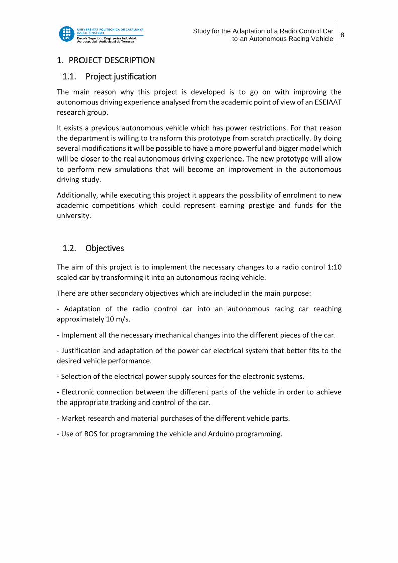
1. PROJECT DESCRIPTION
1.1. Project justification
The main reason why this project is developed is to go on with improving the
autonomous driving experience analysed from the academic point of view of an ESEIAAT
research group.
It exists a previous autonomous vehicle which has power restrictions. For that reason
the department is willing to transform this prototype from scratch practically. By doing
several modifications it will be possible to have a more powerful and bigger model which
will be closer to the real autonomous driving experience. The new prototype will allow
to perform new simulations that will become an improvement in the autonomous
driving study.
Additionally, while executing this project it appears the possibility of enrolment to new
academic competitions which could represent earning prestige and funds for the
university.
1.2. Objectives
The aim of this project is to implement the necessary changes to a radio control 1:10
scaled car by transforming it into an autonomous racing vehicle.
There are other secondary objectives which are included in the main purpose:
- Adaptation of the radio control car into an autonomous racing car reaching
approximately 10 m/s.
- Implement all the necessary mechanical changes into the different pieces of the car.
- Justification and adaptation of the power car electrical system that better fits to the
desired vehicle performance.
- Selection of the electrical power supply sources for the electronic systems.
- Electronic connection between the different parts of the vehicle in order to achieve
the appropriate tracking and control of the car.
- Market research and material purchases of the different vehicle parts.
- Use of ROS for programming the vehicle and Arduino programming.

Study for the Adaptation of a Radio Control Car to an Autonomous Racing Vehicle
9
1.3. Scope of the Project
The list of activities that are included in the scope of this project are the following ones:
- Brief introduction to autonomous vehicles technology.
- Market research and car pieces purchasing.
- Implementation of mechanical, electrical and electronic changes in the vehicle.
- Justification of the different adopted solutions for the adaptation of the vehicle.
- Adaptation of the existing control and tracking system in the new vehicle, from
the software point of view.
The scope of the project does not include:
- Design of the monitoring system of the vehicle.
- The implementation of the parts that turns the vehicle autonomous.
1.4. High Level Requirements
Probably the most important requirement of this project is to complete successfully the
adaptation of the new radio control car to an autonomous driving vehicle.
In order to meet with the prior requirement, the following conditions must be
accomplished:
- At the end of this project the new autonomous vehicle must be compatible with
all the previous autonomous driving environment.
- The final prototype has to be faster than the previous one. It should be driven at
least at a speed of 10 m/s.
- All changes done in the new autonomous vehicle need to be properly
documented.
- The adapted solutions taken through the project elaboration must be adopted
according to the department budget.
1.5. Background
In 2016, there was an educational project developed at the Freie Universität Berlin
which consisted in creating an autonomous vehicle for educational purposes called
“AutoNOMOS Model”.
This project has been refined through the years and there are now a total of four
different versions of the prototype. Each version has got different hardware and
software improvements which can be seen in their github platform. [1]
It was not until 2018 when ESEIAAT’s students got involved into “AutoNOMOS Model”
car taking part into SEAT Autonomous Driving Challenge. This was a contest where
Study for the Adaptation of a Radio Control Car to an Autonomous Racing Vehicle
10
different university students of engineering, computer science and other related fields
had to develop their own architecture software to program their respective
autonomous driving cars, which were borrowed from Freie Universität Berlin, in order
to demonstrate their skills in controlling the autonomous vehicle. To demonstrate their
control skills they had to face different challenges which were divided into different
driving situations with different difficulty levels.
After the involvement into SEAT’s contest, the department of ESEIAAT has decided to
invest its efforts in innovation research to improve the current autonomous vehicle. The
main tasks developed in this research group are to develop different new code sections
where the vehicle must overcome new difficulties which were not implemented before,
for example, the detection and prevention of a collision with an obstacle.
Nevertheless there was detected from the department a new necessity to study the
driving autonomous performance from a more powerful car which would bring the
study closer to the real autonomous driving experience. This is exactly the justification
of this project.

Study for the Adaptation of a Radio Control Car to an Autonomous Racing Vehicle
11
2. TECHNICAL REPORT
2.1. Project background
2.1.1. Autonomous vehicle introduction
2.1.1.1. Autonomous vehicle technologies
Autonomous cars are those vehicles that can perfectly be driven with little or no human
intervention, guaranteeing the security and safety requirements needed to circulate
throughout the existing roads.
In figure 1, different components of a self-driving car are shown.
Image No. 1: Parts of an autonomous vehicle [2]
The different components that conform the total unit of an automotive vehicle (AV) are
defined below.
Light Detection and Ranging (LIDAR)
The use of light beams projected by a 360-degree sensor, determines the distance
between obstacles and the car.
Cameras
These devices collect image data in order to obtain information of the surroundings. It
is necessary to do complex algorithm treatment to convert this data into valuable.
Radio Detection and Ranging (RADAR)
The distance between obstacles and the sensor is calculated by using radio waves.
Infrared Sensors
These sensors are used to detect pedestrians, lane markings or bicycles especially in
adverse environmental conditions.
Study for the Adaptation of a Radio Control Car to an Autonomous Racing Vehicle
12
Inertial Navigation Systems (INS)
Together with the GPS it is the instrument in charge of determining the vehicle’s
position, orientation and velocity by means of gyroscopes and accelerometers.
Dedicated Short-Range Communication (DSRC)
It is a system which allows the car to be communicated with other vehicles or
infrastructures in order to send and receive at any moment critical data such as road
conditions, congestions, crashes, etc. DSRC allows controlling a group of cars that are
driven all together.
Prebuilt Maps
This service helps to correct inaccurate positioning due to different errors that may
occur between the INS and the GPS system. Furthermore, it limits the possible routes
that vehicle can take.
Ultrasonic Sensors
When going backwards or in parking situations these sensors measure the distance
between the car and barriers.
Global Positioning Systems (GPS)
It is possible to know the location of the vehicle at any instant of time thanks to this
tracking system controlled by satellites. [2]
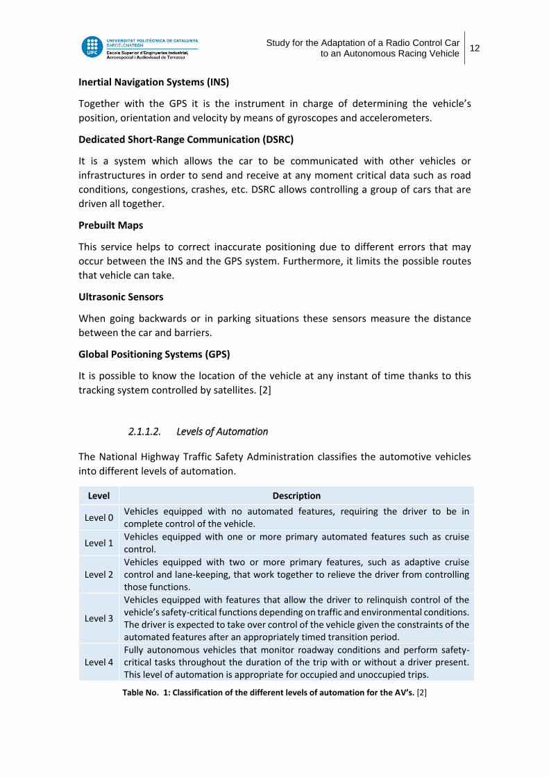
2.1.1.2. Levels of Automation
The National Highway Traffic Safety Administration classifies the automotive vehicles
into different levels of automation.
Level Description
Level 0 Vehicles equipped with no automated features, requiring the driver to be in complete control of the vehicle.
Level 1 Vehicles equipped with one or more primary automated features such as cruise control.
Level 2 Vehicles equipped with two or more primary features, such as adaptive cruise control and lane-keeping, that work together to relieve the driver from controlling those functions.
Level 3
Vehicles equipped with features that allow the driver to relinquish control of the vehicle’s safety-critical functions depending on traffic and environmental conditions. The driver is expected to take over control of the vehicle given the constraints of the automated features after an appropriately timed transition period.
Level 4 Fully autonomous vehicles that monitor roadway conditions and perform safety-critical tasks throughout the duration of the trip with or without a driver present. This level of automation is appropriate for occupied and unoccupied trips.
Table No. 1: Classification of the different levels of automation for the AV’s. [2]

Study for the Adaptation of a Radio Control Car to an Autonomous Racing Vehicle
13
2.1.2. Current 1:10 scaled vehicle
Nowadays ESEIAAT owns the last version of the AutoNOMOS car project. This is a fully
autonomous level 4 vehicle which has been developed for educational purposes.
“AutoNOMOS Mini v3” is a 1:10 scaled vehicle which has integrated all the necessary
electronic components that provide autonomy to the car.
The different components that conform the vehicle can be seen in the following picture.
Image No. 2: Current “AutoNOMOS Mini v3” vehicle components view [1]
The main computer is an Odroid board, XU4 64GB, running Ubuntu Linux and the
Robotic Operating System (ROS) on top. This device is the brain of the system as it is
responsible for receiving all inputs from the sensors, process the information and finally
send the necessary orders to achieve an autonomous driving experience.
Another vital component is the Arduino Nano. Its main function is the direction and the
throttle control of the vehicle. It receives the orders from the computer and governs the
servo, responsible of the direction, and the motor, in charge of providing movement to
the vehicle. It also controls the LED’S and the MPU6050.
All the sensors equipment is also essential for the desired autonomous driving activity.
The rotating laser scanner (RPLIDAR A2 360) is in charge of detecting any possible
obstacles in the surrounding area. There is a Kinect-type stereoscopic system (Intel
RealSense SR300) which provides 3D cloud points that help in the detection of possible
obstacles.
There are two cameras in the AutoNOMOS car. The video camera in the Kinect-type
sensor detects lanes and objects situated in front of the car while the fix-eye video

Study for the Adaptation of a Radio Control Car to an Autonomous Racing Vehicle
14
camera (ELP 1080p) is situated on top of the car and it is pointing to the ceiling. This
camera simulates a GPS navigation unit that allows the car to detect whether it is
indoors or outdoors.
Two WS2812b LED stripes are used In order to simulate the head and tail lights as well
as the blinkers and break lights.
Finally, another important component is the MPU6050. This device complements the
odometry of the vehicle by providing measurements from accelerometers and
gyroscopes to the Arduino Nano.
It is possible to see the interconnections between the different components in the
following schematic representation.
Image No. 3: Electronic modules and interconnections [1]
Image No. 4: Tree of interconnections between the different hardware components [1]
Although the current version is fully operative, it can not reach high speeds. Here
appears the need of having a new and more powerful autonomous car.
Study for the Adaptation of a Radio Control Car to an Autonomous Racing Vehicle
15
2.2. Proposed and adopted solutions
2.2.1. RC car choice
In order to achieve the principal aim of this project, which consists in the adaptation of
a radio control car to an autonomous racing vehicle, it is necessary to do an extensive
market research to select a new RC car that best fits with the requirements.
In this section a deeper comparison is made between the final fourth possible RC
models. The final RC car is chosen among all the possibilities by means of a weighted
table.
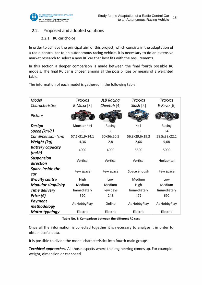
The information of each model is gathered in the following table.
Model Characteristics
Traxxas E-Maxx [3]
JLB Racing Cheetah [4]
Traxxas Slash [5]
Traxxas E-Revo [6]
Picture
Design Monster 4x4 Racing 4x4 Racing
Speed (km/h) 56 80 56 64
Car dimension (cm) 57,1x31,9x24,1 50x36x20,5 56,8x29,6x19,3 58,5x38x22,1
Weight (kg) 4,36 2,8 2,66 5,08
Battery capacity (mAh)
4000 4000 5500 5000
Suspension direction
Vertical Vertical Vertical Horizontal
Space inside the car
Few space Few space Space enough Few space
Gravity centre High Low Medium Low
Modular simplicity Medium Medium High Medium
Time delivery Immediately Few days Immediately Immediately
Price (€) 590 245 479 690
Payment methodology
At HobbyPlay Online At HobbyPlay At HobbyPlay
Motor typology Electric Electric Electric Electric
Table No. 1: Comparison between the different RC cars
Once all the information is collected together it is necessary to analyse it in order to
obtain useful data.
It is possible to divide the model characteristics into fourth main groups.
Tecnhical approaches: All those aspects where the engineering comes up. For example:
weight, dimension or car speed.

Study for the Adaptation of a Radio Control Car to an Autonomous Racing Vehicle
16
Time approaches: How much time it takes from the moment the car is bought until it is
possible to work physically with it.
Price approaches: Which is the price and how easy is it to pay.
Environmental approaches: Whether the RC car may emit pollution or not.
Then, taking into account these main groups and turning the model characteristics table
in a numerical format it is possible to obtain the following numerical table. Each RC car
has got a punctuation from 1 to 5, being 1 the lowest mark and 5 the highest, for each
characteristic.
Once the model characteristics are numerically evaluated it is possible to do a weight
table where the chosen model will be the one with the highest punctuation. In this case
the numerical weights range between 1 to 3. The higher the number the more important
is the characteristic.
The most important specifications, therefore the ones with higher weight value, are
explained hereafter.
- Speed: It is a requisite that the RC car arrives at a minimum speed of 30 km/h.
- Suspension: Depending on the shock absorver orientation the car will withstand the
module where the electronics such as the arduino, the lidar or sensors are placed.
Numerical model characteristics Traxxas E-Maxx
JLB Racing CHEETAH
Traxxas Slash
Traxxas E-Revo
Technical approaches 36 34 41 29
Speed (km/h) 5 4 5 4
Dimensions (cm) 3 4 4 3
Weight (kg) 3 5 5 2
Design 3 4 4 4
Consumption (mAh) 3 3 4 4
Suspension 5 5 5 3
Space inside the car 4 3 5 3
Gravity centre 5 3 4 3
Modular simplicity 3 3 5 3
Time approaches 5 3 5 5
Time delivery 5 3 5 5
Economical approaches 8 8 9 7
Price 3 5 4 2
Payment method 5 3 5 5
Environmental approaches 5 5 5 5
Motor emissions 5 5 5 5
Table No. 2: Numerical model characteristics table

Study for the Adaptation of a Radio Control Car to an Autonomous Racing Vehicle
17
- Space inside the car: It is vital to have free space in the car in order to implement the
mechanical changes.
- Gravity center: The higher the gravity center is the better as it will get lower in the
moment that the electronic module is assembled to the RC car.
- Modular simplicity: It is important how easy it is to operate in the assembly or
disassembling process of the RC car parts.
- Time delivery: Since there is a close deadline in this project it is essential to have the
physical RC car as earlier as possible.
- Payment method: The university is an institution which has got its own payment
methods. If there is a previous agreement with the seller it is highly positive
considerated.
- Motor emission: Which is the most environmentally friendly model between the
different options.
Resuming all this information the final weighted table is elaborated.
The final chosen model is: Traxxas Slash 4x4
Weighted value table Weight Value
Traxxas E-Maxx
JLB Racing CHEETAH
Traxxas Slash
Traxxas E-Revo
Technical approaches - 84 78 98 67
Speed (km/h) 3 15 12 15 12
Dimensions (cm) 1 3 4 4 3
Weight (kg) 2 6 10 10 4
Design 1 3 4 4 4
Consumption (mAh) 2 6 6 8 8
Suspension 3 15 15 15 9
Space inside the car 3 12 9 15 9
Gravity centre 3 15 9 12 9
Modular simplicity 3 9 9 15 9
Time approaches - 15 9 15 15
Time delivery 3 15 9 15 15
Economical approaches - 21 19 23 19
Price 2 6 10 8 4
Payment method 3 15 9 15 15
Environmental approaches - 15 15 15 15
Motor emission 3 15 15 15 15
TOTAL - 135 121 151 116
Table No. 3: Weighted model characteristic table

Study for the Adaptation of a Radio Control Car to an Autonomous Racing Vehicle
18
Traxxas Slash 4x4
More detailed information about the final RC choice is given in this section.
This RC car perfectly fits together with the application of this project. It meets all the
requisites needed to achieve the objective of adapting a RC car to an autonomous racing
vehicle.
One of the most remarkable strengths of the model is the free space inside the vehicle,
which allows the implementation of the board with all the electronic modules on it.
Image No. 5: Traxxas Slash inside design. [5]
Another particular strength of the Slash 4x4 is its modular simplicity. It is possible to
assemble and disassemble the main sections of the car from an easy and useful way. It
permits a faster operation and easier implementation of all the necessary changes in the
chassis.
Image No. 6: Module simplicity of Traxxas Slash. [5]

Study for the Adaptation of a Radio Control Car to an Autonomous Racing Vehicle
19
Parts of the vehicle
Motor: The Velineon 3500 brushless motor is precision-matched for use in 1/10th scale
Traxxas models, delivering the perfect balance of brutal horsepower and long run times.
It is a 3500Kv brushless motor controlled by the ESC that allows the car to reach speeds
of 64 km/h.
Electronic Speed Control (ESC): The Velineon VXL-3S ESC is the responsible for
controlling and delivering the maximum power to the motor at any time. It can be
programmed to the driver’s preferences between sport, race and training mode.
Battery: LiPo battery of 5500mAh and 7,4V that supplies energy to the RC car for approximately half an hour. It is composed of two LiPo cells connected in series that provide the nominal voltage to the ESC. Receiver: Tqi 2.4GHz micro receiver. This device governs both speed and direction of
the car by means of the ESC and the servo. It has Traxxas Stability Management (TSM)
integrated that allows to have a complete car control avoiding undesirable fishtailing or
sliding, for example.
Servo: Powerful steering servo responsible for providing the direction to the car.
Shaft driven: Aluminium driveshaft in charge of transmitting the motor’s torque to the
wheels by means of gear assemblies.
Shock absorbers: Progressive springs in charge of dissipate the kinetic energy of the
different shocks in order to ensure the proper behaviour of the car.
Image No. 7: Set of the different parts that conforms the RC car. [5].
The different shown parts seen from left to right are: Motor, ESC, receiver, springs, shaft
driven and servo.

Study for the Adaptation of a Radio Control Car to an Autonomous Racing Vehicle
20
2.2.2. Actuators working principles
The working principles of the different car actuators are explained from a theoretical
point of view in this section.
Servo functioning
It is known that servo motors are rotary actuators that allow the control of their angular
position, acceleration and velocity.
This device is in charge of the vehicle steering. Depending on the received pulse width
signal the servo rotates from 0 degrees to 180 degrees position. This movement is
transmitted into the wheels rotation through all the direction system formed by bars
and axes.
The servo used in this application is shown next.
Image No. 8: Servo wiring connection [7]
The signal is sent from the Arduino to the servo through the white wire, while the red
and the black wires are respectively the 5V supply and ground connection.
Electronic speed control functioning
As it has been previously explained, the ESC is the responsible of changing the speed of
the motor at all time. In the following picture it is possible to see all its connections.
Image No. 9: ESC wiring scheme [8]

Study for the Adaptation of a Radio Control Car to an Autonomous Racing Vehicle
21
On the left side the ESC has three wires that control the three phases of the motor. There
are two wirings on the other side that obtain the supply power from the battery and
finally there is another set of three wires, which are signal line, 5V and ground. With
these three wires, known as the BEC system, the ESC can provide 5V to the Arduino or
the servo for example.
ESCs use the same type of control signal as servos and that is the standard 50Hz PWM
signal. It is possible to control both of them by generating a 50Hz PWM signal.
Depending on the pulse width, the ESC gives the order to the motor to reach a higher or
lower speed. [9]
The ESC controls the brushless motor movement by means of switching the value for its
different MOSFETs. Depending on which MOSFETs are at high or which are at low state,
it is possible to create the rotating magnetic field in the windings of the motor so that it
can spin. Depending on the frequency of the switching process the motor speed is higher
or lower. The electronic speed controller circuit is represented in the following scheme.
Image No. 10: Electronic speed controller working principle [10]
It is possible to appreciate that there are a total of six MOSFETs. Each pair of switchers
are connected to one of the motor phases. Depending on the frequency of change when
a pair of MOSFETs is sent from ON to OFF the induced magnetic field in the motor
increases or decreases its speed.
The brain of the ESC in charge of controlling the activation of each MOSFET circuit is the
microcontroller. This device determines which switchers circuit must be activated or
deactivated in order to achieve the desired speed. This is possible only by knowing the
exact position of the rotor. [10]

Study for the Adaptation of a Radio Control Car to an Autonomous Racing Vehicle
22
In the following picture it is possible to see the different servo and ESC working
conditions depending on the PWM signal width.
Image No. 11: PWM signal of servo and ESC [9]
When the car is driven straight, the servo is at 90 degrees. In case of willing to turn left
it is necessary to send a PWM signal with a width between 1000 𝜇𝑠 and 1500 𝜇𝑠. The
closer to the lowest value of 1000 𝜇𝑠, the more aggressive will the turning be. When a
signal of 1500 𝜇𝑠 is sent, the car drives straight because the servo moves to the 90
degrees position. Finally, in case of willing to turn right it must be sent a PWM between
1500 𝜇𝑠 and 2000 𝜇𝑠.
However the autonomous car ESC works a little bit different from the image shown
previously. There are three possible states of the motor: backward, stop or forward. In
case of wanting to go backward it is necessary to send a PWM signal with a width
between 1000 𝜇𝑠 and 1500 𝜇𝑠. If it is wanted to stop the car, a signal of 1500 𝜇𝑠 must
be sent. Lastly, in order to go forward it must be sent a PWM signal 1500 𝜇𝑠
and 2000 𝜇𝑠. The closer to the maximum signal width of 2000 𝜇𝑠, the faster will the car
go.

Study for the Adaptation of a Radio Control Car to an Autonomous Racing Vehicle
23
Rpm sensor functioning
It is vital to have as much information of the autonomous vehicle performance as
possible. In order to obtain the current vehicle speed an rpm sensor is installed in the
new autonomous car.
There is a huge variety of rpm sensor types. An rpm sensor based on Hall Effect is the
most appropriate one for this application.
Hall Effect sensors functioning is based on Lorentz Force principle which happens each
time that a charged particle flows in an electric conductor through a magnetic field it
experiences a force which appears because of the mentioned electromagnetic fields.
There is a voltage difference produced because of the deflection of the electrons that
flow through the conductor that is under the magnetic field influence. This voltage
difference can be measured, and it is known as the Hall Effect.
As the induced voltage is a really small value it is necessary to amplify it, as it is shown
in figure 12.
Image No. 12: Amplification of the induced voltage [11]
Each time an electric conductor is moved through a magnetic field, an induced voltage
will appear. This output will be amplified in order to obtain a considerable voltage value
which may be treated later to obtain the rpm desired value.
It is possible to finally obtain a pulse width module signal in case there is a movable
object which its magnet is closer to the electric conductor at a certain time. At this
instant of time the maximum voltage output is reached. However, when there is enough
distance between both of them no voltage is induced.
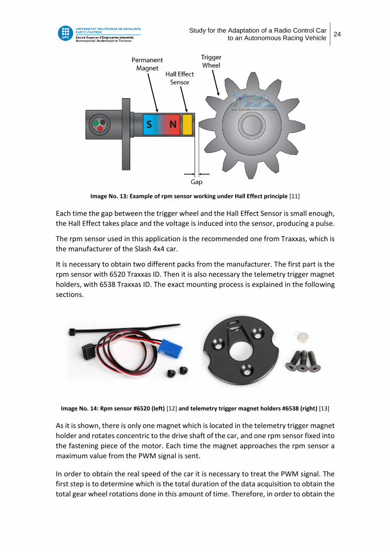
At this point the functioning of Hall Effect sensor can be finally understood under the
following illustrative example.
Study for the Adaptation of a Radio Control Car to an Autonomous Racing Vehicle
24
Image No. 13: Example of rpm sensor working under Hall Effect principle [11]
Each time the gap between the trigger wheel and the Hall Effect Sensor is small enough,
the Hall Effect takes place and the voltage is induced into the sensor, producing a pulse.
The rpm sensor used in this application is the recommended one from Traxxas, which is
the manufacturer of the Slash 4x4 car.
It is necessary to obtain two different packs from the manufacturer. The first part is the
rpm sensor with 6520 Traxxas ID. Then it is also necessary the telemetry trigger magnet
holders, with 6538 Traxxas ID. The exact mounting process is explained in the following
sections.
Image No. 14: Rpm sensor #6520 (left) [12] and telemetry trigger magnet holders #6538 (right) [13]
As it is shown, there is only one magnet which is located in the telemetry trigger magnet
holder and rotates concentric to the drive shaft of the car, and one rpm sensor fixed into
the fastening piece of the motor. Each time the magnet approaches the rpm sensor a
maximum value from the PWM signal is sent.
In order to obtain the real speed of the car it is necessary to treat the PWM signal. The
first step is to determine which is the total duration of the data acquisition to obtain the
total gear wheel rotations done in this amount of time. Therefore, in order to obtain the

Study for the Adaptation of a Radio Control Car to an Autonomous Racing Vehicle
25
rpm value of the gear wheel it is necessary to count the amount of pulses obtained in
one minute of time.
For the car speed calculation it is necessary to know which are the wheel’s rpm, so it is
necessary to do a conversion from the revolutions of the gear wheel to the revolutions
of the car wheels. In this case the experimental adopted solution is to count the number
of gear wheel revolutions per rotation of the car wheels.
It is possible to count how many gear teeth form the shaft gear. It is behind the shaft
gear where the telemetry trigger magnet holder is fixed. The total number of teeth is
54, as it can be observed in figure 15.
Image No. 15: Total teeth number of the gear shaft. Magnet is found behind it in the magnet holder part.
On one hand a mark in the upper part of the wheel is down. On the other hand the mark
is also done in one gear tooth of the shaft gear, where the initial position is known.
Image No. 16: Initial position of the two marks at the beggining of the measurement
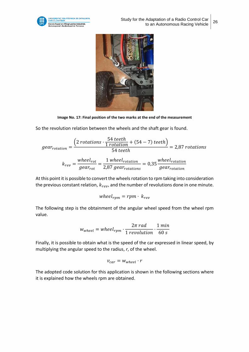
Finally, after a complete rotation of the wheels is done, the new position of the gear
shaft mark is 7 teeth left to complete 3 entire rotations.
Study for the Adaptation of a Radio Control Car to an Autonomous Racing Vehicle
26
Image No. 17: Final position of the two marks at the end of the measurement
So the revolution relation between the wheels and the shaft gear is found.
𝑔𝑒𝑎𝑟𝑟𝑜𝑡𝑎𝑡𝑖𝑜𝑛 =(2 𝑟𝑜𝑡𝑎𝑡𝑖𝑜𝑛𝑠 ·
54 𝑡𝑒𝑒𝑡ℎ1 𝑟𝑜𝑡𝑎𝑡𝑖𝑜𝑛 + (54 − 7) 𝑡𝑒𝑒𝑡ℎ)
54 𝑡𝑒𝑒𝑡ℎ= 2,87 𝑟𝑜𝑡𝑎𝑡𝑖𝑜𝑛𝑠
𝑘𝑟𝑒𝑣 =𝑤ℎ𝑒𝑒𝑙𝑟𝑜𝑡
𝑔𝑒𝑎𝑟𝑟𝑜𝑡=
1 𝑤ℎ𝑒𝑒𝑙𝑟𝑜𝑡𝑎𝑡𝑖𝑜𝑛
2,87 𝑔𝑒𝑎𝑟𝑟𝑜𝑡𝑎𝑡𝑖𝑜𝑛𝑠= 0,35
𝑤ℎ𝑒𝑒𝑙𝑟𝑜𝑡𝑎𝑡𝑖𝑜𝑛
𝑔𝑒𝑎𝑟𝑟𝑜𝑡𝑎𝑡𝑖𝑜𝑛
At this point it is possible to convert the wheels rotation to rpm taking into consideration
the previous constant relation, 𝑘𝑟𝑒𝑣, and the number of revolutions done in one minute.
𝑤ℎ𝑒𝑒𝑙𝑟𝑝𝑚 = 𝑟𝑝𝑚 · 𝑘𝑟𝑒𝑣
The following step is the obtainment of the angular wheel speed from the wheel rpm
value.
𝑤𝑤ℎ𝑒𝑒𝑙 = 𝑤ℎ𝑒𝑒𝑙𝑟𝑝𝑚 ·2𝜋 𝑟𝑎𝑑
1 𝑟𝑒𝑣𝑜𝑙𝑢𝑡𝑖𝑜𝑛·
1 𝑚𝑖𝑛
60 𝑠
Finally, it is possible to obtain what is the speed of the car expressed in linear speed, by
multiplying the angular speed to the radius, r, of the wheel.
𝑣𝑐𝑎𝑟 = 𝑤𝑤ℎ𝑒𝑒𝑙 · 𝑟
The adopted code solution for this application is shown in the following sections where
it is explained how the wheels rpm are obtained.

Study for the Adaptation of a Radio Control Car to an Autonomous Racing Vehicle
27
2.3. Implementations development
2.3.1. New car implementations
Below in this section it is explained which are the new implementations done in the RC
car in order to achieve the desired autonomous racing vehicle.
Removal of receiver and antenna
These two devices are in charge of receiving the signal from the transmitter and
converting it into orders sent to the different actuators such the ESC and the servo are.
Image No. 18: RC chassis before any removal is made
The aim of this project is to get an autonomous vehicle, so the use of the transmitter
and receiver is no longer possible. For this reason the receiver and the antenna are
removed from the RC car.
The Ordroid computer is the brain of the autonomous vehicle and it replaces both
devices by sending different instructions to the actuators through the Arduino.
Merge between the electronic board and the new RC vehicle
The aim of this project is to adapt the previous autonomous vehicle owned by ESEIAAT
to a new autonomous racing vehicle. In order to do this transformation, it is necessary
to have a more powerful car and therefore a new RC car is bought. At this point, there
are two different cars which have to be merged in order to obtain the final purpose.
The methacrylate plaque where the Ordroid computer, the Arduino and all the different
sensors are located is pulled out from the previous university prototype and it is
assembled into the new RC car.

Study for the Adaptation of a Radio Control Car to an Autonomous Racing Vehicle
28
Next, both different vehicle parts are shown.
Image No. 19: Electronic board (left) and new RC chassis (right)
Deeper explanation on the complete assembly process is given in the following sections.
Arduino connection
One of the most important car devices is the Arduino. Its main function is to receive
orders from the Ordroid computer and transmit them to the different actuators such
are the servo and the electronic speed controller.
A Nano Arduino is used in this project and in the following illustration its pinout is shown.
Image No. 20: Arduino NANO pinout [14]

Study for the Adaptation of a Radio Control Car to an Autonomous Racing Vehicle
29
The theoretical working principles of both actuators, servo and ESC, have been explained
earlier. Both devices receive the orders from the Arduino through a PWM signal and
both of them must be connected to different Arduino pins which allow to send PWM
signal.
In figure 21, the connections of the Arduino pins are shown.
Image No. 21: Arduino pins configuration
The ESC, the servo and the rpm sensor have the similar wiring connection. The white
wire is the signal of the ESC, the servo and the rpm sensor and it is connected to the
Arduino pins 6, 10 and 3, respectively. The red one is the 5V supply, which is only
connected in servo actuator and rpm sensor as the ESC has its own supply from the
battery. Finally the black wire is the ground connection.
There is also the pin 9 of the Arduino which is connected to the variable “LED_PIN” that
controls when the different lights found in the car must be turned on and off. The
connections are identical to the two previous actuators with the only difference of the
pin signal connection.
Finally the pin 2 of the Arduino is used as an interrupt pin which is connected to the
MPU, who is in charge of the vehicle’s odometry.
Image No. 22: Arduino pinout connections top view (left) and bottom view (right)
SERVO
LED
ESC
RPM

Study for the Adaptation of a Radio Control Car to an Autonomous Racing Vehicle
30
2.3.2. Assembly methodology
In this section the different necessary steps to assemble both vehicles together is
explained in detail.
All modifications of the assembly process have been made following the Traxxas owner’s
manual straightforward in order to ensure the all components work properly. [15]
2.3.2.1. Extraction of pieces
When transforming the RC car to the autonomous racing vehicle, it is necessary to
remove two parts which are no longer useful.
Receiver
Remove the four screws from the two covers of the receiver.
Detach the connectors of the ESC and servo devices.
Unscrew two screws located in the bottom of the case.
Take away the whole casing.
Image No. 23: Dismounting process of the receiver

Study for the Adaptation of a Radio Control Car to an Autonomous Racing Vehicle
31
Antenna
Unscrew the pressure screw by freeing the antenna.
Remove the antenna without bending it.
Image No. 24: Dismounting process of the antenna
2.3.2.2. Modification of parts
Springs
Shock absorbers are set by default at maximum height for driving the car in irregular
fields. As the car is going to be used for academic purpose it will be driven through tough
pavement, therefore harder shock absorbers are preferred.
Remove the screw from the bottom part of the spring.
Tighten the screw in a further position achieving the height reduction.
Image No. 25: Reallocation of the different shock absorbers

Study for the Adaptation of a Radio Control Car to an Autonomous Racing Vehicle
32
2.3.2.3. Assembly between the methacrylate plaque and the new RC vehicle
Down below all the steps done in order to complete successfully the assembly between
the methacrylate glass plate and the RC car chassis are explained.
The structure is composed of four thin iron rods which are united to the electronic board
and the chassis of the RC vehicle through nuts.
Measuring and tracing holes
First of all, the different positions of the nods are determined maintaining the symmetry
of the vehicle. The different holes are marked in the RC chassis and the methacrylate
glass plate in order to proceed with the drilling process.
Image No. 26: Marking the position of the four iron rods
Drilling process
Once all the iron rods positions are determined, it is possible to start with the drilling
process. It is important to drill the holes firstly with a smaller drill bit of 2mm and then
with a bigger one of 5mm, which is the diameter of the iron rods.
Image No. 27: Drilling process of the different surfaces

Study for the Adaptation of a Radio Control Car to an Autonomous Racing Vehicle
33
USB hub reallocation
It is necessary to reallocate the position of the USB hub to avoid possible contact with
the new position of the rods. A new hole for the screw which subjects the USB hub is
made few millimetres further from the previous position which does not have any other
effect into the plaque distribution.
Image No. 28: USB hub reallocation
Rods adjustment and preparation of level rubber
Once all the holes are made it is possible to check that the four rods position is the
correct one. In case the methacrylate glass plaque does not properly fits with the rods
position it is possible to do some adjustment on the holes.
The following step is to cut a rubber carefully. This rubber allows to compensate the
inclined plane where the rods are fixed to the chassis. By doing this, it will be possible
to have a completely perpendicular fixation.
Image No. 29: Final adjusting of the iron rods position (left) and level rubber preparation (right)

Study for the Adaptation of a Radio Control Car to an Autonomous Racing Vehicle
34
Rods attachment to chassis and methacrylate plaque
The following step is to attach the four rods to the chassis and the methacrylate plaque.
Firstly the attachment to the chassis is done by using the level rubber, a ring pull and the
nut. Once the rod is firmly joined to the chassis is possible to measure which is the height
of the methacrylate plaque. The shorter height the better car stability, so the
recommended height is the shorter possible one which allows the user to operate easily
inside the vehicle.
Finally after the height of the plaque has been fixed the last step is to attach it with the
use of a ring pull and a nut for each side of the board.
Image No. 30: Rods attachment to chassis (left) and methacrylate plaque (right)
Measuring methacrylate plaque straightness
The last step of the construction process is to ensure the complete straightness of the
plaque. The different sensors on board, such is for example the LIDAR, must be always
stabilised to guarantee their proper functioning. Also it is important to have an
equidistributional load division.
For that reason a building level is used to prove the perfect straightness of the
methacrylate plaque.
Image No. 31: Levelling of the methacrylate plaque at back (left) and at front of the car (right)

Study for the Adaptation of a Radio Control Car to an Autonomous Racing Vehicle
35
2.3.3. ROS operating manual
In this section firstly a brief introduction to Robot Operating System, ROS, is done. Then
it is explained how to connect to the autonomous racing vehicle and which are the most
used ROS command-line tools.
2.3.3.1. Robot Operating System introduction
The Robot Operating System (ROS) is a set of tools that taking part of an environment
connects different networks of processes, called nodes, together on a heterogeneous
computer cluster. This environment is used mostly on working with peripheral
hardware. [16]
The basic principle of ROS is to run different nodes at the same time while they exchange
data simultaneously. The different basic concepts that a new user must know from ROS
are explained below. [17]
Nodes: A node is an instance of an executable. It is the process which is executed
declaring itself to the master. Nodes can be two different types of executables:
publishers or subscribers. The first ones are in charge of sending message of any topic,
for example to write which is the desired car speed, while the second ones are those
nodes which read the information that comes from a topic and use this information as
an input value. A node can be a publisher of different topics and at the same time
subscriber of other topics.
Master: This is a node declaration which allows the different nodes to find each other
and exchange data.
Topics: Topics are buses through which data between the different nodes is exchanged.
Different nodes can publish data to the same topic while at the same time others can
subscribe to this topic. It is important to remark that topics are used in unidirectional
streaming communications. This means that topics publish or subscribe data without
the need of a petition. Additionally, each topic is typed so that subscribers will only
transport messages when a type match is done. [18]
Messages: It is a combination of different data types that contain the information of the
status of any node.
Services: Services have the same functionality of topics but they are used when the
communication method between two different nodes is made through request/reply
interactions. A ROS node offers a service and a client node calls the service by sending a
request message and waiting for the proper reply. [19]
Bags: They are used in order to store data so that later it can be played back as many
times as desired to simulate real data. They are very useful also for debugging a system
after the event.

Study for the Adaptation of a Radio Control Car to an Autonomous Racing Vehicle
36
Scheme No. 1: ROS schematic network processes
After a brief introduction to the basics of ROS it is explained which are the basic ROS
command-line tools to work with nodes [20] and topics [21].
rosnode info /node_name: Displays information about a node.
rosnode list: Shows the list of the active nodes.
rosnode kill /node_name: Stop any processes by ceasing the node.
rostopic info /topic_name: Displays information about a topic.
rostopic echo /topic_name: Prints messages published to a topic.
rostopic list: Shows the list of the active topics.
rostopic pub /topic_name stds_msgs/String “message”: Publishes data to a topic.
2.3.3.2. Rosserial y rosserial_arduino
Once the introduction to ROS has been briefly done it is important to mention two
important protocols used in this project.
First of all, rosserial is a protocol inside ROS that allows electronics to talk to the rest of
the ROS system by using topics, nodes and the different parameters explained before.
Communication is done through a serial port or network socket, such are TCP/IP
protocol connections. [22]
The communication is done over a serial transmission line adding a packet header and
tail where multiple topics can share the same serial link in order to be connected each
other. [22]

Study for the Adaptation of a Radio Control Car to an Autonomous Racing Vehicle
37
Furthermore, rosserial protocol has got different client libraries that allows to use its
useful applications from different multiples systems. The client library which is used in
this project is rosserial_arduino.
As it has been previously explained the electronic in charge of communicating the user’s
orders to the different actuators is the Arduino. Communication made between Ordroid
computer and Arduino is made through rosserial_arduino.
This library allows easily to integrate different hardware, such are sensors and actuators,
governed by an Arduino to be used into ROS environment. This is really used in a wide
range of applications, especially in robotic projects. [23]
The following illustration is an example of an application of the communication made
between computer and Arduino.
Image No. 32: Rosserial_arduino illustration example [24]
2.3.3.3. Connection to the autonomous vehicle
How to connect your computer to the car
1) Connect the battery tester to the battery balancing connector as shown in the next
picture.
2) Plug together the yellow power connector of the car to the battery. Always the
metallic power button must be OFF at this step.
3) Turn the vehicle ON by pushing the power button as shown in the following picture.
4) Connect the Ethernet cable from your laptop to the Ordroid computer and select the
MAC address of the desired Ethernet connection in the Network Manager menu. This
step has to be done only once to stablish connection for the first time.
5) Stablish connection with the Ordroid computer by executing the following command.
Command: ”ssh [email protected]“

Study for the Adaptation of a Radio Control Car to an Autonomous Racing Vehicle
38
6) Once the password is entered the connection to the car is completed.
Password: “elfmeter” (all lower case)
If all previous steps have been correctly done the appearance of the vehicle should be
the following one.
Image No. 33: Vehicle appearance after good connection is stablished
Further information on the connection and the installation process of all the necessary
files are found in “ADC 2018 Workshop” document. [25]
2.3.3.4. Software structure to control the autonomous vehicle
The general software structure that governs the autonomous racing vehicle is shown in
figure 34. Nodes are represented through rectangles while topics are the connections
between them.
Image No. 34: General software structure controlling the autonomous vehicle [25]

Study for the Adaptation of a Radio Control Car to an Autonomous Racing Vehicle
39
It is important to explain the main functionality of each node.
Serial_node node:
The communication with the Arduino is done through this ROS node via an USB port.
This is one of the most important nodes of the code. For that reason this node is in detail
explained.
On the one hand, it controls the velocity of the car through /speed topic, but also
commands the angle of the steering servo through /steering and LED lights within /led
topic.
On the other hand, it receives feedback information of wheel’s orientation through
/steering_angle topic, it obtains the position of the car (yaw, pitch and roll angles)
through the /yaw topic and finally it gets the actual linear speed of the vehicle through
/twist topic.
This information can be in more detail seen in figure 35.
Image No. 35: Publishers and subscribers of the serial_node with the corresponding message type [25]
Odometry publisher node:
This ROS node is in charge of estimating which is the current position of the vehicle with
respect to the initial position where the vehicle was powered up for the first time. The
necessary inputs to estimate the position are given through the /serial_node.

Study for the Adaptation of a Radio Control Car to an Autonomous Racing Vehicle
40
Its subscribed and published topics are in more detail shown.
Image No. 36: Publishers and subscribers of the odometry publisher node with the corresponding
message type [25]
RplidarNode
The RPLidar sensor assembled to the car scans all the surrounding obstacles and the
different distances to obstacles are stored in this ROS node.
Auto_stop node
This ROS node is used to detect possible obstacles and modify the speed of the car in order to
avoid a possible accident. The input values of this node are given through the serial_node and
the rplidarNode.
Image No. 37: Publishers and subscribers of the auto_stop node with the corresponding message type [25]
Usb_cam node
This ROS node provides image itself as it interacts with the wide-angle top camera.
App/ camera node
This ROS node provides a cloud of points with depth information and also provides with images,
both in color and grayscale, as it is connected to the frontal camera.
Study for the Adaptation of a Radio Control Car to an Autonomous Racing Vehicle
41
2.3.4. Implemented Arduino code
Arduino is the part in charge of executing the orders received by the Ordroid and
transmitting them to the different actuators.
In a previous project all the Arduino code was developed in order to achieve a complete
autonomous vehicle. The aim of this project is to implement the necessary changes to
this code to get the new RC vehicle to work. For this reason, this section only explains
the part of the code where the peripherals that have been modified in this project
operate.
2.3.4.1. Servo
One of the major changes that have an effect on the code is the connection with the
new servo. The previous one was an analog servo which could send its position to the
Arduino through an analog pin. However, it is not possible to obtain the curren position
of the new servo.
The function responsible for the servo movement is “onSteeringCommand”. This
function starts reading the data given by the user through the Ordroid. When data is
between the range of possible servo working angles then it is saved into “servo_angle”
variable. Then, it is also converted into a readable input for the servo in microseconds.
In addition, the connection of the servo signal to the Arduino corresponding pin is done.
In order to guarantee the proper functioning of the servo the minimum and maximum
movement of the servo is limited.
It is possible to see all the Arduino code related to “onSteeringCommand” function in
figures 38 and 39.

Study for the Adaptation of a Radio Control Car to an Autonomous Racing Vehicle
42
Image No. 38: Servo “onSteeringCommand” function in Arduino code
The code has been modified also so that the ROS node “/steering_angle” publishes the
last order that Arduino has given to the servo. Therefore, it is possible to know which is
the current position of the servo.
Image No. 39: Arduino code modification /steering_angle ROS node

Study for the Adaptation of a Radio Control Car to an Autonomous Racing Vehicle
43
2.3.4.2. Electronic speed controller
The other big challenge related with the Arduino code is to achieve the motor
movement controlled by the Ordroid computer.
First of all, the previous car prototype had a complete different DC motor. For this
reason it has been necessary to redefine all the code of this part.
In this case it is “onSpeedCommand” the function in charge of the movement of the car.
As in the previous explained function, firstly the data given by the user is stored in
“desired_speed” variable.
After the connection of the ESC signal to the Arduino corresponding pin is done, there
is a differentiation between the possible motor states. The vehicle can go forward,
backward or it can be stopped. Depending on the input value the ESC will receive a signal
expressed in microseconds represented by “real_speed” variable. The “real_speed”
value is obtained by the conversion of the input “desired_speed” value given by the user
to microseconds by means of the map function. Additionally, the range of proper
functioning for the ESC is limited between 1000 and 2000 microseconds.
Image No. 40: Motor “onSpeedCommand” function in Arduino code (part 1)

Study for the Adaptation of a Radio Control Car to an Autonomous Racing Vehicle
44
Image No. 41: Motor “onSpeedCommand” function in Arduino code (part 2)
As it is explained in following sections, it exists a dead band where the electric motor
has no response at all. The code has been developed in order that the user enters the
desired speed value which must be an integer. On the one hand, if the input is a negative
value the car will go backward, while on the other hand in order to go forward the user
must enter a positive value. If the user wants to stop the car then the input value must
be 0. This performance is achieved by adjusting the dead band of the motor to the
desired input values.
Furthermore, these input values are not the real speed of the car. However the higher
the value is, the faster will go the car.
In order to know which is the real speed of the car the rpm code is implemented. First
of all it is possible to observe the different variables and calculations that are involved
with the rpm sensor.
Image No. 42: Variables used in the car speed calculation

Study for the Adaptation of a Radio Control Car to an Autonomous Racing Vehicle
45
The variables “k_rev”, “rpm_conv” and “angspeed_conv” are used to calculate the speed
of the car later.
Every time that the magnet is closer enough to the rpm sensor there is a change of state
in the rpm signal that goes from LOW to HIGH. This change of state is done in the digital
pin attached to the rpm signal. When this interruption occurs, the “interrupt_rpm”
function executed where there is a counter (“compt”) which increases its value at every
interruption. By doing this, it is possible to register each revolution of the gear shaft.
During the interrupt execution all other interruptions are disabled until it does not
finishes. Once the interruption is complete the other interruptions are again enabled.
Image No. 43: Interrupt function counting changes of state of the rpm signal
Before obtaining the real speed of the car it is done a previous calculation, which is only
executed once in the code. This calculation takes into account different constant values
that will allow in further calculations to obtain the real speed of the car.
The treatment of all the previous functions and calculations are done in the last part of
the code.
In this part, it is published a value of zero speed when the vehicle is stopped. However,
in case the wheels are rotating, there are two time variables that capture different
instant of times, “currentMillis” and “previousMillis”. During the duration of one
second “compt” variable is increasing its value each time an interruption occurs. When
the difference between these two variables is higher than one second, then “compt”
value will be the number of revolutions made in one second of time. It is possible to
obtain the number of revolutions per minute (rpm) by multiplying “compt” and
“data_time”. At this point the different conversion steps that has been previously
explained to obtain the real speed of the car is done.

Study for the Adaptation of a Radio Control Car to an Autonomous Racing Vehicle
46
After the calculation has been done, “compt” variable is restarted in order to calculate
the new “car_real_speed”.
Finally the real speed of the car is published in /twist topic. In case the vehicle is going
backward /twist topic will have a negative value while if it is going toward /twist will
have a positive value.
The last part of the code is shown next.
Image No. 44: Arduino code modification /twist ROS node

Study for the Adaptation of a Radio Control Car to an Autonomous Racing Vehicle
47
3. RESULTS
3.1. Car characteristics and specifications
After the complete assembly of the new car is made it is possible to highlight the main
characteristics of the prototype.
3.1.1. Technical characteristics
The most significant technical characteristics are explained in the following section.
Speed
In this vehicle it is chosen a 2s LiPo battery of 5500 mAh and 7,4V. This corresponds to
a performance of approximately 40mph, according to manufacturer specifications,
which is equivalent to almost 65 km/h.
Image No. 45: Slash 4x4 performance depending on battery selection [15]
Dimension and weight
The total dimension of the complete assembly is approximately of 57x30x24 𝑐𝑚3 with a
total weight of 3,9 kg.
3.1.2. Driving specifications
As a result of mounting the different parts together there are different driving
limitations that must be taken into account.
Operating ESC range
It has been mentioned before how does the ESC works, depending on the duration of
the input signal the ESC order the motor to move a higher or lower speed.
Although the theoretical operating range of the input signal received by the ESC is
between 1000 𝜇𝑠 to 2000 𝜇𝑠 , in real life this range is shorter. This is because the
existence of the dead band. The dead band, dead zone or neutral zone is the band of

Study for the Adaptation of a Radio Control Car to an Autonomous Racing Vehicle
48
input values where the output is zero, no action occurs. This dead zone has been
experimentally found and it contains input values from 1445 𝜇𝑠 to 1462 𝜇𝑠 and values
from 1515 𝜇𝑠 to 1530 𝜇𝑠 . Finally the range of values that stops the car goes
from 1462 𝜇𝑠 to 1515 𝜇𝑠.
The operating ESC range can be schematically represented in the following table.
Operating servo range
Similarly as the ESC operating range there is a difference between the servo theoretical
movement and the real movement due to the union of the motor shaft to the different
movable parts.
In this case the theoretical movement of the servo contains all degrees from 0 to 180
degrees, but as it has been previously mentioned, the minimum real turning servo angle
is 80𝑜 while the maximum is 100𝑜.
The movement of the servo is turned into the turning of the wheels. The real turning
degree range of wheels goes approximately from 70𝑜 to 110𝑜.
All the working ranges are represented in the following schematic.
1000 1445 1462 1500 1515 1530 2000
Dead band Forward Backward
0 70 80 90 100 110 180
Real servo range
Theoretical servo range
Dead band Stop
Wheel turning degree
Scheme No. 2: Operating ESC range expressed in microseconds
Scheme No. 3: Operating servo range expressed in degree

Study for the Adaptation of a Radio Control Car to an Autonomous Racing Vehicle
49
3.2. Testing
In this section the different functionalities of the car are tested in order to prove the
correct functioning of the autonomous vehicle.
First of all, it is shown that as it has been previously explained when the program is asked
for information of a specific ROS node it is given all the publishers and subscribers that
the node has got.
Image No. 46: Screenshot of command-line rosnode info /serial_node
It is possible to see also how the car responds when it is asked for a specific publisher
or subscriber topic of a ROS node. In this project it is shown the correct functioning of
Serial_node as it is the only one which have been modified.
Other nodes such rpLidar or Odometry have also been tested in the new car and they
are working properly.
Publisher /steering_angle ; Subscriber: /steering_angle
Image No. 47: Vehicle response to steering angle variation from 90 (left) to 130 degrees (right)

Study for the Adaptation of a Radio Control Car to an Autonomous Racing Vehicle
50
Publisher /speed ; Subscriber: /twist (pictures of the code)
Image No. 48: Vehicle response to speed variation from being stopped (left) to moving forward (right)
Publisher /led:
Image No. 49: Vehicle response to LEDs variation from being off (left) to on (right)

Study for the Adaptation of a Radio Control Car to an Autonomous Racing Vehicle
51
3.3. Project budget
The following budget is a cost estimation of the project. An approximated calculation
has been done by taking into consideration different aspects which are explained in the
Budget’s documentation.
The final budget is represented in the following table.
Table No. 4: Total budget of the project
Finally, the total cost approximately of this project is 4005€.
In case university wanted to replicate the autonomous racing vehicle, its total cost would
be definitely lower because the personnel cost would be reduced since the duration of
the project would be shorter.
It is possible to consult in detail the calculation of the budget for each cost typology in
the Budget’s documentation.
Cost typology Price (€)
Material 601
Software 32
Personnel 3240
Hardware devaluation 117
Electrical consumption 15
Total budget 4005

Study for the Adaptation of a Radio Control Car to an Autonomous Racing Vehicle
52
3.4. Environmental implications
One of the major issues humanity is facing over the last years is the environmental
climate change which is affecting directly the Earth nature.
The consideration of the environmental impact of this project is shown in the following
section. Even though the impacts of this project are not extremely critical for the
environment, every small action can revert this disappointing situation.
It is used in this project a total of two electric power supplies which supply energy to all
the vehicle. Although the use of electric power does not have a direct impact on
environment, as for example happens with combustion engines, an indirect impact is
generated. Electrical energy consumed for the batteries recharge may have been
originated from different energy sources which depending on its production can
generate an important impact on the environment. For this reason, the adopted solution
is to avoid wasting battery in circumstances where there is no need to. Every time the
user turns off the vehicle must be aware of disconnecting the batteries to prevent an
avoidable discharge.
In order to be as much environmentally friendly as possible, two different actions must
be followed during the vehicle’s life. The first one is to buy the new and replacement
materials only from sellers who carry out good practices in favor of the environment.
The second stance taken into consideration is that all parts of the car which are no longer
useful will be reused in other applications or in defect they will be properly recycled in
order to generate minimum waste.

Study for the Adaptation of a Radio Control Car to an Autonomous Racing Vehicle
53
3.5. Conclusions
The major aim of this project has been successfully fulfilled since the adaptation of a
new radio control car to an autonomous racing vehicle has been achieved.
First of all a brief introduction to autonomous vehicle technologies is made by
comparing the real autonomous technologies to the previous autonomous car
functioning, owned by ESEIAAT. The different parts that provide autonomy to the
vehicle, such as the Ordroid computer, the Arduino and the different sensors, are
explained in this section.
Secondly, after doing an intense market research about the different radio control
available cars, the Traxxas Slash 4x4 model is the chosen one. The importance of this
decision was crucial for the correct developing of the autonomous vehicle. For that
reason a weighted table was done taking into consideration all project restrictions.
The different theoretical functioning of both actuators located in the majority of radio
control cars are explained in this project. The servo actuator is in charge of the vehicle’s
steering, while the electronic speed controller is in charge of the car throttle. Although
both components play different roles, they are governed by following the same pulse
width module signal principle. In addition, the rpm sensor functioning and its integration
to the car is also explained.
In order to achieve the adaptation of the new radio control car to an autonomous racing
vehicle it is necessary to do mechanical, electric and electronic changes which are
detailed in the project. Furthermore, all the steps to do the assembly of the different
parts of both cars, are completely documented with corresponding images of the
process. For the correct vehicle functioning it is vital to ensure the straightness of the
methacrylate plaque as it is in detailed explained in the specific step.
In this report, it is explained how ROS works and how it is connected to the Arduino
through rosserial_arduino. All steps to be connected to the Ordroid’s computer car
through Ethernet are explained. Furthermore, all the parts of the existing code which
have been modified in this project are also shown.
Finally the results of the project are demonstrated mentioning the final car
characteristics and specifications. Moreover, a testing process is made in order to show
how the final autonomous vehicle responds correctly to the different speed, steering
and LEDS’s commands.
This project has merely started here. It is possible to go further by integrating different
improvements which would transform this autonomous racing vehicle into a
competitive prototype. By doing this transformation, it would be possible to enrol
different autonomous driving university contests In the future.
To sum up all the previous concepts, the principal aim of the project has been reached
since it has been possible to do all the necessary mechanical, electric, electronic and
software changes in order to adapt a radio control car to an autonomous racing vehicle.

Study for the Adaptation of a Radio Control Car to an Autonomous Racing Vehicle
54
3.6. Future improvements planning
After the completion of this project it is possible to remark a list of possible project
upgrades that could be implemented in future interventions.
Firstly, the position of the servo at each instant of time is obtained directly from the last
order sent by the user. It is possible to read this value in /steering_angle topic. However,
a more accurate estimation of the wheel’s position could be done through identification
of dynamic systems.
On one hand, this autonomous racing vehicle is a really powerful car that can reach
speeds around 70 km/h. On the other hand the minimum speed of the car is
approximately 15 km/h. This feature happens because of the dead band of the motor
which has been mentioned in previous sections of the project. A possible solution, in
order to reach lower speeds below the minimum possible, would be to send
automatically two different PWM alternating signals, for example 0 km/h and 15 km/h,
so that the final speed would result an average of the both different speed values.
In this project the methacrylate plaque has been reused from the old autonomous
vehicle version. It has been possible to do a weight-balanced assembly between the two
parts of the cars. Nevertheless in future applications a new methacrylate plaque design
could be made for the new car which could fit perfectly to its chassis.
Finally, another possible upgrade that can be made in the future is to adapt the radio
control car casing to the final autonomous vehicle in order to achieve a more stylish
model. It will also add the possibility to do university advertising.

Study for the Adaptation of a Radio Control Car to an Autonomous Racing Vehicle
55
3.7. Bibliography
[1] “Hardware (AutoNOMOS Model v3.1) · AutoModelCar/AutoModelCarWiki Wiki · GitHub.” [Online]. Available: https://github.com/AutoModelCar/AutoModelCarWiki/wiki/Hardware-(AutoNOMOS-Model-v3.1).
[2] A. L. Meyrowitz, D. Richard Blidberg, and R. C. Michelson, “Autonomous vehicles,” Proc. IEEE, vol. 84, no. 8, pp. 1147–1163, 1996.
[3] “E-Maxx Brushless: 1/10 Scale Brushless Electric Monster Truck with TQi 2.4GHz Traxxas Link Enabled Radio System and Traxxas Stability Management (TSM) | Traxxas.” [Online]. Available: https://traxxas.com/products/models/electric/emaxx-brushless.
[4] “jlb racing cheetah 1/10 brushless rc coche truggy 21101 rtr Venta - Banggood.com|Shopping España.” [Online]. Available: https://es.banggood.com/JLB-Racing-CHEETAH-110-80A-Brushless-RC-Car-Monster-Trunk-21101-RTR-p-1073397.html?cur_warehouse=CN.
[5] “Slash 4X4 VXL: 1/10 Scale 4WD Electric Short Course Truck with TQi Traxxas LinkTM Enabled 2.4GHz Radio System & Traxxas Stability Management (TSM)® | Traxxas.” [Online]. Available: https://traxxas.com/products/models/electric/slash-4x4-tsm.
[6] “Traxxas E-Revo | RC Monster Truck 4x4.” [Online]. Available: https://traxxas.com/products/landing/e-revo/.
[7] “Traxxas 2075 Digital High Torque Waterproof Servo [TRA2075] | Cars & Trucks - HobbyTown.” [Online]. Available: https://www.hobbytown.com/traxxas-2075-digital-high-torque-waterproof-servo-tra2075/p25815.
[8] “Velineon® VXL-3s Electronic Speed Control, waterproof (brushless) (fwd/rev/brake) | Traxxas.” [Online]. Available: https://traxxas.com/products/parts/escs/vxl3s/3355Rvxl3s.
[9] “Arduino Brushless Motor Control Tutorial | ESC | BLDC - HowToMechatronics.” [Online]. Available: https://howtomechatronics.com/tutorials/arduino/arduino-brushless-motor-control-tutorial-esc-bldc/.
[10] “How Brushless Motor and ESC Work - HowToMechatronics.” [Online]. Available: https://howtomechatronics.com/how-it-works/how-brushless-motor-and-esc-work/.
[11] “What is Hall Effect and How Hall Effect Sensors Work - HowToMechatronics.” [Online]. Available: https://howtomechatronics.com/how-it-works/electrical-engineering/hall-effect-hall-effect-sensors-work/.
[12] “Sensor, RPM (long)/ 3x4mm BCS (2)/ 3x4 GS (1) | Traxxas.” [Online]. Available: https://traxxas.com/products/parts/telemetry/6520.
[13] “Telemetry trigger magnet holders, spur gear/ magnet, 5x2mm (1)/ 3x8mm CCS (3)/ 3x10mm CCS (3) | Traxxas.” [Online]. Available: https://traxxas.com/products/parts/telemetry/6538?t=overview.
[14] “▷ Arduino Nano Pinout y características | Descubrearduino.com.” [Online]. Available: https://descubrearduino.com/arduino-nano-pinout/.

Study for the Adaptation of a Radio Control Car to an Autonomous Racing Vehicle
56
[15] “TRAXXAS SLASH 4X4 MODEL 68086-4 owner ’ s manual.”
[16] “An Introduction to Robot Operating System | Toptal.” [Online]. Available: https://www.toptal.com/robotics/introduction-to-robot-operating-system.
[17] “ROS - Robot Operating System.” [Online]. Available: https://www.generationrobots.com/blog/en/ros-robot-operating-system-2/.
[18] “Topics - ROS Wiki.” [Online]. Available: http://wiki.ros.org/Topics.
[19] “Services - ROS Wiki.” [Online]. Available: http://wiki.ros.org/Services.
[20] “rosnode - ROS Wiki.” [Online]. Available: http://wiki.ros.org/rosnode.
[21] “rostopic - ROS Wiki.” [Online]. Available: http://wiki.ros.org/rostopic.
[22] “rosserial - ROS Wiki.” [Online]. Available: http://wiki.ros.org/rosserial.
[23] “rosserial_arduino - ROS Wiki.” [Online]. Available: http://wiki.ros.org/rosserial_arduino.
[24] “Introduction to rosserial_arduino - Atadiat.” [Online]. Available: https://atadiat.com/en/e-rosserial-arduino-introduction/.
[25] V. Gps and B. Ros, “ADC 2018 Workshop,” 2018.

Study for the Adaptation of a Radio Control Car to an Autonomous Racing Vehicle
57
ANNEX A
The Arduino code is attached in the annex section.
// I2Cdev and MPU6050 must be installed as libraries, or else the
.cpp/.h files
// for both classes must be in the include path of your project
#include "I2Cdev.h"
#include <avr/pgmspace.h>
#if __CLION_IDE__
#include "MPU6050/MPU6050_6Axis_MotionApps20.h"
#include "MPU6050/MPU6050.h" // not necessary if using MotionApps
include file
#else
#include "MPU6050_6Axis_MotionApps20.h"
#endif
#if I2CDEV_IMPLEMENTATION == I2CDEV_ARDUINO_WIRE
#include "Wire.h"
#endif
#include <Adafruit_NeoPixel.h>
// Which pin on the Arduino is connected to the NeoPixels?
#define LED_PIN 6
// How many NeoPixels are attached to the Arduino?
#define NUMPIXELS 21
#include <Servo.h>
#define MAX_DELTATIME 20000
#define MOTOR_PIN 6
#define ENCODER_PIN 3
#define SERVO_PIN 10
#define INTERRUPT_PIN 2 // use pin 2 on Arduino Uno & most boards
//#define TEST_COMMUNICATION_LATENCY
#include <ros.h>
#include <std_msgs/Bool.h>
#include <std_msgs/Int8.h>
#include <std_msgs/Int16.h>
#include <std_msgs/UInt8.h>
#include <std_msgs/UInt16.h>
#include <std_msgs/Float32.h>
#include <std_msgs/String.h>
#include <geometry_msgs/Twist.h>
#include <stdio.h>
const char LED_TOPIC[] PROGMEM = { "led" };
const char STEERING_TOPIC[] PROGMEM = { "steering" };
const char SPEED_TOPIC[] PROGMEM = { "speed" };
const char YAW_TOPIC[] PROGMEM = { "yaw" };
const char ROLL_TOPIC[] PROGMEM = { "roll" };
const char PITCH_TOPIC[] PROGMEM = { "pitch" };
const char TWIST_TOPIC[] PROGMEM = { "twist" };
const char STEERING_ANGLE_TOPIC[] PROGMEM = { "steering_angle" };
ros::NodeHandle nh;
std_msgs::Float32 yaw_msg;
std_msgs::Float32 pitch_msg;
std_msgs::Float32 roll_msg;

Study for the Adaptation of a Radio Control Car to an Autonomous Racing Vehicle
58
std_msgs::UInt16 steering_msg;
geometry_msgs::Twist twist_msg;
ros::Publisher pub_yaw(FCAST(YAW_TOPIC), &yaw_msg);
ros::Publisher pubTwist(FCAST(TWIST_TOPIC), &twist_msg);
ros::Publisher pubRoll(FCAST(ROLL_TOPIC), &roll_msg);
ros::Publisher pubPitch(FCAST(PITCH_TOPIC), &pitch_msg);
ros::Publisher pubSteeringAngle(FCAST(STEERING_ANGLE_TOPIC),
&steering_msg);
void onLedCommand(const std_msgs::String &cmd_msg);
void onSteeringCommand(const std_msgs::UInt8 &cmd_msg);
void onSpeedCommand(const std_msgs::Int16 &cmd_msg);
ros::Subscriber<std_msgs::String> ledCommand(FCAST(LED_TOPIC),
onLedCommand);
ros::Subscriber<std_msgs::UInt8>
steeringCommand(FCAST(STEERING_TOPIC), onSteeringCommand);
ros::Subscriber<std_msgs::Int16> speedCommand(FCAST(SPEED_TOPIC),
onSpeedCommand);
#ifdef TEST_COMMUNICATION_LATENCY
#include <std_msgs/Bool.h>
std_msgs::Bool resp_msg;
ros::Publisher pubResponse("resp", &resp_msg);
void onLatency(const std_msgs::Bool &cmd_msg) {
resp_msg.data = true;
pubResponse.publish(&resp_msg);
}
ros::Subscriber<std_msgs::Bool> requestCommand("req", onLatency);
#endif
// class default I2C address is 0x68
// specific I2C addresses may be passed as a parameter here
// AD0 low = 0x68 (default for SparkFun breakout and InvenSense
evaluation board)
// AD0 high = 0x69
MPU6050 mpu;
//MPU6050 mpu(0x69); // <-- use for AD0 high
// uncomment "OUTPUT_READABLE_QUATERNION" if you want to see the
actual
// quaternion components in a [w, x, y, z] format (not best for
parsing
// on a remote host such as Processing or something though)
//#define OUTPUT_READABLE_QUATERNION
// uncomment "OUTPUT_READABLE_EULER" if you want to see Euler angles
// (in degrees) calculated from the quaternions coming from the FIFO.
// Note that Euler angles suffer from gimbal lock (for more info, see
// http://en.wikipedia.org/wiki/Gimbal_lock)
//#define OUTPUT_READABLE_EULER
// uncomment "OUTPUT_READABLE_REALACCEL" if you want to see
acceleration
// components with gravity removed. This acceleration reference frame
is

Study for the Adaptation of a Radio Control Car to an Autonomous Racing Vehicle
59
// not compensated for orientation, so +X is always +X according to
the
// sensor, just without the effects of gravity. If you want
acceleration
// compensated for orientation, us OUTPUT_READABLE_WORLDACCEL instead.
//#define OUTPUT_READABLE_REALACCEL
// uncomment "OUTPUT_READABLE_WORLDACCEL" if you want to see
acceleration
// components with gravity removed and adjusted for the world frame of
// reference (yaw is relative to initial orientation, since no
magnetometer
// is present in this case). Could be quite handy in some cases.
//#define OUTPUT_READABLE_WORLDACCEL
// uncomment "OUTPUT_TEAPOT" if you want output that matches the
// format used for the InvenSense teapot demo
//#define OUTPUT_TEAPOT
// When we setup the NeoPixel library, we tell it how many pixels, and
which pin to use to send signals.
Adafruit_NeoPixel pixels = Adafruit_NeoPixel(NUMPIXELS, LED_PIN,
NEO_GRB + NEO_KHZ800);
Servo myservo; // create servo object to control a servo
Servo ESC; // create servo object to control a ESC
int servo_pw = 1500; // variable to set the angle of servo motor
int last_pw = 1500;
int servo_angle = 90;
bool servo_initialized = false;
int desired_speed = 0; //Initialise at 0 motor speed
int real_speed = 0; //Initialise at 0 motor speed
float pi = 3.1416;
float car_speed_conv;
int car_real_speed;
volatile int compt = 0;
unsigned long previousMillis = 0;
const long time_interval = 500; //100 miliseconds
int data_time = 120; // Variable multiplied to obtain 1 minut of data
float k_rev = (1.0/(155.0/54.0)); //Number of wheels rev / number of
gear rev -> Gear revolutions obtained counting how many teeths are
moves for 1 wheel rev.
float rpm_conv = ((2.0*pi)/60.0); //Conversion of rpm to angular speed
float angspeed_conv = (11.0/100.0)*(3600.0/1000.0); // Linear speed
// MPU control/status vars
bool dmpReady = false; // set true if DMP init was successful
uint8_t mpuIntStatus; // holds actual interrupt status byte from MPU
uint8_t devStatus; // return status after each device operation
(0 = success, !0 = error)
uint8_t packetSize; // expected DMP packet size (default is 42
bytes)
uint16_t fifoCount; // count of all bytes currently in FIFO
uint8_t fifoBuffer[64]; // FIFO storage buffer
// orientation/motion vars
Quaternion q; // [w, x, y, z] quaternion container
VectorFloat gravity; // [x, y, z] gravity vector
//float euler[3]; // [psi, theta, phi] Euler angle
container

Study for the Adaptation of a Radio Control Car to an Autonomous Racing Vehicle
60
float ypr[3]; // [yaw, pitch, roll] yaw/pitch/roll
container and gravity vector
// ================================================================
// === INTERRUPT DETECTION ROUTINE ===
// ================================================================
volatile bool mpuInterrupt = false; // indicates whether MPU
interrupt pin has gone high
void dmpDataReady() {
mpuInterrupt = true;
}
void interrupt_rpm()
{
cli();
compt++; // Each interrupt increases compt value
sei();
}
// ================================================================
// === SUBSCRIBERS ===
// ================================================================
void onSteeringCommand(const std_msgs::UInt8 &cmd_msg) {
if ((cmd_msg.data >= 0) && (cmd_msg.data <= 180)) {
// scale it to use it with the servo (value between 0 and 180)
servo_angle = cmd_msg.data; //save the new position of the
servo
servo_pw = map(cmd_msg.data, 0, 180, 1000, 2000);
if (last_pw!=servo_pw) {
myservo.writeMicroseconds(servo_pw);
}
if (!servo_initialized) {
// attaches the servo on pin 10 to the servo object
myservo.attach(SERVO_PIN);
servo_initialized = true;
}
last_pw = servo_pw;
}
if ( cmd_msg.data > 180) {
servo_pw = 2000;
myservo.writeMicroseconds(servo_pw);
}
if ( cmd_msg.data < 0) {
servo_pw = 1000;
myservo.writeMicroseconds(servo_pw);
}
}
void onSpeedCommand(const std_msgs::Int16 &cmd_msg) {
int16_t desired_speed = cmd_msg.data ;
ESC.attach(MOTOR_PIN); //attach ESC to pin 6

Study for the Adaptation of a Radio Control Car to an Autonomous Racing Vehicle
61
if(desired_speed > 0)
{
if (desired_speed < 500)
{
real_speed = map(desired_speed, 1, 500, 1500, 2000); //Range
from -500 to 500 to have maximum sensitivity
ESC.writeMicroseconds(real_speed);
}
else
{
real_speed = 2000;
ESC.writeMicroseconds(real_speed);
}
}
if(desired_speed < 0)
{
if (desired_speed >-500)
{
real_speed = map(desired_speed, -500, -1, 1000, 1500);
ESC.writeMicroseconds(real_speed);
}
else
{
real_speed = 1000;
ESC.writeMicroseconds(real_speed);
}
}
if (desired_speed ==0) {
real_speed = 1500;
ESC.writeMicroseconds(real_speed);
}
}
#if NUMPIXELS == 8
/* Control lights */
/*L20C32+16+8+4+2+1, 32+16/16=2+1 -> R , 8+4/4=2+1 -> G, 2+1 -> B :
WHITE=63, RED=48, YELLOW=56,OR 60*/
void onLedCommand(const std_msgs::String &cmd_msg) {
if (strcmp_P(cmd_msg.data, PSTR("Lle")) == 0) {
pixels.setPixelColor(0, pixels.Color(255, 80, 0)); //yellow
pixels.setPixelColor(7, pixels.Color(255, 80, 0)); //yellow
} else if (strcmp_P(cmd_msg.data, PSTR("Lri")) == 0) {
pixels.setPixelColor(3, pixels.Color(255, 80, 0)); //yellow
pixels.setPixelColor(4, pixels.Color(255, 80, 0)); //yellow
} else if (strcmp_P(cmd_msg.data, PSTR("Lstop")) == 0) {
for (uint8_t i = 4; i < 8; i++)
pixels.setPixelColor(i, pixels.Color(255, 0, 0)); //red
} else if (strcmp_P(cmd_msg.data, PSTR("Lpa")) == 0 ||
strcmp_P(cmd_msg.data, PSTR("Lta")) == 0) {
for (uint8_t i = 0; i < 4; i++)
pixels.setPixelColor(i, pixels.Color(50, 50, 50)); //white
(darker)
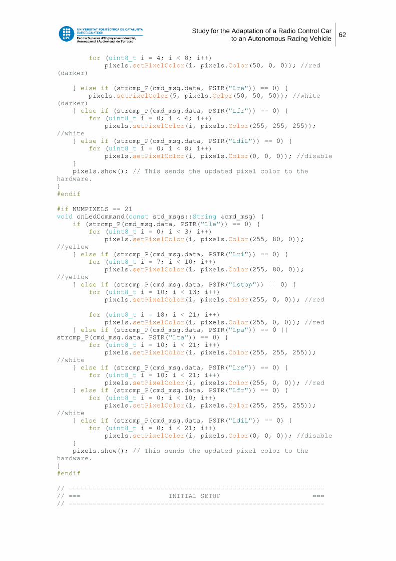
Study for the Adaptation of a Radio Control Car to an Autonomous Racing Vehicle
62
for (uint8_t i = 4; i < 8; i++)
pixels.setPixelColor(i, pixels.Color(50, 0, 0)); //red
(darker)
} else if (strcmp_P(cmd_msg.data, PSTR("Lre")) == 0) {
pixels.setPixelColor(5, pixels.Color(50, 50, 50)); //white
(darker)
} else if (strcmp_P(cmd_msg.data, PSTR("Lfr")) == 0) {
for (uint8_t i = 0; i < 4; i++)
pixels.setPixelColor(i, pixels.Color(255, 255, 255));
//white
} else if (strcmp_P(cmd_msg.data, PSTR("LdiL")) == 0) {
for (uint8_t i = 0; i < 8; i++)
pixels.setPixelColor(i, pixels.Color(0, 0, 0)); //disable
}
pixels.show(); // This sends the updated pixel color to the
hardware.
}
#endif
#if NUMPIXELS == 21
void onLedCommand(const std_msgs::String &cmd_msg) {
if (strcmp_P(cmd_msg.data, PSTR("Lle")) == 0) {
for (uint8_t i = 0; i < 3; i++)
pixels.setPixelColor(i, pixels.Color(255, 80, 0));
//yellow
} else if (strcmp_P(cmd_msg.data, PSTR("Lri")) == 0) {
for (uint8_t i = 7; i < 10; i++)
pixels.setPixelColor(i, pixels.Color(255, 80, 0));
//yellow
} else if (strcmp_P(cmd_msg.data, PSTR("Lstop")) == 0) {
for (uint8_t i = 10; i < 13; i++)
pixels.setPixelColor(i, pixels.Color(255, 0, 0)); //red
for (uint8_t i = 18; i < 21; i++)
pixels.setPixelColor(i, pixels.Color(255, 0, 0)); //red
} else if (strcmp_P(cmd_msg.data, PSTR("Lpa")) == 0 ||
strcmp_P(cmd_msg.data, PSTR("Lta")) == 0) {
for (uint8_t i = 10; i < 21; i++)
pixels.setPixelColor(i, pixels.Color(255, 255, 255));
//white
} else if (strcmp_P(cmd_msg.data, PSTR("Lre")) == 0) {
for (uint8_t i = 10; i < 21; i++)
pixels.setPixelColor(i, pixels.Color(255, 0, 0)); //red
} else if (strcmp_P(cmd_msg.data, PSTR("Lfr")) == 0) {
for (uint8_t i = 0; i < 10; i++)
pixels.setPixelColor(i, pixels.Color(255, 255, 255));
//white
} else if (strcmp_P(cmd_msg.data, PSTR("LdiL")) == 0) {
for (uint8_t i = 0; i < 21; i++)
pixels.setPixelColor(i, pixels.Color(0, 0, 0)); //disable
}
pixels.show(); // This sends the updated pixel color to the
hardware.
}
#endif
// ================================================================
// === INITIAL SETUP ===
// ================================================================

Study for the Adaptation of a Radio Control Car to an Autonomous Racing Vehicle
63
void setup() {
nh.getHardware()->setBaud(115200);
nh.initNode();
nh.advertise(pubTwist);
nh.advertise(pub_yaw);
nh.advertise(pubRoll);
nh.advertise(pubPitch);
nh.advertise(pubSteeringAngle);
nh.subscribe(ledCommand);
nh.subscribe(steeringCommand);
nh.subscribe(speedCommand);
#ifdef TEST_COMMUNICATION_LATENCY
nh.subscribe(requestCommand);
nh.advertise(pubResponse);
#endif
// join I2C bus (I2Cdev library doesn't do this automatically)
#if I2CDEV_IMPLEMENTATION == I2CDEV_ARDUINO_WIRE
Wire.begin();
Wire.setClock(400000); // 400kHz I2C clock. Comment this line if
having compilation difficulties
#elif I2CDEV_IMPLEMENTATION == I2CDEV_BUILTIN_FASTWIRE
Fastwire::setup(400, true);
#endif
// initialize device
nh.logerror(F("Initializing I2C devices..."));
mpu.initialize();
pinMode(INTERRUPT_PIN, INPUT);
// verify connection
nh.loginfo(F("Testing device connections..."));
nh.loginfo(mpu.testConnection() ? F("MPU6050 connection
successful") : F("MPU6050 connection failed"));
// load and configure the DMP
//Serial.println(F("Initializing DMP..."));
devStatus = mpu.dmpInitialize();
// supply your own gyro offsets here, scaled for min sensitivity
mpu.setXAccelOffset(886);
mpu.setYAccelOffset(1414);
mpu.setZAccelOffset(1573); // 1688 factory default for my test
chip
mpu.setXGyroOffset(6);
mpu.setYGyroOffset(31);
mpu.setZGyroOffset(50);
// make sure it worked (returns 0 if so)
if (devStatus == 0) {
// turn on the DMP, now that it's ready
//Serial.println(F("Enabling DMP..."));
mpu.setDMPEnabled(true);
// enable Arduino interrupt detection
nh.loginfo(F("Enabling interrupt detection (Arduino external
interrupt 0)..."));

Study for the Adaptation of a Radio Control Car to an Autonomous Racing Vehicle
64
attachInterrupt(digitalPinToInterrupt(INTERRUPT_PIN),
dmpDataReady, RISING);
mpuIntStatus = mpu.getIntStatus();
// set our DMP Ready flag so the main loop() function knows
it's okay to use it
nh.loginfo(F("DMP ready! Waiting for first interrupt..."));
dmpReady = true;
// get expected DMP packet size for later comparison
packetSize = mpu.dmpGetFIFOPacketSize();
} else {
// ERROR!
// 1 = initial memory load failed
// 2 = DMP configuration updates failed
// (if it's going to break, usually the code will be 1)
nh.logerror(F("DMP Initialization failed (code"));
nh.logerror("" + devStatus);
nh.logerror(F(")"));
}
pinMode(ENCODER_PIN, INPUT_PULLUP);
attachInterrupt(digitalPinToInterrupt(ENCODER_PIN),interrupt_rpm,R
ISING);
pixels.begin(); // This initializes the NeoPixel library.
car_speed_conv = data_time*k_rev*rpm_conv*angspeed_conv;
//Previous constant calculation to obtain real speed
}
// ================================================================
// === MAIN PROGRAM LOOP ===
// ================================================================
void loop() {
// if programming failed, don't try to do anything
if (!dmpReady) return;
// wait for MPU interrupt or extra packet(s) available
//while (!mpuInterrupt && fifoCount < packetSize) {}
if (mpuInterrupt || fifoCount >= packetSize) {
// reset interrupt flag and get INT_STATUS byte
mpuInterrupt = false;
mpuIntStatus = mpu.getIntStatus();
// get current FIFO count
fifoCount = mpu.getFIFOCount();
// check for overflow (this should never happen unless our
code is too inefficient)
if ((mpuIntStatus & 0x10) || fifoCount == 1024) {
// reset so we can continue cleanly
mpu.resetFIFO();
nh.logerror(F("FIFO overflow!"));

Study for the Adaptation of a Radio Control Car to an Autonomous Racing Vehicle
65
// otherwise, check for DMP data ready interrupt (this
should happen frequently)
} else if (mpuIntStatus & 0x02) {
// wait for correct available data length, should be a
VERY short wait
uint16_t fifoCount = mpu.getFIFOCount();
if (fifoCount >= packetSize) {
// read a packet from FIFO
mpu.getFIFOBytes(fifoBuffer, packetSize);
// track FIFO count here in case there is > 1 packet
available
// (this lets us immediately read more without waiting
for an interrupt)
fifoCount -= packetSize;
#ifdef OUTPUT_READABLE_QUATERNION
// display quaternion values in easy matrix form: w x
y z
mpu.dmpGetQuaternion(&q, fifoBuffer);
// Serial.print("quat\t");
//Serial.print(q.w);
//Serial.print("\t");
//Serial.print(q.x);
//Serial.print("\t");
//Serial.print(q.y);
//Serial.print("\t");
//Serial.println(q.z);
#endif
#ifdef OUTPUT_READABLE_EULER
// display Euler angles in degrees
// mpu.dmpGetQuaternion(&q, fifoBuffer);
// mpu.dmpGetEuler(euler, &q);
//Serial.print("euler\t");
//Serial.print(euler[0] * 180/M_PI);
//Serial.print("\t");
//Serial.print(euler[1] * 180/M_PI);
//Serial.print("\t");
//Serial.println(euler[2] * 180/M_PI);
#endif
// display Euler angles in degrees
mpu.dmpGetQuaternion(&q, fifoBuffer);
mpu.dmpGetGravity(&gravity, &q);
mpu.dmpGetYawPitchRoll(ypr, &q, &gravity);
Serial.print("yaw\t");
Serial.print(ypr[0] * 180/M_PI);
yaw_msg.data = ypr[0];
pub_yaw.publish(&yaw_msg);
pitch_msg.data = ypr[1];
pubPitch.publish(&pitch_msg);
roll_msg.data = ypr[2];
pubRoll.publish(&roll_msg);

Study for the Adaptation of a Radio Control Car to an Autonomous Racing Vehicle
66
steering_msg.data = servo_angle ;
pubSteeringAngle.publish(&steering_msg);
if (real_speed ==1500){
twist_msg.linear.x = 0.0;
twist_msg.linear.y = 0.0;
twist_msg.linear.z = 0.0;
}
if (((real_speed >= 1000) && (real_speed <= 1499))
||((real_speed >= 1501) && (real_speed <=
2000))) {
unsigned long currentMillis;
currentMillis = millis();
if (currentMillis - previousMillis >=
time_interval){
previousMillis = currentMillis;
car_real_speed = compt*car_speed_conv;
compt = 0;
if (real_speed <= 1499){
twist_msg.linear.x = -car_real_speed;
twist_msg.linear.y = 0.0;
twist_msg.linear.z = 0.0;
}
else {
twist_msg.linear.x = car_real_speed;
twist_msg.linear.y = 0.0;
twist_msg.linear.z = 0.0;
}
}
}
pubTwist.publish(&twist_msg);
}
}
}
nh.spinOnce();
}