A study of low-strain and medium-strain grain boundary engineering
Upload
khangminh22Category
view
3download
0
Tavio, Arbain TataStress-Strain Relation And Nonliner Behavior of Circular Confined Reinforced Concrete Columns
MEDIA KOMUNIKASI TEKNIK SIPIL 255
STRESS-STRAIN RELATION AND NONLINEAR BEHAVIOR OFCIRCULAR CONFINED REINFORCED CONCRETE COLUMNS
Tavio1, Arbain Tata2
Diterima 04 Agustus 2008
ABSTRACT
This paper presents a nonlinear finite element modeling and analysis of circularnormal-strength reinforced concrete columns confined with transverse steel underaxial compressive loading. In this study, the columns were modeled as discreteelements using ANSYS nonlinear finite element software. Concrete was modeled with8-noded SOLID65 elements that can translate either in the x-, y-, or z-axis directionsfrom ANSYS element library. Longitudinal and transverse steels were modeled asdiscrete elements using 3D-LINK8 bar elements available in the ANSYS elementlibrary. The nonlinear constitutive law of each material was also implemented in themodel. The results indicate that the stress-strain relationships obtained from theanalytical model using ANSYS are in good agreement with the experimental data. Thishas been confirmed with the insignificant difference between the analytical andexperimental, i.e. 1.011 and 1.306 percent for the peak stress and the strain at thepeak stress, respectively. The comparison shows that the ANSYS nonlinear finiteelement program is capable of modeling and predicting the actual nonlinear behaviorof confined concrete column under axial loading. The actual stress-strain relationship,the strength gain and ductility improvement have also been confirmed to besatisfactorily.
Keywords: ANSYS; confinement; ductility; stress-strain relationship; nonlinear finiteelement analysis; nonlinear behavior; reinforced concrete columns;strength.
ABSTRAK
Makalah ini menyajikan pemodelan dan analisis elemen hingga nonlinier kolom bulatbeton normal bertulang yang dikekang dengan baja transversal dibawah pembebanan
1Jurusan Teknik Sipil Faklutas Teknik ITS, Surabaya
Email : [email protected], 088836352622 Jurusan Teknik Sipil FT. Universitas Khairun, Ternate, Maluku Utara
MEDIA KOMUNIKASITEKNIK SIPIL
BMPTTSSI
TAHUN 16, NO. 3 OKTOBER 2008
MEDIA KOMUNIKASI TEKNIK SIPIL256
aksial tekan. Dalam studi ini, kolom dimodelkan sebagai elemen diskrit menggunakanperangkat lunak elemen hingga nonlinier ANSYS. Beton dimodelkan dengan elemenSOLID65 8-titik yang dapat bertranslasi baik dalam arah sumbu-x-, -y, or -z daripustaka elemen ANSYS. Baja longitudinal dan transversal dimodelkan sebagai elemendiskrit menggunakan elemen batang LINK8-3D yang tersedia dalam pustaka elemenANSYS. Hukum konstitutif nonlinier setiap material juga diterapkan dalam model.Hasilnya menunjukkan bahwa hubungan tegangan-regangan yang diperoleh darimodel analisis menggunakan ANSYS sangat sesuai dengan data eksperimental. Hal initelah dikonfirmasi dengan perbedaan yang tidak signifikan antara hasil analisis daneksperimental, yaitu 1,011 and 1,306 persen masing-masing untuk tegangan puncakdan regangan saat tegangan puncak. Perbandingan menunjukkan bahwa programelemen hingga nonlinier ANSYS mampu memodelkan dan memprediksi perilakunonlinier aktual kolom beton terkekang dibawah pembebanan aksial. Hubungantegangan-regangan aktual, peningkatan kekuatan dan perbaikan daktilitas juga telahdikonfirmasi memuaskan.
Kata kunci: Analisis elemen hingga nonlinier; ANSYS; daktilitas; hubungan tegangan-regangan; kekuatan kolom beton bertulang; pengekangan; perilakunonlinier.
INTRODUCTION
One of several reasons that cause thecollapse of a multi-story building orbridge structure is the failure of thesupporting members to withstand theearthquake loading. The failure of thesemembers is mostly due to the lack ofshear-resisting capacity and insufficientductility provided by little amount oftransverse steel. It is well known thatthe ductility of a reinforced concretecolumn plays a very important role inpreventing such a failure. That is whythe study on the ductility of a reinforcedconcrete column has been developingat a fast pace in the last two decades inmany countries worldwide. One of theeffective ways to improve the ductilityof a column is by introducing sufficientlateral reinforcement as confining steelfor concrete core in a column. Thiseffort is primarily intended to delay thesudden collapse of a column and forceit further to fail in a ductile manner.
Figure 1. Effective confined regions in aconcrete core of a circular column cross
section
The effectiveness of confinementdepends on the uniformity of the stressoccurred around the perimeter interfacebetween the confining steel andconcrete core. In circular columnsection, the effective confined region isaround the circular confining steel orspiral as shown in Figure 1. Figure 1also shows the effective region in a

Tavio, Arbain TataStress-Strain Relation And Nonliner Behavior of Circular Confined Reinforced Concrete Columns
MEDIA KOMUNIKASI TEKNIK SIPIL 257
concrete core of a circular columnsection. The effect of confinement in areinforced concrete column can beconsiderably increased if:1. the spacing or pitch of transverse
steel or spiral is denser; and2. the more number of longitudinal
steel is used and well distributedaround the perimeter of the columnsection.
Numerous researches have beenconducted earlier to study theeffectiveness of confinement inimproving the ductility of reinforcedconcrete columns. Some experimentaltests carried out by several previousresearchers include the studiesconducted by Cusson and Paultre [1],Saatcioglu and Razvi [2], and Assa,Nishiyama, and Watanabe [3], etc. [4-11]. Cusson and Paultre [1] carriedthrough the experimental tests on shortcolumns with high-strength concreteand proposed a stress-strain model ofductile confined concrete. Saatciogluand Razvi [2] tested and observed theductile behavior of confined concretecolumns with the strength up to 120MPa. Assa, Nishiyama, and Watanabe[3] also conducted similar tests onconfined short columns and examinedtheir ductile behaviors, and there arestill many more studies conducted byothers [4-11]. The numericalapproaches conducted by previousresearchers were mostly developed onempirical basis. This is due to thecomplex parameters involved inderiving the constitutive law of confinedconcrete. Though, some researchershad made many attempts to come upwith an accurate analytical stress-strainmodel of confined concrete, theyalways ended up with a fine-tuning
measure in matching up the analyticalresults with the experimental dataobtained from their tests.
The authors fully realize that theexperimental program is one of the bestways to adjust the proposed model inorder to achieve an acceptable accuracyfor practical usage. This sort of effort,however, is often very costly and timeconsuming; besides it still depends onthe availability and accuracy of the testapparatus and instrument. In addition,the use of the proposed model is oftenlimited to a certain extent of the testdata where they are calibrated with.
In this paper, the authors propose ananalytical procedure for predicting theactual stress-strain relationship of bothconfined and unconfined circularconcrete column under axial concentricloading. The procedure is valid forcircular concrete columns withtransverse steel or spiral of variousspacing or pitch. To establish theanalytical model, the authors haveselected one of the most popular finiteelement-based commercial software,i.e. ANSYS [12] that capable ofmodeling the nonlinear behavior of bothreinforced concrete beams and columns[13-18]. However, none of the workconducted previously includesreinforced concrete columns confinedby transverse steel or spiral. Theproposed procedure has been verifiedwith four column specimens confinedby various spacing of transverse steelrepresenting light to heavy confinement[19]. The analytical stress-strain curvesobtained from the proposed procedureare shown to be in close agreementwith the experimental data fromliterature [19].

TAHUN 16, NO. 3 OKTOBER 2008
MEDIA KOMUNIKASI TEKNIK SIPIL258
Research Significance
Modeling the constitutive law ofconfined reinforced concrete columnsbased on the empirical approach cansometimes be inaccurate or limited to anarrow range of available experimentaldata. The tests are also very expensiveand sometimes time consuming. Theapplicability of the test data mainlydepends on the accuracy of the testapparatus and the supportinginstruments implemented during thetest. Hence, it is deemed necessary tohave another option of modeling thestress-strain relationship of confinedconcrete without deploying an empiricalapproach in the modeling. One of thesuitable software that can be utilized todescribe the actual nonlinear behaviorof confined concrete columns underaxial loading is ANSYS [12]. This isbecause ANSYS is capable of analyzingthe SOLID elements in a structurebased on the finite element method.With the this option, researchers ordesign engineers can confidently predictin advance the actual behavior ofvarious confined concrete columns notonly in the linear-elastic region, butfurthermore also in the nonlinear post-elastic region. The authors wish thatthis economical procedure can be usedto provide an alternative tool forresearchers or structural engineers ininvestigating various types of structuralconcrete elements in the future.
FINITE ELEMENT PROCEDURE
The finite element procedureimplemented in this study is developedusing the available element types fromANSYS element library [12]. Theconcrete is modeled using SOLID65element type, whereas the steel forlongitudinal and transversereinforcements is modeled with LINK8element type. By adopting andcombining these two element types, thereinforced concrete column model wasdeveloped.The column model was subjected to anaxial compressive loading on their topface simulating the actual loadingapplied in the tests [19], while thebottom side was restrained. The loadingprocedure can be elaborated in thefollowing sequence: (1) for theascending branch (up to peak stress):the column model is subjected to astep-by-step incremental axial pressureon its entire top surface; then (2) forthe descending portion (beyond thepeak stress): the loading was thenswitched into the displacement-modecontrol by applying a step-by-stepincremental displacement on its topsurface.
To obtain an efficient solution, thecolumn was modeled in a quarterfollowing the symmetrical lines of itscross section as shown in Figure 2. Thetwo sides along the symmetrical lines ofa quarter was restrained to simulate theactual behavior of the full-size column,and thus, maintaining the accuracy ofanalysis of the model.

Tavio, Arbain TataStress-Strain Relation And Nonliner Behavior of Circular Confined Reinforced Concrete Columns
MEDIA KOMUNIKASI TEKNIK SIPIL 259
Figure 2. Boundary conditions of a symmetrical quarter of a column model:(a) elevation; (b) cross section
Determination Of Model
The analytical models were constructedaccording to the actual columnspecimens in literature [19] as shown inFig. 3. The column models had a typicalcross sectional diameter of 500 mmwith the height of 1500 mm. Theconcrete cover was 20 mm. The firstcolumn specimen was made from plainconcrete, namely specimen LS0 (Figure
3). The three remaining columnspecimens had various spacings anddiameters of transverse steel, i.e.specimens LS1, LS2, and LS3 (seeFigure 3). The mechanical properties ofeach specimen used for validation inthis study were adopted in developingthe analytical models to better reflectthe actual behavior of each columnspecimen.
Table 1. Summary of geometrical and mechanical properties of the column specimens
ColumnID
CrossSection(mm)
Height
(mm)
fc
(MPa)
(%)
fy
MPa)
fyh
(MPa)
Spacing,s(mm)
Volumetricratio(%)
LS0 Ø 500 1500 28.8 –– –– –– –– ––LS1 Ø 500 1500 28.8 1.01 295 235 300 0.19
LS2 Ø 500 1500 28.8 1.01 295 235 150 0.39LS3 Ø 500 1500 28.8 1.01 295 235 100 0.58
Symmetrical lines(Restrained)
Symmetricalline
Restrained
Axiallyloaded

TAHUN 16, NO. 3 OKTOBER 2008
MEDIA KOMUNIKASI TEKNIK SIPIL260
LC0
Weld Weld
Weld
WeldWeldWeld
LC1 LC2 LC3
Figure 3. Geometrical properties of column specimens LS0, LS1, LS2, and LS3used for model validation
MATERIAL PROPERTIES
The constitutive laws used in theproposed analytical model weredeveloped for two materials of columnspecimens, namely concrete and steel.The analytical model proposed byPopovics [20,21] to represent thestress-strain relationship of concretewas adopted in this study. Forreinforcing steel, the analytical modelwas that proposed by Park and Paulay[22]. The element type used to modeleach material is those from the ANSYSelement library [12] and summarized inTable 2. The concrete is modeled using
SOLID65 element, whereas the steelreinforcement is modeled with LINK8element.
Table 2. Material types for modeling thecolumn specimens
Material ANSYS ElemenType
Concrete Solid65Steel Reinforcement Link8
To develop the proposed analyticalmodel in the ANSYS software, thefollowing data is required to be

Tavio, Arbain TataStress-Strain Relation And Nonliner Behavior of Circular Confined Reinforced Concrete Columns
MEDIA KOMUNIKASI TEKNIK SIPIL 261
prepared for the input data prior to theanalysis. The material properties ofeach element type can be elaborated inthe following details to reflect the actualmechanical and physical properties ofthe column specimens. Following is thesummary of the concrete propertiesrequired for input data:1. stress-strain relationship of
concrete (σc–εc);2. modulus of elasticity of concrete
(Ec);3. specified compressive strength of
concrete (fc=28.8MPa);4. modulus of rupture of concrete (fr);5. poisson ratio of concrete (c=0.2);6. concrete density (γc);
and for the reinforcing steel, it can alsobe summarized as follows:1. stress-strain relationship of reinfor-
cing steel (σs–εs);2. specified yield strength of longitu-
dinal steel (fy = 235MPa);3. specified yield strength of trans-
verse steel (fyh = 295MPa);4. modulus of elasticity of reinforcing
steel (Es);5. poisson ration of reinforcing steel
(s = 0.3);6. steel density (γs).7.
B
C
A
DescendingBranch
co cu
fco
Strain,c
Stres
s,cf'
c0.5f
Figure 4. Stress-strain relationship ofconcrete proposed by Popovics [20,21]
The stress-strain relationship ofconcrete proposed by Popovics [20,21]as a part of the constitutive lawsadopted in the proposed model can bedescribed by the following equations:
nk
co
c
co
cco
c
n
nff
1
..........................(1)
For region AB (0 c co),
k = 1 ifco
c
1 ........................(2)
For region BC (c > co),
K = 0.67+62cf MPa if
co
c
>1 .........(3)
Ec = 3320 cf + 6900 MPa ............(4)
co = 1nn
Efc
c ...............................(5)
n = 0.8 +17cf MPa ........................(6)
B
A
C
D
fy
fsu
fs
sh suy
tan = Es
sStrain
Stres
sf
Figure 5. Stress-strain relationship forreinforcing steel proposed by Park and
Paulay [22]
A
TAHUN 16, NO. 3 OKTOBER 2008
MEDIA KOMUNIKASI TEKNIK SIPIL262
For reinforcing steel, the adoptedstress-strain relationship in theproposed model is that proposed byPark and Paulay [22]. The relatedequations used to develop theconstitutive laws in the model are asfollows:
For region AB (0 s ≤ y),
fs = ssE ......................................(7)
y =s
y
Ef
.........................................(8)
For region BC (y ≤ s ≤ sh),
fs = fy ............................................(9)
sh = 16y .....................................(10)
For region CD (sh ≤ s ≤ su),
fs=
2)130(2)60)((
2)(602)(
rmmf shs
shs
shsy
.....(11)
where:
m =2
2
15160)130)(/(
rrrff ysu ......(12)
r = su – sh ...................................(13)
Element Meshing
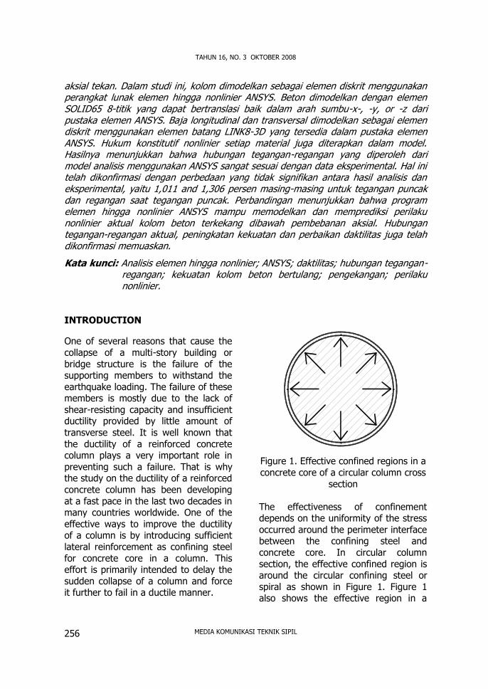
After preparing all the input data ofmaterial and geometrical properties, thecolumn models were divided into smallelements. The meshing results of allcolumn specimens used for modelvalidation are shown in Fig. 6. Columnspecimen LS0 was also meshed withsimilar pattern as three other columnspecimens shown in Fig. 6. For columnsreinforced with steel rebar, it isworthwhile to notice that the meshingwas created according to the locationsof reinforcing bars, either thelongitudinal or transversereinforcement, as well as the column
specimen cross-sectional perimeter. Bythis way, both SOLID65 and LINK8elements [12] are fully interconnectedeach other forming a single solidcolumn model that can simulate theactual behavior of the columnspecimen.
Loading Procedure
To apply the axial load on the top ofthe column specimen, an axial pressurewas implemented over the entire topsurface of the column model in theANSYS software. The axial pressure canbe simulated using the ANSYS load stepoption [12]. Load step option may beused when the incremental loading isconsidered. The number of load stepsdepends on the user’s definition. In thiscase, load steps were defined accordingto the actual load steps applied duringthe test. A solution was obtained bysolving several sub-steps in each loadstep to attain convergence. In eachsub-step, an iteration procedure wascarried out until providing a convergentsolution before moving to the next sub-step. The number of the sub-stepstaken in the analysis may improve theaccuracy of the solution. It will,however, sometimes be very time-consuming when too many sub-stepsare taken. To avoid the problem,ANSYS offers an alternate automatictime step option [12] to reduce thecomputational time required in theanalysis. When the automatic time stepoption is selected, it will automaticallyresize the number of the sub-steps ineach load step when it fails to reach aconvergent solution. This process keepsrepeating until it provides aconvergence value.

Tavio, Arbain TataStress-Strain Relation And Nonliner Behavior of Circular Confined Reinforced Concrete Columns
MEDIA KOMUNIKASI TEKNIK SIPIL 263
When the load has reached its peakvalue, the load control mode wasswitched into the displacement controlmode. The displacement control modewas set into several displacement stepscorresponding to the experimental data.Using the automatic time steps, thecolumn specimen was displaced untilfailure. The objective of using this kindof mode is to obtain the descendingbranch of the stress-strain curve of thecolumn specimens under axial loading.The incremental nonlinear equation canbe written as follows:
uuK = P ............................(14)
where u and P describe the unknownincremental displacement and the givenincremental applied load vectors,respectively.
To solve a nonlinear problem, ANSYSuses the Newton-Raphson (N-R)method [12] involving an iterativeprocedure. This method starts with atrial assumption: u = ui, to define theincremental of the next steps, ui = K–
1(ui)P, and the load vector existsbeyond the equilibrium, Ri = P –K(ui)ui. There will always be adiscrepancy between the applied loadand the load evaluated based on theassumption. To satisfy the state ofequilibrium, the load vector existsbeyond the equilibrium should be zero.Since the solution requires an iterativeprocedure, a tolerance value should bedetermined such that a convergentsolution can be obtained. In eachiteration step, N-R method calculatesthe load vector exists beyond theequilibrium and always checks if theconvergent solution under specifiedtolerance is obtained. If the value is still
greater than the tolerance value, thenthe initial assumed value is updatedwith the incremental displacement, ui+1
= ui + ui. The next incrementalsolution vector is determined with ui+1
= K–1(ui+1)P, providing a new loadvector exists beyond the equilibriumRi+1 = P – K(ui+1)ui+1. Thisprocedure is repeated until theconvergent solution is obtained.
Numerical Impelementation
The quantitative implementation of thefinite element procedure used in theANSYS software [12] is based on theprinciples of virtual work or thepostulation of minimum potentialenergy in the assembly of the elementsas formulated the following equilibriumequation:
000
RFFFFdK sp ....(15)
The stiffness matrix [K],
dvBDBK T .................. (16)
The nodal force due to the surface load,
ele
Tp dVpNF ...............(17)
The nodal force due to the body load,
ele
Tg dVgNF ...............(18)
The nodal force due to the initial strain,
ele
T dVDBF 00 .........(20)
The nodal force due to the initial stress,
ele
T dVDBF 00 .........(21)

TAHUN 16, NO. 3 OKTOBER 2008
MEDIA KOMUNIKASI TEKNIK SIPIL264
Figure 6. Element meshing of quarter column specimens LC0, LC1, LC2, and LC3
where [N] is the shape function; {d} isthe vector of nodal displacement; {R} isthe vector of applied nodal force; {p} isthe vector of surface load; and {g} isthe vector of body load. The ANSYSsoftware uses Newton-Raphson (N-R)method [12] to obtain the convergentsolution of the nonlinear equilibriumiterative equation to develop thestiffness matrix of the column model.
RESULTS AND DISCUSSIONS
Stress Distribution
The axial stress distributions of columnspecimens LS0, LS1, LS2, and LS3obtained from the ANSYS solution areshown in Figure 7. As can be seen inthe figure, for column specimens LS1,
LS2, and LS3, the axial stress contoursover mid-height cross sections of thecolumn specimens indicate similar axialstress distributions with variousintensities of stress concentrations. Theaxial stress concentrations around thelongitudinal reinforcement also indicatesimilar axial stress distributions with theaxial stress distribution in the actualcolumn specimens. Column specimenLS0 has different axial stress contoursince it does not contain any reinforcingbars (plain concrete). Higher axialstress concentration occurs over thecenter region of the column crosssection. This phenomenon describes acorrect mechanism of a plain concretecolumn specimen subjected to axialloading.
LC0
LC1
LC2
LC3

Tavio, Arbain TataStress-Strain Relation And Nonliner Behavior of Circular Confined Reinforced Concrete Columns
MEDIA KOMUNIKASI TEKNIK SIPIL 265
Figure 7. Axial stress distributions over the mid-height cross section ofquarter column specimens LC0, LC1, LC2, and LC3
Stress-Strain Relationship
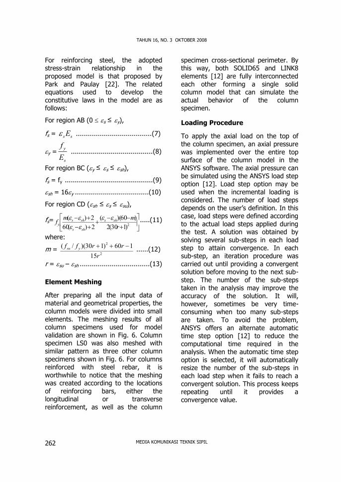
The axial stress-strain curves obtainedfrom the ANSYS solution are confirmedby the experimental results [19]. Fromthe comparisons shown in Figure 8, itshows that the predictions are in closeagreement with the experimentalcurves. This indicates that the actualbehavior of column specimens underaxial compressive loading can beaccurately predicted by the FEMapproach.
The accuracy of the proposedprocedure is also confirmed by theclose values of peak stress, strain at thepeak stress as well as strain when thestress drops to 85 percent of the peakstress obtained from the FEM analysisand the experimental test. From thecomparison values listed in Table 3, itcan be seen that the largest differencesof all column specimens considered inthe study are only 1.011 and 1.306percents for the peak stress, strain atthe peak stress, and strain when thestress drops to 85 percent of the peakstress, respectively.
LC0
LC1
LC2
LC3

TAHUN 16, NO. 3 OKTOBER 2008
MEDIA KOMUNIKASI TEKNIK SIPIL266
Fig. 8. Stress-strain curves of column specimens LC0, LC1, LC2, and LC3
CONCLUSIONS
Based on the FEM analysis anddiscussion above, the followingconclusions can be drawn:1. ANSYS software can be used to
predict the actual stress-strainrelationships of both unconfinedand confined reinforced concretecolumn specimens subjected toaxial loading.
2. From the axial stress contoursobtained from the FEM analysis, itcan be concluded that the axialstress concentrations are in thecenter regions of the column cross
sections, particularly in the confinedareas.
3. The accuracy of the proposedprocedure has been well confirmedby the close values of peak stress,strain at the peak stress as well asstrain when the stress drops to 85percent of the peak stress obtainedfrom the FEM analysis and theexperimental test.
REFERENCES
Cusson, D.; and Paultre, P., High-Strength Concrete Columns Confined byRectangular Ties, (1994). “Journal of
0
5
10
15
20
25
30
0,000 0,005 0,010 0,015 0,020
Strain, c
Stre
ss,f c
(MPa
) FEM [12]fcc = 27.21 MPacc = 0.00356
LC0
0
5
10
15
20
25
30
35
0,000 0,005 0,010 0,015 0,020
Strain, c
Stre
ss,f c
(MPa
)
FEM
TEST
FEM [12]fcc = 30.89 MPacc = 0.00371Test [19]fcc = 32.53 MPacc = 0.0032
FEM [12]Test [19]
LC1
05
1015202530354045
0,000 0,005 0,010 0,015 0,020
Strain, c
Stre
ss,f c
(MPa
)
FEM
TEST
LC3 FEM [12]Test [19]
FEM [12]fcc = 40.30 MPacc = 0.00641
Test [19]fcc = 40.76 MPacc = 0.00420
0
5
10
15
20
25
30
35
40
0,000 0,005 0,010 0,015 0,020
Strain, c
Stre
ss,f c
(MPa
)
FEM
TEST
FEM [12]Test [19]
FEM [12]fcc = 36.23 MPacc = 0.00504
Test [19]fcc = 37.31 MPacc = 0.0042
LC2

Tavio, Arbain TataStress-Strain Relation And Nonliner Behavior of Circular Confined Reinforced Concrete Columns
MEDIA KOMUNIKASI TEKNIK SIPIL 267
Structural Engineering”, ASCE, V. 120,No. 3, Mar. pp. 783-804.
Saatcioglu, M.; and Razvi, S., (1998).“High-Strength Concrete Columns withSquare Section under ConcentricCompression”, Journal of StructuralEngineering, ASCE, V. 124, No. 12, Dec.pp. 1438-1447.
Assa, B.; Nishiyama, M.; and Watanabe,F., (2001). New Approach for ModelingConfined Concrete Circular Columns,Journal of Structural Engineering, ASCE,V. 127, No. 7, July, pp. 743-757.
Fafitis, A.; and Shah, P. S., (1985).“Lateral Reinforcement for High-Strength Concrete Columns”, ACISpecial Publication, SP-87, Detroit, USA,pp. 213-232.
Nagashima, T.; Sugano, S.; Kimura, H.;and Ichikawa, A., (1992). “MonotonicAxial Compression Test on Ultra HighStrength Concrete Tied Columns”,Proceedings of the 10th WorldConference on Earthquake Engineering,Madrid, Spain, July 19-24, V. 5, pp.2983-2988.
Cusson, D.; and Paultre, P., (1995).“Stress-Strain Model for Confined High-Strength Concrete”, Journal ofStructural Engineering, ASCE, V. 121,No. 3, Mar. pp. 468-477.
Sheikh, S. A.; and Uzumeri, S. M.,(1982). “Analytical Model for ConcreteConfinement in Tied Columns”, Journalof the Structural Division, ASCE, V. 108,ST12, Dec. pp. 2703-2722.
Sheikh, S. A.; and Uzumeri, S. M.,(1980). “Strength and Ductility of TiedConcrete Columns”, Journal of theStructural Division, ASCE, V. 106, ST5,May. pp. 1079-1102.
Scott, B. D.; Park, R.; and Priestley, M.J. N., (1982). “Stress-Strain Behavior ofConcrete Confined by OverlappingHoops at Low and High Strain Rates”,ACI Structural Journal, V. 79, No. 1,Jan.-Feb. pp. 13-27.
Nishiyama; M., Fukushima, I.;Watanabe, F.; and Muguruma, H.,(1993). “Axial Loading Test on High-Strength Concrete Prisms Confined byOrdinary and High-Strength Steel”,Proc. Symposium on High-StrengthConcrete, pp. 322-329.
Razvi, S.; and Saatcioglu, M., (1996).“Test of High-Strength ConcreteColumns under Concentric Loading”,Rep. No. OCEERC 96-03, OttawaCarleton Earthquake EngineeringResearch Centre, Ottawa, ON, Canada,pp. 147.
ANSYS, (1999). :ANSYS User’s ManualRevision 5.6”, ANSYS, Inc.,Canonsburg, Pennsylvania, 1286 pp.
Santhakumar, R.; Dhanaraj, R.; andChandrasekaran, E., (2007). “Behaviourof Retrofitted Reinforced ConcreteBeams under Combined Bending andTorsion: A Numerical Study”, ElectronicJournal of Structural Engineering, V. 7,pp. 1-7.
Wolanski, A. J., (2004). “FlexuralBehavior of Reinforced and PrestressedConcrete Beams using Finite ElementAnalysis”, MSc. Thesis, Faculty of theGraduate School, Marquette University,Milwaukee, Wisconsin, May. 76 pp.
Skinner, J. D., (2001). “Finite ElementPredictions of Plasticity-Induced FatigueCrack Closure in Three-DimensionalCracked Geometries”, MSc. Thesis,Department of Mechanical Engineering,

TAHUN 16, NO. 3 OKTOBER 2008
MEDIA KOMUNIKASI TEKNIK SIPIL268
Mississippi State University, MississippiState, Mississippi, Aug. 109 pp.
Barbosa, A. F.; and Ribeiro, G. O.,(1998). “Analysis of ReinforcedConcrete Structures using ANSYSNonlinear Concrete Model”,Computational Mechanics, CIMNE,Barcelona, Spain, pp. 1-7.
Liu, J.; and Foster, S. J., (1999). “AThree-Dimensional Finite ElementModel For Confined ConcreteStructures”, School of Civil Engineering,The University of New South Wales,Sidney, Australia, pp. 45-79.
Qi, Z., (2004). “Finite ElementApplication to Slab-Column ConnectionsReinforced with Glass Fibre-ReinforcedPolymers”, Faculty of Engineering––Memorial University of Newfoundland,Apr., 52 pp.
Hoshikuma, J.; Kawashima, K.; Nagaya,K.; and Taylor, A. W., (1997). “Stress-Strain Model for Confined ReinforcedConcrete in Bridge”, Journal ofStructural Engineering, ASCE, V. 123,No. 5, May, pp. 624-633.
Popovics, S., (1973). “A NumericalApproach to the Complete Stress-StrainCurve of Concrete”, Cement andConcrete Research, V. 3, No. 5, May,pp. 583-599.
Collins, M. P.; Mitchell, D.; andMacGregor, J. G., (1993). “StructuralDesign Consideration for High-StrengthConcrete”, Concrete International, ACI,V. 15, No. 5, May, pp. 27-34.
Park, R.; and Paulay, T., (1975).“Reinforced Concrete Structures”, JohnWiley and Sons, Inc., Canada, 761 pp.
Copyright © 2022 FDOKUMEN