Intensive optimization of masks and sources for 22nm lithography
Stop-Flow Lithography to Generate Cell-Laden Microgel Particles
Priyadarshi Pandaa, Shamsher Alib,c, Edward Lob,c, Bong Geun Chungb,c, T. Alan Hattona,Ali Khademhosseinib,c, and Patrick S. DoyleaPriyadarshi Panda: ; Shamsher Ali: ; Edward Lo: ; Bong Geun Chung: ; T. Alan Hatton: ; Ali Khademhosseini: [email protected];Patrick S. Doyle: [email protected] of Chemical Engineering, Massachusetts Institute of Technology, Cambridge, MA,02139, USA.bCenter for Biomedical Engineering, Department of Medicine, Brigham and Women’s Hospital,Harvard Medical School, Cambridge, MA, 02139, USA.cHarvard-MIT Division of Health Sciences and Technology, Massachusetts Institute of Technology,Cambridge, MA, 02139, USA. Fax: 1-617-768-8477; Tel: 1-617-768-8395
AbstractEncapsulating cells within hydrogels is important for generating three-dimensional (3D) tissueconstructs for drug delivery and tissue engineering. This paper describes, for the first time, thefabrication of large numbers of cell-laden microgel particles using a continuous microfluidic processcalled stop-flow lithography (SFL). Prepolymer solution containing cells was flowed through amicrofluidic device and arrays of individual particles were repeatedly defined using pulses of UVlight through a transparency mask. Unlike photolithography, SFL can be used to synthesize microgelparticles continuously while maintaining control over particle size, shape and anisotropy. Therefore,SFL may become a useful tool for generating cell-laden microgels for various biomedicalapplications.
1. IntroductionThe use of polymeric biomaterials in tissue engineering has grown tremendously over the pastfew decades due both to their physical and chemical properties and to their biocompatibility.1 Polymeric hydrogels, which are highly hydrated cross-linked polymer chains, are particularlyattractive for engineering 3D tissue constructs due to their high water content.2–5 Cells can beencapsulated directly in hydrogels, which can be synthesized from both natural and syntheticpolymers, and thus the cell seeding limitations associated with non-hydrogel tissue scaffoldscan be circumvented. Microengineered hydrogels can potentially be applied in tissueengineering to recreate the complexities of in vivo tissue constructs either by engineering themicrovasculature and cellular organization in large microscale scaffolds, or by assembling thebuilding blocks in the shape of microgel tissue units to generate larger structures.5,6 A numberof microfabrication techniques have been developed both for micropatterning hydrogels forcell encapsulation2,7–19 and for creating cell-laden microgel particles with controlled sizes andshapes.3,20,21 Micropatterning of hydrogels is typically carried out using either soft lithographyor photolithography, and suffers from the limitation that the resulting hydrogels are usuallystuck to the glass surfaces on which they are fabricated. Microgel particles which are freefloating and can be assembled at will to generate tissue structures3,21 would provide a moredesirable system for these constructs. We present here an approach to achieve this goal.
This journal is © The Royal Society of ChemistryCorrespondence to: Ali Khademhosseini, [email protected]; Patrick S. Doyle, [email protected].
NIH Public AccessAuthor ManuscriptLab Chip. Author manuscript; available in PMC 2009 December 8.
Published in final edited form as:Lab Chip. 2008 July ; 8(7): 1056–1061. doi:10.1039/b804234a.
NIH
-PA Author Manuscript
NIH
-PA Author Manuscript
NIH
-PA Author Manuscript
Poly(ethylene glycol) (PEG) is an inert biomaterial, which has been used extensively for theencapsulation of a diverse array of cell types such as chrondocytes,22 vascular smooth musclecells,23 osteoblasts24 and mesenchymal stem cells,25 in addition to its many uses in a broadarray of biomedical applications.2–4,9–11,26,27 When PEG macromers are terminated withmethacrylate or acrylate groups, they undergo rapid crosslinking on exposure to UV light inthe presence of appropriate photoinitiators,26,28,29 and as such, can be used with standardphotolithographic processes. This method has been used widely to control cell–microenvironment interactions in generating tissue engineered constructs that mimic nativetissue architecture and direct cellular differentiation and organization.3,5 A shortcoming ofphotolithography is that it is a batch process which usually limits it to have low yields. Further,photolithography is difficult to perform on prepolymer solutions used for encapsulating cellsdue to their low viscosities.
Another lithography system, called continuous flow lithography (CFL), has recently beendeveloped that can produce microengineered hydrogels continuously and work on a variety ofdifferent materials.30 However, CFL is not suitable for tissue engineering applications, sinceit requires a short polymerization time or slow flow-rate, in order to avoid smearing of thepatterned feature in the hydrogel. Therefore, highly concentrated (either monomer orphotoinitiator) prepolymer solutions are required which would be toxic to cells.31
To overcome the limitations of CFL, SFL has been developed.32 In the current work, we useSFL to synthesize large numbers of cell encapsulated hydrogels in a continuous manner. SFLprovides distinct advantages over CFL in both throughput and control over shape and size.33
We use SFL with photocrosslinkable prepolymer solutions containing cells, which are flowedthrough microfluidic channels. Cells are permanently encapsulated within PEG microgelparticles by exposure to UV light and then flowed out of the device. Compared to standardlithography, SFL provides more flexibility in the type of materials and allows the use of co-flowing streams to generate particles with several adjacent functionalities.30,32,33 Thistechnique has previously been used for the synthesis of multi-functional encoded particles forbimolecular analysis.34 In this work, we demonstrate the use of this technique for theencapsulation of cells in polymeric particles of desired shapes. We also characterize theviability of cells in hydrogels created using SFL.
2. Experimental2.1. Cell culture
Cells were manipulated under sterile tissue culture hoods and maintained in a 95% air/5%CO2 humidified incubator at 37 °C. NIH-3T3 mouse fibroblast cells were maintained in cellculture media composed of Dulbecco’s Modified Eagle Media (DMEM) supplemented with10% Fetal Bovine Serum (FBS) and 1% penicillin-streptomycin. Confluent dishes of NIH-3T3fibroblast cells were passaged and fed every 2–3 days.
2.2 PhotolithographyMaterials—Solutions containing 10–40% (w/v) poly(ethylene glycol) diacrylate (PEGDA,700 MW, Sigma) in culture media were prepared for the experiments. Prior to UVphotopolymerization, 1–5% photoinitiator (w/v), 2-hydroxy-1-(4-(hydroxyethoxy) phenyl)-2-methyl-1-propanone (Irgacure 2959, CIBA Chemicals) was added to the prepolymer solution.0.3% (w/v) n-vinyl pyrrolidone (NVP) was also added to accelerate the photoinitiation reactionin selected samples.
Microgel batch polymerization—A NIH-3T3 fibroblast cell pellet was suspended inphotocrosslinkable PEGDA prepolymer solution (1.5 million cells mL−1). After mixing, 8–10
Panda et al. Page 2
Lab Chip. Author manuscript; available in PMC 2009 December 8.
NIH
-PA Author Manuscript
NIH
-PA Author Manuscript
NIH
-PA Author Manuscript
µL of this solution was placed on top of a cover glass slide (Figure 1a) and exposed 12.4 mW/cm2 UV light (360–480 nm) for various periods of time (Figure 1a). Following UV exposure,the cover slide was removed carefully, placed into culture media, and incubated 37 °C for 60minutes. Hydrogel microblocks were made from 10–40% PEGDA, 1–5% Irgacure 2959(I2959), and 0–0.3% NVP. The shape and size of these hydrogels were controlled usingphotomasks. In addition, the thickness (150 µm) of the hydrogels was controlled by the heightof the spacers that were placed on two edges of the glass slide.
2.3 Stop-Flow Lithography (SFL)Materials—In the SFL experiments (Figure 1b), the prepolymer was mixture of 20% (w/v)PEGDA (700 MW), 4% (w/v) I2959, 75.7% culture media, and 0.3% (w/v) NVP.
Microfluidic device—Microfluidic devices were fabricated by pouringpolydimethylsiloxane (PDMS, Sylgard 184, Dow Corning) on patterned silicon wafers (SU-8photoresist, Microchem) containing positive-relief channels.32 In all our experiments, we usedstraight channels with a height of 35 µm and a width of 500 µm. The PDMS-based microfluidicdevice was peeled off from the wafer and an inlet port was punched into the device to enablethe prepolymer solution to be introduced to the channel. An outlet reservoir for collection ofthe hydrogel particles with their encapsulated cells after polymerization was cut out from thedevice at the other end of the channel. The PDMS microfluidic devices were bonded to PDMScoated glass slides using oxygen plasma. These assemblies were mounted on an invertedmicroscope (Axiovert 200, Zeiss) and the formation of cell-encapsulated hydrogels wasvisualized using a CCD camera (KP-M1A, Hitachi). Images were analyzed and processed usingNIH Image software.
Cell encapsulation using SFL—The prepolymer solution containing cells (6×10⁶ cellsper mL) was passed through a microfluidic channel using the SFL setup (Figure 1b). The SFLprocess essentially involves the three steps of stopping the liquid flow, polymerizing thepatterned solution, and flowing of the particles out of the device.32 The composition of theprepolymer solution used in the SFL hydrogel syntheses was determined from the optimalconditions obtained for the traditional photolithography process. This prepolymer solution withcells was polymerized by a flash of UV light from a 100 W HBO mercury lamp through aphotomask. The photomask was designed using AutoCAD and was printed on a high-resolutionprinter at CAD/ART Services (Bandon, OR). A filter set that provides wide UV excitation(11000v2: UV, Chroma) was used to filter out the undesired wavelengths. A typical exposuretime of 800 ms and a pressure of 1.2 psi were used for all experiments. The microgels withencapsulated cells were collected in the outlet reservoir, which was filled with the culture mediato avoid aggregation of the microgel particles and to ensure that microgels with encapsulatedcells were not exposed to a high concentration of the cytotoxic monomer solution in thereservoir.
2.4 Cell Viability MeasurementsCell viability was determined using a live/dead assay (Invitrogen, CA) containing calcein AM(live cells, green) and ethidium homodimer (dead cells, red). Cell-laden microgels wereincubated for 1 hour after fabrication following which they were stained by incubation withthe live/dead assay agents for 10 minutes to allow the stain to diffuse into the hydrogels. Thestain was removed by washing the hydrogels with culture media before the hydrogels wereimaged. Cell viability was analyzed five times for the photolithography system, and three timesfor SFL. The fraction of viable cells in 400 µm square hydrogels prepared by photolithography(Figure 2) and in 120 µm diameter circular hydrogels prepared by SFL (Figure 5) wasquantified.
Panda et al. Page 3
Lab Chip. Author manuscript; available in PMC 2009 December 8.
NIH
-PA Author Manuscript
NIH
-PA Author Manuscript
NIH
-PA Author Manuscript
3. Results and DiscussionHydrogel microblocks were fabricated via both traditional photolithography and SFL. Standardphotolithography was performed first in order to quickly screen for conditions that are bothsuitable for SFL and yield high cell viabilities. Monomer and photoinitiator concentrations,and polymerization time were systematically varied. These parameters have been shown inprevious studies to influence cell viability inside photocrosslinked hydrogels significantly.28,35 Our goal was to maximize cell viability in the hydrogels by determining the optimizedprepolymer composition and crosslinking parameters using photolithography.
The synthesis of microgels from photocrosslinkable monomers requires UV light,photoinitiator, and PEGDA, each of which is known to influence the viability of cellsnegatively when used at concentrations higher than a threshold, the threshold being differentfor different polymers and photoinitiators which needs to be determined experimentally. Thus,to maximize cell viability, it is desirable to minimize the UV exposure for a specificconcentration of PEGDA and photoinitiator and yet still ensure a fully formed hydrogel, i.e.,to maintain microgel pattern fidelity. The minimum exposure time required to fabricatehydrogels with controlled features was determined for a range of prepolymer solutions bysystematically varying the PEGDA and I2959 concentrations. Overexposure of the prepolymersolutions to UV radiation resulted in the formation of hydrogels larger than the mask featureswhile under exposure produced gels that were smaller than these features. The optimum UVexposure time was deemed to be the time to produce microgels with no distortion in their shapes(Figure 3).
The maximum allowable UV exposure in SFL, is limited by the stability of the masksthemselves. An exposure time of 1.5–2 s can burn the standard polymeric photomasks used inSFL and is typically avoided. Further, at long exposure times, there is the possibility of free-radical diffusion outside the intended polymerization region that compromises pattern fidelityin the hydrogels formed. To avoid damage to our masks and to ensure perfect control overshape and size, exposure times of less than 1 s were used in the SFL system. An exposure timeof 1 s for SFL in a 35 µm tall channel corresponds to a time of about 5.5 s for creating extrudedsquare shaped hydrogels (400 × 400 × 150 µm) using photolithography as determinedexperimentally. This difference in time is due to the difference in light intensity of the UVlamps used and thickness of particles formed in each system
The cell viabilities obtained in the photolithography experiments at different concentrations ofPEGDA (10–40%) and at a constant I2959 concentration of 0.5%, are shown in Figure 3a. Cellviabilities at PEGDA concentrations of 10% and 20% were found to be high (>80%), butdecreased with increasing concentration beyond 20%. Although cell viabilities at 10% and20% PEGDA were high, the exposure times required to crosslink the gels were not suitablefor use in SFL. The concentration of I2959 was, therefore, increased while keeping the PEGDAconcentration at 20%. The cell viabilities decreased with increasing I2959 concentrations at aPEGDA concentration of 20% as shown in Figure 3b. The minimum UV exposure time alsodecreased with increasing I2959 concentration (6.5 s at a concentration of 5%), but again notsufficiently to be of use in SFL.
The UV exposure time was further decreased without increasing the concentrations of PEG orI2959 by adding NVP to the prepolymer solution. NVP has been shown to accelerate reactionsinvolving acrylate groups,36 with a high cell viability retention when used at lowconcentrations.37 Hydrogels formed from prepolymer treated with 0.3% NVP (w/v) showedsimilar viabilities at different I2959 concentrations (1–4%) as indicated in Figure 3b. Theexposure times obtained using NVP are significantly lower than those obtained without NVPand are suitable for use in SFL at an I2959 concentration of 4%. A suitable prepolymer
Panda et al. Page 4
Lab Chip. Author manuscript; available in PMC 2009 December 8.
NIH
-PA Author Manuscript
NIH
-PA Author Manuscript
NIH
-PA Author Manuscript
composition for use in SFL is 20% PEGDA, 4% I2959 and 0.3% NVP, as the exposure timerequired for pattern fidelity is low enough for use in SFL while ensuring reasonable cellviability. In Figure 3 we reported the cell viability and exposure times for the combinations ofPEGdA and I2959 with/without NVP analyzed in this work. The screening can be carried outfor other combinations of polymers and photoinitiators and may result in a higher cell viability.
We analyzed the suitability of the proposed prepolymer solution in the SFL polymerization ofhydrogels of different shapes using appropriate photomasks as shown in Figure 4. SFL cyclesthrough three states which each have associated times: the time to stop the flow (tstop),polymerization time (tpolymerize), and a time required to flush particles out of view (tflow). Thetypical values for tstop, tpolymerize, and tflow in SFL were 200 ms, 800 ms and 100 ms,respectively, resulting in a throughput of ~ 103 particles h−1 using a mask which patterns oneparticle per exposure. For microgel particles with dimensions of 100 µm in a 35 µm tall channel,as synthesized here, the rate of particle generation by SFL can by increased by an order ofmagnitude by using photomasks which pattern multiple particles per exposure.32 Further,several microfluidic channels can be combined in parallel, making the fabrication potential ofSFL greater than that of photolithography, while maintaining precise control over the shapeand size of each gel microparticle. A high rate of hydrogel production is essential to be able toproduce sufficient quantities of particles for applications such as the self-assembly of thesehydrogels into tissue structures. A circular hydrogel generated using SFL and its correspondinglive/dead image is shown in Figure 5. The cell viability measured in hydrogels generated usingSFL (68 ± 3%) correlated well with our values predicted using information from thephotolithography system. Therefore, SFL holds great promise for the high-throughputgeneration of cell-laden microgels which can be used for a variety of diagnostic tools in drugdelivery, DNA sequencing, and tissue engineered constructs.3,38–40
The viability can likely be further optimized if necessary for different biomedical applications.The decreased viability was caused by the unfavorable conditions of the prepolymer solution,particularly, the high concentration of I2959. This high photoinitiator concentration wasrequired due to the time constraint imposed by the masks used. To eliminate the necessity ofa prepolymer that crosslinks rapidly, glass or chrome masks can be used which can withstandlonger exposure times. Further, other more potent combinations of polymers andphotoinitiators which require lower polymerization times while ensuring high cell viability canbe investigated. These combinations of polymers and photoinitiators can be screened usingphotolithography to minimize exposure times before being used in SFL. Shorter exposure timeswould alleviate diffusion limitations to maintaining shape fidelity and increase the throughput.
The SFL system can be potentially used for cells other than the NIH-3T3 mouse fibroblast cellsused in this work. The hydrogel particles synthesized in this study could be assembled intoordered meso-structures using various methods such as evaporation driven assembly,41 DNAhybridization,42–44 or using selective wetting at a liquid-liquid interface.45,46 Furthermore,SFL can be used for creating multicomponent hydrogels30,32–34 by co-flowing more than onestream containing either different cells and the same prepolymer or the same cells but differentprepolymers or a combination of both. These anisotropic particles can be assembled, exploitingthe difference in surface energies of different regions of a particle, finding potential applicationfor generating tissue constructs. Another application of anisotropic microgel particles is multi-cell drug assays, reducing the cost and time involved significantly. The hydrogels formed usingSFL can also be used for immuno-isolation of cells for implantation.14–19
4. ConclusionWe demonstrated the use of SFL to generate high-throughput cell-laden hydrogel microblocksin a continuous manner. The viability of cells encapsulated within hydrogels, for different
Panda et al. Page 5
Lab Chip. Author manuscript; available in PMC 2009 December 8.
NIH
-PA Author Manuscript
NIH
-PA Author Manuscript
NIH
-PA Author Manuscript
experimental parameters (i.e. monomer and photoinitiator concentrations), was analyzed usinga photolithography setup, to obtain an optimized prepolymer solution for SFL. The majorityof cells encapsulated within hydrogels generated by SFL using the optimized solution remainedviable. The potential of SFL to create shape-controlled microgels continously makes hydrogelgeneration by SFL a fertile field for further studies. A comprehensive characterization ofhydrogels generated by SFL with respect to nutrient transfer in and out of the hydrogels mightreveal that SFL is indeed a promising technique for the generation of cell-encapsulatedhydrogels for the fabrication of 3D tissue constructs.
AcknowledgmentsThis paper was partly supported by the Coulter Foundation, National Institutes of Health (NIH), the Center forIntegration of Medicine and Innovative Technology (CIMIT), US Army Core of Engineer, the Charles Stark DraperLaboratory and the NSF NIRT Grant No. CTS-0304128. S. Ali thanks the Higher Education Commission (HEC) ofPakistan for financial support and we thank Dhananjay Dendukuri and Daniel C Pregibon for useful discussions.
References1. Langer R, Vacanti JP. Science 1993;260:920–926. [PubMed: 8493529]2. Liu VA, Bhatia SN. Biomed. Microdev 2002;4:257–266.3. Khademhosseini A, Langer R. Biomaterials 2007;28:5087–5092. [PubMed: 17707502]4. Peppas NA, Hilt JZ, Khademhosseini A, Langer R. Adv. Mater 2006;18:1345–1360.5. Khademhosseini A, Langer R, Borenstein J, Vacanti JP. Proc. Natl. Acad. Sci. USA 2006;103:2480–
2487. [PubMed: 16477028]6. McGuigan AP, Sefton MV. Proc. Natl. Acad. Sci. USA 2006;103:11461–11466. [PubMed: 16864785]7. Burnham MR, Turner JN, Szarowski D, Martin DL. Biomaterials 2006;27:5883–5891. [PubMed:
16934867]8. Koh WG, Revzin A, Simonian A, Reeves T, Pishko M. Biomed. Microdev 2003;5:11–19.9. Albrecht DR, Underhill GH, Wassermann TB, Sah RL, Bhatia SN. Nat. Met 2006;3:369–375.10. Underhill GH, Chen AA, Albrecht DR, Bhatia SN. Biomaterials 2007;28:256–270. [PubMed:
16979755]11. Tsang VL, Chen AA, Cho LM, Jadin KD, Sah RL, DeLong S, West JL, Bhatia SN. FASEB J
2007;21:790–801. [PubMed: 17197384]12. Vozzi G, Flaim C, Ahluwalia A, Bhatia SN. Biomaterials 2003;24:2533–2540. [PubMed: 12695080]13. Cheung YK, Gillette BM, Zhong M, Ramcharan S, Sia SK. Lab Chip 2007;7:574–579. [PubMed:
17476375]14. Veerabadran NG, Goli PL, Stewart-Clark SS, Lvov YM, Mills DK. Macromol. Biosci 2007;7:877–
882. [PubMed: 17599337]15. Serp D, Cantana E, Heinzen C, von Stockar U, Marison IW. Biotechnol. and Bioengg 2000;70:41–
53.16. Cheong SH, Park JK, Kim BS, Chang HN. Biotechnol. Techniq 1993;7:879–884.17. Inloes DS, Smith WJ, Taylor DP, Cohen SN, Michaels AS, Robertson CR. Appl. Environ. Microbiol
1983;46:264–278. [PubMed: 16346346]18. Orive G, Gascón AR, Hernández RM, Igartua M, Pedraz JL. TRENDS in Pharmacol. Sci
2003;24:207–210. [PubMed: 12767713]19. Lanza RP, Hayes JL, Chick WL. Nat. Biotechnol 1996;14:1107–1111. [PubMed: 9631060]20. Franzesi GT, Ni B, Ling Y, Khademhosseini A. J. Am. Chem. Soc 2006;128:15064–15065. [PubMed:
17117838]21. Yeh J, Ling Y, Karp JM, Gantz J, Chandawarkar A, Eng G, Blumling J 3rd, Langer R, Khademhosseini
A. Biomaterials 2006;27:5391–5398. [PubMed: 16828863]22. Riley SL, Dutt S, De La Torre R, Chen AC, Ratcliffe A. J. Mater. Sci. Mater. Med 2001;12:983–990.
[PubMed: 15348352]
Panda et al. Page 6
Lab Chip. Author manuscript; available in PMC 2009 December 8.
NIH
-PA Author Manuscript
NIH
-PA Author Manuscript
NIH
-PA Author Manuscript
23. Mann BK, Gobin AS, Tsai AT, Schmedlen RH, West JL. Biomaterials 2001;22:3045–3051. [PubMed:11575479]
24. Burdick JA, Anseth KS. Biomaterials 2002;23:4315–4323. [PubMed: 12219821]25. Nuttelman CR, Tripodi MC, Anseth KS. J. Biomed. Mater. Res. A 2004;68:773–782. [PubMed:
14986332]26. Anseth KS, Burdick JA. Mrs Bull 2002;27:130–136.27. West JL, Hubbell JA. Biomaterials 1995;16:1153–1156. [PubMed: 8562791]28. Revzin A, Russell RJ, Yadavalli VK, Koh WG, Deister C, Hile DD, Mellott MB, Pishko MV.
Langmuir 2001;17:5440–5447. [PubMed: 12448421]29. Hahn MS, Taite LJ, Moon JJ, Rowland MC, Ruffino KA, West JL. Biomaterials 2006;27:2519–2524.
[PubMed: 16375965]30. Dendukuri D, Pregibon DC, Collins J, Hatton TA, Doyle PS. Nat. Mater 2006;5:365–369. [PubMed:
16604080]31. Williams CG, Malik AN, Kim TK, Manson PN, Elisseeff JH. Biomaterials 2005;26:1211–1218.
[PubMed: 15475050]32. Dendukuri D, Gu SS, Pregibon DC, Hatton TA, Doyle PS. Lab Chip 2007;7:818–828. [PubMed:
17593999]33. Dendukuri D, Hatton TA, Doyle PS. Langmuir 2007;23:4669–4674. [PubMed: 17402702]34. Pregibon DC, Toner M, Doyle PS. Science 2007;315:1393–1396. [PubMed: 17347435]35. Bryant SJ, Nuttelman CR, Anseth KS. J. Biomater. Sci., Polym. Ed 2000;11:439–457. [PubMed:
10896041]36. White TJ, Liechty WB, Guymon CA. J. Polym. Sci., Part A: Polym. Chem 2007;45:4062–4073.37. Smeds KA, Pfister-Serres A, Miki D, Dastgheib K, Inoue M, Hatchell DL, Grinstaff MW. J. Biomed.
Mater. Res 2001;54:115–121. [PubMed: 11077410]38. Burdick JA, Chung C, Jia X, Randolph MA, Langer R. Biomacromolecules 2005;6:386–391.
[PubMed: 15638543]39. Khademhosseini A, Bettinger C, Karp JM, Yeh J, Ling Y, Borenstein J, Fukuda J, Langer R. J.
Biomater. Sci., Polym. Ed 2006;17:1221–1240. [PubMed: 17176747]40. Bruining MJ, Edelbroek-Hoogendoorn PS, Blaauwgeers HG, Mooy CM, Hendrikse FH, Koole LH.
J. Biomed. Mater. Res 1999;47:189–197. [PubMed: 10449629]41. Manoharan VN, Elsesser MT, Pine DJ. Science 2003;301:483–487. [PubMed: 12881563]42. Milam VT, Hiddessen AL, Crocker JC, Graves DJ, Hammer DA. Langmuir 2003;19:10317–10323.43. Soto CM, Srinivasan A, Ratna BR. J. Am. Chem. Soc 2002;124:8508–8509. [PubMed: 12121074]44. Valignat M-P, Theodoly O, Crocker JC, Russel WB, Chaikin PM. Proc. Natl. Acad. Sci. USA
2005;102:4225–4229. [PubMed: 15758072]45. Terfort A, Bowden N, Whitesides GM. Nature 1997;386:162–164.46. Bowden N, Terfort A, Carbeck J, Whitesides GM. Science 1997;276:233–235. [PubMed: 9092466]
Panda et al. Page 7
Lab Chip. Author manuscript; available in PMC 2009 December 8.
NIH
-PA Author Manuscript
NIH
-PA Author Manuscript
NIH
-PA Author Manuscript
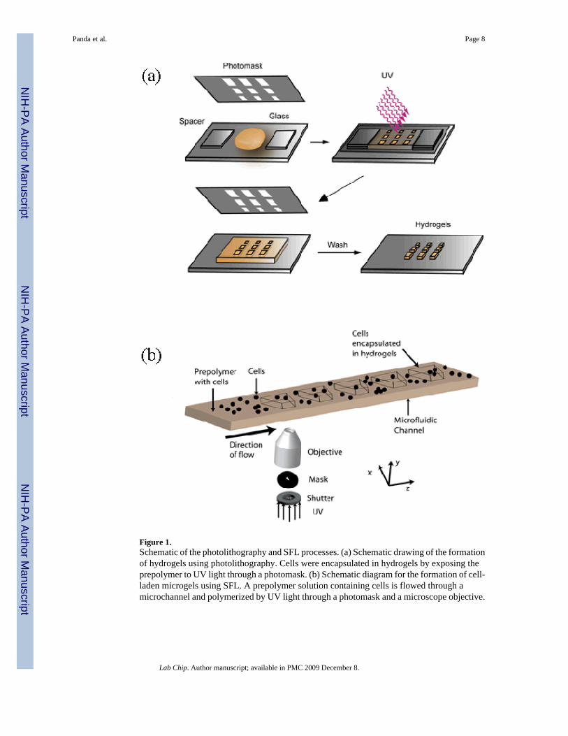
Figure 1.Schematic of the photolithography and SFL processes. (a) Schematic drawing of the formationof hydrogels using photolithography. Cells were encapsulated in hydrogels by exposing theprepolymer to UV light through a photomask. (b) Schematic diagram for the formation of cell-laden microgels using SFL. A prepolymer solution containing cells is flowed through amicrochannel and polymerized by UV light through a photomask and a microscope objective.
Panda et al. Page 8
Lab Chip. Author manuscript; available in PMC 2009 December 8.
NIH
-PA Author Manuscript
NIH
-PA Author Manuscript
NIH
-PA Author Manuscript
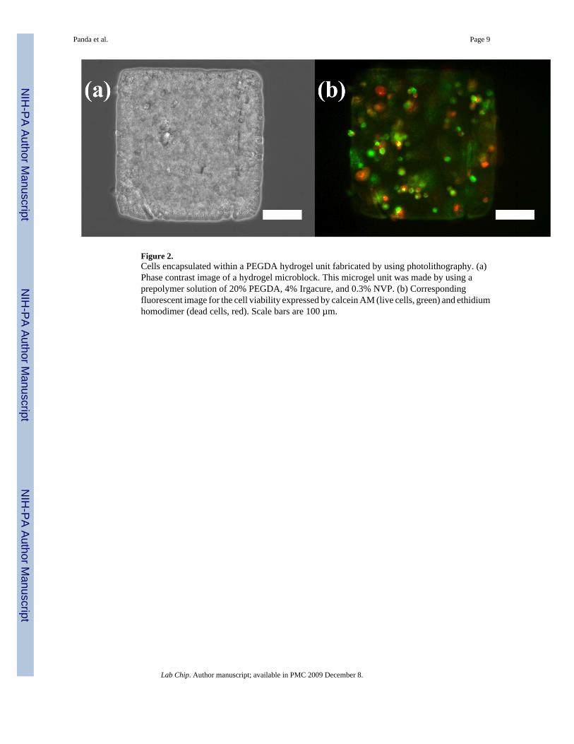
Figure 2.Cells encapsulated within a PEGDA hydrogel unit fabricated by using photolithography. (a)Phase contrast image of a hydrogel microblock. This microgel unit was made by using aprepolymer solution of 20% PEGDA, 4% Irgacure, and 0.3% NVP. (b) Correspondingfluorescent image for the cell viability expressed by calcein AM (live cells, green) and ethidiumhomodimer (dead cells, red). Scale bars are 100 µm.
Panda et al. Page 9
Lab Chip. Author manuscript; available in PMC 2009 December 8.
NIH
-PA Author Manuscript
NIH
-PA Author Manuscript
NIH
-PA Author Manuscript
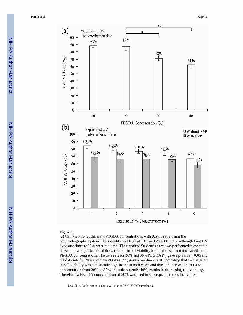
Figure 3.(a) Cell viability at different PEGDA concentrations with 0.5% I2959 using thephotolithography system. The viability was high at 10% and 20% PEGDA, although long UVexposure times (>25 s) were required. The unpaired Student’s t-test was performed to ascertainthe statistical significance of the variations in cell viability for the data sets obtained at differentPEGDA concentrations. The data sets for 20% and 30% PEGDA (*) gave a p-value < 0.05 andthe data sets for 20% and 40% PEGDA (**) gave a p-value < 0.01, indicating that the variationin cell viability was statistically significant in both cases and thus, an increase in PEGDAconcentration from 20% to 30% and subsequently 40%, results in decreasing cell viability.Therefore, a PEGDA concentration of 20% was used in subsequent studies that varied
Panda et al. Page 10
Lab Chip. Author manuscript; available in PMC 2009 December 8.
NIH
-PA Author Manuscript
NIH
-PA Author Manuscript
NIH
-PA Author Manuscript

photoinitiator concentration. (b) Viability at different I2959 concentrations with 20% PEGDAin a photolithography system. A linear decrease was observed for samples without NVPtreatment, while the cell viability of samples treated with NVP was similar at different I2959concentrations (1~4%). The optimized exposure times are marked above the correspondingconditions in the histogram.
Panda et al. Page 11
Lab Chip. Author manuscript; available in PMC 2009 December 8.
NIH
-PA Author Manuscript
NIH
-PA Author Manuscript
NIH
-PA Author Manuscript
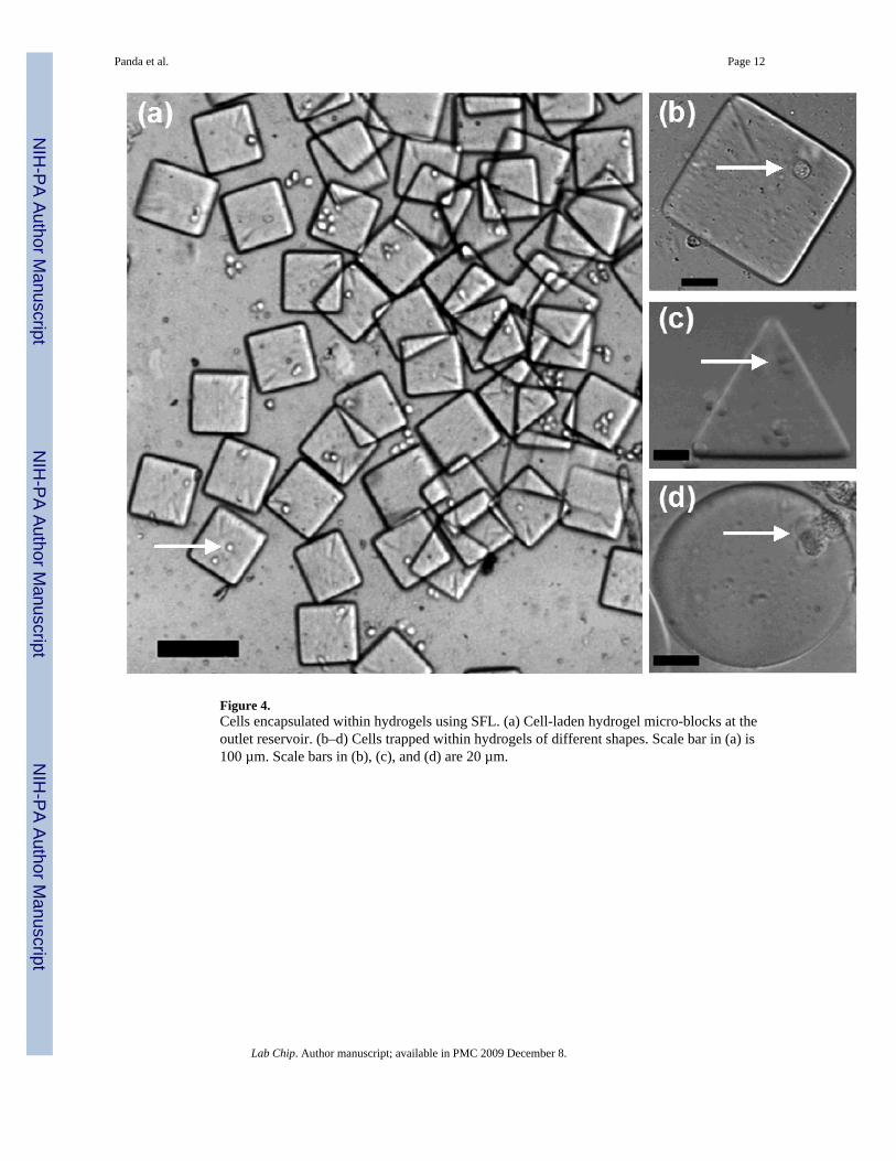
Figure 4.Cells encapsulated within hydrogels using SFL. (a) Cell-laden hydrogel micro-blocks at theoutlet reservoir. (b–d) Cells trapped within hydrogels of different shapes. Scale bar in (a) is100 µm. Scale bars in (b), (c), and (d) are 20 µm.
Panda et al. Page 12
Lab Chip. Author manuscript; available in PMC 2009 December 8.
NIH
-PA Author Manuscript
NIH
-PA Author Manuscript
NIH
-PA Author Manuscript
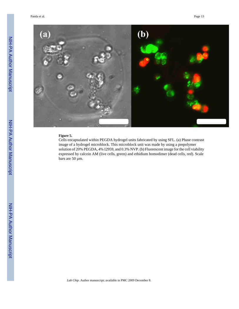
Figure 5.Cells encapsulated within PEGDA hydrogel units fabricated by using SFL. (a) Phase contrastimage of a hydrogel microblock. This microblock unit was made by using a prepolymersolution of 20% PEGDA, 4% I2959, and 0.3% NVP. (b) Fluorescent image for the cell viabilityexpressed by calcein AM (live cells, green) and ethidium homodimer (dead cells, red). Scalebars are 50 µm.
Panda et al. Page 13
Lab Chip. Author manuscript; available in PMC 2009 December 8.
NIH
-PA Author Manuscript
NIH
-PA Author Manuscript
NIH
-PA Author Manuscript
Copyright © 2022 FDOKUMEN