Site-specific role of bifunctional graphitic carbon nitride ...
Upload
independentCategory
view
0download
0
Melissa Britton, Deborah Waters, Russell Messer, and Edward SechkarQSS Group, Inc., Cleveland, Ohio
Bruce BanksGlenn Research Center, Cleveland, Ohio
Sputtering Erosion Measurement onBoron Nitride as a Hall Thruster Material
NASA/TM—2002-211837
September 2002
The NASA STI Program Office . . . in Profile
Since its founding, NASA has been dedicated tothe advancement of aeronautics and spacescience. The NASA Scientific and TechnicalInformation (STI) Program Office plays a key partin helping NASA maintain this important role.
The NASA STI Program Office is operated byLangley Research Center, the Lead Center forNASA’s scientific and technical information. TheNASA STI Program Office provides access to theNASA STI Database, the largest collection ofaeronautical and space science STI in the world.The Program Office is also NASA’s institutionalmechanism for disseminating the results of itsresearch and development activities. These resultsare published by NASA in the NASA STI ReportSeries, which includes the following report types:
• TECHNICAL PUBLICATION. Reports ofcompleted research or a major significantphase of research that present the results ofNASA programs and include extensive dataor theoretical analysis. Includes compilationsof significant scientific and technical data andinformation deemed to be of continuingreference value. NASA’s counterpart of peer-reviewed formal professional papers buthas less stringent limitations on manuscriptlength and extent of graphic presentations.
• TECHNICAL MEMORANDUM. Scientificand technical findings that are preliminary orof specialized interest, e.g., quick releasereports, working papers, and bibliographiesthat contain minimal annotation. Does notcontain extensive analysis.
• CONTRACTOR REPORT. Scientific andtechnical findings by NASA-sponsoredcontractors and grantees.
• CONFERENCE PUBLICATION. Collectedpapers from scientific and technicalconferences, symposia, seminars, or othermeetings sponsored or cosponsored byNASA.
• SPECIAL PUBLICATION. Scientific,technical, or historical information fromNASA programs, projects, and missions,often concerned with subjects havingsubstantial public interest.
• TECHNICAL TRANSLATION. English-language translations of foreign scientificand technical material pertinent to NASA’smission.
Specialized services that complement the STIProgram Office’s diverse offerings includecreating custom thesauri, building customizeddatabases, organizing and publishing researchresults . . . even providing videos.
For more information about the NASA STIProgram Office, see the following:
• Access the NASA STI Program Home Pageat http://www.sti.nasa.gov
• E-mail your question via the Internet [email protected]
• Fax your question to the NASA AccessHelp Desk at 301–621–0134
• Telephone the NASA Access Help Desk at301–621–0390
• Write to: NASA Access Help Desk NASA Center for AeroSpace Information 7121 Standard Drive Hanover, MD 21076
Melissa Britton, Deborah Waters, Russell Messer, and Edward SechkarQSS Group, Inc., Cleveland, Ohio
Bruce BanksGlenn Research Center, Cleveland, Ohio
Sputtering Erosion Measurement onBoron Nitride as a Hall Thruster Material
NASA/TM—2002-211837
September 2002
National Aeronautics andSpace Administration
Glenn Research Center
-

Available from
NASA Center for Aerospace Information7121 Standard DriveHanover, MD 21076
National Technical Information Service5285 Port Royal RoadSpringfield, VA 22100
Available electronically at http://gltrs.grc.nasa.gov

NASA/TM2002-211837 1
Sputtering Erosion Measurement on Boron Nitride as a Hall Thruster Material
Melissa Britton, Deborah Waters, Russell Messer, and Edward Sechkar
QSS Group, Inc. Cleveland, Ohio 44135
Bruce Banks
National Aeronautics and Space Administration Glenn Research Center Cleveland, Ohio 44135
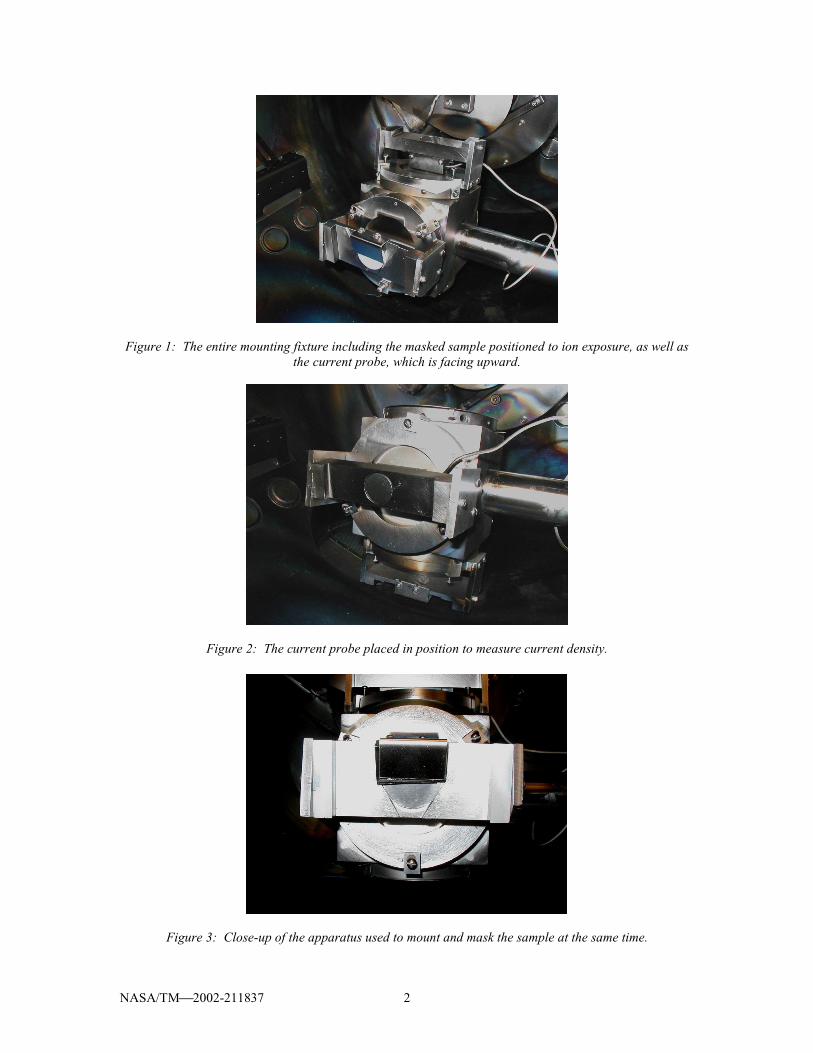
Abstract The durability of a high-powered Hall thruster may be limited by the sputter erosion resistance of its components. During normal operation, a small fraction of the accelerated ions will impact the interior of the main discharge channel, causing its gradual erosion. A laboratory experiment was conducted to simulate the sputter erosion of a Hall thruster. Tests of sputter etch rate were carried out using 300 to 1000 eV Xenon ions impinging on boron nitride substrates with angles of attack ranging from 30 to 75 degrees from horizontal. The erosion rates varied from 3.41 to 14.37 Angstroms/[sec· (mA/cm2)] and were found to depend on the ion energy and angle of attack, which is consistent with the behavior of other materials. 1. Materials and Methods Before the start of the experiment, each 1-inch diameter boron nitride sample supplied by the On-Board Propulsion branch was polished to insure a smooth surface for accurate surface profiling. After polishing, half of each sample to be placed into the Ion Tech Dual Beam II was masked so that an erosion step would be produced. This mask consisted of a 3-layer shim to prevent thermal distortion and thus assure that the thinnest shim remained in intimate contact with the boron nitride so that a clean, abrupt erosion step would form. The mounting fixture used in this experiment also contained a probe to determine the current density at the sample position at the beginning and end of each trial. When the current density was measured, the sample faced the bottom of the dual beam and the probe was moved to the exact location where the sample had been, as shown in Figure 1.
NASA/TM2002-211837 2
Figure 1: The entire mounting fixture including the masked sample positioned to ion exposure, as well as the current probe, which is facing upward.
Figure 2: The current probe placed in position to measure current density.
Figure 3: Close-up of the apparatus used to mount and mask the sample at the same time.
NASA/TM2002-211837 3
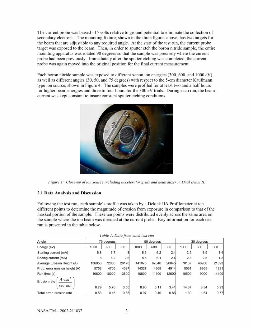
The current probe was biased –15 volts relative to ground potential to eliminate the collection of secondary electrons. The mounting fixture, shown in the three figures above, has two targets for the beam that are adjustable to any required angle. At the start of the test run, the current probe target was exposed to the beam. Then, in order to sputter etch the boron nitride sample, the entire mounting apparatus was rotated 90 degrees so that the sample was precisely where the current probe had been previously. Immediately after the sputter etching was completed, the current probe was again moved into the original position for the final current measurement. Each boron nitride sample was exposed to different xenon ion energies (300, 600, and 1000 eV) as well as different angles (30, 50, and 75 degrees) with respect to the 5-cm diameter Kaufmann type ion source, shown in Figure 4. The samples were profiled for at least two and a half hours for higher beam energies and three to four hours for the 300 eV trials. During each run, the beam current was kept constant to insure constant sputter etching conditions.
Figure 4: Close-up of ion source including accelerator grids and neutralizer in Dual Beam II. 2.1 Data Analysis and Discussion Following the test run, each sample’s profile was taken by a Dektak IIA Profilometer at ten different points to determine the magnitude of erosion from exposure in comparison to that of the masked portion of the sample. These ten points were distributed evenly across the same area on the sample where the ion beam was directed at the current probe. Key information for each test run is presented in the table below.
Table 1: Data from each test run
Angle 75 degrees 50 degrees 30 degrees
Energy (eV) 1000 600 300 1000 600 300 1000 600 300
Starting current (mA) 6.8 6.7 3 6.6 6.2 2.4 2.5 3.9 1.4
Ending current (mA) 8 6.2 2.6 8.5 6.1 2.4 2.8 2.5 1.2
Average Erosion Height (A) 136056 72063 26178 141075 67840 20045 78137 46950 21693
Prob. error erosion height (A) 5752 4705 4097 14327 4368 4914 5561 8865 1291
Run time (s) 10800 10020 13800 10800 11100 12600 10500 9000 14400
Erosion rate
⋅
⋅mA
cmA
sec
2
8.79 5.76 3.50 8.90 5.11 3.41 14.37 8.34 5.93
Total error, erosion rate 0.53 0.45 0.58 0.97 0.40 0.86 1.39 1.64 0.77
NASA/TM2002-211837 4
From average erosion depth, the erosion rate E per milliamp was found from the following equation:
( )21
2
2
pp jjt
HDE
+= π
(1)
where H is the mean average erosion height in Angstroms, D is the diameter of the current probe (2.54 cm), t is the test run duration in seconds, and jp1 and jp2 are the currents in milliamps at the beginning and end of each test run, respectively. Including these two parameters normalizes the erosion rate to a current density of 1 mA/cm2. A small correction factor (<2%) in the calculation of the surface area was used to account for ions hitting the leading edge of the current probe. 2.2 Calculation of Error in Erosion Rate The error values shown in both Table 1 and Figures 6 and 7 are probable errors that were determined by using propagation of errors given by the following equation:
2
12
∂∂±=+ ∑
ixi
i
xx
EEEE δδ (2)
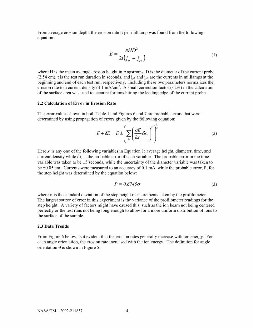
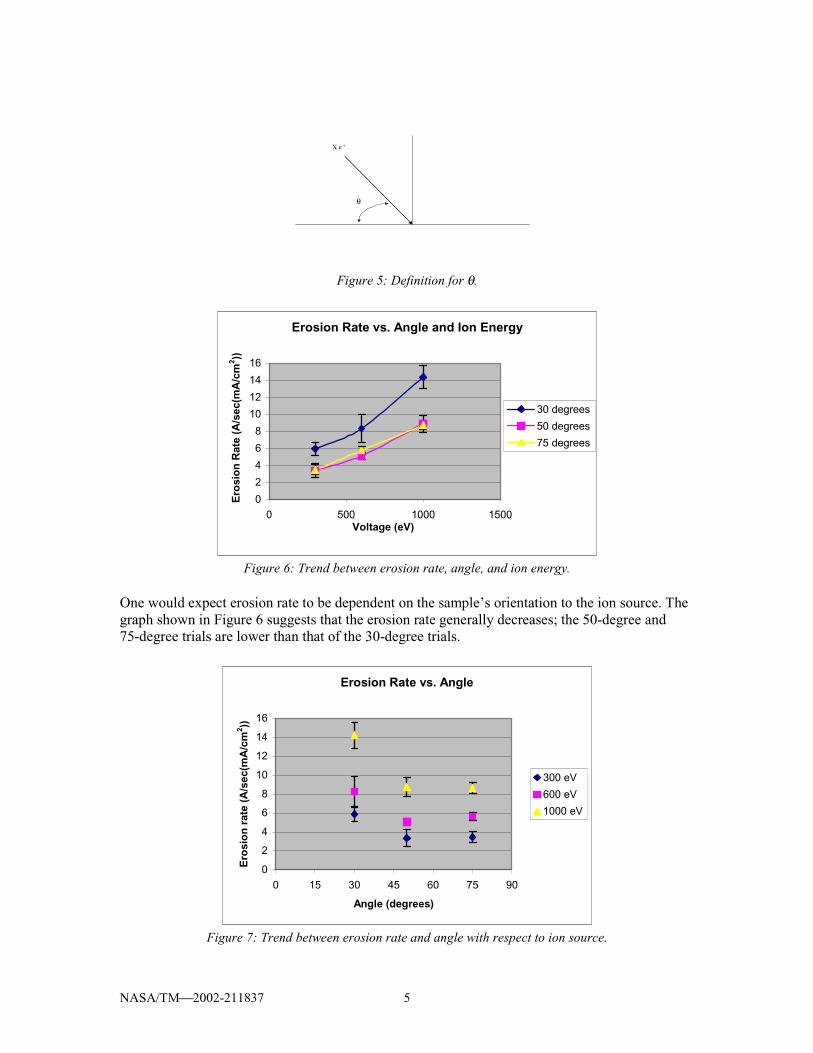
Here xi is any one of the following variables in Equation 1: average height, diameter, time, and current density while δxi is the probable error of each variable. The probable error in the time variable was taken to be ±5 seconds, while the uncertainty of the diameter variable was taken to be ±0.05 cm. Currents were measured to an accuracy of 0.1 mA, while the probable error, P, for the step height was determined by the equation below: P = 0.6745σ (3) where σ is the standard deviation of the step height measurements taken by the profilometer. The largest source of error in this experiment is the variance of the profilometer readings for the step height. A variety of factors might have caused this, such as the ion beam not being centered perfectly or the test runs not being long enough to allow for a more uniform distribution of ions to the surface of the sample. 2.3 Data Trends From Figure 6 below, is it evident that the erosion rates generally increase with ion energy. For each angle orientation, the erosion rate increased with the ion energy. The definition for angle orientation θ is shown in Figure 5.
NASA/TM2002-211837 5
X e +
θ
Figure 5: Definition for θ.
Erosion Rate vs. Angle and Ion Energy
0
2
4
6
8
10
12
14
16
0 500 1000 1500Voltage (eV)
Ero
sio
n R
ate
(A/s
ec(m
A/c
m2 ))
30 degrees
50 degrees
75 degrees
Figure 6: Trend between erosion rate, angle, and ion energy.
One would expect erosion rate to be dependent on the sample’s orientation to the ion source. The graph shown in Figure 6 suggests that the erosion rate generally decreases; the 50-degree and 75-degree trials are lower than that of the 30-degree trials.
Erosion Rate vs. Angle
0
2
4
6
8
10
12
14
16
0 15 30 45 60 75 90
Angle (degrees)
Ero
sio
n r
ate
(A/s
ec(m
A/c
m2 ))
300 eV
600 eV
1000 eV
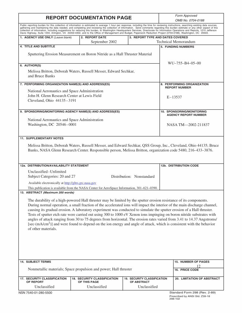
Figure 7: Trend between erosion rate and angle with respect to ion source.

NASA/TM2002-211837 6
It is unclear that the 75-degree erosion rates are above those of the 50-degree erosion rates. A quick look at the data presented in Table 1 reveals that the calculated erosion rates for these two data sets are reasonably close for all beam energies, and overlap of probable errors prevents definitive discrimination. This data set does reflect similar data of other materials. It is known that some materials exhibit a maximum sputter yield at an angle θmax other than perpendicular to the ion source. In Figure 8, notice the peak present in the nickel and molybdenum curves. The value of θmax can range anywhere from approximately 35 to 50 degrees for any given material. Therefore, the 30-degree orientation may have been near θmax for boron nitride, thus explaining the high erosion rates at this orientation.
M o
N iW
Pt
θm ax
Sputter Y ield
A ngle, θ
20° 50°40°30° 80°70°60°0
2
3
4
5
7
6
1
Figure 8: Sputter Yield versus Angle with respect to ion source.
3. Conclusions From the analysis presented above, it is reasonable to conclude that the data collected are representative of what would be found with other materials. It has been shown in Figure 6 that erosion rates increase as expected with ion energy. However, the 30-degree orientation yields the highest erosion rates because this particular angle may be closest to the θmax for boron nitride. In order to obtain more accurate results in future experiments of this type, it would be essential to reduce the fractional error due to the variance in step height measurements. Making use of longer run times and obtaining a greater number of profilometer readings across each sample surface should also decrease the total calculated error in the erosion rates. Also, conducting the test at a wider range of angles would help in estimating erosion rates for any orientation. 4. Reference R. Jankovsky, D. Jacobson, L. Pinero, C. Sarmiento, D. Manzella, R. Hofer, and P. Peterson, “NASA’s Hall Thruster Program 2002,” AIAA–2002–3675, 38th AIAA Joint Propulsion Conference, Indianapolis, Indiana, July 7–10, 2002.
This publication is available from the NASA Center for AeroSpace Information, 301–621–0390.
REPORT DOCUMENTATION PAGE
2. REPORT DATE
19. SECURITY CLASSIFICATION OF ABSTRACT
18. SECURITY CLASSIFICATION OF THIS PAGE
Public reporting burden for this collection of information is estimated to average 1 hour per response, including the time for reviewing instructions, searching existing data sources,gathering and maintaining the data needed, and completing and reviewing the collection of information. Send comments regarding this burden estimate or any other aspect of thiscollection of information, including suggestions for reducing this burden, to Washington Headquarters Services, Directorate for Information Operations and Reports, 1215 JeffersonDavis Highway, Suite 1204, Arlington, VA 22202-4302, and to the Office of Management and Budget, Paperwork Reduction Project (0704-0188), Washington, DC 20503.
NSN 7540-01-280-5500 Standard Form 298 (Rev. 2-89)Prescribed by ANSI Std. Z39-18298-102
Form Approved
OMB No. 0704-0188
12b. DISTRIBUTION CODE
8. PERFORMING ORGANIZATION REPORT NUMBER
5. FUNDING NUMBERS
3. REPORT TYPE AND DATES COVERED
4. TITLE AND SUBTITLE
6. AUTHOR(S)
7. PERFORMING ORGANIZATION NAME(S) AND ADDRESS(ES)
11. SUPPLEMENTARY NOTES
12a. DISTRIBUTION/AVAILABILITY STATEMENT
13. ABSTRACT (Maximum 200 words)
14. SUBJECT TERMS
17. SECURITY CLASSIFICATION OF REPORT
16. PRICE CODE
15. NUMBER OF PAGES
20. LIMITATION OF ABSTRACT
Unclassified Unclassified
Technical Memorandum
Unclassified
National Aeronautics and Space AdministrationJohn H. Glenn Research Center at Lewis FieldCleveland, Ohio 44135–3191
1. AGENCY USE ONLY (Leave blank)
10. SPONSORING/MONITORING AGENCY REPORT NUMBER
9. SPONSORING/MONITORING AGENCY NAME(S) AND ADDRESS(ES)
National Aeronautics and Space AdministrationWashington, DC 20546–0001
Available electronically at http://gltrs.grc.nasa.gov
September 2002
NASA TM—2002-211837
E–13537
WU–755–B4–05–00
12
Sputtering Erosion Measurement on Boron Nitride as a Hall Thruster Material
Melissa Britton, Deborah Waters, Russell Messer, Edward Sechkar,and Bruce Banks
Nonmetallic materials; Space propulsion and power; Hall thruster
Unclassified -UnlimitedSubject Categories: 20 and 27 Distribution: Nonstandard
Melissa Britton, Deborah Waters, Russell Messer, and Edward Sechkar, QSS Group, Inc., Cleveland, Ohio 44135; BruceBanks, NASA Glenn Research Center. Responsible person, Melissa Britton, organization code 5480, 216–433–3876.
The durability of a high-powered Hall thruster may be limited by the sputter erosion resistance of its components.During normal operation, a small fraction of the accelerated ions will impact the interior of the main discharge channel,causing its gradual erosion. A laboratory experiment was conducted to simulate the sputter erosion of a Hall thruster.Tests of sputter etch rate were carried out using 300 to 1000 eV Xenon ions impinging on boron nitride substrates withangles of attack ranging from 30 to 75 degrees from horizontal. The erosion rates varied from 3.41 to 14.37 Angstroms/[sec·(mA/cm2)] and were found to depend on the ion energy and angle of attack, which is consistent with the behaviorof other materials.
Copyright © 2022 FDOKUMEN