
Spanning-Tree Protocols User Guide - Juniper Networks
485
Spanning-Tree Protocols User Guide Published 2021-12-10
-
Upload
khangminh22 -
Category
Documents
-
view
0 -
download
0
Transcript of Spanning-Tree Protocols User Guide - Juniper Networks
Spanning-Tree Protocols User Guide
Published
2021-12-10

Juniper Networks, Inc.1133 Innovation WaySunnyvale, California 94089USA408-745-2000www.juniper.net
Juniper Networks, the Juniper Networks logo, Juniper, and Junos are registered trademarks of Juniper Networks, Inc.in the United States and other countries. All other trademarks, service marks, registered marks, or registered servicemarks are the property of their respective owners.
Juniper Networks assumes no responsibility for any inaccuracies in this document. Juniper Networks reserves the rightto change, modify, transfer, or otherwise revise this publication without notice.
Spanning-Tree Protocols User GuideCopyright © 2021 Juniper Networks, Inc. All rights reserved.
The information in this document is current as of the date on the title page.
YEAR 2000 NOTICE
Juniper Networks hardware and software products are Year 2000 compliant. Junos OS has no known time-relatedlimitations through the year 2038. However, the NTP application is known to have some difficulty in the year 2036.
END USER LICENSE AGREEMENT
The Juniper Networks product that is the subject of this technical documentation consists of (or is intended for usewith) Juniper Networks software. Use of such software is subject to the terms and conditions of the End User LicenseAgreement ("EULA") posted at https://support.juniper.net/support/eula/. By downloading, installing or using suchsoftware, you agree to the terms and conditions of that EULA.
ii

Table of Contents
About This Guide | xii
1 Overview
Spanning-Tree Protocol Overview | 2
How Spanning Tree Protocols Work | 2
Choosing a Spanning Tree Protocol | 6
2 Spanning-Tree Instances and Interfaces
Spanning Tree Instances and Interfaces | 18
Understanding Spanning-Tree Instance Interfaces | 18
Configuring a Virtual Switch Routing Instance on MX Series Routers | 20
Configuring a Spanning-Tree Instance Interface as an Edge Port for Faster Convergence | 21
3 Configuring Spanning-Tree Protocols
Configuring STP Protocol | 23
Understanding STP | 23
Understanding System Identifiers for Bridges in STP or RSTP Instances | 25
Configuring STP on EX Series Switches (CLI Procedure) | 25
Configuring RSTP Protocol | 26
Understanding RSTP | 27
Configuring Rapid Spanning Tree Protocol | 28
Configuring RSTP on EX Series Switches (CLI Procedure) | 31
Example: Configuring Faster Convergence and Network Stability on ELS Switches with RSTP | 32
Requirements | 33
Overview and Topology | 33
Configuring RSTP and Nonstop Bridging on Switch 1 | 36
Configuring RSTP and Nonstop Bridging on Switch 2 | 41
Configuring RSTP and Nonstop Bridging on Switch 3 | 46
Configuring RSTP and Nonstop Bridging on Switch 4 | 51
iii
Verification | 55
Example: Faster Convergence and Improved Network Stability with RSTP on EX SeriesSwitches | 59
Requirements | 59
Overview and Topology | 60
Configuring RSTP and Nonstop Bridging on Switch 1 | 63
Configuring RSTP and Nonstop Bridging on Switch 2 | 68
Configuring RSTP and Nonstop Bridging on Switch 3 | 73
Configuring RSTP and Nonstop Bridging on Switch 4 | 78
Verification | 82
Forcing RSTP or VSTP to Run as IEEE 802.1D STP (CLI Procedure) | 86
Configuring MSTP Protocol | 87
Understanding MSTP | 87
Configuring MSTP on Switches | 91
Configuring Multiple Spanning Tree Protocol | 95
Configuring MSTP Instances on a Physical Interface | 98
Example: Configuring Network Regions for VLANs with MSTP on Switches | 101
Requirements | 101
Overview and Topology | 102
Configuring MSTP on Switch 1 | 105
Configuring MSTP on Switch 2 | 110
Configuring MSTP on Switch 3 | 115
Configuring MSTP on Switch 4 | 120
Verification | 124
Disabling MSTP | 133
Configuring VSTP Protocol | 134
Understanding VSTP | 135
Global and Specific VSTP Configurations for Switches | 136
Example: Configuring VSTP on a Trunk Port with Tagged Traffic | 141
Requirements | 141
Overview | 141
iv
Configuration | 142
Verification | 154
Reverting to RSTP or VSTP from Forced IEEE 802.1D STP | 157
4 BPDU Protection for Spanning-Tree Protocols
BPDU Protection for Spanning-Tree Protocols | 160
Understanding BPDU Protection for Spanning-Tree Instance Interfaces | 160
Understanding BPDU Protection for STP, RSTP, and MSTP | 162
Configuring BPDU Protection for Individual Spanning-Tree Instance Interfaces | 164
Understanding BPDUs Used for Exchanging Information Among Bridges | 165
BPDU Protection on All Edge Ports of the Bridge | 166
Understanding BPDU Protection for EVPN-VXLAN | 166
Configuring BPDU Protection on Switch Spanning Tree Interfaces | 169
Configuring BPDU Protection on ACX Router, EX Switch and MX Router Edge Ports | 171
Configuring BPDU protection For Edge Interfaces | 172
Configuring BPDU for Interface Protection With Port Shutdown Mode | 174
Configuring BPDU for Interface Protection With BPDU Drop Mode | 175
Example: Configuring BPDU Protection on Interfaces to Prevent STP Miscalculations | 178
Requirements | 178
Overview | 179
Configuration | 179
Verification | 181
Example: Configuring BPDU Protection on MX Edge Interfaces to Prevent STP Miscalculations | 185
Requirements | 185
Overview | 186
Configuration | 188
Verification | 189
Example: Configuring BPDU Protection on Edge Interfaces to Prevent STP Miscalculations | 192
Requirements | 192
v
Overview | 193
Configuration | 193
Verification | 195
Example: Configuring BPDU Protection on Switch Edge Interfaces With ELS to Prevent STPMiscalculations | 197
Requirements | 197
Overview and Topology | 198
Configuration | 200
Verification | 201
Example: Configuring BPDU Protection on Edge Interfaces to Prevent STP Miscalculations onnon-ELS EX Series Switches | 204
Requirements | 204
Overview and Topology | 205
Configuration | 207
Verification | 208
Example: Configuring BPDU Protection on Interfaces to Prevent STP Miscalculations on EXSeries Switches | 210
Requirements | 211
Overview and Topology | 212
Configuration | 214
Verification | 215
Example: Blocking BPDUs on Aggregated Ethernet Interface for 600 Seconds | 217
Example: Configuring BPDU Protection on Interfaces to Prevent STP Miscalculations on EXSeries Switches | 218
Requirements | 219
Overview and Topology | 219
Configuration | 222
Verification | 225
5 Loop Protection for Spanning-Tree Protocols
Loop Protection for Spanning-Tree Protocols | 229
Understanding Loop Protection for Spanning-Tree Instance Interfaces | 229
Eliminating Bridge Loops in Ethernet LANs with Spanning Tree Protocol | 231
Example: Enabling Loop Protection for Spanning-Tree Protocols | 240
vi

Configuring Loop Protection for a Spanning-Tree Instance Interface | 240
Example: Configuring Loop Protection to Prevent Interfaces from Transitioning from Blocking toForwarding in a Spanning Tree on non-ELS EX Series Switches | 242
Requirements | 242
Overview and Topology | 243
Configuration | 245
Verification | 246
Example: Configuring Loop Protection to Prevent Interfaces from Transitioning from Blocking toForwarding in a Spanning Tree on EX Series Switches With ELS | 248
Requirements | 249
Overview and Topology | 249
Configuration | 251
Verification | 252
6 Root Protection for VPLS Multihome Environments
Root Protection for VPLS Multihome Environments | 256
Understanding VPLS Multihoming | 256
Understanding Bridge Priority for Election of Root Bridge and Designated Bridge | 261
Understanding Root Protection for Spanning-Tree Instance Interfaces in a Layer 2 SwitchedNetwork | 261
Example: Configuring VPLS Root Topology Change Actions | 263
Enabling Root Protection for a Spanning-Tree Instance Interface | 263
Configuring VPLS Root Protection Topology Change Actions to Control Individual VLANSpanning-Tree Behavior | 264
Example: Configuring Root Protection to Enforce Root Bridge Placement in Spanning Trees onnon-ELS EX Series Switches | 266
Requirements | 266
Overview and Topology | 266
Configuration | 269
Verification | 270
Example: Configuring Root Protection to Enforce Root Bridge Placement in Spanning Trees onEX Series Switches With ELS | 273
Requirements | 273
vii

Overview and Topology | 274
Configuration | 276
Verification | 277
7 Monitoring and Troubleshooting
Monitoring and Troubleshooting Spanning Tree Protocols | 282
Monitoring Spanning Tree Protocols on Switches | 282
Checking the Status of Spanning-Tree Instance Interfaces | 286
Understanding Spanning-Tree Protocol Trace Options | 286
Configuring Tracing Spanning-Tree Operations | 287
Example: Tracing Spanning-Tree Protocol Operations | 289
Unblocking a Switch Interface That Receives BPDUs in Error (CLI Procedure) | 290
Unblocking an Interface on non-ELS EX Series Switches That Receives BPDUs in Error (CLIProcedure) | 291
Clearing the Blocked Status of a Spanning-Tree Instance Interface | 291
Checking for a MAC Rewrite Error Condition Blocking a Spanning-Tree Instance Interface | 292
Clearing a MAC Rewrite Error Condition Blocking a Spanning-Tree Instance Interface | 292
Clearing a MAC Rewrite Error on an Interface with Layer 2 Protocol Tunneling | 293
Understanding Forward Delay Before Ports Transition to Forwarding State | 294
8 Configuration Statements
access-trunk | 297
arp-on-stp | 298
backup-bridge-priority | 300
block (Spanning Trees) | 302
bpdu-destination-mac-address (Spanning Tree) | 303
bpdu-block | 305
bpdu-block-on-edge | 307
bridge-priority | 310
viii

configuration-name | 312
cost | 314
disable | 317
disable-timeout | 319
drop (BPDU Block) | 322
edge | 324
enable-all-ifl | 326
extended-system-id | 328
force-version (IEEE 802.1D STP) | 329
forward-delay | 331
hello-time | 333
interface (BPDU Blocking) | 336
interface (Spanning Tree) | 338
layer2-control | 341
log (Spanning Trees) | 344
mac-rewrite | 345
max-age | 347
max-hops | 350
mode | 352
msti | 355
mstp | 358
no-root-port | 362
priority (Protocols STP) | 364
priority-hold-time | 367
protocol | 368
ix

protocols (STP Type) | 372
revision-level | 374
rstp | 376
shutdown (BPDU Block) | 381
stp | 382
system-id | 385
traceoptions (Spanning Tree) | 387
vlan (MSTP) | 392
vlan (VSTP) | 395
vlan-group | 398
vpls-flush-on-topology-change | 400
vstp | 401
9 Operational Commands
clear error bpdu interface | 409
clear error mac-rewrite | 411
clear ethernet-switching bpdu-error interface | 413
clear spanning-tree protocol-migration | 414
clear spanning-tree statistics | 416
clear spanning-tree statistics bridge | 418
clear spanning-tree stp-buffer | 420
show bridge mac-table | 421
show mac-rewrite interface | 429
show spanning-tree bridge | 432
show spanning-tree interface | 440
show spanning-tree mstp configuration | 453
x

show spanning-tree statistics | 457
show spanning-tree statistics bridge | 460
show spanning-tree statistics interface | 462
show spanning-tree statistics message-queues | 465
show spanning-tree stp-buffer see-all | 467
xi

About This Guide
Spanning-tree protocols on routers and switches address provide link redundancy while simultaneouslypreventing undesirable loops.
xii

1CHAPTER
Overview
Spanning-Tree Protocol Overview | 2

Spanning-Tree Protocol Overview
IN THIS SECTION
How Spanning Tree Protocols Work | 2
Choosing a Spanning Tree Protocol | 6
How Spanning Tree Protocols Work
IN THIS SECTION
Benefits of Using Spanning Tree Protocols | 3
Spanning Tree Protocols Help Prevent Broadcast Storms | 3
Port Roles Determine Participation in the Spanning Tree | 3
Port States Determine How a Port Processes a Frame | 4
Edge Ports Connect to Devices That Cannot Be Part of a Spanning Tree | 4
BPDUs Maintain the Spanning-Tree | 4
When a Root Bridge Fails | 5
Devices Must Relearn MAC Addresses After a Link Failure | 5
Ethernet networks are susceptible to broadcast storms if loops are introduced. However, an Ethernetnetwork needs to include loops because they provide redundant paths in case of a link failure. Spanning-tree protocols address both of these issues because they provide link redundancy while simultaneouslypreventing undesirable loops.
Juniper Networks devices provide Layer 2 loop prevention through Spanning Tree Protocol (STP), RapidSpanning Tree Protocol (RSTP), Multiple Spanning Tree Protocol (MSTP), and VLAN Spanning TreeProtocol (VSTP). RSTP is the default spanning-tree protocol for preventing loops on Ethernet networks.
This topic describes:
2
Benefits of Using Spanning Tree Protocols
Spanning Tree protocols have the following benefits:
• Provide link redundancy while simultaneously preventing undesirable loops
• Prevent Broadcast Storms
• Connects to devices that are not STP-capable, such as PCs, servers, routers, or hubs that are notconnected to other switches, by using edge ports
Spanning Tree Protocols Help Prevent Broadcast Storms
Spanning-tree protocols intelligently avoid loops in a network by creating a tree topology (spanning tree)of the entire bridged network with only one available path between the tree root and a leaf. All otherpaths are forced into a standby state. The tree root is a switch within the network elected by the STA(spanning-tree algorithm) to use when computing the best path between bridges throughout thenetwork and the root bridge. Frames travel through the network to their destination–a leaf such as anend-user PC–along branches. A tree branch is a network segment, or link, between bridges. Switchesthat forward frames through an STP spanning tree are called designated bridges.
NOTE: If you are using Junos OS for EX Series and QFX Series switches with support for theEnhanced Layer 2 Software (ELS) configuration style, you can force the original IEEE 802.1DSpanning Tree Protocol (STP) version to run in place of RSTP or VSTP by setting "force-version"on page 329.
Port Roles Determine Participation in the Spanning Tree
Each port has both a role and a state. A port’s role determines how it participates in the spanning tree.The five port roles used in RSTP are:
• Root port—The port closest to the root bridge (has the lowest path cost from a bridge). This is theonly port that receives frames from and forwards frames to the root bridge.
• Designated port—The port that forwards traffic away from the root bridge toward a leaf. Adesignated bridge has one designated port for every link connection it serves. A root bridge forwardsframes from all of its ports, which serve as designated ports.
• Alternate port—A port that provides an alternate path toward the root bridge if the root port failsand is placed in the discarding state. This port is not part of the active spanning tree, but if the rootport fails, the alternate port immediately takes over.
3

• Backup port—A port that provides a backup path toward the leaves of the spanning tree if adesignated port fails and is placed in the discarding state. A backup port can exist only where two ormore bridge ports connect to the same LAN for which the bridge serves as the designated bridge. Abackup port for a designated port immediately takes over if the port fails.
• Disabled port—The port is not part of the active spanning tree.
Port States Determine How a Port Processes a Frame
Each port has both a state and a role. A port’s state determines how it processes a frame. RSTP placeseach port of a designated bridge in one of three states:
• Discarding—The port discards all BPDUs. A port in this state discards all frames it receives and doesnot learn MAC addresses.
• Learning—The port prepares to forward traffic by examining received frames for location informationin order to build its MAC address table.
• Forwarding—The port filters and forwards frames. A port in the forwarding state is part of the activespanning tree.
Edge Ports Connect to Devices That Cannot Be Part of a Spanning Tree
Spanning Tree also defines the concept of an edge port, which is a designated port that connects todevices that are not STP-capable, such as PCs, servers, routers, or hubs that are not connected to otherswitches. Because edge ports connect directly to end stations, they cannot create network loops andcan transition to the forwarding state immediately. You can manually configure edge ports, and a switchcan also detect edge ports by noting the absence of communication from the end stations.
The edge ports themselves do send BPDUs to the spanning tree. If you have a good understanding ofthe implications on your network and want to modify RSTP on the edge port interface.
BPDUs Maintain the Spanning-Tree
Spanning-tree protocols use frames called bridge protocol data units (BPDUs) to create and maintain thespanning tree. A BPDU frame is a message sent from one switch to another to communicate informationabout itself, such as its bridge ID, root path costs, and port MAC addresses. The initial exchange ofBPDUs between switches determines the root bridge. Simultaneously, BPDUs are used to communicatethe cost of each link between branch devices, which is based upon port speed or user configuration.RSTP uses this path cost to determine the ideal route for data frames to travel from one leaf to anotherleaf and then blocks all other routes. If an edge port receives a BPDU, it automatically transitions to aregular RSTP port.
4
When the network is in a steady state, the spanning tree converges when the spanning-tree algorithm(STA) identifies both the root and designated bridges and all ports are in either a forwarding or blockingstate. To maintain the tree, the root bridge continues to send BPDUs at a hello time interval (default 2seconds). These BPDUs continue to communicate the current tree topology. When a port receives ahello BPDU, it compares the information to that already stored for the receiving port. One of threeactions takes place when a switch receives a BPDU:
• If the BPDU data matches the existing entry in the MAC address table, the port resets a timer calledmax age to zero and then forwards a new BPDU with the current active topology information to thenext port in the spanning tree.
• If the topology in the BPDU has been changed, the information is updated in the MAC address table,max age is again set to zero, and a new BPDU is forwarded with the current active topologyinformation to the next port in the spanning tree.
• When a port does not receive a BPDU for three hello times, it reacts one of two ways. If the port isthe root port, a complete rework of the spanning tree occurs—see When an RSTP Root Bridge Fails.If the bridge is any non-root bridge, RSTP detects that the connected device cannot send BPDUs andconverts that port to an edge port.
When a Root Bridge Fails
When a link to the root port goes down, a flag called a topology change notification (TCN) is added tothe BPDU. When this BPDU reaches the next port in the VLAN, the MAC address table is flushed andthe BPDU is sent to the next bridge. Eventually, all ports in the VLAN have flushed their MAC addresstables. Then, RSTP configures a new root port.After a root port or a designated port fails, the alternate or backup port takes over after an exchange ofBPDUs called the proposal-agreement handshake. RSTP propagates this handshake over point-to-pointlinks, which are dedicated links between two network nodes, or switches, that connect one port toanother. If a local port becomes a new root or designated port, it negotiates a rapid transition with thereceiving port on the nearest neighboring switch by using the proposal-agreement handshake to ensurea loop-free topology.
Devices Must Relearn MAC Addresses After a Link Failure
Because a link failure causes all associated ports to flush their MAC address table, the network might beslower as it floods to relearn the MAC addresses. There is a way to speed up this relearning process.During TCN propagation, the Layer 2 forwarding table of switches is flushed, resulting in a flood of datapackets. The Address Resolution Protocol (ARP) feature causes the switch to proactively send ARPrequests for IP addresses in the ARP cache (present because of Layer 3 VLAN interface). With ARP onSTP enabled, as the reply comes through, the switches builds up the Layer 2 forwarding table, thuslimiting the flooding later. Enabling ARP on STP is most useful to prevent excessive flooding in largeLayer 2 networks using RVIs.
5
NOTE: The ARP feature is not available on Junos OS for EX Series switches with support for theEnhanced Layer 2 Software (ELS) configuration style.
SEE ALSO
Understanding STP | 23
Understanding MSTP | 87
Understanding RSTP | 27
Example: Faster Convergence and Improved Network Stability with RSTP on EX Series Switches | 59
Example: Configuring Faster Convergence and Network Stability on ELS Switches with RSTP | 32
Configuring RSTP on EX Series Switches (CLI Procedure) | 31
Choosing a Spanning Tree Protocol
IN THIS SECTION
Comparison of Spanning Tree Features | 6
Switch and Router Spanning Tree Support and Limitations | 12
When selecting a spanning-tree protocol, consider two basic questions:
• What STP features do I need?
• What switch or router will be used?
Comparison of Spanning Tree Features
Table 1 on page 7 describes differences between spanning-tree protocols STP, RSTP, MSTP and VSTP.
6
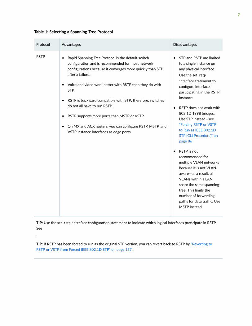
Table 1: Selecting a Spanning-Tree Protocol
Protocol Advantages Disadvantages
RSTP • Rapid Spanning Tree Protocol is the default switchconfiguration and is recommended for most networkconfigurations because it converges more quickly than STPafter a failure.
• Voice and video work better with RSTP than they do withSTP.
• RSTP is backward compatible with STP; therefore, switchesdo not all have to run RSTP.
• RSTP supports more ports than MSTP or VSTP.
• On MX and ACX routers, you can configure RSTP, MSTP, andVSTP instance interfaces as edge ports.
• STP and RSTP are limitedto a single instance onany physical interface.Use the set rstpinterface statement toconfigure interfacesparticipating in the RSTPinstance.
• RSTP does not work with802.1D 1998 bridges.Use STP instead—see"Forcing RSTP or VSTPto Run as IEEE 802.1DSTP (CLI Procedure)" onpage 86
• RSTP is notrecommended formultiple VLAN networksbecause it is not VLAN-aware—as a result, allVLANs within a LANshare the same spanning-tree. This limits thenumber of forwardingpaths for data traffic. UseMSTP instead.
TIP: Use the set rstp interface configuration statement to indicate which logical interfaces participate in RSTP.See
.
TIP: If RSTP has been forced to run as the original STP version, you can revert back to RSTP by "Reverting toRSTP or VSTP from Forced IEEE 802.1D STP" on page 157.
7

Table 1: Selecting a Spanning-Tree Protocol (Continued)
Protocol Advantages Disadvantages
STP • Spanning Tree Protocol works with 802.1D 1998 bridges.
• RSTP is backward compatible with STP; therefore, you canrun RSTP on some switches and STP on others with 802.1D1998 bridges.
• STP and RSTP are limitedto a single instance onany physical interface.Use the set stpinterface statement toconfigure interfacesparticipating in the RSTPinstance.
• STP is slower than RSTP.
• STP is not recommendedfor multiple VLANnetworks because it isnot VLAN-aware—as aresult, all VLANs within aLAN share the samespanning-tree. This limitsthe number offorwarding paths for datatraffic. Use MSTPinstead.
• Although STP providesbasic loop preventionfunctionality, it does notprovide fast networkconvergence when thereare topology changes.The STP process todetermine network statetransitions is slower thanthe RSTP processbecause it is timer-based.RSTP converges fasterbecause it uses ahandshake mechanismbased on point-to-pointlinks instead of thetimer-based processused by STP.
8

Table 1: Selecting a Spanning-Tree Protocol (Continued)
Protocol Advantages Disadvantages
• Edge ports are notsupported when theoriginal IEEE 802.1D STPis configured. If youspecify edge at the [editprotocols stp] hierarchylevel, the softwareignores the option.
TIP: Use the set stp interface statement to configure interfaces to participate in the STP instance. See"Configuring STP on EX Series Switches (CLI Procedure)" on page 25.
MSTP • Multiple Spanning Tree Protocol works with most VLANs.
• MSTP supports multiple instances on a single physicalinterface.
• On MX and ACX routers, you can configure RSTP, MSTP, andVSTP instance interfaces as edge ports.
• Some protocols requirecompatibility notprovided by MSTP. In thiscase, use VSTP.
• MSTP supports a limitednumber of ports. AnMSTP region supports upto 64 MSTIs with eachinstance supporting from1 through 4094 VLANs
• MSTP uses more CPUthan RSTP and does notconverge as fast as RSTP.
TIP: Use the set mstp interface configuration statement to indicate which logical interfaces participate in MSTP.See "Configuring MSTP on Switches" on page 91.
9

Table 1: Selecting a Spanning-Tree Protocol (Continued)
Protocol Advantages Disadvantages
VSTP • VSTP works with VLANs that require device compatibility.Enable VSTP on all VLANs that could receive VSTP bridgeprotocol data units (BPDUs).
• VSTP and RSTP are the only spanning-tree protocols that canbe configured concurrently on a switch.
• For VSTP, interfaces can be configured at the global level or atthe VLAN level. Interfaces configured at the global VSTP levelwill be enabled for all the configured VLANs. If an interface isconfigured at both the global and VLAN levels, theconfiguration at the VLAN level overrides the globalconfiguration.
• On MX and ACX routers, you can configure RSTP, MSTP, andVSTP instance interfaces as edge ports.
• With VSTP, there can beonly one STP instanceper VLAN, where MSTPlets you combinemultiple VLANs in oneinstance.
• VSTP supports a limitednumber of portscompared to RSTP.
• You can configure VSTPfor a maximum of 509VLANs. However, havinga large number of VSTPand RSTP instances cancause continuouschanges in the topology.As a performanceworkaround, reduce thenumber of VSTPinstances to fewer than190.
• Using the same VLAN forRSTP and VSTP is notsupported. For example,if you are configuring aVLAN under VSTP,configuring RSTP with aninterface that containsthe same VLAN is notsupported.
• If you configure VSTPand RSTP at the sametime and the switch hasmore than 253 VLANs,VSTP is configured onlyfor the first 253 VLANs.For the remaining
10

Table 1: Selecting a Spanning-Tree Protocol (Continued)
Protocol Advantages Disadvantages
VLANs, only RSTP isconfigured.
• When you configureVSTP with the setprotocol vstp vlan vlan-id interface interface-name command, the VLANnamed default isexcluded. You mustmanually configure aVLAN with the namedefault to run VSTP.
TIP: When using VSTP, we recommend that you enable VSTP on all VLANs that can receive VSTP bridge protocoldata units (BPDUs).
TIP: When you configure VSTP with the set protocol vstp vlan all command, VLAN ID 1 is not set; it is excludedso that the configuration is compatible with Cisco PVST+. If you want VLAN ID 1 to be included in the VSTPconfiguration on your switch, you must set it separately with the set protocol vstp vlan 1 command. For moreinformation, see Knowledge Base articles KB15138 and KB18291 at https://kb.juniper.net/InfoCenter/index
TIP: The maximum number of VLANs supported by VSTP on a switch depends upon whether you are using JunosOS for EX Series and QFX Series switches with support for the Enhanced Layer 2 Software (ELS) configurationstyle or Junos OS that does not support ELS.
You can use Juniper Networks switches with VSTP and Cisco switches with PVST+ and Rapid-PVST+ in the samenetwork. Cisco supports a proprietary Per-VLAN Spanning Tree (PVST) protocol, which maintains a separatespanning tree instance per each VLAN. One Spanning Tree per VLAN allows fine grain load balancing but requiresmore BPDU CPU processing as the number of VLANs increases. PVST runs on Cisco proprietary ISL trunks whichis not supported by Juniper. Juniper switches only inter-operate with PVST+ and Rapid-PVST+.
TIP: Spanning-tree protocols all generate their own BPDUs. User bridge applications running ona PC can also generate BPDUs. If these BPDUs are picked up by STP applications running on theswitch, they can trigger STP miscalculations, and those miscalculations can lead to networkoutages. See Configuring BPDU Protection on Spanning Tree Interfaces.
11

NOTE: If you are configuring an interface for any spanning tree protocol (STP, MSTP, RSTP, andVSTP), the interface all, vlan all, and vlan-group options are not available when you configure aninterface with the flexible-vlan-tagging family option.
Switch and Router Spanning Tree Support and Limitations
Not all switches and routers support the exact same features and configurations. Known differences arelisted in Table 2 on page 12.
Table 2: Spanning Tree Hardware Considerations
Router or Switch Considerations
MX Series Routers Only MX Series routers can use the virtual-switch routing instance typeto isolate a LAN segment with its spanning-tree instance and toseparate its VLAN ID space. See "Configuring a Virtual Switch RoutingInstance on MX Series Routers" on page 20
Tracing and global tracing are available on ACX and MX routers with theglobal "traceoptions" on page 387 statement—see "UnderstandingSpanning-Tree Protocol Trace Options" on page 286.
Beginning with Release 14.1R1, these STP log enhancements aresupported on MX Series routers:
• Logging of information in the internal ring buffer about events likeSpanning Tree (such as STP, MSTP, RSTP, or VSTP) interface role orstate change without having to configure STP traceoptions.
• Capturing information as to what triggered the spanning-tree role orstate change.
On MX and ACX routers, you can configure RSTP, MSTP, and VSTPinstance interfaces as edge ports for faster convergence than theoriginal STP version. Edge ports transition directly to the forwardingstate, and so the protocol does not need to wait for BPDUs to bereceived on edge ports.
On an MX Series router running RSTP or MSTP in a provider network,you can enable provider bridge participation in the RSTP or MSTPinstance—see Understanding Provider Bridge Participation in RSTP orMSTP Instances.
12

Table 2: Spanning Tree Hardware Considerations (Continued)
Router or Switch Considerations
TIP: For 802.1ad provider bridge networks (stacked VLANs) on MX Series and M Series routers, single-taggedaccess ports and double-tagged trunk ports can co-exist in a single spanning tree context. In this mode, the VLANSpanning Tree Protocol (VSTP) can send and receive untagged Rapid Spanning Tree Protocol (RSTP) bridgeprotocol data units (BPDUs) on Gigabit Ethernet (ge), 10 -Gigabit Ethernet (xe), and aggregated Ethernet (ae)interfaces. The untagged RSTP BPDUs interoperate with tagged VSTP BPDUs sent over the double-tagged trunkports. Double-tagging can be useful for Internet service providers, allowing them to use VLANs internally whilemixing traffic from clients that are already VLAN-tagged.
ACX Series Routers On MX and ACX routers, you can configure RSTP, MSTP, and VSTPinstance interfaces as edge ports for faster convergence than theoriginal STP version. Edge ports transition directly to the forwardingstate, and so the protocol does not need to wait for BPDUs to bereceived on edge ports.
Tracing and global tracing are available on ACX and MX routers with theglobal "traceoptions" on page 387 statement—see "UnderstandingSpanning-Tree Protocol Trace Options" on page 286.
13

Table 2: Spanning Tree Hardware Considerations (Continued)
Router or Switch Considerations
QFX Series Switches See Configuring STP.
If your network includes IEEE 802.1D 1998 bridges, remove RSTP andexplicitly configure STP—see "Forcing RSTP or VSTP to Run as IEEE802.1D STP (CLI Procedure)" on page 86. When you explicitlyconfigure STP, the QFX Series products use the IEEE 802.1D 2004specification, force version 0. This configuration runs a version of RSTPthat is compatible with the classic, basic STP. If you use virtual LANs(VLANs), you can enable VSTP on your network.
The STP support provided for the QFX Series includes:
• IEEE 802.1d
• 802.1w RSTP
• 802.1s MSTP
Use Rapid Spanning Tree Protocol (RSTP) on the network side of theQFX Series to provide quicker convergence time than the baseSpanning Tree Protocol (STP) does. RSTP identifies certain links as pointto point. When a point-to-point link fails, the alternate link cantransition to the forwarding state, which speeds up convergence.
An interface can be configured for either root protection or loopprotection, but not for both.
On EX Series (except EX9200) and QFX Series switches running JunosOS that supports ELS—VSTP can support up to 510 VLANs.
If your EX Series or QFX Series switch interoperates with a Cisco devicerunning Rapid per VLAN Spanning Tree (Rapid PVST+), we recommendthat you enable both VSTP and RSTP on the EX Series or QFX Seriesinterface.
14

Table 2: Spanning Tree Hardware Considerations (Continued)
Router or Switch Considerations
EX Series Switches • There are two versions of EX Series switches. Be sure to use thecorrect commands for each version. Some EX switches run theJuniper Networks Junos operating system (Junos OS) that supportsthe Enhanced Layer 2 Software (ELS) configuration (for example,EX4300, EX2300, EX3400 and EX4600 support ELS) and some donot support the ELS configuration.
• EX Series switches configured to use STP actually run RSTP forceversion 0, which is compatible with STP. If you are using Junos OSfor EX Series switches with support for ELS, you can force theoriginal IEEE 802.1D Spanning Tree Protocol (STP) version to run inplace of RSTP or VSTP. See "Forcing RSTP or VSTP to Run as IEEE802.1D STP (CLI Procedure)" on page 86.
• On EX Series (except EX9200) and QFX Series switches runningJunos OS that supports ELS—VSTP can support up to 510 VLANs.However, on EX9200 switches, VSTP can support only up to 253VLANs.
• The EX Series switches EX4300, EX4600 and the QFX platformsQFX5100, QFX3500, QFX3600 support 510 Vlans on VSTP.
• On EX9200 switches—VSTP can support up to 4000 VLANs.
• On an EX Series switch running Junos OS that does not support ELS—VSTP can support up to 253 VLANs.
• EX4300 switches can be configured for STP only by enabling RSTPand forcing it to act as STP. Select the Force STP check box from theRSTP configuration page.
• An interface can be configured for either root protection or loopprotection, but not for both.
• If your EX Series or QFX Series switch interoperates with a Ciscodevice running Rapid per VLAN Spanning Tree (Rapid PVST+), werecommend that you enable both VSTP and RSTP on the EX Seriesor QFX Series interface.
• The ARP feature is not available for EX Series switches supportingthe Enhanced Layer 2 Software (ELS) configuration style.
15
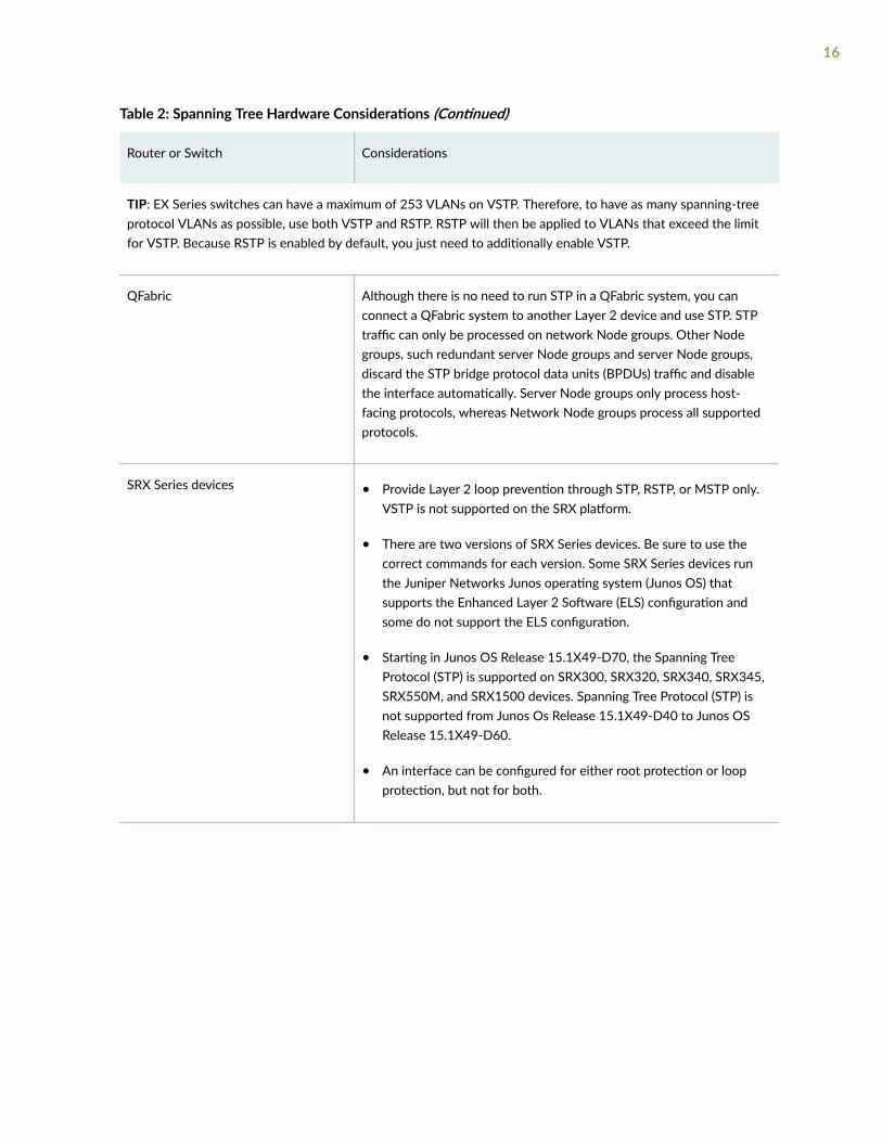
Table 2: Spanning Tree Hardware Considerations (Continued)
Router or Switch Considerations
TIP: EX Series switches can have a maximum of 253 VLANs on VSTP. Therefore, to have as many spanning-treeprotocol VLANs as possible, use both VSTP and RSTP. RSTP will then be applied to VLANs that exceed the limitfor VSTP. Because RSTP is enabled by default, you just need to additionally enable VSTP.
QFabric Although there is no need to run STP in a QFabric system, you canconnect a QFabric system to another Layer 2 device and use STP. STPtraffic can only be processed on network Node groups. Other Nodegroups, such redundant server Node groups and server Node groups,discard the STP bridge protocol data units (BPDUs) traffic and disablethe interface automatically. Server Node groups only process host-facing protocols, whereas Network Node groups process all supportedprotocols.
SRX Series devices • Provide Layer 2 loop prevention through STP, RSTP, or MSTP only.VSTP is not supported on the SRX platform.
• There are two versions of SRX Series devices. Be sure to use thecorrect commands for each version. Some SRX Series devices runthe Juniper Networks Junos operating system (Junos OS) thatsupports the Enhanced Layer 2 Software (ELS) configuration andsome do not support the ELS configuration.
• Starting in Junos OS Release 15.1X49-D70, the Spanning TreeProtocol (STP) is supported on SRX300, SRX320, SRX340, SRX345,SRX550M, and SRX1500 devices. Spanning Tree Protocol (STP) isnot supported from Junos Os Release 15.1X49-D40 to Junos OSRelease 15.1X49-D60.
• An interface can be configured for either root protection or loopprotection, but not for both.
16

2CHAPTER
Spanning-Tree Instances andInterfaces
Spanning Tree Instances and Interfaces | 18

Spanning Tree Instances and Interfaces
IN THIS SECTION
Understanding Spanning-Tree Instance Interfaces | 18
Configuring a Virtual Switch Routing Instance on MX Series Routers | 20
Configuring a Spanning-Tree Instance Interface as an Edge Port for Faster Convergence | 21
Understanding Spanning-Tree Instance Interfaces
IN THIS SECTION
Benefits of Spanning-Tree Instance Interface Configuration | 18
How Many Instances Do Spanning Tree Protocols Have? | 19
Spanning-Tree Instance Interfaces Have Priorities | 19
What is Spanning-Tree Instance Interface Cost? | 19
An instance is analogous to one computer process. The 802.1Q standard defines one unique Spanning-Tree instance to be used by all VLANs in the network. STP runs on the Native VLAN so that it cancommunicate with both 802.1Q and non-802.1Q compatible switches. This single instance of STP isalso referred to as 802.1Q Mono Spanning Tree or Common Spanning Tree (CST).
Benefits of Spanning-Tree Instance Interface Configuration
The interface mode allows RSTP, MSTP, and VSTP to converge faster than the original STP on point-to-point links. The protocol does not need to wait for timers on point-to-point links. Configure interfacesthat have a point-to-point link to another Layer 2 bridge as p2p. This parameter is ignored if the STP isconfigured to run the original spanning-tree version.
If the "interface (Spanning Tree)" on page 338 mode is configured at both the VSTP global and VLANlevels, the configuration at the VLAN level overrides the global configuration.
18
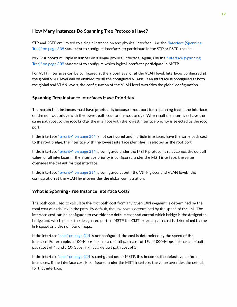
How Many Instances Do Spanning Tree Protocols Have?
STP and RSTP are limited to a single instance on any physical interface. Use the "interface (SpanningTree)" on page 338 statement to configure interfaces to participate in the STP or RSTP instance.
MSTP supports multiple instances on a single physical interface. Again, use the "interface (SpanningTree)" on page 338 statement to configure which logical interfaces participate in MSTP.
For VSTP, interfaces can be configured at the global level or at the VLAN level. Interfaces configured atthe global VSTP level will be enabled for all the configured VLANs. If an interface is configured at boththe global and VLAN levels, the configuration at the VLAN level overrides the global configuration.
Spanning-Tree Instance Interfaces Have Priorities
The reason that instances must have priorities is because a root port for a spanning tree is the interfaceon the nonroot bridge with the lowest path cost to the root bridge. When multiple interfaces have thesame path cost to the root bridge, the interface with the lowest interface priority is selected as the rootport.
If the interface "priority" on page 364 is not configured and multiple interfaces have the same path costto the root bridge, the interface with the lowest interface identifier is selected as the root port.
If the interface "priority" on page 364 is configured under the MSTP protocol, this becomes the defaultvalue for all interfaces. If the interface priority is configured under the MSTI interface, the valueoverrides the default for that interface.
If the interface "priority" on page 364 is configured at both the VSTP global and VLAN levels, theconfiguration at the VLAN level overrides the global configuration.
What is Spanning-Tree Instance Interface Cost?
The path cost used to calculate the root path cost from any given LAN segment is determined by thetotal cost of each link in the path. By default, the link cost is determined by the speed of the link. Theinterface cost can be configured to override the default cost and control which bridge is the designatedbridge and which port is the designated port. In MSTP the CIST external path cost is determined by thelink speed and the number of hops.
If the interface "cost" on page 314 is not configured, the cost is determined by the speed of theinterface. For example, a 100-Mbps link has a default path cost of 19, a 1000-Mbps link has a defaultpath cost of 4, and a 10-Gbps link has a default path cost of 2.
If the interface "cost" on page 314 is configured under MSTP, this becomes the default value for allinterfaces. If the interface cost is configured under the MSTI interface, the value overrides the defaultfor that interface.
19
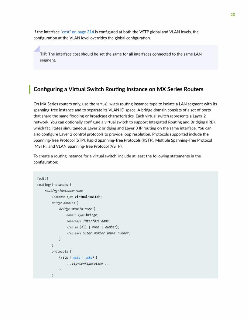
If the interface "cost" on page 314 is configured at both the VSTP global and VLAN levels, theconfiguration at the VLAN level overrides the global configuration.
TIP: The interface cost should be set the same for all interfaces connected to the same LANsegment.
Configuring a Virtual Switch Routing Instance on MX Series Routers
On MX Series routers only, use the virtual-switch routing instance type to isolate a LAN segment with itsspanning-tree instance and to separate its VLAN ID space. A bridge domain consists of a set of portsthat share the same flooding or broadcast characteristics. Each virtual switch represents a Layer 2network. You can optionally configure a virtual switch to support Integrated Routing and Bridging (IRB),which facilitates simultaneous Layer 2 bridging and Layer 3 IP routing on the same interface. You canalso configure Layer 2 control protocols to provide loop resolution. Protocols supported include theSpanning-Tree Protocol (STP), Rapid Spanning-Tree Protocols (RSTP), Multiple Spanning-Tree Protocol(MSTP), and VLAN Spanning-Tree Protocol (VSTP).
To create a routing instance for a virtual switch, include at least the following statements in theconfiguration:
[edit]routing-instances { routing-instance-name instance-type virtual-switch; bridge-domains { bridge-domain-name { domain-type bridge; interface interface-name; vlan-id (all | none | number); vlan-tags outer number inner number; } } protocols { (rstp | mstp | vstp) { ...stp-configuration ... } }
20
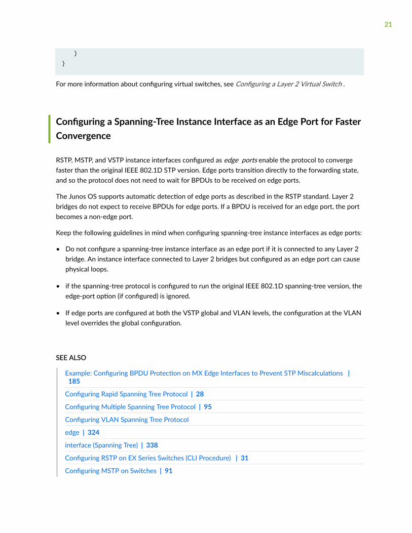
}}
For more information about configuring virtual switches, see Configuring a Layer 2 Virtual Switch .
Configuring a Spanning-Tree Instance Interface as an Edge Port for FasterConvergence
RSTP, MSTP, and VSTP instance interfaces configured as edge ports enable the protocol to convergefaster than the original IEEE 802.1D STP version. Edge ports transition directly to the forwarding state,and so the protocol does not need to wait for BPDUs to be received on edge ports.
The Junos OS supports automatic detection of edge ports as described in the RSTP standard. Layer 2bridges do not expect to receive BPDUs for edge ports. If a BPDU is received for an edge port, the portbecomes a non-edge port.
Keep the following guidelines in mind when configuring spanning-tree instance interfaces as edge ports:
• Do not configure a spanning-tree instance interface as an edge port if it is connected to any Layer 2bridge. An instance interface connected to Layer 2 bridges but configured as an edge port can causephysical loops.
• if the spanning-tree protocol is configured to run the original IEEE 802.1D spanning-tree version, theedge-port option (if configured) is ignored.
• If edge ports are configured at both the VSTP global and VLAN levels, the configuration at the VLANlevel overrides the global configuration.
SEE ALSO
Example: Configuring BPDU Protection on MX Edge Interfaces to Prevent STP Miscalculations | 185
Configuring Rapid Spanning Tree Protocol | 28
Configuring Multiple Spanning Tree Protocol | 95
Configuring VLAN Spanning Tree Protocol
edge | 324
interface (Spanning Tree) | 338
Configuring RSTP on EX Series Switches (CLI Procedure) | 31
Configuring MSTP on Switches | 91
21

3CHAPTER
Configuring Spanning-Tree Protocols
Configuring STP Protocol | 23
Configuring RSTP Protocol | 26
Configuring MSTP Protocol | 87
Configuring VSTP Protocol | 134

Configuring STP Protocol
IN THIS SECTION
Understanding STP | 23
Understanding System Identifiers for Bridges in STP or RSTP Instances | 25
Configuring STP on EX Series Switches (CLI Procedure) | 25
Understanding STP
IN THIS SECTION
Benefits of Using the Original STP | 23
STP on MX Routers | 24
STP on SRX Firewalls | 24
STP on EX Series Switches | 24
STP Operation Mode Commands | 24
Spanning Tree Protocol (STP), defined in IEEE 802.1D, creates a tree of links in the Ethernet switchednetwork. Links that cause loops in the network are disabled, thereby providing a single active linkbetween any two devices.
Benefits of Using the Original STP
Some benefits of using the original STP are:
• Some legacy networks require the slower convergence times of basic STP.
• STP supports older 802.1D 1998 bridges.
• You can run RSTP on some switches and STP on others with 802.1D 1998 bridges. They arecompatible.
23

STP on MX Routers
Beginning with Release 14.1R1, these enhancements are supported on STP logs in the MX Seriessupport:
• Logging of information in the internal ring buffer about events like Spanning Tree (such as STP, MSTP,RSTP, or VSTP) interface role or state change without having to configure STP traceoptions.
• Capturing information as to what triggered the spanning-tree role or state change.
STP on SRX Firewalls
Spanning Tree Protocol (STP) is not supported on SRX devices from Junos Os Release 15.1X49-D40 toJunos OS Release 15.1X49-D60.
Starting in Junos OS Release 15.1X49-D70, the Spanning Tree Protocol (STP) is supported on SRX300,SRX320, SRX340, SRX345, SRX550M, and SRX1500 devices.
STP on EX Series Switches
EX Series switches configured to use STP actually run RSTP force version 0, which is compatible withSTP. If you are using Junos OS for EX Series switches with support for the Enhanced Layer 2 Software(ELS) configuration style, you can force the original IEEE 802.1D Spanning Tree Protocol (STP) version torun in place of RSTP or VSTP by setting "force-version" on page 329.
STP Operation Mode Commands
You can use the operational mode commands "show spanning-tree statistics message-queues" on page465, "show spanning-tree stp-buffer see-all" on page 467, "show spanning-tree statistics bridge" onpage 460, and "show spanning-tree statistics interface" on page 462 to get the information from ring-buffer, bridge, and port statistics. "clear spanning-tree stp-buffer" on page 420 clears the stp-buffer, and"clear spanning-tree statistics bridge" on page 418 clears the statistics of the bridge.
SEE ALSO
Understanding Layer 2 Protocol Tunneling
24

Understanding System Identifiers for Bridges in STP or RSTP Instances
Spanning tree protocols work by creating bridges. A root bridge (switch) is a bridge at the top of aSpanning Tree. Ethernet connections branch out from the root switch, connecting to other switches inthe Local Area Network (LAN). An extended system identifier is assigned to bridges in STP or RSTProuting instances—see "extended-system-id" on page 328.
When you configure STP or RSTP, you specify the extended system identifier.
Configuring STP on EX Series Switches (CLI Procedure)
The default spanning-tree protocol for EX Series switches is Rapid Spanning Tree Protocol (RSTP). RSTPprovides faster convergence times than the original Spanning Tree Protocol (STP). However, some legacynetworks require the slower convergence times of basic STP that work with 802.1D 1998 bridges.
If your network includes 802.1D 1998 bridges, you can remove RSTP and explicitly configure STP. Whenyou explicitly configure STP, the switches use the IEEE 802.1D 2004 specification, force version 0. Thisconfiguration runs a version of RSTP that is compatible with the classic, basic STP.
To configure STP:
1. Either delete RSTP on the entire switch or disable RSTP on specific interfaces:
• To delete RSTP on the entire switch:
[edit protocols]user@switch# delete rstp
• To disable RSTP on a specific interface:
[edit protocols]user@switch# set rstp interface interface-name disable
2. Enable STP either on all interfaces or on a specific interface:
• To enable STP on all interfaces:
[edit protocols]user@switch# set stp interface all
25

• To enable STP on a specific interface:
[edit protocols]user@switch# set stp interface interface-name
3. (Optional) Only if a routed VLAN interface (RVI) is configured, enable the Address ResolutionProtocol (ARP) for faster MAC address recovery:
• To enable ARP on STP on all interfaces:
[edit protocols]user@switch# set stp interface all arp-on-stp
• To enable ARP on STP on a specific interface:
[edit protocols]user@switch# set stp interface interface-name arp-on-stp
RELATED DOCUMENTATION
Understanding Layer 2 Protocol Tunneling
Configuring RSTP Protocol
IN THIS SECTION
Understanding RSTP | 27
Configuring Rapid Spanning Tree Protocol | 28
Configuring RSTP on EX Series Switches (CLI Procedure) | 31
Example: Configuring Faster Convergence and Network Stability on ELS Switches with RSTP | 32
Example: Faster Convergence and Improved Network Stability with RSTP on EX Series Switches | 59
Forcing RSTP or VSTP to Run as IEEE 802.1D STP (CLI Procedure) | 86
26

Understanding RSTP
IN THIS SECTION
Benefits of Using RSTP | 27
Why is RSTP the Default Spanning-Tree Protocol? | 27
Juniper Networks products use Rapid Spanning Tree Protocol (RSTP) on the network side of devices bydefault to provide quicker convergence time than the base Spanning Tree Protocol (STP) does. RSTPidentifies certain links as point to point. When a point-to-point link fails, the alternate link can transitionto the forwarding state, which speeds up convergence.
Benefits of Using RSTP
Some benefits of using the original STP are:
• RSTP is faster than STP.
• Voice and video work better with RSTP than they do with STP.
• RSTP supports more ports than MSTP or VSTP.
• RSTP is backward compatible with STP; therefore, switches do not all have to run RSTP.
• On MX and ACX routers, you can configure RSTP, MSTP, and VSTP instance interfaces as edge ports.
Why is RSTP the Default Spanning-Tree Protocol?
RSTP evolved from the original STP IEEE 802.1D protocol to provide faster spanning-treereconvergence after a switch port, switch, or LAN failure. Where STP took up to 50 seconds to respondto topology changes, RSTP responds to changes within the timeframe of three hello BPDUs (bridgeprotocol data units), or 6 seconds. This is the primary reason that RSTP is the default spanning-treeconfiguration.
TIP: EX Series switches configured to use STP actually run RSTP force version 0, which iscompatible with STP.
27

Configuring Rapid Spanning Tree Protocol
You can configure Rapid Spanning Tree Protocol (RSTP) under the following hierarchy levels:
• [edit logical-systems logical-system-name protocols]
• [edit logical-systems logical-system-name routing-instances routing-instance-name protocols]
• [edit protocols]
• [edit routing-instances routing-instance-name protocols]
The routing instance type can be either virtual-switch or layer2-control.
To configure the Rapid Spanning Tree Protocol:
1. Enable RSTP as the version of spanning-tree protocol to be configured:
[edit]user@host@ edit ... protocols (STP Type) rstp
2. (Optional) For compatibility with older bridges that do not support RSTP, you can force RSTP to runas the original IEEE 802.1D Spanning Tree Protocol (STP) version:
[edit ... protocols rstp]user@host# set force-version stp
NOTE: If RSTP has been forced to run as the original STP version, you can revert back toRSTP by first removing the force-version statement from the configuration and then enteringthe clear spanning-tree protocol-migration configuration mode command.
3. (Optional) Enable provider bridge participation in the RSTP instance:
[edit ... protocols rstp]user@host# set bpdu-destination-mac-address provider-bridge-group
4. (Optional) Specify the extended system identifier used in identifiers bridges that participate in RSTP:
[edit ... protocols rstp]user@host# set extended-system-id identifier
28

5. Configure the interfaces that participate in the RSTP instance.
a. Enable configuration of the interface:
[edit ... protocols rstp]user@host# edit interface interface-name
b. Configure the interface priority:
[edit ... protocols rstp interface interface-name]user@host# set priority interface-priority
c. (Optional) By default, the interface link cost is determined by the link speed. You can configurethe interface link cost to control which bridge is the designated bridge and which port is thedesignated port:
[edit ... protocols rstp interface interface-name]user@host# set cost interface-link-cost
d. Configure the interface link mode to identify point-to-point links:
[edit ... protocols rstp interface interface-name]user@host# set mode (p2p | shared)
Specify p2p if the link is point to point. Specify shared if the link is a shared media.
e. (Optional) Configure the interface as an edge port:
[edit ... protocols rstp interface interface-name]user@host# set edge
Edge ports do not expect to receive bridge protocol data unit (BPDU) packets. If a BPDU packet isreceived for an edge port, the port becomes a non-edge port
You can also enable BPDU root protection for all spanning-tree protocol instances on the interface.BPDU root protect ensures the port is the spanning-tree designated port. If the port receivessuperior BPDU packets, root protect moves this port to a root-prevented spanning-tree state. Forconfiguration details, see "Checking the Status of Spanning-Tree Instance Interfaces" on page 286.
29

6. Configure the bridge priority:
[edit ... protocols rstp]user@host# set bridge-priority bridge-priority
For more information, see "Understanding Bridge Priority for Election of Root Bridge and DesignatedBridge" on page 261.
7. Configure hello BPDU timers.
a. Configure the maximum expected arrival time of hello BPDUs:
[edit ... protocols rstp]user@host# set max-age seconds
b. Configure the time interval at which the root bridge transmits configuration BPDUs:
[edit ... protocols rstp]user@host# set hello-time seconds
8. (Optional) By default, the bridge port remains in the listening and learning states for 15 secondsbefore transitioning to the forwarding state. You can specify a delay from 4 through 20 secondsinstead:
[edit ... protocols rstp]user@host# set forward-delay seconds
9. Verify the RSTP configuration:
[edit]... { # Optional logical system and/or routing instance protocols (STP Type) { rstp { force-version stp; # Optional. bpdu-destination-mac-address provider-bridge-group; # Optional extended-system-id identifier; # Optional. interface interface-name { priority interface-priority; cost interface-link-cost; # Optional. mode (p2p | shared); edge; # Optional.
30

} bridge-priority bridge-priority; max-age seconds; hello-time seconds; forward-delay seconds; # Optional. } } }
Configuring RSTP on EX Series Switches (CLI Procedure)
The default spanning-tree protocol for EX Series switches is Rapid Spanning Tree Protocol (RSTP). RSTPprovides faster convergence times than the original Spanning Tree Protocol (STP). Because RSTP isconfigured by default, you only need to use this procedure If another spanning-tree protocol has beenconfigured. In that case, you can reconfigure RSTP.
To enable RSTP:
1. Disable the other configured spanning-tree protocol (MSTP):
• To disable MSTP:
[edit protocols]user@switch# set mstp disable
2. Configure RSTP
• To enable RSTP on a specific interface:
[edit protocols]user@switch# set rstp interface interface-name
• To disable RSTP on a specific interface:
[edit protocols]user@switch# set rstp interface interface-name disable
31

• To enable RSTP on a range of interfaces:
[edit protocols]user@switch# set rstp interface interface-range-name
• To enable RSTP on all interfaces:
[edit protocols]user@switch# set rstp interface all
Example: Configuring Faster Convergence and Network Stability on ELSSwitches with RSTP
IN THIS SECTION
Requirements | 33
Overview and Topology | 33
Configuring RSTP and Nonstop Bridging on Switch 1 | 36
Configuring RSTP and Nonstop Bridging on Switch 2 | 41
Configuring RSTP and Nonstop Bridging on Switch 3 | 46
Configuring RSTP and Nonstop Bridging on Switch 4 | 51
Verification | 55
NOTE: This example uses Junos OS for EX Series switches with support for the Enhanced Layer2 Software (ELS) configuration style. If your switch runs software that does not support ELS, see"Example: Faster Convergence and Improved Network Stability with RSTP on EX SeriesSwitches" on page 59. For ELS details, see Using the Enhanced Layer 2 Software CLI.
EX Series switches use Rapid Spanning Tree Protocol (RSTP) by default to provide a loop-free topology.
32

When switches that support redundant Routing Engines use RSTP, it is important to keep RSTPsynchronized on both Routing Engines so that no loss of service occurs after a Routing Engineswitchover. Nonstop bridging protocol keeps Routing Engines synchronized.
This example describes how to configure RSTP and NSB on four EX Series switches:
Requirements
This example uses the following software and hardware components:
• Junos OS Release 15.1 or later or later for EX Series switches
• Four EX Series switches
Before you configure the switches for RSTP, be sure you have:
• Installed and connected the four switches. See the hardware documentation for your switch.
• Performed the initial software configuration on all switches. See Connecting and Configuring an EXSeries Switch (CLI Procedure).
Overview and Topology
IN THIS SECTION
Topology | 36
RSTP works by identifying certain links as point to point links and blocking other possible paths. Whenone of the point-to-point links fails, a designated alternate link transitions to the forwarding state andtake over. Configuring nonstop bridging (NSB) on a switch with redundant Routing Engines keeps RSTPsynchronized on both Routing Engines. This way, RSTP remains active immediately after a switchoverbecause it is already synchronized to the backup Routing Engine. RSTP does not have to reconvergeafter a Routing Engine switchover when NSB is enabled because the neighbor devices do not detect anRSTP change on the switch. In this example, four EX Series switches are connected in the topology
33

displayed in Figure 1 on page 34 to create a loop-free topology with NSB applied to switches with dualRouting Engines.
Figure 1: Network Topology for RSTP
Table 3 on page 35 shows the components of the topology for this example.
NOTE: You can configure RSTP only on physical interfaces, not on logical interfaces.
34
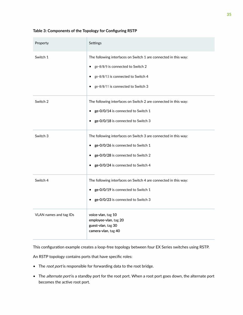
Table 3: Components of the Topology for Configuring RSTP
Property Settings
Switch 1 The following interfaces on Switch 1 are connected in this way:
• ge-0/0/9 is connected to Switch 2
• ge-0/0/13 is connected to Switch 4
• ge-0/0/11 is connected to Switch 3
Switch 2 The following interfaces on Switch 2 are connected in this way:
• ge-0/0/14 is connected to Switch 1
• ge-0/0/18 is connected to Switch 3
Switch 3 The following interfaces on Switch 3 are connected in this way:
• ge-0/0/26 is connected to Switch 1
• ge-0/0/28 is connected to Switch 2
• ge-0/0/24 is connected to Switch 4
Switch 4 The following interfaces on Switch 4 are connected in this way:
• ge-0/0/19 is connected to Switch 1
• ge-0/0/23 is connected to Switch 3
VLAN names and tag IDs voice-vlan, tag 10employee-vlan, tag 20guest-vlan, tag 30camera-vlan, tag 40
This configuration example creates a loop-free topology between four EX Series switches using RSTP.
An RSTP topology contains ports that have specific roles:
• The root port is responsible for forwarding data to the root bridge.
• The alternate port is a standby port for the root port. When a root port goes down, the alternate portbecomes the active root port.
35

• The designated port forwards data to the downstream network segment or device.
• The backup port is a backup port for the designated port. When a designated port goes down, thebackup port becomes the active designated port and starts forwarding data.
NOTE: You also can create a loop-free topology between the aggregation layer and thedistribution layer using redundant trunk links. For more information about configuring redundanttrunk links, see Example: Configuring Redundant Trunk Links for Faster Recovery on Devices withELS Support.
Topology
Configuring RSTP and Nonstop Bridging on Switch 1
IN THIS SECTION
Procedure | 36
Procedure
CLI Quick Configuration
To quickly configure RSTP and nonstop bridging on Switch 1, copy the following commands and pastethem into the switch terminal window:
[edit] set vlans voice-vlan description “Voice VLAN” set vlans voice-vlan vlan-id 10 set vlans employee-vlan description “Employee VLAN” set vlans employee-vlan vlan-id 20 set vlans guest-vlan description “Guest VLAN” set vlans guest-vlan vlan-id 30 set vlans camera-vlan description “Camera VLAN” set vlans camera-vlan vlan-id 40 set interfaces ge-0/0/13 unit 0 family ethernet-switching vlan members [10 20 30 40]
36
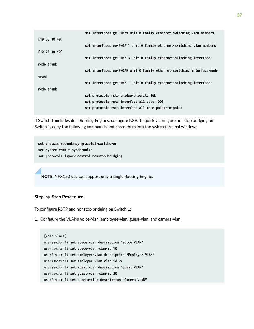
set interfaces ge-0/0/9 unit 0 family ethernet-switching vlan members [10 20 30 40] set interfaces ge-0/0/11 unit 0 family ethernet-switching vlan members [10 20 30 40] set interfaces ge-0/0/13 unit 0 family ethernet-switching interface-mode trunk set interfaces ge-0/0/9 unit 0 family ethernet-switching interface-mode trunk set interfaces ge-0/0/11 unit 0 family ethernet-switching interface-mode trunk set protocols rstp bridge-priority 16k set protocols rstp interface all cost 1000 set protocols rstp interface all mode point-to-point
If Switch 1 includes dual Routing Engines, configure NSB. To quickly configure nonstop bridging onSwitch 1, copy the following commands and paste them into the switch terminal window:
set chassis redundancy graceful-switchoverset system commit synchronizeset protocols layer2-control nonstop-bridging
NOTE: NFX150 devices support only a single Routing Engine.
Step-by-Step Procedure
To configure RSTP and nonstop bridging on Switch 1:
1. Configure the VLANs voice-vlan, employee-vlan, guest-vlan, and camera-vlan:
[edit vlans]user@switch1# set voice-vlan description “Voice VLAN”user@switch1# set voice-vlan vlan-id 10user@switch1# set employee-vlan description “Employee VLAN”user@switch1# set employee-vlan vlan-id 20user@switch1# set guest-vlan description “Guest VLAN”user@switch1# set guest-vlan vlan-id 30user@switch1# set camera-vlan description “Camera VLAN”
37

user@switch1# set camera-vlan vlan-id 40
2. Configure the VLANs on the interfaces, including support for the Ethernet switching protocol:
[edit interfaces]user@switch1# set ge-0/0/13 unit 0 family ethernet-switching vlan members [10 20 30 40]user@switch1# set ge-0/0/9 unit 0 family ethernet-switching vlan members [10 20 30 40]user@switch1# set ge-0/0/11 unit 0 family ethernet-switching vlan members [10 20 30 40]
3. Configure the port mode for the interfaces:
[edit interfaces]user@switch1# set ge-0/0/13 unit 0 family ethernet-switching interface-mode trunkuser@switch1# set ge-0/0/9 unit 0 family ethernet-switching interface-mode trunkuser@switch1# set ge-0/0/11 unit 0 family ethernet-switching interface-mode trunk
4. Configure RSTP on the switch:
[edit protocols]
user@switch1# rstp bridge-priority 16kuser@switch1# rstp interface all cost 1000user@switch1# rstp interface all mode point-to-point
Step-by-Step Procedure
If Switch 1 includes dual Routing Engines, configure nonstop bridging. To configure NSB on Switch 1:
1. Enable graceful Routing Engine switchover (GRES):
[edit chassis redundancy] user@switch1# set graceful-switchover
38
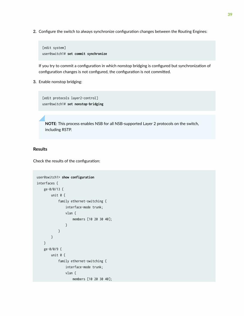
2. Configure the switch to always synchronize configuration changes between the Routing Engines:
[edit system] user@switch1# set commit synchronize
If you try to commit a configuration in which nonstop bridging is configured but synchronization ofconfiguration changes is not configured, the configuration is not committed.
3. Enable nonstop bridging:
[edit protocols layer2-control]user@switch1# set nonstop-bridging
NOTE: This process enables NSB for all NSB-supported Layer 2 protocols on the switch,including RSTP.
Results
Check the results of the configuration:
user@switch1> show configuration interfaces { ge-0/0/13 { unit 0 { family ethernet-switching { interface-mode trunk; vlan { members [10 20 30 40]; } } } } ge-0/0/9 { unit 0 { family ethernet-switching { interface-mode trunk; vlan { members [10 20 30 40];
39

} } } } ge-0/0/11 { unit 0 { family ethernet-switching { interface-mode trunk; vlan { members [10 20 30 40]; } } } }}protocols { layer2-control { nonstop-bridging; } rstp { bridge-priority 16k; interface ge-0/0/13 { cost 1000; mode point-to-point; } interface ge-0/0/9 { cost 1000; mode point-to-point; } interface ge-0/0/11 { cost 1000; mode point-to-point; } } }}vlans { voice-vlan { vlan-id 10; } employee-vlan { vlan-id 20; }
40

guest-vlan { vlan-id 30; } camera-vlan { vlan-id 40; }}system { commit synchronize; } chassis { redundancy { graceful-switchover; }
Configuring RSTP and Nonstop Bridging on Switch 2
IN THIS SECTION
Procedure | 41
Procedure
CLI Quick Configuration
To quickly configure RSTP and nonstop bridging on Switch 2, copy the following commands and pastethem into the switch terminal window:
[edit] set vlans voice-vlan description “Voice VLAN” set vlans voice-vlan vlan-id 10 set vlans employee-vlan description “Employee VLAN” set vlans employee-vlan vlan-id 20 set vlans guest-vlan description “Guest VLAN” set vlans guest-vlan vlan-id 30 set vlans camera-vlan description “Camera VLAN” set vlans camera-vlan vlan-id 40 set interfaces ge-0/0/14 unit 0 family ethernet-switching vlan members
41

[10 20 30 40] set interfaces ge-0/0/18 unit 0 family ethernet-switching vlan members [10 20 30 40] set interfaces ge-0/0/14 unit 0 family ethernet-switching interface-mode trunk set interfaces ge-0/0/18 unit 0 family ethernet-switching interface-mode trunk set protocols rstp bridge-priority 32k set protocols rstp interface ge-0/0/14 cost 1000 set protocols rstp interface ge-0/0/14 mode point-to-point set protocols rstp interface ge-0/0/18 cost 1000 set protocols rstp interface ge-0/0/18 mode point-to-point
NOTE: Starting with Junos OS Release 15.1 for EX Series and QFX Series switches with supportfor the Enhanced Layer 2 Software (ELS) configuration style, you can configure spanning treeparameters globally on all spanning tree interfaces. See "Configuring RSTP on EX Series Switches(CLI Procedure) " on page 31 for additional information.
If Switch 2 includes dual Routing Engines, configure NSB. To quickly configure nonstop bridging onSwitch 2, copy the following commands and paste them into the switch terminal window:
set chassis redundancy graceful-switchoverset system commit synchronizeset protocols layer2-control nonstop-bridging
Step-by-Step Procedure
To configure RSTP and nonstop bridging on Switch 2:
1. Configure the VLANs voice-vlan, employee-vlan, guest-vlan, and camera-vlan:
[edit vlans]user@switch2# set voice-vlan description “Voice VLAN”user@switch2# set voice-vlan vlan-id 10user@switch2# set employee-vlan description “Employee VLAN”user@switch2# set employee-vlan vlan-id 20user@switch2# set guest-vlan description “Guest VLAN”
42

user@switch2# set guest-vlan vlan-id 30user@switch2# set camera-vlan vlan-description “Camera VLAN”user@switch2# set camera-vlan vlan-id 40
2. Configure the VLANs on the interfaces, including support for the Ethernet switching protocol:
[edit interfaces]user@switch2# set ge-0/0/14 unit 0 family ethernet-switching vlan members [10 20 30 40]user@switch2# set ge-0/0/18 unit 0 family ethernet-switching vlan members [10 20 30 40]
3. Configure the port mode for the interfaces:
[edit interfaces]user@switch2# set ge-0/0/14 unit 0 family ethernet-switching interface-mode trunkuser@switch2# set ge-0/0/18 unit 0 family ethernet-switching interface-mode trunk
4. Configure RSTP on the switch:
[edit protocols]user@switch2# rstp bridge-priority 32kuser@switch2# rstp interface ge-0/0/14 cost 1000user@switch2# rstp interface ge-0/0/14 mode point-to-pointuser@switch2# rstp interface ge-0/0/18 cost 1000user@switch2# rstp interface ge-0/0/18 mode point-to-point
Step-by-Step Procedure
If Switch 2 includes dual Routing Engines, configure nonstop bridging. To configure NSB on Switch 2:
1. Enable graceful Routing Engine switchover (GRES):
[edit chassis redundancy] user@switch2# set graceful-switchover
43

2. Configure the switch to always synchronize configuration changes between the Routing Engines:
[edit system] user@switch2# set commit synchronize
If you try to commit a configuration in which nonstop bridging is configured but synchronization ofconfiguration changes is not configured, the configuration is not committed.
3. Enable nonstop bridging:
[edit protocols layer2-control]user@switch2# set nonstop-bridging
NOTE: This process enables NSB for all NSB-supported Layer 2 protocols on the switch,including RSTP.
Results
Check the results of the configuration:
user@switch2> show configuration interfaces { ge-0/0/14 { unit 0 { family ethernet-switching { interface-mode trunk; vlan { members [10 20 30 40]; } } } } ge-0/0/18 { unit 0 { family ethernet-switching { interface-mode trunk; vlan { members [10 20 30 40];
44

} } } }}protocols { layer2-control { nonstop-bridging; } rstp { bridge-priority 32k; interface ge-0/0/14 { cost 1000; mode point-to-point; } interface ge-0/0/18 { cost 1000; mode point-to-point; } } }}vlans { voice-vlan { vlan-id 10; } employee-vlan { vlan-id 20; } guest-vlan { vlan-id 30; } camera-vlan { vlan-id 40; }}system { commit synchronize; } chassis { redundancy {
45
graceful-switchover; }
Configuring RSTP and Nonstop Bridging on Switch 3
IN THIS SECTION
Procedure | 46
Procedure
CLI Quick Configuration
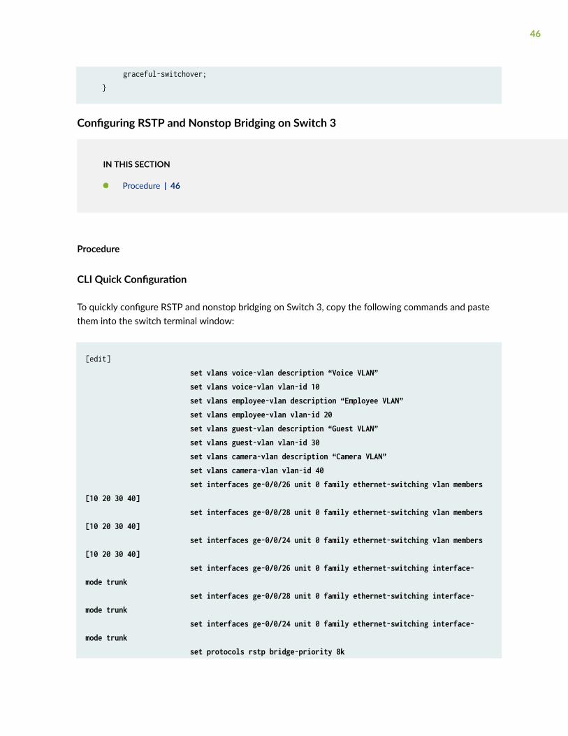
To quickly configure RSTP and nonstop bridging on Switch 3, copy the following commands and pastethem into the switch terminal window:
[edit] set vlans voice-vlan description “Voice VLAN” set vlans voice-vlan vlan-id 10 set vlans employee-vlan description “Employee VLAN” set vlans employee-vlan vlan-id 20 set vlans guest-vlan description “Guest VLAN” set vlans guest-vlan vlan-id 30 set vlans camera-vlan description “Camera VLAN” set vlans camera-vlan vlan-id 40 set interfaces ge-0/0/26 unit 0 family ethernet-switching vlan members [10 20 30 40] set interfaces ge-0/0/28 unit 0 family ethernet-switching vlan members [10 20 30 40] set interfaces ge-0/0/24 unit 0 family ethernet-switching vlan members [10 20 30 40] set interfaces ge-0/0/26 unit 0 family ethernet-switching interface-mode trunk set interfaces ge-0/0/28 unit 0 family ethernet-switching interface-mode trunk set interfaces ge-0/0/24 unit 0 family ethernet-switching interface-mode trunk set protocols rstp bridge-priority 8k
46

set protocols rstp interface ge-0/0/26 cost 1000 set protocols rstp interface ge-0/0/26 mode point-to-point set protocols rstp interface ge-0/0/28 cost 1000 set protocols rstp interface ge-0/0/28 mode point-to-point set protocols rstp interface ge-0/0/24 cost 1000 set protocols rstp interface ge-0/0/24 mode point-to-point
If Switch 3 includes dual Routing Engines, configure NSB. To quickly configure nonstop bridging onSwitch 3, copy the following commands and paste them into the switch terminal window:
set chassis redundancy graceful-switchoverset system commit synchronizeset protocols layer2-control nonstop-bridging
Step-by-Step Procedure
To configure RSTP and nonstop bridging on Switch 3:
1. Configure the VLANs voice-vlan, employee-vlan, guest-vlan, and camera-vlan:
[edit vlans]user@switch3# set voice-vlan description “Voice VLAN”user@switch3# set voice-vlan vlan-id 10user@switch3# set employee-vlan description “Employee VLAN”user@switch3# set employee-vlan vlan-id 20user@switch3# set guest-vlan description “Guest VLAN”user@switch3# set guest-vlan vlan-id 30user@switch3# set camera-vlan description “Camera VLAN”user@switch3# set camera-vlan vlan-id 40
2. Configure the VLANs on the interfaces, including support for the Ethernet switching protocol:
[edit interfaces]user@switch3# set ge-0/0/26 unit 0 family ethernet-switching vlan members [10 20 30 40]user@switch3# set ge-0/0/28 unit 0 family ethernet-switching vlan members [10 20 30 40]
47

user@switch3# set ge-0/0/24 unit 0 family ethernet-switching vlan members [10 20 30 40]
3. Configure the port mode for the interfaces:
[edit interfaces]user@switch3# set ge-0/0/26 unit 0 family ethernet-switching interface-mode trunkuser@switch3# set ge-0/0/28 unit 0 family ethernet-switching interface-mode trunkuser@switch3# set ge-0/0/24 unit 0 family ethernet-switching interface-mode trunk
4. Configure RSTP on the switch:
[edit protocols]user@switch3# rstp bridge-priority 8kuser@switch3# rstp interface ge-0/0/26 cost 1000user@switch3# rstp interface ge-0/0/26 mode point-to-pointuser@switch3# rstp interface ge-0/0/28 cost 1000user@switch3# rstp interface ge-0/0/28 mode point-to-pointuser@switch3# rstp interface ge-0/0/24 cost 1000user@switch3# rstp interface ge-0/0/24 mode point-to-point
Step-by-Step Procedure
If Switch 3 includes dual Routing Engines, configure nonstop bridging. To configure NSB on Switch 3:
1. Enable graceful Routing Engine switchover (GRES):
[edit chassis redundancy] user@switch3# set graceful-switchover
2. Configure the switch to always synchronize configuration changes between the Routing Engines:
[edit system] user@switch3# set commit synchronize
If you try to commit a configuration in which nonstop bridging is configured but synchronization ofconfiguration changes is not configured, the configuration is not committed.
48

3. Enable nonstop bridging:
[edit protocols layer2-control]user@switch3# set nonstop-bridging
NOTE: This process enables NSB for all NSB-supported Layer 2 protocols on the switch,including RSTP.
Results
Check the results of the configuration:
user@switch3> show configuration interfaces { ge-0/0/26 { unit 0 { family ethernet-switching { interface-mode trunk; vlan { members [10 20 30 40]; } } } } ge-0/0/28 { unit 0 { family ethernet-switching { interface-mode trunk; vlan { members [10 20 30 40]; } } } } ge-0/0/24 { unit 0 { family ethernet-switching { interface-mode trunk; vlan {
49

members [10 20 30 40]; } } } } }}protocols { layer2-control { nonstop-bridging; } rstp { bridge-priority 8k; interface ge-0/0/26 { cost 1000; mode point-to-point; } interface ge-0/0/28 { cost 1000; mode point-to-point; } interface ge-0/0/24 { cost 1000; mode point-to-point; } } bridge-priority 8k; } } }}vlans { voice-vlan { vlan-id 10; } employee-vlan { vlan-id 20; } guest-vlan { vlan-id 30; } camera-vlan { vlan-id 40;
50
}}system { commit synchronize; } chassis { redundancy { graceful-switchover; }
Configuring RSTP and Nonstop Bridging on Switch 4
IN THIS SECTION
Procedure | 51
Procedure
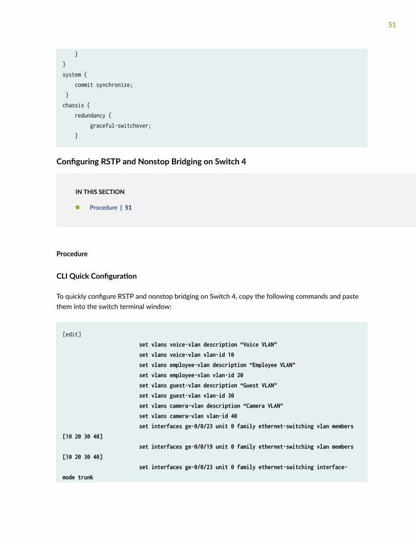
CLI Quick Configuration
To quickly configure RSTP and nonstop bridging on Switch 4, copy the following commands and pastethem into the switch terminal window:
[edit] set vlans voice-vlan description “Voice VLAN” set vlans voice-vlan vlan-id 10 set vlans employee-vlan description “Employee VLAN” set vlans employee-vlan vlan-id 20 set vlans guest-vlan description “Guest VLAN” set vlans guest-vlan vlan-id 30 set vlans camera-vlan description “Camera VLAN” set vlans camera-vlan vlan-id 40 set interfaces ge-0/0/23 unit 0 family ethernet-switching vlan members [10 20 30 40] set interfaces ge-0/0/19 unit 0 family ethernet-switching vlan members [10 20 30 40] set interfaces ge-0/0/23 unit 0 family ethernet-switching interface-mode trunk
51

set interfaces ge-0/0/19 unit 0 family ethernet-switching interface-mode trunk set protocols rstp bridge-priority 16k set protocols rstp interface ge-0/0/23 cost 1000 set protocols rstp interface ge-0/0/23 mode point-to-point set protocols rstp interface ge-0/0/19 cost 1000 set protocols rstp interface ge-0/0/19 mode point-to-point
If Switch 4 includes dual Routing Engines, configure NSB. To quickly configure nonstop bridging onSwitch 4, copy the following commands and paste them into the switch terminal window:
set chassis redundancy graceful-switchoverset system commit synchronizeset protocols layer2-control nonstop-bridging
Step-by-Step Procedure
To configure RSTP and nonstop bridging on Switch 4:
1. Configure the VLANs voice-vlan, employee-vlan, guest-vlan, and camera-vlan:
[edit vlans]user@switch4# set voice-vlan description “Voice VLAN”user@switch4# set voice-vlan vlan-id 10user@switch4# set employee-vlan description “Employee VLAN”user@switch4# set employee-vlan vlan-id 20user@switch4# set guest-vlan description “Guest VLAN”user@switch4# set guest-vlan vlan-id 30user@switch4# set camera-vlan description “Camera VLAN”user@switch4# set camera-vlan vlan-id 40
2. Configure the VLANs on the interfaces, including support for the Ethernet switching protocol:
[edit interfaces]user@switch4# set ge-0/0/23 unit 0 family ethernet-switching vlan members [10 20 30 40]
52

user@switch4# set ge-0/0/19 unit 0 family ethernet-switching vlan members [10 20 30 40]
3. Configure the port mode for the interfaces:
[edit interfaces]user@switch4# set ge-0/0/23 unit 0 family ethernet-switching interface-mode trunkuser@switch4# set ge-0/0/19 unit 0 family ethernet-switching interface-mode trunk
4. Configure RSTP on the switch:
[edit protocols]user@switch4# rstp bridge-priority 16kuser@switch4# rstp interface ge-0/0/23 cost 1000user@switch4# rstp interface ge-0/0/23 mode point-to-pointuser@switch4# rstp interface ge-0/0/19 cost 1000user@switch4# rstp interface ge-0/0/19 mode point-to-point
Step-by-Step Procedure
If Switch 4 includes dual Routing Engines, configure nonstop bridging. To configure NSB on Switch 4:
1. Enable graceful Routing Engine switchover (GRES):
[edit chassis redundancy] user@switch4# set graceful-switchover
2. Configure the switch to always synchronize configuration changes between the Routing Engines:
[edit system] user@switch4# set commit synchronize
If you try to commit a configuration in which nonstop bridging is configured but synchronization ofconfiguration changes is not configured, the configuration is not committed.
53

3. Enable nonstop bridging:
[edit protocols layer2-control]user@switch4# set nonstop-bridging
NOTE: This process enables NSB for all NSB-supported Layer 2 protocols on the switch,including RSTP.
Results
Check the results of the configuration:
user@switch4> show configuration interfaces { ge-0/0/23 { unit 0 { family ethernet-switching { interface-mode trunk; vlan { members [10 20 30 40]; } } } } ge-0/0/19 { unit 0 { family ethernet-switching { interface-mode trunk; vlan { members [10 20 30 40]; } } } }}protocols { layer2-control { nonstop-bridging; }
54

rstp { bridge-priority 16k; interface ge-0/0/23 { cost 1000; mode point-to-point; } interface ge-0/0/19 { cost 1000; mode point-to-point; } } }}vlans { voice-vlan { vlan-id 10; } employee-vlan { vlan-id 20; } guest-vlan { vlan-id 30; } camera-vlan { vlan-id 40; }}system { commit synchronize; } chassis { redundancy { graceful-switchover; }
Verification
IN THIS SECTION
Verifying RSTP Configuration on Switch 1 | 56
55

Verifying RSTP Configuration on Switch 2 | 57
Verifying RSTP Configuration on Switch 3 | 57
Verifying RSTP Configuration on Switch 4 | 58
To confirm that the configuration is working properly, perform these tasks on both Routing Engines:
Verifying RSTP Configuration on Switch 1
Purpose
Verify the RSTP configuration on Switch 1.
Action
Use the operational mode command:
user@switch1> show spanning-tree interface
Spanning tree interface parameters for instance 0
Interface Port ID Designated Designated Port State Role port ID bridge ID Costge-0/0/13 128:526 128:526 16384.0019e25040e0 1000 BLK ALT ge-0/0/9 128:522 128:522 32768.0019e2503d20 1000 BLK ALT ge-0/0/11 128:524 128:524 8192.0019e25051e0 1000 FWD ROOT
Meaning
The operational mode command show spanning-tree interface shows that ge-0/0/13 is in a forwardingstate. The other interfaces on Switch 1 are blocking.
56

Verifying RSTP Configuration on Switch 2
Purpose
Use this procedure to verify the RSTP configuration on both Switch 2 Routing Engines.
Action
Use the operational mode command:
user@switch2> show spanning-tree interface
Spanning tree interface parameters for instance 0
Interface Port ID Designated Designated Port State Role port ID bridge ID Costge-0/0/14 128:527 128:527 32768.0019e2503d20 1000 FWD DESG ge-0/0/18 128:529 128:529 8192.0019e25051e0 1000 FWD ROOT
Meaning
The operational mode command show spanning-tree interface shows that ge-0/0/18 is in a forwardingstate and is the root port.
Verifying RSTP Configuration on Switch 3
Purpose
Use this procedure to verify the RSTP configuration on both Switch 3 Routing Engines.
Action
Use the operational mode commands:
user@switch3> show spanning-tree interface
57
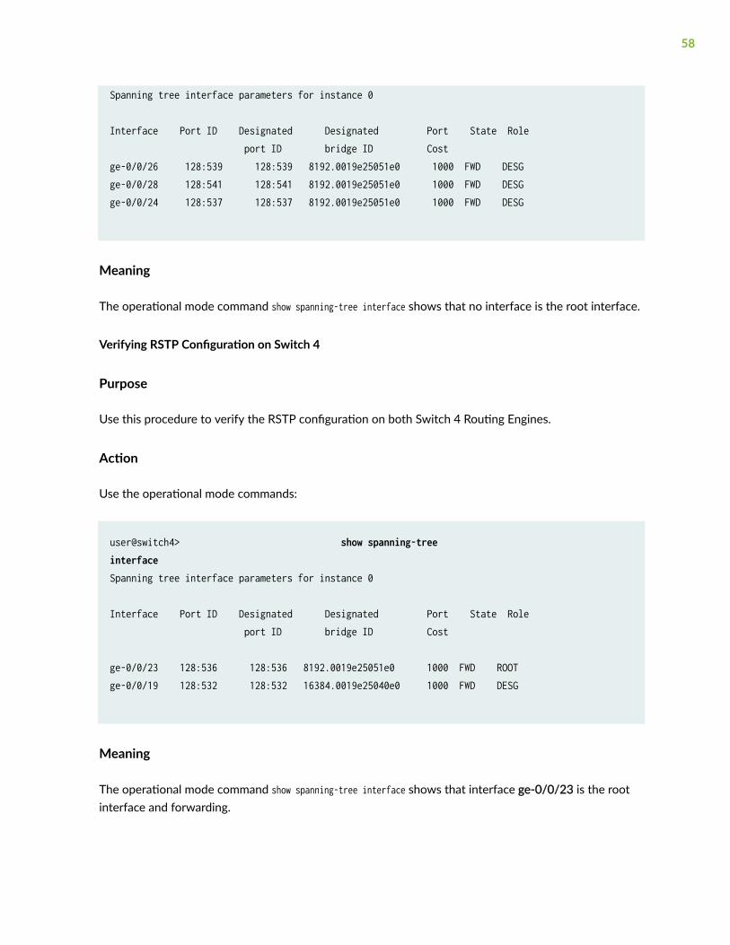
Spanning tree interface parameters for instance 0
Interface Port ID Designated Designated Port State Role port ID bridge ID Costge-0/0/26 128:539 128:539 8192.0019e25051e0 1000 FWD DESG ge-0/0/28 128:541 128:541 8192.0019e25051e0 1000 FWD DESG ge-0/0/24 128:537 128:537 8192.0019e25051e0 1000 FWD DESG
Meaning
The operational mode command show spanning-tree interface shows that no interface is the root interface.
Verifying RSTP Configuration on Switch 4
Purpose
Use this procedure to verify the RSTP configuration on both Switch 4 Routing Engines.
Action
Use the operational mode commands:
user@switch4> show spanning-tree interface Spanning tree interface parameters for instance 0
Interface Port ID Designated Designated Port State Role port ID bridge ID Cost
ge-0/0/23 128:536 128:536 8192.0019e25051e0 1000 FWD ROOT ge-0/0/19 128:532 128:532 16384.0019e25040e0 1000 FWD DESG
Meaning
The operational mode command show spanning-tree interface shows that interface ge-0/0/23 is the rootinterface and forwarding.
58
Example: Faster Convergence and Improved Network Stability with RSTPon EX Series Switches
IN THIS SECTION
Requirements | 59
Overview and Topology | 60
Configuring RSTP and Nonstop Bridging on Switch 1 | 63
Configuring RSTP and Nonstop Bridging on Switch 2 | 68
Configuring RSTP and Nonstop Bridging on Switch 3 | 73
Configuring RSTP and Nonstop Bridging on Switch 4 | 78
Verification | 82
EX Series switches use Rapid Spanning Tree Protocol (RSTP) by default to provide a loop-free topology.
When switches that support redundant Routing Engines use RSTP, it is important to keep RSTPsynchronized on both Routing Engines so that no loss of service occurs after a Routing Engineswitchover. Nonstop bridging protocol keeps Routing Engines synchronized.
This example describes how to configure RSTP and NSB on four EX Series switches:
Requirements
This example uses the following hardware and software components:
• Junos OS Release 11.3 or later for EX Series switches
• Four EX Series switches
Before you configure the switches for RSTP, be sure you have:
• Installed the four switches. See Connecting and Configuring an EX Series Switch (J-Web Procedure).
• Performed the initial software configuration on all switches. See Installing and Connecting anEX3200 Switch.
59

Overview and Topology
IN THIS SECTION
Topology | 63
RSTP works by identifying certain links as point to point links and blocking other possible paths. Whenone of the point-to-point links fails, a designated alternate link transitions to the forwarding state andtake over. Configuring nonstop bridging (NSB) on a switch with redundant Routing Engines keeps RSTPsynchronized on both Routing Engines. This way, RSTP remains active immediately after a switchoverbecause it is already synchronized to the backup Routing Engine. RSTP does not have to reconvergeafter a Routing Engine switchover when NSB is enabled because the neighbor devices do not detect anRSTP change on the switch. In this example, four EX Series switches are connected in the topology
60

displayed in Figure 2 on page 61 to create a loop-free topology with NSB applied to switches with dualRouting Engines.
Figure 2: Network Topology for RSTP
Table 4 on page 62 shows the components of the topology for this example.
NOTE: You can configure RSTP on logical or physical interfaces. This example shows RSTPconfigured on logical interfaces.
61
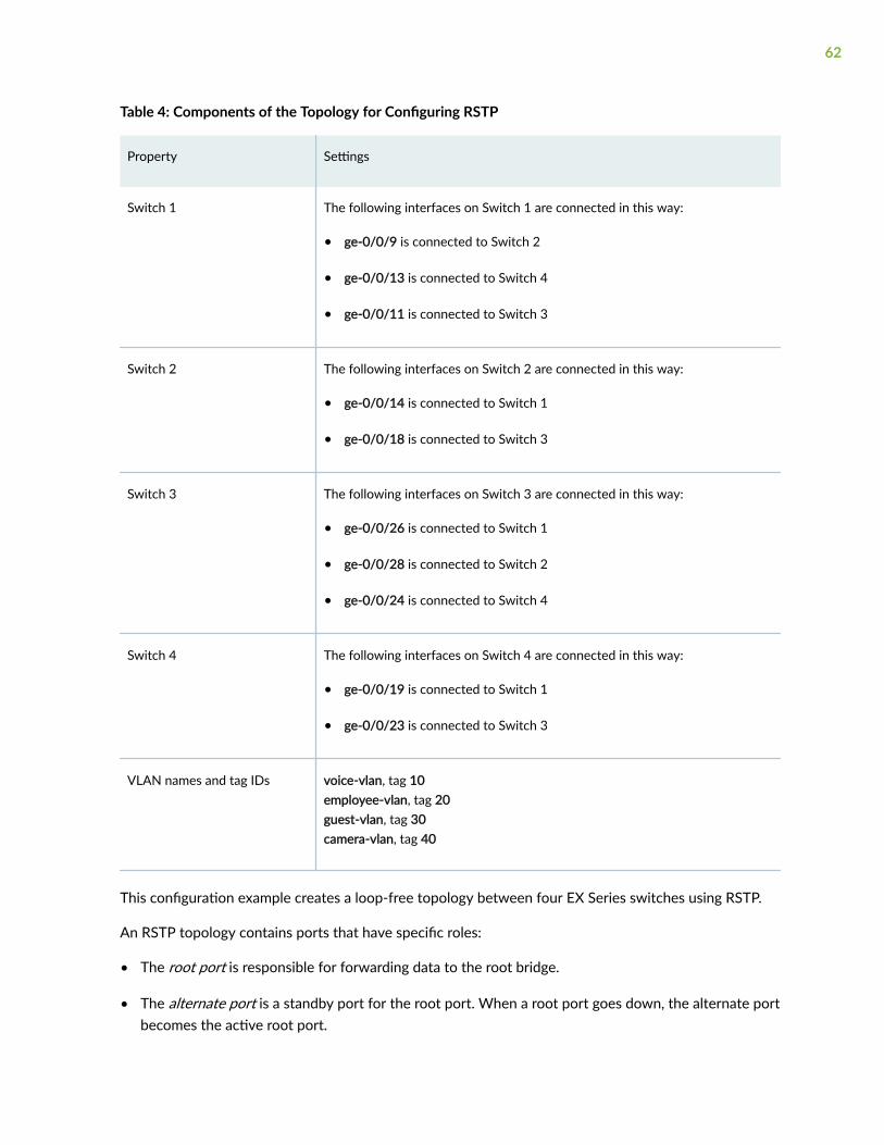
Table 4: Components of the Topology for Configuring RSTP
Property Settings
Switch 1 The following interfaces on Switch 1 are connected in this way:
• ge-0/0/9 is connected to Switch 2
• ge-0/0/13 is connected to Switch 4
• ge-0/0/11 is connected to Switch 3
Switch 2 The following interfaces on Switch 2 are connected in this way:
• ge-0/0/14 is connected to Switch 1
• ge-0/0/18 is connected to Switch 3
Switch 3 The following interfaces on Switch 3 are connected in this way:
• ge-0/0/26 is connected to Switch 1
• ge-0/0/28 is connected to Switch 2
• ge-0/0/24 is connected to Switch 4
Switch 4 The following interfaces on Switch 4 are connected in this way:
• ge-0/0/19 is connected to Switch 1
• ge-0/0/23 is connected to Switch 3
VLAN names and tag IDs voice-vlan, tag 10employee-vlan, tag 20guest-vlan, tag 30camera-vlan, tag 40
This configuration example creates a loop-free topology between four EX Series switches using RSTP.
An RSTP topology contains ports that have specific roles:
• The root port is responsible for forwarding data to the root bridge.
• The alternate port is a standby port for the root port. When a root port goes down, the alternate portbecomes the active root port.
62
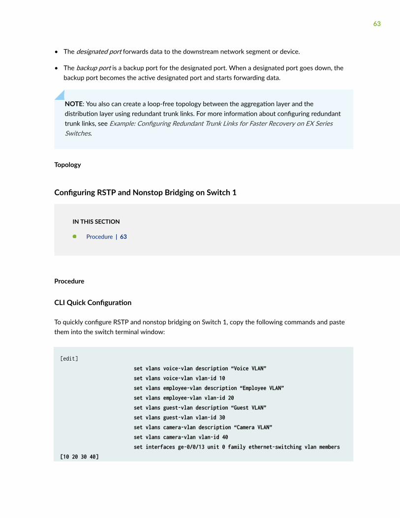
• The designated port forwards data to the downstream network segment or device.
• The backup port is a backup port for the designated port. When a designated port goes down, thebackup port becomes the active designated port and starts forwarding data.
NOTE: You also can create a loop-free topology between the aggregation layer and thedistribution layer using redundant trunk links. For more information about configuring redundanttrunk links, see Example: Configuring Redundant Trunk Links for Faster Recovery on EX SeriesSwitches.
Topology
Configuring RSTP and Nonstop Bridging on Switch 1
IN THIS SECTION
Procedure | 63
Procedure
CLI Quick Configuration
To quickly configure RSTP and nonstop bridging on Switch 1, copy the following commands and pastethem into the switch terminal window:
[edit] set vlans voice-vlan description “Voice VLAN” set vlans voice-vlan vlan-id 10 set vlans employee-vlan description “Employee VLAN” set vlans employee-vlan vlan-id 20 set vlans guest-vlan description “Guest VLAN” set vlans guest-vlan vlan-id 30 set vlans camera-vlan description “Camera VLAN” set vlans camera-vlan vlan-id 40 set interfaces ge-0/0/13 unit 0 family ethernet-switching vlan members [10 20 30 40]
63

set interfaces ge–0/0/9 unit 0 family ethernet-switching vlan members [10 20 30 40] set interfaces ge–0/0/11 unit 0 family ethernet-switching vlan members [10 20 30 40] set interfaces ge–0/0/13 unit 0 family ethernet-switching port-mode trunk set interfaces ge-0/0/9 unit 0 family ethernet-switching port-mode trunk set interfaces ge-0/0/11 unit 0 family ethernet-switching port-mode trunk set protocols rstp bridge-priority 16k set protocols rstp interface ge-0/0/13.0 cost 1000 set protocols rstp interface ge-0/0/13.0 mode point-to-point set protocols rstp interface ge-0/0/9.0 cost 1000 set protocols rstp interface ge-0/0/9.0 mode point-to-point set protocols rstp interface ge-0/0/11.0 cost 1000 set protocols rstp interface ge-0/0/11.0 mode point-to-point
If Switch 1 includes dual Routing Engines, configure NSB. To quickly configure nonstop bridging onSwitch 1, copy the following commands and paste them into the switch terminal window:
set chassis redundancy graceful-switchoverset system commit synchronizeset ethernet-switching-options nonstop-bridging
Step-by-Step Procedure
To configure RSTP and nonstop bridging on Switch 1:
1. Configure the VLANs voice-vlan, employee-vlan, guest-vlan, and camera-vlan:
[edit vlans]user@switch1# set voice-vlan description “Voice VLAN”user@switch1# set voice-vlan vlan-id 10user@switch1# set employee-vlan description “Employee VLAN”user@switch1# set employee-vlan vlan-id 20user@switch1# set guest-vlan description “Guest VLAN”user@switch1# set guest-vlan vlan-id 30
64

user@switch1# set camera-vlan description “Camera VLAN”user@switch1# set camera-vlan vlan-id 40
2. Configure the VLANs on the interfaces, including support for the Ethernet switching protocol:
[edit interfaces]user@switch1# set ge-0/0/13 unit 0 family ethernet-switching vlan members [10 20 30 40]user@switch1# set ge-0/0/9 unit 0 family ethernet-switching vlan members [10 20 30 40]user@switch1# set ge-0/0/11 unit 0 family ethernet-switching vlan members [10 20 30 40]
3. Configure the port mode for the interfaces:
[edit interfaces]user@switch1# set ge-0/0/13 unit 0 family ethernet-switching port-mode trunkuser@switch1# set ge-0/0/9 unit 0 family ethernet-switching port-mode trunkuser@switch1# set ge-0/0/11 unit 0 family ethernet-switching port-mode trunk
4. Configure RSTP on the switch:
[edit protocols]
user@switch1# rstp bridge-priority 16kuser@switch1# rstp interface ge-0/0/13.0 cost 1000user@switch1# rstp interface ge-0/0/13.0 mode point-to-pointuser@switch1# rstp interface ge-0/0/9.0 cost 1000user@switch1# rstp interface ge-0/0/9.0 mode point-to-pointuser@switch1# rstp interface ge-0/0/11.0 cost 1000user@switch1# rstp interface ge-0/0/11.0 mode point-to-point
Step-by-Step Procedure
If Switch 1 includes dual Routing Engines, configure nonstop bridging. To configure NSB on Switch 1:
65

1. Enable graceful Routing Engine switchover (GRES):
[edit chassis redundancy] user@switch1# set graceful-switchover
2. Configure the switch to always synchronize configuration changes between the Routing Engines:
[edit system] user@switch1# set commit synchronize
If you try to commit a configuration in which nonstop bridging is configured but synchronization ofconfiguration changes is not configured, the configuration is not committed.
3. Enable nonstop bridging:
[edit ethernet-switching-options]user@switch1# set nonstop-bridging
NOTE: This process enables NSB for all NSB-supported Layer 2 protocols on the switch,including RSTP.
Results
Check the results of the configuration:
user@switch1> show configuration interfaces { ge-0/0/13 { unit 0 { family ethernet-switching { port-mode trunk; vlan { members [10 20 30 40]; } } } }
66

ge-0/0/9 { unit 0 { family ethernet-switching { port-mode trunk; vlan { members [10 20 30 40]; } } } } ge-0/0/11 { unit 0 { family ethernet-switching { port-mode trunk; vlan { members [10 20 30 40]; } } } }}protocols { rstp { bridge-priority 16k; interface ge-0/0/13.0 { cost 1000; mode point-to-point; } interface ge-0/0/9.0 { cost 1000; mode point-to-point; } interface ge-0/0/11.0 { cost 1000; mode point-to-point; } } }}vlans { voice-vlan { vlan-id 10; }
67

employee-vlan { vlan-id 20; } guest-vlan { vlan-id 30; } camera-vlan { vlan-id 40; }}system { commit synchronize; } chassis { redundancy { graceful-switchover; }ethernet-switching-options { nonstop-bridging; }
Configuring RSTP and Nonstop Bridging on Switch 2
IN THIS SECTION
Procedure | 68
Procedure
CLI Quick Configuration
To quickly configure RSTP and nonstop bridging on Switch 2, copy the following commands and pastethem into the switch terminal window:
[edit] set vlans voice-vlan description “Voice VLAN” set vlans voice-vlan vlan-id 10 set vlans employee-vlan description “Employee VLAN”
68

set vlans employee-vlan vlan-id 20 set vlans guest-vlan description “Guest VLAN” set vlans guest-vlan vlan-id 30 set vlans camera-vlan description “Camera VLAN” set vlans camera-vlan vlan-id 40 set interfaces ge-0/0/14 unit 0 family ethernet-switching vlan members [10 20 30 40] set interfaces ge-0/0/18 unit 0 family ethernet-switching vlan members [10 20 30 40] set interfaces ge-0/0/14 unit 0 family ethernet-switching port-mode trunk set interfaces ge-0/0/18 unit 0 family ethernet-switching port-mode trunk set protocols rstp bridge-priority 32k set protocols rstp interface ge-0/0/14.0 cost 1000 set protocols rstp interface ge-0/0/14.0 mode point-to-point set protocols rstp interface ge-0/0/18.0 cost 1000 set protocols rstp interface ge-0/0/18.0 mode point-to-point
If Switch 2 includes dual Routing Engines, configure NSB. To quickly configure nonstop bridging onSwitch 2, copy the following commands and paste them into the switch terminal window:
set chassis redundancy graceful-switchoverset system commit synchronizeset ethernet-switching-options nonstop-bridging
Step-by-Step Procedure
To configure RSTP and nonstop bridging on Switch 2:
1. Configure the VLANs voice-vlan, employee-vlan, guest-vlan, and camera-vlan:
[edit vlans]user@switch2# set voice-vlan description “Voice VLAN”user@switch2# set voice-vlan vlan-id 10user@switch2# set employee-vlan description “Employee VLAN”user@switch2# set employee-vlan vlan-id 20user@switch2# set guest-vlan description “Guest VLAN”user@switch2# set guest-vlan vlan-id 30
69
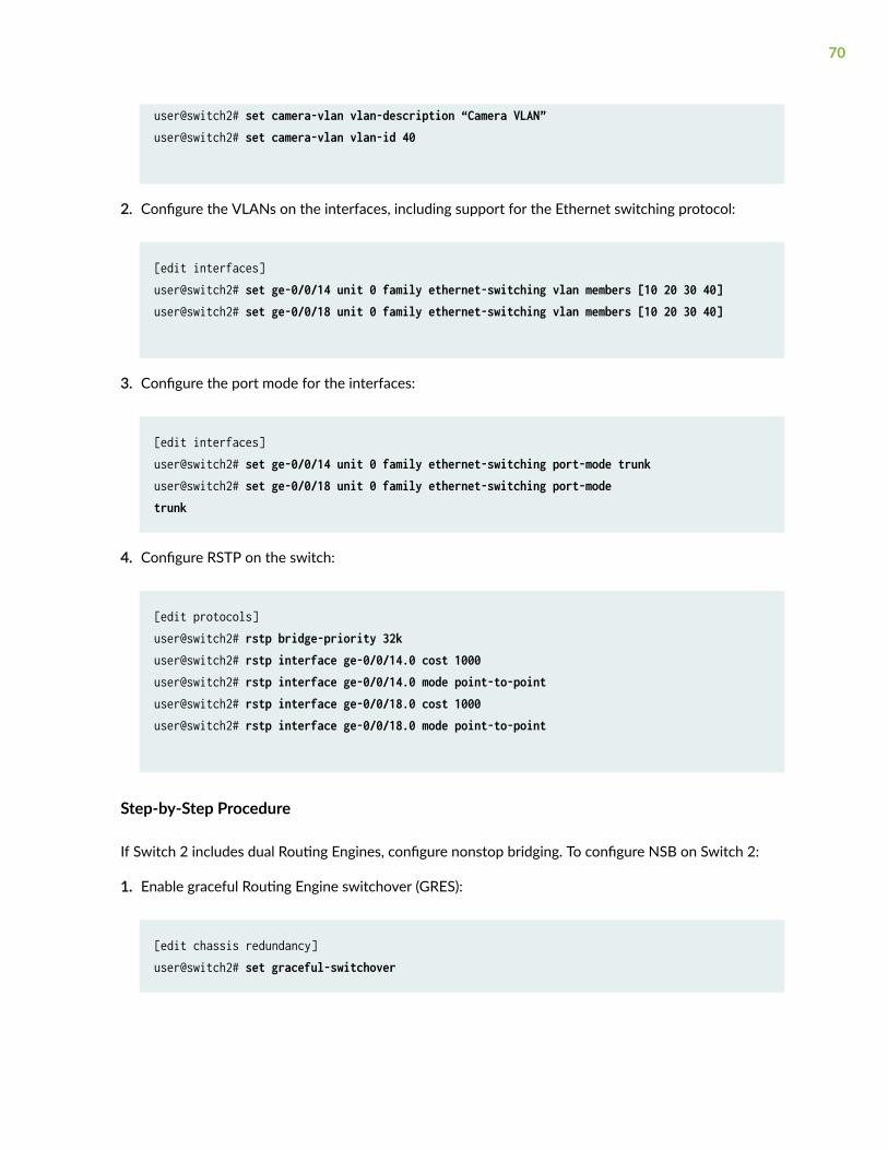
user@switch2# set camera-vlan vlan-description “Camera VLAN”user@switch2# set camera-vlan vlan-id 40
2. Configure the VLANs on the interfaces, including support for the Ethernet switching protocol:
[edit interfaces]user@switch2# set ge-0/0/14 unit 0 family ethernet-switching vlan members [10 20 30 40]user@switch2# set ge-0/0/18 unit 0 family ethernet-switching vlan members [10 20 30 40]
3. Configure the port mode for the interfaces:
[edit interfaces]user@switch2# set ge-0/0/14 unit 0 family ethernet-switching port-mode trunkuser@switch2# set ge-0/0/18 unit 0 family ethernet-switching port-mode trunk
4. Configure RSTP on the switch:
[edit protocols]user@switch2# rstp bridge-priority 32kuser@switch2# rstp interface ge-0/0/14.0 cost 1000user@switch2# rstp interface ge-0/0/14.0 mode point-to-pointuser@switch2# rstp interface ge-0/0/18.0 cost 1000user@switch2# rstp interface ge-0/0/18.0 mode point-to-point
Step-by-Step Procedure
If Switch 2 includes dual Routing Engines, configure nonstop bridging. To configure NSB on Switch 2:
1. Enable graceful Routing Engine switchover (GRES):
[edit chassis redundancy] user@switch2# set graceful-switchover
70

2. Configure the switch to always synchronize configuration changes between the Routing Engines:
[edit system] user@switch2# set commit synchronize
If you try to commit a configuration in which nonstop bridging is configured but synchronization ofconfiguration changes is not configured, the configuration is not committed.
3. Enable nonstop bridging:
[edit ethernet-switching-options]user@switch2# set nonstop-bridging
NOTE: This process enables NSB for all NSB-supported Layer 2 protocols on the switch,including RSTP.
Results
Check the results of the configuration:
user@switch2> show configuration interfaces { ge-0/0/14 { unit 0 { family ethernet-switching { port-mode trunk; vlan { members [10 20 30 40]; } } } } ge-0/0/18 { unit 0 { family ethernet-switching { port-mode trunk; vlan { members [10 20 30 40];
71

} } } }}protocols { rstp { bridge-priority 32k; interface ge-0/0/14.0 { cost 1000; mode point-to-point; } interface ge-0/0/18.0 { cost 1000; mode point-to-point; } } }}vlans { voice-vlan { vlan-id 10; } employee-vlan { vlan-id 20; } guest-vlan { vlan-id 30; } camera-vlan { vlan-id 40; }}system { commit synchronize; } chassis { redundancy { graceful-switchover; }ethernet-switching-options {
72
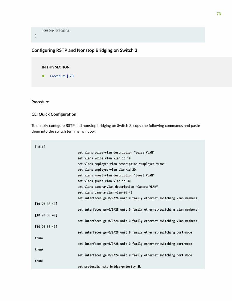
nonstop-bridging; }
Configuring RSTP and Nonstop Bridging on Switch 3
IN THIS SECTION
Procedure | 73
Procedure
CLI Quick Configuration
To quickly configure RSTP and nonstop bridging on Switch 3, copy the following commands and pastethem into the switch terminal window:
[edit] set vlans voice-vlan description “Voice VLAN” set vlans voice-vlan vlan-id 10 set vlans employee-vlan description “Employee VLAN” set vlans employee-vlan vlan-id 20 set vlans guest-vlan description “Guest VLAN” set vlans guest-vlan vlan-id 30 set vlans camera-vlan description “Camera VLAN” set vlans camera-vlan vlan-id 40 set interfaces ge-0/0/26 unit 0 family ethernet-switching vlan members [10 20 30 40] set interfaces ge-0/0/28 unit 0 family ethernet-switching vlan members [10 20 30 40] set interfaces ge-0/0/24 unit 0 family ethernet-switching vlan members [10 20 30 40] set interfaces ge-0/0/26 unit 0 family ethernet-switching port-mode trunk set interfaces ge-0/0/28 unit 0 family ethernet-switching port-mode trunk set interfaces ge-0/0/24 unit 0 family ethernet-switching port-mode trunk set protocols rstp bridge-priority 8k
73

set protocols rstp interface ge-0/0/26.0 cost 1000 set protocols rstp interface ge-0/0/26.0 mode point-to-point set protocols rstp interface ge-0/0/28.0 cost 1000 set protocols rstp interface ge-0/0/28.0 mode point-to-point set protocols rstp interface ge-0/0/24.0 cost 1000 set protocols rstp interface ge-0/0/24.0 mode point-to-point
If Switch 3 includes dual Routing Engines, configure NSB. To quickly configure nonstop bridging onSwitch 3, copy the following commands and paste them into the switch terminal window:
set chassis redundancy graceful-switchoverset system commit synchronizeset ethernet-switching-options nonstop-bridging
Step-by-Step Procedure
To configure RSTP and nonstop bridging on Switch 3:
1. Configure the VLANs voice-vlan, employee-vlan, guest-vlan, and camera-vlan:
[edit vlans]user@switch3# set voice-vlan description “Voice VLAN”user@switch3# set voice-vlan vlan-id 10user@switch3# set employee-vlan description “Employee VLAN”user@switch3# set employee-vlan vlan-id 20user@switch3# set guest-vlan description “Guest VLAN”user@switch3# set guest-vlan vlan-id 30user@switch3# set camera-vlan description “Camera VLAN”user@switch3# set camera-vlan vlan-id 40
2. Configure the VLANs on the interfaces, including support for the Ethernet switching protocol:
[edit interfaces]user@switch3# set ge-0/0/26 unit 0 family ethernet-switching vlan members [10 20 30 40]user@switch3# set ge-0/0/28 unit 0 family ethernet-switching vlan members [10 20 30 40]
74

user@switch3# set ge-0/0/24 unit 0 family ethernet-switching vlan members [10 20 30 40]
3. Configure the port mode for the interfaces:
[edit interfaces]user@switch3# set ge-0/0/26 unit 0 family ethernet-switching port-mode trunkuser@switch3# set ge-0/0/28 unit 0 family ethernet-switching port-mode trunkuser@switch3# set ge-0/0/24 unit 0 family ethernet-switching port-mode trunk
4. Configure RSTP on the switch:
[edit protocols]user@switch3# rstp bridge-priority 8kuser@switch3# rstp interface ge-0/0/26.0 cost 1000user@switch3# rstp interface ge-0/0/26.0 mode point-to-pointuser@switch3# rstp interface ge-0/0/28.0 cost 1000user@switch3# rstp interface ge-0/0/28.0 mode point-to-pointuser@switch3# rstp interface ge-0/0/24.0 cost 1000user@switch3# rstp interface ge-0/0/24.0 mode point-to-point
Step-by-Step Procedure
If Switch 3 includes dual Routing Engines, configure nonstop bridging. To configure NSB on Switch 3:
1. Enable graceful Routing Engine switchover (GRES):
[edit chassis redundancy] user@switch3# set graceful-switchover
2. Configure the switch to always synchronize configuration changes between the Routing Engines:
[edit system] user@switch3# set commit synchronize
If you try to commit a configuration in which nonstop bridging is configured but synchronization ofconfiguration changes is not configured, the configuration is not committed.
75
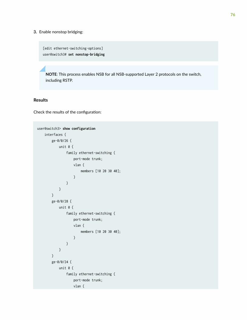
3. Enable nonstop bridging:
[edit ethernet-switching-options]user@switch3# set nonstop-bridging
NOTE: This process enables NSB for all NSB-supported Layer 2 protocols on the switch,including RSTP.
Results
Check the results of the configuration:
user@switch3> show configuration interfaces { ge-0/0/26 { unit 0 { family ethernet-switching { port-mode trunk; vlan { members [10 20 30 40]; } } } } ge-0/0/28 { unit 0 { family ethernet-switching { port-mode trunk; vlan { members [10 20 30 40]; } } } } ge-0/0/24 { unit 0 { family ethernet-switching { port-mode trunk; vlan {
76

members [10 20 30 40]; } } } } }}protocols { rstp { bridge-priority 8k; interface ge-0/0/26.0 { cost 1000; mode point-to-point; } interface ge-0/0/28.0 { cost 1000; mode point-to-point; } interface ge-0/0/24.0 { cost 1000; mode point-to-point; } } bridge-priority 8k; } } }}vlans { voice-vlan { vlan-id 10; } employee-vlan { vlan-id 20; } guest-vlan { vlan-id 30; } camera-vlan { vlan-id 40; }}system {
77

commit synchronize; } chassis { redundancy { graceful-switchover; }ethernet-switching-options { nonstop-bridging; }
Configuring RSTP and Nonstop Bridging on Switch 4
IN THIS SECTION
Procedure | 78
Procedure
CLI Quick Configuration
To quickly configure RSTP and nonstop bridging on Switch 4, copy the following commands and pastethem into the switch terminal window:
[edit] set vlans voice-vlan description “Voice VLAN” set vlans voice-vlan vlan–id 10 set vlans employee-vlan description “Employee VLAN” set vlans employee-vlan vlan-id 20 set vlans guest-vlan description “Guest VLAN” set vlans guest-vlan vlan-id 30 set vlans camera-vlan description “Camera VLAN” set vlans camera-vlan vlan-id 40 set interfaces ge-0/0/23 unit 0 family ethernet-switching vlan members [10 20 30 40] set interfaces ge-0/0/19 unit 0 family ethernet-switching vlan members [10 20 30 40] set interfaces ge-0/0/23 unit 0 family ethernet-switching port-mode trunk
78

set interfaces ge-0/0/19 unit 0 family ethernet-switching port-mode trunk set protocols rstp bridge-priority 16k set protocols rstp interface ge-0/0/23.0 cost 1000 set protocols rstp interface ge-0/0/23.0 mode point-to-point set protocols rstp interface ge-0/0/19.0 cost 1000 set protocols rstp interface ge-0/0/19.0 mode point-to-point
If Switch 4 includes dual Routing Engines, configure NSB. To quickly configure nonstop bridging onSwitch 4, copy the following commands and paste them into the switch terminal window:
set chassis redundancy graceful-switchoverset system commit synchronizeset ethernet-switching-options nonstop-bridging
Step-by-Step Procedure
To configure RSTP and nonstop bridging on Switch 4:
1. Configure the VLANs voice-vlan, employee-vlan, guest-vlan, and camera-vlan:
[edit vlans]user@switch4# set voice-vlan description “Voice VLAN”user@switch4# set voice-vlan vlan-id 10user@switch4# set employee-vlan description “Employee VLAN”user@switch4# set employee-vlan vlan-id 20user@switch4# set guest-vlan description “Guest VLAN”user@switch4# set guest-vlan vlan-id 30user@switch4# set camera-vlan description “Camera VLAN”user@switch4# set camera-vlan vlan-id 40
2. Configure the VLANs on the interfaces, including support for the Ethernet switching protocol:
[edit interfaces]user@switch4# set ge-0/0/23 unit 0 family ethernet-switching vlan members [10 20 30 40]
79

user@switch4# set ge-0/0/19 unit 0 family ethernet-switching vlan members [10 20 30 40]
3. Configure the port mode for the interfaces:
[edit interfaces]user@switch4# set ge-0/0/23 unit 0 family ethernet-switching port-mode trunkuser@switch4# set ge-0/0/19 unit 0 family ethernet-switching port-mode trunk
4. Configure RSTP on the switch:
[edit protocols]user@switch4# rstp bridge-priority 16kuser@switch4# rstp interface all cost 1000user@switch4# rstp interface ge-0/0/23.0 cost 1000user@switch4# rstp interface ge-0/0/23.0 mode point-to-pointuser@switch4# rstp interface ge-0/0/19.0 cost 1000user@switch4# rstp interface ge-0/0/19.0 mode point-to-point
Step-by-Step Procedure
If Switch 4 includes dual Routing Engines, configure nonstop bridging. To configure NSB on Switch 4:
1. Enable graceful Routing Engine switchover (GRES):
[edit chassis redundancy] user@switch4# set graceful-switchover
2. Configure the switch to always synchronize configuration changes between the Routing Engines:
[edit system] user@switch4# set commit synchronize
If you try to commit a configuration in which nonstop bridging is configured but synchronization ofconfiguration changes is not configured, the configuration is not committed.
80

3. Enable nonstop bridging:
[edit ethernet-switching-options]user@switch4# set nonstop-bridging
NOTE: This process enables NSB for all NSB-supported Layer 2 protocols on the switch,including RSTP.
Results
Check the results of the configuration:
user@switch4> show configuration interfaces { ge-0/0/23 { unit 0 { family ethernet-switching { port-mode trunk; vlan { members [10 20 30 40]; } } } } ge-0/0/19 { unit 0 { family ethernet-switching { port-mode trunk; vlan { members [10 20 30 40]; } } } }}protocols { rstp { bridge-priority 16k; interface ge-0/0/23.0 {
81

cost 1000; mode point-to-point; } interface ge-0/0/19.0 { cost 1000; mode point-to-point; } } }}vlans { voice-vlan { vlan-id 10; } employee-vlan { vlan-id 20; } guest-vlan { vlan-id 30; } camera-vlan { vlan-id 40; }}system { commit synchronize; } chassis { redundancy { graceful-switchover; }ethernet-switching-options { nonstop-bridging; }
Verification
IN THIS SECTION
Verifying RSTP Configuration on Switch 1 | 83
82
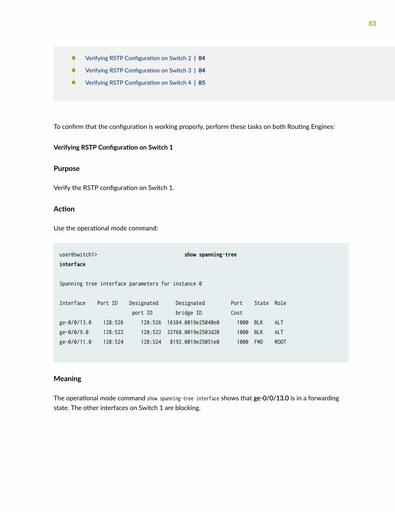
Verifying RSTP Configuration on Switch 2 | 84
Verifying RSTP Configuration on Switch 3 | 84
Verifying RSTP Configuration on Switch 4 | 85
To confirm that the configuration is working properly, perform these tasks on both Routing Engines:
Verifying RSTP Configuration on Switch 1
Purpose
Verify the RSTP configuration on Switch 1.
Action
Use the operational mode command:
user@switch1> show spanning-tree interface
Spanning tree interface parameters for instance 0
Interface Port ID Designated Designated Port State Role port ID bridge ID Costge-0/0/13.0 128:526 128:526 16384.0019e25040e0 1000 BLK ALT ge-0/0/9.0 128:522 128:522 32768.0019e2503d20 1000 BLK ALT ge-0/0/11.0 128:524 128:524 8192.0019e25051e0 1000 FWD ROOT
Meaning
The operational mode command show spanning-tree interface shows that ge-0/0/13.0 is in a forwardingstate. The other interfaces on Switch 1 are blocking.
83

Verifying RSTP Configuration on Switch 2
Purpose
Use this procedure to verify the RSTP configuration on both Switch 2 Routing Engines.
Action
Use the operational mode command:
user@switch2> show spanning-tree interface
Spanning tree interface parameters for instance 0
Interface Port ID Designated Designated Port State Role port ID bridge ID Costge-0/0/14.0 128:527 128:527 32768.0019e2503d20 1000 FWD DESG ge-0/0/18.0 128:529 128:529 8192.0019e25051e0 1000 FWD ROOT
Meaning
The operational mode command show spanning-tree interface shows that ge-0/0/18.0 is in a forwardingstate and is the root port.
Verifying RSTP Configuration on Switch 3
Purpose
Use this procedure to verify the RSTP configuration on both Switch 3 Routing Engines.
Action
Use the operational mode commands:
user@switch3> show spanning-tree interface
84

Spanning tree interface parameters for instance 0
Interface Port ID Designated Designated Port State Role port ID bridge ID Costge-0/0/26.0 128:539 128:539 8192.0019e25051e0 1000 FWD DESG ge-0/0/28.0 128:541 128:541 8192.0019e25051e0 1000 FWD DESG ge-0/0/24.0 128:537 128:537 8192.0019e25051e0 1000 FWD DESG
Meaning
The operational mode command show spanning-tree interface shows that no interface is the root interface.
Verifying RSTP Configuration on Switch 4
Purpose
Use this procedure to verify the RSTP configuration on both Switch 4 Routing Engines.
Action
Use the operational mode commands:
user@switch4> show spanning-tree interface Spanning tree interface parameters for instance 0
Interface Port ID Designated Designated Port State Role port ID bridge ID Cost
ge-0/0/23.0 128:536 128:536 8192.0019e25051e0 1000 FWD ROOT ge-0/0/19.0 128:532 128:532 16384.0019e25040e0 1000 FWD DESG
Meaning
The operational mode command show spanning-tree interface shows that interface ge-0/0/23.0 is the rootinterface and forwarding.
85
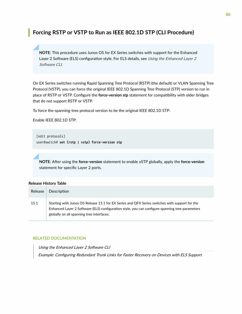
Forcing RSTP or VSTP to Run as IEEE 802.1D STP (CLI Procedure)
NOTE: This procedure uses Junos OS for EX Series switches with support for the EnhancedLayer 2 Software (ELS) configuration style. For ELS details, see Using the Enhanced Layer 2Software CLI.
On EX Series switches running Rapid Spanning Tree Protocol (RSTP) (the default) or VLAN Spanning TreeProtocol (VSTP), you can force the original IEEE 802.1D Spanning Tree Protocol (STP) version to run inplace of RSTP or VSTP. Configure the force-version stp statement for compatibility with older bridgesthat do not support RSTP or VSTP.
To force the spanning-tree protocol version to be the original IEEE 802.1D STP:
Enable IEEE 802.1D STP:
[edit protocols]user@switch# set (rstp | vstp) force-version stp
NOTE: After using the force-version statement to enable xSTP globally, apply the force-versionstatement for specific Layer 2 ports.
Release History Table
Release Description
15.1 Starting with Junos OS Release 15.1 for EX Series and QFX Series switches with support for theEnhanced Layer 2 Software (ELS) configuration style, you can configure spanning tree parametersglobally on all spanning tree interfaces.
RELATED DOCUMENTATION
Using the Enhanced Layer 2 Software CLI
Example: Configuring Redundant Trunk Links for Faster Recovery on Devices with ELS Support
86

Configuring MSTP Protocol
IN THIS SECTION
Understanding MSTP | 87
Configuring MSTP on Switches | 91
Configuring Multiple Spanning Tree Protocol | 95
Configuring MSTP Instances on a Physical Interface | 98
Example: Configuring Network Regions for VLANs with MSTP on Switches | 101
Disabling MSTP | 133
Multiple Spanning Tree Protocol (MSTP) maps multiple VLANs into a spanning tree instance, with eachinstance having a spanning tree topology independent of other spanning tree instances.
Understanding MSTP
IN THIS SECTION
Benefits of MSTP | 88
MSTP Maps Multiple VLANs | 88
Configuring MSTP Regions | 89
Selecting a Spanning Tree Protocol | 89
Ethernet networks are susceptible to broadcast storms if loops are introduced. However, an Ethernetnetwork needs to include loops because they provide redundant paths in case of a link failure. Spanning-tree protocols address both of these issues because they provide link redundancy while simultaneouslypreventing undesirable loops.
Spanning-tree protocols intelligently avoid loops in a network by creating a tree topology (spanning tree)of the entire bridged network with only one available path between the tree root and a leaf. All other
87

paths are forced into a standby state. The tree root is a switch within the network elected by the STA(spanning-tree algorithm) to use when computing the best path between bridges throughout thenetwork and the root bridge. Frames travel through the network to their destination– a leaf. A treebranch is a network segment, or link, between bridges. Switches that forward frames through an STPspanning-tree are called designated bridges.
Juniper Networks devices provide Layer 2 loop prevention through Spanning Tree Protocol (STP), RapidSpanning Tree Protocol (RSTP), Multiple Spanning Tree Protocol (MSTP), and VLAN Spanning TreeProtocol (VSTP). This topic explains MSTP.
NOTE: If you are using Junos OS for EX Series and QFX Series switches with support for theEnhanced Layer 2 Software (ELS) configuration style, you can force the original IEEE 802.1DSpanning Tree Protocol (STP) version to run in place of RSTP or VSTP by setting "force-version"on page 329.
This topic describes:
Benefits of MSTP
MSTP has the following benefits:
• Multiple Spanning Tree Protocol works with most VLANs.
• MSTP supports multiple instances on a single physical interface.
• On MX and ACX routers, you can configure RSTP, MSTP, and VSTP instance interfaces as edge ports.
MSTP Maps Multiple VLANs
MSTP is an extension of RSTP that maps multiple independent spanning-tree instances onto onephysical topology. Each spanning-tree instance (STI) includes one or more VLANs. Unlike in STP andRSTP configurations, a port might belong to multiple VLANs and be dynamically blocked in onespanning-tree instance, but forwarding in another. This behavior significantly improves network resourceutilization by load-balancing across the network and maintaining switch CPU loads at moderate levels.MSTP also leverages the fast reconvergence time of RSTP when a network, switch, or port failure occurswithin a spanning-tree instance.
MSTP creates a common and internal spanning tree (CIST) to interconnect and manage all MSTP regionsand even individual devices that run RSTP or STP, which are recognized as distinct spanning-tree regionsby MSTP. The CIST views each MSTP region as a virtual bridge, regardless of the actual number ofdevices participating in the MSTP region, and enables multiple spanning-tree instances (MSTIs) to link toother regions. The CIST is a single topology that connects all switches (STP, RSTP, and MSTP devices)through an active topology, ensuring connectivity between LANs and devices within a bridged network.
88

This functionality provided by MSTP enables you to better utilize network resources while remainingbackward-compatible with older network devices.
Configuring MSTP Regions
When enabling MSTP, you define one or more MSTP regions. An MSTP region defines a logical domainwhere multiple spanning-tree instances (MSTIs) can be administered independently of MSTIs in otherregions, setting the boundary for bridge protocol data units (BPDUs) sent by one MSTI. An MSTP regionis a group of switches that is defined by three parameters:
• Region name—User-defined alphanumeric name for the region.
• Revision level—User-defined value that identifies the region.
• Mapping table—Numerical digest of VLAN-to-instance mappings.
An MSTP region can support up to 64 MSTIs,, and each MSTI can support from 1 to 4094 VLANs. Whenyou define a region, MSTP automatically creates an internal spanning-tree instance (IST instance 0) thatprovides the root switch for the region and includes all currently configured VLANs that are notspecifically assigned to a user-defined MSTI. An MSTI includes all static VLANs that you specifically addto it. The switch places any dynamically created VLANs in the IST instance by default, unless youexplicitly map them to another MSTI. Once you assign a VLAN to a user-defined MSTI, the switchremoves the VLAN from the IST instance.
Selecting a Spanning Tree Protocol
The default factory configuration is RSTP, a faster version of STP. To determine which spanning-treeprotocol is best for your situation, see Table 5 on page 90 below.
89

Table 5: Selecting a Spanning Tree Protocol
Protocol Advantages Disadvantages
RSTP • Rapid Spanning Tree Protocol is the defaultswitch configuration and is recommendedfor most network configurations because itconverges more quickly than STP after afailure.
• Voice and video work better with RSTP thanthey do with STP.
• RSTP is backward compatible with STP;therefore, switches do not all have to runRSTP.
• RSTP does not work with 802.1D 1998bridges.
• RSTP is not recommended for multipleVLAN networks because it is not VLAN-aware—as a result, all VLANs within a LANshare the same spanning-tree. This limitsthe number of forwarding paths for datatraffic.
STP • Spanning Tree Protocol works with 802.1D1998 bridges.
• RSTP is backward compatible with STP;therefore, switches do not all have to runSTP.
• STP is slower than RSTP.
• STP is not recommended for multiple VLANnetworks because it is not VLAN-aware—asa result, all VLANs within a LAN share thesame spanning-tree. This limits the numberof forwarding paths for data traffic.
• If you are using Junos OS for EX Seriesswitches with support for the EnhancedLayer 2 Software (ELS) configuration style,you can force the original IEEE 802.1DSpanning Tree Protocol (STP) version to runin place of RSTP or VSTP by setting "force-version" on page 329. However, the CLIdoes not include [edit protocols stp].
MSTP • Multiple Spanning Tree Protocol works withmost VLANs.
• RSTP and STP are recognized as distinctspanning-tree regions by MSTP.
• Some protocols require compatibility that isnot provided by MSTP. In this case, useVSTP.
• MSTP uses more CPU than RSTP and doesnot converge as fast as RSTP.
90

Table 5: Selecting a Spanning Tree Protocol (Continued)
Protocol Advantages Disadvantages
VSTP • VLAN Spanning Tree Protocol works withVLANs that require device compatibility.
• VSTP and RSTP are the only spanning-treeprotocols that can be configuredconcurrently on a switch.
• With VSTP there can be only STP instanceper VLAN, whereas MSTP lets you combinemultiple VLANs in one instance.
• VSTP supports a limited number of portscompared to RSTP.
• VSTP uses more CPU than RSTP and doesnot converge as fast as RSTP.
• Having a large number of VSTP and RSTPinstances can cause continuous changes inthe topology. Ensure to check the scalelimits before configuring large number ofVSTP instances.
SEE ALSO
Understanding RSTP | 27
Understanding VSTP
Configuring MSTP on Switches
You can configure the Multiple Spanning Tree Protocol (MSTP) under [edit protocols].
To configure the Multiple Spanning Tree Protocol:
1. Enable MSTP as the version of spanning-tree protocol to be configured:
[edit]user@switch@ edit ... protocols mstp
2. Configure the interfaces that participate in the MSTP instance for all interfaces at one time, or forconfigured interface ranges, or for specific interfaces individually:
91

• Enable MSTP on all the interfaces at one time, for switches that support this option (mostswitches):
[edit ... protocols mstp]user@switch# set interface all
NOTE: You cannot disable MSTP on all the interfaces with one command. See theconfiguration steps for configuring MSTP on specific interfaces later in this topic for howto disable MSTP on interfaces individually.
For QFX5100 switches, which do not support the interface all option, you must configureinterface ranges for the applicable interfaces on which you want to enable MSTP, and then issuethe set protocols mstp interface name command for each name that you have configured as aninterface range (described next).
• Enable MSTP on a range of interfaces, for switches such as QFX5100 switches that do notsupport the interface all option:
a. Configure interface ranges using the interface-range statement at the [edit interfaces] hierarchylevel for the applicable interfaces on which you want to enable MSTP:
[edit interfaces]user@switch# set interface-range interface-range-name member-range interface-name1 to interface-name2
b. Enable MSTP for each configured interface range interface-range-name at the [edit ...protocols mstp] hierarchy level:
[edit ... protocols mstp]user@switch# set interface interface-range-name
• Configure a specific interface individually to enable MSTP and various MSTP options on thatinterface, or to disable MSTP on that interface:
a. Enable MSTP on the specified interface:
[edit ... protocols mstp]user@switch# edit interface interface-name
92

b. Configure the interface priority:
[edit ... protocols mstp interface interface-name]user@switch# set priority interface-priority
c. (Optional) By default, the interface link cost is determined by the link speed. You can configurethe interface link cost to control which bridge is the designated bridge and which port is thedesignated port:
[edit ... protocols mstp interface interface-name]user@switch# set cost interface-link-cost
d. Configure the interface link mode to identify point-to-point links:
[edit ... protocols mstp interface interface-name]user@switch# set mode (p2p | shared)
Specify p2p if the link is point to point. Specify shared if the link is a shared media.
e. (Optional) Configure the interface as an edge port:
[edit ... protocols mstp interface interface-name]user@switch# set edge
Edge ports do not expect to receive bridge protocol data unit (BPDU) packets. If a BPDUpacket is received for an edge port, the port becomes a nonedge port
f. (Optional) Disable MSTP on a specific interface:
[edit protocols mstp interface interface-name]user@switch# set disable
You can also enable BPDU root protection for all spanning-tree protocol instances on the interface.BPDU root protect ensures the port is the spanning-tree designated port. If the port receivessuperior BPDU packets, root protect moves this port to a root-prevented spanning-tree state. Forconfiguration details, see "Checking the Status of Spanning-Tree Instance Interfaces" on page 286.
93

3. Configure the bridge priority
[edit ... protocols mstp]user@switch# set bridge-priority bridge-priority
For more information, see "Understanding Bridge Priority for Election of Root Bridge and DesignatedBridge" on page 261.
4. Configure hello BPDU timers.
a. Configure the maximum expected arrival time of hello BPDUs:
[edit ... protocols mstp]user@switch# set max-age seconds
b. Configure the time interval at which the root bridge transmits configuration BPDUs:
[edit ... protocols mstp]user@switch# set hello-time seconds
5. (Optional) By default, the bridge port remains in the listening and learning states for 15 secondsbefore transitioning to the forwarding state. You can specify a delay from 4 through 20 secondsinstead:
[edit ... protocols mstp]user@switch# set forward-delay seconds
6. Configure MSTP-specific options.
a. Configure the MSTP region configuration name:
[edit ... protocols mstp]user@switch# set configuration-name configuration-name
b. Configure the MSTP revision level:
[edit ... protocols mstp]user@switch# set revision-level revision-level
94

c. Configure the maximum number of hops a BPDU can be forwarded in the MSTP region:
[edit ... protocols mstp]user@switch# set max-hops hops
SEE ALSO
Configuring MSTP Instances on a Physical Interface | 98
Configuring Multiple Spanning Tree Protocol
You can configure the Multiple Spanning Tree Protocol (MSTP) under the following hierarchy levels:
• [edit logical-systems logical-system-name "protocols" on page 372]
• [edit logical-systems logical-system-name routing-instances routing-instance-name "protocols" onpage 372]
• [edit "protocols" on page 372]
• [edit routing-instances routing-instance-name "protocols" on page 372]
The routing instance type can be either virtual-switch or layer2-control.
To configure the Multiple Spanning Tree Protocol:
1. Enable MSTP as the version of spanning-tree protocol to be configured:
[edit]user@host@ edit ... protocols (STP Type) mstp
2. (Optional) Enable provider bridge participation in the MSTP instance:
[edit ... protocols mstp]user@host# set bpdu-destination-mac-address provider-bridge-group
3. Configure the interfaces that participate in the MSTP instance.
95
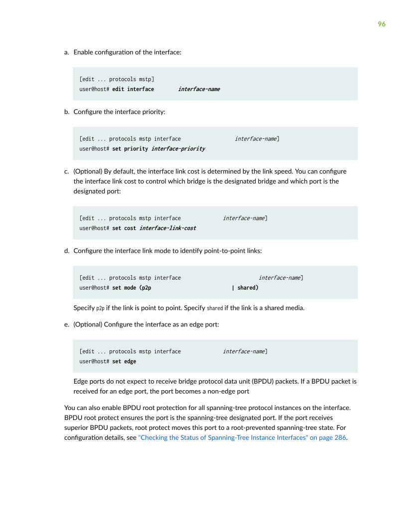
a. Enable configuration of the interface:
[edit ... protocols mstp]user@host# edit interface interface-name
b. Configure the interface priority:
[edit ... protocols mstp interface interface-name]user@host# set priority interface-priority
c. (Optional) By default, the interface link cost is determined by the link speed. You can configurethe interface link cost to control which bridge is the designated bridge and which port is thedesignated port:
[edit ... protocols mstp interface interface-name]user@host# set cost interface-link-cost
d. Configure the interface link mode to identify point-to-point links:
[edit ... protocols mstp interface interface-name]user@host# set mode (p2p | shared)
Specify p2p if the link is point to point. Specify shared if the link is a shared media.
e. (Optional) Configure the interface as an edge port:
[edit ... protocols mstp interface interface-name]user@host# set edge
Edge ports do not expect to receive bridge protocol data unit (BPDU) packets. If a BPDU packet isreceived for an edge port, the port becomes a non-edge port
You can also enable BPDU root protection for all spanning-tree protocol instances on the interface.BPDU root protect ensures the port is the spanning-tree designated port. If the port receivessuperior BPDU packets, root protect moves this port to a root-prevented spanning-tree state. Forconfiguration details, see "Checking the Status of Spanning-Tree Instance Interfaces" on page 286.
96

4. Configure the bridge priority:
[edit ... protocols mstp]user@host# set bridge-priority bridge-priority
For more information, see "Understanding Bridge Priority for Election of Root Bridge and DesignatedBridge" on page 261.
5. Configure hello BPDU timers.
a. Configure the maximum expected arrival time of hello BPDUs:
[edit ... protocols mstp]user@host# set max-age seconds
b. Configure the time interval at which the root bridge transmits configuration BPDUs:
[edit ... protocols mstp]user@host# set hello-time seconds
6. (Optional) By default, the bridge port remains in the listening and learning states for 15 secondsbefore transitioning to the forwarding state. You can specify a delay from 4 through 20 secondsinstead:
[edit ... protocols mstp]user@host# set forward-delay seconds
7. Configure MSTP-specific options.
a. Configure the MSTP region configuration name:
[edit ... protocols mstp]user@host# set configuration-name configuration-name
b. Configure the MSTP revision level:
[edit ... protocols mstp]user@host# set revision-level revision-level
97

c. Configure the maximum number of hops a BPDU can be forwarded in the MSTP region:
[edit ... protocols mstp]user@host# set max-hops hops
8. Verify the MSTP configuration:
[edit]... { # Optional logical system and/or routing instance protocols (STP Type) { mstp { bpdu-destination-mac-address provider-bridge-group; # Optional interface interface-name { priority interface-priority; cost interface-link-cost; # Optional. mode (p2p | shared); edge; # Optional. } bridge-priority bridge-priority; max-age seconds; hello-time seconds; forward-delay seconds; # Optional. configuration-name configuration-name; # MST region configuration name. revision-level revision-level; # MST revision number. max-hops hops; # MST maximum hops. } } }
Configuring MSTP Instances on a Physical Interface
You can configure a Multiple Spanning Tree Instance (MSTI) under the following hierarchy levels:
• [edit logical-systems logical-system-name protocols mstp]
• [edit logical-systems logical-system-name routing-instances routing-instance-name protocols mstp]
• [edit protocols mstp]
• [edit routing-instances routing-instance-name protocols mstp]
98

The routing instance type can be either virtual-switch or layer2-control.
Before you begin, configure Multiple Spanning-Tree Protocol. For configuration details, see "ConfiguringMultiple Spanning Tree Protocol" on page 95.
1. Enable configuration of an MST instance:
[edit]user@host# edit ... protocols mstp msti msti-id
The msti-id value must be from 1 through 64.
2. Configure the interfaces that participate in the MST instance.
a. Enable configuration of the interface:
[edit ... protocols mstp msti msti-id]user@host# edit interface interface-name
b. Configure the interface priority:
[edit ... protocols mstp msti msti-id interface interface-name]user@host# set priority interface-priority
c. (Optional) By default, the interface link cost is determined by the link speed. You can configurethe interface link cost to control which bridge is the designated bridge and which port is thedesignated port:
[edit ... protocols mstp msti msti-id interface interface-name]user@host# set cost interface-link-cost
d. (Optional) Configure the interface as an edge port:
[edit ... protocols mstp msti msti-id interface interface-name]user@host# set edge
Edge ports do not expect to receive bridge protocol data unit (BPDU) packets. If a BPDU packet isreceived for an edge port, the port becomes a non-edge port
99

3. Configure the bridge priority:
[edit ... protocols mstp msti msti-id]user@host# set bridge-priority bridge-priority
For more information, see "Understanding Bridge Priority for Election of Root Bridge and DesignatedBridge" on page 261.
4. (Optional) An MSTI can map to a range of VLANs just as a logical port can map to a range of VLANs.The MSTP VLAN specifies the VLAN or VLAN range to which this MSTI is mapped. The vlan-id isconfigured under the logical interface. Configure the VLAN or VLAN range of the MSTI instance:
[edit]user@host# set vlan (vlan-id | vlan-id-range)
5. Verify the MST interface configuration.
[edit]protocols { mstp { ...basic-mstp-configuration... msti msti-id { # Instance identifier 1 – 64. bridge-priority priority; vlan vlan-id; # Optional interface interface-name { cost cost; edge; priority interface-priority; } } }}
100
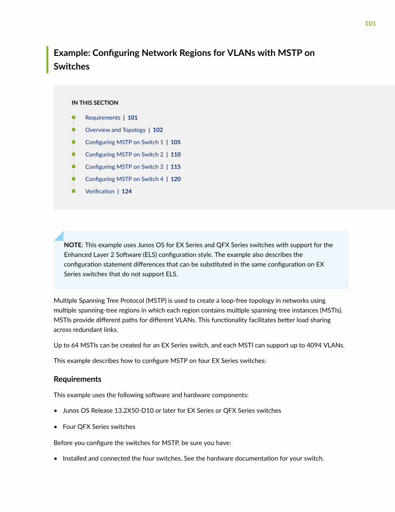
Example: Configuring Network Regions for VLANs with MSTP onSwitches
IN THIS SECTION
Requirements | 101
Overview and Topology | 102
Configuring MSTP on Switch 1 | 105
Configuring MSTP on Switch 2 | 110
Configuring MSTP on Switch 3 | 115
Configuring MSTP on Switch 4 | 120
Verification | 124
NOTE: This example uses Junos OS for EX Series and QFX Series switches with support for theEnhanced Layer 2 Software (ELS) configuration style. The example also describes theconfiguration statement differences that can be substituted in the same configuration on EXSeries switches that do not support ELS.
Multiple Spanning Tree Protocol (MSTP) is used to create a loop-free topology in networks usingmultiple spanning-tree regions in which each region contains multiple spanning-tree instances (MSTIs).MSTIs provide different paths for different VLANs. This functionality facilitates better load sharingacross redundant links.
Up to 64 MSTIs can be created for an EX Series switch, and each MSTI can support up to 4094 VLANs.
This example describes how to configure MSTP on four EX Series switches:
Requirements
This example uses the following software and hardware components:
• Junos OS Release 13.2X50-D10 or later for EX Series or QFX Series switches
• Four QFX Series switches
Before you configure the switches for MSTP, be sure you have:
• Installed and connected the four switches. See the hardware documentation for your switch.
101

• Performed the initial software configuration on all switches. See Connecting and Configuring an EXSeries Switch (CLI Procedure) or Connecting and Configuring an EX Series Switch (J-Web Procedure).
Overview and Topology
IN THIS SECTION
Topology | 103
When the number of VLANs grows in a network, MSTP provides an efficient way of creating a loop-freetopology by using MSTIs. Each MSTI in the spanning-tree domain maintains its own tree. Each tree canbe mapped to different links, utilizing bandwidth that would be unavailable to a single tree. MSTIsreduce the demand on system resources.
102

Topology
Figure 3: Network Topology for MSTP
The interfaces shown in Figure 3 on page 103 will be configured for MSTP.
Table 6: Components of the Topology for Configuring MSTP on EX Series Switches
Property Settings
Switch 1 The following interfaces on Switch 1 are connected in this way:
• xe-0/0/12:0 is connected to Switch 2
• xe-0/0/9:0 is connected to Switch 4
• xe-0/0/11:0 is connected to Switch 3
103

Table 6: Components of the Topology for Configuring MSTP on EX Series Switches (Continued)
Property Settings
Switch 2 The following interfaces on Switch 2 are connected in this way:
• xe-0/0/9:0 is connected to Switch 1
• et-0/0/3 is connected to Switch 3
Switch 3 The following interfaces on Switch 3 are connected in this way:
• xe-0/0/11:0 is connected to Switch 1
• et-0/0/6 is connected to Switch 2
• xe-0/0/21:0 is connected to Switch 4
Switch 4 The following interfaces on Switch 4 are connected in this way:
• xe-0/0/21:0 is connected to Switch 1
• xe-0/0/12:0 is connected to Switch 3
VLAN names and tag IDs voice-vlan, tag 10employee-vlan, tag 20guest-vlan, tag 30camera-vlan, tag 40
MSTIs 12
MSTI region region1
The topology in Figure 3 on page 103 shows a common and internal spanning tree (CIST). The CIST is asingle spanning tree connecting all devices in the network. The switch with the lowest bridge priority iselected as the root bridge of the CIST. You can control the election of the root bridge by configuring thebridge priority. Switch 3 is the root bridge of the CIST.
The ports in an MSTP topology have specific roles:
• The root port is responsible for forwarding data to the root bridge.
104

• The alternate port is a standby port for the root port. When a root port goes down, the alternate portbecomes the active root port.
• The designated port forwards data to the downstream network segment or device.
• The backup port becomes the active designated port and starts forwarding data when the designatedport goes down.
In this example, one MSTP region contains Switch 1, Switch 2, Switch 3, and Switch 4. Within the region,four VLANs are created:
• voice-vlan supports voice traffic and has the VLAN tag identifier of 10.
• employee-vlan supports data traffic and has the VLAN tag identifier of 20.
• guest-vlan supports guest VLAN traffic (for supplicants that fail authentication) and has the VLAN tagidentifier of 30.
• camera-vlan supports video traffic and has the VLAN tag identifier of 40.
The VLANs are associated with specific interfaces on each of the four switches. Two MSTIs, 1 and 2, arethen associated with the VLAN tag identifiers, and some MSTP parameters, such as cost, are configuredon each switch.
Configuring MSTP on Switch 1
IN THIS SECTION
Procedure | 105
Procedure
CLI Quick Configuration
To quickly configure interfaces and MSTP on Switch 1, for ELS switches, copy the following commandsand paste them into the switch terminal window:
[edit]set vlans voice-vlan description “Voice VLAN”set vlans voice-vlan vlan-id 10set vlans employee-vlan description “Employee VLAN”set vlans employee-vlan vlan-id 20
105

set vlans guest-vlan description “Guest VLAN”set vlans guest-vlan vlan-id 30set vlans camera-vlan description “Camera VLAN”set vlans camera-vlan vlan-id 40set interfaces xe-0/0/9:0 unit 0 family ethernet-switching vlan members [10 20 30 40]set interfaces xe-0/0/12:0 unit 0 family ethernet-switching vlan members [10 20 30 40]set interfaces xe-0/0/11:0 unit 0 family ethernet-switching vlan members [10 20 30 40] set interfaces xe-0/0/9:0 unit 0 family ethernet-switching interface-mode trunkset interfaces xe-0/0/12:0 unit 0 family ethernet-switching interface-mode trunkset interfaces xe-0/0/11:0 unit 0 family ethernet-switching interface-mode trunkset protocols mstp configuration-name region1set protocols mstp bridge-priority 16kset protocols mstp interface xe-0/0/9:0 cost 1000set protocols mstp interface xe-0/0/9:0 mode point-to-pointset protocols mstp interface xe-0/0/12:0 cost 1000set protocols mstp interface xe-0/0/12:0 mode point-to-pointset protocols mstp interface xe-0/0/11:0 cost 1000set protocols mstp interface xe-0/0/11:0 mode point-to-pointset protocols mstp msti 1 bridge-priority 16kset protocols mstp msti 1 vlan [10 20]set protocols mstp msti 1 interface xe-0/0/11:0 cost 1000set protocols mstp msti 2 bridge-priority 8kset protocols mstp msti 2 vlan [30 40]
NOTE: For non-ELS switches, instead of the following command used above for ELS switchesthat sets an interface into trunk mode using the interface-mode statement:
set interfaces interface-name unit 0 family ethernet-switching interface-mode trunk
substitute the following command for those lines in the configuration, which uses the non-ELSport-mode statement to set an interface into trunk mode:
set interfaces interface-name unit 0 family ethernet-switching port-mode trunk
Step-by-Step Procedure
To configure interfaces and MSTP on Switch 1:
106
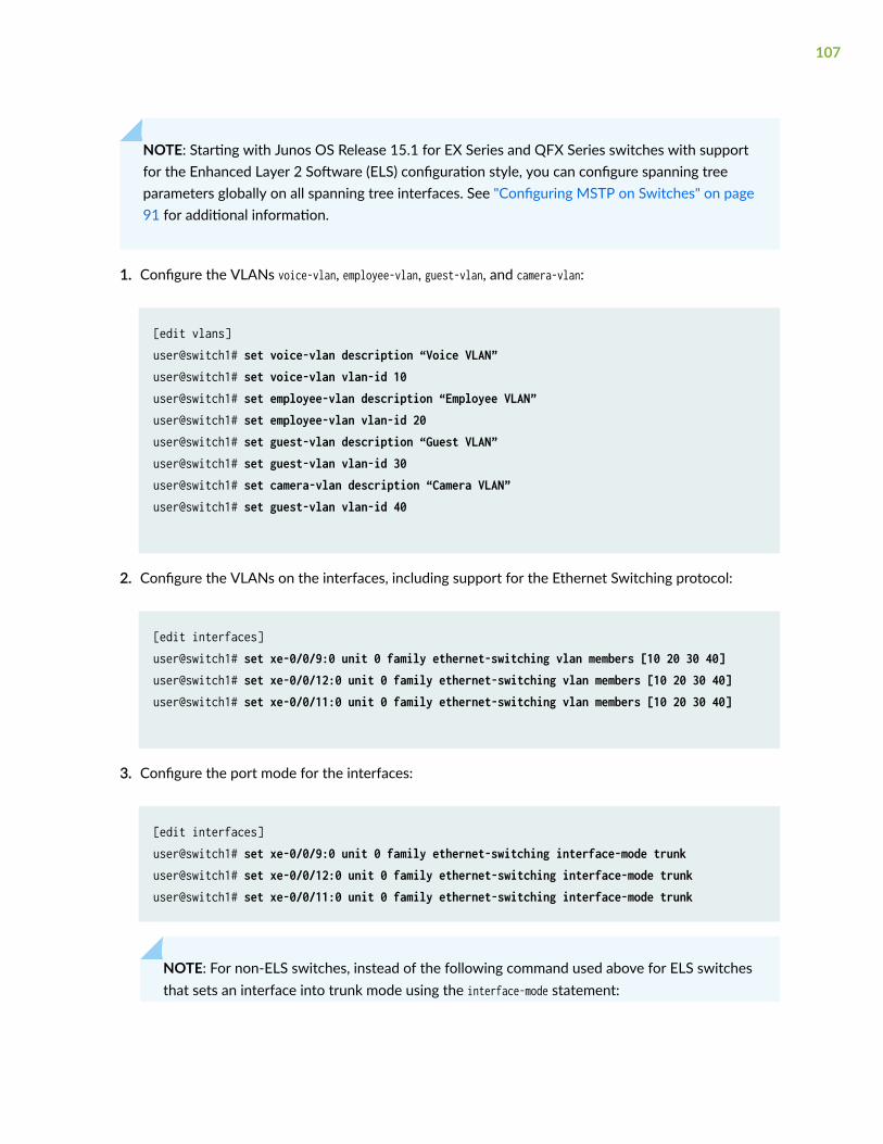
NOTE: Starting with Junos OS Release 15.1 for EX Series and QFX Series switches with supportfor the Enhanced Layer 2 Software (ELS) configuration style, you can configure spanning treeparameters globally on all spanning tree interfaces. See "Configuring MSTP on Switches" on page91 for additional information.
1. Configure the VLANs voice-vlan, employee-vlan, guest-vlan, and camera-vlan:
[edit vlans]user@switch1# set voice-vlan description “Voice VLAN”user@switch1# set voice-vlan vlan-id 10user@switch1# set employee-vlan description “Employee VLAN”user@switch1# set employee-vlan vlan-id 20user@switch1# set guest-vlan description “Guest VLAN”user@switch1# set guest-vlan vlan-id 30user@switch1# set camera-vlan description “Camera VLAN”user@switch1# set guest-vlan vlan-id 40
2. Configure the VLANs on the interfaces, including support for the Ethernet Switching protocol:
[edit interfaces]user@switch1# set xe-0/0/9:0 unit 0 family ethernet-switching vlan members [10 20 30 40]user@switch1# set xe-0/0/12:0 unit 0 family ethernet-switching vlan members [10 20 30 40]user@switch1# set xe-0/0/11:0 unit 0 family ethernet-switching vlan members [10 20 30 40]
3. Configure the port mode for the interfaces:
[edit interfaces]user@switch1# set xe-0/0/9:0 unit 0 family ethernet-switching interface-mode trunkuser@switch1# set xe-0/0/12:0 unit 0 family ethernet-switching interface-mode trunkuser@switch1# set xe-0/0/11:0 unit 0 family ethernet-switching interface-mode trunk
NOTE: For non-ELS switches, instead of the following command used above for ELS switchesthat sets an interface into trunk mode using the interface-mode statement:
107

set interfaces interface-name unit 0 family ethernet-switching interface-mode trunk
substitute the following command for those lines in the configuration, which uses the non-ELS port-mode statement to set an interface into trunk mode:
set interfaces interface-name unit 0 family ethernet-switching port-mode trunk
4. Configure MSTP on the switch, including the two MSTIs:
[edit protocols]user@switch1# mstp configuration-name region1user@switch1# mstp bridge-priority 16kuser@switch1# mstp interface xe-0/0/9:0 cost 1000user@switch1# mstp interface xe-0/0/9:0 mode point-to-pointuser@switch1# mstp interface xe-0/0/12:0 cost 1000user@switch1# mstp interface xe-0/0/12:0 mode point-to-pointuser@switch1# mstp interface xe-0/0/11:0 cost 1000user@switch1# mstp interface xe-0/0/11:0 mode point-to-pointuser@switch1# mstp msti 1 bridge-priority 16kuser@switch1# mstp msti 1 vlan [10 20]user@switch1# mstp msti 1 interface xe-0/0/11:0 cost 1000user@switch1# mstp msti 2 bridge-priority 8kuser@switch1# mstp msti 2 vlan [30 40]
Results
Check the results of the configuration:
user@switch1> show configuration interfaces { xe-0/0/9:0 { unit 0 { family ethernet-switching { interface-mode trunk; vlan { members 10; members 20;
108
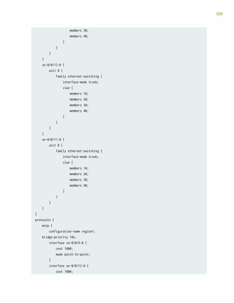
members 30; members 40; } } } } xe-0/0/12:0 { unit 0 { family ethernet-switching { interface-mode trunk; vlan { members 10; members 20; members 30; members 40; } } } } xe-0/0/11:0 { unit 0 { family ethernet-switching { interface-mode trunk; vlan { members 10; members 20; members 30; members 40; } } } }}protocols { mstp { configuration-name region1; bridge-priority 16k; interface xe-0/0/9:0 { cost 1000; mode point-to-point; } interface xe-0/0/12:0 { cost 1000;
109

mode point-to-point; } interface xe-0/0/11:0 { cost 1000; mode point-to-point; } msti 1 { bridge-priority 16k; vlan [ 10 20]; interface xe-0/0/11:0 { cost 1000; } } msti 2 { bridge-priority 8k; vlan [ 30 40 ]; }}vlans { voice-vlan { vlan-id 10; } employee-vlan { vlan-id 20; } guest-vlan { vlan-id 30; } camera-vlan { vlan-id 40; }}
Configuring MSTP on Switch 2
IN THIS SECTION
Procedure | 111
110

Procedure
CLI Quick Configuration
To quickly configure interfaces and MSTP on Switch 2, copy the following commands and paste theminto the switch terminal window:
[edit]set vlans voice-vlan description “Voice VLAN”set vlans voice-vlan vlan-id 10set vlans employee-vlan description “Employee VLAN”set vlans employee-vlan vlan-id 20set vlans guest-vlan description “Guest VLAN”set vlans guest-vlan vlan-id 30set vlans camera-vlan description “Camera VLAN”set vlans camera-vlan vlan-id 40set interfaces xe-0/0/9:0 unit 0 family ethernet-switching vlan members [10 20 30 40]set interfaces et-0/0/3 unit 0 family ethernet-switching vlan members [10 20 30 40]set interfaces xe-0/0/9:0 unit 0 family ethernet-switching interface-mode trunkset interfaces et-0/0/3 unit 0 family ethernet-switching interface-mode trunkset protocols mstp configuration-name region1set protocols mstp bridge-priority 32kset protocols mstp interface xe-0/0/9:0 cost 1000set protocols mstp interface xe-0/0/9:0 mode point-to-pointset protocols mstp interface et-0/0/3 cost 1000set protocols mstp interface et-0/0/3 mode point-to-pointset protocols mstp msti 1 bridge-priority 32kset protocols mstp msti 1 vlan [10 20]set protocols mstp msti 2 bridge-priority 4kset protocols mstp msti 2 vlan [30 40]
NOTE: For non-ELS switches, instead of the following command used above for ELS switchesthat sets an interface into trunk mode using the interface-mode statement:
set interfaces interface-name unit 0 family ethernet-switching interface-mode trunk
substitute the following command for those lines in the configuration, which uses the non-ELSport-mode statement to set an interface into trunk mode:
111

set interfaces interface-name unit 0 family ethernet-switching port-mode trunk
Step-by-Step Procedure
To configure interfaces and MSTP on Switch 2:
1. Configure the VLANs voice-vlan, employee-vlan, guest-vlan, and camera-vlan:
[edit vlans]user@switch2# set voice-vlan description “Voice VLAN”user@switch2# set voice-vlan vlan-id 10user@switch2# set employee-vlan description “Employee VLAN”user@switch2# set employee-vlan vlan-id 20user@switch2# set guest-vlan description “Guest VLAN”user@switch2# set guest-vlan vlan-id 30user@switch2# set camera-vlan vlan-description “Camera VLAN”user@switch2# set guest-vlan vlan-id 40
2. Configure the VLANs on the interfaces, including support for the Ethernet Switching protocol:
[edit interfaces]user@switch2# set xe-0/0/9:0 unit 0 family ethernet-switching vlan members [10 20 30 40]user@switch2# set et-0/0/3 unit 0 family ethernet-switching vlan members [10 20 30 40]
3. Configure the port mode for the interfaces:
[edit interfaces]user@switch2# set xe-0/0/9:0 unit 0 family ethernet-switching interface-mode trunkuser@switch2# set et-0/0/3 unit 0 family ethernet-switching interface-mode trunk
NOTE: For non-ELS switches, instead of the following command used above for ELS switchesthat sets an interface into trunk mode using the interface-mode statement:
112
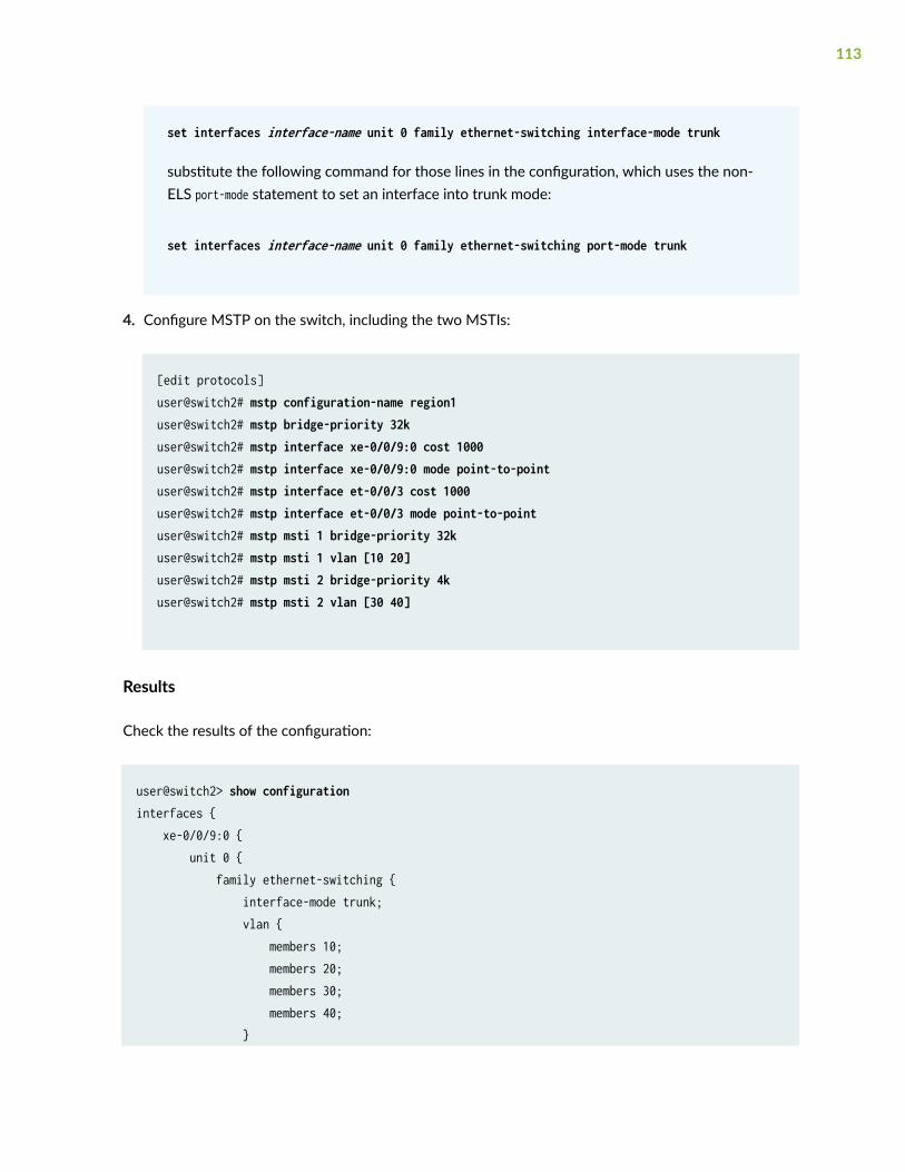
set interfaces interface-name unit 0 family ethernet-switching interface-mode trunk
substitute the following command for those lines in the configuration, which uses the non-ELS port-mode statement to set an interface into trunk mode:
set interfaces interface-name unit 0 family ethernet-switching port-mode trunk
4. Configure MSTP on the switch, including the two MSTIs:
[edit protocols]user@switch2# mstp configuration-name region1user@switch2# mstp bridge-priority 32kuser@switch2# mstp interface xe-0/0/9:0 cost 1000user@switch2# mstp interface xe-0/0/9:0 mode point-to-pointuser@switch2# mstp interface et-0/0/3 cost 1000user@switch2# mstp interface et-0/0/3 mode point-to-pointuser@switch2# mstp msti 1 bridge-priority 32kuser@switch2# mstp msti 1 vlan [10 20]user@switch2# mstp msti 2 bridge-priority 4kuser@switch2# mstp msti 2 vlan [30 40]
Results
Check the results of the configuration:
user@switch2> show configuration interfaces { xe-0/0/9:0 { unit 0 { family ethernet-switching { interface-mode trunk; vlan { members 10; members 20; members 30; members 40; }
113

} } } et-0/0/3 { unit 0 { family ethernet-switching { interface-mode trunk; vlan { members 10; members 20; members 30; members 40; } } } }}protocols { mstp { configuration-name region1; bridge-priority 32k; interface xe-0/0/9:0 { cost 1000; mode point-to-point; } interface et-0/0/3 { cost 1000; mode point-to-point; } msti 1 { bridge-priority 32k; vlan [10 20]; } msti 2 { bridge-priority 4k; vlan [30 40]; } }}vlans { voice-vlan { vlan-id 10; }
114

employee-vlan { vlan-id 20; } guest-vlan { vlan-id 30; } camera-vlan { vlan-id 40; }}
Configuring MSTP on Switch 3
IN THIS SECTION
Procedure | 115
Procedure
CLI Quick Configuration
To quickly configure interfaces and MSTP on Switch 3, copy the following commands and paste theminto the switch terminal window:
[edit]set vlans voice-vlan description “Voice VLAN”set vlans voice-vlan vlan-id 10set vlans employee-vlan description “Employee VLAN”set vlans employee-vlan vlan-id 20set vlans guest-vlan description “Guest VLAN”set vlans guest-vlan vlan-id 30set vlans camera-vlan description “Camera VLAN”set vlans camera-vlan vlan—id 40set interfaces xe-0/0/11:0 unit 0 family ethernet-switching vlan members [10 20 30 40]set interfaces et-0/0/6 unit 0 family ethernet-switching vlan members [10 20 30 40]set interfaces xe-0/0/21:0 unit 0 family ethernet-switching vlan members [10 20 30 40]set interfaces xe-0/0/11:0 unit 0 family ethernet-switching interface-mode trunkset interfaces et-0/0/6 unit 0 family ethernet-switching interface-mode trunk
115

set interfaces xe-0/0/21:0 unit 0 family ethernet-switching interface-mode trunkset protocols mstp configuration-name region1set protocols mstp bridge-priority 8kset protocols mstp interface xe-0/0/11:0 cost 1000set protocols mstp interface xe-0/0/11:0 mode point-to-pointset protocols mstp interface et-0/0/6 cost 1000set protocols mstp interface et-0/0/6 mode point-to-pointset protocols mstp interface xe-0/0/21:0 cost 1000set protocols mstp interface xe-0/0/21:0 mode point-to-pointset protocols mstp msti 1 bridge-priority 4kset protocols mstp msti 1 vlan [10 20]set protocols mstp msti 2 bridge-priority 16kset protocols mstp msti 2 vlan [30 40]
NOTE: For non-ELS switches, instead of the following command used above for ELS switchesthat sets an interface into trunk mode using the interface-mode statement:
set interfaces interface-name unit 0 family ethernet-switching interface-mode trunk
substitute the following command for those lines in the configuration, which uses the non-ELSport-mode statement to set an interface into trunk mode:
set interfaces interface-name unit 0 family ethernet-switching port-mode trunk
Step-by-Step Procedure
To configure interfaces and MSTP on Switch 3:
1. Configure the VLANs voice-vlan, employee-vlan, guest-vlan, and camera-vlan:
[edit vlans]user@switch3# set voice-vlan description “Voice VLAN”user@switch3# set voice-vlan vlan-id 10user@switch3# set employee-vlan description “Employee VLAN”user@switch3# set employee-vlan vlan-id 20user@switch3# set guest-vlan description “Guest VLAN”user@switch3# set guest-vlan vlan-id 30user@switch3# set camera-vlan description “Camera VLAN”
116

user@switch3# set guest-vlan vlan-id 40
2. Configure the VLANs on the interfaces, including support for the Ethernet Switching protocol:
[edit interfaces]user@switch3# set xe-0/0/11:0 unit 0 family ethernet-switching vlan members [10 20 30 40]user@switch3# set et-0/0/6 unit 0 family ethernet-switching vlan members [10 20 30 40]user@switch3# set xe-0/0/21:0 unit 0 family ethernet-switching vlan members [10 20 30 40]
3. Configure the port mode for the interfaces:
[edit interfaces]user@switch3# set xe-0/0/11:0 unit 0 family ethernet-switching interface-mode trunkuser@switch3# set et-0/0/6 unit 0 family ethernet-switching interface-mode trunkuser@switch3# set xe-0/0/21:0 unit 0 family ethernet-switching interface-mode trunk
NOTE: For non-ELS switches, instead of the following command used above for ELS switchesthat sets an interface into trunk mode using the interface-mode statement:
set interfaces interface-name unit 0 family ethernet-switching interface-mode trunk
substitute the following command for those lines in the configuration, which uses the non-ELS port-mode statement to set an interface into trunk mode:
set interfaces interface-name unit 0 family ethernet-switching port-mode trunk
4. Configure MSTP on the switch, including the two MSTIs:
[edit protocols]user@switch3# mstp configuration-name region1user@switch3# mstp bridge-priority 8kuser@switch3# mstp interface xe-0/0/11:0 cost 1000user@switch3# mstp interface xe-0/0/11:0 mode point-to-pointuser@switch3# mstp interface et-0/0/6 cost 1000user@switch3# mstp interface et-0/0/6 mode point-to-pointuser@switch3# mstp interface xe-0/0/21:0 cost 1000
117

user@switch3# mstp interface xe-0/0/21:0 mode point-to-pointuser@switch3# mstp msti 1 bridge-priority 4kuser@switch3# mstp msti 1 vlan [10 20]user@switch3# mstp msti 2 bridge-priority 16kuser@switch3# mstp msti 2 vlan [30 40]
Results
Check the results of the configuration:
user@switch3> show configuration interfaces { xe-0/0/11:0 { unit 0 { family ethernet-switching { interface-mode trunk; vlan { members 10; members 20; members 30; members 40; } } } } et-0/0/6 { unit 0 { family ethernet-switching { interface-mode trunk; vlan { members 10; members 20; members 30; members 40; } } } } xe-0/0/21:0 { unit 0 {
118
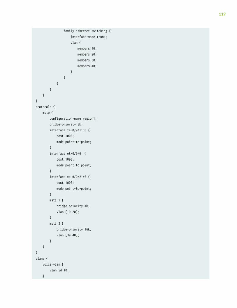
family ethernet-switching { interface-mode trunk; vlan { members 10; members 20; members 30; members 40; } } } } }}protocols { mstp { configuration-name region1; bridge-priority 8k; interface xe-0/0/11:0 { cost 1000; mode point-to-point; } interface et-0/0/6 { cost 1000; mode point-to-point; } interface xe-0/0/21:0 { cost 1000; mode point-to-point; } msti 1 { bridge-priority 4k; vlan [10 20]; } msti 2 { bridge-priority 16k; vlan [30 40]; } }}vlans { voice-vlan { vlan-id 10; }
119

employee-vlan { vlan-id 20; } guest-vlan { vlan-id 30; } camera-vlan { vlan-id 40; }}
Configuring MSTP on Switch 4
IN THIS SECTION
Procedure | 120
Procedure
CLI Quick Configuration
To quickly configure interfaces and MSTP on Switch 4, copy the following commands and paste theminto the switch terminal window:
[edit]set vlans voice-vlan description “Voice VLAN”set vlans voice-vlan vlan-id 10set vlans employee-vlan description “Employee VLAN”set vlans employee-vlan vlan-id 20set vlans guest-vlan description “Guest VLAN”set vlans guest-vlan vlan-id 30set vlans camera-vlan description “Camera VLAN”set vlans camera-vlan vlan-id 40set interfaces xe-0/0/12:0 unit 0 family ethernet-switching vlan members [10 20 30 40]set interfaces xe-0/0/21:0 unit 0 family ethernet-switching vlan members [10 20 30 40]set interfaces xe-0/0/12:0 unit 0 family ethernet-switching interface-mode trunkset interfaces xe-0/0/21:0 unit 0 family ethernet-switching interface-mode trunkset protocols mstp configuration-name region1
120

set protocols mstp bridge-priority 16kset protocols mstp interface xe-0/0/12:0 cost 1000set protocols mstp interface xe-0/0/12:0 mode point-to-pointset protocols mstp interface xe-0/0/21:0 cost 1000set protocols mstp interface xe-0/0/21:0 mode point-to-pointset protocols mstp msti 1 bridge-priority 16kset protocols mstp msti 1 vlan [10 20]set protocols mstp msti 2 bridge-priority 32kset protocols mstp msti 2 vlan [30 40]
NOTE: For non-ELS switches, instead of the following command used above for ELS switchesthat sets an interface into trunk mode using the interface-mode statement:
set interfaces interface-name unit 0 family ethernet-switching interface-mode trunk
substitute the following command for those lines in the configuration, which uses the non-ELSport-mode statement to set an interface into trunk mode:
set interfaces interface-name unit 0 family ethernet-switching port-mode trunk
Step-by-Step Procedure
To configure interfaces and MSTP on Switch 4:
1. Configure the VLANs voice-vlan, employee-vlan, guest-vlan, and camera-vlan:
[edit vlans]user@switch4# set voice-vlan description “Voice VLAN”user@switch4# set voice-vlan vlan-id 10user@switch4# set employee-vlan description “Employee VLAN”user@switch4# set employee-vlan vlan-id 20user@switch4# set guest-vlan description “Guest VLAN”user@switch4# set guest-vlan vlan-id 30user@switch4# set camera-vlan description “Camera VLAN”user@switch4# set guest-vlan vlan-id 40
121
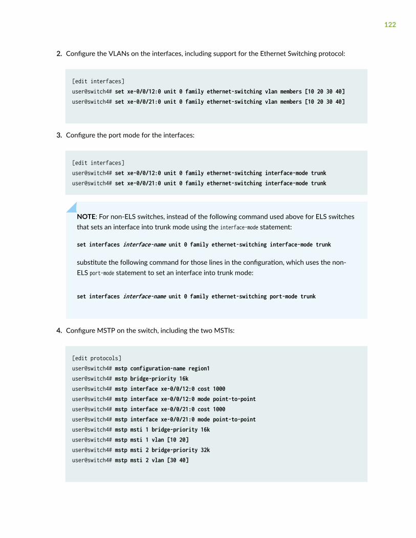
2. Configure the VLANs on the interfaces, including support for the Ethernet Switching protocol:
[edit interfaces]user@switch4# set xe-0/0/12:0 unit 0 family ethernet-switching vlan members [10 20 30 40]user@switch4# set xe-0/0/21:0 unit 0 family ethernet-switching vlan members [10 20 30 40]
3. Configure the port mode for the interfaces:
[edit interfaces]user@switch4# set xe-0/0/12:0 unit 0 family ethernet-switching interface-mode trunkuser@switch4# set xe-0/0/21:0 unit 0 family ethernet-switching interface-mode trunk
NOTE: For non-ELS switches, instead of the following command used above for ELS switchesthat sets an interface into trunk mode using the interface-mode statement:
set interfaces interface-name unit 0 family ethernet-switching interface-mode trunk
substitute the following command for those lines in the configuration, which uses the non-ELS port-mode statement to set an interface into trunk mode:
set interfaces interface-name unit 0 family ethernet-switching port-mode trunk
4. Configure MSTP on the switch, including the two MSTIs:
[edit protocols]user@switch4# mstp configuration-name region1user@switch4# mstp bridge-priority 16kuser@switch4# mstp interface xe-0/0/12:0 cost 1000user@switch4# mstp interface xe-0/0/12:0 mode point-to-pointuser@switch4# mstp interface xe-0/0/21:0 cost 1000user@switch4# mstp interface xe-0/0/21:0 mode point-to-pointuser@switch4# mstp msti 1 bridge-priority 16kuser@switch4# mstp msti 1 vlan [10 20]user@switch4# mstp msti 2 bridge-priority 32kuser@switch4# mstp msti 2 vlan [30 40]
122

Results
Check the results of the configuration:
user@switch4> show configuration interfaces { xe-0/0/12:0 { unit 0 { family ethernet-switching { interface-mode trunk; vlan { members 10; members 20; members 30; members 40; } } } } xe-0/0/21:0 { unit 0 { family ethernet-switching { interface-mode trunk; vlan { members 10; members 20; members 30; members 40; } } } }}protocols { mstp { configuration-name region1; bridge-priority 16k; interface xe-0/0/12:0 { cost 1000; mode point-to-point; } interface xe-0/0/21:0 {
123
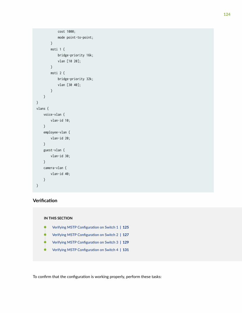
cost 1000; mode point-to-point; } msti 1 { bridge-priority 16k; vlan [10 20]; } msti 2 { bridge-priority 32k; vlan [30 40]; } }}vlans { voice-vlan { vlan-id 10; } employee-vlan { vlan-id 20; } guest-vlan { vlan-id 30; } camera-vlan { vlan-id 40; }}
Verification
IN THIS SECTION
Verifying MSTP Configuration on Switch 1 | 125
Verifying MSTP Configuration on Switch 2 | 127
Verifying MSTP Configuration on Switch 3 | 129
Verifying MSTP Configuration on Switch 4 | 131
To confirm that the configuration is working properly, perform these tasks:
124

Verifying MSTP Configuration on Switch 1
Purpose
Verify the MSTP configuration on Switch 1.
Action
Issue the operational mode commands show spanning-tree interface and show spanning-tree bridge:
user@switch1> show spanning-tree interface
Spanning tree interface parameters for instance 0
Interface Port ID Designated Designated Port State Role port ID bridge ID Costxe-0/0/9:0 128:1010 128:1010 16384.544b8c432703 1000 FWD DESG xe-0/0/12:0 128:1011 128:1011 16384.40a677792303 1000 BLK ALT xe-0/0/11:0 128:1012 128:1010 8192.544b8c44c103 1000 FWD ROOT
Spanning tree interface parameters for instance 1
Interface Port ID Designated Designated Port State Role port ID bridge ID Costxe-0/0/9:0 128:1010 128:1010 16385.544b8c432703 1000 FWD DESG xe-0/0/12:0 128:1011 128:1011 16385.40a677792303 1000 BLK ALT xe-0/0/11:0 128:1012 128:1010 4097.544b8c44c103 1000 FWD ROOT
Spanning tree interface parameters for instance 2
Interface Port ID Designated Designated Port State Role port ID bridge ID Costxe-0/0/9:0 128:1010 128:1012 4098.88a25e8c7603 1000 FWD ROOT xe-0/0/12:0 128:1011 128:1011 8194.544b8c432703 1000 FWD DESG xe-0/0/11:0 128:1012 128:1012 8194.544b8c432703 1000 FWD DESG
user@switch1> show spanning-tree bridge
STP bridge parameters Routing instance name : GLOBALContext ID : 0
125

Enabled protocol : MSTP
STP bridge parameters for CIST Root ID : 8192.54:4b:8c:44:c1:03 Root cost : 0 Root port : xe-0/0/11:0 CIST regional root : 8192.54:4b:8c:44:c1:03 CIST internal root cost : 1000 Hello time : 2 seconds Maximum age : 20 seconds Forward delay : 15 seconds Hop count : 19 Message age : 0 Number of topology changes : 3 Time since last topology change : 675 seconds Local parameters Bridge ID : 16384.54:4b:8c:43:27:03
STP bridge parameters for MSTI 1 MSTI regional root : 4097.54:4b:8c:44:c1:03 Root cost : 1000 Root port : xe-0/0/11:0 Hello time : 2 seconds Maximum age : 20 seconds Forward delay : 15 seconds Hop count : 19 Number of topology changes : 3 Time since last topology change : 675 seconds Local parameters Bridge ID : 16385.54:4b:8c:43:27:03
STP bridge parameters for MSTI 2 MSTI regional root : 4098.88:a2:5e:8c:76:03 Root cost : 1000 Root port : xe-0/0/9:0 Hello time : 2 seconds Maximum age : 20 seconds Forward delay : 15 seconds Hop count : 19 Number of topology changes : 3 Time since last topology change : 675 seconds Local parameters
126

Bridge ID : 8194.54:4b:8c:43:27:03
Meaning
The operational mode command show spanning-tree interface displays spanning-tree domain informationsuch as the designated port and the port roles.
The operational mode command show spanning-tree bridge displays the spanning-tree domain informationat either the bridge level or the interface level. If the optional interface name is omitted, all interfaces inthe spanning-tree domain are displayed.
Verifying MSTP Configuration on Switch 2
Purpose
Verify the MSTP configuration on Switch 2.
Action
Issue the operational mode commands show spanning-tree interface and show spanning-tree bridge:
user@switch2> show spanning-tree bridge
Spanning tree interface parameters for instance 0
Interface Port ID Designated Designated Port State Role port ID bridge ID Costet-0/0/3 128:1010 128:1011 8192.544b8c44c103 1000 FWD ROOT xe-0/0/9:0 128:1012 128:1010 16384.544b8c432703 1000 BLK ALT
Spanning tree interface parameters for instance 1
Interface Port ID Designated Designated Port State Role port ID bridge ID Costet-0/0/3 128:1010 128:1011 4097.544b8c44c103 1000 FWD ROOT xe-0/0/9:0 128:1012 128:1010 16385.544b8c432703 1000 BLK ALT
Spanning tree interface parameters for instance 2
Interface Port ID Designated Designated Port State Role
127

port ID bridge ID Costet-0/0/3 128:1010 128:1010 4098.88a25e8c7603 1000 FWD DESG xe-0/0/9:0 128:1012 128:1012 4098.88a25e8c7603 1000 FWD DESG
user@switch2> show spanning-tree bridge
STP bridge parametersRouting instance name : GLOBALContext ID : 0Enabled protocol : MSTP
STP bridge parameters for CIST Root ID : 8192.54:4b:8c:44:c1:03 Root cost : 0 Root port : et-0/0/3 CIST regional root : 8192.54:4b:8c:44:c1:03 CIST internal root cost : 1000 Hello time : 2 seconds Maximum age : 20 seconds Forward delay : 15 seconds Hop count : 19 Message age : 0 Number of topology changes : 2 Time since last topology change : 659 seconds Local parameters Bridge ID : 32768.88:a2:5e:8c:76:03
STP bridge parameters for MSTI 1 MSTI regional root : 4097.54:4b:8c:44:c1:03 Root cost : 1000 Root port : et-0/0/3 Hello time : 2 seconds Maximum age : 20 seconds Forward delay : 15 seconds Hop count : 19 Number of topology changes : 2 Time since last topology change : 659 seconds Local parameters Bridge ID : 32769.88:a2:5e:8c:76:03
STP bridge parameters for MSTI 2 MSTI regional root : 4098.88:a2:5e:8c:76:03
128

Hello time : 2 seconds Maximum age : 20 seconds Forward delay : 15 seconds Number of topology changes : 3 Time since last topology change : 655 seconds Local parameters Bridge ID : 4098.88:a2:5e:8c:76:03
Meaning
The operational mode command show spanning-tree interface displays spanning-tree domain informationsuch as the designated port and the port roles. The spanning-tree interface parameters for instance 2show that both ports are designated ports, which means Switch 2 is the root bridge for this instance.
The operational mode command show spanning-tree bridge displays the spanning-tree domain informationat either the bridge level or interface level. If the optional interface name is omitted, all interfaces in thespanning-tree domain are displayed.
Verifying MSTP Configuration on Switch 3
Purpose
Verify the MSTP configuration on Switch 3.
Action
Issue the operational mode commands show spanning-tree interface and show spanning-tree bridge:
user@switch3> show spanning-tree interface
Spanning tree interface parameters for instance 0
Interface Port ID Designated Designated Port State Role port ID bridge ID Costxe-0/0/11:0 128:1010 128:1010 8192.544b8c44c103 1000 FWD DESG et-0/0/6 128:1011 128:1011 8192.544b8c44c103 1000 FWD DESG xe-0/0/21:0 128:1012 128:1012 8192.544b8c44c103 1000 FWD DESG
Spanning tree interface parameters for instance 1
129

Interface Port ID Designated Designated Port State Role port ID bridge ID Costxe-0/0/11:0 128:1010 128:1010 4097.544b8c44c103 1000 FWD DESG et-0/0/6 128:1011 128:1011 4097.544b8c44c103 1000 FWD DESG xe-0/0/21:0 128:1012 128:1012 4097.544b8c44c103 1000 FWD DESG
Spanning tree interface parameters for instance 2
Interface Port ID Designated Designated Port State Role port ID bridge ID Costxe-0/0/11:0 128:1010 128:1012 8194.544b8c432703 1000 BLK ALT et-0/0/6 128:1011 128:1010 4098.88a25e8c7603 1000 FWD ROOT xe-0/0/21:0 128:1012 128:1012 16386.544b8c44c103 1000 FWD DESG
user@switch3> show spanning-tree bridge
STP bridge parameters Routing instance name : GLOBALContext ID : 0Enabled protocol : MSTP
STP bridge parameters for CIST Root ID : 8192.54:4b:8c:44:c1:03 CIST regional root : 8192.54:4b:8c:44:c1:03 CIST internal root cost : 0 Hello time : 2 seconds Maximum age : 20 seconds Forward delay : 15 seconds Number of topology changes : 2 Time since last topology change : 786 seconds Local parameters Bridge ID : 8192.54:4b:8c:44:c1:03
STP bridge parameters for MSTI 1 MSTI regional root : 4097.54:4b:8c:44:c1:03 Hello time : 2 seconds Maximum age : 20 seconds Forward delay : 15 seconds Number of topology changes : 1 Time since last topology change : 786 seconds Local parameters
130

Bridge ID : 4097.54:4b:8c:44:c1:03
STP bridge parameters for MSTI 2 MSTI regional root : 4098.88:a2:5e:8c:76:03 Root cost : 1000 Root port : et-0/0/6 Hello time : 2 seconds Maximum age : 20 seconds Forward delay : 15 seconds Hop count : 19 Number of topology changes : 1 Time since last topology change : 786 seconds Local parameters Bridge ID : 16386.54:4b:8c:44:c1:03
Meaning
The operational mode command show spanning-tree interface displays spanning-tree domain informationsuch as the designated port and the port roles. Switch 3 is the root bridge for instance 0, which is theCIST, as well as for instance 1. In both instances, all ports on Switch 3 are designated ports.
The operational mode command show spanning-tree bridge displays the spanning-tree domain informationat either the bridge level or the interface level. If the optional interface name is omitted, all interfaces inthe spanning-tree domain are displayed.
Verifying MSTP Configuration on Switch 4
Purpose
Verify the MSTP configuration on Switch 4.
Action
Issue the operational mode commands show spanning-tree interface and show spanning-tree bridge:
user@switch4> show spanning-tree interface
Spanning tree interface parameters for instance 0
Interface Port ID Designated Designated Port State Role
131

port ID bridge ID Costxe-0/0/12:0 128:1011 128:1011 16384.40a677792303 1000 FWD DESG xe-0/0/21:0 128:1012 128:1012 8192.544b8c44c103 1000 FWD ROOT
Spanning tree interface parameters for instance 1
Interface Port ID Designated Designated Port State Role port ID bridge ID Costxe-0/0/12:0 128:1011 128:1011 16385.40a677792303 1000 FWD DESG xe-0/0/21:0 128:1012 128:1012 4097.544b8c44c103 1000 FWD ROOT
Spanning tree interface parameters for instance 2
Interface Port ID Designated Designated Port State Role port ID bridge ID Costxe-0/0/12:0 128:1011 128:1011 8194.544b8c432703 1000 FWD ROOT xe-0/0/21:0 128:1012 128:1012 16386.544b8c44c103 1000 BLK ALT
user@switch4> show spanning-tree bridge
STP bridge parameters Routing instance name : GLOBALContext ID : 0Enabled protocol : MSTP
STP bridge parameters for CIST Root ID : 8192.54:4b:8c:44:c1:03 Root cost : 0 Root port : xe-0/0/21:0 CIST regional root : 8192.54:4b:8c:44:c1:03 CIST internal root cost : 1000 Hello time : 2 seconds Maximum age : 20 seconds Forward delay : 15 seconds Hop count : 19 Message age : 0 Number of topology changes : 2 Time since last topology change : 823 seconds Local parameters Bridge ID : 16384.40:a6:77:79:23:03
132

STP bridge parameters for MSTI 1 MSTI regional root : 4097.54:4b:8c:44:c1:03 Root cost : 1000 Root port : xe-0/0/21:0 Hello time : 2 seconds Maximum age : 20 seconds Forward delay : 15 seconds Hop count : 19 Number of topology changes : 2 Time since last topology change : 823 seconds Local parameters Bridge ID : 16385.40:a6:77:79:23:03
STP bridge parameters for MSTI 2 MSTI regional root : 4098.88:a2:5e:8c:76:03 Root cost : 2000 Root port : xe-0/0/12:0 Hello time : 2 seconds Maximum age : 20 seconds Forward delay : 15 seconds Hop count : 18 Number of topology changes : 2 Time since last topology change : 823 seconds Local parameters Bridge ID : 32770.40:a6:77:79:23:03
Meaning
The operational mode command show spanning-tree interface displays spanning-tree domain informationsuch as the designated port and the port roles.
The operational mode command show spanning-tree bridge displays the spanning-tree domain informationat either the bridge level or the interface level. If the optional interface name is omitted, all interfaces inthe spanning-tree domain are displayed.
Disabling MSTP
To disable the entire MSTP instance:
133

• Include the "disable" on page 317 statement. You can include this statement at the followinghierarchy levels:
• [edit logical-systems logical-system-name protocols mstp]
• [edit logical-systems logical-system-name routing-instances routing-instance-name protocolsmstp]
• [edit protocols mstp]
• [edit routing-instances routing-instance-name protocols mstp]
Release History Table
Release Description
15.1 Starting with Junos OS Release 15.1 for EX Series and QFX Series switches with support for theEnhanced Layer 2 Software (ELS) configuration style, you can configure spanning tree parametersglobally on all spanning tree interfaces.
Configuring VSTP Protocol
IN THIS SECTION
Understanding VSTP | 135
Global and Specific VSTP Configurations for Switches | 136
Example: Configuring VSTP on a Trunk Port with Tagged Traffic | 141
Reverting to RSTP or VSTP from Forced IEEE 802.1D STP | 157
Virtual Spanning-Tree Protocol works with VLANs that require device compatibility.
134

Understanding VSTP
IN THIS SECTION
Benefits of VSTP | 135
VSTP Restrictions | 135
Recommended Uses of VSTP | 136
When using VSTP, we recommend that you enable VSTP on all VLANs that can receive VSTP bridgeprotocol data units (BPDUs).
Benefits of VSTP
VSTP has the following benefits:
• Connects devices that are not part of the network
• Compatible with Cisco PVST+
• VSTP and RSTP are the only spanning-tree protocols that can be configured concurrently on adevice.
VSTP Restrictions
VSTP has these restrictions:
• The EX Series switches EX4300, EX4600 and the QFX platforms QFX5100,QFX3500,QFX3600support 510 Vlans on VSTP.
• VSTP is not supported on the SRX platform - just STP/RSTP/MSTP are supported on SRX Series.
• On EX Series (except EX9200) and QFX Series switches running Junos OS that supports ELS—VSTPcan support up to 510 VLANs.
• On EX9200 switches—VSTP can support up to 4000 VLANs.
• On an EX Series switch running Junos OS that does not support ELS—VSTP can support up to 253VLANs.
135
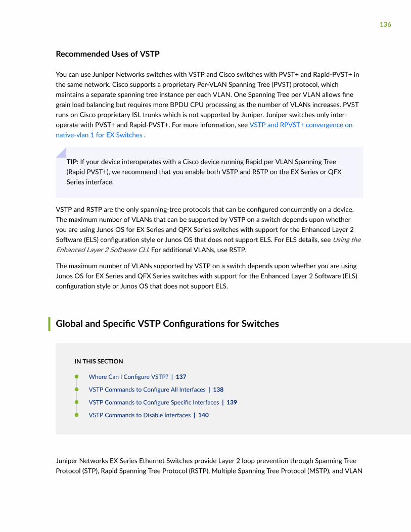
Recommended Uses of VSTP
You can use Juniper Networks switches with VSTP and Cisco switches with PVST+ and Rapid-PVST+ inthe same network. Cisco supports a proprietary Per-VLAN Spanning Tree (PVST) protocol, whichmaintains a separate spanning tree instance per each VLAN. One Spanning Tree per VLAN allows finegrain load balancing but requires more BPDU CPU processing as the number of VLANs increases. PVSTruns on Cisco proprietary ISL trunks which is not supported by Juniper. Juniper switches only inter-operate with PVST+ and Rapid-PVST+. For more information, see VSTP and RPVST+ convergence onnative-vlan 1 for EX Switches .
TIP: If your device interoperates with a Cisco device running Rapid per VLAN Spanning Tree(Rapid PVST+), we recommend that you enable both VSTP and RSTP on the EX Series or QFXSeries interface.
VSTP and RSTP are the only spanning-tree protocols that can be configured concurrently on a device.The maximum number of VLANs that can be supported by VSTP on a switch depends upon whetheryou are using Junos OS for EX Series and QFX Series switches with support for the Enhanced Layer 2Software (ELS) configuration style or Junos OS that does not support ELS. For ELS details, see Using theEnhanced Layer 2 Software CLI. For additional VLANs, use RSTP.
The maximum number of VLANs supported by VSTP on a switch depends upon whether you are usingJunos OS for EX Series and QFX Series switches with support for the Enhanced Layer 2 Software (ELS)configuration style or Junos OS that does not support ELS.
Global and Specific VSTP Configurations for Switches
IN THIS SECTION
Where Can I Configure VSTP? | 137
VSTP Commands to Configure All Interfaces | 138
VSTP Commands to Configure Specific Interfaces | 139
VSTP Commands to Disable Interfaces | 140
Juniper Networks EX Series Ethernet Switches provide Layer 2 loop prevention through Spanning TreeProtocol (STP), Rapid Spanning Tree Protocol (RSTP), Multiple Spanning Tree Protocol (MSTP), and VLAN
136

Spanning Tree Protocol (VSTP). The default factory configuration for EX Series switches uses RSTP. Thistopic describes options for configuring VSTP on an EX Series or QFX Series switch.
NOTE: On EX Series (other than EX9200) and QFX switches running Junos OS that supports ELS—VSTP can support up to 510 VLANs. However, on EX9200 switches, VSTP can support only upto 253 VLANs.
NOTE: When you configure VSTP, we recommend that you enable VSTP on all VLANs that canreceive VSTP bridge protocol data units (BPDUs).
Where Can I Configure VSTP?
You can configure VSTP at the global level:
• For all interfaces on the switch
• For all interfaces within all VLANs
• For all interfaces within a specified VLAN
• For all interfaces within a specified VLAN group
You can configure or disable VSTP for specific interfaces:
• For a specific interface on the switch
• For a specific interface within all VLANs
• For a specific interface within a specified VLAN
• For a specific interface within a specified VLAN group
NOTE:
• If you configure VSTP on an interface at both the global and the specific VLAN level, theinterface configuration that is defined at the specific VLAN level overrides the interfaceconfiguration that is defined at the global level.
• If you specify VSTP to be configured on an interface that is not configured to belong to theVLAN (or VLANs), an error message is displayed.
137

• On EX Series (other than EX9200) and QFX switches running Junos OS that supports ELS—VSTP can support up to 510 VLANs. However, on EX9200 switches, VSTP can support onlyup to 253 VLANs.
• When you configure VSTP, we recommend that you enable VSTP on all VLANs that canreceive VSTP bridge protocol data units (BPDUs).
You must enable RSTP if you used the set vstp vlan all statement to enable VSTP and if theswitch has more than 253 VLANs. If you use the set vstp vlan all statement to enable VSTPon a switch with more than 253 VLANs, the configuration cannot be committed.
VSTP Commands to Configure All Interfaces
Command to configure VSTP on an individual interface on a switch:
[edit protocols vstp]user@switch@ set interface interface-name
Command to configure all VSTP interfaces on a switch:
[edit protocols vstp]user@switch# set interface all
Command to configure all VSTP interfaces for all VLANs:
NOTE: When you issue the set protocols vstp vlan all interface all command, you might notreceive an error message when you have exceed the limit of 5119 vports.
[edit protocols vstp]user@switch# set vlan all interface all
Command to configure all VSTP interfaces within a specified VLAN:
[edit protocols vstp]user@switch# set vlan (vlan-id |vlan-range |open-set-of-values) interface all interface all
138
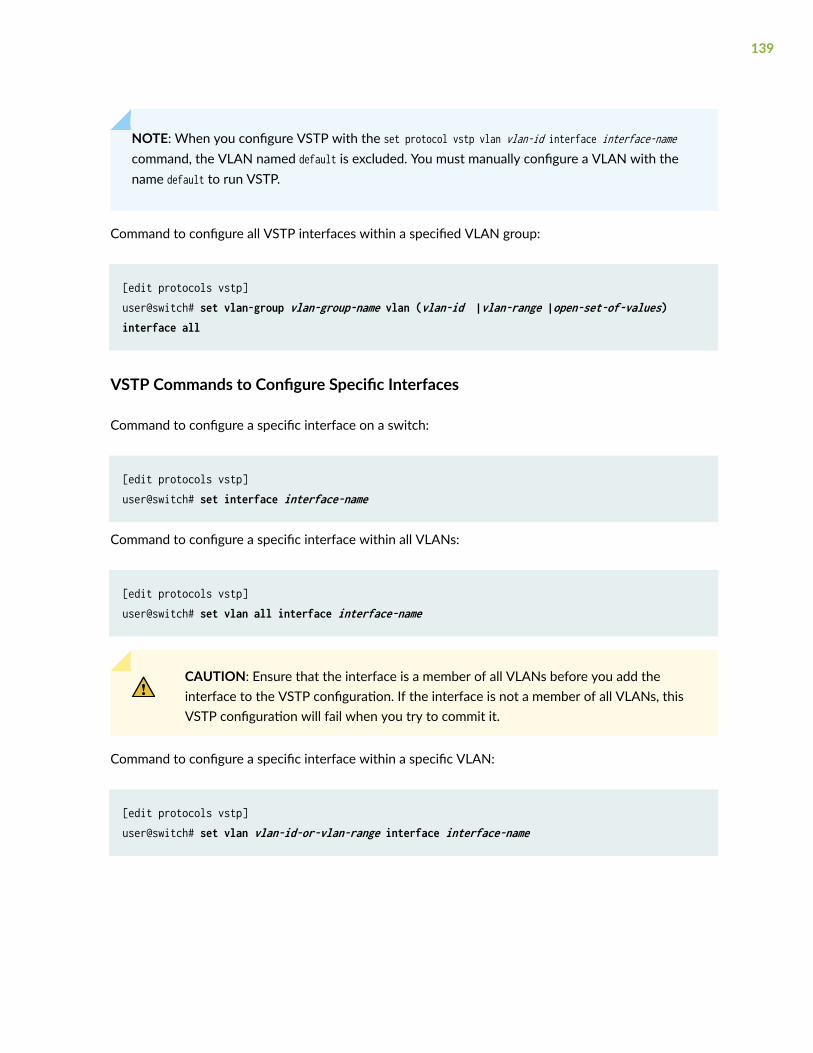
NOTE: When you configure VSTP with the set protocol vstp vlan vlan-id interface interface-namecommand, the VLAN named default is excluded. You must manually configure a VLAN with thename default to run VSTP.
Command to configure all VSTP interfaces within a specified VLAN group:
[edit protocols vstp]user@switch# set vlan-group vlan-group-name vlan (vlan-id |vlan-range |open-set-of-values) interface all
VSTP Commands to Configure Specific Interfaces
Command to configure a specific interface on a switch:
[edit protocols vstp]user@switch# set interface interface-name
Command to configure a specific interface within all VLANs:
[edit protocols vstp]user@switch# set vlan all interface interface-name
CAUTION: Ensure that the interface is a member of all VLANs before you add theinterface to the VSTP configuration. If the interface is not a member of all VLANs, thisVSTP configuration will fail when you try to commit it.
Command to configure a specific interface within a specific VLAN:
[edit protocols vstp]user@switch# set vlan vlan-id-or-vlan-range interface interface-name
139

Command to configure a specific interface within a specific VLAN group:
[edit protocols vstp]user@switch# set vlan-group vlan-group-name vlan (vlan-id |vlan-range |open-set-of-values) interface interface-name
VSTP Commands to Disable Interfaces
Command to disable VSTP on an individual interface on a switch:
[edit protocols vstp]user@switch@ set interface interface-name disable
Command to disable VSTP on a specific interface within a specific VLAN on a switch:
[edit protocols vstp]user@switch@ set vlan vlan-id interface interface-name disable
Command to disable one specific VSTP interface on all the VLANs on the switch:
[edit protocols vstp]user@switch@ set vlan all interface interface-name disable
Command to disable a specific VSTP interface within a specific VLAN group:
[edit protocols vstp]user@switch@ set vlan-group group group-name vlan (vlan-id |vlan-range | open-set-of-values) interface interface-name disable
NOTE: You cannot disable the VSTP VLAN parameters for all VSTP interfaces.
140

Example: Configuring VSTP on a Trunk Port with Tagged Traffic
IN THIS SECTION
Requirements | 141
Overview | 141
Configuration | 142
Verification | 154
In 802.1ad provider bridge networks (stacked VLANs), single-tagged access ports and double-taggedtrunk ports can co-exist in a single spanning tree context. In this mode, the VLAN Spanning TreeProtocol (VSTP) can send and receive untagged Rapid Spanning Tree Protocol (RSTP) bridge protocoldata units (BPDUs) on Gigabit Ethernet (ge), 10 -Gigabit Ethernet (xe), and aggregated Ethernet (ae)interfaces. The untagged RSTP BPDUs interoperate with tagged VSTP BPDUs sent over the double-tagged trunk ports.
Double-tagging can be useful for Internet service providers, allowing them to use VLANs internally whilemixing traffic from clients that are already VLAN-tagged.
This example shows how to configure the VSTP to send and receive standard untagged Rapid SpanningTree Protocol (RSTP) bridge protocol data units (BPDUs) on access trunks that interoperate with taggedVSTP BPDUs sent over the double-tagged trunk ports.
Requirements
This example uses the following hardware and software components:
• Two CE devices (MX Series routers with DPCE or MPC cards)
• Two PE devices (MX Series routers with DPCE or MPC cards)
• Junos OS Release 12.3 or later running on the PE devices
Overview
IN THIS SECTION
Topology | 142
141

This example shows how to configure VSTP on a trunk port with tagged traffic.
Topology
Figure 4 on page 142 shows a sample topology in which two customer edge (CE) bridges are dual-homed to two provider edge (PE) devices. All of the PE-CE links are single-tagged trunks using C-VLANs1-100. The core link between Devices PE1 and PE2 is a double-tagged trunk that carries traffic fromboth CE devices, using S-VLANs 100 and 200 to distinguish the CE traffic.
Two VSTP instances are created on the PE devices, one for each S-VLAN. The CE devices run thestandard RSTP. The PE devices run VSTP on the core link while sending standard untagged RSTP BPDUstoward the CE devices.
Figure 4: Topology for VSTP Configured on a Trunk Port with Tagged Traffic
Configuration
IN THIS SECTION
CLI Quick Configuration | 143
Configuring PE1, PE2, CE1, and CE2 | 145
Results | 148
142

CLI Quick Configuration
To quickly configure this example, copy the following commands, paste them into a text file, remove anyline breaks, change any details necessary to match your network configuration, and then copy and pastethe commands into the CLI at the [edit] hierarchy level.
Device PE1
set interfaces ge-2/0/1 flexible-vlan-taggingset interfaces ge-2/0/1 encapsulation flexible-ethernet-servicesset interfaces ge-2/0/1 unit 1 vlan-id 100set interfaces ge-2/0/1 unit 1 family bridge interface-mode trunkset interfaces ge-2/0/1 unit 1 family bridge inner-vlan-id-list 1-100set interfaces ge-2/0/1 unit 2 vlan-id 200set interfaces ge-2/0/1 unit 2 family bridge interface-mode trunkset interfaces ge-2/0/1 unit 2 family bridge inner-vlan-id-list 1-100set interfaces ge-2/0/4 encapsulation ethernet-vplsset interfaces ge-2/0/4 unit 0 description to_CE1 set interfaces ge-2/0/4 unit 0 family bridge interface-mode trunkset interfaces ge-2/0/4 unit 0 family bridge vlan-id-list 1-100set interfaces ge-2/1/1 unit 0 description to_CE2set interfaces ge-2/1/1 unit 0 family bridge interface-mode trunkset interfaces ge-2/1/1 unit 0 family bridge vlan-id-list 1-100set routing-instances vs1 instance-type virtual-switchset routing-instances vs1 interface ge-2/0/1.1set routing-instances vs1 interface ge-2/0/4.0set routing-instances vs1 protocols vstp vlan 100 interface ge-2/0/1set routing-instances vs1 protocols vstp vlan 100 interface ge-2/0/4 access-trunkset routing-instances vs1 bridge-domains bd vlan-id-list 1-100set routing-instances vs2 instance-type virtual-switchset routing-instances vs2 interface ge-2/0/1.2set routing-instances vs2 interface ge-2/1/1.0set routing-instances vs2 protocols vstp vlan 200 interface ge-2/0/1set routing-instances vs2 protocols vstp vlan 200 interface ge-2/1/1 access-trunkset routing-instances vs2 bridge-domains bd vlan-id-list 1-100
Device PE2
set interfaces ge-2/0/1 flexible-vlan-taggingset interfaces ge-2/0/1 encapsulation flexible-ethernet-servicesset interfaces ge-2/0/1 unit 1 vlan-id 100set interfaces ge-2/0/1 unit 1 family bridge interface-mode trunk
143
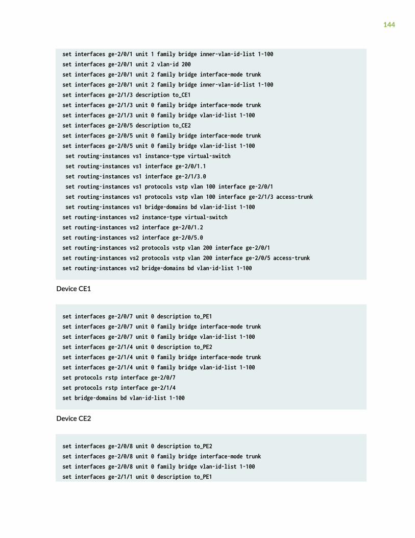
set interfaces ge-2/0/1 unit 1 family bridge inner-vlan-id-list 1-100set interfaces ge-2/0/1 unit 2 vlan-id 200set interfaces ge-2/0/1 unit 2 family bridge interface-mode trunkset interfaces ge-2/0/1 unit 2 family bridge inner-vlan-id-list 1-100set interfaces ge-2/1/3 description to_CE1set interfaces ge-2/1/3 unit 0 family bridge interface-mode trunkset interfaces ge-2/1/3 unit 0 family bridge vlan-id-list 1-100set interfaces ge-2/0/5 description to_CE2set interfaces ge-2/0/5 unit 0 family bridge interface-mode trunkset interfaces ge-2/0/5 unit 0 family bridge vlan-id-list 1-100 set routing-instances vs1 instance-type virtual-switch set routing-instances vs1 interface ge-2/0/1.1 set routing-instances vs1 interface ge-2/1/3.0 set routing-instances vs1 protocols vstp vlan 100 interface ge-2/0/1 set routing-instances vs1 protocols vstp vlan 100 interface ge-2/1/3 access-trunk set routing-instances vs1 bridge-domains bd vlan-id-list 1-100set routing-instances vs2 instance-type virtual-switchset routing-instances vs2 interface ge-2/0/1.2set routing-instances vs2 interface ge-2/0/5.0set routing-instances vs2 protocols vstp vlan 200 interface ge-2/0/1set routing-instances vs2 protocols vstp vlan 200 interface ge-2/0/5 access-trunkset routing-instances vs2 bridge-domains bd vlan-id-list 1-100
Device CE1
set interfaces ge-2/0/7 unit 0 description to_PE1set interfaces ge-2/0/7 unit 0 family bridge interface-mode trunkset interfaces ge-2/0/7 unit 0 family bridge vlan-id-list 1-100set interfaces ge-2/1/4 unit 0 description to_PE2set interfaces ge-2/1/4 unit 0 family bridge interface-mode trunkset interfaces ge-2/1/4 unit 0 family bridge vlan-id-list 1-100set protocols rstp interface ge-2/0/7set protocols rstp interface ge-2/1/4set bridge-domains bd vlan-id-list 1-100
Device CE2
set interfaces ge-2/0/8 unit 0 description to_PE2set interfaces ge-2/0/8 unit 0 family bridge interface-mode trunkset interfaces ge-2/0/8 unit 0 family bridge vlan-id-list 1-100set interfaces ge-2/1/1 unit 0 description to_PE1
144

set interfaces ge-2/1/1 unit 0 family bridge interface-mode trunkset interfaces ge-2/1/1 unit 0 family bridge vlan-id-list 1-100set protocols rstp interface ge-2/0/8set protocols rstp interface ge-2/1/1set bridge-domains bd vlan-id-list 1-100
Configuring PE1, PE2, CE1, and CE2
Step-by-Step Procedure
The following example requires you to navigate various levels in the configuration hierarchy. Forinformation about navigating the CLI, see Using the CLI Editor in Configuration Mode in the CLI UserGuide.
To configure Device PE1:
1. Configure the network interfaces.
[edit interfaces]user@PE1# set ge-2/0/1 flexible-vlan-tagginguser@PE1# set ge-2/0/1 encapsulation flexible-ethernet-servicesuser@PE1# set ge-2/0/1 unit 1 vlan-id 100user@PE1# set ge-2/0/1 unit 1 family bridge interface-mode trunkuser@PE1# set ge-2/0/1 unit 1 family bridge inner-vlan-id-list 1-100user@PE1# set ge-2/0/1 unit 2 vlan-id 200user@PE1# set ge-2/0/1 unit 2 family bridge interface-mode trunkuser@PE1# set ge-2/0/1 unit 2 family bridge inner-vlan-id-list 1-100user@PE1# set ge-2/0/4 encapsulation ethernet-vplsuser@PE1#set ge-2/0/4 unit 0 description to_CE1 user@PE1# set ge-2/0/4 unit 0 family bridge interface-mode trunkuser@PE1#set ge-2/0/4 unit 0 family bridge vlan-id-list 1-100user@PE1# set ge-2/1/1 unit 0 description to_CE2user@PE1# set ge-2/1/1 unit 0 family bridge interface-mode trunkuser@PE1# set ge-2/1/1 unit 0 family bridge vlan-id-list 1-100
2. Configure the routing instances.
[edit routing-instances]user@PE1# set vs1 instance-type virtual-switchuser@PE1# set vs1 interface ge-2/0/1.1user@PE1# set vs1 interface ge-2/0/4.0
145

user@PE1# set vs1 protocols vstp vlan 100 interface ge-2/0/1user@PE1# set vs1 protocols vstp vlan 100 interface ge-2/0/4 access-trunkuser@PE1# set vs1 bridge-domains bd vlan-id-list 1-100user@PE1# set vs2 instance-type virtual-switchuser@PE1# set vs2 interface ge-2/0/1.2user@PE1# set vs2 interface ge-2/1/1.0user@PE1# set vs2 protocols vstp vlan 200 interface ge-2/0/1user@PE1# set vs2 protocols vstp vlan 200 interface ge-2/1/1 access-trunkuser@PE1# set vs2 bridge-domains bd vlan-id-list 1-100
Step-by-Step Procedure
To configure Device PE2:
1. Configure the interfaces.
[edit interfaces]user@PE2# set ge-2/0/1 flexible-vlan-tagginguser@PE2# set ge-2/0/1 encapsulation flexible-ethernet-servicesuser@PE2# set ge-2/0/1 unit 1 vlan-id 100user@PE2# set ge-2/0/1 unit 1 family bridge interface-mode trunkuser@PE2# set ge-2/0/1 unit 1 family bridge inner-vlan-id-list 1-100user@PE2# set ge-2/0/1 unit 2 vlan-id 200user@PE2# set ge-2/0/1 unit 2 family bridge interface-mode trunkuser@PE2# set ge-2/0/1 unit 2 family bridge inner-vlan-id-list 1-100user@PE2# set ge-2/1/3 description to_CE1user@PE2# set ge-2/1/3 unit 0 family bridge interface-mode trunkuser@PE2# set ge-2/1/3 unit 0 family bridge vlan-id-list 1-100user@PE2# set ge-2/0/5 description to_CE2user@PE2# set ge-2/0/5 unit 0 family bridge interface-mode trunkuser@PE2# set ge-2/0/5 unit 0 family bridge vlan-id-list 1-100
2. Configure the routing instances.
[edit routing-instances]user@PE2# set vs1 instance-type virtual-switchuser@PE2# set vs1 interface ge-2/0/1.1user@PE2# set vs1 interface ge-2/1/3.0user@PE2# set vs1 protocols vstp vlan 100 interface ge-2/0/1user@PE2# set vs1 protocols vstp vlan 100 interface ge-2/1/3 access-trunkuser@PE2# set vs1 bridge-domains bd vlan-id-list 1-100
146

user@PE2# set vs2 instance-type virtual-switchuser@PE2# set vs2 interface ge-2/0/1.2user@PE2# set vs2 interface ge-2/0/5.0user@PE2# set vs2 protocols vstp vlan 200 interface ge-2/0/1user@PE2# set vs2 protocols vstp vlan 200 interface ge-2/0/5 access-trunkuser@PE2# set vs2 bridge-domains bd vlan-id-list 1-100
Step-by-Step Procedure
To configure CE1:
1. Configure the interfaces.
[edit interfaces]user@CE1# set ge-2/0/7 unit 0 description to_PE1user@CE1# set ge-2/0/7 unit 0 family bridge interface-mode trunkuser@CE1# set ge-2/0/7 unit 0 family bridge vlan-id-list 1-100user@CE1# set ge-2/1/4 unit 0 description to_PE2user@CE1# set ge-2/1/4 unit 0 family bridge interface-mode trunkuser@CE1# set ge-2/1/4 unit 0 family bridge vlan-id-list 1-100
2. Configure the protocols.
[edit protocols]user@CE1# set rstp interface ge-2/0/7user@CE1# set rstp interface ge-2/1/4
3. Configure the bridge domain.
[edit bridge-domains]user@CE1# set bd vlan-id-list 1-100
Step-by-Step Procedure
To configure CE2:
147

1. Configure the interfaces.
[edit interfaces]user@CE2# set ge-2/0/8 unit 0 description to_PE2user@CE2# set ge-2/0/8 unit 0 family bridge interface-mode trunkuser@CE2# set ge-2/0/8 unit 0 family bridge vlan-id-list 1-100user@CE2# set ge-2/1/1 unit 0 description to_PE1user@CE2# set ge-2/1/1 unit 0 family bridge interface-mode trunkuser@CE2# set ge-2/1/1 unit 0 family bridge vlan-id-list 1-100
2. Configure the protocols.
[edit protocols]user@CE2# set rstp interface ge-2/0/8user@CE2# set rstp interface ge-2/1/1
3. Configure the bridge domain.
[edit bridge-domains]user@CE2# set bd vlan-id-list 1-100
Results
From configuration mode, confirm your configuration by entering the show interfaces, show routing-instances, show protocols, and show bridge-domains commands. If the output does not display theintended configuration, repeat the instructions in this example to correct the configuration.
Device PE1
user@PE1# show interfacesge-2/0/1 { flexible-vlan-tagging; encapsulation flexible-ethernet-services; unit 1 { vlan-id 100; family bridge { interface-mode trunk; inner-vlan-id-list 1-100; }
148

} unit 2 { vlan-id 200; family bridge { interface-mode trunk; inner-vlan-id-list 1-100; } }}ge-2/0/4 { encapsulation ethernet-vpls; unit 0 { description to_CE1; family bridge { interface-mode trunk; vlan-id-list 1-100; } }}ge-2/1/1 { unit 0 { description to_CE2; family bridge { interface-mode trunk; vlan-id-list 1-100; } }}
user@PE1# show routing-instancesvs1 { instance-type virtual-switch; interface ge-2/0/1.1; interface ge-2/0/4.0; protocols { vstp { vlan 100 { interface ge-2/0/1; interface ge-2/0/4 { access-trunk; }
149

} } } bridge-domains { bd { vlan-id-list 1-100; } }}vs2 { instance-type virtual-switch; interface ge-2/0/1.2; interface ge-2/0/1.0; protocols { vstp { vlan 200 { interface ge-2/0/1; interface ge-2/1/1 { access-trunk; } } } } bridge-domains { bd { vlan-id-list 1-100; } }}
Device PE2
user@PE2# show interfacesge-2/0/1 { flexible-vlan-tagging; encapsulation flexible-ethernet-services; unit 1 { vlan-id 100; family bridge { interface-mode trunk; inner-vlan-id-list 1-100; }
150

} unit 2 { vlan-id 200; family bridge { interface-mode trunk; inner-vlan-id-list 1-100; } }}ge-2/0/5 { description to_CE2; unit 0 { family bridge { interface-mode trunk; vlan-id-list 1-100; } }}ge-2/1/3 { description to_CE1; unit 0 { family bridge { interface-mode trunk; vlan-id-list 1-100; } }}
user@PE2# show routing-instancesvs1 { instance-type virtual-switch; interface ge-2/0/1.1; interface ge-2/1/3.0; protocols { vstp { vlan 100 { interface ge-2/0/1; interface ge-2/1/3 { access-trunk; } }
151

} } bridge-domains { bd { vlan-id-list 1-100; } }}vs2 { instance-type virtual-switch; interface ge-2/0/1.2; interface ge-2/0/5.0; protocols { vstp { vlan 200 { interface ge-2/0/1; interface ge-2/0/5 { access-trunk; } } } } bridge-domains { bd { vlan-id-list 1-100; } }}
Device CE1
user@CE1# show interfacesge-2/0/7 { unit 0 { description to_PE1; family bridge { interface-mode trunk; vlan-id-list 1-100; } }}ge-2/1/4 {
152

unit 0 { description to_PE2; family bridge { interface-mode trunk; vlan-id-list 1-100; } }}
user@CE1# show protocolsrstp { interface ge-2/0/7; interface ge-2/1/4;}
user@CE1# show bridge-domainsbd { vlan-id-list 1-100;}
Device CE2
user@CE2 show interfacesge-2/0/8 { unit 0 { description to_PE2; family bridge { interface-mode trunk; vlan-id-list 1-100; } }}ge-2/1/1 { unit 0 { description to_PE1; family bridge { interface-mode trunk; vlan-id-list 1-100; }
153

}}
user@CE2# show protocolsrstp { interface ge-2/0/8; interface ge-2/1/1;}
user@CE2# show bridge-domainsbd { vlan-id-list 1-100;}
If you are done configuring the device, enter commit from configuration mode.
Verification
IN THIS SECTION
Verifying That the Interfaces Are Operational | 154
Verifying the STP Bridge Parameters of the Routing Instances | 155
Displaying STP Statistics for the Configured Bridge | 156
Confirm that the configuration is working properly.
Verifying That the Interfaces Are Operational
Purpose
Verify that the interfaces are operational.
154

Action
From operational mode, enter the show spanning-tree interface routing-instance command.
user@PE1> show spanning-tree interface routing-instance vs1Spanning tree interface parameters for VLAN 100
Interface Port ID Designated Designated Port State Role port ID bridge ID Costge-2/0/1 128:82 128:82 32868.0021590f37d0 20000 FWD DESG ge-2/0/4 128:85 128:85 32868.0021590f37d0 20000 FWD DESG
Meaning
The output shows the status of the interfaces configured for VLAN 100.
Verifying the STP Bridge Parameters of the Routing Instances
Purpose
Verify the STP bridge parameters configured for the routing instances.
Action
From operational mode, enter the show spanning-tree bridge routing-instance command.
user@PE1> show spanning-tree bridge routing-instance vs1STP bridge parameters Routing instance name : vs1Enabled protocol : RSTP
STP bridge parameters for VLAN 100 Root ID : 32868.00:21:59:0f:37:d0 Hello time : 2 seconds Maximum age : 20 seconds Forward delay : 15 seconds Message age : 0 Number of topology changes : 2 Time since last topology change : 687 seconds Local parameters
155

Bridge ID : 32868.00:21:59:0f:37:d0 Extended system ID : 100
Meaning
The output shows the status of the STP bridge parameters for routing instance vs1.
Displaying STP Statistics for the Configured Bridge
Purpose
Display spanning-tree statistics for the configured bridge.
Action
From operational mode, enter the show spanning-tree statistics bridge command.
user@PE1> show spanning-tree statistics bridge STP Context : defaultSTP Instance : 0 Number of Root Bridge Changes: 0 Number of Root Port Changes: 0
STP Context : x/defaultSTP Instance : 0 Number of Root Bridge Changes: 0 Number of Root Port Changes: 0
STP Context : vs1STP Instance : 0 Number of Root Bridge Changes: 2 Last Changed: Thu Sep 20 15:12:18 2012 Number of Root Port Changes: 1 Last Changed: Thu Sep 20 15:01:13 2012 Recent TC Received: ge-2/0/1.1 Received : Thu Sep 20 15:01:17 2012
STP Context : vs2STP Instance : 0 Number of Root Bridge Changes: 2 Last Changed: Thu Sep 20 15:10:25 2012 Number of Root Port Changes: 2 Last Changed: Thu Sep 20 15:10:25 2012 Recent TC Received: ge-2/1/1.0 Received : Thu Sep 20 15:10:47 2012
STP Context : CE1/default
156

STP Instance : 0 Number of Root Bridge Changes: 0 Number of Root Port Changes: 0 Recent TC Received: ge-2/1/4.0 Received : Thu Sep 20 15:12:15 2012
Meaning
The command output shows spanning-tree statistics for the configured bridge.
SEE ALSO
access-trunk | 297
Reverting to RSTP or VSTP from Forced IEEE 802.1D STP
On MX Series routers and EX Series and QFX Series switches on which Rapid Spanning Tree Protocol(RSTP) or VLAN Spanning Tree Protocol (VSTP) has been forced to run as the original IEEE 802.1DSpanning Tree Protocol (STP) version, you can revert back to RSTP or VSTP.
To revert from the forced instance of the original IEEE 802.1D STP version to the originally configuredRSTP or VSTP version:
1. Remove the force-version statement from the following RSTP or VSTP configuration:
user@host# delete protocols rstp force-version stpuser@host# delete protocols vstp force-version stp
Include this statement at the following hierarchy levels:
• [edit logical-systems routing-instance-name protocols rstp]
• [edit protocols rstp]
• [edit protocols vstp]
• [edit routing-instances routing-instance-name protocols rstp]
• [edit routing-instances routing-instance-name protocols vstp]
157

2. Revert the forced IEEE 802.1D STP to run as the configured RSTP or VSTP:
user@host# clear spanning-tree protocol-migration <interface interface-name> <routing-instance routing-instance-name>
To revert the STP protocol globally, issue the statement without options (clear spanning-treeprotocol-migration).
To revert the STP protocol for the specified interface only, specify the interface interface-nameoption.
To revert the STP protocol for a particular routing instance only, specify the routing-instance routing-instance-name option.
RELATED DOCUMENTATION
Connecting and Configuring an EX Series Switch (CLI Procedure)
158

4CHAPTER
BPDU Protection for Spanning-TreeProtocols
BPDU Protection for Spanning-Tree Protocols | 160

BPDU Protection for Spanning-Tree Protocols
IN THIS SECTION
Understanding BPDU Protection for Spanning-Tree Instance Interfaces | 160
Understanding BPDU Protection for STP, RSTP, and MSTP | 162
Configuring BPDU Protection for Individual Spanning-Tree Instance Interfaces | 164
Understanding BPDUs Used for Exchanging Information Among Bridges | 165
BPDU Protection on All Edge Ports of the Bridge | 166
Understanding BPDU Protection for EVPN-VXLAN | 166
Configuring BPDU Protection on Switch Spanning Tree Interfaces | 169
Configuring BPDU Protection on ACX Router, EX Switch and MX Router Edge Ports | 171
Configuring BPDU protection For Edge Interfaces | 172
Configuring BPDU for Interface Protection With Port Shutdown Mode | 174
Configuring BPDU for Interface Protection With BPDU Drop Mode | 175
Example: Configuring BPDU Protection on Interfaces to Prevent STP Miscalculations | 178
Example: Configuring BPDU Protection on MX Edge Interfaces to Prevent STP Miscalculations | 185
Example: Configuring BPDU Protection on Edge Interfaces to Prevent STP Miscalculations | 192
Example: Configuring BPDU Protection on Switch Edge Interfaces With ELS to Prevent STPMiscalculations | 197
Example: Configuring BPDU Protection on Edge Interfaces to Prevent STP Miscalculations on non-ELS EXSeries Switches | 204
Example: Configuring BPDU Protection on Interfaces to Prevent STP Miscalculations on EX SeriesSwitches | 210
Example: Blocking BPDUs on Aggregated Ethernet Interface for 600 Seconds | 217
Example: Configuring BPDU Protection on Interfaces to Prevent STP Miscalculations on EX SeriesSwitches | 218
Understanding BPDU Protection for Spanning-Tree Instance Interfaces
MX Series routers, ACX Series routers, and EX Series switches support spanning-tree protocols thatprevent loops in a network by creating a tree topology (spanning-tree) of the entire bridged network. All
160

spanning-tree protocols use a special type of frame called bridge protocol data units (BPDUs) tocommunicate with each other. Other devices in the network, such as PCs, generate their own BPDUsthat are not compatible with the spanning-tree BPDUs. When BPDUs generated by other devices aretransmitted to switches on which spanning-tree protocols are configured, a misconfiguration can occurin the spanning tree and a network outage can occur. Therefore, it is necessary to protect an interface ina spanning-tree topology from BPDUs generated from other devices.
By default, if a bridge protocol data unit (BPDU) data frame is received on a blocked interface, thesystem will disable the interface and stop forwarding frames out the interface until the interface isexplicitly cleared.
The Spanning Tree Protocol (STP) family is designed to break possible loops in a Layer 2 bridgednetwork. Loop prevention avoids damaging broadcast storms that can potentially render the networkuseless. STP processes on bridges exchange BPDUs to determine the LAN topology, decide the rootbridge, stop forwarding on some ports, and so on. However, a misbehaving user application or devicecan interfere with the operation of the STP protocols and cause network problems.
On the ACX Series routers, MX Series routers, and EX Series switches only, you can configure BPDUprotection to ignore BPDUs received on interfaces where none should be expected (for example, a LANinterface on a network edge with no other bridges present). If a BPDU is received on a blocked interface,the interface is disabled and stops forwarding frames. By default, all BPDUs are accepted and processedon all interfaces.
You can configure BPDU protection on interfaces with the following encapsulation types:
• ethernet-bridge
• ethernet-vpls
• extended-vlan-bridge
• vlan-vpls
• vlan-bridge
• extended-vlan-vpls
You can configure BPDU protection on individual interfaces or on all the edge ports of the bridge.
Enable BPDU protection on interfaces that are configured as edge ports by using the bpdu-block-on-edgecommand. If you have not configured a port as an edge port, you can still configure BPDU protection onthe interface by using the bpdu-block command under the set ethernet-switching-options hierarchy. You canalso use the bpdu-block command to configure BPDU protection on interfaces configured for a spanning-tree.
161

SEE ALSO
Understanding Root Protection for Spanning-Tree Instance Interfaces in a Layer 2 Switched Network | 261
Understanding VPLS Multihoming | 256
Understanding BPDU Protection for STP, RSTP, and MSTP
IN THIS SECTION
Different Kinds of BPDUs | 162
Protecting Switches from Incompatible BPDUs | 163
Maximum Age for Awaiting Arrival of Hello BPDUs | 164
Hello Time for Root Bridge to Transmit Hello BPDUs | 164
Networks frequently use multiple protocols simultaneously to achieve different goals and in some casesthose protocols might conflict with each other. One such case is when spanning-tree protocols areactive on the network, where a special type of switching frame called a bridge protocol data unit (BPDU)can conflict with BPDUs generated on other devices such as PCs. The different kinds of BPDUs are notcompatible, but they can still be recognized by other devices that use BPDUs and cause networkoutages. You need to protect any device that recognizes BPDUs from picking up incompatible BPDUs.
Different Kinds of BPDUs
Spanning-tree protocols such as Spanning Tree Protocol (STP), Rapid Spanning Tree Protocol (RSTP),VLAN Spanning Tree Protocol (VSTP), and Multiple Spanning Tree Protocol (MSTP) generate their ownBPDUs. These peer STP applications use their BPDUs to communicate, and ultimately, the exchange ofBPDUs determines which interfaces block traffic and which interfaces become root ports and forwardtraffic.
User bridge applications running on a PC can also generate BPDUs. If these BPDUs are picked up bySTP applications running on the switch, they can trigger STP miscalculations, and those miscalculationscan lead to network outages. Similarly, BPDUs generated by STP protocols can cause problems if theyare picked up by devices such as PCs that are not using STP. Some mechanism for BPDU protectionmust be implemented in these cases.
162

Protecting Switches from Incompatible BPDUs
To protect the state of spanning-tree protocols on switches from outside BPDUs, enable BPDUprotection on the interfaces of a switch on which spanning-tree protocols are configured and areconnected to user devices (such as PCs)—for example, on edge ports connected to PCs. Use the samestrategy when a device on which STP is not configured is connected to a switch through a trunkinterface that forwards BPDUs generated by spanning-tree protocols. In this case, you protect thedevice from BPDUs generated by the STP on the switch.
To prevent a switch from forwarding BPDUs generated by spanning-tree protocols to a device, you canenable bpdu-block on an interface.
• On Juniper Networks EX Series Ethernet Switches that run Juniper Networks Junos operatingsystem (Junos OS) that supports the Enhanced Layer 2 Software (ELS) configuration style, enablebpdu-block at the [edit protocols layer2-control ] hierarchy level. To clear the BPDU error, use clear errorbpdu interface.
• On EX Series switches that run Junos OS that does not support the ELS configuration style, enablebpdu-block at the [edit ethernet-switching-options] hierarchy level. To clear the BPDU error, use "clearethernet-switching bpdu-error interface" on page 413.
When an interface configured with BPDU protection encounters an incompatible BPDU, it drops thatBPDU and then, either shuts down or continues to receive packets other than spanning-tree protocolBPDUs depending on the configuration defined in the bpdu-block statement. If the interface continues tobe open after dropping all incompatible BPDUs, all packets except incompatible BPDUs continue toingress and egress through the interface.
If the interface shuts down after dropping all BPDUs, you can re-enable the interface as follows:
• On Juniper Networks EX Series and QFX Series switches running Juniper Networks Junos operatingsystem (Junos OS) that supports the Enhanced Layer 2 Software (ELS) configuration style:
• Include the disable-timeout statement at the [edit protocols layer2-control bpdu-block] hierarchy levelto enable the interfaces to automatically return to service when the specified timer expires.
• Issue the operational mode command clear error bpdu interface on the switch.
• On EX Series switches running Junos OS that does not support the ELS configuration style:
• Include the disable-timeout statement at the [edit ethernet-switching-options bpdu-block]hierarchy level to enable the interfaces to automatically return to service when the specified timerexpires.
• Issue the operational mode command clear ethernet-switching bpdu-error interface on the switch.
163
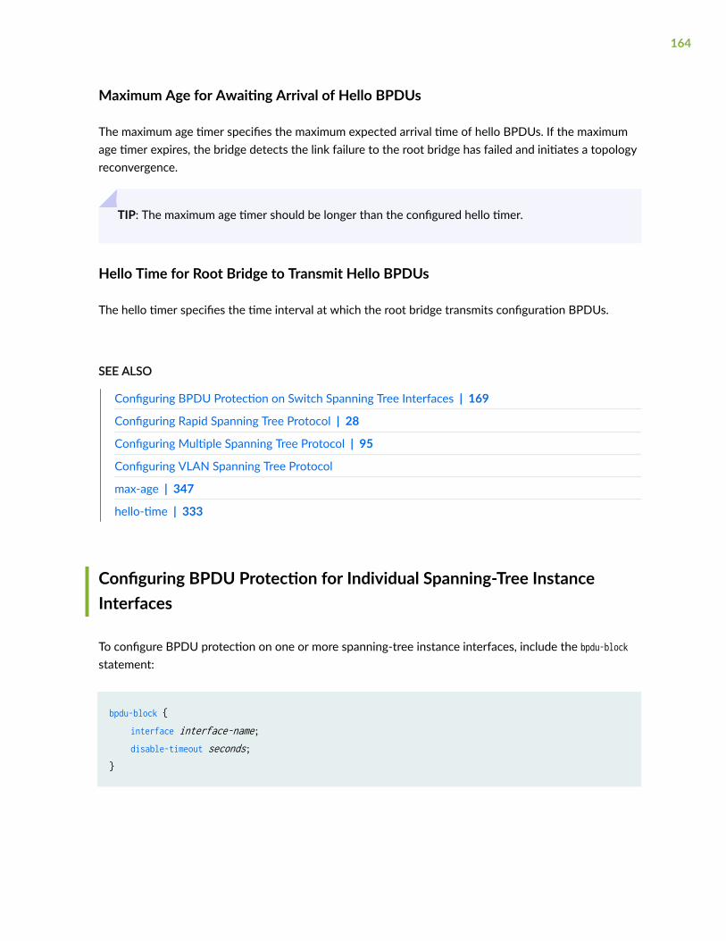
Maximum Age for Awaiting Arrival of Hello BPDUs
The maximum age timer specifies the maximum expected arrival time of hello BPDUs. If the maximumage timer expires, the bridge detects the link failure to the root bridge has failed and initiates a topologyreconvergence.
TIP: The maximum age timer should be longer than the configured hello timer.
Hello Time for Root Bridge to Transmit Hello BPDUs
The hello timer specifies the time interval at which the root bridge transmits configuration BPDUs.
SEE ALSO
Configuring BPDU Protection on Switch Spanning Tree Interfaces | 169
Configuring Rapid Spanning Tree Protocol | 28
Configuring Multiple Spanning Tree Protocol | 95
Configuring VLAN Spanning Tree Protocol
max-age | 347
hello-time | 333
Configuring BPDU Protection for Individual Spanning-Tree InstanceInterfaces
To configure BPDU protection on one or more spanning-tree instance interfaces, include the bpdu-blockstatement:
bpdu-block { interface interface-name; disable-timeout seconds;}
164

NOTE: If you also include the optional disable-timeout seconds statement, blocked interfaces areautomatically cleared after the specified time interval unless the interval is 0.
Understanding BPDUs Used for Exchanging Information Among Bridges
In a Layer 2 bridge environment, spanning-tree protocols use data frames called Bridge Protocol DataUnits (BPDUs) to exchange information among bridges.
Spanning-tree protocols on peer systems exchange BPDUs, which contain information about port roles,bridge IDs, and root path costs. On each MX Series router or EX Series switch, the spanning-treeprotocol uses this information to elect a root bridge, identify root ports for each switch, identifydesignated ports for each physical LAN segment, and prune specific redundant links to create a loop-free tree topology. The resulting tree topology provides a single active Layer 2 data path between anytwo end stations.
NOTE: In discussions of spanning-tree protocols, the terms bridge and switch are often usedinterchangeably.
The transmission of BPDUs is controlled by the Layer 2 Control Protocol process (l2cpd) on MX Series5G Universal Routing Platforms.
The transmission of periodic packets on behalf of the l2cpd process is carried out by periodic packetmanagement (PPM), which, by default, is configured to run on the Packet Forwarding Engine. The ppmdprocess on the Packet Forwarding Engine ensures that the BPDUs are transmitted even when the l2cpdprocess control plane is unavailable, and keeps the remote adjacencies alive during a unified in-servicesoftware upgrade (unified ISSU). However, if you want the distributed PPM (ppmd) process to run on theRouting Engine instead of the Packet Forwarding Engine, you can disable the ppmd process on thePacket Forwarding Engine.
On MX Series routers or EX Series switches with redundant Routing Engines (two Routing Engines thatare installed in the same router), you can configure nonstop bridging. Nonstop bridging enables therouter to switch from a primary Routing Engine to a backup Routing Engine without losing Layer 2Control Protocol (L2CP) information. Nonstop bridging uses the same infrastructure as graceful RoutingEngine switchover (GRES) to preserve interface and kernel information. However, nonstop bridging alsosaves L2CP information by running the l2cpd process on the backup Routing Engine.
165

NOTE: To use nonstop bridging, you must first enable GRES.
Nonstop bridging is supported for the following Layer 2 control protocols:
• Spanning-Tree Protocol (STP)
• Rapid Spanning-Tree Protocol (RSTP)
• Multiple Spanning-Tree Protocol (MSTP)
BPDU Protection on All Edge Ports of the Bridge
To configure edge port blocking for a particular STP family member, include the bpdu-block-on-edgestatement for mstp, rstp, or vstp:
bpdu-block-on-edge;interface interface-name;
In contrast to BPDU protection configured on individual spanning-tree instance interfaces, BPDUprotection configured on all edge ports of an entire spanning-tree protocol disables designated edgeports and does not enable them again.
Understanding BPDU Protection for EVPN-VXLAN
IN THIS SECTION
Enabling BPDU Protection on Edge Ports on Access and Leaf Devices with STP, MSTP, and RSTPConfigured | 167
Enabling BPDU Protection on Access and Leaf Devices without STP, MSTP, or RSTP Configured | 168
Enabling BPDU Protection on Access and Leaf devices without STP, MSTP, or RSTP Configured andForward other Traffic | 168
Automatically Unblocking an Interface Using an Expiry timer on Access and Leaf Devices | 168
Manually Unblocking an Interface on Access and Leaf Devices | 169
166

EVPN-VXLAN data center fabrics have a number of built-in Ethernet loop prevention mechanisms, suchas split-horizon and designated forwarder and non-designated forwarder election. In some existing datacenter environments where a new IP EVPN fabric is being deployed, you might need to configure BPDUprotection at the leaf-to-server interface in order to avoid network outages due to xSTP miscalculations.Incorrect cabling between the server and leaf interfaces, or any back-door layer 2 link between two ormore ESI-LAG interfaces, might cause miscalculations and then result in Ethernet loops. Without BPDUprotection, BPDUs might not be recognized and will be flooded as unknown Layer 2 packets on theVXLAN interfaces. With BPDU protection, when a BPDU is received on an edge port in an EVPN-VXLAN environment, the edge port is disabled and stops forwarding all traffic. You can also configureBPDU protection to drop BPDU traffic but have all other traffic forwarded on the interfaces withouthaving to configure a spanning-tree protocol.
Enabling BPDU Protection on Edge Ports on Access and Leaf Devices with STP,MSTP, and RSTP Configured
In this procedure, RSTP is being configured, but it works the same way for STP and MSTP.
1. o enable edge port blocking for RSTP:
[edit]user@host# set protocols rstp bpdu-block-on-edge
2. Configure RSTP on edge ports that are either access or trunk interfaces.
NOTE: Edge ports can be access or trunk ports.
To configure RSTP on edge ports:
[edit]user@host# set protocols rstp interface interface-name edge
For example:
[edit]user@host# set protocols rstp interface ae0 edge
In this example, ae0 is an ESI-LAG interface.
167
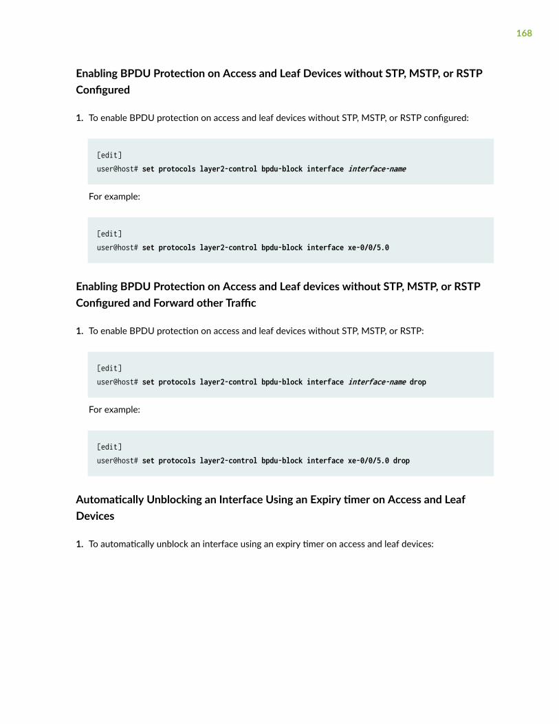
Enabling BPDU Protection on Access and Leaf Devices without STP, MSTP, or RSTPConfigured
1. To enable BPDU protection on access and leaf devices without STP, MSTP, or RSTP configured:
[edit]user@host# set protocols layer2-control bpdu-block interface interface-name
For example:
[edit]user@host# set protocols layer2-control bpdu-block interface xe-0/0/5.0
Enabling BPDU Protection on Access and Leaf devices without STP, MSTP, or RSTPConfigured and Forward other Traffic
1. To enable BPDU protection on access and leaf devices without STP, MSTP, or RSTP:
[edit]user@host# set protocols layer2-control bpdu-block interface interface-name drop
For example:
[edit]user@host# set protocols layer2-control bpdu-block interface xe-0/0/5.0 drop
Automatically Unblocking an Interface Using an Expiry timer on Access and LeafDevices
1. To automatically unblock an interface using an expiry timer on access and leaf devices:
168

NOTE: The range of seconds is between 10 and 3600.
[edit]user@host# set protocols layer2-control bpdu-block disable-timeout seconds
For example:
[edit]user@host# set protocols layer2-control bpdu-block disable-timeout seconds
Manually Unblocking an Interface on Access and Leaf Devices
1. To manually unblock an interface on access and leaf devices:
[edit]user@host# run clear error bpdu interface all
SEE ALSO
Understanding BPDU Protection for STP, RSTP, and MSTP
Using a Default Layer 3 Gateway to Route Traffic in an EVPN-VXLAN Overlay Network
EVPN Multihoming Overview
Configuring BPDU Protection on Switch Spanning Tree Interfaces
All spanning-tree protocols use a special type of frame called bridge protocol data units (BPDUs) tocommunicate with each other. Other devices in the network, such as PCs, generate their own BPDUsthat are not compatible with the spanning-tree BPDUs. When BPDUs generated by other devices aretransmitted to switches on which spanning-tree protocols are configured, a misconfiguration can occurin the spanning tree and a network outage can occur. Therefore, it is necessary to protect an interface ina spanning-tree topology from BPDUs generated from other devices.
On the ACX Series routers, MX Series routers QFX Series switches, and EX Series switches, you canconfigure BPDU protection to ignore BPDU received on interfaces where none are expected. If a BPDU
169

is received on a blocked interface, the interface is disabled and stops forwarding frames. By default, allBPDUs are accepted and processed on all interfaces.
NOTE: This topic applies to Junos OS for EX Series and QFX switches with support for theEnhanced Layer 2 Software (ELS) configuration style. For ELS details, see Using the EnhancedLayer 2 Software CLI.
You can configure BPDU protection to ignore BPDU received on interfaces where none are expected. Ifa BPDU is received on a blocked interface, the interface is disabled and stops forwarding frames. Bydefault, all BPDUs are accepted and processed on all interfaces.
To configure BPDU protection for spanning-tree instance interfaces:
• On a specific spanning-tree interface:
1. Enable BPDU protection on a specified spanning-tree interface:
[edit protocols layer2-control bpdu-block ]user@switcht# set interface (aex | (ge-fpc/pic/port | xe-fpc/pic/port)
If a BPDU is received on the interface, the system will disable the interface and stop forwardingframes out the interface until the bridging process is restarted.
2. (Optional) Configure the amount of time the system waits before automatically unblocking thisinterface after it has received a BPDU.
[edit protocols layer2-control bpdu-block interface interface-name]user@switch# set disable-timeout seconds
The range of the seconds option value is from 10 through 3600 seconds (one hour). A secondsoption value of 0 is allowed, but this results in the default behavior (the interface is blocked untilthe interface is cleared).
3. Verify the configuration of BPDU blocking for individual interfaces:
[edit]interfaces { ge-fpc/pic/port { # VLAN encapsulation on a Gigabit Ethernet. encapsulation (ethernet-bridge | ethernett-vpls | extended-vlan-bridge | extended-vlan-vpls | vlan-bridge| vlan-vpls);
170

} xe-fpc/pic/port { # VLAN encapsulation on 10-Gigabit Ethernet. encapsulation (ethernet-bridge | ethernett-vpls | extended-vlan-bridge | extended-vlan-vpls | vlan-bridge| vlan-vpls); } ae-X { # VLAN encapsulation encapsulation (ethernet-vpls vlan-vpls); # on aggregated Ethernet. ... } ae-X { # Extended VLAN encapsulation vlan-tagging; # on aggregated Ethernet. encapsulation extended-vlan-vpls; unit logical-unit-number { vlan-id number; ...... } ...... }}protocols layer2-control { bpdu-block interface interface-name; disable-timeout seconds; } }
• To disable BPDU protection for a specific spanning-tree interface
[edit protocols layer2-control bpdu-block interface interface-name]user@switch# set disable-timeout seconds
Configuring BPDU Protection on ACX Router, EX Switch and MX RouterEdge Ports
On ACX Series routers, MX Series routers, and EX Series switches, you can configure BPDU protectionto ignore BPDU received on interfaces where none should be expected. If a BPDU is received on a
171
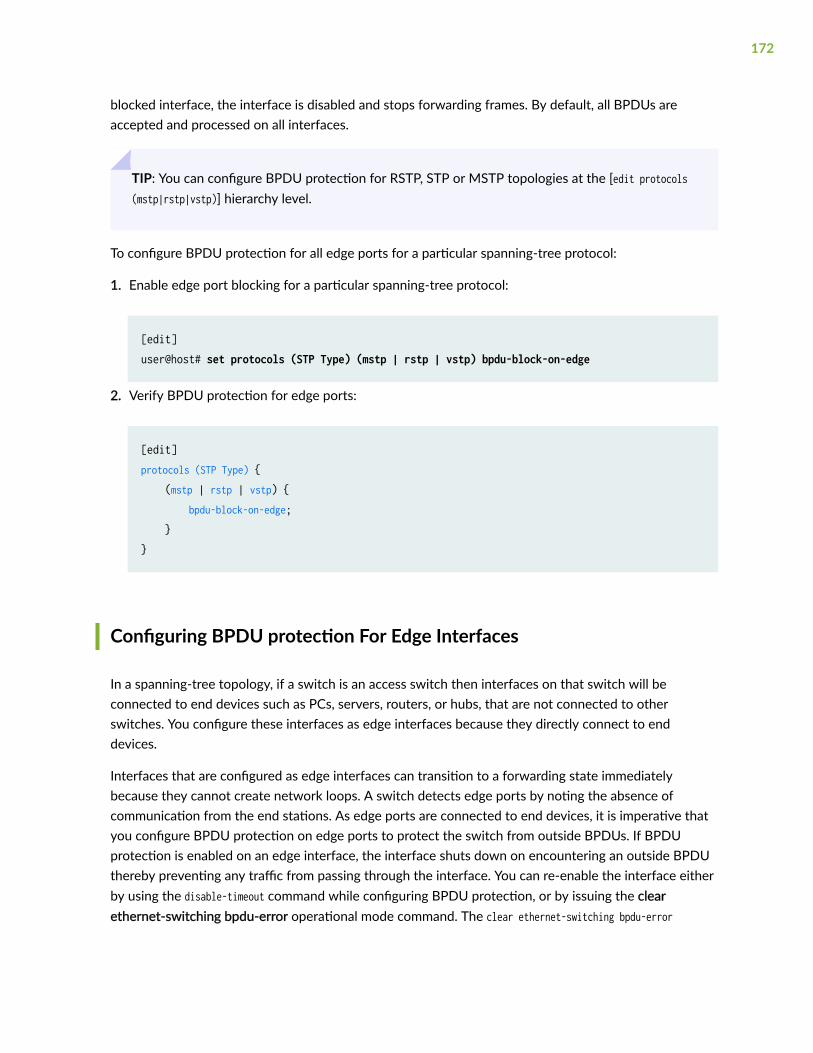
blocked interface, the interface is disabled and stops forwarding frames. By default, all BPDUs areaccepted and processed on all interfaces.
TIP: You can configure BPDU protection for RSTP, STP or MSTP topologies at the [edit protocols(mstp|rstp|vstp)] hierarchy level.
To configure BPDU protection for all edge ports for a particular spanning-tree protocol:
1. Enable edge port blocking for a particular spanning-tree protocol:
[edit]user@host# set protocols (STP Type) (mstp | rstp | vstp) bpdu-block-on-edge
2. Verify BPDU protection for edge ports:
[edit]protocols (STP Type) { (mstp | rstp | vstp) { bpdu-block-on-edge; }}
Configuring BPDU protection For Edge Interfaces
In a spanning-tree topology, if a switch is an access switch then interfaces on that switch will beconnected to end devices such as PCs, servers, routers, or hubs, that are not connected to otherswitches. You configure these interfaces as edge interfaces because they directly connect to enddevices.
Interfaces that are configured as edge interfaces can transition to a forwarding state immediatelybecause they cannot create network loops. A switch detects edge ports by noting the absence ofcommunication from the end stations. As edge ports are connected to end devices, it is imperative thatyou configure BPDU protection on edge ports to protect the switch from outside BPDUs. If BPDUprotection is enabled on an edge interface, the interface shuts down on encountering an outside BPDUthereby preventing any traffic from passing through the interface. You can re-enable the interface eitherby using the disable-timeout command while configuring BPDU protection, or by issuing the clearethernet-switching bpdu-error operational mode command. The clear ethernet-switching bpdu-error
172

command will only re-enable an interface but the BPDU configuration for the interface will continue toexist unless you explicitly remove the BPDU configuration.
To configure BPDU protection on an edge interface of a switch:
NOTE: Ensure that the switch is connected to an end device.
1. Configure any spanning-tree protocol on the switch if not configured already. RSTP is configured inthis procedure.
NOTE: The Rapid Spanning Tree Protocol (RSTP) is configured by default on a switch.
[edit protocols]user@switch# set rstp
2. Enable RSTP on a specific interface and set a priority for the interface—for example, ge-0/0/0.0:
[edit protocols]user@switch# set rstp interface ge-0/0/0.0 priority 16
3. Configure the ge-0/0/0.0 interface as an edge interface and enable BPDU protection on that interface:
[edit protocols]user@switch# set rstp bpdu-block-on-edge interface ge-0/0/0.0 edge
4. Commit the configuration:
[edit]user@switch# commit
5. Verify that BPDU protection is configured properly on the edge interface (ge-0/0/0.0):
• Run the show ethernet-switching interfaces operational mode command to ensure that BPDUprotection is configured on the edge interface:
user@switch> show ethernet-switching interfacesInterface State VLAN members Tag Tagging Blocking
173

ge-0/0/0.0 down default untagged Disabled by bpdu-controlme0.0 up mgmt untagged unblocked
In this output, you note that the ge-0/0/0.0 interface is down because it has received BPDUsfrom the end device. Also, note that the state of the Blocking field is Disabled by bpdu-control,which indicates that the port is disabled because of BPDU protection.
• Run the show spanning-tree interfaces operational mode command to ensure that the ge-0/0/0.0interface is not displayed in the output.
Configuring BPDU for Interface Protection With Port Shutdown Mode
In a spanning-tree topology, if a switch is an access switch then interfaces on that switch will beconnected to end devices such as PCs, servers, routers, or hubs, that are not connected to otherswitches. You configure these interfaces as edge interfaces because they directly connect to enddevices. Interfaces that are configured as edge interfaces can transition to a forwarding stateimmediately because they cannot create network loops. A switch detects edge ports by noting theabsence of communication from the end stations. As edge ports are connected to end devices, it isimperative that you configure BPDU protection on edge ports to protect the switch from outsideBPDUs. If BPDU protection is enabled on an edge interface, the interface shuts down on encounteringan outside BPDU thereby preventing any traffic from passing through the interface. You can re-enablethe interface either by using the disable-timeout command while configuring BPDU protection, or byissuing the clear ethernet-switching bpdu-error operational mode command. The clear ethernet-switchingbpdu-error command will only re-enable an interface but the BPDU configuration for the interface willcontinue to exist unless you explicitly remove the BPDU configuration.
To configure BPDU protection on an edge interface of a switch:
NOTE: Ensure that the switch is connected to an end device.
1. Configure any spanning-tree protocol on the switch if not configured already. RSTP is configured inthis procedure.
NOTE: The Rapid Spanning Tree Protocol (RSTP) is configured by default on a switch.
[edit protocols]user@switch# set rstp
174

2. Enable RSTP on a specific interface and set a priority for the interface—for example, ge-0/0/0.0:
[edit protocols]user@switch# set rstp interface ge-0/0/0.0 priority 16
3. Configure the ge-0/0/0.0 interface as an edge interface and enable BPDU protection on that interface:
[edit protocols]user@switch# set rstp bpdu-block-on-edge interface ge-0/0/0.0 edge
4. Commit the configuration:
[edit]user@switch# commit
5. Verify that BPDU protection is configured properly on the edge interface (ge-0/0/0.0):
• Run the show ethernet-switching interfaces operational mode command to ensure that BPDUprotection is configured on the edge interface:
user@switch> show ethernet-switching interfacesInterface State VLAN members Tag Tagging Blockingge-0/0/0.0 down default untagged Disabled by bpdu-controlme0.0 up mgmt untagged unblocked
In this output, you note that the ge-0/0/0.0 interface is down because it has received BPDUsfrom the end device. Also, note that the state of the Blocking field is Disabled by bpdu-control,which indicates that the port is disabled because of BPDU protection.
• Run the show spanning-tree interfaces operational mode command to ensure that the ge-0/0/0.0interface is not displayed in the output.
Configuring BPDU for Interface Protection With BPDU Drop Mode
For certain access switches, you might want interfaces on the switch not to shutdown on encounteringincompatible BPDU packets; instead, only drop incompatible BPDU packets while allowing theremaining traffic to pass through. Such an interface must not have a spanning-tree protocol configuredon it, so that packets that pass through the interface will not cause STP misconfiguration andconsequent network outages.
175

To configure BPDU protection for an interface to only drop incompatible BPDU packets and to allow theremaining traffic to pass through, while retaining the interface status as up:
NOTE: Ensure that the switch on which you are configuring BPDU protection is connected to apeer device.
1. Delete or disable any spanning-tree protocol (for instance, RSTP as in this procedure) configured onthe switch or on any interface.
• To delete a spanning-tree protocol on the entire switch:
[edit]user@switch# delete protocols rstp
Or,
[edit]user@switch# set protocols rstp disable
• To delete a spanning-tree protocol on a specific interface (for example, ge-0/0/0.0) on the switch:
[edit]user@switch# set protocols rstp interface ge-0/0/0.0 disable
NOTE: As RSTP is configured on a switch by default, ensure that you delete or disable RSTPeven though you had not configured it explicitly.
2. Ensure that the interface on which you want to enable the BPDU protection, is up and unblocked.For example, if you want to configure the BPDU protection on the ge-0/0/0.0 interface, following isthe output of the show ethernet-switching interfaces command if the interface is up and unblocked:
user@switch> show ethernet-switching interfacesInterface State VLAN members Tag Tagging Blockingge-0/0/0.0 up default untagged unblocked
In this output, note that the state of the ge-0/0/0.0 interface is up and the value for the Blockingfield is unblocked.
176

3. Enable the BPDU protection on the interface (ge-0/0/0.0 in this procedure) to drop BPDU packets:
[edit]user@switch set ethernet-switching-options bpdu-block interface ge-0/0/0.0 drop
4. Commit the configuration:
[edit]user@switch# commit
5. Verify that the BPDU protection is configured on the interface:
• Run the show ethernet-switching interfaces operational mode command to ensure that the BPDUprotection is configured on the interface:
user@switch> show ethernet-switching interfacesInterface State VLAN members Tag Tagging Blockingge-0/0/0.0 up default untagged unblocked-xSTP bpdu filter enabled
In this output, note that the ge-0/0/0.0 interface is up even though it has received incompatibleBPDU packets because the drop feature is configured for this interface. Also, note that the stateof the Blocking field is unblocked-xSTP bpdu filter enabled, which indicates that the BPDU dropfeature is enabled on this interface.
• Run the show spanning-tree interfaces operational mode command to ensure that the ge-0/0/0.0interface is displayed in the output and that the State of the interface is DIS, which indicates thatthe interface discards all incompatible BPDUs:
user@switch> show spanning-tree interfaceSpanning tree interface parameters for instance 0
Interface Port ID Designated Designated Port State Role port ID bridge ID Costge-0/0/0.0 128:513 16:513 8192.841888af0681 20000 DIS DIS
177
Example: Configuring BPDU Protection on Interfaces to Prevent STPMiscalculations
IN THIS SECTION
Requirements | 178
Overview | 179
Configuration | 179
Verification | 181
NOTE: This example uses Junos OS for SRX Series devices with support for the Enhanced Layer2 Software (ELS) configuration style. For ELS details, see Using the Enhanced Layer 2 SoftwareCLI.
Spanning-tree protocols support loop-free network communication through the exchange of a specialtype of frame called a bridge protocol data unit (BPDU). However, when BPDUs generated by spanning-tree protocols are communicated to devices on which spanning-tree protocols are not configured, thesedevices recognize the BPDUs, which can lead to network outages. You can, however, enable BPDUprotection on device interfaces to prevent BPDUs generated by spanning-tree protocols from passingthrough those interfaces. When BPDU protection is enabled, an interface shuts down when anyincompatible BPDU is encountered, thereby preventing the BPDUs generated by spanning-treeprotocols from reaching the device.
This example configures BPDU protection on STP device downstream interfaces that connect to twoPCs:
Requirements
This example uses the following software and hardware components:
• One SRX Series device in an RSTP
• One SRX Series device that is not in any spanning-tree
• Junos OS Release 15.1X49-D70 or later
Before you configure the interfaces on device 2 for BPDU protection, be sure you have:
178

• Ensured that RSTP is operating on device 1.
• Disabled RSTP on device 2
Overview
SRX Series devices provide Layer 2 loop prevention through Rapid Spanning Tree protocol (RSTP) andMultiple Spanning Tree Protocol (MSTP). All spanning-tree protocols use a special type of frame called aBPDU to communicate. Other devices also use BPDUs—PC bridging applications, for example, generatetheir own BPDUs. These different BPDUs are not compatible. When BPDUs generated by spanning-treeprotocols are transmitted to a device that uses another type of BPDU, they can cause problems on thedevice. Similarly, if devices within a spanning-tree topology receive BPDUs from other devices, networkoutages can occur because of the miscalculations caused by the outside BPDUs. Therefore, you mustconfigure BPDU protection on interfaces in a spanning-tree to avoid network outages.
This example explains how to block outside BPDUs from reaching a device interface connected todevices that are not part of the STP. In this scenario, an interface is shutdown when it encounters anoutside BPDU.
This example configures downstream BPDU protection on device 2 interfaces ge-0/0/5 and ge-0/0/6.When BPDU protection is enabled, the device interfaces will shut down if BPDUs generated by thelaptops attempt to access device 2.
CAUTION: When configuring BPDU protection on an interface without spanning treesconnected to a device with spanning trees, be careful that you do not configure BPDUprotection on all interfaces. Doing so could prevent BPDUs being received on deviceinterfaces (such as a trunk interface) that you intended to have receive BPDUs from adevice with spanning trees.
Configuration
IN THIS SECTION
CLI Quick Configuration | 180
Procedure | 180
Results | 180
To configure BPDU protection on the interfaces:
179

CLI Quick Configuration
To quickly configure this example, copy the following commands, paste them into a text file, remove anyline breaks, change any details necessary to match your network configuration, copy and paste thecommands into the CLI at the [edit] hierarchy level, and then enter commit from configuration mode.
NOTE: This example configures BPDU protection on specific interfaces. For, SRX Series deviceswith support for the Enhanced Layer 2 Software (ELS) configuration style, you can configureBPDU protection globally on all spanning tree interfaces. See Configuring BPDU Protection onSpanning Tree Interfaces for additional information.
set protocols layer2-control bpdu-block interface ge-0/0/5 set protocols layer2-control bpdu-block interface ge-0/0/6
Procedure
Step-by-Step Procedure
To configure BPDU protection for automatic shutdown.
1. To shutdown the BPDU interface on the downstream interface ge-0/0/5 on device 2:
[edit protocol layer 2]user@host# set bpdu-block interface ge-0/0/5
2. To shutdown the BPDU interface on the downstream interface ge-0/0/6 on device 2:
[edit protocol layer 2]user@host# set bpdu-block interface ge-0/0/6
Results
Check the results of the configuration:
user@host> show protocol layer 2 bpdu-block { interface ge-0/0/5 {
180

interface ge-0/0/6 {}
Verification
IN THIS SECTION
Displaying the Interface State Before BPDU Protection Is Triggered | 181
Verifying That BPDU Shutdown Protection Is Working Correctly | 183
To confirm that the configuration is working properly, perform these tasks:
Displaying the Interface State Before BPDU Protection Is Triggered
Purpose
Before any BPDUs can be received on device 2 on either interface ge-0/0/5 or interface ge-0/0/6, confirmthe state of those interfaces.
Action
Use the operational mode command show interfaces extensive <interface name>:
user@host> show interfaces extensive ge-0/0/5
Physical interface: ge-0/0/5, Enabled, Physical link is Down Interface index: 141, SNMP ifIndex: 516, Generation: 144 Link-level type: Ethernet, MTU: 1514, LAN-PHY mode, Link-mode: Full-duplex, Speed: 1000mbps, BPDU Error: None, MAC-REWRITE Error: None, Loopback: Disabled, Source filtering: Disabled, Flow control: Disabled, Auto-negotiation: Enabled, Remote fault: Online Device flags : Present Running Down Interface flags: Hardware-Down SNMP-Traps Internal: 0x0 Link flags : None CoS queues : 8 supported, 8 maximum usable queues Hold-times : Up 0 ms, Down 0 ms Current address: 30:7c:5e:44:b1:c6, Hardware address: 30:7c:5e:44:b1:c6 Last flapped : 2017-01-16 20:23:55 PST (05:44:46 ago)
181

Statistics last cleared: Never Traffic statistics: Input bytes : 0 0 bps Output bytes : 0 0 bps Input packets: 0 0 pps Output packets: 0 0 pps Dropped traffic statistics due to STP State: Input bytes : 0 Output bytes : 0 Input packets: 0 Output packets: 0 Input errors: Errors: 0, Drops: 0, Framing errors: 0, Runts: 0, Policed discards: 0, L3 incompletes: 0, L2 channel errors: 0, L2 mismatch timeouts: 0, FIFO errors: 0, Resource errors: 0 Output errors: Carrier transitions: 0, Errors: 0, Drops: 0, Collisions: 0, Aged packets: 0, FIFO errors: 0, HS link CRC errors: 0, MTU errors: 0, Resource errors: 0 Active alarms : LINK Active defects : LINK MAC statistics: Receive Transmit Total octets 0 0 Total packets 0 0 Unicast packets 0 0 Broadcast packets 0 0 Multicast packets 0 0 CRC/Align errors 0 0 FIFO errors 0 0 MAC control frames 0 0 MAC pause frames 0 0 Oversized frames 0 Jabber frames 0 Fragment frames 0 VLAN tagged frames 0 Code violations 0 Filter statistics: Input packet count 0 Input packet rejects 0 Input DA rejects 0 Input SA rejects 0 Output packet count 0 Output packet pad count 0 Output packet error count 0 CAM destination filters: 1, CAM source filters: 0
182
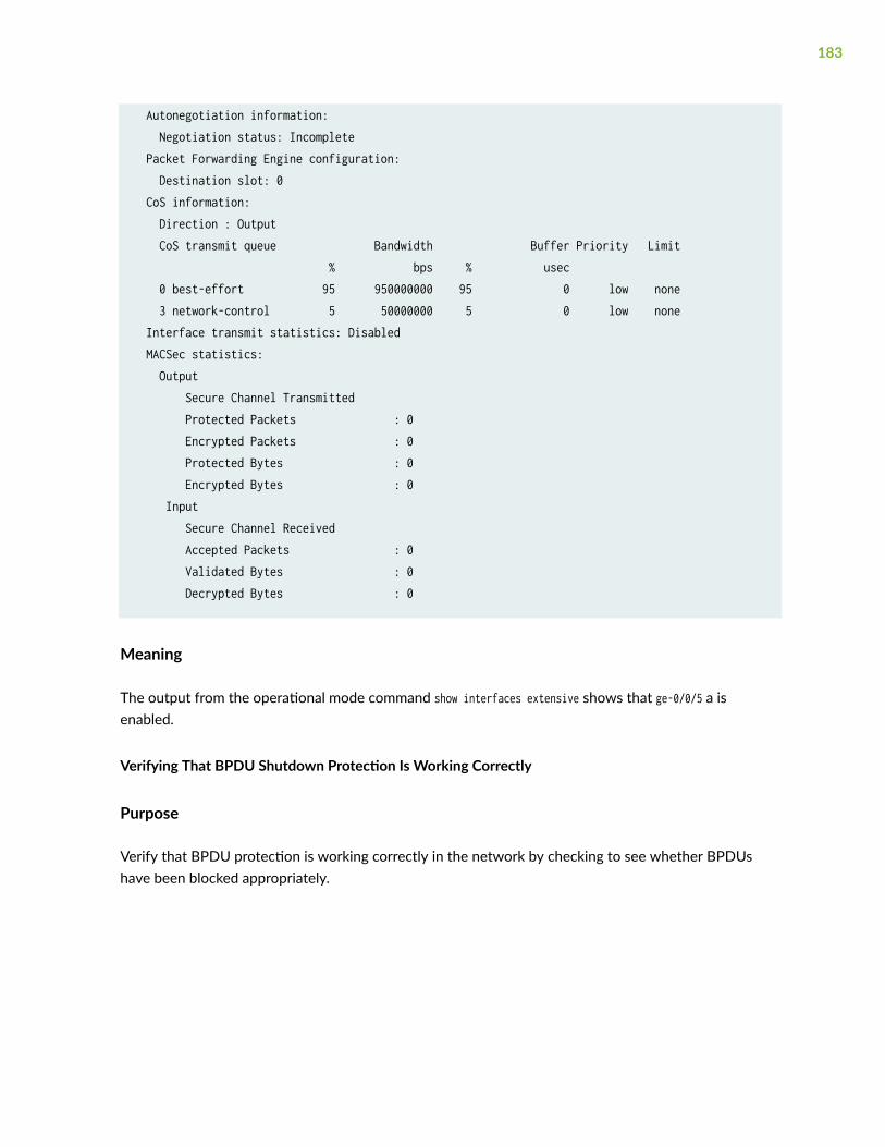
Autonegotiation information: Negotiation status: Incomplete Packet Forwarding Engine configuration: Destination slot: 0 CoS information: Direction : Output CoS transmit queue Bandwidth Buffer Priority Limit % bps % usec 0 best-effort 95 950000000 95 0 low none 3 network-control 5 50000000 5 0 low none Interface transmit statistics: Disabled MACSec statistics: Output Secure Channel Transmitted Protected Packets : 0 Encrypted Packets : 0 Protected Bytes : 0 Encrypted Bytes : 0 Input Secure Channel Received Accepted Packets : 0 Validated Bytes : 0 Decrypted Bytes : 0
Meaning
The output from the operational mode command show interfaces extensive shows that ge-0/0/5 a isenabled.
Verifying That BPDU Shutdown Protection Is Working Correctly
Purpose
Verify that BPDU protection is working correctly in the network by checking to see whether BPDUshave been blocked appropriately.
183
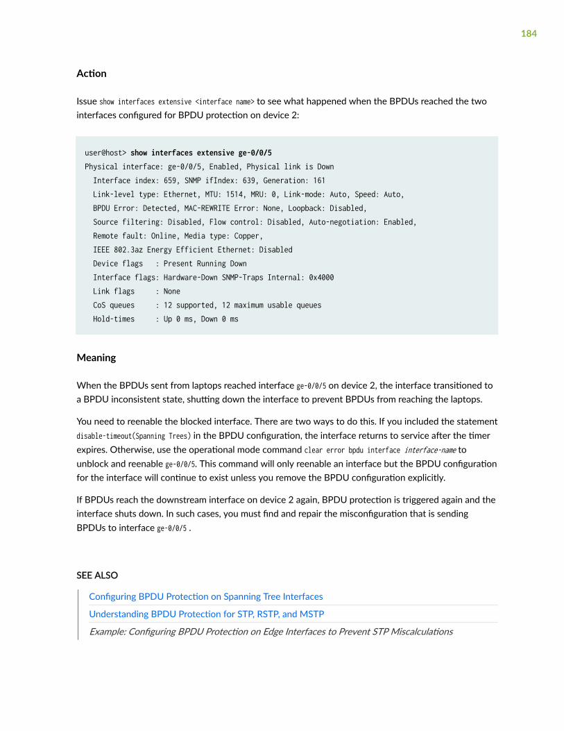
Action
Issue show interfaces extensive <interface name> to see what happened when the BPDUs reached the twointerfaces configured for BPDU protection on device 2:
user@host> show interfaces extensive ge-0/0/5 Physical interface: ge-0/0/5, Enabled, Physical link is Down Interface index: 659, SNMP ifIndex: 639, Generation: 161 Link-level type: Ethernet, MTU: 1514, MRU: 0, Link-mode: Auto, Speed: Auto, BPDU Error: Detected, MAC-REWRITE Error: None, Loopback: Disabled, Source filtering: Disabled, Flow control: Disabled, Auto-negotiation: Enabled, Remote fault: Online, Media type: Copper, IEEE 802.3az Energy Efficient Ethernet: Disabled Device flags : Present Running Down Interface flags: Hardware-Down SNMP-Traps Internal: 0x4000 Link flags : None CoS queues : 12 supported, 12 maximum usable queues Hold-times : Up 0 ms, Down 0 ms
Meaning
When the BPDUs sent from laptops reached interface ge-0/0/5 on device 2, the interface transitioned toa BPDU inconsistent state, shutting down the interface to prevent BPDUs from reaching the laptops.
You need to reenable the blocked interface. There are two ways to do this. If you included the statementdisable-timeout(Spanning Trees) in the BPDU configuration, the interface returns to service after the timerexpires. Otherwise, use the operational mode command clear error bpdu interface interface-name tounblock and reenable ge-0/0/5. This command will only reenable an interface but the BPDU configurationfor the interface will continue to exist unless you remove the BPDU configuration explicitly.
If BPDUs reach the downstream interface on device 2 again, BPDU protection is triggered again and theinterface shuts down. In such cases, you must find and repair the misconfiguration that is sendingBPDUs to interface ge-0/0/5 .
SEE ALSO
Configuring BPDU Protection on Spanning Tree Interfaces
Understanding BPDU Protection for STP, RSTP, and MSTP
Example: Configuring BPDU Protection on Edge Interfaces to Prevent STP Miscalculations
184
Example: Configuring BPDU Protection on MX Edge Interfaces toPrevent STP Miscalculations
IN THIS SECTION
Requirements | 185
Overview | 186
Configuration | 188
Verification | 189
MX Series routers provide Layer 2 loop prevention through the Spanning Tree Protocol (STP), RapidSpanning Tree protocol (RSTP), and Multiple Spanning Tree Protocol (MSTP). All spanning-tree protocolsuse a special type of frame called a bridge protocol data unit (BPDU) to communicate. Other devices—PC bridging applications, for example also use BPDUs and generate their own BPDUs. These differentBPDUs are not compatible. When BPDUs generated by spanning-tree protocols are transmitted to adevice that uses another type of BPDU, they can cause problems on the device. Similarly, if routerswithin a spanning-tree topology receive BPDUs from other devices, network outages can occur becauseof STP miscalculations.
This example configures BPDU protection on MX Series routers that use RSTP. The upstreamconfiguration is done on the edge interfaces, where outside BPDUs are often received from otherdevices.
Requirements
This example uses the following hardware and software components:
• Two MX Series routers in an RSTP topology
• Junos OS Release 13.1 or later
Before you configure the interfaces on Router 2 for BPDU protection, be sure you have:
• RSTP enabled on the routers.
185
Overview
IN THIS SECTION
Topology | 187
The MX Series routers, being in an RSTP topology, support a loop-free network through the exchange ofBPDUs. Receipt of outside BPDUs in an STP, RSTP, or MSTP topology, however, can lead to networkoutages by triggering an STP misconfiguration. To prevent such outages, enable BPDU protection onSTP interfaces that could receive outside BPDUs. If an outside BPDU is received on a BPDU-protectedinterface, the interface shuts down to prevent the outside BPDU from accessing the STP interface.
Figure 5 on page 187 shows the topology for this example. In this example, Router 1 and Router 2 areconfigured for RSTP and create a loop-free topology. The interfaces on Router 2 are edge access portswhich frequently receive outside BPDUs generated by PC applications.
This example configures interface ge-0/0/5.0 and interface ge-0/0/6.0 as edge ports on Router 2, andthen configures BPDU protection on those ports. With BPDU protection enabled, these interfaces shutdown when they encounter an outside BPDU sent by the PCs connected to Router 2.
186

Topology
Figure 5: BPDU Protection Topology
Table 7 on page 187 describes the components that are configured for BPDU protection.
Table 7: Components of the Topology for Configuring BPDU Protection on MX Series Routers
Property Settings
Router 1 (Distribution Layer) Router 1 is connected to Router 2 on a trunk interface.
187
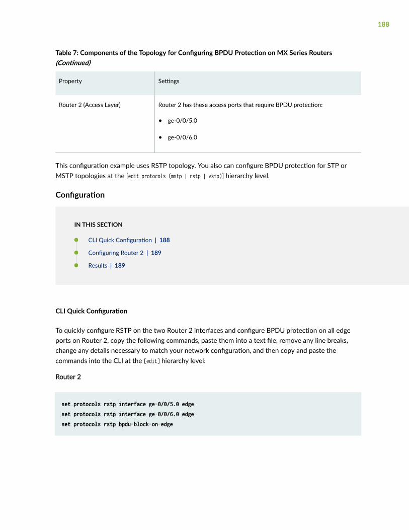
Table 7: Components of the Topology for Configuring BPDU Protection on MX Series Routers(Continued)
Property Settings
Router 2 (Access Layer) Router 2 has these access ports that require BPDU protection:
• ge-0/0/5.0
• ge-0/0/6.0
This configuration example uses RSTP topology. You also can configure BPDU protection for STP orMSTP topologies at the [edit protocols (mstp | rstp | vstp)] hierarchy level.
Configuration
IN THIS SECTION
CLI Quick Configuration | 188
Configuring Router 2 | 189
Results | 189
CLI Quick Configuration
To quickly configure RSTP on the two Router 2 interfaces and configure BPDU protection on all edgeports on Router 2, copy the following commands, paste them into a text file, remove any line breaks,change any details necessary to match your network configuration, and then copy and paste thecommands into the CLI at the [edit] hierarchy level:
Router 2
set protocols rstp interface ge-0/0/5.0 edgeset protocols rstp interface ge-0/0/6.0 edgeset protocols rstp bpdu-block-on-edge
188
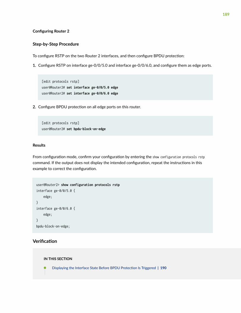
Configuring Router 2
Step-by-Step Procedure
To configure RSTP on the two Router 2 interfaces, and then configure BPDU protection:
1. Configure RSTP on interface ge-0/0/5.0 and interface ge-0/0/6.0, and configure them as edge ports.
[edit protocols rstp]user@Router2# set interface ge-0/0/5.0 edgeuser@Router2# set interface ge-0/0/6.0 edge
2. Configure BPDU protection on all edge ports on this router.
[edit protocols rstp]user@Router2# set bpdu-block-on-edge
Results
From configuration mode, confirm your configuration by entering the show configuration protocols rstpcommand. If the output does not display the intended configuration, repeat the instructions in thisexample to correct the configuration.
user@Router2> show configuration protocols rstp interface ge-0/0/5.0 { edge;}interface ge-0/0/6.0 { edge;}bpdu-block-on-edge;
Verification
IN THIS SECTION
Displaying the Interface State Before BPDU Protection Is Triggered | 190
189

Verifying That BPDU Protection Is Working Correctly | 191
Verify that the configuration is working properly.
Displaying the Interface State Before BPDU Protection Is Triggered
Purpose
Before BPDUs can be received from PCs connected to interface ge-0/0/5.0 and interface ge-0/0/6.0,confirm the interface state.
Action
Use the operational mode command show spanning-tree instance.
user@Router2> show spanning-tree interface
Spanning tree interface parameters for instance 0
Interface Port ID Designated Designated Port State Role port ID bridge ID Costge-0/0/0.0 128:513 128:513 32768.0019e2503f00 20000 BLK DIS ge-0/0/1.0 128:514 128:514 32768.0019e2503f00 20000 BLK DIS ge-0/0/2.0 128:515 128:515 32768.0019e2503f00 20000 BLK DIS ge-0/0/3.0 128:516 128:516 32768.0019e2503f00 20000 FWD DESG ge-0/0/4.0 128:517 128:517 32768.0019e2503f00 20000 FWD DESG ge-0/0/5.0 128:518 128:518 32768.0019e2503f00 20000 FWD DESG ge-0/0/6.0 128:519 128:519 32768.0019e2503f00 20000 FWD DESG [output truncated]
Meaning
The output from the show spanning-tree interface command shows that interface ge-0/0/5.0 and interfacege-0/0/6.0 are ports in a forwarding state.
190

Verifying That BPDU Protection Is Working Correctly
Purpose
In this example, the PCs connected to Router 2 start sending BPDUs to interface ge-0/0/5.0 andinterface ge-0/0/6.0. Verify that BPDU protection is working on the interfaces.
Action
Use the operational mode command show spanning-tree interface.
user@Router2> show spanning-tree interface
Spanning tree interface parameters for instance 0
Interface Port ID Designated Designated Port State Role port ID bridge ID Costge-0/0/0.0 128:513 128:513 32768.0019e2503f00 20000 BLK DIS ge-0/0/1.0 128:514 128:514 32768.0019e2503f00 20000 BLK DIS ge-0/0/2.0 128:515 128:515 32768.0019e2503f00 20000 BLK DIS ge-0/0/3.0 128:516 128:516 32768.0019e2503f00 20000 FWD DESG ge-0/0/4.0 128:517 128:517 32768.0019e2503f00 20000 FWD DESG ge-0/0/5.0 128:518 128:518 32768.0019e2503f00 20000 BLK DIS (Bpdu—Incon)ge-0/0/6.0 128:519 128:519 32768.0019e2503f00 20000 BLK DIS (Bpdu—Incon)ge-0/0/7.0 128:520 128:1 16384.00aabbcc0348 20000 FWD ROOT ge-0/0/8.0 128:521 128:521 32768.0019e2503f00 20000 FWD DESG [output truncated]
Meaning
When BPDUs are sent from the PCs to interface ge-0/0/5.0 and interface ge-0/0/6.0 on Router 2, theoutput from the operational mode command show spanning-tree interface shows that the interfaces havetransitioned to a BPDU inconsistent state. The BPDU inconsistent state causes the interfaces to shutdown.
Disabling the BPDU protection configuration on an interface does not automatically re-enable theinterface. However, if the disable-timeout statement has been included in the BPDU configuration, theinterface does return to service after the timer expires. Otherwise, you must use the operational modecommand clear error bpdu interface interface-name to unblock and re-enable the interface.
If the PCs connected to Router 2 send BPDUs to the interfaces again, BPDU protection is triggered oncemore, and the interfaces transition back to the BPDU inconsistent state, causing them to shut down. In
191

such cases, you need to find and repair the misconfiguration on the PCs that are sending BPDUs toRouter 2.
Example: Configuring BPDU Protection on Edge Interfaces to PreventSTP Miscalculations
IN THIS SECTION
Requirements | 192
Overview | 193
Configuration | 193
Verification | 195
SRX Series devices provide Layer 2 loop prevention through Rapid Spanning Tree protocol (RSTP) andMultiple Spanning Tree Protocol (MSTP). All spanning-tree protocols use a special type of frame called abridge protocol data unit (BPDU) to communicate. Other devices—PC bridging applications, for example,also use BPDUs and generate their own BPDUs. These different BPDUs are not compatible. WhenBPDUs generated by spanning-tree protocols are transmitted to a device that uses another type ofBPDU, they can cause problems on the device. Similarly, if devices within a spanning-tree topologyreceive BPDUs from other devices, network outages can occur because of STP miscalculations.
This example configures BPDU protection on a SRX Series device that uses RSTP. The upstreamconfiguration is done on the edge interfaces, where outside BPDUs are often received from otherdevices:
Requirements
This example uses the following software and hardware components:
• Two SRX Series devices in an RSTP topology
• Junos OS Release 15.1X49-D70 or later
Before you configure the interfaces on device 2 for BPDU protection, be sure you have:
• RSTP enabled on the devices.
192

Overview
The devices, being in an RSTP, support a loop-free network through the exchange of BPDUs. Receipt ofoutside BPDUs in an RSTP or MSTP, however, can lead to network outages by triggering an STPmisconfiguration. To prevent such outages, enable BPDU protection on spanning tree interfaces thatcould receive outside BPDUs. If an outside BPDU is received on a BPDU-protected interface, theinterface shuts down to prevent the outside BPDU from accessing the spanning tree interface.
In this example, device 1 and device 2 are configured for RSTP. The interfaces on device 2 are edgeaccess ports—edge access ports frequently receive outside BPDUs generated by PC applications.
This example configures interface ge-0/0/5 and interface ge-0/0/6 as edge ports on device 2, and thenconfigures BPDU protection on those ports. With BPDU protection enabled, these interfaces shut downwhen they encounter an outside BPDU sent by the PCs connected to device 2.
Configuration
IN THIS SECTION
CLI Quick Configuration | 193
Procedure | 194
Results | 194
To configure BPDU protection on two access interfaces:
CLI Quick Configuration
To quickly configure this example, copy the following commands, paste them into a text file, remove anyline breaks, change any details necessary to match your network configuration, copy and paste thecommands into the CLI at the [edit] hierarchy level, and then enter commit from configuration mode.
NOTE: This example configures BPDU protection on specific interfaces. SRX Series devices withsupport for the Enhanced Layer 2 Software (ELS) configuration style, you can also configure
193

BPDU protection globally on all spanning tree interfaces. See Configuring BPDU Protection onSpanning Tree Interfaces for additional information.
set protocols rstp interface ge-0/0/5 edge set protocols rstp interface ge-0/0/6 edge set protocols rstp bpdu-block-on-edge
Procedure
Step-by-Step Procedure
To configure RSTP on the two device 2 interfaces, and then configure BPDU protection:
1. Configure RSTP on interface ge-0/0/5 and interface ge-0/0/6, and configure them as edge ports:
[edit protocols rstp]user@host# set interface ge-0/0/5 edgeuser@host# set interface ge-0/0/6 edge
2. Configure BPDU protection on all edge ports on this device:
[edit protocols rstp]user@host# set bpdu-block-on-edge
Results
Check the results of the configuration:
user@host> show configuration protocols rstp interface ge-0/0/5 { edge;}interface ge-0/0/6 { edge;
194
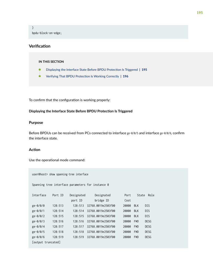
}bpdu-block-on-edge;
Verification
IN THIS SECTION
Displaying the Interface State Before BPDU Protection Is Triggered | 195
Verifying That BPDU Protection Is Working Correctly | 196
To confirm that the configuration is working properly:
Displaying the Interface State Before BPDU Protection Is Triggered
Purpose
Before BPDUs can be received from PCs connected to interface ge-0/0/5 and interface ge-0/0/6, confirmthe interface state.
Action
Use the operational mode command:
user@host> show spanning-tree interface
Spanning tree interface parameters for instance 0
Interface Port ID Designated Designated Port State Role port ID bridge ID Costge-0/0/0 128:513 128:513 32768.0019e2503f00 20000 BLK DIS ge-0/0/1 128:514 128:514 32768.0019e2503f00 20000 BLK DIS ge-0/0/2 128:515 128:515 32768.0019e2503f00 20000 BLK DIS ge-0/0/3 128:516 128:516 32768.0019e2503f00 20000 FWD DESG ge-0/0/4 128:517 128:517 32768.0019e2503f00 20000 FWD DESG ge-0/0/5 128:518 128:518 32768.0019e2503f00 20000 FWD DESG ge-0/0/6 128:519 128:519 32768.0019e2503f00 20000 FWD DESG [output truncated]
195

Meaning
The output from the operational mode command show spanning-tree interface shows that ge-0/0/5 andinterface ge-0/0/6 are ports in a forwarding state.
Verifying That BPDU Protection Is Working Correctly
Purpose
In this example, the PCs connected to device 2 start sending BPDUs to interface ge-0/0/5 and interfacege-0/0/6. Verify that BPDU protection is working on the interfaces.
Action
Use the operational mode command:
user@host> show spanning-tree interface
Spanning tree interface parameters for instance 0
Interface Port ID Designated Designated Port State Role port ID bridge ID Costge-0/0/0 128:513 128:513 32768.0019e2503f00 20000 BLK DIS ge-0/0/1 128:514 128:514 32768.0019e2503f00 20000 BLK DIS ge-0/0/2 128:515 128:515 32768.0019e2503f00 20000 BLK DIS ge-0/0/3 128:516 128:516 32768.0019e2503f00 20000 FWD DESG ge-0/0/4 128:517 128:517 32768.0019e2503f00 20000 FWD DESG ge-0/0/5 128:518 128:518 32768.0019e2503f00 20000 BLK DIS (Bpdu—Incon)ge-0/0/6 128:519 128:519 32768.0019e2503f00 20000 BLK DIS (Bpdu—Incon)ge-0/0/7 128:520 128:1 16384.00aabbcc0348 20000 FWD ROOT ge-0/0/8 128:521 128:521 32768.0019e2503f00 20000 FWD DESG [output truncated]
Meaning
When BPDUs are sent from the PCs to interface ge-0/0/5 and interface ge-0/0/6 on device 2, the outputfrom the operational mode command show spanning-tree interface shows that the interfaces havetransitioned to a BPDU inconsistent state. The BPDU inconsistent state causes the interfaces to shutdown.
196

Disabling the BPDU protection configuration on an interface does not automatically reenable theinterface. However, if the disable-timeout (Spanning Trees) statement has been included in the BPDUconfiguration, the interface does return to service after the timer expires. Otherwise, you must use theoperational mode command clear error bpdu to unblock and reenable the interface.
If the PCs connected to device 2 send BPDUs to the interfaces again, BPDU protection is triggered oncemore and the interfaces transition back to the BPDU inconsistent state, causing them to shut down. Insuch cases, you need to find and repair the misconfiguration on the PCs that is sending BPDUs to device2.
Example: Configuring BPDU Protection on Switch Edge Interfaces WithELS to Prevent STP Miscalculations
IN THIS SECTION
Requirements | 197
Overview and Topology | 198
Configuration | 200
Verification | 201
EX Series and QFX Series switches provide Layer 2 loop prevention through Rapid Spanning Treeprotocol (RSTP) and Multiple Spanning Tree Protocol (MSTP). All spanning-tree protocols use a specialtype of frame called a bridge protocol data unit (BPDU) to communicate. Other devices—PC bridgingapplications, for example, also use BPDUs and generate their own BPDUs. These different BPDUs arenot compatible. When BPDUs generated by spanning-tree protocols are transmitted to a device thatuses another type of BPDU, they can cause problems on the device. Similarly, if switches within aspanning-tree topology receive BPDUs from other devices, network outages can occur because of STPmiscalculations.
This example configures BPDU protection on an EX Series switch that uses RSTP. The upstreamconfiguration is done on the edge interfaces, where outside BPDUs are often received from otherdevices:
Requirements
This example uses the following software and hardware components:
• Two EX Series switches in an RSTP topology
197
• Junos OS Release 13.2X50-D10 or later or later for EX Series or QFX Series switches
Before you configure the interfaces on Switch 2 for BPDU protection, be sure you have:
• RSTP enabled on the switches.
NOTE: By default, RSTP is enabled on all EX Series switches.
Overview and Topology
IN THIS SECTION
Topology | 199
The switches, being in an RSTP topology, support a loop-free network through the exchange of BPDUs.Receipt of outside BPDUs in an RSTP or MSTP topology, however, can lead to network outages bytriggering an STP misconfiguration. To prevent such outages, enable BPDU protection on spanning treeinterfaces that could receive outside BPDUs. If an outside BPDU is received on a BPDU-protectedinterface, the interface shuts down to prevent the outside BPDU from accessing the spanning treeinterface.
Figure 6 on page 199 shows the topology for this example. In this example, Switch 1 and Switch 2 areconfigured for RSTP and create a loop-free topology. The interfaces on Switch 2 are edge access ports—edge access ports frequently receive outside BPDUs generated by PC applications.
This example configures interface ge-0/0/5 and interface ge-0/0/6 as edge ports on Switch 2, and thenconfigures BPDU protection on those ports. With BPDU protection enabled, these interfaces shut downwhen they encounter an outside BPDU sent by the PCs connected to Switch 2.
198

Topology
Figure 6: BPDU Protection Topology
Table 8 on page 199 shows the components that will be configured for BPDU protection.
Table 8: Components of the Topology for Configuring BPDU Protection on EX Series Switches
Property Settings
Switch 1 (Distribution Layer) Switch 1 is connected to Switch 2 on a trunk interface.
Switch 2 (Access Layer) Switch 2 has these access ports that require BPDU protection:
• ge-0/0/5
• ge-0/0/6
199
This configuration example uses RSTP topology. You also can configure BPDU protection for MSTPtopologies at the [edit protocols mstp ] hierarchy level.
Configuration
IN THIS SECTION
Procedure | 200
To configure BPDU protection on two access interfaces:
Procedure
CLI Quick Configuration
Quickly configure RSTP on the two Switch 2 interfaces, and then configure BPDU protection on all edgeports on Switch 2 by copying the following commands and pasting them into the switch terminalwindow:
NOTE: This example configures BPDU protection on specific interfaces. Starting with Junos OSRelease 15.1 for EX Series and QFX Series switches with support for the Enhanced Layer 2Software (ELS) configuration style, you can also configure BPDU protection globally on allspanning tree interfaces. See "Configuring BPDU Protection on Switch Spanning Tree Interfaces"on page 169 for additional information.
[edit]set protocols rstp interface ge-0/0/5 edge set protocols rstp interface ge-0/0/6 edge set protocols rstp bpdu-block-on-edge
Step-by-Step Procedure
To configure RSTP on the two Switch 2 interfaces, and then configure BPDU protection:
200

1. Configure RSTP on interface ge-0/0/5 and interface ge-0/0/6, and configure them as edge ports:
[edit protocols rstp]user@switch# set interface ge-0/0/5 edge user@switch# set interface ge-0/0/6 edge
2. Configure BPDU protection on all edge ports on this switch:
[edit protocols rstp]user@switch# set bpdu-block-on-edge
Results
Check the results of the configuration:
user@switch> show configuration protocols rstp interface ge-0/0/5 { edge;}interface ge-0/0/6 { edge;}bpdu-block-on-edge;
Verification
IN THIS SECTION
Displaying the Interface State Before BPDU Protection Is Triggered | 202
Verifying That BPDU Protection Is Working Correctly | 202
To confirm that the configuration is working properly:
201

Displaying the Interface State Before BPDU Protection Is Triggered
Purpose
Before BPDUs can be received from PCs connected to interface ge-0/0/5 and interface ge-0/0/6, confirmthe interface state.
Action
Use the operational mode command:
user@switch> show spanning-tree interface
Spanning tree interface parameters for instance 0
Interface Port ID Designated Designated Port State Role port ID bridge ID Costge-0/0/0 128:513 128:513 32768.0019e2503f00 20000 BLK DIS ge-0/0/1 128:514 128:514 32768.0019e2503f00 20000 BLK DIS ge-0/0/2 128:515 128:515 32768.0019e2503f00 20000 BLK DIS ge-0/0/3 128:516 128:516 32768.0019e2503f00 20000 FWD DESG ge-0/0/4 128:517 128:517 32768.0019e2503f00 20000 FWD DESG ge-0/0/5 128:518 128:518 32768.0019e2503f00 20000 FWD DESG ge-0/0/6 128:519 128:519 32768.0019e2503f00 20000 FWD DESG [output truncated]
Meaning
The output from the operational mode command show spanning-tree interface shows that ge-0/0/5 andinterface ge-0/0/6 are ports in a forwarding state.
Verifying That BPDU Protection Is Working Correctly
Purpose
In this example, the PCs connected to Switch 2 start sending BPDUs to interface ge-0/0/5 and interfacege-0/0/6. Verify that BPDU protection is working on the interfaces.
202

Action
Use the operational mode command:
user@switch> show spanning-tree interface
Spanning tree interface parameters for instance 0
Interface Port ID Designated Designated Port State Role port ID bridge ID Costge-0/0/0 128:513 128:513 32768.0019e2503f00 20000 BLK DIS ge-0/0/1 128:514 128:514 32768.0019e2503f00 20000 BLK DIS ge-0/0/2 128:515 128:515 32768.0019e2503f00 20000 BLK DIS ge-0/0/3 128:516 128:516 32768.0019e2503f00 20000 FWD DESG ge-0/0/4 128:517 128:517 32768.0019e2503f00 20000 FWD DESG ge-0/0/5 128:518 128:518 32768.0019e2503f00 20000 BLK DIS (Bpdu—Incon)ge-0/0/6 128:519 128:519 32768.0019e2503f00 20000 BLK DIS (Bpdu—Incon)ge-0/0/7 128:520 128:1 16384.00aabbcc0348 20000 FWD ROOT ge-0/0/8 128:521 128:521 32768.0019e2503f00 20000 FWD DESG [output truncated]
Meaning
When BPDUs are sent from the PCs to interface ge-0/0/5 and interface ge-0/0/6 on Switch 2, the outputfrom the operational mode command show spanning-tree interface shows that the interfaces havetransitioned to a BPDU inconsistent state. The BPDU inconsistent state causes the interfaces to shutdown.
Disabling the BPDU protection configuration on an interface does not automatically reenable theinterface. However, if the disable-timeout statement has been included in the BPDU configuration, theinterface does return to service after the timer expires. Otherwise, you must use the operational modecommand clear error bpdu to unblock and reenable the interface.
If the PCs connected to Switch 2 send BPDUs to the interfaces again, BPDU protection is triggered oncemore and the interfaces transition back to the BPDU inconsistent state, causing them to shut down. Insuch cases, you need to find and repair the misconfiguration on the PCs that is sending BPDUs to Switch2.
203
Example: Configuring BPDU Protection on Edge Interfaces to PreventSTP Miscalculations on non-ELS EX Series Switches
IN THIS SECTION
Requirements | 204
Overview and Topology | 205
Configuration | 207
Verification | 208
EX Series switches provide Layer 2 loop prevention through Spanning Tree Protocol (STP), RapidSpanning Tree protocol (RSTP), and Multiple Spanning Tree Protocol (MSTP). All spanning-tree protocolsuse a special type of frame called a bridge protocol data unit (BPDU) to communicate. Other devices—PC bridging applications, for example, also use BPDUs and generate their own BPDUs. These differentBPDUs are not compatible. When BPDUs generated by spanning-tree protocols are transmitted to adevice that uses another type of BPDU, they can cause problems on the device. Similarly, if switcheswithin a spanning-tree topology receive BPDUs from other devices, network outages can occur becauseof STP miscalculations.
This example configures BPDU protection on an EX Series switch that uses RSTP. The upstreamconfiguration is done on the edge interfaces, where outside BPDUs are often received from otherdevices:
Requirements
This example uses the following hardware and software components:
• Two EX Series switches in an RSTP topology
• Junos OS Release 9.1 or later for EX Series switches
Before you configure the interfaces on Switch 2 for BPDU protection, be sure you have:
• RSTP enabled on the switches.
NOTE: By default, RSTP is enabled on all EX Series switches.
204

Overview and Topology
IN THIS SECTION
Topology | 206
The switches, being in an RSTP topology, support a loop-free network through the exchange of BPDUs.Receipt of outside BPDUs in an STP, RSTP, or MSTP topology, however, can lead to network outages bytriggering an STP misconfiguration. To prevent such outages, enable BPDU protection on STP interfacesthat could receive outside BPDUs. If an outside BPDU is received on a BPDU-protected interface, theinterface shuts down to prevent the outside BPDU from accessing the STP interface.
Figure 7 on page 206 shows the topology for this example. In this example, Switch 1 and Switch 2 areconfigured for RSTP and create a loop-free topology. The interfaces on Switch 2 are edge access ports—edge access ports frequently receive outside BPDUs generated by PC applications.
This example configures interface ge-0/0/5.0 and interface ge-0/0/6.0 as edge ports on Switch 2, andthen configures BPDU protection on those ports. With BPDU protection enabled, these interfaces shutdown when they encounter an outside BPDU sent by the PCs connected to Switch 2.
205

Topology
Figure 7: BPDU Protection Topology
Table 9 on page 206 shows the components that will be configured for BPDU protection.
Table 9: Components of the Topology for Configuring BPDU Protection on EX Series Switches
Property Settings
Switch 1 (Distribution Layer) Switch 1 is connected to Switch 2 on a trunk interface.
Switch 2 (Access Layer) Switch 2 has these access ports that require BPDU protection:
• ge-0/0/5.0
• ge-0/0/6.0
206

This configuration example uses RSTP topology. You also can configure BPDU protection for STP orMSTP topologies at the [edit protocols (mstp | stp)] hierarchy level.
Configuration
IN THIS SECTION
Procedure | 207
To configure BPDU protection on two access interfaces:
Procedure
CLI Quick Configuration
Quickly configure RSTP on the two Switch 2 interfaces, and then configure BPDU protection on all edgeports on Switch 2 by copying the following commands and pasting them into the switch terminalwindow:
[edit] set protocols rstp interface ge-0/0/5.0 edge set protocols rstp interface ge-0/0/6.0 edge set protocols rstp bpdu-block-on-edge
Step-by-Step Procedure
To configure RSTP on the two Switch 2 interfaces, and then configure BPDU protection:
1. Configure RSTP on interface ge-0/0/5.0 and interface ge-0/0/6.0, and configure them as edge ports:
[edit protocols rstp]user@switch# set interface ge-0/0/5.0 edge user@switch# set interface ge-0/0/6.0 edge
207

2. Configure BPDU protection on all edge ports on this switch:
[edit protocols rstp]user@switch# set bpdu-block-on-edge
Results
Check the results of the configuration:
user@switch> show configuration protocols rstp interface ge-0/0/5.0 { edge;}interface ge-0/0/6.0 { edge;}bpdu-block-on-edge;
Verification
IN THIS SECTION
Displaying the Interface State Before BPDU Protection Is Triggered | 208
Verifying That BPDU Protection Is Working Correctly | 209
To confirm that the configuration is working properly:
Displaying the Interface State Before BPDU Protection Is Triggered
Purpose
Before BPDUs can be received from PCs connected to interface ge-0/0/5.0 and interface ge-0/0/6.0,confirm the interface state.
208

Action
Use the operational mode command:
user@switch> show spanning-tree interface
Spanning tree interface parameters for instance 0
Interface Port ID Designated Designated Port State Role port ID bridge ID Costge-0/0/0.0 128:513 128:513 32768.0019e2503f00 20000 BLK DIS ge-0/0/1.0 128:514 128:514 32768.0019e2503f00 20000 BLK DIS ge-0/0/2.0 128:515 128:515 32768.0019e2503f00 20000 BLK DIS ge-0/0/3.0 128:516 128:516 32768.0019e2503f00 20000 FWD DESG ge-0/0/4.0 128:517 128:517 32768.0019e2503f00 20000 FWD DESG ge-0/0/5.0 128:518 128:518 32768.0019e2503f00 20000 FWD DESG ge-0/0/6.0 128:519 128:519 32768.0019e2503f00 20000 FWD DESG [output truncated]
Meaning
The output from the operational mode command show spanning-tree interface shows that ge-0/0/5.0 andinterface ge-0/0/6.0 are ports in a forwarding state.
Verifying That BPDU Protection Is Working Correctly
Purpose
In this example, the PCs connected to Switch 2 start sending BPDUs to interface ge-0/0/5.0 andinterface ge-0/0/6.0 . Verify that BPDU protection is working on the interfaces.
Action
Use the operational mode command:
user@switch> show spanning-tree interface
Spanning tree interface parameters for instance 0
209

Interface Port ID Designated Designated Port State Role port ID bridge ID Costge-0/0/0.0 128:513 128:513 32768.0019e2503f00 20000 BLK DIS ge-0/0/1.0 128:514 128:514 32768.0019e2503f00 20000 BLK DIS ge-0/0/2.0 128:515 128:515 32768.0019e2503f00 20000 BLK DIS ge-0/0/3.0 128:516 128:516 32768.0019e2503f00 20000 FWD DESG ge-0/0/4.0 128:517 128:517 32768.0019e2503f00 20000 FWD DESG ge-0/0/5.0 128:518 128:518 32768.0019e2503f00 20000 BLK DIS (Bpdu—Incon)ge-0/0/6.0 128:519 128:519 32768.0019e2503f00 20000 BLK DIS (Bpdu—Incon)ge-0/0/7.0 128:520 128:1 16384.00aabbcc0348 20000 FWD ROOT ge-0/0/8.0 128:521 128:521 32768.0019e2503f00 20000 FWD DESG [output truncated]
Meaning
When BPDUs are sent from the PCs to interface ge-0/0/5.0 and interface ge-0/0/6.0 on Switch 2, theoutput from the operational mode command show spanning-tree interface shows that the interfaces havetransitioned to a BPDU inconsistent state. The BPDU inconsistent state causes the interfaces to shutdown.
Disabling the BPDU protection configuration on an interface does not automatically re-enable theinterface. However, if the disable-timeout statement has been included in the BPDU configuration, theinterface does return to service after the timer expires. Otherwise, you must use the operational modecommand clear ethernet-switching bpdu-error interface to unblock and re-enable the interface.
If the PCs connected to Switch 2 send BPDUs to the interfaces again, BPDU protection is triggered oncemore and the interfaces transition back to the BPDU inconsistent state, causing them to shut down. Insuch cases, you need to find and repair the misconfiguration on the PCs that is sending BPDUs to Switch2.
Example: Configuring BPDU Protection on Interfaces to Prevent STPMiscalculations on EX Series Switches
IN THIS SECTION
Requirements | 211
Overview and Topology | 212
210

Configuration | 214
Verification | 215
NOTE: This example uses Junos OS for EX Series switches with support for the Enhanced Layer2 Software (ELS) configuration style. If your switch runs software that does not support ELS, see"Example: Configuring BPDU Protection on Interfaces to Prevent STP Miscalculations on EXSeries Switches" on page 218. For ELS details, see Using the Enhanced Layer 2 Software CLI.
Spanning-tree protocols support loop-free network communication through the exchange of a specialtype of frame called a bridge protocol data unit (BPDU). However, when BPDUs generated by spanning-tree protocols are communicated to devices on which spanning-tree protocols are not configured, thesedevices recognize the BPDUs, which can lead to network outages. You can, however, enable BPDUprotection on switch interfaces to prevent BPDUs generated by spanning-tree protocols from passingthrough those interfaces. When BPDU protection is enabled, an interface shuts down when anyincompatible BPDU is encountered, thereby preventing the BPDUs generated by spanning-treeprotocols from reaching the switch.
This example configures BPDU protection on STP switch downstream interfaces that connect to twoPCs:
Requirements
This example uses the following software and hardware components:
• One EX Series switch in an RSTP topology
• One EX Series switch that is not in any spanning-tree topology
• Junos OS Release 13.2X50-D10 or later or later for EX Series switches
Before you configure the interfaces on Switch 2 for BPDU protection, be sure you have:
• Ensured that RSTP is operating on Switch 1.
• Disabled RSTP on Switch 2
NOTE: By default, RSTP is enabled on all EX Series switches.
211

Overview and Topology
IN THIS SECTION
Topology | 213
EX Series switches provide Layer 2 loop prevention through Rapid Spanning Tree protocol (RSTP) andMultiple Spanning Tree Protocol (MSTP). All spanning-tree protocols use a special type of frame called aBPDU to communicate. Other devices also use BPDUs—PC bridging applications, for example, generatetheir own BPDUs. These different BPDUs are not compatible. When BPDUs generated by spanning-treeprotocols are transmitted to a device that uses another type of BPDU, they can cause problems on thedevice. Similarly, if switches within a spanning-tree topology receive BPDUs from other devices,network outages can occur because of the miscalculations caused by the outside BPDUs. Therefore, youmust configure BPDU protection on interfaces in a spanning-tree topology to avoid network outages.
This example explains how to block outside BPDUs from reaching a switch interface connected todevices that are not part of the STP topology. In this scenario, an interface is shutdown when itencounters an outside BPDU.
Figure 8 on page 213 shows the topology for this example. Switch 1 and Switch 2 are connectedthrough a trunk interface. Switch 1 is configured for RSTP and Switch 2 does not have a spanning-treeprotocol configured on it.
This example configures downstream BPDU protection on Switch 2 interfaces ge-0/0/5 and ge-0/0/6.When BPDU protection is enabled, the switch interfaces will shut down if BPDUs generated by thelaptops attempt to access Switch 2.
CAUTION: When configuring BPDU protection on an interface without spanning treesconnected to a switch with spanning trees, be careful that you do not configure BPDUprotection on all interfaces. Doing so could prevent BPDUs being received on switchinterfaces (such as a trunk interface) that you intended to have receive BPDUs from aswitch with spanning trees.
212

Topology
Figure 8: BPDU Protection Topology
Table 10 on page 213 shows the components that will be configured for BPDU protection.
Table 10: Components of the Topology for Configuring BPDU Protection on EX Series Switches
Property Settings
Switch 1 (Distribution Layer) Switch 1 is connected to Switch 2 through a trunk interface. Switch 1 isconfigured for RSTP.
Switch 2 (Access Layer) Switch 2 has two downstream access ports connected to laptops:
• ge-0/0/5
• ge-0/0/6
213

Configuration
IN THIS SECTION
Procedure | 214
To configure BPDU protection on the interfaces:
Procedure
CLI Quick Configuration
This configuration causes the interface to automatically shutdown if it receives BPDUs. To quicklyconfigure BPDU protection on Switch 2 , copy the following commands and paste them into the switchterminal window:
NOTE: This example configures BPDU protection on specific interfaces. However, starting withJunos OS Release 15.1 for EX Series and QFX Series switches with support for the EnhancedLayer 2 Software (ELS) configuration style, you can configure BPDU protection globally on allspanning tree interfaces. See "Configuring BPDU Protection on Switch Spanning Tree Interfaces"on page 169 for additional information.
[edit]
user@switch# set protocols layer2-control bpdu-block interface ge-0/0/5 [edit]
user@switch# set protocols layer2-control bpdu-block interface ge-0/0/6
Step-by-Step Procedure
To configure BPDU protection for automatic shutdown.
214

1. To shutdown the BPDU interface on the downstream interface ge-0/0/5 on Switch 2:
[edit protocol layer 2]user@switch# set bpdu-block interface ge-0/0/5
2. To shutdown the BPDU interface on the downstream interface ge-0/0/6 on Switch 2:
[edit protocol layer 2]user@switch# set bpdu-block interface ge-0/0/6
Results
Check the results of the configuration:
user@switch> show protocol layer 2 bpdu-block { interface ge-0/0/5 { interface ge-0/0/6 {}
Verification
IN THIS SECTION
Displaying the Interface State Before BPDU Protection Is Triggered | 215
Verifying That BPDU Shutdown Protection Is Working Correctly | 216
To confirm that the configuration is working properly, perform these tasks:
Displaying the Interface State Before BPDU Protection Is Triggered
Purpose
Before any BPDUs can be received on Switch 2 on either interface ge-0/0/5 or interface ge-0/0/6, confirmthe state of those interfaces.
215

Action
Use the operational mode command show interfaces extensive <interface name>:
user@switch> show interfaces extensive ge-0/0/5
Physical interface: ge-0/0/5, Enabled, Physical link is Down Interface index: 659, SNMP ifIndex: 639, Generation: 161 Link-level type: Ethernet, MTU: 1514, MRU: 0, Link-mode: Auto, Speed: Auto, BPDU Error: Detected, MAC-REWRITE Error: None, Loopback: Disabled, Source filtering: Disabled, Flow control: Disabled, Auto-negotiation: Enabled, Remote fault: Online, Media type: Copper, IEEE 802.3az Energy Efficient Ethernet: Disabled Device flags : Present Running Down Interface flags: Hardware-Down SNMP-Traps Internal: 0x4000 Link flags : None CoS queues : 12 supported, 12 maximum usable queues Hold-times : Up 0 ms, Down 0 ms
Meaning
The output from the operational mode command show interfaces extensive shows that ge-0/0/5 a isenabled.
Verifying That BPDU Shutdown Protection Is Working Correctly
Purpose
Verify that BPDU protection is working correctly in the network by checking to see whether BPDUshave been blocked appropriately.
Action
Issue show interfaces extensive <interface name> to see what happened when the BPDUs reached the twointerfaces configured for BPDU protection on Switch 2:
user@switch> show interfaces extensive ge-0/0/5
216

Physical interface: ge-0/0/5, Enabled, Physical link is Down Interface index: 659, SNMP ifIndex: 639, Generation: 161 Link-level type: Ethernet, MTU: 1514, MRU: 0, Link-mode: Auto, Speed: Auto, BPDU Error: Detected, MAC-REWRITE Error: None, Loopback: Disabled, Source filtering: Disabled, Flow control: Disabled, Auto-negotiation: Enabled, Remote fault: Online, Media type: Copper, IEEE 802.3az Energy Efficient Ethernet: Disabled Device flags : Present Running Down Interface flags: Hardware-Down SNMP-Traps Internal: 0x4000 Link flags : None CoS queues : 12 supported, 12 maximum usable queues Hold-times : Up 0 ms, Down 0 ms
Meaning
When the BPDUs sent from laptops reached interface ge-0/0/5 on Switch 2, the interface transitioned toa BPDU inconsistent state, shutting down the interface to prevent BPDUs from reaching the laptops.
You need to reenable the blocked interface. There are two ways to do this. If you included the statementdisable-timeout(Spanning Trees) in the BPDU configuration, the interface returns to service after the timerexpires. Otherwise, use the operational mode command clear error bpdu interface interface-name tounblock and reenable ge-0/0/5. This command will only reenable an interface but the BPDU configurationfor the interface will continue to exist unless you remove the BPDU configuration explicitly.
If BPDUs reach the downstream interface on Switch 2 again, BPDU protection is triggered again and theinterface shuts down. In such cases, you must find and repair the misconfiguration that is sendingBPDUs to interface ge-0/0/5 .
Example: Blocking BPDUs on Aggregated Ethernet Interface for600 Seconds
The following example, when used with a full bridge configuration with aggregated Ethernet, blocksBPDUs on aggregated interface ae0 for 10 minutes (600 seconds) before enabling the interface again:
[edit protocols layer2-control]bpdu-block { interface ae0; disable-timeout 600;}
217

SEE ALSO
Understanding Root Protection for Spanning-Tree Instance Interfaces in a Layer 2 Switched Network | 261
Checking the Status of Spanning-Tree Instance Interfaces | 286
Example: Configuring BPDU Protection on Interfaces to Prevent STPMiscalculations on EX Series Switches
IN THIS SECTION
Requirements | 219
Overview and Topology | 219
Configuration | 222
Verification | 225
NOTE: This example uses Junos OS for EX Series switches without support for the EnhancedLayer 2 Software (ELS) configuration style. If your switch runs software that supports ELS, see"Example: Configuring BPDU Protection on Interfaces to Prevent STP Miscalculations on EXSeries Switches" on page 210. For ELS details, see Using the Enhanced Layer 2 Software CLI.
Spanning-tree protocols support loop-free network communication through the exchange of a specialtype of frame called a bridge protocol data unit (BPDU). However, when BPDUs generated by spanning-tree protocols are communicated to devices on which spanning-tree protocols are not configured, thesedevices recognize the BPDUs, which can lead to network outages. You can, however, enable BPDUprotection on switch interfaces to prevent BPDUs generated by spanning-tree protocols from passingthrough those interfaces. When BPDU protection is enabled, an interface shuts down or drops BPDUpackets when any incompatible BPDU is encountered, thereby preventing the BPDUs generated byspanning-tree protocols from reaching the switch. When an interface is configured to drop BPDUpackets, all traffic except the incompatible BPDUs can pass through the interface.
218
NOTE: The BPDU drop feature can be specified only on interfaces on which no spanning-treeprotocol is configured.
This example configures BPDU protection on STP switch downstream interfaces that connect to twoPCs:
Requirements
This example uses the following hardware and software components:
• One EX Series switch in an RSTP topology
• One EX Series switch that is not in any spanning-tree topology
• Junos OS Release 9.1 or later for EX Series switches
Before you configure the interfaces on Switch 2 for BPDU protection, be sure you have:
• Ensured that RSTP is operating on Switch 1.
• Disabled or enabled RSTP on Switch 2 (depending on the configuration that you plan to implement.)
If you want to enable the BPDU shutdown feature, then it is optional to disable spanning-treeprotocols on the interface.
NOTE: By default, RSTP is enabled on all EX Series switches.
Overview and Topology
IN THIS SECTION
Topology | 221
EX Series switches provide Layer 2 loop prevention through Spanning Tree Protocol (STP), RapidSpanning Tree protocol (RSTP), and Multiple Spanning Tree Protocol (MSTP). All spanning-tree protocolsuse a special type of frame called a BPDU to communicate. Other devices also use BPDUs—PC bridgingapplications, for example, generate their own BPDUs. These different BPDUs are not compatible. WhenBPDUs generated by spanning-tree protocols are transmitted to a device that uses another type ofBPDU, they can cause problems on the device. Similarly, if switches within a spanning-tree topology
219

receive BPDUs from other devices, network outages can occur because of the miscalculations caused bythe outside BPDUs. Therefore, you must configure BPDU protection on interfaces in a spanning-treetopology to avoid network outages.
This example explains how to block outside BPDUs from reaching a switch interface connected todevices that are not part of the STP topology. This example addresses two scenarios. In the firstscenario, an interface is shutdown when it encounters an outside BPDU. In the second scenario, aninterface drops only BPDU packets while retaining the status of the interface as up and allowing allother traffic to pass through the interface.
Figure 9 on page 221 shows the topology for this example. Switch 1 and Switch 2 are connectedthrough a trunk interface. Switch 1 is configured for RSTP while Switch 2 has a spanning-tree protocolconfigured on it for the first scenario, and does not have a spanning-tree protocol configured on it forthe second scenario.
In the first scenario, this example configures downstream BPDU protection on Switch 2 interfacesge-0/0/5.0 and ge-0/0/6.0 when the default spanning-tree protocol (RSTP) is not disabled on theseinterfaces. When BPDU protection is enabled with the shutdown statement, the switch interfaces will shutdown if BPDUs generated by the laptops attempt to access Switch 2.
In the second scenario, this example configures downstream BPDU protection on Switch 2 interfacesge-0/0/5.0 and ge-0/0/6.0 when the default spanning-tree protocol (RSTP) is disabled on theseinterfaces. When BPDU protection is enabled with the drop statement, the switch interfaces drop onlythe BPDUs while allowing remaining traffic to pass through and retaining their status as up if BPDUsgenerated by the laptops attempt to access Switch 2.
CAUTION: When configuring BPDU protection on an interface without spanning treesconnected to a switch with spanning trees, be careful that you do not configure BPDUprotection on all interfaces. Doing so could prevent BPDUs being received on switchinterfaces (such as a trunk interface) that you intended to have receive BPDUs from aswitch with spanning trees.
220

Topology
Figure 9: BPDU Protection Topology
Table 11 on page 221 shows the components that will be configured for BPDU protection.
Table 11: Components of the Topology for Configuring BPDU Protection on EX Series Switches
Property Settings
Switch 1 (Distribution Layer) Switch 1 is connected to Switch 2 through a trunk interface. Switch 1 isconfigured for RSTP.
Switch 2 (Access Layer) Switch 2 has two downstream access ports connected to laptops:
• ge-0/0/5.0
• ge-0/0/6.0
221
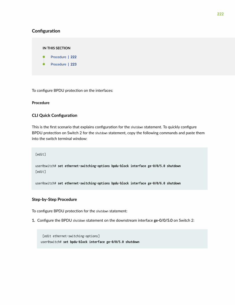
Configuration
IN THIS SECTION
Procedure | 222
Procedure | 223
To configure BPDU protection on the interfaces:
Procedure
CLI Quick Configuration
This is the first scenario that explains configuration for the shutdown statement. To quickly configureBPDU protection on Switch 2 for the shutdown statement, copy the following commands and paste theminto the switch terminal window:
[edit]
user@switch# set ethernet-switching-options bpdu-block interface ge-0/0/5.0 shutdown[edit]
user@switch# set ethernet-switching-options bpdu-block interface ge-0/0/6.0 shutdown
Step-by-Step Procedure
To configure BPDU protection for the shutdown statement:
1. Configure the BPDU shutdown statement on the downstream interface ge-0/0/5.0 on Switch 2:
[edit ethernet-switching-options]user@switch# set bpdu-block interface ge-0/0/5.0 shutdown
222

2. Configure the BPDU shutdown statement on the downstream interface ge-0/0/6.0 on Switch 2:
[edit ethernet-switching-options]user@switch# set bpdu-block interface ge-0/0/6.0 shutdown
Results
Check the results of the configuration:
user@switch> show ethernet-switching-options bpdu-block { interface ge-0/0/5.0 { shutdown; } interface ge-0/0/6.0 { shutdown; }}
Procedure
CLI Quick Configuration
This is the second scenario that explains configuration for the drop statement. To quickly configure BPDUprotection on Switch 2 for the drop statement, copy the following commands and paste them into theswitch terminal window:
[edit]
user@switch# set protocols rstp interface ge-0/0/5.0 disableuser@switch# set protocols rstp interface ge-0/0/6.0 disableuser@switch# set ethernet-switching-options bpdu-block interface ge-0/0/5.0 dropuser@switch# set ethernet-switching-options bpdu-block interface ge-0/0/6.0 drop
NOTE: You can also disable RSTP globally using the delete protocols rstp, the set protocols rstpdisable, or the set protocols rstp interface all disable command.
223

Step-by-Step Procedure
To configure BPDU protection for the drop statement:
1. Disable RSTP on both the interfaces ge-0/0/5.0 and ge-0/0/6.0 interfaces:
[edit]user@switch# set protocols rstp interface ge-0/0/5.0 disableuser@switch# set protocols rstp interface ge-0/0/6.0 disable
2. Configure the BPDU drop statement on the downstream interface ge-0/0/5.0 on Switch 2:
[edit ethernet-switching-options]user@switch# set bpdu-block interface ge-0/0/5.0 drop
3. Configure the BPDU drop statement on the downstream interface ge-0/0/6.0 on Switch 2:
[edit ethernet-switching-options]user@switch# set bpdu-block interface ge-0/0/6.0 drop
Results
Check the results of the configuration:
user@switch> show protocols rstpinterface ge-0/0/5.0 { disable;}interface ge-0/0/6.0 { disable;}user@switch> show ethernet-switching-optionsbpdu-block { interface ge-0/0/5.0 { drop; } interface ge-0/0/6.0 { drop;
224
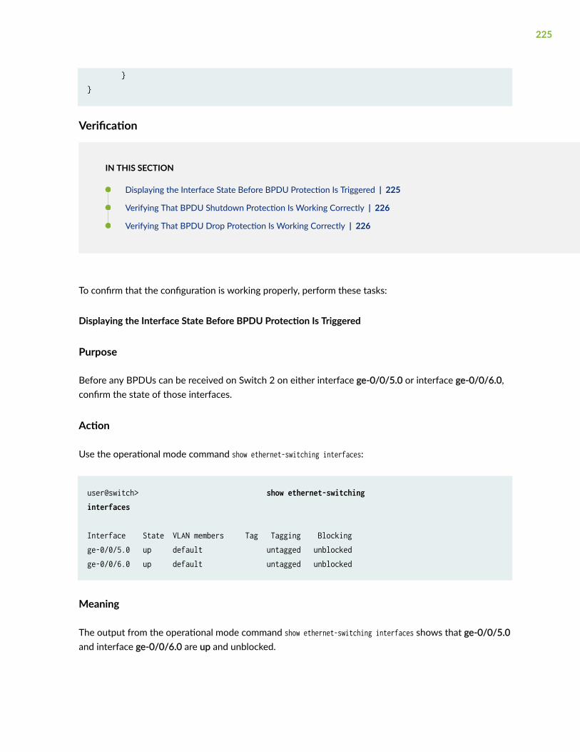
}}
Verification
IN THIS SECTION
Displaying the Interface State Before BPDU Protection Is Triggered | 225
Verifying That BPDU Shutdown Protection Is Working Correctly | 226
Verifying That BPDU Drop Protection Is Working Correctly | 226
To confirm that the configuration is working properly, perform these tasks:
Displaying the Interface State Before BPDU Protection Is Triggered
Purpose
Before any BPDUs can be received on Switch 2 on either interface ge-0/0/5.0 or interface ge-0/0/6.0,confirm the state of those interfaces.
Action
Use the operational mode command show ethernet-switching interfaces:
user@switch> show ethernet-switching interfaces
Interface State VLAN members Tag Tagging Blockingge-0/0/5.0 up default untagged unblockedge-0/0/6.0 up default untagged unblocked
Meaning
The output from the operational mode command show ethernet-switching interfaces shows that ge-0/0/5.0and interface ge-0/0/6.0 are up and unblocked.
225

Verifying That BPDU Shutdown Protection Is Working Correctly
Purpose
Verify that BPDU protection is working correctly in the network by checking to see whether BPDUshave been blocked appropriately.
Action
Issue show ethernet-switching interfaces to see what happened when the BPDUs reached the twointerfaces configured for BPDU protection on Switch 2:
user@switch> show ethernet-switching interfaces Interface State VLAN members Tag Tagging Blockingge-0/0/5.0 down default untagged Disabled by bpdu-controlge-0/0/6.0 down default untagged Disabled by bpdu-control
Meaning
When the BPDUs sent from laptops reached interfaces ge-0/0/5.0 and ge-0/0/6.0 on Switch 2, theinterfaces transitioned to a BPDU inconsistent state, shutting down the two interfaces to preventBPDUs from reaching the laptops.
You need to re-enable the blocked interfaces. There are two ways to do this. If you included thestatement disable-timeout in the BPDU configuration, the interface returns to service after the timerexpires. Otherwise, use the operational mode command clear ethernet-switching bpdu-error interfaceto unblock and re-enable ge-0/0/5.0 and ge-0/0/5.0. This command will only re-enable an interface butthe BPDU configuration for the interface will continue to exist unless you remove the BPDUconfiguration explicitly.
If BPDUs reach the downstream interfaces on Switch 2 again, BPDU protection is triggered again andthe interfaces shut down. In such cases, you must find and repair the misconfiguration that is sendingBPDUs to interfaces ge-0/0/5.0 and ge-0/0/6.0.
Verifying That BPDU Drop Protection Is Working Correctly
Purpose
Verify that BPDU drop protection is working correctly in the network by checking to see whetherBPDUs have been blocked appropriately.
226
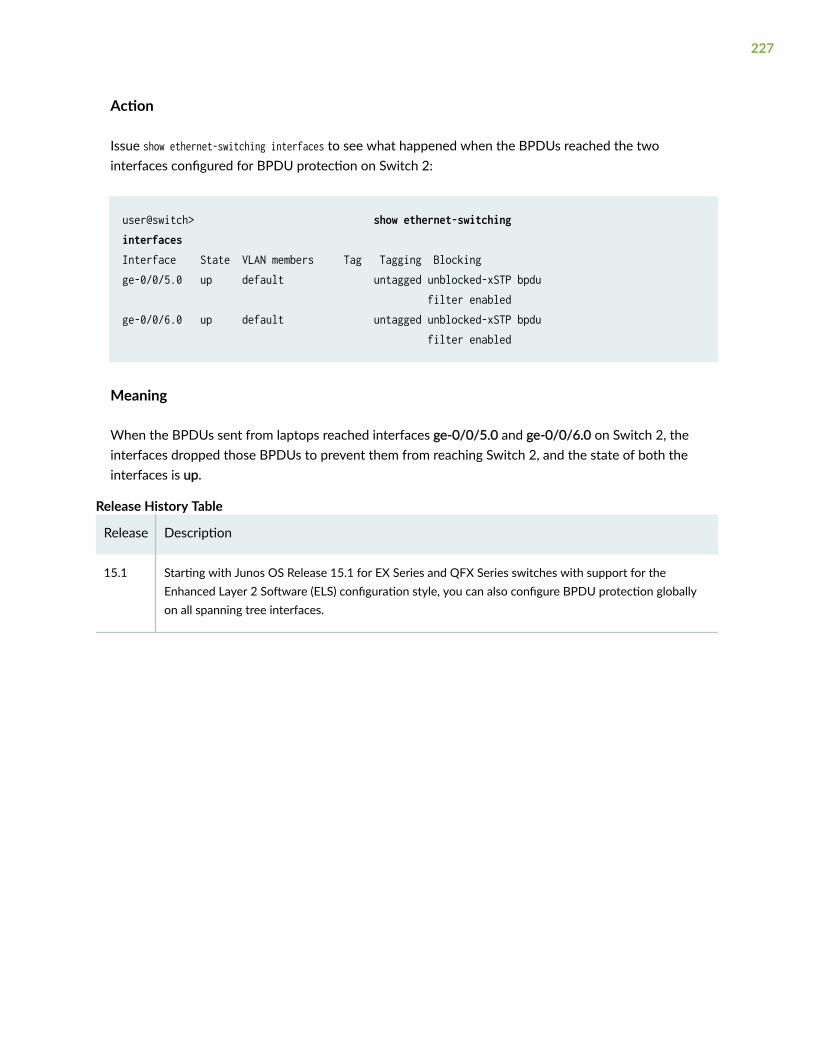
Action
Issue show ethernet-switching interfaces to see what happened when the BPDUs reached the twointerfaces configured for BPDU protection on Switch 2:
user@switch> show ethernet-switching interfaces Interface State VLAN members Tag Tagging Blockingge-0/0/5.0 up default untagged unblocked-xSTP bpdu filter enabledge-0/0/6.0 up default untagged unblocked-xSTP bpdu filter enabled
Meaning
When the BPDUs sent from laptops reached interfaces ge-0/0/5.0 and ge-0/0/6.0 on Switch 2, theinterfaces dropped those BPDUs to prevent them from reaching Switch 2, and the state of both theinterfaces is up.
Release History Table
Release Description
15.1 Starting with Junos OS Release 15.1 for EX Series and QFX Series switches with support for theEnhanced Layer 2 Software (ELS) configuration style, you can also configure BPDU protection globallyon all spanning tree interfaces.
227
5CHAPTER
Loop Protection for Spanning-TreeProtocols
Loop Protection for Spanning-Tree Protocols | 229

Loop Protection for Spanning-Tree Protocols
IN THIS SECTION
Understanding Loop Protection for Spanning-Tree Instance Interfaces | 229
Eliminating Bridge Loops in Ethernet LANs with Spanning Tree Protocol | 231
Example: Enabling Loop Protection for Spanning-Tree Protocols | 240
Configuring Loop Protection for a Spanning-Tree Instance Interface | 240
Example: Configuring Loop Protection to Prevent Interfaces from Transitioning from Blocking to Forwardingin a Spanning Tree on non-ELS EX Series Switches | 242
Example: Configuring Loop Protection to Prevent Interfaces from Transitioning from Blocking to Forwardingin a Spanning Tree on EX Series Switches With ELS | 248
Understanding Loop Protection for Spanning-Tree Instance Interfaces
IN THIS SECTION
How Does Loop Protection Work? | 230
Benefits of Loop Protection on STP Protocols | 230
What Action Causes a Loop? | 230
What Can Loop Protection Do When BPDUs Don’t Arrive? | 230
When Should I Use Loop Protection? | 231
What Happens if I Do Not Use Loop Protection? | 231
Loop protection increases the efficiency of STP, RSTP, and MSTP by preventing ports from moving into aforwarding state that would result in a loop opening up in the network. Spanning-tree protocol loopprotection enhances the normal checks that spanning-tree protocols perform on interfaces. Loopprotection performs a specified action when BPDUs are not received on a nondesignated port interface.You can choose to block the interface or issue an alarm when bridge protocol data units (BPDUs) are notreceived on the port.
229

How Does Loop Protection Work?
A loop-free network in spanning-tree topologies is supported through the exchange of a special type offrame called bridge protocol data unit (BPDU). Peer STP applications running on the switch interfacesuse BPDUs to communicate. Ultimately, the exchange of BPDUs determines which interfaces blocktraffic (preventing loops) and which interfaces become root ports and forward traffic.
However, a blocking interface can transition to the forwarding state in error if the interface stopsreceiving BPDUs from its designated port on the segment. Such a transition error can occur when thereis a hardware error on the switch or software configuration error between the switch and its neighbor.
When loop protection is enabled, the spanning-tree topology detects root ports and blocked ports andmakes sure both keep receiving BPDUs. If a loop-protection-enabled interface stops receiving BPDUsfrom its designated port, it reacts as it would react to a problem with the physical connection on thisinterface. It does not transition the interface to a forwarding state, but instead transitions it to a loop-inconsistent state. The interface recovers and then it transitions back to the spanning-tree blocking stateas soon as it receives a BPDU.
Benefits of Loop Protection on STP Protocols
By default, a spanning-tree protocol interface that stops receiving bridge protocol data unit (BPDU) dataframes will transition to the designated port (forwarding) state, creating a potential loop.
What Action Causes a Loop?
The spanning-tree protocol family is responsible for breaking loops in a network of bridges withredundant links. However, hardware failures can create forwarding loops (STP loops) and cause majornetwork outages. Spanning-tree protocols break loops by blocking ports (interfaces). However, errorsoccur when a blocked port transitions erroneously to a forwarding state.
Ideally, a spanning-tree protocol bridge port remains blocked as long as a superior alternate path to theroot bridge exists for a connected LAN segment. This designated port is determined by receivingsuperior BPDUs from a peer on that port. When other ports no longer receive BPDUs, the spanning-treeprotocol considers the topology to be loop free. However, if a blocked or alternate port moves into aforwarding state, this creates a loop.
What Can Loop Protection Do When BPDUs Don’t Arrive?
To prevent a spanning-tree instance interface from interpreting a lack of received BPDUs as a “falsepositive” condition for assuming the designated port role, you can configure one of the following loopprotection options:
230

• Configure the router to raise an alarm condition if the spanning-tree instance interface has notreceived BPDUs during the timeout interval.
• Configure the router to block the spanning-tree instance interface if the interface has not receivedBPDUs during the timeout interval.
NOTE: Spanning-tree instance interface loop protection is enabled for all spanning-tree instanceson the interface, but blocks or alarms only those instances that stop receiving BPDUs.
When Should I Use Loop Protection?
You can configure spanning-tree protocol loop protection to improve the stability of Layer 2 networks.We recommend you configure loop protection only on non-designated interfaces such as the root oralternate interfaces. Otherwise, if you configure loop protection on both sides of a designated link, thencertain STP configuration events (such as setting the root bridge priority to an inferior value in atopology with many loops) can cause both interfaces to transition to blocking mode.
We recommend that you enable loop protection on all switch interfaces that have a chance of becomingroot or designated ports. Loop protection is most effective when enabled in the entire switchednetwork. When you enable loop protection, you must configure at least one action (log, block, or both).
NOTE: An interface can be configured for either loop protection or root protection, but not forboth.
What Happens if I Do Not Use Loop Protection?
By default (that is, without spanning-tree protocol loop protection configured), an interface that stopsreceiving BPDUs will assume the designated port role and possibly result in a spanning-tree protocolloop.
Eliminating Bridge Loops in Ethernet LANs with Spanning Tree Protocol
IN THIS SECTION
Understanding Bridge Loops | 232
231

How STP Helps Eliminate Loops | 235
Types of Spanning-Tree Protocols Supported | 238
The Spanning Tree Protocol (STP) is a network protocol that is used to eliminate bridge loops in EthernetLANs. STP prevents network loops and associated network outage by blocking redundant links or paths.The redundant paths can be used to keep the network operational if the primary link fails.
The sections describe bridge loops and how STP helps eliminate them.
Understanding Bridge Loops
To understand bridge loops, consider a scenario in which four switches (or bridges) are connected tofour different subsections (Subsection i, ii, iii, and iv) where each subsection is a collection of network
232

nodes (see Figure 10 on page 233). For simplicity, Subsection i and Subsection ii are combined to formSection 1. Similarly, Subsection iii and Subsection iv are combined to form Section 2.
Figure 10: Formation of Bridge Loops
When the switches are powered on, the bridge tables are empty. If User A in Subsection i tries to send asingle packet Packet 1 to User D in Subsection iv, all the switches, which are in listening mode, receivethe packet. The switches make an entry in their respective bridging tables, as shown in the followingtable:
233

Table 12: Switches Make Entries in Respective Bridging Tables
Bridge 1
ID | Port Facing Direction
Bridge 2
ID | Port Facing Direction
Bridge 3
ID | Port Facing Direction
Bridge 4
ID | Port Facing Direction
Packet 1 | Section 1 Packet 1 | Section 1 Packet 1 | Section 1 Packet 1 | Section 1
At this point, the switches do not know where Subsection iv is, and the packet is forwarded to all theports except the source port (which results in flooding of the packet). In this example, after Subsection 1sends the packet, the switches receive the packet on the ports facing Section 1. As a result, they startforwarding the packet through the ports facing Section 2. Which switch gets the first chance to send outthe packet depends on the network configuration. In this example, suppose Switch 1 transmits thepacket first. Because it received the packet from Section 1, it floods the packet toward Section 2.Similarly, Switches 2, 3, and 4, which are also in listening mode, receive the same packet from Switch 1(originally sent from Section 1) on the ports facing Section 2. They readily update their bridging tableswith incorrect information, as shown in the following table:
Table 13: Bridging Tables Updated with Incorrect Information
Bridge 1
ID | Port Facing Direction
Bridge 2
ID | Port Facing Direction
Bridge 3
ID | Port Facing Direction
Bridge 4
ID | Port Facing Direction
Packet 1 | Section 1 Packet 1 | Section 2 Packet 1 | Section 2 Packet 1 | Section 2
Thus, a loop is created as the same packet is received both from Section 1 and Section 2. As illustratedin Figure 10 on page 233, Switch 1 has information that the packet came from Subsection i in Section 1,whereas all other switches have incorrect information that the same packet came from Section 2.
The entire process is repeated when Switch 2 gets the chance to transmit the original packet. Switch 2receives the original packet from Section 1 and transmits the same packet to Section 2. Eventually,Switch 1, which still has no idea where Subsection iv is, updates its bridging table, as shown in thefollowing table:
234
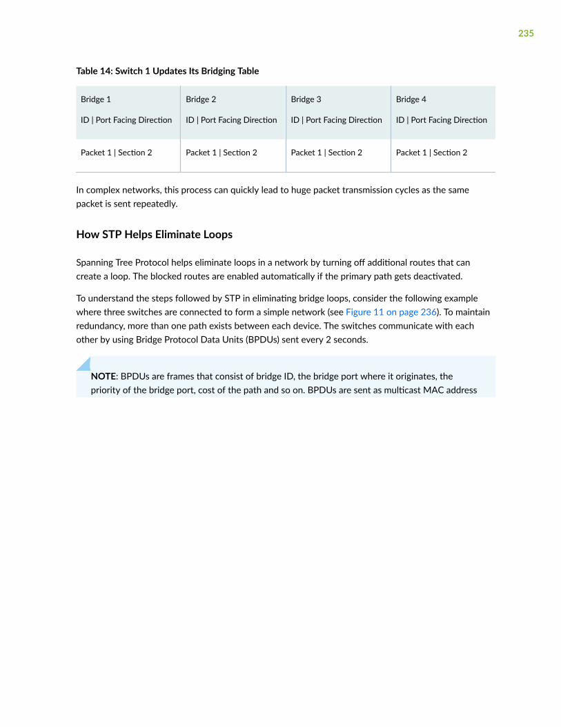
Table 14: Switch 1 Updates Its Bridging Table
Bridge 1
ID | Port Facing Direction
Bridge 2
ID | Port Facing Direction
Bridge 3
ID | Port Facing Direction
Bridge 4
ID | Port Facing Direction
Packet 1 | Section 2 Packet 1 | Section 2 Packet 1 | Section 2 Packet 1 | Section 2
In complex networks, this process can quickly lead to huge packet transmission cycles as the samepacket is sent repeatedly.
How STP Helps Eliminate Loops
Spanning Tree Protocol helps eliminate loops in a network by turning off additional routes that cancreate a loop. The blocked routes are enabled automatically if the primary path gets deactivated.
To understand the steps followed by STP in eliminating bridge loops, consider the following examplewhere three switches are connected to form a simple network (see Figure 11 on page 236). To maintainredundancy, more than one path exists between each device. The switches communicate with eachother by using Bridge Protocol Data Units (BPDUs) sent every 2 seconds.
NOTE: BPDUs are frames that consist of bridge ID, the bridge port where it originates, thepriority of the bridge port, cost of the path and so on. BPDUs are sent as multicast MAC address
235

01:80:c2:00:00:00. BPDUs can be of three types: configuration BPDUs, topology changenotification (TCN) BPDUs, and topology change acknowledgment (TCA) BPDUs.
Figure 11: Simple Network with Redundant Links
To eliminate network loops, STP performs the following steps in this sample network:
1. Elects a root bridge (or switch). To elect a root switch, STP uses the bridge ID. The bridge ID is 8bytes in length and consists of two parts. The first part is 2 bytes of information known as bridgepriority. The default bridge priority is 32,768. In this example, the default value is used for all theswitches. The remaining 6 bytes consist of the MAC address of the switch. In this example, Switch1is elected as the root switch because it has the lowest MAC address.
2. Elects the root ports. Typically, root ports use the least-cost paths from one switch to the other. Inthis example, assume that all paths have similar costs. Therefore, the root port for Switch 2 is theport that receives packets through the direct path from Switch 1 (cost 4), because the other path is
236
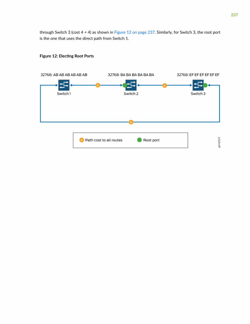
through Switch 3 (cost 4 + 4) as shown in Figure 12 on page 237. Similarly, for Switch 3, the root portis the one that uses the direct path from Switch 1.
Figure 12: Electing Root Ports
237

3. Selects the designated ports. Designated ports are the only ports that can receive and forwardframes on switches other than the root switch. They are generally the ports that use the least-costpaths. In Figure 13 on page 238, the designated ports are marked.
Figure 13: Selecting Designated Ports and Blocking Redundant Paths
Because there is more than one path involved in the network and the root ports and designated portsare identified, STP can block the path between Switch 2 and Switch 3 temporarily, eliminating any Layer2 loops.
Types of Spanning-Tree Protocols Supported
In a Layer 2 environment, you can configure various spanning-tree protocol versions to create a loop-free topology in Layer 2 networks.
A spanning-tree protocol is a Layer 2 control protocol (L2CP) that calculates the best path through aswitched network containing redundant paths. A spanning-tree protocol uses bridge protocol data unit(BPDU) data frames to exchange information with other switches. A spanning-tree protocol uses theinformation provided by the BPDUs to elect a root bridge, identify root ports for each switch, identifydesignated ports for each physical LAN segment, and prune specific redundant links to create a loop-free tree topology. The resulting tree topology provides a single active Layer 2 data path between anytwo end stations.
238

NOTE: In discussions of spanning-tree protocols, the terms bridge and switch are often usedinterchangeably.
The Juniper Networks MX Series 5G Universal Routing Platforms and EX Series switches support STP,RSTP, MSTP, and VSTP.
• The original Spanning Tree Protocol (STP) is defined in the IEEE 802.1D 1998 specification. A newerversion called Rapid Spanning Tree Protocol (RSTP) was originally defined in the IEEE 802.1w draftspecification and later incorporated into the IEEE 802.1D-2004 specification. A recent version calledMultiple Spanning Tree Protocol (MSTP) was originally defined in the IEEE 802.1s draft specificationand later incorporated into the IEEE 802.1Q-2003 specification. The VLAN Spanning Tree Protocol(VSTP) is compatible with the Per-VLAN Spanning Tree Plus (PVST+) and Rapid-PVST+ protocolssupported on Cisco Systems routers and switches.
• RSTP provides faster reconvergence time than the original STP by identifying certain links as point topoint and by using protocol handshake messages rather than fixed timeouts. When a point-to-pointlink fails, the alternate link can transition to the forwarding state without waiting for any protocoltimers to expire.
• MSTP provides the capability to logically divide a Layer 2 network into regions. Every region has aunique identifier and can contain multiple instances of spanning trees. All regions are bound togetherusing a Common Instance Spanning Tree (CIST), which is responsible for creating a loop-freetopology across regions, whereas the Multiple Spanning-Tree Instance (MSTI) controls topologywithin regions. MSTP uses RSTP as a converging algorithm and is fully interoperable with earlierversions of STP.
• VSTP maintains a separate spanning-tree instance for each VLAN. Different VLANs can use differentspanning-tree paths. When different VLANs use different spanning-tree paths, the CPU processingresources being consumed increase as more VLANs are configured. VSTP BPDU packets are taggedwith the corresponding VLAN identifier and are transmitted to the multicast destination mediaaccess control (MAC) address 01-00-0c-cc-cc-cd with a protocol type of 0x010b. VSTP BPDUs aretunneled by pure IEEE 802.1q bridges.
NOTE: All virtual switch routing instances configured on an MX Series router are supportedusing only one spanning-tree process. The Layer 2 control protocol process is named l2cpd.
239

Example: Enabling Loop Protection for Spanning-Tree Protocols
This example blocks and logs the non-designated RSTP port ge-1/2/0 after the BPDU timeout intervalexpires:
[edit]protocols { rstp { interface ge-1/2/0 { bpdu-timeout-action block; } }}
NOTE: This is not a complete configuration. You must also fully configure RSTP, including thege-1/2/0 interface.
Configuring Loop Protection for a Spanning-Tree Instance Interface
Before you begin, you must fully configure the spanning-tree protocol, including instance interfaces. Youcan configure RSTP, MSTP, or VSTP at the following hierarchy levels:
• [edit protocols]
• [edit routing-instances routing-instance-name protocols]
To configure enhanced loop protection:
1. Include the bpdu-timeout-action statement with either the block or log option for the spanning-treeprotocol interface.
• For the STP or RSTP instance on a physical interface:
[edit]protocols { rstp { interface interface-name { bpdu-timeout-action (log | block);
240

} }}
• For all MSTP instances on a physical interface:
[edit]protocols { mstp { interface interface-name { bpdu-timeout-action (log | block); } }}
• For all VSTP instances on a physical interface configured at the global level or a the VLAN level:
[edit]protocols { vstp { interface interface-name { bpdu-timeout-action (log | block); } vlan vlan-id { interface interface-name { bpdu-timeout-action (log | block); } } }}
2. To display the spanning-tree protocol loop protection characteristics on an interface, use the "showspanning-tree interface" on page 440 operational command.
241

Example: Configuring Loop Protection to Prevent Interfaces fromTransitioning from Blocking to Forwarding in a Spanning Tree on non-ELSEX Series Switches
IN THIS SECTION
Requirements | 242
Overview and Topology | 243
Configuration | 245
Verification | 246
EX Series switches provide Layer 2 loop prevention through Spanning Tree Protocol (STP), RapidSpanning Tree protocol (RSTP), and Multiple Spanning Tree Protocol (MSTP). Loop protection increasesthe efficiency of STP, RSTP, and MSTP by preventing interfaces from moving into a forwarding state thatwould result in a loop opening up in the network.
This example describes how to configure loop protection for an interface on an EX Series switch in anRSTP topology:
Requirements
This example uses the following hardware and software components:
• Junos OS Release 9.1 or later for EX Series switches
• Three EX Series switches in an RSTP topology
Before you configure the interface for loop protection, be sure you have:
• RSTP operating on the switches.
NOTE: By default, RSTP is enabled on all EX Series switches.
242
Overview and Topology
IN THIS SECTION
Topology | 244
A loop-free network in spanning-tree topologies is supported through the exchange of a special type offrame called bridge protocol data unit (BPDU). Peer STP applications running on the switch interfacesuse BPDUs to communicate. Ultimately, the exchange of BPDUs determines which interfaces blocktraffic (preventing loops) and which interfaces become root ports and forward traffic.
A blocking interface can transition to the forwarding state in error if the interface stops receiving BPDUsfrom its designated port on the segment. Such a transition error can occur when there is a hardwareerror on the switch or software configuration error between the switch and its neighbor. When thishappens, a loop opens up in the spanning tree. Loops in a Layer 2 topology cause broadcast, unicast, andmulticast frames to continuously circle the looped network. As a switch processes a flood of frames in alooped network, its resources become depleted and the ultimate result is a network outage.
CAUTION: An interface can be configured for either loop protection or root protection,but not for both.
Three EX Series switches are displayed in Figure 14 on page 244. In this example, they are configuredfor RSTP and create a loop-free topology. Interface ge-0/0/6 is blocking traffic between Switch 3 andSwitch 1; thus, traffic is forwarded through interface ge-0/0/7 on Switch 2. BPDUs are being sent fromthe root bridge on Switch 1 to both of these interfaces.
This example shows how to configure loop protection on interface ge-0/0/6 to prevent it fromtransitioning from a blocking state to a forwarding state and creating a loop in the spanning-treetopology.
243

Topology
Figure 14: Network Topology for Loop Protection
Table 15 on page 244 shows the components that will be configured for loop protection.
Table 15: Components of the Topology for Configuring Loop Protection on EX Series Switches
Property Settings
Switch 1 Switch 1 is the root bridge.
Switch 2 Switch 2 has the root port ge-0/0/7.
Switch 3 Switch 3 is connected to Switch 1 through interface ge-0/0/6.
A spanning-tree topology contains ports that have specific roles:
• The root port is responsible for forwarding data to the root bridge.
244
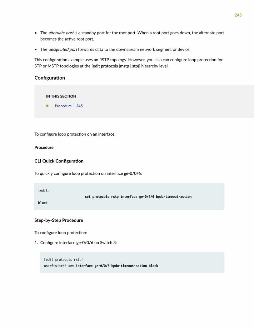
• The alternate port is a standby port for the root port. When a root port goes down, the alternate portbecomes the active root port.
• The designated port forwards data to the downstream network segment or device.
This configuration example uses an RSTP topology. However, you also can configure loop protection forSTP or MSTP topologies at the [edit protocols (mstp | stp)] hierarchy level.
Configuration
IN THIS SECTION
Procedure | 245
To configure loop protection on an interface:
Procedure
CLI Quick Configuration
To quickly configure loop protection on interface ge-0/0/6:
[edit] set protocols rstp interface ge-0/0/6 bpdu-timeout-action block
Step-by-Step Procedure
To configure loop protection:
1. Configure interface ge-0/0/6 on Switch 3:
[edit protocols rstp]user@switch# set interface ge-0/0/6 bpdu-timeout-action block
245

Results
Check the results of the configuration:
user@switch> show configuration protocols rstp interface ge-0/0/6.0 { bpdu-timeout-action { block; }}
Verification
IN THIS SECTION
Displaying the Interface State Before Loop Protection Is Triggered | 246
Verifying That Loop Protection Is Working on an Interface | 247
To confirm that the configuration is working properly, perform these tasks:
Displaying the Interface State Before Loop Protection Is Triggered
Purpose
Before loop protection is triggered on interface ge-0/0/6, confirm that the interface is blocking.
Action
Use the operational mode command:
user@switch> show spanning-tree interface
Spanning tree interface parameters for instance 0
Interface Port ID Designated Designated Port State Role port ID bridge ID Cost
246

ge-0/0/0.0 128:513 128:513 32768.0019e2503f00 20000 BLK DIS ge-0/0/1.0 128:514 128:514 32768.0019e2503f00 20000 BLK DIS ge-0/0/2.0 128:515 128:515 32768.0019e2503f00 20000 BLK DIS ge-0/0/3.0 128:516 128:516 32768.0019e2503f00 20000 FWD DESG ge-0/0/4.0 128:517 128:517 32768.0019e2503f00 20000 FWD DESG ge-0/0/5.0 128:518 128:518 32768.0019e2503f00 20000 FWD DESG ge-0/0/6.0 128:519 128:2 16384.00aabbcc0348 20000 BLK ALT [output truncated]
Meaning
The output from the operational mode command show spanning-tree interface shows that ge-0/0/6.0 isthe alternate port and in a blocking state.
Verifying That Loop Protection Is Working on an Interface
Purpose
Verify the loop protection configuration on interface ge-0/0/6. RSTP has been disabled on interfacege-0/0/4 on Switch 1. This will stop BPDUs from being sent to interface ge-0/0/6 and trigger loopprotection on the interface.
Action
Use the operational mode command:
user@switch> show spanning-tree interface
Spanning tree interface parameters for instance 0
Interface Port ID Designated Designated Port State Role port ID bridge ID Costge-0/0/0.0 128:513 128:513 32768.0019e2503f00 20000 BLK DIS ge-0/0/1.0 128:514 128:514 32768.0019e2503f00 20000 BLK DIS ge-0/0/2.0 128:515 128:515 32768.0019e2503f00 20000 BLK DIS ge-0/0/3.0 128:516 128:516 32768.0019e2503f00 20000 FWD DESG ge-0/0/4.0 128:517 128:517 32768.0019e2503f00 20000 FWD DESG ge-0/0/5.0 128:518 128:518 32768.0019e2503f00 20000 FWD DESG
247

ge-0/0/6.0 128:519 128:519 32768.0019e2503f00 20000 BLK DIS (Loop-Incon)[output truncated]
Meaning
The operational mode command show spanning-tree interface shows that interface ge-0/0/6.0 hasdetected that BPDUs are no longer being forwarded to it and has moved into a loop-inconsistent state.The loop-inconsistent state prevents the interface from transitioning to a forwarding state. The interfacerecovers and transitions back to its original state as soon as it receives BPDUs.
Example: Configuring Loop Protection to Prevent Interfaces fromTransitioning from Blocking to Forwarding in a Spanning Tree on EXSeries Switches With ELS
IN THIS SECTION
Requirements | 249
Overview and Topology | 249
Configuration | 251
Verification | 252
NOTE: This example uses Junos OS for EX Series switches with support for the Enhanced Layer2 Software (ELS) configuration style. If your switch runs software that does not support ELS, see"Example: Configuring Loop Protection to Prevent Interfaces from Transitioning from Blocking toForwarding in a Spanning Tree on non-ELS EX Series Switches" on page 229. For ELS details, seeUsing the Enhanced Layer 2 Software CLI.
EX Series switches provide Layer 2 loop prevention through Spanning Tree Protocol (STP), RapidSpanning Tree protocol (RSTP), and Multiple Spanning Tree Protocol (MSTP). Loop protection increasesthe efficiency of STP, RSTP, and MSTP by preventing interfaces from moving into a forwarding state thatwould result in a loop opening up in the network.
248

This example describes how to configure loop protection for an interface on an EX Series switch in anRSTP topology:
Requirements
This example uses the following software and hardware components:
• Junos OS Release 13.2X50-D10 or later or later for EX Series switches
• Three EX Series switches in an RSTP topology
Before you configure the interface for loop protection, be sure you have:
• RSTP operating on the switches.
NOTE: By default, RSTP is enabled on all EX Series switches.
Overview and Topology
IN THIS SECTION
Topology | 250
A loop-free network in spanning-tree topologies is supported through the exchange of a special type offrame called bridge protocol data unit (BPDU). Peer STP applications running on the switch interfacesuse BPDUs to communicate. Ultimately, the exchange of BPDUs determines which interfaces blocktraffic (preventing loops) and which interfaces become root ports and forward traffic.
A blocking interface can transition to the forwarding state in error if the interface stops receiving BPDUsfrom its designated port on the segment. Such a transition error can occur when there is a hardwareerror on the switch or software configuration error between the switch and its neighbor. When thishappens, a loop opens up in the spanning tree. Loops in a Layer 2 topology cause broadcast, unicast, andmulticast frames to continuously circle the looped network. As a switch processes a flood of frames in alooped network, its resources become depleted and the ultimate result is a network outage.
CAUTION: An interface can be configured for either loop protection or root protection,but not for both.
Three EX Series switches are displayed in Figure 15 on page 250. In this example, they are configuredfor RSTP and create a loop-free topology. Interface ge-0/0/6 is blocking traffic between Switch 3 and
249

Switch 1; thus, traffic is forwarded through interface ge-0/0/7 on Switch 2. BPDUs are being sent fromthe root bridge on Switch 1 to both of these interfaces.
This example shows how to configure loop protection on interface ge-0/0/6 to prevent it fromtransitioning from a blocking state to a forwarding state and creating a loop in the spanning-treetopology.
Topology
Figure 15: Network Topology for Loop Protection
Table 16 on page 250 shows the components that will be configured for loop protection.
Table 16: Components of the Topology for Configuring Loop Protection on EX Series Switches
Property Settings
Switch 1 Switch 1 is the root bridge.
Switch 2 Switch 2 has the root port ge-0/0/7.
250
Table 16: Components of the Topology for Configuring Loop Protection on EX Series Switches(Continued)
Property Settings
Switch 3 Switch 3 is connected to Switch 1 through interface ge-0/0/6.
A spanning-tree topology contains ports that have specific roles:
• The root port is responsible for forwarding data to the root bridge.
• The alternate port is a standby port for the root port. When a root port goes down, the alternate portbecomes the active root port.
• The designated port forwards data to the downstream network segment or device.
This configuration example uses an RSTP topology. However, you also can configure loop protection forMSTP topologies at the [edit protocols mstp ] hierarchy level.
Configuration
IN THIS SECTION
Procedure | 251
To configure loop protection on an interface:
Procedure
CLI Quick Configuration
To quickly configure loop protection on interface ge-0/0/6:
[edit] set protocols rstp interface ge-0/0/6 bpdu-timeout-action block
251

Step-by-Step Procedure
To configure loop protection:
1. Configure interface ge-0/0/6 on Switch 3:
[edit protocols rstp]user@switch# set interface ge-0/0/6 bpdu-timeout-action block
Results
Check the results of the configuration:
user@switch> show configuration protocols rstp interface ge-0/0/6 { bpdu-timeout-action { block; }}
Verification
IN THIS SECTION
Displaying the Interface State Before Loop Protection Is Triggered | 252
Verifying That Loop Protection Is Working on an Interface | 253
To confirm that the configuration is working properly, perform these tasks:
Displaying the Interface State Before Loop Protection Is Triggered
Purpose
Before loop protection is triggered on interface ge-0/0/6, confirm that the interface is blocking.
252

Action
Use the operational mode command:
user@switch> show spanning-tree interface
Spanning tree interface parameters for instance 0
Interface Port ID Designated Designated Port State Role port ID bridge ID Costge-0/0/0 128:513 128:513 32768.0019e2503f00 20000 BLK DIS ge-0/0/1 128:514 128:514 32768.0019e2503f00 20000 BLK DIS ge-0/0/2 128:515 128:515 32768.0019e2503f00 20000 BLK DIS ge-0/0/3 128:516 128:516 32768.0019e2503f00 20000 FWD DESG ge-0/0/4 128:517 128:517 32768.0019e2503f00 20000 FWD DESG ge-0/0/5 128:518 128:518 32768.0019e2503f00 20000 FWD DESG ge-0/0/6 128:519 128:2 16384.00aabbcc0348 20000 BLK ALT [output truncated]
Meaning
The output from the operational mode command show spanning-tree interface shows that ge-0/0/6 is thealternate port and in a blocking state.
Verifying That Loop Protection Is Working on an Interface
Purpose
Verify the loop protection configuration on interface ge-0/0/6. RSTP has been disabled on interfacege-0/0/4 on Switch 1. This will stop BPDUs from being sent to interface ge-0/0/6 and trigger loopprotection on the interface.
Action
Use the operational mode command:
user@switch> show spanning-tree interface
253

Spanning tree interface parameters for instance 0
Interface Port ID Designated Designated Port State Role port ID bridge ID Costge-0/0/0 128:513 128:513 32768.0019e2503f00 20000 BLK DIS ge-0/0/1 128:514 128:514 32768.0019e2503f00 20000 BLK DIS ge-0/0/2 128:515 128:515 32768.0019e2503f00 20000 BLK DIS ge-0/0/3 128:516 128:516 32768.0019e2503f00 20000 FWD DESG ge-0/0/4 128:517 128:517 32768.0019e2503f00 20000 FWD DESG ge-0/0/5 128:518 128:518 32768.0019e2503f00 20000 FWD DESG ge-0/0/6 128:519 128:519 32768.0019e2503f00 20000 BLK DIS (Loop-Incon)[output truncated]
Meaning
The operational mode command show spanning-tree interface shows that interface ge-0/0/6 has detectedthat BPDUs are no longer being forwarded to it and has moved into a loop-inconsistent state. The loop-inconsistent state prevents the interface from transitioning to a forwarding state. To clear the BPDUerror, issue the operational mode command clear error bpdu interface on the switch. The interfacerecovers and transitions back to its original state as soon as it receives BPDUs.
SEE ALSO
Example: Configuring Faster Convergence and Network Stability on ELS Switches with RSTP | 32
254

6CHAPTER
Root Protection for VPLS MultihomeEnvironments
Root Protection for VPLS Multihome Environments | 256

Root Protection for VPLS Multihome Environments
IN THIS SECTION
Understanding VPLS Multihoming | 256
Understanding Bridge Priority for Election of Root Bridge and Designated Bridge | 261
Understanding Root Protection for Spanning-Tree Instance Interfaces in a Layer 2 Switched Network | 261
Example: Configuring VPLS Root Topology Change Actions | 263
Enabling Root Protection for a Spanning-Tree Instance Interface | 263
Configuring VPLS Root Protection Topology Change Actions to Control Individual VLAN Spanning-TreeBehavior | 264
Example: Configuring Root Protection to Enforce Root Bridge Placement in Spanning Trees on non-ELS EXSeries Switches | 266
Example: Configuring Root Protection to Enforce Root Bridge Placement in Spanning Trees on EX SeriesSwitches With ELS | 273
Understanding VPLS Multihoming
IN THIS SECTION
Benefits of Multihoming | 257
How Does Multihoming Work? | 258
VPLS Multihoming Hold Time Before Switching to Primary Priority | 258
VPLS Multihoming Bridge Flush of MAC Cache on Topology Change | 259
VPLS Multihoming System Identifiers for Bridges in the Ring | 260
VPLS Multihoming Priority of the Backup Bridge | 260
Redundancy is built into many networks through the use of alternate links and paths, which often takethe shape of rings. When multiple hosts are attached to customer edge (CE) routers and provider edge(PE) routers to secure virtual private LAN service (VPLS), this technique is often called multihoming.
256

Figure 16 on page 257 shows hosts connected to CE routers and to a VPLS network through two PErouters. The CE routers are also connected, forming a kind of ring structure.
Figure 16: Layer 2 Ring and MPLS Infrastructure Topology
Benefits of Multihoming
Multihoming multihoming is basically giving your computing device or network a presence on more thanone network. When both links are up, both links are fully utilized, increasing overall throughput. If one ofthe links fails, the other still carries traffic so you have redundancy.
Multihoming is used in network bridges, repeaters, range extenders, firewalls, proxy servers, gateways,and when using a virtual machine, configured to use network address translation (NAT).
257
How Does Multihoming Work?
The two PE routers have their own links to a VPLS network service as shown in Figure 16 on page 257,but are not directly connected to each other. All four edge routers run some type of spanning-treeprotocol with root protection enabled, and only one PE interface will be in the forwarding state, theother being blocked.
Assume this forwarding interface is through PE1. If the link between CE1 and CE2 fails, then theblocking PE2 interface must detect a root protection switch and move to the forwarding state. All of theMAC addresses learned by CE2 that connect to the VPLS network service through PE1 need to beflushed. In the same way, when the link between CE1 and CE2 is restored, PE2 again detects the rootprotection switch and begins blocking again. Now all of the MAC addresses learned by CE2 that connectthrough PE2 need to be flushed. All of this is controlled by configuring VPLS root protection topologychange actions on the CE routers.
The Layer 2 ring connects to the multiprotocol link switching (MPLS) infrastructure through two PErouters. Link breaks on the ring are protected by running a version of the spanning-tree protocol withthe root-protect option enabled.
The virtual private network (VPN) protocols at Layer 3, however, are not aware of the blocking state thatresults from this root protection setup (rings or loops are not permitted at Layer 2 because the Layer 2protocols will not function properly).
Multiple hosts attach to CE routers, which are attached to each other as well as to the PE routers thataccess the VPLS network cloud. Any single link between the edge routers can fail without impacting thehosts’ access to the VPLS services.
VPLS Multihoming Hold Time Before Switching to Primary Priority
At a global level, each type of spanning-tree protocol has a priority hold time associated with it. This isthe number of seconds, in the range from 1 through 255 seconds, that the system waits to switch to theprimary priority when the first core domain comes up. The default is 2 seconds. This allows themaximum number of core domains to come up, and some might be slower than others.
The default number of seconds to hold before switching to the primary priority when the first coredomain comes up is 2 seconds.
When an MX Series router or an EX Series switch in a VPLS multihomed Layer 2 ring is running aspanning-tree protocol with root protection enabled, you can modify the default actions taken by therouter or switch when the topology changes. To do this, configure the VPLS root protection topologychange actions.
You can include the statement at the [edit protocols (mstp | rstp | vstp)] hierarchy level (to control globalspanning-tree protocol behavior) or at the [edit protocols vstp vlan vlan-id] hierarchy level (to control aparticular VLAN).
258

NOTE: VPLS root topology change actions are configured independently of VPLS, the spanning-tree protocol, or the spanning-tree protocol root protect option.
VPLS Multihoming Bridge Flush of MAC Cache on Topology Change
By default, if root protect is enabled and then the topology changes, the bridges do not flush the mediaaccess control (MAC) address cache of the MAC addresses learned when other interface ports wereblocked.
To change the default behavior, you can use the statement vpls-flush-on-topology-change.
You can include the statement at the [edit protocols (mstp | rstp | vstp)] hierarchy level (to control globalspanning-tree protocol behavior) or at the [edit protocols vstp vlan vlan-id] hierarchy level (to control aparticular VLAN).
Specifically, MAC flush messages are sent from the blocked PE to LDP peers based on the mapping ofsystem identifier to IP addresses as specified using the system-id statement.
NOTE: VPLS root topology change actions are configured independently of VPLS, the spanning-tree protocol, or the spanning-tree protocol root protect option.
However, to keep the Layer 2 ring functioning in a multihomed environment with link failures, thespanning-tree protocol running on the MX Series routers requires the following additional configuration:
The VPN protocols have to act on the blocking and unblocking of interfaces by the spanning-treeprotocol. Specifically, media access control (MAC) flush messages need to be sent by the blocking PErouter to LDP peers in order to flush the MAC addresses learned when other interface ports wereblocked.
Also, if an active PE router with VPLS root protection bridging enabled loses VPLS connectivity, rootprotection requires that the bridge switch to the other PE router to maintain connectivity. The spanning-tree protocol needs to be aware of the status of the VPLS connectivity on the PE router. If the MACaddress cache is not flushed when the topology changes, frames could be sent to the wrong device.
You can control the actions taken by the MX Series router when the topology changes in a multihomedLayer 2 ring VPLS environment using VPLS root protection.
259

VPLS Multihoming System Identifiers for Bridges in the Ring
When an MX Series router or an EX Series switch in a VPLS multihomed Layer 2 ring is running aspanning-tree protocol with root protection enabled, you can modify the default actions taken by therouter or switch when the topology changes. To do this, configure the VPLS root protection topologychange actions.
The system identifier for bridges in the ring is not configured by default.
You can include the statement at the [edit protocols (mstp | rstp | vstp)] hierarchy level (to control globalspanning-tree protocol behavior) or at the [edit protocols vstp vlan vlan-id] hierarchy level (to control aparticular VLAN).
NOTE: VPLS root topology change actions are configured independently of VPLS, the spanning-tree protocol, or the spanning-tree protocol root protect option.
VPLS Multihoming Priority of the Backup Bridge
When an MX Series router or EX Series switch in a VPLS multihomed Layer 2 ring is running a spanning-tree protocol with root protection enabled, you can modify the default actions taken by the router orswitch when the topology changes. To do this, configure the VPLS root protection topology changeactions.
The default value of the backup bridge is 32,768. You can set the backup bridge priority to a value from0 through 61440, in increments of 4096.
To change the default value, you can use the following statement backup-bridge-priority vpls-ring-backup-bridge-priority
You can include the statement at the [edit protocols (mstp | rstp | vstp)] hierarchy level (to control globalspanning-tree protocol behavior) or at the [edit protocols vstp vlan vlan-id] hierarchy level (to control aparticular VLAN).
NOTE: VPLS root topology change actions are configured independently of VPLS, the spanning-tree protocol, or the spanning-tree protocol root protect option.
260
Understanding Bridge Priority for Election of Root Bridge and DesignatedBridge
Use the bridge priority to control which bridge is elected as the root bridge and also to control whichbridge is elected the root bridge when the initial root bridge fails.
The root bridge for each spanning-tree protocol instance is determined by the bridge ID. The bridge IDconsists of a configurable bridge priority and the MAC address of the bridge. The bridge with the lowestbridge ID is elected as the root bridge. If the bridge priorities are equal or if the bridge priority is notconfigured, the bridge with the lowest MAC address is elected the root bridge.
The bridge priority can also be used to determine which bridge becomes the designated bridge for aLAN segment. If two bridges have the same path cost to the root bridge, the bridge with the lowestbridge ID becomes the designated bridge.
The bridge priority can be set only in increments of 4096.
Consider a sample scenario in which a dual-homed customer edge (CE) router is connected to two otherprovider edge (PE) routers, which function as the VPLS PE routers, with MSTP enabled on all theserouters, and with the CE router operating as the root bridge. Integrated Routing and Bridging (IRB)interface is configured for the VPLS routing instances on the routers. In such a network, the MACaddresses that are learned in the VPLS domain continuously move between the LSI or virtual tunnel (VT)interfaces and the VPLS interfaces on both the PE routers. To avoid the continuous movement of theMAC addresses, you must configure root protection by including the no-root-port statement at the [editrouting-instances routing-instance-name protocols mstp interface interface-name] hierarchy level and configurethe bridge priority as zero by including the bridge priority 0 statement at the [edit routing-instancesrouting-instance-name protocols mstp] hierarchy level on the PE routers. This configuration on the PE routersis required to prevent the CE-side facing interfaces from becoming the root bridge.
Understanding Root Protection for Spanning-Tree Instance Interfaces in aLayer 2 Switched Network
IN THIS SECTION
Benefits of Spanning Tree Protocol Root Protection | 262
How Root Protection Works | 262
Where Should I Enable Root Protection? | 262
261

Peer STP applications running on interfaces use BPDUs to communicate. Ultimately, the exchange ofBPDUs determines which interfaces block traffic and which interfaces become root ports and forwardtraffic.
A root port elected through this process has the possibility of being wrongly elected. A user bridgeapplication running on a PC can generate BPDUs, too, and interfere with root port election. This is whenroot protection is useful.
Benefits of Spanning Tree Protocol Root Protection
Root protection allows network administrators to manually enforce the root bridge placement in aLayer 2 switched network.
How Root Protection Works
When root protection is enabled on an interface, it is enabled for all the STP instances on that interface.If the bridge receives superior BPDUs on a port that has root protect enabled, that port transitions to aroot-prevented STP state and the interface is blocked. This prevents a bridge that should not be the rootbridge from being elected the root bridge. The interface is blocked only for instances for which itreceives superior BPDUs. Otherwise, it participates in the spanning-tree topology.
After the bridge stops receiving superior BPDUs on the port with root protect enabled and the receivedBPDUs time out, that port transitions back to the STP-designated port state.
By default, root protect is disabled.
NOTE: An interface can be configured for either root protection or loop protection, but not forboth.
Where Should I Enable Root Protection?
Enable root protection on interfaces that should not receive superior bridge protocol data units (BPDUs)from the root bridge and must not be elected as the root port.
Interfaces that become designated ports are typically located on an administrative boundary. If thebridge receives superior STP BPDUs on a port that has root protection enabled, that port transitions to aroot-prevented STP state (inconsistency state) and the interface is blocked. This blocking prevents abridge that should not be the root bridge from being elected the root bridge. After the bridge stopsreceiving superior STP BPDUs on the interface with root protection, the interface returns to a listeningstate, followed by a learning state, and ultimately back to a forwarding state. Recovery back to theforwarding state is automatic.
262

Example: Configuring VPLS Root Topology Change Actions
This example configures a bridge priority of 36k, a backup bridge priority of 44k, a priority hold timevalue of 60 seconds, a system identifier of 000203:040506 for IP address 10.1.1.1/32, and sets thebridge to flush the MAC cache on a topology change for MSTP only.
[edit]protocols { mstp { bridge-priority 36k; backup-bridge-priority 44k; priority-hold-time 60; system-id 000203:040506 { 10.1.1.1/32; } vpls-flush-on-topology-change; }}
NOTE: This is not a complete configuration.
Enabling Root Protection for a Spanning-Tree Instance Interface
To enable root protect for a spanning-tree instance interface:
1. Enable configuration of the spanning-tree protocol:
[edit]user@host# edit protocols (mstp | rstp | vstp <vlan vlan-id>)
2. Enable configuration of the spanning-tree instance interface:
[edit ... protocols (mstp | rstp | vstp <vlan vlan-id>)]user@host# edit interface interface-name
263
3. Enable root protection on the interface:
[edit ... protocols (mstp | rstp | vstp <vlan vlan-id>) interface interface-name]user@host# set no-root-port
4. Verify the configuration of root protect for the spanning-tree instance interface:
[edit ... protocols (mstp | rstp | vstp <vlan vlan-id>) interface interface-name]user@host# topuser@host# show ... protocols ...(mstp | rstp | vstp <vlan vlan-id>) { interface interface-name { no-root-port; }}
NOTE: This is not a complete configuration.
Configuring VPLS Root Protection Topology Change Actions to ControlIndividual VLAN Spanning-Tree Behavior
To configure VPLS root protection topology change actions to control a particular VLAN:
1. Enable configuration of the spanning-tree protocol VLAN:
[edit]user@host# edit protocols (STP Type) vstp vlan vlan-id
2. (Optional) Change the priority of the backup bridge in a VPLS multihomed Layer 2 ring with MPLSinfrastructure:
[edit protocols vstp vlan vlan-id]user@host# set backup-bridge-priority vpls-ring-backup-bridge-priority
264

3. (Optional) Change the hold time before switching to the primary priority when the first core domaincomes up:
[edit protocols vstp vlan vlan-id]user@host# set priority-hold-time seconds
4. Configure the system identifier for bridges in the ring:
[edit protocols vstp vlan vlan-id]user@host# set system-id system-id-value bridge-host-ip-address(es)
The system-id-value is configured in the format nnnnnn:nnnnnn, where n = any digit from 0 to 9.
Each bridge-host-ip-address is a valid host IP address with a /32 mask.
NOTE: There are no default values for the system identifier or host IP addresses.
5. Configure bridges to flush the MAC address cache (of the MAC addresses learned when otherinterfaces ports were blocked) when the spanning-tree topology changes:
[edit protocols vstp vlan vlan-id]user@host# setvpls-flush-on-topology-change
6. Verify the configuration of VPLS root protection topology change actions to control a particularVLAN:
[edit]protocols { vstp { vlan vlan-id { backup-bridge-priority priority; # Default is 32,768. priority-hold-time seconds; # Default is 2 seconds. system-id system-id-value { ip-address; } vpls-flush-on-topology-change; } }}
265

Example: Configuring Root Protection to Enforce Root Bridge Placementin Spanning Trees on non-ELS EX Series Switches
IN THIS SECTION
Requirements | 266
Overview and Topology | 266
Configuration | 269
Verification | 270
EX Series switches provide Layer 2 loop prevention through Spanning Tree Protocol (STP), RapidSpanning Tree protocol (RSTP), and Multiple Spanning Tree Protocol (MSTP). Root protection increasesthe efficiency of STP, RSTP, and MSTP by allowing network administrators to manually enforce the rootbridge placement in the network.
This example describes how to configure root protection on an interface on an EX Series switch:
Requirements
This example uses the following hardware and software components:
• Junos OS Release 9.1 or later for EX Series switches
• Four EX Series switches in an RSTP topology
Before you configure the interface for root protection, be sure you have:
• RSTP operating on the switches.
NOTE: By default, RSTP is enabled on all EX Series switches.
Overview and Topology
IN THIS SECTION
Topology | 269
266

Peer STP applications running on switch interfaces exchange a special type of frame called a bridgeprotocol data unit (BPDU). Switches communicate interface information using BPDUs to create a loop-free topology that ultimately determines the root bridge and which interfaces block or forward traffic inthe spanning tree.
However, a root port elected through this process has the possibility of being wrongly elected. A userbridge application running on a PC can generate BPDUs, too, and interfere with root port election.
To prevent this from happening, enable root protection on interfaces that should not receive superiorBPDUs from the root bridge and should not be elected as the root port. These interfaces are typicallylocated on an administrative boundary and are designated ports.
When root protection is enabled on an interface:
• The interface is blocked from becoming the root port.
• Root protection is enabled for all STP instances on that interface.
• The interface is blocked only for instances for which it receives superior BPDUs. Otherwise, itparticipates in the spanning-tree topology.
CAUTION: An interface can be configured for either root protection or loop protection,but not for both.
Four EX Series switches are displayed in Figure 17 on page 268. In this example, they are configured forRSTP and create a loop-free topology. Interface ge-0/0/7 on Switch 1 is a designated port on anadministrative boundary. It connects to Switch 4. Switch 3 is the root bridge. Interface ge-0/0/6 onSwitch 1 is the root port.
267

This example shows how to configure root protection on interface ge-0/0/7 to prevent it fromtransitioning to become the root port.
Figure 17: Network Topology for Root Protection
Table 17 on page 269 shows the components that will be configured for root protection.
268

Table 17: Components of the Topology for Configuring Root Protection on EX Series Switches
Property Settings
Switch 1 Switch 1 is connected to Switch 4 through interface ge-0/0/7.
Switch 2 Switch 2 is connected to Switch 1 and Switch 3. Interface ge-0/0/4 is the alternate port in the RSTPtopology.
Switch 3 Switch 3 is the root bridge and is connected to Switch 1 and Switch 2.
Switch 4 Switch 4 is connected to Switch 1. After root protection is configured on interface ge-0/0/7, Switch 4will send superior BPDUs that will trigger root protection on interface ge-0/0/7.
A spanning tree topology contains ports that have specific roles:
• The root port is responsible for forwarding data to the root bridge.
• The alternate port is a standby port for the root port. When a root port goes down, the alternate portbecomes the active root port.
• The designated port forwards data to the downstream network segment or device.
This configuration example uses an RSTP topology. However, you also can configure root protection forSTP or MSTP topologies at the [edit protocols (mstp | stp)] hierarchy level.
Topology
Configuration
IN THIS SECTION
Procedure | 270
To configure root protection on an interface:
269

Procedure
CLI Quick Configuration
To quickly configure root protection on interface ge-0/0/7, copy the following command and paste itinto the switch terminal window:
[edit] set protocols rstp interface ge-0/0/7 no-root-port
Step-by-Step Procedure
To configure root protection:
1. Configure interface ge-0/0/7:
[edit protocols rstp]user@switch# set interface ge-0/0/7 no-root-port
Results
Check the results of the configuration:
user@switch> show configuration protocols rstp interface ge-0/0/7.0 { no-root-port;}
Verification
IN THIS SECTION
Displaying the Interface State Before Root Protection Is Triggered | 271
Verifying That Root Protection Is Working on the Interface | 272
270

To confirm that the configuration is working properly:
Displaying the Interface State Before Root Protection Is Triggered
Purpose
Before root protection is triggered on interface ge-0/0/7, confirm the interface state.
Action
Use the operational mode command:
user@switch> show spanning-tree interface
Spanning tree interface parameters for instance 0
Interface Port ID Designated Designated Port State Role port ID bridge ID Costge-0/0/0.0 128:513 128:513 32768.0019e2503f00 20000 BLK DIS ge-0/0/1.0 128:514 128:514 32768.0019e2503f00 20000 BLK DIS ge-0/0/2.0 128:515 128:515 32768.0019e2503f00 20000 BLK DIS ge-0/0/3.0 128:516 128:516 32768.0019e2503f00 20000 FWD DESG ge-0/0/4.0 128:517 128:517 32768.0019e2503f00 20000 FWD DESG ge-0/0/5.0 128:518 128:2 16384.00aabbcc0348 20000 BLK ALT ge-0/0/6.0 128:519 128:1 16384.00aabbcc0348 20000 FWD ROOT ge-0/0/7.0 128:520 128:520 32768.0019e2503f00 20000 FWD DESG[output truncated]
Meaning
The output from the operational mode command show spanning-tree interface shows that ge-0/0/7.0 is adesignated port in a forwarding state.
271
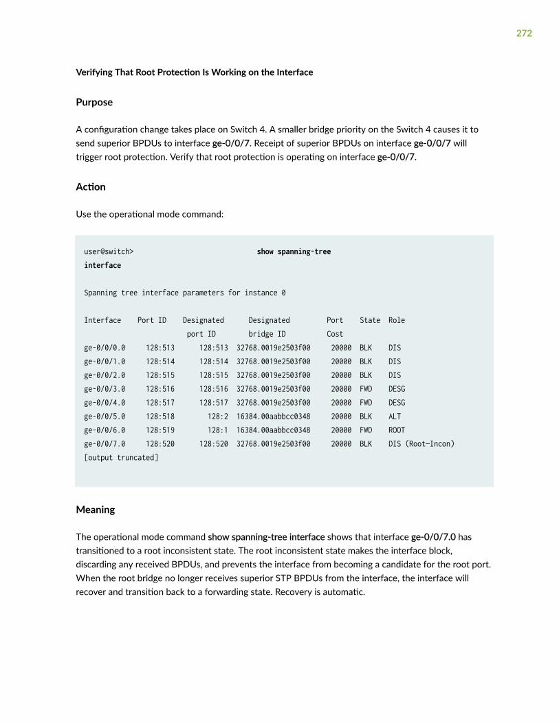
Verifying That Root Protection Is Working on the Interface
Purpose
A configuration change takes place on Switch 4. A smaller bridge priority on the Switch 4 causes it tosend superior BPDUs to interface ge-0/0/7. Receipt of superior BPDUs on interface ge-0/0/7 willtrigger root protection. Verify that root protection is operating on interface ge-0/0/7.
Action
Use the operational mode command:
user@switch> show spanning-tree interface
Spanning tree interface parameters for instance 0
Interface Port ID Designated Designated Port State Role port ID bridge ID Costge-0/0/0.0 128:513 128:513 32768.0019e2503f00 20000 BLK DIS ge-0/0/1.0 128:514 128:514 32768.0019e2503f00 20000 BLK DIS ge-0/0/2.0 128:515 128:515 32768.0019e2503f00 20000 BLK DIS ge-0/0/3.0 128:516 128:516 32768.0019e2503f00 20000 FWD DESG ge-0/0/4.0 128:517 128:517 32768.0019e2503f00 20000 FWD DESG ge-0/0/5.0 128:518 128:2 16384.00aabbcc0348 20000 BLK ALT ge-0/0/6.0 128:519 128:1 16384.00aabbcc0348 20000 FWD ROOT ge-0/0/7.0 128:520 128:520 32768.0019e2503f00 20000 BLK DIS (Root—Incon)[output truncated]
Meaning
The operational mode command show spanning-tree interface shows that interface ge-0/0/7.0 hastransitioned to a root inconsistent state. The root inconsistent state makes the interface block,discarding any received BPDUs, and prevents the interface from becoming a candidate for the root port.When the root bridge no longer receives superior STP BPDUs from the interface, the interface willrecover and transition back to a forwarding state. Recovery is automatic.
272

Example: Configuring Root Protection to Enforce Root Bridge Placementin Spanning Trees on EX Series Switches With ELS
IN THIS SECTION
Requirements | 273
Overview and Topology | 274
Configuration | 276
Verification | 277
NOTE: This example uses Junos OS for EX Series switches with support for the Enhanced Layer2 Software (ELS) configuration style. For ELS details, see Using the Enhanced Layer 2 SoftwareCLI.
EX Series switches provide Layer 2 loop prevention through Spanning Tree Protocol (STP), RapidSpanning Tree protocol (RSTP), and Multiple Spanning Tree Protocol (MSTP). Root protection increasesthe efficiency of STP, RSTP, and MSTP by allowing network administrators to manually enforce the rootbridge placement in the network.
This example describes how to configure root protection on an interface on an EX Series switch:
Requirements
This example uses the following software and hardware components:
• Junos OS Release 13.2X50-D10 or later or later for EX Series switches
• Four EX Series switches in an RSTP topology
Before you configure the interface for root protection, be sure you have:
• RSTP operating on the switches.
NOTE: By default, RSTP is enabled on all EX Series switches.
273

Overview and Topology
IN THIS SECTION
Topology | 276
Peer STP applications running on switch interfaces exchange a special type of frame called a bridgeprotocol data unit (BPDU). Switches communicate interface information using BPDUs to create a loop-free topology that ultimately determines the root bridge and which interfaces block or forward traffic inthe spanning tree.
However, a root port elected through this process has the possibility of being wrongly elected. A userbridge application running on a PC can generate BPDUs, too, and interfere with root port election.
To prevent this from happening, enable root protection on interfaces that must not receive superiorBPDUs from the root bridge and must not be elected as the root port. These interfaces are typicallylocated on an administrative boundary and are designated ports.
When root protection is enabled on an interface:
• The interface is blocked from becoming the root port.
• Root protection is enabled for all STP instances on that interface.
• The interface is blocked only for instances for which it receives superior BPDUs. Otherwise, itparticipates in the spanning-tree topology.
CAUTION: An interface can be configured for either root protection or loop protection,but not for both.
Four EX Series switches are displayed in Figure 18 on page 275. In this example, they are configured forRSTP and create a loop-free topology. Interface ge-0/0/7 on Switch 1 is a designated port on anadministrative boundary. It connects to Switch 4. Switch 3 is the root bridge. Interface ge-0/0/6 on Switch1 is the root port.
274

This example shows how to configure root protection on interface ge-0/0/7 to prevent it fromtransitioning to become the root port.
Figure 18: Network Topology for Root Protection
Table 18 on page 276 shows the components that will be configured for root protection.
275

Table 18: Components of the Topology for Configuring Root Protection on EX Series Switches
Property Settings
Switch 1 Switch 1 is connected to Switch 4 through interface ge-0/0/7.
Switch 2 Switch 2 is connected to Switch 1 and Switch 3. Interface ge-0/0/4 is the alternate port in the RSTPtopology.
Switch 3 Switch 3 is the root bridge and is connected to Switch 1 and Switch 2.
Switch 4 Switch 4 is connected to Switch 1. After root protection is configured on interface ge-0/0/7, Switch 4will send superior BPDUs that will trigger root protection on interface ge-0/0/7.
A spanning tree topology contains ports that have specific roles:
• The root port is responsible for forwarding data to the root bridge.
• The alternate port is a standby port for the root port. When a root port goes down, the alternate portbecomes the active root port.
• The designated port forwards data to the downstream network segment or device.
This configuration example uses an RSTP topology. However, you also can configure root protection forSTP or MSTP topologies at the [edit protocols mstp ] hierarchy level.
Topology
Configuration
IN THIS SECTION
Procedure | 277
To configure root protection on an interface:
276

Procedure
CLI Quick Configuration
To quickly configure root protection on interface ge-0/0/7, copy the following command and paste it intothe switch terminal window:
[edit] set protocols rstp interface ge-0/0/7 no-root-port
Step-by-Step Procedure
To configure root protection:
1. Configure interface ge-0/0/7:
[edit protocols rstp]user@switch# set interface ge-0/0/7 no-root-port
Results
Check the results of the configuration:
user@switch> show configuration protocols rstp interface ge-0/0/7 { no-root-port; }
Verification
IN THIS SECTION
Displaying the Interface State Before Root Protection Is Triggered | 278
Verifying That Root Protection Is Working on the Interface | 279
277

To confirm that the configuration is working properly:
Displaying the Interface State Before Root Protection Is Triggered
Purpose
Before root protection is triggered on interface ge-0/0/7, confirm the interface state.
Action
Use the operational mode command:
user@switch> show spanning-tree interface
Spanning tree interface parameters for instance 0 Interface Port ID Designated Designated Port State Role port ID bridge ID Cost ge-0/0/0 128:513 128:513 32768.0019e2503f00 20000 BLK DIS ge-0/0/1 128:514 128:514 32768.0019e2503f00 20000 BLK DIS ge-0/0/2 128:515 128:515 32768.0019e2503f00 20000 BLK DIS ge-0/0/3 128:516 128:516 32768.0019e2503f00 20000 FWD DESG ge-0/0/4 128:517 128:517 32768.0019e2503f00 20000 FWD DESG ge-0/0/5 128:518 128:2 16384.00aabbcc0348 20000 BLK ALT ge-0/0/6 128:519 128:1 16384.00aabbcc0348 20000 FWD ROOT ge-0/0/7 128:520 128:520 32768.0019e2503f00 20000 FWD DESG [output truncated]
278
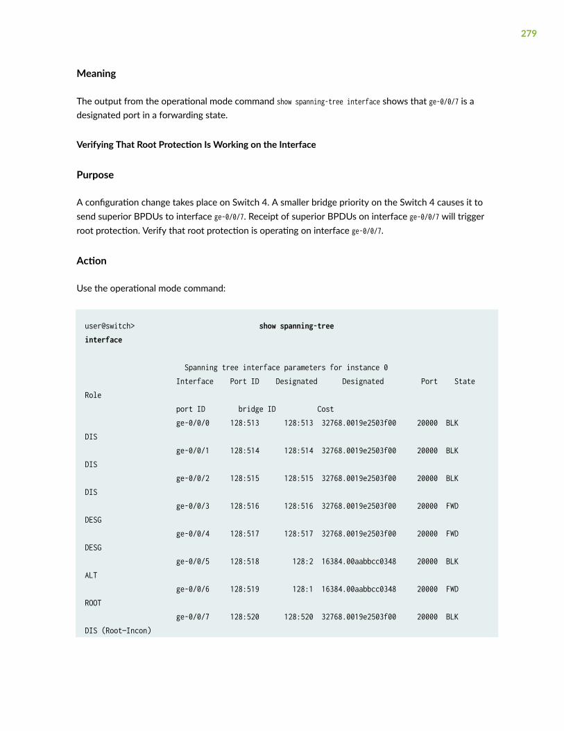
Meaning
The output from the operational mode command show spanning-tree interface shows that ge-0/0/7 is adesignated port in a forwarding state.
Verifying That Root Protection Is Working on the Interface
Purpose
A configuration change takes place on Switch 4. A smaller bridge priority on the Switch 4 causes it tosend superior BPDUs to interface ge-0/0/7. Receipt of superior BPDUs on interface ge-0/0/7 will triggerroot protection. Verify that root protection is operating on interface ge-0/0/7.
Action
Use the operational mode command:
user@switch> show spanning-tree interface
Spanning tree interface parameters for instance 0 Interface Port ID Designated Designated Port State Role port ID bridge ID Cost ge-0/0/0 128:513 128:513 32768.0019e2503f00 20000 BLK DIS ge-0/0/1 128:514 128:514 32768.0019e2503f00 20000 BLK DIS ge-0/0/2 128:515 128:515 32768.0019e2503f00 20000 BLK DIS ge-0/0/3 128:516 128:516 32768.0019e2503f00 20000 FWD DESG ge-0/0/4 128:517 128:517 32768.0019e2503f00 20000 FWD DESG ge-0/0/5 128:518 128:2 16384.00aabbcc0348 20000 BLK ALT ge-0/0/6 128:519 128:1 16384.00aabbcc0348 20000 FWD ROOT ge-0/0/7 128:520 128:520 32768.0019e2503f00 20000 BLK DIS (Root—Incon)
279

[output truncated]
Meaning
The operational mode command show spanning-tree interface shows that interface ge-0/0/7 has transitionedto a root inconsistent state. The root inconsistent state makes the interface block, discarding anyreceived BPDUs, and prevents the interface from becoming a candidate for the root port. When the rootbridge no longer receives superior STP BPDUs from the interface, the interface will recover andtransition back to a forwarding state. Recovery is automatic.
280

7CHAPTER
Monitoring and Troubleshooting
Monitoring and Troubleshooting Spanning Tree Protocols | 282

Monitoring and Troubleshooting Spanning TreeProtocols
IN THIS SECTION
Monitoring Spanning Tree Protocols on Switches | 282
Checking the Status of Spanning-Tree Instance Interfaces | 286
Understanding Spanning-Tree Protocol Trace Options | 286
Configuring Tracing Spanning-Tree Operations | 287
Example: Tracing Spanning-Tree Protocol Operations | 289
Unblocking a Switch Interface That Receives BPDUs in Error (CLI Procedure) | 290
Unblocking an Interface on non-ELS EX Series Switches That Receives BPDUs in Error (CLI Procedure) | 291
Clearing the Blocked Status of a Spanning-Tree Instance Interface | 291
Checking for a MAC Rewrite Error Condition Blocking a Spanning-Tree Instance Interface | 292
Clearing a MAC Rewrite Error Condition Blocking a Spanning-Tree Instance Interface | 292
Clearing a MAC Rewrite Error on an Interface with Layer 2 Protocol Tunneling | 293
Understanding Forward Delay Before Ports Transition to Forwarding State | 294
Monitoring Spanning Tree Protocols on Switches
IN THIS SECTION
Purpose | 283
Action | 283
Meaning | 283
282

Purpose
NOTE: This topic applies only to the J-Web Application package.
Use the monitoring feature to view status and information about the spanning-tree protocol parameterson your EX Series switch.
Action
To display spanning-tree protocol parameter details in the J-Web interface, select Monitor > Switching >STP.
To display spanning-tree protocol parameter details in the CLI, enter the following commands:
• show spanning-tree interface
• show spanning-tree bridge
Meaning
Table 19 on page 283 summarizes the spanning-tree protocol parameters.
Table 19: Summary of Spanning Tree Protocols Output Fields
Field Values
Bridge Parameters
Routing instance name
NOTE: The option is supportedonly on EX4300 switches.
Displays bridge information for the specified routing instance.
Context ID An internally generated identifier.
Enabled Protocol Spanning-tree protocol type enabled.
283

Table 19: Summary of Spanning Tree Protocols Output Fields (Continued)
Field Values
Root ID Bridge ID of the elected spanning-tree root bridge.
The bridge ID consists of a configurable bridge priority and the MACaddress of the bridge.
Root cost Calculated cost to reach the root bridge from the bridge where thecommand is entered.
Root port Interface that is the current elected root port for this bridge.
Bridge ID Locally configured bridge ID.
Hello time The time for which the bridge interface remains in the listening or learningstate.
Forward delay The time for which the bridge interface remains in the listening or learningstate before transitioning to the forwarding state.
Extended System ID The system ID.
Inter Instance ID An internally generated instance identifier.
Maximum age Maximum age of received bridge protocol data units (BPDUs).
Number of topology changes Total number of spanning-tree protocol topology changes detected sincethe switch last booted.
Time since last topology change
NOTE: This option is supportedonly on EX4300 switches.
Number of seconds elapsed since the last topology change.
Spanning Tree Interface Details
284
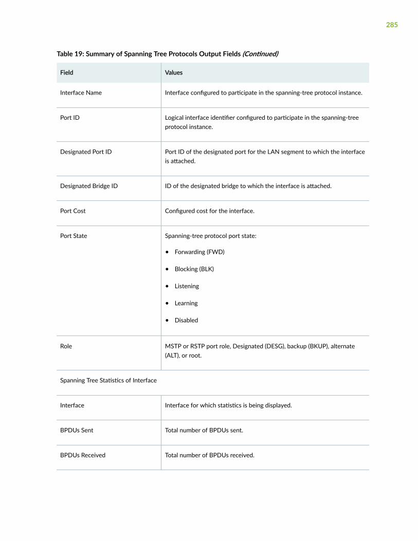
Table 19: Summary of Spanning Tree Protocols Output Fields (Continued)
Field Values
Interface Name Interface configured to participate in the spanning-tree protocol instance.
Port ID Logical interface identifier configured to participate in the spanning-treeprotocol instance.
Designated Port ID Port ID of the designated port for the LAN segment to which the interfaceis attached.
Designated Bridge ID ID of the designated bridge to which the interface is attached.
Port Cost Configured cost for the interface.
Port State Spanning-tree protocol port state:
• Forwarding (FWD)
• Blocking (BLK)
• Listening
• Learning
• Disabled
Role MSTP or RSTP port role, Designated (DESG), backup (BKUP), alternate(ALT), or root.
Spanning Tree Statistics of Interface
Interface Interface for which statistics is being displayed.
BPDUs Sent Total number of BPDUs sent.
BPDUs Received Total number of BPDUs received.
285
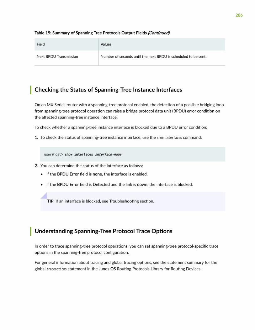
Table 19: Summary of Spanning Tree Protocols Output Fields (Continued)
Field Values
Next BPDU Transmission Number of seconds until the next BPDU is scheduled to be sent.
Checking the Status of Spanning-Tree Instance Interfaces
On an MX Series router with a spanning-tree protocol enabled, the detection of a possible bridging loopfrom spanning-tree protocol operation can raise a bridge protocol data unit (BPDU) error condition onthe affected spanning-tree instance interface.
To check whether a spanning-tree instance interface is blocked due to a BPDU error condition:
1. To check the status of spanning-tree instance interface, use the show interfaces command:
user@host> show interfaces interface-name
2. You can determine the status of the interface as follows:
• If the BPDU Error field is none, the interface is enabled.
• If the BPDU Error field is Detected and the link is down, the interface is blocked.
TIP: If an interface is blocked, see Troubleshooting section.
Understanding Spanning-Tree Protocol Trace Options
In order to trace spanning-tree protocol operations, you can set spanning-tree protocol-specific traceoptions in the spanning-tree protocol configuration.
For general information about tracing and global tracing options, see the statement summary for theglobal traceoptions statement in the Junos OS Routing Protocols Library for Routing Devices.
286
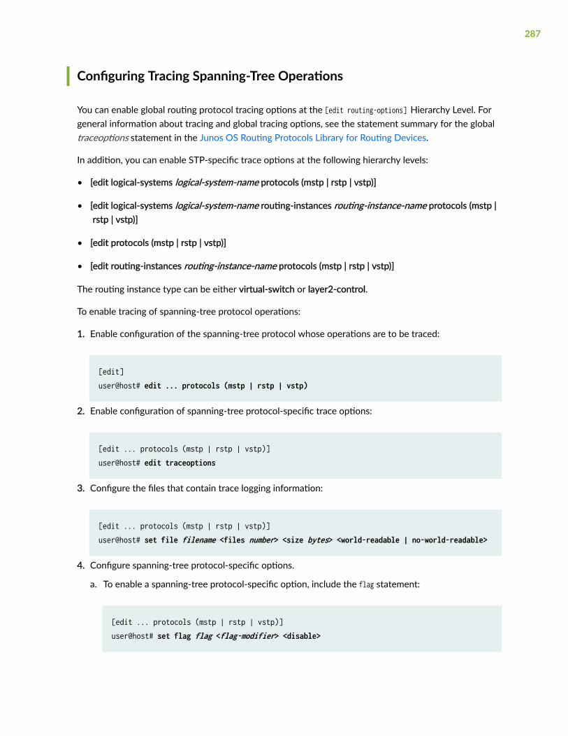
Configuring Tracing Spanning-Tree Operations
You can enable global routing protocol tracing options at the [edit routing-options] Hierarchy Level. Forgeneral information about tracing and global tracing options, see the statement summary for the globaltraceoptions statement in the Junos OS Routing Protocols Library for Routing Devices.
In addition, you can enable STP-specific trace options at the following hierarchy levels:
• [edit logical-systems logical-system-name protocols (mstp | rstp | vstp)]
• [edit logical-systems logical-system-name routing-instances routing-instance-name protocols (mstp | rstp | vstp)]
• [edit protocols (mstp | rstp | vstp)]
• [edit routing-instances routing-instance-name protocols (mstp | rstp | vstp)]
The routing instance type can be either virtual-switch or layer2-control.
To enable tracing of spanning-tree protocol operations:
1. Enable configuration of the spanning-tree protocol whose operations are to be traced:
[edit]user@host# edit ... protocols (mstp | rstp | vstp)
2. Enable configuration of spanning-tree protocol-specific trace options:
[edit ... protocols (mstp | rstp | vstp)]user@host# edit traceoptions
3. Configure the files that contain trace logging information:
[edit ... protocols (mstp | rstp | vstp)]user@host# set file filename <files number> <size bytes> <world-readable | no-world-readable>
4. Configure spanning-tree protocol-specific options.
a. To enable a spanning-tree protocol-specific option, include the flag statement:
[edit ... protocols (mstp | rstp | vstp)]user@host# set flag flag <flag-modifier> <disable>
287
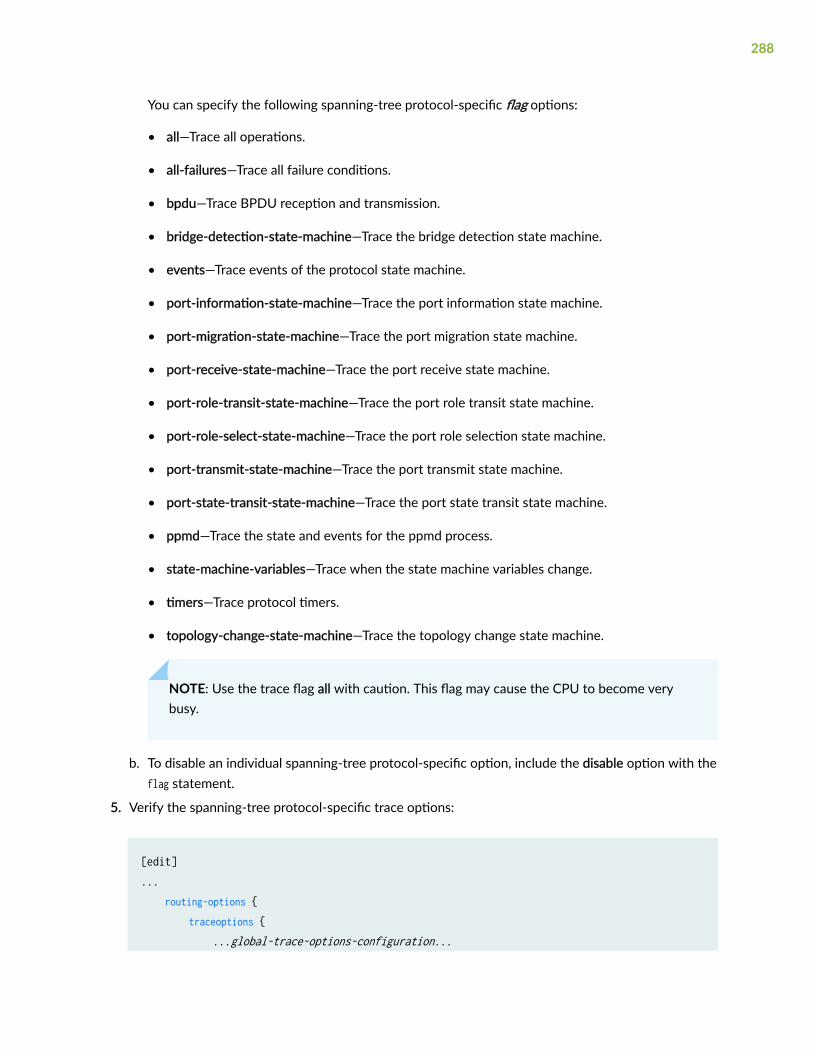
You can specify the following spanning-tree protocol-specific flag options:
• all—Trace all operations.
• all-failures—Trace all failure conditions.
• bpdu—Trace BPDU reception and transmission.
• bridge-detection-state-machine—Trace the bridge detection state machine.
• events—Trace events of the protocol state machine.
• port-information-state-machine—Trace the port information state machine.
• port-migration-state-machine—Trace the port migration state machine.
• port-receive-state-machine—Trace the port receive state machine.
• port-role-transit-state-machine—Trace the port role transit state machine.
• port-role-select-state-machine—Trace the port role selection state machine.
• port-transmit-state-machine—Trace the port transmit state machine.
• port-state-transit-state-machine—Trace the port state transit state machine.
• ppmd—Trace the state and events for the ppmd process.
• state-machine-variables—Trace when the state machine variables change.
• timers—Trace protocol timers.
• topology-change-state-machine—Trace the topology change state machine.
NOTE: Use the trace flag all with caution. This flag may cause the CPU to become verybusy.
b. To disable an individual spanning-tree protocol-specific option, include the disable option with theflag statement.
5. Verify the spanning-tree protocol-specific trace options:
[edit]... routing-options { traceoptions { ...global-trace-options-configuration...
288

} } } protocols { (mstp | rstp | vstp) { traceoptions { # Spanning-tree protocol-specific. file filename <files number> <size bytes> <world-readable | no-world-readable>; flag flag <flag-modifier> <disable>; } } }...
Example: Tracing Spanning-Tree Protocol Operations
Trace only unusual or abnormal operations to /var/log/stp-log:
[edit]routing-options { traceoptions { file routing-log size 10m world-readable; flag all; }}protocols { rstp { traceoptions { file rstp-log size 10m world-readable; flag all; } }}
289

Unblocking a Switch Interface That Receives BPDUs in Error (CLIProcedure)
EX Series and QFX Series switches use bridge protocol data unit (BPDU) protection on interfaces toprevent them from receiving BPDUs that could trigger a spanning-tree misconfiguration. If BPDUs arereceived on a BPDU-protected interface, the interface either shuts down or transitions to a blockingstate and stops forwarding frames. In the latter scenario, after the misconfiguration that triggered theBPDUs being sent to an interface is fixed in the topology, the interface can be unblocked and returnedto service.
NOTE: This topic applies to Junos OS for EX Series and QFX switches with support for theEnhanced Layer 2 Software (ELS) configuration style. For switches that do not support ELS, see"Unblocking an Interface on non-ELS EX Series Switches That Receives BPDUs in Error (CLIProcedure)" on page 291. For ELS details, see Using the Enhanced Layer 2 Software CLI.
To unblock an interface and return it to service using the CLI:
• Automatically unblock an interface by configuring a timer that expires:
[edit protocol layer 2]user@switch# set protocols layer2-control bpdu-block disable-timeout 30
All interfaces on the switch will be reenabled (unblocked) after the timer expires. However, once aninterface on the switch receives a new spanning-tree protocol BPDU, the interface returns to theblocked state.
• Manually unblock an interface using the operational mode command:
user@switch> clear error bpdu interface ge-0/0/6
This command will only reenable an interface but the BPDU configuration for the interface willcontinue to exist unless you remove the BPDU configuration explicitly.
290
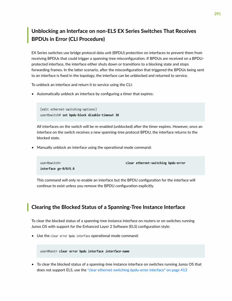
Unblocking an Interface on non-ELS EX Series Switches That ReceivesBPDUs in Error (CLI Procedure)
EX Series switches use bridge protocol data unit (BPDU) protection on interfaces to prevent them fromreceiving BPDUs that could trigger a spanning-tree misconfiguration. If BPDUs are received on a BPDU-protected interface, the interface either shuts down or transitions to a blocking state and stopsforwarding frames. In the latter scenario, after the misconfiguration that triggered the BPDUs being sentto an interface is fixed in the topology, the interface can be unblocked and returned to service.
To unblock an interface and return it to service using the CLI:
• Automatically unblock an interface by configuring a timer that expires:
[edit ethernet-switching-options]user@switch# set bpdu-block disable-timeout 30
All interfaces on the switch will be re-enabled (unblocked) after the timer expires. However, once aninterface on the switch receives a new spanning-tree protocol BPDU, the interface returns to theblocked state.
• Manually unblock an interface using the operational mode command:
user@switch> clear ethernet-switching bpdu-error interface ge-0/0/6.0
This command will only re-enable an interface but the BPDU configuration for the interface willcontinue to exist unless you remove the BPDU configuration explicitly.
Clearing the Blocked Status of a Spanning-Tree Instance Interface
To clear the blocked status of a spanning-tree instance interface on routers or on switches runningJunos OS with support for the Enhanced Layer 2 Software (ELS) configuration style:
• Use the clear error bpdu interface operational mode command:
user@host> clear error bpdu interface interface-name
• To clear the blocked status of a spanning-tree instance interface on switches running Junos OS thatdoes not support ELS, use the "clear ethernet-switching bpdu-error interface" on page 413
291
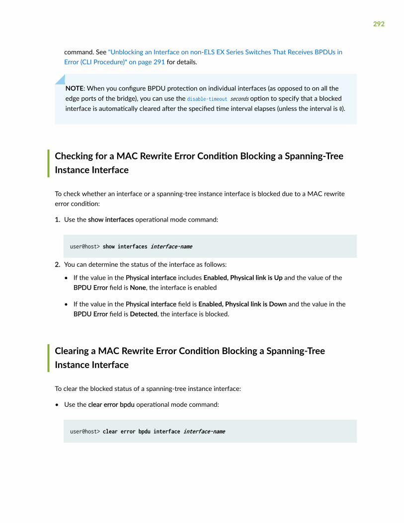
command. See "Unblocking an Interface on non-ELS EX Series Switches That Receives BPDUs inError (CLI Procedure)" on page 291 for details.
NOTE: When you configure BPDU protection on individual interfaces (as opposed to on all theedge ports of the bridge), you can use the disable-timeout seconds option to specify that a blockedinterface is automatically cleared after the specified time interval elapses (unless the interval is 0).
Checking for a MAC Rewrite Error Condition Blocking a Spanning-TreeInstance Interface
To check whether an interface or a spanning-tree instance interface is blocked due to a MAC rewriteerror condition:
1. Use the show interfaces operational mode command:
user@host> show interfaces interface-name
2. You can determine the status of the interface as follows:
• If the value in the Physical interface includes Enabled, Physical link is Up and the value of theBPDU Error field is None, the interface is enabled
• If the value in the Physical interface field is Enabled, Physical link is Down and the value in theBPDU Error field is Detected, the interface is blocked.
Clearing a MAC Rewrite Error Condition Blocking a Spanning-TreeInstance Interface
To clear the blocked status of a spanning-tree instance interface:
• Use the clear error bpdu operational mode command:
user@host> clear error bpdu interface interface-name
292
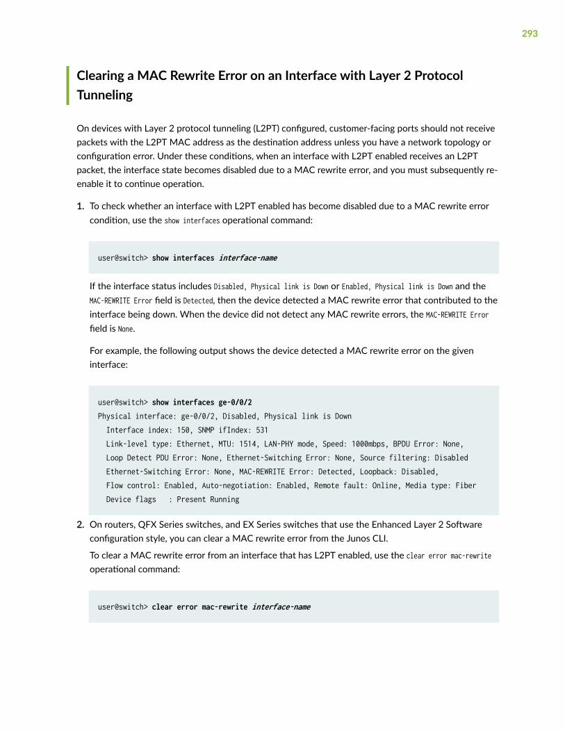
Clearing a MAC Rewrite Error on an Interface with Layer 2 ProtocolTunneling
On devices with Layer 2 protocol tunneling (L2PT) configured, customer-facing ports should not receivepackets with the L2PT MAC address as the destination address unless you have a network topology orconfiguration error. Under these conditions, when an interface with L2PT enabled receives an L2PTpacket, the interface state becomes disabled due to a MAC rewrite error, and you must subsequently re-enable it to continue operation.
1. To check whether an interface with L2PT enabled has become disabled due to a MAC rewrite errorcondition, use the show interfaces operational command:
user@switch> show interfaces interface-name
If the interface status includes Disabled, Physical link is Down or Enabled, Physical link is Down and theMAC-REWRITE Error field is Detected, then the device detected a MAC rewrite error that contributed to theinterface being down. When the device did not detect any MAC rewrite errors, the MAC-REWRITE Errorfield is None.
For example, the following output shows the device detected a MAC rewrite error on the giveninterface:
user@switch> show interfaces ge-0/0/2Physical interface: ge-0/0/2, Disabled, Physical link is Down Interface index: 150, SNMP ifIndex: 531 Link-level type: Ethernet, MTU: 1514, LAN-PHY mode, Speed: 1000mbps, BPDU Error: None, Loop Detect PDU Error: None, Ethernet-Switching Error: None, Source filtering: Disabled Ethernet-Switching Error: None, MAC-REWRITE Error: Detected, Loopback: Disabled, Flow control: Enabled, Auto-negotiation: Enabled, Remote fault: Online, Media type: Fiber Device flags : Present Running
2. On routers, QFX Series switches, and EX Series switches that use the Enhanced Layer 2 Softwareconfiguration style, you can clear a MAC rewrite error from the Junos CLI.
To clear a MAC rewrite error from an interface that has L2PT enabled, use the clear error mac-rewriteoperational command:
user@switch> clear error mac-rewrite interface-name
293

Understanding Forward Delay Before Ports Transition to ForwardingState
The forwarding delay timer specifies the length of time a spanning-tree protocol bridge port remains inthe listening and learning states before transitioning to the forwarding state. Setting the interval tooshort could cause unnecessary spanning-tree reconvergence. Before changing this parameter, youshould have a thorough understanding of spanning-tree protocols.
294

8CHAPTER
Configuration Statements
access-trunk | 297
arp-on-stp | 298
backup-bridge-priority | 300
block (Spanning Trees) | 302
bpdu-destination-mac-address (Spanning Tree) | 303
bpdu-block | 305
bpdu-block-on-edge | 307
bridge-priority | 310
configuration-name | 312
cost | 314
disable | 317
disable-timeout | 319
drop (BPDU Block) | 322
edge | 324
enable-all-ifl | 326
extended-system-id | 328
force-version (IEEE 802.1D STP) | 329
forward-delay | 331
hello-time | 333
interface (BPDU Blocking) | 336

interface (Spanning Tree) | 338
layer2-control | 341
log (Spanning Trees) | 344
mac-rewrite | 345
max-age | 347
max-hops | 350
mode | 352
msti | 355
mstp | 358
no-root-port | 362
priority (Protocols STP) | 364
priority-hold-time | 367
protocol | 368
protocols (STP Type) | 372
revision-level | 374
rstp | 376
shutdown (BPDU Block) | 381
stp | 382
system-id | 385
traceoptions (Spanning Tree) | 387
vlan (MSTP) | 392
vlan (VSTP) | 395
vlan-group | 398
vpls-flush-on-topology-change | 400
vstp | 401

access-trunk
IN THIS SECTION
Syntax | 297
Hierarchy Level | 297
Description | 297
Required Privilege Level | 297
Syntax
access-trunk;
Hierarchy Level
[edit logical-systems logical-system-name protocols vstp],[edit logical-systems logical-system-name routing-instances routing-instance-name protocols vstp],[edit protocols vstp vlan vlan-identifier interface interface-name], [edit routing-instances routing-instance-name instance-type (layer2-control | virtual-switch)]
Description
Enable untagged RTSP BDPUs to be sent and received on the interface.
Required Privilege Level
routing—To view this statement in the configuration.
297

routing-control—To add this statement to the configuration.
arp-on-stp
IN THIS SECTION
Syntax | 298
Hierarchy Level | 298
Description | 299
Default | 299
Required Privilege Level | 299
Release Information | 299
Syntax
arp-on-stp;
Hierarchy Level
[edit protocols mstp interface (all | interface-name)],[edit protocols rstp interface (all | interface-name)],[edit protocols stp interface (all | interface-name)],[edit protocols vstp (all |vlan--id | vlan--name) interface (all | interface-name)]
298

Description
Configure the Address Resolution Protocol (ARP) in a spanning-tree network so that when a spanning-tree protocol topology change notification (TCN) is issued, the VLAN with a broken link can relearn MACaddresses from another, redundant VLAN in the network. The network must include a routed VLANinterface (RVI).
When a link fails in a spanning-tree network (RSTP, STP, MSTP, or VSTP), a message called a TCN isissued that causes all affected Ethernet switching table entries to be flushed. The network must thenrelearn the MAC addresses using flooding. If you have configured an RVI on the network, you have theoption of having the VLAN with the broken link relearn MAC addresses from another VLAN using ARP,thereby avoiding excessive flooding on the VLAN with the broken link.
Default
ARP on STP is disabled.
Required Privilege Level
system—To view this statement in the configuration.
system-control—To add this statement to the configuration.
Release Information
Statement introduced in Junos OS Release 11.2.
RELATED DOCUMENTATION
Configuring STP on EX Series Switches (CLI Procedure) | 25
299

backup-bridge-priority
IN THIS SECTION
Syntax | 300
Hierarchy Level | 300
Description | 301
Options | 301
Required Privilege Level | 301
Release Information | 301
Syntax
backup-bridge-priority priority;
Hierarchy Level
[edit logical-systems logical-system-name protocols (mstp | rstp)],[edit logical-systems logical-system-name protocols vstp vlan vlan-id],[edit logical-systems logical-system-name routing-instances routing-instance-name protocols (mstp | rstp)],[edit logical-systems logical-system-name routing-instances routing-instance-name protocols vstp vlan vlan-id],[edit protocols (mstp | rstp)],[edit protocols vstp vlan vlan-id],[edit routing-instances routing-instance-name protocols (mstp | rstp)],[edit routing-instances routing-instance-name protocols vstp vlan vlan-id]
300

Description
Determine the priority of the backup bridge in a VPLS multihomed Layer 2 ring with MPLSinfrastructure.
Options
priority—The backup bridge priority can be set only in increments of 4096.
• Range: 0 through 61,440
• Default: 32,768
Required Privilege Level
routing—To view this statement in the configuration.
routing-control—To add this statement to the configuration.
Release Information
Statement introduced in Junos OS Release 10.0.
RELATED DOCUMENTATION
Understanding VPLS Multihoming | 256
Configuring VPLS Root Protection Topology Change Actions to Control Individual VLAN Spanning-Tree Behavior | 264
301

block (Spanning Trees)
IN THIS SECTION
Syntax | 302
Hierarchy Level | 302
Description | 302
Required Privilege Level | 303
Release Information | 303
Syntax
block;
Hierarchy Level
[edit protocols mstp interface (all | interface-name) bpdu-timeout-action],[edit protocols rstp interface (all | interface-name) bpdu-timeout-action],[edit protocols stp interface (all | interface-name) bpdu-timeout-action],[edit protocolsvstp vlan vlan-id interface (all | interface-name) bpdu-timeout-action]
Description
Configures loop protection on a specific interface.
302

Required Privilege Level
routing—To view this statement in the configuration.routing-control—To add this statement to the configuration.
Release Information
Statement introduced in Junos OS Release 9.1.
Statement updated in Junos OS Release 9.4 for EX Series switches to add VSTP support.
RELATED DOCUMENTATION
Understanding Loop Protection for STP, RSTP, VSTP, and MSTP
Understanding VSTP
Example: Configuring Network Regions for VLANs with MSTP on Switches | 101
Example: Configuring Faster Convergence and Improving Network Stability with RSTP
Example: Faster Convergence and Improved Network Stability with RSTP on EX Series Switches | 59
Example: Configuring Loop Protection to Prevent Interfaces from Transitioning from Blocking toForwarding in a Spanning Tree
Loop Protection for Spanning-Tree Protocols | 229
show spanning-tree bridge | 432
show spanning-tree interface | 440
bpdu-destination-mac-address (Spanning Tree)
IN THIS SECTION
Syntax | 304
Hierarchy Level | 304
Description | 304
303

Default | 304
Options | 305
Required Privilege Level | 305
Release Information | 305
Syntax
bpdu-destination-mac-address provider-bridge-group;
Hierarchy Level
[edit logical-systems logical-system-name protocols (mstp | rstp)],[edit logical-systems logical-system-name routing-instances routing-instance-name protocols (mstp | rstp)],[edit protocols (mstp | rstp)],[edit routing-instances routing-instance-name protocols (mstp | rstp)]
Description
Enable MX Series router to participate in the provider Rapid Spanning Tree Protocol (RSTP) instance or aprovider Multiple Spanning Tree Protocol (MSTP) instance.
Default
If the bpdu-destination-mac-address statement is not configured, the bridge participates in the customerRSTP instance, transmitting and receiving standard RSTP BPDU packets.
304

Options
provider-bridge-group—The destination MAC address of the BPDU packets transmitted is the providerbridge group address 01:80:c2:00:00:08. Received BPDU packets with this destination MAC address areaccepted and passed to the Routing Engine.
Required Privilege Level
routing—To view this statement in the configuration.
routing-control—To add this statement to the configuration.
Release Information
Statement introduced in Junos OS Release 9.2.
Support for logical systems added in Junos OS Release 9.6.
RELATED DOCUMENTATION
Understanding BPDUs Used for Exchanging Information Among Bridges | 165
Understanding Provider Bridge Participation in RSTP or MSTP Instances
Configuring Rapid Spanning Tree Protocol | 28
Configuring Multiple Spanning Tree Protocol | 95
bpdu-block
IN THIS SECTION
Syntax | 306
Hierarchy Level | 306
305

Description | 306
Required Privilege Level | 307
Release Information | 307
Syntax
bpdu-block { interface (interface-name disable | all); disable-timeout seconds;}
Hierarchy Level
[edit protocols layer2-control ]
[edit ethernet-switching-options]
Description
Configures bridge protocol data unit (BPDU) protection on a specified interface or on all interfaces. Ifthe interface receives incompatible BPDUs, it is disabled.
If the disable-timeout statement is included in the BPDU configuration, the interface is automaticallyreenabled after the timer expires. Otherwise, you must use the operational mode command clearethernet-switching bpdu-error interface to unblock and reenable the interface.
The remaining statements are explained separately. See CLI Explorer.
306

Required Privilege Level
interface—To view this statement in the configuration.
interface-control—To add this statement to the configuration.
Release Information
Statement introduced in Junos OS Release 9.1.
RELATED DOCUMENTATION
Understanding BPDU Protection for Spanning-Tree Instance Interfaces | 160
Configuring BPDU Protection for Individual Spanning-Tree Instance Interfaces | 164
Understanding BPDU Protection for STP, RSTP, and MSTP | 162
Example: Configuring BPDU Protection on Interfaces to Prevent STP Miscalculations on EX SeriesSwitches | 218
Unblocking an Interface on non-ELS EX Series Switches That Receives BPDUs in Error (CLIProcedure) | 291
Understanding BPDU Protection for STP, RSTP, and MSTP | 162
show spanning-tree bridge | 432
show spanning-tree interface | 440
clear ethernet-switching bpdu-error interface | 413
bpdu-block-on-edge
IN THIS SECTION
Syntax | 308
Hierarchy Level | 308
Description | 308
Default | 308
307

Required Privilege Level | 309
Release Information | 309
Syntax
bpdu-block-on-edge;
Hierarchy Level
[edit logical-systems logical-system-name protocols (mstp | rstp | vstp)],[edit logical-systems logical-system-name routing-instances routing-instance-name protocols (mstp | rstp | vstp)],[edit protocols ( mstp | rstp| vstp )],[edit routing-instances routing-instance-name protocols (mstp | rstp | vstp)]
Description
Configure bridge protocol data unit (BPDU) protection on all edge ports of a switch. When the bpdu-block-on-edge statement is configured and the interface encounters an incompatible BPDU, the interfaceshuts down.
If the disable-timeout statement is included in the BPDU configuration, the interface is automaticallyreenabled after the timer expires. Otherwise, you must use the operational mode command clearethernet-switching bpdu-error interface to unblock and reenable the interface.
Default
Not enabled.
308

Required Privilege Level
routing—To view this statement in the configuration.
routing-control—To add this statement to the configuration.
Release Information
Statement introduced in Junos OS Release 9.1.
Statement updated in Junos OS Release 9.4 for EX Series switches to add VSTP support. Statementupdated in Junos OS Release 11.1 for EX Series switches to change blocking behavior to port shutdown.
Support for logical systems added in Junos OS Release 9.6.
RELATED DOCUMENTATION
Understanding BPDU Protection for Spanning-Tree Instance Interfaces | 160
Understanding BPDU Protection for STP, RSTP, and MSTP | 162
BPDU Protection on All Edge Ports of the Bridge | 166
Configuring BPDU Protection on ACX Router, EX Switch and MX Router Edge Ports | 171
Configuring BPDU Protection on Switch Spanning Tree Interfaces | 169
Example: Configuring Network Regions for VLANs with MSTP on Switches | 101
Example: Faster Convergence and Improved Network Stability with RSTP on EX Series Switches | 59
Example: Configuring BPDU Protection on Edge Interfaces to Prevent STP Miscalculations on non-ELS EX Series Switches | 204
rstp | 376
mstp | 358
vstp | 401
show spanning-tree bridge | 432
show spanning-tree interface | 440
clear ethernet-switching bpdu-error interface | 413
309
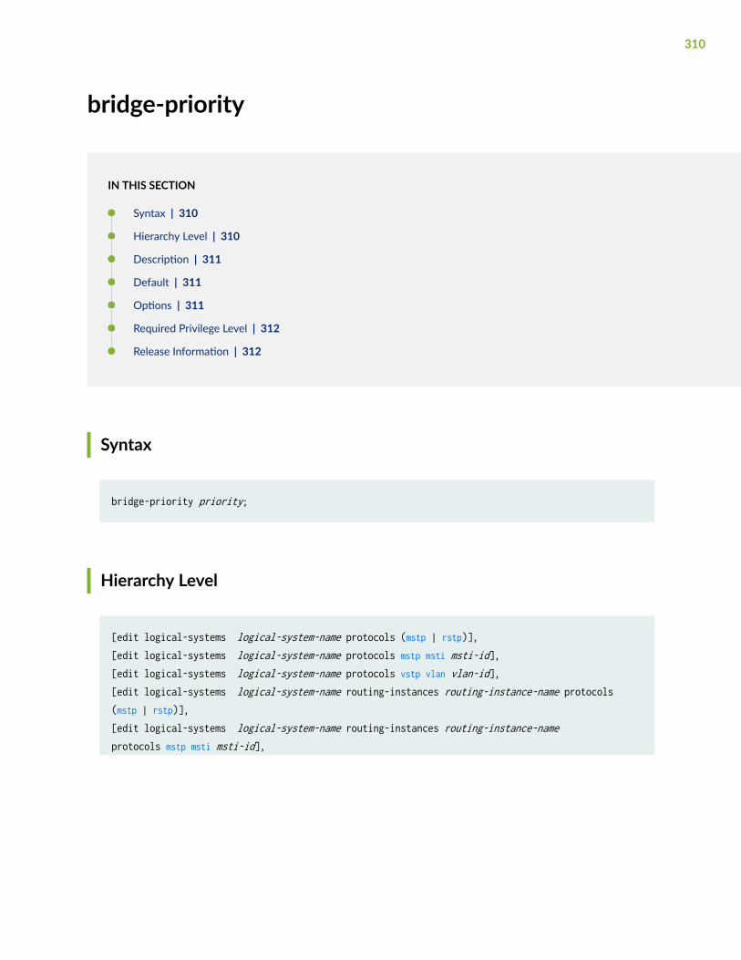
bridge-priority
IN THIS SECTION
Syntax | 310
Hierarchy Level | 310
Description | 311
Default | 311
Options | 311
Required Privilege Level | 312
Release Information | 312
Syntax
bridge-priority priority;
Hierarchy Level
[edit logical-systems logical-system-name protocols (mstp | rstp)],[edit logical-systems logical-system-name protocols mstp msti msti-id],[edit logical-systems logical-system-name protocols vstp vlan vlan-id],[edit logical-systems logical-system-name routing-instances routing-instance-name protocols (mstp | rstp)],[edit logical-systems logical-system-name routing-instances routing-instance-name protocols mstp msti msti-id],
310

[edit logical-systems logical-system-name routing-instances routing-instance-name protocols vstp vlan vlan-id],
[edit routing-instances routing-instance-name protocols (mstp | rstp)],[edit routing-instances routing-instance-name protocols mstp msti msti-id],[edit routing-instances routing-instance-name protocols vstp vlan vlan-id]
[edit protocols mstp], [edit protocols mstp msti msti-id],[edit protocols rstp], [edit protocols stp],[edit protocols vstp vlan vlan-id]
Description
Configures the bridge priority, which determines which bridge is elected as the root bridge. If twobridges have the same path cost to the root bridge, the bridge priority determines which bridgebecomes the designated bridge for a LAN segment.
Default
32,768
Options
priority—The bridge priority can be set only in increments of 4096.
• Range: 0 through 61,440
• Default: 32,768
311
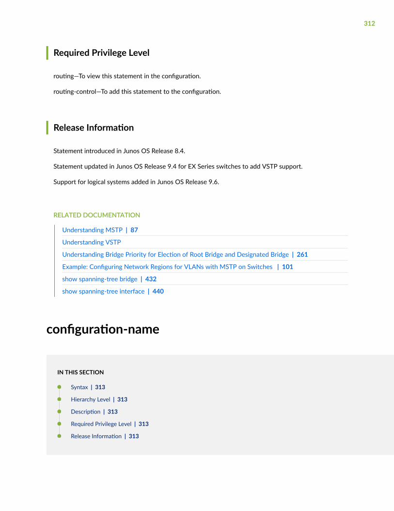
Required Privilege Level
routing—To view this statement in the configuration.
routing-control—To add this statement to the configuration.
Release Information
Statement introduced in Junos OS Release 8.4.
Statement updated in Junos OS Release 9.4 for EX Series switches to add VSTP support.
Support for logical systems added in Junos OS Release 9.6.
RELATED DOCUMENTATION
Understanding MSTP | 87
Understanding VSTP
Understanding Bridge Priority for Election of Root Bridge and Designated Bridge | 261
Example: Configuring Network Regions for VLANs with MSTP on Switches | 101
show spanning-tree bridge | 432
show spanning-tree interface | 440
configuration-name
IN THIS SECTION
Syntax | 313
Hierarchy Level | 313
Description | 313
Required Privilege Level | 313
Release Information | 313
312

Syntax
configuration-name configuration-name;
Hierarchy Level
[edit logical-systems logical-system-name protocols mstp],[edit logical-systems logical-system-name routing-instances routing-instance-name protocols mstp],
[edit protocols mstp],
[edit routing-instances routing-instance-name protocols mstp]
Description
Specify the configuration name, which is the MSTP region name carried in the MSTP BPDUs.
Required Privilege Level
routing—To view this statement in the configuration.
routing-control—To add this statement to the configuration.
Release Information
Statement introduced in Junos OS Release 8.4.
Support for logical systems added in Junos OS Release 9.6.
313

RELATED DOCUMENTATION
Understanding MSTP | 87
Understanding BPDUs Used for Exchanging Information Among Bridges | 165
Configuring Multiple Spanning Tree Protocol | 95
Configuring MSTP on Switches | 91
Example: Faster Convergence and Improved Network Stability with RSTP on EX Series Switches | 59
show spanning-tree bridge | 432
show spanning-tree interface | 440
Example: Configuring Network Regions for VLANs with MSTP on Switches | 101
Example: Configuring Faster Convergence and Network Stability on ELS Switches with RSTP | 32
Understanding MSTP | 87
cost
IN THIS SECTION
Syntax | 314
Hierarchy Level | 315
Description | 315
Default | 315
Options | 316
Required Privilege Level | 316
Release Information | 316
Syntax
cost cost;
314

Hierarchy Level
[edit logical-systems logical-system-name protocols (mstp | rstp | vstp) interface interface-name],[edit logical-systems logical-system-name protocols mstp msti msti-id interface interface-name],[edit logical-systems logical-system-name protocols vstp vlan vlan-id interface interface-name],[edit logical-systems logical-system-name routing-instances routing-instance-name protocols (mstp | rstp | vstp) interface interface-name],[edit logical-systems logical-system-name routing-instances routing-instance-name protocols mstp msti msti-id interface interface-name],[edit logical-systems logical-system-name routing-instances routing-instance-name protocols vstp vlan vlan-id interface interface-name],
[edit protocols (mstp | rstp | vstp) interface interface-name],[edit protocols mstp msti msti-id interface interface-name],[edit protocols vstp vlan vlan-id interface interface-name],
[edit routing-instances routing-instance-name protocols (mstp | rstp | vstp) interface interface-name],[edit routing-instances routing-instance-name protocols mstp msti msti-id interface interface-name],[edit routing-instances routing-instance-name protocols vstp vlan vlan-id interface interface-name]
Description
For Spanning Tree Protocol (STP), Rapid Spanning Tree Protocol (RSTP), VLAN Spanning Tree Protocol(VSTP), or Multiple Spanning Tree Protocol (MSTP), configure the link cost to control which bridge is thedesignated bridge and which interface is the designated interface.
Default
The link cost is determined by the link speed.
315
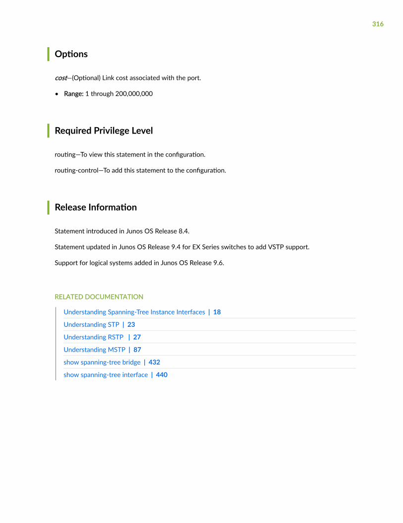
Options
cost—(Optional) Link cost associated with the port.
• Range: 1 through 200,000,000
Required Privilege Level
routing—To view this statement in the configuration.
routing-control—To add this statement to the configuration.
Release Information
Statement introduced in Junos OS Release 8.4.
Statement updated in Junos OS Release 9.4 for EX Series switches to add VSTP support.
Support for logical systems added in Junos OS Release 9.6.
RELATED DOCUMENTATION
Understanding Spanning-Tree Instance Interfaces | 18
Understanding STP | 23
Understanding RSTP | 27
Understanding MSTP | 87
show spanning-tree bridge | 432
show spanning-tree interface | 440
316

disable
IN THIS SECTION
Syntax | 317
Hierarchy Level | 317
Description | 318
Default | 318
Required Privilege Level | 318
Release Information | 319
Syntax
disable;
Hierarchy Level
[edit logical-systems logical-system-name protocols mstp],[edit logical-systems logical-system-name routing-instances routing-instance-name protocols mstp],
[edit protocols mpls], [edit protocols mpls interface (all | interface-name)],
[edit protocols mstp], [edit protocols mstp (all | interface-name)],[edit protocols mstp (all | interface-name) arp-on-stp],[edit protocols mstp msti msti-id vlan (vlan-id | vlan-name) interface (all | interface-name)],[edit protocols mstp msti msti-id vlan (vlan-id | vlan-name) interface interface-name arp-on-stp],
317

[edit protocols rstp], [edit protocols rstp interface (all | interface-name)],[edit protocols rstp interface (all | interface-name) arp-on-stp],[edit protocols stp],[edit protocols stp interface (all | interface-name)],[edit protocols stp interface (all | interface-name) arp-on-stp],[edit protocols vstp],[edit protocols vstp vlan vlan-id interface (all | interface-name)][edit protocols vstp vlan vlan-id interface (all | interface-name) arp-on-stp][edit protocols mstp interface interface-name,[edit protocols mstp msti msti-id vlan (all vlan-id | vlan-name) interface interface-name],[edit protocols rstp interface interface-name],[edit protocols vstp vlan vlan-id interface interface-name]
[edit routing-instances routing-instance-name protocols mstp]
[edit ethernet-switching-options bpdu-block interface]
Description
Disable the entire MSTP, RSTP, or VSTP instance on a specific interface.
NOTE: You cannot disable spanning tree parameters for all interfaces.
Default
Not enabled
Required Privilege Level
routing—To view this statement in the configuration.
318

routing-control—To add this statement to the configuration.
Release Information
Statement introduced in Junos OS Release 9.0.
Statement updated in Junos OS Release 9.4 for EX Series switches to add VSTP support.
Support for logical systems added in Junos OS Release 9.6.
Statement updated in Junos OS Release 15.1 for EX Series switches.
RELATED DOCUMENTATION
Understanding RSTP | 27
Configuring Multiple Spanning Tree Protocol | 95
Configuring RSTP on EX Series Switches (CLI Procedure) | 31
Configuring MSTP on Switches | 91
Disabling MSTP | 133
Example: Configuring BPDU Protection on Interfaces to Prevent STP Miscalculations on EX SeriesSwitches | 218
Example: Configuring Network Regions for VLANs with MSTP on Switches | 101
Example: Configuring Faster Convergence and Network Stability on ELS Switches with RSTP | 32
interface (BPDU Blocking) | 336
show spanning-tree bridge | 432
show spanning-tree interface | 440
disable-timeout
IN THIS SECTION
Syntax | 320
Hierarchy Level | 320
319
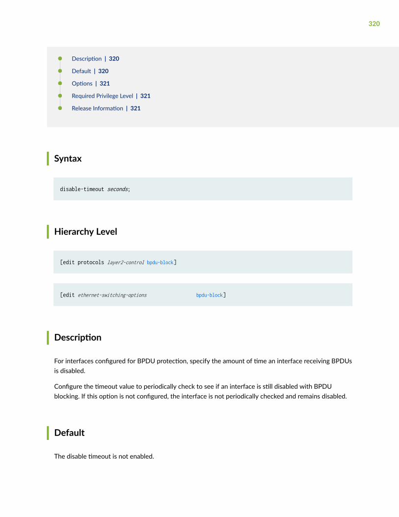
Description | 320
Default | 320
Options | 321
Required Privilege Level | 321
Release Information | 321
Syntax
disable-timeout seconds;
Hierarchy Level
[edit protocols layer2-control bpdu-block]
[edit ethernet-switching-options bpdu-block]
Description
For interfaces configured for BPDU protection, specify the amount of time an interface receiving BPDUsis disabled.
Configure the timeout value to periodically check to see if an interface is still disabled with BPDUblocking. If this option is not configured, the interface is not periodically checked and remains disabled.
Default
The disable timeout is not enabled.
320

Options
seconds——Amount of time, in seconds, the interface receiving BPDUs is disabled. Once the timeoutexpires, the interface is brought back into service.
• Range: 10 through 3600
• Default: If this option is not configured, the interface is not periodically checked and remainsdisabled.
Required Privilege Level
routing—To view this statement in the configuration.
routing-control—To add this statement to the configuration.
system—To view this statement in the configuration.system-control—To add this statement to the configuration.
Release Information
Statement introduced in Junos OS Release 9.1.
RELATED DOCUMENTATION
Understanding BPDU Protection for Spanning-Tree Instance Interfaces | 160
Understanding BPDU Protection for STP, RSTP, and MSTP | 162
Configuring BPDU Protection for Individual Spanning-Tree Instance Interfaces | 164
Example: Faster Convergence and Improved Network Stability with RSTP on EX Series Switches | 59
Example: Configuring BPDU Protection on Interfaces to Prevent STP Miscalculations on EX SeriesSwitches | 218
Example: Configuring Network Regions for VLANs with MSTP on Switches | 101
Example: Configuring BPDU Protection on Switch Edge Interfaces With ELS to Prevent STPMiscalculations | 197
show spanning-tree bridge | 432
show spanning-tree interface | 440
321

drop (BPDU Block)
IN THIS SECTION
Syntax | 322
Hierarchy Level | 322
Description | 322
Default | 323
Required Privilege Level | 323
Release Information | 323
Syntax
drop;
Hierarchy Level
[edit ethernet-switching-options bpdu-block bpdu-block (all | [interface-name])]
Description
Drop bridge protocol data units (BPDUs ) that enter any interface or a specified interface, but do notdisable the interface. Configure the drop statement only on interfaces on which no spanning-treeprotocol (STP, MSTP, or RSTP) is configured.
322
NOTE: Do not configure drop on any interface on which a spanning-tree protocol has beenconfigured. Doing so could cause STP misconfiguration and consequent network outages.
Default
Not enabled.
Required Privilege Level
routing—To view this statement in the configuration.routing-control—To add this statement to the configuration.
Release Information
Statement introduced in Junos OS Release 12.2.
RELATED DOCUMENTATION
Understanding BPDU Protection for STP, RSTP, and MSTP | 162
Example: Configuring BPDU Protection on Edge Interfaces to Prevent STP Miscalculations on non-ELS EX Series Switches | 204
Example: Configuring BPDU Protection on Interfaces to Prevent STP Miscalculations on EX SeriesSwitches | 218
bpdu-block-on-edge | 307
323
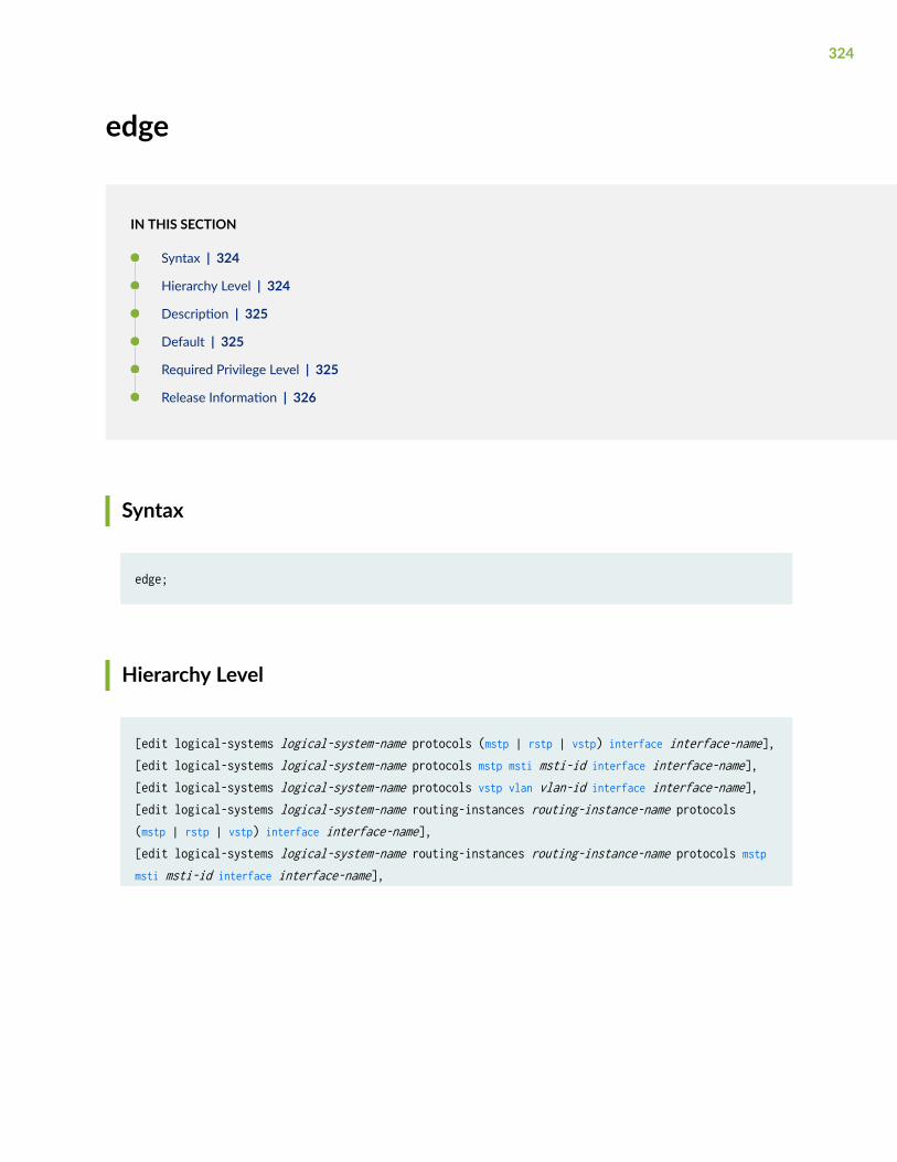
edge
IN THIS SECTION
Syntax | 324
Hierarchy Level | 324
Description | 325
Default | 325
Required Privilege Level | 325
Release Information | 326
Syntax
edge;
Hierarchy Level
[edit logical-systems logical-system-name protocols (mstp | rstp | vstp) interface interface-name],[edit logical-systems logical-system-name protocols mstp msti msti-id interface interface-name],[edit logical-systems logical-system-name protocols vstp vlan vlan-id interface interface-name],[edit logical-systems logical-system-name routing-instances routing-instance-name protocols (mstp | rstp | vstp) interface interface-name],[edit logical-systems logical-system-name routing-instances routing-instance-name protocols mstp msti msti-id interface interface-name],
324

[edit logical-systems logical-system-name routing-instances routing-instance-name protocols vstp vlan vlan-id interface interface-name],
[edit protocols (mstp | rstp | vstp) interface (all | interface-name)], )arp-on-stp],[edit protocols mstp msti msti-id interface (all | interface-name)], )arp-on-stp],[edit protocols vstp vlan vlan-id interface (all | interface-name)], )arp-on-stp],
[edit routing-instances routing-instance-name protocols (mstp | rstp | vstp) interface interface-name][edit routing-instances routing-instance-name protocols mstp msti msti-id interface interface-name],[edit routing-instances routing-instance-name protocols vstp vlan vlan-id interface interface-name]
Description
For Rapid Spanning Tree Protocol (RSTP), VLAN Spanning Tree Protocol (VSTP), or Multiple SpanningTree Protocol (MSTP), configure interfaces as edge ports or edge interfaces. Edge ports do not expect toreceive BPDUs. If a BPDU is received, the port becomes a nonedge port and the Edge interfacesimmediately transition to a forwarding state.
NOTE: Although the edge configuration statement appears in the [edit protocols stp interface (all| interface-name)] or [edit protocols rstp force-version stp interface (all | interface-name)] hierarchyon the switch, this statement has no effect on the switch operation if you configure it.
Default
Edge interfaces are not enabled.
Required Privilege Level
routing—To view this statement in the configuration.
325
routing-control—To add this statement to the configuration.
Release Information
Statement introduced in Junos OS Release 8.4.
Statement updated in Junos OS Release 9.4 for EX Series switches to add VSTP support.
Support for logical systems added in Junos OS Release 9.6.
RELATED DOCUMENTATION
Understanding STP | 23
Example: Configuring Network Regions for VLANs with MSTP on Switches | 101
show spanning-tree bridge | 432
show spanning-tree interface | 440
enable-all-ifl
IN THIS SECTION
Syntax | 326
Hierarchy Level | 327
Description | 327
Required Privilege Level | 327
Release Information | 327
Syntax
enable-all-ifl;
326
Hierarchy Level
[edit protocols layer2-control mac-rewrite interface interface-name]
Description
Enable tunneling for STP, VTP, CDP, and other supported protocols on all logical interfaces (VLANs)configured on the interface.
NOTE: Tunneling on all logical interfaces is enabled automatically for PVST/PVST+.
Required Privilege Level
interface—To view this statement in the configuration.
interface-control—To add this statement to the configuration.
Release Information
Statement introduced in Junos OS Release 13.3.
RELATED DOCUMENTATION
Understanding Layer 2 Protocol Tunneling
protocol
327
extended-system-id
IN THIS SECTION
Syntax | 328
Hierarchy Level | 328
Description | 328
Options | 329
Required Privilege Level | 329
Release Information | 329
Syntax
extended-system-id identifier;
Hierarchy Level
[edit logical-systems logical-system-name protocols rstp],[edit logical-systems logical-system-name routing-instances routing-instance-name protocols rstp],[edit protocols rstp],[edit routing-instances routing-instance-name protocols rstp]
Description
The extended system ID is used to specify different bridge identifiers for different RSTP or STP routinginstances.
328
Options
identifier—Specify the system identifier to use for the RSTP or STP instance.
• Range: 0 through 4095
Required Privilege Level
routing—To view this statement in the configuration.
routing-control—To add this statement to the configuration.
Release Information
Statement introduced in Junos OS Release 8.3.
Support for logical systems added in Junos OS Release 9.6.
RELATED DOCUMENTATION
Configuring Rapid Spanning Tree Protocol | 28
Configuring RSTP on EX Series Switches (CLI Procedure) | 31
Example: Configuring Faster Convergence and Network Stability on ELS Switches with RSTP | 32
Understanding RSTP | 27
force-version (IEEE 802.1D STP)
IN THIS SECTION
Syntax | 330
Hierarchy Level | 330
329

Description | 330
Required Privilege Level | 330
Release Information | 331
Syntax
force-version stp;
Hierarchy Level
[edit logical-systems logical-system-name protocols (rstp | vstp)],[edit logical-systems logical-system-name routing-instances routing-instance-name protocols (rstp | vstp)],
[edit protocols (rstp | vstp)],[edit routing-instances routing-instance-name protocols (rstp | vstp)]
Description
Forces the spanning-tree version to be the original IEEE 803.1D STP protocol.
Required Privilege Level
routing—To view this statement in the configuration.
routing-control—To add this statement to the configuration.
330

Release Information
Statement introduced in Junos OS Release 8.4.
Support for logical systems added in Junos OS Release 9.6.
Support for logical systems added in Junos OS Release 9.6.
forward-delay
IN THIS SECTION
Syntax | 331
Hierarchy Level | 331
Description | 332
Options | 332
Required Privilege Level | 332
Release Information | 332
Syntax
forward-delay seconds;
Hierarchy Level
[edit logical-systems logical-system-name protocols (mstp | rstp)],[edit logical-systems logical-system-name protocols vstp vlan vlan-id],[edit logical-systems logical-system-name routing-instances routing-instance-name protocols (mstp | rstp)],
331

[edit logical-systems logical-system-name routing-instances routing-instance-name protocols vstp vlan vlan-id],
[edit protocols (mstp | rstp)],[edit protocols vstp vlan vlan-id],[edit routing-instances routing-instance-name protocols (mstp | rstp)],
[edit routing-instances routing-instance-name protocols vstp vlan vlan-id]
Description
For Spanning Tree Protocol (STP), Rapid Spanning Tree Protocol (RSTP), VLAN Spanning Tree Protocol(VSTP), or Multiple Spanning Tree Protocol (MSTP), specifies the length of time an STP bridge portremains in the listening and learning states before transitioning to the forwarding state.
Options
seconds—(Optional) Number of seconds the bridge port remains in the listening and learning states.
• Range: 4 through 30
• Default: 15 seconds
Required Privilege Level
routing—To view this statement in the configuration.
routing-control—To add this statement to the configuration.
Release Information
Statement introduced in Junos OS Release 8.4.
332

Statement updated in Junos OS Release 9.4 for EX Series switches to add VSTP support.
Support for logical systems added in Junos OS Release 9.6.
RELATED DOCUMENTATION
Understanding Forward Delay Before Ports Transition to Forwarding State | 294
Understanding STP | 23
Understanding MSTP | 87
Understanding VSTP
Example: Configuring Network Regions for VLANs with MSTP on Switches | 101
Example: Configuring Faster Convergence and Network Stability on ELS Switches with RSTP | 32
Example: Faster Convergence and Improved Network Stability with RSTP on EX Series Switches | 59
show spanning-tree bridge | 432
show spanning-tree interface | 440
hello-time
IN THIS SECTION
Syntax | 334
Hierarchy Level | 334
Description | 334
Default | 334
Options | 335
Required Privilege Level | 335
Release Information | 335
333

Syntax
hello-time seconds;
Hierarchy Level
[edit logical-systems logical-system-name protocols (mstp | rstp)],[edit logical-systems logical-system-name protocols vstp vlan vlan-id],[edit logical-systems logical-system-name routing-instances routing-instance-name protocols (mstp | rstp)],[edit logical-systems logical-system-name routing-instances routing-instance-name protocols vstp vlan vlan-id],
[edit protocols (mstp | rstp)],[edit protocols vstp vlan vlan-id],
[edit routing-instances routing-instance-name protocols (mstp | rstp)],[edit routing-instances routing-instance-name protocols vstp vlan vlan-id]
Description
For Spanning Tree Protocol (STP), Rapid Spanning Tree Protocol (RSTP), VLAN Spanning Tree Protocol(VSTP), or Multiple Spanning Tree Protocol (MSTP), specifies the number of seconds betweentransmissions of configuration BPDUs by the root bridge.
Default
2 seconds
334
Options
seconds—(Optional) Number of seconds between transmissions of configuration BPDUs.
• Range: 1 through 10
• Default: 2 seconds
Required Privilege Level
routing—To view this statement in the configuration.
routing-control—To add this statement to the configuration.
Release Information
Statement introduced in Junos OS Release 8.4.
Statement updated in Junos OS Release 9.4 for EX Series switches to add VSTP support.
Support for logical systems added in Junos OS Release 9.6.
Support for logical systems added in Junos OS Release 9.6.
RELATED DOCUMENTATION
Understanding MSTP | 87
Understanding VSTP
Example: Configuring Network Regions for VLANs with MSTP on Switches | 101
Example: Configuring Faster Convergence and Network Stability on ELS Switches with RSTP | 32
Example: Faster Convergence and Improved Network Stability with RSTP on EX Series Switches | 59
show spanning-tree bridge | 432
show spanning-tree interface | 440
335

interface (BPDU Blocking)
IN THIS SECTION
Syntax | 336
Hierarchy Level | 336
Description | 336
Options | 337
Required Privilege Level | 337
Release Information | 338
Syntax
interface (all | [interface-name]);
Hierarchy Level
[edit protocols layer2-control bpdu-block]
[edit ethernet-switching-options bpdu-block]
Description
Applies Bridge Protocol Data Unit (BPDU) protection on all interfaces or on one or more specifiedinterfaces.
Spanning Tree Protocol (STP), Rapid Spanning Tree protocol (RSTP), and Multiple Spanning Tree Protocol(MSTP) provide Layer 2 loop prevention for EX Series switches. The spanning-tree protocols use BPDU
336
frames to communicate. Through their exchange, spanning-tree topologies determine which interfacesblock traffic and which interfaces become root ports and forward traffic. User bridge applicationsrunning on a PC can also generate BPDUs. If these BPDUs are picked up by STP applications running onthe switch, they can trigger STP miscalculations that can lead to network outages.
To block outside BPDUs from reaching a switch interface connected to devices that are not part of aspanning-tree topology, configure BPDU protection on interfaces in the topology.
CAUTION: When configuring BPDU protection on an interface without spanning treesconnected to a switch with spanning trees, be careful that you do not configure BPDUprotection on all interfaces. Doing so could prevent BPDUs being received on switchinterfaces (such as a trunk interface) that you intended to have receive BPDUs from aswitch with spanning trees.
NOTE: Interfaces that are configured as edge interfaces can transition to a forwarding stateimmediately because they cannot create network loops. As edge ports are connected to enddevices, it is imperative that you configure BPDU protection on edge ports to protect the switchfrom outside BPDUs. When BPDU protection is enabled on an edge interface, the interfaceshuts down on encountering an outside BPDU thereby preventing any traffic from passingthrough the interface.
Options
all—All interfaces.
[interface-name]—One or more Ethernet interface names.
The remaining statements are explained separately. See CLI Explorer.
Required Privilege Level
system—To view this statement in the configuration.system-control—To add this statement to the configuration.
routing—To view this statement in the configuration.
routing-control—To add this statement to the configuration.
337
Release Information
Statement introduced in Junos OS Release 9.1.
RELATED DOCUMENTATION
Understanding BPDU Protection for STP, RSTP, and MSTP | 162
Understanding BPDU Protection for Spanning-Tree Instance Interfaces | 160
Configuring BPDU Protection for Individual Spanning-Tree Instance Interfaces | 164
Example: Configuring Network Regions for VLANs with MSTP on Switches | 101
Example: Faster Convergence and Improved Network Stability with RSTP on EX Series Switches | 59
Example: Configuring BPDU Protection on Interfaces to Prevent STP Miscalculations on EX SeriesSwitches | 218
show spanning-tree bridge | 432
show spanning-tree interface | 440
interface (Spanning Tree)
IN THIS SECTION
Syntax | 339
Syntax | 339
Hierarchy Level | 339
Description | 340
Options | 340
Required Privilege Level | 340
Release Information | 341
338

Syntax
interface interface-name { bpdu-timeout-action { alarm; block; } cost cost; edge; mode (p2p | shared); no-root-port; priority interface-priority;}
Syntax
interface interface-name { arp-on-stp; bpdu-timeout-action block; log; cost cost; disable; edge; mode mode; no-root-port; priority priority;}
Hierarchy Level
[edit logical-systems logical-system-name protocols (mstp | rstp | vstp)],[edit logical-systems logical-system-name protocols vstp vlan vlan-id],[edit logical-systems logical-system-name routing-instances routing-instance-name protocols (mstp | rstp | vstp)],
339

[edit logical-systems logical-system-name routing-instances routing-instance-name protocols vstp vlan vlan-id],
[edit protocols (mstp | rstp | vstp)],[edit protocols vstp vlan vlan-id],
[edit protocols (mstp | rstp | vstp)],[edit protocols vstp vlan vlan-id],[edit protocols vstp vlan-group group group-name vlan (vlan-id | vlan-range |open-set-of-values)
[edit routing-instances routing-instance-name protocols (mstp | rstp | vstp)],[edit routing-instances routing-instance-name protocols vstp vlan vlan-id]
Description
Configures the interface to participate in the RSTP, MSTP, or VSTP instance.
The edge, mode, and no-root-port options are not available at the [edit protocols mstp msti msti-id]hierarchy level.
Options
interface-name—Name of a Gigabit Ethernet or 10-Gigabit Ethernet interface.
The remaining statements are explained separately. See CLI Explorer.
Required Privilege Level
routing—To view this statement in the configuration.
routing-control—To add this statement to the configuration.
340

Release Information
Statement introduced in Junos OS Release 8.4.
Statement updated in Junos OS Release 9.4 for EX Series switches to add VSTP support.
Support for logical systems added in Junos OS Release 9.6.
Statement updated in Junos OS Release 15.1 for EX Series switches to support configuration ofspanning tree parameters globally on all interfaces.
NOTE: You cannot disable spanning tree parameters globally on all interfaces.
RELATED DOCUMENTATION
Understanding Spanning-Tree Instance Interfaces | 18
Understanding RSTP | 27
Understanding MSTP | 87
Understanding VSTP
Configuring RSTP on EX Series Switches (CLI Procedure) | 31
Configuring MSTP on Switches | 91
Example: Configuring Network Regions for VLANs with MSTP on Switches | 101
Example: Faster Convergence and Improved Network Stability with RSTP on EX Series Switches | 59
show spanning-tree bridge | 432
show spanning-tree interface | 440
layer2-control
IN THIS SECTION
Syntax | 342
Hierarchy Level | 342
341

Description | 343
Required Privilege Level | 343
Release Information | 343
Syntax
layer2-control { bpdu-block { disable-timeout seconds; interface interface-name; } mac-rewrite { interface interface-name { enable-all-ifl; protocol protocol-name; } tunnel-destination-mac <destination mac address>; }nonstop-bridging; traceoptions { file filename <files number> <size maximum-file-size> <world-readable | no-world-readable>; flag flag <disable>; }}
Hierarchy Level
[edit protocols]
342
Description
Configure Layer 2 control protocols to enable features such as Layer 2 protocol tunneling or nonstopbridging.
You can configure destination MAC address using tunnel-destination-mac <destination mac address>.
The remaining statements are explained separately. See CLI Explorer.
NOTE: For a detailed description of configuring the nonstop-bridging statement, see the Junos OSHigh Availability User Guide. When you configure this statement on routing platforms with twoRouting Engines, a primary Routing Engine switches over gracefully to a backup Routing Engineand preserves Layer 2 Control Protocol (L2CP) information.
Required Privilege Level
interface—To view this statement in the configuration.
interface-control—To add this statement to the configuration.
Release Information
Statement introduced in Junos OS Release 8.4.
bpdu-block statement added in Junos OS Release 9.4.
enable-all-if statement added in Junos OS Release 13.3.
Statement introduced in Junos OS Release 14.1X53-D10 for EX4300 switches.
tunnel-destination-mac statement added in Junos OS Evolved Release 21.3R1.
RELATED DOCUMENTATION
Understanding Layer 2 Protocol Tunneling
Configuring Layer 2 Protocol Tunneling
instance-type
343

log (Spanning Trees)
IN THIS SECTION
Syntax | 344
Hierarchy Level | 344
Description | 344
Required Privilege Level | 345
Release Information | 345
Syntax
log;
Hierarchy Level
[edit protocols mstp interface (all | interface-name) bpdu-timeout-action],[edit protocols rstp interface (all | interface-name) bpdu-timeout-action],[edit protocols stp interface (all | interface-name) bpdu-timeout-action],[edit protocols vstp vlan vlan-id interface (all | interface-name) bpdu-timeout-action]
Description
For interfaces configured for loop protection, configure the software to generate a message to be sentto the system log file /var/log/messages to record the loop-protection event.
344

Required Privilege Level
routing—To view this statement in the configuration.routing-control—To add this statement to the configuration.
Release Information
Statement introduced in Junos OS Release 9.1.
Statement updated in Junos OS Release 9.4 for EX Series switches to add VSTP support.
RELATED DOCUMENTATION
show spanning-tree bridge | 432
show spanning-tree interface | 440
Example: Configuring Network Regions for VLANs with MSTP on Switches | 101
Example: Faster Convergence and Improved Network Stability with RSTP on EX Series Switches | 59
Loop Protection for Spanning-Tree Protocols | 229
mac-rewrite
IN THIS SECTION
Syntax | 346
Hierarchy Level | 346
Description | 346
Required Privilege Level | 347
Release Information | 347
345

Syntax
mac-rewrite { interface interface-name { enable-all-ifl; protocol protocol-name; } }}
Hierarchy Level
[edit protocols layer2-control]
Description
Enable rewriting of the MAC address for Layer 2 protocol tunneling (L2PT).
When a service provider edge port configured for L2PT receives a control packet for a supportedprotocol, the device rewrites the multicast destination MAC address with the predefined multicasttunneling MAC address 01:00:0c:cd:cd:d0. The packet travels across the provider network transparentlyto the other end of the tunnel, and the destination device restores the original multicast destinationMAC address to deliver the packet at its destination.
Refer to protocol for the list of protocols that you can configure for L2PT on different devices.
To see the protocols for which you enabled L2PT on an interface, enter the show mac-rewrite interfacecommand.
On MX Series and ACX Series routers and EX9200 switches with L2PT configured, customer-facingports should not receive packets with the L2PT MAC address as the destination address unless there is anetwork tolopogy or configuration error. Any such interface receiving an L2PT packet becomes“Disabled”, and you must subsequently re-enable it using the clear error mac-rewrite command.
The remaining statements are explained separately. See CLI Explorer.
346
Required Privilege Level
interface—To view this statement in the configuration.
interface-control—To add this statement to the configuration.
Release Information
Statement introduced in Junos OS Release 9.1.
enable-all-if statement added in Junos OS Release 13.3.
Support for PVSTP protocol introduced in Junos OS Release 13.3 for MX Series routers and EX9200switches.
Statement introduced in Junos OS Release 14.1X53-D10 and 17.3R1 for EX4300 switches.
RELATED DOCUMENTATION
Understanding Layer 2 Protocol Tunneling
Configuring Layer 2 Protocol Tunneling
show mac-rewrite interface
clear error mac-rewrite
max-age
IN THIS SECTION
Syntax | 348
Hierarchy Level | 348
Description | 348
Default | 349
Options | 349
347

Required Privilege Level | 349
Release Information | 349
Syntax
max-age seconds;
Hierarchy Level
[edit logical-systems logical-system-name protocols (mstp | rstp)],[edit logical-systems logical-system-name protocols vstp vlan vlan-id],[edit logical-systems logical-system-name routing-instances routing-instance-name protocols (mstp | rstp)],[edit logical-systems logical-system-name routing-instances routing-instance-name protocols vstp vlan vlan-id],
[edit protocols mstp], [edit protocols rstp], [edit protocols stp],[edit protocols vstp vlan vlan-id]
[edit routing-instances routing-instance-name protocols (mstp | rstp)],[edit routing-instances routing-instance-name protocols vstp vlan vlan-id]
Description
For Spanning Tree Protocol (STP), Rapid Spanning Tree Protocol (RSTP), VLAN Spanning Tree Protocol(VSTP), or Multiple Spanning Tree Protocol (MSTP), specifies the maximum expected arrival time of helloBPDUs.
348

Default
20 seconds
Options
seconds—(Optional) Number of seconds expected between hello BPDUs.
seconds—The maximum age of received protocol BPDUs.
• Range: 6 through 40
• Default: 20 seconds
Required Privilege Level
routing—To view this statement in the configuration.
routing-control—To add this statement to the configuration.
Release Information
Statement introduced in Junos OS Release 8.4.
Statement updated in Junos OS Release 9.4 for EX Series switches to add VSTP support.
Support for logical systems added in Junos OS Release 9.6.
RELATED DOCUMENTATION
Understanding STP | 23
Understanding MSTP | 87
Understanding VSTP
Example: Configuring Network Regions for VLANs with MSTP on Switches | 101
Example: Configuring Faster Convergence and Network Stability on ELS Switches with RSTP | 32
Example: Faster Convergence and Improved Network Stability with RSTP on EX Series Switches | 59
349

show spanning-tree bridge | 432
show spanning-tree interface | 440
max-hops
IN THIS SECTION
Syntax | 350
Hierarchy Level | 351
Description | 351
Options | 351
Required Privilege Level | 351
Release Information | 352
Syntax
max-hops hops;
350

Hierarchy Level
[edit logical-systems logical-system-name protocols mstp],[edit logical-systems logical-system-name routing-instances routing-instance-name protocols mstp],
[edit protocols mstp],
[edit routing-instances routing-instance-name protocols mstp]
Description
Configure the maximum number of hops a BPDU can be forwarded in the MSTP region.
Options
hops—(Optional) Number of hops the BPDU can be forwarded.
• Range: 1 through 255
• Default: 19 hops
20 hops
Required Privilege Level
routing—To view this statement in the configuration.
routing-control—To add this statement to the configuration.
351

Release Information
Statement introduced in Junos OS Release 8.4.
Support for logical systems added in Junos OS Release 9.6.
RELATED DOCUMENTATION
Understanding MSTP | 87
Configuring Multiple Spanning Tree Protocol | 95
Configuring MSTP on Switches | 91
Example: Configuring Network Regions for VLANs with MSTP on Switches | 101
Understanding MSTP | 87
show spanning-tree bridge | 432
show spanning-tree interface | 440
mode
IN THIS SECTION
Syntax | 353
Hierarchy Level | 353
Description | 353
Default | 354
Options | 354
Required Privilege Level | 354
Release Information | 354
352

Syntax
mode (p2p | shared);
Hierarchy Level
[edit logical-systems logical-system-name protocols (mstp | rstp | vstp) interface interface-name],[edit logical-systems logical-system-name protocols vstp vlan vlan-id interface interface-name],[edit logical-systems logical-system-name routing-instances routing-instance-name protocols (mstp | rstp | vstp) interface interface-name],[edit logical-systems logical-system-name routing-instances routing-instance-name protocols vstp vlan vlan-id interface interface-name],
[edit protocols (mstp | rstp | vstp) interface interface-name],[edit protocols vstp vlan vlan-id interface interface-name],[edit protocols mstp interface (all | interface-name) arp-on-stp], [edit protocols mstpmsti msti-id interface interface-name) arp-on-stp], [edit protocols rstp interface (all | interface-name) arp-on-stp],
[edit routing-instances routing-instance-name protocols (mstp | rstp | vstp) interface interface-name],[edit routing-instances routing-instance-name protocols vstp vlan vlan-id interface interface-name][edit protocols stp interface (all | (all | interface-name)],[edit protocols stp interface (all | interface-name) arp-on-stp],[edit protocols vstp vlan vlan-id interface (all | interface-name) arp-on-stp]
Description
For Spanning Tree Protocol (STP), Rapid Spanning Tree Protocol (RSTP), VLAN Spanning Tree Protocol(VSTP), or Multiple Spanning Tree Protocol (MSTP), configures the link mode to identify point-to-pointlinks.
353

NOTE: For EX4300 switches, the interfaces operate in full-duplex mode only.
Default
When the link is configured as full-duplex, the default link mode is p2p. When the link is configured half-duplex, the default link mode is shared.
Options
p2p—The link is point to point.
shared—The link is shared media.
Required Privilege Level
routing—To view this statement in the configuration.
routing-control—To add this statement to the configuration.
Release Information
Statement introduced in Junos OS Release 8.4.
Statement updated in Junos OS Release 9.4 for EX Series switches to add VSTP support.
Support for logical systems added in Junos OS Release 9.6.
RELATED DOCUMENTATION
Understanding Spanning-Tree Instance Interfaces | 18
Understanding STP | 23
354

Understanding VSTP
Example: Configuring Network Regions for VLANs with MSTP on Switches | 101
Example: Configuring Faster Convergence and Network Stability on ELS Switches with RSTP | 32
Example: Faster Convergence and Improved Network Stability with RSTP on EX Series Switches | 59
show spanning-tree bridge | 432
show spanning-tree interface | 440
msti
IN THIS SECTION
Syntax | 355
Syntax | 356
Hierarchy Level | 356
Description | 356
Default | 356
Options | 357
Required Privilege Level | 357
Release Information | 357
Syntax
msti msti-id { bridge-priority priority; vlan (vlan-id | vlan-range|open-set-of-values); interface (interface-name | all) { cost cost; edge; priority interface-priority; }}
355

Syntax
msti msti-id { vlan (vlan-id | vlan-name); interface interface-name { disable-timeout; cost cost; priority priority; }}
Hierarchy Level
[edit logical-systems logical-system-name protocols mstp],[edit logical-systems logical-system-name routing-instances routing-instance-name protocols mstp],
[edit protocols mstp],
[edit routing-instances routing-instance-name protocols mstp]
Description
Configures the Multiple Spanning Tree Instance (MSTI) identifier for Multiple Spanning Tree Protocol(MSTP). MSTI IDs are local to each region, so you can reuse the same MSTI ID in different regions.
Default
MSTI is disabled.
356

Options
msti-id—MSTI instance identifier.
• Range: 1 through 64
• Range: 1 through 4094. The Common Instance Spanning Tree (CIST) is always MSTI 0.
The remaining statements are explained separately. See CLI Explorer.
Required Privilege Level
routing—To view this statement in the configuration.
routing-control—To add this statement to the configuration.
Release Information
Statement introduced in Junos OS Release 8.4.
Support for logical systems added in Junos OS Release 9.6.
Statement updated in Junos OS Release 15.1 for EX Series switches to support configuration ofspanning tree parameters globally on all interfaces.
NOTE: You cannot disable spanning tree parameters globally on all interfaces.
RELATED DOCUMENTATION
Understanding MSTP | 87
Configuring Multiple Spanning Tree Protocol | 95
Configuring MSTP on Switches | 91
Configuring MSTP Instances on a Physical Interface | 98
Example: Configuring Network Regions for VLANs with MSTP on Switches | 101
Understanding MSTP | 87
show spanning-tree bridge | 432
357

show spanning-tree interface | 440
mstp
IN THIS SECTION
MX Series, QFX Series, EX Series (Enhanced Layer 2 Software (ELS) Configuration Style) | 358
EX Series (Without Enhanced Layer 2 Software (ELS) Configuration Style) | 359
Hierarchy Level | 360
Description | 361
Required Privilege Level | 361
Release Information | 361
MX Series, QFX Series, EX Series (Enhanced Layer 2 Software (ELS)Configuration Style)
mstp { backup-bridge-priority priority; bpdu-block-on-edge; bpdu-destination-mac-address provider-bridge-group; bridge-priority priority; configuration-name configuration-name; disable; forward-delay seconds; hello-time seconds; interface ( all | interface-name ) { bpdu-timeout-action { alarm; block; } cost cost; edge; mode (p2p | shared);
358
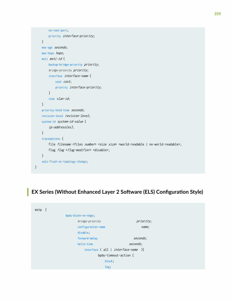
no-root-port; priority interface-priority; } max-age seconds; max-hops hops; msti msti-id { backup-bridge-priority priority; bridge-priority priority; interface interface-name { cost cost; priority interface-priority; } vlan vlan-id; } priority-hold-time seconds; revision-level revision-level; system-id system-id-value { ip-address(es); } traceoptions { file filename <files number> <size size> <world-readable | no-world-readable>; flag flag <flag-modifier> <disable>; } vpls-flush-on-topology-change;}
EX Series (Without Enhanced Layer 2 Software (ELS) Configuration Style)
mstp { bpdu-block-on-edge; bridge-priority priority; configuration-name name; disable; forward-delay seconds; hello-time seconds; interface ( all | interface-name ){ bpdu-timeout-action { block; log;
359
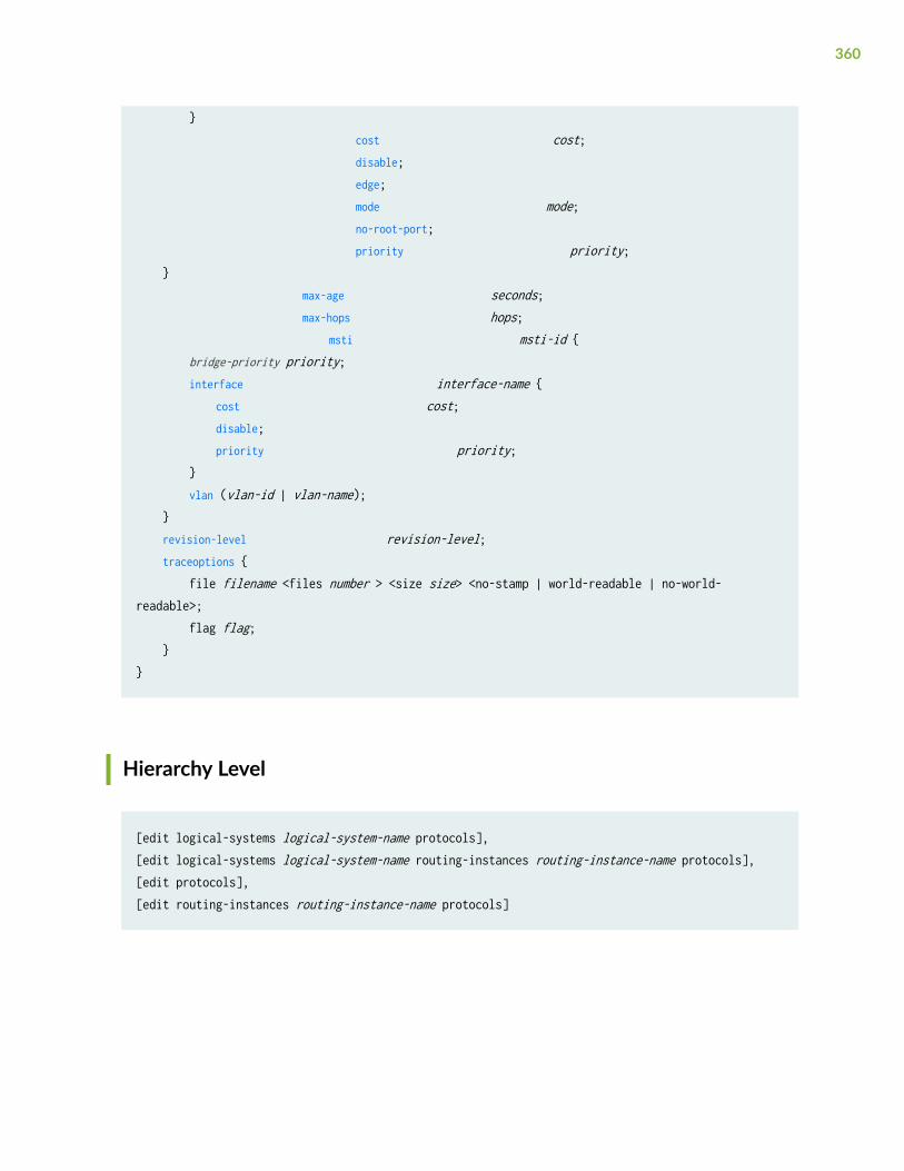
} cost cost; disable; edge; mode mode; no-root-port; priority priority; } max-age seconds; max-hops hops; msti msti-id { bridge-priority priority; interface interface-name { cost cost; disable; priority priority; } vlan (vlan-id | vlan-name); } revision-level revision-level; traceoptions { file filename <files number > <size size> <no-stamp | world-readable | no-world-readable>; flag flag; }}
Hierarchy Level
[edit logical-systems logical-system-name protocols],[edit logical-systems logical-system-name routing-instances routing-instance-name protocols],[edit protocols],[edit routing-instances routing-instance-name protocols]
360
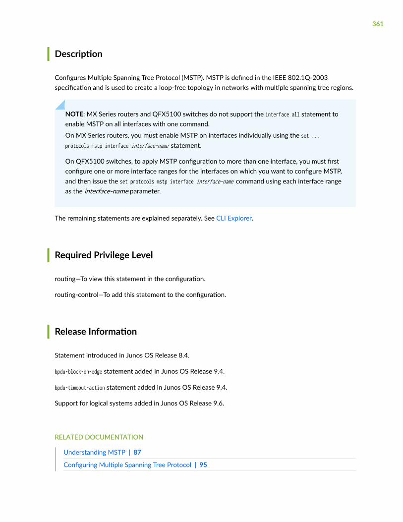
Description
Configures Multiple Spanning Tree Protocol (MSTP). MSTP is defined in the IEEE 802.1Q-2003specification and is used to create a loop-free topology in networks with multiple spanning tree regions.
NOTE: MX Series routers and QFX5100 switches do not support the interface all statement toenable MSTP on all interfaces with one command.
On MX Series routers, you must enable MSTP on interfaces individually using the set ...protocols mstp interface interface-name statement.
On QFX5100 switches, to apply MSTP configuration to more than one interface, you must firstconfigure one or more interface ranges for the interfaces on which you want to configure MSTP,and then issue the set protocols mstp interface interface-name command using each interface rangeas the interface-name parameter.
The remaining statements are explained separately. See CLI Explorer.
Required Privilege Level
routing—To view this statement in the configuration.
routing-control—To add this statement to the configuration.
Release Information
Statement introduced in Junos OS Release 8.4.
bpdu-block-on-edge statement added in Junos OS Release 9.4.
bpdu-timeout-action statement added in Junos OS Release 9.4.
Support for logical systems added in Junos OS Release 9.6.
RELATED DOCUMENTATION
Understanding MSTP | 87
Configuring Multiple Spanning Tree Protocol | 95
361

Configuring MSTP on Switches | 91
Example: Configuring Network Regions for VLANs with MSTP on Switches | 101
show spanning-tree bridge | 432
show spanning-tree interface | 440
no-root-port
IN THIS SECTION
Syntax | 362
Hierarchy Level | 362
Description | 363
Required Privilege Level | 363
Release Information | 363
Syntax
no-root-port;
Hierarchy Level
[edit logical-systems logical-system-name protocols (mstp | rstp | vstp) interface interface-name],[edit logical-systems logical-system-name protocols vstp vlan vlan-id interface interface-name],[edit logical-systems logical-system-name routing-instances routing-instance-name protocols (mstp | rstp | vstp) interface interface-name],
362

[edit logical-systems logical-system-name routing-instances routing-instance-name protocols vstp vlan vlan-id interface interface-name],
[edit protocols (mstp | rstp | vstp) interface interface-name],[edit protocols vstp vlan vlan-id interface interface-name],[edit protocols mstp interface (all | interface-name) arp-on-stp],[edit protocols rstp interface (all | interface-name) arp-on-stp],[edit protocols stp interface (all | interface-name) arp-on-stp],
[edit routing-instances routing-instance-name protocols (mstp | rstp | vstp) interface interface-name],[edit routing-instances routing-instance-name protocols vstp vlan vlan-id interface interface-name][edit protocols vstp vlan vlan-id interface (all | interface-name) arp-on-stp]
Description
Configures an interface to be a spanning-tree designated port. If the bridge receives superior STP bridgeprotocol data units (BPDUs) on a root-protected interface, that interface transitions to a root-preventedSTP state (inconsistency state) and the interface is blocked. This blocking prevents a bridge from beingelected the root bridge. When the bridge stops receiving superior STP BPDUs on the root-protectedinterface, interface traffic is no longer blocked.
Required Privilege Level
routing—To view this statement in the configuration.
routing-control—To add this statement to the configuration.
Release Information
Statement introduced in Junos OS Release 9.1.
Statement updated in Junos OS Release 9.4 for EX Series switches to add VSTP support.
363

Support for logical systems added in Junos OS Release 9.6.
RELATED DOCUMENTATION
Understanding VSTP
Understanding Root Protection for Spanning-Tree Instance Interfaces in a Layer 2 Switched Network | 261
Enabling Root Protection for a Spanning-Tree Instance Interface | 263
Example: Configuring Root Protection to Enforce Root Bridge Placement in Spanning Trees on non-ELS EX Series Switches | 266
Example: Configuring Network Regions for VLANs with MSTP on Switches | 101
Example: Faster Convergence and Improved Network Stability with RSTP on EX Series Switches | 59
show spanning-tree bridge | 432
show spanning-tree interface | 440
priority (Protocols STP)
IN THIS SECTION
Syntax | 364
Hierarchy Level | 365
Description | 365
Default | 366
Options | 366
Required Privilege Level | 366
Release Information | 366
Syntax
priority interface-priority;
364

Hierarchy Level
[edit logical-systems logical-system-name protocols (mstp | rstp | vstp) interface interface-name],[edit logical-systems logical-system-name protocols mstp msti msti-id interface interface-name],[edit logical-systems logical-system-name protocols vstp vlan vlan-id interface interface-name],[edit logical-systems logical-system-name routing-instances routing-instance-name protocols (mstp | rstp | vstp) interface interface-name],[edit logical-systems logical-system-name routing-instances routing-instance-name protocols mstp msti msti-id interface interface-name],[edit logical-systems logical-system-name routing-instances routing-instance-name protocols vstp vlan vlan-id interface interface-name],
[edit protocols (mstp | rstp | vstp) interface interface-name],[edit protocols mstp msti msti-id interface interface-name],[edit protocols vstp vlan-id interface interface-name],[edit protocols mstp ;interface (all | interface-name) arp-on-stp], [edit protocols mstpmsti msti-id interface interface-name arp-on-stp], [edit protocols rstp interface (all | interface-name) arp-on-stp], [edit protocols stp interface (all | interface-name) arp-on-stp],[edit protocols vstp vlan vlan-id interface (all | interface-name) arp-on-stp]
[edit routing-instances routing-instance-name protocols (mstp | rstp | vstp) interface interface-name],[edit routing-instances routing-instance-name protocols mstp msti msti-id interface interface-name],[edit routing-instances routing-instance-name protocols vstp vlan vlan-id interface interface-name]
Description
For Spanning Tree Protocol (STP), Rapid Spanning Tree Protocol (RSTP), VLAN Spanning Tree Protocol(VSTP), or Multiple Spanning Tree Protocol (MSTP), specifies the interface priority to control whichinterface is elected as the root port. The interface priority must be set in increments of 16.
365

Default
The default value is 128.
Options
priority—(Optional) Interface priority. The interface priority must be set in increments of 16.
• Range: 0 through 240
Required Privilege Level
routing—To view this statement in the configuration.
routing-control—To add this statement to the configuration.
Release Information
Statement introduced in Junos OS Release 8.4.
Statement updated in Junos OS Release 9.4 for EX Series switches to add VSTP support.
Support for logical systems added in Junos OS Release 9.6.
RELATED DOCUMENTATION
Understanding STP | 23
show spanning-tree bridge | 432
show spanning-tree interface | 440
366

priority-hold-time
IN THIS SECTION
Syntax | 367
Hierarchy Level | 367
Description | 367
Options | 368
Required Privilege Level | 368
Release Information | 368
Syntax
priority-hold-time seconds;
Hierarchy Level
[edit logical-systems logical-system-name protocols (mstp | rstp)],[edit logical-systems logical-system-name routing-instances routing-instance-name protocols (mstp | rstp)],[edit protocols (mstp | rstp)],[edit routing-instances routing-instance-name protocols (mstp | rstp)],
Description
Specify the number of seconds to hold before switching to the primary priority when the first coredomain comes up.
367
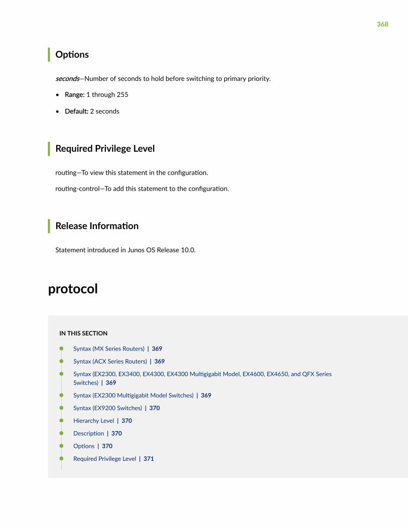
Options
seconds—Number of seconds to hold before switching to primary priority.
• Range: 1 through 255
• Default: 2 seconds
Required Privilege Level
routing—To view this statement in the configuration.
routing-control—To add this statement to the configuration.
Release Information
Statement introduced in Junos OS Release 10.0.
protocol
IN THIS SECTION
Syntax (MX Series Routers) | 369
Syntax (ACX Series Routers) | 369
Syntax (EX2300, EX3400, EX4300, EX4300 Multigigabit Model, EX4600, EX4650, and QFX SeriesSwitches) | 369
Syntax (EX2300 Multigigabit Model Switches) | 369
Syntax (EX9200 Switches) | 370
Hierarchy Level | 370
Description | 370
Options | 370
Required Privilege Level | 371
368

Release Information | 371
Syntax (MX Series Routers)
protocol (cdp | pvstp | stp | vtp);
Syntax (ACX Series Routers)
protocol (cdp | elmi | ieee8021x | ieee8023ah | lacp | lldp | mmrp | mvrp | stp | vtp);
Syntax (EX2300, EX3400, EX4300, EX4300 Multigigabit Model, EX4600,EX4650, and QFX Series Switches)
protocol (cdp | elmi | gvrp | ieee8021x | ieee8023ah | lacp | lldp | mmrp | mvrp | stp | udld | vstp | vtp);
Syntax (EX2300 Multigigabit Model Switches)
protocol (cdp | gvrp | ieee8023ah | lacp | lldp | mvrp | stp | vstp | vtp);
369
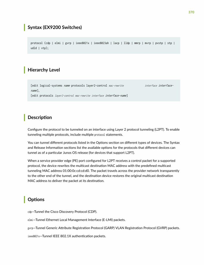
Syntax (EX9200 Switches)
protocol (cdp | elmi | gvrp | ieee8021x | ieee8023ah | lacp | lldp | mmrp | mvrp | pvstp | stp | udld | vtp);
Hierarchy Level
[edit logical-systems name protocols layer2-control mac-rewrite interface interface-name],[edit protocols layer2-control mac-rewrite interface interface-name]
Description
Configure the protocol to be tunneled on an interface using Layer 2 protocol tunneling (L2PT). To enabletunneling multiple protocols, include multiple protocol statements.
You can tunnel different protocols listed in the Options section on different types of devices. The Syntaxand Release Information sections list the available options for the protocols that different devices cantunnel as of a particular Junos OS release (for devices that support L2PT).
When a service provider edge (PE) port configured for L2PT receives a control packet for a supportedprotocol, the device rewrites the multicast destination MAC address with the predefined multicasttunneling MAC address 01:00:0c:cd:cd:d0. The packet travels across the provider network transparentlyto the other end of the tunnel, and the destination device restores the original multicast destinationMAC address to deliver the packet at its destination.
Options
cdp—Tunnel the Cisco Discovery Protocol (CDP).
elmi—Tunnel Ethernet Local Management Interface (E-LMI) packets.
gvrp—Tunnel Generic Attribute Registration Protocol (GARP) VLAN Registration Protocol (GVRP) packets.
ieee8021x—Tunnel IEEE 802.1X authentication packets.
370

ieee8023ah—Tunnel IEEE 802.3AH Operation, Administration, and Maintenance (OAM) link faultmanagement (LFM) packets.
lacp—Tunnel Link Aggregation Control Protocol (LACP) packets.
lldp—Tunnel Link Layer Discovery Protocol (LLDP) packets.
mmrp—Tunnel Multiple MAC Registration Protocol (MMRP) packets.
mvrp—Tunnel Multiple VLAN Registration Protocol (MVRP) packets.
pvstp—Tunnel VLAN Spanning Tree Protocol (VSTP), Per-VLAN Spanning Tree (PVST), and Per-VLANSpanning Tree Plus (PVST+) Protocol packets.
stp—Tunnel packets for all versions of Spanning-Tree Protocols.
udld—Tunnel Unidirectional Link Detection (UDLD) packets.
vstp—Tunnel VLAN Spanning Tree Protocol (VSTP) packets.
vtp—Tunnel VLAN Trunking Protocol (VTP) packets.
Required Privilege Level
interface—To view this statement in the configuration.
interface-control—To add this statement to the configuration.
Release Information
Statement introduced in Junos OS Release 9.1.
Support for PVST/PVST+ introduced in Junos OS Release 13.3 for MX Series routers and EX9200switches.
Support for E-LMI, IEEE 802.1X, MMRP, and UDLD introduced in Junos OS Release 17.3R1 for EX4300switches.
Support for E-LMI, GVRP, IEEE 802.1x, IEEE 802.3AH, LACP, LLDP, MMRP, MVRP, and UDLDintroduced in Junos OS Release 17.3R1 for EX9200 switches.
Support for E-LMI, IEEE 802.1X, MMRP, and UDLD introduced in Junos OS Release 18.2R1 for EX2300and EX3400 switches.
371

RELATED DOCUMENTATION
Understanding Layer 2 Protocol Tunneling
Configuring Layer 2 Protocol Tunneling
protocols (STP Type)
IN THIS SECTION
Syntax | 372
Hierarchy Level | 373
Description | 373
Options | 373
Required Privilege Level | 373
Release Information | 373
Syntax
protocols { mstp { ... } rstp { ... } vstp { ... }}
372

Hierarchy Level
[edit],
[edit logical-systems logical-system-name],[edit logical-systems logical-system-name routing-instances routing-instance-name],
[edit routing-instances routing-instance-name]
Description
Configure the Spanning Tree Protocol type as MSTP, RSTP, or VSTP.
Options
mstp—Configure the protocol as Multiple Spanning Tree.
rstp—Configure the protocol as Rapid Spanning Tree.
vstp—Configure the protocol as VLAN Spanning Tree.
Required Privilege Level
routing—To view this statement in the configuration.
routing-control—To add this statement to the configuration.
Release Information
Statement introduced in Junos OS Release 8.4.
373

Support for logical systems added in Junos OS Release 9.6.
RELATED DOCUMENTATION
Configuring RSTP on EX Series Switches (CLI Procedure) | 31
Configuring MSTP on Switches | 91
Configuring MSTP Instances on a Physical Interface | 98
Configuring Rapid Spanning Tree Protocol | 28
Configuring Multiple Spanning Tree Protocol | 95
Configuring VLAN Spanning Tree Protocol
Understanding MSTP | 87
revision-level
IN THIS SECTION
Syntax | 374
Hierarchy Level | 375
Description | 375
Options | 375
Required Privilege Level | 375
Release Information | 375
Syntax
revision-level revision-level;
374
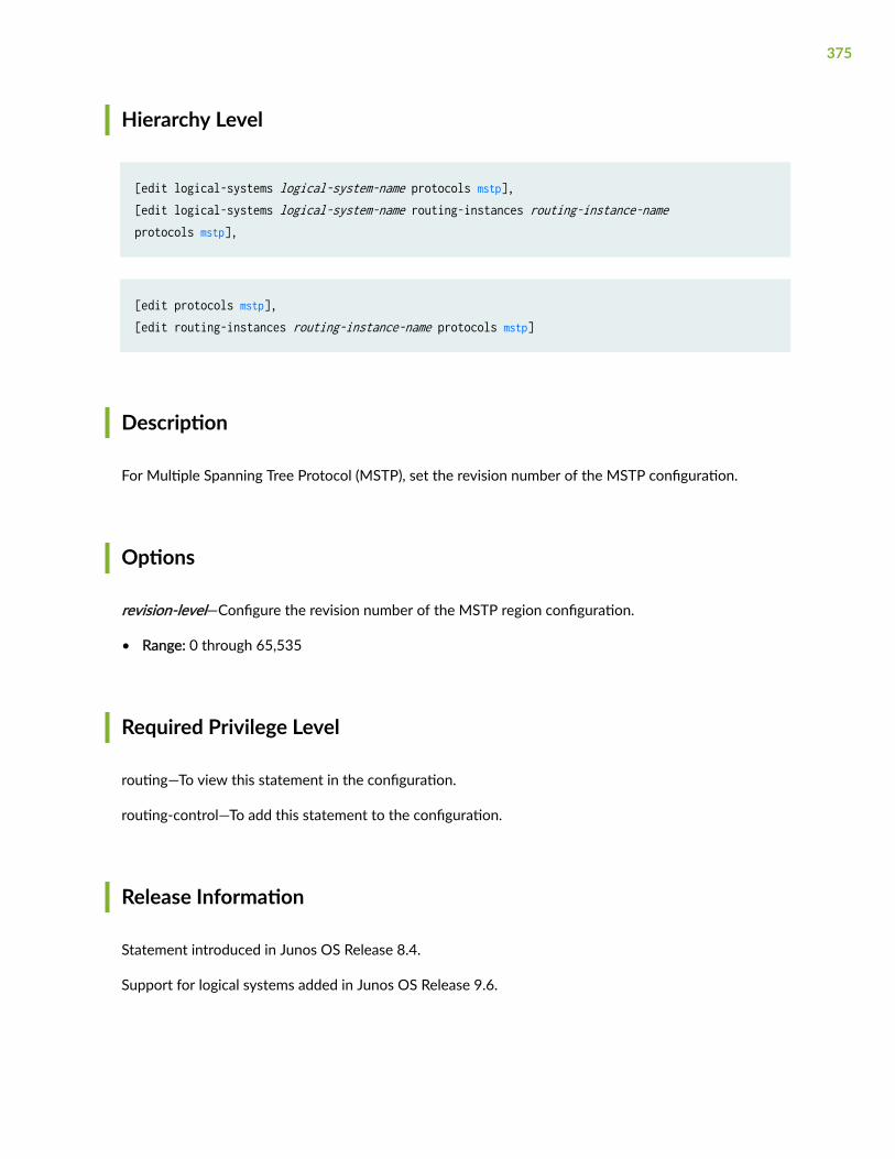
Hierarchy Level
[edit logical-systems logical-system-name protocols mstp],[edit logical-systems logical-system-name routing-instances routing-instance-name protocols mstp],
[edit protocols mstp],[edit routing-instances routing-instance-name protocols mstp]
Description
For Multiple Spanning Tree Protocol (MSTP), set the revision number of the MSTP configuration.
Options
revision-level—Configure the revision number of the MSTP region configuration.
• Range: 0 through 65,535
Required Privilege Level
routing—To view this statement in the configuration.
routing-control—To add this statement to the configuration.
Release Information
Statement introduced in Junos OS Release 8.4.
Support for logical systems added in Junos OS Release 9.6.
375
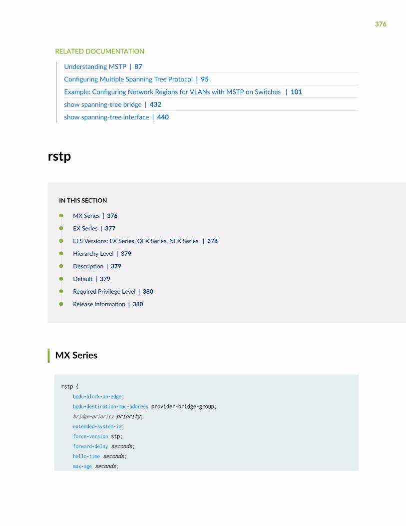
RELATED DOCUMENTATION
Understanding MSTP | 87
Configuring Multiple Spanning Tree Protocol | 95
Example: Configuring Network Regions for VLANs with MSTP on Switches | 101
show spanning-tree bridge | 432
show spanning-tree interface | 440
rstp
IN THIS SECTION
MX Series | 376
EX Series | 377
ELS Versions: EX Series, QFX Series, NFX Series | 378
Hierarchy Level | 379
Description | 379
Default | 379
Required Privilege Level | 380
Release Information | 380
MX Series
rstp { bpdu-block-on-edge; bpdu-destination-mac-address provider-bridge-group; bridge-priority priority; extended-system-id; force-version stp; forward-delay seconds; hello-time seconds; max-age seconds;
376
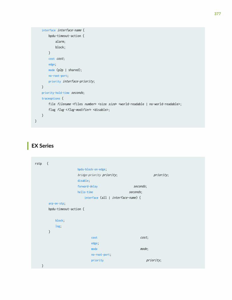
interface interface-name { bpdu-timeout-action { alarm; block; } cost cost; edge; mode (p2p | shared); no-root-port; priority interface-priority; } priority-hold-time seconds; traceoptions { file filename <files number> <size size> <world-readable | no-world-readable>; flag flag <flag-modifier> <disable>; }}
EX Series
rstp { bpdu-block-on-edge; bridge-priority priority; priority; disable; forward-delay seconds; hello-time seconds; interface (all | interface-name) { arp-on-stp; bpdu-timeout-action { block; log; } cost cost; edge; mode mode; no-root-port; priority priority; }
377

max-age seconds; traceoptions { file filename <files number > <size size> <no-stamp | no-world-readable | world-readable>; flag flag; }}
ELS Versions: EX Series, QFX Series, NFX Series
rstp { bpdu-block-on-edge; bpdu-destination-mac-address provider-bridge-group; bridge-priority priority; disable; extended-system-id; force-version stp; forward-delay seconds; hello-time seconds; max-age seconds; priority-hold-time seconds; traceoptions { file filename <files number> <size size> <world-readable | no-world-readable>; flag flag <flag-modifier> <disable>; }}
378

Hierarchy Level
[edit logical-systems logical-system-name protocols],[edit logical-systems logical-system-name routing-instances routing-instance-name protocols],
[edit protocols],
[edit routing-instances routing-instance-name protocols]
Description
Configure Rapid Spanning Tree Protocol (RSTP). RSTP is defined in the IEEE 802.1D-2004 specificationand is used to prevent loops in Layer 2 networks, which results in shorter convergence times than thoseprovided by basic Spanning Tree Protocol (STP).
VSTP and RSTP can be configured concurrently. You can selectively configure up to 253 VLANs usingVSTP; the remaining VLANs will be configured using RSTP. VSTP and RSTP are the only spanning-treeprotocols that can be configured concurrently on the switch.
BEST PRACTICE: Configure RSTP when you configure VSTP. RSTP overhead is minimal and thisconfiguration ensures that a spanning-tree protocol is running on all VLANs on your switch, evenwhen your switch is supporting more than 253 VLANs.
The remaining statements are explained separately. See CLI Explorer.
Default
RSTP is enabled on all Ethernet switching interfaces.
379

Required Privilege Level
routing—To view this statement in the configuration.
routing-control—To add this statement to the configuration.
Release Information
Statement introduced in Junos OS Release 8.4.
bpdu-block-on-edge statement added in Junos OS Release 9.4.
bpdu-timeout-action statement added in Junos OS Release 9.4.
Support for logic systems added in Junos OS Release 9.6.
Statement updated in Junos OS Release 15.1 for EX Series and QFX Series switches to supportconfiguration of spanning tree parameters globally on all interfaces.
NOTE: You cannot disable spanning tree parameters globally on all interfaces.
RELATED DOCUMENTATION
Configuring Rapid Spanning Tree Protocol | 28
Understanding RSTP | 27
Configuring RSTP on EX Series Switches (CLI Procedure) | 31
Example: Faster Convergence and Improved Network Stability with RSTP on EX Series Switches | 59
show spanning-tree bridge | 432
show spanning-tree interface | 440
380

shutdown (BPDU Block)
IN THIS SECTION
Syntax | 381
Hierarchy Level | 381
Description | 381
Default | 382
Required Privilege Level | 382
Release Information | 382
Syntax
shutdown;
Hierarchy Level
[edit ethernet-switching-options bpdu-block interface (all | [interface-name])]
Description
Shut down all or specified interfaces to prevent spanning-tree protocol BPDUs (for STP, MSTP, RSTP,and VSTP) from entering the interfaces on which BPDU protection is configured.
381

Default
Not enabled
Required Privilege Level
routing—To view this statement in the configuration.routing-control—To add this statement to the configuration.
Release Information
Statement introduced in Junos OS Release 12.2.
RELATED DOCUMENTATION
Understanding BPDU Protection for STP, RSTP, and MSTP | 162
Unblocking an Interface on non-ELS EX Series Switches That Receives BPDUs in Error (CLIProcedure) | 291
stp
IN THIS SECTION
Syntax | 383
Syntax (EX Series) | 383
Hierarchy Level | 384
Description | 384
Default | 385
Required Privilege Level | 385
Release Information | 385
382
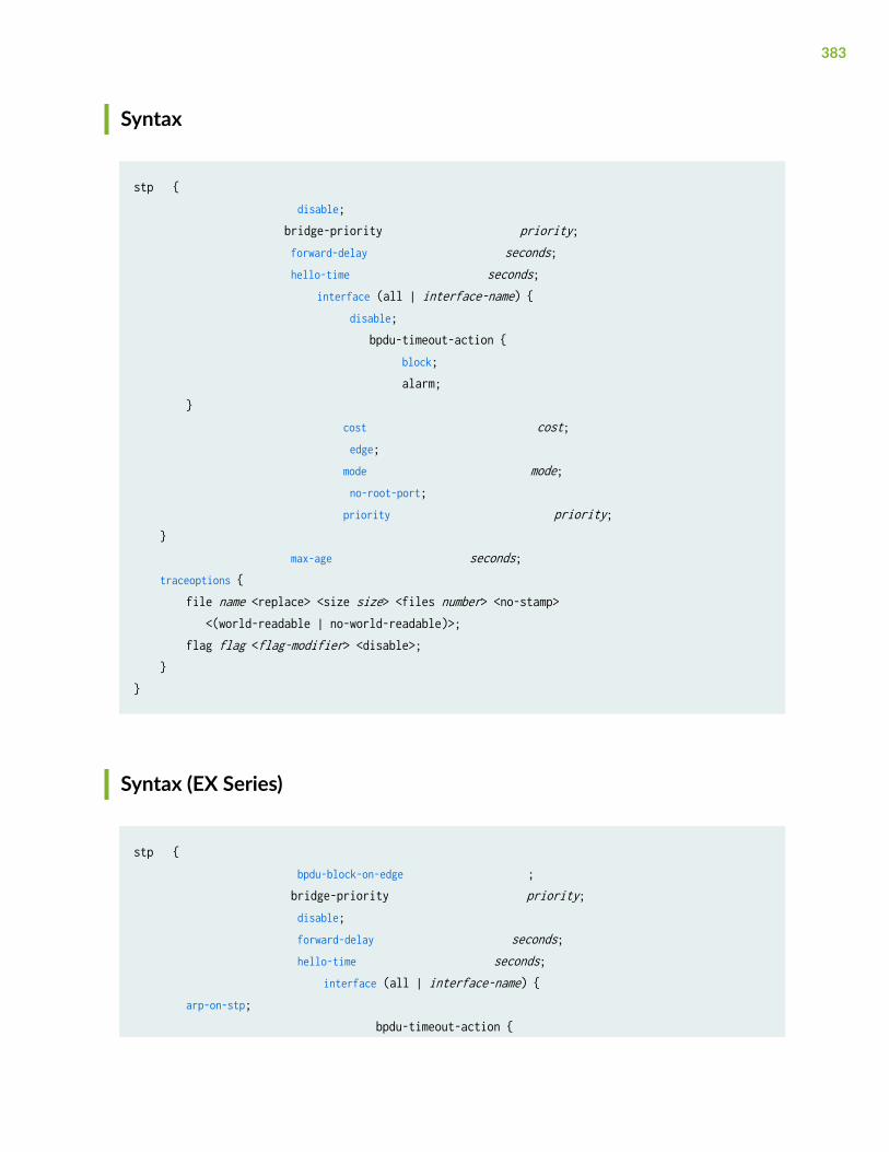
Syntax
stp { disable; bridge-priority priority; forward-delay seconds; hello-time seconds; interface (all | interface-name) { disable; bpdu-timeout-action { block; alarm; } cost cost; edge; mode mode; no-root-port; priority priority; } max-age seconds; traceoptions { file name <replace> <size size> <files number> <no-stamp> <(world-readable | no-world-readable)>; flag flag <flag-modifier> <disable>; }}
Syntax (EX Series)
stp { bpdu-block-on-edge ; bridge-priority priority; disable; forward-delay seconds; hello-time seconds; interface (all | interface-name) { arp-on-stp; bpdu-timeout-action {
383

block; log; } cost cost; disable; mode mode; no-root-port; priority priority; } max-age seconds; traceoptions { file filename <files number > <size size> <no-stamp | world-readable | no-world-readable>; flag flag; }}
Hierarchy Level
[edit protocols], [edit protocols rstp force-version]
Description
When you explicitly configure STP, a switch uses the IEEE 802.1D 2004 specification, force version 0.This configuration runs a version of RSTP that is compatible with the classic, basic STP (defined in theIEEE 802.1D 1998 specification).
The remaining statements are explained separately. See CLI Explorer.
NOTE: Although the edge configuration statement appears in the CLI on the switch, thisstatement has no effect on the switch operation if you configure it.
384

Default
STP is disabled; by default, RSTP is enabled on all Ethernet switching ports.
Required Privilege Level
routing—To view this statement in the configuration.routing-control—To add this statement to the configuration.
Release Information
Statement introduced in Junos OS Release 9.0.
RELATED DOCUMENTATION
Overview of Spanning-Tree Protocols
Understanding STP | 23
Example: Configuring BPDU Protection on STP Interfaces to Prevent STP Miscalculations
Example: Configuring BPDU Protection on Edge Interfaces to Prevent STP Miscalculations on non-ELS EX Series Switches | 204
Configuring STP on EX Series Switches (CLI Procedure) | 25
Configuring STP
show spanning-tree bridge | 432
show spanning-tree interface | 440
system-id
IN THIS SECTION
Syntax | 386
385

Hierarchy Level | 386
Description | 386
Options | 387
Required Privilege Level | 387
Release Information | 387
Syntax
system-id system-id-value { ip-address(es);}
Hierarchy Level
[edit logical-systems logical-system-name protocols (mstp | rstp)],[edit logical-systems logical-system-name protocols vstp vlan vlan-id],[edit logical-systems logical-system-name routing-instances routing-instance-name protocols (mstp | rstp)],[edit logical-systems logical-system-name routing-instances routing-instance-name protocols vstp vlan vlan-id],[edit protocols (mstp | rstp)],[edit protocols vstp vlan vlan-id],[edit routing-instances routing-instance-name protocols (mstp | rstp)],[edit routing-instances routing-instance-name protocols vstp vlan vlan-id]
Description
Determine the system identifier value for bridges in a VPLS multihomed Layer 2 ring with MPLSinfrastructure.
386

Options
system-id-value—System identifier in the format nnnnnn:nnnnnn, where n = any digit from 0 through 9.
• Range: Any valid value
• Default: None
ip-address(es)—Valid IP host addresses in the format ip-address/32.
• Range: Any valid IP address
• Default: None
Required Privilege Level
routing—To view this statement in the configuration.
routing-control—To add this statement to the configuration.
Release Information
Statement introduced in Junos OS Release 10.0.
RELATED DOCUMENTATION
Understanding VPLS Multihoming | 256
traceoptions (Spanning Tree)
IN THIS SECTION
Syntax | 388
Hierarchy Level | 388
387

Description | 388
Default | 389
Options | 389
Required Privilege Level | 391
Release Information | 391
Syntax
traceoptions { file filename <files number> <size size> <world-readable | no-world-readable>; flag flag <flag-modifier> <disable>;}
Hierarchy Level
[edit logical-systems logical-system-name protocols (mstp | rstp | vstp)],[edit logical-systems logical-system-name routing-instances routing-instance-name protocols (mstp | rstp | vstp)],
[edit protocols (mstp | rstp | vstp | vstp vlan vlan-id)],
[edit routing-instances routing-instance-name protocols (mstp | rstp | vstp)]
Description
Sets protocol-level tracing options for for spanning-tree protocols MPLS, MVRP, STP, RSTP, MSTP, andVSTP.
388

Default
The default STP protocol-level trace options are inherited from the global traceoptions statement.Traceoptions is disabled.
Options
disable—(Optional) Disable the tracing operation. One use of this option is to disable a single operationwhen you have defined a broad group of tracing operations, such as all.
file filename—Name of the file to receive the output of the tracing operation. Enclose the name inquotation marks. We recommend that you place STP tracing output in the file /var/log/stp-log.
files number—(Optional) Maximum number of trace files. When a trace file named trace-file reaches itsmaximum size, it is renamed trace-file.0, then trace-file.1, and so on, until the maximum number of tracefiles is reached. Then, the oldest trace file is overwritten.
If you specify a maximum number of files, you must also specify a maximum file size with the sizeoption.
• Range: 2 through 1000 files
• Default: 1 trace file only
flag—Tracing operation to perform. To specify more than one tracing operation, include multiple flagstatements. The following are the STP-specific tracing options:
• all—Trace all operations.
• all-failures—Trace all failure conditions.
• bpdu—Trace BPDU reception and transmission.
• bridge-detection-state-machine—Trace the bridge detection state machine.
• error—Trace all failure conditions.
• events—Trace events of the protocol state machine.
• pdu—Trace PDUs that were received and sent.
• port-information-state-machine—Trace the port information state machine.
• port-migration-state-machine—Trace the port migration state machine.
• port-receive-state-machine—Trace the port receive state machine.
389

• port-role-transit-state-machine—Trace the port role transit state machine.
• port-role-select-state-machine—Trace the port role selection state machine.
• port-state-transit-state-machine—Trace the port state transit state machine.
• port-transmit-state-machine—Trace the port transmit state machine.
• ppmd—Trace the state and events for the ppmd process.
• socket—Trace socket activity.
• state-machine—Trace state machine information.
• state-machine-variables—Trace when the state machine variables change.
• timers—Trace protocol timers.
• topology-change-state-machine—Trace the topology change state machine.
The following are the global tracing options:
• all—All tracing operations.
• config-internal—Trace configuration internals.
• general—Trace general events.
• normal—All normal events.
• Default: If you do not specify this option, only unusual or abnormal operations are traced.
• parse—Trace configuration parsing.
• policy—Trace policy operations and actions.
• regex-parse—Trace regular-expression parsing.
• route—Trace routing table changes.
• state—Trace state transitions.
• task—Trace protocol task processing.
• timer—Trace protocol task timer processing.
no-world-readable—(Optional) Prevent any user from reading the log file.
replace—(Optional) Replace an existing trace file if there is one.
• Default: If you do not include this option, tracing output is appended to an existing trace file.
390

size size—(Optional) Maximum size of each trace file, in kilobytes (KB) or megabytes (MB). When a tracefile named trace-file reaches this size, it is renamed trace-file.0. When the trace-file again reaches itsmaximum size, trace-file.0 is renamed trace-file.1 and trace-file is renamed trace-file.0. This renamingscheme continues until the maximum number of trace files is reached. Then the oldest trace file isoverwritten.
If you specify a maximum file size, you must also specify a maximum number of trace files with the filesoption.
• Syntax: xk to specify KB, xm to specify MB, or xg to specify GB
• Range: 10 KB through the maximum file size supported on your system
• Default: 1 MB
world-readable—(Optional) Allow any user to read the log file.
Required Privilege Level
routing—To view this statement in the configuration.
routing-control—To add this statement to the configuration.
Release Information
Statement introduced in Junos OS Release 8.4.
Statement updated in Junos OS Release 9.4 for EX Series switches to add VSTP support.
Support for logical systems added in Junos OS Release 9.6.
RELATED DOCUMENTATION
Understanding RSTP | 27
Understanding STP | 23
Understanding VSTP
Understanding Multiple VLAN Registration Protocol (MVRP)
Understanding Spanning-Tree Protocol Trace Options | 286
Configuring Tracing Spanning-Tree Operations | 287
391
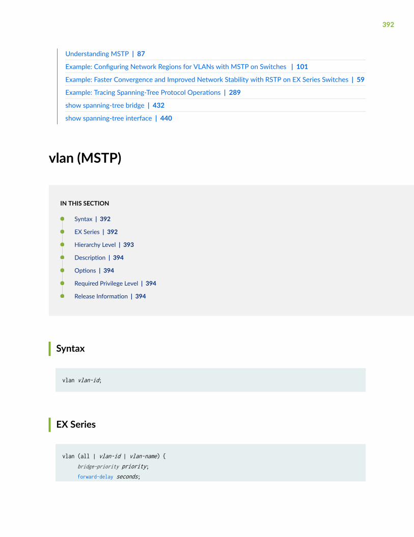
Understanding MSTP | 87
Example: Configuring Network Regions for VLANs with MSTP on Switches | 101
Example: Faster Convergence and Improved Network Stability with RSTP on EX Series Switches | 59
Example: Tracing Spanning-Tree Protocol Operations | 289
show spanning-tree bridge | 432
show spanning-tree interface | 440
vlan (MSTP)
IN THIS SECTION
Syntax | 392
EX Series | 392
Hierarchy Level | 393
Description | 394
Options | 394
Required Privilege Level | 394
Release Information | 394
Syntax
vlan vlan-id;
EX Series
vlan (all | vlan-id | vlan-name) { bridge-priority priority; forward-delay seconds;
392

hello-time seconds; interface interface-name { bpdu-timeout-action { block; log; } cost cost; disable; edge; mode mode; no-root-port; priority priority; } max-age seconds; traceoptions { file filename <files number > <size size> <no-stamp | world-readable | no-world-readable>; flag flag; }}
Hierarchy Level
[edit logical-systems logical-system-name protocols mstp msti msti-id],[edit logical-systems logical-system-name routing-instances routing-instance-name protocols mstp msti msti-id],
[edit protocols mstp msti msti-id],[edit protocols mstpmsti msti-id][edit protocols vstp]
[edit routing-instances routing-instance-name protocols mstp msti msti-id]
393

Description
Configure the VLANs for a Multiple Spanning Tree Instance (MSTI) or VSTP instance.
NOTE: When you configure VSTP with the set prototocol vstp vlan all command, vlan-id 1 isexcluded to be compatible with Cisco PVST+. If you want vlan-id 1 to be included in VSTP, youmust set it separately with the set protocol vstp vlan 1 command.
TIP: To display a list of all configured VLANs on the system, including VLANs that are configuredbut not committed, type ? after vlan or vlans in your configuration mode command line. Notethat only one VLAN is displayed for a VLAN range.
Options
vlan-name—Name of the VLAN.
vlan-id—The VLAN identifier associated with the MSTI.
vlan-id-range—Range of VLAN identifiers associated with the MSTI in the form minimum-vlan-id-maximum-vlan-id. VLAN identifier ranges are not supported for VSTP.
• Range: 1 through 4096
Required Privilege Level
routing—To view this statement in the configuration.
routing-control—To add this statement to the configuration.
Release Information
Statement introduced in Junos OS Release 8.4.
394

Statement updated with enhanced ? (CLI completion feature) functionality in Junos OS Release 9.5 forEX Series switches.
Support for logical systems added in Junos OS Release 9.6.
RELATED DOCUMENTATION
Understanding MSTP | 87
Understanding VSTP
Configuring Multiple Spanning Tree Protocol | 95
Example: Configuring Network Regions for VLANs with MSTP on Switches | 101
vlan (VSTP)
IN THIS SECTION
Syntax | 395
EX Series | 396
Hierarchy Level | 397
Description | 397
Options | 397
Required Privilege Level | 397
Release Information | 398
Syntax
vlan vlan-id { bridge-priority priority; forward-delay seconds; hello-time seconds; max-age seconds; interface interface-name {
395
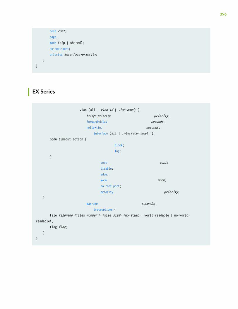
cost cost; edge; mode (p2p | shared); no-root-port; priority interface-priority; }}
EX Series
vlan (all | vlan-id | vlan-name) { bridge-priority priority; forward-delay seconds; hello-time seconds; interface (all | interface-name) { bpdu-timeout-action { block; log; } cost cost; disable; edge; mode mode; no-root-port; priority priority; } max-age seconds; traceoptions { file filename <files number > <size size> <no-stamp | world-readable | no-world-readable>; flag flag; }}
396

Hierarchy Level
[edit logical-systems logical-system-name protocols vstp],[edit protocols vstp]
Description
Configure VSTP VLAN parameters.
TIP: To display a list of all configured VLANs on the system, including VLANs that are configuredbut not committed, type ? after vlan or vlans in your configuration mode command line. Notethat only one VLAN is displayed for a VLAN range.
Options
all All VLANs.
vlan-id Numeric VLAN identifier.
vlan-range Name of the VLAN range.
The remaining statements are explained separately. See CLI Explorer.
Required Privilege Level
routing—To view this statement in the configuration.
routing-control—To add this statement to the configuration.
397

Release Information
Statement introduced in Junos OS Release 9.0.
Support for logical systems added in Junos OS Release 9.6.
RELATED DOCUMENTATION
Understanding VSTP
Configuring VLAN Spanning Tree Protocol
vlan-group
IN THIS SECTION
Syntax | 398
Hierarchy Level | 399
Description | 399
Required Privilege Level | 399
Release Information | 399
Syntax
vlan-group group group-name {vlan (vlan-id |vlan-group |all) {}
398

Hierarchy Level
[edit protocols vstp]
Description
Configure VLAN group for Spanning Tree Protocol (VSTP). VSTP is used to prevent loops in Layer 2networks on a per-VLAN basis.
BEST PRACTICE: Configure RSTP when you configure VSTP. RSTP overhead is minimal and thisconfiguration ensures that a spanning-tree protocol is running on all VLANs on your switch, evenwhen your switch is supporting more than the maximum number of allowed VSTP VLANs.
The remaining statements are explained separately. See CLI Explorer.
Required Privilege Level
routing—To view this statement in the configuration.routing-control—To add this statement to the configuration.
Release Information
Statement introduced in Junos OS Release 15.1.
RELATED DOCUMENTATION
vstp | 401
show spanning-tree bridge | 432
show spanning-tree interface | 440
399
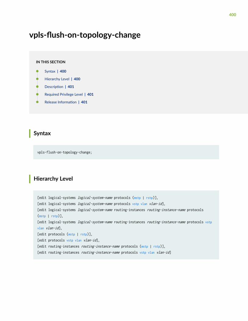
vpls-flush-on-topology-change
IN THIS SECTION
Syntax | 400
Hierarchy Level | 400
Description | 401
Required Privilege Level | 401
Release Information | 401
Syntax
vpls-flush-on-topology-change;
Hierarchy Level
[edit logical-systems logical-system-name protocols (mstp | rstp)],[edit logical-systems logical-system-name protocols vstp vlan vlan-id],[edit logical-systems logical-system-name routing-instances routing-instance-name protocols (mstp | rstp)],[edit logical-systems logical-system-name routing-instances routing-instance-name protocols vstp vlan vlan-id],[edit protocols (mstp | rstp)],[edit protocols vstp vlan vlan-id],[edit routing-instances routing-instance-name protocols (mstp | rstp)],[edit routing-instances routing-instance-name protocols vstp vlan vlan-id]
400

Description
Determine the action the bridge should take when the topology of a multihomed Layer 2 ring withMPLS infrastructure changes: flush the media access control (MAC) cache or not. By default, the bridgedoes not flush the cache when the topology changes.
Required Privilege Level
routing—To view this statement in the configuration.
routing-control—To add this statement to the configuration.
Release Information
Statement introduced in Junos OS Release 10.0.
vstp
IN THIS SECTION
MX Series | 402
EX Series, QFX Series, QFabric | 403
ELS versions: EX Series, QFX Series, NFX Series | 403
Hierarchy Level | 405
Description | 405
Default | 406
Required Privilege Level | 406
Release Information | 406
401

MX Series
vstp { bpdu-block-on-edge; force-version stp; interface interface-name { bpdu-timeout-action { alarm; block; } cost cost; edge; mode (p2p | shared); no-root-port; priority interface-priority; } priority-hold-time seconds; vlan vlan-id { bridge-priority priority; forward-delay seconds; hello-time seconds; max-age seconds; interface interface-name { access-trunk bpdu-timeout-action { alarm; block; } cost cost; edge; mode (p2p | shared); no-root-port; priority interface-priority; } } traceoptions { file filename <files number> <size size> <world-readable | no-world-readable>; flag flag <flag-modifier> <disable>; }}
402

EX Series, QFX Series, QFabric
vstp { bpdu-block-on-edge; disable; force-version stp; vlan (all | vlan-id | vlan-name) { bridge-priority priority; forward-delay seconds; hello-time seconds; interface (all | interface-name) { arp-on-stp; bpdu-timeout-action { block; log; } cost cost; disable; edge; mode mode; no-root-port; priority priority; } max-age seconds; traceoptions { file filename <files number > <size size> <no-stamp | no-world-readable | world-readable>; flag flag; } }}
ELS versions: EX Series, QFX Series, NFX Series
vstp { bpdu-block-on-edge; disable; force-version stp;
403

interface (interface-name disable | interface-range-name | all ){ bpdu-timeout-action { alarm; block; } cost cost; edge; mode (p2p | shared); no-root-port; priority interface-priority; }priority-hold-time seconds; vlan (vlan-id | all){ bridge-priority priority; forward-delay seconds; hello-time seconds; max-age seconds; interface (interface-name disable | interface-range-name | all ){ bpdu-timeout-action { alarm; block; } cost cost; edge; mode (p2p | shared); no-root-port; priority interface-priority; } } traceoptions { file filename <files number> <size size> <world-readable | no-world-readable>; flag flag <flag-modifier> <disable>; } vlan-group group group-name { vlansvlan-name (vlan-id |vlan-range | open-set-of-values) { interface all; interface interface-name { disable; } } }
404

Hierarchy Level
[edit protocols]
[edit logical-systems logical-system-name protocols],[edit logical-systems logical-system-name routing-instances routing-instance-name protocols],
[edit protocols],
[edit routing-instances routing-instance-name protocols]
Description
Configures VLAN Spanning Tree Protocol (VSTP). VSTP is used to prevent loops in Layer 2 networks ona per-VLAN basis.
You can have a maximum of 253 VSTP VLANs per switch.
If the number of VLANs on your switch exceeds the VSTP VLAN limit, you must use the vlan statementto specify which VLANs or VLAN groups use VSTP. You also cannot use the vlan all option to configureVSTP when your switch has more than the maximum allowed VSTP VLANs. To ensure all VLANs arerunning a spanning-tree protocol, run RSTP for networks with large numbers of VLANs .
NOTE: When you configure VSTP with the set protocol vstp vlan all command, VLAN ID 1 is notset; it is excluded so that the configuration is compatible with Cisco PVST+. If you want VLAN ID1 to be included in the VSTP configuration on your switch, you must set it separately with the setprotocol vstp vlan 1 command.
NOTE: Option vlan all is not supported in Junos OS Release 13.2X50.
405

BEST PRACTICE: Configure RSTP when you configure VSTP. RSTP overhead is minimal and thisconfiguration ensures that some spanning tree protocol is running on all VLANs on your switch,even when your switch has more than the maximum number of allowed VSTP VLANs.
The remaining statements are explained separately. See CLI Explorer.
Default
VSTP is not enabled by default.
Required Privilege Level
routing—To view this statement in the configuration.
routing-control—To add this statement to the configuration.
Release Information
Statement introduced in Junos OS Release 9.0.
bpdu-block-on-edge statement added in Junos OS Release 9.4.
bpdu-timeout-action statement added in Junos OS Release 9.4.
Support for logical systems added in Junos OS Release 9.6.
Statement updated in Junos OS Release 15.1 for EX Series switches to support configuration ofspanning tree parameters globally on all interfaces.
NOTE: You cannot disable spanning tree parameters globally on all interfaces.
406

RELATED DOCUMENTATION
Understanding VSTP
Configuring VLAN Spanning Tree Protocol
Configuring VSTP (CLI Procedure)
Example: Configuring VSTP on QFX Series Switches and EX4600 Switches
show spanning-tree bridge | 432
show spanning-tree interface | 440
407

9CHAPTER
Operational Commands
clear error bpdu interface | 409
clear error mac-rewrite | 411
clear ethernet-switching bpdu-error interface | 413
clear spanning-tree protocol-migration | 414
clear spanning-tree statistics | 416
clear spanning-tree statistics bridge | 418
clear spanning-tree stp-buffer | 420
show bridge mac-table | 421
show mac-rewrite interface | 429
show spanning-tree bridge | 432
show spanning-tree interface | 440
show spanning-tree mstp configuration | 453
show spanning-tree statistics | 457
show spanning-tree statistics bridge | 460
show spanning-tree statistics interface | 462
show spanning-tree statistics message-queues | 465
show spanning-tree stp-buffer see-all | 467
clear error bpdu interface
IN THIS SECTION
MX Series | 409
QFX Series, EX Series, NFX Series | 409
Description | 409
Required Privilege Level | 410
Output Fields | 410
Sample Output | 410
Release Information | 410
MX Series
clear error bpdu interface interface-name
QFX Series, EX Series, NFX Series
clear error bpdu interface (all | interface-name)
Description
Clear a bridge protocol data unit (BPDU) error condition caused by the detection of a possible bridgingloop from Spanning Tree Protocol (STP) operation.
409
Required Privilege Level
clear
Output Fields
When you enter this command, you are provided feedback on the status of your request.
Sample Output
clear error bpdu interface ge-1/1/1
user@host> clear error bpdu interface ge-1/1/1
Release Information
Command introduced in Junos OS Release 9.4.
Command supports all option in Junos OS Release 15.1 for EX Series switches.
RELATED DOCUMENTATION
Configuring BPDU Protection on ACX Router, EX Switch and MX Router Edge Ports | 171
Unblocking a Switch Interface That Receives BPDUs in Error (CLI Procedure) | 290
410
clear error mac-rewrite
IN THIS SECTION
Syntax | 411
Description | 411
Options | 411
Required Privilege Level | 412
Output Fields | 412
Sample Output | 412
Release Information | 412
Syntax
clear error mac-rewrite<interface interface-name>
Description
Clear a MAC rewrite error condition on an interface receiving tunneled Layer 2 protocol packets.
On interfaces with L2PT configured, customer-facing ports should not receive packets with the L2PTMAC address as the destination address unless there is a network tolopogy or configuration error. Thedevice sets the status of such interfaces to “Disabled”. Use this command to clear the error and re-enable the interface.
Options
interface interface-name (Optional) Clear the MAC rewrite error condition for the specified interface.
411

Required Privilege Level
clear
Output Fields
When you enter this command, the device returns feedback on the status of the request.
Sample Output
clear error mac-rewrite interface
user@host> clear error mac-rewrite interface ge-1/0/1
Release Information
Command introduced in Junos OS Release 9.1.
RELATED DOCUMENTATION
Configuring Layer 2 Protocol Tunneling
Clearing a MAC Rewrite Error on an Interface with Layer 2 Protocol Tunneling
show mac-rewrite interface
412
clear ethernet-switching bpdu-error interface
IN THIS SECTION
Syntax | 413
Description | 413
Options | 413
Required Privilege Level | 414
Sample Output | 414
Release Information | 414
Syntax
clear ethernet-switching bpdu-error interface interface-name
Description
Clear bridge protocol data unit (BPDU) errors from an interface and bring up the interface.
NOTE: This command is only available on switches running Junos OS without support for theEnhanced Layer 2 Software (ELS) configuration style. To clear BPDU errors from switches thatsupport ELS, see "clear error bpdu interface" on page 409.
Options
interface-name Clear BPDU errors on the specified interface.
413

Required Privilege Level
clear
Sample Output
clear ethernet-switching bpdu-error interface
user@switch> clear ethernet-switching bpdu-error interface xe-0/0/1.0
Release Information
Command introduced in Junos OS Release 9.1.
Command updated in Junos OS Release 11.1 for EX Series switches—a BPDU error shuts down theinterface and this command brings the interface back up.
RELATED DOCUMENTATION
show spanning-tree interface | 440
clear spanning-tree protocol-migration
IN THIS SECTION
Syntax | 415
Description | 415
Options | 415
Additional Information | 415
414

Required Privilege Level | 416
Sample Output | 416
Release Information | 416
Syntax
clear spanning-tree protocol-migration <interface interface-name><routing-instance routing-instance-name>
Description
Revert from the original IEEE 802.1D Spanning Tree Protocol (STP) back to the Rapid Spanning TreeProtocol after the force-version statement has been removed from the configuration.
Options
none Reset the STP protocol for all interfaces and all routing instances.
interface interface-name (Optional) Reset the STP protocol for the specified interface only.
routing-instance routing-instance-name
(Optional) Reset the STP protocol for a particular routing instance.
Additional Information
For information about the force-version statement, see the Junos Routing Protocols Configuration Guide.
415
Required Privilege Level
clear
Sample Output
clear spanning-tree protocol-migration
user@host> clear spanning-tree protocol-migration
Release Information
Command introduced in Junos OS Release 9.0.
clear spanning-tree statistics
IN THIS SECTION
Syntax | 417
Syntax (EX Series Switches and the QFX Series) | 417
Description | 417
Options | 417
Required Privilege Level | 417
Output Fields | 418
Sample Output | 418
Release Information | 418
416
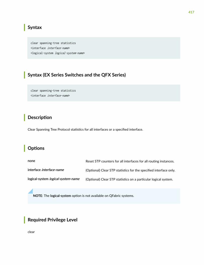
Syntax
clear spanning-tree statistics<interface interface-name><logical-system logical-system-name>
Syntax (EX Series Switches and the QFX Series)
clear spanning-tree statistics<interface interface-name>
Description
Clear Spanning Tree Protocol statistics for all interfaces or a specified interface.
Options
none Reset STP counters for all interfaces for all routing instances.
interface interface-name (Optional) Clear STP statistics for the specified interface only.
logical-system logical-system-name (Optional) Clear STP statistics on a particular logical system.
NOTE: The logical-system option is not available on QFabric systems.
Required Privilege Level
clear
417

Output Fields
This command produces no output.
Sample Output
clear spanning-tree statistics
user@switch> clear spanning—tree statistics
Release Information
Command introduced in Junos OS Release 8.4.
RELATED DOCUMENTATION
Understanding STP | 23
show spanning-tree statistics | 457
show spanning-tree bridge | 432
show spanning-tree interface | 440
clear spanning-tree statistics bridge
IN THIS SECTION
Syntax | 419
Description | 419
Required Privilege Level | 419
Sample Output | 419
418
Release Information | 419
Syntax
clear spanning-tree statistics bridge
Description
Clear the statistics of the bridge.
Required Privilege Level
clear
Sample Output
clear spanning-tree statistics bridge (MX Series)
command-name
user@host> clear spanning-tree statistics bridge
Release Information
Command introduced in Junos OS Release 14.1.
419

clear spanning-tree stp-buffer
IN THIS SECTION
Syntax | 420
Description | 420
Required Privilege Level | 420
Sample Output | 420
Release Information | 421
Syntax
clear spanning-tree stp-buffer
Description
Clear the stp-buffer.
Required Privilege Level
clear
Sample Output
clear spanning-tree stp-buffer (MX Series)
420
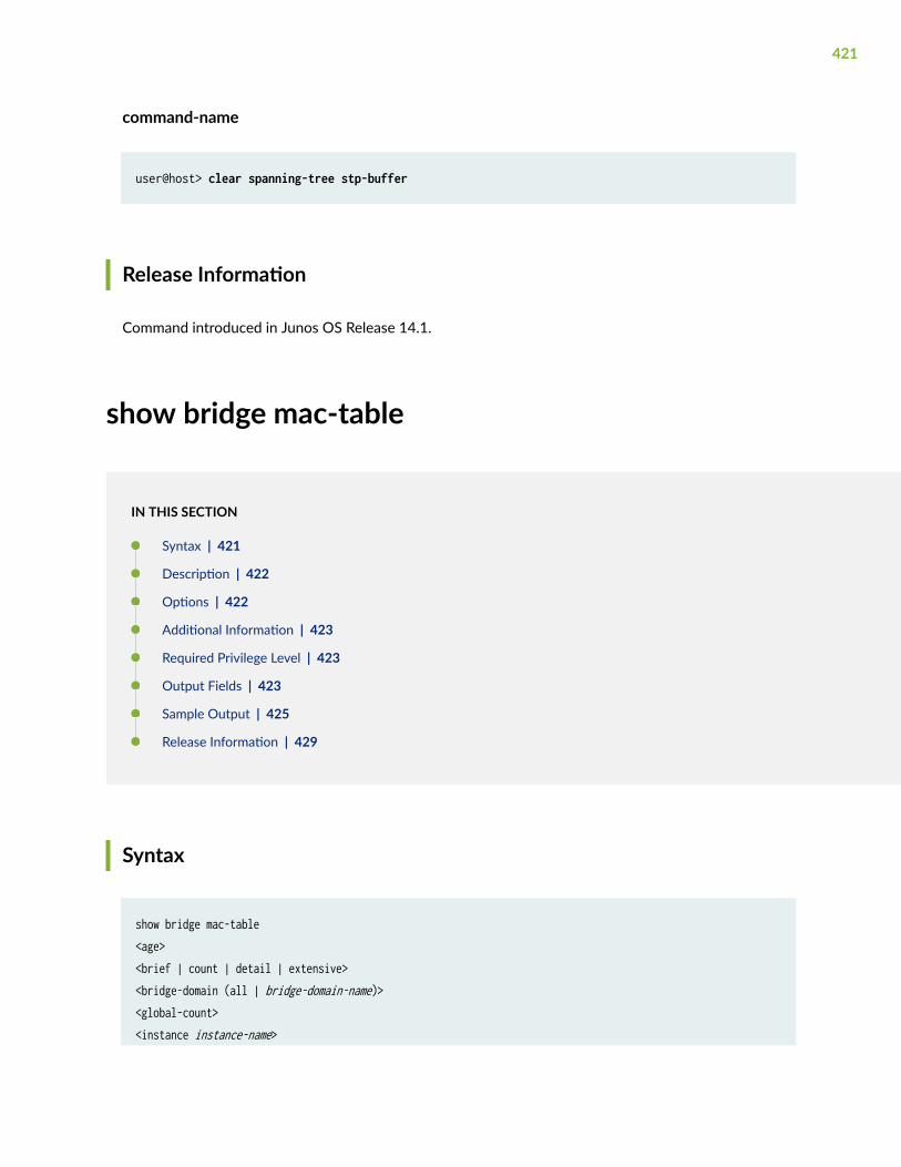
command-name
user@host> clear spanning-tree stp-buffer
Release Information
Command introduced in Junos OS Release 14.1.
show bridge mac-table
IN THIS SECTION
Syntax | 421
Description | 422
Options | 422
Additional Information | 423
Required Privilege Level | 423
Output Fields | 423
Sample Output | 425
Release Information | 429
Syntax
show bridge mac-table<age><brief | count | detail | extensive><bridge-domain (all | bridge-domain-name)><global-count><instance instance-name>
421

<interface interface-name><mac-address><instance instance-name><vlan-id (all-vlan | vlan-id)>
Description
(MX Series routers only) Display Layer 2 MAC address information.
Options
none Display all learned Layer 2 MAC address information.
age (Optional) Display age of a single mac-address.
brief | count | detail |extensive
(Optional) Display the specified level of output.
bridge-domain (all | bridge-domain-name)
(Optional) Display learned Layer 2 MAC addresses for all bridging domainsor for the specified bridging domain.
global-count (Optional) Display the total number of learned Layer 2 MAC addresses onthe system.
instance instance-name (Optional) Display learned Layer 2 MAC addresses for the specified routinginstance.
interface interface-name (Optional) Display learned Layer 2 MAC addresses for the specifiedinterface.
mac-address (Optional) Display the specified learned Layer 2 MAC address information.
vlan-id (all-vlan | vlan-id) (Optional) Display learned Layer 2 MAC addresses for all VLANs or for thespecified VLAN.
422

Additional Information
When Layer 2 protocol tunneling is enabled, the tunneling MAC address 01:00:0c:cd:cd:d0 is installed inthe MAC table. When the Cisco Discovery Protocol (CDP), Spanning Tree Protocol (STP), or VLAN TrunkProtocol (VTP) is configured for Layer 2 protocol tunneling on an interface, the corresponding protocolMAC address is installed in the MAC table.
Required Privilege Level
view
Output Fields
Table 20 on page 423 describes the output fields for the show bridge mac-table command. Output fields arelisted in the approximate order in which they appear.
Table 20: show bridge mac-table Output Fields
Field Name Field Description
Age Age of a single mac-address.
Routing instance Name of the routing instance.
Bridging domain Name of the bridging domain.
MAC address MAC address or addresses learned on a logical interface.
423
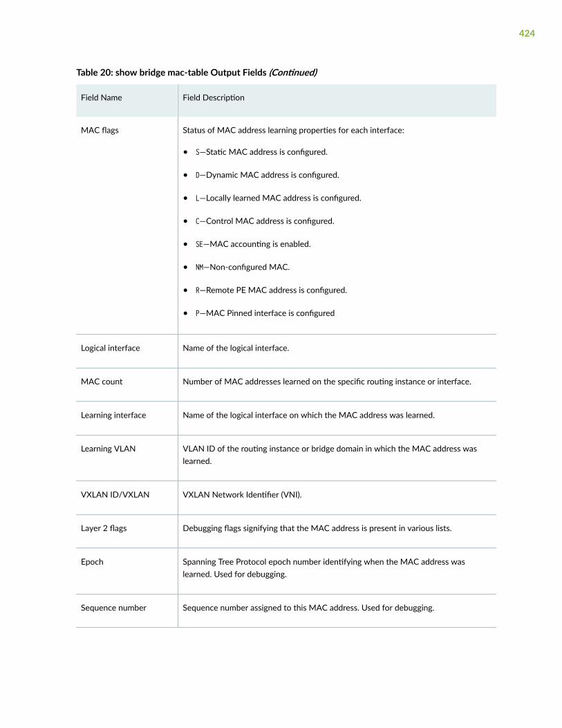
Table 20: show bridge mac-table Output Fields (Continued)
Field Name Field Description
MAC flags Status of MAC address learning properties for each interface:
• S—Static MAC address is configured.
• D—Dynamic MAC address is configured.
• L—Locally learned MAC address is configured.
• C—Control MAC address is configured.
• SE—MAC accounting is enabled.
• NM—Non-configured MAC.
• R—Remote PE MAC address is configured.
• P—MAC Pinned interface is configured
Logical interface Name of the logical interface.
MAC count Number of MAC addresses learned on the specific routing instance or interface.
Learning interface Name of the logical interface on which the MAC address was learned.
Learning VLAN VLAN ID of the routing instance or bridge domain in which the MAC address waslearned.
VXLAN ID/VXLAN VXLAN Network Identifier (VNI).
Layer 2 flags Debugging flags signifying that the MAC address is present in various lists.
Epoch Spanning Tree Protocol epoch number identifying when the MAC address waslearned. Used for debugging.
Sequence number Sequence number assigned to this MAC address. Used for debugging.
424

Table 20: show bridge mac-table Output Fields (Continued)
Field Name Field Description
Learning mask Mask of the Packet Forwarding Engines where this MAC address was learned. Usedfor debugging.
IPC generation Creation time of the logical interface when this MAC address was learned. Used fordebugging.
Sample Output
show bridge mac-table
user@host> show bridge mac-tableMAC flags (S -static MAC, D -dynamic MAC, L -locally learned, C -Control MAC SE -Statistics enabled, NM -Non configured MAC, R -Remote PE MAC)
Routing instance : default-switch Bridging domain : test1, VLAN : 1 MAC MAC Logical NH RTR address flags interface Index ID 01:00:0c:cc:cc:cc S,NM NULL 01:00:0c:cc:cc:cd S,NM NULL 01:00:0c:cd:cd:d0 S,NM NULL 64:87:88:6a:17:d0 D ae0.1 64:87:88:6a:17:f0 D ae0.1
show bridge mac-table (with Layer 2 Services over GRE Interfaces)
user@host> show bridge mac-tableMAC flags (S -static MAC, D -dynamic MAC, L -locally learned SE -Statistics enabled, NM -Non configured MAC, R -Remote PE MAC)
Routing instance : default-switch
425
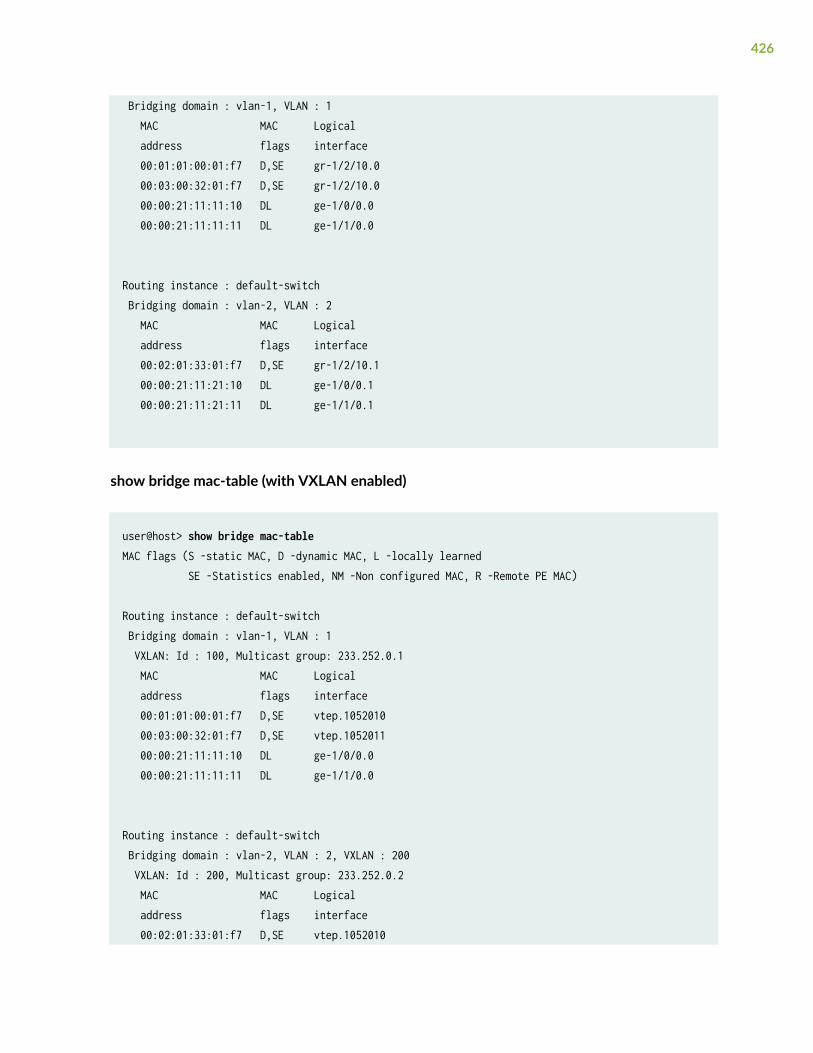
Bridging domain : vlan-1, VLAN : 1 MAC MAC Logical address flags interface 00:01:01:00:01:f7 D,SE gr-1/2/10.0 00:03:00:32:01:f7 D,SE gr-1/2/10.0 00:00:21:11:11:10 DL ge-1/0/0.0 00:00:21:11:11:11 DL ge-1/1/0.0
Routing instance : default-switch Bridging domain : vlan-2, VLAN : 2 MAC MAC Logical address flags interface 00:02:01:33:01:f7 D,SE gr-1/2/10.1 00:00:21:11:21:10 DL ge-1/0/0.1 00:00:21:11:21:11 DL ge-1/1/0.1
show bridge mac-table (with VXLAN enabled)
user@host> show bridge mac-tableMAC flags (S -static MAC, D -dynamic MAC, L -locally learned SE -Statistics enabled, NM -Non configured MAC, R -Remote PE MAC)
Routing instance : default-switch Bridging domain : vlan-1, VLAN : 1 VXLAN: Id : 100, Multicast group: 233.252.0.1 MAC MAC Logical address flags interface 00:01:01:00:01:f7 D,SE vtep.1052010 00:03:00:32:01:f7 D,SE vtep.1052011 00:00:21:11:11:10 DL ge-1/0/0.0 00:00:21:11:11:11 DL ge-1/1/0.0
Routing instance : default-switch Bridging domain : vlan-2, VLAN : 2, VXLAN : 200 VXLAN: Id : 200, Multicast group: 233.252.0.2 MAC MAC Logical address flags interface 00:02:01:33:01:f7 D,SE vtep.1052010
426

00:04:00:14:01:f7 D,SE vtep.1052011 00:00:21:11:21:10 DL ge-1/0/0.1 00:00:21:11:21:11 DL ge-1/1/0.1
show bridge mac-table age (for GE interface)
user@host> show vpls mac-table age 00:02:03:aa:bb:1a instance vpls_instance_1MAC Entry Age informationCurrent Age: 4 seconds
show bridge mac-table age (for AE interface)
user@host> show vpls mac-table age 00:02:03:aa:bb:1a instance vpls_instance_1MAC Entry Age informationCurrent Age on FPC1: 102 secondsCurrent Age on FPC2: 94 seconds
show bridge mac-table count
user@host> show bridge mac-table count2 MAC address learned in routing instance vs1 bridge domain vlan100
MAC address count per interface within routing instance: Logical interface MAC count ge-11/0/3.0 1 ge-11/1/4.100 0 ge-11/1/1.100 0 ge-11/1/0.100 0 xe-10/2/0.100 1 xe-10/0/0.100 0
MAC address count per learn VLAN within routing instance: Learn VLAN ID MAC count 0 2
0 MAC address learned in routing instance vs1 bridge domain vlan200
MAC address count per interface within routing instance:
427

Logical interface MAC count ge-11/1/0.200 0 ge-11/1/1.200 0 ge-11/1/4.200 0 xe-10/0/0.200 0 xe-10/2/0.200 0
MAC address count per learn VLAN within routing instance: Learn VLAN ID MAC count 0 0
show bridge mac-table detail
user@host> show bridge mac-table detailMAC address: 00:00:00:19:1c:db Routing instance: vs1 Bridging domain: vlan100 Learning interface: ge-11/0/3.0 Learning VLAN: 0 Layer 2 flags: in_ifd, in_ifl, in_vlan, kernel Epoch: 4 Sequence number: 0 Learning mask: 0x800 IPC generation: 0
MAC address: 00:00:00:59:3a:2f Routing instance: vs1 Bridging domain: vlan100 Learning interface: xe-10/2/0.100 Learning VLAN: 0 Layer 2 flags: in_ifd, in_ifl, in_vlan, kernel Epoch: 7 Sequence number: 0 Learning mask: 0x400 IPC generation: 0
show bridge mac-table instance pbb-evpn
user@host> show bridge mac-table instance pbb-evpnRouting instance : pbb-evpn Bridging domain : isid-bd10000, ISID : 10000 MAC MAC Logical NH RTR address flags interface Index ID 00:19:e2:b0:76:eb D cbp.1000
428

aa:bb:cc:dd:ee:f2 DC 1048576 1048576 aa:bb:cc:dd:ee:f3 DC 1048575 1048575
show bridge mac-table
user@host>run show bridge mac-tableMAC flags (S -static MAC, D -dynamic MAC, L -locally learned, C -Control MACO -OVSDB MAC, SE -Statistics enabled, NM -Non configured MAC, R -Remote PE MAC, P -Pinned MAC)
Routing instance : VS-541Bridging domain : 541, VLAN : 541MAC MAC Logical NH RTRaddress flags interface Index ID00:00:01:00:00:01 DPRC xe-0/0/3.000:00:02:00:00:01 DP xe-0/0/3.0
Release Information
Command introduced in Junos OS Release 8.4.
Support for PBB-EVPN instance added in Junos OS Release 16.1
MAC Flag P to indicate a MAC Pinned interface introduced in Junos OS 16.2
show mac-rewrite interface
IN THIS SECTION
Syntax | 430
Description | 430
Options | 430
Required Privilege Level | 430
Output Fields | 430
429
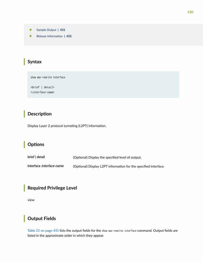
Sample Output | 431
Release Information | 432
Syntax
show mac-rewrite interface
<brief | detail><interface-name>
Description
Display Layer 2 protocol tunneling (L2PT) information.
Options
brief | detail (Optional) Display the specified level of output.
interface interface-name (Optional) Display L2PT information for the specified interface.
Required Privilege Level
view
Output Fields
Table 21 on page 431 lists the output fields for the show mac-rewrite interface command. Output fields arelisted in the approximate order in which they appear.
430

Table 21: show mac-rewrite interface Output Fields
Field Name Field Description Level of Output
Interface Name of the interface on which L2PT is configured. briefdetail
Tunneldestination MACaddress
Name of the configured Layer 2 multicast MAC address briefdetail
Protocols Layer 2 protocols being tunneled on this interface.
All devices that support L2PT can tunnel the following protocols: CiscoDiscovery Protocol (CDP), Spanning Tree Protocol (STP), or VLAN TrunkProtocol (VTP).
The following Layer 2 protocols can also be tunneled on some devicesthat support L2PT: E-LMI, GVRP, IEEE 802.1X, IEEE 802.3AH, LACP,LLDP, MMRP, MVRP, PVSTP+, UDLD, or VSTP. See protocol for moreinformation on the supported protocols for tunneling on differentdevices.
briefdetail
Sample Output
show mac-rewrite interface
user@host> show mac-rewrite interfaceTunnel dest mac : 01:00:0C:CD:CD:D0Interface Protocols
et-0/0/0 STP 8021X 8023AH ELMI LACP LLDP MMRP MVRP VTP CDP
show mac-rewrite interface (EX Series Switches)
user@switch> show mac-rewrite interfaceInterface Protocols
431

ge-0/0/1 802.3AH LLDP STP
Release Information
Command introduced in Junos OS Release 9.1.
Command introduced in Junos OS Release 14.1X53-D10 and 17.3R1 for EX4300 switches.
Command introduced in Junos OS Release 15.1X53-D55 and 18.2R1 for EX2300 and EX3400 switches.
RELATED DOCUMENTATION
layer2-control
mac-rewrite
protocol
Understanding Layer 2 Protocol Tunneling
Configuring Layer 2 Protocol Tunneling
show spanning-tree bridge
IN THIS SECTION
Syntax | 433
Syntax (QFX Series and EX Series) | 433
Description | 433
Options | 433
Required Privilege Level | 434
Output Fields | 434
Sample Output | 436
Release Information | 440
432

Syntax
show spanning-tree bridge<brief | detail><msti msti-id><routing-instance routing-instance-name><vlan-id vlan-id>
Syntax (QFX Series and EX Series)
show spanning-tree bridge<brief | detail><msti msti-id><vlan-id vlan-id>
Description
Displays the configured or calculated spanning-tree protocol (can be either STP, RSTP, MSTP, or VSTP)parameters.
Options
none (Optional) Display brief STP bridge information for all multiple spanning-treeinstances (MSTIs).
brief | detail (Optional) Display the specified level of output.
msti msti-id (Optional) Display spanning-tree protocol bridge information for the specifiedMSTI or Common and Internal Spanning Tree (CIST). Specify 0 for CIST. Specify avalue from 1 through 4094 for an MSTI.
routing-instancerouting-instance-name
(Optional) Display STP bridge information for the specified routing instance.
433

vlan-id vlan-id (Optional) Display spanning-tree protocol bridge information for the specifiedVLAN. Specify a VLAN tag identifier from 1 through 4094.
Required Privilege Level
view
Output Fields
Table 22 on page 434 lists the output fields for the show spanning-tree bridge command. Output fields arelisted in the approximate order in which they appear.
Table 22: show spanning-tree bridge Output Fields
Field Name Field Description
Routing instance name Name of the routing instance under which the bridge is configured.
Enabled protocol Spanning Tree Protocol type enabled.
Root ID Bridge ID of the elected spanning-tree root bridge. The bridge ID consists of aconfigurable bridge priority and the MAC address of the bridge.
Root cost Calculated cost to reach the root bridge from the bridge where the commandis entered.
Root port Interface that is the current elected root port for this bridge.
CIST regional root Bridge ID of the elected MSTP regional root bridge.
CIST internal root cost Calculated cost to reach the regional root bridge from the bridge where thecommand is entered.
434

Table 22: show spanning-tree bridge Output Fields (Continued)
Field Name Field Description
Hello time Configured number of seconds between transmissions of configurationBPDUs.
Maximum age Configured maximum expected arrival time of hello bridge protocol data units(BPDUs).
Forward delay How long an STP bridge port remains in the listening and learning statesbefore transitioning to the forwarding state.
Hop count Configured maximum number of hops a BPDU can be forwarded in the MSTPregion.
Message age Number of elapsed seconds since the most recent BPDU was received.
Number of topology changes Total number of STP topology changes detected since the routing device lastbooted.
Time since last topology change Number of elapsed seconds since the most recent topology change.
Bridge ID (Local) Locally configured bridge ID. The bridge ID consists of a configurable bridgepriority and the MAC address of the bridge.
Extended system ID System identifier.
MSTI regional root Bridge ID of the elected MSTP regional root bridge.
435

Sample Output
show spanning-tree bridge routing-instance
user@host> show spanning-tree bridge routing-instance vs1 detailSTP bridge parametersRouting instance name : vs1Enabled protocol : MSTP
STP bridge parameters for CIST Root ID : 32768.00:13:c3:9e:c8:80 Root cost : 0 Root port : ge-10/2/0 CIST regional root : 32768.00:13:c3:9e:c8:80 CIST internal root cost : 22000 Hello time : 2 seconds Maximum age : 20 seconds Forward delay : 15 seconds Hop count : 18 Message age : 0 Number of topology changes : 1 Time since last topology change : 1191 seconds Local parameters Bridge ID : 32768.00:90:69:0b:7f:d1 Extended system ID : 1
STP bridge parameters for MSTI 1 MSTI regional root : 32769.00:13:c3:9e:c8:80 Root cost : 22000 Root port : ge-10/2/0 Hello time : 2 seconds Maximum age : 20 seconds Forward delay : 15 seconds Hop count : 18 Number of topology changes : 1 Time since last topology change : 1191 seconds Local parameters Bridge ID : 32769.00:90:69:0b:7f:d1 Extended system ID : 1
STP bridge parameters for MSTI 2
436
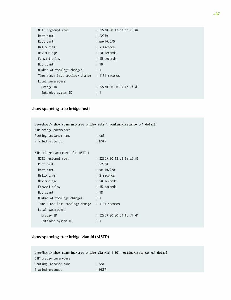
MSTI regional root : 32770.00:13:c3:9e:c8:80 Root cost : 22000 Root port : ge-10/2/0 Hello time : 2 seconds Maximum age : 20 seconds Forward delay : 15 seconds Hop count : 18 Number of topology changes : 1 Time since last topology change : 1191 seconds Local parameters Bridge ID : 32770.00:90:69:0b:7f:d1 Extended system ID : 1
show spanning-tree bridge msti
user@host> show spanning-tree bridge msti 1 routing-instance vs1 detailSTP bridge parametersRouting instance name : vs1Enabled protocol : MSTP
STP bridge parameters for MSTI 1 MSTI regional root : 32769.00:13:c3:9e:c8:80 Root cost : 22000 Root port : xe-10/2/0 Hello time : 2 seconds Maximum age : 20 seconds Forward delay : 15 seconds Hop count : 18 Number of topology changes : 1 Time since last topology change : 1191 seconds Local parameters Bridge ID : 32769.00:90:69:0b:7f:d1 Extended system ID : 1
show spanning-tree bridge vlan-id (MSTP)
user@host> show spanning-tree bridge vlan-id 1 101 routing-instance vs1 detailSTP bridge parametersRouting instance name : vs1Enabled protocol : MSTP
437

STP bridge parameters for CIST Root ID : 32768.00:13:c3:9e:c8:80 Root cost : 0 Root port : xe-10/2/0 CIST regional root : 32768.00:13:c3:9e:c8:80 CIST internal root cost : 22000 Hello time : 2 seconds Maximum age : 20 seconds Forward delay : 15 seconds Hop count : 18 Message age : 0 Number of topology changes : 0 Local parameters Bridge ID : 32768.00:90:69:0b:7f:d1 Extended system ID : 1 Hello time : 2 seconds Maximum age : 20 seconds Forward delay : 15 seconds Path cost method : 32 bit Maximum hop count : 20
show spanning-tree bridge (RSTP)
user@host> show spanning-tree bridgeSTP bridge parametersRouting instance name : GLOBALEnabled protocol : RSTP Root ID : 28672.00:90:69:0b:3f:d0 Hello time : 2 seconds Maximum age : 20 seconds Forward delay : 15 seconds Message age : 0 Number of topology changes : 58 Time since last topology change : 14127 seconds Local parameters Bridge ID : 28672.00:90:69:0b:3f:d0 Extended system ID : 0
STP bridge parameters for bridge VLAN 10 Root ID : 28672.00:90:69:0b:3f:d0
438

Hello time : 2 seconds Maximum age : 20 seconds Forward delay : 15 seconds Message age : 0 Number of topology changes : 58 Time since last topology change : 14127 seconds Local parameters Bridge ID : 28672.00:90:69:0b:3f:d0 Extended system ID : 0
STP bridge parameters for bridge VLAN 20 Root ID : 28672.00:90:69:0b:3f:d0 Hello time : 2 seconds Maximum age : 20 seconds Forward delay : 15 seconds Message age : 0 Number of topology changes : 58 Time since last topology change : 14127 seconds Local parameters Bridge ID : 28672.00:90:69:0b:3f:d0 Extended system ID : 0
show spanning-tree bridge vlan-id (RSTP)
user@host> show spanning-tree bridge vlan-id 10STP bridge parametersRouting instance name : GLOBALEnabled protocol : RSTP
STP bridge parameters for VLAN 10 Root ID : 28672.00:90:69:0b:3f:d0 Hello time : 2 seconds Maximum age : 20 seconds Forward delay : 15 seconds Message age : 0 Number of topology changes : 58 Time since last topology change : 14127 seconds Local parameters Bridge ID : 28672.00:90:69:0b:3f:d0 Extended system ID : 0
439

Release Information
Command introduced in Junos OS Release 8.4.
RELATED DOCUMENTATION
Understanding STP | 23
Understanding RSTP | 27
Example: Configuring Network Regions for VLANs with MSTP on Switches | 101
show spanning-tree interface | 440
show spanning-tree interface
IN THIS SECTION
Syntax | 440
Syntax (EX Series Switches and QFX Series Switches) | 441
Syntax (EX Series Switches) | 441
Description | 441
Options | 441
Required Privilege Level | 442
Output Fields | 442
Sample Output | 443
Release Information | 452
Syntax
show spanning-tree interface<brief | detail><msti msti-id>
440

<routing-instance routing-instance-name><vlan-id vlan-id>
Syntax (EX Series Switches and QFX Series Switches)
show spanning-tree interface<brief | detail><msti msti-id><vlan-id vlan-id>
Syntax (EX Series Switches)
show spanning-tree interface<brief | detail><interface-name interface-name><msti msti-id><vlan-id vlan-id>
Description
Display the configured or calculated interface-level spanning-tree protocol (can be either STP, RSTP, orMSTP) parameters. In brief mode, will not display interfaces that are administratively disabled or do nothave a physical link.
Options
none Display brief STP interface information.
brief | detail (Optional) Display the specified level of output.
441

interface-name interface-name (Optional) Name of an interface.
msti msti-id (Optional) Display STP interface information for the specified MSTinstance.
routing-instance routing-instance-name
(Optional) Display STP interface information for the specified routinginstance.
vlan-id vlan-id (Optional) Display STP interface information for the specified VLAN.
Required Privilege Level
view
Output Fields
Table 23 on page 442 lists the output fields for the show spanning-tree interface command. Output fieldsare listed in the approximate order in which they appear.
Table 23: show spanning-tree Interface Output Fields
Field Name Field Description
Interface name Interface configured to participate in the STP, RSTP, VSTP, or MSTP instance.
Port ID Logical interface identifier configured to participate in the MSTP or VSTPinstance.
Designated port ID Port ID of the designated port for the LAN segment to which this interface isattached.
Designated bridge ID Bridge ID of the designated bridge for the LAN segment to which thisinterface is attached.
Port Cost Configured cost for the interface.
442
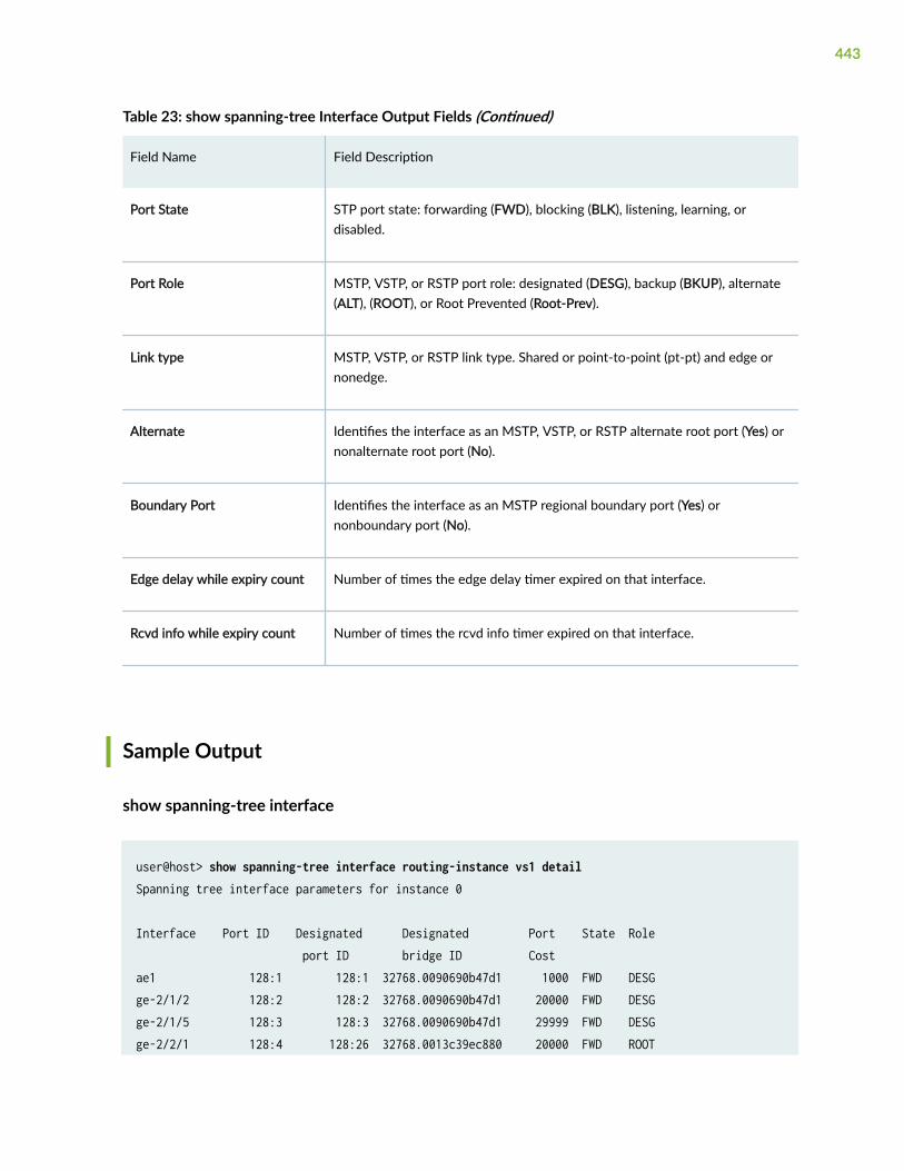
Table 23: show spanning-tree Interface Output Fields (Continued)
Field Name Field Description
Port State STP port state: forwarding (FWD), blocking (BLK), listening, learning, ordisabled.
Port Role MSTP, VSTP, or RSTP port role: designated (DESG), backup (BKUP), alternate(ALT), (ROOT), or Root Prevented (Root-Prev).
Link type MSTP, VSTP, or RSTP link type. Shared or point-to-point (pt-pt) and edge ornonedge.
Alternate Identifies the interface as an MSTP, VSTP, or RSTP alternate root port (Yes) ornonalternate root port (No).
Boundary Port Identifies the interface as an MSTP regional boundary port (Yes) ornonboundary port (No).
Edge delay while expiry count Number of times the edge delay timer expired on that interface.
Rcvd info while expiry count Number of times the rcvd info timer expired on that interface.
Sample Output
show spanning-tree interface
user@host> show spanning-tree interface routing-instance vs1 detailSpanning tree interface parameters for instance 0
Interface Port ID Designated Designated Port State Role port ID bridge ID Costae1 128:1 128:1 32768.0090690b47d1 1000 FWD DESGge-2/1/2 128:2 128:2 32768.0090690b47d1 20000 FWD DESGge-2/1/5 128:3 128:3 32768.0090690b47d1 29999 FWD DESGge-2/2/1 128:4 128:26 32768.0013c39ec880 20000 FWD ROOT
443

xe-9/2/0 128:5 128:5 32768.0090690b47d1 2000 FWD DESGxe-9/3/0 128:6 128:6 32768.0090690b47d1 2000 FWD DESG
Spanning tree interface parameters for instance 1
Interface Port ID Designated Designated Port State Role port ID bridge ID Costae1 128:1 128:1 32769.0090690b47d1 1000 FWD DESGge-2/1/2 128:2 128:2 32769.0090690b47d1 20000 FWD DESGge-2/1/5 128:3 128:3 32769.0090690b47d1 29999 FWD DESGge-2/2/1 128:4 128:26 32769.0013c39ec880 20000 FWD ROOTxe-9/2/0 128:5 128:5 32769.0090690b47d1 2000 FWD DESGxe-9/3/0 128:6 128:6 32769.0090690b47d1 2000 FWD DESG
Spanning tree interface parameters for instance 2
Interface Port ID Designated Designated Port State Role port ID bridge ID Costae1 128:1 128:1 32770.0090690b47d1 1000 FWD DESGge-2/1/2 128:2 128:2 32770.0090690b47d1 20000 FWD DESGge-2/1/5 128:3 128:3 32770.0090690b47d1 29999 FWD DESGge-2/2/1 128:4 128:26 32770.0013c39ec880 20000 FWD ROOTxe-9/2/0 128:5 128:5 32770.0090690b47d1 2000 FWD DESGxe-9/3/0 128:6 128:6 32770.0090690b47d1 2000 FWD DESG
show spanning-tree interface (QFX Series)
user@host> show spanning-tree interface routing-instance vs1 detailSpanning tree interface parameters for instance 0
Interface Port ID Designated Designated Port State Role port ID bridge ID Costae1 128:1 128:1 32768.0090690b47d1 1000 FWD DESGge-2/1/2 128:2 128:2 32768.0090690b47d1 20000 FWD DESGge-2/1/5 128:3 128:3 32768.0090690b47d1 29999 FWD DESGge-2/2/1 128:4 128:26 32768.0013c39ec880 20000 FWD ROOTxe-9/2/0 128:5 128:5 32768.0090690b47d1 2000 FWD DESGxe-9/3/0 128:6 128:6 32768.0090690b47d1 2000 FWD DESG
Spanning tree interface parameters for instance 1
444

Interface Port ID Designated Designated Port State Role port ID bridge ID Costae1 128:1 128:1 32769.0090690b47d1 1000 FWD DESGge-2/1/2 128:2 128:2 32769.0090690b47d1 20000 FWD DESGge-2/1/5 128:3 128:3 32769.0090690b47d1 29999 FWD DESGge-2/2/1 128:4 128:26 32769.0013c39ec880 20000 FWD ROOTxe-9/2/0 128:5 128:5 32769.0090690b47d1 2000 FWD DESGxe-9/3/0 128:6 128:6 32769.0090690b47d1 2000 FWD DESG
Spanning tree interface parameters for instance 2
Interface Port ID Designated Designated Port State Role port ID bridge ID Costae1 128:1 128:1 32770.0090690b47d1 1000 FWD DESGge-2/1/2 128:2 128:2 32770.0090690b47d1 20000 FWD DESGge-2/1/5 128:3 128:3 32770.0090690b47d1 29999 FWD DESGge-2/2/1 128:4 128:26 32770.0013c39ec880 20000 FWD ROOTxe-9/2/0 128:5 128:5 32770.0090690b47d1 2000 FWD DESGxe-9/3/0 128:6 128:6 32770.0090690b47d1 2000 FWD DESG
show spanning-tree interface (EX Series)
user@switch> show spanning-tree interface
Spanning tree interface parameters for instance 0
Interface Port ID Designated Designated Port State Role port ID bridge ID Costge-0/0/0.0 128:513 128:513 8192.0019e2500340 1000 FWD DESG ge-0/0/2.0 128:515 128:515 8192.0019e2500340 1000 BLK DIS ge-0/0/4.0 128:517 128:517 8192.0019e2500340 1000 FWD DESG ge-0/0/23.0 128:536 128:536 8192.0019e2500340 1000 FWD DESG
Spanning tree interface parameters for instance 1
Interface Port ID Designated Designated Port State Role port ID bridge ID Costge-0/0/0.0 128:513 128:513 8193.0019e2500340 1000 FWD DESG ge-0/0/2.0 128:515 128:515 8193.0019e2500340 1000 BLK DIS ge-0/0/4.0 128:517 128:517 8193.0019e2500340 1000 FWD DESG
445

ge-0/0/23.0 128:536 128:536 8193.0019e2500340 1000 FWD DESG
Spanning tree interface parameters for instance 2
Interface Port ID Designated Designated Port State Role port ID bridge ID Costge-0/0/0.0 128:513 128:1 8194.001b549fd000 1000 FWD ROOT ge-0/0/2.0 128:515 128:515 32770.0019e2500340 4000 BLK DIS ge-0/0/4.0 128:517 128:1 16386.001b54013080 1000 BLK ALT ge-0/0/23.0 128:536 128:536 32770.0019e2500340 1000 FWD DESG
show spanning-tree interface detail
user@host> show spanning-tree interface routing-instance vs1 detailSpanning tree interface parameters for instance 0
Interface name : ae1Port identifier : 128.1Designated port ID : 128.1Port cost : 1000Port state : ForwardingDesignated bridge ID : 32768.00:90:69:0b:47:d1Port role : DesignatedLink type : Pt-Pt/NONEDGEBoundary port : No
Interface name : ge-2/1/2Port identifier : 128.2Designated port ID : 128.2Port cost : 20000Port state : ForwardingDesignated bridge ID : 32768.00:90:69:0b:47:d1Port role : DesignatedLink type : Pt-Pt/NONEDGEBoundary port : No
Interface name : ge-2/1/5Port identifier : 128.3Designated port ID : 128.3Port cost : 29999
446

Port state : ForwardingDesignated bridge ID : 32768.00:90:69:0b:47:d1Port role : DesignatedLink type : Pt-Pt/NONEDGEBoundary port : No
Interface name : ge-2/2/1Port identifier : 128.4Designated port ID : 128.26Port cost : 20000Port state : ForwardingDesignated bridge ID : 32768.00:13:c3:9e:c8:80Port role : RootLink type : Pt-Pt/NONEDGEBoundary port : No
Interface name : xe-9/2/0Port identifier : 128.5Designated port ID : 128.5Port cost : 2000Port state : ForwardingDesignated bridge ID : 32768.00:90:69:0b:47:d1Port role : DesignatedLink type : Pt-Pt/NONEDGEBoundary port : No
Interface name : xe-9/3/0Port identifier : 128.6Designated port ID : 128.6Port cost : 2000Port state : ForwardingDesignated bridge ID : 32768.00:90:69:0b:47:d1Port role : DesignatedLink type : Pt-Pt/NONEDGEBoundary port : No
Spanning tree interface parameters for instance 1
Interface name : ae1Port identifier : 128.1Designated port ID : 128.1Port cost : 1000
447

Port state : ForwardingDesignated bridge ID : 32768.00:90:69:0b:47:d1Port role : DesignatedLink type : Pt-Pt/NONEDGEBoundary port : No
Interface name : ge-2/1/2Port identifier : 128.2Designated port ID : 128.2Port cost : 20000Port state : ForwardingDesignated bridge ID : 32768.00:90:69:0b:47:d1Port role : DesignatedLink type : Pt-Pt/NONEDGEBoundary port : No
Interface name : ge-2/1/5Port identifier : 128.3Designated port ID : 128.3Port cost : 29999Port state : ForwardingDesignated bridge ID : 32768.00:90:69:0b:47:d1Port role : DesignatedLink type : Pt-Pt/NONEDGEBoundary port : No
Interface name : ge-2/2/1Port identifier : 128.4Designated port ID : 128.26Port cost : 20000Port state : ForwardingDesignated bridge ID : 32768.00:13:c3:9e:c8:80Port role : RootLink type : Pt-Pt/NONEDGEBoundary port : No
...
448

show spanning-tree interface detail (EX Series)
user@switch> show spanning-tree interface detailSpanning tree interface parameters for instance 0
Interface name : ge-1/0/0.0Port identifier : 128.625Designated port ID : 128.625Port cost : 20000Port state : BlockingDesignated bridge ID : 32768.00:19:e2:50:95:a0Port role : DisabledLink type : Pt-Pt/EDGEBoundary port : NA Edge delay while expiry count : 0Rcvd info while expiry count : 0 Interface name : ge-1/0/1.0Port identifier : 128.626Designated port ID : 128.626Port cost : 20000Port state : BlockingDesignated bridge ID : 32768.00:19:e2:50:95:a0Port role : DisabledLink type : Pt-Pt/NONEDGEBoundary port : NAEdge delay while expiry count : 0Rvcd info while expiry count : 0
Interface name : ge-1/0/2.0Port identifier : 128.627Designated port ID : 128.627Port cost : 20000Port state : BlockingDesignated bridge ID : 32768.00:19:e2:50:95:a0Port role : DisabledLink type : Pt-Pt/NONEDGEBoundary port : NAEdge delay while expiry count : 0Rvcd info while expiry count : 0
Interface name : ge-1/0/10.0
449

Port identifier : 128.635Designated port ID : 128.635Port cost : 20000Port state : BlockingDesignated bridge ID : 32768.00:19:e2:50:95:a0Port role : DisabledLink type : Pt-Pt/NONEDGEBoundary port : NA Edge delay while expiry count : 0Rvcd info while expiry count : 0
Interface name : ge-1/0/20.0Port identifier : 128.645Designated port ID : 128.645Port cost : 20000Port state : BlockingDesignated bridge ID : 32768.00:19:e2:50:95:a0Port role : DisabledLink type : Pt-Pt/NONEDGEBoundary port : NA Edge delay while expiry count : 0Rvcd info while expiry count : 0[output truncated]
show spanning-tree interface msti
user@host> show spanning-tree interface msti 1 routing-instance vs1 detail Spanning tree interface parameters for instance 1
Interface Port ID Designated Designated Port State Role port ID bridge ID Costxe-7/0/0 128:1 128:1 32769.0090690b4fd1 2000 FWD DESGge-5/1/0 128:2 128:2 32769.0090690b4fd1 20000 FWD DESGge-5/1/1 128:3 128:3 32769.0090690b4fd1 20000 FWD DESGae1 128:4 128:1 32769.0090690b47d1 10000 BLK ALTge-5/1/4 128:5 128:3 32769.0090690b47d1 20000 BLK ALTxe-7/2/0 128:6 128:6 32769.0090690b47d1 2000 FWD ROOT
450

show spanning-tree interface vlan-id
user@host> show spanning-tree interface vlan-id 101 routing-instance vs1 detailSpanning tree interface parameters for instance 0
Interface Port ID Designated Designated Port State Role port ID bridge ID Costge-11/0/5 128:1 128:1 32768.0090690b7fd1 20000 FWD DESGge-11/0/6 128:2 128:1 32768.0090690b7fd1 20000 BLK BKUPge-11/1/0 128:3 128:2 32768.0090690b4fd1 20000 BLK ALTge-11/1/1 128:4 128:3 32768.0090690b4fd1 20000 BLK ALTge-11/1/4 128:5 128:1 32768.0090690b47d1 20000 BLK ALTxe-10/0/0 128:6 128:5 32768.0090690b4fd1 2000 BLK ALTxe-10/2/0 128:7 128:4 32768.0090690b47d1 2000 FWD ROOT
show spanning-tree interface (VSTP)
user@host> show spanning-tree interfaceSpanning tree interface parameters for instance 0
Interface Port ID Designated Designated Cost State Role port ID bridge IDge-1/0/1 128:1 128:1 28672.0090690b3fe0 20000 FWD DESGge-1/0/2 128:2 128:2 28672.0090690b3fe0 20000 FWD DESG
Spanning tree interface parameters for VLAN 10
Interface Port ID Designated Designated Cost State Role port ID bridge IDge-1/0/1 128:1 128:1 28672.0090690b3fe0 20000 FWD DESGge-1/0/2 128:2 128:2 28672.0090690b3fe0 20000 FWD DESG
Spanning tree interface parameters for VLAN 20
Interface Port ID Designated Designated Cost State Role port ID bridge IDge-1/0/1 128:1 128:1 28672.0090690b3fe0 20000 FWD DESGge-1/0/2 128:2 128:2 28672.0090690b3fe0 20000 FWD DESG
451

show spanning-tree interface vlan-id (VSTP)
user@host> show spanning-tree interface vlan-id 10Spanning tree interface parameters for VLAN 10
Interface Port ID Designated Designated Cost State Role port ID bridge IDge-1/0/1 128:1 128:1 28672.0090690b3fe0 20000 FWD DESGge-1/0/2 128:2 128:2 28672.0090690b3fe0 20000 FWD DESG
show spanning-tree interface brief (EX Series)
user@switch> show spanning-tree interface briefSpanning tree interface parameters for instance 0
Interface Port ID Designated Designated Port State Role port ID bridge ID Costge-1/0/0.0 128:625 128:625 32768.0019e25095a0 20000 BLK DIS ge-1/0/1.0 128:626 128:626 32768.0019e25095a0 20000 BLK DIS ge-1/0/2.0 128:627 128:627 32768.0019e25095a0 20000 BLK DIS ge-1/0/10.0 128:635 128:635 32768.0019e25095a0 20000 BLK DIS ge-1/0/20.0 128:645 128:645 32768.0019e25095a0 20000 BLK DIS ge-1/0/30.0 128:655 128:655 32768.0019e25095a0 20000 BLK DIS
show spanning-tree interface ge-1/0/0 (EX Series)
user@switch> show spanning-tree interface ge-1/0/0
Interface Port ID Designated Designated Port State Role port ID bridge ID Costge-1/0/0.0 128:625 128:625 32768.0019e25095a0 20000 BLK DIS
Release Information
Command introduced in Junos OS Release 8.4.
452

RELATED DOCUMENTATION
show spanning-tree bridge | 432
Example: Configuring Network Regions for VLANs with MSTP on Switches | 101
Understanding STP | 23
Understanding RSTP | 27
Understanding MSTP | 87
show spanning-tree mstp configuration
IN THIS SECTION
Syntax | 453
Syntax (EX Series Switch and the QFX Series) | 454
Description | 454
Options | 454
Required Privilege Level | 454
Output Fields | 454
Sample Output | 455
Release Information | 456
Syntax
show spanning-tree mstp configuration<brief | detail><routing-instance routing-instance-name>
453
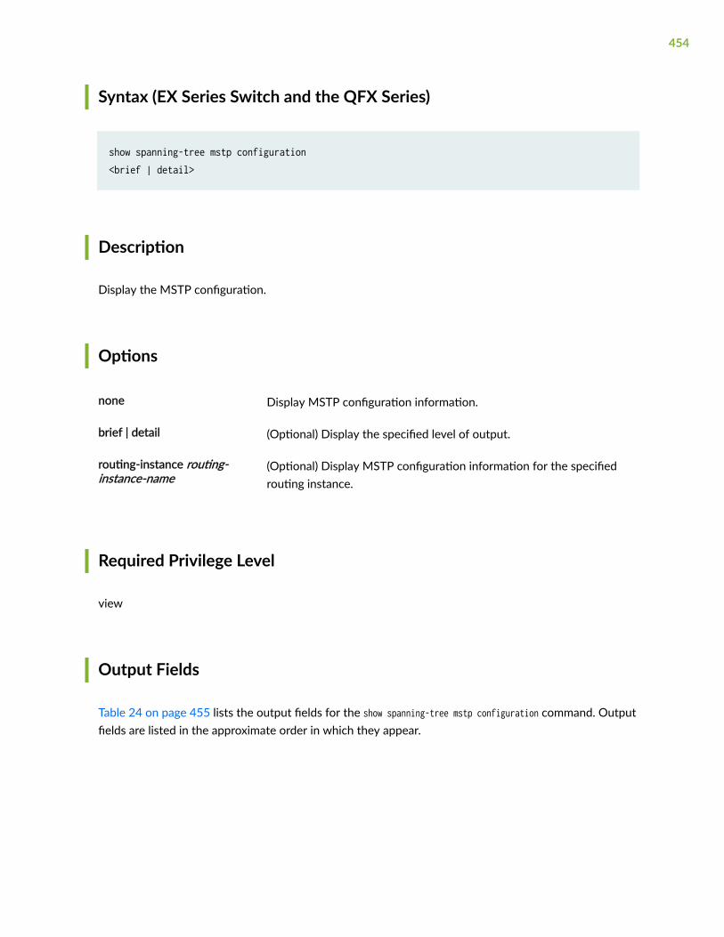
Syntax (EX Series Switch and the QFX Series)
show spanning-tree mstp configuration<brief | detail>
Description
Display the MSTP configuration.
Options
none Display MSTP configuration information.
brief | detail (Optional) Display the specified level of output.
routing-instance routing-instance-name
(Optional) Display MSTP configuration information for the specifiedrouting instance.
Required Privilege Level
view
Output Fields
Table 24 on page 455 lists the output fields for the show spanning-tree mstp configuration command. Outputfields are listed in the approximate order in which they appear.
454

Table 24: show spanning-tree mstp configuration Output Fields
Field Name Field Description
Context id Internally generated identifier.
Region name MSTP region name carried in the MSTP BPDUs.
Revision Revision number of the MSTP configuration.
Configuration digest Numerical value derived from the VLAN-to-instance mapping table.
MSTI MST instance identifier.
Member VLANs VLAN identifiers associated with the MSTI.
Sample Output
show spanning-tree mstp configuration detail
user@host> show spanning-tree mstp configuration routing-instance vs1 detailMSTP configuration informationContext identifier : 1Region name : henryRevision : 3Configuration digest : 0x6da4b5c4fd587757eef35675365e1
MSTI Member VLANs 0 0-99,101-199,201-4094 1 100 2 200
455

show spanning-tree mstp configuration detail (QFX Series)
user@lf0> show spanning-tree mstp configuration routing-instance vs1 detailMSTP configuration informationContext identifier : 1Region name : henryRevision : 3Configuration digest : 0x6da4b5c4fd587757eef35675365e1
MSTI Member VLANs 0 0-99,101-199,201-4094 1 100 2 200
show spanning-tree mstp configuration (EX Series)
user@host> show spanning-tree mstp configuration MSTP configuration information Context identifier : 0Region name : region1Revision : 0Configuration digest : 0xc92e7af9febb44d8df928b87f16b
MSTI Member VLANs 0 0-100,105-4094 1 101-102 2 103-104
Release Information
Command introduced in Junos OS Release 8.4.
RELATED DOCUMENTATION
Understanding MSTP | 87
456

Example: Configuring Network Regions for VLANs with MSTP on Switches | 101
show spanning-tree bridge | 432
show spanning-tree statistics | 457
mstp | 358
show spanning-tree statistics
IN THIS SECTION
Syntax | 457
Syntax (EX Series and QFX Series) | 458
Syntax (EX Series) | 458
Description | 458
Options | 458
Required Privilege Level | 458
Output Fields | 459
Sample Output | 459
Release Information | 460
Syntax
show spanning-tree statistics<brief | detail><interface interface-name><routing-instance routing-instance-name>
457
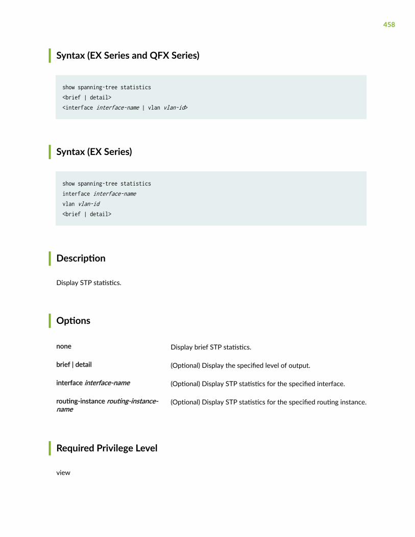
Syntax (EX Series and QFX Series)
show spanning-tree statistics<brief | detail><interface interface-name | vlan vlan-id>
Syntax (EX Series)
show spanning-tree statisticsinterface interface-namevlan vlan-id<brief | detail>
Description
Display STP statistics.
Options
none Display brief STP statistics.
brief | detail (Optional) Display the specified level of output.
interface interface-name (Optional) Display STP statistics for the specified interface.
routing-instance routing-instance-name
(Optional) Display STP statistics for the specified routing instance.
Required Privilege Level
view
458
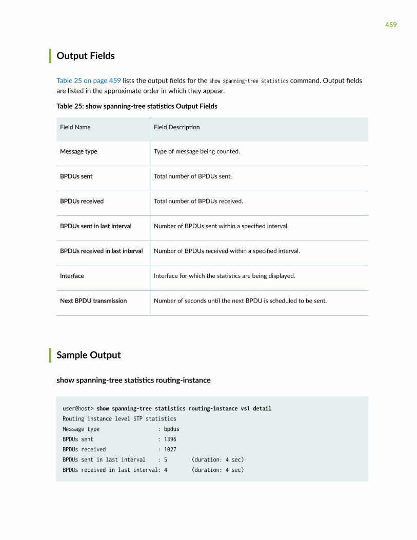
Output Fields
Table 25 on page 459 lists the output fields for the show spanning-tree statistics command. Output fieldsare listed in the approximate order in which they appear.
Table 25: show spanning-tree statistics Output Fields
Field Name Field Description
Message type Type of message being counted.
BPDUs sent Total number of BPDUs sent.
BPDUs received Total number of BPDUs received.
BPDUs sent in last interval Number of BPDUs sent within a specified interval.
BPDUs received in last interval Number of BPDUs received within a specified interval.
Interface Interface for which the statistics are being displayed.
Next BPDU transmission Number of seconds until the next BPDU is scheduled to be sent.
Sample Output
show spanning-tree statistics routing-instance
user@host> show spanning-tree statistics routing-instance vs1 detailRouting instance level STP statisticsMessage type : bpdusBPDUs sent : 1396BPDUs received : 1027BPDUs sent in last interval : 5 (duration: 4 sec)BPDUs received in last interval: 4 (duration: 4 sec)
459
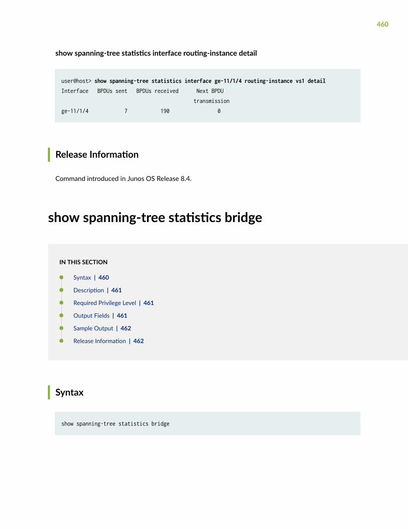
show spanning-tree statistics interface routing-instance detail
user@host> show spanning-tree statistics interface ge-11/1/4 routing-instance vs1 detailInterface BPDUs sent BPDUs received Next BPDU transmissionge-11/1/4 7 190 0
Release Information
Command introduced in Junos OS Release 8.4.
show spanning-tree statistics bridge
IN THIS SECTION
Syntax | 460
Description | 461
Required Privilege Level | 461
Output Fields | 461
Sample Output | 462
Release Information | 462
Syntax
show spanning-tree statistics bridge
460

Description
Display the STP statistics of the bridge.
Required Privilege Level
view
Output Fields
Table 26 on page 461 describes the output fields for the show spanning-tree statistics bridge command.Output fields are listed in the approximate order in which they appear.
Table 26: show spanning-tree statistics bridge Output Fields
Field Name Field Description
STP Context Context of STP instances saved for each routing instance. All STP instances inthe same routing instances have same context.
STP Instance Instance number that uniquely identifies each STP session per routing instance.
Number of Root Bridge Changes Counts the number of Root Bridge change events.
Number of Root Port Changes Counts the number of Root Port change events.
Recent TC Received Details about the last topology change received.
461
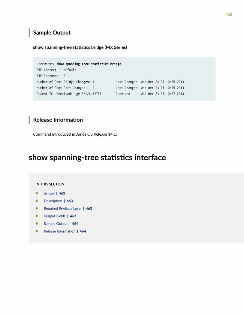
Sample Output
show spanning-tree statistics bridge (MX Series)
user@host> show spanning-tree statistics bridgeSTP Context : defaultSTP Instance : 0 Number of Root Bridge Changes: 1 Last Changed: Wed Oct 23 07:10:05 2013 Number of Root Port Changes: 2 Last Changed: Wed Oct 23 07:10:05 2013 Recent TC Received: ge-3/1/4.32767 Received : Wed Oct 23 07:10:07 2013
Release Information
Command introduced in Junos OS Release 14.1.
show spanning-tree statistics interface
IN THIS SECTION
Syntax | 463
Description | 463
Required Privilege Level | 463
Output Fields | 463
Sample Output | 464
Release Information | 464
462

Syntax
show spanning-tree statistics interface
Description
Display the STP statistics related to the interface.
Required Privilege Level
view
Output Fields
Table 27 on page 463 describes the output fields for the show spanning-tree statistics interfacecommand. Output fields are listed in the approximate order in which they appear.
Table 27: show spanning-tree statistics interface Output Fields
Field Name Field Description
Interface Interface name.
BPDUs sent Total number of BPDUs sent from the bridge on the interface.
BPDUs received Total number of BPDUs received by the bridge on the interface.
Next BPDU Transmission Time after which the next BPDU is sent by the bridge on the interface.
TC Tx/Rx Total number of Topology Change BPDUs sent or received on the interface.
463

Table 27: show spanning-tree statistics interface Output Fields (Continued)
Field Name Field Description
Proposal Tx/Rx Total number of Proposal BPDUs sent or received on the interface.
Agreement Tx/Rx Total number of Agreement BPDUs sent or received on the interface.
Sample Output
show spanning-tree statistics interface (MX Series)
user@host> show spanning-tree statistics interface
Interface BPDUs BPDUs Next BPDU TCs Proposal Agreement Sent Received Transmission Tx/Rx Tx/Rx Tx/Rx xe-0/0/0 49 3 1 5/2 0/2 1/0
ge-1/0/0 48 1 1 5/1 0/1 1/1
Release Information
Command introduced in Junos OS Release 14.1.
464
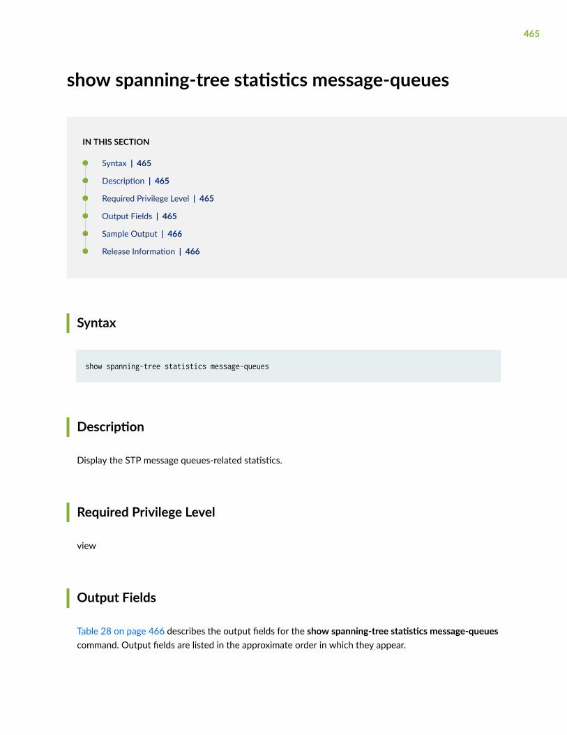
show spanning-tree statistics message-queues
IN THIS SECTION
Syntax | 465
Description | 465
Required Privilege Level | 465
Output Fields | 465
Sample Output | 466
Release Information | 466
Syntax
show spanning-tree statistics message-queues
Description
Display the STP message queues-related statistics.
Required Privilege Level
view
Output Fields
Table 28 on page 466 describes the output fields for the show spanning-tree statistics message-queuescommand. Output fields are listed in the approximate order in which they appear.
465

Table 28: show spanning-tree statistics message-queues Output Fields
Field Name Field Description
Queue PPMD name.
Current size Number of packets currently present in the queue.
High-watermark Maximum number of packets present in the queue at any time.
max/avg wait time Maximum or average time packet waiting to be consumed.
Sample Output
show spanning-tree statistics message-queues (MX Series)
user@host> show spanning-tree statistics message-queues
Queue Current size High-watermark max/avg wait timePPMD-TX 15 142 17636884/17636884PPMD-RX 18 83 18866272/18866272
Release Information
Command introduced in Junos OS Release 14.1.
466

show spanning-tree stp-buffer see-all
IN THIS SECTION
Syntax | 467
Description | 467
Options | 467
Required Privilege Level | 468
Output Fields | 468
Sample Output | 470
Release Information | 473
Syntax
show spanning-tree stp-buffer see-all<stp-instance stp-instance-id routing-instance instance-name> <vlan vlan-id routing-instance instance-name>
Description
Display the configured STP (RSTP, MSTP, VSTP) interface parameters.
Options
none Display STP (RSTP, MSTP, VSTP) interface role/state changes that arelogged into internal memory called the buffer. Entries in the bufferdepend on the user configuration.
467

stp-instance stp-instance-idrouting-instance instance-name
(Optional) Display the STP buffer for the specified stp-instance androuting instance.
vlan vlan-id routing-instanceinstance-name
(Optional) Display the STP buffer for the specified vlan id and routinginstance.
Required Privilege Level
view
Output Fields
Table 29 on page 468 describes the output fields for the show spanning-tree stp-buffer see-allcommand. Output fields are listed in the approximate order in which they appear.
Table 29: show spanning-tree stp-buffer see-all Output Fields
Field Name Field Description Level of Output
Global Events Displays events when PPMDRX/TX queues reach 70 % of theirmaximum queue size. The followingindicates received queue status:
• GT — Greater than 70 % of theirmaximum queue size.
• LT — Less than 70 % of theirmaximum queue size.
none, stp-instance, vlan
Per STP instance Information Information about every STPinstance.
none, stp-instance, vlan
Routing Inst Routing instance to which the STPinstance belongs.
none, stp-instance, vlan
468

Table 29: show spanning-tree stp-buffer see-all Output Fields (Continued)
Field Name Field Description Level of Output
STP Instance Instance number that uniquelyidentifies each STP session perrouting-instance.
none, stp-instance
Root Bridge Bridge priority and bridge ID ofROOT bridge in the topology.
none, vlan
Root Port Information about ROOT port, ifany, on the local bridge at thedisplayed timestamp.
none, vlan
TC Received Time at which topology change wasreceived and on which port.
none, stp-instance, vlan
TC Generated Time at which topology changeoccurred and on which port.
none, stp-instance, vlan
Port The interface where the event isoccurring.
none, stp-instance, vlan
State STP state of the port. The followingare the types of state:
• Forwarding — Port forwards thetraffic and is included in activetopology and learns MACaddresses.
• Blocking — Port does notforward traffic and is notincluded in active topology.Does not learn MAC addresses.
none, vlan
469
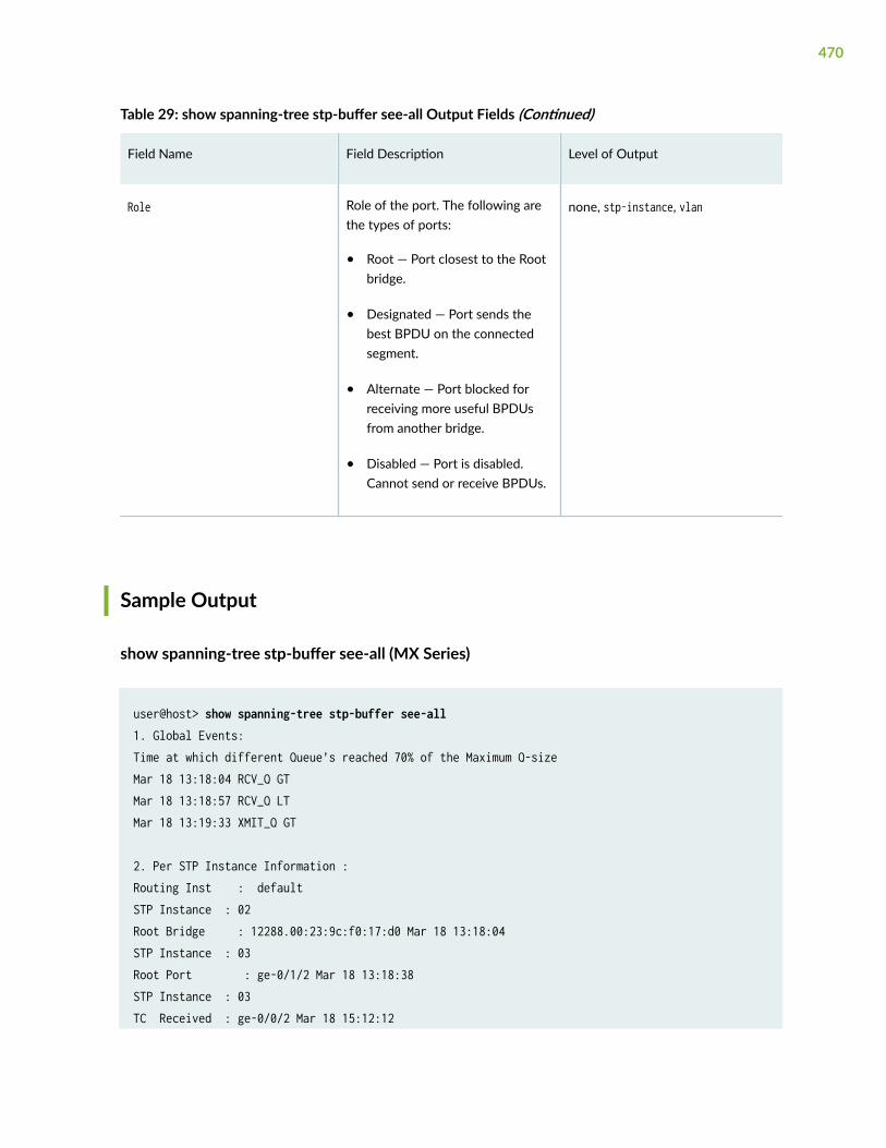
Table 29: show spanning-tree stp-buffer see-all Output Fields (Continued)
Field Name Field Description Level of Output
Role Role of the port. The following arethe types of ports:
• Root — Port closest to the Rootbridge.
• Designated — Port sends thebest BPDU on the connectedsegment.
• Alternate — Port blocked forreceiving more useful BPDUsfrom another bridge.
• Disabled — Port is disabled.Cannot send or receive BPDUs.
none, stp-instance, vlan
Sample Output
show spanning-tree stp-buffer see-all (MX Series)
user@host> show spanning-tree stp-buffer see-all1. Global Events:Time at which different Queue’s reached 70% of the Maximum Q-sizeMar 18 13:18:04 RCV_Q GTMar 18 13:18:57 RCV_Q LTMar 18 13:19:33 XMIT_Q GT 2. Per STP Instance Information : Routing Inst : defaultSTP Instance : 02Root Bridge : 12288.00:23:9c:f0:17:d0 Mar 18 13:18:04STP Instance : 03Root Port : ge-0/1/2 Mar 18 13:18:38STP Instance : 03TC Received : ge-0/0/2 Mar 18 15:12:12
470

STP Instance : 03TC Generated: ge-0/2/2 Mar 18 15:13:27
3. This section will print the time stamp for per Instance – port event changes.STP Instance : 02 Port : ge-1/0/0 Mar 22 13:35:02State : FWD SRole : DESG
STP Instance : 00Port : ge-0/0/3 Mar 22 14:03:46State : BLKRole : ALT RSTP Instance : 00Port : ge-1/0/0 Mar 28 02:03:49State : BLK SRole : ALT
show spanning-tree stp-buffer see-all stp-instance stp-instance-id routing-instance instance-name (MX Series)
user@host> show spanning-tree stp-buffer see-all stp-instance 0 routing-instance mstp_inst
1. Global Events:Time at which different Queue's reached 70% of the Maximum Q-sizeNo Entry So far
2. Per STP Instance Information :
Routing Inst : mstp_inst STP Instance : 0 TC Generated : ge-3/0/5.32767 Tue Dec 17 06:00:50 2013 STP Instance : 0 TC Generated : ge-3/1/1.32767 Tue Dec 17 06:00:50 2013 STP Instance : 0 TC Received : ge-3/0/5.32767 Tue Dec 17 06:00:50 2013 STP Instance : 0
471

TC Received : ge-3/0/5.32767 Tue Dec 17 06:00:50 2013 STP Instance : 0 TC Received : ge-3/0/5.32767 Tue Dec 17 06:00:51 2013 STP Instance : 0 TC Received : ge-3/0/5.32767 Tue Dec 17 06:00:53 2013
3. This section will print the time stamp for per Instance, Port Event changes.
STP Instance : 0 Port : ge-3/0/5.32767 Tue Dec 17 06:00:49 2013 State : BLK S Role : DIS
STP Instance : 0 Port : ge-3/0/5.32767 Tue Dec 17 06:00:49 2013 State : BLK Role : DESG R
STP Instance : 0 Port : ge-3/1/1.32767 Tue Dec 17 06:00:49 2013 State : BLK S Role : DIS
STP Instance : 0 Port : ge-3/1/1.32767 Tue Dec 17 06:00:49 2013 State : BLK Role : DESG R
STP Instance : 0 Port : ge-3/0/5.32767 Tue Dec 17 06:00:50 2013 State : FWD S Role : DESG
STP Instance : 0 Port : ge-3/1/1.32767 Tue Dec 17 06:00:50 2013 State : FWD S Role : DESG
472

show spanning-tree stp buffer see-all vlan vlan-id routing-instance instance-name (MX Series)
user@host> show spanning-tree stp-buffer see-all vlan 10 routing-instance vstp_inst1. Global Events:Time at which different Queue’s reached 70% of the Maximum Q-sizeMar 18 13:18:04 RCV_Q GTMar 18 13:18:57 RCV_Q LTMar 18 13:19:33 XMIT_Q GT 2. Per STP Instance Information : Routing Inst : defaultVLAN ID : 02Root Bridge : 12288.00:23:9c:f0:17:d0 Mar 18 13:18:04VLAN ID : 03Root Port : ge-0/1/2 Mar 18 13:18:38VLAN ID : 03TC Received : ge-0/0/2 Mar 18 15:12:12VLAN ID : 03TC Generated: ge-0/2/2 Mar 18 15:13:27
3. This section will print the time stamp for per Instance – port event changes.VLAN ID : 02 Port : ge-1/0/0 Mar 22 13:35:02State : FWD SRole : DESG
VLAN ID : 00Port : ge-0/0/3 Mar 22 14:03:46State : BLKRole : ALT RVLAN ID : 00Port : ge-1/0/0 Mar 28 02:03:49State : BLK SRole : ALT
Release Information
Command introduced in Junos OS Release 14.1.
473