Paragon Automation Installation Guide | Juniper Networks
196
Paragon Automaon Installaon Guide Published 2022-06-13 RELEASE 21.3
-
Upload
khangminh22 -
Category
Documents
-
view
0 -
download
0
Transcript of Paragon Automation Installation Guide | Juniper Networks

Paragon Automation Installation Guide
Published
2022-06-13
RELEASE
21.3

Juniper Networks, Inc.1133 Innovation WaySunnyvale, California 94089USA408-745-2000www.juniper.net
Juniper Networks, the Juniper Networks logo, Juniper, and Junos are registered trademarks of Juniper Networks, Inc.in the United States and other countries. All other trademarks, service marks, registered marks, or registered servicemarks are the property of their respective owners.
Juniper Networks assumes no responsibility for any inaccuracies in this document. Juniper Networks reserves the rightto change, modify, transfer, or otherwise revise this publication without notice.
Paragon Automation Installation Guide21.3Copyright © 2022 Juniper Networks, Inc. All rights reserved.
The information in this document is current as of the date on the title page.
YEAR 2000 NOTICE
Juniper Networks hardware and software products are Year 2000 compliant. Junos OS has no known time-relatedlimitations through the year 2038. However, the NTP application is known to have some difficulty in the year 2036.
END USER LICENSE AGREEMENT
The Juniper Networks product that is the subject of this technical documentation consists of (or is intended for usewith) Juniper Networks software. Use of such software is subject to the terms and conditions of the End User LicenseAgreement ("EULA") posted at https://support.juniper.net/support/eula/. By downloading, installing or using suchsoftware, you agree to the terms and conditions of that EULA.
ii

Table of Contents
About This Guide | vi
1 Introduction
Paragon Automation Portfolio Installation Overview | 2
2 System Requirements
Paragon Automation System Requirements | 8
3 Install Paragon Automation On Ubuntu
Installation Prerequisites on Ubuntu | 21
Prepare the Control Host | 22
Prepare Cluster Nodes | 24
Virtual IP Address Considerations | 29
Configure DNS Server (Optional) | 37
Install Multinode Cluster on Ubuntu | 37
Download the Paragon Automation Software | 38
Install Paragon Automation | 39
Log in to the Paragon Automation UI | 57
Modify cRPD Configuration | 57
Install Single-Node Cluster on Ubuntu | 61
Download the Software | 62
Install Paragon Automation | 62
Log in to the Paragon Automation UI | 76
Modify cRPD Configuration | 77
4 Install Paragon Automation On CentOS
Installation Prerequisites on CentOS | 82
Prepare the Control Host | 83
iii

Prepare Cluster Nodes | 85
Virtual IP Address Considerations | 91
DNS Server Configuration (Optional) | 99
Install Multi-Node Cluster on CentOS | 99
Download the Software | 100
Install Paragon Automation | 101
Log in to the Paragon Automation UI | 118
Modify cRPD Configuration | 119
Install Single Node Cluster on CentOS | 122
Download the Software | 123
Install Paragon Automation | 124
Log in to the Paragon Automation UI | 138
Modify cRPD Configuration | 139
5 Upgrade and Update Paragon Automation
Upgrade to Paragon Automation Release 21.3 | 144
Reinstall Paragon Automation | 146
Edit Cluster Nodes | 147
Edit Primary Nodes in Multi-Primary NodeClusters and Worker Nodes in All Clusters | 148
Edit Primary Nodes in Single-Primary Node Clusters | 149
Uninstall Paragon Automation | 151
6 Backup and Restore
Backup and Restore | 153
Back Up the Configuration | 154
Restore the Configuration | 157
7 Troubleshooting
Troubleshoot Paragon Automation Installation | 161
Resolve Merge Conflicts of the Configuration File | 161
iv

Resolve Common Backup and Restore Issues | 162
View Installation Log Files | 162
View Log Files in Kibana | 162
Troubleshooting Using the kubectl Interface | 163
View Node Status | 166
View Pod Status | 166
View Detailed Information About a Pod | 167
View the Logs for a Container in a Pod | 167
Run a Command on a Container in a Pod | 167
View Services | 168
Frequently Used kubectl Commands | 169
Troubleshoot Ceph and Rook | 169
Disable udevd Daemon During OSD Creation | 173
Wrapper Scripts for Common Utility Commands | 174
Back Up the Control Host | 174
User Service Accounts for Debugging | 175
8 Migrate Data
Migrate Data from NorthStar to Paragon Automation | 177
Prerequisites | 177
Create the nsmigration Task Pod | 179
Export Cassandra DB Data to CSV Files | 179
Migrate DeviceProfile and Cassandra DB | 182
(Optional) Migrate Analytics Data | 185
(Optional) Migrate NorthStar Planner Data | 188
v

About This Guide
Use this guide to install Paragon Automation on a Linux server.
RELATED DOCUMENTATION
Paragon Automation User Guide
Paragon Automation Release Notes, Release 21.3
vi

1CHAPTER
Introduction
Paragon Automation Portfolio Installation Overview | 2

Paragon Automation Portfolio Installation Overview
Juniper® Paragon™ Automation Portfolio is a cloud-ready solution for network planning, configuration,provisioning, traffic engineering, monitoring, and life-cycle management. This solution brings advancedvisualization capabilities and analytics to network management and monitoring. Paragon Automationoffers base platform support for Juniper Networks devices and some third-party devices.
This guide describes how to install Paragon Automation and is intended for network operators andadministrators who install, configure, and manage the network infrastructure. You deploy ParagonAutomation as the following set of on-premises (customer managed) microservices-based applications:
• Paragon Insights (previously known as HealthBot)
• Paragon Planner (previously known as NorthStar Planner)
• Paragon Pathfinder (previously known as NorthStar Controller)
When you install Paragon Automation, you can install these three applications at the same time. Afterinstallation is complete, you can use these applications only if you have the software licenses installed.
Figure 1: Paragon Automation Portfolio
Communication between the different components of Paragon Automation, and between ParagonAutomation and the managed devices as well as the network administrator, happens through a controlplane network. The control plane network can be the same as the management network (over interfacessuch as fxp0 in devices running Junos OS), or any other non-management network (over interfaces suchas ge-0/0/0 in devices running Junos OS). This communication includes protocols and services such as
2

Path Computation Element Protocol (PCEP), BGP Link State (BGP-LS), HTTPS (Web UI), system logging(syslog), SNMP, and NETCONF.
Figure 2: Communication Paths
Paragon Automation Deployment Architecture
3

Paragon Automation applications are installed on a Kubernetes cluster, which you can can access over acontrol plane network through a Web UI. Figure 3 on page 4 illustrates typical Paragon AutomationDeployment architectures and their communication protocols.
Figure 3: Deployment Architecture
4

The Paragon Automation Kubernetes cluster is a collection of microservices that interact with oneanother through APIs. The Kubernetes cluster comprises multiple nodes that are configured withdifferent roles. For more information about roles, see "Cluster Node Roles" on page 10.
Figure 4: Kubernetes Cluster
Paragon Automation Installation
You use Ansible playbooks to automate the installation of Paragon Automation software. The playbooksinstall the required software on all the cluster nodes. These Ansible playbooks are packaged in a Dockerimage, and executed on a separate dedicated host (control host), which should have Docker installed,and can mount local directories into a Docker container. You must have a dedicated machine functioningas the control host.
Figure 5: Installation Overview
5

To install Paragon Automation, you:
• Download an installation bundle to the control host.
• Create and customize the required installation and configuration files.
• Run the installer on the control host.
, . You must download the installation bundle into the control host and perform the installation from thishost.
The installation is controlled through several variables that are defined in the installation andconfiguration files created during the installation process. Based on these files, the Ansible playbooksdeploy the Kubernetes cluster.
This guide describes how to install Paragon Automation and is intended for network operators andadministrators who install, configure, and manage the network infrastructure. This guide explains howto:
• Install and upgrade Paragon Automation.
• Uninstall Paragon Automation.
• Add and remove nodes.
• Back up and restore a configuration.
• Migrate data from your existing setup to Paragon Automation.
• Perform common installation troubleshooting tasks.
RELATED DOCUMENTATION
Paragon Automation Overview
Paragon Automation System Requirements | 8
6

2CHAPTER
System Requirements
Paragon Automation System Requirements | 8

Paragon Automation System Requirements
IN THIS SECTION
Hardware Requirements | 11
Software Requirements | 13
Disk Requirements | 14
Network Requirements | 16
Web Browser Requirements | 18
Installation on VMs | 18
Before you install the Paragon Automation software, ensure that your system meets the requirementsthat we describe in these sections.
To determine the resources required to implement Paragon Automation, you must understand thefundamentals of the Paragon Automation underlying infrastructure.
Paragon Automation is a collection of microservices that interact with one another through APIs and runwithin containers in a Kubernetes cluster. A Kubernetes cluster is a set of nodes or machines runningcontainerized applications. Each node is a single machine, either physical (bare-metal server) or virtual(virtual machine).
The nodes within the cluster provide the following three different roles or functions depending on howthey are configured.
• Control plane (primary) node—Implements the control plane, which monitors the state of the cluster,manages the worker nodes, schedules application workloads, and manages the life cycle of theworkloads.
• Compute (worker) node—Performs tasks that the control plane node assigns , and hosts the pods andcontainers that execute the application workloads. Each worker node hosts one or more pods thatare collections of containers.
A node can function as both primary and worker.
8

• Storage node—Provides storage for objects, blocks, and files within the cluster. In ParagonAutomation, Ceph provides storage services in the cluster. A storage node must be in a worker node,although not every worker node needs to provide storage.
Figure 6: Kubernetes Cluster Nodes and Roles
A Kubernetes cluster comprises several primary nodes and worker nodes. The worker nodes may or maynot provide storage.
9

The total number of nodes in the cluster, the amount of resources on each node (CPU, memory, diskspace), and the number of nodes acting as primary, worker, or storage nodes, depend on the intendedcapacity of the system, whether high availability is required, and the expected performance.
Figure 7: Kubernetes Cluster
Paragon Automation Implementation
You implement Paragon Automation on top of a Kubernetes cluster. A Paragon Automationimplementation consists of one or more primary nodes and one or more worker nodes. You require aminimum of one primary node and one worker node for a functional cluster. You can implement ParagonAutomation in two different ways:
• Single-node implementation—A single-node implementation comprises one node, either a virtualmachine (VM) or a bare-metal server (BMS), acting as primary, worker, and storage node. When youinstall Paragon Automation with a single node, you must configure the node as "master" in theinventory.yml file and also select Master Scheduling during installation. For more information see,"Install Single-Node Cluster on Ubuntu" on page 61 or "Install Single Node Cluster on CentOS" onpage 122.
NOTE: You must use a single-node setup only as proof of concept (POC) or for labdeployment and not for production deployments.
• Multinode Implementation—A multinode implementation comprises multiple nodes, either VMs orBMSs, where at least one node acts as primary and another node acts as worker and providesstorage. You can implement high availability with a multinode implementation as follows:
• Control plane high availability—For control plane redundancy, you must have a minimum of threeprimary nodes. You can add more primary nodes as long as the total number of primary nodes isan odd number.
10

When you install Paragon Automation with multiple primary nodes, you must configure aKubernetes Master Virtual IP address and select Install Loadbalancer for Master Virtual IPaddress . For more information, see "Install Multinode Cluster on Ubuntu" on page 37 or "InstallMulti-Node Cluster on CentOS" on page 99.
• Workload high availability—For workload high availability and workload performance, you musthave more than one worker. You can add more workers to the cluster as needed.
• Storage high availability—For storage high availability, you must have at least three nodes forCeph storage. You must enable Master Scheduling during installation if you want any of theprimary nodes to provide Ceph storage. Enabling master scheduling allows the primary to act as aworker as well.
You could implement a setup that provides redundancy in different ways, as shown in the examplesin Figure 8 on page 11.
Figure 8: Multinode Redundant Setups
NOTE: For Paragon Automation production deployments, we recommend that you have afully redundant setup with a minimum of three primary nodes (multi-primary node setup), anda minimum of three worker nodes providing Ceph storage. You must enable masterscheduling during the installation process.
Hardware Requirements
This section lists the minimum hardware resources required for the Ansible control host node and theprimary and worker nodes of a Paragon Automation cluster.
11

The compute, memory, and disk requirements of the Ansible control host node are not dependent onthe implementation type (single or multinode) of the cluster or the intended capacity of the system. Thefollowing table shows the requirements for the Ansible control host node:
Node Minimum HardwareRequirement
Storage Requirement Role
Ansible control host 2–4-core CPU, 12-GBRAM, 100-GB HDD
NA
No disk partitions or extradisk space required
Carry out Ansibleoperations to install thecluster.
In contrast, the compute, memory, and disk requirements of the cluster nodes vary widely based on theimplementation type (single-node or multinode) and the intended capacity of the system. The intendedcapacity includes the number of devices to be monitored, type of sensors, frequency of telemetrymessages, and number of playbooks and rules. If you increase the number of device groups, devices, orplaybooks, you'll need higher CPU and memory capacities.
The following table summarizes the minimum hardware resources required per node for a successfulinstallation of a multinode cluster.
Table 1: Minimum Hardware Requirements Per Node for Multinode Deployments
Node Minimum HardwareRequirement
Storage Requirement Role
Primary or worker node 8-core CPU, 32-GB RAM,200 GB including Cephstorage
Minimum 1000 IOPS forthe disks
The cluster must include aminimum of three storagenodes. Each node musthave an unformatted diskpartition or a separateunformatted disk, with atleast 30-GB space, forCeph storage.
See "Disk Requirements"on page 14.
Kubernetes primary orworker node
The following table summarizes the minimum hardware resources required for successful installation ofa single-node cluster.
12

Table 2: Minimum Hardware Requirements Per Node for Single-Node Deployments
Node Minimum HardwareRequirement
Storage Requirement Role
Primaryor worker node 8-core CPU, 32-GB RAM,200-GB storage (includingCeph storage)
Minimum 1000 IOPS forthe disks
The node must have anunformatted diskpartition or a separateunformatted disk, withminimum 30-GB space,for Ceph storage. See"Disk Requirements" onpage 14.
Kubernetes primary orworker node
NOTE: SSDs are mandatory on bare-metal servers.
Here, we've listed only minimum requirements for small deployments supporting up to two devicegroups. In such deployments, each device group may comprise two devices and two to threeplaybooksacross all Paragon Automation components. See the Paragon Automation User Guide forinformation about devices and device groups.
NOTE: To get a scale and size estimate of a production deployment and to discuss detaileddimensioning requirements, contact your Juniper Partner or Juniper Sales Representative.
Software Requirements
• You must install a base OS of Ubuntu version 18.04.04 or later, CentOS version 7.6 or later, or RHELversion 8 or later on all nodes. The nodes must run the same OS (Ubuntu, CentOS, or RHEL) versionof Linux.
Paragon Automation Release 21.3 is qualified to work with the following OS versions:
• Ubuntu versions 18.04.05 LTS (Bionic Beaver) and 20.04.02 LTS (Focal Fossa)
• CentOS 7.9 Minimal ISO
• RHEL version 8.3 on a limited-scale deployment of two nodes with one primary and one worker
13

• You must have Docker installed on the Ansible control host. The control host is where the installationpackages are downloaded and the Ansible installation playbooks are executed. For more information,see "Installation Prerequisites on Ubuntu" on page 21 and "Installation Prerequisites on CentOS" onpage 82.
If you are using Docker CE, we recommend version is 18.09 and later.
If you are using Docker EE, we recommend version is 18.03.1-ee-1 and later. Also, to use Docker EE,you must install Docker EE on all the cluster nodes acting as primary and worker nodes in addition tothe control host.
Docker enables you to run the Paragon Automation installer file, which is packaged with Ansible(version 2.9.5) and the roles and playbooks that are required to install the cluster.
NOTE: Installation will fail if you don't have the correct versions. We've described the commandsto verify these versions in subsequent sections in this guide.
Disk Requirements
The following disk requirements apply to the primary and worker nodes, in both single-node andmultinode deployments:
• Disk must be SSD.
• Required partitions:
• You must mount the root partition at /.
If you create the optional data and Docker partitions, then the root partition must have at least20-GB space.
If you do not create the optional data and Docker partitions, you must add their minimum storagerequirements to the root partition. In this case, the root partition must have at least 170-GBspace.
• The unformatted partition for Ceph storage must have at least 30-GB space.
NOTE: Instead of using this partition, you can use a separate unformatted disk with atleast 30-GB space for Ceph storage.
• Additional (optional) partitions:
14

• Docker partition mounted at /var/lib/docker with at least 50-GB space.
• Data partition mounted at /export with at least 50-GB space. You use the data partition forPostgres, Zookeeper, Kafka, and Elasticsearch.
• Data partition mounted at /var/local with at least 50-GB space. You use this data partition forParagon Insights Influxdb.
You can mount /export and /var/local on the same partition, but you must mount /var/lib/docker ona separate file system to increase the stability of the cluster. If one of the databases fills up itsavailable disk space, Kubernetes can respond by shutting down applications and rescheduling themon other nodes.
After you create the disk partitions, the partitions look similar to those illustrated in Figure 9 on page15.
Figure 9: Recommended Disk Partitions
In this example:
/dev/disk1 ext4 / is the root partition.
15
/dev/disk1 ext4 /var/lib/docker is the Docker partition.
/dev/disk1 ext4 /export is the export data partition.
/dev/disk1 ext4 /var/lib/local is the Influxdb data partition.
/dev/disk2 with no filesystem and no mount point is the unformatted partition for Ceph.
Disk names might vary depending on your system.
Network Requirements
• All nodes must run NTP or other time-synchronization at all times.
• An SSH server must be running on all nodes. You need a common SSH username and password for allnodes.
• You must configure DNS on all nodes.
• All nodes need Internet connection.
• You must allow intercluster communication between the nodes. In particular, you must keep theports listed in Table 3 on page 16 open for communication. Ensure that you check for any iptablesentry on the servers that might be blocking any of these ports.
Table 3: Ports That Must Be Allowed by Firewalls
Port Numbers Purpose
Enable these ports on all cluster nodes for administrative user access.
80 HTTP (TCP)
443 HTTPS (TCP)
7000 Paragon Planner communications (TCP)
Enable these ports on all cluster nodes for communication with network elements.
67 ztpservicedhcp (UDP)
161 SNMP, for telemetry collection (UDP)
16

Table 3: Ports That Must Be Allowed by Firewalls (Continued)
Port Numbers Purpose
162 ingest-snmp-proxy-udp (UDP)
11111 hb-proxy-syslog-udp (UDP)
4000 ingest-jti-native-proxy-udp (UDP)
830 NETCONF communication (TCP)
7804 NETCONF callback (TCP)
4189 PCEP Server (TCP)
30000-32767 Kubernetes port assignment range (TCP)
Enable communication between cluster nodes on all ports. At the least, open the following ports.
6443 Communicate with worker nodes in the cluster (TCP)
3300 ceph (TCP)
6789 ceph (TCP)
6800-7300 ceph (TCP)
6666 calico etcd (TCP)
2379 etcd client requests (TCP)
2380 etcd peer communication (TCP)
9080 cephcsi (TCP)
9081 cephcsi (TCP)
7472 metallb (TCP)
7964 metallb (TCP)
17

Table 3: Ports That Must Be Allowed by Firewalls (Continued)
Port Numbers Purpose
179 calico (TCP)
10250-10256 Kubernetes API communication (TCP)
Enable this port between the control host and the cluster nodes.
22 TCP
Web Browser Requirements
Table 4 on page 18 lists the 64-bit Web browsers that support Paragon Automation.
Table 4: Supported Web Browsers
Browser Supported Versions Supported OS Versions
Chrome 85 and later Windows 10
Firefox 79 and later Windows 10
Safari 14.0.3 MacOS 10.15 and later
Installation on VMs
Paragon Automation can be installed on virtual machines (VMs). The VMs can be created on anyHypervisor, but must fulfill all the size, software, and networking requirements described in this topic.
The VMs must have the recommended base OS installed. The installation process for VMs and bare-metal servers is the same.
18

RELATED DOCUMENTATION
Installation Prerequisites on CentOS | 82
Install Multi-Node Cluster on CentOS | 99
Installation Prerequisites on Ubuntu | 21
Install Multinode Cluster on Ubuntu | 37
19

3CHAPTER
Install Paragon Automation OnUbuntu
Installation Prerequisites on Ubuntu | 21
Install Multinode Cluster on Ubuntu | 37
Install Single-Node Cluster on Ubuntu | 61

Installation Prerequisites on Ubuntu
IN THIS SECTION
Prepare the Control Host | 22
Prepare Cluster Nodes | 24
Virtual IP Address Considerations | 29
Configure DNS Server (Optional) | 37
To successfully install and deploy a Paragon Automation cluster, you must have a control host thatinstalls the distribution software on a single node or on multiple cluster nodes. You can download thedistribution software on the control host and then create and configure the installation files to run theinstallation from the control host. You must have Internet access to download the packages on thecontrol host. You must also have Internet access on the cluster nodes to download any additionalsoftware such as Docker and OS patches. The order of installation tasks is shown at a high level inFigure 10 on page 21.
Figure 10: High-Level Process Flow for Installing Paragon Automation
Before you download and install the distribution software, you must configure the control host and thecluster nodes as described in this topic.
21

Prepare the Control Host
The control host is a dedicated machine that that you use to orchestrate the installation and upgrade ofa Paragon Automation cluster. It carries out the Ansible operations that run the software installer andinstall the software on the cluster nodes as illustrated in Control Host Functions on page 22.
You must download the installer packages on the Ansible control host. As part of the ParagonAutomation installation process, the control host installs any additional packages required on the clusternodes. The packages include optional OS packages, Docker, and Elasticsearch. Your control noderequires Internet access to download software. All microservices, including third-party microservices, aredownloaded onto the control host. The microservices do not access any public registries duringinstallation.
The control host can be on a different broadcast domain from the cluster nodes, although werecommend that you set up the nodes in the same domain. In either case, you must ensure that thecontrol host can use SSH to connect to all the nodes.
Figure 11: Control Host Functions
After installation is complete, the control host plays no role in the functioning of the cluster.However,you'll need the control host to update the software or any component, make changes to thecluster, or re-install it if a node fails. You can also use the control host to archive configuration files. Werecommend that you keep the control host available, and not use it for something else, after installation.
Prepare the control host for the installation process as follows:
1. Install the base OS—Install Ubuntu version 18.04.04 (or later). Paragon Automation Release 21.3 isqualified to work with Ubuntu versions 18.04.05 LTS (Bionic Beaver) and 20.04.02 LTS (Focal Fossa).
2. Install Docker—Install and configure Docker on the control host to implement the Linux containerenvironment. Paragon Automation supports Docker CE and Docker EE. The Docker version you
22

choose to install in the control host is independent of the Docker version you plan to use in thecluster nodes.
If you want to install Docker EE, ensure that you have a trial or subscription before installation. Formore information about Docker EE, supported systems, and installation instructions, see https://www.docker.com/blog/docker-enterprise-edition/.
To download and install Docker CE, perform the following steps:
# sudo apt-get install -y apt-transport-https ca-certificates curl gnupg-agent software-properties-common# curl -fsSL https://download.docker.com/linux/ubuntu/gpg | sudo apt-key add -# sudo add-apt-repository "deb [arch=amd64] https://download.docker.com/linux/ubuntu $(lsb_release -cs) stable"# sudo apt-get update# sudo apt-get install -y docker-ce docker-ce-cli containerd.io
To verify that Docker is installed and running, use the # docker run hello-world command.
To verify the Docker version installed, use the # docker version or # docker --version commands.
For full instructions and more information, see https://docs.docker.com/engine/install/ubuntu/.
3. Configure SSH client authentication—The installer running on the control host connects to the clusternodes using SSH. The user account used for SSH authentication must be root or a non-root accountwith superuser (sudo) privileges. We will refer to this account as the install user account insubsequent steps. You must ensure that the install user account is configured on all the nodes in thecluster. The installer will use the inventory file to determine which username to use, and whether theauthentication will use ssh-keys or a password. See Customize the Inventory File - MultinodeImplementation or Customize the Inventory File - Single Node Implementation.
If you choose the ssh-key authentication (recommended) method, generate the SSH keys.
# cd ~/.ssh# ssh-keygen -t rsa Generating public/private rsa key pair.Enter file in which to save the key (/root/.ssh/id_rsa): <= ENTER (use default)Enter passphrase (empty for no passphrase): <= ENTER (no passphrase)Enter same passphrase again: <= ENTER (no passphrase)Your identification has been saved in /root/.ssh/id_rsa.Your public key has been saved in /root/.ssh/id_rsa.pub.The key fingerprint is:SHA256:YS8cWopND9RFnpHGqaI1Q8e5ca2fxP/yMVzZtIDINbg root@Control1The key's randomart image is:+---[RSA 2048]----+
23

| ..o *=+ || ..= *o*oo || . .o==*+. . .|| =+oO.Eo ..+|| o.++ So.o oo|| . .o .. . || .+ || . .o || o. |+----[SHA256]-----+
If you want to protect the SSH key with a passphrase, you can use ssh-agent. See https://www.ssh.com/academy/ssh/agent.
NOTE: You'll need to copy this key to the nodes as part of the cluster nodes preparationtasks, as described in the next section.
4. (Optional) Install wget—Install the wget tool to download the Paragon Automation distributionsoftware.
# apt install wget
Alternatively, you can use rsync or any other file download software to copy the distribution software.
Prepare Cluster Nodes
The primary and worker nodes are collectively called cluster nodes. Each cluster node must have at leastone static and unique IP address, as illustrated in Figure 12 on page 25. When configuring thehostnames, use only lowercase letters, and do not include any special characters other than “-” or “.”. Ifthe implementation has a separate IP network to provide communication between the ParagonAutomation components, as described in the overview section, the IP addresses in that separatenetwork do not need to be reachable outside the cluster. However, you must assign a second set of IPaddresses assigned to the worker nodes., These IP addresses will help devices from outside the clusterto reach the worker nodes, and enable communication between Paragon Automation and the manageddevices or between Paragon Automation and the network administrator.
24

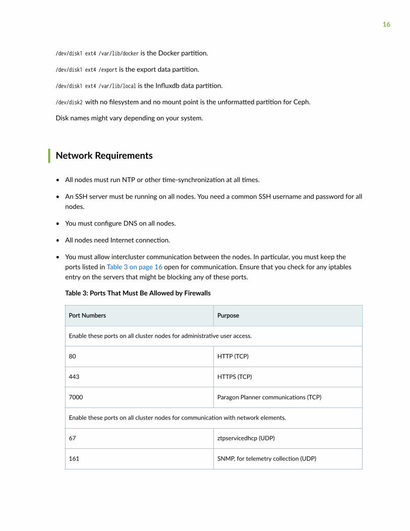
We recommend that you place all the nodes in the same broadcast domain. For cluster nodes indifferent broadcast domains, see "Configure Load Balancing" on page 36 for additional load balancingconfiguration.
Figure 12: Cluster Node Functions
As described in "Paragon Automation System Requirements" on page 8, you can install ParagonAutomation using a single-node or a multinode deployment. The node installation prerequisites are thesame for both multinode and single-node deployments, except for storage requirements.
1. Configure raw disk storage—The cluster nodes must have raw storage block devices withunpartitioned disks or unformatted disk partitions attached. You can also partition the nodes suchthat the root partition and other file systems can use a portion of the disk space available. You mustleave the remaining space unformatted, with no file systems, and reserve it for Ceph to use. For moreinformation, see "Disk Requirements" on page 14.
NOTE: You don't need to install or configure anything to allow Ceph storage to use theunpartitioned disks or unformatted disk partitions. This will be assigned automatically duringthe installation process.
For multinode clusters, you must have a minimum of three cluster nodes with storage spaceattached.
For a single-node cluster, the single node must have storage space.
Installation fails if unformatted disks are not available.
25

Ceph requires newer Kernel versions. If your Linux kernel is very old, consider upgrading orreinstalling a new one. For a list of minimum Linux kernel versions supported by Ceph for your OS,see https://docs.ceph.com/en/latest/start/os-recommendations. To upgrade your Linux kernelversion, see Upgrade your Ubuntu Linux Kernel Version.
NOTE: Ceph does not work on Linux kernel version 4.15.0-55.60.
2. Install the base OS—Install Ubuntu version 18.04.04 (or later) on all nodes. Paragon AutomationRelease 21.3 is qualified to work with Ubuntu versions 18.04.05 LTS (Bionic Beaver) and 20.04.02LTS (Focal Fossa).
3. Create install-user account—The install user is the user that the Ansible playbooks use to log in to theprimary and worker nodes and perform all the installation tasks. Ensure that you configure either aroot password or an account with superuser (sudo) privileges. You will add this information to theinventory file during the installation process.
Set the root user password.
# passwd rootNew password:Retype new password:passwd: password updated successfully
4. Install SSH authentication—. The installer running on the control host connects to the cluster nodesthrough SSH using the install-user account.
a. Log in to the cluster nodes. and install the open-ssh server on all nodes.
b. Edit the sshd_config file..
# vi /etc/ssh/sshd_config
c. If you are using a root password for the install-user account, then permit root login.
PermitRootLogin yes
If you choose to use plain text password for authentication, then you must enable passwordauthentication.
PasswordAuthentication yes
We do not recommend the use of password authentication.
d. If you changed /etc/ssh/sshd_config, restart the SSH daemon.
# systemctl restart sshd
e. Log in to the control host:
26

i. To allow authentication using the SSH key, copy id_rsa.pub to the cluster nodes.
# ssh-copy-id -i ~/.ssh/id_rsa.pub cluster-node-IP-or-hostname
Repeat this step for all the nodes in the cluster (primary and workers). cluster-node-IP is theunique address of the node as shown in Figure 12 on page 25. If a hostname is used instead,the Ansible control host should be able to resolve the name to its IP address.
ii. SSH into the cluster node. You don't need a password to log in.
To verify connectivity. Use the Install User Account to ssh.
You should be able to use SSH to connect to all nodes in the cluster (primary and workers)from the control host using theinstall-use account. If you are not able to log in, review theprevious steps and make sure that you didn't miss anything.
5. Install Docker—Select one of the following Docker versions to install.
• Docker CE—If you want to use Docker CE, you do not need to install it on the cluster nodes. Thedeploy script installs Docker CE on the nodes during Paragon Automation installation.
• Docker EE—If you want to use Docker EE, you must install Docker EE on all the cluster nodes. Ifyou install Docker EE on the nodes, the deploy script uses the installed version and does notattempt to install Docker CE in its place. For more information about Docker EE and supportedsystems, and for instructions to download and install Docker EE, see https://www.docker.com/blog/docker-enterprise-edition/.
The Docker version you choose to install in the cluster nodes is not dependent on the Docker versioninstalled in the control host.
6. Install Python—Install Python 3, if it is not preinstalled with your OS, on the cluster nodes:
# apt install python3
To verify the Python version installed, use the # python3 -V or # python3 --version command.
7. Use the # apt list --installed command and ensure that the following packages are installed:
apt-transport-https, bash-completion, gdisk, iptables, lvm2, openssl
8. Install and enable NTP—All nodes must run Network Time Protocol (NTP) or any other time-synchronization protocol at all times. By default, Paragon Automation installs the Chrony NTP client.If you don't want to use Chrony, you can manually install NTP on all nodes.
a. Install ntpdate to synchronize date and time by querying an NTP server.
# apt install ntpdate -y
b. Run the following command twice to reduce the offset with the NTP server.
# ntpdate ntp-server
27

c. Install the NTP protocol.
# apt install ntp -y
d. Configure the NTP server pools.
# vi /etc/ntp.conf
e. Replace the default Ubuntu pools with the NTP server closest to your location in the ntp.conf file.
server ntp-server prefer iburst
Save and exit the file.
f. Restart the NTP service.
# systemctl restart ntp
g. Confirm that the system is in sync with the NTP server.
# timedatectl
9. (Optional) Upgrade your Ubuntu Linux kernel versionTo upgrade the kernel version of your Ubuntuserver to the latest LTS version to meet the requirements for Paragon Automation installation:
a. Log in as the root user.
b. Check the existing kernel version:
root@server# uname -msr
If the Linux kernel version is earlier than 4.15, upgrade the kernel.
c. Update apt repositories:
root@server# apt update
d. Upgrade existing software packages, including kernel upgrades:
root@server# apt upgrade -y
root@server# apt install --install-recommends linux-generic-hwe-xx.xx
Here, xx.xx is your Ubuntu OS version.
e. Reboot the server to load the new kernel:
root@server# reboot
f. Verify the new kernel version:
root@server# uname -msr
28

Virtual IP Address Considerations
IN THIS SECTION
VIP Address for Multi-Primary Node Deployment | 35
Configure Load Balancing | 36
The Kubernetes worker nodes host the pods that handle the workload of the applications.
A pod is the smallest deployable unit of computing created and managed in Kubernetes. A pod containsone or more containers, with shared storage and network resources, and with specific instructions onhow to run the applications. Containers are the lowest level of processing, and you execute applicationsor microservices in containers.
The primary node in the cluster determines which worker node will host a particular pod and containers.
You implement all features of Paragon Automation using a combination of microservices. You need tomake some of these microservices accessible from outside the cluster as they provide services to endusers (managed devices) and administrators. For example, you must make the pceserver serviceaccessible to establish PCEP sessions between provider edge (PE) routers and Paragon Automation.
You need to expose these services outside of the Kubernetes cluster with specific addresses that arereachable from the external devices. Because a service can be running on any of the worker nodes at agiven time, you must use virtual IP addresses (VIPs) as the external addresses. You must not use theaddress of any given worker node as an external address.
29

In this example:
Consider that WORKER1_IP = 10.1.x.3 and WORKER2_IP = 10.1.x.4.
SERVICE IP = PCEP VIP = 10.1.x.200
PCC_IP = 10.1.x.100
Paragon Automation uses one of two methods of exposing services outside the cluster:
• Load balancer—Each load balancer is associated with a specific IP address and routes external trafficto a specific service in the cluster. This is the default method for many Kubernetes installations in thecloud. The load balancer method supports multiple protocols and multiple ports per service. Eachservice has its own load balancer and IP address.
Paragon Automation uses the load balancer MetalLB.
• Ingress—The ingress method acts as a proxy to bring traffic into the cluster, and then uses internalservice routing to route the traffic to its destination. Under the hood, this method also uses a loadbalancer service to expose itself to the world so it can act as that proxy.
Paragon Automation uses the following ingress proxies:
30

• Ambassador
• Nginx
• HAProxy
Devices from outside the cluster need to access the following services and thus these services require aVIP address.
Required VIP Address Description Load Balancer/Proxy
Ingress controller Used for Web access of theParagon Automation GUI.
Paragon Automation provides acommon Web server that providesaccess to the components andapplications. Access to the server ismanaged through the KubernetesIngress Controller.
Ambassador
MetalLB
Paragon Insights services Used for Insights services such assyslog, DHCP relay, and JTI.
MetalLB
Paragon Pathfinder PCE server Used to establish PCEP sessionswith devices in the network.
MetalLB
SNMP trap receiver proxy(Optional)
User for the SNMP trap receiverproxy only if this functionality isrequired.
MetalLB
31

(Continued)
Required VIP Address Description Load Balancer/Proxy
VIP address for InfrastructureNginx IngressController
Used as a proxy for the ParagonPathfinder netflowd server and,optionally, the Paragon PathfinderPCE server.
The Nginx Ingress Controller needsa VIP within the MetalLB loadbalancer pool. This means thatduring the installation process youneed to include this address as partof the LoadBalancer IP addressranges that you will be required toinclude while creating theconfiguration file.
Nginx
MetalLB
Ports used by Ambassador:
http 80 (TCP) redirect to https
https 443 (TCP)
Paragon Planner 7000 (TCP)
32

DCS/NETCONF initiated 7804 (TCP)
Figure 13: Ambassador
Ports used by Insights Services, PCE server, and SNMP:
• Insights Services
JTI 4000 (UDP)
DHCP (ZTP) 67 (UDP)
SYSLOG 514 (UDP)
SNMP proxy 162 (UDP)
• PCE Server
PCEP 4189 (TCP)
• SNMP
SNMP Trap Receiver 162 (UDP)
33

Ports used by Nginx Controller:
NetFlow 9000 (UDP)
PCEP 4189 (TCP)
Using Nginx for PCEPDuring the installation process, you will be asked whether you want to enableingress proxy for PCEP.
• If you select “None” or “HAProxy“ as the proxy for the Path Computation Element (PCE) server.
• If you select "Nginx-Ingress" as a proxy for PCE server, you do not need to configure the VIP for thePCE server described in the table. In this case, the VIP address for Infrastructure Nginx IngressController is used for both netflowd and the PCE server.
34

•NOTE: The benefit of using Nginx is that you can use a single IP address for multiple services.
Figure 14: Nginx Controller
VIP Address for Multi-Primary Node Deployment
If you are deploying a setup with multiple primary nodes, you need an additional VIP address in thesame broadcast domain as the cluster nodes. This address will be used for communication between theelected primary node and the worker nodes.
In a setup with a single primary node, the worker node communicates with the primary node using theaddress assigned to that node acting as primary (IP address configured on the interface of the nodeacting as primary).
In a multi-primary setup, the worker node communicates with the primary function using the VIPaddress, instead of the address assigned to any of the nodes acting as primary.
The installation wizard refers to this IP address as the Kubernetes Master Virtual IP address. The VIPaddress pool of the MetalLB load balancer must not contain this VIP address .
35

NOTE: You must identify all the required VIP addresses before you start the Paragon Automationinstallation process. You will be asked to enter these addresses as part of the installation process.
Configure Load Balancing
VIPs are managed in Layer 2 by default. When all cluster nodes are in the same broadcast domain, eachVIP address is assigned to one cluster node at a time. Layer 2 mode provides fail-over of the VIP anddoes not provide actual load balancing. For true load balancing between the cluster nodes or if thenodes are in different broadcast domains, you must configure load balancing in Layer 3.
You must configure a BGP router to advertise the VIP address to the network. Make sure that the BGProuter uses ECMP to balance TCP/IP sessions between different hosts. Connect the BGP router directlyto the cluster nodes.
To configure load balancing on the cluster nodes, edit the config.yml file. For example:
metallb_config: peers: - peer-address: 192.x.x.1 ## address of BGP router peer-asn: 64501 ## autonomous system number of BGP router my-asn: 64500 ## ASN of cluster
36

address-pools: - name: default protocol: bgp addresses: - 10.x.x.0/24
In this example, The BGP router at 192.x.x.1 is responsible for advertising reachability of the VIPaddresses with the 10.x.x.0/24 prefix to the rest of the network. The cluster allocates the VIP address ofthis range and advertises the address for the cluster nodes that can handle the address.
Configure DNS Server (Optional)
You can access the main Web gateway either through the ingress controller's VIP address or through ahostname that is configured in the Domain Name System (DNS) server that resolves to the ingresscontroller's VIP address. You need to configure the DNS server only if you want to use a hostname toaccess the Web gateway.
Add the hostname to the DNS as an A, AAAA, or CNAME record. For lab and Proof of Concept (POC)setups, you can add the hostname to the /etc/hosts file on the cluster nodes.
RELATED DOCUMENTATION
Install Multinode Cluster on Ubuntu | 37
Install Single-Node Cluster on Ubuntu | 61
Install Multinode Cluster on Ubuntu
IN THIS SECTION
Download the Paragon Automation Software | 38
Install Paragon Automation | 39
Log in to the Paragon Automation UI | 57
Modify cRPD Configuration | 57
37

Read the following topics to learn how to install Paragon Automation on a multinode cluster withUbuntu host OS. Figure 15 on page 38 shows a summary of installation tasks at a high level. Ensurethat you've completed the preconfiguration and preparation steps described in "InstallationPrerequisites on Ubuntu" on page 21 before you begin installation.
Figure 15: Installation Sequence - Infographic
To view a higher-resolution image in your Web browser, right-click the image and open in a new tab. Toview the image in PDF, use the zoom option to zoom in.
Download the Paragon Automation Software
Prerequisite
• You need a Juniper account to download the Paragon Automation software.
1. Log in to the control host.
2. Create a directory in which you'lldownload the software.
We refer to this directory as pa-download-dir in this guide.
3. Select the version number from the Version drop-down list on the Paragon Automation softwaredownload page at https://support.juniper.net/support/downloads/?p=pa.
38

4. Download the Paragon Automation Setup installation files to the download folder using the wget"http://cdn.juniper.net/software/file-download-url" command.
The Paragon Automation Setup installation bundle consists of the following scripts and TAR files toinstall each of the component modules:
• davinci.tar.gz, which is the primary installer file.
• infra.tar, which installs the Kubernetes infrastructure components including Docker and Helm.
• ems.tar, which installs the base platform component.
• northstar.tar, which installs the Paragon Pathfinder and Paragon Planner components.
• healthbot.tar, which installs the Paragon Insights component.
• paragon_ui.tar, which installs the Paragon Automation UI component.
• run script, which executes the installer image.
Install Paragon Automation
1. Make the run script executable in the pa-download-dir directory.
# chmod +x run
2. Use the run script to create and initialize a configuration directory with the configuration templatefiles.
# ./run -c config-dir init
config-dir is a user-defined directory on the control host that contains configuration information for aparticular installation. The init command automatically creates the directory if it does not exist.Alternatively, you can create the directory before you execute the init command.
Ensure that you include the dot and slash (./) with the run command.
If you are using the same control host to manage multiple installations of Paragon Automation, youcan differentiate between installations by using differently named configuration directories.
3. Ensure that the control host can connect to the cluster nodes through SSH using the install-useraccount.
39

Copy the private key that you generated in "Configure SSH client authentication" on page 23 to theuser-defined config-dir directory. The installer allows the Docker container to access the config-dirdirectory. The SSH key must be available in the directory for the control host to connect to thecluster nodes.
# cd config-dir# cp ~/.ssh/id_rsa .# cd ..
Ensure that you include the dot (.) with the copy command.
4. Customize the inventory file, created under the config-dir directory, with the IP addresses orhostnames of the cluster nodes, as well as the usernames and authentication information that arerequired to connect to the nodes. The inventory file is in the YAML format and describes the clusternodes on which Paragon Automation will be installed. You can edit the file using the inv command ora Linux text editor such as vi.
a. Customize the inventory file using the inv command:
# ./run -c config-dir inv
The following table lists the configuration options that the inv command prompts:
Table 5: inv Command Options
inv Command Prompts Description
Kubernetes master nodes Enter IP addresses of the Kubernetes primarynodes.
Kubernetes worker nodes Enter IP addresses of the Kubernetes workernodes.
40

Table 5: inv Command Options (Continued)
inv Command Prompts Description
Local storage nodes Define the nodes that have disk space available forapplications. The local storage nodes areprepopulated with the IP addresses of the primaryand worker nodes. You can edit these addresses.Enter IP addresses of the nodes on which you wantto run applications that require local storage.
Services such as Postgres, Zookeeper, and Kafkause local storage or disk space partitioned insideexport/local-volumes. By default, worker nodeshave local storage available. If you do not addprimary nodes here, you can run only thoseapplications that do not require local storage on theprimary nodes.
Local storage is different from Ceph storage.
Kubernetes nodes' username (for example, root) Configure the user account and authenticationmethods to authenticate the installer with thecluster nodes. The user account must be root or, inthe case of non-root users, the account must havesuperuser (sudo) privileges.
SSH private key file (optional) If you chose ssh-key authentication, for the controlhost to authenticate with the nodes during theinstallation process, configure the directory (config-dir) where the ansible_ssh_private_key_file islocated, and the id_rsa file, as "{{ config-dir }}/id_rsa".
Kubernetes nodes' password (optional) If you chose password authentication for thecontrol host to authenticate with the nodes duringthe installation process, enter the authenticationpassword directly. Warning: The password iswritten in plain text.
We do not recommend using this option forauthentication.
Kubernetes cluster name (optional) Enter a name for your Kubernetes cluster.
41

Table 5: inv Command Options (Continued)
inv Command Prompts Description
Write inventory file? Click Yes to save the inventory information.
For example:
$ ./run -c config-dir invLoaded image: paragonautomation:latest====================PO-Runtime installer==================== Supported command: deploy [-t tags] deploy runtime destroy [-t tags] destroy runtime init init configuration skeleton inv basic inventory editor conf basic configuration editor info [-mc] cluster installation info Starting now: inv INVENTORY This script will prompt for the DNS names or IP addresses of the Kubernetes master and worker nodes.Addresses should be provided as comma-delimited lists. At least three master nodes are recommended. The number of masters should be an odd number.A minimum of four nodes are recommended. Root access to the Kubernetes nodes is required. See https://docs.ansible.com/ansible/2.10/user_guide/intro_inventory.html ? Kubernetes master nodes 10.12.xx.x3,10.12.xx.x4,10.12.xx.x5? Kubernetes worker nodes 10.12.xx.x6? Local storage nodes 10.12.xx.x3,10.12.xx.x4,10.12.xx.x5,10.12.xx.x6
42

? Kubernetes nodes' username (e.g. root) root? SSH private key file (optional; e.g. "{{ inventory_dir }}/id_rsa") config/id_rsa? Kubernetes nodes' password (optional; WARNING - written as plain text)? Kubernetes cluster name (optional) k8scluster? Write inventory file? Yes
b. Alternatively, you can customize the inventory file manually using a text editor.
# vi config-dir/inventory
Edit the following groups in the inventory file.
i. Add the IP addresses of the Kubernetes primary and worker nodes of the cluster.
The master group identifies the primary nodes, and the node group identifies the workernodes. You cannot have the same IP address in both master and node groups.
To create a multi-primary node setup, list the addresses or hostnames of all the nodes thatwill be acting as primary under the master group. Add the addresses or hostnames of thenodes that will be acting as workers under the node group.
master: hosts: 10.12.xx.x3: {} 10.12.xx.x4: {} 10.12.xx.x5: {} node: hosts: 10.12.xx.x6: {}
ii. Define the nodes that have disk space available for applications under thelocal_storage_nodes:children group.
local_storage_nodes: children: master: hosts: 10.12.xx.x3: {} 10.12.xx.x4: {} 10.12.xx.x5: {} node:
43

hosts: 10.12.xx.x6: {}
iii. Configure the user account and authentication methods to authenticate the the installer inthe Ansible control host with the cluster nodes under the vars group.
vars: ansible_user: root ansible_ssh_private_key_file: config/id_rsa ansible_password:
iv. (Optional) Specify a name for your Kubernetes cluster in the kubernetes_cluster_name group.
kubernetes_cluster_name: k8scluster
5. Configure the installer using the conf command.
# ./run -c config-dir conf
The conf command runs an interactive installation wizard that enables you to choose the componentsyou want to install and configure a basic Paragon Automation setup. The command populates theconfig.yml file with your input configuration. For advanced configuration, you must edit theconfig.yml file manually.
Enter the information as prompted by the wizard. Use the cursor keys to move the cursor, use thespace key to select an option, and use the a or i key to toggle selecting or clearing all options. PressEnter to move to the next configuration option. You can skip configuration options by entering aperiod (.). You can reenter all your choices by exiting the wizard and restarting from the beginning.The installer allows you to exit the wizard after you save the choices that you already made or torestart from the beginning. You cannot go back and redo the choices that you already made in thecurrent workflow without exiting and restarting the wizard altogether.
The following table lists the configuration options that the conf command prompts for :
44

Table 6: conf Command Options
conf Command Prompts Description/Options
Select components You can install the Infrastructure, Pathfinder, Insights, and base platformcomponents. By default, all components are selected.
You can choose to install Pathfinder based on your requirement. However,you must install all other components.
45

Table 6: conf Command Options (Continued)
conf Command Prompts Description/Options
Infrastructure Options These options appear only if you selected to install the Infrastructurecomponent at the previous prompt.
• Install Kubernetes Cluster—Install the required Kubernetes cluster. If youare installing Paragon Automation on an existing cluster, you can clearthis selection.
• Install MetalLB LoadBalancer—Install an internal load balancer for theKubernetes cluster. By default, this option is already selected. If you areinstalling Paragon Automation on an existing cluster with preconfiguredload balancing, you can clear this selection.
• Install Nginx Ingress Controller—Install Nginx Ingress Controller is a load-balancing proxy for the Pathfinder components.
• Install Chrony NTP Client—Install Chrony NTP. You need NTP tosynchronize the clocks of the cluster nodes. If NTP is already installedand configured, you need not install Chrony. All nodes must run NTP orsome other time-synchronization at all times.
• Allow Master Scheduling—Master scheduling determines how the nodesacting as primary nodes are used. Master is another term for a nodeacting as primary.
If you select this option, the primary nodes can also act as worker nodes,which means they not only act as the control plane but can runapplication workloads as well. If you do not select master scheduling, theprimary nodes are used only as the control plane.
Master scheduling allows the available resources of the nodes acting asprimary to be available for workloads. However, if you select this option,a misbehaving workload might exhaust resources on the primary nodeand affect the stability of the whole cluster. Without master scheduling,if you have multiple primary nodes with high capacity and disk space,you risk wasting their resources by not utilizing them completely.
NOTE: This option is required for Ceph storage redundancy.
List of NTP servers Enter a comma-separated list of NTP servers. This option is displayed only ifyou choose to install Chrony NTP.
46

Table 6: conf Command Options (Continued)
conf Command Prompts Description/Options
Kubernetes for Master VirtualIP address
Enter a virtual IP (VIP) address for the Kubernetes API Server for a multi-primary node deployment only. Make sure that the VIP address is in thesame Layer 2 domain as the primary nodes. This VIP address is not part ofthe LoadBalancer pool of VIPs.
You see this option only if you've configured multiple primary nodes in theinventory file (multi-primary installation).
Install LoadBalancer forMaster Virtual IP address
(Optional) Select to install keepalived LoadBalancer for the master VIPaddress.
You see this option only if you've configured multiple primary nodes in theinventory file (multi-primary installation).
Virtual IP address (es) foringress controller
Enter a VIP address to be used for Web access of the Kubernetes cluster orthe Paragon Automation UI. This must be an unused IP address that ismanaged by the MetalLB load balancer pool.
Virtual IP address forInfrastructure Nginx IngressController
Enter a VIP address for the Nginx Ingress Controller. This must be an unusedIP address that is managed by the MetalLB load balancer pool. This addressis used for NetFlow traffic.
Virtual IP address for Insightsservices
Enter a VIP address for Paragon Insights services. This must be an unused IPaddress that is managed by the MetalLB load balancer pool.
Virtual IP address for SNMPtrap receiver (optional)
Enter a VIP address for the SNMP trap receiver proxy only if thisfunctionality is required.
If you do not need this option, enter a period (.).
PCE Server Proxy Select the proxy mode for the PCE server. Select from NONE, HA proxy, orNginx-Ingress.
47

Table 6: conf Command Options (Continued)
conf Command Prompts Description/Options
Virtual IP address forPathfinder PCE server
Enter a VIP address to be used for Paragon Pathfinder PCE server access.This must be an unused IP address that is managed by the load balancer.
If you selected Nginx-Ingress or HA proxy as the PCE Server Proxy in thepreceding step, you don't need this VIP address. You will not be promptedfor this address and PCEP will use the same address as the VIP address forInfrastructure Nginx Ingress Controller.
NOTE: The addresses for ingress controller, Infrastructure Nginx IngressController, Insights services, and PCE server must be unique. You cannot usethe same address for all four VIP addresses.
All these addresses are listed automatically in the LoadBalancer IP addressranges option.
LoadBalancer IP addressranges
The LoadBalancer IP addresses are prepopulated from your VIP addressesrange. You can edit these addresses. The externally accessible services arehandled through MetalLB, which needs one or more IP address ranges thatare accessible from outside the cluster. VIPs addresses for the differentservers are selected from these ranges of addresses.
The address ranges can be (but need not be) in the same broadcast domainas the cluster nodes. For ease of management, because the networktopologies need access to Insights services and the PCE server clients, werecommend that you select the VIP addresses from the same range.
For more information, see "Virtual IP Address Considerations" on page 29.
Addresses can be entered as comma-separated values (CSV), as a range, oras a combination of both. For example:
• 10.x.x.1, 10.x.x.2, 10.x.x.3
• 10.x.x.1-10.x.x.3
• 10.x.x.1, 10.x.x.3-10.x.x.5
• 10.x.x.1-3 is not a valid format.
48

Table 6: conf Command Options (Continued)
conf Command Prompts Description/Options
Hostname of Main webapplication
Enter a hostname for the ingress controller. You can configure this value asan IP address or as a fully qualified domain name (FQDN). For example, youcan enter 10.12.xx.100 or www.paragon.juniper.net (DNS name). Do notinclude http:// or https://.
NOTE: You will use this hostname to access the Paragon Automation WebUI from your browser. For example, https://hostname or https://IP-address.
BGP autonomous systemnumber of CRPD peer
Set up the Containerized Routing Protocol Daemon (cRPD) autonomoussystems and the nodes with which cRPD creates its BGP sessions.
You must configure the autonomous system (AS) number of the network toallow cRPD to peer with one or more BGP Link State (BGP-LS) routers in thenetwork. By default, the AS number is 64500.
NOTE: While you can configure the AS number at the time of installation,you can also modify the cRPD configuration later. See "Modify cRPDConfiguration" on page 57.
49

Table 6: conf Command Options (Continued)
conf Command Prompts Description/Options
Comma separated list ofCRPD peers
Configure cRPD to peer with at least one BGP-LS router in the network toimport the network topology. For a single autonomous system, configure theaddress of the BGP-LS routers that will peer with cRPD to provide topologyinformation to Paragon Pathfinder. The cRPD instance running as part of acluster will initiate a BGP-LS connection to the specified peer routers andimport topology data after the session is established. If more than one peeris required, you can add the peers (or peer IP addresses?) CSV, as a range, oras a combination of both, similar to how you add LoadBalancer IP addresses.
NOTE: While you can configure the peer IP addresses at the time ofinstallation, you can also modify the cRPD configuration later, as describedin "Modify cRPD Configuration" on page 57.
You must configure the BGP peer routers to accept BGP connectionsinitiated from cRPD. The BGP session will be initiated from cRPD using theaddress of the worker where the bmp pod is running as the source address.
Because cRPD could be running on any of the worker nodes at a given time,you must allow connections from any of these addresses. You can allow therange of IP addresses that the worker addresses belong to (for example,10.xx.43.0/24), or the specific IP address of each worker (for example,10.xx.43.1/32, 10.xx.43.2/32, and 10.xx.43.3). You could also configure thisusing the neighbor command with the passive option to prevent the routerfrom attempting to initiate the connection.
If you chose to enter each individual worker address, either with the allowcommand or the neighbor command, make sure you include all the workers,because any worker could be running cRPD at a given time. Only one BGPsession will be initiated. If the node running cRPD fails, the bmp pod thatcontains the cRPD container will be created in a different node, and the BGPsession will be reinitiated.
The following example shows the options to configure a Juniper device toallow BGP-LS connections from cRPD.
The following commands configure the router to accept BGP-LS sessionsfrom any host in the 10.xx.43.0/24 network, where all the worker nodes areconnected.
[edit groups northstar]root@system# show protocols bgp group northstartype internal;family traffic-engineering {
50

Table 6: conf Command Options (Continued)
conf Command Prompts Description/Options
unicast;}export TE;allow 10.xx.43.0/24;
[edit groups northstar]root@system# show policy-options policy-statement TEfrom family traffic-engineering;then accept;
The following commands configure the router to accept BGP-LS sessionsfrom 10.xx.43.1, 10.xx.43.2, and 10.xx.43.3 (the addresses of the threeworkers in the cluster) only.
[edit protocols bgp group BGP-LS]root@vmx101# show | display set set protocols bgp group BGP-LS family traffic-engineering unicastset protocols bgp group BGP-LS peer-as 11set protocols bgp group BGP-LS allow 10.x.43.1set protocols bgp group BGP-LS allow 10.x.43.2set protocols bgp group BGP-LS allow 10.x.43.3set protocols bgp group BGP-LS export TE
cRPD initiates the BGP session. Only one session is established at a timeand is initiated using the address of the worker node currently runningcRPD. If you choose to configure the specific IP addresses instead of usingthe allow option, configure the addresses of all the workers nodes forredundancy.
The following commands also configure the router to accept BGP-LSsessions from 10.xx.43.1, 10.xx.43.2, and 10.xx.43.3 only (the addresses ofthe three workers in the cluster). The passive option prevents the routerfrom attempting to initiate a BGP-LS session with cRPD. The router will waitfor the session to be initiated by any of these three routers.
[edit protocols bgp group BGP-LS]root@vmx101# show | display setset protocols bgp group BGP-LS family traffic-engineering unicastset protocols bgp group BGP-LS peer-as 11set protocols bgp group BGP-LS neighbor 10.xx.43.1set protocols bgp group BGP-LS neighbor 10.xx.43.2set protocols bgp group BGP-LS neighbor 10.xx.43.3
51

Table 6: conf Command Options (Continued)
conf Command Prompts Description/Options
set protocols bgp group BGP-LS passiveset protocols bgp group BGP-LS export TE
You will also need to enable OSPF/IS-IS and MPLS traffic engineering asshown here:
set protocols rsvp interface interface.unit
set protocols isis interface interface.unitset protocols isis traffic-engineering igp-topologyOrset protocols ospf area area interface interface.unitset protocols ospf traffic-engineering igp-topology
set protocols mpls interface interface.unitset protocols mpls traffic-engineering database import igp-topology
For more information, see https://www.juniper.net/documentation/us/en/software/junos/mpls/topics/topic-map/mpls-traffic-engineering-configuration.html.
Finish and write configurationto file
Click Yes to save the configuration information.
This action configures a basic setup and saves the information in theconfig.yml file in the config-dir directory.
For example:
$ ./run -c config confLoaded image: paragonautomation.latest====================PO-Runtime installer====================
Supported command: deploy [-t tags] deploy runtime destroy [-t tags] destroy runtime init init configuration skeleton inv basic inventory editor conf basic configuration editor
52

info [-mc] cluster installation info
Starting now: conf
NOTE: depending on options chosen additional IP addresses may be required for: multi-master Kubernetes Master Virtual IP address Infrastructure Virtual IP address(es) for ingress controller Insights Virtual IP address for Insights services Insights Virtual IP address for SNMP Trap receiver (optional) Pathfinder Virtual IP address for Pathfinder PCE server
? Select components done (4 selections)? Infrastructure Options done (4 selections)? List of NTP servers 0.pool.ntp.org? Virtual IP address(es) for ingress controller 10.12.xx.x7? Virtual IP address for Insights services 10.12.xx.x8? Virtual IP address for SNMP Trap receiver (optional) ? Virtual IP address for Pathfinder PCE server 10.12.xx.x9? LoadBalancer IP address ranges 10.12.xx.x7-10.12.xx.x9? Hostname of Main web application host.example.net? BGP autonomous system number of CRPD peer 64500? Comma separated list of CRPD peers 10.12.xx.11? Finish and write configuration to file Yes
6. (Optional) For more advanced configuration of the cluster, use a text editor to manually edit theconfig.yml file.
The config.yml file consists of an essential section at the beginning of the file that corresponds to theconfiguration options that the installation wizard prompts you to enter. The file also has an extensivelist of sections under the essential section that allows you to enter complex configuration valuesdirectly in the file.
You can configure the following options:
• Set the opendistro_es_admin_password password to log in to the Kibana application. You use OpenDistro to consolidate and index application logs and the visualization tool Kibana to search logsusing keywords and filters.
By default, the username is preconfigured as admin in #opendistro_es_admin_user: admin and theinstall_opendistro_es option is set to true to replace the Elasticsearch version with Open Distro.Use admin as username and this password to log in to Kibana.
53

By default, data is retained on the disks for seven days, before being purged, in a productiondeployment. You can edit the number of days to a smaller number in opendistro_es_retain if yourdisk size is low.
# install_opendistro_es: true# opendistro_es_admin_user: admin# opendistro_es_admin_password: opendistro_password# opendistro_es_retain: 7d
If you do not configure the opendistro_es_admin_password password, the installer generates a randompassword. You can retrieve the password using the command:
# kubectl -n kube-system get secret opendistro-es-account -o jsonpath={..password} | base64 -d
• Set the iam_skip_mail_verification configuration option to true for user management without SMTPby Identity Access Management (IAM). By default, this option is set to false for user managementwith SMTP. You must configure SMTP in Paragon Automation so that you can notify ParagonAutomation users when their account is created, activated, or locked, or when their accountpassword is changed.
• Configure the callback_vip option with an IP address different from that of the virtual IP (VIP)address of the ingress controller. You can use an IP address from the MetalLB pool of addresses.You configure this IP address to enable segregation of management and data traffic from thesouthbound and northbound interfaces. By default, callback_vip is assigned the same or one of theaddresses of the ingress controller.
• If you want to use an interface other than the default interface for intercluster communication,set the kubernetes_system_interface variable. The current setting is"{{ ansible_default_ipv4.interface }}", which is the interface that the default route uses. Thekubernetes_system_interface variable configures the Kubernetes API server and Calico.
To view the default interface, run this command on a primary node:
root@primary-node:~# ip r show defaultdefault via 10.12.xx.254 dev ens3 proto dhcp src 10.12.xx.121 metric 100
In this example, ens3 is default interface for this machine.
If you want to use an interface different from the default one and the same interface can be usedon all cluster nodes, configure kubernetes_system_interface in the config.yml file. For example:
kubernetes_system_interface: ens4
54

If you want to use an interface different from the default one but the interface is different ondifferent nodes, you must remove kubernetes_system_interface from the config.yml file. Instead,configure the interface names in the inventory file. For example:
master: hosts: 10.12.xx.x3: kubernetes_system_interface: ens7 10.12.xx.x4: kubernetes_system_interface: ens8 10.12.xx.x5: kubernetes_system_interface: ens9 node: hosts: 10.12.xx.x6: kubernetes_system_interface: ens7
Note that calico_ip_autodetect is set to "interface={{ kubernetes_system_interface }}", and takes thesame value as kubernetes_system_interface and does not need to be explicitly changed if the defaultinterface is changed.
Save and exit the file after you finish editing it.
7. (Optional) If you want to deploy custom SSL certificates signed by a recognized certificate authority(CA), store the private key and certificate in the config-dir directory. Save the private key asambassador.key.pem and the certificate as ambassador.cert.pem.
By default, Ambassador uses a locally generated certificate signed by the Kubernetes cluster-internalCA.
NOTE: If the certificate is about to expire, save the new certificate as ambassador.cert.pem inthe same directory, and execute the ./run -c config-dir deploy -t ambassador command.
8. Install the Paragon Automation cluster based on the information that you configured in theconfig.yml and inventory files.
# ./run -c config-dir deploy
The installation time to install the configured cluster depends on the complexity of the cluster. Abasic setup installation takes at least 45 minutes to complete.
The installer checks NTP synchronization at the beginning of installation. If clocks are out of sync,installation fails.
55

For multi-primary node deployments only, the installer checks the disk input/output operations persecond (IOPS) at the beginning of installation. If the IOPS value is below 300, installation fails. Todisable disk IOPS check, use the # ./run -c config-dir deploy -e ignore_iops_check=yes command andrerun the deployment.
If you are installing Paragon Automation on an existing Kubernetes cluster, the deploy commandupgrades the currently deployed cluster to the latest Kubernetes version. The command alsoupgrades the Docker CE version, if required. If Docker EE is already installed on the nodes, the deploycommand does not overwrite it with Docker CE. When upgrading the Kubernetes version or theDocker version, the command performs the upgrade sequentially on one node at a time. Thecommand cordons off each node and removes it from scheduling. It performs upgrades, restartsKubernetes on the node, and finally uncordons the node and brings it back into scheduling.
9. After deployment is completed, log in to the worker nodes.
Use a text editor to configure the following recommended information for Paragon Insights in thelimits.conf and sysctl.conf files. These values set the soft and hard memory limits for influx DBmemory requirements. If you do not set these limits, you might see errors such as “out of memory” or“too many open files” because of the default system limits.
a.
# vi /etc/security/limits.conf # End of file * hard nofile 1048576 * soft nofile 1048576 root hard nofile 1048576 root soft nofile 1048576 influxdb hard nofile 1048576 influxdb soft nofile 1048576
b.
# vi /etc/sysctl.conf fs.file-max = 2097152 vm.max_map_count=262144 fs.inotify.max_user_watches=524288 fs.inotify.max_user_instances=512
Repeat this step for all worker nodes.
56

Log in to the Paragon Automation UI
After you install Paragon Automation, log in to the Paragon Automation UI.
1. Open a browser, and enter either the hostname of the main Web application or the VIP address ofthe ingress controller that you entered in the URL field of the installation wizard.
For example, https://vip-of-ingress-controller-or-hostname-of-main-web-application. The ParagonAutomation login page appears.
2. For first-time access, enter admin as username and Admin123! as the password to log in. You mustchange the password immediately.
The Set Password page appears. To access the Paragon Automation setup, you must set a newpassword.
3. Set a new password that meets the password requirements.
Use between 6 and 20 characters and a combination of uppercase letters, lowercase letters,numbers, and special characters. Confirm the new password, and click OK.
The Dashboard page appears. You have successfully installed and logged in to the ParagonAutomation UI.
4. Update the URL to access the Paragon Automation UI in Administration > Authentication > PortalSettings to ensure that the activation e-mail sent to users for activating their account contains thecorrect link to access the GUI. For more information, see Configure Portal Settings.
For high-level tasks that you can perform after you log in to the Paragon Automation GUI, seeParagon Automation Getting Started.
Modify cRPD Configuration
During the installation of Paragon Automation, you can configure the address of the BGP-LS routersthat will peer with cRPD to provide topology information to Paragon Pathfinder. You can also modify thecRPD configuration after installation, in the following ways:
• You can edit the BMP configuration file (kube-cfg.yml) located in the Paragon Automation primarynode /etc/kubernetes/po/bmp/ directory, and then apply the new configuration.
To edit the BMP configuration file and add a new neighbor:
1. Edit the kube-cfg.yml file.
root@primary-node:~# vi /etc/kubernetes/po/bmp/kube-cfg.yml
---
57

apiVersion: v1kind: ConfigMapmetadata: namespace: northstar name: crpd-configdata: config: | protocols { bgp { group northstar { neighbor 10.xx.43.1; neighbor 10.xx.43.2; <= make sure you include the “;” } } }
2. Apply the changes in the kube-cfg.yml file.
root@primary-node:~# kubectl apply -f /etc/kubernetes/po/bmp/kube-cfg.ymldeployment.apps/bmp configuredconfigmap/crpd-config configuredservice/bmp-grpc unchangedservice/crpd unchangedservice/bgp unchangedpersistentvolumeclaim/crpd-data unchanged
3. Connect to the cRPD container.
root@primary-node:/# cd usr/local/bin/
root@primary-node:/usr/local/bin# ./pf-crpd
4. Verify that the changes are applied.
root@bmp-5888bb7dfd-72v9t> show configuration protocols bgp | display inheritance group northstar {---more-- ## ## '10.xx.43.1' was inherited from group 'extra' ##
58

neighbor 10.xx.43.1; ## ## '10.xx.43.2' was inherited from group 'extra' ## neighbor 10.xx.43.2;
NOTE: Any additional neighbor will be added under a configuration group named extra.Use the "| display inheritance" command to see the new neighbor.
• Connect to the cRPD container and edit the configuration like you would on any Junos device.
To connect to cRPD and add a new neighbor or change the autonomous system (AS) number:
1. Connect to the cRPD container and enter configuration mode.
root@primary-node:/# cd usr/local/bin/
root@primary-node:/usr/local/bin# ./pf-crpd
root@ bmp-5888bb7dfd-72v9 > edit
[edit]root@ bmp-5888bb7dfd-72v9t#
2. View the current BGP configuration and AS number.
[edit]root@bmp-5888bb7dfd-72v9t# show protocols bgp | display inheritance group northstar {---more-- ## ## '10.xx.43.1' was inherited from group 'extra' ## neighbor 10.xx.43.1; ## ## '10.xx.43.2' was inherited from group 'extra' ## neighbor 10.xx.43.2;
[edit]
59

root@bmp-5888bb7dfd-72v9t# show routing-options autonomous-system 11;
3. Change the AS number.
[edit]root@bmp-5888bb7dfd-72v9t# set routing-options autonomous-system 64500
4. Add a new neighbor.
[edit]root@bmp-5f78448d69-f84q7# edit protocols bgp
[edit protocols bgp]root@bmp-5888bb7dfd-72v9t# set group northstar neighbor 10.xx.43.3
[edit protocols bgp group northstar]root@bmp-5888bb7dfd-72v9t# show | display inheritance ---more---neighbor 10.xx.43.3; ## ## '10.xx.43.1' was inherited from group 'extra' ## neighbor 10.xx.43.1; ## ## '10.xx.43.2' was inherited from group 'extra' ## neighbor 10.xx.43.2;
NOTE: You could also add the neighbor under the configuration group extra. However, ifthe pod is restarted, this change will be overwritten by the configuration in the kube-cfg.yml file.
5. Commit your configuration changes.
[edit]root@bmp-5f78448d69-f84q7# commit
60

Install Single-Node Cluster on Ubuntu
IN THIS SECTION
Download the Software | 62
Install Paragon Automation | 62
Log in to the Paragon Automation UI | 76
Modify cRPD Configuration | 77
You can also install Paragon Automation on a single node that acts as both primary node and workernode. Make sure you use a single-node setup only as proof of concept (POC) or for lab deployments andnot for production deployments.
Read the following topics to learn how to install Paragon Automation on a single node, with Ubuntu asthe base OS. Figure 16 on page 61 shows a summary of installation tasks at a high level. Ensure thatyou've completed all the preconfiguration and preparation steps described in "Installation Prerequisiteson Ubuntu" on page 21 before you begin installation.
Figure 16: Installation Sequence - Infographic
61

To view a higher-resolution image in your Web browser, right-click the image and open in a new tab. Toview the image in PDF, use the zoom option to zoom in.
Download the Software
Prerequisite
• You need a Juniper account to download the Paragon Automation software.
1. Log in to the control host.
2. Create a directory in which you'll download the software.
We refer to this directory as pa-download-dir in this guide.
3. Select the version number from the Version list on the Paragon Automation software download pageat https://support.juniper.net/support/downloads/?p=pa.
4. Download the Paragon Automation Setup installation files to the download folder using the wget"http://cdn.juniper.net/software/file-download-url" command.
The Paragon Automation Setup installation bundle consists of the following scripts and TAR files toinstall each of the component modules:
• davinci.tar.gz, which is the primary installer file.
• infra.tar, which installs the Kubernetes infrastructure components including Docker and Helm.
• ems.tar, which installs the base platform component.
• northstar.tar, which installs the Paragon Pathfinder and Paragon Planner components.
• healthbot.tar, which installs the Paragon Insights component.
• paragon_ui.tar, which installs the Paragon Automation UI component.
• run script, which executes the installer image.
Install Paragon Automation
1. Make the run script executable in the pa-download-dir directory.
# chmod +x run
62

2. Use the run script to create and initialize a configuration directory with the configuration templatefiles.
# ./run -c config-dir init
config-dir is a user-defined directory on the control host that contains configuration information for aparticular installation. The init command automatically creates the config-dir directory if it does notexist. Alternatively, you can create the directory before you execute the init command.
Ensure that you include the dot and slash (./)with the run command.
If you are using the same control host to manage multiple installations of Paragon Automation, youcan differentiate between installations by using differently named configuration directories.
3. Ensure that the control host can connect to the cluster node through SSH using the install-useraccount.
Copy the private key that you generated in "Configure SSH client authentication" on page 23 to theuser-defined config-dir directory. The installer allows the Docker container to access the config-dirdirectory. The SSH key must be available in the directory for the control host to connect to thecluster nodes.
# cd config-dir# cp ~/.ssh/id_rsa .# cd ..
Ensure that you include the dot "." with the copy command.
4. Customize the inventory file, created under the config-dir directory, with the IP address or hostnameof the single cluster node, as well as the username and authentication information required toconnect to the node. The inventory file is in the YAML format and describes the cluster nodes onwhich Paragon Automation will be installed. You can edit the file using the inv command or a Linuxtext editor such as vi.
a. Customize the inventory file using the inv command:
# ./run -c config-dir inv
The following table lists the configuration options that the inv command prompts for.
63

Table 7: inv Command Options
inv Command Prompts Description
Kubernetes master nodes Enter the IP address of the single Kubernetescluster node.
Kubernetes worker nodes Leave this field empty for a single-node cluster.
Local storage nodes The local storage node is prepopulated with the IPaddress of the single cluster node.
This field defines the node that has disk spaceavailable for applications that require local storage.Services such as Postgres, ZooKeeper, and Kafka,use local storage or disk space partitioned insideexport/local-volumes.
This is different from Ceph storage.
Kubernetes nodes' username (for example, root) Configure the user account and authenticationmethods to authenticate the installer with thecluster nodes. The user account must be root or, incase of non-root users, the account must havesuperuser (sudo) privileges.
SSH private key file (optional) If you chose ssh-key authentication, for the controlhost to authenticate with the nodes during theinstallation process, configure the directory (config-dir) where the ansible_ssh_private_key_file islocated, and the id_rsa file, as "{{ config-dir }}/id_rsa".
Kubernetes nodes' password (optional) If you chose password authentication for thecontrol host to authenticate with the node duringthe installation process, enter the authenticationpassword directly.
Warning: The password is written in plain text. Wedo not recommend using this option forauthentication.
Kubernetes cluster name (optional) Enter a name for your Kubernetes cluster.
64

Table 7: inv Command Options (Continued)
inv Command Prompts Description
Write inventory file? Click Yes to save the inventory information.
For example:
$ ./run -c config-dir invLoaded image: paragonautomation:latest====================PO-Runtime installer==================== Supported command: deploy [-t tags] deploy runtime destroy [-t tags] destroy runtime init init configuration skeleton inv basic inventory editor conf basic configuration editor info [-mc] cluster installation info Starting now: inv INVENTORY This script will prompt for the DNS names or IP addresses of the Kubernetes master and worker nodes.Addresses should be provided as comma-delimited lists. At least three master nodes are recommended. The number of masters should be an odd number.A minimum of four nodes are recommended. Root access to the Kubernetes nodes is required. See https://docs.ansible.com/ansible/2.10/user_guide/intro_inventory.html ? Kubernetes master nodes 10.12.xx.x3? Kubernetes worker nodes ? Local storage nodes 10.12.xx.x3
65

? Kubernetes nodes' username (e.g. root) root? SSH private key file (optional; e.g. "{{ inventory_dir }}/id_rsa") config/id_rsa? Kubernetes nodes' password (optional; WARNING - written as plain text)? Kubernetes cluster name (optional) k8scluster? Write inventory file? Yes
b. Alternatively, you can customize the inventory file manually using a text editor.
# vi config-dir/inventory
Edit the following groups in the inventory file.
i. Add the IP address of the single Kubernetes node in the master group only.
The master group identifies the primary nodes, and the node group identifies the workernodes. You cannot have the same IP address in both master and node groups.
To create a single-primary-node setup, include the IP address or hostname of the node thatwill be acting as both primary and worker under the master group. Do not add any IP addressor hostname under the node group.
master: hosts: 10.12.xx.x3: {} node: hosts:
ii. Add the address or hostname of the single Kubernetes node under thelocal_storage_nodes:children group under master. Do not add anything to thelocal_storage_nodes:children group under node.
local_storage_nodes: children: master: hosts: 10.12.xx.x3: {} node: hosts:
66

iii. Configure the user account and authentication methods to authenticate the installer in theAnsible control host with the cluster node under the vars group.
vars: ansible_user: root ansible_ssh_private_key_file: config/id_rsa ansible_password:
iv. (Optional) Specify a name for your Kubernetes cluster in the kubernetes_cluster_name group.
kubernetes_cluster_name: k8scluster
5. Configure the installer using the conf command.
# ./run -c config-dir conf
The conf command runs an interactive installation wizard that enables you to choose the componentsto be installed and configure a basic Paragon Automation setup. The command populates theconfig.yml file with your input configuration. For advanced configuration, you must edit theconfig.yml file manually.
Enter the information as prompted by the wizard. Use the cursor keys to move the cursor, use thespace key to select an option, and use a or i to toggle selecting or clearing all options. Press Enter tomove to the next configuration option. You can skip configuration options by entering a period (.).You can reenter all your choices by exiting the wizard and restarting from the beginning. The installerallows you to exit the wizard after you save the choices that you already made or to restart from thebeginning. You cannot go back and redo the choices that you already made in the current workflowwithout exiting and restarting the wizard altogether.
The following table lists the configuration options that the conf command prompts for:
Table 8: conf Command Options
conf Command Prompts Description/Options
Select components You can install one or more of the Infrastructure, Pathfinder, Insights, andbase platform components. By default, all components are selected.
Installation of the Pathfinder component is optional and based on yourrequirement. All other components must stay selected and be installed.
67

Table 8: conf Command Options (Continued)
conf Command Prompts Description/Options
Infrastructure Options The wizard displays these options only if you selected to install theInfrastructure component at the preceding prompt.
• Install Kubernetes Cluster—Install the required single-node Kubernetescluster.
• Install MetalLB LoadBalancer—Instal an internal load balancer for thesingle-node Kubernetes cluster. By default, this option is alreadyselected.
• Install Nginx Ingress Controller—Install Nginx Ingress Controller is a load-balancing proxy for the Pathfinder components.
• Install Chrony NTP Client—Install the Chrony NTP client. The node mustrun NTP or some other time-synchronization protocol at all times. If NTPis already installed and configured, you need not install Chrony.
• Allow Master Scheduling—Master scheduling determines how the nodeacting as primary nodes are used. Master is another term for a nodeacting as primary.
If you select this option, the primary nodes can also act as worker nodes,which means they not only act as control plane but can run applicationworkloads as well. If you do not select this option, the primary nodes areused only as the control plane.
NOTE: For single-node cluster installations, you must allow masterscheduling. If you don't, installation will fail.
List of NTP servers Enter a comma-separated list of NTP servers. The wizard displays this optiononly if you chose to install Chrony NTP at the preceding prompt.
Virtual IP address (es) foringress controller
Enter a VIP address to be used for Web access of the Kubernetes cluster orthe Paragon Automation user interface. This address must be an unused IPaddress that is managed by the MetalLB load balancer pool.
Virtual IP address forInfrastructure Nginx IngressController
Enter a VIP address for the Nginx Ingress Controller. This address must bean unused IP address that is managed by the MetalLB load balancer pool.This address is used for NetFlow traffic.
68

Table 8: conf Command Options (Continued)
conf Command Prompts Description/Options
Virtual IP address for Insightsservices
Enter a VIP address for Paragon Insights services. This address must be anunused IP address that is managed by the MetalLB load balancer pool.
Virtual IP address for SNMPtrap receiver (optional)
Enter a VIP address for the SNMP trap receiver proxy only if thisfunctionality is required.
If you do not need this option, enter a dot (.).
PCE Server Proxy Select the proxy mode for the PCE server. Select from NONE, HA proxy, andNginx-Ingress.
Virtual IP address forPathfinder PCE server
Enter a VIP address to be used for Paragon Pathfinder PCE server access.This address must be an unused IP address that is managed by the loadbalancer.
If you selected Nginx-Ingress or HA proxy, as the PCE Server Proxy, this VIPaddress is not necessary. The wizard does not prompt you to enter thisaddress and PCEP will use the same address as the VIP address forInfrastructure Nginx Ingress Controller.
NOTE: The addresses for ingress controller, Infrastructure Nginx IngressController, Insights services, and PCE server must be unique. You cannot usethe same address for all four VIP addresses.
All these addresses are listed automatically in the LoadBalancer IP addressranges option.
69

Table 8: conf Command Options (Continued)
conf Command Prompts Description/Options
LoadBalancer IP addressranges
The LoadBalancer IP addresses are prepopulated from your VIP addressesrange. You can edit these addresses. The externally accessible services arehandled through MetalLB, which needs one or more IP address ranges thatare accessible from outside the cluster. VIPs for the different servers areselected from these ranges of addresses.
The address ranges can be (but need not be) in the same broadcast domainas the cluster nodes. For ease of management, because the networktopologies need access to Insights services and the PCE server clients, werecommend that you select the VIP addresses from the same range.
For more information, see "Virtual IP Address Considerations" on page 29.
Addresses can be entered as comma-separated values (CSV), as a range, oras a combination of both. For example:
• 10.x.x.1, 10.x.x.2, 10.x.x.3
• 10.x.x.1-10.x.x.3
• 10.x.x.1, 10.x.x.3-10.x.x.5
• 10.x.x.1-3 is not a valid format
Hostname of Main webapplication
Enter a hostname for the ingress controller. You can configure the hostnameas an IP address or as a fully qualified domain name (FQDN). For example,you can enter 10.12.xx.100 or www.paragon.juniper.net (DNS name). Donot include http:// or https://.
NOTE: You will use this hostname to access the Paragon Automation WebUI from your browser. For example, https://hostname or https://IP-address.
BGP autonomous systemnumber of CRPD peer
Set up the Containerized Routing Protocol Daemon (cRPD) autonomoussystems and the nodes with which cRPD creates its BGP sessions.
You must configure the autonomous system number of the network to allowcRPD to peer with one or more BGP-LS routers in the network. By default,the autonomous system number is 64500.
NOTE: While you can configure the autonomous system number at the timeof installation, you can also modify the cRPD configuration later. See,"Modify cRPD Configuration" on page 77.
70

Table 8: conf Command Options (Continued)
conf Command Prompts Description/Options
Comma separated list ofCRPD peers
You must configure cRPD to peer with at least one BGP-LS router in thenetwork to import the network topology. For a single autonomous system,configure the address of the BGP-LS router(s) that will peer with cRPD toprovide topology information to Paragon Pathfinder. The CRPD instancerunning as part of a cluster will initiate a BGP-LS connection to the specifiedpeer router(s) and import topology data once the session has beenestablished. If more than one peer is required, these can be added as commaseparated values, or as a range or as a combination of both, similar to howLoadBalancer IP addresses are added.
NOTE: While you can configure the peer IP addresses at the time ofinstallation, you can also modify the cRPD configuration later, as describedin "Modify cRPD Configuration" on page 77.
You must configure the BGP peer routers to accept BGP connectionsinitiated from cRPD. The BGP session will be initiated from cRPD using theaddress of the worker where the bmp pod is running, as the source address.In the single node deployment case, cRPD will be running on the onlyworker configured. If new workers are added to the cluster later, you mustallow connections from the addresses of any of the workers (the currentworker, and any additional worker).
You can allow the range of IP addresses that the worker address belongs to(for example, 10.xx.43.0/24), or the specific IP address of the worker (forexample, 10.xx.43.1/32). You could also configure this using the neighborcommand combined with the passive option to prevent the router fromattempting to initiate the connection.
The following example shows the options to configure a Juniper device toallow BGP-LS connections from cRPD.
The following commands configure the router to accept BGP-LS sessionsfrom any host in the 10.xx.43.0/24 network, where the worker is connected.This will accommodate any worker that is added to the cluster later.
[edit groups northstar]root@system# show protocols bgp group northstartype internal;family traffic-engineering { unicast;}export TE;allow 10.xx.43.0/24;
71

Table 8: conf Command Options (Continued)
conf Command Prompts Description/Options
[edit groups northstar]root@system# show policy-options policy-statement TEfrom family traffic-engineering;then accept;
The following commands configure the router to accept BGP-LS sessionsfrom 10.xx.43.1 only. Additional allow commands can be added later on, ifnew workers are added to the cluster.
[edit protocols bgp group BGP-LS]root@vmx101# show | display set set protocols bgp group BGP-LS family traffic-engineering unicastset protocols bgp group BGP-LS peer-as 11set protocols bgp group BGP-LS allow 10.x.43.1set protocols bgp group BGP-LS export TE
The following commands also configure the router to accept BGP-LSsessions from 10.xx.43.1 only. The passive option was added to prevent therouter from attempting to initiate a BGP-LS session with cRPD. The routerwill wait for the session to be initiated by this BGP cRPD. Additionalneighbor commands can be added later on, if new workers are added to thecluster.
[edit protocols bgp group BGP-LS]root@vmx101# show | display setset protocols bgp group BGP-LS family traffic-engineering unicastset protocols bgp group BGP-LS peer-as 11set protocols bgp group BGP-LS neighbor 10.xx.43.1set protocols bgp group BGP-LS passiveset protocols bgp group BGP-LS export TE
You will also need to enable OSPF/ISIS and MPLS traffic engineering asshown:
set protocols rsvp interface interface.unit
set protocols isis interface interface.unitset protocols isis traffic-engineering igp-topologyOrset protocols ospf area area interface interface.unit
72

Table 8: conf Command Options (Continued)
conf Command Prompts Description/Options
set protocols ospf traffic-engineering igp-topology
set protocols mpls interface interface.unitset protocols mpls traffic-engineering database import igp-topology
For more information, see https://www.juniper.net/documentation/us/en/software/junos/mpls/topics/topic-map/mpls-traffic-engineering-configuration.html.
Finish and write configurationto file
Click Yes to save the configuration information.
This configures a basic setup, and the information is saved in the config.ymlfile in the config-dir directory.
For example:
$ ./run -c config confLoaded image: paragonautomation.latest====================PO-Runtime installer====================
Supported command: deploy [-t tags] deploy runtime destroy [-t tags] destroy runtime init init configuration skeleton inv basic inventory editor conf basic configuration editor info [-mc] cluster installation info
Starting now: conf
NOTE: depending on options chosen additional IP addresses may be required for: multi-master Kubernetes Master Virtual IP address Infrastructure Virtual IP address(es) for ingress controller Insights Virtual IP address for Insights services Insights Virtual IP address for SNMP Trap receiver (optional) Pathfinder Virtual IP address for Pathfinder PCE server
73

? Select components done (4 selections)? Infrastructure Options done (4 selections)? List of NTP servers 0.pool.ntp.org? Virtual IP address(es) for ingress controller 10.12.xx.x7? Virtual IP address for Insights services 10.12.xx.x8? Virtual IP address for SNMP Trap receiver (optional) ? Virtual IP address for Pathfinder PCE server 10.12.xx.x9? LoadBalancer IP address ranges 10.12.xx.x7-10.12.xx.x9? Hostname of Main web application host.example.net? BGP autonomous system number of CRPD peer 64500? Comma separated list of CRPD peers 10.12.xx.11? Finish and write configuration to file Yes
6. (Optional) For more advanced configuration of the cluster, use a text editor to manually edit theconfig.yml file.
The config.yml file consists of an essential section at the beginning of the file that corresponds to theconfiguration options that the installation wizard prompts you to enter. The file also has an extensivelist of sections under the essential section that allows you to enter complex configuration valuesdirectly in the file.
The following options are available.
• Set the opendistro_es_admin_password password to log in to the Kibana application. Open Distro isused to consolidate and index application logs and Kibana is the visualization tool that enablesyou to search logs using keywords and filters.
By default, the username is preconfigured as admin in #opendistro_es_admin_user: admin andinstall_opendistro_es option is set to true to replace the Elasticsearch version with Open Distro.Use admin as username and this password to log in to Kibana.
By default, data is retained on the disks for seven days, before being purged, in a productiondeployment. You can edit the number of days to a smaller number in opendistro_es_retain if yourdisk size is low.
# install_opendistro_es: true# opendistro_es_admin_user: admin# opendistro_es_admin_password: opendistro_password# opendistro_es_retain: 7d
If you do not configure the opendistro_es_admin_password, the installer will generate a randompassword. You can retrieve the password using this command:
# kubectl -n kube-system get secret opendistro-es-account -o jsonpath={..password} | base64 -d
74

• Set the iam_skip_mail_verification configuration option to true for user management without SMTPby Identity Access Management (IAM). By default, this option is set to false for user managementwith SMTP. You must configure SMTP in Paragon Automation so that the Paragon Automationusers can be notified when their account is created, activated, locked, or when the password ischanged for their account.
• Configure the callback_vip option with an IP address different from that of the VIP for the ingresscontroller. You can configure a separate IP address, which is a part of the MetalLB pool ofaddresses, to enable segregation of management and data traffic from the southbound andnorthbound interfaces. By default, callback_vip is assigned the same or one of the addresses of theingress controller.
Save and exit the file after you finish editing it.
7. (Optional) If you want to deploy custom SSL certificates signed by a recognized certificate authority(CA), store the private key and certificate in the config-dir directory. Save the private key asambassador.key.pem and the certificate as ambassador.cert.pem.
By default, Ambassador uses a locally generated certificate signed by the Kubernetes cluster-internalCA.
NOTE: If the certificate is about to expire, save the new certificate as ambassador.cert.pem inthe same directory, and execute the ./run -c config-dir deploy -t ambassador command.
8. Install the Paragon Automation cluster based on the information that you configured in theconfig.yml and inventory files.
# ./run -c config-dir deploy
The installation time to install the configured cluster depends on the complexity of the cluster. Abasic setup installation takes at least 45 minutes to complete.
NTP synchronization is checked at the start of deployment. If clocks are out of sync, deployment willfail. If you are installing Paragon Automation on an existing Kubernetes cluster, the deploy commandupgrades the currently deployed cluster to the latest Kubernetes version. The command alsoupgrades the Docker CE version, if required. If Docker EE is already installed on the nodes, thedeploy command will not overwrite it with Docker CE. When upgrading the Kubernetes version orthe Docker version, the command performs the upgrade sequentially on one node at a time. Eachnode is cordoned off and removed from scheduling and upgrades are performed, Kubernetes isrestarted on the node, and the node is finally uncordoned and brought back into scheduling.
9. When deployment is completed, log in to the worker nodes.
Use a text editor to configure the following recommended information for Paragon Insights in thelimits.conf and sysctl.conf files. These values set the soft and hard memory limits for influx DB
75

memory requirements. If you do not set these limits, you might see errors such as “out of memory” or“too many open files” because of default system limits.
a.
# vi /etc/security/limits.conf # End of file * hard nofile 1048576 * soft nofile 1048576 root hard nofile 1048576 root soft nofile 1048576 influxdb hard nofile 1048576 influxdb soft nofile 1048576
b.
# vi /etc/sysctl.conf fs.file-max = 2097152 vm.max_map_count=262144 fs.inotify.max_user_watches=524288 fs.inotify.max_user_instances=512
Log in to the Paragon Automation UI
After you install Paragon Automation, log in to the Paragon Automation UI.
1. Open a browser, and enter either the hostname of the main Web application or the VIP address ofthe ingress controller that you entered in the URL field of the installation wizard.
For example, https://vip-of-ingress-controller-or-hostname-of-main-web-application. The ParagonAutomation login page appears.
2. For first-time access, enter admin as username and Admin123! as the password to log in. You mustchange the password immediately.
The Set Password page appears. To access the Paragon Automation setup, you must set a newpassword.
3. Set a new password that meets the password requirements.
The password should be between 6 to 20 characters and must be a combination of uppercase letters,lowercase letters, numbers, and special characters. Confirm the new password, and click OK.
The Dashboard page appears. You have successfully installed and logged in to the ParagonAutomation UI.
76

4. Update the URL to access the Paragon Automation UI in Administration > Authentication > PortalSettings to ensure that the activation e-mail sent to users for activating their account contains thecorrect link to access the GUI. For more information, see Configure Portal Settings.
For high-level tasks that you can perform after you log in to the Paragon Automation GUI, seeParagon Automation Getting Started.
Modify cRPD Configuration
You can configure the address of the BGP-LS routers that will peer with cRPD to provide topologyinformation to Paragon Pathfinder, during installation of Paragon Automation. You can also modify thecRPD configuration after installation, in the following ways:
• You can edit the BMP configuration file (kube-cfg.yml) located in the Paragon Automation primarynode /etc/kubernetes/po/bmp/ directory, and then apply the new configuration.
To edit the BMP configuration file and add a new neighbor:
1. Edit the kube-cfg.yml file.
root@primary-node:~# vi /etc/kubernetes/po/bmp/kube-cfg.yml
---apiVersion: v1kind: ConfigMapmetadata: namespace: northstar name: crpd-configdata: config: | protocols { bgp { group northstar { neighbor 10.xx.43.1; neighbor 10.xx.43.2; <= make sure you include the “;” } } }
77

2. Apply the changes in the kube-cfg.yml file.
root@primary-node:~# kubectl apply -f /etc/kubernetes/po/bmp/kube-cfg.ymldeployment.apps/bmp configuredconfigmap/crpd-config configuredservice/bmp-grpc unchangedservice/crpd unchangedservice/bgp unchangedpersistentvolumeclaim/crpd-data unchanged
3. Connect to the cRPD container.
root@primary-node:/# cd usr/local/bin/
root@primary-node:/usr/local/bin# ./pf-crpd
4. Verify that the changes are applied.
root@bmp-5888bb7dfd-72v9t> show configuration protocols bgp | display inheritance group northstar {---more-- ## ## '10.xx.43.1' was inherited from group 'extra' ## neighbor 10.xx.43.1; ## ## '10.xx.43.2' was inherited from group 'extra' ## neighbor 10.xx.43.2;
NOTE: Any additional neighbor will be added under a configuration group named extra.Hence, you need to add "| display inheritance" to see the new neighbor.
• Connect to the cRPD container and edit the configuration like you would on any Junos device.
To connect to cRPD and add a new neighbor or change the autonomous system number:
78

1. Connect to the cRPD container and enter configuration mode.
root@primary-node:/# cd usr/local/bin/
root@primary-node:/usr/local/bin# ./pf-crpd
root@ bmp-5888bb7dfd-72v9 > edit
[edit]root@ bmp-5888bb7dfd-72v9t#
2. View the current BGP configuration and autonomous system number.
[edit]root@bmp-5888bb7dfd-72v9t# show protocols bgp | display inheritance group northstar {---more-- ## ## '10.xx.43.1' was inherited from group 'extra' ## neighbor 10.xx.43.1; ## ## '10.xx.43.2' was inherited from group 'extra' ## neighbor 10.xx.43.2;
[edit]root@bmp-5888bb7dfd-72v9t# show routing-options autonomous-system 11;
3. Change the autonomous system number.
[edit]root@bmp-5888bb7dfd-72v9t# set routing-options autonomous-system 64500
4. Add a new neighbor.
[edit]root@bmp-5f78448d69-f84q7# edit protocols bgp
79

[edit protocols bgp]root@bmp-5888bb7dfd-72v9t# set group northstar neighbor 10.xx.43.3
[edit protocols bgp group northstar]root@bmp-5888bb7dfd-72v9t# show | display inheritance ---more---neighbor 10.xx.43.3; ## ## '10.xx.43.1' was inherited from group 'extra' ## neighbor 10.xx.43.1; ## ## '10.xx.43.2' was inherited from group 'extra' ## neighbor 10.xx.43.2;
NOTE: You could also add the neighbor under the configuration group extra, but if the podis restarted, this change will be overwritten by the configuration in the kube-cfg.yml file.
5. Commit your configuration changes.
[edit]root@bmp-5f78448d69-f84q7# commit
80

4CHAPTER
Install Paragon Automation OnCentOS
Installation Prerequisites on CentOS | 82
Install Multi-Node Cluster on CentOS | 99
Install Single Node Cluster on CentOS | 122

Installation Prerequisites on CentOS
IN THIS SECTION
Prepare the Control Host | 83
Prepare Cluster Nodes | 85
Virtual IP Address Considerations | 91
DNS Server Configuration (Optional) | 99
To successfully install and deploy a Paragon Automation cluster, you must have a control host andinstalls the distribution software on a single or multiple cluster nodes. You can download the distributionsoftware on the control host, and then create and configure the installation files to run the installationfrom the control host. You must have internet access to download the packages on the control host. Youmust also have internet access on the cluster nodes to download any additional software such asDocker, and OS patches.
The order of installation tasks is shown at a high level in Figure 17 on page 82.
Figure 17: High-Level Process Flow for Installing Paragon Automation
Before you download and install the distribution software, you must preconfigure the control host andthe cluster nodes as described in this topic.
82

Prepare the Control Host
The control host is a dedicated machine that is used to orchestrate the installation and upgrade of aParagon Automation cluster. It carries out the Ansible operations that runs the software installer andinstalls the software on the cluster nodes as illustrated in Figure 18 on page 83.
You must download the installer packages on the Ansible control host. As part of the ParagonAutomation installation process, the control host installs any additional packages required on the clusternodes. This includes optional OS packages, Docker, and Elasticsearch. Hence, the control node requiresinternet access to download software. All microservices, including third-party microservices, aredownloaded onto the control host, and do not access any public registries during installation.
The control host can be on a different broadcast domain from the cluster nodes, though it isrecommended that it is in the same domain. In either case, you must ensure that it can SSH into all thenodes.
Figure 18: Control Host Functions
Once installation is complete, the control host plays no role in the functioning of the cluster. However,you will need the control host to update the software or any component, make changes to the cluster, orre-install it if a node fails. You can also use the control host to archive configuration files. Werecommend that you keep the control host available, and not use it for something else, after installation.
You need to prepare the control host for the installation process as follows:
1. Install Base OS—Install CentOS version 7.6 (or later). Paragon Automation Release 21.3 is qualified towork with CentOS 7.9 Minimal ISO.
2. Install Docker—Docker must be installed and configured on the control host to implement the Linuxcontainer environment. Paragon Automation supports Docker CE and Docker EE. The Docker version
83

you choose to install in the control host is independent of the Docker version you plan to use in thecluster nodes.
If you want to install Docker EE, ensure that you have a trial or subscription before installation. Formore information on Docker EE, supported systems, and installation instructions, see https://www.docker.com/blog/docker-enterprise-edition/.
To download and install Docker CE, perform the following steps:
$ sudo yum install -y yum-utils \ device-mapper-persistent-data \ lvm2$ sudo yum-config-manager \ --add-repo \ https://download.docker.com/linux/centos/docker-ce.repo$ sudo yum install docker-ce$ sudo systemctl start docker
To verify that Docker is installed and running, use the $ docker run hello-world command.
To verify the Docker version installed, use the $ docker version or $ docker --version commands.
For full instructions and more information, see https://docs.docker.com/engine/install/centos/.
3. Install SSH Client Authentication—The installer running on the control host connects to the clusternodes using SSH. The user account used for SSH authentication must be root or a non-root accountwith superuser (sudo) privileges. We will refer to this account as the install user account insubsequent steps. You must ensure that the install user account is configured on all the nodes in thecluster. The installer will use the inventory file to determine which username to use, and whetherauthentication will use ssh-keys or a password. See Customize the Inventory File - MultinodeImplementation or Customize the Inventory File - Single Node Implementation.
If you chose ssh-key authentication (recommended), generate the ssh-keys.
# cd ~/.ssh$ ssh-keygen -t rsa Generating public/private rsa key pair.Enter file in which to save the key (/root/.ssh/id_rsa): <= ENTER (use default)Enter passphrase (empty for no passphrase): <= ENTER (no passphrase)Enter same passphrase again: <= ENTER (no passphrase)Your identification has been saved in /root/.ssh/id_rsa.Your public key has been saved in /root/.ssh/id_rsa.pub.The key fingerprint is:SHA256:YS8cWopND9RFnpHGqaI1Q8e5ca2fxP/yMVzZtIDINbg root@Control1The key's randomart image is:
84

+---[RSA 2048]----+| ..o *=+ || ..= *o*oo || . .o==*+. . .|| =+oO.Eo ..+|| o.++ So.o oo|| . .o .. . || .+ || . .o || o. |+----[SHA256]-----+
If you want to protect the SSH key with a passphrase, you can use ssh-agent. See https://www.ssh.com/academy/ssh/agent.
NOTE: You will need to copy this key to the nodes as part of the cluster nodes preparationtasks, as described in the next section.
4. (Optional) Install wget—Install the wget tool to download the Paragon Automation distributionsoftware.
$ yum install wget
Alternatively, you can use rsync or any other file download software to copy the distribution software.
Prepare Cluster Nodes
The primary and worker nodes are collectively called cluster nodes. Each cluster node must at least onestatic, and unique IP address as illustrated in Cluster Nodes Functions on page 86. When configuringthe hostnames, use only lower case letters, and do not include any special characters other than “-” and“.”. If the implementation has a separate IP network to provide communication between the Paragonautomation components, as described in the overview section, these IP addresses do not need to bereachable outside the cluster. However, in this case there should be a second set of IP addressesassigned to the worker nodes, which should be reachable from outside the cluster, to allowcommunication between Paragon Automation and the managed devices or between ParagonAutomation and the network administrator.
85
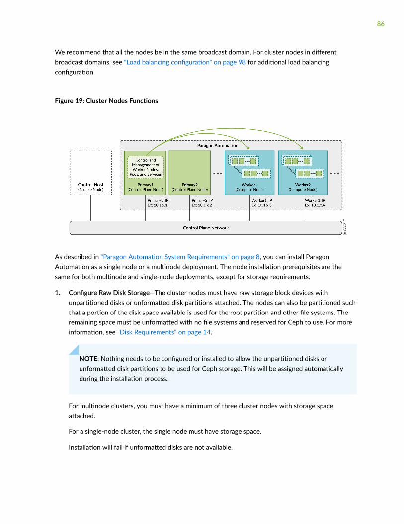
We recommend that all the nodes be in the same broadcast domain. For cluster nodes in differentbroadcast domains, see "Load balancing configuration" on page 98 for additional load balancingconfiguration.
Figure 19: Cluster Nodes Functions
As described in "Paragon Automation System Requirements" on page 8, you can install ParagonAutomation as a single node or a multinode deployment. The node installation prerequisites are thesame for both multinode and single-node deployments, except for storage requirements.
1. Configure Raw Disk Storage—The cluster nodes must have raw storage block devices withunpartitioned disks or unformatted disk partitions attached. The nodes can also be partitioned suchthat a portion of the disk space available is used for the root partition and other file systems. Theremaining space must be unformatted with no file systems and reserved for Ceph to use. For moreinformation, see "Disk Requirements" on page 14.
NOTE: Nothing needs to be configured or installed to allow the unpartitioned disks orunformatted disk partitions to be used for Ceph storage. This will be assigned automaticallyduring the installation process.
For multinode clusters, you must have a minimum of three cluster nodes with storage spaceattached.
For a single-node cluster, the single node must have storage space.
Installation will fail if unformatted disks are not available.
86

Ceph requires newer Kernel versions. If your Linux kernel is very old, consider upgrading orreinstalling a new one. For a list of minimum Linux kernel versions supported by Ceph for your OS,see https://docs.ceph.com/en/latest/start/os-recommendations. To upgrade your Linux kernelversion, see Upgrade your CentOS Linux Kernel Version.
2. Install Base OS—Install CentOS version 7.6 (or later) that allows installation of Docker CE or DockerEE must be installed. Paragon Automation Release 21.3 is qualified to work with CentOS 7.9Minimal ISO.
3. Create Install User Account—The install user is the user that the Ansible playbooks will use to log into the primary and worker nodes and perform all the installation tasks. Ensure that either a rootpassword or an account with superuser (sudo) privileges is configured. You will add this informationto the inventory file during the installation process.
Set the root user password.
# passwd rootNew password:Retype new password:passwd: password updated successfully
4. Configure SSH Authentication—Install open-ssh server on all nodes. The installer running on thecontrol host connects to the cluster nodes through SSH using the install user account.
a. Log in to the cluster nodes. and install open-ssh server on all nodes.
b. After installation, edit the sshd_config file.
$ vi /etc/ssh/sshd_config
c. If you are using "root" as the install user account, permit root login.
PermitRootLogin yes
If you chose to use plain text password for authentication, you must enable passwordauthentication.
PasswordAuthentication yes
We do not recommend the use of password authentication.
d. If you changed /etc/ssh/sshd_config, restart the SSH daemon.
$ systemctl restart sshd
e. Log in to the control host:
87

i. To allow authentication using the SSH key, copy id_rsa.pub to the cluster nodes.
$ ssh-copy-id -i ~/.ssh/id_rsa.pub cluster-node-IP-or-hostname
Repeat this step for ALL the nodes in the cluster (primary and workers). cluster-node-IP isthe unique address of the node as shown in Cluster Nodes Functions on page 86. If thehostname is used instead, the Ansible control host should be able to resolve the name to itsIP address.
ii. SSH into the cluster node. You must not require a password to log in.
To verify connectivity. Use the Install User Account to ssh.
You should be able to SSH into all nodes in the cluster (primary and workers) from thecontrol host using the Install User Account. If you are not able to, review the previous stepsand make sure you did not miss anything.
5. Install Docker—Select one of the following Docker versions to install.
The Docker version you choose to install in the cluster nodes is independent of the Docker versioninstalled in the control host.
• Docker CE—If you want to use Docker CE, you do not need to install it on the cluster nodes. Thedeploy script installs Docker CE on the nodes during Paragon Automation installation.
• Docker EE—If you want to use Docker EE, you must install Docker EE on all the cluster nodes. Ifyou install Docker EE on the nodes, the deploy script uses the installed version and does notattempt to install Docker CE in its place. For more information on Docker EE, supportedsystems, download, and installation instructions, see https://www.docker.com/blog/docker-enterprise-edition/.
The Docker version you choose to install in the cluster nodes is not dependent on the Dockerversion installed in the control host.
6. Disable Firewall—Disable the local firewall.
$ systemctl stop firewalld
$ systemctl disable firewalld
Consider protecting your cluster with an external firewall.
7. Install Python—Install Python 3, if not pre-installed with your OS, on the cluster nodes:
$ yum install -y python3
To verify the Python version installed, use $ python3 -V or $ python3 --version commands.
8. Check Installed Packages—Use the $ yum list installed command and ensure that the followingpackages are installed.
bash-completion, gdisk, iptables, lvm2, python-six, PyYAML, openssl
88

9. Install and Enable NTP—All nodes must run NTP or other time-synchronization at all times. Bydefault, Paragon Automation installs the Chrony NTP client. If you do not want to use Chrony, youcan manually install NTP on all nodes.
a. Install NTP.
$ yum install ntp ntpdate -y
b. Run this command twice to reduce the offset with the NTP server.
$ ntpdate ntp-server
c. Start the NTP daemon.
$ systemctl start ntpd
d. Configure the NTP server pools.
$ vi /etc/ntp.conf
e. Replace the default CentOS pools with your desired NTP server.
server ntp-server prefer iburst
Save and exit the file.
f. Restart the NTP service.
$ systemctl restart ntpd
g. Confirm that the system is in sync with the NTP server.
$ timedatectl
10. (Optional) Upgrade your CentOS Linux Kernel VersionTo upgrade the kernel version of yourCentOS server to the latest LTS version to meet the requirements for Paragon Automationinstallation.
To upgrade the kernel version of your CentOS server to the latest LTS version to meet therequirements for Paragon Automation installation.
a. Log in as root user.
b. Check the existing kernel version:
root@server$ uname -msr
If the Linux kernel version is earlier than 4.18, upgrade the kernel.
c. Update existing software packages to the latest versions
root@server$ yum -y update
89

d. CentOS does not provide the latest available kernel versions in its software repository.Therefore, the ElRepo (elrepo) software repository is used. Additionally, CentOS requires allsoftware to be signed; so you must install the elrepo GPG signature key before installing theelrepo repository.
Installing the elrepo GPG signature key requires a single rpm command which returns no outputif successful:
i. Install GPG Key for ElRepo Software Repository.
root@server$ rpm --import https://www.elrepo.org/RPM-GPG-KEY-elrepo.org
ii. Install ElRepo Software Repository.
root@server$ rpm -Uvh https://www.elrepo.org/elrepo-release-7.0-4.el7.elrepo.noarch.rpm
iii. Confirm the latest kernel in the ElRepo Repository.
root@server$ yum list available --disablerepo='*' --enablerepo=elrepo-kernel
e. Install the latest kernel.
root@server$ yum --enablerepo=elrepo-kernel install kernel-lt
f. Reboot the server to load the new kernel.
root@server$ reboot
g. Edit GRUB configuration. Use the text editor to edit /etc/default/grub file.
root@server$ vi /etc/default/grub
h. Set GRUB_DEFAULT=0. Save and exit the file.
i. Install the GRUB configuration and reboot the server.
root@server$ grub2-mkconfig -o /boot/grub2/grub.cfg
root@server$ reboot
j. Verify the new kernel version.
root@server$ uname -msr
90

Virtual IP Address Considerations
IN THIS SECTION
VIP for multi-primary node deployment | 97
Load balancing configuration | 98
The Kubernetes worker nodes host the pods that handle the applications workload.
A pod is the smallest deployable unit of computing created and managed in Kubernetes, and containsone or more containers, with shared storage and network resources, and with specific instructions onhow to run the applications. Containers are the lowest level of processing and is where applications ormicroservices are executed.
The primary node in the cluster, determines which worker node will host a particular pod andcontainers.
All features of Paragon Automation are implemented using a combination of microservices. Some ofthese microservices need to be accessible from outside the cluster as they provide services to end users(managed devices), and administrators. For example, the pceserver service needs to be accessible toestablish PCEP sessions between PE routers and Paragon Automation.
These services need to be exposed outside of the Kubernetes cluster with specific addresses that arereachable from the external devices. Because a service can be running on any of the worker nodes at agiven time, the external addresses should be Virtual IP Addresses (VIPs), and not the address of anygiven worker node.
91

In this example:
Consider that WORKER1_IP = 10.1.x.3 and WORKER2_IP = 10.1.x.4.
SERVICE IP = PCEP VIP = 10.1.x.200
PCC_IP = 10.1.x.100
The services in Paragon Automation are configured to employ one of two methods of exposing servicesoutside the cluster:
• Load BalancerEach load balancer is associated with a specific IP address and routes external traffic toa specific service in the cluster. This is the default method for many Kubernetes installations in thecloud. It supports multiple protocols and multiple ports per service. Each service has its own loadbalancer, and IP address.
Paragon Automation uses MetalLB.
• IngressIngress acts as a proxy to bring traffic into the cluster, then uses internal service routing toroute the traffic to its destination. Under the hood, Ingress also uses a Load Balancer service toexpose itself to the world so it can act as that proxy.
92

Paragon Automation uses:
• Ambassador
• Nginx
• HAProxy
The following services need to be accessible and thus require a VIP address.
Required VIP Address Description Load Balancer/Proxy
Ingress controller Used for Web access of theParagon Automation GUI.
Paragon Automation provides acommon Web server that providesaccess to the components andapplications. Access to the server ismanaged through the KubernetesIngress Controller.
Ambassador
MetalLB
Paragon Insights services Used for Insights services such assyslog, DHCP relay, and JTI.
MetalLB
Paragon Pathfinder PCE server Used to establish PCEP sessionswith devices in the network.
MetalLB
SNMP trap receiver proxy(Optional)
User for the SNMP trap receiverproxy only if this functionality isrequired.
MetalLB
93

(Continued)
Required VIP Address Description Load Balancer/Proxy
Virtual IP address for InfrastructureNginx Ingress Controller
Used as a proxy for ParagonPathfinder netflowd server, andoptionally Paragon Pathfinder PCEserver.
The Nginx Ingress Controller needsa VIP within the MetalLB loadbalancer pool. This means thatduring the installation process youneed to include this address as partof the LoadBalancer IP addressranges that you will be required toinclude while creating theconfiguration file.
Nginx
MetalLB
Ports used by Ambassador:
http 80 (TCP) redirect to https
https 443 (TCP)
Paragon Planner 7000 (TCP)
94

DCS/NETCONF initiated 7804 (TCP)
Figure 20: Ambassador
Ports used by Insights Services, PCE server, and SNMP.
• Insights Services
JTI 4000 (UDP)
DHCP (ZTP) 67 (UDP)
SYSLOG 514 (UDP)
SNMP proxy 162 (UDP)
• PCE Server
PCEP 4189 (TCP)
• SNMP
SNMP Trap Receiver 162 (UDP)
95

Ports used by Nginx Controller:
NetFlow 9000 (UDP)
PCEP 4189 (TCP)
Using Nginx for PCEPDuring the installation process you will be asked whether you want to enableingress proxy for PCEP.
• If you select “None” or “HAProxy“ as the proxy for PCE server.
• If you select "Nginx-Ingress" as a proxy for PCE server, you do not need to configure the VIP for PCEserver described in the table. In this case, the Virtual IP address for Infrastructure Nginx IngressController is used for both netflowd and PCE server.
96

•NOTE: The benefit of using Nginx is that a single IP address can be used for multiple services.
Figure 21: Nginx Controller
VIP for multi-primary node deployment
If you are deploying a multi-primary node setup, you need an additional VIP, in the same broadcastdomain as the cluster nodes. This address will be used for communication between the elected primarynode and the worker nodes.
In a single primary setup, the worker communicates with the primary function using the addressassigned to that node acting as primary (IP address configured on the interface of the node acting asprimary).
In a multi-primary setup, the worker communicates with the primary function using the VIP, instead ofthe address assigned to any of the nodes acting as primary.
This IP address is referred to as the Kubernetes Master Virtual IP address in the installation wizard. ThisVIP must not be a part of the MetalLB load balancer pool of VIPs.
97

NOTE: You must identify all the required VIPs, before you start the Paragon Automationinstallation process. You will be asked to enter these addresses as part of the installation process.
Load balancing configuration
VIPs are managed in Layer 2 by default. When all cluster nodes are in the same broadcast domain, eachVIP is assigned to one cluster node at a time. Layer 2 mode provides fail-over of the VIP and does notprovide actual load balancing. For true load balancing between the cluster nodes or if the nodes are indifferent broadcast domains, you must configure load balancing in Layer 3.
You must configure a BGP router to advertise the VIP to the network. The BGP router should beconfigured to use ECMP to balance TCP/IP sessions between different hosts. Connect the BGP routerdirectly to the cluster nodes.
To configure load balancing on the cluster nodes, edit the config.yml file. For example:
metallb_config: peers: - peer-address: 192.x.x.1 ## address of BGP router peer-asn: 64501 ## autonomous system number of BGP router my-asn: 64500 ## ASN of cluster
98

address-pools: - name: default protocol: bgp addresses: - 10.x.x.0/24
In this example, The BGP router at 192.x.x.1 is responsible to advertise reachability for the VIPs with the10.x.x.0/24 prefix to the rest of the network. The cluster allocates the VIP of this range and advertisesthe address for the cluster nodes that can handle the address.
DNS Server Configuration (Optional)
You can access the main Web gateway either through the ingress controller VIP or through a hostnamethat is configured in the DNS that resolves to the ingress controller VIP. You need to configure DNS onlyif you want to use a hostname to access the Web gateway.
Add the hostname to DNS as A, AAAA, or CNAME record. For lab and POC setups, you can add thehostname to the /etc/hosts file on the cluster nodes.
RELATED DOCUMENTATION
Install Multi-Node Cluster on CentOS | 99
Install Single Node Cluster on CentOS | 122
Install Multi-Node Cluster on CentOS
IN THIS SECTION
Download the Software | 100
Install Paragon Automation | 101
Log in to the Paragon Automation UI | 118
Modify cRPD Configuration | 119
99

This topic describes the installation of the Paragon Automation on a multi-node cluster. The summary ofinstallation tasks is shown at a high level in Figure 22 on page 100. Ensure that you have completed allthe preconfiguration and preparation steps described in "Installation Prerequisites on CentOS" on page82 before you begin installation.
Figure 22: Installation Sequence - Infographic
To view a higher-resolution image in your Web browser, right-click the image and open in a new tab. Toview the image in PDF, use the zoom option to zoom in.
Download the Software
Prerequisite
• You need a Juniper account to download the Paragon Automation software.
1. Log in to the control host.
2. Create a directory in which you download the software.
This directory is referred to as pa-download-dir in this guide.
3. From the Version drop-down list on the Paragon Automation software download page at https://support.juniper.net/support/downloads/?p=pa, select the version number.
100

4. Download the Paragon Automation Setup installation files to the download folder using the wget"http://cdn.juniper.net/software/file-download-url" command.
The Paragon Automation Setup installation bundle consists of the following scripts and tar files toinstall each of the component modules:
• davinci.tar.gz, which is the primary installer file.
• infra.tar, which installs the Kubernetes infrastructure components including Docker and Helm.
• ems.tar, which installs the base platform component.
• northstar.tar, which installs the Paragon Pathfinder and Paragon Planner components.
• healthbot.tar, which installs the Paragon Insights component.
• paragon_ui.tar, which installs the Paragon Automation UI component.
• run script, which executes the installer image.
Install Paragon Automation
1. Make the run script executable in the pa-download-dir directory.
# chmod +x run
2. Use the run script to create and initialize a configuration directory with the configuration templatefiles.
# ./run -c config-dir init
config-dir is a user-defined directory on the control host that contains configuration information for aparticular installation. The init command automatically creates the directory if it does not exist.Alternatively, you can create the directory before you execute the init command.
Ensure that you include the "./" when issuing the run command.
If you are using the same control host to manage multiple installations of Paragon Automation, youcan differentiate between installations by using differently named configuration directories.
3. Ensure that the control host can connect to the cluster nodes through SSH using the install useraccount.
101

Copy the private key that you generated in "Install SSH Client Authentication" on page 84 to the userdefined config-dir directory. The installer allows the Docker container to access the config-dirdirectory. The SSH key must be available in the directory for the control host to connect to thecluster nodes.
# cd config-dir# cp ~/.ssh/id_rsa .# cd ..
Ensure that you include the dot "." when issuing the copy command.
4. Customize the inventory file, created under the config-dir directory, with the IP addresses orhostnames of the cluster nodes, as well as the usernames and authentication information that arerequired to connect to the nodes. The inventory file is in the YAML format and describes the clusternodes on which Paragon Automation will be installed. You can edit the file using the inv command ora Linux text editor such as vi.
a. Customize the inventory file using the inv command:
# ./run -c config-dir inv
The configuration options that the inv command prompts are listed in the following table.
Table 9: inv Command Options
inv Command Prompts Description
Kubernetes master nodes Enter IP addresses of the Kubernetes primarynodes.
Kubernetes worker nodes Enter IP addresses of the Kubernetes workernodes.
102

Table 9: inv Command Options (Continued)
inv Command Prompts Description
Local storage nodes Define the nodes that have disk space available forapplications. The local storage nodes areprepopulated from the primary and worker node IPaddresses. You can edit these addresses. Enter IPaddresses of the nodes on which you want to runapplications that require local storage.
Services such as Postgres, Zookeeper, and Kafka,use local storage or disk space partitioned insideexport/local-volumes. By default, worker nodeshave local storage available. If you do not addprimary nodes here, you can run only applicationsthat do not require local storage on the primarynodes.
This is different from Ceph storage.
Kubernetes nodes' username (e.g. root) Configure the user account and authenticationmethods to authenticate the installer with thecluster nodes. The user account must be root or incase of non-root users, the account must havesuperuser (sudo) privileges.
SSH private key file (optional) If you chose ssh-key authentication, for the controlhost to authenticate with the nodes during theinstallation process, configure the directory (config-dir) where the ansible_ssh_private_key_file islocated, and the id_rsa file, as "{{ config-dir }}/id_rsa".
Kubernetes nodes' password (optional) If you chose password authentication for thecontrol host to authenticate with the nodes duringthe installation process, enter the authenticationpassword directly.
Warning: The password is written in plain text. Wedo not recommend using this option forauthentication.
Kubernetes cluster name (optional) Enter a name for your Kubernetes cluster.
103

Table 9: inv Command Options (Continued)
inv Command Prompts Description
Write inventory file? Click Yes to save the inventory information.
For example:
$ ./run -c config-dir invLoaded image: paragonautomation:latest====================PO-Runtime installer==================== Supported command: deploy [-t tags] deploy runtime destroy [-t tags] destroy runtime init init configuration skeleton inv basic inventory editor conf basic configuration editor info [-mc] cluster installation info Starting now: inv INVENTORY This script will prompt for the DNS names or IP addresses of the Kubernetes master and worker nodes.Addresses should be provided as comma-delimited lists. At least three master nodes are recommended. The number of masters should be an odd number.A minimum of four nodes are recommended. Root access to the Kubernetes nodes is required. See https://docs.ansible.com/ansible/2.10/user_guide/intro_inventory.html ? Kubernetes master nodes 10.12.xx.x3,10.12.xx.x4,10.12.xx.x5? Kubernetes worker nodes 10.12.xx.x6? Local storage nodes 10.12.xx.x3,10.12.xx.x4,10.12.xx.x5,10.12.xx.x6
104

? Kubernetes nodes' username (e.g. root) root? SSH private key file (optional; e.g. "{{ inventory_dir }}/id_rsa") config/id_rsa? Kubernetes nodes' password (optional; WARNING - written as plain text)? Kubernetes cluster name (optional) k8scluster? Write inventory file? Yes
b. Alternatively, you can customize the inventory file manually using a text editor.
# vi config-dir/inventory
Edit the following groups in the inventory file.
i. Add the IP addresses of the Kubernetes primary and worker nodes of the cluster.
The master group identifies the primary nodes, and the node group identifies the workernodes. The same IP address cannot be in both master and node groups.
To create a multi-primary setup, list the addresses or hostnames of all the nodes that will beacting as primary under the master group. Add the addresses or hostnames of the nodes thatwill be acting as workers under the node group.
master: hosts: 10.12.xx.x3: {} 10.12.xx.x4: {} 10.12.xx.x5: {} node: hosts: 10.12.xx.x6: {}
ii. Define the nodes that have disk space available for applications under thelocal_storage_nodes:children group.
local_storage_nodes: children: master: hosts: 10.12.xx.x3: {} 10.12.xx.x4: {} 10.12.xx.x5: {} node:
105

hosts: 10.12.xx.x6: {}
iii. Configure the user account and authentication methods to authenticate the the installer inthe Ansible control host with the cluster nodes under the vars group.
vars: ansible_user: root ansible_ssh_private_key_file: config/id_rsa ansible_password:
iv. (Optional) Specify a name for your Kubernetes cluster in the kubernetes_cluster_name group.
kubernetes_cluster_name: k8scluster
5. Configure the installer using the conf command.
# ./run -c config-dir conf
The conf command runs an interactive installation wizard that allows you to choose the componentsto be installed and configure a basic Paragon Automation setup. The command populates theconfig.yml file with your input configuration. For advanced configuration, you must edit theconfig.yml file manually.
Enter the information as prompted by the wizard. Use the cursor keys to move the cursor, use thespace key to select an option, and use a or i to toggle selecting or clearing all options. Press Enter tomove to the next configuration option. You can skip configuration options by entering a period (.).You can re-enter all your choices by exiting the wizard and restarting from the beginning. Theinstaller allows you to exit the wizard after you save the choices that you already made or to restartfrom the beginning. You cannot go back and redo the choices that you already made in the currentworkflow without exiting and restarting the wizard altogether.
The configuration options that the conf command prompts for are listed in the following table:
106

conf Command Prompts Description/Options
Select components You can install one or more of the Infrastructure, Pathfinder, Insights, andbase platform components. By default, all components are selected.
Installation of the Pathfinder component is optional and based on yourrequirement. All other components must stay selected and be installed.
Infrastructure Options These options are displayed only if you selected to install the Infrastructurecomponent in the previous prompt.
• Install Kubernetes Cluster—Install the required Kubernetes cluster. If youare installing Paragon Automation on an existing cluster, you can clearthis selection.
• Install MetalLB LoadBalancer—Install an internal load balancer for theKubernetes cluster. By default, this option is already selected. If you areinstalling Paragon Automation on an existing cluster with preconfiguredload balancing, you can clear this selection.
• Install Nginx Ingress Controller—Install Nginx Ingress Controller is a load-balancing proxy for the Pathfinder components.
• Install Chrony NTP Client—Install Chrony NTP. NTP is required tosynchronize the clocks of the cluster nodes. If NTP is already installedand configured, you need not install Chrony. All nodes must run NTP orsome other time-synchronization at all times.
• Allow Master Scheduling—Master scheduling determines how the nodeacting as primary nodes are used. Master is another term for a nodeacting as primary.
If you select this option, the primary nodes can also act as worker nodes,which means they not only act as control plane but can run applicationworkloads as well. If you do not select master scheduling, the primarynodes are used only as the control plane.
Master scheduling allows the available resources of the nodes acting asprimary to be available for workloads. However, you run the risk that amisbehaving workload can exhaust resources on the primary node, andaffect the stability of the whole cluster. Without master scheduling, ifyou have multiple primary nodes with high capacity and disk space, yourisk wasting their resources by not utilizing them completely.
NOTE: This option is required for Ceph storage redundancy.
107

(Continued)
conf Command Prompts Description/Options
List of NTP servers Enter a comma-separated list of NTP servers. This option is displayed only ifyou chose to install Chrony NTP.
Kubernetes for Master VirtualIP address
Enter a VIP for the Kubernetes API Server for a multi-primary nodedeployment only. The VIP must be in the same Layer 2 domain as theprimary nodes. This VIP is not part of the LoadBalancer pool of VIPs.
This option is presented only when multiple primary nodes have beenconfigured in the inventory file (multi-primary installation).
Install LoadBalancer forMaster Virtual IP address
(Optional) Select to install keepalived LoadBalancer for the Master VIP.
This option is presented only when multiple primary nodes have beenconfigured in the inventory file (multi-primary installation).
Virtual IP address (es) foringress controller
Enter a VIP to be used for Web access of the Kubernetes cluster or theParagon Automation user interface. This must be an unused IP address thatis managed by the MetalLB load balancer pool.
Virtual IP address forInfrastructure Nginx IngressController
Enter a VIP for the Nginx Ingress Controller. This must be an unused IPaddress that is managed by the MetalLB load balancer pool. This address isused for NetFlow traffic.
Virtual IP address for Insightsservices
Enter a VIP for Paragon Insights services. This must be an unused IP addressthat is managed by the MetalLB load balancer pool.
Virtual IP address for SNMPtrap receiver (optional)
Enter a VIP for the SNMP trap receiver proxy only if this functionality isrequired.
If you do not need this option, enter a dot ".".
PCE Server Proxy Select the proxy mode for the PCE Server. Select from NONE, HA proxy, orNginx-Ingress.
108

(Continued)
conf Command Prompts Description/Options
Virtual IP address forPathfinder PCE server
Enter a VIP to be used for Paragon Pathfinder PCE server access. This mustbe an unused IP address that is managed by the load balancer.
If you selected Nginx-Ingress or HA proxy, as the PCE Server Proxy, this VIPis not necessary. You will not be prompted for this address and PCEP will usethe same address as the Virtual IP address for Infrastructure Nginx IngressController.
NOTE: The addresses for ingress controller, Infrastructure Nginx IngressController, Insights services, and PCE server must be unique. You cannot usethe same address for all four VIPs.
All these addresses are listed automatically in the LoadBalancer IP addressranges option.
LoadBalancer IP addressranges
The LoadBalancer IP addresses are prepopulated from your VIP addressesrange. You can edit these addresses. The externally accessible services arehandled through MetalLB, which needs one or more IP address ranges thatare accessible from outside the cluster. VIPs for the different servers areselected from these ranges of addresses.
The address ranges can be (but need not be) in the same broadcast domainas the cluster nodes. For ease of management, because the networktopologies need access to Insights services and the PCE server clients, werecommend that the VIPs for these be selected from the same range.
For more information, see "Virtual IP Address Considerations" on page 29.
Addresses can be entered as comma separated values, or as a range, or as acombination of both. For example:
• 10.x.x.1, 10.x.x.2, 10.x.x.3
• 10.x.x.1-10.x.x.3
• 10.x.x.1, 10.x.x.3-10.x.x.5
• 10.x.x.1-3 is not a valid format
109

(Continued)
conf Command Prompts Description/Options
Hostname of Main webapplication
Enter a hostname for the ingress controller. This can be configured as an IPaddress or as hostname (FQDN). For example, you can enter 10.12.xx.100 orwww.paragon.juniper.net (DNS name). Do not include http:// or https://.
NOTE: You will use this hostname to access the Paragon Automation WebUI from your browser. For example, https://hostname or https://IP-address.
BGP autonomous systemnumber of CRPD peer
Set up the Containerized Routing Protocol Daemon (cRPD) autonomoussystems and the nodes with which cRPD creates its BGP sessions.
You must configure the autonomous system number of the network to allowcRPD to peer with one or more BGP-LS routers in the network. By default,the autonomous system number is 64500.
NOTE: While you can configure the autonomous system number at the timeof installation, you can also modify the cRPD configuration later. See,"Modify cRPD Configuration" on page 119.
110

(Continued)
conf Command Prompts Description/Options
Comma separated list ofCRPD peers
You must configure cRPD to peer with at least one BGP-LS router in thenetwork to import the network topology. For a single autonomous system,configure the address of the BGP-LS router(s) that will peer with cRPD toprovide topology information to Paragon Pathfinder. The CRPD instancerunning as part of a cluster will initiate a BGP-LS connection to the specifiedpeer router(s) and import topology data once the session has beenestablished. If more than one peer is required, these can be added as commaseparated values, or as a range or as a combination of both, similar to howLoadBalancer IP addresses are added.
NOTE: While you can configure the peer IP addresses at the time ofinstallation, you can also modify the cRPD configuration later, as describedin "Modify cRPD Configuration" on page 119.
You must configure the BGP peer routers to accept BGP connectionsinitiated from cRPD. The BGP session will be initiated from cRPD using theaddress of the worker where the bmp pod is running, as the source address.
Since cRPD could be running on any of the workers at a given time, youmust allow connections from any of these addresses. You can allow therange of IP addresses that the worker addresses belong to (for example,10.xx.43.0/24), or the specific IP address of each worker (for example,10.xx.43.1/32, 10.xx.43.2/32, and 10.xx.43.3). You could also configure thisusing the neighbor command combined with the passive option to preventthe router from attempting to initiate the connection.
If you chose to enter each individual worker address, either with the allowcommand or the neighbor command, make sure you include all the workers,since any worker could be running cRPD at a given time. Only one BGPsession will be initiated. If the node running cRPD fails, the bmp pod thatcontains the cRPD container will be created in a different node, and the BGPsession will be re-initiated.
The following example shows the options to configure a Juniper device toallow BGP-LS connections from cRPD.
The following commands configure the router to accept BGP-LS sessionsfrom any host in the 10.xx.43.0/24 network, where all the workers areconnected.
[edit groups northstar]root@system# show protocols bgp group northstartype internal;
111

(Continued)
conf Command Prompts Description/Options
family traffic-engineering { unicast;}export TE;allow 10.xx.43.0/24;
[edit groups northstar]root@system# show policy-options policy-statement TEfrom family traffic-engineering;then accept;
The following commands configure the router to accept BGP-LS sessionsfrom 10.xx.43.1, 10.xx.43.2, and 10.xx.43.3 (the addresses of the threeworkers in the cluster) only.
[edit protocols bgp group BGP-LS]root@vmx101# show | display set set protocols bgp group BGP-LS family traffic-engineering unicastset protocols bgp group BGP-LS peer-as 11set protocols bgp group BGP-LS allow 10.x.43.1set protocols bgp group BGP-LS allow 10.x.43.2set protocols bgp group BGP-LS allow 10.x.43.3set protocols bgp group BGP-LS export TE
The BGP session is initiated by cRPD. Only one session is established at atime and is initiated using the address of the worker node currently runningcRPD. If you choose to configure the specific IP addresses instead of usingthe allow option, configure the addresses of all the workers nodes forredundancy.
The following commands also configure the router to accept BGP-LSsessions from 10.xx.43.1, 10.xx.43.2, and 10.xx.43.3 only (the addresses ofthe three workers in the cluster). The passive option was added to preventthe router from attempting to initiate a BGP-LS session with cRPD. Therouter will wait for the session to be initiated by any of these three routers.
[edit protocols bgp group BGP-LS]root@vmx101# show | display setset protocols bgp group BGP-LS family traffic-engineering unicastset protocols bgp group BGP-LS peer-as 11set protocols bgp group BGP-LS neighbor 10.xx.43.1set protocols bgp group BGP-LS neighbor 10.xx.43.2
112

(Continued)
conf Command Prompts Description/Options
set protocols bgp group BGP-LS neighbor 10.xx.43.3set protocols bgp group BGP-LS passiveset protocols bgp group BGP-LS export TE
You will also need to enable OSPF/ISIS and MPLS traffic engineering asshown:
set protocols rsvp interface interface.unit
set protocols isis interface interface.unitset protocols isis traffic-engineering igp-topologyOrset protocols ospf area area interface interface.unitset protocols ospf traffic-engineering igp-topology
set protocols mpls interface interface.unitset protocols mpls traffic-engineering database import igp-topology
For more information, see https://www.juniper.net/documentation/us/en/software/junos/mpls/topics/topic-map/mpls-traffic-engineering-configuration.html.
If you need to modify the cRPD configuration later (such as add a newneighbor), you will need to modify the BMP configuration file ,kube-cfg.yml,located in the /etc/kubernetes/po/bmp/ directory on the ParagonAutomation primary node.
For example:
root@primary:/etc/kubernetes/po/bmp# vi kube-cfg.yml
---apiVersion: v1kind: ConfigMapmetadata: namespace: northstar name: crpd-configdata: config: | protocols { bgp { group northstar {
113

(Continued)
conf Command Prompts Description/Options
neighbor 172.16.xx.105; neighbor 10.1.x.2 } } }
Finish and write configurationto file
Click Yes to save the configuration information.
This configures a basic setup, and the information is saved in the config.ymlfile in the config-dir directory.
For example:
$ ./run -c config confLoaded image: paragonautomation.latest====================PO-Runtime installer====================
Supported command: deploy [-t tags] deploy runtime destroy [-t tags] destroy runtime init init configuration skeleton inv basic inventory editor conf basic configuration editor info [-mc] cluster installation info
Starting now: conf
NOTE: depending on options chosen additional IP addresses may be required for: multi-master Kubernetes Master Virtual IP address Infrastructure Virtual IP address(es) for ingress controller Insights Virtual IP address for Insights services Insights Virtual IP address for SNMP Trap receiver (optional) Pathfinder Virtual IP address for Pathfinder PCE server
? Select components done (4 selections)? Infrastructure Options done (4 selections)
114

? List of NTP servers 0.pool.ntp.org? Virtual IP address(es) for ingress controller 10.12.xx.x7? Virtual IP address for Insights services 10.12.xx.x8? Virtual IP address for SNMP Trap receiver (optional) ? Virtual IP address for Pathfinder PCE server 10.12.xx.x9? LoadBalancer IP address ranges 10.12.xx.x7-10.12.xx.x9? Hostname of Main web application host.example.net? BGP autonomous system number of CRPD peer 64500? Comma separated list of CRPD peers 10.12.xx.11? Finish and write configuration to file Yes
6. (Optional) For more advanced configuration of the cluster, use a text editor to manually edit theconfig.yml file.
The config.yml file consists of an essential section at the beginning of the file that corresponds to theconfiguration options that the installation wizard prompts you to enter. The file also has an extensivelist of sections under the essential section that allows you to enter complex configuration valuesdirectly in the file.
The following options are available.
• Set the opendistro_es_admin_password password to log in to the Kibana application. Open Distro isused to consolidate and index application logs and Kibana is the visualization tool that enablesyou to search logs using keywords and filters.
By default, the username is preconfigured as admin in #opendistro_es_admin_user: admin andinstall_opendistro_es option is set to true to replace the Elasticsearch version with Open Distro.Use admin as username and this password to log in to Kibana.
By default, data is retained on the disks for seven days, before being purged, in a productiondeployment. You can edit the number of days to a smaller number in opendistro_es_retain if yourdisk size is low.
# install_opendistro_es: true# opendistro_es_admin_user: admin# opendistro_es_admin_password: opendistro_password# opendistro_es_retain: 7d
If you do not configure the opendistro_es_admin_password, the installer will generate a randompassword. You can retrieve the password using the command:
# kubectl -n kube-system get secret opendistro-es-account -o jsonpath={..password} | base64 -d
• Set the iam_skip_mail_verification configuration option to true for user management without SMTPby Identity Access Management (IAM). By default, this option is set to false for user management
115

with SMTP. You must configure SMTP in Paragon Automation so that the Paragon Automationusers can be notified when their account is created, activated, locked, or when the password ischanged for their account.
• Configure the callback_vip option with an IP address different from that of the VIP for the ingresscontroller. You can configure a separate IP address, which is a part of the MetalLB pool ofaddresses, to enable segregation of management and data traffic from the southbound andnorthbound interfaces. By default, callback_vip is assigned the same or one of the addresses of theingress controller.
• If you want to use an interface other than the default interface for inter-cluster communication,set the kubernetes_system_interface variable. The current setting is"{{ ansible_default_ipv4.interface }}" which is the interface used by the default route. Thekubernetes_system_interface variable configures the Kubernetes API server and Calico.
To view the default interface, run this command on a primary node:
root@primary-node:~# ip r show defaultdefault via 10.12.xx.254 dev ens3 proto dhcp src 10.12.xx.121 metric 100
In this example, ens3 is default interface for this machine.
If you want to use an interface different from the default one and the same interface can be usedon all cluster nodes, configure the kubernetes_system_interface in the config.yml file. For example:
kubernetes_system_interface: ens4
If you want to use an interface different from the default one but the interface is different ondifferent nodes, you must remove kubernetes_system_interface from the config.yml file. Instead,configure the interface names in the inventory file. For example:
master: hosts: 10.12.xx.x3: kubernetes_system_interface: ens7 10.12.xx.x4: kubernetes_system_interface: ens8 10.12.xx.x5: kubernetes_system_interface: ens9 node: hosts: 10.12.xx.x6: kubernetes_system_interface: ens7
116

Note that calico_ip_autodetect is set to "interface={{ kubernetes_system_interface }}", and takes on thesame value as kubernetes_system_interface and does not need to be explicitly changed if the defaultinterface is changed.
Save and exit the file after you finish editing it.
7. (Optional) If you want to deploy custom SSL certificates signed by a recognized certificate authority(CA), store the private key and certificate in the config-dir directory. Save the private key asambassador.key.pem and the certificate as ambassador.cert.pem.
By default, ambassador uses a locally generated certificate signed by the Kubernetes cluster-internalCA.
NOTE: If the certificate is about to expire, save the new certificate as ambassador.cert.pem inthe same directory, and execute the ./run -c config-dir deploy -t ambassador command.
8. Install the Paragon Automation cluster based on the information that you configured in theconfig.yml and inventory files.
# ./run -c config-dir deploy
The installation time to install the configured cluster depends on the complexity of the cluster. Abasic setup installation takes at least 45 minutes to complete.
The installer checks NTP synchronization at the beginning of installation. If clocks are out of sync,installation will fail.
For multi-primary node deployments only, the installer checks the disk IOPS at the beginning ofinstallation. If the IOPS is below 300, installation will fail. To disable disk IOPS check, use the # ./run -c config-dir deploy -e ignore_iops_check=yes command and rerun deployment.
If you are installing Paragon Automation on an existing Kubernetes cluster, the deploy commandupgrades the currently deployed cluster to the latest Kubernetes version. The command alsoupgrades the Docker CE version, if required. If Docker EE is already installed on the nodes, thedeploy command will not overwrite it with Docker CE. When upgrading the Kubernetes version orthe Docker version, the command performs the upgrade sequentially on one node at a time. Eachnode is cordoned off and removed from scheduling and upgrades are performed, Kubernetes isrestarted on the node, and the node is finally uncordoned and brought back into scheduling.
9. When deployment is completed, log in to the worker nodes.
Use a text editor to configure the following recommended information for Paragon Insights in thelimits.conf and sysctl.conf files. These values set the soft and hard memory limits for influx DBmemory requirements. If you do not set these limits, you might see errors such as “out of memory” or“too many open files” because of default system limits.
117

a.
# vi /etc/security/limits.conf # End of file * hard nofile 1048576 * soft nofile 1048576 root hard nofile 1048576 root soft nofile 1048576 influxdb hard nofile 1048576 influxdb soft nofile 1048576
b.
# vi /etc/sysctl.conf fs.file-max = 2097152 vm.max_map_count=262144 fs.inotify.max_user_watches=524288 fs.inotify.max_user_instances=512
Log in to the Paragon Automation UI
After you install Paragon Automation, log in to the Paragon Automation UI.
1. Open a browser, and enter either the hostname of the main Web application or the VIP of the ingresscontroller that you entered in the URL field of the installation wizard.
For example, https://vip-of-ingress-controller-or-hostname-of-main-web-application. The ParagonAutomation login page is displayed.
2. For first-time access, enter admin as username and Admin123! as the password to log in. You mustchange the password immediately.
The Set Password page is displayed. To access the Paragon Automation setup, you must set a newpassword.
3. Set a new password that meets the password requirements.
The password should be between 6 to 20 characters and must be a combination of uppercase letters,lowercase letters, numbers, and special characters. Confirm the new password, and click OK.
The Dashboard page is displayed. You have successfully installed and logged in to the ParagonAutomation UI.
4. Update the URL to access the Paragon Automation UI in Administration > Authentication > PortalSettings to ensure that the activation e-mail sent to users for activating their account contains thecorrect link to access the GUI. For more information, see Configure Portal Settings.
118

For high-level tasks that you can perform after you log in to the Paragon Automation GUI, seeParagon Automation Getting Started.
Modify cRPD Configuration
You can configure the address of the BGP-LS router(s) that will peer with cRPD to provide topologyinformation to Paragon Pathfinder, during installation of Paragon Automation. You can also modify thecRPD configuration after installation, in the following ways:
• You can edit the BMP configuration file (kube-cfg.yml) located in the Paragon Automation primarynode /etc/kubernetes/po/bmp/ directory, and then apply the new configuration.
To edit the BMP configuration file and add a new neighbor:
1. Edit the kube-cfg.yml file.
root@primary-node:~# vi /etc/kubernetes/po/bmp/kube-cfg.yml
---apiVersion: v1kind: ConfigMapmetadata: namespace: northstar name: crpd-configdata: config: | protocols { bgp { group northstar { neighbor 10.xx.43.1; neighbor 10.xx.43.2; <= make sure you include the “;” } } }
2. Apply the changes in the kube-cfg.yml file.
root@primary-node:~# kubectl apply -f /etc/kubernetes/po/bmp/kube-cfg.ymldeployment.apps/bmp configuredconfigmap/crpd-config configured
119

service/bmp-grpc unchangedservice/crpd unchangedservice/bgp unchangedpersistentvolumeclaim/crpd-data unchanged
3. Connect to the cRPD container.
root@primary-node:/# cd usr/local/bin/
root@primary-node:/usr/local/bin# ./pf-crpd
4. Verify that the changes are applied.
root@bmp-5888bb7dfd-72v9t> show configuration protocols bgp | display inheritance group northstar {---more-- ## ## '10.xx.43.1' was inherited from group 'extra' ## neighbor 10.xx.43.1; ## ## '10.xx.43.2' was inherited from group 'extra' ## neighbor 10.xx.43.2;
NOTE: Any additional neighbor will be added under a configuration group named extra.Hence, you need to add "| display inheritance" to see the new neighbor.
• Connect to the cRPD container and edit the configuration like you would on any Junos device.
To connect to cRPD and add a new neighbor or change the autonomous system number:
1. Connect to the cRPD container and enter configuration mode.
root@primary-node:/# cd usr/local/bin/
root@primary-node:/usr/local/bin# ./pf-crpd
root@ bmp-5888bb7dfd-72v9 > edit
120

[edit]root@ bmp-5888bb7dfd-72v9t#
2. View the current BGP configuration and autonomous system number.
[edit]root@bmp-5888bb7dfd-72v9t# show protocols bgp | display inheritance group northstar {---more-- ## ## '10.xx.43.1' was inherited from group 'extra' ## neighbor 10.xx.43.1; ## ## '10.xx.43.2' was inherited from group 'extra' ## neighbor 10.xx.43.2;
[edit]root@bmp-5888bb7dfd-72v9t# show routing-options autonomous-system 11;
3. Change the autonomous system number.
[edit]root@bmp-5888bb7dfd-72v9t# set routing-options autonomous-system 64500
4. Add a new neighbor.
[edit]root@bmp-5f78448d69-f84q7# edit protocols bgp
[edit protocols bgp]root@bmp-5888bb7dfd-72v9t# set group northstar neighbor 10.xx.43.3
[edit protocols bgp group northstar]root@bmp-5888bb7dfd-72v9t# show | display inheritance ---more---neighbor 10.xx.43.3;
121

## ## '10.xx.43.1' was inherited from group 'extra' ## neighbor 10.xx.43.1; ## ## '10.xx.43.2' was inherited from group 'extra' ## neighbor 10.xx.43.2;
NOTE: You could also add the neighbor under the configuration group extra, but if the podis restarted, this change will be overwritten by the configuration in the kube-cfg.yml file.
5. Commit your configuration changes.
[edit]root@bmp-5f78448d69-f84q7# commit
Install Single Node Cluster on CentOS
IN THIS SECTION
Download the Software | 123
Install Paragon Automation | 124
Log in to the Paragon Automation UI | 138
Modify cRPD Configuration | 139
You can also install Paragon Automation on a single node which acts as both primary and worker node.A single node setup must be used only as Proof-Of-Concept (POC) or for lab deployment and must notbe used for production deployments.
This topic describes the installation of Paragon Automation on a single node. The summary ofinstallation tasks is shown at a high level in Figure 23 on page 123. Ensure that you have completed all
122

the preconfiguration and preparation steps described in "Installation Prerequisites on CentOS" on page82 before you begin installation.
Figure 23: Installation Sequence - Infographic
To view a higher-resolution image in your Web browser, right-click the image and open in a new tab. Toview the image in PDF, use the zoom option to zoom in.
Download the Software
Prerequisite
• You need a Juniper account to download the Paragon Automation software.
1. Log in to the control host.
2. Create a directory in which you download the software.
This directory is referred to as pa-download-dir in this guide.
3. From the Version drop-down list on the Paragon Automation software download page at https://support.juniper.net/support/downloads/?p=pa, select the version number.
4. Download the Paragon Automation Setup installation files to the download folder using the wget"http://cdn.juniper.net/software/file-download-url" command.
123

The Paragon Automation Setup installation bundle consists of the following scripts and tar files toinstall each of the component modules:
• davinci.tar.gz, which is the primary installer file.
• infra.tar, which installs the Kubernetes infrastructure components including Docker and Helm.
• ems.tar, which installs the base platform component.
• northstar.tar, which installs the Paragon Pathfinder and Paragon Planner components.
• healthbot.tar, which installs the Paragon Insights component.
• paragon_ui.tar, which installs the Paragon Automation UI component.
• run script, which executes the installer image.
Install Paragon Automation
1. Make the run script executable in the pa-download-dir directory.
# chmod +x run
2. Use the run script to create and initialize a configuration directory with the configuration templatefiles.
# ./run -c config-dir init
config-dir is a user-defined directory on the control host that contains configuration information for aparticular installation. The init command automatically creates the config-dir directory if it does notexist. Alternatively, you can create the directory before you execute the init command.
Ensure that you include the "./" when issuing the run command.
If you are using the same control host to manage multiple installations of Paragon Automation, youcan differentiate between installations by using differently named configuration directories.
3. Ensure that the control host can connect to the cluster node through SSH using the install useraccount.
124

Copy the private key that you generated in "No Link Title" on page 84 to the user defined config-dirdirectory. The installer allows the Docker container to access the config-dir directory. The SSH keymust be available in the directory for the control host to connect to the cluster nodes.
# cd config-dir# cp ~/.ssh/id_rsa .# cd ..
Ensure that you include the dot "." when issuing the copy command.
4. Customize the inventory file, created under the config-dir directory, with the IP address or hostnameof the single cluster node, as well as the username and authentication information required toconnect to the node. The inventory file is in the YAML format and describes the cluster nodes onwhich Paragon Automation will be installed. You can edit the file using the inv command or a Linuxtext editor such as vi.
a. Customize the inventory file using the inv command:
# ./run -c config-dir inv
The configuration options that the inv command prompts are listed in the following table.
Table 10: inv Command Options
inv Command Prompts Description
Kubernetes master nodes Enter IP address of the single Kubernetes clusternode.
Kubernetes worker nodes Leave this field empty for a single node cluster.
Local storage nodes The local storage node is prepopulated with thesingle cluster node IP address.
This field defines the node that has disk spaceavailable for applications that require local storage.Services such as Postgres, Zookeeper, and Kafka,use local storage or disk space partitioned insideexport/local-volumes.
This is different from Ceph storage.
125

Table 10: inv Command Options (Continued)
inv Command Prompts Description
Kubernetes nodes' username (e.g. root) Configure the user account and authenticationmethods to authenticate the installer with thecluster nodes. The user account must be root or incase of non-root users, the account must havesuperuser (sudo) privileges.
SSH private key file (optional) If you chose ssh-key authentication, for the controlhost to authenticate with the nodes during theinstallation process, configure the directory (config-dir) where the ansible_ssh_private_key_file islocated, and the id_rsa file, as "{{ config-dir }}/id_rsa".
Kubernetes nodes' password (optional) If you chose password authentication for thecontrol host to authenticate with the node duringthe installation process, enter the authenticationpassword directly.
Warning: The password is written in plain text. Wedo not recommend using this option forauthentication.
Kubernetes cluster name (optional) Enter a name for your Kubernetes cluster.
Write inventory file? Click Yes to save the inventory information.
For example:
$ ./run -c config-dir invLoaded image: paragonautomation:latest====================PO-Runtime installer==================== Supported command: deploy [-t tags] deploy runtime destroy [-t tags] destroy runtime init init configuration skeleton inv basic inventory editor
126

conf basic configuration editor info [-mc] cluster installation info Starting now: inv INVENTORY This script will prompt for the DNS names or IP addresses of the Kubernetes master and worker nodes.Addresses should be provided as comma-delimited lists. At least three master nodes are recommended. The number of masters should be an odd number.A minimum of four nodes are recommended. Root access to the Kubernetes nodes is required. See https://docs.ansible.com/ansible/2.10/user_guide/intro_inventory.html ? Kubernetes master nodes 10.12.xx.x3? Kubernetes worker nodes ? Local storage nodes 10.12.xx.x3? Kubernetes nodes' username (e.g. root) root? SSH private key file (optional; e.g. "{{ inventory_dir }}/id_rsa") config/id_rsa? Kubernetes nodes' password (optional; WARNING - written as plain text)? Kubernetes cluster name (optional) k8scluster? Write inventory file? Yes
b. Alternatively, you can customize the inventory file manually using a text editor.
# vi config-dir/inventory
Edit the following groups in the inventory file.
i. Add the IP address of the single Kubernetes node in the master group only.
The master group identifies the primary nodes, and the node group identifies the workernodes. The same IP address cannot be in both master and node groups.
127

To create a single-master setup, include the IP address or hostname of the node that will beacting as primary and worker under the master group. Do not add any IP address orhostname under the node group.
master: hosts: 10.12.xx.x3: {} node: hosts:
ii. Add the address or hostname of the node to the local_storage_nodes:children group undermaster. Do not add anything to the local_storage_nodes:children group under node.
local_storage_nodes: children: master: hosts: 10.12.xx.x3: {} node: hosts:
iii. Configure the user account and authentication methods to authenticate the the installer inthe Ansible control host with the cluster node under the vars group.
vars: ansible_user: root ansible_ssh_private_key_file: config/id_rsa ansible_password:
iv. (Optional) Specify a name for your Kubernetes cluster in the kubernetes_cluster_name group.
kubernetes_cluster_name: k8scluster
5. Configure the installer using the conf command.
# ./run -c config-dir conf
128

The conf command runs an interactive installation wizard that allows you to choose the componentsto be installed and configure a basic Paragon Automation setup. The command populates theconfig.yml file with your input configuration. For advanced configuration, you must edit theconfig.yml file manually.
Enter the information as prompted by the wizard. Use the cursor keys to move the cursor, use thespace key to select an option, and use a or i to toggle selecting or clearing all options. Press Enter tomove to the next configuration option. You can skip configuration options by entering a period or adot (.). You can re-enter all your choices by exiting the wizard and restarting from the beginning. Theinstaller allows you to exit the wizard after you save the choices that you already made or to restartfrom the beginning. You cannot go back and redo the choices that you already made in the currentworkflow without exiting and restarting the wizard altogether.
The configuration options that the conf command prompts for are listed in the following table:
Table 11: conf Command Options
conf Command Prompts Description/Options
Select components You can install one or more of the Infrastructure, Pathfinder, Insights, andbase platform components. By default, all components are selected.
Installation of the Pathfinder component is optional and based on yourrequirement. All other components must stay selected and be installed.
129

Table 11: conf Command Options (Continued)
conf Command Prompts Description/Options
Infrastructure Options These options are displayed only if you selected to install the Infrastructurecomponent in the previous prompt.
• Install Kubernetes Cluster—Install the required single node Kubernetescluster.
• Install MetalLB LoadBalancer—Instal an internal load balancer for thesingle node Kubernetes cluster. By default, this option is alreadyselected.
• Install Nginx Ingress Controller—Install Nginx Ingress Controller is a load-balancing proxy for the Pathfinder components.
• Install Chrony NTP Client—Install the Chrony NTP client. The node mustrun NTP or some other time-synchronization at all times. If NTP isalready installed and configured, you need not install Chrony.
• Allow Master Scheduling—Master scheduling determines how the nodeacting as primary node is used. Master is another term for a node actingas primary.
If you select this option, the primary node can also act as the workernode, which means that it can act as the control plane and can also runapplication workloads. If you do not select master scheduling, theprimary node is used only as the control plane. This option is required forCEPH storage redundancy.
Master scheduling allows the available resources of the nodes acting asprimary to be available for workloads. However, you run the risk that amisbehaving workload can exhaust resources on the primary node, andaffect the stability of the whole cluster. Without master scheduling, ifyou have primary nodes with high capacity and disk space, you riskwasting their resources by not utilizing them completely. This option isrequired for CEPH storage redundancy.
NOTE: For single-node cluster installations, you must allow masterscheduling. Installation will fail, if this is not enabled.
List of NTP servers Enter a comma-separated list of NTP servers. This option is displayed only ifyou chose to install Chrony NTP.
130

Table 11: conf Command Options (Continued)
conf Command Prompts Description/Options
Virtual IP address (es) foringress controller
Enter a VIP to be used for Web access of the Kubernetes cluster or theParagon Automation user interface. This must be an unused IP address thatis managed by the MetalLB load balancer pool.
Virtual IP address forInfrastructure Nginx IngressController
Enter a VIP for the Nginx Ingress Controller. This must be an unused IPaddress that is managed by the MetalLB load balancer pool. This address isused for NetFlow traffic.
Virtual IP address for Insightsservices
Enter a VIP for Paragon Insights services. This must be an unused IP addressthat is managed by the MetalLB load balancer pool.
Virtual IP address for SNMPtrap receiver (optional)
Enter a VIP for the SNMP trap receiver proxy only if this functionality isrequired.
If you do not need this option, enter a dot "." .
PCE Server Proxy Select the proxy mode for the PCE Server. Select from NONE, HA proxy, orNginx-Ingress.
Virtual IP address forPathfinder PCE server
Enter a VIP to be used for Paragon Pathfinder PCE server access. This mustbe an unused IP address that is managed by the load balancer.
If you selected Nginx-Ingress or HA proxy, as the PCE Server Proxy, this VIPis not necessary. You will not be prompted for this address and PCEP will usethe same address as the Virtual IP address for Infrastructure Nginx IngressController.
NOTE: The addresses for ingress controller, Infrastructure Nginx IngressController, Insights services, and PCE server must be unique. You cannot usethe same address for all four VIPs.
All these addresses are listed automatically in the LoadBalancer IP addressranges option.
131

Table 11: conf Command Options (Continued)
conf Command Prompts Description/Options
LoadBalancer IP addressranges
The LoadBalancer IP addresses are prepopulated from your VIP addressesrange. You can edit these addresses. The externally accessible services arehandled through MetalLB, which needs one or more IP address ranges thatare accessible from outside the cluster. VIPs for the different servers areselected from these ranges of addresses.
The address ranges can be (but need not be) in the same broadcast domainas the cluster nodes. For ease of management, because the networktopologies need access to Insights services and the PCE server clients, werecommend that the VIPs for these be selected from the same range.
For more information, see "Virtual IP Address Considerations" on page 91.
Addresses can be entered as comma separated values, or as a range, or as acombination of both. For example:
• 10.x.x.1, 10.x.x.2, 10.x.x.3
• 10.x.x.1-10.x.x.3
• 10.x.x.1, 10.x.x.3-10.x.x.5
• 10.x.x.1-3 is not a valid format
Hostname of Main webapplication
Enter a hostname for the ingress controller. This can be configured as an IPaddress or as hostname (FQDN). For example, you can enter 10.12.xx.100 orwww.paragon.juniper.net (DNS name). Do not include http:// or https://.
NOTE: You will use this hostname to access the Paragon Automation WebUI from your browser. For example, https://hostname or https://IP-address.
BGP autonomous systemnumber of CRPD peer
Set up the Containerized Routing Protocol Daemon (cRPD) autonomoussystems and the nodes with which cRPD creates its BGP sessions.
You must configure the autonomous system number of the network to allowcRPD to peer with one or more BGP-LS routers in the network. By default,the autonomous system number is 64500.
NOTE: While you can configure the autonomous system number at the timeof installation, you can also modify the cRPD configuration later. See,"Modify cRPD Configuration" on page 139.
132

Table 11: conf Command Options (Continued)
conf Command Prompts Description/Options
Comma separated list ofCRPD peers
You must configure cRPD to peer with at least one BGP-LS router in thenetwork to import the network topology. For a single autonomous system,configure the address of the BGP-LS router(s) that will peer with cRPD toprovide topology information to Paragon Pathfinder. The CRPD instancerunning as part of a cluster will initiate a BGP-LS connection to the specifiedpeer router(s) and import topology data once the session has beenestablished. If more than one peer is required, these can be added as commaseparated values, or as a range or as a combination of both, similar to howLoadBalancer IP addresses are added.
NOTE: While you can configure the peer IP addresses at the time ofinstallation, you can also modify the cRPD configuration later, as describedin "Modify cRPD Configuration" on page 139.
You must configure the BGP peer routers to accept BGP connectionsinitiated from cRPD. The BGP session will be initiated from cRPD using theaddress of the worker where the bmp pod is running, as the source address.In the single node deployment case, cRPD will be running on the onlyworker configured. If new workers are added to the cluster later, you mustallow connections from the addresses of any of the workers (the currentworker, and any additional worker).
You can allow the range of IP addresses that the worker address belongs to(for example, 10.xx.43.0/24), or the specific IP address of the worker (forexample, 10.xx.43.1/32). You could also configure this using the neighborcommand combined with the passive option to prevent the router fromattempting to initiate the connection.
The following example shows the options to configure a Juniper device toallow BGP-LS connections from cRPD.
The following commands configure the router to accept BGP-LS sessionsfrom any host in the 10.xx.43.0/24 network, where the worker is connected.This will accommodate any worker that is added to the cluster later.
[edit groups northstar]root@system# show protocols bgp group northstartype internal;family traffic-engineering { unicast;}export TE;allow 10.xx.43.0/24;
133

Table 11: conf Command Options (Continued)
conf Command Prompts Description/Options
[edit groups northstar]root@system# show policy-options policy-statement TEfrom family traffic-engineering;then accept;
The following commands configure the router to accept BGP-LS sessionsfrom 10.xx.43.1 only. Additional allow commands can be added later on, ifnew workers are added to the cluster.
[edit protocols bgp group BGP-LS]root@vmx101# show | display set set protocols bgp group BGP-LS family traffic-engineering unicastset protocols bgp group BGP-LS peer-as 11set protocols bgp group BGP-LS allow 10.x.43.1set protocols bgp group BGP-LS export TE
The following commands also configure the router to accept BGP-LSsessions from 10.xx.43.1 only. The passive option was added to prevent therouter from attempting to initiate a BGP-LS session with cRPD. The routerwill wait for the session to be initiated by this BGP cRPD. Additionalneighbor commands can be added later on, if new workers are added to thecluster.
[edit protocols bgp group BGP-LS]root@vmx101# show | display setset protocols bgp group BGP-LS family traffic-engineering unicastset protocols bgp group BGP-LS peer-as 11set protocols bgp group BGP-LS neighbor 10.xx.43.1set protocols bgp group BGP-LS passiveset protocols bgp group BGP-LS export TE
You will also need to enable OSPF/ISIS and MPLS traffic engineering asshown:
set protocols rsvp interface interface.unit
set protocols isis interface interface.unitset protocols isis traffic-engineering igp-topologyOrset protocols ospf area area interface interface.unit
134

Table 11: conf Command Options (Continued)
conf Command Prompts Description/Options
set protocols ospf traffic-engineering igp-topology
set protocols mpls interface interface.unitset protocols mpls traffic-engineering database import igp-topology
For more information, see https://www.juniper.net/documentation/us/en/software/junos/mpls/topics/topic-map/mpls-traffic-engineering-configuration.html.
Finish and write configurationto file
Click Yes to save the configuration information.
This configures a basic setup, and the information is saved in the config.ymlfile in the config-dir directory.
For example:
$ ./run -c config confLoaded image: paragonautomation.latest====================PO-Runtime installer====================
Supported command: deploy [-t tags] deploy runtime destroy [-t tags] destroy runtime init init configuration skeleton inv basic inventory editor conf basic configuration editor info [-mc] cluster installation info
Starting now: conf
NOTE: depending on options chosen additional IP addresses may be required for: multi-master Kubernetes Master Virtual IP address Infrastructure Virtual IP address(es) for ingress controller Insights Virtual IP address for Insights services Insights Virtual IP address for SNMP Trap receiver (optional) Pathfinder Virtual IP address for Pathfinder PCE server
135

? Select components done (4 selections)? Infrastructure Options done (4 selections)? List of NTP servers 0.pool.ntp.org? Virtual IP address(es) for ingress controller 10.12.xx.x7? Virtual IP address for Insights services 10.12.xx.x8? Virtual IP address for SNMP Trap receiver (optional) ? Virtual IP address for Pathfinder PCE server 10.12.xx.x9? LoadBalancer IP address ranges 10.12.xx.x7-10.12.xx.x9? Hostname of Main web application host.example.net? BGP autonomous system number of CRPD peer 64500? Comma separated list of CRPD peers 10.12.xx.11? Finish and write configuration to file Yes
6. (Optional) For more advanced configuration of the cluster, use a text editor to manually edit theconfig.yml file.
The config.yml file consists of an essential section at the beginning of the file that corresponds to theconfiguration options that the installation wizard prompts you to enter. The file also has an extensivelist of sections under the essential section that allows you to enter complex configuration valuesdirectly in the file.
The following options are available.
• Set the opendistro_es_admin_password password to log in to the Kibana application. Open Distro isused to consolidate and index application logs and Kibana is the visualization tool that enablesyou to search logs using keywords and filters.
By default, the username is preconfigured as admin in #opendistro_es_admin_user: admin andinstall_opendistro_es option is set to true to replace the Elasticsearch version with Open Distro.Use admin as username and this password to log in to Kibana.
By default, data is retained on the disks for seven days, before being purged, in a productiondeployment. You can edit the number of days to a smaller number in opendistro_es_retain if yourdisk size is low.
# install_opendistro_es: true# opendistro_es_admin_user: admin# opendistro_es_admin_password: opendistro_password# opendistro_es_retain: 7d
If you do not configure the opendistro_es_admin_password, the installer will generate a randompassword. You can retrieve the password using the command:
# kubectl -n kube-system get secret opendistro-es-account -o jsonpath={..password} | base64 -d
136

• Set the iam_skip_mail_verification configuration option to true for user management without SMTPby Identity Access Management (IAM). By default, this option is set to false for user managementwith SMTP. You must configure SMTP in Paragon Automation so that the Paragon Automationusers can be notified when their account is created, activated, locked, or when the password ischanged for their account.
• Configure the callback_vip option with an IP address different from that of the VIP for the ingresscontroller. You can configure a separate IP address, which is a part of the MetalLB pool ofaddresses, to enable segregation of management and data traffic from the southbound andnorthbound interfaces. By default, callback_vip is assigned the same or one of the addresses of theingress controller.
Save and exit the file after you finish editing it.
7. (Optional) If you want to deploy custom SSL certificates signed by a recognized certificate authority(CA), store the private key and certificate in the config-dir directory. Save the private key asambassador.key.pem and the certificate as ambassador.cert.pem.
By default, ambassador uses a locally generated certificate signed by the Kubernetes cluster-internalCA.
NOTE: If the certificate is about to expire, save the new certificate as ambassador.cert.pem inthe same directory, and execute the ./run -c config-dir deploy -t ambassador command.
8. Install the Paragon Automation cluster based on the information that you configured in theconfig.yml and inventory files.
# ./run -c config-dir deploy
The installation time to install the configured cluster depends on the complexity of the cluster. Abasic setup installation takes at least 45 minutes to complete.
NTP synchronization is checked at the start of deployment. If clocks are out of sync, deployment willfail. If you are installing Paragon Automation on an existing Kubernetes cluster, the deploy commandupgrades the currently deployed cluster to the latest Kubernetes version. The command alsoupgrades the Docker CE version, if required. If Docker EE is already installed on the nodes, thedeploy command will not overwrite it with Docker CE. When upgrading the Kubernetes version orthe Docker version, the command performs the upgrade sequentially on one node at a time. Eachnode is cordoned off and removed from scheduling and upgrades are performed, Kubernetes isrestarted on the node, and the node is finally uncordoned and brought back into scheduling.
9. When deployment is completed, log in to single cluster node.
Use a text editor to configure the following recommended information for Paragon Insights in thelimits.conf and sysctl.conf files. These values set the soft and hard memory limits for influx DB
137

memory requirements. If you do not set these limits, you might see errors such as “out of memory” or“too many open files” because of default system limits.
a.
# vi /etc/security/limits.conf # End of file * hard nofile 1048576 * soft nofile 1048576 root hard nofile 1048576 root soft nofile 1048576 influxdb hard nofile 1048576 influxdb soft nofile 1048576
b.
# vi /etc/sysctl.conf fs.file-max = 2097152 vm.max_map_count=262144 fs.inotify.max_user_watches=524288 fs.inotify.max_user_instances=512
Log in to the Paragon Automation UI
After you install Paragon Automation, log in to the Paragon Automation UI.
1. Open a browser, and enter either the hostname of the main Web application or the VIP of the ingresscontroller that you entered in the URL field of the installation wizard.
For example, https://vip-of-ingress-controller-or-hostname-of-main-web-application. The ParagonAutomation login page is displayed.
2. For first-time access, enter admin as username and Admin123! as the password to log in. You mustchange the password immediately.
The Set Password page is displayed. To access the Paragon Automation setup, you must set a newpassword.
3. Set a new password that meets the password requirements.
The password should be between 6 to 20 characters and must be a combination of uppercase letters,lowercase letters, numbers, and special characters. Confirm the new password, and click OK.
The Dashboard page is displayed. You have successfully installed and logged in to the ParagonAutomation UI.
138

4. Update the URL to access the Paragon Automation UI in Administration > Authentication > PortalSettings to ensure that the activation e-mail sent to users for activating their account contains thecorrect link to access the GUI. For more information, see Paragon Automation Getting Started.
For high-level tasks that you can perform after you log in to the Paragon Automation GUI, seeParagon Automation Getting Started.
Modify cRPD Configuration
You can configure the address of the BGP-LS router(s) that will peer with cRPD to provide topologyinformation to Paragon Pathfinder, during installation of Paragon Automation. You can also modify thecRPD configuration after installation, in the following ways:
• You can edit the BMP configuration file (kube-cfg.yml) located in the Paragon Automation primarynode /etc/kubernetes/po/bmp/ directory, and then apply the new configuration.
To edit the BMP configuration file and add a new neighbor:
1. Edit the kube-cfg.yml file.
root@primary-node:~# vi /etc/kubernetes/po/bmp/kube-cfg.yml
---apiVersion: v1kind: ConfigMapmetadata: namespace: northstar name: crpd-configdata: config: | protocols { bgp { group northstar { neighbor 10.xx.43.1; neighbor 10.xx.43.2; <= make sure you include the “;” } } }
139

2. Apply the changes in the kube-cfg.yml file.
root@primary-node:~# kubectl apply -f /etc/kubernetes/po/bmp/kube-cfg.ymldeployment.apps/bmp configuredconfigmap/crpd-config configuredservice/bmp-grpc unchangedservice/crpd unchangedservice/bgp unchangedpersistentvolumeclaim/crpd-data unchanged
3. Connect to the cRPD container.
root@primary-node:/# cd usr/local/bin/
root@primary-node:/usr/local/bin# ./pf-crpd
4. Verify that the changes are applied.
root@bmp-5888bb7dfd-72v9t> show configuration protocols bgp | display inheritance group northstar {---more-- ## ## '10.xx.43.1' was inherited from group 'extra' ## neighbor 10.xx.43.1; ## ## '10.xx.43.2' was inherited from group 'extra' ## neighbor 10.xx.43.2;
NOTE: Any additional neighbor will be added under a configuration group named extra.Hence, you need to add "| display inheritance" to see the new neighbor.
• Connect to the cRPD container and edit the configuration like you would on any Junos device.
To connect to cRPD and add a new neighbor or change the autonomous system number:
140

1. Connect to the cRPD container and enter configuration mode.
root@primary-node:/# cd usr/local/bin/
root@primary-node:/usr/local/bin# ./pf-crpd
root@ bmp-5888bb7dfd-72v9 > edit
[edit]root@ bmp-5888bb7dfd-72v9t#
2. View the current BGP configuration and autonomous system number.
[edit]root@bmp-5888bb7dfd-72v9t# show protocols bgp | display inheritance group northstar {---more-- ## ## '10.xx.43.1' was inherited from group 'extra' ## neighbor 10.xx.43.1; ## ## '10.xx.43.2' was inherited from group 'extra' ## neighbor 10.xx.43.2;
[edit]root@bmp-5888bb7dfd-72v9t# show routing-options autonomous-system 11;
3. Change the autonomous system number.
[edit]root@bmp-5888bb7dfd-72v9t# set routing-options autonomous-system 64500
4. Add a new neighbor.
[edit]root@bmp-5f78448d69-f84q7# edit protocols bgp
141

[edit protocols bgp]root@bmp-5888bb7dfd-72v9t# set group northstar neighbor 10.xx.43.3
[edit protocols bgp group northstar]root@bmp-5888bb7dfd-72v9t# show | display inheritance ---more---neighbor 10.xx.43.3; ## ## '10.xx.43.1' was inherited from group 'extra' ## neighbor 10.xx.43.1; ## ## '10.xx.43.2' was inherited from group 'extra' ## neighbor 10.xx.43.2;
NOTE: You could also add the neighbor under the configuration group extra, but if the podis restarted, this change will be overwritten by the configuration in the kube-cfg.yml file.
5. Commit your configuration changes.
[edit]root@bmp-5f78448d69-f84q7# commit
142

5CHAPTER
Upgrade and Update ParagonAutomation
Upgrade to Paragon Automation Release 21.3 | 144
Reinstall Paragon Automation | 146
Edit Cluster Nodes | 147
Uninstall Paragon Automation | 151

Upgrade to Paragon Automation Release 21.3
You can upgrade to Paragon Automation Release 21.3 from Release 21.2. If you are using ParagonAutomation Release 21.1, you cannot upgrade to any later release and must perform a fresh installationof Release 21.3.
Before you upgrade:
• Verify that the control host and cluster nodes meet the preparation prerequisites described in"Installation Prerequisites on Ubuntu" on page 21 or "Installation Prerequisites on CentOS" on page82 as required.
• (Optional) Back up the config-dir directory on your control host to an alternate directory or to aremote location. The config-dir contains the inventory, config.yml, and id_rsa files for your currentRelease 21.2 setup. If the upgrade fails, you can reinstall your current setup with the sameinstallation configuration files. See "Back Up the Control Host" on page 174.
• (Optional) Back up your current Release 21.2 configuration. If the upgrade fails, you can restore yourcurrent deployment from the backed-up configuration. See "Back Up the Configuration" on page154.
Upgrade from Release 21.2 to Release 21.3
1. Log in to the control host. You can use the same host that you used to install Release 21.2.
2. Download the Release 21.3 files to a download folder on the control host.
Make the run script executable by using the chmod +x run command.
3. Initialize the new configuration folder. You can use the same folder name that you did for Release21.2, as long as you backed up the contents of the folder to another location. For the purpose ofthis topic, we will use the same folder name, config-dir.
# ./run -c config-dir init4. Run the inv command to input information into the inventory file. Use the same IP addresses of the
primary and worker nodes as you did for your current Release 21.2 setup.
# ./run -c config-dir inv5. Copy the private key that you generated while installing the SSH server during the cluster node
preparation process to the config-dir directory, where the inventory file is saved.
# cd config-dir# cp ~/.ssh/id_rsa .
144

6. Configure the installer using the conf command.
# ./run -c config-dir conf
Enter the same configuration values as you did for your current Release 21.2 setup.
7. Install the Release 21.3 Paragon Automation cluster.
# ./run -c config-dir deploy
8. Log in to the worker nodes.
Use a text editor to configure the following recommended information for Paragon Insights in thelimits.conf and sysctl.conf files.
a.
# vi /etc/security/limits.conf # End of file * hard nofile 1048576 * soft nofile 1048576 root hard nofile 1048576 root soft nofile 1048576 influxdb hard nofile 1048576 influxdb soft nofile 1048576
b.
# vi /etc/sysctl.conf fs.file-max = 2097152 vm.max_map_count=262144 fs.inotify.max_user_watches=524288 fs.inotify.max_user_instances=512
Repeat this step for all worker nodes.
9. Open a browser, and enter in the URL field either the hostname of the main Web application or theVIP address of the ingress controller that you configured in of the installation wizard.
For example, https://vip-of-ingress-controller-or-hostname-of-main-web-application. The ParagonAutomation login page appears.
10. Log in using admin as the username and the previously configured password for Release 21.2.
The Dashboard page appears. You've successfully upgraded and logged in to the ParagonAutomation UI.
145

11. Update the URL to access the Paragon Automation UI in Administration > Authentication > PortalSettings to ensure that the activation e-mail sent to users for activating their account contains thecorrect link to access the GUI. For more information, see Configure Portal Settings.
Upgrade Failure Scenario
If upgrade fails and you are unable to install Release 21.3, you must reinstall Release 21.2 to restoreoperations. Use one or both of the following options to restore the cluster.
• You can use the backed-up config-dir files to reinstall the previously operational cluster.
• You can restore the cluster data if you previously backed up Release 21.2 configuration.
You cannot restore a backed-up Release 21.2 setup on an upgraded Release 21.3 cluster. That is, if youback up a Release 21.2 setup, and then successfully upgrade it to a Release 21.3 setup, you cannotrestore the Release 21.2 configuration using the backup.
RELATED DOCUMENTATION
Backup and Restore | 153
Reinstall Paragon Automation
To reinstall Paragon Automation, run the deploy script again on the control host.
To update an existing instance of Paragon Automation, edit the inventory and config.yml files, and runthe deploy script again on the control host.
# ./run -c config-dir deploy
If the deploy script fails for a particular component, you can run the destroy command to uninstall thecomponent, and then reinstall it with the deploy script.
# ./run -c config-dir destroy -t tags# ./run -c config-dir deploy -t tags
We support the following optional parameters for the deploy script:
146

• --list-tags—View a list of available tags.
• -t tag1,tag2—Deploy or redeploy a subset of the installation tasks or components of the clusterselectively. For example, to install or update only the Infrastructure component, use # ./run -c config-dir deploy -t infra.
• --skip-tags tag1,tag2—Skip over some installation tasks. For example, to deploy the cluster withoutinstalling the Paragon Insights component, use # ./run -c config-dir deploy --skip-tags healthbot.
• --ask-vault-pass—Prompt for the password to decrypt authentication passwords, if Ansible vault waspreviously configured.
RELATED DOCUMENTATION
Install Multi-Node Cluster on CentOS | 99
Install Multinode Cluster on Ubuntu | 37
Troubleshoot Paragon Automation Installation | 161
Edit Cluster Nodes
IN THIS SECTION
Edit Primary Nodes in Multi-Primary NodeClusters and Worker Nodes in All Clusters | 148
Edit Primary Nodes in Single-Primary Node Clusters | 149
Use the information provided in this topic to edit operational Paragon Automation cluster nodes. Youcan use the repair command to add, remove, or replace cluster nodes, and repair failed nodes. The repairprocess rebuilds the cluster node and restarts the pods in the node.
147

Edit Primary Nodes in Multi-Primary NodeClusters and Worker Nodes inAll Clusters
In clusters with multiple primary nodes, you can edit both primary and worker nodes.You can add orremove primary and worker nodes. However, when you add or remove primary nodes, you must ensurethat the total number of primary nodes is an odd number. You must also have a minimum of threeprimary nodes for high availability in the control plane. Use the following procedure to edit nodes inmulti-primary node clusters.
You can also use the same procedure to edit only worker nodes in single-primary node clusters.
1. Prepare the new node or the replacement node and ensure that it meets all the cluster nodeprerequisites. See "Prepare CentOS Cluster Nodes" on page 85 or "Prepare Ubuntu Cluster Nodes"on page 24 depending on your base OS.
2. Log in to node you want to add or repair.
3. Disable the udevd daemon.
a. Check whether udevd is running.
# systemctl is-active systemd-udevd
b. If udevd is active, disable it. # systemctl mask system-udevd --now
4. Log in to the control host.
5. If you are adding a node, edit the inventory file to add the IP address of the new node.
If you are removing a node, edit the inventory file to delete the IP address of the node you want toremove.
If you are replacing a node, and the IP address of the replacement node is different from the currentnode, update the inventory file to replace the old node address with the new node address.
If you are repairing a node and the IP address is unchanged, you need not edit the inventory file.
6. Run one of the following commands:
If the node address is unchanged or you are adding or removing a node, use
./run –c config-dir repair node-ip-address-or-hostname
If the node address has changed, use
./run -c config-dir repair old-node-ip-address-or-hostname,new-node-ip-address-or-hostname
7. When a node is repaired or replaced, the Ceph distributed filesystems are not automatically updated.If the data disks were destroyed as part of the repair process, then the object storage daemons(OSDs) hosted on those data disks must be recovered.
148

a. Connect to the Ceph toolbox and view the status of OSDs. The ceph-tools script is installed on aprimary node. You can log in to the primary node and use the kubectl interface to access ceph-tools. To use a node other than the primary node, you must copy the admin.conf file (in the config-dir on the control host) and set the kubeconfig environment variable or use the exportKUBECONFIG=config-dir/admin.conf command.
$ ceph-tools# ceph osd status
b. Verify that all OSDs are listed as exists,up. If OSDs are damaged, follow the troubleshootinginstructions explained in "Troubleshoot Ceph and Rook" on page 169.
8. Log in to node that you added or repaired after verifying that all OSDs are created.
9. Reenable udevd on that node.
systemctl unmask system-udevd
Edit Primary Nodes in Single-Primary Node Clusters
In single-primary node clusters, you can edit both primary and worker nodes. However, you cannotremove or add additional primary nodes.
NOTE: You can add additional primary nodes only if your existing cluster is already a multiple-primary cluster.
During node repair, you cannot schedule new pods, and existing pods remain nonoperational, resultingin service degradation.
You need the latest version of the etcd-snapshot.db file to restore the primary node in single-primarynode clusters.
NOTE: The etcd-snapshot.db file is backed up locally in /export/backup/etcd-snapshot.db everyfive minutes. We recommend that you copy this file to a separate remote location at regularintervals or mount /export/backup/ to an external fileserver.
To replace or repair the primary node, you have the etcd-snapshot.db file available.
1. Log in to the node that you want to replace or repair.
2. Disable the udevd daemon.
149

a. Check whether udevd is running.
# systemctl is-active systemd-udevd
b. If udevd is active, disable it. # systemctl mask system-udevd --now
3. Log in to the control host.
4. Copy the etcd-snapshot.db file to the control host or restore the external /export/backup/ mount.
5. Run one of the following commands to replace or repair the node:
If the node address is unchanged, use
./run –c config-dir repair node-ip-address-or-hostname –e etcd_backup=path-to-etcd-snapshot.db
If the node address has changed, use
./run –c config-dir repair old-node-ip-address-or-hostname,new-node-ip-address-or-hostname –eetcd_backup=path-to-etcd-snapshot.db
6. When a node is repaired or replaced, the Ceph distributed filesystems are not automatically updated.If the data disks were destroyed as part of the repair process, then the object storage daemons(OSDs) hosted on those data disks must be recovered.
a. Connect to the Ceph toolbox and view the status of OSDs. The ceph-tools script is installed on aprimary node. You can log in to the primary node and use the kubectl interface to access ceph-tools. To use a node other than the primary node, you must copy the admin.conf file (in theconfig-dir on the control host) and set the kubeconfig environment variable or use the exportKUBECONFIG=config-dir/admin.conf command.
$ ceph-tools# ceph osd status
b. Verify that all OSDs are listed as exists,up. If OSDs are damaged, follow the troubleshootinginstructions explained in "Troubleshoot Ceph and Rook" on page 169.
7. Log in to the node that you added or repaired after verifying that all OSDs are created.
8. Reenable udevd on that node.
systemctl unmask system-udevd
RELATED DOCUMENTATION
Install Multi-Node Cluster on CentOS | 99
Install Multinode Cluster on Ubuntu | 37
Troubleshoot Paragon Automation Installation | 161
150

Uninstall Paragon Automation
To uninstall Paragon Automation:
1. Log in to the control host.
2. Uninstall individual components or component groups.
# ./run -c config-dir destroy -t tags
To view a list of available tags, use # ./run -c config-dir deploy --list-tags.
If you uninstall Paragon Automation completely, you must also ensure that you've removedthe /var/lib/rook directory from all nodes, and cleared all Ceph block devices. For information aboutclearing Ceph block devices, see "Reformat a Disk" on page 170.
NOTE: To completely uninstall the whole cluster, we recommend that you reimage all thecluster nodes. Reimaging is a faster and more complete option.
RELATED DOCUMENTATION
No Link Title
Reinstall Paragon Automation | 146
Edit Cluster Nodes | 147
151

6CHAPTER
Backup and Restore
Backup and Restore | 153

Backup and Restore
IN THIS SECTION
Back Up the Configuration | 154
Restore the Configuration | 157
This topic describes the backup and restore capabilities available in Paragon Automation. AlthoughParagon Automation is a GUI-based application, the backup and restore operations are managed fromthe Paragon Insights cMGD CLI. Postgres is the primary persistent storage database for microservices.Backup files are saved in a local persistent volume on the cluster nodes. The backup procedure can beperformed while microservices are running and does not affect the operation of the cluster. However,for restore procedures, microservices are stopped and the cluster is not functional until the databasesare restored.
Currently, you cannot schedule a backup or restore procedure. Also, you cannot select applications to bebacked up and restored. You can back up and restore only a preconfigured and fixed set of applicationsfor each component.
153

You use containerized scripts invoked through Kubernetes jobs to implement the backup and restoreprocedures.
Figure 24: Backup and Restore Process
Back Up the Configuration
Data across most Paragon Automation applications is primarily stored in Postgres. When you back up aconfiguration, system-determined and predefined data is backed up. When you perform a backup, theoperational system and microservices are not affected. You can continue to use Paragon Automationwhile a backup is running. You'll use the management daemon (MGD) CLI, managed by Paragon Insights(formerly Healthbot), to perform the backup.
To back up the current Paragon Automation configuration:
154

1. Determine the name of the MGD Kubernetes pod, and connect to the cMGD CLI using this name.
For example:
root@primary-node:~# kubectl get -n healthbot pods -l app=mgdNAME READY STATUS RESTARTS AGEmgd-57b5754b7f-26mlm 1/1 Running 0 10droot@primary-node:~# kubectl exec -it -n healthbot mgd-57b5754b7f-26mlm -- bashroot@primary-node:~# cli
NOTE: The main CLI tool in Kubernetes is kubectl, which is installed on a primary node. Youcan use a node other than the primary node, but you must ensure that you copy theadmin.conf file and set the kubeconfig environment variable. Alternatively, you can use theexport KUBECONFIG=config-dir/admin.conf command.
You can also access the Kubernetes API from any node that has access to the cluster,including the control host.
2. Enter the request system backup path path-to-backup-folder command to start a backup job that backs upall databases up until the moment you run the command.
For example:
root@mgd-57b5754b7f-26mlm> request system backup path /hello/world/
The command creates a corresponding Kubernetes db-backup-hello-world job. The Kubernetes jobcreates a backup of the predefined data. The files are stored in a local persistent volume.
3. After backup is complete, you must explicitly and manually back up the base platform resourcesusing kubectl.
a. Back up jobmanager-identitysrvcreds and devicemodel-connector-default-scope-id.
root@primary-node:~# kubectl get secrets -n ems jobmanager-identitysrvcreds devicemodel-connector-default-scope-id -o yaml > ems-scope-bkup.yaml
b. (Optional) If SMTP is configured on the Paragon Automation cluster, then back up the availableiam-smtp-config secret.
root@primary-node:~# kubectl get secrets -n common iam-smtp-config -o yaml > iam-smtp-bkup.yaml
155

If this command fails, then SMTP is not configured in the cluster and you can ignore the error.
Frequently Used kubectl Commands to View Backup Details
To view the status of your backup or the location of your backup files, or to view more information onthe backup files, use the following commands.
• Backup jobs exist in the common namespace and use the common=db-backup label. To view all backupjobs:
root@primary-node:~# kubectl get -n common jobs -l common=db-backupNAME COMPLETIONS DURATION AGEdb-backup-hello-world 1/1 3m11s 2d20h
• To view more details of a specific Kubernetes job:
root@primary-node:~# kubectl describe -n common jobs/db-backup-hello-world
• To view the logs of a specific Kubernetes job:
root@primary-node:~# kubectl logs -n common --tail 50 jobs/db-backup-hello-world
• To determine the location of the backup files:
root@primary-node:~# kubectl get -n common pvc db-backup-pvcNAME STATUS VOLUME CAPACITY ACCESS MODES STORAGECLASS AGEdb-backup-pvc Bound local-pv-cb20f386 145Gi RWO local-storage 3d3h
The output points you to the local persistent volume. Use that persistent volume to determine thenode on which the backup files are stored.
root@primary-node:~# kubectl describe -n common pv local-pv-cb20f386Node Affinity: Required Terms: Term 0: kubernetes.io/hostname in [10.49.xxx.x2]Message:Source: Type: LocalVolume (a persistent volume backed by local storage on a node) Path: /export/local-volumes/pv*
156

To view all the backup files, log in to the node and navigate to the location of the backup folder.
root@primary-node:~# ssh [email protected]@10.49.xxx.x2:~# ls -l /export/local-volumes/pv*
To view commonly seen backup and restore failure scenarios, see "Common Backup and Restore Issues"on page 162.
Restore the Configuration
You can restore a Paragon Automation configuration from a previously backed-up configuration folder. Arestore operation rewrites the databases with all the backed-up configuration information. You cannotselectively restore databases. When you perform a restore operation, a Kubernetes job is spawned,which stops the affected microservices. The job restores the backed-up configuration and restarts themicroservices. Paragon Automation remains nonfunctional until the restoration procedure is complete.
You cannot run multiple restore jobs at the same time because the Kubernetes job stops themicroservices during the restoration process. Also, you cannot run both backup and restore processesconcurrently.
NOTE: We strongly recommend that you restore a configuration during a maintenance window,otherwise the system can go into an inconsistent state.
To restore the Paragon Automation configuration to a previously backed-up configuration:
1. Determine the name of the MGD Kubernetes pod, and connect to the cMGD CLI using this name.
For example:
root@primary-node:~# kubectl get -n healthbot pods -l app=mgdNAME READY STATUS RESTARTS AGEmgd-57b5754b7f-26mlm 1/1 Running 0 10droot@primary-node:~# kubectl exec -it -n healthbot mgd-57b5754b7f-26mlm -- bashroot@primary-node:~# cli
2. Enter the request system restore path path-to-backup-folder command to restore the configuration withthe files in the specified backup folder on the persistent volume.
157

For example:
root@mgd-57b5754b7f-26mlm> request system restore path /hello/world/
A corresponding Kubernetes db-restore-hello-world job is created. The restore process takes longerthan a backup process because the Kubernetes job stops restarts the microservices. When therestoration is complete, the Paragon Automation system is not operational immediately. You mustwait around ten minutes for the system to stabilize and become fully functional.
NOTE: If you are logged in during the restore process, you must log out and log back in afterthe restore process is complete.
3. After restore process is complete, you must explicitly restore the base platform resources with thepreviously manually backed-up base-platform backup files.
a. Delete the jobmanager-identitysrvcreds and devicemodel-connector-default-scope-id base-platform secrets resources.
root@primary-node:~# kubectl delete secrets -n ems jobmanager-identitysrvcreds devicemodel-connector-default-scope-id
b. Restore the previously backed-up base-platform resources.
root@primary-node:~# kubectl apply -f ems-scope-bkup.yaml
c. Restart the jobmanager and devicemodel-connector base-platform services.
root@primary-node:~# kubectl rollout restart deploy jobmanager devicemodel-connector -n ems
d. (Optional) If SMTP is configured on the Paragon Automation cluster, delete the current SMTPsecrets file and restore from the previously backed-up file.
root@primary-node:~# kubectl delete secret -n common iam-smtp-configroot@primary-node:~# kubectl apply -f iam-smtp-bkup.yaml
158

e. (Optional) Delete the manually backed-up files.
root@primary-node:~# rm ems-scope-bkup.yaml iam-smtp-bkup.yaml
Frequently Used kubectl Commands to View Restore Details
To view more information and the status of your restore process, use the following commands:
• Restore jobs exist in the common namespace and use the common=db-restore label. To view all restorejobs:
root@primary-node:~# kubectl get -n common jobs -l common=db-restoreNAME COMPLETIONS DURATION AGEdb-restore-hello-world 0/1 20s 21s
• To view more details of a specific Kubernetes job:
root@primary-node:~# kubectl describe -n common jobs/db-restore-hello-world
• To view the logs of a particular Kubernetes job:
root@primary-node:~# kubectl logs -n common --tail 50 jobs/db-restore-hello-world
To view commonly seen backup and restore failure scenarios, see "Common Backup and Restore Issues"on page 162.
RELATED DOCUMENTATION
Troubleshoot Paragon Automation Installation | 161
Reinstall Paragon Automation | 146
Uninstall Paragon Automation | 151
159

7CHAPTER
Troubleshooting
Troubleshoot Paragon Automation Installation | 161

Troubleshoot Paragon Automation Installation
SUMMARY
Read the following topics to learn how totroubleshoot typical problems that you mightencounter during and after installation.
IN THIS SECTION
Resolve Merge Conflicts of the ConfigurationFile | 161
Resolve Common Backup and RestoreIssues | 162
View Installation Log Files | 162
View Log Files in Kibana | 162
Troubleshooting Using the kubectlInterface | 163
Troubleshoot Ceph and Rook | 169
Disable udevd Daemon During OSDCreation | 173
Wrapper Scripts for Common UtilityCommands | 174
Back Up the Control Host | 174
User Service Accounts for Debugging | 175
Resolve Merge Conflicts of the Configuration File
The init script creates the template configuration files. If you update an existing installation using thesame config-dir directory that was used for the installation, the template files that the init script createsare merged with the existing configuration files. Sometimes, this merging action creates a merge conflictthat you must resolve. The script prompts you about how to resolve the conflict. When prompted, selectone of the following options:
• C—You can retain the existing configuration file and discard the new template file. This is the defaultoption.
• n—You can discard the existing configuration file and reinitialize the template file.
• m—You can merge the files manually. Conflicting sections are marked with lines starting with“<<<<<<<<“, “||||||||”, “========“, and “>>>>>>>>”. You must edit the file and remove the mergemarkers before you proceed with the update.
161

• d—You can view the differences between the files before you decide how to resolve the conflict.
Resolve Common Backup and Restore Issues
Suppose you destroy an existing cluster and redeploy a software image on the same cluster nodes. Insuch a scenario, if you try to restore a configuration from a previously backed-up configuration folder,the restore operation might fail. The restore operation fails because the mount path for the backed-upconfiguration is now changed. When you destroy an existing cluster, the persistent volume is deleted.When you redeploy the new image, the persistent volume gets re-created in one of the cluster nodeswherever space is available, but not necessarily in the same node as it was present in previously. As aresult, the restore operation fails.
To work around these backup and restore issues:
1. Determine the mount path of the new persistent volume.
2. Copy the contents of the previous persistent volume's mount path to the new path.
3. Retry the restore operation.
View Installation Log Files
If the deploy script fails, you must check the installation log files in the config-dir directory. By default, theconfig-dir directory stores six zipped log files. The current log file is saved as log, and the previous logfiles are saved as log.1 through log.5 files. Every time you run the deploy script, the current log is saved,and the oldest one is discarded.
You typically find error messages at the end of a log file. View the error message, and fix theconfiguration.
View Log Files in Kibana
You use Open Distro to consolidate and index application logs. The Kibana application is thevisualization tool that you can use to search logs using keywords and filters.
To view logs in the Kibana application:
1. Use one of the following methods to access Kibana:
162

• Use the virtual IP (VIP)address of the ingress controller: Open a browser and enter https://vip-of-ingress-controller-or-hostname-of-main-web-application/kibana in the URL field.
• Use the Logs page: Open Paragon Automation and click Monitoring > Logs from the left-nav bar.
2. Enter the opendistro_es_admin_user username and the opendistro_es_admin_password password that youconfigured in the config.yml file during installation. The default username is admin.
If you do not configure the opendistro_es_admin_password password, the installer generates a randompassword. You can retrieve the password using the following command:
# kubectl -n kube-system get secret opendistro-es-account -o jsonpath={..password} | base64 -d
3. If you are logging in for the first time, create an index pattern by clicking the Create index patternoption.
4. Enter logstash-* in the Index pattern name field, and then click Next Step >.
5. Select @timestamp from the Time field list, and then click Create index pattern to create an indexpattern.
6. Click the hamburger button and select Discover from the left-nav bar to browse the log files, and toadd or remove filters as required.
Troubleshooting Using the kubectl Interface
IN THIS SECTION
View Node Status | 166
View Pod Status | 166
View Detailed Information About a Pod | 167
View the Logs for a Container in a Pod | 167
Run a Command on a Container in a Pod | 167
View Services | 168
Frequently Used kubectl Commands | 169
kubectl (Kube Control) is a command-line utility that interacts with the Kubernetes API, and the mostcommon command line took to control Kubernetes clusters.
You can issue kubectl commands on the primary node right after installation. To issue kubectl commandson the worker nodes, you need to copy the admin.conf file and set the kubeconfig environment variable
163

or use the export KUBECONFIG=config-dir /admin.conf command. The admin.conf file is copied to theconfig-dir directory on the control host as part of the installation process.
You use the kubectl command-line tool to communicate with the Kubernetes API and obtain informationabout API resources such as nodes, pods, and services, show log files, as well as create, delete, or modifythose resources.
The syntax of kubectl commands is as follows:
kubectl [command] [TYPE] [NAME] [flags]
[command] is simply the action that you want to execute.
kubectl provides an extensive list of commands, which you can display by issuing:
root@primary-node:# kubectl [enter]
You can ask for help, to get details and list all the flags and options associated with a particularcommand. For example:
root@primary-node:/# kubectl get -h
To verify and troubleshoot the operations in Paragon Automation, you'll use the following commands:
[command] Description
get Display one or many resources.
The output shows a table of the most importantinformation about the specified resources.
describe Show details of a specific resource or a group ofresources.
explain Documentation of resources.
logs Print the logs for a container in a pod.
rollout restart Manage the rollout of a resource.
edit Edit a resource.
[TYPE] represents the type of resource that you want to view. Resource types are case-insensitive, andyou can use singular, plural, or abbreviated forms.
164

For example, pod, node, service, or deployment. For a complete list of resources, as well as for theallowed abbreviations (example, pod = po), issue this command:
kubectl api-resources
To learn more about a resource, issue this command:
kubectl explain [TYPE]
For example:
root@primary-node:/# kubectl explain podKIND: PodVERSION: v1
DESCRIPTION: Pod is a collection of containers that can run on a host. This resource is created by clients and scheduled onto hosts.---more---
[NAME] is the name of a specific resource—for example, the name of a service or pod. Names are case-sensitive.
root@primary-node:/# kubectl get pod pod_name
[flags] provide additional options for a command. For example, -o wide lists more attributes for aresource. Use help (-h) to get information about the available flags.
Note that most Kubernetes resources (such as pods and services) are in some namespaces, while othersare not (such as nodes).
Namespaces provide a mechanism for isolating groups of resources within a single cluster. Names ofresources need to be unique within a namespace, but not across namespaces.
When you use a command on a resource that is in a namespace, you must include the namespace aspart of the command. Namespaces are case-sensitive. Without the proper namespace, the specificresource you are interested in might not be displayed.
root@primary-node:/# kubectl get services mgdError from server (NotFound): services "mgd" not found
root@primary-node:/# kubectl get services mgd -n healthbotNAME TYPE CLUSTER-IP EXTERNAL-IP PORT(S) AGEmgd ClusterIP 10.102.xx.12 <none> 22/TCP,6500/TCP,8082/TCP 18h
165

You can get a list of all namespaces by issuing the kubectl get namespace command.
If you want to display resources for all namespaces, or you are not sure what namespaces the specificresource you are interested in belongs to, you can enter --all-namespaces or - A.
For more information about Kubernetes, see:
• https://kubernetes.io/docs/reference/kubectl/overview/
• https://kubernetes.io/docs/reference/generated/kubectl/kubectl-commands
Use the following topics to troubleshoot and view installation details using the kubectl interface.
View Node Status
Use the kubectl get nodes command, abbreviated as the kubectl get no command, to view the status of thecluster nodes. The status of the nodes must be Ready, and the roles must be either control-plane or none.For example:
root@primary-node:~# kubectl get noNAME STATUS ROLES AGE VERSION10.49.xx.x1 Ready control-plane,master 5d5h v1.20.410.49.xx.x6 Ready <none> 5d5h v1.20.410.49.xx.x7 Ready <none> 5d5h v1.20.410.49.xx.x8 Ready <none> 5d5h v1.20.4
If a node is not Ready, verify whether the kubelet process is running. You can also use the system log ofthe node to investigate the issue.
To verify kubelet: root@primary-node:/# kubelet
View Pod Status
Use the kubectl get po –n namespace or kubectl get po -A command to view the status of a pod. You canspecify an individual namespace (such as healthbot, northstar, and common) or you can use the -A parameterto view the status of all namespaces. For example:
root@primary-node:~# kubectl get po -n northstar NAME READY STATUS RESTARTS AGEbmp-854f8d4b58-4hwx4 3/3 Running 1 30hdcscheduler-55d69d9645-m9ncf 1/1 Running 1 7h13m
The status of healthy pods must be Running or Completed, and the number of ready containers shouldmatch the total. If the status of a pod is not Running or if the number of containers does not match, use
166

the kubectl describe po or kubectl log (POD | TYPE/NAME) [-c CONTAINER] command to troubleshoot the issuefurther.
View Detailed Information About a Pod
Use the kubectl describe po -n namespace pod-name command to view detailed information about a specificpod. For example:
root@primary-node:~# kubectl describe po -n northstar bmp-854f8d4b58-4hwx4 Name: bmp-854f8d4b58-4hwx4Namespace: northstarPriority: 0Node: 10.49.xx.x1/10.49.xx.x1Start Time: Mon, 10 May 2021 07:11:17 -0700Labels: app=bmp northstar=bmp pod-template-hash=854f8d4b58…
View the Logs for a Container in a Pod
Use the kubectl logs -n namespace pod-name [-c container-name] command to view the logs for a particularpod. If a pod has multiple containers, you must specify the container for which you want to view thelogs. For example:
root@primary-node:~# kubectl logs -n common atom-db-0 | tail -3 2021-05-31 17:39:21.708 36 LOG {ticks: 0, maint: 0, retry: 0}2021-05-31 17:39:26,292 INFO: Lock owner: atom-db-0; I am atom-db-02021-05-31 17:39:26,350 INFO: no action. i am the leader with the lock
Run a Command on a Container in a Pod
Use the kubectl exec –ti –n namespacepod-name [-c container-name] -- command-line command to run commandson a container inside a pod. For example:
root@primary-node:~# kubectl exec -ti -n common atom-db-0 -- bash
____ _ _/ ___| _ __ (_) | ___\___ \| '_ \| | |/ _ \ ___) | |_) | | | (_) |
167

|____/| .__/|_|_|\___/ |_|
This container is managed by runit, when stopping/starting services use sv
Examples:
sv stop cronsv restart patroni
Current status: (sv status /etc/service/*)
run: /etc/service/cron: (pid 29) 26948srun: /etc/service/patroni: (pid 27) 26948srun: /etc/service/pgqd: (pid 28) 26948sroot@atom-db-0:/home/postgres#
After you run exec the command, you get a bash shell into the Postgres database server. You can accessthe bash shell inside the container, and run commands to connect to the database. Not all containersprovide a bash shell. Some containers provide only SSH, and some containers do not have any shells.
View Services
Use the kubectl get svc -n namespace or kubectl get svc -A command to view the cluster services. You canspecify an individual namespace (such as healthbot, northstar, and common), or you can use the -A parameterto view the services for all namespaces. For example:
root@primary-node:~# kubectl get svc -A --sort-by spec.type NAMESPACE NAME TYPE EXTERNAL-IP PORT(S)…healthbot tsdb-shim LoadBalancer 10.54.xxx.x3 8086:32081/TCPhealthbot ingest-snmp-proxy-udp LoadBalancer 10.54.xxx.x3 162:32685/UDPhealthbot hb-proxy-syslog-udp LoadBalancer 10.54.xxx.x3 514:31535/UDPems ztpservicedhcp LoadBalancer 10.54.xxx.x3 67:30336/UDPambassador ambassador LoadBalancer 10.54.xxx.x2 80:32214/TCP,443:31315/TCP,7804:32529/TCP,7000:30571/TCPnorthstar ns-pceserver LoadBalancer 10.54.xxx.x4
168

4189:32629/TCP…
In this example, the services are sorted by type, and only services of type LoadBalancer are displayed. Youcan view the services that are provided by the cluster and the external IP addresses that are selected bythe load balancer to access those services.
You can access these services from outside the cluster. The external IP address is exposed andaccessible from devices outside the cluster.
Frequently Used kubectl Commands
• List the replication controllers:
# kubectl get –n namespace deploy
# kubectl get –n namespace statefulset
• Restart a component:
kubectl rollout restart –n namespace deploy deployment-name
• Edit a Kubernetes resource: You can edit a deployment or any Kubernetes API object, and thesechanges are saved to the cluster. However, if you reinstall the cluster, these changes are notpreserved.
# kubectl edit –ti –n namespace deploy deployment-name
Troubleshoot Ceph and Rook
Ceph requires relatively newer Kernel versions. If your Linux kernel is very old, consider upgrading orreinstalling a new one.
Use this section to troubleshoot issues with Ceph and Rook.
169

Insufficient Disk Space
A common reason for installation failure is that the object storage daemons (OSDs) are not created. AnOSD configures the storage on a cluster node. OSDs might not be created because of non-availability ofdisk resources, in the form of either insufficient resources or incorrectly partitioned disk space. Ensurethat the nodes have sufficient unpartitioned disk space available.
Reformat a Disk
Examine the logs of the "rook-ceph-osd-prepare-hostname-*" jobs. The logs are descriptive. If you needto reformat the disk or partition, and restart Rook, perform the following steps:
1. Use one of the following methods to reformat an existing disk or partition.
• If you have a block storage device that should have been used for Ceph, but wasn't used becauseit was in an unusable state, you can reformat the disk completely.
$ sgdisk -zap /dev/disk$ dd if=/dev/zero of=/dev/disk bs=1M count=100
• If you have a disk partition that should have been used for Ceph, you can clear the data on thepartition completely.
$ wipefs -a -f /dev/partition$ dd if=/dev/zero of=/dev/partition bs=1M count=100
NOTE: These commands completely reformat the disk or partitions that you are using andyou will lose all data on them.
2. Restart Rook to save the changes and reattempt the OSD creation process.
$ kubectl rollout restart deploy -n rook-ceph rook-ceph-operator
170

View Pod Status
To check the status of Rook and Ceph pods installed in the rook-ceph namespace, use the # kubectl get po-n rook-ceph command. The following pods must be in the running state.
• rook-ceph-mon-*—Typically, three monitor pods are created.
• rook-ceph-mgr-*—One manager pod
• rook-ceph-osd-*—Three or more OSD pods
• rook-ceph-mds-cephfs-*—Metadata servers
• rook-ceph-rgw-object-store-*—ObjectStore gateway
• rook-ceph-tools*—For additional debugging options.
To connect to the toolbox, use the command:
$ kubectl exec -ti -n rook-ceph $(kubectl get po -n rook-ceph -l app=rook-ceph-tools \ -ojsonpath={..metadata.name}) -- bash
Some of the common commands you can use in the toolbox are:
# ceph status # ceph osd status, # ceph osd df, # ceph osd utilization, # ceph osd pool stats, # ceph osdtree, and # ceph pg stat
Repair a Failed Disk
Check the status of pods installed in the rook-ceph namespace.
# kubectl get po -n rook-ceph
If a rook-ceph-osd-* pod is in the Error or CrashLoopBackoff state, then you must repair the disk.
1. Stop the rook-ceph-operator.
# kubectl scale deploy -n rook-ceph rook-ceph-operator --replicas=0
2. Remove the failing OSD processes.
# kubectl delete deploy -n rook-ceph rook-ceph-osd-number
3. Connect to the toolbox.
$ kubectl exec -ti -n rook-ceph $(kubectl get po -n rook-ceph -l app=rook-ceph-tools \ -ojsonpath={..metadata.name}) -- bash
4. Identify the failing OSD.
171

# ceph osd status
5. Mark out the failed OSD.
[root@rook-ceph-tools-/]# ceph osd out 5 marked out osd.5. [root@rook-ceph-tools-/]# ceph osd statusID HOST USED AVAIL WR OPS WR DATA RD OPS RD DATA STATE 0 10.xx.xx.210 4856M 75.2G 0 0 0 0 exists,up 1 10.xx.xx.215 2986M 77.0G 0 0 1 89 exists,up 2 10.xx.xx.98 3243M 76.8G 0 0 1 15 exists,up 3 10.xx.xx.195 4945M 75.1G 0 0 0 0 exists,up 4 10.xx.xx.170 5053M 75.0G 0 0 0 0 exists,up 5 10.xx.xx.197 0 0 0 0 0 0 exists
6. Remove the failed OSD.
# ceph osd purge number --yes-i-really-mean-it
7. Connect to the node that hosted the failed OSD and do one of the following:
• Replace the hard disk in case of a hardware failure.
• Reformat the disk completely.
$ sgdisk -zap /dev/disk$ dd if=/dev/zero of=/dev/disk bs=1M count=100
• Reformat the partition completely.
$ wipefs -a -f /dev/partition$ dd if=/dev/zero of=/dev/partition bs=1M count=100
8. Restart rook-ceph-operator.
# kubectl scale deploy -n rook-ceph rook-ceph-operator --replicas=1
9. Monitor the OSD pods.
# kubectl get po -n rook-ceph
If the OSD does not recover, use the same procedure to remove the OSD, and then remove the diskor delete the partition before restarting rook-ceph-operator.
172

For more information about Rook and Ceph, see https://github.com/rook/rook/blob/master/Documentation/ceph-common-issues.md.
Disable udevd Daemon During OSD Creation
You use the udevd daemon for managing new hardware such as disks, network cards, and CDs. During thecreation of OSDs, the udevd daemon detects the OSDs and can lock them before they are fully initialized.The Paragon Automation installer disables systemd-udevd during installation and enables it after Rook hasinitialized the OSDs.When adding or replacing nodes and repairing failed nodes, you must manually disable the udevd daemonso that OSD creation does not fail. You can reenable the daemon after the OSDs are created.
Use these commands to manually disable and enable udevd.
1. Log in to the node that you want to add or repair.
2. Disable the udevd daemon.
a. Check whether udevd is running.
# systemctl is-active systemd-udevd
b. If udevd is active, disable it. # systemctl mask system-udevd --now
3. When you repair or replace a node, the Ceph distributed filesystems are not automatically updated. Ifthe data disks are destroyed as part of the repair process, then you must recover the object storagedaemons (OSDs) hosted on those data disks.
a. Connect to the Ceph toolbox and view the status of OSDs. The ceph-tools script is installed on aprimary node. You can log in to the primary node and use the kubectl interface to access ceph-tools. To use a node other than the primary node, you must copy the admin.conf file (in theconfig-dir directory on the control host) and set the kubeconfig environment variable or use theexport KUBECONFIG=config-dir/admin.conf command.
$ ceph-tools# ceph osd status
b. Verify that all OSDs are listed as exists,up. If OSDs are damaged, follow the troubleshootinginstructions explained in "Troubleshoot Ceph and Rook" on page 169.
4. Log in to node that you added or repaired after verifying that all OSDs are created.
5. Reenable udevd on the node.
systemctl unmask system-udevd
Alternatively, you can set disable_udevd: true in the config.yml and run the ./run -c config-dir deploycommand. We do not recommend that you redeploy the cluster only to disable the udevd daemon.
173
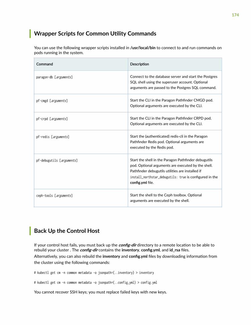
Wrapper Scripts for Common Utility Commands
You can use the following wrapper scripts installed in /usr/local/bin to connect to and run commands onpods running in the system.
Command Description
paragon-db [arguments] Connect to the database server and start the PostgresSQL shell using the superuser account. Optionalarguments are passed to the Postgres SQL command.
pf-cmgd [arguments] Start the CLI in the Paragon Pathfinder CMGD pod.Optional arguments are executed by the CLI.
pf-crpd [arguments] Start the CLI in the Paragon Pathfinder CRPD pod.Optional arguments are executed by the CLI.
pf-redis [arguments] Start the (authenticated) redis-cli in the ParagonPathfinder Redis pod. Optional arguments areexecuted by the Redis pod.
pf-debugutils [arguments] Start the shell in the Paragon Pathfinder debugutilspod. Optional arguments are executed by the shell.Pathfinder debugutils utilities are installed ifinstall_northstar_debugutils: true is configured in theconfig.yml file.
ceph-tools [arguments] Start the shell to the Ceph toolbox. Optionalarguments are executed by the shell.
Back Up the Control Host
If your control host fails, you must back up the config-dir directory to a remote location to be able torebuild your cluster . The config-dir contains the inventory, config.yml, and id_rsa files.Alternatively, you can also rebuild the inventory and config.yml files by downloading information fromthe cluster using the following commands:
# kubectl get cm -n common metadata -o jsonpath={..inventory} > inventory
# kubectl get cm -n common metadata -o jsonpath={..config_yml} > config.yml
You cannot recover SSH keys; you must replace failed keys with new keys.
174

User Service Accounts for Debugging
Paragon Pathfinder, telemetry manager, and base platform applications internally use Paragon Insightsfor telemetry collection. To debug configuration issues associated with these applications, three userservice accounts are created, by default, during Paragon Automation installation. The scope of theseservice accounts is limited to debugging the corresponding application only. The service accounts detailsare listed in the following table.
Table 12: Service Account Details
Application Name and Scope Account Username Account Default Password
Paragon Pathfinder (northstar) hb-northstar-admin Admin123!
Telemetry manager (tm) hb-tm-admin
Base platform (ems-dmon) hb-ems-dmon
You must use these accounts solely for debugging purposes. Do not use these accounts for day-to-dayoperations or for modifying any configuration. We recommend that you change the login credentials forsecurity reasons.
RELATED DOCUMENTATION
Install Multi-Node Cluster on CentOS | 99
Install Multinode Cluster on Ubuntu | 37
Backup and Restore | 153
Upgrade to Paragon Automation Release 21.3 | 144
Edit Cluster Nodes | 147
175

8CHAPTER
Migrate Data
Migrate Data from NorthStar to Paragon Automation | 177

Migrate Data from NorthStar to ParagonAutomation
IN THIS SECTION
Prerequisites | 177
Create the nsmigration Task Pod | 179
Export Cassandra DB Data to CSV Files | 179
Migrate DeviceProfile and Cassandra DB | 182
(Optional) Migrate Analytics Data | 185
(Optional) Migrate NorthStar Planner Data | 188
You can migrate DeviceProfile, Cassandra DB, and Analytics (ES DB) data from an existing NorthStarRelease 6.x setup to a Paragon Automation Release 21.3 setup.
Use the steps described in this topic to migrate date from NorthStar to Paragon Automation.
Prerequisites
• Ensure that both the NorthStar and Paragon Automation setups are up and running.
• Cassandra must be accessible from Paragon Automation. Set the rpc_address parameter in the /opt/northstar/data/apache-cassandra/conf/cassandra.yaml path to an address to which the ParagonAutomation setup can connect. After setting the address, restart Cassandra for the configurationchanges to take effect:
root@ns1: # supervisorctl restart infra:cassandra
• Ensure that both NorthStar and Paragon Automation have enough disk space to migrate theCassandra DB. The Cassandra migration exports all data to CSV files and sufficient space must beavailable for the migration operation. To ensure that sufficient space is available:
177

1. Log in to NorthStar and check the current disk usage by Cassandra. For a multisite setup, issue thefollowing command on all nodes in the setup and add them to calculate total disk usage:
[root@ns1-site1 ~]# du -sh /opt/northstar/data/apache-cassandra/404M /opt/northstar/data/apache-cassandra/ <--- Disk space used by Cassandra
2. Ensure that the available disk space on both NorthStar and Paragon exceeds the total Cassandradisk usage by at least a factor of 2. For Paragon Automation, this amount of space must beavailable on every node that has scheduling enabled on the device used for the /var/localdirectory. For NorthStar, only the node from which data is exported must have the available diskspace.
For example, on a Paragon Automation node that has a large root partition '/' without an optionalpartition for '/var/local':
root@pa-master:~# df -hFilesystem Size Used Avail Use% Mounted onudev 11G 0 11G 0% /devtmpfs 2.2G 32M 2.1G 2% /run/dev/sda3 150G 33G 110G 24% / <--- Available space for /var/localtmpfs 11G 0 11G 0% /dev/shm...
See "Disk Requirements" on page 14 for more information on partition options.
On NorthStar:
[root@ns1-site1 ~]# df -hFilesystem Size Used Avail Use% Mounted on/dev/sda1 108G 9.6G 99G 9% / <--- Available spacedevtmpfs 7.6G 0 7.6G 0% /devtmpfs 7.6G 12K 7.6G 1% /dev/shmtmpfs 7.6G 25M 7.6G 1% /run
Follow this procedure to migrate data from NorthStar to Paragon Automation.
178

Create the nsmigration Task Pod
1. Log in to the Paragon Automation primary node.
2. Create the nsmigration task pod.
root@pa-primary: # kubectl apply -f /etc/kubernetes/po/nsmigration/kube-cfg.yml job.batch/nsmigration created
3. Log in to the nsmigration task pod.
root@pa-primary:~# kubectl exec -it $(kubectl get po -n northstar -l app=nsmigration -o jsonpath={..metadata.name}) -c nsmigration -n northstar -- bashroot@nsmigration-fcvl6:/# cd /opt/northstar/util/db/nsmigration
Export Cassandra DB Data to CSV Files
For the migration procedure, you must export the contents of the Cassandra database in NorthStar toCSV files and copy those files to Paragon Automation.1. Copy the opt/northstar/thirdparty/dsbulk-1.8.0.tar.gz file and /opt/northstar/util/db/export_csv/cass_dsbulk_export_csv.py from the nsmigration container in Paragon Automation to the targetNorthStar installation:
Copy the files locally to the current node:
root@pa-master:~ mkdir migration_files && cd migration_filesroot@pa-master:~/migration_files# kubectl cp northstar/$(kubectl get po -n northstar -l app=nsmigration -o jsonpath={..metadata.name}):/opt/northstar/thirdparty/dsbulk-1.8.0.tar.gz ./dsbulk-1.8.0.tar.gzroot@pa-master:~/migration_files# kubectl cp northstar/$(kubectl get po -n northstar -l app=nsmigration -o jsonpath={..metadata.name}):/opt/northstar/util/db/export_csv/cass_dsbulk_export_csv.py ./cass_dsbulk_export_csv.py
Copy the files to the target NorthStar installation.
root@pa-master:~# scp -r migration_files root@${northstar_host}:/root/
179

2. Log in to the NorthStar instance, and install the migration utils by extracting the dsbulk-1.8.0.tar.gzfile,
[root@ns1-site1 migration_files]# tar -xf dsbulk-1.8.0.tar.gz
3. Export the contents of the Cassandra database to CSV files by running thecass_dsbulk_export_csv.py script. The --skip-historical-data option can be passed to this script to skipthe export of historical event date. For more information, see Table 13 on page 180.
Source the NorthStar environment file.
[root@ns1-site1 migration_files]# source /opt/northstar/northstar.env
Run the export script.
[root@ns1-site1 migration_files]# python3 cass_dsbulk_export_csv.py --dsbulk=$PWD/dsbulk-1.8.0/bin/dsbulk
Table 13: Historical Event Data Tables
keyspace table
taskscheduler taskstatus
pcs topology, lsp_topo, lsp_link, ntad, messages,pcs_lsp_event, link_event, node_event
pcs_provision provision
Running the script exports the contents of the Cassandra database (according to db_schema.json) tothe export_csv folder in the current working directory. The script pipes the progress output from thedsbulk invocations to stdout. Each table has its own sub-directory with one or more CSV files. Theprocedure may take a long time for larger databases.
[root@ns1-site1 migration_files]# python3 cass_dsbulk_export_csv.py --dsbulk=$PWD/dsbulk-1.8.0/bin/dsbulk2021-11-22 23:12:36,908: INFO: ns_dsbulk_export: Exporting NorthStarMLO:Default (page size 500)2021-11-22 23:12:39,232: INFO: ns_dsbulk_export: Operation directory: /root/dsbulk/logs/UNLOAD_20211122-231239-029958
180

2021-11-22 23:12:43,580: INFO: ns_dsbulk_export: total | failed | rows/s | p50ms | p99ms | p999ms2021-11-22 23:12:43,580: INFO: ns_dsbulk_export: 1 | 0 | 2 | 8.18 | 8.19 | 8.192021-11-22 23:12:43,581: INFO: ns_dsbulk_export: Operation UNLOAD_20211122-231239-029958 completed successfully in less than one second....2021-11-22 23:14:22,886: INFO: ns_dsbulk_export: Exporting pcs:links (page size 500)2021-11-22 23:14:24,891: INFO: ns_dsbulk_export: Operation directory: /root/dsbulk/logs/UNLOAD_20211122-231424-6839022021-11-22 23:14:28,863: INFO: ns_dsbulk_export: total | failed | rows/s | p50ms | p99ms | p999ms2021-11-22 23:14:28,863: INFO: ns_dsbulk_export: 16 | 0 | 29 | 6.08 | 6.09 | 6.092021-11-22 23:14:28,863: INFO: ns_dsbulk_export: Operation UNLOAD_20211122-231424-683902 completed successfully in less than one second...[root@ns1-site1 migration_files]# ls -l export_csv/total 0drwxr-xr-x. 2 root root 6 Nov 22 23:20 anycastgroup-anycastgroupIndexdrwxr-xr-x. 2 root root 6 Nov 22 23:20 cmgd-configurationdrwxr-xr-x. 2 root root 6 Nov 22 23:19 device_config-configletsdrwxr-xr-x. 2 root root 6 Nov 22 23:19 device_config-configlets_workorder...[root@ns1-site1 migration_files]# ls -l export_csv/pcs-linkstotal 16-rw-r--r--. 1 root root 14685 Nov 22 23:14 pcs-links-000001.csv
NOTE: The exported CSV files also serve as a backup of the Cassandra DB data. Werecommend archiving the files in case data needs to be restored in the future.
4. Copy the export_csv folder to the Paragon Automation node where the nsmigration pod is running.
root@pa-master:~# kubectl get po -n northstar -l app=nsmigration -o jsonpath={..spec.nodeName}10.52.44.210 <--- In this example, this is the worker3 node
181

Copy the exported files to the correct directory on worker3 node.
root@pa-worker3:~# cd /var/local/ns_db_migration/ && scp -r root@{northstar_ip}:/root/migration_files/export_csv .
Migrate DeviceProfile and Cassandra DB
1. Run the ns_data_migration.py -a -sp -dp script from the nsmigration task pod. The complete commandsyntax is ./ns_data_migration.py -a ns-app-server-ip -su root -sp ns-app-user-ssh-password -dh cassandra-db-host -du cassandra -dp cassandra-password -dcsv /opt/northstar/ns_db_migration/export_csv -pu postgres-user -pp postgres-password -ph postgres-host -po postgres-port -pah vip-of-ingress-controller-or-hostname-of-main-web-application -pau paragon-web-ui-login -pap paragon-web-ui-password -dr 1.For example:
root@nsmigration-7xbbz:/opt/northstar/util/db/nsmigration# ./ns_data_migration.py -a 10.xx.xx.200 -su root -sp password -dh 10.xx.xx.200 -dp password -dcsv /opt/northstar/ns_db_migration/export_csv -pu northstar -pp BB91qaDCfjpGWPbjEZBV -ph atom-db.common -po 5432 -pah 10.xx.xx.11 -pau admin -pap password1 -dr 1 Logs stored at /opt/northstar/util/db/nsmigration/logs/nsdatamigration.logCassandra connection established...connection attempt: 1Testing cassandra connectivityConnected to cluster Test ClusterTesting EMS connectivityscope_id: d3ae39f7-35c6-49dd-a1bd-c509a38bd4ea, auth_token length: 1160scoped token length: 1303jwt_token length: 40974All connection ok starting mirgationStarting device profile migration...Found 2 devices in Northstar device profile
...2022-04-26 20:57:01,976:INFO:Loading health_monitor-health_history-000001.csv (~ 5 rows)2022-04-26 20:57:01,996:INFO:Loaded 5/~5 rows2022-04-26 20:57:01,996:INFO:Copying csv data for table health_monitor:thresholds2022-04-26 20:57:01,997:INFO:Using batch size 5002022-04-26 20:57:02,001:INFO:Loading health_monitor-thresholds-000001.csv (~ 1 rows)2022-04-26 20:57:02,003:INFO:Loaded 1/~1 rows2022-04-26 20:57:02,004:INFO:Copying csv data for table planner:networkdata
182

2022-04-26 20:57:02,005:INFO:Using batch size 202022-04-26 20:57:02,008:INFO:Loading planner-networkdata-000001.csv (~ 1 rows)2022-04-26 20:57:02,071:INFO:Loaded 1/~1 rows...The NS data migration completed
You must specify the following parameters while running the ns_data_migration.py script.
• -a APP, --app APP—IP address or hostname of the application server
• -su SSHUSER, --sshuser SSHUSER—SSH username (default is root)
• -sp SSHPASS, --sshpass SSHPASS—SSH password
• -so SSHPORT, --sshport SSHPORT—SSH port (default is 22)
• -du DBUSER, --dbuser DBUSER—Cassandra DB username (default is cassandra)
• -dp DBPASS, --dbpass DBPASS—Cassandra DB password
• -do DBPORT, --dbport DBPORT—Cassandra DB port (default is 9042)
• -dh DBHOST, --dbhost DBHOST—Comma-separated host IP addresses of Cassandra DB
• -pu PGUSER, --pguser PGUSER—Postgres DB username (default is northstar)
• -dcsv DBCSV, --dbCsvPath DBCSV—The path with CSV data exported from Cassandra
• -pp PGPASS, --pgpass PGPASS—Postgres DB password
• -ph PGHOST, --pghost PGHOST—Postgres DB host (default is atom-db.common)
• -po PGPORT, --pgport PGPORT—Postgres DB port (default is 5432)
• -pah PARAGONHOST, --paragonHost PARAGONHOST—Virtual IP (VIP) address of Paragon Automation Web UI
• -pau PARAGONUSER, --paragonUser PARAGONUSER—Paragon Automation Web UI username
• -pap PARAGONPASSWORD, --paragonPassword PARAGONPASSWORD—Paragon Automation Web UI user password
• -dr DISCOVERYRETRIES, --discoveryRetries DISCOVERYRETRIES—Device discovery retries (default is 2).You use the dr DISCOVERYRETRIES option for DeviceProfile migration when Paragon Automation failsto discover devices at the first attempt. There are multiple reasons for discovery failure, such asdevices not being reachable or device credentials being incorrect. Despite discovery failure fordevices with incorrect information, Paragon Automation discovers devices with correctinformation. Partial failure for a subset of devices while discovering multiple devices at a time ispossible. To determine the exact reason of failure, see the Monitoring > Jobs page in the ParagonAutomation Web UI.
183

If the dr option is set to more than 1, on getting a discovery failure, the ns_data_migration.py scriptretries the discovery for all the devices. This attempt does not impact the devices that are alreadydiscovered. However, the chances of successfully discovering devices in subsequent attempts forany failed device discovery is minimal. We recommend that you set the maximum value for the droption to 2, which is the default value. If there are too many devices in the network, then use avalue of 1 to avoid unnecessary retries.
NOTE: When migrating Cassandra DB data from NorthStar to Paragon Automation, largetables with millions of rows might cause the migration to proceed very slowly and take a longtime. Often these large tables contain historical event data that you can discard duringmigration. To skip migrating this data, you can manually set the '--dbSkipHistoricalData' flagwhile calling the 'ns_data_migration.py' script. This means that the data in the historical eventtables listed in Table 13 on page 180 is not available in Paragon Automation. This data ispermanently lost if not backed up once the NorthStar instance is removed.
2. Verify the DeviceProfile data.
Log in to Paragon Automation Web UI and navigate to Configuration > Device. Verify that all thedevices are discovered and present. Also, verify that the configuration information is the same as thatin the NorthStar device profile.
To view the device discovery result, go to the Monitoring > Jobs page in the Paragon AutomationWeb UI.
3. Verify Cassandra DB data.
The log output of the ns_data_migration.py script indicates whether there were any problems migratingdata from Cassandra. You can also run a script to verify the data in Paragon Automation against theexported CSV files. Note, this may take a long time for larger databases. From the nsmigrationcontainer, run:
root@nsmigration-h7b9m:~# python3 /opt/northstar/util/db/dbinit.py --schema=/opt/northstar/util/db/db_schema.json --host=$PG_HOST --port=$PG_PORT --user=$PG_USER --password=$PG_PASS --dbtype=postgres --check-schema-version --from-cassandra-csv=/opt/northstar/ns_db_migration/export_csv --verify-data --log-level=DEBUG 2>&1 | tee debug_migration.log...2022-04-26 21:11:12,466:INFO:Loading health_monitor-health_history-000001.csv (~ 5 rows)2022-04-26 21:11:12,484:INFO:Loaded 5/~5 rows2022-04-26 21:11:12,484:INFO:Verify stats health_monitor:health_history: Verified 5/52022-04-26 21:11:12,484:INFO:Copying csv data for table health_monitor:thresholds2022-04-26 21:11:12,484:INFO:Using batch size 5002022-04-26 21:11:12,489:INFO:Loading health_monitor-thresholds-000001.csv (~ 1 rows)2022-04-26 21:11:12,491:INFO:Loaded 1/~1 rows2022-04-26 21:11:12,491:INFO:Verify stats health_monitor:thresholds: Verified 1/1
184

2022-04-26 21:11:12,491:INFO:Copying csv data for table planner:networkdata2022-04-26 21:11:12,491:INFO:Using batch size 202022-04-26 21:11:12,496:INFO:Loading planner-networkdata-000001.csv (~ 1 rows)2022-04-26 21:11:12,532:INFO:Loaded 1/~1 rows2022-04-26 21:11:12,533:INFO:Verify stats planner:networkdata: Verified 1/1
The script outputs (rows verified)/(rows checked) in each table (see lines beginning with "Verify") tostdout and debug_migration.log. Note that some rows may have been updated after the data wasimported but before it was verified, so 'rows verified' may not always equal 'rows checked'. Theexported CSV files can be removed once the migration is complete by simply removing the /var/local/ns_db_migration/export_csv directory on the relevant node.
(Optional) Migrate Analytics Data
If you have installed Analytics, perform the following steps to migrate analytics data from NorthStar ESDB to Paragon Automation Influx DB:1. Log in to the nsmigration task pod, and run the import_es_data.py -a script.
root@nsmigration-p7tcd:/# cd /opt/northstar/util/db/nsmigrationroot@nsmigration-p7tcd:/opt/northstar/util/db/nsmigration# ./import_es_data.py -a 10.xx.xx.95Logs stored at /opt/northstar/util/db/nsmigration/logs/es_data_migration.logCerts are missing, fetching them from Northstar app serverPlease enter SSH password:Testing Elasticsearch connectivityElasticsearch DB connection okTesting Influx DB connectivityInflux DB connection okStarting data extraction for type= interface
<OUTPUT SNIPPED>
"migration_rate_sec": 1471.1758360302051, "timetaken_min": 0.7725, "total_points": 68189}ETLWorker-2 completed, total points=68189 in 0.7725 minutes with migration_rate=1471.1758360302051
You must specify the following import_es_data.py script options:.
185

• Statistics type—By default, supports interface, label-switched path (LSP), and link-latencystatistics data. You can select a specific type by using the --type option.
• Rollups type—By default, supports daily and hourly time periods. You can select a specific type byusing the --rollup_type option.
• Migration schema—The mapping of ES DB to Influx DB schema is defined in the /opt/northstar/util/db/nsmigration/es_influx_mapping.json file.
• Rollup ages—By default, fetches hourly and daily data for the last 180 days and 1000 days,respectively. You can change the ages by using the --hourly_age and --daily_age options.
• ETL parallel worker process—By default, uses four ETL parallel worker processes. You can changethe worker process by using the --wp option.
• Execution time—The script execution time varies based on data volume, the number of days, andthe number of ETL parallel worker processes. For example, if four ETL workers use a migrationrate of 1500, then:
• 25,000 LSP statistics of 180 days hourly can take 5 hours
• 50,000 LSP statistics of 180 days hourly can take 10 hours
For more information about script arguments, see help 'import_es_data.py -h'.
2. Verify Influx DB data using the following commands.
• To query all tunnel traffic data for the last 30 days in Influx DB, run the /opt/pcs/bin/getTrafficFiles.py script inside the dcscheduler pod:
root@pa-primary:~# kubectl exec -it $(kubectl get po -n northstar -l app=dcscheduler -o jsonpath={..metadata.name}) -c dcscheduler -n northstar -- /opt/pcs/bin/getTrafficFiles.py -t tunnel_traffic -i 1d -b 30#Starting Time : 08/17/21 12:00:00 AM#Interval : 24 hour# UNIT = 1
# Aggregation:# - Series: time series# - Statistic: 95th percentile# - Interval: 1 day# Report Date= 2021-09-16 (Thu) 08:56
vmx101:Silver-101-102 A2Z 0 0 0 0 0 0 0 0 0 0 0 0 0 0 0 0 0 0 0 0 0 0 0 0 0 -1 -1 -1 0 -1 -1vmx101:Silver-101-104 A2Z 0 0 0 0 0 0 0 0 0 0 0 0 0 0 0 0 0 0 0 0 0 0 0 0 0 0 0 0 0 -1 -1
186

vmx102:Silver-102-101 A2Z 0 1071913 1072869 1073082 1073378 1073436 1073378 1073620 1073378 1073388 1073484 1073896 1074086 1073974 1073795 1073378 1073590 1073790 1074498 1074595 1074498 1074092 1076565 1076565 1076919 1075502 1075857 1075325 1075148 -1 -1vmx102:Silver-102-103 A2Z 0 2118101 2120705 2121258 2120438 2120773 2119652 2121258 2120296 2120190 2120962 2121364 2121867 2121817 2122209 2120167 2120323 2121665 2122733 2122685 2122321 2121511 2121855 2119546 2119700 2109572 2102489 2101604 2121258 2109749 2110280vmx102:Silver-102-104 A2Z 0 3442749 3449550 3450757 3448983 3448603 3446081 3453525 3451513 3448142 3449008 3450874 3452721 3451650 3450733 3447297 3447147 3449132 3451747 3450887 3450727 3448429 3452310 3448132 3447328 3200657 3200480 3197646 3445363 3215530 3215884vmx103:Silver-103-101 A2Z 0 2149705 2151625 2158319 2170251 2170980 2171171 2169252 2167757 2168518 2172730 2168582 2166350 2161904 2161460 2167162 2158050 2160413 2166131 2167033 2166226 2165632 2171717 2178973 2178102 2158015 2158015 2157661 2157306 -1 -1vmx103:Silver-103-102 A2Z 0 2122922 2125508 2131074 2141411 2142899 2141840 2139937 2138338 2139743 2144156 2139602 2138745 2134561 2132725 2137973 2129397 2132755 2138203 2138653 2136713 2135444 2144637 2150006 2147677 2108332 2107801 2107270 2124800 2112228 2113113vmx103:Silver-103-104 A2Z 0 3426540 3437589 3447876 3461550 3464308 3461249 3460710 3453848 3458821 3463446 3456119 3456969 3450036 3446943 3451602 3439059 3445325 3455444 3455491 3454308 3449833 3468558 3472376 3470223 3185429 3187731 3183304 3430135 3198001 3202781vmx104:Silver-104-102 A2Z 0 0 0 0 0 0 0 0 0 0 0 0 0 0 0 0 0 0 0 0 0 0 0 0 0 0 0 0 0 0 0vmx104:Silver-104-103 A2Z 0 0 0 0 0 0 0 0 0 0 0 0 0 0 0 0 0 0 0 0 0 0 0 0 0 0 0 0 0 0 0vmx105:rsvp-105-106 A2Z 0 114 114 121 116 122 125 125 114 214 224 215 223 213 223 222 226 222 217 213 214 216 219 218 219 202 202 202 211 204 202
• To query all egress interface traffic data for the last 30 days in Influx DB, run the /opt/pcs/bin/getTrafficFiles.py script inside the dcscheduler pod:
root@pa-primary:~# kubectl exec -it $(kubectl get po -n northstar -l app=dcscheduler -o jsonpath={..metadata.name}) -c dcscheduler -n northstar -- /opt/pcs/bin/getTrafficFiles.py -t interface_out -i 1d -b 30#Starting Time : 08/17/21 12:00:00 AM#Interval : 24 hour# UNIT = 1
# Aggregation:# - Series: time series# - Statistic: 95th percentile# - Interval: 1 day# Report Date= 2021-09-16 (Thu) 08:49
187

vmx101 ge-0/0/8.0 A2Z 0 2620 2620 2621 2621 2621 2621 2622 2622 2623 2624 2626 2627 2627 2627 2627 2627 2627 2627 2627 2628 2631 2631 2632 2632 0 0 0 2632 -1 -1vmx101 ge-0/0/5 A2Z 0 843 846 848 860 843 858 863 866 1001 1012 1012 1018 1011 1048 1018 1048 1027 1013 1025 1017 1010 1046 1046 1048 1053 1055 1073 1045 -1 -1.........vmx107 ge-0/0/8.0 A2Z 0 2620 2621 2622 2622 2623 2624 2626 2626 2630 2631 2632 2632 2632 2632 2632 2632 2633 2633 2635 2635 2635 2635 2636 2636 0 0 0 2636 0 0vmx107 ge-0/1/9.0 A2Z 0 6888955 6907022 6907653 6902645 6899706 6892876 6905804 6902894 6899395 6897851 6897322 6896863 6900351 6898745 6890080 6889337 6896781 6902034 6899116 6898749 6898630 6903136 6889662 6890800 6401393 6410976 6400867 6885900 6431500 6436156vmx107 ge-0/0/5 A2Z 0 4290428 4296767 4297691 4295393 4292480 4290593 4293842 4293149 4295279 4294504 4294045 4294905 4294996 4294921 4292093 4292703 4295408 4297494 4296424 4295983 4295972 4296808 4294929 4299425 4285605 4286205 4285146 4288390 2126258 2127510vmx107 ge-0/0/6 A2Z 0 0 0 0 0 0 0 0 0 0 0 0 0 0 0 0 0 0 0 0 0 0 122 122 122 122 122 122 122 122 122vmx107 ge-0/0/7 A2Z 0 878 874 915 898 886 879 897 889 1028 1021 1022 1023 1055 1079 1077 1097 1094 1092 1044 1007 1028 1062 1065 1057 1094 1075 1071 1102 1082 1054vmx107 ge-0/0/8 A2Z 0 2921 2925 2925 2924 2925 2926 2928 2928 2930 2934 2934 2936 2934 2935 2935 2934 2935 2936 2939 2938 2938 19892 20581 20965 20582 21076 20376 21578 23252 21312vmx107 ge-0/1/8 A2Z 0 2127443 2130145 2130846 2128792 2128138 2127177 2128628 2128331 2128820 2128716 2128916 2129022 2129380 2128995 2127648 2127240 2128885 2130132 2130474 2130345 2129410 2129376 2125952 2125957 2117061 2114139 2119148 2126518 2122808 2121792vmx107 ge-0/1/9 A2Z 0 6889737 6907821 6908350 6903585 6900486 6893779 6906516 6903747 6900412 6898908 6898427 6897892 6901325 6899809 6891078 6890377 6897822 6903099 6900152 6899763 6899726 6904248 6890745 6891782 6402507 6412083 6401924 6884168 6432556 6437280
(Optional) Migrate NorthStar Planner Data
If you want to use saved NorthStar Planner models on the NorthStar application server file system inParagon Automation, copy the models using the following steps:1. Log in to the NorthStar server.
188

2. Use scp and copy the directory (/opt/northstar/data/specs) where your Planner models are saved tothe Paragon Automation primary node (/root/ns_specs). For example:
[root@ns1-site1 specs]# ls -l /opt/northstar/data/specstotal 8drwx------ 2 root root 4096 Sep 16 08:18 network1drwx------ 2 root root 4096 Sep 16 08:18 sample_fish
[root@ns1-site1 data]# [root@ns1-site1 ~]# scp -r /opt/northstar/data/specs [email protected]:/root/ns_specsThe authenticity of host '10.xx.xx.153 (10.xx.xx.153)' can't be established.ECDSA key fingerprint is SHA256:haylHqFfEuIEm8xThKbHJhG2uuTpT2xBpC2GZdzfZss.ECDSA key fingerprint is MD5:15:71:76:c7:d2:2b:0d:fe:ff:0d:5f:62:7f:52:80:fe.Are you sure you want to continue connecting (yes/no)? yesWarning: Permanently added '10.xx.xx.153' (ECDSA) to the list of known hosts.bblink.x 100% 3893 2.2MB/s 00:00bgplink.x 100% 140 9.6KB/s 00:00bgpnode.x 100% 120 56.5KB/s 00:00bgpobj.x 100% 4888 1.8MB/s 00:00cosalias.x 100% 385 180.4KB/s 00:00custrate.x 100% 1062 184.0KB/s 00:00demand.x 100% 104KB 2.1MB/s 00:00dparam.x 100% 11KB 2.5MB/s 00:00...
3. Log in to the Paragon Automation primary node.
4. Copy the /root/ns_specs folder to the NorthStar Planner pod at /opt/northstar/data/specs using thekubectl command. For example:
root@pa-primary:~# ls -l /root/ns_specstotal 8drwx------ 4 root root 4096 Sep 16 01:41 network1
189

drwx------ 4 root root 4096 Sep 16 01:41 sample_fish
root@pa-primary:~# kubectl cp /root/ns_specs northstar/$(kubectl get po -n northstar -l app=ns-web-planner -o jsonpath={..metadata.name}):/opt/northstar/data/specs -c ns-web-planner
5. Verify that the NorthStar Planner models are copied inside the NorthStar Planner pod at /opt/northstar/data/specs/ns_specs.
root@pa-primary:~/ns_specs# kubectl exec -it $(kubectl get po -n northstar -l app=ns-web-planner -o jsonpath={..metadata.name}) -c ns-web-planner -n northstar -- ls -l /opt/northstar/data/specs/ns_specstotal 8drwx------ 2 root root 4096 Sep 16 08:18 network1drwx------ 2 root root 4096 Sep 16 08:18 sample_fish
RELATED DOCUMENTATION
Paragon Automation System Requirements | 8
Install Multinode Cluster on Ubuntu | 37
Install Multi-Node Cluster on CentOS | 99
Uninstall Paragon Automation | 151
190