Diastereoselective auxiliary- and catalyst-controlled - Archive ...
Upload
independentCategory
view
0download
0
Sol–gel-derived super-hydrophilic nickel doped
TiO2 film as active photo-catalyst
Sunil Dutta Sharma *, Davinder Singh, K.K. Saini, Chander Kant,Vikash Sharma, S.C. Jain, C.P. Sharma
National Physical Laboratory, Dr. K.S. Krishnan Marg, New Delhi 110012, India
Received 13 June 2006; received in revised form 20 July 2006; accepted 31 July 2006
Available online 7 September 2006
Abstract
Pure and nickel doped TiO2 thin films on soda glass substrates were prepared by sol–gel dip coating process. The resulting films were annealed
at 500 8C for 1 h and characterized by X-ray diffraction (XRD), atomic force microscopy (AFM), X-ray photoelectron spectroscopy (XPS) and
UV–vis-near IR techniques. AFM reveals that doping of Ni ions suppresses the grain growth of crystal in the TiO2 film. The contact angle with
water of these films was measured by sessile drop method. The undoped films could be entirely wetted by water after 1 h UV illuminations, while
0.5 mol% Ni ion-doped films become entirely wetted after 20 min UV illumination. The photo-catalytic activity was characterized by photo-
catalytic degradation of aqueous methyl orange under UV radiation. It is found that, with a suitable amount (2–10 mol%), the Ni dopant increases
the photo-catalytic activity of TiO2 films. The mechanism can be attributed to these processes: (1) as the anatase grain sizes decrease with Ni doping
and the specific surface areas of doped TiO2 films increase, the charge transfer in TiO2 film is promoted; (2) by enhancing the electron–hole pair
separation and inhibiting their recombination, the Ni dopant enhances the charge pair separation efficiency for doped TiO2 films.
# 2006 Elsevier B.V. All rights reserved.
Keywords: Titanium dioxide; Sol–gel; Hydrophilicity; Photo-catalyst
www.elsevier.com/locate/apcata
Applied Catalysis A: General 314 (2006) 40–46
1. Introduction
Nano-crystalline TiO2 thin films have attracted a great deal
of attention. They have many advanced functions in photo-
catalysis [1], solar energy cells [2], gas sensors [3], sterilizing
[4] and antifogging [5]. In 1997, Wang et al. [6] reported a new
phenomenon, denoted as super-hydrophilicity in TiO2 films.
When the films are irradiated by ultraviolet (UV) light, the
contact angle with water of these films decreases gradually and
finally becomes zero. There have been numerous research
papers reporting improvement in the photo-catalytic activity
and super-hydrophilicity of TiO2 thin films. Fujishima et al. [7]
reviewed the current progress in the area of TiO2 photo-
catalysis, observed the photo-induced super-hydrophilic phe-
nomenon in TiO2 and discussed its potential applications.
Navio et al. [8] studied the photo-catalytic efficiency of iron
doped titania containing Fe prepared from TiCl4 and Fe(III)
* Corresponding author.
E-mail address: [email protected] (S.D. Sharma).
0926-860X/$ – see front matter # 2006 Elsevier B.V. All rights reserved.
doi:10.1016/j.apcata.2006.07.029
acetylacetonate by sol–gel method. Watanabe et al. [9]
evaluated photo-induced hydrophilic conversion on different
crystal phases of single crystal rutile and polycrystalline
anatase titanium dioxide to clarify the dependence of the crystal
structure on the photo-induced hydrophilic conversion. Thanks
to this phenomenon, this discovery attracted much interest
to TiO2 films. However, there is still a problem that photo-
catalytic efficiency is not high, since TiO2 is active only under
ultraviolet (UV) light, because of its wide band gap �3.2 eV
and because the recombination of photo-generated electron–
hole pairs exhibits low photoquantum efficiency. The effective
separateness of electron–hole pairs, therefore, is one of the
important subjects for the increased utility of TiO2 as a photo-
catalyst. In recent years, impurity doping has been widely
performed by chemical synthesis and other methods in order to
improve photoactivity [10]. Because transition metal elements
have many valences and because trace transition metal ions
doped in the TiO2 matrix can be superficial potential traps
of photo-generated electron–hole pairs, then the process
lengthen the lifetime of electrons and holes and increase the
photo-catalytic activity.

S.D. Sharma et al. / Applied Catalysis A: General 314 (2006) 40–46 41
Many transition metal ion dopants have been investigated
for the TiO2 systems, among which iron has been most
examined [11]. In this paper, we reported the effect of different
amounts of nickel ions on photo-generated hydrophilicity and
photo-catalytic activity of TiO2 thin films.
2. Experimental
2.1. Preparation of TiO2 precursor sol
A 0.5 M TiO2 sol was prepared by the partial hydrolysis and
poly-condensation of titanium tetra-butoxide with water using
isopropyl alcohol (IPA) as a solvent and HNO3 as a catalyst.
Titanium tetrabutoxide and water have been taken in 1:2 molar
ratio. The hydrolysis and poly-condensation of titanium
tetrabutoxide proceeds according to the following scheme:
TiðOC4H9Þ4þ 2H2O ! TiðOC4H9Þ2ðOHÞ2þ 2C4H9OH
TiðOC4H9Þ2ðOHÞ2þTiðOC4H9Þ2ðOHÞ2! Ti2OðOC4H9Þ4ðOHÞ2þH2O
This reaction stops with the inclusion of two water
molecules:
TiðOC4H9Þ4þ 2H2O ! TiO2þ 4C4H9OH
All the chemicals used were of AnalaR grade and were used
as procured i.e. without further purification. The mixture was
stirred vigorously with a magnetic stirrer for 1 h. This results in
a colored transparent solution. The solution was kept overnight
before film deposition.
2.2. Preparation of pure TiO2 and Ni/TiO2 films
For the film deposition, the substrates were first degreased,
cleaned thoroughly and dried before deposition. Then the
substrate was dipped in the precursor solution bath and pulled
out with a constant speed of 12 cm/min to obtain the films of
uniform thickness. A very thin film of TiO2 that formed on the
substrate was first dried in air at room temperature, followed by
drying at 100 8C for 30 min in an electric oven. The films
formed were further heated at 500 8C for 1 h in an electric
furnace in air. The thickness of the films was adjusted by
repeating the above cycle.
For the preparation of the doped titania film, the procedure
was performed as described above; besides that, the appropriate
amount of nickel acetylacetonate from 2 to 10 mol% was
dissolved in the TiO2 precursor sol.
2.3. Characterization techniques
AFM and XRD studies were performed to get the structure
and final phase formation. XRD spectra of the samples have
been recorded in the 2u range 20–808 for crystal phase
identification with a SIEMENS D-500 diffractometer using
monochromatized Cu Ka radiation (l = 1.541 A). The surface
composition and chemical states of the films were analyzed by
X-ray photoelectron spectroscopy (XPS) using Al Ka on a
Perkin Elmer f model with hemispherical analyzer. The
nanoparticle size and surface morphology were studied using a
Nanoscope IIIa Atomic Force Microscope (AFM). Transmis-
sion and absorption spectra were recorded from 300 to 800 nm
with a SHIMADZU UV-3101 PC UV–visible spectrophot-
ometer at normal incidence. The hydrophilicity of the films was
studied in terms of contact angle measurement by a sessile drop
method using a CCD camera.
2.4. Photo-catalytic measurements
It has been well demonstrated that photo-degradation of an
organic compound will occur when TiO2 is illuminated by light
(l < 388 nm) in the presence of water containing dissolved
oxygen and organic compounds. Many organic compounds are
known to be degraded to CO2 under these conditions. The
primary step in photo-degradation is certainly the generation of
electrons and holes within the TiO2 particles.
TiO2 �!l< 388 nm
TiO2ðe� þ hþÞ (1)
In the presence of dissolved oxygen and an electron donor,�OH radical is formed by the reaction between the valence band
holes (h+) and the TiO2 surface-active OH� group or H2O.
hþ þ OH�!�OHad1 (2)
hþ þ H2Oad!�OHad þ Hþ (3)
The photogenerated conduction band electron (e�) is
trapped by the dissolved oxygen to form a super-oxide ion O2�.
e� þ O2!O2� (4)
Methyl orange is attacked by hydroxyl radicals formed in
the above equations and generates inorganic radicals or
some other intermediates. Eventually all the parent compounds
and intermediates are oxidized into CO2, SO42�, and NO3
�
[12].
TiO2 films are settled in aqueous methyl orange with a
concentration of 10 mg l�1 in a quartz cell (10 mm � 10 mm �30 mm). A high pressure mercury lamp (125 W) is used as a light
source. One face (10 mm � 30 mm) of TiO2 thin films is
irradiated along the normal direction. The averaged intensity of
UV irradiance was found to be 0.5 mW cm�2 by measuring with
a UV irradiance meter (Model UV-A); the wavelength range is
320–400 nm and the peak wavelength is 365 nm. The solution is
bubbled with air during irradiation. The concentration of aqueous
methyl orange is determined with a UV–vis spectrophotometer
by measuring the absorbance at 490 nm, because methyl orange
shows an intense band at approximately at 490 nm (A) and the
concentration of methyl orange (C) can be represented
empirically by the equation:
A ¼ 0:0725� C (5)
All the concentration profiles can be correlated by the
following exponential function with good agreement:
C ¼ C0 expð�ktÞ (6)

S.D. Sharma et al. / Applied Catalysis A: General 314 (2006) 40–4642
The apparent rate constant in the above equation decreases
with the increasing of initial concentration of methyl orange
when other parameters are kept unchanged. Therefore, the
photocatalytic decolorization of methyl orange is pseudo-first-
order reaction and its kinetic may also be expressed as follows
[12]:
ln
�C0
C
�¼ kt (7)
According to Eq. (5), Eq. (7) can also be expressed as
follows:
ln
�A0
A
�¼ kt (8)
where A0 is the initial absorbance of aqueous methyl orange, t
the reaction time and A is the absorbance of aqueous methyl
orange at t. k is determined by the linear regression method.
3. Results and discussion
3.1. XRD patterns
Fig. 1 shows XRD patterns of pure and Ni-ion doped TiO2
films annealed at 500 8C. Typical peaks in XRD pattern of TiO2
film are observed at 2u values of 25.288, 38.088, 48.048 and
55.028; these are assigned to 1 0 1, 1 1 2, 2 0 0 and 2 1 1 planes
respectively. Calculations show that the observed crystalline
peaks correspond to anatase TiO2 phase [13]. There is no
indication of rutile phase formation up to a sintering
temperature of 500 8C. For Ni ion-doped TiO2 films; the
crystalline phases of compounds formed by Ni ions were not
detected even when Ni ion concentration was as high as
10 mol%.
Fig. 1. XRD spectra of: (a) pure TiO2 film and (b) 10 mol% Ni/TiO2 film
annealed at 500 8C for 1 h.
3.2. X-ray photoelectron spectroscopy analysis
The photoelectron spectra of pure and Ni ion-doped TiO2
films annealed at 500 8C for 1 h is shown in Fig. 2. During XPS
Fig. 2. X-ray photoelectron spectra of: (a) 2 mol% (b) 5 mol% (c) 8 mol% and
(d) 10 mol% Ni-doped TiO2 thin films.

S.D. Sharma et al. / Applied Catalysis A: General 314 (2006) 40–46 43
Fig. 3. AFM images of: (a) pure TiO2 and (b) 10 mol% Ni-doped TiO2 films.
Fig. 4. UV–vis transmittance spectra of pure and Ni ion-doped TiO2 films.
measurements, development of static charge at the sample
surface created a problem in locating the actual binding energy
positions of Ti 2p and O 1s lines. To overcome this problem, the
amount of static charge was determined by keeping the binding
energy position of C 1s line fixed at 284.6 eV [14]. Thus the
amount of static charge that develops on the film surface was
estimated to be 3.95 eV. In the present study, the actual binding
energy positions corresponding to Ti 2p3/2 and Ti 2p1/2 lines for
pure TiO2 films were found at 457.95 and 463.6 eV; these
indicate the presence of Ti4+ in TiO2 film [15]. The binding
energies of Ti 2p region for the Ni-doped samples were almost
the same as those for pure TiO2 film, except that the XPS peaks
were slightly broadened in highly doped films containing more
than 4 mol% nickel oxide. Titanium was also in the Ti4+
oxidation state in all the Ni-doped TiO2 films.
Oxygen in the films was in the form of O2� in TiO2 and NiO.
The O 1s peak broadened to higher binding energy, which was
associated with the surface hydroxide, could be seen in sample
a and b with small amounts of nickel. The hydroxide might play
an important role in the degradation process. The redox
potential for photo-generated holes is +2.53 V versus the
standard hydrogen electrode (SHE) [7]. After reaction with the
hydroxide, these holes can produce hydroxyl radicals (�OH)
whose redox potential is only slightly decreased.
The NiO was characterized by high-intensity shake-up
satellites at the binding energy about 9 eV higher than the main
Ni 2p3/2 and Ni 2p1/2. In samples c and d with higher Ni
concentration, the Ni 2p peaks and their satellites had high
intensity, indicating the existence of fully oxidized nickel oxide
in the films [16]. Although the intensities of Ni 2p peaks were
low in sample a because of the small amount of Ni, the shake-up
satellites peaks with comparably high intensity could clearly be
seen in the spectra.
3.3. AFM observation
AFM was used to characterize the uniformity and particle
size of pure and doped films. As shown in Fig. 3, the TiO2
crystals of the two samples both exhibit spherical shape. The
TiO2 crystal of the pure film has a particle of 40–50 nm
(Fig. 3a), while TiO2 thin film with 10 mol% Ni ions added
(Fig. 3b) has TiO2 crystals whose particle size is as small as
about 20–30 nm. The crystal size of TiO2 in the film increases
significantly during the annealing process; for the Ni ion-doped
samples, the grain growth of TiO2 is inhibited and the particle
size is much smaller.
It has been observed that observed XRD peaks in Ni doped
TiO2 films are wider than in case of undoped TiO2 films. The
average crystallite size in TiO2 films has been calculated from
the widening of the XRD peaks using Scherer’s formula [17].
The crystallite size decreases from 40–50 nm in case of pure
TiO2 films to 20–30 nm in case of 10 mol% Ni doped TiO2
films. The reason for this reduction in crystallite size is that the
introduction of Ni2+ ions change the surface charge of the TiO2
sol particles and distances them from each other. In this way, the
TiO2 particles most likely formed in smaller size. This finding
is supported by AFM also.
3.4. UV–vis transmittance spectra
Fig. 4 shows the UV–vis transmittance spectra over the
wavelength range of 300–800 nm for pure and Ni ion-doped
TiO2 films deposited on soda glass. Pure TiO2 film shows up to

S.D. Sharma et al. / Applied Catalysis A: General 314 (2006) 40–4644
Fig. 6. The influences of Ni ions doping on hydrophilicity of TiO2 films.
85% transmittance in the visible region. The transmittance of
Ni ion-doped TiO2 films decreases as the concentration of
dopant increases because the metal absorbs electromagnetic
radiation in this region. For 10 mol% doped film, the
transmittance decreases up to 60%.
3.5. UV–vis absorption spectra
Fig. 5 shows the UV–vis absorption spectra over the
wavelength range of 300–450 nm for pure and Ni ion-doped
TiO2 films deposited on soda glass. The absorption edge shifts
to the longer wavelength direction in doped films. The reason
for this large bathochromic shift in optical energy gap is that the
energy level for Ni2+/Ni+ lies below the conduction band edge
(Ecb) and above the valence band edge (Evb) of TiO2.
Introduction of such energy levels in the band gap induces
the bathochromic shift in the band gap transition and the visible
light absorption through a charge transfer between a dopant and
CB (or VB) or a d–d transition in the crystal field according the
energy level [18].
3.6. Hydrophilicity
Fig. 6 shows the contact angle of water on pure TiO2 film and
on TiO2 films doped with different amounts of Ni ions under
0.5 mW cm�2 UV illumination. The contact angle of water on
pure TiO2 film before UV illumination was 528, indicative of its
relative hydrophobicity. After some time of UV exposure, the
contact angle of water decreases, which means the films convert
to a hydrophilic state. After 1 h of UV exposure, the pure TiO2
film shows a contact angle of ffi08. That is, water has
completely spread over the film surface and the film shows
good hydrophilicity. Ni ion-doped films have smaller contact
angles of water without being exposed in UV. The contact angle
of water goes on decreasing with increasing concentration of
dopands up to 5 mol%; after that it increases because the metal
Fig. 5. UV–vis absorption spectra of pure and Ni ions doped TiO2 films.
is not hydrophilic and this affects the hydrophilicity of the film
at high concentrations. Effects of UV illumination on the
contact angle for pure and doped films are shown in Fig. 6.
Without UV exposure, the smaller contact angle was observed
for 5 mol% Ni ion-doped film. However, after UV exposure,
10 mol% Ni ion-doped film shows the greater hydrophilicity
(smaller contact angle).
As for correlation of the hydrophilicity with the surface
properties, it is well known that a rough surface improves the
hydrophilicity. However, the improvement of hydrophilicity
was not due to the change of roughness in this research. It has
been reported that the generation of a highly hydrophilic TiO2
surface is related to the absorption of water on the photo-
generated surface defective sites [18]. Photo-generated
electrons holes could either recombine or move to the
surface to react with species adsorbed on the surface. Some of
the electrons react with lattice metal ions (Ti4+ and Ni2+) to
form Ti3+ and Ni+ defective sites. It was likely that the number
of defective sites increased with Ni ions doping and this led to
the improvement of hydrophilicity. Contact angle measure-
ments show that the amounts of defective sites increase with
increasing Ni ion doping up to 10 mol% after that it decrease.
The energy level for Ni2+/Ni+ lies below the conduction band
edge (ECB) and below the valence band edge (EVB). Doping
allows the vertical displacement of holes from one
semiconductor to another and retards the recombination of
the electron–hole pairs. Upon optical excitation, it was
believed that photo-generated electrons accumulated at the
conduction band of NiO, whereas holes accumulate at the
valance band of TiO2 [19]. Accumulated electrons can be
transferred to oxygen adsorbed on the surface, while
accumulated holes at the valance band of TiO2 lead to the
creation of oxygen vacancies, which are favorable for
dissociated water absorption [20]. As for the doped films,
photo-generated holes are effectively accumulated to TiO2
without recombining with electrons and the reaction of
hydrophilicity on TiO2 is greatly enhanced.
S.D. Sharma et al. / Applied Catalysis A: General 314 (2006) 40–46 45
3.7. Influence of Ni doping on the TiO2 photo-catalytic
activity
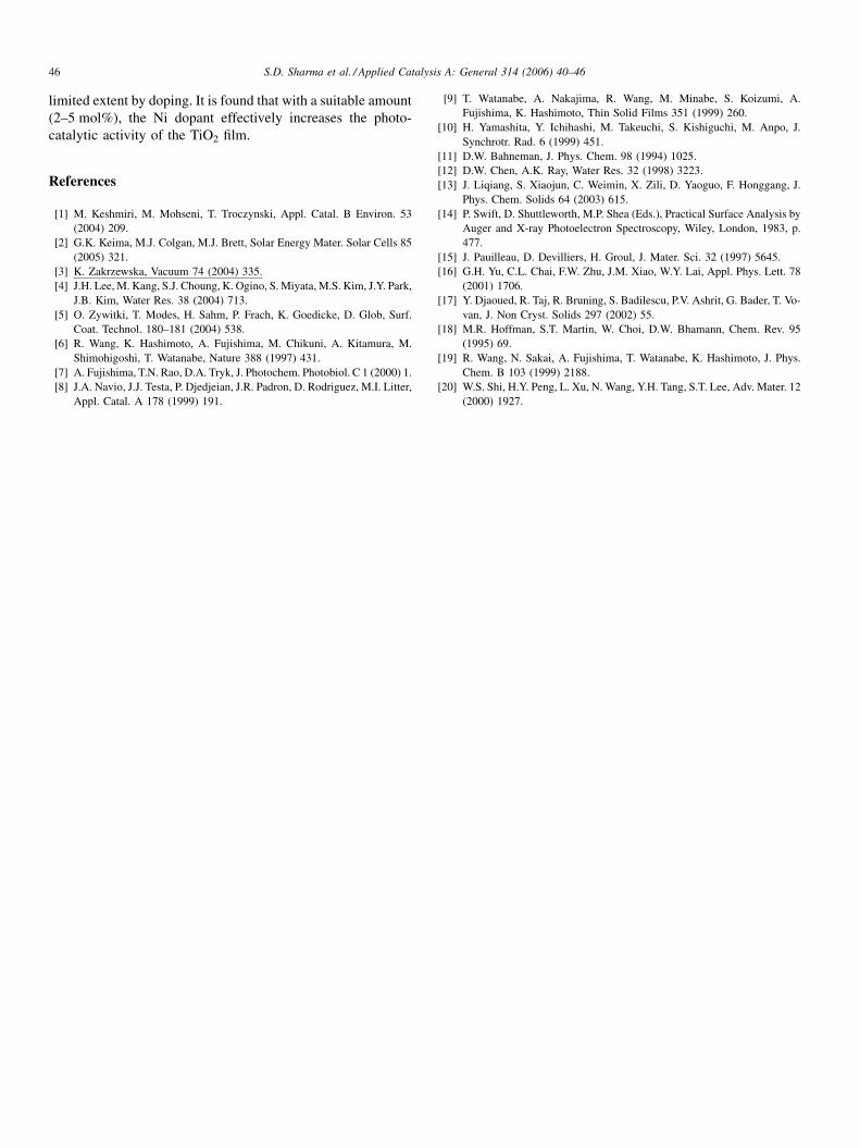
The photo-catalytic activity of TiO2 films was characterized
by the degradation test of methyl orange. The results are given
in Fig. 7. The TiO2 films as prepared have effectively degraded
the methyl orange. After 3 h low intensity irradiation, 25–60%
methyl orange was degraded. Total degradation of methyl
orange reaches 80% after 10 h irradiation. The TiO2 films thus
show desirable photo-catalytic activities. In Fig. 7, it can be
seen that after 3 h irradiation the photo-catalytic degradation of
methyl orange by pure TiO2 films is not more than 30%. But for
TiO2 films NiT-2 mol%, NiT-5 mol%, NiT-8 mol% and NiT-
10 mol%, after 3 h irradiation the degradation of methyl orange
reaches 48%, 51%, 36% and 29% respectively, which indicates
that, with a suitable amount, the Ni dopant has effectively
enhanced the TiO2 photo-catalysis.
According to the principle of TiO2 photo-catalysis, electron
(e�)-hole (h+) pairs are generated when TiO2 is irradiated with
UV light. Separated electrons (e�) and holes (h+) diffuse to the
surface of TiO2 and react with water, hydroxyl group and
molecular oxygen absorbed on TiO2 producing reactive
Fig. 7. The degradation of methyl orange over pure and nickel doped TiO2 films
after: (a) 3 h and (b) 15 h UV irradiation.
radicals, such as O2�, OH, H2O2, etc. These reactive radicals
further react with organic and inorganic compounds absorbed
on TiO2 and oxidize or reduce them. Generally, the photo-
catalytic activity of TiO2 is mainly dependent on three factors:
(1) the electron–hole generation capacity; (2) the separation
efficiency of the photo-generated charge pair; (3) the charge
transfer efficiency of holes and electrons to compounds
absorbed on TiO2.
In Ni ion-doped TiO2 films, nickel can provide a shallow trap
for photo-generated electron and hole so as to inhibit the
recombination and extend the lifetime of charge carrier.
Therefore, the photodegradation rate could be enhanced
consequently because more charge carriers are available.
3.8. Effect of pH on photo-degradation of methyl orange
The experiment was carried out to investigate the effect of
pH on the photo-degradation of methyl orange. At pH 10, the
concentration of methyl orange decreased from 10 through 9.8,
9.7, 9.6, 9.5 and 9.3 to 9.2 mg l�1 in 1–6 h where the rate
constant (K) was 0.01 h�1. At pH 7, the concentration of methyl
orange was 9.4, 8.2, 6.2, 5.1, 4.0 and 3.9 mg l�1 in 1, 2, 3, 4, 5
and 6 h respectively, where the rate constant was 0.16 h�1. At
pH 3, the methyl orange concentration decreased from 10,
through 8.3, 6.2, 3.8 and 0.8 to 0.4 mg l�1 in 1, 2, 3, 4, 5 and 6 h,
where the rate constant was 0.54 h�1. The rate constant was as
low as 0.01 h�1 in the basic region of pH 10; however it
increased to 0.54 h�1 in acidic region of pH 3. The removal
rates per immobilization area were estimated as 0.063, 0.041
and 0.006 mg methyl orange h�1 cm2 at pH 3, 7 and 10
respectively. The overall photo-reaction can be described as
follows
TiO2 ðcatalystÞ þ OH� þ 2Hþ þ �O2�
! 3�OH þ TiO2 ðcatalystÞ
The equilibrium constant (Ke) was estimated as
Ke ¼½�OH�3
½OH��½Hþ�2½�O2�
Since [OH�][H+] = Kw, the equation can be rearranged as
follows:
½�OH�3¼KeKw½Hþ�½�O2��
The concentration of [�OH] radical increases as the
concentration of [H+] increases. Thus the photo-degradation
of methyl orange was done more rapidly at pH 3 than at 10.
4. Conclusion
Pure and Ni ion-doped TiO2 thin films were prepared on
glass substrates by sol–gel method. There was only anatase
phase found in the XRD pattern for the films annealed at 500 8Cfor 1 h. This indicates the absence of Ni ions moving into the
lattice of TiO2 film. The AFM observation indicated that the
particle size of TiO2 in Ni ion-doped films was finer than in pure
films. The hydrophilicity of the films can be improved to a
S.D. Sharma et al. / Applied Catalysis A: General 314 (2006) 40–4646
limited extent by doping. It is found that with a suitable amount
(2–5 mol%), the Ni dopant effectively increases the photo-
catalytic activity of the TiO2 film.
References
[1] M. Keshmiri, M. Mohseni, T. Troczynski, Appl. Catal. B Environ. 53
(2004) 209.
[2] G.K. Keima, M.J. Colgan, M.J. Brett, Solar Energy Mater. Solar Cells 85
(2005) 321.
[3] K. Zakrzewska, Vacuum 74 (2004) 335.
[4] J.H. Lee, M. Kang, S.J. Choung, K. Ogino, S. Miyata, M.S. Kim, J.Y. Park,
J.B. Kim, Water Res. 38 (2004) 713.
[5] O. Zywitki, T. Modes, H. Sahm, P. Frach, K. Goedicke, D. Glob, Surf.
Coat. Technol. 180–181 (2004) 538.
[6] R. Wang, K. Hashimoto, A. Fujishima, M. Chikuni, A. Kitamura, M.
Shimohigoshi, T. Watanabe, Nature 388 (1997) 431.
[7] A. Fujishima, T.N. Rao, D.A. Tryk, J. Photochem. Photobiol. C 1 (2000) 1.
[8] J.A. Navio, J.J. Testa, P. Djedjeian, J.R. Padron, D. Rodriguez, M.I. Litter,
Appl. Catal. A 178 (1999) 191.
[9] T. Watanabe, A. Nakajima, R. Wang, M. Minabe, S. Koizumi, A.
Fujishima, K. Hashimoto, Thin Solid Films 351 (1999) 260.
[10] H. Yamashita, Y. Ichihashi, M. Takeuchi, S. Kishiguchi, M. Anpo, J.
Synchrotr. Rad. 6 (1999) 451.
[11] D.W. Bahneman, J. Phys. Chem. 98 (1994) 1025.
[12] D.W. Chen, A.K. Ray, Water Res. 32 (1998) 3223.
[13] J. Liqiang, S. Xiaojun, C. Weimin, X. Zili, D. Yaoguo, F. Honggang, J.
Phys. Chem. Solids 64 (2003) 615.
[14] P. Swift, D. Shuttleworth, M.P. Shea (Eds.), Practical Surface Analysis by
Auger and X-ray Photoelectron Spectroscopy, Wiley, London, 1983, p.
477.
[15] J. Pauilleau, D. Devilliers, H. Groul, J. Mater. Sci. 32 (1997) 5645.
[16] G.H. Yu, C.L. Chai, F.W. Zhu, J.M. Xiao, W.Y. Lai, Appl. Phys. Lett. 78
(2001) 1706.
[17] Y. Djaoued, R. Taj, R. Bruning, S. Badilescu, P.V. Ashrit, G. Bader, T. Vo-
van, J. Non Cryst. Solids 297 (2002) 55.
[18] M.R. Hoffman, S.T. Martin, W. Choi, D.W. Bhamann, Chem. Rev. 95
(1995) 69.
[19] R. Wang, N. Sakai, A. Fujishima, T. Watanabe, K. Hashimoto, J. Phys.
Chem. B 103 (1999) 2188.
[20] W.S. Shi, H.Y. Peng, L. Xu, N. Wang, Y.H. Tang, S.T. Lee, Adv. Mater. 12
(2000) 1927.
Copyright © 2022 FDOKUMEN