Catalyst free growth of MgO nanoribbons
8
CERAMICS INTERNATIONAL Available online at www.sciencedirect.com Ceramics International 40 (2014) 6365–6372 Short communication Catalyst free growth of MgO nanoribbons Pradip Sekhar Das a , Dipak Kr. Chanda a,b , Arjun Dey c , Ashok K. Mandal a , Kajari Das Gupta a , Nitai Dey a , Anoop K. Mukhopadhyay a,n a Materials Characterization Division, CSIR-Central Glass and Ceramic Research Institute, Kolkata 700032, India b School of Materials Science and Engineering, Bengal Engineering and Science University, Shibpur, Howrah 711103, India c Thermal Systems Group, ISRO Satellite Centre, Vimanapura Post, Bangalore 560017, India Received 5 October 2013; received in revised form 26 October 2013; accepted 29 October 2013 Available online 5 November 2013 Abstract Here, we report for the first time ever the catalyst free growth of magnesium oxide (MgO) nanoribbons on soda lime silica glass substrates by a green and inexpensive chemical route. The MgO nanoribbons were grown when the precursor magnesium hydroxide (Mg(OH) 2 ) thin films were converted to MgO after 2 h of heat treatment in air at 450 1C. The MgO thin films were characterized by X-ray diffraction (XRD), field emission scanning electron microscopy (FE-SEM), transmission electron microscopy (TEM), and the related energy dispersive X-ray spectroscopy (EDAX) techniques. Finally, a plausible mechanism is suggested for growth of the MgO nanoribbons. & 2013 Elsevier Ltd and Techna Group S.r.l. All rights reserved. Keywords: D. MgO; Growth mechanism; Nanoribbons; Thin film 1. Introduction The continuous evolution of nanotechnology in the recent years has now led to the production of low dimensional structures in a variety of morphologies such as nanoribbons, nanowires, core–shell nanowires, nanotubes, nanobelts, hier- archical structures, nanorods (NRs), nanorings, etc. [1–3]. That is why, the semiconducting metal oxides (SCMOXs) are attracting an increasing interest for both fundamental and applied sciences. SCMOXs may range from quasi-crystalline to crystalline in structures with well-defined chemical compo- sition. In addition, the nanoribbons, nanowires and NRs may exhibit physical properties which are significantly different from their bulk counterpart because of their nanosized dimen- sions. Surface effects dominate due to the increase of their specific surface, which leads to the enhancement of the surface related properties, such as catalytic activity or surface adsorption which is a key property for superior chemical sensors production. Further, such low dimensional materials have tremendous application possibilities for optical, electro- nic, opto-electronic, electrical, magnetic, electro-magnetic, gas sensing, efficient light-emitting, thermoelectric and energy storage devices. In this connection, it may be mentioned that MgO in particular is a wide band gap e.g., 7.3–7.8 eV semiconductor with a breakdown field (12 MV/cm) that is high compared to that (e.g., 5.7 MV/cm) of the commonly used dielectric layer e.g., silicon dioxide (SiO 2 ) [4]. MgO has also many other applications e.g., as a protective film for plasma display screens, in brake linings, as a protective sheath in aggressive environments and as single crystal substrates for thin film growth due to the small mismatch in lattice parameters with many metals and metal oxides. In particular, the controlled growth of MgO nanorods (NRs) was investi- gated under electron irradiation in transmission electron microscopes at accelerating voltages of e.g., 120–300 kV in the temperature range from about 180 to 600 1C. The NRs grew due to an electrostatic repulsion–attraction interaction mechanism [5]. MgO NRs are reported to form from a magnesium chloride precursor through an energy intensive heat treatment at 900 1C www.elsevier.com/locate/ceramint 0272-8842/$ - see front matter & 2013 Elsevier Ltd and Techna Group S.r.l. All rights reserved. http://dx.doi.org/10.1016/j.ceramint.2013.10.139 n Correspondence to: Materials Characterization Division, CSIR-Central Glass and Ceramic Research Institute, Mechanical Property Evaluation Section, 196, Raja S.C. Mullick Road, Kolkata 700032, India. Tel.: þ 91 33 24733469/76/77/96; fax: þ 91 33 24730957. E-mail addresses: [email protected], [email protected] (A.K. Mukhopadhyay).
Transcript of Catalyst free growth of MgO nanoribbons
CERAMICSINTERNATIONAL
Available online at www.sciencedirect.com
0272-8842/$ - sehttp://dx.doi.org/
nCorrespondeGlass and CerSection, 196, RaTel.: þ91 33 24
E-mail addremukhopadhyay.a
Ceramics International 40 (2014) 6365–6372www.elsevier.com/locate/ceramint
Short communication
Catalyst free growth of MgO nanoribbons
Pradip Sekhar Dasa, Dipak Kr. Chandaa,b, Arjun Deyc, Ashok K. Mandala, Kajari Das Guptaa,Nitai Deya, Anoop K. Mukhopadhyaya,n
aMaterials Characterization Division, CSIR-Central Glass and Ceramic Research Institute, Kolkata 700032, IndiabSchool of Materials Science and Engineering, Bengal Engineering and Science University, Shibpur, Howrah 711103, India
cThermal Systems Group, ISRO Satellite Centre, Vimanapura Post, Bangalore 560017, India
Received 5 October 2013; received in revised form 26 October 2013; accepted 29 October 2013Available online 5 November 2013
Abstract
Here, we report for the first time ever the catalyst free growth of magnesium oxide (MgO) nanoribbons on soda lime silica glass substrates by agreen and inexpensive chemical route. The MgO nanoribbons were grown when the precursor magnesium hydroxide (Mg(OH)2) thin films wereconverted to MgO after 2 h of heat treatment in air at 450 1C. The MgO thin films were characterized by X-ray diffraction (XRD), field emissionscanning electron microscopy (FE-SEM), transmission electron microscopy (TEM), and the related energy dispersive X-ray spectroscopy(EDAX) techniques. Finally, a plausible mechanism is suggested for growth of the MgO nanoribbons.& 2013 Elsevier Ltd and Techna Group S.r.l. All rights reserved.
Keywords: D. MgO; Growth mechanism; Nanoribbons; Thin film
1. Introduction
The continuous evolution of nanotechnology in the recentyears has now led to the production of low dimensionalstructures in a variety of morphologies such as nanoribbons,nanowires, core–shell nanowires, nanotubes, nanobelts, hier-archical structures, nanorods (NRs), nanorings, etc. [1–3]. Thatis why, the semiconducting metal oxides (SCMOXs) areattracting an increasing interest for both fundamental andapplied sciences. SCMOXs may range from quasi-crystallineto crystalline in structures with well-defined chemical compo-sition. In addition, the nanoribbons, nanowires and NRs mayexhibit physical properties which are significantly differentfrom their bulk counterpart because of their nanosized dimen-sions. Surface effects dominate due to the increase of theirspecific surface, which leads to the enhancement of the surfacerelated properties, such as catalytic activity or surface
e front matter & 2013 Elsevier Ltd and Techna Group S.r.l. All ri10.1016/j.ceramint.2013.10.139
nce to: Materials Characterization Division, CSIR-Centralamic Research Institute, Mechanical Property Evaluationja S.C. Mullick Road, Kolkata 700032, India.733469/76/77/96; fax: þ91 33 24730957.sses: [email protected],[email protected] (A.K. Mukhopadhyay).
adsorption which is a key property for superior chemicalsensors production. Further, such low dimensional materialshave tremendous application possibilities for optical, electro-nic, opto-electronic, electrical, magnetic, electro-magnetic, gassensing, efficient light-emitting, thermoelectric and energystorage devices. In this connection, it may be mentioned thatMgO in particular is a wide band gap e.g., 7.3–7.8 eVsemiconductor with a breakdown field (12 MV/cm) that ishigh compared to that (e.g., 5.7 MV/cm) of the commonlyused dielectric layer e.g., silicon dioxide (SiO2) [4]. MgO hasalso many other applications e.g., as a protective film forplasma display screens, in brake linings, as a protective sheathin aggressive environments and as single crystal substrates forthin film growth due to the small mismatch in latticeparameters with many metals and metal oxides. In particular,the controlled growth of MgO nanorods (NRs) was investi-gated under electron irradiation in transmission electronmicroscopes at accelerating voltages of e.g., 120–300 kV inthe temperature range from about 180 to 600 1C. The NRsgrew due to an electrostatic repulsion–attraction interactionmechanism [5].MgO NRs are reported to form from a magnesium chloride
precursor through an energy intensive heat treatment at 900 1C
ghts reserved.
P.S. Das et al. / Ceramics International 40 (2014) 6365–63726366
in flowing oxygen [6]. Another approach was carbothermalreduction of MgO at about 1200 1C and subsequent re-oxidation of Mg vapor to form the MgO NRs by condensation[7]. Using the catalytic effect of Au nanodots all-self-assembled MgO NRs and nanowires were grown by pulsedlaser deposition (PLD) on MgO (100) single crystal substratesdecorated with Au nanodots formed by using the same PLD[8]. The dimensions and density of NRs/nanowires wereshown to be strongly dependent on the deposition conditionsand on the size and surface density of the self-assembled Aunanodots [8].
It is interesting to note that NRs of magnesium oxide (MgO)were induced also by thermal decomposition of Mg(OH)2 NRsat 700 1C, where the magnesium hydroxide (Mg(OH)2) NRswere synthesized by a simple and facile hydrothermal methodin the presence of cetyltetramethylammonium bromide(CTAB) as a surfactant [9]. MgO nanoplatelets were obtainedby calcination of nanocrystalline Mg(OH)2 samples at 510 1Cprepared by a solvothermal method in which Mg(Ac)2 � 4H2Oand NaOH were used as the starting materials [10]. Recentlynanostructured MgO thin films and MgO/ZnO multilayer thinfilms with and without NRs were prepared by the spin coatingtechnique [4]. A similar method along with templates wasutilized by others also to obtain the MgO NRs and nanopar-ticles [11]. To improve adhesion of CNT reinforcement in agiven matrix, synthesis of uniform MgO/CNT NRs has beenachieved by the precipitation method [12]. Recently, MWCNTfilled with MgO NRs was synthesized through the reaction ofethanol and Mg powder in the presence of TiO2 catalyst at400 1C [13].
MgO nanorods have been prepared also by thermal evapora-tion of pure MgB2 powders at 900 1C [14]. The importance ofMgO NRs and other nanostructures has been reviewed in[15,16]. Very recently, tadpole-, dendrite-, belt- and rod-likeMgO nanostructures were synthesized by DC arc plasma jetchemical vapor deposition with the nanobelts exhibitingrelatively strong blue–green luminescence [17]. Similarly,others have also reported on Zn-catalyst assisted growth andphotoluminescence properties of branched MgO nanowires[18]. However, an attempt to develop MgO nanoribbons(NRBs) is absent in the literature.
Therefore, the objective of the present work is to synthesizeMgO thin films and NRBs on soda lime silica (SLS) glassslides by an uncomplicated, cost effective and green methodwithout using any catalyst. To the best of our knowledge thepresent report is the first of its kind.
2. Materials and methods
MgO NRBs were grown from the precursors i.e. Mg(OH)2thin films. These precursors were chemically deposited on pre-cleaned and dried commercially available SLS glass slides(25 mm� 25 mm� 1.15 mm) by alternate dipping for requi-site number of times at room temperature (30 1C) [19–21]. Thedetails of the experimental procedure have been reportedalready by us elsewhere [19–21] and shall not be repeatedhere, for the sake of brevity. The MgO grew when the
Mg(OH)2 thin films on the SLS glass substrates were heatedat 450 1C for 2 h in air to convert them to MgO thin films.After that, the MgO films were kept in vacuum desiccators toavoid further contamination with environment. Phase analysisof the MgO thin films was investigated by an X-ray diffraction(XRD) technique (PANalytical X'pert Pro MPD Diffract-ometer, The Netherlands). Microstructural characterizationsof the MgO thin films were carried out utilizing field emissionscanning electron microscopy (FE-SEM, Model Supra VP35,Carl Zeiss, Germany), transmission electron microscopy(TEM, Model Tecnai G2 30, S-Twin, 300 kV, FEI, TheNetherlands), related energy dispersive X-ray spectroscopy(EDAX) and selected area electron diffraction (SAED)techniques.
3. Results and discussions
MgO film thickness was gravimetrically measured to be�0.5770.01 mm, considering 60% theoretical density ofMgO i.e., 3.58 g/cm3. The representative XRD data of thechemically deposited MgO thin films are shown in Fig. 1a. Thedata presented in Fig. 1a show peaks corresponding to the(200), (220) and (222) planes for the MgO thin films. Theseare the main characteristic peaks of phase-pure MgO (JCPDS18-1022). Further, the ‘d’ values for the respective interplanarspacings are evaluated from the XRD peaks for (200), (220)and (222) planes. These d values were 2.11 Å, 1.50 Å and1.22 Å correspondingly.Thus, the data obtained on d values in the present work are
in good agreement with the data reported for the standardmaterial i.e. (JCPDS 18-1022). The lattice constant for theMgO thin films was calculated to be a¼4.23270.0087 Å.These data also matched very closely with those reported byother researchers [22]. In addition, the crystallite sizes of MgOthin films were estimated corresponding to the peaks repre-senting the (200), (220) and (222) planes. The well knownScherrer method was employed to obtain these data. However,before the application of Scherrer method to the present XRDdata, the data were corrected for the machine backgroundeffect. The estimated crystallite sizes were about 4.93 nm,5.56 nm and 4.94 nm respectively, for the peaks obtained inthe XRD data corresponding to the (200), (220) and (222)planes of the MgO thin films. Thus, the average crystallite sizewas calculated to be about 5.1570.36 nm for the presentMgO thin films.The data from the corresponding SAED patterns are
presented in Fig. 1b. These data show the distinct presenceof diffraction circles corresponding to the (200), (220) and(222) peaks. It is worth mentioning here that the ‘d’ values forthe (200), (220) and (222) planes were e.g., 1.94 Å, 1.49 Å and1.15 Å, respectively. These data matched reasonably well withthose (e.g., 2.11 Å, 1.50 Å and 1.22 Å, correspondingly)obtained from the XRD data. The typical EDAX analysis dataobtained from TEM work are displayed in Fig. 1c. These datagave e.g., �46.05 at% magnesium and 53.94 at% oxygenpresent as elements in the MgO thin films. Molar ratio ofmagnesium and oxygen was 0.85 which meant that the present
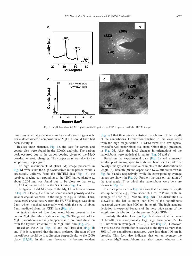
Fig. 1. MgO thin films: (a) XRD plot, (b) SAED pattern, (c) EDAX spectra, and (d) HRTEM image.
P.S. Das et al. / Ceramics International 40 (2014) 6365–6372 6367
thin films were rather magnesium lean and more oxygen rich.For a stoichiometric composition of MgO, it should have hadbeen ideally 1:1.
Besides these elements, Fig. 1c, the data for carbon andcopper also were found in the EDAX analysis. The carbonpeak occurred due to the carbon coating given on the MgOpowder, to avoid charging. The copper peak was due to thesupporting copper grid.
The high resolution TEM (HRTEM) image presented inFig. 1d reveals that the MgO synthesized in the present work isstructurally uniform. From the HRTEM data (Fig. 1b), theresolved spacing corresponding to the (200) lattice plane e.g.,about 0.204 nm, was found out to be close to that (e.g.,d¼2.11 Å) measured from the XRD data (Fig. 1a).
The typical FE-SEM image of the MgO thin films is shownin Fig. 2a. Clearly, the film had some residual porosity and thesmaller crystallites were in the range of e.g., 4–10 nm. Thus,the average crystallite size from the FE-SEM images was about7 nm which matched reasonably well with the size of about5 nm predicted from the XRD data (Fig. 1a).
A typical view of four long nanoribbons present in thecurrent MgO thin films is shown in Fig. 2b. The growth of theMgO nanoribbons actually happened in a preferred directionfrom the layered structure of the MgO thin film (Fig. 2c).
Based on the XRD (Fig. 1a) and the TEM data (Fig. 1band d) it is suggested that the most preferred direction of thenanoribbons could be in a direction perpendicular to the (200)plane [23,24]. In this case, however, it became evident
(Fig. 2c) that there was a statistical distribution of the lengthof the nanoribbons. Further confirmation to this view stemsfrom the high magnification FE-SEM view of a few typicaltwisted/curved nanoribbons (i.e. nano ribbon-rings), presentedin Fig. 2d. Also, the local changes in orientations of thenanoribbons were statistical in nature (Fig. 2d and e).Based on the experimental data (Fig. 2) and numerous
similar photomicrographs (not shown here for the sake ofbrevity), the typical illustrative examples of the distribution oflength (L), breadth (B) and aspect ratio (R¼L/B) are shown inFig. 3a, b and c respectively, while the corresponding averagevalues are shown in Fig. 3d. Further, the data on variation ofthe total angle ‘θ’ at which the nanoribbons were bent areshown in Fig. 3e.The data presented in Fig. 3a show that the range of length
was quite wide e.g., from about 371 to 7535 nm with anaverage of 1848.7471500 nm (Fig. 3d). The distribution isskewed to the left as more than 80% of the nanoribbonsmeasured were less than 3000 nm in length. The high standarddeviation is expected because of the very wide range of thelength size distribution for the present MgO NRBs.Similarly, the data plotted in Fig. 3b illustrate that the range
of breadth was exceptionally large e.g., from about 50 to210 nm with an average of 78.32730 nm (Fig. 3d). However,in this case the distribution is skewed to the right as more than80% of the nanoribbons measured were less than 100 nm inbreadth. This fact also indicates that on an average thenarrower MgO nanoribbons are also longer whereas the

Fig. 2. MgO thin films: (a) FE-SEM image, (b) nanoribbons, (c) oriented growth of nanoribbons from the layered microstructure, (d) twisted nanoribbons and(e) statistical distribution of length and orientations of the nanoribbons.
P.S. Das et al. / Ceramics International 40 (2014) 6365–63726368
broader nanoribbons are shorter in length. The high standarddeviation of about 40% reflects the fact that a very wide rangeof the breadth size distribution has really occurred for thepresent MgO nanoribbons.
As a result of the data plotted in Fig. 3a and b it is obviousthat the aspect ratio R varies from about 5 to 66 (Fig. 3c) withan average of 23.41715.83 (Fig. 3d). In this case of coursethe distribution is skewed to the left as more than 77% of thenanoribbons measured had aspect ratio values of less than 30.The high standard deviation of about 70% is justified by thereality that for the present MgO nanoribbons a truly stochastic,wide range of the length and breadth size distributions had, infact, occurred (Fig. 3a and b).
Further, most of MgO nanoribbons showed ‘ring-openstructure’ (i.e., not a regular closed circular ring form).Assuming that θ is the total angle of bending for a givennanoribbon, the typical illustrative data presented in Fig. 3eshow that a little over 34% of the nanoribbons had
01rθr1001, while about 60% had 1001rθr1501. Thus,a little over 94% of the nanoribbons had 01rθr1501. Onlythe remaining small fraction e.g., about 5.74% of the nanor-ibbons had 1501rθr2501. This phenomenon is linked to thepresence of the localized internal stresses during the growth ofthe present nanoribbons [24]. That is why, the average value ofθ was e.g., �108.81750.31 with a typical range that wasstochastically as wide as, e.g., 27.26–236.971. The relativemagnitudes of such localized internal stresses would be mostlikely governed by the local thermodynamic scenario and itshould be plausible to argue that the inherent stochastic naturein the magnitudes of such local internal stresses might havecontributed to the significantly wide range of variations in theangle of bending ‘θ’ of the present MgO NRBs.A survey of the pertinent literature data [25–37] as
summarized in Table 1 seems to strongly suggest that thepresent work is the first experimental observation of MgOnanoribbon formation. Therefore, it is judged as all the more
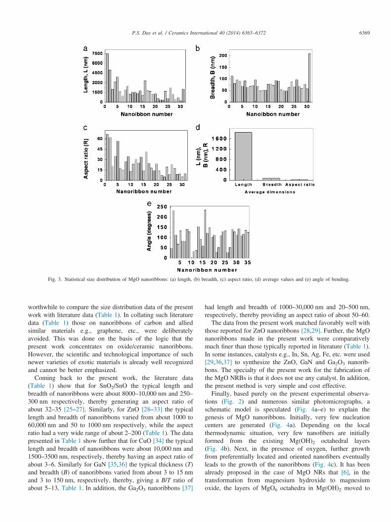
Fig. 3. Statistical size distribution of MgO nanoribbons: (a) length, (b) breadth, (c) aspect ratio, (d) average values and (e) angle of bending.
P.S. Das et al. / Ceramics International 40 (2014) 6365–6372 6369
worthwhile to compare the size distribution data of the presentwork with literature data (Table 1). In collating such literaturedata (Table 1) those on nanoribbons of carbon and alliedsimilar materials e.g., graphene, etc., were deliberatelyavoided. This was done on the basis of the logic that thepresent work concentrates on oxide/ceramic nanoribbons.However, the scientific and technological importance of suchnewer varieties of exotic materials is already well recognizedand cannot be better emphasized.
Coming back to the present work, the literature data(Table 1) show that for SnO2/SnO the typical length andbreadth of nanoribbons were about 8000–10,000 nm and 250–300 nm respectively, thereby generating an aspect ratio ofabout 32–35 [25–27]. Similarly, for ZnO [28–33] the typicallength and breadth of nanoribbons varied from about 1000 to60,000 nm and 50 to 1000 nm respectively, while the aspectratio had a very wide range of about 2–200 (Table 1). The datapresented in Table 1 show further that for CuO [34] the typicallength and breadth of nanoribbons were about 10,000 nm and1500–3500 nm, respectively, thereby having an aspect ratio ofabout 3–6. Similarly for GaN [35,36] the typical thickness (T)and breadth (B) of nanoribbons varied from about 3 to 15 nmand 3 to 150 nm, respectively, thereby, giving a B/T ratio ofabout 5–13, Table 1. In addition, the Ga2O3 nanoribbons [37]
had length and breadth of 1000–30,000 nm and 20–500 nm,respectively, thereby providing an aspect ratio of about 50–60.The data from the present work matched favorably well with
those reported for ZnO nanoribbons [28,29]. Further, the MgOnanoribbons made in the present work were comparativelymuch finer than those typically reported in literature (Table 1).In some instances, catalysts e.g., In, Sn, Ag, Fe, etc. were used[29,36,37] to synthesize the ZnO, GaN and Ga2O3 nanorib-bons. The specialty of the present work for the fabrication ofthe MgO NRBs is that it does not use any catalyst. In addition,the present method is very simple and cost effective.Finally, based purely on the present experimental observa-
tions (Fig. 2) and numerous similar photomicrographs, aschematic model is speculated (Fig. 4a–e) to explain thegenesis of MgO nanoribbons. Initially, very few nucleationcenters are generated (Fig. 4a). Depending on the localthermodynamic situation, very few nanofibers are initiallyformed from the existing Mg(OH)2 octahedral layers(Fig. 4b). Next, in the presence of oxygen, further growthfrom preferentially located and oriented nanofibers eventuallyleads to the growth of the nanoribbons (Fig. 4c). It has beenalready proposed in the case of MgO NRs that [6], in thetransformation from magnesium hydroxide to magnesiumoxide, the layers of MgO6 octahedra in Mg(OH)2 moved to
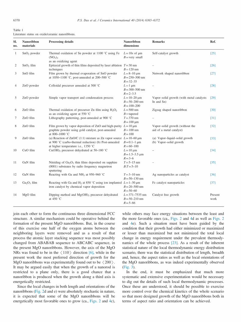
Table 1Literature status on oxide/ceramic nanoribbons.
Sl.no.
Nanoribbonmaterials
Processing details Nanoribbondimensions
Remarks Ref.
1 SnO2 powder Thermal oxidation of Sn powder at 1100 1C using Fe(NO3)3as an oxidizing agent
L¼10s of μm Self-catalyst growth [25]B¼very small
2 SnO2 film Epitaxial growth of thin films deposited by laser ablationtechniques
T¼30 nm – [26]B¼120 nm
3 SnO film Film grown by thermal evaporation of SnO powderat 1050–1100 1C, post-annealed at 200–500 1C
L¼8–10 mm Network shaped nanoribbon [27]B¼250–300 nmR¼32–35
4 ZnO powder Colloidal precursor annealed at 500 1C L¼1 μm – [28]B¼300–500 nmR¼2–3.5
5 ZnO powder Simple vapor transport and condensation process L¼10–20 mm Vapor–solid growth (with metal catalystsIn and Sn)
[29]B¼50–200 nmR¼100–200
6 ZnO film Thermal oxidation of precursor Zn film using H2O2
as an oxidizing agent at 550 1CL¼500 nm Zigzag shaped nanoribbon [30]B¼ tapered
7 ZnO film Lithography patterning, post-annealed at 900 1C T¼370 nm – [31]B¼100 μm
8 ZnO film Film grown by vapor deposition of ZnO and high-puritygraphite powder using gold catalyst, post-annealedat 800–1000 1C
L¼10 μm Vapor–solid growth (without theaid of a metal catalyst)
[32]B¼100 nmR¼100
9 ZnO film (a) Reaction of ZnO/C (1:1) mixture as Zn vapor sourceat 900 1C (carbo-thermal reduction) (b) Post-annealedat higher temperature i.e., 1350 1C
L¼10–60 μm (a) Vapor–liquid–solid growth(b) Vapor–solid growth
[33]B¼0.1–1 μmR¼60–100
10 CuO film Cu(OH)2 precursor dehydrated at 50–180 1C L¼10 mm – [34]B¼1.5–3.5 mmR¼3–6
11 GaN film Nitriding of Ga2O3 thin films deposited on sapphire(0001) substrates by radio frequency magnetronsputtering
T¼5–15 nm – [35]B:T¼5–10
12 GaN film Reacting with Ga and NH3 at 950–960 1C T¼3–10 nm Ag nanoparticles as catalyst [36]B¼50–130 nm
13 Ga2O3 film Reacting with Ga and H2 at 850 1C using ion implantediron catalyst by chemical vapor deposition
L¼1–30 μm Fe catalyst nanoparticles [37]B¼20–500 nmR¼50–60
14 MgO film Dipping method and Mg(OH)2 precursor dehydratedat 450 1C
L¼371–7535 nm Catalyst free growth PresentworkB¼50–210 nm
R¼5–66
P.S. Das et al. / Ceramics International 40 (2014) 6365–63726370
join each other to form the continuous three dimensional FCCstructure. A similar mechanism could be operative behind theformation of the present MgO nanoribbons. But, in the courseof this exercise one half of the oxygen atoms between theneighboring layers were removed and as a result of thatprocess the atomic layer stacking sequence was most possiblychanged from ABABAB sequence to ABCABC sequence, inthe present MgO nanoribbons. However, the axis of the MgONRs was found to be in the /110S direction [6], while in thepresent work the most preferred direction of growth for theMgO nanoribbons was experimentally found out to be /200S.It may be argued easily that when the growth of a nanorod isrestricted to a plane only, there is a good chance that ananoribbon is produced when the growth along a third axis isenergetically restricted.
Since the local changes in both length and orientations of thenanoribbons (Fig. 2d and e) were absolutely stochastic in nature,it is expected that some of the MgO nanoribbons will beenergetically most favorable ones to grow (ca., Figs. 2 and 4c),
while others may face energy situations between the least andthe more favorable ones (ca., Figs. 2 and 4d as well as Figs. 2and 4e). Such a situation must have been guided by thecondition that their growth had either minimized or maximizedor lesser than maximized but not minimized the total localchange in energy requirement under the prevalent thermody-namics of the whole process [23]. As a result of the inherentstatistical nature of the local thermodynamic energy distributionscenario, there was the statistical distribution of length, breadthand, hence, the aspect ratios as well as the local orientations ofthe MgO nanoribbons, as was indeed experimentally observed(Fig. 3).In the end, it must be emphasized that much more
systematic and extensive experimentation would be necessaryto dig out the details of such local thermodynamic processes.Once these are understood, it should be possible to exercisemore control over the chemical kinetics of the whole scenarioso that more designed growth of the MgO nanoribbons both interms of aspect ratio and orientation can be achieved.
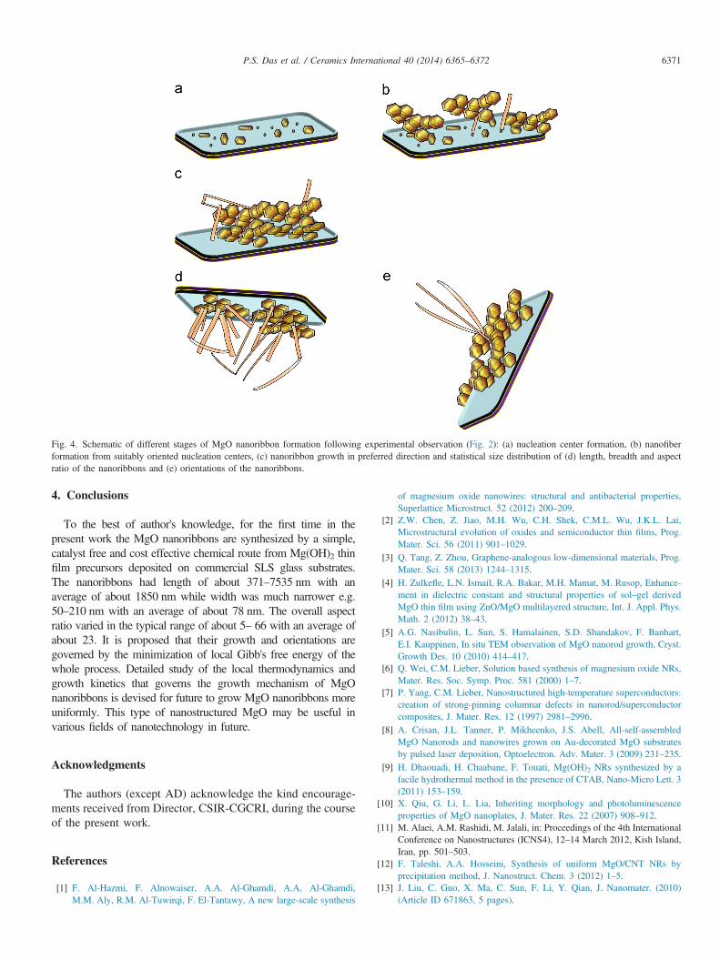
Fig. 4. Schematic of different stages of MgO nanoribbon formation following experimental observation (Fig. 2): (a) nucleation center formation, (b) nanofiberformation from suitably oriented nucleation centers, (c) nanoribbon growth in preferred direction and statistical size distribution of (d) length, breadth and aspectratio of the nanoribbons and (e) orientations of the nanoribbons.
P.S. Das et al. / Ceramics International 40 (2014) 6365–6372 6371
4. Conclusions
To the best of author's knowledge, for the first time in thepresent work the MgO nanoribbons are synthesized by a simple,catalyst free and cost effective chemical route from Mg(OH)2 thinfilm precursors deposited on commercial SLS glass substrates.The nanoribbons had length of about 371–7535 nm with anaverage of about 1850 nm while width was much narrower e.g.50–210 nm with an average of about 78 nm. The overall aspectratio varied in the typical range of about 5– 66 with an average ofabout 23. It is proposed that their growth and orientations aregoverned by the minimization of local Gibb's free energy of thewhole process. Detailed study of the local thermodynamics andgrowth kinetics that governs the growth mechanism of MgOnanoribbons is devised for future to grow MgO nanoribbons moreuniformly. This type of nanostructured MgO may be useful invarious fields of nanotechnology in future.
Acknowledgments
The authors (except AD) acknowledge the kind encourage-ments received from Director, CSIR-CGCRI, during the courseof the present work.
References
[1] F. Al-Hazmi, F. Alnowaiser, A.A. Al-Ghamdi, A.A. Al-Ghamdi,M.M. Aly, R.M. Al-Tuwirqi, F. El-Tantawy, A new large-scale synthesis
of magnesium oxide nanowires: structural and antibacterial properties,Superlattice Microstruct. 52 (2012) 200–209.
[2] Z.W. Chen, Z. Jiao, M.H. Wu, C.H. Shek, C.M.L. Wu, J.K.L. Lai,Microstructural evolution of oxides and semiconductor thin films, Prog.Mater. Sci. 56 (2011) 901–1029.
[3] Q. Tang, Z. Zhou, Graphene-analogous low-dimensional materials, Prog.Mater. Sci. 58 (2013) 1244–1315.
[4] H. Zulkefle, L.N. Ismail, R.A. Bakar, M.H. Mamat, M. Rusop, Enhance-ment in dielectric constant and structural properties of sol–gel derivedMgO thin film using ZnO/MgO multilayered structure, Int. J. Appl. Phys.Math. 2 (2012) 38–43.
[5] A.G. Nasibulin, L. Sun, S. Hamalainen, S.D. Shandakov, F. Banhart,E.I. Kauppinen, In situ TEM observation of MgO nanorod growth, Cryst.Growth Des. 10 (2010) 414–417.
[6] Q. Wei, C.M. Lieber, Solution based synthesis of magnesium oxide NRs,Mater. Res. Soc. Symp. Proc. 581 (2000) 1–7.
[7] P. Yang, C.M. Lieber, Nanostructured high-temperature superconductors:creation of strong-pinning columnar defects in nanorod/superconductorcomposites, J. Mater. Res. 12 (1997) 2981–2996.
[8] A. Crisan, J.L. Tanner, P. Mikheenko, J.S. Abell, All-self-assembledMgO Nanorods and nanowires grown on Au-decorated MgO substratesby pulsed laser deposition, Optoelectron. Adv. Mater. 3 (2009) 231–235.
[9] H. Dhaouadi, H. Chaabane, F. Touati, Mg(OH)2 NRs synthesized by afacile hydrothermal method in the presence of CTAB, Nano-Micro Lett. 3(2011) 153–159.
[10] X. Qiu, G. Li, L. Lia, Inheriting morphology and photoluminescenceproperties of MgO nanoplates, J. Mater. Res. 22 (2007) 908–912.
[11] M. Alaei, A.M. Rashidi, M. Jalali, in: Proceedings of the 4th InternationalConference on Nanostructures (ICNS4), 12–14 March 2012, Kish Island,Iran, pp. 501–503.
[12] F. Taleshi, A.A. Hosseini, Synthesis of uniform MgO/CNT NRs byprecipitation method, J. Nanostruct. Chem. 3 (2012) 1–5.
[13] J. Liu, C. Guo, X. Ma, C. Sun, F. Li, Y. Qian, J. Nanomater. (2010)(Article ID 671863, 5 pages).

P.S. Das et al. / Ceramics International 40 (2014) 6365–63726372
[14] H.W. Kim, S.H. Shim, Fabrication of ZnO-coated MgO nanorods byusing ALD, J. Korean Phys. Soc. 49 (2006) 241–245.
[15] G.R. Patzke, F. Krumeich, R. Nesper, Oxidic nanotubes and NRs-anisotropic modules for a future nanotechnology, Angew. Chem. Int.Ed. Engl. 41 (2002) 5000–5015.
[16] C.N.R. Rao, F.L. Deepak, G. Gundiah, A. Govindaraj, Inorganicnanowires, Prog. Solid State Chem. 31 (2003) 5–147.
[17] M. Li, X. Wang, H. Li, H. Di, X. Wu, C. Fang, B. Yang, Preparation ofphotoluminescent single crystalline MgO nanobelts by DC arc plasma jetCVD, Appl. Surf. Sci. 274 (2013) 188–194.
[18] S.U. Yong, H.E. Zhaoyuan, C. Yiqing, C. Dong, Zn-catalytic growth andphotoluminescence properties of branched MgO nanostructures, RareMet. 25 (2006) 74–78.
[19] P.S. Das, A. Dey, M.R. Chaudhuri, S. Roy, A.K. Mondal, N. Dey,A.K. Mukhopadhyay, Chemically deposited magnesium hydroxide thinfilm, Surf. Eng. 28 (2012) 731–736.
[20] A.K. Mukhopadhyay, P.S. Das, A. Dey, M.R. Chaudhuri, A.K. Mandal,N. Dey, Development and characterization of magnesium hydroxide thinfilms, J. Inst. Eng. (India): Ser. D 93 (2012) 53–57.
[21] P.S. Das, A. Dey, A.K Mandal, N. Dey, A.K. Mukhopadhyay, Synthesisof Mg(OH)2 micro/nano flowers at room temperature, J. Adv. Ceram. 2(2013) 173–179.
[22] S. Chakrabarti, D. Ganguli, S. Chaudhuri, A.K. Pal, Crystalline magne-sium oxide films on soda lime glass by sol–gel processing, Mater. Lett.54 (2002) 120–123.
[23] X.S. Fang, C-H. Ye, L-D. Zhang, J-X. Zhang, J-W. Zhao, P. Yan, Directobservation of the growth process of MgO nanoflowers by a simplechemical route, Small 1 (2005) 422–428.
[24] X. Xiang, C. Cao, F. Huang, R. Lv, H. Zhu, Synthesis and characteriza-tion of crystalline gallium nitride nanoribbon rings, J. Cryst. Growth 263(2004) 25–29.
[25] L. Yang, X. Zhang, R. Huang, G. Zhang, X. An, Synthesis of singlecrystalline GaN nanoribbons on sapphire (0001) substrates, Solid StateCommun. 130 (2004) 769–772.
[26] R. He, M. Law, R. Fan, F. Kim, P. Yang, Functional biomorph compositenanotapes, Nano Lett. 2 (2002) 1109–1112.
[27] Z.L. Wang, Z. Pan, Junctions and networks of SnO nanoribbons, Adv.Mater. 14 (2002) 1229–1232.
[28] Z. Gui, J. Liu, Z. Wang, L. Song, Y. Hu, W. Fan, D. Chan, Frommuticomponent precursor to nanoparticle nanoribbons of ZnO, J. Phys.Chem. B 109 (2005) 1113–1117.
[29] J.G. Wen, J.Y. Lao, D.Z. Wang, T.M. Kyaw, Y.L. Foo, Z.F. Ren, Self-assembly of semiconducting oxide nanowires, nanorods, and nanorib-bons, Chem. Phys. Lett. 372 (2003) 717–722.
[30] L. Wang, K. Chen, L. Dong, Synthesis of exotic zigzag ZnO nanoribbonsand their optical, electrical properties, J. Phys. Chem. C 114 (2010)17358–17361.
[31] T. Ma, Y. Wang, R. Tang, H. Yu, H. Jiang, Pre-patterned ZnOnanoribbons on soft substrate for stretchable energy harvesting applica-tions, J. Appl. Phys. 113 (2013) 204503–204507.
[32] S. Dhara, P.K. Giri, Shape evolution in one-dimensional ZnO nanos-tructures grown from nanopowder source: vapor–liquid–solid versusvapor–solid growth mechanisms, Int. J. Nanosci. 10 (2011) 75–79.
[33] B.H. Yan, J. Johnson, M. Law, R. He, K. Knutsen, J.R. McKinney,J. Pham, R. Saykally, P. Yang, ZnO nanoribbon microcavity lasers, Adv.Mater. 15 (2003) 1907–1911.
[34] P. Gao, Y. Chen, H. Lv, X. Li, Y. Wang, Q. Zhang, Synthesis of CuOnanoribbon arrays with noticeable electrochemical hydrogen storageability by a simple precursor dehydration route at lower temperature,Int. J. Hydrogen Energy 34 (2009) 3065–3069.
[35] J.Q. Hu, Y. Bando, D. Golberg, Self-catalyst growth and optical proper-ties of novel SnO2 fishbone-like nanoribbons, Chem. Phys. Lett. 372(2003) 758–762.
[36] Z.J. Li, X.L. Chen, H.J. Li, Q.Y. Tu, Z. Yang, Y.P. Xu, B.Q. Hu,Synthesis and Raman scattering of GaN nanorings, nanoribbons andnanowires, Appl. Phys. A 72 (2001) 629–632.
[37] J.L. Johnson, Y. Choi, A. Ural, GaN nanowire and Ga2O3 nanowire andnanoribbons growth from ion implanted iron catalyst, J. Vac. Sci.Technol. B 26 (2008) 1841–1847.