Hydrophilic zeolite coatings for improved heat transfer: A quantitative analysis
12
MATERIALS, INTERFACES, AND ELECTROCHEMICAL PHENOMENA Hydrophilic Zeolite Coatings for Improved Heat Transfer: A Quantitative Analysis Jie Liu and Guillermo Aguilar Dept. of Mechanical Engineering, University of California, Riverside, CA 92521 Ronnie Munoz and Yushan Yan Dept. of Chemical and Environmental Engineering, University of California, Riverside, CA 92521 DOI 10.1002/aic.11409 Published online January 24, 2008 in Wiley InterScience (www.interscience.wiley.com). The wetting diameter and life time of a water droplet on the surface of a bare, ZSM-5 coated, and Zeolite-A coated stainless steel 304 substrate at different initial surface temperatures was experimentally studied. ZSM-5 and Zeolite-A coated SS-304 are more much more hydrophilic than bare stainless steel 304 as reflected by their contact angles (278 and 08 vs. 908). The ZSM-5 and Zeolite-A coatings significantly outperformed the bare SS-304 by decreasing the droplet life time, increasing the heat flux and increasing the heat transfer coefficient at all initial surface temperatures stud- ied. At the highest surface temperature studied, T 0 5 2008C, ZSM-5, and Zeolite-A coatings are shown to increase the maximum heat flux on bare SS-304 by as much as 106% and 72%, respectively. At this temperature, the maximum heat transfer coeffi- cients on ZSM-5 and Zeolite-A coatings are improved by 470% and 530% over the bare SS-304, respectively. Ó 2008 American Institute of Chemical Engineers AIChE J, 54: 779–790, 2008 Keywords: zeolite coating, hydrophilic, metal, heat transfer, porous Introduction Efficient heat exchangers, condensing or evaporative, are critical to numerous industrial processes and practical devi- ces. The central function of many heat exchangers is the extraction or injection of the latent heat from or to liquid water that, in general, can be enhanced by a hydrophilic coating on the metallic heat exchanging surface as a result of improved water contact and spreading. 1–4 For a fin-tube con- denser, another benefit of the increased surface hydrophilicity of the fins is a decreased pressure drop. 5 In most fin-tube heat exchangers the distance between the fins is very narrow. As water condenses on the fins, the resulting droplets and bridging water begin to reduce the cross-sectional area for air flow, leading to increased pressure drop and blowing cost. A hydrophilic surface causes the contacting water droplets to spread into a thin film. This film helps to reduce the pressure drop of the air forced through the system, decreases the oper- ation noise and the pumping cost. Another major consideration for a heat exchanger is metal corrosion. 6–10 Galvanic coatings, and more recent plasma vapor deposition (PVD) coatings, have been used for corro- sion protection. 11 The galvanic coatings, however, have neg- ative environmental impact. 11,12 PVD coatings have proved to be promising environmentally friendly alternative for gal- vanic coatings. If a thick PVD coating is desired for corro- sion protection, however, a thin galvanic undercoat often pre- cedes the PVD to help alleviate the relatively high internal stress of the coating. This high stress can cause adhesion problems, but the additional process means that the environ- mental advantages are partially lost. Additional limitations are often imposed by the size and increased operational cost of the vacuum reactor required for PVD. Correspondence concerning this article should be addressed to G. Aguilar at [email protected] and Y. Yan at [email protected]. Ó 2008 American Institute of Chemical Engineers AIChE Journal March 2008 Vol. 54, No. 3 779
-
Upload
independent -
Category
Documents
-
view
0 -
download
0
Transcript of Hydrophilic zeolite coatings for improved heat transfer: A quantitative analysis
MATERIALS, INTERFACES, AND ELECTROCHEMICAL PHENOMENA
Hydrophilic Zeolite Coatings for ImprovedHeat Transfer: A Quantitative Analysis
Jie Liu and Guillermo AguilarDept. of Mechanical Engineering, University of California, Riverside, CA 92521
Ronnie Munoz and Yushan YanDept. of Chemical and Environmental Engineering, University of California, Riverside, CA 92521
DOI 10.1002/aic.11409Published online January 24, 2008 in Wiley InterScience (www.interscience.wiley.com).
The wetting diameter and life time of a water droplet on the surface of a bare,ZSM-5 coated, and Zeolite-A coated stainless steel 304 substrate at different initialsurface temperatures was experimentally studied. ZSM-5 and Zeolite-A coated SS-304are more much more hydrophilic than bare stainless steel 304 as reflected by theircontact angles (278 and 08 vs. 908). The ZSM-5 and Zeolite-A coatings significantlyoutperformed the bare SS-304 by decreasing the droplet life time, increasing the heatflux and increasing the heat transfer coefficient at all initial surface temperatures stud-ied. At the highest surface temperature studied, T0 5 2008C, ZSM-5, and Zeolite-Acoatings are shown to increase the maximum heat flux on bare SS-304 by as much as106% and 72%, respectively. At this temperature, the maximum heat transfer coeffi-cients on ZSM-5 and Zeolite-A coatings are improved by 470% and 530% over thebare SS-304, respectively. � 2008 American Institute of Chemical Engineers AIChE J, 54:779–790, 2008
Keywords: zeolite coating, hydrophilic, metal, heat transfer, porous
Introduction
Efficient heat exchangers, condensing or evaporative, arecritical to numerous industrial processes and practical devi-ces. The central function of many heat exchangers is theextraction or injection of the latent heat from or to liquidwater that, in general, can be enhanced by a hydrophiliccoating on the metallic heat exchanging surface as a result ofimproved water contact and spreading.1–4 For a fin-tube con-denser, another benefit of the increased surface hydrophilicityof the fins is a decreased pressure drop.5 In most fin-tubeheat exchangers the distance between the fins is very narrow.As water condenses on the fins, the resulting droplets andbridging water begin to reduce the cross-sectional area forair flow, leading to increased pressure drop and blowing cost.
A hydrophilic surface causes the contacting water droplets to
spread into a thin film. This film helps to reduce the pressure
drop of the air forced through the system, decreases the oper-
ation noise and the pumping cost.Another major consideration for a heat exchanger is metal
corrosion.6–10 Galvanic coatings, and more recent plasma
vapor deposition (PVD) coatings, have been used for corro-
sion protection.11 The galvanic coatings, however, have neg-
ative environmental impact.11,12 PVD coatings have proved
to be promising environmentally friendly alternative for gal-
vanic coatings. If a thick PVD coating is desired for corro-
sion protection, however, a thin galvanic undercoat often pre-
cedes the PVD to help alleviate the relatively high internal
stress of the coating. This high stress can cause adhesion
problems, but the additional process means that the environ-
mental advantages are partially lost. Additional limitations
are often imposed by the size and increased operational cost
of the vacuum reactor required for PVD.
Correspondence concerning this article should be addressed to G. Aguilar [email protected] and Y. Yan at [email protected].
� 2008 American Institute of Chemical Engineers
AIChE Journal March 2008 Vol. 54, No. 3 779

It is evident that coatings that are both hydrophilic andcorrosion resistant are desirable.13 We have demonstratedthat zeolite coatings can offer high adhesion and excellentcorrosion resistance and they can be easily applied on surfa-ces of complex shape and in confined spaces by a single-step, environmentally benign, in-situ crystallization pro-cess.11,14–18 In addition, by studying water droplet evapora-tion on a hot surface, we have shown that zeolite coatingsare highly hydrophilic and can improve heat transfer. How-ever, our previous heat transfer study4 was only semi-quanti-tative and had limited scope (e.g., only focusing on the waterdroplet life without the calculation of heat flux and heattransfer co-efficient). It is the goal of this current study topresent a much more detailed and quantitative analysis of theheat transfer in a much better controlled experiment.
There have been previous studies that focused on variousissues that affect the heat transfer between a water dropletand a sessile surface, such as contact angle,19 surface rough-ness,20 temperature,21,22 and surfactants.23,24 However, all ofthese studies have been performed using direct imaging anal-ysis to obtain the heat transfer characteristics between thewater droplet and the sessile surface by assuming that thetemperature of the testing surface is constant. However, Zeo-lite-A coating has very low heat conductivity (;1 W/m.K)and thus the sessile surface temperature may vary signifi-cantly during the contact and evaporation of the water drop-let. Thus, in this study, we use both direct imaging and acomputational heat transfer technique to study: (a) spreaddynamics of a water droplet in contact with three differentsurfaces: SS-304, ZSM-5, and Zeolite-A preheated to threedifferent initial temperatures, x, y, and z8C; (b) overall spreadand life time of each droplet; and (c) surface temperatureand heat flux time variations during the droplet spreadingand evaporation processes. To overcome the problem ofvarying surface temperature, the surface temperature varia-tion was measured directly and an Inverse Heat Conduction(IHC) algorithm25,26 was used to calculate the heat fluxbetween the water droplet and the sessile surface. The directimaging analysis obtained from the high speed video wasused as an auxiliary approach only.
Experimental
Surface preparation: application of coatings to a singleside of the substrate
Two SS-304 mirror finished panels measuring 7.62 315.24 3 0.061 cm3 were sandwiched together using a hightemperature epoxy along the edges. The epoxy was allowedto cure at room temperature for two days. The sandwichedpanels were cleaned by submersion for 20 min in 1 N HNO3
at 218C. The sandwiched panels were rinsed under de-ion-ized water and dried with compressed air. The purpose ofthis procedure was to deposit zeolite coating only on oneside of the metal panels.
The synthesized ZSM-5 solution contained a molar compo-sition of 0.16 TPAOH: 0.64 NaOH: 1 TEOS: 92 H2O:0.0018 Al (TPAOH is tetraproplyammonium hydroxide andTEOS is tetraethylorthosilicate). A typical solution prepara-tion began with the addition of 0.0126 g aluminum powder(200 mesh, 99.951%, Aldrich) to 100 g double de-ionizedwater. Then 6.33 g sodium hydroxide (pellets, 971%,
Aldrich) was added to the solution and stirred for 30 min. Tothis solution, 297.03 g double de-ionized water and 20.12 gTPAOH (40 wt %, Sachem) were then added and stirred for30 min. Finally 51.5 g TEOS (98 wt %, Aldrich) was addedto the solution and stirred for 4 h. The sandwiched panelswith 1500 ml of ZSM-5 synthesis solution were placed verti-cally into a large 2,000 ml sealed Teflon lined autoclave(Parr Instrument Co.) and heated in a convection oven at1758C for 12 h. The coated sandwiched panels removedfrom the autoclave were rinsed with de-ionized water anddried with compressed air. The sandwiched panels were thencut using an industrial shear into single side coated substratesmeasuring 2 3 3.5 3 0.061 cm3.
The Zeolite-A synthesis solution contained a molar com-position of 10 NaOH: 0.2 Al2O3: 1 SiO2: 200 H20. A typicalsolution preparation began with the addition of 1.182 g alu-minum powder (200 mesh, 99.951%, Aldrich) to 364.4 gdouble de-ionized water. Then 87.5 g sodium hydroxide (pel-lets, 971%, Aldrich) was added to the solution and stirredfor 30 min. To this solution, 21.9 g Ludox1 LS30 colloidalsilica (30 wt %, silica, Aldrich) was added to the solutionand stirred for 4 h. The sandwiched panels with 1500 ml ofZeolite-A solution were placed vertically into 2000 ml poly-propylene bottle and heated in a convection oven at 658C for12 h. The coated sandwiched panels removed from the poly-propylene bottle were rinsed under de-ionized water anddried with compressed air. The sandwiched panels were thencut using an industrial shear into single side coated substratesmeasuring 2 3 3.5 3 0.061 cm3.
Characterization of coated and uncoated substrates
The application of a ZSM-5 coating onto a single side ofthe SS-304 mirror-finished substrate surface was verifiedusing X-ray diffraction (XRD, Siemens D-500 diffractometerusing Cu Ka radiation) and scanning electron microscope(SEM, Philips XL30-FEG operated at 20 kV). The same wasdone for the Zeolite-A coated substrate.
The wettability of the coated and uncoated surfaces wasdetermined by contact angle measurements (VCA OptimaXE). A 28-gauge blunt tip needle was attached to a VCAOptima XE mechanically controlled micrometer for dispens-ing a 2 ll double de-ionized water droplet onto the surfaceof a sample. Twelve contact angle measurements were takenon the center of the sample, which was then dried with com-pressed air so that the measurement could be repeated.Twenty-four measurements were made on the surface of thethree samples and the averages and standard deviations wereobtained for the collected data.
Characterization of boiling dynamics and heat transfer
The setup used to conduct the heat transfer experimentsand observe the droplet evaporation is shown in Figure 1. Auniform heating surface was constructed for the heat transferexperiments using a 7.6 3 7.6 3 0.2 cm3 fiberglass rein-forced silicone-rubber 90 watt heating blanket (3) sand-wiched between a 7.6 3 7.6 3 2.54 cm3 copper block (4)and a 8.3 3 8.3 3 1.3 cm3 piece of silica board insulation(2). One 0.1-mm thick fast response thin foil CEMENT-ON1
thermocouple (5) (Omega Engineering, Inc) was attached tothe back of the substrates testing surface (10). A 0.2 mm
780 DOI 10.1002/aic Published on behalf of the AIChE March 2008 Vol. 54, No. 3 AIChE Journal

thick OMEGABOND-2001 high heat conductivity epoxy ad-hesive (11) (Omega Engineering, Inc) was used to bond andreduce the thermal resistance between the testing and heatedsurface. The temperature variation was recorded by an Instru-net1 (Omega Engineering, Inc) fast data acquisition system(6) set at 1000 data points per second. Usually, in order tomeasure the surface temperature and heat flux between thedroplet and the sessile surface, the thermocouple is directlyattached to the surface, but in this study, attaching the ther-mocouple on the surface would affect its hydrophilic andheat transfer characteristics. To avoid this problem, the tem-perature was measured underneath the testing surface. Theheat flux and heat transfer coefficient on the upper surfacemay then be calculated by using the measured temperaturesat the bottom, and an IHC technique.25 Considering that thetesting surface is only 0.6-mm thick and that the length andwidth of the thermocouple (0.5 3 0.5 mm2) are much lessthan those of the testing surface, the 2D heat conduction sce-nario may be simplified to a 1D problem.25 This means thatthe calculated results stand for the heat transfer characteris-tics between the testing surface and water droplet.
This experimental approach allows us to study, for the firsttime, the dynamics of droplet spreading and evaporation phe-nomena simultaneously, which are both affected by thehydrophilic nature of the sessile surfaces. The key feature ofthis experimental design is that the initial and boundary con-ditions for all experiments and surfaces are identical, and bylooking at the transient behavior (both wetting/drying andheat transfer) of a droplet gently deposited on the surface, itis possible to discern the effect between impermeable surfa-ces (SS) and the unique porous hydrophilic ones (ZSM-5 andZeolite-A) on the liquid spreading and evaporation. This is incontrast with classical pool boiling tests, which not only
require a strict control of either the temperature or heat fluxat the surface, but they can only provide information aboutthe surface heat transfer and not about the spreading and fil-tering. Furthermore, an important parameter to evaluate thehydrophilicity of the surfaces is the contact angle betweenthe water droplet and sessile surface.4 Using a single dropletheat transfer experiment, we can also directly associate theheat flux at the surface with the static contact angle, whichwould not be possible in a pool boiling experiment.
A 90-mm zoom lens (V-HQ Macro MC 90 mm f/2.5,Elicar, Japan) high speed camera (9) (Photron Fastcam PCI10K, Itronics, Westlake Village, CA) was used to acquire thedigital images of a water droplet boiling on the three differ-ent surfaces. Two Fiber-Lite illuminators (7) (Edmund Indus-trial Optics, Barrington, NJ) were placed above the testingsurfaces. The camera was positioned directly above and ver-tical to the horizontal test surface. The entire heating surfacewas placed within an Acrylic cylinder (1) to limit convectioncurrents and fixed on top of an adjustable stage to allow hor-izontal leveling of the testing surface. The initial temperatureat the copper block surface (upon which the samples wereplaced) was controlled by a PID temperature controller (12)capable of maintaining the temperature of the samples towithin 618C of the set point. A precise micro-liter syringe(7) was used to gently deposit a water droplet with constantvolume of 7.4 ll onto the testing surfaces.
Results and Discussion
Both ZSM-5 and Zeolite-A coatings showed their respec-tive standard diffraction patterns (Figure 2). The presence ofa continuous and well intergrown polycrystalline zeolite coat-ing for both ZSM-5 and Zeolite-A was verified by SEM(Figure 3a, c). The coating thickness for ZSM-5 and Zeolite-A was examined by exposing the profile of the coating to ahydrofluoric acid etch (Figure 3b, d) and determined to beabout 4.5 lm.
The contact angle for the SS-304 mirror finished substratewas 90.2 6 1.48 (Figure 4). For ZSM-5 coated SS-304, thecontact angle was 27.3 6 5.18. Upon placing a drop on the
Figure 1. Experimental Setup.
(1) Acrylic cover, (2) Silica board insulation, (3) HeatingBlanket, (4) Copper Block, (5) Thin Foil Thermocouple, (6)Acquisition Unit, (7) Illumination, (8) Precise Micro-literSyringe, (9) High Speed Camera, (10) Testing Surface, (11)High Heat Conductivity Thermal Epoxy and (12) PID HeatController. [Color figure can be viewed in the online issue,which is available at www.interscience.wiley.com.]
Figure 2. X-ray diffraction patterns of (a) SS-304, (b)ZSM-5 coated SS-304, and (c) Zeolite-Acoated SS-304.
[Color figure can be viewed in the online issue, which isavailable at www.interscience.wiley.com.]
AIChE Journal March 2008 Vol. 54, No. 3 Published on behalf of the AIChE DOI 10.1002/aic 781

surface of a Zeolite-A coated substrate, the drop was wickedaway so quickly that the contact angle was difficult to obtainand was approximated as zero8.
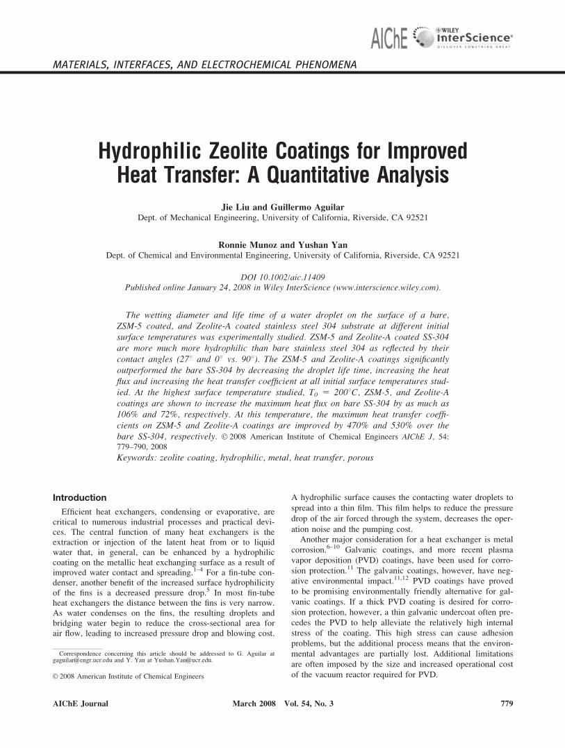
Figure 5 shows the water droplet boiling images at T0 51308C for SS-304, ZSM-5, and Zeolite-A surfaces. Once thewater droplet contacts the surface, the whole process can bedistinguished as five consecutive stages: Stage I, initial con-tact; II, wetting area developing; III, maximum wetting; IV,end of boiling; and V, dry-out. For SS-304, from initial con-tact to the maximum wetting (Stages I–III: 0–1.624 s), thewetting area remains approximately unchanged with an aver-
age wetting diameter of about 4 mm. The dry-out process(Stage V) is slow, taking more than 8 s. A small bulk of thewater can be observed during the whole dry-out process. Forthe ZSM-5 surface, the wetting area increases with timewhile major bubbles are observed during the boiling process.At 1.064 s, two large bubbles can clearly be seen in the drop-let that reaches a maximum wetting diameter of 7.5 mm. Dur-ing the dry-out, no bulk water is observed and eventually non-wet areas can be observed clearly due to the bubble growthduring the boiling process. For the Zeolite-A surface, the drop-let undergoes rapid spreading while numerous tiny bubblesgrow and explode in its interior. It reaches a maximum wet-ting diameter of 13 mm at 0.112 s, and during the dry-out, thewetting diameter is the largest of the three surfaces.
Figure 6 shows the water droplet boiling images at T0 51608C for SS-304, ZSM-5, and Zeolite-A surfaces. The boil-ing phenomena for a water droplet on SS-304 at T0 5 1608Care similar to what occurs at T0 5 1308C. From the initialcontact to the maximum wetting (0–0.204 s), the wetting dia-meter is almost constant at 3.8 mm and splashing is clearlyobserved during the boiling process. Dry-out begins at 1.440s and it takes much shorter time than the dry-out process atT0 5 1308C. For the ZSM-5 surface, the wetting areaincreases with time and reaches a maximum wetting diameterof about 9.4 mm at 0.196 s. During this boiling process, thebubble size remains smaller than that at T0 5 1308C, andthus the non-wetting area during the dry-out is smaller thanthat at T0 5 1308C. For the Zeolite-A surface, the waterdroplet begins to boil and spread quickly, and this is similarto the case at T0 5 1308C. The maximum wetting diameteris smaller than that at T0 5 1308C, about 9.7 mm at 0.136 s.
Figure 3. SEM images of top (a,c) and cross sectional (b,d) views of: Zeolite-A on SS-304 (a,b) and ZSM-5 onSS-304 (c,d).
Films are ;5 m thick.
Figure 4. Wetting angle measurements on (a) SS-304,(b) ZSM-5 coated SS-304, and (c) Zeolite-Acoated SS-304.
782 DOI 10.1002/aic Published on behalf of the AIChE March 2008 Vol. 54, No. 3 AIChE Journal
The dry-out time remains almost the same as that at T0 51308C.
Figure 7 shows the water droplet boiling images at T0 52008C for SS-304, ZSM-5, and Zeolite-A surfaces. For theSS-304 surface, violent splashes are observed immediately.The bulk of water droplet disappears around 0.100 s. Thedry-out process is not observed because there is no water lefton the surface after the splash. For the ZSM-5 surface, thedroplet spreads rapidly and is characterized by very aggres-sive boiling. A maximum wetting diameter of 10.8 mm isobtained at 0.046 s. The dry out process is concluded in lessthan 0.150 s. Unlike the dry-out process at T0 5 130 and1608C, there is nonwetting area during the dry-out at T0 52008C. For the Zeolite-A surface, the droplet begins tospread at a rate much slower than those observed for the sur-face at T0 5 130 and 1608C. The maximum wetting diameter
of 6.7 mm, which is much smaller than that at T0 5 130 and1608C, is obtained at 0.194 s .During the dry-out, the wettingarea is smaller than that at T0 5 130 and 1608C.
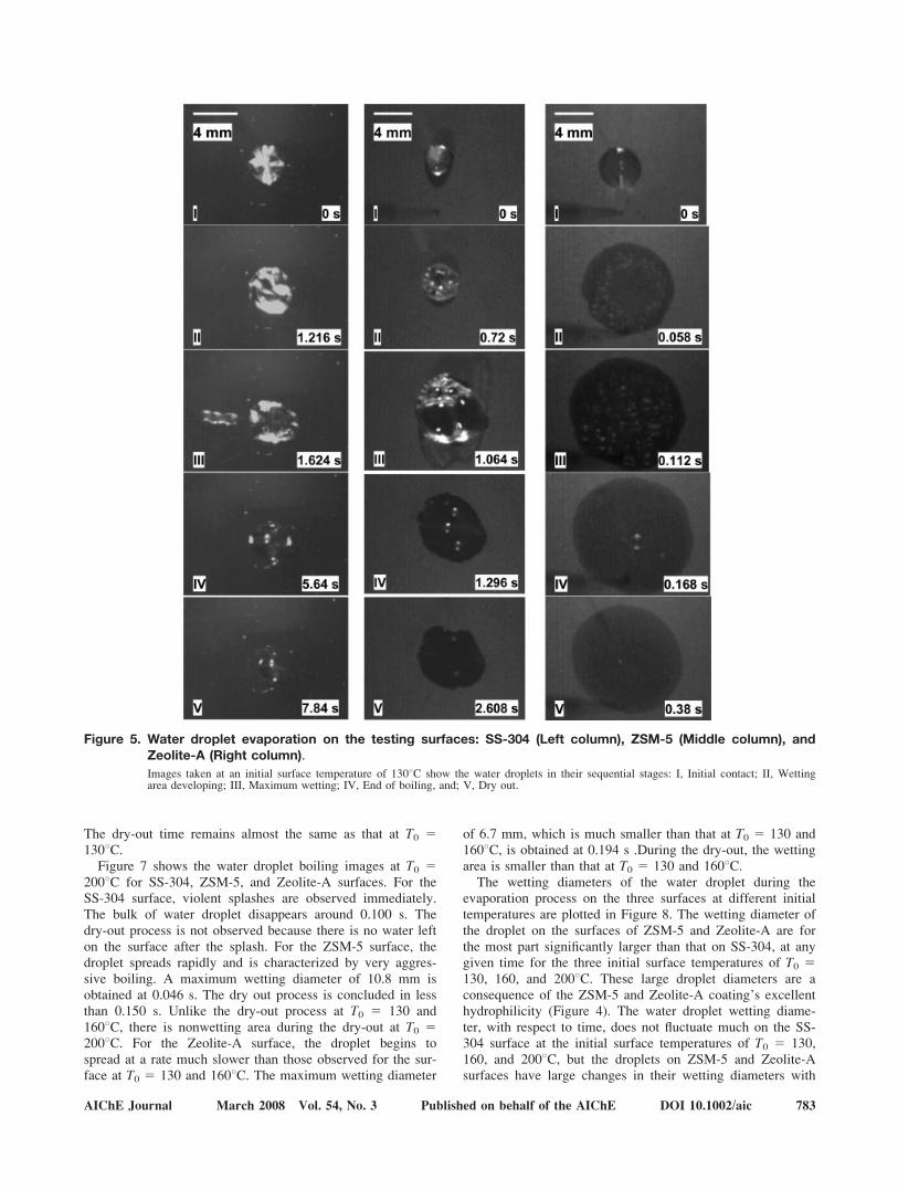
The wetting diameters of the water droplet during theevaporation process on the three surfaces at different initialtemperatures are plotted in Figure 8. The wetting diameter ofthe droplet on the surfaces of ZSM-5 and Zeolite-A are forthe most part significantly larger than that on SS-304, at anygiven time for the three initial surface temperatures of T0 5130, 160, and 2008C. These large droplet diameters are aconsequence of the ZSM-5 and Zeolite-A coating’s excellenthydrophilicity (Figure 4). The water droplet wetting diame-ter, with respect to time, does not fluctuate much on the SS-304 surface at the initial surface temperatures of T0 5 130,160, and 2008C, but the droplets on ZSM-5 and Zeolite-Asurfaces have large changes in their wetting diameters with
Figure 5. Water droplet evaporation on the testing surfaces: SS-304 (Left column), ZSM-5 (Middle column), andZeolite-A (Right column).
Images taken at an initial surface temperature of 1308C show the water droplets in their sequential stages: I, Initial contact; II, Wettingarea developing; III, Maximum wetting; IV, End of boiling, and; V, Dry out.
AIChE Journal March 2008 Vol. 54, No. 3 Published on behalf of the AIChE DOI 10.1002/aic 783

respect to time for all temperatures studied. For ZSM-5, themaximum wetting diameter increases as the temperature isincreased to 2008C while for Zeolite-A, the maximum wet-ting diameter decreases as T0 increases.
The maximum wetting diameter depends on two compet-ing and correlated parameters: wettability of the surface andthe rate of evaporation. Better wettability tends to increasethe diameter of the droplet while faster evaporation tends todecrease the maximum wetting diameter. Note that betterwettability originates from a better match of surface energy.It is known that as temperature increases, the surface tension(or energy) of water is reduced, making water much more‘‘spreadable’’ on a surface with a moderate surface energy(i.e., ZSM-5 surface) and less ‘‘spreadable’’ on Zeolite-A sur-face. But this should have very little effect on a surface likeSS-304 because its surface energy is still too low even for
the hot water droplet. For SS-304, as the initial temperatureof the surface increases, there is little change for the wett-ability, but the evaporation rate increases. This is reflectedby the slight decrease in the maximum wetting diameter. Forthe ZSM-5 surface, the wettability increases significantly asthe temperature increases and thus much larger maximumwetting diameter is achieved relative to the other two surfa-ces. In contrast, for the Zeolite-A surface, poorer wettabilityand faster evaporation work together to lower the maximumwetting diameter as the temperature increases.
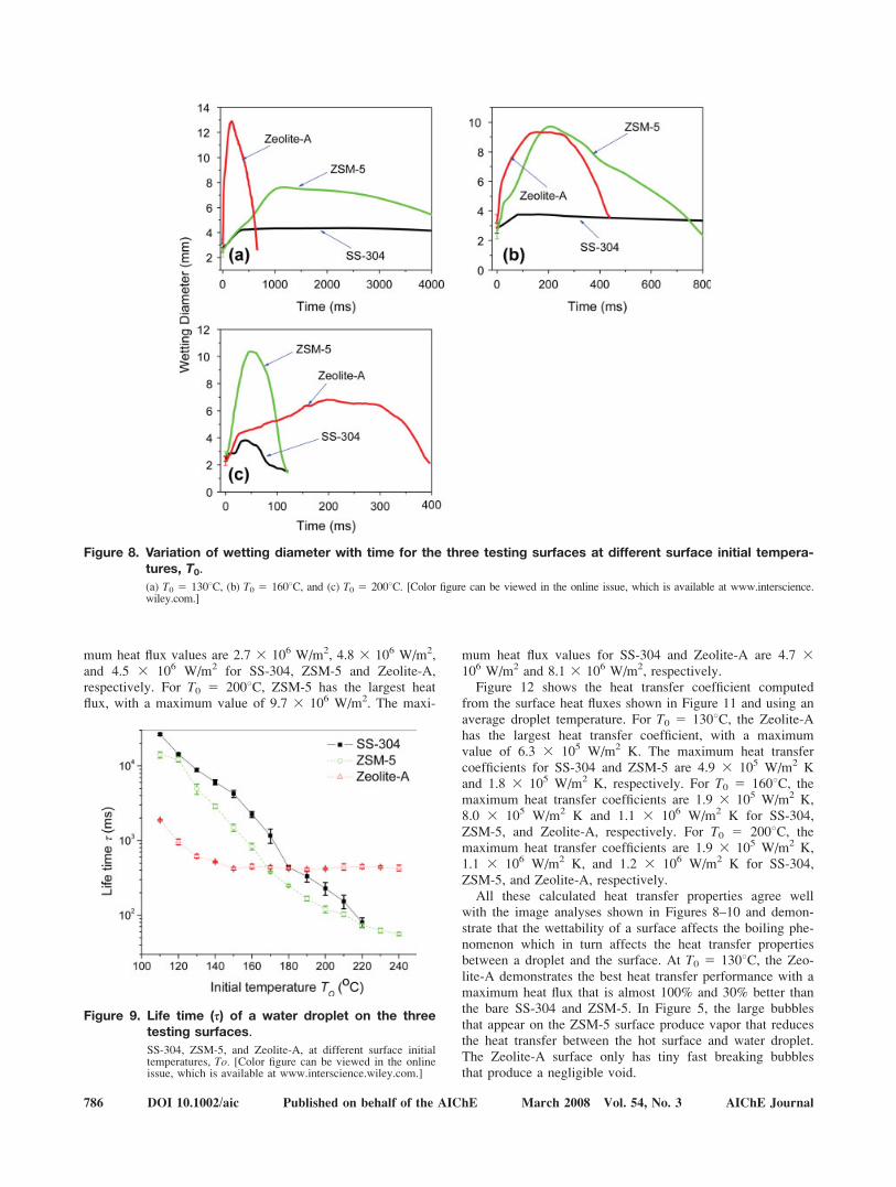
The life time of the water droplet on the three surfaces atdifferent temperatures is shown in Figure 9. For SS-304 andZSM-5, the life time shortens with increasing temperature.This is consistent with the hypothesis that higher temperatureincreases the rate of evaporation for SS-304 and ZSM-5. ForZeolite-A, however, the life time shortens as the temperature
Figure 6. Water droplet evaporation on the testing surfaces: SS-304 (Left column), ZSM-5 (Middle column) andZeolite-A (Right column).
Images taken an initial surface temperature of 1608C show the water droplets in their sequential stages: I, Initial contact; II, Wetting areadeveloping; III, Maximum wetting; IV, End of boiling, and; V, Dry out.
784 DOI 10.1002/aic Published on behalf of the AIChE March 2008 Vol. 54, No. 3 AIChE Journal

is increased to 1608C, but any further increase in temperaturedoes not significantly change the life time of the droplet. Itis believed that below 1608C, increasing temperature leads tofaster overall evaporation, and thus shorter life time. Butabove 1608C, another factor has to be considered, and that isthe microporosity. The ZSM-5 coating has an organic tem-plate in its micropores and thus is nonporous, but the Zeo-lite-A coating has no template in its micropores and thus ismicroporous. The longer life time of water droplet on Zeo-lite-A is likely a result of the increased difficulty to drive outthe water adsorbed inside the micropores.
Figure 10 shows the calculated surface temperature varia-tion with time. At T0 5 1308C, the lowest temperature that awater droplet at 248C can cool the surface to is 110, 105,and 1028C for SS-304, ZSM-5, and Zeolite-A, respectively.At this temperature, Zeolite-A decreases the surface tempera-
ture the fastest and has the best ability to cool down the sur-face. For T0 5 1608C, the lowest temperatures that a waterdroplet at 248C can cool the surface to is 1058C for both Ze-olite-A and ZSM-5, but only to 1308C for SS-304. The rateof decrease in the surface temperatures for ZSM-5 and Zeo-lite-A are very close at this temperature. For T0 5 2008C,the lowest temperatures that a water droplet at 248C can coolthe surface to is 1108C for both Zeolite-A and ZSM-5, butonly to 1458C for SS-304. The rate of decrease in the surfacetemperature of ZSM-5 is the fastest at this temperature.
Figure 11 shows the surface heat flux variation corre-sponding to temperature variations described in Figure 10.For T0 5 1308C, the Zeolite-A has the largest heat flux, witha maximum value of 3.3 3 106 W/m2. The maximum heatflux values for SS-304 and ZSM-5 are 1.8 3 106 W/m2 and2.3 3 106 W/m2, respectively. For T0 5 160 oC, the maxi-
Figure 7. Water droplet evaporation on the three surfaces.
SS-304 (Left column), ZSM-5 (Middle column) and Zeolite-A (Right column). Images taken at an initial surface temperature of 2008Cshow the water droplets in their sequential stages: I, Initial contact; II, Wetting area developing; III, Maximum wetting; IV, End of boiling,and; V, Dry out.
AIChE Journal March 2008 Vol. 54, No. 3 Published on behalf of the AIChE DOI 10.1002/aic 785
mum heat flux values are 2.7 3 106 W/m2, 4.8 3 106 W/m2,and 4.5 3 106 W/m2 for SS-304, ZSM-5 and Zeolite-A,respectively. For T0 5 2008C, ZSM-5 has the largest heatflux, with a maximum value of 9.7 3 106 W/m2. The maxi-
mum heat flux values for SS-304 and Zeolite-A are 4.7 3106 W/m2 and 8.1 3 106 W/m2, respectively.
Figure 12 shows the heat transfer coefficient computedfrom the surface heat fluxes shown in Figure 11 and using anaverage droplet temperature. For T0 5 1308C, the Zeolite-Ahas the largest heat transfer coefficient, with a maximumvalue of 6.3 3 105 W/m2 K. The maximum heat transfercoefficients for SS-304 and ZSM-5 are 4.9 3 105 W/m2 Kand 1.8 3 105 W/m2 K, respectively. For T0 5 1608C, themaximum heat transfer coefficients are 1.9 3 105 W/m2 K,8.0 3 105 W/m2 K and 1.1 3 106 W/m2 K for SS-304,ZSM-5, and Zeolite-A, respectively. For T0 5 2008C, themaximum heat transfer coefficients are 1.9 3 105 W/m2 K,1.1 3 106 W/m2 K, and 1.2 3 106 W/m2 K for SS-304,ZSM-5, and Zeolite-A, respectively.
All these calculated heat transfer properties agree wellwith the image analyses shown in Figures 8–10 and demon-strate that the wettability of a surface affects the boiling phe-nomenon which in turn affects the heat transfer propertiesbetween a droplet and the surface. At T0 5 1308C, the Zeo-lite-A demonstrates the best heat transfer performance with amaximum heat flux that is almost 100% and 30% better thanthe bare SS-304 and ZSM-5. In Figure 5, the large bubblesthat appear on the ZSM-5 surface produce vapor that reducesthe heat transfer between the hot surface and water droplet.The Zeolite-A surface only has tiny fast breaking bubblesthat produce a negligible void.
Figure 8. Variation of wetting diameter with time for the three testing surfaces at different surface initial tempera-tures, T0.
(a) T0 5 1308C, (b) T0 5 1608C, and (c) T0 5 2008C. [Color figure can be viewed in the online issue, which is available at www.interscience.wiley.com.]
Figure 9. Life time (s) of a water droplet on the threetesting surfaces.
SS-304, ZSM-5, and Zeolite-A, at different surface initialtemperatures, To. [Color figure can be viewed in the onlineissue, which is available at www.interscience.wiley.com.]
786 DOI 10.1002/aic Published on behalf of the AIChE March 2008 Vol. 54, No. 3 AIChE Journal
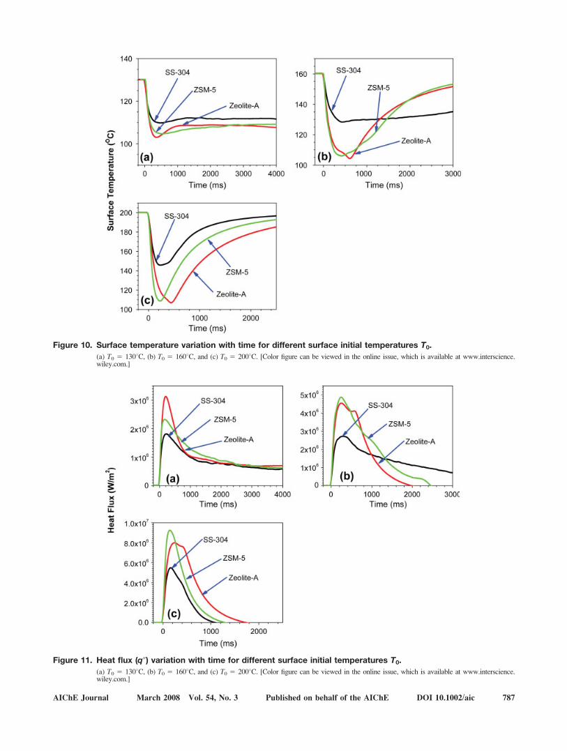
Figure 10. Surface temperature variation with time for different surface initial temperatures T0.
(a) T0 5 1308C, (b) T0 5 1608C, and (c) T0 5 2008C. [Color figure can be viewed in the online issue, which is available at www.interscience.wiley.com.]
Figure 11. Heat flux (q@) variation with time for different surface initial temperatures T0.
(a) T0 5 1308C, (b) T0 5 1608C, and (c) T0 5 2008C. [Color figure can be viewed in the online issue, which is available at www.interscience.wiley.com.]
AIChE Journal March 2008 Vol. 54, No. 3 Published on behalf of the AIChE DOI 10.1002/aic 787
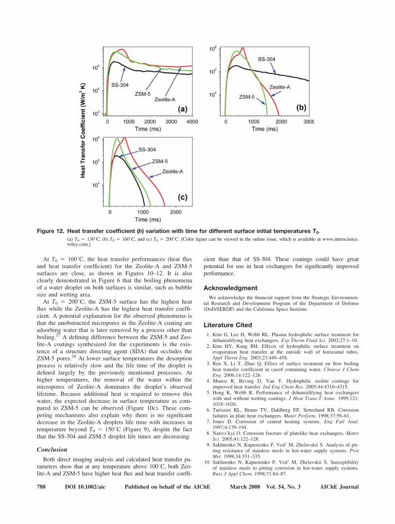
At T0 5 1608C, the heat transfer performances (heat fluxand heat transfer coefficient) for the Zeolite-A and ZSM-5surfaces are close, as shown in Figures 10–12. It is alsoclearly demonstrated in Figure 6 that the boiling phenomenaof a water droplet on both surfaces is similar, such as bubblesize and wetting area.
At T0 5 2008C, the ZSM-5 surface has the highest heatflux while the Zeolite-A has the highest heat transfer coeffi-cient. A potential explanation for the observed phenomena isthat the unobstructed micropores in the Zeolite-A coating areadsorbing water that is later removed by a process other thanboiling.27 A defining difference between the ZSM-5 and Zeo-lite-A coatings synthesized for the experiments is the exis-tence of a structure directing agent (SDA) that occludes theZSM-5 pores.28 At lower surface temperatures the desorptionprocess is relatively slow and the life time of the droplet isdefined largely by the previously mentioned processes. Athigher temperatures, the removal of the water within themicropores of Zeolite-A dominates the droplet’s observedlifetime. Because additional heat is required to remove thiswater, the expected decrease in surface temperature as com-pared to ZSM-5 can be observed (Figure 10c). These com-peting mechanisms also explain why there is no significantdecrease in the Zeolite-A droplets life time with increases intemperature beyond T0 5 1508C (Figure 9), despite the factthat the SS-304 and ZSM-5 droplet life times are decreasing.
Conclusion
Both direct imaging analysis and calculated heat transfer pa-rameters show that at any temperature above 1008C, both Zeo-lite-A and ZSM-5 have higher heat flux and heat transfer coeffi-
cient than that of SS-304. These coatings could have greatpotential for use in heat exchangers for significantly improvedperformance.
Acknowledgment
We acknowledge the financial support from the Strategic Environmen-tal Research and Development Program of the Department of Defense(DoD/SERDP) and the California Space Institute.
Literature Cited
1. Kim G, Lee H, Webb RL. Plasma hydrophilic surface treatment fordehumidifying heat exchangers. Exp Therm Fluid Sci. 2002;27:1–10.
2. Kim HY, Kang BH. Effects of hydrophilic surface treatment onevaporation heat transfer at the outside wall of horizontal tubes.Appl Therm Eng. 2003;23:449–458.
3. Ren X, Li T, Zhao Q. Effect of surface treatment on flow boilingheat transfer coefficient in caso4 containing water. Chinese J ChemEng. 2006;14:122–126.
4. Munoz R, Beving D, Yan Y. Hydrophilic zeolite coatings forimproved heat transfer. Ind Eng Chem Res. 2005;44:4310–4315.
5. Hong K, Webb R. Performance of dehumidifying heat exchangerswith and without wetting coatings. J Heat Trans-T Asme. 1999;121:1018–1026.
6. Turissini RL, Bruno TV, Dahlberg EP, Setterlund RB. Corrosionfailures in plate heat exchangers. Mater Perform. 1998;37:59–61.
7. Jones D. Corrosion of central heating systems. Eng Fail Anal.1997;4:179–194.
8. Narivs’kyi O. Corrosion fracture of platelike heat exchangers. MaterSci. 2005;41:122–128.
9. Sakhnenko N, Kapustenko P, Ved’ M, Zhelavskii S. Analysis of pit-ting resistance of stainless steels in hot-water supply systems. ProtMet. 1998;34:331–335.
10. Sakhnenko N, Kapustenko P, Ved’ M, Zhelavskii S. Susceptibilityof stainless steels to pitting corrosion in hot-water supply systems.Russ J Appl Chem. 1998;71:84–87.
Figure 12. Heat transfer coefficient (h) variation with time for different surface initial temperatures T0.
(a) T0 5 1308C, (b) T0 5 1608C, and (c) T0 5 2008C. [Color figure can be viewed in the online issue, which is available at www.interscience.wiley.com.]
788 DOI 10.1002/aic Published on behalf of the AIChE March 2008 Vol. 54, No. 3 AIChE Journal
11. Navinsek B, Panjan P, Milosev I. Pvd coatings as an environmen-tally clean alternative to electroplating and electroless processes.Surf Coat Tech. 1999;119:476–487.
12. Legg K, Graham M, Chang P, Rastagar F, Gonzales A, Sartwell B.The replacement of electroplating. Surf Coat Tech. 1996;81:99–105.
13. Kwangtaek H, Webb R. Wetting coatings for dehumidifying heatexchangers. Hvac R Res. 2000;6:229–242.
14. Cheng XL, Wang ZB, Yan YS. Corrosion-resistant zeolite coatingsby in situ crystallization. Electrochem Solid St. 2001;4:B23–B26.
15. Beving D, McDonnell A, Yang W, Yan Y. Corrosion resistant high-silica-zeolite mfi coating—one general solution formulation foraluminum alloy aa-2024-t3, aa-5052-h32, aa-6061-t4, and aa-7075-t6. J Electrochem Soc. 2006;153:B325–B329.
16. Beving D, Yan Y. Corrosion resistant zeolite coatings: a generalcoating for aluminum alloys. Abstr Pap Am Chem S. 2004;227:U1550–U1550.
17. Mitra A, Wang Z, Cao T, Wang H, Huang L, Yan Y. Synthesis andcorrosion resistance of high-silica zeolite mtw, bea, and mfi coatingson steel and aluminum. J Electrochem Soc. 2002;149:B472–B478.
18. Munoz R, Beving D, Mao Y, Yan Y. Zeolite y coatings on al-2024-t3 substrate by a three-step synthesis method. Micropor MesoporMater. 2005;86(1-3):243–248.
19. Hong KT, Imadojemu H, Webb RL. Effects of oxidation and sur-face-roughness on contact-angle. Exp Thermal Fluid Sci. 1994;8:279–285.
20. Bernardin JD, Stebbins CJ, Mudawar I. Effects of surface roughnesson water droplet impact history and heat transfer regimes. Int.J Heat Mass Transf. 1997;40:73–88.
21. Michiyoshi I, Makino K. Heat-transfer characteristics of evaporationof a liquid droplet on heated surfaces. Int J Heat Mass Transf.1978;21:605–613.
22. Xiong TY, Yuen MC. Evaporation of a liquid droplet on a hot plate.Int J Heat Mass Transf. 1991;34:1881–1894.
23. Qiao YM, Chandra S. Experiments on adding a surfactant to waterdrops boiling on a hot surface. Proc Royal Soc Lond Series a-MathPhys Eng Sci. 1997;453:673–689.
24. Cui W, Chanda S, McCahan S. The effect of dissolving salts inwater sprays used for quenching a hot surface, Part 1. Boiling of sin-gle droplets. J Heat Transf-Trans Asme. 2003;125:326–332.
25. Beck JV, Blackwell B, Clair C. Inverse Heat Conduction: Ill-PosedProblems. New York: Wiley, 1985.
26. Aguilar G, Wang GX, Nelson JS. Dynamic behavior of cryogenspray cooling: Effects of spurt duration and spray distance. LasersSurg Med. 2003;32:152–159.
27. Stach H, Mugele J, Janchen J, Weiler E. Influence of cycle tempera-tures on the thermochemical heat storage densities in the systemswater/microporous and water/mesoporous adsorbents. Adsorp-J IntAdsorp Soc. 2005;11(3-4):393–404.
28. Lobo R, Zones S, Davis M. Structure-direction in zeolite synthesis.J Inclus Phenom Mol. 1995;21(1-4):47–78.
29. Tunnell JW, Torres JH, Anvari B. Methodology for estimation oftime-dependent surface heat flux due to cryogen spray cooling. AnnBiomed Eng. 2002;30:19–33.
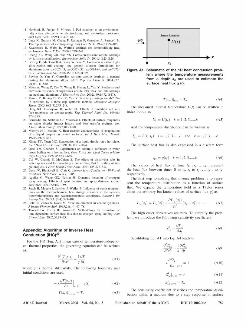
Appendix: Algorithm of Inverse HeatConduction (IHC)29
For the 1-D (Fig. A1) linear case of temperature-independ-ent thermal properties, the governing equation can be writtenas:
@2ðTðx; tÞ@2x2
¼ 1
c@T
@t(A1)
where c is thermal diffusivity. The following boundary andinitial conditions are used,
� k@Tðx; tÞ
@x
���x¼0
¼ qðtÞ (A2)
Tðx; tÞjx¼1 ¼ To (A3)
Tðx; tÞjt¼o ¼ To (A4)
The measured internal temperature U(t) can be written inindex notion as
Uk ¼ UðtkÞ k ¼ 1; 2; 3::::::k (A5)
And the temperature distribution can be written as
Ti;k ¼ Tðxi; tkÞ i ¼ 1; 2; 3::::::I and k ¼ 1; 2; 3::::::k
The surface heat flux is also expressed in a discrete formas
qk ¼ qðtkÞ k ¼ 1; 2; 3::::::k (A6)
The values of heat flux at time t1, t2,. . ., tK, representthe heat flux between times 0 to t1, t1 to t2,. . ., tK-1 to tK,respectively.
The first step to solving this inverse problem is to repre-sent the temperature distribution as a function of surfaceflux. We expand the temperature field in a Taylor seriesabout the arbitrary but known values of surface flux q�k as
Ti;k ðqkÞ ¼ Ti;k ðq�kÞ þ@Ti;k ðq�kÞ
qk�ðqk � q�kÞ þ � � � (A7)
The high order derivatives are zero. To simplify the prob-lem, we introduce the following sensitivity coefficient:
Zki;k¼ @Ti;k
@qk(A8)
Substituting Eq. A1 into Eq. A4 leads to
@2Zki;k
@2x2¼ 1
a
@Zki;k
@t(A9)
� k@Zk
i;k
@x
���x¼0
¼ 1 (A10)
Zki;kji¼1 ¼ 0 (A11)
Zki;kjk¼o ¼ To (A12)
The sensitivity coefficient describes the temperature distri-bution within a medium due to a step response in surface
Figure A1. Schematic of the 1D heat conduction prob-lem where the temperature measurementsfrom a depth xa are used to estimate thesurface heat flux q (t).
AIChE Journal March 2008 Vol. 54, No. 3 Published on behalf of the AIChE DOI 10.1002/aic 789

heat flux. Notice that the sensitivity coefficient is independ-ent of the unknown surface heat flux. We calculateZki;k
numerically using an explicit central finite differencetechnique.
Assuming we know the temperature distribution and sur-face heat flux for times tk-1, tk-2,. . . and that the surface heatflux at tk is to be estimated, we can express the temperaturefield ti;k as a sole function of the unknown function of qk.Substitute the sensitivity coefficient into Eq. A7, the temper-ature distribution can be expressed as
Ti;kðqkÞ ¼ Ti;kðq�kÞ þ Zki;kðqk � q�kÞ (A13)
In this case q�k is known from estimations at previous time,Zki;k
can be calculated from Eqs. A9 to A12 and Ti;k ðq�kÞ issimply Ti,k–1. Equation A13 represents the temperature distri-bution as a sole function of surface heat flux qk. Give that atemperature measurement is made in at least one location,for example, xa, we introduce the measured temperature Uk
into Equation A13 and solve for qk
qk ¼ q�k �Uk � Ti;k ðq�kÞ
Zki;k
; i ¼ a k ¼ 1; 2; 3::::::k; (A14)
However, the solution is severely ill-posed in that a smallperturbation or noise in the recorded temperature can resultin large oscillations in the predicted surface heat flux. Tominimize the effects of measurement noise on the solutions,Beck25 introduced the method of using future (t [ tk) tem-perature measurements where the surface heat flux is tempo-rarily assumed constant over R future time steps:
qk ¼ qkþ1 ¼ :::qkþR(A15)
The least squares method is then used to minimize theerror between the measured temperature Uk and the predictedtemperature Ti;k for a given sensor location (i.e., x 5 xa)over future time steps
D ¼XR
r¼1
ðUkþr�1 � Ti;kþr�1Þ2 ! min i ¼ a k ¼ 1; 2; 3::::::k
(A16)
Since Eq. A13 can be used to calculate Ti;kþr�1as a func-
tion surface heat flux, we substitute Eq. A13 into Eq. A16 to
solve the least squares problem resulting in the solution forthe estimated surface heat flux at time tk:
qk ¼ q�kþPR
r¼1 ½Ukþr�1�Ti;kþr�1ðq�kÞ�Zki;r�1PR
r¼1 ðZki;r�1Þ2
; i¼ a (A17)
Using Eq. A17, we sequentially solve for the surface heatflux for each time step. Figure A2 illustrates the complete so-lution methodology to the inverse heat conduction problem.Notice that Zk
i;konly needs to be calculated once for a given
problem geometry since it does not depend on the unknownsurface heat flux and is only calculated over the time interval0\ t\ tR. In addition, Ti,k1r-1(q*), r 5 1,2,. . .R can be cal-culated using a finite difference solution to Eq. A1 with theboundary conditions Eqs. A2 and A3, qðtÞ ¼ q� ¼ :::qk�1
, andinitial condition of Ti;k ¼ Ti;k�1. Once the Ti;k is calculated,the qk can be obtained using Eq. A17.
Manuscript received Mar. 12, 2007, revision received Aug. 29, 2007, and finalrevision received Nov. 29, 2007.
Figure A2. Flow diagram illustrating the algorithmto solve the inverse heat conductionproblem.
790 DOI 10.1002/aic Published on behalf of the AIChE March 2008 Vol. 54, No. 3 AIChE Journal