Solar drying of sweet pepper and garlic using the tunnel greenhouse drier
14
Renewable Energy 22 (2001) 447–460 www.elsevier.nl/locate/renene Solar drying of sweet pepper and garlic using the tunnel greenhouse drier M. Condorı ´ * , R. Echazu ´, L. Saravia INENCO, Instituto de Investigacio ´n en Energı ´a no Convencional, Universidad Nacional de Salta, Calle Buenos Aires 177, 4400 Salta, Argentina Received 28 March 2000; accepted 27 April 2000 Abstract A new low cost design for a forced convection greenhouse drier, the Tunnel Greenhouse Drier, has been built and tested. Its main parts are: a plastic greenhouse cover containing a drying tunnel made with transparent plastic walls; a line of carts with several stacked trays containing the product and moved manually inside the tunnel and an electrical fan that moves the hot air from the greenhouse into the tunnel. The trays receive solar radiation through the transparent walls, increasing the product temperature. Heat losses from the tunnel are low since greenhouse temperatures are higher than ambient temperature. The main advantages of this drier are: (a) an almost continuous production since some carts with dried product come out of the tunnel every day, while the same amount of fresh product is introduced by the other tunnel extreme; (b) lower labor cost since the product handling is partly mechanized; (c) a conventional heater can be easily installed to keep a constant production rate; (d) the energy consumption is lower than in other drier types; (e) the installation can be used as a greenhouse for small production when it is not used as a drier. The prototype was built in the North of Argentina, and red sweet pepper and garlic were used as load. The drier thermal efficiency, considered as a solar collector, was calculated using the measured experimental data, and a linear relation between the drier temperature and the solar radiation was obtained. 2000 Elsevier Science Ltd. All rights reserved. 1. Introduction The greenhouse drier is a system that uses the regular structure of a greenhouse to work as solar drier during the warmer months of the year, when the greenhouse * Corresponding author. Tel.: 0054-0387-4255424; fax: 0054-0387-4255489. E-mail address: [email protected] (M. Condorı ´). 0960-1481/01/$ - see front matter 2000 Elsevier Science Ltd. All rights reserved. PII:S0960-1481(01)00098-7
Transcript of Solar drying of sweet pepper and garlic using the tunnel greenhouse drier

Renewable Energy 22 (2001) 447–460www.elsevier.nl/locate/renene
Solar drying of sweet pepper and garlic usingthe tunnel greenhouse drier
M. Condorı *, R. Echazu´, L. SaraviaINENCO, Instituto de Investigacio´n en Energı´a no Convencional, Universidad Nacional de Salta,
Calle Buenos Aires 177, 4400 Salta, Argentina
Received 28 March 2000; accepted 27 April 2000
Abstract
A new low cost design for a forced convection greenhouse drier, the Tunnel GreenhouseDrier, has been built and tested. Its main parts are: a plastic greenhouse cover containing adrying tunnel made with transparent plastic walls; a line of carts with several stacked trayscontaining the product and moved manually inside the tunnel and an electrical fan that movesthe hot air from the greenhouse into the tunnel. The trays receive solar radiation through thetransparent walls, increasing the product temperature. Heat losses from the tunnel are lowsince greenhouse temperatures are higher than ambient temperature. The main advantages ofthis drier are: (a) an almost continuous production since some carts with dried product comeout of the tunnel every day, while the same amount of fresh product is introduced by the othertunnel extreme; (b) lower labor cost since the product handling is partly mechanized; (c) aconventional heater can be easily installed to keep a constant production rate; (d) the energyconsumption is lower than in other drier types; (e) the installation can be used as a greenhousefor small production when it is not used as a drier. The prototype was built in the North ofArgentina, and red sweet pepper and garlic were used as load. The drier thermal efficiency,considered as a solar collector, was calculated using the measured experimental data, and alinear relation between the drier temperature and the solar radiation was obtained. 2000Elsevier Science Ltd. All rights reserved.
1. Introduction
The greenhouse drier is a system that uses the regular structure of a greenhouseto work as solar drier during the warmer months of the year, when the greenhouse
* Corresponding author. Tel.: 0054-0387-4255424; fax: 0054-0387-4255489.E-mail address:[email protected] (M. Condorı´).
0960-1481/01/$ - see front matter 2000 Elsevier Science Ltd. All rights reserved.PII: S0960 -1481(01 )00098-7

448 M. Condorıet al. / Renewable Energy 22 (2001) 447–460
is not used. This double function, greenhouse and drier, improves the return rate ofthe initial investment.
The simplest forced convection greenhouse drier is the single chamber drier [1].It uses the greenhouse as a single drying chamber where the fresh product is placedon trays and dried by batch. The product is unloaded after several days when therequired drying is completed. The available solar energy is appropriately used onlyduring the first day when the fresh product still has a high water content. Duringthe next days, the product water content and the water evaporation decrease loweringthe system thermal efficiency.
In an improved version of the previous drier, the double chamber drier [1], thegreenhouse is divided in two chambers. The product partially dried is placed in oneof them and fresh product in the other, while two fans circulates the air from thefirst to the second chamber. When the product in the first chamber is dried, the aircirculation is reversed and new fresh product is loaded in this chamber while thesecond chamber has the half dried product now. This semi-dried product does notadd too much humidity to the air flow, and this chamber works as an air solar heaterfor the other one. The drier production is almost duplicated with respect to a singlechamber drier with the same soil area [2].
In this paper, a new design of a low cost solar greenhouse drier is proposed:thetunnel greenhouse drier. In Figs. 1 and 2 two views are shown. The tunnel, builtwith transparent polyethylene plastic and wood, is placed under the greenhouse coverdividing it in two working zones: the drying tunnel and the rest of the greenhouse.The last one works as solar collector heating the ambient air that is introduced inthe tunnel. The product is placed in several trays stacked on carts. Their movementis manually performed, using two tracks on the soil along the tunnel as a guide.Two axial fans are placed in the tunnel ceiling, one near to the input door and otherat the opposite end.
The ambient air is introduced to the collector zone through two small windows
Fig. 1. Face view of the tunnel greenhouse drier.

449M. Condorıet al. / Renewable Energy 22 (2001) 447–460
Fig. 2. Plant view of the tunnel greenhouse drier.
placed on the greenhouse North face and it is mainly heated by convective exchangewith the soil, covered with black plastic to improve the solar radiation absorption.An operation schema is shown in Fig. 3. The air comes from the collector zone witha greater drying potential than the ambient, that is, low relative humidity and hightemperature, and it is introduced in the tunnel by the fans, where temperature andproduct humidity gradients along the tunnel are produced. The product placed in thefirst cart, in front of the South door, has the lowest moisture and it is the first to beremoved from the tunnel by the South door, while new fresh product is introducedby the opposite door. A transparent plastic tube, placed on the tunnel ceiling, is usedto recycle the air leaving the tunnel allowing a better control of temperature andhumidity into the drier.
This new design has several important improvements when it is compared withthe other greenhouse driers.
1. The countercurrent circulation between the air flow and the product in the cartsimproves the drying efficiency.
Fig. 3. Operation scheme of the tunnel greenhouse drier.

450 M. Condorıet al. / Renewable Energy 22 (2001) 447–460
2. The carts allow a partial mechanization of the product handling, lowering thelabor cost.
3. A conventional heater using wood or other fuel can be easily installed to keepan almost constant production, improving the results to be obtained from an econ-omical point of view.
In this work, the experiments performed with a prototype initially built in the Prov-ince of Salta, Northern Argentina, are presented. These experiments allowed thedevelopment of this type of drier in technological aspects such as the building tech-niques and the most convenient materials as well as more basic aspects such asan analytical model that allows the extrapolation of the results using computingsimulation [3].
2. The drier construction
The prototype drier was built at Lerma Valley, situated at 24.7 South latitude and1200 m above sea level. During the summer, the daily average radiation on horizontalsurface is near 20 MJ/m2 and the monthly average temperature and relative humidityare 20°C and 70%, respectively. Summer is the raining season with an average ofwater precipitation equal to 700 mm.
The prototype was part of an integral system where the drier and the cultivationgreenhouse is combined. The greenhouse had a total soil area of 350 m2, 91 m2
corresponding to the drier while the rest was dedicated to the cultivation. The struc-ture was 7 m wide and 13 m long with its main axis in the North-East direction,since this is the predominant direction of the local wind.
A metallic structure is used, this was built with a series of arches connectedbetween them with longitudinal pipes. Each arch was made with two curved 2.6 cmdiameter tubes. The arches were supported on two lateral tubular vertical posts 2 mheight and with a 4.5 cm diameter. Each post is inserted in a concrete basis, placedunder the soil, and fixed to it with screws. The maximum height of the structurewas 3.70 m.
The drier was separated from the cultivation greenhouse by means of a plasticwall. The polyethylene plastic used to cover the structure was 150µm thick andincorporates UV and far infrared protection. It was protected from the wind actionby a wire mesh crossing the external side. No post is used inside the greenhouse,allowing a better use of the soil area.
The drying tunnel was built under the greenhouse cover along its central axis,using wood frames buried in the soil, with 1.9 m of separation between them. Thetunnel dimensions were 1.2 m wide by 13 m long and 1.9 m high. The tunnel struc-ture was completed with wire ties between the frames supporting the polyethyleneplastic.
The air recycling tube had 0.6 m diameter and was also built with a transparentplastic, placed over the tunnel ceiling using wires as structure elements. On the floor,at both sides of the tunnel, a black plastic film is placed to improve the radiation

451M. Condorıet al. / Renewable Energy 22 (2001) 447–460
absorption. During the drying process, the tunnel was continuously closed with twotransparent plastic doors. Two 1/2 hp axial fans, were placed on the ceiling tunnel,corresponding to the air entrance and exit. This disposition allows a better use ofthe hot air, which is taken by the fans from the greenhouse ceiling; it is introducedinto the tunnel on the more dried product and moves along the carts. Finally, an airfraction is recycled and the rest is expelled to the ambient.
The carts were 1 m wide and 1.5 m long and they were built with rectangularblack tubes. The tunnel has a total capacity of seven carts and 10 trays, 15 cm high,may be stacked on each cart. The trays were built with a 4.2 mm diameter iron meshand a plastic mesh with smaller weave was placed over the metal to avoid the directcontact of the product with the oxidized iron.
3. Experimental test results
Several drying tests, performed with red sweet pepper and garlic as load products,were carried out. A computer equipped with a 16 analogous input channels and 8digital outputs data acquisition card was used to record the main variables. The totalradiation on a horizontal surface was measured with a Kipp and Zonnen pyranometer.The temperature measurement was performed with thermistors, and the relativehumidities were recorded with four HMP 35D Vaisala hygrometers. The wind velo-city was measured with a cup anemometer and a hot wire anemometer was used forthe air flow measurement in the tunnel. The weight of the product was manuallymeasured with a precision mechanical balance. The prototype was tested without aload to study its thermal behavior and then the tests using the mentioned productswere performed.
3.1. The drier as a solar collector
The ambient, as well as the East and West side temperatures of the drier, areshown in Fig. 4 for two days in December. Both sides work as solar collectorssupplying the hot air to the tunnel. Their thermal behavior is slightly asymmetricalwith respect to the solar midday. A large amount of heat stored in the soil duringthe day is delivered into the drier in the afternoon and the first hours of the night.Due to this storing effect, both collector temperatures are always higher than theambient one, and the maximum difference between them, around 25°C, is obtainedat midday. This difference decreases to a few degrees during the night. The higheraverage temperature is produced in the East side during the morning while the Westtemperature is higher during the late afternoon and at night. The temperatures inboth sides are out of phase, due to the soil thermal inertia.
The ambient and the drier relative humidities are shown in Fig. 5. During the day,the maximum difference between them is around 20%. At night, the drier humidityincreases and values over 70% are obtained when the ambient relative humiditygrows up to 90%. This high humidity is dangerous for the product, especially whenit is still fresh, since fungus growth is favored.

452 M. Condorıet al. / Renewable Energy 22 (2001) 447–460
Fig. 4. Ambient and the drier collector zones temperatures.
The more extreme working conditions for the drier without load during sunnydays were: a maximum temperature near 60°C and a minimum relative humiditynear 15%; the high thermal amplitude being a characteristic of this region.
According to the solar collector theory [4], the instantaneous efficiency isdefined as:
h5Cpma(T−Ta)
AsI(1)
where I is the solar energy received by the greenhouse drier in its soil surfaceAs,Cp is the air specific heat,ma is the air mass flow rate,T the drier output temperatureandTa the ambient temperature. The daily records for the greenhouse instantaneousefficiency corresponding to eight serial days are shown in Fig. 6. The average atmidday is around 25% and the peaks out of this average are due to the inertia effectthat keeps the drier temperature almost constant for some minutes when the radiationfalls. The parameter values adopted in Eq. (1) are listed in Table 1.
Since the drier input air is the ambient one, the thermal efficiency only dependson the collector heat removal factorFR and the greenhouse optic parameters:
h5FR(ta) (2)
wheret is the transmittance of the cover anda is the drier mean absorption coef-ficient.

453M. Condorıet al. / Renewable Energy 22 (2001) 447–460
Fig. 5. Ambient and the drier relative humidities.
Fig. 6. The instantaneous thermal efficiency for the drier prototype.

454 M. Condorıet al. / Renewable Energy 22 (2001) 447–460
Table 1List of parameters and their values as used in the Eq. (1)
Parameters Values
ma 1 kg/sr 1 kg/m3
Cp 1 kJ/kg°CAs 75.4 m2
(ta) 0.8
Eq. (2) suggests that the greenhouse efficiency is practically constant for dailyvalues sincet anda do not change andFR mainly depends on the mass flow, almostconstant for a forced convection drier. In this case, a linear correlation between thetemperature differenceT2Ta and the radiationI is obtained according to Eq. (1). InFig. 7, experimental values for this relation with no load in the drier, are shown forthe first eight days of December, showing there is an origin ordinate around 2°Cdue to the thermal inertia of the soil drier. This inertia changes slightly the linearbehavior, particularly when the radiation is low. Nevertheless, if a linear regressionpassing by the origin is adopted, the linear equation is:
T2Ta50.0208I (3)
Fig. 7. The linear fitting between the solar radiation and the temperature difference obtained with thedrier prototype.

455M. Condorıet al. / Renewable Energy 22 (2001) 447–460
having still a good fitting, 0.9, as it is shown in Fig. 7 with the superposed fit line.The fitting improves if radiation records above 400 W/m2 are adopted.
In the greenhouse, the heat losses are greatly convective and they are due to thelarge size of the cover surface. Eq. (2) suggests possible improvements in thedrier efficiency:
1. To improve the radiation absorption, increasing (ta);2. To improve FR, decreasing the drier height or using adequate insulation, to
decrease the surface losses.
3.2. Sweet pepper drying
The red sweet pepper is a traditional crop in Salta. In many locations in the Prov-ince, sun drying is still practised. That is, the pepper is spread on the soil or on thefoothills where it is exposed to the solar radiation and the wind action. This dryingis slower and it is not very convenient from a bromatological point of view, sincethere is contamination with dust, fungus and excrements of rodents and birds. In theLerma valley zone, the tobacco crop is the principal economy and, since the tobaccointernational price is down, the producers are searching for alternative crops. Duringthe last years, they have increased the cultivated area of the sweet pepper for thepaprika production. Since there are virus problems in the region if the open skypractice is used, the cultivation of sweet pepper is only possible in greenhouses,where there is a better controlled environment. Therefore, the tunnel greenhousedrier appears as a very interesting alternative to reduce the costs for a drying unit,maintaining an acceptable drying time and final quality in the paprika production.
Sweet pepper halved is used as fresh product, it is distributed on the cart traysusing a load density of 5 kg by m2 of tray surface. These tests are performed withhybrid pepper since it is better suited for the paprika oleoresin production. The pepperis harvested according to its maturation in the plant, one or two times a week, andit is immediately washed and put on the trays in the drier. Measurements were perfor-med in 300 kg of fresh product, obtaining an average product humidity of 0.15referred to the dried weight and an average color of 200 degree ASTA (AmericanSpice Trade Association) for some samples of dried product. This color standardvalue is acceptable from a commercial point of view. The initial product water con-tent, referred to the dried weight, was around 6 and the samples are considered driedwhen values lower than 0.15 are obtained, being this level appropriate for a safestorage requirement.
Three kinds of fruit surface exposure to the solar radiation are tested: the wholesheath, halved with a longitudinal cutting and halved in traverse mode. In Fig. 8,the drying curves corresponding to these three exposure types are shown. The pepperwith a longitudinal cutting presents the better drying rate, around three days, whilethe pepper in whole sheaths needed around six days to reach a similar moisturecontent. The performance for the pepper halved in traverse mode is placed betweenboth of them. For the longitudinally cut, 80% of its weight is lost during the first

456 M. Condorıet al. / Renewable Energy 22 (2001) 447–460
Fig. 8. Drying curves for sweet pepper corresponding to three exposure surface.
day and it is observed that the drying continues during the night hours. These testsshow that the tunnel drier works very well during sunny days but some problemswith fungus formation appear during cloudy days with high ambient humidity. Thisproblem appears in this region with this product, since the drying months are partof the rainy season. A new design incorporating an auxiliary heating system ispresented in Section 3.4.
3.3. Garlic drying
Garlic is another traditional crop in Salta. Generally, it is commercialized as afresh product in the local market, but in recent years the producers have looked fornew commercial uses where it is required as garlic in powder. Since there is notany recorded antecedent about the garlic drying in the region, it was necessary totest the possible process in all its steps and adapt it to the local conditions.
Once the garlic is harvested, it is placed under the sheds, where a first watercontent decrease is carried out. In fact, this delay is related to merchandising, sincethe producers are looking to save it as fresh product, but the diminution of initialweight improves the drying. The garlic jags are manually separated by friction andthey are submerged in water to remove peels and dirt. Once they are aired, a cuttingof the jags is performed since the garlic skin is not very permeable. This is donewith good edge blades to avoid the jag crushing and the pouring out of the garlic
457M. Condorıet al. / Renewable Energy 22 (2001) 447–460
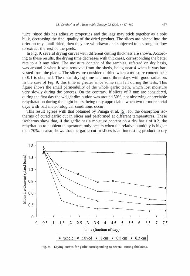
juice, since this has adhesive properties and the jags may stick together as a solebulk, decreasing the final quality of the dried product. The slices are placed into thedrier on trays until dried, then they are withdrawn and subjected to a strong air flowto extract the rest of the peels.
In Fig. 9, several drying curves with different cutting thickness are shown. Accord-ing to these results, the drying time decreases with thickness, corresponding the betterrate to a 3 mm slice. The moisture content of the samples, referred on dry basis,was around 2 when it was removed from the sheds, being near 4 when it was har-vested from the plants. The slices are considered dried when a moisture content nearto 0.1 is obtained. The mean drying time is around three days with good radiation.In the case of Fig. 9, this time is greater since some rain fell during the tests. Thisfigure shows the small permeability of the whole garlic teeth, which lost moisturevery slowly during the process. On the contrary, if slices of 3 mm are considered,during the first day the weight diminution was around 50%, not observing appreciablerehydratation during the night hours, being only appreciable when two or more serialdays with bad meteorological conditions occur.
This result agrees with that obtained by Pin˜aga et al. [5], for the desorption iso-therms of cured garlic cut in slices and performed at different temperatures. Theseisotherms show that, if the garlic has a moisture content on a dry basis of 0.2, therehydration to ambient temperature only occurs when the relative humidity is higherthan 70%. It also shows that the garlic cut in slices is an interesting product to dry
Fig. 9. Drying curves for garlic corresponding to several cutting thickness.

458 M. Condorıet al. / Renewable Energy 22 (2001) 447–460
with solar energy, since it is not necessary to use an auxiliary heating source tosupplement the solar energy. However, from a commercial viewpoint, it is necessaryto bear in mind that the direct solar radiation is only available for some hours ofthe day and for some days of the week, and an auxiliary heating source may assurea more continuous production process.
One of the criterions used to determine the quality of the dried garlic is its appear-ance, the clear colors being much more appreciated. In the tests, a very good driedgarlic with an even, clear cream color is obtained. The average production efficiencywas 1 kg of dried product for 5 kg of fresh product and the load density was around6 or 7 kg of fresh product by tray square meter.
3.4. Auxiliary heating
As it is usual in solar applications, the low radiation density and the variabilityof the energy source are the main problems to solve. It is quite simple to add anauxiliary heater to this drier. Fig. 10 shows the operation of this system either incloudy days or at night. Its size is selected to produce the drying gradient and thedaily production obtained during sunny days. The collector ambient air input isclosed improving the thermal insulation, since it produces an air chamber with lownatural convection surrounding the drying tunnel. The ambient air is taken directlyfrom the outside South side, and it is pushed by the fans through an unfinned tubularheat exchanger, where it is indirectly heated by the combustion gas flowing insidethe tubes. Then, the heated air moves through the file carts as before. The hot gasis produced by a forced flow stove, fed with firewood or agricola surplus. Theremaining cooler combustion gas is expelled to the environment by a chimney. Boththe heat exchanger and the stove are insulated to avoid heat losses and to protectthe plastic cover.
Fig. 10. Operation scheme of the tunnel greenhouse drier with auxiliary heating.
459M. Condorıet al. / Renewable Energy 22 (2001) 447–460
4. Conclusions
The proposed tunnel greenhouse drier has been tested under real working con-ditions, obtaining a good thermal performance during sunny days. An auxiliary heat-ing system is needed to improve the production during the whole drying season andto avoid product losses. The prototype drier was tested used sweet pepper and garlicas load products, obtaining a good drying rate, final moisture content and dried pro-duct aspect.
Also, an acceptable color is obtained with both products, not observing appreciabledeteriorations in the final color of the dried product, as expected from the solarradiation exposition. This is an interesting result and further research must be perfor-med. We suggest that these results may be due to the following improvements intro-duced in the tunnel greenhouse drier:
1. There are several plastics, with UV protection, between the product and the inci-dent solar radiation.
2. The remaining visible and infrared light, is collected by the product and itincreases its internal temperature, improving the drying velocity and decreasingthe exposition time.
The forced air flow allows a better hot air distribution through the trays, improvingthe importance of the convective transfer compared to the radiative process andimproving the drying uniformity.
Another important improvement is the carts system, with its continuous productcharge and discharge facility improving its handling and reducing the worker labor.This is an important point to evaluate the commercial drier feasibility.
The tunnel greenhouse drier presented an acceptable load capacity, i.e. fresh pro-duct mass by unit area, around 50 kg/m2, if only the tunnel area where the productis placed is computed. This ratio is reduced if the collector zones are considered.However, these zones can be used as a temporary storage for the dried product orto place the semi-dried product, improving the final load ratio.
A change in the initial design, incorporating an auxiliary energy source, is neces-sary to work during high humidity days. Also, a complementary energy source willallow an increase of the working time interval, improving the drying rate and thedrier production. The non-renewable energy consumption is increased, but assumingthat the biomass obtained from agricultural surplus is used, the conventional energysavings would still be considerable.
Acknowledgements
This work was supported by the CONICET (Consejo Nacional de InvestigacionesCientıficas y Tecnicas).
460 M. Condorıet al. / Renewable Energy 22 (2001) 447–460
References
[1] Saravia L, Echazu´ R, Zunino L, Quiroga M. Secadero invernadero de doble ca´mara. Actas del VCongreso Ibe´rico de Energı´ as Renovables, 1990. p. 37–53, Madrid.
[2] CondorıM, Saravia L. The performance of forced convection greenhouse driers. Renewable Energy1998;13(4):453–69.
[3] CondorıM, Saravia L. Analytical model for the tunnel greenhouse drier production. (to be submittedfor publication)
[4] Dufie J, Beckman W. Solar Engineering of Thermal Processes. 2nd ed. New York: John Wiley andSons, 1991.
[5] Pinaga F, Carbonell JV, Pea JL, Miquel JJ. Experimental simulation of solar drying of garlic usingan adsorbent energy storage bed. Journal of Food Engineering 1984;3:187–203.