SIMULATION MODEL FOR COMPATIBILITY OF CO-SITED IMT-ADVANCED AND POINT TO MULTIPOINT SERVICES
18
Progress In Electromagnetics Research C, Vol. 6, 127–144, 2009 SIMULATION MODEL FOR COMPATIBILITY OF CO- SITED IMT-ADVANCED AND POINT TO MULTIPOINT SERVICES Z. A. Shamsan and T. A. Rahman Wireless Communication Center Faculty of Electrical Engineering Universiti Teknologi Malaysia (UTM) Malaysia Abstract—3.5 GHz fixed wireless access system is a point-to- multipoint wireless technology providing broadband services. In this paper, point-to-multipoint fixed cellular service network structure such as Local Multipoint Distribution (LMDS) service is proposed to share same network area and frequency band (3400–3600MHz) with the fourth generation of mobile (IMT-Advanced) represented by mobile Worldwide Interoperability for Microwave Access (WiMAX) service on base of co-sited systems. As a result of space and frequency domain sharing, harmful interference probability may be transpired between the two services. Different network cell sizes and different channel bandwidths were considered in dense urban area to investigate the intersystem interference effects based on the average interference to noise ratio INR as a fundamental criterion for coexistence and sharing coordination between different systems. Adjusting of antenna discrimination loss is also proposed to facilitate the frequency efficiency and accomplish frequency sharing. 1. INTRODUCTION LMDS or Local Multipoint Communications Services (LMCS) is an immediate extension of MMDS (Microwave Multipoint Distribution Systems) more focused on residential market services, and may eventually replace it. LMDS are delivering broadband services from a central transmitter or base station to fixed customer stations mounted on individual buildings, blocks of apartments, or buildings Corresponding author: Z. A. Shamsan ([email protected]).
-
Upload
teknologimalaysia -
Category
Documents
-
view
0 -
download
0
Transcript of SIMULATION MODEL FOR COMPATIBILITY OF CO-SITED IMT-ADVANCED AND POINT TO MULTIPOINT SERVICES

Progress In Electromagnetics Research C, Vol. 6, 127–144, 2009
SIMULATION MODEL FOR COMPATIBILITY OF CO-SITED IMT-ADVANCED AND POINT TO MULTIPOINTSERVICES
Z. A. Shamsan and T. A. Rahman
Wireless Communication CenterFaculty of Electrical EngineeringUniversiti Teknologi Malaysia (UTM)Malaysia
Abstract—3.5 GHz fixed wireless access system is a point-to-multipoint wireless technology providing broadband services. In thispaper, point-to-multipoint fixed cellular service network structure suchas Local Multipoint Distribution (LMDS) service is proposed to sharesame network area and frequency band (3400–3600 MHz) with thefourth generation of mobile (IMT-Advanced) represented by mobileWorldwide Interoperability for Microwave Access (WiMAX) serviceon base of co-sited systems. As a result of space and frequencydomain sharing, harmful interference probability may be transpiredbetween the two services. Different network cell sizes and differentchannel bandwidths were considered in dense urban area to investigatethe intersystem interference effects based on the average interferenceto noise ratio INR as a fundamental criterion for coexistence andsharing coordination between different systems. Adjusting of antennadiscrimination loss is also proposed to facilitate the frequency efficiencyand accomplish frequency sharing.
1. INTRODUCTION
LMDS or Local Multipoint Communications Services (LMCS) is animmediate extension of MMDS (Microwave Multipoint DistributionSystems) more focused on residential market services, and mayeventually replace it. LMDS are delivering broadband services froma central transmitter or base station to fixed customer stationsmounted on individual buildings, blocks of apartments, or buildings
Corresponding author: Z. A. Shamsan ([email protected]).
128 Shamsan and Rahman
of residential as well as business customers within its cell size [1].Spectrum for these systems has been allocated at various frequenciesfrom 2500–38000 MHz (2.5–38 GHz) [2]. Due to scarcity of thefrequency spectrum on one hand and the drastic growth demandfor wireless communications on the other hand, many bands areallocated for more than one radio service and therefore the sharingis necessity. Because of all that, International TelecommunicationUnion for Radiocommunication (ITU-R) Working Party 8F (WP 8F)has allocated the frequency band 3400–3600 MHz for InternationalMobile Telecommunication-Advanced (IMT-Advanced) on co-primarybasis with fixed services. This means that intersystem interference willbe occurred and cause performance degradation [3, 4] within C-band(3400-4200) which is characterized by excellent propagation features[5, 6].
There are several studies have been done to investigate theinterference using carrier to interference ratio C/I within the samesystem [1, 5–9]. Our study will focus on intersystem interference andcompatibility issue between two systems using average interferenceto noise ratio INR as coexistence and interference protection criteriabetween systems.
Some recent coexistence studies were carried out in the band3.5 GHz [3, 4] between IMT-Advanced service and FWA as a point topoint service in different terrestrial areas, different clutter loss anddifferent intersystem interference scenarios. In this paper, we areproposing that FWA is a point to multipoint (P-MP) service uses anLMDS service structure in the band 3500 MHz [10] and IMT-Advancedservice will share the same tower with point to multipoint service onco-sited systems basis. Different network cell sizes will be taken intoaccount to evaluate coexistence and also to determine the minimumseparation in spectral frequency and geographical space domains. Inour simulation, spectral efficiency by modifying the off axis angles willbe examined at different bandwidths by determining the minimumfrequency offsets from the carrier frequency within dense urban areafor a network cell size of 6×6 kms. WiMAX is the candidate technologyfor IMT-Advanced systems; therefore some parameters of WiMAX willbe used instead of IMT-Advanced which are not officially released.
The paper is organized as follows: In Section 2, the deploymentnetwork area is described, and the co-sited systems model andintersystem scenario are in detail explained. In Section 3, systemssharing analysis will be introduced. Section 4 presents antennadiscrimination loss concept. The results are discussed in Sections 5and 6. Finally, conclusions will be introduced in Section 7.
Progress In Electromagnetics Research C, Vol. 6, 2009 129
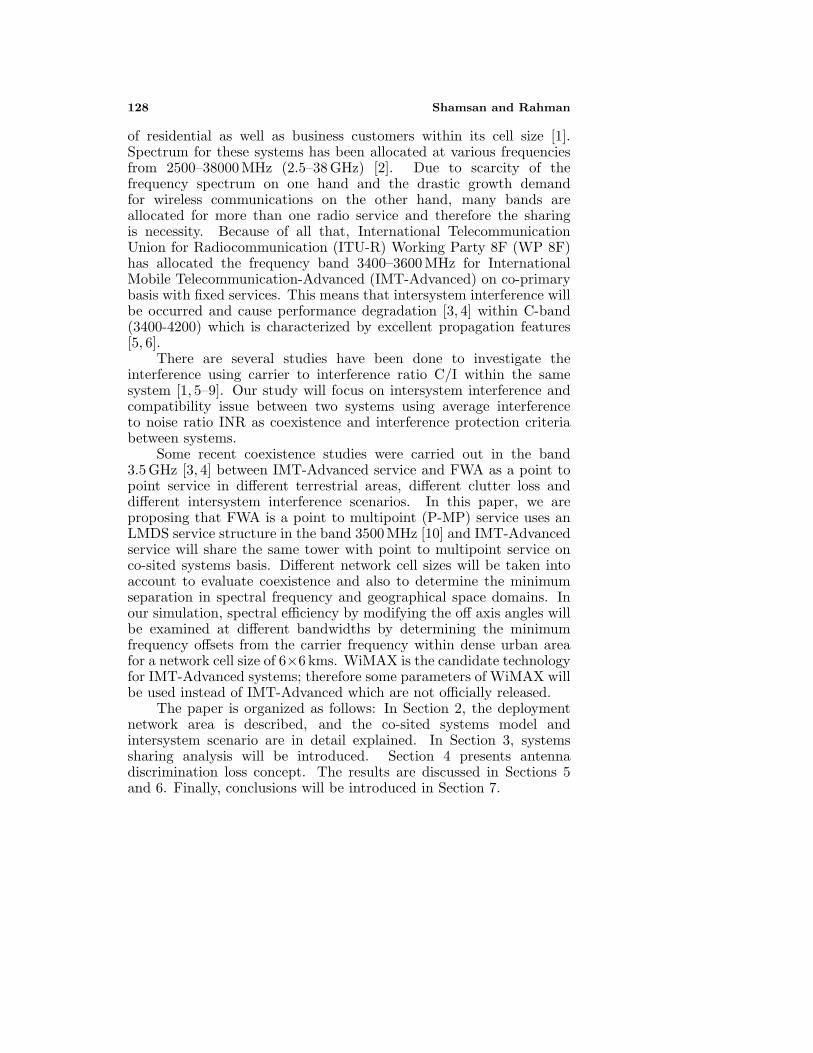
Figure 1. Establishing of IMT-Advanced and fixed services.
2. OPERATION NETWORK DESCRIPTION
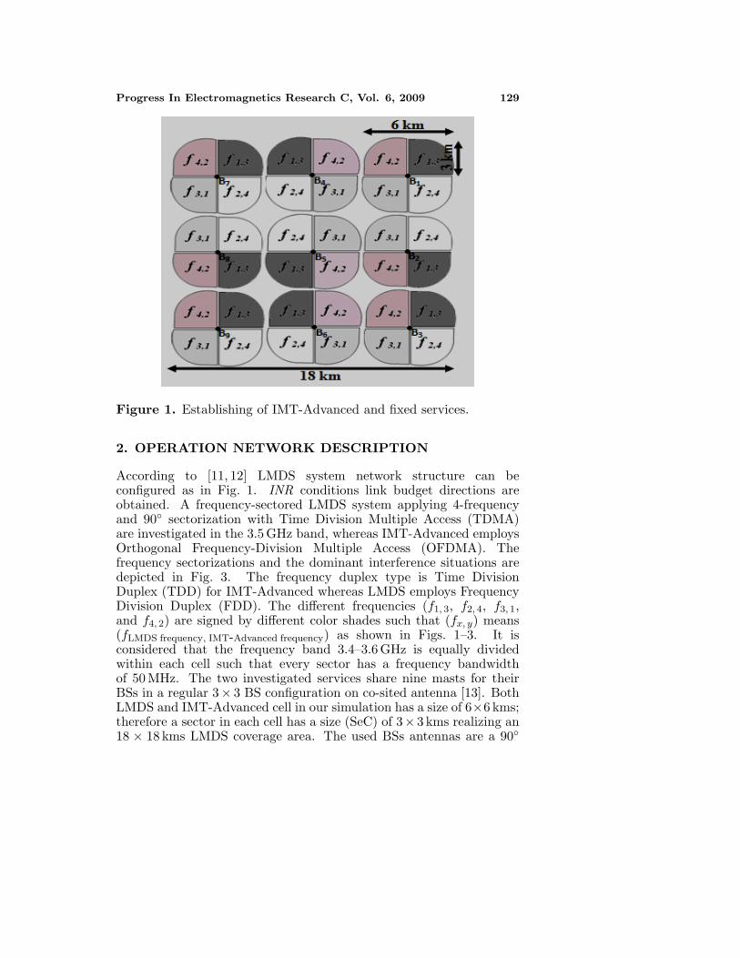
According to [11, 12] LMDS system network structure can beconfigured as in Fig. 1. INR conditions link budget directions areobtained. A frequency-sectored LMDS system applying 4-frequencyand 90◦ sectorization with Time Division Multiple Access (TDMA)are investigated in the 3.5 GHz band, whereas IMT-Advanced employsOrthogonal Frequency-Division Multiple Access (OFDMA). Thefrequency sectorizations and the dominant interference situations aredepicted in Fig. 3. The frequency duplex type is Time DivisionDuplex (TDD) for IMT-Advanced whereas LMDS employs FrequencyDivision Duplex (FDD). The different frequencies (f1, 3, f2, 4, f3, 1,and f4, 2) are signed by different color shades such that (fx, y) means(fLMDS frequency, IMT-Advanced frequency) as shown in Figs. 1–3. It isconsidered that the frequency band 3.4–3.6 GHz is equally dividedwithin each cell such that every sector has a frequency bandwidthof 50 MHz. The two investigated services share nine masts for theirBSs in a regular 3× 3 BS configuration on co-sited antenna [13]. BothLMDS and IMT-Advanced cell in our simulation has a size of 6×6 kms;therefore a sector in each cell has a size (SeC) of 3×3 kms realizing an18 × 18 kms LMDS coverage area. The used BSs antennas are a 90◦
130 Shamsan and Rahman
Figure 2. Sectors frequencies used for fixed and IMT-Advancedservices.
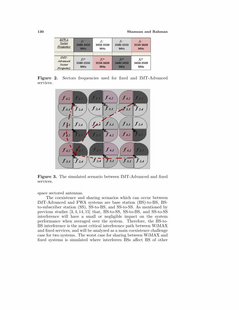
Figure 3. The simulated scenario between IMT-Advanced and fixedservices.
space sectored antennas.The coexistence and sharing scenarios which can occur between
IMT-Advanced and FWA systems are base station (BS)-to-BS, BS-to-subscriber station (SS), SS-to-BS, and SS-to-SS. As mentioned byprevious studies [3, 4, 14, 15] that, BS-to-SS, SS-to-BS, and SS-to-SSinterference will have a small or negligible impact on the systemperformance when averaged over the system. Therefore, the BS-to-BS interference is the most critical interference path between WiMAXand fixed services, and will be analyzed as a main coexistence challengecase for two systems. The worst case for sharing between WiMAX andfixed systems is simulated where interferers BSs affect BS of other

Progress In Electromagnetics Research C, Vol. 6, 2009 131
Table 1. WiMAX and fixed systems parameters.
ParameterValue
WiMAX FWA
Center frequency of operation (MHz)
3400 3600
Bandwidth (MHz) 5, 10, 20 7Base station transmitted
power (dBm) 43 35
Spectral emissions mask requirements
ETSI-EN301021Type
G Type
FBase station antenna gain
(dBi)18 17
Base station antenna height (m)
15 15
Clutter height (m) 25
Nominal distance (km) 0.02Noise figure of base station
(dB)4 5
Up and Down link DuplexType
TDD FDD
Antenna Type Sectored
system. As seen from Fig. 3 that IMT-Advanced antenna at basestation 9 (B9) suffers from three intersystem interference signals (B1,B7, and B3) (the intra-system interference is not considered here).Therefore, the separation distance between the interferer B1 and thevictim BS (B9) antenna is (
√((SeC)2 + (SeC)2) × 4) km, whereas B3
and B7 have an equivalent distance to the victim B9 of (4× SeC) km.All geographical separation distances between every effective interfererbase station and the victim base station are listed in Table 2. All FWAlinks utilize directional antennas, however, antenna patterns are notconsidered except for the maximum antenna gain in link budget, soit is assumed they are considered as omnidirectional in order to studythe worst case scenario.
The BSs parameters in Fig. 3 of two systems are detailed inTable 1. Spectral emission mask Type-G European Telecommunica-tions Standardisation Institute standard EN 301021 (Type-G ETSI-EN301021) [16] is applied to interference from WiMAX, while Type-FETSI-EN301021 [16] is applied when WiMAX is victim and FWA isinterferer. The resultant attenuation via mask can be represented by alinear equation on each segment with respect to frequency offset from
132 Shamsan and Rahman
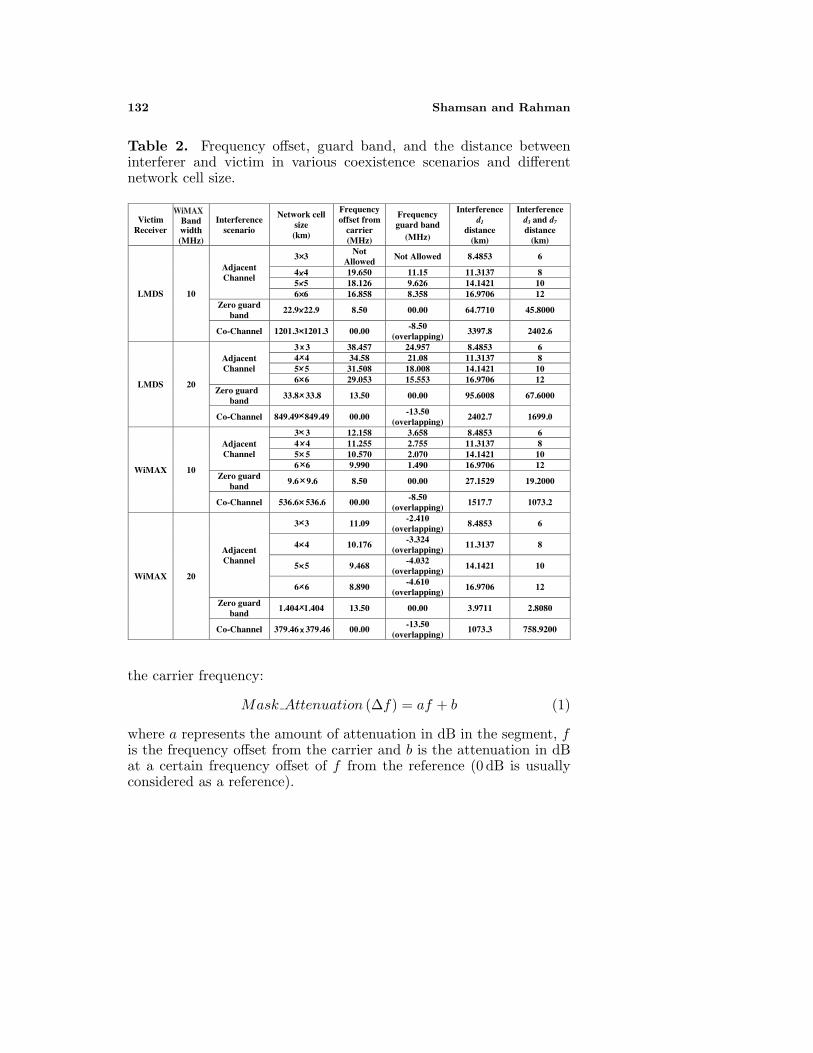
Table 2. Frequency offset, guard band, and the distance betweeninterferer and victim in various coexistence scenarios and differentnetwork cell size.
Victim Receiver
Bandwidth
(MHz)
Interference scenario
Network cell size (km)
Frequency offset from
carrier (MHz)
Frequency guard band
(MHz)
Interference d1
distance (km)
Interference d3 and d7 distance
(km)
LMDS 10
Adjacent Channel
3 3 Not
Allowed Not Allowed 8.4853 6
4 4 19.650 11.15 11.3137 8 5 5 18.126 9.626 14.1421 10 6 6 16.858 8.358 16.9706 12
Zero guard band
22.9 22.9 8.50 00.00 64.7710 45.8000
Co-Channel 1201.3 1201.3 00.00 -8.50
(overlapping) 3397.8 2402.6
LMDS 20
Adjacent Channel
3 3 38.457 24.957 8.4853 6 4 4 34.58 21.08 11.3137 8 5 5 31.508 18.008 14.1421 10 6 6 29.053 15.553 16.9706 12
Zero guard band
33.8 33.8 13.50 00.00 95.6008 67.6000
Co-Channel 849.49 849.49 00.00 -13.50
(overlapping) 2402.7 1699.0
WiMAX 10
Adjacent Channel
3 3 12.158 3.658 8.4853 6 4 4 11.255 2.755 11.3137 8 5 5 10.570 2.070 14.1421 10 6 6 9.990 1.490 16.9706 12
Zero guard band
9.6 9.6 8.50 00.00 27.1529 19.2000
Co-Channel 536.6 536.6 00.00 -8.50
(overlapping) 1517.7 1073.2
WiMAX 20
Adjacent Channel
3 3 11.09 -2.410
(overlapping) 8.4853 6
4 4 10.176 -3.324
(overlapping) 11.3137 8
5 5 9.468 -4.032
(overlapping) 14.1421 10
6 6 8.890 -4.610
(overlapping) 16.9706 12
Zero guard band
1.404 1.404 13.50 00.00 3.9711 2.8080
Co-Channel 379.46 379.46 00.00 -13.50
(overlapping) 1073.3 758.9200
WiMAX
the carrier frequency:
Mask Attenuation (∆f) = af + b (1)
where a represents the amount of attenuation in dB in the segment, fis the frequency offset from the carrier and b is the attenuation in dBat a certain frequency offset of f from the reference (0 dB is usuallyconsidered as a reference).
Progress In Electromagnetics Research C, Vol. 6, 2009 133
3. SYSTEMS SHARING ANALYSIS
The two systems can be coexisted if the sharing fundamental criterionis achieved. The coexistence and interference protection criteria can bedefined as an absolute interference power level I, interference-to-noisepower ratio INR, or carrier-to-interfering signal power ratio C/I [17].
In this paper, and according to ITU R F. 758-2, an INR of −6 dB isthe fundamental criterion for coexistence and intersystem interferencecoordination [15, 18], and this can be justified as in Appendix A:
INR = I[dBm] −N [dBm] ≤ α (α = −6 dB) (2)
In case of point to multipoint system network, there are more than oneinterference signal will affect the victim receiver base station as shownabove in Fig. 3, and thus:
INR = Itotal[dBm] −N [dBm] ≤ α (3)
Itotal =
M∑j=1
IBj(∆f)
M(4)
where Itotal represents the total interference received power at victimreceiver in watt and M is number of the effective interferer base stationson victim receiver. In our case, there are three effective interferencebase stations (B1, B3, and B7).
Itotal=
3∑j=1
IBj(∆f)
3
=IB1(∆f)[watt] + IB3(∆f)[watt] + IB7(∆f)[watt]
3(5)
IBj(∆f)[watt] = 10((IBj(∆f)[dBm]/10)×10−3) (6)IBj(∆f)[dBm] =Pt[dBm]+Gt[dBi]+Gr[dBi]+MaskAtt(∆f)[dB]
+Corr band[dB] + Lossesdj [dB] (7)
where Pt is transmitted power of the interferer, Gt and Gr are thegains of the interferer transmitter and the victim receiver antennas,and MaskAtt(∆f) represents attenuation of adjacent frequency dueto mask where ∆f is the difference between the carriers of interfererand the victim. The attenuation can be derived by using the equationsof straight line as in Eq. (1).
134 Shamsan and Rahman
Corr band denotes correction factor of band ratio and depends onbandwidth of interferer and victim receiver, where,
Corr band=
−10 log10
(BWinterferer
BWvictim
)dB if BWinterferer ≥BWvictim
0 dB if BWinterferer <BWvictim
(8)The interference signal power is from different base stations and itmainly depends on spectral mask and distance between each effectiveinterferer base station and the victim receiver. The Losses are thepropagation model effects and include free space and clutter lossattenuation and for our considered frequency (3500 MHz), the Lossesformula becomes:
Lossesdj [dB] = 103.33 + 20 log10(dj)
+10.25e−dk
[1−tanh
[6
(h
ha−0.625
)]]− 0.33 (9)
where dj denotes distance between each interferer base station Bj andthe victim receiver, dk is the distance (km) from nominal clutter pointto the antenna, h is the antenna height (m) above local ground level,and ha is the nominal clutter height (m) above local ground level.Therefore, Eq. (4) becomes:
Itotal=
3∑j=1
IBj(∆f)
3
=
10((IB1(∆f)[dBm]/10)×10−3) + 10((IB3(∆f)[dBm]/10)×10−3)
+10((IB7(∆f)[dBm]/10)×10−3)
3(10)
For deriving the thermal noise floor (N) of receiver in dBm, it dependson bandwidth and noise figure of victim receiver:
N [dBm] = −114 + NF + 10 log10 (BWvictim) (11)
where NF is noise figure of receiver in dB and BWvictim representsvictim receiver bandwidth in MHz. The interference to noise criterioncan be expressed as a ratio in (12) or as a dB in (13):
INR =Itotal
10((N [dBm]/10)×10−3)≤ 0.26 (12)
INR[dB] = 10 log10
(Itotal/10−3
)−N [dBm] ≤ −6 dB (13)

Progress In Electromagnetics Research C, Vol. 6, 2009 135
Figure 4. Interference scenario for one interferer base station to victimstation with off axis angles Φi and θv.
4. ANTENNA DISCRIMINATION LOSS
Antenna discrimination is the differential gain compared to maximumfor an antenna in the specified direction; usually, masks are providedfor the main lobe, the first sidelobe, and other sidelobes [19]. Antennadiscrimination loss is resultant from the antenna direction of theinterferer transmitter and victim receiver services which is dependanton the off axis angles Φi and θv as in Fig. 4. Therefore, as it is seenfrom Fig. 4, the interference signal emitted from one interferer basestation (it can be supposed that the same scenario is applied for theother effective interferers signals) impacts one victim base station. Anyinterferer signal goes under different losses which include propagationpath loss, dense urban clutter loss, and antenna discrimination loss. Asa result of presence more than one interferer signal (multi interferers)will influence the other receiver service, the interferer signals powerfrom the aggressive base stations can be estimated as an averagereceived power.
5. RESULTS AND DISCUSSIONS
The analytical studies in Sections 5.1 and 5.2 have considered denseurban area deployment. It is assumed that the victim B9 is the fixedservice base station when the interference is coming from WiMAX as inSection 5.1, whereas Section 5.2 assumes that B9 is a victim WiMAXbase station.
136 Shamsan and Rahman
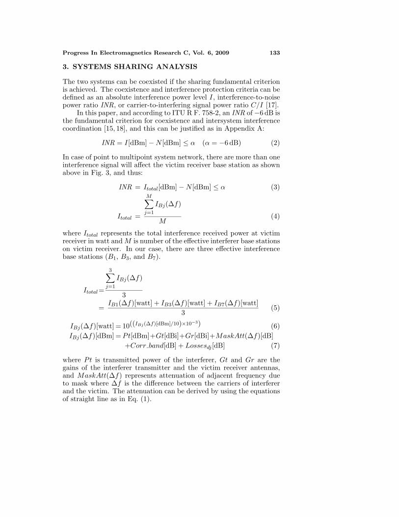
Figure 5. Interference within different network cell size (1×1 kms upto 6 × 6 kms) from 10 MHz WiMAX to 7 MHz FWA.
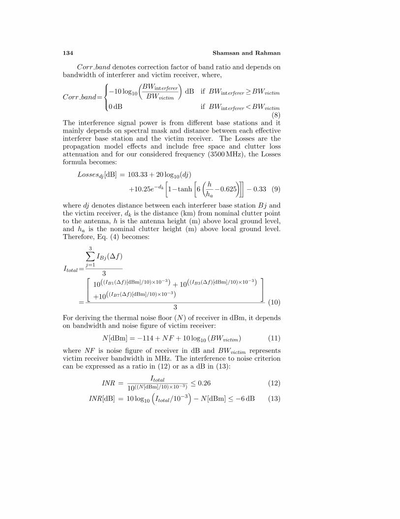
Figure 6. Intersystem interference scenarios in different network cellsize from 10 MHz WiMAX to 7 MHz FWA.

Progress In Electromagnetics Research C, Vol. 6, 2009 137
Figure 7. Intersystem interference scenarios in different network cellsize from 20 MHz WiMAX to 7 MHz FWA.
5.1. Intersystem Interference When WiMAX is theInterferer Service
Figures 5–7 show the external interference effects into 7 MHz fixedservice B9 from 10 MHz and 20 MHz WiMAX service in terms of INRratio, co-channel, adjacent channel, and zero guard band between thetwo systems at different network cell sizes. Fig. 5 shows the interferencefrom 10 MHz WiMAX channel band width within different network cellsizes of 1×1 kms, 2×2 kms, 3×3 kms, 4×4 kms, 5×5 kms, and 6×6 kms.Figs. 5–6 clarify that interference is harmful for 1×1 kms, 2×2 kms, and3× 3 kms, however, there is a possibility to coexist the two services byspectral frequency offset of 19.650 MHz, 18.126 MHz, and 16.858 MHzfor deployment area with cell size of 4×4 kms, 5×5 kms, and 6×6 kms,respectively. By using 20 MHz WiMAX channel bandwidth, a cell sizeof 3 × 3 kms is valid for coexisting the two systems with a frequencyseparation of 38.457 MHz. Null guard band between WiMAX and fixedservice is applicable if the network cell has a size of 22.9×22.9 kms and33.8 × 33.8 kms for 10 MHz and 20 MHz WiMAX channel bandwidth,correspondingly. This is due to that at these network cell sizes theinterference is always 6 dB or more below the thermal noise floor asshown in the figures.
138 Shamsan and Rahman
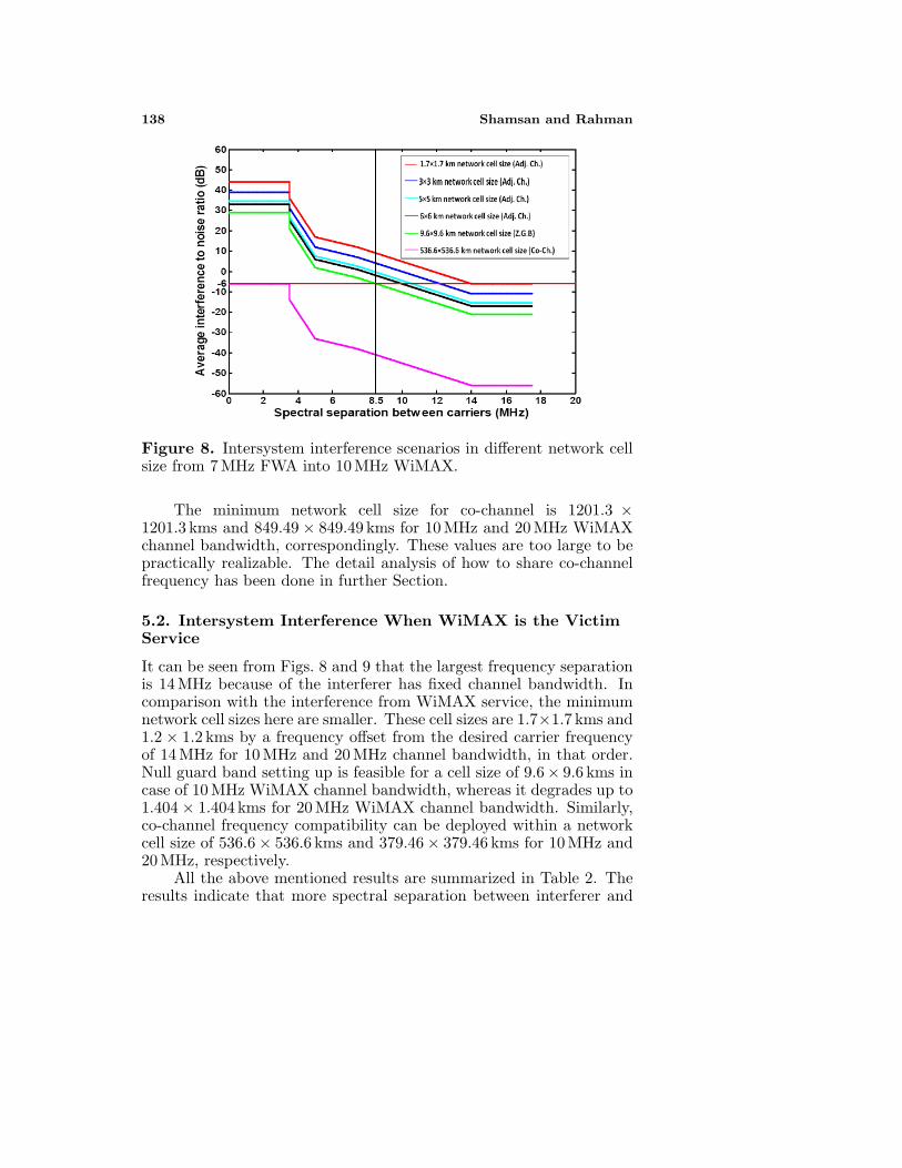
Figure 8. Intersystem interference scenarios in different network cellsize from 7 MHz FWA into 10 MHz WiMAX.
The minimum network cell size for co-channel is 1201.3 ×1201.3 kms and 849.49 × 849.49 kms for 10 MHz and 20 MHz WiMAXchannel bandwidth, correspondingly. These values are too large to bepractically realizable. The detail analysis of how to share co-channelfrequency has been done in further Section.
5.2. Intersystem Interference When WiMAX is the VictimService
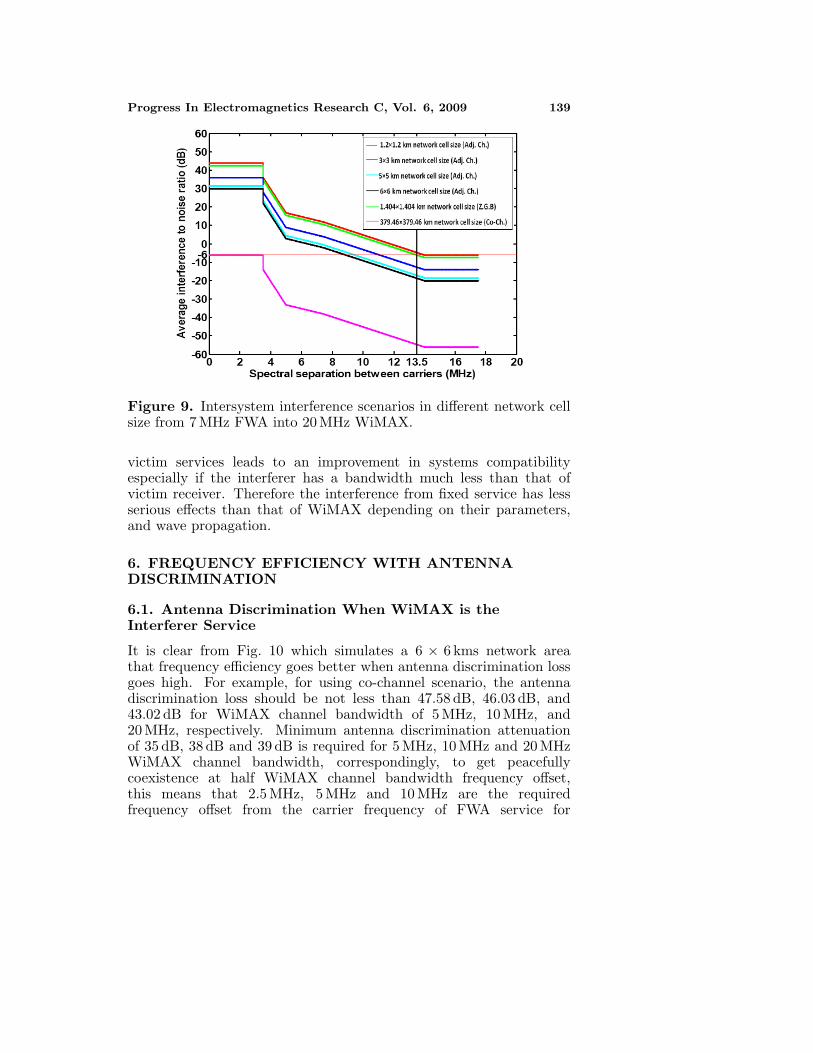
It can be seen from Figs. 8 and 9 that the largest frequency separationis 14 MHz because of the interferer has fixed channel bandwidth. Incomparison with the interference from WiMAX service, the minimumnetwork cell sizes here are smaller. These cell sizes are 1.7×1.7 kms and1.2 × 1.2 kms by a frequency offset from the desired carrier frequencyof 14 MHz for 10 MHz and 20 MHz channel bandwidth, in that order.Null guard band setting up is feasible for a cell size of 9.6× 9.6 kms incase of 10 MHz WiMAX channel bandwidth, whereas it degrades up to1.404 × 1.404 kms for 20 MHz WiMAX channel bandwidth. Similarly,co-channel frequency compatibility can be deployed within a networkcell size of 536.6 × 536.6 kms and 379.46 × 379.46 kms for 10 MHz and20 MHz, respectively.
All the above mentioned results are summarized in Table 2. Theresults indicate that more spectral separation between interferer and
Progress In Electromagnetics Research C, Vol. 6, 2009 139
Figure 9. Intersystem interference scenarios in different network cellsize from 7 MHz FWA into 20 MHz WiMAX.
victim services leads to an improvement in systems compatibilityespecially if the interferer has a bandwidth much less than that ofvictim receiver. Therefore the interference from fixed service has lessserious effects than that of WiMAX depending on their parameters,and wave propagation.
6. FREQUENCY EFFICIENCY WITH ANTENNADISCRIMINATION
6.1. Antenna Discrimination When WiMAX is theInterferer Service
It is clear from Fig. 10 which simulates a 6 × 6 kms network areathat frequency efficiency goes better when antenna discrimination lossgoes high. For example, for using co-channel scenario, the antennadiscrimination loss should be not less than 47.58 dB, 46.03 dB, and43.02 dB for WiMAX channel bandwidth of 5 MHz, 10 MHz, and20 MHz, respectively. Minimum antenna discrimination attenuationof 35 dB, 38 dB and 39 dB is required for 5 MHz, 10 MHz and 20 MHzWiMAX channel bandwidth, correspondingly, to get peacefullycoexistence at half WiMAX channel bandwidth frequency offset,this means that 2.5 MHz, 5 MHz and 10 MHz are the requiredfrequency offset from the carrier frequency of FWA service for

140 Shamsan and Rahman
Figure 10. Effect of antenna discrimination loss on spectrumefficiency when interference from WiMAX into fixed service in caseof 6 × 6 kms network cell size.
5 MHz, 10 MHz and 20 MHz WiMAX channel bandwidth, respectively.Moreover, for coexistence the two services by frequency offset equalsto the same WiMAX channel bandwidth, it is needed to 10 dB,9 dB, and 6 dB antenna discrimination loss for 5 MHz, 10 MHz,and 20 MHz respectively. These results indicate that achieving thesame intersystem interference scenario by high channel bandwidthrequires lower antenna discrimination loss than that in case of lowchannel bandwidth. This is due to high channel bandwidth istechnically having high thermal noise floor which increases the marginbetween interference and noise floor and thus the required antennadiscrimination loss becomes low.
6.2. Antenna Discrimination When WiMAX is the VictimService
Similarly, Fig. 11 describes the intersystem interference from FWAservice into WiMAX service when the network cell size is 6 × 6 kmsunder different antenna discrimination values. It is not like Fig. 10, theinterference from fixed service into 5 MHz is poor than the interferencefrom fixed service to 10 MHz and 20 MHz because of the interferertransmitter bandwidth is wider than that of the victim receiver. It
Progress In Electromagnetics Research C, Vol. 6, 2009 141
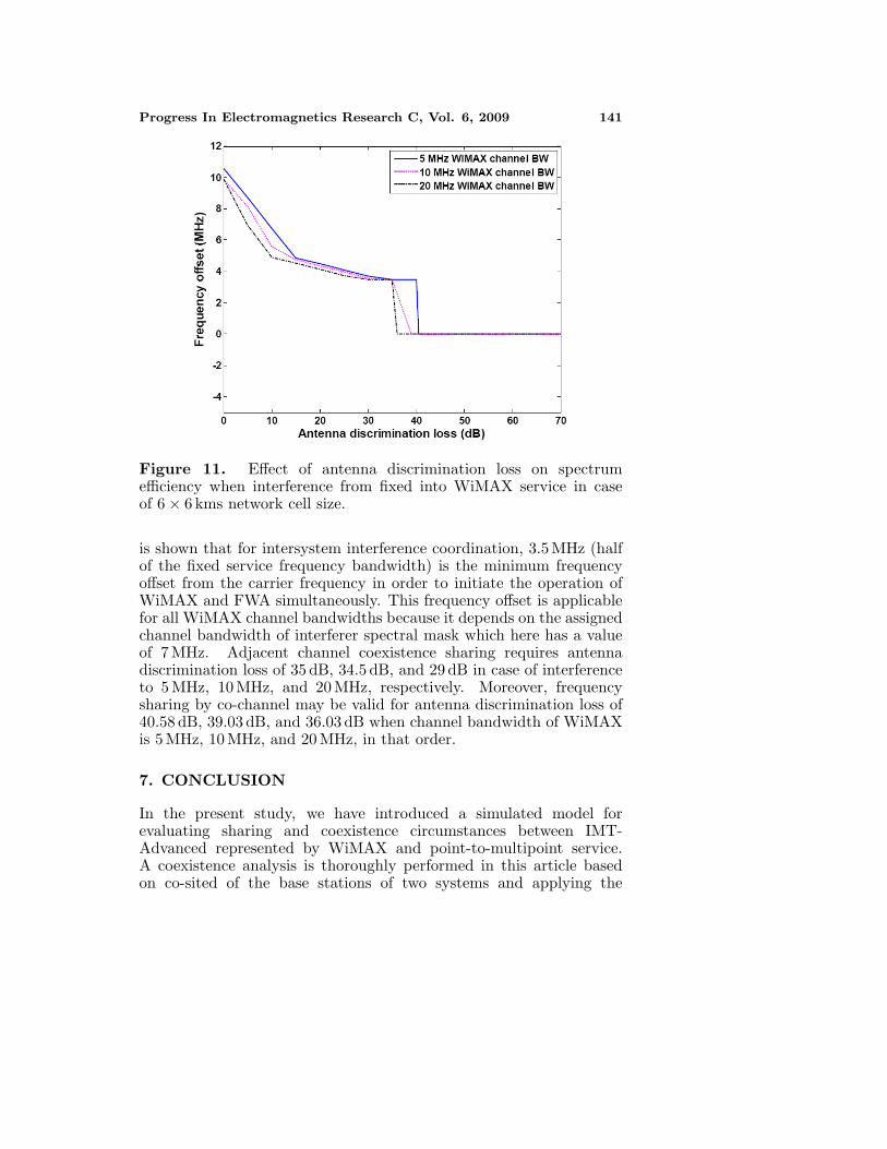
Figure 11. Effect of antenna discrimination loss on spectrumefficiency when interference from fixed into WiMAX service in caseof 6 × 6 kms network cell size.
is shown that for intersystem interference coordination, 3.5 MHz (halfof the fixed service frequency bandwidth) is the minimum frequencyoffset from the carrier frequency in order to initiate the operation ofWiMAX and FWA simultaneously. This frequency offset is applicablefor all WiMAX channel bandwidths because it depends on the assignedchannel bandwidth of interferer spectral mask which here has a valueof 7 MHz. Adjacent channel coexistence sharing requires antennadiscrimination loss of 35 dB, 34.5 dB, and 29 dB in case of interferenceto 5 MHz, 10 MHz, and 20 MHz, respectively. Moreover, frequencysharing by co-channel may be valid for antenna discrimination loss of40.58 dB, 39.03 dB, and 36.03 dB when channel bandwidth of WiMAXis 5 MHz, 10 MHz, and 20 MHz, in that order.
7. CONCLUSION
In the present study, we have introduced a simulated model forevaluating sharing and coexistence circumstances between IMT-Advanced represented by WiMAX and point-to-multipoint service.A coexistence analysis is thoroughly performed in this article basedon co-sited of the base stations of two systems and applying the
142 Shamsan and Rahman
spectral emission mask in a 6 × 6 kms cellular network cell size.Average interference to noise ratio have been used with differentchannel bandwidths, and network cell sizes for estimating impact ofintersystem interference between WiMAX and fixed service. Antennadiscrimination loss have to be adjusted by modifying the off axisangles between WiMAX and fixed services to provide at least 47.58 dB,46.03 dB, and 43.02 dB to achieve co-channel compatibility for WiMAXchannel bandwidth of 5 MHz, 10 MHz, and 20 MHz, respectively.High spectral efficiency in intersystem interference situations could besatisfied by maintaining a significant antenna discrimination loss value.
APPENDIX A.
((C/N) − (C/N + I))[dB] = 1 dB
C/N/C/N + I = 1.26 (as a ratio)
(N + I)/N = 1.26
I/N = 0.26I/N [dB] = −6 dB
REFERENCES
1. Bose, R., “Improving capacity in LMDS networks using trelliscoded modulation,” EURASIP J. Wireless Commun. Networking,No. 2, 365–373, Nov. 2004.
2. Salgado, H., “Spectrum allocation for fixed wireless accesstechnologies in the americas,” Proceeding of IEEE VehicularTechnology Conference (VTC’98), 282–287, 1998.
3. Shamsan, Z. A. and T. A. Rahman, “Spectrum sharing studiesof IMT-advanced and FWA services under different clutter lossand channel bandwidths effects,” Progress In ElectromagneticsResearch, PIER 87, 331–344, 2008.
4. Shamsan, Z. A. and T. A. Rahman, “On the comparison ofintersystem interference scenarios between IMT-Advanced andfixed services over various deployment areas at 3500 MHz,”Progress In Electromagnetics Research C, Vol. 5, 169–185, 2008.
5. Panagopoulos, A. D., “Uplink co-channel and co-polar interferencestatistical distribution between adjacent broadband satellitenetworks,” Progress In Electromagnetics Research B, Vol. 10, 177–189, 2008.
Progress In Electromagnetics Research C, Vol. 6, 2009 143
6. Mandeep, J. S. and J. E. Allnutt, “Rain attenuation predictionsat Ku-band in south east Asia countries,” Progress InElectromagnetics Research, PIER 76, 65–74, 2007.
7. Bose, R., G. Bauer, and R. Jacoby, “Two-dimensional line ofsight interference analysis of LMDS networks for the downlinkand uplink,” IEEE Trans. Antennas Propag., Vol. 52, No. 9, 2464–2473, Sept. 2004.
8. Panagopoulos, A. D., P.-D. M. Arapoglou, J. D. Kanellopoulos,and P. G. Cottis, “Intercell radio interference studies in broadbandwireless access networks,” IEEE Transactions on VehicularTechnology, Vol. 56, 3–12, Jan. 2007.
9. Arapoglou, P.-D. M., A. D. Panagopoulos, J. D. Kanellopoulos,and P. G. Cottis, “Intercell radio interference studies in CDMA-based LMDS networks,” IEEE Trans. Antennas Propag., Vol. 53,No. 8, 2471–2479, Aug. 2005.
10. Espias, M. and J. Perez, “The viability of fixed wireless access inthe Spanish market,” Information Economics and Policy, Vol. 17,No. 1, 85–96, Elsevier, Jan. 2005.
11. Sinka, C. and J. Bito, “Site diversity against rain fading in LMDSsystems,” IEEE Microwave and Wireless Components Letters,Vol. 13, No. 8, 317–319, Aug. 2003.
12. Shamsan, Z. A., M. I. Abo-zeed, and J. Din, “Rain fadingmitigation in BWA using site diversity,” Proceedings of IEEEConference (APACE 2007), 1–5, Dec. 2007.
13. Draft Report for ITU-R M.2045, “Mitigating techniques toaddress coexistence between IMT-2000 Time division duplex andfrequency division duplex radio interface technologies within thefrequency range 2500–2690 MHz operating in adjacent bands andin the same geographical area,” 2004.
14. Ofcom, “Digital dividend–mobile voice and data (IMT) issues,”Mason Communications Ltd., 2007.
15. ITU-R M. 2113, “Draft new report on sharing studies in the 2500–2690 MHz band between IMT-2000 and fixed broadband wirelessaccess (BWA) systems including nomadic applications in the samegeographical area,” 2007.
16. ETSI EN 301 021 (V1.6.1), “Fixed radio systems; point-tomultipoint equipment; time division multiple access (TDMA);point-to-multipoint digital radio systems in frequency bands inthe range 3 GHz to 11 GHz,” 2003.
17. NTIA Report 05-432, “Interference Protection CriteriaPhase 1 — Compilation from existing sources,” Oct. 2005.
144 Shamsan and Rahman
Available: http://www.ntia.doc.gov/osmhome/reports/ntia05-432/ipc phase 1 report.pdf
18. IEEE Std 802.16.2-2004, “IEEE recommended practice for localand metropolitan area networks coexistence of fixed broadbandwireless access systems,” Mar. 2004.
19. Gibson, J. D. and E. Gibson, The Communications Handbook,Second Edition, CRC Press, Apr. 2002.


![kkt_6_dan_7_pemupukan_2014 [Compatibility Mode]](https://static.fdokumen.com/doc/165x107/6322b43c28c445989105e2db/kkt6dan7pemupukan2014-compatibility-mode.jpg)

![Ok wk11 เทคนิคการแก้ปัญหาและตัดสินใจ [Compatibility Mode]](https://static.fdokumen.com/doc/165x107/63363f9e379741109e00f98f/ok-wk11-.jpg)

![Types of Gardens [Compatibility Mode] pdf](https://static.fdokumen.com/doc/165x107/631bd7dc7051d371800f3412/types-of-gardens-compatibility-mode-pdf.jpg)