
SCALABLE DYNAMIC AND MULTIPOINT VIRTUAL PRIVATE ...
83
SCALABLE DYNAMIC AND MULTIPOINT VIRTUAL PRIVATE NETWORK USING INTERNET PROTOCOL SECURITY FOR AN ENTERPRISE NETWORK by Kolupula Pruthviraj A Research Study Submitted in Partial Fulfillment of the Requirements for the Degree of Master of Engineering in Information and Communications Technologies Examination Committee: Dr.Teerapat Sanguankotchakorn (Chairperson) Dr. Attaphongse Taparugssanagorn Dr. Poompat Saengudomlert Nationality: Indian Previous Degree: Bachelor of Technology in Electronics and Communications Engineering Jawaharlal Nehru Technological University, Hyderabad, Telangana, India Scholarship Donor: AIT Fellowship Asian Institute of Technology School of Engineering and Technology Thailand May 2020
-
Upload
khangminh22 -
Category
Documents
-
view
1 -
download
0
Transcript of SCALABLE DYNAMIC AND MULTIPOINT VIRTUAL PRIVATE ...

SCALABLE DYNAMIC AND MULTIPOINT VIRTUAL PRIVATE
NETWORK USING INTERNET PROTOCOL SECURITY FOR
AN ENTERPRISE NETWORK
by
Kolupula Pruthviraj
A Research Study Submitted in Partial Fulfillment of the Requirements for the Degree of
Master of Engineering in Information and Communications Technologies
Examination Committee: Dr.Teerapat Sanguankotchakorn (Chairperson)
Dr. Attaphongse Taparugssanagorn
Dr. Poompat Saengudomlert
Nationality: Indian
Previous Degree: Bachelor of Technology in Electronics and
Communications Engineering
Jawaharlal Nehru Technological University,
Hyderabad, Telangana, India
Scholarship Donor: AIT Fellowship
Asian Institute of Technology
School of Engineering and Technology
Thailand
May 2020

ii
ACKNOWLEDGMENTS
I express my profound gratitude to my academic advisor and my research advisor,
Dr.Teerapat Sangutachkorn, without whom this achievement wouldn’t be possible. It
has been a great journey all during these two years of master’s study in AIT.
I am also thankful to Dr.Attaphongse Taparugssangorn, Dr.Poompat Saengudomlert,
the professors of my research examination committee, for their invaluable suggestions
and inputs towards my research work, from my proposal defense to final defense.
I am always indebted to the whole teaching and non-teaching staff of the TC-ICT
department of AIT. I also would like to thank especially Mrs. Premma Rao, Secretary
of TC-ICT, Mr.Rajesh Dehury, our lab supervisor, and Mr.Jaruk Noonkhao, for me
helping with everything happening and non-happening hours.
Last but not the least, I would like to thank my parents and my brothers, for their
constant encouragement and support.
Kolupula Pruthviraj
May 2020

iii
ABSTRACT
Virtual private networks (VPN) provide a remote secure connection for clients to
exchange information with company networks. Dynamic Multipoint Virtual Private
Network “DMVPN” is a solution for the dynamic creation of virtual Private IP tunnels
between multiple sites automatically, quickly, and with the least configuration.
Dynamic Multipoint VPN (DMVPN) used in this research with some supporting
protocols to allow the changing of Internet Protocol (IP) addresses of remote locations.
It proves to be a very scalable VPN technique with minimal configurations and
robustness. The lesser delay between two branches of an organization by establishing
directly protected tunnels called Shortcut Tunnels. These Shortcut Tunnels are
dynamically created when traffic flows on demand and are protected by IPsec.
DMVPN network is implemented with security protocols for Internet key management
and exchange to Ensure Data confidentiality, integrity, and authenticity using the
GNS3 Network simulator. The testing and verification analysis of data packets is done
using both PING-tool and Wire- shark to ensure the encryption of data packets during
data exchange between different sites.
Keywords: DMVPN, IPsec, mGRE, Enterprise network, GNS3.

iv
CONTENTS
Page
ACKNOWLEDGEMENTS ii
ABSTRACT iii
LIST OF FIGURES vi
LIST OF TABLES viii
LIST OF ABBRIVATIONS ix
CHAPTER 1 INTRODUCTION 1
1.1 Background 1
1.2 Problem Statement 2
1.3 Objectives 3
1.4 Limitations and Scope 3
1.5 Organization of the report 3
CHAPTER 2 LITERATURE REVIEW 4
2.1 DMVPN 4
2.2 DMVPN Technologies 5
2.2.1 Generic Routing Encapsulation (Specifically multipoint GRE) 5
2.2.2 Next-Hop Resolution Protocol (NHRP) 8
2.2.3 IP based Routing Protocols 9
2.2.4Internet Protocol Security(IPsec) 11
2.3 DMVPN Phases 13
2.3.1 Phase 1 Hub to Spoke 13
2.3.2 Phase 2 Spoke to Spoke 15
2.3.3 Phase 3 Spoke to Spoke with Scalable Infrastructure 16
2.4 Virtual Private Network (VPN) 16
2.4.1VPN Connection 18
2.5 Review of Previous Research Work 19
2.6 Route Summarization 21
2.7 Software Requirement 22

v
2.7.1 GNS3 22
2.7.2 Wireshark 24
2.7.3 Cisco IOS 25
2.7.4 VirtualBox 27
CHAPTER 3 METHODOLOGY 28
3.1 DMVPN Network Topology 28
3.1.1 Implementation Procedure 29
3.1.2 DMVPN Scenario-1 (Spoke-to-Spoke Communication) 33
3.1.3 DMVPN Scenario-2 (Spoke-Hub-Spoke Communication) 41
3.2 Contribution 48
3.3 GNS3 design analysis 49
CHAPTER 4 RESULTS 51
4.1 Resulting Parameters 52
4.1.1 RTT 52
4.1.2 Jitter 56
4.1.3 Throughput 59
4.1.4 PDR 62
4.1.5 IPsec Tunnel Configuration 63
CHAPTER 5 CONCLUSION AND RECOMMENDATIONS 66
5.1 Conclusion 66
5.2 Future Recommendations 66
REFERENCES 67
APPENDIX A 69

vi
LIST OF FIGURES
Figures Page
Figure 2.1 DMVPN Overview of a Topology 4
Figure 2.3 GRE Point-To-Multi Point Tunnels. 6
Figure 2.2 GRE Point-To-Point Tunnels. 6
Figure 2.4 GRE/Ipsec IP Packet Encapsulation. 7
Figure 2.5 NHRP Registration. 9
Figure 2.6 Split-Horizon. 10
Figure 2.7 IKEV2 Exchanged Packets 12
Figure 2.8 Phase 1 Hub To Spoke Communication 14
Figure 2.9 Phase 2 Spoke To Spoke Communication 15
Figure 2.10 Route Summarization on Router A 22
Figure 2.11 GNS3 Interface 23
Figure 2.13 Wireshark Main Window 25
Figure 2.14 IOS Packaging Model of 2900 Series Integrated Services Routers 26
Figure 3.1 DMVPN Network Topology 28
Figure 3.2 Hub Side Dynamic Tunnel. 30
Figure 3.3 Spoke Side Dynamic and Static Tunnels. 31
Figure 3.4 NHRP Registration From Spokes. 32
Figure 3.5 DMVPN Spoke-Spoke Network Topology 34
Figure 3.6 DMVPN Spoke1 Static and Dynamic Tunnels 34
Figure 3.7 DMVPN Spoke5 Static and Dynamic Tunnels. 35
Figure 3.8 DMVPN NHRP Spoke1 Traffic Maps 36
Figure 3.9 DMVPN NHRP Spoke5 Traffic Maps. 37
Figure 3.10 DMVPN Routing Table Spoke1 38
Figure 3.11 DMVPN Routing Table Spoke5 39
Figure 3.12 DMVPN Spoke-Spoke Traceroute 40
Figure 3.13 DMVPN Spoke To Spoke Workflow. 41
Figure 3.14 DMVPN Spoke-Hub-Spoke Network Topology. 42

vii
Figure 3.15 DMVPN Spoke1 Static and Dynamic Tunnels. 42
Figure 3.16 DMVPN Spoke5 Static and Dynamic Tunnels. 43
Figure 3.17 DMVPN NHRP Spoke1 Traffic Maps. 43
Figure 3.18 DMVPN NHRP Spoke5 Traffic Maps. 44
Figure 3.19 DMVPN Routing Table Spoke1. 45
Figure 3.20 DMVPN Routing Table Spoke5. 46
Figure 3.21 DMVPN Spoke-Spoke Network Topology. 47
Figure 3.22 DMVPN Spoke-Hub-Spoke Workflow. 48
Figure 3.23 Overview of the Testing Process 50
Figure 4.1 ICMP RTT Estimate Model Route 53
Figure 4.2 Scenario 1 RTT(s) Vs Data Rate(packets/s) 54
Figure 4.3 Scenario 2 RTT(s) Vs Data Rate(packets/s) 55
Figure 4.4 Comparison Of RTT(s) Vs Data Rate(packets/s) 56
Figure 4.5 Scenario 1 Jitter(s) Vs Data Rate(packets/s) 57
Figure 4.6 Scenario 2 Jitter(s) Vs Data Rate(packets/s) 58
Figure 4.7 Comparison Of Jitter(s) Vs Data Rate(packets/s) 59
Figure 4.8 Scenario 1 Throughput (bytes/s) Vs Data Rate(packets/s) 60
Figure 4.9 Scenario 2 Throughput (bytes/s) Vs Data Rate(packets/s) 61
Figure 4.10 Comparison Of Throughput (bytes) Vs Data Rate(packets/s) 62
Figure 4.11 PDR Vs Data Rate (packets/s) 63
Figure 4.12 Ipsec Tunnel Protection 64
Figure 4.13 Ipsec Security Association 65
Figure 4.14 Ipsec IKEV2 Security Association 65
viii
LIST OF TABLES
Tables Page
Table 2.1 IPsec Parameters 13
Table 2.2 VPN Tunnel Protocols. 19
Table 3.1 DMVPN Interface Configuration. 30
Table 3.2 System Configuration. 50
Table 4.1 Network Parameters 52
Table A1 Hub and Spoke Router Configuration of DMVPN 69
Table A2 RTT Values of Scenario 1. 70
Table A3 RTT Values of Scenario 2. 71
Table A4 Jitter Values of Scenario-1. 72
Table A5 Jitter Values of Scenario 2. 73
Table A6 Throughput Values of Scenario-1 And 2. 74
Table A7 PDR Percentage Values of Scenario-1 And 2. 74

ix
LIST OF ABBREVIATIONS
ACL Access control list
AH Authentication Header
Bps Bytes per second
CIOS Cisco Internetwork operating system
CLI Command-line interface
DMVPN Dynamic and Multipoint Virtual Private Network
EIGRP Enhanced Interior Gateway Routing Protocol
GNS3 Graphical Network Simulator 3
GRE Generic Routing Encapsulation
IEEE Institute of Electrical and Electronics Engineering
IETF Internet Engineering Task Force
IKE-SA Internet key exchange Security Association
IKE Internet key exchange IoT Internet of Things
IPsec Internet protocol security
ISAKMP Internet Security Association and Key Management Protocol
L2TP Layer 2 Tunneling Protocol
mGRE Multi-point Generic Routing Encapsulation
NBMA Non-Broadcast Multi-Access
NHC Next-hop client
NHRP Next-Hop Resolution Protocol
NHS Next-hop server
OSPF Open Shortest Path First
PPTP Point to Point Tunneling Protocol
RFC Request for Comments
RIP Routing Information Protocol
SSL Secure Socket Layer
VPN Virtual Private Network

1
CHAPTER 1
INTRODUCTION
1.1 Background
Nowadays, in the world where we live in advanced network facilities, where
the corporate companies are spread wide across the world, the companies have many
branch offices in various countries(cities) and they all need safe and secure
communication links between them. Secure services are offered in a DMVPN which
stands for dynamic multipoint VPN. Which can interchange the data in the network
within multiple sites, where the data need not pass between companies headquarter
VPN server or a router. In a conventional VPN’s integrate with the different remote
sites through the headquarters, where a DMVPN crucially creates a VPN topology in
the form of mesh architecture. This enables each spoke (each site) which can easily
attach directly to all the other sites located across, this gives the advantage of wherever
they are situated.
Large enterprises are using a variety of techniques to develop a safe and secure
network connection between the headquarters and its many more branches(sites) and
corporate locations to send out information, to share applications and resources data.
A large number of organizations implement a leased line method that provides secure
transmission. This leased line method is not cheap and comes with a high cost and huge
amount of time which are barred by the companies to install and activate them.
Endeavor administration is a huge deal and interlinked to all over the nation with
branches separated. In the Endeavour customers and its employees are in a constant
development to increase the security of the data communication and the availability of
the network. In these endeavor organizations, the communication must be secure in all
ways, therefore virtual private networks are used to develop a secure transmission
across various regions. In the case of IPsec implemented VPN does not hold up a
dynamic route. Another major issue with the VPN’s used traditionally is that the cost
of manage the networks and their operation cost including maintenance is highly
expensive. Being said about the huge cost there is a better way by creating an
Enterprise or endeavor network which has higher functionalities and by designing it, a

2
large amount of cost can be decreased. Moreover, we can build a more secure network,
this is where the DMVPN technique across IPsec is to be established for a more secure
and cost-efficient network.
In this network architecture both Hub and Spoke play a major role in DMVPN.
The central interactions in the network are represented by Hub and the spoke in the
network represents the location in the remote. The important benefit if this network is
that there is no need to create all the traffic routed through the hub, instead of private
links can be created between spokes. In this network, the communication is regulated
in mainly two possible scenarios. The hub to spoke is the first method and spoke to
spoke is the other. A DMVPN is a network protocol solution that is capable to create
a scalable mGRE over IPSEC from a low- level point of view using the site to site
dynamic tunnels. In DMVPN the main benefit is that the dynamic routing protocol is
implemented similarly as EIGRP (Enhanced Interior Gateway Routing Protocol), BGP
(Border GatewayProtocol), and OSPF (Open ShortestPath First) can be run.
The suggested DMVPN is represented in a virtual environment, with the usage
of GNS3 software. All the network components such as router, hosts, and switches are
created virtually in the GNS3software. As the hub and spoke topology is crucial and it
is focused on this virtual network. The virtual network parameters are observed with
the data packet analyzer using the PING tool. The data transmitted or interchanged in
the network is observed using Wireshark to ensure encryption between multiple
different sites
1.2 Problem Statement
In the VPN configuration, all its users individually create private links where
VPN relies on a single fixed location to access the company resources. At the time
where all the company branches increase gradually or whenever the total ICT
infrastructure is migrated to the cloud, the problem occurs in the VPN solution where
the traditional solution will not be able to scale up to the demand generated to manage
the number of connections established. The DMVPN comes into the picture to
overcome the established VPN connection limitations in between all the branches of
the company. Routing protocol restriction in DMVPN. As a sample, the hub does not
allow summarization, default routing, and hub to preserve the next-hop on spokes.

3
Specific routes are needed by other networks to reach spokes. To overcome the
limitations of standard VPN connections and routing restrictions in DMVPN, a new
enhanced DMVPN is proposed which offers a more stable and secure VPN interface
between the branches of the company.
1.3 Objectives
• To study and implement an enterprise network based on DMVPN Hub to
branch(spoke) and the branch to branch via hub Network topology by using
GNS3.
• Design and configure a secure DMVPN over IPsec tunnel to Ensure Data
confidentiality, integrity, and authenticity.
• Implement DMVPN direct spoke to spoke communication by using GNS3.
• To evaluate the proposed topology using the following metrics latency,
Throughput, and jitter and compare these metrics with scenario 1 and scenario
1.4 Limitations and Scope
• The proposed system will be implemented only by a simulating scenario but
on the actual routers.
• My work is an attempt to study the performance characteristics of DMVPN
secure enterprise networks and a comparative analysis of the proposed
solutions.
1.5 Organization of the report
I organize the rest of the report as follows.
• In Chapter 2, I provide a Literature Review.
• In Chapter 3, I propose my Methodology.
• In Chapter 4, I provide Results.
• In Chapter 5, I provide a Conclusion and Future Work

4
CHAPTER 2
LITERATURE REVIEW
2.1 DMVPN
DMVPN is mechanization designed to build scalable VPN networks by
integrating the benefits of Multipoint GRE, Dynamic routing protocol (EIGRP), Next
Hop Resolution Protocol (NHRP), and IPSec. The Internet is used as a medium to
connect all the infrastructure branch offices using the tunnelling method by presuming
that the tunnels are initiated dynamically as per the requirement. And there is no
requirement to create any tenacious connections. In this mechanization, there are hub
and spokes situated in the star topology. In the simple configuration, as shown in figure
(2.1), the communication between the central and branches also known as spoke-hub-
spoke connections is offered in DMVPN. This allows the network to increase the
configuration size to directly connect to branch office networks using spoke to spoke
connections. Qehaja et al. (2016).
Figure 2.1
DMVPN Overview of a Topology (Qehaja et al. (2016))

5
By adding dynamic IPsec tunnels in the network without any configuration
helps the DMVPN to improvise scaling ability for hub-and-spoke networks. This also
reduces the requirement of IP address space by untangling the configuration of the hub.
The burden created on the hub is decreased in the network by the ability to learn to
communicate directly to each other by the spokes, this is acquired by dynamic
networks in hub-and-spoke networks (Lammle, Todd 2015). As the DMVPN is greatly
helping in rectifying the gaps which were existed in the previous networks. Yet as
DMVPN is a newly emerging technology, therefore the finest practice is to be
implemented in the real-time communication in the networks and increase security
features for organization businesses in a single package.
2.2 DMVPN Technologies
The following are the common distance metrics in detail. DMVPN based on
four proven technologies. The four technologies are discussed below.
• Generic Routing Encapsulation (Specifically multipoint GRE).
• Next-Hop Resolution Protocol (NHRP).
• IP based Dynamic Routing Protocols.
• Internet protocol security (Optional but recommended for secure transport).
2.2.1 Generic Routing Encapsulation (Specifically multipoint GRE)
Communication protocols that are used to establish a point-to-point, direct link
between network nodes are called Generic routing encapsulation (GRE) as shown in
figure (2.3). In today’s Internet GRE is the easy and most efficient way of carrying
data in the public network. In general GRE tunnels are point to point and do not scale
much. Let us take an example, where there is the company is in various cities and want
to communicate with each other using normal Internet connectivity, then the
communication medium gets messy around. Therefore, we have to implement a
scalable network solution, in which multiple tunnel interface is created with source and
destination IP address. This can be achieved using Multipoint GRE, where it allows us
to have multiple destinations as shown in below figure (2.2).

6
Figure 2.3
GRE Point-to-Multi Point Tunnels. (https//networkdirection.net/articles/)
Figure 2.2
GRE Point-To-Point Tunnels. (https//networkdirection.net/articles/).
In DMVPN, VPN tunnels are used to transport GRE encapsulated IP packets
(Keith Barker 2012). We can consider an example of multi-cast routing
advertisements, and these routes are multi-cast in nature. Also, IPsec is used which is
one of the standard mechanisms which provides security for IP networks, with a
drawback of encrypted multicast packets. Wherein the multi-cast packets are initially

7
encapsulated with GRE tunnels, which later are routed over a VPN connection. Later
the packets which are encapsulated are additionally protected using IPsec.
The mGRE (Multipoint Generic Routing Encapsulation) is accountable for
creating dynamic tunnels. Multi GRE tunnels are dependent on IPsec since GRE
tunnels can encapsulate the packets and distribute them into GRE packets. Therefore,
all the packets transmitted are initially multi and the broadcasted packets are
transferred using mGRE and secured with IPsec. This process joins a GRE header to
every packet which changes the broadcast/multicast packet within a unicast packet. As
the GRE uses the link which same as in IPsec, then the IPsec header is implied to secure
all the GRE data as shown in Figure (2.4). These packets are inadequate for changing
any physical IP address details. As a result, the IPsec needs to fix the IP-address to
create an IPsec tunnel. Therefore, all the GRE tunnel IP addresses are invariable
(cannot be changed).
Figure 2.4
GRE/IPsec IP Packet Encapsulation. (Khelf & Ghoualmi-Zine, n.d.)

8
2.2.2 Next-Hop Resolution Protocol (NHRP)
The NHRP (Next Hop Resolution Protocol) acts as the extension for the ATM
ARP routing mechanism, which can be used to enhance the performance of a routing
computerized network traffic. Through an NBMA (Non-Broadcast Multi-Access)
network is defined in the IETF RFC, 2332.
NHRP is fundamentally a query and reply based model. It is related to client and
server protocol, where the hub and spokes act as server and clients. The details from
the public interface address of each spoke are maintained using the NHRP database.
Whenever a spoke is rebooted it will register again its real address and later queries it
to the NHRP database and build the direct tunnels by obtaining the real addresses of
the destination spokes.
In DMVPN there are two types of addresses, which are Underlay and Overlay IP
addresses. The underlay address can be defined as the public IP address which is used
as a destination and source address for tunnel creation. And overlay address can be
defined and the private IP address which is assigned to a GRE tunnel. Next Hop
Routing Protocol (NHRP) maps the addresses between the overlay and underlay
addresses. NHRP is typically based on the client-server standard, therefore all the
NHRP clients (NHC) will send updates periodically and contains public and tunnels
addresses directly to the hub which is an integral part of the network of NHRP server.
Consequently, spoke (NHC) sends an NHRP registration message to a hub which is
NHS after coming online. A public database is maintained by the NHS which contains
NHC public IP addresses as shown in figure (2.5). Therefore, all the public IP
addresses are dynamically retrieved on the spoke. These addresses are not statically
configured on the hub, instead, they are simultaneously learned by the hub during the
time of registration. After acquiring a list of real IP addresses (NBMA IP) of the spoke
by the NHS, the mapping is created between logical VPN IP addresses (the IPs
accessible over the tunnel) and the NBMA IP addresses. The main advantage of this
process is that the router hub can build dynamic tunnels to the spoke. Since The spoke
is not initially configured with the necessary information about any other spokes, as
they are configured with the information about the hub, If spoke 1 needs to send data
traffic to the spoke 2 using the tunnel, it gets the information from the NHS using
NHRP resolution request. And the NHS will respond with the necessary information

9
using NHRP Resolution Reply. This response message includes the details of logical
VPN IP and NBMA IP details which are required to map.
Figure 2.5
NHRP Registration. (https//networkdirection.net/articles/).
2.2.3 IP based Routing Protocols
DMVPN requires a dynamic routing protocol. In the DMVPN solution a major
role in ensuring a smooth implementation of the dynamic tunnels by routing protocol
and also provide an impact on the transport applications and the network’s behaviour.
Therefore, in recent times, several works are being conducted on accessing the network
performance so we can determine which is the most convenient routing protocol form
VPNorDMVPN. Few among the routing protocols which are used for the DMVPN are
• Enhanced Interior Gateway Routing Protocol (EIGRP) A distance-vector
routing protocol that is only accessible on Cisco routers. EIGRP is used on a
router to share routes with other routers within the same autonomous system
• Routing Information Protocol (RIP) A distance-vector routing protocol that
uses the hop count as a routing metric(15 hops unreachable). RIP implements
the split horizon, route poisoning, and hold-down mechanisms to prevent the
incorrect routing information from being propagated. IP broadcast the
complete routing table to the network. This broadcast can use precious

10
bandwidth on links.
• Open Shortest Path First (OSPF) An IP based routing protocol which It works
a link-state routing algorithm and comes into the group of interior gateway
protocols, operating within a single autonomous system
Figure 2.6
Split-Horizon. (http//oreilly.com/catalog/).
In 2007 Cisco Systems have described the dynamic routing protocols and their
network type, route control, and converge in DMVPN overview guide. Several
dynamic routing protocols can be implemented in a DMVPN design, including EIGRP,
OSPF, RIPv2, and BGP But the EIGRP dynamic routing protocols are best to route
control and converge are very faster than other dynamic routing protocols. The
Dynamic routing protocols control worked into DMVPN technologies to reliably
routing information and faster communication way to design enterprises. EIGRP
protocols in DMVPN to design enterprise network is it supports the multi-area route
system rather than other dynamic routing protocols. The all-inclusiveness of EIGRP
routing protocols is in its ease of use in the systems with other routing protocols because
the data of all routing protocols can be joined by methods for EIGRP.
• Split-horizon A control plain is organized with the spoke and hub and spoke

11
is the neighbor.so, it is not required to disable on the spoke side. There is no
direct connection between spoke and any traffic sent by one of those routers
to the other must pass through the HUB router and that is where split-horizon
comes in. As shown In Figure 2.6, HUB has learned about spoke-1, which is a
loopback network via an update received on the interface as well, so spoke-1
can’t advertise that network via that same interface. Spoke-2 is left out in the
cold No IP split-horizon EIGRP on the hub side the only hub has more than
one neighbor. So, HUB needs to disable the split-horizon.
2.2.4 Internet Protocol Security (IPsec)
IPsec provides end to end security with this use of the encryption, integrity, and
authentication in all IP enabled networks. IPsec can be considered as the most flexible
method to protect the network traffic, It is the most widely used VPN implementation
since it has fewer vulnerabilities discovered and reported. IPsec in DMVPN is only
optional since it has a high concern for securing communication data, unlike GRE
tunnels which are not secure at all. The data which is to be encrypted is done
traditionally using an access control list (ACL). This process can do simplified
because, whenever any data packet matches the defined entry in ACL, then immediately
the encryption tunneling will start. Nevertheless, the mGRE tunnel configuration
combines all the mGRE tunnel peer address at using IPsec-mGRE tunnels, which are
also the IPsec peer addresses.
A third-party unsecured network is used for IP transport over DMVPN, and there
is a need to encrypt traffic. To minimize these effects IP security and Internet Key
Exchange were created. As GRE provides tunneling, IPsec transport mode is preferred
as tunnel mode. Since crypto is based on data traffic entering the GRE tunnel, and there
is not a need for static maps in DMVPN. Simple encryption configuration profile
protection is provided by IPsec tunnel. The confidentiality and integrity of the data
packets are provided by using IPsec encryption and encrypting the entire payload. Each
router has to be configured with IPsec parameters to select common encryption
methods. Pre-share keys or digital certifications provide authentication as shown in
figure (2.7). The first phase is the IKE phase where the establishment of IPsec
tunneling starts, and in the second phase negotiation to create the tunnel itself (Naby

12
et al., 2017).
Figure 2.7
IKEV2 Exchanged Packets (Naby et al., 2017)
In phase1, the very first message exchange (defined as IKE-INIT) involves in
the step of establishing an IKE Security Association (IKE-SA). The IKE-SA serves
and announces and Diffie-Hellman algorithm parameters, and function of defined
secure parameters for the IKE itself. The second message exchange in phase 1 (defined
as IKE-AUTH) involves identities, secret keys, and all the exchange of authentication
information. After phase 1 is started Phase 2 is an optional process. In phase 2 of the
IKE (defined as CREATE-CHILD-SA) implicates the creation of a certain set of
optional SA’s which are called CHILD-SA’s, IPsec SA is used in CHILD-SA. Diffie-

13
Hellman keys are implicated for IPsec protection which is newly calculated using
CHILD-SA. CHILD-SA requests are being sent to create CHILD-SA. After completing
phase 1 these requests are launched by using the VPN peers. The keys and algorithms
used in phase 1 made all the exchanges in phase 2 secure. The number of the messages
which are transmitted across each user session has been reduced from 9 to 6 in the case
of an older version which is IKE version1.
Table 2.1
IPsec Parameters
2.3 DMVPN Phases
At the time of the data interchange between any two spokes, initially, the spoke 1
contact the hub, for gathering information that is required to communicate with the
opposite end. In this process, the dynamic IPsec VPN tunnels are constructed between
the spokes. In the case where a dynamic IP address is being used by the spoke, then it
must initially register its IP address including the headquarters hub every time joining
each network. After passing this step both routers can start implementing their direct
communication among themselves. Therefore, the communication between the spokes
is established by using one of three phases of DMVPN.
2.3.1 Phase 1 Hub to Spoke
In phase 1 all of the spokes are configured with the IP address, obtained of the hub,
and served as the network server. In this network, each spoke has a specific tunnel
IPsec Parameters
Authentication MD5
Integrity SHA
Encryption AES
Group 2
Lifetime 86400

14
which has a fixed destination IP to design Hub’s physical IP address. Similarly, the
spokes can go to one and another via the hub. In phase 1 DMVPN, the important
advantage is that the configuration is simplified figure(2.8). Any dynamic protocol in
this network can provide help in attaining reachability since the choice of the routing
protocol is much easier. The spokes must have to advertise about their sub-nets
dynamically to the hub and similarly, the hub also needs to advertise its default route to
the spoke. The incapability to establish spoke-to-spoke shortcut tunnels can be
considered as the main drawback. This issue can be resolved by implementing NHRP
Phase 2 for spoke-to-spoke tunnels.
Figure 2.8
Phase 1 Hub to Spoke Communication (https//networkdirection.net/articles/)

15
2.3.2 Phase 2 Spoke to Spoke
The main limitation in the implementation of phase 1 was the lack of direct
communication between the spokes. The sub-optimal path or static tunnels are the only
options for the spoke to communicate directly. And the next level of phase 1 is phase 2.
Additionally, more on the spoke side and dynamic spoke registration is added in phase
2. This method enables direct communication between the spokes. Let us consider a
scenario where spoke 1 needs to reach to the 10.0.0.0 /24 network. The main issue or
the challenge would be that the spoke 1 is not aware of which router this network is
behind, and it also doesn’t know the details on how to use the tunnel to reach the
destination. The first it initiates is by sending the NHRP resolution request to the desired
hub. To find the correct entry the hub once investigates its cache for finding NBMA
address mappings. Then the remote spoke router receives the forwarded resolution
request from the hub. The router initially caches the required information in the request
and later sends an NHRP resolution response to the original spoke. NBMA address
(4.4.4.4) is contained in the response of the destination spoke router. The spoke at this
point knows the remote router NBMA address. It will be sent to 4.4.4.4 after
encapsulating relevant traffic as shown figure (2.9).
Figure 2.9
Phase 2 Spoke to Spoke Communication (https//networkdirection.net/articles/)

16
All the spokes in the network need to have complete information about routing
with the next hop preserved in this mode. As we know that not all the spokes in the
network accept a full load of updates on routing, and this is a requirement that might
limit in terms of scalability, most probably in the larger networks. In the case of the
second phase, a larger network may have a scale of 1000 spokes, let us take an instance
wherever the routing tables of all spoke might have too many entries and which is not
needed. Hence the routers face many difficulties to maintain such large routing tables.
This in result makes the summarization to impossible or difficult. Since each spoke has
a large routing table presiding in them. As this process can be defined as unidirectional
and the reverse traffic which is coming from the other spokes in the network will trigger
the same mechanism. The spoke only initiate the unidirectional IPsec session and does
not have two unidirectional IPsec sessions.
2.3.3 Phase 3 Spoke to Spoke with Scalable Infrastructure
Some of the limitations faced in phase 2 are being improved in this phase on
top of the existing features. Phase 3 is implemented in the most effective way possible
to mitigate the problems phased in phase2. All the spoke in the network have now
learned the entire network of the hub. The next step moves to summarize the network
aspects in the hub. The main advantage of phase 3 is scalability, so we can deploy
phase 3 in very large environments than compared to DMVPN phase 2.
2.4 Virtual Private Network (VPN)
According to the tunneling security, endpoints location, types of connectivity,
robustness, and the types of tunneling, VPN can be classified. Through a tunnel, VPN
connectivity is provided which is a virtual link between two nodes that are separated
by networks. VPN tunneling structure is shown in (2.7). Within the router, the tunnel
was established and given with the router IP address at the second end. Inside the IP
datagram, every packet was encapsulated using a router IP address at the end of the
tunnel as a destination address. The same tunneling protocol must be used by the two
endpoints. These logical tunnels that carry the IP packet are payload independent and
consist of different headers due to the implemented protocol. For transmitting data,
VPN relies on techniques of tunneling. The tunneling protocols work at different OSI
layers such as in the network layer, data link layer, or the session layer. layer 2 tunneling

17
protocol (L2TP), Point to point tunneling protocol (PPTP), Secure socket layer (SSL),
and Internet protocol security (IPSec) are the popular protocols linked with the VPN
development. These protocols secure VPN and offer authentication, encryption
mechanisms (Jahan et al., 2017).
• Point to Point Tunneling Protocol (PPTP) In-network working group RFC
2637, PPTP specification was described. It operates at the data link layer and
also an expansion of point-to-point protocol (PPP) using the same mechanisms
of authentication as PPP.
• Layer 2 Tunneling Protocol (L2TP) L2TP establishes the tunnel between the
router and clients or the routers itself. The features of PPTP and layer two
forwarding’s are combined in L2TP and eliminates the network traffic by a
control mechanism to address congestion that keeps overhead to a minimum.
L2TP header contains media information, L2TP encapsulation drives the high
extent of data packets that surpass between the endpoints of tunnels without
increasing overhead on the network. L2TP has the capability of establishing
multiple tunnels between two tunnel endpoints simultaneously.
• Internet Protocol Security (IPsec) Data confidentiality, data integrity, and
authentication originality of data at the network layer in the OSI model are
offered by IPSec. It consists of different protocols namely IPsec Key Exchange
and Management Protocol (ISAKMP) used for management of key which
species the establishment, alteration, negotiation, and omission of a security
association. Internet Key Exchange (IKE) for key exchange that creates a
secure channel to protect the negotiation for setting up the IPsec tunnel for
traffic protection. Authentication Header (AH) offers authentication, anti-
replay, and integrity. Encapsulated Security Payload (ESP) offers
authentication, anti-replay, integrity, and data confidentiality. These protocols
are used to transmit traffic securely and create connections. Two encryption
modes created by IPsec transport mode that encrypts data only and tunnel mode
that encrypts header and data.
• Secure Socket Layer (SSL)encryption and authentication are offered by SSL

18
for web traffic over an encrypted tunnel. Specific applications were supported
by SSL such as web and email services.
2.4.1 VPN Connection
VPN mainly classified into two types which are site-site and remote access VPN.
• Site to Site VPN In this type of VPN, the VPN link is established all along
through the single sites and to the remote location office site. In this
connection, the VPN gateway will help in communication. And multiple
protocols such as IPSec, GRE, and MPLS are used.
• Remote access VPN In this type of VPN access all the connections are
created mobile users and the server which are in the same LAN with the
help of accessing VPN client software. And this communication can be
established only within authorized users, where multiple protocols are used
such as IPsec, SSL, PPTP, and L2TP.
There is a different category of the VPN according to network administration by
the service provider
• Trusted VPNs Customer trusted service providers of the VPN are called
trusted VPN and offer data integrity and also avoid sniffing of the network
traffic.
• Secure VPNs the attacker in this scenario can be able to inspect all the
Network traffic but able to discover it since these networks are established
with the encryption mechanism.
• Hybrid VPNs as a part of the trusted VPN a new secure form runs as a
secure VPN.

19
Table 2.2
VPN Tunnel Protocols. (Salman, 2017)
2.5 Review of Previous Research Work
• A research paper by (Angelescu et al., 2017) presented a simulation of DMVPN
based system, the simulation related to phase 2 of DMVPN networks which
include one headquarter and two branch offices. They showed that the
effectiveness of DMVPN minimizes the number of hops which turns to lower
transit delays.
• Research work by (Qehaja et al., 2016) present in enterprise networks
information is constantly at risk. Therefore, we must prevent and secure this
interval in our communications. To block and to avoid being a target or missing
data, they use Dynamic multipoint virtual private networks in our individual
and public information to be secure.
• Research paper by (Jahan et al., 2017) Shows different VPN tunneling
protocols like GRE, IPSec, PPTP, and L2TP with IPSec, which are analyzed to
measure the performance in terms of throughput, RTT, Jitter and security

20
parameters. Research by (Chen, 2011) network limitations were addressed. The
authors pointed out that GRE is deeply examined because of some lost packet
cases. The network development is not treated, authors supported their theories
by simulating a network simulation in which they decided that DMVPN assures
more possibilities for enterprises to secure and business networks.
• Research work by (Salman, 2017) deals with Site-to-site IPsec-VPN that joins
the company internet. IPsec-VPN network is performed by security protocols
for key management and transfer, authentication, and integrity working GNS3
Network simulator. The experiment and verification examining data packets
are done using both the PING mechanism and Wireshark to assure the
encryption of data packets during data transfer between different sites related
to the same company.
• Research work by (Bahnasse & El Kamoun, 2015) improves the previous
algorithm by understanding the scalability of the DMVPN network by changing
the number of sites and effective routing protocols using OSPF, BGP, and
EIGRP. The outcomes of these experiments explain that EIGRP rules are the best
in terms of initial convergence delay. Throughput, queuing delay, and BGP show
its performance compared to OSPF.
• Research by work by (Naby et al., 2017). Internet Key Exchange Protocol
version 2 (IKEv2) represents a good example of a complex key management
protocol. IKEv2 is one of the most successful key management protocols and
is often used inside the IPsec VPN solution to authorization and authentication
schemes. VPNs are often provisioned for multiple sub-nets; each pair of sub-
nets is connected via a secure channel called Security Association (SA). In
IKEv2, the number of messages exchanged for each user session has been
reduced to 6 from 9 in the case of older version IKEv1. IKE processing and the
message transit time from the GNS3 simulation. We can observe that the
latency of one IKEv2 SA generation is composed of the processing and transit
time of each IKE message. The software VPN processing conducted by GNS3.
• Research by (Shaheen et al., 2015). In this paper, initially, we reviewed IKEv1
and IKEv2 in terms of security. Afterward, a comparative analysis of both is
carried out. This analysis shows that IKEV2 is simpler, more reliable, and less

21
complex than IKEv1. It also evaluates that IKEv2 requires fewer round trips
for messages exchanged to establish IKE SA and IPSec SA as compared to
IKEv1.
2.6 Route Summarization
The purpose of route summarization is to minimize the routing overhead and
to increase the stability, scalability of routing by decreasing a load of routing
information, which is maintained and sent between routers, which result in shorter
routing tables, thus making improving the convergence.
The other purpose of it is to crunch several subnets into one total(aggregate) entry,
which represents all of them. The whole of this description can be depicted in the
picture below. As shown In Figure 2.11,

22
Figure 2.10
Route Summarization on Router A (Teare et al. (2014))
Besides this, route summarization also decreases the number of updates, which
need to be sent between these two routers. To state an example, observe the case of
network change when network 10.12.6.0/24 becomes not reachable. Router A doesn’t
need to notify the neighbor about an unreachable prefix, because the summary route
hasn’t been affected by network change. Routing protocols of various types offer
different types of route summarization options. Summarization configuration on each
of the outbound interface will be supported by distance vector protocols, while only at
area boundaries, will be supported by link-state protocols when planning for route
summarization efficiently. The assignment must be done hierarchically, in contiguous
blocks the network.
2.7 Software Requirement
2.7.1 GNS3
GNS3 can be simply described as a Graphical Network Emulator that enables
composite simulation of the network. A simulator like GNS3 is one type of device that
functions exactly like an actual machine. This is a digital device or machine that
performs similarly to an actual machine or a system, providing nearly all the
functionalities. There are many familiarities with VMware or Virtual Machine which
is used to simulate a different type of OS in a computer environment. You can run

23
Virtual Machine operating systems such as Windows XP Professional or Ubuntu or
Linux utilizing these virtual programs. By utilizing Cisco Internet-work OS, GNS3
does the same emulation process. This allows the user to emulate the Cisco IOS in a
simulated environment on the user computer. GNS3 is a front-end representation of an
outcome named Dynagen. Dynamap is the key application that makes emulation of
IOS. Dynagen a GNS3 product has a key feature to work on above of Dynamics which
allows creating an environment that is customer demonstrative and cantered on text.
Through building a multimedia structure, GNS3 makes this one more step. This can be
used on numerous operating systems such as Windows, Debian based systems, UNIX
operating systems, and Mac-based OS, as it is open-source emulator software for
routers.
Figure 2.11
GNS3 Interface
(https//docs.gns3.com/1NjJlvu176VG4mq7qAl4wDo79P7pmOaiaac7kW5htuo/inde
x.html/).

24
2.7.2 Wireshark
Wireshark is one of the best network protocol analysers. It lets you see what’s
going on the network transmission at a packet level and is enabled with a de facto
standard for most private and non-profit companies, this includes government agencies,
and as well as educational institutions. Wireshark’s success is fuelled by the charitable
contributions of network experts throughout the world and is a result of the 1998
initiative by Gerald Combs.
Wireshark boasts a diverse range of features which includes
• Profound analysis of hundreds of procedures, and constant introduction of more
• Multi-platform Runs on Windows, Linux, macOS, Solaris, FreeBSD, NetBSD, and
many others.
• Captured network data can be browsed via a GUI, or via the TTY-mode TShark
utility.
• The most powerful display filters in the industry.
• Best voice over IP analysis.
• Read and write various file formats tcpdump (libpcap), Pcap NG, Cisco Secure
IDS iplog, Microsoft Network Monitor, Network General Sniffer R
(compressed and uncompressed), Network Instruments Observer, NetScreen
snoop, Novell LANalyzer, RADCOM WAN/LAN Analyzer.
• Live data packets are read through Ethernet, IEEE 802.11, PPP/HDLC, ATM,
Bluetooth, USB, Token Ring, Frame Relay, FDDI, and others (depending on
your platform).
• Decryption support for many protocols, including IPsec, ISAKMP, SSL/TLS, WEP,
and WPA/WPA2.

25
Figure 2.13
Wireshark Main Window
(https//blog.wireshark.org/wp content/uploads/2015/11/ Main-window-1.12.8.png).
Wireshark is one of the free source packet analyzer and mainly used in the process
of capturing data packets in the network. Wireshark is used for the development and
instructional purposes of network analysis, troubleshooting, networking, and analyzing
system protocols. Wireshark is used to intercept GNS3 DMVPN network packets that
help us understand various network parameters and protocols that are shared through
the DMVPN network.
2.7.3 Cisco IOS
A series of hardware devices are made available for building a Cisco network
device with of Cisco IOS operating system. By considering the benefits of the well-
known WAN and MAN platforms of the industry, the Cisco 7200VXR Series Router,
organizations, and service providers can meet new integration requirements without
expensive hardware upgrades or good network architecture. video, hybrid call access,
virtual private networks (VPNs), and multi-channel data path. IOS is currently in use
for Cisco 7200 routers, multi-service access platforms suitable for various medium and

26
large companies, as well as small Internet servicing providers. The Cisco 7200, voice
recordings, hybrid dial access, VPNs, and multi-protocol routing solutions. Increase
performance and compact design protect the valuable customer who has an investment
in one of the network technologies and integrates multiple device functions
individually, regulatory Solution. Normal pictures with the universalk9 icon in file
description This typical image contain all Cisco IOS functionality such as efficient
cryptographic functionalities like IPsec VPN, SSL VPN, and secure integrated
communications.
Figure 2.14
IOS Packaging Model of 2900 Series Integrated Services Routers
(https//www.cisco.com/c/en/us/products/collateral/ ios-nx-os-software/ios-
packaging/).
Cisco IOS has a distinctive CLI, i.e. command-line interface to which other
networking tools usually copy the style. This IOS command-line interface provides a
standard series of various terms, determined by the implemented package mode and
the current user’s privilege status. Global configuration mode implements commands
to vary the configuration of the device, and interface configuration mode provides
commands to change the configuration of a particular device. With the command-line
interface, which defines the implemented commands for one of the correct positions.

27
2.7.4 VirtualBox
VirtualBox is a versatile tool for the industry as well as home using x86 and
AMD64/Intel64 virtualization. The VirtualBox is a feature-rich and has an impeccable
huge performance platform for company users, it remains the only widely available
technological framework as free Source Software under the regulations of the GNU
(General Public License) described as GPL version 2. VirtualBox is currently being
built with regular updates and has an ever-increasing list of apps, licensed OS and
platforms on which it is run. VirtualBox is a group project sponsored by a committed
company everybody is invited to participate while Oracle guarantees that the product
still follows the standards of a professional standard.
Across different host-based OS, including Ubuntu, macOS, Windows, Solaris,
and OpenSolaris, Virtu- Albox is supportable. All Ports are FreeBSD and Genode. It
facilitates the development and including management of Windows, Linux, BSD,
OS/2, Solaris, Haiku, OSx86, and other guest virtual devices operating variants and
including derivations, and minimal virtualization of macOS. VirtualBox can be enabled
on different host operating systems, including Linux, macOS, Windows, Solaris, and
OpenSolaris. Virtu- alBox users can load-guest operating systems under one unified
host operating system(hostOS). Inside your virtual machine(VM) each visitor may be
initiated, halted and stopped independently

28
CHAPTER 3
METHODOLOGY
3.1 DMVPN Network Topology
DMVPN enables more complex topologies for Tree-based DMVPN networks,
where these Tree-based topologies enable DMVPN networks to be constructed with
regional hubs which are central hub spokes. This architecture allows the regional hub
to control data traffic for its regional spokes and the Next Hop Resolution Protocol
(NHRP) control traffic. However, it still allows the construction of spoken-to-speak
tunnels between any spokes within the DMVPN network, irrespective of their presence
in the same region.
Figure 3.1
DMVPN Network Topology

29
3.1.1 Implementation procedure
Execute GRE over IPsec technique to build an enterprise network, which
enabled the IPsec encryption system automatically. IPsec is using the Access Control
List (ACL) to identify which information is being encrypted. The GRE tunnel, GRE,
and IPsec are exchanging the Peer address. Then IPsec protection is automatically set
up in GRE tunnel.
Below is the process of communication over an IPsec / GRE on-demand tunnel
during DMVPN Spoke to Spoke
• Configure the topology with the router, Ethernet switch, and Vpcs. The hub
router has two interfaces g0/0 and g0/1. The IP address 80.20.10.1(inside)
configured interface g0/0. The IP address 10.1.0.1(outside) configured
interface g0/1. Also, spoke 1 has two g0/1 and g0/2 interfaces. The g0/1
interface configured with 20.20.10.1(inside) IP address. The IP address
10.2.0.1(outside) configured interface g0/2. Spoke 2 has two g0/2and g0/3
interfaces. The g0/2 interface configured with 30.20.10.1(inside) IP address.
The IP address 10.3.0.1(outside) configured interface g0/3. Spoke 3 has two
g0/3 and g0/4 interfaces. The g0/3 interface was configured with
40.20.10.1(inside) IP address. The IP address 10.4.0.1(outside) configured
interface g0/4. Spoke 4 has two g0/3 and g0/4 interfaces. The IP address
50.20.10.1(inside) configured interface g0/4. The IP address 10.5.0.1(outside)
configured interface g0/5.Spoke 5 has two g0/5 and g0/6 interfaces. The IP
address 60.20.10.1(inside) configured interface g0/5. The IP address
10.6.0.1(outside) configured interface g0/6. There must be six g0/0, g0/1, g0/2,
g0/3, g0/4, and0/5 interfaces in the cloud (ISP). The IP address 80.20.10.2
(inside) configured interface g0/0. The g0/1 interface was configured with
20.20.10.2 (inside) IP address. The g0/2 interface configured with 30.20.10.2
(inside) IP address. The IP address40.20.10.2 (inside) set up interface g0/3.
The IP address 50.20.10.2 (inside) configured interface g0/4. The IP address
60.20.10.2 (inside) configured interface g0/5, as shown in the figure (3.2).

30
Table 3.1
DMVPN Interface Configuration.
Router Interface type
DMVPN - Tunnel WAN LAN
ISP
N/A g 0/0 - 80.20.10.2 N/A
N/A g 0/1 - 20.20.10.2 N/A
N/A g 0/2 - 30.20.10.2 N/A
N/A g 0/3 - 40.20.10.2 N/A
N/A g 0/4 - 50.20.10.2 N/A
N/A g 0/5 - 60.20.10.2 N/A
HUB 172.16.0.1 g 0/0 - 80.20.10.1 g 0/0 - 10.1.0.1
SPOKE - 1 172.16.0.2 g 0/1 - 20.20.10.1 g 0/1 - 10.2.0.1
SPOKE - 2 172.16.0.3 g 0/2 - 30.20.10.1 g 0/2 - 10.3.0.1
SPOKE - 3 172.16.0.4 g 0/3 - 40.20.10.1 g 0/3 - 10.4.0.1
SPOKE - 4 172.16.0.5 g 0/4 - 50.20.10.1 g 0/4 - 10.5.0.1
SPOKE - 5 172.16.0.6 g 0/5 - 60.20.10.1 g 0/5 - 10.6.0.1
• During this network topology, in the DMVPN approach, primarily, every
branch(spoke) is connected to the headquarters router (HUB) via static tunnels,
and these branches are dynamically linked to each other in a single subnetwork,
as shown in the figure (3.3).
Figure 3.2
Hub Side Dynamic Tunnel.

31
Figure 3.3
Spoke Side Dynamic and Static Tunnels.
• The spokes will directly send traffic to the HUB. Instead of starting with an
NHRP Resolution Request.
• After receiving the redirect, an NHRP resolution request message is sent to a
remote spoke but it doesn’t know how to send directly to the remote spoke. To
solve this issue the message is sent to the Hub and this incoming message is
passed to a remote spoke router

32
Figure 3.4
NHRP Registration from Spokes.
• So, an NHRP Redirect Message is sent to the source spoke from the Hub.
• After receiving the redirect, an NHRP Resolution Request message is sent to a
remote spoke. But it doesn’t know how to send directly to remote spoke, so
before that, the message is sent to the Hub. The Hub then passes this incoming
message to a remote spoke router
• The target spoke sends the NHRP response message which contains prefix

33
required for source spoke to source spoke router.
• The incoming prefix is taken by the source spoke and then installs this
incoming spoke into its routing table with target spoke as next jump. This is
called the NHRP shortcut.
• Setting up on-demand IPsec/GRE route with spoke to spoke communication.
By using the NHRP traffic indication messages, scenario-1 overcomes the
restriction by sending signals from the hub to the spokes about a more reliable path to
reach the destination network. This traffic flow is taken care of by the NHRP redirect
and shortcuts. With the help of these two features, the scalability of the overall design
is much easier since the Hub can now send a predefined route directly to individual
spokes. In scope-to-spoke communication, the redirect command is responsible for
sending the NHRP traffic indication message from the Hub and the shortcut command
is responsible for the spokes to acknowledge the redirect and install the shortcut path.
The design of the scenario-1 DMVPN is much more scalable than scenario-2 and has
some changes in its configuration. During the DMVPN setup, scenario-1 reduces
latency for direct spoke-to-spoke connections and also improves resilience in case of
hub failures and also supports hierarchical hub design.
3.1.2 DMVPN Scenario-1 (Spoke-to-Spoke Communication)
In this section, you have observed the process of establishing direct spoke-to-
spoke.DMVPN scenario-1 is The data plane traffic goes to remote spoke because here
the next-hop is the direct spoke. And it takes an optimal path to get to the destination,
as shown in figure (3.6) this topology carried out from the figure (3.1).

34
Figure 3.5
DMVPN Spoke-Spoke Network Topology
• Spoke-1 performs a route lookup for 10.6.0.20 and finds the entry 10.6.0.0/24
with the next-hop IP address 172.16.0.1. Spoke-1 encapsulates the packet
destined for 10.6.0.20 and forwards it to HUB out the tunnel 0 interface
Figure 3.6
DMVPN Spoke1 Static and Dynamic Tunnels

35
Figure 3.7
DMVPN Spoke5 Static and Dynamic Tunnels.
As shown in figure ( 3.6) and ( 3.7), DMVPN tunnels later spoke-1 and spoke-
5 must initialize the spoke-to-spoke tunnel by summarization on Hub. Notice that both
new spoke-to-spoke tunnel approaches are DT1.
• HUB receives the packet from Spoke-1 and performs a route lookup for the
packet destined for
• 10.6.0.20. HUB locates the 10.6.0.0/24 network with the next-hop IP address
172.16.0.6. HUB
• checks the NHRP cache and locates the entry for the 172.16.0.6/32 address.
HUB forwards the packet to Spoke-5, using the NBMA IP address 60.20.10.0,
found in the NHRP cache. The packet is then forwarded out the same tunnel
interface.
• HUB has ip nhrp redirect configured on the tunnel interface and recognizes that
the packet received from Spoke-1 hair pinned out of the tunnel interface. HUB
sends an NHRP to redirect to Spoke-1, indicating the packet source 10.2.0.10
and destination 10.6.0.20. The NHRP redirect indicates to Spoke-1 that the
traffic is using a suboptimal path

36
Figure 3.8
DMVPN NHRP Spoke1 Traffic Maps
As shown in figure (3.8), The NHRP cache concerning spoke1 and spoke5.
Regard the NHRP mappings router, rib, and nhop. The flag rib nho indicates that the
router has got the same route in the routing table that goes to a different protocol.
NHRP has overridden the other protocol’s next-hop entry for the network by installing
a next-hop shortcut in the routing table.
• Spoke-1 receives the NHRP redirect and sends an NHRP resolution request to
HUB for the 10.6.0.20 address. Inside the NHRP resolution request, Spoke-1
provides its protocol (tunnel IP) address, 172.16.0.2, and source NBMA
address, 20.20.10.0. Spoke-5 performs a route lookup for 10.2.0.10 and finds
the entry 10.2.0.0/24 with the next-hop IP address 172.16.0.1. Spoke-5
encapsulates the packet destined for 10.6.0.20 and forwards it to HUB out the
tunnel 0 interfaces.

37
Figure 3.9
DMVPN NHRP Spoke5 Traffic Maps.
As shown in figure(3.9), The flag rib implicit nhop indicates that the router has an exact
way to enter the tunnel IP address utilizing an NBMA address and has an associated
route established in the routing table.
• HUB receives the packet from Spoke-5 and performs a route lookup for the
packet destined for 10.2.0.10. HUB locates the 10.2.0.0/24 network with the
next-hop IP address 172.16.0.2. HUB checks the NHRP cache and locates an
entry for 172.16.0.2/32. HUB forwards the packet to Spoke- 1, using the
NBMA IP address 20.20.10.0, found in the NHRP cache. The packet is then
forwarded out the same tunnel interface. HUB has ip nhrp redirect configured
on the tunnel interface and recognizes that the packet received from Spoke-5
hair pinned out the tunnel interface. HUB sends an NHRP to redirect to Spoke-
5, indicating the packet source 10.6.0.20 and destination 10.2.0.10 The NHRP
redirect indicates to Spoke-5 that the traffic is using a suboptimal path. HUB
forwards Spoke- 1’s NHRP resolution requests for the 10.6.0.20 address

38
Figure 3.10
DMVPN Routing Table Spoke1

39
Figure 3.11
DMVPN Routing Table Spoke5
As shown in figure (3.8) and (3.9), presents the routing tables for spoke1 and
spoke5. The next-hop IP address as the EIGRP remote network (highlighted) still
shows 172.16.0.6 as the next-hop address.EIGRP arrangement now reveals the
10.0.0.0/8 summary prefix outward tunnel 0. Notice that spoke1 installs the NHRP
route to 172.16.0.6/32 and that spoke5 installs the NHRP route to 172.16.0.2/32 into
the routing table as well.
• Spoke-5 sends an NHRP resolution reply directly to Spoke-1, using the source
information from Spoke-1’s NHRP resolution request. The NHRP resolution
reply contains the source information in Spoke-1’s NHRP resolution request as
a method of verification and contains the client protocol address of 172.16.0.6
and the client NBMA address 60.20.10.0. IPsec protection is configured, the
IPsec tunnel is set up before the NHRP reply is sent.
• HUB forwards Spoke-5’s NHRP resolution requests for the 172.16.0.2 and
10.6.0.20 entries

40
Figure 3.12
DMVPN Spoke-Spoke Traceroute
As shown in figure (3.12), here spoke1 look for a route to spoke5 by using
traceroute command finding the path in computer network diagnostic command for
performing the path (route) also measuring transit delays.
• Spoke-1 sends an NHRP resolution reply directly to Spoke-5, using the
source information from Spoke-5’s NHRP resolution request. The
NHRP resolution reply contains the source information in Spoke-5’s
NHRP resolution request as a method of verification and contains the
client protocol address 172.16.0.2 and the client NBMA address
20.20.10.0. Again, IPsec protection is configured, the tunnel is set up
before the NHRP reply is sent back in the other direction. A spoke-to-
spoke DMVPN tunnel is established in both directions after step 7 is
complete. This allows traffic to flow across the spoke-to-spoke tunnel
instead of traversing the hub router.

41
Figure 3.13
DMVPN Spoke to Spoke Workflow.
3.1.3 DMVPN Scenario-2 (Spoke-Hub-Spoke Communication)
In this section, you have observed the process of establishing spoke-Hub-spoke.
Here, DMVPN scenario-2 is that the data plane traffic goes to the hub. Because here the
next hop is the hub, so the hub router is always the next hop. Now, the next hop is the
spoke router, as shown in the figure (3.14) this topology carried out from the figure(3.1).
42
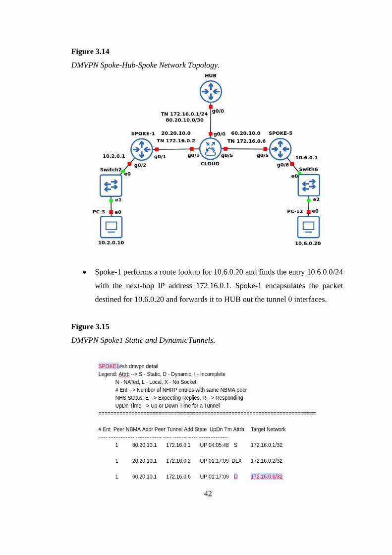
Figure 3.14
DMVPN Spoke-Hub-Spoke Network Topology.
• Spoke-1 performs a route lookup for 10.6.0.20 and finds the entry 10.6.0.0/24
with the next-hop IP address 172.16.0.1. Spoke-1 encapsulates the packet
destined for 10.6.0.20 and forwards it to HUB out the tunnel 0 interfaces.
Figure 3.15
DMVPN Spoke1 Static and Dynamic Tunnels.

43
Figure 3.16
DMVPN Spoke5 Static and Dynamic Tunnels.
As shown in figure (3.15) and (3.16), DMVPN tunnels later spoke-1 and spoke-
5 must initialize the spoke-hub-spoke tunnel. Notice that both new spoke-hub-spoke
tunnel approaches are D.
• HUB receives the packet from Spoke-1 and performs a route lookup for the
packet destined for IP address 10.6.0.20. HUB locates the IP address 10.6.0.0/24
in the network with the next-hop IP address 172.16.0.6. HUB checks the NHRP
cache and locates the entry for the 172.16.0.6/32 address.
Figure 3.17
DMVPN NHRP Spoke1 Traffic Maps.

44
As shown in figure(3.17), the router implicit Indicates that the NHRP mapping
entry was learned completely. Samples of such records are the source mapping data
gleaned of an NHRP resolution request supported by the local router or from an NHRP
resolution data transmitted into the router.
The spoke-1 has now sent an NHRP request to the HUB and requests the HUB
about the destination spoke-5 IP address 10.6.0.20. HUB receives NHRP requests from
Spoke-1 and performs a route lookup for the packet destined for 10.6.0.20. HUB locates
the 10.6.0.0/24 network with the next-hop IP address 172.16.0.6. HUB checks the
NHRP cache and locates the entry for the 172.16.0.6/32 address
Figure 3.18
DMVPN NHRP Spoke5 Traffic Maps.
As shown in figure (3.18), router Means that the NHRP mapping approach is of a
remote router that gives access to a network or host after the remote router.
• HUB forwards the NHRP resolution request to spoke-5 for the 10.6.0.20 IP
address. Inside the NHRP resolution request, Spoke-1 provides its protocol
(tunnel IP) address, 172.16.0.2, and source NBMA address, 20.20.10.0. Spoke-
5 performs a route lookup for 10.2.0.10 and finds the entry 10.2.0.0/24 with the
next-hop IP address 172.16.0.1. Spoke-5 encapsulates the packet destined for
10.6.0.20 and forwards it to HUB out the tunnel 0 interfaces.
• Spoke-5 sends an NHRP resolution reply request to HUB for the 10.2.0.10 IP
address and provides its protocol (tunnel IP) address which is 172.16.0.6. And

45
the source NBMA address is 60.20.10.0. Later Spoke-5 sends an NHRP
resolution reply to the HUB.
Figure 3.19
DMVPN Routing Table Spoke1.
As shown in figure(3.19), presents the routing tables for spoke1 and spoke5.
The next-hop IP address as the EIGRP remote network shows 172.16.0.0 as the next-
hop address.EIGRP arrangement now reveals the 10.0.0.0/8 summary prefix outward
tunnel 0. Notice that spoke1 installs the NHRP route to 172.16.0.0/32 and that spoke5
installs the NHRP route to 172.16.0.0/32 into the routing table as well.
• HUB receives the NHRP reply from Spoke-5 and performs a route lookup for
the packet destined to 10.2.0.10 IP address. HUB locates the IP address
10.2.0.0/24 in the network with the next-hop IP address 172.16.0.2. HUB
checks the NHRP cache and locates an entry for 172.16.0.2/32. HUB forwards
the packet to Spoke-1, using the NBMA IP address 20.20.10.0, found in the
NHRP cache. This traffic is using a suboptimal path in the network.
46
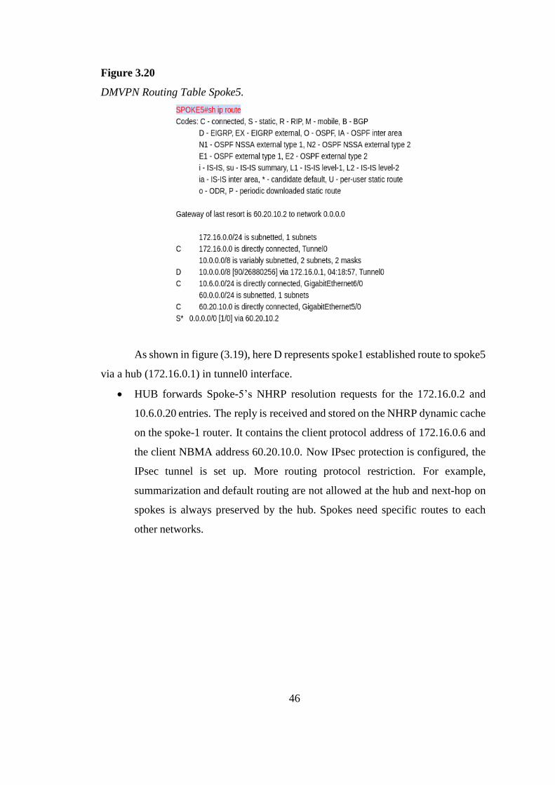
Figure 3.20
DMVPN Routing Table Spoke5.
As shown in figure (3.19), here D represents spoke1 established route to spoke5
via a hub (172.16.0.1) in tunnel0 interface.
• HUB forwards Spoke-5’s NHRP resolution requests for the 172.16.0.2 and
10.6.0.20 entries. The reply is received and stored on the NHRP dynamic cache
on the spoke-1 router. It contains the client protocol address of 172.16.0.6 and
the client NBMA address 60.20.10.0. Now IPsec protection is configured, the
IPsec tunnel is set up. More routing protocol restriction. For example,
summarization and default routing are not allowed at the hub and next-hop on
spokes is always preserved by the hub. Spokes need specific routes to each
other networks.

47
Figure 3.21
DMVPN Spoke-Spoke Network Topology.
As shown in figure(3.21), here spoke1 look for a route to spoke5 by using
traceroute command finding the path in computer network diagnostic command for
performing the path (route) also measuring transit delays.
• Spoke-1 sends an NHRP resolution reply to Spoke-5 via Hub, using the source
information from Spoke-5’s NHRP resolution request. The NHRP resolution
reply contains the source information in Spoke-5’s NHRP resolution request as
a method of verification and contains the client protocol address 172.16.0.2 and
the client NBMA address 20.20.10.0. Again, IPsec protection is configured, the
tunnel is set up before the NHRP reply is sent back in the other direction.
Summarization on hub routes will not arrive at other spokes. Resulting in spoke-
to-spoke traffic going to the hub.
A spoke-hub-spoke DMVPN tunnel is established in both directions after step 7 is
complete. This allows traffic to flow across the spoke-hub-spoke tunnel of traversing

48
Figure 3.22
DMVPN Spoke-Hub-Spoke Workflow.
3.2 Contribution
More routing protocol restrictions in DMVPN scenario 2. As a case, the hub
does not allow summarization, default routing, and hub to preserve the next-hop on
spokes (Angelescu et al., 2017). Specific routes are needed by other networks to reach
spokes. EIGRP Routing On hub only adds command no IP next-hop-self. EIGRP split
horizon on hub routers are disabled to propagate the updates between spokes. If
summarization on spokes is configured, routes will not arrive at other spokes, which
results in spoke-to-spoke traffic going towards the hub.
In scenario-1 DMVPN fully supports summarization, which should be used to
minimize the number of prefixes advertised across the WAN. Summarizing routes that
are present in the WAN connections, it provides stability and increasing scalability by
hiding network convergence. This segment explains that NHRP’s interaction interacts
with the routing table, in case there is no existence of an exact route. HUB’s EIGRP
configuration now advertises the 10.0.0.0/8 summary prefix out tunnel 0. Till the
NHRP initiates the spoke to spoke tunnel, the spoke routers in general use the summary
route to forward the traffic. After initializing the spoke-to-spoke tunnels, an increasing
number of entries from NHRP are installed into the routing tables.
The DMVPN scenario-1 configuration for the hub router adds the interface
parameter command ip nhrp redirect on the hub router. This command checks the flow
of packets on the tunnel interface and sends a redirect message to the source spoke
router when it detects packets hairpinning out of the DMVPN cloud. Hairpinning
means that traffic is received and sent out an interface in the same cloud (identified by the

49
NHRP network ID). For instance, hairpinning occurs when packets come in and go out
the same tunnel interface. Configuration for spoke routers uses the mGRE tunnel
interface and uses the command ip nhrp shortcut on the tunnel interface. This command
helps the spoke to install the incoming prefix onto its routing table, with the next jump
as target spoke. This is called an NHRP Shortcut. Scenario-1 overcomes the restriction
by sending signals from the hub to the spokes about a more reliable path to reach the
destination network. This traffic flow is taken care of by the NHRP redirect and
shortcuts.
The main features of this design are that spoke-to-spoke traffic will traverse
directly to another spoke (by forming Cisco Express Forwarding (CEF) adjacency),
thereby avoiding the hub and reducing latency and load on the hub.
3.3 GNS3 Design Analysis
While implementing in the GNS3 a real model of the system, few steps are to
be followed. The following steps are needed to work with GNS3.
These are

50
Figure 3.23
Overview of the Testing Process
Table 3.2
System Configuration.
System configuration
Processor Intel(R) Core (TM) i7-7500U CPU @ 2.70GHz -2.90 GHz
Memory 8.00 GB
System type 64-bit operating system, x64-based processor
Operating system Windows 10 Home

51
CHAPTER 4
RESULTS
The performance assessment of scenario 1 and scenario 2 is performed in this research
work by measuring round trip time, Jitter, and throughput.
In this section, the simulation results of all scenarios are shown by a mean value of a
95 percent confidence interval.
• DMVPN scenario-1 The data plane traffic goes to remote spoke because here
the next-hop is the direct spoke. And it takes an optimal path to get to the
destination. As shown In Figure 3.6.
• DMVPN scenario 2 the data plane traffic goes to the hub. Because here the
next-hop is the hub, so the next-hop is always the hub router and the spoke
router is the next-hop. As shown In Figure 3.15.

52
4.1 Resulting Parameters
Table 4.1
Network Parameters
Parameters values
IOS router Cisco
IOS Version 15.6(2)T, 12.4(24)T5
Simulator GNS3 version (2.2.2)
Virtual box VMware version ( 15.5)
Data rate 5000, 10000, 20000, 30000, 40000 (Packets/s)
Simulation Time (scenario-1) 325(Sec)
Simulation Time (scenario-2) 400(Sec)
Transmission ICMP
Router bandwidth 1600kbits/sec
Packet size 84 Bytes
Routing protocol EIGRP
Tunnel transmit and receive bandwidth 8000(kbps)
IPsec ESP-256, IKEV2
Encryption 256-bit AES
Authentication esp-sha 512-hmac
Topology 1hub,5spokes, and 12 users
4.1.1 RTT
Latency is a term which comes under networking, it describes that the total
duration, a packet of data travels from one link to another link. In a different context,
when a packet of data is transmitted and drawn back to its source. The complete time
taken for transmitting and receiving a trip will be known as latency. Latency can also
be referred to as a time-period or delay when a component of a system is waiting for
other system components to perform. The duration of this time taken is defined as
Latency. The term latency means delay. It is nothing but the amount of time, i.e delay,

53
it takes to send the data, from one point to the next. The measurement parameters used
for it are seconds (s). This term is also used as a ping rate in speed tests.
Figure 4.1
ICMP RTT Estimate Model Route (Mnisi et al. (2008))
Low latency implies a high efficiency of the network. The estimated delay was
determined between the client (IP 10.2.0.10) and the destination client (IP 10.6.0.20)
respectively.
The round-trip time is based on a traditional ping tool for various packet sizes,
which are about batch packets. The results are shown in the average file size RTT. As
shown In Figure 4.3, this graph shows the data rate on the x-axis(packets/s) and RTT(s)
on the y-axis. The quality calculation is derived from the ping method for values
ranging from 4.3*10-2(s) to 5.4*10-2 (s). The impact of this quality finding is due to its
delay variance. In scenario-1 there is a direct path to the destination. so, it takes an
optimal path.

54
Figure 4.2
Scenario 1 RTT(s) Vs Data Rate(packets/s)
As shown In Figure 4.4, this graph shows data rate and RTT, on the x-axis. Here
data rate(packets/s) on the y-axis is taken in units RTT(s). The quality calculation is
derived by the ping method for values ranging from 7.1*10-2 (s) to 7.6*10-2 (s). The
impact of this quality finding is due to its delay variance. In scenario-2 there is no direct
path to the destination. so, it takes a sub-optimal path via the hub.
0
1
2
3
4
5
6
7
5 1 0 2 0 3 0 4 0
RTT
(s)
Data Rate (Packets/s)
SCENARIO 1ROUND TRIP TIME AND DATA RATE x10-2
x103

55
Figure 4.3
Scenario 2 RTT(s) Vs Data Rate(packets/s)
As shown In Figure 4.5, The RTT of scenarios 1 and 2. Here in scenario-1 RTT
is better than scenario-2 because the delay variation of scenario-1 is lower than
scenario-2. The scenario-1 chooses a better path to reach the destination. Overall, we
can observe a clear upward trend in scenario-2, while the scenario-1 seems to have
levelled off.
0
1
2
3
4
5
6
7
8
9
10
5 1 0 2 0 3 0 4 0
RTT
(s)
Data Rate (Packets/s)
SCENARIO 2ROUND TRIP TIME AND DATA RATE x10-2
x103

56
Figure 4.4
Comparison of RTT(s) Vs Data Rate(packets/s)
4.1.2 Jitter
The change in the signal periodicity or periodic event from its target or true
frequency is called jitter. In Telecommunications Jitter refers to the change in the
latency of packets carrying information across a communication channel. Change in
latency of communications channel, data-carrying packets causes bit errors and
degrades a transmission system’s output.
As shown In Figure 4.6, the Quality calculation of the ping method for values
ranging from 0.5*10-2(s) to 1.32*10-2 (s). The impact of this quality finding is due to its
delay variance.
0
1
2
3
4
5
6
7
8
9
10
5 1 0 2 0 3 0 4 0
RTT
(s)
Data Rate (Packets/s)
COMPARISION OF ROUND TRIP TIME AND DATA RATE
Scenario 1
Scenario 2
x10-2
x103

57
Figure 4.5
Scenario 1 Jitter(s) Vs Data Rate(packets/s)
As shown In Figure 4.7, this graph shows jitter(s) upon the y-axis and data
rate(packets/s) upon the x-axis. The quality calculation is derived from the ping method
for values ranging from 1.30*10-2 (s) to 1.76*10-2 (s). The impact of this quality finding
is due to its delay variance.
0
1
2
3
5 1 0 2 0 3 0 4 0
Jitt
er (
s)
Data Rate (Packets/s)
SCENARIO 1JITTER AND DATA RATE
x10-2
x103

58
Figure 4.6
Scenario 2 Jitter(s) Vs Data Rate(packets/s)
Here are two jitter scenarios triggered by the route change to the spoke-to-spoke
tunnel. When the spoke- the hub-spoke path has higher latency compared to the spoke-
to-spoke path. so, phase 2 jitter is more because of the path of the phase 2 spoke-hub-
spoke. phase 3 has a better path such as direct spoke-to-spoke.
As shown In Figure 4.8, The Jitter of scenario 1 and 2. Here are two jitter
scenarios triggered by the route change to the spoke-to-spoke tunnel. When the
suboptimal path has more latency than the optimal path. Hence, scenario-2 jitter is
more because of the path of scenario-2 (spoke-hub-spoke). scenario-1 has better paths
such as direct spoke-to-spoke.
0
1
2
3
5 1 0 2 0 3 0 4 0
Jitt
er (
s)
Data Rate (Packets/s)
SCENARIO 2JITTER AND DATA RATE
x10-2
x103

59
Figure 4.7
Comparison of Jitter(s) Vs Data Rate(packets/s)
4.1.3 Throughput
Throughput can be defined as a load of data per unit of time, which is sent
through a logical or physical link, which is passing through a certain node. Throughput
can be affected by a number of factors such as a number of hops, payload size, latency,
network load, bandwidth, and others, which can be analysed by theory named queuing
theory. The units that are used to represent bytes per second (Bps). Throughput can be
determined by the following expression below. Equation 4.1 shows the calculation of
throughput.
Throughput (Bytes/s) = Data Rate (Packets/s) × PDR × Packet size (Bytes).
(Equation 4.1)
The advantage with DMVPN scenario-1 is the data plane traffic goes to
remote spoke because here the next-hop is the direct spoke. And it takes an optimal
path to get to the destination.
As shown In Figure 4.9, this graph shows average throughput (Bytes/s) and data
rate(packets/s), on the x-axis and y-axis respectively. The quality calculation is derived
0
1
2
3
5 1 0 2 0 3 0 4 0
Jitt
er (
s)
Data Rate (Packets/s)
COMPARISION OF JITTER AND DATA RATE
Scenario 1
Scenario 2
x10-2
x103

60
from the ping method for values ranging from 42*105 Bps to 33*105 Bps. The impact
of this quality finding is due to its packet delivery ratio.
Figure 4.8
Scenario 1 Throughput (Bytes/s) vs Data Rate(packets/s)
The problem with DMVPN scenario-2 is that the data plane traffic goes to the
hub. Because here the next- hop is the hub, so the next-hop is always a hub router and
the spoke router is the next-hop. The number of hops increases, it affects network
performance. As shown In Figure 4.10, this graph shows average throughput (Bytes/s)
and data rate(packets/s), on the x-axis and y-axis respectively. The quality calculation is
derived from the ping method for values ranging from 42*105 Bps to 33*105Bps. The
impact of this quality finding is due to its packet delivery ratio.
0
5
10
15
20
25
30
35
40
5 1 0 2 0 3 0 4 0
Thro
ugh
pu
t(b
ytes
/s)
Data Rate (Packets/s)
SENARIO 1THROUGHPUT AND DATA RATE x105
x103

61
Figure 4.9
Scenario 2 Throughput (Bytes/s) vs Data Rate(packets/s)
Compared to the traditional ping tool, the proposed model uses the same data
sizes. These large measurements of the throughput give more understanding of the
processing of data which can be passed through the Internet Protocol (IP) layer instead
of depending on measurements of the less ping tool. As shown In Figure (4.11), from
the results, it is observed that overall throughput in scenario-1 and scenario-2 remains
the same. But the packet delivery ratio, which is one of the evaluating parameters of
throughput was varied in both the scenarios. this variation in throughput is due to loss
of packets at 10*103in scenario-1 and at 30*103 in scenario-2.
0
5
10
15
20
25
30
35
40
5 1 0 2 0 3 0 4 0
Thro
ugh
pu
t(b
ytes
/s)
Data Rate (Packets/s)
SCENARIO 2 THROUGHPUT AND DATA RATE x105
x103

62
Figure 4.10
Comparison of Throughput (Bytes) vs Data Rate(packets/s)
4.1.4 PDR
Packet delivery ratio is termed as the ratio of data packets received to the
destinations to those which are generated by the sources. Equation 4.2 shows the
mathematical representation of PDR, where, S1 is the total number of data packets
received by the destination, and S2 is the total number of data packets produced by the
source.
𝑃𝐷𝑅% =𝑠1
𝑠2 Equation (4.2)
As shown In Figure 4.12 Using equation (4.2), the packet delivery ratio in all
packet sending data rate of 5*103,10*103,20*103,30*103,40*103 (packets/s), when the
loss of packets experienced by scenario-1 at a data rate of 10*103 the value is 80% and
scenario-2 at a data rate of 30*103 the value is 93%.
0
5
10
15
20
25
30
35
40
5 1 0 2 0 3 0 4 0
Thro
ugh
pu
t(b
ytes
/s)
Data Rate (Packets/s)
COMPARISION OF THROUGHPUT AND DATA RATE
Scenario 1
Scenario 2
x105
x103

63
Figure 4.11
PDR vs Data Rate (Packets/s)
4.1.5 IPsec Tunnel Configuration
The initial packets are Generic Routing Encapsulation flags are attached to them,
and next to this part of the packets are encrypted by using ESP transportation mode in
DMVPN. A signature for the encrypted packets is joined, and when the GRE IP header
is combined to routing the packets at the transport (underlay) network. As shown below
in the figure4.13, the figure proves the command at spoke-1. The producer lists the
state of the DMVPN tunnel, the underlay IP locations, and packet numbers.
Considering the packet counts during the product is one of the actions that can be used
to prove that network traffic is moving carried out of a DMVPN tunnel or taken on a
DMVPN tunnel. Here crypto session status is active which means it is protected.
0
20
40
60
80
100
120
5 1 0 2 0 3 0 4 0
PD
R (
%)
Data Rate (Packets/s)
PDR AND DATA RATE
Secnario 1 Secnario 2
x103

64
Figure 4.12
Ipsec Tunnel Protection
The IPsec command is contributed additional knowledge about tunnel mode,
reply disclosure, and route MTU which is shown crypto ipsec sa command the below
(figure 4.14) advertise exact data about all the security association.

65
Figure 4.13
IPsec security association
Figure 4.14
Ipsec IKEV2 Security Association

66
CHAPTER 5
CONCLUSION AND RECOMMENDATIONS
5.1 Conclusion
In this research, the DMVPN protocol was studied and implemented using GNS3
network simulation, which stands as an alternative to the traditional VPN.
The single hub single cloud infrastructure consisting of five spokes was
selected to test the design of DMVPN, which reduces the number of hops, thereby
reducing transit delays. The DMVPN design was simulated by taking into account
scenario 1, scenario 2, and then the performance of the design in both the scenarios
was compared. Also, the limitations of the existing solutions were discussed. The
problem with Scenario-2 is that spoke-to-spoke communication would never happen
directly. Data plain traffic goes to the hub. At this time no NHRP requests because the
next hop is the hub. Traffic always flows through the hub, which means can’t
summarize on Scenario-2, that’s why DMVPN scenario-1 was implemented. In
scenario 1, there are no spokes, they don’t have specific routes to the branch office,
they only have one default route. Here next hop is the hub which means the traffic will
always go to the hub. The hub gets the packets and sends NHRP redirect coming from
hub to the spoke. spoke can install the route for himself which the spoke learns from
the hub. The performance metrics used to evaluate the performance of scenario- 2 and
scenario-1 are round trip time, Jitter, and throughput. The result shows that scenario 1
has a better performance compared to scenario 2.
5.2 Future Recommendations
I would like to recommend the following methods that can be implemented
upon the existing research.
In an enterprise network, the organization shares the data over the IP network that
may consist of sensitive information. IP-Sec which is an IP network security is used to
secure the information, the performance of this IP-Sec against various security attacks
can be evaluated, which is recommended as future work.

67
REFERENCES
Angelescu, N., Puchianu, D., Predusca, G., Circiumarescu, L., & Movila, G. (2017).
Dmvpn simulation in gns3 network simulation software. In 2017 9th
international conference on electronics, computers and artificial intelligence
(ecai) (pp. 1–4).
Bahnasse, A., & El Kamoun, N. (2015). Study and analysis of a dynamic routing
protocols’ scalability over a dynamic multi-point virtual private network.
International Journal of Computer Applications, 123(2).
Chen, H. (2011). Design and implementation of secure enterprise network based on
dmvpn. In 2011 international conference on business management and
electronic information (Vol. 1, pp. 506–511).
Jahan, S., Rahman, M. S., & Saha, S. (2017). Application specific tunneling protocol
selection for virtual private networks. In 2017 international conference on
networking, systems and security (nsyss) (pp. 39–44).
Khelf, R., & Ghoualmi-Zine, N.(n.d.). A survey on dynamic multipoint virtual private
networks.
Mnisi, N., Oyedapo, O., & Kurien, A. (2008). Active throughput estimation using rtt
of differing icmp packet sizes. In 2008 third international conference on
broadband communications, information technology, biomedical applications
(pp. 480–485).
Naby, S. A., Arslan, S., & Kim, H. (2017). Ike hardware engine based on cam for
concurrent processing of massive user sessions. In 2017 13th international
computer engineering conference (icenco) (pp. 154–159).
Qehaja, B., Bajraliu, A., Shabani, A., & Hajrizi, E. (2016). Enterprise integration,
networking and virtual communications. IFAC-PapersOnLine, 49(29), 144–
147.
Salman, F. A. (2017). Implementation of ipsec-vpn tunneling using gns3. Indonesian
Journal of Electrical Engineering and Computer Science, 7(3), 855–860.
Shaheen, S. H., Yousaf, M., & Majeed, M. Y. (2015). Comparative analysis of internet
key exchange protocols. In 2015 international conference on information and
communication technologies (icict) (pp. 1–6).

68
Teare, D., Vachon, B., & Graziani, R. (2014). Implementing cisco ip routing (route)
foundation learning guide(ccnp route 300-101). Cisco Press.

69
APPENDIX A
Table A1 Hub and Spoke Router Configuration of DMVPN
HUB router Spoke router
Conf t
int tunnel 0 int tunnel 0
ip add 172.16.0.1 255.255.255.0 ip add 172.16.0.2 255.255.255.0
ip mtu 1400 no ip redirects
ip tcp adjust-mss 1360 ip mtu 1400
tunnel mode gre multipoint ip tcp adjust-mss 1360
tunnel source g0/0 tunnel mode gre multipoint
tunnel key 100 tunnel source g0/1
ip nhrp map multicast dynamic tunnel key 100
ip nhrp authentication master ip nhrp nhs 172.16.0.1
ip nhrp network-id 10 ip nhrp map 172.16.0.1 80.20.10.1
router eigrp 10 ip nhrp map multicast 80.20.10.1
netw 172.16.0.1 0.0.0.255 ip nhrp authentication master
netw 10.1.0.1 0.0.0.0 ip nhrp network-id 10
int tunnel 0 ip nhrp shortcut
no ip split-horizon eigrp 10 router eigrp 10
no ip next-hop-self eigrp 10 netw 172.16.0.2 0.0.0.255
crypto isakmp policy 10 netw 10.2.0.1 0.0.0.0
authentication pre-share crypto isakmp policy 10
encryption 3des encr 3des
hash md5 hash md5
group 2 authentication pre-share
lifetime 86400 group 2
crypto isakmp key dmvpnkey address
0.0.0.0 0.0.0.0
crypto isakmp key dmvpnkey address
0.0.0.0
crypto ipsec transform-set T-SET esp-
aes 256 esp-sha-hmac
crypto ipsec transform-set T-SET esp-
aes 256 esp-sha-hmac
mode transport mode transport
crypto ipsec profile
DMVPN_PROFILE
crypto ipsec profile
DMVPN_PROFILE
set security-association lifetime seconds
86400 set transform-set T-SET
set transform-set T-SET tunnel protection ipsec profile
DMVPN_PROFILE
int tunnel 0 exit
tunnel protection ipsec profile
DMVPN_PROFILE

70
Table A2 RTT Values of Scenario 1.
S. No RTT Scenario 1
1 41.949 45.713 52.825 48.577 52.422 2 61.848 61.318 50.138 62.365 63.155 3 62.932 59.574 42.031 51.842 43.402 4 45.424 40.058 43.074 61.086 41.205 5 59.805 52.883 46.993 33.972 42.15 6 timeout 48.175 39.73 57.55 7 timeout 42.49 45.679 37.373 8 62.177 44.861 37.611 51.986 9 54.569 44.13 63.689 39.711 10 53.298 43.213 62.175 49.894 11 41.907 53.878 42.709 12 34.839 41.341 35.788 13 36.367 57.126 38.38 14 41.926 58.719 52.688 15 39.132 63.619 50.831 16 33.527 62.663 62.275 17 37.314 44.81 46.089 18 59.725 56.039 56.073 19 37.733 63.118 40.139 20 49.548 44.345 60.05 21 63.957 43.652 22 40.338 46.659 23 54.899 53.968 24 40.827 34.582 25 60.242 33.669 26 52.621 64.257 27 37.798 62.122 28 38.228 60.794 29 55.765 54.989 30 38.658 36.843 31 57.582 32 56.642 33 50.681 34 53.408 35 47.888 36 52.248 37 43.545 38 61.832 39 60.76 40 45.904
Data Rate 5000 10000 20000 30000 40000
Average 0.0544 0.0537 0.0435 0.0512 0.0496
Standard
Deviation 0.0099 0.0077 0.0065 0.0100 0.0090
Standard Error 0.0031 0.0024 0.0020 0.0032 0.0028
95%Confidence 0.0087 0.0062 0.0043 0.0065 0.0058

71
Table A3 RTT Values of Scenario 2.
S. No RTT Scenario 2
1 57.375 62.352 66.189 91.589 81.863 2 79.416 62.558 87.94 89.904 82.713 3 76.279 80.085 81.413 88.381 82.245 4 93.682 89.863 59.436 67.816 83.221 5 65.757 99.668 78.942 79.009 84.828 6 78.651 79.297 54.731 91.47 7 78.245 72.138 63.859 87.348 8 56.689 57.322 85.824 84.163 9 92.461 54.45 105.573 75.619 10 54.996 85.635 53.745 60.288 11 60.483 58.405 64.341 12 71.536 78.862 72.829 13 55.421 55.623 73.454 14 89.951 71.4 96.792 15 73.982 60.204 55.05 16 58.155 90.267 73.023 17 67.283 65.28 81.364 18 74.733 timeout 77.338 19 71.984 timeout 98.23 20 77.35 91.102 82.462 21 101.32 58.136 22 90.495 57.881 23 78.788 87.412 24 54.734 56.149 25 53.898 61.701 26 69.046 68.791 27 77.046 65.029 28 101.963 75.388 29 89.334 59.41 30 60.416 60.676 31 69.493 32 57.447 33 80.066 34 62.838 35 86.413 36 56.695 37 98.34 38 97.094 39 92.01 40 64.474
Data Rate 5000 10000 20000 30000 40000
Average 0.0745 0.0756 0.0712 0.0760 0.0751
Standard Deviation 0.0138 0.0157 0.0110 0.0164 0.0133
Standard Error 0.0044 0.0050 0.0035 0.0052 0.0042
95% Confidence 0.0121 0.0126 0.0073 0.0106 0.0085

72
Table A4 Jitter Values of Scenario-1.
S.NO Jitter Scenario 1
1 19.899 15.605 2.687 13.788 10.733 2 1.084 1.744 8.107 10.523 19.753 3 17.508 19.516 1.043 9.244 2.197 4 14.381 12.825 3.919 27.114 0.945 5 9.294 1.182 5.758 15.4 6 7.608 5.685 5.949 20.177 7 1.271 2.3709 8.068 14.613 8 0.7309 26.078 12.275 9 0.917 1.514 10.183 10 1.306 8.297 7.185 11 7.068 12.537 6.921 12 1.528 15.785 2.592 13 5.559 1.593 14.308 14 2.794 4.9 1.857 15 5.605 0.956 11.444 16 3.787 17.853 16.186 17 22.411 11.229 9.984 18 21.992 7.079 15.934 19 11.815 18.773 19.911 20 19.612 16.398 21 23.619 3.007 22 14.561 7.309 23 14.072 19.386 24 19.415 0.913 25 7.621 30.588 26 14.823 2.135 27 0.43 1.328 28 17.537 5.805 29 17.107 18.146 30 20.739 31 0.9399 32 5.961 33 2.727 34 5.52 35 4.36 36 8.703 37 18.287 38 1.072 39 14.856 40 45.904
Data Rate 5000 10000 20000 30000 40000
Average 0.0132 0.0097 0.0058 0.0123 0.0112
Standard
Deviation 0.0084 0.0068 0.0065 0.0074 0.0093
Standard Error 0.0027 0.0022 0.0020 0.0023 0.0029
95%Confidence 0.0074 0.0055 0.0043 0.0048 0.0059

73
Table A5 Jitter Values of Scenario 2.
S.NO Jitter Scenario 2
1 22.041 0.206 21.751 1.685 0.8499 2 3.137 17.527 6.527 1.523 0.4679 3 17.403 9.778 21.977 20.565 0.9759 4 27.925 9.805 19.506 11.193 1.607 5 21.017 0.355 24.278 6.642 6 0.4059 7.1589 9.128 4.122 7 21.556 14.816 21.965 3.185 8 35.772 2.872 19.749 8.544 9 37.465 31.185 51.828 15.331 10 25.152 4.66 4.053 11 11.053 20.457 8.488 12 16.115 23.239 0.625 13 34.53 15.777 23.338 14 15.969 11.196 41.742 15 15.827 30.063 17.973 16 9.128 24.987 8.341
17 7.45 timeout 4.026
18 2.749 timeout 20.892
19 5.366 25.822 15.768 20 10.218 24.326 21 10.825 0.255 22 11.707 29.531 23 24.054 31.263 24 0.8359 5.552 25 15.148 7.09 26 8 3.762 27 24.917 10.359 28 12.629 15.978 29 28.918 1.266 30 8.8169 31 12.046 32 22.619 33 17.228 34 23.575 35 29.718 36 41.645 37 1.246 38 5.0839 39 27.536
40
Data Rate 5000 10000 20000 30000 40000
Average 0.0176 0.0171 0.0142 0.0172 0.0130
Standard
Deviation 0.0106 0.0136 0.0097 0.0110 0.0117
Standard Error 0.0033 0.0043 0.0031 0.0035 0.0037
95%Confidence 0.0093 0.0108 0.0064 0.0071 0.0075

74
Table A6 Throughput Values of Scenario-1 and 2.
Throughtput
S.No Scenario 1
PDR
Scenario 2
PDR DataRate*Pocketsize
Scenario
1
Scenario
2
1 1 1 420000 420000 420000
2 0.8 1 840000 672000 840000
3 1 1 1680000 1680000 1680000
4 1 0.93 2520000 2520000 2343600
5 1 1 3360000 3360000 3360000
Data
Rate 5000 10000 20000 30000 40000
Table A7 PDR Percentage Values of Scenario-1 and 2.
Data Rate Scenario 1 Scenario 2
5000 100 100
10000 80 100
20000 100 100
30000 100 93
40000 100 100