Simple shear of isotropic elasto-plastic soil
20
INTERNATIONAL JOURNAL FOR NUMERICAL AND ANALYnCAL METHODS IN OEOMECHANICS, VOL 15,251-270 (1991) SIMPLE SHEAR OF ISOTROPIC ELASTO-PLASTIC SOIL S. FRYDMAN AND M. TALESNICK Faculty of Civil Engineering, Technio-Israel Institute of Technology, Haifo. Isroel SUMMARY The implications of assuming isotropic elasto-plasticity to model the behaviour of soil under simple shear conditions arc considered. For small strains, usc of such a model implies the following threc consequences: (1) strains and strain increments at any stage of shearing may be expressed as the sum of elastic and plastic components; (2) principal directions of stress and of plastic strain increment are collinear. (3) principal directions of stress increment and of elastic strain increment are collincar. These consequences arc used in order to establish relationships between the stresses, stress increments and strains which develop in a simple shear test. No additional assumptions with regards the form of the yield function, the flow rule or the hardening function arc required for this development. By defining the ratio of the plastic to the total shear strain increment on the horizontal plane (the plane of zero extension) as L, it is possible to define the horizontal normal stress u, in terms of 1 and other stresses and strains which are normally known during simple shear loading. As a result, all components of the stress tensor in the simple shear plane may be defined. Results of some direct simple shear tests on soft clay have been interpreted using the model and found to be generally consistent with some of the observations reported in the literature from tests in which boundary stresses were measured. INTRODUCTION Since its introduction some 38 years ago,’ the direct simple shear test has become increasingly more popular as a method for providing useful information about the stress-strain-strength properties of soils. It has been pointed out that this procedure is particularly relevant for modelling certain field situations in which simple shear conditions are expected to occur; for example, Thiers and Seed’ referred to the stress conditions developed in an element of soil below a horizontal ground surface during the upward propagation of shear waves during an earth- quake, and Ng and Donald3 mentioned the simple shear state of stress which exists along the shaft of piles during loading. In fact it may be expected that simple shear conditions exist along slip surfaces in any plane strain problem. Wroth4 suggested that the simple shear test is the only relevant test for engineering applications where classical analyses of short-term slope stability are being carried out using, for example, limit equilibrium applied to postulated failure surfaces. As was pointed out by R o s c ~ e , ~ slip ‘surfaces’ are of finite thickness, probably of the order of a number of particles; within this slip zone, simple shear conditions may be expected to exist, as shown schematically in Figure 1. Bjerrum and L a n d ~ a , ~ appreciating the simple shear nature of slip zones, developed the Norwegian Geotechnical Institute (NGI) direct simple shear device in order ‘to obtain a better understanding of the factors influencing the in situ shear strength of the highly sensitive, normally consolidated, Norwegian clays, and to develop methods permitting an evaluation of the stability of natural slopes’. This equipment has since become the most popular, commercially available simple shear device and has been used for both research and project- oriented testing. The advantages and disadvantages of the direct simple shear device have been 0363-906 1191/O4025 1-20s 10.00 Q 1991 by John Wiley & Sons, Ltd. Received 25 December I989
Transcript of Simple shear of isotropic elasto-plastic soil

INTERNATIONAL JOURNAL FOR NUMERICAL AND ANALYnCAL METHODS IN OEOMECHANICS, VOL 15,251-270 (1991)
SIMPLE SHEAR OF ISOTROPIC ELASTO-PLASTIC SOIL
S. FRYDMAN AND M. TALESNICK
Faculty of Civil Engineering, Technio-Israel Institute of Technology, Haifo. Isroel
SUMMARY
The implications of assuming isotropic elasto-plasticity to model the behaviour of soil under simple shear conditions arc considered. For small strains, usc of such a model implies the following threc consequences: (1) strains and strain increments at any stage of shearing may be expressed as the sum of elastic and plastic components; (2) principal directions of stress and of plastic strain increment are collinear. (3) principal directions of stress increment and of elastic strain increment are collincar. These consequences arc used in order to establish relationships between the stresses, stress increments and strains which develop in a simple shear test. No additional assumptions with regards the form of the yield function, the flow rule or the hardening function arc required for this development. By defining the ratio of the plastic to the total shear strain increment on the horizontal plane (the plane of zero extension) as L, it is possible to define the horizontal normal stress u, in terms of 1 and other stresses and strains which are normally known during simple shear loading. As a result, all components of the stress tensor in the simple shear plane may be defined. Results of some direct simple shear tests on soft clay have been interpreted using the model and found to be generally consistent with some of the observations reported in the literature from tests in which boundary stresses were measured.
INTRODUCTION
Since its introduction some 38 years ago,’ the direct simple shear test has become increasingly more popular as a method for providing useful information about the stress-strain-strength properties of soils. It has been pointed out that this procedure is particularly relevant for modelling certain field situations in which simple shear conditions are expected to occur; for example, Thiers and Seed’ referred to the stress conditions developed in an element of soil below a horizontal ground surface during the upward propagation of shear waves during an earth- quake, and Ng and Donald3 mentioned the simple shear state of stress which exists along the shaft of piles during loading. In fact it may be expected that simple shear conditions exist along slip surfaces in any plane strain problem. Wroth4 suggested that the simple shear test is the only relevant test for engineering applications where classical analyses of short-term slope stability are being carried out using, for example, limit equilibrium applied to postulated failure surfaces. As was pointed out by R o s c ~ e , ~ slip ‘surfaces’ are of finite thickness, probably of the order of a number of particles; within this slip zone, simple shear conditions may be expected to exist, as shown schematically in Figure 1. Bjerrum and L a n d ~ a , ~ appreciating the simple shear nature of slip zones, developed the Norwegian Geotechnical Institute (NGI) direct simple shear device in order ‘to obtain a better understanding of the factors influencing the in situ shear strength of the highly sensitive, normally consolidated, Norwegian clays, and to develop methods permitting an evaluation of the stability of natural slopes’. This equipment has since become the most popular, commercially available simple shear device and has been used for both research and project- oriented testing. The advantages and disadvantages of the direct simple shear device have been
0363-906 119 1/O4025 1-20s 10.00 Q 1991 by John Wiley & Sons, Ltd.
Received 25 December I989

252 S. FRYDMAN AND M. TALESNICK
Figure 1. Simple shear conditions aloog a slip surface
discussed in a number of publications, and these have been summarized by Airey and Wood.' One particular criticism has centred on its incapability to impose uniform stress conditions on the soil sample. Airey and Wood found that the uniformity is much improved for more plastic clays as compared to sands, and that for clays the device yields results of reasonable quality. Assuming this to be the case, the major limitation of the device then lies in the fact that the stress state in the sample is not fully defined; only the normal and shear stresses on the horizontal boundary are measured during a test, making it impossible to calculate other components of the stress tensor. With regards the strain tensor the situation is better, since the horizontal shear strain and vertical normal strain are measured and the horizontal normal strains are zero in the shearing direction and perpendicular to it (this assumes plane strain conditions). One result of this situation has been the creation of confusion with regards the definition of soil strength parameters on the basis of direct simple shear tests. A Mohr stress circle cannot be drawn on the basis of the measured stresses alone and so the plane of maximum obliquity cannot be defined. Of no less significance is the fact that without the capacity to define the non-measured stress components, the direct simple shear device loses a great part of its potential as a research tool and cannot be used in studies aimed at developing constitutive relations for soils.
The first attempt to tackle this problem was made by Arthur et al.," who, considering the simple shear behaviour of sand, assumed the soil to behave plastically, with the consequence of collinearity between principal directions of stress and of strain increment. The Mohr circle of stress could then be drawn on the basis of the Mohr circle of strain increments, fully defined by the measured strain values during a test. Roscoe et aL9 reported results of some tests on medium- dense sand performed in the Cambridge simple shear device in which boundary stresses were measured; during monotonic shearing of the sand, the principal directions of strain increment and of stress were found to coincide over a large part of the strain range, inferring plastic behaviour, while for unloading, collinearity was reported between principal directions of stress increment and strain increment, inferring elastic behaviour. For loose sand, poorer agreement was found. Similar trends have been reported recently by Budhu." Few data have been presented from tests on clays which have incorporated boundary stress measurements. Possible failure stress states for normally consolidated clays were considered by Ladd and Edgers,' ' while Wroth4- '' used the

SHEAR OF ISOTROPIC ELASTO-PLASTIC SOIL 253
result of a test performed in the Cambridge device by Bonn” to suggest a failure mechanism for such soils.
In the present paper, soil is assumed to behave as an isotropic elasto-plastic material. This model, together with some observed features of the shearing behaviour of soils, is used to develop an approach for the estimation of the stress conditions in a soil specimen undergoing simple shear loading.
THE ELASTO-PLASTIC MODEL
Consider a soil element undergoing simple shear as shown in Figure 2. The soil element is assumed to behave as an isotropic elasto-plastic material undergoing small strains, with the following consequences.
(i) The strains and strain increments at any stage of shearing may be expressed as the superposition of elastic and plastic components. In particular, the following relationships are Used.
(a) The plastic component of the shear strain increment on the horizontal plane, dyt , is related to the total shear strain increment dy,, through the expression
dYL = AdY,, (1)
dY:x=(1--~)dYlx (2)
and so the elastic component is given by
where A has a value between zero and unity and can vary during the shearing process. The complementary elastic, plastic and total shear strain increments dy:,, dy!, and dy,, are equal to dy:,, dy$ and dy,, respectively.
(b) Since the normal strain in the direction of shearing (x) is zero, horizontal lines are lines of zero extension:
dsx = &: + d.$ = 0 (3)
di?! = - d$ (4)
(c) Plane strain conditions are assumed to apply and so total strains and strain increments are zero in the lateral (y) direction:
de, =&; + &; =O (5 )
ds,” = - de: (6)
0; =’ x I“’ - f ’ x t : J Y j
\
‘ rY
Figure 2. Stresses on an ekmcnt undergoing simple shear

254 S. FRYDMAN AND M. TALESNICK
(d) The vertical normal strain increment de, is the sum of the elastic and plastic components,
(7) i.e.
de, = d&z + di$ (ii) There is collinearity between the principal directions of stress and of plastic strain
increment. (iii) There is collinearity between the principal directions of stress increment and of elastic strain
increment. On the basis of the above considerations it is possible to relate, geometrically, the Mohr circles
of stress, stress increment, elastic strain increment and plastic strain increment as shown in Figure 3. In each circle, point P represents the pole and angle JI is the inclination of the relevant major
tT
Figure 3. Mohr circles for simple shear (a) stress incrcmcnts; (b) elastic strain increments; (c) plastic strain increments (d) stresses

SHEAR OF ISOTROPIC ELASTO-PLASTIC SOIL 255
principal plane to the horizontal. The relationships between the circles may be considered as follows. Let Figure 3(a) be the Mohr circle for the stress increments during an increment shear. In the particular case shown there is a decrease in stress level during the increment, both dax and da, being negative; the decrease in ax is shown, arbitrarily, as being greater than that of a,. The angle $da is the inclination of the major principal plane (i.e. of the minor principal stress increment do,) to the horizontal. From Figure 3(a) a schematic representation of the Mohr circle of correspond- ing elastic strain increments which develop during the same increment of shear can be drawn as shown in Figure 3(b). Since the principal directions of stress increment and elastic strain increment are collinear, $dgc is equal to $da and the location of the pole of the circle in Figure 3(b) is geometrically similar to its location in Figure 3(a). From these two circles it is therefore possible to write the relation
de: - da: - dox - do,
This equation may be rewritten on the basis of equation (2) as
Figure 3(c) shows the Mohr circle of plastic strain increments. Clearly, this circle is related to the elastic strain increment circle through equations (1H7). The angle $dtp is the inclination of the major principal plane of plastic strain increment to the horizontal. Since the principal axes of plastic strain increment and of stress are collinear, the geometric location of the pole in the stress circle is identical to that in the plastic strain increment circle. The stress circle may therefore be drawn schematically as shown in Figure 3(d), with angle +dap equal to $.,. From the circles of Figures 3(c) and 3(d) the following relation can be written:
Using equations (1)-(7), equation (10) may be rewritten as
Equating (9) and (1 1) gives
Equation (1 2) establishes the basic relationship between stresses, stress increments and strain increments for an isotropic elasto-plastic material in simple shear. No additional details of the elastic model (e.g. elastic constants) or of the plastic model (e.g. yield function, flow rule, hardening function) affect the relevance of this relationship. A study of the extent to which equation (12) actually represents the relationships which develop during the simple shear loading of real soils may provide an indication of the extent to which the isotropic elasto-plastic model is applicable to such soils.
Application of the basic relationship to direct simple shear tests
In the direct simple shear test carried out in the NGI device, ideal simple shear conditions are not fulfilled throughout the sample.'. '* The major problem lies in the fact that the shear stress on

256 S. FRYDMAN AND M. TALESNICK
the smooth vertical boundary is close to zero, with the result that the complementary shear stress T,, cannot develop in this region. Inhomogeneous stress conditions are therefore developed close to the specimen boundaries. Airey and Wood indicated that these problems appear less critical for plastic clays than for sands; they found, for example, that for normally consolidated kaolin the average shear stress on the horizontal plane measured in the direct simple shear device at failure underestimates the simple shear value by about 8%. The stress conditions in the direct simple shear device may therefore be considered as an approximation to simple shear conditions, particularly in the case of soft, highly plastic clay. Equation (12) may then be used to indicate the relationship to be expected between stresses, stress increments and strain increments which would develop in the device if simple shear conditions could be achieved.
Simple shear tests are generally carried out as either constant-volume tests or as constant-a, tests. In the former case u, is varied during shearing so as to keep the sample height and therefore the volume constant, while in the latter a, is held constant and the sample volume (height) is allowed to change (this is a standard drained test). In both cases shearing is carried out slowly so that no excess pore pressure develops. Applying equation (12) to each of these test conditions, the following relationships are obtained:
(a) constant height (de, =0)
(b) drained test (a, constant)
Equations (13) and (14) can be expressed in incremental form to define do,, which develops during any increment of shear, in terms of the stresses a,, a, and T,, which existed at the end of the previous increment, the measured rate of dilation during the increment, dE,/dyXz, and the plasticity factor A. A forward-marching procedure may then be used to trace the variation of a, during shear; for this purpose it is necessary to estimate the initial value of a, prior to the onset of shearing, and an estimate must be made of the variation of A during shear. The initial value of a, may be taken as Koa,, with KO estimated by one of the commonly available approaches (e.g. Reference 15). A discussion of the variation of A during shearing is presented below.
THE PLASTICITY FACTOR I
The value of A must lie between zero, corresponding to perfectly elastic behaviour, and unity, corresponding to perfectly plastic behaviour. In the following the significance of assuming either of these extreme cases is discussed and then consideration is given to an elasto-plastic model based on observed features of soil behaviour during shear.
Perfectly elastic model ( A = 0)
For simple shear conditions with height constant, equation (13) yields
do, = do, (15)
Now the condition of constant height corresponds, in the plane strain simple shear test, to a condition of constant volume. For a perfectly elastic material this infers a constant mean principal
SHEAR OF ISOTROPIC ELASTO P L A s n c SOIL 257
stress. Remembering that av is the intermediate principal stress, the only way in which equation (1 5 ) can be satisfied is if dux = da, = 0.
If az is held constant, equation (14) leads to
Equation (16) indicates that if the sample height is decreasing (i.e. de, and rate of dilation positive), then dux must be negative (i.e. a, is decreasing). However, for a perfectly elastic material, decreasing sample height (i.e. volumetric compression) must be associated with an increase in mean stress. The only way for this condition to be satisfied is for dux = de, = 0. It is seen, then, that for a perfectly elastic material the cases of constant height and constant vertical stress coincide. All the normal stresses and the vertical strain remain constant during the simple shear loading of such a material.
Perfectly plastic model (A = 1 )
For constant-height (i.e. constant-volume) conditions, equation (1 3) yields
a, = u, (17)
For this case the principal directions of stress and of strain increment are inclined at 45" to direction x.
If a, is constant, equation (14) yields
(18) Q,-CT, de,
-2- 7xr dYx,
--
In this case ox will be greater or smaller than a, depending on whether the rate of dilation is negative or positive respectively.
A varying during shear
Equations (15H18) were developed assuming 1 to be constant during the shearing process and equal to either zero or unity. Expressions which take account of the variation of 1 during shear may be developed by making use of some observed features of the form of the stress-strain relationship for soils. For this purpose a clear definition must be made of the significance of plastic shear strain. In principle, plastic strains are associated with energy dissipation and are those strains which are irrecoverable during a full loading cycle of the stress tensor (i.e. all components of the stress tensor at the end of the cycle are equal to their values at the start of the cycle). The development of plastic strains during monotonic loading under drained triaxial conditions could, in principle, be established by performing a series of loading tests on initially identical samples in which unloading is carried out at various strains. This is possible precisely because all the boundary conditions of a drained triaxial test are stresses and are controlled by the operator. In simple shear, however, since some of the boundary conditions are kinematic, the operator does not have control over all the stresses (e.g. a, and a,, vary during shearing as a result of the kinematic restraints) and so a loading cycle of the stress tensor is almost impossible to apply. Identification of the elastic and plastic components of the overall strains which develop during simple shear loading is therefore problematic. For the purposes of the present develop- ment it is assumed that the plastic component of the shear strain which develops during simple shear loading is that portion which is irrecoverable during a load-unload cycle of shear stress. Since Iz expresses the ratio of plastic to total shear strain increments on the horizontal plane at

258 S. FRYDMAN AND M. TALESNICK
any stage of shearing, the dependence of A on shear stress or shear strain level can be established by performing a series of shear tests in which unloading is carried out at various stresses or strains. The ratio of irrecoverable shear strain to total shear strain on the horizontal plane following unloading is defined as a; the dependence of a on shear strain ( y z x ) can be established from such a test series and 1 can then be obtained as d(ay,,)/dy,,.
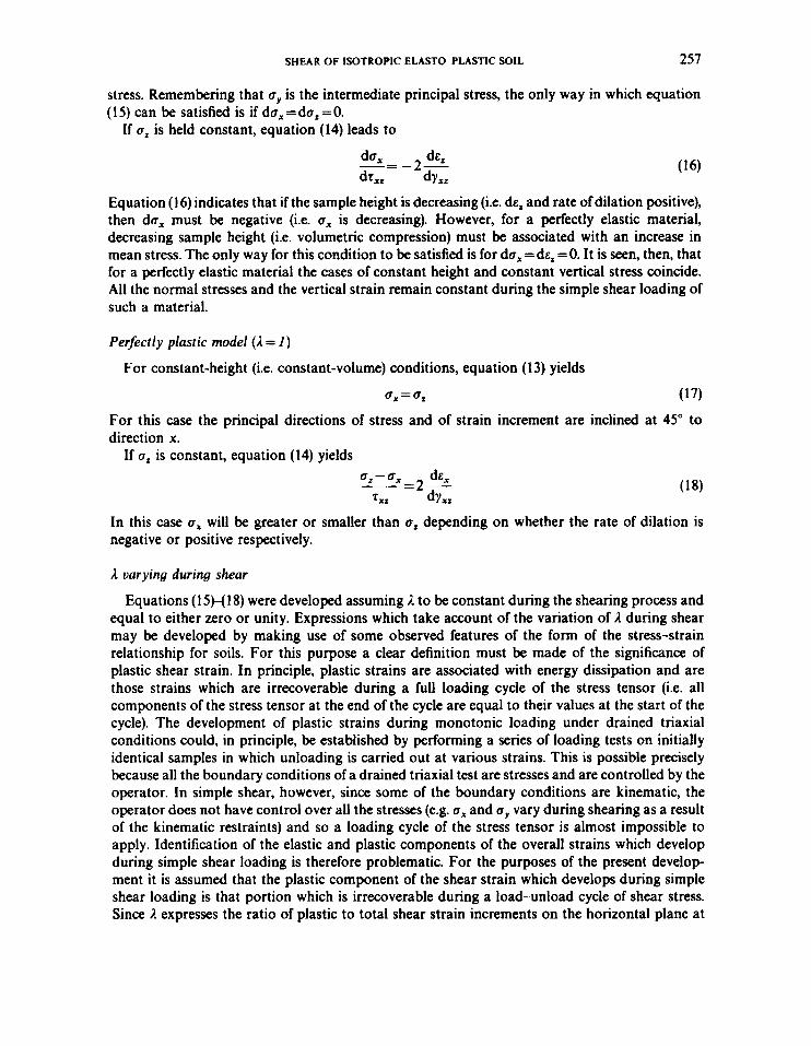
Figures 4(a)-4(d) show load-unload curves obtained in four direct simple shear tests which were performed on undisturbed samples of soft clay from the Israel continental shelf. Indicative properties of the clay as well as results of monotonic and cyclic direct simple shear tests have been presented by Frydman et d.16 The tests were all performed slowly at constant volume (i.e. the sample height was held constant). In Figure 5 the resulting values of a are shown as a function of shear strain yrx; obviously, more test results would be desirable in order to define this function more confidently, but it appears that a straight-line relationship on a semilogarithmic plot is a reasonable fit to the data. This relationship may be expressed by
a =@45 +0*33log(y,,) (19)
Where unload data are not available, it may be possible to make use of stress-strain models which have been found to reasonably describe the behaviour of real soils in order to obtain an estimate of a and 1 during shearing. A model for the load-unload behaviour of structural materials first suggested by Masing" has been applied recently to describe the behaviour of soils under cyclic loading (e.g. References 18 and 19). According to this model, if the stressstrain relationship during first loading is expressed by
0.4 - I @ 0.5
? a
3 In v)
0
0 'D
.- &
.- - $ 0.3 C 0 0 \
! hr v) v) a) Ln
0 W .c
-5 0.1
L
0.0 0
Shear Strain (w) Consolidation Pressure GO - 100 kN/rn2
Figure qa). Normalized strcss-strain diagram, test SFl
259
0.5
0.4
0.3
0.2
0.1
0.0
Shear Strain (w) Consolidation Pressure UZO - 100 kN/m2
Figure 4(b). Normalized str*u-strain diagram, test SF2
0.5 -
0.4 --
0.3 --
0.2 --
0.1 -
0.0 -m 0 2
Shear St ra in (w) Consdidotion Pressure CZO - 200 kN/m2
Figure qc). Normalized strrss-strain diagram. test MT1

260 S. FRYDMAN AND M. TALESNICK
0.5
0.4
0.3
0 .2
0.1
0.0
Shear St ra in (95) Consolidcrion Pressure UZO - 200 k N , / n 3
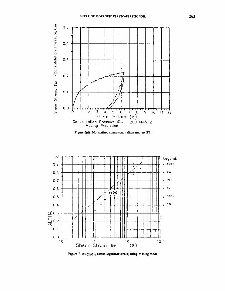
Figure qd). Normalized stm-strain diagram, Itst ST1
10
Figure 5. a = f ix /y ,x versus log (shear strain), t a t MTl
SHEAR OF ISOTROPIC ELASTO-PLASTIC SOIL 26 1
then if unloading occurs at the point y = y , and T='c,, the stress-strain relationship during unloading is expressed by
T-Ta
2
Equation (21) indicates that if the stress-strain curve for unloading is viewed as a loading curve with its origin at the point of stress reversal, it has the same shape as the curve for first loading except that the scale is enlarged by a factor of two. Iwan20.21 demonstrated that these equations are compatible with the behaviour of a simple model made up of a series of elasto-plastic elements (springs and frictional dampers) in series or in paralkl. Application of this frictional model to soils appears potentially attractive. If equation (21) is applicable to the unloading of soil in simple shear, it may be used, together with a given stress-strain function for first loading, to provide an estimate of the irrecoverable strains developed at any shearing stage, and conse- quently of the variation of a and 1 during shear.
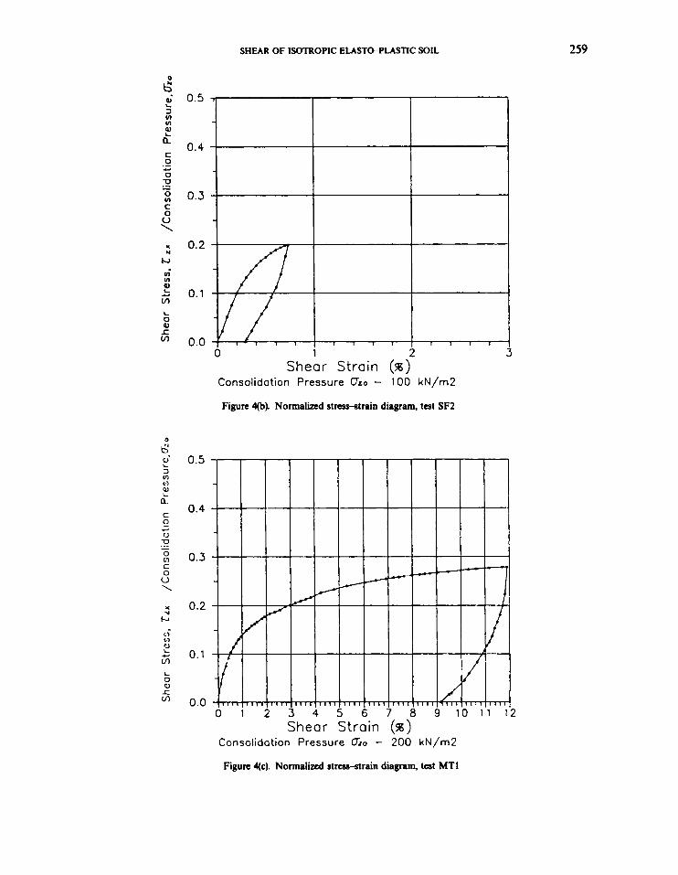
In Figures 6(a)-qd) the results of the tests previously presented in Figures 4(a)-4(d) have been redrawn, together with predicted unload curves consistent with the Masing model. It is seen that in all cases there is reasonable agreement between the pairs of curves, indicating that the Masing model provides a fair approximation for the unload stress-strain curve of the soft clay tested in direct simple shear. Using the Masing model, estimated unload curves can be constructed from any point along a loading curve, and so an estimate may be made of the variation of irrecoverable strain and of 1 throughout shearing. This procedure has been carried out using the monotonic loading curves obtained in a number of direct simple shear tests on normally consolidated clay
C 0 u \ x r(
r u) u1
E Y
ln L 0 al r ln
0.5
0.4
0.3
0.2
0.1
0.0
Shear Strain (%) Consolidation Pressure CTro - 100 kN/m2 - - - - Masing Prediction
Figure qa). Normalized strtss-strain diagram, test SFI

262
0.5 >
0.4
0.3 -
I t
S. FRYDMAN AND M. TALESNICK
, I ,
0.5
0.4
0.3
0.2
0.1
0.0
Shear Strain (w) Consolidation Pressure 0 2 0 - 100 kN/m2 - - - - Mosing Predict ion
Figure qb). Normalized strawtrain diagram, test SF2
Shear Strain (w) Consolidation Pressure GO - 200 kN/rn2 - - - - Mosing Predict ion
Figure qc). Normalized stress-strain diagram, test MT1
2
SHEAR OF ISOTROPIC ELASTePLASTIC SOIL 263
1 .o 0 9
0.8
0.7
0.6
0.5
0 . 4
4 0.3 I a -1 0.2 Q
0.1
0.0
0.5
0 .4
0.3
0.2
0.1
0.0
Figure qd). Normaliztd strcss-strain diagram, t a t ST1
Legend: . ss134
. 552
. t / T 1
+ ss4
6 5511 1
0 S T I
10
Figure 7. ~ = f i J y . ~ versus log(shcar strain) using Masing model
264 S. FRVDMAN AND M. TALESNICK
described by Frydman et al.16 The resulting relationship between a and shear strain is shown in Figure 7, superimposed on the relationship presented in Figure 5. It is seen that the use of the Masing model yields a relationship between a and shear strain which is scattered about the measured one; the model may be used to provide an estimate of this relationship.
ESTIMATION O F LATERAL STRESS a, DURING SHEARING
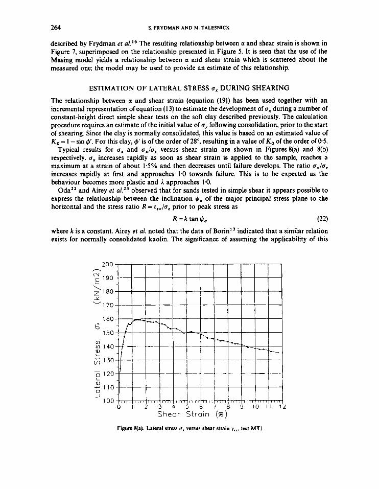
The relationship between a and shear strain (equation (19)) has been used together with an incremental representation of equation (1 3) to estimate the development of a, during a number of constant-height direct simple shear tests on the soft clay described previously. The calculation procedure requires an estimate of the initial value of a, following consolidation, prior to the start of shearing. Since the clay is normally consolidated, this value is based on an estimated value of KO = 1 -sin 9'. For this clay, 9' is of the order of 28", resulting in a value of KO of the order of 0 5 .
Typical results for a, and aJaZ versus shear strain are shown in Figures 8(a) and 8(b) respectively. a, increases rapidly as soon as shear strain is applied to the sample, reaches a maximum at a strain of about 1 5 % and then decreases until failure develops. The ratio a,/a, increases rapidly at first and approaches 1.0 towards failure. This is to be expected as the behaviour becomes more plastic and I approaches 1.0.
observed that for sands tested in simple shear it appears possible to express the relationship between the inclination $, of the major principal stress plane to the horizontal and the stress ratio R =T,,/a, prior to peak stress as
OdaZ2 and Airey et
R = k tan$, (22) where k is a constant. Airey et al. noted that the data of Borin13 indicated that a similar relation exists for normally consolidated kaolin. The significance of assuming the applicability of this
200 A
01
> 180 x -170
160
150
1 1 4 0
130
E 190
t;
2
0 120 - L Q,
0 -I
- 110
1 0 0 ' 1 ~ ~ ~ I I I I I I I I I 8 4 1 I I I I 1 1 1 1 I I I I I I I I I I I I I I I I 1 1 1 1 I I 1 I
0 1 2 3 4 5 6 7 8 9 1 0 1 1 1 Shear Strain (96)
Figure 8(a). Lateral stress 6, versus shear strain y,.. t a t MT1
2

SHEAR OF ISOTROPIC ELASTO-PLASTIC SOIL 265
1.2
6 1 . 1
- 0 .o 0.9 4 L e, > \ 0.8
? 0.7 m rn a, I
3; 0 . 6
Shear Strain (SB) Figure 8(b). u,/u, versus shear strain yz.. test MTI
relation to the soft clay studied in the present investigation is considered in the following. Referring to Figure 3(d), it is seen that
Using equation (22), equation (23) may be rewritten as
2tanJI, - 2R/k 2R - 1 - tan2 JI, 1 - R 2 / k 2 = 1 -a,/a,
This leads to
Airey et al. suggested that k is slightly greater than tan &v, where 4," was defined as the angle of friction for constant-volume shearing. In the present case k would be estimated to be between 0.4 and 0-5. Values of k =0.4 and 0 5 have been used in equation (25) to estimate the development of a, in the test previously analysed and a comparison of the two predictions is shown in Figure 9. There is seen to be a significant difference between the two. Whereas the former prediction shows Q, increasing up to a shear strain of about 1.5% and then decreasing, the prediction based on equation (22) shows a, increasing continuously. This latter trend is contrary to the one test result which has been reported for simple shear of normally consolidated clay in which 6, was measured; Wroth** showed that in a constant-volume simple shear test performed by Bonn" on normally consolidated kaolin, a, decreased during shearing. Unfortunately, other than this

266 S. FRYDMAN AND hi. TALESNICK
180
170
E 160 \ 5 150
140
6 130
0 120
A
ly
W
cn
? t; 110
: 100 -
a,
-1
4
0 90 m 0 1 2 3 4 2
Shear Strain (%)
LEGEND: . Present Model Airey e t 01. k= .4 a Airey e t at. k = . 5
Figure 9. Lateral stress IT, versus shear strain y x x , test MTI
one result, no additional data are available for clays, making it difficult to reach any definite conclusion regarding the trend to be expected for the variation in ox during shear. At the same time, it is worth noting that Budhu,14 testing loose and dense sand in a simple shear device equipped with pressure cells to measure boundary stresses, found that 0, increased and then decreased as shearing progressed. A similar trend may be interpreted from the results of tests on loose sand performed by Shibua and HightZ4 in which a simple shear mode of deformation was applied in a hollow cylinder apparatus. On the other hand, Pradhan et al.,” who also tested loose and dense sand under simple shear conditions in hollow cylinder equipment, reported Q,
increasing continuously up to failure. The prediction of development of Q, during a simple shear test shown in Figure 8(a) was based
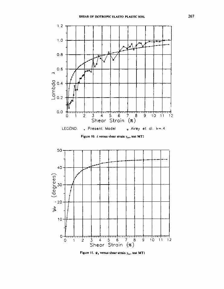
on an assumed relationship between 1 (the ratio of plastic to total shear strain increment) and shear strain obtained from equation (19). It is of interest to check the corresponding relationship which would be inferred by assuming the applicability of equation (22). This is done by inserting the values of Q, calculated from equation (25) at increasing shear strain during the test, together with measured values of the other stresses, into equation (13), yielding values of I. Figure 10 shows the relationship between I and shear strain in a typical test, as obtained by both approaches. The figure shows that according to the model previously developed using equation (19), the shear strain has a larger plastic component in the early stages of shearing than would be inferred by assuming equation (22). Towards failure, the I-values corresponding to the two approaches converge towards 1.0.
On the basis of the estimated development of Q, during shearing, as shown in Figure 8(a), the variation of JI, has been calculated and is shown against shear strain in Figure 11. Figure 12 shows the relationship between the stress ratio R = T,,/c, and both tan JI, and JI,. In both cases
SHEAR OF ISOTROPIC ELASTO-PLASTIC SOIL 267
1.2
1 .o
0.8
0.6 rc
0
-c)
0
0.4
E -I 0.2
G.0
Shear Strain (w) LEGEND: . Present Model Airey e t cl. k= .4
Figure 10. 1 versus shear strain yxI. test MTI
2

268
0.5
0.4
0.3 b" > CI I 1 0.2
CY
0.1
0.0
S. FRYDMAN AND M. TALESNICK
(wo) , (degrees) Figure IZ(a). R = r l , / o , versus +#, test MTI
3
SHEAR OF ISOTROPIC ELASTCPLASTIC SOIL 269
there is seen to be a reasonably linear relationship up to a stress ratio of about 02, at which stage tan JI, and JI, level off, approaching 1.0 and 45" respectively. The levelling off is contrary to the straight-line relationship up to failure associated with the assumption of equation (22). On the other hand, it is consistent with observations made by Shibua and Hight3* and Pradhan et a/.'' in their hollow cylinder 'simple shear' tests. Shibua and Hight found that the principal stress direction JI, rotated rapidly at the start of shearing, increasing almost linearly with R up to R = 0 3 and then staying approximately constant at about 40" as R was increased to failure. Pradhan et al. found that JI, increased rapidly at the start of shearing, reaching a value of about 40" at a very small shear strain (about 1%) and then stayed fairly constant until failure.
CONCLUSIONS
The assumption that soil behaves as an isotropic elasto-plastic material has been used for the interpretation of test data obtained from direct simple shear tests on a soft clay. The approach requires no assumptions regarding the form of the yield function, the flow rule or the hardening function and is applicable to any material which can be modelled by isotropic elasto-plasticity. It enables the estimation of the horizontal normal stress u, during shearing, and as a result, the rotation of the principal stress directions and the definition of the components of the stress tensor in the simple shear plane. Incorporation of additional assumptions would enable the estimation of the elastic and plastic components of the strain tensor.
Use of the model requires an assumption regarding the ratio of plastic to total shear strain, y;x/yzx, which develops during shear. The assumption used in this presentation was that the plastic shear strain is that portion of the strain which is non-recoverable during a shearing load-unload cycle. The model could be applied, however, using any other definition for the plastic shear strain. The interpretations of test data developed on the basis of the model appear to be consistent with features of some of the results of investigations reported in the literature; application of the model to tests in which boundary stresses have been measured would represent the ultimate test of its suitability, providing a useful indication of the degree of applicability of isotropic elasto-plasticity to soils.
REFERENCES
1. W. Kjcllman, Testing the shear strength of clay in Sweden'. Geotechnique, 2(3), 225-232 (1951). 2. G. R. Thiers and H. B. !hi, 'Cyclic strrss-strain characteristics of clay', 1. Soil Mech. Found. Eng., ASCE, 94(SM2),
3. K.-K. Ng and I. B. Donald, 'A hydraulic servocontrolled cyclic simple shear device', Proc. F i f h Australio-New
4. C. P. Wroth, The behaviour of normally consolidated clay as observed in undrained direct shear tats', Geotechnique,
5. K. H. Roscoe, T h e influence of strains in soil mechanics.', Geotechnique, 20(2), 129-170 (1970). 6. L. Bjcrmm and A. Landva, 'Direct simple shear tests on a Norwegian quick clay', Geotechnique, 16(1), 1-20 (1966). 7. D. W. Aircy and D. M. Wood, 'An evaluation of direct simple shear tests on clay', Geotechnique. 37(1), 25-35 (1987). 8. J. R. F. Arthur, R. G. James and K. H. Roscoe, T h e determination of stress fields during plane strain of a sand mass',
9. K. H. Roscoe, R. H. Bassett and E. R. L. Cole. 'Principal axes obsmcd during simple shear of a sand', Proc.
555-569 (1968).
Zealand Conf. on Geomechanics, Sydney, 1988, pp. 168-172
Jf(1). 37-43 (1987).
Geotechnlque, 14(4), 283-308 (1964).
Geotechnical Conf., Oslo, 1967, Vol. 1, pp. 231-237. 10. M. Budhu, The mechanism of failure under cyclic simple shear strain', Soils Found., 28(4), 119-129 (1988). 11. C. C. Ladd and L. Edgers 'Consolidated-undminaincd dircct-simple shear tests on saturated clays'. MI T Research
12. C. P. Wroth, The interpretation of insitu soil tests', Geotechnique. 34(4), 44949 (1984). 13. D. L. Borin, The behaviour of saturated kaolin in thc simpk shear apparatus', Ph.D. 7ksis. University of Cambridgz
14. M. Budhu, 'Lateral stresrar observed in two simple shear apparatus', 1. Georech. Eng., ASCE, 111(6), 698-711 (1985).
Report R72-82, 1972.
1973.

270 S. FRYDMAN AND M. TALESNICK
15. P. W. Mayne and F. H. Kulhawy, ‘K,-OCR relationships in soil’, 1. Geotech. Eng., ASCE, lOB(GT6), 851-872 (1982). 16. S. Frydman, M. Talesnick, G. Almagor and G. Wiseman, ‘Simple shear testing for the study of the earthquake
17. G. Masing, ‘Eigcnspannungcn und Verfestigung bcim Messing’, Roc. Int. Congr. on Applied Mechanics, 1926. pp.
18. W. B. Joyner and A. T. F. Chen, ‘Calculation of nonlinear ground response in earthquakes’. Bull. Seismol. Soc. Am,
19. K. Ishihara, ‘Evaluation of soil properties for usc in earthquake response analysis’, in R. Dungar and J. A. Studcr (eds),
20. W. D. Iwan, ‘A distributcdelement model for hysteresis and its steady state dynamic response', 1. Appl. Mech, 33,
21. W. D. Iwan, ‘On a class of models for the yielding behaviour of continuous and composite systems’. 1. Appl. Mech., 34,
22. M. Oda, ‘On strcss-dilatancy relation of sand in simple shear test’, Soils Found, 15(2), 17-29 (1975). 23. D. W. Airey, M. Budhu and D. M. Wood, ‘Some aspects of the behaviour of soils in simple shear’, in P. K. Banerjjcc
and R. Butterfield (cds), Developments in Soil Mechanics and Foundation Engineering-2 Stress-Strain Modelling in Soils, Elsevia, Amsterdam, 1985, pp. 185-213.
response of clay from the Israeli Continental Slope’, Marine Georechnol. 7 , 113-171 (1988).
332-335.
6S(5), 1315-1336 (1975).
Geomechanical Modelling in Engineering Practice. Balkema, Rotterdam, 1986, pp. 241-275.
893-900 (1966).
612-617 (1967).
24. S. Shibua and D. W. Hight, ‘On the stress path in simple shear’, Georechnique, 37(4), 511-515 (1987). 25. T. B. S. Pradhan, F. Tatsuoka and N. Horii, ‘Simple shear testing on sand in a torsional shear apparatus’, Soils Found.,
28(2), 95-1 12 (1988).