A. Stone Crusher Unit at Khasra No. 187, 188/1, 188/2 and ...
Upload
khangminh22Category
view
1download
0
INTERNATIONAL JOURNAL OF RESEARCH IN AERONAUTICAL AND MECHANICAL ENGINEERING
Vol.2 Issue.7,
July 2014.
Pgs: 102-113
Vishal N. Kshirsagar, Dr.S.K.Choudhary, Prof. A.P. Ninawe 102
ISSN (ONLINE): 2321-3051
INTERNATIONAL JOURNAL OF RESEARCH IN AERONAUTICAL AND MECHANICAL ENGINEERING
AN AUTOMATIC APPROACH FOR CAN/ PLASTIC BOTTLE CRUSHER MACHINE
Vishal N. Kshirsagar1, Dr.S.K.Choudhary2, Prof. A.P. Ninawe3
1 P.G. Student, Department of Mechanical Engg, KDK College of Engineering, Nagpur, R.T.M. Nagpur University, Maharashtra, India. [email protected]
2 Asst. Professor, Department of Mechanical Engg KDK College of Engg. Nagpur, RTM Nagpur University, Maharashtra, India. [email protected]
3 Asst. Professor, Department of Mechanical Engg KDK College of Engg. Nagpur, RTM Nagpur University, Maharashtra, India. [email protected]
Author Correspondence: Department of Mechanical Engg, KDK College of Engg., Nagpur. Tel.:- +919766939060. Email Address: - [email protected]
Abstract
In this project I am going to make this fully automatic by using electronics equipment like sensors, microcontroller, IC’s etc. along with mechanical components due to which crushed cans or bottles are need not to segregate from bin and also machine will not run idle. After all process has been done, this crusher may help us to understand the fabrication and designing process as well as electronics equipment that involved in this project. After the design has complete, it was transformed to its real product where the design is used for guideline. Crushers are major size reduction equipment used in mechanical and allied industries which crushes different types of soft and hard materials. The can or bottle crusher machine is widely used in beverage industries or in scrap dealers shop to reduce the volume of the cans/bottles. Hence in this design and analysis of various parts are necessary. The Electric Motor and a microcontroller make up the backbone for this project. Overall, this project involves processes like design, fabrication and assembling procedures. This project is mainly about generating a new concept of can/bottle crusher that would make easier to bring anywhere and easier to crush the can or bottle.
Keywords: Slider Crank Mechanism, Beverage Cans or Plastic Bottles, Electric Motor, Sensors, Microcontroller, IC’s.
1. Introduction
A can crusher can be defined as “A device used for crushing aluminum cans or plastic bottle for easier storage in recycling bins thereby giving you extra space by flattening of cans”. This project consists of designing and fabrication of an automatic can/bottle crusher machine. In order to reduce the waste, we planned to create a

INTERNATIONAL JOURNAL OF RESEARCH IN AERONAUTICAL AND MECHANICAL ENGINEERING
Vol.2 Issue.7,
July 2014.
Pgs: 102-113
Vishal N. Kshirsagar, Dr.S.K.Choudhary, Prof. A.P. Ninawe 103
can/bottle crusher that will reduce the volume of aluminum cans/plastic bottles by approximately seventy percent by which transportation volume will increase and transportation cost will reduce. Can crushers are primarily used to save space and for recycling. Also the purpose of this project is to understand the fundamental knowledge of design and mechanism by using fulcrum system and a simple mechanism property. A mechanical can/bottle crusher machine is basically one of the most aid able machines. It helps to reduce the pollution of the environment. Thus helps to create a better place to live in, apart from that, this can/bottle crusher can actually be the future mode of recycles apart from the recycle bins. It can be placed everywhere, in the park, houses, restaurants, malls, canteens even in cars. Using a similar type of a design from the diagram below, but with an added bin below the can crusher concept of recycling can be applied. In this project, development of a recycle bin can/bottle crusher so the cans might crush as flat and look as symmetrically as possible and inserted the bin. The designs are an environment friendly and use simple mechanism properties. The design is so done that the knowledge of designing, mechanism and forces. The study of manufacturing was very important in order to carry out this project to ensure that what are needs to do. This project is about designing and fabricating the Recycle Bin Can/Bottle Crusher Machine to help people easy to crush the can as well as bottle and bring anywhere. This project involves the process of designing the different parts of this crusher machine considering forces and ergonomic factor for people to use. After the design has completed, it was transformed to its real product where the design is used for guideline. This project is mainly about generating a new concept of can/bottle crusher that would make easier to bring anywhere and easier to crush the can or bottle. This machine is developed solely for the purpose of recycling as plastic bottles are harmful to environment and aluminum to plants growth. Many people recycles items like paper, glass, and aluminum, While these efforts are a vital part of the process, the true recycling path continues long after recyclables are collected from household bins or community drop-off centers etc. Collecting, processing, manufacturing, and purchasing recycled products create a closed circle or loop that ensures the value of recycling. Recycling is a series of activities that includes the collection of used, reused, or unused items that would otherwise be considered waste, sorting and processing the recyclable products into raw materials, and remanufacturing the recycled raw materials into new products.
2. Concept
This machine is basically works on the principle of Single Slider Crank Mechanism which is the heart of this machine and it converts rotary motion into a reciprocating machine to crush the Cans/Plastic bottles. In this, link 1 is fixed and link 2 which is a crank is rotating about fixed link 1 and converts this rotary motion into the reciprocating motion of slider (corresponds to the link 4) by means of connecting rod which corresponds to the link 3. This is the inversion of single slider crank which is obtained by fixing link 1.
Fig.1- Single Slider Crank Mechanism
INTERNATIONAL JOURNAL OF RESEARCH IN AERONAUTICAL AND MECHANICAL ENGINEERING
Vol.2 Issue.7,
July 2014.
Pgs: 102-113
Vishal N. Kshirsagar, Dr.S.K.Choudhary, Prof. A.P. Ninawe 104
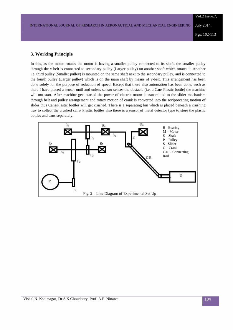
3. Working Principle
In this, as the motor rotates the motor is having a smaller pulley connected to its shaft, the smaller pulley through the v-belt is connected to secondary pulley (Larger pulley) on another shaft which rotates it. Another i.e. third pulley (Smaller pulley) is mounted on the same shaft next to the secondary pulley, and is connected to the fourth pulley (Larger pulley) which is on the main shaft by means of v-belt. This arrangement has been done solely for the purpose of reduction of speed. Except that there also automation has been done, such as there I have placed a sensor until and unless sensor senses the obstacle (i.e. a Can/ Plastic bottle) the machine will not start. After machine gets started the power of electric motor is transmitted to the slider mechanism through belt and pulley arrangement and rotary motion of crank is converted into the reciprocating motion of slider thus Cans/Plastic bottles will get crushed. There is a separating bin which is placed beneath a crushing tray to collect the crushed cans/ Plastic bottles also there is a sensor of metal detector type to store the plastic bottles and cans separately.
B - Bearing M – Motor S – Shaft P – Pulley S - Slider C – Crank C.R. - Connecting Rod
Fig. 2 – Line Diagram of Experimental Set Up

INTERNATIONAL JOURNAL OF RESEARCH IN AERONAUTICAL AND MECHANICAL ENGINEERING
Vol.2 Issue.7,
July 2014.
Pgs: 102-113
Vishal N. Kshirsagar, Dr.S.K.Choudhary, Prof. A.P. Ninawe 105
The different electronic components which help to make this machine automatic are explained as follows:
1. ATMega16 Microcontroller
The ATmega16 is a low-power CMOS 8-bit microcontroller based on the AVR enhanced RISC architecture. By executing powerful instructions in a single clock cycle, the ATmega16 achieves throughputs approaching 1 MIPS per MHz allowing the system designed to optimize power consumption versus processing speed.
Fig. 3 – Designed Experimental Set Up
Metal Detector Sensor
Printed Circuit Board
Hopper
Crushing Tray
Separating Bin
Electric Motor
Fig. 4 - ATMega16 Microcontroller

INTERNATIONAL JOURNAL OF RESEARCH IN AERONAUTICAL AND MECHANICAL ENGINEERING
Vol.2 Issue.7,
July 2014.
Pgs: 102-113
Vishal N. Kshirsagar, Dr.S.K.Choudhary, Prof. A.P. Ninawe 106
Pin Descriptions VCC: Digital supply voltage. GND: Ground. Port A (PA7..PA0): Port A serves as the analog inputs to the A/D Converter. Port A also serves as an 8-bit bi-directional I/O port, if the A/D Converter is not used. Port pins can provide internal pull-up resistors (selected for each bit). The Port A output buffers have symmetrical drive characteristics with both high sink and source capability. When pins PA0 to PA7 are used as inputs and are externally pulled low, they will source current if the internal pull-up resistors are activated. Port B (PB7..PB0): Port B is an 8-bit bi-directional I/O port with internal pull-up resistors (selected for each bit). The Port B output buffers have symmetrical drive characteristics with both high sink and source capability. As inputs, Port B pins that are externally pulled low will source current if the pull-up resistors are activated. The Port B pins are tri-stated when a reset condition becomes active, even if the clock is not running. Port C (PC7..PC0): Port C is an 8-bit bi-directional I/O port with internal pull-up resistors (selected for each bit). The Port C output buffers have symmetrical drive characteristics with both high sink and source capability. As inputs, Port C pins that are externally pulled low will source current if the pull-up resistors are activated. The Port C pins are tri-stated when a reset condition becomes active, even if the clock is not running. If the JTAG interface is enabled, the pull-up resistors on pins PC5(TDI), PC3(TMS) and PC2(TCK) will be activated even if a reset occurs. Port C also serves the functions of the JTAG interface and other special features of the Port D (PD7..PD0) Port D is an 8-bit bi-directional I/O port with internal pull-up resistors (selected for each bit). The Port D output buffers have symmetrical drive characteristics with both high sink and source capability. As inputs, Port D pins that are externally pulled low will source current if the pull-up resistors are activated. The Port D pins are tri-stated when a reset condition becomes active, even if the clock is not running. RESET: Reset Input. A low level on this pin for longer than the minimum pulse length will generate a reset, even if the clock is not running. Shorter pulses are not guaranteed to generate a reset. XTAL1: Input to the inverting Oscillator amplifier and input to the internal clock operating circuit. XTAL2: Output from the inverting Oscillator amplifier. AVCC: AVCC is the supply voltage pin for Port A and the A/D Converter. It should be externally connected to VCC, even if the ADC is not used. If the ADC is used, it should be connected to VCC through a low-pass filter. AREF: AREF is the analog reference pin for the A/D Converter.
INTERNATIONAL JOURNAL OF RESEARCH IN AERONAUTICAL AND MECHANICAL ENGINEERING
Vol.2 Issue.7,
July 2014.
Pgs: 102-113
Vishal N. Kshirsagar, Dr.S.K.Choudhary, Prof. A.P. Ninawe 107
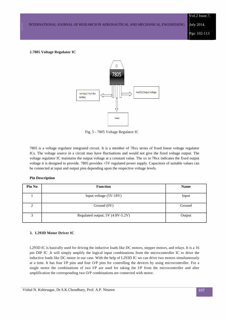
2.7805 Voltage Regulator IC
7805 is a voltage regulator integrated circuit. It is a member of 78xx series of fixed linear voltage regulator ICs. The voltage source in a circuit may have fluctuations and would not give the fixed voltage output. The voltage regulator IC maintains the output voltage at a constant value. The xx in 78xx indicates the fixed output voltage it is designed to provide. 7805 provides +5V regulated power supply. Capacitors of suitable values can be connected at input and output pins depending upon the respective voltage levels.
Pin Description
Pin No Function Name
1 Input voltage (5V-18V) Input
2 Ground (0V) Ground
3 Regulated output; 5V (4.8V-5.2V) Output
3. L293D Motor Driver IC
L293D IC is basically used for driving the inductive loads like DC motors, stepper motors, and relays. It is a 16 pin DIP IC .It will simply amplify the logical input combinations from the microcontroller IC to drive the inductive loads like DC motor in our case. With the help of L293D IC we can drive two motors simultaneously at a time. It has four I/P pins and four O/P pins for controlling the devices by using microcontroller. For a single motor the combinations of two I/P are used for taking the I/P from the microcontroller and after amplification the corresponding two O/P combinations are connected with motor.
Fig. 5 - 7805 Voltage Regulator IC

INTERNATIONAL JOURNAL OF RESEARCH IN AERONAUTICAL AND MECHANICAL ENGINEERING
Vol.2 Issue.7,
July 2014.
Pgs: 102-113
Vishal N. Kshirsagar, Dr.S.K.Choudhary, Prof. A.P. Ninawe 108
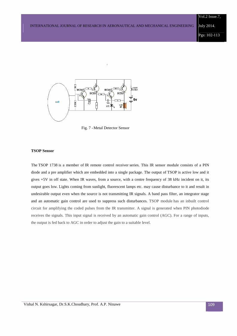
4. Metal Detector
This metal detector circuit electronic project is based on transistors and will provide an visual indication using
a LED and an acoustic sound that will inform you when a metal is detected. This detector must be powered
from a simple 9 volt battery an it needs some little adjustments. To adjust this circuit you need to power it on
and move it away from any metal object .You must turn RV2 potentiometer fully clockwise and RV2
potentiometer anti-clockwise. With SW1pressed you must turn RV1 anti-clockwise until the LED is about to
light and all further sensitivity adjustments should now be done by turning RV2. To set maximum sensitivity,
turn RV2 until the LED is weakly lit. The brightness of the Led indicates the distance and the size of the metal
object detected .The L1 and L2 coil must be on the same support that must have a 8mm diameter. L1 has 120
turns from 0.3mm Cu wire and L2 has 43 turns from 0.3mm Cu wire.
Fig. 6 - L293D Motor Driver IC
INTERNATIONAL JOURNAL OF RESEARCH IN AERONAUTICAL AND MECHANICAL ENGINEERING
Vol.2 Issue.7,
July 2014.
Pgs: 102-113
Vishal N. Kshirsagar, Dr.S.K.Choudhary, Prof. A.P. Ninawe 109
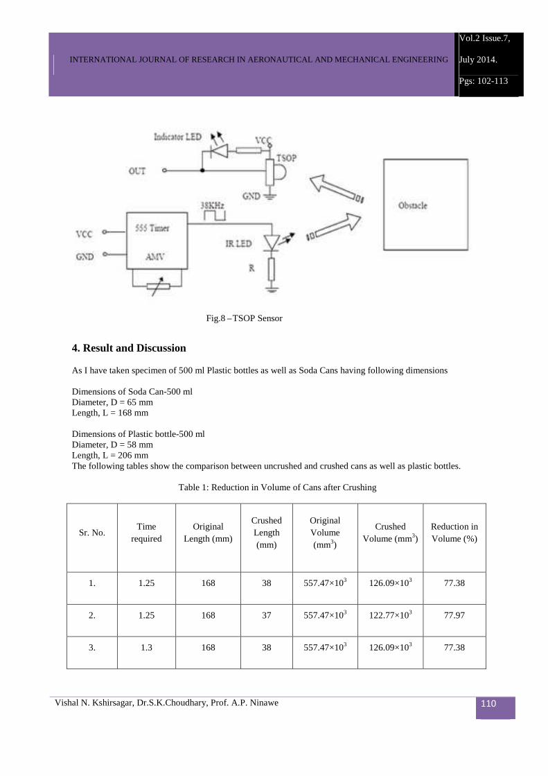
TSOP Sensor
The TSOP 1738 is a member of IR remote control receiver series. This IR sensor module consists of a PIN
diode and a pre amplifier which are embedded into a single package. The output of TSOP is active low and it
gives +5V in off state. When IR waves, from a source, with a centre frequency of 38 kHz incident on it, its
output goes low. Lights coming from sunlight, fluorescent lamps etc. may cause disturbance to it and result in
undesirable output even when the source is not transmitting IR signals. A band pass filter, an integrator stage
and an automatic gain control are used to suppress such disturbances. TSOP module has an inbuilt control
circuit for amplifying the coded pulses from the IR transmitter. A signal is generated when PIN photodiode
receives the signals. This input signal is received by an automatic gain control (AGC). For a range of inputs,
the output is fed back to AGC in order to adjust the gain to a suitable level.
Fig. 7 - Metal Detector Sensor
INTERNATIONAL JOURNAL OF RESEARCH IN AERONAUTICAL AND MECHANICAL ENGINEERING
Vol.2 Issue.7,
July 2014.
Pgs: 102-113
Vishal N. Kshirsagar, Dr.S.K.Choudhary, Prof. A.P. Ninawe 110
4. Result and Discussion
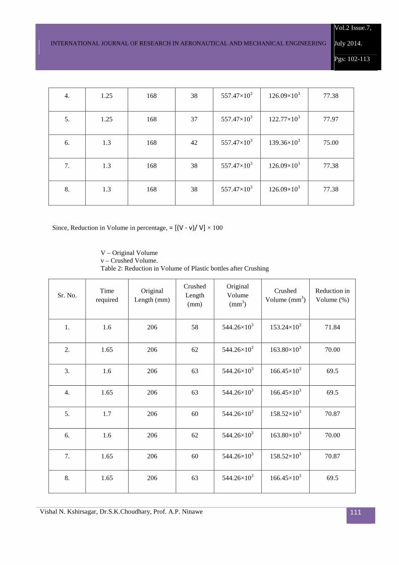
As I have taken specimen of 500 ml Plastic bottles as well as Soda Cans having following dimensions Dimensions of Soda Can-500 ml Diameter, D = 65 mm Length, L = 168 mm Dimensions of Plastic bottle-500 ml Diameter, D = 58 mm Length, L = 206 mm The following tables show the comparison between uncrushed and crushed cans as well as plastic bottles.
Table 1: Reduction in Volume of Cans after Crushing
Sr. No. Time
required Original
Length (mm)
Crushed Length (mm)
Original Volume (mm3)
Crushed Volume (mm3)
Reduction in Volume (%)
1. 1.25 168 38 557.47×10³ 126.09×10³ 77.38
2. 1.25 168 37 557.47×10³ 122.77×10³ 77.97
3. 1.3 168 38 557.47×10³ 126.09×10³ 77.38
Fig.8 – TSOP Sensor
INTERNATIONAL JOURNAL OF RESEARCH IN AERONAUTICAL AND MECHANICAL ENGINEERING
Vol.2 Issue.7,
July 2014.
Pgs: 102-113
Vishal N. Kshirsagar, Dr.S.K.Choudhary, Prof. A.P. Ninawe 111
4. 1.25 168 38 557.47×10³ 126.09×10³ 77.38
5. 1.25 168 37 557.47×10³ 122.77×10³ 77.97
6. 1.3 168 42 557.47×10³ 139.36×10³ 75.00
7. 1.3 168 38 557.47×10³ 126.09×10³ 77.38
8. 1.3 168 38 557.47×10³ 126.09×10³ 77.38
Since, Reduction in Volume in percentage, = [(V - v)/ V] × 100
V – Original Volume v – Crushed Volume. Table 2: Reduction in Volume of Plastic bottles after Crushing
Sr. No. Time
required Original
Length (mm)
Crushed Length (mm)
Original Volume (mm3)
Crushed Volume (mm3)
Reduction in Volume (%)
1. 1.6 206 58 544.26×10³ 153.24×10³ 71.84
2. 1.65 206 62 544.26×10³ 163.80×10³ 70.00
3. 1.6 206 63 544.26×10³ 166.45×10³ 69.5
4. 1.65 206 63 544.26×10³ 166.45×10³ 69.5
5. 1.7 206 60 544.26×10³ 158.52×10³ 70.87
6. 1.6 206 62 544.26×10³ 163.80×10³ 70.00
7. 1.65 206 60 544.26×10³ 158.52×10³ 70.87
8. 1.65 206 63 544.26×10³ 166.45×10³ 69.5

INTERNATIONAL JOURNAL OF RESEARCH IN AERONAUTICAL AND MECHANICAL ENGINEERING
Vol.2 Issue.7,
July 2014.
Pgs: 102-113
Vishal N. Kshirsagar, Dr.S.K.Choudhary, Prof. A.P. Ninawe 112
5. Conclusion
From the above study, it is observed that by arranging different mechanical components along with electronic components machine can be made automatic one to crush the Cans as well as plastic bottles solely to reduce the volume. Thus human efforts can be reduced as well as time also, because sorting system is installed there to separate the bottles and cans to reduce the human fatigue. As above results shows that the volume can be reduced to a large extent i.e. near about seventy percent volume can easily be reduced, thus transportation volume can be increased and transportation cost can be reduced to a large extent and these can be reuse.
References
[1] Mr. Ramkrushna S. More, Sunil J. Rajpal publishes a review paper on “Study of Jaw Plates of Jaw Crusher”. International Journal of Modern Engineering Research (IJMER), Vol.3, Issue.1, Jan-Feb. 2013 pp-518-522 ISSN: 2249-6645. [2] Mr. Shadab Husain, Mohammad Shadab Sheikh presents paper on “Can crusher machine using scotch yoke mechanism”. IOSR Journal of Mechanical and Civil Engineering (IOSR-JMCE) e-ISSN: 2278-2064, p-ISSN: 2320-334X PP 60-63. [3] Mr. Shoichi Kitani, Keiichiro Hayashi, mitsuhiro Yamashina and Keiko Takei Presents a papre on “An Automatic Sorting System For Glass Bottles, Cans and Plastic Bottles”. [4] Mr. Patel Ronak A. presents a paper on “Slider Crank Mechanism for Four bar linkage”. IJSRD - International Journal for Scientific Research & Development| Vol. 1, Issue 9, 2013 | ISSN (online): 2321-0613. [5]Cao Jinxi, Qin Zhiyu, Rong Xingfu, Yang Shichun presents a paper on “ Experimntal Research on Crushing Force and its Distribution Feature in Jaw Crusher ” 2007 Second IEEE Conference on Industrial Electronics and Applications. 1-4244-0737-0/07/$20.00© 2007 IEEE. [6] Rob Legtenberg, Erwin Berenschot, Miko Elwenspoek and Jan Fluitman presents a paper on “Electrostatic Microactuators With Integrated Gear Linkages For Mechanical Power Transmission”. 0-7803-2985-6196 $5.00 © 1996 IEEE. [7] C. LAROUCI(*), G.FELD (**), JP.DIDIER(*) presents a paper on “Modeling and control of the vehicle transmission chain using electric actuators”. 1-4244-0136-4/06/$20.00 © 2006 IEEE [8] Tiehong GaoJunyi Cao, Dunyu Zhu, Jinzhang Zhi presents a paper on “Study on Kinematics Analysis and Mechanism Realization of a Novel Robot Walking on Water Surface”. Proceedings of the 2007 IEEE International Conference on Integration Technology March 20 - 24, 2007, Shenzhen, China. 1-4244-1092-4/07/$25.00 © 2007IEEE.

INTERNATIONAL JOURNAL OF RESEARCH IN AERONAUTICAL AND MECHANICAL ENGINEERING
Vol.2 Issue.7,
July 2014.
Pgs: 102-113
Vishal N. Kshirsagar, Dr.S.K.Choudhary, Prof. A.P. Ninawe 113
A Brief Author Biography Vishal N. Kshirsagar1 – Presently pursuing M Tech in Mechanical Engineering Design from RTMNU, Nagpur University, Nagpur. Maharashtra, India. Dr.S.K.Choudhary2 –Presently working as an Associate Professor in KDK College of Engg., RTMNU, Nagpur University, Nagpur, Maharashtra, India. Prof. A.P. Ninawe3 -Presently working as an Assistant Professor in KDK College of Engg., RTMNU, Nagpur University,Nagpur,Maharashtra,India.
Copyright © 2022 FDOKUMEN