SHiP Experiment - CERN Document Server
81
CERN-SPSC-2019-010 / SPSC-SR-248 25/01/2019 SHiP Experiment P ROGRESS REPORT SHiP Collaboration * Abstract Progress on the SHiP experiment and the Comprehensive Design Study (CDS) is presented with focus on the re-optimization, the simulation studies and the detector developments, including beam tests since the Technical Proposal, and the physics performance. This doc- ument is complementing the proposal submitted to the update of the European Strategy for Particle Physics (ESPPU). Keywords SHiP, Comprehensive Design Study, SPS, CERN * Author list: http://cern.ch/ship/Constitution/SHiP_Authorlist_nov2018.pdf
-
Upload
khangminh22 -
Category
Documents
-
view
1 -
download
0
Transcript of SHiP Experiment - CERN Document Server
CER
N-S
PSC
-201
9-01
0/
SPSC
-SR
-248
25/0
1/20
19
SHiP Experiment
PROGRESS REPORT
SHiP Collaboration∗
Abstract
Progress on the SHiP experiment and the Comprehensive Design Study (CDS) is presentedwith focus on the re-optimization, the simulation studies and the detector developments,including beam tests since the Technical Proposal, and the physics performance. This doc-ument is complementing the proposal submitted to the update of the European Strategy forParticle Physics (ESPPU).
KeywordsSHiP, Comprehensive Design Study, SPS, CERN
∗Author list: http://cern.ch/ship/Constitution/SHiP_Authorlist_nov2018.pdf
Contents
1 Introduction . . . . . . . . . . . . . . . . . . . . . . . . . . . . . . . . . . . . . . . . . . 31.1 Physics Landscape in 2015 . . . . . . . . . . . . . . . . . . . . . . . . . . . . . . . . . 31.2 Physics landscape in 2018 . . . . . . . . . . . . . . . . . . . . . . . . . . . . . . . . . . 31.3 Overview of the SHiP developments and advances since the TP . . . . . . . . . . . . . . 52 Proton beam and experimental facility . . . . . . . . . . . . . . . . . . . . . . . . . . . . 72.1 Proton yield and beam delivery . . . . . . . . . . . . . . . . . . . . . . . . . . . . . . . 72.1.1 Operation with slow beam extraction in bunched mode . . . . . . . . . . . . . . . . . 102.2 Target system . . . . . . . . . . . . . . . . . . . . . . . . . . . . . . . . . . . . . . . . 102.3 Experiment layout . . . . . . . . . . . . . . . . . . . . . . . . . . . . . . . . . . . . . . 112.3.1 Muon shield . . . . . . . . . . . . . . . . . . . . . . . . . . . . . . . . . . . . . . . . 122.3.2 Vacuum vessel . . . . . . . . . . . . . . . . . . . . . . . . . . . . . . . . . . . . . . 172.4 Experimental Area . . . . . . . . . . . . . . . . . . . . . . . . . . . . . . . . . . . . . 212.5 Potential siting of a search for Lepton Flavour Violation experiment . . . . . . . . . . . 223 Simulation and Reconstruction . . . . . . . . . . . . . . . . . . . . . . . . . . . . . . . . 233.1 Simulation . . . . . . . . . . . . . . . . . . . . . . . . . . . . . . . . . . . . . . . . . . 233.2 SHiP detector setup in the simulation . . . . . . . . . . . . . . . . . . . . . . . . . . . . 253.3 Reconstruction . . . . . . . . . . . . . . . . . . . . . . . . . . . . . . . . . . . . . . . 293.4 Validation of the SHiP simulation in test beam . . . . . . . . . . . . . . . . . . . . . . . 293.4.1 Measurement of the muon spectrum . . . . . . . . . . . . . . . . . . . . . . . . . . . 293.4.2 Measurement of charm production in a thick target . . . . . . . . . . . . . . . . . . . 304 Scattering and Neutrino Detector . . . . . . . . . . . . . . . . . . . . . . . . . . . . . . . 334.1 SND spectrometer magnet . . . . . . . . . . . . . . . . . . . . . . . . . . . . . . . . . 344.2 Emulsion Target . . . . . . . . . . . . . . . . . . . . . . . . . . . . . . . . . . . . . . . 364.3 Target Tracker and Downstream Tracker . . . . . . . . . . . . . . . . . . . . . . . . . . 384.3.1 µ-RWELL . . . . . . . . . . . . . . . . . . . . . . . . . . . . . . . . . . . . . . . . . 384.3.2 Scintillating Fibre Tracker . . . . . . . . . . . . . . . . . . . . . . . . . . . . . . . . 394.4 Muon identification system . . . . . . . . . . . . . . . . . . . . . . . . . . . . . . . . . 405 Decay Spectrometer . . . . . . . . . . . . . . . . . . . . . . . . . . . . . . . . . . . . . . 435.1 Surrounding Background Tagger . . . . . . . . . . . . . . . . . . . . . . . . . . . . . . 435.2 Spectrometer Straw Tracker . . . . . . . . . . . . . . . . . . . . . . . . . . . . . . . . . 445.3 Timing detector . . . . . . . . . . . . . . . . . . . . . . . . . . . . . . . . . . . . . . . 465.4 Electromagnetic Calorimeter . . . . . . . . . . . . . . . . . . . . . . . . . . . . . . . . 485.5 Muon system . . . . . . . . . . . . . . . . . . . . . . . . . . . . . . . . . . . . . . . . 486 Physics performance . . . . . . . . . . . . . . . . . . . . . . . . . . . . . . . . . . . . . . 516.1 Hidden Sector particle decays . . . . . . . . . . . . . . . . . . . . . . . . . . . . . . . . 516.1.1 HS background rejection . . . . . . . . . . . . . . . . . . . . . . . . . . . . . . . . . 516.1.2 HS signal sensitivities . . . . . . . . . . . . . . . . . . . . . . . . . . . . . . . . . . . 556.2 Sensitivity to Light Dark Matter . . . . . . . . . . . . . . . . . . . . . . . . . . . . . . 636.3 Physics with neutrinos . . . . . . . . . . . . . . . . . . . . . . . . . . . . . . . . . . . 656.3.1 ντ detection . . . . . . . . . . . . . . . . . . . . . . . . . . . . . . . . . . . . . . . . 66

6.3.2 Neutrino induced charm production . . . . . . . . . . . . . . . . . . . . . . . . . . . 686.3.3 ντ magnetic moment . . . . . . . . . . . . . . . . . . . . . . . . . . . . . . . . . . . 687 Project plan and cost . . . . . . . . . . . . . . . . . . . . . . . . . . . . . . . . . . . . . . 708 Status of the SHiP Collaboration . . . . . . . . . . . . . . . . . . . . . . . . . . . . . . . 73
2
1 IntroductionAn Expression of Interest [1] for a new experiment at CERN aiming at searching for hidden particles byusing the intense beam of protons of the SPS accelerator was submitted to the SPSC in 2013. The SHiPcollaboration that has been formed as a result, prepared in 2015 two documents describing the physicscase [2], and SHiP’s Technical Proposal (TP) [3, 4]. This report provides an update of the physics case,and describes the developments and advances in the technical design and in the evaluation of the physicsperformance of the proposed experiment since the TP. In parallel, a comprehensive design study of theexperimental facility has been performed by the Beam Dump Facility working group in the context ofthe Physics Beyond Colliders study group [5], and is published in [6].
1.1 Physics Landscape in 2015The discovery of the Higgs boson at the LHC in 2012 [7–10] made the Standard Model (SM) of element-ary particles complete - all the particles predicted by the model have been found, and their interactions,tested at the LHC till now, are consistent with those predicted by the SM. The triumph of the SM inparticle physics is accompanied by the success of the standard cosmological model (ΛCDM) based onEinstein’s General Relativity, allowing to describe the structure of the Universe by a small number ofparameters.
The era of guaranteed discoveries in particle physics has come to the end with the detection of theHiggs boson: for the particular value of the Higgs mass revealed by the LHC, the Standard Model remainsself-consistent and valid as an effective field theory up to a very high energy scale, possibly all the wayup to the scale of quantum gravity, the Planck scale [11–15]. It is merely intriguing that the particularvalues of the top-quark and Higgs boson masses lie very close to the criticality line, separating theregions of absolute stability and metastability of the electroweak vacuum (for a discussion and referencessee [11, 13, 16, 17].
The quest for new particles has not ended, however. We are certain that the SM does not representthe complete picture. Several well-established observational phenomena – neutrino masses and oscil-lations, dark matter, and the baryon asymmetry of the Universe – cannot be explained with the knownparticles alone and clearly indicate that New Physics (NP) should exist. Unfortunately, we do not havea definitive prediction where to find NP, nor do we have experimental clues on the masses, spins, andcoupling constants of the associated new particles.
1.2 Physics landscape in 2018In the last 3 years this picture did not change. The first ever run of proton-proton collisions at a centre-of-mass energy of 13 TeV has uncovered no significant deviations from the Standard Model [18–25]. Nordid other searches for new physics at particle physics laboratories worldwide. Intriguing hints of leptonflavour universality violations in semi-leptonic B decays have been reported in the recent years by Belleand LHCb [26–30]. Even if these hints are confirmed, it will not be possible to determine the scale ofNP with certainty.
Significant efforts in neutrino physics in recent years [31, 32] did not improve our knowledgeabout the mass scale of the new particles that could give rise to the neutrino masses and oscillations. Inparticular, taking aside different unconfirmed signals of eV-scale neutrino states (for a review see [33]),all the oscillation signatures can be explained by the SM extended by two additional sterile neutrinos ofessentially any mass ranging from a fraction of an eV to very high masses.
With regard to dark matter, the absence of detections in direct and indirect search experimentsof weakly interacting massive particles (WIMPs) in the GeV-TeV mass range has stimulated growinginterest in light dark matter (LDM) candidates: sterile neutrinos, axions, WIMP-like particles but withlower (sub-GeV) masses [34–36]. This has led to an important increase in activity around the correspond-ing experimental efforts: LDMX [37,38], MiniBooNe [39–41], T2K [41], CRESST [42], NA64 [43,44],
3
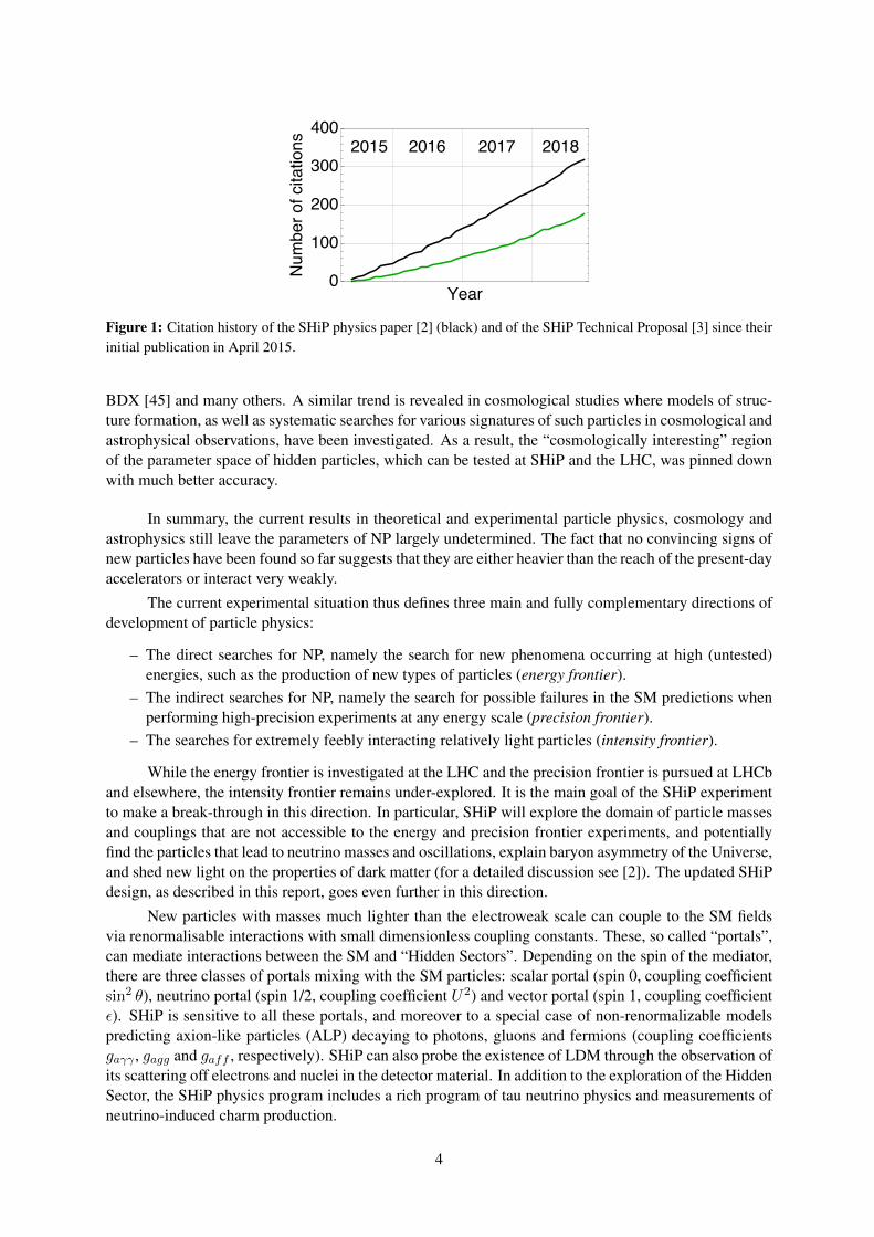
Figure 1: Citation history of the SHiP physics paper [2] (black) and of the SHiP Technical Proposal [3] since theirinitial publication in April 2015.
BDX [45] and many others. A similar trend is revealed in cosmological studies where models of struc-ture formation, as well as systematic searches for various signatures of such particles in cosmological andastrophysical observations, have been investigated. As a result, the “cosmologically interesting” regionof the parameter space of hidden particles, which can be tested at SHiP and the LHC, was pinned downwith much better accuracy.
In summary, the current results in theoretical and experimental particle physics, cosmology andastrophysics still leave the parameters of NP largely undetermined. The fact that no convincing signs ofnew particles have been found so far suggests that they are either heavier than the reach of the present-dayaccelerators or interact very weakly.
The current experimental situation thus defines three main and fully complementary directions ofdevelopment of particle physics:
– The direct searches for NP, namely the search for new phenomena occurring at high (untested)energies, such as the production of new types of particles (energy frontier).
– The indirect searches for NP, namely the search for possible failures in the SM predictions whenperforming high-precision experiments at any energy scale (precision frontier).
– The searches for extremely feebly interacting relatively light particles (intensity frontier).
While the energy frontier is investigated at the LHC and the precision frontier is pursued at LHCband elsewhere, the intensity frontier remains under-explored. It is the main goal of the SHiP experimentto make a break-through in this direction. In particular, SHiP will explore the domain of particle massesand couplings that are not accessible to the energy and precision frontier experiments, and potentiallyfind the particles that lead to neutrino masses and oscillations, explain baryon asymmetry of the Universe,and shed new light on the properties of dark matter (for a detailed discussion see [2]). The updated SHiPdesign, as described in this report, goes even further in this direction.
New particles with masses much lighter than the electroweak scale can couple to the SM fieldsvia renormalisable interactions with small dimensionless coupling constants. These, so called “portals”,can mediate interactions between the SM and “Hidden Sectors”. Depending on the spin of the mediator,there are three classes of portals mixing with the SM particles: scalar portal (spin 0, coupling coefficientsin2 θ), neutrino portal (spin 1/2, coupling coefficient U2) and vector portal (spin 1, coupling coefficientε). SHiP is sensitive to all these portals, and moreover to a special case of non-renormalizable modelspredicting axion-like particles (ALP) decaying to photons, gluons and fermions (coupling coefficientsgaγγ , gagg and gaff , respectively). SHiP can also probe the existence of LDM through the observation ofits scattering off electrons and nuclei in the detector material. In addition to the exploration of the HiddenSector, the SHiP physics program includes a rich program of tau neutrino physics and measurements ofneutrino-induced charm production.
4
SHiP has received a large amount of attention from the particle physics community. The SHiPphysics paper [2] is a highly cited document (see Figure 1), and many groups continue to explore the sci-entific potential of the experiment, making detailed predictions for models of feebly interacting particles.In the wake of the SHiP experiment, several dedicated intensity frontier experiments have been pro-posed in the recent years: CODEX-b [46], MATHUSLA [47–49], FASER [50–52]. Recognising theimportance of diversifying the search efforts, the CERN Management created in 2016 a dedicated studygroup “Physics Beyond Colliders” (PBC) [5]. Searches for heavy neutral leptons, dark photons, darkscalars, light dark matter, and other super-weakly interacting light particles has also been included in thescientific goals of many presently running experiments [39, 40, 42–44, 44, 53–67].
1.3 Overview of the SHiP developments and advances since the TPDespite an active program of searches for HS particles in many experiments, SHiP remains a uniquededicated experiment capable of reconstructing the decay vertex of an HS particle, measuring its invariantmass and providing particle identification of the decay products in an environment of extremely lowbackground. Moreover, SHiP is also optimised to search for LDM through scattering signatures and fortau neutrino physics.
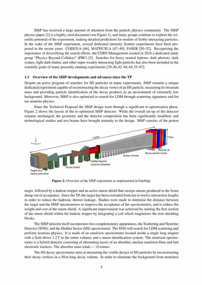
Since the Technical Proposal the SHiP design went through a significant re-optimisation phase.Figure 2 shows the layout of the re-optimised SHiP detector. While the overall set-up of the detectorremains unchanged, the geometry and the detector composition has been significantly modified, andtechnological studies and test beams have brought maturity to the design. SHiP consists of the proton
Figure 2: Overview of the SHiP experiment as implemented in FairShip.
target, followed by a hadron stopper and an active muon shield that sweeps muons produced in the beamdump out of acceptance. Since the TP, the target has been extended from ten to twelve interaction lengthsin order to reduce the hadronic shower leakage. Studies were made to minimise the distance betweenthe target and the SHiP spectrometers to improve the acceptance of the spectrometers, and to reduce theweight and cost of the muon shield. A significant improvement was achieved by starting the first sectionof the muon shield within the hadron stopper by integrating a coil which magnetises the iron shieldingblocks.
The SHiP detector itself incorporates two complementary apparatuses, the Scattering and NeutrinoDetector (SND), and the Hidden Sector (HS) spectrometer. The SND will search for LDM scattering andperform neutrino physics. It is made of an emulsion spectrometer located inside a single long magnetwith a field above 1.2 T in the entire volume, and a muon identification system. The emulsion spectro-meter is a hybrid detector consisting of alternating layers of an absorber, nuclear emulsion films and fastelectronic trackers. The absorber mass totals ∼ 10 tonnes.
The HS decay spectrometer aims at measuring the visible decays of HS particles by reconstructingtheir decay vertices in a 50 m long decay volume. In order to eliminate the background from neutrinos
5
interacting in the decay volume, it is maintained at a pressure ofO(10−3) bar. To maximise the sensitivityto HS particles the muon shield was shortened in combination with changing the shape of the decayvolume from an elliptic cylinder to a pyramidal frustum. The decay volume is followed by a largespectrometer with a rectangular acceptance of 5 m in width and 10 m in height.
The main element of the HS decay spectrometer is the straw tracker designed to accurately re-construct the decay vertex, the mass, and the impact parameter of the hidden particle trajectory at theproton target. The main change since the TP is the removal of the straw veto station that was located 5 minto the decay volume, and the increase of the straw diameter from 10 mm to 20 mm. Also, all trackerstations upstream and downstream of the magnet have now the same dimensions to ease construction andto reduce cost. The spectrometer dipole magnet is still based on a warm magnet with a fiducial apertureof 5× 10 m2 and a field integral of ∼0.5 Tm, but the coil and the fitting of the coil have been updated inorder to accommodate the rectangular vacuum tank of the spectrometer section.
A set of calorimeters and muon detectors provide particle identification, which is essential in dis-criminating between the very wide range of HS models. For the TP, the ECAL was optimised to provideelectron identification and π0 reconstruction. It has now been decided to extend the ECAL requirementsto include reconstruction of axion-like-particles (ALP) decaying to the two photon final state that is theunique way to discriminate between an ALP and a dark photon or a dark scalar. The current version ofECAL, called SplitCal, is a longitudinally segmented lead sampling calorimeter consisting of two partswhich are mechanically separated in the longitudinal direction. Each part is equipped with high spa-tial resolution layers in order to provide pointing with a resolution of ∼5 mrad for photons originatingfrom ALP decays. The longitudinal layer segmentation of SplitCal also improves the electron/hadronseparation. This opened the possibility to remove the HCAL detector without compromising the PIDperformance, and only leave the absorber for the purpose of muon filtering.
The muon system consists of four stations interleaved by three muon filters. The ECAL convertermaterial and the muon filters provide sufficient material budget to stop low momenta muons, such thatthe last muon station is only reached by muons with momenta exceeding 5.3 GeV/c. Since the TP, themuon system considers a new technology based on scintillating tiles with direct SIPMs readout. Thisoption provides better time resolution and is more robust against hit rate variations.
Since the key feature of the HS decay spectrometer design is to ensure efficient suppression of thevarious backgrounds, the tracking and particle identification are complemented by a dedicated timing de-tector with ∼100 ps resolution to provide a measure of time coincidence, in order to reject combinatorialbackgrounds. The decay volume is instrumented by the surround background tagger (SBT) whose pur-pose is to detect neutrino and muon inelastic interactions in the vacuum vessel walls which may producelong-lived neutral particles decaying in the decay volume and mimicking the HS signal events. Similarly,tagging of interactions in the upstream material of the muon identification system of the SND detector isprovided by the associated detector layers.
The muon shield and the SHiP detector systems are housed in an ∼120 m long underground ex-perimental hall at a depth of ∼15 m. To minimise the background induced by the flux of muons andneutrinos interacting with material in the vicinity of the detector, no infrastructure systems are locatedon the sides of the detector, and the hall is 20 m wide along its entire length.
6
2 Proton beam and experimental facilityThe Comprehensive Design Study for the experimental facility has been carried out by the Beam DumpFacility working group and by its dedicated subgroups in the context of the Physics Beyond Collidersstudy group [5], in close collaboration with the SHiP experiment. Based on the request put forward in theaddendum to the SHiP Technical Proposal [3], this study phase has consisted in a detailed elaborationof the SHiP operational scenario and in a preliminary design of the main components of the protondelivery, the target and the target complex, and the experimental area, together with a detailed evaluationof the radiological aspects and mitigation. Several critical items have been prototyped to demonstratethe concepts, notably the new type of three-way combined beam splitter/kicker magnet which allowsalternatively feeding protons to the EHN2 experimental hall and the SHiP experiment, and the targetsystem. In addition, it has been considered of high importance to perform a preliminary study of theintegration of the whole complex, and the civil engineering design and execution process, in order toproduce a more precise cost estimate and time line for the project. A full write-up of the ComprehensiveDesign Study for the facility is available ( [6] and references therein).
Following the global re-optimisation of the experimental configuration, significant progress hasalso been made on the development of the muon shield magnet system, the decay vacuum vessel andits interfaces with the spectrometer magnet, and on the detector layout. Based on this, it has also beenpossible to specify the experimental area and the requirements on the infrastructure and the services, andto draw up a preliminary plan for the installation of the detector.
The sections below summarise the status and the conclusions most relevant to the SHiP experimentconcerning the beam line and the experimental facility, and the status of the development of the muonshield and the decay vacuum vessel.
2.1 Proton yield and beam deliveryAt the SPS, the optimal experimental conditions for SHiP are obtained with a proton beam energy ofaround 400 GeV. The SHiP operational scenario implies returning to full exploitation of the capacity ofthe SPS. The request for the proton yield is based on a similar fraction of beam time as the past CERNNeutrinos to Gran Sasso (CNGS) program. A nominal beam intensity of 4× 10¹³ protons on target perspill is assumed for the design of the experimental facility and the detector. In the baseline scenario forSHiP, the beam sharing delivers an annual yield of 4 × 10¹⁹ protons to the Beam Dump Facility and atotal of 1019 to the other physics programs at the CERN North Area, while respecting the beam deliveryrequired by the HL-LHC . The physics sensitivities are based on acquiring a total of 2× 10²⁰ protons ontarget, which may thus be achieved in five years of nominal operation.
In the search for HS decay vertices the control of combinatorial background from random com-binations of residual muons relies on slow extraction of de-bunched beam with good uniformity over atimescale of around a second. The slow extraction is also required in order to dilute the large beam poweron the proton target. The probability of combinatorial events is directly related to the proton interactionrate in the target, which should have minimum variations. A machine study in 2017 showed the encour-aging results that the spill harmonic content in extractions of one second is not worse than in the longerspills used for the North Area. In order to measure the structure at very fine time resolution, and to takeit into account in the background studies, SHiP has contributed to upgrading the in-vacuum detector thatwas initially developed and installed by the UA9 collaboration to study crystal-assisted extraction [68].The detector is installed in the TT20 transfer line, downstream of the extraction region, and is based ona radiation-hard quartz bar which can be moved in and out of the beam. The Cherenkov light producedby the protons is read out with a photo-multiplier. With the upgrade the system is capable of meas-uring the proton intensity at rates up to 10 MHz. A series of measurements was performed in parallelto a BDF/SHiP Machine Development aiming at optimising the beam extraction process and aiming atexposing a prototype of the SHiP target. Figure 4 shows the measured proton intensity per 400 ns and
7
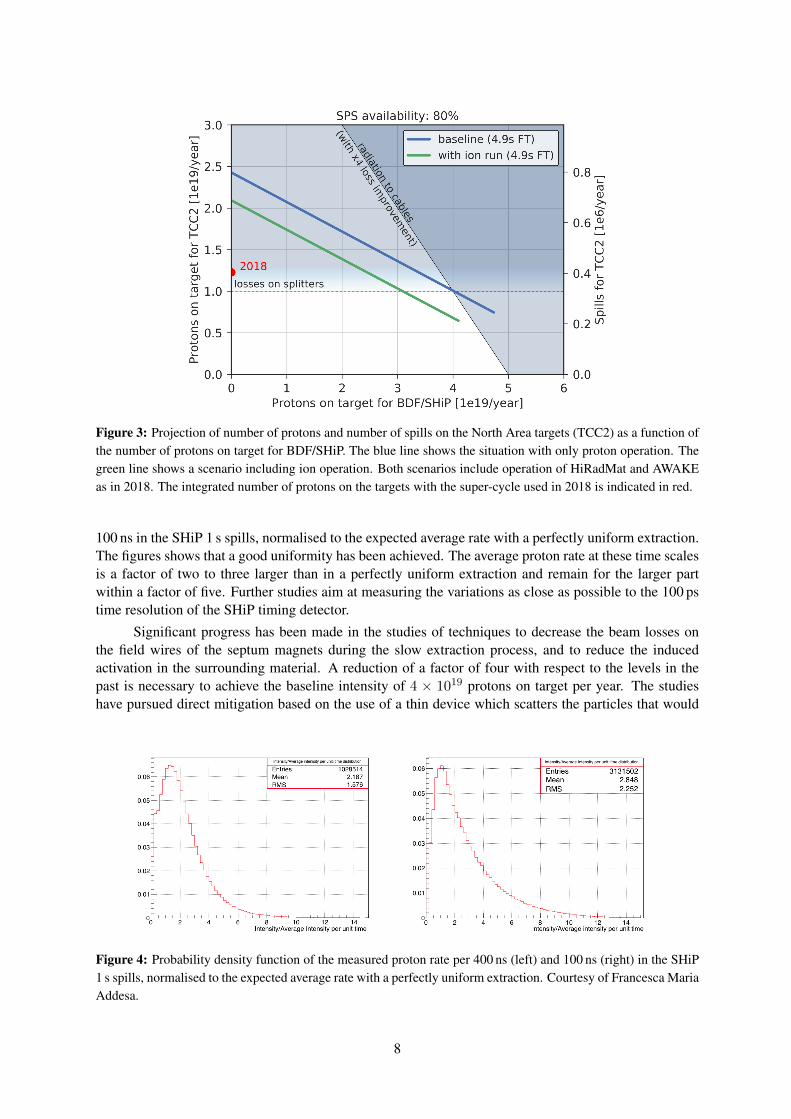
Figure 3: Projection of number of protons and number of spills on the North Area targets (TCC2) as a function ofthe number of protons on target for BDF/SHiP. The blue line shows the situation with only proton operation. Thegreen line shows a scenario including ion operation. Both scenarios include operation of HiRadMat and AWAKEas in 2018. The integrated number of protons on the targets with the super-cycle used in 2018 is indicated in red.
100 ns in the SHiP 1 s spills, normalised to the expected average rate with a perfectly uniform extraction.The figures shows that a good uniformity has been achieved. The average proton rate at these time scalesis a factor of two to three larger than in a perfectly uniform extraction and remain for the larger partwithin a factor of five. Further studies aim at measuring the variations as close as possible to the 100 pstime resolution of the SHiP timing detector.
Significant progress has been made in the studies of techniques to decrease the beam losses onthe field wires of the septum magnets during the slow extraction process, and to reduce the inducedactivation in the surrounding material. A reduction of a factor of four with respect to the levels in thepast is necessary to achieve the baseline intensity of 4 × 10¹⁹ protons on target per year. The studieshave pursued direct mitigation based on the use of a thin device which scatters the particles that would
Figure 4: Probability density function of the measured proton rate per 400 ns (left) and 100 ns (right) in the SHiP1 s spills, normalised to the expected average rate with a perfectly uniform extraction. Courtesy of Francesca MariaAddesa.
8
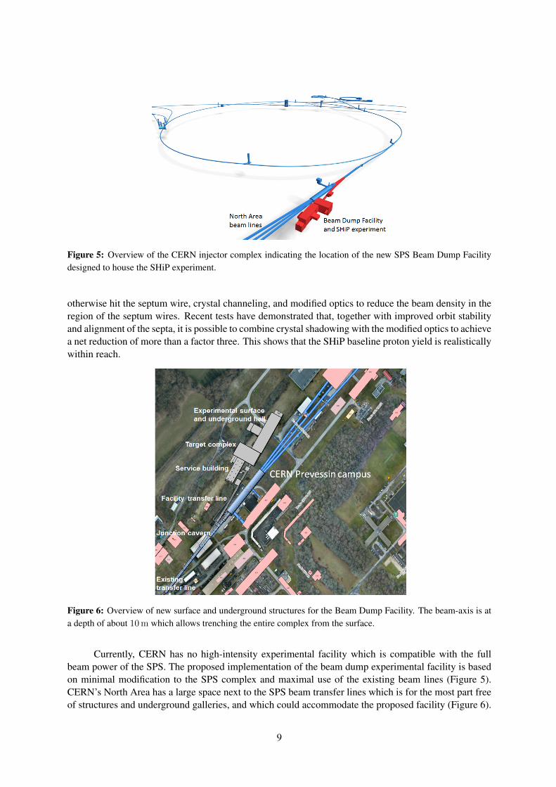
Figure 5: Overview of the CERN injector complex indicating the location of the new SPS Beam Dump Facilitydesigned to house the SHiP experiment.
otherwise hit the septum wire, crystal channeling, and modified optics to reduce the beam density in theregion of the septum wires. Recent tests have demonstrated that, together with improved orbit stabilityand alignment of the septa, it is possible to combine crystal shadowing with the modified optics to achievea net reduction of more than a factor three. This shows that the SHiP baseline proton yield is realisticallywithin reach.
Figure 6: Overview of new surface and underground structures for the Beam Dump Facility. The beam-axis is ata depth of about 10 m which allows trenching the entire complex from the surface.
Currently, CERN has no high-intensity experimental facility which is compatible with the fullbeam power of the SPS. The proposed implementation of the beam dump experimental facility is basedon minimal modification to the SPS complex and maximal use of the existing beam lines (Figure 5).CERN’s North Area has a large space next to the SPS beam transfer lines which is for the most part freeof structures and underground galleries, and which could accommodate the proposed facility (Figure 6).
9
In addition, it may be designed with future extensions in mind. A new type of three-way bi-polar beamsplitter/kicker magnet allows alternatively switching the beam to a short new transfer line for the beamdump experimental facility, and otherwise splitting the beam between the other existing experimentalfacilities in the CERN North Area operational.
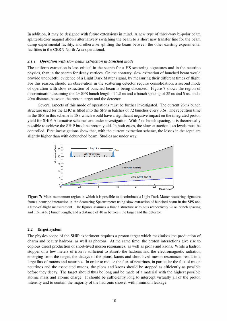
2.1.1 Operation with slow beam extraction in bunched modeThe uniform extraction is less critical in the search for a HS scattering signatures and in the neutrinophysics, than in the search for decay vertices. On the contrary, slow extraction of bunched beam wouldprovide undoubtful evidence of a Light Dark Matter signal, by measuring their different times of flight.For this reason, should an observation in the scattering detector require consolidation, a second modeof operation with slow extraction of bunched beam is being discussed. Figure 7 shows the region ofdiscrimination assuming the 4σ SPS bunch length of 1.5 ns and a bunch spacing of 25 ns and 5 ns, and a40m distance between the proton target and the detector.
Several aspects of this mode of operations must be further investigated. The current 25 ns bunchstructure used for the LHC is filled into the SPS in batches of 72 bunches every 3.6s. The repetition timein the SPS in this scheme is 18 s which would have a significant negative impact on the integrated protonyield for SHiP. Alternative schemes are under investigation. With 5 ns bunch spacing, it is theoreticallypossible to achieve the SHiP baseline proton yield. In both cases, the slow extraction loss levels must becontrolled. First investigations show that, with the current extraction scheme, the losses in the septa areslightly higher than with debunched beam. Studies are under way.
Figure 7: Mass-momentum region in which it is possible to discriminate a Light Dark Matter scattering signaturefrom a neutrino interaction in the Scattering Spectrometer using slow extraction of bunched beam in the SPS anda time-of-flight measurement. The figures assumes a bunch structure with 5 ns respectively 25 ns bunch spacingand 1.5 ns(4σ) bunch length, and a distance of 40 m between the target and the detector.
2.2 Target systemThe physics scope of the SHiP experiment requires a proton target which maximises the production ofcharm and beauty hadrons, as well as photons. At the same time, the proton interactions give rise tocopious direct production of short-lived meson resonances, as well as pions and kaons. While a hadronstopper of a few meters of iron is sufficient to absorb the hadrons and the electromagnetic radiationemerging from the target, the decays of the pions, kaons and short-lived meson resonances result in alarge flux of muons and neutrinos. In order to reduce the flux of neutrinos, in particular the flux of muonneutrinos and the associated muons, the pions and kaons should be stopped as efficiently as possiblebefore they decay. The target should thus be long and be made of a material with the highest possibleatomic mass and atomic charge. It should be sufficiently long to intercept virtually all of the protonintensity and to contain the majority of the hadronic shower with minimum leakage.
10
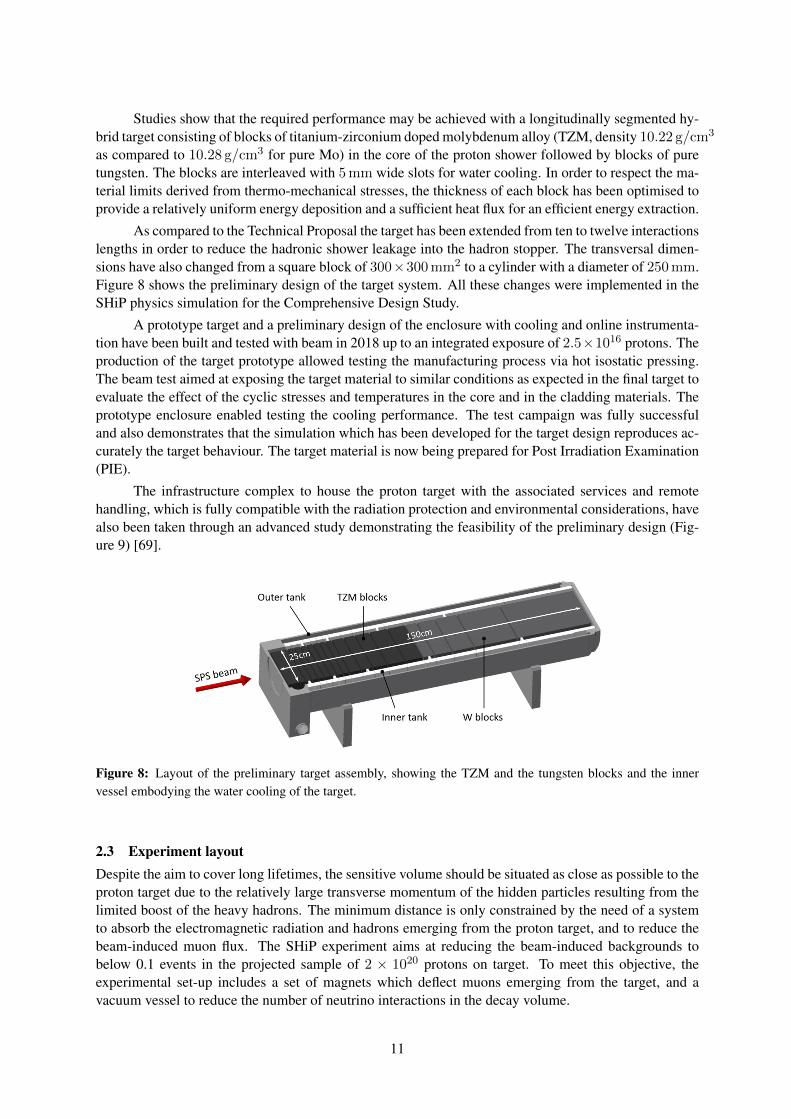
Studies show that the required performance may be achieved with a longitudinally segmented hy-brid target consisting of blocks of titanium-zirconium doped molybdenum alloy (TZM, density 10.22 g/cm3
as compared to 10.28 g/cm3 for pure Mo) in the core of the proton shower followed by blocks of puretungsten. The blocks are interleaved with 5 mm wide slots for water cooling. In order to respect the ma-terial limits derived from thermo-mechanical stresses, the thickness of each block has been optimised toprovide a relatively uniform energy deposition and a sufficient heat flux for an efficient energy extraction.
As compared to the Technical Proposal the target has been extended from ten to twelve interactionslengths in order to reduce the hadronic shower leakage into the hadron stopper. The transversal dimen-sions have also changed from a square block of 300×300 mm2 to a cylinder with a diameter of 250 mm.Figure 8 shows the preliminary design of the target system. All these changes were implemented in theSHiP physics simulation for the Comprehensive Design Study.
A prototype target and a preliminary design of the enclosure with cooling and online instrumenta-tion have been built and tested with beam in 2018 up to an integrated exposure of 2.5×10¹⁶ protons. Theproduction of the target prototype allowed testing the manufacturing process via hot isostatic pressing.The beam test aimed at exposing the target material to similar conditions as expected in the final target toevaluate the effect of the cyclic stresses and temperatures in the core and in the cladding materials. Theprototype enclosure enabled testing the cooling performance. The test campaign was fully successfuland also demonstrates that the simulation which has been developed for the target design reproduces ac-curately the target behaviour. The target material is now being prepared for Post Irradiation Examination(PIE).
The infrastructure complex to house the proton target with the associated services and remotehandling, which is fully compatible with the radiation protection and environmental considerations, havealso been taken through an advanced study demonstrating the feasibility of the preliminary design (Fig-ure 9) [69].
Figure 8: Layout of the preliminary target assembly, showing the TZM and the tungsten blocks and the innervessel embodying the water cooling of the target.
2.3 Experiment layoutDespite the aim to cover long lifetimes, the sensitive volume should be situated as close as possible to theproton target due to the relatively large transverse momentum of the hidden particles resulting from thelimited boost of the heavy hadrons. The minimum distance is only constrained by the need of a systemto absorb the electromagnetic radiation and hadrons emerging from the proton target, and to reduce thebeam-induced muon flux. The SHiP experiment aims at reducing the beam-induced backgrounds tobelow 0.1 events in the projected sample of 2 × 10²⁰ protons on target. To meet this objective, theexperimental set-up includes a set of magnets which deflect muons emerging from the target, and avacuum vessel to reduce the number of neutrino interactions in the decay volume.
11
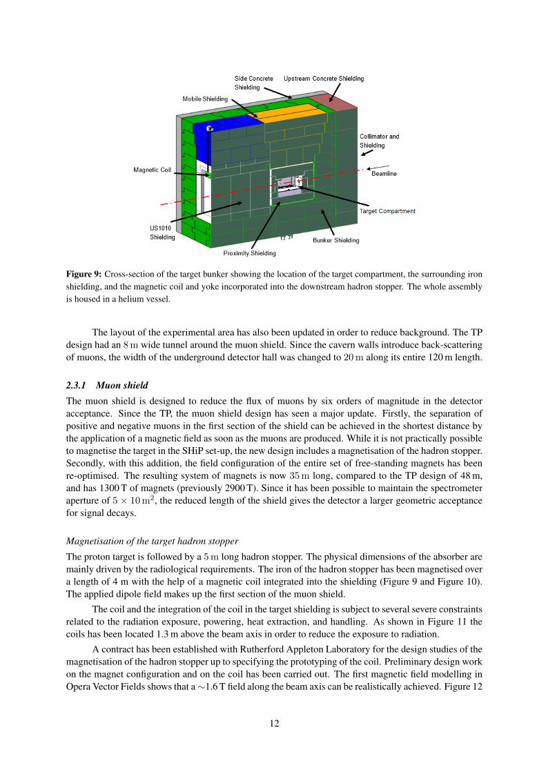
Figure 9: Cross-section of the target bunker showing the location of the target compartment, the surrounding ironshielding, and the magnetic coil and yoke incorporated into the downstream hadron stopper. The whole assemblyis housed in a helium vessel.
The layout of the experimental area has also been updated in order to reduce background. The TPdesign had an 8 m wide tunnel around the muon shield. Since the cavern walls introduce back-scatteringof muons, the width of the underground detector hall was changed to 20 m along its entire 120 m length.
2.3.1 Muon shieldThe muon shield is designed to reduce the flux of muons by six orders of magnitude in the detectoracceptance. Since the TP, the muon shield design has seen a major update. Firstly, the separation ofpositive and negative muons in the first section of the shield can be achieved in the shortest distance bythe application of a magnetic field as soon as the muons are produced. While it is not practically possibleto magnetise the target in the SHiP set-up, the new design includes a magnetisation of the hadron stopper.Secondly, with this addition, the field configuration of the entire set of free-standing magnets has beenre-optimised. The resulting system of magnets is now 35 m long, compared to the TP design of 48 m,and has 1300 T of magnets (previously 2900 T). Since it has been possible to maintain the spectrometeraperture of 5 × 10 m2, the reduced length of the shield gives the detector a larger geometric acceptancefor signal decays.
Magnetisation of the target hadron stopper
The proton target is followed by a 5 m long hadron stopper. The physical dimensions of the absorber aremainly driven by the radiological requirements. The iron of the hadron stopper has been magnetised overa length of 4 m with the help of a magnetic coil integrated into the shielding (Figure 9 and Figure 10).The applied dipole field makes up the first section of the muon shield.
The coil and the integration of the coil in the target shielding is subject to several severe constraintsrelated to the radiation exposure, powering, heat extraction, and handling. As shown in Figure 11 thecoils has been located 1.3 m above the beam axis in order to reduce the exposure to radiation.
A contract has been established with Rutherford Appleton Laboratory for the design studies of themagnetisation of the hadron stopper up to specifying the prototyping of the coil. Preliminary design workon the magnet configuration and on the coil has been carried out. The first magnetic field modelling inOpera Vector Fields shows that a∼1.6 T field along the beam axis can be realistically achieved. Figure 12
12
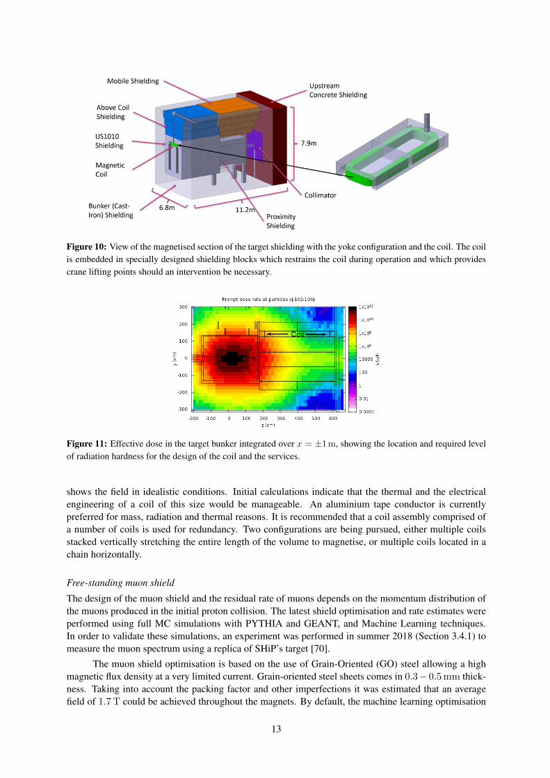
Figure 10: View of the magnetised section of the target shielding with the yoke configuration and the coil. The coilis embedded in specially designed shielding blocks which restrains the coil during operation and which providescrane lifting points should an intervention be necessary.
Figure 11: Effective dose in the target bunker integrated over x = ±1 m, showing the location and required levelof radiation hardness for the design of the coil and the services.
shows the field in idealistic conditions. Initial calculations indicate that the thermal and the electricalengineering of a coil of this size would be manageable. An aluminium tape conductor is currentlypreferred for mass, radiation and thermal reasons. It is recommended that a coil assembly comprised ofa number of coils is used for redundancy. Two configurations are being pursued, either multiple coilsstacked vertically stretching the entire length of the volume to magnetise, or multiple coils located in achain horizontally.
Free-standing muon shield
The design of the muon shield and the residual rate of muons depends on the momentum distribution ofthe muons produced in the initial proton collision. The latest shield optimisation and rate estimates wereperformed using full MC simulations with PYTHIA and GEANT, and Machine Learning techniques.In order to validate these simulations, an experiment was performed in summer 2018 (Section 3.4.1) tomeasure the muon spectrum using a replica of SHiP’s target [70].
The muon shield optimisation is based on the use of Grain-Oriented (GO) steel allowing a highmagnetic flux density at a very limited current. Grain-oriented steel sheets comes in 0.3− 0.5 mm thick-ness. Taking into account the packing factor and other imperfections it was estimated that an averagefield of 1.7 T could be achieved throughout the magnets. By default, the machine learning optimisation
13
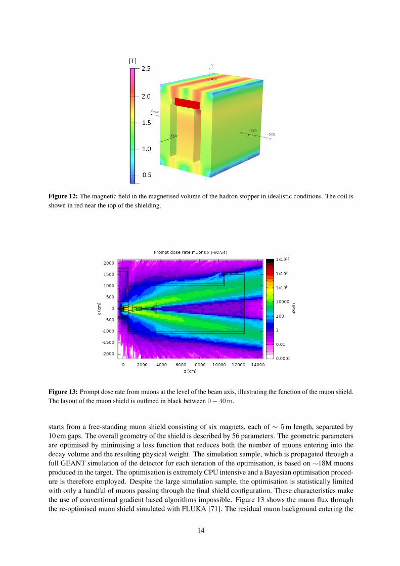
Figure 12: The magnetic field in the magnetised volume of the hadron stopper in idealistic conditions. The coil isshown in red near the top of the shielding.
Figure 13: Prompt dose rate from muons at the level of the beam axis, illustrating the function of the muon shield.The layout of the muon shield is outlined in black between 0− 40 m.
starts from a free-standing muon shield consisting of six magnets, each of ∼ 5 m length, separated by10 cm gaps. The overall geometry of the shield is described by 56 parameters. The geometric parametersare optimised by minimising a loss function that reduces both the number of muons entering into thedecay volume and the resulting physical weight. The simulation sample, which is propagated through afull GEANT simulation of the detector for each iteration of the optimisation, is based on ∼18M muonsproduced in the target. The optimisation is extremely CPU intensive and a Bayesian optimisation proced-ure is therefore employed. Despite the large simulation sample, the optimisation is statistically limitedwith only a handful of muons passing through the final shield configuration. These characteristics makethe use of conventional gradient based algorithms impossible. Figure 13 shows the muon flux throughthe re-optimised muon shield simulated with FLUKA [71]. The residual muon background entering the
14
detector acceptance is mainly composed of muons which undergo large-angle multiple scattering in thefirst part of the shield causing them to move to the “wrong” side of the beam line. The second part of theshield then focuses them towards the detector.
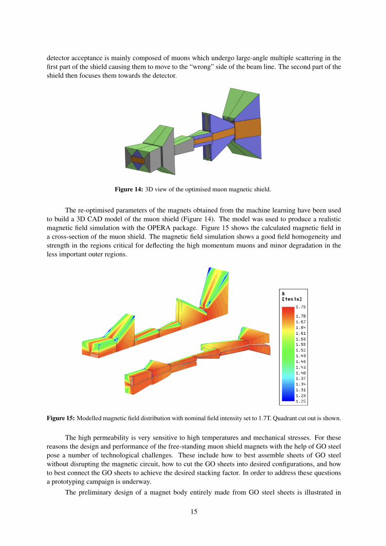
Figure 14: 3D view of the optimised muon magnetic shield.
The re-optimised parameters of the magnets obtained from the machine learning have been usedto build a 3D CAD model of the muon shield (Figure 14). The model was used to produce a realisticmagnetic field simulation with the OPERA package. Figure 15 shows the calculated magnetic field ina cross-section of the muon shield. The magnetic field simulation shows a good field homogeneity andstrength in the regions critical for deflecting the high momentum muons and minor degradation in theless important outer regions.
Figure 15: Modelled magnetic field distribution with nominal field intensity set to 1.7T. Quadrant cut out is shown.
The high permeability is very sensitive to high temperatures and mechanical stresses. For thesereasons the design and performance of the free-standing muon shield magnets with the help of GO steelpose a number of technological challenges. These include how to best assemble sheets of GO steelwithout disrupting the magnetic circuit, how to cut the GO sheets into desired configurations, and howto best connect the GO sheets to achieve the desired stacking factor. In order to address these questionsa prototyping campaign is underway.
The preliminary design of a magnet body entirely made from GO steel sheets is illustrated in
15
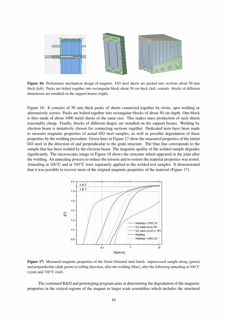
Figure 16: Preliminary mechanical design of magnets. GO steel sheets are packed into sections about 50 mmthick (left). Packs are bolted together into rectangular block about 50 cm thick (left, central). blocks of differentdimensions are installed on the support beams (right).
Figure 16. It consists of 50 mm thick packs of sheets connected together by rivets, spot welding oralternatively screws. Packs are bolted together into rectangular blocks of about 50 cm depth. One blockis thus made of about 1000 metal sheets of the same size. This makes mass production of such sheetsreasonably cheap. Finally, blocks of different shapes are installed on the support beams. Welding byelectron beam is tentatively chosen for connecting sections together. Dedicated tests have been madeto measure magnetic properties of actual GO steel samples, as well as possible degradation of theseproperties by the welding procedure. Green lines in Figure 17 show the measured properties of the initialGO steel in the direction of and perpendicular to the grain structure. The blue line corresponds to thesample that has been welded by the electron beam. The magnetic quality of the welded sample degradessignificantly. The microscopic image in Figure 18 shows the structure which appeared in the joint afterthe welding. An annealing process to reduce the tension and to restore the material properties was tested.Annealing at 500C and at 700C were separately applied to the welded test samples. It demonstratedthat it was possible to recover most of the original magnetic properties of the material (Figure 17).
Figure 17: Measured magnetic properties of the Grain Oriented steel batch: unprocessed sample along (green)and perpendicular (dark green) to rolling direction, after the welding (blue), after the following annealing at 500C(cyan) and 700C (red).
The continued R&D and prototyping program aims at determining the degradation of the magneticproperties in the critical regions of the magnet in larger scale assemblies which includes the structural
16
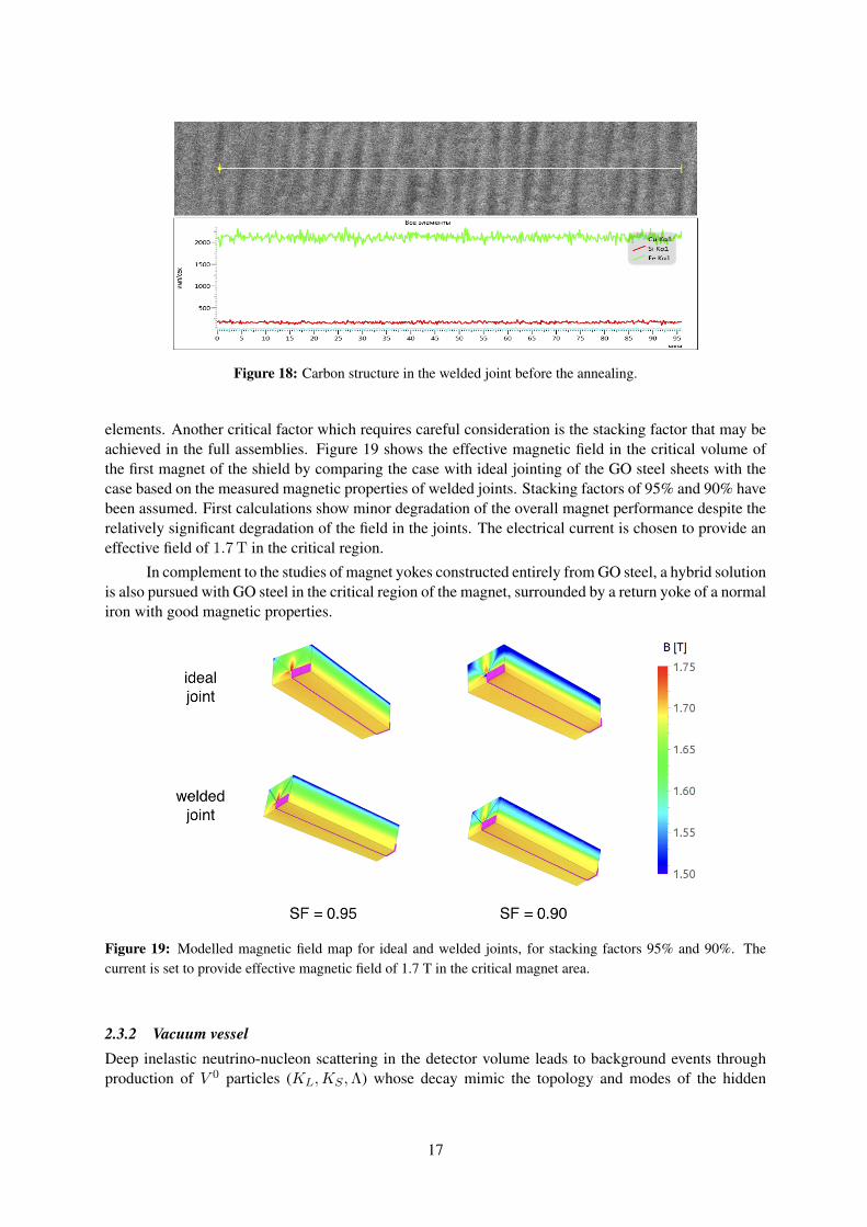
Figure 18: Carbon structure in the welded joint before the annealing.
elements. Another critical factor which requires careful consideration is the stacking factor that may beachieved in the full assemblies. Figure 19 shows the effective magnetic field in the critical volume ofthe first magnet of the shield by comparing the case with ideal jointing of the GO steel sheets with thecase based on the measured magnetic properties of welded joints. Stacking factors of 95% and 90% havebeen assumed. First calculations show minor degradation of the overall magnet performance despite therelatively significant degradation of the field in the joints. The electrical current is chosen to provide aneffective field of 1.7 T in the critical region.
In complement to the studies of magnet yokes constructed entirely from GO steel, a hybrid solutionis also pursued with GO steel in the critical region of the magnet, surrounded by a return yoke of a normaliron with good magnetic properties.
Figure 19: Modelled magnetic field map for ideal and welded joints, for stacking factors 95% and 90%. Thecurrent is set to provide effective magnetic field of 1.7 T in the critical magnet area.
2.3.2 Vacuum vesselDeep inelastic neutrino-nucleon scattering in the detector volume leads to background events throughproduction of V 0 particles (KL,KS ,Λ) whose decay mimic the topology and modes of the hidden
17
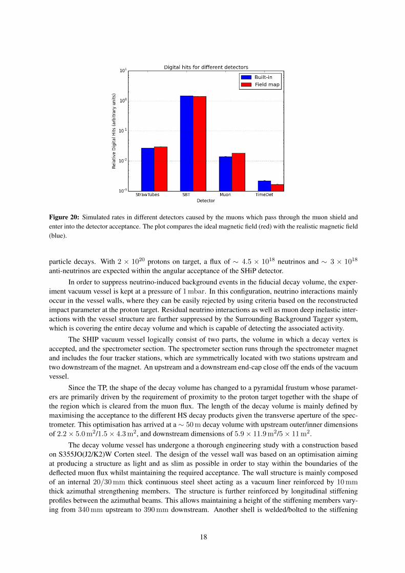
Figure 20: Simulated rates in different detectors caused by the muons which pass through the muon shield andenter into the detector acceptance. The plot compares the ideal magnetic field (red) with the realistic magnetic field(blue).
particle decays. With 2 × 10²⁰ protons on target, a flux of ∼ 4.5 × 10¹⁸ neutrinos and ∼ 3 × 10¹⁸
anti-neutrinos are expected within the angular acceptance of the SHiP detector.
In order to suppress neutrino-induced background events in the fiducial decay volume, the exper-iment vacuum vessel is kept at a pressure of 1 mbar. In this configuration, neutrino interactions mainlyoccur in the vessel walls, where they can be easily rejected by using criteria based on the reconstructedimpact parameter at the proton target. Residual neutrino interactions as well as muon deep inelastic inter-actions with the vessel structure are further suppressed by the Surrounding Background Tagger system,which is covering the entire decay volume and which is capable of detecting the associated activity.
The SHIP vacuum vessel logically consist of two parts, the volume in which a decay vertex isaccepted, and the spectrometer section. The spectrometer section runs through the spectrometer magnetand includes the four tracker stations, which are symmetrically located with two stations upstream andtwo downstream of the magnet. An upstream and a downstream end-cap close off the ends of the vacuumvessel.
Since the TP, the shape of the decay volume has changed to a pyramidal frustum whose paramet-ers are primarily driven by the requirement of proximity to the proton target together with the shape ofthe region which is cleared from the muon flux. The length of the decay volume is mainly defined bymaximising the acceptance to the different HS decay products given the transverse aperture of the spec-trometer. This optimisation has arrived at a ∼ 50 m decay volume with upstream outer/inner dimensionsof 2.2× 5.0 m2/1.5× 4.3 m2, and downstream dimensions of 5.9× 11.9 m2/5× 11 m2.
The decay volume vessel has undergone a thorough engineering study with a construction basedon S355JO(J2/K2)W Corten steel. The design of the vessel wall was based on an optimisation aimingat producing a structure as light and as slim as possible in order to stay within the boundaries of thedeflected muon flux whilst maintaining the required acceptance. The wall structure is mainly composedof an internal 20/30 mm thick continuous steel sheet acting as a vacuum liner reinforced by 10 mmthick azimuthal strengthening members. The structure is further reinforced by longitudinal stiffeningprofiles between the azimuthal beams. This allows maintaining a height of the stiffening members vary-ing from 340 mm upstream to 390 mm downstream. Another shell is welded/bolted to the stiffening
18
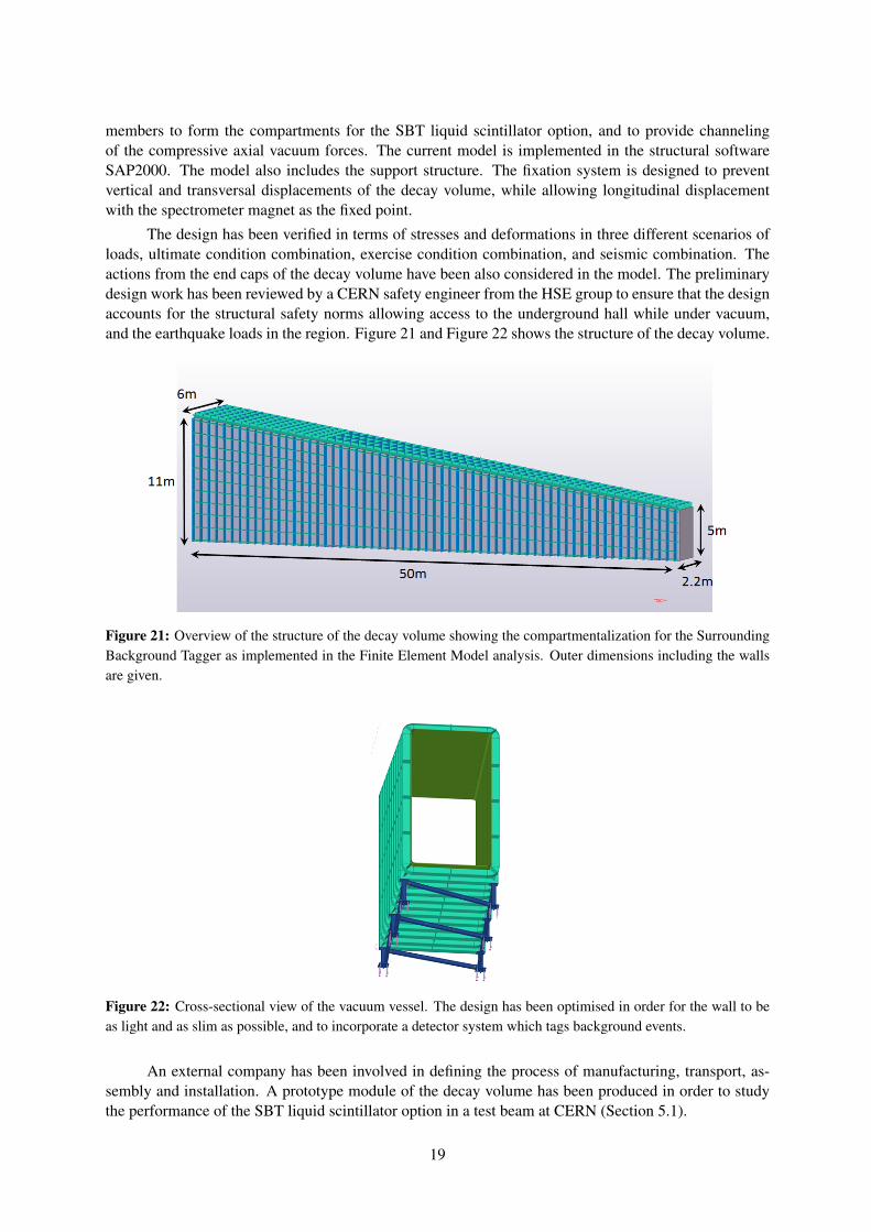
members to form the compartments for the SBT liquid scintillator option, and to provide channelingof the compressive axial vacuum forces. The current model is implemented in the structural softwareSAP2000. The model also includes the support structure. The fixation system is designed to preventvertical and transversal displacements of the decay volume, while allowing longitudinal displacementwith the spectrometer magnet as the fixed point.
The design has been verified in terms of stresses and deformations in three different scenarios ofloads, ultimate condition combination, exercise condition combination, and seismic combination. Theactions from the end caps of the decay volume have been also considered in the model. The preliminarydesign work has been reviewed by a CERN safety engineer from the HSE group to ensure that the designaccounts for the structural safety norms allowing access to the underground hall while under vacuum,and the earthquake loads in the region. Figure 21 and Figure 22 shows the structure of the decay volume.
Figure 21: Overview of the structure of the decay volume showing the compartmentalization for the SurroundingBackground Tagger as implemented in the Finite Element Model analysis. Outer dimensions including the wallsare given.
Figure 22: Cross-sectional view of the vacuum vessel. The design has been optimised in order for the wall to beas light and as slim as possible, and to incorporate a detector system which tags background events.
An external company has been involved in defining the process of manufacturing, transport, as-sembly and installation. A prototype module of the decay volume has been produced in order to studythe performance of the SBT liquid scintillator option in a test beam at CERN (Section 5.1).
19
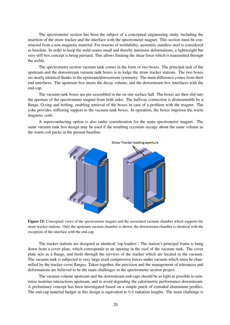
The spectrometer section has been the subject of a conceptual engineering study, including theinsertion of the straw tracker and the interface with the spectrometer magnet. This section must be con-structed from a non-magnetic material. For reasons of weldability, austenitic stainless steel is consideredas baseline. In order to keep the weld seams small and thereby minimise deformations, a lightweight butvery stiff box concept is being pursued. This allows limiting the shear force which is transmitted throughthe welds.
The spectrometer section vacuum tank comes in the form of two boxes. The principal task of theupstream and the downstream vacuum tank boxes is to lodge the straw tracker stations. The two boxesare nearly identical thanks to the upstream/downstream symmetry. The main difference comes from theirend interfaces. The upstream box meets the decay volume, and the downstream box interfaces with theend-cap.
The vacuum tank boxes are pre-assembled in the on-site surface hall. The boxes are then slid intothe aperture of the spectrometer magnet from both sides. The halfway connection is dismountable by aflange, O-ring and bolting, enabling retrieval of the boxes in case of a problem with the magnet. Theyoke provides stiffening support to the vacuum tank boxes. In operation, the boxes imprison the warmmagnetic coils.
A superconducting option is also under consideration for the main spectrometer magnet. Thesame vacuum tank box design may be used if the resulting cryostats occupy about the same volume asthe warm coil packs in the present baseline.
Figure 23: Conceptual views of the spectrometer magnet and the associated vacuum chamber which supports thestraw tracker stations. Only the upstream vacuum chamber is shown, the downstream chamber is identical with theexception of the interface with the end-cap.
The tracker stations are designed as identical ’top loaders’. The station’s principal frame is hungdown from a cover plate, which corresponds to an opening in the roof of the vacuum tank. The coverplate acts as a flange, and feeds through the services of the tracker which are located in the vacuum.The vacuum tank is subjected to very large axial compressive forces under vacuum which must be chan-nelled by the tracker cover flanges. Taken together, the precision and the management of tolerances anddeformations are believed to be the main challenges in the spectrometer section project.
The vacuum volume upstream and the downstream end-caps should be as light as possible to min-imise neutrino interactions upstream, and to avoid degrading the calorimetric performance downstream.A preliminary concept has been investigated based on a simple patch of extruded aluminium profiles.The end-cap material budget in this design is equivalent to 0.8 radiation lengths. The main challenge is
20
the need for large-scale electron welding. Currently, effort is invested on finding an alternative whichsplits the functions of mechanical support and tightness. In this solution the panels are bolted togetherwhile the vacuum tightness is provided by an added stainless steel liner.
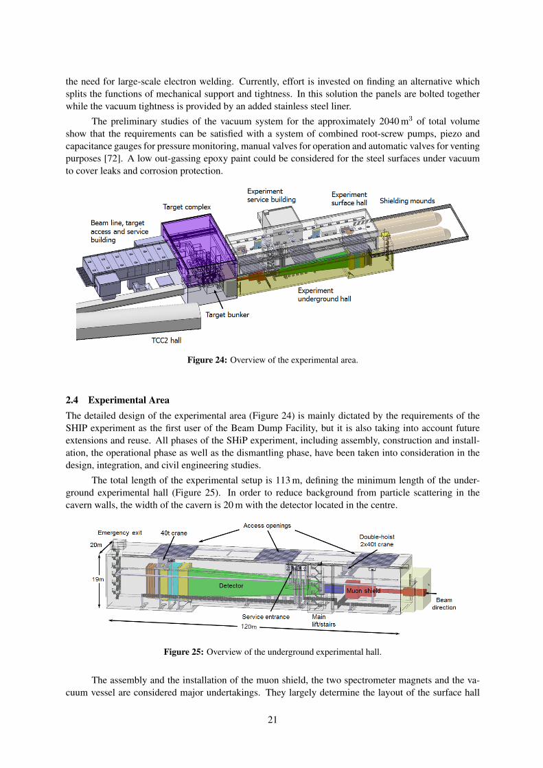
The preliminary studies of the vacuum system for the approximately 2040 m3 of total volumeshow that the requirements can be satisfied with a system of combined root-screw pumps, piezo andcapacitance gauges for pressure monitoring, manual valves for operation and automatic valves for ventingpurposes [72]. A low out-gassing epoxy paint could be considered for the steel surfaces under vacuumto cover leaks and corrosion protection.
Figure 24: Overview of the experimental area.
2.4 Experimental AreaThe detailed design of the experimental area (Figure 24) is mainly dictated by the requirements of theSHIP experiment as the first user of the Beam Dump Facility, but it is also taking into account futureextensions and reuse. All phases of the SHiP experiment, including assembly, construction and install-ation, the operational phase as well as the dismantling phase, have been taken into consideration in thedesign, integration, and civil engineering studies.
The total length of the experimental setup is 113 m, defining the minimum length of the under-ground experimental hall (Figure 25). In order to reduce background from particle scattering in thecavern walls, the width of the cavern is 20 m with the detector located in the centre.
Figure 25: Overview of the underground experimental hall.
The assembly and the installation of the muon shield, the two spectrometer magnets and the va-cuum vessel are considered major undertakings. They largely determine the layout of the surface hall
21
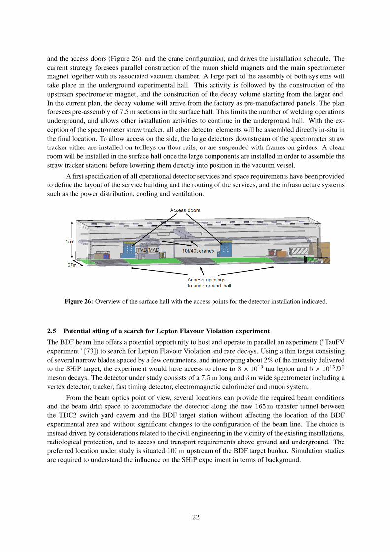
and the access doors (Figure 26), and the crane configuration, and drives the installation schedule. Thecurrent strategy foresees parallel construction of the muon shield magnets and the main spectrometermagnet together with its associated vacuum chamber. A large part of the assembly of both systems willtake place in the underground experimental hall. This activity is followed by the construction of theupstream spectrometer magnet, and the construction of the decay volume starting from the larger end.In the current plan, the decay volume will arrive from the factory as pre-manufactured panels. The planforesees pre-assembly of 7.5 m sections in the surface hall. This limits the number of welding operationsunderground, and allows other installation activities to continue in the underground hall. With the ex-ception of the spectrometer straw tracker, all other detector elements will be assembled directly in-situ inthe final location. To allow access on the side, the large detectors downstream of the spectrometer strawtracker either are installed on trolleys on floor rails, or are suspended with frames on girders. A cleanroom will be installed in the surface hall once the large components are installed in order to assemble thestraw tracker stations before lowering them directly into position in the vacuum vessel.
A first specification of all operational detector services and space requirements have been providedto define the layout of the service building and the routing of the services, and the infrastructure systemssuch as the power distribution, cooling and ventilation.
Figure 26: Overview of the surface hall with the access points for the detector installation indicated.
2.5 Potential siting of a search for Lepton Flavour Violation experimentThe BDF beam line offers a potential opportunity to host and operate in parallel an experiment ("TauFVexperiment" [73]) to search for Lepton Flavour Violation and rare decays. Using a thin target consistingof several narrow blades spaced by a few centimeters, and intercepting about 2% of the intensity deliveredto the SHiP target, the experiment would have access to close to 8 × 10¹³ tau lepton and 5 × 10¹⁵D0
meson decays. The detector under study consists of a 7.5 m long and 3 m wide spectrometer including avertex detector, tracker, fast timing detector, electromagnetic calorimeter and muon system.
From the beam optics point of view, several locations can provide the required beam conditionsand the beam drift space to accommodate the detector along the new 165 m transfer tunnel betweenthe TDC2 switch yard cavern and the BDF target station without affecting the location of the BDFexperimental area and without significant changes to the configuration of the beam line. The choice isinstead driven by considerations related to the civil engineering in the vicinity of the existing installations,radiological protection, and to access and transport requirements above ground and underground. Thepreferred location under study is situated 100 m upstream of the BDF target bunker. Simulation studiesare required to understand the influence on the SHiP experiment in terms of background.
22
3 Simulation and ReconstructionThe software framework adopted by SHiP is based on FairRoot [74] and called FairShip. FairRoot is anideal turn-key solution for small (and large) experiments that do not have enough person power for a fullfledged computing group, or for experiments that do not see the need to develop their own offline com-puting framework. It is fully based on the ROOT system. The FairShip code is largely a specializationof the generic C++ base classes provided by FairRoot, mainly profiting from the methods to describethe detector geometry, implement detector classes, and performing simulation. In addition some spe-cific auxiliary libraries needed by SHiP are included, like GENFIT for reconstruction of tracks. Thesteering of the simulation flow, and the main parts of the reconstruction and analysis is based on Pythonclasses and functions. FairShip moved recently to using aliBuild (https://alisw.github.io/alibuild), asimple build tool developed by the ALICE collaboration. FairShip is regularly updated following thesoftware improvements of the external packages. The current versions of the principal external packagesare ROOT v6-14-00, GEANT4 v10.3.2, GEANT4_VMC v3.6, GENIE v2.12.6, PYTHIA8 v8230, andEVTGEN R01-06-00.
3.1 SimulationThe simulation of the proton collisions with the fixed-target is done in two steps. First, primary protoninteractions are simulated using PYTHIA8 [75]. Then the particles produced are transported through thetarget and the experimental setup using GEANT4 [76]. Some rare processes which produce muons withrelatively high momenta, such as decays of light vector mesons, γ-conversions and positron annihilation,are disabled by default in GEANT4. These have been enabled and their rates artificially boosted by anarbitrary factor of hundred for further studies.
For the heavy quark production a procedure was developed to also simulate charm and beautyhadron production by the products of the primary proton-nucleon collision [77]. This increases theexpected yield compared to the prediction in the TP by a factor of 2.6 and 1.9 in the detector acceptancefor HNLs with mass of 1 GeV/c2 and 3 GeV/c2, respectively.
In total 6.5 × 10¹⁰ protons on target have been simulated with an energy cut for transportingparticles after the hadron absorber of 10 GeV, and 1.8 × 10⁹ protons on target with an energy cut of1 GeV. The samples produced with charm and beauty hadrons correspond to about 100 × 109 protonson target.
Since the TP the simulation of the signals in FairShip has been updated and extended to morephysics models. This allows simulating the hidden particles in the SHiP experimental setup with realisticreconstruction and analysis. Figure 27 - 29 show examples of reconstructed observables for differentdecay modes of 1 GeV/c2 HNLs, demonstrating that the selection efficiency used for the SHiP sensitivies(Table 5) is close to 100% for signal events. Figure 28 has been produced with the TP version of theECAL.
The production and decay of HNLs have been considerably improved according to [78]. Darkscalar production and decay have been implemented. Inclusive decays of dark scalars are consideredusing the inclusive b → SXs branching fraction given in [79]. The production of dark photons viameson decays, proton bremsstrahlung and QCD production has been implemented together with theirdecays. The contribution from cascade production, which is included for the HNL and the dark scalar,is not currently taken into account for the dark photon. A set of benchmarks are considered where theproduction is dominated by charm and beauty hadrons, and the final states consist of different multi-bodyfinal states involving at least two charged particles. All signal sensitivity curves presented in Chapter 6,except for the axion-like particles, have been obtained using the FairShip framework.
The SHiP experiment critically depends on an accurate simulation of the background components,in particular the design of the muon shield relies on an accurate knowledge of the muon flux. Figure 30and Figure 31 show the muon spectrum and the exit point of the muons after the hadron absorber. In the
23
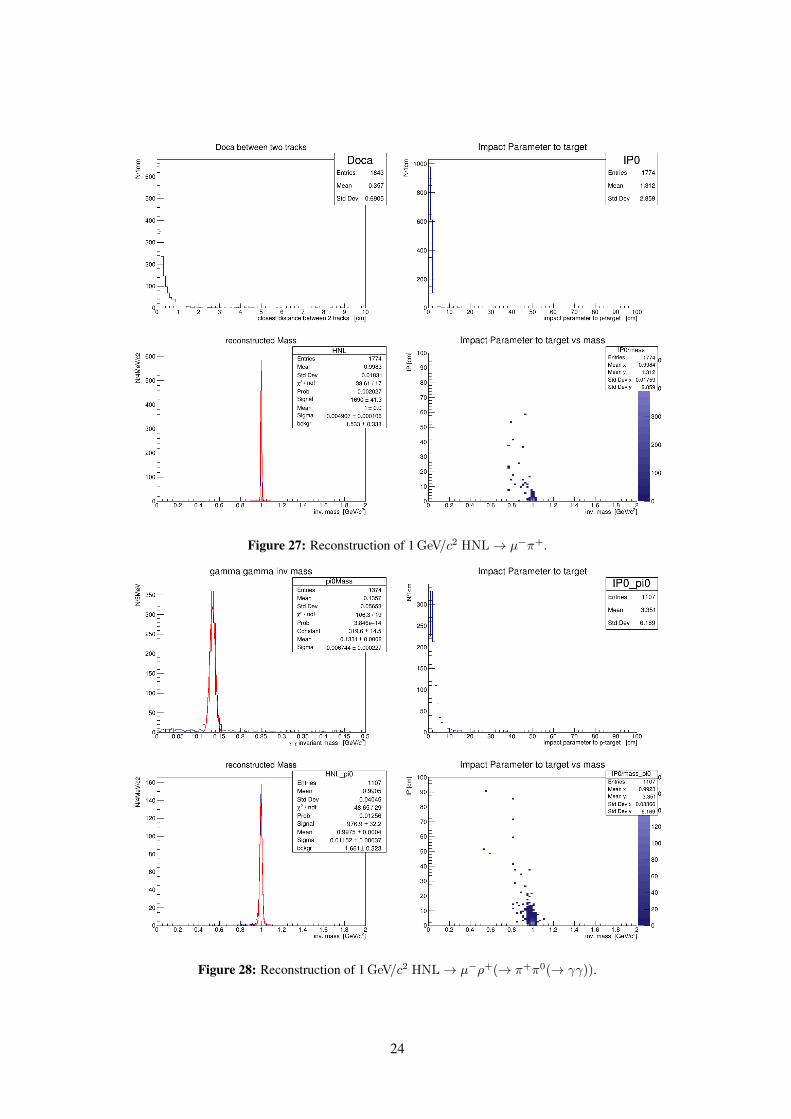
Figure 27: Reconstruction of 1 GeV/c2 HNL→ µ−π+.
Figure 28: Reconstruction of 1 GeV/c2 HNL→ µ−ρ+(→ π+π0(→ γγ)).
24
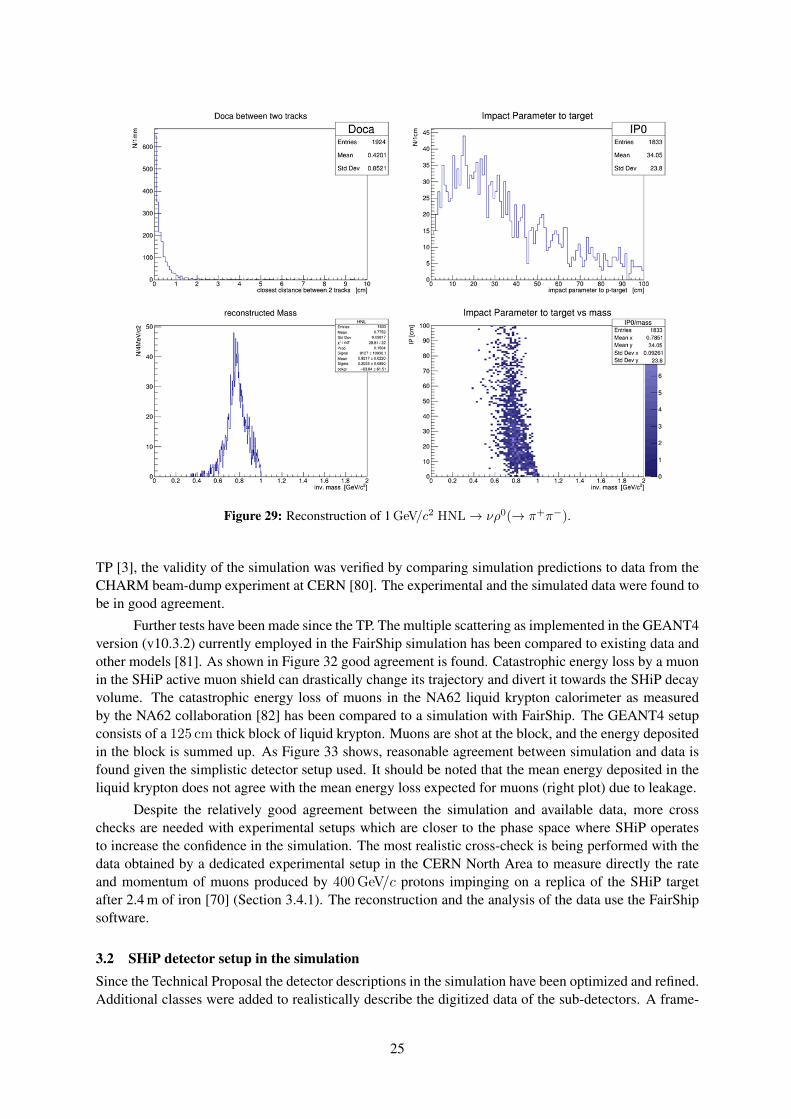
Figure 29: Reconstruction of 1 GeV/c2 HNL→ νρ0(→ π+π−).
TP [3], the validity of the simulation was verified by comparing simulation predictions to data from theCHARM beam-dump experiment at CERN [80]. The experimental and the simulated data were found tobe in good agreement.
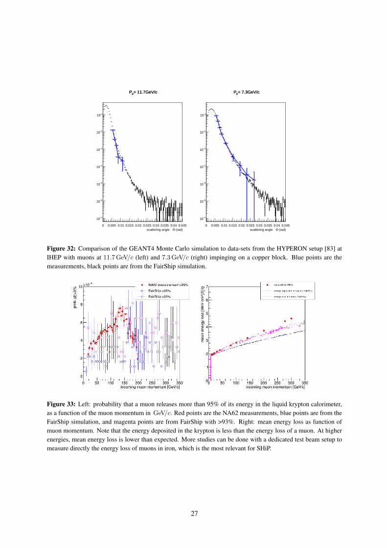
Further tests have been made since the TP. The multiple scattering as implemented in the GEANT4version (v10.3.2) currently employed in the FairShip simulation has been compared to existing data andother models [81]. As shown in Figure 32 good agreement is found. Catastrophic energy loss by a muonin the SHiP active muon shield can drastically change its trajectory and divert it towards the SHiP decayvolume. The catastrophic energy loss of muons in the NA62 liquid krypton calorimeter as measuredby the NA62 collaboration [82] has been compared to a simulation with FairShip. The GEANT4 setupconsists of a 125 cm thick block of liquid krypton. Muons are shot at the block, and the energy depositedin the block is summed up. As Figure 33 shows, reasonable agreement between simulation and data isfound given the simplistic detector setup used. It should be noted that the mean energy deposited in theliquid krypton does not agree with the mean energy loss expected for muons (right plot) due to leakage.
Despite the relatively good agreement between the simulation and available data, more crosschecks are needed with experimental setups which are closer to the phase space where SHiP operatesto increase the confidence in the simulation. The most realistic cross-check is being performed with thedata obtained by a dedicated experimental setup in the CERN North Area to measure directly the rateand momentum of muons produced by 400 GeV/c protons impinging on a replica of the SHiP targetafter 2.4 m of iron [70] (Section 3.4.1). The reconstruction and the analysis of the data use the FairShipsoftware.
3.2 SHiP detector setup in the simulationSince the Technical Proposal the detector descriptions in the simulation have been optimized and refined.Additional classes were added to realistically describe the digitized data of the sub-detectors. A frame-
25
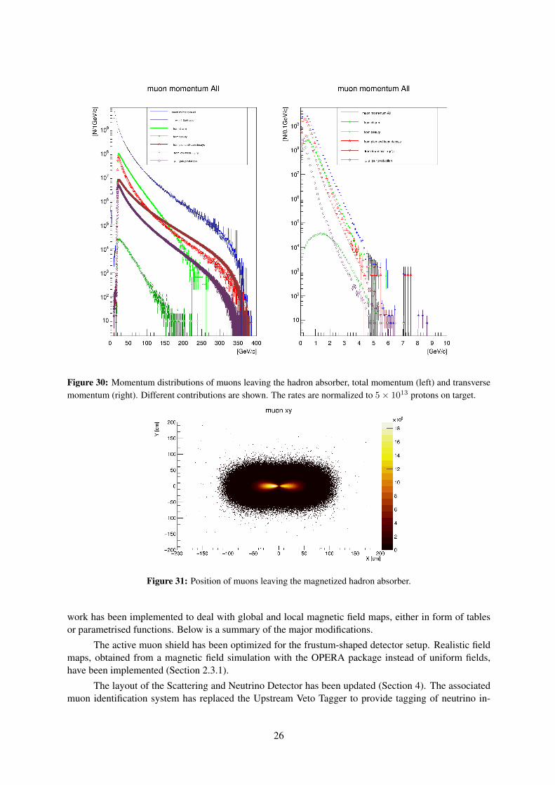
Figure 30: Momentum distributions of muons leaving the hadron absorber, total momentum (left) and transversemomentum (right). Different contributions are shown. The rates are normalized to 5× 10¹³ protons on target.
Figure 31: Position of muons leaving the magnetized hadron absorber.
work has been implemented to deal with global and local magnetic field maps, either in form of tablesor parametrised functions. Below is a summary of the major modifications.
The active muon shield has been optimized for the frustum-shaped detector setup. Realistic fieldmaps, obtained from a magnetic field simulation with the OPERA package instead of uniform fields,have been implemented (Section 2.3.1).
The layout of the Scattering and Neutrino Detector has been updated (Section 4). The associatedmuon identification system has replaced the Upstream Veto Tagger to provide tagging of neutrino in-
26
0 0.005 0.01 0.015 0.02 0.025 0.03 0.035 0.04 0.045 (rad)Θscattering angle
7−10
6−10
5−10
4−10
3−10
2−10
1−10
= 11.7GeV/cµ P = 11.7GeV/cµ P
0 0.005 0.01 0.015 0.02 0.025 0.03 0.035 0.04 0.045 (rad)Θscattering angle
7−10
6−10
5−10
4−10
3−10
2−10
1−10
= 7.3GeV/cµ P = 7.3GeV/cµ P
Figure 32: Comparison of the GEANT4 Monte Carlo simulation to data-sets from the HYPERON setup [83] atIHEP with muons at 11.7 GeV/c (left) and 7.3 GeV/c (right) impinging on a copper block. Blue points are themeasurements, black points are from the FairShip simulation.
Figure 33: Left: probability that a muon releases more than 95% of its energy in the liquid krypton calorimeter,as a function of the muon momentum in GeV/c. Red points are the NA62 measurements, blue points are from theFairShip simulation, and magenta points are from FairShip with >93%. Right: mean energy loss as function ofmuon momentum. Note that the energy deposited in the krypton is less than the energy loss of a muon. At higherenergies, mean energy loss is lower than expected. More studies can be done with a dedicated test beam setup tomeasure directly the energy loss of muons in iron, which is the most relevant for SHiP.
27

teractions in the material upstream of the decay volume that could produce long-lived neutral particleswhich in turn may decay and mimic a HS signal in the Decay Spectrometer. The in-vacuum upstreamStraw Veto Tagger has been removed as it was found to bring a negligible contribution to the backgroundsuppression. Information from the vertex reconstruction with the decay spectrometer is sufficient to vetobackground from KS decays. The SBT has now a realistic detector granularity corresponding to thestructural design of the vacuum vessel. In addition to the layout with a liquid scintillator, an alternat-ive layout with a solid plastic scintillator has also been implemented. The current Spectrometer StrawTracker design is based on straw tubes with 20 mm diameter, while the original TP design (Section 5.2)had 10 mm tubes. The corresponding baseline straw geometry was reoptimized for high hit detectionefficiency. It is implemented in FairShip as the default SST geometry. All tracker stations have now thesame dimensions to simplify the engineering of the straw tracker supports and the vacuum chamber ofthe spectrometer section. The structural support material has been added to the simulation. A detailedfield map for the spectrometer magnet from an OPERA simulation, including the return field, has beenimplemented.
Track finding based on Template Matching Pattern Recognition was used to evaluate the SSTperformance as a function of the straw diameter. Table 1 compares the track recognition efficiency, faketrack rate and relative momentum resolution obtained for muon and pion tracks in the SST acceptanceand originating from simulated decays of HNLs with a mass of 1 GeV/c2. As shown, the 6% loss inrecognition efficiency when going from 10 mm to 20 mm, is considered recoverable by using morecomplex pattern recognition techniques, such as Hough Transform and Artificial Retina. The slightlyincreased rates of clones is not an issue.
Table 1: Quality metric for different track pattern recognition techniques for two different straw tubes innerdiameters.
The optimization of the SST geometry for the best track detection performance is ongoing. Fair-Ship simulation is used to study the influence on the pattern recognition performance of a single viewgeometry, longitudinal distances between stations and stereo angle. Realistic simulation of the signaltiming as function of the straw hit position is under development. The GARFIELD-based parameterisa-tion of the drift time distributions as a function of the track local coordinates for ideal and misalignedstraws was found to be in a reasonable agreement with results from beam test measurements. Paramet-erised dependencies of the most probable signal arrival time and the corresponding time resolution havebeen prepared for the upcoming version of FairShip.
28
The segmentation of the Timing Detector, and proper simulation of the expected timing resolution,has been added. Implementation of the alternative option based on MRPC is underway. An alternativeoption for the electromagnetic calorimeter with pointing capabilities has been added to the simulation,called SplitCal (Section 5.4). Performance studies are ongoing. The hadronic calorimeter has beenremoved as it has been found that the SplitCal should be capable of providing sufficient identificationfor low momentum particles. The material of the hadronic calorimeter is kept at the first filter wall forthe muon system. The scintillating tile option has been implemented as baseline in FairShip for thedownstream muon system.
3.3 ReconstructionDifferent pattern recognition algorithms for the straw tracker reconstruction have been implementedand used to study the effects of detector modifications on the tracking efficiency. The reconstructionof signal with charged particles has been extended to include reconstruction of photons with the newSplitCal version of the ECAL detector. The energy of a photon is taken from the reconstructed clusterwhile the direction is given by the vertex of two charged tracks and the cluster position in the ECAL.
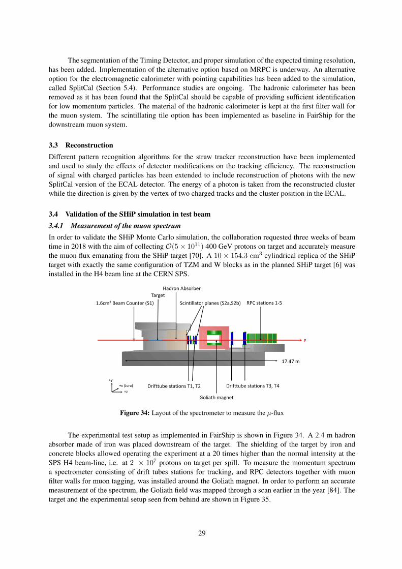
3.4 Validation of the SHiP simulation in test beam3.4.1 Measurement of the muon spectrumIn order to validate the SHiP Monte Carlo simulation, the collaboration requested three weeks of beamtime in 2018 with the aim of collecting O(5× 10¹¹) 400 GeV protons on target and accurately measurethe muon flux emanating from the SHiP target [70]. A 10 × 154.3 cm3 cylindrical replica of the SHiPtarget with exactly the same configuration of TZM and W blocks as in the planned SHiP target [6] wasinstalled in the H4 beam line at the CERN SPS.
p
Target
1.6cm2 Beam Counter (S1)
Hadron Absorber
Drifttube stations T1, T2
Goliath magnet
Drifttube stations T3, T4
RPC stations 1-5Scintillator planes (S2a,S2b)
+z
+x (Jura)
+y
17.47 m
Figure 34: Layout of the spectrometer to measure the µ-flux
The experimental test setup as implemented in FairShip is shown in Figure 34. A 2.4 m hadronabsorber made of iron was placed downstream of the target. The shielding of the target by iron andconcrete blocks allowed operating the experiment at a 20 times higher than the normal intensity at theSPS H4 beam-line, i.e. at 2 × 10⁷ protons on target per spill. To measure the momentum spectruma spectrometer consisting of drift tubes stations for tracking, and RPC detectors together with muonfilter walls for muon tagging, was installed around the Goliath magnet. In order to perform an accuratemeasurement of the spectrum, the Goliath field was mapped through a scan earlier in the year [84]. Thetarget and the experimental setup seen from behind are shown in Figure 35.
29
The total number of protons collected on target has been estimated to ∼ 6 × 10¹¹. Data was collectedfor several settings of the Goliath magnet:
– Default configuration: Maximum field = 1.5 T, 5.3× 10¹¹ protons on target.– Medium field configuration: Maximum field = 1.0 T, 4.8 × 10¹⁰ protons on target to enhance
precision for low momentum muons.– Field off configuration: 2.7× 10¹⁰ protons on target for alignment purposes.
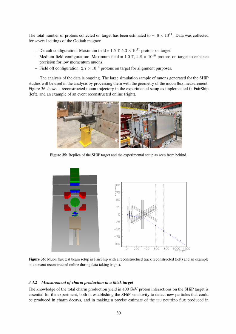
The analysis of the data is ongoing. The large simulation sample of muons generated for the SHiPstudies will be used in the analysis by processing them with the geometry of the muon flux measurement.Figure 36 shows a reconstructed muon trajectory in the experimental setup as implemented in FairShip(left), and an example of an event reconstructed online (right).
Figure 35: Replica of the SHiP target and the experimental setup as seen from behind.
Figure 36: Muon flux test beam setup in FairShip with a reconstructued track reconstructed (left) and an exampleof an event reconstructed online during data taking (right).
3.4.2 Measurement of charm production in a thick targetThe knowledge of the total charm production yield in 400 GeV proton interactions on the SHiP target isessential for the experiment, both in establishing the SHiP sensitivity to detect new particles that couldbe produced in charm decays, and in making a precise estimate of the tau neutrino flux produced in
30
Ds decays. In particular the cascade production of charm from primary protons which initially undergoelastic scattering, and from secondary hadrons interacting inelastically, has never been measured. SHiPaims at measuring the differential charm production cross section in a thick target, including the cascadeproduction. The measurement is also of interest for QCD. In parallel to this measurement, an effort isongoing to progress on the theoretical prediction and tune the next-to-leading order calculation.
Figure 37: Distribution along the z-axis of charmed hadrons production vertices in a lead target.
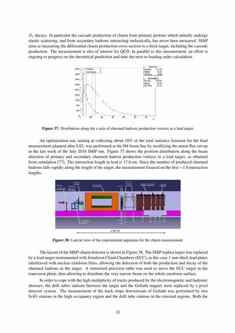
An optimization run, aiming at collecting about 10% of the total statistics foreseen for the finalmeasurement planned after LS2, was performed at the H4 beam line by modifying the muon flux set-upin the last week of the July 2018 SHiP run. Figure 37 shows the position distribution along the beamdirection of primary and secondary charmed hadron production vertices in a lead target, as obtainedfrom simulation [77]. The interaction length in lead is 17.6 cm. Since the number of produced charmedhadrons falls rapidly along the length of the target, the measurement focused on the first∼1.6 interactionlengths.
Figure 38: Lateral view of the experimental apparatus for the charm measurement.
The layout of the SHiP-charm detector is shown in Figure 38. The SHiP replica target was replacedby a lead target instrumented with Emulsion Cloud Chambers (ECC), in this case 1 mm-thick lead platesinterleaved with nuclear emulsion films, allowing the detection of both the production and decay of thecharmed hadrons in the target. A motorised precision table was used to move the ECC target in thetransverse plane, thus allowing to distribute the very narrow beam on the whole emulsion surface.
In order to cope with the high multiplicity of tracks produced by the electromagnetic and hadronicshowers, the drift tubes stations between the target and the Goliath magnet were replaced by a pixeldetector system. The measurement of the track slope downstream of Goliath was performed by twoSciFi stations in the high occupancy region and the drift tube stations in the external regions. Both the
31
muon flux and the charm measurement used the muon tagger system based on the RPCs for identificationand extended tracking.
The target was assembled in six different configurations in order to study the charm production indifferent portions of the target. In total data from 16×105 protons on target were collected during theoptimization run.
The analysis of the data is in progress. The first phase is devoted to the calibration and local re-construction of tracks. In the second phase the alignment of the different sub-detectors will be performedand the data will be imported into FairShip for the overall event reconstruction.
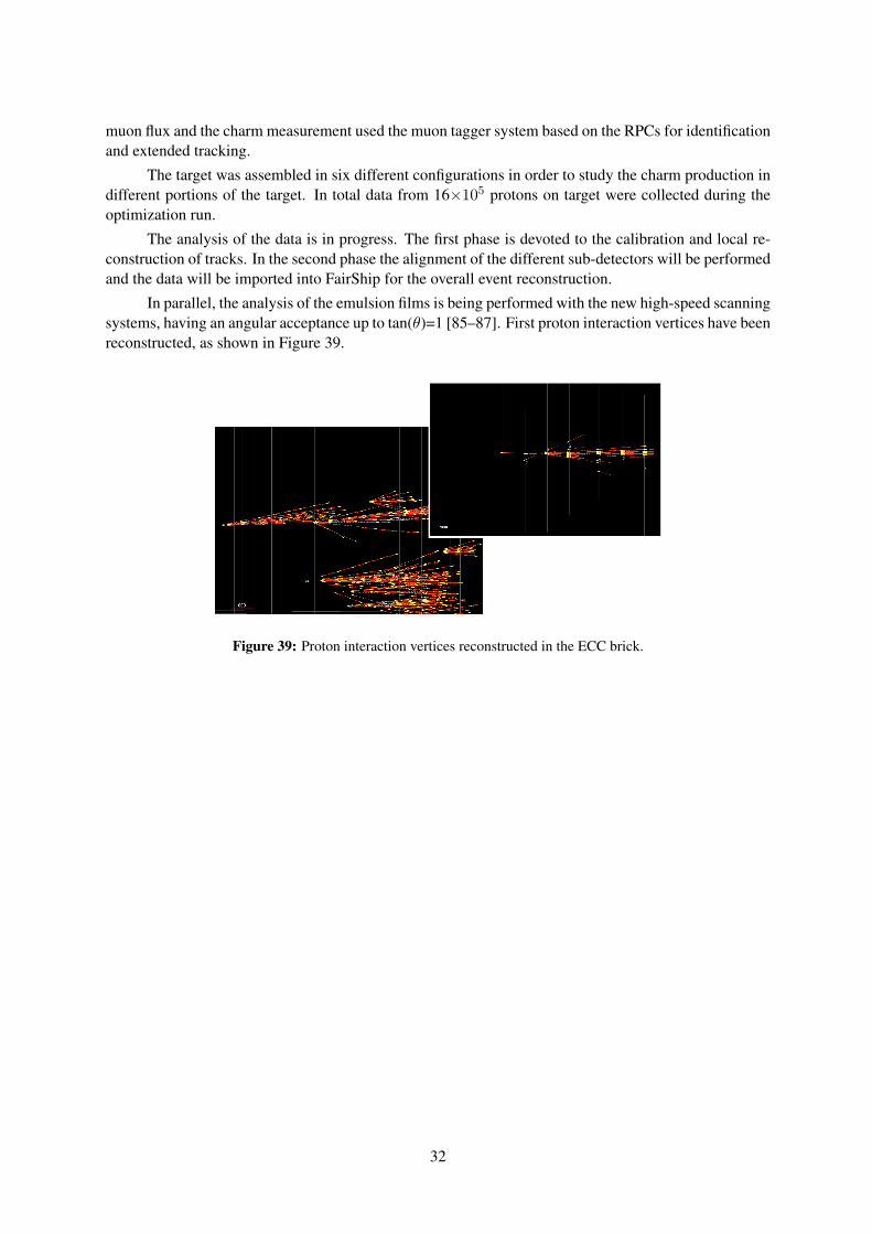
In parallel, the analysis of the emulsion films is being performed with the new high-speed scanningsystems, having an angular acceptance up to tan(θ)=1 [85–87]. First proton interaction vertices have beenreconstructed, as shown in Figure 39.
Figure 39: Proton interaction vertices reconstructed in the ECC brick.
32
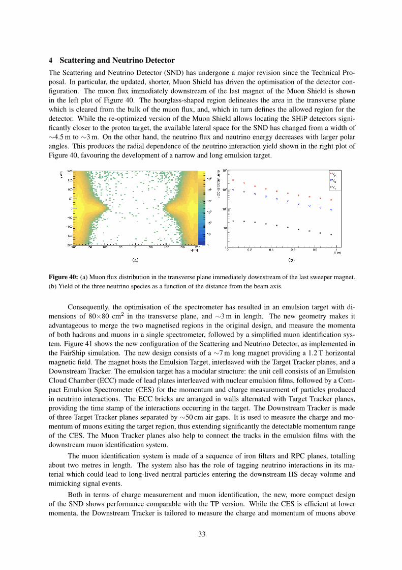
4 Scattering and Neutrino DetectorThe Scattering and Neutrino Detector (SND) has undergone a major revision since the Technical Pro-posal. In particular, the updated, shorter, Muon Shield has driven the optimisation of the detector con-figuration. The muon flux immediately downstream of the last magnet of the Muon Shield is shownin the left plot of Figure 40. The hourglass-shaped region delineates the area in the transverse planewhich is cleared from the bulk of the muon flux, and, which in turn defines the allowed region for thedetector. While the re-optimized version of the Muon Shield allows locating the SHiP detectors signi-ficantly closer to the proton target, the available lateral space for the SND has changed from a width of∼4.5 m to ∼3 m. On the other hand, the neutrino flux and neutrino energy decreases with larger polarangles. This produces the radial dependence of the neutrino interaction yield shown in the right plot ofFigure 40, favouring the development of a narrow and long emulsion target.
Figure 40: (a) Muon flux distribution in the transverse plane immediately downstream of the last sweeper magnet.(b) Yield of the three neutrino species as a function of the distance from the beam axis.
Consequently, the optimisation of the spectrometer has resulted in an emulsion target with di-mensions of 80×80 cm2 in the transverse plane, and ∼3 m in length. The new geometry makes itadvantageous to merge the two magnetised regions in the original design, and measure the momentaof both hadrons and muons in a single spectrometer, followed by a simplified muon identification sys-tem. Figure 41 shows the new configuration of the Scattering and Neutrino Detector, as implemented inthe FairShip simulation. The new design consists of a ∼7 m long magnet providing a 1.2 T horizontalmagnetic field. The magnet hosts the Emulsion Target, interleaved with the Target Tracker planes, and aDownstream Tracker. The emulsion target has a modular structure: the unit cell consists of an EmulsionCloud Chamber (ECC) made of lead plates interleaved with nuclear emulsion films, followed by a Com-pact Emulsion Spectrometer (CES) for the momentum and charge measurement of particles producedin neutrino interactions. The ECC bricks are arranged in walls alternated with Target Tracker planes,providing the time stamp of the interactions occurring in the target. The Downstream Tracker is madeof three Target Tracker planes separated by ∼50 cm air gaps. It is used to measure the charge and mo-mentum of muons exiting the target region, thus extending significantly the detectable momentum rangeof the CES. The Muon Tracker planes also help to connect the tracks in the emulsion films with thedownstream muon identification system.
The muon identification system is made of a sequence of iron filters and RPC planes, totallingabout two metres in length. The system also has the role of tagging neutrino interactions in its ma-terial which could lead to long-lived neutral particles entering the downstream HS decay volume andmimicking signal events.
Both in terms of charge measurement and muon identification, the new, more compact designof the SND shows performance comparable with the TP version. While the CES is efficient at lowermomenta, the Downstream Tracker is tailored to measure the charge and momentum of muons above
33
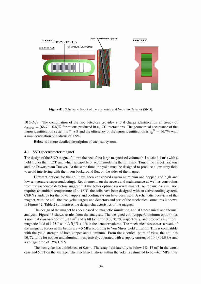
Figure 41: Schematic layout of the Scattering and Neutrino Detector (SND).
10 GeV/c. The combination of the two detectors provides a total charge identification efficiency ofεcharge = (65.7± 0.5)% for muons produced in νµ CC interactions. The geometrical acceptance of themuon identification system is 74.8% and the efficiency of the muon identification is εIDµ = 96.7% witha mis-identication of hadrons of 1.5%.
Below is a more detailed description of each subsystem.
4.1 SND spectrometer magnetThe design of the SND magnet follows the need for a large magnetised volume (∼1×1.6×6.4 m3) with afield higher than 1.2 T, and which is capable of accommodating the Emulsion Target, the Target Trackersand the Downstream Tracker. At the same time, the yoke must be designed to produce a low stray fieldto avoid interfering with the muon background flux on the sides of the magnet.
Different options for the coil have been considered (warm aluminum and copper, and high andlow temperature superconducting). Requirements on the access and maintenance as well as constraintsfrom the associated detectors suggest that the better option is a warm magnet. As the nuclear emulsionrequires an ambient temperature of ∼ 18C, the coils have been designed with an active cooling system.CERN standards for the power supply and cooling system have been used. A schematic overview of themagnet, with the coil, the iron yoke, targets and detectors and part of the mechanical structures is shownin Figure 42. Table 2 summarises the design characteristics of the magnet.
The design of the magnet has been based on magnetic simulation, and 3D mechanical and thermalanalysis. Figure 43 shows results from the analyses. The designed coil (copper/aluminum option) hasa nominal cross-section of 0.41 m2 and a fill factor of 0.68/0.73, respectively, and produces a uniformmagnetic field of 1.25 T with ∆B/B < 1% in the detector volume. The mechanical stresses as a result ofthe magnetic forces at the bends are ∼5 MPa according to Von Mises yield criterion. This is compatiblewith the yield strength of both copper and aluminum. From the electrical point of view, the coil has96/72 turns for copper and aluminum respectively, operated with a supply current of 10.9/14.6 kA anda voltage drop of 128/139 V.
The iron yoke has a thickness of 0.6 m. The stray field laterally is below 1%, 17 mT in the worstcase and 5 mT on the average. The mechanical stress within the yoke is estimated to be ∼6.7 MPa, thus
34
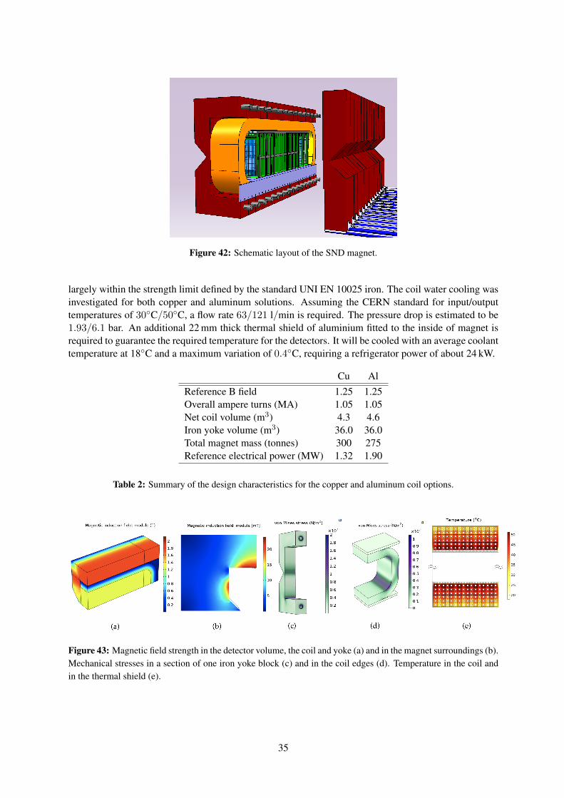
Figure 42: Schematic layout of the SND magnet.
largely within the strength limit defined by the standard UNI EN 10025 iron. The coil water cooling wasinvestigated for both copper and aluminum solutions. Assuming the CERN standard for input/outputtemperatures of 30C/50C, a flow rate 63/121 l/min is required. The pressure drop is estimated to be1.93/6.1 bar. An additional 22 mm thick thermal shield of aluminium fitted to the inside of magnet isrequired to guarantee the required temperature for the detectors. It will be cooled with an average coolanttemperature at 18C and a maximum variation of 0.4C, requiring a refrigerator power of about 24 kW.
Cu AlReference B field 1.25 1.25Overall ampere turns (MA) 1.05 1.05Net coil volume (m3) 4.3 4.6Iron yoke volume (m3) 36.0 36.0Total magnet mass (tonnes) 300 275Reference electrical power (MW) 1.32 1.90
Table 2: Summary of the design characteristics for the copper and aluminum coil options.
Figure 43: Magnetic field strength in the detector volume, the coil and yoke (a) and in the magnet surroundings (b).Mechanical stresses in a section of one iron yoke block (c) and in the coil edges (d). Temperature in the coil andin the thermal shield (e).
35
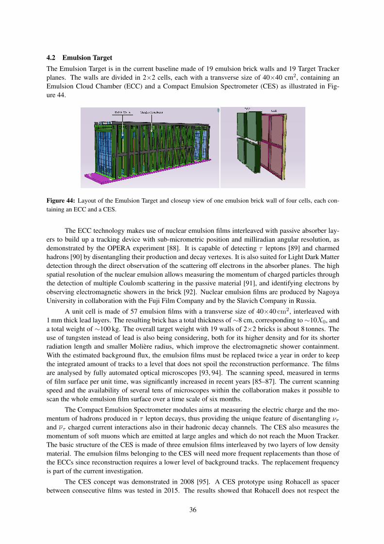
4.2 Emulsion TargetThe Emulsion Target is in the current baseline made of 19 emulsion brick walls and 19 Target Trackerplanes. The walls are divided in 2×2 cells, each with a transverse size of 40×40 cm2, containing anEmulsion Cloud Chamber (ECC) and a Compact Emulsion Spectrometer (CES) as illustrated in Fig-ure 44.
Figure 44: Layout of the Emulsion Target and closeup view of one emulsion brick wall of four cells, each con-taining an ECC and a CES.
The ECC technology makes use of nuclear emulsion films interleaved with passive absorber lay-ers to build up a tracking device with sub-micrometric position and milliradian angular resolution, asdemonstrated by the OPERA experiment [88]. It is capable of detecting τ leptons [89] and charmedhadrons [90] by disentangling their production and decay vertexes. It is also suited for Light Dark Matterdetection through the direct observation of the scattering off electrons in the absorber planes. The highspatial resolution of the nuclear emulsion allows measuring the momentum of charged particles throughthe detection of multiple Coulomb scattering in the passive material [91], and identifying electrons byobserving electromagnetic showers in the brick [92]. Nuclear emulsion films are produced by NagoyaUniversity in collaboration with the Fuji Film Company and by the Slavich Company in Russia.
A unit cell is made of 57 emulsion films with a transverse size of 40×40 cm2, interleaved with1 mm thick lead layers. The resulting brick has a total thickness of∼8 cm, corresponding to∼10X0, anda total weight of ∼100 kg. The overall target weight with 19 walls of 2×2 bricks is about 8 tonnes. Theuse of tungsten instead of lead is also being considering, both for its higher density and for its shorterradiation length and smaller Molière radius, which improve the electromagnetic shower containment.With the estimated background flux, the emulsion films must be replaced twice a year in order to keepthe integrated amount of tracks to a level that does not spoil the reconstruction performance. The filmsare analysed by fully automated optical microscopes [93, 94]. The scanning speed, measured in termsof film surface per unit time, was significantly increased in recent years [85–87]. The current scanningspeed and the availability of several tens of microscopes within the collaboration makes it possible toscan the whole emulsion film surface over a time scale of six months.
The Compact Emulsion Spectrometer modules aims at measuring the electric charge and the mo-mentum of hadrons produced in τ lepton decays, thus providing the unique feature of disentangling ντand ντ charged current interactions also in their hadronic decay channels. The CES also measures themomentum of soft muons which are emitted at large angles and which do not reach the Muon Tracker.The basic structure of the CES is made of three emulsion films interleaved by two layers of low densitymaterial. The emulsion films belonging to the CES will need more frequent replacements than those ofthe ECCs since reconstruction requires a lower level of background tracks. The replacement frequencyis part of the current investigation.
The CES concept was demonstrated in 2008 [95]. A CES prototype using Rohacell as spacerbetween consecutive films was tested in 2015. The results showed that Rohacell does not respect the
36
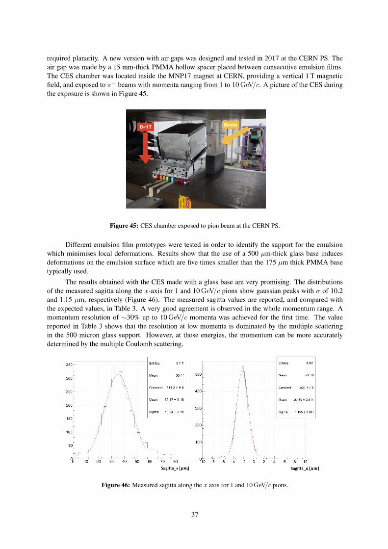
required planarity. A new version with air gaps was designed and tested in 2017 at the CERN PS. Theair gap was made by a 15 mm-thick PMMA hollow spacer placed between consecutive emulsion films.The CES chamber was located inside the MNP17 magnet at CERN, providing a vertical 1 T magneticfield, and exposed to π− beams with momenta ranging from 1 to 10 GeV/c. A picture of the CES duringthe exposure is shown in Figure 45.
Figure 45: CES chamber exposed to pion beam at the CERN PS.
Different emulsion film prototypes were tested in order to identify the support for the emulsionwhich minimises local deformations. Results show that the use of a 500 µm-thick glass base inducesdeformations on the emulsion surface which are five times smaller than the 175 µm thick PMMA basetypically used.
The results obtained with the CES made with a glass base are very promising. The distributionsof the measured sagitta along the x-axis for 1 and 10 GeV/c pions show gaussian peaks with σ of 10.2and 1.15 µm, respectively (Figure 46). The measured sagitta values are reported, and compared withthe expected values, in Table 3. A very good agreement is observed in the whole momentum range. Amomentum resolution of ∼30% up to 10 GeV/c momenta was achieved for the first time. The valuereported in Table 3 shows that the resolution at low momenta is dominated by the multiple scatteringin the 500 micron glass support. However, at those energies, the momentum can be more accuratelydetermined by the multiple Coulomb scattering.
Figure 46: Measured sagitta along the x axis for 1 and 10 GeV/c pions.
37
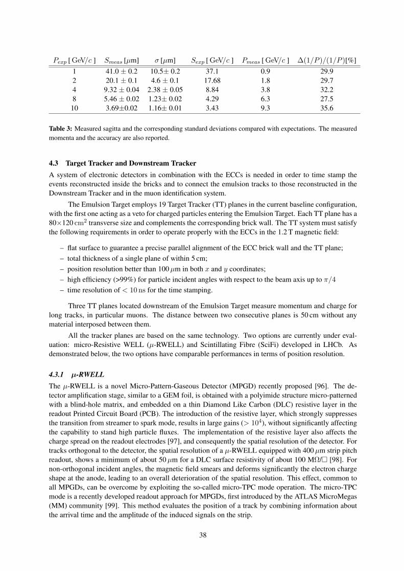
Pexp [ GeV/c ] Smeas [µm] σ [µm] Sexp [ GeV/c ] Pmeas [ GeV/c ] ∆(1/P )/(1/P )[%]1 41.0 ± 0.2 10.5± 0.2 37.1 0.9 29.92 20.1 ± 0.1 4.6 ± 0.1 17.68 1.8 29.74 9.32 ± 0.04 2.38 ± 0.05 8.84 3.8 32.28 5.46 ± 0.02 1.23± 0.02 4.29 6.3 27.510 3.69±0.02 1.16± 0.01 3.43 9.3 35.6
Table 3: Measured sagitta and the corresponding standard deviations compared with expectations. The measuredmomenta and the accuracy are also reported.
4.3 Target Tracker and Downstream TrackerA system of electronic detectors in combination with the ECCs is needed in order to time stamp theevents reconstructed inside the bricks and to connect the emulsion tracks to those reconstructed in theDownstream Tracker and in the muon identification system.
The Emulsion Target employs 19 Target Tracker (TT) planes in the current baseline configuration,with the first one acting as a veto for charged particles entering the Emulsion Target. Each TT plane has a80×120 cm2 transverse size and complements the corresponding brick wall. The TT system must satisfythe following requirements in order to operate properly with the ECCs in the 1.2 T magnetic field:
– flat surface to guarantee a precise parallel alignment of the ECC brick wall and the TT plane;– total thickness of a single plane of within 5 cm;– position resolution better than 100µm in both x and y coordinates;– high efficiency (>99%) for particle incident angles with respect to the beam axis up to π/4– time resolution of < 10 ns for the time stamping.
Three TT planes located downstream of the Emulsion Target measure momentum and charge forlong tracks, in particular muons. The distance between two consecutive planes is 50 cm without anymaterial interposed between them.
All the tracker planes are based on the same technology. Two options are currently under eval-uation: micro-Resistive WELL (µ-RWELL) and Scintillating Fibre (SciFi) developed in LHCb. Asdemonstrated below, the two options have comparable performances in terms of position resolution.
4.3.1 µ-RWELLThe µ-RWELL is a novel Micro-Pattern-Gaseous Detector (MPGD) recently proposed [96]. The de-tector amplification stage, similar to a GEM foil, is obtained with a polyimide structure micro-patternedwith a blind-hole matrix, and embedded on a thin Diamond Like Carbon (DLC) resistive layer in thereadout Printed Circuit Board (PCB). The introduction of the resistive layer, which strongly suppressesthe transition from streamer to spark mode, results in large gains (> 104), without significantly affectingthe capability to stand high particle fluxes. The implementation of the resistive layer also affects thecharge spread on the readout electrodes [97], and consequently the spatial resolution of the detector. Fortracks orthogonal to the detector, the spatial resolution of a µ-RWELL equipped with 400µm strip pitchreadout, shows a minimum of about 50µm for a DLC surface resistivity of about 100 MΩ/ [98]. Fornon-orthogonal incident angles, the magnetic field smears and deforms significantly the electron chargeshape at the anode, leading to an overall deterioration of the spatial resolution. This effect, common toall MPGDs, can be overcome by exploiting the so-called micro-TPC mode operation. The micro-TPCmode is a recently developed readout approach for MPGDs, first introduced by the ATLAS MicroMegas(MM) community [99]. This method evaluates the position of a track by combining information aboutthe arrival time and the amplitude of the induced signals on the strip.
38
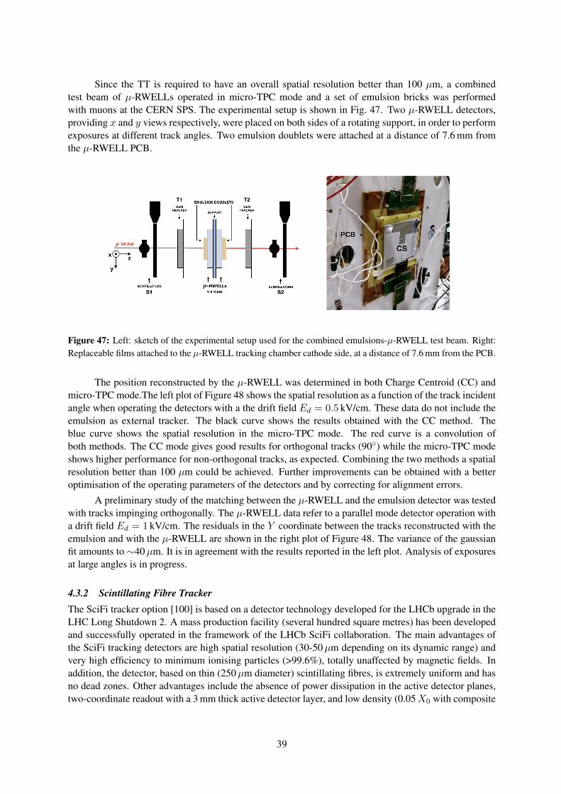
Since the TT is required to have an overall spatial resolution better than 100 µm, a combinedtest beam of µ-RWELLs operated in micro-TPC mode and a set of emulsion bricks was performedwith muons at the CERN SPS. The experimental setup is shown in Fig. 47. Two µ-RWELL detectors,providing x and y views respectively, were placed on both sides of a rotating support, in order to performexposures at different track angles. Two emulsion doublets were attached at a distance of 7.6 mm fromthe µ-RWELL PCB.
Figure 47: Left: sketch of the experimental setup used for the combined emulsions-µ-RWELL test beam. Right:Replaceable films attached to the µ-RWELL tracking chamber cathode side, at a distance of 7.6 mm from the PCB.
The position reconstructed by the µ-RWELL was determined in both Charge Centroid (CC) andmicro-TPC mode.The left plot of Figure 48 shows the spatial resolution as a function of the track incidentangle when operating the detectors with a the drift field Ed = 0.5 kV/cm. These data do not include theemulsion as external tracker. The black curve shows the results obtained with the CC method. Theblue curve shows the spatial resolution in the micro-TPC mode. The red curve is a convolution ofboth methods. The CC mode gives good results for orthogonal tracks (90) while the micro-TPC modeshows higher performance for non-orthogonal tracks, as expected. Combining the two methods a spatialresolution better than 100 µm could be achieved. Further improvements can be obtained with a betteroptimisation of the operating parameters of the detectors and by correcting for alignment errors.
A preliminary study of the matching between the µ-RWELL and the emulsion detector was testedwith tracks impinging orthogonally. The µ-RWELL data refer to a parallel mode detector operation witha drift field Ed = 1 kV/cm. The residuals in the Y coordinate between the tracks reconstructed with theemulsion and with the µ-RWELL are shown in the right plot of Figure 48. The variance of the gaussianfit amounts to ∼40µm. It is in agreement with the results reported in the left plot. Analysis of exposuresat large angles is in progress.
4.3.2 Scintillating Fibre TrackerThe SciFi tracker option [100] is based on a detector technology developed for the LHCb upgrade in theLHC Long Shutdown 2. A mass production facility (several hundred square metres) has been developedand successfully operated in the framework of the LHCb SciFi collaboration. The main advantages ofthe SciFi tracking detectors are high spatial resolution (30-50µm depending on its dynamic range) andvery high efficiency to minimum ionising particles (>99.6%), totally unaffected by magnetic fields. Inaddition, the detector, based on thin (250µm diameter) scintillating fibres, is extremely uniform and hasno dead zones. Other advantages include the absence of power dissipation in the active detector planes,two-coordinate readout with a 3 mm thick active detector layer, and low density (0.05X0 with composite
39
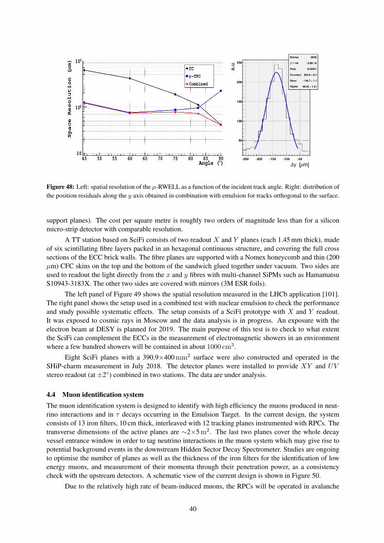
Figure 48: Left: spatial resolution of the µ-RWELL as a function of the incident track angle. Right: distribution ofthe position residuals along the y axis obtained in combination with emulsion for tracks orthogonal to the surface.
support planes). The cost per square metre is roughly two orders of magnitude less than for a siliconmicro-strip detector with comparable resolution.
A TT station based on SciFi consists of two readout X and Y planes (each 1.45 mm thick), madeof six scintillating fibre layers packed in an hexagonal continuous structure, and covering the full crosssections of the ECC brick walls. The fibre planes are supported with a Nomex honeycomb and thin (200µm) CFC skins on the top and the bottom of the sandwich glued together under vacuum. Two sides areused to readout the light directly from the x and y fibres with multi-channel SiPMs such as HamamatsuS10943-3183X. The other two sides are covered with mirrors (3M ESR foils).
The left panel of Figure 49 shows the spatial resolution measured in the LHCb application [101].The right panel shows the setup used in a combined test with nuclear emulsion to check the performanceand study possible systematic effects. The setup consists of a SciFi prototype with X and Y readout.It was exposed to cosmic rays in Moscow and the data analysis is in progress. An exposure with theelectron beam at DESY is planned for 2019. The main purpose of this test is to check to what extentthe SciFi can complement the ECCs in the measurement of electromagnetic showers in an environmentwhere a few hundred showers will be contained in about 1000 cm3.
Eight SciFi planes with a 390.9×400 mm2 surface were also constructed and operated in theSHiP-charm measurement in July 2018. The detector planes were installed to provide XY and UVstereo readout (at ±2) combined in two stations. The data are under analysis.
4.4 Muon identification systemThe muon identification system is designed to identify with high efficiency the muons produced in neut-rino interactions and in τ decays occurring in the Emulsion Target. In the current design, the systemconsists of 13 iron filters, 10 cm thick, interleaved with 12 tracking planes instrumented with RPCs. Thetransverse dimensions of the active planes are ∼2×5 m2. The last two planes cover the whole decayvessel entrance window in order to tag neutrino interactions in the muon system which may give rise topotential background events in the downstream Hidden Sector Decay Spectrometer. Studies are ongoingto optimise the number of planes as well as the thickness of the iron filters for the identification of lowenergy muons, and measurement of their momenta through their penetration power, as a consistencycheck with the upstream detectors. A schematic view of the current design is shown in Figure 50.
Due to the relatively high rate of beam-induced muons, the RPCs will be operated in avalanche
40
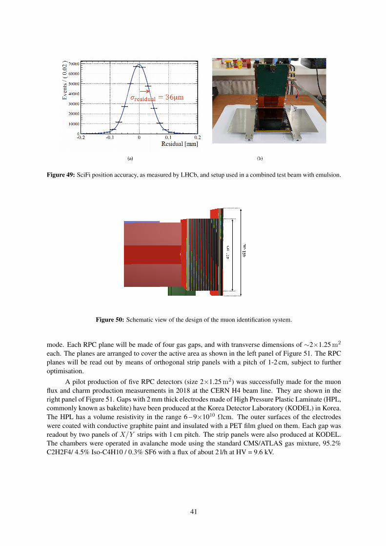
Figure 49: SciFi position accuracy, as measured by LHCb, and setup used in a combined test beam with emulsion.
Figure 50: Schematic view of the design of the muon identification system.
mode. Each RPC plane will be made of four gas gaps, and with transverse dimensions of ∼2×1.25 m2
each. The planes are arranged to cover the active area as shown in the left panel of Figure 51. The RPCplanes will be read out by means of orthogonal strip panels with a pitch of 1-2 cm, subject to furtheroptimisation.
A pilot production of five RPC detectors (size 2×1.25 m2) was successfully made for the muonflux and charm production measurements in 2018 at the CERN H4 beam line. They are shown in theright panel of Figure 51. Gaps with 2 mm thick electrodes made of High Pressure Plastic Laminate (HPL,commonly known as bakelite) have been produced at the Korea Detector Laboratory (KODEL) in Korea.The HPL has a volume resistivity in the range 6 – 9×10¹⁰ Ωcm. The outer surfaces of the electrodeswere coated with conductive graphite paint and insulated with a PET film glued on them. Each gap wasreadout by two panels of X/Y strips with 1 cm pitch. The strip panels were also produced at KODEL.The chambers were operated in avalanche mode using the standard CMS/ATLAS gas mixture, 95.2%C2H2F4/ 4.5% Iso-C4H10 / 0.3% SF6 with a flux of about 2 l/h at HV = 9.6 kV.
41
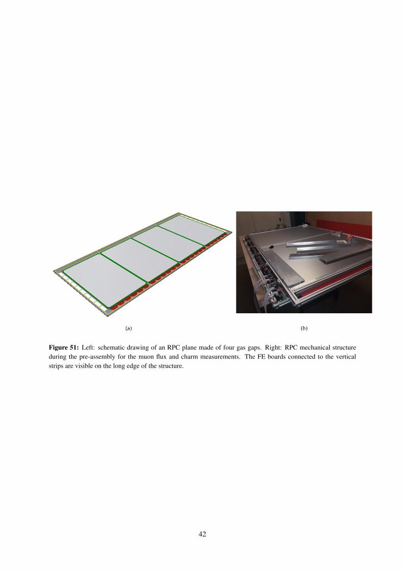
Figure 51: Left: schematic drawing of an RPC plane made of four gas gaps. Right: RPC mechanical structureduring the pre-assembly for the muon flux and charm measurements. The FE boards connected to the verticalstrips are visible on the long edge of the structure.
42
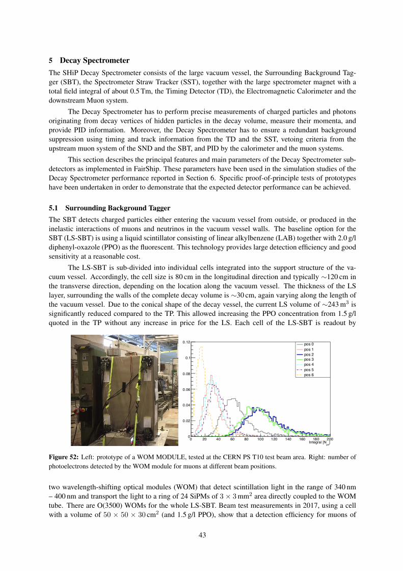
5 Decay SpectrometerThe SHiP Decay Spectrometer consists of the large vacuum vessel, the Surrounding Background Tag-ger (SBT), the Spectrometer Straw Tracker (SST), together with the large spectrometer magnet with atotal field integral of about 0.5 Tm, the Timing Detector (TD), the Electromagnetic Calorimeter and thedownstream Muon system.
The Decay Spectrometer has to perform precise measurements of charged particles and photonsoriginating from decay vertices of hidden particles in the decay volume, measure their momenta, andprovide PID information. Moreover, the Decay Spectrometer has to ensure a redundant backgroundsuppression using timing and track information from the TD and the SST, vetoing criteria from theupstream muon system of the SND and the SBT, and PID by the calorimeter and the muon systems.
This section describes the principal features and main parameters of the Decay Spectrometer sub-detectors as implemented in FairShip. These parameters have been used in the simulation studies of theDecay Spectrometer performance reported in Section 6. Specific proof-of-principle tests of prototypeshave been undertaken in order to demonstrate that the expected detector performance can be achieved.
5.1 Surrounding Background TaggerThe SBT detects charged particles either entering the vacuum vessel from outside, or produced in theinelastic interactions of muons and neutrinos in the vacuum vessel walls. The baseline option for theSBT (LS-SBT) is using a liquid scintillator consisting of linear alkylbenzene (LAB) together with 2.0 g/ldiphenyl-oxazole (PPO) as the fluorescent. This technology provides large detection efficiency and goodsensitivity at a reasonable cost.
The LS-SBT is sub-divided into individual cells integrated into the support structure of the va-cuum vessel. Accordingly, the cell size is 80 cm in the longitudinal direction and typically ∼120 cm inthe transverse direction, depending on the location along the vacuum vessel. The thickness of the LSlayer, surrounding the walls of the complete decay volume is ∼30 cm, again varying along the length ofthe vacuum vessel. Due to the conical shape of the decay vessel, the current LS volume of ∼243 m3 issignificantly reduced compared to the TP. This allowed increasing the PPO concentration from 1.5 g/lquoted in the TP without any increase in price for the LS. Each cell of the LS-SBT is readout by
Figure 52: Left: prototype of a WOM MODULE, tested at the CERN PS T10 test beam area. Right: number ofphotoelectrons detected by the WOM module for muons at different beam positions.
two wavelength-shifting optical modules (WOM) that detect scintillation light in the range of 340 nm– 400 nm and transport the light to a ring of 24 SiPMs of 3 × 3 mm2 area directly coupled to the WOMtube. There are O(3500) WOMs for the whole LS-SBT. Beam test measurements in 2017, using a cellwith a volume of 50 × 50 × 30 cm2 (and 1.5 g/l PPO), show that a detection efficiency for muons of
43
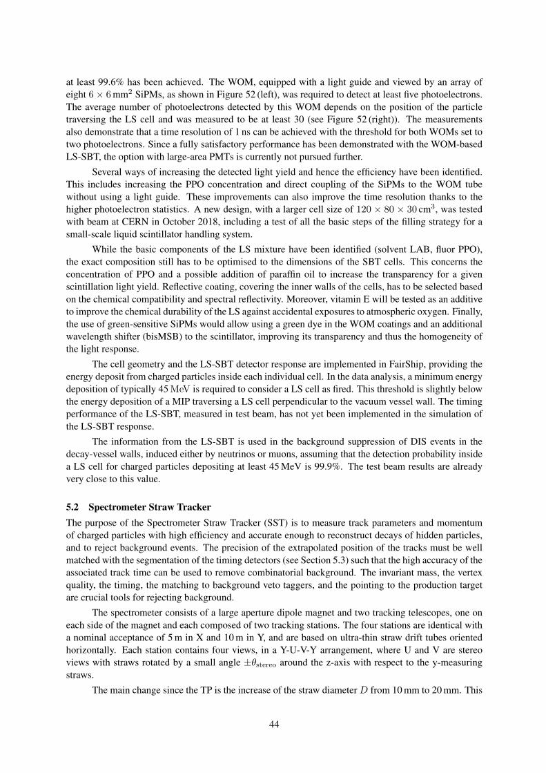
at least 99.6% has been achieved. The WOM, equipped with a light guide and viewed by an array ofeight 6× 6 mm2 SiPMs, as shown in Figure 52 (left), was required to detect at least five photoelectrons.The average number of photoelectrons detected by this WOM depends on the position of the particletraversing the LS cell and was measured to be at least 30 (see Figure 52 (right)). The measurementsalso demonstrate that a time resolution of 1 ns can be achieved with the threshold for both WOMs set totwo photoelectrons. Since a fully satisfactory performance has been demonstrated with the WOM-basedLS-SBT, the option with large-area PMTs is currently not pursued further.
Several ways of increasing the detected light yield and hence the efficiency have been identified.This includes increasing the PPO concentration and direct coupling of the SiPMs to the WOM tubewithout using a light guide. These improvements can also improve the time resolution thanks to thehigher photoelectron statistics. A new design, with a larger cell size of 120 × 80 × 30 cm3, was testedwith beam at CERN in October 2018, including a test of all the basic steps of the filling strategy for asmall-scale liquid scintillator handling system.
While the basic components of the LS mixture have been identified (solvent LAB, fluor PPO),the exact composition still has to be optimised to the dimensions of the SBT cells. This concerns theconcentration of PPO and a possible addition of paraffin oil to increase the transparency for a givenscintillation light yield. Reflective coating, covering the inner walls of the cells, has to be selected basedon the chemical compatibility and spectral reflectivity. Moreover, vitamin E will be tested as an additiveto improve the chemical durability of the LS against accidental exposures to atmospheric oxygen. Finally,the use of green-sensitive SiPMs would allow using a green dye in the WOM coatings and an additionalwavelength shifter (bisMSB) to the scintillator, improving its transparency and thus the homogeneity ofthe light response.
The cell geometry and the LS-SBT detector response are implemented in FairShip, providing theenergy deposit from charged particles inside each individual cell. In the data analysis, a minimum energydeposition of typically 45 MeV is required to consider a LS cell as fired. This threshold is slightly belowthe energy deposition of a MIP traversing a LS cell perpendicular to the vacuum vessel wall. The timingperformance of the LS-SBT, measured in test beam, has not yet been implemented in the simulation ofthe LS-SBT response.
The information from the LS-SBT is used in the background suppression of DIS events in thedecay-vessel walls, induced either by neutrinos or muons, assuming that the detection probability insidea LS cell for charged particles depositing at least 45 MeV is 99.9%. The test beam results are alreadyvery close to this value.
5.2 Spectrometer Straw TrackerThe purpose of the Spectrometer Straw Tracker (SST) is to measure track parameters and momentumof charged particles with high efficiency and accurate enough to reconstruct decays of hidden particles,and to reject background events. The precision of the extrapolated position of the tracks must be wellmatched with the segmentation of the timing detectors (see Section 5.3) such that the high accuracy of theassociated track time can be used to remove combinatorial background. The invariant mass, the vertexquality, the timing, the matching to background veto taggers, and the pointing to the production targetare crucial tools for rejecting background.
The spectrometer consists of a large aperture dipole magnet and two tracking telescopes, one oneach side of the magnet and each composed of two tracking stations. The four stations are identical witha nominal acceptance of 5 m in X and 10 m in Y, and are based on ultra-thin straw drift tubes orientedhorizontally. Each station contains four views, in a Y-U-V-Y arrangement, where U and V are stereoviews with straws rotated by a small angle ±θstereo around the z-axis with respect to the y-measuringstraws.
The main change since the TP is the increase of the straw diameter D from 10 mm to 20 mm. This
44
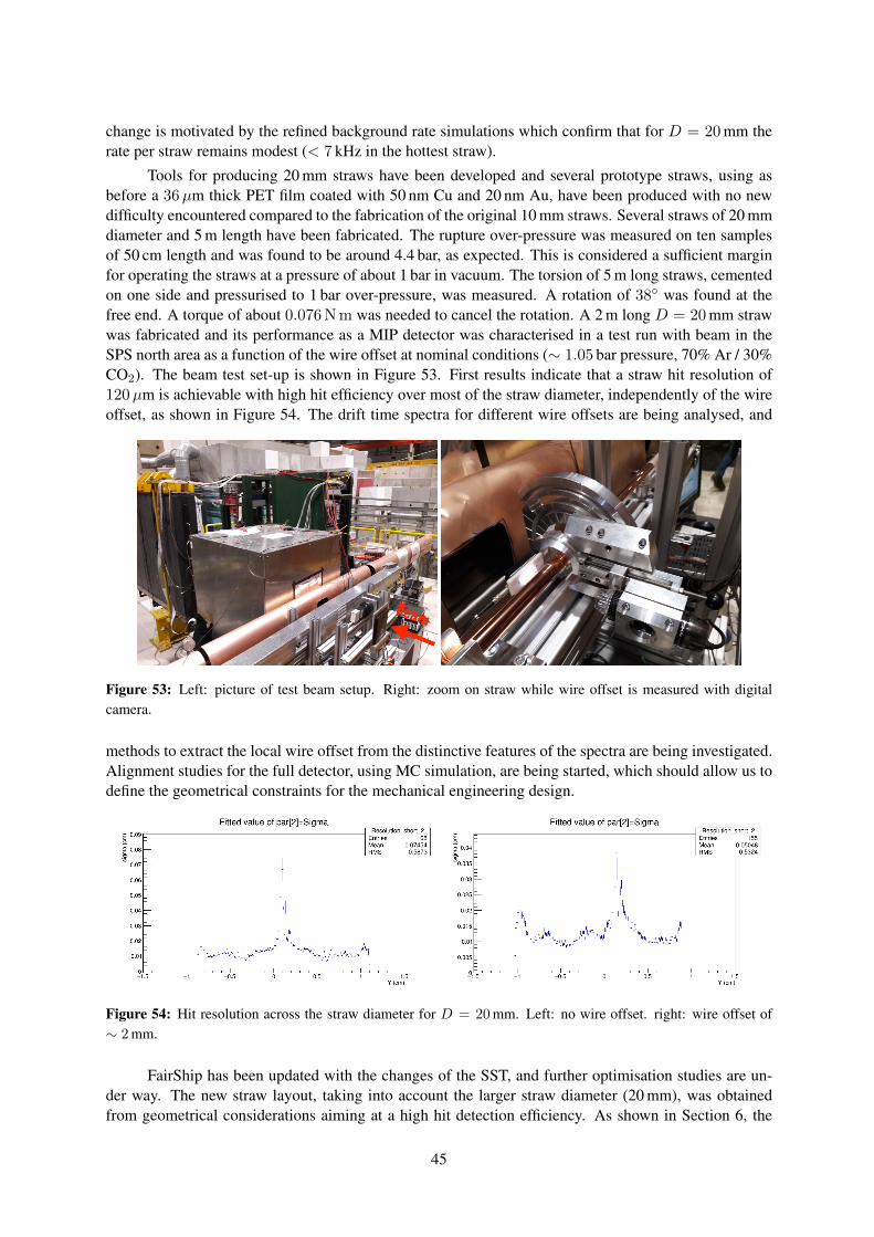
change is motivated by the refined background rate simulations which confirm that for D = 20 mm therate per straw remains modest (< 7 kHz in the hottest straw).
Tools for producing 20 mm straws have been developed and several prototype straws, using asbefore a 36µm thick PET film coated with 50 nm Cu and 20 nm Au, have been produced with no newdifficulty encountered compared to the fabrication of the original 10 mm straws. Several straws of 20 mmdiameter and 5 m length have been fabricated. The rupture over-pressure was measured on ten samplesof 50 cm length and was found to be around 4.4 bar, as expected. This is considered a sufficient marginfor operating the straws at a pressure of about 1 bar in vacuum. The torsion of 5 m long straws, cementedon one side and pressurised to 1 bar over-pressure, was measured. A rotation of 38 was found at thefree end. A torque of about 0.076 N m was needed to cancel the rotation. A 2 m long D = 20 mm strawwas fabricated and its performance as a MIP detector was characterised in a test run with beam in theSPS north area as a function of the wire offset at nominal conditions (∼ 1.05 bar pressure, 70% Ar / 30%CO2). The beam test set-up is shown in Figure 53. First results indicate that a straw hit resolution of120µm is achievable with high hit efficiency over most of the straw diameter, independently of the wireoffset, as shown in Figure 54. The drift time spectra for different wire offsets are being analysed, and
Figure 53: Left: picture of test beam setup. Right: zoom on straw while wire offset is measured with digitalcamera.
methods to extract the local wire offset from the distinctive features of the spectra are being investigated.Alignment studies for the full detector, using MC simulation, are being started, which should allow us todefine the geometrical constraints for the mechanical engineering design.
Figure 54: Hit resolution across the straw diameter for D = 20 mm. Left: no wire offset. right: wire offset of∼ 2 mm.
FairShip has been updated with the changes of the SST, and further optimisation studies are un-der way. The new straw layout, taking into account the larger straw diameter (20 mm), was obtainedfrom geometrical considerations aiming at a high hit detection efficiency. As shown in Section 6, the
45
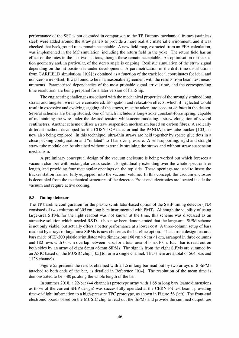
performance of the SST is not degraded in comparison to the TP. Dummy mechanical frames (stainlesssteel) were added around the straw panels to provide a more realistic material environment, and it waschecked that background rates remain acceptable. A new field map, extracted from an FEA calculation,was implemented in the MC simulation, including the return field in the yoke. The return field has aneffect on the rates in the last two stations, though these remain acceptable. An optimisation of the sta-tion geometry and, in particular, of the stereo angle is ongoing. Realistic simulation of the straw signaldepending on the hit position is under development. A parametrization of the drift time distributionsfrom GARFIELD simulations [102] is obtained as a function of the track local coordinates for ideal andnon-zero wire offset. It was found to be in a reasonable agreement with the results from beam test meas-urements. Parametrized dependencies of the most probable signal arrival time, and the correspondingtime resolution, are being prepared for a later version of FairShip.
The engineering challenges associated with the mechanical properties of the strongly strained longstraws and tungsten wires were considered. Elongation and relaxation effects, which if neglected wouldresult in excessive and evolving sagging of the straws, must be taken into account ab inito in the design.Several schemes are being studied, one of which includes a long-stroke constant-force spring, capableof maintaining the wire under the desired tension while accommodating a straw elongation of severalcentimeters. Another scheme utilises a straw suspension mechanism based on carbon fibres. A radicallydifferent method, developed for the COSY-TOF detector and the PANDA straw tube tracker [103], isnow also being explored. In this technique, ultra-thin straws are held together by sparse glue dots in aclose-packing configuration and “inflated” to 1 bar over-pressure. A self-supporting, rigid and straightstraw tube module can be obtained without externally straining the straws and without straw suspensionmechanism.
A preliminary conceptual design of the vacuum enclosure is being worked out which foresees avacuum chamber with rectangular cross section, longitudinally extending over the whole spectrometerlength, and providing four rectangular openings on the top side. These openings are used to insert thetracker station frames, fully equipped, into the vacuum volume. In this concept, the vacuum enclosureis decoupled from the mechanical structures of the detector. Front-end electronics are located inside thevacuum and require active cooling.
5.3 Timing detectorThe TP baseline configuration for the plastic scintillator-based option of the SHiP timing detector (TD)consisted of two columns of 305 cm long bars instrumented with PMTs. Although the viability of usinglarge-area SiPMs for the light readout was not known at the time, this scheme was discussed as anattractive solution which needed R&D. It has now been demonstrated that the large-area SiPM schemeis not only viable, but actually offers a better performance at a lower cost. A three-column setup of barsread out by arrays of large-area SiPMs is now chosen as the baseline option. The current design featuresbars made of EJ-200 plastic scintillator with dimensions 168 cm×6 cm×1 cm, arranged in three columnsand 182 rows with 0.5 cm overlap between bars, for a total area of 5 m×10 m. Each bar is read out onboth sides by an array of eight 6 mm×6 mm SiPMs. The signals from the eight SiPMs are summed byan ASIC based on the MUSIC chip [105] to form a single channel. Thus there are a total of 564 bars and1128 channels.
Figure 55 presents the results obtained with a 1.5 m long bar read out by two arrays of 8 SiPMsattached to both ends of the bar, as detailed in Reference [104]. The resolution of the mean time isdemonstrated to be ∼80 ps along the whole length of the bar.
In summer 2018, a 22-bar (44 channels) prototype array with 1.68 m long bars (same dimensionsas those of the current SHiP design) was successfully operated at the CERN PS test beam, providingtime-of-flight information to a high-pressure TPC prototype, as shown in Figure 56 (left). The front-endelectronic boards based on the MUSIC chip to read out the SiPMs and provide the summed output, are
46
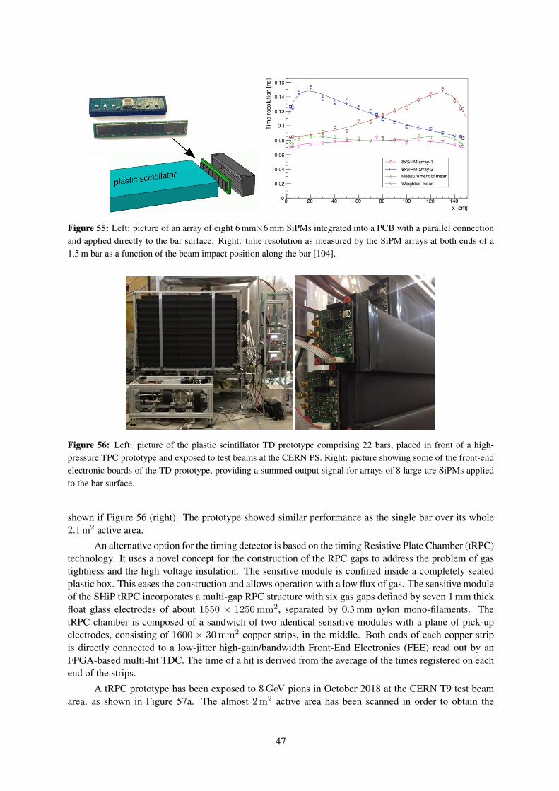
Figure 55: Left: picture of an array of eight 6 mm×6 mm SiPMs integrated into a PCB with a parallel connectionand applied directly to the bar surface. Right: time resolution as measured by the SiPM arrays at both ends of a1.5 m bar as a function of the beam impact position along the bar [104].
Figure 56: Left: picture of the plastic scintillator TD prototype comprising 22 bars, placed in front of a high-pressure TPC prototype and exposed to test beams at the CERN PS. Right: picture showing some of the front-endelectronic boards of the TD prototype, providing a summed output signal for arrays of 8 large-are SiPMs appliedto the bar surface.
shown if Figure 56 (right). The prototype showed similar performance as the single bar over its whole2.1 m2 active area.
An alternative option for the timing detector is based on the timing Resistive Plate Chamber (tRPC)technology. It uses a novel concept for the construction of the RPC gaps to address the problem of gastightness and the high voltage insulation. The sensitive module is confined inside a completely sealedplastic box. This eases the construction and allows operation with a low flux of gas. The sensitive moduleof the SHiP tRPC incorporates a multi-gap RPC structure with six gas gaps defined by seven 1 mm thickfloat glass electrodes of about 1550 × 1250 mm2, separated by 0.3 mm nylon mono-filaments. ThetRPC chamber is composed of a sandwich of two identical sensitive modules with a plane of pick-upelectrodes, consisting of 1600 × 30 mm2 copper strips, in the middle. Both ends of each copper stripis directly connected to a low-jitter high-gain/bandwidth Front-End Electronics (FEE) read out by anFPGA-based multi-hit TDC. The time of a hit is derived from the average of the times registered on eachend of the strips.
A tRPC prototype has been exposed to 8 GeV pions in October 2018 at the CERN T9 test beamarea, as shown in Figure 57a. The almost 2 m2 active area has been scanned in order to obtain the
47
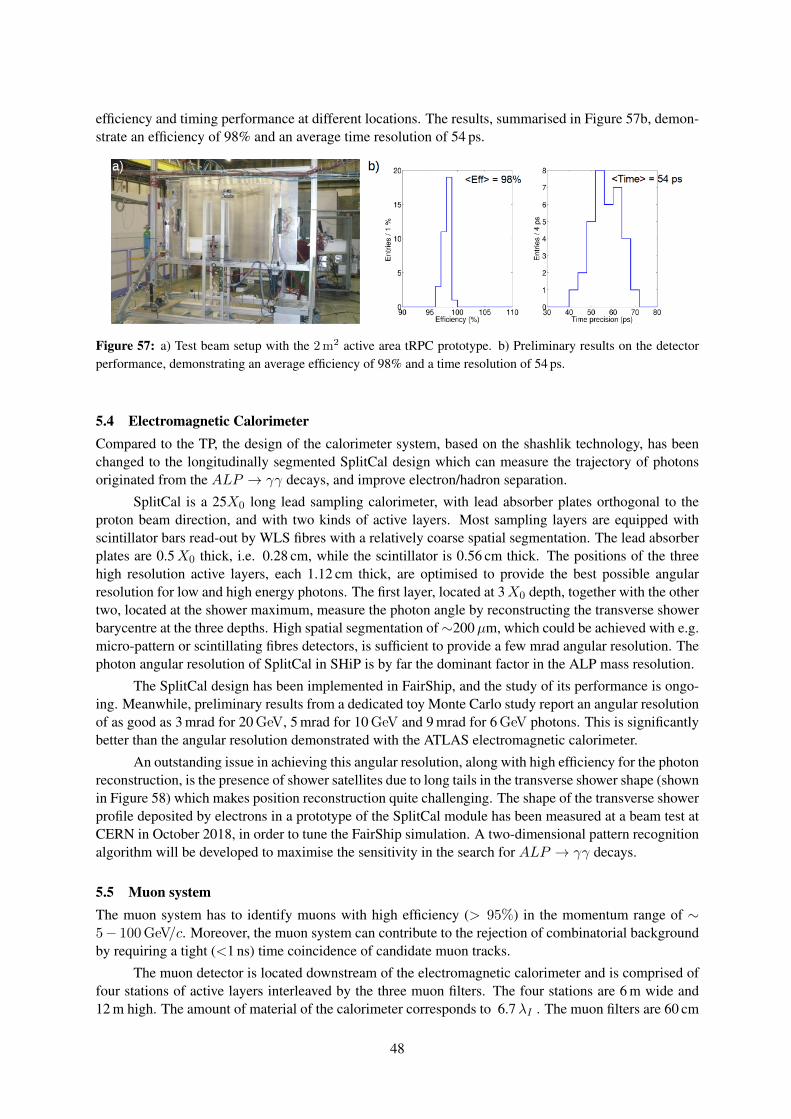
efficiency and timing performance at different locations. The results, summarised in Figure 57b, demon-strate an efficiency of 98% and an average time resolution of 54 ps.
Figure 57: a) Test beam setup with the 2 m2 active area tRPC prototype. b) Preliminary results on the detectorperformance, demonstrating an average efficiency of 98% and a time resolution of 54 ps.
5.4 Electromagnetic CalorimeterCompared to the TP, the design of the calorimeter system, based on the shashlik technology, has beenchanged to the longitudinally segmented SplitCal design which can measure the trajectory of photonsoriginated from the ALP → γγ decays, and improve electron/hadron separation.
SplitCal is a 25X0 long lead sampling calorimeter, with lead absorber plates orthogonal to theproton beam direction, and with two kinds of active layers. Most sampling layers are equipped withscintillator bars read-out by WLS fibres with a relatively coarse spatial segmentation. The lead absorberplates are 0.5X0 thick, i.e. 0.28 cm, while the scintillator is 0.56 cm thick. The positions of the threehigh resolution active layers, each 1.12 cm thick, are optimised to provide the best possible angularresolution for low and high energy photons. The first layer, located at 3X0 depth, together with the othertwo, located at the shower maximum, measure the photon angle by reconstructing the transverse showerbarycentre at the three depths. High spatial segmentation of∼200µm, which could be achieved with e.g.micro-pattern or scintillating fibres detectors, is sufficient to provide a few mrad angular resolution. Thephoton angular resolution of SplitCal in SHiP is by far the dominant factor in the ALP mass resolution.
The SplitCal design has been implemented in FairShip, and the study of its performance is ongo-ing. Meanwhile, preliminary results from a dedicated toy Monte Carlo study report an angular resolutionof as good as 3 mrad for 20 GeV, 5 mrad for 10 GeV and 9 mrad for 6 GeV photons. This is significantlybetter than the angular resolution demonstrated with the ATLAS electromagnetic calorimeter.
An outstanding issue in achieving this angular resolution, along with high efficiency for the photonreconstruction, is the presence of shower satellites due to long tails in the transverse shower shape (shownin Figure 58) which makes position reconstruction quite challenging. The shape of the transverse showerprofile deposited by electrons in a prototype of the SplitCal module has been measured at a beam test atCERN in October 2018, in order to tune the FairShip simulation. A two-dimensional pattern recognitionalgorithm will be developed to maximise the sensitivity in the search for ALP → γγ decays.
5.5 Muon systemThe muon system has to identify muons with high efficiency (> 95%) in the momentum range of ∼5− 100 GeV/c. Moreover, the muon system can contribute to the rejection of combinatorial backgroundby requiring a tight (<1 ns) time coincidence of candidate muon tracks.
The muon detector is located downstream of the electromagnetic calorimeter and is comprised offour stations of active layers interleaved by the three muon filters. The four stations are 6 m wide and12 m high. The amount of material of the calorimeter corresponds to 6.7λI . The muon filters are 60 cm
48
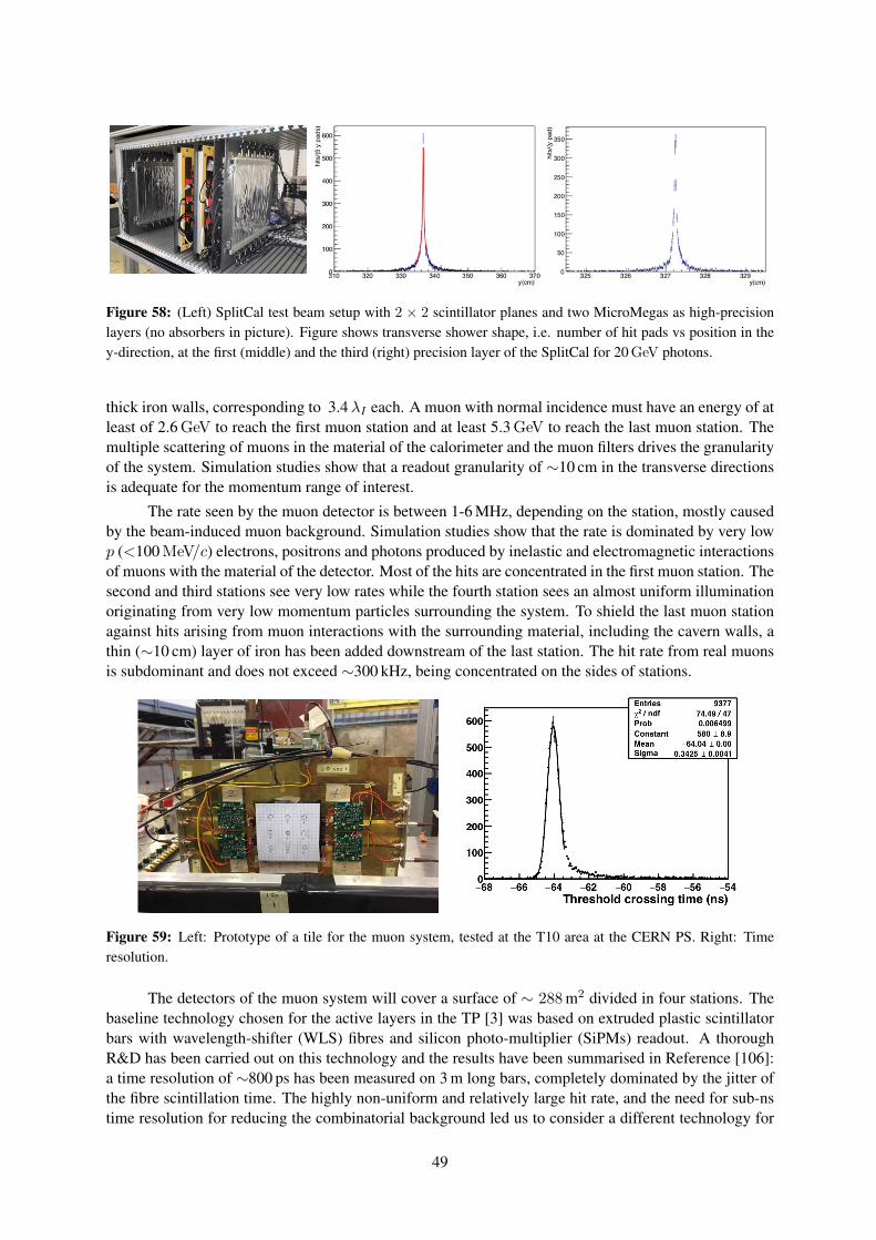
Figure 58: (Left) SplitCal test beam setup with 2 × 2 scintillator planes and two MicroMegas as high-precisionlayers (no absorbers in picture). Figure shows transverse shower shape, i.e. number of hit pads vs position in they-direction, at the first (middle) and the third (right) precision layer of the SplitCal for 20 GeV photons.
thick iron walls, corresponding to 3.4λI each. A muon with normal incidence must have an energy of atleast of 2.6 GeV to reach the first muon station and at least 5.3 GeV to reach the last muon station. Themultiple scattering of muons in the material of the calorimeter and the muon filters drives the granularityof the system. Simulation studies show that a readout granularity of ∼10 cm in the transverse directionsis adequate for the momentum range of interest.
The rate seen by the muon detector is between 1-6 MHz, depending on the station, mostly causedby the beam-induced muon background. Simulation studies show that the rate is dominated by very lowp (<100 MeV/c) electrons, positrons and photons produced by inelastic and electromagnetic interactionsof muons with the material of the detector. Most of the hits are concentrated in the first muon station. Thesecond and third stations see very low rates while the fourth station sees an almost uniform illuminationoriginating from very low momentum particles surrounding the system. To shield the last muon stationagainst hits arising from muon interactions with the surrounding material, including the cavern walls, athin (∼10 cm) layer of iron has been added downstream of the last station. The hit rate from real muonsis subdominant and does not exceed ∼300 kHz, being concentrated on the sides of stations.
Figure 59: Left: Prototype of a tile for the muon system, tested at the T10 area at the CERN PS. Right: Timeresolution.
The detectors of the muon system will cover a surface of ∼ 288 m2 divided in four stations. Thebaseline technology chosen for the active layers in the TP [3] was based on extruded plastic scintillatorbars with wavelength-shifter (WLS) fibres and silicon photo-multiplier (SiPMs) readout. A thoroughR&D has been carried out on this technology and the results have been summarised in Reference [106]:a time resolution of ∼800 ps has been measured on 3 m long bars, completely dominated by the jitter ofthe fibre scintillation time. The highly non-uniform and relatively large hit rate, and the need for sub-nstime resolution for reducing the combinatorial background led us to consider a different technology for
49
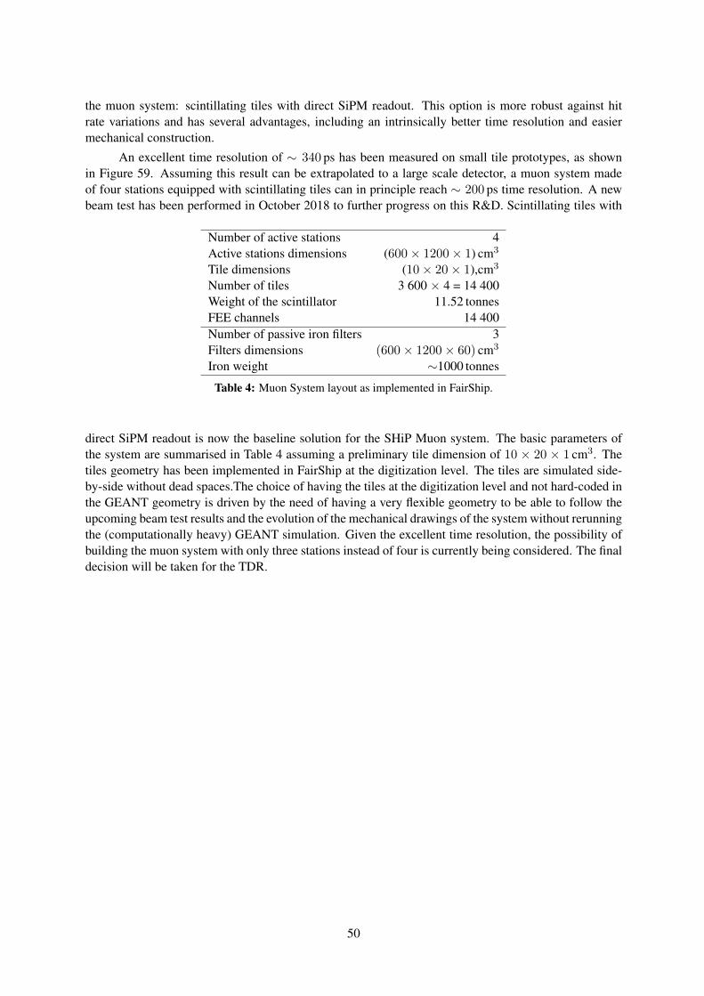
the muon system: scintillating tiles with direct SiPM readout. This option is more robust against hitrate variations and has several advantages, including an intrinsically better time resolution and easiermechanical construction.
An excellent time resolution of ∼ 340 ps has been measured on small tile prototypes, as shownin Figure 59. Assuming this result can be extrapolated to a large scale detector, a muon system madeof four stations equipped with scintillating tiles can in principle reach ∼ 200 ps time resolution. A newbeam test has been performed in October 2018 to further progress on this R&D. Scintillating tiles with
Number of active stations 4Active stations dimensions (600× 1200× 1) cm3
Tile dimensions (10× 20× 1),cm3
Number of tiles 3 600 × 4 = 14 400Weight of the scintillator 11.52 tonnesFEE channels 14 400Number of passive iron filters 3Filters dimensions (600× 1200× 60) cm3
Iron weight ∼1000 tonnes
Table 4: Muon System layout as implemented in FairShip.
direct SiPM readout is now the baseline solution for the SHiP Muon system. The basic parameters ofthe system are summarised in Table 4 assuming a preliminary tile dimension of 10 × 20 × 1 cm3. Thetiles geometry has been implemented in FairShip at the digitization level. The tiles are simulated side-by-side without dead spaces.The choice of having the tiles at the digitization level and not hard-coded inthe GEANT geometry is driven by the need of having a very flexible geometry to be able to follow theupcoming beam test results and the evolution of the mechanical drawings of the system without rerunningthe (computationally heavy) GEANT simulation. Given the excellent time resolution, the possibility ofbuilding the muon system with only three stations instead of four is currently being considered. The finaldecision will be taken for the TDR.
50
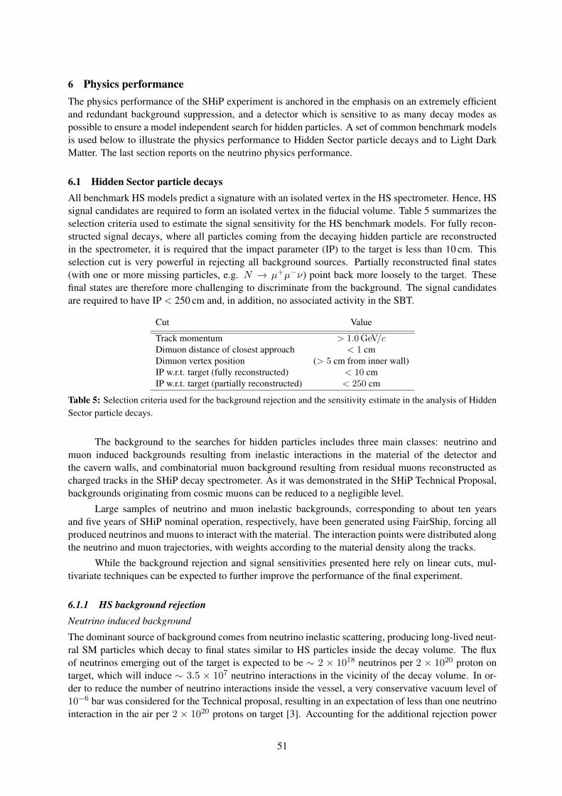
6 Physics performanceThe physics performance of the SHiP experiment is anchored in the emphasis on an extremely efficientand redundant background suppression, and a detector which is sensitive to as many decay modes aspossible to ensure a model independent search for hidden particles. A set of common benchmark modelsis used below to illustrate the physics performance to Hidden Sector particle decays and to Light DarkMatter. The last section reports on the neutrino physics performance.
6.1 Hidden Sector particle decaysAll benchmark HS models predict a signature with an isolated vertex in the HS spectrometer. Hence, HSsignal candidates are required to form an isolated vertex in the fiducial volume. Table 5 summarizes theselection criteria used to estimate the signal sensitivity for the HS benchmark models. For fully recon-structed signal decays, where all particles coming from the decaying hidden particle are reconstructedin the spectrometer, it is required that the impact parameter (IP) to the target is less than 10 cm. Thisselection cut is very powerful in rejecting all background sources. Partially reconstructed final states(with one or more missing particles, e.g. N → µ+µ−ν) point back more loosely to the target. Thesefinal states are therefore more challenging to discriminate from the background. The signal candidatesare required to have IP < 250 cm and, in addition, no associated activity in the SBT.
Cut Value
Track momentum > 1.0 GeV/cDimuon distance of closest approach < 1 cmDimuon vertex position (> 5 cm from inner wall)IP w.r.t. target (fully reconstructed) < 10 cmIP w.r.t. target (partially reconstructed) < 250 cm
Table 5: Selection criteria used for the background rejection and the sensitivity estimate in the analysis of HiddenSector particle decays.
The background to the searches for hidden particles includes three main classes: neutrino andmuon induced backgrounds resulting from inelastic interactions in the material of the detector andthe cavern walls, and combinatorial muon background resulting from residual muons reconstructed ascharged tracks in the SHiP decay spectrometer. As it was demonstrated in the SHiP Technical Proposal,backgrounds originating from cosmic muons can be reduced to a negligible level.
Large samples of neutrino and muon inelastic backgrounds, corresponding to about ten yearsand five years of SHiP nominal operation, respectively, have been generated using FairShip, forcing allproduced neutrinos and muons to interact with the material. The interaction points were distributed alongthe neutrino and muon trajectories, with weights according to the material density along the tracks.
While the background rejection and signal sensitivities presented here rely on linear cuts, mul-tivariate techniques can be expected to further improve the performance of the final experiment.
6.1.1 HS background rejectionNeutrino induced background
The dominant source of background comes from neutrino inelastic scattering, producing long-lived neut-ral SM particles which decay to final states similar to HS particles inside the decay volume. The fluxof neutrinos emerging out of the target is expected to be ∼ 2 × 10¹⁸ neutrinos per 2 × 10²⁰ proton ontarget, which will induce ∼ 3.5 × 10⁷ neutrino interactions in the vicinity of the decay volume. In or-der to reduce the number of neutrino interactions inside the vessel, a very conservative vacuum level of10−6 bar was considered for the Technical proposal, resulting in an expectation of less than one neutrinointeraction in the air per 2 × 10²⁰ protons on target [3]. Accounting for the additional rejection power
51
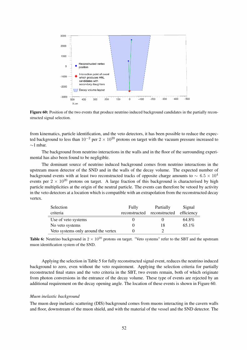
Figure 60: Position of the two events that produce neutrino induced background candidates in the partially recon-structed signal selection.
from kinematics, particle identification, and the veto detectors, it has been possible to reduce the expec-ted background to less than 10−2 per 2 × 10²⁰ protons on target with the vacuum pressure increased to∼1 mbar.
The background from neutrino interactions in the walls and in the floor of the surrounding experi-mental has also been found to be negligible.
The dominant source of neutrino induced background comes from neutrino interactions in theupstream muon detector of the SND and in the walls of the decay volume. The expected number ofbackground events with at least two reconstructed tracks of opposite charge amounts to ∼ 6.5 × 10⁴
events per 2 × 10²⁰ protons on target. A large fraction of this background is characterised by highparticle multiplicities at the origin of the neutral particle. The events can therefore be vetoed by activityin the veto detectors at a location which is compatible with an extrapolation from the reconstructed decayvertex.
Selection Fully Partially Signalcriteria reconstructed reconstructed efficiencyUse of veto systems 0 0 64.8%No veto systems 0 18 65.1%Veto systems only around the vertex 0 2
Table 6: Neutrino background in 2 × 10²⁰ protons on target. "Veto systems" refer to the SBT and the upstreammuon identification system of the SND.
Applying the selection in Table 5 for fully reconstructed signal event, reduces the neutrino inducedbackground to zero, even without the veto requirement. Applying the selection criteria for partiallyreconstructed final states and the veto criteria in the SBT, two events remain, both of which originatefrom photon conversions in the entrance of the decay volume. These type of events are rejected by anadditional requirement on the decay opening angle. The location of these events is shown in Figure 60.
Muon inelastic background
The muon deep inelastic scattering (DIS) background comes from muons interacting in the cavern wallsand floor, downstream of the muon shield, and with the material of the vessel and the SND detector. The
52
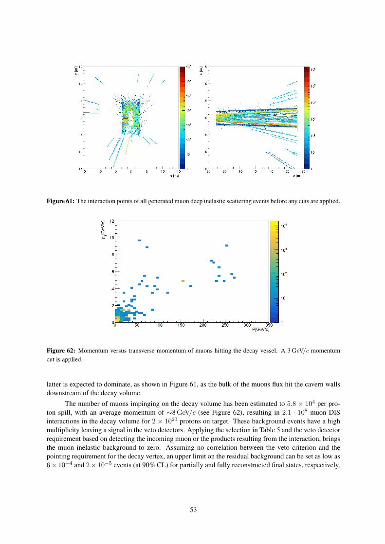
Figure 61: The interaction points of all generated muon deep inelastic scattering events before any cuts are applied.
Figure 62: Momentum versus transverse momentum of muons hitting the decay vessel. A 3 GeV/c momentumcut is applied.
latter is expected to dominate, as shown in Figure 61, as the bulk of the muons flux hit the cavern wallsdownstream of the decay volume.
The number of muons impinging on the decay volume has been estimated to 5.8 × 10⁴ per pro-ton spill, with an average momentum of ∼8 GeV/c (see Figure 62), resulting in 2.1 · 108 muon DISinteractions in the decay volume for 2 × 10²⁰ protons on target. These background events have a highmultiplicity leaving a signal in the veto detectors. Applying the selection in Table 5 and the veto detectorrequirement based on detecting the incoming muon or the products resulting from the interaction, bringsthe muon inelastic background to zero. Assuming no correlation between the veto criterion and thepointing requirement for the decay vertex, an upper limit on the residual background can be set as low as6× 10−4 and 2× 10⁻⁵ events (at 90% CL) for partially and fully reconstructed final states, respectively.
53
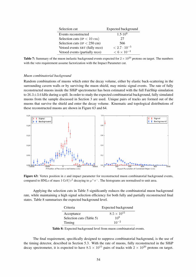
Selection cut Expected backgroundEvents reconstructed 1.5·106
Selection cuts (IP < 10 cm) 27Selection cuts (IP < 250 cm) 566Vetoed events SBT (fully reco) < 2.7 · 10−5
Vetoed events (partially reco) < 6× 10⁻⁴
Table 7: Summary of the muon inelastic background events expected for 2× 10²⁰ protons on target. The numberswith the veto requirement assume factorization with the Impact Parameter cut.
Muon combinatorial background
Random combinations of muons which enter the decay volume, either by elastic back-scattering in thesurrounding cavern walls or by surviving the muon shield, may mimic signal events. The rate of fullyreconstructed muons inside the SHiP spectrometer has been estimated with the full FairShip simulationto 26.3±3.6 kHz during a spill. In order to study the expected combinatorial background, fully simulatedmuons from the sample discussed in Section 3 are used. Unique pairs of tracks are formed out of themuons that survive the shield and enter the decay volume. Kinematic and topological distributions ofthese reconstructed muons are shown in Figure 63 and 64.
Figure 63: Vertex position in z and impact parameter for reconstructed muon combinatorial background events,compared to HNLs of mass 1 GeV/c2 decaying to µ+π−. The histograms are normalised to unit area.
Applying the selection cuts in Table 5 significantly reduces the combinatorial muon backgroundrate, while maintaining a high signal selection efficiency for both fully and partially reconstructed finalstates. Table 8 summarises the expected background level.
Criteria Expected background
Acceptance 8.5× 10¹⁵
Selection cuts (Table 5) 109
Timing 10−2
Table 8: Expected background level from muon combinatorial events.
The final requirement, specifically designed to suppress combinatorial background, is the use ofthe timing detector, described in Section 5.3. With the rate of muons, fully reconstructed in the SHiPdecay spectrometer, it is expected to have 8.5 × 10¹⁵ pairs of tracks with 2 × 10²⁰ protons on target.
54
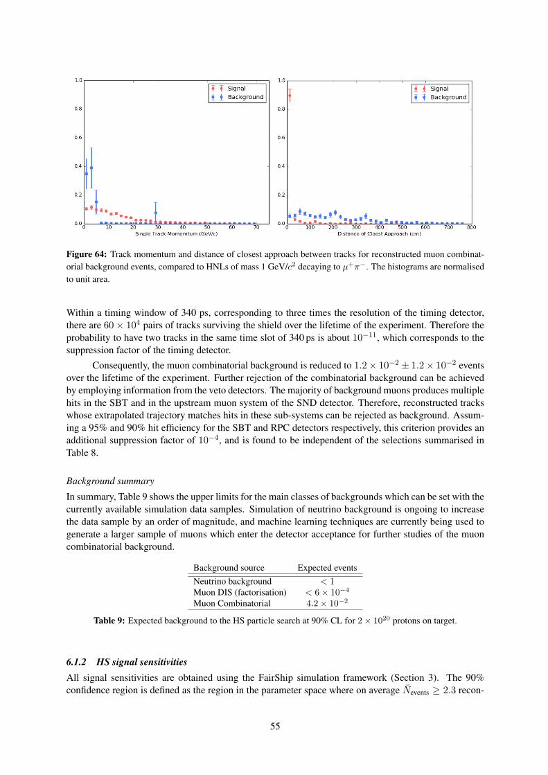
Figure 64: Track momentum and distance of closest approach between tracks for reconstructed muon combinat-orial background events, compared to HNLs of mass 1 GeV/c2 decaying to µ+π−. The histograms are normalisedto unit area.
Within a timing window of 340 ps, corresponding to three times the resolution of the timing detector,there are 60× 104 pairs of tracks surviving the shield over the lifetime of the experiment. Therefore theprobability to have two tracks in the same time slot of 340 ps is about 10−11, which corresponds to thesuppression factor of the timing detector.
Consequently, the muon combinatorial background is reduced to 1.2× 10⁻² ± 1.2× 10⁻² eventsover the lifetime of the experiment. Further rejection of the combinatorial background can be achievedby employing information from the veto detectors. The majority of background muons produces multiplehits in the SBT and in the upstream muon system of the SND detector. Therefore, reconstructed trackswhose extrapolated trajectory matches hits in these sub-systems can be rejected as background. Assum-ing a 95% and 90% hit efficiency for the SBT and RPC detectors respectively, this criterion provides anadditional suppression factor of 10−4, and is found to be independent of the selections summarised inTable 8.
Background summary
In summary, Table 9 shows the upper limits for the main classes of backgrounds which can be set with thecurrently available simulation data samples. Simulation of neutrino background is ongoing to increasethe data sample by an order of magnitude, and machine learning techniques are currently being used togenerate a larger sample of muons which enter the detector acceptance for further studies of the muoncombinatorial background.
Background source Expected eventsNeutrino background < 1Muon DIS (factorisation) < 6× 10⁻⁴
Muon Combinatorial 4.2× 10⁻²
Table 9: Expected background to the HS particle search at 90% CL for 2× 10²⁰ protons on target.
6.1.2 HS signal sensitivitiesAll signal sensitivities are obtained using the FairShip simulation framework (Section 3). The 90%confidence region is defined as the region in the parameter space where on average Nevents ≥ 2.3 recon-
55
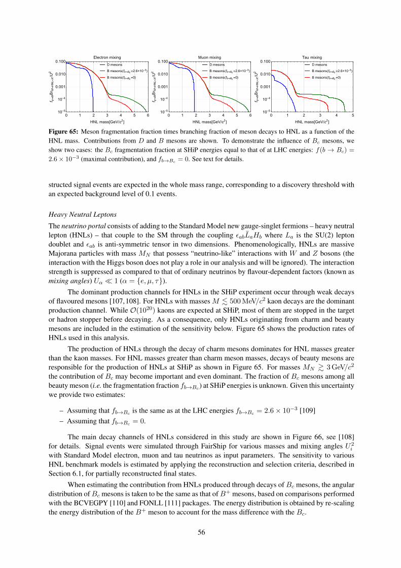
D mesons
B mesons(fb→Bc=2.6×10⁻³)
B mesons(fb→Bc=0)
0 1 2 3 4 5 610-5
10-4
0.001
0.010
0.100
HNL mass[GeV/c2]
f q→MBr M
→HNL+X/U2
Electron mixing
D mesons
B mesons(fb→Bc=2.6×10⁻³)
B mesons(fb→Bc=0)
0 1 2 3 4 5 610-5
10-4
0.001
0.010
0.100
HNL mass[GeV/c2]
f q→MBr M
→HNL+X/U2
Muon mixing
D mesons
B mesons(fb→Bc=2.6×10⁻³)
B mesons(fb→Bc=0)
0 1 2 3 4 510-5
10-4
0.001
0.010
0.100
HNL mass[GeV/c2]
f q→MBr M
→HNL+X/U2
Tau mixing
Figure 65: Meson fragmentation fraction times branching fraction of meson decays to HNL as a function of theHNL mass. Contributions from D and B mesons are shown. To demonstrate the influence of Bc mesons, weshow two cases: the Bc fragmentation fraction at SHiP energies equal to that of at LHC energies: f(b → Bc) =
2.6× 10⁻³ (maximal contribution), and fb→Bc= 0. See text for details.
structed signal events are expected in the whole mass range, corresponding to a discovery threshold withan expected background level of 0.1 events.
Heavy Neutral Leptons
The neutrino portal consists of adding to the Standard Model new gauge-singlet fermions – heavy neutrallepton (HNLs) – that couple to the SM through the coupling εabLaHb where La is the SU(2) leptondoublet and εab is anti-symmetric tensor in two dimensions. Phenomenologically, HNLs are massiveMajorana particles with mass MN that possess “neutrino-like” interactions with W and Z bosons (theinteraction with the Higgs boson does not play a role in our analysis and will be ignored). The interactionstrength is suppressed as compared to that of ordinary neutrinos by flavour-dependent factors (known asmixing angles) Uα 1 (α = e, µ, τ).
The dominant production channels for HNLs in the SHiP experiment occur through weak decaysof flavoured mesons [107,108]. For HNLs with masses M . 500 MeV/c2 kaon decays are the dominantproduction channel. While O(1020) kaons are expected at SHiP, most of them are stopped in the targetor hadron stopper before decaying. As a consequence, only HNLs originating from charm and beautymesons are included in the estimation of the sensitivity below. Figure 65 shows the production rates ofHNLs used in this analysis.
The production of HNLs through the decay of charm mesons dominates for HNL masses greaterthan the kaon masses. For HNL masses greater than charm meson masses, decays of beauty mesons areresponsible for the production of HNLs at SHiP as shown in Figure 65. For masses MN & 3 GeV/c2
the contribution of Bc may become important and even dominant. The fraction of Bc mesons among allbeauty meson (i.e. the fragmentation fraction fb→Bc) at SHiP energies is unknown. Given this uncertaintywe provide two estimates:
– Assuming that fb→Bc is the same as at the LHC energies fb→Bc = 2.6× 10⁻³ [109]– Assuming that fb→Bc = 0.
The main decay channels of HNLs considered in this study are shown in Figure 66, see [108]for details. Signal events were simulated through FairShip for various masses and mixing angles U2
i
with Standard Model electron, muon and tau neutrinos as input parameters. The sensitivity to variousHNL benchmark models is estimated by applying the reconstruction and selection criteria, described inSection 6.1, for partially reconstructed final states.
When estimating the contribution from HNLs produced through decays of Bc mesons, the angulardistribution ofBc mesons is taken to be the same as that ofB+ mesons, based on comparisons performedwith the BCVEGPY [110] and FONLL [111] packages. The energy distribution is obtained by re-scalingthe energy distribution of the B+ meson to account for the mass difference with the Bc.
56
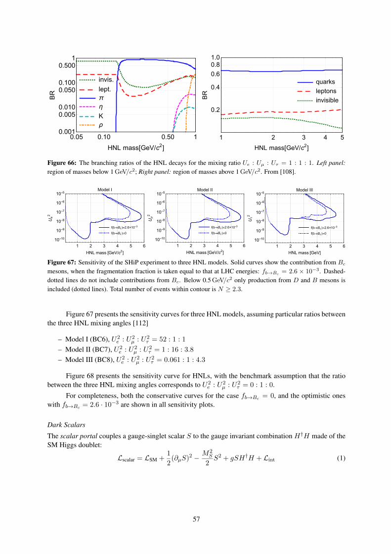
invis.
lept.
π
η
K
ρ
0.05 0.10 0.50 10.001
0.0050.010
0.0500.100
0.5001
HNL mass[GeV/c2]
BR
quarks
leptons
invisible
1 2 3 4 5
0.2
0.4
0.6
0.81.0
HNL mass[GeV/c2]
BR
Figure 66: The branching ratios of the HNL decays for the mixing ratio Ue : Uµ : Uτ = 1 : 1 : 1. Left panel:region of masses below 1 GeV/c2; Right panel: region of masses above 1 GeV/c2. From [108].
f(b→Bc )=2.6×10⁻³
f(b→Bc )=0
1 2 3 4 5 6
10-10
10-9
10-8
10-7
10-6
10-5
HNL mass [GeV/c2]
Ue2
Model I
f(b→Bc )=2.6×10⁻³
f(b→Bc )=0
1 2 3 4 5 6
10-10
10-9
10-8
10-7
10-6
10-5
HNL mass [GeV/c2]
Uμ2
Model II
f(b→Bc )=2.6×10⁻³
f(b→Bc )=0
1 2 3 4 5 6
10-10
10-9
10-8
10-7
10-6
10-5
HNL mass [GeV]U
τ2
Model III
Figure 67: Sensitivity of the SHiP experiment to three HNL models. Solid curves show the contribution from Bcmesons, when the fragmentation fraction is taken equal to that at LHC energies: fb→Bc
= 2.6 × 10⁻³. Dashed-dotted lines do not include contributions from Bc. Below 0.5 GeV/c2 only production from D and B mesons isincluded (dotted lines). Total number of events within contour is N ≥ 2.3.
Figure 67 presents the sensitivity curves for three HNL models, assuming particular ratios betweenthe three HNL mixing angles [112]
– Model I (BC6), U2e : U2
µ : U2τ = 52 : 1 : 1
– Model II (BC7), U2e : U2
µ : U2τ = 1 : 16 : 3.8
– Model III (BC8), U2e : U2
µ : U2τ = 0.061 : 1 : 4.3
Figure 68 presents the sensitivity curve for HNLs, with the benchmark assumption that the ratiobetween the three HNL mixing angles corresponds to U2
e : U2µ : U2
τ = 0 : 1 : 0.
For completeness, both the conservative curves for the case fb→Bc = 0, and the optimistic oneswith fb→Bc = 2.6 · 10−3 are shown in all sensitivity plots.
Dark Scalars
The scalar portal couples a gauge-singlet scalar S to the gauge invariant combination H†H made of theSM Higgs doublet:
Lscalar = LSM +1
2(∂µS)2 −
M2S
2S2 + gSH†H + Lint (1)
57
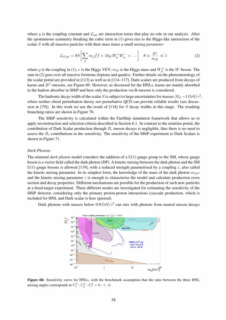
where g is the coupling constant and Lint are interaction terms that play no role in our analysis. Afterthe spontaneous symmetry breaking the cubic term in (1) gives rise to the Higgs-like interaction of thescalar S with all massive particles with their mass times a small mixing parameter
LS,int = θS
[∑f
mf ff +MWW+µ W
−µ + . . .
]θ ≡ gv
mH 1 (2)
where g is the coupling in (1), v is the Higgs VEV; mH is the Higgs mass and W±µ is the W -boson. Thesum in (2) goes over all massive fermions (leptons and quarks). Further details on the phenomenology ofthe scalar portal are provided in [113] as well as in [114–117]. Dark scalars are produced from decays ofkaons and B±-mesons, see Figure 69. However, as discussed for the HNLs, kaons are mainly absorbedin the hadron absorber in SHiP and here only the production via B-mesons is considered.
The hadronic decay width of the scalar S is subject to large uncertainties for massesMS ∼1 GeV/c2,where neither chiral perturbation theory nor perturbative QCD can provide reliable results (see discus-sion in [79]). In this work we use the result of [118] for S decay widths in this range. The resultingbranching ratios are shown in Figure 70.
The SHiP sensitivity is calculated within the FairShip simulation framework that allows us toapply reconstruction and selection criteria described in Section 6.1. In contrast to the neutrino portal, thecontribution of Dark Scalar production through Bc meson decays is negligible, thus there is no need toassess the Bc contributions to the sensitivity. The sensitivity of the SHiP experiment to Dark Scalars isshown in Figure 71.
Dark Photons
The minimal dark photon model considers the addition of a U(1) gauge group to the SM, whose gaugeboson is a vector field called the dark photon (DP). A kinetic mixing between the dark photon and the SMU(1) gauge bosons is allowed [119], with a reduced strength parametrised by a coupling ε, also calledthe kinetic mixing parameter. In its simplest form, the knowledge of the mass of the dark photon mDP
and the kinetic mixing parameter ε is enough to characterise the model and calculate production crosssection and decay properties. Different mechanisms are possible for the production of such new particlesat a fixed-target experiment. Three different modes are investigated for estimating the sensitivity of theSHiP detector, considering only the primary proton-proton interactions (cascade production, which isincluded for HNL and Dark scalar is here ignored).
Dark photons with masses below 0.9 GeV/c2 can mix with photons from neutral meson decays
Figure 68: Sensitivity curve for HNLs, with the benchmark assumption that the ratio between the three HNLmixing angles corresponds to U2
e : U2µ : U2
τ = 0 : 1 : 0.
58
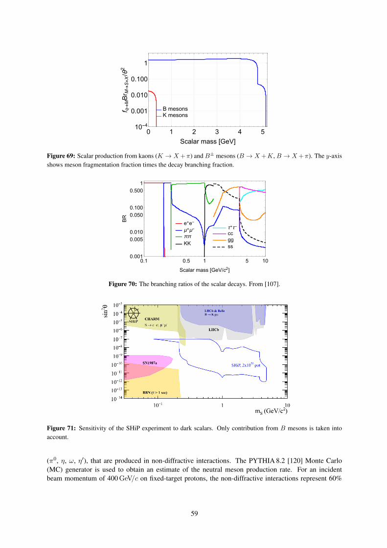
B mesonsK mesons
0 1 2 3 4 510-4
0.001
0.010
0.100
1
Scalar mass [GeV]
f q→MBr M
→S+X/θ2
Figure 69: Scalar production from kaons (K → X +π) and B± mesons (B → X +K, B → X +π). The y-axisshows meson fragmentation fraction times the decay branching fraction.
τ+τ-
ccggss
e+e-
μ+μ-
ππ
KK
0.1 0.5 1 5 100.001
0.005
0.010
0.050
0.100
0.500
1
Scalar mass [GeV/c2]
BR
Figure 70: The branching ratios of the scalar decays. From [107].
Figure 71: Sensitivity of the SHiP experiment to dark scalars. Only contribution from B mesons is taken intoaccount.
(π0, η, ω, η′), that are produced in non-diffractive interactions. The PYTHIA 8.2 [120] Monte Carlo(MC) generator is used to obtain an estimate of the neutral meson production rate. For an incidentbeam momentum of 400 GeV/c on fixed-target protons, the non-diffractive interactions represent 60%
59
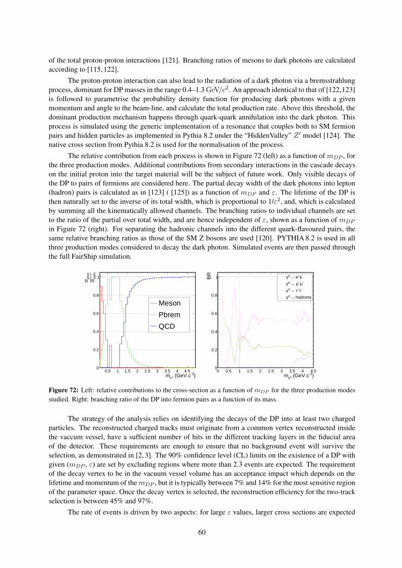
of the total proton-proton interactions [121]. Branching ratios of mesons to dark photons are calculatedaccording to [115, 122].
The proton-proton interaction can also lead to the radiation of a dark photon via a bremsstrahlungprocess, dominant for DP masses in the range 0.4–1.3 GeV/c2. An approach identical to that of [122,123]is followed to parametrise the probability density function for producing dark photons with a givenmomentum and angle to the beam-line, and calculate the total production rate. Above this threshold, thedominant production mechanism happens through quark-quark annihilation into the dark photon. Thisprocess is simulated using the generic implementation of a resonance that couples both to SM fermionpairs and hidden particles as implemented in Pythia 8.2 under the “HiddenValley” Z ′ model [124]. Thenative cross section from Pythia 8.2 is used for the normalisation of the process.
The relative contribution from each process is shown in Figure 72 (left) as a function of mDP , forthe three production modes. Additional contributions from secondary interactions in the cascade decayson the initial proton into the target material will be the subject of future work. Only visible decays ofthe DP to pairs of fermions are considered here. The partial decay width of the dark photons into lepton(hadron) pairs is calculated as in [123] ( [125]) as a function of mDP and ε. The lifetime of the DP isthen naturally set to the inverse of its total width, which is proportional to 1/ε2, and, which is calculatedby summing all the kinematically allowed channels. The branching ratios to individual channels are setto the ratio of the partial over total width, and are hence independent of ε, shown as a function of mDP
in Figure 72 (right). For separating the hadronic channels into the different quark-flavoured pairs, thesame relative branching ratios as those of the SM Z bosons are used [120]. PYTHIA 8.2 is used in allthree production modes considered to decay the dark photon. Simulated events are then passed throughthe full FairShip simulation.
)-2 (GeV.cDγm0.5 1 1.5 2 2.5 3 3.5 4 4.5
sum
σproc
σ
0
0.2
0.4
0.6
0.8
1
Meson
Pbrem
QCD
)-2 (GeV.cDγm0 0.5 1 1.5 2 2.5 3 3.5 4 4.5
BR
0
0.2
0.4
0.6
0.8
1 -e+ e→Dγ-µ+µ →Dγ
-τ+τ →Dγ hadrons→Dγ
Figure 72: Left: relative contributions to the cross-section as a function of mDP for the three production modesstudied. Right: branching ratio of the DP into fermion pairs as a function of its mass.
The strategy of the analysis relies on identifying the decays of the DP into at least two chargedparticles. The reconstructed charged tracks must originate from a common vertex reconstructed insidethe vaccum vessel, have a sufficient number of hits in the different tracking layers in the fiducial areaof the detector. These requirements are enough to ensure that no background event will survive theselection, as demonstrated in [2, 3]. The 90% confidence level (CL) limits on the existence of a DP withgiven (mDP , ε) are set by excluding regions where more than 2.3 events are expected. The requirementof the decay vertex to be in the vacuum vessel volume has an acceptance impact which depends on thelifetime and momentum of themDP , but it is typically between 7% and 14% for the most sensitive regionof the parameter space. Once the decay vertex is selected, the reconstruction efficiency for the two-trackselection is between 45% and 97%.
The rate of events is driven by two aspects: for large ε values, larger cross sections are expected
60
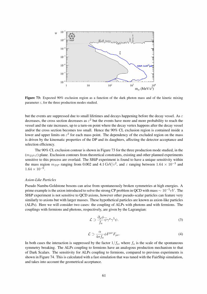
Figure 73: Expected 90% exclusion region as a function of the dark photon mass and of the kinetic mixingparameter ε, for the three production modes studied.
but the events are suppressed due to small lifetimes and decays happening before the decay vessel. As εdecreases, the cross section decreases as ε2 but the events have more and more probability to reach thevessel and the rate increases, up to a turn-on point where the decay vertex happens after the decay vesseland/or the cross section becomes too small. Hence the 90% CL exclusion region is contained inside alower and upper limits on ε2 for each mass point. The dependency of the excluded region on the massis driven by the kinematic properties of the DP and its daughters, affecting the detector acceptance andselection efficiency.
The 90% CL exclusion contour is shown in Figure 73 for the three production mode studied, in the(mDP ,ε) plane. Exclusion contours from theoretical constraints, existing and other planned experimentssensitive to this process are overlaid. The SHiP experiment is found to have a unique sensitivity withinthe mass region mDP ranging from 0.002 and 4.1 GeV/c2, and ε ranging between 1.64 × 10⁻³ and1.64× 10−9.
Axion-Like Particles
Pseudo Nambu-Goldstone bosons can arise from spontaneously broken symmetries at high energies. Aprime example is the axion introduced to solve the strong CP problem in QCD with mass∼ 10−5eV . TheSHiP experiment is not sensitive to QCD axions, however other pseudo-scalar particles can feature verysimilarly to axions but with larger masses. These hypothetical particles are known as axion-like particles(ALPs). Here we will consider two cases: the coupling of ALPs with photons and with fermions. Thecouplings with fermions and photons, respectively, are given by the Lagrangian:
L ⊃ ∂µφ
faψγµγ5ψ. (3)
L ⊃ α
4πfaφFµνFµν . (4)
In both cases the interaction is suppressed by the factor 1/fa, where fa is the scale of the spontaneoussymmetry breaking. The ALPs coupling to fermions have an analogous production mechanism to thatof Dark Scalars. The sensitivity for ALPs coupling to fermions, compared to previous experiments isshown in Figure 74. This is calculated with a fast simulation that was tuned with the FairShip simulation,and takes into account the geometrical acceptance.
61
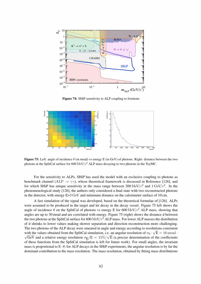
Figure 74: SHiP sensitivity to ALP coupling to fermions
0.5
1
1.5
2
2.5
3
3.5
4
ev/b
in(a
.u.)
10 20 30 40 50 60 70E(GeV)
0
10
20
30
40
50
60
(mra
d)θ
d(cm)0 50 100 150 200 250 300 350 400
ev/b
in(a
.u.)
0
1
2
3
4
5
6
Figure 75: Left: angle of incidence θ (in mrad) vs energy E (in GeV) of photons. Right: distance between the twophotons at the SplitCal surface for 600 MeV/c2 ALP mass decaying to two photons in the ToyMC.
For the sensitivity to ALPs, SHiP has used the model with an exclusive coupling to photons asbenchmark channel (ALP → γγ), whose theoretical framework is discussed in Reference [126], andfor which SHiP has unique sensitivity in the mass range between 200 MeV/c2 and 1 GeV/c2. In thephenomenological study [126], the authors only considered a final state with two reconstructed photonsin the detector, with energy E>3 GeV and minimum distance on the calorimeter surface of 10 cm.
A fast simulation of the signal was developed, based on the theoretical formulae of [126]. ALPswere assumed to be produced in the target and let decay in the decay vessel. Figure 75 left shows theangle of incidence θ on the SplitCal of photons vs energy E for 600 MeV/c2 ALP mass, showing thatangles are up to 30 mrad and are correlated with energy. Figure 75 (right) shows the distance d betweenthe two photons at the SplitCal surface for 600 MeV/c2 ALP mass. For lower ALP masses the distributionof d shrinks to lower values making shower separation and direction reconstruction more challenging.The two photons of the ALP decay were smeared in angle and energy according to resolutions consistentwith the values obtained from the SplitCal simulation, i.e. an angular resolution of σθ ·
√E = 16 mrad ·√
GeV and a relative energy resolution σE/E = 15%/√
E (a precise determination of the coefficientsof these functions from the SplitCal simulation is left for future work). For small angles, the invariantmass is proportional to E ·θ; for ALP decays in the SHiP experiments, the angular resolution is by far thedominant contribution to the mass resolution. The mass resolution, obtained by fitting mass distributions
62
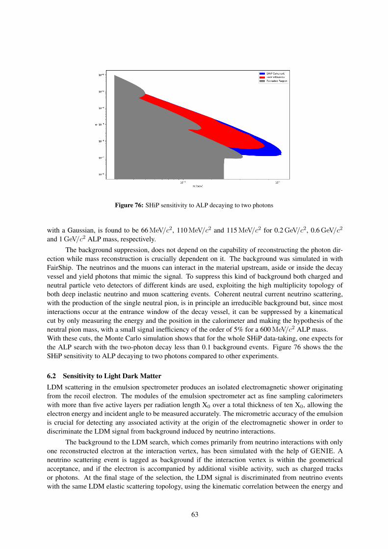
Figure 76: SHiP sensitivity to ALP decaying to two photons
with a Gaussian, is found to be 66 MeV/c2, 110 MeV/c2 and 115 MeV/c2 for 0.2 GeV/c2, 0.6 GeV/c2
and 1 GeV/c2 ALP mass, respectively.
The background suppression, does not depend on the capability of reconstructing the photon dir-ection while mass reconstruction is crucially dependent on it. The background was simulated in withFairShip. The neutrinos and the muons can interact in the material upstream, aside or inside the decayvessel and yield photons that mimic the signal. To suppress this kind of background both charged andneutral particle veto detectors of different kinds are used, exploiting the high multiplicity topology ofboth deep inelastic neutrino and muon scattering events. Coherent neutral current neutrino scattering,with the production of the single neutral pion, is in principle an irreducible background but, since mostinteractions occur at the entrance window of the decay vessel, it can be suppressed by a kinematicalcut by only measuring the energy and the position in the calorimeter and making the hypothesis of theneutral pion mass, with a small signal inefficiency of the order of 5% for a 600 MeV/c2 ALP mass.With these cuts, the Monte Carlo simulation shows that for the whole SHiP data-taking, one expects forthe ALP search with the two-photon decay less than 0.1 background events. Figure 76 shows the theSHiP sensitivity to ALP decaying to two photons compared to other experiments.
6.2 Sensitivity to Light Dark MatterLDM scattering in the emulsion spectrometer produces an isolated electromagnetic shower originatingfrom the recoil electron. The modules of the emulsion spectrometer act as fine sampling calorimeterswith more than five active layers per radiation length X0 over a total thickness of ten X0, allowing theelectron energy and incident angle to be measured accurately. The micrometric accuracy of the emulsionis crucial for detecting any associated activity at the origin of the electromagnetic shower in order todiscriminate the LDM signal from background induced by neutrino interactions.
The background to the LDM search, which comes primarily from neutrino interactions with onlyone reconstructed electron at the interaction vertex, has been simulated with the help of GENIE. Aneutrino scattering event is tagged as background if the interaction vertex is within the geometricalacceptance, and if the electron is accompanied by additional visible activity, such as charged tracksor photons. At the final stage of the selection, the LDM signal is discriminated from neutrino eventswith the same LDM elastic scattering topology, using the kinematic correlation between the energy and
63
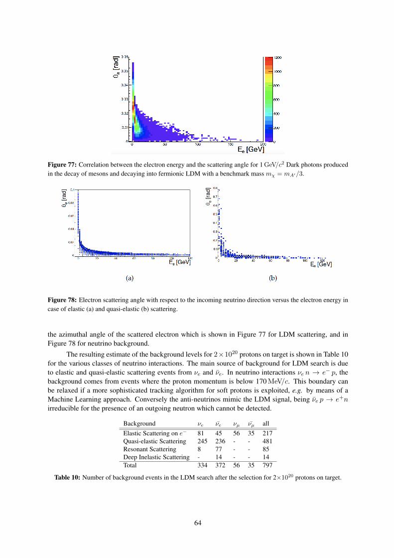
Figure 77: Correlation between the electron energy and the scattering angle for 1 GeV/c2 Dark photons producedin the decay of mesons and decaying into fermionic LDM with a benchmark mass mχ = mA′/3.
Figure 78: Electron scattering angle with respect to the incoming neutrino direction versus the electron energy incase of elastic (a) and quasi-elastic (b) scattering.
the azimuthal angle of the scattered electron which is shown in Figure 77 for LDM scattering, and inFigure 78 for neutrino background.
The resulting estimate of the background levels for 2×10²⁰ protons on target is shown in Table 10for the various classes of neutrino interactions. The main source of background for LDM search is dueto elastic and quasi-elastic scattering events from νe and νe. In neutrino interactions νe n → e− p, thebackground comes from events where the proton momentum is below 170 MeV/c. This boundary canbe relaxed if a more sophisticated tracking algorithm for soft protons is exploited, e.g. by means of aMachine Learning approach. Conversely the anti-neutrinos mimic the LDM signal, being νe p → e+nirreducible for the presence of an outgoing neutron which cannot be detected.
Background νe νe νµ νµ allElastic Scattering on e− 81 45 56 35 217Quasi-elastic Scattering 245 236 - - 481Resonant Scattering 8 77 - - 85Deep Inelastic Scattering - 14 - - 14Total 334 372 56 35 797
Table 10: Number of background events in the LDM search after the selection for 2×10²⁰ protons on target.
64
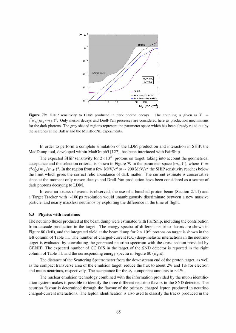
Figure 79: SHiP sensitivity to LDM produced in dark photon decays. The coupling is given as Y =
ε2α′D(mχ/mA′)4. Only meson decays and Drell-Yan processes are considered here as production mechanismsfor the dark photons. The grey shaded regions represent the parameter space which has been already ruled out bythe searches at the BaBar and the MiniBooNE experiments.
In order to perform a complete simulation of the LDM production and interaction in SHiP, theMadDump tool, developed within MadGraph5 [127], has been interfaced with FairShip.
The expected SHiP sensitivity for 2×10²⁰ protons on target, taking into account the geometricalacceptance and the selection criteria, is shown in Figure 79 in the parameter space (mχ,Y ), where Y =ε2α′D(mχ/mA′)
4. In the region from a few MeV/c2 to∼ 200 MeV/c2 the SHiP sensitivity reaches belowthe limit which gives the correct relic abundance of dark matter. The current estimate is conservativesince at the moment only meson decays and Drell-Yan production have been considered as a source ofdark photons decaying to LDM.
In case an excess of events is observed, the use of a bunched proton beam (Section 2.1.1) anda Target Tracker with ∼100 ps resolution would unambiguously discriminate between a new massiveparticle, and nearly massless neutrinos by exploiting the difference in the time of flight.
6.3 Physics with neutrinosThe neutrino fluxes produced at the beam dump were estimated with FairShip, including the contributionfrom cascade production in the target. The energy spectra of different neutrino flavors are shown inFigure 80 (left), and the integrated yield at the beam dump for 2× 10²⁰ protons on target is shown in theleft column of Table 11. The number of charged-current (CC) deep-inelastic interactions in the neutrinotarget is evaluated by convoluting the generated neutrino spectrum with the cross section provided byGENIE. The expected number of CC DIS in the target of the SND detector is reported in the rightcolumn of Table 11, and the corresponding energy spectra in Figure 80 (right).
The distance of the Scattering Spectrometer from the downstream end of the proton target, as wellas the compact transverse area of the emulsion target, reduce the flux to about 2% and 1% for electronand muon neutrinos, respectively. The acceptance for the ντ component amounts to ∼4%.
The nuclear emulsion technology combined with the information provided by the muon identific-ation system makes it possible to identify the three different neutrino flavors in the SND detector. Theneutrino flavour is determined through the flavour of the primary charged lepton produced in neutrinocharged-current interactions. The lepton identification is also used to classify the tracks produced in the
65
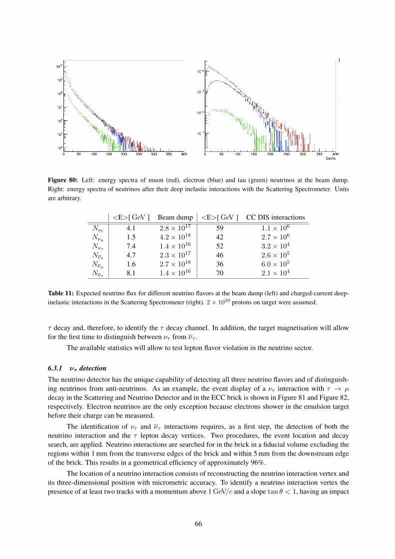
Figure 80: Left: energy spectra of muon (red), electron (blue) and tau (green) neutrinos at the beam dump.Right: energy spectra of neutrinos after their deep inelastic interactions with the Scattering Spectrometer. Unitsare arbitrary.
<E>[ GeV ] Beam dump <E>[ GeV ] CC DIS interactionsNνe 4.1 2.8× 10¹⁷ 59 1.1× 10⁶
Nνµ 1.5 4.2× 10¹⁸ 42 2.7× 10⁶
Nντ 7.4 1.4× 10¹⁶ 52 3.2× 10⁴
Nνe 4.7 2.3× 10¹⁷ 46 2.6× 10⁵
Nνµ 1.6 2.7× 10¹⁸ 36 6.0× 10⁵
Nντ 8.1 1.4× 10¹⁶ 70 2.1× 10⁴
Table 11: Expected neutrino flux for different neutrino flavors at the beam dump (left) and charged-current deep-inelastic interactions in the Scattering Spectrometer (right). 2× 10²⁰ protons on target were assumed.
τ decay and, therefore, to identify the τ decay channel. In addition, the target magnetisation will allowfor the first time to distinguish between ντ from ντ .
The available statistics will allow to test lepton flavor violation in the neutrino sector.
6.3.1 ντ detectionThe neutrino detector has the unique capability of detecting all three neutrino flavors and of distinguish-ing neutrinos from anti-neutrinos. As an example, the event display of a ντ interaction with τ → µdecay in the Scattering and Neutrino Detector and in the ECC brick is shown in Figure 81 and Figure 82,respectively. Electron neutrinos are the only exception because electrons shower in the emulsion targetbefore their charge can be measured.
The identification of ντ and ντ interactions requires, as a first step, the detection of both theneutrino interaction and the τ lepton decay vertices. Two procedures, the event location and decaysearch, are applied. Neutrino interactions are searched for in the brick in a fiducial volume excluding theregions within 1 mm from the transverse edges of the brick and within 5 mm from the downstream edgeof the brick. This results in a geometrical efficiency of approximately 96%.
The location of a neutrino interaction consists of reconstructing the neutrino interaction vertex andits three-dimensional position with micrometric accuracy. To identify a neutrino interaction vertex thepresence of at least two tracks with a momentum above 1 GeV/c and a slope tan θ < 1, having an impact
66
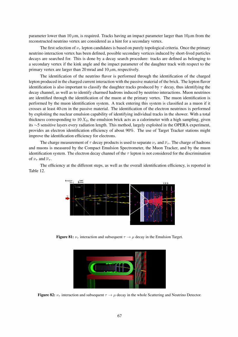
parameter lower than 10µm, is required. Tracks having an impact parameter larger than 10µm from thereconstructed neutrino vertex are considered as a hint for a secondary vertex.
The first selection of ντ lepton candidates is based on purely topological criteria. Once the primaryneutrino interaction vertex has been defined, possible secondary vertices induced by short-lived particlesdecays are searched for. This is done by a decay search procedure: tracks are defined as belonging toa secondary vertex if the kink angle and the impact parameter of the daughter track with respect to theprimary vertex are larger than 20 mrad and 10µm, respectively.
The identification of the neutrino flavor is performed through the identification of the chargedlepton produced in the charged current interaction with the passive material of the brick. The lepton flavoridentification is also important to classify the daughter tracks produced by τ decay, thus identifying thedecay channel, as well as to identify charmed hadrons induced by neutrino interactions. Muon neutrinosare identified through the identification of the muon at the primary vertex. The muon identification isperformed by the muon identification system. A track entering this system is classified as a muon if itcrosses at least 40 cm in the passive material. The identification of the electron neutrinos is performedby exploiting the nuclear emulsion capability of identifying individual tracks in the shower. With a totalthickness corresponding to 10X0, the emulsion brick acts as a calorimeter with a high sampling, givenits ∼5 sensitive layers every radiation length. This method, largely exploited in the OPERA experiment,provides an electron identification efficiency of about 90%. The use of Target Tracker stations mightimprove the identification efficiency for electrons.
The charge measurement of τ decay products is used to separate ντ and ντ . The charge of hadronsand muons is measured by the Compact Emulsion Spectrometer, the Muon Tracker, and by the muonidentification system. The electron decay channel of the τ lepton is not considered for the discriminationof ντ and ντ .
The efficiency at the different steps, as well as the overall identification efficiency, is reported inTable 12.
Figure 81: ντ interaction and subsequent τ → µ decay in the Emulsion Target.
Figure 82: ντ interaction and subsequent τ → µ decay in the whole Scattering and Neutrino Detector.
67
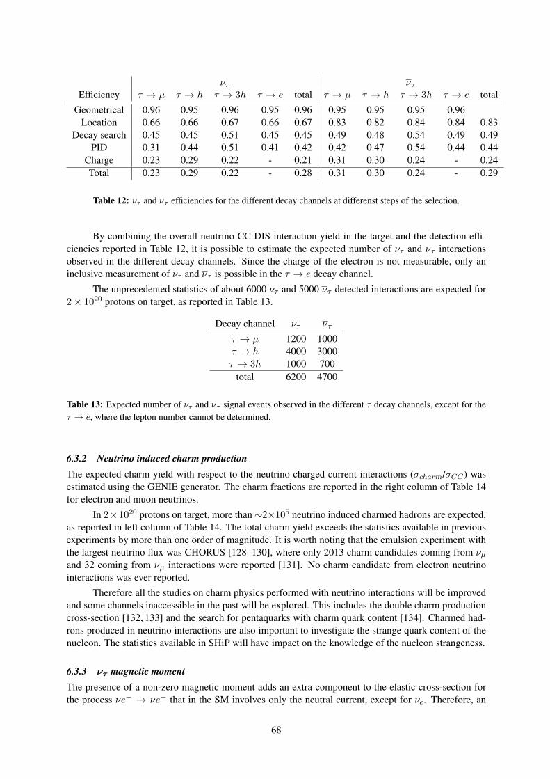
ντ ντEfficiency τ → µ τ → h τ → 3h τ → e total τ → µ τ → h τ → 3h τ → e total
Geometrical 0.96 0.95 0.96 0.95 0.96 0.95 0.95 0.95 0.96Location 0.66 0.66 0.67 0.66 0.67 0.83 0.82 0.84 0.84 0.83
Decay search 0.45 0.45 0.51 0.45 0.45 0.49 0.48 0.54 0.49 0.49PID 0.31 0.44 0.51 0.41 0.42 0.42 0.47 0.54 0.44 0.44
Charge 0.23 0.29 0.22 - 0.21 0.31 0.30 0.24 - 0.24Total 0.23 0.29 0.22 - 0.28 0.31 0.30 0.24 - 0.29
Table 12: ντ and ντ efficiencies for the different decay channels at differenst steps of the selection.
By combining the overall neutrino CC DIS interaction yield in the target and the detection effi-ciencies reported in Table 12, it is possible to estimate the expected number of ντ and ντ interactionsobserved in the different decay channels. Since the charge of the electron is not measurable, only aninclusive measurement of ντ and ντ is possible in the τ → e decay channel.
The unprecedented statistics of about 6000 ντ and 5000 ντ detected interactions are expected for2× 1020 protons on target, as reported in Table 13.
Decay channel ντ ντ
τ → µ 1200 1000τ → h 4000 3000τ → 3h 1000 700
total 6200 4700
Table 13: Expected number of ντ and ντ signal events observed in the different τ decay channels, except for theτ → e, where the lepton number cannot be determined.
6.3.2 Neutrino induced charm productionThe expected charm yield with respect to the neutrino charged current interactions (σcharm/σCC) wasestimated using the GENIE generator. The charm fractions are reported in the right column of Table 14for electron and muon neutrinos.
In 2×10²⁰ protons on target, more than∼2×10⁵ neutrino induced charmed hadrons are expected,as reported in left column of Table 14. The total charm yield exceeds the statistics available in previousexperiments by more than one order of magnitude. It is worth noting that the emulsion experiment withthe largest neutrino flux was CHORUS [128–130], where only 2013 charm candidates coming from νµand 32 coming from νµ interactions were reported [131]. No charm candidate from electron neutrinointeractions was ever reported.
Therefore all the studies on charm physics performed with neutrino interactions will be improvedand some channels inaccessible in the past will be explored. This includes the double charm productioncross-section [132, 133] and the search for pentaquarks with charm quark content [134]. Charmed had-rons produced in neutrino interactions are also important to investigate the strange quark content of thenucleon. The statistics available in SHiP will have impact on the knowledge of the nucleon strangeness.
6.3.3 ντ magnetic momentThe presence of a non-zero magnetic moment adds an extra component to the elastic cross-section forthe process νe− → νe− that in the SM involves only the neutral current, except for νe. Therefore, an
68
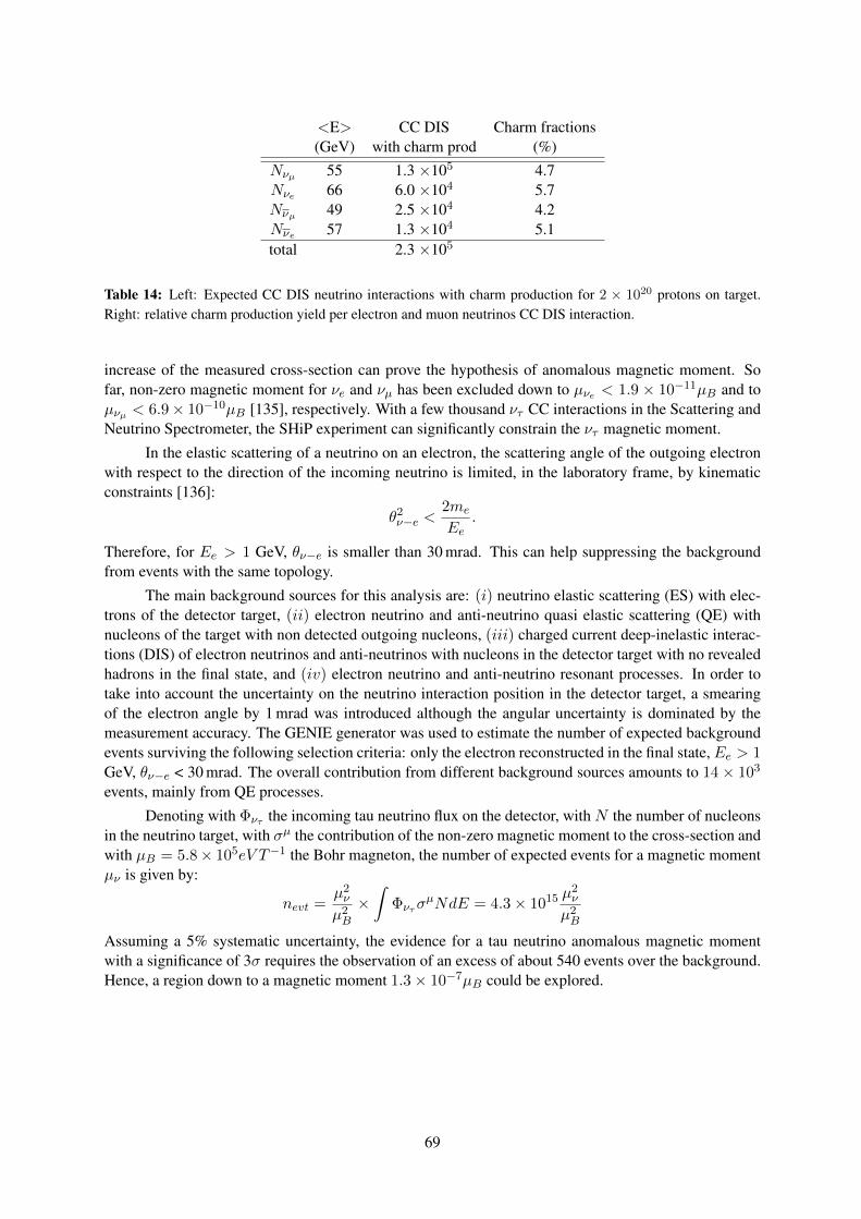
<E> CC DIS Charm fractions(GeV) with charm prod (%)
Nνµ 55 1.3 ×10⁵ 4.7Nνe 66 6.0 ×10⁴ 5.7Nνµ 49 2.5 ×10⁴ 4.2Nνe 57 1.3 ×10⁴ 5.1total 2.3 ×10⁵
Table 14: Left: Expected CC DIS neutrino interactions with charm production for 2 × 10²⁰ protons on target.Right: relative charm production yield per electron and muon neutrinos CC DIS interaction.
increase of the measured cross-section can prove the hypothesis of anomalous magnetic moment. Sofar, non-zero magnetic moment for νe and νµ has been excluded down to µνe < 1.9 × 10⁻¹¹µB and toµνµ < 6.9× 10⁻¹⁰µB [135], respectively. With a few thousand ντ CC interactions in the Scattering andNeutrino Spectrometer, the SHiP experiment can significantly constrain the ντ magnetic moment.
In the elastic scattering of a neutrino on an electron, the scattering angle of the outgoing electronwith respect to the direction of the incoming neutrino is limited, in the laboratory frame, by kinematicconstraints [136]:
θ2ν−e <2me
Ee.
Therefore, for Ee > 1 GeV, θν−e is smaller than 30 mrad. This can help suppressing the backgroundfrom events with the same topology.
The main background sources for this analysis are: (i) neutrino elastic scattering (ES) with elec-trons of the detector target, (ii) electron neutrino and anti-neutrino quasi elastic scattering (QE) withnucleons of the target with non detected outgoing nucleons, (iii) charged current deep-inelastic interac-tions (DIS) of electron neutrinos and anti-neutrinos with nucleons in the detector target with no revealedhadrons in the final state, and (iv) electron neutrino and anti-neutrino resonant processes. In order totake into account the uncertainty on the neutrino interaction position in the detector target, a smearingof the electron angle by 1 mrad was introduced although the angular uncertainty is dominated by themeasurement accuracy. The GENIE generator was used to estimate the number of expected backgroundevents surviving the following selection criteria: only the electron reconstructed in the final state, Ee > 1GeV, θν−e < 30 mrad. The overall contribution from different background sources amounts to 14× 103
events, mainly from QE processes.
Denoting with Φντ the incoming tau neutrino flux on the detector, with N the number of nucleonsin the neutrino target, with σµ the contribution of the non-zero magnetic moment to the cross-section andwith µB = 5.8× 10⁵eV T−1 the Bohr magneton, the number of expected events for a magnetic momentµν is given by:
nevt =µ2νµ2B×∫
ΦντσµNdE = 4.3× 10¹⁵
µ2νµ2B
Assuming a 5% systematic uncertainty, the evidence for a tau neutrino anomalous magnetic momentwith a significance of 3σ requires the observation of an excess of about 540 events over the background.Hence, a region down to a magnetic moment 1.3× 10⁻⁷µB could be explored.
69
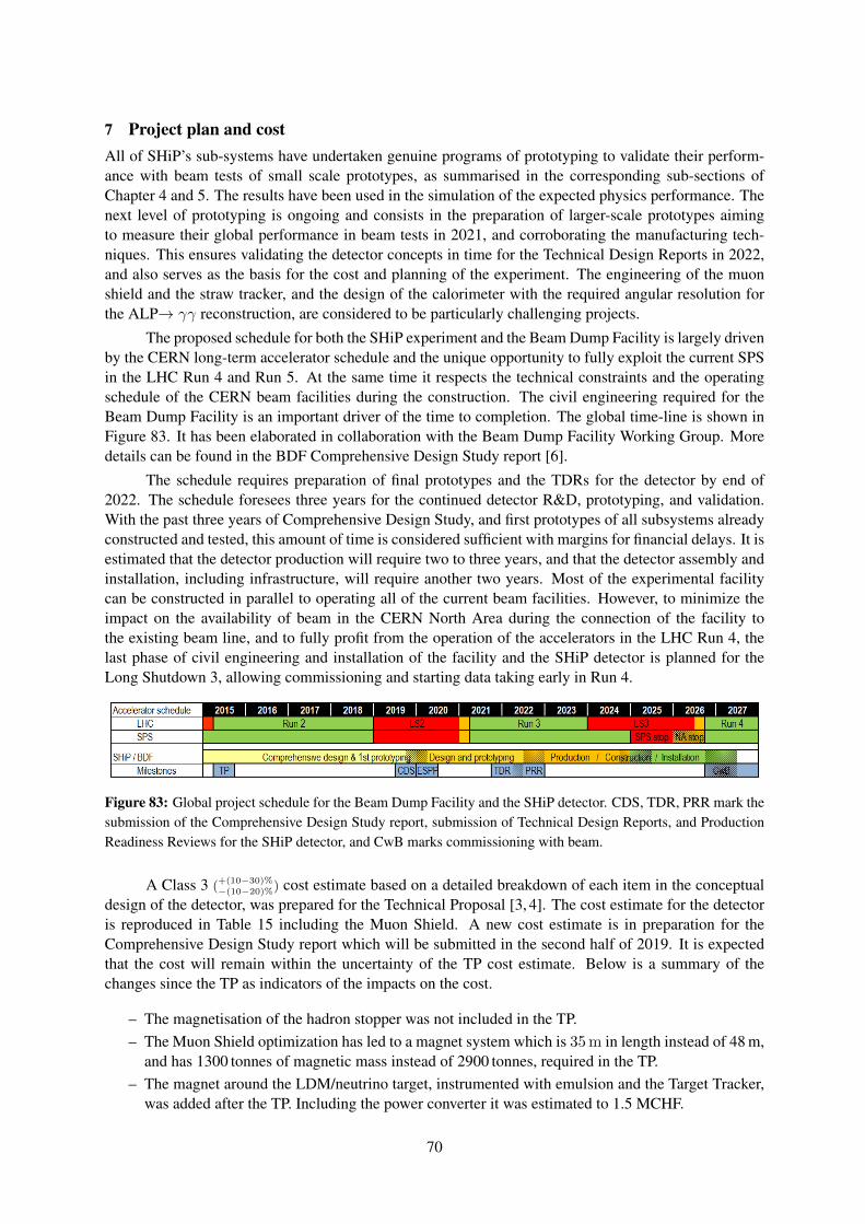
7 Project plan and costAll of SHiP’s sub-systems have undertaken genuine programs of prototyping to validate their perform-ance with beam tests of small scale prototypes, as summarised in the corresponding sub-sections ofChapter 4 and 5. The results have been used in the simulation of the expected physics performance. Thenext level of prototyping is ongoing and consists in the preparation of larger-scale prototypes aimingto measure their global performance in beam tests in 2021, and corroborating the manufacturing tech-niques. This ensures validating the detector concepts in time for the Technical Design Reports in 2022,and also serves as the basis for the cost and planning of the experiment. The engineering of the muonshield and the straw tracker, and the design of the calorimeter with the required angular resolution forthe ALP→ γγ reconstruction, are considered to be particularly challenging projects.
The proposed schedule for both the SHiP experiment and the Beam Dump Facility is largely drivenby the CERN long-term accelerator schedule and the unique opportunity to fully exploit the current SPSin the LHC Run 4 and Run 5. At the same time it respects the technical constraints and the operatingschedule of the CERN beam facilities during the construction. The civil engineering required for theBeam Dump Facility is an important driver of the time to completion. The global time-line is shown inFigure 83. It has been elaborated in collaboration with the Beam Dump Facility Working Group. Moredetails can be found in the BDF Comprehensive Design Study report [6].
The schedule requires preparation of final prototypes and the TDRs for the detector by end of2022. The schedule foresees three years for the continued detector R&D, prototyping, and validation.With the past three years of Comprehensive Design Study, and first prototypes of all subsystems alreadyconstructed and tested, this amount of time is considered sufficient with margins for financial delays. It isestimated that the detector production will require two to three years, and that the detector assembly andinstallation, including infrastructure, will require another two years. Most of the experimental facilitycan be constructed in parallel to operating all of the current beam facilities. However, to minimize theimpact on the availability of beam in the CERN North Area during the connection of the facility tothe existing beam line, and to fully profit from the operation of the accelerators in the LHC Run 4, thelast phase of civil engineering and installation of the facility and the SHiP detector is planned for theLong Shutdown 3, allowing commissioning and starting data taking early in Run 4.
Figure 83: Global project schedule for the Beam Dump Facility and the SHiP detector. CDS, TDR, PRR mark thesubmission of the Comprehensive Design Study report, submission of Technical Design Reports, and ProductionReadiness Reviews for the SHiP detector, and CwB marks commissioning with beam.
A Class 3 (+(10−30)%
−(10−20)%) cost estimate based on a detailed breakdown of each item in the conceptualdesign of the detector, was prepared for the Technical Proposal [3, 4]. The cost estimate for the detectoris reproduced in Table 15 including the Muon Shield. A new cost estimate is in preparation for theComprehensive Design Study report which will be submitted in the second half of 2019. It is expectedthat the cost will remain within the uncertainty of the TP cost estimate. Below is a summary of thechanges since the TP as indicators of the impacts on the cost.
– The magnetisation of the hadron stopper was not included in the TP.– The Muon Shield optimization has led to a magnet system which is 35 m in length instead of 48 m,
and has 1300 tonnes of magnetic mass instead of 2900 tonnes, required in the TP.– The magnet around the LDM/neutrino target, instrumented with emulsion and the Target Tracker,
was added after the TP. Including the power converter it was estimated to 1.5 MCHF.
70
– The Muon Magnetic Spectrometer of the Scattering and Neutrino Detector was replaced with aconventional muon identification system without magnetization.
– The Upstream Veto Tagger has been removed. It has been shown that the SND muon system canperform the same function.
– The original Decay Volume, shaped as an elliptical cylinder with inner dimensions 5 × 10 m2,has been redesigned as a conical frustum with inner dimensions of 1.7 × 4.4 m2 upstream, and5 × 10 m2 downstream. The length is maintained at 50 m. It has been shown that a pressure of10−3 bar is sufficient (TP: 10−6 bar).
– The in-vacuum Straw Veto Tagger has been removed.– The Spectrometer Straw Tracker stations and the vacuum tank through the spectrometer magnet
have been designed with transverse dimensions of 5× 10 m2 throughout.– The Spectrometer Straw Tracker tube diameter has been changed from 10 mm to 20 mm, halving
the total number of tubes.– Further design studies of the spectrometer vacuum tank, the straw tracker mechanics and interfaces
with the spectrometer magnet have shown that this section is more complex than initially expected.– The shashlik-based Electromagnetic Calorimeter has been replaced with a calorimeter based on
two different types of active layers, in order to extend its capability to reconstruct two-photon finalstates. While most sampling layers are based on scintillating bars, resulting in a significant costreduction compared to the shashlik technology, a few high-precision layers are instrumented withmicro-pattern or alternatively scintillating fibre detectors.
– The Hadron Calorimeter has been removed, only the absorber is kept as the first muon filter. Thenew Electromagnetic Calorimeter is expected to be capable of providing sufficient identificationfor low momentum particles.
– The original muon system with scintillating bars has been replaced by a system based on scintil-lating tiles with SiPM readout.
The production and the construction of the detector is based on the concept of deliverables, whichincludes the detector components and assembly, the associated electronics and infrastructure systems, aswell as the transport to CERN and the specific operations related to the installation.
71
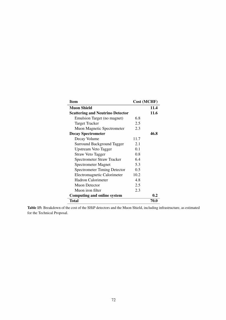
Item Cost (MCHF)Muon Shield 11.4Scattering and Neutrino Detector 11.6
Emulsion Target (no magnet) 6.8Target Tracker 2.5Muon Magnetic Spectrometer 2.3
Decay Spectrometer 46.8Decay Volume 11.7Surround Background Tagger 2.1Upstream Veto Tagger 0.1Straw Veto Tagger 0.8Spectrometer Straw Tracker 6.4Spectrometer Magnet 5.3Spectrometer Timing Detector 0.5Electromagnetic Calorimeter 10.2Hadron Calorimeter 4.8Muon Detector 2.5Muon iron filter 2.3
Computing and online system 0.2Total 70.0
Table 15: Breakdown of the cost of the SHiP detectors and the Muon Shield, including infrastructure, as estimatedfor the Technical Proposal.
72

8 Status of the SHiP CollaborationThe SHiP Expression of Interest was submitted to SPSC in October 2013. This was followed by theTechnical Proposal submitted to the SPSC in April 2015. The SHiP Technical Proposal was success-fully reviewed by the SPSC and the CERN RB up to March 2016, with a recommendation to prepare aComprehensive Design Study report by 2019.
SHiP is currently a collaboration of 53 institutes and 4 associated institutes, in total representing 18countries, CERN and JINR. The formal organisation of SHiP consists of a Country Representative Board(CRB), Interim spokesperson, Technical Coordinator and Physics Coordinator, and the group of projectconveners as elected and ratified by the CRB. The organisation has been adopted for the ComprehensiveDesign Study phase.
73
Bibliography[1] W. Bonivento et al., Proposal to Search for Heavy Neutral Leptons at the SPS,
[arXiv:1310.1762].[2] S. Alekhin et al., A facility to Search for Hidden Particles at the CERN SPS: the SHiP physics
case, Rept. Prog. Phys. 79 (2016), no. 12 124201, [arXiv:1504.04855].[3] SHiP Collaboration, M. Anelli et al., A facility to Search for Hidden Particles (SHiP) at the
CERN SPS, [arXiv:1504.04956].[4] SHiP Collaboration, M. Anelli et al., A Facility to Search for Hidden Particles (SHiP) at the
CERN SPS, Tech. Rep. CERN-SPSC-2015-040, SPSC-P-350-ADD-2, 2015.[5] Physics Beyond Colliders Study Group. https://pbc.web.cern.ch/, 2016.[6] C. C. Ahdida, M. Calviani, B. Goddard, R. Jacobsson, and M. Lamont, SPS Beam Dump Facility
Comprehensive Design Study , Tech. Rep. CERN-PBC-REPORT-2018-001, CERN, Geneva,December 2018.
[7] ATLAS Collaboration, G. Aad et al., Combined search for the Standard Model Higgs bosonusing up to 4.9 fb−1 of pp collision data at
√s = 7 TeV with the ATLAS detector at the LHC,
Phys.Lett. B710 (2012) 49–66, [arXiv:1202.1408].[8] ATLAS Collaboration, G. Aad et al., Observation of a new particle in the search for the
Standard Model Higgs boson with the ATLAS detector at the LHC, Phys. Lett. B716 (2012) 1–29,[arXiv:1207.7214].
[9] CMS Collaboration, S. Chatrchyan et al., Combined results of searches for the standard modelHiggs boson in pp collisions at
√s = 7 TeV, Phys. Lett. B710 (2012) 26–48,
[arXiv:1202.1488].[10] CMS Collaboration, S. Chatrchyan et al., Observation of a new boson at a mass of 125 GeV with
the CMS experiment at the LHC, Phys.Lett. B716 (2012) 30–61, [arXiv:1207.7235].[11] F. Bezrukov, M. Yu. Kalmykov, B. A. Kniehl, and M. Shaposhnikov, Higgs Boson Mass and New
Physics, JHEP 10 (2012) 140, [arXiv:1205.2893].[12] G. Degrassi, S. Di Vita, J. Elias-Miro, J. R. Espinosa, G. F. Giudice, G. Isidori, and A. Strumia,
Higgs mass and vacuum stability in the Standard Model at NNLO, JHEP 08 (2012) 098,[arXiv:1205.6497].
[13] D. Buttazzo, G. Degrassi, P. P. Giardino, G. F. Giudice, F. Sala, A. Salvio, and A. Strumia,Investigating the near-criticality of the Higgs boson, JHEP 12 (2013) 089, [arXiv:1307.3536].
[14] F. Bezrukov, J. Rubio, and M. Shaposhnikov, Living beyond the edge: Higgs inflation andvacuum metastability, Phys. Rev. D92 (2015), no. 8 083512, [arXiv:1412.3811].
[15] F. Bezrukov and M. Shaposhnikov, Why should we care about the top quark Yukawa coupling?,J. Exp. Theor. Phys. 120 (2015) 335–343, [arXiv:1411.1923].
[16] C. D. Froggatt and H. B. Nielsen, Standard model criticality prediction: Top mass 173± 5 GeVand Higgs mass 135± 9 GeV, Phys. Lett. B368 (1996) 96–102, [hep-ph/9511371].
[17] M. Shaposhnikov and C. Wetterich, Asymptotic safety of gravity and the Higgs boson mass,Phys. Lett. B683 (2010) 196–200, [arXiv:0912.0208].
[18] T. Carli, “ATLAS + ALICE highlights (talk at ICHEP 2018).”https://indico.cern.ch/event/686555/contributions/3028060/.
[19] S. Rahatlou, “CMS + LHCb highlights (talk at ICHEP 2018).”https://indico.cern.ch/event/686555/contributions/3028061/.
[20] CMS Collaboration, “CMS Supersymmetry Physics Results.”https://twiki.cern.ch/twiki/bin/view/CMSPublic/PhysicsResultsSUSY, 2015.
[21] ATLAS Collaboration, “ATLAS Exotics Public Results.” https://twiki.cern.ch/twiki/bin/view/AtlasPublic/SupersymmetryPublicResults, 2015.
74
[22] ATLAS Collaboration, “ATLAS Supersymmetry Searches.”https://twiki.cern.ch/twiki/bin/view/AtlasPublic/ExoticsPublicResults, 2015.
[23] CMS Collaboration, “CMS Exotica Public Physics Results.”https://twiki.cern.ch/twiki/bin/view/AtlasPublic/ExoticsPublicResults, 2015.
[24] Del Re, Daniele, “Exotics (talk at ICHEP 2018).”https://indico.cern.ch/event/686555/contributions/3028077/.
[25] S. Strandberg, “SUSY (talk at ICHEP 2018).”https://indico.cern.ch/event/686555/contributions/3028076/.
[26] Belle Collaboration, M. Huschle et al., Measurement of the branching ratio of B → D(∗)τ−ντrelative to B → D(∗)`−ν` decays with hadronic tagging at Belle, Phys. Rev. D92 (2015), no. 7072014, [arXiv:1507.03233].
[27] Belle Collaboration, Y. Sato et al., Measurement of the branching ratio of B0 → D∗+τ−ντrelative to B0 → D∗+`−ν` decays with a semileptonic tagging method, Phys. Rev. D94 (2016),no. 7 072007, [arXiv:1607.07923].
[28] Belle Collaboration, S. Hirose et al., Measurement of the τ lepton polarization and R(D∗) in thedecay B → D∗τ−ντ , Phys. Rev. Lett. 118 (2017), no. 21 211801, [arXiv:1612.00529].
[29] LHCb Collaboration, R. Aaij et al., Measurement of the ratio of branching fractionsB(B0 → D∗+τ−ντ )/B(B0 → D∗+µ−νµ), Phys. Rev. Lett. 115 (2015), no. 11 111803,[arXiv:1506.08614]. [Erratum: Phys. Rev. Lett.115,no.15,159901(2015)].
[30] LHCb Collaboration, R. Aaij et al., Measurement of the ratio of the B0 → D∗−τ+ντ andB0 → D∗−µ+νµ branching fractions using three-prong τ -lepton decays, Phys. Rev. Lett. 120(2018), no. 17 171802, [arXiv:1708.08856].
[31] M. Yokoyama, “Long baseline experiments (talk at ICHEP 2018).”https://indico.cern.ch/event/686555/contributions/3028063/.
[32] S. Petcov, “Neutrino theory including leptogenesis (talk at ICHEP 2018).”https://indico.cern.ch/event/686555/contributions/3028066/.
[33] C. Giunti, Light Sterile Neutrinos: Status and Perspectives, Nucl. Phys. B908 (2016) 336–353,[arXiv:1512.04758].
[34] H. S. Lee, “Dark matter (talk at ICHEP 2018).”https://indico.cern.ch/event/686555/contributions/3028096.
[35] L. D. Duffy and K. van Bibber, Axions as Dark Matter Particles, New J. Phys. 11 (2009) 105008,[arXiv:0904.3346].
[36] A. Boyarsky, M. Drewes, T. Lasserre, S. Mertens, and O. Ruchayskiy, Sterile Neutrino DarkMatter, Prog. Part. Nucl. Phys. (2018) [arXiv:1807.07938].
[37] M. Shaposhnikov and C. Wetterich, Asymptotic safety of gravity and the Higgs boson mass,Phys. Lett. B683 (2010) 196–200, [arXiv:0912.0208].
[38] A. Berlin, N. Blinov, G. Krnjaic, P. Schuster, and N. Toro, Dark Matter, Millicharges, Axion andScalar Particles, Gauge Bosons, and Other New Physics with LDMX, [arXiv:1807.01730].
[39] MiniBooNE DM Collaboration, A. A. Aguilar-Arevalo et al., Dark Matter Search in Nucleon,Pion, and Electron Channels from a Proton Beam Dump with MiniBooNE,[arXiv:1807.06137].
[40] MiniBooNE Collaboration, A. A. Aguilar-Arevalo et al., Dark Matter Search in a Proton BeamDump with MiniBooNE, Phys. Rev. Lett. 118 (2017), no. 22 221803, [arXiv:1702.02688].
[41] P. deNiverville, C.-Y. Chen, M. Pospelov, and A. Ritz, Light dark matter in neutrino beams:production modelling and scattering signatures at MiniBooNE, T2K and SHiP, Phys. Rev. D95(2017), no. 3 035006, [arXiv:1609.01770].
[42] CRESST Collaboration, G. Angloher et al., Results on light dark matter particles with a
75
low-threshold CRESST-II detector, Eur. Phys. J. C76 (2016), no. 1 25, [arXiv:1509.01515].[43] NA64 Collaboration, D. Banerjee et al., Search for vector mediator of Dark Matter production in
invisible decay mode, Phys. Rev. D97 (2018), no. 7 072002, [arXiv:1710.00971].[44] NA64 Collaboration, D. Banerjee et al., Search for invisible decays of sub-GeV dark photons in
missing-energy events at the CERN SPS, Phys. Rev. Lett. 118 (2017), no. 1 011802,[arXiv:1610.02988].
[45] BDX Collaboration, M. Battaglieri et al., Dark Matter Search in a Beam-Dump eXperiment(BDX) at Jefferson Lab, [arXiv:1607.01390].
[46] V. V. Gligorov, S. Knapen, M. Papucci, and D. J. Robinson, Searching for Long-lived Particles:A Compact Detector for Exotics at LHCb, Phys. Rev. D97 (2018), no. 1 015023,[arXiv:1708.09395].
[47] J. P. Chou, D. Curtin, and H. J. Lubatti, New Detectors to Explore the Lifetime Frontier, Phys.Lett. B767 (2017) 29–36, [arXiv:1606.06298].
[48] D. Curtin and M. E. Peskin, Analysis of Long Lived Particle Decays with the MATHUSLADetector, Phys. Rev. D97 (2018), no. 1 015006, [arXiv:1705.06327].
[49] J. A. Evans, Detecting Hidden Particles with MATHUSLA, Phys. Rev. D97 (2018), no. 5 055046,[arXiv:1708.08503].
[50] J. L. Feng, I. Galon, F. Kling, and S. Trojanowski, ForwArd Search ExpeRiment at the LHC,Phys. Rev. D97 (2018), no. 3 035001, [arXiv:1708.09389].
[51] J. L. Feng, I. Galon, F. Kling, and S. Trojanowski, Dark Higgs bosons at the ForwArd SearchExpeRiment, Phys. Rev. D97 (2018), no. 5 055034, [arXiv:1710.09387].
[52] F. Kling and S. Trojanowski, Heavy Neutral Leptons at FASER, Phys. Rev. D97 (2018), no. 9095016, [arXiv:1801.08947].
[53] LHCb Collaboration, R. Aaij et al., Search for Majorana neutrinos in B− → π+µ−µ− decays,Phys. Rev. Lett. 112 (2014), no. 13 131802, [arXiv:1401.5361].
[54] CMS Collaboration, V. Khachatryan et al., Search for heavy Majorana neutrinos in µ±µ±+ jetsevents in proton-proton collisions at
√s = 8 TeV, Phys. Lett. B748 (2015) 144–166,
[arXiv:1501.05566].[55] ATLAS Collaboration, G. Aad et al., Search for heavy Majorana neutrinos with the ATLAS
detector in pp collisions at√s = 8 TeV, JHEP 07 (2015) 162, [arXiv:1506.06020].
[56] CMS Collaboration, A. M. Sirunyan et al., Search for heavy neutral leptons in events with threecharged leptons in proton-proton collisions at
√s = 13 TeV, Phys. Rev. Lett. 120 (2018), no. 22
221801, [arXiv:1802.02965].[57] A. Izmaylov and S. Suvorov, Search for heavy neutrinos in the ND280 near detector of the T2K
experiment, Phys. Part. Nucl. 48 (2017), no. 6 984–986.[58] SHiP Collaboration, P. Mermod, Hidden sector searches with SHiP and NA62, in 2017
International Workshop on Neutrinos from Accelerators (NuFact17) Uppsala University MainBuilding, Uppsala, Sweden, September 25-30, 2017, 2017. [arXiv:1712.01768].
[59] NA62 Collaboration, E. Cortina Gil et al., Search for heavy neutral lepton production in K+
decays, Phys. Lett. B778 (2018) 137–145, [arXiv:1712.00297].[60] S. Antusch, E. Cazzato, and O. Fischer, Sterile neutrino searches via displaced vertices at LHCb,
Phys. Lett. B774 (2017) 114–118, [arXiv:1706.05990].[61] M. Drewes, J. Hajer, J. Klaric, and G. Lanfranchi, NA62 sensitivity to heavy neutral leptons in the
low scale seesaw model, [arXiv:1801.04207].[62] Belle Collaboration, D. Liventsev et al., Search for heavy neutrinos at Belle, Phys. Rev. D87
(2013), no. 7 071102, [arXiv:1301.1105].[63] Belle Collaboration, Y. Kwon, Search for dark sector particles at Belle, PoS EPS-HEP2017
76
(2017) 069.[64] Belle Collaboration, I. Jaegle, Search for the dark photon and the dark Higgs boson at Belle,
Phys. Rev. Lett. 114 (2015), no. 21 211801, [arXiv:1502.00084].[65] BaBar Collaboration, J. P. Lees et al., Search for Invisible Decays of a Dark Photon Produced in
e+e− Collisions at BaBar, Phys. Rev. Lett. 119 (2017), no. 13 131804, [arXiv:1702.03327].[66] ATLAS Collaboration, M. Aaboud et al., Search for long-lived particles in final states with
displaced dimuon vertices in pp collisions at√s = 13 TeV with the ATLAS detector,
[arXiv:1808.03057].[67] LHCb Collaboration, R. Aaij et al., Search for Dark Photons Produced in 13 TeV pp Collisions,
Phys. Rev. Lett. 120 (2018), no. 6 061801, [arXiv:1710.02867].[68] F. Addesa et al., The SE-CpFM Detector for the Crystal-Assisted Extraction at CERN-SPS, in
Proc. of International Beam Instrumentation Conference (IBIC’17), Grand Rapids, MI, USA,20-24 August 2017, no. 6 in International Beam Instrumentation Conference, (Geneva,Switzerland), pp. 419–422, JACoW, Mar., 2018.https://doi.org/10.18429/JACoW-IBIC2017-WEPCF04.
[69] K. Kershaw et al., Design Development for the Beam Dump Facility Target Complex at CERN,JINST 13 (2018), no. 10 P10011, [arXiv:1806.05920].
[70] SHiP Collaboration, A. Akmete et al., Muon flux measurements for SHiP at H4, Tech. Rep.CERN-SPSC-2017-020. SPSC-EOI-016, CERN, Geneva, June 2017.
[71] A. Ferrari, P. R. Sala, A. Fasso, and J. Ranft, FLUKA: A multi-particle transport code (Programversion 2005), CERN-2005-010, SLAC-R-773, INFN-TC-05-11 (2005).
[72] P. Santos Diaz, Preliminary design of the decay volume vacuum system for the SHiP experiment,Tech. Rep. CERN EDMS 2000025, January 2019.
[73] I. Bezshyiko et al., TauFV: a fixed-target experiment to search for flavour violation in tau decays,2018. submitted to ESPPU.
[74] M. Al-Turany, D. Bertini, R. Karabowicz, D. Kresan, P. Malzacher, T. Stockmanns, and F. Uhlig,The fairroot framework, Journal of Physics: Conference Series 396 (2012), no. 2 022001.
[75] T. Sjöstrand, S. Ask, J. R. Christiansen, R. Corke, N. Desai, P. Ilten, S. Mrenna, S. Prestel, C. O.Rasmussen, and P. Z. Skands, An Introduction to PYTHIA 8.2, Comput. Phys. Commun. 191(2015) 159–177, [arXiv:1410.3012].
[76] S. Agostinelli et al., Geant4 - a simulation toolkit, Nucl. Instr. and Meth. A508 (2003) 250.[77] SHiP Collaboration, H. Dijkstra and T. Ruf, Heavy Flavour Cascade Production in a Beam
Dump, December 2015. CERN-SHiP-NOTE-2015-009.[78] SHiP Collaboration, C. Ahdida et al., Sensitivity of the SHiP experiment to Heavy Neutral
Leptons, [arXiv:1811.00930].[79] A. Monin, A. Boyarsky, and O. Ruchayskiy, Hadronic decays of a light Higgs-like scalar,
[arXiv:1806.07759].[80] F. Bergsma, Prompt lepton production in a proton beam dump experiment. PhD thesis,
University of Amsterdam, 1990.[81] SHiP Collaboration, T. Ruf, Studying Multiple Scattering with GEANT4 v10.3.2, December
2018. CERN-SHiP-NOTE-2017-003.[82] G. Ruggiero, NA48 Results, in Proceedings, 43rd Rencontres de Moriond on Electroweak
Interactions and Unified Theories: La Thuile, Italy, March 1-8, 2008, (Paris, France),pp. 293–300, Moriond, Moriond, 2008.
[83] S. A. Akimenko, V. I. Belousov, A. M. Blik, G. I. Britvich, V. N. Kolosov, V. M. Kutin, B. N.Lebedev, V. N. Peleshko, Ya. N. Rastsvetalov, and A. S. Solovev, MULTIPLE COULOMBSCATTERING OF 7.3-GeV/c AND 11.7-GeV/c MUONS ON Cu TARGET, Nucl. Instrum. Meth.
77
A243 (1986) 518.[84] M. Rosenthal, N. Charitonidis, P. Chatzidaki, R. Margraf, H. Wilkens, F. Bergsma, and P.-A.
Guidici, Magnetic Field Measurement of the GOLIATH Magnet in EHN1, Tech. Rep.CERN-ACC-NOTE-2018-0028, March, 2018.
[85] A. Alexandrov et al., A new fast scanning system for the measurement of large angle tracks innuclear emulsions, JINST 10 (2015), no. 11 P11006.
[86] A. Alexandrov et al., A new generation scanning system for the high-speed analysis of nuclearemulsions, JINST 11 (2016), no. 06 P06002.
[87] A. Alexandrov et al., The Continuous Motion Technique for a New Generation of ScanningSystems, Sci. Rep. 7 (2017), no. 1 7310.
[88] R. Acquafredda et al., The OPERA experiment in the CERN to Gran Sasso neutrino beam, JINST4 (2009) P04018.
[89] OPERA Collaboration, N. Agafonova et al., Final Results of the OPERA Experiment on ντAppearance in the CNGS Neutrino Beam, Phys. Rev. Lett. 120 (2018), no. 21 211801,[arXiv:1804.04912]. [Erratum: Phys. Rev. Lett.121,no.13,139901(2018)].
[90] OPERA Collaboration, N. Agafonova et al., Procedure for short-lived particle detection in theOPERA experiment and its application to charm decays, Eur. Phys. J. C74 (2014), no. 8 2986,[arXiv:1404.4357].
[91] OPERA Collaboration, N. Agafonova et al., Momentum measurement by the Multiple CoulombScattering method in the OPERA lead emulsion target, New J. Phys. 14 (2012) 013026,[arXiv:1106.6211].
[92] OPERA Collaboration, N. Agafonova et al., Final results of the search for νµ → νe oscillationswith the OPERA detector in the CNGS beam, JHEP 06 (2018) 151, [arXiv:1803.11400].
[93] L. Arrabito et al., Hardware performance of a scanning system for high speed analysis of nuclearemulsions, Nucl. Instrum. Meth. A568 (2006) 578–587, [physics/0604043].
[94] N. Armenise et al., High-speed particle tracking in nuclear emulsion by last-generationautomatic microscopes, Nucl. Instrum. Meth. A551 (2005) 261–270.
[95] C. Fukushima, M. Kimura, S. Ogawa, H. Shibuya, G. Takahashi, K. Kodama, T. Hara, andS. Mikado, A thin emulsion spectrometer using a compact permanent magnet, Nucl. Instrum.Meth. A592 (2008) 56–62.
[96] G. Bencivenni, R. De Oliveira, G. Morello, and M. P. Lener, The micro-Resistive WELL detector:a compact spark-protected single amplification-stage MPGD, JINST 10 (2015), no. 02 P02008,[arXiv:1411.2466].
[97] M. S. Dixit and A. Rankin, Simulating the charge dispersion phenomena in micro pattern gasdetectors with a resistive anode, Nucl. Instrum. Meth. A566 (2006) 281–285,[physics/0605121].
[98] G. Bencivenni, R. De Oliveira, G. Felici, M. Gatta, G. Morello, A. Ochi, M. P. Lener, andE. Tskhadadze, Performance of µ-RWELL detector vs resistivity of the resistive stage, Nucl.Instrum. Meth. A886 (2018) 36–39.
[99] T. Alexopoulos et al., Development of large size Micromegas detector for the upgrade of theATLAS muon system, Nucl. Instrum. Meth. A617 (2010) 161–165.
[100] LHCb Collaboration, LHCb Tracker Upgrade Technical Design Report, 2014.CERN-LHCC-2014-001, LHCB-TDR-015.
[101] O. Giard, G. Haefeli, et al., “Modular beam telescopes based on scintillation fibers and siliconphoto-multipliers (Talk at BTTB workshop 2018).”https://indico.desy.de/indico/event/18050/session/9/contribution/18.
[102] “GARFIELD simulation package.” http://cern.ch/magboltz, http://cern.ch/garfield
78
and http://cern.ch/garfieldpp.[103] PANDA Collaboration, Technical design report for the panda (antiproton annihilations at
darmstadt) straw tube tracker, The European Physical Journal A 49 (Feb, 2013) 25.[104] C. Betancourt et al., Application of large area SiPMs for the readout of a plastic scintillator
based timing detector, JINST 12 (2017), no. 11 P11023, [arXiv:1709.08972].[105] S. Gomez et al., MUSIC: An 8 channel readout ASIC for SiPM arrays, in Proceedings, Optical
Sensing and Detection IV, SPIE Photonics Europe, 2016, Brussels, Belgium, vol. 9899, 2016.[106] W. Baldini et al., Measurement of parameters of scintillating bars with wavelength-shifting fibres
and silicon photomultiplier readout for the SHiP Muon Detector, JINST 12 (2017), no. 03P03005, [arXiv:1612.01125].
[107] F. Bezrukov and D. Gorbunov, Light inflaton Hunter’s Guide, JHEP 05 (2010) 010,[arXiv:0912.0390].
[108] K. Bondarenko, A. Boyarsky, D. Gorbunov, and O. Ruchayskiy, Phenomenology of GeV-scaleHeavy Neutral Leptons, [arXiv:1805.08567].
[109] LHCb Collaboration, R. Aaij et al., Observation of B+c → D0K+ decays, Phys. Rev. Lett. 118
(2017), no. 11 111803, [arXiv:1701.01856].[110] C.-H. Chang, C. Driouichi, P. Eerola, and X. G. Wu, BCVEGPY: An Event generator for hadronic
production of the Bc meson, Comput. Phys. Commun. 159 (2004) 192–224, [hep-ph/0309120].[111] M. Cacciari, S. Frixione, and P. Nason, The pT spectrum in heavy flavor photoproduction, JHEP
03 (2001) 006, [hep-ph/0102134].[112] D. Gorbunov and M. Shaposhnikov, How to find neutral leptons of the νMSM?, JHEP 10 (2007)
015, [arXiv:0705.1729]. [Erratum: JHEP11 (2013), 101].[113] K. Bondarenko, I. Boiarska, A. Boyarsky, M. Ovchynnikov, and O. Ruchayskiy, Light dark
matter with scalar mediator at Intensity Frontier experiments, to appear (2018).[114] B. Patt and F. Wilczek, Higgs-field portal into hidden sectors, [hep-ph/0605188].[115] B. Batell, M. Pospelov, and A. Ritz, Exploring Portals to a Hidden Sector Through Fixed Targets,
Phys. Rev. D80 (2009) 095024, [arXiv:0906.5614].[116] J. D. Clarke, R. Foot, and R. R. Volkas, Phenomenology of a very light scalar
(100 MeV < mh < 10 GeV) mixing with the SM Higgs, JHEP 02 (2014) 123,[arXiv:1310.8042].
[117] K. Schmidt-Hoberg, F. Staub, and M. W. Winkler, Constraints on light mediators: confrontingdark matter searches with B physics, Phys. Lett. B727 (2013) 506–510, [arXiv:1310.6752].
[118] J. F. Donoghue, J. Gasser, and H. Leutwyler, The Decay of a Light Higgs Boson, Nucl. Phys.B343 (1990) 341–368.
[119] B. Holdom, Two U(1)’s and Epsilon Charge Shifts, Phys. Lett. B166 (1986) 196–198.[120] T. Sjöstrand, S. Ask, J. R. Christiansen, R. Corke, N. Desai, P. Ilten, S. Mrenna, S. Prestel, C. O.
Rasmussen, and P. Z. Skands, An Introduction to PYTHIA 8.2, Comput. Phys. Commun. 191(2015) 159–177, [arXiv:1410.3012].
[121] Particle Data Group Collaboration, C. Patrignani et al., Review of Particle Physics, Chin. Phys.C40 (2016), no. 10 100001.
[122] D. Gorbunov, A. Makarov, and I. Timiryasov, Decaying light particles in the SHiP experiment:Signal rate estimates for hidden photons, Phys. Rev. D91 (2015), no. 3 035027,[arXiv:1411.4007].
[123] J. Blümlein and J. Brunner, New Exclusion Limits on Dark Gauge Forces from ProtonBremsstrahlung in Beam-Dump Data, Phys. Lett. B731 (2014) 320–326, [arXiv:1311.3870].
[124] L. Carloni, J. Rathsman, and T. Sjöstrand, Discerning Secluded Sector gauge structures, JHEP04 (2011) 091, [arXiv:1102.3795].
79
[125] J. D. Bjorken, R. Essig, P. Schuster, and N. Toro, New Fixed-Target Experiments to Search forDark Gauge Forces, Phys. Rev. D80 (2009) 075018, [arXiv:0906.0580].
[126] B. Döbrich, J. Jaeckel, F. Kahlhoefer, A. Ringwald, and K. Schmidt-Hoberg, ALPtraum: ALPproduction in proton beam dump experiments, JHEP 02 (2016) 018, [arXiv:1512.03069].
[127] J. Alwall, M. Herquet, F. Maltoni, O. Mattelaer, and T. Stelzer, MadGraph 5 : Going Beyond,JHEP 06 (2011) 128, [arXiv:1106.0522].
[128] CHORUS Collaboration, A. Kayis-Topaksu et al., Cross-section measurement for quasi-elasticproduction of charmed baryons in nu N interactions, Phys. Lett. B575 (2003) 198–207.
[129] CHORUS Collaboration, A. Kayis-Topaksu et al., Measurement of topological muonicbranching ratios of charmed hadrons produced in neutrino-induced charged-currentinteractions, Phys. Lett. B626 (2005) 24–34.
[130] CHORUS Collaboration, G. Onengut et al., Measurement of fragmentation properties ofcharmed particle production in charged-current neutrino interactions, Phys. Lett. B604 (2004)145–156.
[131] A. Kayis-Topaksu et al., Measurement of charm production in neutrino charged-currentinteractions, New J. Phys. 13 (2011) 093002, [arXiv:1107.0613].
[132] CHORUS Collaboration, A. Kayis-Topaksu et al., Observation of one event with thecharacteristics of associated charm production in neutrino charged-current interactions, Phys.Lett. B539 (2002) 188–196.
[133] HERA-B Collaboration, I. Abt et al., Measurement of D0, D+, D+s and D∗+ Production in
Fixed Target 920-GeV Proton-Nucleus Collisions, Eur. Phys. J. C52 (2007) 531–542,[arXiv:0708.1443].
[134] G. De Lellis, A. M. Guler, J. Kawada, U. Kose, O. Sato, and F. Tramontano, Search for charmedpentaquarks in high energy anti-neutrino interactions, Nucl. Phys. B763 (2007) 268–282.
[135] Particle Data Group Collaboration, M. Tanabashi et al., Review of Particle Physics, Phys. Rev.D98 (2018), no. 3 030001.
[136] G. Radel and R. Beyer, Neutrino electron scattering, Mod. Phys. Lett. A8 (1993) 1067–1088.
80