PDF - CERN Document Server
127
-
Upload
khangminh22 -
Category
Documents
-
view
5 -
download
0
Transcript of PDF - CERN Document Server


1 OUTLINE
This section gives an introduction to neutrino oscillation and recent developments in the eld,
followed by a description of the proposed CERN Neutrino Beam to Gran Sasso (NGS) facility.
The main characteristics of the various parts in the system are given together with the expected
neutrino beam performance. Therefore, this section also provides a summary of the NGS report.
1.1 Neutrino oscillation
One of the most intriguing questions in the present scenario of particle physics is whether neu-
trinos have non-vanishing mass. A massive neutrino would be a direct indication of physics
beyond the Standard Model, representing a fundamental milestone in particle physics. More-
over, it would have profound implications for cosmology and astrophysics, giving a clue to the
explanation of the dark matter puzzle [1]. Most likely, the neutrino mass is out of reach of direct
measurements. The only way to assess this issue is to search for neutrino oscillation [2], which
may occur only for massive neutrinos.
In the rst approximation, oscillation phenomena occur between two neutrino avours and
are described by two parameters: the mixing parameter sin22 and the mass-squared dierence
m2. The sensitivity of the experimental searches to these parameters depends on the neutrino
energy E and on the distance L of the detector from the neutrino source. For experiments at
high-energy accelerators, one usually refers to short- (L 1 km) or long- (L 1000 km) baseline
experiments.
At the moment, there are three experimental indications for neutrino oscillation:
The solar neutrino decit with parameters m2 = (0:51:6) 105 eV2 and sin22 =
(0:41:2) 102 [3] as explained by matter-enhanced oscillations (MSW model) [4].
The apparent decit of atmospheric muon neutrinos, as measured in the Kamiokande [5]
and Superkamiokande [6] experiments, with a small m2 ( 102 103 eV2) and a large
mixing angle (sin22 > 0:5). The recent result of the reactor experiment CHOOZ [7],
which explores the same parameter region, excludes e oscillation down to the level of103 eV2, thus favouring the explanation of the Kamiokande and Superkamiokande results
in terms of oscillation.
The LSND experiment [8] suggests the existence of e oscillation with m2 1 eV2.
In Fig. 1, the results from the Kamiokande, Superkamiokande and CHOOZ experiments
are summarized. The data in the Kamiokande experiment is divided into sub- and multi-
GeV regions. Figure 1 shows the combined region of oscillation parameters favoured by the
experiments (shaded areas) for the e and the channels.
Within the conventional two- avour oscillation scheme, two independent m2 are available
as oscillation parameters. The three m2 values indicated by the experiments would thus require
a fourth (sterile) neutrino [9]. Several phenomenological analyses of the present data have been
published [10][15] where the full mixing matrix of a general three- avour approach is exploited.
Such three- avour analyses can, without a `sterile' neutrino, accommodate the experimental
observations to a larger extent by attributing at least two of the observed phenomena to the
same mass dierence.
The next generation of solar and atmospheric neutrino experiments is expected to con-
tribute substantially to the experimental scenario on neutrino mixing. The SNO [16] and
ICARUS [17] experiments will measure the ratio of charged to neutral current events, studying
oscillations independent of the Solar Model. Superkamiokande will be able to observe eects
that can discriminate between dierent neutrino oscillation schemes, such as time variation of
the solar signal. The BOREXINO experiment [18] can address the energy dependence of the
solar neutrino decit.
1

1
0 0.5
10–1
10–2
10–3
sin2 2θ
∆m2
(eV
2 )
1
0 0.5
10–1
10–2
10–3
sin2 2θ
∆m2
(eV
2 )
multi-GeV
multi-GeV
sub +multi-GeV sub +
multi-GeV
sub-GeV
sub-GeV
νµ – νe νµ – ντ
10–410–4
Kamiokande
Kamiokande
ChoozSuperKamiokande
1 1
Fig. 1: Results from the Kamiokande, Superkamiokande and CHOOZ experiments
Specic appearance searches are being pursued by accelerator experiments. The evidence
for e oscillation reported by LSND may soon be veried by the upgraded KARMEN
experiment [19]. A proposed project at CERN [20] aims at a e appearance search with a
low-energy neutrino beam from the PS, to study the LSND signal.
In the channel, the two experiments running at CERN, CHORUS [21] and
NOMAD [22] have recently reported [23, 24] no evidence for oscillations at the level of the
previous best limit [25]. These are short-baseline (SBL) experiments, sensitive to small mixing
angles (sin22 2 104) and relatively large m2. A positive signal would call for a new
dedicated experiment with higher sensitivity, to conrm the discovery and to learn more. In
case no oscillation is found, theoretical speculations [26][28] suggest a further extension of the
investigation to smaller mixing angles. Interest in a new experiment has recently been expressed
at CERN by a Letter of Intent (I213/TOSCA [29]). It is able to increase the sensitivity by
more than one order of magnitude with respect to the searches presently under way. Within the
three- avour analysis, a new SBL experiment can have sucient sensitivity to mixing in order
to probe a proposed solution for all oscillation evidence and in this framework, the LSND signal
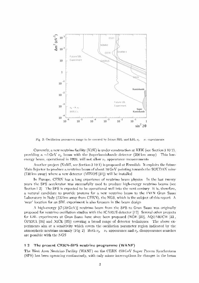
[30]. The limits expected from the sensitivity of CHORUS and NOMAD are shown in Fig. 2,
together with the expected extent of a future SBL experiment.
The present experimental evidence from Kamiokande, Superkamiokande and CHOOZ
points strongly towards oscillation in the small m2 ( 102 103 eV2) region (see
Fig. 1). To explore this region by an independent method, long-baseline (LBL) neutrino-beam
experiments are needed. The sensitivity to small m2 improves with increasing L=E; the physics
requirements for such LBL experiments are described in detail in Section 2.1.
2
10-4
10-3
10-2
10-1
1
10
10 2
10 3
10-6
10-5
10-4
10-3
10-2
10-1
1
sin2 2θ
∆m
2 (eV
2 )
Super
Kamiokande
Kamiokande
Fig. 2: Oscillation parameter range to be covered by future SBL and LBL experiments
Currently, a new neutrino facility (K2K) is under construction at KEK (see Section 3.10.2),
providing a 1GeV beam with the Superkamiokande detector (250 km away). This low-
energy beam, operational in 1999, will not allow appearance measurements.
Another project (NuMI, see Section 3.10.1) is proposed at Fermilab. It exploits the future
Main Injector to produce a neutrino beam of about 10GeV pointing towards the SOUDAN mine
(730 km away) where a new detector (MINOS [31]) will be installed.
In Europe, CERN has a long experience of neutrino beam physics. In the last twenty
years the SPS accelerator was successfully used to produce high-energy neutrino beams (see
Section 1.2). The SPS is expected to be operational well into the next century. It is, therefore,
a natural candidate to provide protons for a new neutrino beam to the INFN Gran Sasso
Laboratory in Italy (732 km away from CERN), the NGS, which is the subject of this report. A
`near' location for an SBL experiment is also foreseen in the beam design.
A high-energy [O (20GeV)] neutrino beam from the SPS to Gran Sasso was originally
proposed for neutrino oscillation studies with the ICARUS detector [17]. Several other projects
for LBL experiments at Gran Sasso have since been proposed (NOE [32], AQUARICH [33],
OPERA [34] and NICE [35]) covering a broad range of detector techniques. The above ex-
periments aim at a sensitivity which covers the oscillation parameter region indicated by the
atmospheric neutrino anomaly (Fig. 2). Both appearance and disappearance searches
are possible with the NGS.
1.2 The present CERN-SPS neutrino programme (WANF)
The West Area Neutrino Facility (WANF) on the CERN 450GeV Super Proton Synchrotron
(SPS) has been operating continuously, with only minor interruptions for changes in the beam
3

conguration, since 1976. For many years now, it has provided a very intense beam of high-
energy muon neutrinos to the particle physics community and has a proven track record for high
operational reliability.
A schematic layout of the present WANF is shown in Fig. 3. Protons extracted from the
straight section 6 of the SPS at 450GeV are directed towards the West Experimental Area and
focused onto a beryllium target (T9). A fast resonant (FS) extraction is used which produces
two beam spills of 6ms duration, separated by 2.7 s, for each 14.4 s cycle of the accelerator.
helium tunnel
TOP VIEW of neutrino cave
SIDE VIEW of beam line behind cave exit
Muon counting Pits
2 31
iron shield
earthshield
ironshield
earthshield
REFLECTORHORN
Target
Cu collimator
Al collimator
TDX iron collimator
tbi
18.90 71.53 124.32 from T9
shutter
vacuum decay tunnel
vacuum decay tunnel
total length 289.81
31.62
258.19 185.0
toroidal magnet 3 kA
44.0 39.5 100.3
782.93 from T9
821.97 from T9
Center
BEBC
Entrance of hall E2
BEBC hall
lengths in m
T9
BCT
~ 20
NOMAD
CHORUS
helium tunnel
Fig. 3: Schematic layout of the CERN WANF beam line indicating its main elements (dimensions in metres)
Pions and kaons produced in the target, in the required energy band, are focused towards
the detectors in an approximately parallel beam: two co-axial magnetic lenses, more familiarly
known as horn and re ector, are used. These pions and kaons decay in ight to produce muons
and muon neutrinos. The muons and remaining hadrons are stopped in a long iron and earth
shield at the end of the decay path leaving only the neutrinos to continue to the detectors some
800m from T9. In the WANF, the distance from the target to the beginning of the iron shield
is 420m. To minimize the number of `parent' particles that interact in the air before their
decay, the spaces between the focusing devices in the 120m long cavern have large-diameter
tubes lled with helium at atmospheric pressure. The nal 300m long decay tunnel is evacuated
to 0.5 Torr.
Measuring the muon ux distributions at a number of monitoring gaps in the iron shielding
has provided an invaluable diagnostic tool for understanding the neutrino ux and aligning the
beam.
4

The last major upgrade of the WANF took place in 1992/93 in preparation for the CHO-
RUS and NOMAD experiments which are now approaching the end of their data taking. These
experiments aim at detecting evidence of non-zero neutrino mass, searching for neutrino oscil-
lation, from into .
The SPS beam presently operating for CHORUS and NOMAD is a quasi-pure wide-
band beam with an average energy of 27GeV, having a few per cent contamination of muon
antineutrinos and about 1% contamination of electron neutrinos e. The contribution from
inherent in the beam, produced mainly by prompt decay of D+s mesons, is expected in the
charged current (CC) events in CHORUS at a level of 3 106 [36, 37].
Such a beam provides an excellent tool to search for oscillation of . Both experiments
are primarily performing a search for the appearance of , aiming at the detection of leptons
from CC interactions. In addition, it is also possible to search for the appearance of e via
the detection of electrons from CC e interactions, if the signal is signicantly above the 1%
background. Searches for disappearance of are possible but less sensitive.
Signicant improvements in the operation of the SPS as a neutrino source have been
achieved and further progress is expected. The WANF has operated at unprecedented intensities,
thanks to a better insight into the behaviour of the target and record performance of the SPS
since 1995.
1.3 The Gran Sasso Laboratory (Laboratori Nazionali del Gran Sasso)
The Gran Sasso Laboratory (LNGS) [38] is located alongside the Gran Sasso tunnel, which
is 10.4 km long, on the motorway connecting Teramo and Rome, about 6 km from the west
entrance. This underground laboratory, founded by INFN in 1987 as a facility for cosmic ray
and rare decay studies, is located at 963m above sea level. The distance from CERN to Gran
Sasso is 732 km, and its direction from CERN is:
azimuth: 122.5 (w.r.t. geographic north)
slope: 5:6% (w.r.t. the horizontal plane).
The LNGS is an INFN national laboratory with an International Scientic Committee,
responsible for recommending the approval of the experiments. The experiments are conducted
by international collaborations.
The LNGS underground laboratory consists of three experimental halls, conventionally
named halls A, B and C, and of a series of connecting tunnels and service areas. The three
experimental caverns are each more than 100m long and about 18m high and wide (see Fig. 4).
The Campo Imperatore region in the Gran Sasso massif is at an altitude of about 2000m
above sea level. In addition to the underground laboratories, this area houses a group of air
shower detectors together with two geophysical experiments.
The position of the Campo Imperatore detectors and the presence of a nearby support-
ing laboratory provide a unique opportunity for combined studies between `atmospheric' and
underground detectors.
The support structure for the underground halls and the Campo Imperatore zone com-
prises a group of external buildings which house the LNGS headquarters with all the adminis-
trative oces, the computing centre, all the technical and engineering services, the electronic
and chemical laboratories, the machine shop, stockroom, and a conference room.
5

Interferometricregion
Hall BMacro
Hall CBOREXICARUS
TeramoHighway tunnelsRome / L’Aquila
Hall AGALLEXLVD
Direction of CERN Neutrinos
Fig. 4: Overview of the Gran Sasso underground laboratory, showing experiments which are presently running or
approved for construction
The main justication for installing experiments in an underground laboratory like the
LNGS is the shielding against cosmic rays. At Gran Sasso, the minimum thickness of the
rock overburden, i.e. the shielding, is 1400m, corresponding to 3800m water equivalent. Only
neutrinos and high-energy muons, among the known particles, can penetrate such a layer of
rock. Owing to their low interaction probability, incoming neutrinos can lter through the
rock independently of their energy, but among the muons that arrive on the Earth's surface
(about 100m2 s1) only those that have a suciently high energy, above 2TeV, can reach the
underground laboratory. Inside the Gran Sasso Laboratory, the remaining muon uence rate is
of about 1m2 h1.
In addition to providing an ecient shield against cosmic rays, the Gran Sasso rock is
characterized by a low rate of natural radioactivity. This results in a very low level of total
radiation background. Therefore, the underground laboratory is an ideal place for delicate
experiments which investigate rare events such as double beta decay and proton decay, as well
as searches for magnetic monopoles and other exotic particles.
In the future, the intense neutrino ux of the NGS beam from CERN will provide an-
other opportunity for a high quality experimental programme at Gran Sasso. Highly sensitive
experiments will allow the detection of the source of the atmospheric neutrino anomaly, either
by appearance or disappearance measurements.
1.4 Overview of the new facility
1.4.1 Layout of the NGS
Accelerator driven neutrino beams are generated from the decay of mesons, mostly and K,
+() ! +() + ()
6

K+() ! +() + () :
These mesons are produced from a high-energy, high-intensity proton beam hitting a suitable
target. The main ingredients of the proposed NGS are shown schematically in Fig. 5 and listed
below. The layout is shown in Figs. 6 and 7.
A proton beam with an energy up to 450GeV (400GeV nominal) extracted from the
CERN SPS accelerator, transported and focused onto a small spot at the target.
A target station consisting of a segmented graphite target, in which the secondary particles,
and K, etc., are produced.
A two-stage focusing system, horn and re ector, which focuses a range of chosen and K
momenta into a parallel beam, pointing towards the Gran Sasso Laboratory.
A 1000m long decay tunnel, which allows a fraction of the , K to decay in ight, producing
a high-intensity beam.
A hadron stop, which absorbs the non-interacting primary protons as well as those sec-
ondary hadrons which have not decayed.
A muon monitoring system, permitting on-line monitoring, tuning, and control of the
beam and its alignment.
The natural shielding provided by a long stretch of molasse (about 730m) to absorb the
muons from hadron decay upstream of the SBL detector.
An underground experimental area allowing the installation of a short-baseline experiment.
The dierent components of the neutrino beam are brie y described in the following
sections. A more detailed explanation is given in Sections 3 and4 The underground experimental
area for the SBL experiment is described in a forthcoming report.
SPS proton beam
target andfocusing devices
decay tunnelmolasse (shielding)
hadron stop andmuon monitoring possible SBL
towards Gran Sasso( π, K, etc.) ( ν − beam)
experiment
(732 km)
Fig. 5: Schematic layout of the new CERN neutrino facility
1.4.2 Implementation at and around CERN
The geographical layout of the NGS facility is shown in Figs. 6 and 7. The guiding principles
for the implementation are the following:
There should be no additional, permanent surface buildings, other than for the proposed
SBL experimental area. This leads to the need for an 800m long access tunnel from point 4
of the SPS to the NGS target cavern.
The LHC project should not be hampered by the NGS implementation | a separate
neutrino civil engineering shaft (PGCN) near point 4 of the SPS is thus required. This
will be a temporary shaft to be closed once the construction is completed.
The target cavern should be large enough to allow the possible installation, after a rst
generation of experiments, of a new target and/or a dierent focusing system, e.g. for a
low-energy or a narrow-band neutrino beam.
7

Fig. 6: Layout of the NGS at and around CERN
0 0,5 km 1 km 1,5 km 2 km 2,5 km 3 km
450
400
350
300
Altitude(m)
Junction TI8-LSS4
LSS4SPS
PGC8
PGCN
MORAINE
Target
MOLASSE
Tunnel TI8 (3,5%)
(5,6%)
LEP/LHC tunnel
Point 8LEP
SBL Detectortector
Point 8Ferney-Voltaire
Airport
BA4(SPS)
Junction TI8-LEP
toGran Sasso
Route de Mategnin
Fig. 7: Vertical cut showing the SPS and the main components of the NGS
8
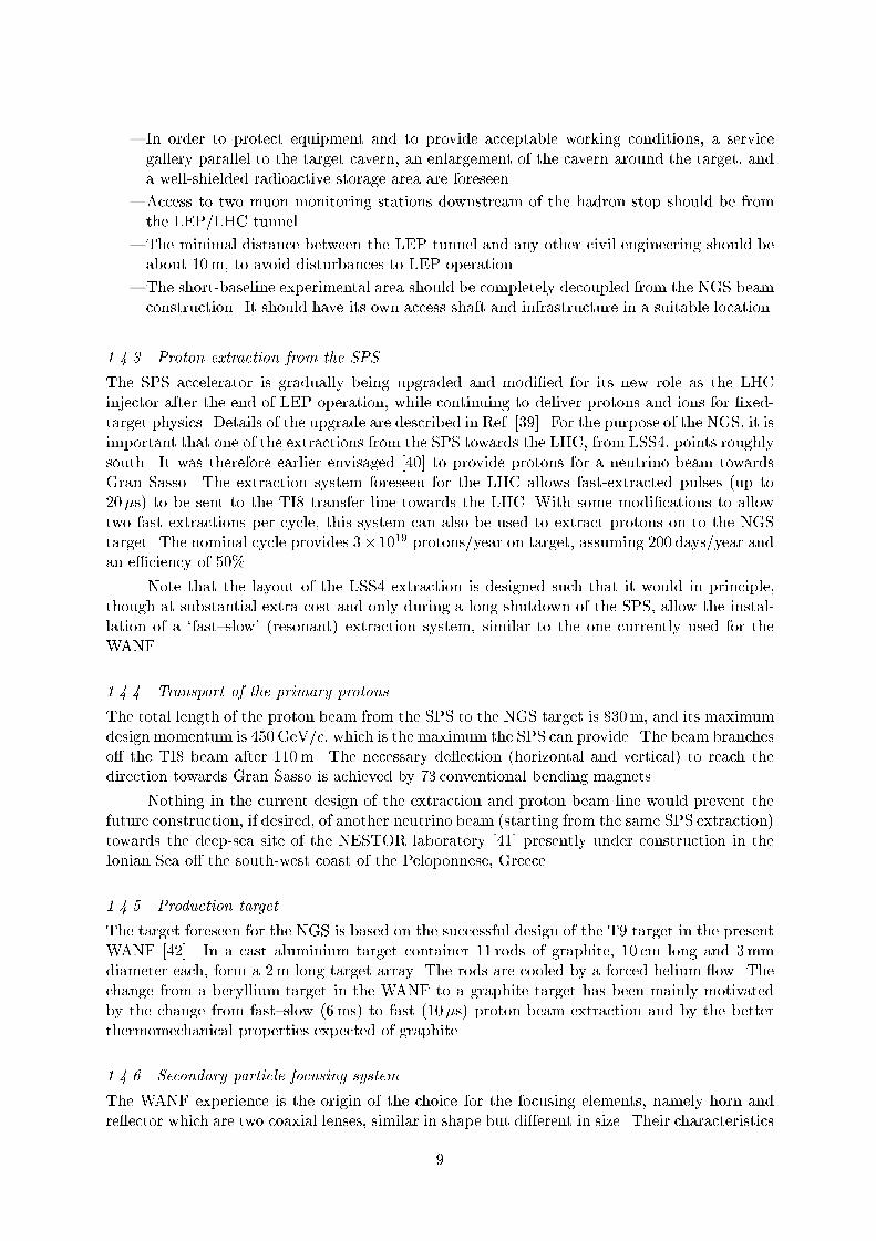
In order to protect equipment and to provide acceptable working conditions, a service
gallery parallel to the target cavern, an enlargement of the cavern around the target, and
a well-shielded radioactive storage area are foreseen.
Access to two muon monitoring stations downstream of the hadron stop should be from
the LEP/LHC tunnel.
The minimal distance between the LEP tunnel and any other civil engineering should be
about 10m, to avoid disturbances to LEP operation.
The short-baseline experimental area should be completely decoupled from the NGS beam
construction. It should have its own access shaft and infrastructure in a suitable location.
1.4.3 Proton extraction from the SPS
The SPS accelerator is gradually being upgraded and modied for its new role as the LHC
injector after the end of LEP operation, while continuing to deliver protons and ions for xed-
target physics. Details of the upgrade are described in Ref. [39]. For the purpose of the NGS, it is
important that one of the extractions from the SPS towards the LHC, from LSS4, points roughly
south. It was therefore earlier envisaged [40] to provide protons for a neutrino beam towards
Gran Sasso. The extraction system foreseen for the LHC allows fast-extracted pulses (up to
20s) to be sent to the TI8 transfer line towards the LHC. With some modications to allow
two fast extractions per cycle, this system can also be used to extract protons on to the NGS
target. The nominal cycle provides 3 1019 protons/year on target, assuming 200 days/year and
an eciency of 50%.
Note that the layout of the LSS4 extraction is designed such that it would in principle,
though at substantial extra cost and only during a long shutdown of the SPS, allow the instal-
lation of a `fastslow' (resonant) extraction system, similar to the one currently used for the
WANF.
1.4.4 Transport of the primary protons
The total length of the proton beam from the SPS to the NGS target is 830m, and its maximum
design momentum is 450GeV/c, which is the maximum the SPS can provide. The beam branches
o the TI8 beam after 110m. The necessary de ection (horizontal and vertical) to reach the
direction towards Gran Sasso is achieved by 73 conventional bending magnets.
Nothing in the current design of the extraction and proton beam line would prevent the
future construction, if desired, of another neutrino beam (starting from the same SPS extraction)
towards the deep-sea site of the NESTOR laboratory [41] presently under construction in the
Ionian Sea o the south-west coast of the Peloponnese, Greece.
1.4.5 Production target
The target foreseen for the NGS is based on the successful design of the T9 target in the present
WANF [42]. In a cast aluminium target container 11 rods of graphite, 10 cm long and 3mm
diameter each, form a 2m long target array. The rods are cooled by a forced helium ow. The
change from a beryllium target in the WANF to a graphite target has been mainly motivated
by the change from fastslow (6ms) to fast (10s) proton beam extraction and by the better
thermomechanical properties expected of graphite.
1.4.6 Secondary particle focusing system
The WANF experience is the origin of the choice for the focusing elements, namely horn and
re ector which are two coaxial lenses, similar in shape but dierent in size. Their characteristics
9

are not very dierent from those used in the WANF [43]. The distances of horn and re ector
from the target and the shape of the magnetic eld provided by them are chosen to optimize a
wide-band high-energy beam.
1.4.7 Decay tunnel
In order to obtain a neutrino beam pointing towards Gran Sasso, the parent hadrons have to
decay in ight while travelling in that direction. To avoid their interacting before they can
decay, an evacuated decay path is necessary. Typical decay lengths, 2.2 km at 40GeV, imply
that a long decay pipe is desirable; given the angular distribution of the parent hadrons which
can produce neutrinos, a longer decay tunnel should also have a bigger diameter. For the NGS,
a pipe of 2.45m diameter and 1000m length has been chosen.
1.4.8 Hadron absorber and muon shield
At the exit of the decay tunnel, a massive iron beam dump is needed to absorb the non-
interacting primary protons as well as all secondary particles. Additional iron, beyond the 10m
typically needed for the beam dump, has to be added in order to protect the SBL cavern against
high-energy muons.
It is foreseen to build a 18 4 4m3 dump, assembled from iron blocks which can be
recovered from the WANF. A 3m long graphite insert at the upstream end provides a better
distribution of the deposited heat. Under the most extreme assumptions (dedicated operation
of the SPS at 450GeV with 4:5 1013 protons on target every 6 s), a heat dissipation of about
50 kW has been estimated. A modest cooling system is thus sucient to assure stable and
relatively low temperatures in the hadron stop cavern.
1.4.9 Muon monitoring station
Most of the hadron decays produce a neutrino and a muon. Measuring the muon intensity and
prole provides information on the intensity and prole of the neutrino beam. Measuring the
muon signals induced in a set of thin silicon detectors allows an `on-line' monitoring and tuning
of the beam (steering of the proton beam on target, horn and re ector alignment, etc.).
The muon monitoring system consists of two arrays of silicon detectors measuring the
intensity and prole of the muon ux penetrating (a) the hadron stop and (b) the hadron stop
plus a 67m thick region of molasse. The separation of the two planes, equivalent to 25m of iron,
allows a rough measurement of the muon energy spectrum. Moreover, some angular information
on the beam is also available by using the information from the two measurement planes.
1.4.10 The short-baseline experimental area
Continued interest is being expressed for a next-generation, short-baseline, neutrino oscillation
experiment at CERN [29], combining the assets of CHORUS and NOMAD. Naturally, such an
experiment has to be located in the new beam towards Gran Sasso and thus forms a part of the
NGS. Details of the experimental area as foreseen for this type of experiment will be discussed
in a forthcoming report.
Present plans foresee the location of this SBL experimental area at a distance of about
1850m from the NGS target, i.e. about 140m underground just north of the Geneva airport
(see Fig. 6). An underground cavern is accessed by a large shaft, containing personnel and
material accesses. A modest surface building, access for trucks, and parking space is needed.
The technical services (water, power, etc.) for this new experimental area are most likely to be
connected to point 8 of the LEP/LHC.
10
1.5 Overview of the NGS beam performance
The expected performance of dierent neutrino beam congurations has been studied. The
so-called `reference beam', investigated in detail and discussed in Section 3, is considered a
preliminary working hypothesis. Its conceptual design is guided by the requirements for long-
and short-baseline appearance experiments.
Simulations of the complete neutrino production process from 400GeV SPS protons on a
graphite target indicate that the expected uences of are about 4:4 109m2 per proton
on target (pot) at the location of the LBL detector and 1:1 103m2 per pot at the SBL
detector. The average energies of these 's are respectively 26.7 and 24.1 GeV. At both LBL
and SBL locations a contamination of around 2% and slightly less than 1% e is expected.
The contamination is estimated to be of the order of 106 at the SBL detector location.
The rates of CC interactions (events per proton per ton of detector material) are
expected to be about 1:11014 in an SBL detector and 4:71020 in an LBL detector. While
these numbers refer to the present working hypothesis, other options are under active study.
The nal beam will be designed according to the approved physics programme to be carried out
with the NGS facility.
2 PHYSICS REQUIREMENTS AND NEUTRINO BEAM DESIGN CRITERIA
2.1 Beam criteria to meet physics requirements
The neutrino oscillation probability P in the standard two- avour mixing scheme may be ex-
pressed in terms of the two oscillation parameters sin22 (the so-called mixing parameter) and
m2 (namely the dierence of the neutrino mass-squared):
P = sin2 2 sin2 (1:27 (L=E)m2) ;
where L is the mean distance of the detector from the neutrino source measured in kilometres,
E is the average neutrino energy (in GeV) and m2 is measured in eV2.
From the above relation one nds that the oscillatory pattern of the probability has an
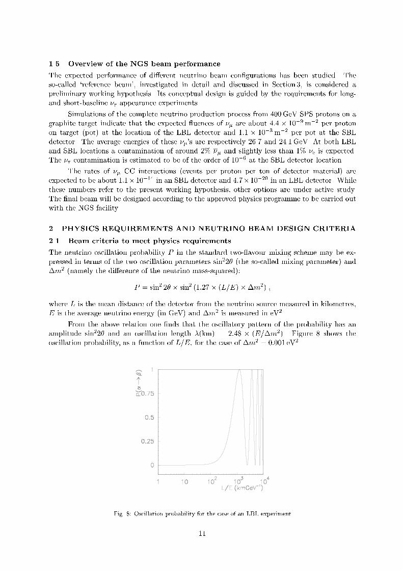
amplitude sin22 and an oscillation length (km) = 2:48 (E=m2). Figure 8 shows the
oscillation probability, as a function of L=E, for the case of m2 = 0:001 eV2.
Fig. 8: Oscillation probability for the case of an LBL experiment
11

It follows that for large m2 the oscillation probability no longer depends on L:
P = 1=2 sin2 2 :
On the other hand, the minimum m2 to which the experiment is sensitive (for full mixing, i.e.
sin22 = 1) is:
m2(eV2) =pP E(GeV)=(1:27 L(km)) :
Therefore, the sensitivity in m2 depends on the ratio E=L. For a typical accelerator neutrino
energy O (10GeV) we dene short-baseline (SBL) experiments as those with L 1 km, so
mostly sensitive to m2 110 eV2, and long-baseline (LBL) experiments where L 1000 km,
required in order to access m2 102 103 eV2.
Neutrino oscillation experiments can also be subdivided into disappearance and appear-
ance searches. In the rst case the main requirement is to have a beam with very well-known
intensity. The ux of the main beam component ( in the case of the NGS) is measured at a
given distance L from the source. The occurrence of neutrino oscillation can be detected as a
reduction of the measured ux compared to the value expected in the absence of oscillation.
The sensitivity of disappearance experiments is limited by systematic uncertainties on the
knowledge of the neutrino beam intensity. For this reason, the measurement of the ux can take
advantage of another detector placed at a dierent position, i.e. L0 smaller than L. One then
names the latter a `near detector'.
On the contrary, appearance experiments exploit beams consisting of predominantly one
neutrino avour and search for the `appearance' of another avour, which in principle is absent
in the beam. The sensitivity of these experiments is obviously limited by the uncertainty in
the contamination of the other neutrino avours in the beam. In the case of the NGS the most
interesting appearance search is for oscillation. The contamination of the beam is at
a very low level, which allows high-sensitivity explorations.
It is important to observe that since the appearance of a dierent neutrino avour is
detected through the interaction of this neutrino with the experimental target, the neutrino
must be energetic enough to produce its corresponding charged lepton. This sets, for a given
oscillation search, a lower limit to the energy of the neutrino. In particular, since the threshold
to produce a lepton is 3:5GeV, a high-energy beam is preferred for a experiment.
Less stringent constraints apply to the neutrino energy for disappearance experiments.
In that case, only the initially produced neutrino must have sucient energy to produce its
charged-lepton partner.
2.1.1 Long-baseline disappearance experiments
The class of experiments designed to test neutrino oscillation through the disappearence of the
original avour can also measure the values of the oscillating parameters, sin22 and m2.
In practice this is performed by extracting the characteristic oscillating pattern from the
reconstructed neutrino spectrum; the period is directly related to the neutrino mass dierence
while the amplitude is related to the mixing angle. The oscillation pattern is reconstructed
either by comparing the neutrino spectrum at the LBL detector with that obtained with a
similar detector at a `near' position, or by comparing the spectra obtained by means of charged-
current events, sensitive to oscillation, and neutral-current events, insensitive to oscillation.
Without explaining details of the possible experiments, it is worth mentioning that disap-
pearance experiments are based essentially on statistical methods. Hence very large detectors
of several kilotons are required to minimize the statistical uctuations; they have to be able
12
to measure accurately both the hadronic energy and the energy and direction of the outgoing
lepton. This demands high granularity calorimeters equipped with a muon spectrometer.
This kind of measurement is best suited for large mixing angles and for m2 values that
full the condition 1:27 (L=E) m2 ' =2, where the disappearence eect is maximized.
The beam requirements of this class of experiment follow directly from the above features. In
order to maximize the disappearance eect for m2 102 103 eV2 at 732 km, the optimum
neutrino energy would be in the region of a few GeV. In addition, the best value has to be
determined by taking into account the neutrino interaction rate which increases with energy,
in order to maximize statistics. Moreover a wide-band beam is preferable because the higher
energy events, where the oscillation is suppressed, are useful for normalization.
The e contamination is not an important background as it is at the level of a few per
cent, the systematic errors inherent to the disappearance method are estimated to be around
23%.
As already mentioned above, an accurate knowledge of the neutrino beam spectrum pro-
duced at the source is mandatory to perform a disappearance search. For this reason most of
the proposed experiments based on this method require the presence of a `near' detector to
measure the neutrino beam with high statistics at the source. This is best performed if the near
detector is using the same techniques as the far (LBL) detector, in order to avoid unpredictable
systematic errors.
2.1.2 Long-baseline appearance experiments
As pointed out in the introduction, the combined result of Superkamiokande on atmospheric
neutrinos and the null result of CHOOZ obtained with reactor neutrinos can be interpreted in
terms of avour oscillation, dening an allowed region in the oscillation parameters space only
for the channel . As a consequence, appearance searches in long-baseline experiments
must be focused on the identication of the signal, through the detection of the lepton.
There are, at present, two classes of proposed experiments aimed at detection. One is
based on the direct identication of the lepton, produced in CC interactions of , by means
of its decay pattern. The characteristic decay length, followed by a `kink' due to the decay
into one or more charged daughters plus neutrino(s) is a unique signature. In practice, since the
decay length is only a few hundred microns this technique has to be based on emulsion as the
active detector; this gives a granularity of the order of a micron. The detection eciency may
be relatively high, of the order of some tens of per cent. The CHORUS experiment makes use
of this technique as does the envisaged OPERA detector at Gran Sasso.
Another class of experiment exploits the detector capability to measure the complete
kinematics of the neutrino interaction. The extraction of the signal is performed by dening
sets of observables for which the interaction is (at least partially) distinguishable from the interaction. The detection eciency depends on the cuts applied to separate the two samples
and it is typically of the order of a few per cent. This is the technique adopted by the NOMAD
experiment at CERN and by the already approved ICARUS experiment at Gran Sasso.
Both techniques require very specialized detectors to be built. As a consequence, the
active mass cannot be very large, of the order of a kiloton or less for the experiments proposed
for the Gran Sasso long-baseline experiments. Moreover, in both cases, the sensitivity is further
reduced by the CC cross-section, which gets smaller near the threshold (about 3.5GeV) and
slowly increases with energy, to reach asymptotically the value of the CC cross-section at
extremely high energy (above 100GeV). This implies that, contrary to disappearance searches,
in order to maximize the detection probability (both in terms of interaction rate and detection
eciency) a higher energy neutrino beam is preferable.
13

To better quantify the above requirements, the number of interactions in a given de-
tector is determined by the following formula:
N = NA Md Z((E) P
(E) (E) (E) dE) ;
where is the ux at the detector site, Pis the oscillation probability between and
, is the CC interaction cross-section, is the detection eciency, NA is the Avogadro
constant and Md is the detector mass.
In case the condition m2 L=E 1 holds, the oscillation probability can be approxi-
mated as follows:
P = sin2 2 (1:27 (L=E) m2)2 :
Moreover, the cross-section can be parametrized as:
= 0 E f (E)
where 0 = 0:67 1038 cm2. Then the number of interactions may be expressed as:
N = NA Md sin2 2 (1:27 m2 L)2 0 Z((E) f (E) (E) dE=E) :
In other words, the quantity to be maximized in order to take advantage of the long-baseline
conguration is the average of f (E)(E)=E over the beam spectrum. To a rst approximation
a wide-band beam peaked around 2025GeV, similar to the present WANF, is the correct choice.
The e contamination in the beam has to be kept low because it can simulate the signal mainly when using kinematic techniques. This requirement, as shown in the following
paragraph, is even more relevant for SBL experiments. However, in this case a contamination
of less than 1%, typical in most of the beam designs, is acceptable. Similar considerations hold
for the contamination: the typical level of a few per cent (see the following section) is low
enough. To conclude, appearance experiments do not need, in principle, any near detector.
2.1.3 Short-baseline appearance experiments
The present SBL experiments on the WANF beam, CHORUS and NOMAD, have recently
reported no evidence for oscillation at the level of sin22 3 103 using a fraction
of their available data [23, 24]. Finally they will reach a sensitivity of sin22 2 104 for
m2 100 eV2, corresponding to a with a mass of about 10 eV. Their sensitivity to a lighter
, in the range of 15 eV is sin22 5 102. This sensitivity can be greatly improved by a
next-generation SBL experiment.
If oscillations occur at the present best limit, CHORUS and NOMAD would each record
more than 50 events. Even if only a few candidates would be unambiguously detected, this
would have profound implications on the understanding of the neutrino oscillation scenario. This
would call for a new high-sensitivity exploration. Moreover, some phenomenological interpreta-
tions of the present data (see Section 2.1) suggest that (e) oscillation may be found at
a m2 1 eV2 and with small eective mixing angle.
The TOSCA Collaboration [29] has proposed to run a new SBL with improved sensitivity
in the existing WANF beam, which would increase by more than one order of magnitude the
sensitivity of CHORUS and NOMAD. For m2 1 eV2, it would detect about 20 candidates.
TOSCA is expecting to run in the NGS facility at the SBL underground experimental area,
near the Geneva airport. The infrastructure required for such an experiment is described in a
forthcoming report.
14

The existence of neutrino oscillation is inferred from the occurrence of CC interactions of
in the emulsion target:
N! X :
The is detected through its decay modes into muons, hadrons, and electrons. Its identication
is carried out: by exploiting the characteristic decay topology; by the charge measurement of
the decay products; by its distinct decay kinematics; and by the missing energy carried away by
the neutrino(s) in the decay.
The main detector features re ect the need of a high-sensitivity SBL experiment, able
to explore a parameter region in some respects complementary to that of an LBL experiment,
namely with small mixing angle and relatively large m2. The product of target mass, neutrino
ux and detection eciency has to be at least ten times larger than in the present searches.
An increase of a factor of more than three in target mass and an increase of a similar factor in
detection eciency with respect to CHORUS is then required.
The rst important criterion to be fullled by the NGS design is the high ux and the
high neutrino energy: the sensitivity in the mixing angle improves linearly with the number
of interacting neutrinos, which calls for high ux and, because of the linear dependence of the
cross-section with the energy, for high-energy neutrinos. This can be obtained with a wide-band
beam conguration.
However, the contamination in the beam is the ultimate irreducible background for
an appearance oscillation search with high sensitivity. The largest contribution to this
background comes from the prompt tauonic decay of the Ds produced from proton interactions in
the neutrino target, inside the shielding and in the beam dump. Estimates of such a background
[36, 37] for a proton energy of 450GeV and the CHORUS detector ducial volume, agree on the
ratio R of the number of CC events to CC events to be 3:0 106.
This level of the prompt background, comfortably below one event for the total dura-
tion of the CHORUS and NOMAD experiments, becomes more relevant for an experiment like
TOSCA, aiming at improving the sensitivity by at least one order of magnitude. The depen-
dence of this background on the energy makes a lower proton energy in principle preferable.
However, a global optimization has to take into account the distance of the detector from the
neutrino source. The prompt may also be reduced by rejecting high-energy events [29].
The other physical backgrounds impose further constraints on the neutrino beam design.
The most abundant events in the detector are inclusive CC interactions of . They have a
negative muon in the nal state, which does not produce a decay topology, nor missing energy.
Only those processes with special topology, such as charm production, may be misidentied as
events with a in the nal state.
As an example, charmed particles produced in and e CC interactions decay with a
lifetime similar to the , but can be distinguished from the by their positive charge. Negative
charmed particles are the most dangerous ones which can be produced in the CC interactions
of and e. The presence of a + or e+ allows the rejection of these events. In the cases
where the primary leptons are not identied, kinematical criteria may be exploited for further
rejection.
The above considerations on the charm background lead to the need for a contamination
as low as possible of , e and e in the main beam.
15

2.2 Other considerations guiding the NGS design
2.2.1 The NGS as a general facility
The goal of this study is the design of the NGS as a general facility, which could be in use
for many years to come and possibly house more than one generation of neutrino beams and
experiments.
The study of neutrino physics in general and more specically of neutrino oscillation is
likely to be in uenced by the results of a number of ongoing experiments. The results of rst-
generation experiments will dictate the aim and the design of the future neutrino beams and
detectors. It seems impossible, today, to predict the long-term physics requirements for the
NGS.
As discussed in Section 2.1, the requirements of the dierent experiments that are currently
being proposed or discussed may imply dierent beam layouts. It is therefore mandatory to build
a facility allowing the necessary exibility. This principle guided several of the choices made for
the civil engineering layout. They can be summarized as follows:
1. The length of the target and focusing hall was chosen to be 123m, long enough to construct
a high-energy beam of the WANF type, allowing the eective focusing of high-energy neu-
trino parents produced at small angles. Lower energy beams can easily be accommodated.
2. A high neutrino ux is vital to make both long- and short-baseline experimentation pos-
sible. The length of the decay tunnel was chosen to be about 1000m, three times longer
than in the WANF.
3. The closest possible location of the underground pit for an SBL experimental area was
identied to be about 1850m downstream of the proton target, below the boundary limits
of the Geneva airport. On the surface, the region between the hadron stop and the airport
is too densely populated to permit the installation of a deep experimental station and of
the related infrastructures. Moreover, the solution chosen oers the additional possibility
of using the existing molasse as a muon absorber, thus requiring less iron reinforcement.
Within these constraints, freedom is left to focus dierent energy slices of the secondary
beam. The bulky and heavy power connections (strip-lines) are designed such that focusing
elements can be positioned essentially anywhere in the 100m length of the target chamber,
downstream of the target itself.
It should be noted that focusing with the coaxial lenses (horn and re ector) permits
antineutrino operation by simply switching the polarity of the devices, if this should be required
at a later stage.
The reference beam described in detail in Section 3 corresponds to a particular choice of
the positions, currents, and shapes of the horn and the re ector. Positions are respectively about
8 m and 80m downstream of the target, the current is 120 kA for both. The shapes of the inner
conductors of the two lenses are such that they can provide parallel focusing of pions and kaons
of 50 and 85GeV respectively.
2.2.2 Building on the CERN experience
CERN has accumulated a long and continuous experience in running neutrino beams since the
early 1960s, rst at the PS and later at the SPS. The present SPS neutrino facility, the WANF,
has been, since its construction and even more today, the world's most powerful beam of high-
energy neutrinos.
The history of the WANF is one of very high operational reliability, with minimal down-
time, and ever increasing performance. Record yields of protons and neutrinos have been and
are available to the ongoing physics programme carried out by CHORUS and NOMAD.
16

Unfortunately, the WANF cannot be used for LBL experimentation because it emerges
from the SPS with an upward slope of about 43mrad. The possibility of installing a detector
on its axis exists only on the CERN site itself, where the beam reaches the ground level around
800m downstream of the target | a suitable location for a SBL experiment. On the same beam
axis one could possibly install a detector in the Jura mountains, about 17 km downstream of
the target | this would be considered a `medium-baseline' experiment. For LBL experiments
using a neutrino beam from CERN, a new facility has to be constructed.
CERN has much experience in building tunnels and big caverns in the kind of rock (mo-
lasse) in which the new project has to be constructed. A total of 39 km of tunnels of various
diameter and length exist, the longest one being the 27 km long LEP tunnel.
For the new NGS, the high energy of the SPS proton beam is one of the key elements that
allows the production of high neutrino uxes and interaction rates. It was decided, therefore,
to design a facility capable of operating at the maximum (450GeV) SPS proton energy. It is
likely, however, that the facility will operate at a slightly lower energy, 400GeV or so, where a
higher number of protons per unit time can be delivered by the SPS.
The main improvement in the design of the new facility with respect to the WANF is of
course its longer decay tunnel. Other improvements are being sought, however, in all areas of
the design, for example: (1) In the search for an optimal focusing conguration, although the
conguration adopted during the data taking of the CHARM II experiment (198691) is already
very close to the requirements of the appearance experiments that are being proposed. (2) In
the choice of a target material dierent from the beryllium used in the WANF, a material which
can sustain a larger number of protons per extraction and make full use of the protons that
the SPS can deliver. (3) Shape and segmentation of the target are being studied to nd ways
to enhance the production from the target of secondary mesons capable of providing useful
neutrinos within the acceptance of the detectors. (4) A gain in the number of neutrinos per
proton is also expected from the larger acceptance of the focusing system envisaged in the new
facility.
The beam tuning, monitoring, and trouble-shooting tools that have been developed for the
WANF, particularly after its major reconstruction in 199293, have proved invaluable during
the years of beam operation. Building on this experience, it is planned to equip the new facility
with an upgraded control system. The requirements of beam alignment are indeed more severe
than in the past and are being properly considered.
2.2.3 Other focusing systems considered
Quadrupole lenses have been considered but a narrow-band neutrino beam, using a spectrom-
eter arrangement to give tight momentum selection, would not provide sucient ux for the
experiments that could be envisaged. However, there is sucient space in the target chamber to
install such a beam, similar to the N3 beam used in the WANF from 1977 to 1980, if required.
An on-axis, large-aperture, quadrupole triplet beam has been considered [44] and might
provide a possible approach to a narrower energy band beam. However, there is no sign-of-charge
selection and both neutrino and antineutrino parents are focused.
Plasma and lithium lenses have been considered and can, in theory, have advantages over
`conventional' horns. They usually have very limited angular acceptance and may not have the
same, proven level of long-term reliability in operation.
17

2.3 Operation of the SPS
2.3.1 The future of the SPS physics programme
The physics programme of the SPS will most likely continue to maintain its proton xed-target
activities beyond 2002, the planned starting year of the NGS operation. This programme would
include xed-target experiments and detector test beams, particularly for the LHC experiments,
in addition to the neutrino xed-target programme discussed in this report. The approved
COMPASS experiment and a possible continuation of the present NA48 experiment are in the
xed-target programme.
The rst two of the above activities require a slow resonant extraction (SE) from the SPS
while the neutrino programme will be served by a half-turn fast extraction (FE) of the circulating
beam in two batches. Among the requirements of the SE physics is a supercycle providing an
acceleration to 450GeV/c and a long at-top. The duration of this at-top is presently 2.58 s,
but owing to the time required for the second of the neutrino fastslow extractions, the time
available for the SE is 2.38 s, thus providing an eective duty-cycle of 16%.
A future SPS supercycle should be able to support the intensity requirements of the full
proton xed-target programme of physics experiments (SE and neutrino) and test beams running
during the same period. Details of a proposal which satises the above requirements for the full
xed-target programme are given in Section 2.3.4.
2.3.2 The SPS as an LHC injector
The SPS will be the nal machine in the injector chain for the LHC, accelerating protons of
26GeV/c from the PS to 450GeV/c before a fast extraction to the LHC via either the TI2 or
TI8 transfer lines. A new fast-extraction channel, which also allows the extraction of protons for
the NGS, will be constructed in the long straight section in LSS4. At this location the rst part
of the TI8 transfer line, required for the proton transfer from the SPS to the LHC anti-clockwise
circulating ring, will also be constructed. A description of the extraction channel for the NGS
and its relation to that of the LHC is given in Sections 4.1 and 4.3.
The protons in the SPS originate from the PS proton Linac II and are accelerated rst in
the PS Booster (PSB) and then in the PS itself. The SPS and PS operate on a cycle which is a
multiple of 1.2 s, given by the repetition time of the PSB.
A number of modications to the PSB and to the PS are foreseen to be implemented before
the start-up of the LHC in an eort to double the brilliance (intensity/transverse emittance)
required by the LHC. The NGS beam also takes advantage of these improvements. Among the
upgrades planned is the injection of the protons from the PSB to the PS at 1.4 GeV instead of
the present 1.0 GeV. This would reduce the space-charge eects during the time the beam spends
on the 1.2 s PS injection plateau, resulting in potentially lower beam losses in the acceleration
chain. This would enable the SPS to operate more comfortably at its present intensities of
around 4:5 1013 protons per cycle and beyond.
Up to the middle of 2005 the SPS will be fully available for the xed-target experiments
including the neutrino experiments, except during the injection tests for the LHC in 2003 which
will need a considerable fraction of the SPS time for two months. There is an option to continue
the injection tests at the beginning of 2004 though this may con ict with the schedule of LHCb.
The running-in of the LHC will start in the middle of 2005 probably requiring the injector chain
to be dedicated to the LHC for a few days per week. It is expected that after this transition
period in 2005 scheduled physics running will increasingly dominate the LHC running, which
implies about two lls per day, each of them requiring the injector chain for about three hours.
The remaining time, during which the LHC is in coast, would be available for xed-target
physics. This implies a reduction of total protons on target of about 25% per day. At a later
18

stage, the lling time will be reduced to two hours, reducing the loss for xed-target operation
to about 17% [45]. The SPS, serving in sequence the LHC and the xed targets, must be capable
of switching rapidly between the various supercycles, of dierent lengths and magnet cycling.
A possible sequence of procedures would require three supercycle changes: from xed-target
physics to LHC pilot (a low-intensity test shot to check the injection process and the LHC
machine parameters), from pilot to LHC lling supercycles, and nally back to the xed-target
supercycle.
At present, the switching time between dierent supercycles (as is the case between the
proton and lead-ion supercycles) takes at least one hour, too long to run the complete physics
programme eciently. However, work is under way to modify the SPS control system so as to
be able to change the supercycle on a cycle-to-cycle basis.
It is not inconceivable that at a later stage the LHC pilot cycles could be combined with
the xed-target supercycle in a longer supercyle in order to minimize the disruption of the xed-
target physics. The actual lling of the LHC always requires a dedicated cycle minimizing the
time the beam has to dwell in the LHC at injection energy.
It has to be pointed out that the operation of the LHC with ions for ALICE precludes
the SPS operation of protons. This also entails a reduction in the number of protons available
for the xed-target experiments except for the case where the total SPS operation time would
be increased by the time required for ALICE (about four weeks) beyond the 200 days per year
assumed for xed-target proton running.
2.3.3 Intensity limitations from the SPS and from the neutrino target
As a working hypothesis, the maximum number of protons per SPS cycle is assumed to be
4:5 1013, a value which has been safely reached and even surpassed in 1997. Given the above
improvements in the SPS and PS complex for the LHC, it is likely that the maximum achievable
intensity will further increase so that 4:51013 protons could be safely assumed for normal SPS
operation.
The maximum proton intensity per burst onto a neutrino target is governed by the choice
of target material and geometry and by the beam parameters. The limit imposed by the target
material stems from an equivalent stress which must not be exceeded. Stresses in targets result
mostly from the thermal shock produced by the impinging protons (see Appendix C).
With the purpose of calculating the maximum permissible intensity onto the neutrino
target, detailed one-dimensional analytical calculations have been performed for both beryllium
and graphite targets and a proton beam from two FEs of 10s duration separated by 50ms. The
results indicate that a graphite target is superior to a beryllium target as it is able to withstand
about twice as many protons as beryllium under the same conditions.
A summary of the intensity limits on a graphite target versus the burst duration is given
in Table 1 for 450 and 400GeV/c. To a good approximation, the allowed proton intensities scale
with the inverse of the incident proton energy.
2.3.4 Proposed SPS acceleration cycle and expected proton intensity on target
A number of operation modes of the SPS have been investigated where the number of protons
on target per year has served as an important parameter in dening these schemes. Since the
impact of LHC commissioning and operation is not taken into account, the following numbers
refer to the years 2002 to 2004. The proposed SPS cycle conguration is presented below,
optimized for the NGS and for the users of the SPS requiring an SE spill structure.
19
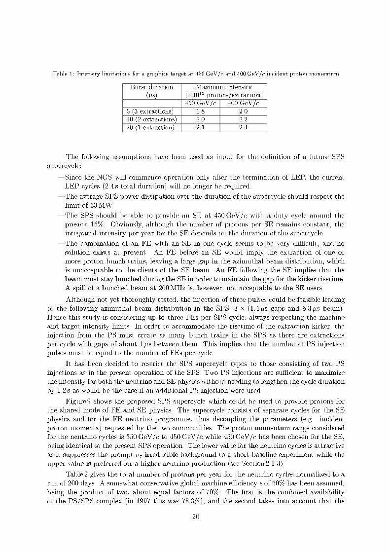
Table 1: Intensity limitations for a graphite target at 450GeV/c and 400GeV/c incident proton momentum
Burst duration Maximum intensity(s) (1013 protons/extraction)
450 GeV/c 400 GeV/c6 (3 extractions) 1.8 2.010 (2 extractions) 2.0 2.220 (1 extraction) 2.1 2.4
The following assumptions have been used as input for the denition of a future SPS
supercycle:
Since the NGS will commence operation only after the termination of LEP, the current
LEP cycles (2.4 s total duration) will no longer be required.
The average SPS power dissipation over the duration of the supercycle should respect the
limit of 33MW.
The SPS should be able to provide an SE at 450GeV/c with a duty cycle around the
present 16%. Obviously, although the number of protons per SE remains constant, the
integrated intensity per year for the SE depends on the duration of the supercycle.
The combination of an FE with an SE in one cycle seems to be very dicult, and no
solution exists at present. An FE before an SE would imply the extraction of one or
more proton bunch trains, leaving a large gap in the azimuthal beam distribution, which
is unacceptable to the clients of the SE beam. An FE following the SE implies that the
beam must stay bunched during the SE in order to maintain the gap for the kicker risetime.
A spill of a bunched beam at 200MHz is, however, not acceptable to the SE users.
Although not yet thoroughly tested, the injection of three pulses could be feasible leading
to the following azimuthal beam distribution in the SPS: 3 (1:4s gaps and 6.3s beam).
Hence this study is considering up to three FEs per SPS cycle, always respecting the machine
and target intensity limits. In order to accommodate the risetime of the extraction kicker, the
injection from the PS must create as many bunch trains in the SPS as there are extractions
per cycle with gaps of about 1s between them. This implies that the number of PS injection
pulses must be equal to the number of FEs per cycle.
It has been decided to restrict the SPS supercycle types to those consisting of two PS
injections as in the present operation of the SPS. Two PS injections are sucient to maximize
the intensity for both the neutrino and SE physics without needing to lengthen the cycle duration
by 1.2 s as would be the case if an additional PS injection were used.
Figure 9 shows the proposed SPS supercycle which could be used to provide protons for
the shared mode of FE and SE physics. The supercycle consists of separate cycles for the SE
physics and for the FE neutrino programme, thus decoupling the parameters (e.g. incident
proton momenta) requested by the two communities. The proton momentum range considered
for the neutrino cycles is 350GeV/c to 450GeV/c while 450GeV/c has been chosen for the SE,
being identical to the present SPS operation. The lower value for the neutrino cycles is attractive
as it suppresses the prompt irreducible background to a short-baseline experiment while the
upper value is preferred for a higher neutrino production (see Section 2.1.3).
Table 2 gives the total number of protons per year for the neutrino cycles normalized to a
run of 200 days. A somewhat conservative global machine eciency of 50% has been assumed,
being the product of two, about equal factors of 70%. The rst is the combined availability
of the PS/SPS complex (in 1997 this was 78.3%), and the second takes into account that the
20

maximum intensity is not always available. For comparison, the corresponding global machine
eciency for 1997 was 58%.
νPS PS PS PS PSPS
FE FESE @ Ep=450 GeV
Tc
E p50 ms 50 ms
Fig. 9: The proposed SPS supercycle. The parameter E
p is the incident proton momentum for the neutrino cycles
and has been studied for all the values given in Table 2
Table 2: SPS operation parameters
Supercycle E
p Tc pot/yeartype (GeV) (s) (1019)A 350 22.8 3.41B 360 22.8 3.41C 370 22.8 3.41D 380 24.0 3.24E 390 26.4 2.95F 400 26.4 2.95G 410 27.6 2.75H 420 28.8 2.57I 430 31.2 2.32J 440 32.4 2.18K 450 34.8 1.99
Figure 10 illustrates the variation in the proton intensity limits per cycle and per year
(200 days and = 50%) coming from the machine and target. For comparison, the target limit
from a beryllium target is plotted, illustrating the inferiority of such a target in relation to a
graphite one. It can be seen that the number of protons per year from the two limits coincides
at an incident proton momentum of 400GeV/c (supercycle type F) as expected since at this
momentum the limit from both factors is 4:5 1013 protons per cycle.
The favoured supercycle type F respects the duty cycle requirements for the SE (around
16%). It should be noted that in this scenario the rst of the cycles is dedicated to the SE,
without any reduction to the at-top duration from a neutrino extraction as is the case at
present.
21

Fig. 10: The upper limits from target and SPS considerations (a) per cycle and (b) per year
The corresponding integrated number of protons per year for the SE shown in Table 3,
which assumes 2:0 1013 protons per SE cycle, is about the same as was provided in 1997 to
the targets other than the WANF neutrino target (0:5 1019 per year). The numbers in Table 3
can also be compared to the required number of protons per year quoted in the present NA48
proposal (0:36 1019), in the COMPASS proposal (0:60 1019), and the number required for
the T1 and T2 targets together (0:24 1019) used mainly for LHC test beams. A total of about
1:2 1019 protons seems to be required. The numbers in the last column of Table 3 take into
account a global eciency of 50%.
The SE proton decit between what is requested and what could be supplied by supercycle
type F could be recovered by increasing the proton intensity during the SE cycle. Since the at-
top time would be longer (4.15 s versus the present 2.38 s eective time), the intensity could
be increased in the ratio of at-top times so that the instantaneous proton intensity does not
change from the present one1. This would provide 1:1 1019 protons per year, close to the
present SE performance.
Finally, for comparison, Fig. 11 and Table 4 give the conguration and performance of a
dedicated neutrino cycle. Obviously, the gains for the NGS are substantial, but at the expense
of the SE programme. However, given that such a neutrino mode of operation is relatively
inexpensive in terms of electrical power, due to the absence of an extended at-top, the neu-
trino beam could be foreseen for periods extending beyond the normal SPS proton xed-target
operation.
1It should be remembered that the current machine limit is 4:5 1013 protons for any cycle.
22

Table 3: SPS and SE physics parameters
Supercycle E
p Tc Flat-top SE pot/yeartype (GeV) (s) (s) (1019)A 350 22.8 3.78 0.76B 360 22.8 3.68 0.76C 370 22.8 3.55 0.76D 380 24.0 3.78 0.72E 390 26.4 4.35 0.65F 400 26.4 4.18 0.65G 410 27.6 4.36 0.63H 420 28.8 4.51 0.60I 430 31.2 5.00 0.55J 440 32.4 5.07 0.53K 450 34.8 5.41 0.50
p
PSPS
FE
Tc
E ν
Fig. 11: The dedicated neutrino operation mode of the SPS
Table 4: SPS parameters for dedicated neutrino operation
Supercycle E
p Tc pot/yearType (GeV) (s) (1019)A 350 6.0 6.5B 360 6.0 6.5C 370 6.0 6.5D 380 6.0 6.5E 390 7.2 5.4F 400 7.2 5.4G 410 7.2 5.4H 420 7.2 5.4I 430 7.2 5.4J 440 7.2 5.4
Obviously, once LHC commissioning and operation starts in parallel with the xed-target
operation, the expected number of protons on target per day in all the modes (FE and SE) will
be decreased by about 25%. Whether this has an impact on the number of protons per year
depends on the scheduling.
23

3 THE NEUTRINO BEAM
The nal detailed parameters of the rst beam to operate in the NGS need to be dened by
the end of 19992, in order to allow sucient time for manufacturing and testing of the horn and
re ector. This assumes a beam starting date of spring 2002. Work has to continue for some
time to optimize the target conguration and the coaxial lenses for the initial physics require-
ments. In parallel, results from dierent simulation packages are being compared. However, in
order to proceed with other aspects of the NGS design and to provide a basis for comparison,
parameters of a `reference beam' have been dened: this beam, which should be considered
a preliminary variant, is intended to match the requirements for long- and short-baseline appearance experiments given in Section 2
A schematic overview of the beam elements is given in Fig. 12, the list of parameters can
be found in Appendix A. An indication of possible improvements and variants to the `reference
beam' is given at the end of this section.
Protonbeam
Coll.1 Coll.2 Coll.3 Coll.4
Decay tube Hadron stop µ - detectorsReflectorHornTarget
C Fe
0,5m 1,5m7,9m
25m80m
100m1092m 18m 70m
67m10m
Fig. 12: Components of the proposed neutrino beam
3.1 Beam simulation and production spectra
A full Monte Carlo simulation of the beam has been made using several dierent computer
programs. Two diering hadron production models have been used: the version of Fluka92 [46]
integrated into Geant 3.21 and the code Fluka97 [47]. The hadronic interaction and particle
production models have been extensively improved with respect to the version available in
Geant [48] in the last few years. Preliminary comparisons [49] with the NA56 (SPY) experiment
[50] show an overall good agreement for the current model, while problems show up for the
version embedded into Geant [51]. It is worth taking note, however, that this latest version
of Fluka has a softer fragmentation function, hence the predicted ux is about 20% less,
and the beam energy somewhat lower, than the Fluka92 version used in Geant 3.21. The
corresponding dierences in the calculation of the fraction of unwanted neutrino types should
stay within a factor of 2, according to the comparisons carried out for the present report and to
those performed for the WANF beam [51].
In addition to the comparison of hadron production models, dierent particle transmission
codes with complex geometry and materials have been used: the well-known Geant 3.21 in
the form developed by CHORUS and NOMAD with a new geometry to describe the NGS beam
[52], and a completely new application, written for the NGS, using the stand-alone Fluka97
package. Moreover, a fast tracking version with precomputed particle production tables based
2This date assumes that the requested currents in horn and re ector are not higher than 120 kA, allowing the
use of a design as described in this report.
24

on Fluka97 has been used [53]. In all cases the neutrino parents are tracked in detail to their
point of decay. Realistic values for material thicknesses, magnetic eld strengths etc. have been
used wherever possible. The use of several independent packages, which allows the comparison of
production models and dierent tracking results lends much condence in the results presented
in this report. As the Fluka97 package shows the best consistency with the experimental
results of the SPY [50] experiment, this has been used in the plots showing neutrino uxes and
event rates.
In order to optimize the integrated neutrino event rates, a proton beam energy of 400GeV
is assumed, as described in detail in Section 2.3
3.2 Decay kinematics
The ratio of to K produced in the target is roughly 10:1. The mean free path of before decay
is 55m/GeV and for K is 7.5m/GeV. The maximum energy of from decay is 43% of the
parent energy. The two-body decay of K gives of up to 96% of the parent energy. This
leads to two superimposed parts of the overall neutrino spectrum, dominated by the -generated
component at lower energies and a smaller K component at higher energy. For a neutrino beam
of mean energy 25GeV it is necessary to collect neutrinos up to 55GeV, this implies decays
of K of up to 60GeV and up to 120GeV.
3.3 Target conguration
The target should be dimensioned such that almost all incident protons interact but, at the
same time, cause as little absorption or scattering of the secondary (neutrino parent) particles
as possible.
In order to minimize the interactions of secondaries produced at large angles, it is required
that the diameter of the target should not be larger than that required to contain the incident
proton beam. The 400GeV beam has a size of less than 2mm (2) at its focal point, so that,allowing for small beam instabilities and scattering in the target material, a target diameter of
3mm is chosen as for the WANF.
The length of the target is 3 interaction lengths, ensuring that 95% of the protons
interact. For particles produced at small angles which have a longer path length in the target,
a material of low atomic number is chosen: `diluting' the target can further reduce absorption
by having discrete elements of target material separated by air gaps.
However, increasing the target length gives an extended source for the secondary beam
optics which can become signicant with respect to the focal lengths of the focusing system. A
compromise has to be found.
Pure beryllium targets have been used in most CERN PS and SPS neutrino beams to date
but evaluations on the use of graphite as a target material look promising in view of operation
with short, intense proton spills in a fast extracted beam. A detailed discussion of the thermal
and mechanical properties under these conditions is given inAppendix C. Particle production
from the two materials is similar and detailed optimization of the positions and lengths of the
target elements has still to be carried out together with the nal choice of the beam optics
layout.
For the `reference beam' calculations, the target layout is identical to that presently used
in the WANF except that graphite (density 1.81 g/cm3) is assumed: it consists of 11 cylindrical
rods of 10 cm length and 3mm diameter supported on the beam axis by thin disks: the spacing
between rods is 9 cm, giving an overall target length of 2m. A schematic view of the target
region is shown in Fig. 13.
25

-150
-100
-50
0
50
100
[cm]
[cm]
150
-200 0 200 400 600
COLL1
shield (optional)
target
(graphite rods)COLL2
marble shield
iron shield
Fig. 13: Schematic view of the target conguration and the rst two collimators
3.4 Focusing system
Coaxial magnetic lenses are chosen since they give higher angular and momentum acceptance
than other focusing systems. They can be made to withstand high radiation levels, have cylin-
drical symmetry, and also give some sign selection, enabling both neutrino and antineutrino
beams to be produced.
A toroidal magnetic eld is produced in the volume between two tubular coaxial conductors
when a high current ows along the inner conductor and back through the outer. The strength
of the eld B (Tesla) at any point is given by B = I=(50 R) where I is the current (kA) and
R is the radius (cm). There is no eld inside the inner conductor or outside the outer conductor
which is usually cylindrical.
In a magnetic horn, the inner conductor is shaped so that particles coming from the
target, with a given energy but with a wide angular spread, traverse an integrated magnetic eld
which will focus them into a parallel beam. Particles of the opposite polarity will, of course, be
defocused. The inner conductor is made as thin as possible to minimize absorption but must
withstand the high current density needed and the radial forces induced by the magnetic eld.
A magnetic re ector, downstream of the horn, works in the same way. It has a large
central aperture to allow the particles which are already well-focused to pass undisturbed, but
provides additional focusing for particles of dierent energies which have been underfocused or
overfocused in the horn. In this way the energy band which is focused by the system is broadened.
Several re ectors can be used but the potential gain in ux and bandwidth is usually oset by
losses from additional absorption.
Cross-sections of horn and re ector are schematically shown in Fig. 14. A few selected rays
tracked through the system are illustrated in Fig. 15, showing the focusing/defocusing eect of
these coaxial lenses.
The beam for appearance experiments should have the highest possible ux, with an
energy band which is substantially above the threshold for charged-current interactions. The
choice of 25GeV as the nominal neutrino energy is a compromise between the requirements for
high ux and high energy. The sensitivity of the dierent detectors to neutrino oscillation, which
is energy-dependent, will also need to be considered at a later stage.
26

-40-40
-40
-30-30
-30
-20
-20-20
-10-10
-10
0
00
1010
10
2020
20
30
30
30
40
40
700700
8000 8100
800800 900
8200
900 1000
8300
1000 11001100
8400 8500
12001200 13001300
8600
14001400
[cm]8700
[cm]
[cm]
[cm]15001500
Horn
Reflector
inner conductor
outer conductor
I=120 kA
I
magnetic volume
I
magnetic volumeB
B
o
to busbarsconnection
Fig. 14: Cross-section of horn and re ector. The current and magnetic elds are indicated schematically for the
latter
Fig. 15: Particles emerging from the target, deviated in the elds of horn and re ector
27

The overall physical lengths of the horn and re ector are 7m, giving an optical length
of 6.65m. The design is extrapolated from the CHARMII beam used in the WANF from 1986
to 1991, which had characteristics similar to those required for the NGS. In order to achieve a
higher neutrino ux, the horn and re ector have been moved closer to the target to increase the
angular acceptance. As a fast extraction is used, the current pulse length needed in the lenses is
shorter and the peak current can be increased to 120 kA for the same integrated current density.
To a rst approximation, the angular acceptance of the horn is proportional to the square root
of the current and the inverse distance from the source.
The parameters of the horn and re ector are given in Table 5. Positions along the beam
axis (Z) are referred to the focal point of the proton beam in the target. The dimensions given
are those of the magnetic eld region: D refers to the conductor nominal diameter, T to the
conductor thickness. The horn is designed to focus and K of 50GeV nominal energy into
a parallel beam and has an acceptance of almost 10mrad. The re ector focuses and K of
85GeV after they have left the horn but will also refocus particles of lower energy which have
been strongly overfocused.
The current in the horn and the re ector can be reversed so that negative mesons are
focused in order to produce antineutrinos, should this be required.
Table 5: Reference beam: horn and re ector positions and conductor coordinates are given
Horn Re ectorCurrent 120 kA 120kA
Start coordinate 7.85m 80.35mLength 6.65m 6.65m
Inner conductor Z [cm] D [cm] T [mm] Z [cm] D [cm] T [mm]0.0 15.5 2 0.0 44.3 277.7 15.5 2 6.4 44.3 2171.1 15.3 2 55.2 42.9 2264.5 14.7 2 175.0 38.8 2355.0 13.7 2 284.2 34.5 2439.6 12.2 2 381.4 30.1 2515.1 10.4 2 465.8 25.4 2578.0 8.2 2 536.3 20.5 2627.5 5.6 2 592.0 15.5 2655.0 2.9 5 665.0 15.5 2659.8 1.5 9
Outer conductor Z [cm] D [cm] T [mm] Z [cm] D [cm] T [mm]0.0 60.0 12 0.0 70.0 12
3.5 Decay tunnel, helium cylinders, collimators
Collecting neutrinos up to 55GeV for a beam of mean energy 25GeV implies decays of K
of up to 60GeV and up to 120GeV with mean free paths of 450 and 6600m respectively.
With the proposed decay path from the target to the hadron stop of 1100m, essentially all K
will decay. It should be noted that a large fraction will already decay in the rst 100m of the
target cavern, so absorption in this region should be minimized. A smaller fraction of will
have decayed in 1100m, a longer decay path would therefore clearly increase the neutrino ux.
For the LBL detector, the eect of a longer decay tunnel, up to 1400m in length, is shown
in Fig. 16 and a cumulative plot in Fig. 17. These plots show the distribution of the points of
origin, i.e. the decay points of parent mesons, as a function of the longitudinal distance from
28

the target, for all events occurring in the detector. The contribution to the number of CC events from a unit section of evacuated tunnel decreases linearly with its distance from
the target. The cumulative gain with increasing length becomes modest at lengths more than
1000m.
The eect for the SBL detector is presented in Fig. 18, and the cumulative plot in Fig. 19.
These plots show that event rate would greatly benet from a longer decay tunnel. The con-
tribution to the ux of from an additional unit section of evacuated tunnel increases very
rapidly due to the increase in the solid angle. In the NGS layout, the possible SBL location
is xed. A longer decay tunnel would imply less molasse, but the shortened length of molasse
shielding would no longer be able to absorb all the muons before they reach the SBL detector
and would have to be compensated for by an extended iron shielding.
The decay tunnel length chosen, 1000m, is therefore a compromise between intensity
and the high cost involved in extending the evacuated decay tunnel and reinforcing the iron
shielding. It should also be noted [44] that a longer decay path does have some additional
unwanted consequences: the proportion of e in the beam increases as more of the produced
in and K decay can themselves decay.
The eect of increasing the diameter of the decay tunnel was also studied. Figure 20, and
the corresponding cumulative plot Fig. 21, show the distribution of the radial distance of the
point of origin from the beam axis for all CC events occurring at the LBL detector. The
distribution for the SBL detector is very similar. It appears that most of the decays leading to
useful CC events are well contained within the proposed radius of 1.225 m from the beam
axis. The gain in ux from an increased diameter would not be substantial.
However, if a lower energy neutrino beam were later required, this could benet from a
larger decay tunnel radius [44]. The diameter of 2.45m was therefore a reasonable compromise
adopted for the NGS.
The vacuum pressure in the decay tunnel should be below 5mbar. At this pressure, the
absorption in the 2mm titanium window at the beginning of the tunnel is comparable to that
in the residual air over the 1000m, each being 0.007 interaction lengths. The expected loss in
neutrino ux due to this material is 1.4% 3. The vacuum system has been designed to reach a
pressure of 1mbar in 3 days, see Section 4.8.2.
Having a vacuum in the target cavern is not practical as access is needed to the target
station and to the horn and re ector. However, the air in the cavern represents about a 10% loss
of ux by absorption. If the air is replaced by helium at atmospheric pressure over two-thirds
of the 100m path length, this loss can be halved. As has been done in the WANF, it is foreseen
to install a large diameter helium tube between the horn and re ector, see Section 4.5.3. Losses
in its two 0.3mm titanium windows are less than 0.2%.
It is essential to stop all unwanted particles as early as possible in order to:
i) concentrate induced radioactivity in well-dened areas;
ii) avoid the propagation of defocused particles that could decay and produce background in
the beam.
3Note that the loss of neutrino ux would be about 75%, if the decay tube is left at atmospheric air pressure,
and about 20% with 1 atm helium.
29

Fig. 16: Longitudinal distribution of the decay-point of parents of CC events in the LBL detector
Fig. 17: Cumulative distribution of the decay-point of parents of CC events in the LBL detector, normalized
to d = 1100m
30

Fig. 18: Longitudinal distribution of the decay-point of parents of CC events in the SBL detector
Fig. 19: Cumulative distribution of the decay-point of parents of CC events in the SBL detector, normalized
to d = 1100m
31

Fig. 20: Radial distribution of the decay point of parents of CC events in the LBL detector
Fig. 21: Cumulative radial distribution of the decay point of parents of CC events in the LBL detector,
normalized to R = 122:5 cm
32

The positions, dimensions and material of the collimators are given inAppendix A. The
function of the collimators are as follows:
Collimator 1 can be considered as part of the target shielding. With eight interaction
lengths of material, it absorbs all particles emerging from the target outside of a cone with
a 20mrad opening angle.
Collimator 2 is placed between the target station and the horn. Its function is also to limit
the angular acceptance of particles reaching the horn. In the `reference beam', the design
acceptance of the horn is 10mrad at the nominal energy of 50GeV. However, particles with
lower energy at higher angles can possibly be focused and therefore an acceptance cone
of 15mrad has been chosen. Collimator 2 can be exchanged more easily than collimator 1
and can therefore be tailored to dierent beam requirements in the future.
Collimator 3 is made of steel blocks with a rectangular aperture, installed between the
horn and re ector. Its function is to absorb all particles which are outside the acceptance
of the re ector and therefore do not contribute to the neutrino beam: in particular it
absorbs particles of opposite polarity which are defocused by the horn. It is eective in
reducing the e background in the beam absorbing unwanted mesons: these can decay to
produce which can straggle into the decay tunnel and in turn decay to e.
Collimator 4 is a cylindrical collar at the entrance of the decay tunnel. Its function is to
limit the acceptance of the decay tunnel and minimize the number of hadrons reaching
the steel tube of the vacuum pipe. Its inner diameter is determined by the cone from the
re ector outer conductor to the end of the decay tunnel; the outer diameter is the same
as that of the vacuum pipe. An additional function is to absorb particles defocused by the
re ector.
3.6 Beam spectra and event rates for the reference beam
The energy distribution of the for the `reference beam' is shown in Fig. 22 for an LBL
experiment and in Fig. 23 for an SBL detector.
These calculations, especially for an LBL detector, are very time consuming. Primary
400GeV protons and all the secondaries produced are tracked in each run through the entire
beam line from the target until they interact, decay, or escape. The detailed description of the
geometry of the `reference beam' materials and magnetic eld is implemented in each of the beam
simulation programs used. The neutrinos coming from secondaries produced in reinteractions
are included in the neutrino spectrum.
In order to collect sucient events, in particular for the LBL detector, 80 to 100 decays are
generated for each neutrino parent that reaches its decay point before interacting or escaping.
A statistical accuracy of 1% or better is thus achieved at the price of some increase in local
statistical uctuations.
Neutrinos from the decays are scored at an LBL detector if they hit a circular area of
100m radius. This is signicantly larger than any conceivable detector and it is used only to
collect higher statistics. It was veried that the results of the calculation change less than the
uctuations from run to run, if smaller detector surfaces are used. The sensitive area of an SBL
detector is taken to be that of the proposed TOSCA detector, about 2m2 (1.44m lateral size).
These and other results of the calculations are summarized in Table 6. Event rates for
CC deep inelastic neutrino interactions are quoted, per proton and per ton of target detector
material, assuming a linear dependence of the interaction cross-section on energy using the
measured slope (0:67 1042 cm2/GeV). The production of CC events by neutrinos dierent
from the main component are given as a percentage of the content.
33

Fig. 22: Energy distribution of the ux at the LBL (732 km) detector
Fig. 23: Energy distribution of the ux at the SBL (1.85 km) detector
34

Table 6: Predicted performance of the NGS `reference beam'. The statistical accuracy of the Monte Carlo
simulations is indicated for the component of the beam
LBL detector SBL detector [m
2/pot] 4:39 109 (0:7%) 1:09 103 (0:3%)Mean energy [GeV] 26.7 24.1 CC events/pot/ton 4:73 1020 (1.0%) 1:06 1014 (0.4%) CC events/year/ton 1.40 3.13 105
Fraction of other neutrino events:e/ 0.8% 0.9%/ 2.2% 2.0%e/ 0.08% 0.07%/ 0.50 0.47
The CC interaction cross-section of increases slowly with energy above its 3.5 GeV
threshold and reaches the universal linear dependence only above energies of about 100GeV or
so. The average value of the ratio (=) of the CC interaction cross-section weighted with the
neutrino energy spectrum is also quoted in Table 6. This is a decisive factor for oscillation
experiments. Together with the fact that the detection eciency typically also increases
slowly with energy, it gives a clear preference for appearance experiments to operate in a
high-energy neutrino beam. The energy distribution of CC neutrino interactions is shown in
Fig. 24 for an LBL detector and in Fig. 25 for an SBL detector. The transverse distribution of
is shown in Fig. 26 for an LBL detector and in Fig. 27 for an SBL experiment.
Fig. 24: Energy distribution of CC interactions at the LBL (732 km) detector
35

Fig. 25: Energy distribution of CC interactions at the SBL (1.85 km) detector
Fig. 26: Radial distribution of CC events at the LBL (732 km) detector
36

Fig. 27: Radial distribution of CC events at the SBL (1.85 km) detector
The standard deviation of the radial distribution at an LBL detector is about 850m.
At an SBL detector it is 1.9m, atter than in the present WANF where most of the decay tunnel
has a smaller diameter (1.2m) than the one adopted here (2.45m).
The number of CC events in both the short- and long-baseline experiments is rather
similar for proton momenta between 360 and 440GeV/c if the dierence, due to the SPS cycle,
in the allowed number of protons on target is taken into account. For the `reference beam'
simulations, a few examples of rates are shown in Table 7. The reference proton beam momentum
has been chosen to be 400GeV/c. For example, operating at 360GeV/c yields slightly less
neutrino events at the detectors than at 400GeV/c but has the advantage of a lower energy
consumption, of a shorter supercycle length, and of a reduced prompt background for the
SBL experiment.
Table 7: Predicted CC event rates for dierent primary proton beam energies
Energy pot/year LBL detector SBL detector(GeV) (see Table 2) CC/pot/ton CC/ton/year CC/pot/ton CC/ton/year360 3:41 1019 3:88 1020 1.32 8:78 1015 2:99 105
400 2:95 1019 4:73 1020 1.40 1:06 1014 3:13 105
440 2:18 1019 5:61 1020 1.22 1:27 1014 2:77 105
3.7 Muon background at the SBL experimental area
There are two kinds of muon background that must be considered at the SBL experiment:
muons coming from the neutrino-induced reactions in the material in front of the detector;
37

muons coming from hadrons decaying in the the decay tunnel and punching through, or
multiple scattering around the shielding material in front of the detector.
The rst case is an irreducible background that cannot be avoided. Adding or taking away
material makes little dierence as the neutrino interactions and muon uence are in equilibrium.
The intrinsically high pt of the muons does have some eect, but only with large distances of air
in front of the detector, i.e. 20 to 30m. The size of the background can, however, be reliably
calculated from the knowledge of neutrino interactions and the estimated neutrino ux at the
detector. Taking into account the expected neutrino ux and its radial distribution, neutrino
interactions are generated in a large volume of molasse in front of the SBL cavern. The volume
used is a cylinder along the beam axis of diameter 30m and a length of 200m. The material
used is molasse, with a density of 2.4 g/cm3. It is not necessary to consider a longer cylinder, as
200m of molasse is sucient to range out almost all produced muons. All muons are tracked,
with multiple scattering and energy loss to the SBL cavern, and the number crossing a typical
detector of 2 2 6m3 is calculated. For an incident proton beam of 450GeV a background
of 10muons per 1013 protons on target is found, corresponding to about 2.5muons per m2. Not
surprisingly 95% of the muons that reach the detector come from the last 40m of molasse.
The second background is more dicult to estimate. Ideally, the punch-through muons
should give a background ux less than the local production of muons from neutrino interac-
tions. Unlike the shielding of the WANF beam (see Section 1.2), which was very inhomogeneous
and lacked any rotational symmetry about the beam axis, the NGS beam is completely and
uniformly imbedded in molasse. Hence a simple geometrical description of the shielding and a
two-dimensional calculation can be made. The total material in the hadron stop and the molasse
up to the nominal SBL cavern position is 186.0 kg/cm2. In reality, there may be up to 20m of
molasse less, in order to t the surface buildings and access pit on the rather restricted site. The
real stopping power may be only 182.0 kg/cm2.
If all energy loss mechanisms: ionization, bremsstrahlung, pair production, and nuclear
interactions are taken into account, the mean energy loss, and penetration, as calculated in
Refs. [54] and [55] for a 450GeV/c muon in the `reference beam' shielding would be 145.8 and
141.9 kg/cm2, respectively. These values show satisfactory agreement, however, as the authors
of Ref. [55] write, \It is important to realise that at high muon energies the stochastic nature of
the energy loss makes it inappropriate or even misleading for detailed designs to be based on a
single mean value".
The problem is to estimate the penetration to greater depths of material due to the
stochastic processes, i.e. the straggling of the muons. Unfortunately, if all the processes except
ionization loss, with some low delta-ray energy cut-o, are arbitrarily switched o, the mean
penetration is of the order of 191.0 kg/cm2, rather more than the stopping power available with
the present geometry. Hence there is no simple Yes/No answer and a full Monte Carlo simulation
of the neutrino beam and the muon penetration of the shield has to be attempted.
The result of the simulation for a 450GeV/c proton beam on a WANF type beryllium
target is shown in Fig. 28. The program used is described in Ref. [47] and the features of the
`reference beam' have been fully simulated to give a realistic hadron and nal muon spectrum.
The gure shows the muon ux density in a radial section, out to 20m against the distance
from the front face of the hadron stop to the position of the SBL cavern. Although there is
substantial straggling of the muons well beyond the mean value, fortunately there still seems
to be a margin of safety before an SBL detector. The results predict that there should be an
incident muon rate on the SBL of less than 0.25 m2 per 1013 protons on target.
38

Z(cm)
R(c
m)
Fig. 28: Radial section of muon ux in the molasse between the front of the hadron stop and an SBL detector
3.8 Improved neutrino beam design
The design of the optimal beam conguration in the NGS facility has only just begun. It should
be stressed again that the `reference beam' option presented above should be considered as a
starting point for the overall design and costing of the facility. The nal beam design will be
dictated by, and optimized to give the best possible performance for, the approved scientic
programme. Changes in the details of the target layout, the focusing system and of other
elements in the target chamber are therefore to be expected. The necessary exibility has been
built into the target chamber design to make this possible.
The results of the beam calculations are also in uenced by the improved version of the
Fluka hadronic interaction generator [47] which has been used, and which is a closer match to
the SPY data [50] on yields of neutrino parents from the target. Using Fluka97 results in a
somewhat lower, but more realistic prediction of the neutrino ux.
A number of dierent beam optics have already been tried and various beam congurations
more favourable than the `reference beam' for appearance experiments have been identied.
This work is far from complete. Possible alternative congurations which could be to considered
are a beam of higher neutrino energy, with a horn focusing and K of 70GeV and a re ector
focusing and K of 120GeV. This could give a comparable uence at a higher energy, and a
correspondingly better position above the threshold for appearance experiments.
Above all, it is of great importance to reduce as much as possible, consistent with reliability,
the amount of material in the path of the secondary hadrons in the rst stages of the beam.
Comparison of the ux calculations, with and without material in the beamline, show that
for the `reference beam' design almost half of the useful and K are absorbed or interact before
they can decay.
3.9 Possibility of a lower energy neutrino beam
The option of a neutrino beam of considerably lower energy has been the subject of some
discussion. Such a beam has been considered in view of disappearance experiments, operating
in an energy region where detection of CC interactions is strongly suppressed. The aim of
this type of experiment would be to explore a region of lower neutrino mass dierences, hardly
accessible with neutrino beams like the NGS `reference beam' described above.
39

A low energy beam would restrict the study to disappearance measurements.
Furthermore, in order to collect a sucient number of events, a low-energy beam would require
a proton intensity which may not be compatible with the possibilities of the existing CERN
facilities nor with the foreseen physics programme of CERN. For these reasons, the low-energy
beam option is not discussed further in this report. It should eventually become the subject of
a separate study, along the lines of Ref. [44].
3.10 Comparison with the Fermilab NuMI and KEK K2K projects
3.10.1 NuMI in the U.S.A.
A new neutrino facility, Neutrinos at the Main Injector (NuMI) [56], is being planned using
protons of 120GeV/c from the Fermilab Main Injector to produce a neutrino beam intended for
experiments located on the Fermilab site and 730 km away at the Soudan mine in Minnesota.
The long-baseline experiment MINOS will consist of two detectors | a near detector situated
about 1.3 km from the target and a far detector at 730 km.
As for the NGS, the neutrino beam at NuMI described in Ref. [56] is a wide-band beam.
The mean CC event energy at the NuMI LBL experiment is given as 17.6 GeV. The secondary
and K resulting from the primary proton interactions with the nuclei of a graphite target are
focused by a set of three magnetic horns in the direction of the detectors. The horn system is
pulsed in coincidence with the Main Injector proton spill over 1ms at 170 kA. The decay pipe
at the end of the focusing region provides an evacuated space of 750m length for the secondary
particles to decay. All hadrons, including the primary protons which did not interact in the
graphite target, are absorbed in the hadron stopper | a water-cooled core of aluminium and
copper surrounded by steel of dimensions 3 3m2 and 4.9m long.
The ux, position, and momentum of the muons originating (primarily) in the secondary
particle decays which produce the neutrinos are monitored by muon detectors placed in a number
of pits constructed in the dolomite downstream of the hadron absorber. The choice of the number
of slots and their location is being optimized.
Tables 8 and 9 compare the expected parameters for the incident proton beam and for
the neutrinos at the NGS and at NuMI. While Fluka97 has been used to calculate the NGS
neutrino beam, the numbers for NuMI where obtained withGNuMI4. For both facilities, a `year'
is normalized to a period of 200 days with an assumed global machine eciency of 50%. Thanks
to the higher repetition time of the Main Injector (1.9 s compared to 26.4 s), NuMI is expected
to provide about six times as many protons per year compared to the NGS. However, the
higher incident proton momentum at the SPS (400GeV/c compared to 120GeV/c) will result
in an increased production of neutrinos at the NGS. For the LBL experiment this partially
compensates for the dierence in the two projects arising from the number of protons on target
(pot). For the case of a possible SBL experiment the dierence in pot is somewhat compensated
by the larger distance between the target and an SBL experiment in the NGS (1.85 km in
the NGS compared to about 1 km at NuMI). Furthermore, for a oscillation search an
additional factor of at least two in favour of the NGS (SBL and LBL) comes from the reduced
interaction probability at the lower NuMI neutrino energies.
As outlined in Section 2.3, the NGS operating parameters are those demonstrated to be
possible at the present SPS. The various improvements envisaged for the SPS will enable it to
operate at even higher intensities. Together with an improved secondary beam, as discussed in
Section 3.8, the NGS will increase its proton and neutrino intensities. To conclude, the NGS
performance compares well with that of NuMI.
4GNuMI is a Monte Carlo beam simulation program based on Geant, developed at Fermilab by J. Hylen and
A. Para, see also [56], AppendixB.
40

Table 8: Incident proton parameters for the NGS and NuMI. A `year' is assumed to allow 200 days of accelerator
operation with 50% overall eciency
Protons NGS NuMIMomentum (GeV/c) 400 120Cycle length [s] 26.4 1.9Protons per cycle 9 1013 4 1013
Protons per s 3:4 1012 2:1 1013
Total protons per year 2:95 1019 1:84 1020
Table 9: Neutrino beam parameters for the NGS and NuMI. A `year' is dened in Table 8. It is now known that
the Fluka97 code gives 20% less ux compared to simulations based on Geant, such as GNuMI
Neutrinos NGS NGS NuMI NuMISBL LBL SBL LBL
Simulation Fluka97 Fluka97 GNuMI GNuMI
uence 1:09 103 4:39 109 1:90 103 1:72 109
[m2 (pot)1] CC events 1:06 1014 4:73 1020 1:01 1014 1:04 1020
[(ton)1 (pot)1] CC events 3:13 105 1:40 1:82 106 1:89[(ton)1 (year)1]
3.10.2 K2K in Japan
The Japanese neutrino project KEK-to-Kamioka (K2K) [57], currently under construction,
will search for oscillation on a long baseline by sending a neutrino beam from KEK to Su-
perkamiokande, 250 km away. Its primary aim is to probe the region of the atmospheric neutrino
anomaly with a m2 between 102 to 103.
The K2K project is based on the KEK-PS which operates at 12GeV and is expected to
eventually accelerate up to 6 1012 protons per cycle with a repetition time of 2.1 s.
The detection of the neutrino events will be performed by two near detectors situated
about 300m from the target: the ne-grain detector and a one-kiloton water Cerenkov detector
similar to Superkamiokande. The far detector is Superkamiokande itself. The secondary and
K from the interactions of the primary protons with an aluminium target will be focused towards
the experimental detectors by a system of two magnetic horns pulsed for about 1ms at 250 kA in
coincidence with the proton spill. A decay tunnel of 200m length and located 20m downstream
of the target will provide the space for these secondary particles to decay. At the end of the decay
tunnel, a beam dump will be constructed to act as the hadron absorber. The dump will consist
of a 3.5m thick iron layer and a 2m thick concrete shielding behind which muon chambers will
be instrumented to monitor the muon prole and hence the neutrino spatial distribution.
K2K will study e oscillation with a search for the appearance of an excess of electronsabove the background in the far detector, while the channel will be studied by measuringthe disappearance rate between the near and far detectors. Owing to the low average neutrino
energy (1.4GeV at the near detector), the direct observation of the is not possible at K2K.
A three-year run commencing in April 1999 is expected to result in 1020 protons on target,
yielding about 400 CC events in the 22.5 kton ducial volume of Superkamiokande.
41

4 CONCEPTUAL TECHNICAL DESIGN
4.1 Civil engineering
4.1.1 Introduction
The preliminary design of the underground structures making up the NGS project has been
drawn up. The requirements considered for this preliminary design were:
As short a work schedule as possible, taking into account the project dates specied (see
Section 6).
The greatest possible degree of independence between the NGS and LHC-TI8 projects,
with a choice of compatible systems.
The choice of technically economical systems without compromising the durability of the
structure.
The status of the project as described here is the one dened in November 1997 by the
CERNINFN Technical Committee. This made it possible to initiate civil engineering design
studies by a consortium of two outside consultants, who will produce the technical documents
required for the Call for Tender. These documents are due in April 1998.
The project is approached in this section from two distinct viewpoints: rst, a description
of the various parts is given which contains the main geometrical parameters. Then, an account
of the working methods is provided including various items of equipment to be used to complete
the project successfully.
4.1.2 Description of the project
General The civil engineering project is divided into ve underground structures:
i) the primary proton beam tunnel,
ii) the target chamber and its ancillary structures,
iii) the equipment and personnel access tunnel to the target chamber, including the access
shaft,
iv) the decay tunnel,
v) the hadron stop chamber, the muon detector chambers and their connecting tunnels with
the LHC.
Towards the SPS accelerator, these structures are connected to the existing hall ECA4
via the access gallery (see Fig. 29), and, at the level of the chamber TJ8, to the LHC injection
tunnel TI8. On the side of the LEP/LHC accelerator, a connection is foreseen from the hadron
stop area of the NGS to the electrical alcove cavern RE88.
The structures have to be excavated almost entirely from rock, which is Leman basin
molasse. This rock consists of variable-quality strata ranging from relatively soft marls to
extremely hard sandstones. The methods and means of excavation and support have been
matched to this type of rock, as described below.
The sole exception is the access tunnel shaft via which all the civil engineering work is
done. Its upper part passes through about 15m of moraine.
It has been decided to provide access to the work site for the NGS project and to this
shaft from the French side of the border for two main reasons:
the location of this work site area together with that of the LHC-TI8 tunnel is on land
already available to CERN;
on the Swiss side, the land above the target chamber is environmentally protected.
42

Generally, a cylindrical shape for all the underground structures has been chosen, as it
is economically the best choice for this type of ground. The values given in the following
description are the nal internal dimensions which dene the actual available space. To obtain
the excavation diameters, the dimensions given in the report must be increased by 0.60 to 1m
to allow for the thicknesses of the temporary support and the nal lining.
Access Gallery TT40
Access Gallery to Target Chamber
PGCN
TT40TN 4
TI 8
TJ8PGC 8
SPS
LHC
SPS
Protons toν- TargetECA 4
Fig. 29: Schematic view of the tunnels around point 4 of the SPS
Proton beam tunnel From its connection to a stub-tunnel at the junction with chamber
TJ8 to the rst structure of the target area facilities, i.e. the junction tunnel, the proton beam
tunnel is 590m long. Its diameter is 3.10m over its entire length5, except for the last 20m
before the target chamber, where it is 3.50m. The width of the tunnel oor slab is 2.24m, with
a height at the crown of the arch of 2.50m. Its radius of curvature in the horizontal plane is
about 1 km.
This tunnel has a central main drain buried in the oor slab. The walls and vaults of this
tunnel are of concrete cast in situ. Its overall slope is 3.50%.
Target chamber and ancillary facilities The target chamber and the surrounding facilities
are shown schematically in Fig. 30, the detailed civil engineering layout is shown inAppendix B.
The target chamber itself is a cylindrical cavern 115m long with a diameter of 6.50m. At
its head is a junction tunnel providing a connection to the access and proton beam tunnels. The
length of this structure is 8m and its diameter 9m.
This chamber is widened on the south side near the targets to a diameter of 8.50m over a
length of 15m. It is tted over its entire length with a 10 ton capacity overhead travelling crane
running on steel tracks.
Upstream of the tunnel junction are the following:
a storage chamber 20m long and 3.10m in diameter;
5Considering the usual tolerances in alignment and construction, a usable diameter of 3.00m should be as-
sumed.
43
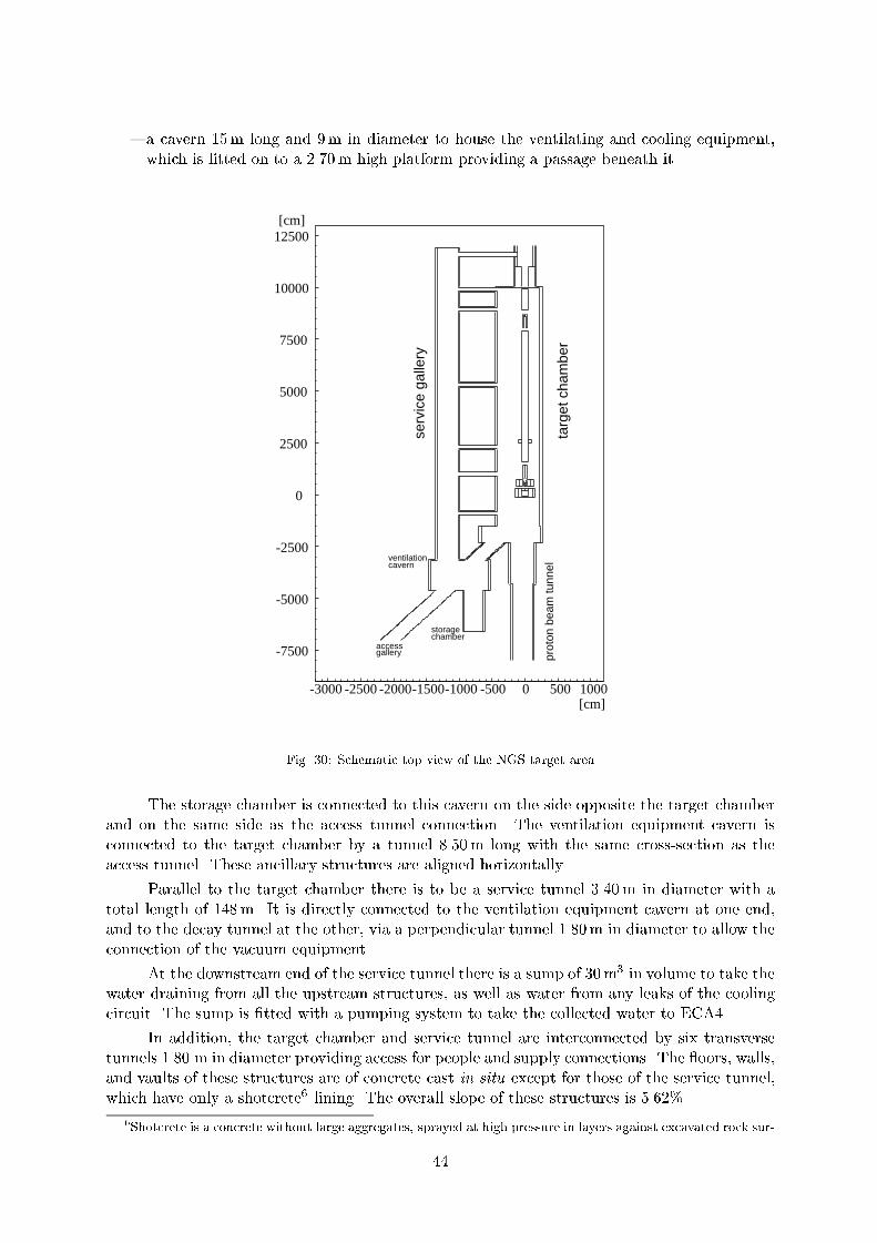
a cavern 15m long and 9m in diameter to house the ventilating and cooling equipment,
which is tted on to a 2.70m high platform providing a passage beneath it.
-7500
-5000
-2500
0
2500
5000
7500
10000
12500[cm]
[cm]-3000 -2500 -2000-1500-1000 -500 0 500 1000
chamber
serv
ice
galle
ry
ventilation
gallery
cavern
prot
on b
eam
tunn
elta
rget
cha
mbe
r
storage
access
Fig. 30: Schematic top view of the NGS target area
The storage chamber is connected to this cavern on the side opposite the target chamber
and on the same side as the access tunnel connection. The ventilation equipment cavern is
connected to the target chamber by a tunnel 8.50m long with the same cross-section as the
access tunnel. These ancillary structures are aligned horizontally.
Parallel to the target chamber there is to be a service tunnel 3.40m in diameter with a
total length of 148m. It is directly connected to the ventilation equipment cavern at one end,
and to the decay tunnel at the other, via a perpendicular tunnel 1.80m in diameter to allow the
connection of the vacuum equipment.
At the downstream end of the service tunnel there is a sump of 30m3 in volume to take the
water draining from all the upstream structures, as well as water from any leaks of the cooling
circuit. The sump is tted with a pumping system to take the collected water to ECA4.
In addition, the target chamber and service tunnel are interconnected by six transverse
tunnels 1.80 m in diameter providing access for people and supply connections. The oors, walls,
and vaults of these structures are of concrete cast in situ except for those of the service tunnel,
which have only a shotcrete6 lining. The overall slope of these structures is 5.62%.
6Shotcrete is a concrete without large aggregates, sprayed at high pressure in layers against excavated rock sur-
44

Access tunnel and civil engineering shaft The access tunnel provides access for personnel
and equipment from the existing chamber ECA4 at point 4 of the SPS accelerator to the target
chamber via the junction tunnel. It is straight, 768.80 m long and 3.10m in diameter. The oor
slab has a width of 2.36m in which the pipes for drainage and for discharging the water from
the target chamber sump are embedded. The maximum headroom is 2.55m. The overall slope
of the structure is 2.20%. Its walls and vaults are shotcreted over the entire length.
The shaft from the surface providing access for all construction work is at 130m from the
existing chamber ECA4. It is 57m deep with a diameter of 8m and is connected and centred
on the access tunnel at its base.
This structure is for temporary use only and therefore its walls are protected only by
shotcrete and rockbolts. Once the entire project has been completed, this shaft will be covered
at the surface by a reinforced concrete slab and the local environment restored to its original
state as far as possible.
Decay tunnel The decay tunnel is located between the downstream end of the target chamber
and the upstream end of the hadron stop chamber. It contains the steel pipe in which a vacuum
of 1 mbar is created so that the secondary particles can decay in ight, undergoing only little
interaction or multiple scattering. The tunnel is 994m long and its inside diameter is 3.10m.
After the passage of the tunnel boring machine, the walls and vaults are shotcreted. The base
of this tunnel consists of prefabricated segments for use as a track for carrying the iron blocks
to the hadron stop and tting the steel pipe.
The inside diameter of the steel pipe, which is of the same length as the tunnel, is 2.45m
(96 00). It is made of 6m sections welded in situ. The space between the steel pipe and the tunnel
is lled with concrete.
The overall slope of this tunnel is 5.62%. It passes 9.80m below the LEP/LHC tunnel,
shortly before reaching the hadron stop.
Hadron stop chamber, muon detector chambers and linking tunnels The general
layout of the hadron stop and the surrounding area is shown in Fig. 31, the details of the civil
engineering in this region are given inAppendix B. The total length of the hadron stop chamber
itself is 26m with a diameter of 6m. It is mainly intended to contain a volume of 4 4 18m3
of steel blocks, graphite, and aluminium elements to stop the hadrons. The decay pipe projects
into this chamber over a length of 2.50m. The widened section thus provided around the end
of the decay tunnel is intended to allow the steel blocks forming the hadron stop to be handled.
The walls of this chamber are of concrete cast in situ. The spaces between them and the steel
blocks of the hadron stop are lled with concrete. The last 5m long downstream section of the
hadron stop chamber houses muon detector No. 1.
There is a perpendicular tunnel section 20m long and 3.10m in diameter on the south
side of the region of muon chamber No. 1. At the end of this tunnel section there is a connecting
chamber 10m long and 4m in diameter for the passage of detector equipment and to house the
electronic and ventilation/cooling equipment. This chamber is itself connected to the end of the
existing alcove RE88 of the LEP/LHC tunnel via a tunnel 224m long and 3.10m in diameter for
access and various connections. This tunnel consists of a straight and a curved section. Their
slopes are respectively 5.64% and 10.80%.
A second muon chamber 6m in diameter and 3.50m long is located at 67m from the rst
one on the beam axis, housing muon detector No. 2. It is linked to the connecting chamber
faces. It is required to provide immediate protection and stabilization of the rock around the foreseen underground
structures.
45

mentioned previously via a tunnel 104m long and 3.10m in diameter. This tunnel consists of
two straight sections at an angle of 75 connected by a curved section. Its overall slope is 3.76%.
The walls and vaults of all the connecting tunnels and chambers are shotcreted, while
those of the muon detector chambers are of concrete cast in situ.
Each of the muon detector chambers is equipped with a sump for collecting drainage water.
Access Tunnel
(Equipment)
(from RE88)
(67
m o
f M
olas
se)
Muon Detectors
Muon Detectors
Hadron StopChamber
Decay Tunnel
Fig. 31: Schematic layout of the hadron stop chamber, the muon chambers, and their access tunnels
4.1.3 Working methods
General The civil engineering for the project is based on two essential conditions:
The dates when the various underground structures have to be available for the installation
of the equipment (see Section 6). These dates in turn depend on the objective to obtain
the rst neutrino beam in May 2002, despite the fact that the rst proton beams for the
LHC will not use the tunnel TI8 until October 2003. Generally speaking, these deadlines
require a very rapid construction as shown in the project planning (see Section 6).
The desired independence of the two projects: NGS and LHC-TI8. This entails provision
of separate access shafts and separate means for performing the work for the NGS.
It should be noted that the work on the LHC-TI8 project has to be speeded up over the
initial LHC programme to make it compatible with that of the NGS project.
These two parameters have of course aected the choice of equipment and working meth-
ods, as shown below.
46

Material resources The material resources to be used by the contractor for this work should
be:
For excavating the access shaft: traditional, using explosives and a rock breaker.
For excavating the standard cross-section of all the tunnels (except, possibly, for the proton
beam tunnel and part of the access tunnel): a single-shield Tunnel Boring Machine (TBM)
with a diameter of about 3.50m.
For excavating the chambers and tunnels not made using the TBM: point-action machines
(roadheaders) of various gauges, dumpers and rock breakers.
For the concrete lining: several heavy-duty shotcreting machines (for temporary and per-
manent walling) and a set of curved shuttering with trains or pumps for transporting the
concrete.
The means of transport over the entire run (underground and surface) for the spoil in one
direction and concrete in the other also have to be provided.
By and large, all the equipment described above is that required in the specication of the
call for tenders. Bidders are free to propose similar equipment which is more available to them,
or more tted to their own working methods, constrained by the proposed time schedule.
Performance sequence of the work
Excavation The performance sequences for the excavation work designed to meet the
required schedules are:
1. Excavation of the access shaft and a chamber at the shaft foot (see Section 3.2).
2. Lowering the tunnelling machine into and assembling it in this chamber.
3. Using the TBM to excavate successively and without interruption:
the access tunnel,
the connecting tunnel and the target chamber (to the actual diameter of the TBM),
the decay tunnel,
the hadron stop chamber up to its end (to the actual diameter of the TBM).
4. At the same time excavation of the access tunnel section from the shaft to chamber ECA4
using a roadheader.
5. Also at the same time and depending on compatibility with the removal of the spoil
from the TBM, widening the various upstream chambers to their nal dimensions using a
roadheader. The same applies to the structures not directly located on the TBM run, e.g.
the service tunnel or the storage chamber.
6. There are two options once the TBM has nished this excavation: either the TBM is
dismantled, transported to and removed via the PGCN shaft, implying that the proton
beam tunnel is excavated with a roadheader, or the TBM is dismantled, carried to the
target chamber and reinstalled in the opposite direction in order to excavate the proton
beam tunnel.
7. At the same time as the above work with the TBM is being carried out, all the remaining
excavation work can be performed using a roadheader: widening the hadron stop chamber
and detector chamber No. 1 to their nal dimensions, excavating the access tunnel to the
muon detector chamber No. 2 and the chamber itself, completing the connecting tunnel to
the existing LEP/LHC compartment RE88, in compliance with the radiation protection
requirements (and taking advantage of the LEP annual shutdown). Where appropriate,
the excavation work on the ancillary chambers and structures near the target chamber can
also be completed with a roadheader.
47

Concreting The concrete lining of the structures will be carried out as follows:
1. For the access and service tunnels, shotcreting should be applied as the excavation pro-
gresses. It is very important to protect the molasse walls quickly as the rock deteriorates
very rapidly in contact with air and may give rise to dangerous swelling, cracking and
rockfalls. A at oor should be laid using prefabricated concrete segments or concrete
cast in situ once the excavation has been completed.
2. For the other structures of the project except for the decay tunnel, the vault should be
made by slabbing and walling using concrete cast in situ and the usual nishing work.
The steel track beams for the overhead travelling crane in the target chamber should be
secured on anchored metal supports or on curved steel proles embedded in the concrete
of the vault.
3. Concerning the decay tunnel, the metal pipe should be taken to the point of work via
the shaft and access tunnel in 6m long sections. The sections, after careful wedging and
alignment, are welded in situ and inspected. The annular space between the pipe and the
excavation is lled with `non-shrink' concrete as each section is installed.
4. For the hadron stop chamber `non-shrink' concrete is to be used around the cast iron
blocks after their installation.
Deadlines and comments According to present planning, the civil engineering work,
except for the tting of the metal pipe in the decay tunnel, is to be completed in December
2000, or February 2001 allowing for the clearing of the work site. The tting of the metal pipe
is to be completed in January 2002.
The working rates needed to make it possible to attain these dicult objectives necessitate
the use of highly competent and reliable contractors who have ad hoc human and material
resources available.
A rigorous selection procedure must be set up, drawing heavily on the experience gained
in civil engineering for the LHC project, to ensure that these goals are met.
4.2 Geodesy and metrology
4.2.1 Introduction
Directing a neutrino beam to a remote detector at 732 km distance is a long-range sighting
problem, the parameters of which are expressed in terms of absolute positions of the origin and
of the target. This permits the deduction of the related azimuth and slope of the vector. All
computations must, of course, be made in a common coordinate system but they must also take
into account some physical aspects of the Earth, i.e. gravity eld anomalies and their eects.
The divergence of the neutrino beam and the resulting distribution at the Gran Sasso
Laboratory can be roughly estimated from the typical transverse momentum of from
decay (30MeV/c) and from the typical pion momentum in the reference beam (50GeV/c). The
resulting order of magnitude is 0.6mrad for the divergence, thus 450m for the beam size at
Gran Sasso. Simulations of the reference beam yield a transverse beam size of about 850m (1,
see Fig. 26). For the purpose discussed here, a maximum oset of 100m from the ideal beam
position at Gran Sasso is therefore assumed to be suciently accurate.
This maximum oset has been adopted as a goal, and the geodetic process must therefore
try to comply with nal r.m.s. errors of 37m, as far as random errors alone are concerned.
This corresponds to 5 105 rad r.m.s., i.e. 10 arcsec. Such a specication for the geodetic
process is not easy, but is achievable. Nevertheless, other uncertainties and various error sources
may aect the direction and the slope of the beam during operation, like geomechanical forces
48

on the constructed structures, thermal expansion and mechanical constraints on the critical
components, etc.
Another crucial point is the length of the sighting baseline and its stability during the
running period. From this point of view and referring to the above specication (5 105 rad
r.m.s.), the baseline can hardly be thought of as the magnetic horn alone: How to guarantee
such an angular accuracy and stability on its magnetic axis at all stages of the installation and
operation?
Supposing now that this stability condition is given and try to solve the alignment problem
upstream of the horn: the criticality would therefore lay on the last straight segment of free
trajectory, i.e. between the last horizontal/vertical corrector and the axis of the horn. Knowing
that the possible deformations and movements can progressively reach millimetres, it becomes
a monitoring problem, complicated by the hostile radiation level of the area.
The NGS project foresees a muon detector station at the end of the decay tunnel after
the hadron stop, and the reference segment for the nal alignment has therefore its origin at
the exit axis of the horn and its end at the centre of the muon detector. This is the only way to
provide a checking of the beam set-up and stability during operation. The following study and
discussion for the geodesy and metrology of the project is based on this 1 km long baseline.
4.2.2 Geodetic parameters
Preliminary data As usual, the preliminary data were either coarse geographic coordinates
(latitude and longitude ) interpolated from cartographic maps or, more precisely, issued
from transformations between national and global systems. Then these ellipsoidal data were
transformed into isometric coordinates on a sphere, in order to solve the `position' triangle by
the means of spherical trigonometry and to obtain the initial data of the line: azimuth, slope
and distance. Nevertheless, it is well known that our cartographic systems are based on old
(historical) data and are subject to various discrepancies and distortions, which depend on the
ellipsoid chosen as the mathematical model, the de ection of the vertical at the datum (origin)
and across the geodetic network, the cumulation of measurement errors, the bridge distance
between astrogeodetic control points, etc. The resulting errors can reach the order of metres
across large national networks, they can be much more between systems (one arc second error
in or leads to an error of 31m in position).
Final parameters All these old problems are now perfectly mastered by modern spatial
geodesy. The techniques used for continental/intercontinental links are Very Long Base Inter-
ferometry (VLBI) by correlation of signals from quasars, Satellite Laser Ranging (SLR) by very
accurate timing of the ight time of ultrashort pulses, and Global Positioning System (GPS)
used in a sophisticated dierential (`interferometric') way, with measurements of the phase dif-
ferences on the two carriers, at 1.2 and 1.5 GHz. This latter technique can reach an accuracy of
108, or even better at the permanent stations used for orbitography and for intercontinental
measurements.
The link between CERN and Gran Sasso does not need to be so accurate in terms of
relative positioning, but the orientation parameters remain critical. Horizontally, the precise
knowledge of the azimuth depends only on the angular dierences between the local system
and the GPS satellite system(s). Vertically, the precise knowledge of the slope is additionally
aected by that of a reference equipotential surface, called `geoid' and dened at a presupposed
zero level of the coordinate system. This is a consequence of a physical fact: altitudes (i.e.
elevations above zero level) are measured by levelling techniques, which refer to gravity, whilst
the GPS Z coordinates are orthogonal heights above the reference ellipsoid, called GRS80. The
49
general problem is therefore to `map' the geoid and its undulations with respect to the GRS80
surface, used for geometrical computations [58]. Such undulations of our level `zero' relate to
gravity anomalies and de ections of the vertical: the induced vertical discrepancies can reach
regionally 60m between mountains and seas, and up to 140m from hollows to bumps in the
global geocentric model! In the limited area of CERN, with the eect of the Jura mountains, a
precise study of the local geoid has been made for the construction of LEP, by means of mass
models and accurate astrogeodetic measurements, and it has shown a maximum local distortion
of about 14 cm over 10 km [59]. This is not at all negligible, but due to the good knowledge (to a
few millimetre accuracy) of the local undulations around CERN, the only remaining uncertainty
is in the slope of the CERN local geoid with respect to the GPS satellite system(s), in the
direction of the beam line.
All these orientation and slope parameters can be obtained from careful GPS measure-
ments of some stable points of the CERN geodetic network, linked to national and/or inter-
national reference GPS points (i.e. permanent stations), expressed in a common computational
system: World Geodetic Reference System 1984 (WGS84) in a rst stage, and then European
Reference Frame (EUREF) for rened data. For the Gran Sasso side, simple dierential GPS
measurements at both ends of the tunnel and a connection of these new points to the surveying
data of the underground laboratory would be sucient [60]. Nevertheless, the precise assess-
ment of the parameters of the CERN local geoid with respect to national and international
(geocentric) models is not a trivial problem, and this may leave more uncertainty on the slope.
4.2.3 Successive stages of the geodetic process
In accordance with the schedule of the nal construction design, and in order to ensure the
optimal set-up of the geodetic parameters along the beam lines (mainly along the last straight
segment under control), the geodetic process consists of the following:
1. Dierential GPS measurement of two points at Gran Sasso (already made) and a link to
reliable survey data, in order to locate correctly the theoretical target point. Errors of a
few metres would not be signicant when considering the rather large divergence of the
neutrino beam.
2. First GPS campaign at CERN (required for the LHC) in March/April 1998.
3. First renement of the geodetic parameters of the neutrino beam line, by reworking all
preliminary computations with coherent data, recently measured and expressed in the
WGS84 system | in order to provide checked values for civil engineering.
4. Second GPS campaign at CERN, limited to the primary geodetic network, in collaboration
with the Laboratoire de Recherche en Geodesie (LAREG, Paris) and the Institut Federal
de Topographie (L+T, Berne). This accurate measurement creates the links to some
national and/or international reference GPS points in France and in Switzerland, in order
to enlarge the span of the comparison between tridimensional systems and to reduce the
errors in the resulting transformation parameters over the CERN area. It mainly allows
a study of the dual assessment of the geoid, from both sides, according to the models
adopted in each country [61],[62]. Final conclusions are drawn for expressing the best
transformation parameters of the `local' geoid used in the CERN coordinate system.
5. Last renement of the geodetic parameters of the neutrino beam line, from coherent GPS
data expressed in the EUREF system and with the optimal transformation parameters be-
tween all useful coordinate systems and reference surfaces, including a sucient knowledge
of the local and global geoids. This provides the nal theoretical data for the positioning
of beam components.
50

6. New calibrations of the gyrotheodolite, on the primary geodetic network, for expressing
its measured azimuths in the EUREF system, along with measurements in the tunnels.
The details of the geodetic metrology of the underground beam line, starting from the
SPS extraction region and ending at the muon detector pits, is described inAppendix D.
4.3 Proton beamline TN4
The general layout of the primary proton beam line, to be called TN4, is shown in Figs. 6 and 7.
The primary proton beam for the NGS uses the new fast extraction system of the SPS and the
rst part (called TT40) of the beam transfer line TI8 from the SPS to the LHC [39], [45]. The
LHC proton beam lls 3/11 of the SPS ring (23s c in circumference) so that the rise time of
the existing extraction kicker system is largely sucient for this application. The proton beam
for the NGS facility, on the contrary, consists of two batches, 10.5 s long and separated by
1.05 s. The rise and fall times of the kicker system are about 15% too long. It is planned to
reduce them to the required values by shortening the length of the magnets. The corresponding
loss of de ection strength is then compensated by an additional magnet. The two batches are
extracted successively with an interval of 50ms towards the NGS target.
4.3.1 Beam optics and magnetic structure
After 110m a set of eight dipoles is used as a switch to branch o the TN4 proton beam from
TI8. These switch magnets together with their power supply and vacuum chambers will be
recovered from the existing WANF. They give a total de ection of 25mrad. The rest of the
primary proton beam line essentially consists of a 580m long arc to bend the beam in the
direction of Gran Sasso, followed by a 90m long focusing section to obtain the desired beam size
on target. The arc must provide a horizontal de ection of 33 and a nal vertical slope of 5.6%.
This is achieved by using 73 new 6.3m long dipoles, each of them de ecting by 8mrad. These
magnets are enlarged versions (37mm gap height) of the dipoles used in TI8. The required
vertical aperture for these magnets can be estimated using the formula:
A=2 = (n +D p=p)k + C:O:,
where D is the dispersion function, k the optical mismatch factor (taken to be 1.1), p=p
the momentum spread (actually 0.12%), =p the betatronic r.m.s. beam size and C:O:
the deviation from the ideal beam trajectory. A normalized emittance of 12mmmrad
is assumed in both transverse planes (0:028mmmrad physical emittance at 400 GeV/c).
Table 10 contains the dierent contributions which have to be accommodated in the gap height
of the main bending magnets.
The maximum vertical dispersion is 1.1m and a peak trajectory excursion of C:O: = 4mm
is assumed, as in the case of TI8 [63]. With these assumptions, space is left for 5 transverse
beam dimension in the magnets7. This includes the beam size as such, the kicker and power
supply ripple, and the SPS closed-orbit imperfections.
The magnetic eld of the main dipoles is 1.9 T at 450GeV and 1.7 T at 400GeV. A careful
choice of the parameters for these magnets makes it possible to use the same power supply as
for TI8, because lling the LHC and sending a proton beam to the NGS target at the same time
is not possible. This option has been retained to reduce the cost of this project. In any case,
the required vertical direction is obtained by tilting 32 of the magnets along the beam axis by
12.8.
7Note that 6 are foreseen for the transfer lines to the LHC. In the nal NGS design, a scheme with more
correction elements for the beam trajectory might have to be used in order to reduce the contribution of C:O:
51

Table 10: Physical vertical aperture of the main dipoles in the TN4 line
Item Size [mm]
Nominal gap height 37
Vacuum tube wall thickness 21.5(including tolerances andand insulating foil)
Sagitta 0.5
Magnet misalignment 0.8(2, = 0.2mm)
Mechanical tolerances 0.2
Remaining full physical aperture 31.8
The common part (TT40) and the rst two quadrupoles in the line are used to match the
optics parameters of the SPS to the FODO lattice of the neutrino line. The arc is made of seven
cells of this FODO lattice ending with ve shortened cells to cancel the horizontal dispersion by
means of individually powered quadrupoles. The half-cell has a length of 31.3m and is made up
of a quadrupole followed by a short straight section and four dipoles. The short straight section
oers space for a monitor and a steering dipole to adjust the beam trajectory. The shortened
half-cell includes only three dipoles. The quadrupoles are an enlarged version of the ones used
in TI8, their length is 2.2m and the inscribed diameter is 45mm. The nominal gradient of these
quadrupoles, of which 21 have to be built, is 40T/m. The arc quadrupoles are powered by power
supplies recovered from LEP. The nal focus consists of three quadrupolar lenses. The rst one
is a single magnet which increases the horizontal dimension of the beam. Then follows a doublet
which focuses the beam onto the target to achieve a nal spot size of 2mm in both directions
at 400GeV ( 0:3mm). The rst lens of the doublet is made of three quadrupoles powered
in series and the last one of two such magnets. Both the magnets and the power supplies for
this section are salvaged from existing CERN facilities (SPS West Area and LEP). The optical
functions for the beam line are shown in Figs. 32 and 33.
Beam steering along the beam line still has to be studied. Using a scheme comparable to
TI8 would imply around 12 new steering dipoles. Four recovered dipoles have to be added to
allow an orthogonal steering in both directions onto the target. The new steering dipoles would
be powered with small ( 3A) power supplies. As for TI8, the cores would be recovered from
LEP correctors and appropriate pole pieces would have to be added.
4.3.2 Beam monitoring
The beam steering of the TN4 line uses the information from beam-position monitors (pick-
up devices), as foreseen for TI8. The monitoring of the proton beam at the target and of
the secondary hadron beam is performed by a system comprising one or more Beam Current
Transformers (BCTs) upstream of the target and by Secondary Emission Monitors (SEMs).
The BCTs, located immediately upstream of the neutrino target, measure the number of
protons per spill impinging on the target. Experience from the WANF shows that the BCTs
can provide a very accurate determination for the absolute proton intensity with fast-extracted
beams of the order of 1%.
The proton intensity is also measured by the SEM foils situated in front of the target.
SEMs work on the principle that a traversing charged particle liberates electrons from the surface
of a metal foil, thereby providing a current which is proportional to the incoming beam intensity.
52

0.0 100 200 300 400 500 600 700 800 900 1000 s (m)
δ E/p 0c = 0
Table name = TWISS
Neutrino line to Gran Sasso B = 1.91 T Lcell = 2*31.3 m 450 GeVRS6000 - AIX version 8.22/12 23/04/98 16.06.59
0.0
100
200
300
400
500
600
700
800
900
1000
1100
1200
β(m
)
β x β y
Fig. 32: TN4 proton beam optics (horizontal and vertical -functions)
0.0 100 200 300 400 500 600 700 800 900 1000 s (m)
δ E/p 0c = 0
Table name = TWISS
Neutrino line to Gran Sasso B = 1.91 T Lcell = 2*31.3 m 450 GeVRS6000 - AIX version 8.22/12 23/04/98 16.06.59
-4.5
-4.0
-3.5
-3.0
-2.5
-2.0
-1.5
-1.0
-0.5
0.0
.5
D(m
)
Dx Dy
Fig. 33: TN4 proton beam optics (dispersions)
53

SEMs are typically made from metallic foils, e.g. aluminium or (more recently) titanium, but
have been found to be less accurate than the BCTs. However, they are required for the steering of
the proton beam onto the target. The ratio of currents measured in SEMs located immediately
downstream and upstream of the neutrino target provides an estimate of the multiplicity of
secondary particles produced from the target. For correct steering this multiplicity value should
be maximized. In addition, by using SEM grids oriented either vertically or horizontally, a
measurement of the proton beam position and size is obtained.
4.4 Target station
4.4.1 Target station design
The heart of the target station is the target box: 11 graphite or beryllium thin cylindrical
rods are aligned in a cast aluminium box. They are cooled by helium gas in a closed circuit
with the ow adjusted to each rod. The box is motorized horizontally and vertically at both
ends, to remotely optimize the secondary particle production by aligning the target with the
incident proton beam. Radiation protection around the station is guaranteed by about 300 tons
of shielding material: iron, copper, marble, and concrete. A schematic view of the target station
is shown in Fig. 13, detailed drawings can be found inAppendix B.
Target box The cast aluminium box is designed to receive either graphite or beryllium rods:
11 rods of 3mm diameter by 10 cm long, spaced every 9 cm. Each one is supported by two thin
(2mm) hollowed-out disks of the same material, which ensure its lateral positional precision and
a certain axial freedom. The two disks are xed to a U-shaped aluminium support, and the
supports are aligned by a channel milled in the bottom of the box. The alignment precision of
the rods is 0.03mm. Three longitudinal conduits, cast into the structure, ensure the circulationof the coolant gas; they are extended upstream by stainless steel exible tubes which traverse
the shielding. The inlet conduits terminate with 22 stainless steel jets, disposed in opposing
pairs either side of each rod.
The box is sealed by a bolted aluminium cover, and by two titanium beam windows of
60mm diameter and 0.1mm thickness. The horizontal and vertical displacement (20mm) ofeach end of the box is achieved by mechanisms driven by DC motors located under the box and
protected from radiation by a thick shielding plate which transmits the movement. The target
box, the mechanisms, the motors, and the shielding plate are considered as a unique assembly,
which should only be pre-positioned (0:5mm) during the rst installation and subsequent
replacements, the nal alignment being rened by a few iterative beam eciency optimizations,
as was successfully, rapidly, and cheaply done at the WANF [64].
The experience gained during the last years of neutrino beam operation at the WANF
shows that, after only a few months, movable equipment near the target becomes unreliable due
to radiation damage. However, experience also shows that these few months of operation are
sucient to perform the necessary target-box position adjustments. After the target alignment,
the motors are electrically disconnected to prevent accidental movements of the target box.
The target box assembly dened above (box, mechanisms, motors, and shielding plate) is
taken out of the front end of the station by removing at the same time the upstream collimator
and monitor (TBIU); this is done after having disconnected the three helium exible tubes, plus
6.7m of upstream vacuum chamber (see Figs. B.4, andB.5 inAppendix B). All these operations,
as well as the reverse ones, should be performed quickly and safely, with minimum irradiation of
personnel, by means of automatic or semi-automatic procedures which still have to be technically
nalized.
54

Helium cooling Helium ow from each pair of jets is calibrated experimentally, by means of
diaphragms of diering diameters positioned at their entries. Flow is maximal on the second
rod (about 50 l/s), and diminishes progressively to the last one (about 10 l/s). The gas ow is
provided by a 1465 turns/min Roots pump housed in the service gallery, delivering 2000m3/h
at atmospheric pressure to the target box, via two water-cooled heat exchangers and over 20m
of exible piping. This circuit, tted with numerous joints, is not perfectly tight (which would
be unnecessary and expensive); consequently, the helium system should be purged twice per
week during periods of operation, and once per week otherwise; an automatic procedure could
easily be implemented, if required. The heat transfer coecient between rod and helium (about
500W/m2 C for the rst rod) was measured in a similar laboratory test installation, with `silver
steel' rods of the same dimensions.
Helium gas is an excellent medium for protecting the target rods (especially graphite) from
oxidation. Acquired experience demonstrated that helium cooling is ecient, safe, inexpensive,
and does not need any additional cooling like water or air: interior air ventilation initially
provided for the WANF was rapidly removed because of irradiated dust inside the station.
Shielding and handling An iron shielding encloses the target box assembly; it ensures the
lowest possible radiation dose to maintenance personnel compatible with restricted access areas.
The shielding base supports two lateral xed walls and two collimators: the upstream collimator
(60mm diameter) is movable to allow the exchange of the target, the downstream copper colli-
mator (85mm diameter) is cooled by six independent water circuits. This `sarcophagus' is closed
by a xed cover, surmounted by 20 cm thick concrete plates. The two lateral sides are protected
by an additional 40 cm of marble. The shielding elements are handled by an overhead travelling
10 ton crane. The iron elements and the copper collimator are shaped to respect this weight
limitation. At the same time, the design avoids leaks in the shielding by means of overlapping
edges (see Fig. B.7 inAppendix B).
Appropriate dismantling facilities are foreseen, anticipating among other scenarios a pos-
sible crane immobilization; this is one of the reasons why a suciently large lateral passage is
required on each side of the target station. These facilities will be rened with the help of a
wooden model, and video lms will be made during the rst installation for later training of the
maintenance teams.
4.4.2 Summary of the thermomechanical analysis
The maximum thermal and mechanical constraints that a target can safely accept depends on its
geometry, on the material that it is made of, and on the beam characteristics: energy, intensity,
proton beam spot size and divergence, burst duration, and repetition rate. The parameters used
to estimate the thermo-mechanical stresses of the target are shown in Table 11.
In order to maximize the safely acceptable ultimate beam intensity on target, the appro-
priate target material and rod length have to be chosen. A 1-D analytical method of thermome-
chanical analysis [65], which proved to be in good agreement with the classical 2-D nite-element
method [66], allows an easier optimization of target length as a function of beam intensity and
burst duration. Details of the calculations, performed for beryllium and isotropic graphite rods,
can be found inAppendix C. A summary is given here.
Detailed Fluka simulations of the energy deposited in the target rods show that the high-
est energy density is found in the rst rod. Therefore, for the thermomechanical analysis, only
this rod is considered. The 1-D analytical calculations for this rst rod provide the theoretical
beam intensity limitations for dierent rod lengths and FE burst duration as summarized in
Table 12.
55
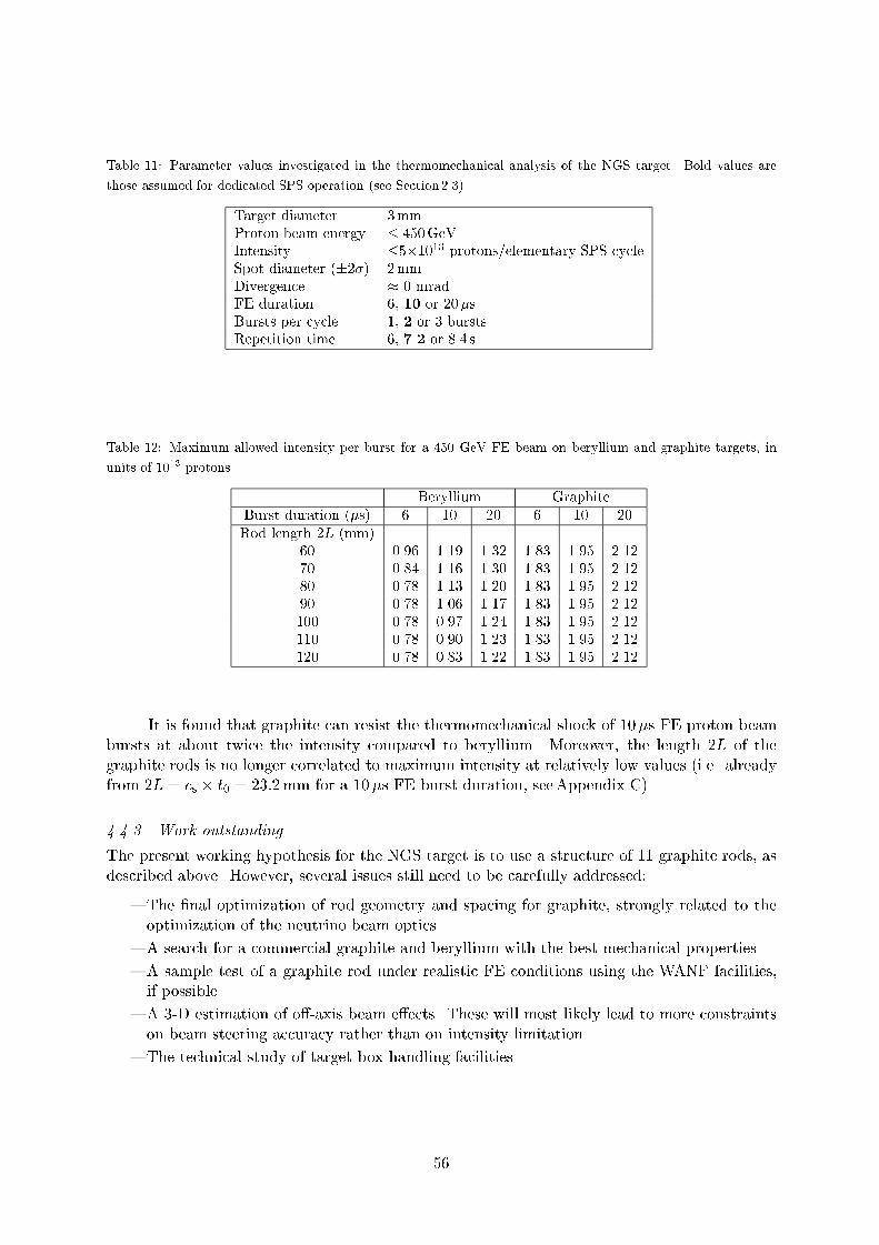
Table 11: Parameter values investigated in the thermomechanical analysis of the NGS target. Bold values are
those assumed for dedicated SPS operation (see Section 2.3)
Target diameter 3mmProton beam energy 450GeVIntensity 51013 protons/elementary SPS cycleSpot diameter (2) 2mmDivergence 0 mradFE duration 6, 10 or 20sBursts per cycle 1, 2 or 3 burstsRepetition time 6, 7.2 or 8.4 s
Table 12: Maximum allowed intensity per burst for a 450 GeV FE beam on beryllium and graphite targets, in
units of 1013 protons
Beryllium Graphite
Burst duration (s) 6 10 20 6 10 20
Rod length 2L (mm)60 0.96 1.19 1.32 1.83 1.95 2.1270 0.84 1.16 1.30 1.83 1.95 2.1280 0.78 1.13 1.20 1.83 1.95 2.1290 0.78 1.06 1.17 1.83 1.95 2.12100 0.78 0.97 1.24 1.83 1.95 2.12110 0.78 0.90 1.23 1.83 1.95 2.12120 0.78 0.83 1.22 1.83 1.95 2.12
It is found that graphite can resist the thermomechanical shock of 10s FE proton beam
bursts at about twice the intensity compared to beryllium. Moreover, the length 2L of the
graphite rods is no longer correlated to maximum intensity at relatively low values (i.e. already
from 2L = cs t0 = 23:2mm for a 10s FE burst duration, seeAppendix C).
4.4.3 Work outstanding
The present working hypothesis for the NGS target is to use a structure of 11 graphite rods, as
described above. However, several issues still need to be carefully addressed:
The nal optimization of rod geometry and spacing for graphite, strongly related to the
optimization of the neutrino beam optics.
A search for a commercial graphite and beryllium with the best mechanical properties.
A sample test of a graphite rod under realistic FE conditions using the WANF facilities,
if possible.
A 3-D estimation of o-axis beam eects. These will most likely lead to more constraints
on beam steering accuracy rather than on intensity limitation.
The technical study of target box handling facilities.
56

4.5 Secondary beam elements (horn and re ector, helium tank, collimators)
The secondary beam line equipment located behind the target down to the entrance window of
the decay tunnel includes:
A pulsed horn (Figs. 34 and35) and a pulsed re ector. These magnetic elements produce
toroidal magnetic elds along the beam axis. They consist of two cylindrically symmetric
thin aluminium alloy current sheets properly shaped as described in Section 3.4, to focus
the pions and kaons emitted from the target into a nearly parallel beam. This maximizes
the neutrino ux seen by the detector for a wide-band neutrino momentum distribution.
Fig. 34: Photograph of the WANF magnetic hornø
in
t: 4
20
Wat er cooling pipes
Base frame
To the tank
Sup port frame
adjusting base
Co
nn
exio
n s
idePart 1 Part 2 Part 3 Part 4 (cyl indri cal)
Inner conductor (t ot al lengt h 656 5)
Tot al lengt h: 6975 ( connect ions included)
Out er conduct or thickness ~1 2 mm:
MAGNETIC HORN S.R january 92
Water f low: 35 l/ mn
adjusti ng base
Fig. 35: Schematic view of the general assembly of the magnetic horn (dimensions in millimetres)
57

A helium gas tank at a slight overpressure, reducing the absorption eect of the neutrino
parents. This tank lls the useful decay volume between horn and re ector.
Massive collimators COLL2 and COLL3 whose aim is to collimate the hadrons in order
to reduce the number of neutrinos of the wrong sign and to reduce the activation of the
walls of the target chamber and decay tunnel.
For the design and construction of these elements, the WANF experience is a valuable
guideline. Details of the present WANF secondary beam elements are described in Ref. [43].
4.5.1 Horn and re ector mechanical systems
Design principles
Apart from their inner and outer conductor shaping, the horn and re ector systems are
conceptually identical. We have chosen two independent systems for reasons of exibility.
Since the horn and re ector are highly irradiated, organic insulation material has to
be avoided: the use of an adapting pulse power transformer with low voltage on the
horn/re ector solves this problem since the use of glassmica compounds becomes possi-
ble.
A maximum of components have to be kept outside the target chamber and are located
in the service gallery.
The inner conductor, end plates and, to a smaller extent, the outer conductor have to be
as thin as possible to minimize the absorption losses of secondary particles.
Higher currents lead to higher cone angles of the inner conductor, so reducing the path
and the corresponding absorption of the secondary particles through the aluminium walls.
The horn and re ector are electrically pulsed. Therefore, the structure is submitted to
dynamic repetitive forces inducing fatigue eects. The inner conductor is, in rst approxi-
mation, forced into traction when pulsed. The design goal is to provide full reliability over
at least 107 current pulses.
Precise centring of inner and outer conductors and accurate azimuthal thickness of the
wall are very important since electromagnetic forces tend to pull the conductor into the
centre line, thus creating alternate exion.
The degree of revolution symmetry of the magnetic eld distribution has to be as high as
possible, especially on the current feeding side of the magnetic volume: a basic condition
to be fullled is that the currents in the feeding strip-lines be equal.
The horn and re ector need to be water-cooled (the possibility to cool the re ector with air
is envisaged). The high radiation level contributes to the production of a highly corrosive
atmosphere. Metal surface treatment needs to be carefully studied.
Quality and reliability of the electrical contacts is a particularly critical issue. One should
keep in mind that contact pressure must not vanish when pulsing.
Precise displacement of the remotely controlled horn and re ector is crucial in order to
tune the beam position and angle at the muon counters (and thus at Gran Sasso).
Easy exchange of horn or re ector with minimal human intervention is compulsory. An
overhead crane with remote control and video camera is proposed, complemented with
special tools for connection/disconnection from the feeding strip-lines.
Horn and re ector currents The operational currents retained are IH = 120 kA and
IR = 120 kA. Fatigue eects caused by 10million alternate tractions are taken into account
when considering the mechanical stress limit. Stress calculations and experimental results from
58

the WANF beam operation conrm that the expected lifetime of 107 pulses, corresponding to
typically four years of operation, is realistic.
General mechanical concept The magnetic horn for the present WANF as seen from the
electrical connection side is shown in Fig. 34. The construction of the NGS horn and re ector is
very similar. The attachments to the exible copper grids connected to the feeding strip-lines are
visible. The exibility of these grids allows the horn or the re ector to be moved in the up/down
and left/right directions as required during the alignment procedure. The copper grids are made
of 16 exible copper cables (50mm2 section each) soldered with tin into the copper connection
bars. Each grid assembly is then silver-plated ( ush of 10m).
Mechanical construction
General assembly:
Figure 35 shows the general assembly of the horn station and its overall dimensions.
The horn is screwed onto a support frame. This assembly is picked up by two hooks,
transported and precisely placed in position by means of the overhead crane onto a base
frame. The positioning is ensured by special vertical girders so that the support frame
comes accurately into place when deposited.
Remote alignment on the beam:
The base frame is itself attached to two adjusting bases each equipped with one vertical
and one horizontal DC motor with corresponding position sensors. Remote horizontal and
vertical adjustments are possible for the beam entrance and exit part of the horn. The
movement ranges are 5mm for each direction with a precision of 0.01mm.
Inner conductor:
It is made of four pieces. The neck region is machined out of Perunal, an aluminium alloy.
The remaining part is an assembly of three parts screwed together, each one made out of
Anticorrodal 100 (1.7mm thick metal sheets rolled and welded). The properties of these
aluminium alloys can be found in Ref. [43].
Outer conductor:
This conductor is cylindrical with a wall thickness of 12mm and is an assembly of ve
parts screwed together, each one made out of Anticorrodal 100. The inner diameter of the
outer conductor is machined with a maximum ovality default of 0.2mm. Inner/outer con-
centricity is 0.1mm. Centring of the inner conductor is achieved with adjustable centring
appliances using stainless steel cables to hold and precisely centre the inner conductor with
respect to the outer conductor. Insulation of the cables with respect to the outer and the
inner conductor is obtained by means of Arclex M glassmica compound spacers.
Water cooling:
The cooling systems of horn and re ector are identical (unless air cooling can be retained
for the re ector). The water circuit is open, with the pump sucking the water from the
recuperation tank of the magnetic element and spraying it continuously onto the inner
conductor. The sprinklers are distributed along two external pipes located on the upper
part of the outer conductor. The water is collected by gravity into the tank located in
the strip-line trench. The total amount of cooling water is 35 l/min for both horn and
re ector. The ow is monitored with an electronic owmeter showing the analog ow-
value. As additional safety, the water circuit includes a digital owmeter with an open
contact when the ow falls below a predened threshold. Both owmeters cut the power
supply in case of insucient ow. The water level in the tank is measured and triggers a
warning to rell. It cuts the pump and the power supply when limits are reached. The
59
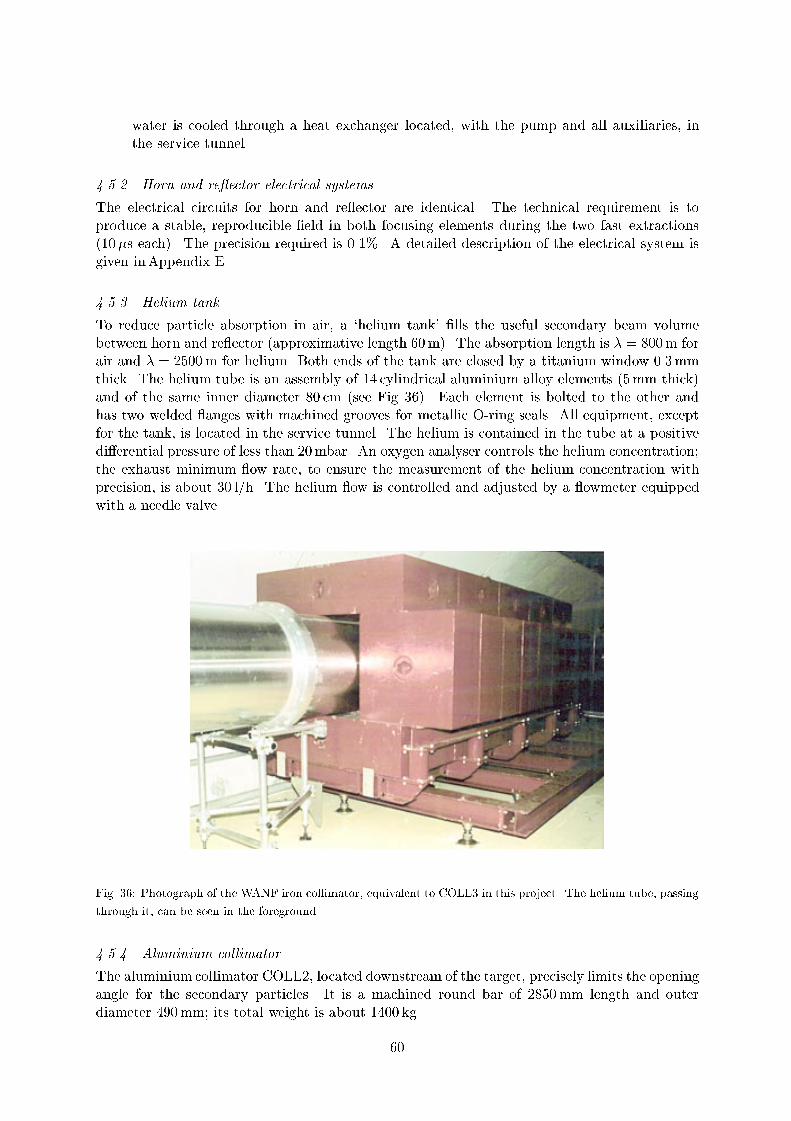
water is cooled through a heat exchanger located, with the pump and all auxiliaries, in
the service tunnel.
4.5.2 Horn and re ector electrical systems
The electrical circuits for horn and re ector are identical. The technical requirement is to
produce a stable, reproducible eld in both focusing elements during the two fast extractions
(10s each). The precision required is 0.1%. A detailed description of the electrical system is
given inAppendix E.
4.5.3 Helium tank
To reduce particle absorption in air, a `helium tank' lls the useful secondary beam volume
between horn and re ector (approximative length 60m). The absorption length is = 800m for
air and = 2500m for helium. Both ends of the tank are closed by a titanium window 0.3mm
thick. The helium tube is an assembly of 14 cylindrical aluminium alloy elements (5mm thick)
and of the same inner diameter 80 cm (see Fig. 36). Each element is bolted to the other and
has two welded anges with machined grooves for metallic O-ring seals. All equipment, except
for the tank, is located in the service tunnel. The helium is contained in the tube at a positive
dierential pressure of less than 20mbar. An oxygen analyser controls the helium concentration;
the exhaust minimum ow rate, to ensure the measurement of the helium concentration with
precision, is about 30 l/h. The helium ow is controlled and adjusted by a owmeter equipped
with a needle valve.
Fig. 36: Photograph of the WANF iron collimator, equivalent to COLL3 in this project. The helium tube, passing
through it, can be seen in the foreground
4.5.4 Aluminium collimator
The aluminium collimator COLL2, located downstream of the target, precisely limits the opening
angle for the secondary particles. It is a machined round bar of 2850mm length and outer
diameter 490mm; its total weight is about 1400 kg.
60

On its longitudinal axis, a bored beam hole ( = 88:8mm) partly cylindrical and partly
conical results in the average requested opening angleAppendix A. The collimator is centred
along the slope of the beam axis. It is placed on a manual adjustable base frame supported by
a specially equipped CERN standard iron shielding block.
Support, collimator, and base frame are autocentring and can easily be removed. The
collimator is water-cooled by two separate drilled circuits, one at each end, both cooling circuits
being connected in parallel. The cooling circuit of the aluminium collimator COLL2 is connected
to the same closed circuit as the copper collimator COLL1. The corresponding pump station
is located in the service tunnel with a heat exchanger cooled by the primary beam transport
demineralized water circuit. The total water ow is 1.5m3/h with p = 3bar resulting in a
mean temperature of 60C measured on the outer circumference at the middle of the collimator,
when the total SPS intensity is 3:0 1013 protons for the two spills of the SPS 6.4 s supercycle.
4.5.5 Iron collimator
The overall dimensions of the iron collimator COLL3 (4m length) correspond to the arrangement
of the WANF TDX collimator (see Fig. 36). The assembly is built up with 80 80 40 cm3
standard iron blocks.
4.6 Hadron stop
The hadron stop is placed at the end of the decay tunnel. The purpose of this object is to absorb
the energy deposition of the primary and secondary particles arriving at the end of the decay
region. The design is based on the following requirements:
1. There must be a high density and potentially demountable region where the energy depo-
sition of the primary and secondary hadrons from the intense production at the target are
absorbed. The cascade of these particles interacting in the dump has to be contained, as
there must be minimal deposition of radioactivity in the molasse.
2. The hadron stop must be considerably larger than any protection required to absorb the
hadrons as there is a need to provide additional material for muon attenuation at the SBL
detector to give a direct muon background less than the irreducible background induced
by neutrino interactions in the molasse in front of the detector. The evaluation of the
amount of material required was discussed in Section 3.7.
3. In order to steer the beam towards the Gran Sasso Laboratory, accurately positioned
detectors must be placed behind the hadron stop. In practice, experience has shown that
at least two detector pits are required to provide angular and very rough energy information
to control any misalignment of the horn and re ector with respect to the target. The two
pits should be separated by sucient material to give an energy dierence of the muons
sampled of about 40GeV.
4.6.1 Hadron stop design
Unlike the WANF system it is evident that because of its insulation against heat loss, buried
deep underground in a bed of poorly conductive molasse, the hadron stop has to be actively
cooled. Preliminary calculations, discussed in the next section, indicate that after 200 days of
running with 51012 protons per second at 400 GeV/c, parts of a simple iron dump could reach
several hundred degrees Celsius ( 700C). These high temperatures would risk destroying the
concrete supporting structures, excluding further access to the muon detector pits. Several heat
ow calculations [67] with dierent conditions have been made, indicating that the dump should
be actively cooled. Also, it is clearly advantageous to have a lower density insert at the start
61

of the dump to diuse the hadronic cascade over a larger volume to improve the heat ow and
minimize exceptional hot spots due to non-interacting primary protons on the beam axis.
The design requirements for a cooled hadron stop are listed below:
1. The total power deposited on the hadron stop in the worst case of continuous dedicated
running is about 50 kW. Half of this deposition comes from non-interacting protons, and
is highly localized in the centre of the dump. The rest, coming from secondary hadrons,
is relatively diused over a region of 2.6m in diameter.
2. The back end of the hadron stop needs to be at a reasonable, constant temperature,
2025C, in order to allow stable operation of the solid-state detectors and electronics.
3. Water cooling must be demineralized in a closed circuit and be very robust. It should be
designed for a 20-year lifetime with no intervention to the heat sink required.
4. A monitoring system of the water ow and temperature is necessary. This has to be
designed with appropriate redundancy, considering the mechanical and thermal stresses
expected in the hadron stop region.
The general layout of the civil engineering of the hadron stop area is shown in Fig. 31.
Access to the area is evidently very limited. It is only possible when neither the LHC nor the NGS
is running. Access is possible via pit 8, about 1.5 km around the machine tunnel, to the RE88
service area, then down 200m of sloping gallery to the rst muon pit area. The second muon
pit area is a further 67m downstream. This distance of molasse gives the required attenuation
of 40GeV. Access to this pit is via another 100m gallery. It is initially slightly angled away
from the detector so that any muons in this region see only an additional 10m of air gap. The
hadron stop is installed in a cavern 6.5m in diameter and 26m long. A preliminary design of
the hadron stop is shown in Fig. 37. The decay tunnel pipe is terminated by a substantial steel
plate welded to the 96 inch gas piping used as the actual evacuated decay tunnel. An insulating
air gap, 20 to 25 cm, is left to separate the plate from the hadron stop and to minimize the
heating of the end plate by the dump. Once installed this region is completely sealed from the
galleries and muon pits.
The rst component of the stop is a block of graphite 2:6 2:6 3:0m3 which is used
to diuse the hadron cascade over a large volume to reduce the temperature gradient in the
dump and take advantage of the better heat conductivity. The graphite block is enclosed in an
aluminium box, with a wall thickness of 10 cm. This box ensures a good heat conductivity over
the whole surface to the heat sink on which the box sits. This heat sink of 280 20 cm2 cross
section and 5m long is water-cooled by 12 independent circuits, each of 4 cm diameter mild steel
pipes leading to the back of the hadron stop. Each circuit is independently attached to a general
manifold and can be turned o in case of internal leaks or breakage. A schematic drawing of
the heat sink is shown in Fig. 38.
The whole water-cooled module is encased in standard CERN steel blocks, see Fig. 39,
and all gaps to the cavern walls lled with concrete.
As it is impossible to transport the aluminium box lled with graphite as a complete
structure down to the cavern, one possibility is to build it in ve 60 cm segments, each weighing
about 10 tons. These segments are bolted together in situ, as shown in Fig. 40. The water-
cooled module is followed by a mass of 240m3 of iron blocks. The cross section of 4 4m2 is
sucient to attenuate any muons that would multiple-scatter around the hadron stop, and the
length of 15m along the beam axis should provide enough attenuation to give a safety margin to
prevent muons from reaching the SBL detector. The heat sink is 5m long, 2m longer than the
graphite. This provides some continuity of cooling to the nal mass of iron. The water cooling
is provided by closed-circuit pumps and a heat exchanger situated in the equipment chamber at
the hadron stop, see Fig. 31. Power and cold water requirements are discussed in Section 4.8.1.
62

The total amount of iron needed for the hadron stop can be found by recovering standard sized
blocks from the WANF system. In the WANF beam line at the end of the West Area, 105m3 of
8080160 and 4080160 blocks can be found. The remaining blocks can be recovered from
the 4700 tons of blocks buried outside the West Area, between the hall and the CERN fence.
Fig. 37: Elevation and plane views of the hadron stop cavern (dimensions in millimetres)
Fig. 38: Illustration of a preliminary heatsink design (dimensions in millimetres)
63

Fig. 39: Beam view of the upstream end of the hadron stop (dimensions in millimetres)
Fig. 40: Schematic view of a possible assembly of the graphite inserts (dimensions in millimetres)
64

4.6.2 Heating of the hadron stop
Some preliminary calculations have been made of the heat ow and nal temperatures in the
hadron stop, though no nal optimization of all the possible parameters has been made. These
calculations have, however, given indications of what could be a reasonable, safe design that
would satisfy the required conditions. The proposed design is described in the following section.
The calculation of the heat ow in the hadron stop was performed in two steps. First the
Fluka program [47] was used to calculate the average energy deposition in the hadron stop
by a fully simulated reference neutrino beam, including primary protons not interacting in the
target. The output from this simulation was used as the input to the dynamic heat transfer
calculation in the hadron stop.
Several simplifying assumptions were made to ease the calculation problem. A rotational
symmetry was assumed to allow a faster rst round of calculations, e.g. the heat sink was taken
as a 3m long cylinder of aluminium with an inside radius of 1.46m and a thickness of 10 cm. To
compensate for this global coverage of the heat sink, which is in reality only at the bottom of
the hadron stop (see Fig. 37), the cooling power was reduced to a quarter of the expected one,
i.e. to 12.5 kW. Boundary conditions in the molasse surrounding the hadron stop were xed at
14C at a reasonable distance of 20m.
The temperature prole due to the impact of the hadron cascade along the beam axis
is shown in Fig. 41, for the hottest region after 200 days of beam on target. The maximum
temperature on axis in the hadron stop, after 200 days continuous running, rises to 160C,
partly due to non-interacting protons8. The peak in temperature at 3m is reduced with the
foreseen longer heat sink of 5m. The maximum temperature at the end of the dump is still
fairly high, about 55C, but can be easily reduced with some air gap and insulation, or with
additional water cooling.
0 2.5 5.0 7.5 10 12.5 15 17.5 20 22.5 25Distance along the dump (m)
20
40
60
80
100
140
160
180
Tem
pera
tute
(˚C
)
0
120
200
Fig. 41: Temperature prole along the hadron stop (with cooling)
The time development of the maximum temperature on axis, in the worst case of con-
tinuous running is shown in Fig. 42. Note that in the simulations, the cooling of the dump is
assumed to stop when the beam is stopped, after 200 days of operation. In the case of complete
8This could be reduced with the use of a longer target in the proton beam.
65

loss of water-cooling, the same time response is shown in Fig. 43. At the hottest spot in the
dump, just at the end of the 3m long heat sink, the temperature at a lateral distance of 2m can
rise to about 140C. This is also reduced with a longer heat sink of 5m. Further calculations
indicate that with a modest increase of the water-cooling power, these temperatures can be
reduced considerably.
4.7 Muon monitoring station
Muon counters in the form of silicon diode detectors (SSDs) are used as in past experiments
[68, 69] to monitor the intensity and distribution of the muon ux after the iron of the hadron
stop. These counters are installed in two chambers, chamber 1 is immediately downstream of
the hadron stop in a small cavern 4 4 5m3. Chamber 2 is a smaller cavern 3 3 3:5m3,
on the beam axis 67m downstream, reached by a gallery 100m long, see Fig. 31. Each chamber
is equipped with a free-standing support holding 19 xed SSDs arranged as shown in Fig. 44.
The central position on the beam axis is equipped with three SSDs, to allow checks and provide
some redundancy. These xed detectors have a point-to-point spacing of 30 cm. An additional
set of ve SSDs, (CALBOX), in each chamber, is mounted on a moveable arm, such that the
group of detectors may be remotely scanned, horizontally and vertically over the useful 2 2m2
area. The precision of movement of this arm is fairly critical, a position accuracy of 0.2mm is
required. These sets of detectors are used to provide a relative calibration between the xed
detectors and also to provide precision scans of the muon proles. Note that the whole support
structure has to be tilted by 5.6% so that it is perpendicular to the beam axis. During data
taking the CALBOX is put in a far o-axis, garage position, as the presence of the CALBOX
in front of a xed SSD counter aects the detector response.
0 50 100 150 200 250
Time (days)
20
40
60
80
100
120
140
160
180
Tem
pera
tute
(˚C
)
Fig. 42: Temperature evolution with time at the hottest point of the hadron stop (with cooling)
66

0 50 100 150 200 250
Time (days)
Tem
pera
tute
(˚C
)
0
50
100
150
200
250
Fig. 43: Temperature evolution with time at the hottest point of the hadron stop (without cooling)
Chamber 1
Chamber 2
67 m
CALBOX
Fig. 44: Layout of the counters in the two muon chambers. Each chamber is equipped with a moveable CALBOX
containing ve SSDs
In the WANF muon monitoring system an additional set of ve SSDs (REFBOX) was
used to intercalibrate the dierent chambers. Experience and calculations have shown that the
detector response, particularly the e= ratio is very sensitive to the physical environment in the
chambers, i.e. the material and distance of the chamber walls. In view of the recent developments
in the speed and accuracy of automatic scanning of nuclear emulsion plates, it is proposed to
calibrate each CALBOX detector with emulsion plates, thus avoiding the additional complexity
of a REFBOX system. The disadvantage of this process is that a few hours of dedicated SPS
time are required to reduce the proton beam intensity in the SPS | in this way, an exposure of
the emulsions can be made with a suciently low intensity so that the plates can be scanned.
67

The movement control and DAQ electronics for the SSDs is placed in the hadron stop
annex. A few racks of low-power CAMAC or VME crates are required, less than a kilowatt, but
some water cooling should be foreseen. Electrical power and water is supplied from the `stub-
tunnel' RE88. The control and data acquisition system should be connected via an optical bre
link to the SL data connection channel to provide connection to BA4 or, if that is considered
undesirable, an optical bre connection could be made to point 8 of the LEP/LHC.
4.8 Infrastructure
4.8.1 Cooling and ventilation
This section describes the ventilation and uid systems for cooling (by water) as well as the
re extinguishing system for the dierent zones in the NGS underground areas. A schematic
overview of the technical concept for the ventilation system of the target chamber and the
tunnels is given in Fig. 45. The hadron stop and muon detector area, which can only be accessed
from the LEP/LHC tunnel, is treated in a separate paragraph at the end of this section.
Fig. 45: Overview of the infrastructure for ventilation
Access gallery
Air handling: The air in the access gallery is treated by a unit at the surface in building
BB4 or its annex and is operated only during access periods. The unit, operating entirely with
fresh air, is used to heat and cool the area. It provides a ow rate of 16 000m3/h and its
components are designed to provide the following ambient conditions:
i) dry temperature 19C,
ii) dewpoint 10C.
Fresh, clean air is supplied to the access gallery, via an air-handling link with the access
gallery and the proton beam tunnel. The electrical power required for this unit amounts to
200 kW and chilled water at 6/12C has to provide 120 kW of cooling power.
68

It is possible to start this unit from the surface or from the access point in ECA4. The
criteria for this, which have to be drawn up to prevent any contamination hazards owing to the
overpressure generated by the injection of fresh air, are to be dened in a detailed procedure.
Smoke removal (cold smoke 100C): A system of smoke removal ducts is located
in the access gallery and connected to two units at the surface (one on stand-by). It is possible
to start this unit from the surface or from the access point in ECA4. A safety procedure for
starting the unit has to be dened to prevent any contamination hazard due to the quality of
the discharged air. In view of the physical link with the surface building via shaft PAM4, two
smoke extraction fans are tted on the roof of BHA4 (BB4). This equipment is powered from
the no-break circuit at the required power of 10 kW.
Target chamber and service gallery
Air handling: The air in these two areas is treated in a shared unit placed underground
in the second level of the tunnel junction labelled `ventilation cavern' in Fig. 45. The unit cools
and dehumidies the air to prevent any risk of corrosion of the equipment. This unit operates
entirely on recirculated air except during access periods, with a total treated air ow rate of
16 000m3/h. The components are designed to ensure the following ambient conditions:
i) dry temperature 19C,
ii) dewpoint 15C.
The power required is: (a) electric 320 kW, (b) cold (chilled water at 6/12C) 120 kW.
This air handling unit is equipped both with local and remote controls.
Smoke removal (cold smoke 100C): A system of smoke removal ducts is located
in the target chamber and its service gallery, connected to the one for the access gallery and
controlled in the same way.
Proton beam tunnel
Air handling: The air in the proton beam tunnel is treated by a unit, placed under-
ground in the ventilation cavern, which cools the air and thus the equipment in the proton beam
tunnel. This unit operates entirely on recirculated air except during access periods, with a to-
tal treated air ow rate of 12 000m3/h. The components are designed to ensure the following
ambient conditions:
i) dry temperature 19C,
ii) dewpoint 10C.
This unit requires 50 kW of electric power and 90 kW of cold (chilled) water at 6/12C. It
is equipped with both local and remote controls.
Smoke removal (cold smoke 100C): A dual-purpose extractor and removal grid
for smoke below 100C is placed on the partition between the ventilation cavern and the proton
beam tunnel, connected to the access gallery system and controlled in the same way.
69

Cooling and re extinction The SPS primary circuit provides the primary cooling of the
demineralized water circuit for the proton beam magnets (2000 kW, 115m3/h). It also serves
as a re extinction circuit ( 5 bar static pressure available).
The equipment in the target chamber is cooled with a demineralized water circuit
( 50 kW, 3m3/h) having either chilled water or the SPS water as primary circuit. The air han-
dling units in the ventilation cavern are supplied with chilled water at 6C (600 kW, 86m3/h).
The primary water of these units is also cooled from the SPS primary circuit. As is usual, a re
extinction circuit is installed.
Finally, all seepage or leakage water is collected in a sump in the service gallery and
pumped to BB4 where it is checked for contamination before discharge or treatment.
Hadron stop and muon chambers
Ventilation: The treated air from sector 8-1 of the LEP/LHC tunnel is supplied from
a fresh-air handling installation on the surface at point 8. The hadron stop area is ventilated by
air taken from this sector 8-1. The air is provided by two fans (one on stand-by) connected to
a ducting system making it possible to take the air as far as the two muon chambers. The air
is returned to the tunnel by overpressure. This device is controlled from RE88, the access point
to the tunnel. The access procedure ensures that the equipment is started up before an access
is given. The air quality is monitored. The unit is put into operation every time access to this
area is required.
Smoke removal (cold smoke 100C): The fans are reversible in order to remove
smoke.
Cooling and re extinction: The water required for re extinction is supplied from
the main LEP tunnel raw water circuit (available pressure around 10 bar). The cooling of the
hadron stop uses the octant demineralized water as primary circuit (50 kW, 3m3/h, 27C) to
avoid any risk of contamination of the raw water circuits or the octant circuit. Any inltration
through the cavern walls or leakages from the cooling equipment is collected in a sump in the
hadron stop area and then pumped to point 8 for checking before discharge or treatment.
4.8.2 Decay pipe accessories
The decay pipe consists of welded steel pipes of 2.45m diameter, with a total length of 1000m
(see Section 4.1). The volume of the pipe is 4800m3, the inner surface amounts to 7700m2.
The thickness of the steel pipes is 20mm, solid enough to withstand the pressure under vacuum
provided the surrounding spaces are lled with concrete.
Vacuum To provide the required vacuum of about 1mbar in less than one week, two rotating
pumps are foreseen. They are installed in the service gallery, near the end of the target cavern.
Each pump has a capacity of 630m3/h and a nal pressure near 0.1mbar. The pumps are
equipped with the necessary valves, lters, and pressure gauges, and they can be remotely
controlled. The ltered exhaust gases are transported to the surface through a dedicated pipe
equipped with a ventilator for extraction.
Using the two pumps, the required pressure of 1mbar can be attained in three days. After
that, one pump is switched to `stand-by' and used as a spare.
70

Vacuum window and shutter The decay pipe is closed on the target chamber side by a 1m
diameter 2mm thick titanium window. The other end (i.e. at the hadron stop) is closed by a
massive steel plate, 5 cm thick.
For safety reasons, i.e. to protect against a possible implosion risk, it is necessary to install
a motor-driven vacuum shutter (a thick circular steel plate) which is moveable along horizontal
rails in front of the 2mm titanium window. When run conditions are established, the plate is
automatically driven out of the beam into a `run position'. When access to the target area is
requested, the shutter is automatically driven in front of the titanium window. This shutter
must be interlocked with the access conditions for the NGS target area. Should the titanium
sheet break, the shutter plate is pushed by the implosion eect against the titanium window
ange thus reducing the leak to a tolerable level.
Decay pipe collimator In order to localize the induced radioactivity from defocused particles
along the decay tunnel, a 10m long iron collimator is foreseen in the very upstream part of the
decay pipe (see Fig. 46). The detailed design of this collimator (COLL4) has to be optimized
according to the nal layout of the focusing elements and their strengths, i.e. once the nal
neutrino beam optics are available.
9500
10000
10500
11000
11500
12000
-300 -200 -100 0 100 200 300
collimatoriron
side gallery
(COLL4)
target cavern
decay tunnel iron pipe
(to vacuum pumps)
titanium window
helium bag
ironcollimator
concrete
"shotcrete"
[cm]
[cm]
(COLL4)
Fig. 46: Schematic view of the beginning of the decay tunnel
71

4.8.3 Power converters
For reasons of operational simplicity and maintenance, the whole system is designed to be an
extension of the SPS. Apart from the corrector power converters, all the power converters are
recovered from the SPS and LEP. All the power converters are pulsed and controlled by the
MUGEF (microprocessor controlled function generator) system.
For the main bending magnets (MBs), it is planned to use the same power converter
as for the TI8 MBs. This converter is made from two units connected in series, working in
a `master/slave' conguration and is located in building BA4. This power converter can be
switched from the TI8 MB circuit to the TN4 (NGS) MB circuit and vice versa with the help of
two remotely controlled power switches. In the TN4 MB circuit the number of magnets is lower
and therefore needs a remotely controlled switchable current loop and may need only one power
converter. The other dipoles are fed by the SPS and LEP power converters. The QD/QF chains
and all the other quadrupoles are fed by the LEP power converters. Concerning the correctors,
neither the quantity nor the electrical parameters are dened today, but it would be judicious
to design the new coils to use new SPS COD (closed-orbit de ector) power converters.
The power converters coming from the SPS will be renovated. At the moment, a renovation
project for the SPS auxiliary converters is planned. All needed power converters will be added
to this programme. This programme includes a complete reconstruction/modernization of all
components, with an upgrading of the regulation, control and interlock subsystems. The power
converters coming from LEP will also be modied. The power part is retained, but the complete
electronics has to be replaced by new SPS electronics, which can be controlled by the MUGEF
system.
4.8.4 Power distribution and DC cabling
Power distribution Most of the electrical installations for the new neutrino facility are fed
from BA4 of the SPS. The service installations in the new underground structures are cabled
from this point.
Although the individual loads are fairly small, the total load combined with the distance
to BA4, may mean that the optimal solution is an 18 kV cable from BA4 to an 18 kV/ 400V
transformer close to the target area. The distribution in the area is entirely low voltage, i.e.
230 V/ 400V.
The major part of the load elements are in the short tunnels and small caverns around
the target area. Here low-voltage switchboards are foreseen for the local distribution.
The part of the load to be installed in the muon pits and the tunnel leading to them
is supplied from the LEP stub-tunnel RE88. Small sub-distribution panels are required for
the distribution to the racks in the pits. Here the load is small, a few tens of kilowatts, so a
230 V/ 400V link from RE88 is sucient.
The lighting of the tunnels is similar to that of the LEP tunnel. Specic areas, where
detailed work requires a higher luminosity, can be equipped with more powerful lighting.
The safety systems (emergency stops, 48V supplies, anti-panic lighting and safe power) are
prepared to the standards developed during the LEP and LEP200 projects. All the equipment
of such installations are part of long-term solutions, proven at CERN over years of operation.
The distribution of services requires cable routing in the structures, either in false oors
or on cable ladders xed to the walls. In the very narrow tunnels care is taken to reduce the
space requirements for routing electrical cables.
72

DC cabling The DC cabling for the magnets in the primary beam tunnel also originate in
point 4 of the SPS. These cables run through the primary beam tunnel on cable ladders in the
upper part of the tunnel cross-section.
Water-cooled cables are used for the dipole circuit. Existing water-cooled cables in the
SPS will be recovered to a maximum possible extent, i.e. from BA4 to ECA4, to reduce costs.
From ECA4 and onwards, the major part of the water-cooled cables will be new.
Conventional cables are used for the other magnet circuits. The cross-section of the
conventional cables has been selected to keep the heat dissipation in the tunnel low.
4.8.5 Access control and machine interlock systems
The realization of the NGS project implies the implementation of safety systems ensuring pro-
tection of personnel as well as of equipment.
Safety considerations The NGS tunnels are considered as a `CERN Primary Beam Area'.
At CERN the access to such areas follows safety rules:
The access to a primary beam area must be forbidden and nobody should be present in
the area during beam exploitation.
The beam should be turned o and interlocked, and the level of remanent radiation must
be acceptable in order to allow access to this primary beam area.
The general rules for the access control and machine interlock systems are equivalent to
the ones found today at the SPS, and more specically at the WANF.
Two access points are foreseen at the NGS:
1. Access to the target chamber is provided from point 4 of the SPS (see Fig. 6). The access
point (door for material transport and turnstile for personnel trac) is in the ECA4 cavern.
Here, the neutrino access tunnel can be entered and the ventilation cavern, storage tunnel,
as well as the service gallery and target chamber can be accessed.
2. Access to the muon pits, downstream of the hadron stop, is provided through the LEP/LHC
tunnel, starting in point 8, and passing through the alcove RE88 (see Fig. 31). Access to
this area, although rarely needed, requires that both the neutrino beam and the LHC be
switched o.
Further details of the Access Control and the Machine Interlock System for the NGS are
described elsewhere [70].
4.8.6 Alarms and re detection
The installation of safety systems is planned in all the areas where equipment is located, i.e. in
the proton beam tunnel, the target chamber and its service gallery, as well as the muon detector
areas.
Evacuation Based on the principles used at LEP, the evacuation alarm systems consist
of two control panels connected to sirens installed at least every few hundred metres. The control
panels are installed in BA4 and at point 8 of LEP. The precise location of the sirens and of a
few dozen glass plates with emergency stop buttons depends on the local equipment layout.
73

Red telephones Some 20 of these emergency telephones are foreseen. When activated,
these telephones automatically generate an alarm of Level 3, thus informing the Fire Brigade
Control Room of the precise location of the person calling. The detailed layout for the installation
of these telephones will be given by the CERN Technical Inspection and Safety Commission
(TIS), once the layout of the equipment is dened.
Fire detection Fire detection in an environment with long tunnels, coupled with high
radiation, is a dicult problem. Since most areas of the NGS are not accessible when the
accelerators are running, smoke detectors would have to be located in BA4 and at point 8 of
LEP (see Fig. 6). Sampling tubes would have to be installed close to the ceiling of the areas with
equipment | they would have to carry the smoke to the detectors. Considering a typical velocity
of 3 m/s in such tubes, this implies that it takes about 6minutes for the smoke generated, e.g.
in the service gallery near the target, to be detected in BA4. In addition, the time for the
smoke to reach the closest sampling tube might be about 25minutes. For the time being,
no manufacturer of smoke detection systems can guarantee that such a diluted smoke can be
reliably detected.
It should be noted at this point that there is no re detection installed over much of the
length of LEP, with the exception of about 150m to either side of the access points. Pending
a detailed safety discussion, it is assumed that no re detection is needed in the NGS caverns
and galleries.
5 RADIOLOGICAL ASPECTS
5.1 Introduction
The most important items in the present proposals for a neutrino beam to Gran Sasso from a
radiological viewpoint are the target chamber, the decay tunnel, and the hadron stop. Estimates
must be made of possible dose rates to which maintenance personnel could be exposed, the total
induced radioactivity in the structure and its surroundings, and the magnitude of any release
to the environment via air or water pathways. Some of these quantities of interest have been
estimated from simulations of the cascades induced by the interactions of the primary protons
from the SPS in the neutrino production target and the hadron stop [71].
Simulations of these cascades were carried out using the 1997 version of the Monte Carlo
cascade program Fluka, see Refs. [47, 72] and the references therein. The study was based on
the Reference Design detailed in this Report (see Section 3 and the Reference Parameter List in
AppendixAppendix A). No attempt has yet been made to optimize the design with respect to
minimizing the radiological quantities of interest. Thus the studies completed so far represent
upper bounds of these quantities serving to show that the project is feasible without undue
adverse eects on the environment.
5.2 Remanent dose rates due to induced radioactivity
The latest version of the present WANF has proved successful in keeping the doses to mainte-
nance personnel to acceptable levels. It has been possible to make repairs to components in the
vicinity of the target, horn and re ector. The design of the new facility allows for the increase in
proton intensity by increasing the shielding around the target and collimators. Thus dose rates
due to induced radioactivity should not increase over present levels in the WANF.
The situation in the new facility has been signicantly improved by the provision of a
service side-gallery which gives access to the target chamber without exposing people to the
most radioactive items in the chamber. This allows necessary equipment to be installed close to
the beam-line components and for this equipment to be maintained without radiation exposure.
74

In addition, people making repairs to the beam-line components themselves can make their
preparations in the service gallery and spend the minimum amount of time in the highest
radiation environment. Such a side-gallery is a feature of both SPS target stations in the North
Area. They were included in these projects as a result of adverse criticism of the WANF Target
Area design, where the civil engineering plans were completed at a very early stage in preparation
for the SPS construction.
Another improvement has been the provision of a simple stub-tunnel as a storage area for
radioactive items close to the target chamber. This means that a horn or re ector which has
been in service and become faulty can be stored easily, reducing the dose to transport personnel.
These provisions ensure that the new facility does not increase the global exposure to
personnel, despite the increased intensity of protons being targeted in the area. In fact the area
has been designed rather to reduce the current level of exposure.
5.3 Radioactivity in the structure and components of the facility
On the assumption that the facility will run for ten years at the reference intensities, the ra-
dioactivity induced in the molasse around the underground structures and in the concrete of the
structures themselves will decay to insignicant levels within 5070 years after the end of target
operation.
The iron shielding around the target and collimators, the TDX collimator and the col-
limator at the front of the decay tunnel, with a mass of the order of 700 t, will have average
specic activities at the end of target operation between 104 and a few times 106 Bq/g. The
decay of the isotopes in this iron will be relatively slow, reaching insignicant levels only after
several hundred years. Disposal of these items as radioactive waste must therefore be foreseen.
The iron of the hadron stopper will have an average specic activity of a few times
103 Bq/g. Parts of this, about 200 t, will also need special disposal facilities.
The iron of the decay tunnel and the iron reinforcements in the concrete of the target
chamber will probably stay in place at the end of the target operation. The reinforcements will
reach insignicant levels of radioactivity within 50 years, but the time for the decay tunnel to
reach similar levels will be of the order of 500 years.
The aluminium of the collimator COLL2, the horn, the re ector, and the two helium-pipes
in the target cave, total mass about 34 t, will have specic activities, after 10 years of operation
and a further ten years of decay, which are of the order of 106 Bq/g. Disposal of these items as
radioactive waste must also be foreseen.
However, the activity in the graphite core of the hadron stop will probably reach levels
where normal disposal will be possible after ten years of decay.
Demineralized water in the cooling circuits of the horn, re ector, collimators, and hadron
stop will be kept in closed circuits. Emptying of these circuits will take place only after mea-
surements have been made of the radioactivity contained. It is to be expected that the tritium
concentrations will allow immediate emptying to the drains, but before that the water must pass
through a demineralizing resin where any 7Be and other radioisotopes will be removed.
5.4 Release of radioactivity via the air of the ventilation system and the drains
The air of the target chamber will be contained within a closed circuit during operation. After
targeting stops, a cooling-down period of several hours will be imposed before ushing of the
target chamber with fresh air is started. It will take at least several hours to ush all the original
air from the target chamber. Control of the radioactivity by careful determination of the delay
time, the ushing time, and the transit time for the air to reach the exhaust stack from the
75
target chamber will ensure that any radioactivity vented will be less than the relevant CERN
Reference Release Constraints. Continuous monitoring of the radioactivity in the released air
will be provided.
The radioactivity contained in the residual air of the decay tunnel and in the front part
of the hadron stop area is signicantly lower than the radioactivity in the target chamber.
Estimates have been made of the quantity of tritium that will be created in the closed
helium-gas cooling circuit for the target and the helium containers in between the horn and
re ector and the re ector and the end of the target chamber. It has been shown that the
production is similar to that of tritium in the air of the target chamber. Since the release of
tritium from this latter source is not of radiological importance, the regular ushing of one of
the helium circuits will not create a signicant release of tritium.
The drains in the target chamber and the LHC tunnel will collect any groundwater that
might seep into the excavation as well as any spillage water. The radioactivity in the groundwa-
ter, even though at a low level, is such that it is prudent to impose controls on the release of the
drain water. In addition to routine controls on drain water leaving the facility, water will not
be released unless point controls have shown that the radioactivity in the water meets CERN
Release Standards. Only then will the drain water be released. If the radioactivity exceeds such
levels, then the drain water must be evaporated, as is done in some present CERN facilities, and
the residue disposed of as solid radioactive waste.
5.5 Dose rates from neutrinos
As a postscript, it has been thought necessary to reply to questions concerning the dose rates
due to neutrinos at the Gran Sasso (LBL) or the short-baseline facility (SBL). The neutrino
uence at the SBL and LBL facilities is 1:09 103m2 and 4:39 109m2, respectively, per
proton on target (see Table 6 in Section 3). For an average of 5 1012 protons per second on
target, this leads to a uence rate of 1:9 109 cm2 h1 and 7:8 103 cm2 h1, respectively,
at the SBL and LBL facilities. The factor to convert neutrino uence to dose equivalent is
close to 1018 Sv cm2. Thus the dose equivalent rates are 1:9 109 Sv/h at the SBL facility
and 7:8 1015 Sv/h at Gran Sasso. For comparison, natural background radiation levels at
the ground surface are typically 100 109 Sv/h and are a factor of about three to four times
lower than this in a limestone underground environment. The levels from neutrinos are thus
insignicant.
6 PLANNING AND COST ESTIMATE
6.1 Installation procedure and planning
The schedule described here is based on the working hypothesis for the NGS study used in 1997.
It assumes that funding would be available such that civil engineering could start in October
1998. This is now known not to be the case.
The eective planning must be based on the funding scenario and could be in uenced
by the duration of the authorization procedure for NGS in the CERN Host States. The latter
can not be started before the authorization for the civil engineering of the LHC by the French
authorities is obtained. Presently, a draft schedule for NGS is being prepared which assumes
the start of civil engineering in spring 1999 and would allow a rst NGS neutrino beam to be
delivered early in 2003. The basic sequence of works follows the pattern described in this section.
76

Since the construction and installation of this new NGS facility interfere considerably with
the LEP and SPS machine operation, as well as with the LHC project, the feasibility of this
schedule is strongly linked to the following external time windows and milestones (see Fig. 29 to
locate PGC8, TJ8 and TT40):
LHC project:
excavation of PGC8 and TJ8 before end 1998
in order to excavate the TT40 beam tunnel.
LEP and SPS operation:
winter shutdown: Dec. 1998 to Mar. 1999
used to excavate the TT40 on the SPS side
winter shutdown: Dec. 1999 to Mar. 2000
to connect the hadron stop area to RE88
on the LEP side
denitive LEP stop and start of LEP dismantling Oct. 2000
long winter shutdown of the SPS: Nov. 2000 to May 2001 (7 months)
equipment installation in the SPS LSS4.
The planning for the construction and installation procedure is presented in Fig. 47. It is
planned to launch the call for tender for civil engineering works by the end of April 1998 in order
to reach the September 1998 Finance Committee for contract adjudication. The civil engineering
construction can then start immediately. In this way, one can expect the rst neutrino beam to
Gran Sasso soon after May 2002. Should any delay in the start and/or execution of construction
occur, the above time windows would be missed, and the operation of the NGS would be delayed
until spring 2003 at the earliest.
Work starts by digging the NGS temporary access pit, followed by the excavation of the
access gallery, the target chamber, the decay tunnel, and the hadron stop cave. It has been
assumed that a tunnel boring machine (TBM) is used instead of a road header machine and/or
explosives because of its higher progress rate (15m/day). When the end of the hadron stop
cave area is reached, the TBM is removed and may be reused to excavate the proton beam
tunnel. The aim is to excavate the connecting tunnel between the hadron stop cave and the
RE88 alcove during the LEP winter shutdown 19992000, and to nish the connection to the
LSS4/ECA4 during the same LEPSPS shutdown. The enlargement on the target chamber, the
excavation of the adjacent caves and galleries, the enlargement of the hadron stop cave, and
the nal connection to the RE88 alcove are done simultaneously with the digging of the proton
beam tunnel.
When the excavation is completed, i.e. 18months after the site opening, the concrete lining
or shotcreting of underground caverns is undertaken. The completion of civil engineering work
is expected by the end of year 2000, leaving 16months for: lowering and building the hadron
stop and lowering the decay tunnel pipes (5months); setting up services into the proton beam
tunnel, the target chamber and adjacent galleries (2months); installing the proton beam line
and target chamber equipment (6months); and commissioning the complete facility (3months).
In order to minimize interference with the dismantling of LEP in sector 8-1, a three-month time
window is reserved to lower and install muon detectors and services in the hadron stop area.
77

Q2Q1 Q3 Q42002
Q2Q1 Q3 Q42001
Q2Q1 Q3 Q42000
Q2Q1 Q3 Q41999
Q2Q1 Q3 Q41998
open site for Civil Worksdig Temporary Access Pit
excavate Access Tunnelexcavate Target Chamberexcavate Decay Tunnelexcavate Hadron Stop Caveexcavate p Beam Tunnel
assemble Tunnel Boring Machine
enlarge Hadron Stop Cavedig Connection to RE88dig 2nd Muon Pit Areashortcrete Decay Tunnelenlarge Target Chamberconcr. lining Target Chamberconcr. lining p Beam Tunneldig Connection to ECA4shortcrete Access Tunnel
assemble Hadron Stop Shielding lower Decay Tunnel Sleevesweld Sleeves, pour conc. aroundset up General Services 1/2set up General Services 2/2
install Equipt Target Chamberinstall Equipt p Beam Tunnelinstall Equipt Muon Pit AreaNGS Facility commissioning1st Neutrino Beam to Gran Sasso 2002-05-01
Fig. 47: Planning of the NGS beam project
6.2 Cost estimate
In Table 13 a summary is given of a detailed cost estimate (see CERN internal note [73]).
Individual items do not contain any contingency, but a modest overall contingency of less than
5% has been added. Note that the cost for the short-baseline experimental area is not included
here.
Manpower through industrial support contracts is included in these cost estimates. On
the other hand, the CERN and INFN manpower needed for this project is not included. These
manpower needs are currently being evaluated.
As is to be expected, the most expensive item in Table 13 is the civil engineering. The esti-
mates given here are considered to be quite precise since they are extrapolated from the recently
adjudicated tenders for the LHC civil engineering. The least expensive of the LHC tenders was
chosen as the guideline for the NGS project. From experience, 10% for civil engineering design
work, soil investigations, consultancies, etc., are then added. Note that the cost for the 1 km
long decay tunnel, including its 2.45m diameter steel tube, are included in the total for civil
engineering.
78

Table 13: Cost estimate, in MCHF, of the NGS beam
Civil engineering 41.6
Proton tunnel, neutrino access galleryand civil engineering shaft (PGCN) 13.90
Caverns (target area, hadron stopand access to muon chambers) 11.10
Decay tunnel (includingsteel tube and concreting) 12.90
Design work, soil investigations,consultancies 3.70
Equipment 19.2
Proton beam 10.70Target 1.60Secondary beam 6.35Hadron stop 0.57
Infrastructure 7.0
Cooling and ventilation 3.69Electrical infrastructure 1.26Handling equipment, crane,survey, safety, access system 2.03
Contingency 3.2
Total 71.0
(incl. industrial support)
A signicant eort has been made to keep the cost of equipment low by re-using existing
components from various facilities at CERN, such as from some West Area beam-lines (operation
stopped at the end of 1996), from the present WANF facility as well as from LEP (not expected
to run beyond 2000). In particular, all the iron needed for the hadron stop can be recovered
from the WANF. All power supplies for the proton beam-line elements as well as for the focusing
system (horn and re ector) can be recovered, together with a good fraction of the water-cooled
cables needed for the high-power magnetic elements.
The cost for infrastructure is dominated by the need for cooling and ventilation equipment.
Several ventilation circuits with lters are needed for the various beam and access tunnels. Smoke
extraction systems are needed in all areas where equipment is to be installed.
The annual cost for the operation of the facility is currently under evaluation.
79

Acknowledgements
The contributions of a large number of people have made this report possible within a very short
period of time.
Most importantly, the enthusiasm and skills of N. Pocock (SL-DI) were of invaluable help
in editing and correcting the report.
Y. Bonnet (SL-EA), J.-P. Bouchet (EST-SU), A. Bronzini (ST-CV), J.-L. Caron (AC),
M. Goujon (EST), C. Martel (ST-CV) and A. Vital (ST-CE) made important contributions to
a number of the gures in the report. The assistance of J. Blondel (ST-TFM) and M. Vannier
(ST-CE) in preparing and typing the civil engineering section is acknowledged.
M.Clement (SL-EA), P. Collier (SL-OP), M. Jones (EST-SU), M. Jonker (SL-OP), B. Pirollet
(ST-CV) and M.Ross (SL-BT) have contributed at various stages of the preparation and during
the evolution of this report.
We thank P. Bonnal (AC) and J.-L.Caron (AC) for the cover page of this report.
The fruitful discussions with members of NuMI at Fermilab, and in particular with
J.Hylen, are gratefully acknowledged. We also thank N. Mokhov for an early calculation of
the muon absorption.
80

Appendix A
REFERENCE PARAMETER LIST
Proton beam
Maximum proton beam momentum (design) 450GeV/c
Proton beam momentum (assumed for operation) 400GeV/c
Proton beam normalized emittance (1) 12mmmrad
at the focus (H and V) 2.5m
! minimum beam size/maximum divergence (1) 0.27mm, 0.1mrad
Minimum repetition time (dedicated operation at 400GeV/c) 7.2 s
Time between bursts 50ms
Proton intensity (for hadron stop considerations) 5 1012 protons/second,
200 days/year
Proton intensity (for environmental considerations) 5 1019 protons/year
Expected integrated number of protons per 200 days (" = 50%), running
with 2 subcycles for neutrinos and 16% duty cycle for slow extraction
(cycle D, CERN-AC note 9715)
at 350GeV/c (SPS accel. limited) 3:4 1019 protons
at 400GeV/c (SPS accel. + target limited) 3:0 1019 protons
at 450GeV/c (graphite target limited) 2:0 1019 protons
Expected period of operation 10 years
Target chamber
Length of target chamber 115m
Diameter of target chamber 6.5m (int.)
Floor width of target chamber 5.6m
[Enlargement at target (optional)] 7.4m
Crane capacity 10 t
Free height under crane hook 3.7m
Beam height in target chamber 1.6m
Diameter of neutrino service gallery 3.4m (int.)
Distance of service gallery from cavern 6.0m
Length of junction tunnel to target chamber 8m
Distance of proton focus to entrance of decay tunnel 100m
Target
Start coordinate (w.r.t. proton focus) 0:5mEnd coordinate (w.r.t. proton focus) +1:5m
Target material carbon
Target rod length 10 cm
Diameter of rods 3mm
Number of rods 11
Distance between rods 9 cm
Note: it is possible that a more compact target (i.e. more rods) will nally
be used inside the dened space.
81

Collimators
COLL1 (at target exit)
Material copper
Start coordinate (w.r.t. proton focus) +1:70m
End coordinate (w.r.t. proton focus) +2:90m
Cross-section: square 1 1m2
Opening: cylindrical, radius such that limitation at exit is 20mrad(seen from the proton focus)
COLL2 (before the horn)
Material aluminum
Start coordinate (w.r.t. proton focus) +4:30m
End coordinate (w.r.t. proton focus) +7:00m
Cross-section: cylindrical diameter 0.5m
Opening: conical, opening angle seen from focus 15mrad
COLL3 (between horn and re ector)
Distance from proton beam focus to COLL3 entrance 25m
Length of collimator 1.6m
Opening of collimator 0:8 0:8m2
Outer dimensions of collimator: like WANF, see Fig. 36 of this report.
Horn and re ector (dimensions referring to magnetic length):
Distance from proton beam focus to horn entrance 7.85m
Length of horn 6.65m
Current in horn 120 kA
Distance from proton beam focus to re ector entrance 80.35m
Length of re ector 6.65m
Current in re ector 120 kA
Present design of conductors see Section 3
Note: for the calculations, it is assumed that all spaces outside the horn and
re ector are lled with helium at 1 atm.
Decay tunnel
Upstream end of decay tunnel (w.r.t. focus) 100m
Length of decay tunnel 992m
Diameter of decay tunnel (TBM) 3.50m (ext.)
Length of decay pipe 994.5m
Diameter of decay pipe (inner diam. steel pipe) 2.45m (96 inch)
Wall thickness decay pipe 20mm
Concrete lling around pipe ca. 53 cm
Entrance window decay pipe diameter 1m,
2mm titanium
Exit window decay pipe 5 cm steel
Pressure in decay pipe (min.) 12Torr
Pumping down time (max.) 2weeks
82

Decay pipe collimator (iron)
Start of collimator (w.r.t. proton beam focus) 100m
Length of collimator 10m
Inner diameter of collimator 1m
Outer diameter of collimator (= inner diameter of shotcrete) 3.1m
Hadron stop and muon chambers
Upstream end of hadron stop cavern (w.r.t. proton focus) 100 + 992m
Length of hadron stop cavern 26m
Diameter of hadron stop cavern 6m (int.)
Length of hadron stop 18.2m
Cross-section of hadron stop 4 4m2
Length of graphite insert 3m
Cross-section of graphite insert 2:6 2:6m2
Wall thickness of aluminium box around graphite 0.1m
Length of airgap upstream of hadron stop 0.25m
Length of airgap downstream of hadron stop 5m
(= length of rst muon chamber)
Length of `muon lter': molasse 67m
Length of 2nd muon chamber 3.5m
Muon pit `service alcove' surface 10 4m2
Access gallery to hadron stop: diameter 3.1m (int.)
Access gallery to 2nd muon pit: diameter 2.5m (int.)
Short-baseline experiment
Distance proton focus to SBL cavern approx. 1850m
83

84

Appendix B
TECHNICAL DRAWINGS: CIVIL ENGINEERING AND TARGET STATION
In this Appendix, detailed drawings showing the civil engineering layout of the CERN-NGS
facility are presented (Figs. B.1B.3). They provide the necessary details for a more technically
interested reader.
Similarly, the detailed drawings of the target station layout inside the target chamber are
shown in the three views (Figs. B.4B.6), together with an illustration of the complex target
station shielding (Fig. B.7).
85

Fig. B.1: Components of the NGS (vertical cut)
86

Fig. B.2: Civil engineering layout of the target chamber and the adjacent areas (dimensions in metres)
87

Fig. B.3: Civil engineering layout of the hadron stop chamber, the muon pits and their access tunnels (dimensions
in metres)
88

Fig. B.4: Side view of the NGS target region (dimensions in millimetres)
89

Fig. B.5: Top view of the NGS target station (dimensions in millimetres)
90

Fig. B.6: Front view of the NGS target station (dimensions in millimetres)
91

Fig. B.7: Shielding of the NGS target station
92

Appendix C
THERMOMECHANICAL ANALYSIS OF THE TARGETS
C.1 Energy deposition
The energy density per incident proton deposited on beryllium or graphite rods of 3mm diameter
and 10 cm long, is estimated from simulations with the Monte Carlo shower code Fluka [46],
using the beam parameters listed in Table 11, Section 4.4. This simulates the random injection
of thousands of protons into the relevant transverse phase space. The interactions, transport,
and energy deposition processes are followed down to 0.1MeV for all charged particles, down to
10 keV for photons, and down to 0.4 eV for neutrons. The energy density on each rod is scored
using a regular cylindrical binning mesh of 0.1mm thick by 10mm long. Other target box
details are neglected for this analysis. FigureC.1 shows the total energy absorbed by successive
beryllium rods, while Fig. C.2 displays, for several of them, the radial distribution of energy
density averaged over the rod length.
The most critical rod is the rst one, as the deposited energy density reaches its maximum
value of 0.44 GeV/cm3 per primary proton (at about 8.5 cm depth) and its steepest axial and
radial gradients. Maximum thermal and mechanical constraints have thus to be expected in
this rod, even though the second one absorbs slightly more integrated energy. Hence, only the
behaviour of the rst rod is considered in the subsequent analysis. The continuous curves of
Fig. C.2 are ts to a Gaussian distribution; they suggest that the mean radial distribution of
energy density in a rod can be modelled as:
d0 exp(b r2)
which is important for the 1-D analytical calculation. For the rst rod, one nds the quantities
given in TableC.1.
Fig. C.1: Energy deposited per proton in each beryllium rod
93

Fig. C.2: Energy density in various beryllium rods
Table C.1: Parameters of energy density deposition in beryllium and graphite
Beryllium Graphite
(g/cm3) 1.85 1.75
d0 (J/cm3 1013 protons) 495 535
b (mm2) 1.60 1.77
C.2 Temperature
Any local energy deposition d is assumed to immediately result in a local temperature rise T :
d =
Z Ti+T
Ti
Cp(T ) dT ;
Ti being the initial temperature, the material density and Cp its specic heat. This equation
links the Fluka output (d) and the input (T ) of any thermal analysis. Most of the thermal
and mechanical material properties are temperature-dependent (e.g. Cp), and thus lead to non-
linear behaviour. Nevertheless, the mean radial distribution of an initial temperature rise can
also be approximated by a Gaussian distribution. The time-dependence of the temperature
distribution can either be estimated by 1-D analytical or 2-D nite-element method. Each
model assumes an axially symmetric thermal load, unconstrained axial and radial expansion,
and thermal convection as heat transfer boundary conditions. The 1-D method considers an
instantaneous and Gaussian initial temperature distribution, identical over the whole rod length.
The 2-D method, performed with the Ansys [74] analysis system, uses an internal thermal load
derived from Fluka output and accounts for the burst duration.
FigureC.3 shows the temperature evolution of a beryllium rod submitted to a single 10s
FE: the temperature rise reaches its maximum value at the end of the burst. Both transient
94

analyses highlight two main phases: a conduction process which leads to a quasi-uniform rod
temperature after 3040ms, followed by an exponential-like homogeneous cooling. The latter,
roughly dened by a time constant (), provides an easy estimation of the steady state stemming
from periodic thermal cycling ( is assumed to be 4.9 s for beryllium and 1.7 s for graphite).
FigureC.4 displays the temperature evolution of two 10s FEs of 2 1013 protons each, 50ms
spaced, impinging on a graphite rod every 7.2 s: the axial temperature varies from 25C to
640C going through 160C. This is the temperature at the start of the second burst, which is
taken as the initial temperature (Ti) in the subsequent mechanical analysis.
Fig. C.3: Temperature evolution of the rst beryllium rod submitted to a single 10 s FE
Fig. C.4: Temperature evolution of the rst graphite rod submitted to two FE bursts of 10 s each
95

C.3 Stresses
It is usual to distinguish between quasistatic and dynamic thermal stress components; this is
rather articial but a very useful method for an analytical approach. A quasistatic process can
be taken as a sequence of stationary states, without any time limitation to meet the required
thermal expansion constraints. Having estimated the radial distribution T (r), the quasi-static
thermal stress calculations can easily be performed (see Appendix A in Ref. [75]). A dynamic
process should only be considered if the burst duration is shorter than or of the same order of
magnitude as the time spent by the sound to travel from the rod centre to the edges. This is
summarized in TableC.2.
Table C.2: Sound propagation in beryllium and graphite
Beryllium Graphite
Sound velocity cs (mm/s) 12.7 2.32
Axial travel duration over 50mm (s) 3.9 21.6
Radial travel duration over 1.5mm (s) 0.1 0.6
In this study, elastic waves of signicant amplitude have thus to be expected in the longitu-
dinal direction only. The Ansys program performs a global thermal stress calculation, including
the dynamic components provided that material density and time-dependence of thermal loads
are specied. FigureC.5 shows the time evolution of the three main stresses stemming from an
FE: the transverse stresses, r and , identical on-axis, have practically no dynamic compo-
nent, whereas the longitudinal one (z) displays a well-shaped dynamic wave superimposed over
the quasistatic component. The 1-D analytical method to estimate the dynamic thermal stress
component is described in Refs. [65, 75]. It assumes a hydrostatic pressure (p) stemming from
the thermal inertia of the rod, instantaneously heated. It is worth noting that the dynamic wave
amplitudes and periods are very similar, in both longitudinal and transverse directions, to those
calculated by a 2-D analysis [66].
Fig. C.5: Time evolution of the three main stresses in the rst beryllium rod submitted to a 10s FE
96

It is of little interest to perform a stress analysis if one has no clear and reliable equivalent
strength criterion. These days, the one most commonly used for materials like beryllium with
the same tensile (0) and compressive (00) strength limits (0;2), is the Von Mises equivalent
stress (eq) based on maximum shear energy. However, for materials like graphite the correct
one, accounting for diering strength limit, is the Stassi criterion (teq) [76]:
k 2teq (k 1) (r + + z) teq 2eq = 0;with k = 00=0 1 :
Note that eq 0;2 (Von Mises) and teq 0 (Stassi), become identical if k = 1; the
Stassi criterion is a generalization of the one introduced by Von Mises.
C.4 Beam intensity limitation
For the calculations, a material of maximum admissible strength 0 is assumed to be submitted to
an FE of t0 duration. The equivalent strength (teq) is a function of two components: quasistatic
and longitudinal dynamic. The quasistatic component depends only on the beam intensity I,
while the longitudinal dynamic component is a function of the hydrostatic pressure p, the burst
length t0 and the rod half-length L; but since p is also dependent on I, this component is nally
a function of I, t0 and L, which can have a maximum value (z0) reaching p [75]; in such a case
it is no longer (t0; L) dependent. The three parameters I; t0 and L are optimized when the
maximum of teq equals 0: L and t0 lead to the longitudinal stress z0 which, together with
the quasielastic stresses stemming from I, adds up to 0. FiguresC.6 and C.7 summarize the
beam intensity limitation on rods of variable length submitted to FEs of various durations (6, 10
and 20 s), for beryllium (0 = 29daN=mm2, k = 1) and graphite (0 = 1:6 daN=mm2, k = 4).
A maximum allowed intensity per burst of a given duration exists at any rod length. However,
for some intensities many rod length values are possible, and L is no longer correlated to I if
2L cs t0. As one can see, very short rod lengths lead to extremely high intensities, but in
particularly unstable (L; I) regions; such instabilities are explained by Fig. 5 of Ref. [75]. More
probable length ranges, presently foreseen, lead to the maximum intensities per burst (1013p+
at 450GeV) given in Table 12, Section 4.4
97

Fig. C.6: Beam intensity limitation for the beryllium target
Fig. C.7: Beam intensity limitation for the graphite target
98

Appendix D
GEODETIC METROLOGY OF THE UNDERGROUND BEAM LINE
D.1 Metrological network
The alignment of the beam line components is done from a metrological network. This network,
consisting of tripods, is determined from the position of the SPS quadrupoles around the de-
parture of the beam line. The main problem for the determination of this network is that there
is no access to any well-known points at the extremity of the decay tunnel, and the polygonal
traverse therefore remains as an `antenna'. As a matter of fact, the geometrical conguration
for a link to LEP points is not good enough for this metrology.
In the vertical plane, the network is measured using optical levels and the accuracy can
be expressed as follows:
= niv pD
Here niv is the standard deviation over 1 km and D the distance in kilometres. At the end of
the decay tunnel, D = 1:8 km and niv = 0:4mm, so the error can reach 0.5mm. As already
mentioned, these vertical measurements apply only to altitudes H (above the geoid) but not to
ellipsoidal heights, which cannot be directly assessed.
In the XY plane, for the above-mentioned reasons and in order to ensure a good absolute
determination of the network all along the tunnel, gyrotheodolite measurements are indispens-
able. The radial accuracy at the end of the network (in the area of the muon detectors) can be
expressed as follows :
r = gyro dpn
where gyro denotes the standard deviation of the gyrotheodolite, d the span between two gy-
romeasurements and n the total number of sides of the traverse.
An optimization of the span d and therefore of the number of sides n has to be done,
according to practical conditions. As an example, for gyro = 3 arcsec, a distance D = 1800m,
a span d = 50m, n is 36, the resulting radial error is 4.7mm.
In addition to the gyrotheodolite measurements, overlapping oset measurements con-
tribute to a better relative determination, in order to ensure a `smoothness' quality of 0.1mm
r.m.s. all along the network.
D.2 Alignment of the curved proton beam line up to the target
The main quadrupoles are initially aligned from the metrological network using optical levels,
theodolites and CERN `ecartometers', which can accurately measure osets to a straight line
materialized by a stretched wire [77]. Then the position of these components are `smoothed' so
that the accuracy in the relative positions between three consecutive components remains lower
than 0.2mm in the XY plane and 0.1mm for the altitude.
Finally, the remaining components are aligned according to these quadrupoles and with
the same relative positional accuracy.
D.3 Metrology of the straight section and the magnetic horn
Particular attention is given to the alignment of the proton beam straight section, containing
the nal focusing quadrupoles, and to the magnetic horn, as all the components in this section
have to be aligned to within 0.1mm and must lie precisely in the absolute direction towards the
Gran Sasso Laboratory. Therefore, oset measurements ensure the required accuracy for the
99

relative position, and gyrotheodolite measurements guarantee the absolute orientation within
3 arcsec.
The maintenance of the alignment of this area together with the level of radiation would
certainly require the setting up of xed reference tripods. Special attention must also be paid
to the positioning and to the stability control of the magnetic horn.
D.4 Metrology of the muon detectors and nal adjustment of the line
In the vertical plane, the error on the slope between the horn and the muon detectors is slightly
dependent upon the error in the dierence of measured altitudes (only 0.4mm at 1 km), but
it can be more strongly aected by the uncertainties of the geoidal parameters | i.e. errors
on its absolute slope in the EUREF system and on local undulations in the interval. The local
undulations are known to within a few millimetres (from the mass model) but there is no clear
idea yet on the possible discrepancies in position and slope between the Swiss geoid, the French
one, the EUREF one, and the CERN one. A good indication results from step 4 of the geodetic
process mentioned in Section 4.2.3.
As for the azimuth, the situation can be more easily sketched and analysed as shown in
Fig.D.1.
SPS
TI8MuonDetector
MagneticHorn
D = n * d
d
δazimuth
~1000 m
Fig. D.1: Schematic view of the (azimuthal) alignment of the NGS beam
The error on the azimuth between the magnetic horn and the muon detectors becomes:
azimuth =r
D=
gyro d pn
d n =gyrop
n:
For a gyro = 3arcsec and n = 20, the r.m.s. error on the resulting azimuth could be
limited to 3 106 rad.
As a by-product of the accurate GPS measurement required for the geoidal parameters, the
orientation parameters in the EUREF system are accurately deduced. Considering an additional
2106 rad random error in this determination, the nal error in absolute orientation would be
maintained to less than 4 106 rad r.m.s. | which makes a radial error of 3m r.m.s. around
the target point, at 732 km from the origin.
100

Appendix E
DETAILS OF THE ELECTRICAL SYSTEMS FOR HORN AND REFLECTOR
E.1 General layout
Horn and re ector electrical circuits are identical according to the scheme shown in Fig. E.1.
C= 39*46.8 µF = 1825 µF
HORN / REFLECTOR ELECTRICAL LAYOUT
POWER SUPPLY
8 KV - 15A
CHARGING
( Nominal 6.5 KV)
BBBB44
1 standard primary cable
PULSE
TRANSFORMER
STRIP LINES
FLEXIBLE GRIDS
MAGNETIC HORNBEAM
TRANSFORMER RATIO = 16
I1= 7.5 KA
I2= 120KA
CONNEXION PLATES
30.0 KA
30.0 KA30.0 KA
30.0 KA
V2 = 410 V nominal max.
TTAARRGGEETT cchhaammbbeerr
High Voltage Primary
Low Voltage Secondary
Shorting relay (SR)
SWITCH
THYRISTOR
manualswitch
SWITCH
THYRISTOR
manualswitch
Shorting relay (SR)
Polaritychanger &accesssafety
800 m
C
C
Horn
C= 28*46.8 µF = 1310 µFReflector
Horn
V2 = 375 V nominal max.Reflector
Pulse 1
Pulse 2
Fig. E.1: Horn/re ector electrical layout
The requirement is to produce a stable reproducible eld (0.1% precision) in the element
during the two 10s fast spill extractions. For each circuit, the currents (pulse 1 and pulse 2) are
produced by the discharge of two capacitor banks into the element which acts as an inductive
load with small resistance. This circuit L, C, R is undercritically damped and the top of the
rst half sine wave is used to produce the magnetic eld needed during the extraction time.
101

The two capacitor banks are charged by one special 8 kV charging power supply. Between
the load and pulse generator a pulse transformer of ratio 16 is inserted which results in the
following advantages:
1. The primary current is the load current divided by 16. This allows the insertion of one
remotely controlled and motorized polarity changer on the power line just after the thyris-
tor switches. It is located in a separate cabinet and remote control is possible from within
the supervisor panel provided by the beam control system. Only one primary high-voltage
cable is necessary between the polarity changer and transformer, and this is useful since
this distance is around 1000m from the surface to the service tunnel where the transformer
is located.
2. The voltage on the load is low since it is the pulse generator voltage divided by 16. This
allows the use of radiation-resistant Arclex spacers for insulation of the connections and
of the strip-lines.
3. The pulse transformer includes in fact four primary coils and four secondary coils inter-
laced. The leads of the four primaries are mounted in parallel externally to the coil mould;
the four secondaries are attached to four strip-lines connected to the horn connection
plates. This gives the possibility to tune their impedance by adjustment of the inductance
of each line through remachining of the width. Hence it is possible to equalize the four
secondary currents. This is used as an indirect measure of the correct eld distribution in
the horn.
E.2 Main electrical components
A schematic diagram of the horn or re ector charging circuit is shown in Fig. E.2. For each
circuit, the main components are:
1. One 8 kV, 15A charging supply:
By reception of the start pulse derived from the SPS timing system, the power supply
starts charging the two capacitor banks with a constant charging current until the voltage
reaches the requested preset value Vc Set. The reception of the stop pulse blocks the
charging unit during the blocking time of 300ms. The trigger pulse for pulse 1 is expected
to arrive in this time interval to re the rst energy storage switching section producing
the rst discharge into the load, followed 50ms later by the trigger pulse for pulse 2 ring
the second energy storage switching section producing the second discharge into the load.
The preset voltage Vc Set is calculated to precisely reach the required horn current of
120 kA. The stability of the power supply enables a precision of 5 104.
The voltage and current settings and the control electronics consist of two parallel senseloops
working respectively in sequence:
rst during the capacitor charging phase,
and second during the voltage stabilization phase.
They act on the phase angle of the TH1TH6 thyristor switch. A rectier bridge D1D6
is located on the secondary side of the power transformer TR1.
The charging current needed is:
Ich =2VcC
t;
where
Vc = Voltage on capacitor,
C = Capacitor of one energy storage switching section,
t = Charging time = [Cycle time - (Blocking Time + stabilization time)],
Ich = 0 to 15A 2%,
Vc = 0 to 8 kV 0.05%.
102

L1.L3
C1.C3R1.R3
TR1
FIRING CIRCUITSYNCHRO
L4
CD1.D6
Ich
I ch loop
Vc Loop SETTINGVOLTAGE
380V3 PHASES
99 % Vc Set
clamp Vc Loop
clamp I ch Loop
Blockingtime
300 msStoppulse
Vc
TH1 - TH6
Blockingt imeEnergy
saver 2 spills
Fig. E.2: Diagram of the horn charging circuit
2. Two capacitor banks:
Parallel mounting of 46.8 F (10 kV) capacitors to build up two 1825 F banks for the
horn and two 1310 F banks for the re ector.
3. Two switching sections:
Each one has two series thyristors (10 kV peak, 7500 A peak) protected against excessive
di/dt by one saturating choke.
4. One interlock system:
Protecting against all faults related to the electrical circuit, water circuit, personnel access,
etc.
5. One polarity changer:
Already mentioned.
6. One primary high-voltage cable:
Of approximately 1000m in length has to be installed per system (EDF type: ROQUE
VN = 18 kV). Total section of the copper conductor is 240mm2. The 6.4 s cyclic double
pulse of 7500 A amplitude corresponds to 180 A r.m.s.
7. One pulse transformer:
A detailed description can be found in Ref. [43] and references therein.
8. Four secondary low-voltage strip-lines:
Four sets of massive aluminium alloy parallel plates connect the pulse transformer to the
horn passing. They need to pass through a trench to avoid blocking the runway along the
beam.
103

E.3 Main electrical data
Only nominal operational data are given in Table E.1.
Table E.1: Electrical characteristics of the horn and re ector
HORN SYSTEM REFLECTOR SYSTEMPeak current in element 120 kA 120 kATransformer ratio 16 16Primary current peak 7500 A 7500 AInductance element 1.2 µH x 16 2 0.30 mH 0.4 µH x 162 0.12 mH
connections 0.12 µH x 162 0.03 mH 0.12 µH x 162 0.03 mHstriplines( 30 m length)
20 nH x 30 x 162 0.15 mH 20 nH x 30 x 162 0.15 mH
transformer 0.10 mH 0.10 mHcable (800m) 240 mm2
0.01 mH 0.01 mH
TOTAL 0.50 mH 0.41 mH
Resistance element 0.6 m Ω x 16 2 0.153 Ω 0.33 m Ω x 162 0.087 Ωstriplines( 30 m length)
2.5 µ Ω x 30 x 162 0.019 Ω 0.019 Ω
transformer 0.019 Ω 0.019 Ωcable (800m)
240 mm 20.125 Ω 0.125 Ω
TOTAL 0.316 Ω 0.250 Ω
Total capacitancefor one switching section
46.8 µF x 39 1825 µF 46.8 µF x 28 1310 µF
Pulse duration 3.3 ms 2.5 msCharging voltage 6500 V 6000 VVoltage on element 340 V 210 VDuty cycle 2 pulses 50 ms apart
all 6 s2 pulses 50 ms apart all 6 s
r.m.s. current in element 2800 A 2400 APower dissipation
in element4800 W 2400 W
r.m.s. current in cable 175 A 150 ACurrent density in cable 0.73 A / mm2 0.61 A / mm2
Voltage drop cable 937 V 937 VPower dissipation
in cable3830 W( 5 W /m)
2700 W(3.5 W/m)
E.4 Horn and re ector magnetic induction
The magnetic volume is conned between the inner and outer conductor of the element with
the azimuthal magnetic induction B (Tesla) varying as B = 0 I=2r in MKSA units. The
maximum value is found on the surface of the neck at the smallest radius on the inner conductor.
For I = 120 kA:
HORN: at radius r = 10:8mm, the corresponding value is B = 2:22 Tesla.
REFLECTOR: at radius r = 100:0mm, the corresponding value is B = 0:24 Tesla.
It appears that the mechanical constraints on the inner conductor of the re ector compared
with the horn are in the ratio (0.24/2.22)2 and are hence much less of a problem.
104

References
[1] J. Primack et al., Cold and hot dark matter cosmology with m m 2.4 eV, Phys. Rev.
Lett. 74 (1995) 2160;
S.Ghigna et al., Statistical tests for CHDM and CDM cosmologies, preprint astro-
ph/9611103 (1996).
[2] B. Pontecorvo, Zh. Ehksp. Teor. Fiz. 7 (1958) 172 [Sov. Phys. JETP 34 (1958) 247].
[3] N.Hata and P. Langacker, Solutions to solar neutrino anomaly, preprint hep-ph/9705339
(1997).
[4] S.P.Mikheyev and A.Yu. Smirnov, Yad. Fiz. 42 (1985) 1441;
L.Wolfenstein, Phys. Rev. D17 (1985) 2369.
[5] Y. Fukuda et al., Two-nucleon pion absorption in 4 He at 1GeV/c, Phys. Lett. B335 (1994)
237.
[6] Y.Totsuka (for the Superkamiokande Collaboration), talk given at the 18th International
Symposium on Lepton and Photon Interactions, Hamburg, 28 July1 August 1997.
[7] M. Apollonio et al., Initial results from the CHOOZ long baseline reactor neutrino oscillation
experiment, Phys. Lett. B420 (1998) 397.
[8] C.Athanassopoulos et al., Evidence for e neutrino oscillations from LSND, Phys.
Rev. C54 (1996) 2658; Phys. Rev. Lett. 77 (1996) 3082.
[9] J.J.Gomez-Cadenas and M.C.Gonzales-Garcia, Z. Phys. C71 (1996) 443.
[10] G.L. Fogli, E. Lisi and D.Montanino, A consistent three- avour approach to possible evi-
dence of neutrino oscillations, Phys. Rev. D49 (1994) 3626.
[11] G.L. Fogli, E. Lisi and D.Montanino,Matter-enhanced three- avor oscillations and the solar
neutrino problem, Phys. Rev. D54 (1996) 2048.
[12] P.F. Harrison, D.H. Perkins and W.G. Scott, Phys. Lett. B349 (1995) 137.
[13] A.Acker and S. Pakvasa, Three neutrino avors are enough, preprint hep-ph/9611423,
vol. 2, 27 November 1996.
[14] C.Y.Cardall and G.M. Fuller, Can a \natural" three-generation neutrino mixing scheme
satisfy everything?, Phys. Rev. D53 (1996) 4421.
[15] C.Y.Cardall, G.M. Fuller and D.B. Cline, Intermediate baseline appearance experiments and
three-neutrino mixing schemes, preprint hep-ph/9706426, 19 June 1997.
[16] G. Ewan et al., Sudbury Neutrino Observatory Proposal, SNO-87-12 (1987).
[17] The ICARUS Collaboration, ICARUS II - A Second Generation Proton Decay Experiment
and Neutrino Observatory at the Gran Sasso Laboratory, Proposal, LNGS-94/99 Vols. I and
II, May 1994;
The ICARUS Collaboration, A First 600-ton ICARUS Detector Installed at the Gran Sasso
Laboratory, Addendum to Proposal LNGS-94/99, 19 May 1995.
[18] C.Arpesella et al., Borexino Proposal, 2 vols., eds. G.Bellini and R.S. Raghavan, University
of Milan (1991).
105
[19] J.Kleinfeller (for the KARMEN Collaboration), talk given at the 17th International Con-
ference on Neutrino Physics and Astrophysics, Helsinki, 1319 June 1996.
[20] N.Armeninse et al., Letter of Intent: Search for Oscillation at the CERN PS,
CERN-SPSC/9721, SPSC/I216.
[21] M. de Jong et al., CHORUS Collaboration, A new search for oscillation, CERN-
PPE/93131 (1993).
[22] P. Astier et al., NOMAD Collaboration, Proposal: Search for the Oscillation , CERN-SPSLC/9121 (1991), CERN SPSLC/9148, SPSLC/P261 Add.1.
[23] E. Eskut et al., CHORUS Collaboration, A search for oscillation, submitted to
Phys. Lett. B (1997).
[24] J.Altegoer et al., NOMAD Collaboration, The NOMAD experiment at the CERN SPS,
Nucl. Instrum. Methods Phys. Res. A404 (1998) 96, and references therein;
J.Altegoer et al., NOMAD Collaboration, A search for oscillations using the NO-
MAD detector, submitted to Phys. Lett. B (1998).
[25] N.Ushida et al., Phys. Rev. Lett. 57 (1986) 2897.
[26] H.Harari, Light neutrinos as cosmological dark matter: a crucial experimental test, Phys.
Lett. B 216 (1989) 413.
[27] J. Ellis, J.L. Lopez and D.V. Nanopoulos, The prospects for CHORUS and NOMAD in the
light of COBE and GALLEX, Phys. Lett. B292 (1992) 189.
[28] J. Ellis, Outlook on neutrino physics, pre-print CERN-TH/96325, hep-ph/9612209 and in
Proceedings of the Conference on Pure Mathematics with Computers, Helsinki, 34 June
1996.
[29] A.S.Ayan et al., Letter of Intent: A High Sensitivity Short Baseline Experiment to Search
for Oscillation, CERN-SPSC/975, SPSC/I 213, 14 March 1997.
[30] G.L. Fogli, E. Lisi and D.Montanino, Fourier analysis of real-time, high-statistics solar neu-
trino observations, BARI-TH-27697, preprint hep-ph/9706228 (1997).
[31] E.Ables et al., MINOS Collaboration, Fermilab Proposal P-875 (1995).
[32] M.Ambrosio et al., NOE Collaboration, A new design scintillating ber calorimeter to
search for neutrino oscillations in massive underground detectors, Nucl. Instrum. Methods
Phys. Res. A363 (1995) 604.
[33] T.Ypsilantis et al., A long base line RICH with a 27 kton water target and radiator for
detection of neutrino oscillations, Nucl. Instrum. Methods Phys. Res. A371 (1996) 330.
[34] H. Shibuya et al., OPERA Collaboration, Letter of Intent: The OPERA Emulsion Detector
for a Long-Baseline Neutrino-Oscillation Experiment, CERN-SPSC 9724, LNGS-LOI-8-97
(1997).
[35] G. Baldini et al., NICE Proposal, LNGS-LOI 98/13 (1998).
[36] B. VandeVyver et al., Prompt background in wide-band beams, CERN-PPE/96113
(1996).
106

[37] M.C.GonzalesGarcia et al., NOMAD Collaboration, Prompt uxes in present and future
tau neutrino experiments, CERN-TH 96220, CERN-PPE 96114, (1996).
[38] More information on the Gran Sasso Laboratory can be found on the World-Wide Web,
http://www.lngs.infn.it/.
[39] P. Collier et al., The SPS as Injector for LHC: Conceptual Design, report CERN-SL/97007
(DI), (1997).
[40] A.E. Ball, B. Bianchi, J.-P. Revol, G.R. Stevenson and E.Weisse, CERN beams for long base
line neutrino oscillation experiments, CERN SL Note 9275 (BT), (1992).
[41] L.K.Resvanis et al., NESTOR Collaboration, NESTOR: a neutrino particle astrophysics
underwater laboratory in the Mediterranean, in Proceedings of the Workshop on High-Energy
Neutrino Astrophysics, Honolulu, 2326 March 1992.
[42] S. Peraire et al., The SPS target station for CHORUS and NOMAD neutrino experiments,
CERN-SL/96044 (BT), in Proceedings of the 5th European Particle Accelerator Conference
EPAC'96, Sitges, 1996.
[43] G. Acquistapace, V. Falaleev, J.M.Maugain, G.Olesen, S.Rangod and J. Zaslavsky, The
West Area neutrino facility for CHORUS and NOMAD experiments (9497 operation),
CERN-ECP/95014 (1995).
[44] A.E. Ball, S.Katsanevas and N.Vassilopoulos, Design studies for a long-baseline neutrino
beam, Nucl. Instrum. Methods Phys. Res. A383 (1996) 277.
[45] P. Lefevre and T.Pettersson eds., LHC Study Group, The Large Hadron Collider: Concep-
tual Design, report CERN-AC/9505 (LHC), (1995).
[46] A. Fasso et al., Simulating accelerator radiation environment, in Proceedings of SARE, Santa
Fe, 1115 January 1993, ed. A.Palounek, (Los Alamos Report LA-12835-C, Los Alamos,
1994) p. 134;
P. A.Aarnio et al., Proc. MC93 International Conference, Tallahassee, 1993, (World Scien-
tic, Singapore, 1994), p. 88.
[47] A. Ferrari and P.R. Sala, The Physics of High Energy Reactions, lecture given at the Work-
shop on Nuclear Reaction Data and Nuclear Reactors Physics, Design and Safety, Interna-
tional Centre for Theoretical Physics, Miramare-Trieste, 15April17May 1996, Proceedings
in press (World Scientic);
A. Fasso et al., Proceedings of the Third Workshop on Simulating Accelerator Radiation
Environments (SARE-3), KEK-Tsukuba, 1997, H. Hirayama ed., (KEK report Proceedings
975, 1997) p. 32.
[48] A. Ferrari and P.R. Sala, Geant hadronic packages: a comparison at the single interaction
level, ATLAS Internal Note PHYS-NO-086, (1996).
[49] M. Bonesini (on behalf of the NA56/SPY Collaboration), The NA56/SPY experiment at
CERN, presented at the International Europhysics Conference on High Energy Physics,
Jerusalem, August 1997, proceedings in press;
A. Guglielmi (on behalf of the NA56/SPY Collaboration), Report on SPY results, presented
at the 16th International Workshop on Weak Interactions and Neutrinos, Capri, 2228 June
1997.
107

[50] G. Ambrosini et al., Measurement of pion and kaon uxes below 60 GeV/c produced by
450 GeV/c protons on a beryllium target, proposal CERN-SPSLC/9601;
G. Ambrosini et al., Phys. Lett. B, in press.
[51] A. Guglielmi, private communication.
[52] I.M. Papadopoulos and the TOSCA Neutrino Beam Study Group, private communication.
[53] F. Pietropaolo, private communication.
[54] C.Richard-Serre, Evaluation de la Perte d' Energie Unitaire et du Parcours pour des Muons
de 2 a 600 GeV dans un Absorbant Quelconque, Report CERN 7118 (1971).
[55] W. Lohmann, R.Kopp and R.Voss, Energy Loss of Muons in the Energy Range 1
10 000 GeV, Report CERN 8503 (1985).
[56] J. Hylen et al., Conceptual Design for the Technical Components of the Neutrino Beam for
the Main Injector (NuMI), FERMILAB-TM-2018 (1997).
[57] Proposal for a Long-Baseline Neutrino Oscillation Experiment Using KEK-PS and
Superkamiokande - E362 (1995).
[58] M.Mayoud, Geometrie theorique du LEP, CERN/LEP-SU/MM/sb (1983).
[59] B. Bell, A simulation of the gravity eld around LEP, CERN/LEP-SU internal report
(1985).
[60] M. Crespi (DITS/Universita di Roma), private communication.
[61] C. Boucher (LAREG, France), private communication.
[62] E. Gubler (L+T, Switzerland), private communication.
[63] A.Hilaire, V.Mertens and E.Weisse, Trajectory correction of the LHC injection transfer
lines TI2 and TI8, preprint LHC Project Report 122 (1997).
[64] G. Catanesi et al., CERN West Area Neutrino Facility beam alignment, preprint CERN-
SL/9624 (OP), in Proceedings of the 5th European Particle Accelerator Conference
EPAC'96, Sitges, 1996.
[65] S. Peraire, Comportement thermique et mecanique d'une cible en beryllium soumise a un
cycle d'extractions rapides, CERN SL/Note 9554 (BT/TA) (1995).
[66] J.M. Zazula et al., Thermomechanical eects induced by SPS beam in a beryllium rod of the
T9 neutrino target, CERN SL/Note 9590 (BT/TA) (1995).
[67] R. Valbuena, CERN EST Division, private communications.
[68] E.Heijne, Muon Flux Measurement with Silicon Detectors in the CERN Neutrino Beams,
Report CERN 8306 (1983).
[69] L.Casagrande et al., The Alignment of the CERN West Area Neutrino Facility, Report
CERN 9606 (1996).
[70] E.Cennini, CERN-ST note, in preparation.
[71] G.R. Stevenson and H.H.Vincke, CERN/TIS-RP/98-draft.
108

[72] A. Ferrari, T.Rancati and P.R. Sala, Fluka applications in high-energy problems: from
LHC to ICARUS and atmospheric showers, in Proceedings of the Third Workshop on Sim-
ulating Accelerator Radiation Environments (SARE-3), KEK, Tsukuba, 1997, H.Hirayama
ed., (KEK report Proceedings 975, 1997) p. 165.
[73] The NGS cost estimate, CERN/AC Note (in preparation).
[74] Swanson Analysis Systems Inc., ANSYS Release 5.3, Houston, USA (1996).
[75] S. Peraire, Vibration d'un cylindre soumis a un champ thermique radial, CERN SL/Note
9739 (BT/TA) (1997).
[76] J.Avril, Encyclopedie Vishay d'Analyse des Contraintes (Vishay-Micromesures, Malako,
France, 1974).
[77] J.Gervaise, Applied geodesy for CERN accelerators, CERN/LEP-SU/84.3 (1984).
109