SERVICE MANUAL - MESCA Technical Information Center
128
SERVICE MANUAL CONTENTS 1. REFERENCE MANUAL ································· 2 2. SAFETY PRECAUTION ································· 2 3. FEATURES ····················································· 6 4. SPECIFICATIONS ·········································· 7 5. DATA·······························································9 6. OUTLINES AND DIMENSIONS ··················· 13 7. WIRING DIAGRAM ······································ 16 8. WIRING SPECIFICATIONS·························· 20 9. REFRIGERANT SYSTEM DIAGRAM ············· 23 10. TROUBLESHOOTING ·································· 26 11. EASY MAINTENANCE FUNCTION·············· 91 12. FUNCTION SETTING ··································· 95 13. MONITORING THE OPERATION DATA BY THE REMOTE CONTROLLER···105 14. DISASSEMBLY PROCEDURE ··················· 114 R410A Outdoor unit [Model Name] PUZ-A18NHA6 PUZ-A24NHA6 PUZ-A30NHA6 PUZ-A36NHA6 PUZ-A42NHA6 PUZ-A18NHA6-BS PUZ-A24NHA6-BS PUZ-A30NHA6-BS PUZ-A36NHA6-BS PUZ-A42NHA6-BS PUY-A12NHA6 PUY-A18NHA6 PUY-A24NHA6 PUY-A30NHA6 PUY-A36NHA6 PUY-A42NHA6 PUY-A12NHA6-BS PUY-A18NHA6-BS PUY-A24NHA6-BS PUY-A30NHA6-BS PUY-A36NHA6-BS PUY-A42NHA6-BS [Service Ref.] PUZ-A18NHA6 PUZ-A24NHA6 PUZ-A30NHA6 PUZ-A36NHA6 PUZ-A42NHA6 PUZ-A18NHA6-BS PUZ-A24NHA6-BS PUZ-A30NHA6-BS PUZ-A36NHA6-BS PUZ-A42NHA6-BS PUY-A12NHA6 PUY-A18NHA6 PUY-A24NHA6 PUY-A30NHA6 PUY-A36NHA6 PUY-A42NHA6 PUY-A12NHA6-BS PUY-A18NHA6-BS PUY-A24NHA6-BS PUY-A30NHA6-BS PUY-A36NHA6-BS PUY-A42NHA6-BS PUZ-A24/30/36NHA6 PUY-A24/30/36NHA6 PARTS CATALOG (OCB577) Notes: 7KLVPDQXDOGHVFULEHVVHUYLFH GDWDRIWKHRXWGRRUXQLWVRQO\ 5R+6FRPSOLDQWSURGXFWVKDYH *!PDUNRQWKHVSHFQDPH SODWH 63/,77<3(+($73803$,5&21',7,21(56 63/,77<3($,5&21',7,21(56 August 2015 No. OCH577 REVISED EDITION-A 3OHDVHYRLG2&+ 5HYLVLRQ 8SGDWHGWKHWDEOHLQ 5()(5(1&(0$18$/LQ 5(9,6('(',7,21$ 6RPHGHVFULSWLRQVKDYHEHHQ PRGLILHG
-
Upload
khangminh22 -
Category
Documents
-
view
1 -
download
0
Transcript of SERVICE MANUAL - MESCA Technical Information Center

SERVICE MANUAL
CONTENTS1. REFERENCE MANUAL ································· 22. SAFETY PRECAUTION ································· 23. FEATURES ····················································· 64. SPECIFICATIONS ·········································· 75. DATA ······························································· 96. OUTLINES AND DIMENSIONS ··················· 137. WIRING DIAGRAM ······································ 168. WIRING SPECIFICATIONS ·························· 209. REFRIGERANT SYSTEM DIAGRAM ············· 23
10. TROUBLESHOOTING ·································· 2611. EASY MAINTENANCE FUNCTION·············· 9112. FUNCTION SETTING ··································· 9513. MONITORING THE OPERATION DATA BY THE REMOTE CONTROLLER ···10514. DISASSEMBLY PROCEDURE ··················· 114
R410AOutdoor unit[Model Name]PUZ-A18NHA6
PUZ-A24NHA6
PUZ-A30NHA6
PUZ-A36NHA6
PUZ-A42NHA6
PUZ-A18NHA6-BS
PUZ-A24NHA6-BS
PUZ-A30NHA6-BS
PUZ-A36NHA6-BS
PUZ-A42NHA6-BS
PUY-A12NHA6
PUY-A18NHA6
PUY-A24NHA6
PUY-A30NHA6
PUY-A36NHA6
PUY-A42NHA6
PUY-A12NHA6-BS
PUY-A18NHA6-BS
PUY-A24NHA6-BS
PUY-A30NHA6-BS
PUY-A36NHA6-BS
PUY-A42NHA6-BS
[Service Ref.]PUZ-A18NHA6 PUZ-A24NHA6PUZ-A30NHA6PUZ-A36NHA6PUZ-A42NHA6PUZ-A18NHA6-BS PUZ-A24NHA6-BSPUZ-A30NHA6-BSPUZ-A36NHA6-BSPUZ-A42NHA6-BSPUY-A12NHA6 PUY-A18NHA6 PUY-A24NHA6PUY-A30NHA6PUY-A36NHA6PUY-A42NHA6PUY-A12NHA6-BS PUY-A18NHA6-BS PUY-A24NHA6-BSPUY-A30NHA6-BSPUY-A36NHA6-BSPUY-A42NHA6-BS
PUZ-A24/30/36NHA6PUY-A24/30/36NHA6
PARTS CATALOG (OCB577)
Notes:
August 2015
No. OCH577REVISED EDITION-A

2
INDOOR UNIT
2 SAFETY PRECAUTION
Before obtaining access to terminal, all supply circuits must be disconnected.
Preparation before the repair service.
Precautions during the repair service.
2-1. ALWAYS OBSERVE FOR SAFETY
1 REFERENCE MANUAL

Cautions for units utilizing refrigerant R410A2-2. CAUTIONS RELATED TO NEW REFRIGERANT
Use new refrigerant pipes.
Make sure that the inside and outside of refrige-rant piping is clean and it has no contaminantssuch as sulfur, oxides, dirt, shaving particles, etc,which are hazard to refrigerant cycle.In addition, use pipes with specified thickness.
Store the piping to be used indoors during installation and both ends of the piping sealed until just before brazing. (Leave elbow joints, etc. in their packaging.)
The refrigerant oil applied to flare and flange connections must be ester oil, ether oil or alkylbenzene oil in a small amount.
In case of using the existing pipes for R22, be careful withthe following:· Be sure to clean the pipes and make sure that the insides of the pipes are clean.· Change flare nut to the one provided with this product. Use a newly flared pipe. · Avoid using thin pipes.
Charge refrigerant from liquid phase of gascylinder.If the refrigerant is charged from gas phase, composition change may occur in refrigerant and the efficiency will be lowered.
Contamination inside refrigerant piping can cause deterio-ration of refrigerant oil, etc.
If dirt, dust or moisture enters into refrigerant cycle, that can cause deterioration of refrigerant oil or malfunction of com-pressor.
If large amount of mineral oil enters, that can cause deterio-ration of refrigerant oil, etc.
Do not use refrigerant other than R410A.
If other refrigerant (R22, etc.) is used, chlorine in refrige-rant can cause deterioration of refrigerant oil, etc.
Use a vacuum pump with a reverse flow check valve.Vacuum pump oil may flow back into refrigerant cycle and that can cause deterioration of refrigerant oil, etc.
Use the following tools specifically designed for use with R410A refrigerant.The following tools are necessary to use R410A refrigerant.
Handle tools with care.
If dirt, dust or moisture enters into refrigerant cycle, that cancause deterioration of refrigerant oil or malfunction of com-pressor.
Do not use a charging cylinder.
If a charging cylinder is used, the composition of refrigera-nt will change and the efficiency will be lowered.
Flare tool
Electronic refrigerant charging scale
Vacuum pump adaptorSize adjustment gauge
Gauge manifold
Torque wrenchGas leak detectorCharge hose
Tools for R410A
Use the specified refrigerant only.
Never use any refrigerant other than that specified.Doing so may cause a burst, an explosion, or fire when the unit is being used, serviced, or disposed of.Correct refrigerant is specified in the manuals and on the spec labels provided with our products.We will not be held responsible for mechanical failure, system malfunction, unit breakdown or accidents caused by failure to follow the instructions.
Ventilate the room if refrigerant leaks during operation. If refrigerant comes into contact witha flame, poisonous gases will be released.

Gravimeter
Unit
[3] Service tools Use the below service tools as exclusive tools for R410A refrigerant.
2-3. CAUTIONS FOR REFRIGERANT PIPING WORK
1
1/43/81/25/83/4
6.359.5212.7015.8819.05
1/32 [0.8] 1/32 [0.8] 1/32 [0.8] 5/128 [1.0]
—
1/32 [0.8] 1/32 [0.8] 1/32 [0.8]5/128 [1.0]5/128 [1.0]
Nominaldimensions (in)
Diagram below: Piping diameter and thicknessOutside
diameter (mm)Thickness : in [mm]
R410A R22
[1] Cautions for service(1) Perform service after recovering the refrigerant left in unit completely.(2) Do not release refrigerant in the air.(3) After completing service, charge the cycle with specified amount of refrigerant.(4) When performing service, install a filter drier simultaneously.
Be sure to use a filter drier for new refrigerant.
[2] Additional refrigerant chargeWhen charging directly from cylinder
1
2
3 —4
5
6 —7
8 —

2
3
1/43/81/25/83/4
6.359.5212.7015.8819.05
11/32-23/64 [ 9.1]1/2-33/64 [13.2]41/64-21/32 [16.6]49/64-25/32 [19.7] —
9.013.016.219.423.3
Nominaldimensions (in)
Flare cutting dimensionsOutside
diameter (mm)Dimension A ( )+0
-0.4
(in [mm])R410A R22 (mm)1/43/81/25/83/4
6.359.52
12.7015.8819.05
43/64 [17.0] 7/8 [22.0] 1-3/64 [26.0] 1-9/64 [29.0]
17.022.024.027.036.0
Nominaldimensions (in)
Flare nut dimensionsOutside
diameter (mm)Dimension B
(in [mm])R410A R22
—
(mm)
Gauge manifoldCharge hoseGas leak detectorRefrigerant recovery equipmentRefrigerant cylinderApplied oil
Safety charger
Charge valve
Vacuum pump
Flare tool
BenderPipe cutterWelder and nitrogen gas cylinderRefrigerant charging scaleVacuum gauge or thermis-tor vacuum gauge and vacuum valveCharging cylinder
Air purge, refrigerant chargeand operation checkGas leak checkCollection of refrigerantRefrigerant chargeApply to flared section
Prevent compressor malfunction when charging refrigerant by spraying liquid refrigerantPrevent gas from blowing out when detaching charge hoseVacuum drying and airpurge
Flaring work of piping
Bend the pipesCut the pipesWeld the pipesRefrigerant chargeCheck the degree of vacuum. (Vacuum valve prevents back flow of oil and refri-gerant to thermistor vacuum gauge)Refrigerant charge
Tool exclusive for R410ATool exclusive for R410ATool for HFC refrigerantTool exclusive for R410ATool exclusive for R410AEster oil, ether oil andalkylbenzene oil(minimum amount)Tool exclusive for R410A
Tool exclusive for R410A
Tools for other refrigerants can be used if equipped with adop-ter for reverse flow checkTools for other refrigerants can be used by adjusting flaring dimensionTools can be used for other refrigerantsTools can be used for other refrigerantsTools can be used for other refrigerantsTools can be used for other refrigerantsTools can be used for otherrefrigerants
Tool exclusive for R410A
Tools and materials Use R410A tools Can R22 tools be used?
(Usable if equipped with adopter for rever- se flow) (Usable by adjusting flaring dimension)
: Prepare a new tool. (Use the new tool as the tool exclusive for R410A.) : Tools for other refrigerants can be used under certain conditions.: Tools for other refrigerants can be used.
2-4. LOW AMBIENT COOLINGPrecautions for low ambient cooling

3 FEATURES
CHARGELESS SYSTEMPRE-CHARGED REFRIGERANT IS SUPPLIED FOR PIPING LENGTH AT SHIPMENT.(Maximum 100 ft [30 m] (A42)/ Maximum 70 ft [21 m] (A12–36))
PUZ-A24/30/36NHA6PUZ-A24/30/36NHA6-BSPUY-A24/30/36NHA6PUY-A24/30/36NHA6-BS
PUZ-A42NHA6PUZ-A42NHA6-BSPUY-A42NHA6PUY-A42NHA6-BS
PUZ-A18NHA6PUZ-A18NHA6-BSPUY-A12/18NHA6PUY-A12/18NHA6-BS
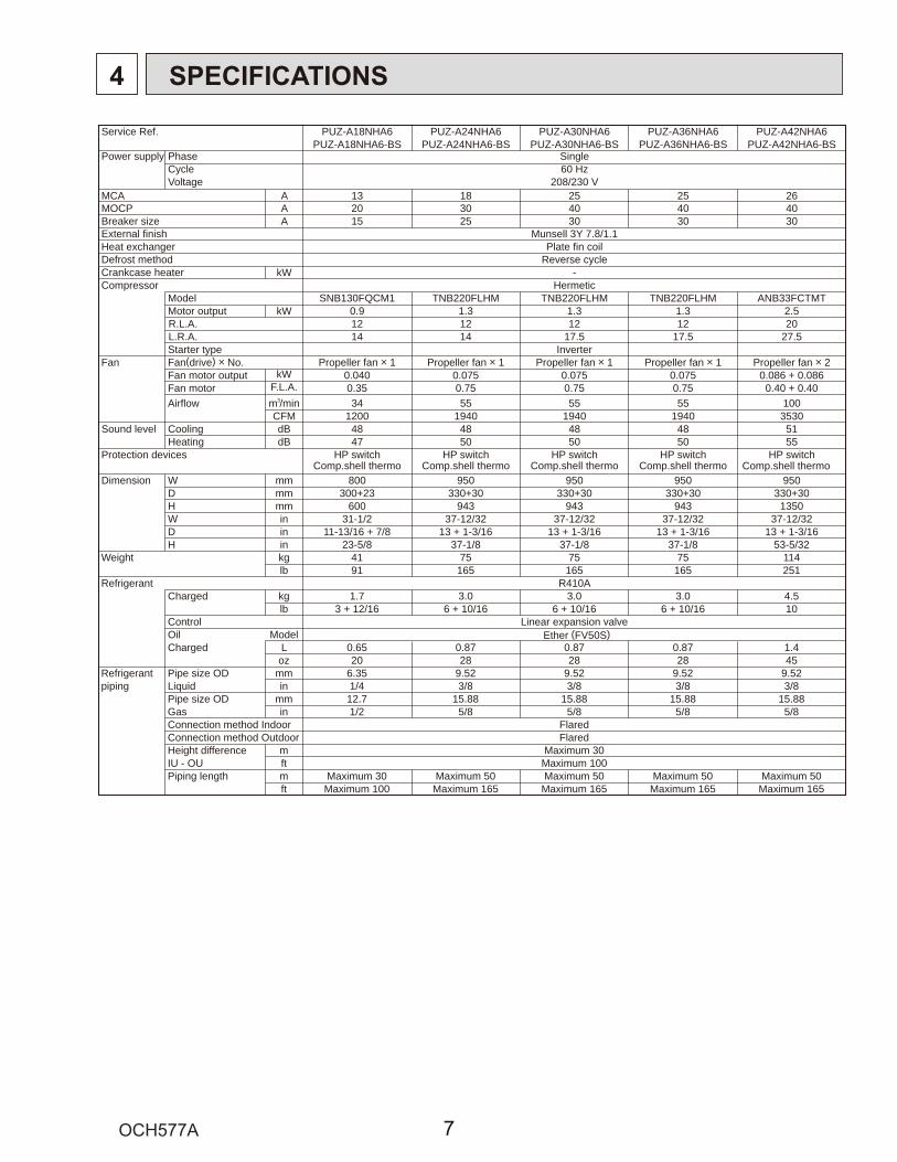
4 SPECIFICATIONS
Service Ref. PUZ-A18NHA6 PUZ-A24NHA6 PUZ-A30NHA6 PUZ-A36NHA6 PUZ-A42NHA6PUZ-A18NHA6-BS PUZ-A24NHA6-BS PUZ-A30NHA6-BS PUZ-A36NHA6-BS PUZ-A42NHA6-BS
Power supply Phase SingleCycle 60 HzVoltage 208/230 V
MCA A 13 18 25 25 26MOCP A 20 30 40 40 40Breaker size A 15 25 30 30 30External finish Munsell 3Y 7.8/1.1Heat exchanger Plate fin coilDefrost method Reverse cycleCrankcase heater kW -Compressor Hermetic
Model SNB130FQCM1 TNB220FLHM TNB220FLHM TNB220FLHM ANB33FCTMTMotor output kW 0.9 1.3 1.3 1.3 2.5R.L.A. 12 12 12 12 20L.R.A. 14 14 17.5 17.5 27.5Starter type Inverter
Fan Fan(drive) o No. Propeller fan o 1 Propeller fan o 1 Propeller fan o 1 Propeller fan o 1 Propeller fan o 2Fan motor output kW 0.040 0.075 0.075 0.075 0.086 + 0.086Fan motor F.L.A. 0.35 0.75 0.75 0.75 0.40 + 0.40Airflow m3/min 34 55 55 55 100
CFM 1200 1940 1940 1940 3530Sound level Cooling dB 48 48 48 48 51
Heating dB 47 50 50 50 55Protection devices HP switch HP switch HP switch HP switch HP switch
Comp.shell thermo Comp.shell thermo Comp.shell thermo Comp.shell thermoDimension W mm 800 950 950 950 950
D mm 300+23 330+30 330+30 330+30 330+30H mm 600 943 943 943 1350W in 31-1/2 37-12/32 37-12/32 37-12/32 37-12/32D in 11-13/16 + 7/8 13 + 1-3/16 13 + 1-3/16 13 + 1-3/16 13 + 1-3/16H in 23-5/8 37-1/8 37-1/8 37-1/8 53-5/32
Weight kg 41 75 75 75 114lb 91 165 165 165 251
Refrigerant R410ACharged kg 1.7 3.0 3.0 3.0 4.5
lb 3 + 12/16 6 + 10/16 6 + 10/16 6 + 10/16 10
Ether (FV50S)Control Linear expansion valveOil ModelCharged L 0.65 0.87 0.87 0.87 1.4
oz 20 28 28 28 45Refrigerant Pipe size OD mm 6.35 9.52 9.52 9.52 9.52piping Liquid in 1/4 3/8 3/8 3/8 3/8
Pipe size OD mm 12.7 15.88 15.88 15.88 15.88Gas in 1/2 5/8 5/8 5/8 5/8Connection method Indoor FlaredConnection method Outdoor FlaredHeight difference m Maximum 30IU - OU ft Maximum 100Piping length m Maximum 30 Maximum 50 Maximum 50 Maximum 50 Maximum 50
ft Maximum 100 Maximum 165 Maximum 165 Maximum 165 Maximum 165
Comp.shell thermo
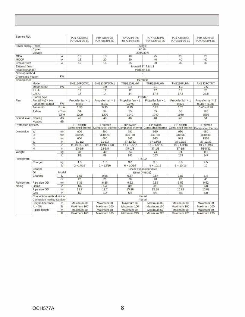
Service Ref. PUY-A12NHA6 PUY-A18NHA6 PUY-A24NHA6 PUY-A30NHA6 PUY-A36NHA6 PUY-A42NHA6PUY-A12NHA6-BS PUY-A18NHA6-BS PUY-A24NHA6-BS PUY-A30NHA6-BS PUY-A36NHA6-BS PUY-A42NHA6-BS
Power supply Phase SingleCycle 60 HzVoltage 208/230 V
MCA A 13 13 18 25 25 26MOCP A 15 20 30 40 40 40Breaker size A 15 15 25 30 30 30External finish Munsell 3Y 7.8/1.1Heat exchanger Plate fin coilDefrost method -Crankcase heater kW -Compressor Hermetic
Model SNB130FQCM1 SNB130FQCM1 TNB220FLHM TNB220FLHM TNB220FLHM ANB33FCTMTMotor output kW 0.9 0.9 1.3 1.3 1.3 2.5R.L.A. 12 12 12 12 12 20L.R.A. 14 14 14 17.5 17.5 27.5Starter type Inverter
Fan Fan (drive) o No. Propeller fan o 1 Propeller fan o 1 Propeller fan o 1 Propeller fan o 1 Propeller fan o 1 Propeller fan o 2Fan motor output kW 0.040 0.040 0.075 0.075 0.075 0.086 + 0.086Fan motor F.L.A. 0.35 0.35 0.75 0.75 0.75 0.40 + 0.40Airflow m3/min 34 34 55 55 55 100
CFM 1200 1200 1940 1940 1940 3530Sound level Cooling dB 46 48 48 48 48 51
Heating dB – – – – – –Protection devices HP switch HP switch HP switch HP switch HP switch HP switch
Comp.shell thermo Comp.shell thermo Comp.shell thermo Comp.shell thermo Comp.shell thermoDimension W mm 800 800 950 950 950 950
D mm 300+23 300+23 330+30 330+30 330+30 330+30H mm 600 600 943 943 943 1350W in 31-1/2 31-1/2 37-12/32 37-12/32 37-12/32 37-12/32D in 11-13/16 + 7/8 11-13/16 + 7/8 13 + 1-3/16 13 + 1-3/16 13 + 1-3/16 13 + 1-3/16H in 23-5/8 23-5/8 37-1/8 37-1/8 37-1/8 53-5/32
Weight kg 37 40 74 74 74 112lb 82 89 163 163 163 247
Refrigerant R410ACharged kg 1.3 1.7 3.0 3.0 3.0 4.5
lb 2 +14/16 3 + 12/16 6 + 10/16 6 + 10/16 6 + 10/16 10Control Linear expansion valveOil ModelCharged L 0.65 0.65 0.87 0.87 0.87 1.4
Ether (FV50S)
oz 20 20 28 28 28 45Refrigerant Pipe size OD mm 6.35 6.35 9.52 9.52 9.52 9.52piping Liquid in 1/4 1/4 3/8 3/8 3/8 3/8
Pipe size OD mm 12.7 12.7 15.88 15.88 15.88 15.88Gas in 1/2 1/2 5/8 5/8 5/8 5/8Connection method Indoor FlaredConnection method Outdoor FlaredHeight difference m Maximum 30 Maximum 30 Maximum 30 Maximum 30 Maximum 30 Maximum 30IU - OU ft Maximum 100 Maximum 100 Maximum 100 Maximum 100 Maximum 100 Maximum 100Piping length m Maximum 50 Maximum 50 Maximum 69 Maximum 69 Maximum 69 Maximum 69
ft Maximum 165 Maximum 165 Maximum 225 Maximum 225 Maximum 225 Maximum 225
Comp.shell thermo

PUZ-A42NHA6
Service Ref.PUZ-A42NHA6-BSPUY-A42NHA6PUY-A42NHA6-BS
Compressor model SNB130FQCM1 TNB220FLHM ANB33FCTMT
(" )Winding Resistance
U-V 0.640 0.880 0.302
U-W 0.640 0.880 0.302
W-V 0.640 0.880 0.302
(at 68°F [20°C] )
PUY-A12/18NHA6-BSPUY-A12/18NHA6PUZ-A18NHA6-BSPUZ-A18NHA6
PUY-A24/30/36NHA6-BSPUY-A24/30/36NHA6PUZ-A24/30/36NHA6-BSPUZ-A24/30/36NHA6
5-1. REFILLING REFRIGERANT CHARGE (R410A: oz, kg)
5-2. COMPRESSOR TECHNICAL DATA
5 DATA
– – – – – – –
– – – – – – –
– – – – – – –
– – – – – – –
– – – – – – – – – – – – – –
– – – – – – – – – – – – – –
– – – – – – –
– – – – – – –
– – – – – – –
– – – – – – –
– – – – – – –
– – – – – – –
– – – – – – –
– – – – – – –

5-3. NOISE CRITERION CURVES
5ft
3.3ftMICROPHONE
UNIT
GROUND
90
80
70
60
50
40
30
20
1063 125 250 500 1000 2000 4000 8000
APPROXIMATETHRESHOLD OFHEARING FORCONTINUOUSNOISE
NC-60
NC-50
NC-40
NC-30
NC-20
NC-70
OC
TAVE
BA
ND
SO
UN
D P
RES
SUR
E LE
VEL,
dB
(0 d
B =
0.0
002 μb
ar)
BAND CENTER FREQUENCIES, Hz
PUY-A18NHA6PUY-A18NHA6-BSPUZ-A18NHA6PUZ-A18NHA6-BS
COOLINGMODE
HEATING48
SPL(dB)
47
LINE
90
80
70
60
50
40
30
20
1063 125 250 500 1000 2000 4000 8000
APPROXIMATETHRESHOLD OFHEARING FORCONTINUOUSNOISE
NC-60
NC-50
NC-40
NC-30
NC-20
NC-70
OC
TAVE
BA
ND
SO
UN
D P
RES
SUR
E LE
VEL,
dB
(0 d
B =
0.0
002 μb
ar)
BAND CENTER FREQUENCIES, Hz
PUY-A24/30/36NHA6PUY-A24/30/36NHA6-BSPUZ-A24/30/36NHA6PUZ-A24/30/36NHA6-BS
COOLINGMODE
HEATING48
SPL(dB)
50
LINE
90
80
70
60
50
40
30
20
1063 125 250 500 1000 2000 4000 8000
APPROXIMATETHRESHOLD OFHEARING FORCONTINUOUSNOISE
OC
TAVE
BA
ND
SO
UN
D P
RES
SUR
E LE
VEL,
dB
(0 d
B =
0.0
002 μb
ar)
BAND CENTER FREQUENCIES, Hz
NC-60
NC-50
NC-40
NC-30
NC-20
NC-70
PUY-A42NHA6PUY-A42NHA6-BSPUZ-A42NHA6PUZ-A42NHA6-BS
COOLINGMODE
HEATING51
SPL(dB)
55
LINE
90
80
70
60
50
40
30
20
1063 125 250 500 1000 2000 4000 8000
APPROXIMATETHRESHOLD OFHEARING FORCONTINUOUSNOISE
NC-60
NC-50
NC-40
NC-30
NC-20
NC-70
OC
TAVE
BA
ND
SO
UN
D P
RES
SUR
E LE
VEL,
dB
(0 d
B =
0.0
002 μb
ar)
BAND CENTER FREQUENCIES, Hz
PUY-A12NHA6PUY-A12NHA6-BS
COOLINGMODE
46SPL(dB) LINE

5-4. STANDARD OPERATION DATA5-4-1. Heat pumpRepresentative matching PKA-A18HA6 PKA-A24KA6 PKA-A30KA6 PKA-A36KA6 PLA-A42BA6
Mode COOLING HEATING COOLING HEATING COOLING HEATING COOLING HEATING COOLING HEATING
Total Capacity BTU/h 18,000
2,240
19,000
1,970
24,000
2,270
26,000
2,330
30,000
4,130
32,000
3,150
34,200
5,030
37,000
3,610
42,000 45,000
Input W 4,600 4,450
Ele
ctric
al c
ircui
t
Indoor unit model PKA-A18HA6 PKA-A24KA6 PKA-A30KA6 PKA-A36KA6 PLA-A42BA6
Phase Single Single Single Single Single
Cycle 60 Hz 60 Hz 60 Hz 60 Hz 60 Hz
Voltage 230 V 230 V 230 V 230 V 230 V
Current 0.33 A 0.36 A 0.36 A 0.57 A 1.00 A 0.94 A
Outdoor unit model PUZ-A18NHA6 PUZ-A24NHA6 PUZ-A30NHA6 PUZ-A36NHA6 PUZ-A42NHA6
Phase Single Single Single Single Single
Cycle 60 Hz 60 Hz 60 Hz 60 Hz 60 Hz
Voltage 230 V 230 V 230 V 230 V 230 V
Current 9.8 A
3.01
0.77
80.1
49.9
3.8
7.6
437
112
176
122
39
8.8 A
3.03
0.64
83.7
50.8
-1.1
7.6
439
93
183
123
34
9.4 A
2.78
0.92
73.9
46.9
12.1
7.6
403
133
165
116
54
10.4 A
2.89
0.68
77.9
48.5
0.4
7.6
419
99
172
119
33
18.1 A
3.08
0.77
81.2
50.8
3.3
7.6
447
117
178
123
38
14.0 A
3.04
0.64
81.4
50.8
-1.5
7.6
441
93
179
123
29
21.7 A
3.23
0.74
88.1
52.8
2.3
7.6
468
107
191
127
36
15.6 A
2.95
0.63
80.7
49.3
-2.0
7.6
428
91
177
121
28
Ref
riger
ant c
ircui
t
Discharge pressure MPa
Suction pressure MPa
Discharge temperature :
Condensing temperature :
Suction temperature :
Ref. Pipe length m
20.4 A
2.83
0.82
73.4
47.5
4.9
7.6
410
120
164
118
40
21.5 A
2.93
0.69
80.3
47.5
0.3
7.6
425
100
177
118
33
Discharge pressure PSIG
Suction pressure PSIG
Discharge temperature °F
Condensing temperature °F
Suction temperature °F
Ref. Pipe length ft 25 25 25 25 25 25 25 25 25 25
sideIndoor
Intake air temperature DB : 26.7 21.1 26.7 21.1 26.7 21.1 26.7 21.1 26.7 21.1
Intake air temperature WB : 19.4
11.3
15.6
45.4
19.4
14.1
15.6
39.2
19.4
12.3
15.6
43.4
19.4
12.3
15.6
42.9
19.4 15.6
Discharge air temperature DB : 12.9 41.9
sideOutdoor Intake air temperature DB : 35 8.3 35 8.3 35 8.3 35 8.3 35 8.3
Intake air temperature WB : 23.9 6.1 23.9 6.1 23.9 6.1 23.9 6.1 23.9 6.1
sideIndoor
Intake air temperature DB °F 80
67
52
70
60
114
80
67
57
70
60
103
80
67
54
70
60
110
80
67
54
70
60
109
80 70
Intake air temperature WB °F 67 60
Discharge air temperature DB °F 55 107
sideOutdoor Intake air temperature DB °F 95 47 95 47 95 47 95 47 95 47
Intake air temperature WB °F 75
0.68
0.08
43 75
0.77
0.09
43 75
0.70
0.09
43 75
0.70
0.09
43 75 43
SHF 0.71
BF
–
–
–
–
–
–
–
–
–
– 0.15
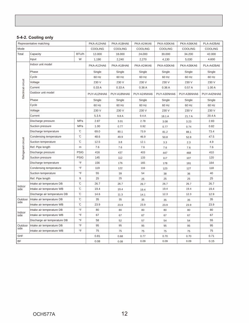
Representative matching PKA-A12HA6 PKA-A18HA6 PKA-A24KA6 PKA-A30KA6 PKA-A36KA6 PLA-A42BA6
Mode COOLING COOLING COOLING COOLING COOLING COOLING
Total Capacity BTU/h 12,000
1,190
18,000
2,240
24,000
2,270
30,000
4,130
34,200
5,030
42,000
Input W 4,600
Ele
ctric
al c
ircui
t
Indoor unit model PKA-A12HA6 PKA-A18HA6 PKA-A24KA6 PKA-A30KA6 PKA-A36KA6 PLA-A42BA6
Phase Single Single Single Single Single Single
Cycle 60 Hz 60 Hz 60 Hz 60 Hz 60 Hz 60 Hz
Voltage 230 V 230 V 230 V 230 V 230 V 230 V
Current 0.33 A 0.33 A 0.36 A 0.36 A 0.57 A 1.00 A
Outdoor unit model PUY-A12NHA6 PUY-A18NHA6 PUY-A24NHA6 PUY-A30NHA6 PUY-A36NHA6 PUY-A42NHA6
Phase Single Single Single Single Single Single
Cycle 60 Hz 60 Hz 60 Hz 60 Hz 60 Hz 60 Hz
Voltage 230 V 230 V 230 V 230 V 230 V 230 V
Current 5.3 A
2.87
1.00
69.0
48.6
12.5
7.6
416
145
156
119
55
20.4 A
Ref
riger
ant c
ircui
t
Discharge pressure MPa
Suction pressure MPa
Discharge temperature :
Condensing temperature :
Suction temperature :
Ref. Pipe length m
2.83
0.82
73.4
47.5
4.9
7.6
410
120
164
118
40
Discharge pressure PSIG
Suction pressure PSIG
Discharge temperature °F
Condensing temperature °F
Suction temperature °F
Ref. Pipe length ft 25 25
sideIndoor
Intake air temperature DB : 26.7 26.7
Intake air temperature WB : 19.4
14.6
19.4
12.9Discharge air temperature DB :
sideOutdoor Intake air temperature DB : 35 35
Intake air temperature WB : 23.9 23.9
sideIndoor
Intake air temperature DB °F 80 80
Intake air temperature WB °F 67
58
67
55Discharge air temperature DB °F
sideOutdoor Intake air temperature DB °F 95 95
Intake air temperature WB °F 75
0.81
0.08
75
SHF 0.71
BF 0.15
9.8 A
3.01
0.77
80.1
49.9
3.8
7.6
437
112
176
122
39
25
26.7
19.4
11.3
35
23.9
80
67
52
95
75
0.68
0.08
9.4 A
2.78
0.92
73.9
46.9
12.1
7.6
403
133
165
116
54
25
26.7
19.4
14.1
35
23.9
80
67
57
95
75
0.77
0.09
18.1 A
3.08
0.77
81.2
50.8
3.3
7.6
447
117
178
123
38
21.7 A
3.23
0.74
88.1
52.8
2.3
7.6
468
107
191
127
36
25 25
26.7 26.7
19.4
12.3
19.4
12.3
35 35
23.9 23.9
80
67
54
80
67
54
95 95
75
0.70
0.09
75
0.70
0.09
5-4-2. Cooling only

PUZ-A18NHA6 PUZ-A18NHA6-BS PUY-A12/18NHA6 PUY-A12/18NHA6-BS
6 OUTLINES AND DIMENSIONS
1/2 conduit hole
144<5-21/32>
2- 22.2<7/8>
22<7/8>
38<1
-1/2
>24
1<9-
1/2>
Min.100mm<3-15/16>
Piping and wiring connection canbe made from the rear direction only.
*1 In the place where short cycle tends to occur, cooling and heating capacity and power consumption might get lowered 10%. Air outlet guide (optional PAC-SG58SG-E) will help them improve. *2 If air discharges to the wall, the surface might get stained.
2 sides should be open inthe right, left and rear side.
Min.100mm<3-15/16> as long as no obstacle is placed on therear and light-and-left sidesof the unit
*1*2 *1
Air intake
Air discharge4-oval hole
Air intake
Service panel
Connection for liquid pipe
Service panel for charge plug
Service port
Connection for gas pipe
Min.100mm<3-15/16>
Min.500mm<19-11/16>
Min.350mm<13-25/32>
Basi
cally
open
Max
.
<Foundation bolt height>
FOUNDATION
Please secure the unit firmlywith 4 foundation M10<W3/8> bolts.(Bolts, washers and nut must be purchased locally.)
18m
m<2
3/32
>
33<1-5/16> drain hole43
.6<1
-23/
32>
152<
6>
155
400<15-25/32>
347.5<13-11/16>
45.4<1-25/32>
365<
14-3
/8>
330<
13>
300<
11-1
3/16
>
40<1-9/16>
Handle
600<
23-5
/8>
10<3
/8>
300<
11-1
3/16
>
150<5-29/32>287.5<11-11/32>
500<19-11/16>
800<31-1/2>
69<2-23/32>
183<7-7/32>
90<3
-17/
32>
155<
6-3/
32>
23<29/32>
32.5
<1-9
/32>
18<23/32>
FLARE 12.7<1/2>
FLARE 6.35<1/4>
Installation bolt pitch
PIPING-WIRING DIRECTION
Minimum installation space for outdoor unit
Free space around the outdoor unit(basic example)
FOUNDATION BOLTS
Unit: mm<in>

PUZ-A24/30/36NHA6 PUZ-A24/30/36NHA6-BS PUY-A24/30/36NHA6 PUY-A24/30/36NHA6-BS
Min.
10mm
<3
/8>Mi
n. 10
mm<3
/8>
Min.
100m
m<3
-15/16
>Mi
n. 50
0mm
<19-1
1/16>
Min. 100mm<3-15/16>
Min. 500mm<191/16>
Max.300mm<1-3/16>
Min
.10
mm
<3/8
>
Min.
500m
m<1
9-11
/16>
Serv
ice s
pace
FOUN
DATIO
N
<Fou
ndati
on bo
lt heig
ht>
FREE
Whe
n ins
tallin
g th
e co
nduit
,Se
t the
atta
chm
ent t
o th
e inn
er si
de o
f eac
h pa
nel.
1/2 C
ondu
it atta
chme
nt2-
22.2<
7/8>
40<1
-9/1
6>
31<1-7/32>
74<2
-19/
32>
330 <13>
175 <
6-7/8>
600
<23-
5/8>
175 <
6-7/8>
53 <2-3/32>
28 <1-3/32>370 <14-9/16>19 <3/4>
56 <2-7/32>
45 <1-25/32>
42 <
1-21
/32>
66 <
2-5/8
>
417 <16-13/32>
2-U
Shap
ed n
otch
ed h
ole(F
ound
fatio
n Bo
lt M10
<W3/
8>)
Side
Air
Inta
ke
Rear
Air
Inta
ke
Air D
ischa
rge
2-12
36 O
val h
ole
(Fou
ndat
ion
Bolt
M10
<W3/
8>)
30 <1-3/16>
Side
Air
Inta
ke
Hand
le
Rear
pip
ing
cove
r
Fron
t pip
ing
cove
r
81<3-3/16>219 <8-5/8>
30 <
1-3/
16>
71 <2-13/16>
71 <
2-13
/16>
Botto
m p
ipin
g ho
le(K
nock
out)
Drain
hole
(5-
33<1
-5/1
6>)
Hand
le
Hand
le
Rear
Air
Inta
ke
Air I
ntak
e
670 <26-3/8>
*1 443<17-7/16>
*1 447<17-19/32>
322
<12-
11/1
6>950
<37-
13/3
2>
473 <18-5/8>943 <37-1/8>
23<29/32>
21
Hand
le
Hand
le
Serv
ice p
anel
Earth
term
inal
Left·
··Pow
er su
pply
wirin
gRi
ght··
·Indo
or/O
utdo
or w
iring
Term
inal B
lock
Cond
uit ho
le (2-
27<1
-1/16
>Kno
ckout)
Right
trunki
ng ho
le(Kn
ockou
t)Rig
ht pip
ing ho
le(K
nock
out)
65<2
-9/16
>92
<3-5/
8>
40 <1
-9/16
>45
<1-25
/32>
19<3
/4>
27<1-1/16>
23<29/32>
23<29/32>
73<2-7/8>
Cond
uit ho
le (2
-27
<1-1
/16>K
nock
out)
Fron
t tru
nking
hole
(Kno
ckou
t)
Fron
t pipi
ng h
ole(K
nock
out)
92 <3-5/
8>
Cond
uit ho
le (2-
27<1
-1/16
>Kno
ckout)
Rear
trunki
ng ho
le(Kn
ockou
t)
Rear
piping
hole
(Knock
out)
220
<8-2
1/32
>14
5<5
-23/32
>14
5<5
-23/32
>14
5<5
-23/32
>
55<2-3/16>63<2-1/2>
63<2-1/2>
75<2
-31/3
2>40
<1-9
/16>
45<1
-25/3
2>40
<1-9/
16>
23<29/32>73<2-7/8>63<2-1/2>
55<2-3/16> 27<1-1/16>
92<3
-5/8>
92<3
-5/8>
73<2-7/8>
27<1-1/16>92<3-5/8>
92<3
-5/8
>65
<2-9
/16>
95<3
-5/8>
55<2
-3/1
6>
Pipin
g an
d wi
ring
conn
ectio
nsca
n be
mad
e fro
m 4
dire
ction
s:fro
nt, r
ight,
rear
and
belo
w.
Dim
ensio
ns o
f spa
ce n
eede
dfo
r ser
vice
acce
ss a
resh
own
in th
e be
low d
iagra
m.
Plea
se se
cure
the
unit f
irmly
with
4 fo
unda
tion
(M10
<W3/
8>)
bolts
. (Bo
lts a
nd w
ashe
rs m
ust
be p
urch
ased
loca
lly.)
The
diagr
am b
elow
show
s aba
sic e
xam
ple.
Expla
natio
n of
par
ticula
r det
ails a
regiv
en in
the
insta
llatio
n m
anua
ls et
c.
····R
efrig
eran
t GAS
pipe
conn
ectio
n (F
LARE
)15
.88<
5/8>
····R
efrig
eran
t LIQ
UID
pipe
conn
ectio
n (F
LARE
) 9
.52<
3/8>
*1 ··
··Ind
icatio
n of
STO
P VA
LVE
conn
ectio
n loc
ation
.
Exam
ple o
f Not
es
Pipin
g Kn
ocko
ut H
ole D
etail
s
1 FRE
E SP
ACE
(Arou
nd th
e unit
)2 S
ERVIC
E SPA
CE3 F
OUND
ATIO
N BO
LTS
4 PIPI
NG-W
IRIN
G DI
RECT
IONS
Unit: mm<in>

PUZ-A42NHA6 PUZ-A42NHA6-BS PUY-A42NHA6 PUY-A42NHA6-BS
Min
. 100
0mm
<39-
3/8>
Min
. 150
mm
<5-2
9/32
>
Min
. 10m
m<3
/8>
Min
. 10m
m<3
/8>
FRE
E
<Fou
ndat
ion
bolt
heig
ht>
FOUN
DATI
ON
Ser
vice
spa
ce
Term
inal
Blo
ckLe
ft···P
ower
sup
ply
wirin
gRi
ght··
··Ind
oor/O
utdo
or w
iring
Ear
th te
rmin
al
Ser
vice
pan
el
Han
dle
1 2
23<29/32>
1076<42-3/8>* 1 447<17-19/32>
* 1 443<17-7/16>
Han
dle
Fron
t pip
ing
cove
r
Rea
r pip
ing
cove
r
Air
Dis
char
ge
Rea
r Air
Inta
ke
Sid
e A
ir In
take
31<1-7/32>
145
<5-23
/32>
145
<5-23
/32>
220
<8-2
1/32
>30
<1-3
/16>
145
<5-23
/32>
81<3-3/16>219<8-5/8>
71<2-13/16>
71<2
-13/
16>
Bot
tom
pip
ing
hole
(Kno
ckou
t)
Dra
in h
ole
5-33
<1-5
/16>
Han
dle
Sid
e A
ir In
take
Air
inta
ke
Rea
r Air
Inta
ke
Han
dle
Han
dle
40<1
-9/1
6>
74<2
-19/
32>
Whe
n in
stal
ling
the
cond
uit.
Set
the
atta
chm
ent t
o th
e in
ner s
ide
of e
ach
pane
l.
2-22
.2<7
/8>
1/2
Con
duit
atta
chm
ent
45<1
-25/3
2>40
<1-9
/16>
65<2
-9/1
6>92
<3-5
/8>
27<1-1/16>55<2-3/16>
23<29/32>73<2-7/8>63<2-1/2>
Rea
r pip
ing
hole
(Kno
ckou
t)
Rea
r tru
nkin
g ho
le(K
nock
out)
Cond
uit ho
le (2-
27<1
-1/16
>Kno
ckou
t)
92<3
-5/8
>19
<3/4>
55<2
-3/1
6>92
<3-5
/8>
75<2
-31/
32>
40<1
-9/1
6>
73<2-7/8>63<2-1/2>
23<29/32>27<1-1/16>92<3-5/8>R
ight
pip
ing
hole
(Kno
ckou
t)R
ight
trun
king
hol
e(K
nock
out)
Con
duit
hole
(2
-27
<1-1
/16>
Kno
ckou
t)
92<3
-5/8
>
92<3
-5/8
>65
<2-9
/16>
45<1
-25/
32>
40<1
-9/1
6>
27<1-1/16>55<2-3/16>
23<29/32>73<2-7/8>
63<2-1/2>
Fron
t pip
ing
hole
(Kno
ckou
t)
Fron
t tru
nkin
g ho
le(K
nock
out)
Con
duit
hole
(2
-27
<1-1
/16>
Kno
ckou
t)
92
<3-5
/8>
371<14-19/32>
330<13> 30<1-3/16>175<
6-7/
8>60
0<23
-5/8
>17
5<6-
7/8> 42
<1-2
1/32
>66
<2-5
/8>
950<
37-1
3/32
>32
2<12
-11/
16>
1350<53-5/32>
635<25>
19<3/4>417<16-13/32>
370<14-9/16>
2-U
Sha
ped
notc
hed
hole
(Fou
ndat
ion
Bol
t M10
<W3/
8>)
56<2-7/32>28<1-3/32>53<2-3/32>
45<1-25/32>
2-12
36 O
val h
ole
(Fou
ndat
ion
Bol
t M10
<W3/
8>)
····R
efrig
eran
t GAS
pipe
conn
ectio
n (F
LARE
)15
.88<
5/8>
····R
efrig
eran
t LIQ
UID
pipe
conn
ectio
n (F
LARE
) 9
.52<
3/8>
*1 ··
··Ind
icatio
n of
STO
P VA
LVE
conn
ectio
n loc
ation
.
Exam
ple
of N
otes
1 FRE
E SPA
CE (A
round
the u
nit)
2 SE
RVIC
E SP
ACE
3 FOU
NDAT
ION
BOLT
S4 P
IPING
-WIR
ING
DIRE
CTIO
NS
Pipi
ng K
nock
out H
ole
Deta
ils
The
diag
ram
bel
ow s
hows
aba
sic e
xam
ple.
Expl
anat
ion
of p
artic
ular
det
ails
are
give
n in
the
inst
alla
tion
man
uals
etc.
Dim
ensio
ns o
f spa
ce n
eede
dfo
r ser
vice
acce
ss a
resh
own
in th
e be
low
diag
ram
.
Plea
se s
ecur
e th
e un
it fir
mly
with
4 fo
unda
tion
(M10
<W3/
8>)
bolts
. (Bo
lts a
nd w
ashe
rs m
ust
be p
urch
ased
loca
lly.)
Pip
ing
and
wiri
ng c
onne
ctio
nsca
n be
mad
e fro
m 4
dire
ctio
ns:
front
, rig
ht, r
ear a
nd b
elow
.
Min
.10
mm
<3/8
>
Min.500mm<19-11/16>
Min.
500m
m<1
9-11
/16>
Min.150mm<5-29/32>
Min.30mm<1-3/16>
Unit: mm<in>

7 WIRING DIAGRAM
1 2 3 4 5 6OFFON
PUZ-A18NHA6
MODEL SW6
1 MODEL SELECT
SW5-5.6
1 2 3 4 5 6OFFONPUY-A12NHA6
PUY-A18NHA61 2 3 4 5 6
7 8
7 8
7 8OFFON
1 2 3 4 5 6OFFON
1 2 3 4 5 6OFFON
1 2 3 4 5 6OFFON
2. SW5-1 to 4 : Function switch
is the switch position
TB1MCMF121S463HTH3
TH32
TH6TH7TH8
LEV-A
CY1,CY2
Terminal Block<Power Supply, Indoor/Outdoor>Motor for CompressorFan Motor Solenoid Valve (Four-Way Valve)High Pressure Switch
Thermistor<Comp. Surface>
Thermistor<2-Phase Pipe>
Thermistor<Heat Sink>
TH33 Thermistor<Suction>
CapacitorACL Reactor
Power Circuit Board
Connection Terminal<U/V/W-Phase>
P.B.
TABU/V/W
Noise Filter Circuit BoardConnection Terminal<L1-Phase>
Connection Terminal<Ground>
N.F.LI/LO
Connection Terminal<L2-Phase>NI/NOEI,E2,E3
Fuse<T6.3AL250V>
Controller Circuit BoardSwitch<Manual Defrost, Defect History, Record Reset, Refrigerant Address>Switch<Test Operation>Switch<Model Select, Function Switch>
Switch<Function Switch>
Switch<Pump Down>Connector<Emergency Operation>
SW1
SW4SW5
SW7Switch<Function Switch>Switch<Function Switch>
SW8
SWPCN31
CNM
CNVMNT
CNDM
Connector<Connected to Optional M-NET Adapter Board>
C.B.
ConverterPFCPower ModuleIPMMain Smoothing CapacitorCB1,CB2,CB3
52C Relay52C
SYMBOL NAME SYMBOL NAME SYMBOL NAME
Connection Terminal<L1/L2-Phase>TABR/S
Connector<Connection for Option>Connector<Connection for Option>
SS
CNMNT Connector<Connected to Optional M-NET Adapter Board>
CN51
Switch<Model Select>SW6
SW9
X51,X52,X55 Relay
LED1,LED2 LED<Operation Inspection Indicators>
Thermistor<Liquid>
Thermistor<Ambient>
Linear Expansion Valve
F1,F2,F3,F4
Connector<Connection for Option>Connector<Connection for Option>
SYMBOLM-NET ADAPTER
NAMETB7CN5CNDCN2M
Terminal Block <M-NET connection>Connector <Transmission>Connector <Power Supply>Connector <M-NET communication>
[LEGEND]
P. B.
C. B.
CNF1(WHT)7
1
MF1MS3~
TRANS
CNDC(PNK)
3
1
TH7/6(RED)
63H(YLW)
TH3(WHT)
TH32(BLK)
TH7 TH6 TH3TH32
41 2121
31
t° t° t°t°
TH33(YLW)
TH33
31
t°
63H
LEV-A(WHT)
LEV-A
M
LED
1
LED
2
61CNVMNT(WHT)
31CN
DM(W
HT)
CN51
(WHT
)
31
5
1
CNMNT(WHT)
CNM(WHT)
51
35
SW7
SW6
SW1
SW9
CN31
1
SW5
SW8
SW4
SWP
14
X51
CNS(WHT)
CNAC(WHT)
SS(WHT)
21S4(GRN)
X52
F1
F2
F4
F3
21
43
21S4
3 1
13 SV2(BLU)
X55
13 13
CN4(WHT)
1 2
2
CN52C(RED)
2
2
1CN2
(WHT)71
5
CN5(WHT)
3 1
TB7
2
1CND
(WHT)
CN2M(WHT)
M-NET
A B S
When M-NET adapter is connected
5
3
5
1
WHT
LI EI NI
LO NO
E2E3
N. F.
2
21
3
1
1
3
2
12
CN5
(RED
)
CNAC
1(W
HT)
CNAC
2(R
ED)
CN52
C(B
LK)
52C
RED
POWER SUPPLY208 / 230V 60Hz
INDOORUNIT
TB1L1 L2 GR S1 S2 S3
RED
BLU
YLW
GRN
ORN
BRN
CY2CY1
CB1 CB2 CB3
TABUTABV
TH8
IPM
TABW
TABR
TABS
CN3(WHT)
CN2(WHT)
CN4(WHT)
CN5(RED)
1
7
12
12
12
2
2
5
t°WHTRED
PFC
RED
WHT
RED
WHT
ACL
MS3~
BLK
WHT
RED
UVW
MC
PUZ only
M-NET ADAPTER
Use copper supply wires.Utilisez des fils d'alimentation en cuivre.
PUZ-A18NHA6 PUZ-A18NHA6-BS PUY-A12/18NHA6 PUY-A12/18NHA6-BS

PUZ-A24NHA6 PUZ-A24NHA6-BS PUY-A24NHA6 PUY-A24NHA6-BS
1 2 3 4 5 6OFFON
PUZ-A24NHA6
MODEL SW6
1 MODEL SELECT
SW5-5.6
1 2 3 4 5 6OFFONPUY-A24NHA6
7 8
7 8
1 2 3 4 5 6OFFON
1 2 3 4 5 6OFFON
2. SW5-1 to 4 : Function switch
is the switch position
SYMBOLM-NET ADAPTER
NAMETB7CN5CNDCN2M
Terminal Block<M-NET connection>Connector<Transmission>Connector<Power Supply>Connector<M-NET communication>
TB1MCMF121S463H
TH3
TH32
TH6TH7TH8
LEV-AACL
Terminal Block<Power Supply, Indoor/Outdoor>Motor for CompressorFan Motor Solenoid Valve (Four-Way Valve)High Pressure Switch
SV Solenoid Valve (Bypass Valve)
Thermistor<Comp. Surface>
Thermistor<2-Phase Pipe>
Thermistor<Heat sink>
TH33 Thermistor<Suction>
Reactor
Power Circuit Board
Connection Terminal<U/V/W-Phase>
P.B.
TABU/V/W
Noise Filter Circuit BoardConnection Terminal<L1-Phase>
Connection Terminal<Ground>
N.F.LI/LO
Connection Terminal<L2-Phase>NI/NOEI,E2,E3
Fuse<T6.3AL250V>
Controller Circuit BoardSwitch<Manual Defrost, Defect History, Record Reset, Refrigerant Address>Switch<Test Operation>Switch<Model Select, Function Switch>
Switch<Function Switch>
Switch<Pump Down>Connector<Emergency Operation>
F1,F2,F3,F4
SW1
SW4SW5
SW7Switch<Function Switch>SW8
SWPCN31
CNM
CNVMNT
CNDM
LED1,LED2 LED<Operation Inspection Indicators>
Connector<Connected to Optional M-NET Adapter Board>
C.B.
ConverterPFC
52C Relay52C
SYMBOL NAME SYMBOL NAME SYMBOL NAME
Connection Terminal<L1/L2-Phase>TABR/S
CNMNT Connector<Connected to Optional M-NET Adapter Board>
Switch<Model Select>SW6
Switch<Function Switch>SW9
X51,X52,X55 Relay
Power ModuleIPMMain Smoothing CapacitorCB1,CB2,CB3
CY1,CY2 Capacitor
Connector<Connection for Option>Connector<Connection for Option>
SS
CN51
Thermistor<Liquid>
Thermistor<Ambient>
Linear Expansion ValveConnector<Connection for Option>Connector<Connection for Option>
P. B.
C. B.
TRANS
CNDC(PNK)
3
1
TH7/6(RED)
63H(YLW)
TH3(WHT)
TH32(BLK)
TH7 TH6 TH3TH32
41 2121
31
t° t° t°t°
TH33(YLW)
TH33
31
t°
63H
LEV-A(WHT)
LEV-AM
LED
1
LED
2
61CNVMNT(WHT)
31
CNDM
(WHT
)CN
51(W
HT)
31
5
1
CNMNT(WHT)
CNM(WHT)
51
35
SW7
SW6
SW1 SW
9CN31
1
SW5
SW8
SW4
SWP
14
X51
CNS(WHT)
CNAC(WHT)
SS(WHT)
21S4(GRN)
X52
F1
F2
F4
F3
21
43
21S4
3 1
13 SV2(BLU)
X55
SV
13 13
CN4(WHT)
1 2
2
CN52C(RED)
2
2
1CN2
(WHT)71
5
CN5(WHT)
3 1
TB7
2
1CND
(WHT)
CN2M(WHT)
M-NET
A B S
When M-NET adapter is connected
5
3
5
1
WHT
LI EINI
LO NO
E2E3
N. F.
2
21
3
1
1
3
2
12
CN5
(RED
)
CNAC
1(W
HT)
CNAC
2(R
ED)
CN52
C(B
LK)
52C
RED
POWER SUPPLY208 / 230V 60Hz
INDOORUNIT
TB1S1 S2 S3
RED
BLU
YLW
GRN
ORN
BRN
CY2CY1
CB1 CB2 CB3
TABU
TABVTH8
IPM
TABW
TABR
TABS
CN3(WHT)
CN2(WHT)
CN4(WHT)
CN5(RED)
1
7
12
12
12
2
2
5
t°WHTRED
PFC
RED
WHT
RED
WHT
ACL
MS3~
BLK
WHT
RED
UVW
MC
PUZ only
L1 L2 GR
M-NET ADAPTERCNF1(WHT)7
1
MF1MS3~
Utilisez des fils d'alimentation en cuivre.Use copper supply wires.
[LEGEND]

PUZ-A30/36NHA6 PUZ-A30/36NHA6-BS PUY-A30/36NHA6 PUY-A30/36NHA6-BS
1 2 3 4 5 6OFFON
PUZ-A30NHA6
PUZ-A36NHA6
MODEL SW6
1 MODEL SELECT
SW5-5.6
1 2 3 4 5 6OFFON
1 2 3 4 5 6OFFONPUY-A30NHA6
PUY-A36NHA61 2 3 4 5 6
7 8
7 8
7 8
7 8OFFON
1 2 3 4 5 6OFFON
1 2 3 4 5 6OFFON
1 2 3 4 5 6OFFON
1 2 3 4 5 6OFFON
2. SW5-1 to 4 : Function switch
is the switch position
TB1MCMF121S4
63HTH3
TH32
TH6TH7TH8
LEV-ADCL
52C
Terminal Block<Power Supply, Indoor/Outdoor >Motor for CompressorFan MotorSolenoid Valve (Four-Way Valve)
High Pressure SwitchSV Solenoid Valve (Bypass Valve)
Thermistor<Comp. Surface>TH33 Thermistor<Suction>
Thermistor<2-Phase Pipe>Thermistor<Ambient>Thermistor<Heat Sink>
Reactor
52C Relay
ACTM Active Filter Module
Power Circuit BoardConnection Terminal<U/V/W-Phase>
Diode Bridge
P.B.TABU/V/W
Noise Filter Circuit BoardConnection Lead<L1-Phase>
Connection Terminal<Ground>
N.F.LI/LO
Connection Lead<L2-Phase>NI/NOEI, E2
Controller Circuit Board
Switch<Pump Down>Connector<Emergency Operation>
SW8
SWPCN31
C.B.
DS2, DS3Power ModuleIPM
SYMBOL NAME SYMBOL NAME SYMBOL NAME
Connection Terminal<L1/L2-Phase>Connection Terminal<DC Voltage>
TABS/TTABP1/P2
Connection Terminal<DC Voltage>TABN1/N2SW9
Fuse<T6.3AL250V>
Switch<Model Select>
SW1
SW6SW7
LED1,LED2 LED<Operation Inspection Indicators>
CNMCNMNTCNVMNTCNDM
Connector<Connected to Optional M-NET Adapter Board>Connector<Connected to Optional M-NET Adapter Board>
X51,X52,X55 RelayCY1, CY2 Capacitor
Switch<Test Operation>Switch<Model Select, Function Switch>
SW4SW5
Connector<Connection for Option>Connector<Connection for Option>
Connector<Connection for Option>Connector<Connection for Option>
SS
CN51
Thermistor<Liquid>
Linear Expansion Valve
Switch<Manual Defrost, Defect History, Record Reset, Refrigerant Address>
F1,F2,F3,F4
Switch<Function Switch>Switch<Function Switch>
Switch<Function Switch>
SYMBOLM-NET ADAPTER
NAMETB7CN5CNDCN2M
Terminal Block<M-net connection>Connector<Transmission>Connector<Power Supply>Connector<M-NET communication>
[LEGEND]
TRANS
CNDC(PNK)
32
1
TH7/6(RED)
63H(YLW)
TH3(WHT)
TH32(BLK)
TH7TH6 TH3TH32
41 2121
31
t° t° t°t°
TH33(YLW)
TH33
31
t°
63H
LEV-A(WHT)
LEV-AM
LED1
LED
2
61CNVMNT
(WHT)
31
CNDM
(WHT
)CN
51(W
HT)
WHT
WHT
WHT
WHT
31
5
1
CNMNT(WHT)
CNM(WHT)
51
3 5
SW7
SW6
SW1 SW
9
CN31
1
SW5
SW8
SW4S
WP
14
X51CNS
(WHT)
CNAC(WHT)
SS(WHT)
21S4(GRN)
X52
F1
F2
F4
F3
21
43
21S4
3 113 SV2
(BLU)
X55
SV
13 13
CN4(WHT)1 2
2
CN52C(RED)
2
2
1CN2
(WHT)71
7
CN5(WHT)
3 1
TB7
2
1 CND(WHT)
CN2M(WHT)
M-NET
A B S
When M-NET adapter is connected
5
3
5
1
PUZ only
P. B.
21
37
1
121212
7
6
2
2
CNDC(PNK)
DS2
DS3
TABNTABP
IPM
TABP
2
TABV
TABW TA
BN2
TABN
1
TABS
TABP1
TABT
TABU
MS3~
U V W
MC
CN2(WHT)
4 1
CNAF(WHT)
CN4(WHT)
CN5(RED)
CN3(WHT)
TH8
t°
DCL
ACTM
L1
LO
52C
NO
LI NI
CN5
(RED
)
L2
N2
Io
N1P
4
1 6
CNAC
2(R
ED)
CN52
C(B
LK)
CNAC
1(W
HT)
2
2
1
3
E2
EI
1
21
2
3
1
N. F.
POWER SUPPLY208 / 230V 60Hz
INDOORUNIT
TB1S1 S2 S3
RED
BLU
BLU
BLK
BLK
GRN
ORNYLW
BRN
L1 L2 GR
WHT
REDRED
RED
RED
BLU
WHT
RED
BLK
BLK
CY2CY1
M-NET ADAPTER
Use copper supply wires.
C. B.
CNF1(WHT)7
1
MF1MS3~
Utilisez des fils d'alimentation en cuivre.

PUZ-A42NHA6 PUZ-A42NHA6-BS PUY-A42NHA6 PUY-A42NHA6-BS
1 2 3 4 5 6OFFON
PUZ-A42NHA6
MODEL SW6
1 MODEL SELECT
SW5-5.6
1 2 3 4 5 6OFFONPUY-A42NHA6
7 8
7 8
1 2 3 4 5 6OFFON
1 2 3 4 5 6OFFON
2. SW5-1 to 4 : Function switch
is the switch position
TB1MCMF1,MF221S463HTH3TH6TH7TH8
LEV-ADCL
Terminal Block<Power Supply, Indoor/Outdoor >Motor for CompressorFan Motor Solenoid Valve (Four-Way Valve)High Pressure SwitchThermistor<Liquid>Thermistor<2-Phase Pipe>Thermistor<Ambient>Thermistor<Heat Sink>
Linear Expansion ValveReactor
ACTM Active Filter ModuleCB Main Smoothing Capacitor
Power Circuit BoardConnection Terminal<U/V/W-Phase>
Diode Bridge
P.B.TABU/V/W
Noise Filter Circuit BoardConnection Lead<L1-Phase>
Connection Terminal<Ground>
N.F.LI/LO
Connection Lead<L2-Phase>NI/NO
52C Relay52CEI, E2
Controller Circuit Board
Switch<Pump Down>Connector<Emergency Operation>
SWPCN31
C.B.
DS2, DS3Power ModuleIPM
SYMBOL NAME SYMBOL NAME SYMBOL NAME
Connection Terminal<L1/L2-Phase>TABS/TConnection Terminal<DC Voltage>TABP1/P2/PConnection Terminal<DC Voltage>TABN1/N2/N Switch<Function Switch>SW8
Switch<Function Switch>SW9
Fuse<T6.3AL250V>Switch<Manual Defrost, Defect History, Record Reset, Refrigerant Address>
Switch<Model Select, Function Switch>Switch<Model Select>
F1,F2,F3,F4SW1
SW5SW6
Switch<Function Switch>SW7
LED1,LED2 LED<Operation Inspection Indicators>
CNMCNMNTCNVMNTCNDM
Connector<Connection for Option>Connector<Connected to Optional M-NET Adapter Board>Connector<Connected to Optional M-NET Adapter Board>Connector<Connection for Option>
X51,X52 Relay
CY1, CY2 Capacitor
Switch<Test Operation>SW4
Connector<Connection for Option>SS
CN51
TH32 Thermistor<Comp. Surface>TH33 Thermistor<Suction>
Connector<Connection for Option>
SYMBOLM-NET ADAPTER
NAMETB7CN5CNDCN2M
Terminal Block<M-NET connection>Connector<Transmission>Connector<Power Supply>Connector<M-NET communication>
[LEGEND]
C. B.
TRANS
CNDC(PNK)
32
1
TH7/6(RED)
TH3(WHT)
TH32(BLK)
TH7TH6 TH3TH32
41 211 2
t° t° t°t°
TH33(YLW)
TH33
1 3
t°
63H(YLW)
31
63H
LEV-A(WHT)
LEV-AM
LED1
LED
2
61CNVMNT
(WHT)
31
CNDM
(WHT
)CN
51(W
HT)
WHT
WHT
WHT
WHT
31
5
1
CNMNT(WHT)
CNM(WHT)
51
35
SW7
SW6
SW1 SW
9CN31
1
SW5
SW8
SW4S
WP
14
X51
CNS(WHT)
CNAC(WHT)
SS(WHT)
21S4(GRN)
X52
F1
F2
F4
F3
21
43
21S4
3 113 13
CN4(WHT)1 2
2
CN52C(RED)
2
2
1CN2(WHT) 71
7
CN5(WHT)
3 1
TB7
2
1 CND(WHT)
CN2M(WHT)
M-NET
A B S
When M-NET adapter is connected
5
3
5
1
2 PUZ only
P. B.
21
37
1
121212
7
6
2
2
CNDC(PNK)
DS2
DS3
TABN
TABP
IPM
TABP
2
TABV
TABW
TABN
2
TABN
1
TABS
TABP1
TABT
TABU
M3~
U V W
MC
CB
CN2(WHT)
4 1
CNAF(WHT)
CN4(WHT)
CN5(RED)
CN3(WHT)
TH8
t°
DCL
ACTM
L1
LO
52C
NO
LI NI
CN5
(RED
)
L2
N2
Io
N1P
4
1 6
CNAC
2(R
ED)
CN52
C(B
LK)
CNAC
1(W
HT)
2
2
1
3
E2
EI
1
21
2
3
1
N. F.
POWER SUPPLY208 / 230V 60Hz
INDOORUNIT
TB1S1 S2 S3
RED
BLU
BLU
BLK
GRN
ORNYLW
BRN
L1 L2 GR
WHT
REDRED
RED
RED
BLU
WHT
RED
BLK
BLK
BLK
RED
WHT
CY2CY1
M-NET ADAPTER
Use copper supply wires.Utilisez des fils d'alimentation en cuivre.
MS3~
MF1
17
CNF1(WHT)
MS3~
MF2
17
CNF2(BLU)

8 WIRING SPECIFICATIONS
8-1. INDOOR UNIT POWER SUPPLIED FROM OUTDOOR UNIT (A-control application)The following connection patterns are available.The outdoor unit power supply patterns vary on models.
1:1 System Simultaneous twin systemA Outdoor unit power supplyB Wiring circuit breaker or isolating switchC Outdoor unitD Indoor unit/outdoor unit connecting cordsE Remote controllerF Indoor unitG Indoor unit earth
S1S2
L1L2GR
12
S1S2S3S3
S1S2
L1L2GR
12
S1S2S3
12
S1S2S3S3
Caution: Be sure to install N-Line. Without N-Line, it could cause damage to the unit.
In case of A-control wiring, there is high voltage potential on the S3 terminal caused by electrical circuit design that has no electrical insulation between power lineand communication signal line. Therefore, please turn off the main power supply when servicing. And do not touch the S1, S2, S3 terminals when the power isenergized. If isolator should be used between indoor unit and outdoor unit, please use 3-pole type .
Note: Affix a label A that is included with the manuals near each wiring diagram for the indoor and outdoor units..
Indoor unit model PLA-A12, 18, 24, 30PCA-A24, 30, PKA
PLA-A36, 42PCA-A36, 42
1 A15 A
–2 A15 A
–
PEAD-A24, 30, 36, 42
2.63, 2.73, 3.30, 3.50 A15 A
–
PEA-A12, 18
1 A 15 A
–
A
C
B
D
E
A
C
B
D
E
FF F
GG G
Indoor unit power supplyMinimum circuit ampacityMaximum rating of overcurrent protective device
1.Wiring size must comply with the applicable local and national code.2.Use copper supply wires.3.Use wires rated 600 V or more for the power supply cables and the indoor/outdoor unit connecting cables.4.Install an earth longer than other cables.
Notes:
Outdoor unit modelOutdoor unit power supplyBreaker sizeMinimum circuit ampacityMaximum rating of overcurrent protective device
Outdoor unit power supplyOutdoor unit power supply earthIndoor unit-Outdoor unit *2
*1
Indoor unit earth *2Remote controller-Indoor unit *3Outdoor unit L1-L2 *4Indoor unit-Outdoor unit S1-S2 *4Indoor unit-Outdoor unit S2-S3 *4Remote controller-Indoor unit *4
A12 A18 A24 A30 A36 A42Single, 208/230 V, 60 Hz Single, 208/230 V, 60 Hz Single, 208/230 V, 60 Hz Single, 208/230 V, 60 Hz Single, 208/230 V, 60 Hz Single, 208/230 V, 60 Hz
15 A 15A 25A 30A 30A 30A13 A 13A 18A 25A 25A 26A15 A 20A 30A 40A 40A 40A
2 o Min. AWG 14 2 o Min. AWG 14 2 o Min. AWG 12 2 o Min. AWG 10 2 o Min. AWG 10 2 o Min. AWG 101 o Min. AWG 14 1 o Min. AWG 14 1 o Min. AWG 12 1 o Min. AWG 10 1 o Min. AWG 10 1 o Min. AWG 10
3 o AWG 16 (polar) 3 o AWG 16 (polar) 3 o AWG 16 (polar) 3 o AWG 16 (polar) 3 o AWG 16 (polar) 3 o AWG 16 (polar)1 o Min. AWG 16 1 o Min. AWG 16 1 o Min. AWG 16 1 o Min. AWG 16 1 o Min. AWG 16 1 o Min. AWG 16
2 o AWG 22 (Non-polar) 2 o AWG 22 (Non-polar) 2 o AWG 22 (Non-polar) 2 o AWG 22 (Non-polar) 2 o AWG 22 (Non-polar) 2 o AWG 22 (Non-polar) 208/230 V AC
24 V DC 24 V DC
Wiri
ngW
ire N
o. o
size
Circ
uit
ratin
g
S1
S2
S3
S1
S2
S3
A-ControlOutdoor Unit
3 poles isolator
230 VSingle phase
Isolator
A-ControlIndoor Unit
*1. A breaker with at least 3 mm contact separation in each pole shall be provided. Use earth leakage breaker (NV). The breaker shall be provided to ensure disconnection of all active phase conductor of the supply. Make sure that the current leakage breaker is one compatible with higher harmonics. Always use a current leakage breaker that is compatible with higher harmonics as this unit is equipped with an inverter. The use of an inadequate breaker can cause the incorrect operation of inverter.*2. Maximum 147 ft [45 m] If AWG13 is used, maximum 164 ft [50 m]. If AWG13 is used and S3 is separated, maximum 262 ft [80 m].*3. The 30 ft [10 m] wire is attached in the remote controller accessory. Maximum 1500 ft*4. The figures are NOT always against the ground. S3 terminal has 24 V DC against S2 terminal. However between S3 and S1, these terminals are NOT electrically insulated by the transformer or other device.
208/230 V AC208/230 V AC208/230 V AC
208/230 V AC208/230 V AC
208/230 V AC208/230 V AC
208/230 V AC208/230 V AC
208/230 V AC208/230 V AC
24 V DC 24 V DC 12 V DC 12 V DC 12 V DC 12 V DC
24 V DC 24 V DC 12 V DC 12 V DC

8-2. SEPARATE INDOOR UNIT/OUTDOOR UNIT POWER SUPPLIESThe following illustrations show available connection patterns.The outdoor unit power supply patterns vary on models.
1:1 System
S1S2
L1L2GR GR
12
L1L2
S1S2S3S3
Affix a label B that is included with the manuals near each wiring diagram for the indoor and outdoor units.
The optional indoor power supply terminal kit is required. Outdoor unit power supplyWiring circuit breaker or isolating switchOutdoor unitIndoor unit/outdoor unit connecting cordsRemote controllerIndoor unitIndoor unit power supply
Simultaneous twin system
If the indoor and outdoor units have separate power supplies, refer to the table below.Change the indoor unit electrical box wiring referring to the figure in the right and the DIP switch settings of the outdoor unit control board.
Affix a label B that is included with the manuals near each wiring diagram for the indoor and outdoor units.
Outdoor unit power supplyWiring circuit breaker or isolating switchOutdoor unitIndoor unit/outdoor unit connecting cordsRemote controllerIndoor unitIndoor unit power supply
ONOFF 1 2 (SW8)
3
Indoor unit electrical box connector con-nection changeLabel affixed near each wiring diagramfor the indoor and outdoor unitsOutdoor unit DIP switch settings (whenusing separate indoor unit/outdoor unitpower supplies only)
Indoor unit specifications
Required
Required
*1. Maximum 393 ft [120 m]*2. The 30 ft [10 m] wire is attached in the remote controller accessory. Maximum 1,500 ft [500 m]*3. The figures are NOT always against the ground.
Notes: 1. Wiring size must comply with the applicable local and national code.2. Use copper supply wires.3. Use wires rated 300 V or more for the power supply cables.4. Install an earth longer than other cables.
Indoor unit model
Indoor unit power supplyMinimum circuit ampacityMaximum rating of overcurrent protective device
Indoor unit power supplyIndoor unit power supply earthIndoor unit-Outdoor unitIndoor unit earthRemote controller-Indoor unitIndoor unit L1-L2Indoor unit-Outdoor unit S1-S2Indoor unit-Outdoor unit S2-S3Remote controller-Indoor unit
Circ
uit
ratin
g
If the indoor andoutdoor units haveseparate powersupplies, change theconnections of theconnectors as shownin the followingfigure.
Connectors
Indoor unitcontrol board
Separate indoor unit/outdoor unit powersupplies
Indoor unitcontrol board
S1S2
L1
GRL2
12
L1L2GR GRS1S2S3
12
L1L2
S1S2S3S3
S1S2S3
L1L2GR
BLUEBLUE
YELLOWYELLOW
CN101
S1S2S3
L1L2GR
YELLOWBLUE
BLUEYELLOW
Wiri
ngW
ire N
o. o
size
*1
*2*3*3*3*3
PLA-A12, 18, 24, 30PKA, PCA-A24, 30
Single 208/230 V, 60 Hz1 A15 A
2 o Min. AWG161 o Min. AWG16
2 o AWG22 (polar)
2 o AWG22 (Non-polar)208/230 V AC
24 V DC
–
–
2 o
PLA-A36, 42PCA-A36, 42
Single 208/230 V, 60 Hz2 A15 A
2 o Min. AWG161 o Min. AWG16
2 o AWG22 (polar)
AWG22 (Non-polar) 208/230 V AC
–
–
Single 208/230 V, 60 Hz2.63, 2.73, 3.30, 3.50 A
15 A
3 o 1.5 (polar)1 o Min.1.5
2 o 0.3 (Non-polar) 2 o 0.3 (Non-polar) 208/230 V AC V AC 208/230
–
––
3 o 1.5 (polar)1 o Min.1.5
–
––
Single 208/230 V, 60 Hz1 A15 A
A
B
C
D
E
F
G
OptionH
OptionH
Indoor unit earthJ
J
A
B
C
D
E
F
G
A H
H
C
B B
D
E
F
G
A
C
B B
D
E
F F
G
CN101
Connectors (connections when shipped from the factory are for indoor unit power supplied from outdoor unit)
Indoor unit power supplied from outdoor unit (Initial setting)
PEAD-A24, 30, 36, 42 PEA-A12, 18
Note:There are three types of label; A, B and C.Affix the appropriate label to the units according to the wiring method.
24 V DC 24 V DC 24 V DC12 V DC 12 V DC 14 V DC 12 V DC

22
Note: The maximum cable length may vary depending on the condition of installation, humidity or materials, etc.
Indoor unit-Outdoor unit
Outdoor power supplyMax. 147 ft [45 m]
3 o AWG16(polar) 3 o AWG13(polar) 3 o AWG13(polar) and S3 separated
Wire No. o Size
Be sure to connect the indoor-outdoor connecting cables directly to the units (no intermediate connections).Intermediate connections can lead to communication errors if water enters the cables and causes insufficient insulation to ground or a poor electrical contact at the intermediate connection point.
Indoor unit-Outdoor unit
Indoor/Outdoor separatepower supply
2 o Min. AWG22
Wire No. o Size
Note: The optional indoor power supply terminal kit is necessary.
Max. 164 ft [50 m] Max. 262 ft [80 m]
Max. 393 ft [120 m]
8-3. INDOOR - OUTDOOR CONNECTING CABLE

9 REFRIGERANT SYSTEM DIAGRAM
PUZ-A24NHA6 PUZ-A24NHA6-BSPUZ-A30NHA6 PUZ-A30NHA6-BSPUZ-A36NHA6 PUZ-A36NHA6-BS
Outdoor heat exchanger
Thermistor(TH3)
Thermistor(TH6)
Distributor
Service port(check)
Accumulator
Compressor
Refrigerant GAS pipe15.88A({5/8)
Refrigerant LIQUID pipe9.52A({3/8)
Stop valve(with service port)
4-way valve
Serviceport(check)
High pressureprotect switch
Refrigerant flow in coolingRefrigerant flow in heating
Linear expansion valve
Muffler
Ball valve
Bypass valve
(#50)Strainer
(#100)Strainer
(#100)Strainer
Thermistor(TH32)Thermistor
(TH33)
Accumulator
Stop valve(with service port)
Compressor
Refrigerant GAS pipe12.7A({1/2)
Refrigerant LIQUID pipe6.35A({1/4)
Stop valve
4-way valve
Serviceport(check)
High pressureprotect switch
Outdoor heat exchanger
Thermistor(TH3)
Thermistor(TH6)
Distributor
Muffler
Thermistor(TH32)
Thermistor(TH33)
Linear expansion valve
Refrigerant flow in coolingRefrigerant flow in heating
(#50)Strainer
(#100)Strainer
(#100)Strainer
PUZ-A42NHA6 PUZ-A42NHA6-BS
Service port(check)
AccumulatorCompressor
Refrigerant GAS pipe15.88A({5/8)
Refrigerant LIQUID pipe9.52A({3/8)
4-way valve
Service port(check)
High pressure protect switch
Linear expansion valve
Muffler
Thermistor(TH32)
Thermistor(TH33)
Refrigerant flow in coolingRefrigerant flow in heating
Ball valve
(#50)Strainer
Strainer(#100)
Strainer(#100)
Strainer(#100)
Stop valve(with service port)
Outdoor heat exchanger
Thermistor(TH3)
Thermistor(TH6)
Distributor
PUZ-A18NHA6 PUZ-A18NHA6-BS Unit: mm (in)

Outdoor heat exchanger
Thermistor(TH3)
Thermistor(TH6)
Distributor
Service port(check)
Accumulator
Compressor
Refrigerant GAS pipe15.88A({5/8)
Refrigerant LIQUID pipe9.52A({3/8) Stop valve
(with service port)
Serviceport(check)
High pressureprotect switch
Refrigerant flow in cooling
Linear expansion valve
Ball valve(#50)
Strainer
(#100)Strainer
(#100)Strainer
Thermistor(TH32)Thermistor
(TH33)
Bypass valve
PUY-A12NHA6 PUY-A12NHA6-BSPUY-A18NHA6 PUY-A18NHA6-BS
PUY-A42NHA6 PUY-A42NHA6-BS
Outdoor heat exchanger
Thermistor(TH3)
Thermistor(TH6)
Distributor
Service port(Check)
Accumulator
Compressor
Refrigerant GAS pipe12.7A({1/2)
Refrigerant LIQUID pipe6.35A({1/4) Stop valve
High pressureprotect switch
Linear expansion valve
Refrigerant flow in cooling
Stop valve(with service port)
(#50)Strainer
(#100)Strainer
(#100)Strainer
Thermistor(TH32)
Thermistor(TH33)
Serviceport(check)
Accumulator
Compressor
Refrigerant GAS pipe15.88A({5/8)
Refrigerant LIQUID pipe9.52A({3/8)
Serviceport(check)
High pressureprotect switch
Thermistor(TH32)
Thermistor(TH33)
Refrigerant flow in cooling
Stop valve(with service port) Linear expansion valve
Ball valve
(#50)Strainer
Strainer(#100)
Strainer(#100)
Strainer(#100)
Outdoor heat exchanger
Thermistor(TH3)
Thermistor(TH6)
Distributor
PUY-A24NHA6 PUY-A24NHA6-BSPUY-A30NHA6 PUY-A30NHA6-BS PUY-A36NHA6 PUY-A36NHA6-BS
Unit: mm (in)

3. Start and finish of test run
1
2
3
Note:The operation mode cannot be changed by SW4-2 during test run. (To change test run mode, stop the unit by SW4-1, change the operation mode and restart the test run by SW4-1.)
OFF1 2
ON
<SW4>
Stop Operation Cooling Heating
(PUZ only)
2. Refrigerant pipe airtight testing method
A B
C D
1
2
3
Stop valve <Liquid side>Stop valve <Gas side>Service portOpen/Close section
Local pipeSealed, same way for gas sidePipe coverDo not use a wrench here.Refrigerant leakage may result.Use 2 wrenches here.
1. Refrigerant collecting (pump down)
1
2
3
2
4
Warning:When pumping down the refrigerant, stop the compressor before disconnecting the refrigerant pipes. The compressor may burst if air etc. get into it.

10 TROUBLESHOOTING
<Check code displayed by self-diagnosis and actions to be taken for service (summary)>10-1. TROUBLESHOOTING
Unit conditions at service Check code Actions to be taken for service (summary)
The trouble is reoccurring.
Displayed
Not displayed
Judge what is wrong and take a corrective action according to “10-4. SELF-DIAGNOSIS ACTION TABLE”.
Conduct trouble shooting and ascertain the cause of thetrouble according to “10-5. TROUBLESHOOTING OFPROBLEMS”.
The trouble is not reoccurring.
Logged
Not logged
1Consider the temporary defects such as the work of protection devices in the refrigerant circuit including compressor, poor connection of wiring, noise , etc. Re-check the symptom, and check the installation environment, refrigerant amount, weather when the trouble occurred, matters related to wiring, etc. 2Reset check code logs and restart the unit after finishing service.3There is no abnormality concerning of parts such as electrical component, controller board, remote controller, etc.
1Re-check the abnormal symptom.2Conduct troubleshooting and ascertain the cause of the trouble according to “10-5. TROUBLESHOOTING OF PROBLEMS”.3Continue to operate unit for the time being if the cause is not ascertained.4There is no abnormality concerning of parts such as electrical component, controller board, remote controller, etc.
10-2. CHECK POINT UNDER TEST RUN
(1) Before test run
"

F1 F2 F3 F4
unem ecivreS
rosruC:unem niaM
Test runInput maintenance info.Function settingCheckSelf check
F1 F2 F3 F4
Test run menu
CursorService menu:
Test runDrain pump test run
1
2
F1 F2 F3 F4
CoolPipe
AutoSwitch disp.
Mode Fan
RemainTest run
F1 F2 F3 F4
Remain
Vane
Test run operation
Auto vane check
F1 F2 F3 F4
MENU RETURN SELECT ON/OFF
10-2-1. Test run for wired remote controller <PAR-30MAA> <PAR-31MAA>

F1 F2 F3 F4
Error informationError codeError unit IURef. address Unt#Model nameSerial No.
ResetPage
Error informationContact informationDealer Tel
ResetPage
Reset error: Reset button
Reset error: Reset button
1
When an error occurs, the following screen will appear.Check the error status, stop the operation, and consult your dealer.
F1 F2 F3 F4
F1 F2 F3 F4
Error information
Error reset
Error reset
Error codeError unit IURef. address Unt#Model nameSerial No.
ResetPage
Reset current error?
Error reset
OKCancel
Main menu:
Reset error: Reset button
2
Errors cannot be reset while the ON/OFF operation is prohibited.
Navigating through the screens
<Error information>

F1 F2 F3 F4
Main
Main display:Cursor Page
Main menuRestrictionEnergy savingNight setbackFilter informationError information
<Checking the error information>
<Error history>
F1 F2 F3 F4
unem ecivreS
rosruC:unem niaM
Test runInput maintenance info.Function settingCheckSelf check
Check menu
CursorService menu:
Error historyRefrigerant volume checkRefrigerant leak checkSmooth maintenanceRequest code
F1 F2 F3 F4
Error history
Page DeleteCheck menu:
Error Unt# dd/mm/yy
Error history
Cancel OK
Delete error history?
Error history
Check menu:
Error history deleted
2
3
Error history
4
Deleting the error history
1

ON/OFF TEMP
FAN
VANEMODE
CHECK LOUVER
TEST RUN
AUTO STOP
AUTO START
h
min
RESETSET CLOCK
TESTRUNCOOL
7
5
6
2
3,4
Test run [for IR wireless remote controller]
"1
2
3
4
5
6
7
Note:
while following steps 2 to 7.
MODE
MODE COOL
HEAT
TEST RUN
FAN
VANE
TEST RUN

F1 F2 F3 F4
unem ecivreS
rosruC:unem niaM
Test runInput maintenance info.Function settingCheckSelf check
kcehc fleS
:tceleS
Ref. address
sserddA
kcehc fleSRef. address
Return:teseR
Error Unt # CI.prG
Self check
Return:Reset
Ref. address 0
Error Grp.-- -Unt# --
When there is no error history
Self check
Delete error history?
Ref. address
Cancel OK
Self check
Return:
Ref. address
Error history deleted
2
1
3
4
Navigating through the screens
10-3. HOW TO PROCEED "SELF-DIAGNOSIS"10-3-1. Self-diagnosis <PAR-30MAA> <PAR-31MAA>

F1 F2 F3 F4
unem ecivreS
rosruC:unem niaM
Maintenance passwordRemote controller check
F1 F2 F3 F4
Remote controller check
:nigeB
Start checking?
Remote controller check
:nigeB
Start checking?
1
2
Check the remote controller display and see if anything is displayed (including lines). Nothing will appear on the remote controller display if the correct voltage (8.5–12 V DC) is not supplied to the remote control-ler. If this is the case, check the remote controller wiring and indoor units.
Remote controller check results screen
10-3-2. Remote controller check <PAR-30MAA> <PAR-31MAA>
3

10-4. SELF-DIAGNOSIS ACTION TABLE<Abnormalities detected when the power is turned on>
Check code Abnormal point and detection method Case Judgment and action
—
1
2
3
4
5
6
7
1
2
3
4
5
6
7

Check code Abnormal point and detection method Judgment and action
Miswiring of indoor/outdoor unit connecting wire (converse wiring or disconnection)
Start-up time over
Case
1
2
7
8
1
2
4
5
6
7
8
Miswiring of indoor/outdoor unit connecting wire
1
2
3
4–6
7
8
1–8
1
2
3
4
5
6
7
8
63H connector open 1
2
3
4
1
2
3
4

<Abnormalities detected while unit is operating>Check code Abnormal point and detection method Judgment and action
High pressure (High-pressure switch 63H operated)
1
2
3
4
5
6
7
8
9
0
1
2
3
4
5
6
7
8
1–6
7
8
9–2
3
4–6
7
8
Case
High discharge temperatureHigh comp. surface temperature
::
:
:
:
:
:
:
:
:
1
2
3
4
5
1
2
34
5

Thermistors Open detection Short detectionSymbol NameTH3TH6TH7TH8
58°F [ 50:] or below 194°F [ 90:] or above
216°F [102:] or above
Thermistor <Liquid>Thermistor <2-phase pipe>
Thermistor <Ambient>Thermistor <Heat sink>
58°F [ 50:] or below58°F [ 50:] or below54°F [ 48:] or below
TH33 Thermistor <Suction>
194°F [ 90:] or above194°F [ 90:] or above
58°F [ 50:] or below 194°F [ 90:] or above
Check code Abnormal point and detection method Case Judgment and action
Temperature of heat sink
::
1
2
3
4
5
6
7
12
3
4
:
5
6
7
Open/short circuit of outdoor unittemperature thermistor (TH32)
::
1
2
3
1
2
3
Open/short of outdoor unit thermistors (TH3, TH6, TH7, TH8 and TH33 )
1
2
3
1
2
3
Power module 1
2
3
4
5
1
2
3
4
5

Check code Abnormal point and detection method Case Judgment and actionOutdoor fan motor
:
1
2
1
2
3
1
1
2
3
4
1
2
3
4
5
6
Input current sensor error/L1-phase open error
1
2
1
2
Overvoltage error 1
2
3
4
Undervoltage error 1
2
3
4
5
6
Abnormal power synchronous signal 1
2
3
1
2
3
PFC error (Overvoltage/Undervoltage/Overcurrent)(A12–24N only)
1
2
3
1
2
3

Compressor overcurrent interruption 1
2
3
4
5
6
7
1
2
3
4
5
6
7
Abnormal point and detection method Case Judgment and actionCheck CodePFC/IGBT error(Undervoltage)
1
2
3
1
2
3
Compressor overcurrent interruption (When compressor locked)
1
2
3
4
5
6
1
2
3
4
5
6
Current sensor error 1
2
1
2
Abnormal low pressure (63L worked) 1
2
3
4
5
6
1
2–4
5
6

Remote controller transmission error (E3)/signal receiving error (E5)1
2
1
2
1
2
3
4–6
1
2
3
4
5
6
Indoor/outdoor unit communication error (Signal receiving error)1
2
3
1
2–4
5
6
1
2
3
4
5
6
Check code Abnormal point and detection method Judgment and actionCaseRemote controller transmission error (E0)/signal receiving error (E4)1
2
1
2
1
2
3
o
1–34
1
2
3
4
5
6
Remote controller control board1
2
1 1

Check code Abnormal point and detection method Judgment and action
Indoor/outdoor unit communication error (Transmitting error) (Outdoor unit)
1
2
3
4
1
2–4
Non defined check code 1
2
3
12
3
Case
Serial communication error 1
2
3
4
12
3
4
1
2
3
1
2
3
Indoor/outdoor unit communication error (Signal receiving error)(Outdoor unit)
1
2
3
4
1
2–4

<M-NET communication error>
Check code Abnormal point and detection method Case Judgment and action
1–4
23
1 2 3 4 5 6
ON
OFF
1 2 3 4 5 6ON
OFF
1 2 3 4 5 6ON
OFF
1 2 3 4 5 6ON
OFF
A-Control Service Tool SW2 setting
Temperature display of indoor liquid pipeIndoor 1
Temperature display of indoor liquid pipeIndoor 2
Temperature display of indoor condenser/evaporator pipe Indoor 1
Temperature display of indoor condenser/evaporator pipe Indoor 2
1
2
3
4
5
Pipe temperature
[ :
: [
Check Code Abnormal point and detection method Case Judgment and actionAddress duplicate definition 1
2
Hardware error of transmission processor 1
2
3
1
2
BUS BUSY 1
2
3
1
2
3
4

Communication error with communica-tion processor
1
2
Check code Abnormal point and detection method Case Judgment and action
NO ACK signal
1
2
3
······
2
4
5
6
1
2
3
Always try the followings when the error “A7” occurs.
1
2
3
4
5
1–5
1–5
1–5
6
6
1–6
1
2
3
4
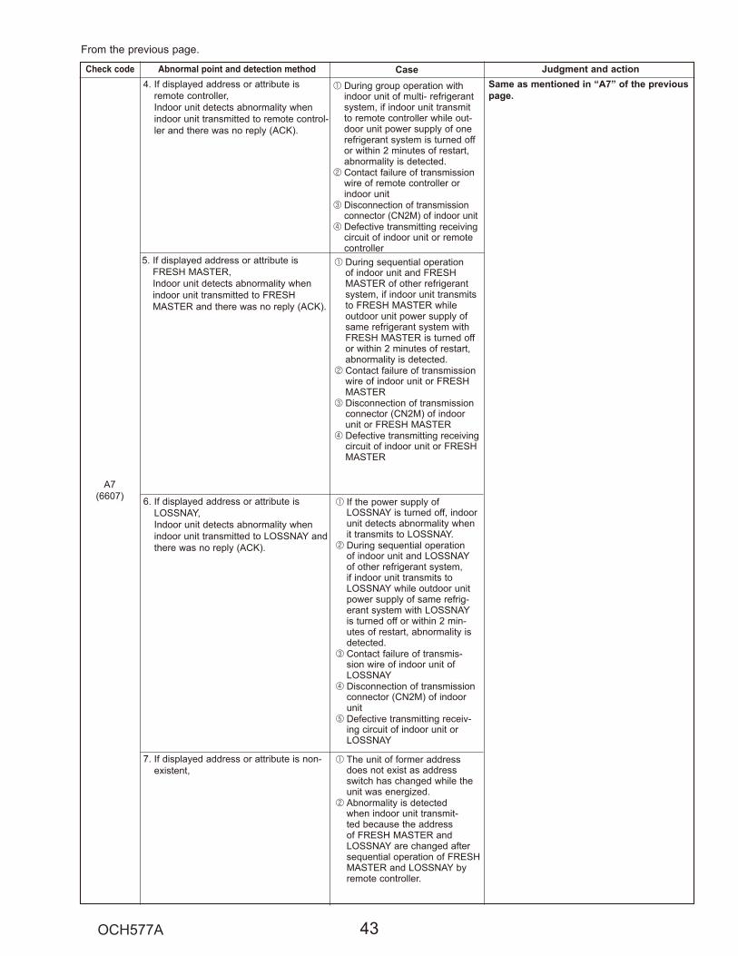
1
2
3
4
Check code Abnormal point and detection method Case Judgment and action
1
2
3
4
5
1
2
1
2
3
4
Same as mentioned in “A7” of the previous page.

10-5. TROUBLESHOOTING OF PROBLEMSPhenomena Factor Countermeasure
1 1
1
2
3
4
1
2
1
2
1
2
3
4
Check code Abnormal point and detection method Case Judgment and actionM-NET NO RESPONSE 1
2
3
······
2
4
1
2

Phenomena Factor Countermeasure
1
2
3
4
5
6
7
1
2
3 4
5
6 7
1
2
12 12
1 1
1
2
3
1
2
3
1
2
3
4
1
2
3
4

How long is “PLEASE WAIT” kept being displayed on the
remote controller?
6 minutes or more
2 minutes or less
2 to 6 minutes
NO
NO
YES
YES
Are any check codes displayed on the remote controller?
Are any check codes displayed on the LED?
Symptoms: “PLEASE WAIT” is kept being displayed on the remote controller.
Check the display time of “PLEASE WAIT” after turning on the main power.
“PLEASE WAIT” will be displayed during the start-up diagnosis after turning on the main power.
The start-up diagnosis will be over in around 2 minutes.
outdoor connecting wire
outdoor connecting wire (S3)
controller board
controller circuit board
action table” in order to solve the trouble.
errors, the display of remote controller may not match the LED display of the outdoor unit.
controller board
controller
Check the LED display of the outdoor controller circuit board.
Diagnosis flow Cause Inspection method and troubleshooting

198 to 253 V AC?
198 to 253 V AC?
198 to 253 V AC?
12 to 16 V DC?
12 to 16 V DC ?
NO
YES
NO
YES
NO
YES
YES
NO
YES
NO
Check the voltage between S1 and S2 on the terminal block (TB4) of the indoor unit.
Check the voltage among L1 and L2 on the terminal block (TB1) of the outdoor power circuit board.
Check the voltage of indoor controller board (CN2D).
Check the voltage of the unit after removing the indoor power board (CN2S).
Check the voltage between S1 and S2 on the terminal block (TB1) of the outdoor unit which is used to connect the indoor unit and the outdoor unit.
Troubles concerning power supply to the outdoor unit.
outdoor controller board
outdoor controller circuit board are blown.
outdoor unit.
Check if the fuses are blown. The fuses on the outdoor controller circuit board will be blown when the indoor /outdoor connecting wire short-circuits.
outdoor controller board
outdoor controller circuit board are blown.
or poor contact is causing this problem. Indoor/outdoor connecting wire is polarized 3-core type. Connect the indoor unit and the outdoor unit by wiring each pair of
side of indoor/outdoor terminal blocks.
power board power board.
controller board controller board.
or poor connection of indoor/outdoor connecting wire
Check if there is miswiring or breaking of wire.
Symptoms: Nothing is displayed on the remote controller. 1
Diagnosis flow Cause Inspection method and troubleshooting
LED display of the indoor controller boardLED1 :LED2 : LED3 :

198 to 253 V AC?
Are there looseness or disconnection of the indoor/outdoor connecting wire?
Is anything displayed?
17 to 28 V DC?
Is “E8” displayed?
Can all the indoor unit be operated?
Check the voltage between S2 and S3 on the terminal block of the outdoor unit.
NO
YES
Not lighting.
Blinking
NO
YES
NO
YES
Not displayed.
Displayed.
YES
NO
YES
NO
Check the voltage between S1 and S2 on the terminal block (TB4) of the indoor unit.
Check the refrigerant address of the outdoor unit. (SW1-3 to 1-6)
Check the looseness or disconnection of the indoor/outdoor connecting wire.
Check the LED display of the outdoor unit after turning on the main power again.
Can the unit be restarted?
contact of the indoor/ outdoor connecting wire
contact of the indoor/outdoor connecting wire.
controller circuit board
controller circuit board.
Only the unit which has the refrigerant address “0” supplies power to the remote controller.
address to “0”. In case of the multiple grouping system, recheck the refrigerant address again.
power board power board.
power circuit board power circuit board.
controller board board of the indoor unit which does not operate.
controller circuit board
controller circuit board.
electromagnetic noise There may be the influence of electromagnetic noise. Check the transmission wire and get rid of the causes.
Symptoms: Nothing is displayed on the remote controller. 2
Diagnosis flow Cause Inspection method and troubleshooting
LED display of the indoor controller boardLED1 :LED2 : LED3 : or
Check the status of the indoor controller board LED3 display.
Is the refrigerant address “0”?
NO
YES
NO
YES
Is “EA” or “Eb” displayed?

10 to 16 V DC?YES
NO
Lighting
Blinking
Lighting
Blinking
Check the voltage of the terminal block (TB6) of the remote controller.
Check the status of the LED2 after disconnecting the remote controller wire from the terminal block (TB5) of the indoor unit.
remote controller remote controller.
contact of the remote controller wire remote controller wire.
Check the voltage of the terminal block (TB5) connecting the remote controller wire. If it is not between 10 and 16 V DC, the indoor controller board must be defective.
wire short-circuits controller wire is short-circuited.
controller board controller board.
Diagnosis flow Cause troubleshooting
Symptoms: Nothing is displayed on the remote controller. 3controller boardLED1 :LED2 : or LED3 : —
Check the status of the LED2.
Check the status of the LED2.

1 The operating display of remote controller does not come on.
Phone Calls From Customers How to Respond Note1 Check if power is supplied to air conditioner. Nothing appears on the display unless power is supplied.
2 Unit cannot be restarted for a while after it’s stopped.
2 Wait around 3 minutes to restart unit. The air conditioner is in a state of being protected by the microprocessor’s directive. Once the compressor is stopped, the unit cannot be restarted for 3 minutes. This control is also applied when the unit is turned on and off by remote controller or thermostat.
3 Check code appears and blinks on the display of remote controller.
Refer to “SELF-DIAGNOSIS ACTION TABLE”. Check if servicing is required for the error.
Display time of “FILTER” depends on the model. Long life filter: 2500 hrs.Standard filter: 100 hrs.
3 Check code will be displayed if any protection devices of the air conditioner are actuated. What is check code?
1 “PLEASE WAIT” is displayed on the screen.
1 Wait around 2 minutes. An automatic startup test will be conducted for 2 minutes when power is supplied to the air conditioner. “PLEASE WAIT” will be kept being displayed while that time.
2 “FILTER” is displayed on the screen.
2 This indicates that it is time to clean the air filters. Clean the air filters. Press the FILTER button on the remote controller twice to clear “FILTER” from the display. See the operation manual that came with the product for how to clean the filters.
3 “STANDBY” is displayed on the screen.
3 This is displayed when the unit starts HEAT operation, when the thermostat puts the compressor in operation mode, or when the outdoor unit ends DEFROST operation and returns to HEAT operation. The display will automatically disappear around 10 minutes later. While “STANDBY” is displayed on the remote controller, the airflow amount will be restricted because the indoor unit’s heat exchanger is not fully heated up. In addition to that, the up/down vane will be automatically set to horizontal blow in order to prevent cold air from directly blowing out to human body. The up/down vane will return to the setting specified by the remote controller when “STANDBY” is released.
4 “DEFROST” is displayed on the screen. (No air comes out of the unit.)
4 The outdoor unit gets frosted when the outside temperature is low and the humidity is high. “DEFROST” indicates the DEFROST operation is being performed to melt this frost. The DEFROST operation ends in around 10 minutes (at most 15 minutes). During the DEFROST operation, the indoor unit’s heat exchanger becomes cold, so the blower is stopped. The up/down vane will be automatically set to horizontal blow in order to prevent cold air from directly blowing out to human body. The display will turn into “STANDBY” when DEFROST operation ends.
Unit does not operate at all.
Remote controller
Frequent calling from customers

Phone Calls From Customers How to Respond Note1 Check the set temperature of remote controller. The outdoor unit cannot be operated if the set temperature is not appropriate. The outdoor unit operates in the following modes. COOL: When the set temperature is lower than the room temperature. HEAT: When the set temperature is higher than the room temperature.2 Check if filters are not dirty and clogged. If filters are clogged, the airflow amount will be reduced and the unit capacity will be lowered. See the instruction manual that came with the product for how to clean the filters.3 Check there is enough space around the air conditioner. If there are any obstacles in the air intake or air outlet of indoor/outdoor units, they block the airflow direction so that the unit capacity will be lowered.
1 A gas escaping sound is heard sometimes.
1 This is not a malfunction. This is the sound which is heard when the flow of refrigerant in the air conditioner is switched.
2 A cracking sound is heard sometimes.
2 This is not a malfunction. This is the sound which is heard when internal parts of units expand or contract when the temperature changes.
3 A buzzing sound is heard sometimes.
3 This is not a malfunction. This is the sound which is heard when the outdoor unit starts operating.
4 A ticking sound is heard from the outdoor unit sometimes.
4 This is not a malfunction. This is the sound which is heard when the fan of the outdoor unit is controlling the airflow amount in order to keep the optimum operating condition.
5 A sound, similar to water flowing, is heard from the unit.
5 This is not a malfunction. This is the sound which is heard when the refrigerant is flowing inside the indoor unit.
2 The fan speed does not match the setting of the remote controller in HEAT operation.
The up/down vane will be automatically set to horizontal blow in these cases listed up on the left (1)–3)). After a while, the up/down vane will be automatically moved according to the setting of the remote controller.
2 This is not a malfunction. 1) When the HEAT operation starts, to prevent the unit from blowing cold air, the fan speed is gradually increased from 0 to the set speed, in proportion to the temperature rise of the discharged air. 2) When the room temperature reaches the set temperature and the outdoor unit stops, the unit starts the LOW AIR operation. 3) During the HEAT operation, the DEFROST operation is performed to defrost the outdoor unit. During the DEFROST operation, the fan is stopped to prevent cold air coming out of the indoor unit.
Sound comes out from the air conditioner.
1 The fan speed does not match the setting of the remote controller during DRY operation.(No air comes out sometimes during DRY operation.)
1 This is not a malfunction. During the DRY operation, the blower’s ON/OFF is controlled by the microprocessor to prevent overcooling and to ensure efficient dehumidification. The fan speed cannot be set by the remote controller during DRY operation.
Something is wrong with the blower…..
The room cannot be cooled or heated sufficiently.

Air blows out for a while after HEAT operation is stopped.
Phone Calls From Customers How to Respond Note
This is not a malfunction. The blower is operating just for cooling down the heated-up air conditioner. This will be done within 1 minute. This control is conducted only when the HEAT operation is stopped with the electric heater ON.
However, this control is also applied to the models which has no electric heater.
“STANDBY” will be displayed on the remote controller in case of 1) and 2).“DEFROST” will be displayed on the screen in case of 3).
The airflow direction is changed during COOL operation.
If the up/down vane is set to downward in COOL operation, it will be automatically set to horizontal blow by the microprocessor in order to prevent water from dropping down. “1 Hr.” will be displayed on the remote controller if the up/down vane is set to downward with the fan speed set to be less than “LOW”.
The airflow direction is changed during HEAT operation. (The airflow direction cannot be set by remote controller.)
In HEAT operation, the up/down vane is automatically controlled according to the temperature of the indoor unit’s heat exchanger. In the following cases written below, the up/down vane will be set to horizontal blow, and the setting cannot be changed by remote controller. 1) At the beginning of the HEAT operation 2) While the outdoor unit is being stopped by thermostat or when the outdoor unit gets started to operate. 3) During DEFROST operation The airflow direction will be back to the setting of remote controller when the above situations are released.
The airflow direction does not change. (Up/down vane, left/right louver)
1) Check if the vane is set to a fixed position. (Check if the vane motor connector is removed.) 2) Check if the air conditioner has a function for switching the air direction. 3) If the air conditioner doesn’t have that function, “NOT AVAILABLE” will be displayed on the remote controller when “AIR DIRECTION” or “LOUVER” button is pressed.
Something is wrong with the blower…..
Something is wrong with the airflow direction….
Check if you set ON/OFF timer. The air conditioner starts operating at the time designated if ON timer has been set before.
Check if any operations are ordered by distant control system or the central remote controller. While “CENTRALLY CONTROLLED INDICATOR” is displayed on the remote controller, the air conditioner is under the control of external directive.
The air conditioner starts operating even though any buttons on the remote controller are not pressed.
Check if you set ON/OFF timer. The air conditioner stops operating at the time designated if OFF timer has been set before.
The air conditioner stops even though any buttons on the remote controller are not pressed.
There might be a case that “CENTRALLY CONTROLLED INDICATOR” will not be displayed.
There might be a case that “CENTRALLY CONTROLLED INDICATOR” will not be displayed.
Check if power is recovered from power failure (black out). The units will automatically start operating when power is recovered after power failure (black out) occurs. This function is called “auto recovery feature from power ”.
Check if any operations are ordered by distant control system or the central remote controller. While “CENTRALLY CONTROLLED INDICATOR” is displayed on the remote controller, the air conditioner is under the control of external directive.

Phone Calls From Customers How to Respond Note
This is not a malfunction.This may occur when the operation gets started in the room of high humidity.
A white mist is expelled from the indoor unit.
COOL: when pipes or piping joints are cooled, they get sweated and water drips down.HEAT: water drips down from the heat exchanger.Note: Use optional parts “Drain Socket” and “Drain
pan” if these water needs to be collected and drained out for once.
Water or moisture is expelled from the outdoor unit.
Batteries are being exhausted. Replace them and press the reset button of remote controller.
The display of IR wireless remote controller gets dim or does not come on.The indoor unit does not receive a signal from remote controller at a long distance.

123456
MGray
OrangeRed
YellowBlack
123456
M
Parts name Check points
Disconnect the connector then measure the resistance with a tester. (At the ambient temperature 50 to 86°F [10 to 30:])
Disconnect the connector then measure the resistance with a tester. (Winding temperature 68°F [20:])
Thermistor (TH3)<Liquid>Thermistor (TH6)< 2-phase pipe>Thermistor (TH7)<Ambient> Thermistor (TH8)<Heat sink>Thermistor (TH32)<Comp. Surface>Thermistor (TH33)<Suction>
Normal160 to 410 k"
4.3 to 9.6 k"
39 to 105 k"
TH32TH3TH6TH7TH33TH8
Abnormal
Open or short
Normal
Red - White Red - Orange Brown - Yellow Brown - Blue
Abnormal
46 i 4 "
Measure the resistance between the terminals with a tester. (At the ambient temperature 68°F [20:])
Solenoid valve coil<4-way valve> (21S4)
Motor for compressor(MC)
Linear expansion valve (LEV-A)For A12, 18
Linear expansion valve (LEV-A)For A24–42
Normal Abnormal
Open or shortA18–36 A42
Open or short
Disconnect the connector then measure the resistance with a tester. (Winding temperature 68°F [20:])
Measure the resistance between the terminals with a tester.(At the ambient temperature 68°F [20:])
Normal1450 i 150 "
AbnormalOpen or short
Solenoid valve coil<Bypass valve> (SV)For A24–36 only
Refer to “10-6-8. Check method of DC fan motor (fan motor/ outdoor controller circuit board)”. Fan motor (MF1,MF2)
1500 i 150 " 2350 i 170 "
A12, 18 A42
0.320 "
A24, 30, 36
0.880 " 0.266 "
Measure the resistance between the terminals with a tester. (Winding temperature 68°F [20:])
Normal Abnormal
Open or shortW
V
U
Red
Brown
BlueOrange
YellowWhite
Normal
Gray - Black Gray - Red Gray - Yellow Gray - Orange
Abnormal
46 i 3 "Open or short
10-6. HOW TO CHECK THE PARTSPUZ-A18/24/30/36/42NHA6 PUZ-A18/24/30/36/42NHA6-BSPUY-A12/18/24/30/36/42NHA6 PUY-A12/18/24/30/36/42NHA6-BS

10-6-1. Check method of outdoor controller circuit boardPUZ-A18/24/30/36/42NHA6 PUZ-A18/24/30/36/42NHA6-BSPUY-A12/18/24/30/36/42NHA6 PUY-A12/18/24/30/36/42NHA6-BS
Normal
LED1LED1: litLED2: lit
LED2
Fuse checkCheck the fuse on outdoor controller circuit board.
Did the fuse (F1 and F2) blow? Check the indoor controller board wiring.
Did the fuse (F3 and F4) blow? Check the wiring for SV1 and 21S4.
Is LED1 or LED2 lit?
280 to 350 V DC?
Check wiring. Replace outdoor controller circuit board.
Check the breaker and main incoming power. Check noise filter circuit board. Check wiring.
Check the voltage from the power circuit board to CNDC(PNK) connector.
No
No
Yes(lit)
No (No lit)
Yes
No
Outdoor controller circuit board check
Yes (blow)
Yes (blow)
Outdoor controller circuit board
CNDC (PNK)
Power circuit board
F1
F2
Conv.Circuit CNDC
(PNK)
280–350 V DC
Noise Filter CircuitBoard
F2
CNAC (WHITE)CNAC1(WHT)
TB1
198–253 V AC
198–253 V AC
198–253 V AC
F3
F4
CNAC2(RED)
1
3
LI NI
L1 N2
1
3
1
3

Normal
Is the voltage of main incoming power198–253 V AC? Check the breaker and power supply.
Is the voltage of CNAC (WHT) on outdoor controller board CNAC (WHT)
198–253 V AC?
Check wiring. Replace the noise filter circuit board.
Is the voltage of CNDC(PNK) on outdoor controller circuit board 280–350 V DC?
Check wiring. Check power circuit board.
Note: To check the voltage of the parts on this board with a tester is difficult due to its location. Test points are limited.
Yes
Yes
YesYes
No
No
No Turn off the incoming power supplyand check the resistance of RS on
the noise filter circuit board.
RS = open ?
Yes (open)
Replace the noise filter circuit board, and check 52C-relay, wiring, power board and ACTM.
No(normal)
Noise filter circuit board check
Noise filter circuit board
CNDC(PNK)
TB1
198–253 V ACN
L
Power circuit board
3
1 2
3 4(PNK)
280–350 V DC
Circuit diagram
R
S Conv.Circuit
controller circuit board CN52C
1
3 4
Outdoor Controller Board
CNAC(WHT)
To outdoor controller circuit board CNDC(WHT)
3
1
12 V DC from outdoor
RS (resistor)
PUZ-A18NHA6 PUZ-A18NHA6-BSPUY-A12/18NHA6 PUY-A12/18NHA6-BS

Normal
Is the voltage of main incoming power198–253 V AC? Check the breaker and power supply.
Is the voltage of CNAC (WHT) on outdoor controller circuit board CNAC (WHT) Check wiring.
Replace the noise filter circuit board.
Is the voltage of CNDC(PNK) on outdoor controller circuit board 280–350 V DC?
Check wiring. Check power board.
Note: To check the voltage of the parts on this board with a tester is difficult due to its location. Test points are limited.
Yes
Yes
YesYes
No
No
No Turn off the incoming power supplyand check the resistance of RS on
the noise filter circuit board.
RS = open ?
Yes (open)
Replace the noise filter circuit board, and check 52C-relay,wiring,power board and ACTM.
No(normal)
Noise filter circuit board check
Noise filter circuit board
TB1
198–253 V ACN
L
1 2
3 4
208/230 V±10% AC
Circuit diagram
12 V DC from outdoor controller circuit board CN52C
1 2
3 4
Outdoor Controller Circuit Board
CNAC(WHT)
CNDC(PNK)
280–350 V DC
Power circuit board
R
STo outdoor controller circuit board CNDC(PNK)
52C(relay)RS(resister)
Conv.Circuit
3
1
198–253 V AC?
PUZ-A24NHA6 PUZ-A24NHA6-BSPUY-A24NHA6 PUY-A24NHA6-BS

Power circuit board
CNDC(PNK)
NO LO
conv.circuit
Noise filter circuit board
280–350 V DC
198–253 V AC
Outdoor controller circuit board
1 2
3 4
CNAC(WHT)
3 1
To outdoor controller circuit boardCNDC(PNK)
PTC1, PTC2(resistor)
52C(relay)12 V DC from outdoorcontroller circuit board
CN52C
Circuit diagram
L2
L1
TB1
NO
CN52C(BLK)
52C
CN5(RED)
CNAC1(WHT)
CNAC2(RED)
LO
NI
LI
1 2E1
U
U
3 13 1
1 2 E2
Normal
Is the voltage of main incoming power198–253 V AC ? Check the breaker and power supply.
Is the voltage of CNAC (WHT) on outdoor controller circuit board CNAC (WHT)
198–253 V AC ?
Check wiring. Replace the noise filter circuit board.
Is the voltage of CNDC(PNK) on outdoor controller circuit board 280–350 V DC?
Check wiring. Check power circuit board.
Note: To check the voltage of the parts on this board with a tester is difficult due to its location. Test points are limited.
Yes
Yes
YesYes
No
No
No Turn off the incoming power supplyand check the resistance of PTC1and PTC2 on the noise filter circuit board.
PTC1 or PTC2 = open ?
Yes (open)
Replace the noise filter circuit board, and check 52C-relay,wiring,power board and ACTM.
No(normal)
Noise filter circuit board check
198–253 V AC
198–253 V AC
PUZ-A30/36/42NHA6 PUZ-A30/36/42NHA6-BSPUY-A30/36/42NHA6 PUY-A30/36/42NHA6-BS

10-6-5. Check method of power circuit board
Normal
Is the voltage of main incoming power198–253 V AC
198–253 V AC
198–253 V AC
Check the breaker and power supply.
Is the voltage to the compressor (U-V,U-W and V-W) balanced?
Note: To check the voltage of the parts on this board with a tester is difficult due to its location. Test points are limited.
Check wiring. Check model setting switch SW6
on the outdoor controller circuit board. Replace the power circuit board.
Is the voltage of CNDC(PNK) on outdoor controller circuit board 280–350V DC?
Check wiring. Check power circuit board. Check noise filter circuit board.
Yes
Yes
Yes
No
No
No
Power circuit board check
7654321
Noise Filter CircuitBoard
Power circuit board
Conv.Circuit
CNDC(PNK)
7 6 5 4 3 2 1
Comp
U
V
W
U-V 10–250 V AC
V-W 10–250 V AC
W-U 10–250 V AC
LI NI
L NTB1
290–350 V DC
Circuit diagram
3
1
PUZ-A18/24NHA6 PUZ-A18/24NHA6-BSPUY-A12/18/24NHA6 PUY-A12/18/24NHA6-BS

10-6-6. Check method of power circuit board
Normal
Is the voltage of main incoming power Check the breaker and power supply.
Is the voltage to the compressor (U-V,U-W and V-W) balanced?
Note: To check the voltage of the parts on this board with a tester is difficult due to its location. Test points are limited.
Check wiring. Check model setting switch SW6
on the outdoor controller circuit board. Replace the power circuit board.
Is the voltage of CNDC(PNK) on outdoor controller circuit board 280–350 V DC?
Check wiring. Check power circuit board. Check noise filter circuit board.
Yes
Yes
Yes
No
No
No
Power circuit board check
Outdoor controller circuit board
Noise filter circuit board
LI
NI
208/230 V ±10% AC
3-1
CNDC(PNK)
LO
NO
Power circuit board
280–350 V DC
COMP
W
7 6 5 4 3 2 1CN2(WHT)
U-V 10–250 V ACU-W 10–250 V ACV-W 10–250 V AC
conv.circuit
Note: See test point.
52C
W
W
WVU Circuit diagram
L1
L2
TB1
198–253 V AC
198–253 V AC
198–253 V AC
PUZ-A30/36/42NHA6 PUZ-A30/36/42NHA6-BSPUY-A30/36/42NHA6 PUY-A30/36/42NHA6-BS

10-6-7. Check method of ACTM
Normal
Is the voltage of main incoming power198–253 V AC Check the breaker and power supply.
Note: To check the voltage of the parts on this board with a tester is difficult due to its location. Test points are limited.
Is the voltage of CNDC(PNK) on outdoor controller circuit board 330–350 V DC during cooling or heating operation?
Check wiring. Check 52C relay. Check ACTM.
Yes
Yes
No
No
Is the voltage between 3pin and4pin of CN2 on outdoor controller
circuit board 18 V DC?
Replace the outdoor controller circuit board.
Yes
No
ACTM check(Active Filter Module)
Power supply
52C relay
Bus bar voltage(DC)
COMP (Hz)
ACTM OFF
OFFON
OFFON
0Hz
ex. 48Hz
0V
290/325 V330–350 V
ON
208/230 V
min. Hz
290/325 V
OFF
TIME CHART
power on starts stop
Noise filter circuit board
LI
NI
208/230 V ±10% AC
LO
NO
Power board
operate:330–350 V DCstop :290–325 V DC
A C TM
Outdoor controller circuit board
3-1
CNDC(PNK)
7 6 5 4 3 2 1 CN2(WHT)
conv. circuit
CN2 3-4pin : 18 V DC ACTM gate drive power supply
operate:330–350 V DCstop :290–325 V DC
52C
DCL
Circuit diagramCOMP
W
U-V 10–250 V ACU-W 10–250 V ACV-W 10–250 V AC
W
W
WVU
L1
L2
TB1
198–253 V AC
198–253 V AC
PUZ-A30/36/42NHA6 PUZ-A30/36/42NHA6-BSPUY-A30/36/42NHA6 PUY-A30/36/42NHA6-BS

Notes · High voltage is applied to the connecter (CNF1, 2) for the fan motor. Pay attention to the service. · Do not pull out the connector (CNF1, 2) for the motor with the power supply on. (It causes trouble of the outdoor controller circuit board and fan motor.)Self checkSymptom : The outdoor fan cannot rotate.
1
2
10-6-8. Check method of DC fan motor (fan motor/ outdoor controller circuit board)
Power supply check(Remove the connector (CNF1, 2))Measure the voltage in the outdoor controller circuit board.TEST POINT 1 : VDC (between 1 (+) and 4 ( ) of the fan connector): VDC 280–340 V DC (When ACTM stops), 350 V DC (When ACTM is operating)TEST POINT 2 : VCC (between 5 (+) and 4 ( ) of the fan connector): VCC 15 V DC
No
No
No
Wiring contact checkContact of fan motor connector (CNF1, 2)
Fuse checkCheck F5 on outdoorcontroller board.
Recover wiring.
Replace the outdoor controller circuit board.
Replace the fan motor.
Replace the outdoor controller circuit board (C.B)and fan motor (MF1, 2).
Replace the outdoor controller circuit board.
Replace the fan motor.
Is the voltage normal?
Is there contact failure? Yes
Yes
No
Did the F5 open?
No
Yes
Check the operation of fan. END
Yes OK
Check the operation. END
OK

"
: t
10-7. HOW TO CHECK THE COMPONENTS<Thermistor feature chart>
Low temperature thermistors
: ": ": ": "
: ": "
"
:
: ": ": ": ": "
: ": ": ": ": "
High temperature thermistor
0
10
20
30
40
50
20 10 0 10 20 30 40 504 14 32 50 68 86 104122
:°F
Temperature
Res
ista
nce
(k"
)
500
400
300
200
100
025 50 75 100 12077 122 167 212 248 °F
Temperature
Res
ista
nce
(k)
: ": ": ": ": "
"
:
Medium temperature thermistor 200
150
100
50
025 50 75 100 110 12577 122 167 212 230 257 °F
Temperature
Res
ista
nce
(k)

<Output pulse signal and the valve operation>
(2) Linear expansion valve operation
Open
Extra tightening (about 32 pulse)
Pulse number
500 pulseOpening a valveall the way
CloseValv
e po
sitio
n (c
apac
ity)
A
B A
B A
LEV
M
16
[4 [4
[3
[2
[1
2
1Red
Brown
Blue
Orange
Yellow
White
3
4
5
6
Connector LEV-A
12 V DC
Outdoor controller board
Drive circuit
[3
[2
[1
3
2
54
(1) Operation summary of the linear expansion valve
1
ON
OFF
OFF
OFF
ON
ON
OFF
OFF
OFF
ON
OFF
OFF
OFF
ON
ON
OFF
1
Output(Phase)
Output
2
3
4
2 3 4 5 6 7 8
OFF
OFF
ON
OFF
OFF
OFF
ON
ON
OFF
OFF
OFF
ON
ON
OFF
OFF
ON

<Output pulse signal and the valve operation>
(2) Linear expansion valve operation
Open
Extra tightening (about 32 pulse)
Pulse number
500 pulseOpening a valveall the way
CloseValv
e po
sitio
n (c
apac
ity)
A
B A
B A
LEV
M
16
[4 [4
[3
[2
[1
1Gray
Orange
Red
Yellow
Black
3
4
5
6
Connector LEV-A
DC12V
Outdoor controller board
Drive circuit
[3
[2
[1
3
2
54
(1) Operation summary of the linear expansion valve
1
ON
OFF
OFF
OFF
ON
ON
OFF
OFF
OFF
ON
OFF
OFF
OFF
ON
ON
OFF
1
Output(Phase)
Output
2
3
4
2 3 4 5 6 7 8
OFF
OFF
ON
OFF
OFF
OFF
ON
ON
OFF
OFF
OFF
ON
ON
OFF
OFF
ON

Main body
Lead wire Stopper
Coil
(3) How to attach and detach the coil of linear expansion valve (A12, 18 )
A
<How to detach the coil>
Be sure to attach thestopper to pipe B.
B A
<How to attach the coil>

Main body
Lead wire
StopperCoil
(4) How to attach and detach the coil of linear expansion valve (A24, 30, 36, 42)
Be sure to attach the stopper.
A
<How to attach the coil>
A
<How to detach the coil>

10-8. EMERGENCY OPERATION
(2) Check the following items and cautions for emergency operation 1
2
3
4
5
(3) Emergency operation procedure 1
2
3
4
5
SW4
1 2 Cooling
HeatingON ON
OFF
CN31 Shorting pins
(4) Releasing emergency operation 1
2
3
4
SW4
1 2 Cooling
Heating(PUZ only)
ON
Inspected contentOpen/short of pipe thermistor (TH3/TH6)
Communication error other than outdoor unit
Check codeU4
–7

(5) Operation data during emergency operation
Operation dataOperation mode
RemarksCOOL HEAT
Intake temperature (TH1) : :
: :
Indoor 2-phase pipe temperature (TH5) : :
Set temperature : :
Outdoor liquid pipe temperature (TH3) : :
Outdoor 2-phase pipe temperature (TH6) : :
Outdoor air temperature (TH7) : :
Outdoor suction (TH33) : :
Temperature difference code (intake temperature
Discharge super heat (SHd) : :
Sub-cool (SC) : :
Thermistor COOL HEAT
: :
: :
: :
:
:: :

10-9. TEST POINT DIAGRAMOutdoor controller circuit boardPUZ-A18/24/30/36/42NHA6 PUZ-A18/24/30/36/42NHA6-BSPUY-A12/18/24/30/36/42NHA6 PUY-A12/18/24/30/36/42NHA6-BS
1
2–4:
1–3:
1–45–46–47–4
1–2
1–3
1 3
4
7 4
SP
3
–
SWP
1–5
2–5–
3–46–57–5

Outdoor noise filter circuit boardPUZ-A18NHA6 PUZ-A18NHA6-BSPUY-A12/18NHA6 PUY-A12/18NHA6-BS

Outdoor noise filter circuit boardPUZ-A24NHA6 PUZ-A24NHA6-BSPUY-A24NHA6 PUY-A24NHA6-BS

Outdoor noise filter circuit boardPUZ-A30/36/42NHA6 PUZ-A30/36/42NHA6-BSPUY-A30/36/42NHA6 PUY-A30/36/42NHA6-BS

1–5
2–53–46–57–5
Outdoor power circuit boardPUZ-A18NHA6PUZ-A18NHA6-BSPUY-A12/18NHA6PUY-A12/18NHA6-BS
1 2 6 7
5
Brief check of DIP-IPM and DIP-PFC
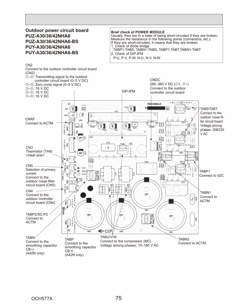
Outdoor power circuit boardPUZ-A30/36/42NHA6PUZ-A30/36/42NHA6-BSPUY-A30/36/42NHA6PUY-A30/36/42NHA6-BS
1–5
2–53–46–57–5
1 3
Brief check of POWER MODULE

Active filter modulePUZ-A30/36/42NHA6 PUZ-A30/36/42NHA6-BSPUY-A30/36/42NHA6 PUY-A30/36/42NHA6-BS
– Io
N2
P
12–13–14 56–1
Upper side Lower side
DCL
L1 L2 ACTM
P
Io
N1N2
(+)
(–)
Load+
Connection and internal circuit diagram
" 1
" " 1
1 2
" " 1
1 2
" " 1
1 2
" " 1
1 2
1 6
ONOFF

SwitchType
ofswitch
DIPswitch
Pushswitch
SW1
1
2
No. Function Effective timingAction by the switch operation
Manual defrost *1 Start NormalWhen compressor is operating in heating operation. *1
Abnormal history clear
Refrigerant addresssetting
When power supply ON
Clear Normal Off or operating
SWP
6
5
4
3
Under suspensionPump down Start Normal
SW4
SW8
1212
3
Test run Operating OFFUnder suspension
Test run mode setting Heating CoolingNo function — —No function — —
Separate indoor/outdoorunit power supplies Used Not used
——
When power supply ON
ON OFF
1 2 30 1 2 3
4 5 6
ON
1 2 3 4 5 6
ON
1 2 3 4 5 6
ON
1 2 3 4 5 6
ON
1 2 34 5 6 7
4 5 6
ON
1 2 3 4 5 6
ON
1 2 3 4 5 6
ON
1 2 3 4 5 6
ON
1 2 38 9 10 11
4 5 6
ON
1 2 3 4 5 6
ON
1 2 3 4 5 6
ON
1 2 3 4 5 6
ON
1 2 312 13 14 15
4 5 6
ON
1 2 3 4 5 6
ON
1 2 3 4 5 6
ON
1 2 3 4 5 6
ON
1
2
10-10. FUNCTION OF SWITCHES, CONNECTORS AND JUMPERS (1) Function of switches

1
2
3,4,56
345612
3,4123456785
ON OFFNo. Function Effective timingAction by the switch operation
No function
Power failureautomatic recovery *2
No functionModel select
Max. Hz setting(cooling)Max. Hz setting(heating)
No functionDefrost setting
No functionFunction switch
No function
Switch
SW5
SW7*4
DIPswitch
SW9
SW6
SW5
Type ofSwitch
—
Auto recovery
—
Max. Hz(cooling) o 0.8Max. Hz(heating) o 0.8
—For high humidity
—Valid
—
—
No auto recovery
—
NormalNormal
—Normal
—Normal
—
—
When power supply ON
—
Always
AlwaysAlways
—
Always—
Always—
Setting of demand control *3
1
2
SW7-1 SW7-2OFF 0% (Operation stop)
75%50%
OFFON
OFFOFFON
Max. compressor frequency (Demand switch ON)
Model select
Following SW5-6 reference
6
1 2 3 4 5 6OFFON
PUZ-A18NHA6
MODEL SW6 SW5-5, 6 *5
1 2 3 4 5 6OFFONPUY-A12NHA6
PUY-A18NHA61 2 3 4 5 6
7 8
7 8
7 8OFFON
1 2 3 4 5 6OFFON
1 2 3 4 5 6OFFON
1 2 3 4 5 6OFFON
1 2 3 4 5 6OFFON
PUZ-A24NHA6
1 2 3 4 5 6OFFONPUY-A24NHA6
7 8
7 8
1 2 3 4 5 6OFFON
1 2 3 4 5 6OFFON
1 2 3 4 5 6OFFON
PUZ-A30NHA6
PUZ-A36NHA6
MODEL SW6 SW5-5, 6 *5
1 2 3 4 5 6OFFON
1 2 3 4 5 6OFFON
PUY-A30NHA6
PUY-A36NHA61 2 3 4 5 6
7 8
7 8
7 8
7 8OFFON
1 2 3 4 5 6OFFON
1 2 3 4 5 6OFFON
1 2 3 4 5 6OFFON
1 2 3 4 5 6OFFON
1 2 3 4 5 6OFFON
PUZ-A42NHA6
1 2 3 4 5 6OFFONPUY-A42NHA6
7 8
7 8
1 2 3 4 5 6OFFON
1 2 3 4 5 6OFFON
(2) Function of connector
CN31
Types Connector Function Effective timing
Connector Start
Short Open
Action by open/ short operation
Emergency operation When power supply ONNormal

Special function
SW7-1 SW7-2OFF 0% (Operation stop)
75%50%
OFFON
OFFOFFON
Max. compressor frequency(SW1 on)
CNDMXSW1~
X
Max. 10 m [33 ft] including local wiringSW1 : Switch X : Relay (Contact spec. : DC1mA)
Relay supply
Red 3Brown 2
Orange 1
Purchased locally
Adaptor for external signal input(PAC-SC36NA)
Outdoor unit controller board
3
2
1
Insulate this point securely as this is not used.
<Low-level sound priority mode circuit>

<Display function of inspection for outdoor unit>
F5
—
—
—E6
E7
—
—
E0
E3
E4
E5
EF
Ed
A0–A8
[Display] (1)Normal condition
(2)Abnormal condition
Unit conditionOutdoor controller board A-Control Service Tool
LED1 (Green) LED2 (Red) Check code
When the power is turned onWhen unit stopsWhen compressor is warming upWhen unit operates
Lighted LightedLightedLightedLighted
Not lighted
Indication of the displayAlternately blinking display
Operation modeNot lighted
Lighted
00, etc.08, etc.
C5, H7 etc.
Indication ErrorCheckcode
*1
Outdoor controller boardContents Inspection method
LED1 (Green) LED2 (Red)1 blinking 2 blinking
2 blinking 1 blinking
2 blinking
3 blinking
4 blinking
5 blinking
Connector (63H) is open.
Startup time over
Check code is not defined.
Miswiring of indoor/outdoor unit conne-cting wire, excessive number of indoor units (4 units or more)Miswiring of indoor/outdoor unit co-nnecting wire (converse wiring or di-sconnection)
Indoor/outdoor unit communication error(signal receiving error) is detected by in-door unit. Indoor/outdoor unit communication error(transmitting error) is detected by indoorunit.Indoor/outdoor unit communication error(signal receiving error) is detected by outdoor unit.Indoor/outdoor unit communication error (transmitting error) is detected by outdoorunit.Remote controller signal receiving error is detected by remote controller.
Remote controller transmitting error is detected by remote controller.
Remote controller signal receiving error is detected by indoor unit.
Remote controller transmitting error is detected by indoor unit.
Serial communication error<Communication between outdoor controller board and outdoor power board><Communication between outdoor controller board and M-NET P.C. board>Communication error of M-NETsystem
*1 Check code displayed on remote controller*2 Refer to the indoor unit service manual.
1Check if indoor/outdoor connecting wire is connected correctly.2Check if 4 or more indoor units are connected to outdoor unit.3Check if noise entered into indoor/outdoor connecting wire or power supply.4Re-check error by turning off power, and on again.
1Check if connector (63H) on the outdoor controller board is not disconnected. 2Check continuity of pressure switch (63H) by tester.
1Check if connector (CN4) on outdoor controller board and outdoor power board is not disconnected.2Check if there is poor connection of connector on outdoor controller board(CNMNT and CNVMNT).3Check M-NET communication signal.
1Check if remote controller is MA remote controller (PAR-21MAA).2Check if noise entered into transmission wire of remote controller.3Check if noise entered into indoor/outdoor connecting wire.4Re-check error by turning off power, and on again.
1Check if connecting wire of indoor unit or remote controller is connected correctly.2Check if noise entered into transmission wire of remote controller.3Re-check error by turning off power, and on again.
1Check if indoor/outdoor connecting wire is connected correctly.2Check if noise entered into indoor/outdoor connecting wire or power supply.3Check if noise entered into indoor/outdoor controller board.4Re-check error by turning off power, and on again.
P.34
P.34(EA)P.34(Eb)P.34(EC)*2
*2
P.40(E8)P.40(E9)P.39
P.39
P.39
P.39
P.40
P.40
P.41–P.44
Detailedreference
page

U2
U1
U8
UFUPUHU6U3U4
U5
U9
P1P2P9
P4
P5
P6
P8
Fb
E1E2
Indication ErrorCheckcode
*1
Outdoor controller boardContents Inspection method
LED1 (Green) LED2 (Red)3 blinking 1 blinking
2 blinking
3 blinking
*1 Check code displayed on remote controller*2 Refer to the indoor unit service manual.
4 blinking
5 blinking
6 blinking
7 blinking
1 blinking
2 blinking
3 blinking
4 blinking
5 blinking
––
4 blinking
Abnormality of shell thermistor (TH32)and discharging temperature (TH4)
1Check if stop valves are open.2Check if connectors (TH4, TH32, LEV-A) on outdoor controller board are not disconnected.3Check if unit is filled with specified amount of refrigerant.4Measure resistance values among terminals on indoor valve and outdoor linear expansion valve using a tester.
Abnormal high pressure (High pressure switch 63H operated.)
Abnormality of outdoor fan motor rotational speed
1Check if indoor/outdoor units have a short cycle on their air ducts.2Check if connector (63H) on outdoor controller board is not disconnected.3Check if heat exchanger and filter is not dirty.4Measure resistance values among terminals on linear expansion valve using a tester.
1Check if stop valves are open.2Check looseness, disconnection, and converse connection of compressor wiring.3Measure resistance values among terminals on compressor using a tester.4Check if outdoor unit has a short cycle on its air duct.
Compressor overcurrent breaking (Start-up locked)Compressor overcurrent breakingAbnormality of current sensor (P.B.)Abnormality of power moduleOpen/short of discharge thermistor (TH4)Open/short of outdoor thermistors(TH3, TH6, TH7, TH8 and TH33)
1Check if connectors (TH3, TH4, TH6, TH7 and TH33) on outdoor controller board and connector (CN3) on outdoor power board are not disconnected.2Measure resistance value of outdoor thermistors.
Abnormality of heatsinktemperature
1Check if indoor/outdoor units have a short cycle on their air ducts.2Measure resistance value of outdoor heatsink thermistor(TH8).
1Check the outdoor fan motor.
Abnormality of voltage 1Check looseness, disconnection, and converse connection of compressor wiring.2Measure resistance value among terminals on compressor using a tester.3Check the continuity of contactor (52C).4Check if power supply voltage decreases.5Check the wiring of CN52C.6Check the wiring of CNAF.
Abnormality of room temperature thermistor (TH1)Abnormality of pipe temperature thermistor /Liquid (TH2)Abnormality of pipe temperature thermistor/Condenser-Evaporator(TH5)
1Check if connectors (CN20, CN21, CN29, and CN44) on indoor controller board are not disconnected.2Measure resistance value of indoor thermistors.
Abnormality of drain sensor (DS)Float switch connector open(FS)Indoor drain overflow protection
1Check if connector (CN31)(CN4F) on indoor controller board is not disconnected.2Measure resistance value of indoor thermistors.3Measure resistance value among terminals on drain pump using a tester.4Check if drain pump works.5Check drain function.
Freezing (cooling)/overheating (heating) protection
1Check if indoor unit has a short cycle on its air duct.2Check if heat exchanger and filter is not dirty.3Measure resistance value on indoor and outdoor fan motors.4Check if the inside of refrigerant piping is not clogged.
Abnormality of pipe temperature
Abnormality of indoor con-troller boardAbnormality of remote con-troller board
1Check if indoor thermistors (TH2 and TH5) are not disconnected from holder.2Check if stop valve is open.3Check converse connection of extension pipe. (on plural units connection)4Check if indoor/outdoor connecting wire is connected correctly. (on plural units connection)
1Replace indoor controller board.
1Replace remote controller.
P.35
P.35
P.37
P.38P.38P.38P.36P.36P.36
P.36
P.37–38
Detailedreference
page
*2*2
*2
*2
*2
*2
P.39

<Outdoor unit operation monitor function>[When option part ‘A-Control Service Tool (PAC-SK52ST)’ is connected to outdoor controller board (CNM)]
1
ON
2 3 4 5 6
<Digital indicator LED1 working details>
1
1
ON
2 3 4 5 6
SW2
1 secondinterval
Display Operation ModelThe tens digit : Operation mode The ones digit : Relay output
OCHd
Display012345678A
CompressorWarming-up Compressor 4-way valve Solenoid valve————ONONONON——
————————ONON
——ONON——ONON—ON
—ON—ON—ON—ON——
OFF / FANCOOLING / DRY
HEATINGDEFROSTING
2
Display Contents to be inspected (When power is turned on)F3F5F9E8E9EAEbEC
E0–E7
63L connector(red) is open.63H connector(yellow) is open.2 connectors (63H/63L) are open.Indoor/outdoor communication error (Signal receiving error) (Outdoor unit)Indoor/outdoor communication error (Transmitting error) (Outdoor unit)Miswiring of indoor/outdoor unit connecting wire, excessive number of indoor units (4 units or more)Miswiring of indoor/outdoor unit connecting wire(converse wiring or disconnection)Startup time overCommunication error except for outdoor unit
Display Inspection unit012
Outdoor unitIndoor unit 1Indoor unit 2
Display Contents to be inspected (During operation)U1U2U3U4U5U6U8UFUHULUP
P1–P8A0–A7
Abnormal high pressure (63H worked)Abnormal high discharge temperature, shortage of refrigerantOpen/short circuit of comp. surface thermistor (TH32)Open/short of outdoor unit thermistors (TH3, TH6, TH7, TH8 and TH33)Abnormal temperature of heat sinkAbnormality of power moduleAbnormality in outdoor fan motor. Compressor overcurrent interruption (When Comp. locked)Current sensor errorAbnormal low pressure (63L worked)Compressor overcurrent interruptionAbnormality of indoor unitsCommunication error of M-NET system

1
ON
2 3 4 5 6
:
:
1
ON
2 3 4 5 6
1
ON
2 3 4 5 6
1
ON
2 3 4 5 6
1
ON
2 3 4 5 6
:
:
1
ON
2 3 4 5 6
1
ON
2 3 4 5 6
1
ON
2 3 4 5 61
ON
2 3 4 5 6
10
1
ON
2 3 4 5 6
1 05
4 25
2 45
1 25
1 50
1
ON
2 3 4 5 6

1
ON
2 3 4 5 6
:
:
1
ON
2 3 4 5 6
1
ON
2 3 4 5 6
1
ON
2 3 4 5 6
1
ON
2 3 4 5 6
:
:
1
ON
2 3 4 5 6
15
1 30
2 45
1 05
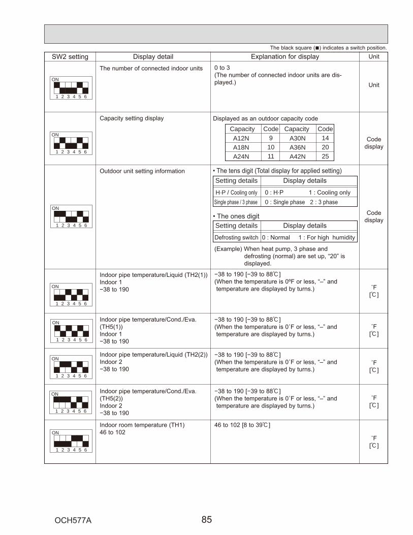
1
ON
2 3 4 5 6
1
ON
2 3 4 5 6
1
ON
2 3 4 5 6
:
:
1
ON
2 3 4 5 6
1
ON
2 3 4 5 6
CapacityA12NA18NA24N
A30NA36NA42N
Code9
1011
Capacity Code142025
Setting details
H·P / 0 : 2 :
Setting details
1
ON
2 3 4 5 6
1
ON
2 3 4 5 6
:
:
:
:
:
:
:
:
1
ON
2 3 4 5 6

:
:
1
ON
2 3 4 5 6:
:
:
:
1
ON
2 3 4 5 6
1
ON
2 3 4 5 6
1
ON
2 3 4 5 6
1
ON
2 3 4 5 6
1
ON
2 3 4 5 6
1
ON
2 3 4 5 6
1
ON
2 3 4 5 6
1
ON
2 3 4 5 6
:
:
:
:
:
:
2
C49

1
ON
2 3 4 5 6
1
ON
2 3 4 5 6
1
ON
2 3 4 5 6
1
ON
2 3 4 5 6
1
ON
2 3 4 5 6
1
ON
2 3 4 5 6
1
ON
2 3 4 5 6
001
251

1
ON
2 3 4 5 6
:
:
301
1
ON
2 3 4 5 6
1
ON
2 3 4 5 6
1
ON
2 3 4 5 6
1
ON
2 3 4 5 6
1
ON
2 3 4 5 6
1
ON
2 3 4 5 6
15
15
15
15
:
:
:
:
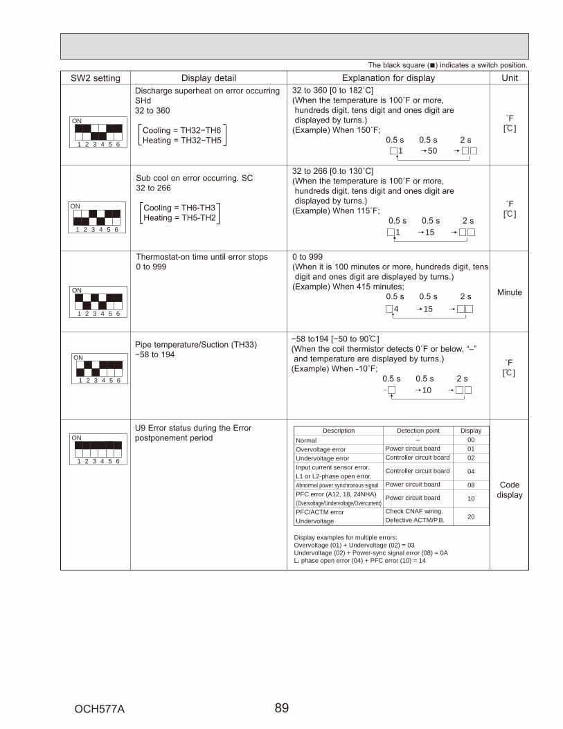
:
5011
ON
2 3 4 5 6
1
ON
2 3 4 5 6
1
ON
2 3 4 5 6
:
151
154
1
ON
2 3 4 5 6
NormalOvervoltage errorUndervoltage errorInput current sensor error.L1 or L2-phase open error.Abnormal power synchronous signalPFC error (A12, 18, 24NHA) (Overvoltage/Undervoltage/Overcurrent)PFC/ACTM errorUndervoltage
Display examples for multiple errors:Overvoltage (01) + Undervoltage (02) = 03Undervoltage (02) + Power-sync signal error (08) = 0AL1 phase open error (04) + PFC error (10) = 14
Power circuit boardController circuit board
Controller circuit board
Power circuit board
Power circuit board
Check CNAF wiring.Defective ACTM/P.B.
–Description Detection point Display
000102
04
08
10
20
1
ON
2 3 4 5 6
:
:
10

1
ON
2 3 4 5 6
Display Compressor operating frequency control
Display Compressor operating frequency control
Primary current controlSecondary current control
12
1
4
8
2
The tens digit
The ones digit (In this digit, the total number of activated control is displayed.)
Preventive control for excessive temperaturerise of discharge temperaturePreventive control for excessive temperaturerise of condensing temperatureFrosting preventing controlPreventive control for excessive temperaturerise of heatsink
(Example)The following controls are activated.
ature rise of condensing temperature
ature rise of heatsink
LED

11 EASY MAINTENANCE FUNCTION11-1. SMOOTH MAINTENANCE11-1-1. PAR-30MAA/PAR-31MAA
This cannot be executed during test operation.Depending on the combination with the outdoor unit, this may not be supported by some models.
F1 F2 F3 F4
Check menu
CursorService menu:
Error historyRefrigerant volume checkRefrigerant leak checkSmooth maintenanceRequest code
Smooth maintenance
Begin:
Smooth maintenance
Exit:
Ref.addressStable mode
Cursor -Address+
Ref.addressStable mode
Cool / Heat/ Normal
Cool / Heat/ Normal
Smooth maintenance
Return:
Smooth maintenance
Return:
Smooth maintenance
Return:
Page
Page
Page
COMP. currentCOMP. run timeCOMP. On / OffCOMP. frequency
A
Hz
Hrtimes
Hr
Ref. address Cool
Ref.address Cool
Ref.address Cool
Sub coolOU TH4 temp.OU TH6 temp.OU TH7 temp.
IU air temp.IU HEX temp.IU filter time
Navigating through the screens
1
2
3

Data measurementWhen the operation is stabilized, measure operation data as explained below.
(4) Press the [TEMP] buttons ( and ) to select the desired refrigerant address.
[Screen ]
(5) Select the type of data to be displayed.After selecting, go to step (6).
Compressor information
MENU button
[Display ]
Outdoor unit information
ON/OFF button
[Display ]
Indoor unit information
button
[Display ]
(6) Press the FILTER ( ) button to confirm the setting.
[Display example for accumulated operating time]
(7) Data is displayed on the display (at ).To check the data for each item, repeat steps (5) to (7).
(8) To cancel maintenance mode, press the TEST button for 3 seconds or press the ON/OFF button.
COMP ONx10 HOURS
COMP ONx100 TIMES
COMP ONCURRENT (A)
Cumulativeoperation time
ON/OFF Number Operating current
OUTDOOR UNITH·EXC. TEMP
OUTDOOR UNITOUTLET TEMP
OUTDOOR UNITOUTDOOR TEMP
Heat exchangertemperature
Comp dischargetemperature
Outdoor ambienttemperature
INDOOR UNITINLET TEMP
INDOOR UNITH·EXC. TEMP
INDOOR UNITFILTER USE H
Indoor roomtemperature
Heat exchangertemperature
Filter operatingtime
12,340 hoursDisplay
Waiting for response
Blinking
After approx.10 seconds
[1:1]Refrigerantaddress=00
[Twin]Refrigerantaddress=00
Outdoorunit
Indoor unit02
Indoor unit01
Outdoorunit
Remotecontroller
Remotecontroller
Indoor unit01
Refrigerant addressSingle refrigerant systemIn the case of single refrigerant system, the refrigerant addressis "00" and no operation is required.Simultaneous twin, triple units belong to this category(single refrigerant system).
Multi refrigerant system (group control)Up to 16 refrigerant systems (16 outdoor units) can be con-nected as a group by 1 remote controller. To check or set therefrigerant addresses.
Refrigerantaddress00
Refrigerantaddress01
Refrigerantaddress02
Refrigerantaddress15
Outdoorunit
Indoor unit01
Outdoorunit
Indoor unit01
Outdoorunit
Indoor unit01
Outdoorunit
Indoor unit01
Remotecontroller

11-2.GUIDE FOR OPERATION CONDITIONInspection item Result
Pow
er s
uppl
y
Loos
e co
n-ne
ctio
n
Breaker Good RetightenedTerminal block Outdoor Unit Good Retightened
Indoor Unit Good Retightened(Insulation resistance) M"
(Voltage) V1 Accumulated operating time Time2 Number of ON/OFF times Times3 Current A4 Refrigerant/heat exchanger temperature COOL °F HEAT °F5 Refrigerant/discharge temperature COOL °F HEAT °F6 Air/outside air temperature COOL °F HEAT °F (Air/discharge temperature) COOL °F HEAT °FAppearance Good Cleaning requiredHeat exchanger Good Cleaning requiredSound/vibration None Present
Air/intake air temperature COOL °F HEAT °F (Air/discharge temperature) COOL °F HEAT °F8
7
9
Refrigerant/heat exchanger temperature COOL °F HEAT °FFilter operating time* Time
Decorative panel Good Cleaning requiredFilter Good Cleaning requiredFan Good Cleaning requiredHeat exchanger Good Cleaning requiredSound/vibration None Present
Com-pressor
Tem
pera
ture
Cle
anli-
ness
Out
door
Uni
t
Tem
pera
ture
Cle
anlin
ess
Indo
or U
nit
* The filter operating time is the time that has elapsed since the filter was reset.
Check PointsEnter the temperature differences between 5 , 4 , 7 and 8 intothe graph given below.Operation state is determined according to the plotted areas onthe graph.For data measurements, set the fan speed to "Hi" before activat-ing maintenance mode.
Is "000" displayed stably in Display D on the remote controller?
Is "000" displayed stably in Display D on the remote controller?
(5 Discharge temperature) – (4 Outdoorheat exchanger temperature)(7 Indoor intake air temperature) – (8Indoor heat exchanger temperature)
(5 Discharge temperature) – (8 Indoorheat exchanger temperature)(8 Indoor heat exchanger temperature) –(7 Indoor intake air temperature)
Coo
l
Classification Item Result
Inspection
Temperaturedifference
Hea
t
Inspection
Temperaturedifference
Stable Unstable
°F
°F
Stable Unstable
°F
°F
Notes: Fixed Hz operation may not be possible under the following tempera-ture ranges.A)In cool mode, outdoor intake air temperature is 104 °For higher or
indoor intake air temperature is 73 °F or lower.B)In heat mode, outdoor intake air temperature is 68 °F or higher or
indoor intake air temperature is 77 °F or lower.If the air conditioner is operated at a temperature range other than theones above but operation is not stabilized after 30 minutes or more haveelapsed, carry out inspection.In heat mode, the operation state may vary due to frost forming on theoutdoor heat exchanger.
°F81
72
63
54
45
36
27
18
9
ºF81
63
54
45
36
27
18
72
0 18 36 54 72 90 108 126 144
NormalFilter inspection
Inspection C
Inspection A
Inspection B
9
°F°F
Normal
Filter inspectionInspection C
Inspection A
Inspection B
Cool mode Heat mode
( 7 In
door
inta
ke a
ir te
mpe
ratu
re)—
( 8In
door
heat
exc
hang
er te
mpe
ratu
re)
( 8 In
door
hea
t exc
hang
er te
mpe
ratu
re) —
( 7 In
door
inta
ke a
ir te
mpe
ratu
re)
[5 Discharge temperature] – [4 Outdoorheat exchanger temperature)
[5 Discharge temperature] – [8 Indoorheat exchanger temperature)
Res
ultNormal operation state
Filter may be clogged.*Performance has dropped. Detailed in-spection is necessary.Refrigerant amount is dropping.Filter or indoor heat exchanger may beclogged.
Area Check itemJudgment
Cool Heat
NormalFilter inspectionInspection A
Inspection BInspection C
*
18 36 54 72 90 108 126 144
Note: The above judgment is just guide based on Japanese standard conditions. It may be changed depending on the indoor and outdoor temperature.It may be judged as "filter inspection" due to the outdoor and indoor temperature, even though it is not clogged.
1.
2.
3.

"Refrigerant leak check" is valid only with models which support the refrigerant leak check function.
F1 F2 F3 F4
Check menu
CursorService menu:
Error historyRefrigerant volume checkRefrigerant leak checkSmooth maintenanceRequest code
Refrigerant leak check
Begin:
Start refrigerant leak checkApprox. 20minutes
Refrigerant leak checkAdd Add
Check menu:Page
Cond CondOKOK
OKNG––
OKNG
1
2
3
Default value RP71 – :– RP50 :
<Resetting the initial learning data>
11-3. INITIAL SETTINGS FOR REFRIGERANT LEAKAGE DETECTION FUNCTION11-3-1. PAR-30MAA/PAR-31MAA

12 FUNCTION SETTING
Function SettingsMode No.
Wired remote controller(RF thermistor)
Setting No. : Initial setting (when sent from the factory) Remarks
Power failure automatic recoveryIndoor temperature detecting
LOSSNAY connectivity
Power supply voltageFrost prevention temperatureHumidifier control
Change of defrosting control
Not availableAvailableAverage data from each indoor unitData from the indoor unit with remote controllersData from main remote controllerNot supportedSupported (indoor unit dose not intake outdoor air through LOSSNAY)Supported (indoor unit intakes outdoor air through LOSSNAY)230V208V2 [36°F] (Normal)3 [37°F]When the compressor operates, the humidifier also operates.When the fan operates, the humidifier also operates.StandardFor high humidity
1212312312121212
01(101)
02(—)
03(103)
04(104)
15(115)
16(116)
17(117)
The setting is applied to all the units in the same refrigerant system.
12-1. UNIT FUNCTION SETTING BY THE REMOTE CONTROLLER
4
Meaning of "Function setting"Mode02 : indoor temperature detecting
No. Indoor temperature(ta)=
No1. Average data of the sensor on all the indoor units
Initialsetting
ta=(A+B)/2 ta=(A+B)/2 ta=A ta=A
No2. Data of the sensoron the indoor unit thatconnectedwith remote controller
ta=A ta=B ta=A ta=A
No3. Data of the sensoron main remote controller
ta=C ta=C ta=C ta=C
OUTDOOR
INDOOR
REMOTE(MAIN)
REMOTE(SUB)
INDOOR
OUTDOOR
INDOOR
REMOTE(MAIN)
REMOTE(SUB)
OUTDOOR
INDOOR
REMOTE(MAIN)
OUTDOOR
INDOOR
REMOTE(MAIN)
REMOTE(SUB)
INDOOR

Function Settings
Mode No.
No.Setting
: Initial setting (Factory setting)- : Not available
4-Waycassette
Ceiling suspended Wall mounted
PCA-KA PKA-HA(L) PKA-KA(L)
Filter sign 100h 12500h 07
(107) 2"Clean the filter" indicator is not displayed 3
Air flow Quiet 1 -(Fan speed) Standard 08
(108) 2High ceiling 3
No.of air outlets 4 directions 1 - -3 directions 09
(109) 2 - -2 directions 3 - -
Optional high efficiency Not supported 10(110)
1 -filter Supported 2 -Vane setting No vanes (Vane No.3 setting : PLA only) 1 -
Vane No.1 setting 11(111) 2 -
Vane No.2 setting 3 -Optional humidifier Not supported 13
(113)1 - -
(PLA only) Supported 2 - -Vane differential setting No.1 setting (TH5: 75-82°F (24-28 )) 1in heating mode No.2 setting (Standard, TH5: 82-90°F (28-32 )) 14
(114)2
(cold wind prevention) No.3 setting (TH5: 90-100°F (32-38 )) 3Swing 23
(123)12
Set temperature in heating 24(124)
1mode (4 deg up) *1 2Fan speed when the Extra low 1heating thermostat is OFF Stop
25(125) 2
Keeping fan speed set by remote controller 3Fan speed when the Keeping fan speed set by remote controller 27
(127)1
cooling thermostat is OFF Stop 2Detection of abnormality of Detect 28
(128)1
the pipe temperature (P8)
*1. PKA-HA(L)/KA(L): 3.6°F (2°C) up.Neglect 2
-----------
PLA-BA
Not available SwingAvailable Wave air flowAvailableNot available
}PLA-BA
Wired remote controller(RF thermistor)
4
4
4
Mode No.11Setting No. Settings PLA-BA PCA-KA
1 No VanesVane No.3 setting
( Downward position than the standard )Less smudging No vane function
2 Vane No.1 setting Standard Standard
3 Vane No.2 setting ( Upward position than the standard )Less draft *
( Upward position than the standard )Less draft *
* Be careful of the smudge on ceiling.
Wired remote controller(RF thermistor) Wired remote controller
Function SettingsMode No.
No.Setting : Initial setting
(Factory setting)
Filter sign 100h 12500h
07(107) 2
No filter sign indicator 3External static pressure 35/50/70/100/125Pa 08
(108)10
(110)12
Extra low
3
Fan speed during theheating thermo OFF Stop
25(125)
1
Set fan speed2
27(127)
12
Detection of abnormalityof the pipe temperature (P8)
128(128) 2
Set temperature in heating 24(124)mode (4 deg up)
Refer to the right table
Refer to the right table
AvailableNot available
Fan speed during thecooling thermo OFF
Set fan speedStopAvailableNot available
External static pressure
Setting No.Initial setting (Factory setting)
35Pa 50Pa70Pa 100Pa125Pa
23123
Mode No.
8 (108)11222
10 (110)
PEAD-AA

Main
Main display:Cursor Page
Main menuMaintenanceInitial settingService
F1 F2 F3 F4
Service menu
CursorSelect:
Enter maintenance password
unem ecivreS
unem ecivreS
rosruC
rosruC
:unem niaM
:unem niaM
Test runInput maintenance info.Function settingCheckSelf check
Maintenance passwordRemote controller check
Service menu
Service menu:
Not available.Please stop the unit.
2
1
Maintenance password is required
Note: The initial maintenance password is "9999". Change the default password as necessary to prevent unauthorized access. Have the password available for those who need it.
: If you forget your maintenance password, you can initialize the password to the default password "9999" by pressing and holding the and buttons simultaneously for three seconds on the maintenance password setting screen.
3
Note: Air conditioning units may need to be stopped to make certain set-tings. There may be some settings that cannot be made when the system is centrally controlled.
Navigating through the screens
12-1-1. Selecting functions using the wired remote controller <PAR-30MAA> <PAR-31MAA>
<Service menu>

F1 F2 F3 F4
unem ecivreS
rosruC:unem niaM
Test runInput maintenance info.Function settingCheckSelf check
F1 F2 F3 F4
Function setting
Cursor AddressMonitor:
Ref. addressUnit No. Grp./1/2/3/4/All
Function setting
Cursor CursorRequest:
Ref. addressMode 1Mode 2Mode 3Mode 4
Grp.
F1 F2 F3 F4
Function setting
Cursor CursorRequest:
Ref. addressMode 7Mode 8Mode 9Mode 10
Unit #1
2
3
4
1
<Checking the indoor unit No.>
F1 F2 F3 F4
Function settingRef. address
Sending data
Grp.5
The above function settings are not available for the City Multi units.Table 1 summarizes the setting options for each mode number. Refer to the indoor unit Installation Manual for the detailed information about ini-tial settings, mode numbers, and setting numbers for the indoor units.Be sure to write down the settings for all functions if any of the initial settings has been changed after the completion of installation work.
<Function setting>

[Operating Procedure]1 Check the setting items provided by function selection.
If settings for a mode are changed by function selection, the functions of that mode will be changed accordingly. Check all the current settings according to steps 2to 7 , fill in the "Check" column in Table 1, then change them as necessary. For initial settings, refer to the indoor unit's installation manual.
2 Switch off the remote controller.A Hold down the ( mode is 15 to 28)and B
buttons simultaneously for at least 2 seconds. will start to blink,
then the remote controller's display content will change as shown below.
FILTER3 Set the outdoor unit's refrigerant address.
C Press the [ CLOCK] buttons ( and ) to select the desiredrefrigerant address. The refrigerant address changes from "00" to "15". (This operation is not possible for single refrigerant systems.)
If the unit stops after FUNCTIONSELECTION blinked for 2 seconds or "88" blinks in the room temperature display area for 2 seconds, a transmission error may have occurred.
Check to see if there are any sources of noise or interference near the transmission path.
Note: If you have made operational mistakes during this procedure, exit function selection (see step 0 ), then restart from step 2.
4 Set the indoor unit number.
D Press the ON/OFF button so that "- -" blinks in the unit number displayarea.
C Press the [ CLOCK] buttons ( and ) to select the unit numberof the indoor unit for which you want to perform function selection. The unitnumber changes to "00", "01", "02","03",04" and "AL" each time a button ispressed.
To set modes 01 to 06 or 15 to 22, select unit number "00".To set modes 07 to 14 or 23 to 28, carry out as follows:
To set each indoor unit individually, select " 01" to "04".To set all the indoor units collectively, select " AL".
5 Confirm the refrigerant address and unit number.E Press the MODE button to confirm the refrigerant address and unit
number.After a while, "- - " will start to blink in the mode number display area.
E When the refrigerant address and unit number are confirmed by pressing the
MODE button, the corresponding indoor unit will start fan operation. Thishelps you find the location of the indoor unit for which you want to perform functionselection. However, if "00" or "AL" is selected as the unit number, all the indoorunits corresponding to the specified refrigerant address will start fan operation.
"88" will blink in the room temperature display area if the selected refrigerantaddress does not exist in the system.Furthermore, if "F" appears and blinks in the unit number display area and therefrigerant address display area also blinks, there are no units that corre-spond to the selected unit number. In this case, the refrigerant address and unitnumber may be incorrect, so repeat steps 2 and 3 to set the correct ones.
When grouping different refrigerant systems, if an indoor unit other than theone to which the refrigerant address has been set to perform fan operation,there may be another refrigerant address that is the same as the specified one.In this case, check the DIP switch of the outdoor unit to see whether such arefrigerant address exists.
6 Select the mode number.F Press the [ TEMP] buttons ( and ) to set the desired mode
number.(Only the selectable mode numbers can be selected.)
7 Select the setting content for the selected mode.G Press the MENU button. The currently selected setting number will
blink, so check the currently set content.
F Press the [ TEMP] buttons ( and ) to select the desired settingnumber.
8 Register the settings you have made in steps 3 to 7 .E Press the MODE button. The mode number and setting number will start
to blink and registration starts.
The mode number and setting number will stop blinking and remain lit, indicating theend of registration.
If " - - - " is displayed for both the mode number and setting number and " " blinks in the room temperature display area, a transmission error may have occurred.Check to see if there are any sources of noise or interference near the transmission path.
9 If you wish to continue to select other functions, repeat steps 3 to 8 .
0 Complete function selection.A Hold down the ( mode is 15 to 28) and B buttons
simultaneously for at least 2 seconds. FILTER
After a while, the function selection screen will disappear and the air condi-tioner OFF screen will reappear.
Do not operate the remote controller for at least 30 seconds after completingfunction selection. (No operations will be accepted even if they are made.)
Note:If a function of an indoor unit is changed by function selection after installation is complete, make sure that a " " mark, etc., is given in the "Check" column of Table1 to indicate the change.
Refrigerant addressdisplay section
Unit numberdisplay section
Mode numberdisplay section
00 refrigerant address
Indoor unit
Fan draftRemote controller
Unit number 01 Unit number 02
Outdoor unit
Designate operation
Example: When the refrigerant address is set to 00 and the unit number is 02.
Mode numberdisplay section
Mode number 02 = Indoor temperature detection
Setting number display section Setting number 3 = Remote controller built-in sensorSetting number 1 = Indoor unit operating average
TESTFUNCTIONSELECTION
TEST

ON/OFF TEMP
FAN
VANEMODE
CHECK LOUVER
TEST RUN
AUTO STOP
AUTO START
h
min
CHECK
RESETSET CLOCK
The flow of the function selection procedure is shown below. This example shows how to turn off the function that raises the set temperature by 4 degrees during HEAT operation. The procedure is given after the flow chart.
Check the function selection setting.
Switch to function selection mode. (Enter address "50" in troubleshooting mode, then press the HOUR button.)
Troubleshooting mode is the mode entered whenyou press the CHECK button twice to display"CHECK".
Specify unit No. "01" (since the function applies to unit 01). (Set address "01" while still in troubleshooting mode, then press the MINUTE button.)Note: You can't specify the refrigerant address.
Select mode No. "24" (function that raises set temperature by 4 degrees during HEAT operation). (Set address "24" while still in troubleshooting mode, then press the HOUR button.)
Finished
End function selection mode. (End troubleshooting mode.)
YES
NO
Note: When you switch to function selection mode on the IR wireless remote controller's operation area, the unit ends function selection mode automatically if nothing is input for 10 minutes or longer.
Select setting No. "02" (OFF). (Set address "02" while still in troubleshooting mode, then press the HOUR button.)
Change unit No.
YES
NO
[Flow of function selection procedure]
12-1-2. Selecting functions using the IR wireless remote controller (Type C)
[Operating instructions]1
2
3
4
5
6 4 5
7 3 5
8
h
CHECK
min
h
h
min

F1 F2 F3 F4
ON/OFF button
When the backlight is off, pressing any button turns the backlight on and does not perform its function. (except for the (ON/OFF) button)
SELECT button
RETURN button
MENU button
Backlit LCD
ON/OFF lamp
Function button F1
Function button F2
Function button F3
Function button F4
Fri
Room
Set temp.
Mode Temp. Fan
Cool Auto
Main
Main display:Cursor Page
Main menuVane·Louver·Vent. (Lossnay)High powerTimerWeekly timerOU silent mode
<Main display> <Main menu>
12-2. FUNCTION SELECTION OF REMOTE CONTROLLER12-2-1. PAR-30MAA/PAR-31MAA

Not all functions are available on all models of indoor units.
Energy saving
Night setback
Main menu
Vane · Louver · Vent. (Lossnay)
High power
Weekly timer
Restriction
Maintenance
Initial setting
Timer
Service
Menu structure
Filter information
Error information

Setting and display items Setting detailsVane · Louver · Vent. (Lossnay) Use to set the vane angle.
Use to turn ON/OFF the louver.
Use to set the amount of ventilation.
High power Use to reach the comfortable room temperature quickly.
Timer ON/OFF timer* Use to set the operation ON/OFF times.
Auto-Off timer Use to set the Auto-Off time.
Weekly timer* Use to set the weekly operation ON/OFF times.
Restriction Temp. range Use to restrict the preset temperature range.
Operation lock Use to lock selected functions.
Energy saving Auto return Use to get the units to operate at the preset temperature after performing energy-save operation for a
Schedule* Set the start/stop times to operate the units in the energy-save mode for each day of the week, and set the energy-saving rate.
Night setback* Use to make Night setback settings.
Filter information
Error information Use to check error information when an error occurs.
Maintenance Auto descending panel Auto descending panel (Optional parts) Up / Down you can do.
Manual vane angle
Initial setting Main/Sub When connecting two remote controllers, one of them needs to be designated as a sub controller.
Clock Use to set the current time.
Main display Use to switch between "Full" and "Basic" modes for the Main display.
Contrast
Display details Make the settings for the remote controller related items as necessary.Clock: Temperature: Room temp. : Auto mode:
Auto mode Whether or not to use the Auto mode can be selected by using the button.This setting is valid only when indoor units with the Auto mode function are connected.
Administrator password The administrator password is required to make the settings for the following items.
Language selection Use to select the desired language.Service Test run Select "Test run" from the Service menu to bring up the Test run menu.
Input maintenance Select "Input maintenance Info." from the Service menu to bring up the Maintenance information screen.The following settings can be made from the Maintenance Information screen.
Function setting Make the settings for the indoor unit functions via the remote controller as necessary.Check Error history:
Refrigerant leak check: Smooth maintenance: Request code:
Self check Error history of each unit can be checked via the remote controller.Maintenance password Use to change the maintenance password.Remote controller check When the remote controller does not work properly, use the remote controller checking function to trouble-
shoot the problem.
Main menu list
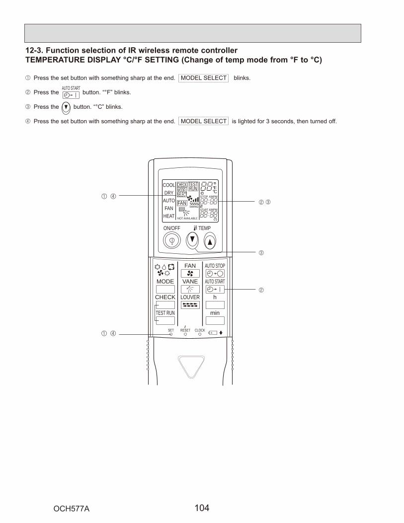
12-3. Function selection of IR wireless remote controllerTEMPERATURE DISPLAY °C/°F SETTING (Change of temp mode from °F to °C)
1
2
3
4
AUTO START
ON/OFF TEMP
FAN
VANE
TEST RUN
AUTO STOP
AUTO START
h
min
LOUVER
MODE
CHECK
RESETSET CLOCK
MODELSELECT
NOT AVAILABLE
SWING
CHECK
FAN
TESTRUN °F
°CAMPMSTOP
START AMPM
COOLDRY
AUTOFAN
HEAT
1 4
1 42
2
3
3

13 MONITORING THE OPERATION DATA BY THE REMOTE CONTROLLER
F1 F2 F3 F4
Check menu
CursorService menu:
Error historyRefrigerant volume checkRefrigerant leak checkSmooth maintenanceRequest code
2
F1 F2 F3 F4
Request code
Request:
Request:
Request code
Ref.addressRequest code
Cursor - +
Ref.addressRequest code
Cursor - +
Request code: 004
1
13-1. HOW TO "MONITOR THE OPERATION DATA"13-1-1. PAR-30MAA/PAR-31MAA

13-2. REQUEST CODE LISTCertain indoor/outdoor combinations do not have the request code function; therefore, no request codes are displayed.
Req
uest
cod
e
Request contentDescription
(Display range)Unit Remarks
0123456789101112131415161718
19
20
2122232425262728293031
32
33
34
35
3637383940414243444546474849
Operation stateCompressor-Operating current (rms)Compressor-Accumulated operating timeCompressor-Number of operation timesDischarge temperature (TH32)Outdoor unit - Liquid pipe 1 temperature (TH3)Outdoor unit - Liquid pipe 2 temperatureOutdoor unit-2-phase pipe temperature (TH6)Suction temperature (TH33)Outdoor unit-Outside air temperature (TH7)Outdoor unit-Heatsink temperature (TH8)
Discharge super heat (SHd)Sub-cool (SC)
Compressor-Operating frequencyCompressor-Target operating frequencyOutdoor unit-Fan output stepOutdoor unit-Fan 1 speed(Only for air conditioners with DC fan motor)Outdoor unit-Fan 2 speed(Only for air conditioners with DC fan motor)
LEV (A) openingLEV (B) opening
Primary currentDC bus voltage
Number of connected indoor unitsIndoor unit-Setting temperatureIndoor unit-Intake air temperature <Measured by thermostat>Indoor unit-Intake air temperature (Unit No. 1)<Heat mode-4-deg correction>Indoor unit-Intake air temperature (Unit No. 2)<Heat mode-4-deg correction>Indoor unit-Intake air temperature (Unit No. 3)<Heat mode-4-deg correction>Indoor unit-Intake air temperature (Unit No. 4)<Heat mode-4-deg correction>
Indoor unit - Liquid pipe temperature (Unit No. 1)Indoor unit - Liquid pipe temperature (Unit No. 2)Indoor unit - Liquid pipe temperature (Unit No. 3)Indoor unit - Liquid pipe temperature (Unit No. 4)
Indoor unit-Cond./Eva. pipe temperature (Unit No. 1)Indoor unit-Cond./Eva. pipe temperature (Unit No. 2)Indoor unit-Cond./Eva. pipe temperature (Unit No. 3)Indoor unit-Cond./Eva. pipe temperature (Unit No. 4)
Thermo ON operating timeTest run elapsed time
Refer to 13-2-1. Detail Contents in Request Code.0–500–9999
37– 32758–194
58–194
–A
10 hours100 times
°F°F°F°F°F°F°F
°F°F
HzHz
Step
rpm
rpm
PulsesPulses
AV
Units°F°F
°F
°F
°F
°F
°F°F°F°F
°F°F°F°F
MinutesMinutes
"0" is displayed if the air conditioner is a single-fantype.
"0" is displayed if the target unit is not present.
"0" is displayed if the target unit is not present.
"0" is displayed if the target unit is not present.
Not possible to activate maintenance mode during the test run.
0–9999
40–19458–190
58–19040–327
0–3270–234
0–2550–2550–10
0–9999
0–9999
0–5000–500
0–50180–370
0–462–8646–102
46–102
46–102
46–102
46–102
38–19038–19038–19038–190
38–19038–19038–19038–190
0–9990–120

Req
uest
cod
e
Request contentDescription
(Display range)Unit Remarks
50515253545556575859606162636465666768697071727374757677787980818283
84
85868788
89
90
91
9293949596979899
100
101
102
Indoor unit-Control stateOutdoor unit-Control stateCompressor-Frequency control stateOutdoor unit-Fan control stateActuator output stateError content (U9)
Signal transmission demand capacityContact demand capacityExternal input state (silent mode, etc.)
Outdoor unit-Capacity setting displayOutdoor unit-Setting information
M-NET adapter connection (presence/absence)
Display of execution of replace/wash operation
Outdoor unit-Microprocessor version information
Outdoor unit-Microprocessor version information (sub No.)
Outdoor unit - Error postponement history 1 (latest)
Outdoor unit - Error postponement history 2 (previous)
Outdoor unit - Error postponement history 3 (last but one)
"0000": Not connected
Examples) Ver 5.01 Auxiliary information (displayed afterversion information)Examples) Ver 5.01 A000
Displays postponement code. (" - - " isdisplayed if no postponement code is present)Displays postponement code. (" - - " isdisplayed if no postponement code is present)Displays postponement code. (" - - " isdisplayed if no postponement code is present)
––––––
%––
––
––
–––––––
–
–
Ver
–
Code
Code
Code
Refer to 13-2-1.Detail Contents in Request Code.
Refer to 13-2-1.Detail Contents in Request Code.Refer to 13-2-1.Detail Contents in Request Code.
Refer to 13-2-1.Detail Contents in Request Code.
Refer to 13-2-1.Detail Contents in Request Code.
Refer to 13-2-1.Detail Contents in Request Code.
Refer to 13-2-1.Detail Contents in Request Code.
Refer to 13-2-1.Detail Contents in Request Code.
Refer to 13-2-1.Detail Contents in Request Code.
Refer to 13-2-1.Detail Contents in Request Code.
"0001": Connected
"0000": Not washed"0001": Washed
"0501"
"A000"
0–255

Req
uest
cod
e
Request contentDescription
(Display range)Unit Remarks
103104105
106
107108109110111112113114115116117118119120
121
122
123
124125126127128129130131
132
133
134
135136137138139140~
146147148149150151152
Displays error history. (" - - " is displayed if no history is present.)Displays error history. (" - - " is displayed if no history is present.)Displays error history. (" - - " is displayed if no history is present.)
: TH36 : TH67 : TH78 : TH80 : No thermistor error
Displayed in the same way as request code "0".
CodeCodeCode
Sensornumber
–A
10 hours100 times
°F°F°F°F
°F°F°F°FHz
Step
rpm
rpm
PulsesPulses
Minutes
°F
°F
°F
°F°F°F
"0" is displayed if the air conditioner is a single-fan type.
Average value of all indoor units is displayed if the air condi-tioner consists of two or more indoor units (twin, triple, quad).Average value of all indoor units is displayed if the air condi-tioner consists of two or more indoor units (twin, triple, quad).
Error history 1 (latest)Error history 2 (second to last)Error history 3 (third to last)
Abnormal thermistor display(TH3/TH6/TH7/TH8)
Operation mode at time of errorCompressor-Operating current at time of errorCompressor-Accumulated operating time at time of errorCompressor-Number of operation times at time of errorDischarge temperature at time of errorOutdoor unit - Liquid pipe 1 temperature (TH3) at time of error
Outdoor unit - Liquid pipe 2 temperature at time of errorOutdoor unit-2-phase pipe temperature (TH6) at time of error
Outdoor unit-Outside air temperature (TH7) at time of errorOutdoor unit-Heatsink temperature (TH8) at time of errorDischarge super heat (SHd) at time of errorSub-cool (SC) at time of errorCompressor-Operating frequency at time of errorOutdoor unit at time of error Fan output step
Outdoor unit at time of error Fan 1 speed (Only for air conditioners with DC fan)
Outdoor unit at time of error Fan 2 speed (Only for air conditioners with DC fan)
LEV (A) opening at time of errorLEV (B) opening at time of error
Thermo ON time until operation stops due to error
Indoor - Liquid pipe temperature at time of error
Indoor-Cond./Eva. pipe temperature at time of error
Indoor at time of error Intake air temperature <Thermostat judge temperature>
Indoor-Actual intake air temperatureIndoor - Liquid pipe temperatureIndoor-Cond./Eva. pipe temperature
3
0–999937–327
0–3270–2340–255
0–10
0–500–9999
0–9999
0–9999
0–5000–500
0–999

Req
uest
cod
e
Request contentDescription
(Display range)Unit Remarks
153
154
155
156157
158
159160161162163164165166167~
189190191
192~
764765766
767
Fan control data
00 **" "**" indicates fan control data.
"00 **" "**" indicates fan control data.
Refer to 13-2-1 Detail Contents in Request Code.UndefinedRefer to 13-2-1 Detail Contents in Request Code.
Undefined
Examples) Ver 5.01 "0501"Auxiliary information (displayed after version information)Examples) Ver 5.01 A000 "A000"
1 hour
10 hours
–
–
–
–––––
Ver
–
For indoor fan phase control
For indoor fan pulsation control
For indoor DC brushless motor control
Indoor-Fan operating time(After filter is reset)Indoor-Total operating time(Fan motor ON time)
Indoor fan output value (Sj value)Indoor fan output value(Pulsation ON/OFF)Indoor fan output value (duty value)
Indoor unit-Model setting informationIndoor unit-Capacity setting informationIndoor unit-SW3 informationWireless pair No. (indoor control board side) settingIndoor unit-SW5 information
Indoor unit-Microprocessor version informationIndoor unit-Microprocessor version information (sub No.)
Stable operation (Heat mode)Stable operation (Cool mode)
Stable operation cancellation
This request code is not provided to collect data. It is used to fix the operation state.This request code is not provided to collect data. It is used to fix the operation state.This request code is not provided to collect data. It is used to cancel the operation state that has beenfixed by request codes "765" and "766".
"
Refer to 13-2-1 Detail Contents in Request Code.
0–9999
0–9999
0–255

Frequency control state 2
Display Discharge temperature Condensation temperature Anti-freeze Heatsink temperatureoverheat prevention overheat prevention protection control overheat prevention
01 Controlled2 Controlled3 Controlled Controlled4 Controlled5 Controlled Controlled6 Controlled Controlled7 Controlled Controlled Controlled8 Controlled9 Controlled ControlledA Controlled Controlledb Controlled Controlled ControlledC Controlled Controlledd Controlled Controlled ControlledE Controlled Controlled ControlledF Controlled Controlled Controlled Controlled
13-2-1. Detail Contents in Request Code
[Operation state] (Request code : "0")
Data display
Example) Request code "004"Discharge temperature 156°FRefrigerant address "00"
B: Refrigerant addressA: Mode display
C: Data display areaD: Request code display area
A
B
C
D
C 4Relay output stateOperation mode
[Indoor unit – Control state] (Request code : "50")
Data display
Operation mode
Display Operation mode0 STOP FANC COOL DRYH HEATd DEFROST
Relay output state
Display Power currently Compressor Four-way valve Solenoid valvesupplied to compressor
Unit No. 4 stateUnit No. 3 state
Unit No. 2 state
Unit No. 1 state
Display State0 Normal1 Preparing for heat operation.2 –3 –4 Heater is ON.5 Anti-freeze protection is ON.6 Overheat protection is ON.7 Requesting compressor to turn OFF.F There are no corresponding units.
[Outdoor unit – Control state] (Request code : "51")
Data display State0 0 0 0 Normal0 0 0 1 Preparing for heat operation.0 0 0 2 Defrost
[Compressor – Frequency control state] (Request code : "52")
Data display
0 0Frequency control state 2
Frequency control state 1
Frequency control state 1
Display Current limit control0 No current limit1 Primary current limit control is ON.2 Secondary current limit control is ON.
–
ONON
012345678A
–
ONONONON
–
ONON
ONON
ON
–ON
ON
ON
ON

[Fan control state] (Request code : "53")
Data display
Fan step correction value by heatsink temperature overheat prevention controlFan step correction value by cool condensation temperature overheat prevention control
0 0
Display Correction value- (minus) – 1
0 0
2
[Actuator output state] (Request code : "54")
Data displayActuator output state 1Actuator output state 2
0 0
Actuator output state 1
Display SV1 Four-way valve Compressor
0123456789AbCdEF
ON
ON
ON
ON
ON
ON
ON
ON
ONON
ONON
ONON
ONON
ONONONON
ONONONON
ONONONONONONONON
Actuator output state 2
Display 52C SV2 SS
01234567
ON
ON
ON
ON
ONON
ONON
ONONONON
[Error content (U9)] (Request code : "55")Data display
Error content 1Error content 2
0 0
Error content 1 : Detected
Display Overvoltage Undervoltage L1-phase Power synchronizingerror error open error signal error
0123456789AbCdEF
Error content 2 : Detected
Display Converter Fo PAM errorerror
0123
Compressor iswarming up
1 +1+2

[Contact demand capacity] (Request code : "61")
Data display 0 0 0Setting content
[External input state] (Request code : "62")
Data display 0 0 0Input state
Input state : Input present
Display Contact demand Silent mode Spare 1 Spare 2input input input input
0123456789AbCdEF
[Outdoor unit – Capacity setting display] (Request code : "70")
Data display Capacity
10 18 9 12
11 2414 3020 3625 42
[Outdoor unit – Setting information] (Request code : "71")
Data displaySetting information Setting information
0 0Setting information
Display Defrost mode0 Standard1 For high humidity
Setting information
Display Single-/ Heat pump/3-phase cooling only
0 Single-phase Heat pump1 Cooling only2 3-phase Heat pump3 Cooling only
Setting content
Display Setting value SettingSW7-1 SW7-2
01 50% ON
ON2 75% ON
ON
0%
3 100%

[Indoor unit – Model setting information] (Request code : 162)
Data display
0 0
See the table on the right.
Display Model setting state Display Model setting state
00 2001 2102 22
PLA-A·BA
PEA-A·AAPCA-A·KAPKA-A·HA(L)/KA(L)
03 2304 2405 2506 2607 2708 2809 290A 2A0b 2b0C 2C0d 2d0E 2E0F 2F10 3011 3112 3213 3314 3415 3516 3617 3718 3819 391A 3A1b 3b1C 3C1d 3d1E 3E1F 3F
[Indoor unit – Capacity setting information] (Request code : 163) Data display
0 0
See the table on the right.
Display Capacity setting state Display Capacity setting state
00 10 4201 1102 1203 1304 1405 1506 12 1607 1708 1809 18 190A 1A0b 24 1b0C 1C0d 30 1d0E 1E0F 36 1F
Display Pair No. setting state
00 No. 001 No. 1 J41 disconnected02 No. 2 J42 disconnected03 No. 3 J41, J42 disconnected
[Wireless pair No. (indoor control board side) setting] (Request code : 165)
Data display
0 0
See the table on the right.
PEAD-A·AAPEAD-A·AA

14 DISASSEMBLY PROCEDURE
1. Removing the top panel, service panel, front panel and back panel
2. Removing the fan motor
Photo 1
Photo 2
Photo 3
Photo 4
PUZ-A18NHA6 PUZ-A18NHA6-BS PUY-A12/18NHA6 PUY-A12/18NHA6-BS
OPERATING PROCEDURE PHOTOS

4. Removing the thermistor <2-phase pipe> (TH6), thermis-tor <Liquid> (TH3) and thermistor <Suction> (TH33)
Note: Replace the thermistor <2-phase pipe> (TH6) and the thermistor <Ambient> (TH7) together since they are combined. Refer to No. 5. to remove the thermistor <Ambient> (TH7).
Photo 5
Photo 6
3. Removing the electrical parts box
OPERATING PROCEDURE PHOTOS

5. Removing the thermistor <Ambient> (TH7)
Note: In case of replacing thermistor <Ambient> (TH7), replace it together with thermistor <2-phase pipe> (TH6), since they are combined together. Refer to No.4. to remove thermistor <2-phase pipe>.
Photo 7
Photo 9
6. Removing the thermistor <Comp. surface> (TH32)
7. Removing the 4-way valve coil (21S4) and linear expansion valve coil (LEV-A)
[Removing the 4-way valve coil (21S4)]
[Removing the linear expansion valve coil (LEV-A)]
Photo 8
OPERATING PROCEDURE PHOTOS

9. Removing linear expansion valve
Note 1: Recover refrigerant without spreading it in the air.Note 2: The welded part can be removed easily by
removing the back panel.Note 3: When installing the linear expansion valve, cover
or more), then braze the pipes so that the inside of pipes are not oxidized.
8. Removing the 4-way valve
Note 1: Recover refrigerant without spreading it in the air.Note 2: The welded part can be removed easily by
removing the right side panel.Note 3: When installing the four-way valve, cover it with
more), then braze the pipes so that the inside of pipes are not oxidized.
Photo 10
Photo 11 10. Removing the high pressure switch (63H)
Note 1: Recover refrigerant without spreading it in the air. Note 2: The welded part can be removed easily by
removing the back panel. Note 3: When installing the high pressure switch, cover it
or more), then braze the pipes so that the inside of pipes are not oxidized.
11. Removing the reactor (ACL) Photo 12
OPERATING PROCEDURE PHOTOS

Photo 13
Photo 14
12. Removing the compressor (MC)
Note: Recover refrigerant without spreading it in the air.
13. Removing the accumulator
Note: Recover refrigerant without spreading it in the air.
OPERATING PROCEDURE PHOTOS

1. Removing the service panel and top panel Figure 1
2. Removing the fan motor (MF1)
Photo 3
Photo 1 Photo 2
3. Removing the electrical parts box
PUZ-A24/30/36NHA6(-BS) PUY-A24/30/36NHA6(-BS)OPERATING PROCEDURE PHOTOS & ILLUSTRATION

4. Removing the thermistor <2-phase pipe> (TH6)
Note: In case of replacing thermistor <2-phase pipe> (TH6), replace it together with thermistor <Ambient> (TH7), since they are combined together.
Refer to No.5 below to remove thermistor<Ambient>.
5. Removing the thermistor <Ambient> (TH7)
Note: In case of replacing thermistor <Ambient> (TH7), replace it together with thermistor <2-phase pipe> (TH6), since they are combined together. Refer to No.4 above to remove thermistor <2-phase pipe>.
Photo 6 6. Removing the thermistor <Liquid> (TH3)
Photo 5
Photo 4
7. Removing the thermistor <Comp. surface> (TH32) andthermistor <Suction> (TH33)
Photo 7
OPERATING PROCEDURE PHOTOS

8. Removing the 4-way valve coil (21S4), linear expansion valve coil (LEV-A) and bypass valve coil (SV)
[Removing the 4-way valve coil]
[Removing the linear expansion valve coil]
[Removing the bypass valve coil]
9. Removing the 4-way valve
Note 1: Recover refrigerant without spreading it in the air.Note 2: The welded part can be removed easily by
removing the right side panel.Note 3: When installing the 4-way valve, cover it with a wet
braze the pipes so that the inside of pipes are not oxidized.
10. Removing the linear expansion valve
Note 1: Recover refrigerant without spreading it in the air.Note 2: The welded part can be removed easily by
removing the right side panel.Note 3: When installing the linear expansion valve, cover
or more), then braze the pipes so that the inside of pipes are not oxidized.
Photo 8
Photo 9
OPERATING PROCEDURE PHOTOS

11. Removing the bypass valve
Note 1: Recover refrigerant without spreading it in the air. Note 2: The welded part can be removed easily by
removing the right side panel.
13. Removing the reactor (ACL) (A24)
Photo 10
12. Removing the high pressure switch (63H)
Note 1: Recover refrigerant without spreading it in the air. Note 2: The welded part can be removed easily by
removing the right side panel. Note 3: When installing the high pressure switch, cover it
or more), then braze the pipes so that the inside of pipes are not oxidized.
Photo 11
Photo 12
OPERATING PROCEDURE PHOTOS

15. Removing the compressor (MC)
Note: Recover refrigerant without spreading it in the air.
16. Removing the accumulator
Note: Recover refrigerant without spreading it in the air.
Photo 14
Photo 15
14. Removing the reactor (DCL) (A30, 36) Photo 13
OPERATING PROCEDURE PHOTOS

1. Removing the service panel and top panel Figure 1
2. Removing the fan motor (MF1, MF2)
Photo 33. Removing the electrical parts box
Photo 1 Photo 2
PUZ-A42NHA6(-BS) PUY-A42NHA6(-BS)OPERATING PROCEDURE PHOTOS & ILLUSTRATION
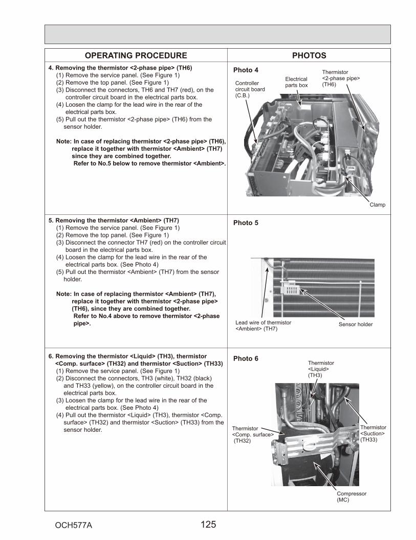
PHOTOSPhoto 4
5. Removing the thermistor <Ambient> (TH7)
Note: In case of replacing thermistor <Ambient> (TH7), replace it together with thermistor <2-phase pipe> (TH6), since they are combined together. Refer to No.4 above to remove thermistor <2-phase pipe>.
Photo 6 6. Removing the thermistor <Liquid> (TH3), thermistor<Comp. surface> (TH32) and thermistor <Suction> (TH33)
Photo 5
4. Removing the thermistor <2-phase pipe> (TH6)
Note: In case of replacing thermistor <2-phase pipe> (TH6), replace it together with thermistor <Ambient> (TH7) since they are combined together. Refer to No.5 below to remove thermistor <Ambient>.
OPERATING PROCEDURE

7. Removing the 4-way valve coil (21S4) and linear expansion valve coil (LEV-A)
[Removing the 4-way valve coil]
[Removing the linear expansion valve coil]
8. Removing the 4-way valve
Note 1: Recover refrigerant without spreading it in the air.Note 2: The welded part can be removed easily by
removing the right side panel.Note 3: When installing the 4-way valve, cover it with a
then braze the pipes so that the inside of pipes are not oxidized.
9. Removing linear expansion valve
Note 1: Recover refrigerant without spreading it in the air.Note 2: The welded part can be removed easily by
removing the right side panel.Note 3: When installing the linear expansion valve, cover
it with a wet cloth to prevent it from heating
inside of pipes are not oxidized.
Photo 7
OPERATING PROCEDURE PHOTOS

PHOTOS
11. Removing the reactor (DCL) and capacitor (CE)
Photo 8
Photo 9
10. Removing the high pressure switch (63H)
Note 1: Recover refrigerant without spreading it in the air. Note 2: The welded part can be removed easily by remov-
ing the right side panel. Note 3: When installing the high pressure switch, cover it
with a wet cloth to prevent it from heating (210°F or more), then braze the pipes so that the inside of pipes are not oxidized.
OPERATING PROCEDURE

12. Removing the compressor (MC)
Note: Recover refrigerant without spreading it in the air.
13. Removing the accumulator
Note: Recover refrigerant without spreading it in the air.
Photo 10
Photo 11
C
OPERATING PROCEDURE PHOTOS