Seismic response of structures with coupled vertical stiffness–strength irregularities
30
12 Seismic Energy Dissipation Systems for Buildings Andrew Whittaker Michael Constantinou 12.1 Introduction In conventional construction, earthquake-induced energy is dissipated in components of the gravityand lateral-load-resisting system. The action of dissipating energy in framing such as beams and joints in a moment-resisting frame produces damage in those components. Repair of such damage after an earthquake is typically expensive and often requires evacuation of the building while repair work on the gravity system is undertaken. The objective of adding energy dissipation (damping) hardware to new and existing construction is to dissipate much of the earthquake-induced energy in disposable elements not forming part of the gravity framing system. Key to this philosophy is limiting or eliminating damage to the gravity-loadresisting system. Although testing and perhaps replacement of all supplemental damping devices in a building should be anticipated after a severe earthquake, evacuation of the building for repair might not be necessary and the total repair cost will likely be minor compared with the costs associated with repair and business interruption in a conventional building. This chapter introduces the different types of supplemental passive damping hardware used or proposed for use in the United States at this time (Section 12.2), describes the new analysis procedures for supplemental dampers in FEMA 273; FEMA 1997; FEMA 356; FEMA, 2000 and in the 2000 NEHRP Recommended Provisions (FEMA 2001) that were developed in part by the authors (Sections 12.3 and 12.4) and presents a number of new damper configurations with high efficiency (Section 12.5). No information on semiactive or active supplemental damping systems is provided in this chapter. The reader is referred to the literature (e.g. Soongl990; Soong and Constantinou 1994; ASCE 1997) for information on these systems. 0-8493-3143–9/04/$0.00+$1.50 © 2004 by CRC Press LLC
-
Upload
independent -
Category
Documents
-
view
2 -
download
0
Transcript of Seismic response of structures with coupled vertical stiffness–strength irregularities
12 Seismic Energy Dissipation Systems for
Buildings
Andrew Whittaker
Michael Constantinou
12.1 Introduction
In conventional construction, earthquake-induced energy is dissipated in components of the gravityand lateral-load-resisting system. The action of dissipating energy in framing such as beams and joints in a moment-resisting frame produces damage in those components. Repair of such damage after an earthquake is typically expensive and often requires evacuation of the building while repair work on the gravity system is undertaken.
The objective of adding energy dissipation (damping) hardware to new and existing construction is to dissipate much of the earthquake-induced energy in disposable elements not forming part of the gravity framing system. Key to this philosophy is limiting or eliminating damage to the gravity-loadresisting system. Although testing and perhaps replacement of all supplemental damping devices in a building should be anticipated after a severe earthquake, evacuation of the building for repair might not be necessary and the total repair cost will likely be minor compared with the costs associated with repair and business interruption in a conventional building.
This chapter introduces the different types of supplemental passive damping hardware used or proposed for use in the United States at this time (Section 12.2), describes the new analysis procedures for supplemental dampers in FEMA 273; FEMA 1997; FEMA 356; FEMA, 2000 and in the 2000 NEHRP Recommended Provisions (FEMA 2001) that were developed in part by the authors (Sections 12.3 and 12.4) and presents a number of new damper configurations with high efficiency (Section 12.5). No information on semiactive or active supplemental damping systems is provided in this chapter. The reader is referred to the literature (e.g. Soongl990; Soong and Constantinou 1994; ASCE 1997) for information on these systems.
0-8493-3143–9/04/$0.00+$1.50 © 2004 by CRC Press LLC
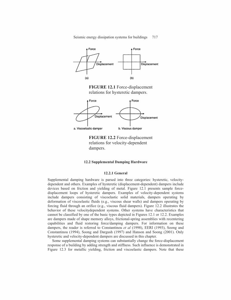
FIGURE 12.1 Force-displacement relations for hysteretic dampers.
FIGURE 12.2 Force-displacement relations for velocity-dependent dampers.
12.2 Supplemental Damping Hardware
12.2.1 General
Supplemental damping hardware is parsed into three categories: hysteretic, velocity-dependent and others. Examples of hysteretic (displacement-dependent) dampers include devices based on friction and yielding of metal. Figure 12.1 presents sample force-displacement loops of hysteretic dampers. Examples of velocity-dependent systems include dampers consisting of viscoelastic solid materials, dampers operating by deformation of viscoelastic fluids (e.g., viscous shear walls) and dampers operating by forcing fluid through an orifice (e.g., viscous fluid dampers). Figure 12.2 illustrates the behavior of these velocitydependent systems. Other systems have characteristics that cannot be classified by one of the basic types depicted in Figures 12.1 or 12.2. Examples are dampers made of shape memory alloys, frictional-spring assemblies with recentering capabilities and fluid restoring force/damping dampers. For information on these dampers, the reader is referred to Constantinou et al (1998), EERI (1993), Soong and Constantinou (1994), Soong and Dargush (1997) and Hanson and Soong (2001). Only hysteretic and velocity-dependent dampers are discussed in this chapter.
Some supplemental damping systems can substantially change the force-displacement response of a building by adding strength and stiffness. Such influence is demonstrated in Figure 12.3 for metallic yielding, friction and viscoelastic dampers. Note that these
Seismic energy dissipation systems for buildings 717
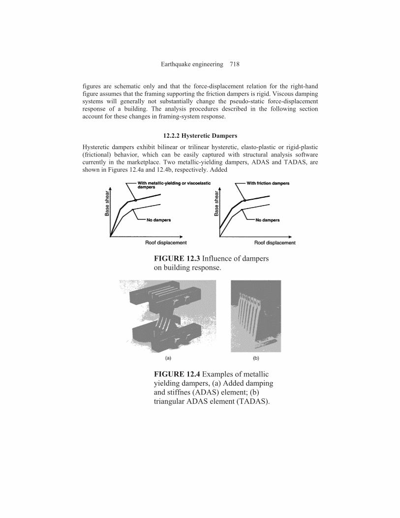
figures are schematic only and that the force-displacement relation for the right-hand figure assumes that the framing supporting the friction dampers is rigid. Viscous damping systems will generally not substantially change the pseudo-static force-displacement response of a building. The analysis procedures described in the following section account for these changes in framing-system response.
12.2.2 Hysteretic Dampers
Hysteretic dampers exhibit bilinear or trilinear hysteretic, elasto-plastic or rigid-plastic (frictional) behavior, which can be easily captured with structural analysis software currently in the marketplace. Two metallic-yielding dampers, ADAS and TADAS, are shown in Figures 12.4a and 12.4b, respectively. Added
FIGURE 12.3 Influence of dampers on building response.
FIGURE 12.4 Examples of metallic yielding dampers, (a) Added damping and stiffnes (ADAS) element; (b) triangular ADAS element (TADAS).
Earthquake engineering 718

FIGURE 12.5 Unbonded steel brace (courtesy of Nippon Steel), (a) Conceptual details; (b) cruciform configuration of steel
damping and stiffness (ADAS) elements have been implemented in the United States and Mexico. Triangular added damping and stiffness (TADAS) elements have been implemented in Taiwan.
Stiff support framing is required for the metallic yielding dampers of Figure 12.4 to ensure that the displacement across the height of the damper is maximized and approximately equal to the interstory displacement for that story in which the damper is installed. Such framing is likely more expensive than the damper it supports.
FIGURE 12.6 Unbonded steel brace applications (courtesy of I.Aiken). (a)
Seismic energy dissipation systems for buildings 719

University of California at Davis; (b) University of California at Berkeley.
FIGURE 12.7 Parameter definition for velocity-dependent dampers, (a) Viscoelastic damper; (b) viscous damper.
An alternate metallic yielding damper, the unbonded steel brace, is shown in Figure 12.5. This damper was developed in Japan in the mid-1980s (Watanabe et al. 1988) and has been used in a number of projects in California and also found widespread application in Japan. The schematic of Figure 12.5a illustrates the key components of the unbonded steel brace, namely, a cruciform cross section of welded steel plate that is designed to yield in tension and compression, and an exterior steel tube of circular or rectangular cross section that is selected such that the buckling capacity of the tube exceeds the squash load of the cruciform cross section. The space between the cruciform cross section and the steel tube is filled with concrete to delay local buckling of the cruciform cross-section outstands. Materials are used to de-bond the cruciform cross section from the concrete. Figure 12.5b is a photograph of a cruciform cross section. The unbonded brace is designed to have approximately equal strength in tension and compression, and is conceptually superior to the concentrically braced frame because the beam at the intersection point of the chevron braces does not have to be designed for large out-of-balance vertical forces (Bruneau et al. 1998). Sample installations of unbonded braces in California are presented in Figure 12.6.
12.2.3 Velocity-Dependent Dampers
Solid viscoelastic dampers typically consist of constrained layers of viscoelastic polymers. They exhibit viscoelastic solid behavior with mechanical properties dependent on frequency, temperature and amplitude of motion. A force-displacement loop for a viscoelastic solid device, under sinusoidal motion of amplitude !0 and frequency ", is shown in Figure 12.7a. The force in the damper may be expressed as
(12.1)
Earthquake engineering 720

where Keff is the effective stiffness (also termed the storage stiffness K!) as defined in
Figure 12.7a, C is the damping coefficient and ! and are the relative displacement and relative velocity between the ends of the damper, respectively. The damping constant is calculated as
(12.2)
where WD is the energy dissipated in one fully reversed cycle of sinusoidal motion at displacement amplitude !0 and angular frequency ". The damping constant C is also equal to the loss stiffness, K", divided by ". More information on the characteristics of viscoelastic dampers and the derivation of the storage and loss moduli are presented in Soong and Dargush (1997).
The effective stiffness and damping coefficient are dependent on the frequency, temperature and amplitude of motion (Soong and Dargush 1997). The frequency and temperature dependences of viscoelastic polymers generally vary as a function of the composition of the polymer. The standard linear solid model (a spring in series with a Kelvin model), which can be implemented in commercially available structural analysis software, is capable of modeling behavior over a small range of frequencies, which will generally be satisfactory for most projects.
Fluid viscoelastic devices, which operate on the principle of deformation (shearing) of viscoelastic fluids, have behavior that resembles a solid viscoelastic device. However, fluid viscoelastic devices have zero effective stiffness under static loading conditions. Fluid and solid viscoelastic devices are distinguished by the ratio of the loss stiffness to the effective or storage stiffness. This ratio approaches infinity for fluid devices and zero for solid viscoelastic devices as the loading frequency approaches zero. Fluid viscoelastic behavior may be modeled with advanced models of viscoelasticity (Makris et al. 1993). However, for most practical purposes, the Maxwell model (a spring in series with a dashpot) can be used to model fluid viscoelastic devices.
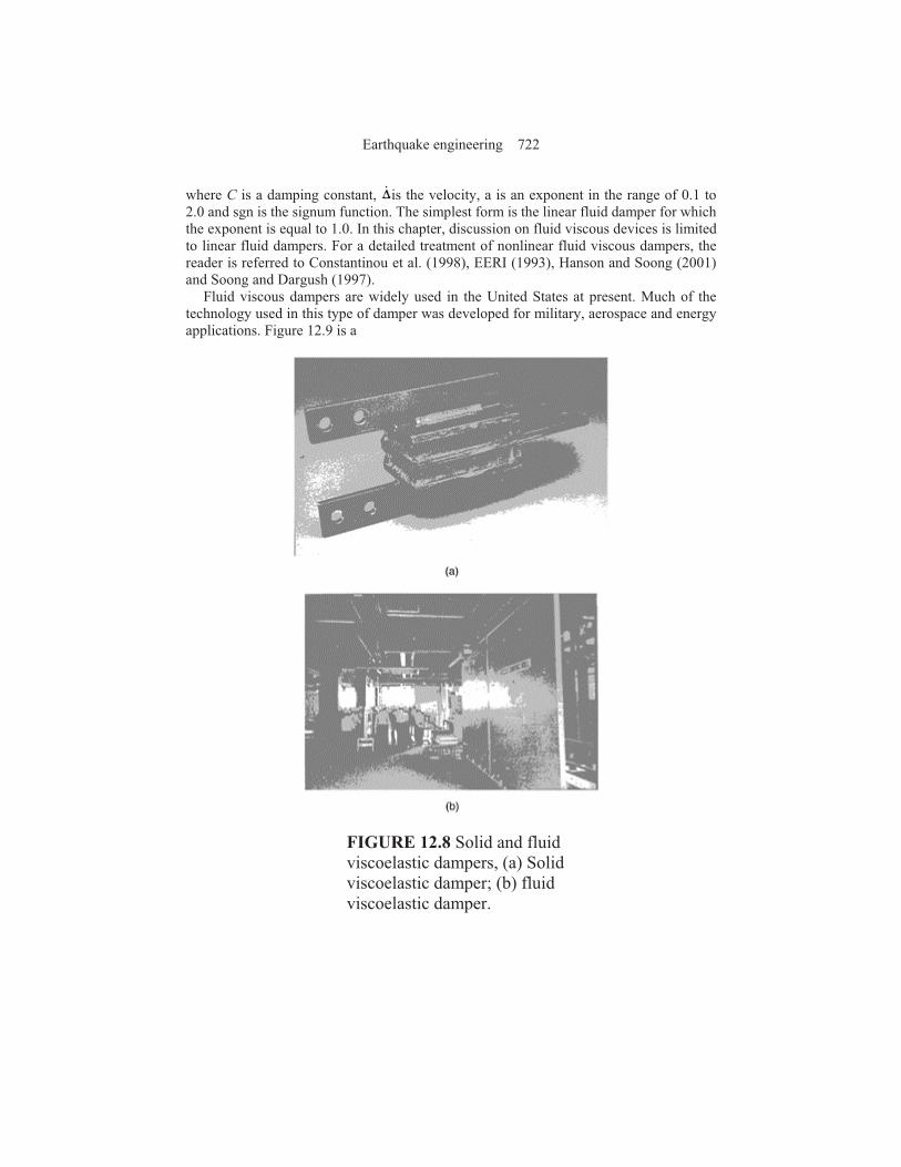
Figure 12.8 presents photographs of two viscoelastic dampers. Figure 12.8a is a solid viscoelastic damper. This damper configuration is similar to that employed to reduce the wind-induced vibrations of buildings. Other configurations employ rectangular tube steel sections with copolymer bonded to all four faces of the tube. Figure 12.8b is a fluid viscoelastic damper that is known by many as a viscous damping wall (VDW). The VDW is composed of a cavity-precast wall that is filled with a viscous fluid and attached at its base to the floor framing. A T-shaped paddle is inserted in the fluid and is attached to the framing above the cavity wall. Interstory drift in the building frame produces relative movement between the paddle and the cavity wall and dissipates energy. Viscoelastic solid devices have found a small number of applications in the United States (Soong and Dargush 1997).
Pure viscous behavior may be produced by forcing fluid through an orifice (Constantinou and Symans 1993; Soong and Constantinou 1994; Soong and Dargush 1997). The force output of a viscous damper has the general form:
(12.3)
Seismic energy dissipation systems for buildings 721
where C is a damping constant, is the velocity, a is an exponent in the range of 0.1 to 2.0 and sgn is the signum function. The simplest form is the linear fluid damper for which the exponent is equal to 1.0. In this chapter, discussion on fluid viscous devices is limited to linear fluid dampers. For a detailed treatment of nonlinear fluid viscous dampers, the reader is referred to Constantinou et al. (1998), EERI (1993), Hanson and Soong (2001) and Soong and Dargush (1997).
Fluid viscous dampers are widely used in the United States at present. Much of the technology used in this type of damper was developed for military, aerospace and energy applications. Figure 12.9 is a
FIGURE 12.8 Solid and fluid viscoelastic dampers, (a) Solid viscoelastic damper; (b) fluid viscoelastic damper.
Earthquake engineering 722
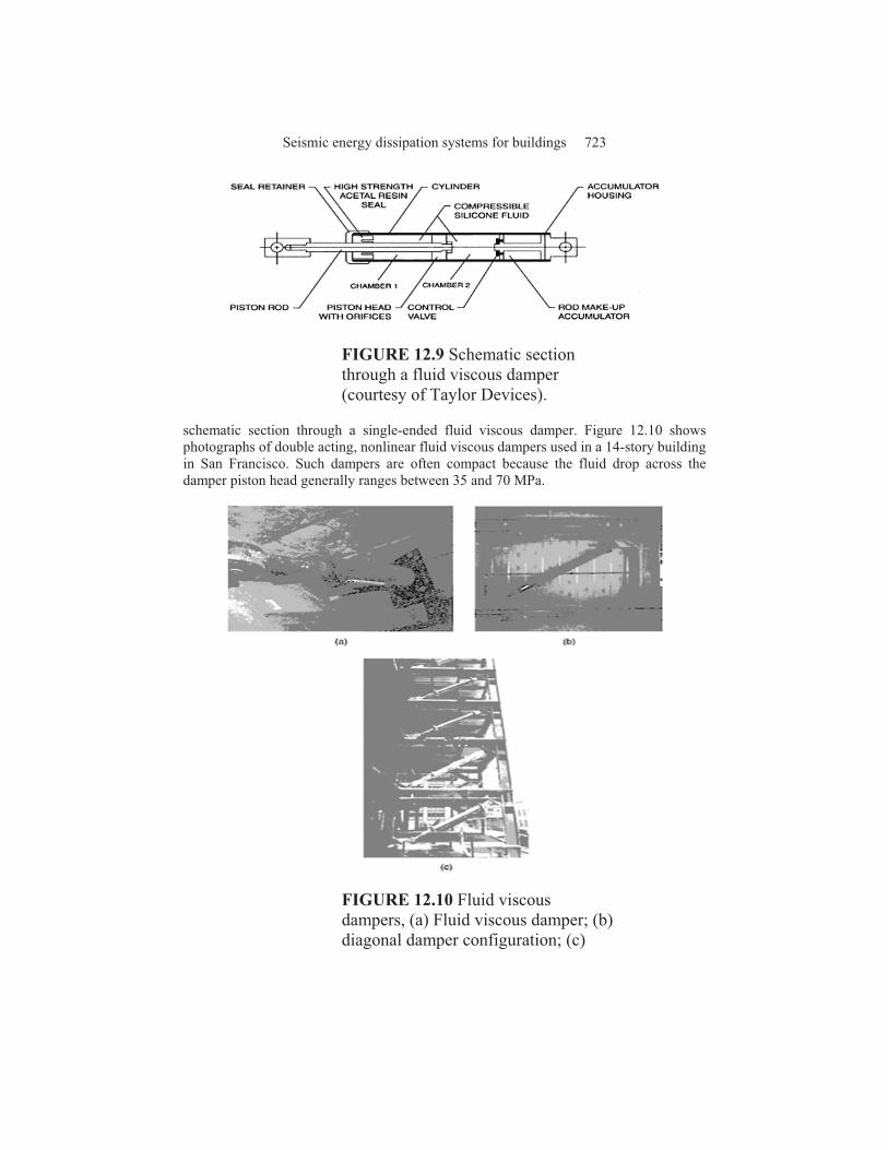
FIGURE 12.9 Schematic section through a fluid viscous damper (courtesy of Taylor Devices).
schematic section through a single-ended fluid viscous damper. Figure 12.10 shows photographs of double acting, nonlinear fluid viscous dampers used in a 14-story building in San Francisco. Such dampers are often compact because the fluid drop across the damper piston head generally ranges between 35 and 70 MPa.
FIGURE 12.10 Fluid viscous dampers, (a) Fluid viscous damper; (b) diagonal damper configuration; (c)
Seismic energy dissipation systems for buildings 723

installed dampers in the San Francisco Civic Center building frame.
12.3 FEMA 273/274/356 Analysis Procedures for Supplemental
Dampers
12.3.1 Introduction
The lack of analysis methods, guidelines and commentary has been the key impediment to the widespread application of supplemental dampers in buildings and bridges. Prior to 1997, seismic design codes and guidelines in the United States focused on designing structures for strength alone, where the design forces were set equal to the elastic forces divided by a response reduction factor (for buildings). Component deformations, which are indicators of damage and performance, were not checked.
FEMA 273 (FEMA 1997), entitled Guidelines for the Seismic Rehabilitation of Buildings, was published in 1997 after more than 5 years of development. FEMA 273 represented a paradigm shift in the practice of earthquake engineering in the United States because deformations and not forces were used as the basis for the design of ductile components. Performance and damage were characterized in terms of component deformation capacity of ductile components. A commentary to FEMA 273 was published as FEMA 274 (FEMA 1997). Recently, FEMA 273 has been updated and republished as FEMA 356 (FEMA 2000), entitled Prestandard and Commentary for the Seismic
Rehabilitation of Buildings. The discussion below is based primarily on the presentations of FEMA 273 and FEMA 274.
Four methods of seismic analysis were presented in FEMA 273/356: linear static procedure (LSP), linear dynamic procedure (LDP), nonlinear static procedure (NSP) and nonlinear dynamic procedure (NDP). All four procedures can be used to implement supplemental dampers in buildings although the limitations on the use of the linear procedures likely will limit their widespread use. Of the four, only the NDP can explicitly capture nonlinear deformations and strain- and load-history effects. The other three procedures are considered to be less precise than the NDP, although given the additional uncertainties associated with nonlinear analysis, the loss of accuracy might be small. The two nonlinear procedures lend themselves to component checking using deformations and displacements; component deformation limits are given in FEMA 273, but most are based on engineering judgment and evaluation of test data. The two static methods are described below. More information on these procedures and the two dynamic procedures is available in FEMA 273/274/356.
12.3.2 Linear Static Procedure: General
In any linear procedure, there is a direct relation between internal deformations and internal forces. Component checking involves comparing actions with capacities. In building design codes such as the Uniform Building Code (ICBO 1997) and the International Building Code (ICC 2000), component actions due to earthquake effects are calculated using elastic spectral forces divided by a response modification factor.
Earthquake engineering 724
Although inelastic response is implied by the use of values of the factor greater than 1, component deformation capacity is not checked.
The LSP of FEMA 273/356 is substantially different from the static lateral force procedures adopted in modern seismic codes. A pseudo lateral force, V, is applied to a linear elastic model of the building frame such that its maximum displacement is approximately equal to the expected displacement of the yielding building frame. The objective is to estimate displacements in a yielding building using a linear procedure. As such, the pseudo lateral force may be much greater than the yielding strength of the building, and component demands may exceed component capacities by a significant margin. However, the LSP acceptance criteria accommodate this situation by permitting demand-to-capacity ratios (denoted m in FEMA 273/356) greater than 1.0, where the values assigned to m vary as a function of the nonlinear deformation capacity of the component. The FEMA 273/356 equation for the pseudo lateral force is
V=C1C2C3SaW
(12.4)
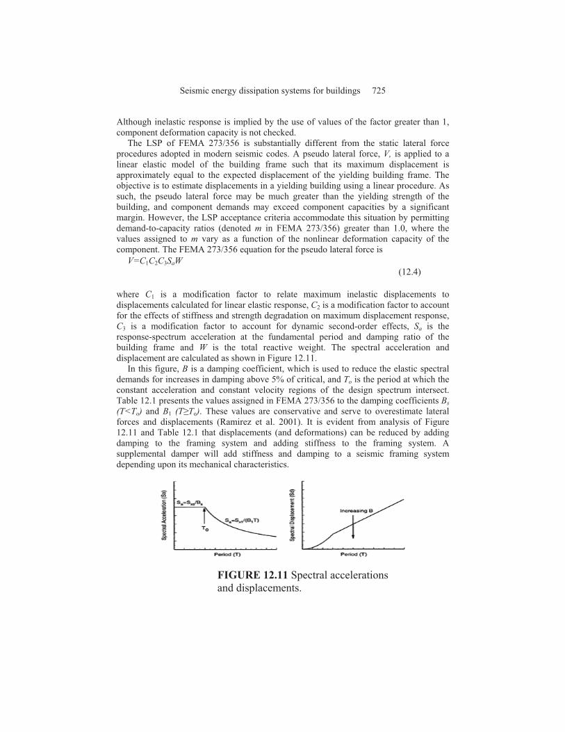
where C1 is a modification factor to relate maximum inelastic displacements to displacements calculated for linear elastic response, C2 is a modification factor to account for the effects of stiffness and strength degradation on maximum displacement response, C3 is a modification factor to account for dynamic second-order effects, Sa is the response-spectrum acceleration at the fundamental period and damping ratio of the building frame and W is the total reactive weight. The spectral acceleration and displacement are calculated as shown in Figure 12.11.
In this figure, B is a damping coefficient, which is used to reduce the elastic spectral demands for increases in damping above 5% of critical, and To is the period at which the constant acceleration and constant velocity regions of the design spectrum intersect. Table 12.1 presents the values assigned in FEMA 273/356 to the damping coefficients Bs (T<To) and B1 (T#To). These values are conservative and serve to overestimate lateral forces and displacements (Ramirez et al. 2001). It is evident from analysis of Figure 12.11 and Table 12.1 that displacements (and deformations) can be reduced by adding damping to the framing system and adding stiffness to the framing system. A supplemental damper will add stiffness and damping to a seismic framing system depending upon its mechanical characteristics.
FIGURE 12.11 Spectral accelerations and displacements.
Seismic energy dissipation systems for buildings 725

TABLE 12.1 Damping Coefficients as a Function of Effective Damping (FEMA 1997)
Effective damping, #eff Bs B1
<2% 0.8 0.8
5% 1.0 1.0
10% 1.3 1.2
20% 1.8 1.5
30% 2.3 1.7
40% 2.7 1.9
>50% 3.0 2
12.3.3 Nonlinear Static Procedure: General
The nonlinear static procedure (NSP) is a displacement-based method of analysis. Structural components are modeled using nonlinear force-deformation relations and the stiffness of the supplemental dampers is included in the model. Lateral loads are applied in a predetermined pattern to the model, which is incrementally pushed to a target displacement thereby establishing a force (base shear) versus displacement (roof) relation for the building. Component deformations are calculated at the target displacement. Component evaluation involves checking maximum deformation versus deformation capacity; force-based checking is not used for deformation-controlled components. Deformation capacities are given in FEMA 273/356 for different components, materials and performance levels. Because higher mode loading patterns are not considered, FEMA 273/356 limits the use of the NSP unless an LDP evaluation is also performed.
The target displacement is established in FEMA 273 by either the coefficient method or a modified version of the capacity-spectrum method. Both methods are equally accurate if the yield strength of the building exceeds 20% of the required elastic strength (Whittaker et al. 1998). Only the coefficient method is described below. For information on the modified capacity-spectrum method, refer to FEMA 274.
Calculation of the target displacement by the coefficient method is based on the assumption that, for periods greater than approximately 0.5 sec (for a rock site), displacements are preserved in a mean sense, that is, mean elastic displacements are approximately equal to mean inelastic displacements. Note that the degree of scatter in the ratio of elastic and inelastic displacements may be substantial, and that this assumption is not conservative for buildings with low strength. The general form of the target displacement, $t, equation is
(12.5)
Earthquake engineering 726

FIGURE 12.12 Calculation of secant stiffness at maximum displacement (FEMA 1997).
where Te is the effective fundamental period of the building (see Figure 12.12 for the definition of effective stiffness that is used to calculate Te), C0 is a modification factor that relates roof displacement to spectral displacement, and all other terms are as defined above.
12.3.4 Linear Static Procedure: Supplemental Dampers
Limits are placed on the use of the linear static procedure (LSP) for implementing dampers in buildings. The LSP can be used only if the framing system exclusive of the dampers remains essentially linearly elastic in the design earthquake after the effects of the added damping are considered. Further, the level of effective damping must not exceed 30% of critical in the fundamental mode. Dampers are modeled using their secant stiffness at the point of maximum displacement. The stiffness of each damper must be included in the mathematical model. Specific requirements for displacement- and velocity-dependent dampers follow.
12.3.4.1 Displacement-Dependent Dampers
Additional restrictions to those noted above are placed on the use of the LSP in FEMA 273/356. Specifically, the maximum resistance in each story must vary uniformly over the height of the building and the maximum resistance (strength) of the supplemental dampers cannot exceed 50% of the lateral resistance of the remainder of the framing so as to provide a significant restoring force.
For use with the LSP, displacement-dependent dampers (see Figure 12.1a) are modeled as viscoelastic dampers (see Figure 12.2a). The effective damping of the frame (see Table 12.1) is calculated as
(12.6)
Seismic energy dissipation systems for buildings 727

where #I is the inherent damping in the building frame exclusive of the dampers, Wj is the energy dissipated (work done) by device j in one fully reversed cycle of sinusoidal motion at a displacement corresponding to floor displacements $i and the summation extends over all devices. The maximum strain energy in the frame, Wk, can be calculated as
(12.7)
where Fi is the inertial force at floor level i and $i is the displacement of floor level i and the summation extends over all floor levels.
The value of $eff is used to calculate a value of B from Table 12.1. The spectral acceleration for use in 12.5 is calculated using the fundamental period of the framing system whose model includes the secant stiffness of the displacement-dependant dampers. Component actions and deformations are checked at the stage of maximum displacement.
12.3.4.2 Velocity-Dependent Dampers
One additional restriction to those noted above is placed on the use of the LSP, namely, that the maximum resistance (strength) of the velocity-dependent supplemental dampers in any story cannot exceed 50% of the resistance of the remainder of the framing in that story. This restriction applies only to viscoelastic dampers.
The effective damping is calculated using equations 12.6 and 12.7. For linear viscous dampers, the work done by damper j can be calculated as
(12.8)
where Cj is the damper constant for device j, $rj is the relative displacement between the ends of device j measured along the axis of the damper and T is the fundamental period of the framing system whose model includes the stiffness of the dampers. This equation assumes harmonic motion of amplitude $rj and periodicity T. As such, it may not be applicable if near-field (non-harmonic) ground motions are used for design. FEMA 273 provides an alternative equation for calculating the effective damping provided by linear viscous devices using first mode information:
(12.9)
where is the first mode displacement of floor level i, mi is the mass of floor level i, %j is
the angle of device j to the horizontal, is first mode relative horizontal displacement between the ends of device j and all other terms are as described above. Equation 12.9, with minor modification, can be used to calculate modal damping ratios for buildings incorporating nonlinear viscous dampers.
Earthquake engineering 728

Design actions in components of buildings incorporating velocity-dependent dampers must be checked at three stages: maximum, maximum velocity and maximum acceleration (at the displacement corresponding to the maximum force). Information on the calculation of component actions at the stages of maximum velocity and maximum acceleration can be found in FEMA 273/274/356 and Constantinou et al. (1998).
12.3.5 Nonlinear Static Procedure: Supplemental Dampers
Two methods of nonlinear static analysis are provided in FEMA 273/356 for implementing supplemental dampers: Method 1 (known as the coefficient method) and Method 2 (known as the capacity-spectrum method). The two methods are equally precise. The use of the coefficient method to implement dampers is described below. Tsopelas et al. (1997) and Section C9.3.5 of FEMA 274 provide information on the use of the capacity-spectrum method with damping devices.
Regardless of which method is used to calculate the target displacement and the associated component deformations, the nonlinear mathematical model of the building frame must include the nonlinear force-velocity-displacement relations for the dampers and the mechanical characteristics of the framing supporting the dampers. If the stiffness of a damper is dependent upon amplitude, frequency or velocity, the stiffness value used for analysis should be consistent with deformations corresponding to the target displacement and frequencies corresponding to the inverse of the effective period Te.
12.3.5.1 Displacement-Dependent Dampers
The benefit of adding displacement-dependent dampers to a building frame is recognized in FEMA 273 by the increase in building stiffness afforded by the dampers. The increase in stiffness will reduce the effective period Te in equation 12.5 thereby reducing the maximum displacement. The spectral acceleration in this equation should be calculated using the effective period of the mathematical model that includes the stiffness of the dampers and the value of B assigned to the building frame exclusive of the dampers.
12.3.5.2 Velocity-Dependent Dampers
The benefits of adding velocity-dependent dampers to a building frame are recognized in FEMA 273/ 356 by (a) the increase in viscous damping and (b) the increase in building stiffness, provided by the dampers. The increase in damping will reduce the spectral acceleration. The increase in stiffness will reduce the effective period and thus generally reduce the spectral displacement.
The effective damping in the building frame at the point of maximum displacement is calculated iteratively using equations 12.6, 12.7, 12.8 and 12.9. In these equations, the floor displacements $i are those that correspond to the target displacement, the forces Fi are the lateral forces that correspond to the target displacement, and Te is replaced by the secant period (=Ts) at the point of maximum displacement. Using the force-displacement relation of Figure 12.12, the secant period can be calculated as
(12.10)
Seismic energy dissipation systems for buildings 729

An estimate of target displacement is needed to calculate the effective damping and secant stiffness, which in turn are used to calculate a revised estimate of the target displacement. When the assumed and calculated values of the target displacement are sufficiently close, the solution has converged.
As described above, component actions in a framing system incorporating velocity-dependent dampers must be checked at the stages of maximum drift, maximum velocity and maximum acceleration. Procedures for such checking are presented in FEMA 273/356 and 274. Higher mode damping forces must be considered if velocity-dependent dampers are implemented using the NSP. The magnitude of these forces may be similar to those damping forces calculated using the procedure described above. An example of the calculation of higher mode forces is presented in FEMA 274.
12.4 NEHRP Analysis and Design Procedures
Key aspects of the 2000 NEHRP Recommended Provisions (FEMA, 2001), hereafter termed 2000 NEHRP, analysis and design procedures for new buildings incorporating damping devices are presented below. A detailed description of these procedures, applications and verification studies are presented in Ramirez et al. (2001,2002a, 2002b, 2003) and Whittaker et al. (2003). Attention is focused below on the equivalent lateral force (ELF) analysis procedure for which the residual mode is used in lieu of all modes higher than the fundamental mode. The use of the ELF procedure is limited to low-rise regular buildings (five stories or less in height) with rigid floor diaphragms, modest levels of damping (#1&0.35), and at least two damping devices in each story of the building, distributed to resist the effects of torsion. (Because only limited information is presented in this section, the reader should not just use only the steps listed below to design a damping system per 2000 NEHRP.) Although checks are made for maximum earthquake shaking in the 2000 NEHRP, only the key steps in the ELF design earthquake analysis are listed below. Further, for the steps listed below it is assumed that (a) T1>T0, (b) the importance factor I is equal to 1.0, (c) the target design base shear force for the damped building is greater than or equal to 0.75V where V is the minimum design base shear force for a building without the damping system, (d) the target drift in the building is the limiting value of 2000 NEHRP and (e) plastic or pushover analysis is not used to establish the yield strength of the frame.
TABLE 12.2 2000 NEHRP Recommended Provisions Damping Coefficients (FEMA 2001)
Effective damping #eff Damping coefficient B
2% 0.8
5% 1.0
10% 1.2
20% 1.5
30% 1.8
Earthquake engineering 730

40% 2.1
50% 2.4
60% 2.7
80% 3.3
100% 4.0
Correct calculation of displacements is key to the use of the 2000 NEHRP provisions for energy dissipation systems. The equal displacements rule is imposed on frames incorporating damping systems by setting the displacement amplification factor, Cd,
equal to the response modification factor, R. As such, a number of terms in 2000 NEHRP are multiplied by [R/Cd] to correctly calculate displacements in the building frame.
The main steps in the analysis and design process, subject to the assumptions listed above, are enumerated below:
1. Calculate a minimum seismic base shear, for the design of the seismic force resisting system as the greater of
(12.11)
where Vcb is the total design base shear for the framing system exclusive of the damping devices, and BV+I is the damping coefficient for effective damping equal to the sum of the viscous damping in the fundamental mode and the inherent damping in the building frame. The damping coefficients, B, in Table 13.A.3.1 of 2000 NEHRP are listed in Table 12.2 for periods greater than 0.2T0 sec.
2. Develop a trial design based on Vdb=0.75Vcb and a distribution of Vdb over the height of the building frame similar to that adopted in 2000 NEHRP for conventional buildings.
3. Establish mode shapes, modal participation factors, modal weights and periods for the first and residual modes.
4. Select a target level of supplemental damping in the fundamental mode, #v1, so that the frame of step 2 will meet the drift limits of 2000 NEHRP if the frame was to respond elastically.
5. Assume a trial value for the effective ductility µD of the order of 1.5 to 2.0, based on the trial designs of Ramirez et al. (2001), and calculate the effective damping and effective period in the fundamental mode
(12.12)
where qh is a hysteresis-loop quality factor, less than or equal to 1.0.
6. Calculate B1D, and the seismic coefficient CS1 and base shear force V1 as follows:
Seismic energy dissipation systems for buildings 731

(12.13)
7. Check that the base shear force V1 from step 6 is approximately equal to the value of Vdb from step 1. If so, proceed to step 8. If not, assume a new value for the effective ductility demand and return to step 5.
8. Calculate displacements DY, D1D and the effective ductility demand µD
(12.14)
9. Calculate the residual mode contributions to the response and the damping coefficient in the residual mode, BR
(12.15)
10. Calculate the seismic base shear, Vdb, and the design lateral forces at level i,
(12.16)
Refine the design from step 1 as necessary using the first mode and residual mode lateral forces.
11. Calculate the fundamental and residual mode interstory drifts due to the design earthquake, !1D, and !RD, respectively, and the design earthquake interstory drift
(12.17)
Earthquake engineering 732

Check !D versus the 2000 NEHRP drift limits. If the calculated drifts exceed the drift limits, increase the value of Vdb and return to step 2.
12. If velocity-dependent dampers are considered, the design earthquake interstory
velocity, is calculated using the velocities in the fundamental and residual modes as follows:
(12.18)
where
(12.19)
The values for can then be used to size the velocity-dependent dampers by resolving the interstory velocities along the axes of the dampers.
13. Check the components of the frame of steps 2 and 10 for the seismic load combinations of Section 13A.7 of 2000 NEHRP including checks at the stages of maximum displacement (all dampers), maximum velocity (velocity-dependent dampers only) and maximum acceleration (velocitydependent dampers only).
12.5 New Configurations for Damping Systems
Small interstory drifts and velocities characterize stiff seismic framing systems and all framing systems for wind excitation. Many have assumed that such systems are not candidates for the addition of dampers because significant drifts and velocities are needed to dissipate substantial energy, although the values listed in Table 12.1 indicate that damping is most effective in the short-period (constant acceleration) range of the spectrum. FEMA (1995) writes:
Structural systems best suited for implementation of energy dissipation devices are the momentresisting frame and the flexible dual system, in either structural steel or reinforced concrete. The interstory response of a stiff lateral load-resisting system, such as a reinforced concrete shear wall system or a steel-braced dual system, is generally characterized by both small relative velocities and small relative displacements. As such it may not be feasible to implement supplemental energy dissipation.
This observation is correct for conventional damper configurations involving diagonal (in-line) or chevron installations. For example, interstory displacements in a stiff code-compliant building will likely not exceed 15 mm in the design earthquake. Large damper forces are then needed to develop moderate levels of supplemental damping. Damper
Seismic energy dissipation systems for buildings 733
displacements in conventionally configured systems will be less than or equal to the interstory displacements. For a small-stroke fluid viscous damper, special details are required that increase the volume and cost of the damper.
Recent work at the University at Buffalo, State University of New York (Constantinou and Sigaher 2000; Constantinou et al. 2001; Sigaher and Constantinou 2003) has sought to expand the utility of fluid viscous damping devices to the short-period range and for wind applications through the use of mechanisms that magnify the damper displacement for a given interstory drift. Such magnification permits the use of dampers with smaller force outputs (smaller damper volume), larger strokes and reduced cost. Two configurations are the toggle-brace and the scissor-jack.
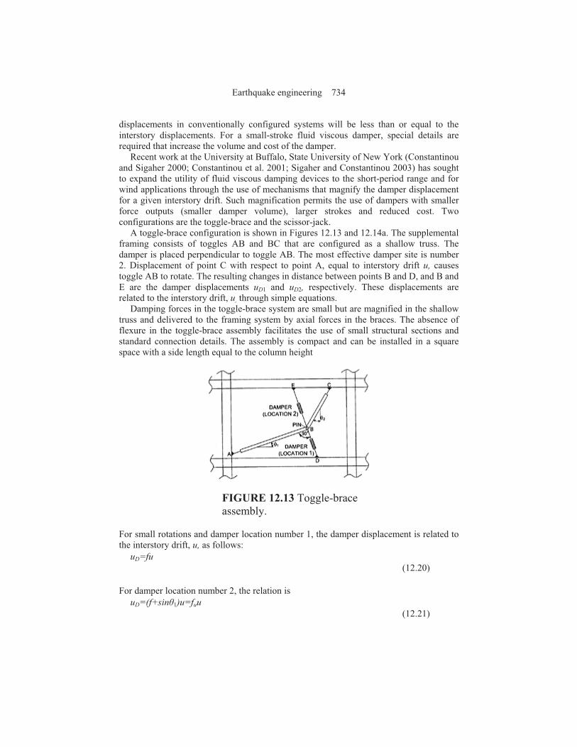
A toggle-brace configuration is shown in Figures 12.13 and 12.14a. The supplemental framing consists of toggles AB and BC that are configured as a shallow truss. The damper is placed perpendicular to toggle AB. The most effective damper site is number 2. Displacement of point C with respect to point A, equal to interstory drift u, causes toggle AB to rotate. The resulting changes in distance between points B and D, and B and E are the damper displacements uD1 and uD2, respectively. These displacements are related to the interstory drift, u, through simple equations.
Damping forces in the toggle-brace system are small but are magnified in the shallow truss and delivered to the framing system by axial forces in the braces. The absence of flexure in the toggle-brace assembly facilitates the use of small structural sections and standard connection details. The assembly is compact and can be installed in a square space with a side length equal to the column height
FIGURE 12.13 Toggle-brace assembly.
For small rotations and damper location number 1, the damper displacement is related to the interstory drift, u, as follows:
uD=fu
(12.20)
For damper location number 2, the relation is
uD=(f+sin%1)u=fuu
(12.21)
Earthquake engineering 734

where,
(12.22)
The displacement magnification factors f and fu depend only on the inclination of the toggle-braces. High displacement magnifications can be achieved although values are sensitive to small changes in %1 and %2. Magnification factors between 2 and 3 can be easily achieved and are insensitive to small variations in changes in %1 and %2.
For small rotations, the relation between the damper force, F, and the force exerted by the toggle-brace assembly on the structural frame, FF, is
FF=fF
(12.23)
for location number 1 (see Figure 12.13), and
FF=fuF
(12.24)
for location number 2. Equations 12.20 through 12.24 have the same form as those equations written for dampers installed in diagonal or in-line braces and dampers atop chevron braces.
The reverse toggle and the scissor-jack assemblies of Figures 12.14b and 12.15 are variants of the togglebrace assembly. Equations similar to those presented above for the toggle-brace assemblies have been developed for the reverse toggle and the scissor-jack systems. See Figure 12.15 for details.
To illustrate the effectiveness of the toggle-brace and scissor-jack assemblies for short-period framing systems, consider the six damper configurations presented in Figure 12.15. The diagonal (in-line) and chevron brace configurations represent conventional damper assemblies. For the purpose of comparison, assume that (1) the elastic single-bay, single-story frame has a fundamental period of 0.3 sec, (2) the
FIGURE 12.14 Toggle-brace and scissor-jack damper assemblies on the
Seismic energy dissipation systems for buildings 735
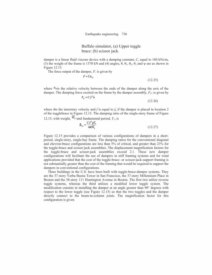
Buffalo simulator, (a) Upper toggle brace: (b) scissor jack.
damper is a linear fluid viscous device with a damping constant, C, equal to 160 kNs/m, (3) the weight of the frame is 1370 kN and (4) angles, %, %1, %2, %3 and ' are as shown in Figure 12.15.
The force output of the damper, F, is given by
(12.25)
where is the relative velocity between the ends of the damper along the axis of the damper. The damping force exerted on the frame by the damper assembly, FF, is given by
(12.26)
where is the interstory velocity and f is equal to fu if the damper is placed in location 2 of the togglebrace in Figure 12.13. The damping ratio of the single-story frame of Figure
12.15, with weight, and fundamental period, T1, is
(12.27)
Figure 12.15 provides a comparison of various configurations of dampers in a short-period, single-story, single-bay frame. The damping ratios for the conventional diagonal and chevron-brace configurations are less than 5% of critical, and greater than 23% for the toggle-brace and scissor-jack assemblies. The displacement magnification factors for the toggle-brace and scissor-jack assemblies exceed 2.1. These new damper configurations will facilitate the use of dampers in stiff framing systems and for wind applications provided that the cost of the toggle-brace- or scissor-jack-support framing is not substantially greater than the cost of the framing that would be required to support the dampers in conventional configurations.
Three buildings in the U.S. have been built with toggle-brace-damper systems. They are the 37-story Yerba Buena Tower in San Francisco, the 37-story Millennium Place in Boston and the 38-story 111 Huntington Avenue in Boston. The first two utilize reverse toggle systems, whereas the third utilizes a modified lower toggle system. The modification consists in installing the damper at an angle greater than 90° degrees with respect to the lower toggle (see Figure 12.15) so that the two toggles and the damper directly connect to the beam-to-column joints. The magnification factor for this configuration is given
Earthquake engineering 736
FIGURE 12.15 Effectiveness of damper configurations (Sigaher and Constantinou 2003).
by equation 12.22 after multiplication by cos%3 where %3=angle of damper axis with respect to the 90° line. For the 111 Huntington Avenue building, angle %3=21.5° so that the magnification factor is reduced by a small amount (about 7%). However, the installation with connections of the toggles and dampers directly to the beam-to-column joints eliminates additional bending in the beams and provides for easy and reliable
Seismic energy dissipation systems for buildings 737

calculation of the magnification factor. Figure 12.16 presents a photograph of the Yerba Buena Tower and one of its toggle-brace assemblies.
12.6 Summary and Conclusions
Two types of supplemental damping hardware were described: displacement-dependent and velocitydependent dampers. Examples of each type of hardware, including metallic yielding ADAS, TADAS and unbonded-brace, solid and fluid viscoelastic, and fluid viscous dampers were presented.
FIGURE 12.16 Toggle-brace assemblies in the Yerba Buena Tower, (a) Elevation of tower; (b) toggle brace assembly.
New procedures for the analysis and design of buildings incorporating displacement- and velocitydependent dampers were discussed. Linear and nonlinear static methods of analysis were described. These analysis methods are displacement oriented and as such represent a paradigm shift in the analysis of buildings for the effects of earthquakes. For implementing dampers, the linear procedures can be used only if the building is regular, the response of the framing system is essentially elastic in the design earthquake, and the effective damping ratio is 30% of critical or less. Displacementand velocity-dependent
Earthquake engineering 738
dampers are modeled using their secant stiffness at the maximum displacement and their damping is assumed to be equivalent viscous. The nonlinear analysis procedures of FEMA 273 are displacement based; component checking focuses on deformations rather than on forces. The force-displacement relations for displacement-dependent dampers are modeled explicitly and the key benefit of such dampers is the stiffness they add to the building frame. Velocity-dependent dampers are modeled using their secant stiffness at the stage of maximum displacement and the primary benefit of such dampers is added viscous damping. The ELF method of analysis and design for buildings with damping systems of the 2000 NEHRP has been described. This method is based on the nonlinear static analysis procedures of FEMA 273/274/356 but without the need for pushover analysis.
Until now damping systems have generally been considered appropriate only for flexible framing systems although the greatest benefit of viscous damping, measured as a percentage reduction in displacement, is typically realized for stiff framing systems. Two new damper configurations, toggle-brace and scissor jack, were described. The efficacy of these configurations was demonstrated by application to a stiff framing system with a period of 0.3 sec. Fourfold to tenfold increases in damping ratio with respect to that provided by conventional damper configurations were shown to be possible with the toggle-brace and scissor-jack configurations.
Acknowledgments
The authors thank their colleagues Professors T.T. (Larry) Soong, Andrei Reinhorn, Gary Dargush and Dr. Ani Natali Sigaher-Boyle of the University at Buffalo, Dr. Charles Kircher of Kircher and Associates, California, former graduate students and visiting scholars Professor Oscar Ramirez of the Technological University of Panama, Professor Nicos Makris of the University of Patras, Professor Michael Symans of Rensselaer Polytechnic Institute, NY, Professor Panos Tsopelas of the Catholic University, Washington, DC, and Dr. Christis Chrysostomou of the Higher Technical Institute, Cyprus for their contributions in the development of damping systems and the analysis/design procedures of FEMA 273/274/356 and 2000 NEHRP.
Glossary
Damper—Device added to a building frame to mitigate response due to earthquake shaking
Displacement-dependent damper—Hysteretic damper Energy dissipation device—Damper Hysteretic damper—A damper that dissipates energy through yielding of metal or
friction where energy dissipation is not a function of the rate of loading Scissor jack assembly—Assembly that amplifies the motion of a damping device(s) Toggle-brace assembly—Assembly that amplifies the motion of a damping device(s) Velocity-dependent damper—A damper that dissipates energy through shearing of solid
or fluid viscoelastic materials or by forcing fluid through or past a piston head
Seismic energy dissipation systems for buildings 739

List of Symbols
Bs Damping coefficient in the constant acceleration range of the spectrum
BV+I Damping coefficient for effective damping equal to the sum of the viscous damping in the fundamental mode and the inherent damping in the building frame
B1 Damping coefficient in the constant velocity range of the spectrum
B1D Damping coefficient for effective damping in the fundamental mode per 2000 NEHRP
BR Damping coefficient for effective damping in the residual mode per 2000 NEHRP
C Damping constant
Cd Displacement amplification factor
C Damping constant for device j
CS1 Seismic coefficient in the fundamental mode per 2000 NEHRP
CSR Seismic coefficient in the residual mode per 2000 NEHRP
C0 Factor that relates roof displacement to spectral displacement
C1 Factor that relates maximum inelastic displacement to maximum elastic displacement
C2 Factor to account for the effects of stiffness and strength degradation on displacement response
C3 Factor to account for the effect of dynamic second-order effects on displacement response
DY Yield displacement of the damped frame per 2000 NEHRP
D1D Fundamental mode displacement of the damped frame per 2000 NEHRP
DRD Residual mode displacement of the damped frame per 2000 NEHRP
f, fu Displacement magnification factors in damper assemblies (see Figure 12.15)
F Damper force
FF Force exerted on the structural frame of Figure 12.15 by the damper assembly
Fi Inertial force at floor level i
Fi1 Fundamental mode design lateral force at floor level i per 2000 NEHRP
FiR Residual mode design lateral force at floor level i per 2000 NEHRP
g Acceleration due to gravity
I Importance factor
Ke Effective initial stiffness of the building frame (see Figure 12.12)
Keff Effective stiffness of a damping device
Ks Secant stiffness of the building frame at the maximum displacement (see Figure 12.12)
K! Storage stiffness
K" Loss stiffness
mi Mass of floor level i
Earthquake engineering 740

qh Building frame hysteresis loop quality factor per 2000 NEHRP
R Response modification factor
Sa Spectral acceleration
SD1 Design earthquake spectral ordinate at a period of 1 second
SDS Design earthquake spectral ordinate at a period of 0.2 second
T0 Period at the intersection point of the constant acceleration and constant velocity segments of the spectrum
T Period
TR Residual mode period per 2000 NEHRP
T1 Fundamental period of the building frame inclusive of the damping devices
T1D Effective fundamental mode period of the building frame inclusive of the damping devices per 2000 NEHRP
Te Effective initial period of the frame (see Figure 12.12)
Ts Secant period of the frame at maximum displacement (see Figure 12.12)
u Interstory drift in single-story damped frame assembly (see Figure 12.15)
Interstory velocity in single-story damped frame assembly (see Figure 12.15)
uDi Relative displacement between the ends of damper at location i (see Figure 12.15)
Relative velocity between the ends of damper at location i (see Figure 12.15)
V Pseudo lateral force per FEMA 273/356 LSP
Vcb Design base shear for a conventional building per 2000 NEHRP
Vdb Design base shear for a damped building per 2000 NEHRP
Minimum design base shear for a damped building per 2000 NEHRP
V1 Base shear force in the fundamental mode per 2000 NEHRP
VR Base shear force in the residual mode per 2000 NEHRP
W Total reactive weight
WD Energy dissipated in one fully reversed cycle of sinusoidal motion
Wj Energy dissipated by damping device j in one fully reversed cycle of sinusoidal motion
Wk Maximum strain energy in the frame
Reactive weight in the fundamental mode
Reactive weight in the residual mode
( Velocity exponent on a fluid viscous damper
#I Inherent damping in the frame exclusive of the damping devices
#eff Effective damping in the frame inclusive of the damping devices
Seismic energy dissipation systems for buildings 741
#R Effective damping in the residual mode per 2000 NEHRP
#1D Effective damping in the fundamental mode per 2000 NEHRP
#vr Supplemental damping in the residual mode per 2000 NEHRP
#vl Supplemental damping in the fundamental mode per 2000 NEHRP
)R Residual mode participation factor
*1 Fundamental mode participation factor
Fundamental mode displacement at floor level i
Fundamental mode relative floor displacement between the ends of device j
Fundamental mode displacement at floor level i per 2000 NEHRP
Residual mode displacement at floor level i per 2000 NEHRP
%j Angle between the axis of the damper and a horizontal plane
! Relative displacement between the ends of a damper
!D Design earthquake interstory drift per 2000 NEHRP
!RD Residual mode interstory drift per 2000 NEHRP
!1D Fundamental mode interstory drift per 2000 NEHRP
!0 Displacement amplitude
Relative velocity between the ends of a damper
$i Displacement of floor level i
$rj Relative displacement between the ends of device j
Relative velocity between the ends of device j
$t Target displacement per FEMA 273/356 NSP
µD Effective ductility of the building frame per 2000 NEHRP
+0 Framing system overstrength factor per 2000 NEHRP
" Angular frequency of sinusoidal motion
Design earthquake interstory velocity per 2000 NEHRP
Residual mode interstory velocity per 2000 NEHRP
Fundamental mode interstory velocity per 2000 NEHRP
References ASCE. (1997). Structural Control: Past, Present, and Future, Special Issue, J. Engineering
Mechanics, ASCE, Vol. 123, 897,971. Bruneau, M., Uang, C.M. and Whittaker, A.S. (1998). Ductile Design of Steel Structures, McGraw-
Hill, New York.
Earthquake engineering 742
Constantinou, M.C., Soong, T.T. and Dargush, G.F. (1998). Passive Energy Dissipation Systems for Structural Design and Retrofit, MCEER Monograph No.1, Multidisciplinary Center for Earthquake Engineering Research, Buffalo, New York.
Constantinou, M.C. and Sigaher, A.N. (2000). Energy dissipation system configurations for improved performance. Proc., 2000 Structures Congress, American Society of Civil Engineers, Philadelphia, PA.
Constantinou, M.C. and Symans, M.D. (1993), Experimental study of seismic response of buildings with supplemental fluid dampers. Structural Design of Tall Buildings, 2, 93,132.
Constantinou, M.C., Tsopelas, P., Hammel, W. and Sigaher, A.N. (2001). Toggle-brace-damper seismic energy dissipation systems. J. Structural Engineering, ASCE, 127, 105–112.
EERI. (1993). Theme Issue: Passive Energy Dissipation, Earthquake Spectra, 9, 319,636. FEMA. (1995) 1994 NEHRP Recommended Provisions for Seismic Regulations for New
Buildings, Report No. FEMA 222A, Federal Emergency Management Agency, Washington, D.C.
FEMA. (1997). NEHRP Guidelines for the Seismic Rehabilitation of Buildings, Report No. FEMA 273 (Guidelines) and FEMA 274 (Commentary), Federal Emergency Management Agency, Washington, D.C.
FEMA (2000). Prestandard and Commentary for the Seismic Rehabilitation of Buildings, Report No. FEMA 356, Federal Emergency Management Agency, Washington, D.C.
FEMA. (2001). 2001 NEHRP Recommended Provisions for Seismic Regulations for New Buildings and Other Structures, Report No. FEMA 369, Federal Emergency Management Agency, Washington, D.C.
Hanson, R.D. and Soong, T.T. (2001). Seismic Design with Supplemental Energy Dissipation Devices, EERI Monograph MNO-8, Earthquake Engineering Research Institute, Oakland, California, 2001.
ICBO. (1997). Uniform Building Code, International Conference of Building Officials, Whittier, CA.
ICC. (2000). International Building Code, International Code Council, Falls Church, VA. Makris, N., Constantinou, M.C. and Dargush, G.F. (1993). Analytical model of viscoelastic fluid
dampers. J. Structural Engineering, ASCE, 119, 3310,3325. Ramirez, O.M., Constantinou, M.C.,. Gomez, J.D., Whittaker, A.S. and Chrysostomou, C.Z.
(2002a). Evaluation of simplified methods of analysis of yielding structures with damping systems. Earthquake Spectra, 18, 501,530.
Ramirez, O.M., Constantinou, M.C., Kircher, C.A., Whittaker, A.S., Johnson, M.W., Gomez, J.D. and Chrysostomou, C.Z. (2001). Development and evaluation of simplified procedures for analysis and design of buildings with passive energy dissipation systems. Report No. MCEER-00–0010, Revision 1, Multidisciplinary Center for Earthquake Engineering Research, Buffalo, New York.
Ramirez, O.M., Constantinou, M.C., Whittaker, A.S., Kircher, C.A. and Chrysostomou, C.Z. (2002b). Elastic and inelastic seismic response of buildings with damping systems. Earthquake Spectra, 18, 531,547.
Ramirez, O.M., Constantinou, M.C., Whittaker, A.S., Kircher, C.A., Johnson, M.W. and C.Z. Chrysostomou. (2003). Validation of the 2000 NEHRP Provisions equivalent lateral force and modal analysis procedures for buildings with damping systems. Earthquake Spectra, 19, 981–999.
Sigaher, A.N. and Constantinou, M.C. (2003). Scissor-jack-damper energy dissipation system. Earthquake Spectra, 19, 133–158.
Soong, T.T. (1990). Active Structural Control: Theory and Practice, Longman Scientific and Technical, UK.
Soong, T.T. and Constantinou, M.C. (1994). Passive and Active Structural Vibration Control in Civil Engineering, Springer-Verlag, Wien.
Seismic energy dissipation systems for buildings 743
Soong, T.T. and Dargush, G.F. (1997). Passive Energy Dissipation Systems in Structural Engineering, John Wiley & Sons, New York.
Tsopelas, P., Constantinou, M.C., Kircher, C.A. and Whittaker, A.S. (1997). Evaluation of simplified methods of analysis for yielding structures. Report No. NCEER-97–0012, National Center for Earthquake Engineering Research, State University of New York, Buffalo, New York.
Watanabe, A., Hitomi, Y, Saeki, E., Wada, A. and Fujimoto, M. (1988). Properties of brace encased in buckling restrained concrete and steel tube. Proc., Ninth World Conference on Earthquake Engineering, Tokyo, Japan, 4, 719,723.
Whittaker, A.S., Constantinou, M.C. and Tsopelas, P. (1998). Displacement estimates for performancebased seismic design. J. Structural Engineering, ASCE124 905,912.
Whittaker, A.S., Constantinou, M.C., Ramirez, O.M., Johnson, M.W. and Chrysostomou, C.Z. (2003). Equivalent lateral force and modal analysis procedures of the 2000 NEHRP Provisions for buildings with damping systems. Earthquake Spectra, 19, 959,980.
Earthquake engineering 744