EFFECT OF STIFFNESS CONDITIONS ON THE STATE OF ...
13
EFFECT OF STIFFNESS CONDITIONS ON THE STATE OF STRESSES IN HYPERSTATIC MULTISTOREY FRAMEWORKS UNDER HORIZONTAL LOADS By 1. SCHNELLER Department of Strength of Materials and Structures, Technical University, Budapest Received April 8, 1975 Presented by Prof. Dr. Gy. DE . .\K Setting the problem Internal forces due to given loads in hyperstatic structures of a given structural lay-out and of elastic material are affectcd by stiffness conditions. In structural design, assumption of stiffness ratios is facilitated by the predic- tion of their effect on the internal forces. Nevertheless, actual structural design problems involve an excessive multiplicity of possihle stiffness conditions, so it is too lahorious to comprehcnsively explore the expected effects in the frames of an actual design study. Therefore preliminary analysis seems to he justified for the sake of being acquainted ,\ith the effect of the stiffness ratio on the state of stresses for some familiar structure types. Conclusions are expected to help practical design work and training of structural designers. In the following, a set of analyses on multistorey, single-hay frameworks consisting of hars with constant cross section will be presented. Principal set of analyses The analysis was focussed on force redistrihution resulting from varying the beam to column stiffness ratio in a ten-storey, single-hay framework (Fig. 1). Storey height was constant throughout. In one series, the span, the beam cross section and the ,,,idth of the columns were assumed to be constant, and the depth of the column cross section to vary by small increments. Both span and cross-scctional dimensions approach practical values, hence heam to column stiffness ratios obtained by varying the cross section may correspond to most cases likely to practically occur. In the basic study the span was chosen as L = 6 m, beam cross section was kept invariahly as 40 hy 80 cm, the column cross sections varied from 40 by 20 cm to 4·0 by 180 cm with 20 cm increments. The resulting heam to column stiffness ratios are compiled in Table 1. The load in the different test variants - ,vind load - was kept identical and varied ,,,ith the height co-ordinate according to the Hungarian standard. Column spacing was 6 m. For any of the tested cases, internal forces have been
-
Upload
khangminh22 -
Category
Documents
-
view
1 -
download
0
Transcript of EFFECT OF STIFFNESS CONDITIONS ON THE STATE OF ...
EFFECT OF STIFFNESS CONDITIONS ON THE STATE OF STRESSES IN HYPERSTATIC MULTISTOREY
FRAMEWORKS UNDER HORIZONTAL LOADS By
1. SCHNELLER
Department of Strength of Materials and Structures, Technical University, Budapest
Received April 8, 1975
Presented by Prof. Dr. Gy. DE . .\K
Setting the problem
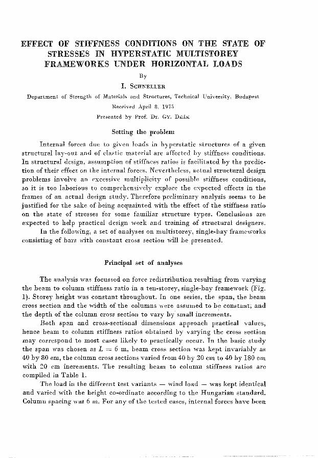
Internal forces due to given loads in hyperstatic structures of a given structural lay-out and of elastic material are affectcd by stiffness conditions. In structural design, assumption of stiffness ratios is facilitated by the prediction of their effect on the internal forces. Nevertheless, actual structural design problems involve an excessive multiplicity of possihle stiffness conditions, so it is too lahorious to comprehcnsively explore the expected effects in the frames of an actual design study. Therefore preliminary analysis seems to he justified for the sake of being acquainted ,\ith the effect of the stiffness ratio on the state of stresses for some familiar structure types. Conclusions are expected to help practical design work and training of structural designers.
In the following, a set of analyses on multistorey, single-hay frameworks consisting of hars with constant cross section will be presented.
Principal set of analyses
The analysis was focussed on force redistrihution resulting from varying the beam to column stiffness ratio in a ten-storey, single-hay framework (Fig. 1). Storey height was constant throughout. In one series, the span, the beam cross section and the ,,,idth of the columns were assumed to be constant, and the depth of the column cross section to vary by small increments.
Both span and cross-scctional dimensions approach practical values, hence heam to column stiffness ratios obtained by varying the cross section may correspond to most cases likely to practically occur. In the basic study the span was chosen as L = 6 m, beam cross section was kept invariahly as 40 hy 80 cm, the column cross sections varied from 40 by 20 cm to 4·0 by 180 cm with 20 cm increments. The resulting heam to column stiffness ratios are compiled in Table 1.
The load in the different test variants - ,vind load - was kept identical and varied ,,,ith the height co-ordinate according to the Hungarian standard. Column spacing was 6 m. For any of the tested cases, internal forces have been

112 SCHNELLER
COLUMN CROSS SECTION
180
~!!ijjjl' ~
~-+ ~~ • 80 !
BEAM CROSS SECTION
Fig. 1. Geometry of the structure
Tahle 1
Column cross section 40/20 40/40 40/60 40/80 40/100 40/120 40/140 40/160 40/180
cm
Stiffness ratio 32.2 4.08 1.19 0.50 0.25 0.14 0.093 0.062 0.044
determined according to the first-order theory of bar systems, assuming an ideal-elastic structural material, taking deformations due to bending moments and axial forces into consideration (neglecting shcar deformations). Computations were made in an ODRA 1204 computer of the Computing Center of the Faculty of Civil Engineering, Technical University, Budapest, applying a library program of the Computing Center.
HYPERSTATIC _UULTISTOREY FRAJIEWORKS 113
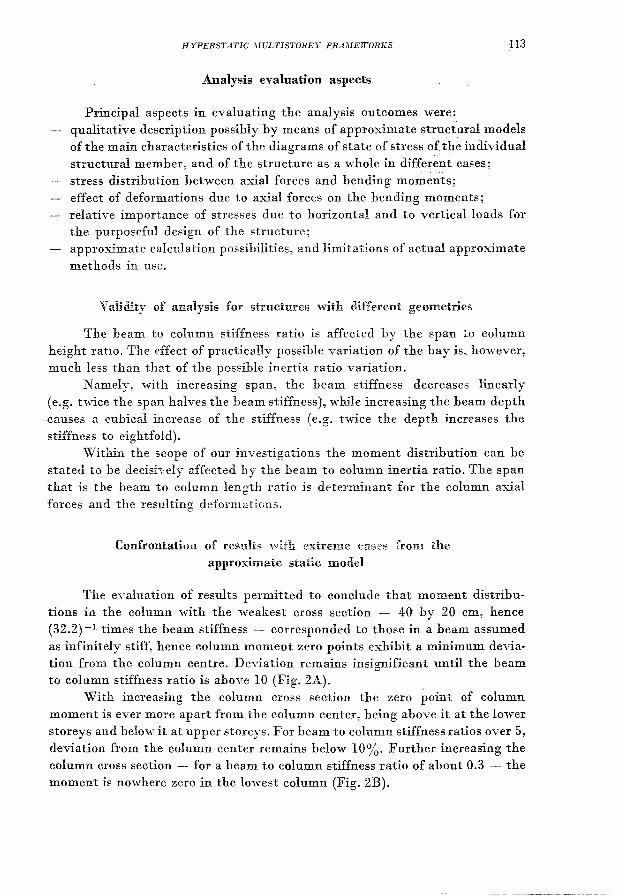
Analysis evaluation aspects
Principal aspects in evaluating the analysis outcomes were: qualitative description possibly by means of approximate struct'ural models of the main characteristics of the diagrams of state of stress of the individual structural member, and of the structure as a ,,,-hole in different cases; stress distribution hetween axial forces and bending moments; effect of deformations due to axial forces on the bending moments; relative importance of stresses due to horizontal and to vertical loads for the purposeful design of the structure; approximate calculation possihilities, and limitations of actual approximate
methods in use.
Validity of analysis for structures with different geometries
The heam to column stiffness ratio is affected by the span to column height ratio. The effect of practically possible variation of the bay is, however, much less than that of the possihle inertia ratio variation.
Namely, with increasing span, the heam stiffness decreases linearly (e.g. twice the span halves the beam stiffness), while increasing the heam depth causes a cubical increase of the stiffness (e.g. twice the depth increases the stiffness to eightfold).
Within the scope of our investigations the moment distribution can be stated to be decisively affected hy the heam to column inertia ratio. The span that is the heam to column length ratio is determinant for the column axial forces and the resulting deformations.
Confrontatiou of results extl"erne cases from the approximate static model
The evaluation of results permitted to conclude that moment distributions in the column with the weakest cross section - 40 by 20 cm, hence (32.2) -1 times the beam stiffness - corresponded to those in a beam assumed as infinitely stiff, hence column moment zero points exhibit a minimum deviation from the column centre. De'dation remains insignificant until the beam to column stiffness ratio is ahove 10 (Fig. 2A).
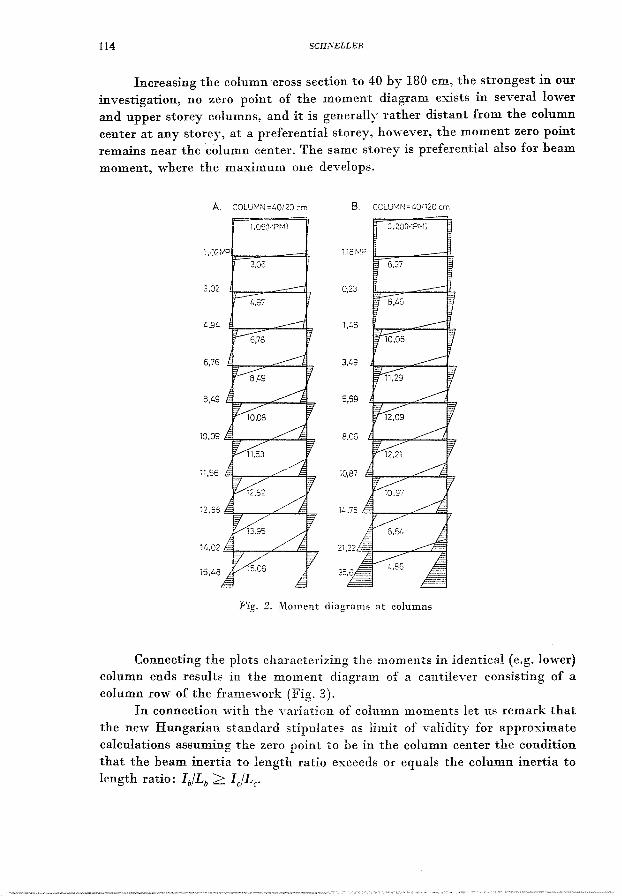
With increasing the column cross section the zero point of column moment is ever more apart from the column center, heing above it at the lower storeys and below it at upper storeys. For heam to column stiffness ratios over 5, deviation from the column center remains helow 10%. Further increasing the column cross section - for a heam to column stiffness ratio of about 0.3 - the moment is nowhere zero in the lowest column (Fig. 2B).
114 SCHSELLER
Increasing the column cross section to 40 by 180 cm, the strongest in our investigation, no zero point of the moment diagram exists in several lower and upper storey columns, and it is generally rather distant from the column cent er at any storey, at a preferential storey, however, the moment zero point remains near the column center. The same storey is preferential also for beam
moment, where the maximum one develops.
B. CO~U;viN:;:::"O/i20 cm
i ,02~~"P'I== __ ==4,
3,C6
3,02
£..97
Fig. 2. l\loment diagram:" at columns
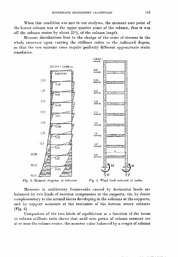
Connecting the plots characterizing the moments in identical (e.g. lower) column ends results in the moment diagram of a cantilever consisting of a column row of the frame'work (Fig. 3).
In connection with the nuiation of column moments let us remark that the new Hungarian standard stipulatei' ai' limit of validity for approximate calculations assuming the zel'O point to be in the column cent er the condition that the beam inertia to length ratio exceeds or equals the column inertia to
length ratio: Ib/Lb ~ le/Le'
HYPERSTATIC MULTISTOREY FRAMEWORKS 115
When this condition was met in our analyses, the moment zero point of the lowest column was at the upper quarter point of the column, thus it was off the column centre by about 25% of the column length.
Moment distributions hint to the change of the state of stresses in the whole structure upon varying the stiffness ratios to the indicated degree, so that the two extreme cases require perfectly different approximate static simulation.
COLUMN = 40/183 cm
5,58 (MPM)
22,68
35,90
55,74
Fig, 3. Moment diagram at columns Fig. 4. Wind load reduced at nodes
Moments in multistorey frameworks caused by horizontal loads are balanced by two kinds of reaction components at the supports, viz. by forces complementary to the normal forces developing in the columns at the supports, and by support moments at the restraints of the bottom storey columns (Fig. 4).
Comparison of the two kinds of equilihrium as a function of the beam to column stiffness ratio shows that until zero points of column moment are at or near the column center, the moment value balanced by a couple of column
116 SCHNELLER
normal forces prevails. The structure is in perfect interaction, it reacts horizontal force effects as a single cantilever. Then, the moments assumed "with normal forces as a force couple are more than 90% of the total. Upon increasing the column stiffness ratio, support moments at bottom column restraint increase, at a loss of prevalence of the moment assumed ·with a force couple. For the stiffest column tested, 60% and 40% of the moment are balanced by the couple of the normal forces, and by the support moments, respectively (Table 2).
Table 2 Comparison of the two kinds of equilibrium
Column cross Moment
section M cm
40/20 91.3% 8.7% 40/40 90.5% 9.6% 40/60 89,0% 11.0% 40/80 86.5% 13.5% 40/100 83.0% 17.0% 40/120 79.6% 20.4% 40/140 76.0% 24.0% 40/160 71.8% 28.2% 40/180 68.0% 32.0~~
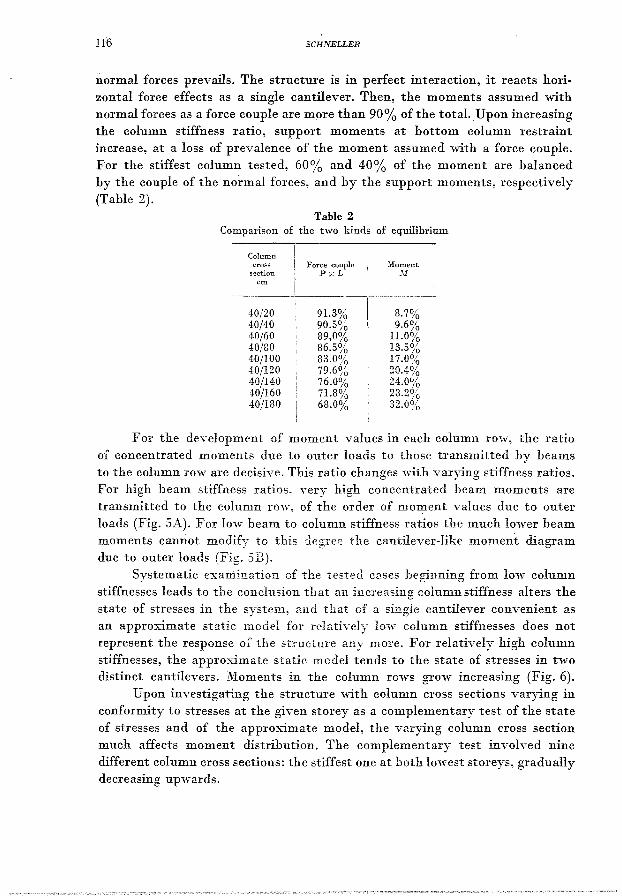
For the development of moment values in each column row, the ratio of concentrated moments due to outer loads to those transmitted by beams to the column row are decisive. This ratio changes "with varying stiffness ratios. For high beam stiffness ratios, very high concentrated beam moments are transmitted to the column rO'iv", of the order of moment values due to outer loads (Fig. SA). For low beam to column stiffness ratios the much lower beam moments cannot modify to this degree the cantilever-like moment diagram due to outer loads (Fig. 3B).
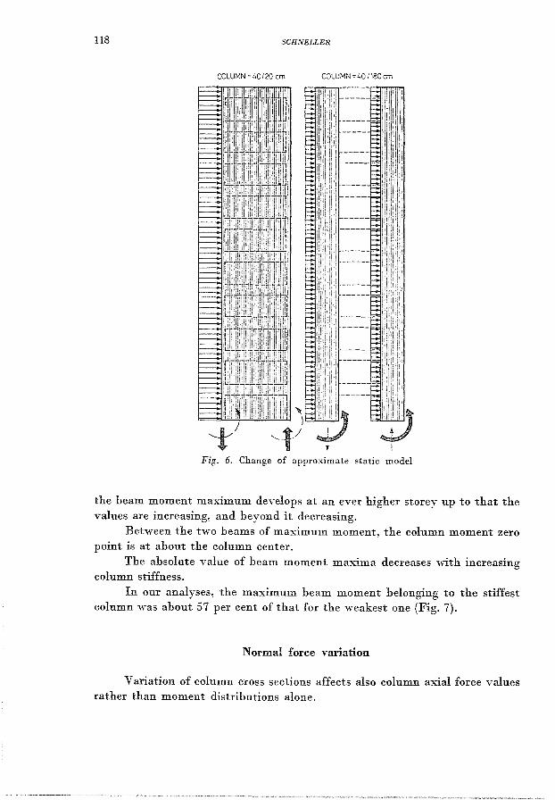
Systematic examination of the tested cases heginning from lo·w column stiffnesscs leads to the conclusion that an increasing column stiffness alters the state of stresses in the system, and that of a single cantilever convenient as an approximate static model for relatively low column stiffnesses does not represent the response of the structure any more. For relatively high column stiffnesses, the approximate static model tends to the state of stresses in two distinct cantilevers. Moments in the column rows grow increasing (Fig. 6).
Upon investigati.ng the structure 'with column cross sections varying in conformity to stresses at the given storey as a complementary test of the state of stresses and of the approximate model, the varying column cross section much affects moment distribution. The complementary test involved nine different column cross sections: the stiffest one at both lowest storeys, gradually decreasing upwards.
HYPERSTATIC .UULTISTOREY FRAMEWORKS 117
Except for the two lowest storeys, column moment distribution returned to the moment zero point near the column center resulting from the assumption of an infinitely stiff beam.
Beam moment variation
In the case of beams, the moment zero is invariably at mid-beam, both columns being of identical stiffness (KCl = Kc2)' Variation of beam moment values is, however, much dependent on the beam to column stiffness ratio.
B.
·76,03
160,56
119,E6
COLU:·1N 40!i80
Fig. 5. Development of moment values in column rows
For high beam to column stiffness ratios, hence, for little off-center column moment zero points, the beam moment values are maximum at the lowest storey, and gradually decrease upwards.
With increasing column stiffness and off-centering of moment zero points in lower and upper storeys, beam moment ratios are changing.
In our analyses, the sequence changed already for the 40 by 60 cm column, hence for a beam to column stiffness ratio of 1.19, the maximum beam moment is not at the lowest storey any more. With increasing column stiffness,
118 SCHNELLER
COLUMN :40120 cm COLUMN: 40 1180 cm
Fig. 6. Change of approximate static model
the beam moment maximum develops at an ever higher storey up to that the values are increasing, and beyond it decreasing.
Between the two beams of maximum moment, the column moment zero point is at about the column center.
The absolute value of beam moment maxima decreases with increasing column stiffness.
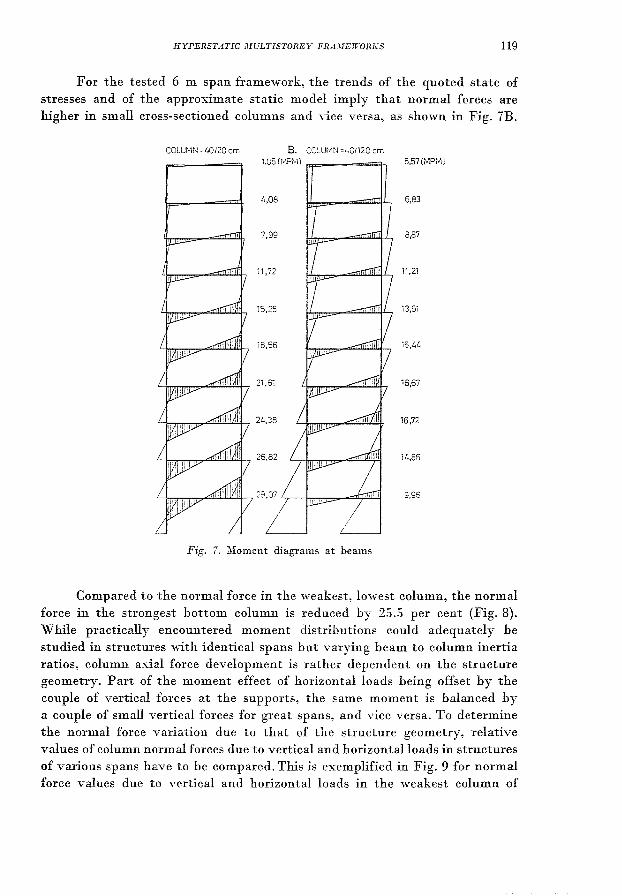
In our analyses, the maximum beam moment belonging to the stiffest column was about 57 per cent of that for the weakest one (Fig. 7).
Normal force variation
Variation of column cross sections affects also column axial force values rather than moment distributions alone.
HYPERSTATIC .1fULTISTOREY FRA.\IEWORKS 119
For the tested 6 m span framework, the trends of the quoted state of stresses and of the approximate static model imply that normal forces are higher in small cross-sectioned columns and vice versa, as shown in Fig. 7B.
COLU~'IN~40/20 crn 8. COLUMN =i.QI120 cm
1,05 (t>t.Ptvl) FT"'---=::::r,
4,08
7,99
11,72
15,25
18,56
21,61
24,38
26,82
Fig. ,. lVloment diagram;, at beams
5,57 (MPMj
6,83
8,87
11,21
13,51
15,44
16,67
16,72
14,85
9,96
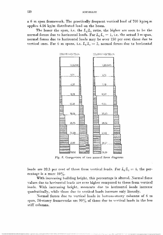
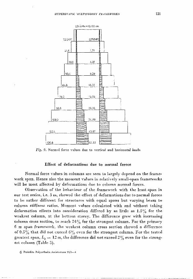
Compared to the normal force in the weakest, lowest column, the normal force in the strongest bottom column is reduced by 25.5 per cent (Fig. 8). While practically encountered moment distributions could adequately be studied in structures v,ith identical spans but varying beam to column inertia ratios, column axial force development is rather dependent on the structure geometry. Part of the moment effect of horizontal loads being offset by the couple of vertical forces at the supports, the same moment is balanced by a couple of small vertical forces for great spans, and vice versa. To determine the normal force variation due to that of the structure geometry, relative values of column normal forces due to vertical and horizontal loads in structures of various spans have to be compared. This is exemplified in Fig. 9 for normal force values due to vertical and horizontal loads in the weakest column of
120 SCHNELLER
a 6 m span framework. The practically frequent vertical load of 700 kp/sq.m applies 4.56 kp/m distributed load on the beam.
The lesser the span, i.e. the LblLc ratio, the higher are seen to be the normal forces due to horizontal loads. For Lb,Lc = 1, i.e. the actual 3 m span, normal forces due to horizontal loads may be over 150 per cent those due to vertical ones. For 6 m spans, i.e. Lb/LC = 2, normal forces due to horizontal
COLUr'lN =40120 cm COLUI'~I'J = L.Oi1BO cm
0.35 (I"'P)
1.71 ~.i4
4.37
Fig. 8. Comparison of two normal force diagrams
loads are 39.3 per cent of those from vertical loads. For LbiLc = 4, the percentage is a mere 10%.
With increasing building height, this percentage is altered. Normal force values due to horizontal loads are ever higher compared to those from vertical loads. With increasing height, moments due to horizontal loads increase quadratic ally, w'hile those due to yerticalloads increase only linearly.
Normal forces due to vertical loads in hottom-storey columns of 6 ill
span, 24-storey frameworks are 90% of those due to vertical loads in the less stiff columns.
HYPERSTATIC MULTISTOREY FRA;vIEWORKS 121
COlUM;, =~OI20 cm
Fig. 9. Normal force yalues due to yertical and horizontal loads
Effect of deformations due to normal' forces
Normal force values in columns are seen to largely depend on the framework span. Hence also the moment values in relatively small-span frameworks vdll be most affected by deformations due to column normal forces.
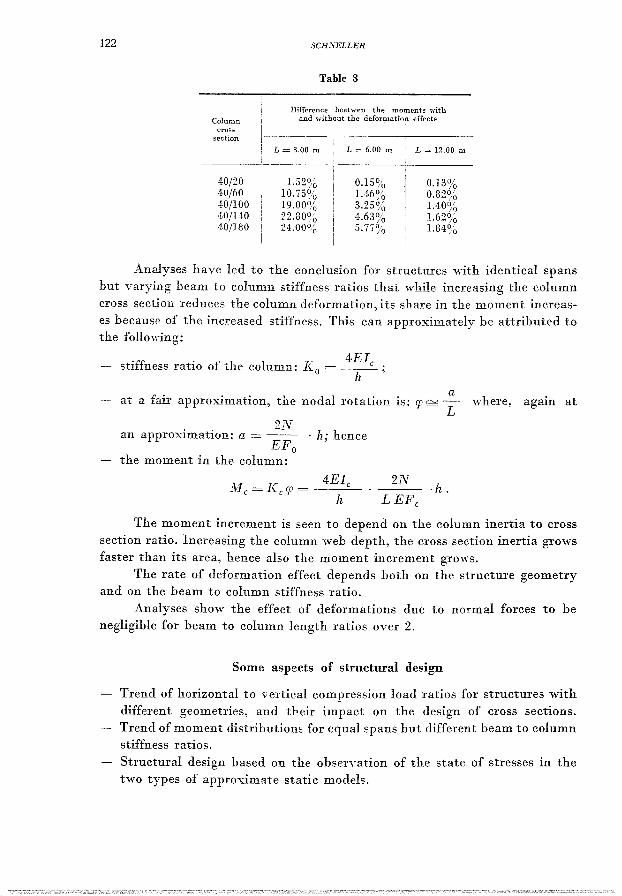
Observation of the behaviour of the framework ",ith the least span in our test series, i.e. 3 m, showed the effect of deformations due to normal forces to be rather different for structures 'with equal spans but varying beam to column stiffness ratios. Moment values calculated ,vith and , ... ithout taking deformation effects into consideration differed by as little as 1.5 % for the weakest column, at the bottom storey. The difference grew , ... ith increasing column cross section, to reach 24% for the strongest column. For the primary 6 m span framework, the weakest column cross section showed a difference of 0.5% that did not exceed 6% even for the strongest column. For the tested greatest span, Lb = 12 m, the difference did not exceed 2 % even for the strongest column (Table 3).
6 Periodic a Poly technic a Architcctura 19/3-4
122
Column cross
section
40/20 40/60 to/lOO 40/140 40/180
SCHiVELLER
Table 3
Difference beet-wen the moments with and, \,,-ithout the deformation effects
L = 3.00 III
1.52% 10.75% 19.00% 22.80% 24.00~()
L = 12.00 m
0.13% 0.82% 1.4.0% 1.62% 1.84%
Analyses have led to the conclusion for structures ,,,ith identical spans but varying beam to column stiffness ratios that while increasing the column cross section reduces the column deformation, its share in the moment increases because of the increased stiffness. This can approximately bc attributed to the following:
stiffness ratio f th I K 4E1c o e co unIn: .... 0 = -h-,- ;
a - at a fair approximation, the nodal rotation is: rp 0/ L where, again at
2N an approximation: a = -- . h; hence
EFo the moment in the column:
2N ·h.
The moment increment is seen to depend on the column inertia to cross section ratio. Increasing the column web depth, the cross section inertia grows faster than its area, hence also the moment increment grows.
The rate of deformation effect depends both on the structure geometry and on the beam to column stiffness ratio.
Analyses show the effect of deformations due to normal forces to be negligible for beam to column length ratios over 2.
Some aspects of structural design
Trend of horizontal to vertical compression load ratios for structures with different geometries, and tbeir impact on the design of cross sections. Trend of moment distributiom for equal spans but different beam to column stiffness ratios.
Structural design based on the observation of the state of stresses in the two types of approximate static models.
HYPERSTATIC MULTISTOREY FRA2HEWORKS 123
Ratio of stresses due to horizontal and vertical loads, and selection of the prevalent one were seen to depend on the structure geometry. In case of tall structures with low beam to column length ratios, column normal forces due to horizontal loads may be many times those due to vertical loads, being decisive for the design of cross-sectional dimensions. Increasing column normal forces and small spans permitting to apply beams with relatively small cross sections shifts the heam to column stiffness ratio in favour of the beam. As a conclusion, also the effect of normal force deformations is important for these structures.
For the tested large-span frameworks, column normal forces due to horizontal loads are rather slight compared to those due to vertical loads; hence the design of cross sections is determined hy the vertical load. Effect of deformations due to normal forces is negligible in these structures.
The relative share of couple and of support moments needed to halance moments due to horizontal loads is determined hy the beam to column inertia ratio for structures with identical spans. From the dynamic hehaviour of tbe two types of static models approximating the state of stresses, viz., the single cantilever, and the two separate cantilevers, it can be concluded that in case of the weakest column, balancing the moments due to horizontal loads is predominated by axial forces, and flexural stresses are uniform in the columns; with increasing column stiffness, however, equilihrium is ever more dependent on flexural stresses, to the detriment of axial stresses.
In structural design it is advisable to possibly shift the beam to column stiffness ratio in favour of thc beam, hence, to have state of stresses in the structure as near to those in a single cantilever as possible, permitting predominantly axial stresses in the columns.
Economy analyses of skyscraper structures pointed to important saving possibilities upon achieving frameworks with or without bracing to act as single cantilevers.
In design, economically favourable stress ratios corresponding to multistorey frameworks independent of hracing can he approximated by correctly selecting the structure geometry, by an adeqnate dt'3ign of beam to column stiffness ratios, by applying columns with cross sections varying to cope with the stresses.
Summary
Development of the state of stresses as a function of the beam to column stiffness ratio in a ten-storey. single-span. hyperstatie framework exposed to horizontal wind load has been analysed. The beam cross section has been assumed to be constant, and the column cross section step-wise variable: stresses developing in the different cases have been obtained by means of a computer library program. Outputs have been evaluated from the viewpoint of an economically favourable structural design.
Istvan SCHNELLER, H-1521 Budapest
6*