A Review on Tailoring Stiffness in Compliant Systems, via ...
31
applied sciences Review A Review on Tailoring Stiffness in Compliant Systems, via Removing Material: Cellular Materials and Topology Optimization Mauricio Arredondo-Soto 1,2,† , Enrique Cuan-Urquizo 1,2, * ,† and Alfonso Gómez-Espinosa 1, * Citation: Arredondo-Soto, M.; Cuan-Urquizo, E.; Gómez-Espinosa, A. A Review on Tailoring Stiffness in Compliant Systems, via Removing Material: Cellular Materials and Topology Optimization. Appl. Sci. 2021, 11, 3538. https://doi.org/ 10.3390/app11083538 Academic Editor: Valentino Paolo Berardi Received: 21 March 2021 Accepted: 9 April 2021 Published: 15 April 2021 Publisher’s Note: MDPI stays neutral with regard to jurisdictional claims in published maps and institutional affil- iations. Copyright: © 2021 by the authors. Licensee MDPI, Basel, Switzerland. This article is an open access article distributed under the terms and conditions of the Creative Commons Attribution (CC BY) license (https:// creativecommons.org/licenses/by/ 4.0/). 1 Tecnologico de Monterrey, School of Engineering and Sciences, Querétaro 76130, Mexico; [email protected] 2 Laboratorio Nacional de Manufactura Aditivay Digital (MADIT), Apodaca, Nuevo León 66629, Mexico * Correspondence: [email protected] (E.C.-U.); [email protected] (A.G.-E.); Tel.: +52-442-238-3302 (A.G.-E.) † These authors are part of the Metamaterials Lab Group at Tecnologico de Monterrey Campus Querétaro. Abstract: Cellular Materials and Topology Optimization use a structured distribution of material to achieve specific mechanical properties. The controlled distribution of material often leads to several advantages including the customization of the resulting mechanical properties; this can be achieved following these two approaches. In this work, a review of these two as approaches used with compliance purposes applied at flexure level is presented. The related literature is assessed with the aim of clarifying how they can be used in tailoring stiffness of flexure elements. Basic concepts needed to understand the fundamental process of each approach are presented. Further, tailoring stiffness is described as an evolutionary process used in compliance applications. Additionally, works that used these approaches to tailor stiffness of flexure elements are described and categorized. Finally, concluding remarks and recommendations to further extend the study of these two approaches in tailoring the stiffness of flexure elements are discussed. Keywords: cellular materials; topology optimization; flexure element; compliant system; tailoring stiffness 1. Introduction Compliance is the term used when referring to low levels of stiffness, in other words, when flexibility is the characteristic feature. Compliant systems can be categorized in com- pliant mechanisms (Figure 1a), compliant joints (Figure 1b), and flexure elements (Figure 1c). Compliant mechanisms transmit motion, force, and energy through the elastic deformation of flexible members known as flexures. Compliant joints are the key-components in compliant mechanisms; they act analogously to the kinematic pairs in rigid-body mechanisms. The basic form of a compliant joint is a single flexure, which is usually formed by removing material from a bulk piece. A compliant joint can be composed of more than one flexure and could be considered as a compliant mechanism on its own. Flexures stretch, bend, or twist during deformation, which leads to the relative motion between parts in a compliant system. (a) (b) (c) Flexure elements Figure 1. Compliant systems: (a) compliant mechanism, (b) compliant joint, and (c) flexure. Appl. Sci. 2021, 11, 3538. https://doi.org/10.3390/app11083538 https://www.mdpi.com/journal/applsci
-
Upload
khangminh22 -
Category
Documents
-
view
6 -
download
0
Transcript of A Review on Tailoring Stiffness in Compliant Systems, via ...

applied sciences
Review
A Review on Tailoring Stiffness in Compliant Systems,via Removing Material: Cellular Materials andTopology Optimization
Mauricio Arredondo-Soto 1,2,† , Enrique Cuan-Urquizo 1,2,*,† and Alfonso Gómez-Espinosa 1,*
Citation: Arredondo-Soto, M.;
Cuan-Urquizo, E.; Gómez-Espinosa,
A. A Review on Tailoring Stiffness
in Compliant Systems, via Removing
Material: Cellular Materials and
Topology Optimization. Appl. Sci.
2021, 11, 3538. https://doi.org/
10.3390/app11083538
Academic Editor: Valentino Paolo
Berardi
Received: 21 March 2021
Accepted: 9 April 2021
Published: 15 April 2021
Publisher’s Note: MDPI stays neutral
with regard to jurisdictional claims in
published maps and institutional affil-
iations.
Copyright: © 2021 by the authors.
Licensee MDPI, Basel, Switzerland.
This article is an open access article
distributed under the terms and
conditions of the Creative Commons
Attribution (CC BY) license (https://
creativecommons.org/licenses/by/
4.0/).
1 Tecnologico de Monterrey, School of Engineering and Sciences, Querétaro 76130, Mexico;[email protected]
2 Laboratorio Nacional de Manufactura Aditivay Digital (MADIT), Apodaca, Nuevo León 66629, Mexico* Correspondence: [email protected] (E.C.-U.); [email protected] (A.G.-E.); Tel.: +52-442-238-3302 (A.G.-E.)† These authors are part of the Metamaterials Lab Group at Tecnologico de Monterrey Campus Querétaro.
Abstract: Cellular Materials and Topology Optimization use a structured distribution of materialto achieve specific mechanical properties. The controlled distribution of material often leads toseveral advantages including the customization of the resulting mechanical properties; this canbe achieved following these two approaches. In this work, a review of these two as approachesused with compliance purposes applied at flexure level is presented. The related literature isassessed with the aim of clarifying how they can be used in tailoring stiffness of flexure elements.Basic concepts needed to understand the fundamental process of each approach are presented.Further, tailoring stiffness is described as an evolutionary process used in compliance applications.Additionally, works that used these approaches to tailor stiffness of flexure elements are describedand categorized. Finally, concluding remarks and recommendations to further extend the study ofthese two approaches in tailoring the stiffness of flexure elements are discussed.
Keywords: cellular materials; topology optimization; flexure element; compliant system;tailoring stiffness
1. Introduction
Compliance is the term used when referring to low levels of stiffness, in other words,when flexibility is the characteristic feature. Compliant systems can be categorized in com-pliant mechanisms (Figure 1a), compliant joints (Figure 1b), and flexure elements (Figure 1c).Compliant mechanisms transmit motion, force, and energy through the elastic deformation offlexible members known as flexures. Compliant joints are the key-components in compliantmechanisms; they act analogously to the kinematic pairs in rigid-body mechanisms. The basicform of a compliant joint is a single flexure, which is usually formed by removing materialfrom a bulk piece. A compliant joint can be composed of more than one flexure and couldbe considered as a compliant mechanism on its own. Flexures stretch, bend, or twist duringdeformation, which leads to the relative motion between parts in a compliant system.
(a) (b) (c)
Flexure elements
Figure 1. Compliant systems: (a) compliant mechanism, (b) compliant joint, and (c) flexure.
Appl. Sci. 2021, 11, 3538. https://doi.org/10.3390/app11083538 https://www.mdpi.com/journal/applsci

Appl. Sci. 2021, 11, 3538 2 of 31
Compared with traditional rigid-body mechanisms, compliant mechanisms havemany inherent advantages, including elimination of sliding contact between surfaces,monolithic manufacturing, higher precision, reduced friction, and reduced weight [1].In contrast to their rigid-body counterparts, compliant mechanisms facilitate smooth,continuous motion, without backlash, and with high levels of repeatability and precision [2].Therefore, compliant mechanisms find applications in fields requiring high precisionmotion, such as precision manufacturing [3], biological cell handling [4], micro/nano-manipulation [5], positioning stages [6], microelectromechanical systems (MEMS) [7],micro-vibration suppression [8], optical guides [9], and so forth.
Apart from the advantages, compliant systems have some drawbacks owing to theirintrinsic coupling of kinematics and elastomechanical behaviors. Consequently, design andanalysis cannot be done by separating kinematics and dynamics. The design process is evenmore complicated if the compliant elements undergo large deflections, due to the resultingnonlinear relationship between stress and strain. The challenging process for designing andanalyzing compliant systems limits the wide use of three-dimensional (3D) architectureswith multi Degrees of Freedom (DoFs),restricts the design to small deflections, and maylead to inaccuracies such as cross-coupling errors and erroneous undesired displacementstermed as parasitic motions [10–13].
Applications increasingly demand compliant systems with large workspaces, multiple-DoFs, low cross-coupling errors, and reduced parasitic motions. Attempts to reduce in-accuracies and limitations have been proposed, some examples are the use of redundantconstraints [14,15], compound joints [16,17], addition of subsystems [18,19], implementation oftracking control systems [20], and design of spatial complex architectures to perform basic pla-nar motions [21]. However, all of these techniques are based on the incorporation of elementsor sub-systems to the compliant system, thus increasing complexity, size, and weight.
The performance of a flexure element, i.e., its range of motion, accuracy, kinematics,and dynamics, is determined by the proper characterization of its force-deformation re-lation, i.e., the stiffness (or compliance) of the element. Having control over the stiffnessof the flexure elements appears as an ideal way to deal with inaccuracies and limitationsof compliant systems. As the stiffness of a flexure element is governed by the materialthat composes it, boundary conditions and external geometry, changing its dimensionswill result in a modification to its stiffness. However, the geometry is generally dependenton the available material stock, manufacturing process, or other design constraints [22].Moreover, a change in the overall dimensions of a flexure element may lead to a lossin the off-axis stiffness leading to instability, thus resulting in inaccuracies.
In this regard, methods to control the stiffness of flexure elements that do not imply a rad-ical change in their overall dimensions can be found in the literature [23,24]. Some methods,such as static balancing [25–30], antagonism principle [31,32], and lever mechanism [33–35],consist of pre-deforming the flexure elements of compliant systems, reducing actuation effort,thus increasing range of motion. Flexure elements used in these methods are commonly coilsprings. Others techniques are based on changing the effective length of elastic componentsin a compliant system to achieve variable stiffness [36–40]. Despite the success in modifyingthe stiffness via pre-deformation or change in effective length of flexures, the use of externalsystems or actuators is demanded, thus increasing complexity, size, and cost.
Intentional contact between elements in compliant systems is another approach tomodify their stiffness known as contact-aided.Besides, as contact surfaces are common partsof the compliant systems, this method avoids the use of external elements and actuators.Examples of contact-aided compliant systems can be found in the literature, addressingtopics such as morphing [41–43], stress relief [44–46], improve load-bearing capacity [47],and energy absorption [48,49]. In all cases, global strain capability of contact-aided com-pliant systems is increased. Furthermore, in [50,51] variable stiffness compliant jointsare achieved through changing the effective length during deformation by self-contactbetween the flexible parts and support points manufactured as part of the same system.
Appl. Sci. 2021, 11, 3538 3 of 31
Contact-aided compliant systems act as stiffness switches during deformation and aresuitable only in applications where abrupt changes of stiffness are needed.
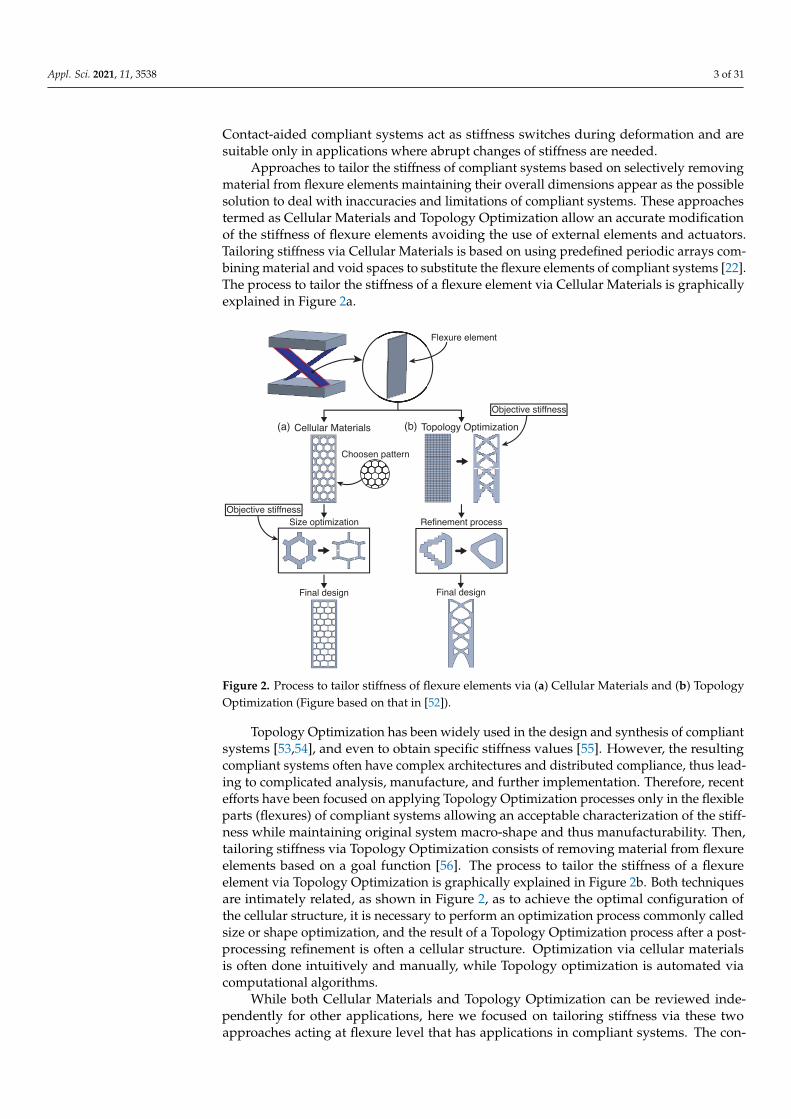
Approaches to tailor the stiffness of compliant systems based on selectively removingmaterial from flexure elements maintaining their overall dimensions appear as the possiblesolution to deal with inaccuracies and limitations of compliant systems. These approachestermed as Cellular Materials and Topology Optimization allow an accurate modificationof the stiffness of flexure elements avoiding the use of external elements and actuators.Tailoring stiffness via Cellular Materials is based on using predefined periodic arrays com-bining material and void spaces to substitute the flexure elements of compliant systems [22].The process to tailor the stiffness of a flexure element via Cellular Materials is graphicallyexplained in Figure 2a.
Cellular Materials
Choosen pattern
Topology Optimization
Objective stiffness
Size optimization
Final design
Objective stiffness
Flexure element
Refinement process
Final design
(b)(a)
Figure 2. Process to tailor stiffness of flexure elements via (a) Cellular Materials and (b) TopologyOptimization (Figure based on that in [52]).
Topology Optimization has been widely used in the design and synthesis of compliantsystems [53,54], and even to obtain specific stiffness values [55]. However, the resultingcompliant systems often have complex architectures and distributed compliance, thus lead-ing to complicated analysis, manufacture, and further implementation. Therefore, recentefforts have been focused on applying Topology Optimization processes only in the flexibleparts (flexures) of compliant systems allowing an acceptable characterization of the stiff-ness while maintaining original system macro-shape and thus manufacturability. Then,tailoring stiffness via Topology Optimization consists of removing material from flexureelements based on a goal function [56]. The process to tailor the stiffness of a flexureelement via Topology Optimization is graphically explained in Figure 2b. Both techniquesare intimately related, as shown in Figure 2, as to achieve the optimal configuration ofthe cellular structure, it is necessary to perform an optimization process commonly calledsize or shape optimization, and the result of a Topology Optimization process after a post-processing refinement is often a cellular structure. Optimization via cellular materialsis often done intuitively and manually, while Topology optimization is automated viacomputational algorithms.
While both Cellular Materials and Topology Optimization can be reviewed inde-pendently for other applications, here we focused on tailoring stiffness via these twoapproaches acting at flexure level that has applications in compliant systems. The con-
Appl. Sci. 2021, 11, 3538 4 of 31
trolled distribution of material within a certain structure often leads to several advantages;one of them is the customization of the resulting mechanical properties of it. Followingthese two approaches, this can be achieved; therefore, reviewing the related literature to aidthe understating and implementation of the approaches gains relevance. The main effort ofthis work is in clarifying how the stiffness can be tailored through these approaches andreviewing the works found in the literature that used them on flexure elements. Commentson the mechanical characteristics that the compliant systems gained with these methods,such as weight reduction, stiffness ratios, stress relief and motion range, are also addressed.As this work focuses on tailoring stiffness, applications of these methods in the customiza-tion of properties, such as thermal [57], electrical [58], and acoustic [59], are beyond ofthe scope of this review. This review is structured as follows. Tailoring stiffness via CellularMaterials is presented in Section 2. Tailoring stiffness via Topology Optimization is detailedin Section 3. Concluding remarks and discussion on research trends of these two are givenin Section 4.
2. Tailoring Stiffness via Cellular Materials
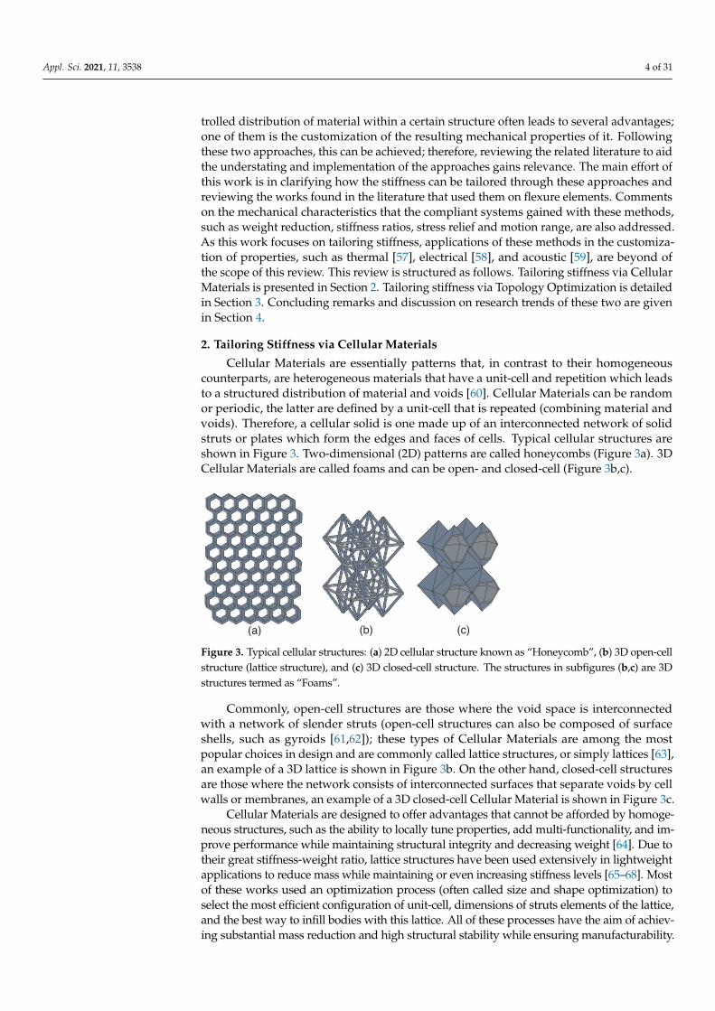
Cellular Materials are essentially patterns that, in contrast to their homogeneouscounterparts, are heterogeneous materials that have a unit-cell and repetition which leadsto a structured distribution of material and voids [60]. Cellular Materials can be randomor periodic, the latter are defined by a unit-cell that is repeated (combining material andvoids). Therefore, a cellular solid is one made up of an interconnected network of solidstruts or plates which form the edges and faces of cells. Typical cellular structures areshown in Figure 3. Two-dimensional (2D) patterns are called honeycombs (Figure 3a). 3DCellular Materials are called foams and can be open- and closed-cell (Figure 3b,c).
(a) (b) (c)
Figure 3. Typical cellular structures: (a) 2D cellular structure known as “Honeycomb”, (b) 3D open-cellstructure (lattice structure), and (c) 3D closed-cell structure. The structures in subfigures (b,c) are 3Dstructures termed as “Foams”.
Commonly, open-cell structures are those where the void space is interconnectedwith a network of slender struts (open-cell structures can also be composed of surfaceshells, such as gyroids [61,62]); these types of Cellular Materials are among the mostpopular choices in design and are commonly called lattice structures, or simply lattices [63],an example of a 3D lattice is shown in Figure 3b. On the other hand, closed-cell structuresare those where the network consists of interconnected surfaces that separate voids by cellwalls or membranes, an example of a 3D closed-cell Cellular Material is shown in Figure 3c.
Cellular Materials are designed to offer advantages that cannot be afforded by homoge-neous structures, such as the ability to locally tune properties, add multi-functionality, and im-prove performance while maintaining structural integrity and decreasing weight [64]. Due totheir great stiffness-weight ratio, lattice structures have been used extensively in lightweightapplications to reduce mass while maintaining or even increasing stiffness levels [65–68]. Mostof these works used an optimization process (often called size and shape optimization) toselect the most efficient configuration of unit-cell, dimensions of struts elements of the lattice,and the best way to infill bodies with this lattice. All of these processes have the aim of achiev-ing substantial mass reduction and high structural stability while ensuring manufacturability.

Appl. Sci. 2021, 11, 3538 5 of 31
When the characteristic lattice dimensions are significantly smaller than the overalldimensions of a piece of solid, one can represent the properties of such structural solids bymeans of apparent properties considering them as homogeneous having equivalent continuumproperties [69]. In general, an apparent property, 〈P〉, of a Cellular Material is often beexpressed as 〈P〉 = CPρn, where P is the property of the parent material (e.g., Young’smodulus), and n and C are constants related to the deformation mechanism of the lattice elementsand topology. The exponent n, which depends on the micro-architecture response, definesthe scaling relation of the apparent property with the relative density [70]. The relative densityis equal to the volume fraction, ρ = Vs/Vc, where Vs is the volume of the solid material and Vcis the volume of the lattice material considering the external dimensions.
According to their deformation mechanism, cellular Materials are classified into twomain groups: bending-dominated and stretch-dominated structures [71]. When loaded,the cellular elements of the structured material can respond by bending or stretching-shortening; thus, they are said to be bending- or stretch-dominated (Figure 4a,b), respectively.Therefore, customization of the stiffness via Cellular Materials is possible as their apparentmechanical properties show dependence on the following: (i) the mechanical properties ofthe parent material, (ii) the topology and cell geometry, and (iii) the relative density. Properlyplanned selection or modification on any of these three can lead to a meta-material with tai-lored properties. In this regard, the stiffness of a compliant system can be modified throughthe implementation of specific cellular arrays in the flexible parts of the system.
(a) (b)
Figure 4. Schematic of (a) bending-dominated and (b) stretch-dominated structures.
Tailoring stiffness has become more relevant with the emergence of modern man-ufacturing processes such as additive manufacturing techniques, capable of fabricatingcomplex topologies and shapes [72–75]. Some studies [76–78] showed how the stiffnessin beams can be customized by using different types of cellular structures while obtainingminimum weight designs. Other works [79–81] focused on obtaining optimal designsof lattice structures to achieve the desired stiffness along with exceptional load-bearingefficiency and minimum weight. Later, Maskery et al. [82] investigated the effect of celltopology, orientation, and volume fraction to provide a specified stiffness in the latticestructures. Further, Weisgraber et al. [83] conducted research works where they provedthat by modifying cell parameters, it is possible to control the stress-strain curve of a Cellu-lar Material to assess specific load requirements and performance. A similar study wasdeveloped by Wang et al. [84], where the authors optimized lattice structures to providespecific stiffness for given multi-loading scenarios in the low volume fraction limit. Mostrecently, Alvarez-Trejo et al. [85] synthesized a new type of Bézier-based metamaterial,characteristics of which enable the generation of structures with customized mechanicalproperties by adjusting the geometry of the unit cells.
Some studies [86–90] demonstrated the possibility to tailor specific stiffness dependingon the loading direction, allowing the design of customized anisotropic Cellular Materials.Niknam et al. [87] introduced the concept of multi-directional functionally graded CellularMaterials made by assembling porous unit cells of dissimilar densities and cell topologiesto improve the performance of lightweight structural elements. In [88], the authors ev-idenced that tailoring the apparent anisotropy in Cellular Materials at the macroscopiclevel is possible by changing the ratio of bending-to-axial stiffness of the constituent beams,as, depending on the direction of loading, the nature of the mechanical response of cubicelementary trusses changes smoothly from bending-dominated to stretching-dominated.
Appl. Sci. 2021, 11, 3538 6 of 31
This concept was also studied in [86], where the authors performed customization of effec-tive anisotropic material properties in micro-lattice structures by controlling the unit-celltopology. Recently, Chen et al. [90] designed isotropic Cellular Materials created by super-imposing complementary anisotropic lattices, enhancing the potential of high-stiff isotropicCellular Materials. Variable stiffness is also achieved by including contacts during deformationof Cellular Materials. An example is found in Tanaka et al. [91], where the authors synthesizeda square-cell Cellular Material with the bi-stiffness property in response to compressive loading.The specific case of stiffness depends on the orientation of the unit cells leading to a specificdeformation of cells and further overlapping of cell walls. Kim et al. [89] synthesized a 3D vari-able stiffness and dual Poisson’s ratio Cellular Material by including internal contacts betweenslit surfaces during both tensile and compressive loading achieving engineered stiffness.
Applications of tailored Cellular Materials have been focused mainly on stiffness max-imization. Examples of Cellular Materials customized to offer maximum possible stiffnessusing different cellular structures such as 2D honeycombs [92,93], 3D lattices [94,95], and 3Dclosed-cell foams [96] are found in the literature. Tailored Cellular Materials have beenalso used to maximize transverse shear stiffness in honeycomb cores [97,98]. Studies ofapplications including the use of Cellular Materials to enhance buckling behavior [99], tunestress localization, minimize stress levels [100], and engineer failure location for specific loadconditions [101] are limited.
Optimization via Cellular Materials can also be used for match specific stiffness. Thisaspect is particularly attractive for the manufacturing of bone implants, where the elasticmodulus of the implant should match that of the bone in order to avoid stress shield-ing effects, bone atrophy, and implant loosening. Additionally, offering advantagessuch as improving stability by promoting tissue ingrowth and high energy absorption towithstand impacts. Three-dimensional topologies are the most frequently encounteredin this application. A variety of works for this application can be found in the literature.Parthasarathy et al. [102] presented a thorough review where they expose the capacityof additive manufacturing techniques to fabricate biomedical devices with mechanicalproperties of surrounding bone tissue with replacements parts.
Most recently, tailoring stiffness through Cellular Materials to enhance flexibility orcompliance behavior has been studied. Some of the first examples can be found in the worksof Kim et al. [103,104], where the authors proposed Cellular Materials with customizedanisotropic stiffness. The proposed materials consisted of flexible mesostructures de-signed from the deformation of re-entrant auxetic (negative Poisson’s ratio) honeycomband compliant amplifiers mechanisms. They could tailor in-plane properties of the saidmesostructures, obtaining low stiffness and high strain in one direction and high stiffnessand low strain in the other direction. A complete review of auxetic cellular materials isfound in [105]. After, Duoss et al. [106] demonstrated the possibility to independently tailorcompression and shear response in 3D printed Cellular Materials offering the extremalproperty of negative shear stiffness in designed structures. Then, Neff et al. [107] usedmodified diamond lattice structures to create Cellular Materials with reduced stiffness,advantageous for energy absorption, vibration isolation, and reduction of stress. Later,Runkel et al. [108] modified the topology of hexagonal chiral lattices and demonstratedthat purposely choosing the parameters permits to tailor the behavior of the chiral lattice,enabling extreme variations in stiffness, including the possibility to attain negative andzero-stiffness regimes over large compressive strains which exemplifies the potential totune deformation of compliant systems. Additionally, Ion et al. [109] introduced the meta-material mechanisms concept, which considers cellular materials as machines instead ofmaterials and allows the creation of macroscopic movement through the well-definedinteraction of cells in a single block of cellular material. Similarly, Ou et al. [110] presenteda group of auxetic-inspired material structures that can transform into various shapes uponcompressive loading. Most recently, in [111] a 2D kagome honeycomb was optimized fordelivering high amplitude actuation. In the same year, Dunn et al. [112] demonstrate that
Appl. Sci. 2021, 11, 3538 7 of 31
changing the cell size in lattice materials might involve maximizing stiffness in one modewhile minimizing it in another.
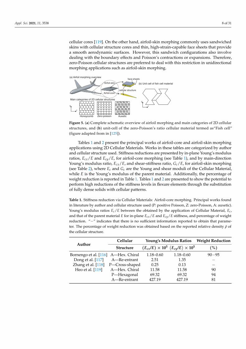
Regarding this, some applications have taken advantage of the compliance behavioroffered by Cellular Materials. One of the most extensively studied applications is in shapemorphing as the material used should not only be in-plane flexible enough to morph withactuation, but stiff enough not to deform excessively under out-of-plane loads. To this end,2D cellular structures have been suggested for general morphing skin applications [113–115].In [113], the authors presented a novel zero-Poisson’s ratio honeycomb structure that canachieve deformations along two orthogonal directions and avoid the increase of effectivestiffness in the morphing direction by restraining the Poisson’s effect in the non-morphingdirection. The same concept was explored by Liu et al. [114,115] in the development ofzero-Poisson’s ratio cellular structures with lightweight, low in-plane moduli and high straincapability. Results demonstrated the potential of the proposed structures for in-plane morphing.Moreover, the main application is in aircraft morphing, where efforts have been mainly focusedin airfoil-core morphing [116–119] and airfoil-skin morphing [120–126]. Bornengo et al. [116]proposed the use of an auxetic hexagonal structure as the airfoil-core of wings as an attemptto take advantage of the high deformability of the structure thus providing the flexibilityrequired for morphing, while preserving the structural integrity due to its high in-plane shearresistance. Dong et al. [117] designed airfoil-cores with a re-entrant cellular structure due totheir ability to undergo large in-plane displacements with limited deformation in span-wisedirection. Zhang et al. [118] investigated the use of a cross-shaped honeycomb structurein airfoil-core morphing, resulting in great in-plane deformation capacity and adequate out-of-plane support. Heo et al. [119] investigated the airfoil-core morphing capacity of threetypes of Cellular Materials through the in-plane flexible properties. Hexagonal chiral, regularhoneycomb, and re-entrant honeycomb were chosen for this analysis. All structures showedhigh levels of in-plane flexibility. The re-entrant honeycomb showed the highest flexibility andcauses a lower stress in cell walls than the other cellular cores, thus suggesting potential to beused in real morphing applications. On the other hand, Olympio et al. [120] studied the useof hexagonal honeycomb cellular structures in airfoil-skin morphing. Results showed thatCellular Materials could easily undergo global strains several times greater that the parentmaterial while maintaining good out-of-plane stiffness; however, when honeycomb CellularMaterials are stretched along the principal axis they geometrically stiffen, thereby reducingthe maximum global strain achievable. Olympio et al. [121] proposed two types of zero-Poisson’s ratio cellular structures (hybrid and accordion) to be used in one-dimensional airfoil-skin morphing applications. Results showed that the axial stiffness in the motion direction ofthe zero-Poisson’s ratio cellular structures remains low when the skins are restrained in the non-morphing direction, making these cellular structures ideal for use in airfoil-skin morphing.Other works [122–124] have studied similar zero-Poisson’s ratio cellular structures to be usedin airfoil-skin morphing, obtaining high levels of flexibility in the actuation direction whilemaintaining the desired shape and strength in the others. Most recently, in [125,126] a newCellular Material with zero-Poisson’s ratio called Fish cell (Figure 5b) was introduced forapplications in airfoil-skin morphing. The proposed cellular structures were parametrized toobtain desired stiffness values under specific conditions.
Finally, 3D arrays have been reserved for complete wing morphing [127,128]. 2Dcellular structures used in airfoil-core and airfoil-skin morphing can be subdivided in threemain categories according to the value of their Poisson’s modulus (ν): positive-Poisson(ν > 0), zero-Poisson (ν ≈ 0), and auxetic (ν < 0). A complete overview of airfoilmorphing by 2D cellular structures is depicted in Figure 5a, graphically showing the maincategories of 2D patterns: positive-Poisson, zero-Poisson, and auxetic. In general, 2Dcellular structures used in airfoil morphing applications showed lower levels of in-planestiffness than their parent material, and higher levels of out-of-plane stiffness than fullydense elements of comparable mass, as well as mass reduction percentages above 90% andhigher strain capabilities [120]. In airfoil cores, auxetic cellular structures are preferred dueto their higher in-plane flexibility which causes lower stress in cell walls than other types of
Appl. Sci. 2021, 11, 3538 8 of 31
cellular cores [119]. On the other hand, airfoil-skin morphing commonly uses sandwichedskins with cellular structure cores and thin, high-strain-capable face sheets that providea smooth aerodynamic surfaces. However, this sandwich configurations also involvedealing with the boundary effects and Poisson’s contractions or expansions. Therefore,zero-Poisson cellular structures are preferred to deal with this restriction in unidirectionalmorphing applications such as airfoil-skin morphing.
Airfoil-skin
Airfoil-core
cellular structure
face-sheets(a) Airfoil morphing overview
(b) Unit cell of fish cell material
Main categories of 2D cellular structures
x
y x
y
Honeycomb Zero-poisson Auxetic
Figure 5. (a) Complete schematic overview of airfoil morphing and main categories of 2D cellularstructures, and (b) unit-cell of the zero-Poisson’s ratio cellular material termed as“Fish cell”(figure adapted from in [125]).
Tables 1 and 2 present the principal works of airfoil-core and airfoil-skin morphingapplications using 2D Cellular Materials. Works in these tables are categorized by authorand cellular structure used. Stiffness reductions are presented by in-plane Young’s modulusratios, Ecx/E and Ecy/E, for airfoil-core morphing (see Table 1), and by main-directionYoung’s modulus ratio, Ecx/E, and shear-stiffness ratio, Gc/E, for airfoil-skin morphing(see Table 2), where Ec and Gc are the Young and shear moduli of the Cellular Material,while E is the Young’s modulus of the parent material. Additionally, the percentage ofweight reduction is reported in Table 1. Tables 1 and 2 are presented to show the potential toperform high reductions of the stiffness levels in flexure elements through the substitutionof fully dense solids with cellular patterns.
Table 1. Stiffness reduction via Cellular Materials: Airfoil-core morphing. Principal works foundin literature by author and cellular structure used (P: positive Poisson, Z: zero-Poisson, A: auxetic).Young’s modulus ratios Ec/E between the obtained by the application of Cellular Material, Ec,and that of the parent material E for in-plane Ecx/E and Ecy/E stiffness, and percentage of weightreduction. “−” indicates that there is no sufficient information reported to obtain that parame-ter. The percentage of weight reduction was obtained based on the reported relative density ρ ofthe cellular structure.
AuthorCellular Young’s Modulus Ratios Weight Reduction
Structure (Ecx/E)× 105 (Ecy/E
)× 105 (%)
Bornengo et al. [116] A—Hex. Chiral 1.18–0.60 1.18–0.60 90−95Dong et al. [117] A—Re-entrant 2.51 1.35 −Zhang et al. [118] P—Cross-shaped 0.25 0.13 −
Heo et al. [119] A—Hex. Chiral 11.58 11.58 90P—Hexagonal 69.32 69.32 94A—Re-entrant 427.19 427.19 81

Appl. Sci. 2021, 11, 3538 9 of 31
Table 2. Stiffness reduction via Cellular Materials: Airfoil-skin morphing. Principal works foundin literature by author and cellular structure used (P: positive Poisson, Z: zero-Poisson, A: auxetic).Main direction Young’s modulus ratio Ecx/E, and shear stiffness ratio Gc/E. “−” indicates that thereis no sufficient information reported to obtain that parameter.
AuthorCellular Young’s Modulus Ratios
Structure Ecx/E Gc/E
Olympio et al. [121] Z—hybrid 0.096–0.0047 −Z—Accordion 0.0047–0.10 −
Olympio et al. [120] P—Hexagonal 0.39–2.88 × 10⁻⁵ 0.022–1.07 × 10⁻⁵
Chen et al. [122] Z—Chevron 0.033–2.92 × 10⁻⁵ 5.2 × 10⁻⁵–6.74 × 10⁻⁴
Vigliotti et al. [123] Z—Chevron 3.29 × 10⁻⁶ 2.05 × 10⁻²
Chang et al. [124] P—Hexagonal 0.015 0.0025Z—Accordion 0.023 0.0026
Zadeh et al. [125,126] Z—Fish cell 1.84 × 10⁻⁶–5.75 × 10⁻⁷ 1.30 × 10⁻⁷
Other important application of the compliance behavior of Cellular Materials is in en-ergy absorption. Cellular Materials are suitable for energy absorption applications astheir particular structures permit high levels of elastic deflections without permanentdeformations or high values of stress, allowing the material to spring back to its originalconfiguration after the load is released. There are many works in the literature that provethe tailorability of Cellular Materials by manipulating their structural topology to enhanceenergy absorption capacity e.g., general energy absorption [129,130] or impact absorp-tion [131–134]. Some studies generate negative stiffness materials [135,136], increasingthe amount of energy absorbed, and others include contacts during the deformation of Cel-lular Materials to ensure restorability [137,138]. Many authors extensively studied the useof Cellular Materials in energy absorption applications, and a review of this applicationis out of the scope of this work. Therefore, interested readers are referred to specializedreviews in [139–142].
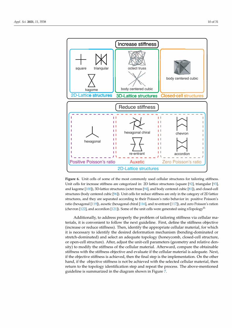
In the process of tailoring stiffness via cellular materials approach, certain topologiesare preferred depending on the stiffness objective (increase stiffness or reduce stiffness).When stiffness maximization is the objective, a stretch-dominated lattice and closed cellstructures are preferred. On the other hand, if flexibility is the goal, a bending-dominatedauxetic and zero-Poisson’s ratio honeycombs are the most commonly used. The unit-cellsof some of the most commonly used cellular structures for tailoring stiffness are shownin Figure 6. Increasing stiffness via cellular materials has been widely studied; therefore,unit cells for this objective, shown in Figure 6, are categorized in 2D-lattice structures,3D-lattice structures, and Closed-cell structures. On the other hand, reducing stiffnessvia cellular materials has been limited to explore 2D-lattice structures; thus, unit cellsfor reduce stiffness, shown in Figure 6, are only in the category of 2D-lattice structures,nevertheless, they are separated according to their Poisson’s ratio behavior in positivePoisson’s ratio, auxetic, and zero-Poisson’s ration.
Appl. Sci. 2021, 11, 3538 10 of 31
Increase stiffness
2D-Lattice structures 3D-Lattice structures
square triangular
kagome
octect truss
body centered cubic
Closed-cell structures
body centered cubic
2D-Lattice structures
hexagonal
hexagonal chiral
re-entrant
Positive Poisson’s ratio Zero Poisson’s ratio
chevron
accordion
Auxetic
Reduce stiffness
ed cubic
agome body centered cubic
body centere
triangular octect truss
Figure 6. Unit cells of some of the most commonly used cellular structures for tailoring stiffness.Unit cells for increase stiffness are categorized in: 2D lattice structures (square [92], triangular [93],and kagome [100]), 3D-lattice structures (octet truss [94], and body centered cubic [81]), and closed-cellstructures (body centered cubic [96]). Unit cells for reduce stiffness are only in the category of 2D latticestructures, and they are separated according to their Poisson’s ratio behavior in: positive Poisson’sratio (hexagonal [119]), auxetic (hexagonal chiral [116], and re-entrant [117]), and zero Poisson’s ration(chevron [122], and accordion [121]). Some of the unit cells were generated using nTopology®.
Additionally, to address properly the problem of tailoring stiffness via cellular ma-terials, it is convenient to follow the next guideline. First, define the stiffness objective(increase or reduce stiffness). Then, identify the appropriate cellular material, for whichit is necessary to identify the desired deformation mechanism (bending-dominated orstretch-dominated) and select an adequate topology (honeycomb, closed-cell structure,or open-cell structure). After, adjust the unit-cell parameters (geometry and relative den-sity) to modify the stiffness of the cellular material. Afterward, compare the obtainablestiffness with the stiffness objective and evaluate if the cellular material is adequate. Next,if the objective stiffness is achieved, then the final step is the implementation. On the otherhand, if the objective stiffness is not be achieved with the selected cellular material, thenreturn to the topology identification step and repeat the process. The above-mentionedguideline is summarized in the diagram shown in Figure 7.

Appl. Sci. 2021, 11, 3538 11 of 31
Define stiffness obtective
increase stiffness
bending-dominated
honeycomb closed-cell structures open-cell structure
stretch-dominated
reduce stiffness
Identify deformation mechanism
Select adequate topology
Cellular material topology identification
Parameter variation
Implementation
Adjust relative density
Compare obtainable
stiffness with the
stiffness objective
Adjust unit cell
defining parameters
Figure 7. Guideline diagram to select an appropriate cellular material for tailoring stiffness.
Cellular Materials in Compliant Systems as Flexure Elements
There is a great amount of evidence for the capability of Cellular Materials to achievedesired levels of compliance in certain directions while maintaining high levels of stiffnessin others. However, only Merriam and Howell [22] have applied a cellular lattice structuredirectly in the flexures elements of compliant joints, as shown in Figure 8. In [22], Merriamand Howell introduced the concept of lattice flexure, which was not common before additivemanufacturing techniques were widely available. They demonstrated that these types offlexures have a reduced bending stiffness when compared to traditional rectangular-sectionblade flexures of similar dimensions while maintaining comparable stiffness in off-axisdirections. Making use of additive-manufactured flexures, they found that both typeof lattice flexures—X-type and V-type—shown in Figure 8 have the potential to reducethe bending stiffness by 60–80% compared to a traditional blade flexure of similar size,and at the same time to exhibit a torsional/bending stiffness ratio as much as 1.7 timeshigher than an equal aspect-ratio blade flexure, and a transverse bending/motion-directionbending stiffness ratio up to 6.5 times higher than an equal aspect-ratio blade flexure.

Appl. Sci. 2021, 11, 3538 12 of 31
X-type lattice flexure
V-type lattice flexure
Figure 8. Lattice flexures proposed by Merriam and Howell [22] to be used in cross-axis flexuraljoints. (Adapted with permission from ref. [22]. 2021, Elsevier.)
Aiming to modify or allow compliance, it is possible to tailor the stiffness of flexureelements via Cellular Materials, while obtaining other advantageous mechanical conditionssuch as mass reduction, stress relief, and increments in stiffness ratios. However, whenspecific stiffness values are desired, tailorability is possible by using optimization processesthat modified the final configuration of predefined cellular structures (see Figure 2). Then,one may express the effective stiffness as a function of cell parameters (strut or wallthickness, length, width, angle, etc.). Although this approach to design is powerful,its disadvantage is that the true optimization of the resulting materials architecture isultimately limited by the designers initial choice of cellular structure. Therefore, othertypes of optimization processes that overcome this limitation are reviewed in the followingsection. This approach, termed as Topology Optimization, results in the optimal topologyby removing or adding material to a design domain.
3. Tailoring Stiffness via Topology Optimization
Topology Optimization is a computational design method, which varies the materialdistribution within a structure or part, considering a predefined performance objective.In contrast to size and shape optimization in the use of Cellular Materials, topology opti-mization does not require a predefined initial design, and it can generate optimal geometrieswhen intuitive design approaches fail [143]. The general Topology Optimization problemcan be described as follows: To find the material distribution that minimizes an objectivefunction F, subjected to a volume constraint g0 ≤ V0 and possibly n other constraintsgi ≤ 0, i = 1, . . . , n. The material distribution is described by the density variable ~ρ(x) thatcan take any value among 0 (void) and 1 (solid material) at any point in the discretizeddesign domain Ω. This optimization problem can be written in a mathematical form as
minρ
: F(~ρ)
s.t. : g0 ≤ V0
: gi(~ρ) ≤ 0, i = 1, . . . , n
: ~ρ(x) = value among 0 and 1 ∀x ∈ Ω.
(1)
Considering the density approach, this Topology Optimization problem is typicallysolved by discretizing the domain Ω into m finite elements and density can take eitherthe value 0 or 1. In this case, the last line of Equation (1) must be rearranged as ~ρj = 0 or 1for j = 1, . . . , m. On the other hand, the continuous Topology Optimization problem allowsthe finite elements to take values between 0 (void) and 1 (solid material). In this case,the last line of Equation (1) is reformulated as 0 ≤ ~ρj ≤ 1 j = 1, . . . , m.
In general, Topology Optimization approaches are density-based and level set-based.In density-based methods [144], which include the popular Solid Isotropic Material withPenalization (SIMP) method [145], the geometry composed of finite elements is described viaa material distribution of two or more phases, of which usually one represents “no material”(i.e., the void phase) leading to jagged boundary geometries. On the other hand, level set-based methods [143] define the interfaces between material phases implicitly by iso-contours
Appl. Sci. 2021, 11, 3538 13 of 31
of a level set function allowing a crisp description of the boundaries and the accurateenforcement of boundary conditions. For further details on Topology Optimization methods,solution strategies, algorithms, regularization methods, etc. refer to the works in [146–149].
Thus, by selecting a specific objective function F in Equation (1), it is possible to createstructures with customized properties, e.g., stiffness. When the design domain has a simplegeometry and is free of specific boundary conditions, the topology-optimized result is oftena cellular pattern [56] (Figure 2b). In addition, structures resulting from Topology Optimizationprocesses need a postprocessing refinement in order to smooth the jagged curves generatedfrom the discretized domain and to achieve manufacturability [150]. As with the use of CellularMaterials, the main efforts of Topology Optimization processes have been focused in reducingmass while maximizing stiffness [151–154]. Then, the basic process shown in Figure 2b ishereafter termed as Topology Optimization Resulting in Cellular Patterns (TORCP).
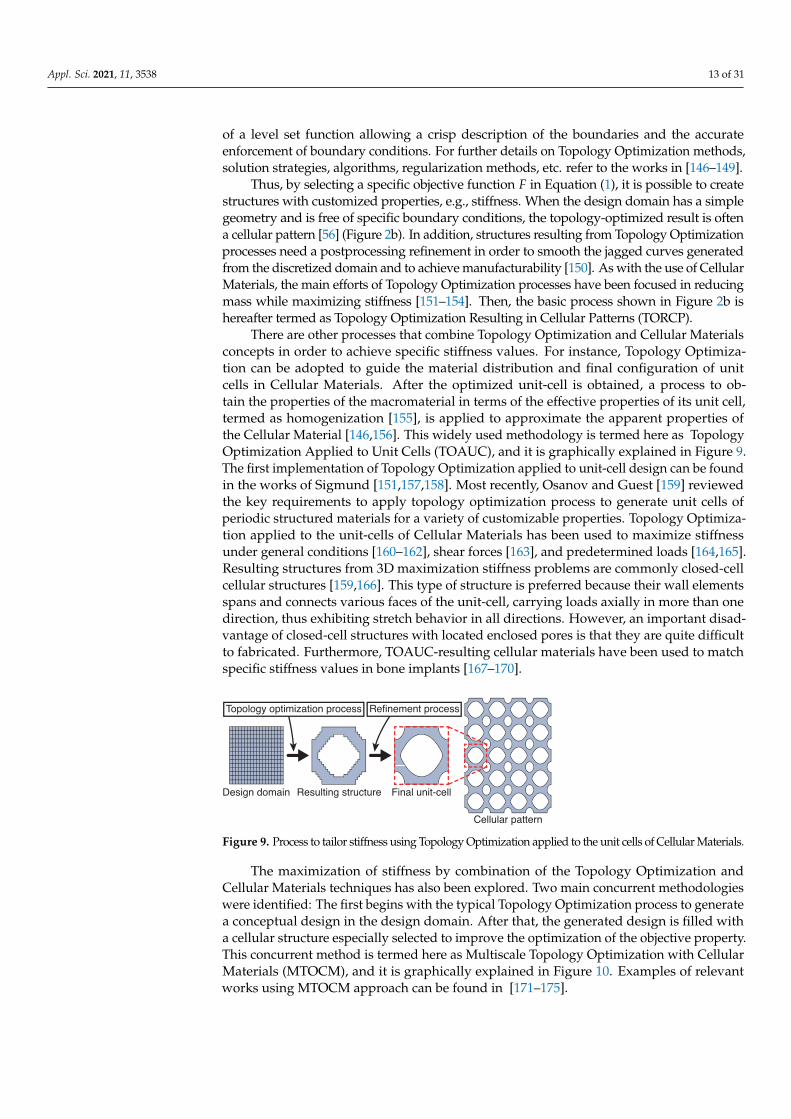
There are other processes that combine Topology Optimization and Cellular Materialsconcepts in order to achieve specific stiffness values. For instance, Topology Optimiza-tion can be adopted to guide the material distribution and final configuration of unitcells in Cellular Materials. After the optimized unit-cell is obtained, a process to ob-tain the properties of the macromaterial in terms of the effective properties of its unit cell,termed as homogenization [155], is applied to approximate the apparent properties ofthe Cellular Material [146,156]. This widely used methodology is termed here as TopologyOptimization Applied to Unit Cells (TOAUC), and it is graphically explained in Figure 9.The first implementation of Topology Optimization applied to unit-cell design can be foundin the works of Sigmund [151,157,158]. Most recently, Osanov and Guest [159] reviewedthe key requirements to apply topology optimization process to generate unit cells ofperiodic structured materials for a variety of customizable properties. Topology Optimiza-tion applied to the unit-cells of Cellular Materials has been used to maximize stiffnessunder general conditions [160–162], shear forces [163], and predetermined loads [164,165].Resulting structures from 3D maximization stiffness problems are commonly closed-cellcellular structures [159,166]. This type of structure is preferred because their wall elementsspans and connects various faces of the unit-cell, carrying loads axially in more than onedirection, thus exhibiting stretch behavior in all directions. However, an important disad-vantage of closed-cell structures with located enclosed pores is that they are quite difficultto fabricated. Furthermore, TOAUC-resulting cellular materials have been used to matchspecific stiffness values in bone implants [167–170].
Design domain Resulting structure Final unit-cell
Cellular pattern
Topology optimization process Refinement process
Figure 9. Process to tailor stiffness using Topology Optimization applied to the unit cells of Cellular Materials.
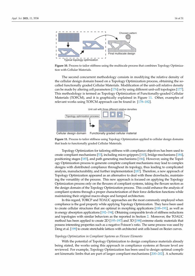
The maximization of stiffness by combination of the Topology Optimization andCellular Materials techniques has also been explored. Two main concurrent methodologieswere identified: The first begins with the typical Topology Optimization process to generatea conceptual design in the design domain. After that, the generated design is filled witha cellular structure especially selected to improve the optimization of the objective property.This concurrent method is termed here as Multiscale Topology Optimization with CellularMaterials (MTOCM), and it is graphically explained in Figure 10. Examples of relevantworks using MTOCM approach can be found in [171–175].
Appl. Sci. 2021, 11, 3538 14 of 31
Typical topology optimization
Final multiscale design Fi l l i l d i
Choosen pattern
Figure 10. Process to tailor stiffness using the multiscale process that combines Topology Optimiza-tion with Cellular Materials.
The second concurrent methodology consists in modifying the relative density ofthe cellular design domain based on a Topology Optimization process, obtaining the so-called functionally graded Cellular Materials. Modification of the unit-cell relative densitycan be made by altering cell parameters [176] or by using different unit-cell topologies [177].This methodology is termed as Topology Optimization of Functionally-graded CellularMaterials (TOFCM), and it is graphically explained in Figure 11. Other, examples ofrelevant works using TOFCM approach can be found in [178–182].
Topology optimization process
Unit cell with three different relative densities
Cellular design domain Functionally graded cellular material
Figure 11. Process to tailor stiffness using Topology Optimization applied to cellular design domainsthat leads to functionally graded Cellular Materials.
Topology Optimization for tailoring stiffness with compliance objectives has been used tocreate compliant mechanisms [53], including micro-grippers [183], bridge-mechanisms [184],positioning stages [185], and path generating mechanisms [186]. However, using the Topol-ogy Optimization process to generate complete compliant mechanisms may lead to complexdesigns with distributed compliance throughout its topology, thus leading to complicatedanalysis, manufacturability, and further implementation [187]. Therefore, a new approach ofTopology Optimization appeared as an alternative to deal with these drawbacks, maintain-ing the versatility of the process. This new approach is focused on applying the TopologyOptimization process only on the flexures of compliant systems, taking the flexure section asthe design domain of the Topology Optimization process. This could enhance the analysis ofcompliant systems through a proper characterization of their force deflection functions whilemaintaining their original macro-shape and lumped architecture.
In this regard, TORCP and TOAUC approaches are the most commonly employed whencompliance is the goal property while applying Topology Optimization. They have been usedto create cellular structures that are optimal in morphing applications [188–191], as well asin energy absorption applications [192–194]. Obtaining comparable levels of stiffness reductionsand topologies with similar behaviors as the reported in Section 2. Moreover, the TOAUCmethod has been applied to create 2D [195–197] and 3D [198] extreme elastic materials thatpossess interesting properties such as a negative Poisson’s ratio. The same process was used byDeng et al. [199] to create stretchable lattices with architected unit cells based on Bezier curves.
Topology Optimization in Compliant Systems as Flexure Elements
With the potential of Topology Optimization to design compliance materials alreadybeing stated, the works using this approach in compliance systems at flexure level arereviewed. For example, Topology Optimization has been used to design optimal compli-ant kinematic limbs that are part of larger compliant mechanisms [200–202]. A schematic
Appl. Sci. 2021, 11, 3538 15 of 31
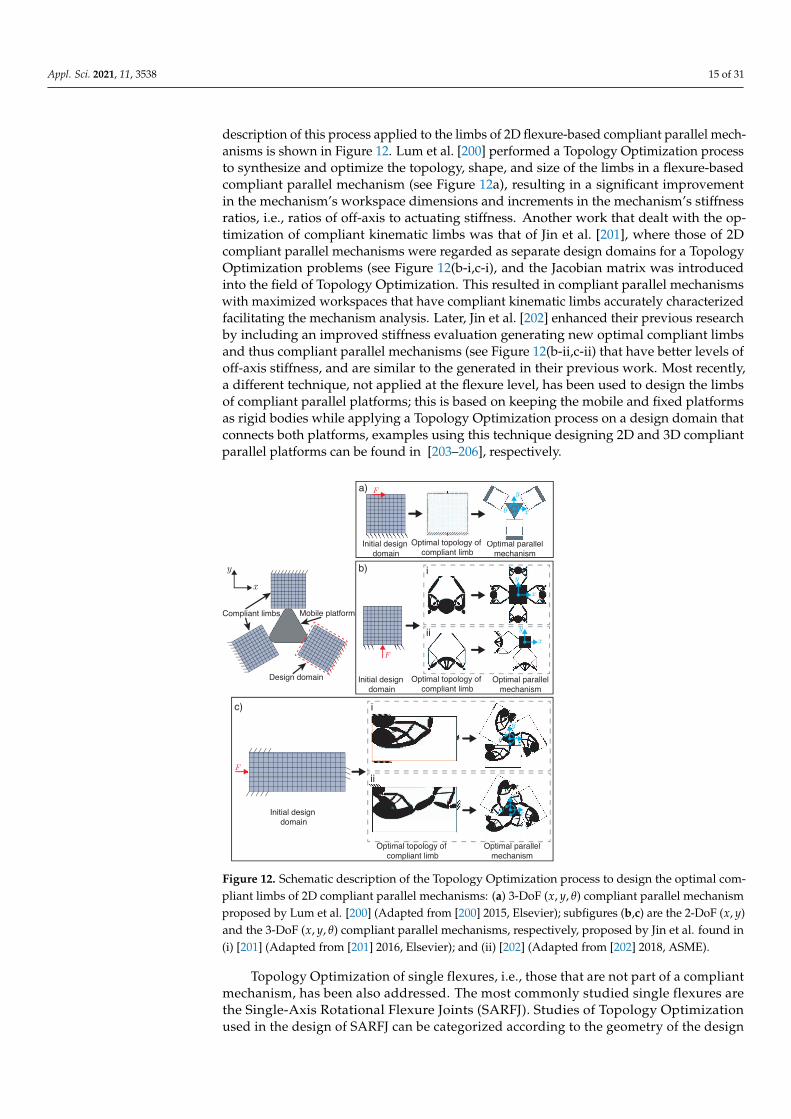
description of this process applied to the limbs of 2D flexure-based compliant parallel mech-anisms is shown in Figure 12. Lum et al. [200] performed a Topology Optimization processto synthesize and optimize the topology, shape, and size of the limbs in a flexure-basedcompliant parallel mechanism (see Figure 12a), resulting in a significant improvementin the mechanism’s workspace dimensions and increments in the mechanism’s stiffnessratios, i.e., ratios of off-axis to actuating stiffness. Another work that dealt with the op-timization of compliant kinematic limbs was that of Jin et al. [201], where those of 2Dcompliant parallel mechanisms were regarded as separate design domains for a TopologyOptimization problems (see Figure 12(b-i,c-i), and the Jacobian matrix was introducedinto the field of Topology Optimization. This resulted in compliant parallel mechanismswith maximized workspaces that have compliant kinematic limbs accurately characterizedfacilitating the mechanism analysis. Later, Jin et al. [202] enhanced their previous researchby including an improved stiffness evaluation generating new optimal compliant limbsand thus compliant parallel mechanisms (see Figure 12(b-ii,c-ii) that have better levels ofoff-axis stiffness, and are similar to the generated in their previous work. Most recently,a different technique, not applied at the flexure level, has been used to design the limbsof compliant parallel platforms; this is based on keeping the mobile and fixed platformsas rigid bodies while applying a Topology Optimization process on a design domain thatconnects both platforms, examples using this technique designing 2D and 3D compliantparallel platforms can be found in [203–206], respectively.
Mobile platformCompliant limbs
xy
Design domain
a)
Optimal topology of
compliant limb
Optimal topology of
compliant limb
Optimal topology of
compliant limb
Optimal parallel
mechanism
Optimal parallel
mechanism
Optimal parallel
mechanism
x
yF
F
b) i
ic)
Initial design
domain
Initial design
domain
Initial design
domain
F
x
y
x
y
xy
ii
ii
x
y
Figure 12. Schematic description of the Topology Optimization process to design the optimal com-pliant limbs of 2D compliant parallel mechanisms: (a) 3-DoF (x, y, θ) compliant parallel mechanismproposed by Lum et al. [200] (Adapted from [200] 2015, Elsevier); subfigures (b,c) are the 2-DoF (x, y)and the 3-DoF (x, y, θ) compliant parallel mechanisms, respectively, proposed by Jin et al. found in(i) [201] (Adapted from [201] 2016, Elsevier); and (ii) [202] (Adapted from [202] 2018, ASME).
Topology Optimization of single flexures, i.e., those that are not part of a compliantmechanism, has been also addressed. The most commonly studied single flexures arethe Single-Axis Rotational Flexure Joints (SARFJ). Studies of Topology Optimizationused in the design of SARFJ can be categorized according to the geometry of the design
Appl. Sci. 2021, 11, 3538 16 of 31
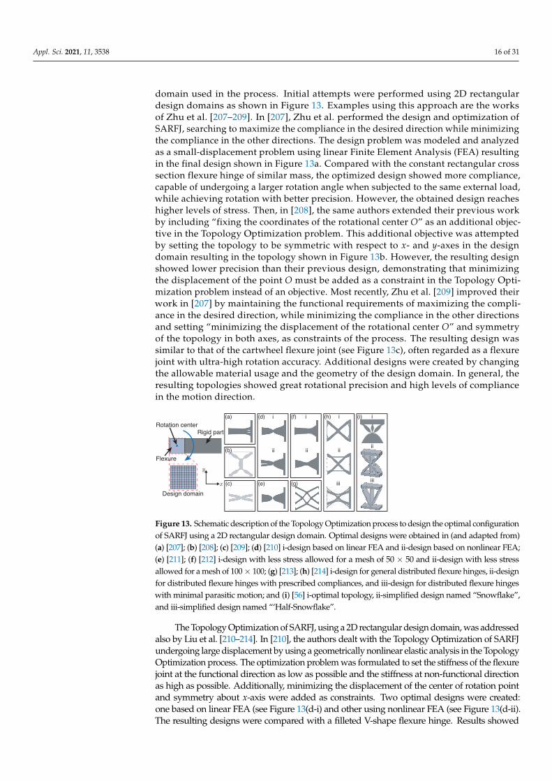
domain used in the process. Initial attempts were performed using 2D rectangulardesign domains as shown in Figure 13. Examples using this approach are the worksof Zhu et al. [207–209]. In [207], Zhu et al. performed the design and optimization ofSARFJ, searching to maximize the compliance in the desired direction while minimizingthe compliance in the other directions. The design problem was modeled and analyzedas a small-displacement problem using linear Finite Element Analysis (FEA) resultingin the final design shown in Figure 13a. Compared with the constant rectangular crosssection flexure hinge of similar mass, the optimized design showed more compliance,capable of undergoing a larger rotation angle when subjected to the same external load,while achieving rotation with better precision. However, the obtained design reacheshigher levels of stress. Then, in [208], the same authors extended their previous workby including “fixing the coordinates of the rotational center O” as an additional objec-tive in the Topology Optimization problem. This additional objective was attemptedby setting the topology to be symmetric with respect to x- and y-axes in the designdomain resulting in the topology shown in Figure 13b. However, the resulting designshowed lower precision than their previous design, demonstrating that minimizingthe displacement of the point O must be added as a constraint in the Topology Opti-mization problem instead of an objective. Most recently, Zhu et al. [209] improved theirwork in [207] by maintaining the functional requirements of maximizing the compli-ance in the desired direction, while minimizing the compliance in the other directionsand setting “minimizing the displacement of the rotational center O” and symmetryof the topology in both axes, as constraints of the process. The resulting design wassimilar to that of the cartwheel flexure joint (see Figure 13c), often regarded as a flexurejoint with ultra-high rotation accuracy. Additional designs were created by changingthe allowable material usage and the geometry of the design domain. In general, theresulting topologies showed great rotational precision and high levels of compliancein the motion direction.
Rotation centerRigid part
Flexure
Design domain
x
y
i
ii
i
ii
i
ii
iii
i
ii
iii
(a)
(b)
(c)
(d)
(e)
(f)
(g)
(h) (i)
Figure 13. Schematic description of the Topology Optimization process to design the optimal configurationof SARFJ using a 2D rectangular design domain. Optimal designs were obtained in (and adapted from)(a) [207]; (b) [208]; (c) [209]; (d) [210] i-design based on linear FEA and ii-design based on nonlinear FEA;(e) [211]; (f) [212] i-design with less stress allowed for a mesh of 50 × 50 and ii-design with less stressallowed for a mesh of 100× 100; (g) [213]; (h) [214] i-design for general distributed flexure hinges, ii-designfor distributed flexure hinges with prescribed compliances, and iii-design for distributed flexure hingeswith minimal parasitic motion; and (i) [56] i-optimal topology, ii-simplified design named “Snowflake”,and iii-simplified design named “‘Half-Snowflake”.
The Topology Optimization of SARFJ, using a 2D rectangular design domain, was addressedalso by Liu et al. [210–214]. In [210], the authors dealt with the Topology Optimization of SARFJundergoing large displacement by using a geometrically nonlinear elastic analysis in the TopologyOptimization process. The optimization problem was formulated to set the stiffness of the flexurejoint at the functional direction as low as possible and the stiffness at non-functional directionas high as possible. Additionally, minimizing the displacement of the center of rotation pointand symmetry about x-axis were added as constraints. Two optimal designs were created:one based on linear FEA (see Figure 13(d-i) and other using nonlinear FEA (see Figure 13(d-ii).The resulting designs were compared with a filleted V-shape flexure hinge. Results showed

Appl. Sci. 2021, 11, 3538 17 of 31
that nonlinear design can reach the highest rotation angle and has the lowest level of stressconcentration. On the other hand, the linear design has better precision but the highest level ofstress. This was further extended in [211], with the design of a three-segment flexure joint namedquasi-V-shaped flexure hinge (QVFH) shown in Figure 13e. The authors derived the in-planecompliance equations for small displacements based on Castigliano’s second theorem. Comparedwith the filleted V-shaped flexure hinge, the QVFH showed less compliance, more precisionin keeping the center of rotation with the minimal offset, and larger maximum stress level. Afterthat, Liu et al. [212] designed flexure joints by using stress-constrained Topology Optimization,aiming to reduce the general stress level and remove the sharp corners of the flexure hinges,thereby reducing the stress concentration and improving the range of motion. Various topologieswere created for several levels of stress limit. The resulting final topology without stress constraintis similar to the one obtained in [211]. It can be observed that when the stress constraints areadded, the length and thickness of the middle segment become longer and thicker, respectively,thus removing sharp corners distributing the stress and reducing stress concentrations. Severaldesigns were created varying the level of stress constraint and changing the mesh refinementof the design domain, only two final topologies are shown in Figure 13f, corresponding tothe designs with less stress allowed for a mesh of 50× 50 (see Figure 13(f-i) and for a meshof 100 × 100 (see Figure 13(f-ii). As it can be seen, optimal designs with stress constraintstend to seem blade flexures, therefore losing precision.
In this regard, Liu et al. [213] presented a systematic method for designing flexurehinges with distributed stress by using Topology Optimization with the objective of maxi-mizing the bending displacement while minimizing the axial displacement and at the sametime to minimize the maximum level of stress. Additionally, a symmetry constraint in bothx- and y-axes was added, resulting in the non-conventional notch flexure hinge, shownin Figure 13g, that exhibited distributed stress. Finally, this work was extended in [214],where authors designed flexure hinges with a symmetrical distributed configuration thataccomplish the desired performances of prescribed compliance and minimal parasitic mo-tion. Several designs were obtained for each desired performance; only three of them areshown in Figure 13h, accounting for general distributed flexure hinges (see Figure 13(h-i),distributed flexure hinges with prescribed compliances (see Figure 13(h-ii), and distributedflexure hinges with minimal parasitic motion (see Figure 13(h-iii). Resulting configurationsare similar to the cartwheel flexure hinge which, as was mentioned before, it is well knownfor being a high precision flexure joint. Finally, Pinskier et al. [56] used Topology Optimiza-tion to design SARFJ to account for the goals of motion-range, compliance, and precisionsimultaneously. The resulting main topology is shown in Figure 13(i-i). Based on thistopology, a second design stage was performed to produce two simplified hinge designsnamed “Snowflake” and “Half-Snowflake” shown in Figure 13(i-ii,iii), respectively. Aftercomparing their performance, the new type of flexure hinge showed higher precision andcomparable levels of rotational compliance than blade and cross-axis flexures. Addition-ally, the resulting structures have extra members that could lead to an off-axis stiffnessincrement, reducing parasitic displacements and making them able to transfer forces.
Other optimal designs of SARFJ were created using 2D design domains, basedon the geometry of a right circular flexure hinge as shown in Figure 14. For instance,Liu et al. [215] used Topology Optimization to remove material from a right circular flexurehinge in order to increase compliance while retaining high precision, resulting in the multi-notched flexure hinge topology shown in Figure 14(a-i). Several topologies were obtainedusing different dimensions in the design domain and varying the percentage of removedmaterial; however, they resulted in nearly the same for all examples. Then, a final shape ofthe multi-notched flexure hinge (see Figure 14(a-ii) was proposed after a postprocessing re-finement stage and was used for comparison in its performance with various flexure hinges(right circular [216], corner-filleted [217], elliptical [218], parabolic, and hyperbolic [219]).Results showed that the multi-notched flexure hinges can have larger rotational compliance,higher rotational precision, and lower stress levels than any other type of flexure hingewhen certain dimensional conditions are satisfied. Additionally, Zhu et al. [209] obtained
Appl. Sci. 2021, 11, 3538 18 of 31
a similar topology, shown in Figure 14b, using Topology Optimization with a multi-criteriaobjective function and a symmetry constraint. The resulting design showed great rotationalprecision and high levels of compliance in the motion direction.
Rotation centerRigid part
Flexure
Design domain
x
yOptimal topology Final shape Optimal topology
(a) (b)i ii
Figure 14. Schematic description of the Topology Optimization process to design the optimalconfiguration of SARFJ using a 2D design domain based on the geometry of a right circular flexurehinge. Optimal designs obtained: (a) i-optimal topology and ii-final shape (Adapted with permissionfrom ref. [215]. 2021, Elsevier) and (b) optimal topology obtained in [209] (Adapted from ref. [209].2019, Springer).
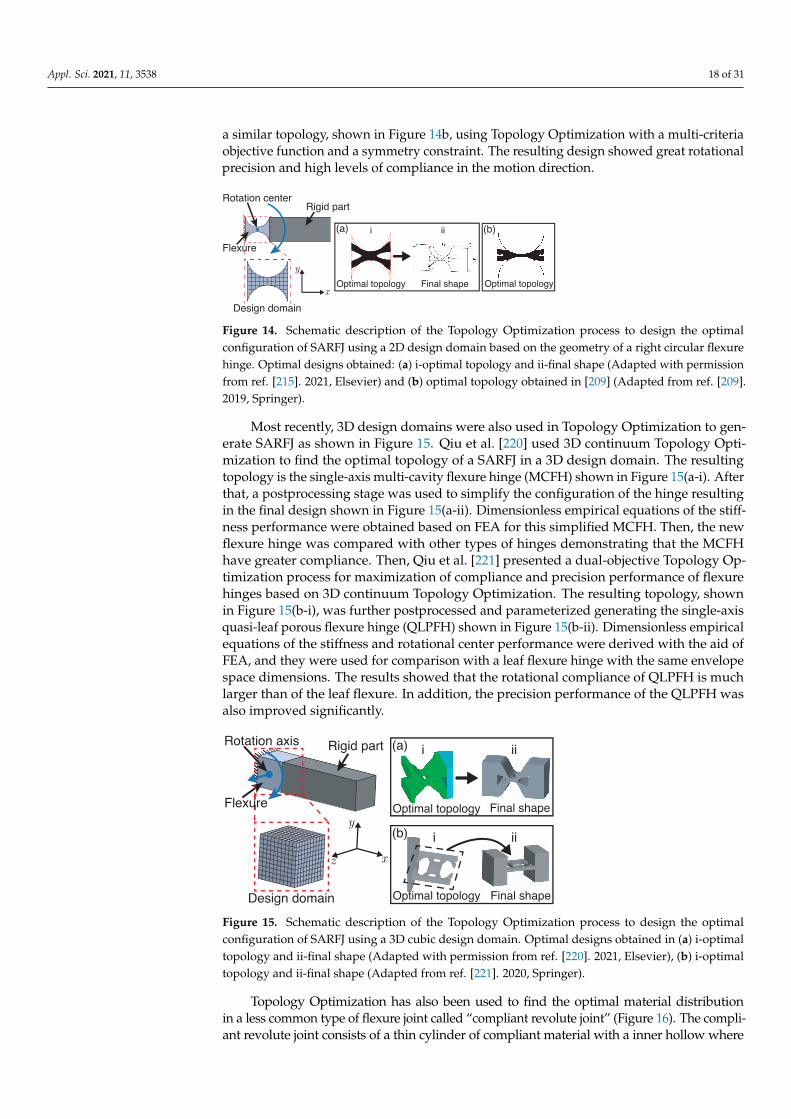
Most recently, 3D design domains were also used in Topology Optimization to gen-erate SARFJ as shown in Figure 15. Qiu et al. [220] used 3D continuum Topology Opti-mization to find the optimal topology of a SARFJ in a 3D design domain. The resultingtopology is the single-axis multi-cavity flexure hinge (MCFH) shown in Figure 15(a-i). Afterthat, a postprocessing stage was used to simplify the configuration of the hinge resultingin the final design shown in Figure 15(a-ii). Dimensionless empirical equations of the stiff-ness performance were obtained based on FEA for this simplified MCFH. Then, the newflexure hinge was compared with other types of hinges demonstrating that the MCFHhave greater compliance. Then, Qiu et al. [221] presented a dual-objective Topology Op-timization process for maximization of compliance and precision performance of flexurehinges based on 3D continuum Topology Optimization. The resulting topology, shownin Figure 15(b-i), was further postprocessed and parameterized generating the single-axisquasi-leaf porous flexure hinge (QLPFH) shown in Figure 15(b-ii). Dimensionless empiricalequations of the stiffness and rotational center performance were derived with the aid ofFEA, and they were used for comparison with a leaf flexure hinge with the same envelopespace dimensions. The results showed that the rotational compliance of QLPFH is muchlarger than of the leaf flexure. In addition, the precision performance of the QLPFH wasalso improved significantly.
x
y
z
Optimal topology Final shape
(a) i iiRigid part
Flexure
Design domain
Rotation axis
Optimal topology Final shape
(b) i ii
Figure 15. Schematic description of the Topology Optimization process to design the optimalconfiguration of SARFJ using a 3D cubic design domain. Optimal designs obtained in (a) i-optimaltopology and ii-final shape (Adapted with permission from ref. [220]. 2021, Elsevier), (b) i-optimaltopology and ii-final shape (Adapted from ref. [221]. 2020, Springer).
Topology Optimization has also been used to find the optimal material distributionin a less common type of flexure joint called “compliant revolute joint” (Figure 16). The compli-ant revolute joint consists of a thin cylinder of compliant material with a inner hollow where

Appl. Sci. 2021, 11, 3538 19 of 31
its external face is fixed and its internal face is subject to a rotational displacement producedby a tangential force applied at the same face. Li et al. [222–224] presented a series of worksdealing with the Topology Optimization of this type of flexure joint. In [222], the authorsdesigned new compliant revolute joints reconstructed after removing material with a TopologyOptimization process. The obtained designs are shown in Figure 16(i–iv). FEA was used tocompare the performance of the optimized designs with the non-optimized compliant revolutejoint. Results showed that optimized designs can achieve more rotational displacement. How-ever, their stress levels were also increased. Further experimental validation in the rotationalangle and stress levels of the optimal designs was performed in [223], obtaining a maximumerror between experimental and FEA results of 8.7%. This was expanded in [224], by modelingthe compliant revolute joint as a kinetoelastic model considering the kinematic propertiesand structural elastic properties simultaneously. This approach allowed obtaining optimizedcompliant revolute joints with desirable compliance properties that are quite similar to thoseobtained in their previous works.
i ii
Design domain
iii iv
Fixed face
Flexure materialand
Rotation point
Figure 16. Schematic description of the Topology Optimization process to design the optimalconfiguration of SARFJ using a 2D design domain based on the geometry of compliant revolute joint.(i–iv) Optimal designs obtained in [222] (Adapted from ref. [222]. 2017, Springer).
Furthermore, Topology Optimization has been used to achieve the optimal materialdistribution of single-axis translational flexure joints (SATFJ) based on the geometry ofblade flexures (see Figure 17). Pinskier et al. [2,52] investigated the design of this type offlexure to be used in parallelogram linear flexure guides using Topology Optimization tomaximize their ratio of in-plane to out-of-plane stiffness. The resulting topology shownin Figure 17(a-i) resembles a X-type lattice structure similar to that used in [22] (see Figure 8).After that, a parameterized flexure design was generated based on the resulting topology(see Figure 17(a-ii), and it showed stiffness ratios of 1.5 to 6 times greater than standardblade structures with mass reductions up to 75%.

Appl. Sci. 2021, 11, 3538 20 of 31
Rigid part
Design domain
x
yz
Optimal topology
(a) ix
y
Flexure
i ii
Final shape
ii
Figure 17. Schematic description of the Topology Optimization process to design the optimal configura-tion of SATFJ using a 2D design domain based on the geometry of blade flexures. (a) Optimal designobtained in [52] i-optimal topology and ii-final shape (reprinted with permission from [52]. 2019, Elsevier).
4. Remarks on Tailoring Stiffness via Cellular Materials and Topology Optimization
Cellular Materials and Topology Optimization can be used effectively for tailoringstiffness. The Cellular Materials approach is based on the proper selection of the unit-cellthat constructs the cellular material; note that this approach works on the micro-scale.On the other hand, the Topology Optimization approach generates an optimal topologyfor specific external load conditions; then, it is said that this approach acts on the macro-scale. Therefore, both approaches can be combined to take advantage of their particularcharacteristics at the same time. A summary that address advantages and disadvantagesof Cellular Materials and Topology Optimization approaches as well as their combinations,is presented in the diagram in Figure 18.
Cellular Materials Topology Optimization
Benefits Benefits Drawbacks Drawbacks
Smooth geometries ready to
be manufactured
Parameterizable geometries
that can can be modified to
alter the stiffness
Siutable for general load
conditions Geometry proposed by the
experienced designer
Computationally demanding
to analyze
Customization range
restricted by the unit-cell
selection
Optimal geometry generated
automatically
Unrestricted customization
process
Optimal design for specific
load conditions
Outputted geometry optimized
only for a particular case
Resulting geometries that are
difficult to parameterize
Jagged boundary geometries
that need a post-processing
refinement to be manufactured
Combinations
TORCPTopology optimization resulting in
cellular patterns allow a uniform
distribution of stiffness in the
design domain
TOAUCTopology optimization applied to unit
cells implements the optimal
topology under specific conditions as
the unit cell of cellular materials
MTOCMMultiscale topology optimization
with cellular materials extends
the customization range by filling
an optimal geometry with a
cellular pattern
TOFCMTopology optimization of
functionally-graded cellular
materials generates the optimal
topology inside a cellular material
by modifying the relative density
of the unit cells in specific zones
Figure 18. Summary diagram of the Cellular Materials and Topology Optimization approachesand their combinations.
In addition, the implementation of Cellular Materials and Topology Optimizationapproaches for tailoring stiffness in compliant systems entails the modification of othermechanical characteristics such as weight reduction, stiffness ratios, stress relief, andmotion range. Therefore, a brief discussion on how these characteristics are modified asthe stiffness is modified is presented here.
Weight reductionStiffness reduction via Cellular Materials and Topology Optimization approaches
implies removing material. Therefore, a reduction in stiffness brings with it a weight

Appl. Sci. 2021, 11, 3538 21 of 31
reduction. The key aspect relies on a controlled removing of material (or distribution ofmaterial), so that this reduction in overall weight can be related to the resulting mechanicalproperties. A random removal of material will in turn reduce stiffness and weight; however,the control of the resulting mechanics becomes a trail and error process (non-systematic).
Motion rangeThe motion range of a compliant system is related to the elastic displacement. This
scales with the elastic modulus of the structure, i.e., its stiffness. Therefore, any attemptto tailor the stiffness of the cellular material or optimize the topology will lead to mod-ifications in the motion range that can be achieved. Another aspect that can come withthe incorporation of any of the two approaches is the anisotropy, as the proposed or result-ing geometries may be directionally dependent. Structures made of anisotropic materialscan have displacements in directions apart from the those aligned to the loading axis.
Stress reliefThe use of Cellular Materials and Topology Optimization approaches for stiffness reduc-
tion often leads to geometries with sharp corners, thus incrementing the stress level. However,by controlling the topology of a cellular material, it is possible to tune the localization andmagnitude of the stress [100] in a structure. Moreover, certain cellular structures such asthe contact-aided patterns have been used to provide stress relief [44–46], while others such asthe auxetic patterns allow a better stress distribution due to their high flexibility [119].
Stiffness ratiosStiffness ratios allow one to compare the stiffness levels in different directions. A flex-
ure element commonly needs great flexibility in certain directions while maintaining highlevels of stiffness in the others, i.e., its stiffness ratios must be large. The use of CellularMaterials and Topology Optimization approaches for stiffness reduction in certain directiongenerally produce stiffness reductions also in the others. However, the stiffness reductionin the desired direction is significantly higher than in the non-desired directions, thusincrementing the stiffness ratios [22]. Moreover, the stiffness ratios can be maximizedin the Topology Optimization process [52].
5. Conclusions
Cellular Materials and Topology Optimization can be considered as approaches totailor properties by selectively removing material, e.g., stiffness, in a structure eliminat-ing the need of additional elements and maintaining the overall dimensions of the piece.These approaches appear as a possible solution to deal with inaccuracies and limitationsof compliant systems. In this work, these two were reviewed regarding their used in tai-loring the stiffness of flexure elements. Interest in both has grown in recent years due tothe increasing availability of additive manufacturing processes. These allow the fabricationof complex geometries with a controlled distribution of matter, comparable to the onesresulting from these approaches. It was then relevant to overview both approaches, so thatthe users and readers can compare and contrast prior selecting one of them.
Regarding Cellular Materials, stretch-dominated structures are preferred when maxi-mizing stiffness is the objective, while bending-dominated structures are the best option forcompliance applications. Two-dimensional bending-dominated lattice arrangements havebeen more frequently used in compliance applications. The use of bending-dominated 3Dclosed-cell structures has been studied recently in energy absorption applications, demonstrat-ing their capacity to be used for compliance purposes. Therefore, tailoring stiffness of flexuresvia Cellular Materials using 3D and closed-cell structures appears to be a promising option,due to the design advantages such as high off-axis stiffness and greater load bearing capacity.
Auxetic architectures are the most widely used in compliance applications because oftheir high deformations under relatively low stresses. However, the use of these type ofarchitectures in flexure elements has not been explored. In addition, cellular structures witha zero-Poisson ratio represent another type of non-explored architecture. This type of meta-structure is characterized for providing deformation in one direction while maintainingunchanged its dimensions in the others. This particular deformation-mechanism could

Appl. Sci. 2021, 11, 3538 22 of 31
be useful in the design of flexure elements and compliant mechanisms to avoid parasiticmotions due to non-desire displacements.
Numerous literature has focused on flexure joints for rotational motion, while veryfew works on joints for other types of motion were encountered. Research has been focusedalmost entirely on SARFJ leaving unexplored other types of joints such as prismatic orcylindric. The wide variety of Cellular Materials may allow the creation of unexploredcompliant joints that commonly need more than one flexure to be conformed.
On the other hand, the use of Topology Optimization allows finding the best option ofmaterial distribution, and with the use of computational power, this could be done relativelyfast. However, it often leads to a complex architecture that requires a postprocessingstage to obtain the final design. Furthermore, the resulting design could be difficult toparametrize and handle analytically, compromising the prediction of the behavior underany other conditions different from the ones used in formulation of the optimization process.As opposed to this, the use of Cellular Materials allows an accurate structure-propertyrelation. Still, the potential tailorability is limited to the Cellular Material topologies.Therefore, combinations of Cellular Materials and Topology Optimization, i.e., TOAUC,MTOCM, and TOFCM, must be explored in the design of flexure elements making used ofthe advantages offered by both approaches.
The use of Topology Optimization in the design of flexure joints has been studied morethan that of Cellular Materials. Looking at the evolution of the Topology Optimization of flexurejoints, it is possible to see that the tendency is to create designs with distributed compliancethrough the implementation of repeatable members in their geometrical sapce, avoidingthe concentration of deformation in a single element. Therefore, Topology Optimization can beused as a first stage in the design of flexure elements, after that it can be followed by adjustingthe material distribution by means of Cellular Material topology, therefore having a controlledstructure-property relation and perhaps a simplification of the design.
Finally, further trends in research in this area and recommendations to extend the studyof tailoring stiffness of flexure elements via Cellular Materials and Topology Optimizationare provided based on the available literature reviewed here.
1. Due to their advantages in tailoring the mechanical properties, exploring the use ofclosed-cell structures, 3D arrays, auxetic, and zero-Poisson architectures in tailoringthe stiffness of flexure elements could lead to benefits compliant systems.
2. As flexures base their functioning on the elastic response of their elements, othermaterial properties, i.e., Poisson’s ratio, could complicate their use to build up otherkinematic pairs, e.g., cylindrical. However, a correct selection of cellular pattern couldbe designed so that it restricts the Poisson’s ratio to 0. This opens up a new range ofpossibilities in compliant systems applications.
3. Combining both Cellular Materials and Topology Optimization approaches (TOAUC,MTOCM, and TOFCM) to expand the possibilities in tailoring stiffness of flexureelements. This combination leads to obtain the best out of each. An example of the useof these two could be by implementing Topology Optimization at the conceptualdesign stage for the proposal of a flexure element. Then, employ a Cellular Materialto adjust the stiffness by modifying the parameters that define the structure.
4. Analytical parameterization of the Cellular Material employed can result in an accu-rate and precise tracking of the stiffness. This allows a controlled tailoring of stiffnessin compliant systems.
5. Another aspect to keep in mind is that lattice honeycombs might have in-planeanisotropy. Therefore, when used in flexures, the proper selection of orientationbecomes crucial. Failure in considering this could lead to deformations in non-desireddirections, i.e., parasitic motions.
Author Contributions: Conceptualization, M.A.-S. and E.C.-U.; methodology, M.A.-S., E.C.-U.,and A.G.-E.; investigation, M.A.-S.; writing—original draft preparation, M.A.-S.; writing—reviewand editing, E.C.-U. and A.G.-E.; supervision, E.C.-U. and A.G.-E.; project administration, A.G.-E.All authors have read and agreed to the published version of the manuscript.

Appl. Sci. 2021, 11, 3538 23 of 31
Funding: The authors would like to acknowledge the financial support of Tecnologico de Monterrey,in the production of this work.
Acknowledgments: The authors would like to acknowledge support from CONACyT for PhDstudies of first author (scholarship number 863078) and nTopology for providing access to researchand academic licenses.
Conflicts of Interest: The authors declare no conflicts of interest.
Abbreviations
MEMS Microelectromechanical Systems3D Three-dimensionalDOF Degrees of Freedom2D Two-dimensionalSIMP Solid Isotropic Material with PenalizationTORCP Topology Optimization Resulting in Cellular PatternsTOAUC Topology Optimization Applied to Unit CellsMTOCM Multiscale Topology Optimization with Cellular MaterialsTOFCM Topology Optimization of Functionally-graded Cellular MaterialsSARFJ Single Axis Rotational Flexure JointsFEA Finite Element AnalysisQVFH Quasi V-shaped Flexure HingeMCFH Multi-Cavity Flexure HingeQLPFH Quasi-Leaf Porous Flexure HingeSATFJ Single-Axis Translational Flexure Joints
References1. Howell, L.L. Compliant Mechanisms; Wiley: New York, NY, USA, 2001.2. Pinskier, J.; Shirinzadeh, B. Topology optimization of leaf flexures for stiffness ratio maximization in compliant mechanisms. In Pro-
ceedings of the 2018 IEEE/ASME International Conference on Advanced Intelligent Mechatronics (AIM), Auckland, New Zealand,9–12 July 2018; IEEE: Piscataway, NJ, USA, 2018; pp. 407–412. [CrossRef]
3. Tian, Y.; Zhang, D.; Shirinzadeh, B. Dynamic modelling of a flexure-based mechanism for ultra-precision grinding operation.Precis. Eng. 2011, 35, 554–565. [CrossRef]
4. Cecchi, R.; Verotti, M.; Capata, R.; Dochshanov, A.; Broggiato, G.B.; Crescenzi, R.; Balucani, M.; Natali, S.; Razzano, G.; Lucchese,F.; et al. Development of micro-grippers for tissue and cell manipulation with direct morphological comparison. Micromachines2015, 6, 1710–1728. [CrossRef]
5. Zubir, M.N.M.; Shirinzadeh, B.; Tian, Y. Development of a novel flexure-based microgripper for high precision micro-objectmanipulation. Sensors Actuators A Phys. 2009, 150, 257–266. [CrossRef]
6. Fleming, A.J.; Yong, Y.K. An ultrathin monolithic XY nanopositioning stage constructed from a single sheet of piezoelectricmaterial. IEEE/ASME Trans. Mechatron. 2017, 22, 2611–2618. [CrossRef]
7. Kota, S.; Joo, J.; Li, Z.; Rodgers, S.M.; Sniegowski, J. Design of compliant mechanisms: Applications to MEMS. Analog. Integr.Circuits Signal Process. 2001, 29, 7–15. [CrossRef]
8. Sun, X.; Yang, B. A new methodology for developing flexure-hinged displacement amplifiers with micro-vibration suppressionfor a giant magnetostrictive micro drive system. Sens. Actuators A Phys. 2017, 263, 30–43. [CrossRef]
9. Chen, B.K.; Zhang, Y.; Sun, Y. Active release of microobjects using a MEMS microgripper to overcome adhesion forces.J. Microelectromech. Syst. 2009, 18, 652–659. [CrossRef]
10. Ling, M.; Howell, L.L.; Cao, J.; Chen, G. Kinetostatic and dynamic modeling of flexure-based compliant mechanisms: A survey.Appl. Mech. Rev. 2020, 72, 030802. [CrossRef]
11. Lee, C.; Stepanick, C.K.; Lee, S.K.; Tarbutton, J.A. Cross-coupling effect of large range XY nanopositioning stage fabricated bystereolithography process. Precis. Eng. 2016, 46, 81–87. [CrossRef]
12. Yuanqiang, L.; Wangyu, L. Analysis of the displacement of distributed compliant parallel-guiding mechanism consideringparasitic rotation and deflection on the guiding plate. Mech. Mach. Theory 2014, 80, 151–165. [CrossRef]
13. Luo, Y.; Liu, W.; Wu, L. Analysis of the displacement of lumped compliant parallel-guiding mechanism considering parasiticrotation and deflection on the guiding plate and rigid beams. Mech. Mach. Theory 2015, 91, 50–68. [CrossRef]
14. Cornelissen, R.; Müller, A.; Aarts, R. A Compliant and Redundantly Actuated 2-DOF 3RRR PKM: Best of Both Worlds?In Proceedings of the IFToMM World Congress on Mechanism and Machine Science, Duisburg, Germany, 26 August 2019;Springer: Berlin/Heidelberg, Germany, 2019; pp. 163–171. [CrossRef]

Appl. Sci. 2021, 11, 3538 24 of 31
15. Yun, Y.; Li, Y. Design and analysis of a novel 6-DOF redundant actuated parallel robot with compliant hinges for high precisionpositioning. Nonlinear Dyn. 2010, 61, 829–845. [CrossRef]
16. Merriam, E.G.; Lund, J.M.; Howell, L.L. Compound joints: Behavior and benefits of flexure arrays. Precis. Eng. 2016, 45, 79–89.[CrossRef]
17. Li, S.; Yu, J. Design principle of high-precision flexure mechanisms based on parasitic-motion compensation. Chin. J. Mech. Eng.2014, 27, 663–672. [CrossRef]
18. Yong, Y.K.; Liu, K.; Moheimani, S.R. Reducing cross-coupling in a compliant XY nanopositioner for fast and accurate rasterscanning. IEEE Trans. Control. Syst. Technol. 2009, 18, 1172–1179. [CrossRef]
19. Zhang, Z.; Yang, X.; Yan, P. Large dynamic range tracking of an XY compliant nanomanipulator with cross-axis couplingreduction. Mech. Syst. Signal Process. 2019, 117, 757–770. [CrossRef]
20. Bhagat, U.; Shirinzadeh, B.; Tian, Y.; Zhang, D. Experimental analysis of laser interferometry-based robust motion trackingcontrol of a flexure-based mechanism. IEEE Trans. Autom. Sci. Eng. 2012, 10, 267–275. [CrossRef]
21. Liu, Z.; Zhang, Z.; Yan, P. A Spatial Design of a Large Stroke Compliant XY Nanomanipulator with Cross-Coupling ErrorReduction. In Proceedings of the 2019 International Conference on Manipulation, Automation and Robotics at Small Scales(MARSS), Helsinki, Finland, 1–5 July 2019; IEEE: Piscataway, NJ, USA, 2019; pp. 1–6. [CrossRef]
22. Merriam, E.G.; Howell, L.L. Lattice flexures: Geometries for stiffness reduction of blade flexures. Precis. Eng. 2016, 45, 160–167.[CrossRef]
23. Ham, R.V.; Sugar, T.; Vanderborght, B.; Hollander, K.; Lefeber, D. Compliant actuator designs. IEEE Robot. Autom. Mag. 2009,3, 81–94. [CrossRef]
24. Vanderborght, B.; Albu-Schäffer, A.; Bicchi, A.; Burdet, E.; Caldwell, D.G.; Carloni, R.; Catalano, M.; Eiberger, O.; Friedl, W.;Ganesh, G.; et al. Variable impedance actuators: A review. Robot. Auton. Syst. 2013, 61, 1601–1614. [CrossRef]
25. Pluimers, P.J.; Tolou, N.; Jensen, B.D.; Howell, L.L.; Herder, J.L. A compliant on/off connection mechanism for preloading staticallybalanced compliant mechanisms. In Proceedings of the International Design Engineering Technical Conferences and Computersand Information in Engineering Conference, Chicago, IL, USA, 12–15 August 2012; American Society of Mechanical Engineers(ASME): New York, NY, USA, 2012; Volume 4, pp. 373–377. [CrossRef]
26. Stapel, A.; Herder, J.L. Feasibility study of a fully compliant statically balanced laparoscopic grasper. In Proceedings ofthe International Design Engineering Technical Conferences and Computers and Information in Engineering Conference,Salt Lake City, UT, USA, 28 September–2 October 2004; Volume 2, pp. 635–643. [CrossRef]
27. Merriam, E.G.; Howell, L.L. Non-dimensional approach for static balancing of rotational flexures. Mech. Mach. Theory 2015,84, 90–98. [CrossRef]
28. Chen, G.; Zhang, S. Fully-compliant statically-balanced mechanisms without prestressing assembly: Concepts and case studies.Mech. Sci. 2011, 2, 169–174. doi:10.5194/ms-2-169-2011. [CrossRef]
29. Dunning, A.; Tolou, N.; Herder, J. A compact low-stiffness six degrees of freedom compliant precision stage. Precis. Eng. 2013,37, 380–388. [CrossRef]
30. Morsch, F.M.; Herder, J.L. Design of a generic zero stiffness compliant joint. In Proceedings of the International Design EngineeringTechnical Conferences and Computers and Information in Engineering Conference, Montreal, QC, Canada, 15–18 August 2010;Volume 2, pp. 427–435. [CrossRef]
31. Schiavi, R.; Grioli, G.; Sen, S.; Bicchi, A. VSA-II: A novel prototype of variable stiffness actuator for safe and performingrobots interacting with humans. In Proceedings of the 2008 IEEE International Conference on Robotics and Automation,Pasadena, CA, USA, 19–23 May 2008; IEEE: Piscataway, NJ, USA, 2008; pp. 2171–2176. [CrossRef]
32. Liu, Y.; Liu, X.; Yuan, Z.; Liu, J. Design and analysis of spring parallel variable stiffness actuator based on antagonistic principle.Mech. Mach. Theory 2019, 140, 44–58. [CrossRef]
33. Jafari, A.; Tsagarakis, N.G.; Vanderborght, B.; Caldwell, D.G. A novel actuator with adjustable stiffness (AwAS). In Proceed-ings of the 2010 IEEE/RSJ International Conference on Intelligent Robots and Systems, Taipei, Taiwan, 18–22 October 2010;IEEE: Piscataway, NJ, USA, 2010; pp. 4201–4206. [CrossRef]
34. Jafari, A.; Tsagarakis, N.G.; Caldwell, D.G. AwAS-II: A new actuator with adjustable stiffness based on the novel principleof adaptable pivot point and variable lever ratio. In Proceedings of the 2011 IEEE International Conference on Roboticsand Automation, Shanghai, China, 9–13 May 2011; IEEE: Piscataway, NJ, USA, 2011; pp. 4638–4643. [CrossRef]
35. Sun, J.; Guo, Z.; Sun, D.; He, S.; Xiao, X. Design, modeling and control of a novel compact, energy-efficient, and rotational serialvariable stiffness actuator (SVSA-II). Mech. Mach. Theory 2018, 130, 123–136. [CrossRef]
36. Choi, J.; Hong, S.; Lee, W.; Kang, S.; Kim, M. A robot joint with variable stiffness using leaf springs. IEEE Trans. Robot. 2011,27, 229–238. [CrossRef]
37. Wang, W.; Fu, X.; Li, Y.; Yun, C. Design of variable stiffness actuator based on modified Gear–Rack mechanism. J. Mech. Robot.2016, 8, 061008. [CrossRef]
38. Hawks, J.C.; Colton, M.B.; Howell, L.L. A variable-stiffness straight-line compliant mechanism. In Proceedings of the InternationalDesign Engineering Technical Conferences and Computers and Information in Engineering Conference, Boston, MA, USA, 2–5August 2015; American Society of Mechanical Engineers: New York, NY, USA, 2015; Volume 5A, p. V05AT08A011, [CrossRef]
39. Xie, Z.; Qiu, L.; Yang, D. Design and analysis of a variable stiffness inside-deployed lamina emergent joint. Mech. Mach. Theory2018, 120, 166–177. [CrossRef]

Appl. Sci. 2021, 11, 3538 25 of 31
40. Galloway, K.C.; Clark, J.E.; Koditschek, D.E. Variable stiffness legs for robust, efficient, and stable dynamic running. J. Mech. Robot.2013, 5, 011009. [CrossRef]
41. Wissa, A.; Tummala, Y.; Hubbard, J., Jr.; Frecker, M.I. Passively morphing ornithopter wings constructed using a novel compliantspine: Design and testing. Smart Mater. Struct. 2012, 21, 094028. [CrossRef]
42. Tummala, Y.; Frecker, M.I.; Wissa, A.; Hubbard, J.E., Jr. Design and optimization of a bend-and-sweep compliant mechanism.Smart Mater. Struct. 2013, 22, 094019. [CrossRef]
43. Tummala, Y.; Wissa, A.; Frecker, M.; Hubbard, J.E. Design and optimization of a contact-aided compliant mechanism for passivebending. J. Mech. Robot. 2014, 6, 031013. [CrossRef]
44. Mehta, V.; Frecker, M.; Lesieutre, G.A. Stress relief in contact-aided compliant cellular mechanisms. J. Mech. Des. 2009, 131, 091009.[CrossRef]
45. Mankame, N.D.; Ananthasuresh, G. A novel compliant mechanism for converting reciprocating translation into enclosing curvedpaths. J. Mech. Des. 2004, 126, 667–672. [CrossRef]
46. Cannon, J.R.; Howell, L.L. A compliant contact-aided revolute joint. Mech. Mach. Theory 2005, 40, 1273–1293. [CrossRef]47. Guérinot, A.E.; Magleby, S.P.; Howell, L.L.; Todd, R.H. Compliant joint design principles for high compressive load situations.
J. Mech. Des. 2005, 127, 774–781. [CrossRef]48. Gupta, G.; Tan, J.; Seepersad, C.C. ME Design and Freeform Fabrication of Compliant Cellular Materials with Graded Stiffness.
In Proceedings of the 2006 International Solid Freeform Fabrication Symposium, Austin, TX, USA, 14–16 August 2006.49. Jovanova, J.; Nastevska, A.; Frecker, M. Tailoring energy absorption with functional grading of a contact-aided compliant
mechanism. Smart Mater. Struct. 2019, 28, 084003. [CrossRef]50. Xie, Z.; Qiu, L.; Yang, D. Using the Parts Used to Be Removed to Improve Compliant Joint’s Performance. In Proceedings
of the International Design Engineering Technical Conferences and Computers and Information in Engineering Conference,Quebec City, QC, Canada, 26–29 August 2018; American Society of Mechanical Engineers: New York, NY, USA, 2018; Volume 5A,p. V05AT07A006, [CrossRef]
51. Xie, Z.; Qiu, L.; Yang, D. Analysis of a novel variable stiffness filleted leaf hinge. Mech. Mach. Theory 2020, 144, 103673. [CrossRef]52. Pinskier, J.; Shirinzadeh, B. Topology optimization of leaf flexures to maximize in-plane to out-of-plane compliance ratio.
Precis. Eng. 2019, 55, 397–407. [CrossRef]53. Zhu, B.; Zhang, X.; Zhang, H.; Liang, J.; Zang, H.; Li, H.; Wang, R. Design of compliant mechanisms using continuum topology
optimization: A review. Mech. Mach. Theory 2020, 143, 103622. [CrossRef]54. Gallego, J.A.; Herder, J. Synthesis methods in compliant mechanisms: An overview. In Proceedings of the International
Design Engineering Technical Conferences and Computers and Information in Engineering Conference, San Diego, CA, USA,30 August–2 September 2009; Volume 7, pp. 193–214. [CrossRef]
55. Huang, X.; Li, Y.; Zhou, S.; Xie, Y. Topology optimization of compliant mechanisms with desired structural stiffness. Eng. Struct.2014, 79, 13–21. [CrossRef]
56. Pinskier, J.; Shirinzadeh, B.; Ghafarian, M.; Das, T.K.; Al-Jodah, A.; Nowell, R. Topology optimization of gy optimization ofstiffness constrained flexure-hinges for precision and range maximization. Mech. Mach. Theory 2020, 150, 103874. [CrossRef]
57. Pingen, G.; Meyer, D. Topology optimization for thermal transport. In Proceedings of the Fluids Engineering Division SummerMeeting, Vail, CO, USA, 2–6 August 2009; Volume 1, pp. 2237–2243.
58. Nomura, K.; Yamasaki, S.; Yaji, K.; Bo, H.; Takahashi, A.; Kojima, T.; Fujita, K. Topology optimization of conductors in electricalcircuit. Struct. Multidiscip. Optim. 2019, 59, 2205–2225. [CrossRef]
59. Christensen, J.; de Abajo, F.J.G. Anisotropic metamaterials for full control of acoustic waves. Phys. Rev. Lett. 2012, 108, 124301.[CrossRef]
60. Bhate, D.; Penick, C.A.; Ferry, L.A.; Lee, C. Classification and selection of cellular materials in mechanical design: Engineeringand biomimetic approaches. Designs 2019, 3, 19. [CrossRef]
61. Tamburrino, F.; Graziosi, S.; Bordegoni, M. The Design Process of Additively Manufactured Mesoscale Lattice Structures:A Review. J. Comput. Inf. Sci. Eng. 2018, 18, 040801. [CrossRef]
62. Savio, G.; Rosso, S.; Meneghello, R.; Concheri, G. Geometric Modeling of Cellular Materials for Additive Manufacturing inBiomedical Field: A Review. Appl. Bionics Biomech. 2018, 2018, 14. [CrossRef]
63. Bhate, D. Lattice Design Optimization: Crowdsourcing Ideas in the Classroom. In Proceedings of the 2018 Annual InternationalSolid Freeform Fabrication Symposium, Austin, TX, USA, 13–15 August 2018; pp. 12–14.
64. Schaedler, T.A.; Carter, W.B. Architected cellular materials. Annu. Rev. Mater. Res. 2016, 46, 187–210. [CrossRef]65. Nguyen, J.; Park, S.I.; Rosen, D.W. Cellular structure design for lightweight components. In Innovative Developments in Virtual
and Physical Prototyping; Taylor & Francis: Abingdon, UK, 2012; pp. 203–210.66. Kantareddy, S.; Roh, B.; Simpson, T.; Joshi, S.; Dickman, C.; Lehtihet, E. Saving weight with metallic lattice structures: Design
challenges with a real-world example. In Proceedings of the Solid Freeform Fabrication Symposium (SFF), Austin, TX, USA,8–10 August 2016; pp. 8–10.
67. Cheng, L.; Zhang, P.; Biyikli, E.; Bai, J.; Robbins, J.; To, A. Efficient design optimization of variable-density cellular structures foradditive manufacturing: Theory and experimental validation. Rapid Prototyp. J. 2017, 23, 660–677. [CrossRef]
68. Chen, W.; Zheng, X.; Liu, S. Finite-element-mesh based method for modeling and optimization of lattice structures for additivemanufacturing. Materials 2018, 11, 2073. [CrossRef] [PubMed]

Appl. Sci. 2021, 11, 3538 26 of 31
69. Gibson, L.J.; Ashby, M.F. Cellular Solids: Structure and Properties; Cambridge University Press: Cambridge, UK, 1999.70. Bhate, D. Four questions in cellular material design. Materials 2019, 12, 1060. [CrossRef] [PubMed]71. Benedetti, M.; du Plessis, A.; Ritchie, R.; Dallago, M.; Razavi, S.; Berto, F. Architected cellular materials: A review on their
mechanical properties towards fatigue-tolerant design and fabrication. Mater. Sci. Eng. R Rep. 2021, 144, 100606. [CrossRef]72. Cuan-Urquizo, E.; Espinoza-Camacho, J.I.; Álvarez-Trejo, A.; Uribe, E.; Treviño-Quintanilla, C.D.; Crespo-Sánchez, S.E.;
Gómez-Espinosa, A.; Roman-Flores, A.; Olvera-Silva, O. Elastic response of lattice arc structures fabricated using curved-layered fused deposition modeling. Mech. Adv. Mater. Struct. 2019, 1–11. [CrossRef]
73. Rosso, S.; Uriati, F.; Grigolato, L.; Meneghello, R.; Concheri, G.; Savio, G. An Optimization Workflow in Design for AdditiveManufacturing. Appl. Sci. 2021, 11. [CrossRef]
74. Nazir, A.; Abate, K.M.; Kumar, A.; Jeng, J.-Y. A state-of-the-art review on types, design, optimization, and additive manufacturingof cellular structures. Int. J. Adv. Manuf. Technol. 2019, 104, 3489–3510. [CrossRef]
75. Askari, M.; Hutchins, D.A.; Thomas, P.J.; Astolfi, L.; Watson, R.L.; Abdi, M.; Ricci, M.; Laureti, S.; Nie, L.; Freear, S.; et al. Additivemanufacturing of metamaterials: A review. Addit. Manuf. 2020, 36, 101562. [CrossRef]
76. Chen, L.M.; Chen, M.J.; Pei, Y.M.; Zhang, Y.H.; Fang, D.N. Optimal design of sandwich beams with lightweight cores inthree-point bending. Int. J. Appl. Mech. 2012, 4, 1250033. [CrossRef]
77. Potes, F.; Silva, J.; Gamboa, P. Development and characterization of a natural lightweight composite solution for aircraft structuralapplications. Compos. Struct. 2016, 136, 430–440. [CrossRef]
78. Cuan-Urquizo, E.; Shalchy, F.; Bhaskar, A. Compressive stiffness of staggered woodpile lattices: Mechanics, measurement,and scaling laws. Int. J. Mech. Sci. 2020, 187, 105932. [CrossRef]
79. Chu, J.; Engelbrecht, S.; Graf, G.; Rosen, D.W. A comparison of synthesis methods for cellular structures with application toadditive manufacturing. Rapid Prototyp. J. 2010, 16, 275–283. [CrossRef]
80. Dragoni, E. Optimal mechanical design of tetrahedral truss cores for sandwich constructions. J. Sandw. Struct. Mater. 2013,15, 464–484. [CrossRef]
81. Leary, M.; Mazur, M.; Elambasseril, J.; McMillan, M.; Chirent, T.; Sun, Y.; Qian, M.; Easton, M.; Brandt, M. Selective laser melting(SLM) of AlSi12Mg lattice structures. Mater. Des. 2016, 98, 344–357. [CrossRef]
82. Maskery, I.; Aremu, A.; Parry, L.; Wildman, R.; Tuck, C.; Ashcroft, I. Effective design and simulation of surface-based latticestructures featuring volume fraction and cell type grading. Mater. Des. 2018, 155, 220–232. [CrossRef]
83. Weisgraber, T.H.; Metz, T.; Spadaccini, C.M.; Duoss, E.B.; Small, W.; Lenhardt, J.M.; Maxwell, R.S.; Wilson, T.S. A mechanicalreduced order model for elastomeric 3D printed architectures. J. Mater. Res. 2018, 33, 309–316. [CrossRef]
84. Wang, Y.; Groen, J.P.; Sigmund, O. Simple optimal lattice structures for arbitrary loadings. Extrem. Mech. Lett. 2019, 29, 100447.[CrossRef]
85. Álvarez Trejo, A.; Cuan-Urquizo, E.; Roman-Flores, A.; Trapaga-Martinez, L.; Alvarado-Orozco, J. Bézier-based metamaterials:Synthesis, mechanics and additive manufacturing. Mater. Des. 2021, 199, 109412. [CrossRef]
86. Trifale, N.T.; Nauman, E.A.; Yazawa, K. Systematic generation, analysis, and characterization of 3D micro-architected metamate-rials. ACS Appl. Mater. Interfaces 2016, 8, 35534–35544. [CrossRef]
87. Niknam, H.; Akbarzadeh, A.; Rodrigue, D.; Therriault, D. Architected multi-directional functionally graded cellular plates.Mater. Des. 2018, 148, 188–202. [CrossRef]
88. Tancogne-Dejean, T.; Mohr, D. Elastically-isotropic elementary cubic lattices composed of tailored hollow beams. Extrem. Mech. Lett.2018, 22, 13–18. [CrossRef]
89. Kim, K.; Heo, H.; Ju, J. A mechanism-based architected material: A hierarchical approach to design Poisson’s ratio and stiffness.Mech. Mater. 2018, 125, 14–25. [CrossRef]
90. Chen, W.; Watts, S.; Jackson, J.A.; Smith, W.L.; Tortorelli, D.A.; Spadaccini, C.M. Stiff isotropic lattices beyond the Maxwellcriterion. Sci. Adv. 2019, 5, eaaw1937. [CrossRef] [PubMed]
91. Tanaka, H. Bi-stiffness property of motion structures transformed into square cells. Proc. R. Soc. A Math. Phys. Eng. Sci. 2013,469, 20130063. [CrossRef]
92. Mihai, L.A.; Alayyash, K.; Wyatt, H. The optimal density of cellular solids in axial tension. Comput. Methods Biomech. Biomed. Eng.2017, 20, 701–713. [CrossRef]
93. Lubombo, C.; Huneault, M.A. Effect of infill patterns on the mechanical performance of lightweight 3D-printed cellular PLAparts. Mater. Today Commun. 2018, 17, 214–228. [CrossRef]
94. Wang, H.; Chen, Y.; Rosen, D.W. A hybrid geometric modeling method for large scale conformal cellular structures. In Proceedingsof the International Design Engineering Technical Conferences and Computers and Information in Engineering Conference,Long Beach, CA, USA, 24–28 September 2005; Volume 3, pp. 421–427. [CrossRef]
95. Wang, R.; Shang, J.; Li, X.; Wang, Z.; Luo, Z. Novel topological design of 3D Kagome structure for additive manufacturing.Rapid Prototyp. J. 2018, 24, 261–269. [CrossRef]
96. Tancogne-Dejean, T.; Li, X.; Diamantopoulou, M.; Roth, C.; Mohr, D. High strain rate response of additively-manufacturedplate-lattices: Experiments and modeling. J. Dyn. Behav. Mater. 2019, 5, 361–375. [CrossRef]
97. Qiao, P.; Fan, W.; Davalos, J.F.; Zou, G. Optimization of transverse shear moduli for composite honeycomb cores. Compos. Struct.2008, 85, 265–274. [CrossRef]
Appl. Sci. 2021, 11, 3538 27 of 31
98. Fan, W.; Qiao, P.; Davalos, J.F. Design Optimization of Honeycomb Core Configurations for Effective Transverse Shear Stiffness.In Proceedings of the Earth & Space 2008: Engineering, Science, Construction, and Operations in Challenging Environments,Long Beach, CA, USA, 3–5 March 2008; pp. 1–8.
99. Nazir, A.; Arshad, A.B.; Jeng, J.Y. Buckling and Post-Buckling Behavior of Uniform and Variable-Density Lattice ColumnsFabricated Using Additive Manufacturing. Materials 2019, 12, 3539. [CrossRef]
100. Lipperman, F.; Fuchs, M.B.; Ryvkin, M. Stress localization and strength optimization of frame material with periodic microstruc-ture. Comput. Methods Appl. Mech. Eng. 2008, 197, 4016–4026. [CrossRef]
101. Injeti, S.S.; Daraio, C.; Bhattacharya, K. Metamaterials with engineered failure load and stiffness. Proc. Natl. Acad. Sci. USA 2019,116, 23960–23965. [CrossRef] [PubMed]
102. Parthasarathy, J.; Starly, B.; Raman, S. A design for the additive manufacture of functionally graded porous structures withtailored mechanical properties for biomedical applications. J. Manuf. Process. 2011, 13, 160–170. [CrossRef]
103. Kim, K.; Ju, J.; Kim, D.M. Cellular materials with extremely high negative and positive Poisson’s ratios: A mechanism basedmaterial design. In Proceedings of the ASME International Mechanical Engineering Congress and Exposition, San Diego, CA, USA,15–21 November 2013; American Society of Mechanical Engineers: New York, NY, USA, 2013; Volume 9, p. V009T10A045, [CrossRef]
104. Kim, K.; Ju, J.; Kim, D.M. Porous materials with high negative Poisson’s ratios—A mechanism based material design.Smart Mater. Struct. 2013, 22, 084007. [CrossRef]
105. Novak, N.; Vesenjak, M.; Ren, Z. Auxetic cellular materials-a review. Stroj. Vestn. J. Mech. Eng. 2016, 62, 485–493. [CrossRef]106. Duoss, E.B.; Weisgraber, T.H.; Hearon, K.; Zhu, C.; Small IV, W.; Metz, T.R.; Vericella, J.J.; Barth, H.D.; Kuntz, J.D.;
Maxwell, R.S.; et al. Three-dimensional printing of elastomeric, cellular architectures with negative stiffness. Adv. Funct. Mater.2014, 24, 4905–4913. [CrossRef]
107. Neff, C.; Hopkinson, N.; Crane, N.B. Selective laser sintering of diamond lattice structures: Experimental results and FEA modelcomparison. Solid Free Fabr. 2015, 25, 1104.
108. Runkel, F.; Molinari, G.; Arrieta, A.F.; Ermanni, P. Tailorable stiffness chiral metastructure. Phys. Status Solidi RRL Rapid Res. Lett.2017, 11, 1700233. [CrossRef]
109. Ion, A.; Frohnhofen, J.; Wall, L.; Kovacs, R.; Alistar, M.; Lindsay, J.; Lopes, P.; Chen, H.T.; Baudisch, P. Metamaterial mechanisms.In Proceedings of the 29th Annual Symposium on User Interface Software and Technology, Tokyo, Japan, 16–19 October 2016; pp. 529–539.
110. Ou, J.; Ma, Z.; Peters, J.; Dai, S.; Vlavianos, N.; Ishii, H. KinetiX—Designing auxetic-inspired deformable material structures.Comput. Graph. 2018, 75, 72–81. [CrossRef]
111. Soltani, Z.; Santer, M. The determination and enhancement of compliant modes for high-amplitude actuation in lattices.Int. J. Solids Struct. 2020, 206, 124–136. [CrossRef]
112. Dunn, M.; Wheel, M. Size effect anomalies in the behaviour of loaded 3D mechanical metamaterials. Philos. Mag. 2020,100, 139–156. [CrossRef]
113. Gong, X.; Huang, J.; Scarpa, F.; Liu, Y.; Leng, J. Zero Poisson’s ratio cellular structure for two-dimensional morphing applications.Compos. Struct. 2015, 134, 384–392. [CrossRef]
114. Liu, W.; Li, H.; Zhang, J.; Bai, Y. In-plane mechanics of a novel cellular structure for multiple morphing applications. Compos. Struct.2019, 207, 598–611. [CrossRef]
115. Liu, W.; Li, H.; Yang, Z.; Zhang, J.; Xiong, C. Mechanics of a novel cellular structure for morphing applications. Aerosp. Sci. Technol.2019, 95, 105479. [CrossRef]
116. Bornengo, D.; Scarpa, F.; Remillat, C. Evaluation of hexagonal chiral structure for morphing airfoil concept. Proc. Inst. Mech. Eng.Part G J. Aerosp. Eng. 2005, 219, 185–192. [CrossRef]
117. Dong, W.J.; Sun, Q. A Novel Basic Conceptual Design and Analysis of a Morphing Wing Using Re-Entrant Hexagonal CellularStructure. Adv. Mater. Res. 2011, 308, 548–552. [CrossRef]
118. Zhang, P.; Zhou, L.; Qiu, T. Design and application of cross-shaped cellular honeycombs for a variable camber wing. J. Aircr.2012, 49, 1451–1459. [CrossRef]
119. Heo, H.; Ju, J.; Kim, D.M. Compliant cellular structures: Application to a passive morphing airfoil. Compos. Struct. 2013,106, 560–569. [CrossRef]
120. Olympio, K.R.; Gandhi, F. Flexible skins for morphing aircraft using cellular honeycomb cores. J. Intell. Mater. Syst. Struct. 2010,21, 1719–1735. [CrossRef]
121. Olympio, K.; Gandhi, F. Zero-v cellular honeycomb flexible skins for one-dimensional wing morphing. In Proceedings ofthe 48th AIAA/ASME/ASCE/AHS/ASC Structures, Structural Dynamics, and Materials Conference, Honolulu, HI, USA,23–26 April 2007; p. 1735, [CrossRef]
122. Chen, J.; Shen, X.; Li, J. Zero Poisson’s ratio flexible skin for potential two-dimensional wing morphing. Aerosp. Sci. Technol. 2015,45, 228–241. [CrossRef]
123. Vigliotti, A.; Pasini, D. Analysis and design of lattice materials for large cord and curvature variations in skin panels of morphingwings. Smart Mater. Struct. 2015, 24, 037006. [CrossRef]
124. Chang, L.; Shen, X. Design of cellular based structures in sandwiched morphing skin via topology optimization.Struct. Multidiscip. Optim. 2018, 58, 2085–2098. [CrossRef]
125. Naghavi Zadeh, M.; Dayyani, I.; Yasaee, M. Fish Cells, a new zero Poisson’s ratio metamaterial—Part I: Design and experiment.J. Intell. Mater. Syst. Struct. 2020, 31, 1617–1637. [CrossRef]

Appl. Sci. 2021, 11, 3538 28 of 31
126. Zadeh, M.N.; Dayyani, I.; Yasaee, M. Fish Cells, a new zero Poisson’s ratio metamaterial—Part II: Elastic properties. J. Intell.Mater. Syst. Struct. 2020, 31, 2196–2210. [CrossRef]
127. Jenett, B.; Calisch, S.; Cellucci, D.; Cramer, N.; Gershenfeld, N.; Swei, S.; Cheung, K.C. Digital morphing wing: Active wingshaping concept using composite lattice-based cellular structures. Soft Robot. 2017, 4, 33–48. [CrossRef] [PubMed]
128. Cramer, N.B.; Cellucci, D.W.; Formoso, O.B.; Gregg, C.E.; Jenett, B.E.; Kim, J.H.; Lendraitis, M.; Swei, S.S.; Trinh, G.T.;Trinh, K.V.; et al. Elastic shape morphing of ultralight structures by programmable assembly. Smart Mater. Struct. 2019,28, 055006. [CrossRef] [PubMed]
129. Habib, F.; Iovenitti, P.; Masood, S.; Nikzad, M. Fabrication of polymeric lattice structures for optimum energy absorption usingMulti Jet Fusion technology. Mater. Des. 2018, 155, 86–98. [CrossRef]
130. Yuan, S.; Chua, C.K.; Zhou, K. 3D-Printed Mechanical Metamaterials with High Energy Absorption. Adv. Mater. Technol. 2019,4, 1800419. [CrossRef]
131. Sarvestani, H.Y.; Akbarzadeh, A.; Mirbolghasemi, A.; Hermenean, K. 3D printed meta-sandwich structures: Failure mechanism,energy absorption and multi-hit capability. Mater. Des. 2018, 160, 179–193. [CrossRef]
132. Gao, Q.; Zhao, X.; Wang, C.; Wang, L.; Ma, Z. Multi-objective crashworthiness optimization for an auxetic cylindrical structureunder axial impact loading. Mater. Des. 2018, 143, 120–130. [CrossRef]
133. Lai, C.Q.; Daraio, C. Highly porous microlattices as ultrathin and efficient impact absorbers. Int. J. Impact Eng. 2018, 120, 138–149.[CrossRef]
134. Saxena, K.K.; Calius, E.P.; Das, R. Tailoring cellular auxetics for wearable applications with multimaterial 3D printing. In Pro-ceedings of the ASME International Mechanical Engineering Congress and Exposition, Phoenix, AZ, USA, 11–17 November 2016;American Society of Mechanical Engineers: New York, NY, USA, 2016; Volume 9, p. V009T12A063, [CrossRef]
135. Izard, A.G.; Alfonso, R.F.; McKnight, G.; Valdevit, L. Optimal design of a cellular material encompassing negative stiffnesselements for unique combinations of stiffness and elastic hysteresis. Mater. Des. 2017, 135, 37–50. [CrossRef]
136. Wang, B.; Tan, X.; Zhu, S.; Chen, S.; Yao, K.; Xu, P.; Wang, L.; Wu, H.; Sun, Y. Cushion performance of cylindrical negative stiffnessstructures: Analysis and optimization. Compos. Struct. 2019, 227, 111276. [CrossRef]
137. Hyland, J.E.; Frecker, M.I.; Lesieutre, G.A. Optimization of honeycomb contact-Aided compliant cellular mechanism forstrain energy absorption. In Proceedings of the International Design Engineering Technical Conferences and Computers andInformation in Engineering Conference, Chicago, IL, USA, 12–15 August 2012; American Society of Mechanical Engineers:New York, NY, USA, 2012; Volume 4, pp. 311–320. [CrossRef]
138. Khurana, J.; Hanks, B.; Frecker, M. Design for additive manufacturing of cellular compliant mechanism using thermal his-tory feedback. In Proceedings of the International Design Engineering Technical Conferences and Computers and Informa-tion in Engineering Conference, Quebec City, QC, Canada, 26–29 August 2018; American Society of Mechanical Engineers:New York, NY, USA, 2018; Volume 2A, p. V02AT03A035, [CrossRef]
139. Han, B.; Zhang, Z.J.; Zhang, Q.C.; Zhang, Q.; Lu, T.J.; Lu, B.H. Recent advances in hybrid lattice-cored sandwiches for enhancedmultifunctional performance. Extrem. Mech. Lett. 2017, 10, 58–69. [CrossRef]
140. Xu, F.; Zhang, X.; Zhang, H. A review on functionally graded structures and materials for energy absorption. Eng. Struct. 2018,171, 309–325. [CrossRef]
141. San Ha, N.; Lu, G. A review of recent research on bio-inspired structures and materials for energy absorption applications.Compos. Part B Eng. 2020, 181, 107496. [CrossRef]
142. Zhang, J.; Lu, G.; You, Z. Large deformation and energy absorption of additively manufactured auxetic materials and structures:A review. Compos. Part B Eng. 2020, 108340. [CrossRef]
143. van Dijk, N.P.; Maute, K.; Langelaar, M.; Van Keulen, F. Level-set methods for structural topology optimization: A review.Struct. Multidiscip. Optim. 2013, 48, 437–472. [CrossRef]
144. Bendsoe, M.P.; Sigmund, O. Topology Optimization: Theory, Methods, and Applications; Springer Science & Business Media:Berlin/Heidelberg, Germany, 2013.
145. Bendsøe, M.P. Optimal shape design as a material distribution problem. Struct. Optim. 1989, 1, 193–202. [CrossRef]146. Cadman, J.E.; Zhou, S.; Chen, Y.; Li, Q. On design of multi-functional microstructural materials. J. Mater. Sci. 2013, 48, 51–66.
[CrossRef]147. Deaton, J.D.; Grandhi, R.V. A survey of structural and multidisciplinary continuum topology optimization: Post 2000.
Struct. Multidiscip. Optim. 2014, 49, 1–38. [CrossRef]148. Sigmund, O.; Maute, K. Topology optimization approaches. Struct. Multidiscip. Optim. 2013, 48, 1031–1055. [CrossRef]149. Huang, X.; Xie, M. Evolutionary Topology Optimization of Continuum Structures: Methods and Applications;
John Wiley & Sons: Hoboken, NJ, USA, 2010.150. Subedi, S.C.; Verma, C.S.; Suresh, K. A Review of Methods for the Geometric Post-Processing of Topology Optimized Models.
J. Comput. Inf. Sci. Eng. 2020, 20, 060801. [CrossRef]151. Sigmund, O. Design of Material Structures Using Topology Optimization. Ph.D. Thesis, Technical University of Denmark,
Lyngby, Denmark, 1994.152. Eschenauer, H.A.; Olhoff, N. Topology optimization of continuum structures: A review. Appl. Mech. Rev. 2001, 54, 331–390. [CrossRef]153. Sigmund, O. A new class of extremal composites. J. Mech. Phys. Solids 2000, 48, 397–428. [CrossRef]
Appl. Sci. 2021, 11, 3538 29 of 31
154. Gibiansky, L.V.; Sigmund, O. Multiphase composites with extremal bulk modulus. J. Mech. Phys. Solids 2000, 48, 461–498.[CrossRef]
155. Arabnejad, S.; Pasini, D. Mechanical properties of lattice materials via asymptotic homogenization and comparison withalternative homogenization methods. Int. J. Mech. Sci. 2013, 77, 249–262. [CrossRef]
156. Neves, M.; Rodrigues, H.; Guedes, J.M. Optimal design of periodic linear elastic microstructures. Comput. Struct. 2000,76, 421–429. [CrossRef]
157. Sigmund, O. Materials with prescribed constitutive parameters: An inverse homogenization problem. Int. J. Solids Struct. 1994,31, 2313–2329. [CrossRef]
158. Sigmund, O. Tailoring materials with prescribed elastic properties. Mech. Mater. 1995, 20, 351–368. [CrossRef]159. Osanov, M.; Guest, J.K. Topology optimization for architected materials design. Annu. Rev. Mater. Res. 2016, 46, 211–233.
[CrossRef]160. Song, J.; Wang, Y.; Zhou, W.; Fan, R.; Yu, B.; Lu, Y.; Li, L. Topology optimization-guided lattice composites and their mechanical
characterizations. Compos. Part B Eng. 2019, 160, 402–411. [CrossRef]161. Hu, Z.; Gadipudi, V.K.; Salem, D.R. Topology optimization of lightweight lattice structural composites inspired by cuttlefish
bone. Appl. Compos. Mater. 2019, 26, 15–27. [CrossRef]162. Zhang, L.; Song, B.; Fu, J.; Wei, S.; Yang, L.; Yan, C.; Li, H.; Gao, L.; Shi, Y. Topology-optimized lattice structures with
simultaneously high stiffness and light weight fabricated by selective laser melting: Design, manufacturing and characterization.J. Manuf. Process. 2020, 56, 1166–1177. [CrossRef]
163. Du, Y.; Li, H.; Luo, Z.; Tian, Q. Topological design optimization of lattice structures to maximize shear stiffness. Adv. Eng. Softw.2017, 112, 211–221. [CrossRef]
164. Xiao, Z.; Yang, Y.; Xiao, R.; Bai, Y.; Song, C.; Wang, D. Evaluation of topology-optimized lattice structures manufactured viaselective laser melting. Mater. Des. 2018, 143, 27–37. [CrossRef]
165. Yang, C.; Xu, P.; Xie, S.; Yao, S. Mechanical performances of four lattice materials guided by topology optimisation. Scr. Mater.2020, 178, 339–345. [CrossRef]
166. Challis, V.; Roberts, A.; Wilkins, A. Design of three dimensional isotropic microstructures for maximized stiffness and conductivity.Int. J. Solids Struct. 2008, 45, 4130–4146. [CrossRef]
167. Barba, D.; Reed, R.C.; Alabort, E. Design of Metallic Lattices for Bone Implants by Additive Manufacturing. In Proceedingsof the TMS 2020 149th Annual Meeting & Exhibition Supplemental Proceedings, San Diego, CA, USA, 23–27 February 2020;pp. 745–759. [CrossRef]
168. Colabella, L.; Cisilino, A.P.; Fachinotti, V.; Kowalczyk, P. Multiscale design of elastic solids with biomimetic cancellous bonecellular microstructures. Struct. Multidiscip. Optim. 2019, 60, 639–661. [CrossRef]
169. Colabella, L.; Cisilino, A.; Fachinotti, V.; Capiel, C.; Kowalczyk, P. Multiscale design of artificial bones with biomimetic elasticmicrostructures. J. Mech. Behav. Biomed. Mater. 2020, 108, 103748. [CrossRef]
170. Sutradhar, A.; Paulino, G.H.; Miller, M.J.; Nguyen, T.H. Topological optimization for designing patient-specific large craniofacialsegmental bone replacements. Proc. Natl. Acad. Sci. USA 2010, 107, 13222–13227. [CrossRef] [PubMed]
171. Panesar, A.; Abdi, M.; Hickman, D.; Ashcroft, I. Strategies for functionally graded lattice structures derived using topologyoptimisation for additive manufacturing. Addit. Manuf. 2018, 19, 81–94. [CrossRef]
172. Wang, Y.; Zhang, L.; Daynes, S.; Zhang, H.; Feih, S.; Wang, M.Y. Design of graded lattice structure with optimized mesostructuresfor additive manufacturing. Mater. Des. 2018, 142, 114–123. [CrossRef]
173. Zhang, H.; Wang, Y.; Kang, Z. Topology optimization for concurrent design of layer-wise graded lattice materials and structures.Int. J. Eng. Sci. 2019, 138, 26–49. [CrossRef]
174. Xia, L.; Breitkopf, P. Concurrent topology optimization design of material and structure within FE2 nonlinear multiscale analysisframework. Comput. Methods Appl. Mech. Eng. 2014, 278, 524–542. [CrossRef]
175. Qiu, W.; Jin, P.; Jin, S.; Wang, C.; Xia, L.; Zhu, J.; Shi, T. An Evolutionary Design Approach to Shell-infill Structures. Addit. Manuf.2020, 34, 101382. [CrossRef]
176. Jin, X.; Li, G.X.; Zhang, M. Design and optimization of nonuniform cellular structures. Proc. Inst. Mech. Eng. Part C J.Mech. Eng. Sci. 2018, 232, 1280–1293. [CrossRef]
177. Liu, P.; Kang, Z.; Luo, Y. Two-scale concurrent topology optimization of lattice structures with connectable microstructures.Addit. Manuf. 2020, 36, 101427. [CrossRef]
178. Seyedkanani, A.; Niknam, H.; Akbarzadeh, A. Bending Behavior of Optimally Graded 3D Printed Cellular Beams. Addit. Manuf.2020, 35, 101327. [CrossRef]
179. Jia, J.; Da, D.; Loh, C.L.; Zhao, H.; Yin, S.; Xu, J. Multiscale topology optimization for non-uniform microstructures with hybridcellular automata. Struct. Multidiscip. Optim. 2020, 62, 757–770. [CrossRef]
180. Kang, D.; Park, S.; Son, Y.; Yeon, S.; Kim, S.H.; Kim, I. Multi-lattice inner structures for high-strength and light-weight in metalselective laser melting process. Mater. Des. 2019, 175, 107786. [CrossRef]
181. Li, D.; Liao, W.; Dai, N.; Xie, Y.M. Anisotropic design and optimization of conformal gradient lattice structures. Comput. Aided Des.2020, 119, 102787. [CrossRef]
182. Radman, A.; Huang, X.; Xie, Y. Topology optimization of functionally graded cellular materials. J. Mater. Sci. 2013, 48, 1503–1510.[CrossRef]

Appl. Sci. 2021, 11, 3538 30 of 31
183. Bharanidaran, R.; Ramesh, T. Numerical simulation and experimental investigation of a topologically optimized compliantmicrogripper. Sens. Actuators A Phys. 2014, 205, 156–163. [CrossRef]
184. Clark, L.; Shirinzadeh, B.; Pinskier, J.; Tian, Y.; Zhang, D. Topology optimisation of bridge input structures with maximalamplification for design of flexure mechanisms. Mech. Mach. Theory 2018, 122, 113–131. [CrossRef]
185. Ramesh, T.; Bharanidaran, R.; Gopal, V. Design and development of XY Micro-Positioning Stage Using Modified TopologyOptimization Technique. Appl. Mech. Mater. 2014, 592, 2220–2224. [CrossRef]
186. Wang, J.X.; Guo, W.Z. The Topology Optimization of Controllable Path-Generating Compliant Mechanisms. J. Shanghai Jiaotong Univ. 2006, 6.187. Bharanidaran, R.; Ramesh, T. A modified post-processing technique to design a compliant based microgripper with a plunger
using topological optimization. Int. J. Adv. Manuf. Technol. 2017, 93, 103–112. [CrossRef]188. Olympio, K.R.; Gandhi, F. Optimal cellular core topologies for one-dimensional morphing aircraft structures. J. Mech. Des. 2012,
134, 081005. [CrossRef]189. Chang, L.; Shen, X.; Dai, Y.; Wang, T.; Zhang, L. Investigation on the mechanical properties of topologically optimized cellular
structures for sandwiched morphing skins. Compos. Struct. 2020, 250, 112555. [CrossRef]190. Gomes, P.; Palacios, R. Aerodynamic-driven topology optimization of compliant airfoils. Struct. Multidiscip. Optim. 2020, 62, 2117–2130.
[CrossRef]191. Zhang, Z.; Song, C.; Yang, C.; Cavalieri, V.; De Gaspari, A.; Ricci, S. Combining Density-based Approach and Optimization
Refinement in the Design of Morphing Airfoil Structures. In Proceedings of the AIAA Scitech 2020 Forum, Orlando, FL, USA,6–10 January 2020; p. 1546, [CrossRef]
192. Liu, Y.; Li, S.; Zhang, L.; Hao, Y.; Sercombe, T. Early plastic deformation behaviour and energy absorption in porous β-typebiomedical titanium produced by selective laser melting. Scr. Mater. 2018, 153, 99–103. [CrossRef]
193. Deng, H.; Cheng, L.; Liang, X.; Hayduke, D.; To, A.C. Topology optimization for energy dissipation design of lattice structuresthrough snap-through behavior. Comput. Methods Appl. Mech. Eng. 2020, 358, 112641. [CrossRef]
194. Najmon, J.; DeHart, J.; Wood, Z.; Tovar, A. Development of a Helmet Liner Through Bio-Inspired Structures and TopologyOptimized Compliant Mechanism Arrays. SAE Int. J. Trans. Safety 2018, 6, 217–235. [CrossRef]
195. Borovinšek, M.; Novak, N.; Vesenjak, M.; Ren, Z.; Ulbin, M. Designing 2D auxetic structures using multi-objective topologyoptimization. Mater. Sci. Eng. A 2020, 795, 139914. [CrossRef]
196. de Lima, C.R.; Paulino, G.H. Auxetic structure design using compliant mechanisms: A topology optimization approach withpolygonal finite elements. Adv. Eng. Softw. 2019, 129, 69–80. [CrossRef]
197. Kaminakis, N.T.; Drosopoulos, G.A.; Stavroulakis, G.E. Design and verification of auxetic microstructures using topologyoptimization and homogenization. Arch. Appl. Mech. 2015, 85, 1289–1306. [CrossRef]
198. Andreassen, E.; Lazarov, B.S.; Sigmund, O. Design of manufacturable 3D extremal elastic microstructure. Mech. Mater. 2014,69, 1–10. [CrossRef]
199. Deng, H.; Hinnebusch, S.; To, A.C. Topology optimization design of stretchable metamaterials with Bézier skeleton explicitdensity (BSED) representation algorithm. Comput. Methods Appl. Mech. Eng. 2020, 366, 113093. [CrossRef]
200. Lum, G.Z.; Teo, T.J.; Yeo, S.H.; Yang, G.; Sitti, M. Structural optimization for flexure-based parallel mechanisms–Towardsachieving optimal dynamic and stiffness properties. Precis. Eng. 2015, 42, 195–207. [CrossRef]
201. Jin, M.; Zhang, X. A new topology optimization method for planar compliant parallel mechanisms. Mech. Mach. Theory 2016, 95, 42–58.[CrossRef]
202. Jin, M.; Zhang, X.; Yang, Z.; Zhu, B. Jacobian-based topology optimization method using an improved stiffness evaluation.J. Mech. Des. 2018, 140, 011402. [CrossRef]
203. Zhan, W.; He, X.; Yang, J.; Lai, J.; Zhu, D. Optimal design method for 3-DOF planar compliant mechanisms based on mappingmatrix constraints. Structures 2020, 26, 1–5. [CrossRef]
204. Wang, G.; Zhu, D.; Liu, N.; Zhao, W. Multi-objective topology optimization of a compliant parallel planar mechanism undercombined load cases and constraints. Micromachines 2017, 8, 279. [CrossRef] [PubMed]
205. Zhu, D.; Zhang, C.; Feng, Y. Topological Structure Synthesis of Three-Rotational-DOF Compliant Mechanisms. In Proceedingsof the 2018 IEEE International Conference on Manipulation, Manufacturing and Measurement on the Nanoscale (3M-NANO),Hangzhou, China, 13–17 August 2018; IEEE: Piscataway, NJ, USA, 2018; pp. 304–307. [CrossRef]
206. Zhu, D.; Feng, Y.; Zhan, W. Topology optimization of three-translational degree-of-freedom spatial compliant mechanism.Adv. Mech. Eng. 2019, 11, 1–12. [CrossRef]
207. Zhu, B.; Zhang, X.; Fatikow, S. Design of single-axis flexure hinges using continuum topology optimization method. Sci. ChinaTechnol. Sci. 2014, 57, 560–567. [CrossRef]
208. Zhu, B.; Liu, M.; Chen, Q.; Li, H.; Zhang, X.; Fu, Y. Topology optimization of the flexure hinges for precision engineering.In Proceedings of the 2017 International Conference on Manipulation, Automation and Robotics at Small Scales (MARSS),Montreal, QC, Canada, 17–21 July 2017; IEEE: Piscataway, NJ, USA, 2017; pp. 1–5. [CrossRef]
209. Zhu, B.; Zhang, X.; Liu, M.; Chen, Q.; Li, H. Topological and shape optimization of flexure hinges for designing compliantmechanisms using the level set method. Chin. J. Mech. Eng. 2019, 32, 13. [CrossRef]
210. Liu, M.; Zhang, X.; Fatikow, S. Topology optimization of large-displacement flexure hinges. In Proceedings of the InternationalDesign Engineering Technical Conferences and Computers and Information in Engineering Conference, Boston, MA, USA, 2–5August 2015; American Society of Mechanical Engineers: New York, NY, USA, 2015; Volume 5A, p. V05AT08A005, [CrossRef]
Appl. Sci. 2021, 11, 3538 31 of 31
211. Liu, M.; Zhang, X.; Fatikow, S. Design and analysis of a high-accuracy flexure hinge. Rev. Sci. Instrum. 2016, 87, 055106, [CrossRef]212. Liu, M.; Zhang, X.; Fatikow, S. Design of flexure hinges based on stress-constrained topology optimization. Proc. Inst. Mech. Eng.
Part C J. Mech. Eng. Sci. 2017, 231, 4635–4645. [CrossRef]213. Liu, M.; Zhan, J.; Zhu, B.; Zhang, X. Topology Optimization of Flexure Hinges with Distributed Stress for Flexure-Based
Mechanisms. In Proceedings of the 2018 International Conference on Manipulation, Automation and Robotics at Small Scales(MARSS), Nagoya, Japan, 4–8 July 2018; IEEE: Piscataway, NJ, USA, 2018; pp. 1–5. [CrossRef]
214. Liu, M.; Zhan, J.; Zhang, X. Topology optimization of distributed flexure hinges with desired performance. Eng. Optim. 2020,52, 405–425. [CrossRef]
215. Liu, M.; Zhang, X.; Fatikow, S. Design and analysis of a multi-notched flexure hinge for compliant mechanisms. Precis. Eng. 2017,48, 292–304. [CrossRef]
216. Lobontiu, N.; Cullin, M. In-plane elastic response of two-segment circular-axis symmetric notch flexure hinges: The right circulardesign. Precis. Eng. 2013, 37, 542–555. [CrossRef]
217. Lobontiu, N.; Paine, J.S.; Garcia, E.; Goldfarb, M. Corner-filleted flexure hinges. J. Mech. Des. 2001, 123, 346–352. [CrossRef]218. Smith, S.T.; Badami, V.G.; Dale, J.S.; Xu, Y. Elliptical flexure hinges. Rev. Sci. Instrum. 1997, 68, 1474–1483. [CrossRef]219. Lobontiu, N.; Paine, J.S.; O’Malley, E.; Samuelson, M. Parabolic and hyperbolic flexure hinges: Flexibility, motion precision and stress
characterization based on compliance closed-form equations. Precis. Eng. 2002, 26, 183–192. [CrossRef]220. Qiu, L.; Yue, X.; Xie, Z. Design and analysis of Multicavity Flexure Hinge (MCFH) based on three-dimensional continuum
topology optimization. Mech. Mach. Theory 2019, 139, 21–33. [CrossRef]221. Qiu, L.; Yue, X.; Zheng, L.; Li, Y. Design and analysis of porous flexure hinge based on dual-objective topology optimization of
three-dimensional continuum. J. Braz. Soc. Mech. Sci. Eng. 2020, 42. [CrossRef]222. Li, L.; Geng, Z.; Zhong, B. Design and Optimization of Compliant Revolute Joint Based on Finite Element Method. In Intelligent Computing,
Networked Control, and Their Engineering Applications; Springer: Berlin/Heidelberg, Germany, 2017; pp. 115–124. [CrossRef]223. Li, L.; Geng, Z.; Zhu, X. Experimental and numerical investigation of a large stroke compliant revolute joint. Microsyst. Technol.
2019, 25, 925–935. [CrossRef]224. Li, L.; Zhu, X. Design of compliant revolute joints based on mechanism stiffness matrix through topology optimization using
a parameterization level set method. Struct. Multidiscip. Optim. 2019, 60, 1475–1489. [CrossRef]