
TAILORING THE SURFACE CHEMISTRY OF VULCAN XC ...
13
1092 TAILORING THE SURFACE CHEMISTRY OF VULCAN XC-72R FOR THE PRODUCTION OF DILUTE HYDROGEN PEROXIDE WITH A TWO-COMPARTMENT ELECTROCHEMICAL CELL Sara Aslan 1,2 , Cavus Falamaki 1 , Mahmood Kazemzad 3 ABSTRACT It is shown that the tailored chemical surface oxidation of Vulcan XC-72R carbon powder may highly improve its catalytic behavior in the production of dilute hydrogen peroxide aqueous solutions using a two-compartment electrochemical cell. The chemical treatment is performed treating the parent carbon sample with HNO 3 , KMnO 4 and piranha solutions. The resultant powders are analyzed by BET, FTIR, FESEM and TEM and XPS analyses. The oxygen reduction reaction (ORR) taking place on the produced samples is followed by simple voltammetry and rotating disk electrode (RDE) experiments. The results obtained show that while Vulcan XC-72R guides ORR far from the 2-electron hydrogen peroxide production reaction in the potential range of -0.3 V to -0.6 V (Ag/AgCl), the chemical surface oxidation by different treatment methods leads the process towards hydrogen peroxide formation. The HNO 3 treated sample exhibits the best behavior with an average number of electrons transferred ca. 2 within the potential range pointed above. The performance of a two-compartment electrochemical prototype cell with catholyte and anolyte flow circulation shows that the sample treated with HNO 3 exhibits the best trend with time in respect to H 2 O 2 production yield and Faradaic efficiency, verifying the RDE results. A mechanism of ORR leading to selective H 2 O 2 production is advanced. It is based on increased presence of electron pairs on the zigzag edges adjacent to the quinonoid and phenol-like groups. It corroborates with the XPS and FTIR analyses. Keywords: Vulcan XC-72R, chemical surface oxidation, hydrogen peroxide, oxygen reduction reaction, RDE. Received 31 May 2019 Accepted 15 December 2019 Journal of Chemical Technology and Metallurgy, 55, 5, 2020, 1092-1104 1 Chemical Engineering Department, Amirkabir University of Technology, P.O. Box 15875- 4413, Tehran, Iran E-mail: [email protected] 2 Research Center for Advanced Technologies, No. 12, Bisheh Dd.End, Motahari- Sohrevari Crossroad, Tehran, Iran 3 Laboratory of Electrochemistry, Materials and Energy Research Center, P.O. Box 14155-4777, Tehran, Iran INTRODUCTION The production of dilute hydrogen peroxide aqueous solutions is an attractive subject, especially for the health care industries. Cheap, effective and non-pathogenic disinfection of water is of extreme engineering inter- est. Dilute hydrogen peroxide aqueous solutions are promising candidates for water treatment due to their high activity, relative cheapness and a remnant effect producing non-hazardous by-products [1, 2]. Hydrogen peroxide may be produced by three principal methods: (a) chemical auto-oxidation processes (like 2-ethylanth- raquinone process) [3]; (b) a direct synthesis by the reac- tion of oxygen and hydrogen [4]; (c) electro-synthesis methods [5]. Many of the above processes referring to the production of concentrated hydrogen peroxide aque- ous solutions have not yet found industrial application because of technological and economic limitations. However, as far as dilute solutions are concerned, the electro-synthesis methods receive an increasing interest, especially for the growing demand of such solutions for disinfection purposes. The electro-chemical synthesis of dilute hydrogen peroxide with a minimum of added chemicals has been developed more than 80 years ago [6]. It uses dissolved oxygen which is electrochemically reduced in an alkaline solution (KOH as a base). This technique is now acquir- ing an emerging interest and several designs of multiple compartment electrochemical cells have been developed so far aiming at fabricating commercial production units
-
Upload
khangminh22 -
Category
Documents
-
view
3 -
download
0
Transcript of TAILORING THE SURFACE CHEMISTRY OF VULCAN XC ...

Journal of Chemical Technology and Metallurgy, 55, 5, 2020
1092
TAILORING THE SURFACE CHEMISTRY OF VULCAN XC-72R FOR THE PRODUCTION OF DILUTE HYDROGEN PEROXIDE WITH A TWO-COMPARTMENT ELECTROCHEMICAL CELL
Sara Aslan1,2, Cavus Falamaki1, Mahmood Kazemzad3
1
ABSTRACT
It is shown that the tailored chemical surface oxidation of Vulcan XC-72R carbon powder may highly improve its catalytic behavior in the production of dilute hydrogen peroxide aqueous solutions using a two-compartment electrochemical cell. The chemical treatment is performed treating the parent carbon sample with HNO3, KMnO4 and piranha solutions. The resultant powders are analyzed by BET, FTIR, FESEM and TEM and XPS analyses. The oxygen reduction reaction (ORR) taking place on the produced samples is followed by simple voltammetry and rotating disk electrode (RDE) experiments. The results obtained show that while Vulcan XC-72R guides ORR far from the 2-electron hydrogen peroxide production reaction in the potential range of -0.3 V to -0.6 V (Ag/AgCl), the chemical surface oxidation by different treatment methods leads the process towards hydrogen peroxide formation. The HNO3 treated sample exhibits the best behavior with an average number of electrons transferred ca. 2 within the potential range pointed above. The performance of a two-compartment electrochemical prototype cell with catholyte and anolyte flow circulation shows that the sample treated with HNO3 exhibits the best trend with time in respect to H2O2 production yield and Faradaic efficiency, verifying the RDE results. A mechanism of ORR leading to selective H2O2 production is advanced. It is based on increased presence of electron pairs on the zigzag edges adjacent to the quinonoid and phenol-like groups. It corroborates with the XPS and FTIR analyses.
Keywords: Vulcan XC-72R, chemical surface oxidation, hydrogen peroxide, oxygen reduction reaction, RDE.
Received 31 May 2019 Accepted 15 December 2019
Journal of Chemical Technology and Metallurgy, 55, 5, 2020, 1092-1104
1 Chemical Engineering Department, Amirkabir University of Technology, P.O. Box 15875- 4413, Tehran, Iran E-mail: [email protected] Research Center for Advanced Technologies, No. 12, Bisheh Dd.End, Motahari- Sohrevari Crossroad, Tehran, Iran 3Laboratory of Electrochemistry, Materials and Energy Research Center, P.O. Box 14155-4777, Tehran, Iran
INTRODUCTION
The production of dilute hydrogen peroxide aqueous solutions is an attractive subject, especially for the health care industries. Cheap, effective and non-pathogenic disinfection of water is of extreme engineering inter-est. Dilute hydrogen peroxide aqueous solutions are promising candidates for water treatment due to their high activity, relative cheapness and a remnant effect producing non-hazardous by-products [1, 2]. Hydrogen peroxide may be produced by three principal methods: (a) chemical auto-oxidation processes (like 2-ethylanth-raquinone process) [3]; (b) a direct synthesis by the reac-tion of oxygen and hydrogen [4]; (c) electro-synthesis methods [5]. Many of the above processes referring to
the production of concentrated hydrogen peroxide aque-ous solutions have not yet found industrial application because of technological and economic limitations. However, as far as dilute solutions are concerned, the electro-synthesis methods receive an increasing interest, especially for the growing demand of such solutions for disinfection purposes.
The electro-chemical synthesis of dilute hydrogen peroxide with a minimum of added chemicals has been developed more than 80 years ago [6]. It uses dissolved oxygen which is electrochemically reduced in an alkaline solution (KOH as a base). This technique is now acquir-ing an emerging interest and several designs of multiple compartment electrochemical cells have been developed so far aiming at fabricating commercial production units

Sara Aslan, Cavus Falamaki, Mahmood Kazemzad
1093
[7, 8]. The open literature pursues two main objectives in this direction: the ‘design’ of electrochemical reac-tors and the development of improved catalysts [2, 5, 9, 10]. The main objective of the present work concerns the second task. That is why the relevant recent works are critically reviewed to finally guide the readers to the importance of the investigation carried out.
On the route of obtaining highly efficient electro-catalysts for hydrogen peroxide production, an intensive research has been recently done for the improvement of Vulcan XC-72R performance. This kind of carbon is com-monly used as a support of the electrocatalysts [11]. It is also an essential material of the PEM fuel cells construc-tion. Vulcan XC-72R is highly active for ORR and has been mostly modified for the realization of a 4-electron reaction, namely complete reduction of dissolved O2 to H2O [12 - 14]. To increase the selectivity of this carbon support material in respect to 2-electron reactions (mainly in alkaline media), several attempts have been done, including functionalization with a variety of organic/metallic materials. Examples include functionalization with cobalt-porphyrin [15] and addition of nanoparticles like manganese oxide [16] aiming to produce hydrogen peroxide in alkaline media and preventing its further re-duction to water. Although such modifications have been quite successful, it is believed that oxidative chemical treatments with no metallic nanoparticles’ addition could lead to a hydrogen peroxide selective Vulcan XC-72R catalyst. It should be reminded that there exists at least one other commercial carbon black pigment that com-petes with Vulcan XC-72R in leading the electrochemi-cal reactions versus 2-electron reduction under alkaline conditions, namely Printex L6 [17].
It is well known that the surface chemistry of carbon may be tailored through a chemical treatment with oxi-dative reagents [18-22].The electro-catalytic properties of carbons have been found to strongly depend on their surface chemistry and porosity [23,24]. Most chemical modifications concern activated carbons and carbon na-notubes and the main commercial carbon source has been relatively ignored. A recent work reports the effect of a treatment with HNO3 (5 wt. %), H3PO4 (0.07 M), KOH (0.2 M) and H2O2 (10 wt. %) on the physical character-istics and the product of the oxygen reduction reaction (ORR) [25].However, the latter work is focused on the electrochemical characteristics of Pd nanoparticles/treat-ed carbon support referring to 4- electron ORR in acidic
media (water formation). The effects of chemical “oxida-tion” treatments by KMnO4, a piranha solution (H2SO4/H2O2) and HNO3 on ORR under alkaline conditions are studied aiming to improve the electrocatalytic perfor-mance of Vulcan XC-72R in respect to 2- electron ORR in alkaline media . The chemical treatment is assessed through FTIR, BET, ESEM, TEM and XPS analyses. The electrochemical activity is evaluated by cyclic voltam-metry and rotating disk electrode (RDE) techniques. A detailed comparison of the different treatment methods based on the activity in respect to the 2-electron ORR and the inhibition of further reduction under alkaline conditions is discussed. A reaction mechanism is ad-vanced that corroborates with the XPS, FTIR and RDE analyses. Finally, the performance of parent carbon and differently treated samples is assessed in the production of H2O2 using a two-compartment electrochemical cell. The outcome is then discussed in correlation with the analytical and RDE experiment results.
EXPERIMENTALVulcan XC-72R carbon (Cabot) powder was used
as the main carbon source. The carbon treatment was performed according to the following procedures:Treatment with HNO3
Aiming this, 3.00 g of a carbon powder were added to 100 cm3 of HNO3 aqueous solution (65 wt. %, Merck). The resulting mixture was heated at 100 °C for 4 h under reflux and agitation.Treatment with Piranha solution
3.00 g carbon of a powder were added to 50 cm3 of
piranha solution (H2SO4:H2O2 vol. ratio = 30:70, Merck). The resulting mixture was heated to 95°C for 5 h under reflux and agitation.Treatment with KMnO4
1.58 g KMnO4 were dissolved in 100 cm3 of 0.5 M H2SO4 aqueous solution. 3.00 g of a source carbon powder were added to the latter solution. The obtained mixture was heated at 70°C for 6 h under reflux and agitation.
In all cases, the final mixture was diluted with de-ionized water, filtered and rinsed with de-ionized water until pH reached a value near 7. It should be added that neutralization was performed by adding proper amounts of 0.5 M KOH solution to decrease the initial high pH of the solution. The surface cleaning process was done with great care to exclude or minimize any unwanted anions of SO3
2-, NO32- and oxides like manganese oxides on the

Journal of Chemical Technology and Metallurgy, 55, 5, 2020
1094
carbon surface. The treated carbon powders were dried overnight at 70°C. The samples were initially turned into special inks for the investigation of their electrocatalytic activity. Aiming this, Nafion solution (Aldrich, 0.5 wt. % in ethanol, 33 wt. % with respect to the carbon powder), 2 cm3 of iso-propanol (HPLC grade, Merck) and 1 cm3 of de-ionized water were added to 10 mg of each solid powder sample. The resulting mixture was subjected to an ultrasound treatment for 20 min prior to each experiment.
The cyclic voltammetry tests were performed us-ing an EG&G Princeton Applied Research instrument (Model 273A). A glassy carbon electrode was used as a working electrode. It was polished each time with α-Al2O3 powder and subjected to an ultrasound treatment for 2 min. After drying the glassy-carbon electrode, 10 µl of the prepared ink were transferred onto the electrode surface in several steps. A three-electrode configuration was implemented using Ag/AgCl as a reference and a platinum plate (1 cm x 1 cm) as a counter electrode. The electro-catalytic tests were performed in a 0.1 M KOH electrolyte solution with a scan rate of 100 mV s-1. The experiments were conducted after purging oxygen for 15 min to provide a saturated solution. Throughout the experiments run at a room temperature, the system was continuously purged with high purity oxygen.
The RDE experiments were performed with a Parstat 2273 apparatus. The electrode configuration and the electrolyte concentration were identical with those used in the cyclic voltammetry experiments. The Koutecky-Levich formula constant was derived using a platinized carbon (20 %, Cabot) electrode. A scan rate of 10 mV s-1 was used. Oxygen free tests were performed after purging argon for 15 min.
The FTIR spectrum of the treated carbon powders was taken using a Spectrum 400, Perkin Elmer apparatus. The scanning electron microscopy and energy dispersive X-ray analyses were performed using a XL30 ESEM, Philips apparatus, while the transmission electron mi-croscopy was applied on a CM120 Philips instrument. The nitrogen adsorption analysis of the treated samples was performed using a PHS 1020instrument.
Two-compartment H2O2 production electrochemical cellFig. 1 shows the scheme of the experimental setup
used for the two-compartment H2O2 electrochemical cell. The material of the cell framework referred to conventional transparent Plexiglas sheets. The cathode
and anode compartments are separated through a Na-fion membrane (Nafion 117, DuPont). A water-proofed carbon cloth (Toray, Japan), impregnated with the par-ent Vulcan XC-72R or the treated catalyst served as a cathode of the cathode chamber (3.5 cm x 3.5 cm x 3.0 cm). The catholyte consisted of a 0.1 M NaCl aqueous solution. A dimensionally stable anode electrode (DSA) (Baoji Qi Xin Titanium Co.) consisting of a perforated titanium sheet coated with iridium and zirconium oxide was used as an anode in the corresponding chamber (3.5 cm x 3.5 cm x 3.0 cm). The anolyte referred to 0.1 M Na2SO3 aqueous solution. Both electrodes were con-nected via stainless steel wires to the DC power supply.
The experimental procedure was as follows. High purity oxygen was purged into the catholyte for 15 min under open-circuit conditions. Then DC voltage was applied, while the purging continued until the end of the experiment. Peristaltic pumps recirculated the anolyte and the catholyte electrolytes in the corresponding chambers. Samplings from the catholyte were taken each 20 min. The H2O2 content of the samples (each of 1 cm3) was determined through a reaction with titanium potassium oxalate. It led to the formation of a pertitanic acid complex in H2SO4 environment. The content of the latter was obtained on the ground of a spectroscopic analysis (wavelength of 390 nm).
RESULTS AND DISCUSSIONElectron microscopy analysis
As far as the general morphology is concerned, the different treatments do not impart a clear change of the morphology of the constituent particles. Preliminary SEM analyses show that the general morphology of the parent particles does not undergo any substantial modi-
Fig. 1. Scheme of experimental setup for the two-compart-ment H2O2 production electrochemical cell.
Sara Aslan, Cavus Falamaki, Mahmood Kazemzad
1095
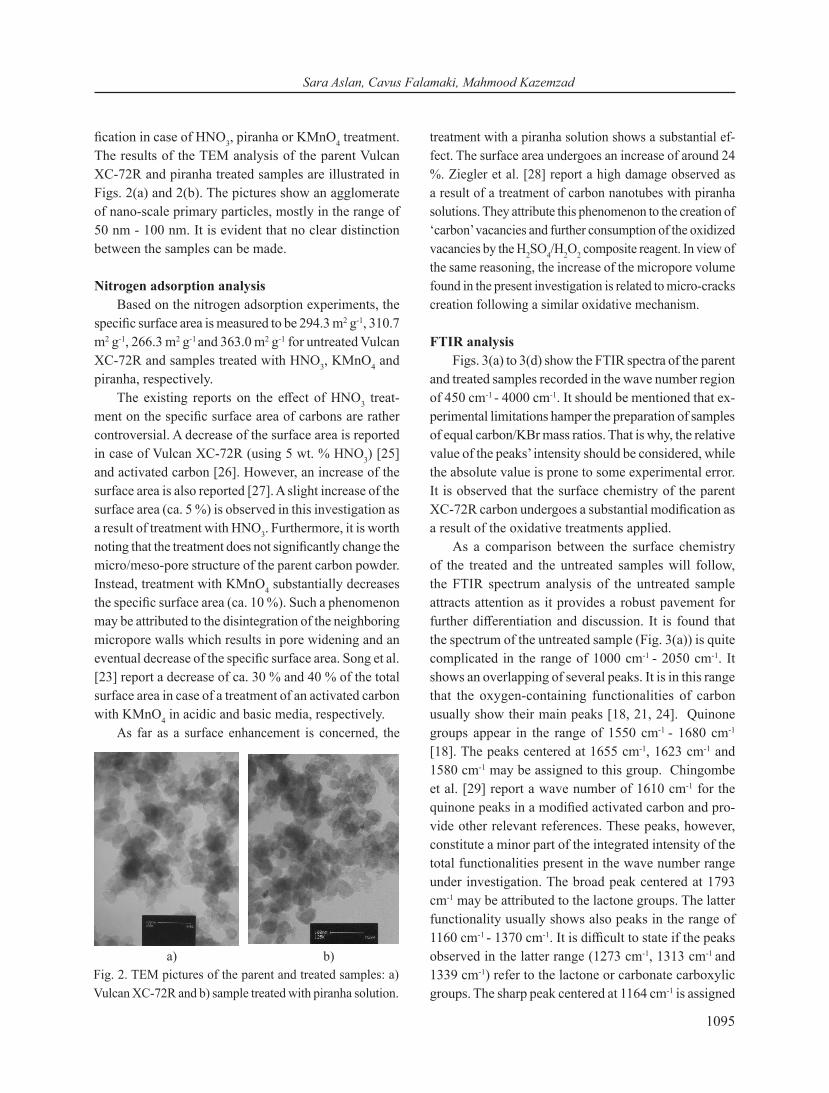
fication in case of HNO3, piranha or KMnO4 treatment. The results of the TEM analysis of the parent Vulcan XC-72R and piranha treated samples are illustrated in Figs. 2(a) and 2(b). The pictures show an agglomerate of nano-scale primary particles, mostly in the range of 50 nm - 100 nm. It is evident that no clear distinction between the samples can be made.
Nitrogen adsorption analysisBased on the nitrogen adsorption experiments, the
specific surface area is measured to be 294.3 m2 g-1, 310.7 m2 g-1, 266.3 m2 g-1 and 363.0 m2 g-1 for untreated Vulcan XC-72R and samples treated with HNO3, KMnO4 and piranha, respectively.
The existing reports on the effect of HNO3 treat-ment on the specific surface area of carbons are rather controversial. A decrease of the surface area is reported in case of Vulcan XC-72R (using 5 wt. % HNO3) [25] and activated carbon [26]. However, an increase of the surface area is also reported [27]. A slight increase of the surface area (ca. 5 %) is observed in this investigation as a result of treatment with HNO3. Furthermore, it is worth noting that the treatment does not significantly change the micro/meso-pore structure of the parent carbon powder. Instead, treatment with KMnO4 substantially decreases the specific surface area (ca. 10 %). Such a phenomenon may be attributed to the disintegration of the neighboring micropore walls which results in pore widening and an eventual decrease of the specific surface area. Song et al. [23] report a decrease of ca. 30 % and 40 % of the total surface area in case of a treatment of an activated carbon with KMnO4 in acidic and basic media, respectively.
As far as a surface enhancement is concerned, the
treatment with a piranha solution shows a substantial ef-fect. The surface area undergoes an increase of around 24 %. Ziegler et al. [28] report a high damage observed as a result of a treatment of carbon nanotubes with piranha solutions. They attribute this phenomenon to the creation of ‘carbon’ vacancies and further consumption of the oxidized vacancies by the H2SO4/H2O2 composite reagent. In view of the same reasoning, the increase of the micropore volume found in the present investigation is related to micro-cracks creation following a similar oxidative mechanism.
FTIR analysisFigs. 3(a) to 3(d) show the FTIR spectra of the parent
and treated samples recorded in the wave number region of 450 cm-1 - 4000 cm-1. It should be mentioned that ex-perimental limitations hamper the preparation of samples of equal carbon/KBr mass ratios. That is why, the relative value of the peaks’ intensity should be considered, while the absolute value is prone to some experimental error. It is observed that the surface chemistry of the parent XC-72R carbon undergoes a substantial modification as a result of the oxidative treatments applied.
As a comparison between the surface chemistry of the treated and the untreated samples will follow, the FTIR spectrum analysis of the untreated sample attracts attention as it provides a robust pavement for further differentiation and discussion. It is found that the spectrum of the untreated sample (Fig. 3(a)) is quite complicated in the range of 1000 cm-1 - 2050 cm-1. It shows an overlapping of several peaks. It is in this range that the oxygen-containing functionalities of carbon usually show their main peaks [18, 21, 24]. Quinone groups appear in the range of 1550 cm-1 - 1680 cm-1 [18]. The peaks centered at 1655 cm-1, 1623 cm-1 and 1580 cm-1 may be assigned to this group. Chingombe et al. [29] report a wave number of 1610 cm-1 for the quinone peaks in a modified activated carbon and pro-vide other relevant references. These peaks, however, constitute a minor part of the integrated intensity of the total functionalities present in the wave number range under investigation. The broad peak centered at 1793 cm-1 may be attributed to the lactone groups. The latter functionality usually shows also peaks in the range of 1160 cm-1 - 1370 cm-1. It is difficult to state if the peaks observed in the latter range (1273 cm-1, 1313 cm-1 and 1339 cm-1) refer to the lactone or carbonate carboxylic groups. The sharp peak centered at 1164 cm-1 is assigned
Fig. 2. TEM pictures of the parent and treated samples: a) Vulcan XC-72R and b) sample treated with piranha solution.
a) b)

Journal of Chemical Technology and Metallurgy, 55, 5, 2020
1096
to the presence of phenolic groups (in fact to O-H group bend/stretch vibration). This is supported by the presence of a strong peak at 1059 cm-1, which may belong to the C-OH group stretch vibration of the phenolic groups
[18]. A clear peak at 1117 cm-1 may also belong to the latter, although the vibration mode type attribution is rather hardly discriminated. The peak located at 1540 cm-1 may be assigned to aromatic C=C stretching vibra-tions showing the graphitic character of the surface. A strong peak is located at 1460 cm-1 which is attributed to the presence of carboxyl-carbonate structures. This assignment is rather tentative, and a reference has been made to the drift study of Fanning and Vannice [18]. Although there are other peaks to be assigned, it is be-lieved that the peaks corresponding to the main groups affecting the electrochemical performance of the sample in respect to ORR are identified. For example, the exist-ence of anhydride peaks is most probable, but this is of less importance because of their small intensity.
Fig. 3(b) shows the FTIR spectrum of the HNO3 treated sample. A clear increase of the relative area of the peaks recorded in the region of 1000 cm-1 - 2050 cm-1 is observed when compared to that of the parent sample. In other words, the concentration of the oxygenated surface groups increases substantially upon the acidic treatment. The major peak is centered at 1061 cm-1, while that of the parent sample is recorded at 1059 cm-1. It is assigned to the presence of phenolic groups (mainly C-OH stretch vibrations) and is accompanied by a peak at 1167 cm-1 at-tributed to the O-H bend/stretch vibration of the phenolic groups. Peaks located at 1101 cm-1 and 1085 cm-1 may be similarly attributed to the latter groups. The peaks pertinent to quinone groups undergo a substantial in-crease of their relative intensity and generally appear as a major peak at 1628 cm-1 and a minor one at 1572 cm-1. However, the relative integrated intensity of the phenolic groups is clearly greater than that corresponding to the quinone groups. Peaks related to lactone groups are al-most absent. Peaks corresponding to carboxyl-carbonate species are still present (1451 cm-1 and 1416 cm-1) and have a significant relative intensity. A clear increase of the peaks’ relative intensity is observed in the wave number region of 1270 cm-1 - 1384 cm-1. These peaks are mainly attributed to the creation of carboxyl-carbonate groups upon the treatment of the carbon black with HNO3. They are centered at 1209 cm-1, 1252 cm-1, 1269 cm-1, 1309 cm-1, 1350 cm-1 and 1383 cm-1.
The spectrum of the sample treated with KMnO4 is distinctly different from those of the other samples (Fig. 3(c). The different groups are exhibited in a more dif-ferentiable fashion in this spectrum. The quinone group
Fig. 3. FTIR spectra of the parent and treated samples: a) Vulcan XC-72R b) HNO3 treated sample c) KMnO4 treated sample and d) sample treated with piranha solution.
a)
b)
c)
d)

Sara Aslan, Cavus Falamaki, Mahmood Kazemzad
1097
may be considered the dominant one among the other functionalities present. It appears as an isolated peak (centered at 1629cm-1). The phenol group is presented by a broad peak including major and minor peaks located at 1053 cm-1 and 1160 cm-1, respectively. The broad peak at 1448 cm-1 is attributed to the presence of carboxyl-carbonate entities. These, however, are present as a minor constituent of the surface groups of the treated sample.
A new peak of a considerable intensity appears centered at 534 cm-1. It is in fact a broad one including peaks in the range of less than 450 cm-1 to more than 620 cm-1. This broad peak is absent in the spectra of the parent and the other treated samples. It is suggested to refer this peak to the presence of Mn-O groups created during the oxidative treatment with KMnO4 and residues remaining on the surface of the carbon particles. Bulk and supported manganese oxides (MnOx species) are reported to exhibit FTIR vibrational peaks around 530 cm-1, 570 cm-1, and 610 cm-1 - 620 cm-1, depending on the kind of the oxide [30]. This is an important result and will be considered in the discussion of the electrochemical properties of the KMnO4 treated sample.
The FTIR spectrum of the KMnO4 treated sample shows another peculiar but less pronounced characteristics. Two peaks centered around 2338 cm-1 and 2677 cm-1 appear in the spectrum which are not found in the spectra of the other samples. It would be very tentative to assign them to specific functional groups. Based on an extensive literature survey it can be assumed that these peaks may refer to some cyclic oxygenated compounds like ethers. Further investigation is needed for their reliable identification.
It should be reminded that the concentration of the phenolic groups of the parent carbon sample is not sig-nificantly altered upon treatment with KMnO4.
Fig. 3(d) shows the FTIR spectrum of the piranha solution treated sample. In general, it resembles Fig. 3(b) (the sample treated with HNO3) in many aspects. Compared to Fig. 3(a), a clear increase of the relative content of surface groups corresponding to oxygenated compounds is observed. The most striking change is the appearance of a well outlined peak centered at 1627 cm-1. Based on the previous discussion, this peak refers to quinone groups which are the major groups in the spectrum of the piranha solution treated sample. Lactone groups, which are presented by peaks to the left (higher wave numbers) of the quinone group in the parent carbon spectrum, are almost eliminated upon piranha treatment.
A large peak centered at 1055 cm-1 is observed in Fig. 3(b). It is attributed to the presence of phenol groups (O-H group bend/stretch vibration) and is accompanied by a relatively strong peak at 1163 cm-1(C-OH group stretch vibration of phenolic groups). The broad peak attributed to carboxyl-carbonate groups, which is well outlined in the spectrum of the original carbon, appears of almost identical relative intensity upon treatment with piranha. The weak peak at 1729 cm-1 is attributed to the presence of carbonyl groups in the carboxyl entities. As in the case of HNO3 treatment, it is observed that the treatment with piranha solution results in the appearance of new carboxyl-carbonate groups, with peaks in this case centered at 1217 cm-1, 1258 cm-1, 1338 cm-1, 1353 cm-1, 1370 cm-1 and 1384 cm-1.
Summing up, it is found that each treatment procedure results in an increase of the relative content of the surface quinone groups. It is recognized that these are the main groups active in respect to the formation of superoxides in the course of ORR in alkaline media. They are reduced to semiquinone radical anions by a 1-electron reduction reaction, which in turn transform into active intermediates reacting with dissolved oxygen [10]. The presence of other surface oxygenated groups like phenol, ether, carboxylic one, etc., may have a detrimental effect on the mentioned superoxide formation reaction. The reasoning presented above leads to the conclusion that the KMnO4 treatment could be a potential method, at least theoretically, for en-hancing the hydrogen peroxide reaction of Vulcan XC-72C.
Cyclic voltammetry and RDE experimentsThe results of the cyclic voltammetry analysis in
absence and presence of dissolved oxygen in the sample treated with the piranha solution are illustrated in Fig. 4. It is evident that a reproducible pattern is obtained after 10 cycles. A new wave between -0.2 V and - 0.4 V is recorded on the cathodic sweep in presence of dissolved oxygen veri-fying the proceeding of ORR. Similar results are obtained using the parent carbon and other treated carbon samples.
The RDE voltammograms of the unmodified and modified carbons are shown in Figs.5 (a) and 5(b) for two rotating speeds of 2200 rpm and 2600 rpm, respectively. At a first sight, the general trend of the curves seems invariant for rotation speeds greater than 2200 rpm, at least for the modified carbons. All of them exhibit a clear shoulder at potentials more positive than -0.5 V. However, in case of the original carbon, this shoulder

Journal of Chemical Technology and Metallurgy, 55, 5, 2020
1098
is more clearly outlined at a speed of 2600 rpm. At least one other shoulder is observed for all kinds of carbons at potentials more negative than -0.7 V at both rotation speeds. The assessment of each peak and its assignment to a given reaction requires an information on the number of electrons involved. This may be retrieved by the ap-plication of the Koutecky-Levich correlation:
(1)
where is the measured current (mA), the kinetic current (mA), the rotation speed (rpm), while is a constant depending on the concentration and the diffu-sion coefficient of the dissolved oxygen, the dynamic viscosity of the liquid and the effective surface area of the working electrode. Although exact values of the physi-cal properties can be found in the literature, these are usually scattered. Therefore, this parameter is obtained through calibration experiments. The latter is performed using platinized carbon as a working electrode at the operating conditions of the main experiments. It should be added that the surface area of the Pt/C electrode is
the same as that of the other samples. Making a rather acceptable assumption that the platinized carbon elec-trode exhibits a constant 4-electron reduction reaction at potentials more positive than -0.8 V (the reproducibility is experimentally observed), the value of is calculated equal to 3290.9 Cs-1.
Fig. 6 shows the dependence of the number of transferred electrons on the potential applied for the samples treated with HNO3, KMnO4 and piranha solu-tion, respectively. In case of the original carbon the number of the electrons transferred amounts to 2.65 at a potential of -0.30 V. It increases to 3.60 at -0.6 V and to 3.83 at a potential of -0.80 V. The results obtained show that the original carbon is not the preferred catalyst of the synthesis of hydrogen peroxide at potentials more positive than -0.60 V.
The results referring to the HNO3 treated sample are promising. The number of electrons transferred is calculated to increase from 2.10 to 2.16 in the potential range from -0.35 V to -0.60 V. Afterwards they undergo a quasi-constant rate increase to 3.17 up to the potential of -0.80 V. It may be stated that this kind of treatment preferably guides the 2-electron hydrogen peroxide for-mation reaction in the potential range of -0.35 V to -0.60 V. Based on the FTIR analysis discussed above, the trend observed may be attributed to the formation of quinone groups as a result of the chemical treatment. It should be added that an initial electron number exceeding 3 is observed at a potential of -0.30 V. Such a high number of electrons involved at potentials near zero is reported by other authors [10]. Based on Fig. 5 it should be noted that substantially less cathodic currents are recorded in the potential range referring to the first wave in case of the HNO3 treated sample when compared to that observed with the parent carbon sample. Besides, the specific surface area of the treated sample is about 6 % larger.
Fig. 4. Cyclic voltammetry diagrams in the absence (dashed line) and presence of dissolved oxygen (bold line) for the sample treated with the piranha solution. The con-stant patterns have been obtained after 10 cycles.
Fig. 5. RDE voltammograms of the unmodified and modified carbons at a rotation speed of a) 2200 rpm and b) 2600 rpm.

Sara Aslan, Cavus Falamaki, Mahmood Kazemzad
1099
The results obtained with the KMnO4 treated sample are impressive again, although the number of electrons involved is observed to be slightly higher than that of the HNO3 treated sample. This number is in the range of 2.26-2.28 at potentials varying from -0.30 V to -0.50 V. It increases to 2.59 at -0.60 V and additionally to 2.74 at -0.80 V. The KMnO4 treated sample is thus more adapted for hydrogen peroxide production in alkaline media at potentials more positive than -0.50 V when compared to the parent carbon sample. The oxide groups (MnOx) pre-sent on this sample may be responsible for a less efficient catalytic action for hydrogen peroxide production reaction compared to that of the HNO3 treated sample. In view of the distribution of the functional groups of the latter sample, it can be suggested that the new quinone groups formed determine the proceeding of the required 2-electron reaction throughout the whole potential range under study.
It is observed that the piranha solution treated sample behaves better than the parent carbon sample. Its behavior in respect to the hydrogen peroxide production is more unfavorable when compared to that of KMnO4 and HNO3 treated one. The number of electrons involved is between 2.35 and 2.37 in the potential range from -0.35 V to -0.60 V. An increase to 2.70 is observed up to -0.80 V. It is worth noting that despite the approximate resemblance of the functional group distribution on the surface of the piranha and HNO3 treated samples, their performance is obviously different. Referring to Fig. 5, it is evident that the piranha solution treated sample shows much higher cathodic currents during the first wave. Based on the nitrogen adsorption experiments discussed above, such a behavior may be attributed on one hand to the higher
(by 17 %) specific surface area of the piranha solution treated sample. The increase of surface area is accom-panied by the formation of a higher number of defects prone to be converted to electro-active sites, thus result-ing in a substantial higher cathodic current. At present it is unclear why, despite the FTIR spectrum resemblance, the ORR mechanism is so different in case of HNO3 and piranha solution treated samples. The creation of a higher defects’ concentration because of the piranha solution aggressiveness might be a plausible reason.
XPS analysisBased on cyclic voltammetry and RDE analyses
results, the Vulcan sample treated with HNO3 exhibits the best performance in respect to 2-electron ORR se-lectivity under basic conditions. This sample and that of parent Vulcan XC-72R are analyzed by XPS. The results pertaining to the C1s and O1s spectra are shown in Figs.
Functional group
binding energy
(eV)
Vulcan XC-72R relative intensity
(%)
HNO3 treated Vulcan XC-72R relative intensity
(%)
C-C (2s22p2 ground state)
282.4 nil 0.31
C-C (sp2 hybridized state) 284.10 67.95 53.83
C-C (sp3 hybridized state) 285.37 11.81 24.52
C-O 286.43 9.61 10.65
C=O 288.66 8.24 9.30
carboxyl 290.60 1.37 0.38
π- π* 291.90
1.04 1.03
Table 1. Peak assignment and deconvolution results of the XPS C1s spectra of the parent and HNO3 treated samples. The first C-C peak assignment is a tentative postulate of this work.
Fig. 6. Variation of transferred electrons number with potential applied during the RDE experiments for the parent Vulcan XC-72R, HNO3, piranha and KMnO4 solution treated samples.

Journal of Chemical Technology and Metallurgy, 55, 5, 2020
1100
7(a) to 7(d). Due to the lower signal-to-noise ratio of the O1s spectrum, the deconvolution of the C1s spectrum is more reliable [19]. Figs.7(a) and 7(b) show the C1s spec-trum of the Vulcan XC-72R and HNO3 treated samples, respectively. The peaks detected and their attribution to functional groups are listed in Table 1. The latter also includes the contribution percent of each functional group as a result of the spectrum deconvolution. It is observed that most of the peak areas of Vulcan XC-72R refer to the C-C bonds, which in turn correspond to sp2 and sp3 hybrid states [25]. The relative content of sp2 C-C bonds undergoes a significant decrease (ca. 13 %) in case of an acidic treatment. This is accompanied by a 14 % increase of the sp3 C-C bonds. The peak centered at 286.43 eV is attributed to C-O bonds belonging to ether, hydroxyl or phenolic entities [25, 30]. Based on the XPS analysis, the relative content of the C-O bonds does not change upon treatment with HNO3. The assignment of the other peaks is in accordance with previous reports [16, 19, 22, 25, 31]. It is observed that the content of C=O (288.66 eV) and π-π* shake-up satellite peaks (291.90 eV) also remain un-
changed. The carboxyl peak (290.60 eV), initially present at a low relative concentration in the parent Vulcan carbon (ca. 2 %), decreases to 0.4 % upon an acidic treatment.
Figs. 7(c) and 7(d) show the O1s spectrum of the Vulcan XC-72R and HNO3 treated samples, respectively. The details referring to the peak assignment and the de-convolution results are summarized in Table 2. Based only on Table 2, it is evident that the relative concentration of the carbonyl (531.90 eV) and the C-O groups (532.55 eV) does not significantly change upon an oxidative treatment. In addition, the same table shows that the relative con-centration of the carboxyl groups (533.20 eV) increases with about 13 % upon an acidic treatment.
To get a better understanding of the main changes taking place as a consequence of the surface oxidation, it is more informative to resort to Figs. 7(c) and 7(d) (O1s XPS spectra) where the count number of the emitted X-rays from the irradiated samples is retrievable. It is observed that the total peaks area increases substantially upon a surface treatment (ca. 2.5 folds). In other words, it may be stated that the presence of all groups (carbonyl,
Fig. 7. XPS spectrum of the parent and acid treated samples and their deconvolution curves: a) C1s spectrum of the Vul-can XC-72R sample b)C1s spectrum of the HNO3 treated Vulcan XC-72R sample c)O1s spectrum of the Vulcan XC-72R sample d)O1s spectrum of the HNO3 treated Vulcan XC-72R sample.
a) b)
c) d)
Sara Aslan, Cavus Falamaki, Mahmood Kazemzad
1101
C-O and carboxyl) considered undergoes a significant increase due to the chemical treatment. This is in ac-cordance with the FTIR results, especially regarding the phenol groups (here C-O groups). The increase of the absolute concentration of the carboxyl groups may be partly attributed to the formation of quinonoid species, as deduced from the FTIR analysis.
Based on the XPS and FTIR analyses results, it may be stated that especially active groups like the quinonoid and the phenol-like entities are created upon a nitric acid treatment. These groups might be responsible for an en-hanced ORR of a high selectivity in respect to hydrogen peroxide. The mechanism of the enhancement of the overall two-step 2-electron ORR has been a subject of a great debate till now. One of the rational mechanisms is that proposed by Tarashevich and Khrushcheva [32] claiming a somewhat indirect role of the quinone like groups in the formation of carbene edges active sites at the directly adjacent carbons or nearby ones. On the other hand, an experimental evidence has been recently reported claiming the effective role of the phenolic groups in H2O2 production reaction [33]. The results obtained in the present investigation provide the assumption that the quinonoid and the phenolic like entities might be responsible for the enhanced 2-electron ORR.
At this point it is of interest to consider more at-tentively the XPS C1s spectra (Figs. 7(a) and 7(b)). The comparison of the parent and the treated carbon samples shows that a rather weak but distinct peak is observed at 282.4 eV. It appears more distinctively after an oxidative treatment. According to Table 1, the area of the latter peak constitutes only 0.31 % of the total area. Such a peak of a binding energy less than that of the sp2 hybrid (284.1 eV) has been recently reported for
carbonaceous materials [34]. However, no specific as-signment has been presented so far. To proceed further, it is mandatory at this stage to recall the unrecognized hypothesis of Coulson [35] revisited a decade ago by Radovic and Bockrath [36]. It refers to the chemical nature of the carbon materials edge sites: the edge sites of the carbon materials may exhibit a carbyne or carbine type nature depending on being of armchairs or zigzag types, respectively. The zigzag types will be considered.
It has been postulated that carbon edge sites might exhibit a peculiar chemical reactivity due to the predomi-nance of electron configurations different from sp2 or sp3 hybrids. The exact nature of the edges is still a matter of a debate, but it has been mostly claimed that a ground state of 2s22p2 (divalent state) may be present, leaving a pair of electrons exposed. Accepting the validity of this theory, it is worth adding that the electron binding ener-gies (Eb) of the 2s22p2 (ground state), 2sp2 (hybrid state) and 2sp3 (hybrid state) orbitals obey the following rule:
(2)Hence, the small peak appearing at ca. 284.2 eV in
the C1s spectrum of the HNO3 treated sample may be attributed to 2s22p2 ground state orbitals.
The proposed scheme provides to advance a general mechanism of ORR on the HNO3 treated carbon. It is summarized as follows:
(a)
(b)
(c)
(d)
Table 2. Peak assignment and deconvolution of the XPS O1s spectra of the parent and HNO3 treated samples.
Functional group Binding energy (eV)Vulcan XC-72Rrelative intensity
(%)
HNO3 treated Vulcan XC-72R relative
intensity (%)carbonates/physically
adsorbed oxygen530.70 20.27 8.04
carbonyl 531.90 14.19 13.40
C-O 532.55 4.73 4.83
carboxyl 533.20 60.81 73.73

Journal of Chemical Technology and Metallurgy, 55, 5, 2020
1102
The symbol denominates a zigzag type carbon atom present in its ground state with a pair of electrons exposed to the electrolyte. This carbon atom, however, is located adjacently or relatively near to quinonoid or phenol like groups as discussed above. The dissolved oxygen, which is a bi-radical itself, upon getting close to such zigzag sites interacts with these electron pairs and gets undissociatively adsorbed (a). Through a one electron transfer reaction, a superoxide ion is created (b). The latter transforms into a more stable peroxide species mediated by the presence of water molecules (c). Finally, the per-oxide ion is released to the solution by accepting another electron and leaving behind the parent zigzag site with a pair of electrons (d). It should be reminded that the release of the peroxide ion to the solution may also proceed via a disproportionation reaction. Aiming a better elucidation of the postulated mechanism, the scheme of reactions (a) to (d) is depicted in Fig. 8. The rate-controlling step (or steps), if any, cannot be determined. This requires a de-tailed kinetic analysis and is a subject of a separate work.
Two-compartment electrochemical cell performanceFig. 9 shows the concentration of H2O2 as a function
of time in case of experiments performed with a two-compartment cell set up and a potential of 2 V applied by the DC current supply for a stationary state. Each point corresponds to the average of triplicate experiments. Fig. 10 shows the Faradaic efficiency of the same processes as a function of the time and the type of the catalyst used. The Faradaic efficiency (E) is calculated according to the following relation:
(3)where F is the Faraday constant, C is the concentration, V is the catholyte volume, I is the current, while t is the time elapsed.
Referring to Fig. 9, it is observed that all the catalysts used provide the production of H2O2, albeit with different rates. Parent Vulcan XC-72R exhibits the least, while the HNO3 treated carbon shows the highest selectivity towards H2O2 production throughout the time span under consideration. The piranha and KMnO4 treated carbons show a performance in between of these two extremes.
Referring to Fig. 10, it is observed that both KMnO4 and HNO3 treated carbons exhibit the highest Faradaic efficiency at short times (ca. 85 %) unlike the other sam-ples whose efficiency in this time span amounts to ca. 45 %. Generally, all samples undergo a decrease of the Faradaic efficiency at longer times. The KMnO4 sample exhibits a sharp efficiency decrease with respect to that of the HNO3 treated sample. The Vulcan XC-72R, piranha and KMnO4 treated samples approach an approximately unique but low efficiency asymptote up to 225 min. This is the period during which the HNO3 treated sample
Fig. 8. Mechanism proposed for the ORR process leading to selective H2O2 production for the acid treated Vulcan XC-72R.
Fig. 9. Concentration of H2O2 as a function of time for the experiments performed using the two-compartment cell set up and an electrical potential of 2 V.
Fig. 10. Faradaic efficiency as a function of time for the experiments performed using the two-compartment cell set up and an electrical potential of 2 V.

Sara Aslan, Cavus Falamaki, Mahmood Kazemzad
1103
undergoes a relatively much smaller efficiency decrease.Based on these experimental findings, it may be
strongly stated that the HNO3 treated carbon catalyst shows the best performance in respect to H2O2 produc-tion when compared to those of the parent XC-72R car-bon and the piranha or KMnO4 treated samples. This is in accordance with the RDE experiments and is soundly supported by the XPS and FTIR analyses discussed in the previous sections.
CONCLUSIONSIt is shown that the chemical surface oxidation of
Vulcan XC-72R carbon powder may highly improve its electrochemical behavior in favor of the production of hydrogen peroxide through ORR. The results obtained show that while Vulcan XC-72R guides the ORR process far from the 2-electron hydrogen peroxide production reaction in the potential span from -0.3 V to -0.6 V (Ag/AgCl), the chemical surface oxidation by different treatment methods leads to a favored hydrogen peroxide formation process. However, it is shown that the HNO3 treated sample exhibits the best behavior with an average number of electrons transferred ca. 2.1 in the potential range from -0.30 V to -0.55 V (Ag/AgCl). The perfor-mance of the two-compartment electrochemical cell with catholyte and anolyte flow circulation shows that the increase of H2O2 yield is the highest for the sample treated with HNO3. The last finding is in an agreement with the analytical and RDE results and discloses a new kind of a catalyst and a cell configuration to produce H2O2. A reaction mechanism based on enhanced pres-ence of electron pairs at the zigzag edges close to the quinonoid and the phenol like groups is advanced. It corroborates with the XPS analysis results.
REFERENCES
1. P. Drogui, S. Elmaleh, M. Rumeau, C. Bernard, A. Rambaud, Hydrogen peroxide production by water electrolysis: Application to disinfection, J. Appl. Electrochem., 31, 2001, 877-882.
2. P. Drogui, S. Elmaleh, M. Rumeau, C. Bernard, A. Rambaud, Oxidizing and disinfecting by hydrogen peroxide produced in a two-electrode cell, Wat. Res., 35, 2001, 3235-3241.
3. J. Balei, K. Baloogh, O. Spalek, Possibility of pro-ducing hydrogen peroxide by cathodic reduction of
oxygen, Chem. Zvesti, 30, 1976, 384-392 .4. R. Dittmeyer, J.D. Grunwaldt, A. Pashkova, A
review of catalyst performance and novel reaction engineering concepts in direct synthesis of hydrogen peroxide, Catal. Today, 248, 2014, 149-159.
5. T. Murayama, I. Yamanaka, Electrosynthesis of neutral H2O2 solution from O2 and water at a mixed carbon cathode using an exposed solid-polymer-electrolyte electrolysis cell, J. Phys. Chem. C, 115, 2011, 5792-5799.
6. E. Berl, A new cathodic process for the production of H2O2, Trans. Electrochem. Soc., 139, 1939, 359-378.
7. J.S.C. Chiang, Process and cell for producing hydro-gen peroxide, US patent 4758317, 1988.
8. W.E., Buschmann, P.I. James, Methods and apparatus for the on-site production of hydrogen peroxide, US patent 7754064, 2010.
9. A. Sarapuu, K. Vaik, D.J. Schiffrin, K. Tammeveski, Electrochemical reduction of oxygen on antraqui-none-modified glassy carbon electrodes in alkaline solution, J. Electroanal. Chem., 541, 2003, 23-29.
10. E. Lobyntseva, T. Kallio, N. Alexeyeva, K. Tammeveski, K. Kontturi, Electrochemical syn-thesis of hydrogen peroxide:Rotating disk electrode and fuel cell studies, Electrochem. Acta , 52, 2007, 7262-7269.
11. Y. Ma , H. Wang, S. Ji, J. Goh, H. Feng, R. Wang, Highly active Vulcan carbon composite for oxygen reduction reaction in alkaline medium, Electrochem. Acta, 133, 2014, 391-398.
12. Y. Xia, T.T. Nguyen, S. Fontana, A. Desforges, , J.F. Mareche, C. Bonnet, F. Lapicque, Development of half-cells with sulfonated Pt/Vulcan catalyst for PEM fuel cells, J. Electroanal. Chem., 724, 2014, 62-70.
13. M.M. Antxustegi, A.R. Pierna, N. Ruiz, Chemical activation of Vulcan® XC72R to be used as support for NiNbPtRu catalysts in PEM fuel cells, Int. J. Hydrogen Energy, 39, 2014, 3978-3983.
14. Y. Xia , T.T. Nguyen, T. Fontana, A. Desforges, J.F. Maréché, C. Bonnet, F. Lapicque, Development of half-cells with sulfonated Pt/Vulcan catalyst for PEM fuel cells, J. Electroanal. Chem., 724, 2014, 62-70.
15. I. Yamanaka, R. Ichihashi, T. Iwasaki, N. Nishimura, T. Murayama, W. Ueda, S. Takenaka, Electrocatalysis of heat-treated cobalt-porphyrin/carbon for hydrogen peroxide formation, Electrochem. Acta, 108, 2013, 321-329.

Journal of Chemical Technology and Metallurgy, 55, 5, 2020
1104
16. M.L. Calegaro, F.H.B. Lima, E.A. Ticianelli, Oxygen reduction reaction on nanosized manganese oxide particles dispersed on carbon in alkaline solu-tions, J. Power Sources, 158, 2006, 735-739.
17. M.H.M.T. Assumpcao, R.F.B. DeSouza, D.C. Rascio, J.C.M. Silva, M.L. Calegaro, I. Gaubeur, T.R.L.C. Paixao, P. Hammer, M.R.V. Lanza, M.C. Santos, A comparative study of the electrogeneration of hy-drogen peroxide using Vulcan and Printex carbon supports, Carbon, 49, 2011, 2842-2851.
18. P.E. Fanning, M.A. Vannice, A drifts study of the formation of surface groups on carbon by oxidation, Carbon, 31, 1993, 721-730.
19. H.P. Boehm, Some aspects of the surface chemistry of carbon blacks and other carbons, Carbon, 32, 1993, 759-769.
20. H.P. Boehm, Surface oxides on carbon and their analysis: a critical assessment, Carbon, 40, 2002, 145-149.
21. J. Zhang, H. Zou, Q. Quing, Y. Yang, Q. Li, Z. Liu, X. Guo, Z. Du, Effect of chemical oxidation on the structure of single-walled carbon nanotubes, J. Phys. Chem. B, 107, 2003, 3721-3718.
22. J. Vivo-Vilches, E. Bailon-Garcia, A. Perez-Cadenas, F. Carrasco-Marin, F.J. Maldonado-Hodar, Tailoring the surface chemistry and porosity of activated carbons: Evidence of reorganization and mobility of oxygenated surface groups, Carbon, 68, 2014, 520-530.
23. W. Song , Y. Li, X. Guo, J. Li, X. Huang, W. Shen, Selective surface modification of activated carbon for enhancing the catalytic performance in hydrogen peroxide production by hydroxylamine oxidation, J. Mol. Catal. A: Chemical, 328, 2010, 53-59.
24. R. Berenguer, J.P. Marco-Lozar, C. Quijada, D. Cazorla-Amoros, E. Morallon, A comparison between oxidation of activated carbon by electro-chemical and chemical treatments, Carbon, 50, 2012, 1123-1134.
25. S.M. Senthil Kumar, J. Soler Herrero, S. Irusta, K. Scott, The effect of pretreatment of Vulcan XC-72R carbon on morphology and electrochemical oxygen reduction kinetics on Pd nano-particle in acidic
media, J . Electroanal. Chem., 647, 2012, 211-221. 26. A. Guha, W. Lu, Jr. T.A. Zawodzinski, D.A.
Schiraldi, Surface-modified carbons as platinum catalyst support for PEM fuel cells, Carbon, 7, 2007, 1506-1517.
27. S. Wang, G.Q. Lu, Effects of acidic treatments on the pore and surface properties of Ni catalyst supported on activated carbon, Carbon, 36, 1999, 283-292.
28. K.J. Ziegler, Z. Gu, H. Peng, E.L. Flor, R.H. Hauge, R.E. Smalley, Controlled Oxidative Cutting of Single-Walled Carbon Nanotubes, J. Am. Chem. Soc., 127, 2005, 1541-1547.
29. P. Chingombe, B. Saha, R.J. Wakeman, Surface modification and characterization of a coal-based activated carbon, Carbon, 43, 2005, 3132-3143.
30. F. Buciuman, F. Patcas, R. Craciun, D.R.T. Zahn, Vibrational spectroscopy of bulk and supported manganese oxides, Phys. Chem. Chem. Phys., 1, 1998, 185-190.
31. V. Datsyuk, M. Kalyva, K. Papagelis, J. Parthenios, D. Tasis, A. Siokou, I. Kallitsis, C. Galiotis, Chemical oxidation of multiwalled carbon nanotubes, Carbon, 46, 2008, 833-840.
32. M.R. Tarasevich, E.I. Khrushcheva, Electrocatalytic properties of carbon materials, in: B. E. Conway, J.O.M. Bockris, R.E. White (Eds.), Modern Aspects of Electrochemistry, Plenum Press, New York, 1989, 295.
33. T. Murayama, I. Yamanaka, Electrosynthesis of neutral H2O2 solution from O2 in water at a mixed carbon cathode using an exposed solid-polymer-electrolyte electrolysis cell, J. Phys. Chem., 115, 2011, 5792-5799.
34. S.K. Singh, S.B. Rai, Detection of carbonaceous materials in naga bhasma, Ind. J. Pharm. Sci., 74, 2012, 178-183.
35. C.A. Coulson, The electronic structure of the boun-dary atoms of a graphite layer, Proc. of the 4th con-ference on carbon, University of Buffalo, NY, 1960, 215-219.
36. L.R. Radovic, B. Bockrath, On the chemical nature of graphene edges: Origin of stability and potential for magnetism in carbon materials, J. Am. Chem. Soc., 127, 2005, 5917-5927.


![XC series PLC User manual[Instruction] - KALATEC](https://static.fdokumen.com/doc/165x107/6316c313f68b807f880362ed/xc-series-plc-user-manualinstruction-kalatec.jpg)


