Compliant actuation of rehabilitation robots
10
IEEE Robotics & Automation Magazine 60 1070-9932/08/$25.00ª2008 IEEE SEPTEMBER 2008 Compliant Actuation of Rehabilitation Robots D evelopment of robotic devices for gait rehabilitation of stroke patients is moti- vated by the need for a both intensive and task-specific training, which are key factors in recovery [1], [2], and by the need for therapist-friendly training. Evaluations of the first-generation commercial devices have shown that gait training using these devices is at least as effec- tive as manual therapy [3], [4]. First-generation devi- ces are characterized by the approach of enforcing gait upon a patient by rigidly moving the legs through a pre- scribed pattern, so that the patient can hardly influence these motions. The training effect may be extendable by increasing active participation of patients, e.g., by letting the patient walk on own effort and only offer robotic assistance as needed (AAN). The potential of AAN algorithms in promoting neural recov- ery has not yet been shown in gait training of humans, but it was assessed in gait training of mice [5] and in arm training of stroke patients [6], [7]. AAN strategies require interaction control [8], meaning that the apparent mechanical impedance of the device is programmable to desired values (within limits), so that the behavior of the robot can be varied from very stiff to very compliant. Com- pared with general haptic devices, low apparent stiffness and mass are demanded from a gait trainer, and gait motions are slow. We opted for a combination of compliant actuation and impedance control [9], [10], which provides means to minimize unde- sired interaction torques. This article describes and discusses the general advantages and limitations of a compliant actuation concept for rehabilitation robots on the example of our realiza- tion called the lower extremity powered exoskeleton (LOPES). The major focus is on the limitations: stiffness and bandwidth constraints as well as the influence of uncompensated exoskeleton dynamics. The stability analysis provides an interesting new result. If the rendered stiffness of an elastically actuated joint is increased beyond the intrinsic stiffness of the elastic element, stability of the coupled system human-robot cannot be guaranteed, at least not in the conservative terms of passiv- ity. Finally, the experimental results with subjects walking with the device are presented. These results show that the limitations, in the given application, become secondary to the gain of compliant actuation. LOPES: A Low-Weight Exoskeleton with Series Elastic Actuated Joints Mechanical Design Impedance control implies that the actuators should be high-precision force sources. Mass and inertia of the actuated construction (the exoskeleton) should be minimized, as the means to reduce the apparent mass by control are limited. Our gait rehabilitation robot LOPES is characterized by 1) the choice of degrees of freedom (DoF) that are actuated or left free to allow kinematically natural walking patterns and 2) the possibility Digital Object Identifier 10.1109/MRA.2008.927689 Benefits and Limitations of Series Elastic Actuators BY HEIKE VALLERY, JAN VENEMAN, EDWIN VAN ASSELDONK, RALF EKKELENKAMP, MARTIN BUSS, AND HERMAN VAN DER KOOIJ ©PUNCHSTOCK Authorized licensed use limited to: National Chung Hsing University. Downloaded on June 03,2010 at 07:55:47 UTC from IEEE Xplore. Restrictions apply.
Transcript of Compliant actuation of rehabilitation robots
IEEE Robotics & Automation Magazine60 1070-9932/08/$25.00ª2008 IEEE SEPTEMBER 2008
Compliant Actuationof Rehabilitation Robots
Development of robotic devices for gaitrehabilitation of stroke patients is moti-vated by the need for a both intensiveand task-specific training, which are keyfactors in recovery [1], [2], and by the
need for therapist-friendly training. Evaluations ofthe first-generation commercial devices have shownthat gait training using these devices is at least as effec-tive as manual therapy [3], [4]. First-generation devi-ces are characterized by the approach of enforcing gait
upon a patient by rigidly moving the legs through a pre-scribed pattern, so that the patient can hardly influence these
motions. The training effect may be extendable by increasingactive participation of patients, e.g., by letting the patient walk onown effort and only offer robotic assistance as needed (AAN).
The potential of AAN algorithms in promoting neural recov-ery has not yet been shown in gait training of humans, butit was assessed in gait training of mice [5] and in arm trainingof stroke patients [6], [7]. AAN strategies require interaction
control [8], meaning that the apparent mechanical impedanceof the device is programmable to desired values (within limits), so that
the behavior of the robot can be varied from very stiff to very compliant. Com-pared with general haptic devices, low apparent stiffness and mass are demanded froma gait trainer, and gait motions are slow. We opted for a combination of compliantactuation and impedance control [9], [10], which provides means to minimize unde-sired interaction torques.
This article describes and discusses the general advantages and limitations of acompliant actuation concept for rehabilitation robots on the example of our realiza-tion called the lower extremity powered exoskeleton (LOPES). The major focus ison the limitations: stiffness and bandwidth constraints as well as the influence ofuncompensated exoskeleton dynamics. The stability analysis provides an interestingnew result. If the rendered stiffness of an elastically actuated joint is increasedbeyond the intrinsic stiffness of the elastic element, stability of the coupled systemhuman-robot cannot be guaranteed, at least not in the conservative terms of passiv-ity. Finally, the experimental results with subjects walking with the device arepresented. These results show that the limitations, in the given application, becomesecondary to the gain of compliant actuation.
LOPES: A Low-Weight Exoskeletonwith Series Elastic Actuated Joints
Mechanical DesignImpedance control implies that the actuators should be high-precision force sources.Mass and inertia of the actuated construction (the exoskeleton) should be minimized, asthe means to reduce the apparent mass by control are limited. Our gait rehabilitationrobot LOPES is characterized by 1) the choice of degrees of freedom (DoF) that areactuated or left free to allow kinematically natural walking patterns and 2) the possibilityDigital Object Identifier 10.1109/MRA.2008.927689
Benefits
and Limitations
of Series Elastic
Actuators
BY HEIKE VALLERY,
JAN VENEMAN,
EDWIN VAN ASSELDONK,
RALF EKKELENKAMP,
MARTIN BUSS, AND
HERMAN VAN DER KOOIJ
©PUNCHSTOCK
Authorized licensed use limited to: National Chung Hsing University. Downloaded on June 03,2010 at 07:55:47 UTC from IEEE Xplore. Restrictions apply.

of low impedance control of these DoF to allow unhindered andthus kinetically natural walking. Both horizontal pelvis translationsare actuated [1 and 2 in Figure 1(a)]; the vertical motion of the pel-vis is left free with passive weight compensation [3 in Figure 1(a)].There are three rotational joints per leg: hip adduction [4 in Figure1(a)], hip flexion [5 in Figure 1(a)], and knee flexion [6 in Figure1(a)]. With these nine DoF, LOPES allows more versatile motionthan just forward stepping (as also provided by commercial devicessuch as the Lokomat [11]). Maintaining the fundamental instabilityof a standing or walking human, LOPES allows balance training,which has been recognized as an important aspect of gait training[12], [13]. Pelvis motion is also increasingly integrated into othernew robotic devices such as ALEX [14] or KineAssist [15].
In contrast to the aforementioned devices, which use stiff actua-tors, LOPES is intrinsically compliant, similar to PAM and POGOpresented in [8]. The joints of the robot are actuated with serieselastic actuators (SEAs), anactuation principle introducedby Robinson and colleagues[16]. Bowden cables are usedto realize a flexible transmis-sion, so that the motors aredetached from the exoskele-ton, reducing its weight [seeFigure 1(a)]. For the rotaryjoints, two compressionsprings are connected to theactuator disk with a cable, sothat a torsion spring is createdbetween the actuator disk andthe load side segment [see Fig-ure 1(b)]. Both springs are pre-tensioned with the maximumdesired force, so that the cablesare always under tension dur-ing operation. The concept,construction, and functionalityof these joints are describedextensively in [9]. The side-ways pelvis translation isequipped with a linear SEA.
Table 1 provides the geo-metric and inertial specifica-tions of the exoskeleton part.For each segment of theexoskeleton, the length L,
the center of mass location with respect to the proximal jointLCoM , the mass m, and the moment of inertia around the centerof mass Js1 and around the proximal joint Js2 are listed for an aver-age configuration (the segment lengths are adaptable to thepatient). Table 2 gives the specifications of components used inthe actuation part. Motor and gear inertial properties and trans-mission ratio i determine the reflected inertia JA or mA of thedrives in the exoskeleton coordinate system. For the sidewaysdirection, the reflected mass mA of the drive is 1.2 kg, much less
(a) (b) (c)
1
54
2
3
6
Figure 1. Design of the LOPES robot. (a) DoF of the pelvis and leg segments of the LOPES gaitrehabilitation robot: (1) forward linear guides, (2) sideways linear guides, (3) vertical motion,passively weight compensated by a spring parallelogram between frame and pelvis segment,(4) hip frontal rotation (adduction), (5) hip sagittal rotation (flexion/extension), (6) knee sagittalrotation. Except for (3), all DoFs are actuated. (b) Design of the SEAs: Bowden cables connectthe springs to EM motors, which are detached from the exoskeleton. (c) Photographicimpression of LOPES in operation.
Table 1. Dimensions and mass properties of the LOPES exoskeleton.
L (m) LCoM (m) m (kg) Js1 (kg �m2) Js2 (kg �m2)
Upper limb 0.43 0.27 2.9 0.088 0.30
Lower limb 0.37 0.17 2.25 0.064 0.13
Pelvis B/F 35
Pelvis L/R 27
Table 2. Actuator specifications of the LOPES.
DoF Motor Type Power
Torque/
Force Motor Inertia Gear Inertia i
Refl. Inertia
JA, mA rd ks
Flex/ext hip Kollmorgen 567 W 2.73 Nm 1.6e-5 kg �m2 1.6e-5 kg �m2 64 0.13 kg �m2 0.047 m 35.10 kN/m
Flex/ext knee Kollmorgen 567 W 2.73 Nm 1.6e-5 kg �m2 1.6e-5 kg �m2 64 0.13 kg �m2 0.047 m 35.10 kN/m
Ab/ad hip Kollmorgen 567 W 2.73 Nm 1.6e-5 kg �m2 1.6e-5 kg �m2 64 0.13 kg �m2 0.047 m 57.20 kN/m
Left/right Berger-Lahr 690 W 2.2 Nm 1.6e-4 kg �m2 1.8e-5 kg �m2 8/rd 1.2 kg 0.098 m 3.98 kN/m
Back/forward Linmot 250 W 204 N 1.8e-5 kg �m2 2.3 kg 2.3 kg
To lower undesired interaction
torques, it is crucial to minimize the
reflected mass of the device.
IEEE Robotics & Automation MagazineSEPTEMBER 2008 61
Authorized licensed use limited to: National Chung Hsing University. Downloaded on June 03,2010 at 07:55:47 UTC from IEEE Xplore. Restrictions apply.

than the mass of the pelvis segment (27 kg). In contrast, thereflected moment of inertia JA of the drives actuating the rota-tional joints is 0:13 kg �m2, which is in the same order ofmagnitude as the moment of inertia Js2 of the exoskeleton seg-ments. However, as the motor mass is decoupled from the exo-skeleton by the springs, the actuator mass is not felt by thesubject, and the reflected mass of the device is reduced to theexoskeleton mass only. The disk radius rd and the spring con-stant ks in Table 2 define the intrinsic rotational stiffness K of theSEA; for hip and knee, K is given by 2ksr2
d ¼ 155 Nm/rad.
Control SchemeThe control strategy is multilayered. On the outermost layer,references for the desired interaction with the patient are de-fined. Two different strategies have been implemented on theLOPES: complementary limb motion estimation (CLME) [17],[18] and virtual model control (VMC) [19], [20]. The controlschemes differ in their conceptual background, yet they bothaim at improved patient cooperativeness and do not prescribefixed trajectories to be tracked. This article describes only
VMC. The low-level control deals with the SEA unit used togenerate and measure the interaction forces. First, this underly-ing low-level SEA control is described as a single-input single-output (SISO) system, and then, the VMC is outlined.
Control of the SEA
In a SEA, the load is coupled to the drive via a compliant ele-ment, in this case, a spring with linear characteristic [see Figure1(b)]. A relative displacement of load and actuator provokes aspring torque sL. This principle is schematically illustrated inFigure 2. The simplifying assumptions made here neglect severalimportant aspects of the actuator side that are relevant in thespecific mechanical realization, such as friction and elasticity inthe Bowden cable transmission. We justify this by the purposeof the investigations in the later analysis, which is to show somegeneric parameter and performance limitations of SEAs.
Figure 3 shows the block chart of the SEA embedded in aSISO impedance control loop. The concept of a cascadedforce control loop with proportional-integral (PI) controllerswas chosen because of its reported effectiveness [21], [22]. Inour setup, the innermost motor velocity loop is realized by thepulse-width modulation. The force control has been describedand evaluated in [23]. The outer impedance controller sets thedesired impedance, whereby we consider only the case of arendered stiffness P.
Selective and Partial Support of Gait Functions
with Virtual Model Control
The observation of manual physical therapy of stroke survivorsshows that in case of severely impaired subjects, two or threetherapists are needed. Depending on the individual impairment,the therapist assists only in certain gait subtasks. The idea of theLOPES control is that the therapist still decides how to assist thepatient but that the strenuous labor is taken over by the robot.Following this concept, LOPES should assist a patient onlywhen it is needed. For example, in case of deficient foot clear-ance during the swing phase, LOPES should help in lifting upthe foot. We have divided the control of human gait into differ-ent functional units, which can be partially and selectively sup-ported by LOPES, depending on the patient’s individual needs:
1) balance control in the sagittal/frontal plane2) control of walking speed3) foot placement in the sagittal and frontal plane
τL
− −
−
−
−
τA
ϕL
ϕAϕL,d
K
1JA
ωA,d
ωA
τL,dKo +
Ios Ki +
IisP 1
s1s
Controller
Figure 3. Impedance control with cascaded torque control. The plant (SEA, on the right) is characterized by actuator inertia JA
and spring constant K. The torque controller is cascaded, with inner (index i) loop on motor velocity xA and outer (index o) loopon torque sL, both PI-controlled with gains K and I. Outside, an impedance control loop is closed on the joint angle uL, hererendering a pure virtual stiffness P. The subscript d denotes reference signals.
τL τLτA
ϕLϕA
K
Motor Load
JA Aϕ
Figure 2. SEA: The drive is connected to the load via acompliant element (a torsion spring with spring constant K).The drive dynamics are represented by the inertia JA, and themotor torque is sA. The spring torque sL acting on the load isproportional to the difference between motor angle uA andjoint angle uL, which makes the spring length a directmeasure of the torque acting on the load.
The SEA cannot display a higher pure
stiffness than the spring stiffness, if
passivity is desired.
IEEE Robotics & Automation Magazine62 SEPTEMBER 2008
Authorized licensed use limited to: National Chung Hsing University. Downloaded on June 03,2010 at 07:55:47 UTC from IEEE Xplore. Restrictions apply.
4) foot clearance during swing phase to prevent stumbling5) weight bearing.
The reason behind the division of subfunctions is given in [24].To support these gait functions, we use VMC, which is a motioncontrol framework that uses virtual mechanical components togenerate desired interaction forces and torques. With compo-nents such as springs and dampers, it is possible to simulatealmost any interaction that a therapist would have with a patient.Usual therapist interaction forces have been quantified in [25].VMC has been implemented in several two- and three-dimensionalwalking robot models [26].
The supportive forces for balance control and walking speedcontrol are realized by the drives actuating the pelvis in thehorizontal plane [1 and 2 in Figure 1(a)]. All other DoF arerotational, such that the virtual forces in Cartesian space needto be mapped to joint torques. These torques create the illusionthat the simulated components are connected to the robot.
Balance control, control of walking speed, and weight bear-ing are described elsewhere. In this article, we consider onlythe case of a healthy subject walking in LOPES while the steplength and height are modified by VMC. Each of these twovirtual models consists of a spring attached to the ankle ofLOPES either horizontally or vertically. The desired virtualforce acting on the ankle is given by
FVMC ¼ KVMCx (x� xref ), (1)
where KVMCx is the Cartesian virtual stiffness matrix, x con-
tains the Cartesian coordinates of LOPES’ ankle position, andxref is the ankle position reference trajectory. This referencetrajectory is tailored to each patient’s individual needs, by scal-ing his/her normal, unassisted ankle trajectory during swingphase in the vertical and horizontal direction to increase footclearance and/or step length.
The virtual force FVMC is mapped to joint torque by
sVMC ¼ JT (h)F, (2)
where h is the joint angle and J(h) is the Jacobian relatingjoint velocities to Cartesian ankle velocities. Security mea-sures are taken to avoid knee hyperextension. For step heightmodification, the ankle height reference is defined withrespect to the horizontal ankle-hip distance. Thus, it is notpredefined in time. For step length control, the horizontalankle reference is defined in time, and it is triggered at toeoff. Toe off and heel contact are sensed by force transducerson the treadmill.
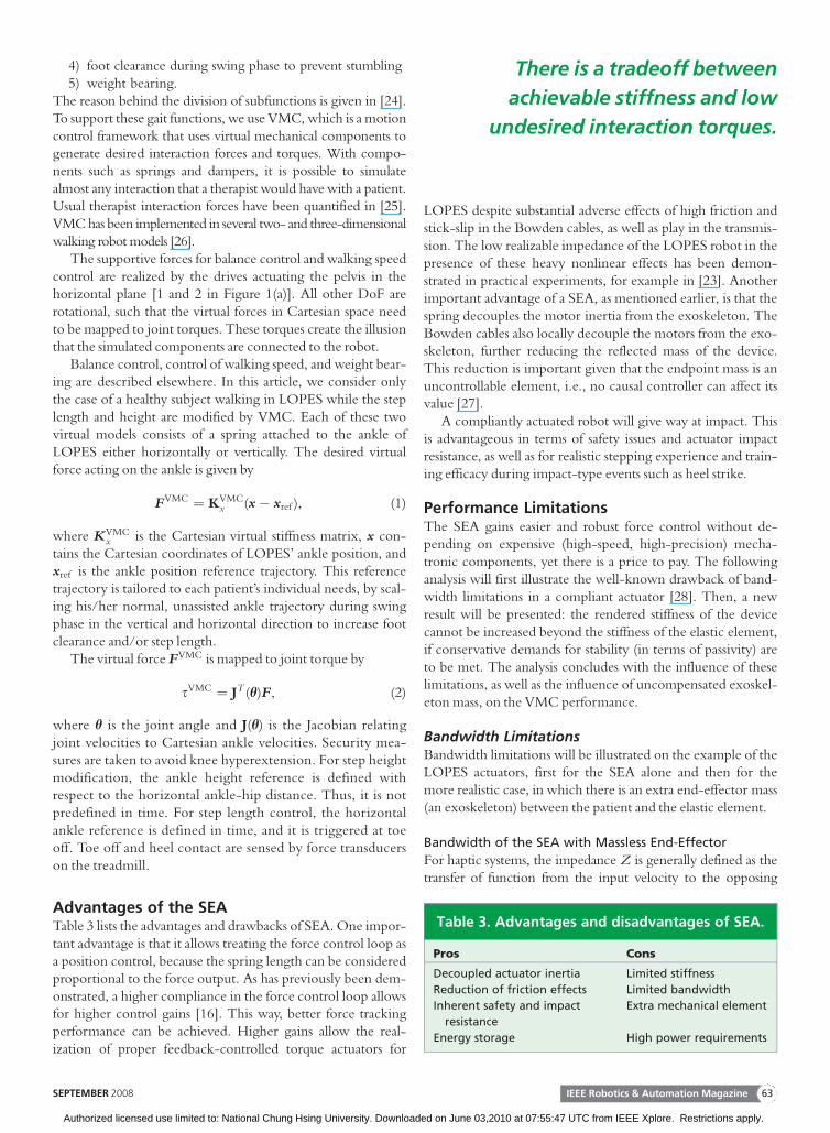
Advantages of the SEATable 3 lists the advantages and drawbacks of SEA. One impor-tant advantage is that it allows treating the force control loop asa position control, because the spring length can be consideredproportional to the force output. As has previously been dem-onstrated, a higher compliance in the force control loop allowsfor higher control gains [16]. This way, better force trackingperformance can be achieved. Higher gains allow the real-ization of proper feedback-controlled torque actuators for
LOPES despite substantial adverse effects of high friction andstick-slip in the Bowden cables, as well as play in the transmis-sion. The low realizable impedance of the LOPES robot in thepresence of these heavy nonlinear effects has been demon-strated in practical experiments, for example in [23]. Anotherimportant advantage of a SEA, as mentioned earlier, is that thespring decouples the motor inertia from the exoskeleton. TheBowden cables also locally decouple the motors from the exo-skeleton, further reducing the reflected mass of the device.This reduction is important given that the endpoint mass is anuncontrollable element, i.e., no causal controller can affect itsvalue [27].
A compliantly actuated robot will give way at impact. Thisis advantageous in terms of safety issues and actuator impactresistance, as well as for realistic stepping experience and train-ing efficacy during impact-type events such as heel strike.
Performance LimitationsThe SEA gains easier and robust force control without de-pending on expensive (high-speed, high-precision) mecha-tronic components, yet there is a price to pay. The followinganalysis will first illustrate the well-known drawback of band-width limitations in a compliant actuator [28]. Then, a newresult will be presented: the rendered stiffness of the devicecannot be increased beyond the stiffness of the elastic element,if conservative demands for stability (in terms of passivity) areto be met. The analysis concludes with the influence of theselimitations, as well as the influence of uncompensated exoskel-eton mass, on the VMC performance.
Bandwidth LimitationsBandwidth limitations will be illustrated on the example of theLOPES actuators, first for the SEA alone and then for themore realistic case, in which there is an extra end-effector mass(an exoskeleton) between the patient and the elastic element.
Bandwidth of the SEA with Massless End-Effector
For haptic systems, the impedance Z is generally defined as thetransfer of function from the input velocity to the opposing
Table 3. Advantages and disadvantages of SEA.
Pros Cons
Decoupled actuator inertia Limited stiffness
Reduction of friction effects Limited bandwidth
Inherent safety and impact
resistance
Extra mechanical element
Energy storage High power requirements
There is a tradeoff between
achievable stiffness and low
undesired interaction torques.
IEEE Robotics & Automation MagazineSEPTEMBER 2008 63
Authorized licensed use limited to: National Chung Hsing University. Downloaded on June 03,2010 at 07:55:47 UTC from IEEE Xplore. Restrictions apply.

torque. This definition is used here because it allows to assessstability in terms of passivity. Using the notation of II-B1, Z(s) is
Z(s) ¼ sL
�uLs: (3)
With the simplified model of Figure 2, which neglects frictionand elasticity of the Bowden cables, and with the parametersgiven in Figure 3, the impedance transfer function value is
Z(s) ¼ K( JAs4 þ Kis3 þ (KiKoP þ Ii)s2 þ aPsþ IiIoP)
( JAs4 þ Kis3 þ (KiKoK þ K þ Ii)s2 þ aKsþ IiIoK)s,
(4)
with a ¼ (IiKo þ IoKi).Replacing the complex variable s in (4) by jx, the fre-
quency response Z( jx) is obtained. A look at the asymptoticbehavior of Z( jx) is useful for an intuitive understanding ofthe SEA behavior; for frequencies below the bandwidth(x! 0), the programmed impedance can be achieved, whichis that of a virtual spring with stiffness P. For high frequencies(x!1), however, the impedance of the haptic display willapproach the impedance of the SEA’s mechanical spring withstiffness K .
The integrators show considerable influence only for lowfrequencies, and thus, the bandwidth analysis can be simplified
by considering only the case where both integrator gains arezero. This makes major effects more obvious, as it reduces (4) to
Zs(s) ¼ KJAs2 þ Kisþ KiKoP
( JAs2 þ Kisþ KiKoK þ K)s: (5)
The actually displayed stiffness value Kdisp deviates from thevalue of P if no integrators are employed:
Kdisp ¼ lims!0
s Zs(s) ¼PKoKi
1þ KoKi, (6)
and a desired stiffness must be mapped to a higher P.Figure 4(a) illustrates the bandwidth limitations; for low
frequencies, the desired impedance is successfully rendered,whereas for frequencies above the bandwidth, the systembehaves like the (stiffer) mechanical spring. For frequenciesin between, the behavior approaches a spring-damper, thedamping parameter of which depends only on the controlparameters (given in the figure legend). The intersection ofasymptotes of damper and rendered spring in Figure 4(a)shows that the bandwidth, i.e., the maximum frequency untilwhich rendering of the pure desired stiffness is possible, isbounded by x ¼ PKo. This implies that the control gain Ko
has a dominant influence on bandwidth. A high value of Ko
lowers the damping characteristics of the second-order low-pass in (5), and to counteract this, the motor velocity loopgain value Ki needs to be increased as well. Practical consider-ations such as motor saturation, however, put bounds on therealizable gains.
Influence of Exoskeleton Mass on Bandwidth
In a realistic rehabilitation robot, there will always be somemass between the actuator and the patient, generally connec-tion elements like an exoskeleton. The exoskeleton LOPES is
101 102 103−90
−45
−40
40
0
ω = PKo
Mag
nitu
de(d
B)
Pha
se(°
)
Frequency ω (rad/s)
(a)
10−1 100 101 102 103−90
−45
90
45
Frequency ω (rad/s)
−40
40
0
0
80ω = Kdisp / Je
(b)
102 103
−90
Frequency ω (rad/s)
−10
10
30
(c)
Pure Mass jωJe(Exoskeleton)
Damper Ki
KiKo + 1
PureSpring K
jω (of SEA)
DisplayedImpedance Z (jω)
DesiredImpedance
Kdjω
Figure 4. Bandwidth and stiffness limitations. (a) Bandwidth with massless end effector: At high frequencies, the displayedimpedance (black solid line) matches the intrinsic elasticity (green dotted line) of the SEA. The achievable bandwidth depends onthe torque control gain Ko. (b) With an additional mass at the load side of the SEA (e.g., an exoskeleton), further bandwidthlimitations are introduced. (c) Impedance control with too high desired stiffness (above the natural spring stiffness): The phase ofthe impedance frequency response has values below �90�, and thus the system is not passive.
The employed VMC, which attempts
to separately modify the selected
gait characteristics, proved to be
effective.
IEEE Robotics & Automation Magazine64 SEPTEMBER 2008
Authorized licensed use limited to: National Chung Hsing University. Downloaded on June 03,2010 at 07:55:47 UTC from IEEE Xplore. Restrictions apply.

constituted of several coupled segments, such that a multi-input multi-output (MIMO) system results. For schematicpurposes, i.e., to illustrate the general influence of this extramass on bandwidth, however, we will consider only the sim-plified case where a rigid body with inertia Je is introduced onthe load side of the SEA model of Figure 2, which could beinterpreted as a 1-DoF exoskeleton. This extra mass augmentsthe impedance transfer function (4) by the extra summand Jes.The system will no longer behave like a spring at high frequen-cies, and its behavior will then be dominated by the addedmass, as displayed in Figure 4(b). Depending on its value, suchan additional mass can also lower the bandwidth even further.Another upper bound for the bandwidth is indicated at theintersection of the asymptotes in Figure 4(b), with a value ofx ¼
ffiffiffiffiffiffiffiffiffiffiffiffiffiffiffiKdisp=Je
p.
Stiffness Limitations Due to Passivity ConcernsNow, passivity conditions for the impedance control of Figure3 will be investigated with similar methods as in [23], resultingin bounds for the control gains (with integrators).
Passivity is ensured if the impedance (3) is positive real.Necessary and sufficient conditions for this are as follows [27]:
u Z(s) must be stableu The real part of Z( jx) must be nonnegative for all x
for which jx is not a pole of Z(s).First, we look at the stability condition. As the system poles
are independent of the impedance parameters, stability dependsonly on the inner force control loop. Checking the Hurwitzdeterminants gives a necessary and sufficient condition:
KiKoI2i þ KKið1þ KoKiÞa� KJAa2 > 0: ð7Þ
For example, this can be achieved conservatively by fol-lowing the simple rules in [23], which is to select a velocityloop gain higher than the motor inertia, and constrainingboth integrator gains to half of the respective proportionalgain values.
For passivity, the real part of
Z( jx) ¼: A( jx)=B( jx) (8)
has to be nonnegative for all x 2 (�1,1) that are not rootsof the denominator. For nonzero denominator B, the real partof the complex fraction can be nonnegative only if
R(x) ¼ Re(A)Re(B)þ Im(A)Im(B) ¼X8
i¼1
dixi (9)
is nonnegative for all x 2 (�1,1). All coefficients di of thepolynomial in x are zero, except for
d6 ¼ K�(K2
i Ko � aJA)(K � P)þ KiK�,
d4 ¼ K�I2i Ko(K � P)� aKP
�:
The requirement that both coefficients have to be nonnegativebounds the achievable stiffness. With positive integrator gains,
the coefficient d4 is only nonnegative for
P � KI2i Ko
I2i Ko þ aK
< K : (10)
With zero integrator gains, (9) simplifies to
R(x) ¼ x6K(� K2i KoP þ K2
i KoK þ KiK) � 0: (11)
The controller gain P may thus exceed the value of K . How-ever, without integrators, the stiffness displayed at low fre-quencies deviates from the value of P, as given in (6), and theactually displayed stiffness Kdisp equals K for the maximumvalue of P allowed in (11). This implies that the SEA cannotdisplay a higher pure stiffness than the spring stiffness, if passiv-ity is desired.
It is important to note that the real part of the impedanceand thus passivity is independent of the presence of additionalend-effector mass Je, because this simply adds the imaginaryterm jxJe to the frequency response.
Figure 4(a) and (b) features a desired stiffness lower thanthe allowed value. The phase never leaves the range of þ90�
to �90�, which is equivalent to a positive real part, and thusthe system is passive. In contrast, Figure 4(c) illustrates thecase of an excessive desired stiffness; the phase falls below�90�. This implies that the haptic display is not passive, andthe coupled system will only be stable with a certain numberof environments, for example with a pure spring (a differen-tiator, which shifts the phase up). However, coupled to a puremass (an integrator), the open-loop frequency response willinvariably have a phase below �180� for all frequencies, andthus the closed-loop system is unstable.
Limitations for the VMCAs indicated in the preceding section, both the bandwidth andthe maximum value of the rendered stiffness are constrainedbecause of the compliant actuator. Further performance limi-tations originate from undesired interaction forces due to exo-skeleton dynamics. The influence of these effects on theachievable performance of the VMC will now be analyzed.
Performance Limitations Due to Limited Stiffness
To meet passivity requirements, the maximal joint stiffness thatcan be realized by joint-space impedance control is limited bythe spring stiffness of the series elastic element, as was shown inthe previous section. This results in boundaries for the maxi-mum displayed Cartesian stiffness, whereby the relationbetween the Cartesian stiffness matrix Kx and the joint stiffnessmatrix Kh is defined by the Jacobian [29]:
Kx ¼ J�TKh J�1: ð12Þ
The mapped Cartesian stiffness ellipse, with Kh as the identitymatrix and specifications given in Table 1, is displayed in Fig-ure 5. Its shape and orientation are determined by the eigen-values and vectors of Kx, whereby it can be seen that thesmallest eigenvalue depends on the knee angle.
IEEE Robotics & Automation MagazineSEPTEMBER 2008 65
Authorized licensed use limited to: National Chung Hsing University. Downloaded on June 03,2010 at 07:55:47 UTC from IEEE Xplore. Restrictions apply.

When the exoskeleton has 90� knee flexion, the smallesteigenvalue of Kx is 2.53, and it is 1.3 with 10� knee flexion.The worst case is when the knee is fully extended and when theCartesian stiffness ellipse is aligned with one of the virtual mod-els. In this worst case scenario, the Cartesian stiffness is only200 N/m given the maximal joint stiffness of the hip and kneeof 155 Nm/rad, as given in the ‘‘Mechanical Design’’ section.
Performance Limitations Due to Manipulator Dynamics
The VMC does not compensate for the open-loop impedanceof the exoskeleton. As a consequence, in free space, the humanoperator will always feel the full inertia and friction of themanipulator [30], and thus not only the virtual model.
The undesired additional interaction torque s in the swingphase given by the equation of motion of the exoskeleton:
s ¼ M(h)€hþ v(h, _h)þ g(h), (13)
where h is the vector of joint angles, M(h) is the mass matrix,v(h, _h) are Coriolis and centrifugal torques, and g(h) are gravi-tational torques. To give an idea of the inertia of the devicereflected at LOPES’s ankle, these unwanted torques can bemapped to forces in Cartesian space with ankle position x:
F ¼Mx(h)€xþ vx(h, _h)þ gx(h), (14)
whereby the relation between joint space and Cartesian spacematrices can be derived using the Jacobian [29].
To compensate the components vx(h, _hÞ and gx(h), theVMC could be modified, since as terms depend only on jointangles and velocities. However, in our application, we com-pensate neither of these forces. First, centrifugal and Coriolisforces in vx are negligibly small. Second, subjects walking withcompensated exoskeleton gravitational forces gx reported thatit felt unnatural, and compensating for gx with constant Mx
increases the natural frequency. (As stated before, Mx can notbe reduced by any causal controller.)
Especially at high frequencies, the behavior of the device isdominated by the reflected mass Mx of the exoskeleton. Withrespect to the ankle, this reflected mass is related to the jointspace mass matrix by
Mx ¼ J�TMJ�1: (15)
Using the specifications given in Table 1, this reflected mass isvisualized by the inertia ellipse of Figure 5. Its shape and orien-tation are determined by the eigenvalues and vectors of Mx.The orientation of the ellipse is always perpendicular to thelower segment of the exoskeleton, which means that thereflected mass is minimal in perpendicular direction and maxi-mal in the parallel direction of the most distal segment of theexoskeleton. The eigenvalues of Mx depend only on the kneeangle of the exoskeleton. The smallest eigenvalue remainsfairly constant around 0.95 kg. The largest eigenvalue is mini-mal (3.9 kg) when the knee is 90� flexed and increases whenthe knee is extended. Note that the reflected mass of the devicewould be much higher if the motors were not detached fromthe exoskeleton and if the motor mass was not decoupled fromthe device by the series elastic element.
Experimental ResultsThe remarkable capabilities of the SEA in terms of force track-ing and backdrivability (i.e., the inner control loop) have beenevaluated experimentally and are described in [23]. Thesepractical experiments also showed a very good agreementbetween the theoretically predicted and actually achieved forcetracking bandwidth, with a value of approximately 16 Hz. Theexperimental results presented in this article are limited to theperformance of the outer impedance control loop.
For the control of an individual joint of the exoskeletonalone (without human subject), the maximum achievable stiff-ness before undesired oscillations occurred is almost equal tothe spring stiffness (�10%, depending on gain variations in thetorque control loop), as predicted by the theoretical analysis.In contrast, the maximum achievable Cartesian stiffness inpractical experiments with healthy subjects walking under theinfluence of VMC resulted to be 1,500 N/m in vertical direc-tion (step height control) and 700 N/m in horizontal direction(step length control), which is considerably higher than thetheoretic worst-case bound. With the angle data from theexperiment and (12), the Cartesian stiffness in horizontaldirection should be limited to 200 Nm and in vertical directionto 355 Nm.
The reflected mass of the exoskeleton constrains theachievable bandwidth, as illustrated in the ‘‘Bandwidth Limita-tions’’ section for the SISO case. The limit is given by thesquare root of the desired stiffness of the virtual component
Initial Swing Mid Swing Terminal Swing
Ankle
Hipy
x
−θh
−θk
0.5
0.5
0.5
1
1.5
−100−100−100−100 −50−50−50 −50 0000
100
50
0.948
0.952
Inertia Ellipse Stiffness Ellipse
λ 1 (
kg)
λ 2 (
kg)
λ 1 (
kN/m
)
λ 2 (
kN/m
)
1.5
1
2
00
θk (°)θk (°)θk (°)θk (°)
Figure 5. Reflected mass and stiffness at the ankle: The mass (red and dashed) and stiffness (green and solid) ellipses that reflectthe inertia of the exoskeleton and hip and knee joint stiffnesses of 1 Nm/rad at the ankle for different kinematic configurations.The principal axes of the stiffness ellipses are the inverse of the Cartesian stiffness matrix eigenvalues k1 and k2; the axes of theinertia ellipses are the inverse of the square root of the respective eigenvalues. Thus, the larger the ellipses, the less mass orstiffness is reflected.
IEEE Robotics & Automation Magazine66 SEPTEMBER 2008
Authorized licensed use limited to: National Chung Hsing University. Downloaded on June 03,2010 at 07:55:47 UTC from IEEE Xplore. Restrictions apply.

divided by the reflected exoskeleton mass. Below thisfrequency, the virtual spring is felt, whereas above, thereflected device mass is felt. In the case where the reflectedmass is minimal (0.95 kg), this frequency is 4.3 and 6.3 Hz forthe stiffnesses of 700 and 1,500 N/m, respectively. For adesired stiffness of 700 N/m and using a worst-case approach,it reduces to 2.14, 1.93, 1.21, and 0.44 Hz for 90�, 60�, 30�,and 10� knee flexion, respectively.
Despite these heavy bandwidth limitations, the combina-tion of the mechanical designs of LOPES and VMC was wellable to modify the step height and step length of healthy sub-jects [20]. Each of the two parameters could be lengthenedor shortened by VMC, simply by scaling the reference path.The change in each specific gait parameter left the otherparts of the gait cycle almost unaffected, and the modifica-tion was not perceived awkward until it got excessively large.In experiments with varying stiffness, we found that the sub-jects perceived stiffer controllers as less comfortable; theypreferred more compliant virtual springs. Adjustment of thereference parameters beyond the desired value in combina-tion with a softer controller (equivalent to additional feed-forward torques, which is not unique to VMC) also achievedthe desired modification and was perceived as morecomfortable than a stiff control. The selective modificationof average ankle trajectories is shown in Figure 6 for themaximum stiffness. However, the figure also shows that thestep length was not exactly modified by the desired 20% dueto the compliant interface. The experiments are described indetail in [31].
DiscussionA comparison of the theoretical predictions and the experi-mental outcome shows good agreement for joint-spaceimpedance control without human subject, but it also showsthat the Cartesian stiffness used in the VMC can be higherthan the theoretically derived worst-case bound. The factthat this higher stiffness is rendered without stability prob-lems can be explained by several factors. First, the worst casein terms of kinematic configuration hardly occurred in thepractical experiments, or at least, the system never remainedin this state for long, such that the instable effects might havebeen transient. Second, passivity is a conservative means ofensuring stability of coupled systems, and a less conservative,explicit MIMO stability analysis could replace it (requiringthe exoskeleton, the patient’s impedance, the compliantcoupling between human and exoskeleton, and the environ-ment to be modeled reliably, which is difficult). Nevertheless,without a human subject, the theoretical and practical resultscoincided well. Therefore, a probable reason is that thehealthy subjects did not behave like pure masses, the worstenvironment discussed in the section ‘‘Stiffness LimitationsDue to Passivity Concerns,’’ but formed stabilizing elementsin the control loop. This positive contribution might stemfrom intrinsic and neuronally coordinated stiffness and damp-ing, and it is for example exploited for the control of BLEEX[32]. Although it seemed possible to render higher stiffnessfor healthy subjects than theoretically derived, we decided
not to rely on this effect when working with patients. Instead,we increased the stiffness of the SEA by a factor of 2.5.Equipped with these stiffer springs, LOPES can operate withsufficiently stiff VMC and still remain within the conservativelimits resulting from the passivity analysis. Generally, there isa tradeoff between achievable stiffness on the one hand andlow undesired interaction torques on the other. One possibil-ity would be to use an adaptive compliance, as suggested by[33], to meet the individual patient’s needs.
ConclusionThis article discusses the pros and cons of compliant actuationfor rehabilitation robots on the example of LOPES, focusingon the cons. After illustrating the bandwidth limitations, anew result has been derived: if stability in terms of passivity ofthe haptic device is desired, the renderable stiffness is boundedby the stiffness of the SEA’s elastic component.
In practical experiments with the VMC, the aforemen-tioned limitations affected the control performance. Desiredgait modifications were not tracked exactly, because thesubjects were able to deviate from the prescribed patterneven in the stiffest possible configuration. Despite the limi-tations, the practical experiments also demonstrated thegeneral effectiveness of the realization. Manipulation ofselected gait parameters is possible, whereby other parame-ters are left unaffected. This high selectivity is made possibleby the low level of undesired interaction torques, which is
(a)
0.8 1 1.2 1.4 1.6
00.10.20.3
Forward/Backward Position
Ver
tical
Pos
ition
ReferenceAnkle Path
(b)
#hu#hd#no
Step Length +20%Step Length –20%Normal
0.5 1
00.10.20.3
Forward Position
Ver
tical
Pos
ition
ReferenceAnkle Path
Figure 6. Modification of the (a) step height and (b) length.The normal ankle trajectories are scaled to obtain areference trajectory for the ankle. With a virtual springattached at the ankle, the differences between the true anddesired ankle position are mapped to a (a) vertical or (b)horizontal virtual force at the ankle. Typical example of asubject’s modified ankle trajectories (a) for the case that themaximal foot clearance is increased to 17 or 22 cm, and (b)for the case that the step length is increased or decreasedby 20%.
IEEE Robotics & Automation MagazineSEPTEMBER 2008 67
Authorized licensed use limited to: National Chung Hsing University. Downloaded on June 03,2010 at 07:55:47 UTC from IEEE Xplore. Restrictions apply.

achieved by elastic decoupling of motor mass and a light-weight exoskeleton.
The discrepancy between theoretical bounds and renderedstiffness indicated that healthy subjects might represent a stabi-lizing component of the coupled system, which could be dif-ferent for patients. In light of the theoretical stability analysisand with the focus on patients, the LOPES actuation wasslightly modified. The robot was equipped with stiffer springsto obtain sufficient stiffness and to ensure stability withoutrelying on stabilizing effects of the human.
For this application, the disadvantages of compliantactuation can thus be tolerated or dealt with, and they aresmall compared with the advantages. Given that a rehabilita-tion robot, in the first place, is supposed to imitate therapistaction, the limitations of bandwidth and stiffness do notpose severe problems. In contrast, safety and backdrivabilityare highly relevant, and they can be ensured easier with acompliant actuator. Therefore, we conclude that compliantactuation and a lightweight exoskeleton provide effectivemeans to accomplish the desired AAN behavior of a rehabil-itation robot. The next step is to evaluate the robot behav-ior, control performance, and therapeutic effectiveness inpatient studies.
AcknowledgmentsH. Vallery was supported by the Studienstiftung des DeutschenVolkes. All authors from the University of Twente were sup-ported by the Netherlands Organisation for Scientific research(Vernieuwings-impuls 2001, 22016027011, granted to Dr. H.van der Kooij) and by the Institute for Biomedical Technology.
Keywords
Series elastic actuators, gait training, passivity-based control,stroke, compliance, rehabilitation robots.
References[1] G. Kwakkel, R. C. Wagenaar, T. W. Koelman, G. J. Lankhorst, and
J. C. Koetsier, ‘‘Effects of intensity of rehabilitation after stroke. Aresearch synthesis,’’ Stroke, vol. 28, no. 8, pp. 1550–1556, 1997.
[2] R. Teasell, J. Bitensky, K. Salter, and N. A. Bayona, ‘‘The role of timingand intensity of rehabilitation therapies,’’ Top. Stroke Rehabil., vol. 12,no. 3, pp. 46–57, 2005.
[3] B. Husemann, F. Muller, C. Krewer, S. Heller, and E. Koenig, ‘‘Effects oflocomotion training with assistance of a robot-driven gait orthosis in hemi-paretic patients after stroke: A randomized controlled pilot study,’’ Stroke,vol. 38, no. 2, pp. 349–354, 2007.
[4] M. Pohl, C. Werner, M. Holzgraefe, G. Kroczek, J. Mehrholz, I. Wing-endorf, G. Hoolig, R. Koch, and S. Hesse, ‘‘Repetitive locomotortraining and physiotherapy improve walking and basic activities of dailyliving after stroke: A single-blind, randomized multicentre trial(DEutsche GAngtrainerStudie, DEGAS),’’ Clin. Rehabil., vol. 21,pp. 17–27, 2007.
[5] L. L. Cai, A. J. Fong, C. K. Otoshi, Y. Liang, J. W. Burdick, R. R.Roy, and V. R. Edgerton, ‘‘Implications of assist-as-needed roboticstep training after a complete spinal cord injury on intrinsic strategiesof motor learning,’’ J. Neurosci., vol. 26, no. 41, pp. 10564–10568,2006.
[6] M. Ferraro, J. J. Palazzolo, J. Krol, H. I. Krebs, N. Hogan, and B. T.Volpe, ‘‘Robot-aided sensorimotor arm training improves outcome in
patients with chronic stroke,’’ Neurology, vol. 61, no. 11, pp. 1604–1607,2003.
[7] N. Hogan, H. I. Krebs, B. Rohrer, J. J. Palazzolo, L. Dipietro, S. E.Fasoli, J. Stein, R. Hughes, W. R. Frontera, D. Lynch, and B. T. Volpe,‘‘Motions or muscles? Some behavioral factors underlying robotic assis-tance of motor recovery’’ J. Rehabil. Res. Dev., vol. 43, no. 5, pp. 605–
618, 2006.[8] D. Aoyagi, W. E. Ichinose, S. J. Harkema, D. J. Reinkensmeyer, and J.
E. Bobrow, ‘‘A robot and control algorithm that can synchronously assistin naturalistic motion during body-weight-supported gait training fol-lowing neurologic injury,’’ IEEE Trans. Neural Syst. Rehab. Eng., vol. 15,no. 3, pp. 387–400, 2007.
[9] J. F. Veneman, R. Ekkelenkamp, R. Kruidhof, F. C. T. van der Helm,and H. van der Kooij, ‘‘A series elastic- and Bowden-cable-based actua-tion system for use as torque actuator in exoskeleton-type robots,’’ Int. J.Robot. Res., vol. 25, no. 3, pp. 261–281, 2006.
[10] J. F. Veneman, R. Kruidhof, E. E. G. Hekman, R. Ekkelenkamp, E.H. F. Van Asseldonk, and H. Van der Kooij, ‘‘Design and evaluation ofthe LOPES exoskeleton robot for interactive gait rehabilitation,’’ IEEETrans. Neural. Syst. Rehabil. Eng., vol. 15, no. 3, pp. 379–386, 2007.
[11] G. Colombo, M. Joerg, R. Schreier, and V. Dietz, ‘‘Treadmill trainingof paraplegic patients using a robotic orthosis,’’ J. Rehabil. Res. Dev.,vol. 37, no. 6, pp. 693–700, 2000.
[12] J. F. Israel, D. D. Campbell, J. H. Kahn, and T. G. Hornby, ‘‘Metaboliccosts and muscle activity patterns during robotic- and therapist-assistedtreadmill walking in individuals with incomplete spinal cord injury,’’Phys. Ther., vol. 86, no. 11, pp. 1466–1478, 2006.
[13] D. J. Reinkensmeyer, D. Aoyagi, J. L. Emken, J. A. Galvez, W.Ichinose, G. Kerdanyan, S. Maneekobkunwong, K. Minakata, J. A.Nessler, R. Weber, R. R. Roy, R. de Leon, J. E. Bobrow, S. J. Har-kema, and V. R. Edgerton, ‘‘Tools for understanding and optimizingrobotic gait training,’’ J. Rehabil. Res. Dev., vol. 43, no. 5, pp. 657–
670, 2006.[14] S. K. Banala, S. K. Agrawal, and J. P. Scholz, ‘‘Active leg exoskeleton
(ALEX) for gait rehabilitation of motor-impaired patients,’’ in Proc.IEEE ICORR 2007, pp. 401–407.
[15] M. Peshkin, D. A. Brown, J. J. Santos-Munn�e, A. Makhlin, E. Lewis,J. E. Colgate, J. Patton, and D. Schwandt, ‘‘KineAssist: A robotic over-ground gait and balance training device,’’ in Proc. IEEE ICORR 2005,Chicago, pp. 241–246.
[16] D. W. Robinson, ‘‘Design and analysis of series elasticity in closed-loopactuator force control,’’ Ph.D. thesis, Dept. Mech. Eng., MIT, Cam-bridge, MA, 2000.
[17] H. Vallery and M. Buss, ‘‘Bewegungsintentionssch€atzung auf Basis vonGelenkkoordination,’’ at-Automatisierungstechnik, vol. 55, no. 10,pp. 503–510, 2007.
[18] H. Vallery, R. Ekkelenkamp, H. van der Kooij, and M. Buss,‘‘Complementary limb motion estimation based on interjoint coordina-tion: experimental evaluation,’’ in Proc. IEEE ICORR 2007, pp. 798–
803.[19] R. Ekkelenkamp, J. Veneman, and H. van der Kooij, ‘‘LOPES: Selec-
tive control of gait functions during the gait rehabilitation of CVApatients,’’ in Proc. IEEE ICORR 2005, pp. 361–364.
[20] E. H. F. Van Asseldonk, R. Ekkelenkamp, J. F. Veneman, F. C. T. vander Helm, and H. van der Kooij, ‘‘Selective control of a subtask ofwalking in a robotic gait trainer(LOPES),’’ in Proc. IEEE ICORR 2007,pp. 841–848.
[21] G. Wyeth, ‘‘Control issues for velocity sourced series elastic actuators,’’in Proc. Australasian Conf. Robotics and Automation, 2006.
[22] G. A. Pratt, P. Willisson, C. Bolton, and A. Hofman, ‘‘Late motorprocessing in low-impedance robots: Impedance control of series-elasticactuators,’’ in Proc. 2004 ACC, pp. 3245–3251.
[23] H. Vallery, R. Ekkelenkamp, H. van der Kooij, and M. Buss, ‘‘Passiveand accurate torque control of series elastic actuators,’’ in Proc. IEEEIROS 2007, San Diego, CA, pp. 3534–3538.
[24] H. van der Kooij, R. Jacobs, B. Koopman, and F. van der Helm, ‘‘Analternative approach to synthesizing bipedal walking,’’ Biol. Cybern.,vol. 88, no. 1, pp. 46–59, 2003.
IEEE Robotics & Automation Magazine68 SEPTEMBER 2008
Authorized licensed use limited to: National Chung Hsing University. Downloaded on June 03,2010 at 07:55:47 UTC from IEEE Xplore. Restrictions apply.
[25] J. A. Galvez, G. Kerdanyan, S. Maneekobkunwong, R. Weber, M.Scott, S. J. Harkema, and D. J. Reinkensmeyer, ‘‘Measuring humantrainers’ skill for the design of better robot control algorithms for gaittraining after spinal cord injury,’’ in Proc. IEEE ICORR 2005, pp. 231–
234.[26] J. E. Pratt, C. M. Chew, A. Torres, P. Dilworth, and G. Pratt, ‘‘An
intuitive approach for bipedal locomotion,’’ Int. J. Robot. Res., vol. 20,no. 2, pp. 129–143, 2001.
[27] J. E. Colgate, ‘‘The control of dynamically interacting systems,’’ Ph.D.thesis, Dept. Mech. Eng., MIT, Cambridge, MA, 1988.
[28] S. D. Eppinger and W. P. Seering, ‘‘Understanding bandwidth limita-tions in robot force control,’’ in Proc. ICRA 1987, pp. 904–909.
[29] J. J. Craig, Introduction to Robototics: Mechanics and Control, 2nd ed.Reading, MA: Addison-Wesley, 1989.
[30] R. W. Adams and B. Hannaford, ‘‘Control Law Design for HapticInterfaces to Virtual Reality,’’ IEEE Trans. Contr. Syst. Technol., vol. 10,no. 1, pp. 3–13, 2002.
[31] R. Ekkelenkamp, E.H.F. van Asseldonk, B. Koopman, P. H. Veltink,S. Stramigioli, and H. van der Kooij, ‘‘Swing phase adaptation duringwalking by virtual model control of a powered exoskeleton,’’ submittedfor publication.
[32] H. Kazerooni, Jean-Louis Racine, Lihua Huang, and Ryan Steger,‘‘On the control of the berkeley lower extremity exoskeleton (BLEEX),’’in Proc. IEEE ICRA 2005, pp. 4364–4371.
[33] K. W. Hollander, T. G. Sugar, and D. E. Herring, ‘‘Adjustable robotictendon using a ‘Jack Spring’,’’ in Proc. IEEE ICORR 2005, pp. 113–
118.
Heike Vallery received her diploma (with honors) inmechanical engineering from RWTH Aachen University inGermany in 2004. She is about to finish her Ph.D. degree atthe Institute of Automatic Control Engineering at the Tech-nische Universit€at M€unchen, Germany, where she workedon patient-cooperative control strategies for rehabilitationrobots. In May 2008, she joined the Sensory-Motor SystemsLaboratory at the ETH Z€urich, Switzerland. Her researchinterests include haptics, human motor control, and robotics.She is a Student Member of the IEEE.
Jan Veneman received M.Sc. degrees in mechanical engi-neering and philosophy of science, technology and societyin 1998 and 2001, respectively, and the Ph.D. degree in bio-mechanical engineering in 2007, all from the University ofTwente, Enschede, The Netherlands. His research projectwas on the design and evaluation of a prototype gait rehabil-itation robot. His principal research interests are haptics,man–machine interaction, and robotics.
Edwin van Asseldonk received his M.Sc. degree(honors) in human movement sciences from the FreeUniversity, Amsterdam, The Netherlands and his Ph.D.degree in biomechanical engineering from the Universityof Twente in 2008. Currently, he is an assistant professorat the University of Twente. His field of research includesbalance control, motor control in stroke patients and re-habilitation robotics.
Ralf Ekkelenkamp received his M.Sc. degree in electricalengineering at the University of Twente in 2003. From2003 until 2007, he was working as a Ph.D. candidate onthe advanced control of a gait rehabilitation robot, also at
the University of Twente. Currently, he is a design engineerat Sensata Technologies.
Martin Buss received the diploma engineer degree inelectrical engineering in 1990 from the Technical Univer-sity Darmstadt, Germany, and the doctor of engineeringdegree in electrical engineering from the University ofTokyo, Japan, in 1994. In 2000, he finished his habilitationin the Department of Electrical Engineering and Informa-tion Technology, Technische Universit€at M€unchen, Ger-many. In 1988, he was a research student at the ScienceUniversity of Tokyo, Japan, for one year. As a postdoctoralresearcher, he worked at the Department of Systems Engi-neering, Australian National University, Canberra, Aus-tralia, in 1994–1995. From 1995 to 2000, he has beensenior research assistant and lecturer at the Institute ofAutomatic Control Engineering, Department of ElectricalEngineering and Information Technology, Technische Uni-versit€at M€unchen, Germany. He has been appointed fullprofessor, head of the control systems group, and deputydirector of the Institute of Energy and AutomationTechnology, Faculty IV—Electrical Engineering andComputer Science, Technical University Berlin, Germany,from 2000–2003. Since 2003, he has been full professor(chair) at the Institute of Automatic Control Engineering,Technische Universit€at M€unchen, Germany. Since 2006,he has been the coordinator of the DFG ExcellenceResearch Cluster Cognition for Technical Systems—CoTeSys. His research interests include automatic control,mechatronics, multimodal human–system interfaces, opti-mization, nonlinear, and hybrid discrete-continuous sys-tems. He is a Member of the IEEE.
Herman van der Kooij received his Ph.D. degree withhonors (cum laude) in 2000 and is an associate professor at theDepartment of Biomechanical Engineering at the Universityof Twente (0.8 fte), and Delft University of Technology(0.2 fte), The Netherlands. His expertise and interests are inthe field of human motor control, adaptation, and learning,rehabilitation robots, diagnostic robotics, virtual reality, reha-bilitation medicine, and neurocomputational modeling. He isa Member of the IEEE Engineering in Medicine and BiologySociety Technical Committee of Biorobots and was a memberof several scientific program committees in the field of rehabil-itation robotics, biorobotics, and assistive devices. He is thefounder and head of the Rehabilitation Robotics Laboratory,at the University of Twente, which developed powered exo-skeletons for the rehabilitation of upper and lower extremities.He is also the founder and head of the Virtual Reality HumanPerformance Lab that combines robotic devices, motion cap-turing, and virtual environments to assess and train human bal-ance, walking, and hand–eye coordination. He is a recipientof the VIDI award.
Address for Correspondence: Heike Vallery, Sensory Motor Sys-tems Lab, ETH Z€urich, 8008 Z€urich, Switzerland. E-mail:[email protected].
IEEE Robotics & Automation MagazineSEPTEMBER 2008 69
Authorized licensed use limited to: National Chung Hsing University. Downloaded on June 03,2010 at 07:55:47 UTC from IEEE Xplore. Restrictions apply.