
iMOLSDOCK : induced-fit docking using mutually orthogonal ...
Upload
khangminh22Category
view
0download
0
SDM-E2 Docking StationPC Controlled Configuration
Operator’s Manual
Part Number: 71-0251RK
Revision: K
Released: 4/13/20
www.rkiins truments .com

Warranty
RKI Instruments, Inc. warrants gas alarm equipment sold by us to be free from defects in materials and workmanship, and performance for a period of one year from date of shipment from RKI Instruments, Inc. Any parts found defective within that period will be repaired or replaced, at our option, free of charge. This warranty does not apply to those items which by their nature are subject to deterioration or consumption in normal service, and which must be cleaned, repaired, or replaced on a routine basis. Examples of such items are:
Warranty is voided by abuse including mechanical damage, alteration, rough handling, or repairs procedures not in accordance with the instruction manual. This warranty indicates the full extent of our liability, and we are not responsible for removal or replacement costs, local repair costs, transportation costs, or contingent expenses incurred without our prior approval.
THIS WARRANTY IS EXPRESSLY IN LIEU OF ANY AND ALL OTHER WARRANTIES AND REPRESENTATIONS, EXPRESSED OR IMPLIED, AND ALL OTHER OBLIGATIONS OR LIABILITIES ON THE PART OF RKI INSTRUMENTS, INC. INCLUDING BUT NOT LIMITED TO THE WARRANTY OF MERCHANTABILITY OR FITNESS FOR A PARTICULAR PURPOSE. IN NO EVENT SHALL RKI INSTRUMENTS, INC. BE LIABLE FOR INDIRECT, INCIDENTAL, OR CONSEQUENTIAL LOSS OR DAMAGE OF ANY KIND CONNECTED WITH THE USE OF ITS PRODUCTS OR FAILURE OF ITS PRODUCTS TO FUNCTION OR OPERATE PROPERLY.
This warranty covers instruments and parts sold to users only by authorized distributors, dealers, and representatives as appointed by RKI Instruments, Inc.
We do not assume indemnification for any accident or damage caused by the operation of this gas monitor and our warranty is limited to replacement of parts or our complete goods.
Absorbent cartridges Batteries
Pump diaphragms and valves Filter elements
Fuses

Table of Contents
Chapter 1: Introduction . . . . . . . . . . . . . . . . . . . . . . . . . . . . . . . . . . . . . . . . . . . . . . . . . . . . . . . . 6
Overview. . . . . . . . . . . . . . . . . . . . . . . . . . . . . . . . . . . . . . . . . . . . . . . . . . . . . . . . . . . . . . . 6
System Requirements . . . . . . . . . . . . . . . . . . . . . . . . . . . . . . . . . . . . . . . . . . . . . . . . . . . . . 7
Specifications . . . . . . . . . . . . . . . . . . . . . . . . . . . . . . . . . . . . . . . . . . . . . . . . . . . . . . . . . . . 8
About This Manual . . . . . . . . . . . . . . . . . . . . . . . . . . . . . . . . . . . . . . . . . . . . . . . . . . . . . . . 9
Cautions & Safety Information. . . . . . . . . . . . . . . . . . . . . . . . . . . . . . . . . . . . . . . . . . . . . . 9
Chapter 2: Description . . . . . . . . . . . . . . . . . . . . . . . . . . . . . . . . . . . . . . . . . . . . . . . . . . . . . . . . 10
Overview. . . . . . . . . . . . . . . . . . . . . . . . . . . . . . . . . . . . . . . . . . . . . . . . . . . . . . . . . . . . . . 10
AC Adapter . . . . . . . . . . . . . . . . . . . . . . . . . . . . . . . . . . . . . . . . . . . . . . . . . . . . . . . . . . . . 10
Single-Port AC Adapter . . . . . . . . . . . . . . . . . . . . . . . . . . . . . . . . . . . . . . . . . . . .10
3-Port AC Adapter . . . . . . . . . . . . . . . . . . . . . . . . . . . . . . . . . . . . . . . . . . . . . . . .10
USB Cable . . . . . . . . . . . . . . . . . . . . . . . . . . . . . . . . . . . . . . . . . . . . . . . . . . . . . . . . . . . . 11
Air Filter, Sample Tubing, and Check Valve . . . . . . . . . . . . . . . . . . . . . . . . . . . . . . . . . . 11
Instrument Panel . . . . . . . . . . . . . . . . . . . . . . . . . . . . . . . . . . . . . . . . . . . . . . . . . . . . . . . . 12
Back Panel . . . . . . . . . . . . . . . . . . . . . . . . . . . . . . . . . . . . . . . . . . . . . . . . . . . . . . . . . . . . 13
Power Jack . . . . . . . . . . . . . . . . . . . . . . . . . . . . . . . . . . . . . . . . . . . . . . . . . . . . . .14
Sample Fittings . . . . . . . . . . . . . . . . . . . . . . . . . . . . . . . . . . . . . . . . . . . . . . . . . . .14
PC Connection . . . . . . . . . . . . . . . . . . . . . . . . . . . . . . . . . . . . . . . . . . . . . . . . . . .14
Control Panel . . . . . . . . . . . . . . . . . . . . . . . . . . . . . . . . . . . . . . . . . . . . . . . . . . . . . . . . . . 14
Front Panel . . . . . . . . . . . . . . . . . . . . . . . . . . . . . . . . . . . . . . . . . . . . . . . . . . . . . . . . . . . . 15
USB Hub Requirements for Multiple-Station Systems . . . . . . . . . . . . . . . . . . . . . . . . . . 16
Chapter 3: Mechanical Setup . . . . . . . . . . . . . . . . . . . . . . . . . . . . . . . . . . . . . . . . . . . . . . . . . . 16
Hardware Assembly . . . . . . . . . . . . . . . . . . . . . . . . . . . . . . . . . . . . . . . . . . . . . . . . . . . . . 16
Assembling a Manifold for Multiple SDM-E2 Units . . . . . . . . . . . . . . . . . . . . . . . . . . . . 18
Exhaust Tubing . . . . . . . . . . . . . . . . . . . . . . . . . . . . . . . . . . . . . . . . . . . . . . . . . . .18
GAS 1 Tubing . . . . . . . . . . . . . . . . . . . . . . . . . . . . . . . . . . . . . . . . . . . . . . . . . . . .20
GAS 2 Tubing . . . . . . . . . . . . . . . . . . . . . . . . . . . . . . . . . . . . . . . . . . . . . . . . . . . .20
Connecting Calibration Gas . . . . . . . . . . . . . . . . . . . . . . . . . . . . . . . . . . . . . . . . . . . . . . . 24
EAGLE 2 and GX Type Instrument Connection . . . . . . . . . . . . . . . . . . . . . . . . . . . . . . . 26
Chapter 4: Computer Setup. . . . . . . . . . . . . . . . . . . . . . . . . . . . . . . . . . . . . . . . . . . . . . . . . . . . 27
Installing the SDM-E2 Docking Station PC Controller Program. . . . . . . . . . . . . . . . . . . 26
Launching the PC Program. . . . . . . . . . . . . . . . . . . . . . . . . . . . . . . . . . . . . . . . . . . . . . . . 32
Setting Parameters in the Configuration Window . . . . . . . . . . . . . . . . . . . . . . . . . . . . . . 33
Setting Up the SDM-E2 Display Order . . . . . . . . . . . . . . . . . . . . . . . . . . . . . . . . . . . . . . 41

Cylinders Window . . . . . . . . . . . . . . . . . . . . . . . . . . . . . . . . . . . . . . . . . . . . . . . . . . . . . . 43
Selecting a Cylinder from the Pre-Defined List . . . . . . . . . . . . . . . . . . . . . . . . . .44
Defining New Cylinders . . . . . . . . . . . . . . . . . . . . . . . . . . . . . . . . . . . . . . . . . . . .45
Chapter 5: Operation . . . . . . . . . . . . . . . . . . . . . . . . . . . . . . . . . . . . . . . . . . . . . . . . . . . . . . . . . 47
Connecting Instruments to the PC Controller Program . . . . . . . . . . . . . . . . . . . . . . . . . . 47
Icon View vs. Details View. . . . . . . . . . . . . . . . . . . . . . . . . . . . . . . . . . . . . . . . . . . . . . . . 52
Printing and Exporting an Instrument List from the Main Program Window . . . . . . . . . 53
Instrument Placement for Bump Testing and Calibration. . . . . . . . . . . . . . . . . . . . . . . . . 54
Automatic Bump Testing and Calibration . . . . . . . . . . . . . . . . . . . . . . . . . . . . . . . . . . . . 56
Bump Testing a Standard 4-Gas Instrument . . . . . . . . . . . . . . . . . . . . . . . . . . . . . . . . . . . 57
Calibrating a Standard 4-Gas Instrument . . . . . . . . . . . . . . . . . . . . . . . . . . . . . . . . . . . . . 68
Bump Testing an Instrument with Special Sensors. . . . . . . . . . . . . . . . . . . . . . . . . . . . . . 78
Calibrating and Instrument with Special Sensors . . . . . . . . . . . . . . . . . . . . . . . . . . . . . . . 94
Power Off Function. . . . . . . . . . . . . . . . . . . . . . . . . . . . . . . . . . . . . . . . . . . . . . . . . . . . . 108
Chapter 6: Maintenance. . . . . . . . . . . . . . . . . . . . . . . . . . . . . . . . . . . . . . . . . . . . . . . . . . . . . . 109
Troubleshooting . . . . . . . . . . . . . . . . . . . . . . . . . . . . . . . . . . . . . . . . . . . . . . . . . . . . . . . 109
Charging an Instrument in an SDM-E2 . . . . . . . . . . . . . . . . . . . . . . . . . . . . . . . . . . . . . 111
Recharging a Battery Pack After Performing a Bump Test or Calibration . . . . 111
Recharging a Battery Pack Without Performing any Operations. . . . . . . . . . . . 112
Batteries Too Drained for PC Controller Operation . . . . . . . . . . . . . . . . . . . . . 113
Chapter 7: Managing Log Data. . . . . . . . . . . . . . . . . . . . . . . . . . . . . . . . . . . . . . . . . . . . . . . . 114
Download Function. . . . . . . . . . . . . . . . . . . . . . . . . . . . . . . . . . . . . . . . . . . . . . . . . . . . . 114
Clear Logs Function . . . . . . . . . . . . . . . . . . . . . . . . . . . . . . . . . . . . . . . . . . . . . . . . . . . . 114
Alarm Trend Data . . . . . . . . . . . . . . . . . . . . . . . . . . . . . . . . . . . . . . . . . . . . . . . . . . . . . . 118
Calibration Data . . . . . . . . . . . . . . . . . . . . . . . . . . . . . . . . . . . . . . . . . . . . . . . . . . . . . . . 126
Event Data. . . . . . . . . . . . . . . . . . . . . . . . . . . . . . . . . . . . . . . . . . . . . . . . . . . . . . . . . . . . 130
Interval Trend Data . . . . . . . . . . . . . . . . . . . . . . . . . . . . . . . . . . . . . . . . . . . . . . . . . . . . . 132
Memo Data . . . . . . . . . . . . . . . . . . . . . . . . . . . . . . . . . . . . . . . . . . . . . . . . . . . . . . . . . . . 141
Bump Test Data. . . . . . . . . . . . . . . . . . . . . . . . . . . . . . . . . . . . . . . . . . . . . . . . . . . . . . . . 143
Deleting Data in the Logs Window. . . . . . . . . . . . . . . . . . . . . . . . . . . . . . . . . . . . . . . . . 147
Chapter 8: Viewing and Editing EAGLE 2 Parameters . . . . . . . . . . . . . . . . . . . . . . . . . . . . 148
Open Function. . . . . . . . . . . . . . . . . . . . . . . . . . . . . . . . . . . . . . . . . . . . . . . . . . . . . . . . . 148
Edit Function. . . . . . . . . . . . . . . . . . . . . . . . . . . . . . . . . . . . . . . . . . . . . . . . . . . . . . . . . . 149
Parameter Tab . . . . . . . . . . . . . . . . . . . . . . . . . . . . . . . . . . . . . . . . . . . . . . . . . . . . . . . . . 149
Sensor Tab. . . . . . . . . . . . . . . . . . . . . . . . . . . . . . . . . . . . . . . . . . . . . . . . . . . . . . . . . . . . 156
Station & User Tab . . . . . . . . . . . . . . . . . . . . . . . . . . . . . . . . . . . . . . . . . . . . . . . . . . . . . 158

Conversion Table Tab . . . . . . . . . . . . . . . . . . . . . . . . . . . . . . . . . . . . . . . . . . . . . . . . . . . 163
PID Sensor Tab . . . . . . . . . . . . . . . . . . . . . . . . . . . . . . . . . . . . . . . . . . . . . . . . . . . . . . . . 167
Channel Gas Tab . . . . . . . . . . . . . . . . . . . . . . . . . . . . . . . . . . . . . . . . . . . . . . . . . . . . . . . 173
Gas Name Tab. . . . . . . . . . . . . . . . . . . . . . . . . . . . . . . . . . . . . . . . . . . . . . . . . . . . . . . . . 174
Obtaining a Relative Response Factor . . . . . . . . . . . . . . . . . . . . . . . . . . . . . . . . . . . . . . 174
Chapter 9: Spare Parts List . . . . . . . . . . . . . . . . . . . . . . . . . . . . . . . . . . . . . . . . . . . . . . . . . . 187
Appendix A: Multiple Instrument Configurations . . . . . . . . . . . . . . . . . . . . . . . . . . . . . . . . 190
Bump Testing Multiple EAGLE 2s with Different Sensor Configurations . . . . . . . . . . 190
Calibrating Multiple EAGLE 2s with Different Sensor Configurations . . . . . . . . . . . . 207
Appendix B: Bump Testing and Calibrating EAGLE 2s with IR Sensors . . . . . . . . . . . . . 223
CAUTION: Read and understand this manual before using the SDM-E2. Also read and understand the EAGLE 2 Operator’s Manual.

Chapter 1: Introduction
Overview
This section briefly describes the SDM-E2 Docking Station, the Single Module Data Viewer Program, and the SDM-E2 Docking Station PC Controller Program. This section also describes the SDM-E2 Docking Station Operator’s Manual (this document). Table 1 at the end of this chapter lists the SDM-E2’s specifications.
The SDM-E2 Docking Station is an advanced, reliable system that provides charging, calibration, bump testing, and calibration and bump test records for the EAGLE 2 portable gas monitor. It is designed to save the calibration and bump test records to a USB flash drive (standalone functionality) or to be connected directly to a computer (PC controlled functionality). If calibration and bump test records are stored to a USB flash drive while operating in the standalone configuration, the Single Module Data Viewer Program can then be used with a Windows-based personal computer to retrieve calibration and bump test data files from the USB flash drive or from the computer’s hard drive if the files have been transferred to the hard drive from the flash drive. If you are using the PC Controller Program while operating in the PC controlled configuration, you may retrieve instrument data, bump test, and calibrate up to 10 units at once. Instrument information and data for each instrument can be viewed directly using the PC Controller Program and can be printed from the PC Controller Program. For instructions to use the SDM-E2 in the Standalone configuration, see the SDM-E2 Docking Station Standalone Configuration Operator’s Manual.
The purpose of this manual is to explain how to set up and use the SDM-E2 in PC Controlled configuration. It also explains how to use the PC Program. You will learn how to:
• install and launch the SDM-E2 Docking Station PC Controller Program
• setup the PC Program for use with the SDM-E2
• prepare the SDM-E2 for use
• bump test and calibrate up to 10 units using the PC controlled configuration
• use the SDM-E2 to charge an EAGLE 2
• view, print, and export calibration and bump test records
• view instrument information and data using the PC Controller Program
• update instrument parameters using the PC Controller Program
CAUTION: The EAGLE 2 detects oxygen deficiency and elevated levels of oxygen, combustible gases, carbon monoxide, and hydrogen sulfide, all of which can be dangerous or life threatening. When using the EAGLE 2, you must follow the instructions and warnings in the EAGLE 2 Operator’s Manual to assure proper and safe operation of the unit and to minimize the risk of personal injury.
6 • Chapter 1: Introduction

CAUTION: The operator of this instrument is advised that if the equipment is used in a manner not specified in this manual, the protection provided by the equipment may be impaired.
System Requirements
To use the SDM-E2 Docking Station PC Controller Software, your personal computer must meet the following requirements:
• Operating Systems: Windows® XP, Windows® Vista, Windows® 7, Windows® 8, or
Windows® 10.
• Processor: IBM® compatible PC running Pentium® 2 processor or equivalent minimum
• Memory: 32 MB RAM minimum
• Hard Disk Space: 32 MB minimum
• One (for 4 or less SDM-E2s) or two (for 5 or more SDM-E2s) available USB port(s), one or two USB hubs may also be needed depending on the number of SDM-E2s in your system. See pg.16.
Chapter 1: Introduction • 7

Specifications
Table 1: SDM-E2 Specifications
Input Power 12 VDCNOTE: AC Adapter with 100 - 240 VAC, 50/60 Hz, 0.6A input and 12 VDC, 1.2A output provided as standard.
Environmental Conditions • For Indoor Use Only• -10° C to 40° C, below 80% Relative Humidity, Non-
Condensing
Applicable Instrument EAGLE 2
Memory Capacity 64 KB (Standalone configuration only)
Maximum Record Size 256 bytes (Standalone configuration only)
Maximum Number of Records Saved
200 (Standalone configuration only)
Number of Calibration Gas Cylinders
Up to two calibration gas cylinders per bump test or calibration at a timeNOTE: If your EAGLE 2 contains more than one non-standard gas, more than two gas cylinders may be needed to complete a bump test or calibration.
Standard Accessories • AC Adapter• USB Flash Drive• Single Module Data Viewer Software*• SDM-E2 Docking Station PC Controller Software*• Inlet Air Filter• Instruction Manual• 10 Foot Long Exhaust Tube• Two 3 Foot Long Tubes for GAS 1 and GAS 2 Fittings• 3 T-Fittings • Check Valve • USB Cable, Type A to Type B
* Not sent with SDM-E2. Download from www.rkiinstruments.com/sdme2.
8 • Chapter 1: Introduction

About this Manual
The SDM-E2 Docking Station PC Controlled Configuration Operator’s Manual uses the following conventions for notes, cautions, and warnings.
NOTE: Describes additional or critical information.
CAUTION: Describes potential damage to equipment.
WARNING: Describes potential danger that can result in injury or death.
Cautions & Safety Information
• Use only polyurethane sample tubing with the SDM-E2. Consult RKI Instruments, Inc. for other materials.
• Do not subject the SDM-E2 to infrared or intense light. This may cause communication errors.
• Do not expose the SDM-E2 to water.
• Do not subject the SDM-E2 to any hard impact.
Chapter 1: Introduction • 9

Chapter 2: Description
Overview
This section describes the SDM-E2 docking station. It is designed to be used on a table top and consists of the AC adaptor, Type A to Type B USB cable, air filter, check valve, sample tubing, instrument panel, back panel, control panel, status LEDs, and 2 USB ports.
AC Adapter
Single-Port AC Adapter
The single-port AC adapter is a wall plug style adapter with a 5 foot cable. The end of the cable has a plug that connects to the power jack on the SDM-E2’s back panel. The AC adapter is rated 100 - 240 VAC input, 12 VDC 1.2 A output.
3-Port AC Adapter
The 3-port AC adapter is a wall plug style adapter with three 5-foot cables. The end of each cable has a plug that connects to the power jack on the SDM-E2’s back panel. The AC adapter is rated 100 - 240 VAC input, 12 VDC 2.0 A output.
To Power Jackon SDM-E2Back Panel
Figure 1: Single-Port AC Adapter
To Power Jackon SDM-E2Back Panels
Figure 2: 3-Port AC Adapter
10 • Chapter 2: Description

USB Cable
A Type A to Type B USB cable is provided with the docking station. It is used to connect the USB port on the back of the SDM-E2 to a computer.
Figure 3: USB Cable
Air Filter, Sample Tubing, and Check Valve
A cylindrical particle filter with a short length of tubing is supplied with the SDM-E2 for installation to the AIR fitting on the back panel. The filter keeps particulate contamination out of the docking station.
Two types of sample tubes are included with the docking station. Two 3 foot lengths of 3/16 inch ID polyurethane tubing are provided to connect the regulator on a calibration cylinder to the GAS 1 and GAS 2 fittings on the back panel. In addition, a 10 foot length of 3/16 inch ID polyurethane tubing is provided for connection to the exhaust fitting on the back panel to allow routing of the exhaust to a location such as an open window where the exhaust can disperse.
Type B, for connection to USB port on the SDM-E2's back panel
Type A, for connection to PC USB port
Exhaust Tubing, 10 feet
Particle Filter for Air Inlet
Calibration Gas Sample Tubing, 3 feet
Figure 4: Air Filter & Sample Tubing
Chapter 2: Description • 11

WARNING: Do not use an exhaust tube that is longer than 30 feet. The increased flow restriction caused by a longer tube may affect gas response and cause inaccurate calibration and bump test results.
A check valve is included with the SDM-E2. It is intended for use on the exhaust fitting when manifolding multiple docking stations together. See pg.18 for manifolding instructions.
Instrument Panel
The instrument panel is located on the top of the SDM-E2 and includes the instrument cradle, the exhaust bellow, the IR port, the charging cord, and a recess for the fitting at the end of the gas out to EAGLE 2 line. The instrument cradle is a recessed area on the top of the SDM-E2 that is designed to accept the EAGLE 2. Insert the EAGLE 2 in the instrument cradle before you perform a bump test, calibrate, or charge an EAGLE 2. The exhaust bellow is at the back of the instrument panel and must line up with the exhaust port on the EAGLE 2 when it is in the cradle. The instrument panel also has a protective metal loop to protect the exhaust bellow and to prevent the EAGLE 2 from being accidentally dislodged from the cradle. Follow the instructions in this manual and at the center of the instrument cradle for installing the EAGLE 2 in the cradle to avoid damaging the exhaust bellow. An infrared (IR) port at the rear of the panel lines up with the EAGLE 2’s IR port when it is inserted in the cradle and is used to communicate with the EAGLE 2. The charging cord and the fitting at the end of the gas out to EAGLE 2 line are stored in the instrument panel.
Figure 5: Check Valve
12 • Chapter 2: Description
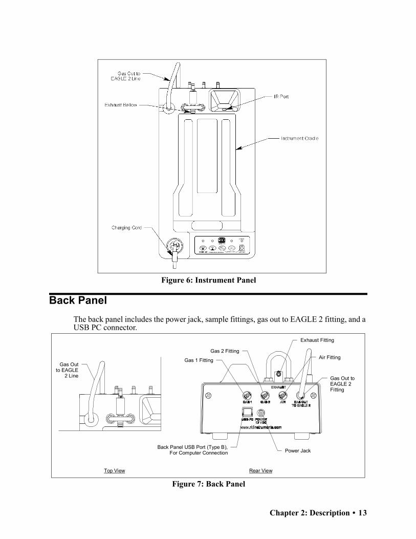
Back Panel
The back panel includes the power jack, sample fittings, gas out to EAGLE 2 fitting, and a USB PC connector.
Figure 6: Instrument Panel
Exhaust Fitting
Air Fitting
Gas Out to EAGLE
2 Line Gas Out to EAGLE 2 Fitting
Power JackBack Panel USB Port (Type B),
For Computer Connection
Top View Rear View
Gas 1 Fitting
Gas 2 Fitting
Figure 7: Back Panel
Chapter 2: Description • 13

Power Jack
The power jack is located in the center of the back panel. The plug on the end of the AC adapter cable mates to it.
Sample Fittings
Five sample fittings are located on the back of the SDM-E2. The gas out to EAGLE 2 fitting is in the upper right corner and has factory installed tubing connected to it. The gas out to EAGLE 2 fitting directs sample gas to the EAGLE 2 through the gas out to EAGLE 2 line. The gas out to EAGLE 2 line is stored in the top panel as shown in Figure 7 above. The AIR fitting is to the left of the gas out to EAGLE 2 fitting and draws air into the SDM-E2. The two GAS fittings are next to the AIR fitting and are used to connect the SDM-E2 to calibration gas cylinders. All three fittings accept 3/16 inch ID tubing.
An exhaust fitting is located above the back panel at the back of the exhaust bellow. It allows routing of the exhausted calibration gas to a convenient location. This fitting accepts 3/16 inch ID tubing. Even though the exhaust gas can be routed to an area to be safely dispersed, the docking station should still be installed in a well ventilated area.
PC Connection
A type B USB connection is located just to the left of the power jack on the SDM-E2’s back panel. It is used to connect the SDM-E2 to a PC.
Control Panel
The control panel is used to setup and operate the docking station in the Standalone configuration. It is located at the front of the docking station. It includes the control buttons, the control button LEDs, and the CHARGE status LED.
Figure 8: Control Panel
14 • Chapter 2: Description

Five control buttons are located on the control panel. From left to right they are BUMP, CAL, EDIT ENTER, COPY, and POWER. The BUMP, CAL, EDIT ENTER, and COPY control buttons are not used in the PC Controlled configuration of the SDM-E2. The BUMP LED and CAL LEDs indicate the results of bump tests and calibrations, respectively. The COPY LED does not indicate anything in the PC Controlled configuration but will be on if the SDM-E2 was used in the Standalone configuration and calibration and bump test records are still stored in the SDM-E2’s memory. The CHARGE LED is located above the POWER button and functions as a pilot LED, a system failure LED, and a charge indication LED.
The POWER button turns the SDM-E2 on and off.
Front Panel
A type A USB port is located on the front of the docking station. This port can be used to save calibration and bump test data to a USB flash drive. This USB port is for use only in the Standalone configuration of the SDM-E2 and is not used in the PC Controlled configuration.
NOTE: The SDM-E2 does not support connection of a computer to the front USB port, only a USB flash drive.
Front Panel USB Port (Type A),For Flash Drive
Figure 9: Front Panel
Chapter 2: Description • 15

Chapter 3: Mechanical Setup
USB Hub Requirements for Multiple-Station Systems
If you have more docking stations than you have available USB ports, you will need a USB hub. RKI provides both a 4-port hub and a 7-port hub. If you have more than 7 docking stations, you will need to purchase one of each hub. Do not connect one hub to the other. Make sure that each USB hub has its own USB port on your computer. You may also purchase your own USB hub of any port number from your local electronics store but it must meet the following requirements:
• USB 2.0
If your USB hub has an AC adapter, it does not need to be plugged in for SDM-E2 operation.
Hardware Assembly
The hardware assembly consists of connecting the AC adapter(s), installing the air filter(s), installing the check valve(s), connecting the sample tubing and connecting the USB cable(s). The SDM-E2 Docking Station PC Controller software can support 1-10 SDM-E2 docking stations connected at the same time. Perform the following steps to complete the hardware assembly for each SDM-E2:
1. Place the SDM-E2(s) on a convenient table top near an AC wall socket or power strip in a well ventilated area. A location near a window that can be opened is best so that the exhaust can be routed to the window.
2. If you have more than one SDM-E2, arrange them side by side as shown in Figure 10 below.
3. Insert the round plug on the end of each AC adapter’s cable into the power jack on the back of each SDM-E2.
Figure 10: SDM-E2 Arrangement
16 • Chapter 3: Mechanical Setup

NOTE: If you have multiple SDM-E2s and are using a 3-port AC adapter, plug each of the round plugs on the end of the AC adapter into the power jack on the back of 3 separate SDM-E2s.
4. Connect the AC adapter’s wall plug into a wall AC socket or power strip.
5. Install the air filter to the AIR fitting of each SDM-E2 so that the arrow on the filter that indicates direction of flow is pointing towards the AIR fitting. Push the open end of the flexible tube that is on one end of the filter onto the AIR fitting on the back of the SDM-E2.
NOTE: If you have an EAGLE 2 with an IR CO2 sensor in the 0-10,000 ppm or 0-5.00 %vol range, be sure to replace the air filter at the AIR inlet fitting with the CO2 scrubber when testing an instrument with a CO2 sensor installed to ensure that the CO2 present in fresh air is scrubbed out. Remove the black end caps from each end of the scrubber before installing onto the AIR inlet fitting. Replace the caps when the scrubber is not in use. See the pg.187 for a scrubber with a tubing stub.
6. Install the 10 foot long 3/16 inch ID flexible tube that is included with each SDM-E2 on the exhaust fitting of each SDM-E2. Route the tube to an area where the exhaust can be safely dispersed, such as an open window. Exhaust tubing from multiple units can be daisy chained together in a manifold for more convenient operation. In this case, the check valves that are provided with the docking stations need to be used. See "Assembling a Manifold for Multiple SDM-E2 Units" below for instructions.
CAUTION: The maximum recommended length for the exhaust tube is 30 feet. Do not use more than 30 feet of tubing or tubing with an ID of less than 3/16 inch for the exhaust tube or the bump test and calibration accuracy will be adversely affected. The exhaust tube that is shipped with the SDM-E2 has an ID of 3/16 inch and is 10 feet long.
7. Install the 3 foot long 3/16 inch ID tubes that are included with the SDM-E2 on the GAS 1 and GAS 2 fittings. GAS 1 and GAS 2 tubing from multiple units can be daisy chained together in a manifold for more convenient operation. See "Assembling a Manifold for Multiple SDM-E2 Units" below for instructions.
8. Connect the provided USB cable from the type B USB port on the back of the SDM-E2 to an available USB port on your computer or to a USB hub that is connected to your computer. See pg.16 for more information about USB hubs.
Chapter 3: Mechanical Setup • 17

Assembling a Manifold for Multiple SDM-E2 Units
One 10-docking station manifold can be created for GAS 1. Although the demand flow regulators can handle up to 10 EAGLE 2 pumps, the PC Controller program is set up to handle GAS 2s in groups of 5. Depending on your sensor configuration, you may be able to have one GAS 2 manifold for all 10 docking stations as long as there are two 5-instrument sets of EAGLE 2s with different sensor configurations. For example if you have 5 standard 4 gas plus PID instruments and 5 standard 4 gas plus NH3 instruments, all 10 docking stations can be connected to the same GAS 2 manifold since the PID sensor in the 5 standard 4 gas plus PID instruments will be calibrated and then the NH3 sensor in the 5 standard 4 gas plus NH3 instruments will be calibrated. If you have 10 EAGLE 2s with exactly the same GAS 2 configuration, you will need to create 2 5-docking station manifolds for GAS 2. See Figure 12 through Figure 14 for more explanation. If you have multiple instruments with different configurations, see pg.54 for more information and suggestions for manifolding.
Each SDM-E2 is shipped with exhaust tubing, GAS 1 and GAS 2 tubing, T-fittings, and a check valve. Be sure to set aside one 10 foot length of exhaust tubing to direct the exhaust to a window. Use the other provided 10 foot lengths of tubing to build the manifold.
Exhaust Tubing
Reference Figure 11 for the instructions below.
1. Cut a 1-2” piece of tubing for each SDM-E2 and connect it to each station’s exhaust fitting.
2. Connect the provided check valves to the short pieces of tubing already installed at the exhaust fittings. Be sure that the arrows that appear on the check valve are pointing away from the exhaust fitting.
3. Cut a 2-3” piece of tubing for every SDM-E2 except the first one and connect it to the other end of the check valve.
4. Insert T-fittings into the tubing so that the remaining two ports on the T-fitting are perpendicular to the exhaust tube and check valve.
5. For the first SDM-E2, cut a 9-10” piece of tubing and connect it from the check valve on the first SDM-E2 to the closest port on the second SDM-E2’s exhaust T-fitting.
6. Use one of the provided 10 foot lengths of tubing and connect it to the T-fitting on the last SDM-E2. If a longer exhaust tube is needed, it can be ordered from RKI Instruments or found locally. The maximum recommended exhaust tube length is 30 feet.
7. For the remaining SDM-E2s, cut 6-7” pieces of tubing and connect the remaining T-fittings.
18 • Chapter 3: Mechanical Setup

Uni
t 1
T-F
ittin
g
Un
it 2
Uni
t 9U
nit1
0
9 in
ches
30F
ootM
ax
Exh
aust
Tub
eT
oO
pen
Are
a
Che
ckV
alve
...
7 in
ches
Figure 11: Exhaust Tubing Connections
Chapter 3: Mechanical Setup • 19

GAS 1 Tubing
The GAS 1 fittings for up to 10 docking stations can be manifolded together. Reference Figure 12 for the instructions below.
1. Cut a 3-4” piece of tubing for each GAS 1 fitting on every SDM-E2 except the last one.
2. Connect the tubing to the GAS 1 fittings on every SDM-E2 except the last one.
3. Insert T-fittings into the tubing so that the remaining two ports on the T-fitting are perpendicular to the GAS fitting.
4. Cut 6-7” pieces of tubing and connect the T-fittings.
5. Cut one more 6-7” pieces of tubing and connect the GAS 1 fitting of the last SDM-E2 to the T-fitting from the second to last SDM-E2.
6. Cut 1 piece of tubing long enough for easy access to the calibration cylinder and connect it to the T-fitting on the first SDM-E2.
GAS 2 Tubing
Reference Figure 13 - Figure 14 for the instructions below.
1. For the purpose of manifolding the GAS 2 fittings of your docking stations, slightly separate the SDM-E2s into one group of 5 and one group of the remaining docking stations. If you have 5 or fewer docking stations, you will only need one manifold. For further explanation of how to properly arrange your SDM-E2s, see pg.54.
2. Cut a 3-4” piece of tubing for each GAS 2 fitting on every SDM-E2 except the last one in each group.
3. Connect the tubing to the GAS 2 fittings on every SDM-E2 except the last one in each group.
4. Insert T-fittings into the tubing so that the remaining two ports on the T-fitting are perpendicular to the GAS fitting.
5. Cut 6-7” pieces of tubing and connect the T-fittings.
6. Cut one more 6-7” pieces of tubing and connect the GAS 2 fittings of the last SDM-E2 in each group to the appropriate T-fittings from the second to last SDM-E2 in each group.
7. Cut 1 piece of tubing long enough for easy access to the calibration cylinder(s) and connect them to the T-fittings on the first SDM-E2 in each group.
20 • Chapter 3: Mechanical Setup

Uni
t 2
Uni
t 7
Uni
t 4
Uni
t 9
Uni
t 1
Uni
t 6
Uni
t 5
Uni
t 10
Uni
t 3
Uni
t 8
Figure 12: Gas 1 Tubing Connections
Chapter 3: Mechanical Setup • 21

NOTE: Use this figure if the EAGLE 2s that will be connected have exactly the same GAS 2 configuration.
Uni
t 2
Uni
t 7
Uni
t 1
Uni
t 6
Uni
t 4
Uni
t 5
Uni
t 9
Uni
t 10
Uni
t 8
Uni
t 3
Figure 13: Tubing for Instruments with the Same Gas 2 Configuration
22 • Chapter 3: Mechanical Setup

NOTE: Use this figure if 5 or less EAGLE 2s have exactly the same GAS 2 configuration.
Uni
t 7
Uni
t 4
Uni
t 9
Uni
t 1
Uni
t 2
Uni
t 6
Uni
t 5
Uni
t 10
Uni
t 8
Uni
t 3
Figure 14: Tubing for Instruments with Different Gas 2s
Chapter 3: Mechanical Setup • 23

Connecting Calibration Gas
The GAS 1 and GAS 2 fittings on the back of the docking station are designed to be used with a calibration gas cylinder that is fitted with a demand flow regulator. The AIR fitting may be used with a demand flow regulator and a cylinder of zero emissions air, but this is not normally necessary since the docking station will generally be in a fresh air area.
WARNING: RKI Instruments, Inc. recommends that you dedicate a regulator for use with chlorine (Cl2) gas and that you do not use that dedicated regulator for any other gases, particularly hydrogen sulfide (H2S).
GAS 1
The type of calibration gas cylinder used for the GAS 1 fitting depends on the gas sensors installed in the EAGLE 2. A 4-gas mix, LEL/Oxygen/CO/H2S, is used for the GAS 1 fitting if the instrument being used with the docking station is a standard 4-gas unit or is a version that has less than four standard channels but still has an H2S channel. If the instrument does not have an H2S channel, then a 3-gas mix, LEL/Oxygen/CO, is used for the GAS 1 fitting. Although a 4-gas cylinder will work for an instrument of any standard gas combination, if you have multiple 3- and 4-gas instruments, you may want to keep a 4-gas cylinder and a 3-gas cylinder to help preserve the charcoal filter that protects the CO sensor in instruments without an H2S channel.
GAS 2 for EAGLE 2s with One Special Sensor
The GAS 2 fitting is intended to be used for special sensors (i.e. PID, TC, ESM-01, etc.) when GAS 1 is used for standard sensors. If you have a special sensor installed (i.e. PID, TC, ESM-01, etc.), a special cylinder for the target gas of that sensor needs to be used for calibration. For example, if you have a standard 4-gas unit plus a PID sensor, you will need both a 4-gas cylinder and a cylinder of 10 ppm isobutylene for low range or 100 ppm isobutylene for high range calibration. The isobutylene cylinder needs to be connected to the GAS 2 fitting on the back of the SDM-E2. Similarly, if you have a standard 4-gas EAGLE 2 plus an ammonia ESM-01 sensor, you will need a cylinder of 10 ppm ammonia connected to the GAS 2 fitting on the back of the SDM-E2. If you have an EAGLE 2 configuration for which a 5-gas cylinder is available (ie. standard 4-gas plus SO2 or standard 4-gas plus high range PID, you may use the 5-gas cylinder and connect it to the GAS 1 fitting. You will have to assign the SO2 or high range PID channel to GAS 1 instead of GAS 2 during bump testing or calibration. See “Bump Testing an Instrument with Special Sensors” on page 78 or “Calibrating an Instrument with Special Sensors” on page 94 for further instruction. Some infrared sensors can be bump tested or calibrated at the same time as the standard gases using a 3- or 4-gas cylinder. In these cases, a second cylinder is not needed for the GAS 2 fitting. See pg.223 for a description of infrared sensor gas port assignments.
GAS 2 for EAGLE 2s with Two Special Sensors
If you have an EAGLE 2 with two special sensors installed, for example, a standard 4-gas EAGLE 2 plus a PID sensor and an ammonia ESM-01 sensor, you will need both an isobutylene calibration cylinder and an ammonia calibration cylinder. For instruments with 2 special sensors, the calibration cylinder for the first special sensor channel
24 • Chapter 3: Mechanical Setup

(typically channel 5) needs to be connected to the GAS 2 fitting first. During bump testing or calibration, the PC Controller program will prompt you to change the GAS 2 calibration cylinder when it needs to calibrate the second special sensor (typically channel 6). If one of the two special sensors has a target gas that’s in a 5-gas cylinder (ie. SO2 or high range PID), no cylinder change will be required as long as the SO2 or high range PID channel is assigned to GAS 1 during the bump testing or calibration procedure. If one of the two special sensors is an IR sensor that can be calibrated with the 3- or 4- gas cylinder being used for the standard sensors (ie. autoranging IR CH4), no cylinder change will be required as long as the IR channel is assigned to GAS 1. See pg.223 for a brief description of operation specific to IR sensors.
Special Sensor Only EAGLE 2s
NOTE: The following description of default gas port assignments does not necessarily apply to infrared sensors. If your EAGLE 2 has one or more infrared sensors installed, read and understand pg.223 before deciding how to arrange your manifold. The gas port assignments described in the appendix take precedent over those described below. Keep those gas port assignments in mind while reading the rest of this section and deciding how to arrange your manifold.
For a single gas special sensor instrument, the special sensor will be bump tested or calibrated using GAS 1. Be sure the appropriate cylinder is connected to the GAS 1 fitting or manifold. For multiple configurations of single gas special sensor instruments, the PC Controller program allows you to select the gas(es) to be applied through GAS 1. If you do not have a manifold set up for your system, connect the appropriate calibration cylinder to the GAS 1 fitting on the back of the SDM-E2 that contains the matching special sensor and select all gases to be applied through GAS 1. If you have a manifold set up for your system (as described in “Assembling a Manifold for Multiple SDM-E2 Units” on page 18), select only one gas to be applied through GAS 1. Any unselected gases will be applied through GAS 2 and you will be prompted by the PC Controller program to change the GAS 2 cylinder. Be sure the selected calibration cylinder is connected to the GAS 1 manifold and that the calibration cylinder for the first GAS 2 to be tested is connected to the GAS 2 manifold.
Use Table 2 below as a guide in determining which calibration gas cylinder is appropriate for your system. See pg.187 for a list of available cylinder part numbers.
Table 2: Recommended Gas Cylinders for Typical Instrument Types
Typical Instrument Types Recommended Calibration Gas Cylinder
3-gas (LEL/Oxy/CO) 3-gas mix with LEL/Oxy/CO
Standard 4-gas (LEL/Oxy/H2S/CO) 4-gas mix with LEL/Oxy/H2S/CO
Standard 4-gas + low range PID 4-gas mix and IBL
Standard 4-gas + high range PID 5-gas mix with LEL/Oxy/CO/H2S/IBL
Standard 4-gas + NH3 4-gas mix and NH3
Standard 4-gas + low range PID + NH3 4-gas mix and IBL and NH3
Chapter 3: Mechanical Setup • 25

To connect calibration gas to the SDM-E2, do the following:
1. If the area around the docking station is not considered a fresh air area (an area free of combustible and toxic gases and of normal oxygen content, 20.9%) install a tube not longer than 10 feet on the filter attached to the AIR fitting on the back of the docking station and route it to a fresh air area or connect a cylinder of zero air with a demand flow regulator to the AIR fitting.
2. Install the demand flow regulator on the calibration gas cylinder(s).
WARNING: RKI Instruments, Inc. recommends that you dedicate a regulator for use with chlorine (Cl2) gas and that you do not use that dedicated regulator for any other gases, particularly hydrogen sulfide (H2S).
3. Connect the demand flow regulator to the GAS 1 or GAS 2 inlet fitting using the 3 foot length of 3/16 inch ID sample tubing provided with the docking station.
For a 3- or 4-gas mix, connect the regulator to the GAS 1 inlet.
For a special calibration cylinder (PID, TC, ESM-01, etc.), connect the regulator to the GAS 2 inlet.
NOTE: If you have set up a manifold for calibrating instruments, the regulators can be connected to tubing leading to the manifold inlet instead of connected directly to the GAS 1 or GAS 2 inlet fitting.
EAGLE 2 and GX Type Instrument Connection
There are 2 different versions of the Docking Station PC Controller program. The SDM-E2 Docking Station PC Controller program is intended for use with SDM-E2 docking stations and EAGLE 2 instruments. The SDM-GX Docking Station PC Controller program is intended for use with GX type docking stations and GX type instruments.
Bump tests and calibrations can be performed on multiple EAGLE 2s and GX type instruments at the same time. The SDM-E2 Docking Station PC Controller program controls the EAGLE 2 functions while the SDM-GX Docking Station PC Controller program controls the GX type instrument functions. Both programs can be used simultaneously on your PC. Follow all instructions in the appropriate SDM-GX type Docking Station PC Controlled Configuration Operator’s Manual as well as the instructions in this manual.
Standard 4-gas + high range PID + NH3 5-gas mix with LEL/Oxy/CO/H2S/IBL and NH3
Standard 4-gas + SO2 5-gas mix with LEL/Oxy/CO/H2S/SO2
Table 2: Recommended Gas Cylinders for Typical Instrument Types
Typical Instrument Types Recommended Calibration Gas Cylinder
26 • Chapter 3: Mechanical Setup

Chapter 4: Computer Setup
Installing the SDM-E2 Docking Station PC Controller Software
1. Launch Windows®.
2. Exit from all applications and open windows.
3. Go to www.rkiinstruments.com/sdme2.
4. Click on the Download tab.
5. Click the SDM-E2 PC Controlled Software link.
6. A .zip file will begin to download. Select whether you want to open or save the .zip file.
7. Extract the contents of the .zip file.
8. Double click the setup.exe file.
9. The SDM-E2 Docking Station PC Controller InstallShield Wizard comes up to guide you through installation. Click Next to proceed to the License Agreement window.
10.Read the license agreement and click the agreement acceptance selection box, then click Next to proceed to the Customer Information window.
11.Enter a user name and organization and select if you want to install the program for all users on the computer or just for your user account, then click Next to proceed to the Destination Folder window.
12.The default installation folder (C:\Program Files\SDM-E2\) is displayed. If you want to install the software in the default folder continue with step 13. If you want to install the software in a different location, click Change and choose a new installation folder and then continue with step 13.
13.Click Next to proceed to the Ready to Install the Program window.
14.Review the installation settings. If they are OK, click Install and the installation process will begin. If you want to change installation settings, click Back and change them to the desired settings.
15.During software installation, the installation program may find newer versions of Windows files on your computer than those in the downloaded .zip file. If this happens, the installation software will ask you if you want to keep these newer files. Click Yes to do so.
Chapter 4: Computer Setup • 27

16.A Device Driver Window will appear prompting you to install necessary drivers. You cannot continue the installation without installing the drivers.
Figure 15: Device Driver Installation
17.Click Next to install the drivers. The Wizard will find the appropriate drivers.
18.If this is the first time you are installing a PC Controller Program, a window will appear saying that the file did not pass Windows logo testing. Click Continue Anyway.
28 • Chapter 4: Computer Setup

19.Click Finish once the drivers are successfully installed.
Figure 16: Finish Device Driver Installation
The installation will continue.
20.Follow the on-screen instructions to complete software installation.
21.To complete the driver installation, ensure that all of your docking stations are connected to your computer.
22.Turn on a docking station by pressing and holding the POWER button for at least 1 second.
Chapter 4: Computer Setup • 29

23.The first time a SDM-E2 is turned on after being connected to the computer, a Found New Hardware window will appear.
NOTE: The following instructions apply only to computers running Windows XP. If you have a newer operating system, the hardware driver will automatically install and you will be notified that the USB device is ready for use.
Figure 17: Found New Hardware Wizard
24.Select the “Install the software automatically” option and click Next.
30 • Chapter 4: Computer Setup

25.The wizard will search for the driver files.
Figure 18: Searching
26.Once the files have been found, a window will appear saying that the file did not pass Windows logo testing. Click Continue Anyway.
Figure 19: Windows Logo Error
27.The installation will continue. Click Finish when the installation has completed.
28.Repeat steps 22 through 27 for every docking station in your system.
Chapter 4: Computer Setup • 31

Launching the PC Program
1. Click Start on the Windows Icon Tray, then select Programs/SDM-E2 Docking Station PC Controller. You may also double click the shortcut created on your desktop. The PC Program is launched and the main program window appears.
Figure 20: Main Program Window
2. If you are starting the software for the first time, a message window appears informing you that a database has been created. Click OK in that window.
32 • Chapter 4: Computer Setup

Setting Parameters in the Configuration Window
Parameter Tab
1. Launch the program as described on pg.32.
NOTE: It is not necessary to turn on the SDM-E2 docking stations if you are only performing configuration setup.
2. Click the Config button along the top of the main program window.
3. You will be prompted to enter a password. The case-sensitive, factory-set password is ABCDE. Enter the password and click OK. See pg.41 for instructions to change the password.
4. The Parameter Tab of the Configuration Window appears.
Figure 21: Config Window Parameter Tab
Chapter 4: Computer Setup • 33

5. Change the desired parameters, described below.
6. Click OK and Yes in the window that appears.
Instrument Information Section
Change Parameter
Selected (factory setting): The Edit function is active in the Instrument Function Menu allowing you to change various parameters in connected instruments. See pg.149 for a complete description of the Edit function.
Deselected: The Edit function is not active.
Auto Power OFF Time
This is the length of time that will pass after the last operation is finished before the program will automatically shut off the EAGLE 2. If a successful bump test or calibration is performed, the program will automatically shut off the EAGLE 2 in 20 seconds regardless of the Auto Power OFF Time setting. Use the arrows to the right of the current setting to change the value or highlight the current setting and type in the desired value. It is defined in seconds with a maximum setting of 3600 seconds (1 hour). The factory setting is 3600 seconds.
Data Logger Section
Down Load Data Logger
Selected: The PC Program will automatically download logged data from connected EAGLE 2s based on the frequency set in Down Load Interval.
Deselected (factory setting): Logged data is not automatically downloaded from connected EAGLE 2s.
Clear After Down Load
If Down Load Data Logger is not selected, selecting Clear After Down Load has no effect.
Selected: The PC Program automatically clears an EAGLE 2’s logged data at the end of an automatic data download.
Deselected (factory setting): The EAGLE 2’s logged data is not automatically cleared.
Down Load Interval
The length of time, in days, that will pass before the PC Controller program will automatically download data from an EAGLE 2 if Down Load Data Logger is selected. If the EAGLE 2 is connected to the program before the interval has passed, a data download will not automatically occur. The Down Load Interval can be set anywhere from 1 to 60 days. The factory setting is 1 day.
SDM Selection Section
If you select the Initialize Display Order selection box, the PC Controller program will reset the numbers it has assigned to specific docking stations and reassign them as you turn SDM-E2 docking stations on and connect them to the program. See pg.41 for instructions to use this feature.
34 • Chapter 4: Computer Setup

Waiting Time for Auto Process
The Waiting Time for Auto Process parameter defines the time delay of an automatic calibration or automatic bump test after an instrument is connected to the SDM-E2. You can set the delay from 0 seconds to 3600 seconds.
Calibration Section
If neither Manual Calibration nor Auto Calibration is selected, you will not be able to perform a calibration. Select the box for the desired operation.
Manual Calibration
Selected (factory setting): A manual calibration can be performed by selecting an instrument or instruments in the main program window and clicking Calibration in the lower right corner of the window.
Deselected: A manual calibration cannot be performed.
Auto Calibration
Auto Calibration selected and Every Time deselected (factory setting): An automatic calibration is performed only if the instrument is due for calibration. Only instruments with one or more of the standard 4 sensors and 1 special sensor can be fully calibrated using Auto Calibration. If you have an instrument with more than 1 special sensor, only the standard 4 sensors will be calibrated. You must perform a manual calibration in order to perform a complete calibration.
Auto Calibration selected and Every Time selected: An automatic calibration is performed every time an instrument is connected to the PC program regardless of whether a calibration is due or not. Only instruments with one or more of the standard 4 sensors and 1 special sensor can be fully calibrated using Auto Calibration. If you have an instrument with more than 1 special sensor, only the standard 4 sensors will be calibrated. You must perform a manual calibration in order to perform a complete calibration.
Auto Calibration deselected (factory setting): A calibration is not automatically performed.
Standard GAS/All GAS
Standard GAS (factory setting): Only the standard sensors (catalytic LEL, O2, CO, and H2S) will be calibrated during an automatic calibration.
All GAS: All installed sensors will be calibrated during an automatic calibration if the instrument has only 1 special sensor. If the instrument has more than 1 special sensor, only the standard 4 sensors will be calibrated.
Interval (CX-II only)
The Interval parameter sets the calibration interval but is only used for CX-II instruments. It does not have any effect on the SDM-E2 program when used with EAGLE 2s.
Bump Test Section
If neither Manual Bump Test nor Auto Bump Test is selected, you will not be able to perform a bump test. Select the box for the desired operation.
Chapter 4: Computer Setup • 35

Manual Bump Test
Selected (factory setting): A manual bump test can be performed by selecting an instrument or instruments in the main program window and clicking Bump Test in the lower right corner of the window.
Deselected: A manual bump test cannot be performed.
Auto Bump Test
Selected: An automatic bump test is performed only if the instrument is due for bump testing. Only instruments with one or more of the standard 4 sensors and 1 special sensor can be fully bump tested using Auto Bump Test. If you have an instrument with more than 1 special sensor, only the standard 4 sensors will be bump tested. You must perform a manual bump test in order to perform a complete bump test.
Deselected (factory setting): A bump test is not automatically performed.
Standard GAS/All GAS
Standard GAS (factory setting): Only the standard sensors (catalytic LEL, O2, CO, and H2S) will be bump tested during an automatic bump test.
All GAS: All installed sensors will be bump tested during an automatic bump test if the instrument has only 1 special sensor. If the instrument has more than 1 special sensor, only the standard 4 sensors will be bump tested.
Fast Bump
Deselected: If Fast Bump is not selected, the gas application during a bump test will continue for the time period defined by the Gas Exposure Time bump test parameter regardless of the sensor reading(s).
Selected (factory setting): If the gas reading for the sensor(s) being tested is above the lower tolerance and below the upper tolerance within 10 seconds, the sensor(s) pass bump testing, the gas application will be stopped, and the test will move on to the next sensor(s) or to the fresh air purge. If the gas reading on any of the tested channels is below the lower tolerance or above the upper tolerance within 10 seconds, the gas application will continue for the time period defined by the Gas Exposure Time bump test parameter, and the pass/fail status of the sensor(s) will be determined at that point. Turning Fast Bump on allows calibration gas to be saved when the tested sensors respond quickly and accurately.
Consider the following scenario as an example.
• 50% LEL methane used for bump testing the combustible gas channel
• GAS bump test parameter set to 20 seconds
• Tolerance set to ± 50% LEL, which means that the acceptable reading range is 25% LEL - 75% LEL
• Fast selected
36 • Chapter 4: Computer Setup

The table below shows possible readings at 10 seconds and the effect on the gas application.
Interval
The Interval can be set anywhere between 1 and 30 days and is the length of time that can pass before the program will prompt you to perform a bump test. The factory setting is 30 days.
Gas Exposure Time
The Gas Exposure Time can be set to 30 (factory setting), 45, 60, 90, 120 seconds or Auto and is the length of time that gas is applied to the EAGLE 2. If you select Auto, the PC Controller program will apply gas for the appropriate amount of time based on your EAGLE 2 sensor configurations.
Tolerance
The Tolerance can be set between 10% and 50%. The factory setting is 50%. It determines how close the EAGLE 2 gas reading must be to the calibration gas concentration for each channel during a bump test in order to pass the bump test. It is defined as a percentage of the calibration gas concentration.The amount that the EAGLE 2 gas reading differs from the calibration gas concentration must be equal to or less than this percentage of the calibration gas concentration. For example, if the tolerance is set to 50%, and the %LEL calibration gas concentration is 50% LEL, then the bump test gas reading for the LEL channel on the EAGLE 2 must be 50 %LEL ± 25 %LEL.
Table 3: Example Fast Bump Scenarios
Gas Reading 10 Seconds Into Fast Bump
Outcome
15% LEL (-70% of 50% LEL) • Gas application continues for the full 20 seconds• Pass/fail determined at end of 20 seconds
30% LEL (-40% of 50% LEL) • Gas application stops• Sensor passes bump testing
60% LEL (+20% of 50% LEL) • Gas application stops• Sensor passes bump testing
80% LEL (+60% of 50% LEL) • Gas application continues for the full 20 seconds• Pass/fail determined at end of 20 seconds
Chapter 4: Computer Setup • 37

Database Tab
The Database Tab allows you to view or change where the data from your SDM-E2 docking stations is saved. It also allows you to create a brand new database, import data from another database, or export saved data.
1. Launch the program as described on pg.32.
NOTE: It is not necessary to turn on the SDM-E2 docking stations if you are only performing configuration setup.
2. Click the Config button along the top of the main program window.
3. You will be prompted to enter a password. The case-sensitive, factory-set password is ABCDE. Enter the password and click OK. See pg.41 for instructions to change the password.
4. The Parameter Tab of the Configuration Window appears.
Figure 22: Config Window Parameter Tab
38 • Chapter 4: Computer Setup

5. Click on the Database tab to get it to appear.
Figure 23: Config Window Database Tab
Changing the Database Location
1. Click the button to the right of the current location that has three dots on it.
2. Choose a new location where a database exists and click Open. The new database location will be displayed in the Data Location field.
3. A window will appear telling you to restart the PC Controller Program. Click OK.
4. Click OK in the Database Tab.
5. Click the Exit control button in the upper right corner of the main program window.
6. Reopen the PC Controller Program.
Creating a New Database
1. Click the Create button located along the left side of the Database Tab window.
2. Choose where you would like the new database to be stored and enter a name for it and click Save. The new database will be created but data will not be stored there until you change the file path as described above.
Chapter 4: Computer Setup • 39
Importing a .mdb File into the Current Database
1. Click the Import button located along the left side of the Database Tab window.
2. Select an existing .mdb file that you wish to import. You can import a .mdb file that was created on another computer and moved to your computer, you can select a file that was generated on your computer using the Create button, or you can navigate to another network computer’s .mdb file. If you navigate to another computer’s files, the location for the default .mdb file is in the Program Files folder (ie. MannyPC:\Program Files\SDM-E2). It is named SDMLog.mdb. If you wish to import a different .mdb file, it will have a different name and may be in a different location.
3. Once you have selected a .mdb file, click Open. The program will indicate that the file is being imported. Once the import is finished, the data from the .mdb file will be added to your current data. New serial numbers/station IDs/user IDs will appear in the Data frame of the Logs Window. Instrument information associated with those new instruments will also be available in the Logs Window.
Exporting Instrument Data to a .mdb File
1. Select the desired units from the list on the bottom of the Database Tab.
2. Click Export. Select where you would like to save the file, and click Save. The program will indicate that it is exporting the data and will confirm that it has finished. Click OK in the window that comes up.
If you want to remove a unit’s information after it’s been exported, select Remove before selecting Export. You cannot remove a unit’s information while it’s connected to the computer so be sure to turn off the EAGLE 2 before removing data.
40 • Chapter 4: Computer Setup
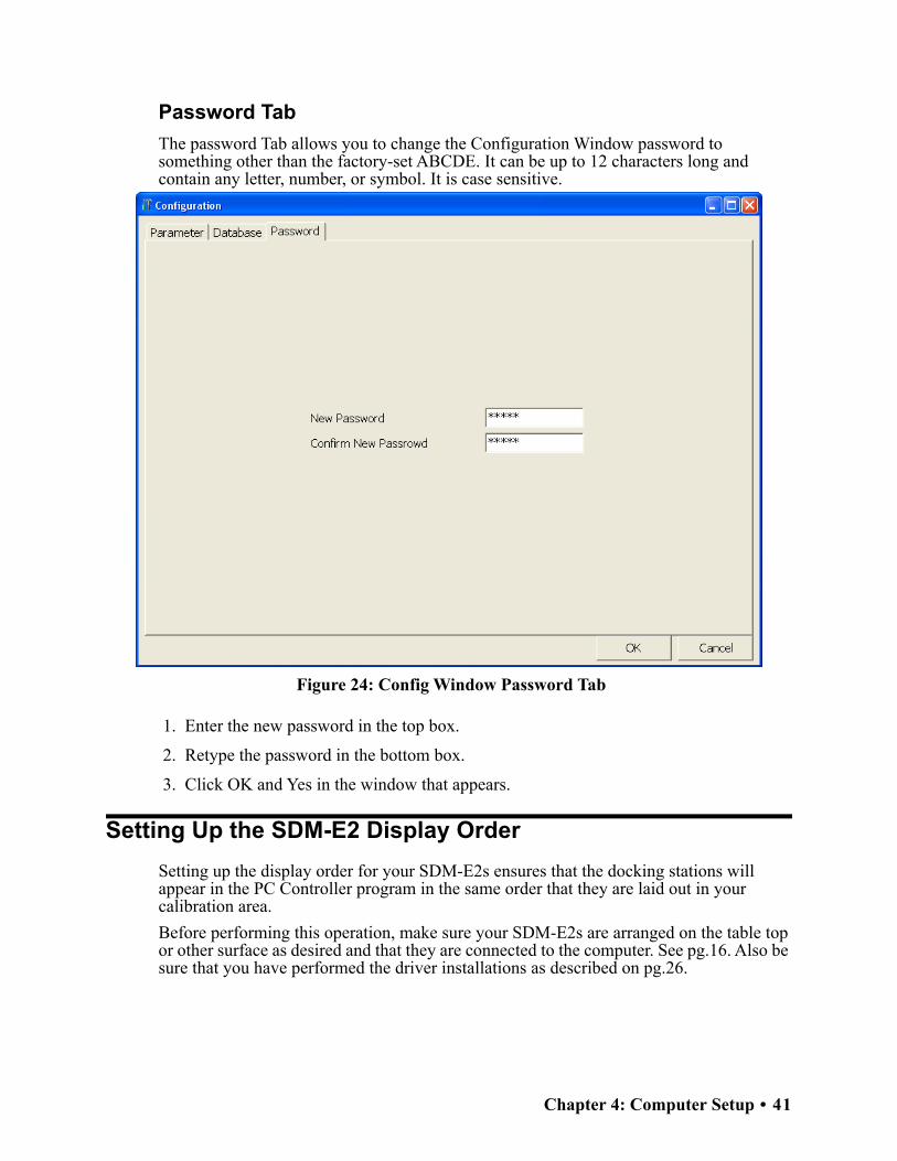
Password Tab
The password Tab allows you to change the Configuration Window password to something other than the factory-set ABCDE. It can be up to 12 characters long and contain any letter, number, or symbol. It is case sensitive.
Figure 24: Config Window Password Tab
1. Enter the new password in the top box.
2. Retype the password in the bottom box.
3. Click OK and Yes in the window that appears.
Setting Up the SDM-E2 Display Order
Setting up the display order for your SDM-E2s ensures that the docking stations will appear in the PC Controller program in the same order that they are laid out in your calibration area.
Before performing this operation, make sure your SDM-E2s are arranged on the table top or other surface as desired and that they are connected to the computer. See pg.16. Also be sure that you have performed the driver installations as described on pg.26.
Chapter 4: Computer Setup • 41

1. Click the Config button along the top of the screen.
2. You will be prompted to enter a password. The case-sensitive, factory-set password is ABCDE. Enter the password and click OK. See pg.41 for instructions to change the password.
3. The Parameter Tab of the Configuration Window appears.
Figure 25: Config Window Parameter Tab
4. Select Initialize Display Order in the SDM portion of the Parameter tab.
5. Click OK and then Yes in the window that appears.
6. A window will appear informing you that you need to turn off all SDM-E2s and restart the program. Click OK.
7. Click the Exit button in the upper right corner of the main program window to exit the program.
8. Turn off all of the SDM-E2s if they are on.
42 • Chapter 4: Computer Setup

9. Open the PC Program again.
10.Turn on your SDM-E2s in the order that you wish for them to appear on the main program window. Typically the order in which the docking stations appear on the screen corresponds to their left to right arrangement on the tabletop.
11.Your SDM-E2 docking stations should all appear on the screen in numerical order. The program will remember each SDM-E2’s number. If fewer than all of the docking stations are turned on, the stations will still appear in numerical order on the Main Program Window, but the stations which are off will not be shown.
12.If you need to reorder the docking stations, repeat steps 1 through 11.
Cylinders Window
The Cylinders Window allows you to keep track of cylinders that are in use and the expiration date for those cylinders. If a cylinder’s expiration date has passed, the PC Controller program will alert you in the message area of the main program window as soon as the program is started. The Cylinders Window comes with a list of predefined cylinders that are fairly common. If a cylinder that you need to use is not on this list, it can be added at the bottom of the cylinder list. You may add as many custom cylinders as necessary.
Figure 26: Cylinders Window
The Cylinders window has the cylinder list number, the cylinder name, the part number, the expiration date, and the status of the cylinder.
Chapter 4: Computer Setup • 43

Selecting a Cylinder from the Predefined List
The Cylinders Window comes with several predefined cylinders that you can choose from.
1. Click the Cylinders button along the top of the main program window.
2. Click in a Name field, click on the drop down menu that appears, and select a predefined cylinder.
Figure 27: Predefined List of Cylinders
3. Set the expiration date by clicking in the Expiration field and clicking the drop down menu that appears. Use the calendar to choose an expiration date. The expiration date box will be highlighted in orange if the expiration date of the cylinder is less than 10 days away. The expiration date box will be highlighted in red if the expiration date has passed.
4. Select or deselect the Active box for each cylinder. If the cylinder is active, the PC Controller program will alert you at start up if the cylinder has passed its expiration date. If it is not active, the program will not alert you.
5. To return to the main program window without saving any changes, click Cancel in the Cylinders Window. A window will appear notifying you that changes will not be saved. To continue to the main program window, click OK. To return to the Cylinders
44 • Chapter 4: Computer Setup

Window to save your changes, click Cancel.
6. If you want to save any changes made, click OK. A window will appear asking if you want to save the changes you made. To return to the main program window and save your changes, click Yes. To return to the main program window without saving changes, click No. To return to the Cylinders Window, click Cancel.
Defining New Cylinders
If your EAGLE 2 configuration requires the use of a cylinder that is not in the predefined list, you can add that cylinder by either typing in the information for the cylinder or by editing the information for an existing cylinder.
1. Click the Cylinders button along the top of the main program window.
2. Click in any blank cylinder Name field and click again to bring the cursor up or use the drop down menu to select a cylinder name that is close to the one you want and click the name to bring the cursor up.
Figure 28: New Cylinder
3. Type in the name of your new cylinder (ie. gas name and concentration).
4. Click in the Part No field once to select it and once more to bring the cursor up. Type in the part number for your new cylinder (typically the RKI part number).
Chapter 4: Computer Setup • 45

5. Click in the blank Expiration field and click on the drop down menu that appears. Use the calendar to select an expiration date. The expiration date box will be highlighted in orange if the expiration date of the cylinder is less than 10 days away. The expiration date box will be highlighted in red if the expiration date has passed.
6. Select the Active box if you want the PC Controller program to alert you when the cylinder’s expiration date has passed. If you do not want the program to alert you, leave the box deselected.
7. To enter any more cylinders, repeat step 3 through step 6.
8. Click OK. A window will appear asking if you want to save the changes you made. To return to the main program window and save your changes, click Yes. To return to the main program window without saving changes, click No. To return to the Cylinders Window, click Cancel.
To return to the main program window without saving any changes, click Cancel in the Cylinders Window. A window will appear notifying you that changes will not be saved. To continue to the main program window, click OK. To return to the Cylinders Window to save your changes, click Cancel.
46 • Chapter 4: Computer Setup

Chapter 5: Operation
Connecting Instruments to the PC Controller Program
NOTE: Be sure to set up the display order for the SDM-E2s as described on pg.41, before continuing.
Do the following to turn on the SDM-E2s and establish a connection with the EAGLE 2s in your system:
1. If necessary, verify that the SDM-E2(s) are arranged on the work surface as desired, all plumbing is installed, and all hardware and cables are installed. See pg.16.
2. Launch the SDM-E2 Docking Station PC Controller Software as described on pg.32.
3. Install an EAGLE 2 in the instrument cradle of each SDM-E2. Set the EAGLE 2 onto the top of the SDM-E2 and slide the instrument forward until it falls into place as illustrated below.
Chapter 5: Operation • 47

WARNING: Inserting the EAGLE 2 improperly may damage the exhaust bellow at the back of the SDM-E2.
Figure 29: Inserting the EAGLE 2
4. Turn on each SDM-E2 by pressing and holding the SDM-E2’s POWER button. When the control panel LEDs turn on, release the POWER button.
5. The BUMP and CAL LEDs will turn off and the COPY LED will be steadily on or off. It will be on if the SDM-E2 was used in Standalone Configuration and calibration and bump test records are still stored in the SDM-E2’s memory (see the SDM-E2 Docking Station Standalone Configuration Manual for more information). The CHARGE LED will be blinking green if the SDM-E2 is operating properly or solid red if there is a system failure.
6. If any of the EAGLE 2s are equipped with NiMH batteries and you wish to charge the batteries, connect the charging cable at the front of the SDM-E2(s) to the charging jack on the back of the applicable instrument(s). The CHARGE LED will begin to flash amber. If the batteries are fully charged, the CHARGE LED will become solid green
Ca
lib
rati
on
Sta
tio
n
CO
PY
EA
GL
E 2
OF
F
CH
AR
GE
1 S
EC
O
N3
SE
C
OF
F
CA
LE
DIT
EN
TE
R
PO
WE
R
SD
M-E
2
BU
MP
AIR
YE
S
RA
NG
E
SH
IF
T
PO
WE
R
EN
TE
R
RE
SE
T
DIS
PL
AY
AD
JU
ST
NO
48 • Chapter 5: Operation
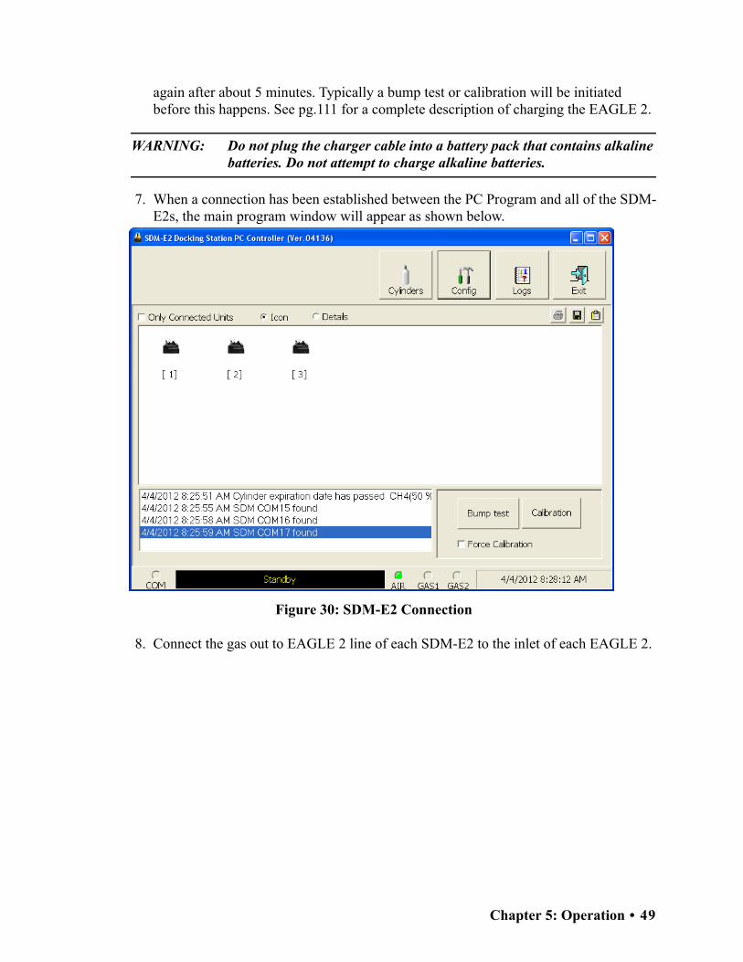
again after about 5 minutes. Typically a bump test or calibration will be initiated before this happens. See pg.111 for a complete description of charging the EAGLE 2.
WARNING: Do not plug the charger cable into a battery pack that contains alkaline batteries. Do not attempt to charge alkaline batteries.
7. When a connection has been established between the PC Program and all of the SDM-E2s, the main program window will appear as shown below.
Figure 30: SDM-E2 Connection
8. Connect the gas out to EAGLE 2 line of each SDM-E2 to the inlet of each EAGLE 2.
Chapter 5: Operation • 49

9. Turn on each EAGLE 2 by pressing and holding the POWER ENTER RESET button on each EAGLE 2 until you hear a beep, then release it. The EAGLE 2 will begin its power up sequence. If a successful connection between the EAGLE 2 and the SDM-E2 occurs, the home screen will appear on the EAGLE 2 display at the end of the start up sequence. It indicates the calibration gas value for each channel. If the charge LED was amber, it will begin to blink green and the battery charging will stop until the EAGLE 2 is turned off.
10.For each instrument, the PC Program will indicate that an EAGLE 2 was found and it will download the instrument’s parameters. The BUMP and CAL LEDs will flash amber while the data is being downloaded. Once the parameter download is complete, the BUMP and CAL LEDs will be solid amber. When all EAGLE 2 instruments have been turned on, connected, and downloaded, the main program window will appear as shown below. When the EAGLE 2 is connected to the PC Controller Program, the date and time of the instrument are automatically updated to the current date and time on the PC Controller Program’s screen.
NOTE: Turn each EAGLE 2 on 10-15 seconds after the previous instrument to minimize the possibility of the EAGLE 2 not connecting to the PC Controller Program. If an EAGLE 2 does not connect and the pump continues to run or IrDA CONNECT appears on the EAGLE 2 display, use the instrument’s POWER ENTER RESET button to turn it off and turn it back on again.
CH4 50%LEL OXY 12.0vol%
H2S 25.0ppm CO 50ppm --- ---
50 • Chapter 5: Operation

Figure 31: EAGLE 2s Connected and Downloaded
If an instrument is due for calibration, the docking station number and instrument serial number will be highlighted in red.
If an instrument is due for calibration within the next 10 days, the docking station number and instrument serial number will be highlighted in orange.
If an instrument’s parameters could not be downloaded properly, a red triangle will appear over the EAGLE 2 and SDM-E2 picture.
Chapter 5: Operation • 51

Icon View vs. Details View
EAGLE 2s that are currently connected or have been previously connected can be viewed in either Icon View or Details View. Choose Icon or Details View by clicking the Icon or Details radio button below the control buttons. Icon View allows you to view connected EAGLE 2s and previously connected EAGLE 2s in an icon configuration. Connected EAGLE 2s are shown as an EAGLE 2 inserted in an SDM-E2 icon. Previously connected EAGLE 2s are shown as EAGLE 2 icons. Right clicking an instrument causes the Instrument Function Menu to appear.
Details View allows you to view connected EAGLE 2s and previously connected EAGLE 2s in a table format. Scrolling to the right in Details View allows you to view existing EAGLE 2 parameters. For a description of these parameters and instructions to change them, see pg.149.
Figure 32: Main Program Window, Details View
Unless otherwise noted, all following figures that show the main program window in this manual are shown in Icon View.
52 • Chapter 5: Operation

Printing and Exporting an Instrument List from the Main Program Window
You can print, save, or add to clipboard the instrument list in the main program window. You can only print the list if it is viewed in Details format. The list cannot be printed when viewed in Icon format.
Printing the Instrument List
1. Ensure that the main program window is being viewed in Details format. The print icon will not be active if the main program window is viewed in Icon format.
Figure 33: Details View
2. Click the Print icon located just below the Exit button.
3. Click OK in the confirmation window that appears.
Chapter 5: Operation • 53

Saving the Instrument List as a .csv File
1. Click the Save icon located just below the Exit button.
2. Choose a file path and enter a file name and click Save.
Saving the Instrument List to the Clipboard
1. Click the Clipboard button located just below the Exit button. The serial number, model, station ID, user ID, next bump test date, next calibration date, the calibration interval, and the data logging interval time for each instrument in the main program window will be saved to the clipboard in a table format.
2. Open a spreadsheet program such as Excel or a word processing program such as Word and paste the clipboard data into it.
Instrument Placement for Bump Testing or Calibration
NOTE: The following descriptions assume you have configured your manifold system appropriately for the number and configuration of your EAGLE 2s. See pg.18 for a discussion of configuring manifolds for the SDM-E2.
If you have 5 or less EAGLE 2s with the same sensor configuration, in order to streamline the bump testing and calibration process, it is recommended that the EAGLE 2s be placed in the same 5-docking station manifold bank.
If you have more than 5 EAGLE 2s with exactly the same sensor configuration, you will need to bump test and calibrate those instruments using both sets of docking station manifold banks. To bump test or calibrate them all at the same time, you will need 2 of each required calibration cylinder since one set will be used for the first docking station manifold bank and the other set will be used for the second docking station manifold bank.
54 • Chapter 5: Operation

If your EAGLE 2s of the same sensor configuration have 2 special sensors (ie. PID, TC, IR, ESM-01), you will need to change the GAS 2 cylinder for both banks of docking stations when the PC Controller Program prompts you to do so. Be sure that you also have 2 calibration cylinders for your second special sensor. If you have an EAGLE 2 for which a 5-gas cylinder is available, for example standard 4-gas plus SO2 plus NH3 or standard 4-gas plus high range PID plus NH3, the calibration cylinder for the second special sensor, NH3 in this case, can be connected to the GAS 2 fitting and you will not need to change it if you are using the 5-gas cylinder for GAS 1.
If you have 5 or less EAGLE 2s with one configuration (ie. standard 4 plus TC) and 5 or less EAGLE 2s with another configuration (ie. standard 4 plus NH3), it is recommended that you place the first set of like instruments in the first docking station manifold bank and put the second set of like EAGLE 2s in the second docking station manifold bank. You will need two GAS 1 manifolds of 5 or less docking stations each for this situation and you will need 2 GAS 1 calibration cylinders. Only one GAS 2 manifold is required for this situation. You will need to change the GAS 2 cylinder that is connected to the GAS 2 manifold at least once depending on how many special sensors are installed in the various connected EAGLE 2s but you will only need 1 of each required GAS 2 cylinder. The PC Controller Program will prompt you to change the GAS 2 cylinder as required. If you have an EAGLE 2 for which a 5-gas cylinder is available, for example standard 4-gas plus SO2 plus NH3 or standard 4-gas plus high range PID plus NH3, be sure that the 5-gas cylinder is connected to the appropriate GAS 1 manifold and that the cylinder for the second special sensor, in this case NH3, is connected to the appropriate GAS 2 manifold. See pg.190 for instructions to bump test and calibrate multiple instruments with different configurations.
If you have 6-9 EAGLE 2s with one configuration (ie. standard 4 plus TC) and 1-4 EAGLE 2s with another configuration (ie. standard 4 plus NH3), place the 1-4 EAGLE 2s in the same bank and place the 6-9 EAGLE 2s in the remaining docking stations. You will need 2 manifolds both for GAS 1 and for GAS 2. You will also need 2 of each calibration cylinder for GAS 1 and for the special sensor(s) in the 6-9 EAGLE 2s. You will only need one calibration cylinder for each special sensor(s) in the 1-4 EAGLE 2s. If you have an EAGLE 2 for which a 5-gas cylinder is available, for example standard 4-gas plus SO2 plus NH3 or standard 4-gas plus high range PID plus NH3, be sure that the cylinder(s) are connected to the appropriate GAS 1 manifold(s) and that the calibration cylinder for the second special sensor (if installed) is connected to the appropriate GAS 2 manifold(s). See pg.190 for instructions to bump test and calibrate multiple instruments with different configurations.
Before you begin bump testing or calibrating, be sure the correct GAS 1 and GAS 2 calibration cylinders are connected to the appropriate manifolds for your instrument configurations.
NOTE: If your instrument(s) include one or more infrared sensors, see pg.223 for a description of the GAS 1/GAS 2 assignments for this type of sensor.
Chapter 5: Operation • 55

Automatic Bump Testing and Calibration
The PC Controller Program will automatically perform a bump test or calibration on a connected instrument if Auto Bump Test or Auto Calibration is selected in the Configuration Window and if the bump test or calibration is due. The use of these features allows the user to launch the PC Controller Program, turn on the EAGLE 2(s) and walk away. No oversight of the bump test or calibration is needed. For this reason, the calibration cylinders need to already be in place and the instrument configurations must be such that the gas cylinders do not require any changing.
If Standard GAS is selected in the Configuration Window, only the standard 4 sensors will be tested so only one calibration cylinder is needed. If All GAS is selected, different GAS 2 configurations will need to be installed in separate manifolds with the appropriate GAS 2 calibration cylinder connected to each manifold. EAGLE 2s with more than one special sensor that require more than 2 gas cylinders cannot be bump tested or calibrated automatically since those instruments will always need a gas cylinder change during bump testing or calibration. The PC Controller Program will only bump test or calibrate the standard 4 sensors if Auto Bump Test or Auto Cal is selected. Even if you have a 5-gas mix that contains the target gases for the standard 4 sensors and one of your special sensors, you cannot bump test or calibrate all installed sensors using the automatic bump test or automatic calibration features. The processes do not give you the opportunity to use the 5-gas cylinder. If you have instruments with more than one special sensor, RKI Instruments, Inc. recommends manually bump testing or calibrating that instrument with the PC Controller Program as described in “Bump Testing an Instrument with Special Sensors” on page 78 and “Calibrating an Instrument with Special Sensors” on page 94.
To automatically bump test or calibrate an instrument or instruments:
1. Be sure that Auto Bump Test or Auto Calibration are selected in the Configuration Window. See pg.33 for instructions.
2. Verify that all of the bump test and/or calibration parameters are set correctly. See pg.33 for instructions.
3. Verify that the appropriate calibration gas cylinder or cylinders is connected to the appropriate manifold line.
4. Ensure that the gas out to EAGLE 2 line is connected to the inlet of the EAGLE 2.
5. Establish a connection between the SDM-E2, EAGLE 2 and the PC Controller program as described in “Connecting Instruments to the PC Controller Program” on page 47.
6. The bump test or calibration will begin 1 minute after the last connected EAGLE 2’s instrument information download is complete.
7. During an automatic bump test, if the bump test fails, a calibration is immediately performed.
8. If Auto Bump Test and Auto Calibration are both selected, the calibration will begin 1 minute after the bump test has finished.
56 • Chapter 5: Operation

Bump Testing Standard 4-Gas Instrument(s)
The following instructions apply to EAGLE 2s with one or more of the standard four sensors (catalytic LEL, O2, H2S, and CO) when you are using only a 3-gas or 4-gas cylinder. RKI Instruments, Inc. recommends using a 3-gas or 4-gas cylinder instead of multiple cylinders for calibrating standard instruments. If your EAGLE 2 includes one or more special sensors such as a TC, PID, ESM-01, etc., see pg.78.
The PC Controller Program is capable of performing a bump test both manually and automatically when an EAGLE 2 is connected to it. When a bump test is performed, the PC Controller Program performs an air adjust operation on an EAGLE 2 and then applies calibration gas to the instrument. The program analyzes the response results based on predefined criteria and determines if the EAGLE 2 passed the bump test.
The criteria that the PC Controller Program uses to determine if the EAGLE 2 passes a bump test, whether the Bump Test button is active, and whether or not the PC Controller Program automatically performs a bump test if it is due on a connected EAGLE 2 is defined in the Parameter tab of the Configuration Window. See pg.33 for a description of the bump test configuration setup.
To manually bump test an instrument or instruments:
1. Establish a connection between the SDM-E2, EAGLE 2 and the PC Controller program as described on pg.47.
WARNING: Do not plug the charger cable into a battery pack that contains alkaline batteries. Do not attempt to charge alkaline batteries.
2. Verify that all of the bump test parameters are set correctly. See pg.33 for instructions.
3. Verify that the appropriate calibration gas cylinder or cylinders is connected to the appropriate SDM-E2 or manifold line.
4. Ensure that the gas out to EAGLE 2 line is connected to the inlet of the EAGLE 2.
Chapter 5: Operation • 57
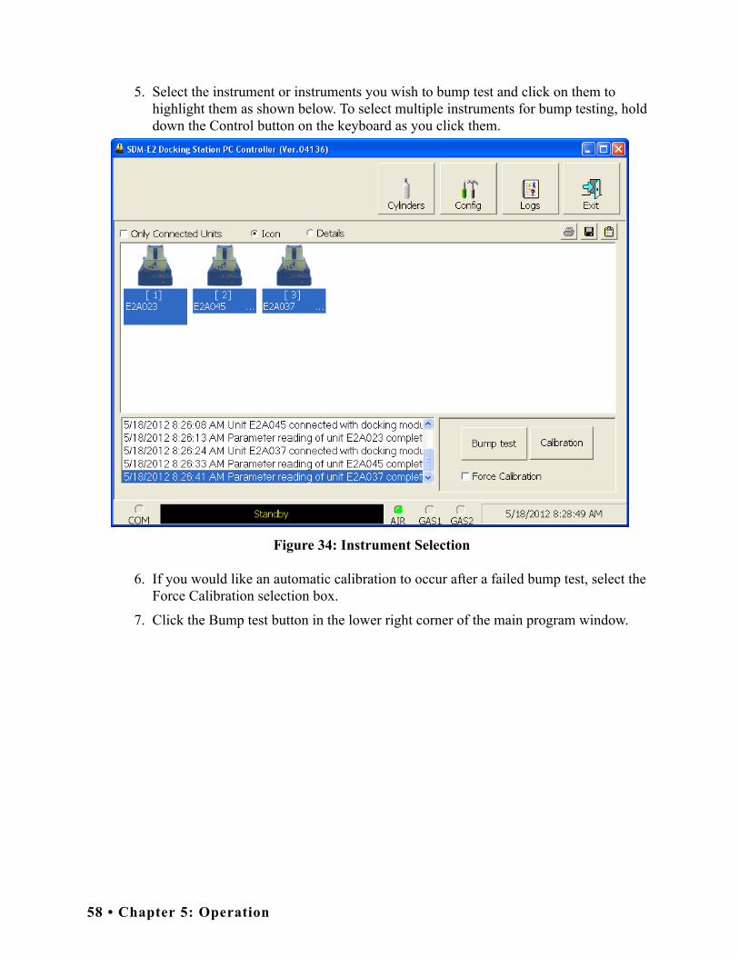
5. Select the instrument or instruments you wish to bump test and click on them to highlight them as shown below. To select multiple instruments for bump testing, hold down the Control button on the keyboard as you click them.
Figure 34: Instrument Selection
6. If you would like an automatic calibration to occur after a failed bump test, select the Force Calibration selection box.
7. Click the Bump test button in the lower right corner of the main program window.
58 • Chapter 5: Operation

8. You will be asked to confirm which EAGLE 2 channels will use GAS 1 for the bump test. When using a 3-gas (no H2S channel) or a 4-gas (H2S channel included) cylinder, to bump test a standard instrument, select all channels. If your instrument has fewer than 4 channels, your screen will only display the active channels.
Figure 35: Gas Cylinder Confirmation Screen
When all of the desired channels are selected, click OK. If you don’t want to proceed, click Cancel to abort the bump test.
Chapter 5: Operation • 59

9. You will then be asked to confirm the gas cylinder concentration and the instruments that the cylinder will be used for. The serial number and gas combination of all selected instruments will appear sequentially beneath the gas cylinder concentration.
Figure 36: Gas Order Confirmation Screen
10.Click OK. You will be asked if you want to bump test the instrument(s). Click OK to proceed. If you don’t want to proceed with the bump test, click Cancel to return to the main program window.
60 • Chapter 5: Operation

11.The pump will start and the program will indicate that air is flowing. The AIR indicator on the program screen will be on and air will be applied to the instrument(s) for 45 seconds, then the PC Controller Program will perform a zero adjustment on all the channels. The BUMP LED on the SDM-E2 control panel will be flashing amber.
Figure 37: Air Flowing
The PC Controller Program will analyze the zero adjustment results. If any sensors failed the zero adjustment, the bump test will be aborted.
Chapter 5: Operation • 61

12.After air is applied, and if all the channels passed the zero adjustment, calibration gas will be applied. The GAS 1 indicator on the program screen will come on and calibration gas will be applied to the instrument(s) for the duration specified in the Gas Exposure Time parameter in the Configuration Window.
Figure 38: Calibration Gas Flowing
The PC Controller Program will analyze the results. If the bump test on the standard 4 sensors fails and Force Calibration is selected, a calibration will automatically begin and GAS 1 calibration gas will continue to flow.
62 • Chapter 5: Operation

13.After calibration gas is applied, the docking station will purge with fresh air for 45 seconds.
Figure 39: Fresh Air Purge
Chapter 5: Operation • 63

14.After the fresh air purge is complete,
• If the bump test passes, the following window will open indicating that. The BUMP LED will be solid green. Click OK to return to the main program window. The BUMP LED will turn off.
Figure 40: Bump Test Passed
The EAGLE 2 will automatically be shut off 20 seconds after a successful bump test.
64 • Chapter 5: Operation

• If the bump test fails and the Force Calibration box was not selected, the following window will open indicating which channels failed the bump test. The BUMP LED on the SDM-E2 control panel will be solid red. Click OK to return to the main program window or double click the instrument information line to view the bump test results in the Logs window. The BUMP LED on the SDM-E2 control panel will turn off.
Figure 41: Bump Test Failed
Chapter 5: Operation • 65

• If the bump test fails and the Force Calibration box was selected, the SDM-E2 automatically performs a calibration immediately after the failed bump test. The results screen will indicate the results of both the bump test and calibration. The BUMP LED on the SDM-E2 control panel will be solid red. The CAL LED will be solid green if the calibration passed or solid red if the calibration failed. Click OK to return to the main program window or double click an instrument information line to view the bump test or calibration results in the Logs window. The BUMP LED and CAL LED on the SDM-E2 control panel will turn off.
Figure 42: Bump Test Failed/Calibration Failed
66 • Chapter 5: Operation
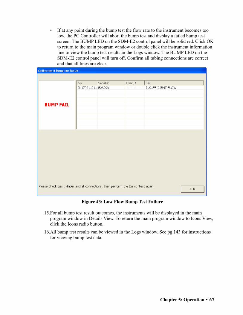
• If at any point during the bump test the flow rate to the instrument becomes too low, the PC Controller will abort the bump test and display a failed bump test screen. The BUMP LED on the SDM-E2 control panel will be solid red. Click OK to return to the main program window or double click the instrument information line to view the bump test results in the Logs window. The BUMP LED on the SDM-E2 control panel will turn off. Confirm all tubing connections are correct and that all lines are clear.
Figure 43: Low Flow Bump Test Failure
15.For all bump test result outcomes, the instruments will be displayed in the main program window in Details View. To return the main program window to Icons View, click the Icons radio button.
16.All bump test results can be viewed in the Logs window. See pg.143 for instructions for viewing bump test data.
Chapter 5: Operation • 67

Calibrating a Standard 4-Gas Instrument
The following instructions apply to EAGLE 2s with one or more of the standard four sensors (catalytic LEL, O2, H2S, and CO) when you are using only a 3-gas or 4-gas cylinder. RKI Instruments, Inc. recommends using a 3-gas or 4-gas cylinder instead of multiple cylinders for calibrating standard instruments. If your EAGLE 2 includes one or more special sensors such as a TC, PID, ESM-01, etc., see pg.94.
The PC Controller Program is capable of performing a calibration both manually and automatically on an EAGLE 2. When a calibration is performed, the PC Controller Program performs an air adjust operation on an EAGLE 2 and then applies calibration gas to the EAGLE 2. The PC Controller Program analyzes the calibration results and determines if the EAGLE 2 passed the calibration.
To manually calibrate an instrument or instruments:
1. Establish a connection between the SDM-E2, EAGLE 2 and the PC Controller program as described on pg.47.
WARNING: Do not plug the charger cable into a battery pack that contains alkaline batteries. Do not attempt to charge alkaline batteries.
2. Verify that all of the calibration parameters are set correctly. See pg.33 for instructions.
3. Verify that the appropriate calibration gas cylinder or cylinders is connected to the appropriate SDM-E2 or manifold line.
4. Ensure that the gas out to EAGLE 2 line is connected to the inlet of the EAGLE 2.
68 • Chapter 5: Operation

5. Select the instrument or instruments you wish to calibrate and click on them to highlight them as shown below. To select more than one instrument for calibration, hold down the Control button on the keyboard as you click them.
Figure 44: Instrument Selection
6. Click the Calibration button in the lower right corner of the main program window.
Chapter 5: Operation • 69

7. You will be asked to confirm which EAGLE 2 channels will use GAS 1 for the calibration. When using a 3-gas (no H2S channel) or a 4-gas (H2S channel included) cylinder, to calibrate a standard instrument, select all channels. If your instrument has fewer than 4 channels, your screen will only display the active channels.
Figure 45: Gas Cylinder Confirmation Screen
When all of the desired channels are selected, click OK. If you don’t want to proceed, click Cancel to abort the calibration.
70 • Chapter 5: Operation

8. You will then be asked to confirm the gas cylinder concentration and the instruments that the cylinder will be used for. The serial number and gas combination of all selected instruments will appear sequentially beneath the gas cylinder concentration.
Figure 46: Gas Order Confirmation
9. Click OK. You will be asked if you want to calibrate the instrument(s). Click OK to proceed. If you don’t want to proceed with the calibration, click Cancel to return to the main program window.
Chapter 5: Operation • 71

10.The pump will start and the program will indicate that air is flowing. The CAL LED will begin to flash amber. Air will be applied to the instrument(s) for 45 seconds, then the PC Controller Program will perform a zero adjustment on all the channels.
Figure 47: Air Flowing
The PC Controller Program will analyze the zero adjustment results. If any sensors failed the zero adjustment, the calibration will be aborted.
72 • Chapter 5: Operation

11.After air is applied, and if all the channels passed the zero adjustment, calibration gas will be applied. The GAS 1 indicator on the program screen will come on. Calibration gas will be applied to the instrument(s) for 90 seconds.
Figure 48: Calibration Gas Flowing
The PC Controller Program will analyze the results.
Chapter 5: Operation • 73

12.After calibration gas is applied, the docking station will purge with fresh air for 45 seconds.
Figure 49: Fresh Air Purge
74 • Chapter 5: Operation

13.After the fresh air purge is complete,
• If the calibration passes, the following window will open indicating that. The CAL LED on the SDM-E2 control panel will be solid green. Click OK to return to the main program window. The CAL LED will turn off.
Figure 50: Calibration Passed
The EAGLE 2 will automatically be shut off 20 seconds after a successful calibration.
Chapter 5: Operation • 75

• If the calibration fails, the following window will open indicating which channels failed to calibrate. The CAL LED on the SDM-E2 control panel will be solid red. Click OK to return to the main program window or double click the instrument information line to view the calibration results in the Logs window. The CAL LED on the SDM-E2 control panel will turn off.
Figure 51: Calibration Failed
76 • Chapter 5: Operation

• If at any point during the calibration the flow rate to the instrument becomes too low, the PC Controller will abort the calibration and display a failed calibration screen. The CAL LED on the SDM-E2 control panel will be solid red. Click OK to return to the main program window or double click the instrument information line to view the calibration results in the Logs window. The CAL LED on the SDM-E2 control panel will turn off. Confirm all tubing connections are correct and that all lines are clear.
Figure 52: Low Flow Calibration Failure
14.For all calibration result outcomes, the instrument(s) will be displayed in the main program window in Details View. To return to Icons View, click the Icons radio button.
15.All calibration results can be viewed in the Logs window. See pg.126 for instructions for viewing calibration data.
Chapter 5: Operation • 77

Bump Testing an Instrument with Special Sensors
Standard EAGLE 2s contain some combination of the standard 4 sensors (catalytic LEL, O2, H2S, and CO). Any other sensor that is installed in your EAGLE 2 is considered a special sensor. A special sensor is a PID, TC, IR, or ESM-01 sensor. In the examples that follow, EAGLE 2s with the standard 4 sensors and an ammonia ESM-01 and a PID sensor are described. For instructions to bump test a standard EAGLE 2, see pg.57. For instructions to bump test multiple EAGLE 2s with different configurations, see pg.190.
The PC Controller Program is capable of performing a bump test both manually and automatically when an EAGLE 2 is connected to it. When a bump test is performed, the PC Controller Program performs an air adjust operation on an EAGLE 2 and then applies calibration gas to the instrument. The program analyzes the response results based on predefined criteria and determines if the EAGLE 2 passed the bump test.
The criteria that the PC Controller Program uses to determine if the EAGLE 2 passes a bump test, whether the Bump Test button is active, and whether or not the PC Controller Program automatically performs a bump test if it is due on a connected EAGLE 2 is defined in the Parameter tab of the Configuration Window. See pg.33 for a description of the bump test configuration setup.
To manually bump test an instrument or instruments with a special sensor:
1. Establish a connection between the SDM-E2, EAGLE 2 and the PC Controller program as described in “Connecting Instruments to the PC Controller Program” on page 47.
WARNING: Do not plug the charger cable into a battery pack that contains alkaline batteries. Do not attempt to charge alkaline batteries.
2. Verify that all of the bump test parameters are set correctly. See pg.33 for instructions.
3. Verify that the appropriate calibration gas cylinder(s) are connected to the appropriate SDM-E2(s) or manifold line(s).
NOTE: If you have an EAGLE 2 with an IR CO2 sensor in the 0-10,000 ppm or 0-5.00 %vol range, be sure to replace the air filter at the AIR inlet fitting with the CO2 scrubber when testing an instrument with a CO2 sensor installed to ensure that the CO2 present in fresh air is scrubbed out. Remove the black end caps from each end of the scrubber before installing onto the AIR inlet fitting. Replace the caps when the scrubber is not in use. See the pg.187 for a scrubber with a tubing stub.
WARNING: RKI Instruments, Inc. recommends that you dedicate a regulator for use with chlorine (Cl2) gas and that you do not use that dedicated regulator for any other gases, particularly hydrogen sulfide (H2S).
4. Ensure that the gas out to EAGLE 2 line is connected to the inlet of the EAGLE 2.
78 • Chapter 5: Operation

5. Select the instrument or instruments you wish to bump test and click on them to highlight them as shown below. To select multiple instruments for bump testing, hold down the Control button on the keyboard as you click them.
Figure 53: Instrument Selection
6. If you would like an automatic calibration to occur after a failed bump test, select the Force Calibration selection box.
7. Click the Bump test button in the lower right corner of the main program window.
Chapter 5: Operation • 79

8. You will be asked to confirm which EAGLE 2 channels will use GAS 1 for the bump test. If you have a 5 gas cylinder that includes the target gas of the special sensor in the appropriate concentration, then be sure that all 5 channels (or fewer if less than 4 standard channels are active) are selected for GAS 1. If you are using a standard 4-gas cylinder and a separate cylinder for the special sensor(s), leave the special sensor(s) deselected in this screen.
Figure 54: Gas Cylinder Confirmation Screen
When all of the desired channels are selected, click OK. If you don’t want to proceed, click Cancel to abort the bump test.
NOTE: If your instrument(s) include one or more infrared sensors, see pg.223 for a description of the GAS 1/GAS 2 assignments for this type of sensor.
Separate GAS 2 cylinder 5-gas cylinder
80 • Chapter 5: Operation

9. You will then be asked to confirm the gas cylinder concentration and the instruments that the cylinder will be used for. The serial number and gas combination of all selected instruments will appear sequentially beneath the gas cylinder concentrations. The screen below confirms that the standard 4 sensors will be bump tested using GAS 1 and the special sensor will be bump tested using GAS 2. The GAS 2 selection box is deselected by default. You must select the GAS 2 box if you wish to bump test the special sensor. If you do not wish to bump test the special sensor, leave the GAS 2 box deselected.
Figure 55: Gas Order Confirmation Screen, Separate GAS 2 Cylinder
Chapter 5: Operation • 81

If you have a 5-gas cylinder that contains the special sensor’s target gas in the correct concentration, the confirmation screen will appear as shown below. All sensors will be calibrated using GAS 1.
Figure 56: Gas Order Confirmation Screen, 5-Gas Cylinder
82 • Chapter 5: Operation

If you are bump testing an instrument or instruments with 2 special sensors, the confirmation screen will indicate that the calibration cylinder for the first special sensor (in this case, NH3) must be connected to the GAS 2 fitting first and that you must change the GAS 2 cylinder midway through the bump test (in this example, to IBL). The GAS 2 shown in the middle column will always be bump tested before the GAS 2 shown in the right column. The GAS 2 selection boxes are deselected by default. You must select the GAS 2 boxes if you wish to bump test the special sensors. If you do not wish to bump test the special sensors, leave the GAS 2 boxes deselected. Be sure that the appropriate GAS 2 cylinder is connected to the GAS 2 fitting.
Figure 57: Multiple GAS 2 Cylinder Confirmation
10.Click OK. You will be asked if you want to bump test the instrument(s). Click OK to proceed. If you don’t want to proceed with the bump test, click Cancel to return to the main program window.
Chapter 5: Operation • 83

11.The pump will start and the program will indicate that air is flowing. The AIR indicator on the program screen will be on. The BUMP LED on the SDM-E2 control panel will be flashing amber. Air will be applied to the EAGLE 2 for 45 seconds, then the PC Controller Program will perform a zero adjustment on all the channels.
Figure 58: Air Flowing
The PC Controller Program will analyze the zero adjustment results. If any sensors failed the zero adjustment, the bump test will be aborted.
84 • Chapter 5: Operation

12.After air is applied, and if all channels passed the zero adjustment, calibration gas from the GAS 1 cylinder will be applied. The GAS 1 indicator on the program screen will come on and calibration gas will be applied to the instrument(s) for the duration specified in the Gas Exposure Time parameter in the Configuration Window.
Figure 59: GAS 1 Flowing
The PC Controller Program will analyze the results. If the bump test on the standard 4 sensors fails and Force Calibration is selected, a calibration will automatically begin and GAS 1 calibration gas will continue to flow.
Chapter 5: Operation • 85

13.After GAS 1 calibration gas is applied, calibration gas for the first special sensor will then begin flowing. The GAS 2 indicator will come on. Be sure that the appropriate cylinder is attached to the GAS 2 inlet. The GAS 2 calibration gas will be applied to the instrument(s) for the duration specified in the Gas Exposure Time parameter in the Configuration Window.
Figure 60: GAS 2 Flowing
The PC Controller Program will analyze the results. If the bump test on the first special sensor fails and Force Calibration is selected, a calibration will automatically begin and GAS 2 calibration gas will continue to flow.
86 • Chapter 5: Operation

14.If you are bump testing an instrument or instruments with 2 special sensors, you will then be prompted to change the GAS 2 cylinder. The pumps on the instruments will stop.
• If you are bump testing an instrument or instruments in the first bank of 5 docking stations (numbered 1-5), the following screen will appear. Be sure to change the calibration cylinder connected to the GAS 2 manifold of the first bank of 5 docking stations.
• If you are bump testing an instrument or instruments in the second bank of 5 docking stations (numbered 6-10), the following screen will appear. Be sure to change the calibration cylinder connected to the GAS 2 manifold of the second bank of 5 docking stations.
• If you are bump testing instruments of the same configuration in both 5-docking station banks, the following screen will appear. Be sure to change the calibration cylinder connected to the GAS 2 manifold of each 5-docking station bank. You will need to change 2 cylinders.
When you have changed the GAS 2 cylinder, click OK. The bump test will continue and the second GAS 2 calibration gas will be applied to the instrument(s) for the duration specified in the Gas Exposure Time parameter in the Configuration Window.
Chapter 5: Operation • 87

Figure 61: Second GAS 2 Flowing
The PC Controller Program will analyze the results. If the bump test on the second special sensor fails and Force Calibration is selected, a calibration will automatically begin and GAS 2 calibration gas will continue to flow.
88 • Chapter 5: Operation

15.After GAS 2 calibration gas has been applied, the docking station will purge with fresh air for 45 seconds.
Figure 62: Fresh Air Purge
Chapter 5: Operation • 89

16.After the fresh air purge is complete,
• If the bump test passes, the following window will open indicating that. The BUMP LED will be solid green. Click OK to return to the main program window. The BUMP LED will turn off.
Figure 63: Bump Test Passed
The EAGLE 2 will automatically be shut off 20 seconds after a successful bump test.
90 • Chapter 5: Operation

• If the bump test fails and the Force Calibration box was not selected, the following window will open indicating which channels failed the bump test. The BUMP LED on the SDM-E2 control panel will be solid red. Click OK to return to the main program window or double click the instrument information line to view the bump test results in the Logs window. The BUMP LED on the SDM-E2 control panel will turn off.
Figure 64: Bump Test Failed
Chapter 5: Operation • 91

• If the bump test fails and the Force Calibration box was selected, the SDM-E2 automatically performs a calibration immediately after the failed bump test. The results screen will indicate the results of both the bump test and calibration. The BUMP LED on the SDM-E2 control panel will be solid red. The CAL LED will be solid green if the calibration passed or solid red if the calibration failed. Click OK to return to the main program window or double click an instrument information line to view the bump test or calibration results in the Logs window. The BUMP LED and CAL LED on the SDM-E2 control panel will turn off.
Figure 65: Bump Test Failed/Calibration Failed
92 • Chapter 5: Operation

• If at any point during the bump test the flow rate to the instrument becomes too low, the PC Controller will abort the bump test and display a failed bump test screen. The BUMP LED on the SDM-E2 control panel will be solid red. Click OK to return to the main program window or double click the instrument information line to view the bump test results in the Logs window. The BUMP LED on the SDM-E2 control panel will turn off. Confirm all tubing connections are correct and that all lines are clear.
Figure 66: Low Flow Bump Test Failure
17.For all bump test result outcomes, the instruments will be displayed in the main program window in Details View. To return the main program window to Icons View, click the Icons radio button.
18.All bump test results can be viewed in the Logs window. See pg.143 for instructions for viewing bump test data.
Chapter 5: Operation • 93
Calibrating an Instrument with Special Sensors
Standard EAGLE 2s contain some combination of the standard 4 sensors (catalytic LEL, O2, H2S, and CO). Any other sensor that is installed in your EAGLE 2 is considered a special sensor. A special sensor is a PID, TC, IR, or ESM-01 sensor. In the examples that follow, EAGLE 2s with the standard 4 sensors and an ammonia ESM-01 and a PID sensor are described. For instructions to calibrate a standard EAGLE 2, see pg.68. For instructions to calibrate multiple EAGLE 2s with different configurations, see pg.207.
The PC Controller Program is capable of performing a calibration both manually and automatically on an EAGLE 2. When a calibration is performed, the PC Controller Program performs an air adjust operation on an EAGLE 2 and then applies calibration gas to the EAGLE 2. The PC Controller Program analyzes the calibration results and determines if the EAGLE 2 passed the calibration.
To manually calibrate an instrument or instruments with a special sensor:
1. Establish a connection between the SDM-E2, EAGLE 2 and the PC Controller program as described on pg.47.
WARNING: Do not plug the charger cable into a battery pack that contains alkaline batteries. Do not attempt to charge alkaline batteries.
2. Verify that all of the calibration parameters are set correctly. See pg.33 for instructions.
3. Verify that the appropriate calibration gas cylinder(s) are connected to the appropriate SDM-E2(s) or manifold line(s).
NOTE: If you have an EAGLE 2 with an IR CO2 sensor in the 0-10,000 ppm or 0-5.00 %vol range, be sure to replace the air filter at the AIR inlet fitting with the CO2 scrubber when testing an instrument with a CO2 sensor installed to ensure that the CO2 present in fresh air is scrubbed out. Remove the black end caps from each end of the scrubber before installing onto the AIR inlet fitting. Replace the caps when the scrubber is not in use. See the pg.187 for a scrubber with a tubing stub.
WARNING: RKI Instruments, Inc. recommends that you dedicate a regulator for use with chlorine (Cl2) gas and that you do not use that dedicated regulator for any other gases, particularly hydrogen sulfide (H2S).
4. Ensure that the gas out to EAGLE 2 line is connected to the inlet of the EAGLE 2.
94 • Chapter 5: Operation

5. Select the instrument or instruments you wish to calibrate and click on them to highlight them as shown below. To select multiple instruments for calibration, hold down the Control button on the keyboard as you click them.
Figure 67: Instrument Selection
6. Click the Calibration button in the lower right corner of the computer program screen.
Chapter 5: Operation • 95

7. You will be asked to confirm which EAGLE 2 channels will use GAS 1 for the calibration. If you have a 5 gas cylinder that includes the target gas of the special sensor in the appropriate concentration, then be sure that all 5 channels (or fewer if less than 4 standard channels are active) are selected for GAS 1. If you are using a standard 4-gas cylinder and a separate cylinder for the special sensor(s), leave the special sensor(s) deselected in this screen.
Figure 68: Gas Cylinder Confirmation Screen
When all of the desired channels are selected, click OK. If you don’t want to proceed, click Cancel to abort the calibration.
NOTE: If your instrument(s) include one or more infrared sensors, see pg.223 for a description of the GAS 1/GAS 2 assignments for this type of sensor.
Separate GAS 2 cylinder 5-gas cylinder
96 • Chapter 5: Operation

8. You will then be asked to confirm the gas cylinder concentration and the instruments that the cylinder will be used for. The serial number and gas combination of all selected instruments will appear sequentially beneath the gas cylinder concentrations. The screen below confirms that the standard 4 sensors will be calibrated using GAS 1 and the special sensor will be calibrated using GAS 2. The GAS 2 selection box is deselected by default. You must select the GAS 2 box if you wish to calibrate the special sensor. If you do not wish to calibrate the special sensor, leave the GAS 2 box deselected.
Figure 69: Gas Order Confirmation Screen
Chapter 5: Operation • 97

If you have a 5-gas cylinder that contains the special sensor’s target gas in the correct concentration, the confirmation screen will appear as shown below. All sensors will be calibrated using GAS 1.
Figure 70: Gas Order Confirmation Screen, 5-Gas Cylinder
98 • Chapter 5: Operation

If you are calibrating an instrument or instruments with 2 special sensors, this confirmation screen will indicate that the calibration cylinder for the first special sensor (in this case, NH3) must be connected to the GAS 2 fitting first and that you must change the GAS 2 cylinder midway through the calibration (in this example, to IBL). The GAS 2 shown in the middle column will always be calibrated before the GAS 2 shown in the right column. The GAS 2 selection boxes are deselected by default. You must select the GAS 2 boxes if you wish to calibrate the special sensors. If you do not wish to calibrate the special sensors, leave the GAS 2 boxes deselected. Be sure that the appropriate GAS 2 cylinder is connected to the GAS 2 fitting.
Figure 71: Multiple GAS 2 Cylinder Confirmation
9. Click OK. You will be asked if you want to calibrate the instrument(s). Click OK to proceed. If you don’t want to proceed with the calibration, click Cancel to return to the main program window.
Chapter 5: Operation • 99

10.The pump will start and the program will indicate that air is flowing. The AIR indicator on the program screen will be on. The CAL LED will begin to flash amber. Air will be applied to the instrument(s) for 45 seconds, then the PC Controller Program will perform a zero adjustment on all of the channels.
Figure 72: Air Flowing
The PC Controller Program will analyze the zero adjustment results. If any sensors failed the zero adjustment, the calibration will be aborted.
100 • Chapter 5: Operation

11.After air is applied, and if all channels passed the zero adjustment, calibration gas from the GAS 1 cylinder will be applied. The GAS 1 indicator on the program screen will come on. GAS 1 calibration gas will be applied to the instrument for 90 seconds.
Figure 73: GAS 1 Flowing
The PC Controller Program will analyze the results.
Chapter 5: Operation • 101

12.After the GAS 1 calibration gas is applied, calibration gas for the first special sensor will then begin flowing. The GAS 2 indicator will come on. Be sure that the appropriate cylinder is attached to the GAS 2 inlet. The GAS 2 calibration gas will be applied to the EAGLE 2 for an automatically defined amount of time based on the type of special sensor.
Figure 74: GAS 2 Flowing
The PC Controller Program will analyze the results.
102 • Chapter 5: Operation

13.If you are calibrating an instrument or instruments with 2 special sensors, you will then be prompted to change the GAS 2 cylinder. The pumps on the instruments will stop.
• If you are calibrating an instrument or instruments in the first bank of 5 docking stations, the following screen will appear. Be sure to change the calibration cylinder connected to the GAS 2 manifold of the first bank of 5 docking stations.
• If you are calibrating an instrument or instruments in the second bank of 5 docking stations, the following screen will appear. Be sure to change the calibration cylinder connected to the GAS 2 manifold of the second bank of 5 docking stations.
• If you are calibrating instruments of the same configuration in both 5-docking station banks, the following screen will appear. Be sure to change the calibration cylinder connected to the GAS 2 manifold of each 5-docking station bank. You will need to change 2 cylinders.
When you have changed the GAS 2 cylinder, click OK. The calibration will continue and the second GAS 2 calibration gas will be applied to the EAGLE 2 for an automatically defined amount of time based on the type of special sensor.
Chapter 5: Operation • 103

Figure 75: Second GAS 2 Flowing
The PC Controller Program will analyze the results.
104 • Chapter 5: Operation

14.After calibration gas is applied, the docking stations will purge with fresh air for 45 seconds.
Figure 76: Fresh Air Purge
Chapter 5: Operation • 105

15.After the fresh air purge is complete,
• If the calibration passes, the following window will open indicating that. The CAL LED on the SDM-E2 control panel will be solid green. Click OK to return to the main program window. The CAL LED will turn off.
Figure 77: Calibration Passed
The EAGLE 2 will automatically be shut off 20 seconds after a successful calibration.
106 • Chapter 5: Operation

• If the calibration fails, the following window will open indicating which channels failed to calibrate. The CAL LED on the SDM-E2 control panel will be solid red. Click OK to return to the main program window or double click the instrument information line to view the calibration results in the Logs window. The CAL LED on the SDM-E2 control panel will turn off.
Figure 78: Calibration Failed
Chapter 5: Operation • 107

• If at any point during the calibration the flow rate to the instrument becomes too low, the PC Controller will abort the calibration and display a failed calibration screen. The CAL LED on the SDM-E2 control panel will be solid red. Click OK to return to the main program window or double click the instrument information line to view the calibration results in the Logs window. The CAL LED on the SDM-E2 control panel will turn off. Confirm all tubing connections are correct and that all lines are clear.
Figure 79: Low Flow Calibration Failure
16.For all calibration result outcomes, the instrument(s) will be displayed in the main program window in Details View. To return to Icons View, click the Icons radio button.
17.All calibration results can be viewed in the Logs window. See “Calibration Data” on page 126 for instructions for viewing calibration data.
Power Off Function
This function can be activated by either right clicking an instrument and selecting Power Off(P) when the pull down menu appears or by selecting an instrument and then using the alt/P key combination. The Power Off function turns off the selected instrument. If you select Power Off, a confirmation box appears. Click OK to turn off the selected unit.
108 • Chapter 5: Operation

Chapter 6: Maintenance
Troubleshooting
NOTE: This troubleshooting guide describes SDM-E2 problems only. See the EAGLE 2 Operator’s Manual for problems you may encounter with the EAGLE 2.
Table 4: Troubleshooting the SDM-E2
Symptoms Probable Causes Recommended Action
• Fresh air adjustment fails
• The SDM-E2 is not in a fresh air environment or the cylinder being used is not a zero air cylinder.
• If a zero air cylinder is used, the calibration cylinder is out of gas.
• If a zero air cylinder is used, the gas out to EAGLE 2 line is not connected to the inlet of the EAGLE 2.
1. Confirm that the SDM-E2 is in a fresh air environment or that a zero air cylinder is attached to the AIR fitting.
2. If a zero air cylinder is used, verify that it contains an adequate supply of test sample.
3. Check to make sure the gas out to EAGLE 2 line is connected to the inlet of the EAGLE 2.
4. If a zero air cylinder is used, check all calibration tubing for leaks or for any bad connections.
5. If the fail condition continues, replace the sensor(s) in the EAGLE 2.
6. If the difficulties continue, contact RKI Instruments, Inc. for further instruction.
Chapter 6: Maintenance • 109

• Calibration fails • The auto calibration values do not match the cylinder gas concentrations.
• The calibration cylinder is out of gas or is outdated.
• The calibration cylinder is not connected to the appropriate GAS 1 or GAS 2 fitting.
• The gas out to EAGLE 2 line is not connected to the inlet of the EAGLE 2.
• The tubing from the regulator to the GAS 1 or GAS 2 fitting or manifold is not connected.
1. Confirm that the auto calibration values match the concentrations listed on the gas cylinder.
2. Verify that the calibration cylinder contains an adequate supply of fresh test sample.
3. Verify that the calibration cylinder is connected to the appropriate GAS 1 or GAS 2 fitting.
4. Check to make sure the gas out to EAGLE 2 line is connected to the inlet of the EAGLE 2.
5. Check all calibration tubing for leaks or for any bad connections.
6. If the fail condition continues, replace the sensor(s) in the EAGLE 2.
7. If the difficulties continue, contact RKI Instruments, Inc. for further instruction.
• No connection between EAGLE 2 and PC Controller Program
• SDM-E2 is not turned on.
• The EAGLE 2 is not correctly inserted into the instrument cradle.
• The IR window is dirty.
• The USB cable is not properly plugged into the SDM-E2 or the PC.
1. Turn on the SDM-E2. If it does not turn on, check that the AC adapter is plugged into an AC socket and to the jack on the back of the SDM-E2.
2. Check to make sure the EAGLE 2 is inserted properly.
3. Clean the IR window on the SDM-E2.
4. Check to make sure the USB cable is plugged into the back of the SDM-E2 and to a USB port on your PC.
5. If the difficulties continue, contact RKI Instruments, Inc. for further instruction.
• The batteries in the EAGLE 2 are not charging
• The EAGLE 2 has alkaline batteries installed.
• One of the rechargeable batteries is faulty.
• The charging plug from the SDM-E2 is not fully inserted in the EAGLE 2 jack.
• The charger is malfunctioning.
1. Check to make sure your EAGLE 2 doesn’t have alkaline batteries installed.
2. Replace the rechargeable batteries and attempt to charge them.
3. Be sure that the charging plug from the SDM-E2 is fully inserted in the EAGLE 2 jack.
4. If the difficulties continue, contact RKI Instruments, Inc. for further instruction.
110 • Chapter 6: Maintenance

Charging an Instrument in an SDM-E2
The SDM-E2 can be used to charge the rechargeable batteries in an EAGLE 2. To maximize the EAGLE 2’s run time and the battery life, make sure the batteries’ charge is as low as possible before recharging them.
WARNING: Do not plug the charger cable into a battery pack that contains alkaline batteries. Do not attempt to charge alkaline batteries.
Recharging a Battery Pack After Performing a Bump Test or Calibration
To recharge the battery pack in an instrument after performing a bump test or calibration:
1. Perform a bump test or calibration on an instrument.
2. After the bump test or calibration has been completed, turn off the instrument(s) by selecting the instrument(s), right clicking on them, and selecting Power Off. The docking station will automatically turn off the instrument(s) 20 seconds after a successful bump test or calibration or if there is no activity for the time period defined by Auto Power OFF Time in the Configuration Window.
3. Be sure that the AC adapter is plugged into a wall outlet and that the power jack is plugged into the back panel of the SDM-E2.
4. Plug the charger cable into the charging jack at the back of the EAGLE 2. Before you plug in the charger cable, the CHARGE LED will be blinking green. After you plug in the charger cable, the CHARGE LED will blink amber.
NOTE: The SDM-E2 does not start charging the batteries until the EAGLE 2 is off. If the charger cable is plugged into the charging jack on the EAGLE 2 while the instrument is still on, the CHARGE LED will blink green. Once the instrument is shut off, the CHARGE LED will begin to blink amber.
5. If the battery pack is fully charged, then the CHARGE LED will turn solid green in a few minutes.
If the battery pack is drained enough for the docking station to charge it, the CHARGE LED will continue to blink amber while charging is taking place. The SDM-E2 will take approximately 10 hours to charge a fully discharged EAGLE 2.
If you are attempting to charge alkaline batteries, the CHARGE LED will either turn steadily red or start to blink red 2-3 minutes after the charger cable has been plugged into the charger jack.
NOTE: If alkaline batteries are detected, the SDM-E2 must be turned off and on again before attempting to charge another battery pack.
Chapter 6: Maintenance • 111

If the charging process encounters a fail condition, the CHARGE LED will turn steadily red. A fail condition could indicate that there is something wrong with the NiMH batteries or that there is something wrong with the charger.
6. When the charge is complete, the CHARGE status LED will turn solid green.
Recharging a Battery Pack Without Performing Any Operations
To recharge the batteries in an instrument without performing any other operations:
1. Confirm that the AC adapter is connected to the back panel of the SDM-E2 and to an AC wall socket.
2. Plug the charger cable into the charging jack at the back of the EAGLE 2.
3. Press and hold the SDM-E2’s POWER button. When the LEDs turn on, release the POWER button. The COPY LED will remain on if the SDM-E2 was used in Standalone Configuration and calibration and bump test records are still stored in the SDM-E2’s memory (see the SDM-E2 Docking Station Standalone Configuration Manual for more information).
4. The CHARGE LED will be blinking amber.
5. If the battery pack is fully charged, then the blinking amber LED will turn solid green in a few minutes.
If the battery pack is drained enough for the SDM-E2 to charge it, the CHARGE LED will continue to blink amber while charging is taking place. The SDM-E2 will take approximately 10 hours to charge a fully discharged EAGLE 2.
If you are attempting to charge alkaline batteries, the CHARGE LED will either turn steadily red or start to blink red 2-3 minutes after the charger cable has been plugged into the charger jack.
NOTE: If alkaline batteries are detected, the SDM-E2 must be turned off and on again before attempting to charge another battery pack.
If the charging process encounters a fail condition, the CHARGE LED will turn steadily red. A fail condition could indicate that there is something wrong with the NiMH batteries or that there is something wrong with the charger.
6. When the charge is complete, the CHARGE status LED will turn solid green.
112 • Chapter 6: Maintenance

Batteries Too Drained for PC Controlled Operation
If the charger is connected to the EAGLE 2 and the batteries in the EAGLE 2 do not have enough power to keep the instrument on, it will go into a 20 minute charge cycle and the following screen will be displayed on the EAGLE 2.
It will not connect to the PC Program. The instrument cannot be bump tested or calibrated in the charge cycle. Once the 20 minute charge cycle has ended, the unit will automatically turn back on and connect to the PC Program. The unit can now be bump tested or calibrated.
LOW BATTERY
PLEASE WAITWHILE CHARGING
19’59”
Chapter 6: Maintenance • 113

Chapter 7: Managing Log Data
Download Function
This function can be activated by either right clicking an instrument and selecting Download(D) when the pull down menu appears or by selecting an instrument and then using the alt/D key combination. The Download function downloads all logged data and calibration information from the EAGLE 2. If you select Download(D), a confirmation box appears. Click the OK button to proceed with downloading from the instrument.
Clear Logs Function
This function can be activated by either right clicking an instrument and selecting Clear Logs(C) when the pull down menu appears or by selecting an instrument and then using the alt/C key combination. The Clear Logs function clears all logged data and calibration files from an instrument. If you select Clear Logs(C), a confirmation box appears. Click the OK button to proceed with clearing all the data from the instrument. The message window will indicate that the data is being cleared. When the data has been cleared, the message window will indicate this.
Logs Window Overview
The Logs Window contains saved data from EAGLE 2 instruments in addition to records of bump tests and calibrations performed with the PC Controller Program. If you perform a complete download by right clicking a selected instrument and clicking Download, the Logs Window will contain alarm trend data, calibration data, event data, interval trend data, memo data, and bump test data. If you do not perform a complete download or select Down Load Data Logger in the Configuration Window, the Logs Window will only have memo files and files for any bump tests or calibrations completed while the EAGLE 2 was connected to the PC Controller Program.
The Logs Window is divided into four frames. The upper left frame is the Data Frame and displays all the data folders. If no data has been saved, then no folders will appear in the Data Frame.
The upper right frame shows the contents of a data folder that is selected in the Data Frame. The lower right frame shows the summary information for a data file that is selected in the upper right frame.
114 • Chapter 7: Managing Log Data

The lower left frame contains three selection boxes for organizing data. When viewing the data, it can be organized in two ways:
1. Base View Format
If you do not select Serial No, Station ID, or User ID, the Base view box appears next to the selection boxes. The data can be organized by either data type or by the year and month of the saved data.
Figure 80: Logs Window in Base View Format, Date
To view data in the Date Base View Format:
a. Select Date in the Base view box.
b. Click the expanded view symbol (+) next to a date folder in the Data frame of the Logs window or double click the folder to view the contents below it.
c. Single click on the data type folder (Alarm, Calibration, etc.). All of the files in that data type folder will appear in the upper right frame of the Logs window.
Chapter 7: Managing Log Data • 115

d. If an item is expanded and you want to close it, click the (-) symbol next to the item or double click it.
Figure 81: Logs Window in Base View Format, Type
To view data in the Type Base View Format:
a. Select Type in the Base view box.
b. Click the expanded view symbol (+) next to a data type folder (Alarm, Calibration, etc.) in the Data frame of the Logs window or double click the folder to view the contents below it.
c. Single click on a date folder. The dates are displayed in year/month format. All of the files in that date folder will appear in the upper right frame of the Logs window.
d. If an item is expanded and you want to close it, click the (-) symbol next to the item or double click it.
116 • Chapter 7: Managing Log Data

2. ID View Format
The data may be organized by one or more of the following parameters:
• Serial Number
• Station ID
• User ID
If any of these boxes are selected, the Base view box disappears. Click the selection box or boxes in the lower left frame to organize the data as desired.
Figure 82: Logs Window in ID View Format
To view data in the ID View Format:
a. Select one or more of the ID view choices, Serial No., Station ID, or User ID.
b. Click the expanded view symbol (+) next to an ID folder (Serial No., Station ID, or User ID) in the Data frame of the Logs window or double click the folder to view the contents below it.
c. Click the expanded view symbol (+) next to the data type folder (Alarm, Calibration, etc.) you wish to view or double click the folder to view the contents below it.
d. Single click on a date folder. The dates are displayed in year/month format. All of the files in that date folder will appear in the upper right frame of the Logs window.
Chapter 7: Managing Log Data • 117

e. If an item is expanded and you want to close it, click the (-) symbol next to the item or double click it.
When viewing data by Serial No., no two EAGLE 2s should have the same serial number. However, if two EAGLE 2s do have the same serial number and have data for the same year/month, they will be distinguished by their different Station ID or User ID. When viewing data by Station ID or by User ID, if two EAGLE 2s have the same Station ID and/or User ID and have data for the same year/month, they will be distinguished by their different serial numbers.
NOTE: In the examples that follow, the data will be shown organized by serial number. If you do not select any of the organization boxes or select the Station ID or User ID boxes instead of or in addition to the Serial No. box, your Logs Window will look slightly different.
Alarm Trend Data
The EAGLE 2 saves files that describe the most recent gas alarm events. If a gas alarm event occurs, then an alarm trend file that is centered around the event is saved. It shows the readings up to 30 minutes before and 30 minutes after the event, with the log interval time every 5 seconds. The readings that are saved are the peak (minimum for oxygen) readings for the previous 5 seconds. If the EAGLE 2 was operating in Inert Mode at the time of the alarm, the maximum oxygen readings will be saved. If the EAGLE 2 has not been on for 30 minutes before the alarm event occurs, the data during this time is left blank. If the EAGLE 2 is turned off less than 30 minutes after an alarm event occurs, the data file will only have logged data until the unit was turned off.
The EAGLE 2 saves up to 8 alarm trend files. When an alarm event triggers an alarm trend file to be saved, subsequent alarm events must occur 15 minutes after the previous triggering event in order to trigger the saving of another alarm trend file. If 8 alarm trend files are already saved in the EAGLE 2’s memory, the oldest alarm trend file is overwritten when a new alarm trend file is saved.
Alarm trend data is downloaded from an EAGLE 2 when a complete download is performed. To view and perform desired operations with the alarm trend files:
1. While in the Logs window, find your instrument by serial number, then click the expanded view symbol (+) of or double-click the serial number folder to view the contents.
2. Click the expanded view symbol (+) of or double-click the Alarm folder to view the contents. Alarm trend data folders are arranged by year/month.
118 • Chapter 7: Managing Log Data

3. Click the year/month folder you wish to view. All alarm trend data files for that instrument in that particular year/month will appear in the upper right frame. The file number, serial number, station ID, user ID, model, date/time, and sample count of the alarm trend file appear in the same line.
Figure 83: Viewing Alarm Trend Files
Chapter 7: Managing Log Data • 119
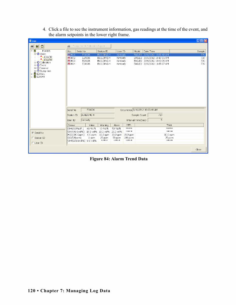
4. Click a file to see the instrument information, gas readings at the time of the event, and the alarm setpoints in the lower right frame.
Figure 84: Alarm Trend Data
120 • Chapter 7: Managing Log Data

5. To view the alarm trend data, double click the desired file.
Figure 85: Alarm Trend Data
Each data point will be displayed in the left half of the screen along with the peak readings (minimum for oxygen) over the previous 5 seconds. A graph of the data will appear on the right half of the screen.
To change the layout of the table and chart in relation to each other, click any of the four layout control buttons in the upper left corner of the screen.
To change the proportions of the table to the graph, click the divider between the two and move it.
To display instrument information along with the data table and graph, click the “i” control button in the upper left corner.
Restore PreviousLayout Control Buttons
Chapter 7: Managing Log Data • 121

6. In the table part of the screen,
• The gas readings at the time of the alarm event around which the logged data is centered are highlighted in red and are the instantaneous readings at that time.
• The catalytic combustible channel can be recorded in %LEL, ppm, or %volume units depending on the instrument setting. However, when viewing alarm trend data, the data for the catalytic LEL channel can only be viewed in one set of units. Use the CAT Range Select box to select the desired units. If %LEL is chosen as a unit, any ppm or %volume data is converted and shown in the table as %LEL. The user may change back and forth between the units for the table and still have all data shown.
• If installed, an infrared methane or hydrocarbon channel records data in %LEL and/or % volume units depending on whether the channel is configured as a % LEL channel or a %LEL/% volume autoranging channel. When viewing the alarm trend data in table format, the units are displayed as the unit the reading was recorded in. In the following figure, the first channel is a catalytic LEL channel and the fifth channel is an IR autoranging CH4 channel.
Figure 86: Autoranging IR CH4 Alarm Trend Data, Table Format
122 • Chapter 7: Managing Log Data

7. In the graph part of the screen,
• You can choose which gas(es) you want to graph by selecting or deselecting the boxes next to each gas name.
• You can select the display units for the catalytic LEL channel (%LEL, ppm, vol%). While readings can be recorded in any of these units and stored in the same file, those readings may only be graphed in one unit at a time. If %LEL is chosen as the unit, any ppm or %volume data is converted and graphed as %LEL. The user may change back and forth between the units for the graph and still have all data shown. The CAT Range Select box is where the user may select %LEL, ppm, or %volume as the units for the graph.
• If installed, an IR HC or CH4 channel can be graphed in %LEL or % volume in order to accurately depict the full range of the sensor.
If the channel is configured as a %LEL only channel, then data will only be recorded in %LEL and the range will be 0-100% LEL. Any gas concentration above that level will not be recorded.
If the channel is configured as a %LEL/% volume autoranging channel, then data will be recorded in %LEL and % volume where appropriate. It will record data in %LEL up to 100% LEL and then it will start recording data in % volume up to 100% volume. If %LEL is chosen as the graphing units, all data collected for a %LEL only channel will be displayed. Any data collected in an autoranging configuration that exceeds 100% LEL will not be shown. In order to view data above 100% LEL, % volume must be selected. When % volume is selected, all data will be shown in terms of % volume.
Chapter 7: Managing Log Data • 123

The IR Range Select box is located in the upper right corner of the graph portion of the alarm trend screen just to the right of the CAT Range Select screen and is used to make the unit selection for the IR channel.
Figure 87: Autoranging IR CH4 Alarm Trend Data, Graph Format
NOTE: The IR Range Select box in the upper right hand corner only appears if an IR HC or CH4 sensor is installed, is in use, and is set up for autoranging. If an IR HC or CH4 sensor is not installed, if its channel is turned off, or if the channel is set up for % LEL only, this box will not appear.
• To zoom in on a particular part of the graph, drag a box around that area so that it is highlighted in gray. The graph will zoom in. To return to a previous zoom, click the Previous control button in the upper right corner of the graph section. To return to the original zoom, click the Restore control button in the upper right corner of the graph section.
• A vertical red line appears on the graph at the point that created the alarm trend file. Clicking anywhere on the graph will move that red line and highlight that data point in the table. Clicking a data point in the table will move the red line in the graph to that data point.
124 • Chapter 7: Managing Log Data

8. To print the data, select either List or Graph in the upper right corner of the window and then click the Print control button in the upper right corner of the window. The Print control button has a printer icon on it. A dialog box will appear confirming if you want to print. Click OK. If Graph is selected, the data will print as a graph. If List is selected, the data will print as a table.
9. To save the data to a file which can be imported into another program, select either List or Graph in the upper right corner of the window and then click the Save to File control button. The Save to File control button has a floppy disk icon on it. A dialog box will appear for you to specify the file name, file location, and file type.
Figure 88: Save As Dialog Box
If List is selected, the file type is “.csv” (comma-separated values). If Graph is selected, the file type is “.bmp” (Windows bitmap). After specifying the file name and file location, click Save to save the file to the specified location.
10.To save the data to the clipboard, select either List or Graph in the upper right corner of the window and then click the Copy to Clipboard control button. The Copy to Clipboard control button has a clipboard icon on it. The table or graph will be saved to the clipboard. It can then be pasted into a document by using the Paste command in an application.
11.To go back and view other data, click Close to return to the Logs window.
Chapter 7: Managing Log Data • 125

Calibration Data
The EAGLE 2 is capable of saving calibration information for up to the 100 most recent calibrations. When the maximum number of calibration files is reached, the oldest calibration file is overwritten when a new one is saved. When an EAGLE 2 is connected to the PC Controller Program and a complete download occurs, the calibration files are retrieved and stored by the program. In addition, all calibrations performed by the PC Controller Program are stored by the program. To view and perform desired operations with the calibration files:
1. While in the Logs window, find your instrument by serial number, then click the expanded view symbol (+) of or double-click the serial number folder to view the contents.
2. Click the expanded view symbol (+) of or double-click the Calibration folder to view the contents. Calibration data folders are arranged by year/month.
3. Click the year/month folder you wish to view. All calibration data files for that instrument in that particular year/month will appear in the upper right frame. The file number, serial number, station ID, user ID, model, date/time, and result of the calibration appear in the same line. If calibrations were performed prior to connecting the EAGLE 2 with the SDM-E2 Docking Station PC Controller software, data for those calibrations will not appear until a complete download is performed.
Figure 89: Viewing Calibration Log Files
126 • Chapter 7: Managing Log Data

4. Click one of the calibration data files. The fields in the bottom right frame will fill in. The instrument information will be displayed along with the calibration information. The tested sensors will be displayed along with the final gas concentration, the calibration gas values, and the result of the calibration. A Certificate button will also appear along the right side of the screen. This button is only active if the selected calibration passed.
Figure 90: Viewing Calibration Data
5. Files that record a failed calibration on all channels are highlighted in red. Files that record a calibration where not all channels passed are highlighted in orange.
6. If any calibrations were performed that required more than one gas cylinder, a separate calibration file will be created for the sensor(s) calibrated with the additional cylinder(s). For example, a calibration performed on an EAGLE 2 that contained the standard 4 sensors plus an NH3 ESM-01 sensor would result in one calibration file for the standard 4 sensors if a 4-gas mix was used and one calibration file for the NH3 ESM-01 sensor.
7. To print the calibration data (everything in the lower right frame of the screen), click the Print control button located just above the calibration judge column. A dialog box will appear confirming if you want to print. Click OK.
8. To print the basic calibration results from a date folder (everything in the upper right frame), be sure that the desired date folder is selected and click the Print control button in the upper left corner of the Logs window. A dialog box will appear confirming if you want to print. Click OK.
Chapter 7: Managing Log Data • 127

9. To print detailed calibration data for each calibration file in a date folder, be sure that the desired date folder is selected and click the Bump Test & Calibration Report control button along the top of the Logs window. A dialog box will appear confirming if you want to print. Click OK.
10.To print detailed calibration and bump test data (if available) for each calibration and bump test file for a specific serial number, be sure that the desired serial number is selected in the upper left frame and click the Bump Test & Calibration Report control button along the top of the Logs window. A dialog box will appear confirming if you want to print. Click OK.
11.To save calibration data from a specific date folder, be sure the desired date folder is highlighted and click the Save control button in the upper left corner of the Logs window. A “Save As” dialog box will appear for you to specify the file name and file location.
Figure 91: Save As Dialog Box
The file type will be “.csv” (comma separated values).
Specify the file name and location and click Save.
12.To copy calibration data in a date folder to the clipboard, be sure the desired date folder is selected and click the Save to Clipboard control button. The data will be saved to the clipboard. It can then be pasted into a document by using the Paste command in an application.
128 • Chapter 7: Managing Log Data

13.To view or print a calibration certificate for a passed calibration, click the Certificate button along the right side of the window. The calibration certificate will appear.
Figure 92: Calibration Certificate
The calibration date, instrument information, and calibration gas concentration information will be displayed. Laboratory name, laboratory address, standard or regulation used, traceability, environmental conditions, observations, and executor fields are all available for user-entered information. If you would like to enter information into any of these fields, click in the field, and type in the desired information.
Use the English and Português selection dots in the Language section at the top of the screen to choose the language you want the information displayed in.
Use the Left and Center selection dots in the Align section at the top of the certificate to change the alignment of the information that’s manually typed in.
Chapter 7: Managing Log Data • 129

To print a certificate, enter the desired information and click the Print button in the top right corner of the screen. Printing the certificate saves any information that was added to the open fields.
Event Data
The EAGLE 2 saves the 100 most recent alarm events and the 100 most recent trouble events. When an EAGLE 2 is connected to the PC Controller Program and a complete download is performed, the alarm and trouble event files are retrieved and saved in the program.
Alarm event files save the time, instrument channel, gas, and alarm type of every gas alarm event that occurs on a particular instrument. Warning (low alarm), Alarm (high alarm), STEL, TWA, and overscale events are saved.
Trouble event files note the time, instrument channel, whether the event is an instrument system failure or sensor failure, and the specific type of failure. Calibration failures, dead battery alarms, and sensor failures are among the trouble events that are saved.
Even though two types of files are saved, the PC Controller Program does not distinguish between the two and shows them together and with the same lightning bolt symbol. To view and perform desired operations with the event files:
1. While in the Logs window, find your instrument by serial number, then click the expanded view symbol (+) of or double-click the serial number folder to view the contents.
2. Click the expanded view symbol (+) of or double-click the Event folder to view the contents. Event data folders are arranged by year/month.
130 • Chapter 7: Managing Log Data

3. Click the year/month folder you wish to view. All event data files for that instrument in that particular year/month will appear in the upper right frame. The file number, serial number, station ID, user ID, model, date/time, channel number, sensor, and event type appear in the same line.
Figure 93: Viewing Event Data
4. To print event data from a date folder, be sure the desired date folder is selected and click the Print control button in the upper left corner of the Logs window. A dialog box will appear confirming if you want to print. Click OK.
Chapter 7: Managing Log Data • 131

5. To save event data from a date folder, be sure the desired date folder is selected and click the Save control button in the upper left corner of the Logs window. A “Save As” dialog box will appear for you to specify the file name and file location.
Figure 94: Save As Dialog Box
The file type will be “.csv” (comma separated values).
Specify the file name and location and click Save.
6. To copy event data from a date folder to the clipboard, be sure the desired date folder is selected and click the Save to Clipboard control button. The data will be saved to the clipboard. It can then be pasted into a document by using the Paste command in an application.
Interval Trend Data
Average gas concentrations over the user defined interval trend time are logged in the interval trend data files. The interval trend time is set using either the Data Log Interval menu item in the Edit Function Screen or in the EAGLE 2 Setup Mode. See “Edit Function” on page 149 or the EAGLE 2 Operator’s Manual for instructions to set the interval trend time. Events such as gas alarms or sensor failures are saved in the interval trend data file when they occur.
An interval trend data file is created and saved in the EAGLE 2 when the instrument is turned off or when a user ID, station ID, or catalytic combustible channel gas configuration (using the relative response feature in Display Mode) is changed during operation. The serial number, user ID, station ID, and catalytic combustible channel configuration that are entered in the instrument when it is turned on or that are updated during operation are saved for the corresponding interval trend file. If the instrument’s
132 • Chapter 7: Managing Log Data

user ID or station ID are changed during operation, any interval trend files that result from subsequent operating sessions will have the new user ID or station ID saved in them. If the catalytic combustible channel gas configuration is changed during operation using the relative response feature in Display Mode, the new configuration will be saved in the data until it is changed or the unit is turned off. Any catalytic combustible channel gas configuration changes made using the relative response feature in Display Mode are cleared when the unit is turned off and the unit returns to its original configuration when it is turned on.
The data may be viewed in both table format and graph format if at least 5 scheduled data points have been logged at the programmed interval trend time. This does not include events. If an interval data file has fewer than five scheduled data points, the graph controls are not functional and the data is shown only in table format.
Interval trend data will not appear unless a complete download is performed. To view and perform desired operations with the interval trend files:
1. While in the Logs window, find your instrument by serial number, then click the expanded view symbol (+) of or double-click the serial number folder to view the contents.
2. Click the expanded view symbol (+) of or double-click the Interval folder to view the contents. Interval data folders are arranged by year/month.
3. Click the year/month folder you wish to view. All interval trend data files for that instrument in that particular year/month will appear in the upper right frame. The file number, serial number, station ID, user ID, model, date/time, and sample count of the interval trend appear in the same line.
Figure 95: Viewing Interval Trend Files
Chapter 7: Managing Log Data • 133
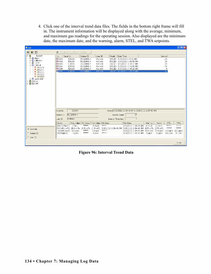
4. Click one of the interval trend data files. The fields in the bottom right frame will fill in. The instrument information will be displayed along with the average, minimum, and maximum gas readings for the operating session. Also displayed are the minimum date, the maximum date, and the warning, alarm, STEL, and TWA setpoints.
Figure 96: Interval Trend Data
134 • Chapter 7: Managing Log Data

5. To view the interval trend data, double click the desired file.
Figure 97: Interval Trend Data
In table format on the left half of the screen, the interval trend data is shown as the average gas readings over the user defined interval trend time. So if the data logging session started at 4:13:38 PM and the interval time is set to 1 minute, then the readings logged at 4:14:38 PM are the average reading for each channel over that one minute period. If a channel went into Warning or Alarm, it will be indicated. A graph of the data will appear on the right half of the screen.
Events are displayed on the screen under the channel in which they occur and with the time of the event. Events are displayed whether they occurred at scheduled log times or in between them. Events include gas alarms such as a warning condition, trouble conditions such as a sensor failure, and an indication that the unit is returning to “normal” condition after an alarm has been reset using the POWER ENTER RESET button on the EAGLE 2.
To change the layout of the table and chart, click any of the four layout control buttons in the upper left corner of the screen.
Layout Control Buttons Restore Previous
Chapter 7: Managing Log Data • 135

To change the proportions of the table to the graph, click the divider between the two and move it.
To display instrument information along with the data and graph, click the “i” control button in the upper left corner.
6. In the table part of the screen,
• To view only events in the interval trend data file, click the Only Event selection box.
• The catalytic combustible channel can be recorded in %LEL, ppm, or %volume units depending on the instrument setting. When viewing the interval trend data in table format, the units are displayed as the unit the reading was recorded in.
Figure 98: Interval Trend Data with Different Catalytic LEL Channel Units
136 • Chapter 7: Managing Log Data

• If installed, an infrared methane or hydrocarbon channel records data in %LEL and/or % volume units depending on whether the channel is configured as a % LEL channel or a %LEL/% volume autoranging channel. When viewing the interval trend data in table format, the units are displayed as the unit the reading was recorded in. In the following figure, the first channel is a catalytic LEL channel and the fifth channel is an IR autoranging CH4 channel.
Figure 99: Autoranging IR CH4 Interval Trend Data, Table Format
Chapter 7: Managing Log Data • 137

7. In the graph part of the screen,
• You can choose which gas(es) you want to graph by selecting or deselecting the boxes next to each gas name.
• You can select the display units for the catalytic LEL channel (%LEL, ppm, vol%). While readings can be recorded in any of these units and stored in the same file, those readings may only be graphed in one unit at a time. If %LEL is chosen as the unit, any ppm or %volume data is converted and graphed as %LEL. The user may change back and forth between the units for the graph and still have all data shown. The CAT Range Select box is where the user may select %LEL, ppm, or %volume as the units for the graph.
• If installed, an IR HC or CH4 channel can be graphed in %LEL or % volume in order to accurately depict the full range of the sensor.
If the channel is configured as a %LEL only channel, then data will only be recorded in %LEL and the range will be 0-100% LEL. Any gas concentration above that level will not be recorded.
If the channel is configured as a %LEL/% volume autoranging channel, then data will be recorded in %LEL and % volume where appropriate. It will record data in %LEL up to 100% LEL and then it will start recording data in % volume up to 100% volume. If %LEL is chosen as the graphing units, all data collected for a %LEL only channel will be displayed. Any data collected in an autoranging configuration that exceeds 100% LEL will not be shown. In order to view data above 100% LEL, % volume must be selected. When % volume is selected, all data will be shown in terms of % volume.
138 • Chapter 7: Managing Log Data

The IR Range Select box is located in the upper right corner of the graph portion of the interval trend screen just to the right of the CAT Range Select screen and is used to make the unit selection for the IR channel.
Figure 100: Autoranging IR CH4 Interval Trend Data, Graph Format
NOTE: The IR Range Select box in the upper right hand corner only appears if an IR HC or CH4 sensor is installed, is in use, and is set up for autoranging. If an IR HC or CH4 sensor is not installed, if its channel is turned off, or if the channel is set up for % LEL only, this box will not appear.
• To zoom in on a particular part of the graph, drag a box around that area so that it is highlighted in gray. The graph will zoom in. To return to a previous zoom, click the Previous control button in the upper right corner of the graph section. To return to the original zoom, click the Restore control button in the upper right corner of the graph section.
• Clicking anywhere on the graph will cause a vertical red line to appear and the corresponding data point will be highlighted in the table. Clicking a data point in the table will move the red line in the graph to that data point.
Chapter 7: Managing Log Data • 139

8. To print the data, select either List or Graph in the upper right corner of the window and then click the Print control button in the upper right corner of the window. The Print control button has a printer icon on it. A dialog box will appear confirming if you want to print. Click OK. If Graph is selected, the data will print as a graph. If List is selected, the data will print as a table.
9. To save the data to a file which can be imported into another program, select either List or Graph in the upper right corner of the window and then click the Save to File control button. The Save to File control button has a floppy disk icon on it. A dialog box will appear for you to specify the file name, file location, and file type.
Figure 101: Save As Dialog Box
If List is selected, the file type is “.csv” (comma-separated values). If Graph is selected, the file type is “.bmp” (Windows bitmap). After specifying the file name and file location, click Save to save the file to the specified location.
10.To save the data to the clipboard, select either List or Graph in the upper right corner of the window and then click the Copy to Clipboard control button. The Copy to Clipboard control button has a clipboard icon on it. The table or graph will be saved to the clipboard. It can then be pasted into a document by using the Paste command in an application.
11.To go back and view other data, click Close to return to the Logs window.
140 • Chapter 7: Managing Log Data

Memo Data
Any information entered into the Memo field in the Edit window is saved in a file in the Logs window. If there is text in the Memo field, a new file is created every time an EAGLE 2 is connected to the PC Controller Program. If a change is made to the Memo, the change is saved in the Memo file for that operating session. See pg.149 for instructions to use the Memo field. To view and perform desired operations with the memo files:
1. While in the Logs window, find your instrument by serial number, then click the expanded view symbol (+) of or double-click the serial number folder to view the contents.
2. Click the expanded view symbol (+) of or double-click the Memo folder to view the contents. Memo data folders are arranged by year/month.
3. Click the year/month folder you wish to view. All memo files for that instrument in that particular year/month will appear in the upper right frame. The file number, serial number, station ID, user ID, model, date/time, and the first few words of the memo appear in the same line.
Figure 102: Viewing Memo Files
Chapter 7: Managing Log Data • 141

4. Click on one of the memo files. The fields in the bottom right screen will fill in. The instrument information will be displayed along with the memo information.
Figure 103: Viewing Memo File Data
5. To print memo data, click the Print control button in the upper left corner of the Logs window. A dialog box will appear confirming if you want to print. Click OK.
142 • Chapter 7: Managing Log Data

6. To save memo data, click the Save control button in the upper left corner of the Logs window. A “Save As” dialog box will appear for you to specify the file name and file location.
Figure 104: Save As Dialog Box
Specify the file name and location and click Save.
7. To copy memo data to the clipboard, click the Save to Clipboard control button. The data will be saved to the clipboard. It can then be pasted into a document by using the Paste command in an application.
Bump Test Data
Any bump tests performed on an EAGLE 2 while it is connected to the PC Controller Program are saved in the Bump Test folder for that instrument. The information in the Bump Test folder does not come from the EAGLE 2 and is not stored in the EAGLE 2. To view and perform desired operations with the bump test files:
1. While in the Logs window, find your instrument by serial number, then click the expanded view symbol (+) of or double-click the serial number folder to view the contents.
2. Click the expanded view symbol (+) of or double-click the Bump Test folder to view the contents. Bump test data folders are arranged by year/month.
Chapter 7: Managing Log Data • 143

3. Click the year/month folder you wish to view. All bump test data files for that instrument in that particular year/month will appear in the upper right frame. The file number, serial number, station ID, user ID, model, date/time of the bump test, and the results appear in the same line.
Figure 105: Viewing Bump Test Log Files
144 • Chapter 7: Managing Log Data

4. Click on one of the bump test data files. The fields in the bottom right screen will fill in. The instrument information will be displayed along with the bump test information. The tested sensors will be displayed along with the bump test gas reading, the bump test gas values, and the result of the bump test.
Figure 106: Viewing Bump Test Data
5. Files that record a failed bump test on all channels are highlighted in red. Files that record a bump test where not all channels passed are highlighted in orange.
6. If any bump tests were performed that required more than one gas cylinder, a separate bump test file will be created for the sensor(s) bump tested with the additional cylinder(s). For example, a bump test performed on an EAGLE 2 that contained the standard 4 sensors plus an NH3 ESM-01 sensor would result in one bump test file for the standard 4 sensors if a 4-gas mix was used and one bump test file for the NH3 ESM-01 sensor.
7. To print the bump test data (everything in the lower right frame of the screen), click the Print control button located just above the bump test judge column. A dialog box will appear confirming if you want to print. Click OK.
8. To print the basic bump test results from a date folder (everything in the upper right frame), be sure that the desired date folder is selected and click the Print control button in the upper left corner of the Logs window. A dialog box will appear confirming if you want to print. Click OK.
Chapter 7: Managing Log Data • 145

9. To print detailed bump test data for each bump test file in a date folder, be sure that the desired date folder is selected and click the Bump Test & Calibration Report control button along the top of the Logs window. A dialog box will appear confirming if you want to print. Click OK.
10.To print detailed calibration (if available) and bump test data for each calibration and bump test file for a specific serial number, be sure that the desired serial number is selected in the upper left frame and click the Bump Test & Calibration Report control button along the top of the Logs window. A dialog box will appear confirming if you want to print. Click OK.
11.To save bump test data from a specific date folder, be sure the desired date folder is highlighted and click the Save control button in the upper left corner of the Logs window. A “Save As” dialog box will appear for you to specify the file name and file location.
Figure 107: Save As Dialog Box
Specify the file name and location and click Save.
12.To copy bump test data in a date folder to the clipboard, be sure the desired date folder is selected and click the Save to Clipboard control button. The data will be saved to the clipboard. It can then be pasted into a document by using the Paste command in an application.
146 • Chapter 7: Managing Log Data

Deleting Data in the Logs Window
Data can be deleted from the Logs window by right clicking on the folder or file you wish to delete. Any file or folder except for Memo data may be deleted.
Figure 108: Deleting Data in the Logs Window
1. Right click on the folder or file you wish to delete and click Delete.
2. You will be prompted for a password. The factory set password is ABCDE. It is case sensitive. After you have entered the password, click OK.
3. To delete the folder or file, click OK in the confirmation window that comes up. If you do not want to delete the data, click Cancel.
Chapter 7: Managing Log Data • 147

Chapter 8: Viewing and Editing EAGLE 2 Parameters
Open Function
This function can be activated by either right clicking an instrument and selecting Open(O) when the pull down menu appears or by selecting an instrument and then using the alt/O key combination. The Open function brings up the Instrument Information window for viewing only. No changes can be made with the Open function. The Instrument Information Window consists of the Parameter Tab, the Sensor Tab, the Station & User Tab, the Conversion Table Tab, the PID Sensor Tab, the Channel Gas Tab, and the Gas Name Tab. For further explanation of each tab, see the next section.
Figure 109: Instrument Function Menu
148 • Chapter 8: Viewing and Editing EAGLE 2 Parameters

To exit the Instrument Information Window and return to the main program window, click Cancel.
Edit Function
This function can be activated by either right clicking an instrument and selecting Edit(E) when the pull down menu appears or by selecting an instrument and then using the alt/E key combination.
NOTE: The Edit function is not active and cannot be selected if the Change Parameter selection box in the Instrument Information section of the Parameter Tab in the Configuration Window is not selected.
Parameter Tab
The Parameter Tab is selected when the Edit function is opened. This tab allows you to view and change various instrument parameters and settings and has information in two sub tabs: the Option 1 Tab and the Option 2 Tab.
Figure 110: Instrument Information Window, Parameter Tab
Chapter 8: Viewing and Editing EAGLE 2 Parameters • 149

Main Part of TabTable 5: Parameter Tab, Main Parameters
Serial No. To change the current instrument serial number, place the cursor in the Serial No. field and enter the desired serial number. If you change the serial number, once you upload the changes to the EAGLE 2 and return to the main program window, the PC Controller Program will indicate that the EAGLE 2 with the old serial number was disconnected. An EAGLE 2 with the new serial number will then connect to the PC Controller Program.
Station ID To change the station ID, select the drop-down menu and select the desired station ID. To change the station ID list, see pg.158.
User ID To change the user ID, select the drop-down menu and select the desired sta-tion ID. To change the user ID list, see pg.158.
Cal Interval (Day)
The calibration interval is the length of time between scheduled calibrations. To change the calibration interval, use the arrows to the right of the current value to increase or decrease the interval. You may also highlight the current setting and type in the new desired setting. It can be set anywhere between 1 and 365 days. The factory setting is 90 days.
Interval Time (sec)
The interval time is how often the EAGLE 2 will log interval trend readings. It can be set to 5, 10, 20, 30 (factory setting), 60, 180, 300, or 600 seconds. To change the interval time, use the arrows to the right of the current value to increase or decrease it. You may also highlight the current setting and type in the new desired setting. The value that you type in must match the allowable interval settings. If it does not, when you save your changes, your entered value will be shifted to the closest match. For example, if you enter 90 sec-onds, when you save the changes, the interval will adjust itself to 60 seconds.
Memo The Memo section of the Parameter Tab allows the user to enter remarks for an EAGLE 2 that is connected to the program. The Memo may be used to doc-ument anything of interest, such as maintenance records (noting when a sensor or a battery pack was changed). The Memo section is empty until the user enters information. The first time information is entered, a Memo file is cre-ated in the Logs window. If the Memo is changed in the same operating ses-sion, that Memo file is updated. When the EAGLE 2 is disconnected from the PC Controller Program and connected again, a new Memo file is created with the current memo. If you edit the memo field in that operating session, the new Memo file is updated. If you clear the Memo field for an instrument, the Memo file that was created when the EAGLE 2 was connected to the PC Con-troller Program will be deleted since it is now empty. All memos from previ-ous operating sessions will always be available in the Logs window. They cannot be deleted.
150 • Chapter 8: Viewing and Editing EAGLE 2 Parameters

Option 1 Sub Tab
The adjustable parameters in the Option 1 Tab are:
Table 6: Parameter Tab, Option 1 Parameters
OXY Alarm Pattern Falling and Rising (factory setting): The first oxygen alarm will be a decreasing alarm and the second oxygen alarm will be an increas-ing alarm. Both Alarms Falling: Both oxygen alarms will be decreasing alarms.Both Alarms Rising: Both oxygen alarms will be increasing alarms.
Figure 111: Parameter Tab, Option 1
Chapter 8: Viewing and Editing EAGLE 2 Parameters • 151

Cal Past Due Act Confirm to Cal (factory setting): The EAGLE 2 will sound an alarm and the user will have to press and release the POWER ENTER RESET button to continue. Must Calibrate: The EAGLE 2 cannot be used until a calibration has been performed. Notification Only: The EAGLE 2 will display that a calibration is due but will continue with the warm up sequence.
Alarm Latching Selected (factory setting): The EAGLE 2 remains in alarm condi-tion until the alarm condition passes and the POWER ENTER RESET button is pressed. Deselected: The EAGLE 2 automatically resets an alarm when the alarm condition passes.
Alarm Silence Selected (factory setting): Pressing and releasing any button silences the buzzer when the EAGLE 2 is in a gas alarm. The LEDs continue to flash and the display continues to show the alarm. When the gas concentration falls below the alarm level, pressing and releasing POWER ENTER RESET clears all alarm indications for that alarm. Deselected: You cannot silence the buzzer. You must wait until the alarm condition clears before you can press POWER ENTER RESET to clear the alarm indications.
User/Station ID Selected: The ID Screen displays during start up and the Select User ID Screen and Select Station ID Screen appear in Display Mode. Deselected (factory setting): The ID Screen does not display during start up and the Select User ID Screen and Select Station ID Screen do not appear in Display Mode.
Cal Reminder Selected (factory setting): The EAGLE 2 will give an indication at start up if it is due for calibration. The type of indication will depend on the Cal Past Due Act setting.Deselected: The EAGLE 2 will not give an indication at start up if it is due for calibration.
Auto Fresh Air Adj Selected: The EAGLE 2 will perform a fresh air adjustment after the start up sequence. Deselected (factory setting): The EAGLE 2 will not perform a fresh air adjustment after the start up sequence.
Table 6: Parameter Tab, Option 1 Parameters
152 • Chapter 8: Viewing and Editing EAGLE 2 Parameters

Lunch Break Selected (factory setting): The Resume Measurements Screen dis-plays during startup. From this screen, you can choose to continue accumulating TWA and PEAK readings and the time in operation from the last time the EAGLE 2 was used or start collecting new TWA and PEAK readings and reset the time in operation. Deselected: The EAGLE 2 automatically starts new TWA and PEAK reading collection and resets the time in operation at startup.
Data Log Overwrite Selected (factory setting): The EAGLE 2 writes over the oldest data with new data when the data logger memory is full. Deselected: The EAGLE 2 stops saving data to the data logger when the data logger memory is full.
Data Log Memory Selected (factory setting): The Data Logging Screen in Display Mode asks whether you want to clear the logged data in addition to showing the log time remaining. Deselected: The Data Logging Screen only shows the remaining log time and does not give you the opportunity to clear the logged data.
Password Protection Selected: The EAGLE 2 prompts you for a password when you enter Calibration Mode or Setup Mode. Delete the current password in the box below the selection and enter the desired password.Deselected (factory setting): No password is required to enter Cali-bration Mode or Setup Mode.
Table 6: Parameter Tab, Option 1 Parameters
Chapter 8: Viewing and Editing EAGLE 2 Parameters • 153

Option 2 Sub Tab
The Option 2 Tab of the Parameter Tab contains additional parameters that can be changed.
Table 7: Parameter Tab, Option 2 Parameters
Date Time Display The Date can be displayed MM/DD/YYYY (factory setting) or DD/MM/YYYY.
LB Mode Turn on Leak Check Mode, Bar Hole Mode, or both. If any of these modes are turned on, you will be prompted to select an operational mode when you turn the EAGLE 2 on. The factory setting is OFF.
Language Change the language of your EAGLE 2 to English (factory setting), Spanish, French, Italian, or German.
Catalytic Units Set the catalytic LEL channel’s units to ppm only, %LEL only, %vol-ume only, or Change OK (factory setting). If you choose Change OK, you can use the RANGE SHIFT button to change the units during operation.
Figure 112: Parameter Tab, Option 2
154 • Chapter 8: Viewing and Editing EAGLE 2 Parameters

BH Measuring Time
The BH Measuring Time parameter only applies to instruments being used in Bar Hole Mode. The BH Measuring Time is the amount of time the unit samples the bar hole. It can be set to 30 (factory setting), 45, or 60 seconds.
Battery Type You can select whether your unit is set up for alkaline batteries or rechargeable Ni-MH batteries. Since the discharge characteristics of alkaline and Ni-MH batteries are different, the EAGLE 2 uses this set-ting to ensure that the low battery warning is in effect long enough before a dead battery alarm to allow the user to change the batteries without a dead battery alarm occurring. This setting has no effect on battery charging.
Catalytic Display Units
The Catalytic Units and Catalytic Display Units parameters determine what units are displayed for the catalytic channel when the instrument is turned on. The factory setting for Catalytic Display Units is %LEL. If Catalytic Units is set to anything but CHANGE OK, then Catalytic Display Units is grayed out.
Confirmation Alert The confirmation alert confirms that the EAGLE 2 is still operating by either flashing, beeping, or both every 15 minutes. The confirmation alert can be set to LIGHT ONLY, BEEP ONLY, LIGHT & BEEP, or OFF (factory setting).
Backlight Delay The Backlight Delay setting is how long the backlight stays on after the last button push. It can be set anywhere from 0 to 255 seconds. The factory setting is 30 seconds.
Relative Response Selected: The Relative Response Screen will appear in Display Mode. Deselected (factory setting): The Relative Response Screen will not appear in Display Mode.
Span Factor Display
Selected (factory setting): The EAGLE 2 will display the minimum and maximum readings it could have adjusted to during a single cali-bration span adjustment. Deselected: The EAGLE 2 will not display the minimum and maxi-mum readings it could have adjusted to during a single calibration span adjustment.
Leak Buzzer Selected (factory setting): The buzzer will operate in Leak Check Mode.Deselected: The buzzer will not operate in Leak Check Mode.
Adjust Contrast The Adjust Contrast parameter allows you to adjust the display con-trast on the EAGLE 2. Select the setting so the characters on the dis-play are easy to see. It can be set from 1 to 15. The factory setting is 8. The higher the setting, the darker the characters and LCD background.
Table 7: Parameter Tab, Option 2 Parameters
Chapter 8: Viewing and Editing EAGLE 2 Parameters • 155

Sensor Tab
The Sensor Tab displays the alarm settings and auto calibration values for all installed sensors. It also shows the date and time of the most recent calibration for each channel. The three lines at the bottom of the Sensor Tab that are displayed in green are for special conditions. The first line, CH4(5000ppm), displays the alarm points for the catalytic LEL channel while it’s detecting in the ppm range. The second line, CH4(5.00vol%), displays the alarm points for %volume combustible gas detection. The factory setting for these alarms is off (*****) but they can be set. The third line, OXY(40.0vol%), shows the alarm points for the oxygen channel when the EAGLE 2 is being used in Inert Mode. These oxygen alarms are both rising alarms and will only appear if Inert Mode is factory set to On for the connected EAGLE 2.
Methane Elimination
In order for this parameter selection to be active, the EAGLE 2 must have its catalytic LEL channel configured to hexane. If the catalytic LEL channel is not configured to hexane, this parameter selection will be grayed out. Selected: Methane elimination is on.Deselected (factory setting): Methane elimination is off.
Table 7: Parameter Tab, Option 2 Parameters
Figure 113: Sensor Tab
156 • Chapter 8: Viewing and Editing EAGLE 2 Parameters

Any value in a white box can be changed. Values in shaded boxes cannot be changed. To change a value:
1. Click the box whose value you want to change. The entire box will turn blue.
2. Click the box again and only the value will be highlighted in blue.
3. Type in the new desired value.
4. Repeat steps 1 through 3 for any other values you wish to change and then click OK.
5. You will be asked if you want to save the changes that you made.
• Select Yes if you wish to save the changes. The PC Controller program will update the EAGLE 2 and then return you to the main program window.
• Select No is you do not want to save the changes. The PC Controller program will return you to the main program window.
• Select Cancel to return to the Sensor Tab and make any additional changes.
Chapter 8: Viewing and Editing EAGLE 2 Parameters • 157

Station & User Tab
The Station & User Tab allows you to update the Station ID and User ID lists in a connected instrument.
To edit the Station ID or User ID list, you will need to import a csv (comma separated values) file into the program. A Station csv file and a User csv file are provided with the SDM-E2 product CD. In addition, you can generate csv files for editing from the program.
Creating ID Files
1. To create a csv file for editing, click the Export csv file button for either the Station or User ID list.
Figure 114: Station and User Tab
Click to generate Station csv file Click to generate User csv file
158 • Chapter 8: Viewing and Editing EAGLE 2 Parameters

2. Navigate to the location you want to save the file, type in a file name, and click Save. You can save multiple station and user ID files if desired.
Figure 115: Save As
Chapter 8: Viewing and Editing EAGLE 2 Parameters • 159

3. The csv files can be opened, edited, and saved using a word processing program such as Word, WordPad, or Notepad. The Station and User csv files consist of the Station or User ID number and its associated name. Below is an example of the Station csv file opened in WordPad.
Any existing Station or User IDs will be displayed. Undefined Station or User IDs will appear as dashes. To edit a Station or User ID, delete either the existing name or the dashes and replace them with the desired name. The name may consist of any letter, number, or character.
4. Save the changes you made to the csv file.
Figure 116: Station ID CSV File Opened in WordPad
160 • Chapter 8: Viewing and Editing EAGLE 2 Parameters

Loading ID Files
1. In the Station & User Tab, click Import csv file for either the Station ID list or User ID list.
Figure 117: Station and User Tab
Press to import Station csv file Press to import User csv file
Chapter 8: Viewing and Editing EAGLE 2 Parameters • 161

2. Navigate to the file you wish to import and click Open.
3. Once you have imported the Station ID and/or User ID csv files, the new list will be reflected in the Station & User Tab.
Figure 118: Open Station ID CSV File
Figure 119: New Station and User IDs
162 • Chapter 8: Viewing and Editing EAGLE 2 Parameters

4. Click OK to save the changes and click Yes in the confirmation window that comes up. The program will tell you to wait while it updates the instrument.
To exit this screen without saving changes, click Cancel.
5. To select a Station ID or User ID for the instrument, go back to the Parameter tab. See pg.149 for instructions to select a station ID or user ID.
6. To exit the Station & User Tab, click the OK button in the lower right corner of the window. A confirmation screen will appear asking if you would like to save the changes you have made. To save the changes and return to the main program window, click Yes. To return to the main program window without saving your changes, click No. To return to the Parameter tab and update your changes, click Cancel.
To return to the main program window without saving any changes, click Cancel in the lower right corner of the window.
Conversion Table Tab
The Conversion Table tab is used to view the pre-defined relative response gases for the catalytic combustible channel and to edit or add user-defined gases. The pre-defined gases can be found in the Pre-Defined Table tab while the user-defined gases can be found under the User-Defined Table tab.
Figure 120: Conversion Table Tab, Pre-Defined
Chapter 8: Viewing and Editing EAGLE 2 Parameters • 163

There are 8 columns in both the Pre-Defined Table tab and the User-Defined Table tab:
No. Gas Number (1-30)
Name This is what will appear in the EAGLE 2’s Catalytic Sensor Relative Response Screen. The name can be up to 3 numbers or upper case let-ters long. No special characters may be used.
Long Name Used to better describe the target gas. It may contain any character in upper- or lower-case.
Factor This value is the response factor for the listed gas relative to methane. The factor for each pre-defined gas is factory defined. The factor for any user-defined gases must be obtained through testing as described on pg.174. Even if not all of the user-defined catalytic combustible chan-nels are being defined, the Factor column must have a valid number entered. A valid number for the Factor is a value between 0.01 and 25.00.
1st Low alarm point (in ppm).
2nd High alarm point (in ppm).
Ratio The ppm value of the LEL. This value is specific to each gas. The max-imum value it may be set to is 150,000 ppm. If an invalid number is entered, the box will turn red when the csv file is imported back into the PC Program.
If you define a gas whose LEL is above 50,000 ppm, the %LEL reading in Measuring Mode will reflect the defined ppm ratio, but the ppm read-ing in Measuring Mode will not indicate above 50,000 ppm. For exam-ple, if you set the ratio to be 150,000 ppm and set the catalytic combustible channel to display the reading in ppm, the gas reading will not indicate higher than 50,000 ppm, the equivalent of 33 %LEL and 5% volume for this ratio, but will continue to indicate %LEL readings up to 100 %LEL and %volume readings up to 15 %volume, the equiva-lent of 150,000 ppm, if the display units are changed to %LEL or %vol-ume. In addition, all adjustable ppm parameters cannot be set higher than 50,000 ppm.
Volt This value determines the sensor voltage for the catalytic combustible sensor. It can be set to 1.3 or 2.4. When set to 1.3, the sensor is in meth-ane elimination mode. When set to 2.4, the sensor is reading at full response. Even if not all of the user-defined catalytic combustible chan-nels are being defined, the Volt column must have a valid number entered. A valid number for the Volt column is either 1.3 or 2.4.
164 • Chapter 8: Viewing and Editing EAGLE 2 Parameters

While the pre-defined gases may not be edited, the 5 user-defined gases may be edited by doing the following:
1. Click on the User-Defined Table tab.
2. If no user-defined gases have been previously defined for the connected instrument, the Name and Long Name columns in User-Defined Table will be blank. Any previously defined gases will appear.
3. Export the current data by pressing the “Export csv file” button. Choose the file path you wish to save the file in.
Figure 121: Conversion Table Tab, User-Defined
Chapter 8: Viewing and Editing EAGLE 2 Parameters • 165

4. Open the csv file using Notepad, Word, or WordPad. The example below shows a csv file opened in WordPad. The list of gases are associated with the numbers 1-5.
If there were no previously defined gases, the csv file will appear as the following:
5. The values in the csv file are all separated by commas. These values are in the same order as the columns in the User-Defined Table Tab. The first value is the gas number, the second is the gas name, etc.
6. Edit the values you wish to change and save and close the file.
7. Return to the PC Program with the User-Defined Table tab still up and press “Import csv file”.
8. Choose the file you just edited and press “Open”.
9. The values you entered in the csv file will appear in the User-Defined Table.
Figure 122: User Defined Conversion CSV File
Figure 123: Blank User Defined Conversion CSV File
166 • Chapter 8: Viewing and Editing EAGLE 2 Parameters

10.If the program finds anything wrong with the values that were entered, the box containing those values will turn red. Make sure that you have entered valid characters for each field.
11.Once all of the data you wish to enter has been entered and is correct, save the data and upload it to the EAGLE 2 by clicking OK and clicking Yes in the confirmation window that appears.
PID Sensor Tab
The PID Sensor tab is used to view the pre-defined relative response gases and to view or define the 1 user-defined relative response gas. The pre-defined gases are 1-16 and the user defined gas is gas 17 which is highlighted in white. Every gas has a low and high range which are displayed in the Low Range tab and High Range tab, respectively.
Figure 124: PID Sensor Tab, High Range
Chapter 8: Viewing and Editing EAGLE 2 Parameters • 167

There are 13 columns in both the High and Low Range tabs:
No. Gas Number (1-17)
Name What will appear in the EAGLE 2’s PID Sensor Relative Response Screen. The name can be up to 3 numbers or upper case letters. No spe-cial characters may be used.
Long Name Used to better describe the target gas. It may contain any character in upper- or lower-case.
Full Scale Full scale value for the detection gas.
Point To what decimal place the gas readings are shown. A value of 1/1 indi-cates a reading to the “ones” place (ie. 10 ppm) while a value of 1/100 indicates a reading to the “hundredths” place (ie. 10.00 ppm).
Unit What units the gas reading is provided in. Must be set to ppm.
Digit Gas reading increment.
1st Low alarm point (in ppm).
2nd High alarm point (in ppm).
STEL STEL (short-term exposure limit) value.
TWA TWA (time-weighted average) value.
AutoCal Gas concentration used for calibration.
Factor The Relative Response Factor for the PID channel. The factor for each pre-defined gas is factory defined. The factor for the user defined gas must be obtained from Table 11 on page 176 or through testing as described in “Obtaining a Relative Response Factor” on page 174. A valid character for the Factor is a value between 0.01 and 25.00.
168 • Chapter 8: Viewing and Editing EAGLE 2 Parameters

While the pre-defined gases may not be edited, the 1 user-defined gas may be edited by doing the following:
1. Click on the PID Sensor tab and then click on the High Range tab.
Figure 125: PID Sensor Tab, High Range
Chapter 8: Viewing and Editing EAGLE 2 Parameters • 169

2. The user-defined gas is gas 17. If no user-defined PID gas has been previously defined for the connected instrument, the name and long name will both appear as PID for the High Range and Low Range tabs. The full scale, digit, and factor values will appear as shown in Table 8 below. The rest of the fields will contain asterisks (*****).
3. Export the current data by pressing the “Export csv file” button. Choose the file path you wish to save the file in.
Table 8: Default Values for User Defined PID Gas
Full Scale (ppm) Digit Factor
High Range 2000 2 1.00
Low Range 50.00 0.02 1.00
Figure 126: Save As
170 • Chapter 8: Viewing and Editing EAGLE 2 Parameters
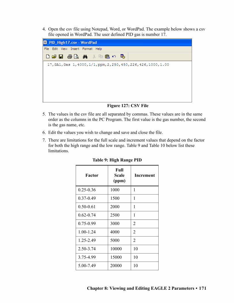
4. Open the csv file using Notepad, Word, or WordPad. The example below shows a csv file opened in WordPad. The user defined PID gas is number 17.
5. The values in the csv file are all separated by commas. These values are in the same order as the columns in the PC Program. The first value is the gas number, the second is the gas name, etc.
6. Edit the values you wish to change and save and close the file.
7. There are limitations for the full scale and increment values that depend on the factor for both the high range and the low range. Table 9 and Table 10 below list these limitations.
Table 9: High Range PID
FactorFull Scale (ppm)
Increment
0.25-0.36 1000 1
0.37-0.49 1500 1
0.50-0.61 2000 1
0.62-0.74 2500 1
0.75-0.99 3000 2
1.00-1.24 4000 2
1.25-2.49 5000 2
2.50-3.74 10000 10
3.75-4.99 15000 10
5.00-7.49 20000 10
Figure 127: CSV File
Chapter 8: Viewing and Editing EAGLE 2 Parameters • 171

8. Return to the PC Program with the High Range tab still up and press “Import csv file”.
9. Choose the file you just edited and press “Open”.
10.The values you entered in the csv file will appear in the High Range tab.
11.If the program finds anything wrong with the values that were entered, the box containing those values will turn red. Make sure that you have entered valid characters for each field.
7.50-9.99 30000 20
10.00-12.49 40000 20
12.50 50000 2500
Table 10: Low Range PID
FactorFull Scale (ppm)
Increment
0.20-0.29 10.00 0.01
0.30-0.39 15.00 0.01
0.40-0.49 20.00 0.01
0.50-0.59 25.00 0.01
0.60-0.79 30.00 0.02
0.80-0.99 40.00 0.02
1.00-1.99 50.00 0.02
2.00-2.99 100.0 0.1
3.00-3.99 150.0 0.1
4.00-5.99 200.0 0.1
6.00-7.99 300.0 0.2
8.00-9.99 400.0 0.2
10.00 500.0 0.2
Table 9: High Range PID
FactorFull Scale (ppm)
Increment
172 • Chapter 8: Viewing and Editing EAGLE 2 Parameters

NOTE: The Name and Long Name for the Low Range and High Range tabs must agree. If they do not, the program will keep the Low Range Name and Long Name and change the High Range to agree with it.
12.Repeat step 1 - step 11 for the Low Range tab.
13.Once all of the data you wish to enter has been entered and is correct, save the data and upload it to the EAGLE 2 by clicking OK and clicking Yes in the confirmation window that appears.
Channel Gas Tab
The Channel Gas Tab allows the view the gas channel order and various parameters related to those channels. The information in this tab cannot be edited.
Figure 128: Channel Gas Tab
Chapter 8: Viewing and Editing EAGLE 2 Parameters • 173

Gas Name Tab
The Gas Name Tab displays current gas names and values related to the catalytic LEL channel. The information in this tab cannot be edited.
Obtaining a Relative Response Factor
If the gas that you want to monitor on the catalytic combustible or PID channel is not included in the catalytic or PID relative response lists, you may define up to 5 gases for the catalytic combustible channel using the Conversion Table tab and 1 gas for the PID channel using the PID Sensor tab. Testing must be done using the desired target gas in order to obtain the response factor value for the catalytic combustible channel. To determine the relative response factor value for the PID channel, first look in Table 11 for the desired gas. If the desired gas does not appear in the table, you must obtain the response factor through the testing procedure described below.
To determine the relative response factor value for the catalytic or PID channels, do the following:
1. For determining the catalytic combustible channel relative response factor, calibrate the catalytic combustible channel to methane. For determining the PID channel relative response factor, calibrate the PID channel to isobutylene.
Figure 129: Gas Name Tab
174 • Chapter 8: Viewing and Editing EAGLE 2 Parameters

2. Obtain a gas sample of known concentration for the target gas you wish to define. The sample needs to be at least 10% of the full scale but RKI Instruments, Inc. recommends using 50% of the full scale. If the concentration tested results in an overscale reading, test a lower concentration.
3. Apply the gas sample to the EAGLE 2 and take note of the reading. If the gas sample is of 50 %LEL concentration and the EAGLE 2 display shows a reading of 25 %LEL, then the factor for that gas is 2. Conversely, if the gas sample is of 50 %LEL concentration and the EAGLE 2 display shows a reading of 100 %LEL, then the factor for that gas is 0.5. This conversion factor value is what you will enter in the Factor column of the gas you are defining.
Table 11 below has 4 columns:
• Gas/VOC-The most common name for the VOC (volatile organic compound)
• CAS No.-Sometimes it is easier to identify a VOC from the internationally recognized CAS (Chemical Abstracts Service) number
• Formula-Molecular formula for each VOC
• Response Factor (RF)-The relative response factor for each gas. This is the value that is plugged into the PC Program.
Chapter 8: Viewing and Editing EAGLE 2 Parameters • 175

Some abbreviations that appear in the table are:
• ZR-No response
• NV-Cannot be measured
Table 11: Response Factors Relative to Isobutylene
Gas / VOC CAS No. Formula Re lative Res pons e
Aceta ldehyde 75-07-0 C2H4O 4.9
Ace tic Acid 64-17-7 C2H4O2 36
Ace tic Anhydride 108-24-7 C4H6O3 4
Ace tone 67-64-1 C3H6O 0.7
Ace tonitrile 75-05-8 CH3CN ZR
Ace tylene 74-86-2 C2H2 ZR
Acrole in 107-02-8 C3H4O 4
Acrylic Acid 79-10-7 C3H4O2 2.7
Acrylonitrile 107-13-1 C3H3N ZR
Allyl a lcohol 107-18-6 C3H6O 2.1
Allyl chloride 107-05-1 C3H5Cl 4.5
Ammonia 7664-41-7 NH3 8.5
Amyl ace ta te , n- 628-63-7 C7H14O2 1.8
Amyl a lcohol 71-41-0 C5H12O 3.2
Aniline 62-53-3 C6H7N 0.5
Anisole 100-66-3 C7H8O 0.5
Ars ine 7784-42-1 AsH3 2.5
Asphalt, pe troleum fumes 8052-42-4 1
Benzaldehyde 100-52-7 C7H6O 0.9
Benzene 71-43-2 C6H6 0.5
Benzene thiol 108-98-5 C6H5SH 0.7
Benzonitrile 100-47-0 C7H5N 0.7
Benzyl a lcohol 100-51-6 C7H8O 1.3
Benzyl chloride 100-44-7 C7H7Cl 0.6
Benzyl formate 104-57-4 C8H8O2 0.8
Biphenyl 92-52-4 C12H10 0.4
Bis (2,3-epoxypropyl) e the r 7/5/38 C6H10O3 3
Boron trifluoride 7637 07 2 BF3 ZR
Bromine 7726-95-6 Br2 20
Bromine penta fluoride 7789-30-2 BrF5 ZR
Bromobenzene 108-86-1 C6H5Br 0.7
Bromochloromethane 74-97-5 CH2ClBr ZR
Bromoethane 74-96-4 C2H5Br 5
Bromoethyl methyl e the r, 2- 6482-24-2 C3H7OBr 2.5
Bromoform 75-25-2 CHBr3 2.8
Bromopropane , 1- 106-94-5 C3H7Br 1.3
Bromotrifluoromethane 75-63-8 CF3Br ZR
Butadiene 106-99-0 C4H6 0.8
Butadiene diepoxide , 1,3- 1464-53-5 C4H6O2 4
176 • Chapter 8: Viewing and Editing EAGLE 2 Parameters

Gas / VOC CAS No. Formula Re lative Res pons e
Butane , n- 106-97-8 C4H10 46
Butanol, 1- 71-36-3 C4H10O 4
Buten-3-ol, 1- 598-32-3 C4H8O 1.2
Butene , 1- 106-98-9 C4H8 1.3
Butoxye thanol, 2- 111-76-2 C6H14O2 1.1
Butyl ace ta te , n- 123-86-4 C6H12O2 2.4
Butyl acryla te , n- 141-32-2 C7H12O2 1.5
Butyl lacta te 138-22-7 C7H14O3 2.5
Butyl mercaptan 109-79-5 C4H10S 0.5
Butylamine , 2- 513-49-5 C4H11N 0.9
Butylamine , n- 109-73-9 C4H11N 1
Camphene 565-00-4 C10H16 0.5
Carbon dioxide 124-38-9 CO2 ZR
Carbon disulfide 75-15-0 CS2 1.4
Carbon monoxide 630-08-0 CO ZR
Carbon te trabromide 558-13-4 CBr4 3
Carbon te trachloride 56-23-5 CCl4 ZR
Carbonyl sulphide 463-58-1 COS ZR
Carvone , R- 6485-40-1 C10H14O 1
Chlorine 7782-50-5 Cl2 ZR
Chlorine dioxide 10049-04-4 ClO2 1
Chlorine trifluoride 7790-91-2 ClF3 ZR
Chloro-1,1,1,2-te tra fluoroe thane 2837-89-0 C2HClF4 ZR
Chloro-1,1,1-trifluoroe thane , 2- 75-88-7 C2H2ClF3 ZR
Chloro-1,1,2,2-te tra fluoroe thane 354-25-6 C2HClF4 ZR
Chloro-1,1,2-trifluoroe thane , 1- 421-04-5 C2H2ClF3 ZR
Chloro-1,1-difluoroe thane , 1- 75-68-3 C2H3ClF2 ZR
Chloro-1,1-difluoroe thane , 1- 75-68-3 C2H3ClF2 ZR
Chloro-1,1-difluoroe thane , 2- 338-65-8 C2H3ClF2 ZR
Chloro-1,2,2-trifluoroe thane 431-07-2 C2H2ClF3 ZR
Chloro-1,3-butadiene , 2- 126-99-8 C4H5Cl 3.2
Chloro-1-fluoroe thane , 1- 1615-75-4 C2H4ClF ZR
Chloro-2-fluoroe thane , 1- 762-50-5 C2H4ClF ZR
Chloroace ta ldehyde 107-20-0 C2H3OCl ZR
Chlorobenzene 108-90-7 C6H5Cl 0.5
Chlorodifluoromethane 75-45-6 CHClF2 ZR
Chloroe thane 75-00-3 C2H5Cl ZR
Chloroe thanol 2- 107-07-3 C2H5ClO 10
Chloroe thyl methyl e the r, 2- 627-42-9 C3H7ClO 2.6
Chlorofluoromethane 593-70-4 CH2ClF ZR
Chloroform 67-66-3 CHCl3 ZR
Chloromethane 74-87-3 CH3Cl ZR
Chloropentafluoroe thane 76-15-3 C2ClF5 ZR
Chapter 8: Viewing and Editing EAGLE 2 Parameters • 177

Gas / VOC CAS No. Formula Re lative Res pons e
Chlorotoluene , o- 95-49-8 C7H7Cl 0.5
Chlorotoluene , p- 108-41-8 C7H7Cl 0.5
Chlorotrifluoroe thylene 79-38-9 C2ClF3 1
Chlorotrifluoromethane 75-72-9 CClF3 ZR
Citronellol 26489-01-0 C10H20O 1
Cresol, m- 108-39-4 C7H8O 1.1
Cresol, o- 95-48-7 C7H8O 1.1
Cresol, p- 106-44-5 C7H8O 1.1
Crotona ldehyde 4170-30-3 C4H6O 1
Cumene 98-82-8 C9H12 0.6
Cyanamide 420-04-2 CH2N2 ZR
Cyanogen bromide 506-68-3 CNBr ZR
Cyanogen chloride 506-77-4 CNCl ZR
Cyclohexane 110-82-7 C6H12 1.3
Cyclohexanol 108-93-0 C6H12O 2.9
Cyclohexanone 108-94-1 C6H10O 1.1
Cyclohexene 110-83-8 C6H10 0.8
Cyclohexylamine 108-91-8 C6H13N 1
Cyclopentane 287-92-3 C5H10 4
Decane , n- 124-18-5 C10H22 1
Diace tone a lcohol 123-42-2 C6H12O2 0.8
Dibenzoyl pe roxide 94-36-0 C14H10O4 0.8
Diborane 19287-45-7 B2H6 ZR
Dibromochloromethane 124-48-1 CHBr2Cl 10
Dibromodifluoromethane 75-61-6 CF2Br2 ZR
Dibromoethane 1,2- 106-93-4 C2H4Br2 2
Dibromote tra fluoroe thane , 1,2- 124-73-2 C2F4Br2 ZR
Dibutyl hydrogen phosphate 107-66-4 HC8H18 PO4 4
Dichloro-1,1,1-trifluoroe thane , 2,2-
306-83-2 C2HCl2F3 ZR
Dichloro-1,1-difluoroe thane , 1,2- 1649-08-7 C2H2Cl2F2 ZR
Dichloro-1,2,2-trifluoroe thane , 1,2-
354-23-4 C2HCl2F3 ZR
Dichloro-1,2-difluoroe thane , 1,2- 631-06-1 C2H2Cl2F2 ZR
Dichloro-1-fluoroe thane , 1,1- 1717-00-6 C2H3Cl2F ZR
Dichloro-1-fluoroe thane , 1,1- 1717-00-6 C2H3Cl2F ZR
Dichloro-1-fluoroe thane , 1,2- 430-57-9 C2H3Cl2F ZR
Dichloro-1-propene , 2,3- 78-88-6 C3H4Cl2 1.4
Dichloro-2,2,-difluoroe thane , 1,1- 79-35-6 C2H2Cl2F2 ZR
Dichloroace tylene 7572-29-4 C2Cl2 5
Dichlorobenzene o- 95-50-1 C6H4Cl2 0.5
Dichlorodifluoromethane 75-71-8 CCl2F2 ZR
Dichloroe thane 1,2- 107-06-2 C2H4Cl2 ZR
178 • Chapter 8: Viewing and Editing EAGLE 2 Parameters

Gas / VOC CAS No. Formula Re lative Res pons e
Dichloroe thane , 1,1- 75-34-3 C2H4Cl2 ZR
Dichloroe thene , 1,1- 75-35-4 C2H2Cl2 1
Dichloroe thene , cis -1,2- 156-59-2 C2H2Cl2 0.8
Dichloroe thene , trans -1,2- 540-59-0 C2H2Cl2 0.7
Dichloroe thylene 1,2- 540-59-0 C2H2Cl2 0.8
Dichlorofluoromethane 75-43-4 CHFCl2 ZR
Dichloromethane 75-09-2 CH2Cl2 39
Dichloropropane , 1,2- 78-87-5 C3H6Cl2 ZR
Dichlorote tra fluoroe thane , 1,1- 374-07-2 C2Cl2F4 ZR
Dichlorote tra fluoroe thane , 1,2- 76-14-2 C2Cl2F4 ZR
Dicyclopentadiene 77-73-6 C10H12 0.9
Diese l Fue l 68334-30-5 0.8
Die thyl e the r 60-29-7 C4H10O 0.9
Die thyl ma lea te 141-05-9 C8H12O4 2
Die thyl phtha la te 84-66-2 C12H14O4 1
Die thyl sulphate 64-67-5 C4H10SO4 3
Die thyl sulphide 352-93-2 C4H10S 0.6
Die thylamine 109-89-7 C4H11N 1
Die thylaminoe thanol, 2- 100-37-8 C6H15ON 2.7
Die thylaminopropylamine , 3- 104-78-9 C7H18N2 1
Difluoroe thane , 1,1- 75-37-6 C2H4F2 ZR
Difluoroe thane , 1,2- 624-72-6 C2H4F2 ZR
Difluoromethane 75-10-5 CH2F2 ZR
Dihydrogen se lenide 7783 07 5 H2Se 1
Dihydroxybenzene , 1,2 120-80-9 C6H6O2 1
Dihydroxybenzene , 1,3 108-46-3 C6H6O2 1
Diisobutylene 107-39-1 C8H16 0.6
Diisopropyl e ther 108-20-3 C6H14O 0.7
Diisopropylamine 108-18-9 C6H15N 0.7
Dike tene 674-82-8 C4H4O2 2.2
Dimethoxymethane 109-87-5 C3H8O2 1.4
Dimethyl cyclohexane , 1,2- 583-57-3 C8H16 1.1
Dimethyl disulphide 624-92-0 C2H6S2 0.2
Dimethyl e the r 115-10-6 C2H6O 1.3
Dimethyl phtha la te 131-11-3 C10H10O4 1
Dimethyl sulphate 77-78-1 C2H6O4S ZR
Dimethyl sulphide 75-18-3 C2H6S 0.5
Dimethylace tamide N,N- 127-19-5 C4H9NO 1.3
Dimethylamine 124-40-3 C2H7N 1.4
Dimethylaminoe thanol 108-01-0 C4H11NO 1.5
Dimethylaniline , NN- 121-69-7 C8H11N 0.6
Dimethylbutyl ace ta te 108-84-9 C8H16O2 1.6
Dimethyle thylamine , NN- 598-56-1 C4H11N 0.8
Dimethylformamide 68-12-2 C3H7NO 0.9
Dimethylheptan-4-one , 2,6- 108-83-8 C9H18O 0.8
Dimethylhydrazine , 1,1- 57-14-7 C2H8N2 1
Dinitrobenzene , m- 99-65-0 C6H4N2O4 3
Chapter 8: Viewing and Editing EAGLE 2 Parameters • 179

Gas / VOC CAS No. Formula Re lative Res pons e
Dinitrobenzene , o- 528-29-0 C6H4N2O4 ZR
Dinitrobenzene , p- 100-25-4 C6H4N2O4 5
Dinonyl phtha la te 84-76-4 C26H42O4 1
Dioxane 1,2- C4H8O2 1.5
Dioxane 1,4- 123-91-1 C4H8O2 1.5
Dipentene 138-86-3 C10H16 0.9
Diphenyl e the r 101-84-8 C12H10O 0.8
Disulphur deca fluoride 5714-22-7 S2F10 ZR
Disulphur dichloride 10025-67-9 S2Cl2 3
Di-te rt-butyl-p-cresol 2409-55-4 C11H16O 1
Divinylbenzene 1321-74-0 C10H10 0.4
Dodecanol 112-53-8 C12H26O 0.9
Enflurane 13838-16-9 C4H2F5ClO ZR
Epichlorohydrin 106-89-8 C3H5ClO 8
Epoxypropyl isopropyl e the r, 2,3- 4016-14-2 C6H12O2 1.1
Ethane 74-84-0 C2H6 ZR
Ethanol 64-17-5 C2H6O 8.7
Ethanolamine 141-43-5 C2H7NO 3
Ethoxy-2-propanol, 1- 1569-02-4 C5H10O2 2
Ethoxye thanol, 2- 110-80-5 C4H10O2 29.8
Ethoxye thyl ace ta te , 2- 111-15-9 C6H12O3 3
Ethyl (S )-(-)-lacta te 97-64-3 C5H10O3 3
Ethyl ace ta te 141-78-6 C4H8O2 3.6
Ethyl acryla te 140-88-5 C5H8O2 2
Ethyl amine 75-04-7 C2H7N 1
Ethyl benzene 100-41-4 C8H10 0.5
Ethyl butyra te 105-54-4 C6H12O2 1
Ethyl chloroformate 541-41-3 C3H5O2Cl 80
Ethyl cyanoacryla te 7085-85-0 C6H7O2N 1.5
Ethyl decanoate 110-38-3 C12H24O2 1.8
Ethyl formate 109-94-4 C3H6O2 30
Ethyl hexanoate 123-66-0 C8H16O2 2.6
Ethyl hexanol, 2- 105-76-7 C8H18O 1.5
Ethyl hexyl acryla te , 2- 103-11-7 C11H20O2 1
Ethyl mercaptan 75-08-1 C2H6S 0.7
Ethyl octanoa te 106-32-1 C10H20O2 2.3
Ethylene 74-85-1 C2H4 8
Ethylene dinitra te 628-96-6 C2H4O6N2 ZR
Ethylene glycol 107-21-1 C2H6O2 20
Ethylene oxide 75-21-8 C2H4O 15
Ferrocene 102-54-5 C10H10Fe 0.8
Fluorine 7782-41-4 F2 ZR
Fluoroe thane 353-33-6 C2H5F ZR
Fluoromethane 593-53-3 CH3F ZR
Formaldehyde 50-00-0 CH2O ZR
Formamide 75-12-7 CH3ON 2
180 • Chapter 8: Viewing and Editing EAGLE 2 Parameters

Gas / VOC CAS No. Formula Re lative Res pons e
Formic acid 64-18-6 CH2O2 ZR
Furfura l 98-01-1 C5H4O2 1.4
Furfuryl a lcohol 98-00-0 C5H6O2 2
Gasoline vapors 8006-61-9 1.1
Gasoline vapors 8006-61-9 0.8
Gasoline vapors 92 octane 8006-61-9 0.8
Germane 7782-65-2 GeH4 10
Glutara ldehyde 111-30-8 C5H8O2 0.9
Halothane 151-67-7 CF3CHBrCl ZR
Helium He ZR
Heptan-2-one 110-43-0 C7H14O 0.7
Heptan-3-one 106-35-4 C7H14O 0.8
Heptane n- 142-82-5 C7H16 2.1
Hexachloroe thane 67-72-1 C2Cl6 ZR
Hexafluoroe thane 76-16-4 C2F6 ZR
Hexamethyldis ilazane , 1,1,1,3,3,3-.
999-97-3 C6H19NSi2 1
Hexamethyldis iloxane . 107-46-0 C6H18OSi2 0.3
Hexan-2-one 591-78-6 C6H12O 0.8
Hexane n- 110-54-3 C6H14 4.2
Hexene , 1- 592-41-6 C6H12 0.9
Hydrazine 302-01-2 H4N2 3
Hydrazoic acid 7782-79-8 HN3 ZR
Hydrogen 1333-74-0 H2 ZR
Hydrogen bromide 10035-10-6 HBr ZR
Hydrogen chloride 7647-01-0 HCl ZR
Hydrogen cyanide 74-90-8 HCN ZR
Hydrogen fluoride 7664-39-3 HF ZR
Hydrogen pe roxide 7722-84-1 H2O2 4
Hydrogen sulfide 6/4/83 H2S 4
Hydroquinone 123-31-9 C6H6O2 0.8
Hydroxypropyl acryla te 2- 999-61-1 C6H10O3 1.5
Iminodi(e thylamine) 2,2- 111-40-0 C4H13N3 0.9
Iminodie thanol 2,2'- 111-42-2 C4H11NO2 1.6
Indene 95-13-6 C9H8 0.5
Iodine 7553-56-2 I2 0.2
Iodoform 75-47-8 CHI3 1.5
Iodomethane 74-88-4 CH3I 0.4
Isoamyl ace ta te 123-92-2 C7H14O2 1.6
Isobutane 75-28-5 C4H10 8
Isobutanol 78-83-1 C4H10O 3.5
Isobutyl ace ta te 110-19-0 C6H12O2 2.3
Isobutyl acryla te 106-63-8 C7H12O2 1.3
Isobutylene 115-11-7 C4H8 1
Isobutyra ldehyde 78-84-2 C4H8O 1.2
Isocyana tes , a ll NV
Chapter 8: Viewing and Editing EAGLE 2 Parameters • 181

Gas / VOC CAS No. Formula Re lative Res pons e
Isodecanol 25339-17-7 C10H22O 0.9
Isoflurane 26675-46-7 C3H2ClF5O ZR
Isononanol 2452-97-9 C9H20O 1.5
Isooctane 565-75-3 C8H18 1.1
Isooctanol 26952-21-6 C8H18O 1.7
Isopentane 78-78-4 C5H12 6
Isophorone 78-59-1 C9H14O 0.8
Isoprene 78-79-5 C5H8 0.7
Isopropanol 67-63-0 C3H8O 4.4
Isopropyl ace ta te 108-21-4 C5H10O2 2.2
Isopropyl chloroformate 108-23-6 C4H7O2Cl 1.6
Je t Fue l JP-4 0.8
Je t Fue l JP-5 0.7
Je t Fue l JP-8 0.7
Kerosene 8008-20-6 0.8
Ketene 463-51-4 C2H2O 3
Liquefied pe troleum gas 68476-85-7 ZR
Male ic anhydride 108-31-6 C4H2O3 2
Mercaptoace tic acid 68-11-1 C2H4O2S 1
Mercury 7439-97-6 Hg NV
Mercury a lkyls NV
Mesitylene 108-67-8 C9H12 0.3
Methacrylic acid 79-41-4 C4H6O2 2.3
Methacrylonitrile 126-98-7 C4H5N 5
Methane 74-82-8 CH4 ZR
Methanol 67-56-1 CH4O 200
Methoxye thanol, 2- 109-86-4 C3H8O2 2.7
Methoxye thoxye thanol, 2- 111-77-3 C5H12O3 1.4
Methoxymethyle thoxy-2-propanol
34590-94-8 C7H16O3 1.3
Methoxypropan-2-ol 107-98-2 C4H10O2 3
Methoxypropyl ace ta te 108-65-6 C6H12O3 1.2
Methyl ace ta te 79-20-9 C3H6O2 5.2
Methyl acryla te 96-33-3 C4H6O2 3.4
Methyl bromide 74-83-9 CH3Br 1.9
Methyl cyanoacryla te 137-05-3 C5H5O2N 5
Methyl e thyl ke tone 78-93-3 C4H8O 0.8
Methyl e thyl ke tone pe roxides 1338-23-4 C8H18O2 0.8
Methyl formate 107-31-3 C2H4O2 ZR
Methyl isobutyl ke tone 108-10-1 C6H12O 0.8
Methyl isocyanate 624-83-9 C2H3NO ZR
Methyl isothiocyana te 556-61-6 C2H3NS 0.6
Methyl mercaptan 74-93-1 CH4S 0.7
Methyl me thacryla te 80-62-6 C5H8O2 1.6
Methyl propyl ke tone 107-87-9 C5H10O 0.8
Methyl sa licyla te 119-36-8 C8H8O3 1.2
Methyl sulphide 75-18-3 C2H6S 0.5
182 • Chapter 8: Viewing and Editing EAGLE 2 Parameters

Gas / VOC CAS No. Formula Re lative Res pons e
Methyl t-butyl e the r 1634-04-4 C5H12O 0.8
Methyl-2-propen-1-ol, 2- 51-42-8 C4H8O 1.1
Methyl-2-pyrrolidinone , N- 872-50-4 C5H9NO 0.9
Methyl-4,6-dinitrophenol, 2- 534-52-1 C7H6N2O5 3
Methyl-5-hepten-2-one , 6- 110-93-0 C8H14O 0.8
Methylamine 74-89-5 CH5N 1.4
Methylbutan-1-ol, 3- 123-51-3 C5H12O 3.4
Methylcyclohexane 108-87-2 C7H14 1.1
Methylcyclohexanol, 4- 589-91-3 C7H14O 2.4
Methylcyclohexanone 2- 583-60-8 C7H12O 1
Methylheptan-3-one , 5- 541-85-5 C8H16O 0.8
Methylhexan-2-one , 5- 110-12-3 C7H14O 0.8
Methylhydrazine 60-34-4 CH6N2 1.3
Methyl-N-2,4, 6-te tranitroaniline , N-
479-45-8 C7H5N5O8 3
Methylpent-3-en-2-one , 4- 141-79-7 C6H10O 0.7
Methylpentan-2-ol, 4- 108-11-2 C6H14O 2.8
Methylpentane-2,4-diol, 2- 107-41-5 C6H14O2 4
Methylpropan-2-ol, 2- 75-65-0 C4H10O 3.5
Methyls tyrene 25013-15-4 C9H10 0.5
Minera l oil 8042-47-5 0.8
Minera l spirits 64475-85-0 0.8
Naphtha lene 91-20-3 C10H8 0.4
Nitric oxide 10102-43-9 NO 8
Nitroaniline 4- 100-01-6 C6H6N2O2 0.8
Nitrobenzene 98-95-3 C6H5NO2 1.7
Nitroe thane 79-24-3 C2H5NO2 ZR
Nitrogen dioxide 10102-44-0 NO2 10
Nitrogen trichloride 10025-85-1 NCl3 1
Nitrogen trifluoride 7783-54-2 NF3 ZR
Nitromethane 75-52-5 CH3NO2 ZR
Nitropropane , 1- 108-03-2 C3H7NO2 ZR
Nitropropane , 2- 79-46-9 C3H7NO2 ZR
Nitrous oxide 10024-97-2 N2O ZR
Nonane , n- 111-84-2 C9H20 1.3
Norbornadiene , 2,5- 121-46-0 C7H8 0.6
Octachloronaphtha lene 2234-13-1 C10Cl8 1
Octane , n- 111-65-9 C8H18 1.6
Octene , 1- 111-66-0 C8H16 0.7
Oxa lic acid 144-62-7 C2H2O4 ZR
Oxa lonitrile 460-19-5 C2N2 ZR
Oxydie thanol 2,2- 111-46-6 C4H10O3 4
Oxygen O2 ZR
Ozone 10028-15-6 O3 ZR
Para ffin wax, fume 8002-74-2 1
Para ffins , normal 64771-72-8 1
Pentaca rbonyl iron 13463-40-6 FeC5O5 1
Chapter 8: Viewing and Editing EAGLE 2 Parameters • 183

Gas / VOC CAS No. Formula Re lative Res pons e
Pentachloroe thane 76-01-7 C2HCl5 ZR
Pentachlorofluoroe thane 354-56-3 C2Cl5F ZR
Penta fluoroe thane 354-33-6 C2HF5 ZR
Pentan-2-one 107-87-9 C5H10O 0.8
Pentan-3-one 96-22-0 C5H10O 0.8
Pentandione , 2,4- 123-54-6 C5H8O2 0.8
Pentane , n- 109-66-0 C5H12 7.9
Perace tic acid 79-21-0 C2H4O3 2
Perchloryl fluoride 7616-94-6 Cl03F ZR
Perfluoropropane 76-19-7 C3F8 ZR
Pe troleum e ther 0.9
Phenol 108-95-2 C6H6O 1.2
Phenyl propene , 2- 98-83-9 C9H10 0.4
Phenyl-2,3-epoxypropyl e the r 122-60-1 C9H10O2 0.8
Phenylenediamine , p- 106-50-3 C6H8N2 0.6
Phosgene 75-44-5 COCl2 ZR
Phosphine 7803-51-2 PH3 2
Picoline , 3- 108-99-6 C6H7N 0.9
Pinene , a lpha 80-56-8 C10H16 0.3
Pinene , be ta 127-91-3 C10H16 0.3
Pipe ridine 110-89-4 C5H11N 0.9
Piperylene 504-60-9 C5H8 0.7
Prop-2-yn-1-ol 107-19-7 C3H4O 1.3
Propan-1-ol 71-23-8 C3H8O 4.8
Propane 74-98-6 C3H8 ZR
Propane-1,2-diol, tota l 57-55-6 C3H8O2 10
Propene 115-07-1 C3H6 1.4
Propiona ldehyde 123-38-6 C3H6O 1.7
Propionic acid 79-09-4 C3H6O2 8
Propyl ace ta te , n- 109-60-4 C5H10O2 2.5
Propylene dinitra te 6423-43-4 C3H6N2O6 ZR
Propylene oxide 75-56-9 C3H6O 7
Propylene imine 75-55-8 C3H7N 1.3
Pyridine 110-86-1 C5H5N 0.8
Pyridylamine 2- 504-29-0 C5H6N2 0.8
Silane 7803-62-5 S iH4 ZR
Sodium fluoroace ta te 62-74-8 C2H2O2FNa ZR
Styrene 100-42-5 C8H8 0.4
Sulphur dioxide 9/5/46 SO2 ZR
Sulphur hexafluoride 2551-62-4 SF6 ZR
Sulphur te tra fluoride 7783-60-0 SF4 ZR
Sulphuric acid 7664-93-9 H2SO4 ZR
Sulphuryl fluoride 2699-79-8 SO2F2 ZR
Terphenyls C18H14 0.6
Terpinolene 586-62-9 C10H16 0.5
Tert-butanol 75-65-0 C4H10O 2.6
184 • Chapter 8: Viewing and Editing EAGLE 2 Parameters

Gas / VOC CAS No. Formula Re lative Res pons e
Tetrabromoethane , 1,1,2,2- 79-27-6 C2H2Br4 2
Te traca rbonylnicke l 13463-39-3 NiC4O4 1
Te trachloro-1,2-difluoroe thane , 1,1,2,2-
76-12-0 C2Cl4F2 ZR
Te trachloro-1-fluoroe thane , 1,1,2,2-
354-14-3 C2HCl4F ZR
Te trachloro-2,2-difluoroe thane , 1,1,1,2-
76-11-9 C2Cl4F2 ZR
Te trachloro-2-fluoroe thane , 1,1,1,2-
354-11-0 C2HCl4F ZR
Te trachloroe thane , 1,1,1,2- 630-20-6 C2H2Cl4 ZR
Te trachloroe thane , 1,1,2,2- 79-34-5 C2H2Cl4 ZR
Te trachloroe thylene 127-18-4 C2Cl4 0.7
Te trachloronaphtha lenes , a ll isomers
20020-02-4 C10H4Cl4 1
Te trae thyl orthos ilica te 78-10-4 C8H20O4Si 2
Te trae thyllead 78-00-2 C8H20Pb ZR
Te trafluoroe thane , 1,1,1,2- 811-97-2 C2H2F4 ZR
Te trafluoroe thane , 1,1,2,2- 359-35-3 C2H2F4 ZR
Te trafluoroe thylene 116-14-3 C2F4 1
Te trafluoromethane 75-73-0 CF4 ZR
Te trahydrofuran 109-99-9 C4H8O 1.6
Te tramethyl orthos ilica te 681-84-5 C4H12O4Si ZR
Te tramethyl succinonitrile 3333-52-6 C8H12N2 1
Therminol 1
Thionyl chloride 9/7/19 SOCl2 ZR
Toluene 108-88-3 C7H8 0.5
Toluene-2,4-diisocyana te 584-84-9 C9H6N2O2 1.6
Toluenesulphonyl chloride , p- 98-59-9 C7H7SO2 Cl 3
Toluidine , o- 95-53-4 C7H9N 0.5
Tributyl phospha te 126-73-8 C12H27O4P 5
Tributylamine 102-82-9 C12H27N 1
Trichloro-1,1-difluoroe thane , 1,2,2-
354-21-2 C2HCl3F2 ZR
Trichloro-1,2-difluoroe thane , 1,1,2-
354-15-4 C2HCl3F2 ZR
Trichloro-2,2-difluoroe thane , 1,1,1-
354-12-1 C2HCl3F2 ZR
Trichloro-2-fluoroe thane , 1,1,2- 359-28-4 C2H2Cl3F ZR
Trichlorobenzene 1,2,4- 120-82-1 C6H3Cl3 0.6
Trichloroe thane , 1,1,1- 71-55-6 C2H3Cl3 ZR
Trichloroe thane , 1,1,2- 79-00-5 C2H3Cl3 ZR
Trichloroe thylene 79-01-6 C2HCl3 0.7
Trichlorofluoromethane 75-69-4 CCl3F ZR
Trichloronitromethane 76-06-2 CCl3NO2 ZR
Trichlorophenoxyace tic acid, 2,4,5-
93-76-5 C8H5O3Cl 3 1
Chapter 8: Viewing and Editing EAGLE 2 Parameters • 185

Gas / VOC CAS No. Formula Re lative Res pons e
Trichloropropane 1,2,3- 96-18-4 C3H5Cl3 ZR
Trichlorotrifluoroe thane , 1,1,1- 354-58-5 C2Cl3F3 ZR
Trichlorotrifluoroe thane , 1,1,2- 76-13-1 C2Cl3F3 ZR
Trie thylamine 121-44-8 C6H15N 0.9
Trifluoroe thane , 1,1,1- 420-46-2 C2H3F3 ZR
Trifluoroe thane , 1,1,2- 430-66-0 C2H3F3 ZR
Trifluoroe thanol, 2,2,2- 75-89-8 C2H3F3O ZR
Trifluoromethane 75-46-7 CHF3 ZR
Trimethylamine 53-50-3 C3H9N 0.5
Trimethylbenzene mixtures C9H12 0.3
Trimethylbenzene , 1,3,5- 108-67-8 C9H12 0.3
Trinitrotoluene 2,4,6- 118-96-7 C7H5N3O6 ZR
Turpentine 8006-64-2 C10H16 0.6
TVOC 1
Undecane , n- 1120-21-4 C11H24 0.9
Vinyl ace ta te 108-05-2 C4H6O2 1.1
Vinyl bromide 593-60-2 C2H3Br 1
Vinyl chloride 75-01-4 C2H3Cl 2.1
Vinyl-2-pyrrolidinone , 1- 88-12-0 C6H9NO 0.9
Xylene mixed isomers 1330-20-7 C8H10 0.4
Xylene , m- 108-38-3 C8H10 0.4
Xylene , o- 95-47-6 C8H10 0.6
Xylene , p- 106-42-3 C8H10 0.6
Xylidine , a ll 1300-73-8 C8H11N 0.7
186 •

Chapter 9: Spare Parts List
Table 12: Spare Parts List
Part Number Description
06-1248RK Polyurethane tubing, 5/16-inch OD x 3/16-inch ID, for connecting to inlet fittings and the exhaust fitting
06-1248RK-03 Polyurethane tubing, 5/16-inch OD x 3/16-inch ID, 3 foot length
17-0604RK T-fitting for assembling manifolds
32-0502RK Check valve for exhaust fitting (when manifolded)
33-0167RK Particle air filter replacement, CF-8369
33-6010RK-04 CO2 scrubber
47-5073RK USB cable, Type A to Type B
49-0115RK Single-port AC adapter
49-2058RK-03 3-port AC adapter
71-0224RK Operator’s Manual, SDM-E2 Docking Station Standalone Configuration
71-0251RK Operator’s Manual, SDM-E2 Docking Station PC Controlled Configuration (this document)
71-8006RK Product CD, SDM-E2, includes Single Module Data Viewer and PC Controller Programs
81-0012RK-01 Calibration cylinder, 50 %LEL CH4 in air, 34 liter steel
81-0012RK-03 Calibration cylinder, 50 %LEL CH4 in air, 103 liter
81-0013RK-01 Calibration cylinder, 50% vol CH4 in N2, 34 liter steel
81-0013RK-05 Calibration cylinder, 50% vol CH4 in N2, 58 liter
81-0018RK-01 Calibration cylinder, 50 %LEL isobutane in air, 34 liter steel
81-0018RK-03 Calibration cylinder, 50 %LEL isobutane in air, 103 liter
81-0023RK-01 Calibration cylinder, H2, 8% volume in nitrogen, 34 liter steel
81-0024RK-01 Calibration cylinder, H2, 100% volume, 34 liter steel
81-0025RK-01 Calibration cylinder, 35% CO2/50% CH4, balance N2, 34 liter steel, intended for landfill applications
81-0071RK-01 Calibration cylinder, 5000 ppm CO2 in nitrogen, 34 liter steel
Chapter 9: Spare Parts List • 187

81-0071RK-03 Calibration cylinder, 5000 ppm CO2 in nitrogen, 103 liter
81-0072RK-01 Calibration cylinder, 2.5 %vol CO2 in nitrogen, 34 liter steel
81-0072RK-03 Calibration cylinder, 2.5 %vol CO2 in nitrogen, 103 liter
81-0073RK-01 Calibration cylinder, 15 %vol CO2 in nitrogen, 34 liter steel
81-0073RK-03 Calibration cylinder, 15 %vol CO2 in nitrogen, 103 liter
81-0076RK Zero air cylinder, 17 liter
81-0076RK-01 Zero air cylinder, 34 liter steel
81-0076RK-03 Zero air cylinder, 103 liter
81-0090RK-01 Three-gas calibration cylinder, 50% LEL CH4/12% O2/50 ppm CO, 34 liter steel
81-0090RK-03 Three-gas calibration cylinder, 50% LEL CH4/12% O2/50 ppm CO, 103 liter
81-0103RK-01 Calibration cylinder, isobutylene, 100 ppm in air, 34 liter steel
81-0103RK-03 Calibration cylinder, isobutylene, 100 ppm in air, 103 liter steel
81-0103RK-04 Calibration cylinder, isobutylene, 100 ppm in air, 34 liter aluminum
81-0104RK-01 Calibration cylinder, isobutylene, 10 ppm in air, 34 liter steel
81-0104RK-03 Calibration cylinder, isobutylene, 10 ppm in air, 103 liter
81-0104RK-04 Calibration cylinder, isobutylene, 10 ppm in air, 34 liter aluminum
81-0142RK-02 Five-gas calibration cylinder, 50% LEL CH4/12% O2/25 ppm H2S/50 ppm CO/5 ppm SO2 in nitrogen, 58 liter
81-0142RK-04 Five-gas calibration cylinder, 50% LEL CH4/12% O2/25 ppm H2S/50 ppm CO/5 ppm SO2 in nitrogen, 34 liter aluminum
81-0143RK-02 Five-gas calibration cylinder, CH4/O2/H2S/CO/IBL, 58 liter
81-0143RK-04 Five-gas calibration cylinder, CH4/O2/H2S/CO/IBL, 34 liter aluminum
81-0154RK-02 Four-gas calibration cylinder, 50% LEL CH4/12% O2/50 ppm CO/25 ppm H2S, 58 liter
Table 12: Spare Parts List
Part Number Description
188 • Chapter 9: Spare Parts List

81-0154RK-04 Four-gas calibration cylinder, 50% LEL CH4/12% O2/50 ppm CO/25 ppm H2S, 34 liter aluminum
81-0158RK-02 Four-gas calibration cylinder, 50% LEL Isobutane/12% O2/50 ppm CO/25 ppm H2S, 58 liter
81-0158RK-04 Four-gas calibration cylinder, 50% LEL Isobutane/12% O2/50 ppm CO/25 ppm H2S, 34 liter aluminum
81-0170RK-02 Calibration cylinder, 5 ppm SO2 in nitrogen, 58 liter
81-0170RK-04 Calibration cylinder, 5 ppm SO2 in nitrogen, 34 liter aluminum
81-0176RK-02 Calibration cylinder, 25 ppm NH3 in nitrogen, 58 liter
81-0176RK-04 Calibration cylinder, 25 ppm NH3 in nitrogen, 34 liter aluminum
81-0185RK-02 Calibration cylinder, 0.5 ppm PH3 in nitrogen, 58 liter
81-0192RK-02 Calibration cylinder, 2 ppm Cl2 in nitrogen, 58 liter
81-0192RK-04 Calibration cylinder, 2 ppm Cl2 in nitrogen, 34 liter aluminum
81-0196RK-02 Calibration cylinder, 10 ppm HCN in nitrogen, 58 liter
81-0196RK-04 Calibration cylinder, 10 ppm HCN in nitrogen, 34 liter aluminum
81-1054RK Demand flow regulator, for 34 liter aluminum, 58 liter, and 103 liter cyl-inders (cylinders with internal threads)
81-1055RK Demand flow regulator, for 17 liter and 34 liter steel cylinders (cylinders with external threads)
81-SDME2 Docking Station for EAGLE 2
814-101-P25 Calibration kit, 5-gas with IBL, 58 liter aluminum cylinder
814-101-P25-DLV Calibration kit, 5-gas with IBL, 34 liter aluminum cylinder
82-6050RK USB hub, 4-port
82-6051RK USB hub, 7-port
Table 12: Spare Parts List
Part Number Description
Chapter 9: Spare Parts List • 189

Appendix A: Multiple Instrument Configurations
EAGLE 2s with different sensor combinations can be bump tested or calibrated at once using the PC Controller Program. Be sure that you have set up your docking station manifold as described on pg.18 and that you have read the information on pg.54.
Bump Testing Multiple EAGLE 2s with Different Sensor Configurations
Standard EAGLE 2s contain some combination of the standard 4 sensors (catalytic LEL, O2, H2S, and CO). Any other sensor that is installed in your EAGLE 2 is considered a special sensor. A special sensor is a PID, TC, IR, or ESM-01 sensor. In the examples that follow, three EAGLE 2s with multiple configurations are described. One is a standard 4-gas plus NH3, one is a standard 4-gas plus PID, and the last is a standard 4-gas plus TC. For instructions to bump test a standard EAGLE 2, see pg.57. For instructions to bump test multiple EAGLE 2s with the same special sensor configuration, see pg.78.
The PC Controller Program is capable of performing a bump test both manually and automatically when an EAGLE 2 is connected to it. When a bump test is performed, the PC Controller Program performs an air adjust operation on an EAGLE 2 and then applies calibration gas to the instrument. The program analyzes the response results based on predefined criteria and determines if the EAGLE 2 passed the bump test.
The criteria that the PC Controller Program uses to determine if the EAGLE 2 passes a bump test, whether the Bump Test button is active, and whether or not the PC Controller Program automatically performs a bump test if it is due on a connected EAGLE 2 is defined in the Parameter tab of the Configuration Window. See pg.33 for a description of the bump test configuration setup.
To manually bump test multiple instruments with different sensor configurations:
1. Establish a connection between the SDM-E2, EAGLE 2 and the PC Controller program as described on pg.47.
WARNING: Do not plug the charger cable into a battery pack that contains alkaline batteries. Do not attempt to charge alkaline batteries.
2. Verify that all of the bump test parameters are set correctly. See pg.33 for instructions.
3. Verify that the appropriate calibration gas cylinder(s) are connected to the appropriate SDM-E2(s) or manifold line(s).
WARNING: RKI Instruments, Inc. recommends that you dedicate a regulator for use with chlorine (Cl2) gas and that you do not use that dedicated regulator for any other gases, particularly hydrogen sulfide (H2S).
190 • Appendix A: Multiple Instrument Configurations

4. Ensure that the gas out to EAGLE 2 line is connected to the inlet of the EAGLE 2.
NOTE: If you have an EAGLE 2 with an IR CO2 sensor in the 0-10,000 ppm or 0-5.00 %vol range, be sure to replace the air filter at the AIR inlet fitting with the CO2 scrubber when testing an instrument with a CO2 sensor installed to ensure that the CO2 present in fresh air is scrubbed out. Remove the black end caps from each end of the scrubber before installing onto the AIR inlet fitting. Replace the caps when the scrubber is not in use. See the pg.187 for a scrubber with a tubing stub.
5. Select the instruments you wish to bump test and click on them to highlight them as shown below. To select multiple instruments for bump testing, hold down the Control button on the keyboard as you click them.
Figure 130: Instrument Selection
Appendix A: Multiple Instrument Configurations • 191

6. If you would like an automatic calibration to occur after a failed bump test, select the Force Calibration selection box.
7. Click the Bump test button in the lower right corner of the main program window.
8. You will be asked to confirm which EAGLE 2 channels will use GAS 1 for the bump test. Leave the special sensors deselected in this screen.
Figure 131: Gas Cylinder Confirmation Screen
If you are bump testing multiple single channel special sensor instruments, the selections you make in the gas cylinder confirmation screen are affected by the layout of your system. If you do not have a manifold set up for your system, connect each appropriate calibration cylinder to the GAS 1 fitting on the back of the SDM-E2 that contains the matching special sensor and select all gases to be applied through GAS 1. Each docking station will have its own demand flow regulator and its own calibration cylinder. If you have a manifold set up for your system, select only one gas to be applied through GAS 1. Any unselected gases will be applied through GAS 2 and you will be prompted by the PC Controller program to change the GAS 2 cylinder. Be sure the selected calibration cylinder is connected to the GAS 1 manifold and that the calibration cylinder for the first GAS 2 to be tested is connected to the GAS 2 manifold.
192 • Appendix A: Multiple Instrument Configurations

NOTE: Do not select every gas in the gas cylinder confirmation screen unless you have calibration cylinders individually connected to your docking stations. This will result in an inaccurate bump test.
Figure 132: Gas Cylinder Confirmation Screen, Single Channel Special Sensor
When all of the desired channels are selected, click OK. If you don’t want to proceed, click Cancel to abort the bump test.
NOTE: If your instrument(s) include one or more infrared sensors, see pg.223 for a description of the GAS 1/GAS 2 assignments for this type of sensor.
No Manifold Assembled Manifold Assembled
Appendix A: Multiple Instrument Configurations • 193

9. You will then be asked to confirm the gas cylinder concentration and the instruments that the cylinder will be used for. The serial number and gas combination of all selected instruments will appear sequentially beneath the gas cylinder concentrations. The confirmation screen will indicate that the calibration cylinder for the first special sensor (in this case, NH3) must be connected to the GAS 2 fitting first and that you must change the GAS 2 cylinder midway through the bump test (in this example, to IBL and then to CH4). The GAS 2 shown in the column directly to the right of the GAS 1 column will always be bump tested before the GAS 2 shown in the following columns. Be sure that the appropriate GAS 2 cylinder is connected to the GAS 2 fitting. The screen below confirms that the standard 4 sensors will be bump tested using GAS 1 and the special sensors will be bump tested using GAS 2. The GAS 2 selection boxes are deselected by default. You must select the GAS 2 boxes if you wish to bump test the special sensors. If you do not wish to bump test the special sensors, leave the GAS 2 boxes deselected.
Figure 133: Gas Order Confirmation Screen
194 • Appendix A: Multiple Instrument Configurations

If you are bump testing single channel special sensor instruments and do not have a manifold assembled, the gas order confirmation screen will appear as shown below. All sensors will be tested using GAS 1. Be sure that each docking station has a demand flow regulator and the appropriate calibration cylinder connected to the GAS 1 fitting.
Figure 134: Gas Order Confirmation Screen, Single Channel Units, No Manifold
Appendix A: Multiple Instrument Configurations • 195
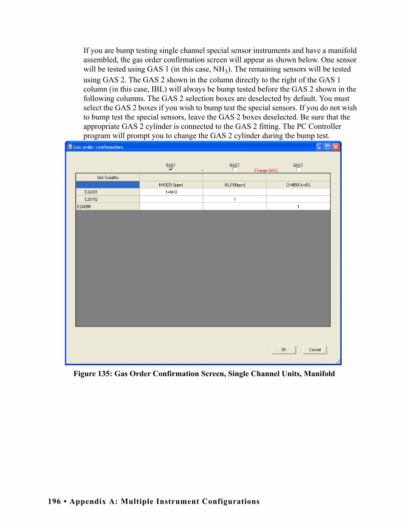
If you are bump testing single channel special sensor instruments and have a manifold assembled, the gas order confirmation screen will appear as shown below. One sensor will be tested using GAS 1 (in this case, NH3). The remaining sensors will be tested using GAS 2. The GAS 2 shown in the column directly to the right of the GAS 1 column (in this case, IBL) will always be bump tested before the GAS 2 shown in the following columns. The GAS 2 selection boxes are deselected by default. You must select the GAS 2 boxes if you wish to bump test the special sensors. If you do not wish to bump test the special sensors, leave the GAS 2 boxes deselected. Be sure that the appropriate GAS 2 cylinder is connected to the GAS 2 fitting. The PC Controller program will prompt you to change the GAS 2 cylinder during the bump test.
Figure 135: Gas Order Confirmation Screen, Single Channel Units, Manifold
196 • Appendix A: Multiple Instrument Configurations

10.Click OK. You will be asked if you want to bump test the instruments. Click OK to proceed. If you don’t want to proceed with the bump test, click Cancel to return to the main program window.
11.The pump in each instrument will start and the program will indicate that air is flowing. The AIR indicator on the program screen will be on. The BUMP LED on the SDM-E2 control panel will be flashing amber. Air will be applied to the EAGLE 2 for 45 seconds, then the PC Controller Program will perform a zero adjustment on all the channels.
Figure 136: Air Flowing
The PC Controller Program will analyze the zero adjustment results. If any sensors failed the zero adjustment, the bump test will be aborted.
Appendix A: Multiple Instrument Configurations • 197

12.After air is applied, and if all channels passed the zero adjustment, calibration gas from the GAS 1 cylinder will be applied. The GAS 1 indicator on the program screen will come on and calibration gas will be applied to the instruments for the duration specified in the Gas Exposure Time parameter in the Configuration Window.
Figure 137: GAS 1 Flowing
The PC Controller Program will analyze the results. If the bump test on the standard 4 sensors fails and Force Calibration is selected, a calibration will automatically begin on the standard 4 sensors and GAS 1 calibration gas will continue to flow.
198 • Appendix A: Multiple Instrument Configurations

13.After GAS 1 calibration gas is applied, calibration gas for the first special sensor will then begin flowing. The GAS 2 indicator will come on. Be sure that the appropriate cylinder is attached to the GAS 2 inlet. The GAS 2 calibration gas will be applied to the instrument(s) for the duration specified in the Gas Exposure Time parameter in the Configuration Window.
Figure 138: GAS 2 Flowing
The PC Controller Program will analyze the results. If the bump test on the first special sensor fails and Force Calibration is selected, a calibration will automatically begin on that sensor and GAS 2 calibration gas will continue to flow.
Appendix A: Multiple Instrument Configurations • 199

14.You will then be prompted to change the GAS 2 cylinder. The pumps on the instruments will stop.
• If you are bump testing an instrument or instruments in the first bank of 5 docking stations (numbered 1-5), the following screen will appear. Be sure to change the calibration cylinder connected to the GAS 2 manifold of the first bank of 5 docking stations.
• If you are bump testing an instrument or instruments in the second bank of 5 docking stations (numbered 6-10), the following screen will appear. Be sure to change the calibration cylinder connected to the GAS 2 manifold of the second bank of 5 docking stations.
• If you are bump testing instruments of the same configuration in both 5-docking station banks, the following screen will appear. Be sure to change the calibration cylinder connected to the GAS 2 manifold of each 5-docking station bank. You will need to change 2 cylinders.
When you have changed the GAS 2 cylinder, click OK. The bump test will continue and the second GAS 2 calibration gas will be applied to the instrument(s) for the duration specified in the Gas Exposure Time parameter in the Configuration Window.
200 • Appendix A: Multiple Instrument Configurations
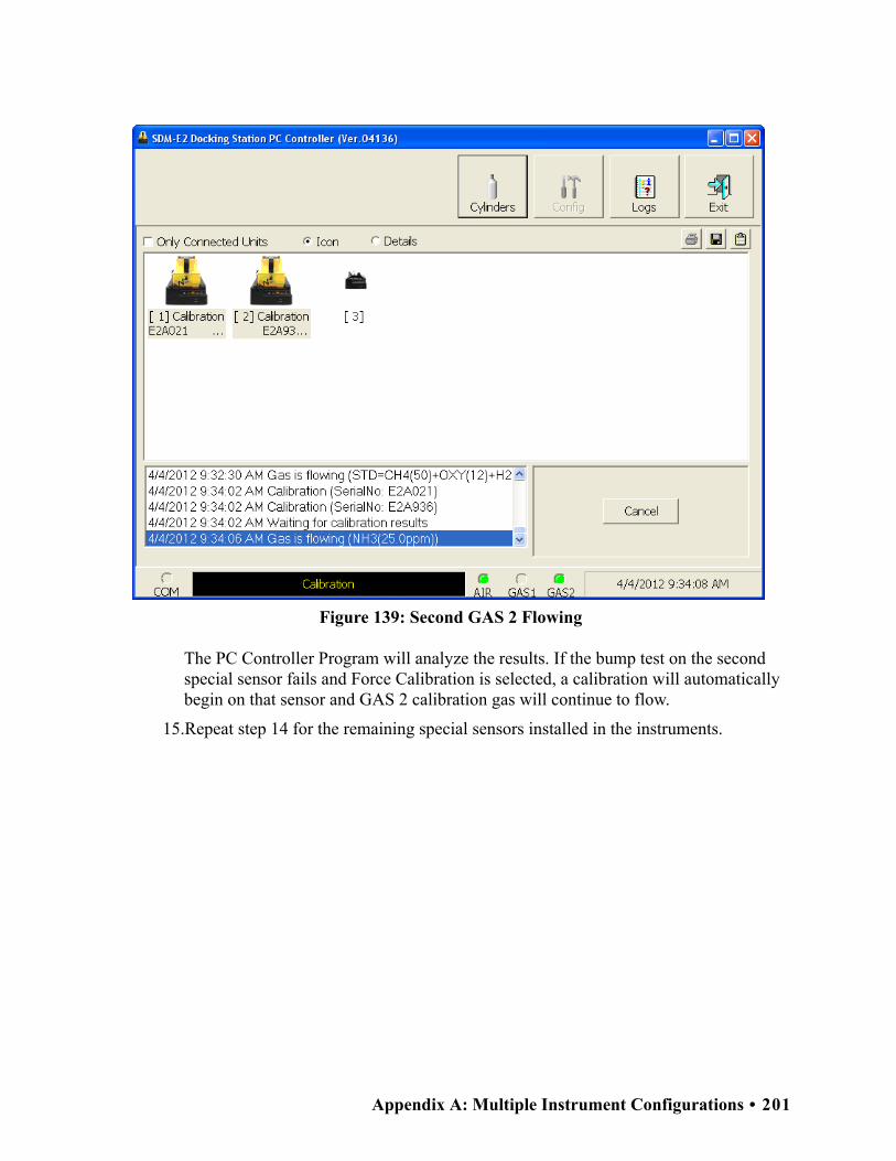
Figure 139: Second GAS 2 Flowing
The PC Controller Program will analyze the results. If the bump test on the second special sensor fails and Force Calibration is selected, a calibration will automatically begin on that sensor and GAS 2 calibration gas will continue to flow.
15.Repeat step 14 for the remaining special sensors installed in the instruments.
Appendix A: Multiple Instrument Configurations • 201

16.After the last GAS 2 calibration gas has been applied, the docking station will purge with fresh air for 45 seconds.
Figure 140: Fresh Air Purge
202 • Appendix A: Multiple Instrument Configurations
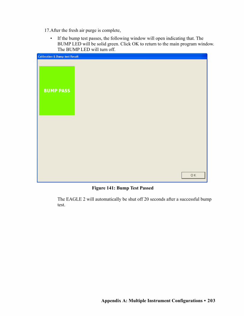
17.After the fresh air purge is complete,
• If the bump test passes, the following window will open indicating that. The BUMP LED will be solid green. Click OK to return to the main program window. The BUMP LED will turn off.
Figure 141: Bump Test Passed
The EAGLE 2 will automatically be shut off 20 seconds after a successful bump test.
Appendix A: Multiple Instrument Configurations • 203

• If the bump test fails and the Force Calibration box was not selected, the following window will open indicating which channels failed the bump test. The BUMP LED on the SDM-E2 control panel will be solid red. Click OK to return to the main program window or double click the instrument information line to view the bump test results in the Logs window. The BUMP LED on the SDM-E2 control panel will turn off.
Figure 142: Bump Test Failed
204 • Appendix A: Multiple Instrument Configurations

• If the bump test fails and the Force Calibration box was selected, the SDM-E2 automatically performs a calibration immediately after the failed bump test. The results screen will indicate the results of both the bump test and calibration. The BUMP LED on the SDM-E2 control panel will be solid red. The CAL LED will be solid green if the calibration passed or solid red if the calibration failed. Click OK to return to the main program window or double click an instrument information line to view the bump test or calibration results in the Logs window. The BUMP LED and CAL LED on the SDM-E2 control panel will turn off.
Figure 143: Bump Test Failed/Calibration Failed
Appendix A: Multiple Instrument Configurations • 205

• If at any point during the bump test the flow rate to the instrument becomes too low, the PC Controller will abort the bump test and display a failed bump test screen. The BUMP LED on the SDM-E2 control panel will be solid red. Click OK to return to the main program window or double click the instrument information line to view the bump test results in the Logs window. The BUMP LED on the SDM-E2 control panel will turn off. Confirm all tubing connections are correct and that all lines are clear.
Figure 144: Low Flow Bump Test Failure
18.For all bump test result outcomes, the instruments will be displayed in the main program window in Details View. To return the main program window to Icons View, click the Icons radio button.
19.All bump test results can be viewed in the Logs window. See pg.143 for instructions for viewing bump test data.
206 • Appendix A: Multiple Instrument Configurations

Calibrating Multiple EAGLE 2s with Different Sensor Configurations
Standard EAGLE 2s contain some combination of the standard 4 sensors (catalytic LEL, O2, H2S, and CO). Any other sensor that is installed in your EAGLE 2 is considered a special sensor. A special sensor is a PID, TC, IR, or ESM-01 sensor. In the examples that follow, three EAGLE 2s with multiple configurations are described. One is a standard 4-gas plus NH3, one is a standard 4-gas plus PID, and the last is a standard 4-gas plus TC. For instructions to calibrate a standard EAGLE 2, see pg.68. For instructions to calibrate multiple EAGLE 2s with the same special sensor configuration, see pg.94.
The PC Controller Program is capable of performing a calibration both manually and automatically on an EAGLE 2. When a calibration is performed, the PC Controller Program performs an air adjust operation on an EAGLE 2 and then applies calibration gas to the EAGLE 2. The PC Controller Program analyzes the calibration results and determines if the EAGLE 2 passed the calibration.
To manually calibrate multiple instruments with different sensor configurations:
1. Establish a connection between the SDM-E2, EAGLE 2 and the PC Controller program as described on pg.47.
WARNING: Do not plug the charger cable into a battery pack that contains alkaline batteries. Do not attempt to charge alkaline batteries.
2. Verify that all of the calibration parameters are set correctly. See pg.33 for instructions.
3. Verify that the appropriate calibration gas cylinder(s) are connected to the appropriate SDM-E2(s) or manifold line(s).
WARNING: RKI Instruments, Inc. recommends that you dedicate a regulator for use with chlorine (Cl2) gas and that you do not use that dedicated regulator for any other gases, particularly hydrogen sulfide (H2S).
4. Ensure that the gas out to EAGLE 2 line is connected to the inlet of the EAGLE 2.
NOTE: If you have an EAGLE 2 with an IR CO2 sensor in the 0-10,000 ppm or 0-5.00 %vol range, be sure to replace the air filter at the AIR inlet fitting with the CO2 scrubber when testing an instrument with a CO2 sensor installed to ensure that the CO2 present in fresh air is scrubbed out. Remove the black end caps from each end of the scrubber before installing onto the AIR inlet fitting. Replace the caps when the scrubber is not in use. See the pg.187 for a scrubber with a tubing stub.
Appendix A: Multiple Instrument Configurations • 207

5. Select the instruments you wish to calibrate and click on them to highlight them as shown below. To select multiple instruments for calibration, hold down the Control button on the keyboard as you click them.
Figure 145: Instrument Selection
6. Click the Calibration button in the lower right corner of the main program window.
208 • Appendix A: Multiple Instrument Configurations
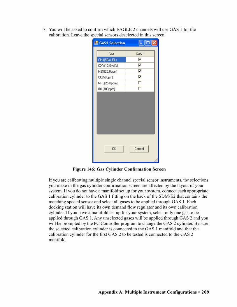
7. You will be asked to confirm which EAGLE 2 channels will use GAS 1 for the calibration. Leave the special sensors deselected in this screen.
Figure 146: Gas Cylinder Confirmation Screen
If you are calibrating multiple single channel special sensor instruments, the selections you make in the gas cylinder confirmation screen are affected by the layout of your system. If you do not have a manifold set up for your system, connect each appropriate calibration cylinder to the GAS 1 fitting on the back of the SDM-E2 that contains the matching special sensor and select all gases to be applied through GAS 1. Each docking station will have its own demand flow regulator and its own calibration cylinder. If you have a manifold set up for your system, select only one gas to be applied through GAS 1. Any unselected gases will be applied through GAS 2 and you will be prompted by the PC Controller program to change the GAS 2 cylinder. Be sure the selected calibration cylinder is connected to the GAS 1 manifold and that the calibration cylinder for the first GAS 2 to be tested is connected to the GAS 2 manifold.
Appendix A: Multiple Instrument Configurations • 209

NOTE: Do not select every gas in the gas cylinder confirmation screen unless you have calibration cylinders individually connected to your docking stations. This will result in an inaccurate calibration.
Figure 147: Gas Cylinder Confirmation Screen, Single Channel Special Sensor
When all of the desired channels are selected, click OK. If you don’t want to proceed, click Cancel to abort the calibration.
NOTE: If your instrument(s) include one or more infrared sensors, see pg.223 for a description of the GAS 1/GAS 2 assignments for this type of sensor.
No Manifold Assembled Manifold Assembled
210 • Appendix A: Multiple Instrument Configurations

8. You will then be asked to confirm the gas cylinder concentration and the instruments that the cylinder will be used for. The serial number and gas combination of all selected instruments will appear sequentially beneath the gas cylinder concentrations. The confirmation screen will indicate that the calibration cylinder for the first special sensor (in this case, NH3) must be connected to the GAS 2 fitting first and that you must change the GAS 2 cylinder midway through the calibration (in this example, to IBL and then to CH4). The GAS 2 shown in the column directly to the right of the GAS 1 column will always be calibrated before the GAS 2 shown in the following columns. Be sure that the appropriate GAS 2 cylinder is connected to the GAS 2 fitting. The screen below confirms that the standard 4 sensors will be calibrated using GAS 1 and the special sensors will be calibrated using GAS 2. The GAS 2 selection boxes are deselected by default. You must select the GAS 2 boxes if you wish to calibrate the special sensors. If you do not wish to calibrate the special sensors, leave the GAS 2 boxes deselected.
Figure 148: Gas Order Confirmation Screen
Appendix A: Multiple Instrument Configurations • 211

If you are calibrating single channel special sensor instruments and do not have a manifold assembled, the gas order confirmation screen will appear as shown below. All sensors will be tested using GAS 1. Be sure that each docking station has a demand flow regulator and the appropriate calibration cylinder connected to the GAS 1 fitting.
Figure 149: Gas Order Confirmation Screen, Single Channel Units, No Manifold
212 • Appendix A: Multiple Instrument Configurations

If you are calibrating single channel special sensor instruments and have a manifold assembled, the gas order confirmation screen will appear as shown below. One sensor will be tested using GAS 1 (in this case, NH3). The remaining sensors will be tested using GAS 2. The GAS 2 shown in the column directly to the right of the GAS 1 column (in this case, IBL) will always be calibrated before the GAS 2 shown in the following columns. The GAS 2 selection boxes are deselected by default. You must select the GAS 2 boxes if you wish to calibrate the special sensors. If you do not wish to calibrate the special sensors, leave the GAS 2 boxes deselected. Be sure that the appropriate GAS 2 cylinder is connected to the GAS 2 fitting. The PC Controller program will prompt you to change the GAS 2 cylinder during the calibration.
Figure 150: Gas Order Confirmation Screen, Single Channel Units, Manifold
Appendix A: Multiple Instrument Configurations • 213

9. Click OK. You will be asked if you want to calibrate the instruments. Click OK to proceed. If you don’t want to proceed with the calibration, click Cancel to return to the main program window.
10.The pump in each instrument will start and the program will indicate that air is flowing. The AIR indicator on the program screen will be on. The CAL LED will begin to flash amber. Air will be applied to the instruments for 45 seconds, then the PC Controller Program will perform a zero adjustment on all of the channels.
Figure 151: Air Flowing
The PC Controller Program will analyze the zero adjustment results. If any sensors failed the zero adjustment, the calibration will be aborted.
214 • Appendix A: Multiple Instrument Configurations

11.After air is applied, and if all channels passed the zero adjustment, calibration gas from the GAS 1 cylinder will be applied. The GAS 1 indicator on the program screen will come on. GAS 1 calibration gas will be applied to the instrument for 90 seconds.
Figure 152: GAS 1 Flowing
The PC Controller Program will analyze the results.
Appendix A: Multiple Instrument Configurations • 215

12.After the GAS 1 calibration gas is applied, calibration gas for the first special sensor will then begin flowing. The GAS 2 indicator will come on. Be sure that the appropriate cylinder is attached to the GAS 2 inlet. The GAS 2 calibration gas will be applied to the EAGLE 2 for an automatically defined amount of time based on the type of special sensor.
Figure 153: GAS 2 Flowing
The PC Controller Program will analyze the results.
216 • Appendix A: Multiple Instrument Configurations

13.You will then be prompted to change the GAS 2 cylinder. The pumps on the instruments will stop.
• If you are calibrating an instrument or instruments in the first bank of 5 docking stations, the following screen will appear. Be sure to change the calibration cylinder connected to the GAS 2 manifold of the first bank of 5 docking stations.
• If you are calibrating an instrument or instruments in the second bank of 5 docking stations, the following screen will appear. Be sure to change the calibration cylinder connected to the GAS 2 manifold of the second bank of 5 docking stations.
• If you are calibrating instruments of the same configuration in both 5-docking station banks, the following screen will appear. Be sure to change the calibration cylinder connected to the GAS 2 manifold of each 5-docking station bank. You will need to change 2 cylinders.
When you have changed the GAS 2 cylinder, click OK. The calibration will continue and the second GAS 2 calibration gas will be applied to the EAGLE 2 for an automatically defined amount of time based on the type of special sensor.
Appendix A: Multiple Instrument Configurations • 217

Figure 154: Second GAS 2 Flowing
The PC Controller Program will analyze the results.
14.Repeat step 13 for the remaining special sensors installed in the instruments.
218 • Appendix A: Multiple Instrument Configurations
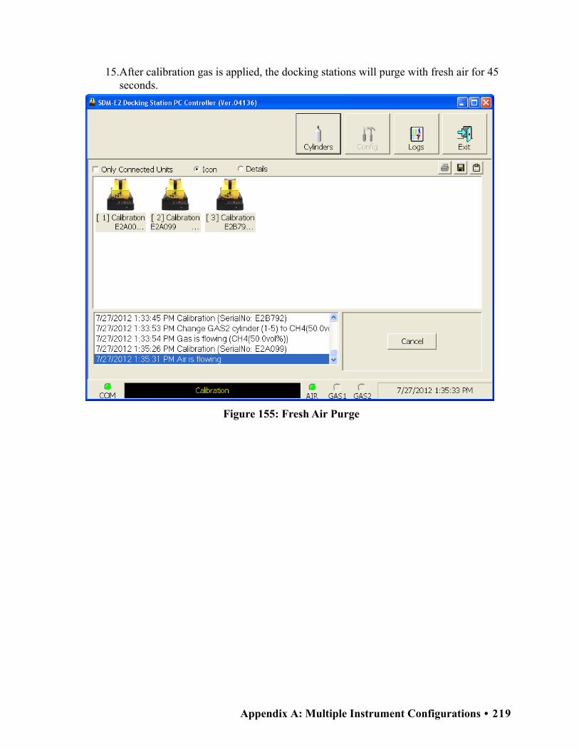
15.After calibration gas is applied, the docking stations will purge with fresh air for 45 seconds.
Figure 155: Fresh Air Purge
Appendix A: Multiple Instrument Configurations • 219

16.After the fresh air purge is complete,
• If the calibration passes, the following window will open indicating that. The CAL LED on the SDM-E2 control panel will be solid green. Click OK to return to the main program window. The CAL LED will turn off.
Figure 156: Calibration Passed
The EAGLE 2 will automatically be shut off 20 seconds after a successful calibration.
220 • Appendix A: Multiple Instrument Configurations

• If the calibration fails, the following window will open indicating which channels failed to calibrate. The CAL LED on the SDM-E2 control panel will be solid red. Click OK to return to the main program window or double click the instrument information line to view the calibration results in the Logs window. The CAL LED on the SDM-E2 control panel will turn off.
Figure 157: Calibration Failed
Appendix A: Multiple Instrument Configurations • 221

• If at any point during the calibration the flow rate to the instrument becomes too low, the PC Controller will abort the calibration and display a failed calibration screen. The CAL LED on the SDM-E2 control panel will be solid red. Click OK to return to the main program window or double click the instrument information line to view the calibration results in the Logs window. The CAL LED on the SDM-E2 control panel will turn off. Confirm all tubing connections are correct and that all lines are clear.
Figure 158: Low Flow Calibration Failure
17.For all calibration result outcomes, the instruments will be displayed in the main program window in Details View. To return to Icons View, click the Icons radio button.
18.All calibration results can be viewed in the Logs window. See pg.126 for instructions for viewing calibration data.
222 • Appendix A: Multiple Instrument Configurations

Appendix B: Bump Testing and Calibrating EAGLE 2s with IR Sensors
The default gas port assignments for EAGLE 2s that have IR sensors installed depend on the type of IR sensor. Table 13 below outlines the default gas port assignments for various typical sensor combinations. The gas combinations listed under the “Multiple IR Sensors” section are listed as the channels appear on the screen. The gas port assignments can be changed during bump testing or calibration if the default assignment is not desireable. See pg.78 for instructions to change the gas port assignment.
NOTE: These default gas port assignments apply only to the SDM-E2 when used in its PC Controlled Configuration. See the SDM-E2 Standalone Configuration Operator’s Manual for a description of the Standalone Configuration’s default gas port assignments for IR sensors.
Table 13: Default Gas Port Assignments for IR Sensors
EAGLE 2 Gas CombinationIR Sensor Gas Port
Assignment
Infrared Hydrocarbon Sensors
Standard 4 + IR “HC” (LEL only or autoranging) GAS 1
IR “HC” (LEL or autoranging) only GAS 1
Standard 4 + IR “IBU” (LEL only or autoranging) GAS 2
IR “IBU” (LEL or autoranging) only GAS 2
Standard 4 + IR “custom name” (LEL only or autoranging)* GAS 2
IR “custom name” (LEL or autoranging) only* GAS 2
Infrared Methane Sensors
Standard 4 + IR CH4 (LEL only or autoranging) GAS 1
IR CH4 (LEL or autoranging) only GAS 1
Standard 4 + IR CH4 (volume only) GAS 2
IR CH4 (volume only) GAS 2
Infrared Carbon Dioxide Sensors
Standard 4 + IR CO2 (any range) GAS 2
IR CO2 (any range) only GAS 2
Appendix B: Bump Testing and Calibrating EAGLE 2s with IR Sensors • 223

The LEL only and autoranging ranges of the IR CH4 and IR “HC” sensors are the only cases of an IR sensor being assigned to GAS 1 automatically. If the IR HC sensor is not displayed as “HC” and is instead displayed as “IBU” or a custom name, it will be assigned to GAS 2.
Multiple IR Sensors
IR CO2 (any range) + IR “HC” (LEL only or autoranging) IR CO2: GAS 2IR “HC”: GAS 1
IR CH4 (volume only) + IR “HC” (LEL only or autoranging) IR CH4: GAS 2IR “HC”: GAS 1
IR CH4 (volume only) + IR “IBU” (LEL only or autoranging) IR CH4: GAS 2IR “IBU”: GAS 2
IR CH4 (volume only) + IR “custom name” (LEL only or auto-ranging)*
IR CH4: GAS 2IR “custom”: GAS 2
IR CH4 (volume only) + IR CH4 (LEL only or autoranging) IR CH4 vol only: GAS 2IR CH4 LEL/auto: GAS 2
IR CH4 (volume only) + IR CO2 (any range) IR CH4: GAS 2IR CO2: GAS 2
* Depending on special requirements, your infrared hydrocarbon channel’s gas name may be something other than “HC” or “IBU”.
Table 13: Default Gas Port Assignments for IR Sensors
EAGLE 2 Gas CombinationIR Sensor Gas Port
Assignment
224 • Appendix B: Bump Testing and Calibrating EAGLE 2s with IR Sensors
Copyright © 2022 FDOKUMEN