sarasota county volume 3 - | SRQ Airport
569
-
Upload
khangminh22 -
Category
Documents
-
view
4 -
download
0
Transcript of sarasota county volume 3 - | SRQ Airport
!
"##$%& !
!" !#
' ()*+
$ *
,-
*./ **0
"1"21$
3( 4' ()*5)


SARASOTA MANATEE AIRPORT AUTHORITY RENOVATION OF SRQ AIRPORT POLICE DEPARTMENT & BADGING AREA 09.10.18 SARASOTA, FLORIDA
COMMON WORK RESULTS FOR FIRE SUPPRESSION 21 05 00-1
SECTION 21 05 00 - COMMON WORK RESULTS FOR FIRE SUPPRESSION PART 1 - GENERAL
1.1 RELATED DOCUMENTS
A. Drawings and general provisions of the Contract, including General and Supplementary Conditions and Division 01 Specification Sections, apply to this Section.
1.2 SUMMARY
A. This Section includes the following:
1. Piping materials and installation instructions common to most piping systems. 2. Mechanical sleeve seals. 3. Sleeves. 4. Escutcheons. 5. Grout. 6. Fire-suppression equipment and piping demolition. 7. Equipment installation requirements common to equipment sections. 8. Painting and finishing. 9. Concrete bases. 10. Supports and anchorages.
1.3 DEFINITIONS
A. Finished Spaces: Spaces other than mechanical and electrical equipment rooms, furred spaces, pipe chases, unheated spaces immediately below roof, spaces above ceilings, unexcavated spaces, crawlspaces, and tunnels.
B. Exposed, Interior Installations: Exposed to view indoors. Examples include finished occupied spaces and mechanical equipment rooms.
C. Exposed, Exterior Installations: Exposed to view outdoors or subject to outdoor ambient temperatures and weather conditions. Examples include rooftop locations.
D. Concealed, Interior Installations: Concealed from view and protected from physical contact by building occupants. Examples include above ceilings and in chases.
E. Concealed, Exterior Installations: Concealed from view and protected from weather conditions and physical contact by building occupants but subject to outdoor ambient temperatures. Examples include installations within unheated shelters.
F. The following are industry abbreviations for plastic materials:
1. CPVC: Chlorinated polyvinyl chloride plastic.
G. The following are industry abbreviations for rubber materials:
1. EPDM: Ethylene-propylene-diene terpolymer rubber.
SARASOTA MANATEE AIRPORT AUTHORITY RENOVATION OF SRQ AIRPORT POLICE DEPARTMENT & BADGING AREA 09.10.18 SARASOTA, FLORIDA
COMMON WORK RESULTS FOR FIRE SUPPRESSION 21 05 00-2
2. NBR: Acrylonitrile-butadiene rubber.
1.4 SUBMITTALS
A. Product Data: For the following:
1. Mechanical sleeve seals. 2. Escutcheons.
B. Welding certificates.
1.5 QUALITY ASSURANCE
A. Steel Support Welding: Qualify processes and operators according to AWS D1.1, "Structural Welding Code--Steel."
B. Steel Pipe Welding: Qualify processes and operators according to ASME Boiler and Pressure Vessel Code: Section IX, "Welding and Brazing Qualifications."
1. Comply with provisions in ASME B31 Series, "Code for Pressure Piping." 2. Certify that each welder has passed AWS qualification tests for welding processes involved and
that certification is current.
C. Electrical Characteristics for Fire-Suppression Equipment: Equipment of higher electrical characteristics may be furnished provided such proposed equipment is approved in writing and connecting electrical services, circuit breakers, and conduit sizes are appropriately modified. If minimum energy ratings or efficiencies are specified, equipment shall comply with requirements.
1.6 DELIVERY, STORAGE, AND HANDLING
A. Deliver pipes and tubes with factory-applied end caps. Maintain end caps through shipping, storage, and handling to prevent pipe end damage and to prevent entrance of dirt, debris, and moisture.
B. Store plastic pipes protected from direct sunlight. Support to prevent sagging and bending.
1.7 COORDINATION
A. Arrange for pipe spaces, chases, slots, and openings in building structure during progress of construction, to allow for fire-suppression installations.
B. Coordinate installation of required supporting devices and set sleeves in poured-in-place concrete and other structural components as they are constructed.
C. Coordinate requirements for access panels and doors for fire-suppression items requiring access that are concealed behind finished surfaces. Access panels and doors are specified in Division 08 Section "Access Doors and Frames."

SARASOTA MANATEE AIRPORT AUTHORITY RENOVATION OF SRQ AIRPORT POLICE DEPARTMENT & BADGING AREA 09.10.18 SARASOTA, FLORIDA
COMMON WORK RESULTS FOR FIRE SUPPRESSION 21 05 00-3
PART 2 - PRODUCTS
2.1 MANUFACTURERS
A. In other Part 2 articles where subparagraph titles below introduce lists, the following requirements apply for product selection:
1. Manufacturers: Subject to compliance with requirements, provide products by the manufacturers specified.
2.2 PIPE, TUBE, AND FITTINGS
A. Refer to individual Division 21 piping Sections for pipe, tube, and fitting materials and joining methods.
B. Pipe Threads: ASME B1.20.1 for factory-threaded pipe and pipe fittings.
2.3 JOINING MATERIALS
A. Refer to individual Division 21 piping Sections for special joining materials not listed below.
B. Pipe-Flange Gasket Materials: Suitable for chemical and thermal conditions of piping system contents.
1. ASME B16.21, nonmetallic, flat, asbestos-free, 1/8-inch maximum thickness unless thickness or specific material is indicated.
a. Full-Face Type: For flat-face, Class 125, cast-iron and cast-bronze flanges. b. Narrow-Face Type: For raised-face, Class 250, cast-iron and steel flanges.
2. AWWA C110, rubber, flat face, 1/8 inch thick, unless otherwise indicated; and full-face or ring type, unless otherwise indicated.
C. Flange Bolts and Nuts: ASME B18.2.1, carbon steel, unless otherwise indicated.
D. Plastic, Pipe-Flange Gasket, Bolts, and Nuts: Type and material recommended by piping system manufacturer, unless otherwise indicated.
E. Solder Filler Metals: ASTM B 32, lead-free alloys. Include water-flushable flux according to ASTM B 813.
F. Welding Filler Metals: Comply with AWS D10.12 for welding materials appropriate for wall thickness and chemical analysis of steel pipe being welded.
G. Solvent Cements for Joining CPVC Plastic Piping: ASTM F 493.
2.4 MECHANICAL SLEEVE SEALS
A. Description: Modular sealing element unit, designed for field assembly, to fill annular space between pipe and sleeve.
1. Manufacturers:
SARASOTA MANATEE AIRPORT AUTHORITY RENOVATION OF SRQ AIRPORT POLICE DEPARTMENT & BADGING AREA 09.10.18 SARASOTA, FLORIDA
COMMON WORK RESULTS FOR FIRE SUPPRESSION 21 05 00-4
a. Advance Products & Systems, Inc. b. Calpico, Inc. c. Metraflex Co. d. Pipeline Seal and Insulator, Inc
2. Sealing Elements: EPDM interlocking links shaped to fit surface of pipe. Include type and number required for pipe material and size of pipe.
3. Pressure Plates: Carbon steel or Stainless steel. Include two for each sealing element. 4. Connecting Bolts and Nuts: Carbon steel with corrosion-resistant coating or Stainless steel of
length required to secure pressure plates to sealing elements. Include one for each sealing element.
2.5 SLEEVES
A. Steel Pipe: ASTM A 53, Type E, Grade B, Schedule 40, galvanized, plain ends.
B. Cast Iron: Cast or fabricated "wall pipe" equivalent to ductile-iron pressure pipe, with plain ends and integral waterstop, unless otherwise indicated.
C. Stack Sleeve Fittings: Manufactured, cast-iron sleeve with integral clamping flange. Include clamping ring and bolts and nuts for membrane flashing.
1. Underdeck Clamp: Clamping ring with set screws.
D. PVC Pipe: ASTM D 1785, Schedule 40.
E. Molded PE: Reusable, PE, tapered-cup shaped, and smooth-outer surface with nailing flange for attaching to wooden forms.
2.6 PIPING ESCUTCHEONS
A. Description: Manufactured wall and ceiling escutcheons and floor plates, with an ID to closely fit around pipe, tube, and insulation of insulated piping and an OD that completely covers opening.
B. One-Piece, Cast-Brass Type: With set screw.
1. Finish: Polished chrome-plated.
C. Split-Casting, Cast-Brass Type: With concealed hinge and set screw.
1. Finish: Polished chrome-plated.
D. One-Piece, Stamped-Steel Type: With set screw and chrome-plated finish.
E. Split-Plate, Stamped-Steel Type: With concealed hinge, set screw, and chrome-plated finish.
2.7 GROUT
A. Description: ASTM C 1107, Grade B, nonshrink and nonmetallic, dry hydraulic-cement grout.

SARASOTA MANATEE AIRPORT AUTHORITY RENOVATION OF SRQ AIRPORT POLICE DEPARTMENT & BADGING AREA 09.10.18 SARASOTA, FLORIDA
COMMON WORK RESULTS FOR FIRE SUPPRESSION 21 05 00-5
1. Characteristics: Post-hardening, volume-adjusting, nonstaining, noncorrosive, nongaseous, and recommended for interior and exterior applications.
2. Design Mix: 5000-psi, 28-day compressive strength. 3. Packaging: Premixed and factory packaged.
PART 3 - EXECUTION
3.1 PIPING SYSTEMS - COMMON REQUIREMENTS
A. Install piping according to the following requirements and Division 21 Sections specifying piping systems.
B. Drawing plans, schematics, and diagrams indicate general location and arrangement of piping systems. Indicated locations and arrangements were used to size pipe and calculate friction loss, expansion, pump sizing, and other design considerations. Install piping as indicated unless deviations to layout are approved on Coordination Drawings.
C. Install piping in concealed locations, unless otherwise indicated and except in equipment rooms and service areas.
D. Install piping indicated to be exposed and piping in equipment rooms and service areas at right angles or parallel to building walls. Diagonal runs are prohibited unless specifically indicated otherwise.
E. Install piping above accessible ceilings to allow sufficient space for ceiling panel removal.
F. Install piping to permit valve servicing.
G. Install piping at indicated slopes.
H. Install piping free of sags and bends.
I. Install fittings for changes in direction and branch connections.
J. Install piping to allow application of insulation.
K. Select system components with pressure rating equal to or greater than system operating pressure.
L. Install escutcheons for penetrations of walls, ceilings, and floors according to the following:
1. New Piping:
a. Bare Piping at Wall Ceiling and Floor Penetrations in Finished Spaces: One-piece, cast-brass type with polished chrome-plated finish.
M. Permanent sleeves are not required for holes formed by removable PE sleeves.
N. Install sleeves for pipes passing through concrete and masonry walls, gypsum-board partitions, and concrete floor and roof slabs.
1. Cut sleeves to length for mounting flush with both surfaces.

SARASOTA MANATEE AIRPORT AUTHORITY RENOVATION OF SRQ AIRPORT POLICE DEPARTMENT & BADGING AREA 09.10.18 SARASOTA, FLORIDA
COMMON WORK RESULTS FOR FIRE SUPPRESSION 21 05 00-6
a. Exception: Extend sleeves installed in floors of mechanical equipment areas or other wet areas 2 inches above finished floor level. Extend cast-iron sleeve fittings below floor slab as required to secure clamping ring if ring is specified.
2. Install sleeves in new walls and slabs as new walls and slabs are constructed. 3. Install sleeves that are large enough to provide 1/4-inch annular clear space between sleeve and
pipe or pipe insulation. Use the following sleeve materials:
a. PVC or Steel Pipe Sleeves. b. Stack Sleeve Fittings: For pipes penetrating floors with membrane waterproofing. Secure
flashing between clamping flanges. Install section of cast-iron soil pipe to extend sleeve to 2 inches above finished floor level. Refer to Division 07 Section "Sheet Metal Flashing and Trim" for flashing.
1) Seal space outside of sleeve fittings with grout.
4. Except for underground wall penetrations, seal annular space between sleeve and pipe or pipe insulation, using joint sealants appropriate for size, depth, and location of joint. Refer to Division 07 Section "Joint Sealants" for materials and installation.
O. Aboveground, Exterior-Wall Pipe Penetrations: Seal penetrations using sleeves and mechanical sleeve seals. Select sleeve size to allow for 1-inch annular clear space between pipe and sleeve for installing mechanical sleeve seals.
1. Install steel pipe for sleeves smaller than 6 inches in diameter. 2. Install cast-iron "wall pipes" for sleeves 6 inches and larger in diameter. 3. Mechanical Sleeve Seal Installation: Select type and number of sealing elements required for pipe
material and size. Position pipe in center of sleeve. Assemble mechanical sleeve seals and install in annular space between pipe and sleeve. Tighten bolts against pressure plates that cause sealing elements to expand and make watertight seal.
P. Underground, Exterior-Wall Pipe Penetrations: Install cast-iron "wall pipes" for sleeves. Seal pipe penetrations using mechanical sleeve seals. Select sleeve size to allow for 1-inch annular clear space between pipe and sleeve for installing mechanical sleeve seals.
1. Mechanical Sleeve Seal Installation: Select type and number of sealing elements required for pipe material and size. Position pipe in center of sleeve. Assemble mechanical sleeve seals and install in annular space between pipe and sleeve. Tighten bolts against pressure plates that cause sealing elements to expand and make watertight seal.
Q. Fire-Barrier Penetrations: Maintain indicated fire rating of walls, partitions, ceilings, and floors at pipe penetrations. Seal pipe penetrations with firestop materials. Refer to Division 07 Section "Penetration Firestopping" for materials.
R. Verify final equipment locations for roughing-in.
S. Refer to equipment specifications in other Sections of these Specifications for roughing-in requirements.
3.2 PIPING JOINT CONSTRUCTION
A. Join pipe and fittings according to the following requirements and Division 21 Sections specifying piping systems.

SARASOTA MANATEE AIRPORT AUTHORITY RENOVATION OF SRQ AIRPORT POLICE DEPARTMENT & BADGING AREA 09.10.18 SARASOTA, FLORIDA
COMMON WORK RESULTS FOR FIRE SUPPRESSION 21 05 00-7
B. Ream ends of pipes and tubes and remove burrs. Bevel plain ends of steel pipe.
C. Remove scale, slag, dirt, and debris from inside and outside of pipe and fittings before assembly.
D. Soldered Joints: Apply ASTM B 813, water-flushable flux, unless otherwise indicated, to tube end. Construct joints according to ASTM B 828 or CDA's "Copper Tube Handbook," using lead-free solder alloy complying with ASTM B 32.
E. Threaded Joints: Thread pipe with tapered pipe threads according to ASME B1.20.1. Cut threads full and clean using sharp dies. Ream threaded pipe ends to remove burrs and restore full ID. Join pipe fittings and valves as follows:
1. Apply appropriate tape or thread compound to external pipe threads unless dry seal threading is specified.
2. Damaged Threads: Do not use pipe or pipe fittings with threads that are corroded or damaged. Do not use pipe sections that have cracked or open welds.
F. Welded Joints: Construct joints according to AWS D10.12, using qualified processes and welding operators according to Part 1 "Quality Assurance" Article.
G. Flanged Joints: Select appropriate gasket material, size, type, and thickness for service application. Install gasket concentrically positioned. Use suitable lubricants on bolt threads.
H. Plastic Piping Solvent-Cement Joints: Clean and dry joining surfaces. Join pipe and fittings according to the following:
1. Comply with ASTM F 402 for safe-handling practice of cleaners, primers, and solvent cements. 2. CPVC Piping: Join according to ASTM D 2846/D 2846M Appendix.
3.3 PAINTING
A. Painting of fire-suppression systems, equipment, and components is specified in Division 09 Sections "Interior Painting" and "Exterior Painting."
B. Damage and Touchup: Repair marred and damaged factory-painted finishes with materials and procedures to match original factory finish.
C. All exposed sprinkler, pipe and standpipe shall be painted in red.
3.4 CONCRETE BASES
A. Concrete Bases: Shall be coordinated with Division 03
3.5 ERECTION OF METAL SUPPORTS AND ANCHORAGES
A. Refer to Division 05 Section "Metal Fabrications" for structural steel.
B. Cut, fit, and place miscellaneous metal supports accurately in location, alignment, and elevation to support and anchor fire-suppression materials and equipment.
C. Field Welding: Comply with AWS D1.1.
SARASOTA MANATEE AIRPORT AUTHORITY RENOVATION OF SRQ AIRPORT POLICE DEPARTMENT & BADGING AREA 09.10.18 SARASOTA, FLORIDA
COMMON WORK RESULTS FOR FIRE SUPPRESSION 21 05 00-8
3.6 GROUTING
A. Mix and install grout for fire-suppression equipment base bearing surfaces, pump and other equipment base plates, and anchors.
B. Clean surfaces that will come into contact with grout.
C. Provide forms as required for placement of grout.
D. Avoid air entrapment during placement of grout.
E. Place grout, completely filling equipment bases.
F. Place grout on concrete bases and provide smooth bearing surface for equipment.
G. Place grout around anchors.
H. Cure placed grout.
END OF SECTION 21 05 00

SARASOTA MANATEE AIRPORT AUTHORITY RENOVATION OF SRQ AIRPORT POLICE DEPARTMENT & BADGING AREA 09.10.18 SARASOTA, FLORIDA
SLEEVES AND SLEEVE SEALS FOR FIRE-SUPPRESSION PIPING
21 05 17-1
SECTION 21 05 17 - SLEEVES AND SLEEVE SEALS FOR FIRE-SUPPRESSION PIPING
PART 1 - GENERAL
1.1 RELATED DOCUMENTS
A. Drawings and general provisions of the Contract, including General and Supplementary Conditions and Division 01 Specification Sections, apply to this Section.
1.2 SUMMARY
A. Section Includes: 1. Sleeves. 2. Stack-sleeve fittings. 3. Sleeve-seal systems. 4. Sleeve-seal fittings. 5. Grout.
1.3 ACTION SUBMITTALS
A. Product Data: For each type of product indicated.
PART 2 - PRODUCTS
2.1 SLEEVES
A. Cast-Iron Wall Pipes: Cast or fabricated of cast or ductile iron and equivalent to ductile-iron pressure pipe, with plain ends and integral waterstop unless otherwise indicated.
B. Galvanized-Steel-Pipe Sleeves: ASTM A 53/A 53M, Type E, Grade B, Schedule 40, zinc coated, with plain ends.
C. PVC-Pipe Sleeves: ASTM D 1785, Schedule 40.
D. Molded-PE Sleeves: Removable, tapered-cup shaped, and smooth outer surface with nailing flange for attaching to wooden forms.
2.2 STACK-SLEEVE FITTINGS
A. Manufacturers: Subject to compliance with requirements, available manufacturers offering products that may be incorporated into the Work include, but are not limited to, the following: 1. Smith, Jay R. Mfg. Co. 2. Zurn Specification Drainage Operation; Zurn Plumbing Products Group.
B. Description: Manufactured, cast-iron sleeve with integral clamping flange. Include clamping ring, bolts, and nuts for membrane flashing. 1. Underdeck Clamp: Clamping ring with setscrews.
SARASOTA MANATEE AIRPORT AUTHORITY RENOVATION OF SRQ AIRPORT POLICE DEPARTMENT & BADGING AREA 09.10.18 SARASOTA, FLORIDA
SLEEVES AND SLEEVE SEALS FOR FIRE-SUPPRESSION PIPING
21 05 17-2
2.3 SLEEVE-SEAL SYSTEMS
A. Manufacturers: Subject to compliance with requirements, available manufacturers offering products that may be incorporated into the Work include, but are not limited to, the following: 1. Advance Products & Systems, Inc. 2. CALPICO, Inc. 3. Metraflex Company (The). 4. Pipeline Seal and Insulator, Inc. 5. Proco Products, Inc.
B. Description: Modular sealing-element unit, designed for field assembly, for filling annular space between piping and sleeve. 1. Sealing Elements: EPDM-rubber interlocking links shaped to fit surface of pipe. Include type and
number required for pipe material and size of pipe. 2. Pressure Plates: Carbon steel. 3. Connecting Bolts and Nuts: Carbon steel, with corrosion-resistant coating of length required to
secure pressure plates to sealing elements.
2.4 SLEEVE-SEAL FITTINGS
A. Manufacturers: Subject to compliance with requirements, available manufacturers offering products that may be incorporated into the Work include, but are not limited to, the following: 1. Presealed Systems.
B. Description: Manufactured plastic, sleeve-type, waterstop assembly made for imbedding in concrete slab or wall. Unit has plastic or rubber waterstop collar with center opening to match piping OD.
2.5 GROUT
A. Standard: ASTM C 1107/C 1107M, Grade B, post-hardening and volume-adjusting, dry, hydraulic-cement grout.
B. Characteristics: Nonshrink; recommended for interior and exterior applications.
C. Design Mix: 5000-psi, 28-day compressive strength.
D. Packaging: Premixed and factory packaged.
PART 3 - EXECUTION
3.1 SLEEVE INSTALLATION
A. Install sleeves for piping passing through penetrations in floors, partitions, roofs, and walls.
B. For sleeves that will have sleeve-seal system installed, select sleeves of size large enough to provide 1-inch annular clear space between piping and concrete slabs and walls. 1. Sleeves are not required for core-drilled holes.
C. Install sleeves in concrete floors, concrete roof slabs, and concrete walls as new slabs and walls are constructed. 1. Permanent sleeves are not required for holes in slabs formed by molded-PE or -PP sleeves. 2. Cut sleeves to length for mounting flush with both surfaces.
SARASOTA MANATEE AIRPORT AUTHORITY RENOVATION OF SRQ AIRPORT POLICE DEPARTMENT & BADGING AREA 09.10.18 SARASOTA, FLORIDA
SLEEVES AND SLEEVE SEALS FOR FIRE-SUPPRESSION PIPING
21 05 17-3
a. Exception: Extend sleeves installed in floors of mechanical equipment areas or other wet areas 2 inches above finished floor level.
3. Using grout, seal the space outside of sleeves in slabs and walls without sleeve-seal system.
D. Install sleeves for pipes passing through interior partitions. 1. Cut sleeves to length for mounting flush with both surfaces. 2. Install sleeves that are large enough to provide 1/4-inch annular clear space between sleeve and
pipe or pipe insulation. 3. Seal annular space between sleeve and piping or piping insulation; use joint sealants appropriate
for size, depth, and location of joint. Comply with requirements for sealants specified in Section 079200 "Joint Sealants."
E. Fire-Barrier Penetrations: Maintain indicated fire rating of walls, partitions, ceilings, and floors at pipe penetrations. Seal pipe penetrations with firestop materials. Comply with requirements for firestopping specified in Section 078413 "Penetration Firestopping."
3.2 STACK-SLEEVE-FITTING INSTALLATION
A. Install stack-sleeve fittings in new slabs as slabs are constructed. 1. Install fittings that are large enough to provide 1/4-inch annular clear space between sleeve and
pipe or pipe insulation. 2. Secure flashing between clamping flanges for pipes penetrating floors with membrane
waterproofing. Comply with requirements for flashing specified in Section 076200 "Sheet Metal Flashing and Trim."
3. Install section of cast-iron soil pipe to extend sleeve to 2 inches above finished floor level. 4. Extend cast-iron sleeve fittings below floor slab as required to secure clamping ring if ring is
specified. 5. Using grout, seal the space around outside of stack-sleeve fittings.
B. Fire-Barrier Penetrations: Maintain indicated fire rating of floors at pipe penetrations. Seal pipe penetrations with firestop materials. Comply with requirements for firestopping specified in Section 078413 "Penetration Firestopping."
3.3 SLEEVE-SEAL-SYSTEM INSTALLATION
A. Install sleeve-seal systems in sleeves in exterior concrete walls and slabs-on-grade at service piping entries into building.
B. Select type, size, and number of sealing elements required for piping material and size and for sleeve ID or hole size. Position piping in center of sleeve. Center piping in penetration, assemble sleeve-seal system components, and install in annular space between piping and sleeve. Tighten bolts against pressure plates that cause sealing elements to expand and make a watertight seal.
3.4 SLEEVE-SEAL-FITTING INSTALLATION
A. Install sleeve-seal fittings in new walls and slabs as they are constructed.
B. Assemble fitting components of length to be flush with both surfaces of concrete slabs and walls. Position waterstop flange to be centered in concrete slab or wall.
C. Secure nailing flanges to concrete forms.
D. Using grout, seal the space around outside of sleeve-seal fittings.

SARASOTA MANATEE AIRPORT AUTHORITY RENOVATION OF SRQ AIRPORT POLICE DEPARTMENT & BADGING AREA 09.10.18 SARASOTA, FLORIDA
SLEEVES AND SLEEVE SEALS FOR FIRE-SUPPRESSION PIPING
21 05 17-4
3.5 SLEEVE AND SLEEVE-SEAL SCHEDULE
A. Use sleeves and sleeve seals for the following piping-penetration applications: 1. Exterior Concrete Walls above Grade:
a. Piping Smaller Than NPS 6 Galvanized-steel-pipe sleeves with sleeve seal system. b. Piping NPS 6 and Larger: Galvanized-steel-pipe sleeves.
2. Exterior Concrete Walls below Grade: a. Piping Smaller Than NPS 6: Galvanized-steel-pipe sleeves with sleeve-seal system.
1) Select sleeve size to allow for 1-inch annular clear space between piping and sleeve for installing sleeve-seal system.
b. Piping NPS 6 and Larger: Galvanized-steel-pipe sleeves with sleeve-seal system 1) Select sleeve size to allow for 1-inch (25-mm) annular clear space between piping
and sleeve for installing sleeve-seal system. 3. Concrete Slabs-on-Grade:
a. Piping Smaller Than NPS 6: Galvanized-steel-pipe sleeves with sleeve-seal system. 1) Select sleeve size to allow for 1-inch annular clear space between piping and sleeve
for installing sleeve-seal system. b. Piping NPS 6 and Larger: Galvanized-steel-pipe sleeves with sleeve-seal system
1) Select sleeve size to allow for 1-inch annular clear space between piping and sleeve for installing sleeve-seal system.
4. Concrete Slabs above Grade: a. Piping Smaller Than NPS 6: Galvanized-steel-pipe sleeves, PVC-pipe sleeves, Stack-
sleeve fittings, Sleeve-seal fittings, Molded-PE or Molded-PVC sleeves. b. Piping NPS 6 and Larger: Galvanized-steel-pipe sleeves.
5. Interior Partitions: a. Piping Smaller Than NPS 6 Galvanized-steel-pipe sleeves. b. Piping NPS 6 and Larger: Galvanized-steel-sheet sleeves.
END OF SECTION 21 05 17

SARASOTA MANATEE AIRPORT AUTHORITY RENOVATION OF SRQ AIRPORT POLICE DEPARTMENT & BADGING AREA 09.10.18 SARASOTA, FLORIDA
ESCUTCHEONS FOR FIRE-SUPPRESSION PIPING
21 05 18-1
SECTION 21 05 18 - ESCUTCHEONS FOR FIRE SUPPRESSION PIPING
PART 1 - GENERAL
1.1 RELATED DOCUMENTS
A. Drawings and general provisions of the Contract, including General and Supplementary Conditions and Division 01 Specification Sections, apply to this Section.
1.2 SUMMARY
A. Section Includes: 1. Escutcheons. 2. Floor plates.
1.3 ACTION SUBMITTALS
A. Product Data: For each type of product indicated.
PART 2 - PRODUCTS
2.1 ESCUTCHEONS
A. One-Piece, Cast-Brass Type: With polished, chrome-plated finish and setscrew fastener.
B. Split-Casting Brass Type: With polished, chrome-plated finish and with concealed hinge and setscrew.
C. Split-Plate, Stamped-Steel Type: With chrome-plated finish, concealed hinge, and spring-clip fasteners.
2.2 FLOOR PLATES
A. One-Piece Floor Plates: Cast-iron flange with holes for fasteners.
B. Split-Casting Floor Plates: Cast brass with concealed hinge.
PART 3 - EXECUTION
3.1 INSTALLATION
A. Install escutcheons for piping penetrations of walls, ceilings, and finished floors.
B. Install escutcheons with ID to closely fit around pipe, tube, and insulation of piping and with OD that completely covers opening.
C. Install floor plates for piping penetrations of equipment-room floors.
D. Install floor plates with ID to closely fit around pipe, tube, and insulation of piping and with OD that completely covers opening. 1. New Piping: One-piece, floor-plate type. 2. Existing Piping: Split-casting, floor-plate type.
SARASOTA MANATEE AIRPORT AUTHORITY RENOVATION OF SRQ AIRPORT POLICE DEPARTMENT & BADGING AREA 09.10.18 SARASOTA, FLORIDA
ESCUTCHEONS FOR FIRE-SUPPRESSION PIPING
21 05 18-2
3.2 FIELD QUALITY CONTROL
A. Replace broken and damaged escutcheons and floor plates using new materials.
END OF SECTION 21 05 18

SARASOTA MANATEE AIRPORT AUTHORITY RENOVATION OF SRQ AIRPORT POLICE DEPARTMENT & BADGING AREA 09.10.18 SARASOTA, FLORIDA
IDENTIFICATION FOR FIRE-SUPPRESSION PIPING AND EQUIPMENT
21 05 52-1
SECTION 210553 IDENTIFICATION FOR FIRE SUPPRESSION PIPING AND EQUIPMENT
PART 1 - GENERAL
1.1 RELATED DOCUMENTS
A. Drawings and general provisions of the Contract, including General and Supplementary Conditions and Division 01 Specification Sections, apply to this Section.
1.2 SUMMARY
A. Section Includes: 1. Equipment labels. 2. Warning signs and labels. 3. Pipe labels. 4. Stencils. 5. Valve tags. 6. Warning tags.
1.3 ACTION SUBMITTALS
A. Product Data: For each type of product.
B. Samples: For color, letter style, and graphic representation required for each identification material and device.
C. Equipment-Label Schedule: Include a listing of all equipment to be labeled and the proposed content for each label.
D. Valve Schedules: Valve numbering scheme.
1.4 CLOSEOUT SUBMITTALS
A. Maintenance Data: For each piping system to include in maintenance manuals.
PART 2 - PRODUCTS
2.1 EQUIPMENT LABELS
A. Metal Labels for Equipment: 1. Material and Thickness: anodized aluminum, 0.032 inch (0.8 mm) thick, with predrilled holes for
attachment hardware. 2. Letter Color: White. 3. Background Color: Red. 4. Minimum Label Size: Length and width vary for required label content, but not less than 2-1/2 by
3/4 inch (64 by 19 mm). 5. Minimum Letter Size: 1/4 inch (6.4 mm) for name of units if viewing distance is less
than 24 inches (600 mm), 1/2 inch (13 mm) for viewing distances up to 72 inches (1830 mm), and proportionately larger lettering for greater viewing distances. Include secondary lettering two-thirds to three-fourths the size of principal lettering.
6. Fasteners: Stainless-steel rivets or self-tapping screws. 7. Adhesive: Contact-type permanent adhesive, compatible with label and with substrate.
SARASOTA MANATEE AIRPORT AUTHORITY RENOVATION OF SRQ AIRPORT POLICE DEPARTMENT & BADGING AREA 09.10.18 SARASOTA, FLORIDA
IDENTIFICATION FOR FIRE-SUPPRESSION PIPING AND EQUIPMENT
21 05 52-2
B. Label Content: Include equipment's Drawing designation or unique equipment number, Drawing numbers where equipment is indicated (plans, details, and schedules), and the Specification Section number and title where equipment is specified.
C. Equipment-Label Schedule: For each item of equipment to be labeled, on 8-1/2-by-11-inch (A4) bond paper. Tabulate equipment identification number and identify Drawing numbers where equipment is indicated (plans, details, and schedules) and the Specification Section number and title where equipment is specified. Equipment schedule shall be included in operation and maintenance data.
2.2 WARNING SIGNS AND LABELS
A. Material and Thickness: Multilayer, multicolor, plastic labels for mechanical engraving, 1/16 inch (1.6 mm) thick, with predrilled holes for attachment hardware.
B. Letter Color: White.
C. Background Color: Red.
D. Maximum Temperature: Able to withstand temperatures up to 160 deg F (71 deg C).
E. Minimum Label Size: Length and width vary for required label content, but not less than 2-1/2 by 3/4 inch (64 by 19 mm).
F. Minimum Letter Size: 1/4 inch (6.4 mm) for name of units if viewing distance is less than 24 inches (600 mm), 1/2 inch (13 mm) for viewing distances up to 72 inches (1830 mm), and proportionately larger lettering for greater viewing distances. Include secondary lettering two-thirds to three-fourths the size of principal lettering.
G. Fasteners: Stainless-steel rivets.
H. Adhesive: Contact-type permanent adhesive, compatible with label and with substrate.
I. Label Content: Include caution and warning information, plus emergency notification instructions.
2.3 PIPE LABELS
A. General Requirements for Manufactured Pipe Labels: Preprinted, color-coded, with lettering indicating service and showing flow direction.
B. Pretensioned Pipe Labels: Precoiled, semirigid plastic formed to cover full circumference of pipe and to attach to pipe without fasteners or adhesive.
C. Self-Adhesive Pipe Labels: Printed plastic with contact-type, permanent-adhesive backing.
D. Pipe-Label Contents: Include identification of piping service using same designations or abbreviations as used on Drawings; pipe size; and an arrow indicating flow direction. 1. Flow-Direction Arrows: Integral with piping-system service lettering to accommodate both
directions, or as separate unit on each pipe label to indicate flow direction. 2. Lettering Size: At least 1-1/2 inches high.
E. Pipe-Label Colors: 1. Background Color: Red. 2. Letter Color: White.

SARASOTA MANATEE AIRPORT AUTHORITY RENOVATION OF SRQ AIRPORT POLICE DEPARTMENT & BADGING AREA 09.10.18 SARASOTA, FLORIDA
IDENTIFICATION FOR FIRE-SUPPRESSION PIPING AND EQUIPMENT
21 05 52-3
2.4 STENCILS
A. Stencils: Prepared with letter sizes according to ASME A13.1 for piping; and minimum letter height of 3/4 inch for access panel and door labels, equipment labels, and similar operational instructions. 1. Stencil Material: Fiberboard or metal 2. Stencil Paint: Exterior, gloss, acrylic enamel black unless otherwise indicated. Paint may be in
pressurized spray-can form. 3. Identification Paint: Exterior, acrylic enamel in colors according to ASME A13.1 unless
otherwise indicated.
2.5 VALVE TAGS
A. Valve Tags: Stamped or engraved with 1/4-inch (6.4-mm) letters for piping-system abbreviation and 1/2-inch (13-mm) numbers. 1. Tag Material: Brass, 0.032 inch (0.8 mm) thick, with predrilled holes for attachment hardware. 2. Fasteners: Brass wire-link chain. 3. Valve-Tag Color: Red. 4. Letter Color: White.
B. Valve Schedules: For each piping system, on 8-1/2-by-11-inch (A4) bond paper. Tabulate valve number, piping system, system abbreviation (as shown on valve tag), location of valve (room or space), normal-operating position (open, closed, or modulating), and variations for identification. Mark valves for emergency shutoff and similar special uses. 1. Valve-tag schedule shall be included in operation and maintenance data.
2.6 WARNING TAGS
A. Warning Tags: Preprinted or partially preprinted, accident-prevention tags, of plasticized card stock with matte finish suitable for writing. 1. Size: Approximately 4 by 7 inches (100 by 178 mm). 2. Fasteners: Brass grommet and wire. 3. Nomenclature: Large-size primary caption such as "DANGER," "CAUTION," or "DO NOT
OPERATE." 4. Color: Yellow background with black lettering.
PART 3 - EXECUTION
3.1 PREPARATION
A. Clean piping and equipment surfaces of substances that could impair bond of identification devices, including dirt, oil, grease, release agents, and incompatible primers, paints, and encapsulants.
3.2 LABEL INSTALLATION
A. Coordinate installation of identifying devices with completion of covering and painting of surfaces where devices are to be applied.
B. Coordinate installation of identifying devices with locations of access panels and doors.
C. Install or permanently fasten labels on each major item of mechanical equipment.
D. Locate equipment labels where accessible and visible.
SARASOTA MANATEE AIRPORT AUTHORITY RENOVATION OF SRQ AIRPORT POLICE DEPARTMENT & BADGING AREA 09.10.18 SARASOTA, FLORIDA
IDENTIFICATION FOR FIRE-SUPPRESSION PIPING AND EQUIPMENT
21 05 52-4
E. Piping Color-Coding: Painting of piping is specified in Division 09 Section "Interior Painting."
F. Pipe-Label Locations: Locate pipe labels where piping is exposed or above accessible ceilings in finished spaces; machine rooms; accessible maintenance spaces such as shafts, tunnels, and plenums; and exterior exposed locations as follows: 1. Near each valve and control device. 2. Near each branch connection excluding short takeoffs. Where flow pattern is not obvious, mark
each pipe at branch. 3. Near penetrations through walls, floors, ceilings, and inaccessible enclosures. 4. At access doors, manholes, and similar access points that permit view of concealed piping. 5. Near major equipment items and other points of origination and termination. 6. Spaced at maximum intervals of 50 feet (15 m) along each run. Reduce intervals to 25 feet
(7.6 m) in areas of congested piping and equipment. 7. On piping above removable acoustical ceilings. Omit intermediately spaced labels.
3.3 VALVE-TAG INSTALLATION
A. Install tags on valves and control devices in piping systems. List tagged valves in a valve-tag schedule.
B. Valve-Tag Application Schedule: Tag valves according to size, shape, and with captions similar to those indicated in "Valve-Tag Size and Shape" Subparagraph below: 1. Valve-Tag Size and Shape:
a. Fire-Suppression Standpipe: 2 inches (50 mm), round. b. Wet-Pipe Sprinkler System: 2 inches (50 mm), round. c. Foam-Water System: 2 inches (50 mm), round.
3.4 WARNING-TAG INSTALLATION
A. Write required message on, and attach warning tags to, equipment and other items where required.
END OF SECTION 21 05 53

SARASOTA MANATEE AIRPORT AUTHORITY RENOVATION OF SRQ AIRPORT POLICE DEPARTMENT & BADGING AREA 09.10.18 SARASOTA, FLORIDA
WET-PIPE SPRINKLER SYSTEMS 21 13 13-1
SECTION 21 13 13 - WET-PIPE SPRINKLER SYSTEMS PART 1 - GENERAL
1.1 RELATED DOCUMENTS
A. Drawings and general provisions of the Contract, including General and Supplementary Conditions and Division 01 Specification Sections, apply to this Section.
1.2 SUMMARY
A. Section Includes:
1. Pipes, fittings, and specialties. 2. Fire-protection valves. 3. Fire-department connections. 4. Sprinklers.
B. Related Sections:
1. Division 21 Section "Fire-Suppression Standpipes" for standpipe piping. 2. Division 21 Section "Dry-Pipe Sprinkler Systems" for dry-pipe sprinkler piping. 3. Division 21 Section for fire pumps, pressure-maintenance pumps, and fire-pump controllers.
1.3 DEFINITIONS
A. Standard-Pressure Sprinkler Piping: Wet-pipe sprinkler system piping designed to operate at working pressure of 175 psig maximum.
1.4 SYSTEM DESCRIPTIONS
A. Wet-Pipe Sprinkler System: Automatic sprinklers are attached to piping containing water and that is connected to water supply through alarm valve. Water discharges immediately from sprinklers when they are opened. Sprinklers open when heat melts fusible link or destroys frangible device. Hose connections are included if indicated.
1.5 PERFORMANCE REQUIREMENTS
A. Standard-Pressure Piping System Component: Listed for 175-psig minimum working pressure.
B. Sprinkler system shall be approved by authorities having jurisdiction.
1. Margin of Safety for Available Water Flow and Pressure: 10 P.S.I. 2. Sprinkler Occupancy Hazard Classifications refer to drawings.
SARASOTA MANATEE AIRPORT AUTHORITY RENOVATION OF SRQ AIRPORT POLICE DEPARTMENT & BADGING AREA 09.10.18 SARASOTA, FLORIDA
WET-PIPE SPRINKLER SYSTEMS 21 13 13-2
1.6 SUBMITTALS
A. Product Data: For each type of product indicated. Include rated capacities, operating characteristics, electrical characteristics, and furnished specialties and accessories.
B. Shop Drawings: For wet-pipe sprinkler systems. Include plans, elevations, sections, details, and attachments to other work.
C. Hydraulic Calculations.
1.7 QUALITY ASSURANCE
A. Installer Qualifications:
1. Installer's responsibilities include fabricating, and installing sprinkler systems and providing working plans per NFPA 13. Base calculations on results of fire-hydrant flow test.
B. Welding Qualifications: Qualify procedures and operators according to ASME Boiler and Pressure Vessel Code.
C. Electrical Components, Devices, and Accessories: Listed and labeled as defined in NFPA 70, by a qualified testing agency, and marked for intended location and application.
D. NFPA Standards: Sprinkler system equipment, specialties, accessories, installation, and testing shall comply with the following:
1. NFPA 13, "Installation of Sprinkler Systems." 2. NFPA 13R, "Installation of Sprinkler Systems in Residential Occupancies up to and Including
Four Stories in Height." 3. NFPA 24, "Installation of Private Fire Service Mains and Their Appurtenances."
1.8 PROJECT CONDITIONS
A. Interruption of Existing Sprinkler Service: Do not interrupt sprinkler service to facilities occupied by Owner or others unless permitted under the following conditions and then only after arranging to provide temporary sprinkler service according to requirements indicated:
1. Notify Architect and Construction Manager no fewer than two days in advance of proposed interruption of sprinkler service.
2. Do not proceed with interruption of sprinkler service without Architect's and Construction Manager's written permission.
1.9 COORDINATION
A. Coordinate layout and installation of sprinklers with other construction that penetrates ceilings, including light fixtures, HVAC equipment, and partition assemblies.

SARASOTA MANATEE AIRPORT AUTHORITY RENOVATION OF SRQ AIRPORT POLICE DEPARTMENT & BADGING AREA 09.10.18 SARASOTA, FLORIDA
WET-PIPE SPRINKLER SYSTEMS 21 13 13-3
PART 2 - PRODUCTS
2.1 STEEL PIPE AND FITTINGS
A. Standard Weight, Black-Steel Pipe: ASTM A 53/A 53M or ASTM A 135.
B. Piping Schedule shall be: All piping with threaded fittings shall be schedule 40 and all piping with grooved fittings shall be schedule 10.
C. Galvanized- and Black-Steel Pipe Nipples: ASTM A 733, made of ASTM A 53/A 53M, standard-weight, seamless steel pipe with threaded ends.
D. Galvanized and Uncoated, Steel Couplings: ASTM A 865, threaded.
E. Galvanized and Uncoated, Gray-Iron Threaded Fittings: ASME B16.4, Class 125, standard pattern.
F. Grooved-Joint, Steel-Pipe Appurtenances:
1. Manufacturers: Subject to compliance with requirements, available manufacturers offering products that may be incorporated into the Work include, but are not limited to, the following:
a. Tyco Fire & Building Products LP. b. Victaulic Company. c. Anvil Star Piping Inc.
2. Pressure Rating: 175 psig unless otherwise noted. 3. Galvanized and Uncoated, Grooved-End Fittings for Steel Piping: ASTM A 47/A 47M,
malleable-iron casting or ASTM A 536, ductile-iron casting; with dimensions matching steel pipe. 4. Grooved-End-Pipe Couplings for Steel Piping: AWWA C606 and UL 213, rigid pattern, unless
otherwise indicated, for steel-pipe dimensions. Include ferrous housing sections, EPDM-rubber gasket, and bolts and nuts.
2.2 PIPING JOINING MATERIALS
A. Pipe-Flange Gasket Materials: AWWA C110, rubber, flat face, 1/8 inch thick or ASME B16.21, nonmetallic and asbestos free.
1. Class 125, Cast-Iron Flanges and Class 150, Bronze Flat-Face Flanges: Full-face gaskets. 2. Class 250, Cast-Iron Flanges and Class 300, Steel Raised-Face Flanges: Ring-type gaskets.
B. Metal, Pipe-Flange Bolts and Nuts: ASME B18.2.1, carbon steel unless otherwise indicated.
C. Brazing Filler Metals: AWS A5.8/A5.8M, BCuP Series, copper-phosphorus alloys for general-duty brazing unless otherwise indicated.
D. Welding Filler Metals: Comply with AWS D10.12M/D10.12 for welding materials appropriate for wall thickness and chemical analysis of steel pipe being welded.
E. Solvent Cements for Joining CPVC Piping and Tubing: ASTM F 493, solvent cement recommended by pipe and fitting manufacturer, and made for joining CPVC sprinkler pipe and fittings. Include cleaner or primer recommended by pipe and fitting manufacturer.
SARASOTA MANATEE AIRPORT AUTHORITY RENOVATION OF SRQ AIRPORT POLICE DEPARTMENT & BADGING AREA 09.10.18 SARASOTA, FLORIDA
WET-PIPE SPRINKLER SYSTEMS 21 13 13-4
1. Use solvent cement that has a VOC content of 490 g/L or less when calculated according to 40 CFR 59, Subpart D (EPA Method 24).
2. Use adhesive primer that has a VOC content of 650 g/L or less when calculated according to 40 CFR 59, Subpart D (EPA Method 24).
F. Plastic, Pipe-Flange Gasket, and Bolts and Nuts: Type and material recommended by piping system manufacturer unless otherwise indicated.
2.3 LISTED FIRE-PROTECTION VALVES
A. General Requirements:
1. Valves shall be UL listed or FM approved. 2. Minimum Pressure Rating for Standard-Pressure Piping: 175 psig. 3. Minimum Pressure Rating for High-Pressure Piping: 300 psig.
B. Ball Valves:
1. Standard: UL 1091 except with ball instead of disc. 2. Valves NPS 1-1/2 and Smaller: Bronze body with threaded ends. 3. Valves NPS 2 and NPS 2-1/2: Bronze body with threaded ends or ductile-iron body with grooved
ends. 4. Valves NPS 3: Ductile-iron body with grooved ends.
C. Check Valves:
1. Standard: UL 312. 2. Pressure Rating: 300 psig. 3. Type: Swing check. 4. Body Material: Cast iron. 5. End Connections: Flanged or grooved.
D. Iron Butterfly Valves:
1. Manufacturers: Subject to compliance with requirements, provide products by one of the following:
a. Anvil International, Inc. b. Kennedy Valve; a division of McWane, Inc. c. Milwaukee Valve Company. d. NIBCO INC. e. Tyco Fire & Building Products LP. f. Victaulic Company.
2. Standard: UL 1091. 3. Pressure Rating: 175 psig. 4. Body Material: Cast or ductile iron. 5. Style: Lug or wafer. 6. End Connections: Grooved.
SARASOTA MANATEE AIRPORT AUTHORITY RENOVATION OF SRQ AIRPORT POLICE DEPARTMENT & BADGING AREA 09.10.18 SARASOTA, FLORIDA
WET-PIPE SPRINKLER SYSTEMS 21 13 13-5
2.4 FIRE-DEPARTMENT CONNECTIONS
A. Fire-Department Connection:
1. Manufacturers: Subject to compliance with requirements, available manufacturers offering products that may be incorporated into the Work include, but are not limited to, the following:
a. Fire-End & Croker Corporation. b. Tyco Fire & Building Products LP c. Potter Roemer d. Elkhart Brass
2. Standard: UL 405. 3. Type: As indicated on drawings. 4. Pressure Rating: 175 psig minimum. 5. Body Material: Corrosion-resistant metal. 6. Inlets: Threads according to NFPA 1963 and matching local fire-department sizes and threads.
Include extension pipe nipples, lugged swivel connections, and check devices or clappers. 7. Caps: Lugged type, with gasket and chain.
2.5 SPRINKLERS
A. Manufacturers: Subject to compliance with requirements, available manufacturers offering products that may be incorporated into the work include, but are not limited to, the following:
1. Reliable Automatic Sprinkler Co., Inc. 2. Tyco Fire & Building Products LP. 3. Viking Corporation.
B. General Requirements:
1. Standard: UL's "Fire Protection Equipment Directory" listing or "Approval Guide," published by FM Global, listing.
2. Pressure Rating for Residential Sprinklers: 175 psig maximum. 3. Pressure Rating for Automatic Sprinklers: 175 psig minimum. 4. Pressure Rating for High-Pressure Automatic Sprinklers: 300 psig. 5. Refer to drawings for sprinkler types and applicable locations.
2.6 GROUT
A. Standard: ASTM C 1107, Grade B, posthardening and volume adjusting, dry, hydraulic-cement grout.
B. Characteristics: Nonshrink, and recommended for interior and exterior applications.
C. Design Mix: 5000-psi, 28-day compressive strength.
D. Packaging: Premixed and factory packaged.
SARASOTA MANATEE AIRPORT AUTHORITY RENOVATION OF SRQ AIRPORT POLICE DEPARTMENT & BADGING AREA 09.10.18 SARASOTA, FLORIDA
WET-PIPE SPRINKLER SYSTEMS 21 13 13-6
PART 3 - EXECUTION
3.1 PREPARATION
A. Perform fire-hydrant flow test according to NFPA 13 and NFPA 291. Use results for system design calculations required in "Quality Assurance" Article.
B. Report test results promptly and in writing.
3.2 SERVICE-ENTRANCE PIPING
A. Connect sprinkler piping to water-service piping for service entrance to building.
B. Install shutoff valve, backflow preventer, pressure gage, drain, and other accessories indicated at connection to water-service piping.
3.3 PIPING INSTALLATION
A. Locations and Arrangements: Drawing plans, schematics, and diagrams indicate general location and arrangement of piping. Install piping as indicated, as far as practical.
1. Deviations from approved working plans for piping require written approval from authorities having jurisdiction. File written approval with Architect before deviating from approved working plans.
B. Piping Standard: Comply with requirements for installation of sprinkler piping in NFPA 13.
C. Use listed fittings to make changes in direction, branch takeoffs from mains, and reductions in pipe sizes.
D. Install unions adjacent to each valve in pipes NPS 2 and smaller.
E. Install flanges, flange adapters, or couplings for grooved-end piping on valves, apparatus, and equipment having NPS 2-1/2 and larger end connections.
F. Install "Inspector's Test Connections" in sprinkler system piping, complete with shutoff valve, and sized and located according to NFPA 13.
G. Install sprinkler piping with drains for complete system drainage.
H. Install sprinkler control valves, test assemblies, and drain risers adjacent to standpipes when sprinkler piping is connected to standpipes.
I. Install automatic (ball drip) drain valve at each check valve for fire-department connection, to drain piping between fire-department connection and check valve. Install drain piping to and spill over floor drain or to outside building.
J. Install alarm devices in piping systems.
K. Install hangers and supports for sprinkler system piping according to NFPA 13. Comply with requirements for hanger materials in NFPA 13. Powder driven inserts are not allowed.

SARASOTA MANATEE AIRPORT AUTHORITY RENOVATION OF SRQ AIRPORT POLICE DEPARTMENT & BADGING AREA 09.10.18 SARASOTA, FLORIDA
WET-PIPE SPRINKLER SYSTEMS 21 13 13-7
L. Install pressure gages on riser or feed main, at each sprinkler test connection, and at top of each standpipe. Include pressure gages with connection not less than NPS 1/4 and with soft metal seated globe valve, arranged for draining pipe between gage and valve. Install gages to permit removal, and install where they will not be subject to freezing.
M. Fill sprinkler system piping with water.
3.4 JOINT CONSTRUCTION
A. Install couplings, flanges, flanged fittings, unions, nipples, and transition and special fittings that have finish and pressure ratings same as or higher than system's pressure rating for aboveground applications unless otherwise indicated.
B. Install unions adjacent to each valve in pipes NPS 2 and smaller.
C. Install flanges, flange adapters, or couplings for grooved-end piping on valves, apparatus, and equipment having NPS 2-1/2 and larger end connections.
D. Ream ends of pipes and tubes and remove burrs. Bevel plain ends of steel pipe.
E. Remove scale, slag, dirt, and debris from inside and outside of pipes, tubes, and fittings before assembly.
F. Flanged Joints: Select appropriate gasket material in size, type, and thickness suitable for water service. Join flanges with gasket and bolts according to ASME B31.9.
G. Threaded Joints: Thread pipe with tapered pipe threads according to ASME B1.20.1. Cut threads full and clean using sharp dies. Ream threaded pipe ends to remove burrs and restore full ID. Join pipe fittings and valves as follows:
1. Apply appropriate tape or thread compound to external pipe threads. 2. Damaged Threads: Do not use pipe or pipe fittings with threads that are corroded or damaged.
H. Welded Joints: Construct joints according to AWS D10.12M/D10.12, using qualified processes and welding operators according to "Quality Assurance" Article.
1. Shop weld pipe joints where welded piping is indicated. Do not use welded joints for galvanized-steel pipe.
I. Steel-Piping, Roll-Grooved Joints: Roll rounded-edge groove in end of pipe according to AWWA C606. Assemble coupling with housing, gasket, lubricant, and bolts. Join steel pipe and grooved-end fittings according to AWWA C606 for steel-pipe grooved joints.
J. Dissimilar-Material Piping Joints: Make joints using adapters compatible with materials of both piping systems.
K. Plastic-Piping, Solvent-Cement Joints: Clean and dry joining surfaces. Join pipe and fittings according to the following:
1. Comply with ASTM F 402 for safe-handling practice of cleaners, primers, and solvent cements. Apply primer.
2. CPVC Piping: Join according to ASTM D 2846/D 2846M Appendix.

SARASOTA MANATEE AIRPORT AUTHORITY RENOVATION OF SRQ AIRPORT POLICE DEPARTMENT & BADGING AREA 09.10.18 SARASOTA, FLORIDA
WET-PIPE SPRINKLER SYSTEMS 21 13 13-8
3.5 VALVE AND SPECIALTIES INSTALLATION
A. Install listed fire-protection valves, trim and drain valves, specialty valves and trim, controls, and specialties according to NFPA 13 and authorities having jurisdiction.
B. Install listed fire-protection shutoff valves supervised open, located to control sources of water supply except from fire-department connections. Install permanent identification signs indicating portion of system controlled by each valve.
C. Install check valve in each water-supply connection. Install backflow preventers instead of check valves in potable-water-supply sources.
D. Specialty Valves:
1. General Requirements: Install in vertical position for proper direction of flow, in main supply to system.
2. Alarm Valves: Include bypass check valve and retarding chamber drain-line connection.
3.6 SPRINKLER INSTALLATION
A. Install sprinklers in suspended ceilings in center of acoustical ceiling panels. Sprinklers may be centered in tile either by hard pipe or with flexible connectors. Connectors shall be UL 2443 listed, Flex Heads Industries or equal.
B. Sprinkler Head Location: Sprinkler heads shall be installed no closer than 4 inches to any Ceiling grid or wall.
C. Install dry-type sprinklers with water supply from heated space. Do not install pendent or sidewall, wet-type sprinklers in areas subject to freezing.
3.7 ESCUTCHEON INSTALLATION
A. Install escutcheons for penetrations of walls, ceilings, and floors.
B. Escutcheons for Piping:
1. Piping with Fitting or Sleeve Protruding from Wall: deep pattern. 2. Bare Piping at Wall and Floor Penetrations in Finished Spaces: cast brass with polished chrome-
plated finish. 3. Bare Piping at Ceiling Penetrations in Finished Spaces cast brass with polished chrome-plated
finish.
3.8 SLEEVE INSTALLATION
A. General Requirements: Install sleeves for pipes and tubes passing through penetrations in floors, partitions, roofs, and walls.
B. Sleeves are not required for core-drilled holes.
C. Permanent sleeves are not required for holes formed by removable PE sleeves.

SARASOTA MANATEE AIRPORT AUTHORITY RENOVATION OF SRQ AIRPORT POLICE DEPARTMENT & BADGING AREA 09.10.18 SARASOTA, FLORIDA
WET-PIPE SPRINKLER SYSTEMS 21 13 13-9
D. Cut sleeves to length for mounting flush with both surfaces unless otherwise indicated.
E. Install sleeves in new partitions, slabs, and walls as they are built.
F. For interior wall penetrations, seal annular space between sleeve and pipe or pipe insulation using joint sealants appropriate for size, depth, and location of joint. Comply with requirements for joint sealants in Division 07 Section "Joint Sealants."
G. For exterior wall penetrations above grade, seal annular space between sleeve and pipe using joint sealants appropriate for size, depth, and location of joint. Comply with requirements for joint sealants in Division 07 Section "Joint Sealants."
H. For exterior wall penetrations below grade, seal annular space between sleeve and pipe using sleeve seals.
I. Seal space outside of sleeves in concrete slabs and walls with grout.
J. Install sleeves that are large enough to provide 1/4-inch annular clear space between sleeve and pipe or pipe insulation unless otherwise indicated.
K. Install sleeve materials according to the following applications:
1. Sleeves for Piping Passing through Concrete Floor Slabs: Molded PVC. 2. Sleeves for Piping Passing through Concrete Floor Slabs of Mechanical Equipment Areas or Other
Wet Areas: Stack sleeve fittings.
a. Extend sleeves 2 inches above finished floor level. b. For pipes penetrating floors with membrane waterproofing, extend cast-iron sleeve fittings
below floor slab as required to secure clamping ring if ring is specified. Secure flashing between clamping flanges. Install section of cast-iron soil pipe to extend sleeve to 2 inches above finished floor level. Comply with requirements for flashing in Division 07 Section "Sheet Metal Flashing and Trim."
3. Sleeves for Piping Passing through Gypsum-Board Partitions:
a. PVC-pipe sleeves for pipes smaller than NPS 6. b. Galvanized-steel-sheet sleeves for pipes NPS 6 and larger. c. Exception: Sleeves are not required for water-supply tubes and waste pipes for individual
plumbing fixtures if escutcheons will cover openings.
4. Sleeves for Piping Passing through Concrete Roof Slabs: Molded PVC. 5. Sleeves for Piping Passing through Exterior Concrete Walls:
a. Galvanized-steel-pipe sleeves for pipes smaller than NPS 6. b. Cast-iron wall pipe sleeves for pipes NPS 6 and larger. c. Install sleeves that are large enough to provide 1-inch annular clear space between sleeve
and pipe or pipe insulation when sleeve seals are used. d. All exterior sleeves shall be sealed water tight.
6. Sleeves for Piping Passing through Interior Concrete Walls:
a. PVC-pipe sleeves for pipes smaller than NPS 6. b. Galvanized-steel-sheet sleeves for pipes NPS 6 and larger.

SARASOTA MANATEE AIRPORT AUTHORITY RENOVATION OF SRQ AIRPORT POLICE DEPARTMENT & BADGING AREA 09.10.18 SARASOTA, FLORIDA
WET-PIPE SPRINKLER SYSTEMS 21 13 13-10
L. Fire-Barrier Penetrations: Maintain indicated fire rating of walls, partitions, ceilings, and floors at pipe penetrations. Seal pipe penetrations with firestop materials. Comply with requirements for firestop materials and installations in Division 07 Section "Penetration Firestopping."
3.9 IDENTIFICATION
A. Install labeling and pipe markers on equipment and piping according to requirements in NFPA 13.
B. Identify system components, wiring, cabling, and terminals. Comply with requirements for identification specified in Division 26 Section "Identification for Electrical Systems."
3.10 FIELD QUALITY CONTROL
A. Perform tests and inspections.
B. Tests and Inspections:
1. Leak Test: After installation, charge systems and test for leaks. Repair leaks and retest until no leaks exist.
2. Test and adjust controls and safeties. Replace damaged and malfunctioning controls and equipment.
3. Flush, test, and inspect sprinkler systems according to NFPA 13, "Systems Acceptance" Chapter. 4. Energize circuits to electrical equipment and devices. 5. Start and run excess-pressure pumps. 6. Coordinate with fire-alarm tests. Operate as required. 7. Coordinate with fire-pump tests. Operate as required. 8. Verify that equipment hose threads are same as local fire-department equipment.
C. Sprinkler piping system will be considered defective if it does not pass tests and inspections.
D. Prepare test and inspection reports.
END OF SECTION 21 13 13

SARASOTA MANATEE AIRPORT AUTHORITY
RENOVATION OF SRQ AIRPORT POLICE DEPARTMENT & BADGING AREA 09.10.18
SARASOTA, FLORIDA
BASIC PLUMBING REQUIREMENTS
22 05 00-1
SECTION 22 05 00 - BASIC PLUMBING REQUIREMENTS
PART 1 - GENERAL
1.1 RELATED DOCUMENTS
A. Basic Requirements: Requirements of the Contract Forms, Conditions of the Contract, Specifications, Drawings,
and Addenda and Contract Modifications (the Contract Documents), apply to the requirements of each Section
of Division 22.
B. Conflicts: Nothing contained in this Section shall be construed to conflict in any way with other provisions or
requirements of the Contract documents. The intent is that this Section will take precedence. Where differences
arise, the Architect shall decide which directions or instructions take precedence.
1.2 SUMMARY
A. General: Unless an item is specifically mentioned as being provided by others, the requirements of Division 22
Contract Documents shall be completed. The systems, equipment, devices and accessories shall be installed,
finished, tested and adjusted for continuous and proper operation. Any apparatus, material or device not shown
on the Drawings but mentioned in these Specifications, or vice versa, or any incidental accessories necessary to
make the project complete and operational in all respects, shall be furnished, delivered and installed without
additional expense to the Owner. Include all materials, equipment, supervision, operation, methods and labor
for the fabrication, installation, start-up and tests necessary for complete and properly functioning systems.
1.3 APPLICABLE STANDARDS
A. Code Compliance: Refer to Division 1. As a minimum, unless otherwise indicated, comply with all rules,
regulations, standards, codes, ordinances and laws of local, state and federal governments and the amendments
and interpretation of such rules, regulations, standards, codes, ordinances and laws of local, state and federal
governments by the authorities having lawful jurisdiction.
B. ADA: Comply with the requirements of the Americans with Disabilities Act (ADA).
C. Comply: With the National Fire Protection Association (NFPA) Standards and other Codes and Standards as
adopted by the Local Authority having Jurisdiction.
D. Florida Building Code 2017: Conform in strict compliance to the Florida Building Code (FBC), 2017 Edition.
1. Florida Building Code – Plumbing 2017 Edition
2. Florida Building Code – Fuel Gas 2017 Edition
3. Florida Building Code – Chapter 13 Florida Energy Efficiency for Building Construction 2017 Edition
4. Florida Building Code – Mechanical 2017 Edition
E. NATIONAL FIRE PROTECTION (NFPA) Standards
1. NFPA-13, Standard for the Installation of Sprinkler Systems, 2013 Edition
2. NFPA-70, National Electrical Code, 2011 Edition
F. Notification: Comply with all of the requirements of the Federal "Right-To-Know" Regulations and the Florida
"Right-To-Know" Law and provide notification to all parties concerned as to the use of toxic substances.
G. Florida DOE Requirements: Comply with the requirements of the Department of Education's design standard,
State Requirements for Educational Facilities (SREF), 2007.

SARASOTA MANATEE AIRPORT AUTHORITY
RENOVATION OF SRQ AIRPORT POLICE DEPARTMENT & BADGING AREA 09.10.18
SARASOTA, FLORIDA
BASIC PLUMBING REQUIREMENTS
22 05 00-2
H. Owner Design Guidelines: Comply with all the requirements of the latest Owner MEP Engineering Design
Guidelines and the latest Owner Architectural Construction Standards.
1.4 DRAWINGS AND SPECIFICATIONS
A. Intent: The intent of the drawings and specifications is to establish minimum acceptable quality standards for
materials, equipment and workmanship, and to provide operable mechanical systems complete in every respect.
B. Equipment Placement: The drawings are diagrammatic, intended to show general arrangement, capacity and
location of various components, equipment and devices. Each location shall be determined by reference to the
general building plans and by actual measurements in the building as built. Reasonable changes in locations
ordered by the Architect prior to the performance of the affected Work shall be provided at no additional cost to
the Owner.
C. Drawing Scale: Due to the small scale of the drawings, and to unforeseen job conditions, all required offsets,
transitions and fittings may not be shown but shall be provided at no additional cost.
D. Conflict: In the event of a conflict, the Architect will render an interpretation in accordance with the General
Conditions.
1.5 DEFINITIONS
A. Provide/Install: The word "provide" shall mean furnish, install, connect, test, complete, and leave ready for
operation. The word "install" where used in conjunction with equipment furnished by the Owner or under
another contract shall mean mount, connect, complete, and leave ready for operation.
B. Concealed: The surface of insulated or non-insulated piping or equipment is concealed from view when
standing inside a finished room, such as inside a chase or above a ceiling.
C. Exposed: The surface of insulated or non-insulated piping or equipment is seen from inside a finished room,
such as inside an equipment or air handling unit room.
D. Protected: The surface of insulated or non-insulated piping or equipment on the exterior of the building but
protected from direct exposure to rain by an overhang, eave, in an unconditioned parking garage or building
crawl space.
E. Unprotected: The surface of insulated or non-insulated piping or equipment on the exterior of the building and
exposed to rain.
F. Abbreviations: Abbreviations, where not defined in the Contract Documents, shall be interpreted to mean the
normal construction industry terminology, as determined by the Architect. Plural words shall be interpreted as
singular and singular words shall be interpreted as plural where applicable for context of the Contract
Documents.
1.6 SUBMITTAL
A. General: The provisions of this section are supplemental to the requirements in Division 1, and only apply to the
material and equipment covered in Division 22.

SARASOTA MANATEE AIRPORT AUTHORITY
RENOVATION OF SRQ AIRPORT POLICE DEPARTMENT & BADGING AREA 09.10.18
SARASOTA, FLORIDA
BASIC PLUMBING REQUIREMENTS
22 05 00-3
B. Time: Submit manufacturer's literature, performance data and installation instructions covered in each Section
of Division 22 under an individual letter of transmittal within 30 days after Notice to Proceed unless otherwise
indicated.
C. Submitter's Review: All items required for each section shall be reviewed before submittal. Submittal
information for each item shall bear a review stamp of approval, indicating the name of the Contractor and
Subcontractor (where applicable), the material suppliers, the initials of submitter and date checked.
Responsibility for errors or omissions in submittals shall not be relieved by the Architect's review of submittals.
Responsibility for submittals cannot be subrogated to material suppliers by Contractors or Subcontractors.
1. Review of the submittal data, whether indicated with "APPROVED" or with review comments, does not
constitute authorization for or acceptance of a change in the contract price.
D. Architect's Review: The submittal data shall be reviewed only for general conformance with the design concept
of the project and for general compliance with the Contract Documents. Any action indicated is subject to the
requirements of the Contract Documents. Reviews of submittal data review shall not include quantities;
dimensions (which shall be confirmed and correlated at the job site); fabrication processes; techniques of
construction; and co-ordination of the submittal data with all other trades. Copies of the submittal data will be
returned marked "ACCEPTED AS SUBMITTED", "ACCEPTED AS NOTED", "REVISED AS NOTED AND
RESUBMIT", "REJECTED, REVISED AS NOTED AND RESUBMIT”.
E. Submittal Items: Submittal items shall be inserted in a Technical Information Brochure. Mark the appropriate
specification section or drawing reference number in the right hand corner of each item. All typewritten pages
shall be on the product or equipment manufacturer's printed letterhead.
1. Manufacturer's Literature: Where indicated, include the manufacturer's printed literature. Literature shall
be clearly marked to indicate the item intended for use.
2. Performance Data: Provide performance data, wiring and control diagrams and scale drawings which
show that proposed equipment will fit into allotted space (indicate areas required for service access,
connections, etc.), and other data required for the Architect to determine that the equipment complies
with the Contract Documents. Where noted, performance data shall be certified by the manufacturer at
the design rating points.
3. Installation Instructions: Where requested, each product submittal shall include the manufacturer's
installation instructions. Generic installation instructions are not acceptable. Instructions shall be the
same as those included with the product when it is shipped from the factory.
4. Written Operating Instructions: Instructions shall be the manufacturer's written operating instructions for
the specified product. If the instructions cover more than one model or type of product they shall be
clearly marked to identify the instructions that cover the product delivered to the project. Operating
Instructions shall be submitted immediately after the product or equipment submittal has been returned
from the Architect marked "APPROVED" or "APPROVED AS NOTED".
5. Maintenance Instructions: Information shall be the manufacturer's printed instructions and parts lists for
the equipment furnished. If the instructions cover more than one model or type of equipment they shall
be marked to identify the instructions for the furnished product. Submit maintenance instructions
immediately after the product or equipment submittal has been returned from the Architect marked
"APPROVED" or "APPROVED AS NOTED".
F. Substitutions:
1. General: Refer to Division 1. Substitutions may be considered for any product or equipment of a
manufacturer. See paragraph entitled "MANUFACTURER" in this Section. Any product or equipment
may be submitted for review; however, only one substitution per item will be considered. If a substituted
product or equipment item is rejected, provide the specified product or equipment.
a. Submittal shall include the name of the material or equipment to be substituted, equipment model
numbers, drawings, catalog cuts, performance and test data and any other data or information
necessary for the Architect to determine that the equipment meets the specification requirements.
If the Architect accepts any proposed substitutions, such acceptance will be set forth in writing.

SARASOTA MANATEE AIRPORT AUTHORITY
RENOVATION OF SRQ AIRPORT POLICE DEPARTMENT & BADGING AREA 09.10.18
SARASOTA, FLORIDA
BASIC PLUMBING REQUIREMENTS
22 05 00-4
b. Substituted equipment with all accessories installed or optional equipment where permitted and
found acceptable, must conform to space requirements. Substituted equipment that cannot meet
space requirements, whether accepted or not, shall be replaced at no additional expense to the
Owner. If the substituted item affects the work of other trades, the Request for Substitution form
shall include a list of the necessary modifications.
2. Deviations: The Request for Substitution form shall include a complete list of deviations from the
scheduled item stating both the features and functions of the scheduled item and the comparable features
and functions of the proposed substitution.
a. Any deviation not indicated in writing will be assumed to be identical to the specified item even if
it is shown otherwise on the submittal data.
b. If a deviation not listed is found anytime after review and acceptance by the Architect and that
deviation, in the opinion of the Architect, renders the substituted item as unacceptable, the item
shall be removed and replaced by the scheduled item at no additional cost to the Owner.
c. The Architect shall retain the right to specify modifications to the substituted item, correcting or
adjusting for the deviation, if the Architect deems it to be in the best interest of the Owner.
3. Scheduled Item: A scheduled item is a product or item of equipment indicated in the Contract Documents
by manufacturer's name and model number identifying a single item. The manufacturer's trade name for a
group of products that does not signify a single item including type, style, quality, performance, and
sound rating shall not be classified as a scheduled item. Where more than one manufacturer and product
model number are indicated, each shall be considered as a scheduled item.
4. Form: When a product or item of equipment is proposed as a substitution a "REQUEST FOR
SUBSTITUTION" form shall be completed and submitted with the required data. A copy of the form is
included after the end of this section.
5. Rejection: Substituted products or equipment will be rejected if, in the opinion of the Architect, the
submittal does not meet any one of the following conditions or requirements:
a. The submittal data is insufficient or not clearly identified. The Architect may or may not request
additional information.
b. The product or equipment will not fit the space available and still provide the manufacturers
published service area requirements.
c. The product or equipment submitted is not equivalent to or better than the specified item.
Products or equipment of lesser quality may be considered provided an equitable financial rebate,
satisfactory to the Architect, is to be returned to the Owner.
d. The product or equipment submitted has less capacity, efficiency and safety provisions than the
specified item.
e. The product or equipment submitted does not have warranty, service and factory representation
equivalent to that specified.
f. The Owner prefers not to accept the submitted product.
G. Technical Information Brochure:
1. Binder: Include binders with the first submittal for the Technical Information Brochure. Each binder
shall be size 3 inch, hardcover, 3-ring type for 8-1/2" X 11" sheets. Provide correct designation on
outside cover and on spine of each binder, i.e., MECHANICAL SUBMITTAL DATA, MECHANICAL
OPERATION INSTRUCTION and MECHANICAL MAINTENANCE INSTRUCTIONS.
2. Number: Submit not less than five sets of binders for each of the three mechanical brochures indicated
above. Each set shall consist of a minimum of two binders for submittal data and 1 binder each for
operating instructions and for maintenance instructions. Additional binders shall be submitted at the
request of the Architect. One set of binders shall be retained by the Architect. Three sets of binders shall
be maintained for the Owner and the remaining set shall become the property of the Engineer.
3. Index: First sheet in each brochure shall be a photocopy of the "Division 22 Index" of the specifications.
Second sheet shall list the firm name, address, phone number, superintendent's name for the contractor
and all major subcontractors and suppliers associated with the project.
SARASOTA MANATEE AIRPORT AUTHORITY
RENOVATION OF SRQ AIRPORT POLICE DEPARTMENT & BADGING AREA 09.10.18
SARASOTA, FLORIDA
BASIC PLUMBING REQUIREMENTS
22 05 00-5
4. Dividers: Provide reinforced separation sheets tabbed with the appropriate specifications Section
reference number for each Section in which submittal data or operation and maintenance instructions is
required.
5. Specifications: Insert a copy of the specifications for each Section and all addenda applicable to the
Section between each of the Section dividers.
1.7 MANUFACTURER'S CHECKOUT
A. Start-up and Checkout: At completion of installation and prior to performance verification, a factory-trained
representative of the manufacturer shall provide start-up and checkout service. After the performance
verification the manufacturer's representative shall examine performance information and check the equipment
in operation, and sign "Check-Out Memo" for the record. Submit a copy of Memo on each item of equipment
where indicated in individual sections of these specifications for inclusion in each Technical Information
Brochure. The "Check-Out Memo" shall be included with the performance verification data. Do not request
"Instruction in Operation Conference" or request final inspection until Memos have been submitted and found
acceptable.
1.8 INSTRUCTION TO OWNER
A. General: Instructions to the Owner shall be by competent representatives of the manufacturers involved, with
time allowed for complete coverage of all operating procedures. Provide classroom instruction and field
training in the design, operation and maintenance of the equipment and troubleshooting procedures. Explain the
identification system, operational diagrams, emergency and alarm provisions, sequencing requirements,
seasonal provisions, security, safety, efficiency and similar provisions of the systems. On the date of substantial
completion, turn over the prime responsibility for operation of the mechanical equipment and systems to the
Owner's operating personnel.
B. Training Period: Unless otherwise indicated training periods shall encompass the following number of hours of
classroom and hands-on instructions with a maximum period of 4 hours per day for either. Mixing classroom
instructions and hands on training in the same day is unacceptable.
1. Training periods:
a. 4 hours Classroom
b. 4 hours Hands-on
C. Scheduling: Submit any remaining required items for checking at least one week before final inspection of
building. When submittal items are found acceptable, notify Owner, in writing, that an "Instruction in Operation
Conference" may proceed. Conference will be scheduled by the Owner. After the conference, copies of a
memo certifying that the "Instruction in Operation Conference" and "Completed Demonstration" have been
made will by signed by Owner and the instructors, and one copy will be inserted in each Technical Information
Brochure.
PART 2 - PRODUCTS
2.1 MANUFACTURERS
A. Specified Products: Manufacturer’s names and product model numbers indicated on the drawings and in these
specifications establish the type, style, quality, performance, and sound rating of the desired product. Listing of
other manufacturers indicates that their equivalent products would be acceptable if they meet the specification
requirements, the specific use and installation shown on the drawings, including space and clearance
requirements, and the energy consumption and efficiency of the specified product. The listing of additional
manufacturers in no way indicates that the manufacturer can provide an acceptable product.

SARASOTA MANATEE AIRPORT AUTHORITY
RENOVATION OF SRQ AIRPORT POLICE DEPARTMENT & BADGING AREA 09.10.18
SARASOTA, FLORIDA
BASIC PLUMBING REQUIREMENTS
22 05 00-6
B. Space Requirements: All manufactured products furnished on this project must have the required space and
service areas indicated in the manufacturer's printed literature or shown on their shop drawing. When the
manufacturer does not indicate the space required for servicing the equipment, the space shown on the drawings
or as required by the Architect must be provided.
2.2 MATERIAL AND EQUIPMENT
A. General: Material and equipment used shall be produced by manufacturers regularly engaged in the production
of similar items, and with a history of satisfactory use as judged by the Architect.
B. Specified Equipment: Equipment shall be the capacity and types indicated or shall be equivalent in the opinion
of the Architect. Material and equipment furnished and installed shall be new, recently manufactured, of
standard first grade quality and designed for the specific purpose. Equipment and material furnished shall be
the manufacturer's standard item of production unless specified or required to be modified to suit job conditions.
Sizes, material, finish, dimensions and the capacities for the specified application shall be published in catalogs
for national distribution. Ratings and capacities shall be certified by a recognized rating bureau. Products shall
be complete with accessories, trim, finish, safety guards and other devices and details needed for a complete
installation and for the intended use and effect.
C. Compatibility: Material and equipment of one and the same kind, type or classification and used for identical or
similar purposes shall be made by the same manufacturer. Where more than one choice is available, select the
options which are compatible with other products already selected. Compatibility is a basic general requirement
of product selection.
PART 3 - EXECUTION
3.1 WORKMANSHIP
A. General: The installation of materials and equipment shall be done in a neat, workmanlike and timely manner by
an adequate number of craftsmen knowledgeable of the requirements of the Contract Documents. They shall be
skilled in the methods and craftsmanship needed to produce a first-quality installation. Personnel who install
materials and equipment shall be qualified by training and experience to perform their assigned tasks. All
materials and equipment shall be installed per the manufacturer’s written requirements.
B. Acceptable Workmanship: Acceptable workmanship is characterized by first-quality appearance and function
which conforms to applicable standards of building system construction and exhibits a degree of quality and
proficiency which is judged by the Architect as equivalent or better than that ordinarily produced by qualified
industry tradesmen.
C. Performance: Personnel shall not be used in the performance of the installation of material and equipment who,
in the opinion of the Architect, are deemed to be careless or unqualified to perform the assigned tasks. Material
and equipment installations not in compliance with the Contract Documents, or installed with substandard
workmanship in the opinion of the Architect, shall be removed and reinstalled by qualified craftsmen at no
change in the contract price.
3.2 CLEANING AND PROTECTION
A. General: Refer to Division 1.
B. Emergency Contacts: Prior to the beginning of the project, provide the Owner with a list of names, emergency
telephone and beeper numbers of individuals who can be contacted during working and non-working hours,
including weekends, for assistance throughout the warranty period if leaks, equipment failure or other damages

SARASOTA MANATEE AIRPORT AUTHORITY
RENOVATION OF SRQ AIRPORT POLICE DEPARTMENT & BADGING AREA 09.10.18
SARASOTA, FLORIDA
BASIC PLUMBING REQUIREMENTS
22 05 00-7
occur. Update the list throughout installation and warranty to provide continuous availability of responsible
parties to the Owner. If the Owner cannot contact the responsible party during an emergency situation, the
Owner may effect emergency repairs through other means and may backcharge for the costs of repair material
and labor incurred.
C. Housekeeping: Keep interiors of pipe systems clean and free from dirt, rubbish and foreign matter. Close open
ends of piping at all times throughout the installation. Prevent dust, debris and foreign material from entering
the piping.
D. Equipment Protection: Protect fan motors, switches, equipment, fixtures, and other items from dirt, rubbish and
foreign matter. Do not operate air-handling equipment if the building is not clean or if dust can enter the coils
or the fan housings.
E. Equipment Cleaning: Thoroughly clean equipment and entire piping systems internally upon completion of
installation and immediately prior to final acceptance. Open dirt pockets and strainers, blow down each piping
system and clean strainer screens of accumulated debris. Remove accumulated dirt, scale, oil and foreign
substances. (See para. 3.2 above.)
F. Building Cleanup: Remove debris, rubbish, leftover materials, tools and equipment from work areas and site.
Clean tunnels and closed off spaces of packing boxes, wood frame members and other waste materials used in
the installation. Final acceptance shall not be approved until site is cleaned.
G. Fixture Cleanup: Remove temporary labels, stickers, etc., from fixtures and equipment. Do not remove
permanent nameplates, equipment model numbers, ratings, etc.
H. Protection of Finished Installation: Where installation is required in areas previously finished by other trades,
protect the area from marring, soiling or other damage.
3.3 CORRECTION OF WORK
A. General: At no additional cost to the Owner, rectify discrepancies between the actual installation and contract
documents when in the opinion of the Architect the discrepancies will affect system balance and performance.
3.4 COORDINATION AND ASSISTANCE
A. General: Provide all labor, equipment, tools and material required to operate the equipment and systems
necessary for the testing and balancing of the systems and for the adjustment, calibration or repair of all electric
or pneumatic automated control devices and components. These services shall be available on each working
day during the period of final testing and balancing.
B. Drawings and Specifications: Provide to the T&B Agency a complete set of project record drawings and
specifications and an approved copy of all HVAC shop drawings and equipment submittals. The T&B Agency
shall be informed of all changes made to the system during construction, including applicable change orders.
C. Coordination: Coordinate the work of all trades and equipment suppliers to complete the modifications
recommended by the T&B Agency and accepted by the Architect. Cut or drill holes for the insertion of air
measuring devices as directed for test purposes; repair to as-new condition, inserting plastic caps or covers to
prevent air leakage. Repair or replace insulation and re-establish the integrity of the vapor retardant.
3.5 PROTECTION OF MATERIALS AND EQUIPMENT

SARASOTA MANATEE AIRPORT AUTHORITY
RENOVATION OF SRQ AIRPORT POLICE DEPARTMENT & BADGING AREA 09.10.18
SARASOTA, FLORIDA
BASIC PLUMBING REQUIREMENTS
22 05 00-8
A. Requirements: Do not store fiberglass insulation or any equipment within the building until it has been "dried
in". If dry space is unavailable and the insulation and equipment must be installed or stored before the building
is "dried in" and completely enclosed, provide polyethylene film cover for protection.
B. Replacement of Damaged Stored Material and Equipment: Any material and equipment that has been wet or
otherwise damaged prior to installation, in the opinion of the Architect, shall be replaced with new material
regardless of the condition of the material and equipment at the time of installation.
C. Repair of Damaged Installed Material and Equipment: After installation correct or repair dents, scratches and
other visible blemishes. At the direction of Architect replace or repair to "as new" condition equipment which
has been damaged during construction.
D. During construction, all piping system openings shall be capped with at least two layers of polyethylene film,
fastened tightly in place with banding material or foil tape until connection of the continuation of such piping is
occurring.
3.6 ASBESTOS AND HAZARDOUS MATERIALS
A. General: Should asbestos or other hazardous material be encountered during execution of the work, or should
the presence of asbestos or other hazardous material be suspected, immediately notify the Architect and suspend
work in the affected area. The Owner will initiate a study to determine if asbestos or other hazardous materials
are present and will determine what action will be taken. Removal of asbestos or other hazardous materials will
be done under a separate contract.
3.7 COORDINATION OF SERVICES
A. General: Coordinate interruption of existing services in writing at least 1 week in advance with the Architect.
Shutdown time and duration of services interruption shall be decided by the Owner. Provide shutoff valves at
points of interconnection to minimize downtime. Procedures incidental to the outage shall be prepared in
advance to minimize downtime.
B. Fire Safety in Existing facilities: Do not decrease the fire rating of walls, partitions, ceilings, floors, doors or
combinations thereof in adjacent areas or means of egress. Do not interrupt fire sprinkling or life safety systems
without prior coordination with the Architect. Inform all necessary parties (Fire Department, Owner's insurance
carrier, etc.) in advance, prior to and immediately after shutdown, disconnection or isolation of any portion of
life safety or fire sprinkler system.
C. Protection of Facilities: Portions of the building may be operational during construction. Maintain operation of
the equipment and systems whenever the installation interfaces with existing equipment or systems. Provide
protection for the building, its contents and occupants wherever installation under the contract is performed. As
necessary, move, store, and protect furniture, office fixtures and carpets. Provide acoustical isolation of the
work area with temporary doors, partitions, etc., to allow normal work functions. Provide exhaust fans,
temporary dust barrier partitions and any containment measures required to prevent dirt, dust or fumes from
reaching adjacent occupied spaces as required by the Owner or Architect. Access to the building, including exit
stairs, doors and passageways, and loading dock and other delivery areas shall be kept open and continuously
accessible to the occupants. Workmen shall be confined to those areas directly involved in the project
installation, and only during time periods indicated and approved by the Owner.
3.8 LAYOUT OF EXISTING EQUIPMENT
A. General: Existing equipment, piping, etc., as indicated on the drawings have, for the most part, been provided to
the Architect through existing drawings. The layouts shown may not be from as-built drawings and may be
from partial copies of original design documents not produced by the Architect. The Architect is not
responsible for the accuracy nor completeness of the existing installation and all layouts are shown for reference

SARASOTA MANATEE AIRPORT AUTHORITY
RENOVATION OF SRQ AIRPORT POLICE DEPARTMENT & BADGING AREA 09.10.18
SARASOTA, FLORIDA
BASIC PLUMBING REQUIREMENTS
22 05 00-9
only. It is to be understood that unforeseen conditions probably exist and that existing and new work may not
be field located exactly as shown on the drawings. Verify existing conditions in the field and notify the
Architect of any deviations required to install the work as shown. Coordinate new work with existing
equipment, including removing, relocating, rerouting, extending with new materials, and reinstall existing
piping, conduits, wiring, tubing, supports and other equipment. The Architect shall make the final decision on
all deviations or modifications required by the existing conditions.
3.9 OWNERSHIP OF REMOVED EQUIPMENT
A. General: Construction materials and items of mechanical and electrical equipment which are removed and not
reused shall be removed from the job-site unless indicated as to be retained for the Owner. Include rigging,
removal and hauling cost, as well as any salvage value, in the contract.
3.10 CLEAN-UP
A. General: Debris and rubbish shall not be disposed into the Owner's containers.
END OF SECTION 22 05 00

SARASOTA MANATEE AIRPORT AUTHORITY
RENOVATION OF SRQ AIRPORT POLICE DEPARTMENT & BADGING AREA 09.10.18
SARASOTA, FLORIDA
BASIC PLUMBING REQUIREMENTS
22 05 00-10
THIS PAGE INTENTIONALLY BLANK

SARASOTA MANATEE AIRPORT AUTHORITY RENOVATION OF SRQ AIRPORT POLICE DEPARTMENT & BADGING AREA 09.10.18 SARASOTA, FLORIDA
SLEEVES AND SLEVVE SEALS FOR PLUMBING PIPING
22 05 17-1
SECTION 22 05 17 - SLEEVES AND SLEEVE SEALS FOR PLUMBING PIPING
PART 1 - GENERAL
1.1 SUMMARY
A. Section Includes:
1. Sleeves.
2. Sleeve-seal systems.
3. Grout.
1.2 SUBMITTALS
A. Product Data: For each type of product indicated.
PART 2 - PRODUCTS
2.1 SLEEVES
A. Cast-Iron Wall Pipes: Cast or fabricated of cast or ductile iron and equivalent to ductile-iron pressure pipe, with plain ends and integral waterstop unless otherwise indicated.
B. Galvanized-Steel Wall Pipes: ASTM A 53/A 53M, Schedule 40, with plain ends and welded steel collar; zinc coated.
C. Galvanized-Steel-Pipe Sleeves: ASTM A 53/A 53M, Type E, Grade B, Schedule 40, zinc coated, with plain ends.
D. PVC-Pipe Sleeves: ASTM D 1785, Schedule 40.
E. Galvanized-Steel-Sheet Sleeves: 0.0239-inch (0.6-mm) minimum thickness; round tube closed with welded longitudinal joint.
2.2 SLEEVE-SEAL SYSTEMS
A. Manufacturers: Subject to compliance with requirements, provide products by one of the following :
B. Retain option in first paragraph below if manufacturer's name and model number are indicated in schedules or plans on Drawings; delete option and insert manufacturer's name and model number if not included on Drawings.
1. Advance Products & Systems, Inc.
2. CALPICO, Inc.
3. Metraflex Company (The).
4. Pipeline Seal and Insulator, Inc.

SARASOTA MANATEE AIRPORT AUTHORITY RENOVATION OF SRQ AIRPORT POLICE DEPARTMENT & BADGING AREA 09.10.18 SARASOTA, FLORIDA
SLEEVES AND SLEVVE SEALS FOR PLUMBING PIPING
22 05 17-2
5. Proco Products, Inc.
C. Description: Modular sealing-element unit, designed for field assembly, for filling annular space between piping and sleeve.
1. Sealing Elements: EPDM-rubber interlocking links shaped to fit surface of pipe. Include type and number required for pipe material and size of pipe.
2. Pressure Plates: Carbon steel.
3. Connecting Bolts and Nuts: Carbon steel, with corrosion-resistant coating, of length required to secure pressure plates to sealing elements.
2.3 GROUT
A. Standard: ASTM C 1107/C 1107M, Grade B, post-hardening and volume-adjusting, dry, hydraulic-cement grout.
B. Characteristics: Nonshrink; recommended for interior and exterior applications.
C. Design Mix: 5000-psi (34.5-MPa), 28-day compressive strength.
D. Packaging: Premixed and factory packaged.
PART 3 - EXECUTION
3.1 SLEEVE INSTALLATION
A. Install sleeves for piping passing through penetrations in floors, partitions, roofs, and walls.
B. For sleeves that will have sleeve-seal system installed, select sleeves of size large enough to provide 1-inch (25-mm) annular clear space between piping and concrete slabs and walls.
1. Sleeves are not required for core-drilled holes.
C. Install sleeves in concrete floors, concrete roof slabs, and concrete walls as new slabs and walls are constructed.
1. Cut sleeves to length for mounting flush with both surfaces.
a. Exception: Extend sleeves installed in floors of mechanical equipment areas or other wet areas 2 inches (50 mm) above finished floor level.
2. Using grout, seal the space outside of sleeves in slabs and walls without sleeve-seal system.
D. Install sleeves for pipes passing through interior partitions.
1. Cut sleeves to length for mounting flush with both surfaces.
2. Install sleeves that are large enough to provide 1/4-inch (6.4-mm) annular clear space between sleeve and pipe or pipe insulation.

SARASOTA MANATEE AIRPORT AUTHORITY RENOVATION OF SRQ AIRPORT POLICE DEPARTMENT & BADGING AREA 09.10.18 SARASOTA, FLORIDA
SLEEVES AND SLEVVE SEALS FOR PLUMBING PIPING
22 05 17-3
3. Seal annular space between sleeve and piping or piping insulation; use joint sealants appropriate for size, depth, and location of joint. Comply with requirements for sealants specified in Division 07 Section "Joint Sealants."
E. Fire-Barrier Penetrations: Maintain indicated fire rating of walls, partitions, ceilings, and floors at pipe penetrations. Seal pipe penetrations with firestop materials. Comply with requirements for firestopping specified in Division 07 Section "Penetration Firestopping."
3.2 SLEEVE-SEAL-SYSTEM INSTALLATION
A. Install sleeve-seal systems in sleeves in exterior concrete walls and slabs-on-grade at service piping entries into building.
B. Select type, size, and number of sealing elements required for piping material and size and for sleeve ID or hole size. Position piping in center of sleeve. Center piping in penetration, assemble sleeve-seal system components, and install in annular space between piping and sleeve. Tighten bolts against pressure plates that cause sealing elements to expand and make a watertight seal.
3.3 SLEEVE AND SLEEVE-SEAL SCHEDULE
A. Use sleeves and sleeve seals for the following piping-penetration applications:
1. Exterior Concrete Walls above Grade:
a. Piping Smaller Than NPS 6 (DN 150): Cast-iron wall sleeves.
b. Piping NPS 6 (DN 150) and Larger: Cast-iron wall sleeves.
c. Exterior Concrete Walls below Grade:
d. Piping Smaller Than NPS 6 (DN 150): Cast-iron wall sleeves with sleeve-seal system.
1) Select sleeve size to allow for 1-inch (25-mm) annular clear space between piping and sleeve for installing sleeve-seal system.
e. Piping NPS 6 (DN 150) and Larger: Cast-iron wall sleeves with sleeve-seal system.
f. Select sleeve size to allow for 1-inch (25-mm) annular clear space between piping and sleeve for installing sleeve-seal system.
2. Concrete Slabs-on-Grade:
a. Piping Smaller Than NPS 6 (DN 150): Cast-iron wall sleeves with sleeve-seal system.
1) Select sleeve size to allow for 1-inch (25-mm) annular clear space between piping and sleeve for installing sleeve-seal system.
b. Piping NPS 6 (DN 150) and Larger: Cast-iron wall sleeves with sleeve-seal system.
c. Retain first subparagraph below if using sleeve-seal systems; delete if using only galvanized-steel-pipe sleeves.

SARASOTA MANATEE AIRPORT AUTHORITY RENOVATION OF SRQ AIRPORT POLICE DEPARTMENT & BADGING AREA 09.10.18 SARASOTA, FLORIDA
SLEEVES AND SLEVVE SEALS FOR PLUMBING PIPING
22 05 17-4
1) Select sleeve size to allow for 1-inch (25-mm) annular clear space between piping and sleeve for installing sleeve-seal system.
3. Concrete Slabs above Grade:
a. Piping Smaller Than NPS 6 (DN 150): Galvanized-steel-pipe sleeves.
b. Piping NPS 6 (DN 150) and Larger: Galvanized-steel-pipe sleeves.
c. Interior Partitions:
d. Piping Smaller Than NPS 6 (DN 150): Galvanized-steel-pipe sleeves.
e. Piping NPS 6 (DN 150) and Larger: Galvanized-steel-sheet sleeves.
END OF SECTION 22 05 17

SARASOTA MANATEE AIRPORT AUTHORITY RENOVATION OF SRQ AIRPORT POLICE DEPARTMENT & BADGING AREA 09.10.18 SARASOTA, FLORIDA
VALVES, COCKS & SPECIALTIES FOR PLUMBING SYSTEMS 22 05 23-1
SECTION 22 05 23 - VALVES, COCKS & SPECIALTIES FOR PLUMBING SYSTEMS PART 1 - GENERAL 1.1 RELATED DOCUMENTS
A. Drawings and general provisions of Contract, including General and Special Conditions and Division-01 Specification sections, apply to work of this section.
1.2 SCOPE
A. Furnish and install valves, cocks and specialties as indicated on drawings or specified herein.
B. Valves, cocks and specialties may not be indicated in every instance on the drawings, but whether or not shown, all valves, cocks and check valves necessary to the proper operation of the system shall be furnished and installed by subcontractor in an approved manner and location. Pressure ratings given for valves are steam working pressure. Valves shall have rising stems except in locations where space is limited; in these locations non-rising stem valves of equal material and pressure class will be accepted.
1.3 RELATION TO OTHER WORK
A. Refer to the section, "General Mechanical Provisions", for related requirements. Refer to other sections of Division 22 and to all other applicable portions of the Drawings and Specifications.
1.4 SUBMITTALS
A. Submit manufacturer's data for review before any work is commenced. PART 2 - PRODUCTS 2.1 BALL VALVES (UNDERGROUND ONLY)
A. 2 inches and smaller for underground applications only: Flanged or welded connections, port area equal to or greater than connecting pipe diameter, class 125, two piece cast-iron body, chrome plated bronze ball, blow-out proof bronze stem, teflon seat and seals.
Crane Nibco Stockham
2.2 BUTTERFLY VALVES A. 2-1/2” and larger above ground with flanged, welded or mechanical joint connections -300 CWP, cast-
iron body lead free with EPDM seat and aluminum-bronze disc:
Crane Milwaukee NIBCO Inc.

SARASOTA MANATEE AIRPORT AUTHORITY RENOVATION OF SRQ AIRPORT POLICE DEPARTMENT & BADGING AREA 09.10.18 SARASOTA, FLORIDA
VALVES, COCKS & SPECIALTIES FOR PLUMBING SYSTEMS 22 05 23-2
2.3 GATE VALVES
A. 2" and smaller threaded or soldered valves, rising stem, iron wheel, rough brass body and trim, solid wedge disc, screwed or union bonnet and finished gland nut - 150 psi class.
Crane Powell Stockham
2.4 CHECK VALVES (SWING)
A. Check valves 3" and smaller shall have a pressure rating of not less than 200 psi threaded pattern and 125 psi solder pattern, wye pattern swing check with rough brass body, finished gland nut and regrinding bronze disc.
B. Check valves larger than 3" shall be flanged pattern, 125 psi iron body swing check with renewable
brass seat, disc and trim. Check valves on primary heating hot water or chilled water piping system shall be 200 psi WP brass or ferrosteel body swing check valves, with renewable brass seat, disc and trim.
Crane Powell Stockham
2.5 BALANCING COCKS
A. Provide tight shut off balancing cocks at locations indicated on drawings.
B. Cocks 2" and smaller, square head bronze cocks 125 psi class with check. Crane Powell, or approved equal
C. Cocks over 2", lubricated plug valves with semi-steel body 175 psi class.
Powell ACF, or approved equivalent
D. Lubricated plug cocks over 6" shall have a geared or worm drive operator. 2.6 BACK FLOW PREVENTER (REDUCED PRESSURE)
A. 3/4" to 4" size; ASSE Std. 1013, AWWA Std. C-506; unit shall have all bronze construction, stainless steel internal parts, test cocks and suitable for 175 psi supply water pressure. Unit shall be furnished with factory mounted bronze inlet strainer, union and non-rising stem gate valves (on inlet and outlet). Valve shall have an integral low inlet pressure check valve. Golden Anderson – no substitutions
B. 4" to 6" size; ASSE Std. 1013, AWWA Std. C-506; unit shall have iron body construction, epoxy
coated internal water way, stainless steel internal parts, test cocks and stainless steel bolts. Unit shall be furnished with inlet strainer and non-rising stem gate valves (on inlet and outlet). Valve shall have an integral low inlet pressure check valve. Golden Anderson – no substitutions

SARASOTA MANATEE AIRPORT AUTHORITY RENOVATION OF SRQ AIRPORT POLICE DEPARTMENT & BADGING AREA 09.10.18 SARASOTA, FLORIDA
VALVES, COCKS & SPECIALTIES FOR PLUMBING SYSTEMS 22 05 23-3
2.7 DIELECTRIC UNIONS
A. Epco Sales, Inc., 3204 Sackett Avenue, Cleveland, Ohio; Capitol Manufacturing & Supply Company, Columbus; Patrol Valve Company, Cleveland, Ohio, or approved equal.
2.8 STEEL PIPING SYSTEM STRAINERS
A. Malleable or cast iron, 125 psig working pressure. Free area of strainer - not less than 300 per cent cross sectional area of pipe. Strainer mesh, perforation size, and pattern as follows:
Pipe Size Pattern Mesh or Perforation Diameter to 2 in. threaded wye 20 mesh
2 to 4 in. threaded wye 0.045 inch dia. 5 to 10 in. flanged wye 0.125 inch dia. 12 in. up flanged basket 0.125 inch dia.
2.9 COPPER PIPING SYSTEM STRAINERS
A. Copper piping system strainers solder pattern with removable bolted flange on strainer leg. Strainer 40 mesh bronze screen, with free area of screen at least 3 times cross sectional area of pipe.
2.10 ACCESS PANELS
A. Access panels (Milcor) Inland-Ryerson Construction Products Co., (Boico) Birmingham Ornamental Iron Co., or approved equal. Steel panels and frames shall be furnished with prime coat of rust inhibitor enamel. See plans for sizes (12 x 12) min.). Access panel styles as follows:
Milco Boico
Fire rated 1-1/2 hr. B. Label 1-1/2 hr. B. Label 2.11 SAFETY VALVES
A. Safety Valves to be Manning, Maxwell & Moore, Watts Regulator, or Bell & Gossett Co., ASME rated as shown on the drawings and/or required by applicable codes.
B. Refrigerant Safety Valves in accordance with USASI Code for refrigeration apparatus, and pipe
discharge outside building.
C. Protect water heaters with Watts, Beaton Cadwell or McDonnell Miller, combination automatic temperature and pressure relief valves (with manual lift lever). Relief capacity shall exceed input energy at 125 psig pressure and 210oF temperature.
2.12 AUTOMATIC AIR VENTS
A. Automatic Air Vents to be equal to:
(150 psig W.P) (75 psig W.P) Metraflex MV-15 Maid-O-Mist 7 Crane Co. 976 Bell & Gossett 7 Sarco 13W Hoffman 79 Armstrong 1AV
2.13 MANUAL AIR VENTS
A. Manual air vents shall be brass manual cock equal to Crane 700 series.
SARASOTA MANATEE AIRPORT AUTHORITY RENOVATION OF SRQ AIRPORT POLICE DEPARTMENT & BADGING AREA 09.10.18 SARASOTA, FLORIDA
VALVES, COCKS & SPECIALTIES FOR PLUMBING SYSTEMS 22 05 23-4
2.14 WATER HAMMER ARRESTERS
A. Water hammer arresters (shock stops) shall be equal to those manufactured by Zurn Industries, Inc., MIFAB or Jay R. Smith Manufacturing Company.
PART 3 - EXECUTION 3.1 GENERAL
A. Install valves and cocks in horizontal piping with the valve stem in the vertical upright position.
B. Install valves and cocks to provide adequate clearance to permit easy operation of the valve hand wheel and permit servicing of the valve packing.
C. Provide blow down valve on 1-1/2" and larger strainers (except refrigerant piping). Use valve not less
than 1/2 strainer blow down outlet size. 3.2 ACCESS PANELS
A. Furnish adequate number of properly sized access panels (18" x 18" minimum size) to adequately service and maintain systems installed under each section of specifications.
B. Access panels shall be installed and painted under other divisions of these specifications. Exact panel
location shall be designated by the subcontractor performing the work of this Section.
C. Access panels are not required in exposed grid or other types of readily removable ceilings.
D. Access panels shall not compromise the fire rating of the wall. 3.3 SAFETY VALVES
A. Safety valves to have valve spindle enclosure with gland seal to minimize leakage and manual lift lever to check discharge required. Cut discharge pipe from safety valve on a 45 degree angle, pipe to floor and direct toward or into floor drain (unless noted otherwise on the drawings).
3.4 AUTOMATIC AIR VENTS
A. Install automatic air vents with inlet isolation cock at locations indicated on drawings and at high points of hot and chilled water piping systems. Pipe vent discharge to drain pan, plumbing trap or to outside of building.
3.5 WATER HAMMER ARRESTERS
A. Install water hammer arresters (shock stops) at the locations indicated on the plans and in accordance with size and placement recommendations given in Plumbing and Drainage Institute Standard PDI-WH201.
3.6 BACKFLOW PREVENTERS
A. Water service back flow preventers shall be installed above grade and in such a manner to prevent the discharge relief opening from becoming submerged by ground water. Provide suitable protection to prevent assembly from freezing.
END OF SECTION 22 05 23

SARASOTA MANATEE AIRPORT AUTHORITY
RENOVATION OF SRQ AIRPORT POLICE DEPARTMENT & BADGING AREA 09.10.18
SARASOTA, FLORIDA
BASIC PLUMBING MATERIALS AND METHODS
22 05 29-1
SECTION 22 03 29 - BASIC PLUMBING MATERIALS AND METHODS
PART 1 - GENERAL
1.1 RELATED DOCUMENTS
A. Basic Requirements: Provisions of Section 22 0500, BASIC MECHANICAL REQUIREMENTS, are part of
this Section.
1.2 SUMMARY
A. General: Materials listed herein are general mechanical materials to be used for Division 22 sections of the
specifications unless noted otherwise.
1.3 ADDITIONAL REQUIREMENTS
A. Related Sections: This section relates to the requirements of all sections in Division 22.
1.4 APPLICABLE STANDARDS
A. General: All equipment, material, accessories, methods of construction and reinforcement, finish quality,
workmanship and installation shall comply with the paragraph entitled "Code Compliance" in Section 22 0500.
B. Comply: With the National Fire Protection Association (NFPA) Standards and other Codes and Standards as
adopted by the Local Authority having Jurisdiction.
C. ANSI: Color coding for piping systems shall comply with The American National Standards Institute, ASME
A13.1-2007, "Scheme for the Identification of Piping Systems".
D. NFPA: NFPA 704, Standard System for the Identification of the Fire Hazards of Materials for Emergency
Response, 2001 Revision.
E. Trench Safety Act: Excavation exceeding 5 feet in depth shall comply with OSHA 29 CFR Part 1926.650
Subpart P.
1.5 SUBMITTAL
A. General: Refer to paragraph entitled "SUBMITTAL" in Section 22 0500. Include the following data:
1. Manufacturers Literature:
a. Piping system identification markers and tags including a representative sample of each type.
b. Each type of pipe hanger and supporting device, including but not limited to attachment/interface
to structure.
2. Installation Instructions:
3. Operating Instructions:
a. Valve tag list framed under glass and mounted in the each mechanical equipment room.

SARASOTA MANATEE AIRPORT AUTHORITY
RENOVATION OF SRQ AIRPORT POLICE DEPARTMENT & BADGING AREA 09.10.18
SARASOTA, FLORIDA
BASIC PLUMBING MATERIALS AND METHODS
22 05 29-2
PART 2 - PRODUCTS
2.1 GENERAL
A. Acceptance: Materials and equipment shall be products which will meet with the acceptance to the authority
having jurisdiction. Where acceptance is contingent upon having the products examined, tested and certified by
Underwriters Laboratories or other recognized testing laboratory, the product shall be so examined, tested and
certified.
B. Material: Refer to the paragraph entitled "MATERIAL AND EQUIPMENT" in Section 22 0500.
2.2 HOUSEKEEPING PADS AND EQUIPMENT SUPPORTS
A. General: Pads and supports shall extend a minimum of 4 inches and a maximum of 8 inches beyond the base or
supporting member in all direction. It is the intent not to have the pad extend under the entire piece of
equipment unless that equipment is located on the exterior of the building on the ground, or the weight of the
pad is required for vibration control. Pads shall have 1/2 inch chamfered on all exposed edges and shall be
poured and finished smooth and level to insure proper and continuous support for the bearing surfaces of the
equipment, with no deviation in excess of 1/8 inch when tested with a 10-foot straight edge.
B. Size: Coordinate length and width of pads and penetrations necessary for piping or conduit with the actual
equipment approved for use on the project. Pad shall be 4” thick, unless noted otherwise.
C. Concrete and Steel Requirements: All concrete and steel for housekeeping pads shall comply with the
requirements of Division 3, CONCRETE.
D. Housekeeping Pads:
1. Location: Provide concrete housekeeping pads for all floor mounted equipment where indicated and
where located in rooms where water piping exists. Unless otherwise indicated housekeeping pads shall
be reinforced with a minimum of two layers of 6 by 6 inch, 10/10 welded wire mesh with an 1-1/2 inch
cover from the bottom and any exposed surface. Pads less than 18 inches wide shall be reinforced with a
minimum of two #4 bars at 6 inches on centers both ways set 1-1/2 inches above the bottom of the pad.
2. Bonding: Housekeeping pads shall be bonded to the floor slab. If the equipment located on the pad must
be anchored for support, the anchor bolts shall be anchored to the floor slab prior to the installation of the
housekeeping pad.
2.3 PAINTING AND MARKING
A. Prohibited Material: The use of red lead or any lead-based component in primer or paint is prohibited.
B. Marking: Refer also to sections describing identification of mechanical systems.
2.4 IDENTIFICATION OF PIPING AND EQUIPMENT
A. General: Comply with ASME A13.1-2007, "Scheme for Identification of Piping Systems" and OSHA
requirements, or as otherwise indicated.
B. Manufacturer:
1. Refer to paragraph entitled "MANUFACTURERS" in Section 22 0500. Model numbers or product type
listed for one or more manufacturers are given to provide an example of the item required.
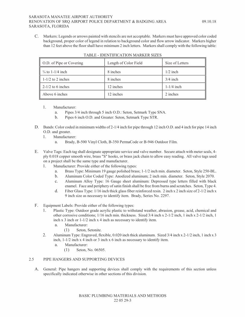
SARASOTA MANATEE AIRPORT AUTHORITY
RENOVATION OF SRQ AIRPORT POLICE DEPARTMENT & BADGING AREA 09.10.18
SARASOTA, FLORIDA
BASIC PLUMBING MATERIALS AND METHODS
22 05 29-3
C. Markers: Legends or arrows painted with stencils are not acceptable. Markers must have approved color coded
background, proper color of legend in relation to background color and flow arrow indicator. Markers higher
than 12 feet above the floor shall have minimum 2 inch letters. Markers shall comply with the following table:
TABLE - IDENTIFICATION MARKER SIZES O.D. of Pipe or Covering
Length of Color Field
Size of Letters
¾ to 1-1/4 inch
8 inches
1/2 inch
1-1/2 to 2 inches
8 inches
3/4 inch
2-1/2 to 6 inches
12 inches
1-1/4 inch
Above 6 inches
12 inches
2 inches
1. Manufacturer:
a. Pipes 3/4 inch through 5 inch O.D.: Seton, Setmark Type SNA.
b. Pipes 6 inch O.D. and Greater: Seton, Setmark Type STR.
D. Bands: Color coded in minimum widths of 2-1/4 inch for pipe through 12 inch O.D. and 4 inch for pipe 14 inch
O.D. and greater.
1. Manufacturer:
a. Brady, B-500 Vinyl Cloth, B-350 PermaCode or B-946 Outdoor Film.
E. Valve Tags: Each tag shall designate appropriate service and valve number. Secure attach with meter seals, 4-
ply 0.018 copper smooth wire, brass "S" hooks, or brass jack chain to allow easy reading. All valve tags used
on a project shall be the same type and manufacturer.
1. Manufacturer: Provide either of the following types:
a. Brass Type: Minimum 19 gauge polished brass; 1-1/2 inch min. diameter. Seton, Style 250-BL.
b. Aluminum Color Coded Type: Anodized aluminum; 2 inch min. diameter. Seton, Style 2070.
c. Aluminum Alloy Type: 16 Gauge sheet aluminum: Depressed type letters filled with black
enamel. Face and periphery of satin finish shall be free from burns and scratches. Seton, Type 4.
d. Fiber Glass Type: 1/16 inch thick glass fiber reinforced resin. 2 inch x 2 inch size of 2-1/2 inch x
9 inch size as necessary to identify item. Brady, Series No. 2297.
F. Equipment Labels: Provide either of the following types:
1. Plastic Type: Outdoor grade acrylic plastic to withstand weather, abrasion, grease, acid, chemical and
other corrosive conditions; 1/16 inch min. thickness. Sized 3/4 inch x 2-1/2 inch, 1 inch x 2-1/2 inch, 1
inch x 3 inch or 1-1/2 inch x 4 inch as necessary to identify item.
a. Manufacturer:
(1) Seton, Setonite.
2. Aluminum Type: Engraved, flexible, 0.020 inch thick aluminum. Sized 3/4 inch x 2-1/2 inch, 1 inch x 3
inch, 1-1/2 inch x 4 inch or 3 inch x 6 inch as necessary to identify item.
a. Manufacturer:
(1) Seton, No. 06505.
2.5 PIPE HANGERS AND SUPPORTING DEVICES
A. General: Pipe hangers and supporting devices shall comply with the requirements of this section unless
specifically indicated otherwise in other sections of this division.

SARASOTA MANATEE AIRPORT AUTHORITY
RENOVATION OF SRQ AIRPORT POLICE DEPARTMENT & BADGING AREA 09.10.18
SARASOTA, FLORIDA
BASIC PLUMBING MATERIALS AND METHODS
22 05 29-4
B. Material: Pipe supporting devices apply to all piping unless modified in subsequent sections (i.e., vibration
isolation) or detailed on the drawings.
1. Pipe hangers for copper pipe shall be PVC coated steel or copper, clevis type.
2. Hangers for all other types of piping shall be as indicated on paragraph 3, 4 and 5 below, steel clevis type
or split ring. Pipe hangers shall be capable of vertical adjustment after erection of the piping. Hanger
rods shall be as indicated on paragraph 3, 4 and 5 below.
3. Provide and install Hot Dipped Galvanized hangers and supports in when exposed to weather.
4. Provide and install Carbon steel hangers and supports in enclosed mechanical rooms or enclosed
conditioned spaces.
5. Provide and install Electroplated Galvanized steel hangers and supports when located in enclosed,
unconditioned spaces.
6. Vertical piping riser clamp supports shall be constructed of steel with rounded ears and two or four holes
for clamping bolts. Riser clamps shall be galvanized steel, except that riser clamps for copper and brass
piping riser clamps shall have PVC coating finish or copper.
7. Manufacturer:
(1) Empire
(2) Grinnell/Anvil
(3) Tolco
C. Beam Clamp: Beam clamps may be used when supporting piping from steel structures.
D. Inserts: Concrete inserts shall be placed in forms prior to the time that concrete is poured.
E. Tamp-ins: Lead tamp-ins may be used when installed in a concrete or masonry wall or other vertical surface to
support a vertical hanger. Lead tamp-ins will not be permitted to support hangers from the underside of a
concrete slab.
F. Drilled-in Anchors: Steel anchor set in existing or new concrete by drilling and the use of an expansion device is
permitted. The anchor shall be provided with a NPT threaded rod connection.
G. Trapeze: For parallel runs of above ground suspended piping, trapeze-type hanger may be used. Provide
permanent, non-conductive wrapping between copper pipe and steel trapeze hangers.
H. Prohibited Type: Powder set type fasteners or inserts shall not be used.
2.6 FLOOR, WALL OR CEILING PLATES OR ESCUTCHEONS
A. General: Shall be chrome-plated brass. Escutcheons for extended sleeves shall be of the type designed for that
purpose. Solid escutcheons shall be used up to 2 inches, split ring escutcheons will be allowed for sizes 2-1/2
inches and above.
B. Manufacturer:
1. Guarantee Specialty Mfg. Co.
2. American Sanitary Mfg. Co.
3. Benton & Caldwell
C. Location: Provide escutcheons or fabricated plates or collars at each location where pipe or duct passes through
a finished surface. Escutcheons for flush sleeves shall be equivalent to Benton & Caldwell No. 3A chromium
plated brass; for sleeves extending above floor shall be equivalent to Benton & Caldwell No. 36 chrome plated
brass. Collars or plates for ducts and large diameter insulated pipe shall be fabricated of 18 gage galvanized
sheet steel, secured to structure and neatly fitted around duct or pipe.
SARASOTA MANATEE AIRPORT AUTHORITY
RENOVATION OF SRQ AIRPORT POLICE DEPARTMENT & BADGING AREA 09.10.18
SARASOTA, FLORIDA
BASIC PLUMBING MATERIALS AND METHODS
22 05 29-5
2.7 SLEEVE
A. Pipe Sleeves: Except where indicated otherwise, pipe sleeves shall be as follows:
1. Sleeves installed in walls subject to hydrostatic (water) pressures shall be modular mechanical type
consisting of interlocking synthetic rubber links shaped to continuously fill the annular space between the
pipe and sleeve, connected with bolts and pressure plates which cause the rubber sealing elements to
expand when tightened to provide a watertight seal.
a. Manufacturer:
(1) Thunderline Corp., Link-Seal Type WS.
2. When there is piping existing, and fire rated walls are to be erected, Proset fire rated split wall system
pipe sleeves, or an NFPA/UL listed pipe sleeve shall be used.
B. Walls and Partitions:
1. Sleeves (Above Grade): Sleeves shall be mild steel pipe sleeves built into wall, partition or beam, sized to
pass pipe and covering, leaving a clear space of 1/4 inch minimum between covering and sleeve.
Penetrations of fire rated partitions shall have mild steel sleeves.
2. Sleeves Installed in Exterior Walls (Below Grade): Schedule 40 steel hot dipped galvanized after
fabrication or cast iron. Fabricate the sleeve with 1/4 inch x 3 inch center flange (water stop) around the
outside.
C. Floors (Above Grade): Sleeves shall be Schedule 10 galvanized steel. When copper or steel piping penetrates
concrete slabs, Proset System for fire-rated and water pipe installations may be used.
D. Duct Sleeves: Sleeves or openings sized for mechanical ducts and covering shall be minimum 24 gauge
galvanized sheet steel framed construction in roof, wall, or partitions.
PART 3 - EXECUTION
3.1 GENERAL
A. Concrete Bases and Structural Steel: Concrete bases and structural steel to support equipment and piping
installed under each specification section of this division and not specifically shown on the structural or
architectural plans shall be furnished.
3.2 HOUSEKEEPING PADS AND EQUIPMENT SUPPORT
A. Housekeeping Pads: Provide reinforced concrete housekeeping pads where indicated and for all floor mounted
equipment located in rooms where water piping exist. Pads shall be 4 inches high unless otherwise indicated.
Ground mounted equipment shall have an 8 inch high reinforced concrete housekeeping pad unless otherwise
indicated. The pad shall extend a minimum of 6 inches above finish grade.
3.3 PAINTING
A. General: Paint all exposed piping, insulation, equipment, structural bases, racks, in equipment rooms and on
roof, furnished under Division 22 of these specifications. All exposed metal surfaces shall be given one prime
coat and two finish coats. All insulated surfaces shall be given one coat of glue sizing (omit this step if factory
applied finish is suitable to receive prime coat), one prime coat and one finish coat. Factory painted or finished
items do not require field painting but shall require "touch-up" with matching paint or finish where scratched.
Follow manufacturers recommendations on ambient conditions for painting, coat thickness, and drying time
between coats.

SARASOTA MANATEE AIRPORT AUTHORITY
RENOVATION OF SRQ AIRPORT POLICE DEPARTMENT & BADGING AREA 09.10.18
SARASOTA, FLORIDA
BASIC PLUMBING MATERIALS AND METHODS
22 05 29-6
B. Ancillary Items: Pipe hangers, saddles, supports, riser clamps and accessories shall be painted to match their
piping.
C. Inaccessible Items: Equipment not completely accessible for painting when set in place shall be thoroughly
cleaned and painted before installation and suitably protected.
D. Concealed Items: Concealed piping need not be painted.
E. Metal Surfaces: Use a scraper or wire brush to remove rust and roughen metal surfaces prior to painting. After
wire brushing, wash surfaces to remove particulates, apply primer coat after surface is dry but not more than 48
hours after wire brushing.
F. Colors: Colors for piping systems and equipment which are required to be painted shall be as indicated in the
following table:
TABLE - PIPING PAINTING SCHEDULE Class
Paint Color
F – Fire Protection Equipment
Red
D – Dangerous Material
Yellow (or Orange)
S – Safe Material
Green (or the achromatic colors White, Black,
Gray or Aluminum) P – Protective Material
Bright Blue
V – Valuable Material
Deep Purple
3.4 IDENTIFICATION OF PIPING AND EQUIPMENT
A. General: Apply after completion of insulation, painting and cleaning work so that final identification is not
disfigured.
1. Coordinate with composition and operating temperatures of surface for permanent adhesion of markers
and labels to surface.
2. Locate marking and banding to facilitate ease of visual tracking. (For example, mark and band parallel
runs of pipe and duct which are side-by-side at the same general place.) Labels on vertical piping and
ductwork shall be 7 foot above the floor.
3. Pipes less than 3/4 inch diameter may be identified with tags similar to those specified for valves.
4. Adhere or affix all identification items permanently except where removal may be necessary for
maintenance or service. Where labels or arrows are used, overlap the label ends 2 inches with matching
color bands completely encircling the pipe.
5. Apply labels on the bottom lower quarters of overhead pipe. Pipe within 24 inches of a wall does not
require a label on the quarter facing the wall.
B. Markers and Bands: Provide on piping as follows:
1. Pipe Concealed in Otherwise Inaccessible Locations (e.g., Chases, non-accessible ceilings): No
identification required, except at access doors.
2. Pipe Concealed in Accessible Locations (e.g., Ceiling Plenums): Markers every 30 feet of pipe length.
Bands every 15 feet of pipe length.
3. Pipe Exposed in Equipment Rooms: Markers and bands every 15 feet of pipe length for pipe through 12
inch O.D. and every 30 feet for pipe 14 inch O.D. and greater.
4. Exterior Pipe, Exposed: Markers and bands every 40 feet of pipe length.
SARASOTA MANATEE AIRPORT AUTHORITY
RENOVATION OF SRQ AIRPORT POLICE DEPARTMENT & BADGING AREA 09.10.18
SARASOTA, FLORIDA
BASIC PLUMBING MATERIALS AND METHODS
22 05 29-7
5. Exterior Pipe, Underground: Place a color-coded 6 inch wide, 0.004 inch thick polyethylene printed
identification tape directly above all underground piping systems. The tapes shall be located
approximately 12 inches below finish grade. Each tape shall be continuously printed with the words
"CAUTION" in large bold lettering, and with the type of service piping also indicated.
C. Valve Tags: Valve tags shall be installed on the following items:
1. All control valves (except those valves associated with direct control of flow to air handling apparatus
whereby the valve may be identified by reference to the item of equipment it serves).
2. All fire protection system valves located in mains and branches (except those valves in fire hose
cabinets).
3. Valves installed under this division of the specifications except check valves, drain valves, gauge valves,
and manual air vent valves.
4. Small piping (other than domestic water) where markers are impractical.
5. Small but critical equipment items on which it is impractical to install labels.
D. Valve Tag List: Prior to substantial completion, provide a complete list of all valves having tags. Frame under
glass and mount in the mechanical equipment room at a location acceptable to the Architect. Indicate the
following:
1. Valve size.
2. Valve location.
3. Valve type.
4. Service application.
5. Valve manufacturer and model number.
6. Pressure class and allowable working pressure.
7. Safety warnings.
8. Sequencing information.
9. Seasonal operating position (normally open/normally closed).
E. Labels: Provide labels of proper size on mechanical system equipment including but not limited to, pumps,
chillers, tanks, major piping components such as air separators, air handling equipment, fans, control panels,
terminal units, flow stations, reheat coils and similar items. Provide labels on access panels indicating the item
accessible through the panel. Equipment labels shall be mechanically fastened with machine screws or rivets;
adhesive securing is not acceptable.
F. Identification: Coordinate colors and finishes with pipe identification markers.
3.5 HANGERS AND INSERTS
A. General: Refer also to other sections which may describe additional requirements for hanging and supporting.
B. Location: Provide and properly locate hangers to adequately support piping and equipment. Arrange hangers to
permit expansion and contraction. Do not hang piping from fire or smoke walls. Provide pipe hangers at each
valve, strainer, and other piping accessory, and at each change of direction.
C. Size: The size of hanger for non-insulated pipes shall be suitable for pipe size to be supported. For insulated
piping, the size of the hanger shall be suitable for the pipe size, plus the insulation and an insulation shield.
Refer to Section 22 0700, THERMAL INSULATION, for insulation shield requirements.
D. Protection: Isolation of copper pipe from steel trapeze hangers shall consist of wrapping pipe and 1 inch each
side of contact surface with not less than two layers of adhesive type plastic dielectric insulating tape.
E. Spacing: Locate pipe supports as indicated in the following table unless noted otherwise in other sections of the
specifications or on the drawings:
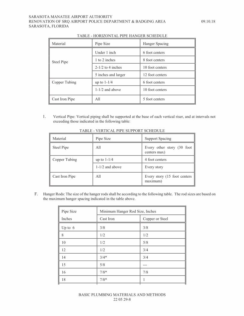
SARASOTA MANATEE AIRPORT AUTHORITY
RENOVATION OF SRQ AIRPORT POLICE DEPARTMENT & BADGING AREA 09.10.18
SARASOTA, FLORIDA
BASIC PLUMBING MATERIALS AND METHODS
22 05 29-8
TABLE - HORIZONTAL PIPE HANGER SCHEDULE Material
Pipe Size
Hanger Spacing
Steel Pipe
Under 1 inch
6 foot centers
1 to 2 inches
8 foot centers
2-1/2 to 4 inches
10 foot centers
5 inches and larger
12 foot centers
Copper Tubing
up to 1-1/4
6 foot centers
1-1/2 and above
10 foot centers
Cast Iron Pipe
All
5 foot centers
1. Vertical Pipe: Vertical piping shall be supported at the base of each vertical riser, and at intervals not
exceeding those indicated in the following table:
TABLE - VERTICAL PIPE SUPPORT SCHEDULE Material
Pipe Size
Support Spacing
Steel Pipe
All
Every other story (30 foot
centers max) Copper Tubing
up to 1-1/4
4 foot centers
1-1/2 and above
Every story
Cast Iron Pipe
All
Every story (15 foot centers
maximum)
F. Hanger Rods: The size of the hanger rods shall be according to the following table. The rod sizes are based on
the maximum hanger spacing indicated in the table above.
Pipe Size
Minimum Hanger Rod Size, Inches
Inches
Cast Iron
Copper or Steel
Up to 6
3/8
3/8
8
1/2
1/2
10
1/2
5/8
12
1/2
3/4
14
3/4*
3/4
15
5/8
---
16
7/8*
7/8
18
7/8*
1

SARASOTA MANATEE AIRPORT AUTHORITY
RENOVATION OF SRQ AIRPORT POLICE DEPARTMENT & BADGING AREA 09.10.18
SARASOTA, FLORIDA
BASIC PLUMBING MATERIALS AND METHODS
22 05 29-9
20 1* 1 24
1-1/4*
1-1/4
* Indicates mechanical joint, ductile iron pipe.
G. Pipe Guides: Provide pipe alignment guides to guide expanding pipe to move freely from anchor points in
expansion joints, loops or bends.
3.6 SLEEVES
A. General: Lay out work and set sleeves in new or existing construction for a minimum of cutting, drilling and
patching. Sleeves not used during construction shall be sealed using grout. Unused penetrations or sleeves
through fire and smoke rated partitions shall be sealed to prevent passage of fire and smoke using an
Underwriters Laboratories approved method rated at least equal to the partition being penetrated; method
utilized must show proof of UL approval.
B. Placement: Extend sleeves through walls, partitions and ceilings to finished surface. Extend sleeves 1/4 inch
above finished concrete floors and 1 inch above slab in chases. Sleeves, installed above finished ceilings, for
fire/smoke rated wall assemblies shall extend 1 inch beyond each face of wall. Sleeves shall be set before floor
is poured, sized to pass pipe and covering, leaving a clear space of 1/4 inch between covering and sleeve.
C. Size: Size sleeves to permit clearance for pipe movement and proper grading of pipes. Sleeves for insulated
pipe shall be sized to clear insulation.
D. Sealing of Sleeves:
1. Sleeves Below Grade: Caulk annular space between pipe and sleeve using oakum and poured lead both
sides minimum one inch deep to make wall penetration water tight or use mechanical link-seal.
2. Sleeves Above Grade Through Non-rated Surface: Openings around pipes, duct, etc., passing through
sleeves shall be draft free and vermin-proof.
E. Fire and Fire/Smoke Penetrations: Protect all penetrations of rated partitions with a listed assembly for each
particular rating and building material partition. Comply with the manufacturer's instructions for installation of
the partition penetration protection assembly.
F. Water Tight: Sleeves in walls and/or slabs subject to hydrostatic pressures shall be watertight.
3.7 ESCUTCHEONS
A. General: Provide escutcheons (for 1/4 or 1 inch projecting sleeves as required) at each point where pipe passes
through a finished surface.
3.8 EXCAVATION AND BACKFILL
A. General: Provide as necessary to accomplish excavation and backfilling for mechanical piping and equipment.
Perform in accordance with applicable State and Local codes and with other applicable sections or divisions.
See identification tape requirement indicated above.
B. Excavation: Excavate to a minimum necessary depth. Provide an even surface to ensure a solid, continuous
bearing surface. If cut is too deep, backfill with clean earth and hand tamp. Form depressions at joints to
receive collars and couplings.

SARASOTA MANATEE AIRPORT AUTHORITY
RENOVATION OF SRQ AIRPORT POLICE DEPARTMENT & BADGING AREA 09.10.18
SARASOTA, FLORIDA
BASIC PLUMBING MATERIALS AND METHODS
22 05 29-10
C. Backfill: Backfill shall be with clean earth, able to pass through a No. 10 sieve, free from rocks and debris.
Hand tamp backfill in 6 inch layers until 18 inches has been deposited over the buried pipe or conduit, then
tamp with a mechanical vibrating tamper in maximum 8 inch layers to a 90 percent compaction.
3.9 FIRE/SMOKE RATED FLOOR, PARTITION OR WALL PENETRATIONS
A. Fire and Fire/Smoke Penetrations: Protect all penetrations of rated partitions with a listed assembly for each
particular rating and building material partition. Comply with the manufacturer's instructions for installation of
the partition penetration protection assembly.
END OF SECTION 22 05 29


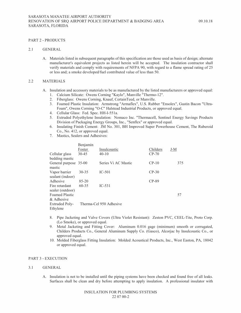

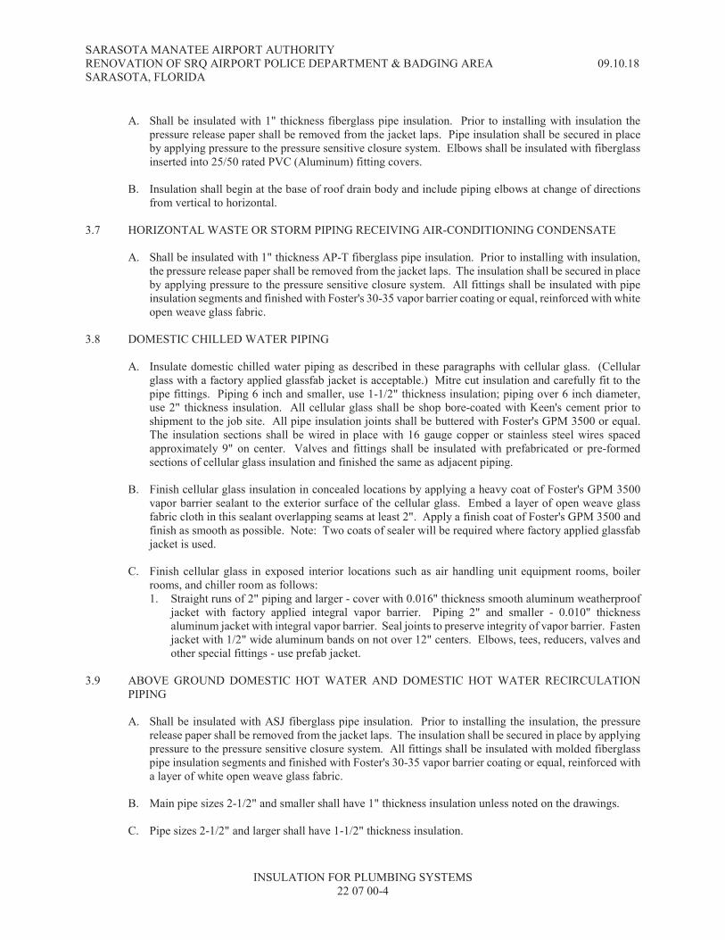


SARASOTA MANATEE AIRPORT AUTHORITY
RENOVATION OF SRQ AIRPORT POLICE DEPARTMENT & BADGING AREA 09.10.18
SARASOTA, FLORIDA
PLUMBING PIPING SYSTEM
22 10 00-1
SECTION 22 10 00 - PLUMBING PIPING SYSTEM
PART 1 - GENERAL
1.1 RELATED DOCUMENTS
A. Basic Requirements: Provisions of Section 22 0500, BASIC PLUMBING REQUIREMENTS, are a part of this
Section.
1.2 SUMMARY
A. General: Provide domestic water piping, drainage waste and vent piping, and other plumbing piping and
appurtenances as indicated.
1.3 ADDITIONAL REQUIREMENTS
A. Related Sections: Other Sections of Division 22 which relate to the requirements of this Section may include but
are not limited to the following:
1. 22 0529, BASIC PLUMBING MATERIALS AND METHODS
2. 22 2114, PLUMBING PIPE AND FITTINGS
3. 22 0519, PLUMBING PIPING SPECIALTIES
4. 22 0523, PLUMBING VALVES
5. 22 0700, PLUMBING THERMAL INSULATION
6. 22 3300, PLUMBING EQUIPMENT
7. 22 4000, PLUMBING FIXTURES
B. Related Divisions: Other Divisions or Sections of these specifications which relate to the requirements of this
Section may include but are not limited to the following:
1. Division 1, ALTERNATES
1.4 SUBMITTALS
A. General: Refer to paragraph entitled "SUBMITTAL" in Section 22 0500. Provide shop drawing and/or
manufacturer's data sheet for the following items:
1. Manufacturers Literature:
a. Dimensional outline drawing for all plumbing valves and products.
b. Complete list of all piping materials to be used in this section including valves and method of
connection for each piping system.
1.5 APPLICABLE STANDARDS
A. General: All equipment, material, accessories, methods of construction and reinforcement, finish quality,
workmanship and installation shall be in compliance with the paragraph entitled "Code Compliance" in Section
22 0500.
B. Domestic Water System: All system components that come in contact with potable water systems shall be
certified under ANSI/NSF Standards 60 and 61.

SARASOTA MANATEE AIRPORT AUTHORITY
RENOVATION OF SRQ AIRPORT POLICE DEPARTMENT & BADGING AREA 09.10.18
SARASOTA, FLORIDA
PLUMBING PIPING SYSTEM
22 10 00-2
PART 2 - PRODUCTS
2.1 GENERAL
A. Application: The plumbing piping system shall only be of the materials indicated. Refer to Section 23 2114,
PIPE AND FITTINGS, and Section 22 0700, THERMAL INSULATION, for material specifications.
Insulation shall comply with ASTM E-84 requirements with a flame spread rating not exceeding 25 and with a
smoke developed/fuel contributed rating not exceeding 50.
B. Valves: All valves used in the plumbing piping shall be 125 psi SWP, 200 psi WOG as specified in Section 23
0523, VALVES.
C. Manufacturer: Refer to paragraph entitled "MANUFACTURERS" in Section 22 0500.
D. Dielectric Connections: Provide approved connections for dissimilar materials per 22 2114.
2.2 DOMESTIC WATER PIPE
A. Above and Below Ground:
1. Piping 4 inches and smaller shall be copper tube, Type K.
2.3 SANITARY WASTE AND VENT PIPING
A. Above Ground:
1. Cast iron soil pipe, service weight.
2. No-Hub: Joints shall be "No-hub" type coupling consisting of a 24 gauge 304 stainless steel compression
clamp with gasket guides, 304 stainless steel screw clamp, and matching full neoprene gasket that
interlocks with the housing. Fittings shall conform to CISPI Standard 310 unless noted otherwise.
Maximum size allowable is 15 inches.
a. Manufacturer: Husky, Inc., Orange shield HD 4000 or approved equal.
B. Below Ground:
1. Cast iron soil pipe, service weight.
2. Hub and spigot with push-on joints.
2.4 CONDENSATE DRAIN PIPING
A. General: Unless otherwise specifically noted condensate drain piping shall be copper tube, Type L.
2.5 STORM WATER PIPING
A. Above Ground:
1. Cast-iron soil pipe, service weight, with no-hub couplings. For above ground installation only.
2. No-Hub: Joints shall be "No-hub" type coupling consisting of a 24 gauge 304 stainless steel compression
clamp with gasket guides, 304 stainless steel screw clamp, and matching full neoprene gasket that
interlocks with the housing. Fittings shall conform to CISPI Standard 310 unless noted otherwise.
Maximum size allowable is 15 inches.
a. Manufacturer: Husky, Inc., Orange shield HD 4000 or approved equal
3. Exposed storm piping shall be cast iron with bell and hub spigot push-on fittings. Consult architect for
paint options.
4. For encasement in concrete walls or columns will be Schedule 40 PVC.

SARASOTA MANATEE AIRPORT AUTHORITY
RENOVATION OF SRQ AIRPORT POLICE DEPARTMENT & BADGING AREA 09.10.18
SARASOTA, FLORIDA
PLUMBING PIPING SYSTEM
22 10 00-3
B. Below Ground:
1. Cast iron soil pipe, service weight, with bell and spigot joints
2.6 THERMAL INSULATION
A. General: All insulation, jackets and adhesives used shall comply with the requirements of ASTM E-84 with a
maximum flame spread rating of 25 and a maximum smoke developed/fuel contributed rating of 50. Insulation
on piping exposed in boiler rooms, mechanical equipment rooms, air handling equipment rooms, etc. or
exposed on the exterior of the building shall be cellular glass. Insulation for concealed piping shall be
preformed pipe insulation as follows:
1. Domestic Hot Water:
a. Fiberglass
b. Polymer Foam
2. Condensate Drain:
a. Elastomeric
B. Thickness: The insulation thickness in inches shall be in accordance with the following table:
TABLE - PIPING INSULATION THICKNESS
Pipe Size, Inches
Up to 1
1-1/4 to 2
2-1/2 to 4
5 to 6
8 & Up
Hot Water
1
1
1-1/2
1-1/2
1-1/2
Condensate Drain
1/2
1/2
½
1/2
1/2
Storm Water
1/2
1/2
½
1/2
1/2*
* (Or manufacturer's minimum thickness based on the pipe size.)
C. Exposed: For piping, other than domestic cold water, exposed to the outdoor air or in an unconditioned space or
cellar area, increase insulation thickness by 1/2 inch.
2.7 VALVES
A. General: Refer to the requirements of Section 22 0523, VALVES, for the complete requirements of all valves
indicated in this section.
B. 4 inch and smaller: Valves 4 inch and smaller shall be full port valves with bronze or brass body and bronze
trim, threaded or soldered connections.
C. Butterfly and gate valves shall not be permitted on domestic water systems. No quarter turn stop valves shall be
used.
D. Domestic hot water recirculation systems shall be controlled with ball type/or auto flow control valves.
E. Underground: Valves underground shall be gate-type with cast iron body and bronze trim, flanged or welded
connections, and non-rising stem with square wrench nut head.
1. Acceptable Manufacturers: Stockham, U.S. Pipe Metroseal, Kennedy

SARASOTA MANATEE AIRPORT AUTHORITY
RENOVATION OF SRQ AIRPORT POLICE DEPARTMENT & BADGING AREA 09.10.18
SARASOTA, FLORIDA
PLUMBING PIPING SYSTEM
22 10 00-4
2.8 HANGERS
A. Reference Section 22 0529 for Basic Hanger Materials and Spacing Requirements.
B. Additional Plumbing Hanger Requirements:
1. Copper piping installed within metal stud walls shall be supported with manufactured isolators. Isolators
shall be Pipe-Tytes or approved equivalents.
2. Non-insulated copper pipes installed on trapeze hangers shall have isolation clamps. B-Line "Vibra
Cushion", "Vibraclamp" or approved equivalent shall be provided. Wrapping the pipe with tape shall not
be acceptable
PART 3 - EXECUTION
3.1 GENERAL
A. Location of Vents: Vents shall be offset as required to penetrate roofs at least 3 feet from the edges of the
building, and 15 feet from any supply air intake or operable window or door.
B. Slope: Unless otherwise indicated, horizontal sanitary and storm piping 2-1/2 inches and smaller shall be sloped
at a minimum of 1/4 inch per linear foot; piping 3 inches and larger shall be sloped a minimum of 1/8 inch per
foot.
C. Vent Piping: Horizontal vent branches shall be kept above the highest fixture served by the vent branch in order
to prevent the vent from being used as a waste line. Horizontal vent branches shall be sloped upward to prevent
accumulating water or trapping.
D. Vent Connections: Vent piping connected to a horizontal pipe shall be taken from the centerline of the pipe.
Vent piping shall rise at an angle not exceeding 45 degrees from vertical, to a point at least 6 inches above the
flood rim of the highest attached fixture.
E. Vent Flashing: Refer to architectural details and specifications for proper flashing requirements of vent piping
through the roof.
3.2 INSULATION
A. Horizontal Storm Water: Insulation shall begin at the base of the roof and overflow drain body and include all
horizontal piping and elbows at change of directions from the horizontal to the vertical.
B. Condensate Piping: Insulate condensate piping and waste lines from ice machines with a minimum of 1/2 inch
thickness elastomeric insulation.
C. Floor drains and traps: Insulate all floor drain bodies and traps receiving condensate with a minimum 1/2"
elastomeric insulation. Insulation shall extend 10 feet horizontally from the P-trap of the drain.
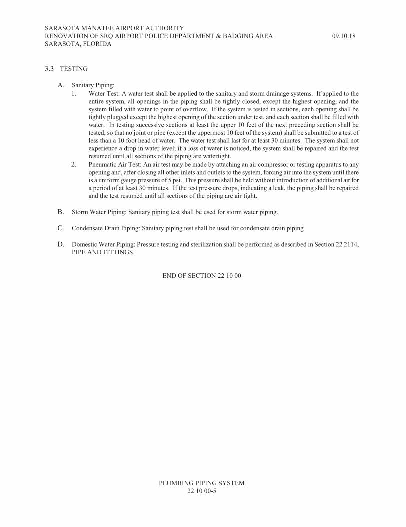
SARASOTA MANATEE AIRPORT AUTHORITY
RENOVATION OF SRQ AIRPORT POLICE DEPARTMENT & BADGING AREA 09.10.18
SARASOTA, FLORIDA
PLUMBING PIPING SYSTEM
22 10 00-5
3.3 TESTING
A. Sanitary Piping:
1. Water Test: A water test shall be applied to the sanitary and storm drainage systems. If applied to the
entire system, all openings in the piping shall be tightly closed, except the highest opening, and the
system filled with water to point of overflow. If the system is tested in sections, each opening shall be
tightly plugged except the highest opening of the section under test, and each section shall be filled with
water. In testing successive sections at least the upper 10 feet of the next preceding section shall be
tested, so that no joint or pipe (except the uppermost 10 feet of the system) shall be submitted to a test of
less than a 10 foot head of water. The water test shall last for at least 30 minutes. The system shall not
experience a drop in water level; if a loss of water is noticed, the system shall be repaired and the test
resumed until all sections of the piping are watertight.
2. Pneumatic Air Test: An air test may be made by attaching an air compressor or testing apparatus to any
opening and, after closing all other inlets and outlets to the system, forcing air into the system until there
is a uniform gauge pressure of 5 psi. This pressure shall be held without introduction of additional air for
a period of at least 30 minutes. If the test pressure drops, indicating a leak, the piping shall be repaired
and the test resumed until all sections of the piping are air tight.
B. Storm Water Piping: Sanitary piping test shall be used for storm water piping.
C. Condensate Drain Piping: Sanitary piping test shall be used for condensate drain piping
D. Domestic Water Piping: Pressure testing and sterilization shall be performed as described in Section 22 2114,
PIPE AND FITTINGS.
END OF SECTION 22 10 00

SARASOTA MANATEE AIRPORT AUTHORITY
RENOVATION OF SRQ AIRPORT POLICE DEPARTMENT & BADGING AREA 09.10.18
SARASOTA, FLORIDA
PLUMBING PIPING SYSTEM
22 10 00-6
THIS PAGE INTENTIONALLY BLANK
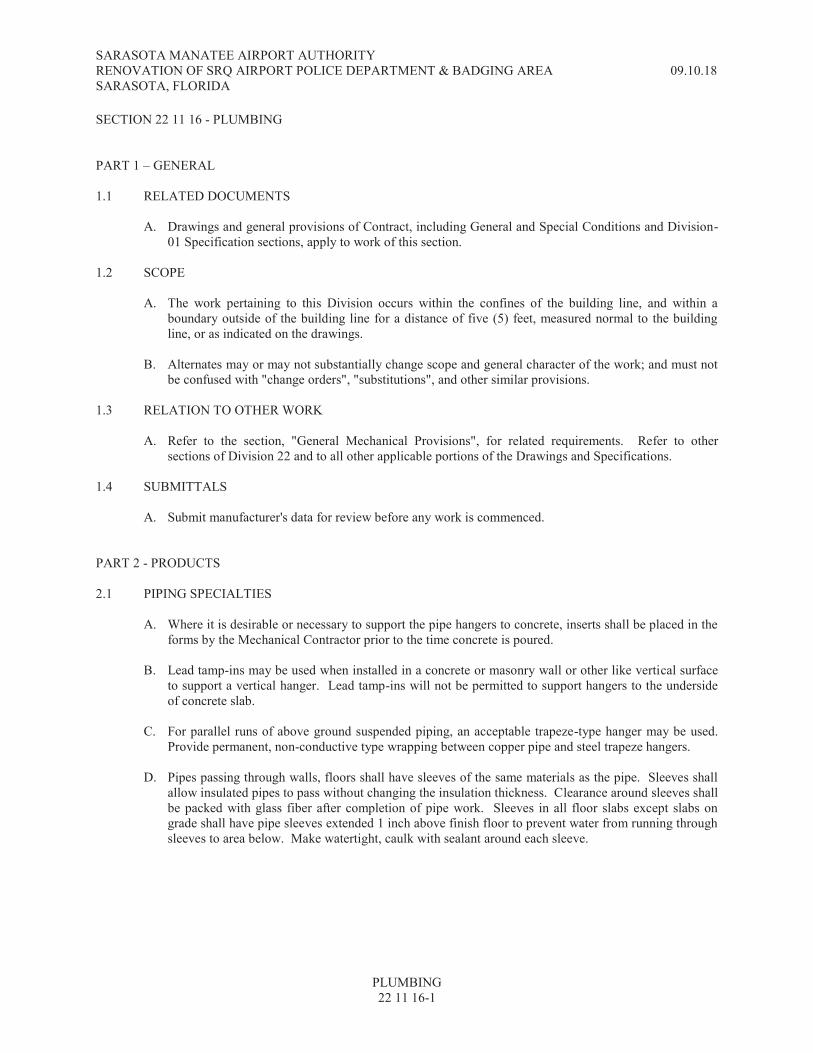
SARASOTA MANATEE AIRPORT AUTHORITY RENOVATION OF SRQ AIRPORT POLICE DEPARTMENT & BADGING AREA 09.10.18 SARASOTA, FLORIDA
PLUMBING 22 11 16-1
SECTION 22 11 16 - PLUMBING PART 1 – GENERAL 1.1 RELATED DOCUMENTS
A. Drawings and general provisions of Contract, including General and Special Conditions and Division-01 Specification sections, apply to work of this section.
1.2 SCOPE
A. The work pertaining to this Division occurs within the confines of the building line, and within a boundary outside of the building line for a distance of five (5) feet, measured normal to the building line, or as indicated on the drawings.
B. Alternates may or may not substantially change scope and general character of the work; and must not be confused with "change orders", "substitutions", and other similar provisions.
1.3 RELATION TO OTHER WORK
A. Refer to the section, "General Mechanical Provisions", for related requirements. Refer to other sections of Division 22 and to all other applicable portions of the Drawings and Specifications.
1.4 SUBMITTALS
A. Submit manufacturer's data for review before any work is commenced. PART 2 - PRODUCTS 2.1 PIPING SPECIALTIES
A. Where it is desirable or necessary to support the pipe hangers to concrete, inserts shall be placed in the forms by the Mechanical Contractor prior to the time concrete is poured.
B. Lead tamp-ins may be used when installed in a concrete or masonry wall or other like vertical surface to support a vertical hanger. Lead tamp-ins will not be permitted to support hangers to the underside of concrete slab.
C. For parallel runs of above ground suspended piping, an acceptable trapeze-type hanger may be used.
Provide permanent, non-conductive type wrapping between copper pipe and steel trapeze hangers. D. Pipes passing through walls, floors shall have sleeves of the same materials as the pipe. Sleeves shall
allow insulated pipes to pass without changing the insulation thickness. Clearance around sleeves shall be packed with glass fiber after completion of pipe work. Sleeves in all floor slabs except slabs on grade shall have pipe sleeves extended 1 inch above finish floor to prevent water from running through sleeves to area below. Make watertight, caulk with sealant around each sleeve.

SARASOTA MANATEE AIRPORT AUTHORITY RENOVATION OF SRQ AIRPORT POLICE DEPARTMENT & BADGING AREA 09.10.18 SARASOTA, FLORIDA
PLUMBING 22 11 16-2
PART 3 - EXECUTION 3.1 INSTALLATION
A. The contractor shall furnish all labor, materials, *including gases* equipment and instruments required to conduct tests of piping systems. Tests shall be as herein called for.
B. PVC piping, fittings and other PVC materials shall not be installed in air conditioning plenums or equipment rooms used as air conditioning plenums.
C. Tests shall be conducted and the inspection of the piping shall be made in the presence of the Architect
and/or Engineers. D. Material and/or joints found defective shall be replaced and/or corrected and additional tests shall be
conducted after correction of work. 3.2 PIPE SIZING, DRAWINGS AND SPECIFICATIONS
A. It is intended that work covered by these specifications and drawings include everything requisite and necessary to make the various systems complete and operative, irrespective of whether or not every item is specifically provided for. Any omission of direct reference herein to any essential item shall not excuse contractor from complying with the above intent.
B. Figured dimensions supersede scaled ones. Contractor shall take no advantage of, and shall promptly call the Owner's Representative's attention to any error, omission or inconsistency in specifications and drawings.
C. Special attention is directed to requirements that equipment and materials stated in specifications
and/or indicated on drawings shall be furnished, except if otherwise noted, completely installed, adjusted and left in safe and satisfactory operating condition. Accessories, appliances and connections necessary for operation of equipment shall be provided to satisfaction of the Owner's Representative.
D. Materials, apparatus or equipment specified or otherwise provided for on drawings, addenda, or change
orders issued subsequent to award of contract shall be same brand, type, quality and character originally specified unless otherwise provided.
E. Layout of equipment, accessories, specialties and suspended, concealed or exposed piping systems are
diagrammatic unless dimensioned. In preparing shop drawings, contractor shall check project conditions before installing work. If there are any interferences or conflicts, they shall be called to attention of the Owner's Representative immediately for clarification.
F. The drawings indicate required size and points of termination of pipes and ducts and suggest proper
routes to conform to structure, avoid obstructions and preserve clearances. However, it is not intended that drawings indicate all necessary offsets, and it shall be the work of this contractor to make the installation in such a manner as to conform to structure, avoid obstructions, preserve headroom and keep openings and passageways clear, without further obstruction or cost to the Owner.
G. Shop drawings shall be furnished by this contractor, indicating all changes to meet space requirements,
code requirements and as necessary to resolve all space conflicts. H. It is intended that all apparatus be located symmetrical with architectural elements, and shall be
installed at exact height and locations as shown on the architectural drawings. Refer to architectural details in completing and correlating work.

SARASOTA MANATEE AIRPORT AUTHORITY RENOVATION OF SRQ AIRPORT POLICE DEPARTMENT & BADGING AREA 09.10.18 SARASOTA, FLORIDA
PLUMBING 22 11 16-3
I. The contractor shall fully inform himself regarding any and all peculiarities and limitations of the spaces available for the installation of all work and materials furnished and installed under the contract, prior to submitting his bid. He shall exercise due and particular caution to determine that all parts of his work are made quickly and easily accessible.
J. The contractor shall carefully examine any existing conditions, existing piping and ducts and premises
and compare the drawing with the existing conditions, prior to submitting his bid. K. It cannot be too strongly emphasized that, except for work specifically excluded herein, every system
shall be turned over to Owner installed completed, with components, ready for normal operation. L. In addition to work shown on mechanical drawings, see Architectural Drawings for existing work to be
removed, relocated and/or modified. Modify existing systems by rerouting for systems to remain or remove the abandoned systems as required to accommodate new general construction, plumbing, electrical and mechanical work.
M. Pipe sizes shall be minimum as allowed by local codes or as shown on the drawings, whichever is
larger.
END OF SECTION 22 11 16

SARASOTA MANATEE AIRPORT AUTHORITY RENOVATION OF SRQ AIRPORT POLICE DEPARTMENT & BADGING AREA 09.10.18 SARASOTA, FLORIDA
PLUMBING 22 11 16-4
THIS PAGE INTENTIONALLY BLANK

SARASOTA MANATEE AIRPORT AUTHORITY RENOVATION OF SRQ AIRPORT POLICE DEPARTMENT & BADGING AREA 09.10.18 SARASOTA, FLORIDA
DOMESTIC COLD & HOT WATER SUPPLY PIPING & HOT WATER CIRCULATING PIPING 22 11 19-1
SECTION 22 11 19 - DOMESTIC COLD & HOT WATER SUPPLY PIPING HOT WATER CIRCULATING PIPING PART 1 - GENERAL 1.1 RELATED DOCUMENTS
A. Drawings and general provisions of Contract, including General and Special Conditions and Division-01 Specification sections, apply to work of this section.
1.2 SCOPE
A. The work pertaining to this Division occurs within the confines of the building line, and within a boundary outside of the building line for a distance of five (5) feet, measured normal to the building line, or as indicated on the drawings.
B. Alternates may or may not substantially change scope and general character of the work; and must not be confused with "change orders", "substitutions", and other similar provisions.
1.3 RELATION TO OTHER WORK
A. Refer to the section, "General Mechanical Provisions", for related requirements. Refer to other sections of Division 22 and to all other applicable portions of the Drawings and Specifications.
1.4 SUBMITTALS
A. Submit manufacturer's data for review before any work is commenced. PART 2 - PRODUCTS 2.1 GENERAL
A. Provide valves and specialties as specified under additional Sections of this Specification. 2.2 PIPE
A. The following schedule covers materials unless otherwise specified under a particular System Section. 1. Copper tube, Type K, hard temper, ASTM B 88. For above ground. 2. Copper tube, Type K, soft drawn, ASTM B 88. For below ground. 3. Copper tube, Type L, hard drawn, ASTM B 88. For condensate waste only. 4. Brass pipe or tube, chrome plated.
2.3 FITTINGS
A. Steel Pipe: Malleable iron 150 lb. banded, galvanized to match pipe.
B. Copper Tube: Wrought or cast brass solder joint. C. The 'T' drill extruded fitting method may not be used. D. Service material shall be brass compression fittings-angle ball cocks, ball corporations, etc. Flared
fittings are acceptable under controlled conditions.

SARASOTA MANATEE AIRPORT AUTHORITY RENOVATION OF SRQ AIRPORT POLICE DEPARTMENT & BADGING AREA 09.10.18 SARASOTA, FLORIDA
DOMESTIC COLD & HOT WATER SUPPLY PIPING & HOT WATER CIRCULATING PIPING 22 11 19-2
2.4 PIPE JOINTS
A. Joints in copper piping shall be made with tin-antimony solder (95-5) and non-acid flux. Contractor shall furnish manufacturers literature documenting that the lead content (trace quantities) are within the guidelines of the local codes having jurisdiction as well as the Safe Drinking Water Act Amendment (SDWAA).
B. Joints in threaded piping shall be made with Teflon tape or non-hardening pipe compound (Seal-tite). PART 3 - EXECUTION 3.1 GENERAL
A. The design drawings are generally diagrammatic. They do not show every bend, off-set, elbow or other fitting which may be required in the piping for installation in the space allotted. Careful coordination of the work is necessary to avoid conflicts.
B. Run all water lines parallel or perpendicular to building lines. C. For piping requiring insulation, lay out and carefully install piping with sufficient clearances to permit
proper application of the insulation. If the piping is such that a neat insulation job cannot be obtained with reasonable effort, the piping subcontractor shall relocate piping.
D. Separate underground water piping and building sewer with undisturbed or compacted earth at least 10'
horizontally if installed at the same level or lower than the sewer. Where water piping is closer than 10' to a sewer, place the bottom of the water pipe at least 18" above the top of the sewer, or the sewer shall be encased in a concrete envelope as required by the Department of Health & Rehabilitative Services (State of Florida).
E. Minimum cover for exterior underground piping is three feet over insulation or conduit unless
otherwise noted on plans. Carefully excavate trench to smooth finished surface; if cut is too deep, backfill with clean earth and hand tamp to compact bottom. Make depression at joints to receive flanges, collars, and couplings. Provide continuous support for pipe or conduit. Backfill to be clean earth, free of rocks and debris completely enveloping pipe or conduit on both sides and top to a minimum thickness of 6". Carefully hand tamp backfill in 6" layers until 24" has been deposited over pipe or conduit.
F. Place color coded 6" wide 0.004" thickness polyethylene printed plastic identification tape directly
above all underground piping systems approximately 12" below finished grade. Tapes shall be continuously printed with "CAUTION" in large bold letters. Printed second line with type of service below. Yellow tape is to be used for water, (Print type of water on tape; i.e., domestic cold water.)
3.2 HANGERS AND SUPPORTS
A. Vertical Piping shall be supported at its base and no greater than every story height.
B. Horizontal Piping (Suspended) shall be supported at not more than eight (8) foot intervals. Supports shall be adequate to maintain alignment and prevent sagging.
C. Supports shall be connected to the building structure not from other equipment, ducts or conduits.
SARASOTA MANATEE AIRPORT AUTHORITY RENOVATION OF SRQ AIRPORT POLICE DEPARTMENT & BADGING AREA 09.10.18 SARASOTA, FLORIDA
DOMESTIC COLD & HOT WATER SUPPLY PIPING & HOT WATER CIRCULATING PIPING 22 11 19-3
3.3 JOINTING PIPE
A. All pipe lines shall be correctly aligned before joints are made.
B. Squarely cut pipe and properly ream to remove all constriction and burrs before making up the joints. C. Threaded Pipe: Ream all pipe after cutting and before threading. Use non-hardening pipe compound
or tape on male threads only at each joint and tighten joint to leave not more than 3 threads exposed. D. Copper Tube: Ream all pipe after cutting squarely, clean outside of tube ends and inside of fittings
and tin end to be soldered. Apply solder flux to joint areas of both tubes and fittings. Insert tube full depth into fitting, and solder in manner which will draw solder full depth and circumference of joint. Wipe excess solder from joint before it hardens.
E. Provide nipples of same material and weight as pipe used. Provide extra strong nipples when length of
unthreaded part of standard weight nipple is less than 1-1/2". F. Run water supply main to point indicated on plans.
3.4 AIR CHAMBERS
A. 20 pipe diameters, but not less than 12". Provide at each fixture, risers and ends of supply lines. 3.5 WATER HAMMER ARRESTERS
A. Water hammer arresters (shock stops) shall be installed at the locations on the plans and in accordance with PDI Standard WH-201. Provide access panels so located to permit ease of service.
3.6 VALVES
A. Provide valves to isolate each riser, and branch line. See also Section 220523 for requirements. 3.7 REDUCERS
A. Screwed bushings are prohibited, except where available space prevents use of reducing couplings. Pipe reductions on horizontal, hot water piping shall be made with eccentric reducers. Top of hot water piping shall be flat for venting.
3.8 TESTS
A. Apply a water pressure test to all parts of the water supply system before the piping is concealed and before the fixtures and equipment are connected. Use a hydrostatic pressure of not less than 100 psig or 150% of system operating pressure, applied to the system for a period of four hours. There shall be no leaks at any point in the system at this pressure.
B. Leave concealed work uncovered until required tests have been completed, but if necessary, make tests on portions of the work and those portions of the work may be concealed after being inspected and approved. Make repairs of defects that are discovered as a result of inspection or tests with new materials. Caulking, welding or other such sealing methods of screwed joints, cracks or holes will not be accepted. Repeat tests after defects have been eliminated.
C. Complete all field testing prior to insulation, wrapping and/or backfill.
SARASOTA MANATEE AIRPORT AUTHORITY RENOVATION OF SRQ AIRPORT POLICE DEPARTMENT & BADGING AREA 09.10.18 SARASOTA, FLORIDA
DOMESTIC COLD & HOT WATER SUPPLY PIPING & HOT WATER CIRCULATING PIPING 22 11 19-4
3.9 STERILIZATION
A. As soon as the water piping has been thoroughly flushed out, sterilize the lines by introducing into them a solution of calcium hypochlorite or chloride of lime. Open and close all valves while system is being chlorinated. After the sterilizing agent has been applied for 24 hours, test for residual chlorine at the ends of the lines. If less than 10 parts per million is indicated, repeat the process. When tests show at least 10 parts per million of residual chlorine, flush out the system until all traces of the chemical used are removed. Make necessary connections to sterilized piping.
3.10 PIPE PROTECTIONS
A. Paint all uninsulated piping underground with two coats of asphaltic paint. (Manual wiping is not acceptable)
B. Wrap pipe that touches metal or is exposed to masonry with a layer of 6 mil polylene film or 15 lb. felt.
C. Spirally wrap all pipe lines embedded in concrete with two layers of 30 lb. felt. D. All exposed threads on galvanized steel pipe after assembly with two coats of zinc chromate. Remove
pipe thread lubricants prior to applying paint.
END OF SECTION 22 11 19
SARASOTA MANATEE AIRPORT AUTHORITY RENOVATION OF SRQ AIRPORT POLICE DEPARTMENT & BADGING AREA 09.10.18 SARASOTA, FLORIDA
SANITARY SEWER, STORM WATER & SANITARY VENT PIPING 22 13 16-1
SECTION 22 13 16 – SANITARY SEWER, STORM WATER & SANITARY VENT PIPING PART 1 - GENERAL 1.1 RELATED DOCUMENTS
A. Drawings and general provisions of Contract, including General and Special Conditions and Division-01 Specification sections, apply to work of this section.
1.2 SCOPE
A. The work pertaining to this Division occurs within the confines of the building line, and within a boundary outside of the building line for a distance of five (5) feet, measured normal to the building line, or as indicated on the drawings.
B. Alternates may or may not substantially change scope and general character of the work; and must not be confused with "change orders", "substitutions", and other similar provisions.
1.3 RELATION TO OTHER WORK
A. Refer to the section, "General Mechanical Provisions", for related requirements. Refer to other sections of Division 22 and to all other applicable portions of the Drawings and Specifications.
1.4 SUBMITTALS
A. Submit manufacturer's data for review before any work is commenced. PART 2 - PRODUCTS 2.1 MATERIAL
A. The following schedule covers materials unless otherwise specified under a particular System Section. 2.2 PIPE
A. Cast-iron soil pipe service weight, centrifugally cast, ANSI A112.5.1. 2" Through 15" size, bell and spigot joint.
B. Cast-iron soil pipe service weight, centrifugally cast, ANSI A112.5.1. 1-1/2" through 10" size, "non-hub" joint.
C. Reinforced concrete pipe (RCP) 12" through 144" bell and spigot pattern with O-ring rubber gaskets,
ASTM C76.
D. Copper type DWV.
E. Brass pipe or tube, chrome plated. F. PVC Type DWV, ASTM D2665-78. 1-1/2" through 6" size.
2.3 PIPING APPLICATIONS
A. For above ground soil waste and vent piping, use any of the following materials: 1. Cast iron soil pipe service weight “NO-HUB” joints.
SARASOTA MANATEE AIRPORT AUTHORITY RENOVATION OF SRQ AIRPORT POLICE DEPARTMENT & BADGING AREA 09.10.18 SARASOTA, FLORIDA
SANITARY SEWER, STORM WATER & SANITARY VENT PIPING 22 13 16-2
2. Brass pipe or tube, chrome plated. This shall be provided for all above ground p-traps. PVC p-traps are not acceptable.
B. For below ground soil waste and vent piping, use any of the following materials: 1. Sanitary waste:
a. Cast iron soil pipe service weight bell and spigot. b. (Note: In HVAC plenums, PVC piping shall not be installed.)
2. Storm (Refer to size limitation in Section 2.2): a. Cast iron soil pipe service weight bell and spigot. b. For encasement in concrete walls and columns will be Schedule 40 PVC.
2.4 FITTINGS
A. Cast-Iron Soil Pipe: 1. Underground: Provide fittings of same weight and manufacture as pipe in which installed. Joints
shall be bell and spigot push-on type neoprene gasket or "NO HUB" type conforming to CIPI Standard 301 unless noted otherwise on drawings.
2. Above ground and in buildings: "NO-HUB" type conforming to CIPI Standard 301 unless noted otherwise on the drawings.
B. Threaded Drainage Pipe: Cast-iron, recessed.
C. Copper DWV: Cast or wrought solder joint DWV drainage fittings. Copper is not acceptable for vent system.
D. PVC Type DWV: ASTM D-2665, NSF Seal of Approval, Solvent-cement joint.
2.5 PIPE JOINTS
A. Bell and spigot type joint shall be made with push-on compression type, neoprene gasket conforming to ASTM A-74.
B. No-hub type joints shall be constructed of 24 gage type 304 stainless steel, with gasket guides, type 304 stainless steel screw clamp, and matching neoprene (ASTM C-564) gasket that shall interlock with housing.
C. Joints in copper piping shall be made with tin-antimony solder (95-5) silver solder and non-acid flux. D. Joints in threaded piping shall be made with teflon tape or non hardening pipe compound (Seal-tite).
2.6 VENT FLASHING
A. Furnish 4 lb. lead flashing, material as recommended by roofing system manufacturer, or copper pitch pans for all vents through the roof. Type of flashing used shall be compatible with piping material.
2.7 IDENTIFICATION
A. Below grade piping identification and warning tape shall be 0.004 inch thick polyethylene, printed with a continuous two line message. Tapes used for non magnetic piping materials shall have a metallic core. Acceptable manufacturer is Seton Name Plate Corporation or approved equal.
B. Above ground piping identification tape shall conform to ANSI and ASME A13.1 2007.

SARASOTA MANATEE AIRPORT AUTHORITY RENOVATION OF SRQ AIRPORT POLICE DEPARTMENT & BADGING AREA 09.10.18 SARASOTA, FLORIDA
SANITARY SEWER, STORM WATER & SANITARY VENT PIPING 22 13 16-3
PART 3 - EXECUTION 3.1 GENERAL
A. The design drawings are generally diagrammatic. They do not show every bend, off-set, elbow or other fitting which may be required in the piping for installation in the space allotted. Careful coordination of the work is necessary to avoid conflicts.
B. PVC piping, fittings and other PVC materials shall not be installed in air conditioning plenums or equipment rooms used as air conditioning plenums.
C. Joints and connections shall be made permanent and watertight. D. Run piping to sewer connection point outside of building or as indicated on drawings.
E. Install 3" and larger horizontal soil and waste piping to 1/8" per foot slope. Piping 2" and smaller shall
be installed at a slope of 1/4" per foot. Run horizontal vent lines to a minimum grade back to stacks and vertical vent lines as direct and free from bends as possible.
F. For piping requiring insulation, lay out and carefully install piping with sufficient clearances to permit proper application of the insulation. If the piping is such that a neat insulation job cannot be obtained with reasonable effort, the piping subcontractor shall relocate piping.
G. Separate underground water piping and building sewer with undisturbed or compacted earth at least 10'
horizontally if installed at the same level or lower than the sewer. Where water piping is closer than 10' to a sewer, place the bottom of the water pipe at least 18" above the top of the sewer, or the sewer shall be encased in a concrete envelope as required by the Department of Health & Rehabilitative Services (State of Florida).
H. Minimum cover for exterior underground piping is three feet over conduit unless otherwise noted on
plans. Carefully excavate trench to smooth finished surface; if cut is too deep, backfill with clean earth and hand tamp to compact bottom. Make depression at joints to receive bells, collars, and couplings. Provide continuous support for pipe or conduit. Backfill to be clean earth, free of rocks and debris completely enveloping pipe or conduit on both sides and top to a minimum thickness of 6". Carefully hand tamp backfill in 6" layers until 18" has been deposited over pipe or conduit.
I. Place color coded 6" wide 0.004" thickness polyethylene printed plastic identification tape directly
above all underground piping systems approximately 12" below finished grade. Tapes shall be continuously printed with "CAUTION" in large bold letters. Printed second line with type of service below. Red tape is to be used for sewer, (Print type of water on tape; i.e., storm water.)
J. Where condensate piping is indicated, piping shall be extended to the nearest catch basin/yard drain. A
cast iron back water valve shall be provided with epoxy-coated steel access housing. 3.2 HANGERS AND SUPPORTS
A. Vertical Piping shall be supported at its base and no greater than every story height, not to exceed 20 foot intervals.
B. Horizontal Piping (Suspended) shall be supported at each bend; at not more than five (5) foot intervals; except that pipe exceeding five (5) feet in length may be supported at not more than ten (10) foot intervals. Supports shall be adequate to maintain alignment and prevent sagging and shall be made directly behind the bell or coupling, where possible, not near the center of the pipe.
C. Supports shall be connected to the building structure not from other equipment, ducts or conduits.

SARASOTA MANATEE AIRPORT AUTHORITY RENOVATION OF SRQ AIRPORT POLICE DEPARTMENT & BADGING AREA 09.10.18 SARASOTA, FLORIDA
SANITARY SEWER, STORM WATER & SANITARY VENT PIPING 22 13 16-4
D. Horizontal pipe and fittings six inches and larger shall be suitably braced to prevent horizontal movement. This should be done at every branch opening or change of direction by the use of braces, blocks, rodding or other suitable method, to prevent movement.
E. Where components are suspended in excess of eighteen inches by means of non-rigid hangers, they should be suitably braced against movement horizontally, often called sway bracing.
3.3 LINE AND GRADE
A. Install gravity lines at uniform grade to low point after field verification of low point invert.
B. Run piping straight, plumb and grade in the direction indicated on the drawings. 3.4 JOINTING PIPE
A. All pipe lines shall be correctly aligned before joints are made.
B. Squarely cut pipe and properly ream to remove all constriction and burrs before making up the joints. C. Threaded Pipe: Ream all pipe after cutting and before threading. Use non-hardening pipe compound
on male threads only at each joint and tighten joint to leave not more than 3 threads exposed. D. Copper Tube: Ream all pipe after cutting squarely, clean outside of tube ends and inside of fittings
and tin end to be soldered. Apply non-acid solder flux to joint areas of both tubes and fittings. Insert tube full depth into fitting, and solder in manner which will draw solder full depth and circumference of joint. Wipe excess solder from joint before it hardens.
E. Joining "NO-HUB" cast iron soil pipe and fittings shall be in accordance with recommended practices
described by the coupling manufacturers. F. Provide nipples of same material and weight as pipe used. Provide extra strong nipples when length of
unthreaded part of standard weight nipple is less than 1-1/2". G. Provide reducing fittings (reducing bushings shall not be used) where changes in pipe sizes occur. H. Provide dielectric unions or flanges between copper and steel piping and between brassware and steel.
Do not use steel and copper piping in the same system without such isolation. 3.5 PIPE PROTECTION
A. Paint all uninsulated piping underground (except cast iron) with two coats of asphaltic paint (Manual wiping is not acceptable).
B. Wrap soil pipe that touches metal or is exposed to masonry with a layer of 6 mil polylene film or 15 lb. roofing felt.
C. Spirally wrap all pipe lines embedded in concrete with two layers of 30 lb. roofing felt.
3.6 TESTS
A. A water test shall be applied to the sanitary and storm drainage systems either in its entirety or in sections. If applied to the entire system, all openings in the piping shall be tightly closed, except the highest opening and the system filled with water to point of overflow. If the system is tested in sections, each opening shall be tightly plugged except the highest openings of the section under test, and each section shall be filled with water, but no section shall be tested with less than 10 ft. head of

SARASOTA MANATEE AIRPORT AUTHORITY RENOVATION OF SRQ AIRPORT POLICE DEPARTMENT & BADGING AREA 09.10.18 SARASOTA, FLORIDA
SANITARY SEWER, STORM WATER & SANITARY VENT PIPING 22 13 16-5
water. In testing successive sections at least the upper 10 ft of the next preceding section shall be tested, so that no joint or pipe in the building (except the uppermost 10 ft of the system) shall have been submitted to a test of less than a 10 ft head of water. The water shall be kept in the system, or in the portion under test, for at least 30 minutes before inspection starts; the system shall then be tight at all points.
B. An air test shall be made by attaching an air compressor or testing apparatus to any suitable opening and after closing all other inlets and outlets to the system, forcing air into the system until there is a uniform gauge pressure of 5 psi or sufficient to balance a column of mercury ten inches in height. This pressure shall be held without introduction of additional air for a period of at least 30 minutes.
C. Complete all field testing prior to insulation, wrapping and/or backfill.
3.7 VENT FLASHING
A. Extend lead type flashing 12" beyond pipe in all directions and carry to top of pipe with at least 2" return inside of pipe.
B. Install PVC pipe flashing in accordance with flashing manufacturer's recommendation. C. Flashing for PVC piping shall be installed in accordance with manufacturer's instructions. D. Install flashing materials as required by roofing system manufacturer's details and methods.
END OF SECTION 22 13 16
SARASOTA MANATEE AIRPORT AUTHORITY RENOVATION OF SRQ AIRPORT POLICE DEPARTMENT & BADGING AREA 09.10.18 SARASOTA, FLORIDA
SANITARY SEWER, STORM WATER & SANITARY VENT PIPING 22 13 16-6
THIS PAGE INTENTIONALLY BLANK

SARASOTA MANATEE AIRPORT AUTHORITY RENOVATION OF SRQ AIRPORT POLICE DEPARTMENT & BADGING AREA 09.10.18 SARASOTA, FLORIDA
CLEANOUTS & CLEANOUT ACCESS COVERS 22 13 17-1
SECTION 22 13 17 – CLEANOUTS & CLEANOUT ACCESS COVERS PART 1 - GENERAL 1.1 RELATED DOCUMENTS
A. Drawings and general provisions of Contract, including General and Special Conditions and Division-01 Specification sections, apply to work of this section.
B. Alternates may be or may not substantially change scope and general character of the work; and must not be confused with "change orders", "substitutions", and other similar provisions.
1.2 SCOPE
A. Furnish and install cleanouts as shown on drawing or specified herein. 1.3 RELATION TO OTHER WORK
A. Refer to the section, "General Mechanical Provisions", for related requirements. Refer to other sections of Division 22 and to all other applicable portions of the Drawings and Specifications.
1.4 SUBMITTALS
A. Submit manufacturer's data for review before any work is commenced. PART 2 - PRODUCTS 2.1 MATERIALS
A. Cleanouts and cleanout access covers shall be of the type and materials as scheduled on the drawings.
B. Provide all necessary bolts and appurtenances to affect a complete installation. PART 3 - EXECUTION 3.1 INSTALLATION
A. Install all cleanouts and cleanout access covers in accordance with the manufacturer’s instructions.
B. Exterior cleanouts below grade shall be extended to finish grade. Pour a concrete pad 18" x 18" x 6" thick around cleanout; slope top down approximately 2" from cleanout to edge of pad so that edge of pad is flush with grade.
C. Cleanouts shall be of the same nominal size as the pipes to which they are connected up to 4" in
diameter; and not less than 4" for larger pipes. D. Cleanouts shall be provided at not more than 50 feet apart in horizontal drainage lines of 4" nominal
diameter, and at not more than 75 feet apart for larger diameter pipe. E. At change in direction: Cleanouts shall be provided at each change of direction of the building drain
when the angle of change is 90 degrees. F. At base of stacks: Cleanouts shall be provided at or near the base of each vertical stack.
SARASOTA MANATEE AIRPORT AUTHORITY RENOVATION OF SRQ AIRPORT POLICE DEPARTMENT & BADGING AREA 09.10.18 SARASOTA, FLORIDA
CLEANOUTS & CLEANOUT ACCESS COVERS 22 13 17-2
G. Direction of cleanout: All cleanouts shall be installed so that the cleanout opens in a direction opposite
to the flow of the drainage line, or at a right angle to the line. H. Concealed cleanouts in wall shall be provided with removable access panel. I. Where access cleanout boxes or covers are installed in the floor, the top surface shall be scoriated and
the cover secured, but removable when necessary. Polished brass. Install carpet type covers in carpeted areas.
END OF SECTION 22 13 17

SARASOTA MANATEE AIRPORT AUTHORITY RENOVATION OF SRQ AIRPORT POLICE DEPARTMENT & BADGING AREA SARASOTA, FLORIDA
09.10.18
FLOOR DRAINS 22 13 19 - 1
SECTION 22 13 19 – FLOOR DRAINS
PART 1 - GENERAL
1.1 RELATED DOCUMENTS
A. Drawings and general provisions of Contract, including General and Special Conditions and Division-01 Specification sections, apply to work of this section.
1.2 SCOPE
A. Furnish and install floor drains and shower drains including strainers and trap primers.
B. Alternates may or may not substantially change scope and general character of the work; and must not be confused with "change orders", "substitutions", and other similar provisions.
1.3 RELATION TO OTHER WORK
A. Refer to the section, "General Mechanical Provisions", for related requirements. Refer to other sections of Division 22 and to all other applicable portions of the Drawings and Specifications.
1.4 SUBMITTALS
A. Submit manufacturer's data for review before any work is commenced.
PART 2 - PRODUCTS
2.1 DRAINS
A. Drains shall be of the type and materials as scheduled on the drawings.
B. Provide all necessary bolts, clamping rings and appurtenances to effect a complete installation.
C. The strainer size shall be as recommended by the manufacturer unless otherwise indicated on the drawings. The strainers shall be nickel alloy or polished brass. Provide tapped boss and trap primer floor drains as indicated on the drawings.
2.2 TRAP PRIMERS
A. Provide for all floor drains.
B. Units shall be cast bronze, with removable top cover, threaded or sweat pattern, and integral vacuum breaker.
C. Acceptable manufacturers are: Wade, PPP, MIFAB and Zurn.
SARASOTA MANATEE AIRPORT AUTHORITY RENOVATION OF SRQ AIRPORT POLICE DEPARTMENT & BADGING AREA SARASOTA, FLORIDA
09.10.18
FLOOR DRAINS 22 13 19 - 2
PART 3 - EXECUTION
3.1 DRAINS
A. Install all drains in accordance with the manufacturer’s instructions.
3.2 TRAP PRIMERS
A. Trap primer outlet should extend vertically a minimum of 12" before a change in direction to horizontal is made. The horizontal line to the trap primer connection shall be installed sloping to the trap it serves. Provide a minimum size of 12" x 12" stainless steel access cover for each trap primer.
END OF SECTION 22 13 19
SARASOTA MANATEE AIRPORT AUTHORITY RENOVATION OF SRQ AIRPORT POLICE DEPARTMENT & BADGING AREA 09.10.18 SARASOTA, FLORIDA
DRAINAGE & VENT SYSTEMS 22 13 21-1
SECTION 22 13 21 – DRAINAGE & VENT SYSTEMS PART 1 - GENERAL 1.1 RELATED DOCUMENTS
A. Drawings and general provisions of Contract, including General and Supplementary Conditions and Division-01 Specification sections, apply to work of this section.
1.2 SUMMARY
A. This Section specifies building sanitary and vent piping systems.
B. Related Sections: 1. Separate sections in Division-02 specify sanitary sewage systems, and trenching and backfilling. 2. Separate sections in Division-07 specify flashing and sheet metal and joint sealers. 3. Division-23 Basic Mechanical Requirements section applies to the work of this section. 4. Separate sections of Division-22 specify Basic Piping Materials and Methods, Hangers and
Supports, Expansion Compensation, piping system requirements, pipe insulation, and plumbing equipment.
1.3 DEFINITIONS
A. Drainage System: Includes all the piping within a public or private premises which conveys sewage or other liquid wastes to a point of disposal. It does not include the mains of public sewer systems or a private or public sewage treatment or disposal plant.
B. Vent System: A pipe or pipes installed to provide a flow of air to or from a drainage system, or to provide a circulation of air within such system to protect trap seals from siphonage and back pressure.
1.4 QUALITY ASSURANCE
A. Codes and Standards: 1. Plumbing Code Compliance: Comply with applicable portions of the Florida Building Code.
1.5 SEQUENCING AND SCHEDULING
A. Coordinate the installation of flashing and roof penetrations.
B. Coordinate flashing materials installation of roofing, waterproofing, and adjoining substrate work. C. Coordinate with installation of sanitary and storm sewer systems as necessary to interface building
drains with drainage piping systems. D. Coordinate the installation of drains in poured-in-place concrete slabs, to include proper drain
elevations, installation of flashing, and slope of slab to drains. PART 2 - PRODUCTS 2.1 MANUFACTURERS
A. Manufacturer Uniformity: Conform with the requirements specified in Basic Mechanical Requirements.

SARASOTA MANATEE AIRPORT AUTHORITY RENOVATION OF SRQ AIRPORT POLICE DEPARTMENT & BADGING AREA 09.10.18 SARASOTA, FLORIDA
DRAINAGE & VENT SYSTEMS 22 13 21-2
B. Drainage Piping Specialties, including expansion joints, drains, trap primers, and vandal-proof vent
caps: 1. Josam Mfg. Co. 2. Zurn Ind.,Inc; Hydromechanics Div. 3. Wade Division, Tyler Pipe
2.2 ABOVE GROUND DRAINAGE AND VENT PIPE AND FITTINGS
A. Hubless cast-iron soil pipe: Conform to CISPI Standard 301 and ASTM A-888, Service weight, cast-iron soil pipe and fittings, with neoprene gaskets conforming to CISPI Standard 310.
B. Hubless joints will be no-hub type coupling consisting of a 24 gauge 304 stainless steel compression clamp with gasket guides, 304 stainless steel screw clamp and matching full neoprene gasket that interlocks with the housing. Will comply with the requirements of CISPI 310 and ASTM C-564.
C. Maximum size allowed for no-hub piping is 8 inch. D. Exposed storm piping shall be cast-iron hub and spigot and joints will be installed with compression
gaskets conforming the requirements of ASTM C0564.
E. Concealed in chase rain water leader piping above grade may be Schedule 40 PVC meeting AWWA C900 Class 100. Joints shall be mechanical using elastomeric gaskets. Use of PVC in return air plenums (ie, office area) and through fire rated assemblies will not be permitted.
F. Schedule 40 PVC is acceptable when storm is concealed in concrete walls and columns.
2.3 UNDERGROUND BUILDING DRAIN PIPE AND FITTINGS
A. Pipe sizes 15" and smaller: Cast-iron soil pipe. Conform to ASTM A74, for Extra-Heavy weight, hub-and-spigot soil pipe and fittings, with neoprene compression gasket joints conforming to ASTM C564. Pipe and fittings shall have a heavy coating of coal tar varnish or asphaltum on both inside and outside surfaces.
B. PVC is acceptable underground only. 2.4 DRAINAGE PIPING SPECIALTIES
A. Trap Primers: Bronze body valve with automatic vacuum breaker, with ½" connections matching piping system, complying with ASSE 1018.
B. Expansion Joints: Cast-iron body with adjustable bronze sleeve, bronze bolts with wing nuts.
C. Cleanout Plugs: Cast-bronze or brass, threads complying with ANSI B2.1, countersunk head.
D. Floor Cleanouts: Cast-iron body and frame, with clean-out plug and adjustable round top as follows: 1. Nickel-Bronze Top: Manufacturer's standard cast unit with a standard non-slip scored or abrasive
finish. 2. Cast-iron Top: Manufacturer's standard cast unit with a standard non-slip scored or abrasive
finish.
E. Wall Cleanouts: Cast-iron body adaptable to pipe with cast-bronze or brass cleanout plug; stainless steel cover including screws.
F. Flashing Flanges: Cast-iron watertight stack or wall sleeve with membrane flashing ring. Provide
SARASOTA MANATEE AIRPORT AUTHORITY RENOVATION OF SRQ AIRPORT POLICE DEPARTMENT & BADGING AREA 09.10.18 SARASOTA, FLORIDA
DRAINAGE & VENT SYSTEMS 22 13 21-3
under-deck clamp and sleeve length as required.
G. Vent Flashing Sleeves: Cast-iron caulking type roof coupling for cast-iron stacks, cast-iron threaded type roof coupling for steel stacks, and cast-bronze stack flashing sleeve for copper tubing.
H. Floor Drains: 1. Floor drain type designations and sizes are indicated on Drawings; See fixture schedules.
I. Roof Drain:
1. Roof drain type designations and sizes are indicated on the drawings. PART 3 - EXECUTION 3.1 EXAMINATION
A. Verify all dimensions by field measurements. Verify that all drainage and vent piping and specialties may be installed in accordance with pertinent codes and regulations, the original design, and the referenced standards.
B. Verify all existing grades, inverts, utilities, obstacles, and topographical conditions prior to installations.
C. Examine rough-in requirements for plumbing fixtures and other equipment having drain connections to
verify actual locations of piping connections prior to installation. D. Examine walls, floors, roof, and plumbing chases for suitable conditions where piping and specialties
are to be installed. E. Do not proceed until unsatisfactory conditions have been corrected.
3.2 JOINING PIPES AND FITTINGS
A. Copper Tubing: Solder joints in accordance with the procedures specified in ANSI B9.1.
B. Cast-Iron Soil Pipe: Make lead and oakum caulked joints, compression joints, and hubless joints in accordance with the recommendations in the CISPI Cast Iron Soil Pipe and Fittings Handbook, Chapter IV.
3.3 INSTALLATION
A. Refer to the separate Division-22 section: Basic Piping Materials and Methods, for general piping installation instructions.
B. Install supports and anchors in accordance with Division-23 Basic Mechanical Materials and Methods section "Supports and Anchors".
C. General Locations and Arrangements: Drawings (plans, schematics, and diagrams) indicate the
general location and arrangement of the piping systems. Location and arrangement of piping layout take into account many design considerations. So far as practical, install piping as indicated.
D. Make changes in direction for drainage and vent piping using appropriate 45-degree wyes, half-wyes,
or long sweep quarter, sixth, eighth, or sixteenth bends. Sanitary tees or short quarter bends may be used on vertical stacks of drainage lines where the change in direction of flow is from horizontal to vertical, except use long-turn tees where two fixtures are installed back to back and have a common
SARASOTA MANATEE AIRPORT AUTHORITY RENOVATION OF SRQ AIRPORT POLICE DEPARTMENT & BADGING AREA 09.10.18 SARASOTA, FLORIDA
DRAINAGE & VENT SYSTEMS 22 13 21-4
drain. Straight tees, elbows, and crosses may be used on vent lines. No change in direction of flow greater than 90 degrees shall be made. Where different sizes of drainage pipes and fittings are connected, use proper size, standard increasers and reducers. Reduction of the size of drainage piping in the direction of flow is prohibited.
E. Make joints of "No-Hub" cast iron soil pipe with coupling assembly using torque wrench pre-set at 60
inch pounds. F. Install Thrust blocks at the bottom of the waste stack, condensate stack and rain leader pipe. G. Install sleeve and mechanical sleeve seal through foundation wall for watertight installation.
3.4 INSTALLATION OF PIPING SPECIALTIES
A. Install expansion joints on vertical risers as indicated and as required by the plumbing code.
B. Above Ground Cleanouts: Install in above ground piping as indicated: 1. As required by plumbing code. 2. At each change in direction of piping greater than 45 degrees. 3. At minimum intervals of 50' for piping 3" and smaller, 75' piping 4" and larger. 4. At base of each vertical soil or waste stack.
C. Cleanouts Covers: Install floor and wall cleanout covers for concealed piping, types as indicated.
D. Flashing Flanges: Install flashing flange and clamping device with each stack and cleanout passing
through waterproof membranes. E. Vent Flashing Sleeves: Install on stacks passing through roof, secure over stack flashing in accordance
with manufacturer's instructions. 3.5 INSTALLATION OF TRAP PRIMERS
A. Install trap primers with piping pitched towards drain trap, minimum of 1/8" per foot (1 percent). Adjust trap primer for proper flow.
3.6 CONNECTIONS
A. Piping Runouts to Fixtures: Provide drainage and vent piping runouts to plumbing fixtures and drains, with approved trap, of sizes indicated; but in no case smaller than required by the plumbing code.
B. Locate piping runouts as close as possible to bottom of floor slab supporting fixtures or drains. 3.7 FIELD QUALITY CONTROL
A. Inspections: 1. Do not enclose, cover, or put into operation drainage and vent piping system until it has been
inspected and approved by the authority having jurisdiction. 2. During the progress of the installation, notify the plumbing official having jurisdiction, at least 24
hours prior to the time such inspection must be made. Perform tests specified below in the presence of the plumbing official. a. Rough-in Inspection: Arrange for inspection of the piping system before concealed or closed-
in after system is roughed-in, and prior to setting fixtures. b. Final Inspection: Arrange for a final inspection by the plumbing official to observe the tests
specified below and to insure compliance with the requirements of the plumbing code.

SARASOTA MANATEE AIRPORT AUTHORITY RENOVATION OF SRQ AIRPORT POLICE DEPARTMENT & BADGING AREA 09.10.18 SARASOTA, FLORIDA
DRAINAGE & VENT SYSTEMS 22 13 21-5
3. Reinspections: Whenever the piping system fails to pass the test or inspection, make the required corrections, and arrange for reinspection by the plumbing official.
3.8 PIPING SYSTEM TEST
A. Test for leaks and defects all new drainage and vent piping systems.
B. Leave uncovered and unconcealed all new, altered, extended, or replaced drainage and vent piping until it has been tested and approved. Expose all such work for testing that has been covered or concealed before it has been tested and approved.
C. Drainage and Venting System Testing Procedures:
1. Rough Plumbing: Test the piping of plumbing drainage and venting systems upon completion of the rough piping installation. Tightly close all openings in the piping system, and fill with water to the point of overflow, but not less than 10 feet head of water. Water level shall not drop during the period from 15 minutes before the inspection starts, through completion of the inspection. Inspect all joints for leaks.
2. Finished Plumbing: After the plumbing fixtures have been set and their traps filled with water, their connections shall be tested and proved gas and water-tight. Plug the stack openings on the roof and building drain where it leaves the building, and introduce air into the system equal to a pressure of 1" water column. Use a "U" tube or manometer inserted in the trap of a water closet to measure this pressure. Air pressure shall remain constant without the introduction of additional air throughout the period of inspection. Inspect all plumbing fixture connections for gas and water leaks.
D. Repair all leaks and defects using new materials and retest system or portion thereof until satisfactory results are obtained.
3.9 ADJUSTING AND CLEANING
A. Clean interior of piping. Remove dirt and debris as work progresses.
B. Clean drain strainers, domes, and traps. Remove dirt and debris. 3.10 PROTECTION
A. Protect drains during remainder of construction period, to avoid clogging with dirt and debris, and to prevent damage from traffic and construction work.
B. Place plugs in ends of uncompleted piping at end of day or whenever work stops.
END OF SECTION 22 13 21

SARASOTA MANATEE AIRPORT AUTHORITY RENOVATION OF SRQ AIRPORT POLICE DEPARTMENT & BADGING AREA 09.10.18 SARASOTA, FLORIDA
DRAINAGE & VENT SYSTEMS 22 13 21-6
THIS PAGE INTENTIONALLY BLANK

SARASOTA MANATEE AIRPORT AUTHORITY RENOVATION OF SRQ AIRPORT POLICE DEPARTMENT & BADGING AREA 09.10.18 SARASOTA, FLORIDA
PLUMBING PIPE AND FITTINGS 22 21 14-1
SECTION 22 21 14 – PLUMBING PIPE AND FITTINGS PART 1 -GENERAL 1.1 RELATED DOCUMENTS
A. Basic Requirements: Provisions of Section 22 0500, BASIC MECHANICAL REQUIREMENTS, are a part of this Section.
1.2 SUMMARY
A. General: Provide and install pipe and fittings as indicated and including all offsets, fittings, sleeves and similar items required but not necessarily indicated due to drawing scale for complete and operable systems.
1.3 ADDITIONAL REQUIREMENTS
A. Related Sections: Other Sections of Division 23 which relate to the requirements of this Section may
include but are not limited to the following: 1 22 0529, BASIC PLUMBING MATERIALS AND METHODS 2 22 0523, PLUMBING VALVES 3 22 0700, PLUMBING THERMAL INSULATION
1.4 SUBMITTAL
A. General: Refer to paragraph entitled "SUBMITTAL" in Section 22 0500. Provide shop drawing and/or manufacturer's data sheet for the following items:
1. Manufacturers Literature: a. Complete design and construction data for dielectric unions and flanges. b. Manufacturer's data on piping and fittings used, with an indication of each specific application.
2. Performance Data: a. Submit a copy of the Welding Procedure Specification with the Procedure Qualification
Record and certificates of the welders and welding operators required by Section IX of the ASME Boiler and Pressure Vessel Code.
3. Installation Data:
a. UL approval number, installation materials, and procedures for pipe penetrations of fire-rated walls and floor.
1.5 APPLICABLE STANDARDS
A. General: All equipment, material, accessories, methods of construction and reinforcement, finish quality,
workmanship and installation shall be in compliance with the applicable standards and codes listed in paragraph entitled "Code Compliance" in Section 23 0500.
B. Quality and Weight: The quality and weight of materials shall comply with requirements and specifications of the appropriate standards of the American Society of Testing and Materials, American National
Standards Institute, American Society of Mechanical Engineers, and the American Welding Society.
C. Piping System: All pressurized piping systems shall conform to ASME B31.9, Code for Pressure Piping, Building Services Piping.
D. Welder Certification: Welders shall be tested and certified within the last 2 years by the National Certified Pipe Welding Bureau or recognized testing agency acceptable to the Architect. Competent certified welders shall perform all welding operations. Each welder shall possess a stamp to identify his work and

SARASOTA MANATEE AIRPORT AUTHORITY RENOVATION OF SRQ AIRPORT POLICE DEPARTMENT & BADGING AREA 09.10.18 SARASOTA, FLORIDA
PLUMBING PIPE AND FITTINGS 22 21 14-2
shall stamp each weld. A copy of the certification shall be available at the job site for each welder.
E. Welding Installation: Welding shall be in accordance with the welding procedures and requirements set forth in "Welding of Pipe Joints" of the "Code for Pressure Piping" in the American Welding Society Welding handbook. Pipe welding shall comply with the provisions of the latest revision of the applicable code, whether ASME Boiler and Pressure Vessel Code, ANSI Code for Pressure Piping, or state or local
requirements as may supersede these codes.
F. Brazing: Brazing of copper tubing shall be in accordance with the standards of the American Welding Society, the Copper Development Association Copper Tube Handbook instructions on brazing, and ASME Boiler code Section IX.
G. Soldering: Soldering of copper tubing shall be done in accordance with the Copper Development Association, Copper Tube Handbook instructions on Joining and Forming Copper Tube, Soldered Joints.
PART 2 -PRODUCTS
2.1 GENERAL
A. Application: This section covers the material and installation of various pipe and fittings which may be
indicated in other sections of these specifications for use in a specific piping system. Pipe and fittings specified in this section may not be substituted in piping systems for the specific pipe and fitting materials indicated in those individual sections of these specifications.
B. Fittings: Fittings shall be at a minimum the same gauge as the connected piping, and shall be compatible with the piping material (i.e., galvanized fittings on galvanized pipe.) The use of field-fabricated fittings is
prohibited.
C. Lead Content: Pipe, fittings or any other piping device which includes any lead in the alloy shall not be used in any potable water system.
D. Connection of Different Pipe Materials: Where different types of above ground pipe material or different weights or schedules of pipe are joined, provide a stainless steel coupling with an elastomeric gasket for the
connection. The coupling shall incorporate a full-length shield of 304 stainless steel, with bolts manufactured of 304 stainless steel which tighten the shield around the gasket to provide a solid connection. 1. Manufacturer and Model:
a. Fernco: Lowflex Series 2000 for 4 inch or smaller; Series 1000 with stainless steel shear rings for up to 10 inches.
2.2 STEEL PIPING
A. Pipe: Black steel pipe shall be seamless or electric resistance weld for pipe sizes 2 inch and above,
conforming to ASTM A 54 Grade A below 2 inch, continuous weld conforming to ASTM A 53-89a Type B, ASTM A 106 Grade B. Galvanized pipe shall conform to ASTM A 53-89a. Unless otherwise noted, black and galvanized steel pipe smaller than 12 inches shall be schedule 40 and pipe 12 inches and larger shall be standard schedule. The ASTM number shall be marked on each length of pipe.
B. Fittings:
1. Threaded Fittings: Malleable iron 150 lb. or 300 lb. class conforming to ASTM A-47 and ANSI B16.3, or cast iron 125 lb. or 250 lb. class conforming to ASTM A-234 and ANSI B16.4. Threads shall conform to ANSI B1.20.1, standard pattern.
2. Pipe Nipples: Provide nipples of same material and weight as pipe used, except provide schedule 80 nipples when length of unthreaded part of nipple is less than 1-1/2 inch. Threads shall comply

SARASOTA MANATEE AIRPORT AUTHORITY RENOVATION OF SRQ AIRPORT POLICE DEPARTMENT & BADGING AREA 09.10.18 SARASOTA, FLORIDA
PLUMBING PIPE AND FITTINGS 22 21 14-3
with ANSI B1.20.1. Nipples shall not be threaded full-length (no close nipples). 3. Welded Fittings: Forged, seamless, black steel, long radius, conforming to ANSI B16.11 for
socket-type welds and ANSI B16.9 for butt-type welds. Weldolet fittings may be used in lieu of forged tees where branch connections are not larger than three-quarters the size of main pipe, except on piping 2 inch and smaller, where forged fittings shall be used exclusively. Mitred elbows, tees and reducers are prohibited.
4. Unions: Unions shall be malleable iron or steel with ground joint on piping 1-1/2 inch and smaller; flanges shall be used on sizes 2 inch and larger. Unions shall conform to ANSI B16.39 with ANSI B1.20.1 threads and shall have hexagonal ball-and-socket joints with bronze metal-to-metal seating surfaces, female ends, and a seat ring pressed into the headpiece so it cannot be forced out.
5. Couplings: All couplings shall be taper tapped. Couplings shipped with pipe are not acceptable. 6. Flanges: Forged carbon steel, welding neck type and lap joint conforming to ANSI B16.5. Flanges
shall have raised face and gaskets with bolt spacing for the required pressure classification. Gasket material shall be ring-type, 1/16 inch thick compressed heat-resistant fiber or neoprene; gasket shall not contain any asbestos. Flange bolts shall conform to ASTM A307 hex bolts, with ANSI B18.2 hex nuts. Black steel flanges shall have black steel bolts and nuts; galvanized steel flanges shall have galvanized steel bolts and nuts.
2.4 JOINT FILLER MATERIALS
A. Solder: Solder containing lead shall not be used in potable water piping; only 95% tin - 5% antimony (95/5) or silver brazing (no substitutions) are acceptable for solder joints in potable water piping. 95/5 and 50/50 tin-lead solder shall conform to ASTM B32.
B. Brazing: Brazing (silver solder) material shall conform to AWS A5.8, classification BAg 1.
C. Welding: All electrodes shall conform to AWS Standards E-6010, E-7010, E-7018 or E-8018-B2, C2, or C3 as applicable.
PART 3 -EXECUTION
3.1 GENERAL
A. Installation: Pipe and fittings shall be installed as specified in this section unless specific installation
instructions are provided in the individual sections covering the piping system. Install each run with a minimum of joints and couplings, but with adequate and accessible unions for disassembly and maintenance/replacement of valves and equipment. Reduce sizes where indicated using reducing fittings. Align piping at connections within 1/16 inch misalignment tolerance.
B. Routing and Placement: Piping shall be run without traps or pockets and pitched a minimum 1 inch in 40
feet in the direction of flow, unless indicated or required to be pitched steeper. Grade piping so that air in the mains and risers will be carried up and discharged at venting points. Coordinate installation with structural and architectural features, and with other piping, equipment and the work of other trades. All piping shall be installed as close to the structure overhead as possible.
C. Prohibited Installation: Do not run piping through transformer vaults, elevator equipment rooms or other
electrical or electronic equipment spaces and enclosures. Do not run piping over electrical panels. Where pipe joints or valves in water lines occur within two feet in horizontal directions from electrical panels or equipment, provide drip pans, if allowed by the local authority, sized to afford protection. Pans shall be 20-gauge galvanized steel with edges turned up 2-1/2 inches on all sides, reinforced with galvanized steel
angles or by rolling edges over 1/4-inch diameter steel wire. Provide a drain with 3/4-inch flange and pipe to nearest floor drain, and support the pan assemblies as required to prevent sagging or swaying.

SARASOTA MANATEE AIRPORT AUTHORITY RENOVATION OF SRQ AIRPORT POLICE DEPARTMENT & BADGING AREA 09.10.18 SARASOTA, FLORIDA
PLUMBING PIPE AND FITTINGS 22 21 14-4
D. Interior Piping: Interior piping shall be run parallel to the walls and ceilings; avoid diagonal runs. Provide a
minimum 6 inch clearance between walls and horizontal piping.
E. Insulated Piping: Pipe requiring insulation shall be installed with sufficient clearances to permit proper application of insulation.
F. PVC Pipe: PVC piping, fittings and other PVC materials shall not be installed in air conditioning plenums or equipment rooms used as air conditioning plenums.
G. Cast Iron Pipe: Unless otherwise indicated, install 3 inch and larger horizontal storm and waste piping with
1/8 inch per foot slope; piping 2-1/2 inch and smaller shall be installed at a slope of 1/4 inch per foot. Run horizontal vent lines to a minimum grade back to stacks and vertical vent lines as direct as possible.
H. Drains: Install drains at low points in mains, risers, and branch lines consisting of a tee fitting, 3/4 inch ball valve, and short 3/4 inch threaded nipple with hose end and cap.
I. Tool Marks: Copper, brass and chromed, polished or painted piping, fittings and connections fixtures shall not show tool marks. Replace damaged piping and fittings.
J. Potable Water Solder Joints: Samples of solder in potable water piping may be taken from completed joints
and tested for lead. If tests indicate lead, the joints will be condemned and all fittings, valves and pipe ends shall be replaced with new materials where such joints occur at no cost to the Owner.
3.2 EXPANSION AND CONTRACTION
A. Provision for Expansion: Piping shall be installed with provisions for expansion both horizontally and vertically in all long runs including runouts from risers. Expansion loops and/or expansion elbows shall be
provided for expansion and contraction where required and where shown on the drawings.
B. Cold-Springing of Pipe: Cold-spring hot piping systems to reduce the amount of thermal expansion of the piping.
C. Pipe Anchors: Provide pipe anchors as indicated or as required to eliminate excessive piping movement in thermal and pressure piping systems.
3.3 JOINTS AND CONNECTIONS
A. General: Align all pipe before joints are made. Joints and connections shall be air, gas and watertight.
B. Steel Pipe Joints: All pipe joints up to 1-1/4 inch shall be threaded; joints in pipe 1-1/2 inch and 2 inch may be socket-type welded or threaded; pipe 2-1/2 inch and larger shall be butt fusion welded.
C. Welded Joints: All welds shall be first quality metal, thoroughly fused to the base metal at all points, free of
cracks, oxidation, blow holes and nonmetallic inclusions. The welder shall leave his indelible identifying mark on the piping adjacent to each weld.
D. Testing of Welded Joints: The Architect may at his own discretion visually spot check welding work anytime. The Architect may also employ an outside testing agency to analyze, using whatever means available, any of the welded joints for imperfections. All welded joints found by inspection or testing to
have imperfections shall be repaired as directed by the Architect.

SARASOTA MANATEE AIRPORT AUTHORITY RENOVATION OF SRQ AIRPORT POLICE DEPARTMENT & BADGING AREA 09.10.18 SARASOTA, FLORIDA
PLUMBING PIPE AND FITTINGS 22 21 14-5
E. Threaded Joints: Use ANSI B2.1 threaded joints in piping with a minimum wall thickness of Standard
Schedule pipe. Assemble the joint wrench-tight, applying force on the end of the fitting into which the pipe is being joined. If a seam fails during cutting or threading, that portion of pipe shall be discarded. Threaded joints shall have a minimum of 3 threads engaged and a maximum of 3 threads exposed.
F. Flanges: Connect pipe flanges to pipe ends in accordance with ASME B31.1. Code for Pressure Piping;
clean flange faces and install gaskets. Using a torque wrench, tighten flange to the torque specified by the manufacturer of the flange to provide uniform compression of gaskets.
G. Rolled-Groove Mechanical Couplings for Copper Pipe: Pipe grooving shall be in accordance with the pipe coupling manufacturer's recommendations. Piping shall be rolled-grooved without removal of any metal. Before the assembly of couplings, lightly coat the pipe ends and the outside of gaskets with approved
lubricant or silicone to facilitate installation. Tighten bolts or lugs to the proper torque as directed by the manufacturer to provide a watertight joint.
H. Rated Penetrations: Provide UL-approved method of sealing fire- and fire/smoke rated wall and floor penetrations. Submit method proposed prior to installation.
3.4 EQUIPMENT CONNECTIONS
A. General: Make connections between equipment and piping system in this section of the specifications with
unions, flange joints or other fittings which permit equipment to be disconnected and removed for maintenance. Connections to equipment shall be made in accordance with details on the drawings and the equipment manufacturer's installation instructions. Final connections to equipment shall be made with unions for pipe sizes 2 inch and under and with flanges for pipe sizes over 2 inch.
B. Locations: Provide unions or flanges where indicated, and in the following locations even if not indicated: 1 In long runs of straight piping for water and other non-gaseous services at 60-foot intervals to
permit convenient disassembly for alterations and repairs. 2 In bypasses around equipment. 3 In connections to pumps, steam traps and other in-line equipment requiring disconnection for
repairs and replacement, located between the isolation valve and the equipment. 4 Within 3 inches of each threaded valve and each piece of equipment not having unions or flanges
attached.
C. Pump Connections: Where the suction or discharge of any pump unit is smaller than the pipe size noted on
the drawings, reducing elbows or fittings shall be provided at the pump connections only.
D. Coil Connections: Where coil piping connections are smaller than the distribution piping size shown on the drawings, the reduction in size shall be provided as close to the coil as possible. All valves, strainers, unions, flanges, balancing valves, etc. shall be full distribution pipe size except for control valves.
3.5 PIPE SIZE REDUCTIONS AND ENLARGEMENTS
A. Prohibited Fittings: Screwed bushings are prohibited, except where available space prevents use of
reducing couplings.
B. No-Hub Clamps: No-hub clamps with bushings shall not be used for pipe size reduction. Cast iron fittings are required.
C. Reducing Couplings: Eccentric reducing couplings shall be installed throughout steam and water piping to prevent air or water pockets occurring due to a change in pipe size. Eccentric couplings on steam shall
bring the pipes flush on the bottom; eccentric couplings on water lines shall bring the pipes flush on top except as otherwise specified or indicated. Concentric reducing couplings in horizontal water circulating

SARASOTA MANATEE AIRPORT AUTHORITY RENOVATION OF SRQ AIRPORT POLICE DEPARTMENT & BADGING AREA 09.10.18 SARASOTA, FLORIDA
PLUMBING PIPE AND FITTINGS 22 21 14-6
piping may be utilized if a manual air vent on the larger pipe adjacent to the reducer is installed.
3.6 PROTECTION
A. Protective Wrap: Wrap pipe that touches metal or is exposed to masonry with a layer of 6 mil polyethylene film or 15 lb. felt.
B. Thread Protection: Coat all exposed threads on galvanized steel pipe after assembly with two coats of zinc chromate. Remove pipe thread lubricants prior to applying paint.
3.7 FLUSHING AND CLEANING
A. Preparation for Testing: Before final testing, flush piping systems with clean water to remove debris. Disconnect all coils and heat exchangers from the system before flushing. Flush all coils and heat exchangers separately to assure that debris does not become lodged in them. Provide temporary valves and drains as required to accomplish flushing.
B. Final Flushing: After flushing, thoroughly clean each piping system with appropriate cleanser to remove
oil, grease, lacquer, etc. Thoroughly flush each liquid system with clean water after cleaning.
C. Chemical cleaning: After the piping is installed, add an aqueous solution of trisodium phosphate in a proportion of one pound per fifty gallons of water in the system. After filling with this solution, the system shall be allowed to circulate for two hours. The system shall then be drained completely. All strainers shall be removed, cleaned and replaced, and the system shall be refilled with fresh water. The Architect shall be
given notice of this cleaning operation. If, in the opinion of the Architect, the cleaning operation has not been properly performed, the above procedure shall be repeated. After cleaning system, it shall be tested by litmus paper and shall be left on the slightly alkaline side (pH > 7.5). If the system is still acidic, the trisodium phosphate cleaning shall be repeated.
3.8 PRESSURE TESTING
A. Pressure Test: Prior to insulating and concealing the piping system, apply a water pressure test to all parts of each system before equipment is connected. Use a hydrostatic pressure of not less than 100 psig or 150 percent of system operating pressure whichever is greater. Test system for a period not less than four hours. There shall be no leaks at any point in the system at this pressure.
B. Concealed Work: Leave concealed work uncovered until required tests have been completed, but if
necessary, make tests on portions of the work and those portions of the work may be concealed after being inspected and found free of leaks. Make repairs to defects that are discovered as a result of inspections or tests with new materials; caulking of screwed joints, cracks or holes will not be accepted. Repeat tests after defects have been eliminated.
C. Field Testing: Complete all field testing prior to insulating, wrapping or backfilling.
END OF SECTION 22 21 14
SARASOTA MANATEE AIRPORT AUTHORITY RENOVATION OF SRQ AIRPORT POLICE DEPARTMENT & BADGING AREA SARASOTA, FLORIDA
09.10.18
DOMESTIC WATER HEATERS, COMMERICAL ELECTRIC 22 34 05 - 1
SECTION 22 34 05 – DOMESTIC WATER HEATERS, COMMERICAL ELECTRIC
PART 1 - GENERAL
1.1 RELATED DOCUMENTS
A. Drawings and general provisions of Contract, including General and Special Conditions and Division-01 Specification sections, apply to work of this section.
1.2 SCOPE
A. Furnish and install water heater including all valves, fittings, overflow drain pan, relief valve, heat trap and appurtenances.
1.3 RELATION TO OTHER WORK
A. Refer to the section, "General Mechanical Provisions", for related requirements. Refer to other sections of Division 22 and to all other applicable portions of the Drawings and Specifications.
1.4 SUBMITTALS
A. Submit manufacturer's data for review before any work is commenced.
1.5 MANUFACTURERS
A. Products listed in this Section or on the plans are based on a specific manufacturer to establish the desired style, quality and type. Equivalent products, complying with the requirements of this Section and the installation requirements of the plans, by the following manufacturers are acceptable:
1. Lochinvar
2. State Industries
3. A. O. Smith
PART 2 - PRODUCTS
2.1 MATERIALS
A. Water heater shall be of size, voltage and wattage as shown on drawings. Tank shall be 300 p.s.i. test pressure, 150 p.s.i. W.P. approved; glass lined, with 1.315 dia. "Dow" magnesium tank saver. Elements will be copper sheath, tin coated immersion type, low watt density (75 watts p.s.i. maximum). Tank shall be insulated to ASHRAE 90A-1980 energy efficiency standards. Heater jacket shall be heavy gauge steel with baked enamel finish. Internal wiring

SARASOTA MANATEE AIRPORT AUTHORITY RENOVATION OF SRQ AIRPORT POLICE DEPARTMENT & BADGING AREA SARASOTA, FLORIDA
09.10.18
DOMESTIC WATER HEATERS, COMMERICAL ELECTRIC 22 34 05 - 2
shall be composed of solid copper wire having an insulation material rated at 600 V, 200 C. Heater shall have a factory installed temperature and pressure relief valve.
B. Control Circuit:
1. Surface Mounted Thermostats: Individual thermostats with built-in manual reset hi limit providing staged control and over-temperature protection for each heating element.
2. Immersion Thermostats: Supplied with one magnetic contactor for each 18 KW increment. 120 volt control circuit with built in transformer.
C. Water heater shall be U.L. listed and approved and shall be fused in accordance with U.L. requirements.
D. Water heater to be size voltage and wattage as shown on drawings. Heater to be completely insulated and jacketed for (vertical) or (horizontal) installation. The jacket shall be rectangular 16-gauge galvanized steel with beige acrylic enamel finish. Jacket shall have a full-length hinged access door with key lock. Tank insulation shall be high-density fiberglass sufficient to meet ASHRAE 90A-1980 standards of 4 watts per square foot of tank surface maximum energy loss. Key lock door provides additional safety and security.
E. Tank construction shall be 300-pound test. 125-pound working pressure and be ASME stamped and National Board listed. All tanks are to be lined with vitreous glass, fired at 1600
F. provided molecular interchange of glass and steel. Manhole cleanout shall be standard on 500 through 2500 gallon models.
F. Handhole cleanout on heaters under 500 gallons heater shall include the following standard features: internal fusing for control and load circuits, built-in safety drain pan with piping connections, low-watt density incoloy sheath elements, ASME rated temperature and pressure relief
valve, terminal block wiring, 180oF water temperature approval, U.L. listing, 3 year limited warranty.
G. Control system: Individual thermostats with built in manual reset hi limit providing staged control and hi-limit safety for each heating element. (Not available on horizontal models) - OR-
H. Water heater to be provided with fully adjustable temperature controls and automatic high limit control.
I. Magnetic contactors with immersion thermostat: 120 volt control with built in transformer.
J. The discharge from the relief valve shall be piped full-size separately to the outside of the building or to another approved terminal as provided for safety pan drain terminals but in no case shall the discharge from a relief valve be trapped.
K. Provide magnesium storage tank savers.
PART 3 - EXECUTION
3.1 GENERAL
A. Provide gate valves on both the incoming cold water and leaving hot water supply piping.
B. Cold water supply shall also be equipped with a check valve downstream of the gate valve.

SARASOTA MANATEE AIRPORT AUTHORITY RENOVATION OF SRQ AIRPORT POLICE DEPARTMENT & BADGING AREA SARASOTA, FLORIDA
09.10.18
DOMESTIC WATER HEATERS, COMMERICAL ELECTRIC 22 34 05 - 3
C. Provide unions to facilitate replacement of the storage tank and/or heater.
D. Provide thermometer on the hot water discharge side piping of the water heater.
E. Heat trap shall be installed in the hot water supply piping.
END OF SECTION 22 34 05
SARASOTA MANATEE AIRPORT AUTHORITY RENOVATION OF SRQ AIRPORT POLICE DEPARTMENT & BADGING AREA SARASOTA, FLORIDA
09.10.18
DOMESTIC WATER HEATERS, COMMERICAL ELECTRIC 22 34 05 - 4
THIS PAGE INTENTIONALLY BLANK

SARASOTA MANATEE AIRPORT AUTHORITY RENOVATION OF SRQ AIRPORT POLICE DEPARTMENT & BADGING AREA 09.10.18 SARASOTA, FLORIDA
PLUMBING FIXTURES 22 40 00-1
SECTION 22 40 00 – PLUMBING FIXTURES PART 1 - GENERAL 1.1 RELATED DOCUMENTS
A. Drawings and general provisions of Contract, including General and Supplementary Conditions and Division-01 Specification sections, apply to work of this section.
B. Related Sections: 1. Separate grab bars and toilet accessories not an integral part of plumbing fixtures are specified in
Division-10.
C. This Section specifies plumbing fixtures and trim. The types of fixtures specified included the following: 1. Lavatories (including wheelchair type); 2. Water Closets; 3. Urinals; 4. Faucets; 5. Flush Valves; 6. Toilet Seats; 7. Sinks; 8. Water Coolers; 9. Service Sinks; 10. Fixture Supports (including wheelchair type); 11. Wall Hydrants and Hose Bibbs;
1.2 QUALITY ASSURANCE
A. Codes and Standards: 1. ASHRAE Standard 18: "Method of Testing for Rating Drinking Water Coolers with Self-
Contained Mechanical Refrigeration Systems." 2. ARI Standard 1010: "Drinking-Fountains and Self-Contained Mechanically-Refrigerated
Drinking-Water Coolers." 3. ANSI Standard All7.1: "Specifications for Making Buildings and Facilities Accessible To and
Usable By Physically Handicapped People." 4. Public Law 90-480: "Architectural Barriers Act of 1968." 5. UL Standard 399: "Drinking-Water Coolers."
B. Delivery, Storage, and Handling:
1. Store fixtures where environmental conditions are uniformly maintained within the manufacturer's recommended temperatures to prevent damage.
2. Store fixtures and trim in the manufacturer's original shipping containers. Do not stack containers or store in such a manner that may cause damage to the fixture on trim.
C. Sequence and Scheduling: 1. Schedule rough-in installations with the installation of other building components.
1.3 MAINTENANCE
A. Extra Stock: 1. Furnish special wrenches and other devices necessary for servicing plumbing fixtures and trim to
Owner with receipt in a quantity of one device for each 10 fixtures.

SARASOTA MANATEE AIRPORT AUTHORITY RENOVATION OF SRQ AIRPORT POLICE DEPARTMENT & BADGING AREA 09.10.18 SARASOTA, FLORIDA
PLUMBING FIXTURES 22 40 00-2
PART 2 - PRODUCTS 2.1 MANUFACTURERS
A. Manufacturer uniformity shall be as specified in Section 220500: Basic Plumbing Requirements under Product Options. Refer to plumbing fixture schedule and plans for additional information. 1. Subject to compliance with specified requirements, provide plumbing fixtures of one of the
following: a. Lavatories:
(a) Kohler Co.: Undermount K-2882-0. (Atrium Bldg. restrooms). Refer to architectural plans for countertop details or additional information).
(b) Kohler Co.: Wall hung K-2005-0, single deck hole. (Atrium Bldg. restrooms). (c) American Standard: Wall hung 0355.012, 4” center deck hole, concealed arms support.
(Cell Lot Bldg. restrooms). b. Water Closets:
(a) Kohler Co.: K-4324, 1.6 gpf. (Atrium Bldg. restrooms). (b) American Standard: 2634.001 1.6 gpf. (Cell Lot Bldg. restrooms).
c. Urinals: (a) Toto: UT104EV, 0.5 gpf. (Atrium Bldg. restrooms). (b) American Standard: 6515.001, 0.5 gpf. (Cell Lot Bldg. restrooms).
d. Faucets: (a) Kohler Co.: K-13463, 0.5 gpm, less temperature mixer. (Atrium Bldg. restrooms). (b) Speakman: S-8810-BO-HTS-VRS, 0.5 gpm. (Cell Lot Bldg. restrooms). (c) Elkay (Kitchen Sink). (d) Chicago (Kitchen Sink).
e. Flush Valves: (a) Water Closets: Zurn Industries, Inc.; Hydromechanics Div.:
ZEMS6152AV, 1.6 gpf w/ manual push button override and 6VDC plug-in power converter. Refer to schedule for additional information.
(b) Urinals: Zurn Industries, Inc.; Hydromechanics Div.: ZEMS6195AV, 0.5 gpf w/ manual push button override and 6VDC plug-in power converter. Refer to schedule for additional information.
f. Water Closet Seats: (a) Bemis Mfg. Co. (b) Beneke Corp.
g. Sinks: (a) Elkay. (b) American Standard.
h. Water Coolers w/ bottle filling station, water filtration and remote chiller (shelf mounted within plumbing chase or as indicated on drawings): (a) Halsey Taylor. HTHBWF-OVLSER-I, 8.0 gph, w/o bottom louvered grill panel. (b) Haws Drinking Faucet Co. (c) Elkay Mfg. Co.
i. Service Sinks: (a) Fiat products. (b) Crane Co. (c) Kohler Co.
j. Fixture Supports: (a) Zurn Industries, Inc.; Hydromechanics Div. Z-1222, Z-1225, Z1231.
k. Wall Hydrants and Hose Bibbs: (a) Woodford, B74, 3/4-inch male hose thread nozzle, vacuum breaker, hinged cover, loose
key stem and door. (Interior). (b) Woodford, B65, 3/4-inch male hose thread nozzle, vacuum breaker, hinged cover, loose
key stem and door. (Exterior).

SARASOTA MANATEE AIRPORT AUTHORITY RENOVATION OF SRQ AIRPORT POLICE DEPARTMENT & BADGING AREA 09.10.18 SARASOTA, FLORIDA
PLUMBING FIXTURES 22 40 00-3
(c) Woodford, 24P-3/4 (mech rooms, plumbing chases). 2.2 FIXTURES (See schedule) 2.3 WATER COOLERS (See schedule) 2.4 FAUCETS (See schedule) 2.5 FLUSH VALVES (See schedule) 2.6 FIXTURE SUPPORTS (See schedule)
2.7 WALL HYDRANTS ( See schedule) 2.8 ELECTRIC WATER HEATER (See schedule and spec section 223405) 2.9 FITTINGS, TRIM AND ACCESSORIES
A. Toilet Seats: elongated, solid white plastic, closed back/open front, less cover, and having stainless steel check hinge and replaceable bumpers.
2.10 ESCUTCHEONS
A. Chrome-plated cast brass with set screw. PART 3 - EXECUTION 3.1 EXAMINATION
A. Verify all dimensions by field measurements. Verify that all plumbing fixtures may be installed in accordance with pertinent codes and regulations, the original design, and the referenced standards.
B. Examine rough-in for potable water and waste piping systems to verify actual locations of piping connections prior to installing fixtures.
C. Examine walls, floors, and cabinets for suitable conditions where fixtures are to be installed. D. Do not proceed until unsatisfactory conditions have been corrected.
3.2 INSTALLATION
A. Install plumbing fixtures level and plumb, in accordance with fixture manufacturer's written instructions, rough-in drawings, and pertinent codes and regulations, the original design, and the referenced standards.
B. Comply with the installation requirements of ANSI All1.1 and Public Law 90-480 with respect to plumbing fixtures for the physically handicapped.
C. Fasten plumbing fixtures securely to supports or building structure. Secure supplies behind or within wall construction to provide rigid installation.
D. Set mop basins in a leveling bed of cement grout. E. Install a stop valve in an accessible location in the water connection to each fixture.

SARASOTA MANATEE AIRPORT AUTHORITY RENOVATION OF SRQ AIRPORT POLICE DEPARTMENT & BADGING AREA 09.10.18 SARASOTA, FLORIDA
PLUMBING FIXTURES 22 40 00-4
F. Install escutcheons at each wall, floor, and ceiling penetration in exposed finished locations and within
cabinets and millwork. G. Seal fixtures to walls and floors using silicone sealant as specified in Section 079200. Match sealant
color to fixture color. 3.3 FIELD QUALITY CONTROL
A. Test fixtures to demonstrate proper operation upon completion of installation and after units are water pressurized. Replace malfunctioning units, then retest.
B. Inspect each installed unit for damage. Replace damaged fixtures. 3.4 ADJUSTING
A. Adjust water pressure at drinking fountains, faucets, and flush valves to provide proper flow and stream.
B. Replace washers of leaking or dripping faucets and stops. Clean fixtures, trim, and strainers using manufacturer's recommended cleaning methods and materials.
3.5 CLEANING
A. Clean fixtures, trim, and strainers using manufacturer's recommended cleaning methods and materials. 3.6 PROTECTION
A. Provide protective covering for installed fixtures, water coolers, and trim.
B. Do not allow use of fixtures for temporary facilities unless expressly approved in writing by the Owner.
3.7 ROUGH-IN SCHEDULE (Refer to Drawings) 3.8 MOUNTING HEIGHTS SCHEDULE Fixture Mounting Height Water Closet 15" floor to rim Wheelchair Water Closet 18" floor to rim Standard Urinals 22" floor to rim Accessible Urinals 17" floor to rim Adult Standard Water Cooler 40" floor to rim Wheelchair Water Cooler 35" floor to rim Adult Standard Drinking Fountains 40" floor to rim Wheelchair Drinking Fountain 35" floor to rim
END OF SECTION 22 40 00
SARASOTA MANATEE AIRPORT AUTHORITY RENOVATION OF SRQ AIRPORT POLICE DEPARTMENT & BADGING AREA 09.10.18 SARASOTA, FLORIDA
PLUMBING FIXTURES & TRIM 22 40 05-1
SECTION 22 40 05 – PLUMBING FIXTURES & TRIM PART 1 - GENERAL
1.1 RELATED DOCUMENTS
A. Drawings and general provisions of Contract, including General and Special Conditions and Division-01 Specification sections, apply to work of this section.
1.2 SCOPE
A. Furnish and install plumbing fixtures indicated on drawings or specified herein.
B. All plumbing fixtures shall be "First Quality" as defined and set forth in Commercial Standard CS77-28 as promulgated by the U.S. Department of Commerce. All fixtures are to be white vitreous china unless otherwise specifically noted. Where enameled iron fixtures are specified, they shall be furnished with acid resisting enamel.
C. Fixtures shall be properly protected from damage during construction and shall be cleaned in accordance with manufacturer's instruction under this section of the specifications.
D. Fixtures and fittings proposed shall be from one manufacturer and of similar character in any room or location. Escutcheons, handles, etc., on the different fixtures shall be of the same design.
E. The fixture numbers and types are scheduled on the drawings, and are used to indicate type and quality of fixtures desired. Acceptable fixture manufacturers are as follows: American Standard, Eljer and Kohler. Fixture manufacturers not listed herein will be considered subject to the general requirement outlined in Section 230100 General Mechanical Provisions.
F. Alternates may or may not substantially change scope and general character of the work; and must not be confused with "change orders", "substitutions", and other similar provisions.
1.3 RELATION TO OTHER WORK
A. Refer to the section, "General Mechanical Provisions", for related requirements. Refer to other sections of Division 22 and to all other applicable portions of the Drawings and Specifications.
1.4 SUBMITTALS
A. Submit manufacturer's data for review before any work is commenced.
PART 2 - PRODUCTS
2.1 MATERIALS
A. Flush valves and water closet seats shall be as scheduled on the drawings.
B. All exposed metal not otherwise specified shall be polished chromium on brass or bronze. All supply valves shall have renewable seats and discs. All hot and cold water supply to fixtures shall be provided with stops. Provide P-trap with cleanout for each lavatory and sink except as specifically noted.

SARASOTA MANATEE AIRPORT AUTHORITY RENOVATION OF SRQ AIRPORT POLICE DEPARTMENT & BADGING AREA 09.10.18 SARASOTA, FLORIDA
PLUMBING FIXTURES & TRIM 22 40 05-2
C. All seats shall be solid, white, open front seat with checking and self sustaining, stainless steel hinge.
D. Chair carriers and combination chair carriers and fittings shall be as scheduled on the drawings.
E. Chrome-plated. Provide where exposed piping passes through finished surfaces. Escutcheons for extended sleeves shall be of the type designed for that purpose.
F. Provide a concealed hanger type lavatory chair carrier with short foot mounted in the chase to support lavatories shown on walls of a chase.
G. Provide through toggle bolts, 1/8" thickness steel backing plate, and wall hangers for support of lavatories on 6" or thicker concrete block walls.
PART 3 - EXECUTION
3.1 INSTALLATION
A. Layout fixtures as indicated on the drawings.
B. Carefully install fixtures in accordance with manufacturer's data with sufficient clearances to coordinate with accessories, specialties and equipment specified in other divisions of these specifications and/or as shown on the drawings.
C. Hangers and carriers shall be installed in accordance with manufacturer's recommendations and in accordance with good practice and workmanship.
D. Clean all exposed metal surfaces from grease, dirt, paint or other foreign material.
E. Fixtures shall be properly protected from damage during construction and shall be cleaned in accordance with manufacturer's instruction under this section of the specification.
F. Fixtures, chrome-plated piping, fittings and trim shall be polished before requesting acceptance of the system.
END OF SECTION 22 40 05

SARASOTA MANATEE AIRPORT AUTHORITY RENOVATION OF SRQ AIRPORT POLICE DEPARTMENT & BADGING AREA 09.10.18 SARASOTA, FLORIDA
GENERAL MECHANICAL PROVISIONS 23 01 00 - 1
SECTION 23 01 00 - GENERAL MECHANICAL PROVISIONS PART 1 - GENERAL 1.1 RELATED DOCUMENTS
A. Drawings and general provisions of Contract, including General and Supplementary Conditions and Division-01 Specification sections, apply to work of this section.
1.2 SCOPE OF DIVISION
A. Work shall include all materials, equipment and labor necessary for a complete and properly functioning mechanical installation in accordance with all applicable codes, and contract drawings and specifications. Work shall include all work specified in Division-22, Plumbing and Division-23, HVAC.
B. Pay for all required licenses, fees, inspections and permits.
1.3 RELATION TO OTHER WORK
A. Work Not in Divisions 22 and 23: Related work not included in this division consists of requirements given in the following as may be included in the contract documents:
1. Other divisions which may include work (such as concrete, steel, painting, ceiling systems,
structure and other work) related to the work of Divisions 22 and 23.
B. Work of Divisions 22 and 23: Any or all sections of Divisions 22 and 23 may include a paragraph or paragraphs under the heading, "Relation to other Work". Where such a paragraph is indicated and work directly related to the section is listed or described, such work shall be considered as relating directly to the indicated section. Any related work (directly related or otherwise) which may be omitted by reference from the "Relation to Other Work" paragraph of such section(s), shall be provided as necessary and required whether or not such work is included by reference. Such listing or description of related work within a section is given only as a convenience to the Contractor; omission of other related sections or described work does not in any way exclude the provision of such work.
1.4 CODES
A. Install all work in accordance with the latest edition of all applicable regulations and governing codes, including the regulations of the utility companies serving the project.
B. Where a conflict in code requirements occurs the more stringent requirement shall govern.
1.5 STANDARDS
A. All equipment and devices shall bear U.L. label, the label of an industry recognized approved testing agency or A.G.A. certification for said item of equipment or device.
B. All electrical devices must be U.L. approved.
1.6 DRAWINGS
A. Architectural and structural drawings take precedence over mechanical drawings with reference to the building construction. Mechanical drawings are diagrammatic and indicate the general arrangement

SARASOTA MANATEE AIRPORT AUTHORITY RENOVATION OF SRQ AIRPORT POLICE DEPARTMENT & BADGING AREA 09.10.18 SARASOTA, FLORIDA
GENERAL MECHANICAL PROVISIONS 23 01 00 - 2
and extent of work. Architectural drawings indicate more exactly the desired relationship between diffusers, registers, lighting fixtures, equipment, electric panels and devices, plumbing fixtures, and other items which remain exposed in the completed building. Exact locations and arrangement of materials and equipment shall be determined, with the acceptance of the Architect/Engineer, as work progresses to conform in the best possible manner with the surroundings and with the adjoining work of other trades. Where locations of equipment, devices or fixtures are controlled by architectural features, establish such locations by referring to dimensions on Architectural drawings and not by scaling drawings.
1.7 DISCREPANCIES
A. In case of differences between drawings and specifications, or where drawings and specifications are not clear or definite, the subject shall be referred to Architect/Engineer for clarification and instructions.
1.8 ELECTRICAL PROVISIONS
A. Work of Divisions 22 and 23 shall include the electrical requirements which are indicated to be integral with mechanical work and which can be summarized to include (but not necessarily be limited to) the following:
1. Motors.
2. Motor starters.
3. Wiring from mechanical equipment to electrical work termination (junction box or disconnect
switch).
4. Control switch, pilot lights, interlocks and similar devices.
5. Electrical heating coils and similar elements in mechanical equipment.
6. Electrical work specified in Division-23 for the HVAC control system.
7. Drip pans to protect electrical work.
B. Motors, Starters, Switches: Provide with all motorized mechanical equipment unless otherwise indicated.
C. Drip Pans: Where possible, do not run mechanical piping directly above electrical (or electronic)
equipment which is sensitive to moisture; otherwise provide drip pans under mechanical piping. Locate pan below piping, and extend 6" on each side of piping and lengthwise 18" beyond equipment. Fabricate pans 2" deep, of reinforced sheet metal with rolled edges and soldered or welded seams; 20 gage copper, or 16 gage steel with 2 oz. zinc finish hot dipped after fabrication. Provide 3/4" copper drainage piping, properly discharged.
D. Motors: Unless specifically specified otherwise in the section covering the driven equipment (or the
equipment drives), motors shall comply with the following:
1. Three Phase: NEMA design B, three-phase, squirrel cage induction type designed for 1800 rpm synchronous speed for operation in 40oC ambient at 1.15 service factor at constant speed on the scheduled voltage. Motors shall be insulated with Class B insulation material and shall be cast iron, drip proof, horizontal foot mounted type with ball bearings. Two speed motors shall be provided as scheduled and shall be two winding type.

SARASOTA MANATEE AIRPORT AUTHORITY RENOVATION OF SRQ AIRPORT POLICE DEPARTMENT & BADGING AREA 09.10.18 SARASOTA, FLORIDA
GENERAL MECHANICAL PROVISIONS 23 01 00 - 3
2. Single Phase: Squirrel cage induction type designed for 1800 rpm synchronous speed for
operation in 40oC ambient at 1.15 service factor at constant speed on the scheduled voltage. Motors shall be insulated with Class B insulation materials and shall be two winding capacitor start type with steel enclosure, drip proof, horizontal foot mount and ball bearings.
3. Electric motors which are designated to be high efficiency type shall also comply with the section
describing high efficiency motors.
E. Scheduled Horsepower: The horsepowers scheduled or specified are those nominal sizes estimated to be required by the equipment when operating at specified duties and efficiencies. In the case of pumps, these horsepowers are non-overloading and may also include provisions for future planned impeller changes. If the actual horsepower for the equipment furnished differs from that specified or shown on the drawings, it shall be the Contractor's responsibility to insure that proper size feeders, breakers, starters, etc. are provided at no change in contract price.
F. Any TEFC motors shall have Class F insulation.
G. Drip proof protected motors shall have Class B insulation.
H. Manufacturer: Electric motors, complying with the requirements of this Section and the installation
and performance requirements of the plans, by the following manufacturers are acceptable:
1. Reliance Electric 2. Gould Electric 3. General Electric 4. Westinghouse
1.9 ELECTRICAL/MECHANICAL WORK
A. Definitions: Definitions for the purpose of mechanical/electrical control and power coordination are as follows: (Note: The use of the words, "Provide", "furnish" and "install" are intended only for use in describing the coordination indicated by this paragraph and do not necessarily have the same definitions when used outside of the context of this paragraph.) Any items which do not fall within the scope of this paragraph shall be coordinated as individually specified.
1. "Furnish" means to procure an item and to deliver it to the project for installation.
2. "Install" means to determine (in coordination with others as necessary) the appropriate intended
location of an item and to set and connect it in place.
3. "Provide" means to both furnish and install.
4. Power Circuit: Circuit which carries main electric power to apparatus to which the power circuit is connected.
5. Control Circuit: Circuit which carries electrical signals directing the performance of a controller
but which does not carry the main electric power. (See NEC, Section 430-71.) Such circuits shall also include those which serve a dual control and power function (e.g., a line voltage thermostat circuit which both activates and powers a small fan motor).
6. Controller: A device, or group of devices, which serves to govern, in some predetermined
manner, electric power delivered to apparatus to which the controller is connected and includes

SARASOTA MANATEE AIRPORT AUTHORITY RENOVATION OF SRQ AIRPORT POLICE DEPARTMENT & BADGING AREA 09.10.18 SARASOTA, FLORIDA
GENERAL MECHANICAL PROVISIONS 23 01 00 - 4
any switch or device normally used to start and stop a motor. (See NEC, Article 100, Definitions, "Controller", and Section 430-81(a).)
7. Control Device: A device which reacts to an operating condition (pressure, temperature, flow,
humidity, etc.) and which initiates transmission of an electrical control signal which causes operation of a controller or which causes operation of pressure switches, etc.
8. Auxiliary Control Device: A device (such as a low voltage control transformer, electric relay,
etc.) which is located in a control circuit and which carries or responds to (but does not initiate) an electrical control signal initiated by a control device.
B. Work of Division-23 includes (but is not necessarily limited to):
1. Provide:
a. All controllers which are generally manufactured or shipped as integral with Division-23
equipment (such as starters packaged with air cooled chillers, etc.).
b. All electric motors and other electrical power consuming equipment (such as electric air heating coils, electric boilers, electric hot water heaters, etc.) which are specified in Division 22 or 23.
c. All control circuits (including conduit and boxes) from the Division-26 panels to point of use
including the necessary circuit breakers.
d. All other control circuits, including conduit and boxes.
e. All control connections to equipment.
f. All control connections to controllers, switches, motors and other mechanical systems electrical power consuming equipment (such as electric air heating coils, electric boilers, electric hot water heaters, etc.).
g. Auxiliary control devices.
h. All control devices (thermostats, pressure switches, flow switches, humidistats, etc.) and
make control circuit connections thereto.
i. Any and all pneumatic and electronic and electric control devices and electric or pneumatic connections thereto.
2. Furnish:
a. All controllers which are generally manufactured and/or shipped as separate but companion
items to Division-23 equipment (such as centrifugal chiller starters which are matched with the chillers but are not physically an integral part of the chiller assembly.)
C. Work of Division-26 includes (but is not necessarily limited to):
1. Provide:
a. All power circuits, including conduit and boxes.
SARASOTA MANATEE AIRPORT AUTHORITY RENOVATION OF SRQ AIRPORT POLICE DEPARTMENT & BADGING AREA 09.10.18 SARASOTA, FLORIDA
GENERAL MECHANICAL PROVISIONS 23 01 00 - 5
b. All power connections to controllers, switches, motors and other mechanical systems electrical power consuming equipment (such as electric air heating coils, electric boilers, electric hot water heaters, etc.).
c. All remote motor disconnects (remote from the related controller) at all locations required by
NEC and connections thereto except those disconnects which are specified in Division-23 to be provided as part of the equipment itself.
d. All controllers (except those which are generally manufactured or shipped as separate but
companion items to Division-23 equipment such as centrifugal chiller starters).
2. Install:
a. All controllers which are generally manufactured and/or shipped as separate but companion items to Division-23 equipment (e.g., chiller starters).
1.10 AUXILIARIES AND ACCESSORIES
A. Include all auxiliaries and accessories for complete and properly operating systems. 1.11 INVESTIGATION OF SITE
A. Check site and existing conditions thoroughly before bidding. Advise Architect/Engineer of discrepancies or questions noted before bidding.
1.12 ASBESTOS
A. Should asbestos, or any other hazardous waste material, be encountered during the execution of the work, or should the presence of asbestos or any other hazardous material be suspected, immediately notify the Owner and suspend all work in the affected area. The Owner will activate an assessment study to determine the presence of asbestos, or other hazardous material, and evaluate what condition it is in. Removal of asbestos, or other hazardous material, if required, will be conducted by a qualified Contractor, and will be done under separate contract.
1.13 COORDINATION
A. Provide all required coordination and supervision where work of this division connects to or is affected by work of others.
1.14 PROVISIONS FOR OPENINGS
A. Provide all openings required for work performed under Division-23. Provide sleeves or other approved methods to allow passage of items installed under any Section of Division-23.
1.15 INTERRUPTION OF EXISTING SERVICES
A. Any interruption of existing services shall be coordinated in advance with the Owner's Representative. Shutdown time and duration of critical services shall be decided by the Owner. Contractor shall provide shutoff valves at point of tie-in to minimize downtime.
1.16 CLEANING AND PROTECTION
A. Ductwork: Keep the interior of the duct system free from dirt and rubbish and other foreign matter. All fan motors, switches, and other items, shall also be protected from dirt, rubbish and other foreign

SARASOTA MANATEE AIRPORT AUTHORITY RENOVATION OF SRQ AIRPORT POLICE DEPARTMENT & BADGING AREA 09.10.18 SARASOTA, FLORIDA
GENERAL MECHANICAL PROVISIONS 23 01 00 - 6
matter during building construction. Thoroughly clean all components of the ductwork and remove all dirt, scale, oil and other foreign substances which may have accumulated during the installation process.
B. Equipment: All mechanical equipment provided shall be thoroughly cleaned of all dirt, oil, concrete,
etc. Any dents, scratches or other visible blemishes shall be corrected and the appearance of the equipment made "like new" and to the satisfaction of the Architect/Engineer.
C. Upon completion, and before final acceptance of the work, all debris, rubbish, leftover materials, tools
and equipment shall be removed from the site.
D. Protection of Work Until Final Acceptance: Protect all materials and equipment from damage, entrance of dirt and construction debris from the time of installation until final acceptance. Any materials and equipment which are damaged shall be repaired to "as new" condition or replaced at the direction of the Architect/Engineer. Where factory finishes occur and damage is minor, finishes may be touched up. If, in the opinion of the Architect/Engineer the damage is excessive, factory finish shall be replaced to "new" condition.
1.17 SHOP DRAWINGS
A. Submit shop drawings for all items, services and systems included in the project.
B. Shop drawings shall clearly show the following:
1. Technical and descriptive data in detail equal to or greater than the data given in the item specification. Indicate all characteristics, special modifications and features. Where performance and characteristic data is shown on the drawings or specified, submitted data shall be provided in a degree which is both quantitatively and qualitatively equal to that specified and shown so that comparison can be made. Present data in detail equal to or greater than that given in item specification and include all weights, deflections, speeds, velocities, pressure drops, operating temperatures, operating curves, temperature ranges, sound ratings, dimensions, sizes, manufacturers' names, model numbers, types of material used, operating pressures, full load amperages, starting amperages, fouling factors, capacities, set points, chemical compositions, certifications and endorsements, operating voltages, thicknesses, gauges and all other related information as applicable to particular item.
2. Exceptions to or deviations from the contract documents. Should Architect/Engineer accept any
items having such deviations which are not clearly brought to Architect/Engineer's attention, in writing, on item submittal, then Contractor is responsible for correction of such deviations regardless of when such deviations are discovered.
C. Additional Requirements: See specific sections of the Specifications for any additional requirements.
1.18 SHOP DRAWINGS TECHNICAL INFORMATION BROCHURE
A. Submit within thirty days after Notice to Proceed. Each brochure shall consist of an adequately sized, hard-cover, 3-ring binder for 8-1/2" x 11" sheets. Provide correct designation on outside cover and on spine of binder, i.e., mechanical. All shop drawings shall be submitted at one time; partial submittals will not be accepted.
B. First sheet in the brochure shall be a photocopy of the "Division-23 Index" for these specifications.
Second sheet shall be prepared by the Contractor and shall list Project addresses for this Project for Contractor and all major subcontractors and suppliers.
SARASOTA MANATEE AIRPORT AUTHORITY RENOVATION OF SRQ AIRPORT POLICE DEPARTMENT & BADGING AREA 09.10.18 SARASOTA, FLORIDA
GENERAL MECHANICAL PROVISIONS 23 01 00 - 7
C. Provide reinforced separation sheets tabbed with the appropriate specifications section reference number and typed index for each section.
D. Shop drawing technical and descriptive data shall be inserted in the brochure in proper order on all
items. Mark the appropriate specification section or drawing reference number in the right hand corner of each item. Provide complete information, including, but not limited to, wiring and control diagrams, scale drawings showing that proposed substitute equipment will fit into allotted space (indicate all service access, connections, etc.), test data, and other data required to determine if equipment complies fully with the specifications. All typewritten pages shall be on contractor or equipment manufacturer printed letterhead.
E. At the end of the brochure, provide and insert a copy of the specifications for Division-23 and all
addenda applicable to this Division.
F. Submit not less than six brochures. Provide separate tag marking on an individual copy for the Owner, Architect, Engineer, Contractor, Subcontractor (two copies).
G. Contractor shall review the brochure before submitting. Submittal information on each item in each
brochure shall bear the Contractor's stamp of approval, initials of checker and date checked by him. No request for payment of or substitutions will be considered until brochure has been reviewed by the Contractor and submitted for checking.
1.19 SHOP DRAWINGS FOR PIPING SYSTEMS AND DUCT SYSTEMS
A. Shop drawings for piping systems and duct systems shall be done on reproducible transparencies and shall be of sufficient scale to verify clearances and equipment locations. Shop drawings shall show all required maintenance and operational clearances required. Cost of shop drawing preparation and reproduction shall be borne by the Contractor. Title drawings shall include identification of project and names of Architect, Engineer, Contractor, subcontractor and/or supplier, date, be numbered sequentially and shall indicate the following:
1. Architectural and structural (as required) backgrounds with room names and numbers, etc.,
including but not limited to plans, sections, elevations, details, etc.
a. Fabrication and Erection dimensions.
b. Arrangements and sectional views.
c. Necessary details, including complete information for making connections with other work.
d. Kinds of materials and finishes.
e. Descriptive names of equipment.
f. Modifications and options to standard equipment required by the contract.
g. Leave blank area, size approximately 4 by 2-1/2 inches, near title block (for Engineer's shop drawing stamp imprint).
B. In order to facilitate review of drawings, insofar as practicable, they shall be noted, indicating by cross
reference the contract drawings, note, and/or specification paragraph numbers where item(s) occur in the contract documents.

SARASOTA MANATEE AIRPORT AUTHORITY RENOVATION OF SRQ AIRPORT POLICE DEPARTMENT & BADGING AREA 09.10.18 SARASOTA, FLORIDA
GENERAL MECHANICAL PROVISIONS 23 01 00 - 8
C. Also provide shop drawings, using sepias of the architectural reflected ceiling plans, which indicate locations of the following (to be verified by Contractor): Air distribution devices, sprinkler heads, lights and access panels.
D. See specific sections of specifications for further requirements.
1.20 AIR HANDLING UNIT AND DUCTWORK CONFIGURATION SHOP DRAWINGS
A. Contractor shall submit a shop drawing for each air handling unit. Such shop drawings shall meet the following requirements:
1. Be drawn at not less than a scale of 1/4" = 1'-0". Contractor may elect to use a larger scale if he
desires (i.e., if drawing of unit is at 1/4" = 1'-0", 1/2" = 1'-0" may be used.). 2. Clearly show all proposed ductwork configuration changes (sizes, routing, and similar differences)
which are different in any respect from the Drawings. Extent of shop drawings shall show all ductwork to and from each unit beginning with and terminating at those points where ductwork is intended to remain unchanged as shown on Drawings.
3. Where proposed changes affect any other work such as structure, housekeeping pads, piping,
equipment, electrical work or any other work, shop drawings shall clearly show those proposed changes.
4. Proposed changes shall be at no additional change in contract price.
5. Where Drawings show units in plan only, shop drawings shall show proposed units in plan and
also in elevation.
6. Shop drawings shall also show exact locations of related work (such as bar joists, columns, beams, sound attenuators, and like items) which affect the proposed ductwork routing and unit location and configuration.
7. Each section of each air handling unit shall be clearly identified (i.e., coil section, fan section,
filter section, mixing box section, etc.).
B. Failure to submit these shop drawings together at the same time with the air handling unit shop drawings will result in total disapproval of the proposed air handling units. Time delays or other reasons will not be considered.
1.21 ELECTRONIC FILES
A. CADD files will be available on a limited basis to qualified firms at the Architects prerogative. The cost of the files will be $100 per sheet. Recipients are cautioned that these files may not accurately show actual conditions as constructed. Users are responsible to verify actual field conditions. These files are not intended to be used as shop drawings.
1. A request for CADD files should be delivered in writing along with payment for such files. Files
will not be processed until payment is received. 1.22 OPERATING INSTRUCTIONS
A. Submit for checking a specific set of written operating instructions on each item which requires instructions to operate. After acceptance, insert information in each Technical Information Brochure. Refer also to other sections which may describe operating instructions.
SARASOTA MANATEE AIRPORT AUTHORITY RENOVATION OF SRQ AIRPORT POLICE DEPARTMENT & BADGING AREA 09.10.18 SARASOTA, FLORIDA
GENERAL MECHANICAL PROVISIONS 23 01 00 - 9
1.23 MAINTENANCE INFORMATION
A. Submit for acceptance Maintenance Information consisting of manufacturer's printed instruction and parts lists for each major item of equipment. After acceptance, insert information in each Technical Information Brochure. Refer also to other sections which may describe maintenance.
1.24 MANUFACTURER'S CHECK-OUT
A. Check out by Manufacturer's Representative (for major items of equipment): At completion of construction and after performance verification information as above-mentioned has been gathered, submitted and accepted, provide one copy of this information to the manufacturer's representative. Work required under this section shall include having the representative examine the performance verification information, check the equipment in the field while it is operating, and sign a Check-Out Memo for record. Submit a copy of the memo on each major item of equipment for each brochure. Accepted memos shall be inserted on each brochure with the performance verification information and submittal data. Memos shall be submitted and accepted before Instruction in Operation to Owner or a request for final inspection.
1.25 SYSTEM GUARANTEE
A. The work required under Division-23 shall include a one year guarantee. This guarantee shall be by the Contractor to the Owner to replace for the Owner any defective workmanship, equipment, or material which has been furnished under this Contract at no cost to the Owner for a period of one year from the date of acceptance of the System. This guarantee shall also include reasonable adjustments of the system required for proper operation during the guarantee period. Explain the provisions of guarantee to Owner at the "Instruction in Operation Conference".
1.26 INSTRUCTION TO OWNER
A. Submit all required items for checking one week before final inspection of the building is scheduled. When all items are accepted and placed in the proper brochures, the Contractor shall give notice in writing that he is ready to give the Owner an "Instruction in Operation Conference". After the above mentioned request is received the Contractor will be notified of the time the conference can be held with the Owner. At the conference, the Contractor shall review with the Owner all appropriate information. At the end of the conference, seven copies of a memo certifying Instruction in Operation and Completed Demonstration shall be signed by the Contractor, Subcontractor and Owner and one copy inserted in each brochure.
1.27 MATERIALS AND EQUIPMENT
A. Each bidder represents that his bid is based upon the materials and equipment described in this division of the specifications.
1. Submittal shall include the name of the material or equipment for which it is to be substituted,
substituted equipment model numbers, drawings, cuts, performance and test data and any other data or information necessary for the Architect/Engineer to determine that the equipment meets all specification and requirements. If the Architect/Engineer accepts any proposed substitutions, such acceptance will be set forth in writing.
2. Substituted equipment with all accessories installed or optional equipment where permitted and
accepted, must conform to space requirements. Any substituted equipment that cannot meet space requirements, whether accepted or not, shall be replaced at the Contractor's expense. Any modifications of related systems of this or other trades as a result of substitutions shall be made at the Contractor's expense, and Contractor shall so state in his written request for substitution.

SARASOTA MANATEE AIRPORT AUTHORITY RENOVATION OF SRQ AIRPORT POLICE DEPARTMENT & BADGING AREA 09.10.18 SARASOTA, FLORIDA
GENERAL MECHANICAL PROVISIONS 23 01 00 - 10
1.28 ACCEPTABLE MANUFACTURERS
A. Acceptable Manufacturers: Materials and Equipment specified in these contract documents are accepted only in regards to general performance and quality. It shall be the Contractor's responsibility to insure that acceptable materials and equipment meet or exceed the efficiencies, capacities, electrical characteristics, performance and quality of the equipment herein specified. Acceptable equipment must also generally conform, without extensive modification of related systems to the accessories, weights, space and maintenance requirements, etc., of the specified equipment. Any modification to related systems of this or other trades shall be made at the Contractor's expense and the Contractor shall be responsible for coordination between trades. Any difference in capacity, efficiency, electrical characteristics, weights or quality of product, etc., between specified materials and equipment and acceptable alternates shall be submitted to the Architect/Engineer for acceptance within 30 days of Notice to Proceed.
PART 2 - PRODUCTS 2.1 Section part not applicable. PART 3 - EXECUTION 3.1 Section part not applicable. END OF SECTION 23 01 00
SARASOTA MANATEE AIRPORT AUTHORITY RENOVATION OF SRQ AIRPORT POLICE DEPARTMENT & BADGING AREA 09.10.18 SARASOTA, FLORIDA
BASIC MECHANICAL MATERIALS AND METHODS 23 05 00 - 1
SECTION 23 05 00 - BASIC MECHANICAL MATERIALS AND METHODS PART 1 - GENERAL 1.1 RELATED DOCUMENTS
A. Drawings and general provisions of Contract, including General and Supplementary Conditions and Division-01 Specification sections, apply to work of this section, in addition to the following:
1.2 SCOPE
A. Materials listed herein are general mechanical materials to be used under the Division 22 and 23 sections of the specifications unless specifically noted otherwise in the particular section or on the drawings.
1.3 RELATION TO OTHER WORK
A. Refer to the section, "General Mechanical Provisions", for related requirements. Refer to other sections of Division 22 and 23 and to all other applicable portions of the Drawings and Specifications. This section relates to all sections of Division 23 as may be applicable to the work of each section.
1.4 STANDARDS
A. Quality and weight of materials shall comply with requirements and specifications of the appropriate standards of the American Society of Testing and Materials.
PART 2 - PRODUCTS 2.1 MATERIALS AND EQUIPMENT, GENERAL
A. All materials and equipment shall be new and without blemish or defect.
B. Equipment and materials shall be products which will meet with the acceptance of the agency inspecting the work. Where acceptance is contingent upon having the products examined, tested and certified by Underwriters Laboratory or other recognized testing laboratory, the product shall be so examined, tested and certified.
C. Where no specific indication as to the type or quality of material or equipment is indicated, a standard
item or system shall be furnished with all options, features and capabilities to meet the project requirements.
D. Performance and Capacity:
1. Performance as delineated in schedules and in the specifications shall be interpreted as minimum
performance. In some cases equipment may be sized to allow for future requirements or for other reasons which may not be stated on the Drawings or in the Specifications; provide equipment and systems with the capacities, capabilities and features indicated to provide the maximum or minimum (as appropriate) conditions.
E. Operating conditions and capacities must be as follows:
1. No overloading.

SARASOTA MANATEE AIRPORT AUTHORITY RENOVATION OF SRQ AIRPORT POLICE DEPARTMENT & BADGING AREA 09.10.18 SARASOTA, FLORIDA
BASIC MECHANICAL MATERIALS AND METHODS 23 05 00 - 2
2. No operation at conditions outside of maximum and minimum limits recommended by the manufacturer and accepted by the Architect/Engineer.
3. Compatible with all systems.
F. Unless otherwise specified, all equipment and materials furnished must be as follows:
1. Recommended by the manufacturer for the application.
2. Installed in accordance with the manufacturer's recommendations for the application except where
specifications and drawings clearly indicate otherwise. 2.2 ACCESS DOORS AND PANELS
A. Locations: Provide access doors and panels (access units) as necessary for access to items which are concealed and which may require service or maintenance or other reason for accessibility. Examples of such items include, but are not limited to, the following: valves, cleanouts, pipe unions, expansion joints and connectors, dampers, coils, junction boxes, duct heaters, terminal units, HVAC control system devices and similar types of items.
B. Access units: Shall be manufactured by the Milcor Division of Inland-Ryerson, Boico, Nystrom or
Ventfabrics. Types are as follows (Milcor style designations are used for example only):
Location Door/Panel Type Drywall Style "DW" Masonry or tile Style "M-stainless" Acoustical tile Style "AT" Plaster Style "K" Fire-rated walls Style "Fire Rated"** (**or as indicated below)
C. Fire Rated Units:
1. Frame and panel assembly shall bear a U.L. label reading, "frame and door assembly, rating 1-1/2-
hour (B), temperature rise 30 minutes 250oF maximum".
2. Have an automatic closing device and mechanism to release the latch bolt from the inside.
3. Acceptable Manufacturers: Boico Style F, Inryco/Milcor Style VA, Nystrom Style APFR.
D. Non-fire Rated Units:
1. Steel panels and frames. 2. Locks and latches shall be as appropriate for the location and shall be cam-lock type latches, flush
screw driver operated locks or cylindrical locks.
3. Provide two keys for all doors. All doors shall be keyed the same.
E. Other Requirements:
1. Doors and panels installed in glazed or ceramic tiled surfaces, in toilet rooms or in kitchens shall be stainless steel.
SARASOTA MANATEE AIRPORT AUTHORITY RENOVATION OF SRQ AIRPORT POLICE DEPARTMENT & BADGING AREA 09.10.18 SARASOTA, FLORIDA
BASIC MECHANICAL MATERIALS AND METHODS 23 05 00 - 3
2. Unless otherwise indicated, finish shall be rust inhibitive prime coat.
F. Sizes:
1. Minimum size: 8" x 8".
2. Sizes of each unit shall be individually selected to allow the recommended and required service
and maintenance and accessibility functions to be accomplished. These functions shall generally include, for example, valve removal, damper linkage resetting, control adjustment, lubrication, repair, replacement and similar tasks as may be necessary and recommended for the concealed item.
3. Sizes shall be of the following increments (unless otherwise approved) to allow the accessibility
function to be accomplished: 8" x 8", 8" x 12", 12" x 12", 12" x 16", 16" x 16", 16" x 24", 24" x 24", 24" x 36", 30" x 30", 36" x 36" or 36" x 48".
4. No size smaller than 16" x 24" shall be allowed when a person must pass through the access
opening in order to accomplish the desired accessibility function.
5. Every attic or furred space in which mechanical equipment is installed shall be accessible by an opening and passageway as large as the largest piece of the equipment and in no case less than 22 x 36 inches continuous from the opening to the equipment and its controls. The opening to the passageway shall be located not more than 20 feet from the equipment measured along the center line of such passageway.
2.3 PAINTING AND MARKING
A. All paint and materials used for painting shall be manufacturer's "first quality" product. For additional paint material requirements, refer to Section 099101, Painting.
B. Marking: Refer also to sections describing identification of mechanical systems.
2.4 PIPE HANGERS AND SUPPORTING DEVICES
A. General: Refer to other sections of Division 23 for any requirements which may be additional to this section. Comply with the more stringent requirement if more than one method is specified or shown.
B. Pipe supporting devices specified herein shall apply to all Division 22 and 23 piping unless modified in subsequent sections of Division 22 and 23 (ie., vibration isolation) or detailed on the drawings.
1. Pipe hangers for copper pipe shall be copper or copperplated and for steel pipe shall be zinc-
plated, clevis type hangers.
2. Hangers for pressure piping shall be clevis type or accepted as equivalent. Pipe hangers shall be capable of vertical adjustment after erection of the piping. Piping shall not be hung from fire and/or smoke walls.
3. Vertical piping supports shall be constructed of carbon steel with rounded ears and two or four
holes for clamping bolts. Steel, galvanized and cast iron piping riser clamps shall have galvanized finish. Copper and brass piping riser clamps shall have electro-plated copper or PVC coating finish.
4. Acceptable Manufacturers are Grinnell, PHD Manufacturing Inc., Fee and Mason, Michigan and
Elcen.

SARASOTA MANATEE AIRPORT AUTHORITY RENOVATION OF SRQ AIRPORT POLICE DEPARTMENT & BADGING AREA 09.10.18 SARASOTA, FLORIDA
BASIC MECHANICAL MATERIALS AND METHODS 23 05 00 - 4
C. Beam clamps may be used when supporting piping from steel structures.
D. Concrete inserts shall be placed in forms as work of Division 22 and 23 prior to the time that concrete
is poured.
E. Lead tamp-ins may be used when installed in a concrete or masonry wall or other like vertical surface to support a vertical hanger. Lead tamp-ins will not be permitted to support hangers to the underside of a concrete slab.
F. For parallel runs of above ground suspended piping, an acceptable trapeze-type hanger may be used.
Provide permanent, non-conductive type wrapping between copper pipe and steel trapeze hangers.
G. Powder set type fasteners or inserts shall not be used. 2.5 FLOOR, WALL OR CEILING PLATES OR ESCUTCHEONS IN EXPOSED AREAS
A. Shall be chrome-plated. Escutcheons for extended sleeves shall be of the type designed for that purpose. Split ring escutcheons will not be allowed.
B. Escutcheons to be as manufactured by Guarantee Specialty Mfg. Co., Cleveland, Ohio; American
Sanitary Mfg. Co., Abingdon, Ill., or Beaton Cadwell.
C. Provide escutcheons or fabricated plates or collars at each location where pipe or duct passes through a finished surface. Escutcheons for flush sleeves shall be equivalent to Benton & Caldwell No. 3A chromium plated brass; for sleeves extending above floor shall be equivalent to Benton & Caldwell No. 36 chrome plated brass. Collars or plates for ducts and large diameter insulated pipe shall be fabricated of 18 gage galvanized copper bearing sheet steel, secured to structure and neatly fitted around duct or pipe.
2.6 SLEEVES
A. General: Lay out work and set sleeves in new or existing construction so that minimum cutting, drilling and patching is required. Seal all sleeves not used during construction period with grout. Seal unused penetrations and sleeves through fire rated barriers to prevent passage of smoke and heat using an Underwriters' Laboratories approved method; sealing method must be rated at least equivalent to the barrier being penetrated. Submit proposed method to show proof of UL approval.
B. Pipe Sleeves, Special Considerations: The following conditions require pipe sleeves as indicated:
1. Where subject to hydrostatic pressure: Sleeves installed in walls and floors subject to hydrostatic
(water) pressures shall be "Link Seal" (Thunderline Corp) Type WS or accepted as equivalent.
2. Where piping is existing: When fire rated walls are to be erected where there is existing piping, provide Proset fire rated split wall system pipe sleeves, or accepted equivalent.
3. Where penetration is part of air duct or plenum system: Do not use plastic pipe for sleeves where
floor being penetrated is part of an air plenum so that no fire or smoke hazard is introduced by use of plastic.
4. Where penetration is through fire rated barriers: Provide mild steel sleeves for penetrations of fire
rated barriers.
C. Pipe Sleeves in Walls and Partitions:

SARASOTA MANATEE AIRPORT AUTHORITY RENOVATION OF SRQ AIRPORT POLICE DEPARTMENT & BADGING AREA 09.10.18 SARASOTA, FLORIDA
BASIC MECHANICAL MATERIALS AND METHODS 23 05 00 - 5
1. Sleeves Above Grade: Use schedule 40 mild steel pipe or schedule 80 CPVC pipe. Provide
sleeves built into wall, partition or beam of size to allow penetration by carrier pipe and insulation covering with not less than 1/4 inch minimum clear space between outer surface of carrier pipe covering (or carrier pipe surface if no covering is provided) and inner surface of sleeve.
2. Sleeves Below Grade in Exterior Walls: Schedule 40 steel hot dipped galvanized after fabrication
or cast iron sleeve with not less than 1/4-inch x 3-inch center flange (water stop) around the exterior face of the wall.
3. Penetrations of fire rated barriers shall have only mild steel sleeves; plastic is not allowed.
D. Pipe Sleeves in Floors Above Grade: Use schedule 40 mild steel pipe or schedule 80 CPVC pipe.
Provide sleeves built into wall, partition or beam of size to allow penetration by carrier pipe and insulation covering with not less than 1/4 inch minimum clear space between outer surface of carrier pipe covering (or carrier pipe surface if no covering is provided) and inner surface of sleeve. Set sleeves before floor is poured; extend not less than ½-inch above finished floor.
E. Pipe Sleeves in Floors on Grade: Sleeves shall be Schedule 40 steel or Schedule 80 CPVC plastic. Set
sleeves before floor is poured. Size sleeves to allow penetration by carrier pipe and insulation covering with not less than 1/4 inch minimum clear space between outer surface of carrier pipe covering (or carrier pipe surface if no covering is provided) and inner surface of sleeve. Extend sleeve not less than ½ inch above finished floor.
F. Duct Sleeves: Sleeves or openings sized to pass mechanical ducts and covering shall be of framed
steel construction in roof, wall, and partitions.
G. Sealing of Sleeves:
1. Pipe Sleeves Below Grade and On Grade: Caulk annular space between pipe and sleeve using approved caulking material to a minimum one inch deep. Result shall be a water tight and vermin proof penetration.
2. Pipe and Duct Sleeves Above Grade: Openings around pipes, ducts and other conduit passing
through sleeves shall be made draft free and vermin-proof by solidly packing with mineral wool or fiberglass or by other such approved method.
3. Pipe and Duct Sleeves Through Fire Rated Barriers: All penetrations through fire rated barriers
(both walls and floors) shall comply with Division-07 or be as specified in this Division. 2.7 FIRE/SMOKE RATED FLOOR, PARTITION OR WALL PENETRATION SEALANT
A. Seal shall be composed of fire barrier product, putty, or caulking materials used either in combination or singularly. Acceptable Manufacturers are 3M Corporation or Dow Corning.
2.8 EXCAVATION AND BACKFILL
A. Provide as necessary to accomplish work specified. Perform in accordance with applicable State and Local codes and accepted good practice and in accordance with other applicable sections or divisions.
2.9 BELT DRIVES
A. General: Equip each motor driven machine not direct connected with V-belt drive. Belts shall be of correct cross section to fit properly in sheave grooves and shall be carefully matched for each drive.

SARASOTA MANATEE AIRPORT AUTHORITY RENOVATION OF SRQ AIRPORT POLICE DEPARTMENT & BADGING AREA 09.10.18 SARASOTA, FLORIDA
BASIC MECHANICAL MATERIALS AND METHODS 23 05 00 - 6
Sheaves shall be cast iron or steel, bored to fit properly on shafts and secured with keys of proper size. The rating of each drive shall be as recommended by manufacturer for service but shall be at least 1.5 times nameplate rating of motor.
B. Speed Adjustment: Adjust fan speed by change(s) in sheave size as necessary to obtain proper design
air flow with fan in its installed location. Fans may be first fitted with variable pitch drives until proper speed adjustment is made and then fitted with proper fixed pitch drive size, or alternate sizes of fixed pitch drives may be used until proper fan needed to deliver necessary air quantity.
C. Vibration of Air Handling Equipment and Fan Units: For air handling equipment and fans driven by
motors 5-hp or greater, field vibration levels will not be acceptable if the maximum vibration velocity or displacement measurement exceeds the following values (when measurements are taken at the bearing supports using a vibration analyzer with the filter set at the operating fan speed):
Fan Speed (RPM) Maximum Vibration Level
800 or Less 5 Mils (0.127 mm) max. displacement 801 and Greater 0.20 in/sec. (5 mm/s) max. velocity
D. Belt and Coupling Guards: Each belt drive shall be equipped with an OSHA approved guard. Guards
shall be constructed of #12 U.S. standard gage 3/4-inch diamond mesh wire screen, or equivalent, welded to one inch steel angle frames, and shall enclose all belts and sheaves. Tops and bottoms of guards shall be of substantial sheet metal or not less than #18 U.S. standard gage. Braces or supports must not "bridge" sound and vibration isolators. Guards shall be designed with adequate provision for movement of motor required to adjust belt tension. Means shall also be provided to permit oiling, use of speed counters, and other maintenance and testing operations with guard in place. All direct drive equipment shall have coupling guards in accordance with Florida Department of Business Regulation safety regulations and OSHA.
2.10 BEARINGS
A. All bearings shall be 200,000-hour rated unless otherwise specified. PART 3 - EXECUTION 3.1 EQUIPMENT ACCESS
A. Access Doors and Panels:
1. Locations: Provide access unit at the following locations.
a. Where additionally specified in other sections of this Divisions 22 and 23 and where specifically indicated on the drawings.
b. Where not specifically indicated on the drawings but where the work to be provided will
require accessibility for purposes as described or as recommended by the manufacturer of the concealed item.
c. At all locations where concealed equipment, fixtures, devices and similar items require
accessibility for service, inspection, maintenance, repair, replacement and where such concealed item would not otherwise be accessible for such functions without the provision of an appropriately sized access unit.
SARASOTA MANATEE AIRPORT AUTHORITY RENOVATION OF SRQ AIRPORT POLICE DEPARTMENT & BADGING AREA 09.10.18 SARASOTA, FLORIDA
BASIC MECHANICAL MATERIALS AND METHODS 23 05 00 - 7
B. Installation:
1. Definitions: For the purpose of coordination of responsibility, the following words are defined to
describe the intended coordination.
a. "Furnish" means to procure an item and deliver it to the project for installation.
b. "Install" means to determine (in coordination with others as necessary) the intended appropriate location of an item and to set, connect and otherwise fix in place in a manner to allow intended operation and use.
c. "Provide" means to both furnish and install fully and completely in all aspects.
2. Furnishing Access Units: Access units shall be furnished as work of the Division which governs
the item which is intended to be made accessible by the access unit. 3. Installing Access Units: Access units shall be installed as work of the Division which governs the
surface, barrier, partition or other building component in and on which the access unit is to be placed.
4. Determination of Locations:
a. Where the work of Divisions 22 or 23 requires that the access unit be provided (i.e., both
furnished and installed), then the responsibility for determination of the location at which the access unit is to be placed is also work of Divisions 22 and 23.
b. Where the work of Divisions 22 or 23 requires that access unit be furnished for installation as
work of another Division, then the responsibility for determination of the location at which the access unit is to be installed shall be work of Divisions 22 and 23. Conversely, where the work of one Division requires that an access unit be only installed, then the responsibility for determination of the location of which the access unit is to be installed shall be work of Divisions 22 or 23 which furnishes the access unit.
5. Determination of Sizes:
a. Unless an access unit size is indicated on the drawings or otherwise specified, the size of each
access unit shall be determined as work of the Division which either provides or furnishes the access unit.
b. Sizes for access units which are provided or furnished as work of this Division shall be in
compliance with sizing criteria of this Division. 3.2 PAINTING
A. Paint all exposed piping, insulation, equipment, structural bases, racks, in equipment rooms and on roof, furnished under Divisions 22 and 23 of these specifications. All exposed metal surfaces shall be given one prime coat and two finish coats. All insulated surfaces shall be given one sizing coat of glue sizing (omit this step if factory applied finish is suitable to receive prime coat), one prime coat and one finish coat. Factory painted or finished items do not require field painting but shall require "touch-up" with matching paint or finish where scratched.
B. Pipe hangers, saddles, supports, riser clamps and accessories shall be painted to match their piping.

SARASOTA MANATEE AIRPORT AUTHORITY RENOVATION OF SRQ AIRPORT POLICE DEPARTMENT & BADGING AREA 09.10.18 SARASOTA, FLORIDA
BASIC MECHANICAL MATERIALS AND METHODS 23 05 00 - 8
C. Equipment not completely accessible for painting when set in place shall be thoroughly cleaned and painted before installation and suitably protected.
D. Piping concealed need not be painted.
3.3 HANGERS AND INSERTS
A. Refer also to other sections which may describe additional requirements for hanging and supporting. Comply with the more stringent requirement if more than one method is specified or shown.
B. Provide and properly locate hangers to adequately support piping and equipment. Arrange hangers to
permit expansion and contraction.
C. The size of hanger for non-insulated pipes shall be suitable for pipe size to be supported. For insulated piping, the size of the hanger shall be suitable for the pipe size, plus the insulation and a 16-gauge half-circle galvanized sheet metal insulation saddle.
D. Isolation of copper pipe from steel hangers to consist of wrapping pipe at, and 1" each side of contact
surface with not less than two layers of adhesive type plastic electrical insulating tape.
E. Pipe supports for piping 2" diameter and below may be supported directly from Epicure steel decking using Epicure standard hangers (200 lb. max. load). Piping above 2" shall be supported from steel beams.
F. Locate pipe supports as follows unless noted in other sections of these specifications or on the
drawings:
1. Horizontal cast iron pipe inside building - supported on each length of pipe.
2. Vertical cast iron pipe inside building - supported at each floor level and at the base.
3. Horizontal steel piping and copper tubing 1" diameter and under - support on 6' centers.
4. Horizontal steel piping and copper tubing above 1" through 1-1/2" diameter - support on 8' centers.
5. Horizontal steel piping and copper tubing larger than 1-1/2" diameter -support on 10' centers,
except 24" diameter piping shall be supported by main roof beams (20' O.C. maximum).
6. Support vertical cast iron, steel and copper piping at each floor penetration not to exceed 20 foot intervals.
3.4 ANCHORS
A. Install a suitable anchor on piping to prevent movement from expansion and contraction by welding or clamping securely to pipe at fitting or coupling. Approval of the Architect/Engineer of method of anchorage must be obtained before installation of work. Properly anchor piping to remove strains on equipment which would be caused by expansion and contraction. Adequately insulate anchors on piping, with operating fluid temperatures below 75oF, to prevent moisture condensation problems.

SARASOTA MANATEE AIRPORT AUTHORITY RENOVATION OF SRQ AIRPORT POLICE DEPARTMENT & BADGING AREA 09.10.18 SARASOTA, FLORIDA
BASIC MECHANICAL MATERIALS AND METHODS 23 05 00 - 9
3.5 EXPANSION AND CONTRACTION PROVISIONS
A. Piping is designed with offsets and loops to provide for expansion and contraction. At such points, piping shall be cold sprung to equalize expansion when at operating temperatures. Install piping to maintain grade at all operating temperatures.
3.6 FLASHING
A. Flashing shall be done as work of other divisions. 3.7 SLEEVES FOR PIPING
A. Provide sleeves for all piping where pipe penetrations in walls, floors or other building structure are required. Sleeves in poured concrete shall have water tight seams and joints.
B. Extend sleeves through walls, partitions and ceilings to finished surface. Extend sleeves through
finished floors to not less than 1/4 inch above finished surface. Extend sleeves in concrete floors in chases to not less than 1 inch above floor top surface. Sleeves installed above finished ceilings as part of fire/smoke rated wall assemblies shall extend not less than 1" beyond both wall faces.
C. Provide sleeves of adequate size to permit clearance for pipe movement and proper grading and
sloping of pipes. Provide sleeves for insulated pipe of adequate size to clear insulation.
D. Caulk space between sleeve’s inner surface and pipe’s outer surface (including insulation surface if
pipe is insulated) with approved with fire rated safing material. Provide flexible fire retardant sealant if pipe is subject to expansion or contraction. Final result shall be an approved fire and smoke stop at pipe and sleeve assembly.
E. Sleeves in walls and slabs subject to hydrostatic pressures shall be water tight at twice the hydrostatic
pressure expected to be encountered at the location of the penetration. 3.8 SLEEVES FOR DUCTWORK
A. Ductwork sleeves shall be provided in accord with current SMACNA recommendations or as otherwise detailed on Drawings. Refer also section describing duct systems.
3.9 ESCUTCHEONS
A. Provide chrome plated brass escutcheons (for 1/4 or 1 inch projecting sleeves as required) at each point where an uninsulated pipe passes thru a finished surface.
3.10 CONCRETE BASES AND STRUCTURAL STEEL
A. Concrete bases and structural steel to support equipment and piping installed under each specification section or division and not specifically shown on the structural or architectural plans shall be furnished for this work.
3.11 SEALANT
A. Fire/smoke sealant shall be installed in strict compliance with the manufacturer's installation instructions.
END OF SECTION 23 05 00
SARASOTA MANATEE AIRPORT AUTHORITY RENOVATION OF SRQ AIRPORT POLICE DEPARTMENT & BADGING AREA 09.10.18 SARASOTA, FLORIDA
BASIC MECHANICAL MATERIALS AND METHODS 23 05 00 - 10
THIS PAGE INTENTIONALLY BLANK

SARASOTA MANATEE AIRPORT AUTHORITY RENOVATION OF SRQ AIRPORT POLICE DEPARTMENT & BADGING AREA 09.10.18 SARASOTA, FLORIDA
INSTRUCTIONS AND MAINTENANCE MANUALS 23 05 15 - 1
SECTION 23 05 15 - INSTRUCTIONS AND MAINTENANCE MANUALS PART 1 - GENERAL 1.1 RELATED DOCUMENTS
A. Drawings and general provisions of Contract, including General and Supplementary Conditions and Division-01 Specification sections, apply to work of this section.
1.2 SCOPE
A. Provide complete written and verbal operating and maintenance instruction to the Owner for all mechanical systems.
1.3 RELATION TO OTHER WORK
A. Refer to the section, "General Mechanical Provisions", for related requirements. Refer to other sections of Divisions 22 and 23 and to all other applicable portions of the Drawings and Specifications.
B. This section directly relates in particular to sections which describe the following:
1. Valves and piping systems components requiring maintenance and which are involved in the
dynamic function of the systems.
2. Pumps and related flow devices.
3. Plumbing equipment (heat exchangers, packaged systems, etc.)
4. HVAC equipment (all air handling equipment, terminal units, filter assemblies, etc).
5. Control systems. PART 2 - PRODUCTS 2.1 INSTRUCTIONS AND MAINTENANCE MANUALS
A. Provide three Instructions and Maintenance Manuals, each complete as follows:
1. Hardback three-ring loose-leaf binders. 2. Title sheet with job name, Contractor's, subcontractor's control subcontractor and related
contractor's or material supplier's names, addresses and phone numbers.
3. Index of contents.
4. A signed copy of acknowledgment of instructions to the Owner or his authorized representative. Two additional copies of the signed acknowledgment shall be sent directly to the Architect as soon as possible after receipt.

SARASOTA MANATEE AIRPORT AUTHORITY RENOVATION OF SRQ AIRPORT POLICE DEPARTMENT & BADGING AREA 09.10.18 SARASOTA, FLORIDA
INSTRUCTIONS AND MAINTENANCE MANUALS 23 05 15 - 2
5. Typewritten operating instructions for the Owner's personnel describing the following for each piece of equipment and systems:
a. How to start and stop each piece of equipment.
b. How to set equipment and systems for normal operation.
c. Normal restarting procedures before contacting the service contractor.
d. Complete description of functions and operations of each piece of equipment including
description of how equipment operates in conjunction with automatic control systems.
e. Instructions for cleaning, oiling, greasing, fueling and similar tasks.
6. Approved shop drawings and submittal data and parts and maintenance booklet for each item of material and equipment furnished under this Division, including (but not limited to) the following:
a. Spare parts list and source of supply for each equipment item.
b. List of valves with location, service, size, model and operating position.
c. Diagrams clearly indicating automatic control hook-up.
7. Any as-built wiring diagrams as called for in other sections of this division as needed to show how
equipment controls interface with related systems.
8. Copies of certificates of inspection.
9. Guarantees. PART 3 - EXECUTION 3.1 VERBAL INSTRUCTION
A. Provide verbal, hands-on, operating and maintenance instruction to Owner's authorized personnel for each equipment item and system. Instruction shall be given by competent personnel.
1. Duration: Total instruction period for all systems of this Divisions 22 and 23 shall be not less than
fifteen (15) working days. The Owner reserves the right to audio-tape or video-tape the instruction procedure.
3.2 MANUFACTURERS' SERVICE REPRESENTATIVES
A. Verbal instruction at the site for the following equipment items and systems shall be given jointly by the contractor and the authorized manufacturer's service representative. (Contractor and manufacturer's service representative shall provide instruction to Owner for each equipment item of no less duration than the hours indicated in parenthesis. Duration shall be greater if otherwise specified).
1. Water Cooled Chillers. (48 hours)
2. Pumps. (16 hours)
3. Heat Exchanger. (8 hours)
SARASOTA MANATEE AIRPORT AUTHORITY RENOVATION OF SRQ AIRPORT POLICE DEPARTMENT & BADGING AREA 09.10.18 SARASOTA, FLORIDA
INSTRUCTIONS AND MAINTENANCE MANUALS 23 05 15 - 3
4. Air Handling Units. (48 hours)
5. Exhaust Fans. (24 hours)
6. Terminal Units. (8 hours) END OF SECTION 23 05 15
SARASOTA MANATEE AIRPORT AUTHORITY RENOVATION OF SRQ AIRPORT POLICE DEPARTMENT & BADGING AREA 09.10.18 SARASOTA, FLORIDA
INSTRUCTIONS AND MAINTENANCE MANUALS 23 05 15 - 4
THIS PAGE INTENTIONALLY BLANK

SARASOTA MANATEE AIRPORT AUTHORITY RENOVATION OF SRQ AIRPORT POLICE DEPARTMENT & BADGING AREA 09.10.18 SARASOTA, FLORIDA
HANGERS AND SUPPORTS 23 05 29 - 1
SECTION 23 05 29 - HANGERS AND SUPPORTS PART 1 - GENERAL 1.1 RELATED DOCUMENTS
A. Drawings and general provisions of Contract, including General and Supplementary Conditions and Division-01 Specification sections, apply to work of this Section.
1.2 SCOPE
A. Provide all angles, brackets, clamps, anchors, inserts, rods, braces, frames, hangers nuts and bolts, and other miscellaneous steel and hardware items as may be required for the proper support of equipment, piping systems, HVAC systems, plumbing systems and fire protection systems.
1.3 RELATION TO OTHER WORK
A. Refer to the section, "General Mechanical Provisions", for related requirements. Refer to other sections of Divisions 22 and 23 and to all other applicable portions of the Drawings and Specifications.
B. This section directly relates in particular to sections (which may or may not be included in this
division) which describe the following:
1. Piping systems. 2. Duct systems. 3. Equipment items.
1.4 SHOP DRAWINGS
A. Refer to Section entitled "General Mechanical Provisions". Provide specific data on hangers, stands, clamps, rollers, guides, shields, anchors and their proposed application. Submit detailed shop drawings, showing method of support and anchoring for all piping and equipment as follows:
1. Piping Systems:
2. Scaled single line piping plans superimposed on structural construction drawings. Scale shall be
minimum 1/4" = 1'-0". Piping which is three inch (3") diameter and smaller may be omitted from these shop drawings. Drawings shall clearly indicate the location and type of each and every insert, hanger, stand, support, guide, isolator and anchor; and shall also indicate the size, type locations and method of attachment for all miscellaneous structural steel required.
3. Sectional drawings, sketches and other details as may be required to clearly communicate the
method of support, anchoring, guiding and vibration isolation.
4. Show details of any typical floor or wall penetrations including: riser clamp, pipe sleeve, and provisions for water stop to prevent the water travel between penetrations.
1.5 INDUSTRY STANDARDS
A. Where compliance with an industry, society or association standard is specified or indicated, certification of such compliance shall be submitted with shop drawings.
1.6 MANUFACTURER

SARASOTA MANATEE AIRPORT AUTHORITY RENOVATION OF SRQ AIRPORT POLICE DEPARTMENT & BADGING AREA 09.10.18 SARASOTA, FLORIDA
HANGERS AND SUPPORTS 23 05 29 - 2
A. Products listed in this Section or on the plans are based on a specific manufacturer to establish the desired style, quality and type. Equivalent products, complying with the requirements of this Section and the installation requirements of the plans, by the following manufacturers are acceptable:
1. F&S Manufacturing Corp. 2. Fee and Mason Manufacturing Co.
PART 2 - PRODUCTS 2.1 HANGERS
A. Hangers In Contact With Copper Piping: Shall be copper plated or teflon coated. Hangers shall be Fed. Spec. WW-H-171E, Type 9. Acceptable: Grinnell Fig. 97 or 97C, or equivalent.
B. Hangers (other than in Contact with Copper Piping): Shall have manufacturer's standard finish.
Hangers shall be of the following types:
1. Pipe 3" and Larger: Fed. Spec. WW-H-171E, Type 1. Acceptable: Grinnell Fig. 260 or equivalent.
2. Pipe 2-1/2" and Smaller: Fed. Spec. WW-172E, Type 6. Acceptable: Grinnell Fig. 104 or
equivalent. 2.2 ISOLATORS
A. Refer to the Section, if included in this Division, which describes vibration isolation. 2.3 PIPE ROLLER STANDS
A. Shall be Fed. Spec. WW-H-171D, Type 47. Acceptable: Grinnell Fig. 171, or equivalent. 2.4 PIPE ROLLER HANGERS
A. Pipe Roller Hangers: Shall be Fed. Spec. WW-H-171E, Type 42. Acceptable: Grinnell Fig. 171, or equivalent.
2.5 PIPE ALIGNMENT GUIDES
A. Acceptable: Grinnell Fig. 256, or equivalent. 2.6 PIPE RISER CLAMPS
A. Pipe Riser Clamps: Shall be Fed. Spec. WW-H-171D, Type 8. 2.7 INSULATION SHIELDS
A. Shall be Fed. Spec. WW-H-171D, Type 41. Acceptable: Grinnell Fig. 167, or equivalent. 2.8 BEAM CLAMPS
A. Fed. Spec. WW-H-171D, Type 29. Acceptable: Grinnell Fig. 292 with links, or equivalent.

SARASOTA MANATEE AIRPORT AUTHORITY RENOVATION OF SRQ AIRPORT POLICE DEPARTMENT & BADGING AREA 09.10.18 SARASOTA, FLORIDA
HANGERS AND SUPPORTS 23 05 29 - 3
2.9 INSERTS
A. Preset Type: Malleable iron with removable interchangeable nuts having lateral adjustment of not less than one and five-eighths inches. Continuous inserts shall have a capacity of 2,000 lb. per foot and shall be hooked over reinforcing. Acceptable: C-B Universal Fig. 282; Unistrut Products Co., P3200 or P3300; B-Line Systems, Inc., Series B- 32.1, or equivalent.
2.10 ROD
A. Carbon steel, black threaded bolt ends or continuous thread, sized with safety factor of five (5). Acceptable: Grinnell Fig. 140 or 146, or equivalent.
PART 3 - EXECUTION 3.1 GENERAL
A. Refer to Section entitled "General Mechanical Provisions". All inserts, fasteners, hangers and supports shall be installed in strict accordance with manufacturer's instructions.
3.2 PIPE
A. General: Hangers shall be spaced to prevent sag and to permit proper drainage. All piping shall be run parallel with the lines of building, unless otherwise indicated on drawings. The hanger spacing and placement shall be such that after the covering (insulation and finish) is applied, there will be not less than 1/2" clear space between finished covering and other surfaces, including the finished covering of parallel adjacent pipes. Hangers for insulated pipes shall be sized to encompass the insulation, finish and metal insulation shield (a metal insulation shield shall be provided for each hanger or support). Vertical piping shall be supported with pipe riser clamps at every floor penetration, unless specifically indicated otherwise on the drawings. Hangers and supports shall not be placed at greater than the following intervals:
1. Pipe 1" and Smaller: Eight foot (8') centers and not more than two feet (2') from a change in
direction (offsets, elbows, and tees).
2. Pipe 1-1/4" through 2-1/2": Ten foot (10') centers and not more than two feet (2') from a change in direction (offsets, elbows and tees).
3. Pipe 3" and Larger: Fourteen foot (14') centers and not more than two feet (2') from a change in
direction (offsets, elbows, and tees). 3.3 EQUIPMENT
A. Equipment supports shall be as otherwise indicated on the drawings or in the specifications. 3.4 DUCTWORK
A. Refer to Sections describing ductwork. 3.5 POWDER (GUNPOWDER) ACTUATED FASTENERS
A. Not allowed.

SARASOTA MANATEE AIRPORT AUTHORITY RENOVATION OF SRQ AIRPORT POLICE DEPARTMENT & BADGING AREA 09.10.18 SARASOTA, FLORIDA
HANGERS AND SUPPORTS 23 05 29 - 4
3.6 STEEL DECKING
A. On projects where floor or roof slabs are installed over steel decking, drill or punch web of steel decking and insert hangers with washers before the concrete fill is poured in place. Hangers shall be plumb within one-half inch (1/2") in four feet (4') and spaced as required for service intended.
END OF SECTION 23 05 29
SARASOTA MANATEE AIRPORT AUTHORITY RENOVATION OF SRQ AIRPORT POLICE DEPARTMENT & BADGING AREA 09.10.18 SARASOTA, FLORIDA
PERFORMANCE VERIFICATION, PRELIMINARY 23 05 93 - 1
SECTION 23 05 93 - PERFORMANCE VERIFICATION, PRELIMINARY PART 1 - GENERAL 1.1 RELATED DOCUMENTS
A. Drawing and general provisions of Contract, including General and Supplementary Conditions and Division-01 Specification sections, apply to work of this section.
1.2 SCOPE
A. Put all work in a state of readiness for final performance verification.
B. Final performance verification shall not begin until the systems are complete and operable in all respects and all related building systems are complete.
1.3 RELATION TO OTHER WORK
A. Refer to the section, "General Mechanical Provisions", for related requirements. Refer to other sections of Division 23 and to all other applicable portions of the Drawings and Specifications.
B. Refer to the section which describes "Performance Verification, Final".
PART 2 - PRODUCTS This section not applicable. PART 3 - EXECUTION 3.1 AIR SYSTEMS
A. Prepare the air side for balancing in the following manner:
1. All fans, blowers, and air handling equipment shall be mechanically checked and available to operate under design conditions.
2. All splitters, volume dampers, fire dampers, and vanes shall be in their neutral positions.
3. All grilles, diffusers, and like items, shall be installed with dampers, vanes, and blades in their
neutral positions.
4. All controls, whether they are electronic, electric or pneumatic or a combination thereof, shall be mechanically checked and ready to operate under design code in an operable and non-overloading condition.
3.2 ADDITIONAL REQUIREMENTS
A. Complete Installation: The Contractor shall complete the equipment and system installation to the satisfaction of the Architect/Engineer (who will be the sole judge of its state of readiness) prior to advising, the writing, that final performance verification is ready to begin. The Contractor is hereby advised that the Certificate of Substantial Completion will not be issued prior to the completion of final

SARASOTA MANATEE AIRPORT AUTHORITY RENOVATION OF SRQ AIRPORT POLICE DEPARTMENT & BADGING AREA 09.10.18 SARASOTA, FLORIDA
PERFORMANCE VERIFICATION, PRELIMINARY 23 05 93 - 2
performance verification work and that he should therefore, schedule all other work accordingly allowing no less than 60 days for completion of final performance verification.
B. Correction of Defects: The Contractor shall promptly and properly correct all defects in workmanship,
material, installation and equipment of which he is aware prior to requesting that final performance verification work begin. Once the final performance verification work has begun, the Contractor shall promptly correct all defects in workmanship, materials, installation, and equipment as they are called to his attention by Architect/Engineer.
C. Drive Changes: Changes in pulleys or belts required for correct final balance during testing shall be
made at no additional cost.
D. Scheduling and Coordination: The Contractor shall be responsible for proper scheduling and coordination of work involved in preliminary performance verification. This shall include, but is not necessarily limited to the timely provision of: mechanics, tools, equipment, correction of defects, equipment manufacturer's representatives, test modules, and all other items which may be required.
E. Report: Submit a written report describing and certifying in detail all preliminary performance
verification items and tasks that have been performed. Approval of this report by the Architect/Engineer will precede final performance verification.
END OF SECTION 23 05 93

SARASOTA MANATEE AIRPORT AUTHORITY RENOVATION OF SRQ AIRPORT POLICE DEPARTMENT & BADGING AREA 09.10.18 SARASOTA, FLORIDA
PERFORMANCE VERIFICATION, FINAL 23 05 94 - 1
SECTION 23 05 94 - PERFORMANCE VERIFICATION, FINAL PART 1 - GENERAL 1.1 RELATED DOCUMENTS
A. Drawings and general provisions of Contract, including General and Supplementary Conditions and Division-01 Specification sections, apply to work of this section.
1.2 SCOPE
A. Provide the services of an independent test and balance agency to verify the performance of the complete heating, ventilating and air conditioning systems as described by Division 23. Performance verification shall be accomplished by established testing and balancing procedures as described in this section.
1.3 RELATION TO OTHER WORK
A. Refer to the section, "General Mechanical Provisions", for related requirements. Refer to other sections of Division 23 and to all other applicable portions of the Drawings and Specifications.
1.4 TEST AND BALANCE AGENCY
A. All performance verification shall be performed by an independent test and balance agency (herein referred to as the "T & B Agency") which is fully certified by and a current member of the Associated Air Balance Council (AABC).
1.5 CONTRACTUAL RELATIONSHIP
A. Performance verification shall be performed as a service of the T & B Agency directly to the Contractor with no other subcontractors as part of the agreement.
B. Performance verification is specified in this Division 23 only because it relates predominantly to
Division 23 work. However, the inclusion in this Division 23 of this section covering performance verification shall not preclude the contractual agreement of the T & B Agency from contracting directly to the Contractor with no other subcontractors as part of such agreement.
1.6 AGENCY APPROVAL
A. Submit the name and qualifications of the proposed T & B Agency to the Architect/Engineer for approval within thirty (30) days of Notice to Proceed.
B. Include AABC National Project Certification Performance Guaranty.
1.7 WORK INCLUDED
A. The T & B Agency shall provide all labor, supervision, professional services, tools, test equipment and instruments (except as otherwise specified) to perform the following work and all other work of this section:
1. Review the automatic temperature control and air terminal unit specifications for their respective
and combined effects on the testing and balancing procedures for the air and hydronic systems.

SARASOTA MANATEE AIRPORT AUTHORITY RENOVATION OF SRQ AIRPORT POLICE DEPARTMENT & BADGING AREA 09.10.18 SARASOTA, FLORIDA
PERFORMANCE VERIFICATION, FINAL 23 05 94 - 2
2. Where in the opinion of the T & B Agency conditions may exist in the system design or
construction that may have the potential of adversely affecting system performance, then the T & B Agency shall identify the condition and submit in writing recommended correctives for consideration by the Architect/Engineer.
3. During construction, review those shop drawings which have relevance to performance
verification to confirm that the required piping, ductwork and equipment, and their respective specialties and accessories such as gauges, valves, dampers, access doors, etc., are properly selected, sized and located to permit proper and complete testing and balancing to be accomplished.
4. Perform site inspections to verify compliance with documents, and observe pressure tests on
ductwork.
5. Perform a complete air and hydronic test and balance of all heating, ventilating, air conditioning and exhaust air systems and all water and steam systems shown and described on the Construction Documents and as further described herein.
6. Submit Equipment Test and Systems Balance Report.
7. Furnish specifications to Contractor for properly sized fixed sheaves on fan systems after proper
RPM has been established. 1.8 EXISTING SYSTEMS
A. Prior to balancing and testing the new systems, obtain test data on those existing systems which may be affected by the new work. Then, after the new work is provided, rebalance (if and as necessary) those existing systems so that they operate at the same conditions under which they were operating prior to the new work.
B. The above test data shall be provided as part of the test and balance report. The test data shall include
the water and air flow rates and temperatures entering and leaving any equipment items which are part of the existing heating, ventilating and air conditioning system. However, only the fluid affected by the new work need be tested (for example, an air handling unit which is unaffected on its airside but which is affected on its waterside need only have water data obtained). Also, if a piping system branch serves a group of units, then only the flow at the existing branch need be measured and not necessarily the flow at each air handling unit served by the branch (unless measurement at each unit is the only way to obtain the branch total flow).
1.9 GUARANTY
A. The T & B Agency shall include a warranty period of ninety (90) days after completion and acceptance of test and balance work. During the warranty period, the Architect/Engineer may request a re-check or re-setting of any system component requiring testing and balancing. The T & B Agency shall provide technicians, instruments, and tools to assist the Architect/Engineer in conducting any test that he may require during this time. The foregoing shall be in addition to the A.A.B.C. National Project Certification Performance Guaranty which shall also be provided.

SARASOTA MANATEE AIRPORT AUTHORITY RENOVATION OF SRQ AIRPORT POLICE DEPARTMENT & BADGING AREA 09.10.18 SARASOTA, FLORIDA
PERFORMANCE VERIFICATION, FINAL 23 05 94 - 3
PART 2 - PRODUCTS 2.1 GENERAL
A. The tangible product of this section shall include the reports and documentation necessary to verify the systems' performance.
2.2 REPORT
A. The T & B Agency shall in the course of his work record the information herein specified. Recorded test data shall be at the final balanced condition for each system. Recorded data shall be arranged by system using the appropriate designation as established on the Construction Documents. Four (4) copies of the final report signed, bound and indexed shall be submitted to the Architect/Engineer for his approval or comments.
B. Where actual measurements recorded for the final balance show deviations of more than 10% from the
design, the T & B Agency shall note same in the report and submit recommendations for corrective action to the Architect/Engineer for his consideration.
C. In those cases where recorded data can be reasonably interpreted to be inaccurate, inconsistent and/or
erroneous, the Architect/Engineer may request additional testing and balancing. The T & B Agency shall at no additional cost perform such retesting and rebalancing as directed by and in the presence of the Architect/Engineer.
D. Where, in the opinion of the T & B Agency, there is excessive vibration, movement or noise from any
piece of equipment, ductwork, pipes, etc., the T & B Agency shall note same in the report and submit recommendations for action to the Architect/Engineer.
E. The T & B Agency shall verify that each thermostat and the devices it is controlling, such as control
valves, motorized dampers, VAV boxes, etc., operate in the exact sequence required.
F. Test Data: Include the following data in the Systems Test and Balance Report:
1. Motors:
Manufacturer Model and serial number Rated amperage and voltage Rated horsepower Rated RPM Corrected full load amperage Measured amperage and voltage Calculated BHP Measured RPM Sheave size, type and manufacturer
2. Fans:
Manufacturer Model or Serial number, BI or Air Foil - number of blades Rated CFM, measured CFM Rated RPM, measured RPM Measured pressures - Inlet and Outlet Static Pressure Pulley size, type and manufacturer
SARASOTA MANATEE AIRPORT AUTHORITY RENOVATION OF SRQ AIRPORT POLICE DEPARTMENT & BADGING AREA 09.10.18 SARASOTA, FLORIDA
PERFORMANCE VERIFICATION, FINAL 23 05 94 - 4
Belt size and quantity Rated TSP Operating TSP & operating ESP (at discharge side of Supply Fan or suction side of Exhaust/Return Fan)
3. Air Systems (including inlets and outlets):
Provide single line diagrammatic plan locating each air inlet and outlet and its reference number. Grille or diffuser reference number and manufacturer. Grille or diffuser location. Design velocity. Design CFM. Effective area factor and size. Measured velocity. Measured CFM Terminal Unit CFM
G. Other Report Requirements: Where any systems have equipment or components which are not
covered by the above, then the Final Test and Balance Report shall include the following data as applicable to such equipment or systems to confirm actual operation:
1. All inlet and outlet areas.
2. All applicable duct, pipe and coil sizes.
3. Outside, inside, mixed and supply air conditions.
4. All fluid velocities, flow rates, temperatures and pressures at appropriate locations.
5. All speeds.
6. All voltage and ampere ranges.
7. Descriptions of each test method used.
2.3 INSTRUMENTATION
A. All test and balance equipment and instruments to be furnished by the T & B Agency shall have been calibrated within six (6) months of use on this work. A list of equipment and instruments to be used shall be submitted to the Architect/Engineer prior to commencing test and balancing operations and shall include equipment and/or instruments, name, manufacturer, serial number and certification of last calibration date. Instruments without calibration adjustment capability shall be accompanied with manufacturer's certification of accuracy. Test and balance equipment and instruments furnished by the Contractor to the T & B Agency shall be accompanied with certification as required above. The T & B Agency shall be responsible for the protection from damage due to accident, abuse or misuse, all equipment and instruments provided by the Contractor, and shall return same in good working condition at the completion of the test and balance work to the Contractor. The T & B Agency shall repair at his expense to original condition and accuracy or replace with like equipment and instruments damaged in the work.

SARASOTA MANATEE AIRPORT AUTHORITY RENOVATION OF SRQ AIRPORT POLICE DEPARTMENT & BADGING AREA 09.10.18 SARASOTA, FLORIDA
PERFORMANCE VERIFICATION, FINAL 23 05 94 - 5
2.4 DIAGRAMS
A. Provide a schematic diagram (i.e., one-line) of duct system(s) tested. Indicate on the diagram the relative location of all air distribution devices, VAV boxes, heating/cooling coils, points of data measurements (i.e., pitot traverse, temperature, static pressure) fans, air handling units, and similar equipment included in the system. Diagram shall identify each component tested. Said identification shall utilize the conventions shown on the drawings (i.e., AHU-1 or SF-6) and correlate with the data sheets provided in the Test and Balance Report.
2.5 LOGS AND FORMS
A. Logs and forms shall clearly indicate following:
1. All inlet and outlet areas.
2. All applicable duct, pipe and coil sizes.
3. Outside, inside, mixed and supply air conditions.
4. All fan speeds.
5. All motor ampere ranges.
6. Descriptions of each test method used.
B. Associated Air Balance Council log and data forms. PART 3 - EXECUTION 3.1 GENERAL
A. Sheaves: The Contractor shall provide applicable fans with V-belt drives and fixed pitch sheaves. In order to provide the properly sized fixed pitch sheave, the Contractor shall initially provide fans with V-belt drives, variable pitch sheaves. The Contractor, upon completion of system balancing by the T & B Agency, will replace these adjustable pitch sheaves with fixed sheaves of the size and type specified by the T & B Agency. The Contractor shall tag the adjustable sheaves, transmit same to Owner, and receive written receipt by Owner of acceptance of these sheaves.
B. Load Conditions: All testing and balancing of systems shall be undertaken with maximum attainable
load. Testing and balancing of all air handling systems shall be accomplished with ceiling tile in place and enclosing partitions and doors erected.
C. Observe all equipment and exposed piping for noise, movement or vibrations under normal operating
conditions and report excesses to the Architect and Owner.
D. Where patented measuring stations are installed, each of these is to be read and recorded. In the hydronic systems, the permanent devices, such as flow tubes with mercury manometers, annular ring systems, venturi tubes with portable meters, etc. must be used for final measurements after they are completed, calibrated and in satisfactory condition.
3.2 PERFORMANCE VERIFICATION, PRELIMINARY
A. The Contractor, prior to commencement of the balancing by the T & B Agency, shall verify in writing:

SARASOTA MANATEE AIRPORT AUTHORITY RENOVATION OF SRQ AIRPORT POLICE DEPARTMENT & BADGING AREA 09.10.18 SARASOTA, FLORIDA
PERFORMANCE VERIFICATION, FINAL 23 05 94 - 6
1. That all air filters have been installed and are in clean condition.
2. That all automatic valves, hand valves, and balancing valves have been left or fixed in the open
position for full flow through all devices.
3. That all linkages between valves or dampers and their actuators are secure.
4. That all fans are operating at the specified RPM.
B. The Contractor shall confirm in writing that the systems as scheduled for balancing, are operational and complete and that all piping and ductwork have been pressure tested and accepted and all affected piping systems have been cleaned, flushed and refilled with prescribed treated water and vented.
3.3 PROTECTION OF WORK
A. The Contractor shall protect all mechanical devices during the testing and balancing period. The activities of the T & B Agency will include but not be limited to the adjustments of designated balancing devices including; adjustment of balancing dampers, adjustment of inlet vane dampers, adjustment of air extractors, air splitters, or manual dampers, the adjustment of adjustable sheaves for fan speed, the adjustment of balancing valves, or similar devices. The existence of the T & B Agency shall not relieve the Contractor of his responsibility for the complete operation of the mechanical systems in conformance with the contract documents.
3.4 CORRECTION OF WORK
A. The Contractor shall at no additional cost to the Owner rectify discrepancies between the actual installation and contract documents when in the opinion of the T & B Agency the discrepancy will significantly affect system balance and performance.
3.5 COORDINATION AND ASSISTANCE
A. The Contractor shall assist the T & B Agency by providing all labor, equipment, tools and material required to operate all of the equipment and systems necessary for the testing and balancing of the systems and for the adjustment, calibration or repair of all electric or pneumatic or automated control devices and components. These services shall be available on each working day during the period of final testing and balancing. The Contractor shall assist the T & B Agency by arranging to have all ceilings, partitions, windows, and doors installed prior to the scheduled commencement of balancing within each specified area.
B. The Contractor shall provide to the approved T & B Agency a complete set of plans and specifications
and an approved copy of all heating, ventilating and air conditioning equipment shop drawings. The Contractor shall include the cost of all pulley, belt, and drive changes, as well as balancing dampers required to achieve proper system balance recommended by the T & B Agency.
3.6 AIR SYSTEMS
A. The testing and balancing shall include, but is not limited to, the following requirements:
1. Adjust fan speeds to deliver the required cfm and static pressure, and record rpm and full load amperes.
2. Make pilot tube traverse of main supply ducts to verify design cfm. Seal duct access holes with
rubber or metal snap-in plugs.

SARASOTA MANATEE AIRPORT AUTHORITY RENOVATION OF SRQ AIRPORT POLICE DEPARTMENT & BADGING AREA 09.10.18 SARASOTA, FLORIDA
PERFORMANCE VERIFICATION, FINAL 23 05 94 - 7
3. For each supply air system, verify the quantity of outside air and return air when the system is
operating in the maximum cooling and full heating modes.
4. Test and adjust each diffuser, grille and register to within 10% of design requirements, and also adjust so as to minimize drafts in all areas.
5. Observe all equipment and exposed ductwork for noise, movement or vibration under normal
operating conditions and report excesses to the Architect/Engineer.
B. After all air distribution devices have been balanced to distribute calculated design indicated air quantities and if temperature in any area (where such area does not have the particular zone temperature control thermostat located therein) of any zone is not maintained within 2 degrees plus or minus of the zone areas which does have the zone temperature control thermostat, then notify Architect/Engineer of such conditions and obtain approval to rebalance devices to obtain air quantities other than those indicated so that air temperature in entire zone will be as even as possible regardless of calculated design air quantities. After obtaining approval to rebalance, perform such necessary rebalancing.
END OF SECTION 23 05 94

SARASOTA MANATEE AIRPORT AUTHORITY RENOVATION OF SRQ AIRPORT POLICE DEPARTMENT & BADGING AREA 09.10.18 SARASOTA, FLORIDA
PERFORMANCE VERIFICATION, FINAL 23 05 94 - 8
THIS PAGE INTENTIONALLY BLANK

SARASOTA MANATEE AIRPORT AUTHORITY RENOVATION OF SRQ AIRPORT POLICE DEPARTMENT & BADGING AREA 09.10.18 SARASOTA, FLORIDA
INSULATION, HVAC 23 07 00 - 1
SECTION 23 07 00 - INSULATION, HVAC PART 1 - GENERAL 1.1 RELATED DOCUMENTS
A. Drawings and general provisions of Contract, including General and Supplementary Conditions and Division-01 Specification sections, apply to work of this section.
1.2 SCOPE
A. Provide all work necessary to insulate all equipment, piping, ducts and other items related to the piping and duct systems.
1.3 RELATION TO OTHER WORK
A. Refer to the section, General Mechanical Provisions", for related requirements. Refer to other sections of Division-23 and to all other applicable portions of the Drawings and Specifications.
B. This section directly relates in particular to sections (which may or may not be included in this
division) which describe the following:
1. Piping systems. 2. Duct systems. 3. Heat generating equipment. 4. Heat exchange equipment. 5. Cooling equipment.
C. Vessels, tanks, stacks, and other items which contain or convey fluids which are at such temperatures
as to create condensation or surface temperatures which are hazardous or where heat loss or gain prohibits proper system operation.
1.4 SHOP DRAWINGS
A. General: Refer to the Section entitled "General Mechanical Provisions". Shop drawings shall contain complete descriptive and engineering data, including flame spread and smoke developed ratings (ASTM E84 test method) on all materials and adhesives. Where finishes, covers, or jackets are specified, provide complete data on same. Shop drawings shall contain specified information on: densities, conductivities, conductances, or resistances as required to establish conformance with the specified values or materials.
B. Industry Standards: Where compliance with an industry, society or association standard is specified or
indicated, certification of such compliance shall be submitted with shop drawings.
C. Commencement of Work: Submit shop drawings before any work is commenced. 1.5 STORAGE OF MATERIALS
A. Do not store fiberglass insulation within the building until it has been "dried in". If no other dry space is available and this insulation must be installed or stored before the building is "dried in" and completely enclosed, provide polyethylene film cover for protection.
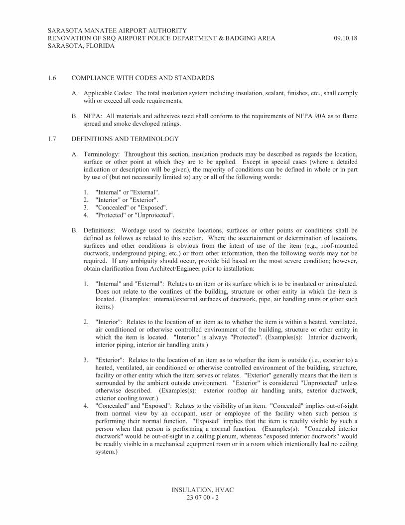
SARASOTA MANATEE AIRPORT AUTHORITY RENOVATION OF SRQ AIRPORT POLICE DEPARTMENT & BADGING AREA 09.10.18 SARASOTA, FLORIDA
INSULATION, HVAC 23 07 00 - 2
1.6 COMPLIANCE WITH CODES AND STANDARDS
A. Applicable Codes: The total insulation system including insulation, sealant, finishes, etc., shall comply with or exceed all code requirements.
B. NFPA: All materials and adhesives used shall conform to the requirements of NFPA 90A as to flame
spread and smoke developed ratings. 1.7 DEFINITIONS AND TERMINOLOGY
A. Terminology: Throughout this section, insulation products may be described as regards the location, surface or other point at which they are to be applied. Except in special cases (where a detailed indication or description will be given), the majority of conditions can be defined in whole or in part by use of (but not necessarily limited to) any or all of the following words:
1. "Internal" or "External". 2. "Interior" or "Exterior". 3. "Concealed" or "Exposed". 4. "Protected" or "Unprotected".
B. Definitions: Wordage used to describe locations, surfaces or other points or conditions shall be
defined as follows as related to this section. Where the ascertainment or determination of locations, surfaces and other conditions is obvious from the intent of use of the item (e.g., roof-mounted ductwork, underground piping, etc.) or from other information, then the following words may not be required. If any ambiguity should occur, provide bid based on the most severe condition; however, obtain clarification from Architect/Engineer prior to installation:
1. "Internal" and "External": Relates to an item or its surface which is to be insulated or uninsulated.
Does not relate to the confines of the building, structure or other entity in which the item is located. (Examples: internal/external surfaces of ductwork, pipe, air handling units or other such items.)
2. "Interior": Relates to the location of an item as to whether the item is within a heated, ventilated,
air conditioned or otherwise controlled environment of the building, structure or other entity in which the item is located. "Interior" is always "Protected". (Examples(s): Interior ductwork, interior piping, interior air handling units.)
3. "Exterior": Relates to the location of an item as to whether the item is outside (i.e., exterior to) a
heated, ventilated, air conditioned or otherwise controlled environment of the building, structure, facility or other entity which the item serves or relates. "Exterior" generally means that the item is surrounded by the ambient outside environment. "Exterior" is considered "Unprotected" unless otherwise described. (Examples(s): exterior rooftop air handling units, exterior ductwork, exterior cooling tower.)
4. "Concealed" and "Exposed": Relates to the visibility of an item. "Concealed" implies out-of-sight from normal view by an occupant, user or employee of the facility when such person is performing their normal function. "Exposed" implies that the item is readily visible by such a person when that person is performing a normal function. (Examples(s): "Concealed interior ductwork" would be out-of-sight in a ceiling plenum, whereas "exposed interior ductwork" would be readily visible in a mechanical equipment room or in a room which intentionally had no ceiling system.)

SARASOTA MANATEE AIRPORT AUTHORITY RENOVATION OF SRQ AIRPORT POLICE DEPARTMENT & BADGING AREA 09.10.18 SARASOTA, FLORIDA
INSULATION, HVAC 23 07 00 - 3
5. "Protected" and "Unprotected": Relates to an exterior item which may or may not be sheltered from the outside elements but which exists in contiguous contact with the ambient environment without benefit of any direct heating, ventilating or air conditioning. (Example(s): Piping or ducts located in an open crawl space beneath a building would be "protected/concealed"; in an open parking garage such piping or ducts would be "protected/exposed". Piping or ducts on a rooftop would be "unprotected" and usually "exposed".)
PART 2 - PRODUCTS 2.1 GENERAL
A. Materials: Materials listed are those used as basis of design; equivalent products of acceptable manufacturers will be accepted. Materials must be approved and recommended by the insulation product manufacturer for the particular application(s).
B. Flame and Smoke Ratings: Application of insulation materials may require, in many cases, that the
final insulation system comply with NFPA 90A with regard to maintaining a flame spread rating of 25 or less and a smoke developed/fuel contributed valve of 50 or less. In such cases, verify that the materials comply with the indicated flame spread and smoke developed ratings.
C. Applicability: Products and manufacturers listed may not all be applicable. Use only those products
and manufacturers which are indicated as being applicable to a specific insulation condition.
D. Acceptable Manufacturers: Manufacturers which are listed are those manufacturers who may make one or more of the insulation products required. Listing of a manufacturer does not necessarily mean the manufacturer is approved for all applicable insulation conditions. Each listed manufacturer must still comply with the specific requirements of each insulation condition to be acceptable for the particular application. Acceptable manufacturers of insulation-related products include (but are not necessarily limited to) the following: Armstrong; CertainTeed; Childers Products Co.; Knauf; Manville; Owens-Corning; Pittsburg Corning; Rubatex; Upjohn Co.; Duracote Corporation; Ferro Corporation; Dow Corning Corporation; Duro Dyne Corporation; Goodloe E. Moore, Inc.; 3M Co.; United McGill Corporation, Vimasco Corporation; Foster; Gustin-Bacon; Nomaco Inc.; Insulcoustic; Molded Acoustical Products; Lion Nokorode and other manufacturers as may be listed for a specific application.
2.2 BASIC MATERIALS
A. Cellular Glass Insulation: Preformed or block type as indicated or as applicable. Fire, water and vermin retardant; closed cell glass composition; density of 8.5-pcf. Comply with the following: ASTM C 552, "Specification for Cellular Glass Thermal Insulation"; Military Specification MIL-I-24244B. Flame spread rating of "5" and a smoke developed rating of "0" as per ASTM E 84. Recommended temperature applications from -450oF to 1200oF when installed in accord with manufacturer's recommendations. Pittsburg-Corning Foamglas.
B. Elastomeric Insulation: Preformed (tube), roll or sheet as indicated or as applicable. Nitrile, rubber
based, closed cell structure. K factor of 0.28 at 75oF. In tube, roll or sheet form of 3/4-inch thickness or less, ASTM E 84 flame spread rating of "25" or less and smoke developed rating of "50" or less. Recommended temperature applications from -40oF to 220oF when installed in accord with manufacturer's recommendations. Do not install in return air plenums unless flame spread rating and smoke developed rating are within constraints of applicable codes. Manufacturers and/or series: Armstrong "Armaflex"; Manville "Aerotube"; "Rubatex"; Gustin-Bacon "Ultra-Foam".

SARASOTA MANATEE AIRPORT AUTHORITY RENOVATION OF SRQ AIRPORT POLICE DEPARTMENT & BADGING AREA 09.10.18 SARASOTA, FLORIDA
INSULATION, HVAC 23 07 00 - 4
C. Fiberglass Insulation: Inorganic fibrous glass. Flame spread of "25" or less and smoke developed rating of "50" or less per ASTM E 84.
1. Board: Rigid or semi-rigid form, faced or unfaced as indicated. Stiffness of 475 EI, 800 EI or
1400 EI as indicated.
2. Blanket: Flexible form; faced, unfaced or coated as indicated.
3. Preformed: Jacketed or unjacketed as indicated.
D. Calcium Silicate Insulation: Preformed or block type as indicated or as applicable. Asbestos free. Rigid hydrous calcium silicate. K factor of 0.42 at 200oF. Density: 14-pcf. Flame spread rating of "0" and smoke developed rating of "0" as per ASTM E 84. Recommended temperature applications up to 1200 oF. Use where indicated only on equipment and surfaces which generate heat; do not use as a cold-surface insulation.
2.3 INSULATION PRODUCTS, BASIC
A. Type PI-1: Pipe insulation, preformed cellular glass. Pittsburg-Corning "Foamglas" or equivalent.
B. Type PI-2: Pipe insulation, preformed jacketed fiberglass. Jacketed with factory-applied kraft reinforced foil vapor barrier jacket. Jacket closure system of double pressure-sensitive adhesive on longitudinal joints; self-sealing butt strips at circumferential joints; provide positive vapor barrier seal. Thermal conductivity (K) of 0.24 at 100oF. Owens-Corning Fiberglas ASJ/SSL-II; Manville Micro-Lok with AP-T Plus jacket; CertainTeed 500 Snap-On; or equivalent.
C. Type PI-3: Pipe insulation, preformed unjacketed fiberglass. Suitable for field-jacketing. Thermal
conductivity (K) of 0.23 at 100oF. Owens-Corning Fiberglas No-Wrap, Manville Micro-Lok, or equivalent.
D. Type PI-4: Pipe insulation, preformed segmental rigid calcium silicate. Thickness as indicated;
provide single layer where nominal pipe size allows; provide "factory nested" double layer when nominal pipe size so requires for the thickness indicated. Owens-Corning Kaylo; Manville Thermo-12; or equivalent.
E. Type PI-5: Pipe insulation, preformed elastomeric. Rubatex, Armaflex II or equivalent.
F. Type I-1: Cellular glass block insulation. Field formed, fitted and finished as required for the
application. Pittsburg-Corning Foamglas or equivalent.
G. Type I-2: Calcium silicate block insulation. Field formed, fitted and finished as required for the application. Owens-Corning Kaylo; Manville Thermo-12; or equivalent.
H. Type I-3: Elastomeric insulation. Field formed, fitted and finished as required for the application.
Armaflex, Rubatex or equivalent.
I. Type I-4: Fiberglass flexible blanket insulation. Unfinished, non-combustible, wool-like; composed of long glass fibers bonded with a thermosetting resin. Thermal conductivity (K) of 0.23 at 100oF. Applicable where indicated for boilers, vessels, breaching and stacks operating at up to 1000oF. Finished or held in place by wire ties, metal lath, lagging or as indicated. Owens-Corning Thermal Insulating Wool TIW Type II or equivalent.
J. Type DI-1: Duct insulation, fiberglass flexible blanket wrap. Composed of flexible blanket of glass
fiber factory laminated to a reinforced foil kraft (FRK) vapor barrier with a minimum 2-inch taping

SARASOTA MANATEE AIRPORT AUTHORITY RENOVATION OF SRQ AIRPORT POLICE DEPARTMENT & BADGING AREA 09.10.18 SARASOTA, FLORIDA
INSULATION, HVAC 23 07 00 - 5
and stapling flange on one edge. Suitable for operation at temperatures from 40oF to 250oF. Thermal conductivity of 0.31 at 75oF. Minimum density of three-quarter (3/4) pound per cubic foot. Provide in thickness of (2.2) inches unless otherwise specified as 2-1/2 or 3-inch thickness. Owens-Corning All Service Faced Duct Wrap; Manville R-Series Microlite; CertainTeed Standard Duct Wrap; or equivalent.
K. Type DI-2: Duct insulation, fiberglass semi-rigid board. Composed of resin bonded glass fibers faced
with a foil scrim-kraft (FSK) reinforced laminate of aluminum foil and kraft bonded to provide a metallic surface finish vapor barrier; alternate vapor barrier facing (if specifically indicated) is an all service jacket (ASJ) of high intensity white bleached, chemically treated kraft paper reinforced with fiberglass yarn mesh and laminated to aluminum foil with fire-retardant adhesive to impart a clean, white appearance. Conductivity (K) of not greater than 0.23 at 75oF. Provide in thickness of one (1) inch unless otherwise indicated. Provide with minimum density of 3-pcf unless 6-pcf is specifically indicated. CertainTeed Industrial Insulation Board Type IB-300 (or IB-600); Manville 800 Series Spin-Glas Type 814 (or 817); Owens-Corning 700 Series Industrial Insulation Board Type 703 ( or Type 705); or equivalent.
2.4 INSULATION ADHESIVES, MASTICS, SEALANTS
A. Adhesive (Type A-E1): For joints and seams in elastomeric insulation (Type I-3) not requiring weather protection. Rubatex R-373 Insulation Adhesive; Armstrong 520 Adhesive or equivalent.
B. Joint Sealant (Type JS-CG1): Non-hardening vapor barrier sealant specifically designed for use with
cellular glass insulation (Types PI-1, I-1): Foster's 35-40 Foamseal Sealant, Pittsburg-Corning Pittseal 111 Sealant or equivalent.
C. Adhesive (Type A-F1): For adhering fiberglass blanket and board insulations (Types DI-1, DI-2) to metal substrate such as ductwork. Insulcoustic I-C 201, Foster 85-20 or equivalent.
D. Mastic, General Purpose (Type M-GP1): Non hardening vapor barrier general purpose mastic. For
use where indicated or otherwise applicable. Foster GPM 35-00 or equivalent. 2.5 INSULATION FINISHES, JACKETS AND COVERS
A. Finishing Coating (Type FC-E1): For weather protection of elastomeric insulations (Types I-3, PI-5). Rubatex 374 coating; Armstrong Armaflex Finish or equivalent.
B. Finish Mastic (Type FM-CG1): For cellular glass insulations (Types PI-1, I-1). Waterproof, weather,
acid and alkali resistant asphalt mastic coating for use in the range of -40oF to 200oF (installation must be done when in the 50oF to 120oF range). Pittsburg-Corning Pittcote 300 Vapor and Weather Barrier Finish or equivalent.
C. Finish Fabric (Type FF-CG1): For cellular glass insulations (Types PI-1, I-1). 6 x 6 meshes per inch
polyester fabric for reinforcing the finish mastic. Pittsburg-Corning PC Fabric 79 or equivalent.
D. Finish Fabric, General Purpose (Type FF-GP1): Nylon membrane. For use generally with fiberglass duct insulations (Types DI-1, DI-2) at joints or seams or as may be indicated. Apply using Foster GPM 35-00 or equivalent.
E. Jacket, Underground Pipe (Type JP-CG-1): For cellular glass pipe insulations (Type PI-1, I-1) where
indicated. Prefabricated laminate containing a 20 x 10 mesh asphalt impregnated glass fabric and a 1-mil thick aluminum foil sandwiched between three layers of a bituminous mastic. External jacket surface coated with a protective plastic film and internal surface with a special release paper. Apply around cellular glass pipe insulation in a cigarette type wrap with the overlap heat sealed. Seal butt joints in the same manner using a 4-inch wide seal strip of the jacketing. Irregular surfaces of the pipe

SARASOTA MANATEE AIRPORT AUTHORITY RENOVATION OF SRQ AIRPORT POLICE DEPARTMENT & BADGING AREA 09.10.18 SARASOTA, FLORIDA
INSULATION, HVAC 23 07 00 - 6
system shall have the jacket's plastic film burned away prior to application of a 20 x 10 asphalt impregnated mesh which shall be sandwiched between two glove coats of finish mastic (Type FM-CG1).
F. Jacket, Pipe, PVC (Type JP-PVC): All purpose, UL-rated, white vinyl jacket, with or without self-
sealing feature. Pittsburg-Corning "UNI-JAC" or equivalent.
G. Jacket, Pipe, Aluminum (Type JP-A1): Aluminum jacketing, 0.016 inches thick, type 3003 alloy, H-14 temper, circumferentially corrugated, with a continuously laminated moisture barrier of one mil polyethylene film and a protective layer of 40 lb. virgin kraft paper. Childers Products Co. "Corolon"; General Aluminum Supply Co. (Gasco); Insulcoustic "Alcorjac" or equivalent.
H. Pipe Fitting Covers, PVC (Type PFC-PVC): Insulated polyvinyl-chloride fitting covers in shapes as
required; with fiberglass insulation insert. Suitable for temperature range of 0oF to 450oF. Flame spread rating of 25 or less and smoke developed rating of 50 or less when kept below 150oF. Acid, alkali and chemical resistant. Suitable for painting if required. Manville Zeston 25/50 PVC Insulated Fitting Covers or equivalent.
I. Pipe Fitting Covers, Aluminum (Type PFC-A1): Aluminum fitting covers, 0.020 inches minimum thickness, type 3003 alloy, H-14 temper prefabricated fitting covers with baked epoxy moisture barrier for pipe sizes through 24". Field fabricate fitting covers for pipe sizes larger than 24" using 0.020 inches thick aluminum roll jacketing with laminated polyethylene/kraft moisture barrier. Childers Products "Ell-Jacs", "Gore Ell-Jacs", "Tee-Jack", "End-Caps", and "Flange Jacs" or equivalent.
2.6 RELATED PRODUCTS
A. Wire (Type W-1): Dead soft, 16-gauge, stainless steel.
B. Straps (Type ST-1): Stainless steel T-304 (18-8) soft annealed with deburred edge with stainless steel wing seals. Childers Products "Febstraps" or equivalent.
C. Tape (Type T-1): High tensile strength rope stock flat back paper pressure sensitive tape. Pittsburg-
Corning "PC Tape No. 25" or equivalent.
D. Screws (Type S-1): Aluminum pan head type "A" slotted #8 by 1/2-inch. PART 3 - EXECUTION 3.1 GENERAL
A. Field Forming, Fitting and Finishing: Where preformed insulation products are indicated as being acceptable for a particular application, provide field formed, fitted and finished insulation systems if such application is more practical (such as due to size, configuration or dimensions which may be outside of the availability ranges for size, dimension and/or thickness of preformed products).
B. Pre-installation:
1. Do not apply insulation adhesives, materials or finishes until the item to be insulated has been
completely installed and tested and proved tight and suitable for insulation.
2. Prepare surfaces to be clean and dry before attempting to apply insulation.
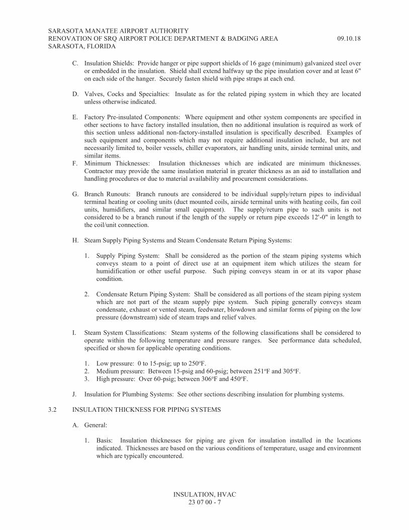
SARASOTA MANATEE AIRPORT AUTHORITY RENOVATION OF SRQ AIRPORT POLICE DEPARTMENT & BADGING AREA 09.10.18 SARASOTA, FLORIDA
INSULATION, HVAC 23 07 00 - 7
C. Insulation Shields: Provide hanger or pipe support shields of 16 gage (minimum) galvanized steel over or embedded in the insulation. Shield shall extend halfway up the pipe insulation cover and at least 6" on each side of the hanger. Securely fasten shield with pipe straps at each end.
D. Valves, Cocks and Specialties: Insulate as for the related piping system in which they are located
unless otherwise indicated.
E. Factory Pre-insulated Components: Where equipment and other system components are specified in other sections to have factory installed insulation, then no additional insulation is required as work of this section unless additional non-factory-installed insulation is specifically described. Examples of such equipment and components which may not require additional insulation include, but are not necessarily limited to, boiler vessels, chiller evaporators, air handling units, airside terminal units, and similar items.
F. Minimum Thicknesses: Insulation thicknesses which are indicated are minimum thicknesses. Contractor may provide the same insulation material in greater thickness as an aid to installation and handling procedures or due to material availability and procurement considerations.
G. Branch Runouts: Branch runouts are considered to be individual supply/return pipes to individual
terminal heating or cooling units (duct mounted coils, airside terminal units with heating coils, fan coil units, humidifiers, and similar small equipment). The supply/return pipe to such units is not considered to be a branch runout if the length of the supply or return pipe exceeds 12'-0" in length to the coil/unit connection.
H. Steam Supply Piping Systems and Steam Condensate Return Piping Systems:
1. Supply Piping System: Shall be considered as the portion of the steam piping systems which
conveys steam to a point of direct use at an equipment item which utilizes the steam for humidification or other useful purpose. Such piping conveys steam in or at its vapor phase condition.
2. Condensate Return Piping System: Shall be considered as all portions of the steam piping system
which are not part of the steam supply pipe system. Such piping generally conveys steam condensate, exhaust or vented steam, feedwater, blowdown and similar forms of piping on the low pressure (downstream) side of steam traps and relief valves.
I. Steam System Classifications: Steam systems of the following classifications shall be considered to
operate within the following temperature and pressure ranges. See performance data scheduled, specified or shown for applicable operating conditions.
1. Low pressure: 0 to 15-psig; up to 250oF. 2. Medium pressure: Between 15-psig and 60-psig; between 251oF and 305oF. 3. High pressure: Over 60-psig; between 306oF and 450oF.
J. Insulation for Plumbing Systems: See other sections describing insulation for plumbing systems.
3.2 INSULATION THICKNESS FOR PIPING SYSTEMS
A. General:
1. Basis: Insulation thicknesses for piping are given for insulation installed in the locations indicated. Thicknesses are based on the various conditions of temperature, usage and environment which are typically encountered.

SARASOTA MANATEE AIRPORT AUTHORITY RENOVATION OF SRQ AIRPORT POLICE DEPARTMENT & BADGING AREA 09.10.18 SARASOTA, FLORIDA
INSULATION, HVAC 23 07 00 - 8
2. Applicable Thicknesses: All thicknesses as applicable to all conditions may not be given in this section article. Where an insulation thickness for a particular application is specified to be of other thickness than may be listed in this section article, "INSULATION THICKNESSES FOR PIPING SYSTEMS", then provide the insulation in the thickness indicated in other portion of this section which specifically describes the particular insulation application and its required insulation thickness. Thicknesses for other than piping insulation are given in the specific description of the particular application or description of the particular material used.
3. Ambient Conditions: Unless otherwise indicated, ambient conditions for the purpose of
describing insulation thicknesses are related to cold applications to prevent condensation or excessive heat gain (e.g., chilled water pipe, cold vessels) and are related to hot applications to prevent harm to personnel or to prevent objectionable heat loss to the environment (e.g., hot water pipe, hot vessels, hot stacks).
a. These conditions are generally:
Interior: 80oF and 80% RH. Exterior: 90oF and 80% RH.
4. Thickness Requirements: Thicknesses are given below based on the following information:
a. General type of fluid or process involved (e.g., chilled water, hot water, steam, refrigerant).
b. General location and, if necessary, conditions related to temperature (either or both internal or
external to the insulation barrier) and ambient environment of the insulated item.
c. Pipe size range.
B. Chilled Water Piping Systems: Fluid generally considered to be between 40oF and 65oF. Thickness is for cellular glass unless other insulation material is indicated.
Location or Description Pipe Size (inches) Insulation Thickness
Interior Up to 1 1-1/2" Interior 1-1/4 to 4 2" Interior 6 and up 2-1/2" ----------------------- ------------------ ----------- Exterior Up to 4 2-1/2" Exterior 6 and up 3" ----------------------- ------------------ ----------- Underground All Sizes 2" ----------------------- ------------------ -----------
C. Hot Water Piping Systems, Low Temperature: Fluid generally considered to be 200oF or less.
Thickness is for fiberglass insulation except where annotated by the letter "G" in which case the insulation thickness is for cellular glass unless other insulation material is indicated. An asterisk (*) indicates branch runouts.
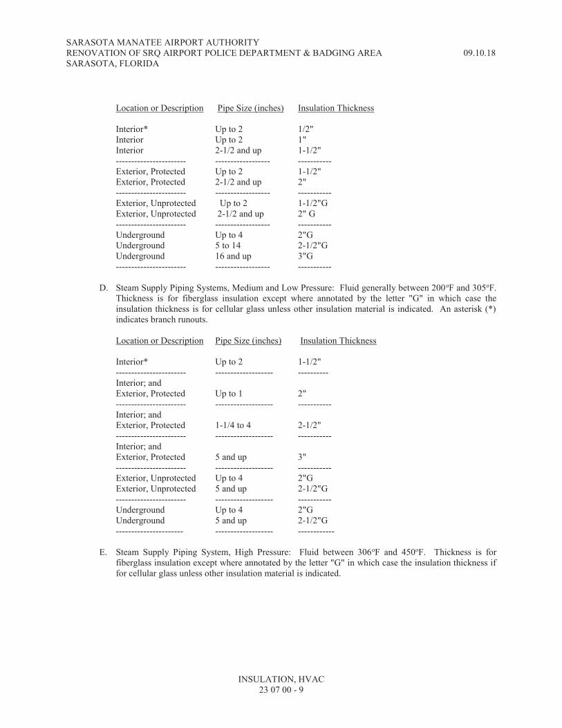
SARASOTA MANATEE AIRPORT AUTHORITY RENOVATION OF SRQ AIRPORT POLICE DEPARTMENT & BADGING AREA 09.10.18 SARASOTA, FLORIDA
INSULATION, HVAC 23 07 00 - 9
Location or Description Pipe Size (inches) Insulation Thickness
Interior* Up to 2 1/2" Interior Up to 2 1" Interior 2-1/2 and up 1-1/2" ----------------------- ------------------ ----------- Exterior, Protected Up to 2 1-1/2" Exterior, Protected 2-1/2 and up 2" ----------------------- ------------------ -----------
Exterior, Unprotected Up to 2 1-1/2"G Exterior, Unprotected 2-1/2 and up 2" G ----------------------- ------------------ ----------- Underground Up to 4 2"G Underground 5 to 14 2-1/2"G Underground 16 and up 3"G ----------------------- ------------------ -----------
D. Steam Supply Piping Systems, Medium and Low Pressure: Fluid generally between 200oF and 305oF.
Thickness is for fiberglass insulation except where annotated by the letter "G" in which case the insulation thickness is for cellular glass unless other insulation material is indicated. An asterisk (*) indicates branch runouts.
Location or Description Pipe Size (inches) Insulation Thickness
Interior* Up to 2 1-1/2" ----------------------- ------------------- ---------- Interior; and Exterior, Protected Up to 1 2" ----------------------- ------------------- ----------- Interior; and Exterior, Protected 1-1/4 to 4 2-1/2" ----------------------- ------------------- ----------- Interior; and Exterior, Protected 5 and up 3" ----------------------- ------------------- ----------- Exterior, Unprotected Up to 4 2"G Exterior, Unprotected 5 and up 2-1/2"G ----------------------- ------------------- ----------- Underground Up to 4 2"G Underground 5 and up 2-1/2"G ---------------------- ------------------- ------------
E. Steam Supply Piping System, High Pressure: Fluid between 306oF and 450oF. Thickness is for
fiberglass insulation except where annotated by the letter "G" in which case the insulation thickness if for cellular glass unless other insulation material is indicated.

SARASOTA MANATEE AIRPORT AUTHORITY RENOVATION OF SRQ AIRPORT POLICE DEPARTMENT & BADGING AREA 09.10.18 SARASOTA, FLORIDA
INSULATION, HVAC 23 07 00 - 10
Location or Description Pipe Size (inches) Insulation Thickness
Interior; and Exterior, Protected Up to 2 2-1/2" ----------------------- ------------------- ----------- Interior; and Exterior, Protected 2-1/2 to 4 3" ----------------------- ------------------- ----------- Interior; and Exterior, Protected 5 and up 3-1/2" ----------------------- ------------------- ----------- Underground Up to 4 2"G Underground 5 to 8 2-1/2"G Underground 10 and up 3"G ----------------------- ------------------- -----------
F. Steam Condensate Return Piping System (including all related piping for steam vent, steam blowdown,
and feedwater). Thickness is for fiberglass insulation except where annotated by the letter "G" in which case the insulation thickness is for cellular glass unless other insulation material is indicated. An asterisk (*) indicates branch runouts.
Location or Description Pipe Size (inches) Insulation Thickness
Interior* Up to 2 1" ----------------------- ------------------- ----------- Interior; and Exterior, Protected Up to 1 1-1/2" ----------------------- ------------------- ----------- Interior; and Exterior, Protected 1-1/4 and up 2" ----------------------- ------------------- ----------- Exterior, Unprotected Up to 4 2"G Exterior, Unprotected 5 and up 2-1/2"G ----------------------- ------------------- ----------- Underground Up to 4 2"G Underground 5 and up 2-1/2"G ----------------------- ------------------- -----------
3.3 CHILLED WATER PIPING SYSTEMS
A. Interior, Concealed (e.g., ceiling plenums): Insulate with prefabricated, cellular glass pipe insulation (PI-1, I-1). Butter joints with joint sealant (JS-CG1) and secure each section with not less than two wires (W-1). Finish with a layer of fabric (FF-CG1) applied between two glove coats of mastic (FM-CG1). Mastic and fabric shall be applied in strict accordance with the manufacturer's recommendations.
B. Interior, Exposed (e.g., central mechanical rooms, air handling unit rooms): Insulate with
prefabricated, cellular glass pipe insulation (PI-1, I-1). Butter joints with joint sealant (JS-CG1) and secure each section with not less than two wires (W-1). Finish with jacketing (JP-A1). Secure jacketing with straps. Finish elbows and fittings with mastic (FM-CG1), reinforced with fabric (FF-CG1); or finish with fitting covers (PFC-A1). Finish materials shall be applied in strict accordance with the manufacturer's recommendations.

SARASOTA MANATEE AIRPORT AUTHORITY RENOVATION OF SRQ AIRPORT POLICE DEPARTMENT & BADGING AREA 09.10.18 SARASOTA, FLORIDA
INSULATION, HVAC 23 07 00 - 11
C. Interior, Exposed, Special Locations: Same as for "Interior, Concealed" with the additional requirement that the final coat of mastic for the insulation finish shall be especially gloved and finished smooth to accept painting of color(s) required in other divisions as specially selected by the Architect/Engineer. These special locations consist of exposed piping in the following normally occupied areas of the building:
1. Gymnasium. 2. Natatorium.
D. Exterior, Protected: Same insulation system as for "Interior, Exposed" except thickness as required.
E. Exterior, Unprotected: Same insulation system as for "Exterior, Protected" except thickness as
required.
F. Underground: Insulate with cellular glass pipe insulation (PI-1, I-1). Butter joints with joint sealant (JS-CG1) and secure each section with not less than two wires (W-1). Finish with underground jacket (JP-CG1) having 2-inch minimum overlap of the longitudinal seams. Heat seal longitudinal seams with a propane torch. Cover butt joints with a 4-inch wide strip of jacket with the edges heat sealed around the circumference. Precut the jacket to fit the contour or irregular surfaces such as 90o bends, 45o bends, fittings, etc. to which it is to be applied; in addition to heat sealing the jacket on these irregular surfaces, burn away the polyester film and glove a coat of mastic (FM-CG1) on the surface; while this coat is still tacky, embed a 10 x 10 asphalt impregnated fabric (FF-CG1) into the mastic. After this application has dried for not less than one hour, apply another coating of mastic. Caution: Keep mastic away from sparks and open flame and keep container closed when not in use.
G. Underground Expansion Joints, Expansion Elbows and Expansion Loops: Provide oversized insulation
telescoped over the adjacent pipe insulation to provide close fit and adequate annular space to allow all movement expected to be encountered through maximum temperature ranges (including idle) of the conveyed fluid. Provide 1-1/2 pcf density fiberglass pipe insulation of thickness equal to the cellular glass insulation beneath the oversized insulation to completely fill the annular space void and yet allow freedom of pipe movement. Comply with insulation manufacturer's recommendations for these conditions or with details on drawings, as applicable.
3.4 HOT WATER PIPING SYSTEMS
A. Interior, Concealed: Insulate with glass fiber insulation (PI-2) with all purpose jacket. Elbows, joints, valves, unions and all like items shall be insulated using closely mitered insulation and wrapped with glass fabric and mastic or these items may be insulated and jacketed using pipe fitting covers (PFC-PVC). Install in strict accordance with the manufacturer's recommendations.
B. Interior, Exposed: As specified for "Interior, Concealed", except finish with aluminum jacketing (JP-
A1) and fitting covers (PFC-A1). Secure fitting covers with screws (S-1) and secure jacketing with straps (ST-1). Finish materials shall be applied in strict accordance with the manufacturer's recommendations.
C. Interior, Exposed, Special Locations: Same as for "Interior, Concealed" with the additional requirement that the final coat of mastic for the insulation finish shall be especially gloved and finished smooth to accept painting of color(s) required in other divisions as specially selected by the Architect/Engineer. These special locations consist of exposed piping in the following normally occupied areas of the building.
1. Gymnasium. 2. Natatorium.
D. Exterior, Protected: Same insulation system as for "Interior, Exposed" except thickness as specified.

SARASOTA MANATEE AIRPORT AUTHORITY RENOVATION OF SRQ AIRPORT POLICE DEPARTMENT & BADGING AREA 09.10.18 SARASOTA, FLORIDA
INSULATION, HVAC 23 07 00 - 12
E. Exterior, Unprotected: None applicable.
F. Underground: Same insulation system as for "Chilled Water Piping Systems" in this location except thickness as specified.
G. Underground Expansion Joints, Expansion Elbows and Expansion Loops: Same as for "Chilled Water
Piping Systems" in this location except thickness as specified. 3.5 STEAM SUPPLY PIPING SYSTEMS, LOW AND MEDIUM PRESSURE
A. Interior, Concealed: Same insulation system as for "Hot Water Piping Systems" in this location except thickness as specified.
B. Interior, Exposed: Same insulation system as for "Hot Water Piping Systems" in this location except
thickness as specified.
C. Exterior, Protected: Same insulation system as for "Interior, Exposed" except thickness as specified.
D. Exterior, Unprotected: Same insulation system as for "Chilled Water Piping systems" in this location except thickness as specified.
E. Underground: Same insulation system as for "Chilled Water Piping systems" in this location except
thickness as indicated.
F. Underground Expansion Joints, Expansion Elbows and Expansion Loops: Same insulation system as for "Chilled Water Piping Systems" in this location except thickness as specified.
3.6 STEAM SUPPLY PIPING SYSTEMS, HIGH PRESSURE
A. Interior, Concealed: Same insulation system as for "Hot Water Piping Systems" in this location except thickness as specified.
B. Interior, Exposed: Same insulation system as for "Hot Water Piping Systems" in this location except
thickness as specified.
C. Exterior, Protected: Same insulation system as for "Interior, Exposed" except thickness as specified.
D. Exterior, Unprotected: None applicable. 3.7 DUCT SYSTEMS
A. General:
1. Locations and extent of both internal and external insulation for duct systems are described in section entitled "Ductwork" and/or by the "Duct Type and Location Schedule" on the Drawings.
2. Internal Insulation: Ductwork which is required to be insulated internally (acoustically/thermally
lined) shall be insulated as work of the section entitled "Ductwork". 3. External Insulation: Ductwork which is required to be insulated externally shall be insulated as
work of this section.
4. Factory Insulation: Ductwork which is factory manufactured with internal or external insulation is not to be additionally insulated as work of this section unless specifically stated. Such factory insulated ductwork generally consists of flexible externally insulated ductwork and double walled acoustically thermally lined ductwork.

SARASOTA MANATEE AIRPORT AUTHORITY RENOVATION OF SRQ AIRPORT POLICE DEPARTMENT & BADGING AREA 09.10.18 SARASOTA, FLORIDA
INSULATION, HVAC 23 07 00 - 13
B. Interior, Concealed (e.g., ceiling plenums): Where external insulation is required, insulate externally
with 2.2 inch thick fiberglass blanket wrap (Type DI-1). Adhere duct insulation using adhesive (Type A-F1) applied in accordance with the manufacturer's recommendations. Where duct width exceeds twenty-four inches (24"), the insulation shall be additionally secured to the bottom of the duct using mechanical fasteners spaced one foot (1') on center. Insulation shall be applied with edges tightly butted, and all joints and breaks in the vapor barrier sealed using glass fabric and mastic applied in conformance with manufacturer's recommendations.
C. Interior, Exposed, (e.g., air handling unit rooms): Where external insulation is required, insulate with
1-inch thick semi-rigid fiberglass board (Type DI-2). Adhere to ductwork with adhesive (Type A-F1). Finish joints and seams with finish fabric (Type FF-GP1).
3.8 DUCT SYSTEMS EQUIPMENT
A. General: Insulate as follows unless detailed to a greater extent on the Drawings.
B. Fire damper and Fire/Smoke Damper External Surfaces:
1. Externally Insulated Duct Locations: Extend duct insulation up face of fire damper to damper sleeve. Seal insulation edges with 4-inch minimum width duct tape.
2. Internally Insulated Duct Locations: Provide additional external insulation from a point on the
duct 12 inches from the fire damper to the fire damper and on the face of the fire damper to the fire damper sleeve. Seal insulation edges with 4-inch minimum width duct tape.
C. Air Distribution Devices: Insulate the backs of all ceiling diffusers and other air outlet devices
installed in other than return air plenums as specified for interior concealed ducts. 3.9 COLD EQUIPMENT AND RELATED COMPONENTS
A. Pump Volutes for Chilled Water Systems: Insulate with elastomeric sheet insulation (Type 1-3) out to and including pump flanges. Provide cutouts or removable sections as required to provide access to grease fittings and similar items and to allow adequate clearance for shaft. Secure the insulation with adhesive (Type A-E1). Insulation thickness shall be one and one-half (1-1/2) inches.
B. Expansion Tanks(s), Air Separator(s) and Chemical Pot Type Feeder(s) for Chilled Water Systems:
Insulate with elastomeric sheet insulation (Type 1-3). Secure the insulation with adhesive (Type A-E1) applied to a clean surface and finish with a layer of membrane (Type FF-GP1) applied between two glove coats of mastic (Type M-GP1). Insulation thickness shall be one and one-half (1-1/2) inch.
C. Condensate Drain Piping From Cooling Equipment:
1. Interior, and Exterior, Protected: Insulate with preformed elastomeric pipe insulation (Type PI-5)
secured with adhesive (Type A-E1) and finished with white finish coating (FCC-E1). Thickness 3/4-inch. Provide 25/50 flame/smoke rating.
2. Exterior, Unprotected: None applicable.
D. Cold Surfaces at Chillers and Evaporators: Factory insulated. No insulation required as work of this
section.

SARASOTA MANATEE AIRPORT AUTHORITY RENOVATION OF SRQ AIRPORT POLICE DEPARTMENT & BADGING AREA 09.10.18 SARASOTA, FLORIDA
INSULATION, HVAC 23 07 00 - 14
E. Flexible Pipe Connectors for Vibration Isolation: Insulate with elastomeric insulation (Type 1-3). Secure the insulation with adhesive (Type A-E1) applied to a clean surface and finish with white finish coating (FC-E1). Insulation thickness shall be one and one-half inches (1-1/2").
3.10 HOT EQUIPMENT AND RELATED COMPONENTS
A. Heat Exchangers, Shell and Tube: Insulate with 2-1/2-inch thick calcium silicate insulation (Type -2). Wire insulation securely to vessel and then cover with wire mesh. Apply a 1/2-inch thick finish coat of insulating finish cement over the wire mesh. Trowel external surface to a smooth finish.
END OF SECTION 23 07 00

SARASOTA MANATEE AIRPORT AUTHORITY RENOVATION OF SRQ AIRPORT POLICE DEPARTMENT & BADGING AREA 09.10.18 SARASOTA, FLORIDA
DUCTWORK 23 31 00- 1
SECTION 23 31 00 - DUCTWORK PART 1 - GENERAL 1.1 RELATED DOCUMENTS
A. Drawings and general provisions of Contract, including General and Supplementary Conditions and Division-01 Specification sections, apply to work of this section.
1.2 SCOPE
A. Provide complete duct systems as indicated. Systems shall include, but not be limited to, the following: outside air, exhaust air, and air conditioning supply and return air duct systems as shown on drawings. Drawing scales prohibit the indication of all offsets, fittings, and like items; however, these items shall be installed as required for the actual project conditions at no change in contract price.
B. Items Included: This section generally includes, but is not limited to, the following major items:
1. Low pressure sheet metal ductwork. 2. Acoustical thermal duct liner. 3. Low pressure fiberglass ductwork. 4. High pressure sheet metal ductwork, round and flat oval. 5. High pressure sheet metal ductwork, rectangular. 6. Low pressure flexible ducts. 7. High pressure flexible ducts. 8. Other special duct systems.
1.3 RELATION TO OTHER WORK
A. Refer to the section, "General Mechanical Provisions" for related requirements. Refer to other sections of Division 23 and to other applicable portions of the Drawings and Specifications.
B. This section is directly related in particular to sections (which may or may not be included in this
division) which describe the following:
1. Sections describing air handling equipment and fans. 2. Air distribution devices. 3. Terminal units. 4. Duct system accessories. 5. Insulation.
C. Coordinate shop drawings, ordering, delivery, and placement of all items affecting the duct systems including, but not limited to, the following items: air handling units, exhaust fans, supply fans, sound attenuators, duct mounted coils, access panels, air distribution devices, fire dampers, outside air louvers, hoods, filters, roof curbs, structural framing, roof construction, roofing, and the work of all trades to insure an orderly and timely progression of the work. Refer to the requirements of Section entitled "General Mechanical Provisions".
D. Refer to other sections which may describe additional sound attenuation measures which may relate to this section.

SARASOTA MANATEE AIRPORT AUTHORITY RENOVATION OF SRQ AIRPORT POLICE DEPARTMENT & BADGING AREA 09.10.18 SARASOTA, FLORIDA
DUCTWORK 23 31 00- 2
1.4 SHOP DRAWINGS
A. Refer to Section entitled "General Mechanical Provisions". Include complete data as applicable to this project on: all prefabricated duct and fittings; duct liner including mechanical fasteners and adhesives; duct sealing materials; duct joining and seaming methods; and all other items. If required by Architect, prepare and submit for approval completely detailed shop drawings of supply and return ductwork from any or each air handling unit through its transitions, bends and elbows until such ducts are extended beyond the air handling unit equipment area and/or congested areas; these shop drawings will not be required unless specifically called for elsewhere or unless significant deviation from the Drawings is necessitated by the equipment provided.
1.5 OTHER REQUIREMENTS
A. Provide all ductwork and components thereof in accord with manufacturer's recommendations. All ductwork dimensions indicated are nominal free clearance internal dimensions which do not include insulation thickness.
1.6 DEFINITIONS
A. "SMACNA" means "Sheet Metal and Air Conditioning Contractors National Association, Inc."
B. Low Pressure Ductwork: Any and all ductwork conveying air or other gases at velocities less than 2500 fpm and static pressure less than 2.0 inches wg. This ductwork may also be referred to in these specifications as "Low Velocity Ductwork". SMACNA "HVAC Duct Construction Standards, Metal and Flexible", Second Edition, 1995, shall govern construction of this ductwork unless otherwise specified.
1. Where and if fiberglass ductwork is specified, it shall be considered only for low pressure
classification use and shall be constructed in accord with SMACNA "Fiberous Glass Duct Construction Standards", Fifth Edition, 1977.
C. High Pressure Ductwork: Any and all ductwork conveying air or other gases at velocities equal to or
greater than 2500 fpm or static pressure equal to or greater than 2.0 inches wg. This ductwork may also be referred to in these specifications as "High Velocity Ductwork" or "Medium Pressure Ductwork", but shall be considered, in either terminology, to fall within pressure/velocity class (PV/C designation) 3 to 10. SMACNA "HVAC Duct Construction Standards, Metal and Flexible", Second Edition, 1995, shall govern construction of this ductwork unless otherwise specified.
1.7 PRESSURE/VELOCITY CLASSIFICATIONS
A. Pressure and velocity classifications (hereinafter called "P/VC") for ducts are defined as follows: Positive SMACNA Static or SMACNA Maximum P/VC Pressure Pressure Negative Seal Velocity Desig. Class Rating Pressure Class (fpm)
10 High 10" + A 2000 up 6 Medium 6" + A 2000 up
4 Medium 4" + A 4000 dn 3 Medium 3" + or - B 4000 dn 2 Low 2" + or - C 2500 dn

SARASOTA MANATEE AIRPORT AUTHORITY RENOVATION OF SRQ AIRPORT POLICE DEPARTMENT & BADGING AREA 09.10.18 SARASOTA, FLORIDA
DUCTWORK 23 31 00- 3
1 Low 1" + or - C 2500 dn ½ Low 1/2" + or - C 2000 dn
B. See Part 3, EXECUTION, of this section for duct sealing requirements.
PART 2 - PRODUCTS 2.1 GENERAL
A. Materials shall comply with current SMACNA standards.
B. ASTM: Unless otherwise specified, ASTM material specifications applicable are:
Material Type ASTM Number Galvanized steel G90 A525 Stainless steel 304,316 A240 Cold rolled steel 20-28 ga. A366 Cold rolled steel 18 ga. A619 Aluminum 3003 H-14 B609
C. Special Materials, Gauges and Construction:
1. Special Materials: Where special duct material other than galvanized steel is required, such duct
material (e.g., fiberglass, stainless steel, plastic such as polyvinylchloride, etc.) shall be specifically indicated.
2. Gauges: Gauges indicated in this section are for galvanized steel. Where greater or lesser gauges
are specifically indicated for a sheet metal material other than galvanized steel, provide the indicated gauge. Comply with the SMACNA construction standard covering the required material if no gauge is given.
3. Construction: Comply with indicated special requirements (i.e., such as welding, soldering, etc.)
where application requires. 2.2 LOW PRESSURE SHEET METAL DUCTWORK
A. Material: Prime quality forty-eight inch wide resquare tight coat galvanized steel conforming to the requirements of ASTM A-525 and/or A-527 as applicable to the intended use.
B. Construction:
1. Construct to comply with the pressure/velocity classification(s) indicated.
2. Use rectangular or round as indicated on drawings.
3. Reinforcing, Cross Breaking, Seams, Joints: Be in accord with latest SMACNA construction standard for low pressure sheet metal duct.
4. Gauge: As required by SMACNA for the dimensions and pressure/velocity classification
involved.
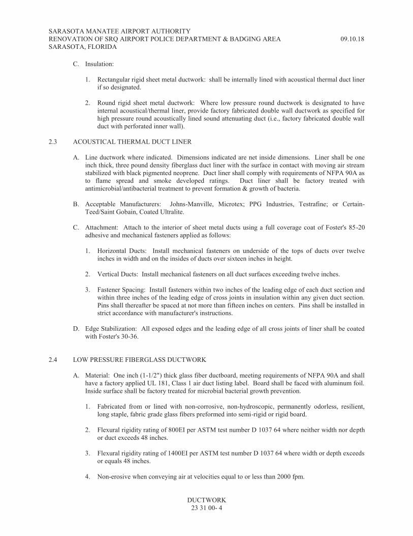
SARASOTA MANATEE AIRPORT AUTHORITY RENOVATION OF SRQ AIRPORT POLICE DEPARTMENT & BADGING AREA 09.10.18 SARASOTA, FLORIDA
DUCTWORK 23 31 00- 4
C. Insulation:
1. Rectangular rigid sheet metal ductwork: shall be internally lined with acoustical thermal duct liner if so designated.
2. Round rigid sheet metal ductwork: Where low pressure round ductwork is designated to have
internal acoustical/thermal liner, provide factory fabricated double wall ductwork as specified for high pressure round acoustically lined sound attenuating duct (i.e., factory fabricated double wall duct with perforated inner wall).
2.3 ACOUSTICAL THERMAL DUCT LINER
A. Line ductwork where indicated. Dimensions indicated are net inside dimensions. Liner shall be one inch thick, three pound density fiberglass duct liner with the surface in contact with moving air stream stabilized with black pigmented neoprene. Duct liner shall comply with requirements of NFPA 90A as to flame spread and smoke developed ratings. Duct liner shall be factory treated with antimicrobial/antibacterial treatment to prevent formation & growth of bacteria.
B. Acceptable Manufacturers: Johns-Manville, Microtex; PPG Industries, Testrafine; or Certain-
Teed/Saint Gobain, Coated Ultralite.
C. Attachment: Attach to the interior of sheet metal ducts using a full coverage coat of Foster's 85-20 adhesive and mechanical fasteners applied as follows:
1. Horizontal Ducts: Install mechanical fasteners on underside of the tops of ducts over twelve
inches in width and on the insides of ducts over sixteen inches in height.
2. Vertical Ducts: Install mechanical fasteners on all duct surfaces exceeding twelve inches.
3. Fastener Spacing: Install fasteners within two inches of the leading edge of each duct section and within three inches of the leading edge of cross joints in insulation within any given duct section. Pins shall thereafter be spaced at not more than fifteen inches on centers. Pins shall be installed in strict accordance with manufacturer's instructions.
D. Edge Stabilization: All exposed edges and the leading edge of all cross joints of liner shall be coated
with Foster's 30-36. 2.4 LOW PRESSURE FIBERGLASS DUCTWORK
A. Material: One inch (1-1/2") thick glass fiber ductboard, meeting requirements of NFPA 90A and shall have a factory applied UL 181, Class 1 air duct listing label. Board shall be faced with aluminum foil. Inside surface shall be factory treated for microbial bacterial growth prevention.
1. Fabricated from or lined with non-corrosive, non-hydroscopic, permanently odorless, resilient,
long staple, fabric grade glass fibers preformed into semi-rigid or rigid board.
2. Flexural rigidity rating of 800EI per ASTM test number D 1037 64 where neither width nor depth or duct exceeds 48 inches.
3. Flexural rigidity rating of 1400EI per ASTM test number D 1037 64 where width or depth exceeds
or equals 48 inches.
4. Non-erosive when conveying air at velocities equal to or less than 2000 fpm.

SARASOTA MANATEE AIRPORT AUTHORITY RENOVATION OF SRQ AIRPORT POLICE DEPARTMENT & BADGING AREA 09.10.18 SARASOTA, FLORIDA
DUCTWORK 23 31 00- 5
5. Approved, fire retardant, moisture sealing, factory-applied jacket made of kraft paper and 2 mil
minimum thickness aluminum foil.
6. Maximum thermal conductivity of 0.23 at 75oF mean temperature.
B. Fabrication: Ductwork fabrication shall be in accordance with SMACNA Fibrous Glass Manual, Duct Construction Standards, and current manufacturer's literature on approved fabrication methods.
C. Closure Systems: Closure systems shall be as specified by manufacturer of the ductboard to maintain
the UL Class 1 duct label. Provide closure of all joints using 9/16" outward clinch staples, approximately two inches (2") wide pressure sensitive tape. Use factory molded male-female joints wherever possible. Use appropriate UL and SMACNA approved tapes.
D. Acceptable Products: Johns-Manville Micro-Aire Type 475 or 800 as applicable; Owens Corning
Fiberglass Type 800FR or 1400FR as applicable; or approved equal. 2.5 HIGH PRESSURE DUCTWORK, ROUND AND FLAT-OVAL
A. General:
1. Comply with current SMACNA standards. 2. Factory fabricated portions shall be made by United McGill, Semco or equal.
B. Straight Conduit: Galvanized steel unless otherwise indicated for a specific application.
1. Seam construction: Spiral lock-seam (SMACNA Type RL-1) allowed for all pressure/velocity
classifications. Longitudinal grooved seam (SMACNA Type RL-5) allowed only up to pressure/velocity classification P/VC-3.
C. Fittings:
1. Material: Same as connecting duct system.
2. Configuration: Standard design as manufactured by United McGill, Semco or equal. 3. Elbows:
a. General: All mitered elbows must be vaned.
b. Round: 5-inch diameter and larger shall be five-section construction; less than 5-inches
diameter shall be die-formed.
c. Flat-oval: Five-section construction.
d. Hard turn oval elbows shall have vanes as follows:
Equivalent diameters Number of Vanes 10" through 14" 3 15" through 19" 4 20" through 60" 5 Over 60" 12" spacing
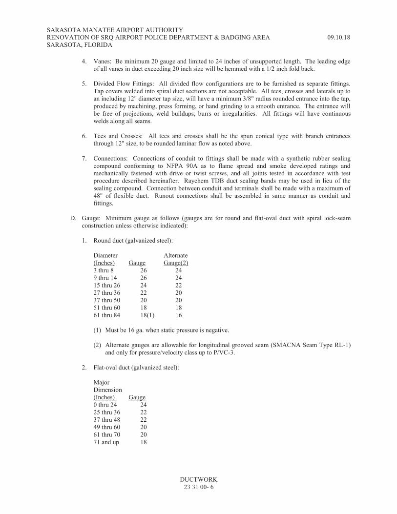
SARASOTA MANATEE AIRPORT AUTHORITY RENOVATION OF SRQ AIRPORT POLICE DEPARTMENT & BADGING AREA 09.10.18 SARASOTA, FLORIDA
DUCTWORK 23 31 00- 6
4. Vanes: Be minimum 20 gauge and limited to 24 inches of unsupported length. The leading edge of all vanes in duct exceeding 20 inch size will be hemmed with a 1/2 inch fold back.
5. Divided Flow Fittings: All divided flow configurations are to be furnished as separate fittings.
Tap covers welded into spiral duct sections are not acceptable. All tees, crosses and laterals up to an including 12" diameter tap size, will have a minimum 3/8" radius rounded entrance into the tap, produced by machining, press forming, or hand grinding to a smooth entrance. The entrance will be free of projections, weld buildups, burrs or irregularities. All fittings will have continuous welds along all seams.
6. Tees and Crosses: All tees and crosses shall be the spun conical type with branch entrances
through 12" size, to be rounded laminar flow as noted above.
7. Connections: Connections of conduit to fittings shall be made with a synthetic rubber sealing compound conforming to NFPA 90A as to flame spread and smoke developed ratings and mechanically fastened with drive or twist screws, and all joints tested in accordance with test procedure described hereinafter. Raychem TDB duct sealing bands may be used in lieu of the sealing compound. Connection between conduit and terminals shall be made with a maximum of 48" of flexible duct. Runout connections shall be assembled in same manner as conduit and fittings.
D. Gauge: Minimum gauge as follows (gauges are for round and flat-oval duct with spiral lock-seam
construction unless otherwise indicated):
1. Round duct (galvanized steel):
Diameter Alternate (Inches) Gauge Gauge(2) 3 thru 8 26 24 9 thru 14 26 24 15 thru 26 24 22 27 thru 36 22 20 37 thru 50 20 20 51 thru 60 18 18 61 thru 84 18(1) 16
(1) Must be 16 ga. when static pressure is negative.
(2) Alternate gauges are allowable for longitudinal grooved seam (SMACNA Seam Type RL-1)
and only for pressure/velocity class up to P/VC-3.
2. Flat-oval duct (galvanized steel):
Major Dimension (Inches) Gauge 0 thru 24 24 25 thru 36 22 37 thru 48 22 49 thru 60 20 61 thru 70 20 71 and up 18

SARASOTA MANATEE AIRPORT AUTHORITY RENOVATION OF SRQ AIRPORT POLICE DEPARTMENT & BADGING AREA 09.10.18 SARASOTA, FLORIDA
DUCTWORK 23 31 00- 7
E. Fittings:
1. Round duct: Same as duct unless otherwise recommended by manufacturer.
2. Flat-oval duct:
Major Dimension (Inches) Gauge 0 to 24 20 25 to 36 20 36 to 48 18 49 to 60 18 61 to 70 16 71 and up 16
F. Acoustically Lined Sound Attenuating Round and Flat Oval Duct and Fittings: General construction is
specified in paragraphs above. Flame spread and smoke developed ratings shall comply with NFPA 90A. Double walled with zinc coated solid sheet steel outer wall and zinc coated perforated sheet steel inner wall. One inch thick annular space between inner and outer walls uniformly packed with fiberglass insulation with effective thermal conductivity of 0.27 BTUH per sq. ft. (Fo per inch) separated from air stream using mylar film. Equal to United Acousti-K27.
2.6 HIGH PRESSURE DUCTWORK, RECTANGULAR
A. General:
1. Airtight and structurally stable at maximum system operating pressure. 2. Any welding shall be continuous and corrosion resistant. 3. Galvanized sheet steel unless otherwise indicated for a specific application. 4. Reinforced and supported to neither cause nor convey any objectionable vibrations. 5. Be in accordance with latest SMACNA construction standard for high pressure ductwork.
B. Turning Vanes: Adequate rigidity and strength to be completely flutterproof. Airfoil, permanently
fixed type constructed of galvanized steel of aluminum with sound attenuating fiberglass inner liner with open protective metal facing. Quantity in each elbow in accordance with manufacturer's recommendations. Airsan Acoustiturn as made by Air Filter Corporation, 4554 W. Woolworth Ave., Milwaukee, Wisconsin 53218 or equal.
2.7 HIGH PRESSURE DUCT RELIEF AND ACCESS DOORS
A. Provide suitable size for access to heaters, dampers and other equipment installed in duct, and at other points indicated on drawings. Size shall be as listed by paragraph above and compatible with duct size but not smaller than 8"x12". Doors shall be 24 US gauge galvanized steel hinged to a 24 gauge galvanized mounting frame and for insulated duct shall be double panel construction with 1/2 inch rigid insulation material between metal panels. Doors shall be United Sheet Metal Type AR or an approved equal.
2.8 LOW PRESSURE FLEXIBLE DUCTS
A. General:
1. The inclusion of flexible ducts in this specification shall not be construed as approval of use on the project unless specifically shown on the Drawings.
SARASOTA MANATEE AIRPORT AUTHORITY RENOVATION OF SRQ AIRPORT POLICE DEPARTMENT & BADGING AREA 09.10.18 SARASOTA, FLORIDA
DUCTWORK 23 31 00- 8
2. Where used, provide in factory finished lengths not in excess of lengths required to make kink-free
connections with minimum air pressure drop.
B. Insulated flexible ducts: Flexible duct shall be factory-fabricated preinsulated type with seamless vapor barrier. Duct shall bear UL 181 Class 1 Air Duct label and shall comply with NFPA 90A and 90B. Fiberglass insulation nominal 1" thickness with thermal conductance of 0.23 BTU/hr-ft2-oF maximum at 75oF mean temperature. Flexible duct shall have an operating range of minus 0.5" w.g. to plus 2" w.g. Core shall be continuous and consist of aluminized mylar laminated to corrosion resistant steel wire helix. Vapor barrier perm rating shall be 0.17 maximum per ASTM E96-A. Maximum working velocity shall be 4000 FPM. Flexible duct shall be Genflex SLR-25, Clevaflex Type KQ, Wire Mold type WG, Flexmaster Type 5B, or approved equal.
C. Un-insulated flexible ducts, steel: Flexible ductwork shall be constructed of all metal one ply hot-
dipped galvanized steel, closely corrugated for strength and flexibility, with seams interlocked, folded flat, and knurled to insure tightness. Duct shall be listed as #UL181 "Flexible Air Duct", Class 1, and NFPA 90A. Products shall be Flexmaster Type NI-TL, Clevaform Type GS or approved equal.
D. Round branch take-off fittings for flexible duct:
1. Round duct branch take-off fitting shall be made of galvanized sheet metal designed for twist-in
installation and to assure minimum air loss at the take-off. The fittings shall be of the conical converging type to reduce the pressure drop through the fittings. Provide a raised bead on the throat of the fitting to assure a tight positive connection. Products shall be Flexmaster Model CB-DE-BO3 or approved equal.
2. Provide each fitting with the following:
a. Lockable quadrant damper. b. 45-degree extractor scoop. c. Insulation guard where used with internally lined ductwork.
3. Provide these "spin-in" type fittings at all connections between rigid sheet metal duct and flexible
duct at the upstream end of the flexible duct. 2.9 HIGH PRESSURE FLEXIBLE DUCTS
A. Meet all requirements for low pressure flexible ducts except be recommended by manufacturer for high pressure application.
2.10 FLEXIBLE STAINLESS STEEL EXHAUST DUCTS
A. Flexible ducts shall be factory fabricated uninsulated all metal type. Ducts shall be spiral flexible lockformed from type 302 stainless steel strips of 0.18" to 0.20" minimum thickness. Ends of individual duct lengths shall be plain for connection to ductwork collars and for securing to collars with stainless steel band clamps. Flexible duct lengths shall suit the usage and purpose requirements of the devices served by the flexible ducts. Flexible ducts shall have an operating range of minus 3.0" w.g. to plus 3.0" w.g. Maximum working velocity shall be 4000 FPM. Minimum allowable inside bend radius shall be no greater than four and one-half duct diameters. Flexible ducts shall be Universal Metal Hose Company "U-120", Flexmaster Type SS-NI-TL, or approved equivalent.

SARASOTA MANATEE AIRPORT AUTHORITY RENOVATION OF SRQ AIRPORT POLICE DEPARTMENT & BADGING AREA 09.10.18 SARASOTA, FLORIDA
DUCTWORK 23 31 00- 9
2.11 RIGID STAINLESS STEEL EXHAUST DUCTS
A. Food Service Equipment Exhaust Ducts: Exhaust ducts which are intended to remove air laden with grease vapor and/or water vapor from cooking ranges, fryers, ovens and similar cooking equipment shall be as follows:
1. Construct ductwork and vertical exhaust duct stackheads of stainless steel ANSI type 304, mill
finish, 16 gauge minimum.
2. Exposed locations shall have No. 4 polished finish.
B. Exhaust Ducts for Laboratory Fume Hoods and Ethylene Oxide Sterilizers:
1. Construct ductwork and vertical exhaust duct stackheads of stainless steel ANSI type 302, mill finish.
2. Ductwork in exposed locations shall have No. 4 polished finish.
2.12 OTHER SPECIAL DUCT SYSTEMS
A. Perchloric Acid Fume Hood Exhaust Ducts and Wash-Down Systems:
1. Perchloric acid fume hood exhaust ductwork shall be type 316 stainless steel, flanged and gasketed. Ductwork in exposed locations shall have No. 4 polished finish.
2. Provide two washdown systems for each perchloric acid fume hood system. One washdown
system shall serve the hood, and the other system shall serve the exhaust ductwork and fan system.
3. Washdown systems shall include type 316 stainless steel full-jet spray nozzles with stainless steel piping to the centerline of each duct with exterior duct couplings and all interconnecting piping, including water supply and drain piping. The washdown systems shall provide complete coverage including fume hoods, ductwork, elbows, fans and stacks. All controls, valves and appurtenances shall be provided for proper operation of the systems.
4. All perchloric acid fume hood exhaust ductwork, including exhaust fans and stacks, shall be
fabricated and installed by the fume hood manufacturer. All perchloric acid fume hood exhaust washdown and drain systems shall be designed, fabricated, and installed by the fume hood manufacturer.
PART 3 - EXECUTION 3.1 GENERAL
A. All duct systems shall be free of noise, chatter, vibration and pulsation under all conditions of operation. Remove, replace or reinforce as directed by the Architect/Engineer if necessary to correct such conditions.
B. If field conditions are determined to exist which would limit the guarantee of air delivery or system
performance, due notice in writing shall be submitted to the Architect/Engineer of such conditions prior to starting fabrication.

SARASOTA MANATEE AIRPORT AUTHORITY RENOVATION OF SRQ AIRPORT POLICE DEPARTMENT & BADGING AREA 09.10.18 SARASOTA, FLORIDA
DUCTWORK 23 31 00- 10
C. Properly support and align ductwork. Ducts to be free of sag and bulge. Hang ductwork below concrete floors or roof deck with hangers set prior to pouring concrete, or from self drilling screw anchors. GUN POWDER SET ANCHORS ARE NOT PERMITTED.
D. Where it is necessary that ducts be divided due to pipes or other obstructions which must pass through
these ducts, the Contractor shall, at locations as noted or directed, provide air-stream deflectors in the duct and the duct shall be increased in size to maintain equivalent area around deflectors. Such changes shall be in accord with standard SMACNA details and shall be shown on Contractor's As-Built Drawings.
E. Interior of ductwork visible through registers, grilles, or diffusers shall be painted flat black.
F. Do not route ductwork through transformer vaults and electrical equipment spaces and enclosures.
G. Construct all ductwork and accessories in accord with the latest indicated editions of applicable
SMACNA construction standards. Sheet Metal and Air Conditioning Contractors' National Association.
H. Streamline all ductwork to the full extent practical and equip with proper and adequate devices to
assure proper balance and quiet draftless distribution of indicated air quantities.
I. Protect all ductwork and system accessories from damage during construction until Architect/Engineer's final acceptance of project.
J. Prior to ductwork fabrication, verify if all ductwork as dimensioned and generally shown will
satisfactorily fit allocated spaces. Take precautions to avoid space interferences with beams, columns, joists, pipes, lights, conduit, other ducts, equipment, etc. Notify Architect/Engineer if any spatial conflicts exist, and then obtain Architect/Engineer's approval of necessary routing. Make any such necessary revisions which are minor at no additional cost.
K. Carefully correlate all duct connections to air handling units and fans to provide proper connections,
elbows and bends which minimize noise and pressure drop.
L. Provide all curved elbows with radius ratios of not less than 1.5 unless otherwise shown or approved by Architect/Engineer. Provide all mitered elbows with turning vanes.
M. Properly suspend all ductwork so that no objectionable conditions result (such as vibration, sagging,
etc.).
N. Coordinate any and all dimensions at interfaces of dissimilar type of ductwork and at interfaces of ductwork with equipment so that proper overlaps, interfaces, etc., of insulation and continuity of vapor barriers are maintained.
O. If necessary where ducts interface and have different types of insulation, provide transitions so that
internal free-clear dimensions of duct remain unchanged.
P. Install horizontal low pressure ductwork at a level which maximizes length of any vertical, rectangular or round rigid duct connections to rectangular diffuser necks; however, such vertical duct connections are not required to be over 24 inches in length.
Q. Make connections from any low pressure ductwork to terminal units (fan terminal units, variable
volume boxes, etc.) with appropriate lengths of flexible duct unless other type of connection is indicated.
SARASOTA MANATEE AIRPORT AUTHORITY RENOVATION OF SRQ AIRPORT POLICE DEPARTMENT & BADGING AREA 09.10.18 SARASOTA, FLORIDA
DUCTWORK 23 31 00- 11
R. Install all flexible round duct without kinks or similar obstructions so that pressure drop is minimized. Cut and remove excess lengths as necessary.
S. Install horizontal rigid ductwork as high as practical above suspended ceilings so that movable light
fixtures may be relocated without interference to meet any future partition relocation requirements.
T. Insulated Duct: Where ducts will be insulated, make provision for neat insulation finish around damper operating quadrants, splitter adjusting clamps, access doors, and similar operating devices. A metal collar equivalent in depth to insulation thickness and of suitable size to which insulation may be finished shall be mounted on duct.
3.2 LOW PRESSURE SHEET METAL DUCTS
A. If width or height of rectangular duct exceeds 12 inches, cross break or roll a cross bead in panels to increase stiffness; otherwise, use two gages heavier steel.
B. Provide corner closures. Longitudinal seams and transverse joints shall be flat and smooth inside.
Make slip joints in direction of air flow. See governing SMACNA manual for transition requirements.
C. Fabricate offsets, turns and elbows with centerline radius equal to 1-1/2 times diameter when possible. No mitered offsets will be allowed. Provide double thickness turning vanes to assist in smooth flow of air in square elbows or elbows with centerline radius less than duct width or diameter.
3.3 FIBERGLASS DUCT
A. General: Fiberglass duct is not allowed on the project unless specifically shown on the Drawings.
B. Provide all reinforcement, bracing, suspension, workmanship and construction details for this ductwork and its accessories in strict accord with the recommendations of the Sheet Metal and Air Conditioning Contractors' National Association Fibrous Glass Duct Construction Standards or in accord with the manufacturer's recommendations, whichever is more stringent. Completed duct system(s) shall be stable and airtight at 2 inches w.g. internal static pressure. Comply with the reinforcement schedule for rectangular fiber glass air ducts as published in the SMACNA Standard.
C. Entirely comply with NFPA Bulletin 90A and be Class I by UL-181.
D. Miter all longitudinal corners (except seams) with jacket undisturbed.
E. Provide ship lap construction with 1-1/2 inch minimum tape overlap on all sides of all longitudinal
seams and transverse joints.
F. All joints shall be fiber glass tape and mastic providing a UL-181 Duct Systems Class I rating.
G. Round cross-section ducts shall be factory molded.
H. Square and rectangular ducts shall be shop or field fabricated from flat ductboard.
I. Metallic duct reinforcement support, and duct heater sleeves shall be galvanized steel.
J. Fabricate offsets, turns and elbows with centerline radius equal to 1- 1/2 times diameter when possible. No mitered offsets will be allowed. Provide double turning vanes to assist in smooth flow of air in square elbows or elbows with centerline radius less than duct width or diameter.
SARASOTA MANATEE AIRPORT AUTHORITY RENOVATION OF SRQ AIRPORT POLICE DEPARTMENT & BADGING AREA 09.10.18 SARASOTA, FLORIDA
DUCTWORK 23 31 00- 12
K. Taped joints on fiber glass ductwork shall be made by first taping the joint, then stapling through the tape on both sides of the joint interface, and then adding another layer of tape over the stapled and taped joint. Staples shall be in pairs with one staple on each side of the joint interface and with a distance between staple pairs of not greater than 3 inches as measured around the perimeter of the taped joints. Staples shall be minimum 1/2" x 1/2".
3.4 HIGH PRESSURE DUCTWORK
A. In addition to other requirements, this ductwork shall be as follows:
1. Any welds shall be continuous and corrosion resistant.
2. Reinforced and supported to cause and/or to convey no objectionable vibrations.
3. All seams and joints permanently sealed and joined in strict accordance with the manufacturer's recommendations.
B. Conical Tees: Make all branch duct take-offs and all connections to flexible duct supplying air to
terminal units with conical tees. 3.5 LOW PRESSURE FLEXIBLE DUCTS
A. Flexible ducts shall not be used unless specifically indicated on drawings.
B. If flexible duct is indicated for use on this project, it must comply with the following requirements.
1. The extent of the use of flexible ductwork shall be limited to that shown on the drawings.
2. Flexible duct installation shall be per SMACNA Flexible Duct Installation Standards, and manufacturers latest printed instructions, whichever is stricter. In addition the following shall apply:
a. Flexible duct between rigid duct and diffusers shall be a MAXIMUM of 8 feet in length and
shall be fully extended with a maximum equivalent of (2) 90 degree bends (no bend shall be made with centerline radius of less than one duct diameter). No additional flexible duct shall be provided for future terminal device relocation unless otherwise specified.
b. Flexible duct shall be supported at ends and at each 90 degree bend. Maximum permissible
sag is 1/2 inch per foot of spacing between supports.
c. Hanger or saddle material in contact with the flexible duct shall be of sufficient width to prevent any restriction of the internal diameter of the duct when the weight of the supported section rests on the hanger or saddle material. In no case will the material contacting the flexible duct be less than 1 inch wide. Narrower hanger material may be used in conjunction with a sheet metal saddle which meets the foregoing specifications. This saddle must be formed to cover one-half the circumference of the outside diameter of the flexible duct and must be rolled to fit neatly around the lower half of the duct's outer circumference.
d. Factory installed suspension systems integral to the flexible duct are an acceptable alternative
hanging method when manufacturers recommended procedures are followed. e. Hangers shall be adequately attached to the building structure (not pipe, conduit, etc.).
f. To prevent tearing of vapor barrier, do not support entire weight of flexible duct on any one
hanger during installation. Avoid contact of flexible duct with sharp edges of hanger

SARASOTA MANATEE AIRPORT AUTHORITY RENOVATION OF SRQ AIRPORT POLICE DEPARTMENT & BADGING AREA 09.10.18 SARASOTA, FLORIDA
DUCTWORK 23 31 00- 13
material. Damage to vapor barrier may be repaired with approved tape. If internal core is penetrated, replace flexible duct or treat as a connection.
3. Terminal devices connected by flexible duct shall be supported independently of the flexible duct.
3.6 HIGH PRESSURE FLEXIBLE DUCTS
A. Meet all the requirements for low pressure flexible ducts. 3.7 FLEXIBLE STAINLESS STEEL EXHAUST DUCTS
A. Flexible stainless steel ducts shall not be used unless specifically indicated on drawings.
B. If flexible stainless steel duct is indicated for use on this project, it must comply with the following requirements.
1. The extent of the use of flexible ductwork shall be limited to that shown on the drawings.
2. Flexible duct installation shall be per SMACNA Flexible Duct Installation Standards, and
manufacturers latest printed instructions, whichever is stricter. In addition the following shall apply:
a. Flexible duct between rigid duct and terminal devices shall be fully extended with a
maximum equivalent of (2) 90 degree bends (no bend shall be made with centerline radius of less than one duct diameter).
b. Flexible duct shall be supported at ends and at each 90 degree bend. Maximum permissible
sag is 1/2 inch per foot of spacing between supports.
c. Hanger or saddle material in contact with the flexible duct shall be of sufficient width to prevent any restriction of the internal diameter of the duct when the weight of the supported section rests on the hanger or saddle material. In no case will the material contacting the flexible duct be less than 1 inch wide. Narrower hanger material may be used in conjunction with a sheet metal saddle which meets the foregoing specifications. This saddle must be formed to cover one-half the circumference of the outside diameter of the flexible duct and must be rolled to fit neatly around the lower half of the duct's outer circumference.
d. Factory installed suspension systems integral to the flexible duct are an acceptable alternative
hanging method when manufacturers recommended procedures are followed.
e. Hangers shall be adequately attached to the building structure (not pipe, conduit, etc.).
f. Provide collars on rigid duct at flexible duct connection points. Connect flexible ducts to rigid ducts and to terminal devices and secure with stainless steel band clamps, or otherwise in accordance with flexible duct manufacturer's instructions.
g. Do not support entire weight of flexible duct on any one hanger during installation. Avoid
contact of flexible duct with sharp edges of hanger material. If duct is penetrated, replace flexible duct or treat as a connection.
3. Terminal devices connected by flexible duct shall be supported independently of the flexible duct.

SARASOTA MANATEE AIRPORT AUTHORITY RENOVATION OF SRQ AIRPORT POLICE DEPARTMENT & BADGING AREA 09.10.18 SARASOTA, FLORIDA
DUCTWORK 23 31 00- 14
3.8 RIGID STAINLESS STEEL DUCT
A. In addition to SMACNA recommendations and other requirements, rigid stainless steel duct systems shall comply with the following:
1. All joints and seams shall be made with continuous welds. Ductwork shall be liquid tight and gas
tight.
2. Hangers and supports in finished areas shall be of same material as ductwork.
3. Joints in laboratory hood exhaust duct may be flanged and gasketed at the Contractor's option.
4. Food Service Equipment Exhaust Ductwork:
a. Kitchen exhaust ductwork of stainless steel shall be installed in accordance with NFPA 96 Standard for removal of smoke and grease laden vapors from commercial cooking equipment.
b. Install horizontal stainless steel kitchen exhaust ductwork with a minimum slope of 1-inch per
foot.
c. Provide access panels of suitable size at 3'-0" centers minimum and at each change of direction for cleaning purposes.
d. Changes in Shape and Direction: Construct all changes in shape or direction in such a manner
as to prevent the formation of any traps or pockets which might collect grease.
e. Cleanout Openings: Provide an opening in each exhaust duct at each change in direction of duct for the purposes of inspection and cleaning. Openings shall be at the sides and large enough to permit cleaning. In horizontal sections the lower edge of the opening shall be not less than one and one-half inches from bottom of the duct. Covers shall be constructed of the same material and thickness as the duct and shall be grease tight when in place.
f. Standards: Comply with latest SMACNA construction standard which covers this type of
duct system. 3.9 POLY-VINYL-STEEL DUCTS
A. In addition to the requirements for low pressure sheet metal ducts and other requirements specified herein elsewhere in this section, poly-vinyl-steel duct systems shall comply with the following:
1. All ducts and fittings shall be constructed in accordance with manufacturer's recommendations
and specifications.
2. All exposed raw edges shall be covered completely with poly-vinyl-steel sealant.
3. Apply aerosol poly-vinyl-steel coating compound to any scratched surfaces.
4. All sheet metal screws and fasteners shall be stainless steel. 3.10 OTHER SPECIAL DUCT SYSTEMS
A. Roof Mounted Exterior Ductwork:
SARASOTA MANATEE AIRPORT AUTHORITY RENOVATION OF SRQ AIRPORT POLICE DEPARTMENT & BADGING AREA 09.10.18 SARASOTA, FLORIDA
DUCTWORK 23 31 00- 15
1. Support all roof-mounted exterior ductwork with angle iron bracing firmly secured to roof construction and in such a manner to maintain watertight integrity of specified roofing system. All ductwork roof penetrations and ductwork support roof penetrations shall also be provided in such a manner to maintain watertight integrity of specified roofing system.
2. All roof-mounted exterior ductwork shall be completely and permanently weatherproof including
connections at air conditioning units, roof penetration points and all other points.
3. Submit shop drawings completely describing all supporting systems for this external ductwork.
B. Perchloric Acid Fume Hood Exhaust Ductwork and Wash-Down System:
1. The fume hood manufacturer shall fabricate and install all perchloric acid fume hood exhaust ductwork, including exhaust fans and stacks. The ductwork shall be routed as shown on the drawings, shall be fabricated and installed by the mechanical contractor.
2. The fume hood manufacturer shall design, fabricate and install all perchloric acid fume hood
exhaust washdown and drain systems. The respective washdown water supply and drain piping systems shall be connected to domestic water supply and drain connections provided at the locations shown on the plumbing drawings.
3.11 MISCELLANEOUS DUCT SYSTEM COMPONENTS
A. Spin-In Take-Off Fittings: Install around duct branch takeoff fittings according to manufacturer's installation instruction. Additionally seal fitting to rectangular duct with a thin bead of mastic sealant.
3.12 HANGERS AND SUPPORTS
A. General: Comply with latest applicable SMACNA construction standard. Where sprayed fireproofing occurs, install hangers before application of such treatment and withhold installation of ducts until after application.
B. Supports: Vertical risers and other duct runs where the method of support specified above is not
applicable shall be supported by substantial angle brackets designed to meet field conditions and installed to allow for duct expansion.
C. Fasteners: Secure hangers to steel beams or metal deck with beam clamps or drop through connections
from the metal or concrete deck. 3.13 CHANGES IN SHAPE OR DIMENSION
A. Where duct size or shape is changed to effect a change in area, the following shall apply:
1. Where the area at the end of the transformation results in an increase in area over that at the beginning, the slope of the transformation shall not exceed one inch in seven inches.
2. Where the area at the end of the transformation results in a decrease in area from that at the
beginning, the slope of the transformation may be one inch in four inches, but one inch in seven inches is preferable, space permitting.
3. The angle of transformation at connections to heating coils or other equipment shall not exceed
thirty degrees from a line parallel to the air flow on the entering side of the equipment, nor fifteen
SARASOTA MANATEE AIRPORT AUTHORITY RENOVATION OF SRQ AIRPORT POLICE DEPARTMENT & BADGING AREA 09.10.18 SARASOTA, FLORIDA
DUCTWORK 23 31 00- 16
degrees on the leaving side. The angle of approach may be increased to suit limited space conditions when the transformation is provided with vanes approved by the Architect/Engineer.
3.14 CHANGES IN DIRECTION
A. Changes in direction shall be basically as indicated on the drawings and the following shall apply:
1. Supply duct turns of ninety degrees in low pressure duct shall be made with mitered elbows fitted with closely spaced turning vanes designed for maintaining a constant velocity through the elbow.
2. Return and exhaust duct turns of ninety degrees in low pressure duct shall be made with mitered
elbows, as specified hereinbefore for supply ducts, unless radius elbows are indicated in which case they shall be constructed with a turning radius one and one-half (1-1/2) times the width (with width considered as the dimension in the plane of the turn) as measured to the duct centerline.
3. Tees in low pressure duct shall conform to the design requirements specified hereinbefore for
elbows.
4. Branch take-offs in low pressure supply duct shall be made with extractors or splitter dampers, as indicated, in square take-offs.
5. In high pressure duct, branch take-offs and connections to flexible duct supplying air to terminal
units shall be made with conical taps. 3.15 IMPROPER MATERIALS OR CONFIGURATION
A. If ductwork materials or ductwork configurations are installed which do not meet these specifications, Contractor shall remove such ductwork and replace with materials or configurations which are acceptable. Any delay in job progress will be the responsibility of the Contractor.
3.16 OTHER REQUIREMENTS
A. Insulated Duct: Where ducts will be insulated, make provision for neat insulation finish around damper operating quadrants, splitter adjusting clamps, access doors, and similar operating devices. A metal collar equivalent in depth to insulation thickness and of suitable size to which insulation may be finished shall be mounted on duct.
B. Control Devices: Properly install all control related devices which are part of the duct systems. See
Section(s) describing control systems. 3.17 SEALING OF DUCTS
A. Duct seal classes are as follows:
1. Seal class "A": Seal all transverse joints, longitudinal seams and duct wall penetrations. Use for P/VC-4 (4" w.g.) and greater unless otherwise indicated.
2. Seal class "B": Seal all transverse joints and longitudinal seams. Use for P/VC-3 (3" w.g.) unless
otherwise indicated.
3. Seal class "C": Seal all transverse joints. Use for P/VC-2 (2" w.g.) and lower unless otherwise indicated.

SARASOTA MANATEE AIRPORT AUTHORITY RENOVATION OF SRQ AIRPORT POLICE DEPARTMENT & BADGING AREA 09.10.18 SARASOTA, FLORIDA
DUCTWORK 23 31 00- 17
B. Where sealing is required it shall mean the following:
1. The use of adhesives, gaskets, tape systems or combinations thereof to close openings in the surface of the ductwork and field-erected plenums and casings through which air leakage would occur; or
2. The use of continuous welds;
3. The prudent selection and application of sealing methods by fabricators and installers, giving due
consideration to the designated pressure class, pressure mode (positive or negative), chemical compatibility of the closure system, potential movement of mating parts, workmanship, amount and type of handling; cleanliness of surfaces, product shelf life, curing time and manufacturer-identified exposure limitations;
4. That these provisions are applicable to duct connections to equipment and to apparatus but are not
for equipment and apparatus;
5. That where distinctions between seams and joints are made herein, a seam is defined as joining of two longitudinally (in the direction of air-flow) oriented edges of duct surface material occurring between two joints. Helical (spiral) lock seams are exempt from sealant requirements. All other duct surface connections made on the perimeter are deemed to be joints. Joints are inclusive of but not limited to girth joints; branch and sub-branch intersections; so-called duct collar tap-ins; fitting subsections; louver and air terminal connections to ducts; access door and access panel frames and jambs; duct, plenum and casing abutments to building structures; that sealing requirements herein do not contain provisions to:
a. Resist chemical attack. b. Be dielectrically isolated. c. Be waterproof, weatherproof or ultraviolet ray resistant. d. Withstand temperatures higher than 120oF or lower than 40oF. e. Contain atomic radiation or serve in other safety-related construction. f. Be electrically grounded. g. Maintain leakage integrity at pressures in excess of the duct classification herein. h. Be underground below the water table. i. Be submerged in liquid. j. Withstand continuous vibration visible to the naked eye. k. Be totally leak-free within an encapsulating vapor barrier. l. Create closure in portions of the building structure used as ducts, e.g., ceiling plenums, shafts,
pressurized compartments.
6. The requirements to seal apply to both positive pressure and negative pressure of operation.
7. Externally insulated ducts located outside of buildings shall be sealed prior to being insulated as though they were inside. If metal surfaces of ducts located on the exterior of buildings are exposed to weather, they shall receive exterior duct sealant. An exterior duct sealant is defined as a sealant that is marketed specifically as forming a positive air and water tight seal, bonding well to the metal involved, remaining flexible with metal movement and having a service temperature range of -30oF to 175oF. If exposed to direct sunlight it shall also be ultraviolet ray and ozone resistant or shall, after curing, be painted with a compatible coating that provides such resistance. The term sealant herein is not limited to materials of adhesive or mastic nature but is inclusive of tapes and combinations of open weave fabric strips and mastics.
C. Materials and applications for sealing ducts:

SARASOTA MANATEE AIRPORT AUTHORITY RENOVATION OF SRQ AIRPORT POLICE DEPARTMENT & BADGING AREA 09.10.18 SARASOTA, FLORIDA
DUCTWORK 23 31 00- 18
1. General:
a. Complete product data on all materials used for sealing ducts must be submitted for approval prior to any duct fabrication.
b. All sealants must be specifically recommended by their manufacturer for the purpose of
sealing ducts.
2. Liquid Sealant:
a. Use only for slip type joints where sealant is to fill small space between overlapping pieces of metal. Do not use where metal clearances exceed 1/32-inch.
b. Sealant must be specifically manufactured for the purpose of sealing ducts.
3. Mastics:
a. Use in lieu of liquid sealant at Contractor's option. b. Use as a fillet, in grooves and between flanges. c. Do not use oil base caulking or glazing compounds.
4. Gaskets:
a. Use soft elastomer butyl or neoprene rubber or extruded forms of sealants in flanged joints in
addition to mastic.
5. Tape:
a. Tape is not allowed on sheet metal ducts.
6. Combination of mastic and embedded fabric:
a. Use mastic/mesh/mastic as a sealant where pressure/velocity classification equals and exceeds P/VC-3 and where any spaces between metal surfaces at transverse joints or longitudinal seams or duct wall penetrations exceeds 1/16-inch.
b. Apply glove coat of mastic, then embed a continuous or overlapping strip of not less than 4-
inch wide 10 x 10 fiberglass cloth into the mastic, then apply a final glove coat of mastic over the glass cloth.
7. Surface preparation:
a. Surfaces to receive sealant should be adequately clean (free from oil, dust, dirt, rust, moisture,
ice crystals and other substances that inhibit or prevent bonding). Use solvent and/or apply a face primer if necessary to obtain adequately clean surface for adhesion.
3.18 LEAKAGE TESTING
A. General:
1. Test the following duct systems:

SARASOTA MANATEE AIRPORT AUTHORITY RENOVATION OF SRQ AIRPORT POLICE DEPARTMENT & BADGING AREA 09.10.18 SARASOTA, FLORIDA
DUCTWORK 23 31 00- 19
a. All ducts which are (1) under positive or negative pressure and (2) which are directly
connected to air moving device (air handling unit, exhaust fan, supply fan or similar air moving equipment) and (3) which convey 1000-cfm or greater through their largest portion.
b. All ducts which are (1) under positive or negative pressure and (2) which are part of a supply, return, outside and/or exhaust air system and (3) which are equal to or greater than 25 feet in length and (4) which may or may not be directly connected to an air moving device.
2. Portions of duct to be tested shall consist of all portions from the largest cross sectional area to the
air distribution device connection or to the smallest inlet or outlet point, whichever is applicable.
3. Duct systems shall be constructed so that leakage does not exceed 5.00% of the air quantity handled by the respective fan.
B. Allowable Leakage:
1. Leakage shall be measured during leakage test at a test pressure which is equal to the
pressure/velocity classification of the duct system (e.g., a P/VC-2 duct shall be tested at 2.0 in. w.g.s.p., a P/VC-1/2 duct at 0.5 in. w.g.s.p., etc.).
C. Test Procedure:
1. Test at time of duct installation and prior to installation of any field applied insulation and prior to
any concealment in chases or similar enclosures.
2. Duct openings (both entry openings and outlet openings) shall be capped or sealed by taping or banding a flexible plastic sheet over each opening prior to pressurizing duct. The plastic sheet shall be of adequate strength and thickness to withstand the test pressures. Use other method of sealing duct openings providing objective of test is obtained and if method of sealing is approved by Architect/Engineer.
3. Use a fan having a minimum capacity of 300-cfm or 5% of the particular duct system design
capacity, whichever is greater and which is capable of producing a duct test pressure of 150% of the duct test pressure.
4. Test fan shall be connected to a flow measuring assembly consisting of straightening vanes and an
orifice plate mounted in a straight tube with appropriately located pressure taps. Orifice assembly shall be accurately calibrated with its own calibration curve. Pressures shall be measured with U-tube manometers and corresponding flow rates obtained from the orifice performance curve.
5. Connect test fan and orifice flow measuring assembly to the duct to be tested with a section of
flexible duct.
6. Test for audible leaks as follows:
a. Close off and seal all openings in the duct section to be tested. Connect the test apparatus to the duct by means of a section of flexible duct.
b. Start the blower with its control damper closed (some small blowers popularly used for testing
ducts may damage the duct because they can develop pressures up to 25 inches (W.G.).

SARASOTA MANATEE AIRPORT AUTHORITY RENOVATION OF SRQ AIRPORT POLICE DEPARTMENT & BADGING AREA 09.10.18 SARASOTA, FLORIDA
DUCTWORK 23 31 00- 20
c. Gradually open the inlet damper until the duct pressure reaches 50% in excess of designed duct operating pressure.
d. Survey all joints for audible leaks. Mark each leak and repair after shutting down blower. Do
not apply a retest until sealing has been repaired if and where necessary.
7. After all audible leaks have been sealed, the leakage should be measured with the orifice section of the test apparatus as follows:
a. Start blower and open damper until pressure in duct reaches 25% in excess of designed duct
operating pressure. b. Total allowable leakage shall not exceed five (5) percent of the total system design air flow
rate. When partial sections (such as supply section, return section, etc.) of the duct system are tested, the summation of the leakage for all sections shall not exceed the total allowable leakage.
8. Correct any duct leaks which are detected either audibly or by touch regardless of whether leakage
through duct system is less than allowable test leakage. 3.19 DEFINITIONS OF DUCT TYPES
A. Refer to the "Duct Type and Location Schedule" on the Drawings for:
1. The type of ductwork and where it is to be installed. 2. The pressure/velocity class at each location. 3. Indication of whether the ductwork is to be insulated externally or internally lined or not insulated.
SPECIFIER SHOULD REFER TO SECTION 15891, "DUCT TYPE AND LOCATION INFORMATION" FOR PREPARATION OF THE DUCT TYPE AND LOCATION SCHEDULE WHICH SHOULD BE PLACED ON THE DRAWINGS. END OF SECTION 23 31 00

SARASOTA MANATEE AIRPORT AUTHORITY RENOVATION OF SRQ AIRPORT POLICE DEPARTMENT & BADGING AREA 09.10.18 SARASOTA, FLORIDA
DUCT SYSTEM ACCESSORIES 23 33 00 - 1
SECTION 23 33 00 - DUCT SYSTEM ACCESSORIES PART 1 - GENERAL 1.1 RELATED DOCUMENTS
A. Drawings and general provisions of Contract, including General and Supplementary Conditions and Division-01 Specification sections, apply to work of this section.
1.2 SCOPE
A. Provide all necessary duct system accessories to assure proper balance, quiet and draftless distribution and conveyance, and minimization of turbulence, noise and pressure drop for all supply return, exhaust and ventilation air quantities indicated.
B. Items Included: This section generally includes, but is not limited to, the following items as may be
applicable to this project:
1. Flexible duct connections. 2. Splitters. 3. Turning vanes. 4. Extractors. 5. Manual volume dampers. 6. Access doors.
1.3 RELATION TO OTHER WORK
A. Refer to the section, "General Mechanical Provisions", for related requirements. Refer to other sections of Division 23 and to all other applicable portions of the Drawings and Specifications.
B. This section directly relates in particular to sections (which may or may not be included in this
division) which describe the following:
1. Ductwork. 2. Air distribution devices. 3. All types of air handling equipment.
1.4 COORDINATION
A. Coordinate all items affecting the duct systems including but not limited to the following items: air handling units, exhaust fans, supply fans, sound attenuators, duct mounted coils, access panels air distribution devices, fire dampers, outside air louvers, hoods, filters, roof curbs, structural framing, roof construction, roofing, and the work of all trades to insure an orderly and timely progression of the work.
1.5 SHOP DRAWINGS
A. Include complete data on: access doors; flexible connectors; manual volume dampers including operating hardware; extractors; turning vanes; automatic shutters and all other items.
B. See section entitled, "General Mechanical Provisions".

SARASOTA MANATEE AIRPORT AUTHORITY RENOVATION OF SRQ AIRPORT POLICE DEPARTMENT & BADGING AREA 09.10.18 SARASOTA, FLORIDA
DUCT SYSTEM ACCESSORIES 23 33 00 - 2
1.6 OTHER REQUIREMENTS
A. Provide all components in accordance with manufacturer's recommendations.
B. All ductwork dimensions indicated which may affect items of this section are nominal free clearance internal dimensions which do not include insulation thickness.
1.7 DEFINITIONS
A. "SMACNA" means "Sheet Metal and Air Conditioning Contractors National Association, Inc.". PART 2 - PRODUCTS 2.1 GENERAL
A. Be recommended by the manufacturer for the application.
B. Products listed in this Section or on the plans are based on a specific manufacturer to establish the desired style, quality and type. Equivalent products, complying with the requirements of this Section and the installation requirements of the plans, by the following manufacturers are acceptable:
1. Ventfabrics 2. Barber-Colman 3. Tuttle & Bailey 4. Dura-Dyne 5. Airsan 6. Titus 7. Anemostat 8. Young 9. Metalaire 10. United McGill
C. Products which are specified may not necessarily all be required on the projects; provide those
products which are applicable. 2.2 FLEXIBLE DUCT CONNECTIONS
A. Provided where air handlers, fans and blowers connect to their ductwork.
B. At least 4 inches long.
C. Connected on each side to metal (either metal ductwork, air handling apparatus, or heavy gauge steel sleeves).
D. For use in high and/or low pressure duct systems.
E. Ventfabrics, Inc., "Ventglas Metaledge", or equivalent.
2.3 SPLITTERS
A. Provide for adjustment of air volume to their respective branches, where indicated. Constructed of at least the same gauge galvanized steel as the duct wherein they are used, and in no instance be less than twenty-two (22) US gauge. Use in low pressure duct systems only. Be adequately sized to close off
SARASOTA MANATEE AIRPORT AUTHORITY RENOVATION OF SRQ AIRPORT POLICE DEPARTMENT & BADGING AREA 09.10.18 SARASOTA, FLORIDA
DUCT SYSTEM ACCESSORIES 23 33 00 - 3
air to applicable branches. Rigidly attached to pivot rod and operating linkage. Install on raised insulated base when used in internally insulated ductwork. Splitter blades; formed in two thicknesses of metal so that entering edge presents rounded nose to air flow; length no less than one and one half times the width of the smaller branch served or twelve inches, whichever is larger. Hardware used for the construction, assembly, and operation of splitter dampers shall be as follows:
1. Operators for exposed splitters and those located above"lay-in" or accessible ceiling shall be
Ventlok #690 splitter damper assembly.
2. Operators for concealed splitters shall be Ventlok #691 with #680 miter and #677 concealed regulator.
2.4 LOW PRESSURE METAL TURNING VANES
A. Provide in all elbows, bends and tees of all low velocity supply air ducts whether or not shown in detail; provide in all elbows, bends and tees of all other low velocity ducts where portions of such ducts convey air at greater than 700 fpm average velocity. Adequate rigidity and strength to be completely flutterproof; properly designed; permanently fixed type. Aluminum, or steel with acid/solvent chemical corrosion resistant coating, or galvanized steel. Air foil type in all mitered elbows, mitered bends and tees. Air foil type must be manufactured by Titus, Tuttle & Bailey, Anemostat, Waterloo, Metalaire, Barber-Colman or other approved manufacturer. Be Barber-Colman "Airturns", Tuttle and Bailey "Ducturns", or Dura-Dyne "VR" with 24 gauge rails and hollow vanes, or equivalent.
2.5 HIGH PRESSURE TURNING VANES
A. None required for this project. 2.6 EXTRACTORS
A. Provide at rectangular branch duct take-offs.
B. Use in low pressure duct systems only.
C. Properly designed to deflect, proportion and direct the indicated air quantities to the branch duct and/or to the registers, grilles or other outlets without causing objectionable noise or pressure drop.
D. Multivaned and adjustable.
E. Aluminum, or steel with acid/solvent chemical corrosion resistant coating, or galvanized steel.
F. Provided with devices for adjusting and securing the position of these deflectors; these devices shall
allow adjustment of the deflectors from outside the completed ductwork without necessity for puncturing or otherwise penetrating ductwork and/or its vapor barrier.
G. Made by Titus, Tuttle and Bailey, Metalaire, Anemostat, Waterloo, Barber-Colman, or equivalent.
H. Be similar to Titus Model AG-45 or AG-225 Volume Extractor, Tuttle & Bailey Type VCL or VLK
Vectrol, Waterloo Type DTM or DT2M Extractor, Anemostat "DTB" or "DTA" or Young Regulator "890" or 890A", or equivalent.

SARASOTA MANATEE AIRPORT AUTHORITY RENOVATION OF SRQ AIRPORT POLICE DEPARTMENT & BADGING AREA 09.10.18 SARASOTA, FLORIDA
DUCT SYSTEM ACCESSORIES 23 33 00 - 4
2.7 MANUAL VOLUME DAMPERS
A. These dampers are to be other than those specified as being integral with each register, diffuser and other air outlet or inlet.
B. Provided where indicated in the complete air distribution system(s) (including ductwork, return air
plenums, etc.) to allow complete balancing of the air supply, return, ventilation and exhaust system(s).
C. Opposed blade type.
D. 8" maximum blade width.
E. Made of galvanized steel, steel with acid/solvent chemical resistant coating, or steel with a sprayed or dipped aluminum rust resistant finish; flutterproof.
F. Provided so that all damper adjustment can be made form outside the completed ductwork without
necessity for puncturing or otherwise penetrating the ductwork and/or its vapor barrier.
G. Fully adjustable and with locking device.
H. Manufactured by Titus, Tuttle & Bailey, Anemostat, Waterloo, Metalaire, Greenheck or equivalent.
I. Provided at a point in the ductwork which is a sufficient distance upstream from an outlet (or downstream from an inlet) to attenuate objectionable noise due to damper throttling and to preclude adverse effects on the distribution device.
J. Based upon location of the duct in which the damper is to be installed, provide the following types:
1. Dampers in ducts which are exposed or located above "lay-in" or "accessible ceilings": Young
Regulator Company Model 817 or equivalent.
2. Dampers in ducts concealed above plaster ceilings or behind dry wall construction: Young Regulator Company Model 817A or equivalent.
K. Use in low pressure duct system only.
2.8 LOW PRESSURE DUCT ACCESS DOORS
A. Provided for: each manual and motorized damper; fire damper; smoke damper; electric duct heater; and where access is otherwise necessary.
B. Factory prefabricated double wall insulated type of 24 US gauge galvanized steel (of same or thicker
gauge than ductwork panel in which installed, whichever is greater).
C. Minimum size shall be as large as is compatible with duct size but in no case less than the following (provide larger sizes if necessary to permit proper access operation):
Max. Duct Dimensions Access Door Size
11" and less 10" x 12" 12" through 16" 12" x 16" 17" and over 16" x 24"

SARASOTA MANATEE AIRPORT AUTHORITY RENOVATION OF SRQ AIRPORT POLICE DEPARTMENT & BADGING AREA 09.10.18 SARASOTA, FLORIDA
DUCT SYSTEM ACCESSORIES 23 33 00 - 5
D. Doors shall be provided with and operated adjustable tension catches and shall be completely gasketed around their perimeters. Doors shall be Ventlok "Access Doors". Install in accordance with manufacturers recommendations using Ventlok #360 sealant or equivalent.
2.9 TEST OPENINGS
A. Furnish and install gasketed capped test openings for test equipment (pitot tubes, etc.) on the entering and leaving sides of air handling unit and other air handling equipment and heating coils. Test openings shall be Ventlok #699-2 or equivalent.
2.10 PREFABRICATED DUCT CONNECTIONS
A. At Contractor's option, prefabricated duct connections as manufactured by Ductmate (or approved equal system) may be used in locations and applications for which the duct connection system is recommended. Use of these connections must meet or exceed specified duct construction quality as related to structural rigidity, pressure, accessibility and other such requirements.
PART 3 - EXECUTION 3.1 GENERAL
A. Construct and install all accessories in accordance with the latest indicated editions of applicable SMACNA construction standards.
B. Provide all mitered elbows with turning vanes.
C. Install all duct system accessories in accordance with manufacturer’s recommendations. D. All accessories installed in poly-vinyl-steel ductwork shall have acid/solvent chemical corrosion
resistant coating. E. All manual damper arms shall be tagged with fluorescent colored strip.
END OF SECTION 23 33 00

SARASOTA MANATEE AIRPORT AUTHORITY RENOVATION OF SRQ AIRPORT POLICE DEPARTMENT & BADGING AREA 09.10.18 SARASOTA, FLORIDA
DUCT SYSTEM ACCESSORIES 23 33 00 - 6
THIS PAGE INTENTIONALLY BLANK

SARASOTA MANATEE AIRPORT AUTHORITY RENOVATION OF SRQ AIRPORT POLICE DEPARTMENT & BADGING AREA SARASOTA, FLORIDA
09.10.18
FANS: IN-LINE CENTRIFUGAL, LIGHT DUTY 23 34 25 - 1
SECTION 23 34 25 - FANS: IN-LINE CENTRIFUGAL, LIGHT DUTY PART 1 - GENERAL 1.1 RELATED DOCUMENTS
A. Drawings and general provisions of Contract, including General and Supplementary Conditions and Division-01 Specification sections, apply to work of this section.
1.2 SCOPE
A. Provide in-line centrifugal light duty exhaust fans of size, sound power level, and electrical characteristics indicated on drawings.
1.3 RELATION TO OTHER WORK
A. Refer to the section, "General Mechanical Provisions", for related requirements. Refer to other sections of Division 23 and to all other applicable portions of the Drawings and Specifications.
1.4 SHOP DRAWINGS
A. Refer to requirements of Section entitled "General Mechanical Provisions". Include complete data on: fan external static pressure, fan rpm, motor rpm, fan tip speed, fan size, fan performance tables or curves showing all possible operating selection points for each fan size (including rating certification), fan brake horsepower, motor horsepower and electrical characteristics sound level, fan accessories, and a complete schedule worked up by fan number.
B. Exhaust air fans shall be AMCA certified as to both sound and performance ratings.
1.5 MANUFACTURER
A. Products listed in this Section or on the plans are based on a specific manufacturer to establish the desired style, quality and type. Equivalent products, complying with the requirements of this Section and the installation requirements of the plans, by the following manufacturers are acceptable:
1. Acme Engineering and Manufacturing Company 2. Greenheck Fan and Ventilator Corp. 3. Ilg Industries, Inc. 4. Powerline, Inc. 5. Penn Ventilator Company 6. Loren Cook Company 7. Jenn Air 8. Carnes 9. Captive Aire
PART 2 - PRODUCTS 2.1 FAN HOUSING
A. Fan housing including longitudinal, traverse, and diagonal stiffeners, motor mounts, bearing and drive supports shall be constructed of steel. Entire fan housing shall be internally lined with 1/2-inch or

SARASOTA MANATEE AIRPORT AUTHORITY RENOVATION OF SRQ AIRPORT POLICE DEPARTMENT & BADGING AREA SARASOTA, FLORIDA
09.10.18
FANS: IN-LINE CENTRIFUGAL, LIGHT DUTY 23 34 25 - 2
greater, three pound per cubic foot density fiberglass acoustical duct liner with a stabilized surface. Liner shall be held in place with adhesive and mechanical fasteners. All insulation and adhesives shall meet requirements of NFPA 90A as to flame spread and smoke developed ratings. Housing, including all bracing, stiffeners and motor mounting assembly shall be factory finished with a baked on alkyd enamel finish over a corrosion resistant primer. Removable panel in bottom of housing for complete access to motor and fan. Inlet and outlet duct connections.
2.2 FAN WHEEL
A. Shall be centrifugal type and shall be statically and dynamically balanced. 2.3 FAN MOTOR
A. Permanently lubricated shaded pole motor mounted on resilient isolators to minimize vibration and noise.
2.4 BACKDRAFT DAMPER
A. Mounted in throat of fan discharge. 2.5 DRIVE ASSEMBLY
A. Drive shall be direct drive type as indicated on drawings, and shall conform with the requirements of Section entitled "General Mechanical Provisions".
2.6 DISCONNECT SWITCH
A. Fans shall include factory mounted disconnect switches prewired to the drive motor. 2.7 SPEED CONTROL
A. Solid state speed controller for speed reduction to 40%. Mounted on housing or as otherwise indicated.
PART 3 - EXECUTION 3.1 FAN PLACEMENT AND MOUNTING
A. Fan locations shall be essentially as shown on drawings; however, actual wall openings and fan placement shall be verified using field measurements and data relating to equipment approved for actual installation on this project. Mount fan in strict accordance with manufacturer's instructions.
3.2 SOUND AND VIBRATION CONTROL
A. Refer to Section entitled "Ductwork" for air side sound control and to Section entitled "Vibration Isolation" for vibration control.
3.3 DUCT CONNECTIONS
A. Inlet and discharge ducts shall be connected to the fan duct collars using flexible connectors. These connectors shall be installed properly so that they are not in tension and are aligned with their respective ducts.

SARASOTA MANATEE AIRPORT AUTHORITY RENOVATION OF SRQ AIRPORT POLICE DEPARTMENT & BADGING AREA SARASOTA, FLORIDA
09.10.18
FANS: IN-LINE CENTRIFUGAL, LIGHT DUTY 23 34 25 - 3
3.4 TEST AND BALANCE
A. All fan performance shall be certified as specified in section describing test and balance procedures. 3.5 OTHER REQUIREMENTS
A. Remove shipping bolts and temporary supports within fans. Adjust dampers for free operation.
B. Provide necessary anchorage and supports to prevent vibration. END OF SECTION 23 34 25

SARASOTA MANATEE AIRPORT AUTHORITY RENOVATION OF SRQ AIRPORT POLICE DEPARTMENT & BADGING AREA SARASOTA, FLORIDA
09.10.18
FANS: IN-LINE CENTRIFUGAL, LIGHT DUTY 23 34 25 - 4
THIS PAGE INTENTIONALLY BLANK

SARASOTA MANATEE AIRPORT AUTHORITY RENOVATION OF SRQ AIRPORT POLICE DEPARTMENT & BADGING AREA 09.10.18 SARASOTA, FLORIDA
TERMINAL UNITS: VAV, SINGLE INLET, ELECTRIC COIL 23 36 16 - 1
SECTION 23 36 16 - TERMINAL UNITS: VAV, SINGLE INLET, ELECTRIC COIL PART 1 - GENERAL 1.1 RELATED DOCUMENTS
A. Drawings and general provisions of Contract, including General and Supplementary Conditions and Division-01 Specification sections, apply to work of this section.
1.2 SCOPE
A. Provide single inlet, variable air volume (VAV) terminal units of types, sizes and capacities indicated. 1.3 RELATION TO OTHER WORK
A. Refer to the section, "General Mechanical Provisions", for related requirements. Refer to other sections of Division 23 and to all other applicable portions of the Drawings and Specifications.
1.4 SHOP DRAWINGS
A. Refer to Section entitled "General Mechanical Provisions". Include: complete performance data at the scheduled operating conditions; dimensions; performance data; pressure loses; descriptions; discharge and radiated sound power levels at the stated conditions.
1.5 MANUFACTURER
A. Products listed in this Section or on the plans are based on a specific manufacturer to establish the desired style, quality and type. Equivalent products, complying with the requirements of this Section and the installation requirements of the plans, by the following manufacturers are acceptable:
1. Anemostat 2. Phoenix
1.6 TERMINOLOGY
A. The word "box" or "terminal unit" used throughout this section without any modifying adjective shall mean the entire terminal unit assembly including all other accessories integral therewith, unless otherwise indicated. Terminal units may be referred to as "TU".
1.7 NOISE CRITERIA
A. Unless otherwise indicated on drawings, the following noise criteria comprise the basis upon which the selected terminal units must be rated in order to comply with the design limits for allowable NC levels:
1. All sound power level decibels are referenced to 10 to the minus 12 watts.
2. Room outlet NC sound pressure levels specified for these TUs are based on 10db room absorption.
3. Room radiated NC sound pressure levels specified for these TUs are based on 10db room
absorption plus 13 NC ceiling sound transmission loss.
4. The maximum allowable NC level in any occupied space (unless otherwise indicated) shall not exceed NC35 as a result of radiated or discharge noise from any terminal unit.
SARASOTA MANATEE AIRPORT AUTHORITY RENOVATION OF SRQ AIRPORT POLICE DEPARTMENT & BADGING AREA 09.10.18 SARASOTA, FLORIDA
TERMINAL UNITS: VAV, SINGLE INLET, ELECTRIC COIL 23 36 16 - 2
1.8 SELECTION
A. Terminal units shall be selected for maximum air discharge within the mid-range of the TU rating so that field adjustment of maximum indicated discharge air quantity may be made plus and minus 15%.
1.9 LEAKAGE
A. Terminal units intended for full shut-off operation shall not have air leakage of more than 2% of nominal box capacity when inlet pressure is 6.0 inches w.g.
1.10 PRESSURE DROP
A. Maximum allowable static pressure drop across the control box portion of any terminal unit (i.e., excluding any applicable companion sound attenuator or heating coil) shall not exceed 0.20 inches w.g. or the value(s) scheduled on drawings. Maximum allowable minimum operating pressure of the entire unit shall not exceed 0.50 inches w.g.
PART 2 - PRODUCTS 2.1 TERMINAL UNITS
A. Control Unit: Galvanized steel or aluminum casing; insulated internally to prevent condensation (comply with NFPA 90A); acoustically treated to reduce noise level; air quantity indicator; access panel(s) for complete access to all parts of the assembly which may require service, maintenance and repair.
B. Sound Attenuators: Factory made companion items to the control box. Provide when either of the
following conditions exist:
1. If companion sound attenuators are indicated on the drawing schedule.
2. If companion sound attenuator must be provided in order to comply with the noise criteria limits indicated.
2.2 COMPANION HOT WATER COILS
A. Performance: Provide complete hot water heating coil assemblies of size, capacity and characteristics indicated on the drawings. Coils shall be ARI certified.
B. Coordinative Requirements: Coils shall be an integral component of the TU assembly and shall be
factory installed and coordinated to function with the TU as described.
C. Other Coil Requirements:
1. Aluminum fins mechanically bonded to copper tubes and leak tested to be leak proof at a minimum pressure of 1.5 times maximum operating pressure.
2. Hot water heated.
3. Supply and return connections on same side of coils (unless otherwise specified).

SARASOTA MANATEE AIRPORT AUTHORITY RENOVATION OF SRQ AIRPORT POLICE DEPARTMENT & BADGING AREA 09.10.18 SARASOTA, FLORIDA
TERMINAL UNITS: VAV, SINGLE INLET, ELECTRIC COIL 23 36 16 - 3
4. Of proper size(s) as shown on the Drawings and/or as specified. Correlate size(s) of enclosing ductwork and/or other enclosure(s) with size(s) of actual coil(s) provided.
5. Be suitable for installation in location shown on the Drawings and/or where specified.
6. Piped and installed in accordance with manufacturer's recommendations for the particular
application on this project.
7. Drainable.
8. Entire assembly capable of isolation for servicing by gate valve in supply line and gate valve in return line.
9. Have balancing cock in supply.
10. Have 3-way modulating valve junction.
11. Have means of air venting.
2.3 CONTROL REQUIREMENTS
A. Pressure Independent Operation: Terminal units must operate independent of inlet pressure fluctuations in the main or branch duct system. Units must have controls which are factory installed, factory calibrated and factory tested to be pressure-independent. This pressure-independent feature must be a standard catalogued feature or available and provided as a standard catalogued option.
1. Units shall maintain constant discharge flow for any given setpoint with any variation in inlet
static pressure between 0.2 inches w.g. and 6.0- inches w.g.
2. All terminal units must be factory set for design air flow and for minimum air flow.
B. Adjustment: Unit must have capability for easy field adjustment of maximum and minimum air quantities by resetting of control mechanism(s) on terminal unit.
C. Operation:
1. Discharge volume setting shall be controlled throughout indicated variable volume operating
range as dictated by the controller which signals air flow requirements. 2. Controls integral with the terminal unit shall be provided by the terminal unit manufacturer. This
includes damper motors and similar items. These controls shall not consume more than 0.020-scfm at 20-psig control supply air pressure if controls are pneumatic.
3. Controls must be completely compatible in all respects with the related components of the
building temperature control system.
D. Refer to section describing control operation and to control diagrams for coordination.
E. Sensor: In addition to other requirements, the terminal unit shall have an inlet flow/pressure sensor which is designed to operate in conjunction with variable air volume exhaust hood control systems where applicable.
SARASOTA MANATEE AIRPORT AUTHORITY RENOVATION OF SRQ AIRPORT POLICE DEPARTMENT & BADGING AREA 09.10.18 SARASOTA, FLORIDA
TERMINAL UNITS: VAV, SINGLE INLET, ELECTRIC COIL 23 36 16 - 4
PART 3 - EXECUTION 3.1 INSTALLATION
A. Coordinate location with all ducts, beams, joists, conduit, lights, piping, air distribution devices and other items in immediate vicinity of indicated locations. Make minor adjustments in exact locations shown to best fit available space.
B. Make all duct connections to and from boxes in as streamlined a manner as practical so that air
pressure drop is minimized. Make such connections air tight at operating pressures encountered. Coordinate exact box location and inlet duct connection so that any straight diameters of inlet duct are provided as may be required by the terminal unit manufacturer for proper operation.
C. Locate boxes so that access for repair, maintenance and adjustment is easily facilitated without
removal of other permanently located items which are in the immediate vicinity of boxes (this excludes removable ceiling panels, removable air distribution devices attached to flexible ductwork and other similar items).
D. No terminal unit outlet (including companion sound attenuator, if needed) shall be nearer than 60-
inches from the first flexible duct connection take-off to the first downstream air distribution device.
E. Coordinate controls to take into account reverse or direct acting thermostats, whether TUs are normally open or normally closed, and similar interfacing.
F. Provide proper pipe connections.
END OF SECTION 23 36 16

SARASOTA MANATEE AIRPORT AUTHORITY RENOVATION OF SRQ AIRPORT POLICE DEPARTMENT & BADGING AREA 09.10.18 SARASOTA, FLORIDA
TERMINAL UNITS: VAV, SINGLE INLET 23 36 17 - 1
SECTION 23 36 17 - TERMINAL UNITS: VAV, SINGLE INLET PART 1 - GENERAL 1.1 RELATED DOCUMENTS
A. Drawings and general provisions of Contract, including General and Supplementary Conditions and Division-01 Specification sections, apply to work of this section.
1.2 SCOPE
A. Provide single inlet, variable air volume (VAV) terminal units of types, sizes and capacities indicated. 1.3 RELATION TO OTHER WORK
A. Refer to the section, "General Mechanical Provisions", for related requirements. Refer to other sections of Division 23 and to all other applicable portions of the Drawings and Specifications.
1.4 SHOP DRAWINGS
A. Refer to Section entitled "General Mechanical Provisions". Include: complete performance data at the scheduled operating conditions; dimensions; performance data; pressure loses; descriptions; discharge and radiated sound power levels at the stated conditions.
1.5 MANUFACTURER
A. Products listed in this Section or on the plans are based on a specific manufacturer to establish the desired style, quality and type. Equivalent products, complying with the requirements of this Section and the installation requirements of the plans, by the following manufacturers are acceptable:
1. Trane 2. Titus 3. Metalaire 4. Krueger 5. Carrier 6. Carnes 7. Anemostat 8. Barber-Colman
1.6 TERMINOLOGY
A. The word "box" or "terminal unit" used throughout this section without any modifying adjective shall mean the entire terminal unit assembly including all other accessories integral therewith, unless otherwise indicated. Terminal units may be referred to as "TU".
1.7 NOISE CRITERIA
A. Unless otherwise indicated on drawings, the following noise criteria comprise the basis upon which the selected terminal units must be rated in order to comply with the design limits for allowable NC levels:
1. All sound power level decibels are referenced to 10 to the minus 12 watts.
2. Room outlet NC sound pressure levels specified for these TUs are based on 10db room absorption.
SARASOTA MANATEE AIRPORT AUTHORITY RENOVATION OF SRQ AIRPORT POLICE DEPARTMENT & BADGING AREA 09.10.18 SARASOTA, FLORIDA
TERMINAL UNITS: VAV, SINGLE INLET 23 36 17 - 2
3. Room radiated NC sound pressure levels specified for these TUs are based on 10db room
absorption plus 13 NC ceiling sound transmission loss.
4. The maximum allowable NC level in any occupied space (unless otherwise indicated) shall not exceed NC35 as a result of radiated or discharge noise from any terminal unit.
5. NC levels which are generated by the terminal units on which noise criteria will be judged are
those NC levels generated when the terminal unit is operating with an inlet static pressure of 1.0-inch w.g.
1.8 SELECTION
A. Terminal units shall be selected for maximum air discharge within the mid-range of the TU rating so that field adjustment of maximum indicated discharge air quantity may be made plus and minus 15%
1.9 LEAKAGE
A. Terminal units intended for full shut-off operation shall not have air leakage of more than 2% of nominal box capacity when inlet pressure is 6.0 inches w.g.
1.10 PRESSURE DROP
A. Maximum allowable static pressure drop across the control box portion of any terminal unit (i.e., excluding any applicable companion sound attenuator or heating coil) shall not exceed 0.30 inches w.g. or the value(s) scheduled on drawings. Maximum allowable minimum operating pressure of the entire unit shall not exceed 0.50 inches w.g.
PART 2 - PRODUCTS 2.1 TERMINAL UNITS
A. Control Unit: Galvanized steel or aluminum casing; insulated internally to prevent condensation (comply with NFPA 90A); acoustically treated to reduce noise level; air quantity indicator; access panel(s) for complete access to all parts of the assembly which may require service, maintenance and repair.
B. Sound Attenuators: Factory made companion items to the control box. Provide when either of the
following conditions exist: 1. If companion sound attenuators are indicated on the drawing schedule.
2. If companion sound attenuator must be provided in order to comply with the noise criteria limits
indicated. 2.2 CONTROL REQUIREMENTS
A. Pressure Independent Operation: Terminal units must operate independent of inlet pressure fluctuations in the main or branch duct system. Units must have controls which are factory installed, factory calibrated and factory tested to be pressure-independent. This pressure-independent feature must be a standard catalogued feature or available and provided as a standard catalogued option.
1. Units shall maintain constant discharge flow for any given setpoint with any variation in inlet
static pressure between 0.2 inches w.g. and 6.0- inches w.g.
SARASOTA MANATEE AIRPORT AUTHORITY RENOVATION OF SRQ AIRPORT POLICE DEPARTMENT & BADGING AREA 09.10.18 SARASOTA, FLORIDA
TERMINAL UNITS: VAV, SINGLE INLET 23 36 17 - 3
2. All terminal units must be factory set for design air flow and for minimum air flow.
B. Adjustment: Unit must have capability for easy field adjustment of maximum and minimum air
quantities by resetting of control mechanism(s) on terminal unit.
C. Operation:
1. Discharge volume setting shall be controlled throughout indicated variable volume operating range as dictated by the controller which signals air flow requirements.
2. Controls integral with the terminal unit shall be provided by the terminal unit manufacturer. This
includes damper motors and similar items. These controls shall not consume more than 0.020-scfm at 20-psig control supply air pressure if controls are pneumatic.
3. Controls must be completely compatible in all respects with the related components of the
building temperature control system.
D. Refer to section describing control operation and to control diagrams for coordination. PART 3 - EXECUTION 3.1 INSTALLATION
A. Coordinate location with all ducts, beams, joists, conduit, lights, piping, air distribution devices and other items in immediate vicinity of indicated locations. Make minor adjustments in exact locations shown to best fit available space.
B. Make all duct connections to and from boxes in as streamlined a manner as practical so that air
pressure drop is minimized. Make such connections air tight at operating pressures encountered. Coordinate exact box location and inlet duct connection so that any straight diameters of inlet duct are provided as may be required by the terminal unit manufacturer for proper operation.
C. Locate boxes so that access for repair, maintenance and adjustment is easily facilitated without
removal of other permanently located items which are in the immediate vicinity of boxes (this excludes removable ceiling panels, removable air distribution devices attached to flexible ductwork and other similar items).
D. No terminal unit outlet (including companion sound attenuator, if needed) shall be nearer than 60-
inches from the first flexible duct connection take-off to the first downstream air distribution device.
E. Coordinate controls to take into account reverse or direct acting thermostats, whether TUs are normally open or normally closed, and similar interfacing.
END OF SECTION 23 36 17

SARASOTA MANATEE AIRPORT AUTHORITY RENOVATION OF SRQ AIRPORT POLICE DEPARTMENT & BADGING AREA 09.10.18 SARASOTA, FLORIDA
TERMINAL UNITS: VAV, SINGLE INLET 23 36 17 - 4
THIS PAGE INTENTIONALLY BLANK

SARASOTA MANATEE AIRPORT AUTHORITY RENOVATION OF SRQ AIRPORT POLICE DEPARTMENT & BADGING AREA 09.10.18 SARASOTA, FLORIDA
AIR DISTRIBUTION DEVICES 23 37 13 - 1
SECTION 23 37 13 - AIR DISTRIBUTION DEVICES PART 1 - GENERAL 1.1 RELATED DOCUMENTS
A. Drawings and general provisions of Contract, including General and Supplementary Conditions and Division-01 Specification sections, apply to work of this section.
1.2 SCOPE
A. Provide all air distribution devices as indicated on the drawings and as specified herein for a complete and operable system.
1.3 RELATION TO OTHER WORK
A. Refer to the section, "General Mechanical Provisions", for related requirements. Refer to other sections of Division 23 and to all other applicable portions of the Drawings and Specifications.
B. Coordinate with work of the ceiling, drywall and plastering trades as required to insure an orderly
progression of work and a first class finished system with respect to placement, alignment, finish, general fit and absence of conflict with lighting systems and fire protection systems.
Insulate air distribution devices to prevent condensation formation. 1.4 DESIGN CONDITIONS
A. Acoustical: Noise produced at each diffuser, register, grille or other air distribution device shall not exceed a noise criteria level of NC 35 based on sound pressure levels in db re 0.002 microbars unless otherwise indicated. Coordinate air distribution devices, sound attenuation measures and equipment actually provided to insure that this design constraint is not exceeded by the system installed.
Exceptions: Any particular rooms or areas which are normally occupied by other than maintenance staff or service staff and which may be noted on the drawings as requiring lower NC criteria.
B. Pressure Drop: Pressure drop across any air distribution device shall not exceed 0.15 in wg static
pressure unless otherwise indicated. 1.5 SHOP DRAWINGS
A. Refer to the requirements of Section entitled "General Mechanical Provisions". 1.6 MANUFACTURER
A. Products listed in this Section or on the plans are based on a specific manufacturer to establish the desired style, quality and type. Equivalent products, complying with the requirements of this Section and the installation requirements of the plans, by the following manufacturers are acceptable:
1. Titus 2. Metalaire 3. Price

SARASOTA MANATEE AIRPORT AUTHORITY RENOVATION OF SRQ AIRPORT POLICE DEPARTMENT & BADGING AREA 09.10.18 SARASOTA, FLORIDA
AIR DISTRIBUTION DEVICES 23 37 13 - 2
4. Krueger 5. Carnes
B. Manufacturers must be members of the Air Distribution Council unless otherwise indicated.
1.7 OTHER REQUIREMENTS
A. All aluminum is to be extruded unless otherwise indicated.
B. Appearance: Each air distribution device which has a portion thereof (frame, core, etc.) exposed to view in the finished area shall have a factory applied finish which matches and is compatible with the color of the surrounding surface on which the device is installed. Colors must be approved by Architect prior to device fabrication.
C. All louvers, dampers and/or shutters shall be rated by their manufacturer in accord with AMCA
Standard 500-74.
D. Integral Components: All dampers, blank-off baffles and other companion devices which form an integral part of air distribution device shall be factory made items produced by the manufacturer of air distribution device.
E. Louvers: Louvers may be specified in another division but for reference may also be indicated on
mechanical drawings.
F. Door Grilles: Door grilles may be specified in another division but for reference may also be indicated on mechanical drawings.
PART 2 - PRODUCTS 2.1 GENERAL
A. Provide the following air distribution devices as applicable to this project. Refer to air distribution device schedule as shown on drawings.
2.2 OTHER REQUIREMENTS
A. All devices must each comply with the applicable portions of the Air Diffusion Council (ADC) Equipment Test Code 1062R4 "Certification, Rating and Test Manual", the Air Movement and Control Association, Inc. (AMCA) Standard 500 "Test Method for Louvers, Dampers and Shutters" and the "National Fire Protection Association" (NFPA) Standard 90A "Installation of Air Conditioning and Ventilating Systems".
B. Provide ceiling and/or linear diffusers with border styles that are compatible with adjacent ceiling
systems, and that are specifically manufactured to fit into ceiling module with accurate fit and adequate support. Refer to general construction drawings and specifications for types of ceiling systems which will contain each type of diffuser.
C. Diffusers, grilles and registers installed in fire rated ceiling, or floor/ceiling assemblies shall be
constructed of steel.
D. Mounting Screws: Where grilles, diffusers or registers are specified which require mounting screws visible from the face of the device these screws shall be furnished with the air distribution equipment and be finished at the factory to match the finish on the grille, diffuser or register in which they are to be used.

SARASOTA MANATEE AIRPORT AUTHORITY RENOVATION OF SRQ AIRPORT POLICE DEPARTMENT & BADGING AREA 09.10.18 SARASOTA, FLORIDA
AIR DISTRIBUTION DEVICES 23 37 13 - 3
PART 3 - EXECUTION 3.1 GENERAL
A. Install neatly where indicated in accord with manufacturer's recommendations and in accord with SMACNA recommendations and as otherwise indicated.
B. Properly test, balance and adjust to produce quiet, draftless operation to best degree possible.
3.2 INSTALLATION
A. Rectangular Diffusers: Where diffusers are the lay-in type, they shall be supported by the inverted T-bar suspension system but all ducts connected thereto shall be supported independently of the ceiling as specified under Section entitled "Ductwork". Surface mounted diffusers shall be supported by the duct runouts or drops where sheet metal ducts are indicated and by separate hangers where flex runouts are indicated. All rectangular ceiling diffusers shall be installed with their lines parallel and perpendicular to the building line and properly aligned with the ceiling.
B. Sidewall Grilles and Registers: Mount securely to the duct system flanges using finish screws and in
accordance with accepted good practice.
C. Ceiling mounted Exhaust and Return Registers/Grilles: Mount as specified hereinbefore for surface mounted ceiling diffusers except use finished screws provided and secure to duct and finished ceiling (or finished ceiling for nonducted returns) in accordance with the manufacturer's instructions. Where required to provide adequate support for nonducted registers or grilles, provide appropriate mounting frame for incorporation into the ceiling system.
D. Install all outlets and inlets as recommended by the manufacturer; in accordance with recognized
industry practices; to insure that products serve intended functions.
E. Locate ceiling air outlets and inlets as indicated on the drawings. Unless otherwise indicated, locate units in center of acoustical ceiling modules. Install square and parallel with partitions, ceiling grid members, etc.
F. Spare Parts: Furnish to Owner, with receipt, 3 operating keys for each type of outlet and inlet that
require them.
G. Do not install blank-offs under continuous linear diffuser distribution plenums. Distribution plenums shall cover only active portion of the diffuser.
3.3 PROTECTION OF WORK UNTIL FINAL ACCEPTANCE
A. Coordinate the installation of the air distribution equipment with related work and finishing of adjacent surfaces to prevent damage to the devices or adjacent finishes. Protect the finish of all air distribution equipment until final acceptance. Replace or repair to the Architect's satisfaction any damaged equipment.
END OF SECTION 23 37 13

SARASOTA MANATEE AIRPORT AUTHORITY RENOVATION OF SRQ AIRPORT POLICE DEPARTMENT & BADGING AREA 09.10.18 SARASOTA, FLORIDA
AIR DISTRIBUTION DEVICES 23 37 13 - 4
THIS PAGE INTENTIONALLY BLANK

SARASOTA MANATEE AIRPORT AUTHORITY RENOVATION OF SRQ AIRPORT POLICE DEPARTMENT & BADGING AREA SARASOTA, FLORIDA
09.10.18
BASIC ELECTRICAL REQUIREMENTS
26 01 00 - 1
SECTION 26 01 00 – BASIC ELECTRICAL REQUIREMENTS PART 1 - GENERAL 1.1 RELATED DOCUMENTS
A. Drawings and general provisions of the Contract, including General and Supplementary Conditions and
Division-01 Specification Sections, apply to work of this Section. B. Coordination of work between mechanical and electrical trades is covered in Division-23 Section
“GENERAL MECHANICAL PROVISIONS”. 1.2 SUMMARY
A. This Section specifies the basic requirements for electrical installations and includes requirements common
to all sections of Division-26. It expands and supplements the requirements specified in sections of Division-01.
1.3 CODES AND STANDARDS
A. Install all work in accordance with the applicable requirements of the latest edition of the following:
1. Florida Building Code, 2017 6TH Edition. 2. National Fire Protection Association (NFPA). 3. National Electric Code (NFPA 70 - NEC), 2014 Edition. 4. Life Safety Code (NFPA 101), 2015 Edition. 5. Standard for emergency Standby Power Systems, 2013 Edition 6. National Electrical Safety Code (NESC) 7. Florida Fire Prevention Code, 2017 Edition. 8. Local, State, County and City Codes. 9. American National Standards Institute (ANSI). 10. Physically Handicapped (ANSI A117.1). 11. Illuminating Engineering Society (IES). 12. Institute of Electrical and Electronics Engineers (IEEE). 13. National Electrical Manufacturer’s Associations (NEMA). 14. Occupational Safety and Health Act (OSHA). 15. Underwriter’s Laboratories, Inc. (UL).
B. It is the intent of the Contract Documents to comply with the applicable codes, ordinances, regulations, and
standards. Where discrepancies occur, notify the Architect in writing, and ask for interpretation. Correct any installation that fails to comply with the applicable codes and standards at no additional cost to the Owner.
C. All materials shall be new and free of defects, and shall be U.L. listed, bear the U.L. label or be labeled or
listed with an approved, nationally recognized Electrical Testing Agency. Where no labeling or listing service is available for certain types of equipment, test data shall be submitted to prove to the Engineer that equipment meets or exceeds available standards.
D. Comply with regulations and codes of suppliers of utilities
E. Where no specific method or form of construction is called for in Contract Documents, the Contractor shall
comply with code requirement when carrying out such work.
SARASOTA MANATEE AIRPORT AUTHORITY RENOVATION OF SRQ AIRPORT POLICE DEPARTMENT & BADGING AREA SARASOTA, FLORIDA
09.10.18
BASIC ELECTRICAL REQUIREMENTS
26 01 00 - 2
F. Where code conflict exists, generally the most stringent requirement applies.
1.4 PERMITS AND INSPECTIONS
A. Contractor shall obtain and make all payments for permits and inspections required. At the completion of
the project and before final acceptance of the electrical work, provide evidence of final inspection and approval by the authorities having jurisdiction.
B. Coordinate additional permitting and inspecting fees with St. Petersburg College. 1.5 QUALITY ASSURANCE
A. Manufacturers: Firms regularly engaged in manufacture of electrical products specified, whose products
have been in satisfactory use in similar service for not less than 5 years. B. Installer's Qualifications: Firm with at least 5 years of successful installation experience on projects with
electrical work similar to that required for this project. 1.6 IDENTIFICATION
A. The following items shall be equipped with nameplates: All motors, motor starters, motor-control centers,
pushbutton stations, control panels, time switches, disconnect switches, panelboards, circuit breakers, contactors.
B. Nameplates shall adequately describe the function of the particular equipment involved. Nameplates for
panelboards and switchboards shall include the panel designation, branch (normal or emergency), voltage and phase of the supply. For example, "Panel A, Emergency Branch, 480Y/277V, 3-phase, 4-wire."
C. See Section 260553, Identification for Electrical Systems, for additional requirements.
D. Provide nameplates on all existing equipment that a circuit under this contract is fed from.
1.7 ROUGH-IN
A. Verify final locations for rough-ins with field measurements and with the requirements of the actual
equipment to be connected, and architectural room elevations. 1.8 ELECTRICAL INSTALLATIONS
A. Coordinate electrical equipment and materials installation with other building components. Review and
coordinate between all construction documents, all project specifications, and all sections in St. Petersburg College Design and Construction Guidelines. Notify Architect and Engineer of conflicts or discrepancies prior to proceeding with work.
B. Verify all dimensions by field measurements.
C. Arrange for chases, slots, and openings in other building components to allow for electrical installations.
D. Coordinate the installation of required supporting devices and sleeves to be set in poured in place concrete
and other structural components, as they are constructed.

SARASOTA MANATEE AIRPORT AUTHORITY RENOVATION OF SRQ AIRPORT POLICE DEPARTMENT & BADGING AREA SARASOTA, FLORIDA
09.10.18
BASIC ELECTRICAL REQUIREMENTS
26 01 00 - 3
E. Sequence, coordinate, and integrate installations of electrical materials and equipment for efficient flow of the Work. Give particular attention to large equipment requiring positioning prior to closing-in the building.
F. Coordinate the cutting and patching of building components to accommodate the installation of electrical
equipment and materials. G. Coordinate connection of electrical systems with local utility services. Comply with requirements of
governing regulations, franchised service companies, and controlling agencies. Provide required connections for each service.
H. Branch Circuits: No more than 6 current carrying conductors (3 circuits) shall be installed in any one
raceway. 6 current carrying conductors shall consist of 3 circuit conductors and 3 neutral conductors. Provide dedicated neutrals for multi-wire branch circuits for compliance with NEC 210.4.
I. Locate all underground utilities required by the Sunshine Law prior to proceeding with work.
1.9 SITE
A. All existing utilities shall remain in place unless otherwise noted on the contract documents. B. Contractor shall restore back to original installation primary gear, primary feeders, utilities, irrigation, etc.
damaged by the contractor in the area of construction.
C. Safety fencing shall be neon green. Orange or black safety fencing shall not be used. D. Conduit trenches shall be backfilled completely to provide safe crossing by the end of work day or whenever
the work zone becomes inactive.
E. Maintain access to side streets, drives, and sidewalks at all times during construction. F. Construction Sites: Provide protective barriers around primary switchgear, transformers, electrical and
communications manholes, and temporary services.
1. Transformers protective barricades shall allow 5’ clearance on the sides and rear and 10’ clearance
in front. The area in front shall be clear of construction materials or equipment for 20’.
2. Electrical and communications manholes: Provide 15’ square barricade around manhole cover.
Manhole cover shall be accessible at all times. Remove construction debris such as dirt, sod, ground cover, etc.
3. Temporary services protective barricades shall allow 3’ clearance on sides and rear (or required by
code if greater), and 5’ clearance in front of equipment.
4. No construction materials or construction tools shall be stored within the protective barricades.
5. No construction vehicles or personal vehicles shall be parked over electrical or communications manhole covers.
6. Project site design and final site constructed conditions shall include clear vehicle access to all above
mentioned equipment for maintenance. G. Areas where work is performed shall be kept clean of debris and materials and shall be cleaned at the end
of each work day. Contractor is responsible to secure all tools and materials at all times.

SARASOTA MANATEE AIRPORT AUTHORITY RENOVATION OF SRQ AIRPORT POLICE DEPARTMENT & BADGING AREA SARASOTA, FLORIDA
09.10.18
BASIC ELECTRICAL REQUIREMENTS
26 01 00 - 4
H. Abandoned Raceways:
1. Remove cables.
2. Cut abandoned raceway at horizontal level (before turn up) and cap (do not use tape – use
existing conduit type cap). 3. Indicate location on record (as-built) documents.
1.10 CUTTING AND PATCHING
A. This Article specifies the cutting and patching of electrical equipment, components, and materials to include
removal and legal disposal of selected materials, components, and equipment. B. Do not endanger or damage installed Work through procedures and processes of cutting and patching.
C. Arrange for repairs required to restore other work, because of damage caused as a result of electrical
installations. D. No additional compensation will be authorized for cutting and patching Work that is necessitated by ill-
timed, defective, or non-conforming installations. E. Perform cutting, fitting, and patching of electrical equipment and materials required to:
1. Uncover Work to provide for installation of ill-timed work; 2. Remove and replace defective Work; 3. Remove and replace Work not conforming to requirements of the Contract Documents; 4. Remove samples of installed Work as specified for testing; 5. Upon written instructions from the Architect/Engineer, uncover and restore Work to provide for
Architect/Engineer observation of concealed Work. 6. Install electrical work in existing facilities.
1.11 WORKMANSHIP A. All material, fixtures, and equipment shall be installed and completed in a first-class workmanlike manner
and in accordance with the best modern methods and practice. Any materials installed which do not present an orderly and reasonably meat and/or workmanlike appearance, or do not allow adequate space for maintenance, shall be removed and replaced when so directed by the Engineer.
1.12 ELECTRICAL SUBMITTALS
A. Refer to the Conditions of the Contract (General and Supplementary) and Division-01 Section: SHOP
DRAWINGS, PRODUCT DATA, AND SAMPLES for submittal definitions, requirements, and procedures.
B. Submittal of shop drawings, product data, and samples will be accepted only when submitted by the Contractor. Data submitted from subcontractors and material suppliers directly to the Architect/Engineer will not be processed.

SARASOTA MANATEE AIRPORT AUTHORITY RENOVATION OF SRQ AIRPORT POLICE DEPARTMENT & BADGING AREA SARASOTA, FLORIDA
09.10.18
BASIC ELECTRICAL REQUIREMENTS
26 01 00 - 5
1.13 PRODUCT OPTIONS AND SUBSTITUTIONS A. Refer to the Instructions to Bidders and the Division-01 for requirements in selecting products and
requesting substitutions. Where a listing of acceptable manufacturers has been given, use one of those manufacturers given only.
1.14 PRODUCT LISTING
A. Prepare listing of major electrical equipment and materials for the project.
B. Provide all information requested.
C. Submit this listing as a part of the submittal requirement specified in Division-01.
D. When two or more items of the same material or equipment are required they shall be of the same
manufacturer, i.e., panelboards, motor starters, transformers, etc. Product manufacturer uniformity does not apply to raw materials, bulk materials, wire, conduit, fittings, sheet metal, steel bar stock, welding rods, solder, fasteners, motors for dissimilar equipment units, and similar items used in Work, except as otherwise indicated.
E. Provide products which are compatible within systems and other connected items.
1.15 DELIVERY, STORAGE, AND HANDLING
A. Deliver products to project properly identified with names, model numbers, types, grades, compliance
labels, and similar information needed for distinct identifications; adequately packaged and protected to prevent damage during shipment, storage, and handling.
B. Store equipment and materials at the site, unless off-site storage is authorized in writing. Protect stored
equipment and materials from damage. C. Coordinate deliveries of electrical materials and equipment to minimize construction site congestion. Limit
each shipment of materials and equipment to the items and quantities needed for the smooth and efficient flow of installations.
1.16 RECORD DOCUMENTS A. Refer to the Division-01 Section: PROJECT CLOSEOUT or PROJECT RECORD DOCUMENTS for
requirements. The following paragraphs supplement the requirements of Division-01. B. Mark Drawings to indicate revisions to conduit size and location both exterior and interior; actual
equipment locations, distribution and branch electrical circuitry; fuse and circuit breaker size and arrangements; support and hanger details.
C. Mark Specifications to indicate approved substitutions; Change Orders; actual equipment and materials
used.
D. Provide record documents per St. Petersburg College requirements.
E. Record Documents shall include all directional boring logs.

SARASOTA MANATEE AIRPORT AUTHORITY RENOVATION OF SRQ AIRPORT POLICE DEPARTMENT & BADGING AREA SARASOTA, FLORIDA
09.10.18
BASIC ELECTRICAL REQUIREMENTS
26 01 00 - 6
1.17 OPERATION AND MAINTENANCE DATA A. Refer to the Division-01 Section; PROJECT CLOSEOUT or OPERATION AND MAINTENANCE
DATA for procedures and requirements for preparation and submittal of maintenance manuals. 1.18 WARRANTIES
A. Refer to individual equipment specifications for warranty requirements.
B. Compile and assemble the warranties specified in Division-26, into a separate set of vinyl covered, three
ring binders, tabulated and indexed for easy reference. C. Provide complete warranty information for each item to include product or equipment, date of beginning
of warranty or bond; duration of warranty or bond; and names, addresses, and telephone numbers and procedures for filing a claim and obtaining warranty services.
D. The Contractor shall guarantee labor, materials and equipment for a period of one (1) year from Substantial
Completion, or from Owner’s occupancy, whichever is earlier. Contractor shall make good any defects
and shall include all necessary adjustments to and replacement of defective items without expense to the Owner.
E. In addition to manufacturer’s guarantee of each item, Contractor shall provide his standard guarantee after
final acceptance and make good any defects of materials or workmanship occurring during this period without expense to the owner.
F. Owner reserves the right to make emergency repairs as required to keep equipment in operation without
voiding Contractor’s Guarantee Bond nor relieving Contractor of his responsibilities during guarantee
period. 1.19 CLEANING
A. Refer to the Division-01 Section; PROJECT CLOSEOUT or FINAL CLEANING for general requirements
for final cleaning. B. Clean all light fixtures, lamps and lenses prior to final acceptance. Replace all inoperative lamps.
1.20 TEMPORARY POWER
A. Provide and pay for all temporary electrical service as required for construction.
B. Provide all temporary lighting and power distribution as required for construction. All temporary electrical
work shall be in accordance with the N.E.C. 1.21 ELECTRONIC FILES
A. CADD files will be available on a limited basis to qualified firms at the Architects prerogative. The cost
of the files will be $100 per sheet. Recipients are cautioned that these files may not accurately show actual conditions as constructed. Users are responsible to verify actual field conditions. These files are not intended to be used as shop drawings.
1. A request for CADD files should be delivered in writing along with payment for such files. Files
will not be processed until payment is received.
END OF SECTION 26 01 00

SARASOTA MANATEE AIRPORT AUTHORITY RENOVATION OF SRQ AIRPORT POLICE DEPARTMENT & BADGING AREA SARASOTA, FLORIDA
09.10.18
COMMON WORK RESULTS FOR ELECTRICAL
26 05 00 - 1
SECTION 26 05 00 - COMMON WORK RESULTS FOR ELECTRICAL
PART 1 - GENERAL
1.1 SUMMARY
A. Section Includes:
1. Sleeves for raceways and cables. 2. Sleeve seals. 3. Grout. 4. Common electrical installation requirements.
1.2 SUBMITTALS
A. Product Data: For sleeve seals.
PART 2 - PRODUCTS
2.1 SLEEVES FOR RACEWAYS AND CABLES
A. Steel Pipe Sleeves: ASTM A 53/A 53M, Type E, Grade B, Schedule 40, galvanized steel, plain ends.
B. Cast-Iron Pipe Sleeves: Cast or fabricated "wall pipe," equivalent to ductile-iron pressure pipe, with plain ends and integral waterstop, unless otherwise indicated.
C. Sleeves for Rectangular Openings: Galvanized sheet steel.
1. Minimum Metal Thickness:
a. For sleeve cross-section rectangle perimeter less than 50 inches and no side more than 16 inches, thickness shall be 0.052 inch.
b. For sleeve cross-section rectangle perimeter equal to, or more than, 50 inches and 1 or more sides equal to, or more than, 16 inches, thickness shall be 0.138 inch.
2.2 SLEEVE SEALS
A. Description: Modular sealing device, designed for field assembly, to fill annular space between sleeve and raceway or cable.
1. Manufacturers: Subject to compliance with requirements, available manufacturers offering products that may be incorporated into the Work include, but are not limited to, the following:
a. Advance Products & Systems, Inc. b. Calpico, Inc. c. Metraflex Co. d. Pipeline Seal and Insulator, Inc.
2. Sealing Elements: EPDM interlocking links shaped to fit surface of cable or conduit. Include type and number required for material and size of raceway or cable.
SARASOTA MANATEE AIRPORT AUTHORITY RENOVATION OF SRQ AIRPORT POLICE DEPARTMENT & BADGING AREA SARASOTA, FLORIDA
09.10.18
COMMON WORK RESULTS FOR ELECTRICAL
26 05 00 - 2
3. Pressure Plates: Plastic. Include two for each sealing element. 4. Connecting Bolts and Nuts: Carbon steel with corrosion-resistant coating of length required to
secure pressure plates to sealing elements. Include one for each sealing element.
2.3 GROUT
A. Nonmetallic, Shrinkage-Resistant Grout: ASTM C 1107, factory-packaged, nonmetallic aggregate grout, noncorrosive, nonstaining, mixed with water to consistency suitable for application and a 30-minute working time.
PART 3 - EXECUTION
3.1 COMMON REQUIREMENTS FOR ELECTRICAL INSTALLATION
A. Comply with NECA 1.
B. Measure indicated mounting heights to bottom of unit for suspended items and to center of unit for wall-mounting items.
C. Headroom Maintenance: If mounting heights or other location criteria are not indicated, arrange and install components and equipment to provide maximum possible headroom consistent with these requirements.
D. Equipment: Install to facilitate service, maintenance, and repair or replacement of components of both electrical equipment and other nearby installations. Connect in such a way as to facilitate future disconnecting with minimum interference with other items in the vicinity.
E. Right of Way: Give to piping systems installed at a required slope.
3.2 SLEEVE INSTALLATION FOR ELECTRICAL PENETRATIONS
A. Electrical penetrations occur when raceways, cables, wireways, cable trays, or busways penetrate concrete slabs, concrete or masonry walls, or fire-rated floor and wall assemblies.
B. Concrete Slabs and Walls: Install sleeves for penetrations unless core-drilled holes or formed openings are used. Install sleeves during erection of slabs and walls. Coordinate any core-drilled holes with Structural Engineer prior to any work.
C. Use pipe sleeves unless penetration arrangement requires rectangular sleeved opening.
D. Fire-Rated Assemblies: Install sleeves for penetrations of fire-rated floor and wall assemblies unless openings compatible with firestop system used are fabricated during construction of floor or wall.
E. Cut sleeves to length for mounting flush with both surfaces of walls.
F. Extend sleeves installed in floors 2 inches above finished floor level.
G. Size pipe sleeves to provide 1/4-inch annular clear space between sleeve and raceway or cable, unless indicated otherwise.
H. Seal space outside of sleeves with grout for penetrations of concrete and masonry

SARASOTA MANATEE AIRPORT AUTHORITY RENOVATION OF SRQ AIRPORT POLICE DEPARTMENT & BADGING AREA SARASOTA, FLORIDA
09.10.18
COMMON WORK RESULTS FOR ELECTRICAL
26 05 00 - 3
1. Promptly pack grout solidly between sleeve and wall so no voids remain. Tool exposed surfaces smooth; protect grout while curing.
I. Interior Penetrations of Non-Fire-Rated Walls and Floors: Seal annular space between sleeve and raceway or cable, using joint sealant appropriate for size, depth, and location of joint. Comply with requirements in Division 07 Section "Joint Sealants."
J. Fire-Rated-Assembly Penetrations: Maintain indicated fire rating of walls, partitions, ceilings, and floors at raceway and cable penetrations. Install sleeves and seal raceway and cable penetration sleeves with firestop materials. Comply with requirements in Division 07 Section "Penetration Firestopping."
K. Roof-Penetration Sleeves: Seal penetration of individual raceways and cables with flexible boot-type flashing units applied in coordination with roofing work.
L. Aboveground, Exterior-Wall Penetrations: Seal penetrations using steel pipe sleeves and mechanical sleeve seals. Select sleeve size to allow for 1-inch annular clear space between pipe and sleeve for installing mechanical sleeve seals.
M. Underground, Exterior-Wall Penetrations: Install cast-iron pipe sleeves. Size sleeves to allow for 1-inch annular clear space between raceway or cable and sleeve for installing mechanical sleeve seals.
3.3 SLEEVE-SEAL INSTALLATION
A. Install to seal exterior wall penetrations.
B. Use type and number of sealing elements recommended by manufacturer for raceway or cable material and size. Position raceway or cable in center of sleeve. Assemble mechanical sleeve seals and install in annular space between raceway or cable and sleeve. Tighten bolts against pressure plates that cause sealing elements to expand and make watertight seal.
3.4 FIRESTOPPING
A. Apply firestopping to penetrations of fire-rated floor and wall assemblies for electrical installations to restore original fire-resistance rating of assembly. Firestopping materials and installation requirements are specified in Division 07 Section "Penetration Firestopping."
END OF SECTION 26 05 00
SARASOTA MANATEE AIRPORT AUTHORITY RENOVATION OF SRQ AIRPORT POLICE DEPARTMENT & BADGING AREA SARASOTA, FLORIDA
09.10.18
COMMON WORK RESULTS FOR ELECTRICAL
26 05 00 - 4
THIS PAGE INTENTIONALLY BLANK

SARASOTA MANATEE AIRPORT AUTHORITY RENOVATION OF SRQ AIRPORT POLICE DEPARTMENT & BADGING AREA SARASOTA, FLORIDA
09.10.18
LOW-VOLTAGE ELECTRICAL POWER CONDUCTORS AND CABLES
26 05 19 - 1
SECTION 26 05 19 - LOW-VOLTAGE ELECTRICAL POWER CONDUCTORS AND CABLES
PART 1 - GENERAL
1.1 SUMMARY
A. Section Includes:
1. Building wires and cables rated 600 V and less. 2. Connectors, splices, and terminations rated 600 V and less.
1.2 ACTION SUBMITTALS
A. Product Data: For each type of product.
1.3 INFORMATIONAL SUBMITTALS
A. Field quality-control reports.
PART 2 - PRODUCTS
2.1 CONDUCTORS AND CABLES
A. Conductors: Comply with NEMA WC 70/ICEA S-95-658.
B. Conductor Insulation: Comply with NEMA WC 70/ICEA S-95-658 for .
C. Multiconductor Cable: Comply with NEMA WC 70/ICEA S-95-658 for with ground wire.
D. VFC Cable:
1. Comply with UL 1277, UL 1685, and NFPA 70 for Type TC-ER cable. 2. Type TC-ER with oversized crosslinked polyethylene insulation, , and sunlight- and oil-resistant
outer PVC jacket. 3. Comply with UL requirements for cables in applications.
2.2 CONNECTORS AND SPLICES
A. Description: Factory-fabricated connectors and splices of size, ampacity rating, material, type, and class for application and service indicated.
2.3 SYSTEM DESCRIPTION
A. Electrical Components, Devices, and Accessories: Listed and labeled as defined in NFPA 70, by a qualified testing agency, and marked for intended location and application.

SARASOTA MANATEE AIRPORT AUTHORITY RENOVATION OF SRQ AIRPORT POLICE DEPARTMENT & BADGING AREA SARASOTA, FLORIDA
09.10.18
LOW-VOLTAGE ELECTRICAL POWER CONDUCTORS AND CABLES
26 05 19 - 2
B. Comply with NFPA 70.
PART 3 - EXECUTION
3.1 CONDUCTOR MATERIAL APPLICATIONS
A. Material: Aluminum #3 and larger, Copper #4 and smaller.
B. Feeders: Solid for No. 10 AWG and smaller; stranded for No. 8 AWG and larger.
C. Branch Circuits: Copper. Solid for 10 AWG and smaller; stranded for 8 AWG and larger, except VFC cable, which shall be extra flexible stranded.
3.2 CONDUCTOR INSULATION AND MULTICONDUCTOR CABLE APPLICATIONS AND WIRING METHODS
A. Service Entrance: THWN in PVC and GRC through slab.
B. Exposed Feeders: THHN in GRC as required.
C. Feeders Concealed in Ceilings, Walls, Partitions, and Crawlspaces: THHN in EMT.
D. Feeders Concealed in Concrete, below Slabs-on-Grade, and Underground: THWN in PVC.
E. Branch Circuits Concealed in Ceilings, Walls, and Partitions: THHN in EMT, or MC cable. MC cable may only be used in the rooms being served with the homerun to the panel in EMT.
F. Branch Circuits Concealed in Concrete, below Slabs-on-Grade, and Underground: THWN in PVC.
3.3 INSTALLATION OF CONDUCTORS AND CABLES
A. Conceal cables in finished walls, ceilings, and floors unless otherwise indicated.
B. Complete raceway installation between conductor and cable termination points according to Section 260533 "Raceways and Boxes for Electrical Systems" prior to pulling conductors and cables.
C. Use manufacturer-approved pulling compound or lubricant where necessary; compound used must not deteriorate conductor or insulation. Do not exceed manufacturer's recommended maximum pulling tensions and sidewall pressure values.
D. Use pulling means, including fish tape, cable, rope, and basket-weave wire/cable grips, that will not damage cables or raceway.
E. Install exposed cables parallel and perpendicular to surfaces of exposed structural members, and follow surface contours where possible.
F. Support cables according to Section 260529 "Hangers and Supports for Electrical Systems."

SARASOTA MANATEE AIRPORT AUTHORITY RENOVATION OF SRQ AIRPORT POLICE DEPARTMENT & BADGING AREA SARASOTA, FLORIDA
09.10.18
LOW-VOLTAGE ELECTRICAL POWER CONDUCTORS AND CABLES
26 05 19 - 3
3.4 CONNECTIONS
A. Tighten electrical connectors and terminals according to manufacturer's published torque-tightening values. If manufacturer's torque values are not indicated, use those specified in UL 486A-486B.
B. Make splices, terminations, and taps that are compatible with conductor material.
1. Use oxide inhibitor in each splice, termination, and tap for aluminum conductors.
C. Wiring at Outlets: Install conductor at each outlet, with at least 6” of slack.
3.5 IDENTIFICATION
A. Identify and color-code conductors and cables according to Section 260553 "Identification for Electrical Systems."
B. Identify each spare conductor at each end with identity number and location of other end of conductor, and identify as spare conductor.
3.6 SLEEVE AND SLEEVE-SEAL INSTALLATION FOR ELECTRICAL PENETRATIONS
A. Install sleeves and sleeve seals at penetrations of exterior floor and wall assemblies. Comply with requirements in Section 260544 "Sleeves and Sleeve Seals for Electrical Raceways and Cabling."
3.7 FIRESTOPPING
A. Apply firestopping to electrical penetrations of fire-rated floor and wall assemblies to restore original fire-resistance rating of assembly according to Section 078413 "Penetration Firestopping."
3.8 FIELD QUALITY CONTROL
A. Perform the following tests and inspections:
1. Perform each visual and mechanical inspection and electrical test stated in NETA Acceptance Testing Specification. Certify compliance with test parameters.
END OF SECTION 26 05 19

SARASOTA MANATEE AIRPORT AUTHORITY RENOVATION OF SRQ AIRPORT POLICE DEPARTMENT & BADGING AREA SARASOTA, FLORIDA
09.10.18
LOW-VOLTAGE ELECTRICAL POWER CONDUCTORS AND CABLES
26 05 19 - 4
THIS PAGE INTENTIONALLY BLANK
SARASOTA MANATEE AIRPORT AUTHORITY RENOVATION OF SRQ AIRPORT POLICE DEPARTMENT & BADGING AREA SARASOTA, FLORIDA
09.10.18
GROUNDING AND BONDING FOR ELECTRICAL SYSTEMS
26 05 26 - 1
SECTION 26 05 26 - GROUNDING AND BONDING FOR ELECTRICAL SYSTEMS
PART 1 - GENERAL
1.1 SUMMARY
A. Section includes grounding and bonding systems and equipment.
1.2 ACTION SUBMITTALS
A. Product Data: For each type of product indicated.
PART 2 - PRODUCTS
2.1 SYSTEM DESCRIPTION
A. Electrical Components, Devices, and Accessories: Listed and labeled as defined in NFPA 70, by a qualified testing agency, and marked for intended location and application.
B. Comply with UL 467 for grounding and bonding materials and equipment.
2.2 CONDUCTORS
A. Insulated Conductors: wire or cable insulated for 600 V unless otherwise required by applicable Code or authorities having jurisdiction.
B. Bare Copper Conductors:
1. Solid Conductors: ASTM B 3. 2. Stranded Conductors: ASTM B 8. 3. Tinned Conductors: ASTM B 33. 4. Bonding Cable: 28 kcmil, 14 strands of No. 17 AWG conductor, 1/4 inch in diameter. 5. Bonding Conductor: No. 4 or No. 6 AWG, stranded conductor. 6. Bonding Jumper: Copper tape, braided conductors terminated with copper ferrules; 1-5/8 inches
wide and 1/16 inch thick. 7. Tinned Bonding Jumper: Tinned-copper tape, braided conductors terminated with copper ferrules;
1-5/8 inches wide and 1/16 inch thick.
2.3 CONNECTORS
A. Listed and labeled by an NRTL acceptable to authorities having jurisdiction for applications in which used and for specific types, sizes, and combinations of conductors and other items connected.
B. Bolted Connectors for Conductors and Pipes: Copper or copper alloy.
SARASOTA MANATEE AIRPORT AUTHORITY RENOVATION OF SRQ AIRPORT POLICE DEPARTMENT & BADGING AREA SARASOTA, FLORIDA
09.10.18
GROUNDING AND BONDING FOR ELECTRICAL SYSTEMS
26 05 26 - 2
C. Welded Connectors: Exothermic-welding kits of types recommended by kit manufacturer for materials being joined and installation conditions.
D. Bus-Bar Connectors: Mechanical type, cast silicon bronze, solderless -type wire terminals, and long-barrel, two-bolt connection to ground bus bar.
2.4 GROUNDING ELECTRODES
A. Ground Rods: Copper-clad steel;.
PART 3 - EXECUTION
3.1 APPLICATIONS
A. Conductors: Install solid conductor for 10 AWG and smaller, and stranded conductors for 8 AWG and larger unless otherwise indicated.
B. Underground Grounding Conductors: Install bare copper conductor as scheduled on the drawings, 4 AWG minimum.
1. Bury at least 24 inches below grade.
C. Conductor Terminations and Connections:
1. Pipe and Equipment Grounding Conductor Terminations: Bolted connectors. 2. Underground Connections: Welded connectors except at test wells and as otherwise indicated. 3. Connections to Ground Rods at Test Wells: Bolted connectors. 4. Connections to Structural Steel: Welded connectors.
3.2 GROUNDING AT THE SERVICE
A. Equipment grounding conductors and grounding electrode conductors shall be connected to the ground bus. Install a main bonding jumper between the neutral and ground buses.
3.3 GROUNDING UNDERGROUND DISTRIBUTION SYSTEM COMPONENTS
A. Comply with IEEE C2 grounding requirements.
B. Grounding Manholes and Handholes: Install a driven ground rod through manhole or handhole floor, close to wall, and set rod depth so 4 inches will extend above finished floor. If necessary, install ground rod before manhole is placed and provide No. 1/0 AWG bare, tinned-copper conductor from ground rod into manhole through a waterproof sleeve in manhole wall. Protect ground rods passing through concrete floor with a double wrapping of pressure-sensitive insulating tape or heat-shrunk insulating sleeve from 2 inches above to 6 inches below concrete. Seal floor opening with waterproof, nonshrink grout.
C. Grounding Connections to Manhole Components: Bond exposed-metal parts such as inserts, cable racks, pulling irons, ladders, and cable shields within each manhole or handhole, to ground rod or grounding conductor. Make connections with No. 4 AWG minimum, stranded, hard-drawn copper bonding conductor.

SARASOTA MANATEE AIRPORT AUTHORITY RENOVATION OF SRQ AIRPORT POLICE DEPARTMENT & BADGING AREA SARASOTA, FLORIDA
09.10.18
GROUNDING AND BONDING FOR ELECTRICAL SYSTEMS
26 05 26 - 3
Train conductors level or plumb around corners and fasten to manhole walls. Connect to cable armor and cable shields according to written instructions by manufacturer of splicing and termination kits.
D. Pad-Mounted Transformers and Switches: Install two ground rods around the pad. Ground pad-mounted equipment and noncurrent-carrying metal items associated with substations by connecting them to underground cable and grounding electrodes. Install tinned-copper conductor not less than No. 2 AWG for taps to equipment grounding terminals.
3.4 EQUIPMENT GROUNDING
A. Install insulated equipment grounding conductors with all feeders and branch circuits.
B. Install insulated equipment grounding conductors with the following items, in addition to those required by NFPA 70:
1. Feeders and branch circuits. 2. Lighting circuits. 3. Receptacle circuits. 4. Single-phase motor and appliance branch circuits. 5. Three-phase motor and appliance branch circuits. 6. Flexible raceway runs. 7. Armored and metal-clad cable runs.
C. Air-Duct Equipment Circuits: Install insulated equipment grounding conductor to duct-mounted electrical devices operating at 120 V and more, including air cleaners, heaters, dampers, humidifiers, and other duct electrical equipment. Bond conductor to each unit and to air duct and connected metallic piping.
D. Water Heater, Heat-Tracing, and Antifrost Heating Cables: Install a separate insulated equipment grounding conductor to each electric water heater and heat-tracing cable. Bond conductor to heater units, piping, connected equipment, and components.
E. Poles Supporting Outdoor Lighting Fixtures: Install grounding electrode and a separate insulated equipment grounding conductor in addition to grounding conductor installed with branch-circuit conductors.
3.5 INSTALLATION
A. Grounding Conductors: Route along shortest and straightest paths possible unless otherwise indicated or required by Code. Avoid obstructing access or placing conductors where they may be subjected to strain, impact, or damage.
B. Ground Bonding Common with Lightning Protection System: Comply with NFPA 780 and UL 96 when interconnecting with lightning protection system. Bond electrical power system ground directly to lightning protection system grounding conductor at closest point to electrical service grounding electrode. Use bonding conductor sized same as system grounding electrode conductor, and install in conduit.
C. Ground Rods: Drive rods until tops are 2 inches below finished floor or final grade unless otherwise indicated.
1. Interconnect ground rods with grounding electrode conductor below grade and as otherwise indicated. Make connections without exposing steel or damaging coating if any.

SARASOTA MANATEE AIRPORT AUTHORITY RENOVATION OF SRQ AIRPORT POLICE DEPARTMENT & BADGING AREA SARASOTA, FLORIDA
09.10.18
GROUNDING AND BONDING FOR ELECTRICAL SYSTEMS
26 05 26 - 4
2. For grounding electrode system, install at least 3 rods spaced at least one-rod length from each other and located at least the same distance from other grounding electrodes, and connect to the service grounding electrode conductor.
D. Test Wells: Ground rod driven through drilled hole in bottom of handhole. Handholes are specified in Section 260543 "Underground Ducts and Raceways for Electrical Systems," and shall be at least 12 inches deep, with cover.
1. Test Wells: Install at least one test well for each service unless otherwise indicated. Install at the ground rod electrically closest to service entrance. Set top of test well flush with finished grade or floor.
E. Bonding Straps and Jumpers: Install in locations accessible for inspection and maintenance except where routed through short lengths of conduit.
1. Bonding to Structure: Bond straps directly to basic structure, taking care not to penetrate any adjacent parts.
2. Bonding to Equipment Mounted on Vibration Isolation Hangers and Supports: Install bonding so vibration is not transmitted to rigidly mounted equipment.
3. Use exothermic-welded connectors for outdoor locations; if a disconnect-type connection is required, use a bolted clamp.
F. Grounding and Bonding for Piping:
1. Metal Water Service Pipe: Install insulated copper grounding conductors, in conduit, from building's main service equipment, or grounding bus, to main metal water service entrances to building. Connect grounding conductors to main metal water service pipes; use a bolted clamp connector or bolt a lug-type connector to a pipe flange by using one of the lug bolts of the flange. Where a dielectric main water fitting is installed, connect grounding conductor on street side of fitting. Bond metal grounding conductor conduit or sleeve to conductor at each end.
2. Water Meter Piping: Use braided-type bonding jumpers to electrically bypass water meters. Connect to pipe with a bolted connector.
3. Bond each aboveground portion of gas piping system downstream from equipment shutoff valve.
3.6 FIELD QUALITY CONTROL
A. Perform tests and inspections. Inspect physical and mechanical condition. Verify tightness of accessible, bolted, electrical connections with a calibrated torque wrench according to manufacturer's written instructions.
END OF SECTION 26 05 26

SARASOTA MANATEE AIRPORT AUTHORITY RENOVATION OF SRQ AIRPORT POLICE DEPARTMENT & BADGING AREA SARASOTA, FLORIDA
09.10.18
HANGERS AND SUPPORTS FOR ELECTRICAL SYSTEMS
26 05 29 - 1
SECTION 26 05 29 - HANGERS AND SUPPORTS FOR ELECTRICAL SYSTEMS
PART 1 - GENERAL
1.1 SUMMARY
A. Section includes:
1. Hangers and supports for electrical equipment and systems. 2. Construction requirements for concrete bases.
1.2 PERFORMANCE REQUIREMENTS
A. Delegated Design: Design supports for multiple raceways, including comprehensive engineering analysis by a qualified professional engineer, using performance requirements and design criteria indicated.
B. Design supports for multiple raceways capable of supporting combined weight of supported systems and its contents.
C. Design equipment supports capable of supporting combined operating weight of supported equipment and connected systems and components.
D. Rated Strength: Adequate in tension, shear, and pullout force to resist maximum loads calculated or imposed for this Project, with a minimum structural safety factor of 2 times the applied force.
1.3 ACTION SUBMITTALS
A. Product Data: For steel slotted support systems.
B. Shop Drawings: Show fabrication and installation details and include calculations for the following:
1. Trapeze hangers. Include Product Data for components. 2. Steel slotted channel systems. Include Product Data for components. 3. Equipment supports.
1.4 INFORMATIONAL SUBMITTALS
A. Welding certificates.
1.5 QUALITY ASSURANCE
A. Welding: Qualify procedures and personnel according to AWS D1.1/D1.1M, "Structural Welding Code - Steel."
B. Comply with NFPA 70.

SARASOTA MANATEE AIRPORT AUTHORITY RENOVATION OF SRQ AIRPORT POLICE DEPARTMENT & BADGING AREA SARASOTA, FLORIDA
09.10.18
HANGERS AND SUPPORTS FOR ELECTRICAL SYSTEMS
26 05 29 - 2
PART 2 - PRODUCTS
2.1 SUPPORT, ANCHORAGE, AND ATTACHMENT COMPONENTS
A. Steel Slotted Support Systems: Comply with MFMA-4, factory-fabricated components for field assembly.
1. Metallic Coatings: Hot-dip galvanized after fabrication and applied according to MFMA-4. 2. Nonmetallic Coatings: Manufacturer's standard PVC, polyurethane, or polyester coating applied
according to MFMA-4. 3. Painted Coatings: Manufacturer's standard painted coating applied according to MFMA-4. 4. Channel Dimensions: Selected for applicable load criteria.
B. Raceway and Cable Supports: As described in NECA 1 and NECA 101.
C. Conduit and Cable Support Devices: hangers, clamps, and associated fittings, designed for types and sizes of raceway or cable to be supported.
D. Support for Conductors in Vertical Conduit: Factory-fabricated assembly consisting of threaded body and insulating wedging plug or plugs for non-armored electrical conductors or cables in riser conduits. Plugs shall have number, size, and shape of conductor gripping pieces as required to suit individual conductors or cables supported. Body shall be malleable iron.
E. Structural Steel for Fabricated Supports and Restraints: ASTM A 36/A 36M, steel plates, shapes, and bars; black and galvanized.
F. Mounting, Anchoring, and Attachment Components: Items for fastening electrical items or their supports to building surfaces include the following:
1. Powder-Actuated Fasteners: Threaded-steel stud, for use in hardened portland cement concrete, steel, or wood, with tension, shear, and pullout capacities appropriate for supported loads and building materials where used.
2. Mechanical-Expansion Anchors: Insert-wedge-type, steel, for use in hardened portland cement concrete with tension, shear, and pullout capacities appropriate for supported loads and building materials in which used.
3. Concrete Inserts: Steel or malleable-iron, slotted support system units similar to MSS Type 18; complying with MFMA-4 or MSS SP-58.
4. Clamps for Attachment to Steel Structural Elements: MSS SP-58, type suitable for attached structural element.
5. Through Bolts: Structural type, hex head, and high strength. Comply with ASTM A 325. 6. Toggle Bolts: All-steel springhead type. 7. Hanger Rods: Threaded steel.
2.2 FABRICATED METAL EQUIPMENT SUPPORT ASSEMBLIES
A. Description: Welded or bolted, structural-steel shapes, shop or field fabricated to fit dimensions of supported equipment.
B. Materials: Comply with requirements in Section 055000 "Metal Fabrications" for steel shapes and plates.

SARASOTA MANATEE AIRPORT AUTHORITY RENOVATION OF SRQ AIRPORT POLICE DEPARTMENT & BADGING AREA SARASOTA, FLORIDA
09.10.18
HANGERS AND SUPPORTS FOR ELECTRICAL SYSTEMS
26 05 29 - 3
PART 3 - EXECUTION
3.1 APPLICATION
A. Comply with NECA 1 and NECA 101 for application of hangers and supports for electrical equipment and systems except if requirements in this Section are stricter.
B. Maximum Support Spacing and Minimum Hanger Rod Size for Raceway: Space supports for EMT, IMC, and RMC as NFPA 70. Minimum rod size shall be 1/4 inch in diameter.
C. Multiple Raceways or Cables: Install trapeze-type supports fabricated with steel slotted support system, sized so capacity can be increased by at least 20 percent in future without exceeding specified design load limits.
1. Secure raceways and cables to these supports with .
D. Spring-steel clamps designed for supporting single conduits without bolts may be used for 1-1/2-inch and smaller raceways serving branch circuits and communication systems above suspended ceilings and for fastening raceways to trapeze supports.
3.2 SUPPORT INSTALLATION
A. Comply with NECA 1 and NECA 101 for installation requirements except as specified in this Article.
B. Raceway Support Methods: In addition to methods described in NECA 1, may be supported by openings through structure members, as permitted in NFPA 70.
C. Strength of Support Assemblies: Where not indicated, select sizes of components so strength will be adequate to carry present and future static loads within specified loading limits. Minimum static design load used for strength determination shall be weight of supported components plus 200 lb.
D. Mounting and Anchorage of Surface-Mounted Equipment and Components: Anchor and fasten electrical items and their supports to building structural elements by the following methods unless otherwise indicated by code:
1. To Wood: Fasten with lag screws or through bolts. 2. To New Concrete: Bolt to concrete inserts. 3. To Masonry: Approved toggle-type bolts on hollow masonry units and expansion anchor fasteners
on solid masonry units. 4. To Existing Concrete: Expansion anchor fasteners. 5. Instead of expansion anchors, powder-actuated driven threaded studs provided with lock washers
and nuts may be used in existing standard-weight concrete 4 inches thick or greater. Do not use for anchorage to lightweight-aggregate concrete or for slabs less than 4 inches thick.
6. To Steel: beam clamps or through bolts. 7. To Light Steel: Sheet metal screws. 8. Items Mounted on Hollow Walls and Nonstructural Building Surfaces: Mount cabinets,
panelboards, disconnect switches, control enclosures, pull and junction boxes, transformers, and other devices on slotted-channel racks attached to substrate.
E. Drill holes for expansion anchors in concrete at locations and to depths that avoid reinforcing bars.

SARASOTA MANATEE AIRPORT AUTHORITY RENOVATION OF SRQ AIRPORT POLICE DEPARTMENT & BADGING AREA SARASOTA, FLORIDA
09.10.18
HANGERS AND SUPPORTS FOR ELECTRICAL SYSTEMS
26 05 29 - 4
3.3 INSTALLATION OF FABRICATED METAL SUPPORTS
A. Comply with installation requirements in Section 055000 "Metal Fabrications" for site-fabricated metal supports.
B. Cut, fit, and place miscellaneous metal supports accurately in location, alignment, and elevation to support and anchor electrical materials and equipment.
C. Field Welding: Comply with AWS D1.1/D1.1M.
3.4 CONCRETE BASES
A. Construct concrete bases of dimensions indicated but not less than 4 inches larger in both directions than supported unit, and so anchors will be a minimum of 10 bolt diameters from edge of the base.
B. Use 5000 psi, 28-day compressive-strength concrete. Concrete materials, reinforcement, and placement requirements are specified in
C. Anchor equipment to concrete base.
1. Place and secure anchorage devices. Use supported equipment manufacturer's setting drawings, templates, diagrams, instructions, and directions furnished with items to be embedded.
2. Install anchor bolts to elevations required for proper attachment to supported equipment. 3. Install anchor bolts according to anchor-bolt manufacturer's written instructions.
3.5 PAINTING
A. Touchup: Clean field welds and abraded areas of shop paint. Paint exposed areas immediately after erecting hangers and supports. Use same materials as used for shop painting. Comply with SSPC-PA 1 requirements for touching up field-painted surfaces.
1. Apply paint by brush or spray to provide minimum dry film thickness of 2.0 mils.
B. Touchup: Comply with requirements in the architectural painting specification for cleaning and touchup painting of field welds, bolted connections, and abraded areas of shop paint on miscellaneous metal.
C. Galvanized Surfaces: Clean welds, bolted connections, and abraded areas and apply galvanizing-repair paint to comply with ASTM A 780.
END OF SECTION 26 05 29

SARASOTA MANATEE AIRPORT AUTHORITY RENOVATION OF SRQ AIRPORT POLICE DEPARTMENT & BADGING AREA SARASOTA, FLORIDA
09.10.18
RACEWAYS AND BOXES FOR ELECTRICAL SYSTEMS
26 05 33 - 1
SECTION 26 05 33 - RACEWAYS AND BOXES FOR ELECTRICAL SYSTEMS
PART 1 - GENERAL
1.1 SUMMARY
A. Section Includes:
1. Metal conduits, tubing, and fittings. 2. Nonmetal conduits, tubing, and fittings. 3. Metal wireways and auxiliary gutters. 4. Nonmetal wireways and auxiliary gutters. 5. Surface raceways. 6. Boxes, enclosures, and cabinets. 7. Handholes and boxes for exterior underground cabling.
1.2 ACTION SUBMITTALS
A. Product Data: For surface raceways, wireways and fittings, floor boxes, hinged-cover enclosures, and cabinets.
B. Shop Drawings: For custom enclosures and cabinets. Include plans, elevations, sections, and attachment details.
1.3 INFORMATIONAL SUBMITTALS
A. Coordination Drawings: Conduit routing plans, drawn to scale, on which the following items are shown and coordinated with each other, using input from installers of items involved:
1. Structural members in paths of conduit groups with common supports. 2. HVAC and plumbing items and architectural features in paths of conduit groups with common
supports.
PART 2 - PRODUCTS
2.1 METAL CONDUITS, TUBING, AND FITTINGS
A. Listing and Labeling: Metal conduits, tubing, and fittings shall be listed and labeled as defined in NFPA 70, by a qualified testing agency, and marked for intended location and application.
B. GRC: Comply with ANSI C80.1 and UL 6.
C. ARC: Comply with ANSI C80.5 and UL 6A.
D. IMC: Comply with ANSI C80.6 and UL 1242.
E. PVC-Coated Steel Conduit: PVC-coated .

SARASOTA MANATEE AIRPORT AUTHORITY RENOVATION OF SRQ AIRPORT POLICE DEPARTMENT & BADGING AREA SARASOTA, FLORIDA
09.10.18
RACEWAYS AND BOXES FOR ELECTRICAL SYSTEMS
26 05 33 - 2
1. Comply with NEMA RN 1. 2. Coating Thickness: 0.040 inch, minimum.
F. EMT: Comply with ANSI C80.3 and UL 797.
G. FMC: Comply with UL 1;.
H. LFMC: Flexible steel conduit with PVC jacket and complying with UL 360.
I. Fittings for Metal Conduit: Comply with NEMA FB 1 and UL 514B.
1. Conduit Fittings for Hazardous (Classified) Locations: Comply with UL 886 and NFPA 70. 2. Fittings for EMT:
a. Material: . b. Type: .
3. Expansion Fittings: PVC or steel to match conduit type, complying with UL 651, rated for environmental conditions where installed, and including flexible external bonding jumper.
4. Coating for Fittings for PVC-Coated Conduit: Minimum thickness of 0.040 inch, with overlapping sleeves protecting threaded joints.
J. Joint Compound for IMC, GRC, or ARC: Approved, as defined in NFPA 70, by authorities having jurisdiction for use in conduit assemblies, and compounded for use to lubricate and protect threaded conduit joints from corrosion and to enhance their conductivity.
2.2 NONMETALLIC CONDUITS, TUBING, AND FITTINGS
A. Listing and Labeling: Nonmetallic conduits, tubing, and fittings shall be listed and labeled as defined in NFPA 70, by a qualified testing agency, and marked for intended location and application.
B. ENT: Comply with NEMA TC 13 and UL 1653.
C. RNC: Complying with NEMA TC 2 and UL 651 unless otherwise indicated.
D. LFNC: Comply with UL 1660.
E. Continuous HDPE: Comply with UL 651B.
F. Coilable HDPE: Preassembled with conductors or cables, and complying with ASTM D 3485.
G. Fittings for ENT and RNC: Comply with NEMA TC 3; match to conduit or tubing type and material.
H. Fittings for LFNC: Comply with UL 514B.
I. Solvent cements and adhesive primers shall have a VOC content of 510 and 550 g/L or less, respectively, when calculated according to 40 CFR 59, Subpart D (EPA Method 24).
J. Solvent cements and adhesive primers shall comply with the testing and product requirements of the California Department of Health Services' "Standard Practice for the Testing of Volatile Organic Emissions from Various Sources Using Small-Scale Environmental Chambers."

SARASOTA MANATEE AIRPORT AUTHORITY RENOVATION OF SRQ AIRPORT POLICE DEPARTMENT & BADGING AREA SARASOTA, FLORIDA
09.10.18
RACEWAYS AND BOXES FOR ELECTRICAL SYSTEMS
26 05 33 - 3
2.3 METAL WIREWAYS AND AUXILIARY GUTTERS
A. Description: Sheet metal, complying with UL 870 and NEMA 250, unless otherwise indicated, and sized according to NFPA 70.
1. Metal wireways installed outdoors shall be listed and labeled as defined in NFPA 70, by a qualified testing agency, and marked for intended location and application.
B. Fittings and Accessories: Include covers, couplings, offsets, elbows, expansion joints, adapters, hold-down straps, end caps, and other fittings to match and mate with wireways as required for complete system.
2.4 NONMETALLIC WIREWAYS AND AUXILIARY GUTTERS
A. Listing and Labeling: Nonmetallic wireways and auxiliary gutters shall be listed and labeled as defined in NFPA 70, by a qualified testing agency, and marked for intended location and application.
B. Description: Fiberglass polyester, extruded and fabricated to required size and shape, without holes or knockouts. Cover shall be gasketed with oil-resistant gasket material and fastened with captive screws treated for corrosion resistance. Connections shall be flanged and have stainless-steel screws and oil-resistant gaskets.
C. Description: PVC, extruded and fabricated to required size and shape, and having snap-on cover, mechanically coupled connections, and plastic fasteners.
D. Fittings and Accessories: Couplings, offsets, elbows, expansion joints, adapters, hold-down straps, end caps, and other fittings shall match and mate with wireways as required for complete system.
E. Solvent cements and adhesive primers shall have a VOC content of 510 and 550 g/L or less, respectively, when calculated according to 40 CFR 59, Subpart D (EPA Method 24).
F. Solvent cements and adhesive primers shall comply with the testing and product requirements of the California Department of Health Services' "Standard Practice for the Testing of Volatile Organic Emissions from Various Sources Using Small-Scale Environmental Chambers."
2.5 SURFACE RACEWAYS
A. Listing and Labeling: Surface raceways and tele-power poles shall be listed and labeled as defined in NFPA 70, by a qualified testing agency, and marked for intended location and application.
B. Surface Metal Raceways: Galvanized steel with snap-on covers complying with UL 5.
C. Surface Nonmetallic Raceways: Two- or three-piece construction, complying with UL 5A, and manufactured of rigid PVC. Product shall comply with UL 94 V-0 requirements for self-extinguishing characteristics.
2.6 BOXES, ENCLOSURES, AND CABINETS
A. General Requirements for Boxes, Enclosures, and Cabinets: Boxes, enclosures, and cabinets installed in wet locations shall be listed for use in wet locations.
B. Sheet Metal Outlet and Device Boxes: Comply with NEMA OS 1 and UL 514A.

SARASOTA MANATEE AIRPORT AUTHORITY RENOVATION OF SRQ AIRPORT POLICE DEPARTMENT & BADGING AREA SARASOTA, FLORIDA
09.10.18
RACEWAYS AND BOXES FOR ELECTRICAL SYSTEMS
26 05 33 - 4
C. Cast-Metal Outlet and Device Boxes: Comply with NEMA FB 1, Type FD, with gasketed cover.
D. Nonmetallic Outlet and Device Boxes: Comply with NEMA OS 2 and UL 514C.
E. Metal Floor Boxes:
1. Material: . 2. Type: . 3. Shape: Rectangular. 4. Listing and Labeling: Metal floor boxes shall be listed and labeled as defined in NFPA 70, by a
qualified testing agency, and marked for intended location and application.
F. Nonmetallic Floor Boxes: Nonadjustable,.
1. Listing and Labeling: Nonmetallic floor boxes shall be listed and labeled as defined in NFPA 70, by a qualified testing agency, and marked for intended location and application.
G. Luminaire Outlet Boxes: Nonadjustable, designed for attachment of luminaire weighing 50 lb. Outlet boxes designed for attachment of luminaires weighing more than 50 lb shall be listed and marked for the maximum allowable weight.
H. Paddle Fan Outlet Boxes: Nonadjustable, designed for attachment of paddle fan weighing 70 lb.
1. Listing and labeling: Paddle fan outlet boxes shall be listed and labeled as defined in NFPA 70, by a qualified testing agency, and marked for intended location and application.
I. Small Sheet Metal Pull and Junction Boxes: NEMA OS 1.
J. Cast-Metal Access, Pull, and Junction Boxes: Comply with NEMA FB 1 and UL 1773, with gasketed cover.
K. Box extensions used to accommodate new building finishes shall be of same material as recessed box.
L. Gangable boxes .
M. Hinged-Cover Enclosures: Comply with UL 50 and NEMA 250, with continuous-hinge cover with flush latch unless otherwise indicated.
1. Metal Enclosures: Steel, finished inside and out with manufacturer's standard enamel. 2. Nonmetallic Enclosures: . 3. Interior Panels: Steel; all sides finished with manufacturer's standard enamel.
N. Cabinets:
1. NEMA 250, galvanized-steel box with removable interior panel and removable front, finished inside and out with manufacturer's standard enamel.
2. Hinged door in front cover with flush latch and concealed hinge. 3. Key latch to match panelboards. 4. Metal barriers to separate wiring of different systems and voltage. 5. Accessory feet where required for freestanding equipment. 6. Nonmetallic cabinets shall be listed and labeled as defined in NFPA 70, by a qualified testing
agency, and marked for intended location and application.

SARASOTA MANATEE AIRPORT AUTHORITY RENOVATION OF SRQ AIRPORT POLICE DEPARTMENT & BADGING AREA SARASOTA, FLORIDA
09.10.18
RACEWAYS AND BOXES FOR ELECTRICAL SYSTEMS
26 05 33 - 5
2.7 HANDHOLES AND BOXES FOR EXTERIOR UNDERGROUND WIRING
A. General Requirements for Handholes and Boxes:
1. Boxes and handholes for use in underground systems shall be designed and identified as defined in NFPA 70, for intended location and application.
2. Boxes installed in wet areas shall be listed and labeled as defined in NFPA 70, by a qualified testing agency, and marked for intended location and application.
B. Polymer-Concrete Handholes and Boxes with Polymer-Concrete Cover: Molded of sand and aggregate, bound together with polymer resin, and reinforced with steel, fiberglass, or a combination of the two.
1. Standard: Comply with SCTE 77. 2. Configuration: Designed for flush burial with bottom unless otherwise indicated. 3. Cover: Weatherproof, secured by tamper-resistant locking devices and having structural load rating
consistent with enclosure and handhole location. 4. Cover Finish: Nonskid finish shall have a minimum coefficient of friction of 0.50. 5. Cover Legend: Molded lettering,. 6. Conduit Entrance Provisions: Conduit-terminating fittings shall mate with entering ducts for secure,
fixed installation in enclosure wall.
PART 3 - EXECUTION
3.1 RACEWAY APPLICATION
A. Outdoors: Apply raceway products as specified below unless otherwise indicated:
1. Exposed Conduit: GRC below 8 feet, Aluminum IMC above.. 2. Concealed Conduit, Aboveground: EMT, NM, MC as required.. 3. Underground Conduit: Schedule 40 PVC. 4. Connection to Vibrating Equipment (Including Transformers and Hydraulic, Pneumatic, Electric
Solenoid, or Motor-Driven Equipment): Flexible Non-metallic Conduit. 5. Boxes and Enclosures, Aboveground: NEMA 250,.
B. Indoors: Apply raceway products as specified below unless otherwise indicated.
1. Exposed, Not Subject to Physical Damage: EMT. 2. Exposed and Subject to Severe Physical Damage: GRC or AL IMC. Raceway locations include the
following:
a. Loading dock. b. Corridors used for traffic of mechanized carts, forklifts, and pallet-handling units. c. Mechanical rooms. d. Gymnasiums.
3. Concealed in Ceilings and Interior Walls and Partitions: EMT, NM or MC. 4. Connection to Vibrating Equipment (Including Transformers and Hydraulic, Pneumatic, Electric
Solenoid, or Motor-Driven Equipment): FMC, except use LFMC in damp or wet locations. 5. Damp or Wet Locations: AL IMC weatherproof. 6. Boxes and Enclosures: NEMA 250, Type 1, except use NEMA 250, Type 4 in institutional and
commercial kitchens and damp or wet locations.

SARASOTA MANATEE AIRPORT AUTHORITY RENOVATION OF SRQ AIRPORT POLICE DEPARTMENT & BADGING AREA SARASOTA, FLORIDA
09.10.18
RACEWAYS AND BOXES FOR ELECTRICAL SYSTEMS
26 05 33 - 6
C. Minimum Raceway Size: ½” trade size.
D. Raceway Fittings: Compatible with raceways and suitable for use and location.
1. Rigid and Intermediate Steel Conduit: Use threaded rigid steel conduit fittings unless otherwise indicated. Comply with NEMA FB 2.10.
2. PVC Externally Coated, Rigid Steel Conduits: Use only fittings listed for use with this type of conduit. Patch and seal all joints, nicks, and scrapes in PVC coating after installing conduits and fittings. Use sealant recommended by fitting manufacturer and apply in thickness and number of coats recommended by manufacturer.
3. EMT: Use , fittings. Comply with NEMA FB 2.10. 4. Flexible Conduit: Use only fittings listed for use with flexible conduit. Comply with
NEMA FB 2.20.
E. Do not install aluminum conduits, boxes, or fittings in contact with concrete or earth.
F. Install surface raceways only where indicated on Drawings.
3.2 INSTALLATION
A. Comply with NECA 1 and NECA 101 for installation requirements except where requirements on Drawings or in this article are stricter. Comply with NECA 102 for aluminum conduits. Comply with NFPA 70 limitations for types of raceways allowed in specific occupancies and number of floors.
B. Keep raceways at least 6 inches away from parallel runs of flues and steam or hot-water pipes. Install horizontal raceway runs above water and steam piping.
C. Comply with requirements in Section 260529 "Hangers and Supports for Electrical Systems" for hangers and supports.
D. Arrange stub-ups so curved portions of bends are not visible above finished slab.
E. Install no more than the equivalent of three 90-degree bends in any conduit run except for control wiring conduits, for which fewer bends are allowed. Support within 12 inches of changes in direction.
F. Conceal conduit and EMT within finished walls, ceilings, and floors unless otherwise indicated. Install conduits parallel or perpendicular to building lines.
G. Support conduit within 12 inches of enclosures to which attached.
H. Raceways Embedded in Slabs:
1. Run conduit larger than 1-inch trade size, parallel or at right angles to main reinforcement. Where at right angles to reinforcement, place conduit close to slab support. Secure raceways to reinforcement at maximum 10-foot intervals.
2. Arrange raceways to cross building expansion joints at right angles with expansion fittings. 3. Arrange raceways to keep a minimum of 2” of concrete cover in all directions. 4. Do not embed threadless fittings in concrete unless specifically approved by Architect for each
specific location. 5. Change from ENT to before rising above floor.
I. Stub-ups to Above Recessed Ceilings:
SARASOTA MANATEE AIRPORT AUTHORITY RENOVATION OF SRQ AIRPORT POLICE DEPARTMENT & BADGING AREA SARASOTA, FLORIDA
09.10.18
RACEWAYS AND BOXES FOR ELECTRICAL SYSTEMS
26 05 33 - 7
1. Use EMT, IMC, or RMC for raceways. 2. Use a conduit bushing or insulated fitting to terminate stub-ups not terminated in hubs or in an
enclosure.
J. Threaded Conduit Joints, Exposed to Wet, Damp, Corrosive, or Outdoor Conditions: Apply listed compound to threads of raceway and fittings before making up joints. Follow compound manufacturer's written instructions.
K. Coat field-cut threads on PVC-coated raceway with a corrosion-preventing conductive compound prior to assembly.
L. Raceway Terminations at Locations Subject to Moisture or Vibration: Use insulating bushings to protect conductors including conductors smaller than No. 4 AWG.
M. Terminate threaded conduits into threaded hubs or with locknuts on inside and outside of boxes or cabinets. Install bushings on conduits up to 1-1/4-inch trade size and insulated throat metal bushings on 1-1/2-inch trade size and larger conduits terminated with locknuts. Install insulated throat metal grounding bushings on service conduits.
N. Install pull wires in empty raceways. Use polypropylene or monofilament plastic line with not less than 200-lb tensile strength. Leave at least 12 inches of slack at each end of pull wire. Cap underground raceways designated as spare above grade alongside raceways in use.
O. Surface Raceways:
1. Install surface raceway with a minimum 2-inchradius control at bend points. 2. Secure surface raceway with screws or other anchor-type devices at intervals not exceeding 48
inches and with no less than two supports per straight raceway section. Support surface raceway according to manufacturer's written instructions. Tape and glue are not acceptable support methods.
P. Install raceway sealing fittings at accessible locations according to NFPA 70 and fill them with listed sealing compound. For concealed raceways, install each fitting in a flush steel box with a blank cover plate having a finish similar to that of adjacent plates or surfaces.
Q. Install devices to seal raceway interiors at accessible locations. Locate seals so no fittings or boxes are between the seal and the following changes of environments. Seal the interior of all raceways at the following points:
1. Where conduits pass from warm to cold locations, such as boundaries of refrigerated spaces. 2. Where an underground service raceway enters a building or structure. 3. Where otherwise required by NFPA 70.
R. Expansion-Joint Fittings:
1. Install in each run of aboveground RNC that is located where environmental temperature change may exceed 30 deg F and that has straight-run length that exceeds 25 feet.
2. Install type and quantity of fittings that accommodate temperature change listed for each of the following locations:
a. Outdoor Locations Not Exposed to Direct Sunlight: 25 degree temperature change. b. Outdoor Locations Exposed to Direct Sunlight: 40 degree temperature change. c. Attics: 50 degree temperature change.
.

SARASOTA MANATEE AIRPORT AUTHORITY RENOVATION OF SRQ AIRPORT POLICE DEPARTMENT & BADGING AREA SARASOTA, FLORIDA
09.10.18
RACEWAYS AND BOXES FOR ELECTRICAL SYSTEMS
26 05 33 - 8
3. Install fitting(s) that provide expansion and contraction for at least 0.00041 inch per foot of length of straight run per degree F of temperature change for PVC conduits.
4. Install expansion fittings at all locations where conduits cross building or structure expansion joints. 5. Install each expansion-joint fitting with position, mounting, and piston setting selected according to
manufacturer's written instructions for conditions at specific location at time of installation. Install conduit supports to allow for expansion movement.
S. Flexible Conduit Connections: Comply with NEMA RV 3. Use a maximum of 72 inches of flexible conduit for equipment subject to vibration, noise transmission, or movement; and for transformers and motors.
1. Use LFMC in damp or wet locations subject to severe physical damage. 2. Use LFMC or LFNC in damp or wet locations not subject to severe physical damage.
T. Mount boxes at heights indicated on Drawings. If mounting heights of boxes are not individually indicated, give priority to ADA requirements. Install boxes with height measured to of box unless otherwise indicated.
U. Recessed Boxes in Masonry Walls: Saw-cut opening for box in center of cell of masonry block, and install box flush with surface of wall. Prepare block surfaces to provide a flat surface for a raintight connection between the box and cover plate or the supported equipment and box.
V. Horizontally separate boxes mounted on opposite sides of walls so they are not in the same vertical channel.
W. Locate boxes so that cover or plate will not span different building finishes.
X. Support boxes of three gangs or more from more than one side by spanning two framing members or mounting on brackets specifically designed for the purpose.
Y. Fasten junction and pull boxes to or support from building structure. Do not support boxes by conduits.
Z. Set metal floor boxes level and flush with finished floor surface.
AA. Set nonmetallic floor boxes level. Trim after installation to fit flush with finished floor surface.
3.3 INSTALLATION OF UNDERGROUND CONDUIT
A. Direct-Buried Conduit:
1. Excavate trench bottom to provide firm and uniform support for conduit. Prepare trench bottom as specified in Section 312000 "Earth Moving" for pipe less than 6 inches in nominal diameter.
2. Install backfill as specified in Section 312000 "Earth Moving." 3. After installing conduit, backfill and compact. Start at tie-in point, and work toward end of conduit
run, leaving conduit at end of run free to move with expansion and contraction as temperature changes during this process. Firmly hand tamp backfill around conduit to provide maximum supporting strength. After placing controlled backfill to within 12 inches of finished grade, make final conduit connection at end of run and complete backfilling with normal compaction as specified in Section 312000 "Earth Moving."
4. Install manufactured duct elbows for stub-up at poles and equipment and at building entrances through floor unless otherwise indicated. Encase elbows for stub-up ducts throughout length of elbow.
5. Install manufactured rigid steel conduit elbows for stub-ups at poles and equipment and at building entrances through floor.

SARASOTA MANATEE AIRPORT AUTHORITY RENOVATION OF SRQ AIRPORT POLICE DEPARTMENT & BADGING AREA SARASOTA, FLORIDA
09.10.18
RACEWAYS AND BOXES FOR ELECTRICAL SYSTEMS
26 05 33 - 9
a. Couple steel conduits to ducts with adapters designed for this purpose, and encase coupling with 3 inches of concrete for a minimum of 12 inches on each side of the coupling.
b. For stub-ups at equipment mounted on outdoor concrete bases and where conduits penetrate building foundations, extend steel conduit horizontally a minimum of 60 inches from edge of foundation or equipment base. Install insulated grounding bushings on terminations at equipment.
6. Underground Warning Tape: Comply with requirements in Section 260553 "Identification for Electrical Systems."
3.4 INSTALLATION OF UNDERGROUND HANDHOLES AND BOXES
A. Install handholes and boxes level and plumb and with orientation and depth coordinated with connecting conduits to minimize bends and deflections required for proper entrances.
B. Unless otherwise indicated, support units on a level bed of crushed stone or gravel, graded from 1/2-inch sieve to No. 4 sieve and compacted to same density as adjacent undisturbed earth.
C. Elevation: In paved areas, set so cover surface will be flush with finished grade. Set covers of other enclosures 1 inch above finished grade.
D. Install handholes with bottom below frost line, below grade.
E. Field-cut openings for conduits according to enclosure manufacturer's written instructions. Cut wall of enclosure with a tool designed for material to be cut. Size holes for terminating fittings to be used, and seal around penetrations after fittings are installed.
3.5 SLEEVE AND SLEEVE-SEAL INSTALLATION FOR ELECTRICAL PENETRATIONS
A. Install sleeves and sleeve seals at penetrations of exterior floor and wall assemblies. Comply with requirements in Section 260544 "Sleeves and Sleeve Seals for Electrical Raceways and Cabling."
3.6 FIRESTOPPING
A. Install firestopping at penetrations of fire-rated floor and wall assemblies. Comply with requirements in Section 078413 "Penetration Firestopping."
3.7 PROTECTION
A. Protect coatings, finishes, and cabinets from damage and deterioration.
1. Repair damage to galvanized finishes with zinc-rich paint recommended by manufacturer. 2. Repair damage to PVC coatings or paint finishes with matching touchup coating recommended by
manufacturer.
END OF SECTION 26 05 33
SARASOTA MANATEE AIRPORT AUTHORITY RENOVATION OF SRQ AIRPORT POLICE DEPARTMENT & BADGING AREA SARASOTA, FLORIDA
09.10.18
RACEWAYS AND BOXES FOR ELECTRICAL SYSTEMS
26 05 33 - 10
THIS PAGE INTENTIONALLY BLANK
SARASOTA MANATEE AIRPORT AUTHORITY RENOVATION OF SRQ AIRPORT POLICE DEPARTMENT & BADGING AREA SARASOTA, FLORIDA
09.10.18
SLEEVES AND SLEEVE SEALS FOR ELECTRICAL RACEWAYS AND CABLING
26 05 44 - 1
SECTION 26 05 44 - SLEEVES AND SLEEVE SEALS FOR ELECTRICAL RACEWAYS AND CABLING
PART 1 - GENERAL
1.1 SUMMARY
A. Section Includes:
1. Sleeves for raceway and cable penetration of non-fire-rated construction walls and floors. 2. Sleeve-seal systems. 3. Sleeve-seal fittings. 4. Grout. 5. Silicone sealants.
B. Related Requirements:
1. Section 078413 "Penetration Firestopping" for penetration firestopping installed in fire-resistance-rated walls, horizontal assemblies, and smoke barriers, with and without penetrating items.
1.2 ACTION SUBMITTALS
A. Product Data: For each type of product.
B. LEED Submittals:
1. Product Data for Credit EQ 4.1: For sealants, documentation including printed statement of VOC content.
2. Laboratory Test Reports for Credit EQ 4: For sealants, documentation indicating that products comply with the testing and product requirements of the California Department of Health Services' "Standard Practice for the Testing of Volatile Organic Emissions from Various Sources Using Small-Scale Environmental Chambers."
PART 2 - PRODUCTS
2.1 SLEEVES
A. Wall Sleeves:
1. Steel Pipe Sleeves: ASTM A 53/A 53M, Type E, Grade B, Schedule 40, zinc coated, plain ends. 2. Cast-Iron Pipe Sleeves: Cast or fabricated "wall pipe," equivalent to ductile-iron pressure pipe, with
plain ends and integral waterstop unless otherwise indicated.
B. Sleeves for Conduits Penetrating Non-Fire-Rated Gypsum Board Assemblies: Galvanized-steel sheet; 0.0239-inch minimum thickness; round tube closed with welded longitudinal joint, with tabs for screw-fastening the sleeve to the board.
C. Sleeves for Rectangular Openings:

SARASOTA MANATEE AIRPORT AUTHORITY RENOVATION OF SRQ AIRPORT POLICE DEPARTMENT & BADGING AREA SARASOTA, FLORIDA
09.10.18
SLEEVES AND SLEEVE SEALS FOR ELECTRICAL RACEWAYS AND CABLING
26 05 44 - 2
1. Material: Galvanized sheet steel. 2. Minimum Metal Thickness:
a. For sleeve cross-section rectangle perimeter less than 50 inches and with no side larger than 16 inches, thickness shall be 0.052 inch.
b. For sleeve cross-section rectangle perimeter 50 inches or more and one or more sides larger than 16 inches, thickness shall be 0.138 inch.
2.2 SLEEVE-SEAL SYSTEMS
A. Description: Modular sealing device, designed for field assembly, to fill annular space between sleeve and raceway or cable.
1. <Double click here to find, evaluate, and insert list of manufacturers and products.>
2. Sealing Elements: rubber interlocking links shaped to fit surface of pipe. Include type and number required for pipe material and size of pipe.
3. Pressure Plates: . 4. Connecting Bolts and Nuts: of length required to secure pressure plates to sealing elements.
2.3 SLEEVE-SEAL FITTINGS
A. Description: Manufactured plastic, sleeve-type, waterstop assembly made for embedding in concrete slab or wall. Unit shall have plastic or rubber waterstop collar with center opening to match piping OD.
2.4 GROUT
A. Description: Nonshrink; recommended for interior and exterior sealing openings in non-fire-rated walls or floors.
B. Standard: ASTM C 1107/C 1107M, Grade B, post-hardening and volume-adjusting, dry, hydraulic-cement grout.
C. Design Mix: 5000-psi, 28-day compressive strength.
D. Packaging: Premixed and factory packaged.
2.5 SILICONE SEALANTS
A. Silicone Sealants: Single-component, silicone-based, neutral-curing elastomeric sealants of grade indicated below.
1. Grade: Pourable (self-leveling) formulation for openings in floors and other horizontal surfaces that are not fire rated.
2. Sealant shall comply with the testing and product requirements of the California Department of Health Services' "Standard Practice for the Testing of Volatile Organic Emissions from Various Sources Using Small-Scale Environmental Chambers."
B. Silicone Foams: Multicomponent, silicone-based liquid elastomers that, when mixed, expand and cure in place to produce a flexible, nonshrinking foam.
SARASOTA MANATEE AIRPORT AUTHORITY RENOVATION OF SRQ AIRPORT POLICE DEPARTMENT & BADGING AREA SARASOTA, FLORIDA
09.10.18
SLEEVES AND SLEEVE SEALS FOR ELECTRICAL RACEWAYS AND CABLING
26 05 44 - 3
PART 3 - EXECUTION
3.1 SLEEVE INSTALLATION FOR NON-FIRE-RATED ELECTRICAL PENETRATIONS
A. Comply with NECA 1.
B. Comply with NEMA VE 2 for cable tray and cable penetrations.
C. Sleeves for Conduits Penetrating Above-Grade Non-Fire-Rated Concrete and Masonry-Unit Floors and Walls:
1. Interior Penetrations of Non-Fire-Rated Walls and Floors:
a. Seal annular space between sleeve and raceway or cable, using joint sealant appropriate for size, depth, and location of joint. Comply with requirements in Section 079200 "Joint Sealants."
b. Seal space outside of sleeves with mortar or grout. Pack sealing material solidly between sleeve and wall so no voids remain. Tool exposed surfaces smooth; protect material while curing.
2. Use pipe sleeves unless penetration arrangement requires rectangular sleeved opening. 3. Install sleeves for wall penetrations unless core-drilled holes or formed openings are used. Install
sleeves during erection of walls. Cut sleeves to length for mounting flush with both surfaces of walls. Deburr after cutting.
4. Install sleeves for floor penetrations. Extend sleeves installed in floors 4” above finished floor level. Install sleeves during erection of floors.
D. Sleeves for Conduits Penetrating Non-Fire-Rated Gypsum Board Assemblies:
1. Use circular metal sleeves unless penetration arrangement requires rectangular sleeved opening. 2. Seal space outside of sleeves with approved joint compound for gypsum board assemblies.
E. Roof-Penetration Sleeves: Seal penetration of individual raceways and cables with flexible boot-type flashing units applied in coordination with roofing work.
F. Aboveground, Exterior-Wall Penetrations: Seal penetrations using pipe sleeves and mechanical sleeve seals. Select sleeve size to allow for 1-inch annular clear space between pipe and sleeve for installing mechanical sleeve seals.
G. Underground, Exterior-Wall and Floor Penetrations: Install cast-iron pipe sleeves. Size sleeves to allow for 1-inch annular clear space between raceway or cable and sleeve for installing sleeve-seal system.
3.2 SLEEVE-SEAL-SYSTEM INSTALLATION
A. Install sleeve-seal systems in sleeves in exterior concrete walls and slabs-on-grade at raceway entries into building.
B. Install type and number of sealing elements recommended by manufacturer for raceway or cable material and size. Position raceway or cable in center of sleeve. Assemble mechanical sleeve seals and install in annular space between raceway or cable and sleeve. Tighten bolts against pressure plates that cause sealing elements to expand and make watertight seal.

SARASOTA MANATEE AIRPORT AUTHORITY RENOVATION OF SRQ AIRPORT POLICE DEPARTMENT & BADGING AREA SARASOTA, FLORIDA
09.10.18
SLEEVES AND SLEEVE SEALS FOR ELECTRICAL RACEWAYS AND CABLING
26 05 44 - 4
3.3 SLEEVE-SEAL-FITTING INSTALLATION
A. Install sleeve-seal fittings in new walls and slabs as they are constructed.
B. Assemble fitting components of length to be flush with both surfaces of concrete slabs and walls. Position waterstop flange to be centered in concrete slab or wall.
C. Secure nailing flanges to concrete forms.
D. Using grout, seal the space around outside of sleeve-seal fittings.
END OF SECTION 26 05 44

SARASOTA MANATEE AIRPORT AUTHORITY RENOVATION OF SRQ AIRPORT POLICE DEPARTMENT & BADGING AREA SARASOTA, FLORIDA
09.10.18
IDENTIFICATION FOR ELECTRICAL SYSTEMS
26 05 53 - 1
SECTION 26 05 53 - IDENTIFICATION FOR ELECTRICAL SYSTEMS
PART 1 - GENERAL
1.1 SUMMARY
A. Section Includes: 1. Identification of power and control cables. 2. Identification for conductors. 3. Underground-line warning tape. 4. Warning labels and signs. 5. Instruction signs. 6. Equipment identification labels. 7. Miscellaneous identification products.
1.2 ACTION SUBMITTALS
A. Product Data: For each electrical identification product indicated.
1.3 QUALITY ASSURANCE
A. Comply with ANSI A13.1.
B. Comply with NFPA 70.
C. Comply with 29 CFR 1910.144 and 29 CFR 1910.145.
D. Comply with ANSI Z535.4 for safety signs and labels.
E. Adhesive-attached labeling materials, including label stocks, laminating adhesives, and inks used by label printers, shall comply with UL 969.
PART 2 - PRODUCTS
2.1 POWER RACEWAY IDENTIFICATION MATERIALS
A. Comply with ANSI A13.1 for minimum size of letters for legend and for minimum length of color field for each raceway size.
B. Self-Adhesive Vinyl Labels for Raceways Carrying Circuits at 600 V or Less: Preprinted, flexible label laminated with a clear, weather- and chemical-resistant coating and matching wraparound adhesive tape for securing ends of legend label.
C. Snap-Around Labels for Raceways Carrying Circuits at 600 V or Less: Slit, pretensioned, flexible, preprinted, color-coded acrylic sleeve, with diameter sized to suit diameter of raceway or cable it identifies and to stay in place by gripping action.

SARASOTA MANATEE AIRPORT AUTHORITY RENOVATION OF SRQ AIRPORT POLICE DEPARTMENT & BADGING AREA SARASOTA, FLORIDA
09.10.18
IDENTIFICATION FOR ELECTRICAL SYSTEMS
26 05 53 - 2
D. Snap-Around, Color-Coding Bands for Raceways Carrying Circuits at 600 V or Less: Slit, pretensioned, flexible, solid-colored acrylic sleeve, 2 inches long, with diameter sized to suit diameter of raceway or cable it identifies and to stay in place by gripping action.
E. Write-On Tags: Polyester tag, with corrosion-resistant grommet and cable tie for attachment to conductor or cable.
1. Marker for Tags: Permanent, waterproof, black ink marker recommended by tag manufacturer. 2. Marker for Tags: Machine-printed, permanent, waterproof, black ink marker recommended by
printer manufacturer.
2.2 ARMORED AND METAL-CLAD CABLE IDENTIFICATION MATERIALS
A. Comply with ANSI A13.1 for minimum size of letters for legend and for minimum length of color field for each raceway and cable size.
B. Self-Adhesive Vinyl Labels: Preprinted, flexible label laminated with a clear, weather- and chemical-resistant coating and matching wraparound adhesive tape for securing ends of legend label.
C. Self-Adhesive Vinyl Tape: Colored, heavy duty, waterproof, fade resistant; 2 inches wide; compounded for outdoor use.
2.3 POWER AND CONTROL CABLE IDENTIFICATION MATERIALS
A. Comply with ANSI A13.1 for minimum size of letters for legend and for minimum length of color field for each raceway and cable size.
B. Self-Adhesive Vinyl Labels: Preprinted, flexible label laminated with a clear, weather- and chemical-resistant coating and matching wraparound adhesive tape for securing ends of legend label.
C. Write-On Tags: Polyester tag, thick, with corrosion-resistant grommet and cable tie for attachment to conductor or cable.
1. Marker for Tags: Permanent, waterproof, black ink marker recommended by tag manufacturer. 2. Marker for Tags: Machine-printed, permanent, waterproof, black ink marker recommended by
printer manufacturer.
D. Snap-Around Labels: Slit, pretensioned, flexible, preprinted, color-coded acrylic sleeve, with diameter sized to suit diameter of raceway or cable it identifies and to stay in place by gripping action.
E. Snap-Around, Color-Coding Bands: Slit, pretensioned, flexible, solid-colored acrylic sleeve, 2 inches long, with diameter sized to suit diameter of raceway or cable it identifies and to stay in place by gripping action.
2.4 CONDUCTOR IDENTIFICATION MATERIALS
A. Color-Coding Conductor Tape: Colored, self-adhesive vinyl tape not less than 3 mils thick by 1 to 2 inches wide.
B. Self-Adhesive Vinyl Labels: Preprinted, flexible label laminated with a clear, weather- and chemical-resistant coating and matching wraparound adhesive tape for securing ends of legend label.

SARASOTA MANATEE AIRPORT AUTHORITY RENOVATION OF SRQ AIRPORT POLICE DEPARTMENT & BADGING AREA SARASOTA, FLORIDA
09.10.18
IDENTIFICATION FOR ELECTRICAL SYSTEMS
26 05 53 - 3
C. Marker Tapes: Vinyl or vinyl-cloth, self-adhesive wraparound type, with circuit identification legend machine printed by thermal transfer or equivalent process.
D. Write-On Tags: Polyester tag, thick, with corrosion-resistant grommet and cable tie for attachment to conductor or cable.
1. Marker for Tags: Permanent, waterproof, black ink marker recommended by tag manufacturer. 2. Marker for Tags: Machine-printed, permanent, waterproof, black ink marker recommended by
printer manufacturer.
2.5 FLOOR MARKING TAPE
A. 2-inch- wide, 5-mil pressure-sensitive vinyl tape, with black and white stripes and clear vinyl overlay.
2.6 UNDERGROUND-LINE WARNING TAPE
A. Tape:
1. Recommended by manufacturer for the method of installation and suitable to identify and locate underground electrical utility lines.
2. Printing on tape shall be permanent and shall not be damaged by burial operations. 3. Tape material and ink shall be chemically inert, and not subject to degrading when exposed to acids,
alkalis, and other destructive substances commonly found in soils.
B. Color and Printing:
1. Comply with ANSI Z535.1 through ANSI Z535.5. 2. Inscriptions for Red-Colored Tapes: ELECTRIC LINE, HIGH VOLTAGE, \ 3. Inscriptions for Orange-Colored Tapes: TELEPHONE CABLE, CATV CABLE,
COMMUNICATIONS CABLE, OPTICAL FIBER CABLE.
2.7 WARNING LABELS AND SIGNS
A. Comply with NFPA 70 and 29 CFR 1910.145.
B. Self-Adhesive Warning Labels: Factory-printed, multicolor, pressure-sensitive adhesive labels, configured for display on front cover, door, or other access to equipment unless otherwise indicated.
C. Baked-Enamel Warning Signs:
1. Preprinted aluminum signs, punched or drilled for fasteners, with colors, legend, and size required for application.
2. 1/4-inch grommets in corners for mounting. 3. Nominal size, 7 by 10 inches.
D. Metal-Backed, Butyrate Warning Signs:
1. Weather-resistant, nonfading, preprinted, cellulose-acetate butyrate signs with 0.0396-inch galvanized-steel backing; and with colors, legend, and size required for application.
2. 1/4-inch grommets in corners for mounting. 3. Nominal size, 10 by 14 inches.

SARASOTA MANATEE AIRPORT AUTHORITY RENOVATION OF SRQ AIRPORT POLICE DEPARTMENT & BADGING AREA SARASOTA, FLORIDA
09.10.18
IDENTIFICATION FOR ELECTRICAL SYSTEMS
26 05 53 - 4
E. Warning label and sign shall include, but are not limited to, the following legends:
1. Multiple Power Source Warning: "DANGER - ELECTRICAL SHOCK HAZARD - EQUIPMENT HAS MULTIPLE POWER SOURCES."
2. Workspace Clearance Warning: "WARNING - OSHA REGULATION - AREA IN FRONT OF ELECTRICAL EQUIPMENT MUST BE KEPT CLEAR FOR 36 INCHES."
2.8 INSTRUCTION SIGNS
A. Engraved, laminated acrylic or melamine plastic, minimum 1/16 inch thick for signs up to 20 sq. inches and 1/8 inch thick for larger sizes.
1. Engraved legend with white field and black text. 2. Punched or drilled for mechanical fasteners. 3. Framed with mitered acrylic molding and arranged for attachment at applicable equipment.
B. Adhesive Film Label: Machine printed, in black, by thermal transfer or equivalent process. Minimum letter height shall be 3/8 inch.
C. Adhesive Film Label with Clear Protective Overlay: Machine printed, in black, by thermal transfer or equivalent process. Minimum letter height shall be 3/8 inch. Overlay shall provide a weatherproof and UV-resistant seal for label.
2.9 EQUIPMENT IDENTIFICATION LABELS
A. Adhesive Film Label with Clear Protective Overlay: Machine printed, in black, by thermal transfer or equivalent process. Minimum letter height shall be 3/8 inch. Overlay shall provide a weatherproof and UV-resistant seal for label.
B. Self-Adhesive, Engraved, Laminated Acrylic or Melamine Label: Adhesive backed, with white letters on a dark-gray background. Minimum letter height shall be 3/8 inch.
C. Stenciled Legend: In nonfading, waterproof, white field and black text ink or paint. Minimum letter height shall be 1”.
2.10 MISCELLANEOUS IDENTIFICATION PRODUCTS
A. Paint: Comply with requirements in painting Sections for paint materials and application requirements. Select paint system applicable for surface material and location (exterior or interior).
B. Fasteners for Labels and Signs: Self-tapping, stainless-steel screws or stainless-steel machine screws with nuts and flat and lock washers.
PART 3 - EXECUTION
3.1 INSTALLATION
A. Location: Install identification materials and devices at locations for most convenient viewing without interference with operation and maintenance of equipment.

SARASOTA MANATEE AIRPORT AUTHORITY RENOVATION OF SRQ AIRPORT POLICE DEPARTMENT & BADGING AREA SARASOTA, FLORIDA
09.10.18
IDENTIFICATION FOR ELECTRICAL SYSTEMS
26 05 53 - 5
B. Apply identification devices to surfaces that require finish after completing finish work.
C. Self-Adhesive Identification Products: Clean surfaces before application, using materials and methods recommended by manufacturer of identification device.
D. Attach signs and plastic labels that are not self-adhesive type with mechanical fasteners appropriate to the location and substrate.
E. System Identification Color-Coding Bands for Raceways and Cables: Each color-coding band shall completely encircle cable or conduit. Place adjacent bands of two-color markings in contact, side by side. Locate bands at changes in direction, at penetrations of walls and floors, at 50-foot maximum intervals in straight runs, and at 25-foot maximum intervals in congested areas.
F. Underground-Line Warning Tape: During backfilling of trenches install continuous underground-line warning tape directly above line at 6 to 8 inches below finished grade. Use multiple tapes where width of multiple lines installed in a common trench exceeds 16 inches overall.
G. Painted Identification: Comply with requirements in painting Sections for surface preparation and paint application.
3.2 IDENTIFICATION SCHEDULE
A. Power-Circuit Conductor Identification, 600 V or Less: For conductors in vaults, pull and junction boxes, manholes, and handholes, use color-coding conductor tape to identify the phase.
1. Color-Coding for Phase Identification, 600 V or Less: Use colors listed below for ungrounded conductors.
a. Color shall be factory applied. b. Colors for 208/120-V Circuits:
1) Phase A: Black. 2) Phase B: Red. 3) Phase C: Blue.
c. Colors for 480/277-V Circuits:
1) Phase A: Brown. 2) Phase B: Orange. 3) Phase C: Yellow.
d. Field-Applied, Color-Coding Conductor Tape: Apply in half-lapped turns for a minimum distance of 6 inches from terminal points and in boxes where splices or taps are made. Apply last two turns of tape with no tension to prevent possible unwinding. Locate bands to avoid obscuring factory cable markings.
B. Install instructional sign including the color-code for grounded and ungrounded conductors using adhesive-film-type labels.
C. Conductors to Be Extended in the Future: Attach to conductors and list source.
D. Auxiliary Electrical Systems Conductor Identification: Identify field-installed alarm, control, and signal connections.
SARASOTA MANATEE AIRPORT AUTHORITY RENOVATION OF SRQ AIRPORT POLICE DEPARTMENT & BADGING AREA SARASOTA, FLORIDA
09.10.18
IDENTIFICATION FOR ELECTRICAL SYSTEMS
26 05 53 - 6
1. Identify conductors, cables, and terminals in enclosures and at junctions, terminals, and pull points. Identify by system and circuit designation.
2. Use system of marker tape designations that is uniform and consistent with system used by manufacturer for factory-installed connections.
3. Coordinate identification with Project Drawings, manufacturer's wiring diagrams, and the Operation and Maintenance Manual.
E. Locations of Underground Lines: Identify with underground-line warning tape for power, lighting, communication, and control wiring and optical fiber cable.
1. Limit use of underground-line warning tape to direct-buried cables. 2. Install underground-line warning tape for both direct-buried cables and cables in raceway.
F. Workspace Indication: Install floor marking tape to show working clearances in the direction of access to live parts. Workspace shall be as required by NFPA 70 and 29 CFR 1926.403 unless otherwise indicated. Do not install at flush-mounted panelboards and similar equipment in finished spaces.
G. Warning Labels for Indoor Cabinets, Boxes, and Enclosures for Power and Lighting: .
1. Comply with 29 CFR 1910.145. 2. Identify system voltage with black letters on an orange background. 3. Apply to exterior of door, cover, or other access. 4. For equipment with multiple power or control sources, apply to door or cover of equipment
including, but not limited to, the following:
a. Power transfer switches. b. Controls with external control power connections.
H. Operating Instruction Signs: Install instruction signs to facilitate proper operation and maintenance of electrical systems and items to which they connect. Install instruction signs with approved legend where instructions are needed for system or equipment operation.
I. Equipment Identification Labels: On each unit of equipment, install unique designation label that is consistent with wiring diagrams, schedules, and the Operation and Maintenance Manual. Apply labels to disconnect switches and protection equipment, central or master units, control panels, control stations, terminal cabinets, and racks of each system. Systems include power, lighting, control, communication, signal, monitoring, and alarm systems unless equipment is provided with its own identification.
1. Labeling Instructions:
a. Indoor Equipment: . Unless otherwise indicated, provide a single line of text with 1/2-inch- high letters on 1-1/2-inch- high label; where two lines of text are required, use labels 2 inches high.
b. Outdoor Equipment: . c. Elevated Components: Increase sizes of labels and letters to those appropriate for viewing
from the floor. d. Unless provided with self-adhesive means of attachment, fasten labels with appropriate
mechanical fasteners that do not change the NEMA or NRTL rating of the enclosure.
END OF SECTION 26 05 53

SARASOTA MANATEE AIRPORT AUTHORITY RENOVATION OF SRQ AIRPORT POLICE DEPARTMENT & BADGING AREA SARASOTA, FLORIDA
09.10.18
LIGHTING CONTROL DEVICES
26 09 23 - 1
SECTION 26 09 23 - LIGHTING CONTROL DEVICES
PART 1 - GENERAL
1.1 SUMMARY
A. Section Includes:
1. Time switches. 2. Photoelectric switches. 3. Sensors.
B. Related Requirements:
1. Section 262726 "Wiring Devices" for wall-box dimmers, wall-switch occupancy sensors, and manual light switches.
1.2 ACTION SUBMITTALS
A. Product Data: For each type of product.
1.3 INFORMATIONAL SUBMITTALS
A. Field quality-control reports.
1.4 CLOSEOUT SUBMITTALS
A. Operation and maintenance data
PART 2 - PRODUCTS
2.1 TIME SWITCHES
A. Electronic Time Switches: Solid state, programmable, with alphanumeric display; complying with UL 917.
1. Listed and labeled as defined in NFPA 70, by a qualified testing agency, and marked for intended location and application.
2. Contact Configuration: SPST. 3. Contact Rating: 20A. 4. Programs: Eight on-off set points on a 24-hour schedule. 5. Programs: Two on-off set points on a 24-hour schedule, allowing different set points for each day
of the week. 6. Astronomic Time: channels. 7. Automatic daylight savings time changeover. 8. Battery Backup: Not less than seven days reserve, to maintain schedules and time clock.

SARASOTA MANATEE AIRPORT AUTHORITY RENOVATION OF SRQ AIRPORT POLICE DEPARTMENT & BADGING AREA SARASOTA, FLORIDA
09.10.18
LIGHTING CONTROL DEVICES
26 09 23 - 2
2.2 OUTDOOR PHOTOELECTRIC SWITCHES
A. Description: Solid state, with dry contacts rated for 1800 VA, to operate connected load, complying with UL 773.
1. Listed and labeled as defined in NFPA 70, by a qualified testing agency, and marked for intended location and application.
2. Light-Level Monitoring Range: 1.5 to 10 fc, with an adjustment for turn-on and turn-off levels within that range.
3. Time Delay: Thirty-second minimum, to prevent false operation. 4. Lightning Arrester: Air-gap type. 5. Mounting: Twist lock complying with NEMA C136.10, with base.
2.3 INDOOR OCCUPANCY SENSORS
A. General Requirements for Sensors: Wall- or ceiling-mounted, solid-state indoor occupancy sensors with a separate power pack.
1. Listed and labeled as defined in NFPA 70, by a qualified testing agency, and marked for intended location and application.
2. Operation: Unless otherwise indicated, turn lights on when coverage area is occupied, and turn them off when unoccupied; with a time delay for turning lights off, adjustable over a minimum range of 1 to 15 minutes.
3. Sensor Output: Contacts rated to operate the connected relay, complying with UL 773A. Sensor is powered from the power pack.
4. Power Pack: Dry contacts rated for 20-A ballast load at 120- and 277-V ac, for 13-A tungsten at 120-V ac, and for 1 hp at 120-V ac. Sensor has 24-V dc, 150-mA, Class 2 power source, as defined by NFPA 70.
5. Mounting:
a. Sensor: Suitable for mounting in any position on a standard outlet box. b. Relay: Externally mounted through a 1/2-inch knockout in a standard electrical enclosure. c. Time-Delay and Sensitivity Adjustments: Recessed and concealed behind hinged door.
6. Indicator: Digital display, to show when motion is detected during testing and normal operation of sensor.
7. Bypass Switch: Override the "on" function in case of sensor failure.
B. PIR Type: Ceiling mounted; detect occupants in coverage area by their heat and movement.
1. Detector Sensitivity: Detect occurrences of 6-inch- minimum movement of any portion of a human body that presents a target of not less than 36 sq. in..
2. Detection Coverage (Room): Detect occupancy anywhere in a circular area of 1000 sq. ft. when mounted on a 96-inch- high ceiling.
3. Detection Coverage (Corridor): Detect occupancy within 90 feet when mounted on a 10-foot- high ceiling.
C. Ultrasonic Type: Ceiling mounted; detect occupants in coverage area through pattern changes of reflected ultrasonic energy.
1. Detector Sensitivity: Detect a person of average size and weight moving not less than 12 inches in either a horizontal or a vertical manner at an approximate speed of 12 inches/s.
SARASOTA MANATEE AIRPORT AUTHORITY RENOVATION OF SRQ AIRPORT POLICE DEPARTMENT & BADGING AREA SARASOTA, FLORIDA
09.10.18
LIGHTING CONTROL DEVICES
26 09 23 - 3
2. Detection Coverage (Small Room): Detect occupancy anywhere within a circular area of 600 sq. ft. when mounted on a 96-inch- high ceiling.
3. Detection Coverage (Standard Room): Detect occupancy anywhere within a circular area of 1000 sq. ft. when mounted on a 96-inch- high ceiling.
4. Detection Coverage (Large Room): Detect occupancy anywhere within a circular area of 2000 sq. ft. when mounted on a 96-inch- high ceiling.
5. Detection Coverage (Corridor): Detect occupancy anywhere within 90 feet when mounted on a 10-foot- high ceiling in a corridor not wider than 14 feet.
D. Dual-Technology Type: Ceiling mounted; detect occupants in coverage area using PIR and ultrasonic detection methods. The particular technology or combination of technologies that control on-off functions is selectable in the field by operating controls on unit.
1. Sensitivity Adjustment: Separate for each sensing technology. 2. Detector Sensitivity: Detect occurrences of 6-inch- minimum movement of any portion of a human
body that presents a target of not less than 36 sq. in., and detect a person of average size and weight moving not less than 12 inches in either a horizontal or a vertical manner at an approximate speed of 12 inches/s.
3. Detection Coverage (Standard Room): Detect occupancy anywhere within a circular area of 1000 sq. ft. when mounted on a 96-inch- high ceiling.
2.4 SWITCHBOX-MOUNTED OCCUPANCY SENSORS
A. General Requirements for Sensors: Automatic-wall-switch occupancy sensor, suitable for mounting in a single gang switchbox.
1. Listed and labeled as defined in NFPA 70, by a qualified testing agency, and marked for intended location and application.
2. Operating Ambient Conditions: Dry interior conditions, 32 to 120 deg F. 3. Switch Rating: Not less than 800-VA fluorescent at 120 V, 1200-VA fluorescent at 277 V, and 800-
W incandescent.
B. Wall-Switch Sensor Tag:
1. Standard Range: 180-degree field of view, field adjustable from 180 to 40 degrees; with a minimum coverage area of .
2. Sensing Technology: PIR/Ultrasonic. 3. Concealed, field-adjustable, "off" time-delay selector at up to 30 minutes. 4. Concealed "off" time-delay selector at 30 seconds, and 5, 10, and 20 minutes. 5. Adaptive Technology: Self-adjusting circuitry detects and memorizes usage patterns of the space
and helps eliminate false "off" switching.
2.5 LIGHTING CONTACTORS
A. Description: Electrically operated and held, combination-type lighting contactors with , complying with NEMA ICS 2 and UL 508.
1. Current Rating for Switching: Listing or rating consistent with type of load served, including tungsten filament, inductive, and high-inrush ballast (ballast with 15 percent or less total harmonic distortion of normal load current).

SARASOTA MANATEE AIRPORT AUTHORITY RENOVATION OF SRQ AIRPORT POLICE DEPARTMENT & BADGING AREA SARASOTA, FLORIDA
09.10.18
LIGHTING CONTROL DEVICES
26 09 23 - 4
2. Fault Current Withstand Rating: Equal to or exceeding the available fault current at the point of installation.
3. Enclosure: Comply with NEMA 250. 4. Provide with control and pilot devices, matching the NEMA type specified for the enclosure.
2.6 CONDUCTORS AND CABLES
A. Power Wiring to Supply Side of Remote-Control Power Sources: Not smaller than No. 12 AWG. Comply with requirements in Section 260519 "Low-Voltage Electrical Power Conductors and Cables."
B. Classes 2 and 3 Control Cable: Multiconductor cable with stranded-copper conductors not smaller than AWG. Comply with requirements in Section 260519 "Low-Voltage Electrical Power Conductors and Cables."
C. Class 1 Control Cable: Multiconductor cable with stranded-copper conductors not smaller than AWG. Comply with requirements in Section 260519 "Low-Voltage Electrical Power Conductors and Cables."
PART 3 - EXECUTION
3.1 INSTALLATION
A. Install and aim sensors in locations to achieve not less than 90 percent coverage of areas indicated. Do not exceed coverage limits specified in manufacturer's written instructions.
B. Mount electrically held lighting contactors with elastomeric isolator pads to eliminate structure-borne vibration, unless contactors are installed in an enclosure with factory-installed vibration isolators.
C. Wiring Method: Comply with Section 260519 "Low-Voltage Electrical Power Conductors and Cables." Minimum conduit size is 1/2 inch.
D. Identify components and power and control wiring according to Section 260553 "Identification for Electrical Systems."
3.2 FIELD QUALITY CONTROL
A. Testing Agency: a qualified testing agency to evaluate lighting control devices and perform tests and inspections.
B. Perform the following tests and inspections:
1. Operational Test: After installing time switches and sensors, and after electrical circuitry has been energized, start units to confirm proper unit operation.
2. Test and adjust controls and safeties. Replace damaged and malfunctioning controls and equipment.
C. Lighting control devices will be considered defective if they do not pass tests and inspections.
D. Prepare test and inspection reports.
END OF SECTION 26 09 23

SARASOTA MANATEE AIRPORT AUTHORITY RENOVATION OF SRQ AIRPORT POLICE DEPARTMENT & BADGING AREA SARASOTA, FLORIDA
09.10.18
PANELBOARDS
26 24 16 - 1
SECTION 26 24 16 - PANELBOARDS
PART 1 - GENERAL
1.1 SUMMARY
A. Section includes distribution panelboards and lighting and appliance branch-circuit panelboards.
1.2 ACTION SUBMITTALS
A. Product Data: For each type of product indicated.
B. Shop Drawings: For each panelboard and related equipment.
1. Include dimensioned plans, elevations, sections, and details. Show tabulations of installed devices, equipment features, and ratings.
2. Detail enclosure types and details for types other than NEMA 250, Type 1. 3. Detail bus configuration, current, and voltage ratings. 4. Short-circuit current rating of panelboards and overcurrent protective devices. 5. Include evidence of NRTL listing for series rating of installed devices. 6. Detail features, characteristics, ratings, and factory settings of individual overcurrent protective
devices and auxiliary components. 7. Include wiring diagrams for power, signal, and control wiring. 8. Include time-current coordination curves for each type and rating of overcurrent protective device
included in panelboards.
1.3 INFORMATIONAL SUBMITTALS
A. Seismic Qualification Certificates: Submit certification that panelboards, overcurrent protective devices, accessories, and components will withstand seismic forces defined in Section 260548.16 "Seismic Controls for Electrical Systems."
B. Field quality-control reports.
C. Panelboard schedules for installation in panelboards.
1.4 CLOSEOUT SUBMITTALS
A. Operation and maintenance data.
1.5 QUALITY ASSURANCE
A. Electrical Components, Devices, and Accessories: Listed and labeled as defined in NFPA 70, by a qualified testing agency, and marked for intended location and application.
B. Comply with NEMA PB 1.

SARASOTA MANATEE AIRPORT AUTHORITY RENOVATION OF SRQ AIRPORT POLICE DEPARTMENT & BADGING AREA SARASOTA, FLORIDA
09.10.18
PANELBOARDS
26 24 16 - 2
C. Comply with NFPA 70.
1.6 WARRANTY
A. Special Warranty: Manufacturer's standard form in which manufacturer agrees to repair or replace transient voltage suppression devices that fail in materials or workmanship within specified warranty period.
1. Warranty Period: 5 years from date of Substantial Completion.
PART 2 - PRODUCTS
2.1 GENERAL REQUIREMENTS FOR PANELBOARDS
A. Fabricate and test panelboards according to IEEE 344 to withstand seismic forces defined in Section 260548.16 "Seismic Controls for Electrical Systems."
B. Enclosures: -mounted cabinets.
1. Rated for environmental conditions at installed location.
a. Indoor Dry and Clean Locations: NEMA 250,. b. Outdoor Locations: NEMA 250, NEMA #R.
2. Front: Secured to box with concealed trim clamps. For surface-mounted fronts, match box dimensions; for flush-mounted fronts, overlap box.
3. Hinged Front Cover: Entire front trim hinged to box and with standard door within hinged trim cover.
4. Directory Card: Inside panelboard door, mounted in transparent card holder.
C. Incoming Mains Location: contractor selected.
D. Phase, Neutral, and Ground Buses: copper plated aluminum.
E. Conductor Connectors: Suitable for use with conductor material and sizes.
1. Material: . 2. Main and Neutral Lugs: type. 3. Ground Lugs and Bus Configured Terminators: type. 4. Feed-Through Lugs: type, suitable for use with conductor material. Locate at opposite end of bus
from incoming lugs or main device. 5. Subfeed (Double) Lugs: type suitable for use with conductor material. Locate at same end of bus as
incoming lugs or main device.
F. Service Equipment Label: NRTL labeled for use as service equipment for panelboards with one or more main service disconnecting and overcurrent protective devices.
G. Future Devices: Mounting brackets, bus connections, filler plates, and necessary appurtenances required for future installation of devices.

SARASOTA MANATEE AIRPORT AUTHORITY RENOVATION OF SRQ AIRPORT POLICE DEPARTMENT & BADGING AREA SARASOTA, FLORIDA
09.10.18
PANELBOARDS
26 24 16 - 3
H. Panelboard Short-Circuit Current Rating: Rated for series-connected system with integral or remote upstream overcurrent protective devices and labeled by an NRTL. Include size and type of allowable upstream and branch devices, and listed and labeled for series-connected short-circuit rating by an NRTL.
I. Panelboard Short-Circuit Current Rating: Fully rated to interrupt symmetrical short-circuit current available at terminals.
2.2 DISTRIBUTION PANELBOARDS
A. Panelboards: NEMA PB 1, power and feeder distribution type.
B. Doors: Secured with vault-type latch with tumbler lock; keyed alike.
C. Mains: .
D. Branch Overcurrent Protective Devices: For Circuit-Breaker Frame Sizes 125 A and Smaller: circuit breakers.
E. Branch Overcurrent Protective Devices: For Circuit-Breaker Frame Sizes Larger Than 125 A: Bolt-on circuit breakers; plug-in circuit breakers where individual positive-locking device requires mechanical release for removal.
F. Branch Overcurrent Protective Devices: Fused switches.
2.3 LIGHTING AND APPLIANCE BRANCH-CIRCUIT PANELBOARDS
A. Panelboards: NEMA PB 1, lighting and appliance branch-circuit type.
B. Mains: As Scheduled on drawings.
C. Branch Overcurrent Protective Devices: circuit breakers, replaceable without disturbing adjacent units.
D. Doors: Concealed hinges; secured with flush latch with tumbler lock; keyed alike.
E. Column-Type Panelboards: Narrow gutter extension, with cover, to overhead junction box equipped with ground and neutral terminal buses.
2.4 DISCONNECTING AND OVERCURRENT PROTECTIVE DEVICES
A. Molded-Case Circuit Breaker (MCCB): Comply with UL 489, with to meet available fault currents.
1. Thermal-Magnetic Circuit Breakers: Inverse time-current element for low-level overloads, and instantaneous magnetic trip element for short circuits. Adjustable magnetic trip setting for circuit-breaker frame sizes 250 A and larger.
2. Adjustable Instantaneous-Trip Circuit Breakers: Magnetic trip element with front-mounted, field-adjustable trip setting.
3. Electronic trip circuit breakers with rms sensing; field-replaceable rating plug or field-replicable electronic trip; and the following field-adjustable settings:
a. Instantaneous trip. b. Long- and short-time pickup levels.

SARASOTA MANATEE AIRPORT AUTHORITY RENOVATION OF SRQ AIRPORT POLICE DEPARTMENT & BADGING AREA SARASOTA, FLORIDA
09.10.18
PANELBOARDS
26 24 16 - 4
c. Long- and short-time time adjustments. d. Ground-fault pickup level, time delay, and I squared x t response.
4. Current-Limiting Circuit Breakers: Frame sizes 400 A and smaller; let-through ratings less than NEMA FU 1, RK-5.
5. GFCI Circuit Breakers: Single- and two-pole configurations with Class A ground-fault protection (6-mA trip).
6. Ground-Fault Equipment Protection (GFEP) Circuit Breakers: Class B ground-fault protection (30-mA trip).
7. Arc-Fault Circuit Interrupter (AFCI) Circuit Breakers: Comply with UL 1699; 120/240-V, single-pole configuration.
8. Molded-Case Circuit-Breaker (MCCB) Features and Accessories:
a. Standard frame sizes, trip ratings, and number of poles. b. Lugs: style, suitable for number, size, trip ratings, and conductor materials. c. Application Listing: Appropriate for application; Type SWD for switching fluorescent
lighting loads; Type HID for feeding fluorescent and high-intensity discharge (HID) lighting circuits.
d. Ground-Fault Protection: relay and trip unit with adjustable pickup and time-delay settings, push-to-test feature, and ground-fault indicator.
e. Communication Capability: communication module with functions and features compatible with power monitoring and control system specified in Section 260913 "Electrical Power Monitoring and Control."
f. Shunt Trip: 120V trip coil energized from separate circuit, set to trip at percent of rated voltage.
g. Handle Padlocking Device: Fixed attachment, for locking circuit-breaker handle in position.
h. Handle Clamp: Loose attachment, for holding circuit-breaker handle in on position.
B. Fused Switch: NEMA KS 1, Type HD; clips to accommodate specified fuses; lockable handle.
1. Fuses, and Spare-Fuse Cabinet: Comply with requirements specified in Section 262813 "Fuses."
2.5 ACCESSORY COMPONENTS AND FEATURES
A. Portable Test Set: For testing functions of solid-state trip devices without removing from panelboard. Include relay and meter test plugs suitable for testing panelboard meters and switchboard class relays.
PART 3 - EXECUTION
3.1 INSTALLATION
A. Receive, inspect, handle, store and install panelboards and accessories according to .
B. Comply with mounting and anchoring requirements specified in Section 260548.16 "Seismic Controls for Electrical Systems."
C. Mount panelboard cabinet plumb and rigid without distortion of box. Mount recessed panelboards with fronts uniformly flush with wall finish and mating with back box.
D. Install overcurrent protective devices and controllers not already factory installed.

SARASOTA MANATEE AIRPORT AUTHORITY RENOVATION OF SRQ AIRPORT POLICE DEPARTMENT & BADGING AREA SARASOTA, FLORIDA
09.10.18
PANELBOARDS
26 24 16 - 5
1. Set field-adjustable, circuit-breaker trip ranges.
E. Install filler plates in unused spaces.
F. Stub four 1-inch empty conduits from panelboard into accessible ceiling space or space designated to be ceiling space in the future. Stub four 1-inch empty conduits into raised floor space or below slab not on grade.
G. Arrange conductors in gutters into groups and bundle and wrap with wire ties.
H. Comply with NECA 1.
3.2 IDENTIFICATION
A. Identify field-installed conductors, interconnecting wiring, and components; provide warning signs complying with Section 260553 "Identification for Electrical Systems."
B. Create a directory to indicate installed circuit loads and incorporating Owner's final room designations. Obtain approval before installing. Use a computer or typewriter to create directory; handwritten directories are not acceptable.
C. Panelboard Nameplates: Label each panelboard with a nameplate complying with requirements for identification specified in Section 260553 "Identification for Electrical Systems."
D. Device Nameplates: Label each branch circuit device in distribution panelboards with a nameplate complying with requirements for identification specified in Section 260553 "Identification for Electrical Systems."
3.3 FIELD QUALITY CONTROL
A. Perform tests and inspections.
B. Acceptance Testing Preparation:
1. Test insulation resistance for each panelboard bus, component, connecting supply, feeder, and control circuit.
2. Test continuity of each circuit.
C. Tests and Inspections:
1. Perform each visual and mechanical inspection and electrical test stated in NETA Acceptance Testing Specification. Certify compliance with test parameters.
2. Correct malfunctioning units on-site, where possible, and retest to demonstrate compliance; otherwise, replace with new units and retest.
D. Panelboards will be considered defective if they do not pass tests and inspections.
E. Prepare test and inspection reports, including a certified report that identifies panelboards included and that describes scanning results. Include notation of deficiencies detected, remedial action taken, and observations after remedial action.

SARASOTA MANATEE AIRPORT AUTHORITY RENOVATION OF SRQ AIRPORT POLICE DEPARTMENT & BADGING AREA SARASOTA, FLORIDA
09.10.18
PANELBOARDS
26 24 16 - 6
END OF SECTION 26 24 16

SARASOTA MANATEE AIRPORT AUTHORITY RENOVATION OF SRQ AIRPORT POLICE DEPARTMENT & BADGING AREA SARASOTA, FLORIDA
09.10.18
WIRING DEVICES
26 27 26- 1
SECTION 26 27 26 - WIRING DEVICES
PART 1 – GENERAL
1.1 SUMMARY
A. Section Includes: 1. Receptacles, receptacles with integral GFCI, and associated device plates.
2. Weather-resistant receptacles.
3. Snap switches and wall-box dimmers.
4. Solid-state fan speed controls.
5. Wall-switch and exterior occupancy sensors.
6. Communications outlets.
1.2 ACTION SUBMITTALS
A. Product Data: For each type of product.
B. Shop Drawings: List of legends and description of materials and process used for marking wall plates.
1.3 INFORMATIONAL SUBMITTALS
A. Field quality-control reports.
1.4 CLOSEOUT SUBMITTALS
A. Operation and maintenance data.
PART 2 – PRODUCTS
2.1 MANUFACTURERS
A. Manufacturers: Subject to compliance with requirements, provide products from one of the following: 1. Cooper Wiring Devices; Division of Cooper Industries, Inc. (Cooper).
2. Hubbell Incorporated; Wiring Device-Kellems (Hubbell).
3. Leviton Mfg. Company Inc. (Leviton).
4. Pass & Seymour/Legrand (Pass & Seymour).
B. Source Limitations: Obtain each type of wiring device and associated wall plate from single source from single manufacturer
2.2 GENERAL WIRING-DEVICE REQUIREMENTS
A. Wiring Devices, Components, and Accessories: Listed and labeled as defined in NFPA 70, by a quali-
fied testing agency, and marked for intended location and application.
B. Comply with NFPA 70.
SARASOTA MANATEE AIRPORT AUTHORITY RENOVATION OF SRQ AIRPORT POLICE DEPARTMENT & BADGING AREA SARASOTA, FLORIDA
09.10.18
WIRING DEVICES
26 27 26- 2
2.3 STRAIGHT-BLADE RECEPTACLES
A. Convenience Receptacles, 125 V, 20 A: Comply with NEMA WD 1, NEMA WD 6 Configuration 5-20R, UL 498, and FS W-C-596. 1. Products: Subject to compliance with requirements, provide products by one of the following:
a. Cooper; 5351 (single), CR5362 (duplex).
b. Hubbell; HBL5351 (single), HBL5352 (duplex).
c. Leviton; 5891 (single), 5352 (duplex).
d. Pass & Seymour; 5361 (single), 5362 (duplex).
2.4 GFCI RECEPTACLES
A. General Description: 1. Straight blade, non-feed-through type.
2. Comply with NEMA WD 1, NEMA WD 6, UL 498, UL 943 Class A, and FS W-C-596.
3. Include indicator light that shows when the GFCI has malfunctioned and no longer provides prop-
er GFCI protection.
B. Duplex GFCI Convenience Receptacles, 125 V, 20 A: 1. Products: Subject to compliance with requirements, provide products by one of the following:
a. Cooper.
b. Hubbell.
c. Pass & Seymour.
d. Leviton.
2.5 TOGGLE SWITCHES
A. Comply with NEMA WD 1, UL 20, and FS W-S-896.
B. Switches, 120/277 V, 20 A:
1. Products: Subject to compliance with requirements, provide one of the following available products that may be incorporated into the Work include, but are not limited to, the following: a. Single Pole:
1) Cooper; AH1221.
2) Hubbell; HBL1221.
3) Leviton; 1221-2.
4) Pass & Seymour; CSB20AC1.
b. Two Pole: 1) Cooper; AH1222.
2) Hubbell; HBL1222.
3) Leviton; 1222-2.
4) Pass & Seymour; CSB20AC2.
c. Three Way: 1) Cooper; AH1223.
2) Hubbell; HBL1223.
3) Leviton; 1223-2.

SARASOTA MANATEE AIRPORT AUTHORITY RENOVATION OF SRQ AIRPORT POLICE DEPARTMENT & BADGING AREA SARASOTA, FLORIDA
09.10.18
WIRING DEVICES
26 27 26- 3
4) Pass & Seymour; CSB20AC3.
d. Four Way: 1) Cooper; AH1224.
2) Hubbell; HBL1224.
3) Leviton; 1224-2.
4) Pass & Seymour; CSB20AC4. C. Pilot-Light Switches, 20 A:
1. Products: Subject to compliance with requirements, provide one of the following available products that may be incorporated into the Work include, but are not limited to, the following: a. Cooper; AH1221PL for 120 and 277 V.
b. Hubbell; HBL1201PL for 120 and 277 V.
c. Leviton; 1221-LH1.
d. Pass & Seymour; PS20AC1RPL for 120 V, PS20AC1RPL7 for 277 V.
2. Description: Single pole, with neon-lighted handle, illuminated when switch is "off." D. Key-
Operated Switches, 120/277 V, 20 A:
1. Products: Subject to compliance with requirements, provide one of the following available products that may be incorporated into the Work include, but are not limited to, the following: a. Cooper; AH1221L.
b. Hubbell; HBL1221L.
c. Leviton; 1221-2L.
d. Pass & Seymour; PS20AC1-L.
2. Description: Single pole, with factory-supplied key in lieu of switch handle.
2.7 WALL-BOX DIMMERS
A. Dimmer Switches: Modular, full-wave, solid-state units with integral, quiet on-off switches, with au-
dible frequency and EMI/RFI suppression filters.
B. Control: Continuously adjustable slider toggle switch; with single-pole or three-way switching.
Comply with UL 1472.
C. LED Dimmer Switches: Compatible with dimmer LED drivers, capable of consistent dimming with
low end not greater than 10 percent of full brightness. In new construction, utilize LED dimmable
fixtures with compatible LED dimmer.
2.8 WALL PLATES
A. Single and combination types shall match corresponding wiring devices. 1. Plate-Securing Screws: Metal with head color to match plate finish.
2. Material for Finished Spaces: 302 stainless steel.
3. Material for Unfinished Spaces: Galvanized steel.
4. Material for Damp Locations: Cast aluminum while in use cover listed and labeled for use in wet
and damp locations.
C. Wet-Location, Weatherproof Cover Plates: NEMA 250, complying with Type 3R, weather resistant, die-cast aluminum while in use cover.

SARASOTA MANATEE AIRPORT AUTHORITY RENOVATION OF SRQ AIRPORT POLICE DEPARTMENT & BADGING AREA SARASOTA, FLORIDA
09.10.18
WIRING DEVICES
26 27 26- 4
2.9 FINISHES
A. Device Color: 1. Wiring Devices Connected to Normal Power System: Color shall be coordinated with architect.
2. Wiring Devices Connected to Emergency Power System: Red.
3. TVSS Devices: Blue.
PART 3 – EXECUTION
3.1 INSTALLATION
A. Comply with NECA 1, including mounting heights listed in that standard, unless otherwise indicated.
B. Coordination with Other Trades:
1. Protect installed devices and their boxes. Do not place wall finish materials over device boxes and
do not cut holes for boxes with routers that are guided by riding against outside of boxes.
2. Keep outlet boxes free of plaster, drywall joint compound, mortar, cement, concrete, dust, paint,
and other material that may contaminate the raceway system, conductors, and cables.
3. Install device boxes in brick or block walls so that the cover plate does not cross a joint unless the
joint is troweled flush with the face of the wall.
4. Install wiring devices after all wall preparation, including painting, is complete. C. Conductors:
1. Do not strip insulation from conductors until right before they are spliced or terminated on devic-
es.
2. Strip insulation evenly around the conductor using tools designed for the purpose. Avoid scoring
or nicking of solid wire or cutting strands from stranded wire.
3. The length of free conductors at outlets for devices shall meet provisions of NFPA 70, Article 300,
without pigtails.
4. Existing Conductors:
a. Cut back and pigtail, or replace all damaged conductors.
b. Straighten conductors that remain and remove corrosion and foreign matter.
c. Pigtailing existing conductors is permitted, provided the outlet box is large enough,
meets NEC. D. Device Installation:
1. Replace devices that have been in temporary use during construction and that were installed before
building finishing operations were complete.
2. Keep each wiring device in its package or otherwise protected until it is time to connect conduc-
tors.
3. Do not remove surface protection, such as plastic film and smudge covers, until the last possible
moment.
4. Connect devices to branch circuits using pigtails that are not less than 6 inches in length.

SARASOTA MANATEE AIRPORT AUTHORITY RENOVATION OF SRQ AIRPORT POLICE DEPARTMENT & BADGING AREA SARASOTA, FLORIDA
09.10.18
WIRING DEVICES
26 27 26- 5
5. When there is a choice, use side wiring with binding-head screw terminals. Wrap solid conductor
tightly clockwise, two-thirds to three-fourths of the way around terminal screw.
6. Use a torque screwdriver when a torque is recommended or required by manufacturer.
7. When conductors larger than No. 12 AWG are installed on 15- or 20-A circuits, splice No. 12
AWG pigtails for device connections.
8. Tighten unused terminal screws on the device.
9. When mounting into metal boxes, remove the fiber or plastic washers used to hold devicemount-
ing screws in yokes, allowing metal-to-metal contact.
10. Do not install GFI type devices where readily inaccessible such as behind water fountain housings
or where food prep equipment blocks access. In these instances, provide a GFI type circuit breaker
protecting a standard device. E. Receptacle Orientation:
11. Install ground pin of vertically mounted receptacles up, and on horizontally mounted receptacles to the right.
C. Device Plates: Do not use oversized or extra-deep plates. Repair wall finishes and remount outlet box-
es when standard device plates do not fit flush or do not cover rough wall opening. G. Dimmers:
1. Install dimmers within terms of their listing.
2. Verify that dimmers used for fan speed control are listed for that application.
3. Install unshared neutral conductors on line and load side of dimmers according to manufacturers'
device listing conditions in the written instructions.
D. Arrangement of Devices: Unless otherwise indicated, mount flush, with long dimension vertical
and with grounding terminal of receptacles on top. Group adjacent switches under single, multigang
wall plates.
3.2 FIELD QUALITY CONTROL
A. Perform the following tests and inspections: 1. Test Instruments: Use instruments that comply with UL 1436.
2. Test Instrument for Convenience Receptacles: Digital wiring analyzer with digital readout or il-
luminated digital-display indicators of measurement.
B. Tests for Convenience Receptacles: 1. Line Voltage: Acceptable range is 115 to 126 V.
2. Percent Voltage Drop under 15-A Load: A value of 5 percent or higher is unacceptable.
3. Ground Impedance: Values of up to 2 ohms are acceptable.
4. GFCI Trip: Test for tripping values specified in UL 1436 and UL 943.
5. Using the test plug, verify that the device and its outlet box are securely mounted.
6. Tests shall be diagnostic, indicating damaged conductors, high resistance at the circuit breaker,
poor connections, inadequate fault current path, defective devices, or similar problems. Correct
circuit conditions, remove malfunctioning units and replace with new ones, and retest as specified
above.
C. Wiring device will be considered defective if it does not pass tests and inspections.
D. Prepare test and inspection reports.

SARASOTA MANATEE AIRPORT AUTHORITY RENOVATION OF SRQ AIRPORT POLICE DEPARTMENT & BADGING AREA SARASOTA, FLORIDA
09.10.18
WIRING DEVICES
26 27 26- 6
END OF SECTION 26 27 26

SARASOTA MANATEE AIRPORT AUTHORITY RENOVATION OF SRQ AIRPORT POLICE DEPARTMENT & BADGING AREA SARASOTA, FLORIDA
09.10.18
SURGE PROTECTION FOR LOW-VOLTAGE ELECTRICAL POWER CIRCUITS
26 43 13 - 1
SECTION 26 43 13 - SURGE PROTECTION FOR LOW-VOLTAGE ELECTRICAL POWER CIRCUITS
PART 1 - GENERAL
1.1 SUMMARY
A. Section includes field-mounted SPDs for low-voltage (120 to 600 V) power distribution and control equipment.
1.2 ACTION SUBMITTALS
A. Product Data: For each type of product.
1. Include rated capacities, operating characteristics, electrical characteristics, and furnished specialties and accessories.
2. Copy of UL Category Code VZCA certification, as a minimum, listing the tested values for VPRs, Inominal ratings, MCOVs, type designations, OCPD requirements, model numbers, system voltages, and modes of protection.
1.3 INFORMATIONAL SUBMITTALS
A. Field quality-control reports.
B. Sample Warranty: For manufacturer's special warranty.
1.4 CLOSEOUT SUBMITTALS
A. Maintenance data.
1.5 WARRANTY
A. Manufacturer's Warranty: Manufacturer agrees to replace or replace SPDs that fail in materials or workmanship within specified warranty period.
1. Warranty Period: 1 years from date of Substantial Completion.
PART 2 - PRODUCTS
2.1 GENERAL SPD REQUIREMENTS
A. SPD with Accessories: Listed and labeled as defined in NFPA 70, by a qualified testing agency, and marked for intended location and application.
B. Comply with NFPA 70.

SARASOTA MANATEE AIRPORT AUTHORITY RENOVATION OF SRQ AIRPORT POLICE DEPARTMENT & BADGING AREA SARASOTA, FLORIDA
09.10.18
SURGE PROTECTION FOR LOW-VOLTAGE ELECTRICAL POWER CIRCUITS
26 43 13 - 2
C. Comply with UL 1449.
D. MCOV of the SPD shall be the nominal system voltage.
2.2 SERVICE ENTRANCE SUPPRESSOR
A. SPDs: Comply with UL 1449,.
1. SPDs with the following features and accessories:
a. Integral disconnect switch. b. Internal thermal protection that disconnects the SPD before damaging internal suppressor
components. c. Indicator light display for protection status.
B. Peak Surge Current Rating: The minimum single-pulse surge current withstand rating per phase shall not be less than 100k. The peak surge current rating shall be the arithmetic sum of the ratings of the individual MOVs in a given mode.
C. Protection modes and UL 1449 VPR for grounded wye circuits with , three-phase, four-wire circuits shall not exceed the following:
1. Line to Neutral: 700V. 2. Line to Ground: 700V. 3. Line to Line: 1000V.
D. Protection modes and UL 1449 VPR for 240/120 V, single-phase, three-wire circuits shall not exceed the following:
1. Line to Neutral: 700V. 2. Line to Ground: 700V. 3. Line to Line: 1000V.
E. SCCR: Equal or exceed 100k.
F. Inominal Rating: 20 kA.
2.3 ENCLOSURES
A. Indoor Enclosures: NEMA 250, Type 1.
B. Outdoor Enclosures: NEMA 250,.
PART 3 - EXECUTION
3.1 INSTALLATION
A. Comply with NECA 1.
B. Install an OCPD or disconnect as required to comply with the UL listing of the SPD.

SARASOTA MANATEE AIRPORT AUTHORITY RENOVATION OF SRQ AIRPORT POLICE DEPARTMENT & BADGING AREA SARASOTA, FLORIDA
09.10.18
SURGE PROTECTION FOR LOW-VOLTAGE ELECTRICAL POWER CIRCUITS
26 43 13 - 3
C. Install SPDs with conductors between suppressor and points of attachment as short and straight as possible, and adjust circuit-breaker positions to achieve shortest and straightest leads. Do not splice and extend SPD leads unless specifically permitted by manufacturer. Do not exceed manufacturer's recommended lead length. Do not bond neutral and ground.
D. Use crimped connectors and splices only. Wire nuts are unacceptable.
E. Complete startup checks according to manufacturer's written instructions. Energize SPDs after power system has been energized, stabilized, and tested.
3.2 FIELD QUALITY CONTROL
A. Perform the following tests and inspections with the assistance of a factory-authorized service representative.
1. Compare equipment nameplate data for compliance with Drawings and Specifications. 2. Inspect anchorage, alignment, grounding, and clearances. 3. Verify that electrical wiring installation complies with manufacturer's written installation
requirements.
B. An SPD will be considered defective if it does not pass tests and inspections.
C. Prepare test and inspection reports.
3.3 DEMONSTRATION
A. Owner's maintenance personnel to operate and maintain SPDs.
END OF SECTION 26 43 13
SARASOTA MANATEE AIRPORT AUTHORITY RENOVATION OF SRQ AIRPORT POLICE DEPARTMENT & BADGING AREA SARASOTA, FLORIDA
09.10.18
SURGE PROTECTION FOR LOW-VOLTAGE ELECTRICAL POWER CIRCUITS
26 43 13 - 4
THIS PAGE INTENTIONALLY BLANK
SARASOTA MANATEE AIRPORT AUTHORITY RENOVATION OF SRQ AIRPORT POLICE DEPARTMENT & BADGING AREA SARASOTA, FLORIDA
09.10.18
LED INTERIOR LIGHTING
26 51 19 - 1
SECTION 26 51 19 - LED INTERIOR LIGHTING
PART 1 - GENERAL
1.1 RELATED DOCUMENTS
A. Drawings and general provisions of the Contract, including General and Supplementary Conditions and Division 01 Specification Sections, apply to this Section.
1.2 SUMMARY
A. Section includes the following types of LED luminaires:
1. Cylinder. 2. Downlight. 3. Recessed, linear. 4. Strip light. 5. Surface mount, linear. 6. Surface mount, nonlinear. 7. Suspended, linear. 8. Suspended, nonlinear.
B. Related Requirements:
1. Section 260923 "Lighting Control Devices" for automatic control of lighting, including time switches, photoelectric relays, occupancy sensors, and multipole lighting relays and contactors.
1.3 DEFINITIONS
A. CCT: Correlated color temperature.
B. CRI: Color Rendering Index.
C. Fixture: See "Luminaire."
D. IP: International Protection or Ingress Protection Rating.
E. LED: Light-emitting diode.
F. Lumen: Measured output of lamp and luminaire, or both.
G. Luminaire: Complete lighting unit, including lamp, reflector, and housing.
1.4 ACTION SUBMITTALS
A. Product Data: For each type of product.
1. Arrange in order of luminaire designation.
SARASOTA MANATEE AIRPORT AUTHORITY RENOVATION OF SRQ AIRPORT POLICE DEPARTMENT & BADGING AREA SARASOTA, FLORIDA
09.10.18
LED INTERIOR LIGHTING
26 51 19 - 2
2. Include data on features, accessories, and finishes. 3. Include physical description and dimensions of luminaires. 4. Include emergency lighting units, including batteries and chargers. 5. Include life, output (lumens, CCT, and CRI), and energy-efficiency data. 6. Photometric data and adjustment factors based on laboratory tests, complying with IES "Lighting
Measurements Testing and Calculation Guides" for each luminaire type.
a. Manufacturers' Certified Data: Photometric data certified by manufacturer's laboratory with a current accreditation under the National Voluntary Laboratory Accreditation Program for Energy Efficient Lighting Products.
B. Sustainable Design Submittals:
1. Include Samples of luminaires and accessories involving color and finish selection as requested by the Architect.
C. Product Schedule: For luminaires and lamps. Use same designations indicated on Drawings.
1.5 INFORMATIONAL SUBMITTALS
A. Coordination Drawings: Reflected ceiling plan(s) and other details, drawn to scale, on which the following items are shown and coordinated with each other, using input from installers of the items involved:
1. Luminaires. 2. Suspended ceiling components. 3. Partitions and millwork that penetrate the ceiling or extend to within 12 inches of the plane of the
luminaires. 4. Structural members to which equipment and luminaires will be attached. 5. Initial access modules for acoustical tile, including size and locations. 6. Items penetrating finished ceiling, including the following:
a. Other luminaires. b. Access panels. c. Ceiling-mounted projectors.
B. Qualification Data: For testing laboratory providing photometric data for luminaires.
C. Seismic Qualification Data: For luminaires, accessories, and components, from manufacturer.
1. Basis for Certification: Indicate whether withstand certification is based on actual test of assembled components or on calculation.
2. Dimensioned Outline Drawings of Equipment Unit: Identify center of gravity and locate and describe mounting and anchorage provisions.
3. Detailed description of equipment anchorage devices on which the certification is based and their installation requirements.
D. Product Certificates: For each type of luminaire.
E. Sample warranty.

SARASOTA MANATEE AIRPORT AUTHORITY RENOVATION OF SRQ AIRPORT POLICE DEPARTMENT & BADGING AREA SARASOTA, FLORIDA
09.10.18
LED INTERIOR LIGHTING
26 51 19 - 3
1.6 CLOSEOUT SUBMITTALS
A. Operation and Maintenance Data: For luminaires and lighting systems to include in operation and maintenance manuals.
1. Provide a list of all lamp types used on Project; use ANSI and manufacturers' codes.
1.7 MAINTENANCE MATERIAL SUBMITTALS
A. Furnish extra materials that match products installed and that are packaged with protective covering for storage and identified with labels describing contents.
1. Lamps: Twenty of each type and rating installed. Furnish at least one of each type. 2. Diffusers and Lenses: Twenty of each type and rating installed. Furnish at least one of each type. 3. Globes and Guards: Furnish at least one of each type.
1.8 QUALITY ASSURANCE
A. Luminaire Photometric Data Testing Laboratory Qualifications: Luminaire manufacturer's laboratory that is accredited under the NVLAP for Energy Efficient Lighting Products.
B. Provide luminaires from a single manufacturer for each luminaire type.
C. Mockups: For interior luminaires in room or module mockups, complete with power and control connections.
1. Obtain Architect's approval of luminaires in mockups before starting installations. 2. Approval of mockups does not constitute approval of deviations from the Contract Documents
contained in mockups unless Architect specifically approves such deviations in writing.
1.9 DELIVERY, STORAGE, AND HANDLING
A. Protect finishes of exposed surfaces by applying a strippable, temporary protective covering before shipping.
1.10 WARRANTY
A. Warranty: Manufacturer and Installer agree to repair or replace components of luminaires that fail in materials or workmanship within specified warranty period.
B. Warranty Period: Five year(s) from date of Substantial Completion.
PART 2 - PRODUCTS
2.1 PERFORMANCE REQUIREMENTS
A. Ambient Temperature: 41 to 104 deg F.
SARASOTA MANATEE AIRPORT AUTHORITY RENOVATION OF SRQ AIRPORT POLICE DEPARTMENT & BADGING AREA SARASOTA, FLORIDA
09.10.18
LED INTERIOR LIGHTING
26 51 19 - 4
1. Relative Humidity: Zero to 95 percent.
B. Altitude: Sea level to 500 feet.
2.2 LUMINAIRE REQUIREMENTS
A. Electrical Components, Devices, and Accessories: Listed and labeled as defined in NFPA 70, by a qualified testing agency, and marked for intended location and application.
B. Factory-Applied Labels: Comply with UL 1598. Include recommended lamps. Locate labels where they will be readily visible to service personnel, but not seen from normal viewing angles when lamps are in place.
1. Label shall include the following lamp characteristics:
a. "USE ONLY" and include specific lamp type. b. Lamp diameter, shape, size, wattage, and coating. c. CCT and CRI.
C. Recessed luminaires shall comply with NEMA LE 4.
2.3 CYLINDER
A. Nominal Operating Voltage: 120 V ac.
B. Lamp:
1. Minimum 1000 lm. 2. Minimum allowable efficacy of 80 lm/W. 3. CRI of minimum 80. CCT of 3000 K or as specified on drawings. 4. Rated lamp life of 50,000 hours to L70. 5. Dimmable from 100 percent to 10 percent of maximum light output. 6. Internal driver. 7. User-Replaceable Lamps:
a. Bulb shape complying with ANSI C78.79. b. Lamp base complying with ANSI C81.61 or IEC 60061-1.
8. Lens Thickness: At least 0.125-inch minimum unless otherwise indicated.
C. Housings:
1. Extruded-aluminum housing and heat sink. 2. Powder-coat finish.
D. Doors, Frames, and Other Internal Access: Smooth operating, free of light leakage under operating conditions, and designed to permit relamping without use of tools. Components are designed to prevent doors, frames, lenses, diffusers, and other components from falling accidentally during relamping and when secured in operating position.
E. Diffusers and Globes:
SARASOTA MANATEE AIRPORT AUTHORITY RENOVATION OF SRQ AIRPORT POLICE DEPARTMENT & BADGING AREA SARASOTA, FLORIDA
09.10.18
LED INTERIOR LIGHTING
26 51 19 - 5
1. Clear, UV-stabilized acrylic. 2. Acrylic Diffusers: One hundred percent virgin acrylic plastic, with high resistance to yellowing
and other changes due to aging, exposure to heat, and UV radiation. 3. Glass: Annealed crystal glass unless otherwise indicated. 4. Lens Thickness: At least 0.125-inch minimum unless otherwise indicated.
F. With integral mounting provisions.
G. Standards:
1. ENERGY STAR certified. 2. RoHS compliant. 3. UL Listing: Listed for damp location.
2.4 DOWNLIGHTS.
A. Nominal Operating Voltage: 120 V ac.
B. Lamp:
1. Minimum 800 lm. 2. Minimum allowable efficacy of 80 lm/W. 3. CRI of minimum 80. CCT of 3000 K or as specified on drawings. 4. Rated lamp life of 50,000 hours to L70. 5. Dimmable from 100 percent to 10 percent of maximum light output. 6. Internal driver. 7. User-Replaceable Lamps:
a. Bulb shape complying with ANSI C78.79. b. Lamp base complying with ANSI C81.61 or IEC 60061-1.
8. Lens Thickness: At least 0.125-inch minimum unless otherwise indicated.
C. Housings:
1. Extruded-aluminum housing and heat sink. 2. Clear, powder-coat finish. 3. Universal mounting bracket. 4. Integral junction box with conduit fittings.
D. Doors, Frames, and Other Internal Access: Smooth operating, free of light leakage under operating conditions, and designed to permit relamping without use of tools. Designed to prevent doors, frames, lenses, diffusers, and other components from falling accidentally during relamping and when secured in operating position.
E. Diffusers and Globes:
1. Fixed lens. 2. Wide light distribution. 3. Clear, UV-stabilized acrylic. 4. Acrylic Diffusers: One hundred percent virgin acrylic plastic, with high resistance to yellowing
and other changes due to aging, exposure to heat, and UV radiation. 5. Lens Thickness: At least 0.125-inch minimum unless otherwise indicated.

SARASOTA MANATEE AIRPORT AUTHORITY RENOVATION OF SRQ AIRPORT POLICE DEPARTMENT & BADGING AREA SARASOTA, FLORIDA
09.10.18
LED INTERIOR LIGHTING
26 51 19 - 6
F. Standards:
1. ENERGY STAR certified. 2. UL Listing: Listed for damp location. 3. Recessed luminaires shall comply with NEMA LE 4.
2.5 RECESSED, LINEAR.
A. Nominal Operating Voltage: 120 V ac.
B. Lamp:
1. Minimum 2,000 lm. 2. Minimum allowable efficacy of 85 lm/W. 3. CRI of 80 CCT of 3000 K or as specified on drawings. 4. Rated lamp life of 50,000 hours to L70. 5. Dimmable from 100 percent to 0 percent of maximum light output. 6. Internal driver. 7. User-Replaceable Lamps:
a. Bulb shape complying with ANSI C78.79. b. Lamp base complying with ANSI C81.61 or IEC 60061-1.
8. Lens Thickness: At least 0.125-inch minimum unless otherwise indicated.
C. Housings:
1. Extruded-aluminum housing and heat sink. 2. Powder-coat finish. 3. With integral mounting provisions.
D. Doors, Frames, and Other Internal Access: Smooth operating, free of light leakage under operating conditions, and designed to permit relamping without use of tools. Components are designed to prevent doors, frames, lenses, diffusers, and other components from falling accidentally during relamping and when secured in operating position.
E. Diffusers and Globes:
1. Prismatic acrylic or Clear, UV-stabilized acrylic as specified on drawings. 2. Acrylic Diffusers: One hundred percent virgin acrylic plastic, with high resistance to yellowing
and other changes due to aging, exposure to heat, and UV radiation. 3. Glass: Annealed crystal glass unless otherwise indicated. 4. Lens Thickness: At least 0.125-inch minimum unless otherwise indicated.
F. Standards:
1. ENERGY STAR certified. 2. RoHS compliant. 3. UL Listing: Listed for damp location. 4. NEMA LE 4.
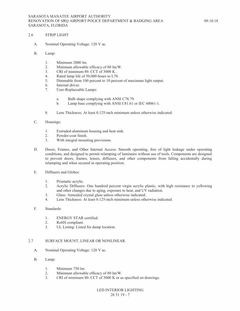
SARASOTA MANATEE AIRPORT AUTHORITY RENOVATION OF SRQ AIRPORT POLICE DEPARTMENT & BADGING AREA SARASOTA, FLORIDA
09.10.18
LED INTERIOR LIGHTING
26 51 19 - 7
2.6 STRIP LIGHT
A. Nominal Operating Voltage: 120 V ac.
B. Lamp:
1. Minimum 2000 lm. 2. Minimum allowable efficacy of 80 lm/W. 3. CRI of minimum 80. CCT of 3000 K . 4. Rated lamp life of 50,000 hours to L70. 5. Dimmable from 100 percent to 10 percent of maximum light output. 6. Internal driver. 7. User-Replaceable Lamps:
a. Bulb shape complying with ANSI C78.79. b. Lamp base complying with ANSI C81.61 or IEC 60061-1.
8. Lens Thickness: At least 0.125-inch minimum unless otherwise indicated.
C. Housings:
1. Extruded-aluminum housing and heat sink. 2. Powder-coat finish. 3. With integral mounting provisions.
D. Doors, Frames, and Other Internal Access: Smooth operating, free of light leakage under operating conditions, and designed to permit relamping of luminaire without use of tools. Components are designed to prevent doors, frames, lenses, diffusers, and other components from falling accidentally during relamping and when secured in operating position.
E. Diffusers and Globes:
1. Prismatic acrylic. 2. Acrylic Diffusers: One hundred percent virgin acrylic plastic, with high resistance to yellowing
and other changes due to aging, exposure to heat, and UV radiation. 3. Glass: Annealed crystal glass unless otherwise indicated. 4. Lens Thickness: At least 0.125-inch minimum unless otherwise indicated.
F. Standards:
1. ENERGY STAR certified. 2. RoHS compliant. 3. UL Listing: Listed for damp location.
2.7 SURFACE MOUNT, LINEAR OR NONLINEAR.
A. Nominal Operating Voltage: 120 V ac.
B. Lamp:
1. Minimum 750 lm. 2. Minimum allowable efficacy of 80 lm/W. 3. CRI of minimum 80. CCT of 3000 K or as specified on drawings.
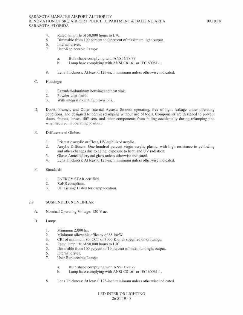
SARASOTA MANATEE AIRPORT AUTHORITY RENOVATION OF SRQ AIRPORT POLICE DEPARTMENT & BADGING AREA SARASOTA, FLORIDA
09.10.18
LED INTERIOR LIGHTING
26 51 19 - 8
4. Rated lamp life of 50,000 hours to L70. 5. Dimmable from 100 percent to 0 percent of maximum light output. 6. Internal driver. 7. User-Replaceable Lamps:
a. Bulb shape complying with ANSI C78.79. b. Lamp base complying with ANSI C81.61 or IEC 60061-1.
8. Lens Thickness: At least 0.125-inch minimum unless otherwise indicated.
C. Housings:
1. Extruded-aluminum housing and heat sink. 2. Powder-coat finish. 3. With integral mounting provisions.
D. Doors, Frames, and Other Internal Access: Smooth operating, free of light leakage under operating conditions, and designed to permit relamping without use of tools. Components are designed to prevent doors, frames, lenses, diffusers, and other components from falling accidentally during relamping and when secured in operating position.
E. Diffusers and Globes:
1. Prismatic acrylic or Clear, UV-stabilized acrylic. 2. Acrylic Diffusers: One hundred percent virgin acrylic plastic, with high resistance to yellowing
and other changes due to aging, exposure to heat, and UV radiation. 3. Glass: Annealed crystal glass unless otherwise indicated. 4. Lens Thickness: At least 0.125-inch minimum unless otherwise indicated.
F. Standards:
1. ENERGY STAR certified. 2. RoHS compliant. 3. UL Listing: Listed for damp location.
2.8 SUSPENDED, NONLINEAR
A. Nominal Operating Voltage: 120 V ac.
B. Lamp:
1. Minimum 2,000 lm. 2. Minimum allowable efficacy of 85 lm/W. 3. CRI of minimum 80. CCT of 3000 K or as specified on drawings. 4. Rated lamp life of 50,000 hours to L70. 5. Dimmable from 100 percent to 10 percent of maximum light output. 6. Internal driver. 7. User-Replaceable Lamps:
a. Bulb shape complying with ANSI C78.79. b. Lamp base complying with ANSI C81.61 or IEC 60061-1.
8. Lens Thickness: At least 0.125-inch minimum unless otherwise indicated.

SARASOTA MANATEE AIRPORT AUTHORITY RENOVATION OF SRQ AIRPORT POLICE DEPARTMENT & BADGING AREA SARASOTA, FLORIDA
09.10.18
LED INTERIOR LIGHTING
26 51 19 - 9
C. Housings:
1. Extruded-aluminum housing and heat sink. 2. Powder-coat finish. 3. Universal mounting bracket. 4. Integral junction box with conduit fittings.
D. Doors, Frames, and Other Internal Access: Smooth operating, free of light leakage under operating conditions, and designed to permit relamping without use of tools. Components are designed to prevent doors, frames, lenses, diffusers, and other components from falling accidentally during relamping and when secured in operating position.
E. Diffusers and Globes:
1. Prismatic acrylic or Clear, UV-stabilized acrylic. 2. Acrylic Diffusers: One hundred percent virgin acrylic plastic, with high resistance to yellowing
and other changes due to aging, exposure to heat, and UV radiation. 3. Glass: Annealed crystal glass unless otherwise indicated. 4. Lens Thickness: At least 0.125-inch minimum unless otherwise indicated.
F. Standards:
1. ENERGY STAR certified. 2. RoHS compliant. 3. UL Listing: Listed for damp location.
2.9 MATERIALS
A. Metal Parts:
1. Free of burrs and sharp corners and edges. 2. Sheet metal components shall be steel unless otherwise indicated. 3. Form and support to prevent warping and sagging.
B. Steel:
1. ASTM A36/A36M for carbon structural steel. 2. ASTM A568/A568M for sheet steel.
C. Stainless Steel:
1. 1. Manufacturer's standard grade. 2. 2. Manufacturer's standard type, ASTM A240/240M.
D. Galvanized Steel: ASTM A653/A653M.
E. Aluminum: ASTM B209.
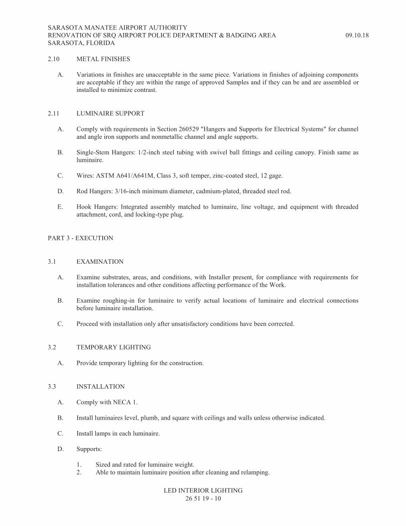
SARASOTA MANATEE AIRPORT AUTHORITY RENOVATION OF SRQ AIRPORT POLICE DEPARTMENT & BADGING AREA SARASOTA, FLORIDA
09.10.18
LED INTERIOR LIGHTING
26 51 19 - 10
2.10 METAL FINISHES
A. Variations in finishes are unacceptable in the same piece. Variations in finishes of adjoining components are acceptable if they are within the range of approved Samples and if they can be and are assembled or installed to minimize contrast.
2.11 LUMINAIRE SUPPORT
A. Comply with requirements in Section 260529 "Hangers and Supports for Electrical Systems" for channel and angle iron supports and nonmetallic channel and angle supports.
B. Single-Stem Hangers: 1/2-inch steel tubing with swivel ball fittings and ceiling canopy. Finish same as luminaire.
C. Wires: ASTM A641/A641M, Class 3, soft temper, zinc-coated steel, 12 gage.
D. Rod Hangers: 3/16-inch minimum diameter, cadmium-plated, threaded steel rod.
E. Hook Hangers: Integrated assembly matched to luminaire, line voltage, and equipment with threaded attachment, cord, and locking-type plug.
PART 3 - EXECUTION
3.1 EXAMINATION
A. Examine substrates, areas, and conditions, with Installer present, for compliance with requirements for installation tolerances and other conditions affecting performance of the Work.
B. Examine roughing-in for luminaire to verify actual locations of luminaire and electrical connections before luminaire installation.
C. Proceed with installation only after unsatisfactory conditions have been corrected.
3.2 TEMPORARY LIGHTING
A. Provide temporary lighting for the construction.
3.3 INSTALLATION
A. Comply with NECA 1.
B. Install luminaires level, plumb, and square with ceilings and walls unless otherwise indicated.
C. Install lamps in each luminaire.
D. Supports:
1. Sized and rated for luminaire weight. 2. Able to maintain luminaire position after cleaning and relamping.

SARASOTA MANATEE AIRPORT AUTHORITY RENOVATION OF SRQ AIRPORT POLICE DEPARTMENT & BADGING AREA SARASOTA, FLORIDA
09.10.18
LED INTERIOR LIGHTING
26 51 19 - 11
3. Provide support for luminaire without causing deflection of ceiling or wall. 4. Luminaire-mounting devices shall be capable of supporting a horizontal force of 100 percent of
luminaire weight and a vertical force of 400 percent of luminaire weight.
E. Flush-Mounted Luminaires:
1. Secured to outlet box. 2. Attached to ceiling structural members at four points equally spaced around circumference of
luminaire. 3. Trim ring flush with finished surface.
F. Wall-Mounted Luminaires:
1. Attached to structural members in walls or attached to a minimum 20 gauge backing plate attached to wall structural members.
2. Do not attach luminaires directly to gypsum board.
G. Suspended Luminaires:
1. Ceiling Mount:
a. Two 5/32-inch diameter aircraft cable supports adjustable to 10 feet in length. b. Pendant mount with 5/32-inch diameter aircraft cable supports adjustable to 10 feet in
length. c. Hook mount.
2. Pendants and Rods: Where longer than 48 inches, brace to limit swinging. 3. Stem-Mounted, Single-Unit Luminaires: Suspend with twin-stem hangers. Support with approved
outlet box and accessories that hold stem and provide damping of luminaire oscillations. Support outlet box vertically to building structure using approved devices.
4. Continuous Rows of Luminaires: Use tubing or stem for wiring at one point and wire support for suspension for each unit length of luminaire chassis, including one at each end.
5. Do not use ceiling grid as support for pendant luminaires. Connect support wires or rods to building structure.
H. Ceiling-Grid-Mounted Luminaires:
1. Secure to any required outlet box. 2. Secure luminaire to the luminaire opening using approved fasteners in a minimum of four
locations, spaced near corners of luminaire. 3. Use approved devices and support components to connect luminaire to ceiling grid and building
structure in a minimum of four locations, spaced near corners of luminaire.
I. Comply with requirements in Section 260519 "Low-Voltage Electrical Power Conductors and Cables" for wiring connections.
3.4 IDENTIFICATION
A. Identify system components, wiring, cabling, and terminals. Comply with requirements for identification specified in Section 260553 "Identification for Electrical Systems."

SARASOTA MANATEE AIRPORT AUTHORITY RENOVATION OF SRQ AIRPORT POLICE DEPARTMENT & BADGING AREA SARASOTA, FLORIDA
09.10.18
LED INTERIOR LIGHTING
26 51 19 - 12
3.5 FIELD QUALITY CONTROL
A. Perform the following tests and inspections:
1. Operational Test: After installing luminaires, switches, and accessories, and after electrical circuitry has been energized, test units to confirm proper operation.
2. Test for Emergency Lighting: Interrupt power supply to demonstrate proper operation. Verify transfer from normal power to battery power and retransfer to normal.
B. Luminaire will be considered defective if it does not pass operation tests and inspections.
C. Prepare test and inspection reports.
3.6 STARTUP SERVICE
A. Comply with requirements for startup specified in Section 260943.16 "Addressable-Luminaire Lighting Controls."
B. Comply with requirements for startup specified in Section 260943.23 "Relay-Based Lighting Controls."
3.7 ADJUSTING
A. Occupancy Adjustments: When requested within 12 months of date of Substantial Completion, provide on-site assistance in adjusting the direction of aim of luminaires to suit occupied conditions. Make up to two visits to Project during other-than-normal hours for this purpose. Some of this work may be required during hours of darkness.
1. During adjustment visits, inspect all luminaires. Replace lamps or luminaires that are defective. 2. Parts and supplies shall be manufacturer's authorized replacement parts and supplies. 3. Adjust the aim of luminaires in the presence of the Architect.
END OF SECTION 26 51 19
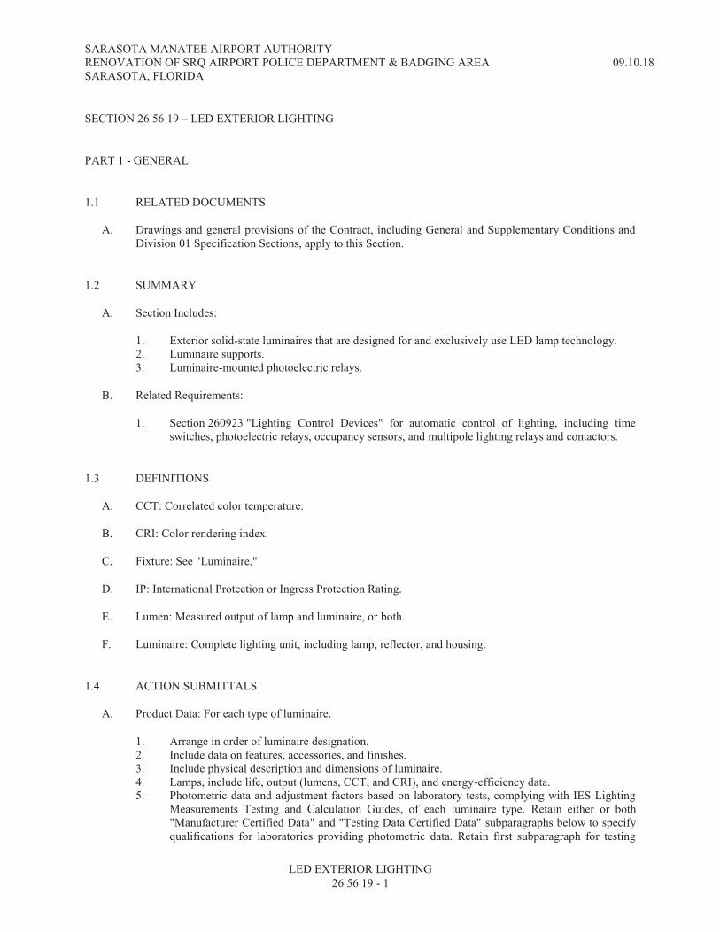
SARASOTA MANATEE AIRPORT AUTHORITY RENOVATION OF SRQ AIRPORT POLICE DEPARTMENT & BADGING AREA SARASOTA, FLORIDA
09.10.18
LED EXTERIOR LIGHTING
26 56 19 - 1
SECTION 26 56 19 – LED EXTERIOR LIGHTING
PART 1 - GENERAL
1.1 RELATED DOCUMENTS
A. Drawings and general provisions of the Contract, including General and Supplementary Conditions and Division 01 Specification Sections, apply to this Section.
1.2 SUMMARY
A. Section Includes:
1. Exterior solid-state luminaires that are designed for and exclusively use LED lamp technology. 2. Luminaire supports. 3. Luminaire-mounted photoelectric relays.
B. Related Requirements:
1. Section 260923 "Lighting Control Devices" for automatic control of lighting, including time switches, photoelectric relays, occupancy sensors, and multipole lighting relays and contactors.
1.3 DEFINITIONS
A. CCT: Correlated color temperature.
B. CRI: Color rendering index.
C. Fixture: See "Luminaire."
D. IP: International Protection or Ingress Protection Rating.
E. Lumen: Measured output of lamp and luminaire, or both.
F. Luminaire: Complete lighting unit, including lamp, reflector, and housing.
1.4 ACTION SUBMITTALS
A. Product Data: For each type of luminaire.
1. Arrange in order of luminaire designation. 2. Include data on features, accessories, and finishes. 3. Include physical description and dimensions of luminaire. 4. Lamps, include life, output (lumens, CCT, and CRI), and energy-efficiency data. 5. Photometric data and adjustment factors based on laboratory tests, complying with IES Lighting
Measurements Testing and Calculation Guides, of each luminaire type. Retain either or both "Manufacturer Certified Data" and "Testing Data Certified Data" subparagraphs below to specify qualifications for laboratories providing photometric data. Retain first subparagraph for testing

SARASOTA MANATEE AIRPORT AUTHORITY RENOVATION OF SRQ AIRPORT POLICE DEPARTMENT & BADGING AREA SARASOTA, FLORIDA
09.10.18
LED EXTERIOR LIGHTING
26 56 19 - 2
laboratories that are associated with a luminaire manufacturer's production facility. Retain second subparagraph for testing laboratories that are independent of a luminaire manufacturer's production facility.
a. Manufacturer's Certified Data: Photometric data certified by manufacturer's laboratory with a current accreditation under the NVLAP for Energy Efficient Lighting Products.
b. Testing Agency Certified Data: For indicated luminaires, photometric data certified by a qualified independent testing agency. Photometric data for remaining luminaires shall be certified by manufacturer.
6. Wiring diagrams for power, control, and signal wiring. 7. Photoelectric relays. 8. Means of attaching luminaires to supports and indication that the attachment is suitable for
components involved.
B. Shop Drawings: For nonstandard or custom luminaires.
1. Include plans, elevations, sections, and mounting and attachment details. 2. Include details of luminaire assemblies. Indicate dimensions, weights, loads, required clearances,
method of field assembly, components, and location and size of each field connection. 3. Include diagrams for power, signal, and control wiring.
C. Sustainable Design Submittals:
D. Samples: For each luminaire and for each color and texture indicated with factory-applied finish.
E. Product Schedule: For luminaires and lamps. Use same designations indicated on Drawings.
F. Delegated-Design Submittal: For luminaire supports.
1. Include design calculations for luminaire supports.
1.5 INFORMATIONAL SUBMITTALS
A. Coordination Drawings: Plans, drawn to scale, on which the following items are shown and coordinated with each other, using input from installers of the items involved:
1. Luminaires. 2. Structural members to which luminaires will be attached. 3. Above-grade utilities and structures. 4. Building features. 5. Vertical and horizontal information.
B. Qualification Data: For testing laboratory providing photometric data for luminaires.
C. Seismic Qualification Data: For luminaires, accessories, and components, from manufacturer.
1. Basis for Certification: Indicate whether withstand certification is based on actual test of assembled components or on calculation.
2. Dimensioned Outline Drawings of Equipment Unit: Identify center of gravity and locate and describe mounting and anchorage provisions.
3. Detailed description of equipment anchorage devices on which the certification is based and their installation requirements.

SARASOTA MANATEE AIRPORT AUTHORITY RENOVATION OF SRQ AIRPORT POLICE DEPARTMENT & BADGING AREA SARASOTA, FLORIDA
09.10.18
LED EXTERIOR LIGHTING
26 56 19 - 3
D. Product Certificates: For each type of the following:
1. Luminaire. 2. Photoelectric relay.
E. Product Test Reports: For each luminaire, for tests performed by manufacturer and witnessed by a qualified testing agency.
F. Source quality-control reports.
G. Sample warranty.
1.6 CLOSEOUT SUBMITTALS
A. Operation and Maintenance Data: For luminaires and photoelectric relays to include in operation and maintenance manuals.
1. Provide a list of all lamp types used on Project. Use ANSI and manufacturers' codes. 2. Provide a list of all photoelectric relay types used on Project; use manufacturers' codes.
1.7 MAINTENANCE MATERIAL SUBMITTALS
A. Furnish extra materials that match products installed and that are packaged with protective covering for storage and identified with labels describing contents.
1. Lamps: Two of each type and rating installed. Furnish at least one of each type. 2. Glass, Acrylic, and Plastic Lenses, Covers, and Other Optical Parts: One for every 100 of each
type and rating installed. Furnish at least one of each type. 3. Diffusers and Lenses: One for every 100 of each type and rating installed. Furnish at least one of
each type. 4. Globes and Guards: One for every 20 of each type and rating installed. Furnish at least one of each
type.
1.8 QUALITY ASSURANCE
A. Luminaire Photometric Data Testing Laboratory Qualifications: Luminaire manufacturers' laboratory that is accredited under the NVLAP for Energy Efficient Lighting Products.
B. Luminaire Photometric Data Testing Laboratory Qualifications: Provided by an independent agency, with the experience and capability to conduct the testing indicated, that is an NRTL as defined by OSHA in 29 CFR 1910.7, accredited under the NVLAP for Energy Efficient Lighting Products and complying with applicable IES testing standards.
C. Provide luminaires from a single manufacturer for each luminaire type.
D. Each luminaire type shall be binned within a three-step MacAdam Ellipse to ensure color consistency among luminaires.
E. Installer Qualifications: An authorized representative who is trained and approved by manufacturer.
F. Mockups: For exterior luminaires, complete with power and control connections.

SARASOTA MANATEE AIRPORT AUTHORITY RENOVATION OF SRQ AIRPORT POLICE DEPARTMENT & BADGING AREA SARASOTA, FLORIDA
09.10.18
LED EXTERIOR LIGHTING
26 56 19 - 4
1. Obtain Architect's approval of luminaires in mockups before starting installations. 2. Approval of mockups does not constitute approval of deviations from the Contract Documents
contained in mockups unless Architect specifically approves such deviations in writing. 3. Subject to compliance with requirements, approved mockups may become part of the completed
Work if undisturbed at time of Substantial Completion.
1.9 DELIVERY, STORAGE, AND HANDLING
A. Protect finishes of exposed surfaces by applying a strippable, temporary protective covering prior to shipping.
1.10 FIELD CONDITIONS
A. Verify existing and proposed utility structures prior to the start of work associated with luminaire installation.
B. Mark locations of exterior luminaires for approval by Architect prior to the start of luminaire installation.
1.11 WARRANTY
A. Warranty: Manufacturer and Installer agree to repair or replace components of luminaires that fail in materials or workmanship within specified warranty period.
1. Failures include, but are not limited to, the following:
a. Structural failures, including luminaire support components. b. Faulty operation of luminaires and accessories. c. Deterioration of metals, metal finishes, and other materials beyond normal weathering.
2. Warranty Period: 2 year(s) from date of Substantial Completion.
PART 2 - PRODUCTS
2.1 PERFORMANCE REQUIREMENTS
2.2 LUMINAIRE REQUIREMENTS
A. Electrical Components, Devices, and Accessories: Listed and labeled as defined in NFPA 70, by a qualified testing agency, and marked for intended location and application.
B. NRTL Compliance: Luminaires shall be listed and labeled for indicated class and division of hazard by an NRTL.
C. FM Global Compliance: Luminaires for hazardous locations shall be listed and labeled for indicated class and division of hazard by FM Global.
D. UL Compliance: Comply with UL 1598 and listed for wet location.

SARASOTA MANATEE AIRPORT AUTHORITY RENOVATION OF SRQ AIRPORT POLICE DEPARTMENT & BADGING AREA SARASOTA, FLORIDA
09.10.18
LED EXTERIOR LIGHTING
26 56 19 - 5
E. Lamp base complying with ANSI C81.61 or IEC 60061-1.
F. Bulb shape complying with ANSI C79.1.
G. CRI of minimum 80. CCT of 3000 K or as specified on drawings.
H. L70 lamp life of 50,000 hours.
I. Lamps dimmable from 100 percent to 0 percent of maximum light output.
J. Internal driver.
K. Nominal Operating Voltage: 24 V dc. Provide 120 V ac to 12 V dc transformer sized to operate luminaires connects.
L. Lamp Rating: Lamp marked for outdoor use and in enclosed locations.
M. Source Limitations: Obtain luminaires from single source from a single manufacturer.
N. Source Limitations: For luminaires, obtain each color, grade, finish, type, and variety of luminaire from single source with resources to provide products of consistent quality in appearance and physical properties.
2.3 LUMINAIRE-MOUNTED PHOTOELECTRIC RELAYS
A. Comply with UL 773 or UL 773A.
B. Contact Relays: Factory mounted, single throw, designed to fail in the on position, and factory set to turn light unit on at 1.5 to 3 fc and off at 4.5 to 10 fc with 15-second minimum time delay. Relay shall have directional lens in front of photocell to prevent artificial light sources from causing false turnoff.
1. Relay with locking-type receptacle shall comply with ANSI C136.10. 2. Adjustable window slide for adjusting on-off set points.
2.4 LUMINAIRE TYPES
A. Bollard:
1. Shape: Round. 2. Height Above Finished Grade: 30 inches or as specified on drawings. 3. Overall Height: 36 inches or as specified on drawings. 4. Diameter: 6 inches or as specified on drawings. 5. Mounting: 3 point cast aluminum base or as specified on drawings. 6. Distribution: As specified on drawings. 7. Diffusers and Globes: Clear, UV-stabilized acrylic. 8. Housings:
a. Extruded-aluminum housing and heat sink. b. Powder-coat finish.
B. Canopy:
SARASOTA MANATEE AIRPORT AUTHORITY RENOVATION OF SRQ AIRPORT POLICE DEPARTMENT & BADGING AREA SARASOTA, FLORIDA
09.10.18
LED EXTERIOR LIGHTING
26 56 19 - 6
1. Shape: Round or Square as specified on drawings. 2. Dimensions: 12 inches or as specified on drawings. 3. Diffusers and Globes: Clear, UV-stabilized acrylic. 4. Housings:
a. Extruded-aluminum housing and heat sink. b. Clear powder-coat finish.
C. Decorative Post Top:
1. Luminaire-Mounting Height: As specified on drawings. 2. Mounting Type: Ring. 3. Distribution: As specified on drawings. 4. Diffusers and Globes: Clear, UV-stabilized acrylic. 5. Housings:
a. Extruded-aluminum housing and heat sink. b. Powder-coat finish.
2.5 MATERIALS
A. Metal Parts: Free of burrs and sharp corners and edges.
B. Sheet Metal Components: Corrosion-resistant aluminum. Form and support to prevent warping and sagging.
C. Doors, Frames, and Other Internal Access: Smooth operating, free of light leakage under operating conditions, and designed to permit relamping without use of tools. Designed to prevent doors, frames, lenses, diffusers, and other components from falling accidentally during relamping and when secured in operating position. Doors shall be removable for cleaning or replacing lenses.
D. Diffusers and Globes:
1. Acrylic Diffusers: 100 percent virgin acrylic plastic, with high resistance to yellowing and other changes due to aging, exposure to heat, and UV radiation.
2. Glass: Annealed crystal glass unless otherwise indicated. 3. Lens Thickness: At least 0.125 inch minimum unless otherwise indicated.
E. Lens and Refractor Gaskets: Use heat- and aging-resistant resilient gaskets to seal and cushion lenses and refractors in luminaire doors.
F. Reflecting surfaces shall have minimum reflectance as follows unless otherwise indicated:
1. White Surfaces: 85 percent. 2. Specular Surfaces: 83 percent. 3. Diffusing Specular Surfaces: 75 percent.
G. Housings:
1. Rigidly formed, weather- and light-tight enclosure that will not warp, sag, or deform in use. 2. Provide filter/breather for enclosed luminaires.
SARASOTA MANATEE AIRPORT AUTHORITY RENOVATION OF SRQ AIRPORT POLICE DEPARTMENT & BADGING AREA SARASOTA, FLORIDA
09.10.18
LED EXTERIOR LIGHTING
26 56 19 - 7
H. Factory-Applied Labels: Comply with UL 1598. Include recommended lamps. Labels shall be located where they will be readily visible to service personnel, but not seen from normal viewing angles when lamps are in place.
1. Label shall include the following lamp characteristics:
a. "USE ONLY" and include specific lamp type. b. Lamp diameter, shape, size, wattage and coating. c. CCT and CRI for all luminaires.
2.6 FINISHES
A. Variations in Finishes: Noticeable variations in same piece are unacceptable. Variations in appearance of adjoining components are acceptable if they are within the range of approved Samples and are assembled or installed to minimize contrast.
B. Luminaire Finish: Manufacturer's standard paint applied to factory-assembled and -tested luminaire before shipping. Where indicated, match finish process and color of pole or support materials.
C. Factory-Applied Finish for Aluminum Luminaires: Comply with NAAMM's "Metal Finishes Manual for Architectural and Metal Products" for recommendations for applying and designating finishes.
1. Finish designations prefixed by AA comply with the system established by the Aluminum Association for designating aluminum finishes.
2. Natural Satin Finish: Provide fine, directional, medium satin polish (AA-M32); buff complying with AA-M20 requirements; and seal aluminum surfaces with clear, hard-coat wax.
3. Class I, Clear-Anodic Finish: AA-M32C22A41 (Mechanical Finish: Medium satin; Chemical Finish: Etched, medium matte; Anodic Coating: Architectural Class I, clear coating 0.018 mm or thicker) complying with AAMA 611.
4. Class I, Color-Anodic Finish: AA-M32C22A42/A44 (Mechanical Finish: Medium satin; Chemical Finish: Etched, medium matte; Anodic Coating: Architectural Class I, integrally colored or electrolytically deposited color coating 0.018 mm or thicker), complying with AAMA 611.
a. Color: Bronze or as specified on drawings.
D. Factory-Applied Finish for Steel Luminaires: Comply with NAAMM's "Metal Finishes Manual for Architectural and Metal Products" for recommendations for applying and designating finishes.
1. Surface Preparation: Clean surfaces to comply with SSPC-SP 1, to remove dirt, oil, grease, and other contaminants that could impair paint bond. Grind welds and polish surfaces to a smooth, even finish. Remove mill scale and rust, if present, from uncoated steel, complying with SSPC-SP 5/NACE No. 1 or SSPC-SP 8.
2. Exterior Surfaces: Manufacturer's standard finish consisting of one or more coats of primer and two finish coats of high-gloss, high-build polyurethane enamel.
a. Color: As selected from manufacturer's standard catalog of colors. b. Color: Match Architect's sample of manufacturer's standard color. c. Color: As selected by Architect from manufacturer's full range.
SARASOTA MANATEE AIRPORT AUTHORITY RENOVATION OF SRQ AIRPORT POLICE DEPARTMENT & BADGING AREA SARASOTA, FLORIDA
09.10.18
LED EXTERIOR LIGHTING
26 56 19 - 8
2.7 LUMINAIRE SUPPORT COMPONENTS
A. Comply with requirements in Section 260529 "Hangers and Supports for Electrical Systems" for channel and angle iron supports and nonmetallic channel and angle supports.
PART 3 - EXECUTION
3.1 EXAMINATION
A. Examine substrates, areas, and conditions, with Installer present, for compliance with requirements for installation tolerances and other conditions affecting performance of the Work.
B. Examine roughing-in for luminaire electrical conduit to verify actual locations of conduit connections before luminaire installation.
C. Examine walls, roofs, and canopy ceilings for suitable conditions where luminaires will be installed.
D. Proceed with installation only after unsatisfactory conditions have been corrected.
3.2 TEMPORARY LIGHTING
A. If approved by the Architect, use selected permanent luminaires for temporary lighting. When construction is substantially complete, clean luminaires used for temporary lighting and install new lamps.
3.3 GENERAL INSTALLATION REQUIREMENTS
A. Comply with NECA 1.
B. Use fastening methods and materials selected to resist seismic forces defined for the application and approved by manufacturer.
C. Install lamps in each luminaire.
D. Fasten luminaire to structural support.
E. Supports:
1. Sized and rated for luminaire weight. 2. Able to maintain luminaire position after cleaning and relamping. 3. Support luminaires without causing deflection of finished surface. 4. Luminaire-mounting devices shall be capable of supporting a horizontal force of 100 percent of
luminaire weight and a vertical force of 400 percent of luminaire weight.
F. Wall-Mounted Luminaire Support:
1. Attached to structural members in walls or attached to a minimum 1/8 inch backing plate attached to wall structural members.
G. Wiring Method: Install cables in raceways. Conceal raceways and cables.
SARASOTA MANATEE AIRPORT AUTHORITY RENOVATION OF SRQ AIRPORT POLICE DEPARTMENT & BADGING AREA SARASOTA, FLORIDA
09.10.18
LED EXTERIOR LIGHTING
26 56 19 - 9
H. Install luminaires level, plumb, and square with finished grade unless otherwise indicated. Install luminaires at height and aiming angle as indicated on Drawings.
I. Coordinate layout and installation of luminaires with other construction.
J. Adjust luminaires that require field adjustment or aiming. Include adjustment of photoelectric device to prevent false operation of relay by artificial light sources, favoring a north orientation.
K. Comply with requirements in Section 260519 "Low-Voltage Electrical Power Conductors and Cables" and Section 260533 "Raceways and Boxes for Electrical Systems" for wiring connections and wiring methods.
3.4 BOLLARD LUMINAIRE INSTALLATION:
A. Align units for optimum directional alignment of light distribution.
1. Install on concrete base with top 4 inches above finished grade or surface at luminaire location. Cast conduit into base, and shape base to match shape of bollard base. Finish by troweling and rubbing smooth. Concrete materials, installation, and finishing are specified in Section 033000 "Cast-in-Place Concrete."
3.5 INSTALLATION OF INDIVIDUAL GROUND-MOUNTED LUMINAIRES
A. Aim as indicated on Drawings.
B. Install on concrete base with top 4 inches above finished grade or surface at luminaire location. Cast conduit into base, and finish by troweling and rubbing smooth. Concrete materials, installation, and finishing are specified in Section 033000 "Cast-in-Place Concrete."
3.6 CORROSION PREVENTION
A. Aluminum: Do not use in contact with earth or concrete. When in direct contact with a dissimilar metal, protect aluminum by insulating fittings or treatment.
B. Steel Conduits: Comply with Section 260533 "Raceways and Boxes for Electrical Systems." In concrete foundations, wrap conduit with 0.010-inch thick, pipe-wrapping plastic tape applied with a 50 percent overlap.
3.7 IDENTIFICATION
A. Identify system components, wiring, cabling, and terminals. Comply with requirements for identification specified in Section 260553 "Identification for Electrical Systems."
3.8 FIELD QUALITY CONTROL
A. Inspect each installed luminaire for damage. Replace damaged luminaires and components.
B. Perform the following tests and inspections with the assistance of a factory-authorized service representative:

SARASOTA MANATEE AIRPORT AUTHORITY RENOVATION OF SRQ AIRPORT POLICE DEPARTMENT & BADGING AREA SARASOTA, FLORIDA
09.10.18
LED EXTERIOR LIGHTING
26 56 19 - 10
1. Operational Test: After installing luminaires, switches, and accessories, and after electrical circuitry has been energized, test units to confirm proper operation.
2. Verify operation of photoelectric controls.
C. Illumination Tests:
1. Measure light intensities at night. Use photometers with calibration referenced to NIST standards. Comply with the following IES testing guide(s):
a. IES LM-5. b. IES LM-50. c. IES LM-52. d. IES LM-64. e. IES LM-72.
2. Operational Test: After installing luminaires, switches, and accessories, and after electrical circuitry has been energized, test units to confirm proper operation.
D. Luminaire will be considered defective if it does not pass tests and inspections.
E. Prepare a written report of tests, inspections, observations, and verifications indicating and interpreting results. If adjustments are made to lighting system, retest to demonstrate compliance with standards.
3.9 DEMONSTRATION
A. Engage a factory-authorized service representative to train Owner's maintenance personnel to adjust, operate, and maintain luminaires and photocell relays.
3.10 ADJUSTING
A. Occupancy Adjustments: When requested within 12 months of date of Substantial Completion, provide on-site assistance in adjusting the direction of aim of luminaires to suit occupied conditions. Make up to two visits to Project during other-than-normal hours for this purpose. Some of this work may be required during hours of darkness.
1. During adjustment visits, inspect all luminaires. Replace lamps or luminaires that are defective. 2. Parts and supplies shall be manufacturer's authorized replacement parts and supplies. 3. Adjust the aim of luminaires in the presence of the Architect.
END OF SECTION 26 56 19

SARASOTA MANATEE AIRPORT AUTHORITY RENOVATION OF SRQ AIRPORT POLICE DEPARTMENT & BADGING AREA 09.10.18 SARASOTA, FLORIDA
TECHNOLOGY GENERAL PROVISIONS 27 00 10 - 1
SECTION 27 00 10 - TECHNOLOGY GENERAL PROVISIONS
PART 1 - GENERAL
1.1 GENERAL CONDITIONS AND DEFINITIONS
A. Scope: This specification section applies to all Division 27 specification sections and all Division 28 specification sections. All systems under the specification sections indicated above are also referenced in these contract documents as “technology systems”.
B. Drawings and specifications: The words “drawings” and “specifications” used in this section refers to all contract drawings and specifications that describe the scope of work for the technology systems. These items combined create the Construction Documents.
C. Installer and Contractor: The word “installer”, where used on the drawings or specifications without any further description, shall reference the installer of the referenced systems. The word “contractor”, where used on the drawings or specifications without any further description, shall reference the General Contractor / Construction Manager that holds the prime agreement with the Owner for the construction of this project.
D. Provide and Install: The word "provide", where used on the drawings or specifications, shall mean: furnish, install, mount, connect, test, document, and make ready for operation. The word "install", where used on the drawings or specifications, shall mean: mount, connect, test, complete, and make ready for operation.
E. Engineer: The word “Engineer or A&E”, where used on the drawings or specifications, refers to the design engineer that is working for the project Architect or the Owner. It does not refer to an engineer employed by the General Contractor / Construction Manager or any trades contractors working on the project.
F. Designer / Contractor / Owner Responsibilities: Refer to attachment 2 of this specification section for “Responsibility Matrix” document outlining the responsibility of each trade on each technology system.
1.2 INTERPRETATION OF DRAWINGS AND SPECIFICATIONS
A. Objective: The intent of the design drawings and specifications are to provide the installer of the technology systems the necessary information to create a scope of work for bidding and construction purposes. The drawings and specifications are not intended to show every single element of the project to produce a buyout list for the installer. Unless indicated otherwise, all primary components are specifically indicated. However small components and cabling assemblies are generally not indicated in the documents.
B. Accuracy: The drawings are diagrammatic and are not intended to show exact locations of conduit runs, outlet boxes, junction boxes, pull boxes, etc. Exact locations shall be coordinated with all trades in the field and as accepted by the Architect or Engineer during construction. Obtain all information relevant to the placing of technology systems work in the field. In cases where there is a conflict with other trades that cannot be easily resolved through coordination, proceed as directed by the Architect or Engineer.
C. Distances: Although most drawings have a scale referenced on each sheet, the drawings are a two dimensional representation of the system. The design drawings do not indicate changes in elevation that

SARASOTA MANATEE AIRPORT AUTHORITY RENOVATION OF SRQ AIRPORT POLICE DEPARTMENT & BADGING AREA 09.10.18 SARASOTA, FLORIDA
TECHNOLOGY GENERAL PROVISIONS 27 00 10 - 2
may cause additional lengths and/or material quantity. It is the responsibility of the installer of each technology system to field verify all distances and elevation changes prior to bidding.
D. Discrepancies: Notify the A&E of any discrepancies found during the construction of the project. Do not proceed with this portion of the project until a written resolution to the discrepancy is received. If a conflict exists between the contract documents and any applicable code or standard, the most stringent requirement shall be considered the minimum requirement for this project.
E. Existing Conditions: All existing conditions might not be indicated in the contract documents. The installer of each system shall review the site and all existing conditions thoroughly before bidding. The installer shall advise the Engineer of any issues prior to bidding.
F. Coordination: The technology systems drawings are intended to be coordinated with other design disciplines. However, the installer for other systems might have changes to their design and/or shop drawings which are not properly coordinated. The Contractor is required to produce coordination documents for specific rooms to facilitate space planning and coordination for all trades.
1.3 ABBREVIATIONS
A. Abbreviations: The following abbreviations or initials may be used: 1. ABV CLG - Above Ceiling 2. AC - Alternating Current 3. ADA - American Disabilities Act 4. AFF - Above Finished Floor 5. AFG - Above Finished Grade 6. AMP - Ampere 7. ANSI - American National Standards Institute 8. AWG - American Wire Gauge 9. BC - Bare Copper 10. CCTV - Closed Circuit Television 11. CATV - Community antenna television 12. CLG - Ceiling 13. COAX - Coaxial Cable 14. CPU - Central Processing Unit 15. DC - Direct Current 16. DEG - Degree 17. EMT - Communication Metallic Tubing 18. GND - Ground 19. IDF - Intermediate Distribution Frame (Telecom Room) 20. IMC - Intermediate Metallic Conduit 21. IN - Inches 22. IP - Internet Protocol 23. JB - Junction Box 24. KVA - Kilo-Volt-Amps 25. KW - Kilowatts 26. LBS - Pounds 27. LED - Light Emitting Diode 28. MAX - Maximum 29. MDF - Main Distribution Frame (Main Telecom Room) 30. MIC - Microphone 31. MIN - Minimum 32. MTD - Mounted 33. MTG - Mounting 34. NEC - National Communication Code

SARASOTA MANATEE AIRPORT AUTHORITY RENOVATION OF SRQ AIRPORT POLICE DEPARTMENT & BADGING AREA 09.10.18 SARASOTA, FLORIDA
TECHNOLOGY GENERAL PROVISIONS 27 00 10 - 3
35. NECA - National Communication Contractors Association 36. NEMA - National Communication Manufacturers Association 37. NFPA - National Fire Protection Association 38. NIC - Not in Contract 39. OFE - Owner furnished equipment 40. OSHA - Occupational Safety and Health Administration 41. PB - Pullbox 42. PWR - Power 43. PVC - Polyvinylchloride 44. EF - Telecommunications Entrance Facility 45. TR - Telecommunications Room 46. TTB - Telephone Terminal Board 47. V - Volt 48. WP - Weatherproof
1.4 CODES AND STANDARDS
A. Application: The codes, standards, and practices listed in this section generally apply to all technology systems. Other codes, standards, or practices that are more specific will be referenced within the applicable specification section.
B. Requirements: All articles, products, materials, fixtures, forms, or types of construction covered in the technology system specifications are required to meet or exceed all applicable standards and requirements of the manufacturer. The technology systems installation shall be done in accordance with the requirements of ANSI, NEMA, IEEE, NEC, BICSI, and TIA documents where indicated and the manufacturer recommended best practices. Requirements indicated on the contract documents which exceed but are not contrary to governing codes or practices shall be followed.
C. Compliance and Certification: The installation shall comply with the governing state and local codes and ordinances. The complete technology system installation shall be inspected and certified by all applicable agencies to indicate the systems are in compliance with their requirements.
D. Applicability: The State of Florida codes, standards, and practices listed herein (revision date to be latest adopted) are provided as the minimum requirements. The list for all technology systems is as follows: 1. Florida Administrative Code 2. Florida Building Code 3. Accessibility Requirements Manual - Florida Department of Community Affairs.
E. UL Labels: All equipment assemblies shall be new, free of defects, and shall be U.L. listed. As an alternative to UL, the equipment can be tested and listed with an approved, nationally recognized Communication Testing Agency. No equipment shall be installed without this testing and subsequent listing.
1.5 MATERIALS ALTERNATES AND SUBSTITUTIONS
A. Definitions: 1. Basis of design: A product or group of products from an identified manufacturer that was used as
the basis of system layouts and installation details as part of the Construction Documents. 2. Prototype: A product or group of products that are not yet ready for commercial and are in the
testing phase (Beta testing) of product development. 3. Alternates: Products or manufacturers listed in the Construction Documents as comparable to the
basis of design. Alternates shall follow the same system architecture and design philosophy as the basis of design.

SARASOTA MANATEE AIRPORT AUTHORITY RENOVATION OF SRQ AIRPORT POLICE DEPARTMENT & BADGING AREA 09.10.18 SARASOTA, FLORIDA
TECHNOLOGY GENERAL PROVISIONS 27 00 10 - 4
4. Obsolete: A product that has been discontinued by the manufacturer or reached the end of life and is no longer being manufactured.
5. Substitution: A product not listed in the Construction Documents but capable of the same characteristics as the basis of design. Substitutions shall function as a direct replacement of the referenced product. The installer can propose a substitution only if all requirements of the specification are met and substitutions are approved by the Architect and /or Owner.
B. Use of prototypes. Prototypes are not allowed in any technology system.
C. Use of alternates. Alternates are allowed and the installer shall adhere to the following requirements: 1. Where several models or manufacturers are listed as acceptable alternates each shall be regarded
as equally acceptable to the basis of design. Where a manufacturer's model number is listed, this model shall set the standard of quality and performance required. Where no model is specified, the source and quality shall be based on the specified equipment criteria and subject to the Engineer's review and acceptance. Where three or more manufacturers are listed, one of the listed manufacturers shall be submitted for acceptance.
2. The use of alternates does not allow for the change of the system architecture.
D. Use of substitutions. Substitutions are only allowed when they meet all the requirements below: 1. Substitutions are only allowed when a particular specification section for a technology system
allows the use of substitutions for that particular system. 2. The performance of all substitution components must meet or exceed those of the basis of design.
Should an installer wish to submit a substitution product, and substitutions are listed in the construction documents as acceptable, it shall be the responsibility of the installer to submit to the Engineer an item-for-item CROSS REFERENCE for all specifications of the product versus the basis of design. Substitution requests shall be submitted with a completed substitution request form indicated in Addendum 1 of this specification.
3. The Engineer has the authority to reject a substitute request without cause and the installer shall provide the basis of design (or listed alternate) at no additional cost.
4. Substitutions of unnamed manufacturers will not be accepted. 5. Certification of substitutions: When a basis of design is specified to be in accordance with a trade
association or government standard requested by the Engineer, the installer shall provide a certificate that the substitute complies with the referenced standard. Upon the request of Engineer, the installer shall submit supporting test data to substantiate said compliance.
6. Substitutions that create a change in system architecture are not allowed, a. A substitution request that changes the system architecture requires the installer to submit
the overall cost of the substitute product including the cost of changing other systems affected, the re-design cost for such systems, and any additional services costs from other firms on the design team. Without this information this substitution will not be evaluated at all.
1.6 SHOP DRAWINGS AND SUBMITTALS
A. General: Shop drawings shall be submitted as required in the specification sections for each system.
B. Shop drawings submittal quantity: Follow the Division 1 specification requirements for quantity of shop drawings and any additional submittal requirements. If the project does not have a Division 1 specification, shop drawings shall be submitted in quantity of one (1) for electronic format submittal and four (4) for hardcopies.
C. Electronic submittals: .pdf format is the only acceptable file type for electronic submittals.
D. When product data sheets of products are submitted, and the manufacturer’s cut sheets indicate several model numbers or variations of the same product, the product data sheet shall have the model number of
SARASOTA MANATEE AIRPORT AUTHORITY RENOVATION OF SRQ AIRPORT POLICE DEPARTMENT & BADGING AREA 09.10.18 SARASOTA, FLORIDA
TECHNOLOGY GENERAL PROVISIONS 27 00 10 - 5
the submitted equipment highlighted by the installer. Submittals received with product data sheets indicating multiple model numbers without being highlighted will be rejected and not reviewed.
E. Equipment and material quantities are not reviewed by the Engineer as part of the submittal process. Equipment quantities are to be provided by the installer to meet the requirements of the construction documents. Approved shop drawings with equipment quantities or overall scope of work that is different from the construction documents does not constitute approval by the Engineer of these changes. The construction documents, along with any changes issued formally by the A&E during the construction process, are to always be followed for equipment quantities and scope of work.
F. All electronic equipment prone to obsolescence and with lead times of less than 3 months shall be submitted for approval no sooner than 12 months before the scheduled date of substantial completion of the project. Electronic equipment prone to obsolescence includes: flat panel displays, transceivers, servers, players, workstation, and routers
G. Equipment and materials that are not installed in accordance with the construction drawings and approved shop drawings shall be replaced at the installer’s expense.
H. Multiple submissions may be required as indicated in each specification section. For final completion and testing, the Installer shall provide a submittal with the following information: 1. Detailed course syllabus for each type of training required in the specification section. 2. A proposed schedule of training sessions in compliance with the specification section and
indicating where the training will take place. 3. A copy of all training material to be used during each session. 4. Test result sheets for all testing performed by the Installer as required in the specification section
prior to the final system acceptance test.
PART 2 - PRODUCTS
2.1 IDENTIFICATION AND LABELING TAGS
A. All conduit, cabinets, cables, individual conductors, wiring forms, terminal blocks, and terminals shall be clearly identified with pre-printed labels or tags.
B. The only approved types of labels for technology systems installed indoors are: 1. Non-laminated thermal transfer labels, printed with a high quality thermal transfer printer. 2. Laminated thermal transfer labels printed with a high quality thermal transfer printer. 3. Thermal transfer polyolefin tape printed with a high quality thermal transfer printer. 4. Self laminated dot-matrix labels, printed with a high quality dot matrix printer. 5. Non-laminated dot-matrix labels, printed with a high quality dot matrix printer.
C. For labeling of cables or equipment in outdoor or wet environments use only marker plates attached to cable with cable ties. Marker plates attached to equipment shall be with an adhesive designed for the material being bonded in that environmental condition. Do not use any labels with adhesive materials, unless the adhesive is rated for the application. Use different color plates for different cable types. Use only waterproof ink for writing on cable marker plates. Marker plates on equipment shall be engraved or machine lettered.
D. Hand written labels (except for outdoor marker plates), including writing on cable jackets or directly on equipment, are not acceptable and shall be corrected with approved labeling methods at no additional cost to the owner.
SARASOTA MANATEE AIRPORT AUTHORITY RENOVATION OF SRQ AIRPORT POLICE DEPARTMENT & BADGING AREA 09.10.18 SARASOTA, FLORIDA
TECHNOLOGY GENERAL PROVISIONS 27 00 10 - 6
E. Approved manufacturers: 1. Rhino, 2. Brady, 3. Panduit or 4. approved equal
2.2 TECHNOLOGY EQUIPMENT AND MATERIALS
A. General: Each item of equipment or material shall be manufactured by a company regularly engaged in the manufacturer of the type and size of equipment specified. The equipment shall be suitable for the environment in which it is to be installed and shall be approved for the intended purpose, environment, and application. Equipment shall bare the label of the independent testing agency as indicated in paragraph 1.4.E. of this section.
B. Installation Requirements: Each item of equipment or material shall be installed in accordance with the instructions and recommendations of the manufacturer as it relates to the construction documents.
C. Required Accessories: The equipment specified in the technology systems specifications shall be provided with all required accessories for proper operation and mounting. Such accessories include items such as power supplies, power cords, rack ears, rack rails, bolts, lugs, faceplates, etc.
PART 3 - EXECUTION
3.1 INSTALLATION PRACTICES
A. WORKMANSHIP: The installation of all material and equipment shall be performed in a neat, workmanlike, and professional manner by an adequate number of craftsmen who are knowledgeable of the requirements of the Construction Documents. They shall be skilled in the methodology and craftsmanship required to produce a high level of workmanship. Personnel who install materials and equipment shall be qualified through training and experience in order to perform their assigned tasks.
B. STANDARD OF QUALITY: To define a high level workmanship, all installation best practices described by the manufacturer, BICSI, ASIS, and infoComm standards publications shall be followed.
C. PROTECTION OF EQUIPMENT: Equipment for technology systems shall be adequately protected against any damage which may occur due to the elements or work performed by other trades at all times during construction. Equipment shall be stored in dry permanent shelters or weatherproof storage trailers. If any equipment or materials have been damaged during this time, such equipment shall be replaced at no additional cost or time extension. Damaged equipment and materials include the following conditions: 1. Equipment that has visible scratches, cracks, or other surface coating damage. 2. Equipment with visible indication of rust or water intrusion. 3. Equipment that has dents that are clearly visible. 4. Equipment that has been sprayed with paint, fire proofing materials, or any other type of chemical
that was not intended to have these materials applied to it, per the construction documents. 5. Equipment that has been damaged by fire, power surges, power sags, or lightning. 6. Equipment that has known damage to any parts, electronic boards, or components and the damage
is not overtly visible. 7. Cables that have visible damage to the jackets; even if the cables are not broken, still provide
electrical continuity, and allow for system functionality. 8. Cables sprayed with paints that affect the warranty of the cable as defined by the cable
manufacturer.

SARASOTA MANATEE AIRPORT AUTHORITY RENOVATION OF SRQ AIRPORT POLICE DEPARTMENT & BADGING AREA 09.10.18 SARASOTA, FLORIDA
TECHNOLOGY GENERAL PROVISIONS 27 00 10 - 7
9. Equipment with screws that have stripped heads or threads.
D. CLEAN EQUIPMENT: All installed equipment like racks, cabinets, wall mounted panels, credenzas, etc. shall be free of dust at the time that space or area of the project gets the final Certificate of Occupancy and at the time of the acceptance test by the A&E.
E. IDENTIFICATION AND TAGGING: All technology system items shall be labeled and identified as specified in the Construction Documents. Such identification shall be in addition to the manufacturer's nameplates and shall serve to provide a unique identifier of the equipment and systems which it serves or controls. Refer to the identification part of each specification section for additional information. All labels of equipment and wiring shall match the labeling used in the shop drawings for the system or as approved by the Owner.
3.2 COORDINATION
A. General: The installer shall coordinate their shop drawings and installation work with those of other trades and the Owner’s contractors. Report any conflicts to the A&E. The installer shall obtain from the A&E written instructions required to make the necessary changes for the affected scope of work. All work shall be installed in coordination with all other Contractor and Owner subcontractors.
B. Adjustments: Locations of conduit and equipment shall be adjusted as required to accommodate the work of all trades with the understanding all interferences have been anticipated and encountered through coordination. The installer shall determine the exact routing and location of all contracted technology systems prior to fabrication or installation.
C. Replacement: All work shall be installed in a way that permits removal (without damage to other parts) of all system components provided under the construction documents requiring periodic replacement or maintenance. All conduits shall be arranged in a manner that clears the openings of swinging access doors and ceiling tiles.
3.3 TELECOM ROOM/EQUIPMENT ROOM READINESS
A. In any projects where the technology systems require the use of network equipment (switches, routers, firewalls, etc) provided by the Owner, the Contractor shall complete all telecom rooms to a point where they are suitable for the Owner to deploy such equipment. At a minimum the following conditions shall be met in the rooms for the Owner to install the equipment: 1. All power outlets in the telecom rooms shall be fed from the permanent source of power.
Temporary power shall not be provided. 2. Backup power (generator and/or UPS) if provided shall be in full operation and tested. 3. The mechanical equipment providing the cooling for the telecommunications rooms shall be fully
operational with permanent filtration. Temporary cooling and filtration shall not be provided. 4. Fire suppression systems (wet sprinkler, dry sprinkler, or clean agent) protecting the
telecommunications rooms shall be fully operational and tested. 5. All light fixtures in the telecommunications rooms shall be fully operational. 6. All walls to the telecom rooms shall be complete, including the last coat of paint. No sanding of
the wall surface will be allowed once the Owner’s equipment is installed. 7. The ceiling and flooring of the telecommunications rooms shall be finished. 8. The final and permanent doors to the telecommunications rooms shall be installed with a key core
different from all other construction cores in the site 9. Telecommunications rooms shall be cleared of all stored materials inside the room. 10. Telecommunications rooms shall be fully cleaned by the Contractor’s finish cleaning personnel.
Clean is defined as not having any debris left in the room and not having dust in any rack, cabinet,

SARASOTA MANATEE AIRPORT AUTHORITY RENOVATION OF SRQ AIRPORT POLICE DEPARTMENT & BADGING AREA 09.10.18 SARASOTA, FLORIDA
TECHNOLOGY GENERAL PROVISIONS 27 00 10 - 8
or wall mounted panel. If wiping a finger on the surfaces of such equipment leaves visible dust residue on the finger, the room will not be considered clean.
11. Hallways and rooms leading into the telecommunications rooms shall require no more sanding to be done on the walls. The floor finish shall be completed to avoid dust from these spaces moving into the telecom rooms.
12. Prior to the Owner deploying their equipment in these rooms, the Contractor shall provide disposable sticky mats at the entrance of each room to capture dust and/or dirt from shoes or boots. The sticky mats shall sized to cover the full width of the door opening plus three (3) inches on each side. The sticky mats shall contain no less than 60 sheets per unit. The sheets shall be replaced no less than once a day and will be replaced as required if worn out during the day. Sticky mats shall be provided until the project receives the final Certificate of Occupancy for the entire area served by the telecommunications room.
3.4 SYSTEMS WARRANTY AND SERVICE
A. General: At a minimum all technology systems shall include a warranty from the manufacturer and installer of the system for no less than one (1) year with the following exceptions: 1. When specific equipment manufacturers include a warranty longer than one year, the
manufacturer’s warranty shall be transferred to the Owner in the same terms indicated by the manufacturer to the Installer.
B. Warranty coverage. The warranty for the technology systems shall cover the following elements: 1. All equipment, and materials. 2. The labor to replace malfunctioning parts. 3. Shipping and freight charges to send equipment back and forth from the manufacturer and/or site. 4. Any manufacturer RMA (return material authorization) charges. 5. Tool rentals such as scaffold or lifts required to access equipment. 6. The troubleshooting time to detect faults. 7. All travel time and expenses associated with the warranty service.
C. Start of warranty. For new construction projects, the warranty period for the technology systems starts the day the project receives the Certificate of Occupancy (CO). For retrofit projects for a particular system, the warranty starts when the project is accepted by A&E. For most equipment/software manufacturers the warranty period starts when the equipment is shipped from the factory, it is the responsibility of the installer of each system to provide additional warranty coverage from the manufacturer to cover the additional time of warranty up to the CO date plus one year as required.
D. Service calls. During the warranty period the Installer shall support the technology systems when called by Owner/Contractor for service. All equipment/software service shall be done by personnel trained and qualified by the manufacturer for the system and as indicated in each technology system specification section. Service calls shall be performed during normal business hours (same time zone as the project) for normal service and twenty four (24) hours a day for three hundred and sixty five (365) days in the year for emergency service. Emergency service shall be defined as the loss or failure of any critical component necessary to maintain the overall integrity and proper operation of the system. Normal service shall be defined as the loss or failure of a system component that does not compromise the full operation of the system and allows the Owner to operate the system at a minimum of 90% of intended capacity.
E. Response time for service. The maximum allowed on site response time for emergency service shall be four (4) hours and normal service shall be twenty four (24) hours.
SARASOTA MANATEE AIRPORT AUTHORITY RENOVATION OF SRQ AIRPORT POLICE DEPARTMENT & BADGING AREA 09.10.18 SARASOTA, FLORIDA
TECHNOLOGY GENERAL PROVISIONS 27 00 10 - 9
3.5 AS BUILT DOCUMENTS
A. Production: During the course of the project the Installer shall maintain a record as-built drawing set. The set shall be maintained at the site at all times and shall be accurate, clear, and complete. The set shall show the actual location of all equipment in the installed location. The as-built drawings shall show all technology systems work completed and installed to the current stage of construction. These drawings shall be available for review by the A&E's field representatives at all times.
B. Completion: At the completion of the work, the Installer shall transfer the record as-built drawing set information onto a second set of clean drawings with all changes marked in colored ink. This copy shall be submitted to the A&E.
C. Final: Submit full size drawings and one (1) copy of the Installer’s CAD/Autodesk Revit© files for review and acceptance.
D. Additional documents. At project completion, the Installer of the technology system shall provide updated tables, equipment schedules, configuration worksheets and labeling systems used on the project. See individual system specification sections for more detailed information on these document requirements.
END OF SECTION 27 00 10
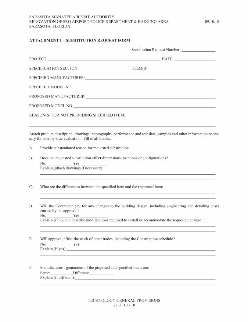
SARASOTA MANATEE AIRPORT AUTHORITY RENOVATION OF SRQ AIRPORT POLICE DEPARTMENT & BADGING AREA 09.10.18 SARASOTA, FLORIDA
TECHNOLOGY GENERAL PROVISIONS 27 00 10 - 10
ATTACHMENT 1 – SUBSTITUTION REQUEST FORM
Substitution Request Number: PROJECT: DATE: SPECIFICATION SECTION: ITEM(S): SPECIFIED MANUFACTURER: SPECIFIED MODEL NO: PROPOSED MANUFACTURER: PROPOSED MODEL NO: REASON(S) FOR NOT PROVIDING SPECIFIED ITEM: Attach product description, drawings, photographs, performance and test data, samples and other information neces-sary for side-by-side evaluation. Fill in all blanks.
A. Provide substantiated reason for requested substitution.
B. Does the requested substitution affect dimensions, locations or configurations?
No: Yes: Explain (attach drawings if necessary):
C. What are the differences between the specified item and the requested item:
D. Will the Contractor pay for any changes to the building design, including engineering and detailing costs caused by the approval? No: Yes: Explain (if no, and describe modifications required to install or accommodate the requested change):
E. Will approval affect the work of other trades, including the Construction schedule?
No: Yes: Explain (if yes):
F. Manufacturer’s guarantees of the proposed and specified items are:
Same: Different: Explain (if different):
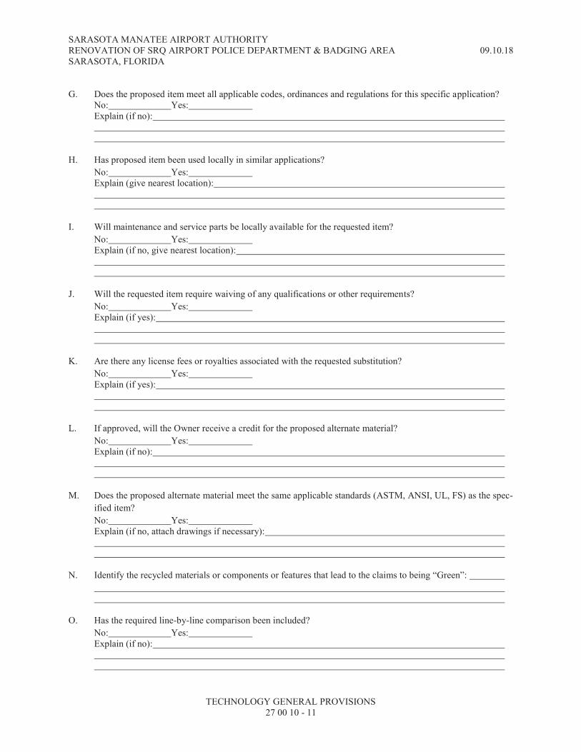
SARASOTA MANATEE AIRPORT AUTHORITY RENOVATION OF SRQ AIRPORT POLICE DEPARTMENT & BADGING AREA 09.10.18 SARASOTA, FLORIDA
TECHNOLOGY GENERAL PROVISIONS 27 00 10 - 11
G. Does the proposed item meet all applicable codes, ordinances and regulations for this specific application?
No: Yes: Explain (if no):
H. Has proposed item been used locally in similar applications?
No: Yes: Explain (give nearest location):
I. Will maintenance and service parts be locally available for the requested item?
No: Yes: Explain (if no, give nearest location):
J. Will the requested item require waiving of any qualifications or other requirements?
No: Yes: Explain (if yes):
K. Are there any license fees or royalties associated with the requested substitution?
No: Yes: Explain (if yes):
L. If approved, will the Owner receive a credit for the proposed alternate material?
No: Yes: Explain (if no):
M. Does the proposed alternate material meet the same applicable standards (ASTM, ANSI, UL, FS) as the spec-
ified item?
No: Yes: Explain (if no, attach drawings if necessary):
N. Identify the recycled materials or components or features that lead to the claims to being “Green”:
O. Has the required line-by-line comparison been included?
No: Yes: Explain (if no):

SARASOTA MANATEE AIRPORT AUTHORITY RENOVATION OF SRQ AIRPORT POLICE DEPARTMENT & BADGING AREA 09.10.18 SARASOTA, FLORIDA
TECHNOLOGY GENERAL PROVISIONS 27 00 10 - 12
The undersigned agrees to pay for the Designer’s review time and for changes to the building design, including re-view, re-design, engineering, drawings and other costs caused by the requested substitution.
Signature
Print The following Purchase Order or billing number is to be used for billing the Contractor for costs incurred in evaluat-ing and if applicable accommodating the requested substitution. The Engineer will not be required to approve any product that is not equal or suitable for the specific application and functionality of this project.

SARASOTA MANATEE AIRPORT AUTHORITY RENOVATION OF SRQ AIRPORT POLICE DEPARTMENT & BADGING AREA 09.10.18 SARASOTA, FLORIDA
TECHNOLOGY GENERAL PROVISIONS 27 00 10 - 13
ATTACHMENT 2 – RESPONSIBILITY MATRIX

SARASOTA MANATEE AIRPORT AUTHORITY RENOVATION OF SRQ AIRPORT POLICE DEPARTMENT & BADGING AREA 09.10.18 SARASOTA, FLORIDA
TECHNOLOGY GENERAL PROVISIONS 27 00 10 - 14
THIS PAGE INTENTIONALLY BLANK

SARASOTA MANATEE AIRPORT AUTHORITY RENOVATION OF SRQ AIRPORT POLICE DEPARTMENT & BADGING AREA 09.10.18
SARASOTA, FLORIDA
GROUNDING AND BONDING FOR TELECOMMUNICATIONS SYSTEMS 27 05 26 - 1
SECTION 27 05 26 – GROUNDING AND BONDING FOR TELECOMMUNICATIONS SYSTEMS
PART 1 - GENERAL
1.1 RELATED DOCUMENTS
A. General: Drawings and general provisions of the Contract, including the General and Supplementary Conditions and Division 1 Specification sections, apply to work specified in this section.
B. General: Refer to specification section 260526 for the grounding electrode system and the equipment grounding system for telecommunications. In all cases the applicable electrical codes for grounding and bonding for telecommunications shall be met.
C. Supplemental: Refer to the specification sections identified below for additional requirements, which are supplemented by this section. 1. 270010 Technology General Provisions 2. 270528 Raceways for Technology
D. General. Refer to the technology system drawings for the telecommunications bonding diagram.
E. General. The bonding approach required herein is intended to work in concert with the pathways as specified and installed in accordance with specification section 270528.
F. Reference Standards: 1. TIA-607-B 2. TIA-568-C 3. TIA-606 4. UL 1863 Communication Circuit Accessories 5. UL-50 & UL-514 6. NFPA 70 – NATIONAL ELECTRIC CODE 7. IEEE Std. 1100-1992, Powering and Grounding Sensitive Electronic Equipment. 8. BICSI TDMM, Telecommunications Distribution Method Manual. 9. UL 1449 10. NFPA 780
G. Standard compliance: This project requires compliance with the R56 grounding standards. The requirements of the R56 grounding standards are more stringent and supersede the requirements indicated in this specification section.
1.2 MATERIALS ALTERNATES AND SUBSTITUTIONS
A. General: Substitutions are allowed for all components of the systems under this specification sections as long as all requirements for substitutions indicated in specification section 270010 are followed.
1.3 SHOP DRAWINGS AND SUBMITTALS
A. See additional requirements for the submittals in specification section 270010.

SARASOTA MANATEE AIRPORT AUTHORITY RENOVATION OF SRQ AIRPORT POLICE DEPARTMENT & BADGING AREA 09.10.18
SARASOTA, FLORIDA
GROUNDING AND BONDING FOR TELECOMMUNICATIONS SYSTEMS 27 05 26 - 2
B. The Installer of the telecommunications grounding systems shall provide the following information for the initial submittal for the project: 1. Provide manufacturer’s product data sheets for all equipment indicated in Part 2 of this
specification section and any additional equipment indicated on the technology drawings. Product data sheets shall bear the printed logo or trademark of the manufacturer for each type of product being provided. The product data sheets for this submittal will match the chronological order of the equipment indicated in Part 2 (product data sheets for equipment shown on the drawings will submitted in order based be based on the sheet). Failure to properly sequence the product data sheets will result in the submittal being rejected not reviewed.
2. Provide a spreadsheet indicating the telecommunications ground bar product selection for each telecommunications room indicated in the technology drawings. The spreadsheet will include the following information: a. Room Name or number b. Quantity of ground bars c. Ground bar dimensions d. Number of holes and placement in each ground bar e. Labelling for each ground bar
3. Provide a drawing indicating the following information: a. The location of all telecommunications ground bars and routing of all telecommunications
grounding backbone conductors. b. Wire size charts for all telecommunications grounding backbone conductors on the project. c. All labels being used on the telecommunications backbone conductors, bonding
conductors, and telecommunications ground bars.
1.4 ABBREVIATONS
A. General: The following abbreviations are used in this specification section: 1. TBB - Telecommunications Bonding Backbone 2. BC - Bonding Conductor 3. EMT - Electrical Metallic Tubing 4. RMC - Rigid Metal Conduit 5. MCBN – Mesh Common Bonding Network
PART 2 - PRODUCTS
2.1 TELECOMMUNICATIONS MAIN GROUNDING BUSBAR (TMGB)
A. The TMGB serves as the dedicated extension of the building grounding electrode system for the telecommunications system infrastructure. The TMGB shall be located and provided in the main telecommunications room of each building. The TMGB must be listed by a nationally recognized testing laboratory (NRTL) such as UL.
B. The TMGB shall have the following specifications: 1. Material: Copper 2. Thickness: ¼” thick 3. Width: No less than 4” 4. Length: The installer of the grounding system shall estimate the length of the bar as to have
enough pre-drilled holes for all BCs in the room. The bar shall be no less than 14” long. The
installer shall follow the following criteria in estimating the amount of pre-drilled holes required in the TMGB: a. Two holes required for each TBB termination. b. Two holes for each cabinet or rack row in the room
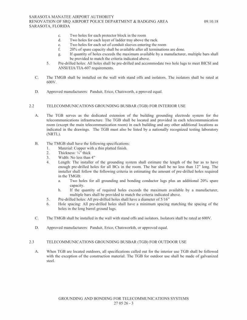
SARASOTA MANATEE AIRPORT AUTHORITY RENOVATION OF SRQ AIRPORT POLICE DEPARTMENT & BADGING AREA 09.10.18
SARASOTA, FLORIDA
GROUNDING AND BONDING FOR TELECOMMUNICATIONS SYSTEMS 27 05 26 - 3
c. Two holes for each protector block in the room d. Two holes for each layer of ladder tray above the rack. e. Two holes for each set of conduit sleeves entering the room f. 20% of spare capacity shall be available after all terminations are done. g. If quantity of holes exceeds the maximum available by a manufacturer, multiple bars shall
be provided to match the criteria indicated above. 5. Pre-drilled holes: All holes shall be pre-drilled and accommodate two hole lugs to meet BICSI and
ANSI/EIA/TIA-607 requirements.
C. The TMGB shall be installed on the wall with stand offs and isolators. The isolators shall be rated at 600V.
D. Approved manufacturers: Panduit, Erico, Chatsworth, a pproved equal.
2.2 TELECOMMUNICATIONS GROUNDING BUSBAR (TGB) FOR INTERIOR USE
A. The TGB serves as the dedicated extension of the building grounding electrode system for the telecommunications infrastructure. The TGB shall be located and provided in each telecommunication room (except the main telecommunication room) in each building and any other additional locations as indicated in the drawings. The TGB must also be listed by a nationally recognized testing laboratory (NRTL).
B. The TMGB shall have the following specifications: 1. Material: Copper with a thin platted finish. 2. Thickness: ¼” thick 3. Width: No less than 4” 4. Length: The installer of the grounding system shall estimate the length of the bar as to have
enough pre-drilled holes for all BCs in the room. The bar shall be no less than 12” long. The
installer shall follow the following criteria in estimating the amount of pre-drilled holes required in the TMGB: a. Two holes for all grounding and bonding conductor lugs plus an additional 20% spare
capacity. b. If the quantity of required holes exceeds the maximum available by a manufacturer,
multiple bars shall be provided to match the criteria indicated above. 5. Pre-drilled holes: All pre-drilled holes shall have a diameter of 5/16” 6. Hole spacing: All pre-drilled holes shall have a minimum spacing matching the spacing of the
holes in the long barrel ground lugs.
C. The TMGB shall be installed in the wall with stand offs and isolators. Isolators shall be rated at 600V.
D. Approved manufacturers: Panduit, Erico, Chatsworkth, or approved equal.
2.3 TELECOMMUNICATIONS GROUNDING BUSBAR (TGB) FOR OUTDOOR USE
A. When TGB are located outdoors, all specifications called out for the interior use TGB shall be followed with the exception of the construction material. The TGB for outdoor use shall be made of galvanized steel.

SARASOTA MANATEE AIRPORT AUTHORITY RENOVATION OF SRQ AIRPORT POLICE DEPARTMENT & BADGING AREA 09.10.18
SARASOTA, FLORIDA
GROUNDING AND BONDING FOR TELECOMMUNICATIONS SYSTEMS 27 05 26 - 4
2.4 FLEX CONDUCTOR TERMINAL, TWO HOLE, LONG BARREL, INSPECTION WINDOW LUG
A. Flex conductor terminal lugs shall be used with the TBB and BC to provide a good bond between the conductor, equipment, and the TGB. All lugs shall be selected to match the size of the conductor being used. Other types of terminations are not accepted.
B. The flex conductor terminal lugs shall have the following specification: 1. Finish: Thin platted 2. Cable types: Designed to work with Flexible, Extra-Flexible, and Code Stranded Copper
Conductors. 3. Stud hole size: ¼” 4. Hole spacing: to match spacing of pre-drilled holes on the ground bar or equipment. 5. Barrel length: > 1” 6. Termination type: crimp type 7. Angle: straight is preferred or angled if installation space is limited. 8. Listing: UL listed and tested to 35 KV and 90ºC
C. Flex conductors terminal lugs shall be used with the BC in the following conditions: 1. Bonding two sections of pathways such as sections of tubular runways or cable trays. 2. Bonding a BC or a TBB to a TGB or TMGB 3. Bonding to equipment for bonding.
D. Approved manufacturers: Panduit, Erico, Chatsworth, or approved equal.
2.5 C TYPE COMPRESSION CONNECTOR
A. When a BC is required to be bonded to another BC of the same or different size the only approved method of bonding shall be with a C type compression connectors. Screw type connectors, wire nuts or any other method are not acceptable. The specifications of the C type compression connectors are: 1. Cable types: designed to work with Flexible, Extra-Flexible, and Code Stranded Copper
Conductors. 2. Tap grooves: installer to select connector based on size of BCs and quantity of BCs to be bonded. 3. Termination type: crimp type 4. Listing: UL listed and tested to 600V
B. Approved manufacturers: Panduit, Erico, Chatsworth, or approved equal.
2.6 TELECOMMUNICATIONS BONDING BACKBONE (TBB)
A. Telecommunications bonding backbone conductors shall be provided as indicated in the Construction Documents. TBBs shall be insulated stranded copper conductors with a wire gauge dictated by the length of the cable. The TBB shall be sized at 2 kcmil per linear foot of conductor length up to a maximum of 3/0 AWG. The following table shall be used to estimate the size of the TBBs:
TBB LENGTH
LINEAR M (FT) TBB SIZE (AWG)
Less than 4 (13) 6
5- 6 (14 – 20) 4
6 – 8 (21 – 26) 3
8– 10 (27 – 33) 2

SARASOTA MANATEE AIRPORT AUTHORITY RENOVATION OF SRQ AIRPORT POLICE DEPARTMENT & BADGING AREA 09.10.18
SARASOTA, FLORIDA
GROUNDING AND BONDING FOR TELECOMMUNICATIONS SYSTEMS 27 05 26 - 5
10– 13 (34 – 41) 1
13 – 16 (42 – 52) 1/0
16 – 20 (53 – 66) 2/0
Greater than 20 (66) 3/0
B. Extension of an installed TBB shall not be done with a wire gauge smaller than the original conductor regardless of distance.
2.7 BONDING CONDUCTOR (BC)
A. Bonding conductors shall be used to bond equipment and raceways to the telecommunications grounding infrastructure. The specifications of the BC are: 1. Conductor Size: use the chart in 2.6 to estimate the size of the bonding conductor. The BC shall be
no smaller than an AWG-6. For projects with R56 grounding compliance, the BC shall be no smaller than AWG-2.
2. Material: stranded copper conductor. 3. Insulation: Insulation color shall be green with a yellow stripe. Use non-insulated conductors only
under raised access floor spaces.
B. Pre-fabricated BC or field made BC are acceptable.
C. Both ends of a BC shall be terminated with two hole long barrel lugs.
2.8 RAISED ACCESS FLOOR BONDING CLAMP
A. The raised access floor bonding clamp shall be used to bond the BC installed under the raised access floor to the floor pedestals. The specifications of the raised access floor bonding clamp shall be: 1. Construction: solid metal device 2. Bonding to BC: The device used to bond the BC shall be a split screw copper bolt that is sized to
match the size of the BC being bonded to. 3. Bonding of raised access floor pedestals: The device shall include an adjustable clamp to bond to
the floor pedestal. The Installer is responsible for selecting the size of the clamp to match the size and shape of the floor pedestal provided for this project.
4. Listing: UL listed
B. Approved manufacturers: Panduit, Erico, Chatsworth, or approved equal.
2.9 MESH COMMON BONDING NETWORK (MCBN)
A. A Mesh Common Bonding Network (MCBN) shall be provided under all raised access floor spaces on the project. The MCBN is a grid of non-insulated BCs running under the raised floor. The MCBN shall include a loop around the perimeter of the raised access floor. The details of the construction of the MCBN shall be: 1. Size of conductors: Conductors shall be sized per 2.6. Conductors shall not be larger than 1/0
AWG. 2. Spacing of the grid: The conductor grid shall have a spacing of no more than 10’. Each row of
cabinets, racks, and consoles shall have a BC installed below as part of this grid. 3. Continuous conductors: Each line of conductors shall be continuous, without any splices. 4. Aligning: All BC shall be installed adjacent to the raised access floor pedestals to bond the
pedestals.

SARASOTA MANATEE AIRPORT AUTHORITY RENOVATION OF SRQ AIRPORT POLICE DEPARTMENT & BADGING AREA 09.10.18
SARASOTA, FLORIDA
GROUNDING AND BONDING FOR TELECOMMUNICATIONS SYSTEMS 27 05 26 - 6
5. Elevation: All BC installed as part of the MCBN shall not rest on or touch the floor slab. They shall be installed at approximately half of the height of the raised access floor pedestals.
6. Bonding: Bonding shall be provided to the MCBM at the following locations: a. Each pedestal with one or more BCs adjacent to it, shall be bonded using a raised access
floor bonding clamp. b. All metal equipment, such as cable trays or conduits, under the raised access floor shall be
bonded to the MCBN. c. All ground bars above the raised access floor in the same room shall be bonded to the
MCBM with a BC of equal size as the largest conductor in the MCBN 7. Listing: All bonding equipment used for the MCBN shall be UL 467 listed.
B. Racks, cabinets, and consoles above the raised access floor shall be individually bonded to the MCBN with a non-insulated BC, if space below the raised access floor is being used as an air plenum for conditioned air distribution. An insulated BC shall be used if the space below the raised access floor is not being used as an air plenum.
2.10 LABELS FOR TELECOMMUNICATIONS GROUNDING INFRASTRUCTURE
A. The Installer shall follow the labeling materials and methodology indicated in specification section 270010.
PART 3 - EXECUTION
3.1 INSTALLATION PRACTICES.
A. General: Specification section 260526 applies to the work of this section. Specific installation requirements called for in this section take precedence over specification section 260526.
B. General: All installation requirements indicated in specification section 270010 shall be followed.
C. PROTECTION. All TBB and BC shall be installed and protected from physical and mechanical damage.
D. GALVANIC CONTINUITY. The TBB and BC shall be continuous and routed in the shortest possible straight line path.
E. CRIMPING. All lugs shall be crimped with the proper die for the size of lug being used.
F. PAINT REMOVAL. Paint shall be removed before attaching any BC to equipment with a painted surface, such as ladder trays and racks, if no factory installed ground lug is available.
G. SPLICING. The TBB and BC shall be installed without splices. Where splices are necessary, the number of splices should be kept to a minimum and shall be accessibly located within the telecommunications spaces. Joined segments of a TBB or BC shall be connected using exothermic welding, irreversible compression-type connectors, or equivalent. All joints shall be adequately supported and protected from damage.
H. BONDING TO ELECTRICAL PANELS. The TGB or TMGB shall be as close to the electrical power panel as is practicable and shall be installed to maintain clearances required by applicable electrical codes. The electrical power panel bus or the panel enclosure feeding telecommunications equipment racks/cabinets shall be bonded to the TGB or TMGB.

SARASOTA MANATEE AIRPORT AUTHORITY RENOVATION OF SRQ AIRPORT POLICE DEPARTMENT & BADGING AREA 09.10.18
SARASOTA, FLORIDA
GROUNDING AND BONDING FOR TELECOMMUNICATIONS SYSTEMS 27 05 26 - 7
I. BONDING TO BUILDING STEEL. All connectors used for bonding to the metal frame of a building shall be listed for their intended purpose.
J. LUG SCREWS. All connections from lugs to ground bars or grounding equipment shall be done with metal screws secured with nuts and compression washers. Connections made with metal self tapping screws will not be allowed.
K. BONDING PROTECTOR BLOCKS. All primary or secondary building entrance protector blocks for outside plant cabling shall be bonded to the nearest TMGB or TGB with a BC. A minimum of 1’ separation shall be maintained between the BC and any DC power cables, switchboard cable, or high frequency cables (even when the BC is routed in RMC, IMC, or EMT).
L. BONDING OUTSIDE PLANT CABLES. When the outside plant cables in the Telecommunications Entrance Facility room incorporate a metallic cable shield (armored) isolation gap, the metallic cable shield on the building side of the gap shall be bonded to the TMGB or TGB as it enters the building.
M. BONDING BACKBONE CABLES. Where backbone cables (fiber or copper) incorporate a shield (armor) or metallic member, it shall be bonded to the TMGB or TGB as it enters the building.
N. BONDING HORIZONTAL CABLES. When shielded horizontal cables are used and terminated in patch panels, each patch panel shall be bonded to the telecommunications grounding systems. A BC shall be used between each patch panel and the rack rails of the rack/cabinet or the rack’s vertical ground bar (if
available).
O. INTENDED USE OF TBB / BC. The TBB / BC is not intended to serve as the only conductor providing a ground fault current return path. The intended function of the TBB / BC is to equalize potential ground reference differences within the telecommunications system infrastructure.
P. INSTALLATION OF TBB INSIDE TELECOMMUNICATIONS SPACES. When the TBB is installed inside the telecommunications spaces they shall be protected from damage by installing inside conduit. Conduit to protect TBBs inside telecommunications spaces shall be made of PVC and shall be sized and supported as required by NEC. If metal conduit is used, the conduit shall be EMT or RMC. To avoid an electromagnetic choke effect in this conductor, each end of the conduit used to protect the TBB shall be bonded to the TMGB or TGB at each end. Conduit used for protection of TBBs shall be sized and supported as required by NEC.
Q. INSTALLATION OF TBB OUTSIDE TELECOMMUNICATIONS SPACES. When the TBB is installed outside of the telecommunications spaces they shall be protected from damage installing inside conduit. Conduit to protect the TBB outside of the telecommunications spaces shall be EMT or RMC. To avoid an electromagnetic choke effect in this conductor, each end of the conduit used to protect the TBB shall be bonded to the TMGB or TGB at each end. Conduit used for protection of TBBs shall be sized and supported as required by NEC.
R. RACK/CABINET BONDING. All racks/cabinets on the project shall be bonded to the nearest TMGB or TGB inside the telecommunications room. All rows of rack/cabinets shall be bonded together by a single AWG-2 conductor coming from the nearest TMGB or TGB inside the room. This bonding conductor shall be insulated and installed above the racks along the side of the cable tray system and supported by a hanger external to the cable tray. At each rack a bonding jumper (AWG-6) shall be provided and terminated to the rack/cabinet manufacturer’s recommended bonding lug. The bonding jumper shall be connected to the AWG-2 conductor by means of a C type compression connector that is protected with heat shrink material. When the project requires R56 grounding compliance, the bonding jumper size shall be increased to AWG-2 and a vertical ground bar shall be provided for each rack/cabinet from the top to the bottom. This ground bar shall be the termination point for the bonding jumper for each rack and shall also bond the manufacturer approved grounding lug in the rack/cabinet to the ground bar.
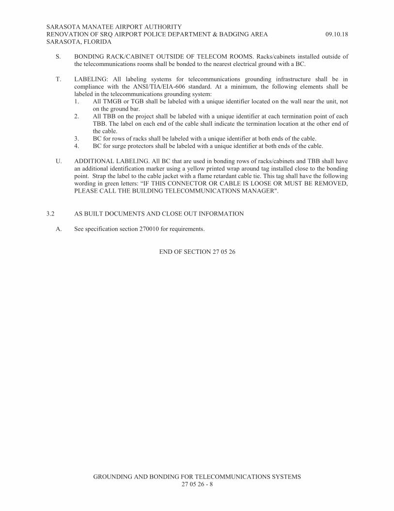
SARASOTA MANATEE AIRPORT AUTHORITY RENOVATION OF SRQ AIRPORT POLICE DEPARTMENT & BADGING AREA 09.10.18
SARASOTA, FLORIDA
GROUNDING AND BONDING FOR TELECOMMUNICATIONS SYSTEMS 27 05 26 - 8
S. BONDING RACK/CABINET OUTSIDE OF TELECOM ROOMS. Racks/cabinets installed outside of the telecommunications rooms shall be bonded to the nearest electrical ground with a BC.
T. LABELING: All labeling systems for telecommunications grounding infrastructure shall be in compliance with the ANSI/TIA/EIA-606 standard. At a minimum, the following elements shall be labeled in the telecommunications grounding system: 1. All TMGB or TGB shall be labeled with a unique identifier located on the wall near the unit, not
on the ground bar. 2. All TBB on the project shall be labeled with a unique identifier at each termination point of each
TBB. The label on each end of the cable shall indicate the termination location at the other end of the cable.
3. BC for rows of racks shall be labeled with a unique identifier at both ends of the cable. 4. BC for surge protectors shall be labeled with a unique identifier at both ends of the cable.
U. ADDITIONAL LABELING. All BC that are used in bonding rows of racks/cabinets and TBB shall have an additional identification marker using a yellow printed wrap around tag installed close to the bonding point. Strap the label to the cable jacket with a flame retardant cable tie. This tag shall have the following wording in green letters: “IF THIS CONNECTOR OR CABLE IS LOOSE OR MUST BE REMOVED,
PLEASE CALL THE BUILDING TELECOMMUNICATIONS MANAGER".
3.2 AS BUILT DOCUMENTS AND CLOSE OUT INFORMATION
A. See specification section 270010 for requirements.
END OF SECTION 27 05 26

SARASOTA MANATEE AIRPORT AUTHORITY
RENOVATION OF SRQ AIRPORT POLICE DEPARTMENT & BADGING AREA 09.10.18 SARASOTA, FLORIDA
RACEWAYS FOR TECHNOLOGY
270528 - 1
SECTION 27 05 28 - RACEWAYS FOR TECHNOLOGY
PART 1 - GENERAL
1.1 RELATED DOCUMENTS
A. General: The drawings and general provisions of the Contract, including General and Supplementary
Conditions and the Division 1 specification sections, apply to the work of this section.
B. Section 260533 - Raceway Systems applies to the work of this Section. Specifications requirements described
herein take precedence over Section 260533.
C. Supplemental: Refer to the specification sections identified below for additional requirements, which are
supplemented by this section.
1. 270010 Technology General Provisions
2. 270526 Grounding and Bonding for Telecommunications Systems
1.2 DESCRIPTION
A. General: Furnish and install, complete with all accessories a raceway system as indicated on the construction
drawings for support of the Structured Cabling System (SCS) and routing of other technology systems. The
goal of the project is to provide a reliable raceway architecture within the building that shall serve as a support
for transport of data, voice telephony, security, and audio/visual cabling throughout the building. The
raceway shall be routed from designated demarcation points to various wall, floor, ceiling, column, room, and
other locations as indicated on the contract drawings and described herein. The cabling that shall be supported
includes, but is not limited to:
1. Copper: Balanced twisted four pair category plenum or non-plenum cable, multipair balanced twisted
pair plenum and Non-plenum.
2. Fiber Optic: Air blown fiber optic cables and conventional fiber optic cables plenum or non-plenum.
3. Other: Hybrid and composite cables plenum or non-plenum.
B. General: Pathways shall be provided and located as shown in the quantities indicated on the drawings.
Pathways shall terminate in rooms or closets using approved fasteners and termination hardware. All conduit
stubs shall use bushings and shall be reamed to eliminate sharp edges. All Pathways shall be identified at all
locations.
C. The Installer should anticipate that all products and installation procedures shall comply with ANSI/TIA/EIA-
569-A (CSA T530) requirements at a minimum.
D. General: Installation of the raceways for communications shall be a complete system including all supports
and hangers as required per contract documents and manufacturer’s installation guidelines.
E. Support: All raceways shall be supported from the structural portion of the building. Supports and hangers
shall be of a type approved by Underwriters' Laboratories. Ceiling grid support wire can be used for support
as long as the support wire is used for this sole purpose and not to support the ceiling or other devices. Boxes
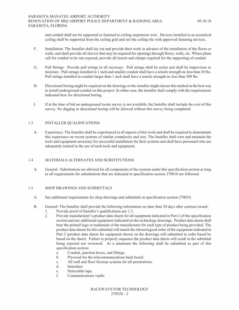
SARASOTA MANATEE AIRPORT AUTHORITY
RENOVATION OF SRQ AIRPORT POLICE DEPARTMENT & BADGING AREA 09.10.18 SARASOTA, FLORIDA
RACEWAYS FOR TECHNOLOGY
270528 - 2
and conduit shall not be supported or fastened to ceiling suspension wire. Devices installed in an acoustical
ceiling shall be supported from the ceiling grid and not the ceiling tile with approved fastening devices.
F. Installation: The Installer shall lay out and provide their work in advance of the installation of the floors or
walls, and shall provide all sleeves that may be required for openings through floors, walls, etc. Where plans
call for conduit to be run exposed, provide all inserts and clamps required for the supporting of conduit.
G. Pull Strings: Provide pull strings in all raceways. Pull strings shall be nylon and shall be impervious to
moisture. Pull strings installed in 1 inch and smaller conduit shall have a tensile strength no less than 30 lbs.
Pull strings installed in conduit larger than 1 inch shall have a tensile strength no less than 200 lbs.
H. Directional boring might be required on the drawings or the installer might choose this method as the best way
to install underground conduit on this project. In either case, the installer shall comply with the requirements
indicated here for directional boring.
I. If at the time of bid an underground locate survey is not available, the Installer shall include the cost of this
survey. No digging or directional boring will be allowed without this survey being completed.
1.3 INSTALLER QUALIFICATIONS
A. Experience: The Installer shall be experienced in all aspects of this work and shall be required to demonstrate
this experience on recent systems of similar complexity and size. The Installer shall own and maintain the
tools and equipment necessary for successful installation for their systems and shall have personnel who are
adequately trained in the use of such tools and equipment.
1.4 MATERIALS ALTERNATES AND SUBSTITUTIONS
A. General: Substitutions are allowed for all components of the systems under this specification section as long
as all requirements for substitutions that are indicated in specification section 270010 are followed.
1.5 SHOP DRAWINGS AND SUBMITTALS
A. See additional requirements for shop drawings and submittals in specification section 270010.
B. General: The Installer shall provide the following information no later than 30 days after contract award:
1. Provide proof of Installer’s qualifications per 1.3.
2. Provide manufacturer’s product data sheets for all equipment indicated in Part 2 of this specification
section and any additional equipment indicated on the technology drawings. Product data sheets shall
bear the printed logo or trademark of the manufacturer for each type of product being provided. The
product data sheets for this submittal will match the chronological order of the equipment indicated in
Part 2 (product data sheets for equipment shown on the drawings will submitted in order based be
based on the sheet). Failure to properly sequence the product data sheets will result in the submittal
being rejected not reviewed. At a minimum the following shall be submitted as part of this
specification section:
a. Conduit, junction boxes, and fittings.
b. Plywood for the telecommunications back board.
c. All wall and floor firestop systems for all penetrations.
d. Innerduct.
e. Detectable tape.
f. Communications vaults.

SARASOTA MANATEE AIRPORT AUTHORITY
RENOVATION OF SRQ AIRPORT POLICE DEPARTMENT & BADGING AREA 09.10.18 SARASOTA, FLORIDA
RACEWAYS FOR TECHNOLOGY
270528 - 3
g. Conduit waterfalls.
1.6 WORK EXTERNAL TO THE BUILDING
A. General: Any work external to the confines of the building shown on the Construction Documents shall be
governed by the provisions of this specification.
PART 2 - PRODUCTS
2.1 CONDUIT
A. All conduit shall be as indicated in Specification Division 26
B. Acceptable manufacturers: Carlon Type EB, Queen City Plastics, or accepted substitution.
2.2 GUTTER TROUGH
A. General: The gutter trough shall be NEMA 1 rated lay-in type and sized as shown on. The sides and bottom
shall contain no electrical conduit knock-outs unless shown otherwise on the drawings. The Installer shall
punch holes required for conduit penetrations. The cover shall be hinged with quarter turn fasteners to hold
the cover shut. Covers and bodies shall be 16 gauge steel.
B. Approved manufacturers: Hoffman Engineering Company, Square "D", or Steel City.
2.3 PLYWOOD TELECOMMUNCIATIONS BACKBOARD
A. Plywood telecommunications backboard: The plywood telecommunications backboards shall be installed on
the walls of each telecommunications room. The backboards shall measure 8 feet x 4 feet and installed 8
inches AFF to minimize the risk of damage to the backboard. The telecommunications rooms shall have the
walls covered with the backboard as indicated on the drawings. The backboard shall be 3/4 inch AC Grade
with the best side out. All imperfections and voids shall be filled, sealed and sanded prior to being primed and
painted with two (2) coats of UL Classified, fire retardant intumescent paint on the front, back and all four
sides of the plywood. Fire retardant coating shall be tested to UL723, “Test for surface burning characteristics
of building materials.” Color to be grey, white or blue. Coordinate color selection with the Owner/Architect.
The backboards shall be clearly labeled with the name of the Backboard Manufacturer, UL Classification of
the Fire Retardant Coating, NFPA 255 Coating Flame Spread Index Class and the APA Grade of the plywood.
One section of the backboard that shows has this stamped information shall be left unfinished for verification
purposes.
B. Approved manufacturers: Series Pathways & Spaces, Inc. ReadySpec Series or equal, field fabricate
backboards to all of the specifications listed above for TBB.
2.4 THROUGH WALL / FLOOR FITTING FIRE STOP SYSTEM
A. General. The systems covered under this specification are for firestop systems used in through penetrations of
a wall or floor. These systems are used to maintain the fire rating of the wall or floor, as well as to route and
protect power and/or communications conduit and cable distribution for commercial facilities.

SARASOTA MANATEE AIRPORT AUTHORITY
RENOVATION OF SRQ AIRPORT POLICE DEPARTMENT & BADGING AREA 09.10.18 SARASOTA, FLORIDA
RACEWAYS FOR TECHNOLOGY
270528 - 4
B. Classification and use: The firestop system to be used in through penetration shall have previously been
examined and tested by Underwriters Laboratories Inc. to UL1479 (ASTM E 814) and bear the U.S. and
Canadian UL Classification Mark. The system shall be classified for use in one, two, three, and four hour
rated walls and provide a maximum L (air leakage) rating of 3.3 cfm. The system shall be classified for use in
one, two, and three hour rated concrete floors having a minimum 4 ½ inch thick reinforced lightweight or
normal weight (100-150 psf) concrete. The devices shall also have been tested by Underwriters Laboratories
Inc. to UL2043 and determined to be suitable for use in air distribution plenum spaces. The entire fire stop
systems shall be listed. Components from other systems or that have not been listed with the system being
installed shall not be used.
C. Materials:
1. Box: The fire stop device box shall be constructed of 16 gauge G90 steel.
2. Intumescent block: The fire stop device’s intumescent block shall be constructed of a graphite base
material with an unrestrained expansion of 6 to 12 times normal size starting at 375º F. The
intumescent block shall be securely mounted to the box in order to prevent tampering and damage
during installation.
3. Adjustable doors: the fire stop device shall have doors or other closing systems which can be adjusted
to prevent unnecessary gaps between cabling and the fire stop device if the device is empty, partially
full, or completely full. The doors shall be constructed of 16 gage G90 steel with no. 10-32 screws use
to adjust opening size.
4. Heat shield: For retrofit applications where an existing in-wall conduit extends out from the wall more
than 7/8" [22mm], a UL listed Heat Shield must be used in order to maintain UL Fire Classification.
The firestop device is then installed onto the heat shield
D. Sleeve system: For retrofit applications where no conduit is installed in the wall to protect existing cabling, a
split conduit assembly should be used to provide fire rating. After installing the split conduit within the wall, a
wall plate should be installed to cover any gaps between the sleeve and the wall.
E. Sizes: the fire stop device shall be available for two (2) inch to four (4) inch trade size EMT conduit.
F. Finish: the fire stop device shall be available in safety yellow, orange, custom colors, and an unpainted
galvanized finish.
G. Approved manufacturers: Wiremold FlameStopper, STI EZpath, or approved equal
2.5 FIRE STOP SYSTEMS FOR SMALL PENETRATIONS
A. General: Fire stop systems shall be selected by the Installer as to comply with the following requirements:
1. The selected system shall be UL listed for the conditions in which it will be installed. These conditions
include: wall/slab type (masonry, drywall, etc), hour rating, and accessibility.
B. Acceptable manufacturers: caulk based products or firestop grommets by STI or equal.
2.6 CONDUIT WATERFALLS
A. All 4 inch EMT stub outs with communications cable entering/exiting the conduit from a cable tray system
shall be fitted with a device to control the bend radius of the communication cable to a minimum of a 4 inch
radius. The device that controls the bend radius shall be called a conduit waterfall and must comply with all
National Electrical Code and TIA/EIA standards. The product must be RoHS compliant to meet
environmental requirements, UL 94V-0 approved to reduce the spread of flame, and approved by UL for use

SARASOTA MANATEE AIRPORT AUTHORITY
RENOVATION OF SRQ AIRPORT POLICE DEPARTMENT & BADGING AREA 09.10.18 SARASOTA, FLORIDA
RACEWAYS FOR TECHNOLOGY
270528 - 5
in air handling plenum spaces. The conduit waterfall must support a static load of 40 lbs. and have a fastening
device that allows for incremental adjustments necessary to conform to variances in conduit diameter.
B. Approved manufacturers: Panduit CWF 400 or approved equal.
2.7 EXPANSION FITTINGS
A. Installation: Provide expansion fittings in each conduit run wherever the conduit crosses an expansion joint.
Install the fitting on one side of the joint with its sliding sleeve end flush with joint, and with a length of
bonding jumper in the expansion equal to at least three times the normal width of expansion joint.
PART 3 - EXECUTION
3.1 INSTALLATION PRACTICES
A. See additional requirements indicated in Part 3 of specification section 270010.
3.2 INDOOR INSTALLED CONDUITS BELOW GRADE AND ABOVE GRADE
A. Bend radius: Conduits shall utilize long radius sweeps for all 90 degree bends. The inside radius of a conduit
bend shall be at least six (6) times the internal diameter. When the conduit size is greater than 2 inches, the
inside radius shall be at least ten (10) times the internal diameter of the conduit. For fiber optic cable, the
inside radius of a bend shall always be at least ten (10) times the internal diameter of the conduit
B. Maximum distance between pull boxes: For indoor installation no section of conduit shall be longer than 100
feet or contain more than two (2) 90 degree bends between pull points without the installation of a pull box.
For outdoor installations no section of conduit shall be longer than 500 feet or contain more than two (2) 90
degree bends between pull points without the installation of a pull box.
C. Labeling: All indoor conduits 2 inches or larger shall be labeled at both ends when these conduit runs are
continuous between two rooms and going through multiple walls or slabs. Labeling materials shall be as
indicated in specification section 270010. Conduit sleeves 2” or larger penetrating just one wall are not
required to be labeled.
D. Pull strings: All conduits for technology systems shall be installed with pull strings.
3.3 UNDERGROUND TELECOMMUNICATIONS DUCT BANK
A. Description: Underground duct banks shall be composed of individual conduits installed adjacent to each
other. Conduits shall be encased in concrete where indicated on the drawings. The conduits shall be
constructed from sunlight resistant PVC Schedule 40 that meets the requirements of UL 651 and NEMA TC
6, unless indicated or specified otherwise. The use and installation of the duct bank shall be in accordance
with the National Electrical Code requirements for the installation of non-metallic rigid conduit. The conduit
used shall not be smaller than 4 inches in diameter unless otherwise noted on the drawings.
B. Sloping: The duct banks leaving a building shall have a continuous slope downward toward the
communication vaults with a pitch of not less than 0.125 inches per foot. Manufactured bends shall have a
minimum radius of 48 inches.

SARASOTA MANATEE AIRPORT AUTHORITY
RENOVATION OF SRQ AIRPORT POLICE DEPARTMENT & BADGING AREA 09.10.18 SARASOTA, FLORIDA
RACEWAYS FOR TECHNOLOGY
270528 - 6
C. Conduits termination: Conduits shall terminate in end-bells where duct banks enter communications vaults.
Provide reducers as required. When multiple conduits are installed adjacent to each other, each end shall be a
painted a different color where the conduit enters a communications vault or building. Conduit separators
within a duct bank shall be constructed of pre-cast concrete, high impact polystyrene, steel or any combination
of these. The joints of the conduits shall be staggered to provide the duct bank with the maximum strength
possible. During construction all open duct banks shall be protected from the entrance of debris by means of
suitable conduit plugs. After the duct bank is completed, a testing mandrel with stiff bristles that is not less
than 13 inches long and with a diameter 1/4 inch less than the size of the conduit shall be drawn through from
both sides until the conduit is clear of all debris. After this is complete provide a conduit plug on the conduit
for those conduits that are stubbed out underground and buried.
D. Conduit storage: All PVC conduit, fittings, and joints shall not be stored in the sun or weather, in an
excessively heated space, or unevenly supported during storage.
E. Trenching: Trenches for duct banks shall be completely dry before installing conduits or pouring concrete.
Well point as required to keep the trench dry.
F. Excavation: Backfilling shall be in layers not more than 8 inches deep, and shall be thoroughly tamped after
is layer is placed. The first layer shall be earth or sand, free from particles that would be retained in a 1/4 inch
sieve. The succeeding layers shall be excavated material having stones no larger than would pass through a 4
inch ring. The backfill shall be level with adjacent surface, except in sodded or paved areas. At these
locations a space equal to the thickness of the sod or paving shall be left.
G. Plugging: All unused conduit openings shall be plugged or capped with a suitable device designed for the
intended purpose. Caulking compound shall not be used for plugging unused conduit openings.
H. Stubs: Spare conduit stubs shall be capped and marked in the field and accurately dimensioned on the as-built
drawings.
I. Spacers: All conduit installed underground or stubbed above floor from underground shall be separated with
plastic interlocking spacers manufactured specifically for this purpose. Another option shall be to strap the
conduit to a Kindorf channel supported by conduit or steel rods driven into the ground.
J. Minimum burial depth: All underground duct bank (with the exception of single conduit raceways installed
under floor slab) shall be installed in accordance with Section 300 5 of the NEC. The minimum cover for any
conduit or duct bank shall be two (2) feet, unless otherwise indicated.
K. Directional boring. For all applications requiring directional boring the following installation practices shall
be followed.
1. The Installer shall select the directional boring equipment based on the length of the pull, soil
conditions, conduit size, and conduit quantity.
2. When multiple conduits are installed adjacent to each other, each end shall be a painted a different
color where the conduit enters a communications vault or building.
3. Any conduit with a directional bore distance less than 500 feet shall be a continuous bore without
splices.
4. Any splices to HDPE conduit shall be done using the manufacturer’s approved methods.
3.4 CUTTING AND PATCHING
A. Core Drilling: The Installer shall be responsible for all core drilling as required for work under this section,
but in no case shall the Installer cut into or weld onto any structural element of the project without the written

SARASOTA MANATEE AIRPORT AUTHORITY
RENOVATION OF SRQ AIRPORT POLICE DEPARTMENT & BADGING AREA 09.10.18 SARASOTA, FLORIDA
RACEWAYS FOR TECHNOLOGY
270528 - 7
approval of the A&E and the structural engineer. All concrete slabs above ground level shall be X-rayed prior
to coring by the Installer.
B. Cutting and Patching: All cutting, rough patching, and finish patching shall be provided as specified in the
contract documents. All cutting and patching shall be performed in a neat and workmanlike manner.
C. Openings and Sleeves: Locate all openings required for work performed under this section. Provide sleeves,
guards, or other accepted methods to allow passage of items installed under this section. All sleeves that pass
through a wall shall be securely fastened to the wall support structure (studs) or grouted in place.
D. Roof Penetrations: All roof penetrations for raceways that are part of technology systems shall be approved by
A&E prior to executing this work. All roof penetrations shall be as accepted and approved by the roof
membrane manufacturer.
3.5 IDENTIFICATION OF BOXES
A. Tags: During installation of the pull strings all pull strings shall be marked with waterproof vinyl tags
indicating where the opposite end may be found. Tagging is not required where the conduit is stubbed out to
the ceiling for one outlet box.
3.6 BLANK PLATES
A. Plates: Unless otherwise noted all unused outlet boxes shall receive blank plates matching the finish of the
plates for electrical devices in the same room.
3.7 RACEWAY INSTALLATION
A. Support: All raceways shall be run in a neat and workmanlike manner and shall be properly supported in
accordance with the latest edition of the NEC and BICSI guidelines. Exposed raceways where allowed, shall
be supported with one hole straps (fasteners based on structure construction). All conduits shall be securely
fastened in place with at least one support per eight foot section. The required hangers, supports and fasteners
shall be provided at each elbow and no more than 1 foot from termination. The use of perforated iron for
supporting conduits shall not be permitted. The required strength of the supporting equipment and size and
type of anchors shall be based on the combined weight of the conduit, hanger, and cabling. Horizontal and
vertical conduit runs may be supported by one-hole straps, clamp-backs, or other accepted devices with
suitable bolts, expansion shields (where needed), or beam-clamps for mounting to building structure or special
brackets.
B. Hanger installation: Where two or more 1 inch conduits or larger are run parallel to each other, trapeze
hangers may be used. Trapeze hangars shall consist of anchors, threaded rods, spring nuts, and unistrut cross
members. These conduits shall be individually fastened to the cross member of every trapeze hanger with
galvanized pipe straps.
C. Fire stopping: For 4” sleeves, the Installer shall provide a through wall/floor firestop system. For smaller
sleeves or wall penetrations through fire rated partitions the Installer can use the same type of firestop system
or a fire stop system for small penetrations in compliance with the products described in Part 2 of this
specification.
D. Membrane penetrations in fire rated partitions: Installation of electrical boxes or equipment backboxes in fire
rated walls and smoke barriers shall follow the following requirements:

SARASOTA MANATEE AIRPORT AUTHORITY
RENOVATION OF SRQ AIRPORT POLICE DEPARTMENT & BADGING AREA 09.10.18 SARASOTA, FLORIDA
RACEWAYS FOR TECHNOLOGY
270528 - 8
1. Electrical boxes and / or technology system backboxes can be installed in 1 or 2 hour rated walls as
long as all requirements indicated in the proper Building Code, National Electrical Code, and
nationally recognized testing laboratories are met for this type of installation. In Florida, see Section
713 of the Florida Building Code 2010, article 300.21 of the NEC 2010 and UL database website for
acceptable product to be used.
2. As a summary, some of the requirements indicated by the codes listed above are:
a. Boxes shall be metallic or listed for that purpose
b. The overall wall area of the boxes shall not exceed 16 square inches, provided the total
aggregate area of the openings through the membrane does not exceed 100 square inches in any
100 square feet of wall area.
c. The gap between the wall membrane and the box shall not exceed 1/8 of an inch.
d. Boxes on opposite sides of the walls shall be separated by no less than 24 inches, or boxes shall
be covered by listed fire rated putty pads.
3. Electrical boxes or technology system backboxes shall not be installed in a 3 or 4 hour fire rated wall.
Boxes installed on these walls shall be surface mounted.
E. Routing: Conduits shall be run parallel to building walls wherever possible and shall be exposed or concealed
as specified. Conduits shall be grouped in workmanlike fashion. Crisscrossing of conduits shall be minimized.
F. Protection during construction: All raceways, whether terminated in boxes or not, shall be capped during the
course of construction until wires are pulled in them and junction box covers are in place. No conductors
shall be pulled into raceways until the raceway system is clean and complete.
G. Protective bushings: All un-terminated conduits (stub out) shall have an insulated protective bushing to avoid
cable damage at the edge of the conduit.
H. Avoiding EMI: To avoid EMI for technology systems cabling and/or conduit containing cabling, all raceways
shall provide clearances of at least 4 feet from motors or transformers; 1 foot from conduit and cables used for
electrical-power distribution; and 5 inches from fluorescent lighting. Raceways shall cross perpendicular to
fluorescent lighting and electrical-power cables and conduits. The Installer shall not place any raceway
adjacent to power distribution lines.
I. Coordination: All raceways shall be kept clear of mechanical, electrical, and plumbing equipment to facilitate
future repair or replacement of said equipment without disturbing the technology systems cabling. Except
where it is necessary for control purposes, all raceways shall be kept away from items producing heat.
J. Masonry Installation: All raceways installed inside masonry walls shall be installed at the same time as the
masonry so that no face cutting is required, except to accommodate boxes.
K. Use of conduit in different areas: When technology systems cables have to be run above ground in a space
with no type of accessible ceiling (interior or exterior), all cable runs shall be in conduit completely. Conduit
shall be installed to the nearest accessible ceiling (in the direction of the telecommunications room).
Conduits can be grouped into a single larger diameter conduit with the same or larger cross sectional area than
the sum of all the conduits coming into it. The use of j-hooks to support technology systems cables in areas
with no ceiling or hard ceiling shall not be allowed. This is usually not indicated in the drawings because
design drawings don’t show conduits smaller than 2”, nevertheless it shall be provided as indicated herein.
L. Use of conduit for different systems: The following paragraphs indicate the design intent for raceways for all
technology systems.
1. For all technology systems indicated on the drawings, provide a junction box and 1” conduit from the
device to the nearest telecommunications room.

SARASOTA MANATEE AIRPORT AUTHORITY
RENOVATION OF SRQ AIRPORT POLICE DEPARTMENT & BADGING AREA 09.10.18 SARASOTA, FLORIDA
RACEWAYS FOR TECHNOLOGY
270528 - 9
3.8 AS BUILT DOCUMENTS AND CLOSE OUT INFORMATION
A. See specification section 270010 for as built and close out information.
END OF SECTION 27 05 28
SARASOTA MANATEE AIRPORT AUTHORITY
RENOVATION OF SRQ AIRPORT POLICE DEPARTMENT & BADGING AREA 09.10.18 SARASOTA, FLORIDA
RACEWAYS FOR TECHNOLOGY
270528 - 10
THIS PAGE INTENTIONALLY BLANK
SARASOTA MANATEE AIRPORT AUTHORITY RENOVATION OF SRQ AIRPORT POLICE DEPARTMENT & BADGING AREA 09.10.18 SARASOTA, FLORIDA
STRUCTURED CABLING SYSTEM 27 10 00 - 1
SECTION 27 10 00 - STRUCTURED CABLING SYSTEM
PART 1 - GENERAL
1.1 SCOPE OF WORK
A. General: The overall and detailed Structured Cabling System (SCS) design shown on the technology drawings apply to the work indicated in this specification section.
B. General: Furnish, install, test, and certify (complete with all required accessories) an ANSI/TIA 568C SCS with a minimum 25 year performance warranty for the entire system from the manufacturer and a minimum of 3 years warranty for materials and labor from the Installer for all components not covered under the manufacturer’s 25 year warranty. The goal of the SCS design is to provide an enhanced system that shall serve as a vehicle for the transport of voice telephony, data, audio, video, security, and other low voltage systems throughout the buildings to outlets located at various desk, workstation, and other locations as indicated in the contract drawings.
C. All two post racks and equipment cabinets for this project shall be provided and installed by the structured cabling contractor. This includes all grounding bars, UPS, power strips, slide out trays, and drawers. Blank panels are to be provided and installed by the Audio Visual Systems contractor.
D. Coordination with other trades: It is the responsibility of the SCS Installer to verify and advise the Installer of the raceway infrastructure (conduit, boxes, cable tray, in ground boxes, etc) on raceway routing to minimize the wiring distances to the telecommunication rooms. When J-hooks are acceptable for use in structured cabling system, all J-hooks and supports for these devices shall be in the scope of work of the SCS Installer.
E. All patching and cross connects to Owner provided equipment shall be included under this scope of work for the project unless otherwise noted.
1.2 RELATED DOCUMENTS
A. General: The drawings and general provisions of the Contract, including General and Supplementary Conditions and Division 1 shall apply to the work of this section
B. Supplemental: Refer to the specification sections identified below for additional requirements, which are supplemented by this section: 1. 270010 Technology General Provisions 2. 270526 Grounding and Bonding for Telecommunications Systems 3. 270528 Raceways for Technology
C. Standards: All work related to the SCS shall be in compliance with the following industry codes and standards, latest edition: 1. ANSI/TIA-568-C.0 “Generic Telecommunications Cabling for Customer Premises” with
addendums and errata. 2. ANSI/TIA-568-C.1, “Commercial Building Telecommunications Cabling Standard” with
addendums and errata. 3. TIA-568-C.2, “Commercial Building Telecommunications Cabling Standard Part 2: Balanced
Twisted- Pair Cabling Components” with addendums and errata. 4. ANSI/TIA-568-C.3, “Optical Fiber Cabling Component Standard” \with addendums and errata.

SARASOTA MANATEE AIRPORT AUTHORITY RENOVATION OF SRQ AIRPORT POLICE DEPARTMENT & BADGING AREA 09.10.18 SARASOTA, FLORIDA
STRUCTURED CABLING SYSTEM 27 10 00 - 2
5. TIA-569-C, “Telecommunications Pathways and Spaces” with addendums and errata. 6. ANSI/NECA/BICSI 568-2006, “Standard for Installing Commercial Building Telecommunications
Cabling”. 7. TIA-606-B, “Administration Standard for Telecommunications Infrastructure” with addendum and
errata. 8. TIA-607-B “Commercial Building Grounding (Earthing) and Bonding requirements for
Telecommunications” with addendum and errata. 9. NECA/BICSI 607-2011, Standard for Telecommunications Bonding and Grounding Planning and
Installation Methods for Commercial Buildings. 10. TIA-526-7 “Measurement of Optical Power Loss of Installed Single-Mode Fiber Cable Plant”.
December 2008 11. TIA-526-14B “Optical Power Loss Measurements of Installed Multimode Fiber Cable Plant”.
October 2010. 12. TIA-598-C. Optical Fiber Cable color coding. . 13. IEC/TR3 61000-5-2 - Ed. 1.0 and amendments. “Electromagnetic compatibility (EMC) - Part 5:
Installation and mitigation guidelines - Section 2: Earthing and cabling” 14. ANSI/TIA-942-A , “Telecommunications Infrastructure Standard for Data Centers” with addendum
and errata 15. ANSI/BICSI 002-2011, Data Center Design and Implementation Best Practices 16. ANSI/NFPA 70 “National Electrical Code”, CSA C22.1. 17. BICSI Telecommunications Distribution Methods Manual (TDMM) 18. BICSI Telecommunications Cabling Installation Manual (TCIM) 19. BICSI Customer Owned Outside Plant Manual (COOPM) 20. Local County/City Codes, Ordinances and Regulations. 21. Underwriters Laboratories (UL) 22. FCC -Federal Communications Commission 23. ADA Requirements 24. Occupational Safety and Health Regulations (OSHA) 25. National Fire Protection Association (NFPA) 26. ANSI/TIA-1179, Healthcare Facility Telecommunications Infrastructure Standards 27. Florida Statutes and Administrative Rules 28. Manufacturers Product Cabling Catalogs 29. Manufacturers Training Manuals (Design and Installation).
D. General: The installation practices for the SCS as describe herein shall take precedence over any other part of the construction documents.
1.3 STRUCTURED CABLING SYSTEM INSTALLER QUALIFICATIONS
A. The Installer for the project must be certified by the manufacturer of the products being installed. The installation shall adhere to the manufacturer’s engineering, installation, and testing procedures. Only utilize the authorized manufacturer’s components and distribution channels for each type of installation required.
B. The installer directly responsible for this work shall be a SCS Installer who has been regularly engaged in the installation of commercial and industrial systems matching the type, size, and complexity of this project for at least the last five years. Any other company working for the SCS Installer of this system shall have the same training and certifications as the SCS Installer.
C. Certification: The SCS Installer’s project manager shall possess a current BICSI Registered Communications Distribution Designer (RCDD®) certificate. The project manager shall be directly employed by the Installer and not employed by a third party. All shop drawings submitted by the SCS Installer shall bear them project manager’s RCDD's stamp. The Installer’s on site supervisor assigned to the project shall be a certified BICSI Level II installer or have proven and qualified experience that is equal to this certification.

SARASOTA MANATEE AIRPORT AUTHORITY RENOVATION OF SRQ AIRPORT POLICE DEPARTMENT & BADGING AREA 09.10.18 SARASOTA, FLORIDA
STRUCTURED CABLING SYSTEM 27 10 00 - 3
D. Experience: The SCS Installer shall be experienced in all aspects of this work and shall be required to demonstrate direct experience on recent systems of similar type, size, and complexity. The SCS Installer shall own and maintain the tools and equipment necessary for successful installation and testing of SCS and have personnel who are adequately trained in the use of such tools and equipment. The Owner or Engineer may elect to request the submission of additional financial, operational, and administrative information for the SCS Installer in order to demonstrate the required experience.
E. The SCS Installer shall possess a State of Florida Low Voltage Electrical License.
F. The SCS Installer shall maintain a permanent office within 100 miles of the project site.
1.4 MATERIALS ALTERNATES AND SUBSTITUTIONS
A. The SCS Installer shall follow all requirements for material alternates and substitutions indicated in specification section 270010.
B. Substitutions are only allowed for the SCS when the substitutions do not change the manufacturer’s
warranty of the SCS as indicated in this specification section
1.5 SHOP DRAWINGS AND SUBMITTALS.
A. See additional requirements for shop drawings and submittals in specification section 270010.
B. Initial Submittal: The SCS Installer shall submit the following information upon receiving approval to execute the work: 1. A list of five recently completed projects of similar type, size, and complexity with the contact
names and telephone numbers for each. 2. A list of test equipment proposed to verify the integrity of the installed SCS. The test equipment list
shall include the manufacturer’s part number, serial numbers, and a copy of the last calibration report (with the date of calibration indicated). The equipment calibration shall not be older than one year. Test equipment includes but is not limited to: cable certifiers, OTDRs, fiber splicers.
3. A technical resume of experience for the Installer’s engineer/RCDD and on-site foreman who will be assigned to the project, including the RCDD license number (copy of the RCDD certificate is preferred).
4. Similar documentation for any company working for the SCS Installer who will assist in the performance of this work.
5. A copy of a current and valid Low voltage License for the State of Florida. 6. Location of the office from which installation and warranty work will be performed.
C. Drawing and product data submittals: Once the initial submittal has been reviewed and approved by the Architect and Engineer (A&E) of the project, the SCS Installer shall provide all drawing and product data submittals. The drawing and product data submittal is composed of the following items: 1. Provide manufacturer’s product data sheets for all equipment indicated in Part 2 of this specification
section and any additional equipment indicated on the technology drawings. Product data sheets shall bear the printed logo or trademark of the manufacturer for each type of product being provided. The product data sheets for this submittal will match the chronological order of the equipment indicated in Part 2 (product data sheets for equipment shown on the drawings will submitted in order based be based on the sheet). Failure to properly sequence the product data sheets will result in the submittal being rejected not reviewed.
2. Faceplate color selection.

SARASOTA MANATEE AIRPORT AUTHORITY RENOVATION OF SRQ AIRPORT POLICE DEPARTMENT & BADGING AREA 09.10.18 SARASOTA, FLORIDA
STRUCTURED CABLING SYSTEM 27 10 00 - 4
3. A detailed explanation of the labeling scheme to be used for all components of the system. This explanation shall include examples of all label types to be used such as labels for cables, patch panels, outlet jacks, etc.
4. Autocad® or Revit shop drawings matching the size of the design documents with the following information: a. Floor plans indicating all outlets on the project. All outlets shall be tagged with the label to
be used during the identification and tagging process described in this specification section. b. Enlarged telecommunication rooms with all equipment components and rack layouts for each
room. All racks shall be indicated with the label to be used during the identification and tagging process described in this specification section.
c. Drawings indicating the elevation for all cabinets or racks on the project. The elevations shall identify the precise quantity of patch panels, fiber distribution center,s and wire managers with accurate RU heights based on the equipment selection. All equipment shall be tagged with the label to be used during the identification and tagging process described in this specification section.
d. A spreadsheet indicating all patch cords (fiber and copper) to be provided in the project. The spreadsheet shall indicate the quantity, color of the jacket, cable type, length, and connector termination on each side.
D. Drawing and product data submittals received before the initial submittal is approved will be rejected.
1.6 ABBREVIATIONS
A. General: The following abbreviations are used in this specification section: 1. A&E - Architect and Engineer. The Architect is the legal entity that holds a contract for the design
the project. The Engineer is the consulting engineer firm or engineer of record for the project who prepared this specification.
2. APC - Angle physical contact connector. Reference to the polish style of the ferrule in fiber optic connectors.
3. Array connector - a multi-strand fiber connector user for high density applications, such as the MPO connector
4. BICSI - Building Industry Consultant Services International 5. CCTV - Close circuit television system (surveillance video system) 6. FCC - Federal Communications Commission. 7. FTP - Foiled Twisted pair. One foiled screen around each cable pair. 8. IDC - Insulation Displacement Connector 9. NEC - National Electrical Code.® 10. NEMA - National Electrical Manufacturers Association. 11. OM1 - ISO 11801 designation for multimode 62.5/125µm glass fiber optics. 12. OM2 - ISO 11801 designation for multimode 50/125µm glass fiber optics. 13. OM3 - ISO 11801 designation for multimode laser optimized 50/125µm glass fiber optics. 14. OM4 - TIA designation for multimode laser optimized 50/125µm glass fiber optics in compliance
with TIA-492-AAAD. 15. OS1 - ISO 11801 designation for single mode 9/125µm glass fiber optics. 16. OS2 - ISO 11801 designation for single mode 9/125µm glass fiber optic with performance criteria
identical to ITU-T G652. 17. OTDR - Optical Time Domain Reflectometer. 18. RU - Rack units. Height dimension for rack mounted equipment. 1 RU equivalent to 1.75”. 19. SCS - Structured Cabling System 20. ScTP - Screened twisted pair. One foiled screen around all cable pairs 21. TIA - Telecommunications Industry Association. 22. TR - Telecommunications Room. 23. UPC - Ultra physical contact connector. Reference to the polish style of the ferrule in fiber optic
connectors.

SARASOTA MANATEE AIRPORT AUTHORITY RENOVATION OF SRQ AIRPORT POLICE DEPARTMENT & BADGING AREA 09.10.18 SARASOTA, FLORIDA
STRUCTURED CABLING SYSTEM 27 10 00 - 5
24. UTP - Unshielded twisted Pair 25. UV - Ultra violet 26. VAC - Volts alternating current.
PART 2 - PRODUCTS
2.1 EQUIPMENT CABINETS
A. Provide equipment cabinets where indicated on the Construction Drawings. The equipment cabinets shall be constructed from welded steel frames and shall have a powder coat painted finish. The equipment cabinets shall have the following specifications: 1. Cabinet construction material: Welded and bolted steel frames. 2. Footprint: 31”x 42” ±1” 3. Height: Usable height between 44 and 45 RU. 4. Rack rail type: Standards EIA 19” square holes with cage nut rail located in the front and back of
cabinet. Rack rails shall be adjustable for depth and shall have RUs marked and labeled. 5. Rack screw type: Cage nuts clipped to rack rails. Nuts and screws shall be provided for all slots in
the rack rails and shall be constructed of steel with #10-32 threads. 6. Side panels (end of row cabinet sides): Solid steel, removable, and locking. 7. Side panels (between adjacent cabinets): Solid steel, removable panels with manufacturer provided
penetrations for cable pass through. Penetrations shall be covered with removable plastic caps, rubber caps, or brushed openings. No less than eight openings shall be provide with each opening no less than 34 square inches in size.
8. Top panel: Solid steel with no less than four brushed openings for cables. Each opening shall be no less than 34 square inches in size.
9. Bottom panel: solid steel with no less than two brush protected openings for cables. Each opening shall be no less than 34 square inches in size. For cabinets with a top exhaust duct a bottom air director shall be provided on the back side of the cabinets to force air up towards the exhaust duct.
10. Door hinge supports shall be provided on both sides of the cabinet’s front and back to allow the door swing to be reversed.
11. Bonding: The cabinet shall be provided with a factory prepared location for connecting a bonding lug at the top and bottom of the cabinet frame. The doors shall include bonding jumper to cabinet.
12. Weight capacity: UL listed for 2,500 lbs. 13. Finish: Epoxy-polyester hybrid powder coated paint on frame, rails, panels, and metal accessories. 14. Finish color: Black for all parts of the cabinet
B. Equipment cabinets shall be provided with the following accessories: 1. Front: 78% perforated panel hinged door with keyed lock. 2. Rear: 78% perforated panel hinged doors with keyed lock. 3. Locking system: Locks for the front and rear doors shall be two point latching locks and shall be
keyed identically for front and rear lock. All locks for each user’s cabinets shall be keyed alike and different keys provided between user groups. Coordinate with Owner keying requirements for each cabinet.
4. Leveling: Provide leveling feet and all accessories required to bolt the cabinet to the floor with 1/2 inch screws or threaded rod.
5. Vertical cable managers: Provide cable wire managers in the front of the cabinet covering the full height of the rack rails. The vertical cable managers shall be as recommended by the equipment cabinet manufacturer to avoid obstructions to the rack rails and doors. The vertical cable managers shall have brush openings to run cables between the front and back of the cabinet and shall have all openings sealed to avoid air leakage between the front and back.
6. PDU bracket: PDU brackets shall be provided in each cabinet according to the number of vertical PDUs programmed to be installed in each cabinet (see drawings for configurations). These brackets

SARASOTA MANATEE AIRPORT AUTHORITY RENOVATION OF SRQ AIRPORT POLICE DEPARTMENT & BADGING AREA 09.10.18 SARASOTA, FLORIDA
STRUCTURED CABLING SYSTEM 27 10 00 - 6
shall be selected by the SCS Installer to match the support holes of the PDU selection for each cabinet.
7. All cabinets with equipment installed that has a substantial amount of cabling terminating in the rear of the equipment (such as audio/visual and security systems) shall be provided with metal cable lashing brackets to strap all cables to the frame for proper organization and support.
8. Ground bar: All cabinets shall be provided with a vertical copper ground bar covering the complete height of the rack rails. The ground bar shall be 1/8 inch thick and 1 inch wide with threated holes mounted to the cabinet using nylon insulation washers
C. Required equipment cabinet certifications: Complaint with EIA 310-E and UL 2416 listed.
D. Airflow re-director: The manufacturer of the equipment cabinet shall offer an air flow re-director kit for the type of cabinet selected for this project to allow for changing air flow direction if installed equipment is designed for side to side ventilation. The SCS installer shall provide air flow re-director kits for all cabinets equipped with core or edge networking switches and associated equipment.
E. Field cuts or openings. Any cabinet with field cuts or openings will be rejected and the SCS Installer shall provide a new cabinet to remedy the condition.
F. Approved manufacturers: Panduit, Middle Atlantic Products, Comm-Scope, or approved equal.
2.2 TWO POST RACKS
A. Provide two post racks where indicated on the Construction Drawings. The two post racks shall be constructed from aluminum or welded steel frames and shall have a powder coat painted finish. The two post racks shall have the following specifications: 1. Height: The two post rack shall provide a usable height of between 44 and 45 RU. 2. Channel depth: 6” ± 1” 3. Rack rails type: standards EIA 19” located in the front and back of each rack post. The rack rails
shall have the RU marked and labeled. 4. Rack screw type: #12-24 threaded rack rails. Screws shall be provided for all openings in the rack
rails and shall be made of steel. 5. Weight capacity: UL listed for 1,000 lbs. or more.
B. Two post racks shall be provided with the following accessories: 1. Runway cable tray mounting brackets to support the runway installed above the racks. 2. Isolation pads. 3. Grounding kit. 4. Ground bar: All cabinets shall be provided with a copper vertical ground bar covering the complete
height of the rack rails. The ground bar shall be 1/8" thick and 1" wide with threated holes mounted to the cabinet using nylon insulation washers.
5. End panels to support vertical cable managers at both ends of each rack row.
C. Front vertical cable managers shall be provided in between all racks and at both ends of the rack rows. The height of the vertical cable managers shall cover from the top to the bottom of each rack. The specifications for the vertical cable managers shall be: 1. Style: Metal cage with dual hinged cover door 2. Sides: Single sided wire manager (front only). 3. Capacity: Usable cross sectional area shall be a minimum of: 48 sq-in. 4. Accessories: Whenever the vertical cable manager supports the use of spools inside the unit, spools
shall be provided at all locations in the vertical cable manager. 5. Accessories: Whenever the vertical cable manager supports the use of spools inside the unit, spools
shall be provided at all locations in the vertical cable manager.

SARASOTA MANATEE AIRPORT AUTHORITY RENOVATION OF SRQ AIRPORT POLICE DEPARTMENT & BADGING AREA 09.10.18 SARASOTA, FLORIDA
STRUCTURED CABLING SYSTEM 27 10 00 - 7
D. Approved manufacturer: Match selection for Equipment Cabinets
2.3 PATCH PANELS FOR 4 PAIR BALANCED TWISTED PAIR HORIZONTAL CABLING
A. All 4-pair balanced twisted pair horizontal cables shall be terminated in a rack mounted patch panel located in the telecommunication room racks. These patch panels shall have the following specifications. 1. Connector type: 8P8C modular plug 2. Cable termination: T568B. 3. Performance requirement: CAT6 4. Maximum connectors per path panel allowed: 48 5. Patch panel type: Factory preloaded panels 6. Patch panel shape: Straight (flat) 7. Permanent marking: All connectors shall be labeled in sequential number 8. Field labels: Patch panels shall have a space for field labels covered with transparent protectors.
B. Approved manufacturers. Panduit, CommScope, Leviton.
2.4 HORIZONTAL CABLE MANAGERS
A. Horizontal cable managers shall be mounted on the racks to route cabling from the patch panels to the vertical cable managers and to rack installed equipment. Horizontal cable managers shall have the following specifications: 1. Style: Finger duct style with hinged cover 2. Sides: Front of rack 3. Minimum height: Two RU
B. Approved manufacturers. Match selection for patch panels.
2.5 CROSS OVER CABLE MANAGERS
A. Cross over cable managers shall be used to route patch cables from the right vertical cable manager to the left vertical cable manager or between racks. Cross over cable managers shall have the following specifications: 1. Style: Six port finger spacing with a cover 2. Sides: Front of rack 3. Minimum height: Four RU
B. Approved manufacturers. Match selection for balanced twisted pair patch panels.
2.6 FIBER OPTIC DISTRIBUTION CENTERS
A. All strands of the fiber optic cabling shall be terminated in fiber optic distribution centers (FODC). Inside premise horizontal fiber optic cabling shall be terminated inside the telecommunications room in a rack or wall mounted FODC. Backbone cabling shall be terminated at both ends in a rack or wall mounted FODC. The FODC is composed of an enclosure and snap on adapter plates / cassettes. The FODC shall have the following specifications: 1. Mounting: Use rack mounted FODCs in all rooms where racks or any type of rack rails are available.
Use wall mounted FODCs only when racks are not available such as in an outdoor enclosures or other interior spaces that do not serve as a telecommunications room.
SARASOTA MANATEE AIRPORT AUTHORITY RENOVATION OF SRQ AIRPORT POLICE DEPARTMENT & BADGING AREA 09.10.18 SARASOTA, FLORIDA
STRUCTURED CABLING SYSTEM 27 10 00 - 8
2. Size: The SCS Installer shall size the FODC based on the amount of fiber strands to be terminated and spliced in the FODC plus 20% spare capacity.
3. Front locking doors are required. 4. The front locking door shall be transparent with labeling cards. 5. When fiber splices are indicated on the Construction Drawings at an FODC, the enclosures shall be
selected by the SCS Installer as to accommodate the fiber splice trays.
B. The specifications for the snap on adapters for the FODC are as follows: 1. Style: Plate style 2. Connector type: LC to match the type of fiber cabling. 3. Maximum fiber strands allowed per adapter: 12 4. Security level: Non-keyed connector 5. Pairing style: duplex
C. Approved manufacturers. Corning, Panduit, CommScope
2.7 POWER STRIPS
A. All equipment cabinets and racks on the project shall be provided with at least one power strip. The power strip selection shall be as indicated on the Construction Drawings. If the Construction Drawings do not indicate a specific model number to be used, then the following specifications shall be meet:
B. For equipment cabinets: 1. Power strip capacity: 120VAC 15A 2. Quantity of power outlets: No less than 14 3. Power outlet configuration: NEMA 5-15R 4. Strip power cord plug: NEMA L5-15P 5. Breaker: Built in thermal breaker with guard protection. The breaker capacity shall match the power
strip capacity. 6. Monitoring: Built in digital display with readings for amperage and voltage. 7. Surge suppression: Included and built-in. 8. Listing: UL listed 9. Mounting: Vertically mounted full height of cabinet, not occupying any rack space, with mounting
accessories. The installation of the power strip shall not prevent the removal or installation of any equipment inside the rack. Provide one power strip per side for a total of two per equipment cabinet
C. For quad post racks, two post racks, or wall mounted cabinets: 1. Power strip capacity: 125V 15A 2. Quantity of power outlets: No less than 10 3. Power outlet configuration: NEMA 5-15R 4. Strip power cord plug: NEMA L5-15P 5. Breaker: Built in thermal breaker with guard protection. The breaker capacity shall match the power
strip capacity. 6. Surge suppression: Included and built-in. 7. Listing: UL listed 8. Mounting: Horizontally and occupying 1 RU of rack space. The installation of the power strip shall
not prevent the removal or installation of any equipment inside the rack.
D. Approved manufacturer: Geist Manufacturing, Leviton, APC, Middle Atlantic, Panduit, or approved equal.
SARASOTA MANATEE AIRPORT AUTHORITY RENOVATION OF SRQ AIRPORT POLICE DEPARTMENT & BADGING AREA 09.10.18 SARASOTA, FLORIDA
STRUCTURED CABLING SYSTEM 27 10 00 - 9
2.8 RACK MOUNTED UNINTERUPTED POWER SUPPLY (UPS)
A. Equipment cabinets and racks on the project shall be provided with one uninterrupted power supply (UPS) as indicated on the Construction Drawings. The following specifications shall apply to each type of UPS installed:
B. Rack mount UPS units shall have the following specifications: 1. Output power capacity: 2700 W/2880 VA 2. Output voltage: 120V 3. Output voltage distortion: Less than 5% at full load 4. Output Frequency: (sync to mains) 57 - 63 Hz for 60 Hz nominal 5. Topology: Line Interactive 6. Waveform Type: Sine wave 7. Output Connections: (6) NEMA 5-15R, (2) NEMA 5-20R 8. Nominal Input Voltage 120V 9. Input Frequency 50/60 Hz +/- 3 Hz (auto sensing) 10. Input Connections NEMA L5-30 11. Battery Type Maintenance-free sealed Lead-Acid battery with suspended electrolyte, leak-proof. 12. Run time: 3.5 minutes at full load 13. Communications: 8P8C 10 Base-T Ethernet for web/ SNMP/ Telnet management included. 14. Surge energy rating 459 Joules 15. Rack Height: no bigger than 2U 16. Regulatory Approvals CSA, FCC Part 15 Class A, UL 1778.
C. Approved manufacturers: APC, Liebert, Tripplite or approved equal. All UPS shall be provided from the same manufacturer
2.9 MODULAR SCS JACKS
A. The structured cabling system outlets indicated in Construction Drawings are composed of modular SCS jacks that are mounted in a faceplate secured to an electrical box. The modular SCS jacks shall be 8P8C connectors that meet or exceed the following electrical and mechanical specifications: 1. Electrical Specifications:
a. Insulation resistance: 500 MΩ minimum. b. Dielectric voltage rating: 1,000 VAC RMS, 60 Hz minimum, contact-to-contact and 1,500
VAC RMS, 60 Hz minimum from any contact to exposed conductive surface. c. Contact resistance: 20 M Ω maximum. d. Current rating: 1.5 A at 68 º F (20 º C) per IEC publication 512-3, Test 5b e. ISO 9001 Certified Manufacturer f. UL verified for EIA/TIA electrical performance g. Comply with FCC Part 68 h. Cable termination: IDC type universal T568A or T568B.
2. Mechanical Performance: a. Plug Insertion Life: 750 insertions b. Contact Force: 3.5 oz (99.2 g) minimum using FCC-Approved modular plug. c. Plug Retention Force: 30 lb (133 N) minimum between modular plug and jack. d. Temperature Range: -40º to 150ºF (-40 º to 66 º C)
B. Design selection: modular SCS jacks shall be selected according to the following criteria: 1. Performance requirement: CAT6 2. Style: Rear loading 3. Mounting orientation: straight mounting 4. Color: To match faceplate
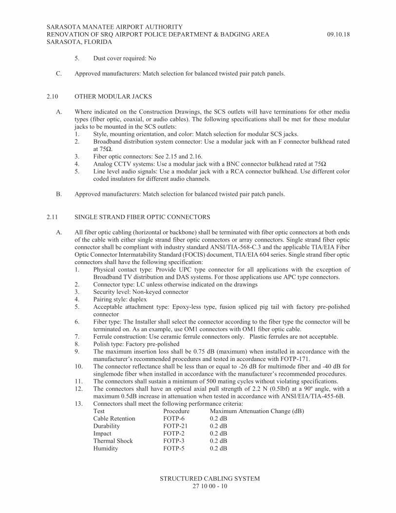
SARASOTA MANATEE AIRPORT AUTHORITY RENOVATION OF SRQ AIRPORT POLICE DEPARTMENT & BADGING AREA 09.10.18 SARASOTA, FLORIDA
STRUCTURED CABLING SYSTEM 27 10 00 - 10
5. Dust cover required: No
C. Approved manufacturers: Match selection for balanced twisted pair patch panels.
2.10 OTHER MODULAR JACKS
A. Where indicated on the Construction Drawings, the SCS outlets will have terminations for other media types (fiber optic, coaxial, or audio cables). The following specifications shall be met for these modular jacks to be mounted in the SCS outlets: 1. Style, mounting orientation, and color: Match selection for modular SCS jacks. 2. Broadband distribution system connector: Use a modular jack with an F connector bulkhead rated
at 75Ω. 3. Fiber optic connectors: See 2.15 and 2.16. 4. Analog CCTV systems: Use a modular jack with a BNC connector bulkhead rated at 75Ω 5. Line level audio signals: Use a modular jack with a RCA connector bulkhead. Use different color
coded insulators for different audio channels.
B. Approved manufacturers: Match selection for balanced twisted pair patch panels.
2.11 SINGLE STRAND FIBER OPTIC CONNECTORS
A. All fiber optic cabling (horizontal or backbone) shall be terminated with fiber optic connectors at both ends of the cable with either single strand fiber optic connectors or array connectors. Single strand fiber optic connector shall be compliant with industry standard ANSI/TIA-568-C.3 and the applicable TIA/EIA Fiber Optic Connector Intermatability Standard (FOCIS) document, TIA/EIA 604 series. Single strand fiber optic connectors shall have the following specification: 1. Physical contact type: Provide UPC type connector for all applications with the exception of
Broadband TV distribution and DAS systems. For those applications use APC type connectors. 2. Connector type: LC unless otherwise indicated on the drawings 3. Security level: Non-keyed connector 4. Pairing style: duplex 5. Acceptable attachment type: Epoxy-less type, fusion spliced pig tail with factory pre-polished
connector 6. Fiber type: The Installer shall select the connector according to the fiber type the connector will be
terminated on. As an example, use OM1 connectors with OM1 fiber optic cable. 7. Ferrule construction: Use ceramic ferrule connectors only. Plastic ferrules are not acceptable. 8. Polish type: Factory pre-polished 9. The maximum insertion loss shall be 0.75 dB (maximum) when installed in accordance with the
manufacturer’s recommended procedures and tested in accordance with FOTP-171. 10. The connector reflectance shall be less than or equal to -26 dB for multimode fiber and -40 dB for
singlemode fiber when installed in accordance with the manufacturer’s recommended procedures. 11. The connectors shall sustain a minimum of 500 mating cycles without violating specifications. 12. The connectors shall have an optical axial pull strength of 2.2 N (0.5lbf) at a 90º angle, with a
maximum 0.5dB increase in attenuation when tested in accordance with ANSI/EIA/TIA-455-6B. 13. Connectors shall meet the following performance criteria:
Test Procedure Maximum Attenuation Change (dB) Cable Retention FOTP-6 0.2 dB Durability FOTP-21 0.2 dB Impact FOTP-2 0.2 dB Thermal Shock FOTP-3 0.2 dB Humidity FOTP-5 0.2 dB
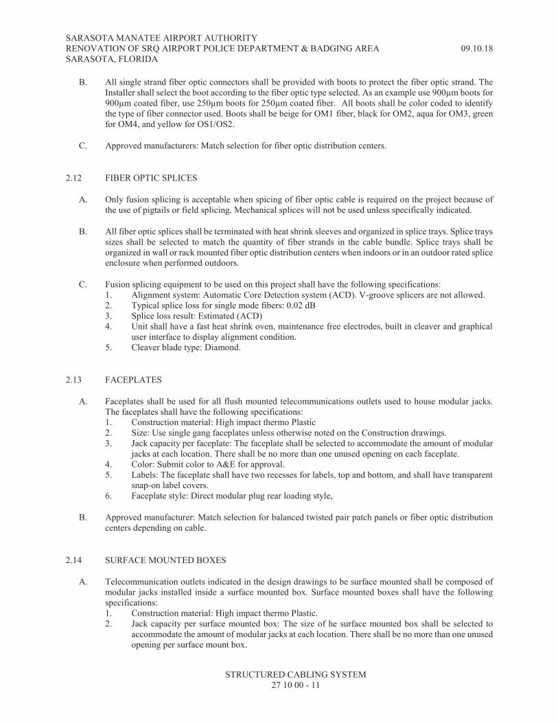
SARASOTA MANATEE AIRPORT AUTHORITY RENOVATION OF SRQ AIRPORT POLICE DEPARTMENT & BADGING AREA 09.10.18 SARASOTA, FLORIDA
STRUCTURED CABLING SYSTEM 27 10 00 - 11
B. All single strand fiber optic connectors shall be provided with boots to protect the fiber optic strand. The Installer shall select the boot according to the fiber optic type selected. As an example use 900µm boots for 900µm coated fiber, use 250µm boots for 250µm coated fiber. All boots shall be color coded to identify the type of fiber connector used. Boots shall be beige for OM1 fiber, black for OM2, aqua for OM3, green for OM4, and yellow for OS1/OS2.
C. Approved manufacturers: Match selection for fiber optic distribution centers.
2.12 FIBER OPTIC SPLICES
A. Only fusion splicing is acceptable when spicing of fiber optic cable is required on the project because of the use of pigtails or field splicing. Mechanical splices will not be used unless specifically indicated.
B. All fiber optic splices shall be terminated with heat shrink sleeves and organized in splice trays. Splice trays sizes shall be selected to match the quantity of fiber strands in the cable bundle. Splice trays shall be organized in wall or rack mounted fiber optic distribution centers when indoors or in an outdoor rated splice enclosure when performed outdoors.
C. Fusion splicing equipment to be used on this project shall have the following specifications: 1. Alignment system: Automatic Core Detection system (ACD). V-groove splicers are not allowed. 2. Typical splice loss for single mode fibers: 0.02 dB 3. Splice loss result: Estimated (ACD) 4. Unit shall have a fast heat shrink oven, maintenance free electrodes, built in cleaver and graphical
user interface to display alignment condition. 5. Cleaver blade type: Diamond.
2.13 FACEPLATES
A. Faceplates shall be used for all flush mounted telecommunications outlets used to house modular jacks. The faceplates shall have the following specifications: 1. Construction material: High impact thermo Plastic 2. Size: Use single gang faceplates unless otherwise noted on the Construction drawings. 3. Jack capacity per faceplate: The faceplate shall be selected to accommodate the amount of modular
jacks at each location. There shall be no more than one unused opening on each faceplate. 4. Color: Submit color to A&E for approval. 5. Labels: The faceplate shall have two recesses for labels, top and bottom, and shall have transparent
snap-on label covers. 6. Faceplate style: Direct modular plug rear loading style,
B. Approved manufacturer: Match selection for balanced twisted pair patch panels or fiber optic distribution centers depending on cable.
2.14 SURFACE MOUNTED BOXES
A. Telecommunication outlets indicated in the design drawings to be surface mounted shall be composed of modular jacks installed inside a surface mounted box. Surface mounted boxes shall have the following specifications: 1. Construction material: High impact thermo Plastic. 2. Jack capacity per surface mounted box: The size of he surface mounted box shall be selected to
accommodate the amount of modular jacks at each location. There shall be no more than one unused opening per surface mount box.

SARASOTA MANATEE AIRPORT AUTHORITY RENOVATION OF SRQ AIRPORT POLICE DEPARTMENT & BADGING AREA 09.10.18 SARASOTA, FLORIDA
STRUCTURED CABLING SYSTEM 27 10 00 - 12
3. Color: White. 4. Labels: The surface mounted boxes shall have at least one (1) recessed location for labels with
transparent snap-on label covers.
B. Approved manufacturer: Match the selection for balanced twisted pair patch panels or fiber optic distribution centers depending on cable.
2.15 MOUNTING FRAMES
A. All telecommunication outlets shall be properly mounted to the electrical raceway system installed for the outlet. The SCS Installer shall select the proper mounting frame and/or bezel to mount the modular jacks. Raceway systems include: furniture systems, floor boxes, poke-thru devices, power poles, and surface raceways system.
B. Where the Construction Drawings indicate a telecommunication outlet is to be mounted in a furniture system, the SCS Installer shall select the proper mounting frame to hold the modular jacks based on the furniture system. The color of the mounting frames shall match the color of the furniture system.
C. If the Owner provided furniture system does not have a raceway system for telecommunications and the Construction Drawings indicate an is outlet to be mounted in the furniture system, then the SCS Installer shall provide a surface mounted box that allows for the mounting of the modular jacks in a standard faceplate.
D. The SCS Installer shall provide all mounting frames and bezels required to properly install the modular jacks inside the floor boxes or poke-thru devices.
E. All ports in the mounting frames that are not being used shall be covered with blank inserts.
F. Approved manufacturer: Match the selection for balanced twisted pair patch panels or fiber optic distribution centers depending on cable.
2.16 HORIZONTAL BALANCED TWISTED PAIR CABLE
A. General: Horizontal balanced 4-pair twisted cables shall be used to connect the telecommunications outlet location to the associated equipment inside the telecommunications room. The cable shall consist of 4 pair balanced twisted pair cable with solid copper conductors and certified to the specified performance standard. All horizontal balanced 4-pair twisted cables shall be terminated in modular jacks at the outlet location and patch panels with IDC type connectors in the telecommunications room. The cable shall have the following specifications: 1. Cable Gauge: minimum 23 AWG solid copper conductor 2. Performance standard: TIA/EIA CAT6 3. Cable type: UTP 4. Performance characterized to: 600 MHz 5. Time delay skew: Maximum 45 ns/100m 6. Input impedance (1-100MHz): 100Ω 7. Cable diameter: ≤ 0.295 inch
B. Cable jacket color shall be selected according to the following criteria: 1. Voice or data cables: Blue 2. Wireless access points: Green 3. CCTV Surveillance cameras: Red

SARASOTA MANATEE AIRPORT AUTHORITY RENOVATION OF SRQ AIRPORT POLICE DEPARTMENT & BADGING AREA 09.10.18 SARASOTA, FLORIDA
STRUCTURED CABLING SYSTEM 27 10 00 - 13
C. Performance verification: The performance of the horizontal balanced 4-pair twisted cable shall be verified by a Nationally Recognized Testing Laboratory (NRTL) for EIA/TIA electrical performance and shall comply with FCC Part 68.
D. Jacket: The cable jacket for inside premise cabling installations shall comply with NEC Article 800 for the correct use in the environment it will be used. If the SCS Installer does not know the environment the cable will be installed, the SCS Installer shall assume plenum rated cable is required. All cable shall have a riser rated flame retardant PVC jacket at a minimum.
E. OSP Jackets: All cable installed in conduit run underground below the floor slab shall have a water resistant fill compound and a jacket made of UV resistant polyethylene. Cable with a PVC jacket is not acceptable for this application.
F. Jacket marking: All cable shall have at least two types of markings imprinted on the jacket: transmission performance and the NEC rating for the installed environment.
G. Approved manufacturers: The cable manufacturer and type must be approved by the patch panel and modular jack manufacturer in order to maintain the manufacturer’s 25 year warranty.
2.17 FOUR PAIR BALANCED TWISTED PAIR PATCH CORDS
A. Four pair balanced twisted pair patch cords are required at the work area side and at the patch panel side to complete the channel pathway to the equipment. All patch cords shall be factory tested and shall have molded boots to the cable jacket. Field made patch cords are not acceptable. Four pair patch cords shall have the following specifications: 1. Connectors: 8P8C plugs at both ends 2. Conductors: 4-pair stranded copper conductors. 3. Wiring map: See section 3 of this specification 4. Performance requirement: To match horizontal 4-pair cable performance 5. Cable type: UTP
B. Approved manufacturers. Match the selection for balanced twisted pair patch panels.
2.18 PATCH CORDS FOR MULTIPAIR BACKBONE CABLES
A. The patch cords shall be used to connect horizontal cabling to the termination blocks for multipair backbone cable. The patch cord shall be selected based on the type of termination for the backbone cable.
B. When multipair backbone cable is terminated in a patch panel, the patch cords shall have the same specifications as the 4-pair balanced twisted pair patch cords.
C. When multipair backbone cable is terminated in wall mounted or rack mounted termination blocks, the patch cords shall have a patch plug connector on one end and an 8P8C modular plug on the other. The SCS Installer shall coordinate with the phone system installer and determine if one pair or two pairs are required for each phone. The patch cord shall have one or two pairs terminated based on the equipment selection. Patch plugs shall terminate one or two pairs accordingly. The patch plug selection shall match the manufacturer and family of the termination blocks.
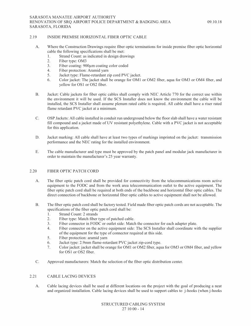
SARASOTA MANATEE AIRPORT AUTHORITY RENOVATION OF SRQ AIRPORT POLICE DEPARTMENT & BADGING AREA 09.10.18 SARASOTA, FLORIDA
STRUCTURED CABLING SYSTEM 27 10 00 - 14
2.19 INSIDE PREMISE HORIZONTAL FIBER OPTIC CABLE
A. Where the Construction Drawings require fiber optic terminations for inside premise fiber optic horizontal cable the following specifications shall be met: 1. Strand Count: as indicated in design drawings 2. Fiber type: OM3 3. Fiber coating: 900µm coating color coded 4. Fiber protection: Aramid yarn 5. Jacket type: Flame-retardant zip cord PVC jacket. 6. Color jacket: The jacket shall be orange for OM1 or OM2 fiber, aqua for OM3 or OM4 fiber, and
yellow for OS1 or OS2 fiber.
B. Jacket: Cable jackets for fiber optic cables shall comply with NEC Article 770 for the correct use within the environment it will be used. If the SCS Installer does not know the environment the cable will be installed, the SCS Installer shall assume plenum rated cable is required. All cable shall have a riser rated flame retardant PVC jacket at a minimum.
C. OSP Jackets: All cable installed in conduit run underground below the floor slab shall have a water resistant fill compound and a jacket made of UV resistant polyethylene. Cable with a PVC jacket is not acceptable for this application.
D. Jacket marking: All cable shall have at least two types of markings imprinted on the jacket: transmission performance and the NEC rating for the installed environment.
E. The cable manufacturer and type must be approved by the patch panel and modular jack manufacturer in order to maintain the manufacturer’s 25 year warranty.
2.20 FIBER OPTIC PATCH CORD
A. The fiber optic patch cord shall be provided for connectivity from the telecommunications room active equipment to the FODC and from the work area telecommunication outlet to the active equipment. The fiber optic patch cord shall be required at both ends of the backbone and horizontal fiber optic cables. The direct connection of backbone or horizontal fiber optic cables to active equipment shall not be allowed.
B. The fiber optic patch cord shall be factory tested. Field made fiber optic patch cords are not acceptable. The specifications of the fiber optic patch cord shall be: 1. Strand Count: 2 strands 2. Fiber type: Match fiber type of patched cable. 3. Fiber connector in FODC or outlet side: Match the connector for each adapter plate. 4. Fiber connector on the active equipment side: The SCS Installer shall coordinate with the supplier
of the equipment for the type of connector required at this side. 5. Fiber protection: aramid yarn 6. Jacket type: 2.9mm flame-retardant PVC jacket zip-cord type. 7. Color jacket: jacket shall be orange for OM1 or OM2 fiber, aqua for OM3 or OM4 fiber, and yellow
for OS1 or OS2 fiber.
C. Approved manufacturers: Match the selection of the fiber optic distribution center.
2.21 CABLE LACING DEVICES
A. Cable lacing devices shall be used at different locations on the project with the goal of producing a neat and organized installation. Cable lacing devices shall be used to support cables to j-hooks (when j-hooks
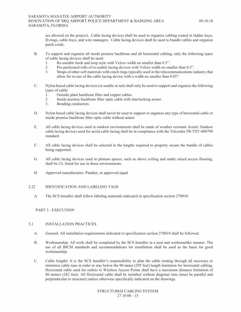
SARASOTA MANATEE AIRPORT AUTHORITY RENOVATION OF SRQ AIRPORT POLICE DEPARTMENT & BADGING AREA 09.10.18 SARASOTA, FLORIDA
STRUCTURED CABLING SYSTEM 27 10 00 - 15
are allowed on the project). Cable lacing devices shall be used to organize cabling routed in ladder trays, D-rings, cable trays, and wire managers. Cable lacing devices shall be used to bundle cables and organize patch cords.
B. To support and organize all inside premise backbone and all horizontal cabling, only the following types of cable lacing devices shall be used: 1. Re-useable hook and loop style with Velcro width no smaller than 0.5”. 2. Pre-perforated rolls of re-usable lacing devices with Velcro width no smaller than 0.5”. 3. Straps of other soft materials with cinch rings typically used in the telecommunications industry that
allow for re-use of the cable lacing device with a width no smaller than 0.85”.
C. Nylon based cable lacing devices (re-usable or not) shall only be used to support and organize the following types of cable: 1. Outside plant backbone fiber and copper cables. 2. Inside premise backbone fiber optic cable with interlocking armor. 3. Bonding conductors.
D. Nylon based cable lacing devices shall never be used to support or organize any type of horizontal cable or inside premise backbone fiber optic cable without armor.
E. All cable lacing devices used in outdoor environments shall be made of weather resistant Acetal. Outdoor cable lacing devices used for aerial cable lacing shall be in compliance with the Telcordia TR-TSY-000789 standard.
F. All cable lacing devices shall be selected in the lengths required to properly secure the bundle of cables being supported.
G. All cable lacing devices used in plenum spaces, such as above ceiling and under raised access flooring, shall be UL listed for use in those environments.
H. Approved manufactures: Panduit, or approved equal
2.22 IDENTIFICATION AND LABELING TAGS
A. The SCS Installer shall follow labeling materials indicated in specification section 270010.
PART 3 - EXECUTION
3.1 INSTALLATION PRACTICES
A. General: All installation requirements indicated in specification section 270010 shall be followed.
B. Workmanship: All work shall be completed by the SCS Installer in a neat and workmanlike manner. The use of all BICSI standards and recommendations for installation shall be used as the basis for good workmanship.
C. Cable lengths: It is the SCS Installer’s responsibility to plan the cable routing through all raceways to minimize cable runs in order to stay below the 90 meter (295 feet) length limitation for horizontal cabling. Horizontal cable used for outlets to Wireless Access Points shall have a maximum distance limitation of 80 meters (262 feet). All Horizontal cable shall be installed without diagonal runs (must be parallel and perpendicular to structure) unless otherwise specifically indicated on the drawings.

SARASOTA MANATEE AIRPORT AUTHORITY RENOVATION OF SRQ AIRPORT POLICE DEPARTMENT & BADGING AREA 09.10.18 SARASOTA, FLORIDA
STRUCTURED CABLING SYSTEM 27 10 00 - 16
D. Wire mapping: All terminations of 4-pair balanced twisted pair horizontal cabling and patch cords on this project shall be per the T568B standard.
E. Fiber optic cable termination polarity: All fiber optic cable (horizontal or backbone) terminated in duplex style adapter panels shall be connected in a cross-over polarity configuration. As an example, if fibers 1 and 2 are terminated at one end in positions A and B respectively, the same strands shall be terminated in positions B and A on the other side.
F. Polarity for fiber optics array connectors: Array connectors and cassettes for this project shall use the Method C polarity system as outline in TIA-568.B.1.
G. Location of horizontal cable terminations: In a multi-story facility with telecommunications rooms on every floor, all horizontal cabling shall be terminated in the telecommunications room on the same floor as the outlet (unless indicated otherwise). The correct floor for a floor box or poke thru device shall be defined as the level these boxes provide service to.
H. Cable bundles: If cable trays or conduits are shown in suspended ceiling or raised access floor areas on the contract drawings, the SCS Installer shall bundle (40 cable or less) horizontal cabling of the same type with cable lacing devices wrapped snug, but not deforming the cable geometry. The SCS Installer shall adhere to the manufacturers' requirements for cable bend radius and pulling tension.
I. Fire stop protection: The sealing of openings between floors and through rated fire and smoke walls created by the SCS Installer for cable pass through shall be the responsibility of the SCS Installer. Sealing material and the application of this material shall be accomplished in a manner that is acceptable to the local authorities having jurisdiction over this work. The creation of these openings for cable passage as shown on the Construction Drawings shall be the responsibility of the SCS Installer. Any sleeve or pass through devices installed by or for the SCS Installer and left unused shall be sealed as part of this work. Penetration rating shall equal the rating of the wall or floor being penetrated.
J. New materials: All components, wiring, and materials to be used for the installation of the SCS shall be new and free of any defects. Used components, wiring, and materials shall only be used when specifically indicated on the Construction Drawings.
Work external to the building: Any work external to the confines of the building as shown on the Construction Drawings shall be governed by the provisions of this specification.
K. Demolition: Any tasks required as part of the installation of the SCS that call for relocation, rerouting, or demolition shall be done according to the following requirements: 1. Coordination: Prior to commencing any deactivation, relocation, or demolition work arrange a
conference with the A&E, Contractor, and the Owner's representative to inspect each of the items to be deactivated, relocated, or removed. Care shall be taken to protect all equipment designated to be returned to Owner, relocated and reused, or to remain in operational and integrated with the new systems.
2. Provisions: All deactivation, relocation, and temporary connectivity shall be provided by the SCS Installer. All demolition, removal, and legal disposal of demolished shall be provided by the SCS Installer.
3. All existing SCS cable and connecting hardware within the areas where work is required as part of this project and not used after the new installation is complete shall be removed by the SCS Installer. All existing cable indicated to be left for future use shall be tagged for that purpose.
4. Owner Salvage: The Owner reserves the right to inspect the material scheduled for removal and salvage any items. The SCS Installer shall provide this material to the Owner.
5. Phasing: The SCS installer shall phase all work as directed by the Architect, Owner, or Contractor in order to accommodate the project schedule and the completion date(s) of the project.

SARASOTA MANATEE AIRPORT AUTHORITY RENOVATION OF SRQ AIRPORT POLICE DEPARTMENT & BADGING AREA 09.10.18 SARASOTA, FLORIDA
STRUCTURED CABLING SYSTEM 27 10 00 - 17
L. Icons: Provide icons for all faceplates, modular jacks, and patch panels when the unit is capable of accepting icons. Icons at the work area (outlet) shall match the color of the faceplate. Icons at the telecommunications rooms shall match the color of the horizontal cabling.
M. Blank inserts: All faceplates and mounting frames with unused modular outlet spaces shall have a blank insert installed. The blank inserts shall match the color of the faceplate or mounting frame. No more than one blank insert shall be required for each faceplate. If more than one is required, provide a faceplate with a smaller quantity of outlet spaces. All unused adapter panels in a FODC shall be covered with blank panels.
N. Patch panel and FODC separation: All horizontal cabling (copper and fiber) shall be terminated in separate patch panels based on the use for the cabling. Patch panels for the same use shall be installed together in the equipment cabinets or racks. The following segregation of cabling based on use shall be provided: 1. Wireless Access Points (WAPS) shall be separated from cabling used for other purposes. 2. Cabling for CCTV cameras shall be separated from cabling used for other purposes. 3. Voice cabling shall be separated from data cabling. 4. Cabling for specialty systems (security systems, audio, paging, etc.) shall all be terminated in
separate patch panels from any other cables. 5. Horizontal fiber optic cabling shall be terminated in separate FODCs from backbone cabling.
O. Patch panel rear support: All horizontal cable patch panels shall be provided with a rear support bar to properly lace the cabling and to provide strain relief. At a minimum one rear support bar shall be provided for every 24 cables.
P. Horizontal wire managers: Horizontal cable managers shall be provided based on the following this criteria: 1. Provide one above and below each patch panel. 2. Provide one above and below each data network switch. 3. Provide one below each rack mounted termination block.
Q. Cross over wire managers: Cross over cable managers shall be provided when angled or curved patch panels are installed. Provide one cross over wire manager at the same height in the middle of each rack.
R. Patch cord quantity, color and lengths: Copper and fiber optic patch cords shall be provided based on the following chart at the field location and the telecommunications room (all percentage calculations shall be rounded off to the largest whole number):
TYPE / USE QUANTITY JACKET COLOR LENGTH
4 pair balanced twisted pair for work area outlet
One for 90% of all work area outlets on the project
Match horizontal cable color
60% 8’, 30% 10’ and 10% 14’
4 pair balanced twisted pair for WAP
One for 100% of all WAP outlets on the project plus 10% spare
Match horizontal cable color
The SCS Installer shall field verify all lengths to match the WAP locations selected to be used by the Owner.
4 pair balanced twisted pair for CCTV camera
One for 100% of all CCTV cameras on the project plus 10% spare
Match horizontal cable color
The SCS Installer shall field verify all lengths to match camera locations.
Fiber optic for work area outlet, WAP, and CCTV cameras
One for 100% of all work area outlets on the project plus 10% spare
Per fiber type 50% 8’ and 50% 10’
One or two pair copper backbone cross connect
One for 90% of all backbone copper pairs installed in the project.
Gray For pricing purposes use: 80% 8’, 20% 10’. SCS Installer shall field verify.

SARASOTA MANATEE AIRPORT AUTHORITY RENOVATION OF SRQ AIRPORT POLICE DEPARTMENT & BADGING AREA 09.10.18 SARASOTA, FLORIDA
STRUCTURED CABLING SYSTEM 27 10 00 - 18
S. Cable slack: Cable slack shall be provided for all cables installed on the project based on the following guideline: 1. Work area outlets shall have 12 inches at the outlet. 2. All horizontal cabling in the telecommunications room shall have at least 6 feet neatly organized on
the wall using a figure eight or loop configuration arrangement with Velcro straps. 3. Backbone cabling shall have at least 15 feet of slack at each termination point neatly organized on
the wall using a loop configuration with Velcro straps. 4. Outside plant backbone cabling pulled through in-ground boxes greater than 24 inches X24 inches
shall include one loop inside each box.
T. Fiber optic cable bend radius: The installation of fiber optic cable shall be in accordance with ANSI/TIA-568C guidelines and the cable manufacturer’s specifications. The bend radius parameters shall be followed for both load and no load conditions. Cable installation and terminations that do not comply with these parameters shall be replaced by the SCS Installer at no additional charge. If no parameters are specified by the cable manufacturer, then the following criteria shall be meet: 1. The bend radius for intrabuilding two and four strand horizontal fiber optic cable shall be no less
than 1 inch under no load conditions. When under a maximum tensile load of 50 ftlbs, the bend radius shall be no less than 2 inches.
2. The bend radius for intrabuilding fiber optic backbone cable with more than four strands shall be no less than 10 times the cable’s outside diameter under no load conditions and no less than 15 times the cable’s outside diameter when the cable is under tensile load.
3. The bend radius for interbuilding fiber optic backbone cable shall be no less than 10 times the cable’s outside diameter under no load conditions and no less than 20 times the cable’s outside diameter when the cable is under a tensile load up to the rating of the cable, 600 ftlbs.
U. Innerduct: Innerduct shall be provided from beginning to end of a raceway system under the following conditions: 1. Inside underground conduits as indicated in design drawings. 2. For horizontal and inside premise backbone fiber optic cables without interlocking armor when
routed through cable trays, ladder trays, or vertical risers. This requirement is not indicated on the drawings but must be followed under this specification.
V. SCS protection during construction: The SCS Installer shall protect all SCS materials from damage during construction. Racks shall be covered with fabric or plastic after installation to prevent dust, debris, and other foreign materials from having contact with installed SCS equipment. The SCS Installer shall protect all fiber optic and copper cable from damage during installation. All cable shall maintain the manufacturer’s
constructed physical integrity for testing and delivery to the Owner. All damaged cable shall be replaced at no additional cost to the Owner.
W. Cable bonding: Shielded cable and cable with metal strength / protection members (i.e. interlocking armor) shall be bonded to the telecommunications grounding system per specification section 270526.
X. Rack installation: All racks shall be installed level and plumb. Four post racks and two post racks shall be anchored to the floor and installed with isolation pads. Equipment cabinets shall be leveled using the cabinet’s leveling feet unless specifically indicated to provide the cabinets with casters.
Y. Rack bonding: All equipment cabinets and racks shall be bonded to the telecommunication grounding system as required in specification section 270526.
3.2 IDENTIFICATION AND TAGGING
A. General: Identification and tagging of all SCS components shall be executed by the SCS Installer. At a minimum, identification and tagging shall be provided for the following system components:

SARASOTA MANATEE AIRPORT AUTHORITY RENOVATION OF SRQ AIRPORT POLICE DEPARTMENT & BADGING AREA 09.10.18 SARASOTA, FLORIDA
STRUCTURED CABLING SYSTEM 27 10 00 - 19
1. All horizontal and backbone cable at both ends. Labels on each side shall be indicate the location of the other side of the cable.
2. All faceplates indicating all modular jacks terminated in the faceplate. 3. All patch panels. 4. All racks. 5. All termination blocks. 6. All telecommunications rooms and enclosures. 7. All interbuilding backbone cable routed inside in ground pull boxes shall have a visible label in each
box they pass through.
B. The SCS Installer shall follow the Owner provided identification system. If the Owner does not have a preference or standard, the SCS Installer shall provide a system for approval by the A&E and the Owner as required in the submittal paragraph of this specification. The identification system shall follow TIA/EIA 606-B standard.
3.3 TESTING OF BALANCED TWISTED PAIR COPPER CABLING
A. General: All horizontal and backbone cable shall be tested in accordance with ANSI/TIA/EIA-568-C, Cabling Transmission Performance and Test Requirements.
B. The test method selected for all 4-pair balanced twisted pair cable is the permanent link style test. A permanent link test is defined as a test that does not include the patch cords.
C. General: If the A&E elects to be present during testing, provide notification a minimum of two weeks prior to testing.
D. General: The Installer’s RCDD shall sign off on all copper and fiber optic cable test results to indicate they were are responsible for all cable testing procedures and that all cables were tested in compliance with the Construction Documents and met or exceeded the requirements stated herein.
E. Testing Equipment: The tester shall be manufactured by Agilent, Fluke, IDEAL, or Wavetek. The tester shall be 100% Level III compliant with ANSI/EIA/TIA 568C specifications for testing of the CAT6 cabling. No tester will be approved without meeting these requirements.
F. Each modular jack in each faceplate shall be tested to the minimum manufacturer’s performance of the
cable to verify the integrity of all conductors and the correct termination sequence. Testing shall be performed between the work area and the rack patch panel. The tester shall be calibrated per the manufacturer’s guidelines prior to any cable testing. The correct cable nominal velocity of propagation shall be entered into the tester to ensure proper length and attenuation readings.
G. Documentation of the cable testing shall be provided in the format provided by the testing equipment manufacturer. The SCS Installer shall provide the results of all cable tests in electronic format (final results in PDF format). There shall be one test results page provided per cable. The test results shall indicate: sweep tests, continuity, polarity, wire map, attenuation, NEXT, PSNEXT, FEXT, PSFEXT, ELFEXT, PSELFEXT, ACR, Return Loss, Delay Skew, and the cable length. Cables that do not comply with the EIA/TIA 568C tests results shall be indicated to the A&E for tracking of the corrective action. The corrective action may include replacement of the cable at no additional expense to the Owner. All identification nomenclature used for each cable in the test shall match the labeling system approved for the project.
H. Any Fail, Fail*, Pass* or WARNING test result shall be considered a fail for the cable test. In order to achieve an overall pass condition, the results for each cable test parameter must be passed.
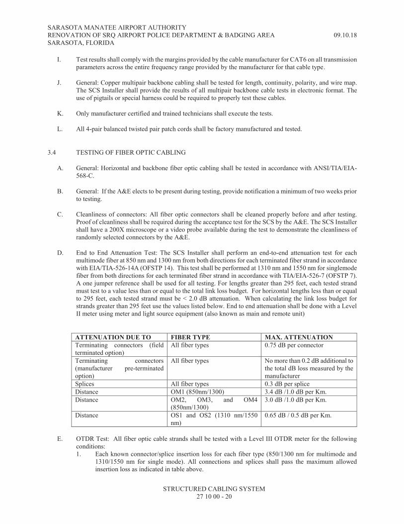
SARASOTA MANATEE AIRPORT AUTHORITY RENOVATION OF SRQ AIRPORT POLICE DEPARTMENT & BADGING AREA 09.10.18 SARASOTA, FLORIDA
STRUCTURED CABLING SYSTEM 27 10 00 - 20
I. Test results shall comply with the margins provided by the cable manufacturer for CAT6 on all transmission parameters across the entire frequency range provided by the manufacturer for that cable type.
J. General: Copper multipair backbone cabling shall be tested for length, continuity, polarity, and wire map. The SCS Installer shall provide the results of all multipair backbone cable tests in electronic format. The use of pigtails or special harness could be required to properly test these cables.
K. Only manufacturer certified and trained technicians shall execute the tests.
L. All 4-pair balanced twisted pair patch cords shall be factory manufactured and tested.
3.4 TESTING OF FIBER OPTIC CABLING
A. General: Horizontal and backbone fiber optic cabling shall be tested in accordance with ANSI/TIA/EIA-568-C.
B. General: If the A&E elects to be present during testing, provide notification a minimum of two weeks prior to testing.
C. Cleanliness of connectors: All fiber optic connectors shall be cleaned properly before and after testing. Proof of cleanliness shall be required during the acceptance test for the SCS by the A&E. The SCS Installer shall have a 200X microscope or a video probe available during the test to demonstrate the cleanliness of randomly selected connectors by the A&E.
D. End to End Attenuation Test: The SCS Installer shall perform an end-to-end attenuation test for each multimode fiber at 850 nm and 1300 nm from both directions for each terminated fiber strand in accordance with EIA/TIA-526-14A (OFSTP 14). This test shall be performed at 1310 nm and 1550 nm for singlemode fiber from both directions for each terminated fiber strand in accordance with TIA/EIA-526-7 (OFSTP 7). A one jumper reference shall be used for all testing. For lengths greater than 295 feet, each tested strand must test to a value less than or equal to the total link loss budget. For horizontal lengths less than or equal to 295 feet, each tested strand must be < 2.0 dB attenuation. When calculating the link loss budget for strands greater than 295 feet use the values listed below. End to end attenuation shall be done with a Level II meter using meter and light source equipment (also known as main and remote unit)
ATTENUATION DUE TO FIBER TYPE MAX. ATTENUATION
Terminating connectors (field terminated option)
All fiber types 0.75 dB per connector
Terminating connectors (manufacturer pre-terminated option)
All fiber types No more than 0.2 dB additional to the total dB loss measured by the manufacturer
Splices All fiber types 0.3 dB per splice
Distance OM1 (850nm/1300) 3.4 dB /1.0 dB per Km.
Distance OM2, OM3, and OM4 (850nm/1300)
3.0 dB /1.0 dB per Km.
Distance OS1 and OS2 (1310 nm/1550 nm)
0.65 dB / 0.5 dB per Km.
E. OTDR Test: All fiber optic cable strands shall be tested with a Level III OTDR meter for the following conditions: 1. Each known connector/splice insertion loss for each fiber type (850/1300 nm for multimode and
1310/1550 nm for single mode). All connections and splices shall pass the maximum allowed insertion loss as indicated in table above.

SARASOTA MANATEE AIRPORT AUTHORITY RENOVATION OF SRQ AIRPORT POLICE DEPARTMENT & BADGING AREA 09.10.18 SARASOTA, FLORIDA
STRUCTURED CABLING SYSTEM 27 10 00 - 21
2. Overall insertion loss of the cable at both sides (sum of all connectors, splices, and total cable length).
3. Estimated cable distance. 4. Cable signature that provides readings along the complete length of the cable. Any unexplained
cable reflections shown in the OTDR shall require the Installer to submit a letter explaining the reason for the reflection and pictures of the cable’s condition at the location where the unexplained reflection is located to demonstrate the cable has not been kinked or damaged during installation.
F. OTDR Test conditions: All OTDR testing shall be performed with the following requirements: 1. Use a launch cable and a tail cable in accordance with the type of fiber being tested and the
requirements of the OTDR manufacturer. 2. The launch and tail cables shall be products that are sold by the testing equipment manufacturer and
not field constructed cables. 3. The launch and tail cables shall be selected according to the type of connector being tested, such as
APC or UPC types. 4. Use the launch compensation mode during the test to subtract the effects of the launch and tail
cables. 5. Test from one direction only, unless the presence of “gainers” are spotted during the test. In these
instances the Installer shall test in both directions and adjust the test equipment to average the measurements from both directions.
6. The SCS Installer shall verify the backscatter coefficient used in the test to make sure it matches the manufacturer’s coefficient for the cable being tested.
G. OTDR Testing Equipment used on this project shall have the following specifications indicated:
MULTIMODE SINGLEMODE
Wavelengths 850 nm ±10 nm 1300 nm +35 / -15 nm.
1310 nm ±25 nm. 1550 nm ±30 nm.
Event Dead Zone. Measured at 1.5 dB below non-saturating reflection peak with the shortest pulse width. Reflection peak < -40 dB for mm and < -50 dB for sm.
850 nm: 0.5 [3.7] m typical 1300 nm: 0.7 [3.5] m typical
1310 nm: 0.6 [3.5] m typical 1550 nm: 0.6 [3.5] m typical
Attenuation Dead Zone. Measured at ± 0.5 dB deviation from backscatter with the shortest pulse width. Reflection peak < -40 dB for mm. and < -50 dB for sm.
850 nm: 2.2 [10] m typical 1300 nm: 4.5 [13] m typical
1310 nm: 3.6 [10] m typical 1550 nm: 3.7 [12] m typical
Pulse Widths (nominal)
850 nm: 3, 5, 20, 40, 200 ns. 1300 nm: 3, 5, 20, 40, 200, 1000 ns.
3, 10, 30, 100, 300, 1000, 3000, 10000, 20000 ns
Loss Threshold Setting
0.01 dB to 1.5 dB Adjustable in 0.01 dB increments
0.01 dB to 1.5 dB Adjustable in 0.01 dB increments
H. The fiber strand test report shall include the following information: 1. Calculated Loss Budget for each optical fiber link (see attenuation table above). 2. Cable/strand ID that matches the approved labeling system. 3. Name of the technicians who performed the test.

SARASOTA MANATEE AIRPORT AUTHORITY RENOVATION OF SRQ AIRPORT POLICE DEPARTMENT & BADGING AREA 09.10.18 SARASOTA, FLORIDA
STRUCTURED CABLING SYSTEM 27 10 00 - 22
4. Date and time the test was performed. 5. Measurement direction. 6. Jumper reference set up date/time and attenuation value. 7. Equipment model and serial number of the testing device used and calibration date. 8. End to end attenuation loss data for each fiber strand. 9. OTDR Traces, one page per strand. Expand the chart to cover most of the page 10. Each event loss data and the test limits used, including the test limit file date used.
I. For fiber optic cable with factory terminated connectors or pre-terminated pig-tails, the SCS Installer shall provide the test results performed at the factory for the factory terminated connectors to compare with the field testing performed by the SCS Installer. There shall be no significant variations between the factory test results and the field test results.
3.5 SYSTEM WARRANTY AND SERVICE
A. The SCS Installer shall follow all warranty and service requirements indicated in specification section 270010.
B. Warranty: The SCS shall be under the manufacturer’s warranty program for a complete channel configuration. Manufacturers shall provide the worst-case performance warranty data for the installed cabling system.
C. A manufacturers twenty five (25) year warranty for the SCS cabling installation shall be provided for an end-to-end channel model which covers cable, terminations, connecting hardware, and the labor cost for the repair or replacement thereof.
D. Additional features of the warranty shall include: 1. The SCS complies with the margins claimed by the manufacturer for the category 6 channel for all
transmission parameters across the entire frequency range of 1-600 MHz.
3.6 SPARE PARTS
A. As part of this contract the SCS Installer shall provide the following spare parts. 1. Ten (10) modular jacks of each type installed. 2. Five (5) faceplates of each type installed. 3. Two (2) faceplates with support posts. 4. Ten (10) fiber optic connectors of each type installed.
B. As part of this contract the SCS Installer shall provide the following tools: 1. Two (2) modular jack termination tools when the modular jacks require a manufacturer specific
tool. 2. One (1) punch down tool with 110 and 66 blades. 3. One electric (1) cable finder.
3.7 COMISSIONING
A. The SCS Installer shall follow all warranty and service requirements indicated in specification section 270010.
SARASOTA MANATEE AIRPORT AUTHORITY RENOVATION OF SRQ AIRPORT POLICE DEPARTMENT & BADGING AREA 09.10.18 SARASOTA, FLORIDA
STRUCTURED CABLING SYSTEM 27 10 00 - 23
3.8 ENGINEER’S FINAL ACCEPTANCE TEST
A. The SCS Installer shall follow all requirements for final acceptance testing as indicated in specification section 270010.
B. The Engineer’s final acceptance test will not include testing of the structured cabling components (unless otherwise indicated), but could include verification of the cleanliness of the fiber optic connectors.
3.9 TRAINING AND INSTRUCTION
A. Training shall only be done after all testing, identification/labeling, and commissioning have been completed and passed as indicated in this specification section. Any training performed prior to the final acceptance will not be accepted as the formal training. The SCS Installer shall be required repeat all training after the final acceptance test has passed, at no additional cost to the Owner.
B. The SCS Installer shall follow all training requirements indicated in specification section 270010 17010
C. The training for the SCS shall include the following: 1. A detailed explanation of the identification system. 2. A walkthrough of all spaces and locations where cross connect terminations have been done. 3. A walkthrough of all telecommunications rooms.
3.10 AS BUILT DOCUMENTS AND PROJECT CLOSE OUT
A. The SCS shall follow all requirements for as-built and close out documentation as indicated in specification section 270010
B. The following are additional requirements above and beyond the requirements in specification section 270010: 1. Provide the Warranty certificate issued by the manufacturer of the SCS infrastructure. 2. The Installer’s RCDD shall stamp the as-built drawings, indicating they have reviewed and
approved the drawings as being complete, accurate, and representative of the system installed. 3. As built drawings provided inside each telecommunications room for the layout of that room and
the areas that room serves. Each drawing shall be mounted in a frame and installed on a wall in the telecommunications room.
4. The SCS Installer shall provide an Excel spreadsheet that provides each telecommunications outlet identifier, location, number of voice/data/special jacks, and patch panel port.
5. Electronic copies of all test results (copper and fiber). Electronic copies shall include raw data files and PDF files with the test results. PDF files shall be organized based on: a. All copper cable terminating in each telecommunications room in a single consolidated PDF
file. The file name shall match the label used in the shop drawings for the telecommunications room.
b. All attenuation and OTDR test results for all strands of a single cable shall be in one PDF file. The file name shall match the cable identifier.
END OF SECTION 27 10 00

SARASOTA MANATEE AIRPORT AUTHORITY RENOVATION OF SRQ AIRPORT POLICE DEPARTMENT & BADGING AREA 09.10.18 SARASOTA, FLORIDA
STRUCTURED CABLING SYSTEM 27 10 00 - 24
THIS PAGE INTENTIONALLY LEFT BLANK


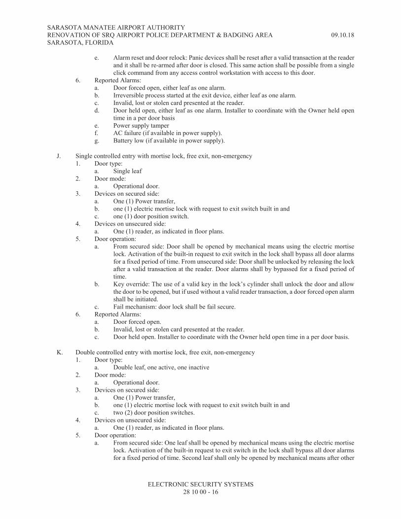
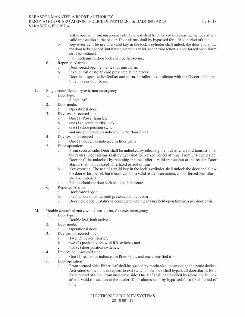


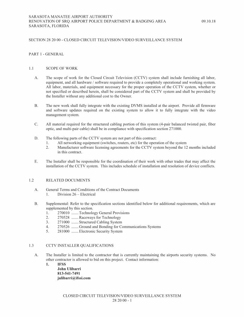
SARASOTA MANATEE AIRPORT AUTHORITY RENOVATION OF SRQ AIRPORT POLICE DEPARTMENT & BADGING AREA 09.10.18 SARASOTA, FLORIDA
CLOSED CIRCUIT TELEVISION/VIDEO SURVEILLANCE SYSTEM 28 20 00 - 1
SECTION 28 20 00 - CLOSED CIRCUIT TELEVISION/VIDEO SURVEILLANCE SYSTEM
PART 1 - GENERAL
1.1 SCOPE OF WORK
A. The scope of work for the Closed Circuit Television (CCTV) system shall include furnishing all labor, equipment, and all hardware / software required to provide a completely operational and working system. All labor, materials, and equipment necessary for the proper operation of the CCTV system, whether or not specified or described herein, shall be considered part of the CCTV system and shall be provided by the Installer without any additional cost to the Owner.
B. The new work shall fully integrate with the existing DVMS installed at the airport. Provide all firmware and software updates required on the existing system to allow it to fully integrate with the video management system.
C. All material required for the structured cabling portion of this system (4-pair balanced twisted pair, fiber optic, and multi-pair cable) shall be in compliance with specification section 271000.
D. The following parts of the CCTV system are not part of this contract: 1. All networking equipment (switches, routers, etc) for the operation of the system 2. Manufacturer software licensing agreements for the CCTV system beyond the 12 months included
in this contract.
E. The Installer shall be responsible for the coordination of their work with other trades that may affect the installation of the CCTV system. This includes schedule of installation and resolution of device conflicts.
1.2 RELATED DOCUMENTS
A. General Terms and Conditions of the Contract Documents 1. Division 26 – Electrical
B. Supplemental: Refer to the specification sections identified below for additional requirements, which are supplemented by this section. 1. 270010 ....... Technology General Provisions 2. 270528 ....... Raceways for Technology 3. 271000 ....... Structured Cabling System 4. 270526 ....... Ground and Bonding for Communications Systems 5. 281000 ....... Electronic Security System
1.3 CCTV INSTALLER QUALIFICATIONS
A. The Installer is limited to the contractor that is currently maintaining the airports security systems. No other contractor is allowed to bid on this project. Contact information:
1. IFSS
John Ulibarri
813-541-7491

SARASOTA MANATEE AIRPORT AUTHORITY RENOVATION OF SRQ AIRPORT POLICE DEPARTMENT & BADGING AREA 09.10.18 SARASOTA, FLORIDA
CLOSED CIRCUIT TELEVISION/VIDEO SURVEILLANCE SYSTEM 28 20 00 - 2
1.4 SHOP DRAWINGS AND SUBMITTALS
A. The Installer shall follow all requirements for shop drawings indicated in specification section 270010.
B. Initial submittal: The Installer shall submit the following information upon receiving approval to execute the work: 1. Proof of Installer qualifications, addressing all requirements of paragraph 1.3 of this specification
section. 2. A list of five recently completed projects of similar type, size, and complexity with the contact
names and telephone numbers for each. 3. Provide manufacturer’s product data sheets for all equipment indicated in Part 2 of this
specification section and any additional equipment indicated on the technology drawings. Product data sheets shall bear the printed logo or trademark of the manufacturer for each type of product being provided. The product data sheets for this submittal will match the chronological order of the equipment indicated in Part 2 (product data sheets for equipment shown on the drawings will submitted in order based be based on the sheet). Failure to properly sequence the product data sheets will result in the submittal being rejected not reviewed.
4. Data sheets and samples of all labeling materials and equipment to be used on the project. 5. A complete explanation of the identification method to be used for all equipment and cabling
installed as part of the CCTV system. 6. Detailed drawings of any custom manufactured products to be used on the project.
C. Shop drawing submittal: The shop drawing submittal shall be provided after all portions of the initial submittal have been accepted by the A&E. The following information is required to be indicated on the shop drawings: 1. Floor plans indicating all devices to be provided and the homerun location for the associated
cabling. All devices shall have a unique identifier, based on the approved identification method, which matches the nomenclature to be programmed into the system configuration database.
2. Provide a network configuration spreadsheet representing all IP network devices used on this project. This spreadsheet will be used to provide IP addresses for the Installer from the network administrator.
3. Overall system configuration matrix/diagram that indicates all head end equipment, room location, and configuration characteristics.
4. The Installer shall provide a storage calculation spreadsheet for each recording appliance (RAID configuration included) with all assigned cameras at the specified recording frame rates, resolutions, activity percentages, and times of recording. Based on this information the spreadsheet will provide the total storage requirements per camera and recording appliance.
5. Each recording server responsible for processing video for storage / retrieval shall have a total bit rate calculation that indicates the front side bus processing capacity requirements for all the cameras assigned to a recording server.
6. The Installer shall provide panel schedules, in a table format, indicating all ports being used and the exact device connected to each port. Panel schedules shall be submitted for all camera power supplies, multiport encoder/decoders, fiber optics distribution centers (FODC), Ethernet switches, patch panels, termination blocks, etc.
7. Outline of the testing process.
D. Final submittal: Provide the final submittal documentation at least two months prior to substantial completion and final acceptance testing. This submittal will be used to coordinate with the Owner the necessary systems training of their staff. The Installer shall provide a submittal with the following information: 1. Detailed course syllabus for each type of training required in this specification section. 2. A proposed schedule of training sessions in compliance with this specification section and
indicating where the training will take place. 3. A copy of all training material to be used during each session.
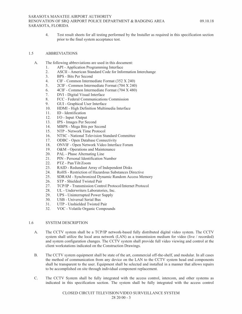
SARASOTA MANATEE AIRPORT AUTHORITY RENOVATION OF SRQ AIRPORT POLICE DEPARTMENT & BADGING AREA 09.10.18 SARASOTA, FLORIDA
CLOSED CIRCUIT TELEVISION/VIDEO SURVEILLANCE SYSTEM 28 20 00 - 3
4. Test result sheets for all testing performed by the Installer as required in this specification section prior to the final system acceptance test.
1.5 ABBREVIATIONS
A. The following abbreviations are used in this document: 1. API - Application Programming Interface 2. ASCII - American Standard Code for Information Interchange 3. BPS - Bits Per Second 4. CIF - Common Intermediate Format (352 X 240) 5. 2CIF - Common Intermediate Format (704 X 240) 6. 4CIF - Common Intermediate Format (704 X 480) 7. DVI - Digital Visual Interface 8. FCC - Federal Communications Commission 9. GUI - Graphical User Interface 10. HDMI - High Definition Multimedia Interface 11. ID - Identification 12. I/O - Input /Output 13. IPS - Images Per Second 14. MBPS - Mega Bits per Second 15. NTP - Network Time Protocol 16. NTSC - National Television Standard Committee 17. ODBC - Open Database Connectivity 18. ONVIF - Open Network Video Interface Forum 19. O&M - Operations and Maintenance 20. PAL - Phase Alternating Line 21. PIN - Personal Identification Number 22. PTZ - Pan/Tilt/Zoom 23. RAID - Redundant Array of Independent Disks 24. RoHS - Restriction of Hazardous Substances Directive 25. SDRAM - Synchronized Dynamic Random Access Memory 26. STP - Shielded Twisted Pair 27. TCP/IP - Transmission Control Protocol/Internet Protocol 28. UL - Underwriters Laboratories, Inc. 29. UPS - Uninterrupted Power Supply 30. USB - Universal Serial Bus 31. UTP - Unshielded Twisted Pair 32. VOC - Volatile Organic Compounds
1.6 SYSTEM DESCRIPTION
A. The CCTV system shall be a TCP/IP network-based fully distributed digital video system. The CCTV system shall utilize the local area network (LAN) as a transmission medium for video (live / recorded) and system configuration changes. The CCTV system shall provide full video viewing and control at the client workstations indicated on the Construction Drawings.
B. The CCTV system equipment shall be state of the art, commercial off-the-shelf, and modular. In all cases the method of communication from any device on the LAN to the CCTV system head end components shall be transparent to the user. Equipment shall be selected and installed in a manner that allows repairs to be accomplished on site through individual component replacement.
C. The CCTV System shall be fully integrated with the access control, intercom, and other systems as indicated in this specification section. The system shall be fully integrated with the access control

SARASOTA MANATEE AIRPORT AUTHORITY RENOVATION OF SRQ AIRPORT POLICE DEPARTMENT & BADGING AREA 09.10.18 SARASOTA, FLORIDA
CLOSED CIRCUIT TELEVISION/VIDEO SURVEILLANCE SYSTEM 28 20 00 - 4
application to allow events to be directly linked to the CCTV surveillance recording system. See specification section 281000 for details of the integration scope of work and required performance.
D. All cameras shall be connected and controlled through a CCTV workstation utilizing a standard mouse and keyboard.
PART 2 - PRODUCTS
2.1 DVMS STORAGE APPLIANCE
A. The DVMS storage appliance shall store all recorded video that cannot be stored on the recording server for the specified amount of time. The storage appliance shall match the requirements of the recording server if the DVMS software requires a processor. If the DVMS software allows only hard drives with the recording server handling all processing, the specifications indicated in 2.5.B shall be met.
B. The DVMS storage appliance must meet all of the requirements established by the DVMS software manufacturer. The DVMS storage appliance shall have the following minimum specifications: 1. Hard drive configuration: Hot Plug 4 TB 7.2K RPM SAS 6Gbps RAID 6 with controller 2. Backplane: 12 bays for 3.5” hard drives 3. Hard drives: Based on storage calculations 4. Connectivity: Cables as required for DAS or NICs as required for SAN 5. Power supply: Energy Smart redundant 600W power supply with dual cords. NEMA 5-15p 15A
10 ft. cords 6. Mounting: Rack chassis with sliding rapid/versa rails and cable management arm. 7. Height: 2RU 8. Operating system: Microsoft Windows Server version as recommended by the DVMS
manufacturer, with software licenses to connect all workstations on the project plus 2 spare licenses.
9. Warranty: 3 years
C. Design Selection: Dell MD1400 series or approved equal.
2.2 FIXED IP DOME CAMERA
A. The fixed IP dome camera for this project shall be an integrated camera and dome enclosure rated for the environment which it is installed. If installed outdoors the camera shall be IP66 rated.
B. The fixed IP dome camera shall operate in an IP video system environment specified for this project and shall be controllable from that platform. Video compression shall be H.264 with a minimum of two simultaneous video streams (multicasting) communicating in TCP/IP network protocol.
C. Cameras installed outdoors will be provided with IR illuminators for low light performance.
D. The fixed IP dome camera shall have an 8P8C 100Base-TX network interface. Power shall be provided from either a 12 VDC, 24 VAC, or PoE source. All network data sent and received by the camera shall be encoded with access to the camera programming password protected.
E. The fixed IP dome camera shall be provided in 8 MP resolutions minimum. Camera lenses shall be varifocal, auto-iris, auto-focus, and with a minimum low light capabilities of 0.01 lux in black and white.
F. Design selection: Avigilon.
SARASOTA MANATEE AIRPORT AUTHORITY RENOVATION OF SRQ AIRPORT POLICE DEPARTMENT & BADGING AREA 09.10.18 SARASOTA, FLORIDA
CLOSED CIRCUIT TELEVISION/VIDEO SURVEILLANCE SYSTEM 28 20 00 - 5
2.3 CAMERA MOUNTS AND DOME MOUNTS
A. Camera, enclosures and dome mounts shall be provided as shown in the design drawings. The Installer shall choose the mounts based on the equipment being supported. All mounts shall be made by the same manufacturer of the cameras. Custom made mounts are not acceptable unless approved by the A&E.
B. All camera mounts and dome mounts shall me made of steel, aluminum, or stainless steel. Plastic mounts are not acceptable. Outdoor rated mounts shall be used for outdoor cameras and indoor rated mounts shall be used for indoor cameras.
2.4 LENSE FOR FIXED CAMERAS
A. All lenses for fixed cameras shall be selected to provide the optimum viewing angle. All lenses shall be varifocal, auto-iris mount, and compatible with the camera format being provided.
B. Lenses for megapixel cameras shall be designed specifically for that type of cameras.
2.5 SURGE PROTECTION
A. All CCTV components mounted outside the building shall be provided with surge and lightning protection. Provide UL listed multi-stage protection on all low voltage and signal transmission lines. All 120 VAC surge suppression devices shall be EDCO HSP121BT-1RU or an approved equal. For low voltage connections provide FAS-1 surge suppressors manufactured by EDCO or an approved equal. For coax connections provide CX-06-BNCY line protectors manufactured by EDCO or an approved equal.
B. For exposed Ethernet connections with PoE, use EDCO CAT6-E PoE or approved equa.
2.6 WIRE & CABLE
A. Cables for analog video transmission (less than 750 ft.) shall have the following specification: 1. Minimum cable gauge: AWG 20. 2. Number of conductors: 1 solid coaxial cable 3. Conductor type: Bare copper 4. Cable insulation: Foam polyolefin 5. Nominal Impedance: 75 Ohms, RG-59 6. Cable shield: 95% bare copper braid.
B. Cables for analog video transmission (less than 10 ft.) shall have the following specification: 1. Minimum cable gauge: AWG 25. 2. Number of conductors: 1 solid coaxial cable 3. Conductor type: Bare copper 4. Cable insulation: Foam polyolefin 5. Nominal Impedance: 75 Ohms, mini-RG-59 6. Cable shield: 95% bare copper braid.
C. Cables for PTZ control, RS-422 or RS-485 control lines shall have the following specifications: 1. Minimum cable gauge: AWG 24 2. Number of conductors: 2-paired, stranded conductors 3. Conductor type: Tinned copper 4. Cable insulation: Polyethylene 5. Conductor insulation colors: White-blue, blue-white white-orange and orange-white

SARASOTA MANATEE AIRPORT AUTHORITY RENOVATION OF SRQ AIRPORT POLICE DEPARTMENT & BADGING AREA 09.10.18 SARASOTA, FLORIDA
CLOSED CIRCUIT TELEVISION/VIDEO SURVEILLANCE SYSTEM 28 20 00 - 6
6. Voltage rating: 300V 7. Cable shield: Aluminum/polyester foil (overall), a tinned copper braid (90% coverage) and a
AWG 24 tinned copper drain wire 8. Nominal characteristic impedance: 120 Ohms 9. Nominal capacitance: 12.8 pF/ft. 10. Nominal delay: 1.6 ns/ft. 11. Nominal attenuation: 0.6 dB/100 ft @ 1 MHz.
D. Cables for camera power supply shall have the following specifications: 1. Minimum cable gauge: AWG 18 2. Number of conductors: 2, stranded conductors 3. Conductor type: Bare copper 4. Cable insulation: PVC 5. Conductor insulation colors: Black and red. 6. Voltage rating: 300V 7. Cable shield: No cable shields
E. HDMI or DVI cables shall be factory made and tested cables. For all DVI connections use an HDMI cable with HDMI to DVI adapters. All HDMI cables shall be capable of passing a signal at 340 MHz,
F. All UTP Category horizontal cables and fiber optic cables for the CCTV system shall be in compliance of all requirements in specification section 271000 and shall be under the same warranty as all UTP category cables and fiber optic cables described in specification section 271000. Color jacket for wiring for the CCTV system shall be red.
G. Cable gauge: All cable gauges shall be estimated as to allow a maximum of 5% voltage drop from the source to the load. Sizes given previously are only minimum gauges accepted. The Installer shall always estimate proper values.
H. Cable jackets: All cable jackets shall be suitable for the environment on which the cables will be installed. Use plenum rated cables when cables are installed in plenum spaces. Use riser rated cables when cables are installed through floor sleeves. Use cable jackets with water-blocking material when installed in underground conduits.
I. Cable jackets for this project: Except when cables are run continuously in conduit all cable or patch cord cables; jackets for CCTV cables shall be plenum rated.
J. All cables shall be RoHS compliant and free of VOC. The SSI shall provide proof of compliance for all cables during the submittal process.
K. Acceptable manufacturers: Belden, Alpha Wire Company, General Cable and West Penn Wire.
2.7 IDENTIFICATION AND LABELING TAGS
A. The CI shall follow labeling materials indicated in specification section 270010.
PART 3 - EXECUTION
3.1 CAMERA TYPES
A. FIXED CAMERA TYPE 1:

SARASOTA MANATEE AIRPORT AUTHORITY RENOVATION OF SRQ AIRPORT POLICE DEPARTMENT & BADGING AREA 09.10.18 SARASOTA, FLORIDA
CLOSED CIRCUIT TELEVISION/VIDEO SURVEILLANCE SYSTEM 28 20 00 - 7
1. Camera: Fixed IP dome camera 8 MP resolution. 2. Mounting: Recess in ceiling 3. Accessories: Interior dome mount for fixed camera. Recessed ceiling mount.
B. FIXED CAMERA TYPE 2: 1. Camera: Fixed IP dome camera 3MP resolution. 2. Mounting: Wall 3. Accessories: Wall mount adaptor.
C. FIXED CAMERA TYPE 3: 1. Camera: Multi-imager panoramic IP camera 12 MP resolution total. 2. Mounting: Recess in ceiling 3. Accessories: Interior dome mount for fixed camera. Recessed ceiling mount
D. FIXED CAMERA TYPE 4: 1. Camera: Multi-imager panoramic IP camera 12 MP resolution total. 2. Mounting: Wall 3. Accessories: Wall mount adaptor.
E. FIXED CAMERA TYPE 6: 1. Camera: Fixed analog dome camera (elevator cab). 2. Mounting: Inside elevator cab 3. Accessories: UTP to coax transceiver and analog video encoder.
3.2 INSTALLATION PRACTICES
A. General: The CI shall follow all installation practices indicated in specification section 270010
B. For all building exterior applications, CCTV imagers shall be day/night type of cameras.
C. All camera power supplies need to be installed next to the access control equipment in the same room.
D. All coaxial cable for local monitors shall be termination in a faceplate in the wall to provide means of disconnect from permanent cables. All faceplates shall be a single gang plate with BNC connectors as required for the amount of monitor cables being run for local monitoring.
E. All camera video output controls shall be adjusted to provide 1-volt peak-to-peak composite video output.
3.3 WIRING METHODS
A. All proposed wire and cable shall meet or exceed the recommendations established by the equipment manufacturers, and shall comply with all state and local codes.
B. Visually inspect all wire and cable for faulty insulation prior to installation. Protect cable ends at all times with acceptable end caps.
C. Provide grommets and strain relief materials where necessary to avoid abrasion and excess tension on wire and cable.
D. All penetrations through fire rated barriers shall be provided, by the CI, with appropriate fire stopping materials in accordance with NFPA requirements and local fire authority having jurisdiction.

SARASOTA MANATEE AIRPORT AUTHORITY RENOVATION OF SRQ AIRPORT POLICE DEPARTMENT & BADGING AREA 09.10.18 SARASOTA, FLORIDA
CLOSED CIRCUIT TELEVISION/VIDEO SURVEILLANCE SYSTEM 28 20 00 - 8
E. All cable runs shall be continuous from the device to the equipment. Cable splices shall not be allowed inside conduits, or cable trays.
F. All cameras shall have a camera interface box with disconnect means to horizontal cabling for testing purposes and service. Camera interface boxes shall be located in accessible ceiling spaces as close as possible to the camera. Disconnect means shall be provided for UTP cables in the form of an 8-pin modular plug and receptacle. Disconnect means shall be provide for low voltage camera power cables in the form of insulated spade connectors (female connectors in load side, male connectors in camera side).
G. All video cable connectors and terminations shall be 3-way crimp-on type and shall including connector cables for 24 VAC input and video/data coax output. Twist on style connectors will not be acceptable for any terminations on this project.
H. Cables of similar signal level shall be bundled together and kept physically separate from power cords, plug strips or other circuits with different potential. Exposed wire bundles or individual cables shall be neatly secured with self-clinching nylon "TY Raps" (Thomas & Betts or equal). Lacing of cables shall not be permitted.
I. All cables run part of the CCTV system in areas where ceiling is not accessible or in building exterior shall be in conduit at all times
J. All termination of UTP Category type multi pair cables shall be done in Insulation Displacement Connectors (IDC), modular plugs or connectors. The use of wire nuts or manually twisting cables and protecting them with electrical tape are not acceptable means of termination.
K. Components of the distribution system shall be installed in a neat, workmanlike manner consistent with all best practices.
L. Wiring color codes shall be strictly observed and terminations shall be uniform throughout the building.
3.4 IDENTIFICATION AND TAGGING
A. All cables, wires, wiring forms, terminal blocks, and terminals shall be clearly identified by pre-printed labels or tags. The permanent markings shall clearly indicate the function, source, and destination of all cabling, wire, and terminals. All cables shall be labeled at both ends of the cable with the same and unique identifier label.
B. Cable and equipment identifiers shall follow a standard labeling system like TIA/EIA-606. The identification system chosen by the CI shall be submitted for approval to the A&E.
C. All camera power supplies, patch panels shall include a work sheet attached to the interior of the equipment cabinet in plastic envelops. This work sheet shall include the location, type of device and part number of all devices connected to the boards inside those equipments. All names used to identify devices in these worksheets shall match all names and identifiers used in the software or the user interface of the system. A second copy of this worksheet shall be delivered to as part of the as-built information.
3.5 CCTV SYSTEM PROGRAMMING
A. The CI shall program the CCTV system and the integration to the Security System as indicated in specification section 281000.
SARASOTA MANATEE AIRPORT AUTHORITY RENOVATION OF SRQ AIRPORT POLICE DEPARTMENT & BADGING AREA 09.10.18 SARASOTA, FLORIDA
CLOSED CIRCUIT TELEVISION/VIDEO SURVEILLANCE SYSTEM 28 20 00 - 9
B. IP Video Management System (IPVMS) programming: The CI is responsible for all programming and installation labor associated with the IPVMS and the CCTV workstations, as well as all components to make the system operational. The CI shall program the IPVMS system as to create the minimum amount of traffic in the network, and still comply with all resolutions and frame rates as indicated in this specification.
C. IP video frame rate setting: The CI shall program all settings for the IPVMS following these criteria: 1. The system shall be programmed for 2 different modes of operation: high activity mode and low
activity mode. The CI Installer shall work with the owner to establish in a regular week for each area of the building what hours in each day are considered high activity and what hours of each day are considered low activity.
2. All cameras in low traffic interior non-public hallways or rooms shall be recorded normally at 2fps @ highest resolution during high activity mode. During high activity mode frame rate shall be increased to 15 fps upon motion detection or alarm from access control system in the field of view for at least 5 minutes after motion ceased or alarm cleared. During low activity mode these cameras shall be recorded at 1 fps @ 4CIF. Upon motion detection in the field of view of those cameras, the frame rate shall be increased to 15 fps @ highest resolution for at least 5 minutes after motion ceased.
3. All cameras in public areas inside the building shall be recorded at least at 15 fps @ highest resolution during high activity mode. During low activity mode cameras in these areas shall be recorded at 4 fps @ 4CIF. Upon motion detection in the field of view of those cameras, the frame rate shall be increased to 15 fps @ highest resolution for at least 5 minutes after the motion ceased.
4. All site and exterior cameras shall be recorded at 15 fps @ highest resolution at all times.
3.6 ADDITIONAL INSTALLER RESPONSIBILITIES
A. Upon project commencement, the CI shall provide qualified technical personnel on-site. Personnel shall be present on each consecutive working day until the system is fully functional and ready to begin the testing phase of this project.
B. During the installation process the CI shall maintain an up-to-date set of as-built shop drawings, which shall always be available for review by the client and/or consulting engineers. This set of documents should be clearly annotated with as-built data as the work is performed. These documents will be reviewed as part of the approval process when evaluating payment request applications. At a minimum, the drawings should contain the following information: 1. Quantity and location of all equipment installed. 2. Cable and wire runs along with the designations tags assigned to each. 3. Wiring diagrams that indicate terminal strip layout, identification, and terminations.
C. The CI Project Manager shall maintain continuous coordination with the consulting engineers. The engineers shall be kept informed of the progress and all conflicts that arise during the course of this project. Prior to the start of construction the CI shall submit a complete plan and schedule for proposed operations. This schedule should include information relevant to number of employees assigned to the project, work hours, etc.
3.7 REQUEST OF IP ADRESSES
A. The CI shall comply with all requirements indicated in specification section 270010 for requesting IP address for the security system.
SARASOTA MANATEE AIRPORT AUTHORITY RENOVATION OF SRQ AIRPORT POLICE DEPARTMENT & BADGING AREA 09.10.18 SARASOTA, FLORIDA
CLOSED CIRCUIT TELEVISION/VIDEO SURVEILLANCE SYSTEM 28 20 00 - 10
3.8 SYSTEM WARRANTY AND SERVICE
A. General: The CI shall follow all warranty and service requirements indicated in specification section 270010.
3.9 ENGINEER’S FINAL ACCEPTANCE TEST
A. General: The SSI shall follow all test requirements indicated in specification section 270010.
B. Additional requirements for the system acceptance test: 1. The day of the final acceptance test the CI shall have at least two (2) 2-way radios to communicate
between the testing groups. Cell phones are not acceptable for communication since it takes too long to establish communication, and will delay the test substantially. Radios shall be fully charged, and spare batteries shall be available for 8 hours of use.
2. The final acceptance test will be done with two groups of people. Each group will have at least one member of each stakeholder of the project (A&E, Owner, SSI, General Installer/ Construction Manager). One group will be station in the monitoring room the other group will be going to all locations in the project where security equipment is installed.
3. During the final acceptance test every single camera will be tested in the system. When possible, CCTV equipment will be tested for operation during main power failure. All features requested in this specification will be tested
C. Testing of all structured cabling system part of the Video Surveillance system shall be done in accordance of specification section 271000
3.10 AS-BUILT DOCUMENTS AND CLOSE OUT INFORMATION
A. General: The CI shall follow all as built and close out information requirements indicated in specification section 270010
B. Additional requirements for as-built documentation shall include: 1. Approved as-built drawings shall be a complete set of floor plans drawings, riser diagrams, and
wiring details indicating the layout and interconnection of the system. All cable routings and elevation of each outlet, tie, and riser cable terminations shall be required.
2. The content of the as-built information shall be no less than the content provided during the shop drawings, and shall be modified as per changes done during construction.
C. Close out information shall also include: 1. Two (2) digital backups of all configuration files and databases part of the CCTV system not
earlier than the day after the final acceptance test is approved. These backups shall include a list of all the file names used and a complete description of the system that each file name belong to. The media for these backups shall be a compatible media that can be read by the computer system running the specific software program.
2. Testing reports for structured cabling system used for the CCTV system.
END OF SECTION 28 20 00
SARASOTA MANATEE AIRPORT AUTHORITY RENOVATION OF SRQ AIRPORT POLICE DEPARTMENT & BADGING AREA 09.10.18 SARASOTA, FLORIDA
CLOSED CIRCUIT TELEVISION/VIDEO SURVEILLANCE SYSTEM 28 20 00 - 11

SARASOTA MANATEE AIRPORT AUTHORITY RENOVATION OF SRQ AIRPORT POLICE DEPARTMENT & BADGING AREA 09.10.18 SARASOTA, FLORIDA
CLOSED CIRCUIT TELEVISION/VIDEO SURVEILLANCE SYSTEM 28 20 00 - 12
THIS PAGE LEFT INTENTIONALLY BLANK
SARASOTA MANATEE AIRPORT AUTHORITY RENOVATION OF SRQ AIRPORT POLICE DEPARTMENT & BADGING AREA SARASOTA, FLORIDA
09.10.18
ADDRESABLE FIRE ALARM 28 31 11 - 1
SECTION 28 31 11 - ADDRESSABLE FIRE ALARM SYSTEM
PART 1 – GENERAL
1.1. SUMMARY
A. This Section covers fire alarm systems, including initiating devices, notification appliances, controls, and supervisory devices.
B. Work covered by this section includes the furnishing of labor, equipment, and materials for installation of the fire alarm system as indicated on the drawings and specifications.
C. The Fire Alarm System shall consist of all necessary hardware equipment and software programming to perform the following functions:
1. Fire alarm system, detection and notification operations.
2. Control and monitoring of elevators, smoke control equipment, door hold-open devices, fire suppression systems, emergency power systems and other equipment as indicated in the drawings and specifications.
1.2. SCOPE OF WORK
A. The fire alarm system is existing and shall be modified under project scope as indicated on the drawings. All new initiation components and supervisory signaling components shall be compatible with and operate as an extension of, existing system. Provide system manufacturer's certification that all components provided have been tested as and will operate as a system. Provide new expansion panels and strobe synchronization modules as required to expand the existing fire alarm system. Verify that existing fire-alarm system is operational before making changes or connections and notify owner in writing prior to commencement of work
1.3. ACCEPTABLE EQUIPMENT AND SERVICE PROVIDERS
A. Manufacturers: The fire alarm system is existing and all new fire alarm devices shall be compatible with the existing Eaton equipment. Provide new synchronization modules as required for strobes..
B. This fire alarm service provider, (contractor), shall be familiar with the facility, factory trained and NICET Level III certified technicians, and shall maintain a service organization within 10 miles of this project location. The equipment and service provider shall have a minimum of 10 years experience in the fire protective signaling systems industry.
1.4. RELATED DOCUMENTS
A. Drawings and general provisions of the Contract, including General and Supplementary Conditions and Division 1 Specification Sections apply to this section.
B. The work covered by this section is to be coordinated with related work as specified elsewhere in the specifications. Requirements of the following sections apply:
1. Division 26: "Basic Electrical Materials and Methods."
2. Division 26: "Wiring Methods."
3. Division 21: "Fire Suppression".
4. Division 21: "Fire Protection".
5. Division 23: "HVAC Systems".
6. Division 23: "Building Automation and Control".
C. The system and all associated operations shall be in accordance with the following:
1. NFPA 72, National Fire Alarm Code 2013 Edition
2. NFPA 70, National Electrical Code, 2014 Edition

SARASOTA MANATEE AIRPORT AUTHORITY RENOVATION OF SRQ AIRPORT POLICE DEPARTMENT & BADGING AREA SARASOTA, FLORIDA
09.10.18
ADDRESABLE FIRE ALARM 28 31 11 - 2
3. NFPA 101, Life Safety Code, 2015 Edition
4. NFPA 90A, Standard for the Installation of Air Conditioning and Ventilating Systems 2012 Edition
5. Local Jurisdictional Adopted Codes and Standards
6. ADA Accessibility Guidelines
1.5. SYSTEM DESCRIPTION
A. General: Provide a complete, fire alarm system with initiating devices, notification appliances, and monitoring and control devices as indicated on the drawings and as specified herein. The existing fire alarm system shall be tested prior to demolition and all defective equipment shall be brought to the attention of the owner, architect and engineer prior to demolition.
B. Software: Update the existing fire alarm system as required for loading and editing instructions and operating sequences as necessary.
1. The system shall be capable of on-site programming to accommodate system expansion and facilitate changes in operation. Provide new expansion panels, power supplies and relay modules compatible with the existing system to accommodate the renovation.
2. Update panels as required to provide a capable of full system operation during renovated site specific configuration.
3. Panels shall provide electronic file storage with a means to retrieve a record copy of the site-specific software and previous revisions. Sufficient file storage shall be provided for other related system documentation such as record drawings, record of completion, owner’s manuals, testing and maintenance records, etc.
4. Transmission shall be hard-wired, using separate individual circuits for each zone of alarm operation as required or addressable signal transmission, dedicated to fire alarm service only.
5. System connections for initiating device circuits and notification devices shall be Class A or Class B to match the existing fire alarm system.
6. Circuit Supervision: Circuit faults shall be indicated by a trouble signal at the FACP. Provide a distinctive indicating audible tone and alphanumeric annunciation.
C. Required Functions: The following are required system functions and operating features:
1. Priority of Signals: Fire alarm events have highest priority. Subsequent alarm events are queued in the order received and do not affect existing alarm conditions. Priority Two, Supervisory and Trouble events have second-, third-, and fourth-level priority, respectively. Signals of a higher-level priority take precedence over signals of lower priority even though the lower-priority condition occurred first. Annunciate all events regardless of priority or order received.
2. Non-interfering: An event on one zone does not prevent the receipt of signals from any other zone. All zones are manually resettable from the FACP after the initiating device or devices are restored to normal. The activation of an addressable device does not prevent the receipt of signals from subsequent addressable device activations.
3. Transmission to an approved Supervising Station: Automatically route alarm, supervisory, and trouble signals to an approved supervising station service provider, under another contract.
4. Annunciation: Operation of alarm and supervisory initiating devices shall be annunciated at the FACP and the remote annunciator, indicating the type of device, the operational state of the device (i.e alarm, trouble or supervisory) and shall display the custom label associated with the device.
5. General Alarm: A system general alarm shall include the following Sequence of Events:
a) Indication of alarm condition at the FACP and the annunciator(s).
b) Identification of the device /zone that is the source of the alarm at the FACP and the annunciator(s).
c) Operation of audible and visible notification appliances until silenced at FACP.

SARASOTA MANATEE AIRPORT AUTHORITY RENOVATION OF SRQ AIRPORT POLICE DEPARTMENT & BADGING AREA SARASOTA, FLORIDA
09.10.18
ADDRESABLE FIRE ALARM 28 31 11 - 3
d) Closing doors normally held open by magnetic door holders.
e) Unlocking designated doors.
f) Shutting down supply and return fans serving zone where alarm is initiated.
g) Closing smoke dampers on system serving zone where alarm is initiated.
h) Initiation of smoke control sequence.
i) Transmission of signal to the supervising station.
6. Supervisory Operations: Upon activation of a supervisory device such as a fire pump power failure, low air pressure switch, Duct Detectors and tamper switch, the system shall operate as follows:
a) Activate the system supervisory service audible signal and illuminate the LED at the control unit and the remote annunciator.
b) Pressing the Supervisory Acknowledge Key will silence the supervisory audible signal while maintaining the Supervisory LED "on" indicating off-normal condition.
c) Record the event in the FACP historical log.
d) Transmission of supervisory signal to the supervising station.
e) Restoring the condition shall cause the Supervisory LED to clear and restore the system to normal.
7. Alarm Silencing: If the "Alarm Silence" button is pressed, all audible alarm signals shall cease operation.
8. System Reset
a) The "System Reset" button shall be used to return the system to its normal state. Display messages shall provide operator assurance of the sequential steps ("IN PROGRESS", "RESET COMPLETED") as they occur. The system shall verify all circuits or devices are restored prior to resetting the system to avoid the potential for re-alarming the system. The display message shall indicate "ALARM PRESENT, SYSTEM RESET ABORTED."
b) Should an alarm condition continue, the system will remain in an alarmed state.
9. A manual evacuation (drill) switch shall be provided to operate the notification appliances without causing other control circuits to be activated.
10. WALKTEST: The system shall have the capacity of 8 programmable passcode protected one person testing
groups, such that only a portion of the system need be disabled during testing. The actuation of the "enable one person test" program at the control unit shall activate the "One Person Testing" mode of the system as follows:
a) The city circuit connection and any suppression release circuits shall be bypassed for the testing group.
b) Control relay functions associated with one of the 8 testing groups shall be bypassed.
c) The control unit shall indicate a trouble condition.
d) The alarm activation of any initiating device in the testing group shall cause the audible notification appliances assigned only to that group to sound a code to identify the device or zone.
e) The unit shall automatically reset itself after signaling is complete.
f) Any opening of an initiating device or notification appliance circuit wiring shall cause the audible signals to sound for 4 seconds indicating the trouble condition.

SARASOTA MANATEE AIRPORT AUTHORITY RENOVATION OF SRQ AIRPORT POLICE DEPARTMENT & BADGING AREA SARASOTA, FLORIDA
09.10.18
ADDRESABLE FIRE ALARM 28 31 11 - 4
D. Smoke Detectors:
1. Monitoring: FACP shall individually monitor sensors for calibration, sensitivity, and alarm condition, and shall individually adjust for sensitivity. The control unit shall determine the condition of each sensor by comparing the sensor value to the stored values.
2. Environmental Compensation: The FACP shall maintain a moving average of the sensor's smoke chamber value to automatically compensate for dust, dirt, and other conditions that could affect detection operations.
3. Programmable Sensitivity: Photoelectric Smoke Sensors shall have 7 selectable sensitivity levels ranging from 0.2% to 3.7%, programmed and monitored from the FACP.
4. Sensitivity Testing Reports: The FACP shall provide sensor reports that meet NFPA 72 calibrated test method requirements. The reports shall be viewed on a CRT Display or printed for annual recording and logging of the calibration maintenance schedule.
5. The FACP shall automatically indicate when an individual sensor needs cleaning. The system shall provide a means to automatically indicate when a sensor requires cleaning. When a sensor's average value reaches a predetermined value, (3) progressive levels of reporting are provided. The first level shall indicate if a sensor is close to a trouble reporting condition and will be indicated on the FACP as "ALMOST DIRTY." This condition provides a means to alert maintenance staff of a sensor approaching dirty without creating a trouble in the system. If this indicator is ignored and the second level is reached, a "DIRTY SENSOR" condition shall be indicated at the FACP and subsequently a system trouble is reported [to the Supervising Station][none]. The sensor base LED shall glow steady giving a visible indication at the sensor location. The "DIRTY SENSOR" condition shall not affect the sensitivity level required to alarm the sensor. If a "DIRTY SENSOR" is left unattended, and its average value increases to a third predetermined value, an "EXCESSIVELY DIRTY SENSOR" trouble condition shall be indicated at the control unit.
6. The FACP shall continuously perform an automatic self-test on each sensor that will check sensor electronics and ensure the accuracy of the values being transmitted. Any sensor that fails this test shall indicate a "SELF TEST ABNORMAL" trouble condition.
7. Multi-Sensors shall combine photoelectric smoke sensing and heat sensing technologies. An alarm shall be determined by either smoke detection, with selectable sensitivity from 0.2 to 3.7 %/ft obscuration; or heat detection, selectable as fixed temperature or fixed with selectable rate-of-rise; or based on an analysis of the combination of smoke and heat activity.
8. Programmable bases. It shall be possible to program relay and sounder bases to operate independently of their associated sensor.
9. Magnet test activation of smoke sensors shall be distinguished by its label and history log entry as being activated by a magnet.
E. Audible Alarm Notification: By horns or chimes in areas as indicated on drawings.
F. Fire Suppression Monitoring:
1. Water flow: Activation of a water flow switch shall initiate general alarm operations.
2. Sprinkler valve tamper switch: The activation of any valve tamper switch shall activate system supervisory operations.
3. WSO: Water flow switch and sprinkler valve tamper switch shall be capable of existing on the same initiating zone. Activation of either device shall distinctly report which device is in alarm on the initiating zone.
G. Power Requirements
1. The control unit shall receive AC power via a dedicated fused disconnect circuit.
2. The system shall be provided with sufficient battery capacity to operate the entire system upon loss of normal AC power in a normal supervisory mode for a period of 8 hours with 5 minutes of alarm operation at the end of this period. The system shall automatically transfer to battery standby upon power failure. All battery charging and recharging operations shall be automatic. Provide additional batteries as required for the existing
SARASOTA MANATEE AIRPORT AUTHORITY RENOVATION OF SRQ AIRPORT POLICE DEPARTMENT & BADGING AREA SARASOTA, FLORIDA
09.10.18
ADDRESABLE FIRE ALARM 28 31 11 - 5
system.
3. All circuits requiring system-operating power shall be 24 VDC and shall be individually fused at the control unit.
4. The incoming power to the system shall be supervised so that any power failure will be indicated at the control unit. A green "power on" LED shall be displayed continuously at the user interface while incoming power is present.
5. The system batteries shall be supervised so that a low battery or a depleted battery condition, or disconnection of the battery shall be indicated at the control unit and displayed for the specific fault type.
6. The system shall support NAC Lockout feature to prevent subsequent activation of Notification Appliance Circuits after a Depleted Battery condition occurs in order to make use of battery reserve for front panel annunciation and control.
7. The system shall support 100% of addressable devices in alarm or operated at the same time, under both primary (AC) and secondary (battery) power conditions.
8. Loss of primary power shall sound a trouble signal at the FACP. FACP shall indicate when the system is operating on an alternate power supply.
1.6. SUBMITTALS
A. General: Submit the following according to Conditions of Contract and Division 1 Specification Sections.
1. Product data sheets for system components highlighted to indicate the specific products, features, or functions required to meet this specification. Alternate or as-equal products submitted under this contract must provide a detailed line-by-line comparison of how the submitted product meets, exceeds, or does not comply with this specification.
2. Wiring diagrams from manufacturer.
3. Shop drawings showing system details including location of FACP, all devices, circuiting and details of graphic annunciator.
4. System power and battery charts with performance graphs and voltage drop calculations to assure that the system will operate in accordance with the prescribed backup time periods and under all voltage conditions per UL and NFPA standards.
5. System operation description including method of operation and supervision of each type of circuit and sequence of operations for all manually and automatically initiated system inputs and outputs. A list of all input and output points in the system shall be provided with a label indicating location or use of IDC, SLC, NAC, relay, sensor, and auxiliary control circuits.
6. Operating instructions for FACP.
7. Operation and maintenance data for inclusion in Operating and Maintenance Manual. Include data for each type product, including all features and operating sequences, both automatic and manual. Provide the names, addresses, and telephone numbers of service organizations.
8. Product certification signed by the manufacturer of the fire alarm system components certifying that their products comply with indicated requirements.
9. Record of field tests of system.
B. Submission to Authority Having Jurisdiction: In addition to routine submission of the above material, make an identical submission to the authority having jurisdiction. Include copies of shop drawings as required to depict component locations to facilitate review. Upon receipt of comments from the Authority, make resubmissions, if required, to make clarifications or revisions to obtain approval.
1.7. QUALITY ASSURANCE
A. Installer Qualifications: A factory authorized installer is to perform the work of this section.
SARASOTA MANATEE AIRPORT AUTHORITY RENOVATION OF SRQ AIRPORT POLICE DEPARTMENT & BADGING AREA SARASOTA, FLORIDA
09.10.18
ADDRESABLE FIRE ALARM 28 31 11 - 6
B. Each and every item of the Fire Alarm System shall be listed under the appropriate category by Underwriters Laboratories, Inc. (UL), and shall bear the "UL" label.
PART 2 – PRODUCTS
2.1. FIRE ALARM CONTROL PANEL (FACP)
A. General: Comply with UL 864, "Control Units and Accessories for Fire Alarm Systems".
B. The FACP is existing. All new fire alarm devices shall be compatible with the existing fire alarm system. Provide an expander panel as required to add new devices. Provide a synchronization module for strobe devices located in common areas.
1. Provide compatible wiring for the system expansion.
2.2. ADDRESSABLE MANUAL PULL STATIONS
A. Description: Addressable single- or double-action type, red LEXAN, with molded, raised-letter operating instructions of contrasting color. Station will mechanically latch upon operation and remain so until manually reset by opening with a key common with the control units.
2.3. SMOKE SENSORS
A. General: Comply with UL 268, "Smoke Detectors for Fire Protective Signaling Systems." Include the following features:
1. Factory Nameplate: Serial number and type identification.
2. Operating Voltage: 24 VDC, nominal.
3. Self-Restoring: Detectors do not require resetting or readjustment after actuation to restore normal operation.
4. Plug-In Arrangement: Sensor and associated electronic components are mounted in a module that connects to a fixed base with a twist-locking plug connection. Base shall provide break-off plastic tab that can be removed to engage the head/base locking mechanism. No special tools shall be required to remove head once it has been locked. Removal of the detector head shall interrupt the supervisory circuit of the fire alarm detection loop and cause a trouble signal at the control unit.
5. Quick Connect Arrangement: Photoelectric sensor and electronics in a single piece construction which shall twist-lock onto a mounting base that attaches to a standard electrical box.
6. Each sensor base shall contain an LED that will flash each time it is scanned by the Control Unit (once every 4 seconds). In alarm condition, the sensor base LED shall be on steady.
7. Each sensor base shall contain a magnetically actuated test switch to provide for easy alarm testing at the sensor location.
8. Each sensor shall be scanned by the Control Unit for its type identification to prevent inadvertent substitution of another sensor type. Upon detection of a "wrong device", the control unit shall operate with the installed device at the default alarm settings for that sensor; 2.5% obscuration for photoelectric sensor, 135-deg F and 15-deg F rate-of-rise for the heat sensor, but shall indicate a "Wrong Device" trouble condition.
9. The sensor's electronics shall be immune from nuisance alarms caused by EMI and RFI.
10. Sensors include a communication transmitter and receiver in the mounting base having a unique identification and capability for status reporting to the FACP. Sensor address shall be located in base to eliminate false addressing when replacing sensors.
11. Removal of the sensor head for cleaning shall not require the setting of addresses.
B. Type: Smoke sensors shall be of the photoelectric or combination photoelectric / heat type.
C. Bases: Relay output, sounder and isolator bases shall be supported alternatives to the standard base.
D. Duct Smoke Sensor: Photoelectric type, with sampling tube of design and dimensions as recommended by the

SARASOTA MANATEE AIRPORT AUTHORITY RENOVATION OF SRQ AIRPORT POLICE DEPARTMENT & BADGING AREA SARASOTA, FLORIDA
09.10.18
ADDRESABLE FIRE ALARM 28 31 11 - 7
manufacturer for the specific duct size and installation conditions where applied. Sensor includes relay as required for fan shutdown.
1. Environmental compensation, programmable sensitivity settings, status testing, and monitoring of sensor dirt accumulation for the duct smoke sensor shall be provided by the FACP.
2. The Duct Housing shall provide a supervised relay driver circuit for driving up to 15 relays with a single "Form C" contact rated at 7A@ 28VDC or 10A@ 120VAC. This auxiliary relay output shall be fully programmable. Relay shall be mounted within 3 feet of HVAC control circuit.
3. Duct Housing shall provide a relay control trouble indicator Yellow LED.
4. Duct Housing shall have a transparent cover to monitor for the presence of smoke. Cover shall secure to housing by means of four (4) captive fastening screws.
5. Duct Housing shall provide two (2) Test Ports for measuring airflow and for testing. These ports will allow aerosol injection in order to test the activation of the duct smoke sensor.
6. Duct Housing shall provide a magnetic test area and Red sensor status LED.
7. For maintenance purposes, it shall be possible to clean the duct housing sampling tubes by accessing them through the duct housing front cover.
8. Each duct smoke sensor shall have a Remote Test Station with an alarm LED and test switch.
9. Where indicated provide a NEMA 4X weatherproof duct housing enclosure that shall provide for the circulation of conditioned air around the internally mounted addressable duct sensor housing to maintain the sensor housing at its rated temperature range. The housing shall be UL Listed to Standard 268A.
2.4. HEAT SENSORS
A. Thermal Sensor: Combination fixed-temperature and rate-of-rise unit with plug-in base and alarm indication lamp; 135-deg F fixed-temperature setting except as indicated.
B. Thermal sensor shall be of the epoxy encapsulated electronic design. It shall be thermistor-based, rate-compensated, self-restoring and shall not be affected by thermal lag.
C. Sensor fixed temperature sensing shall be independent of rate-of-rise sensing and programmable to operate at 135-deg F or 155-deg F. Sensor rate-of-rise temperature detection shall be selectable at the FACP for either 15-deg F or 20-deg F per minute.
D. Sensor shall have the capability to be programmed as a utility monitoring device to monitor for temperature extremes in the range from 32-deg F to 155-deg F.
2.5. ADDRESSABLE CIRCUIT INTERFACE MODULES
A. Addressable Circuit Interface Modules: Arrange to monitor or control one or more system components that are not otherwise equipped for addressable communication. Modules shall be used for monitoring of waterflow, valve tamper, non-addressable devices, and for control of AHU systems.
B. Addressable Circuit Interface Modules will be capable of mounting in a standard electric outlet box. Modules will include cover plates to allow surface or flush mounting. Modules will receive their operating power from the signaling line circuit or a separate two wire pair running from an appropriate power supply, as required.
C. There shall be the following types of modules:
1. Type 1: Monitor Circuit Interface Module:
a) For conventional 2-wire smoke detector and/or contact device monitoring with Class B or Class A wiring supervision. The supervision of the zone wiring will be Class B. This module will communicate status (normal, alarm, trouble) to the FACP.
b) For conventional 4-wire smoke detector with Class B wiring supervision. The module will provide detector reset capability and over-current power protection for the 4-wire detector. This module will communicate status (normal, alarm, trouble) to the FACP.

SARASOTA MANATEE AIRPORT AUTHORITY RENOVATION OF SRQ AIRPORT POLICE DEPARTMENT & BADGING AREA SARASOTA, FLORIDA
09.10.18
ADDRESABLE FIRE ALARM 28 31 11 - 8
2. Type 2: Line Powered Monitor Circuit Interface Module
a) This type of module is an individually addressable module that has both its power and its communications supplied by the two wire signaling line circuit. It provides location specific addressability to an initiating device by monitoring normally open dry contacts. This module shall have the capability of communicating four zone status conditions (normal, alarm, current limited, trouble) to the FACP.
b) This module shall provide location specific addressability for up to five initiating devices by monitoring normally closed or normally open dry contact security devices. The module shall communicate four zone status conditions (open, normal, abnormal, and short). The two-wire signaling line circuit shall supply power and communications to the module.
3. Type 3: Single Address Multi-Point Interface Modules
a) This multipoint module shall provide location specific addressability for four initiating circuits and control two output relays from a single address. Inputs shall provide supervised monitoring of normally open, dry contacts and be capable of communicating four zone status conditions (normal, open, current limited, and short). The input circuits and output relay operation shall be controlled independently and disabled separately.
b) This dual point module shall provide a supervised multi-state input and a relay output, using a single address. The input shall provide supervised monitoring of two normally open, dry contacts with a single point and be capable of communicating four zone status conditions (normal, open, current limited, and short). The two-wire signaling line circuit shall supply power and communications to the module.
c) This dual point module shall monitor an unsupervised normally open, dry contact with one point and control an output relay with the other point, using a single address. The two-wire signaling line circuit shall supply power and communications to the module.
4. Type 4: Line Powered Control Circuit Interface Module
a) This module shall provide control and status tracking of a Form "C" contact. The two-wire signaling line circuit shall supply power and communications to the module.
5. Type 5: 4-20 mA Analog Monitor Circuit Interface Module
a) This module shall communicate the status of a compatible 4-20 mA sensor to the FACP. The FACP shall annunciate up to three threshold levels, each with custom action message; display and archive actual sensor analog levels; and permit sensor calibration date recording.
D. All Circuit Interface Modules shall be supervised and uniquely identified by the control unit. Module identification shall be transmitted to the control unit for processing according to the program instructions. Modules shall have an on-board LED to provide an indication that the module is powered and communicating with the FACP. The LEDs shall provide a troubleshooting aid since the LED blinks on poll whenever the peripheral is powered and communicating.
2.6. MAGNETIC DOOR HOLDERS
A. Description: Units shall be listed to UL 228. Units are equipped for wall or floor mounting as indicated and are complete with matching door plate. Unit shall operate from a 120VAC, a 24VAC or a 24VDC source, and develop a minimum of 25 lbs. holding force.
B. Material and Finish: Match door hardware.
PART 3 – EXECUTION
3.1. INSTALLATION, GENERAL
A. Install system components and all associated devices in accordance with applicable NFPA Standards and manufacturer's recommendations.

SARASOTA MANATEE AIRPORT AUTHORITY RENOVATION OF SRQ AIRPORT POLICE DEPARTMENT & BADGING AREA SARASOTA, FLORIDA
09.10.18
ADDRESABLE FIRE ALARM 28 31 11 - 9
B. Installation personnel shall be supervised by persons who are qualified and experienced in the installation, inspection, and testing of fire alarm systems. Examples of qualified personnel shall include, but not be limited to, the following:
1. Factory trained and certified personnel.
2. National Institute of Certification in Engineering Technologies (NICET) fire alarm level II certified personnel.
3. Personnel licensed or certified by state or local authority.
3.2. EQUIPMENT INSTALLATION
A. Furnish and install a complete Fire Alarm System as described herein and as shown on the plans. Include sufficient control unit(s), annunciator(s), manual stations, automatic fire detectors, smoke detectors, audible and visible notification appliances, wiring, terminations, electrical boxes, ethernet drops, and all other necessary material for a complete operating system.
B. Water-Flow and Valve Supervisory Switches: Connect for each sprinkler valve required to be supervised.
C. Device Location-Indicating Lights: Locate in the public space immediately adjacent to the device they monitor.
D. Install manual station with operating handle 48 inches (1.22 m) above floor. Install wall mounted audible and visual notification appliances not less than 80 inches (2.03 m) above floor to bottom of lens and not greater than 96 inches (2.44 m) above floor to bottom of lens.
E. Mount outlet box for electric door holder to withstand 80 pounds pulling force.
F. Automatic Detector Installation: Conform to NFPA 72.
3.3. PREPARATION
A. Coordinate work of this Section with other affected work and construction schedule.
3.4. WIRING INSTALLATION
A. System Wiring: Wire and cable shall be a type listed for its intended use by an approval agency acceptable to the Authority Having Jurisdiction and shall be installed in accordance with the appropriate articles from the current approved edition of NFPA 70: National Electric Code (NEC).
B. Contractor shall obtain from the Fire Alarm System Manufacturer written instruction regarding the appropriate wire/cable to be used for this installation. No deviation from the written instruction shall be made by the Contractor without the prior written approval of the Fire Alarm System Manufacturer.
C. Color Coding: Color-code fire alarm conductors differently from the normal building power wiring. Use one color code for alarm initiating device circuits wiring and a different color code for supervisory circuits. Color-code notification appliance circuits differently from alarm-initiating circuits. Paint fire alarm system junction boxes and covers red.
D. Ethernet circuits shall be provided to the Fire Alarm Control Panel as shown on the plans.
3.5. FIELD QUALITY CONTROL
A. Manufacturer's Field Services: Provide services of a factory-authorized service representative to supervise the field assembly and connection of components and the pretesting, testing, and adjustment of the system.
B. Service personnel shall be qualified and experienced in the inspection, testing, and maintenance of fire alarm systems. Examples of qualified personnel shall be permitted to include, but shall not be limited to, individuals with the following qualifications:
1. Factory trained and certified.
2. National Institute for Certification in Engineering Technologies (NICET) fire alarm certified.
3. International Municipal Signal Association (IMSA) fire alarm certified.
4. Certified by a state or local authority.
5. Trained and qualified personnel employed by an organization listed by a national testing laboratory for the servicing of fire alarm systems.
SARASOTA MANATEE AIRPORT AUTHORITY RENOVATION OF SRQ AIRPORT POLICE DEPARTMENT & BADGING AREA SARASOTA, FLORIDA
09.10.18
ADDRESABLE FIRE ALARM 28 31 11 - 10
C. Pretesting: Determine, through pretesting, the conformance of the system to the requirements of the Drawings and Specifications. Correct deficiencies observed in pretesting. Replace malfunctioning
D. Inspection:
1. Inspect equipment installation, interconnection with system devices, mounting locations, and mounting methods.
2. Verify that units and controls are properly installed, connected, and labeled and that interconnecting wires and terminals are identified.
E. Acceptance Operational Tests:
1. Perform operational system tests to verify conformance with specifications:
a) Each alarm initiating device installed shall be operationally tested. Each device shall be tested for alarm and trouble conditions. Contractor shall submit a written certification that the Fire Alarm System installation is complete including all punch-list items. Test battery operated emergency power supply. Test emergency power supply to minimum durations specified. Test Supervising Station Signal Transmitter. Coordinate testing with Supervising Station monitoring firm/entity.
b) Test each Notification Appliance installed for proper operation. Submit written report indicating sound pressure levels at specified distances.
c) Test Fire Alarm Control Panel and Remote Annunciator.
2. Provide minimum 10 days notice of acceptance test performance schedule to Owner, and local Authority Having Jurisdiction.
F. Retesting: Correct deficiencies indicated by tests and completely retest work affected by such deficiencies. Verify by the system test that the total system meets the Specifications and complies with applicable standards.
G. Report of Tests and Inspections: Provide a written record of inspections, tests, and detailed test results in the form of a test log. Use NFPA 72 Forms for documentation.
H. Final Test, Record of Completion, and Certificate of Occupancy:
1. Test the system as required by the Authority Having Jurisdiction in order to obtain a certificate of occupancy. Provide completed NFPA 72 Record of Completion form to Owner and AHJ.
3.6. CLEANING AND ADJUSTING
A. Cleaning: Remove paint splatters and other spots, dirt, and debris. Clean unit internally using methods and materials recommended by manufacturer.
B. Occupancy Adjustments: When requested within one year of date of Substantial Completion, provide on-site assistance in adjusting sound pressure levels and adjusting controls and sensitivities to suit actual occupied conditions. Provide up to three visits to the site for this purpose.
3.7. TRAINING
A. Provide the services of a factory-authorized service representative to demonstrate the system and train Owner's maintenance personnel as specified below.
1. Train Owner's maintenance personnel in the procedures and schedules involved in operating, troubleshooting, servicing, and preventive maintaining of the system. Provide a minimum of 8 hours' training.
2. Schedule training with the Owner at least seven days in advance.
END OF SECTION 28 31 11