“SAIRS” — Scalable AMTEC Integrated Reactor space power System
45
ELSEVIER www.els evier.coxrdlocate/pnucene Available online at www.sciencedirect.com SCIENCE @DIRECT* doi: lO.lO16/j.pnucene.2004.08.002 Progress in Nuclear Energy, Vol. 45, No. 1, pp. 25~59, 2004 © 2004 All rights reserved Elsevier Ltd. Printed in Great Britain 0149-1970/$ - see front matter "SAIRS"- SCALABLE AMTEC INTEGRATED REACTOR SPACE POWER SYSTEM MOHAMED S. EL-GENK and JEAN-MICHEL E TOURNIER Institute for Space and Nuclear Power Studies Chemical and Nuclear Engineering Department The University of New Mexico, Albuquerque, NM 87131, USA (505) 2 77-5442, Fax: -2814, mgenk @unm. edu ABSTRACI" - Conceptual Designs of three, 111 kWe, S_calable A MTEC Integrated R__eactorSpace Power Systems (SAIRS) are developed. These systems employ fast-spectrum reactors cooled by sodium (Na) heat pipes, C-C armored, potassium (K) heat pipes radiators, and Alkali Metal Thermal-To-Electric Conversion (AMTEC) units. The reactor Na- and the radiator K-heat pipes operate at < 47% of their prevailing capillary and/or sonic limit. The reactor core is comprised of 60 modules, each has 3 UN fuel pins with rhenium (Re) cladding brazed to a central Na / Mo-14%Re heat pipe of the same OD (1.5 cm). Although heavy, Re is compatible with UN fuel and an effective Spectral Shift Absorber (SSA) that ensures reactor's sub-criticality when fully submerged in wet sand or water, following a launch abort accident. Each of the 6 radiator panels in SAIRS has 6 double-vapor-cavity potassium heat pipes for removing the rejected heat from one of six AMTEC blocks. Each block consists of either 3 or 4 Na-AMTEC units that are heated by ten reactor Na-heat pipes. The AMTEC unit measures 410 x 594 x 115 mm in outside dimensions and weights 44.3 kg. These units are connected in series in 3 or 4 parallel strings for redundancy, while providing a terminal voltage of 400 V DC. At an AMTEC cold side temperature of 700 K and reactor exit temperatures of 1202 K, 1176 K and 1133 K, the nominal efficiencies of the three SAIRS options are 27.3%, 26.9% and 22.7% respectively, resulting in low system masses. The Na-AMTEC units in SAIRS operate at 64-86% of their peak electrical powers, providing for up to 14-36% passive load-following increase in demand without actively increasing the reactor power. The three SAIRS options are identical, except in the efficiency and the number (18 or 24) and electrical connections of Na-AMTEC units, and have alphas < 30.5 kg/kWe and total heights and major diameters of < 6 m and < 4 m, respectively. © 2004 Elsevier Ltd. All rights reserved. KEYWORDS Space reactor power system; AMTEC; NASA's Prometheus Project; Heat pipes; Redundancy.
Transcript of “SAIRS” — Scalable AMTEC Integrated Reactor space power System
ELSEVIER
www.els evier.coxrdlocate/pnucene
Available online at www.sciencedirect.com
SCIENCE @DIRECT*
doi: lO.lO16/j.pnucene.2004.08.002
Progress in Nuclear Energy, Vol. 45, No. 1, pp. 25~59, 2004 © 2004 All rights reserved Elsevier Ltd.
Printed in Great Britain 0149-1970/$ - see front matter
"SAIRS"- SCALABLE AMTEC INTEGRATED REACTOR SPACE POWER SYSTEM
MOHAMED S. EL-GENK and JEAN-MICHEL E TOURNIER
Institute for Space and Nuclear Power Studies Chemical and Nuclear Engineering Department
The University of New Mexico, Albuquerque, NM 87131, USA (505) 2 77-5442, Fax: -2814, mgenk @ unm. edu
ABSTRACI" - Conceptual Designs of three, 111 kWe, S_calable A MTEC Integrated R__eactor Space Power Systems (SAIRS) are developed. These systems employ fast-spectrum reactors cooled by sodium (Na) heat pipes, C-C armored, potassium (K) heat pipes radiators, and Alkali Metal Thermal-To-Electric Conversion (AMTEC) units. The reactor Na- and the radiator K-heat pipes operate at < 47% of their prevailing capillary and/or sonic limit. The reactor core is comprised of 60 modules, each has 3 UN fuel pins with rhenium (Re) cladding brazed to a central Na / Mo-14%Re heat pipe of the same OD (1.5 cm). Although heavy, Re is compatible with UN fuel and an effective Spectral Shift Absorber (SSA) that ensures reactor's sub-criticality when fully submerged in wet sand or water, following a launch abort accident. Each of the 6 radiator panels in SAIRS has 6 double-vapor-cavity potassium heat pipes for removing the rejected heat from one of six AMTEC blocks. Each block consists of either 3 or 4 Na-AMTEC units that are heated by ten reactor Na-heat pipes. The AMTEC unit measures 410 x 594 x 115 mm in outside dimensions and weights 44.3 kg. These units are connected in series in 3 or 4 parallel strings for redundancy, while providing a terminal voltage of 400 V DC. At an AMTEC cold side temperature of 700 K and reactor exit temperatures of 1202 K, 1176 K and 1133 K, the nominal efficiencies of the three SAIRS options are 27.3%, 26.9% and 22.7% respectively, resulting in low system masses. The Na-AMTEC units in SAIRS operate at 64-86% of their peak electrical powers, providing for up to 14-36% passive load-following increase in demand without actively increasing the reactor power. The three SAIRS options are identical, except in the efficiency and the number (18 or 24) and electrical connections of Na-AMTEC units, and have alphas < 30.5 kg/kWe and total heights and major diameters of < 6 m and < 4 m, respectively.
© 2004 Elsevier Ltd. All rights reserved.
KEYWORDS
Space reactor power system; AMTEC; NASA's Prometheus Project; Heat pipes; Redundancy.
26 M.S. El-Genk and J-M.P. Tournier
1. INTRODUCTION
Future exploration of the farthest planets in the Solar System planned by NASA sometime in the next decade requires light weight, compact, and reliable Space Reactor Power Systems (SRPSs) capable of generating 50-300 kWe for 10-15 year missions. For such missions, solar power is not an enabling option; solar brightness on the surface of the nearest planet "Mars" is - 45% of that on Earth, and it is nil on Jupiter and beyond. The launch cost to such far away planets could exceed a million dollar per kg, depending on destination. Therefore, desirable SRPSs are those with a specific mass (or alpha) _< 40 kg/kWe (or specific power of _> 25 We/kg) in order to reduce the mission cost. A key choice that strongly impacts mass, size, operation temperatures, and the integration of SRPSs is the technology for converting the reactor thermal power to electricity. An attractive choice is the Alkali Metal Thermal-to-Electric Conversion (AMTEC) with no moving parts. For SRPSs, AMTEC units could be designed to generate 4-7 kWe each and used as building blocks for enhanced redundancy, while providing high output voltage (> 400 V DC) and inherent load-following (Tournier and E1-Genk, 2003b). Although currently at a Technology Readiness Level-3 (TRL-3), AMTEC technology is an outstanding and promising choice for SRPSs (El-Genk and Tournier, 2002). In addition to operating at high efficiency (> 20%) that is a very high fraction of Carnot (> 60%), the combination of high efficiency and relatively high heat rejection radiator temperature (650-700 K) significantly reduces the overall size and mass of SRPSs. Such a potential is being investigated in this paper.
The recent NASA's Nuclear Systems Initiative (NSI) aims at advancing key energy conversion technologies for Advanced Radioisotope Power Systems (ARPSs) and SRPSs. The latter would be used with high-power electric propulsion thrusters (10-25 kWe) to enable future planetary and deep-space exploration missions by significantly reducing flight time to destination planets by > 50%, while increasing the data transmission rate and quantity and the science payload. In addition to providing ample electrical power for science experiments, high data transmission, and enhanced communication at target planets, SRPSs could facilitate multiple destination opportunities and operate at variable power levels including multiple starts and shutdowns, and are extremely safe as they would be started up only after being fully deployed in high Earth orbit. After shutdown, the nuclear reactor must not be subjected to excessive cooling below either the freezing temperature of its liquid metal coolant (E1-Genk, Buksa and Seo, 1988) and/or the Ductile-to-Brittle Transition Temperature (DBTT) of structure materials to avoid excessive thermal stresses and embrittlement of the structure (King and E1-Genk, 2001).
The freezing temperature for potassium, typically used in the radiator heat pipes, and sodium liquid metal coolant of the reactor is 336 K (63 °C) and 371 K (98 °C), respectively, and is as high as 454 K (181 °C) for lithium. Therefore, in order to avoid the complexity of restarting a liquid metal (Na or Li) cooled reactor from a frozen state, SRPSs with such reactors could be designed to prolong the shutdown time without freezing these coolants via minimizing the dissipation rate of the reactor's decay heat after shutdown. A passive approach for progressively decreasing the rate of dissipation of the decay heat is to design the K-heat pipes in the radiator to operate sonic limited, shortly after the reactor is shutdown (EI- Genk, Buksa and Seo, 1988; El-Genk and Seo, 1990). Such design and operation feature could prolong the cool-down time of the nuclear reactor after shutdown by a few months (E1-Genk, Buksa and Seo, 1988).
Another approach is to employ alkali liquid metal heat pipes-cooled nuclear reactors. In addition to their high redundancy in reactor cooling that eliminates single point failures, heat pipes could be restarted relatively easily from a frozen state (Reid et al., 1991; Toumier and E1-Genk, 1996 and 2003a). Such a choice, however, increases the masses of the reactor and the shield and results in a relatively complex layout of the heat pipes after exiting the reactor that requires displacing the radiation shadow shield some distance from the reactor, increasing its mass and that of the SRPS (E1-Genk and Tournier, 2004a).
SAIRS 27
To minimize the total mass and volume of SRPSs, while ensuring reliable operation for 5-10 years, or even longer, both the nominal radiator temperature (> 650 K) and the efficiency of converting the reactor thermal power to electricity need to be as high as possible (> 10%). Also, the exit temperature of the nuclear reactor should be kept as low as possible (< 1250 K). While high conversion efficiency typically means higher reactor exit temperature and/or lower radiator temperature, in order to attain an attractive combination of high conversion efficiency and high radiator temperature, the selected conversion technology needs to operate at a high efficiency that is also a large fraction of that of the ideal Carnot cycle. Such a combination is only possible with AMTEC (E1-Genk, 2003) and alkali metal Rankine cycle (Bevard and Yoder, 2003).
Increasing the reactor exit temperature should be discouraged; while it increases the conversion efficiency it decreases the reactor operation lifetime because of increased fuel swelling (Louie and E1-Genk, 1987; Ross, El-Genk and Matthews, 1990), fission gas release, and fuel restructuring as well as reduced strength and higher mass of refractory structural materials. On the other hand, increasing the operation lifetime of the reactor by lowering the exit temperature makes it possible to use structural materials with well-know properties and fabrication techniques and that are widely available commercially at low cost (e.g. stainless steel, super-steel alloys, or Mechanically Alloyed-Oxide Dispersion Strengthened Steels (MA-ODS)). These materials are not only lighter and easier to fabricate than refractory metals and alloys (King and E1- Genk, 2001; E1-Genk and Tournier, 2004c), but also have low DBTTs and are compatible with liquid metals such as Na, and with oxygen, CO2, and other gases that may be present on the surfaces of various planets in the Solar System. In order to use steel or super-steel structures, however, the reactor temperature should be kept at or below 1000-1100 K, but with MA-ODS steels this temperature could be as high as 1200-1300 K.
Static energy conversion technologies are inherently redundant and have no single-point failures, a feature that is only partially attainable with dynamic conversion options such as Closed Brayton Cycle (CBC), Free Piston Stirling Engine (FPSE), and alkali metal Rankine Cycle through the use of multiple coolant loops. On the otlher hand, dynamic conversion technologies are radiation hard, while static conversion technologies such as thermoelectric (Marriott and Fujita, 1994; England and Ewell, 1994) are not; therefore, static converters must be placed behind a shadow radiation shield to minimize single and multiple event upsets caused by fast neutrons and high energy gammas from the nuclear reactor. The static AMTEC technology, however, could be more radiation hard than thermoelectric, pending further quantification with actual irradiation experiments. The high conversion efficiency of AMTEC significantly decreases the nominal thermal power of the nuclear reactor and hence, its mass and that of the radiation shadow shield. Also, the relatively high radiator temperature for rejecting the waste heat from AMTEC units (at > 650 K), as shown later in this paper, decreases the area and mass of the radiator.
The objective of this work is to develop a conceptual design of the Scalable A IVITEC Integrated R_eactor Space Power System (SAIRS) with high power (4-7 kWe), liquid anode AMTEC units, and also to investigate the effects of the type of the AMTEC working fluid (K and Na), the reactor exit temperature and electrical connections of the units to provide 400 V DC on the performance and overall system mass and size. The three SAIRS options investigated generate 110 kWe nominally each and are nearly identical except in the number of the AMTEC units and the reactor exit temperature. The estimates of the SAIRS total mass are compared with those of the SP-100 SRPS (Marriott and Fujita, 1994). The SP-100 developed in the eighties and early nineties employs a fast spectrum, lithium-cooled nuclear reactor and SiGe multi-couples converters, and has been designed for 7-10 years missions with electrical power requirements ranging from 15 kWe to more than 1 MWe, and a system efficiency < 5%.
28 M.S. EI-Genk and J-IV1.P. Tournier
2. "SAIRS" CONCEPTUAL DESIGN
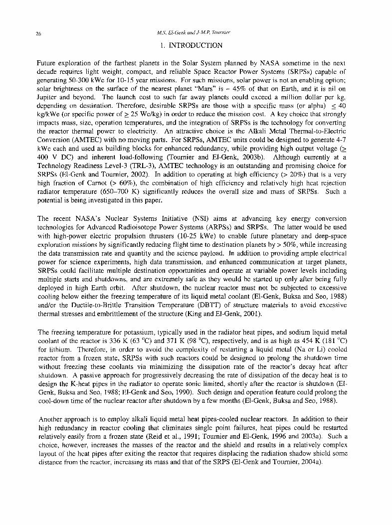
Schematics of the reference SAIRS layout are shown in Figure la and Figure lb. Figure la presents an isometric view of the fully integrated SAIRS-C (one of the three options investigated) and Figure lb shows the arrangement of the AMTEC units and their thermal coupling to the reactor sodium heat pipes and to the radiator potassium heat pipes and of the latter to the C-C armored radiator panels. SAIRS has a nominal electrical power of 110 kWe that is delivered at a terminal voltage of 400 V DC, and employs either 18, 6.17 kWe, or 24, 4.63 kWe Na-AMTEC units grouped in six blocks (Figure lb). Each block consists of 3 or 4 AMTEC units with a separate heat rejection radiator panel (Figure lb) and is serviced by 10 reactor Na-heat pipes for enhanced redundancy. Six double-vapor-cavity potassium heat pipes that are conductively coupled to the C-C armored and fined radiator panel remove the heat rejected by the AMTEC units block. The AMTEC units are placed behind the radiation shadow shield within the cone angle of SAIRS (34 °) (Figure la). Further testing of the effects of fast neutrons and high energy gammas from the nuclear reactor on the stability, strength, and lifetime of the thin beta"-alumina solid electrolyte (BASE) membrane, and of the W-Rh electrodes material in the AMTEC units is needed to quantify the radiation hardness of these units.
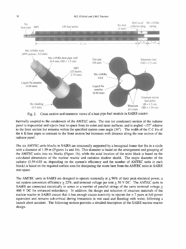
The fast-spectrum nuclear reactor in SAIRS is cooled by a total of 60, 1.5 cm OD Mo-14%Re/sodium heat pipes. After exiting the Mo-14%Re reactor vessel (0.5 mm thick) and the rear BeO axial reflector (4 cm thick), the Na-heat pipes are bent around the shadow shield and then laid out inside the radiator cavity, where they are conductively coupled to the Mo-41%Re evaporator walls of the AMTEC units (Figure 1). The sections of the Na-heat pipes that extend from the reactor to the AMTEC blocks are thermally insulated using Multi-Foils Insulation (MFI) to minimize thermal losses. The MFI consists of 25, 10 gm thick Mo foils separated by 100-gm gaps.
The Mo-14%Re wick (0.2 mm thick) is separated from the Mo-14%Re wall of the reactor Na-heat pipes by a 0.6 mm annulus filled with liquid sodium (Figure 2) to decrease the pressure losses for liquid Na returning from the condenser to the evaporator section and hence, raising the wicking limit of the heat pipes. The porous wick has an average porosity of 0.69 and an effective pore radius of 9-18 gm (Table 1). The length of the evaporator in the Na-heat pipes is identical to the active height of the SAIRS reactor core (42 cm), and the length of the condenser section is equal to the length of the AMTEC units block, 1.64 m in SAIRS-A and SAIRS-B, and 1.23 m in SAIRS-C (Figure 1 and Table 1). The length of the adiabatic section of the reactor Na-heat pipes varies by up to -10 cm, depending on the radial location of the heat pipe in the reactor core. For the longest reactor Na-heat pipe, the length of the adiabatic section is 1.9 m in SAIRS-A and 1.84 m in both SAIRS-B and -C (Table 1). The current system performance analysis assumes a temperature drop of 20 K between the condenser wall of the reactor Na-heat pipes and the hot side of the AMTEC units. The three reference SAIRS system options (SAIRS-A, -B and -C) presented and analyzed in this paper are identical except for the system efficiency (22.7%-27.3%), the operating conditions, and the number of the Na-AMTEC units (18 or 24) and their electrical connections. The reactor thermal and fission powers are quite low, 407 kWth to 488 kWth and 452 kW to 542 kW, respectively, depending on the system efficiency. In order to minimize the diameter and the mass of the radiation shadow shield (628 kg) as well as the minor diameter of the radiator, the shadow shield is placed as close to the reactor as possible. A distance of 25 cm separates the rear BeO axial reflector of the reactor from the front of the shadow shield, just enough to maneuver the Na-heat pipes around the shield before entering the radiator cavity (Figure 1).
Each radiator panel has two sections that are thermally coupled using six, double vapor cavity K-heat pipes (Figure 1). The front (or evaporator) section is a flat rectangle that spans the length of the AMTEC units block and rejects heat to space only from its outer surface. The inner surface of the radiator section is
SAIRS 29
5V J
,.,'" A
Double vapor cavity radiator K-heat pipes
/ ' / " 1 ,-" .,
..... "17o Nuclear reactor
W 157 ° / Radiator
panel (1 of 6)
Radiation Reactor Na-heat pipes shield
(a) Three-dimensional view of SAIRS-C
(b) Cutaway view through converters' section
Fig. 1. Isometric and cross-sectional views showing the layout of SAIRS-C.
30 M.S. E1-Genk and J-M.P. Tournier
N a
he Re disk
BeO axial Mo-14%Re rof lF .otnr n l n o ~nr in a
4
Mo- 14%Re wick (69% porous, 0.2 mm)
Liquid (0.6
42 cm
Gas gap (50 ~tm)
Mo-14' wic
Liquid l~ annulu
(0.60 mJ :ide t rl,
uu = l.a> cm) tri-cusps
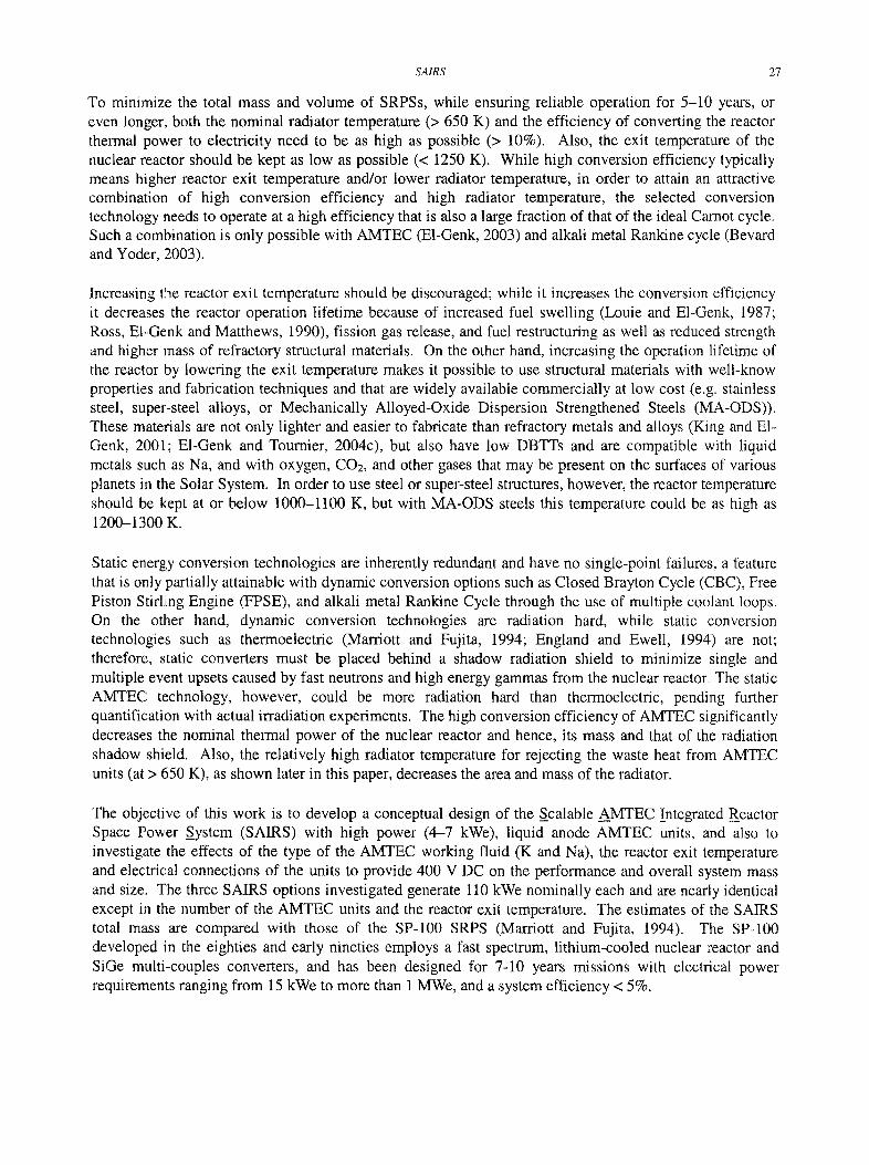
Fig. 2. Cross section and isometric views of a heat pipe fuel module in SAIRS reactor.
thermally coupled to the condensers of the AMTEC units. The rear (or condenser) section of the radiator panel is trapezoidal and rejects heat to space from its outer and inner surfaces, and is angled -157 ° relative to the front section but remains within the specified system cone angle (34°). The width of the C-C fin of the 6 K-heat pipes is constant in the front section but increases with distance along the rear section of the radiator panel.
The six AMTEC units blocks in SAIRS are structurally supported by a hexagonal frame that fits in a circle with a diameter of 1.59 m (Figures la and lb). This diameter is based on the arrangement and grouping of the AMTEC units into six blocks (Figure lb), while the axial location of the units block is based on the calculated dimensions of the nuclear reactor and radiation shadow shield. The major diameter of the radiator (3.59-4.03 m, depending on the system's efficiency and the number of AMTEC units in each block) is based on the required surface area for dissipating the waste heat from the AMTEC units in SAIRS into space.
The AMTEC units in SAIRS are designed to operate nominally at < 90% of their peak electrical power, a net system conversion efficiency > 22%, and terminal voltage per unit > 50 V DC. The AMTEC units in SAIRS are connected electrically in series in a number of parallel strings of the same terminal voltage > 400 V DC for enhanced redundancy. In addition, the design and selection of structure materials of the nuclear reactor in SAIRS ensure that it has enough excess reactivity to operate for > 7 years at full power equivalent and remains sub-critical during immersion in wet sand and flooding with water, following a launch abort accident. The following section provides a detailed description of the SAIRS nuclear reactor design.
SAIRS
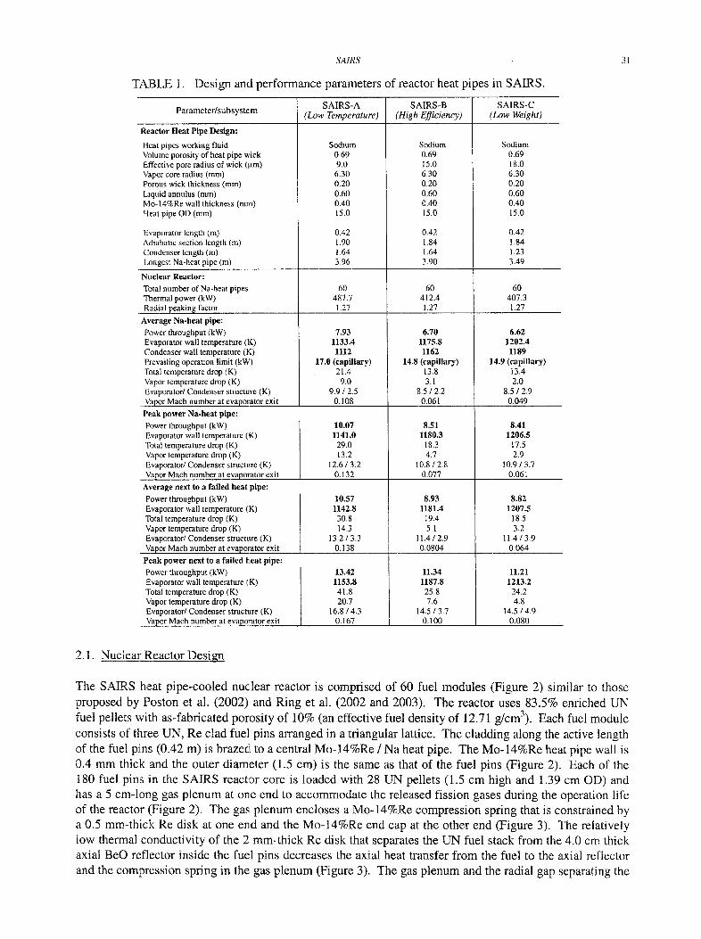
TABLE 1. Design and performance parameters of reactor heat pipes in SAIRS.
31
SAIRS-A SAIRS-B SAIRS-C Parameter/subsystem (Low Temperature) (High Efficiency) (Low Weight)
Reactor Heat Pipe Design:
Heat pipes working fluid Volume porosity of heat pipe wick Effective pore radius of wick (~m) Vapor core radius (ram) Porous wick thickness (mm) Liquid annulus (ram) Mo-14%Re wall thickness (nun) Heat pipe OD (ram)
Evaporator length (m) Adiabatic section length (m) Condenser length (m) Longest Na-heat pipe (m)
Nuclear Reactor:
Total number of Na-heat pipes Thermal power (kW) Radial peakin~ factor
Average Na-heat pipe:
Power throughput (kW) Evaporator wall temperature (K) Condenser wall temperature (K)
Sodium 0.69 9,0 6.30 0,20 0.60 0,40 15,0
0.42 1,90 1,64 3.96
60 487.7 1.27
Sodium 0.69 15.0 6.30 0.20 0.60 0.40 15.0
0.42 1.84 1.64 3,90
60 412.4 1.27
7.93 1133.4 1112
6.70 1175.8 1162
Sodium 0.69 18.0 6.30 0,20 0.60 0.40 15.0
0.42 1.84 1.23 3.49
60 407.3 1.27
6.62 1202.4
1189 Prevailing operation limit (kW) Total temperature drop (K) Vapor temperature drop (K) Evaporator/Condenser structure (K) Vapor Mach number at evaporator exit
Peak power Na-heat pipe: Power throughput (kW) Evaporator wall temperature (K) Total temperature drop (K) Vapor temperature drop (K) Evaporator/Condenser structure (K) Vapor Math number at evaporator exit
Average next to a failed heat pipe:
Power throughput (kW) Evaporator wall temperature (K) Total temperature drop (K) Vapor temperature drop (K) Evaporator/Condenser structure (K) Vapor Mach number at evaporator exit
17.0 (capillary) 21.4
9.0 9.9 / 2.5
0.108
10.07 1141.0 29.0 13.2
12.6/3.2 0.132
10.57 1142.8 30.8 14.3
13.2 / 3.3 0.138
14.8 (capillary) 13.8 3.1
8,5/2.2 0.061
8.51 1180,3
18.3 4.7
10.8/2,8 0.077
8.93 1181.4
19.4 5.1
11.4/2,9 0,0804
Peak power next to a failed heat pipe:
Power throughput (kW) 13.42 Evaporator wall temperature (K) 1153.8 Total temperature drop (K) 41.8 Vapor temperature drop (K) 20.7 Evaporator/Condenser structure (K) 16.8 / 4.3 Vapor Mach number at evaporator exit 0.167
11.34 1187.8 25.8 7.6
145 / 3.7 i I 0.100
14.9 (capillary) 13.4 2.0
8.5 / 2.9 0.049
8.41 1206.5
17.5 2.9
10.9 / 3.7 0.061
8.82 1207.5
18.5 3.2
11,4/3.9 0,064
11.21 1213.2
24,2 4.8
14,5 / 4.9 0,080
2.1. Nuciear Reactor Design
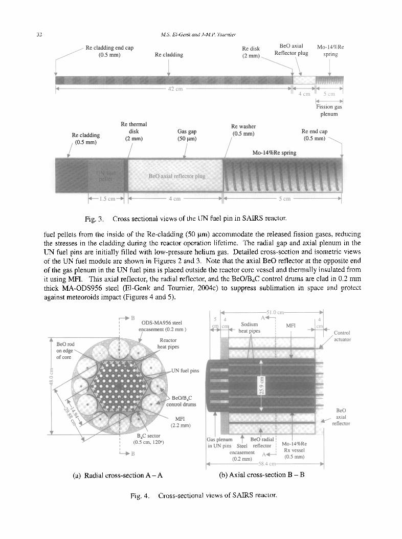
The SAIRS heat pipe-cooled nuclear reactor is comprised of 60 fuel modules (Figure 2) similar to those proposed by Poston et al. (2002) and Ring et al. (2002 and 2003). The reactor uses 83.5% enriched UN fuel pellets with as-fabricated porosity of 10% (an effective fuel density of 12.71 g/cm3). Each fuel module consists of three UN, Re clad fuel pins arranged in a triangular lattice. The cladding along the active length of the fuel pins (0.42 m) is brazed to a central Mo-14%Re / Na heat pipe. The Mo-14%Re heat pipe wall is 0.4 mm thick and the outer diameter (1.5 cm) is the same as that of the fuel pins (Figure 2). Each of the 180 fuel pins in the SAIRS reactor core is loaded with 28 UN pellets (1.5 cm high and 1.39 cm OD) and has a 5 cm-long gas plenum at one end to accommodate the released fission gases during the operation life of the reactor (Figure 2). The gas plenum encloses a Mo-14%Re compression spring that is constrained by a 0.5 ram-thick Re disk at one end and the Mo-14%Re end cap at the other end (Figure 3). The relatively low thermal conductivity of the 2 ram-thick Re disk that separates the UN fuel stack from the 4.0 cm thick axial BeO reflector inside the fuel pins decreases the axial heat transfer from the fuel to the axial reflector and the compression spring in the gas plenum (Figure 3). The gas plenum and the radial gap separating the
32
/ Re cladding,_ _ end cap
1
M.S. El-Genk and J-M.P. Tournier
,I 42 cm
Re disk BeO axial Mo-14%Re K) o r ° l a o t n T n | , t ~ ~ - - - : - -
1~,~ e l n d d i n c,
Fission gas plenum
Re thermal Re washer disk Gas gap (0.5 mm) Re end cap
Fig. 3. Cross sectional views of the UN fuel pin in SAIRS reactor.
fuel pellets from the inside of the Re-cladding (50 gin) accommodate the released fission gases, reducing the stresses in the cladding during the reactor operation lifetime. The radial gap and axial plenum in the UN fuel pins are initially filled with low-pressure helium gas. Detailed cross-section and isometric views of the UN fuel module are shown in Figures 2 and 3. Note that the axial BeO reflector at the opposite end of the gas plenum in the UN fuel pins is placed outside the reactor core vessel and thermally insulated from it using MFI. This axial reflector, the radial reflector, and the BeO/BgC control drums are clad in 0.2 mm thick MA-ODS956 steel (E1-Genk and Tournier, 2004c) to suppress sublimation in space and protect against meteoroids impact (Figures 4 and 5).
r--~B , ODS-MA956 steel I , encasement (0.2 mm )
pins
c l l n s
(a) Radial cross-section A - A (b) Axial cross-section B - B
Fig. 4. Cross-sectional views of SAIRS reactor.
SAIRS 33
r0
0 c~
Graphite support disk (2 ram) ..
Rx Na-heat pipes
Control drum actuator ~ " ~ " 1
Tungsten (2.5 cm)
ilcm ̧ ̧ i cm , 25 cm
Natural LiH in SS honeycomb matrix / (50 cm)
Shield steel encasemenl (0.5 ram)
c5
~-- 25 cm ~ 5 2 . 7
45 °
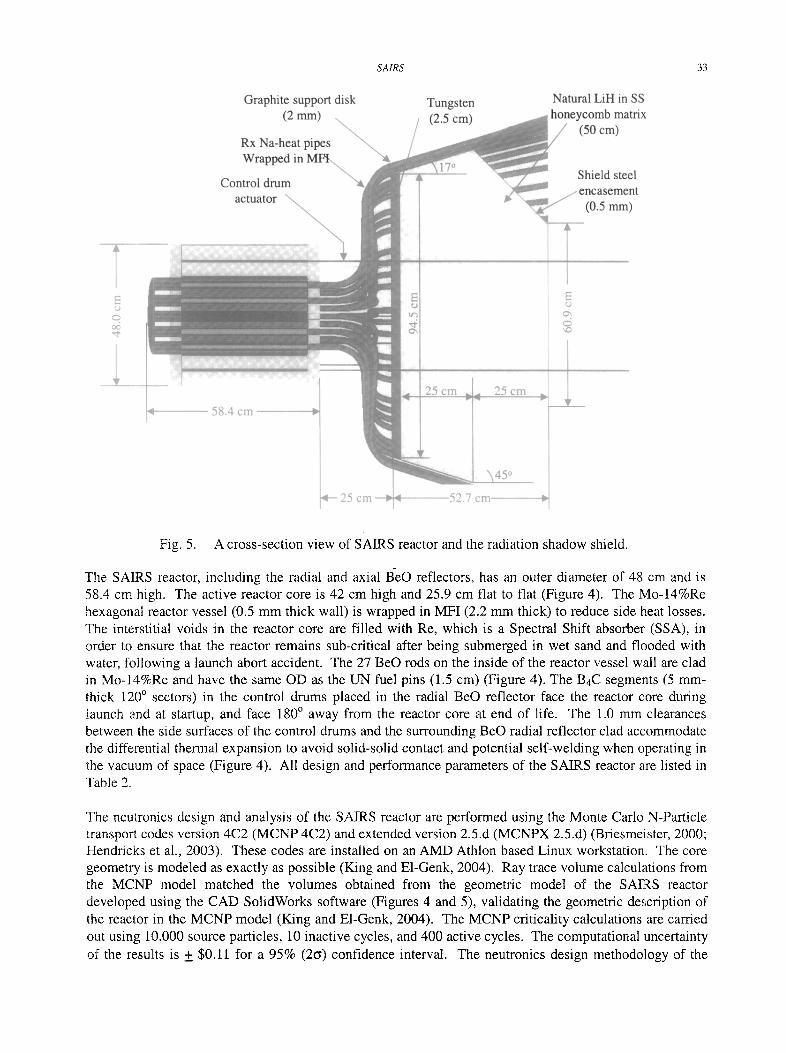
Fig. 5. A cross-section view of SAIRS reactor and the radiation shadow shield.
The SAIRS reactor, including the radial and axial B-eO reflectors, has an outer diameter of 48 cm and is 58.4 cm high. The active reactor core is 42 cm high and 25.9 cm flat to flat (Figure 4). The Mo-14%Re hexagonal reactor vessel (0.5 mm thick wall) is wrapped in MFI (2.2 mm thick) to reduce side heat losses. The interstitial voids in the reactor core are filled with Re, which is a Spectral Shift absorber (SSA), in order to ensure that the reactor remains sub-critical after being submerged in wet sand and flooded with water, following a launch abort accident. The 27 BeO rods on the inside of the reactor vessel wall are clad in Mo-14%Re and have the same OD as the UN fuel pins (1.5 cm) (Figure 4). The B4C segments (5 mm- thick 120 ° sectors) in the control drums placed in the radial BeO reflector face the reactor core during launch and at startup, and face 180 ° away from the reactor core at end of life. The 1.0 mm clearances between the side surfaces of the control drums and the surrounding BeO radial reflector clad accommodate the differential thermal expansion to avoid solid-solid contact and potential self-welding when operating in the vacuum of space (Figure 4). All design and performance parameters of the SAIRS reactor are listed in Table 2.
The neutronics design and analysis of the SAIRS reactor are performed using the Monte Carlo N-Particle transport codes version 4C2 (MCNP 4C2) and extended version 2.5.d (MCNPX 2.5.d) (Briesmeister, 2000; Hendricks et al., 2003). These codes are installed on an AMD Athlon based Linux workstation. The core geometry is. modeled as exactly as possible (King and E1-Genk, 2004). Ray trace volume calculations from the MCNP model matched the volumes obtained from the geometric model of the SAIRS reactor developed using the CAD SolidWorks software (Figures 4 and 5), validating the geometric description of the reactor in the MCNP model (King and E1-Genk, 2004). The MCNP criticality calculations are camed out using 10,000 source particles, 10 inactive cycles, and 400 active cycles. The computational uncertainty of the results is + $0.11 for a 95% (26) confidence interval. The neutronics design methodology of the
34 M.S. E1-Genk and J-M.P. Tournier
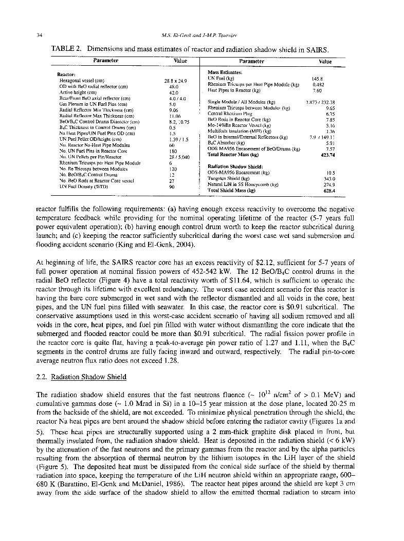
Dimensions and mass estimates of reactor and radiation shadow shield in SAIRS.
Parameter Value Parameter Value
TABLE 2.
Reactor: Hexagonal vessel (cm) 28,8 x 2&9 OD with BeO radial reflector (cm) 48.0 Active height (cm) 42.0 Rear/Front BeO axial reflector (cm) 4.0 / 4.0 Gas Plenum in UN Fuel Pins (cm) 5.0 Radial Reflector Min Thickness (cm) 9.06 Radial Reflector Max Thickness (cm) 11.06 BeO/B4C Control Drums Diameter (cm) 8.2, 10.75 B4C Thickness in Control Drums (cm) 0.5 Na Heat Pipes/UN Fuel Pins OD (cm) 1.5 UN Fuel Pellet OD/height (cm) 1.39 / 1.5 No. Reactor Na-Heat Pipe Modules 60 No. UN Fuel Pins in Reactor Core 180 No. UN Pellets per Pin/Reactor 28 / 5,040 Rhenium Trieusps per Heat Pipe Module 6 No. Re Tricusps between Modules 120 No. BeO/B4C Control Drums 12 No. BeO Rods at Reactor Core vessel 27 UN Fuel Density (%TD) 90
Mass Estimates: UN Fuel (kg) 145.8 Rhenium Tricusps per Heat Pipe Module (kg) 0.482 Heat Pipes in Reactor (kg) 7.60
Single Module / All Modules (kg) 3.873 / 232.38 Rhenium Tricusps between Modules (kg) 9.65 Central Rhenium Plug 6.75 BeO Rods in Reactor Core (kg) 7.85 M o- 14%Re Reactor Vessel (kg) 3.16 Multifoits Insulation (MFI) (kg) 1.36 BeO in Internal/External Reflectors (kg) 7.9 / 149.11 B4C Absorber (kg) 5.91 ODS-MA956 Encasement of BeO/Drums (kg) 7.57 Total Reactor Mass (kg) 423.74
Radiation Shadow Shield: ODS-MA956 Encasement (kg) 10.5 Tungsten Shield (kg) 343.0 Natural LiH in SS Honeycomb (kg) 274.9 Total Shield Mass (kg) 628.4
reactor fulfills the following requirements: (a) having enough excess reactivity to overcome the negative temperature feedback while providing for the nominal operating lifetime of the reactor (5-7 years full power equivalent operation); (b) having enough control drum worth to keep the reactor subcritical during launch; and (c) keeping the reactor sufficiently subcritical during the worst case wet sand submersion and flooding accident scenario (King and E1-Genk, 2004).
At beginning of life, the SAIRS reactor core has an excess reactivity of $2.12, sufficient for 5-7 years of full power operation at nominal fission powers of 452-542 kW. The 12 BeO/B4C control drums in the radial BeO reflector (Figure 4) have a total reactivity worth of $11.64, which is sufficient to operate the reactor through its lifetime with excellent redundancy. The worst case accident scenario for this reactor is having the bare core submerged in wet sand with the reflector dismantled and all voids in the core, heat pipes, and the UN fuel pins filled with seawater. In this case, the reactor core is $0.91 subcritical. The conservative assumptions used in this worst-case accident scenario of having all sodium removed and all voids in the core, heat pipes, and fuel pin filled with water without dismantling the core indicate that the submerged and flooded reactor could be more than $0.91 subcritical. The radial fission power profile in the reactor core is quite flat, having a peak-to-average pin power ratio of 1.27 and 1.11, when the B4C segments in the control drums are fully facing inward and outward, respectively. The radial pin-to-core average neutron flux ratio does not exceed 1.28.
2.2. Radiation Shadow Shield
The radiation shadow shield ensures that the fast neutrons fluence (- l012 n/cm 2 of > 0.1 MeV) and cumulative gammas dose (~ 1.0 Mrad in Si) in a 10-15 year mission at the dose plane, located 20-25 m from the backside of the shield, are not exceeded. To minimize physical penetration through the shield, the reactor Na heat pipes are bent around the shadow shield before entering the radiator cavity (Figures la and
5). These heat pipes are structurally supported using a 2 mm-thick graphite disk placed in front, but thermally insulated from, the radiation shadow shield. Heat is deposited in the radiation shield (< 6 kW) by the attenuation of the fast neutrons and the primary gammas from the reactor and by the alpha particles resulting from the absorption of thermal neutron by the lithium isotopes in the LiH layer of the shield (Figure 5). The deposited heat must be dissipated from the conical side surface of the shield by thermal radiation into space, keeping the temperature of the LiH neutron shield within an appropriate range, 600- 680 K (Barattino, El-Genk and McDaniel, 1986). The reactor heat pipes around the shield are kept 3 cm away from the side surface of the shadow shield to allow the emitted thermal radiation to stream into
SAIRS 35
space. The Na-heat pipes maneuvered around the shield (Figure 5) also avoid obstructing the drive shafts (or actuators) of the 12 BeO/B4C control drums. Figure 5 shows a cross-section of the radiation shadow shield and the composition and dimensions of the various shield layers to satisfy not only the dose requirements at the payload plane, but also maintain the LiH temperature between 600 K and 680 K. The details of the shield mass estimate of 628 kg are listed in Table 2. The design of the reference liquid anode AMTEC units in SAIRS is described next.
3. HIGH POWER AMTEC UNITS
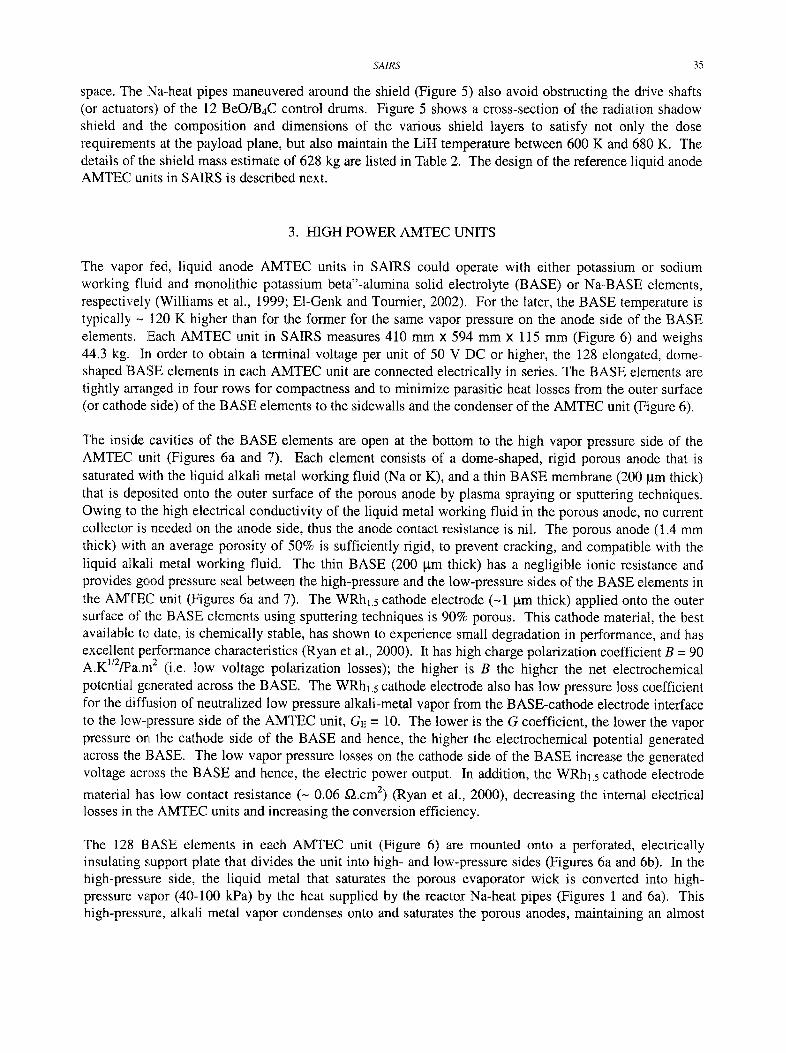
The vapor fed, liquid anode AMTEC units in SAIRS could operate with either potassium or sodium working fluid and monolithic potassium beta"-alumina solid electrolyte (BASE) or Na-BASE elements, respectively (Williams et al., 1999; E1-Genk and Tournier, 2002). For the later, the BASE temperature is typically - 120 K higher than for the former for the same vapor pressure on the anode side of the BASE elements. ]Each AMTEC unit in SAIRS measures 410 mm x 594 mm x 115 mm (Figure 6) and weighs 44.3 kg. In order to obtain a terminal voltage per unit of 50 V DC or higher, the 128 elongated, dome- shaped BASE elements in each AMTEC unit are connected electrically in series. The BASE elements are tightly arranged in four rows for compactness and to minimize parasitic heat losses from the outer surface (or cathode side) of the BASE elements to the sidewalls and the condenser of the AMTEC unit (Figure 6).
The inside cavities of the BASE elements are open at the bottom to the high vapor pressure side of the AMTEC unit (Figures 6a and 7). Each element consists of a dome-shaped, rigid porous anode that is saturated with the liquid alkali metal working fluid (Na or K), and a thin BASE membrane (200 gm thick) that is deposited onto the outer surface of the porous anode by plasma spraying or sputtering techniques. Owing to the high electrical conductivity of the liquid metal working fluid in the porous anode, no current collector is needed on the anode side, thus the anode contact resistance is nil. The porous anode (1.4 mm thick) with an average porosity of 50% is sufficiently rigid, to prevent cracking, and compatible with the liquid alkali metal working fluid. The thin BASE (200 gm thick) has a negligible ionic resistance and provides good pressure seal between the high-pressure and the low-pressure sides of the BASE elements in the AMTEC unit (Figures 6a and 7). The WRhl.5 cathode electrode (-1 ~tm thick) applied onto the outer surface of the BASE elements using sputtering techniques is 90% porous. This cathode material, the best available to, date, is chemically stable, has shown to experience small degradation in performance, and has excellent performance characteristics (Ryan et al., 2000). It has high charge polarization coefficient B = 90 A.K1/2/pa.m 2 (i.e. low voltage polarization losses); the higher is B the higher the net electrochemical potential generated across the BASE. The WRhl.s cathode electrode also has low pressure loss coefficient for the diffusion of neutralized low pressure alkali-metal vapor from the BASE-cathode electrode interface to the low-pressure side of the AMTEC unit, C,-z = 10. The lower is the G coefficient, the lower the vapor pressure on the cathode side of the BASE and hence, the higher the electrochemical potential generated across the BASE. The low vapor pressure losses on the cathode side of the BASE increase the generated voltage across the BASE and hence, the electric power output. In addition, the WRhl.s cathode electrode
material has low contact resistance (- 0.06 g2.cm 2) (Ryan et al., 2000), decreasing the internal electrical losses in the AMTEC units and increasing the conversion efficiency.
The 128 BASE elements in each AMTEC unit (Figure 6) are mounted onto a perforated, electrically insulating support plate that divides the unit into high- and low-pressure sides (Figures 6a and 6b). In the high-pressure side, the liquid metal that saturates the porous evaporator wick is converted into high- pressure vapor (40-100 kPa) by the heat supplied by the reactor Na-heat pipes (Figures 1 and 6a). This high-pressure, alkali metal vapor condenses onto and saturates the porous anodes, maintaining an almost
36 M.S. El-Genk and J-M.P. Tournier
Radiation shield with orifices
low-pressure Cavity (Pc= 20-100 Pa)
elements
high- i pressure
cavity
ot | I t m~= 40-100
kPa
Wlo Eva
41.0
Radiation shield
Mo-41%Re wall
E l AI20 3 insulator plate
Mo-41%Re support
Porous wick
A
Mo-41%Re metal Support plate
(a) Elevation cross-sectional view B - B.
BASE Mo-41%Re wall
I%Re wall nm thick)
1.82
iquid-return orous artery
L(" ,C
(b) Plane cross-sectional view A - A (all dimensions are in centimeters).
Fig. 6. Cross-sectional views of a high-power AMTEC for SRPSs.
isothermal BASE temperature. Such condensation is stimulated by: (a) the electrochemical expansion work by the sodium ions in the BASE element; (b) the heat losses by thermal radiation from the cathode electrode surface to the surrounding structure; and (c) the heat removed by the departing low-pressure sodium vapor from the surface of the cathode electrode.
SAIRS 37
P, f3 t / 3 ' )
Sputtered Sputtered thin BASE cathode
...... , ctrode
Cathode current collector
lposite BASE membrane
C Cl
Mo current conductor Porous cathode electrode Cathode current collector Porous anode Thin BASE membrane Alumina insulation
Na high vapor pressure cavity (40- 100 kPa) [All dimensions are in mrnJ
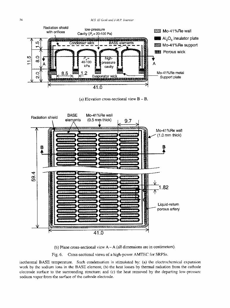
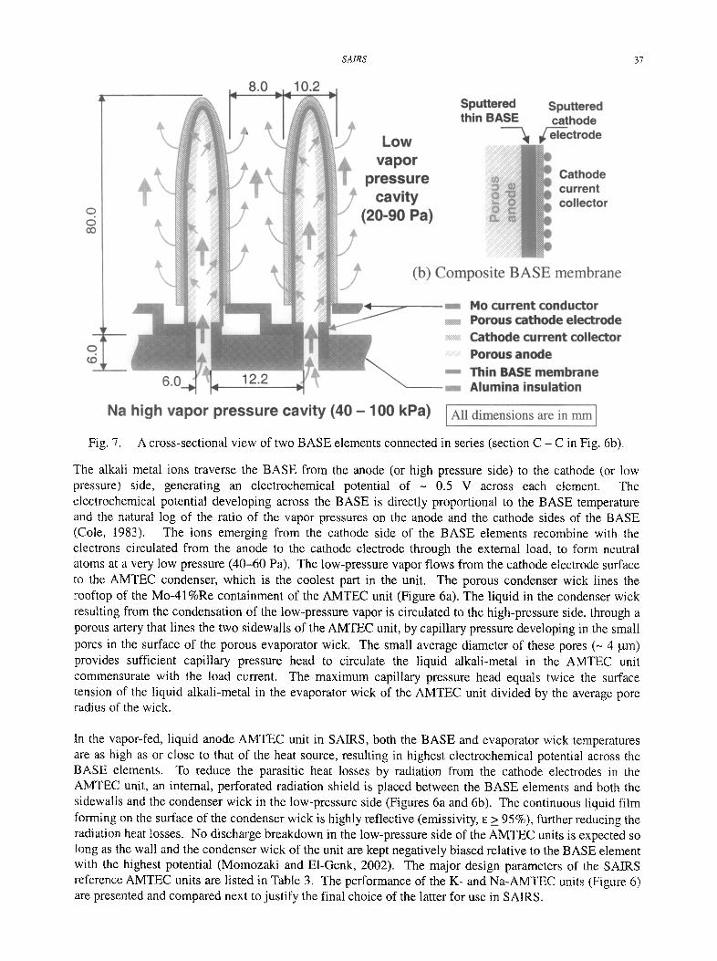
Fig. 7. A cross-sectional view of two BASE elements connected in series (section C - C in Fig. 6b).
The alkali metal ions traverse the BASE from the anode (or high pressure side) to the cathode (or low pressure) side, generating an electrochemical potential of ~ 0.5 V across each element. The electrochemical potential developing across the BASE is directly proportional to the BASE temperature and the natural log of the ratio of the vapor pressures on the anode and the cathode sides of the BASE (Cole, 1983). The ions emerging from the cathode side of the BASE elements recombine with the electrons circulated from the anode to the cathode electrode through the external load, to form neutral atoms at a very low pressure (40-60 Pa). The low-pressure vapor flows from the cathode electrode surface to the AMTEC condenser, which is the coolest part in the unit. The porous condenser wick lines the roeftop of the Mo-41%Re containment of the AMTEC unit (Figure 6a). The liquid in the condenser wick resulting from the condensation of the low-pressure vapor is circulated to the high-pressure side, through a porous artery that lines the two sidewalls of the AMTEC unit, by capillary pressure developing in the small pores in the', surface of the porous evaporator wick. The small average diameter of these pores (- 4 gin) provides sufficient capillary pressure head to circulate the liquid alkali-metal in the AMTEC unit commensurate with the load current. The maximum capillary pressure head equals twice the surface tension of the liquid alkali-metal in the evaporator wick of the AMTEC unit divided by the average pore radius of the wick.
In the vapor-fed, liquid anode AMTEC unit in SAIRS, both the BASE and evaporator wick temperatures are as high as or close to that of the heat source, resulting in highest electrochemical potential across the BASE elements. To reduce the parasitic heat losses by radiation from the cathode electrodes in the AMTEC unit, an internal, perforated radiation shield is placed between the BASE elements and both the sidewalls and the condenser wick in the low-pressure side (Figures 6a and 6b). The continuous liquid film forming on the surface of the condenser wick is highly reflective (emissivity, ~ > 95%), further reducing the radiation heat losses. No discharge breakdown in the low-pressure side of the AMTEC units is expected so long as the wall and the condenser wick of the unit are kept negatively biased relative to the BASE element with the highest potential (Momozaki and E1-Genk, 2002). The major design parameters of the SAIRS reference AMTEC units are listed in Table 3. The performance of the K- and Na-AMTEC units (Figure 6) are presented and compared next to justify the final choice of the latter for use in SAIRS.
38 M.S. El-Genk and J-M.P. Tournier
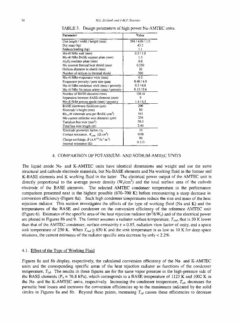
TABLE 3. Design parameters of high power Na-AMTEC units.
Parameter Value
Unit length / width / height (mm) Dry mass (kg) Sodium loading (kg) Mo-41%Re wall (mm) Mo-41%Re BASE support plate (mm) A1203 insulator plate (ram) Mo internal thermal heat shield (mm) Orifices diameter in shield (mm) Number of orifices in thermal shield Mo-41%Re evaporator wick (mm) Evaporator porosity / pore size (I.tm) Mo-41%Re condenser wick (mm) / porosity Mo-41%Re Na return artery (mm) / porosity Number of BASE elements/rows Separation between BASE elements (mm) Mo-41%Re porous anode (mm) / porosity BASE membrane thickness (gin) Electrode's height (mm) Rhl.sW electrode area per BASE (cm ~) Mo current collector wire diameter (/.tin) Tantalum bus wire (mm 2) Total bus wire length (m) Electrode geometric factor, Ge Contact resistance, R~.on t (g2.cm 2)
Charge-exchange, B (A.KIr2.PaI.m "2) Internal resistance (g2)
594/410/115 43.2 1.1
0.5 / 1.0 1.5 6.0
0.250 10
300 0.5
0.40 / 4.0 0.5 / 0.6
0.15 / 0.6 128/4
9 1.4/0.5
200 80 141 254 50.3 2.40
10 0.06 90
0.113
4. COMPARISON OF POTASSIUM- AND SODIUM-AMTEC UNITS
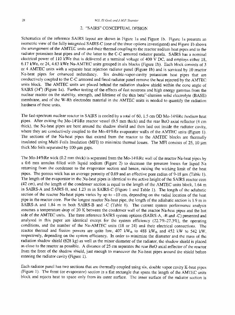
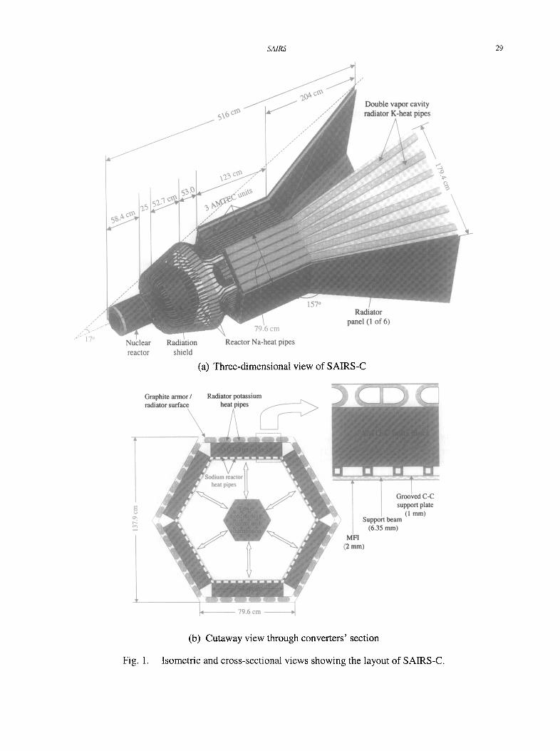
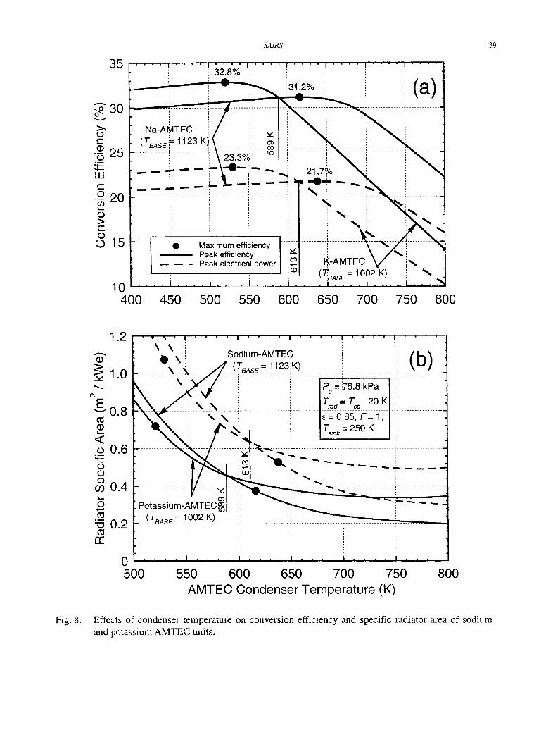
The liquid anode Na- and K-AMTEC units have identical dimensions and weight and use the same structural and cathode electrode materials, but Na-BASE elements and Na working fluid in the former and K-BASE elements and K working fluid in the latter. The electrical power output of the AMTEC unit is directly proportional to the average power density (We/cm 2) and the total surface area of the cathode electrode of the BASE elements. The selected AMTEC condenser temperature in the performance comparison presented next is the highest possible (670-700 K) before encountering a steep decrease in conversion efficiency (Figure 8a). Such high condenser temperatures reduce the size and mass of the heat rejection radiator. This section investigates the effects of the type of working fluid (Na and K) and the temperatures of the BASE and condenser on the conversion efficiency of the reference AMTEC unit (Figure 6). Estimates of the specific area of the heat rejection radiator (m2]kWe) and of the electrical power are plotted in Figures 8b and 9. The former assumes a radiator surface temperature, Trad, that is 20 K lower than that of the AMTEC condenser, surface emissivity e = 0.85, radiation view factor of unity, and a space sink temperature of 250 K. When Traa > 650 K and the sink temperature is as low as 10 K for deep space missions, the current estimates of the radiator specific area decrease by only < 2.2%.
4.1. Effect of the Type of Working Fluid
Figures 8a and 8b display, respectively, the calculated conversion efficiency of the Na- and K-AMTEC units and the corresponding specific areas of the heat rejection radiator as functions of the condenser temperature, Tcd. The results in these figures are for the same vapor pressure in the high-pressure side of the BASE elements (Pa = 76.8 kPa), which corresponds to a BASE temperature of 1123 K and 1002 K in the Na- and the K-AMTEC units, respectively. Increasing the condenser temperature, Tea, decreases the parasitic heat losses and increases the conversion efficiencies up to the maximums indicated by the solid circles in Figures 8a and 8b. Beyond these points, increasing Tcd causes these efficiencies to decrease
SAIRS 39
> , O' r-
(j,
UJI c': .c_!
I . , , . ,
> c-: O
O
3 5
3 0
2 5
2 0
1 5
1 0
400
. . . . . . . . . . o " [ . . . . . . . . . . . . . . . . . . . .
L i -
............. i ............. • ........... -5" ....... to . . . . . . . . . ! ............. ] . . . . . . . . . . . . i _ 2 \ - 2 ~ . 3 Y<~_ ~ ! - - ~ - - -
- - - - @ - - i - ~ - i - - i " ",4 21'7~/° . . " ~ i
- - " . . . . . . . . . . . . . ~ . . . . . . . . . . . . . . i . . . . . . . . . . . ~ ~ : _ . , : _ ' . ~ . . . . . i . . . . . . . . . . . . . . . . . . . . . . . . . . .
. . . . . [ @ Maximum efficiency [ ~ i ......... : ~ | - - - Peak efficiency I ~ . = ~ \ / " i . / - - - Peak electrical power I # 1 I~-AMTEC,~ ~ / i ~ i , , I ~,®1 (TBASE = 10()2 K) I
. . . . . . . . i . . . . i . . . . i . . . . i ~ . . . . i . . . . i . . . . " 450 500 550 600 650 700 750 800
E v
< : Cl
° ~ , M - . - ° l
Cl
CL.
i , . ,
O
-Ct
rr:
1 . 2
1 . 0
0.8
0.6
0.4
0 . 2
\ \ l l \
....... _k____.X .......
N _ _ N ..... \ \
03 Po tass ium- .AMTEC~
(7~,o= = ! 0 0 2 K)
So."dium-AMTE¢
Pa = ~6.8 kPa
r , - rc,- 2o K . . . . . . . . . . . . . . . . . . . . . . . . . .
E = 0:;85, F = 1,
Tin k ",= 250 K
( b )
0 500 550 600 650 700 750 800
AMTEC Condenser Temperature (K)
Fig. 8. Effects of condenser temperature on conversion efficiency and specific radiator area of sodium and potassium AMTEC units.
40 M.S. El-Genk and J-M.P. Tournier
8
v
L =
o 4 O_
o . m
0
0
[]
0
Nominal operation Peak power Peak efficiency Load-following operation Non-load following Present AMTEC performance
/ /
,#.' J - - ! . . . . . . . . -
i i / f :
17- = 1123 (N~, Pa = 76.8 k'Pa)
-" 1073 K (N~, 45.9 kPa)
102~ K (Na, 26.1z~ kPa) / T d = 7 0 0 /
/ /
" / / ~,
/ / , j f , s ' "
/ / / ,,i "~
j ~ 1 ~ " " ~ . ~ , '
~ ~1002 K (K, 76.8 k~a
[
i J /
/
0 5 10 15 20 25 30 Conversion Efficiency (%)
Fig. 9. Performance of present AMTEC units at a condenser temperature of 700 K.
precipitously, due to the sharp rise in the vapor pressure of the alkali metal working fluid in the low- pressure side of the AMTEC units. Such rise in the vapor pressure also decreases the electrochemical potential generated across the BASE and hence, the electrical power output of the AMTEC units. As shown in Figure 8a, the maximum efficiency for the K-AMTEC unit (32.8%) is higher than that for the Na- AMTEC unit (31.2%) and occurs at 100 K lower condenser temperature (520 K versus 620 K for the latter). Conversely, when the condenser temperature is > 589 K, the maximum efficiency of the K- AMTEC unit drops below that of the Na-AMTEC unit. For the same condenser temperature and type of working fluid, the conversion efficiencies at the peak electrical powers (solid circles on the dashed curves) are on average about 9 percentage points lower than the maximum efficiencies (solid circles on the solid curves) (Figure 8a). These differences, however, decrease as Ted increases slightly beyond those corresponding to the maximum efficiencies. At the maximum electrical power, the specific area of the heat rejection radiator for the Na-AMTEC unit is -40% higher than that at the maximum efficiency (Figure 8b). When Tc,~ > 613 K, the specific area of the radiator for the Na-AMTEC unit is lower than for the K- AMTEC unit.
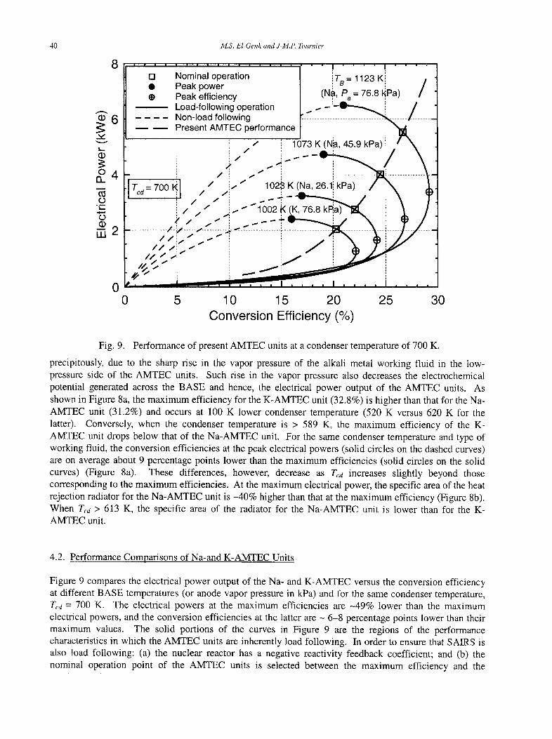
4.2. Performance Comparisons of Na-and K-AMTEC Units
Figure 9 compares the electrical power output of the Na- and K-AMTEC versus the conversion efficiency at different BASE temperatures (or anode vapor pressure in kPa) and for the same condenser temperature, T,.d = 700 K. The electrical powers at the maximum efficiencies are ~49% lower than the maximum electrical powers, and the conversion efficiencies at the latter are - 6-8 percentage points lower than their maximum values. The solid portions of the curves in Figure 9 are the regions of the performance characteristics in which the AMTEC units are inherently load following. In order to ensure that SAIRS is also load following: (a) the nuclear reactor has a negative reactivity feedback coefficient; and (b) the nominal operation point of the AMTEC units is selected between the maximum efficiency and the
SAIRS 41
maximum electrical power on the solid parts of performance characteristics in Figure 9. For example, selecting the nominal operation point for the AMTEC units in SAIRS at say 86% of the maximum
electrical power allows for up to 14% load-following increase in the load demand without having to actively increase the reactor thermal power and stressing the structural materials (E1-Genk, Seo and Buksa, i988).
With these design and operation features accomplished, an increased demand for electrical power beyond nominal increases the electrical power generated by SAIRS, up to the maximum electrical power of the AMTEC unit (solid circle symbols in Figure 9). With a further increase in the load demand beyond the maximum power, SAIRS becomes non-load following, generating lower electrical power. Therefore, the operation domain up to the maximum electrical power is the most appropriate because in it SAIRS as well as the AMTEC units are inherently load following. Therefore, the domain beyond the maximum electrical power of the AMTEC units (delineated by the dashed lines in Figure 9) should be avoided.
Figure 9 also shows that at the same anode vapor pressure of 76.8 kPa, the BASE temperature in the Na- AMTEC unit is 1123 K, but only 1002 K in the K-AMTEC unit. The crossed open circle symbols indicate the maximum conversion efficiency and the thick dashed curve connecting the open square symbols represents the locus of the nominal operation points at the different BASE temperatures corresponding to a nominal operation at 86% of the maximum electrical power. For such nominal operation, the conversion efficiencies of the AMTEC units are only 2-2.5 percentage points lower than their maximum values, but -5 percentage points higher than those at the peak electrical powers. At the same anode vapor pressure of 76.8 kPa, tl~e peak electrical power of the Na-AMTEC unit is -2.7 times that of the K-AMTEC unit. However, the BASE temperature in the latter (or the nuclear reactor exit temperature) is 120 K lower than in the former. At a BASE temperature of 1123 K (or a nuclear reactor exit temperature of -1165 K), when operating nominally at 86% of the maximum electrical power, the Na-AMTEC unit has a conversion efficiency of 26.7 % and generates 5.6 kWe, at a terminal voltage of 56 V DC. At the same anode vapor pressure of 76.8 kPa, the K-AMTEC unit has an efficiency of only 20.3% and generates 2.0 kWe at a terminal voltage of only 32 V DC. Therefore, for a 100 kWe SRPS, a total of 50, 2.0 kWe K-AMTEC units would be needed, compared to only 18, 5.6 kWe Na-AMTEC units, significantly increasing the mass of the system, since all AMTEC units weigh the same (44.3 kg). Because the K-AMTEC-units have a conversion efficiency that is only 76% of that of the Na-AMTEC unit, they are excluded from further consideration for SAIRS.
Figure 9 also shows that at 50 K and 100 K lower BASE temperatures of 1073 K and 1023 K, respectively, the nominal electrical power of the Na-AMTEC unit decreases to 4.0 kWe and 2.75 kWe, and the corresponding terminal voltage of the units decreases to 48 and 42 V DC, respectively. At these BASE temperatures, the corresponding reactor exit temperature would be ~1115 K and 1065 K, respectively. Therefore, to maximize the specific power of the Na-AMTEC unit, a good choice is to operate at a BASE temperature of 1123 K, or a reactor exit temperature of 1165 K. The second best choice is operating the Na-AMTEC units at a BASE temperature of 1073 K (or a reactor exit temperature of 1115 K), at which the units specific power is -30% lower. For the ll0-kWe SAIRS, either 24, 4.6 kWe Na-AMTEC units or 18, 6.1 kWe Na-AMTEC units are needed, which operate at a BASE temperature of 1123 K or higher.
Based on these results and to reduce the total surface area of the radiator, while operating at a reasonably high conversion efficiency, a condenser temperature of -700 K is selected for the integration of the Na- AMTEC units into SAIRS. At this condenser temperature, the specific area of the heat rejection radiator with the Na-AMTEC units is significantly (-40%) smaller. At such radiator temperature the conversion efficiency of the Na-AMTEC is also superior to that of the K-AMTEC; a trend that holds true for Tm> 613 K (Figure 8a). At a condenser temperature of 700 K, the specific radiator area for the Na-AMTEC is lowest (0.24 m2/kWe), while the potassium heat pipes in the heat rejection radiator of SAIRS (Figure 1) operate significantly (> 70%) below the sonic limit. In all subsequent analyses, the selected Na-AMTEC units operate at a constant condenser temperature of 700 K.
42 M.S. El-Genk and J-M.P. Tournier
5. SAIRS OPTIONS
The performance results presented in this section are for three SAIRS options. These options are identical except in the number and the electrical connections of the Na-AMTEC units, the nominal system efficiency, and the BASE and reactor exit temperatures. SAIRS-A and SAIRS-B both use 24 Na-AMTEC units arranged in 6 blocks of 4 units each, while SAIRS-C uses 18 units, arranged in 6 blocks of 3 units each. The AMTEC units in all SAIRS options operate at the selected condenser temperature of 700 K and < 86% of the peak electrical power. Each SAIRS option generates 111 kWe at a terminal voltage of 400 V DC, thus allowing for total losses of 11 kWe to deliver a net of 100 kWe to the payload. These losses include 10 kWe of electrical losses in the Power Management and Distribution (PMAD) sub-system and in the transmission lines to the ion thrusters, and a potential decrease in the electrical power output of -1 kWe as a result of losing - 20% of the physical surface area of the heat rejection radiator due to meteoroids impacts or degradation in surface emissivity, as explained in a later section.
The thermal efficiency of SAIRS, for the purpose of determining the nominal thermal power of the nuclear reactor, is taken equal to 90.25%. The 9.75% thermal losses include 2.5% losses through the MFI surrounding the reactor core vessel, 2.5% thermal losses through MFI along the adiabatic section of the reactor Na-heat pipes, and 5% thermal losses to the AMTEC units. Thus, the reactor Na-heat pipes transport only 95% of the reactor thermal power, and only 95% of this power is delivered to the AMTEC units. Note that the internal electrical and thermal losses in the AMTEC units are already accounted for in figuring out the conversion efficiency and the electrical power output of these units.
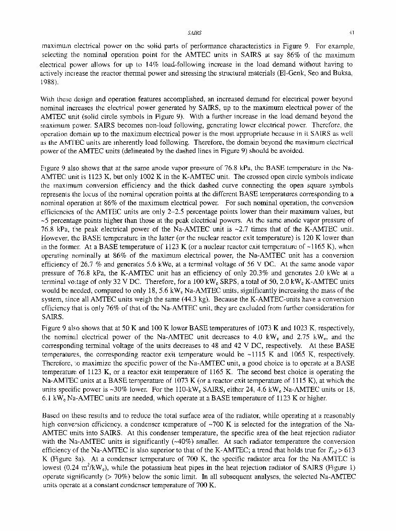
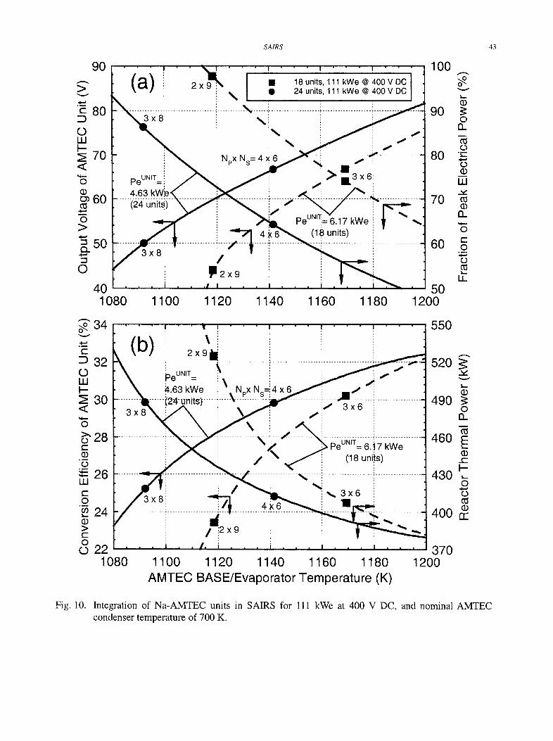
The AMTEC units in SAIRS-A and SAIRS-B deliver 4.63 kWe each, while those in SAIRS-C deliver 6.17 kWe each. Figures 10a and 10b show the effect of the BASE temperature on the performance of the Na- AMTEC units for generating constant electrical powers of 4.63 and 6.17 kWe. Increasing the BASE temperature (or the reactor exit temperature) increases the output voltage (Figure 10a) and the conversion efficiency of the AMTEC units (Figure 10b). For a BASE temperature of 1092 K, the Na-AMTEC unit delivers 4.63 kWe at an output voltage of 50 V DC. Thus, for SAIRS to operate at a terminal voltage of 400 V DC, the 24, 4.63 kWe Na-AMTEC units in this system are connected in 3 parallel strings (Np = 3), and each string has 8 AMTEC units electrically connected in series (Ns = 8). This arrangement is the one used in SAIRS-A, and is indicated in Figures 10a and 10b by the solid circle symbols marked (3 x 8). When the 24 Na-AMTEC units in SAIRS are connected in 4 parallel strings, each with 6 units connected in series, each unit operates at a terminal voltage output of 66.7 V DC. As shown in Figure 10a this arrangement is used in SAIRS-B, requiring the Na-AMTEC units to operate at a BASE temperature of 1142 K. The advantages of operating at such higher BASE temperature are four-fold:
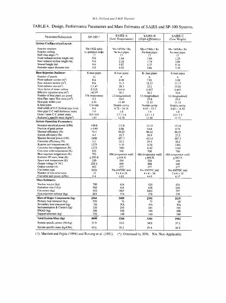
(a) Higher Conversion Efficiency: The conversion efficiency of the Na-AMTEC unit is 29.8%, versus 25.2% when operating at the lower BASE temperature of 1092 K (Figure 10b), decreasing the nuclear reactor thermal power from 488 kWth to 412 kWth.
(b) Smaller Radiator." Such high BASE temperature also reduces the total surface area and mass of the heat rejection radiator for SAIRS from 38.1 m 2 to 30.2 m 2 and from 374 kg to 276 kg, respectively (Table 4). On the other hand, operating at a higher BASE temperature increases the reactor temperature, slightly increasing UN fuel swelling.
(c) Higher Load-Following Margin." The Na-AMTEC unit operates at a low fraction (64%) of the maximum electrical power, versus 86% at the lower BASE temperature of 1092 K (Figure 10a), thus
allowing SAIRS-B to deliver much higher power (~ 150 kWe) than nominal (111 kWe), while being load-following.
(d) Enhanced Redundancy: Increasing the number of parallel strings for electrically connecting the Na- AMTEC units from 3 to 4 increases the redundancy in energy conversion and hence, that of SAIRS (Figures 10a and 10b).
SAIRS 4 3
> v
¢ -
o LU t - -
< o
e5 m
O
Fig. 10.
90
80
70
60
>
EL
O
o~ v
E
O UJ I--
<
o >, o c-
o
LU c- O 00
> t - O o
50,
4 0 ~ " 1080
(a) 3x8i
peUNIT=
_4. _._6_ _3_ . _k_ _ .W_ ~ (24 units)
3 x 8
2 x 9 \ •
I~i2 x9
• I i /
4x
18 units, 111 kWe @ 400 V DC 24 units, 111 kWe @ 400 V DC
. . . . . . . . . . '~ . . . . . . . . . . . . . . . . . . . i - - ~
~'~,~ 1 3 x 6 ! t
~ ..... _.%.
peUNIT:"= 6.17 kWe . (18 units)
1100 1120 1140 1160 1180
• - - 100
I 90
~-- 80
--] 70
. . . . 60
-~--] 50 1200
o~ v
(D
O n
o "E O (D UJ
n
O E O
, m
O
U_
34.
32.
30
28
26
24.
i 2 x 9 / i T . . . . . . . . . . . . . . . . . . 1 . . . . . . . . . . . . . . . , - - -
peU~,t= \ ',
~,.63 kWe il \ NpX Ns=:: 4
, / x8
X b f :
, ==/ / / :
\ / . . . . . . . . . . . . i . . . .
¢ . . . . . . ,, . . . . . . . . . . . ~ . . . . . • . . . .
4X6 ....... ( t . . . . . . . . . . . . . . . . . .
d : [
/ 12x9 , ,,
3 x 6
peUNIT= 6. t 7 ('18 uni,ts)
' ~ 3 x 6 l _
I
kWe
550
520
490 ~ o
460 E
430 ~ ~ o 0
400
22 370 1080 1100 1120 1140 1160 1180 1200
A M T E C BASE/EvaporatorTemperature(K)
Integration of Na-AMTEC units in SAIRS for 111 kWe at 400 V DC, and nominal AMTEC condenser temperature of 700 K.
M.S. El-Genk and J-M.P. Tournier
TABLE 4. Design, Performance Parameters and Mass Estimates of SAIRS and SP-100 Systems.
SAIRS-A SAIRS-B SAIRS-C Parameter/Subsystem SP-100 J (Low Temperature) (High-Efficiency) (Low Weight)
System Configuration/Layout:
Reactor structure Reactor cooling Half cone angle (°) Front radiator section length (m) Rear radiator section length (m) Stowed height (m) Radiator major diameter (m)
Heat Rejection Radiator: Number of panels Front radiator section (m 2) Rear radiator section (m 2) Total radiator area (m z) View factor of inner surface Effective rejection area (m 2)
Nb- 1%Zr alloy Li-pumped loops
17 NA NA 9.6 8.0
Mo-14%Re / Re Na-heat pipes
17 1.64 2.28 5.87 4.03
Mo-14%Re / Re Na-heat pipes
17 1.64 1.74 5.27 3.66
K-heat pipes
12 NA NA
111.4" 0.310 145.9"
K heat pipes 6
8.00 21.3 29.3
0.414 38.1
K- heat pipes 6
7.83 15.37 23.2
0.457 30.2
Mo-14%Re / Re Na-heat pipes
17 1.23 2.04 5.16 3.59
K-heat pipes 6
5.88 17.17 23.05 0.403 30.0
Number of heat pipes per panel Heat Pipe vapor flow area (cm 2) Heat pipe width (cm) K-heat pipes Half-width of C-C fin/heat pipe (cm) Heat pipe C-C wall thickness (mm) Outer ! inner C-C armor (mm) Radiator's specific mass (kg/m 2)
System Operation Parameters: Nominal electrical power (kWe) Fraction of peak power Thermal efficiency (%) System efficiency (%) Reactor thermal power (kW) Converter efficiency (%) Reactor exit temperature (K) Converter hot temperature (K) Converter cold temperature (K) Heat rejection temperature (K) Radiator HP sonic limit (K) Space sink temperature (K) Output voltage (V DC) Output current (A) Converters type Number of converter units
378 (transverse) 4.2 2.54
Circular NA 1.0
0.0 / 0.0 7.67
100.8 > 0.95 79.3 4.2
2400 5.3
1373 1273 823 793
<_ 580 K 250
208,6 483 SiGe
12
12 (longitudinal) 32.0 11.49
Double cavity 6.78 - 16.74
1.0 2.7 / 1.6
12.76
111.0 0.86
90.25 22.7
487.7 25.2 1133 1092 700
686 (evaporator wall) 656 K 250 400 277
Na-AMTEC unit 3 x 8 = 2 4
12 (longitudinal) 25.0 11.15
Double cavity 6.63 - 15.2
1,0 25 / 1.5
t 1.90
12 (longitudinal) 25.0 11.15
Double cavity 6.63 - 14.92
1.0 2.5 / 1.5
11.7I
111.0 0.64
90.25 26.9
412.4 29.8 1176 1142 700
686 (evaporator wall) 660 K 250 400 277
Na-AMTEC unit 4 x 6 = 24 3 x 6 =
111.0 0.74
90.25 27.3
407.3 30.2 1202 1169 700
686 (evaporator wall) 662 K 250 400 277
Na-AMTEC unit 18
Converter unit power (kWe)
Mass Estimates:
Nuclear reactor (kg) Radiation shield (kg) Converters (kg) Heat rejection radiator (kg)
Mass of Major Components (kg) Primary heat transport (kg) Secondary heat transport (kg) Instrumentation & Control (kg) PMAD (kg) Support structure (kg)
Total System Mass (kg)
System specific power (We/kg)
System specific mass (kg/kWe)
8.4
700 960 450 854
2964 520 186 320 390 220
4600
21.9
45.6
4.63
424 628
1063 374
2489 76
NA 245 390 160
3360
33.0
30.3
4.63
424 628
1063 276
2391 75
NA 245 390 160
3261
34.0
29.4
6.17
424 628 797 270
2119 68
NA 245 390 160
2982
37.2
26.9
( t ) : M a r r i o t t and F u j i t a ( 1 9 9 4 ) and R o v a n g et al. ( 1991) . (*): O v e r s i z e d by 2 0 % . N A : N o n - A p p l i c a b l e .
SA1RS 45
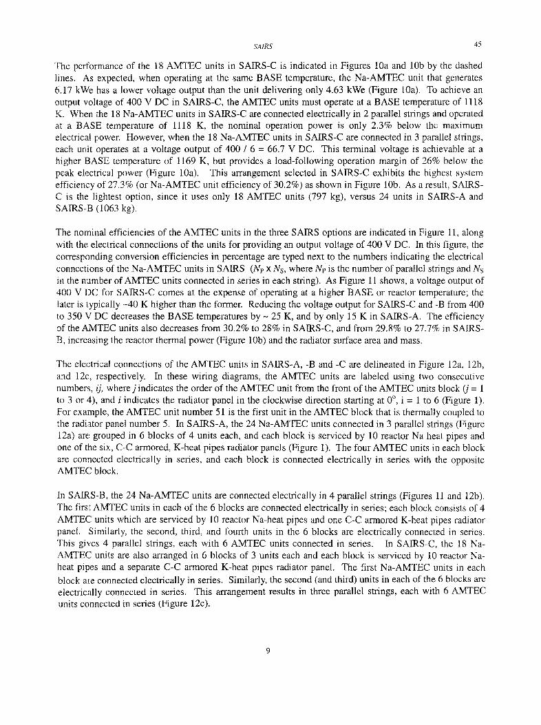
The performance of the 18 AMTEC units in SAIRS-C is indicated in Figures 10a and 10b by the dashed lines. As expected, when operating at the same BASE temperature, the Na-AMTEC unit that generates 6.17 kWe Ihas a lower voltage output than the unit delivering only 4.63 kWe (Figure 10a). To achieve an output voltage of 400 V DC in SAIRS-C, the AMTEC units must operate at a BASE temperature of 1118 K. When the 18 Na-AMTEC units in SAIRS-C are connected electrically in 2 parallel strings and operated at a BASE temperature of 1118 K, the nominal operation power is only 2.3% below the maximum electrical power. However, when the 18 Na-AMTEC units in SAIRS-C are connected in 3 parallel strings, each unit operates at a voltage output of 400 / 6 = 66.7 V DC. This terminal voltage is achievable at a higher BASE temperature of 1169 K, but provides a load-following operation margin of 26% below the peak electrical power (Figure 10a). This arrangement selected in SAIRS-C exhibits the highest system efficiency of 27.3% (or Na-AMTEC unit efficiency of 30.2%) as shown in Figure 10b. As a result, SAIRS- C is the lightest option, since it uses only 18 AMTEC units (797 kg), versus 24 units in SAIRS-A and SAIRS-B (1063 kg).
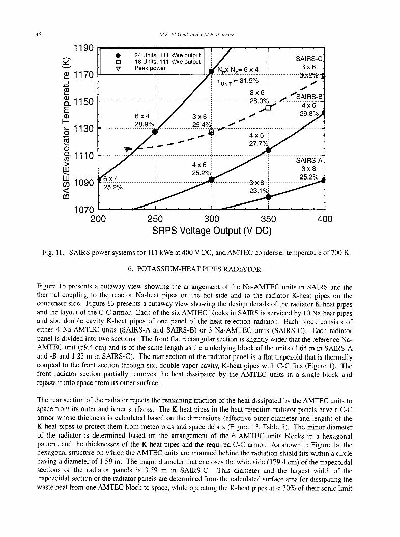
The nominal efficiencies of the AMTEC units in the three SAIRS options are indicated in Figure 11, along with the electrical connections of the units for providing an output voltage of 400 V DC. In this figure, the corresponding conversion efficiencies in percentage are typed next to the numbers indicating the electrical connections of the Na-AMTEC units in SAIRS (Ne x Ns, where Ne is the number of parallel strings and Ns in the number of AMTEC units connected in series in each string). As Figure 11 shows, a voltage output of 400 V DC for SAIRS-C comes at the expense of operating at a higher BASE or reactor temperature; the later is typically -40 K higher than the former. Reducing the voltage output for SAIRS-C and -B from 400 to 350 V DC decreases the BASE temperatures by - 25 K, and by only 15 K in SAIRS-A. The efficiency of the AMTEC units also decreases from 30.2% to 28% in SAIRS-C, and from 29.8% to 27.7% in SAIRS- B, increasing the reactor thermal power (Figure 10b) and the radiator surface area and mass.
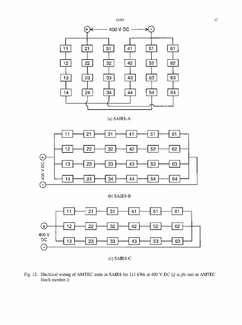
The electrical connections of the AMTEC units in SAIRS-A, -B and -C are delineated in Figure 12a, 12b, and 12c, respectively. In these wiring diagrams, the AMTEC units are labeled using two consecutive numbers, ij, wherej indicates the order of the AMTEC unit from the front of the AMTEC units block (j = 1 to 3 or 4), and i indicates the radiator panel in the clockwise direction starting at 0 °, i = 1 to 6 (Figure 1). For example, the AMTEC unit number 51 is the first unit in the AMTEC block that is thermally coupled to the radiator panel number 5. In SAIRS-A, the 24 Na-AMTEC units connected in 3 parallel strings (Figure 12a) are grouped in 6 blocks of 4 units each, and each block is serviced by 10 reactor Na heat pipes and one of the six, C-C armored, K-heat pipes radiator panels (Figure 1). The four AMTEC units in each block are connected electrically in series, and each block is connected electrically in series with the opposite AMTEC block.
In SAIRS-B, the 24 Na-AMTEC units are connected electrically in 4 parallel strings (Figures 11 and 12b). The first AMTEC units in each of the 6 blocks are connected electrically in series; each block consists of 4 AMTEC units which are serviced by 10 reactor Na-heat pipes and one C-C armored K-heat pipes radiator panel. Similarly, the second, third, and fourth units in the 6 blocks are electrically connected in series. This gives 4 parallel strings, each with 6 AMTEC units connected in series. In SAIRS-C, the 18 Na- AMTEC units are also arranged in 6 blocks of 3 units each and each block is serviced by 10 reactor Na- heat pipes and a separate C-C armored K-heat pipes radiator panel. The first Na-AMTEC units in each block are connected electrically in series. Similarly, the second (and third) units in each of the 6 blocks are electrically connected in series. This arrangement results in three parallel strings, each with 6 AMTEC units connected in series (Figure 12c).
46 M.S. E1-Genk and J-M.P. Tournier
c l .
E ! - -
I,.=.
O
O o .
> W
UJ
m
1190 []
V
1170 t'
1150 .............
1130 ...........
1110 ............. • I
1090 2 5 . 2 %
1070 i__.,.._,. 200
24 Units, 111 kWe output 18 Units, 111 kWe output Peak power
6 x 4
28 .9%1 3 x 6
25_:_4°_/o::._
. . . . . . . . . . . . . i -
4 x 6 : 25.2%i
S A I R S - C
~1 x N = 6 x 4 : 3 x 6 .... P: ..... ~ . . . . . . . . . . . ..: . . . . . . . . . . . 3 0 . 2 % - 1 ?IUNI T ----- 3 1 . 5 % I
I
3 x 6 I S A I R S _ g . . . . . . . . . . . . . . . . . . 28.O9,~ ...... I__
..xr" 4 2,
4 x 6
2 7 . 7 ° / i
S A I R S - A
3 x 8
2 5 . 2 % , -3-x-8 ....
23•1°/~
250 300 350 SRPS Voltage Output (V DC)
400
Fig. 11. SAIRS power systems for 111 kWe at 400 V DC, and AMTEC condenser temperature of 700 K.
6. POTASSIUM-HEAT PIPES RADIATOR
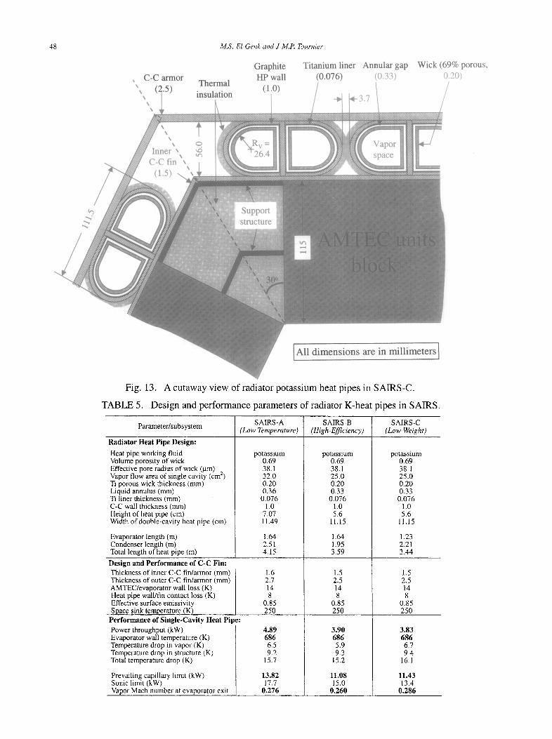
Figure lb presents a cutaway view showing the arrangement of the Na-AMTEC units in SAIRS and the thermal coupling to the reactor Na-heat pipes on the hot side and to the radiator K-heat pipes on the condenser side. Figure 13 presents a cutaway view showing the design details of the radiator K-heat pipes and the layout of the C-C armor. Each of the six AMTEC blocks in SAIRS is serviced by 10 Na-heat pipes and six, double cavity K-heat pipes of one panel of the heat rejection radiator. Each block consists of either 4 Na-AMTEC units (SAIRS-A and SAIRS-B) or 3 Na-AMTEC units (SAIRS-C). Each radiator panel is divided into two sections. The front flat rectangular section is slightly wider that the reference Na- AMTEC unit (59.4 cm) and is of the same length as the underlying block of the units (1.64 m in SAIRS-A and -B and 1.23 m in SAIRS-C). The rear section of the radiator panel is a flat trapezoid that is thermally coupled to the front section through six, double vapor cavity, K-heat pipes with C-C fins (Figure 1). The front radiator section partially removes the heat dissipated by the AMTEC units in a single block and rejects it into space from its outer surface•
The rear section of the radiator rejects the remaining fraction of the heat dissipated by the AMTEC units to space from its outer and inner surfaces. The K-heat pipes in the heat rejection radiator panels have a C-C armor whose thickness is calculated based on the dimensions (effective outer diameter and length) of the K-heat pipes to protect them from meteoroids and space debris (Figure 13, Table 5). The minor diameter of the radiator is determined based on the arrangement of the 6 AMTEC units blocks in a hexagonal pattern, and the thicknesses of the K-heat pipes and the required C-C armor. As shown in Figure la, the hexagonal structure on which the AMTEC units are mounted behind the radiation shield fits within a circle having a diameter of 1.59 m. The major diameter that encloses the wide side (179.4 cm) of the trapezoidal sections of the radiator panels is 3.59 m in SAIRS-C. This diameter and the largest width of the trapezoidal section of the radiator panels are determined from the calculated surface area for dissipating the waste heat from one AMTEC block to space, while operating the K-heat pipes at < 30% of their sonic limit
Fq
Fq
Fq
SAIRS
400 V DC
(a) SAIRS-A
47
m
Q (b) SAIRS-B
® 400 V
DC
Q (c) SAIRS-C
Fig. 12. Electrical wiring of AMTEC units in SAIRS for 111 kWe at 400 V DC (ij isj th unit in AMTEC block number i).
48
C-C armor
,. ~ ,~ (~i "5),,
Inner C-C fin
(1.5) . .
M.S. EI-Genk and J-M.P. Tournier
Graphite Titanium liner Annular gap HP wall (0.076) (0.33)
Thermal (1.0) / t insulation , . I I. ~ . ,
o ,,d t ~
Wick (69% porous, 0.20)
% Support structure
All dimensions are in millimeters
Fig. 13. A cutaway view of radiator potassium heat pipes in SAIRS-C.
TABLE 5. Design and performance parameters of radiator K-heat pipes in SAIRS.
SAIRS-A SAIRS-B SAIRS-C Parameter/subsystem (Low Temperature) (High-Efficiency) (Low Weight)
Radiator Heat Pipe Design:
Heat pipe working fluid Volume porosity of wick Effective pore radius of wick (ktm) 2 Vapor flow area of single cavity (cm) Ti porous wick thickness (ram) Liquid annulus (ram) Ti liner thickness (ram)
potassium 0.69 38.1 32.0 0.20 0.36
0.076
potassium 0.69 38.1 25.0 0.20 0.33
0.076
potassium 0.69 38.1 25.0 0.20 0.33 0.076
C-C wall thickness (mm) Height of heat pipe (cm) Width of double-cavity heat pipe (cm)
Evaporator length (m) Condenser length (m) Total length of heat pipe (m)
Design and Performance of C-C Fin: Thickness of inner C-C fin/armor (mm) Thickness of outer C-C fin/armor (mm) AMTEC/evaporator wall loss (K) Heat pipe wall/fin contact loss (K) Effective surface emissivity Space sink temperature (K)
Performance of Single-Cavity Heat Pipe: Power throughput (kW) Evaporator wall temperature (K) Temperature drop in vapor (K) Temperature drop in structure (K) Total temperature drop (K)
Prevailing capillary limit (kW) Sonic limit (kW) Vapor Mach number at evaporator exit
1.0 7.07 11.49
1.64 2.51 4.15
1.6 2.7 14 8
0.85 250
4.89 686 6.5 9.2
15.7
13.82 17.7
0.276
1.0 5.6
11.15
1.64 1.95 3.59
1.5 2.5 14 8
0.85 250
3.90 686 5.9 9.3
15.2
11.08 15.0
0.260
1.0 5.6
ll.15
1.23 2.21 3.44
1.5 2.5 14 8
0.85 250
3.83 686 6.7 9.4
16.1
11.43 13.4
0.286
SAIRS 49
(Figure la). The reactor Na-heat pipes are designed to operate at < 47% of the prevailing wicking or sonic limit. The length of the reactor Na-heat pipes is determined based on the calculated dimensions of the nuclear reactor and the radiation shadow shield and the needed separation distance to route the heat pipes around the :radiation shadow shield (Figure 1 a). Each radiator K-heat pipe has a thin titanium liner (0.0762 mm thick) encased in a 1.0 mm-thick C-C outer wall, and a 0.2 mm-thick titanium wick (with an effective pore radius of 38.1 btm) separated from the titanium liner by a 0.33-0.36 mm annulus filled with liquid potassium (Figure 13, Table 5). This liquid annulus significantly reduces the pressure losses of the returning liquid from the condenser to the evaporator section, raising the capillary limit of the K-heat pipes.
The vapor flow area in each of the double cavity K-heat pipes of the radiator is 64 cm 2 in SAIRS-A, and 50 cm 2 in both SAIRS-B and SAIRS-C (Figure 13). These areas ensure that at an evaporator wall temperature of 686 K, which corresponds to an AMTEC condenser temperature of 700 K, the heat pipes operate at < 30 % of the sonic limit (for > 70% operation margin). Such large design margin also ensures that in case of a failure of up to two adjacent K-heat pipes (i.e. by meteoroids impact), the neighboring K-heat pipes will operate at < 60% of the sonic limit. The inner and outer C-C fins of the SAIRS-C radiator panel are 1.5 mm and 2.:5 mm thick, respectively. The outer C-C fin and the 1 ram-thick C-C wall of the radiator heat pipe combined provide a total thickness of the C-C armor at the outer surface of the radiator of 3.5 mm. In the front section of the radiator panel, the width of the C-C fin per double-cavity heat pipe is slightly larger
than the wiidth of the heat pipe. The width of this fin, however, increases with distance along the rear radiator section to reach its largest value, 33.5 cm, 30.4 cm and 29.8 cm, at the major diameter of the radiator for SAIRS-A, -B and -C, respectively (see Table 4). All the design and performance analyses of the reactor Na- and the radiator K-heat pipes are performed using the University of New Mexico's-Heat Pipe (UNM-HP) model, described briefly next.
6.1. _UNM Heat Pipe Model (UNM-HP)
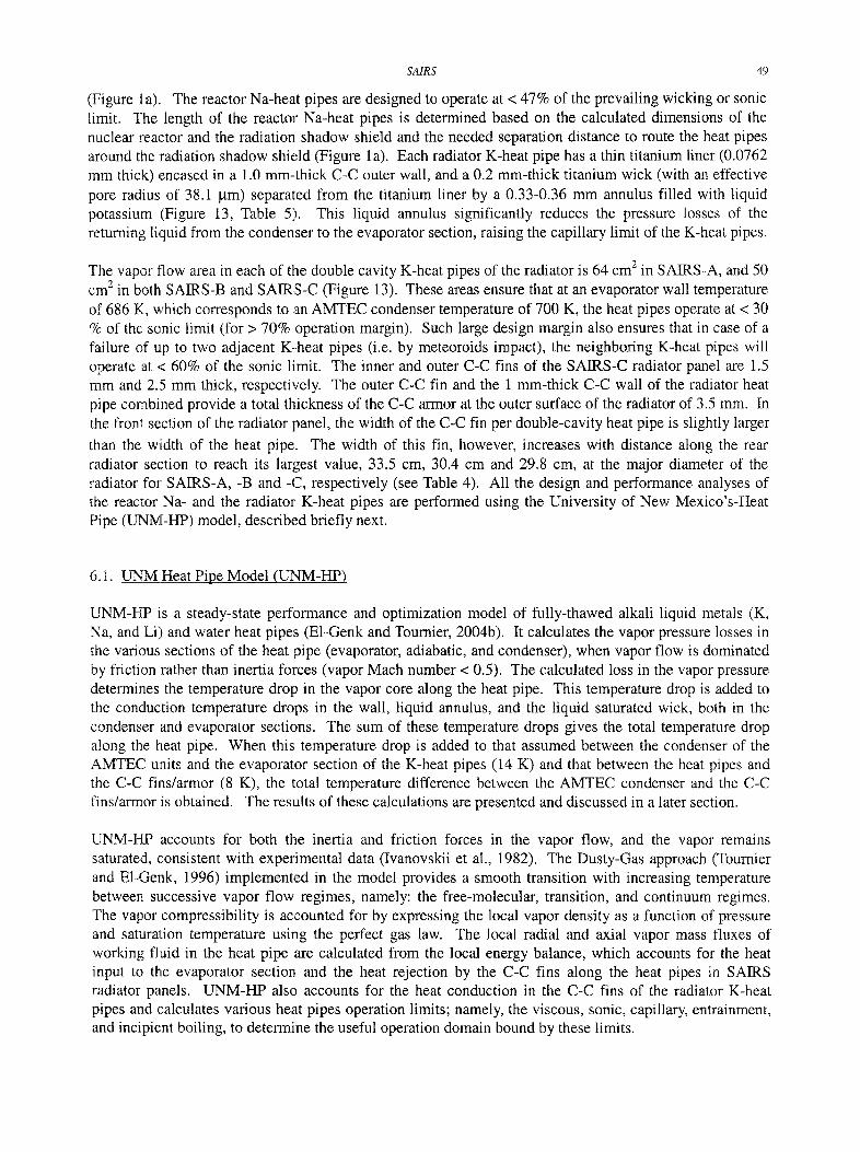
UNM-HP is a steady-state performance and optimization model of fully-thawed alkali liquid metals (K, Na, and Li) and water heat pipes (E1-Genk and Tournier, 2004b). It calculates the vapor pressure losses in the various sections of the heat pipe (evaporator, adiabatic, and condenser), when vapor flow is dominated by friction rather than inertia forces (vapor Mach number < 0.5). The calculated loss in the vapor pressure determines the temperature drop in the vapor core along the heat pipe. This temperature drop is added to the conduction temperature drops in the wall, liquid annulus, and the liquid saturated wick, both in the condenser and evaporator sections. The sum of these temperature drops gives the total temperature drop along the heat pipe. When this temperature drop is added to that assumed between the condenser of the AMTEC units and the evaporator section of the K-heat pipes (14 K) and that between the heat pipes and the C-C fins/armor (8 K), the total temperature difference between the AMTEC condenser and the C-C fins/armor is obtained. The results of these calculations are presented and discussed in a later section.
UNM-HP accounts for both the inertia and friction forces in the vapor flow, and the vapor remains saturated, consistent with experimental data (Ivanovskii et al., 1982). The Dusty-Gas approach (Tournier and E1-Genk, 1996) implemented in the model provides a smooth transition with increasing temperature between successive vapor flow regimes, namely: the free-molecular, transition, and continuum regimes. The vapor compressibility is accounted for by expressing the local vapor density as a function of pressure and saturation temperature using the perfect gas law. The local radial and axial vapor mass fluxes of working fluid in the heat pipe are calculated from the local energy balance, which accounts for the heat input to the evaporator section and the heat rejection by the C-C fins along the heat pipes in SAIRS radiator panels. UNM-HP also accounts for the heat conduction in the C-C fins of the radiator K-heat pipes and calculates various heat pipes operation limits; namely, the viscous, sonic, capillary, entrainment, and incipient boiling, to determine the useful operation domain bound by these limits.
50 M.S. EI-Genk and J-M.P. Tournier
This heat pipe model has been verified successfully using experimental data of the vapor temperature along a short sodium heat pipe (0.7 m) operated at different powers and Mach numbers up to 0.4 (Ivanovskii et al., 1982; E1-Genk and Tournier, 2004b). Such measurements are rare and to the best of the authors' knowledge none have been reported for longer liquid metal heat pipes. As indicated earlier, the prevailing wicking limit for the radiator K-heat pipes has been raised by having a liquid annulus between the porous wick and the Ti wall, which reduces the pressure losses for the circulating liquid from the condenser to the evaporator section. The diameter of these heat pipes, however, is driven by the sonic limit, which is discussed briefly next.
6.2. Heat Pipe Sonic Limit
The sonic limit is reached when the vapor velocity at the exit of either the evaporator or the adiabatic section of the heat pipe equals the sonic speed, shocking the vapor transport to the condenser and hence, constraining the heat pipe power throughput. Under this condition, increasing the thermal power input to the evaporator section of the heat pipe does not increase the power throughput to the condenser, but rather
causes the evaporator section to overheat and the porous wick to dryout. Because of the inherently low vapor pressure of alkali liquid metal working fluids (in order of decreasing vapor pressure, K, Na, and Li), operating at higher temperature helps raise the sonic limit.
The sonic power throughput of a heat pipe, Qsonic (W) is a limiting upper bound for operating the alkali metal heat pipes at relatively low temperatures (< 650 K for K, < 750 K for Na, and < 1000 K for Li when Qsoni,. / Av < 300 W/cm2). It depends on the effective vapor flow area in the heat pipe, Av (m2), the saturation vapor temperature, Tev in degrees Kelvin and pressure, Psat (Tev) in Pascal at the exit of either the evaporator or the adiabatic section, the molecular weight of the vapor, M (kg/mol), and the latent heat of vaporization at the vapor temperature, hrg(TeO in J/kg, and can be expressed as:
f -~1/2
= hfg (Tev) × Psat (Tev) (1)
In this equation, the vapor specific heat ratio, y= 5/3, and Rg (8.314 J/mol.K) is the perfect gas constant. For example, the sonic power throughput for a potassium heat pipe operating at Tev = 623 K is 120 W/cm 2, but it is a high as 450 W/cm 2 when Tev increases to 680 K. Such heat pipes are typically designed to operate nominally at or below 1/3 the sonic limit at the design value of the evaporator temperature, T~. This limit and other operation limits of the radiator K-heat pipes in SAIRS are presented and discussed next.
6.3. Operation Limits and Point Design
The sonic, capillary/wicking, and the entrainment limits of the radiator K-heat pipes in SAIRS are calculated at the nominal design evaporator wall temperature of 686 K. This temperature is 14 K lower than that of the condenser of the AMTEC units in contact with the radiator heat pipes. The operation limits in Figures 14a and 14b are in terms of the vapor temperature at the end of the evaporator section of the radiator heat pipes. Because the radiator K-heat pipes in SAIR-C have the shortest evaporator section, the vapor pressure drop in the evaporator section is highest, hence the design margin to the sonic limit is lowest. The length of the evaporator section for the radiator K-heat pipes in contact with the AMTEC blocks is 1.64 m in SAIRS-A and -B, and 1.23 m in SAIRS-C. By contrast, the total length of the radiator K-heat pipes is 4.15 m, 3.59 m and 3.44 m in SAIRS-A, -B and -C, respectively. Because they are the shortest, the K-heat pipes in SAIRS-C exhibit the highest design margin relative to the prevailing capillary limit. The vapor flow area of each K-heat pipe vapor cavity is 32.0 cm 2 in SAIRS-A and 25.0 cm 2 in both SAIRS-B and -C.
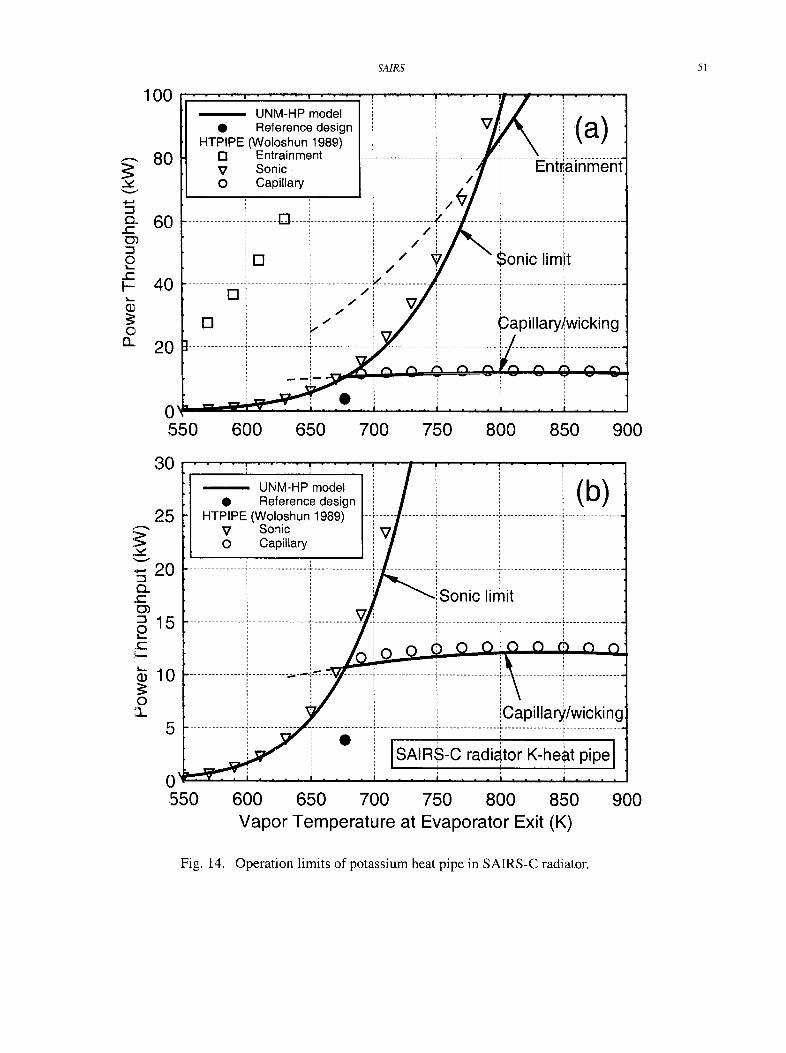
SA1RS 51
v
c-
O, c-
l - -
O 13_
100
80
o.~ v
{D. ~ZZ
O
(D
O
60
40
20
0 ~ r , ,
55O
UNM-HP model • Reference design
HTPIPE (Woloshun 1989) [] Entrainment V Sonic O Capillary
[]
[]
[]
600
/
}(a)
[ ] ..................................... - - z ..... / / /
. . . . . . . . . ' . . . . . . . . . . . . . . . . . . . . . . . . . . . . J I / ~'TJ
J
J , f Z
. _ 1 . . . .
Sonic lim!t
t
Capil lary/ , ,wicking
, , . . .
650 700 750 800 850 900
30
25
20
15
10
5
UNM-HP model • Reference design
HTPIPE (Woloshun 1989) V Sonic O Capillary
4Sonic limit
t
(b)
0 '11=:=
550
~: iCapillary/wickin
[SAIRS-C radiator K-heat pipei
600 650 700 750 800 850 Vapor Temperature at Evaporator Exit (K)
900
Fig. 14. Operation limits of potassium heat pipe in SAIRS-C radiator.
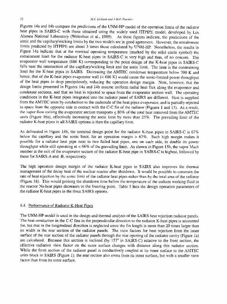
52 M.S. El-Genk and J-M.P. Tournier
Figures 14a and 14b compare the predictions of the UNM-HP model of the operation limits of the radiator heat pipes in SAIRS-C with those obtained using the widely used HTPIPE model, developed by Los Alamos National Laboratory (Woloshun et al., 1989). As these figures indicate, the predictions of the sonic and the capillary/wicking limits by the two models are in good agreement. However, the entrainment limits predicted by HTPIPE are about 3 times those calculated by UNM-HP. Nonetheless, the results in Figure 14a indicate that at the nominal operating temperature (marked by the solid circle symbol) the entrainment limit for the radiator K-heat pipes in SAIRS-C is very high and thus, of no concern. The evaporator wall temperature (686 K) corresponding to the point design of the K-heat pipes in SAIRS-C falls near the intersection of the capillary/wicking limit and the sonic limit. The later is the constraining limit for the K-heat pipes in SAIRS. Decreasing the AMTEC condenser temperature below 700 K and hence, that of the K-heat pipes evaporator wall (< 686 K) would cause the sonic-limited power throughput of the heat pipes to drop precipitously, reducing the operation design margin. Note, however, that the design limits presented in Figures 14a and 14b assume uniform radial heat flux along the evaporator and condenser sections, and that no heat is rejected to space from the evaporator section wall. The operating conditions in the K-heat pipes integrated into the radiator panel of SAIRS are different. Heat is supplied from the AMTEC units by conduction to the underside of the heat pipes evaporator, and is partially rejected to space from the opposite side in contact with the C-C fin of the radiator (Figures 1 and 13). As a result, the vapor flow exiting the evaporator section transports < 80% of the total heat removed from the AMTEC units (Figure 16a), effectively increasing the sonic limit by more than 25%. The prevailing limit of the radiator K-heat pipes in all SAIRS options is then the capillary limit.
As delineated in Figure 14b, the nominal design point for the radiator K-heat pipes in SAIRS-C is 67% below the capillary and the sonic limit, for an operation margin > 67%. Such high margin makes it possible for a radiator heat pipe next to two failed heat pipes, one on each side, to double its power throughput while still operating at < 66% of the prevailing limit. As shown in Figure 15b, the vapor Mach number at the exit of the evaporator section of the radiator K-heat pipe in SAIRS-C is highest, followed by those for SAIRS-A and -B, respectively.
The high operation design margin of the radiator K-heat pipes in SAIRS also improves the thermal management of the decay heat of the nuclear reactor after shutdown. It would be possible to constrain the rate of heat rejection by the sonic limit of the radiator heat pipes rather than by the total area of the radiator (Figure 18). This would prolong the shutdown time before the temperature of the sodium working fluid in the reactor Na-heat pipes decreases to the freezing point. Table 5 lists the design operation parameters of the radiator K-heat pipes in the three SAIRS options.
6.4. Performance of Radiator K-Heat Pipes
The UNM-HP model is used in the design and thermal analysis of the SAIRS heat rejection radiator panels. The heat conduction in the C-C fins in the perpendicular direction to the radiator K-heat pipes is accounted for, but that in the longitudinal direction is neglected since the fin length is more than 20 times larger than its width in the rear section of the radiator panels. The view factors for heat rejection from the inner surface of the rear section of the radiator panels through the rear opening of the radiator cavity (Figure la) are calculated. Because this section is inclined (by 157 ° in SAIRS-C) relative to the front section, the effective radiation view factor on the outer surface changes with distance along this radiator section. While the front section of the radiator panel is conductively coupled at its inner surface to the AMTEC units block in SAIRS (Figure 1), the rear section also emits from its inner surface, but with a smaller view factor than from its outer surface.
SA1RS 5 3
0.75
~. 0.70
09 0.65
13..
Q .
0.60
0.55
678
( / 3
676
674 t -
O 672
*~670 E
668
666
' =, Cond~ ~nser
Evapora tor :. Condenser
0 1 2 3 4
Condenser t ~
~ . ~ .. . . . . . . . ~ . . . . . . . . . . . . . . i .............. ~',
...... i ................. s A,is . ............. ' ' ` " ................ ............
~\ ~ . l . . --~"
Evaporator Condenser i _1 i
0 1 2 3 4 Distance along Radiator Heat Pipe (m)
0.35
0.30
0.25 E - 1
z 0.20 ¢ -
O
:~ 0.15
~-O.lO >
0.05
EvaporAtor t CondJnser .-- -- i :- i i i
. . . . . . . . . . . . ! \ , . . . . . . . . . . . = i
0 0 1 2 3 4
; . , d i i
= E v a p o r 4 t o r :, C o n d e n s e r _ i
i (d)i
i
i
..... ! s A , R s 8 i
. . . . i
I : Condenser - _
10 ; . ; _ . i 0 1 2 3 4
Distance along Radiator Heat Pipe (m)
~" 0 v
13. 0
c3 2
. 1
13 .
g- >
6 ............ ~ .........
8 _ Evapora te i
Fig. 15. Performance of potassium heat pipes in SAIRS radiators.
The radiator K-heat pipes in SAIRS-C have 1.23 m-long evaporator section and 2.21 m-long condenser section, and each removes nominally a total of 2 x 3.83 = 7.66 kW of the heat dissipated by the Na- AMTEC units. With a vapor flow area of 25 cm 2 for each of the 2 cavities of the radiator K-heat pipes in SAIRS-C, the vapor temperature drop along the heat pipe is only 6.6 K (Figure 15d), while operating nominally at only 28.6% of the sonic limit (Figure 15b). All design parameters of the radiators in the three SAIRS options are listed in Tables 4 and 5. Because of the nearly identical efficiencies of SAIRS-B and SAIR-C, their radiators are similar. However, the K-heat pipes in the former have 1.64 m-long evaporator and 1.95 m-long condenser sections, and each nominally removes 2 x 3.9 = 7.8 kW from the condensers of the Na-AMTEC units, while the heat pipes in the latter have 1.23 m-long evaporator and 2.21 m-long condenser sections and remove 2 x 3.83 = 7.66 kW each. The geometrical surface area of the six radiator panels in SAIRS-C (efficiency = 27.3%) is the smallest (23.05 m2), while that in SAIRS-B (efficiency = 26.9%) is slightly larger (23.2 m2). In the latter, the radiator K-heat pipes operate at 26% of the sonic limit and 35.2% of the prevailing capillary limit (2 x 11.08 = 22.16 kW). Owing to the lower efficiency of
SAIRS-A (22.7%), it has the largest radiator geometrical area of 29.3 m 2, which is -27% larger that those in SAIRS-B and-C.
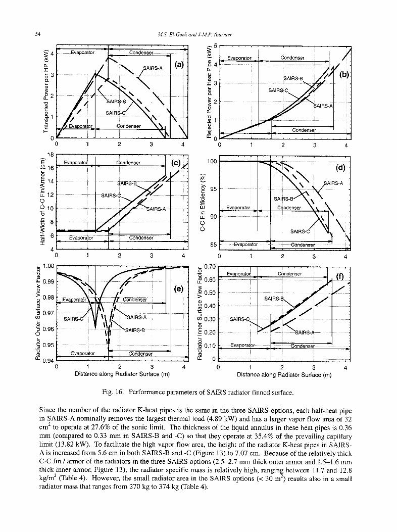
54
v
(2 . "1-
$3
o 2 iX .
" 0
"I::: 0 o-1 E
M.S. El-Genk and J-M.P. Tournier
4 --" Evapo~:a~or ........ ~....=.....~ ....... Condenser ....
. . . . . . . . . . . . ........ ) \
_ ,#I~ Evapora,oE SAIRi~ ....... %dondenser , ~ , '
0 1
18
E ° 1 6
~E~4 <~ E
LT. 12 O d l O
t -
~ 8
~ 6 T
4 0
,- 1.00 O
"5
u_ 0.99
._ > 0.98 O
0.97 O9
"5 0.96 ©
"~ 0.95
15
r r 0.94 0
; . . . i 2 3
m--- ~.5 i
( a ) £ 4
~2 no
X = -~- . m 0
4 0
Eva.oraJ I oo,e=er i O' = ~ . . . . ( ) ,
. . . . . . . . . . . . . . . . . . . . . . . : . . . . . . . . . . . . . . . . . . SAIFIS # . . . . . . . . . . . . .
r . . . . . . . . . . . . . . . . ; - - - v - s ~ i = s . e ~ . 1 2 . z t . . . . . . . . . . . . . . . . . i---
1 2 3 4
/ "~po~a~-:'~~r ! Z
" i T i ) t l t i - i
Evaporator _ _ i! C°ndensei ; : ; , . i . . . . i
1 2 3 Distance a long Radia tor Surface (m)
(e)i . . . . I i
) i
4
/ _ Evaporato# Gondenser i
......................... ~ ................ i -i ---],~/- I) --~ ~; sA,=s-= ! / ) , (1~)
............... i ............ SA=Si I . .... i
:m- ~ . ~ ] . i ~ ; ~ . ,
1 2 3 4
100
o>" 95 E ._~ ._o I J J
E iT 90 o,
' " ' , 4 U i i
:: . . . . . . ~ ~AIRS-A i
E v a p o r a t o r i C~ndenser ' ~ _ . ~ i
i ! SA RS-C ~ ::
85 = : ' - ' : ........... Evapofater .................. r------eondenset- ..........................
0 1 2 3 4
L 0.70 O
*6 ,,= 0.60
0.50
0.40 " rE
~0 0.30
0.20 i
....... S A I R S - G ~
" T !~ 1 !
Condenser . . . . . ~ ...(!).i. i ~J
sA,=s-=. 1 1 / f ) ................... ! . . ~ ............ l ...... i
<~ 0.10 ~- ......... E.vapo~at:or . . . . . . . . . . . . . ~ ........ Gondenser ............ --:- - - ; ~ : i i i i im
0 1 2 3 4 Distance a long Radiator Surface (m)
Fig. 16. Performance parameters of SAIRS radiator finned surface.
Since the number of the radiator K-heat pipes is the same in the three SAIRS options, each half-heat pipe in SAIRS-A nominally removes the largest thermal load (4.89 kW) and has a larger vapor flow area of 32 cm 2 to operate at 27.6% of the sonic limit. The thickness of the liquid annulus in these heat pipes is 0.36 mm (compared to 0.33 mm in SAIRS-B and -C) so that they operate at 35.4% of the prevailing capillary limit (13.82 kW). To facilitate the high vapor flow area, the height of the radiator K-heat pipes in SAIRS- A is increased from 5.6 cm in both SAIRS-B and -C (Figure 13) to 7.07 cm. Because of the relatively thick C-C fin / armor of the radiators in the three SAIRS options (2.5-2.7 mm thick outer armor and 1.5-1.6 mm thick inner armor, Figure 13), the radiator specific mass is relatively high, ranging between 11.7 and 12.8 kg/m 2 (Table 4). However, the small radiator area in the SAIRS options (< 30 m 2) results also in a small radiator mass that ranges from 270 kg to 374 kg (Table 4).
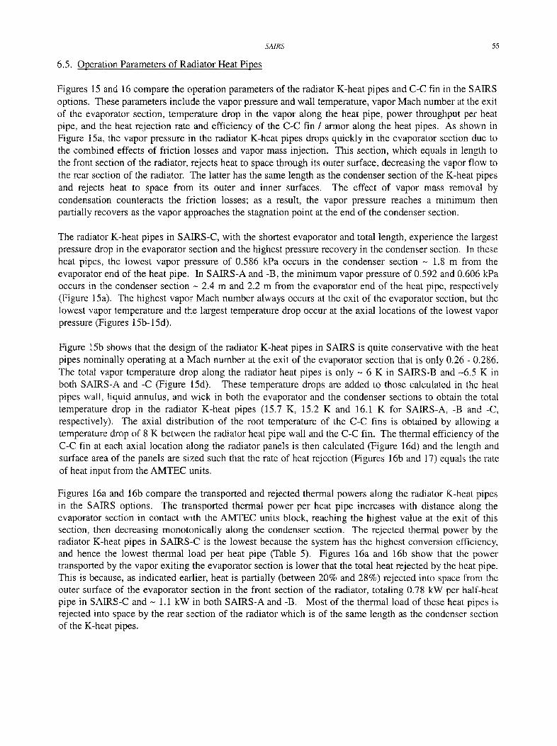
SMRS
6.5. Operation Parameters of Radiator Heat Pipes
55
Figures 15 and 16 compare the operation parameters of the radiator K-heat pipes and C-C fin in the SAIRS options. These parameters include the vapor pressure and wall temperature, vapor Mach number at the exit of the evaporator section, temperature drop in the vapor along the heat pipe, power throughput per heat pipe, and the heat rejection rate and efficiency of the C-C fin / armor along the heat pipes. As shown in Figure 15a, the vapor pressure in the radiator K-heat pipes drops quickly in the evaporator section due to the combined effects of friction losses and vapor mass injection. This section, which equals in length to the front section of the radiator, rejects heat to space through its outer surface, decreasing the vapor flow to the rear section of the radiator. The latter has the same length as the condenser section of the K-heat pipes and rejects heat to space from its outer and inner surfaces. The effect of vapor mass removal by condensation counteracts the friction losses; as a result, the vapor pressure reaches a minimum then partially recovers as the vapor approaches the stagnation point at the end of the condenser section.
The radiator K-heat pipes in SAIRS-C, with the shortest evaporator and total length, experience the largest pressure drop in the evaporator section and the highest pressure recovery in the condenser section. In these heat pipes, the lowest vapor pressure of 0.586 kPa occurs in the condenser section - 1.8 m from the evaporator end of the heat pipe. In SAIRS-A and -B, the minimum vapor pressure of 0.592 and 0.606 kPa occurs in the condenser section - 2.4 m and 2.2 m from the evaporator end of the heat pipe, respectively (Figure 15a). The highest vapor Mach number always occurs at the exit of the evaporator section, but the lowest vapor temperature and the largest temperature drop occur at the axial locations of the lowest vapor pressure (Figures 15b- 15d).
Figure lSb shows that the design of the radiator K-heat pipes in SAIRS is quite conservative with the heat pipes nominally operating at a Mach number at the exit of the evaporator section that is only 0.26 - 0.286. The total vapor temperature drop along the radiator heat pipes is only - 6 K in SAIRS-B and -6.5 K in both SAIRS-A and -C (Figure 15d). These temperature drops are added to those calculated in the heat pipes wall, liquid annulus, and wick in both the evaporator and the condenser sections to obtain the total temperature drop in the radiator K-heat pipes (15.7 K, 15.2 K and 16.1 K for SAIRS-A, -B and -C, respectively). The axial distribution of the root temperature of the C-C fins is obtained by allowing a temperature drop of 8 K between the radiator heat pipe wall and the C-C fin. The thermal efficiency of the C-C fin at each axial location along the radiator panels is then calculated (Figure 16d) and the length and surface area of the panels are sized such that the rate of heat rejection (Figures 16b and 17) equals the rate of heat input from the AMTEC units.
Figures 16a and 16b compare the transported and rejected thermal powers along the radiator K-heat pipes in the SAIRS options. The transported thermal power per heat pipe increases with distance along the evaporator section in contact with the AMTEC units block, reaching the highest value at the exit of this section, then decreasing monotonically along the condenser section. The rejected thermal power by the radiator K-heat pipes in SAIRS-C is the lowest because the system has the highest conversion efficiency, and hence the lowest thermal load per heat pipe (Table 5). Figures 16a and 16b show that the power transported by the vapor exiting the evaporator section is lower that the total heat rejected by the heat pipe. This is because, as indicated earlier, heat is partially (between 20% and 28%) rejected into space from the outer surface of the evaporator section in the front section of the radiator, totaling 0.78 kW per half-heat pipe in SAIRS-C and - 1.1 kW in both SAIRS-A and -B. Most of the thermal load of these heat pipes is rejected into space by the rear section of the radiator which is of the same length as the condenser section of the K-heat pipes.
56 M.S. El-Genk and J-M.P. Tournier
I = ~ t o r ~ t . , r o ÷ t . , r I
0.5 1 1.5 2 2.5 3 Distance along Radiator Surface (m)
i t ' ~ A _ , .1 . . . . .
3.5
18
16
S 12~
10~ o
8 6
4~ - . r
"3
4 .-.E L t .
o o
J ~
"1o
- r
0.6 1 1,5 2 2.5 Distance along Radiator Surface (m)
A
0.5 1 1.5 2 2,5 3 Distance along Radiator Surface (m)
3.5
16
14
12.... o
,E i i
8 o 6
8 ~
n . -
2
0
Fig. 17. Surface temperature contours of SAIRS radiator C-C armor/fin.
SA1RS 57
The half-width of the C-C fin per heat pipe in the front section of the radiator (or along the evaporator section) is constant (6.63-6.78 cm), but increases with distance along the rear section, to its largest value at the end of the radiator (or major diameter). This value is 16.74 cm, 15.2 cm and 14.92 cm in SAIRS-A, -B and -C, respectively (Figure 16c). The thermal efficiency of the C-C fin along the front section of the radiator in SAIRS is -100%, but decreases with distance along the rear section of the radiator to its lowest value at the end of this section; it is 85.6%, 86.3%, and 87.1% in SAIRS-A, -B, and -C, respectively (Figure 16d).
Owing to the inclination (157 ° in SAIRS-C) of the rear section of the radiator relative to the front section, the two outer surfaces of these sections exchange thermal radiation, causing the effective radiation view factor to be lower and change with distance along the radiator. Its lowest value occurs at the end of the front section and the start of the rear section where thermal radiation exchange between the two surfaces is the highest ,(Figure 16e). The highest radiation view factors of - 0.996 and 0.999 occur at the beginning of the front section and the end of the rear section of the radiator, respectively, where the exchange of thermal radiation between the two sections is negligible. As indicated earlier, unlike the front section, the rear section of the radiator rejects heat from its outer and inner surfaces. The later radiates to space through the rear opening of the radiator cavity. The calculated values of the radiation view factor for the inner surface of the rear section of the radiator are compared in Figure 16f. These values include a 20% reduction to account for possible obstructions by the extended boom and the structure and equipments that may be placed inside the radiator cavity. Figure 16f indicates that the local radiation view factor for the inner surface of the rear section of the radiator is 0.2-0.57 in SAIR-C, and 0.206--0.58 and 0.27-0.6 in SAIRS-A and -B, respectively.
Figures 17a-17c present the calculated temperature contours on the outer surface of one half of the C-C fin/armor of a single radiator K-heat pipe in the SAIRS options. These figures also indicate the extent of the front and rear sections of the radiator and the thermal power transport by the heat pipe. In SAIRS-A and -B, the front radiator sections are of same length (1.64 m), but the rear sections run a little cooler than in SAIRS-C. SAIRS-A has the longest rear radiator section (2.51 m) and total radiator length (4.15 m) because it has the lowest system efficiency (22.7%) (Figure 17a). Despite the similar temperature contours on the surface of the rear radiator section in SAIRS-B, the length of this section is only 1.95 m and the total length is, 3.:59 m, owing to the much higher efficiency of this system (26.9%). The efficiency of SAIRS-C is the highest (27.3%) and the front section of the radiator is the shortest (1.23 m). In this system, the rear section of tlhe radiator runs a little hotter due to the shorter fin width and lower heat transport, but the total length of the radiator is the smallest (3.44 m) (Table 5).
6.6. Thermal Management of Decay Heat in SAIRS Reactor
Another consideration in the design of the radiator K-heat pipes is to ensure that they operate sonic limited shortly after the nuclear reactor is shutdown. This would prolong the shutdown time before freezing the Na in the reactor heat pipes. During nominal operation, the heat rejection from SAIRS is limited by the effective surface area of the radiator (Figure 18), but after the reactor is shutdown the heat rejection would be limited by the sonic limit of the radiator K-heat pipes, which is much lower. Figure 18 plots the heat rejection in SAIRS as a function of the evaporator wall temperature of the radiator K-heat pipes. In SAIRS-C, the radiator K-heat pipes operate nominally at an evaporator wall temperature of 686 K. Above 550 K, the vapor flow in the heat pipes is in the continuum regime, but it is in the transition regime between 440 K and 550 K and in the free-molecular regime below 440 K (Tournier and E1-Genk, 1996). Owing to the large decrease in the pressure and density of potassium vapor with decreasing temperature, the power throughput in the free-molecular regime is almost nil, increasing somewhat in the transition regime, and reaches its highest value in the continuum regime.
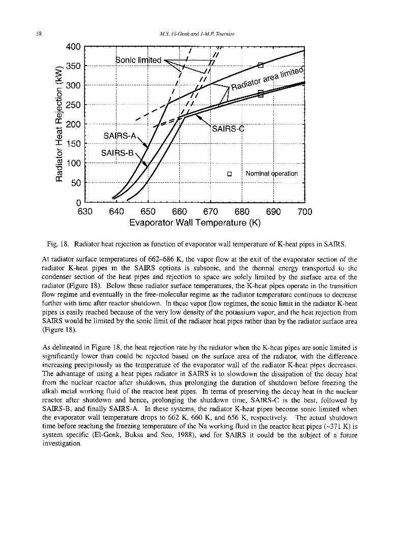
58 M.S. El-Genk and J-M.P. Tournier
400
.--. 350
" - " 300 t - O
. m
o 250 II)
rr 200
-1- 150
• -~ 100
rr 5O
Sonic limited
,4",
SAIRS-B\ /i i
/ T,;
t / / i
....... ,! / - ~ i p,~6~toY
[ ] Nominal Qperation
630 640 650 660 670 680 690 700 Evaporator Wall Temperature (K)
Fig. 18. Radiator heat rejection as function of evaporator wall temperature of K-heat pipes in SAIRS.
At radiator surface temperatures of 662-686 K, the vapor flow at the exit of the evaporator section of the radiator K-heat pipes in the SAIRS options is subsonic, and the thermal energy transported to the condenser section of the heat pipes and rejection to space are solely limited by the surface area of the radiator (Figure 18). Below these radiator surface temperatures, the K-heat pipes operate in the transition flow regime and eventually in the free-molecular regime as the radiator temperature continues to decrease further with time after reactor shutdown. In these vapor flow regimes, the sonic limit in the radiator K-heat pipes is easily reached because of the very low density of the potassium vapor, and the heat rejection from SAIRS would be limited by the sonic limit of the radiator heat pipes rather than by the radiator surface area (Figure 18).
As delineated in Figure 18, the heat rejection rate by the radiator when the K-heat pipes are sonic limited is significantly lower than could be rejected based on the surface area of the radiator, with the difference increasing precipitously as the temperature of the evaporator wall of the radiator K-heat pipes decreases. The advantage of using a heat pipes radiator in SAIRS is to slowdown the dissipation of the decay heat from the nuclear reactor after shutdown, thus prolonging the duration of shutdown before freezing the alkali metal working fluid of the reactor heat pipes. In terms of preserving the decay heat in the nuclear reactor after shutdown and hence, prolonging the shutdown time, SAIRS-C is the best, followed by SAIRS-B, and finally SAIRS-A. In these systems, the radiator K-heat pipes become sonic limited when the evaporator wall temperature drops to 662 K, 660 K, and 656 K, respectively. The actual shutdown time before reaching the freezing temperature of the Na working fluid in the reactor heat pipes (-371 K) is system specific (E1-Genk, Buksa and Seo, 1988), and for SAIRS it could be the subject of a future investigation.
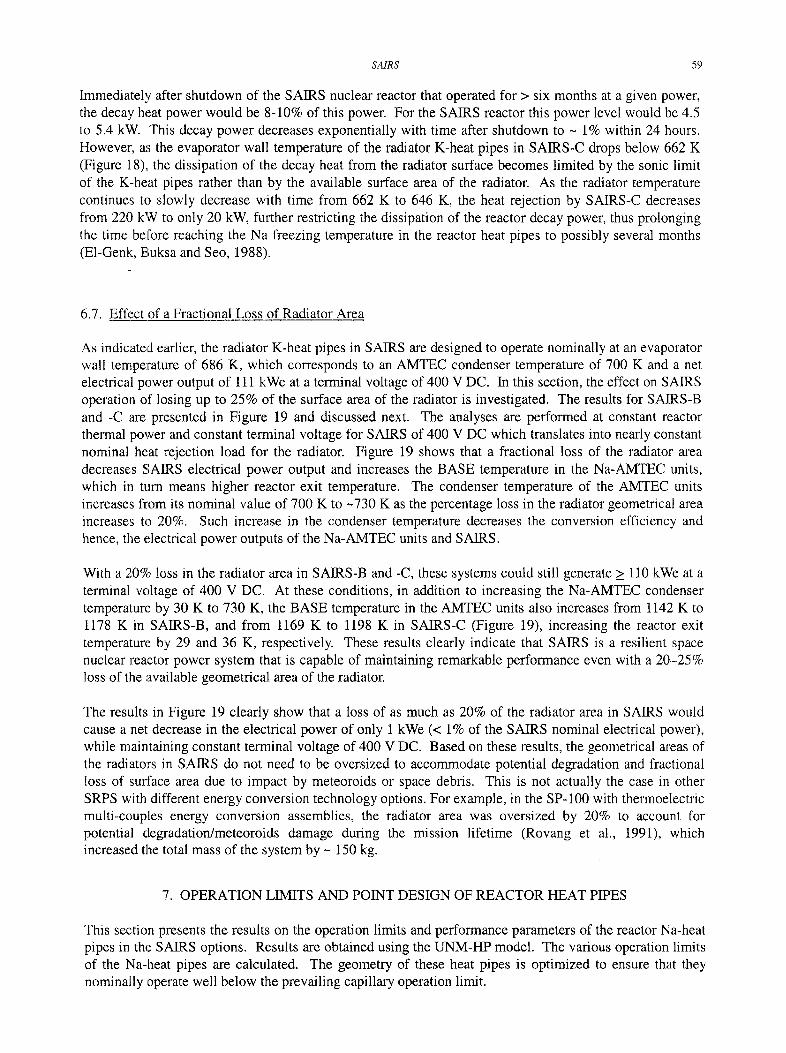
SAIRS 59
Immediately after shutdown of the SAIRS nuclear reactor that operated for > six months at a given power, the decay heat power would be 8-10% of this power. For the SAIRS reactor this power level would be 4.5 to 5.4 kW. This decay power decreases exponentially with time after shutdown to - 1% within 24 hours. However, as the evaporator wall temperature of the radiator K-heat pipes in SAIRS-C drops below 662 K (Figure 18), the dissipation of the decay heat from the radiator surface becomes limited by the sonic limit of the K-heat pipes rather than by the available surface area of the radiator. As the radiator temperature continues to slowly decrease with time from 662 K to 646 K, the heat rejection by SAIRS-C decreases from 220 kW to only 20 kW, further restricting the dissipation of the reactor decay power, thus prolonging the time before reaching the Na freezing temperature in the reactor heat pipes to possibly several months (EI-Genk, Buksa and Seo, 1988).
6.7. Effect of a Fractional Loss of Radiator Area
As indicated earlier, the radiator K-heat pipes in SAIRS are designed to operate nominally at an evaporator wall temperature of 686 K, which corresponds to an AMTEC condenser temperature of 700 K and a net electrical power output of 111 kWe at a terminal voltage of 400 V DC. In this section, the effect on SAIRS operation of losing up to 25% of the surface area of the radiator is investigated. The results for SAIRS-B and -C are presented in Figure 19 and discussed next. The analyses are performed at constant reactor thermal power and constant terminal voltage for SAIRS of 400 V DC which translates into nearly constant nominal heat rejection load for the radiator. Figure 19 shows that a fractional loss of the radiator area decreases SAIRS electrical power output and increases the BASE temperature in the Na-AMTEC units, which in turn means higher reactor exit temperature. The condenser temperature of the AMTEC units increases from its nominal value of 700 K to ~730 K as the percentage loss in the radiator geometrical area increases to 20%. Such increase in the condenser temperature decreases the conversion efficiency and hence, the electrical power outputs of the Na-AMTEC units and SAIRS.
With a 20% loss in the radiator area in SAIRS-B and -C, these systems could still generate >_ 110 kWe at a terminal voltage of 400 V DC. At these conditions, in addition to increasing the Na-AMTEC condenser temperature by 30 K to 730 K, the BASE temperature in the AMTEC units also increases from 1142 K to 1178 K in SAIRS-B, and from 1169 K to 1198 K in SAIRS-C (Figure 19), increasing the reactor exit temperature by 29 and 36 K, respectively. These results clearly indicate that SAIRS is a resilient space nuclear reactor power system that is capable of maintaining remarkable performance even with a 20-25% loss of the available geometrical area of the radiator.
The results in Figure 19 clearly show that a loss of as much as 20% of the radiator area in SAIRS would cause a net decrease in the electrical power of only 1 kWe (< 1% of the SAIRS nominal electrical power), while maintaining constant terminal voltage of 400 V DC. Based on these results, the geometrical areas of the radiators in SAIRS do not need to be oversized to accommodate potential degradation and fractional loss of surface area due to impact by meteoroids or space debris. This is not actually the case in other SRPS with different energy conversion technology options. For example, in the SP-100 with thermoelectric multi-couples energy conversion assemblies, the radiator area was oversized by 20% to account for potential degradation/meteoroids damage during the mission lifetime (Rovang et al., 1991), which increased the total mass of the system by - 150 kg.
7. OPERATION LIMITS AND POINT DESIGN OF REACTOR HEAT PIPES
This section presents the results on the operation limits and performance parameters of the reactor Na-heat pipes in the SAIRS options. Results are obtained using the UNM-ItP model. The various operation limits of the Na-heat pipes are calculated. The geometry of these heat pipes is optimized to ensure that they nominally operate well below the prevailing capillary operation limit.
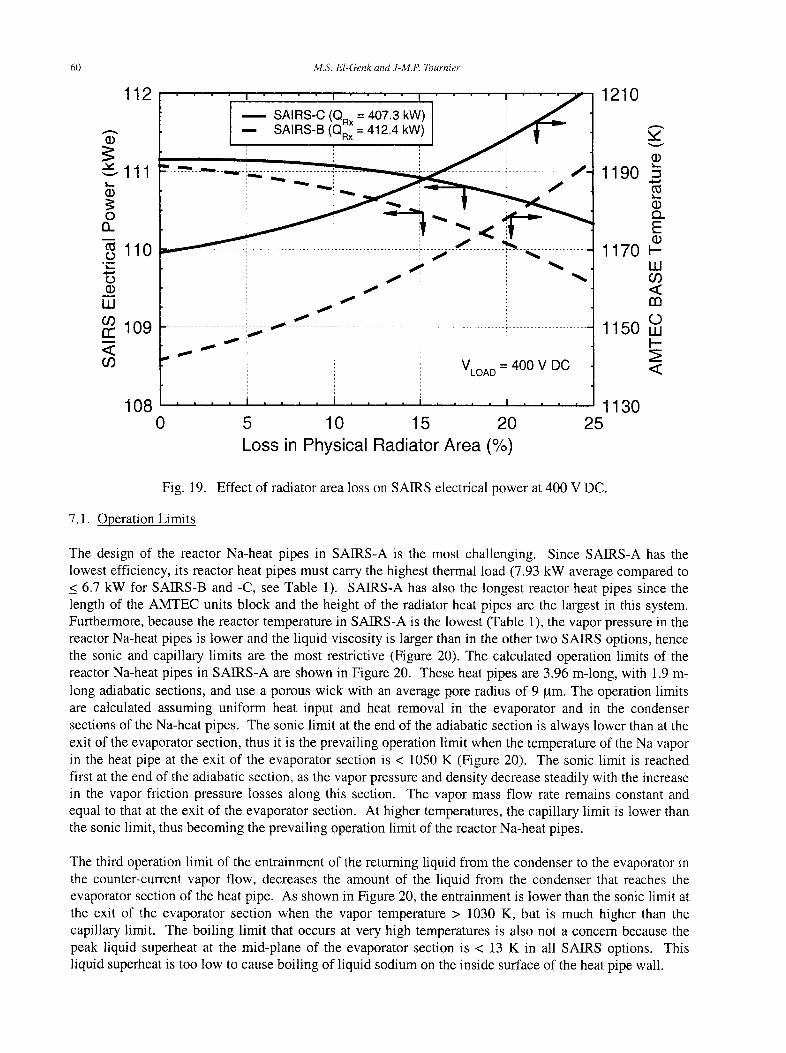
60
112
111
no
110
O (1) UJ 03 rr 109 < 0O
108
M.S. EI-Genk and J-M.P. Tournier
0
" " " i I- " ~ C ; _ ~ k W ) . . . . . / ., ] -- SAIRS-B (QR:=I 412,4 kW)! ~ i
. . . . . . . . . . . . . . . . . . .
VLOAD - - 400 V DC
i . . . . . . . . i i i | m u u
5 10 15 20 Loss in Physical Radiator Area (%)
1210
g 1 1 9 0
&
1 1 7 0 w- Iii 03 < m
(O 1 1 5 0 tu
t--
<
1130 25
Fig. 19. Effect of radiator area loss on SAIRS electrical power at 400 V DC.
7.1. Operation Limits
The design of the reactor Na-heat pipes in SAIRS-A is the most challenging. Since SAIRS-A has the lowest efficiency, its reactor heat pipes must carry the highest thermal load (7.93 kW average compared to < 6.7 kW for SAIRS-B and -C, see Table 1). SAIRS-A has also the longest reactor heat pipes since the length of the AMTEC units block and the height of the radiator heat pipes are the largest in this system. Furthermore, because the reactor temperature in SAIRS-A is the lowest (Table 1), the vapor pressure in the reactor Na-heat pipes is lower and the liquid viscosity is larger than in the other two SAIRS options, hence the sonic and capillary limits are the most restrictive (Figure 20). The calculated operation limits of the reactor Na-heat pipes in SAIRS-A are shown in Figure 20. These heat pipes are 3.96 m-long, with 1.9 m- long adiabatic sections, and use a porous wick with an average pore radius of 9 gm. The operation limits are calculated assuming uniform heat input and heat removal in the evaporator and in the condenser sections of the Na-heat pipes. The sonic limit at the end of the adiabatic section is always lower than at the exit of the evaporator section, thus it is the prevailing operation limit when the temperature of the Na vapor in the heat pipe at the exit of the evaporator section is < 1050 K (Figure 20). The sonic limit is reached first at the end of the adiabatic section, as the vapor pressure and density decrease steadily with the increase in the vapor friction pressure losses along this section. The vapor mass flow rate remains constant and equal to that at the exit of the evaporator section. At higher temperatures, the capillary limit is lower than the sonic limit, thus becoming the prevailing operation limit of the reactor Na-heat pipes.
The third operation limit of the entrainment of the returning liquid from the condenser to the evaporator in the counter-current vapor flow, decreases the amount of the liquid from the condenser that reaches the evaporator section of the heat pipe. As shown in Figure 20, the entrainment is lower than the sonic limit at the exit of the evaporator section when the vapor temperature > 1030 K, but is much higher than the capillary limit. The boiling limit that occurs at very high temperatures is also not a concern because the peak liquid superheat at the mid-plane of the evaporator section is < 13 K in all SAIRS options. This liquid superheat is too low to cause boiling of liquid sodium on the inside surface of the heat pipe wall.
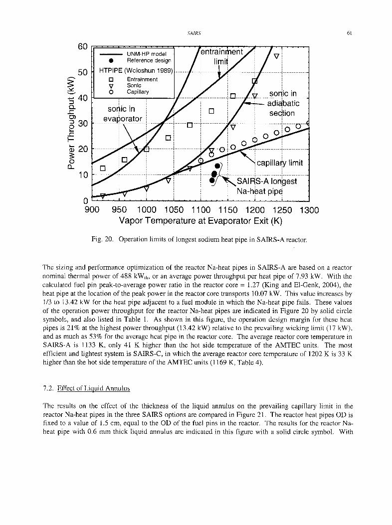
SAIRS 61
,,,,,
"-I
c-
O c"
I--
o I3_
60
50
40
30
20
10
| .
900
UNM-HP model • Reference design
HTPIPE (Woloshun 1989) [ ] Entrainment V Sonic O Capi l lary
sonic in evap0rator
[ ]
l im i i I ,". v '
....... i13
e
[ ]
ent~iE / V
LB ..... sonic in adiabatic sedtion
< capilla~/limit
,SAIFiS-A longest Na-heat pipe,'
950 1000 1050 1100 1150 1200 1250 Vapor Temperature at Evaporator Exit (K)
1300
Fig. 20. Operation limits of longest sodium heat pipe in SAIRS-A reactor.
The sizing and performance optimization of the reactor Na-heat pipes in SAIRS-A are based on a reactor nominal thermal power of 488 kWth, or an average power throughput per heat pipe of 7.93 kW. With the calculated fuel pin peak-to-average power ratio in the reactor core = 1.27 (King and E1-Genk, 2004), the heat pipe at the location of the peak power in the reactor core transports 10.07 kW. This value increases by 1/3 to 13.42 kW for the heat pipe adjacent to a fuel module in which the Na-heat pipe fails. These values of the operation power throughput for the reactor Na-heat pipes are indicated in Figure 20 by solid circle symbols, and also listed in Table 1. As shown in this figure, the operation design margin for these heat pipes is 21% at the highest power throughput (13.42 kW) relative to the prevailing wicking limit (17 kW), and as much as 53% for the average heat pipe in the reactor core. The average reactor core temperature in SAIRS-A is 1133 K, only 41 K higher than the hot side temperature of the AMTEC units. The most efficient and lightest system is SAIRS-C, in which the average reactor core temperature of 1202 K is 33 K higher than the hot side temperature of the AMTEC units (1169 K, Table 4).
7.2. Effect of Liquid Annulus
The results on the effect of the thickness of the liquid annulus on the prevailing capillary limit in the reactor Na--heat pipes in the three SAIRS options are compared in Figure 21. The reactor heat pipes OD is fixed to a value of 1.5 cm, equal to the OD of the fuel pins in the reactor. The results for the reactor Na- heat pipe with 0.6 mm thick liquid annulus are indicated in this figure with a solid circle symbol. With
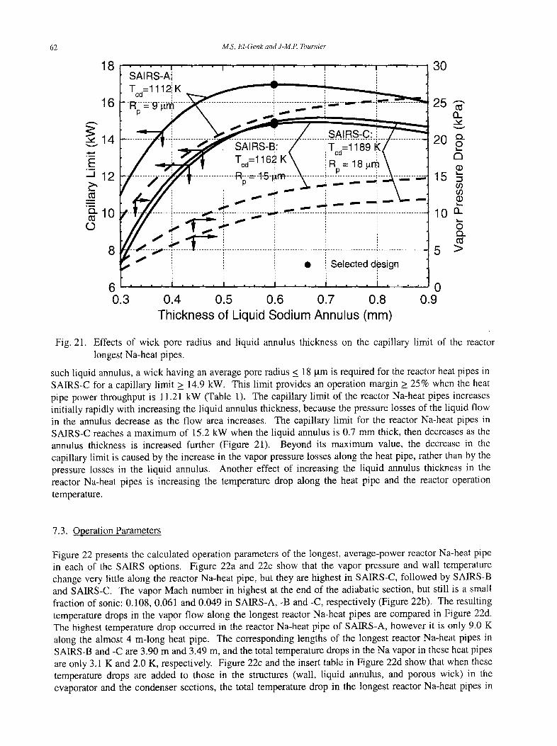
62 M.S. El-Genk and J-M.P. Tournier
18
16
'-'14
E J 1 2
o..10 O
8
SAIRS-AI Tcd=l 112:. K
- l - - - ~ - - ~ - - - ~ ................... I
r i Tcd=116~ K\ ........ J----R-=-t-5)m ....
P 1 ', ',
~ - - - - 4 . . . . . . . . . . . . . . . . . - , , , , , , ~ - - - ~ ' - - .
1
............ i i - ~ " ~ - - m l f "'mm~-~---
/ ............................ Tc0=,,8 R =18g~
. . . . . . . . . . . . . . . . . . . . . . . . . '~ 7 - i -,
Selected d#sign
3 0
2 5
20
15
10
5
6 '0 0.3 0.4 0.5 0.6 0.7 0.8 0.9
Thickness of Liquid Sodium Annulus (mm)
&. v
c~ O £3
O9 O9
n
o c~
>
Fig. 21. Effects of wick pore radius and liquid annulus thickness on the capillary limit of the reactor longest Na-heat pipes.
such liquid annulus, a wick having an average pore radius < 18 gm is required for the reactor heat pipes in SAIRS-C for a capillary limit > 14.9 kW. This limit provides an operation margin _> 25% when the heat pipe power throughput is 11.21 kW (Table 1). The capillary limit of the reactor Na-heat pipes increases initially rapidly with increasing the liquid annulus thickness, because the pressure losses of the liquid flow in the annulus decrease as the flow area increases. The capillary limit for the reactor Na-heat pipes in SAIRS-C reaches a maximum of 15.2 kW when the liquid annulus is 0.7 mm thick, then decreases as the annulus thickness is increased further (Figure 21). Beyond its maximum value, the decrease in the capillary limit is caused by the increase in the vapor pressure losses along the heat pipe, rather than by the pressure losses in the liquid annulus. Another effect of increasing the liquid annulus thickness in the reactor Na-heat pipes is increasing the temperature drop along the heat pipe and the reactor operation temperature.
7.3. Operation Parameters
Figure 22 presents the calculated operation parameters of the longest, average-power reactor Na-heat pipe in each of the SAIRS options. Figure 22a and 22c show that the vapor pressure and wall temperature change very little along the reactor Na-heat pipe, but they are highest in SAIRS-C, followed by SAIRS-B and SAIRS-C. The vapor Mach number in highest at the end of the adiabatic section, but still is a small fraction of sonic: 0.108, 0.061 and 0.049 in SAIRS-A, -B and -C, respectively (Figure 22b). The resulting temperature drops in the vapor flow along the longest reactor Na-heat pipes are compared in Figure 22d. The highest temperature drop occurred in the reactor Na-heat pipe of SAIRS-A, however it is only 9.0 K along the almost 4 m-long heat pipe. The corresponding lengths of the longest reactor Na-heat pipes in SAIRS-B and -C are 3.90 m and 3.49 m, and the total temperature drops in the Na vapor in these heat pipes are only 3.1 K and 2.0 K, respectively. Figure 22c and the insert table in Figure 22d show that when these temperature drops are added to those in the structures (wall, liquid annulus, and porous wick) in the evaporator and the condenser sections, the total temperature drop in the longest reactor Na-heat pipes in
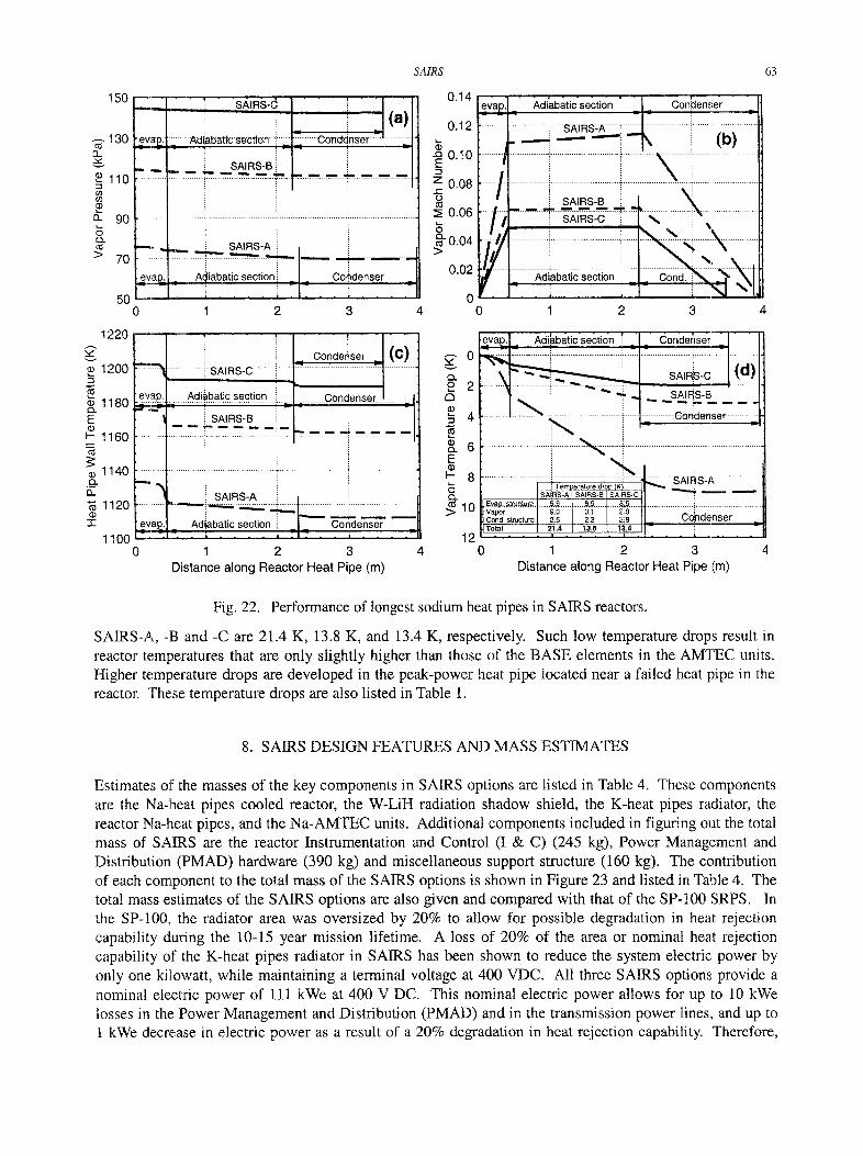
SA1RS 63
150
130 cd
(3_ 2 ~ v
110 i f ) o 9
a. 90
> 70
50 0
" i SAIRS-~ i
" - Con ,inse r _ ( a ) N I ........ Adiabatic s e c t i o n i l = ....... etd ........... ±r
i ~ I . . , _ " "~" ~ ~ ~ *" "" " ~ - ~ - 'I
. . . . . . . . . . . . . . . i .......................... T i " . . . . . . . . . . . i . . . . . . . . . . . . . . .
:i SAIRS-A i i
~ Aiiabatic section ---, i Co!denser =
1 2 3 4
0 .14
~. 0 .12
~ 0.10
z0.08
0.06
~ 0.04
0 .02
0 0
e_vap _ Adiabatic section i Conidenser
' i SAIRS_B i: X . . . . . . . . " i " - ....... ' ? ' . .............
. ; . . . . ; - - i " J X l , 1 2 3
1220 ,,z" v
1200
1180 O..
E
~- 1160
1140 O_
13. 1120
I l l 7" 1100
0
9 Conde ser ( C ) ....... ~ .......... iSAtRS;C ....... i .......................... ': ........... E ..............
~ A I R S - B • ~ - t - :
i ! :
i 1
- h ! SAIRS-A
.evap. _ Adiabatic section i Condenser
1 2 3 D is tance a long R e a c t o r Hea t Pipe (m)
4
g
c3
& E o3 I-- Q.
evap_. ~,di~batic section ': Condenser
l x ............ L ' ? : ....
6 i
8 . . . . . . . . . . . . . i7;;;;2;2;e3;;i7<7 ........ ~ S ~ S : ~ . . . . . . . . . S A • S - A I SA IRS-8 [ SA I~S-C
E~t~.o,.~tr:uqtu.m.....~,~ . . . . . . . . . .8,5.. . .1.. . .~L~ . . . . . . . . . . . . . . . . . . . . . . . . . . . i . . . . . . . . . . . 10 v~or ~.o 3.1 / 2i0 i Cond. structure 2.5 2.2 / 2~9 _ Copdenser T.~, I 2~.. / 1~.. I 1~. / - i "
12 . . . . ' ' ' ' ' 0 1 2 3 4
Distance along Reactor Heat Pipe (m)
Fig. 22. Performance of longest sodium heat pipes in SAIRS reactors.
SAIRS-A, -B and -C are 21.4 K, 13.8 K, and 13.4 K, respectively. Such low temperature drops result in reactor temperatures that are only slightly higher than those of the BASE elements in the AMTEC units. Higher temperature drops are developed in the peak-power heat pipe located near a failed heat pipe in the reactor. These temperature drops are also listed in Table 1.
8. SAIRS DESIGN FEATURES AND MASS ESTIMATES
Estimates of the masses of the key components in SAIRS options are listed in Table 4. These components are the Na-lheat pipes cooled reactor, the W-LiH radiation shadow shield, the K-heat pipes radiator, the reactor Na-heat pipes, and the Na-AMTEC units. Additional components included in figuring out the total mass of SAIRS are the reactor Instrumentation and Control (I & C) (245 kg), Power Management and Distribution (PMAD) hardware (390 kg) and miscellaneous support structure (160 kg). The contribution of each component to the total mass of the SAIRS options is shown in Figure 23 and listed in Table 4. The total mass estimates of the SAIRS options are also given and compared with that of the SP-100 SRPS. In the SP-100, the radiator area was oversized by 20% to allow for possible degradation in heat rejection capability during the 10-15 year mission lifetime. A loss of 20% of the area or nominal heat rejection capability of the K-heat pipes radiator in SAIRS has been shown to reduce the system electric power by only one kilowatt, while maintaining a terminal voltage at 400 VDC. All three SAIRS options provide a nominal electric power of 111 kWe at 400 V DC. This nominal electric power allows for up to 10 kWe losses in the Power Management and Distribution (PMAD) and in the transmission power lines, and up to 1 kWe decrease in electric power as a result of a 20% degradation in heat rejection capability. Therefore,
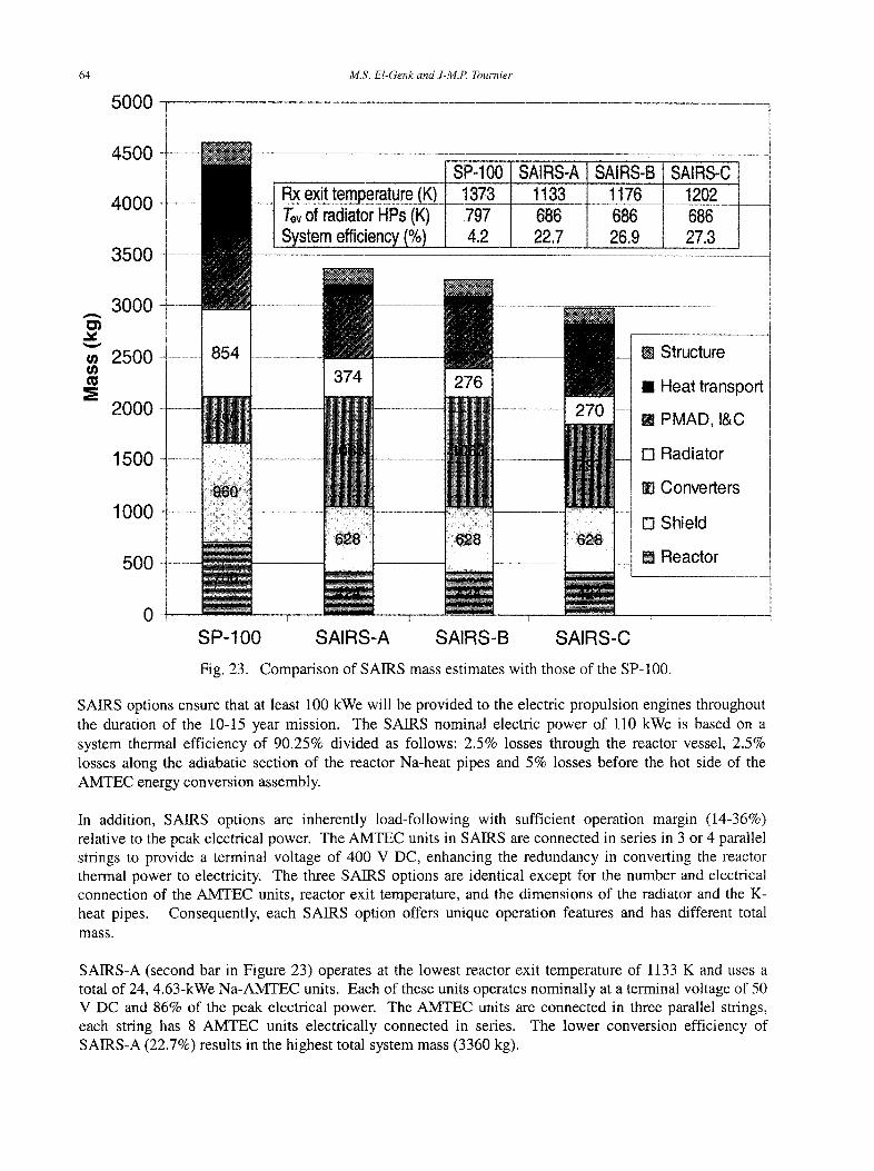
6 4 M.S. El-Genk and J-M.P. Tournier
5000 1
4500
4000
3500
RX exit temperature (K) Tev of radiator HPs (K) System efficiency (%)
SP-100 .... 1373
SAIRS-A SAIRS-B SAIRS-C 1133 1176 1202
797 686 686 686 4.2 22.7 26.9 27.3
m
3000
2500
2000
1500
1000
500
[] Structure
[] Heat transport
[] PMAD, I&C
[] Radiator
[] Converters
[] Shield
[] Reactor
0 • • I I I . . . . t '
SP-IO0 SAIRS-A SAIRS-B SAIRS-C
Fig. 23. Comparison of SAIRS mass estimates with those of the SP-100.
SAIRS options ensure that at least 100 kWe will be provided to the electric propulsion engines throughout the duration of the 10-15 year mission. The SAIRS nominal electric power of 110 kWe is based on a system thermal efficiency of 90.25% divided as follows: 2.5% losses through the reactor vessel, 2.5% losses along the adiabatic section of the reactor Na-heat pipes and 5% losses before the hot side of the AMTEC energy conversion assembly.
In addition, SAIRS options are inherently load-following with sufficient operation margin (14-36%) relative to the peak electrical power. The AMTEC units in SAIRS are connected in series in 3 or 4 parallel strings to provide a terminal voltage of 400 V DC, enhancing the redundancy in converting the reactor thermal power to electricity. The three SAIRS options are identical except for the number and electrical connection of the AMTEC units, reactor exit temperature, and the dimensions of the radiator and the K- heat pipes. Consequently, each SAIRS option offers unique operation features and has different total mass.
SAIRS-A (second bar in Figure 23) operates at the lowest reactor exit temperature of 1133 K and uses a total of 24, 4.63-kWe Na-AMTEC units. Each of these units operates nominally at a terminal voltage of 50 V DC and 86% of the peak electrical power. The AMTEC units are connected in three parallel strings, each string has 8 AMTEC units electrically connected in series. The lower conversion efficiency of SAIRS-A (22.7%) results in the highest total system mass (3360 kg).
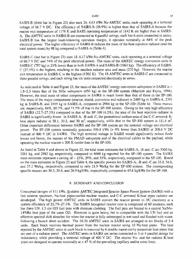
SAIRS 65
SAIRS-B (third bar in Figure 23) also uses 24, 4.63 kWe Na-AMTEC units, each operating at a terminal voltage of 66.7 V DC. The efficiency of SAIRS-B (26.9%) is higher than that of SAIRS-A because the reactor exit temperature of 1176 K and BASE operating temperature of 1142 K are higher than in SAIRS- A. The AMTEC units in SAIRS-B are connected in 4 parallel strings, each has 6 units connected in series. SAIRS-B has the largest load-following operation margin, it operates nominally at 64% of the peak electrical power. The higher efficiency of SAIRS-B reduces the mass of the heat rejection radiator (and the total system mass) by 98 kg compared to SAIRS-A (Table 4).
SAIRS-C (last bar in Figure 23) uses 18, 6.17 kWe Na-AMTEC units, each operating at a terminal voltage of 66.7 V DC and 74% of the peak electrical power. The mass of the AMTEC energy conversion units in SAIRS-C ('7'97 kg) is 25% lower than in both SAIRS-A and SAIRS-B (1063 kg). The efficiency of SAIRS- C (27.3%) is the highest, resulting in the smallest radiator area and mass (270 kg). However, the reactor exit temperature in SAIRS-C is the highest (1202 K). The 18 AMTEC units in SAIRS-C are connected in three paralM strings, and each string has six units connected electrically in series.
As indicated in Table 4 and Figure 23, the mass of the AMTEC energy conversion subsystem in SAIRS is - 1.8-2.3 times that of the SiGe subsystem (450 kg) in the SP-100 system (Marriott and Fujita, 1994). However, the total mass of other components in SAIRS is much lower than that of those in the SP-100. The mass of the major components (reactor, shield, converters and radiator) is 2489 kg in SAIRS-A, 2391 kg in SAIRS-B, and 2119 kg in SAIRS-A, compared to 2964 kg in the SP-100 (Table 4). These masses are, respectively, 84%, 80.7%, and 71.5% of that in the SP-100 system. Owing to the very high efficiency of SAIRS (22.7-27.3%) compared to that of the SP-100 (4.2%), the area of the heat rejection radiator in SAIRS is significantly lower. In SAIRS-A, -B and -C, the geometrical surface area of the C-C armored, K- heat pipes radiator is 38.1, 30.2, and 30 m 2, respectively, while that in the SP-100 system is 111.4 m 2. Other important differences between SAIRS and the SP-100 system are the nominal voltage and electrical power. The SP-100 system nominally generates 100.8 kWe (> 9% lower than SAIRS) at 208.6 V DC instead of ,100 V DC in SAIRS. The high terminal voltage in SAIRS would significantly reduce Joule losses and hence, the masses of the PMAD subsystem and of the electrical cables to the payload, while operating the nuclear reactor > 200 K cooler than in the SP-100.
As listed in Table 4 and shown in Figure 23, the total mass estimates for SAIRS-A, -B and -C are 3360 kg, 3261 kg, and 2982 kg, respectively, compared to 4600 kg reported for the SP-100 system. The SAIRS mass estimates represent a saving of ~ 23%, 29%, and 35%, respectively, compared to the SP-100. Based on the mass; estimates in Figure 23 and Table 4, the specific powers for SAIRS-A, -B and -C are 33.0, 34.0, and 37.2 We/kg, respectively, compared to only 21.9 We/kg for the SP-100 system. The corresponding specific masses are 30.3, 29.4, and 26.9 kg/kWe, respectively, compared to 45.6 kg/kWe for the SP-100.
9. SUMMARY AND CONCLUSION
Conceptual designs of 111 kWe, Scalable AMTEC INtegrated Reactor Space Power System (SAIRS) with a fast neutron spectrum, Na-heat pipes-cooled nuclear reactor, and C-C armored K-heat pipes radiator are developed. The high power AMTEC units in SAIRS convert the reactor power to DC electricity at a system efficiency of 22.7%-27.3%. The SAIRS hexagonal reactor core is comprised of 60 modules, each has three UN, 1.5 cm OD fuel pins with rhenium cladding. The fuel pins are brazed to a central Na/Mo- 14%Re heat pipe of the same OD. Rhenium is quite heavy, but is compatible with the UN fuel and an effective spectral shift absorber for when the reactor is fully submerged in wet sand and flooded with water, following a launch abort accident. The 18-24 AMTEC units in SAIRS are arranged in six blocks of 3-4 units. Each block receives thermal power from the nuclear reactor using 10 Na-heat pipes. The heat rejected by the AMTEC units in each block is removed by 6 double-vapor-cavity potassium heat pipes that are part of a radiator panel. The AMTEC units in SAIRS are series connected in 3 or 4 parallel strings for redundancy, while providing a terminal voltage of 400 V DC. The reactor Na- and the radiator K-heat pipes are designed to operate nominally at < 47 % of the prevailing capillary and/or sonic limit.
66 M.S. EI-Genk and J-M.P. Tournier
The Na-AMTEC units in SAIRS are selected over K-AMTEC units of identical dimension and mass because of their higher conversion efficiency and electrical power at a nominal condenser temperature of 700 K. The AMTEC units are 410 x 594 x 115 mm in outside dimensions and weight 44.3 kg each. The three SAIRS options developed and analyzed are identical except in the number of the AMTEC units (18 or 24 units) and the electrical connections of these units in parallel strings, the reactor exit temperature, and the conversion efficiency. In addition to nominally generating 111 kWe at a terminal voltage of 400 V DC, they are inherently load following, fully passive, and have no single point failures. The Na-heat pipes provide redundancy in the transport of the reactor thermal power to the AMTEC units. The K-heat pipes provide redundancy in the transport of the rejected thermal power by the AMTEC units to the heat rejection radiator; and the radiator consists of six separate, and operationally independent panels.
The AMTEC units in SAIRS operate at high efficiency (25.2-30.2%) that is also a very high percentage of Carnot (> 60%), resulting in compact and lightweight space power systems and a reactor exit temperature that is < 1200 K. Such low temperature makes is possible to use commercially available structure materials with well-known properties and fabrication techniques, adding additional confidence in SAIRS reliability throughout the proposed 10-15 year long missions. SAIRS-A operates at the lowest reactor exit temperature of 1133 K, and uses a total of 24, 4.63-kWe Na-AMTEC units. Each unit operates nominally at a terminal voltage of 50 V DC and at 86% of the peak electrical power. SAIRS-B also uses 24, 4.63 kWe Na-AMTEC units, each operating at a terminal voltage of 66.7 V DC. This system has the largest load-following operation margin as it operates nominally at 64% of the peak electrical power. SAIRS-C is the lightest and uses 18, 6.17 kWe Na-AMTEC units. Each unit operates at a terminal voltage of 66.7 V DC and 74% of the peak electrical power.
The mass of the AMTEC units in SAIRS-C (797 kg) is 25% lower than in both SAIRS-A and SAIRS-B (1063 kg). The relatively lower conversion efficiency of SAIRS-A (22.7%) results in the largest radiator and highest system total mass (3360 kg). The efficiency of SAIRS-B of 26.9% is the second highest, and the reactor exit temperature of 1176 K is higher than in SAIRS-A. The conversion efficiency of SAIRS-C of 27.3% is the highest, resulting in the lowest radiator area and mass (270 kg), but the highest reactor exit temperature of 1202 K. The three SAIRS options have specific powers > 33 We/kg (or alpha < 30.5 kg/kWe) and stowed height and diameter < 6 m and < 4 m, respectively. System analysis results indicated that a 20% loss in the radiator heat rejection capability in SAIRS would decrease the nominal electric power by only 1.0 kWe.
The mass of the Na-AMTEC units (797-1063 kg) and the specific mass of the C-C armored heat rejection radiator (11.71-12.75 kg/m 2) in SAIRS are higher than those of the SiGe thermoelectric multicouples (450 kg) and the radiator (7.67 kg/m 2) in the SP-100. However, the lower total masses of the reactor, radiation shield, reactor heat pipes, and the radiator make SAIRS options 27%-35% lighter than the SP-100. In the latter the nominal output power of 100.8 kWe (> 9% lower than SAIRS) is delivered at a terminal voltage of 208.6 V DC, while in SAIRS the nominal electric power of 111 kWe is delivered at 400 V DC. The higher terminal voltage in SAIRS significantly reduces Joule losses and hence, the masses of the PMAD subsystem and the electrical cables to the payload, while operating the nuclear reactor more than 200 K cooler than in the SP-100.
10. ACKNOWLEDGMENTS
The authors are grateful to Jeffrey King for performing the neutronics calculations demonstrating that the SAIRS reactor would remain sufficiently subcritical during submersion in wet sand or sea water, and to Brian Nease for his assistance in developing the SAIRS isometric model, including maneuvering the reactor Na-heat pipes around the shadow shield.
SAIRS 67
11. REFERENCES
Barattino W., El-Genk M. S. and McDaniel P. (1986), Thermal Analysis of a W-LiH Radiation Shield for an SP-100 Type Reactor. Space Nuclear Power Systems 1985, CONF-850103, M. S. E1-Genk and M. D. Hoover, Eds., Orbit Book Company, Inc., Malabar, FL, 1986, 4, 287-302.
Bevard B. B. and Yoder G. L. (2003), Technology Development Program for an Advanced Potassium Rankine Power Conversion System Compatible with Several Space Reactor Designs. Proc. Space Technology and Applications International Forum (STAIF-2003), M. S. E1-Genk, Ed., AIP-CP-654, American Institute of Physics, Melville, NY, 2003, pp. 629-640.
Briesmeister J. E, Ed. (2000), MCNP - A General Monte Carlo N-Particle Transport Code - Version 4C, Los Alamos National Laboratory Report No. LA-13709-M, Los Alamos, NM, April 2000.
Cole T. (1983), Thermoelectric Energy Conversion with Solid Electrolytes. Science 221, 915-920.
El-Genk M. S. (2003), Energy Conversion Options for Advanced Radioisotope Power Systems. Proc. Space Technology and Applications International Forum (STAIF-2003), M. S. E1-Genk, Ed., AIP-CP-654, American Institute of Physics, Melville, NY, 2003, pp. 368-375.
El-Genk M. S., Buksa J. J. and Seo J. T. (1988), Decay Heat Thermal Management of an SP-100 System. Space Nuclear Power Systems 1987, M. S. E1-Genk and M. D. Hoover, Eds., Orbit Book Company, Inc., Malabar, FL, 1988, 6, pp. 99-110.
El-Genk M. S. and Seo J. T. (1990), A Study of the SP-100 Radiator Heat Pipes Response to External Thermal Exposure. J. of Propulsion and Power 6(1), 69-77.
E1-Genk M. S., Seo J. T. and Buksa J. J. (1988), Load Following and Reliability Studies of an Integrated SP-100 System. J. Propulsion and Power 4(2), 152-156.
El-Genk M. S. and Tournier J.-M. (2002), Performance Comparison of Potassium and Sodium Vapor Anode, Multi-Tube AMTEC Converters. J. Energy Conversion and Management 43, 1931-1951~
El-Genk ME. S. and Tournier J.-M. (2004a), Conceptual Design of HP-STMCs Space Reactor Power System for 110 kWe. Proc. Space Technology and Applications International Forum (STAIF-2004), M. S. E1-Genk, Ed., AIP-CP-699, American Institute of Physics, Melville, NY, 2004, pp. 658-672.
El-Genk M. S. and Tournier J.-M. (2004b), Performance Analysis of Potassium Heat Pipes Radiator for HP-STMCs Space Reactor Power System. Proc. Space Technology and Applications International Forum (STAIF-2004), M. S. E1-Genk, Ed., AIP-CP-699, American Institute of Physics, Melville, NY, 2004, pp. 793-805.
E1-Genk M. S. and Tournier J.-M. (2004c), Mechanically Alloyed-Oxide Dispersion Strengthened Steels for Use in Space Nuclear Power Systems. Proc. Space Technology and Applications International Forum (STAIF-2004), M. S. El-Genk, Ed., AIP-CP-699, American Institute of Physics, Melville, NY, 2004, pp. 829-841.
England C. and Ewell R. C. (1994), Progress on the SP-100 Power Conversion Subsystem. Proc. 11 th Symposium on Space Nuclear Power and Propulsion, DOE CONF-940101, M.S. El-Genk and M. D. Hoover, Eds., American Institute of Physics, New York, NY, 1994, 1, pp. 183-193.
68 M.S. El-Genk and J-M.P. Tournier
Hendricks J. S. et al. (2003), MCNPX, Version 2.5.d., Los Alamos National Laboratory Report No. LA- UR-03-5916, Los Alamos, NM, August 2003.
Ivanovskii M. N., Sorokin V. R and Yagodkin I. V. (1982), The Physical Principles of Heat Pipes, translated by R. Berman and G. Rice, Oxford University Press, New York, NY, Section 2.2 pp. 34-56, and pp. 73-140.
King J. C. and EI-Genk M. S. (2001), Review of Refractory Materials for Alkali Metal Thermal-to-Electric Conversion Cells. J. Propulsion and Power 17(3), 547-556.
King J. C. and E1-Genk M. S. (2004), A Methodology for the Neutronics Design of Space Nuclear Reactors. Proc. Space Technology and Applications International Forum (STAIF-2004), M. S. E1-Genk, Ed., AIP-CP-699, American Institute of Physics, Melville, NY, 2004, pp. 319-329.
Louie D. L. Y. and E1-Genk M. S. (1987), Characterization of Fuel Swelling in Helium-Bonded (U, Pu)C Fuel Pins, Final Report No. NE-116 (87), LANL-727-i, University of New Mexico, Albuquerque, NM.
Marriott, A. T. and Fujita T. (1994), Evolution of SP-100 System Designs. Proc. 11 th Symposium on Space Nuclear Power and Propulsion, CONF-940101, M.S. E1-Genk and M. D. Hoover, Eds., American Institute of Physics, New York, NY, 1, pp. 157-169.
Momozaki Y. and El-Genk M. S. (2002), An Investigation of Breakdown Voltage in AMTECs. Proc. Space Technology and Applications International Forum (STAIF-2002), M. S. El-Genk, Ed., AIP-CP-608, American Institute of Physics, Melville, NY, 2002, pp. 972-979.
Poston D. I., Kapernick R. J. and Guffee R. M. (2002), Design and Analysis of the SAFE-400 Space Fission Reactor. Proc. Space Technology and Applications International Forum (STAIF-2002), M. S. E1- Genk, Ed., AIP-CP-608, American Institute of Physics, Melville, NY, 2002, 1, pp. 578-588.
Reid R. S., Merrigan M. A. and Sena J. T. (1991), Review of Liquid Metal Heat Pipe Work at Los Alamos. Proc. 8 th Symposium on Space Nuclear Power Systems, DOE CONF-910116, M.S. E1-Genk and M. D. Hoover, Eds., American Institute of Physics, New York, NY, 1991, 3, pp. 999-1008.
Ring P. J., Sayre E. D., Van Dyke M. and Houts M. (2002), Progress in Hardware Development for the SAFE Heatpipe Reactor System. Proc. Space Technology and Applications International Forum (STAIF- 2002), M. S. E1-Genk, Ed., AIP-CP-608, American Institute of Physics, Melville, NY, 2002, 1, pp. 148- 155.
Ring P. J., Sayre E. D. and Sena J. T. (2003), SAFE-100 Module Fabrication and Test. Proc. Space Technology and Applications International Forum (STAIF-2003), M. S. EI-Genk, Ed., AIP-CP-654, American Institute of Physics, Melville, NY, 2003, pp. 96-100.
Ross S. B., EI-Genk M. S. and Matthews R. B. (1990), Uranium Nitride Fuel Swelling Correlation. J. Nuclear Materials 170, 169-177.
Rovang R. D., Hunt M. E., Dirling R. B. Jr. and Holzl R. A. (1991), SP-100 High-Temperature Advanced Radiator Development. Proc. 8 th Symposium on Space Nuclear Power Systems, CONF-910116, M.S. E1- Genk and M. D. Hoover, Eds., American Institute of Physics, New York, NY, 1991, 2, pp. 702-707.
Ryan M. A. et al. (2000), Lifetime of AMTEC Electrodes: Molybdenum, Rhodium-Tungsten, and Titanium Nitride. Proc. Space Technology and Applications International Forum (STAIF-2000), M. S. EI-Genk, Ed., AIP-CP-504, American Institute of Physics, Woodbury, NY, 2000, 2, pp. 1377-1382.
SAIRS 69
Tournier J.-M. and El-Genk M. S. (1996), A Vapor Flow Model for Analysis of Liquid-Metal Heat Pipe Startup from a Frozen State. International Journal of Heat and Mass Transfer 39(18), 3767-3780.
Tournier J.-.M. and El-Genk M. S. (2003a), Startup of a Horizontal Lithium/Molybdenum Heat Pipe from a Frozen State. International Journal of Heat and Mass Transfer 46, 671-685.
Tournier J.-M. and El-Genk M. S. (2003b), Design Optimization of High-Power, Liquid Anode AMTEC. Proc. Space, Technology and Applications International Forum (STAIF-2003), M. S. El-Genk, Ed., AIP- CP-654, American Institute of Physics, Melville, NY, 2003, pp. 740-750.
Williams R. M., et al. (1999), The Thermal Stability of Sodium Beta"-Alumina Solid Electrolyte Ceramic in AMTEC Converters. Proc. Space Technology and Applications International Forum, M. S. El-Genk, Ed., A1P-CP-458, American Institute of Physics, Woodbury, NY, 1999, 2, pp. 1306-1311.
Woloshun K. A., Merrigan M. A. and Best E. D. (1989), HTPIPE - A Steady-State Heat Pipe Analysis Program. Space Nuclear Power Systems 1988, M. S. E1-Genk and M. D. Hoover, Eds., Orbit Book Company, Malabar, FL., 1988, 9, 395-403.