RYZ014 Modules - Use Cases with AT Commands - Renesas
77
Application Note R19AN0075EU0100 Rev.1.00 Page 1 of 76 Apr.15.21 RYZ014 Modules Use Cases with AT Commands Introduction This document will provide RYZ014-based platform users with practical use cases of AT commands. Target Device RYZ014 modules. Contents 1. General Introduction ................................................................................................................ 5 2. Network Connection ................................................................................................................ 5 2.1 Check that the SIM Card is Ready .......................................................................................................... 5 2.1.1 Feature Description ............................................................................................................................... 5 2.1.2 Use Cases ............................................................................................................................................. 6 2.1.3 Error Handling ....................................................................................................................................... 9 2.2 Configure the Operator Mode................................................................................................................ 10 2.2.1 Feature Description ............................................................................................................................. 10 2.2.2 Use Cases ........................................................................................................................................... 11 2.2.3 Error Handling ..................................................................................................................................... 14 2.3 Connect to the Network and Check that Attach is Done ....................................................................... 14 2.3.1 Feature Description ............................................................................................................................. 14 2.3.2 Use Cases ........................................................................................................................................... 14 2.3.3 Error Handling ..................................................................................................................................... 15 3. Factory Reset ........................................................................................................................ 18 3.1 Execute a Factory Reset ....................................................................................................................... 18 3.1.1 Feature Description ............................................................................................................................. 18 3.1.2 Use Cases ........................................................................................................................................... 18 3.1.3 Error Handling ..................................................................................................................................... 18 4. Data over UART .................................................................................................................... 18 4.1 How to Send Data with UDP ................................................................................................................. 19 4.1.1 Feature Description ............................................................................................................................. 19 4.1.2 Use Cases in Online Mode.................................................................................................................. 20 4.1.3 Use Cases in Command Mode ........................................................................................................... 21 4.1.4 Error Handling ..................................................................................................................................... 21 4.2 How to Send Data with TCP.................................................................................................................. 22 4.2.1 Feature Description ............................................................................................................................. 22 4.2.2 Use Cases in Online Mode.................................................................................................................. 23 4.2.3 Use Cases in Command Mode with Text Data ................................................................................... 24
-
Upload
khangminh22 -
Category
Documents
-
view
1 -
download
0
Transcript of RYZ014 Modules - Use Cases with AT Commands - Renesas
Application Note
R19AN0075EU0100 Rev.1.00 Page 1 of 76 Apr.15.21
RYZ014 Modules
Use Cases with AT Commands Introduction This document will provide RYZ014-based platform users with practical use cases of AT commands.
Target Device RYZ014 modules.
Contents
1. General Introduction ................................................................................................................ 5
2. Network Connection ................................................................................................................ 5 2.1 Check that the SIM Card is Ready .......................................................................................................... 5 2.1.1 Feature Description ............................................................................................................................... 5 2.1.2 Use Cases ............................................................................................................................................. 6 2.1.3 Error Handling ....................................................................................................................................... 9 2.2 Configure the Operator Mode ................................................................................................................ 10 2.2.1 Feature Description ............................................................................................................................. 10 2.2.2 Use Cases ........................................................................................................................................... 11 2.2.3 Error Handling ..................................................................................................................................... 14 2.3 Connect to the Network and Check that Attach is Done ....................................................................... 14 2.3.1 Feature Description ............................................................................................................................. 14 2.3.2 Use Cases ........................................................................................................................................... 14 2.3.3 Error Handling ..................................................................................................................................... 15
3. Factory Reset ........................................................................................................................ 18 3.1 Execute a Factory Reset ....................................................................................................................... 18 3.1.1 Feature Description ............................................................................................................................. 18 3.1.2 Use Cases ........................................................................................................................................... 18 3.1.3 Error Handling ..................................................................................................................................... 18
4. Data over UART .................................................................................................................... 18 4.1 How to Send Data with UDP ................................................................................................................. 19 4.1.1 Feature Description ............................................................................................................................. 19 4.1.2 Use Cases in Online Mode .................................................................................................................. 20 4.1.3 Use Cases in Command Mode ........................................................................................................... 21 4.1.4 Error Handling ..................................................................................................................................... 21 4.2 How to Send Data with TCP .................................................................................................................. 22 4.2.1 Feature Description ............................................................................................................................. 22 4.2.2 Use Cases in Online Mode .................................................................................................................. 23 4.2.3 Use Cases in Command Mode with Text Data ................................................................................... 24
RYZ014 Modules Use Cases with AT Commands
R19AN0075EU0100 Rev.1.00 Page 2 of 76 Apr.15.21
4.2.4 Use Cases in Command Mode with Hex Data .................................................................................... 25 4.2.5 Error Handling ..................................................................................................................................... 25 4.3 How to Send Data on HTTP Connection............................................................................................... 26 4.3.1 Feature Description ............................................................................................................................. 26 4.3.2 Use Cases with +SQNHTTP Commands ............................................................................................ 27 4.3.3 Use Case with +SQNFPUT Command ............................................................................................... 28 4.3.4 Error Handling ..................................................................................................................................... 29 4.4 How to Manage TLS Certificates ........................................................................................................... 29 4.4.1 Feature Description ............................................................................................................................. 29 4.4.2 Use Cases with Certificates ................................................................................................................ 29 4.4.3 Use Cases with Private Keys .............................................................................................................. 31 4.4.4 Use Cases to Setup a Security Profile ................................................................................................ 31 4.4.5 Error Handling ..................................................................................................................................... 32 4.5 How to Use HTTPS AT Commands ...................................................................................................... 33 4.5.1 Feature Description ............................................................................................................................. 33 4.5.2 Use Cases ........................................................................................................................................... 33 4.6 How to Use TFTP AT Commands ......................................................................................................... 35 4.6.1 Feature Description ............................................................................................................................. 35 4.6.2 Use Cases ........................................................................................................................................... 35 4.7 How to Use FTP AT Commands ........................................................................................................... 35 4.7.1 Feature Description ............................................................................................................................. 35 4.7.2 Use Cases ........................................................................................................................................... 36 4.8 How to Use MQTT Commands ............................................................................................................. 36 4.8.1 Feature Description ............................................................................................................................. 36 4.8.2 Mosquitto ............................................................................................................................................. 37 4.8.3 AWS IoT .............................................................................................................................................. 37 4.8.4 Cloud IoT Core .................................................................................................................................... 39 4.8.5 Use Case: Test mosquitto Broker, MQTT Non-Encrypted .................................................................. 40 4.8.6 Use Case: Test mosquitto Broker, MQTT Encrypted .......................................................................... 41 4.8.7 Use Case: Test mosquitto Broker, MQTT Encrypted and Client Certificate Required ....................... 43 4.8.8 Error Handling ..................................................................................................................................... 45
5. SMS ...................................................................................................................................... 45 5.1 How to Send and Receive SMS in Text Mode ...................................................................................... 47 5.1.1 Feature Description ............................................................................................................................. 47 5.1.2 Use Case: Read SMS ......................................................................................................................... 47 5.1.3 Use Case: Send SMS with AT Commands ......................................................................................... 47 5.1.4 Use Case: Send a SMS in Korean Characters ................................................................................... 48 5.2 How to Send and Receive a SMS in PDU Mode .................................................................................. 48 5.2.1 Feature Description ............................................................................................................................. 48 5.2.2 Use Case ............................................................................................................................................. 48

RYZ014 Modules Use Cases with AT Commands
R19AN0075EU0100 Rev.1.00 Page 3 of 76 Apr.15.21
5.3 How to Manage SMS Storage ............................................................................................................... 49 5.3.1 Feature Description ............................................................................................................................. 49 5.3.2 Use Cases ........................................................................................................................................... 49 5.3.3 Error Handling ..................................................................................................................................... 51
6. Low Power with eDRX and PSM ............................................................................................ 52 6.1 How to Use eDRX Feature .................................................................................................................... 53 6.1.1 Feature Description ............................................................................................................................. 53 6.1.2 Use Cases in Cat-M1 .......................................................................................................................... 54 6.1.3 Use Cases in Cat-NB1 ........................................................................................................................ 55 6.2 How to Use PSM Feature ...................................................................................................................... 56 6.2.1 Feature Description ............................................................................................................................. 56 6.2.2 Use Cases ........................................................................................................................................... 58 6.3 eDRX and PSM Troubleshooting .......................................................................................................... 59
7. Informal Network Scan .......................................................................................................... 59 7.1 How to Perform an Informal Network Scan ........................................................................................... 59 7.1.1 Feature Description ............................................................................................................................. 59 7.1.2 Use Cases ........................................................................................................................................... 60 7.1.3 Error Handling ..................................................................................................................................... 60
8. Hardware Configuration ......................................................................................................... 60 8.1 UART Interfaces on RYZ014 ................................................................................................................. 60 8.2 How to Configure the RING Signal ........................................................................................................ 62 8.2.1 Feature Description ............................................................................................................................. 62 8.2.2 Use Cases ........................................................................................................................................... 63 8.3 How to Configure Modem Alarms ......................................................................................................... 63 8.3.1 Feature Description ............................................................................................................................. 63 8.3.2 Use Cases ........................................................................................................................................... 64
9. Manufacturing ........................................................................................................................ 66 9.1 How to Configure GPIO’s Alternate Function ........................................................................................ 66 9.1.1 Feature Description ............................................................................................................................. 66 9.1.2 Use Case for ps_status ....................................................................................................................... 67 9.1.3 Use Case for wake .............................................................................................................................. 68 9.1.4 Use Case for status_led ...................................................................................................................... 69 9.1.5 Use Case for ring0 .............................................................................................................................. 70 9.1.6 Behavior at Factory Reset ................................................................................................................... 71 9.1.7 Error Handling ..................................................................................................................................... 73 9.2 How to Set GPIO and RFDATA ............................................................................................................ 73 9.2.1 Setting RFDATA .................................................................................................................................. 73 9.2.2 Setting GPIOs...................................................................................................................................... 73 9.3 How to Use ADC ................................................................................................................................... 74
RYZ014 Modules Use Cases with AT Commands
R19AN0075EU0100 Rev.1.00 Page 4 of 76 Apr.15.21
9.3.1 Feature Description ............................................................................................................................. 74 9.3.2 Use Cases ........................................................................................................................................... 74
Revision History ............................................................................................................................ 76

RYZ014 Modules Use Cases with AT Commands
R19AN0075EU0100 Rev.1.00 Page 5 of 76 Apr.15.21
1. General Introduction The host MCU can interact with the RYZ014 modem either through:
• AT commands This is the focus of the current document.
• PPP protocol Please refer to the document RYZ014 Platform - Data over UART with PPP User Guide for more details on PPP connection setup with RYZ014 modules.
At power up, the modem will send +SYSSTART URC whenever UARTs are initialized and it is ready to receive AT commands.
By default, the modem starts in state +CFUN=0, meaning minimum functionality. It will not try to attach to the network until the host MCU sets the +CFUN state to 1 meaning full functionality.
Important: AT command are handled serially by the modem. The host MCU should never send an AT command before receiving the reply for the previous AT command.
There are two types of AT commands
• Synchronous The AT command returns a result. This can take several seconds. The duration of this AT command is mostly time-dependent on the network, so it is not possible to
define a timeout for these. During all the time of execution of the synchronous command, no other commands or URC can be
treated by the modem. All incoming URC will be delayed until the end of the command. • Asynchronous
The AT command returns immediately within 300 ms The result is received later through a URC (Unsolicited Result Code) The host MCU needs to handle the URC that will appear at any time. The RYZ014 platform will
toggle the RING line of the AT UART to notify of any incoming URC. It is recommended that the host MCU defines an AT safeguard. In case the host MCU does not
receive a reply to an AT command within a time limit, for example 1 minute, it should decide to reset the RYZ014 module in order to prevent the module from being blocked.
RYZ014 modules embed:
• TCP/IP stack • Security certificate provisioning functions and full TLS stack • MQTT/HTTP interface • LwM2M protocol stack
2. Network Connection This section will help you to connect your RYZ014-based device to the network, following these simple steps:
1. Confirm that the SIM card in your device works properly (Check that the SIM Card is Ready) 2. Confirm that your device is configured to interact with your operator’s network (Configure the Operator
Mode) 3. Attach your device to the network (Connect to the Network and Check Attach is Done) 2.1 Check that the SIM Card is Ready 2.1.1 Feature Description Depending on the RYZ014 module used, the modem can support one or two SIM slots (external only or internal and external). In case of two slots available, the AT+CSUS command should be used to switch from one slot to another.
This section also provides instructions on how to check the SIM card state and lock or unlock the SIM card with PIN or PUK code.
RYZ014 Modules Use Cases with AT Commands
R19AN0075EU0100 Rev.1.00 Page 6 of 76 Apr.15.21
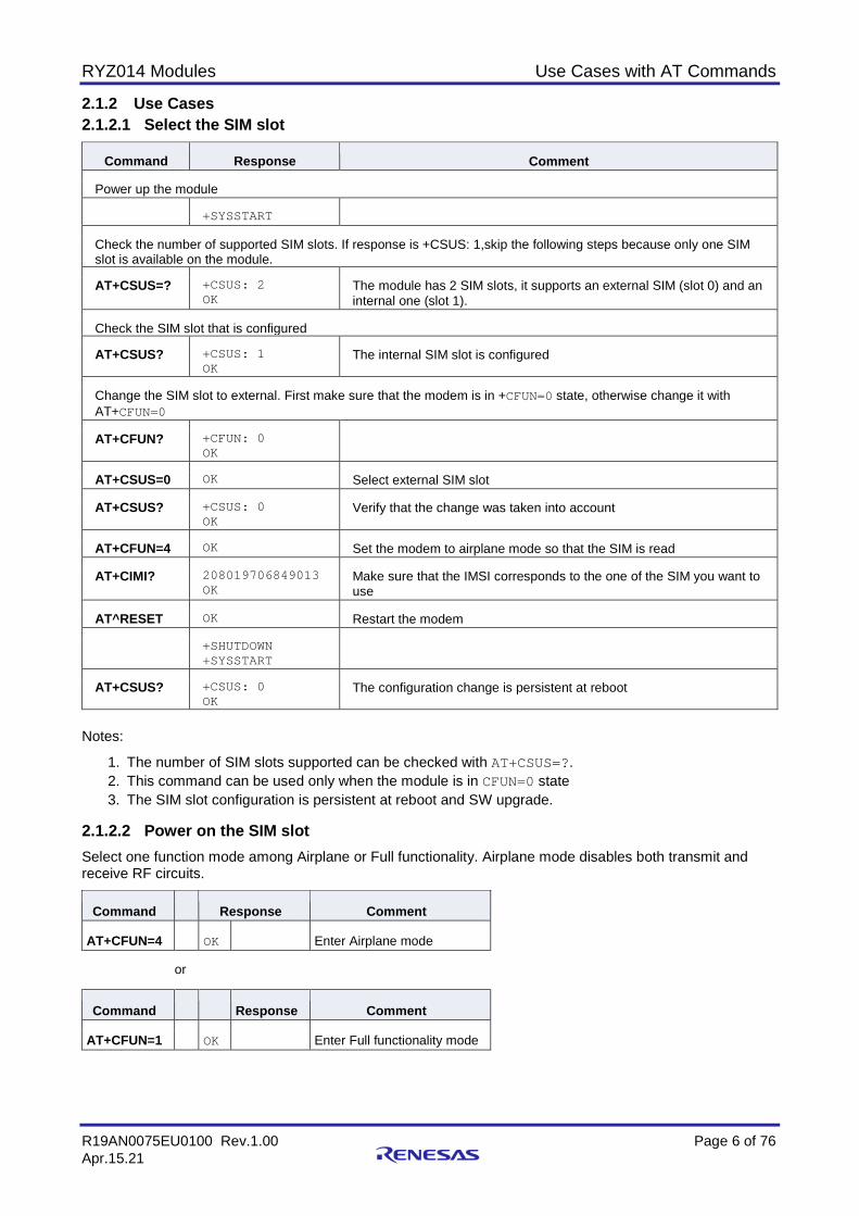
2.1.2 Use Cases 2.1.2.1 Select the SIM slot
Command Response Comment
Power up the module
+SYSSTART
Check the number of supported SIM slots. If response is +CSUS: 1,skip the following steps because only one SIM slot is available on the module.
AT+CSUS=? +CSUS: 2 OK
The module has 2 SIM slots, it supports an external SIM (slot 0) and an internal one (slot 1).
Check the SIM slot that is configured
AT+CSUS? +CSUS: 1 OK
The internal SIM slot is configured
Change the SIM slot to external. First make sure that the modem is in +CFUN=0 state, otherwise change it with AT+CFUN=0
AT+CFUN? +CFUN: 0 OK
AT+CSUS=0 OK Select external SIM slot
AT+CSUS? +CSUS: 0 OK
Verify that the change was taken into account
AT+CFUN=4 OK Set the modem to airplane mode so that the SIM is read
AT+CIMI? 208019706849013 OK
Make sure that the IMSI corresponds to the one of the SIM you want to use
AT^RESET OK Restart the modem
+SHUTDOWN +SYSSTART
AT+CSUS? +CSUS: 0 OK
The configuration change is persistent at reboot
Notes:
1. The number of SIM slots supported can be checked with AT+CSUS=?. 2. This command can be used only when the module is in CFUN=0 state 3. The SIM slot configuration is persistent at reboot and SW upgrade.
2.1.2.2 Power on the SIM slot Select one function mode among Airplane or Full functionality. Airplane mode disables both transmit and receive RF circuits.
Command Response Comment
AT+CFUN=4 OK Enter Airplane mode
or
Command Response Comment
AT+CFUN=1 OK Enter Full functionality mode
RYZ014 Modules Use Cases with AT Commands
R19AN0075EU0100 Rev.1.00 Page 7 of 76 Apr.15.21
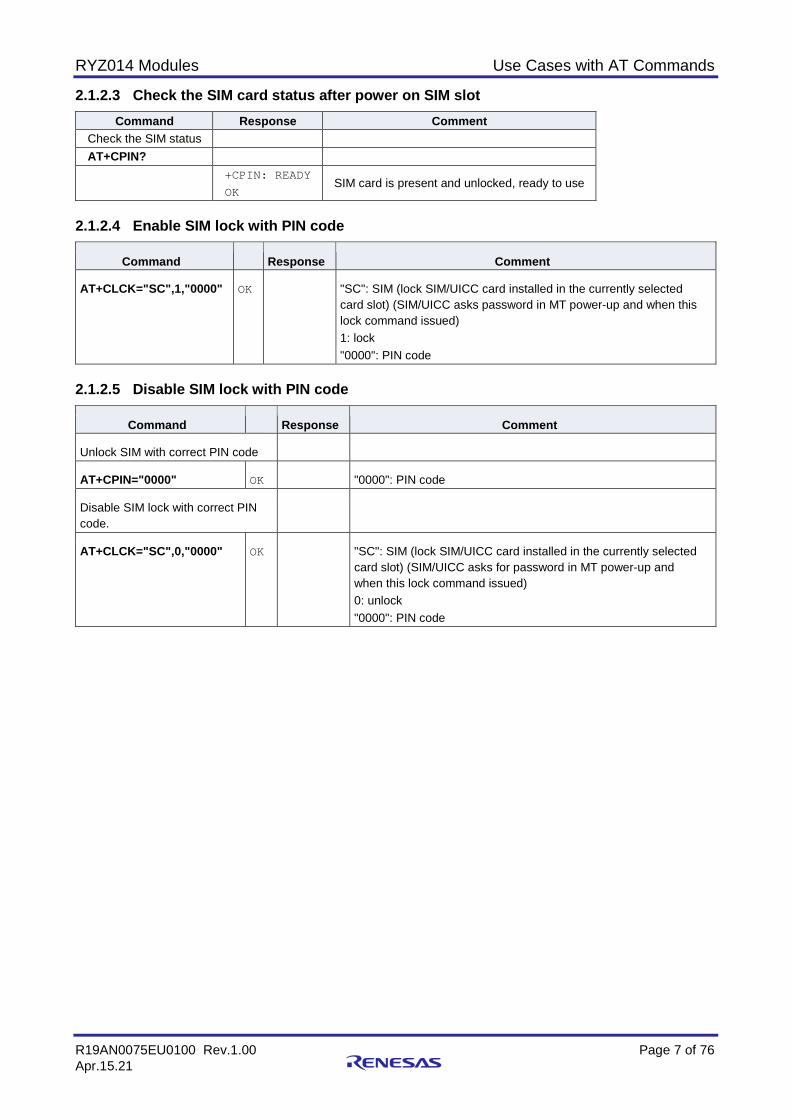
2.1.2.3 Check the SIM card status after power on SIM slot Command Response Comment
Check the SIM status AT+CPIN? +CPIN: READY
OK SIM card is present and unlocked, ready to use
2.1.2.4 Enable SIM lock with PIN code
Command Response Comment
AT+CLCK="SC",1,"0000" OK "SC": SIM (lock SIM/UICC card installed in the currently selected card slot) (SIM/UICC asks password in MT power-up and when this lock command issued) 1: lock "0000": PIN code
2.1.2.5 Disable SIM lock with PIN code
Command Response Comment
Unlock SIM with correct PIN code
AT+CPIN="0000" OK "0000": PIN code
Disable SIM lock with correct PIN code.
AT+CLCK="SC",0,"0000" OK "SC": SIM (lock SIM/UICC card installed in the currently selected card slot) (SIM/UICC asks for password in MT power-up and when this lock command issued) 0: unlock "0000": PIN code

RYZ014 Modules Use Cases with AT Commands
R19AN0075EU0100 Rev.1.00 Page 8 of 76 Apr.15.21
2.1.2.6 Enter PIN code to unlock SIM
Command Response Comment
Check current SIM card state
AT+CPIN?
CPIN: SIM PIN
OK SIM PIN is required to unlock SIM card
type PIN code to unlock with "1234" PIN code
AT+CPIN="1234"
ERROR PIN code is not correct, SIM card is still locked
type PIN code to unlock with "0000" PIN code
AT+CPIN="0000"
OK PIN code is correct, SIM card unlocked
Check SIM card state
AT+CPIN?
+CPIN: READY SIM card is present and unlocked, ready to use 2.1.2.7 Enter PUK code to unlock SIM
Command Response Comment
Check current SIM card state
AT+CPIN?
+CPIN: SIM PUK OK
Require SIM PUK to unlock SIM card
type PUK code to unlock with "12345678" PUK code
AT+CPIN="12345678"
ERROR PUK code is not correct, SIM card is still locked
type PUK code to unlock with "00000000" PUK code
AT+CPIN="00000000"
OK PUK code is correct, SIM card unlocked
Check SIM card state
AT+CPIN?
+CPIN: READY OK
SIM card is present and unlocked, ready to use
RYZ014 Modules Use Cases with AT Commands
R19AN0075EU0100 Rev.1.00 Page 9 of 76 Apr.15.21
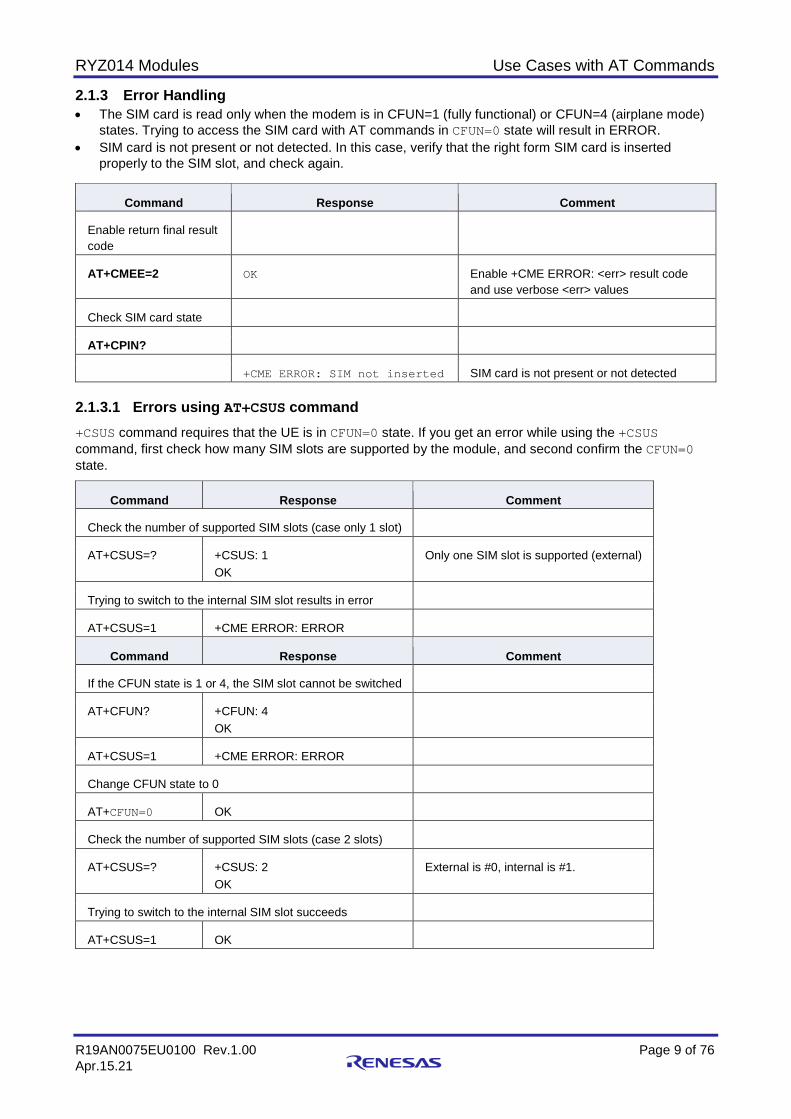
2.1.3 Error Handling • The SIM card is read only when the modem is in CFUN=1 (fully functional) or CFUN=4 (airplane mode)
states. Trying to access the SIM card with AT commands in CFUN=0 state will result in ERROR. • SIM card is not present or not detected. In this case, verify that the right form SIM card is inserted
properly to the SIM slot, and check again.
Command Response Comment
Enable return final result code
AT+CMEE=2 OK Enable +CME ERROR: <err> result code and use verbose <err> values
Check SIM card state
AT+CPIN?
+CME ERROR: SIM not inserted SIM card is not present or not detected 2.1.3.1 Errors using AT+CSUS command +CSUS command requires that the UE is in CFUN=0 state. If you get an error while using the +CSUS command, first check how many SIM slots are supported by the module, and second confirm the CFUN=0 state.
Command Response Comment
Check the number of supported SIM slots (case only 1 slot)
AT+CSUS=? +CSUS: 1 OK
Only one SIM slot is supported (external)
Trying to switch to the internal SIM slot results in error
AT+CSUS=1 +CME ERROR: ERROR
Command Response Comment
If the CFUN state is 1 or 4, the SIM slot cannot be switched
AT+CFUN? +CFUN: 4 OK
AT+CSUS=1 +CME ERROR: ERROR
Change CFUN state to 0
AT+CFUN=0 OK
Check the number of supported SIM slots (case 2 slots)
AT+CSUS=? +CSUS: 2 OK
External is #0, internal is #1.
Trying to switch to the internal SIM slot succeeds
AT+CSUS=1 OK
RYZ014 Modules Use Cases with AT Commands
R19AN0075EU0100 Rev.1.00 Page 10 of 76 Apr.15.21
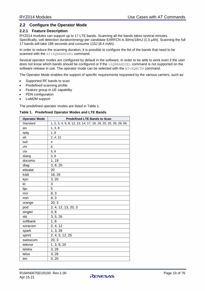
2.2 Configure the Operator Mode 2.2.1 Feature Description RYZ014 modules can support up to 17 LTE bands. Scanning all the bands takes several minutes. Specifically, cell detection duration/energy per candidate EARFCN is 30ms/18mJ (1.3 µAh). Scanning the full 17 bands will take 186 seconds and consume 115J (8.4 mAh).
In order to reduce the scanning duration, it is possible to configure the list of the bands that need to be scanned with the AT+SQNBANDSEL command.
Several operator modes are configured by default in the software, in order to be able to work even if the user does not know which bands should be configured or if the +SQNBANDSEL command is not supported on the software release in use. The operator mode can be selected with the AT+SQNCTM command.
The Operator Mode enables the support of specific requirements requested by the various carriers, such as:
• Supported RF bands to scan • Predefined scanning profile • Feature group in UE capability • PDN configuration • LwM2M support The predefined operator modes are listed in Table 1.
Table 1. Predefined Operator Modes and LTE Bands
Operator Mode Predefined LTE Bands to Scan Standard 1, 2, 3, 4, 5, 8, 12, 13, 14, 17, 18, 19, 20, 25, 26, 28, 66 ais 1, 3, 8 aptg 1, 8 att 2, 4, 12 bell 4 cht 8 cta 5, 8 dialog 3, 8 docomo 1, 19 dtag 3, 8, 20 etisalat 20 kddi 18, 26 kpn 3, 20 kt 3 lgu 5 mci 8, 3 mtn 8, 3 orange 20, 3 pod 2, 4, 12, 13, 20, 3 singtel 3, 8 skt 3, 5, 26 softbank 1, 8 soracom 2, 4, 12 spark 1, 3, 28 sprint 2, 4, 5, 12, 25 swisscom 20, 3 telenor 1, 3, 8, 20 telstra 3, 28 telus 3, 28 tim 3, 20
RYZ014 Modules Use Cases with AT Commands
R19AN0075EU0100 Rev.1.00 Page 11 of 76 Apr.15.21
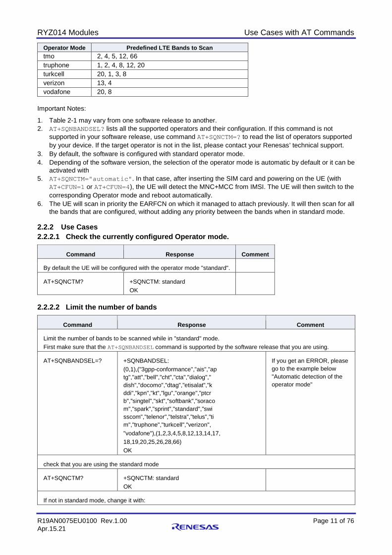
Operator Mode Predefined LTE Bands to Scan tmo 2, 4, 5, 12, 66 truphone 1, 2, 4, 8, 12, 20 turkcell 20, 1, 3, 8 verizon 13, 4 vodafone 20, 8
Important Notes:
1. Table 2-1 may vary from one software release to another. 2. AT+SQNBANDSEL? lists all the supported operators and their configuration. If this command is not
supported in your software release, use command AT+SQNCTM=? to read the list of operators supported by your device. If the target operator is not in the list, please contact your Renesas’ technical support.
3. By default, the software is configured with standard operator mode. 4. Depending of the software version, the selection of the operator mode is automatic by default or it can be
activated with 5. AT+SQNCTM="automatic". In that case, after inserting the SIM card and powering on the UE (with
AT+CFUN=1 or AT+CFUN=4), the UE will detect the MNC+MCC from IMSI. The UE will then switch to the corresponding Operator mode and reboot automatically.
6. The UE will scan in priority the EARFCN on which it managed to attach previously. It will then scan for all the bands that are configured, without adding any priority between the bands when in standard mode.
2.2.2 Use Cases 2.2.2.1 Check the currently configured Operator mode.
Command Response Comment
By default the UE will be configured with the operator mode "standard".
AT+SQNCTM? +SQNCTM: standard OK
2.2.2.2 Limit the number of bands
Command Response Comment
Limit the number of bands to be scanned while in "standard" mode. First make sure that the AT+SQNBANDSEL command is supported by the software release that you are using.
AT+SQNBANDSEL=? +SQNBANDSEL: (0,1),("3gpp-conformance","ais","ap tg","att","bell","cht","cta","dialog"," dish","docomo","dtag","etisalat","k ddi","kpn","kt","lgu","orange","ptcr b","singtel","skt","softbank","soraco m","spark","sprint","standard","swi sscom","telenor","telstra","telus","ti m","truphone","turkcell","verizon", "vodafone"),(1,2,3,4,5,8,12,13,14,17, 18,19,20,25,26,28,66) OK
If you get an ERROR, please go to the example below "Automatic detection of the operator mode"
check that you are using the standard mode
AT+SQNCTM? +SQNCTM: standard OK
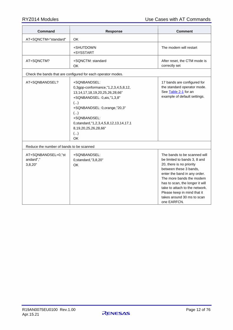
If not in standard mode, change it with:
RYZ014 Modules Use Cases with AT Commands
R19AN0075EU0100 Rev.1.00 Page 12 of 76 Apr.15.21
Command Response Comment
AT+SQNCTM="standard" OK
+SHUTDOWN +SYSSTART
The modem will restart
AT+SQNCTM? +SQNCTM: standard OK
After reset, the CTM mode is correctly set
Check the bands that are configured for each operator modes.
AT+SQNBANDSEL? +SQNBANDSEL: 0,3gpp-conformance,"1,2,3,4,5,8,12, 13,14,17,18,19,20,25,26,28,66" +SQNBANDSEL: 0,ais,"1,3,8" (...) +SQNBANDSEL: 0,orange,"20,3" (...) +SQNBANDSEL: 0,standard,"1,2,3,4,5,8,12,13,14,17,1 8,19,20,25,26,28,66" (...) OK
17 bands are configured for the standard operator mode. See Table 2-1 for an example of default settings.
Reduce the number of bands to be scanned
AT+SQNBANDSEL=0,"standard"," 3,8,20"
+SQNBANDSEL: 0,standard,"3,8,20" OK
The bands to be scanned will be limited to bands 3, 8 and 20, there is no priority between these 3 bands, enter the band in any order. The more bands the modem has to scan, the longer it will take to attach to the network. Please keep in mind that it takes around 30 ms to scan one EARFCN.
RYZ014 Modules Use Cases with AT Commands
R19AN0075EU0100 Rev.1.00 Page 13 of 76 Apr.15.21
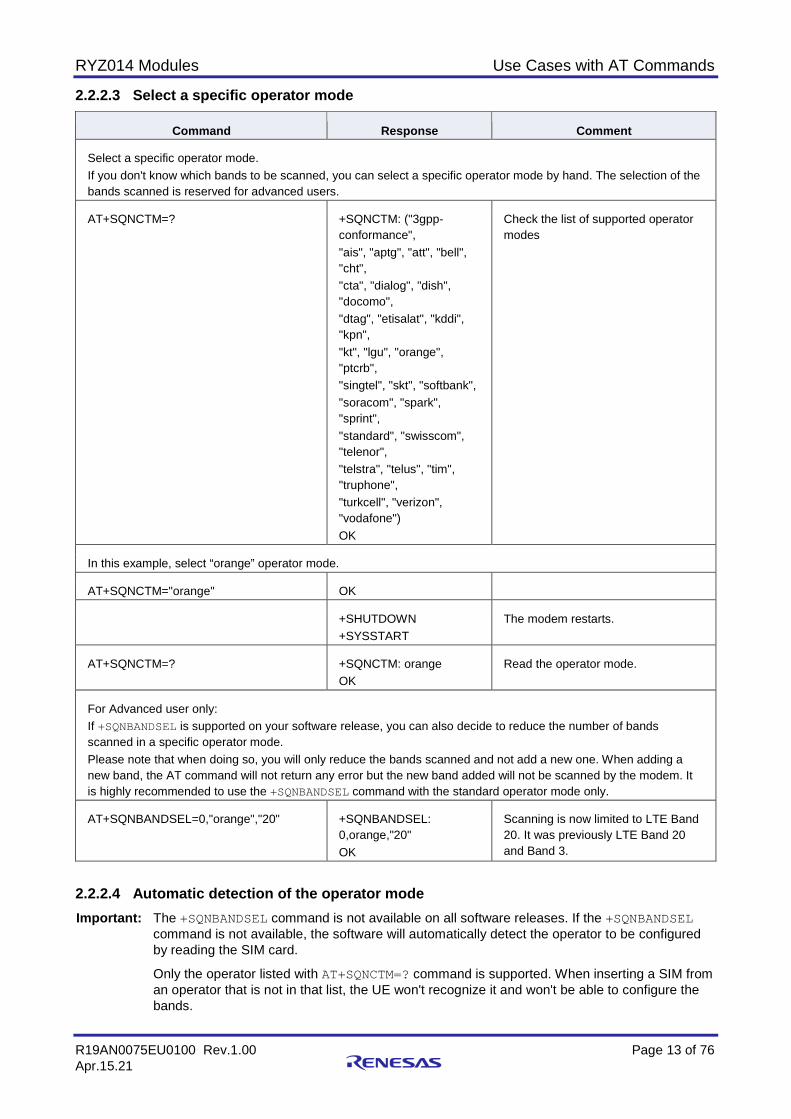
2.2.2.3 Select a specific operator mode
Command Response Comment
Select a specific operator mode. If you don't know which bands to be scanned, you can select a specific operator mode by hand. The selection of the bands scanned is reserved for advanced users.
AT+SQNCTM=? +SQNCTM: ("3gpp-conformance", "ais", "aptg", "att", "bell", "cht", "cta", "dialog", "dish", "docomo", "dtag", "etisalat", "kddi", "kpn", "kt", "lgu", "orange", "ptcrb", "singtel", "skt", "softbank", "soracom", "spark", "sprint", "standard", "swisscom", "telenor", "telstra", "telus", "tim", "truphone", "turkcell", "verizon", "vodafone") OK
Check the list of supported operator modes
In this example, select “orange” operator mode.
AT+SQNCTM="orange" OK
+SHUTDOWN +SYSSTART
The modem restarts.
AT+SQNCTM=? +SQNCTM: orange OK
Read the operator mode.
For Advanced user only: If +SQNBANDSEL is supported on your software release, you can also decide to reduce the number of bands scanned in a specific operator mode. Please note that when doing so, you will only reduce the bands scanned and not add a new one. When adding a new band, the AT command will not return any error but the new band added will not be scanned by the modem. It is highly recommended to use the +SQNBANDSEL command with the standard operator mode only.
AT+SQNBANDSEL=0,"orange","20" +SQNBANDSEL: 0,orange,"20" OK
Scanning is now limited to LTE Band 20. It was previously LTE Band 20 and Band 3.
2.2.2.4 Automatic detection of the operator mode Important: The +SQNBANDSEL command is not available on all software releases. If the +SQNBANDSEL
command is not available, the software will automatically detect the operator to be configured by reading the SIM card.
Only the operator listed with AT+SQNCTM=? command is supported. When inserting a SIM from an operator that is not in that list, the UE won't recognize it and won't be able to configure the bands.

RYZ014 Modules Use Cases with AT Commands
R19AN0075EU0100 Rev.1.00 Page 14 of 76 Apr.15.21
Command Response Comment
Insert a Telstra SIM card.
AT+SQNCTM? +SQNCTM: orange OK
Read the current configuration. Operator mode is not correct.
AT+CFUN=4 OK UE reads SIM card. The same effect is obtained with AT+CFUN=1.
UE detects the new operator, reconfigures and reboots.
+SYSSHDN +SYSTART
AT+SQNCTM? +SQNCTM: telstra OK
Read the current configuration. Operator mode is correct.
2.2.3 Error Handling 2.2.3.1 Usage of +SQNBANDSEL command This AT command should be used only to limit the number of bands to be scanned compared to the default configuration. You cannot add a new band to scan with this command. If you enter the +SQNBANDSEL command with a band that was not set for a specific operator mode in the factory reset settings, it will be ignored: the command will not return any error but the band will not be scanned.
2.3 Connect to the Network and Check that Attach is Done 2.3.1 Feature Description This section describes how to attach to or detach from the network.
Related AT commands are:
• AT+CEREG • AT+CFUN • AT+CGACT • AT+CGATT • AT+CGCDCONT • URC +CEREG
Command Response Comment AT+CFUN=0 OK Power-off UE +CEREG:0
2.3.2 Use Cases 2.3.2.1 Attach to the network
Command Response Comment
Insert a SIM card and power-on the UE
AT+CFUN=1 OK UE should attach to network automatically.
+CEREG:2 By default, <n> parameter if +CEREG URC is set to 2 to enable network registration and URC.
+CEREG:1,”0002”,”01A2 2002”,7
RYZ014 Modules Use Cases with AT Commands
R19AN0075EU0100 Rev.1.00 Page 15 of 76 Apr.15.21
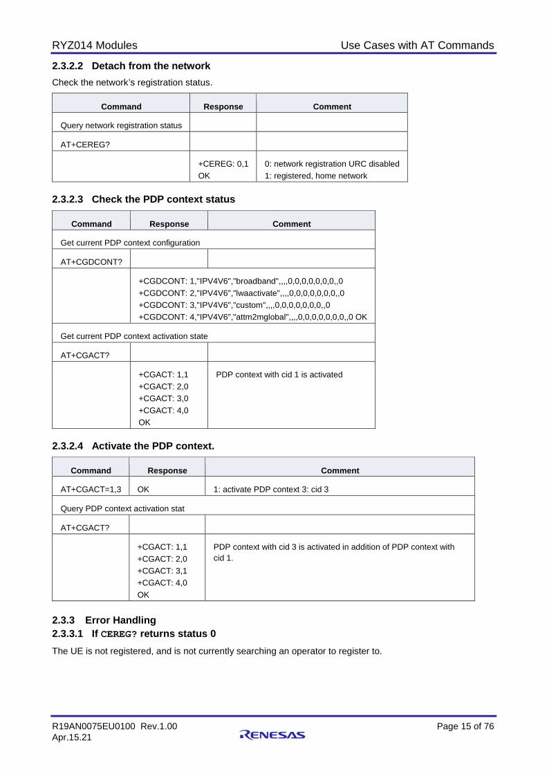
2.3.2.2 Detach from the network Check the network’s registration status.
Command Response Comment
Query network registration status
AT+CEREG?
+CEREG: 0,1 OK
0: network registration URC disabled 1: registered, home network
2.3.2.3 Check the PDP context status
Command Response Comment
Get current PDP context configuration
AT+CGDCONT?
+CGDCONT: 1,"IPV4V6","broadband",,,,0,0,0,0,0,0,0,,0 +CGDCONT: 2,"IPV4V6","lwaactivate",,,,0,0,0,0,0,0,0,,0 +CGDCONT: 3,"IPV4V6","custom",,,,0,0,0,0,0,0,0,,0 +CGDCONT: 4,"IPV4V6","attm2mglobal",,,,0,0,0,0,0,0,0,,0 OK
Get current PDP context activation state
AT+CGACT?
+CGACT: 1,1 +CGACT: 2,0 +CGACT: 3,0 +CGACT: 4,0 OK
PDP context with cid 1 is activated
2.3.2.4 Activate the PDP context.
Command Response Comment
AT+CGACT=1,3 OK 1: activate PDP context 3: cid 3
Query PDP context activation stat
AT+CGACT?
+CGACT: 1,1 +CGACT: 2,0 +CGACT: 3,1 +CGACT: 4,0 OK
PDP context with cid 3 is activated in addition of PDP context with cid 1.
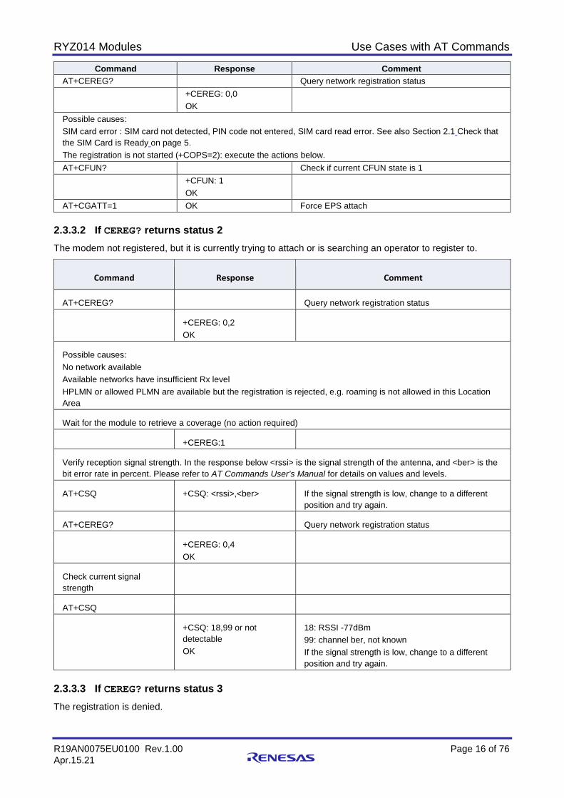
2.3.3 Error Handling 2.3.3.1 If CEREG? returns status 0 The UE is not registered, and is not currently searching an operator to register to.
RYZ014 Modules Use Cases with AT Commands
R19AN0075EU0100 Rev.1.00 Page 16 of 76 Apr.15.21
Command Response Comment AT+CEREG? Query network registration status +CEREG: 0,0
OK
Possible causes: SIM card error : SIM card not detected, PIN code not entered, SIM card read error. See also Section 2.1 Check that the SIM Card is Ready on page 5. The registration is not started (+COPS=2): execute the actions below. AT+CFUN? Check if current CFUN state is 1 +CFUN: 1
OK
AT+CGATT=1 OK Force EPS attach 2.3.3.2 If CEREG? returns status 2 The modem not registered, but it is currently trying to attach or is searching an operator to register to.
Command Response Comment
AT+CEREG? Query network registration status
+CEREG: 0,2 OK
Possible causes: No network available Available networks have insufficient Rx level HPLMN or allowed PLMN are available but the registration is rejected, e.g. roaming is not allowed in this Location Area
Wait for the module to retrieve a coverage (no action required)
+CEREG:1
Verify reception signal strength. In the response below <rssi> is the signal strength of the antenna, and <ber> is the bit error rate in percent. Please refer to AT Commands User’s Manual for details on values and levels.
AT+CSQ +CSQ: <rssi>,<ber> If the signal strength is low, change to a different position and try again.
AT+CEREG? Query network registration status
+CEREG: 0,4 OK
Check current signal strength
AT+CSQ
+CSQ: 18,99 or not detectable OK
18: RSSI -77dBm 99: channel ber, not known If the signal strength is low, change to a different position and try again.
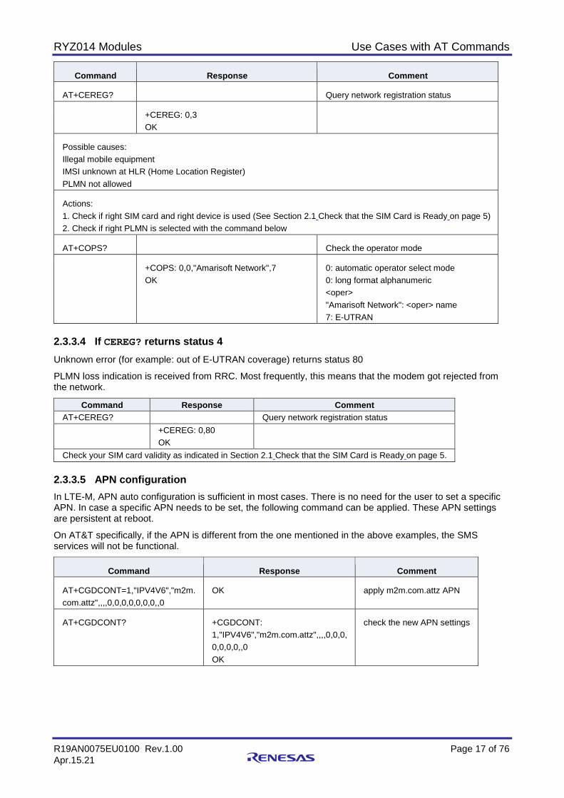
2.3.3.3 If CEREG? returns status 3 The registration is denied.
RYZ014 Modules Use Cases with AT Commands
R19AN0075EU0100 Rev.1.00 Page 17 of 76 Apr.15.21
Command Response Comment
AT+CEREG? Query network registration status
+CEREG: 0,3 OK
Possible causes: Illegal mobile equipment IMSI unknown at HLR (Home Location Register) PLMN not allowed
Actions: 1. Check if right SIM card and right device is used (See Section 2.1 Check that the SIM Card is Ready on page 5) 2. Check if right PLMN is selected with the command below
AT+COPS? Check the operator mode
+COPS: 0,0,"Amarisoft Network",7 OK
0: automatic operator select mode 0: long format alphanumeric <oper> "Amarisoft Network": <oper> name 7: E-UTRAN
2.3.3.4 If CEREG? returns status 4 Unknown error (for example: out of E-UTRAN coverage) returns status 80
PLMN loss indication is received from RRC. Most frequently, this means that the modem got rejected from the network.
Command Response Comment AT+CEREG? Query network registration status +CEREG: 0,80
OK
Check your SIM card validity as indicated in Section 2.1 Check that the SIM Card is Ready on page 5. 2.3.3.5 APN configuration In LTE-M, APN auto configuration is sufficient in most cases. There is no need for the user to set a specific APN. In case a specific APN needs to be set, the following command can be applied. These APN settings are persistent at reboot.
On AT&T specifically, if the APN is different from the one mentioned in the above examples, the SMS services will not be functional.
Command Response Comment
AT+CGDCONT=1,"IPV4V6","m2m. com.attz",,,,0,0,0,0,0,0,0,,0
OK apply m2m.com.attz APN
AT+CGDCONT? +CGDCONT: 1,"IPV4V6","m2m.com.attz",,,,0,0,0, 0,0,0,0,,0 OK
check the new APN settings
RYZ014 Modules Use Cases with AT Commands
R19AN0075EU0100 Rev.1.00 Page 18 of 76 Apr.15.21
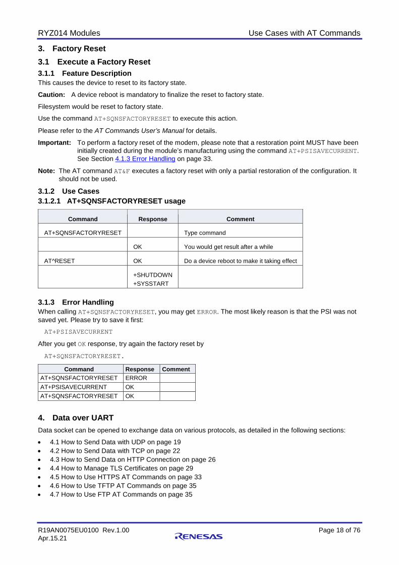
3. Factory Reset 3.1 Execute a Factory Reset 3.1.1 Feature Description This causes the device to reset to its factory state.
Caution: A device reboot is mandatory to finalize the reset to factory state.
Filesystem would be reset to factory state.
Use the command AT+SQNSFACTORYRESET to execute this action.
Please refer to the AT Commands User’s Manual for details.
Important: To perform a factory reset of the modem, please note that a restoration point MUST have been initially created during the module’s manufacturing using the command AT+PSISAVECURRENT. See Section 4.1.3 Error Handling on page 33.
Note: The AT command AT&F executes a factory reset with only a partial restoration of the configuration. It should not be used.
3.1.2 Use Cases 3.1.2.1 AT+SQNSFACTORYRESET usage
Command Response Comment
AT+SQNSFACTORYRESET Type command
OK You would get result after a while
AT^RESET OK Do a device reboot to make it taking effect
+SHUTDOWN +SYSSTART
3.1.3 Error Handling When calling AT+SQNSFACTORYRESET, you may get ERROR. The most likely reason is that the PSI was not saved yet. Please try to save it first:
AT+PSISAVECURRENT
After you get OK response, try again the factory reset by
AT+SQNSFACTORYRESET.
Command Response Comment AT+SQNSFACTORYRESET ERROR AT+PSISAVECURRENT OK AT+SQNSFACTORYRESET OK
4. Data over UART Data socket can be opened to exchange data on various protocols, as detailed in the following sections:
• 4.1 How to Send Data with UDP on page 19 • 4.2 How to Send Data with TCP on page 22 • 4.3 How to Send Data on HTTP Connection on page 26 • 4.4 How to Manage TLS Certificates on page 29 • 4.5 How to Use HTTPS AT Commands on page 33 • 4.6 How to Use TFTP AT Commands on page 35 • 4.7 How to Use FTP AT Commands on page 35
RYZ014 Modules Use Cases with AT Commands
R19AN0075EU0100 Rev.1.00 Page 19 of 76 Apr.15.21
• How to Use MQTT Commands on page 36 A maximum of six sessions can be established in parallel based on a socket. A socket is created by the RYZ014 module and not by the host MCU. The RYZ014 module can support both TCP and UDP protocols (sections 4.1 How to Send Data with UDP on page 19 and 4.2 How to Send Data with TCP on page 22).
UDP and TCP sockets can be opened with either of the following modes:
• Command mode: in this mode, the UART transmits AT commands and responses. In that mode, the user can send data using either: AT+SQNSSEND: the user enters the data to be sent after the prompt and concludes with CTRL+Z to
confirm the data to send or ESC to cancel. AT+SQNSSENDEXT: in that case, the host MCU defines the size of the payload to be sent and the
modem escapes automatically once the defined number of bytes is reached. • Online mode: all data is treated as pure data and is transferred to the other side. In this mode, the UART
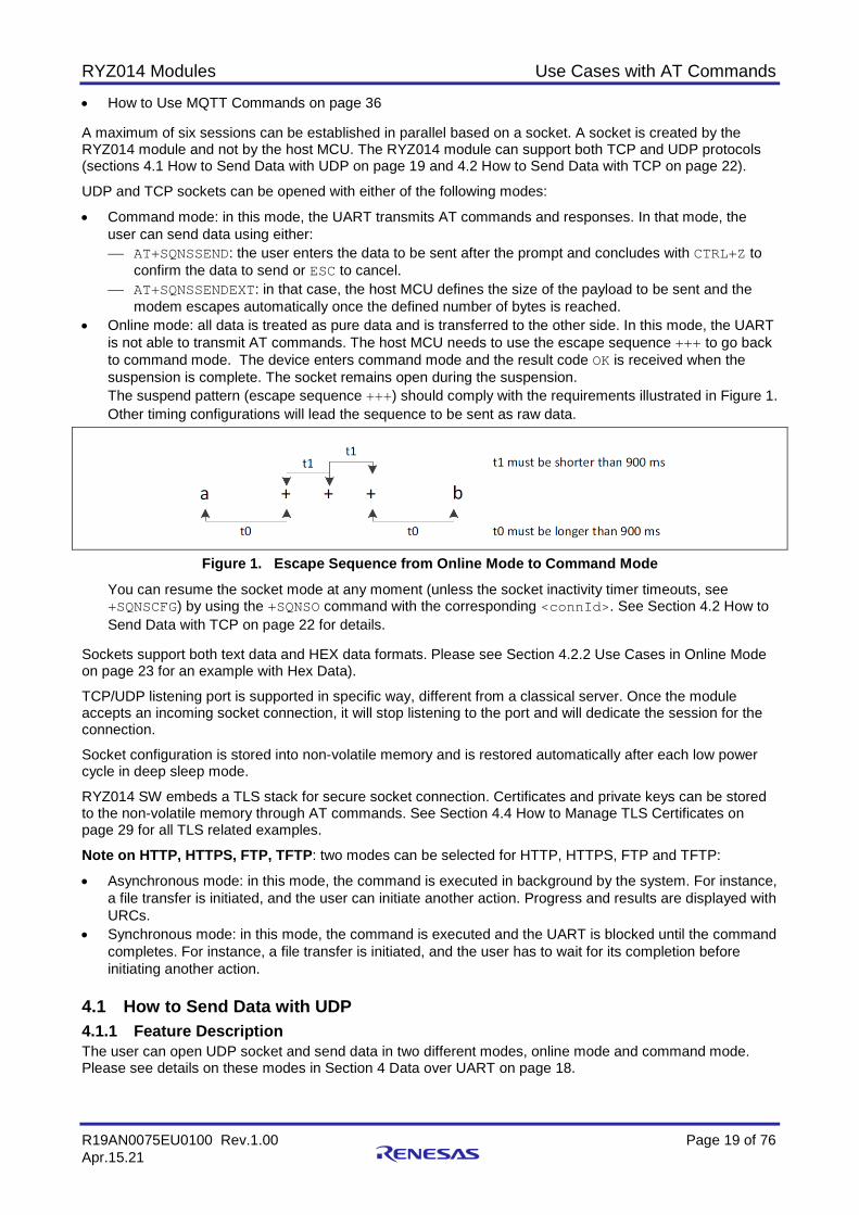
is not able to transmit AT commands. The host MCU needs to use the escape sequence +++ to go back to command mode. The device enters command mode and the result code OK is received when the suspension is complete. The socket remains open during the suspension. The suspend pattern (escape sequence +++) should comply with the requirements illustrated in Figure 1. Other timing configurations will lead the sequence to be sent as raw data.
Figure 1. Escape Sequence from Online Mode to Command Mode
You can resume the socket mode at any moment (unless the socket inactivity timer timeouts, see +SQNSCFG) by using the +SQNSO command with the corresponding <connId>. See Section 4.2 How to Send Data with TCP on page 22 for details.
Sockets support both text data and HEX data formats. Please see Section 4.2.2 Use Cases in Online Mode on page 23 for an example with Hex Data).
TCP/UDP listening port is supported in specific way, different from a classical server. Once the module accepts an incoming socket connection, it will stop listening to the port and will dedicate the session for the connection.
Socket configuration is stored into non-volatile memory and is restored automatically after each low power cycle in deep sleep mode.
RYZ014 SW embeds a TLS stack for secure socket connection. Certificates and private keys can be stored to the non-volatile memory through AT commands. See Section 4.4 How to Manage TLS Certificates on page 29 for all TLS related examples.
Note on HTTP, HTTPS, FTP, TFTP: two modes can be selected for HTTP, HTTPS, FTP and TFTP:
• Asynchronous mode: in this mode, the command is executed in background by the system. For instance, a file transfer is initiated, and the user can initiate another action. Progress and results are displayed with URCs.
• Synchronous mode: in this mode, the command is executed and the UART is blocked until the command completes. For instance, a file transfer is initiated, and the user has to wait for its completion before initiating another action.
4.1 How to Send Data with UDP 4.1.1 Feature Description The user can open UDP socket and send data in two different modes, online mode and command mode. Please see details on these modes in Section 4 Data over UART on page 18.
RYZ014 Modules Use Cases with AT Commands
R19AN0075EU0100 Rev.1.00 Page 20 of 76 Apr.15.21
This section describes the usage of UDP. The usage of TCP is described in Section 4.2 How to Send Data with TCP on page 22 .
Note: With UDP protocol, there is no URC to inform the host MCU that a UDP packet was actually transmitted by the modem.
Related AT commands are:
• AT+SQNSD Use parameter <TxProt> of AT+SQNSD to configure the transmission protocol (TCP or UDP).
• AT+SQNSSEND • AT+SQNSSENDEXT • AT+SQNSRECV • AT+SQNSH • URC +SQNSRING Important: If +SQNSRING URC mode is set to 2 (data view mode), it is required to use AT+SQNSRECV to
receive the data. Otherwise, the data buffer would remain full and all following data would be dropped.
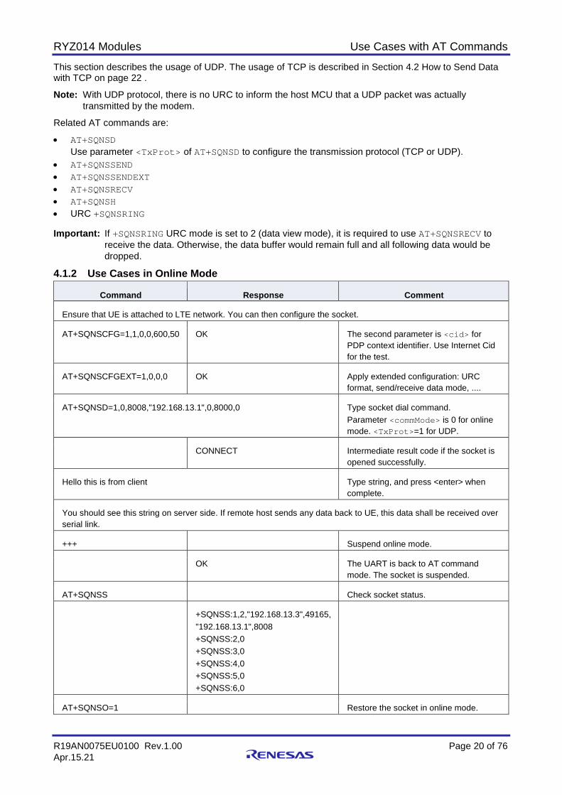
4.1.2 Use Cases in Online Mode
Command Response Comment
Ensure that UE is attached to LTE network. You can then configure the socket.
AT+SQNSCFG=1,1,0,0,600,50 OK The second parameter is <cid> for PDP context identifier. Use Internet Cid for the test.
AT+SQNSCFGEXT=1,0,0,0 OK Apply extended configuration: URC format, send/receive data mode, ....
AT+SQNSD=1,0,8008,"192.168.13.1",0,8000,0 Type socket dial command. Parameter <commMode> is 0 for online mode. <TxProt>=1 for UDP.
CONNECT Intermediate result code if the socket is opened successfully.
Hello this is from client Type string, and press <enter> when complete.
You should see this string on server side. If remote host sends any data back to UE, this data shall be received over serial link.
+++ Suspend online mode.
OK The UART is back to AT command mode. The socket is suspended.
AT+SQNSS Check socket status.
+SQNSS:1,2,"192.168.13.3",49165, "192.168.13.1",8008 +SQNSS:2,0 +SQNSS:3,0 +SQNSS:4,0 +SQNSS:5,0 +SQNSS:6,0
AT+SQNSO=1 Restore the socket in online mode.
RYZ014 Modules Use Cases with AT Commands
R19AN0075EU0100 Rev.1.00 Page 21 of 76 Apr.15.21
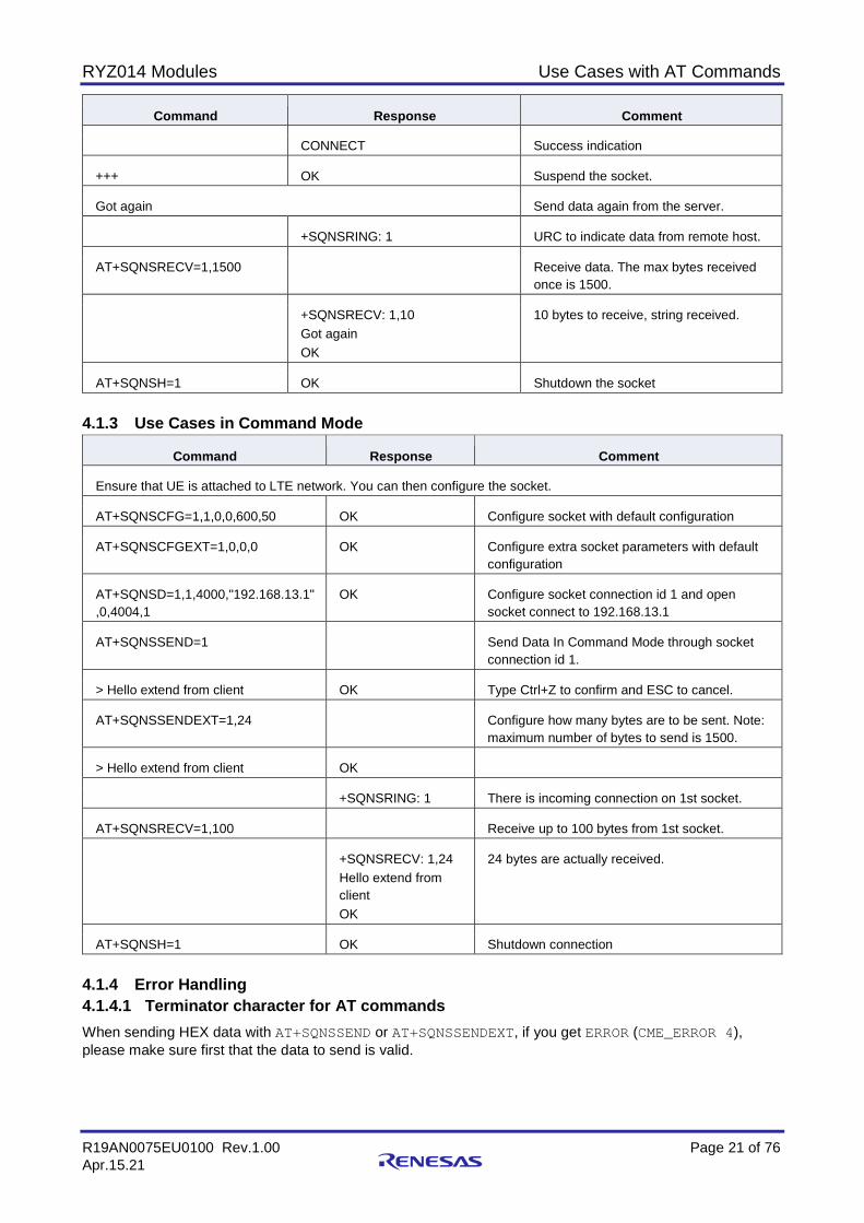
Command Response Comment
CONNECT Success indication
+++ OK Suspend the socket.
Got again Send data again from the server.
+SQNSRING: 1 URC to indicate data from remote host.
AT+SQNSRECV=1,1500 Receive data. The max bytes received once is 1500.
+SQNSRECV: 1,10 Got again OK
10 bytes to receive, string received.
AT+SQNSH=1 OK Shutdown the socket 4.1.3 Use Cases in Command Mode
Command Response Comment
Ensure that UE is attached to LTE network. You can then configure the socket.
AT+SQNSCFG=1,1,0,0,600,50 OK Configure socket with default configuration
AT+SQNSCFGEXT=1,0,0,0 OK Configure extra socket parameters with default configuration
AT+SQNSD=1,1,4000,"192.168.13.1" ,0,4004,1
OK Configure socket connection id 1 and open socket connect to 192.168.13.1
AT+SQNSSEND=1 Send Data In Command Mode through socket connection id 1.
> Hello extend from client OK Type Ctrl+Z to confirm and ESC to cancel.
AT+SQNSSENDEXT=1,24 Configure how many bytes are to be sent. Note: maximum number of bytes to send is 1500.
> Hello extend from client OK
+SQNSRING: 1 There is incoming connection on 1st socket.
AT+SQNSRECV=1,100 Receive up to 100 bytes from 1st socket.
+SQNSRECV: 1,24 Hello extend from client OK
24 bytes are actually received.
AT+SQNSH=1 OK Shutdown connection 4.1.4 Error Handling 4.1.4.1 Terminator character for AT commands When sending HEX data with AT+SQNSSEND or AT+SQNSSENDEXT, if you get ERROR (CME_ERROR 4), please make sure first that the data to send is valid.
RYZ014 Modules Use Cases with AT Commands
R19AN0075EU0100 Rev.1.00 Page 22 of 76 Apr.15.21
If the data is confirmed valid, please check if you use the proper terminator for AT command. Only one char is allowed. The AT command syntax is described in the 3GPP 27.007 (§4.1 and §4.2) and ITU V250 (§5.2.1). The termination character is <CR> by default.
For example, when using <CR><LF> (“\r\n”) as terminator, it would be without impact for most of AT commands since the "\n" would be treated as invalid AT command. But for AT which need input data during executing, the second char <LF> ("\n") would stay in the buffer and be treated as input data.
When sending data in text mode, the module will not return ERROR, but the server would receive data start with "\n" and this may trigger other problems. When sending data in HEX mode, it will trigger and ERROR immediately as "\n" is an invalid HEX char.
The terminator char can be changed by ATS3 command, please refer to AT Commands User’s Manual for the detail.
When developing an application on the host MCU based on AT commands, if no specific requirements are set, please use <CR> ("\r") as the terminator character.
4.1.4.2 • Receive Buffer Full The format of +SQNSRING can be configured by AT+SQNSCFGEXT. When AT+SQNSCFGEXT parameter <srMode> is set to 2, the Unsolicited Response is:
+SQNSRING: <connId>,<recData>,<data>
Data is in the URC, but this does not mean that the received bytes are flushed from the buffer. Not flushing the buffer with +SQNSRECV command will trigger an ERROR when the receive buffer becomes full, and all next incoming data would be dropped.
For data arrival notification, received bytes are not flushed until explicit read through +SQNSRECV command.
Internal buffering is limited and +SQNSRING notification will stop until host starts reading data through +SQNSRECV command. URC will be sent again if enough data has been read and if there are still new incoming data.
4.2 How to Send Data with TCP 4.2.1 Feature Description The user can open a TCP socket and send data in two different modes, online mode and command mode.
This section describes the usage of TCP. The usage of UDP is described in Section 4.1 How to Send Data with UDP.
Note: If +SQNSRING URC mode is set to 2 (data view mode), it is required to use AT+SQNSRECV to receive the data. Otherwise, the data buffer would remain full and all following data would be dropped.
Related AT commands are:
• AT+SQNSD Use parameter <TxProt> of AT+SQNSD to configure the transmission protocol (TCP or UDP).
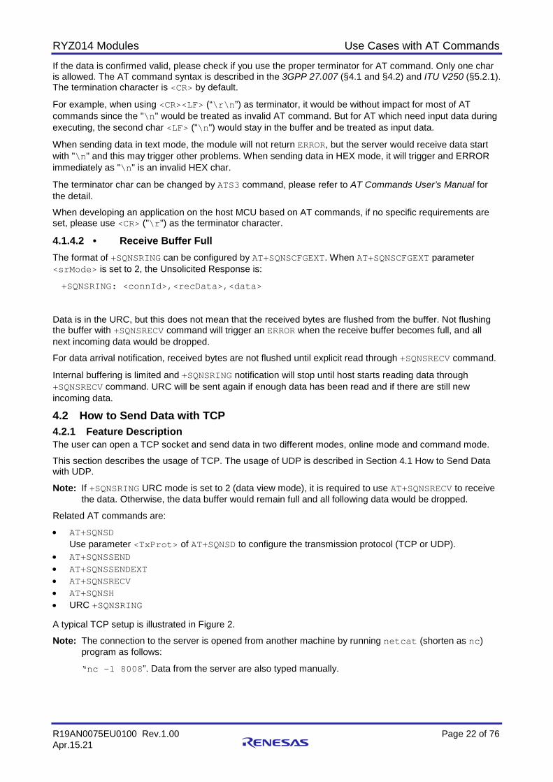
• AT+SQNSSEND • AT+SQNSSENDEXT • AT+SQNSRECV • AT+SQNSH • URC +SQNSRING A typical TCP setup is illustrated in Figure 2.
Note: The connection to the server is opened from another machine by running netcat (shorten as nc) program as follows:
“nc -l 8008”. Data from the server are also typed manually.

RYZ014 Modules Use Cases with AT Commands
R19AN0075EU0100 Rev.1.00 Page 23 of 76 Apr.15.21
Figure 2. TCP Typical Setup
4.2.2 Use Cases in Online Mode
Command Response Comment
Ensure that UE is attached to LTE network. You can then configure the socket.
AT+SQNSCFG=1,1,0,0,600,50 OK The second parameter is <cid> for PDP context identifier. Use Internet Cid for the test.
AT+SQNSCFGEXT=1,0,0,0 OK Apply extended configuration: URC format, send/receive data mode, ....
AT+SQNSD=1,0,8008,"192.168.13.1",0,8000,0 Type socket dial command. Parameter <commMode> is 0 for online mode. <TxProt>=0 for TCP.
CONNECT Intermediate result code if the socket is opened successfully.
Hello this is from client Type string, and press <enter> when complete.
You should see this string on server side. If remote host sends any data back to UE, this data shall be received over serial link.
+++ Suspend online mode.
OK The UART is back to AT command mode. The socket is suspended.
AT+SQNSS Check socket status.

RYZ014 Modules Use Cases with AT Commands
R19AN0075EU0100 Rev.1.00 Page 24 of 76 Apr.15.21
Command Response Comment
+SQNSS:1,2,"192.168.13.3",49165, "192.168.13.1",8008 +SQNSS:2,0 +SQNSS:3,0 +SQNSS:4,0 +SQNSS:5,0 +SQNSS:6,0
AT+SQNSO=1 Restore the socket in online mode.
CONNECT Success indication
+++ OK Suspend the socket.
Got again Send data again from the server.
+SQNSRING: 1 URC to indicate data from remote host.
AT+SQNSRECV=1,1500 Receive data. The max bytes received once is 1500.
+SQNSRECV: 1,10 Got again OK
10 bytes to receive, string received.
AT+SQNSH=1 OK Shutdown the socket 4.2.3 Use Cases in Command Mode with Text Data
Command Response Comment
Ensure that UE is attached to LTE network. You can then configure the socket.
AT+SQNSCFG=1,1,0,0,600,50 OK The second parameter is <cid> for PDP context identifier. Use Internet Cid for the test.
AT+SQNSCFGEXT=1,0,0,0 OK Configure extra socket parameters with default configuration
AT+SQNSD=1,0,8008,"192.168.13.1" ,0, 8000,1
OK Type TCP socket dial command. Configure socket connection id 1 and open socket connect to 192.168.13.1
AT+SQNSSEND=1
> Hello extend from client Send Data In Command Mode through socket connection id 1,
Type Ctrl+Z to confirm and ESC to cancel.
OK
AT+SQNSSENDEXT=1,24 Configure how many bytes to be sent,
maximum number of bytes to send is 1500.
> Hello extend from client OK
+SQNSRING: 1 There is incoming connection on 1st socket.
RYZ014 Modules Use Cases with AT Commands
R19AN0075EU0100 Rev.1.00 Page 25 of 76 Apr.15.21
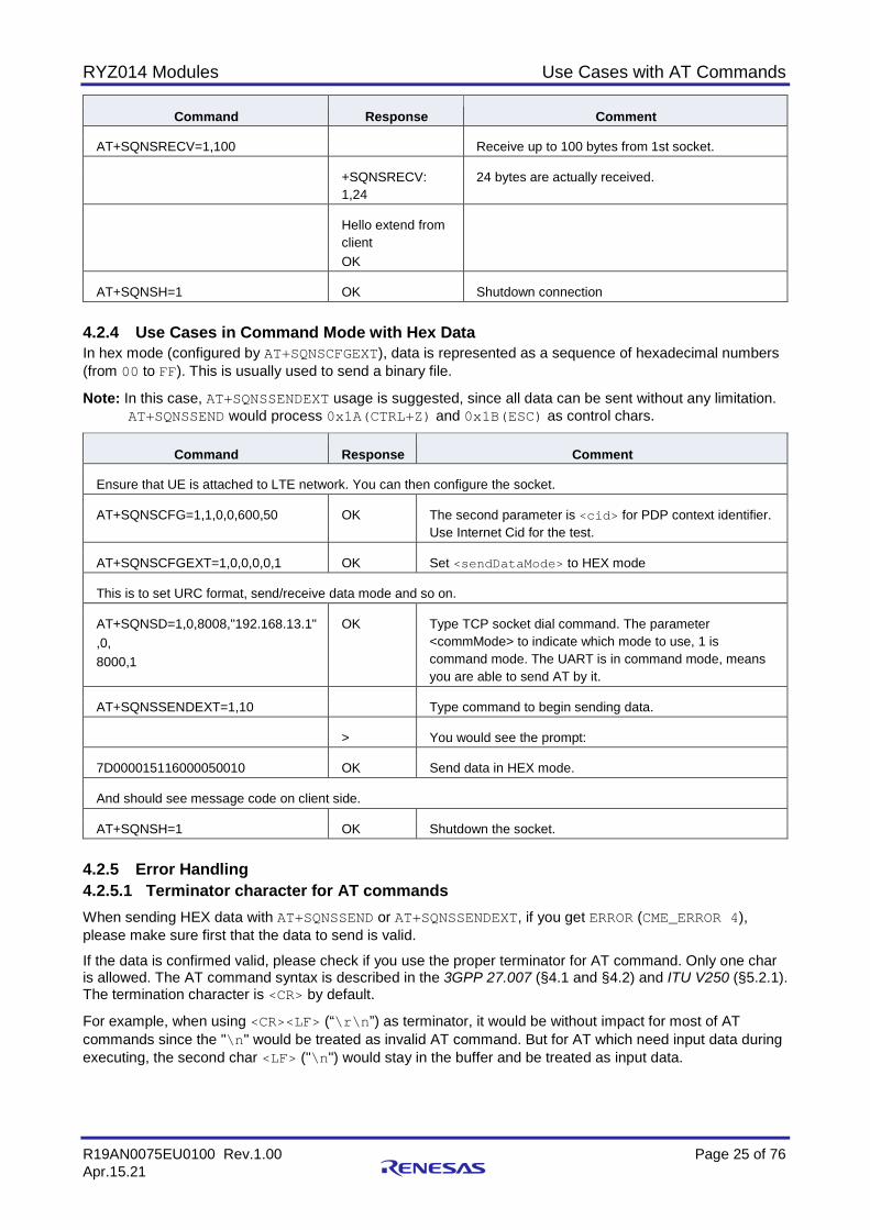
Command Response Comment
AT+SQNSRECV=1,100 Receive up to 100 bytes from 1st socket.
+SQNSRECV: 1,24
24 bytes are actually received.
Hello extend from client OK
AT+SQNSH=1 OK Shutdown connection 4.2.4 Use Cases in Command Mode with Hex Data In hex mode (configured by AT+SQNSCFGEXT), data is represented as a sequence of hexadecimal numbers (from 00 to FF). This is usually used to send a binary file.
Note: In this case, AT+SQNSSENDEXT usage is suggested, since all data can be sent without any limitation. AT+SQNSSEND would process 0x1A(CTRL+Z) and 0x1B(ESC) as control chars.
Command Response Comment
Ensure that UE is attached to LTE network. You can then configure the socket.
AT+SQNSCFG=1,1,0,0,600,50 OK The second parameter is <cid> for PDP context identifier. Use Internet Cid for the test.
AT+SQNSCFGEXT=1,0,0,0,0,1 OK Set <sendDataMode> to HEX mode
This is to set URC format, send/receive data mode and so on.
AT+SQNSD=1,0,8008,"192.168.13.1" ,0, 8000,1
OK Type TCP socket dial command. The parameter <commMode> to indicate which mode to use, 1 is command mode. The UART is in command mode, means you are able to send AT by it.
AT+SQNSSENDEXT=1,10 Type command to begin sending data.
> You would see the prompt:
7D000015116000050010 OK Send data in HEX mode.
And should see message code on client side.
AT+SQNSH=1 OK Shutdown the socket. 4.2.5 Error Handling 4.2.5.1 Terminator character for AT commands When sending HEX data with AT+SQNSSEND or AT+SQNSSENDEXT, if you get ERROR (CME_ERROR 4), please make sure first that the data to send is valid.
If the data is confirmed valid, please check if you use the proper terminator for AT command. Only one char is allowed. The AT command syntax is described in the 3GPP 27.007 (§4.1 and §4.2) and ITU V250 (§5.2.1). The termination character is <CR> by default.
For example, when using <CR><LF> (“\r\n”) as terminator, it would be without impact for most of AT commands since the "\n" would be treated as invalid AT command. But for AT which need input data during executing, the second char <LF> ("\n") would stay in the buffer and be treated as input data.

RYZ014 Modules Use Cases with AT Commands
R19AN0075EU0100 Rev.1.00 Page 26 of 76 Apr.15.21
When sending data in text mode, the module will not return ERROR, but the server would receive data start with "\n" and this may trigger other problems. When sending data in HEX mode, it will trigger and ERROR immediately as "\n" is an invalid HEX char.
The terminator char can be changed by ATS3 command, please refer to AT Commands User’s Manual for the detail.
When developing an application on the host MCU based on AT commands, if no specific requirements are set, please use <CR> ("\r") as the terminator character.
4.2.5.2 Receive Buffer Full The format of +SQNSRING can be configured by AT+SQNSCFGEXT. When AT+SQNSCFGEXT parameter <srMode> is set to 2, the Unsolicited Response is:
+SQNSRING: <connId>,<recData>,<data>
Data is in the URC, but this does not mean that the received bytes are flushed from the buffer. Not flushing the buffer with +SQNSRECV command will trigger an ERROR when the receive buffer becomes full, and all next incoming data would be dropped.
For data arrival notification, received bytes are not flushed until explicit read through +SQNSRECV command.
Internal buffering is limited and +SQNSRING notification will stop until host starts reading data through +SQNSRECV command. URC will be sent again if enough data has been read and if there are still new incoming data.
4.3 How to Send Data on HTTP Connection 4.3.1 Feature Description The user can send data on HTTP connection in two different modes, asynchronous mode and synchronous mode. Please see details on these modes in Section 4, Data over UART.
HTTP connection can be managed with the following specific +SQNHTTP AT commands:
• AT+SQNHTTPCFG • AT+SQNHTTPQRY (as GET, HEAD, DELETE) • AT+SQNHTTPRCV (as RECEIVE) • AT+SQNHTTPSND (as POST, PUT) POST and PUT can also be managed with the following AT command:
• AT+SQNFPUT (as POST, PUT)
RYZ014 Modules Use Cases with AT Commands
R19AN0075EU0100 Rev.1.00 Page 27 of 76 Apr.15.21
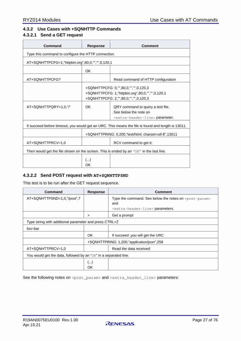
4.3.2 Use Cases with +SQNHTTP Commands 4.3.2.1 Send a GET request
Command Response Comment
Type this command to configure the HTTP connection.
AT+SQNHTTPCFG=1,"httpbin.org",80,0,"","",0,120,1
OK
AT+SQNHTTPCFG? Read command of HTTP configuration
+SQNHTTPCFG: 0,"",80,0,"","",0,120,3 +SQNHTTPCFG: 1,"httpbin.org",80,0,"","",0,120,1 +SQNHTTPCFG: 2,"",80,0,"","",0,120,3
AT+SQNHTTPQRY=1,0,"/" OK QRY command to query a test file. See below the note on <extra-header-line> parameter.
If succeed before timeout, you would get an URC. This means the file is found and length is 13011.
+SQNHTTPRING: 0,200,"text/html; charset=utf-8",13011
AT+SQNHTTPRCV=1,0 RCV command to get it:
Then would get the file shown on the screen. This is ended by an “OK” in the last line.
(...) OK
4.3.2.2 Send POST request with AT+SQNHTTPSND This test is to be run after the GET request sequence.
Command Response Comment AT+SQNHTTPSND=1,0,"/post",7 Type the command. See below the notes on <post-param>
and <extra-header-line> parameters.
> Get a prompt
Type string with additional parameter and press CTRL+Z
foo=bar
OK If succeed ,you will get the URC
+SQNHTTPRING: 1,200,"application/json",258
AT+SQNHTTPRCV=1,0 Read the data received:
You would get the data, followed by an “OK” in a separated line.
(...) OK
See the following notes on <post_param> and <extra_header_line> parameters:
RYZ014 Modules Use Cases with AT Commands
R19AN0075EU0100 Rev.1.00 Page 28 of 76 Apr.15.21
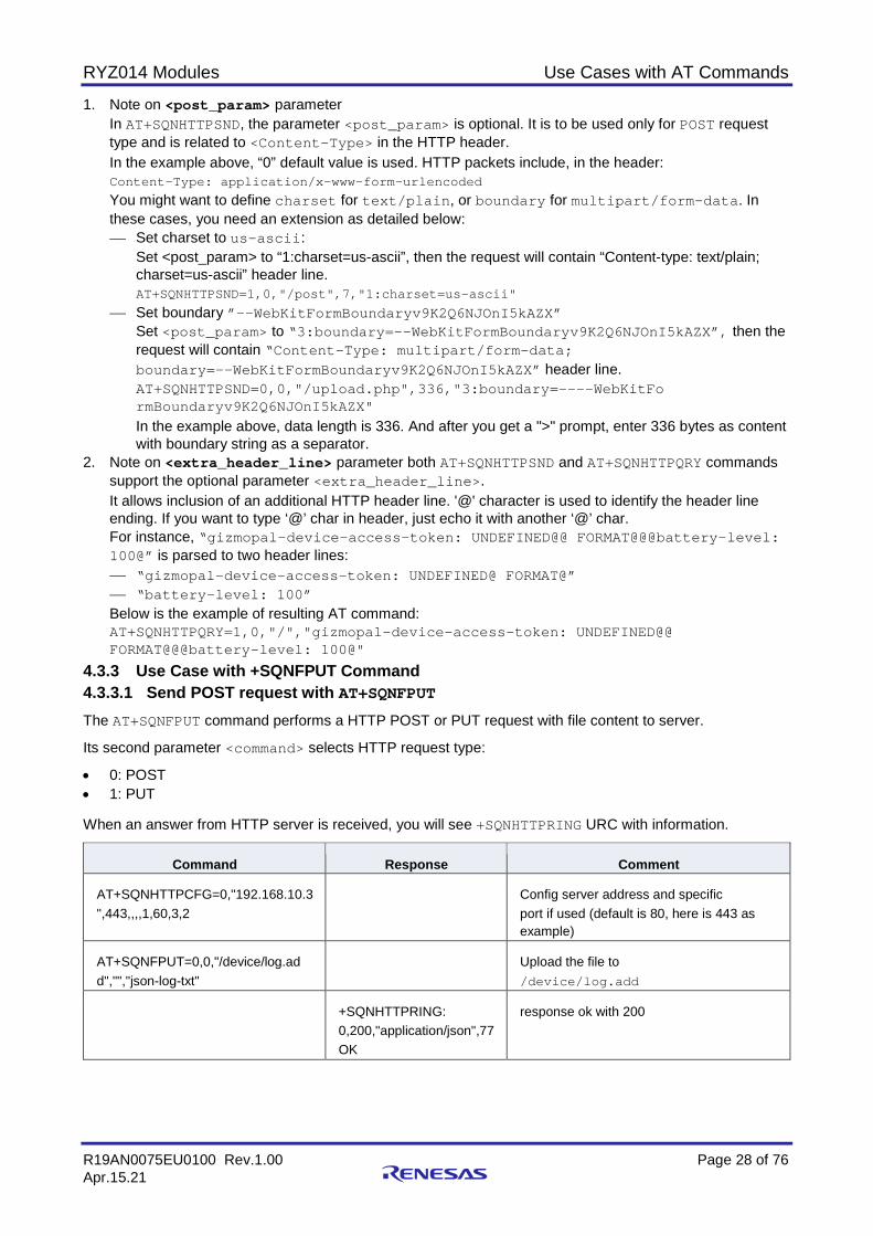
1. Note on <post_param> parameter In AT+SQNHTTPSND, the parameter <post_param> is optional. It is to be used only for POST request type and is related to <Content-Type> in the HTTP header. In the example above, “0” default value is used. HTTP packets include, in the header: Content-Type: application/x-www-form-urlencoded You might want to define charset for text/plain, or boundary for multipart/form-data. In these cases, you need an extension as detailed below: Set charset to us-ascii:
Set <post_param> to “1:charset=us-ascii”, then the request will contain “Content-type: text/plain; charset=us-ascii” header line. AT+SQNHTTPSND=1,0,"/post",7,"1:charset=us-ascii"
Set boundary ”—-WebKitFormBoundaryv9K2Q6NJOnI5kAZX” Set <post_param> to “3:boundary=—-WebKitFormBoundaryv9K2Q6NJOnI5kAZX”, then the request will contain “Content-Type: multipart/form-data; boundary=—-WebKitFormBoundaryv9K2Q6NJOnI5kAZX” header line. AT+SQNHTTPSND=0,0,"/upload.php",336,"3:boundary=----WebKitFo rmBoundaryv9K2Q6NJOnI5kAZX" In the example above, data length is 336. And after you get a ">" prompt, enter 336 bytes as content with boundary string as a separator.
2. Note on <extra_header_line> parameter both AT+SQNHTTPSND and AT+SQNHTTPQRY commands support the optional parameter <extra_header_line>. It allows inclusion of an additional HTTP header line. '@' character is used to identify the header line ending. If you want to type ‘@’ char in header, just echo it with another ‘@’ char. For instance, “gizmopal-device-access-token: UNDEFINED@@ FORMAT@@@battery-level: 100@” is parsed to two header lines: “gizmopal-device-access-token: UNDEFINED@ FORMAT@” “battery-level: 100” Below is the example of resulting AT command: AT+SQNHTTPQRY=1,0,"/","gizmopal-device-access-token: UNDEFINED@@ FORMAT@@@battery-level: 100@"
4.3.3 Use Case with +SQNFPUT Command 4.3.3.1 Send POST request with AT+SQNFPUT The AT+SQNFPUT command performs a HTTP POST or PUT request with file content to server.
Its second parameter <command> selects HTTP request type:
• 0: POST • 1: PUT When an answer from HTTP server is received, you will see +SQNHTTPRING URC with information.
Command Response Comment
AT+SQNHTTPCFG=0,"192.168.10.3 ",443,,,,1,60,3,2
Config server address and specific port if used (default is 80, here is 443 as example)
AT+SQNFPUT=0,0,"/device/log.ad d","","json-log-txt"
Upload the file to /device/log.add
+SQNHTTPRING: 0,200,"application/json",77 OK
response ok with 200
RYZ014 Modules Use Cases with AT Commands
R19AN0075EU0100 Rev.1.00 Page 29 of 76 Apr.15.21
4.3.4 Error Handling • +SQNHTTPSND is a synchronous command. The modem will not accept any other AT commands and
send any URC while the command is being executed. This command depends on the network conditions. Under bad RF condition, the command will take some time to execute. The user can define a timeout for this AT command with SQNHTTPCFG as shown in the example from section Use Case with +SQNFPUT Command: AT+SQNHTTPCFG=0,"192.168.10.3",443,,,,1,60,3,2 In this example, the timeout is set to 60 seconds.
• Terminator character for AT commands When sending HEX data with AT+SQNHTTPSND, if you get ERROR (CME_ERROR 4), please make sure first that the data to send is valid. If the data is confirmed valid, please check if you use the proper terminator for AT command. Only one char is allowed. The AT command syntax is described in the 3GPP 27.007 (§4.1 and §4.2) and ITU V250 (§5.2.1). The termination character is <CR> by default. For example when using <CR><LF> (“\r\n”) as terminator, it would be without impact for most of AT commands since the "\n" would be treated as invalid AT command. But for AT which need input data during executing, the second char <LF> ("\n") would stay in the buffer and be treated as input data. When sending data in text mode, the module will not return ERROR, but the server would receive data start with "\n" and this may trigger other problems. When sending data in HEX mode, it will trigger and ERROR immediately as "\n" is an invalid HEX char. The terminator char can be changed by ATS3 command, please refer to AT Commands User’s Manual for the detail. When developing an application on the host MCU based on AT commands, if no specific requirements are set, please use <CR> ("\r") as the terminator character.
4.4 How to Manage TLS Certificates 4.4.1 Feature Description For secured socket connections, it is necessary to write beforehand the certificate or private key in non-volatile memory (NV). AT+SQNSNVW is used to write or delete data in the non-volatile (NV) memory using “certificate” or “privatekey” parameters with the specific index in the file system.
The file size corresponds to the exact number of bytes to be uploaded.
After the AT+SQNSNVW write command is issued, the user sends certificate bytes in PEM (Privacy-enhanced Electronic Mail) format. To delete a certificate or privatekey, the user simply writes a ‘0’ byte certificate or privatekey using file ID as <index>.
Notes:
• RYZ014 module holds 20 slots to store certificates and 20 slots for private keys. These files are stored on the file system of the module. There is no specific limitation on the size of the certificate that can be stored at one given index other than the size of the file system itself.
• CA certificates chain is supported: it is possible to combine several root CA certificates into one. 4.4.2 Use Cases with Certificates Note: To get the file size, use Linux command “ls -l filename”, or DOS command “dir”, or open file
with Notepad to check its length.

RYZ014 Modules Use Cases with AT Commands
R19AN0075EU0100 Rev.1.00 Page 30 of 76 Apr.15.21
4.4.2.1 Add certificate at index 0
Command Response Comment
Upload certificate type file with size 1078 bytes into file system.
AT+SQNSNVW="certificate",0,1078
>
After prompt '>', enter the data from certificate file and type enter in the end.
-----BEGIN CERTIFICATE----- MIIC8DCCAlmgAwIBAgIJAOD63PlXjJi8MA0GCSqGSIb3DQEBBQUAMIGQMQswCQYD VA+GIbdYKO3JprPxSBoRponZJvDGEZuM3N7p3S/lRoi7G5wG5mvUmaE5RAgMBAAGj (...)REyPOFdGdhBY2P1FNRy0MDr6xr+D2ZOwxs63dG1nnAnWZg7qwoLgpZ4fESPD3PkA 1ZgKJc2zbSQ9fCPxt2W3mdVav66c6fsb7els2W2Iz7gERJSX -----END CERTIFICATE-----
OK 4.4.2.2 Read certificate at index 0
Command Response Comment AT+SQNSNVR="certificate",0 Read certificate at index 0 +SQNSNVR: "certificate",0,"/C=GB/ST=United
Kingdom/L=Derby/O=Mosquitto/OU=CA/CN=mosquitto.org/emailAddr [email protected]","0000000000000000000000000000000000000000000 000000000000000000000000000000000000000000(...)00000000000000000000 00000000000000000000000000000000000","/C=GB/ST=United Kingdom/L=Derby/O=Mosquitto/OU=CA/CN=mosquitto.org/emailAddr [email protected]","12/06/29 22:11:59","22/06/27 22:11:59","sha1RSA","00000000000000000000","sha1","1d214e931ab1da59c 1e08f025f268d2783a51f0a" OK
4.4.2.3 Remove certificate at index 0
Command Response Comment AT+SQNSNVW="certificate",0,0 OK Remove certificate at index 0
RYZ014 Modules Use Cases with AT Commands
R19AN0075EU0100 Rev.1.00 Page 31 of 76 Apr.15.21
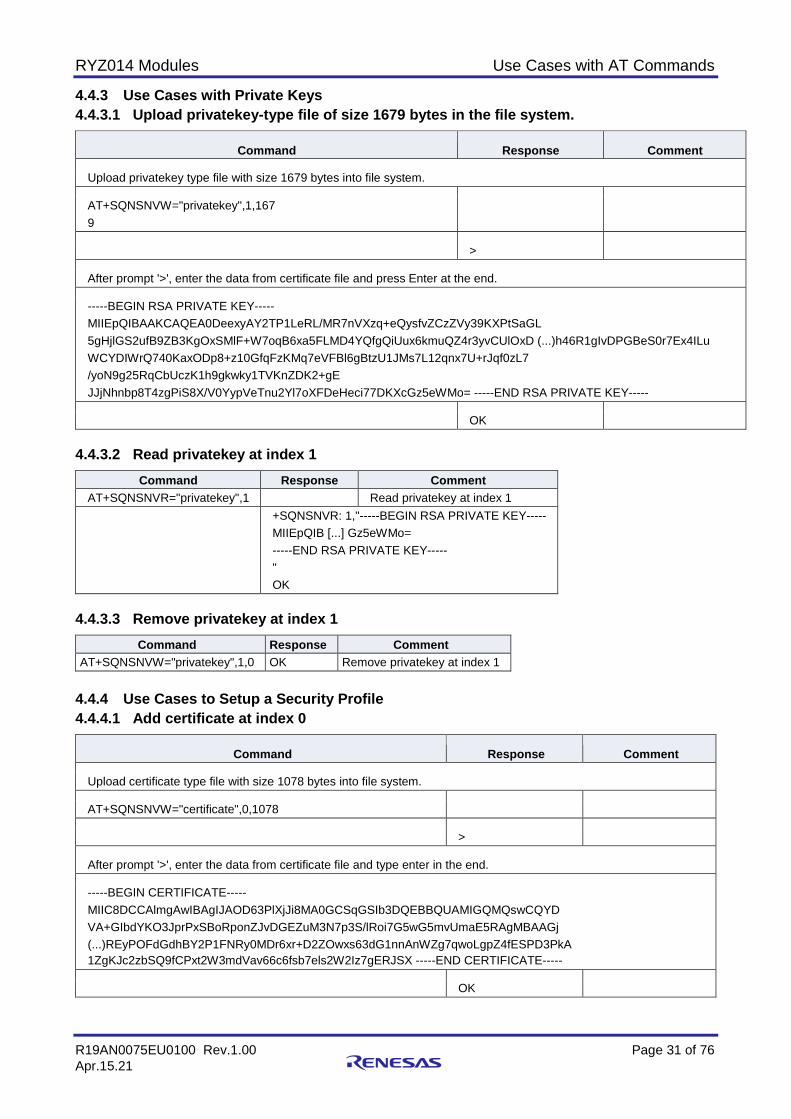
4.4.3 Use Cases with Private Keys 4.4.3.1 Upload privatekey-type file of size 1679 bytes in the file system.
Command Response Comment
Upload privatekey type file with size 1679 bytes into file system.
AT+SQNSNVW="privatekey",1,167 9
>
After prompt '>', enter the data from certificate file and press Enter at the end.
-----BEGIN RSA PRIVATE KEY----- MIIEpQIBAAKCAQEA0DeexyAY2TP1LeRL/MR7nVXzq+eQysfvZCzZVy39KXPtSaGL 5gHjlGS2ufB9ZB3KgOxSMlF+W7oqB6xa5FLMD4YQfgQiUux6kmuQZ4r3yvCUlOxD (...)h46R1gIvDPGBeS0r7Ex4ILu WCYDIWrQ740KaxODp8+z10GfqFzKMq7eVFBl6gBtzU1JMs7L12qnx7U+rJqf0zL7 /yoN9g25RqCbUczK1h9gkwky1TVKnZDK2+gE JJjNhnbp8T4zgPiS8X/V0YypVeTnu2Yl7oXFDeHeci77DKXcGz5eWMo= -----END RSA PRIVATE KEY-----
OK 4.4.3.2 Read privatekey at index 1
Command Response Comment AT+SQNSNVR="privatekey",1 Read privatekey at index 1 +SQNSNVR: 1,"-----BEGIN RSA PRIVATE KEY-----
MIIEpQIB [...] Gz5eWMo= -----END RSA PRIVATE KEY----- " OK
4.4.3.3 Remove privatekey at index 1
Command Response Comment AT+SQNSNVW="privatekey",1,0 OK Remove privatekey at index 1
4.4.4 Use Cases to Setup a Security Profile 4.4.4.1 Add certificate at index 0
Command Response Comment
Upload certificate type file with size 1078 bytes into file system.
AT+SQNSNVW="certificate",0,1078
>
After prompt '>', enter the data from certificate file and type enter in the end.
-----BEGIN CERTIFICATE----- MIIC8DCCAlmgAwIBAgIJAOD63PlXjJi8MA0GCSqGSIb3DQEBBQUAMIGQMQswCQYD VA+GIbdYKO3JprPxSBoRponZJvDGEZuM3N7p3S/lRoi7G5wG5mvUmaE5RAgMBAAGj (...)REyPOFdGdhBY2P1FNRy0MDr6xr+D2ZOwxs63dG1nnAnWZg7qwoLgpZ4fESPD3PkA 1ZgKJc2zbSQ9fCPxt2W3mdVav66c6fsb7els2W2Iz7gERJSX -----END CERTIFICATE-----
OK
RYZ014 Modules Use Cases with AT Commands
R19AN0075EU0100 Rev.1.00 Page 32 of 76 Apr.15.21
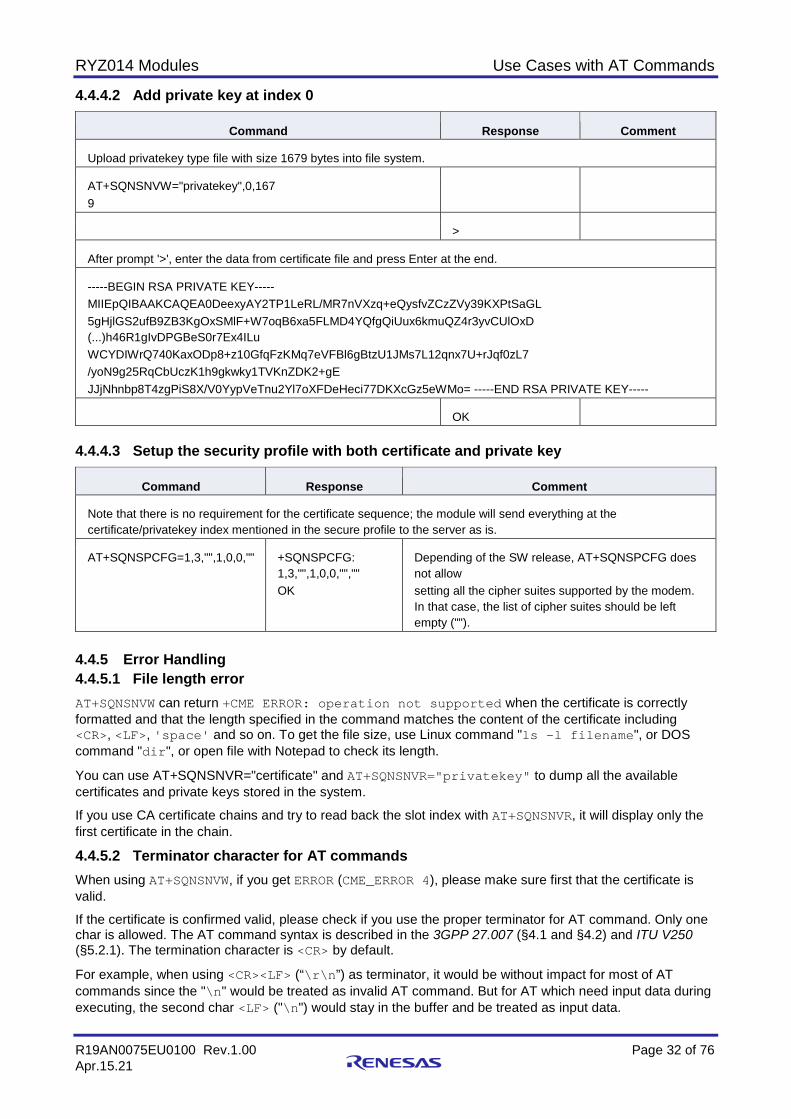
4.4.4.2 Add private key at index 0
Command Response Comment
Upload privatekey type file with size 1679 bytes into file system.
AT+SQNSNVW="privatekey",0,167 9
>
After prompt '>', enter the data from certificate file and press Enter at the end.
-----BEGIN RSA PRIVATE KEY----- MIIEpQIBAAKCAQEA0DeexyAY2TP1LeRL/MR7nVXzq+eQysfvZCzZVy39KXPtSaGL 5gHjlGS2ufB9ZB3KgOxSMlF+W7oqB6xa5FLMD4YQfgQiUux6kmuQZ4r3yvCUlOxD (...)h46R1gIvDPGBeS0r7Ex4ILu WCYDIWrQ740KaxODp8+z10GfqFzKMq7eVFBl6gBtzU1JMs7L12qnx7U+rJqf0zL7 /yoN9g25RqCbUczK1h9gkwky1TVKnZDK2+gE JJjNhnbp8T4zgPiS8X/V0YypVeTnu2Yl7oXFDeHeci77DKXcGz5eWMo= -----END RSA PRIVATE KEY-----
OK 4.4.4.3 Setup the security profile with both certificate and private key
Command Response Comment
Note that there is no requirement for the certificate sequence; the module will send everything at the certificate/privatekey index mentioned in the secure profile to the server as is.
AT+SQNSPCFG=1,3,"",1,0,0,"" +SQNSPCFG: 1,3,"",1,0,0,"","" OK
Depending of the SW release, AT+SQNSPCFG does not allow setting all the cipher suites supported by the modem. In that case, the list of cipher suites should be left empty ("").
4.4.5 Error Handling 4.4.5.1 File length error AT+SQNSNVW can return +CME ERROR: operation not supported when the certificate is correctly formatted and that the length specified in the command matches the content of the certificate including <CR>, <LF>, 'space' and so on. To get the file size, use Linux command "ls -l filename", or DOS command "dir", or open file with Notepad to check its length.
You can use AT+SQNSNVR="certificate" and AT+SQNSNVR="privatekey" to dump all the available certificates and private keys stored in the system.
If you use CA certificate chains and try to read back the slot index with AT+SQNSNVR, it will display only the first certificate in the chain.
4.4.5.2 Terminator character for AT commands When using AT+SQNSNVW, if you get ERROR (CME_ERROR 4), please make sure first that the certificate is valid.
If the certificate is confirmed valid, please check if you use the proper terminator for AT command. Only one char is allowed. The AT command syntax is described in the 3GPP 27.007 (§4.1 and §4.2) and ITU V250 (§5.2.1). The termination character is <CR> by default.
For example, when using <CR><LF> (“\r\n”) as terminator, it would be without impact for most of AT commands since the "\n" would be treated as invalid AT command. But for AT which need input data during executing, the second char <LF> ("\n") would stay in the buffer and be treated as input data.
RYZ014 Modules Use Cases with AT Commands
R19AN0075EU0100 Rev.1.00 Page 33 of 76 Apr.15.21
When sending data in text mode, the module will not return ERROR, but the server would receive data start with "\n" and this may trigger other problems. When sending data in HEX mode, it will trigger and ERROR immediately as "\n" is an invalid HEX char.
The terminator char can be changed by ATS3 command, please refer to AT Commands User’s Manual for the detail.
When developing an application on the host MCU based on AT commands, if no specific requirements are set, please use <CR> ("\r") as the terminator character.
4.4.5.3 +SQNSPCFG Command Depending of the software release, AT+SQNSPCFG might not allow setting all the cipher suites supported by the modem. In that case, the list of cipher suites should be left empty ("").
4.4.5.4 Reading chain of CA certificates When reading out a CA certificates chain with AT+SQNSNVR, only the first certificate is displayed.
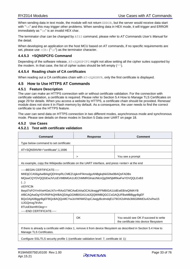
4.5 How to Use HTTPS AT Commands 4.5.1 Feature Description The user can make an HTTPS connection with or without certificate validation. For the connection with certificate validation, a certificate is required. Please refer to Section 5.4 How to Manage TLS Certificates on page 29 for details. When you access a website by HTTPS, a certificate chain should be provided. Renesas’ module does not store it in Flash memory by default. As a consequence, the user needs to find the correct certificate to use the HTTPS feature.
The user can send data on HTTPS connection in two different modes, asynchronous mode and synchronous mode. Please see details on these modes in Section 5 Data over UART on page 18.
4.5.2 Use Cases 4.5.2.1 Test with certificate validation
Command Response Comment
Type below command to set certificate:
AT+SQNSNVW="certificate",1,1696
> You see a prompt
As example, copy the Wikipedia certificate on the UART interface, and press <enter> at the end
-----BEGIN CERTIFICATE----- MIIEtjCCA56gAwIBAgIQDHmpRLCMEZUgkmFf4msdgzANBgkqhkiG9w0BAQsFADBs MQswCQYDVQQGEwJVUzEVMBMGA1UEChMMRGlnaUNlcnQgSW5jMRkwFwYDVQQLExB3 (...) c63YlC3k 8wyd7sFOYn4XwHGeLN7x+RAoGTMCAwEAAaOCAUkwggFFMBIGA1UdEwEB/wQIMAYB Af8CAQAwDgYDVR0PAQH/BAQDAgGGMB0GA1UdJQQWMBQGCCsGAQUFBwMBBggrBgEF BQcDAjA0BggrBgEFBQcBAQQoMCYwJoVWNWlZopCJwqjyBcdmdqEU79OX2olHdx3ti6G8MdOu42vi/hw15 UJGQmxg7kVkn 8TUoE6smftX3eg== -----END CERTIFICATE-----
OK You would see OK if succeed to write the certificate into device filesystem
If there is already a certificate with index 1, remove it from device filesystem as described in Section 5.4 How to Manage TLS Certificates.
Configure SSL/TLS security profile 1 (certificate validation level: 7, certificate id: 1):

RYZ014 Modules Use Cases with AT Commands
R19AN0075EU0100 Rev.1.00 Page 34 of 76 Apr.15.21
Command Response Comment
AT+SQNSPCFG=1,2,"",7,1
+SQNSPCFG: 1,2,"",7,1,,,"" OK
Configure http profile 0(cid: 1, security profile: 1):
AT+SQNHTTPCFG=0,"github.com",443,0,"","",1,120,1,1
OK
AT+SQNHTTPQRY=0,0,"/" OK Send a HTTP “Get” query on profile 0:
if succeed you would get an URC later: +SQNHTTPRING: 0,200,"text/html; charset=utf-8",0 AT+SQNHTTPRCV=0,0 Read the body of http response: You would see a prompt ”<<<”, then the whole data followed by an OK. <<<
... OK
4.5.2.2 Test with no certificate in filesystem This test follows the previous test with certificate validation.
Command Response Comment
Remove certificate from device filesystem.
AT+SQNSNVW="certificate",1,0 OK The third parameter 0 means removing the appointed certificate.
AT+SQNHTTPQRY=0,0,"/" OK Send a HTTP “Get” query on profile 0:
Result status, and URC which indicates no HTTP response:
+SQNHTTPRING: 0,0,"",0
Configure SSL/TLS security profile 1 with no certificate validation:
AT+SQNSPCFG=1,2,"",0
+SQNSPCFG: 1,2,"",0,,,,"" OK
AT+SQNHTTPQRY=0,0,"/" OK Send a HTTP “Get” query on profile 0:
If result status is OK, an URC will be received:
+SQNHTTPRING: 0,200,"text/html",74711
AT+SQNHTTPRCV=0,0 Read the body of HTTP response:
<<< ... OK

RYZ014 Modules Use Cases with AT Commands
R19AN0075EU0100 Rev.1.00 Page 35 of 76 Apr.15.21
4.6 How to Use TFTP AT Commands 4.6.1 Feature Description The user can send data on TFTP connection in two different modes, asynchronous mode and synchronous mode. Please see details on these modes in Section 5 Data over UART on page 18.
The AT commands for TFTP support are:
• AT+SQNFGET: File download command • AT+SQNFGETDATA: Read asynchronously received data (asynchronous) • +SQNFGETREPORT: Download status URC (asynchronous) • +SQNFGETRING: Download size URC (asynchronous) Note: Refer to AT Commands User’s Manual for detailed description of the commands.
Command Response Comment
AT+SQNFGET="tftp://192.168.13.1/test.txt",0 Start downloading by TFTP
OK
+SQNFGETREPORT: "started" +SQNFGETRING: 114 +SQNFGETREPORT: "downloading"
Receive “download status” URC and “download size” URC:
AT+SQNFGETDATA Read received data
You would see the content displayed then, followed by a result status.
[Data] OK
If all data are received, you will get the download status URC to indicate that the download is complete.
+SQNFGETREPORT: "complete" 4.6.2 Use Cases The example detailed in this section is the typical application of downloading a file to the Host (MCU/PC/…) in asynchronous mode.
4.7 How to Use FTP AT Commands 4.7.1 Feature Description The user can send data on FTP connection in two different modes, asynchronous mode and synchronous mode. Please see details on these modes in Section 5 Data over UART on page 18.
The AT commands for TFTP support are: • AT+SQNFGET: File download command • AT+SQNFGETDATA: Read asynchronously received data (asynchronous) • +SQNFGETREPORT: Download status URC (asynchronous) • +SQNFGETRING: Download size URC (asynchronous) Note: In asynchronous mode, the <local_filename> parameter of AT+SQNFGET command is used for
local save of the file to the file system, in /fs/local_filename. If <local_filename> parameter is not provided, then the received data is accumulated in internal buffer, and you need to use AT+SQNFGETDATA command to read it.
Note: Refer to AT Commands User’s Manual for detailed description of the commands.

RYZ014 Modules Use Cases with AT Commands
R19AN0075EU0100 Rev.1.00 Page 36 of 76 Apr.15.21
4.7.2 Use Cases 4.7.2.1 Synchronous mode
Command Response Comment
Download the test file from the remote FTP server 192.168.10.1 and save the file as mylocalfile on the device’s file system.
AT+SQNFGET="ftp://192.168.10.1/testfile",1,"mylocalfile"
OK
The possible status values are: started, downloading, error, complete, not running
AT+SQNFGET? +SQNFGET: "complete" OK
Read the status.
4.7.2.2 Asynchronous mode
Command Response Comment
Download the test file from the remote ftp server 192.168.10.1 and save the file as mylocalfile on the device’s file system.
AT+SQNFGET="ftp://192.168.10.1/testfile",0,"mylocalfile" If <local_filename> is omitted, the received data is accumulated in internal buffer
OK
+SQNFGETREPORT: "started" +SQNFGETRING: 200 +SQNFGETREPORT: "downloading" +SQNFGETREPORT: "complete"
AT+SQNFGET="ftp://192.168.10.1/testfile",0
OK
+SQNFGETREPORT: "started" +SQNFGETRING: 200 +SQNFGETREPORT: "downloading" +SQNFGETREPORT: "complete"
AT+SQNFGETDATA Read internal buffer
[Data] OK
4.8 How to Use MQTT Commands 4.8.1 Feature Description 4.8.1.1 AT Commands Renesas provides the following set of dedicated AT commands to implement MQTT protocol:

RYZ014 Modules Use Cases with AT Commands
R19AN0075EU0100 Rev.1.00 Page 37 of 76 Apr.15.21
• Configure MQTT client: +SQNSMQTTCFG • Initiate a MQTT client connection to a broker: +SQNSMQTTCONNECT • Subscribe client to MQTT topic on a broker: +SQNSMQTTSUBSCRIBE • Publish payload text message into MQTT topic: +SQNSMQTTPUBLISH • Disconnect MQTT client by id: +SQNSMQTTDISCONNECT • Receive MQTT message: +SQNSMQTTRCVMESSAGE Important: There is no AT command to unsubscribe from a topic.
4.8.1.2 MQTT and TLS MQTT relies on TCP as transport protocol, which means by default the connection does not use an encrypted communication. To encrypt the whole MQTT communication, most MQTT brokers allow to use TLS in addition to the standard username/password authentication.
While it is enough for the server to use a private/public key pair to establish a secure connection, some clients can handle a unique public/private key pair which can be used in the TLS handshake. The client sends its certificate (which includes the public key of the client) as part of the TLS handshake after the server certificate is validated. The server is then able to verify the identity of the client and can abort the handshake if the verification of the client certificate fails. This allows authenticating the client before a secure connection is established.
Most of the IoT platforms such as AWS IoT, Google IoT Core and Orange Live Objects are using this approach.
The AT command AT+SQNSNVW should be used to upload the certificates on the device (refer to Section 5.8 How to Use MQTT Commands on page 36 for more details).
The AT command AT+SQNSPCFG sets the security profile parameters required to configure the following SSL/TLS connections properties.
4.8.1.3 MQTT Server AWS IoT platform, Cloud IoT Core or any other MQTT server can be used tests and usage. Another test server is mosquitto https://test.mosquitto.org/.
4.8.2 Mosquitto Mosquitto is a MQTT open source test server: https://test.mosquitto.org/.
This server can run on a local setup.
To test MQTTS connection, use openssl to generate certificate and keys.
4.8.3 AWS IoT AWS IoT provides secure, bi-directional communication between Internet-connected devices such as sensors, actuators, embedded micro-controllers, or smart appliances and the AWS Cloud. This enables to collect telemetry data from multiple devices, store and analyze the data.
To use AWS IOT you need to get an AWS account (Note that Amazon offers the possibility to open free accounts: https://aws.amazon.com/free/?all-free-tier.sort-by=item.additionalFields.Sort Rank&all-free-tier.sort-order=asc). You first need to register under https://aws.amazon.com/iot/. For detail information about AWS IOT, please refer to http://docs.aws.amazon.com/iot/latest/developerguide/what-is-aws-iot.html.
Then, you need to create an AWS IOT Thing for your device as follows. When you login to your AWS IOT console, you need to register your device in the AWS IOT registry. AWS IOT provides the detail developer guides on how to register a device, create and activate certificates here:
https://docs.aws.amazon.com/en_us/iot/latest/developerguide/register-device .html
Once the certificates are created, you will get the device public and private keys, the device certificate and the root certificate authority (CA).
You need to download:
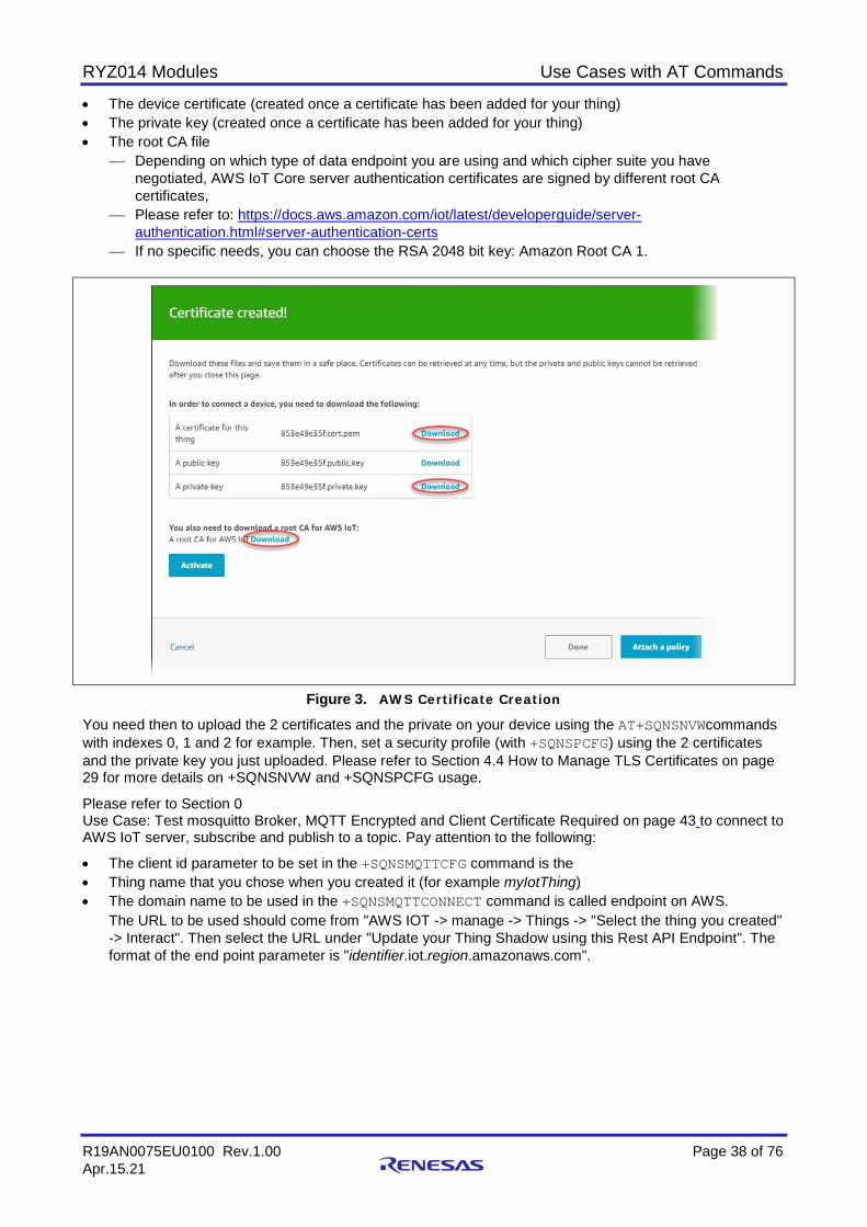
RYZ014 Modules Use Cases with AT Commands
R19AN0075EU0100 Rev.1.00 Page 38 of 76 Apr.15.21
• The device certificate (created once a certificate has been added for your thing) • The private key (created once a certificate has been added for your thing) • The root CA file
Depending on which type of data endpoint you are using and which cipher suite you have negotiated, AWS IoT Core server authentication certificates are signed by different root CA certificates,
Please refer to: https://docs.aws.amazon.com/iot/latest/developerguide/server-authentication.html#server-authentication-certs
If no specific needs, you can choose the RSA 2048 bit key: Amazon Root CA 1.
Figure 3. AWS Certificate Creation You need then to upload the 2 certificates and the private on your device using the AT+SQNSNVWcommands with indexes 0, 1 and 2 for example. Then, set a security profile (with +SQNSPCFG) using the 2 certificates and the private key you just uploaded. Please refer to Section 4.4 How to Manage TLS Certificates on page 29 for more details on +SQNSNVW and +SQNSPCFG usage.
Please refer to Section 0 Use Case: Test mosquitto Broker, MQTT Encrypted and Client Certificate Required on page 43 to connect to AWS IoT server, subscribe and publish to a topic. Pay attention to the following:
• The client id parameter to be set in the +SQNSMQTTCFG command is the • Thing name that you chose when you created it (for example myIotThing) • The domain name to be used in the +SQNSMQTTCONNECT command is called endpoint on AWS.
The URL to be used should come from "AWS IOT -> manage -> Things -> "Select the thing you created" -> Interact". Then select the URL under "Update your Thing Shadow using this Rest API Endpoint". The format of the end point parameter is "identifier.iot.region.amazonaws.com".
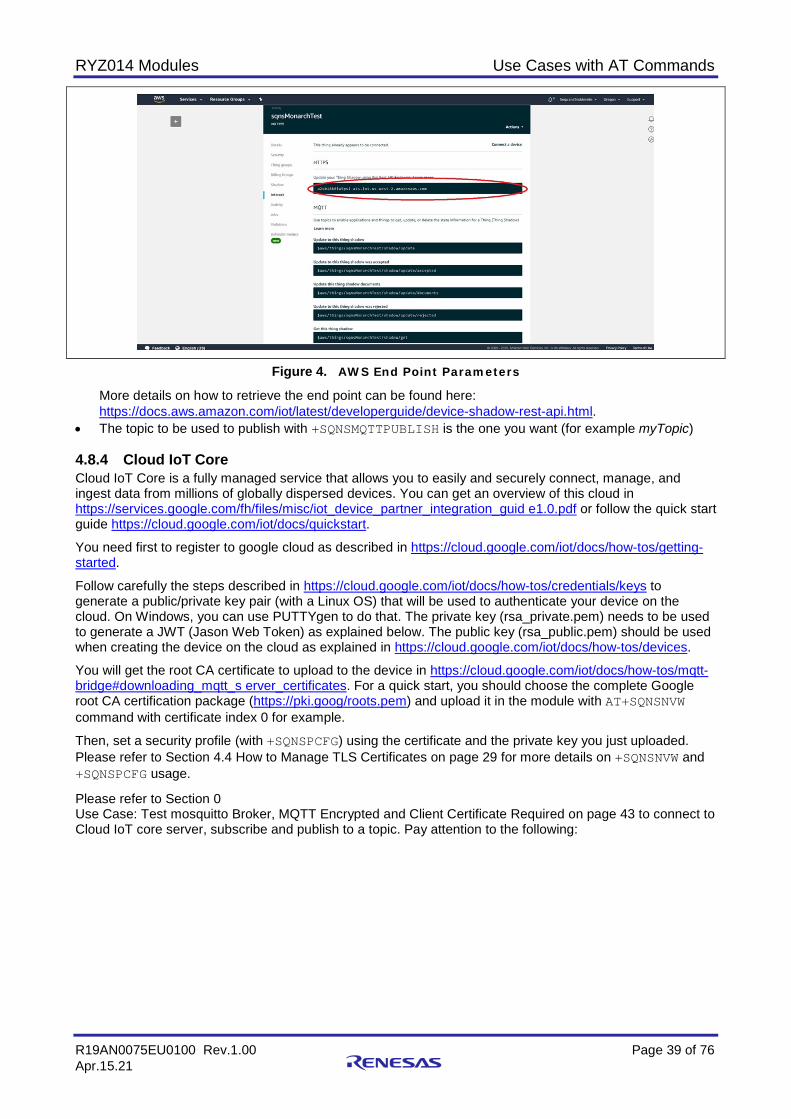
RYZ014 Modules Use Cases with AT Commands
R19AN0075EU0100 Rev.1.00 Page 39 of 76 Apr.15.21
Figure 4. AWS End Point Parameters
More details on how to retrieve the end point can be found here: https://docs.aws.amazon.com/iot/latest/developerguide/device-shadow-rest-api.html.
• The topic to be used to publish with +SQNSMQTTPUBLISH is the one you want (for example myTopic) 4.8.4 Cloud IoT Core Cloud IoT Core is a fully managed service that allows you to easily and securely connect, manage, and ingest data from millions of globally dispersed devices. You can get an overview of this cloud in https://services.google.com/fh/files/misc/iot_device_partner_integration_guid e1.0.pdf or follow the quick start guide https://cloud.google.com/iot/docs/quickstart.
You need first to register to google cloud as described in https://cloud.google.com/iot/docs/how-tos/getting-started.
Follow carefully the steps described in https://cloud.google.com/iot/docs/how-tos/credentials/keys to generate a public/private key pair (with a Linux OS) that will be used to authenticate your device on the cloud. On Windows, you can use PUTTYgen to do that. The private key (rsa_private.pem) needs to be used to generate a JWT (Jason Web Token) as explained below. The public key (rsa_public.pem) should be used when creating the device on the cloud as explained in https://cloud.google.com/iot/docs/how-tos/devices.
You will get the root CA certificate to upload to the device in https://cloud.google.com/iot/docs/how-tos/mqtt-bridge#downloading_mqtt_s erver_certificates. For a quick start, you should choose the complete Google root CA certification package (https://pki.goog/roots.pem) and upload it in the module with AT+SQNSNVW command with certificate index 0 for example.
Then, set a security profile (with +SQNSPCFG) using the certificate and the private key you just uploaded. Please refer to Section 4.4 How to Manage TLS Certificates on page 29 for more details on +SQNSNVW and +SQNSPCFG usage.
Please refer to Section 0 Use Case: Test mosquitto Broker, MQTT Encrypted and Client Certificate Required on page 43 to connect to Cloud IoT core server, subscribe and publish to a topic. Pay attention to the following:
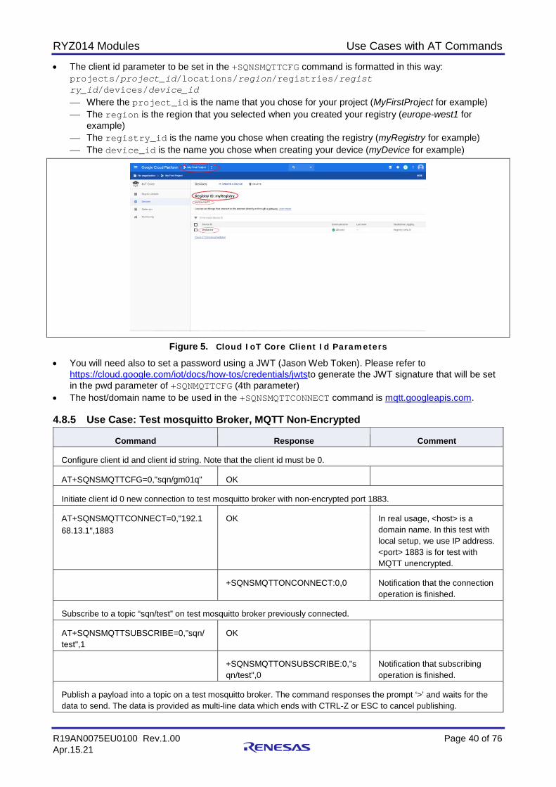
RYZ014 Modules Use Cases with AT Commands
R19AN0075EU0100 Rev.1.00 Page 40 of 76 Apr.15.21
• The client id parameter to be set in the +SQNSMQTTCFG command is formatted in this way: projects/project_id/locations/region/registries/regist ry_id/devices/device_id Where the project_id is the name that you chose for your project (MyFirstProject for example) The region is the region that you selected when you created your registry (europe-west1 for
example) The registry_id is the name you chose when creating the registry (myRegistry for example) The device_id is the name you chose when creating your device (myDevice for example)
Figure 5. Cloud IoT Core Client Id Parameters • You will need also to set a password using a JWT (Jason Web Token). Please refer to
https://cloud.google.com/iot/docs/how-tos/credentials/jwtsto generate the JWT signature that will be set in the pwd parameter of +SQNMQTTCFG (4th parameter)
• The host/domain name to be used in the +SQNSMQTTCONNECT command is mqtt.googleapis.com. 4.8.5 Use Case: Test mosquitto Broker, MQTT Non-Encrypted
Command Response Comment
Configure client id and client id string. Note that the client id must be 0.
AT+SQNSMQTTCFG=0,"sqn/gm01q" OK
Initiate client id 0 new connection to test mosquitto broker with non-encrypted port 1883.
AT+SQNSMQTTCONNECT=0,"192.1 68.13.1",1883
OK In real usage, <host> is a domain name. In this test with local setup, we use IP address. <port> 1883 is for test with MQTT unencrypted.
+SQNSMQTTONCONNECT:0,0 Notification that the connection operation is finished.
Subscribe to a topic “sqn/test” on test mosquitto broker previously connected.
AT+SQNSMQTTSUBSCRIBE=0,"sqn/ test",1
OK
+SQNSMQTTONSUBSCRIBE:0,"s qn/test",0
Notification that subscribing operation is finished.
Publish a payload into a topic on a test mosquitto broker. The command responses the prompt ‘>’ and waits for the data to send. The data is provided as multi-line data which ends with CTRL-Z or ESC to cancel publishing.
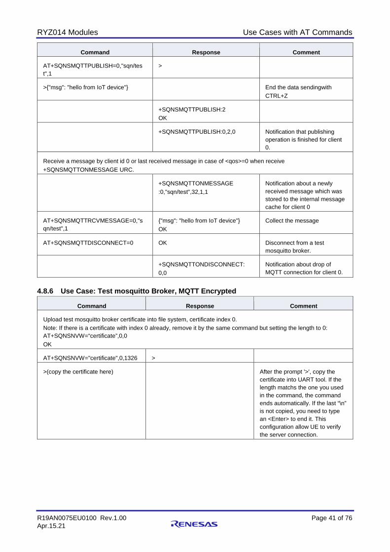
RYZ014 Modules Use Cases with AT Commands
R19AN0075EU0100 Rev.1.00 Page 41 of 76 Apr.15.21
Command Response Comment
AT+SQNSMQTTPUBLISH=0,"sqn/tes t",1
>
>{"msg": "hello from IoT device"} End the data sendingwith CTRL+Z
+SQNSMQTTPUBLISH:2 OK
+SQNSMQTTPUBLISH:0,2,0 Notification that publishing operation is finished for client 0.
Receive a message by client id 0 or last received message in case of <qos>=0 when receive +SQNSMQTTONMESSAGE URC.
+SQNSMQTTONMESSAGE :0,"sqn/test",32,1,1
Notification about a newly received message which was stored to the internal message cache for client 0
AT+SQNSMQTTRCVMESSAGE=0,"s qn/test",1
{"msg": "hello from IoT device"} OK
Collect the message
AT+SQNSMQTTDISCONNECT=0 OK Disconnect from a test mosquitto broker.
+SQNSMQTTONDISCONNECT: 0,0
Notification about drop of MQTT connection for client 0.
4.8.6 Use Case: Test mosquitto Broker, MQTT Encrypted
Command Response Comment
Upload test mosquitto broker certificate into file system, certificate index 0. Note: If there is a certificate with index 0 already, remove it by the same command but setting the length to 0: AT+SQNSNVW=“certificate”,0,0 OK
AT+SQNSNVW="certificate",0,1326 >
>(copy the certificate here) After the prompt '>', copy the certificate into UART tool. If the length matchs the one you used in the command, the command ends automatically. If the last “\n” is not copied, you need to type an <Enter> to end it. This configuration allow UE to verify the server connection.
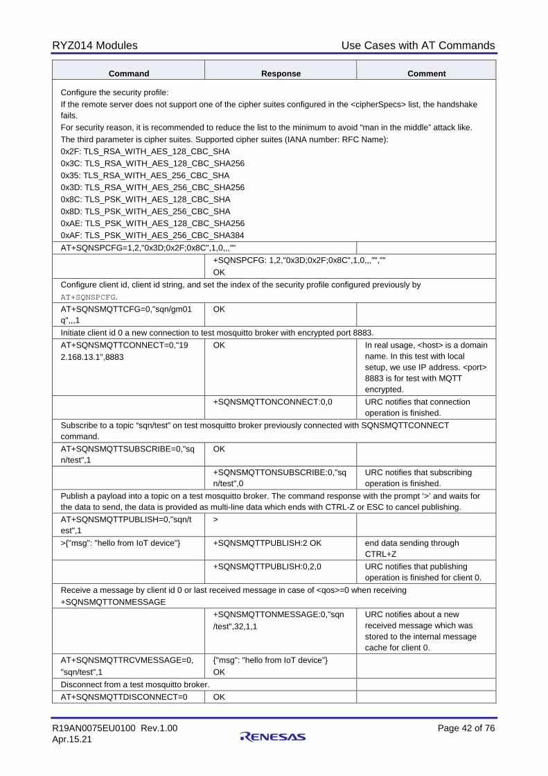
RYZ014 Modules Use Cases with AT Commands
R19AN0075EU0100 Rev.1.00 Page 42 of 76 Apr.15.21
Command Response Comment
Configure the security profile: If the remote server does not support one of the cipher suites configured in the <cipherSpecs> list, the handshake fails. For security reason, it is recommended to reduce the list to the minimum to avoid “man in the middle” attack like. The third parameter is cipher suites. Supported cipher suites (IANA number: RFC Name): 0x2F: TLS_RSA_WITH_AES_128_CBC_SHA 0x3C: TLS_RSA_WITH_AES_128_CBC_SHA256 0x35: TLS_RSA_WITH_AES_256_CBC_SHA 0x3D: TLS_RSA_WITH_AES_256_CBC_SHA256 0x8C: TLS_PSK_WITH_AES_128_CBC_SHA 0x8D: TLS_PSK_WITH_AES_256_CBC_SHA 0xAE: TLS_PSK_WITH_AES_128_CBC_SHA256 0xAF: TLS_PSK_WITH_AES_256_CBC_SHA384 AT+SQNSPCFG=1,2,"0x3D;0x2F;0x8C",1,0,,,"" +SQNSPCFG: 1,2,"0x3D;0x2F;0x8C",1,0,,,"",""
OK Configure client id, client id string, and set the index of the security profile configured previously by AT+SQNSPCFG. AT+SQNSMQTTCFG=0,"sqn/gm01 q",,,1
OK
Initiate client id 0 a new connection to test mosquitto broker with encrypted port 8883. AT+SQNSMQTTCONNECT=0,"19 2.168.13.1",8883
OK In real usage, <host> is a domain name. In this test with local setup, we use IP address. <port> 8883 is for test with MQTT encrypted.
+SQNSMQTTONCONNECT:0,0 URC notifies that connection operation is finished.
Subscribe to a topic “sqn/test” on test mosquitto broker previously connected with SQNSMQTTCONNECT command. AT+SQNSMQTTSUBSCRIBE=0,"sq n/test",1
OK
+SQNSMQTTONSUBSCRIBE:0,"sq n/test",0
URC notifies that subscribing operation is finished.
Publish a payload into a topic on a test mosquitto broker. The command response with the prompt ‘>’ and waits for the data to send, the data is provided as multi-line data which ends with CTRL-Z or ESC to cancel publishing. AT+SQNSMQTTPUBLISH=0,"sqn/t est",1
>
>{"msg": "hello from IoT device"} +SQNSMQTTPUBLISH:2 OK end data sending through CTRL+Z
+SQNSMQTTPUBLISH:0,2,0 URC notifies that publishing operation is finished for client 0.
Receive a message by client id 0 or last received message in case of <qos>=0 when receiving +SQNSMQTTONMESSAGE +SQNSMQTTONMESSAGE:0,"sqn
/test",32,1,1 URC notifies about a new received message which was stored to the internal message cache for client 0.
AT+SQNSMQTTRCVMESSAGE=0, "sqn/test",1
{"msg": "hello from IoT device"} OK
Disconnect from a test mosquitto broker. AT+SQNSMQTTDISCONNECT=0 OK
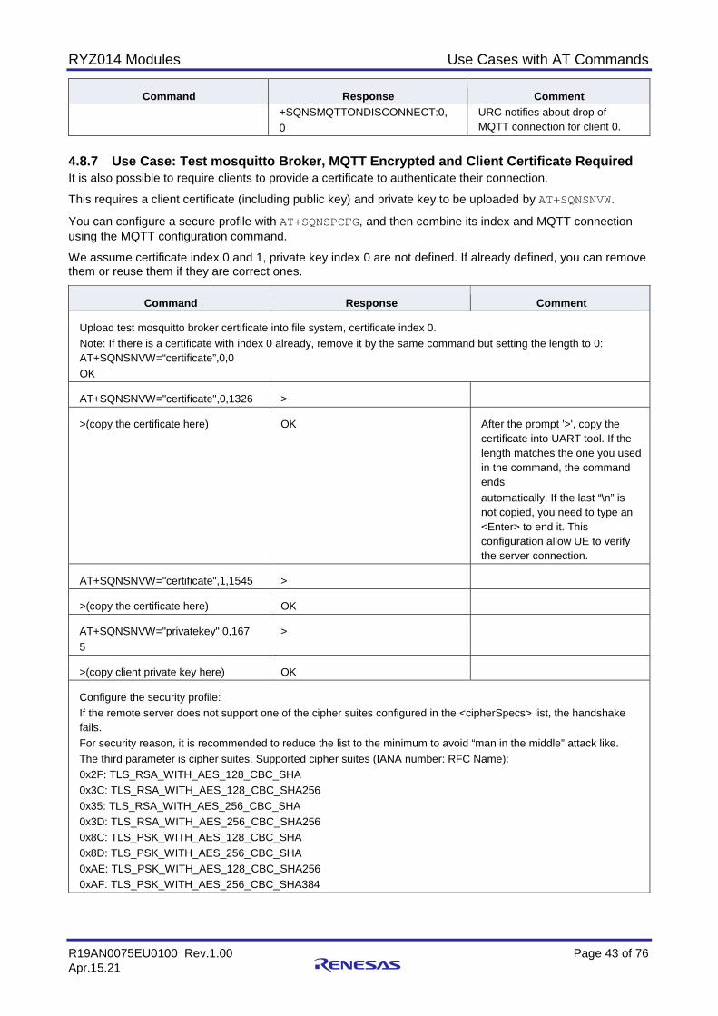
RYZ014 Modules Use Cases with AT Commands
R19AN0075EU0100 Rev.1.00 Page 43 of 76 Apr.15.21
Command Response Comment +SQNSMQTTONDISCONNECT:0,
0 URC notifies about drop of MQTT connection for client 0.
4.8.7 Use Case: Test mosquitto Broker, MQTT Encrypted and Client Certificate Required It is also possible to require clients to provide a certificate to authenticate their connection.
This requires a client certificate (including public key) and private key to be uploaded by AT+SQNSNVW.
You can configure a secure profile with AT+SQNSPCFG, and then combine its index and MQTT connection using the MQTT configuration command.
We assume certificate index 0 and 1, private key index 0 are not defined. If already defined, you can remove them or reuse them if they are correct ones.
Command Response Comment
Upload test mosquitto broker certificate into file system, certificate index 0. Note: If there is a certificate with index 0 already, remove it by the same command but setting the length to 0: AT+SQNSNVW=“certificate”,0,0 OK
AT+SQNSNVW="certificate",0,1326 >
>(copy the certificate here) OK After the prompt '>', copy the certificate into UART tool. If the length matches the one you used in the command, the command ends automatically. If the last “\n” is not copied, you need to type an <Enter> to end it. This configuration allow UE to verify the server connection.
AT+SQNSNVW="certificate",1,1545 >
>(copy the certificate here) OK
AT+SQNSNVW="privatekey",0,167 5
>
>(copy client private key here) OK
Configure the security profile: If the remote server does not support one of the cipher suites configured in the <cipherSpecs> list, the handshake fails. For security reason, it is recommended to reduce the list to the minimum to avoid “man in the middle” attack like. The third parameter is cipher suites. Supported cipher suites (IANA number: RFC Name): 0x2F: TLS_RSA_WITH_AES_128_CBC_SHA 0x3C: TLS_RSA_WITH_AES_128_CBC_SHA256 0x35: TLS_RSA_WITH_AES_256_CBC_SHA 0x3D: TLS_RSA_WITH_AES_256_CBC_SHA256 0x8C: TLS_PSK_WITH_AES_128_CBC_SHA 0x8D: TLS_PSK_WITH_AES_256_CBC_SHA 0xAE: TLS_PSK_WITH_AES_128_CBC_SHA256 0xAF: TLS_PSK_WITH_AES_256_CBC_SHA384
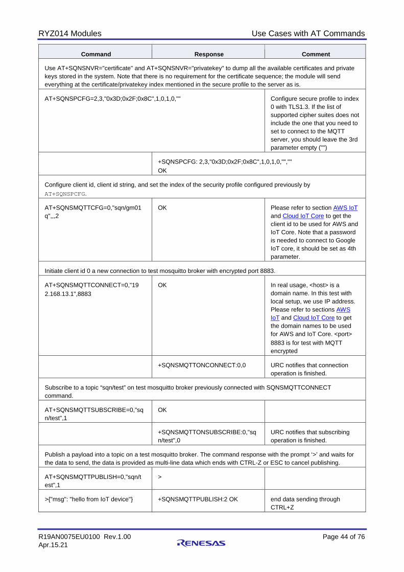
RYZ014 Modules Use Cases with AT Commands
R19AN0075EU0100 Rev.1.00 Page 44 of 76 Apr.15.21
Command Response Comment
Use AT+SQNSNVR="certificate" and AT+SQNSNVR="privatekey" to dump all the available certificates and private keys stored in the system. Note that there is no requirement for the certificate sequence; the module will send everything at the certificate/privatekey index mentioned in the secure profile to the server as is.
AT+SQNSPCFG=2,3,"0x3D;0x2F;0x8C",1,0,1,0,"" Configure secure profile to index 0 with TLS1.3. If the list of supported cipher suites does not include the one that you need to set to connect to the MQTT server, you should leave the 3rd parameter empty ("")
+SQNSPCFG: 2,3,"0x3D;0x2F;0x8C",1,0,1,0,"","" OK
Configure client id, client id string, and set the index of the security profile configured previously by AT+SQNSPCFG.
AT+SQNSMQTTCFG=0,"sqn/gm01 q",,,2
OK Please refer to section AWS IoT and Cloud IoT Core to get the client id to be used for AWS and IoT Core. Note that a password is needed to connect to Google IoT core, it should be set as 4th parameter.
Initiate client id 0 a new connection to test mosquitto broker with encrypted port 8883.
AT+SQNSMQTTCONNECT=0,"19 2.168.13.1",8883
OK In real usage, <host> is a domain name. In this test with local setup, we use IP address. Please refer to sections AWS IoT and Cloud IoT Core to get the domain names to be used for AWS and IoT Core. <port> 8883 is for test with MQTT encrypted
+SQNSMQTTONCONNECT:0,0 URC notifies that connection operation is finished.
Subscribe to a topic “sqn/test” on test mosquitto broker previously connected with SQNSMQTTCONNECT command.
AT+SQNSMQTTSUBSCRIBE=0,"sq n/test",1
OK
+SQNSMQTTONSUBSCRIBE:0,"sq n/test",0
URC notifies that subscribing operation is finished.
Publish a payload into a topic on a test mosquitto broker. The command response with the prompt ‘>’ and waits for the data to send, the data is provided as multi-line data which ends with CTRL-Z or ESC to cancel publishing.
AT+SQNSMQTTPUBLISH=0,"sqn/t est",1
>
>{"msg": "hello from IoT device"} +SQNSMQTTPUBLISH:2 OK end data sending through CTRL+Z
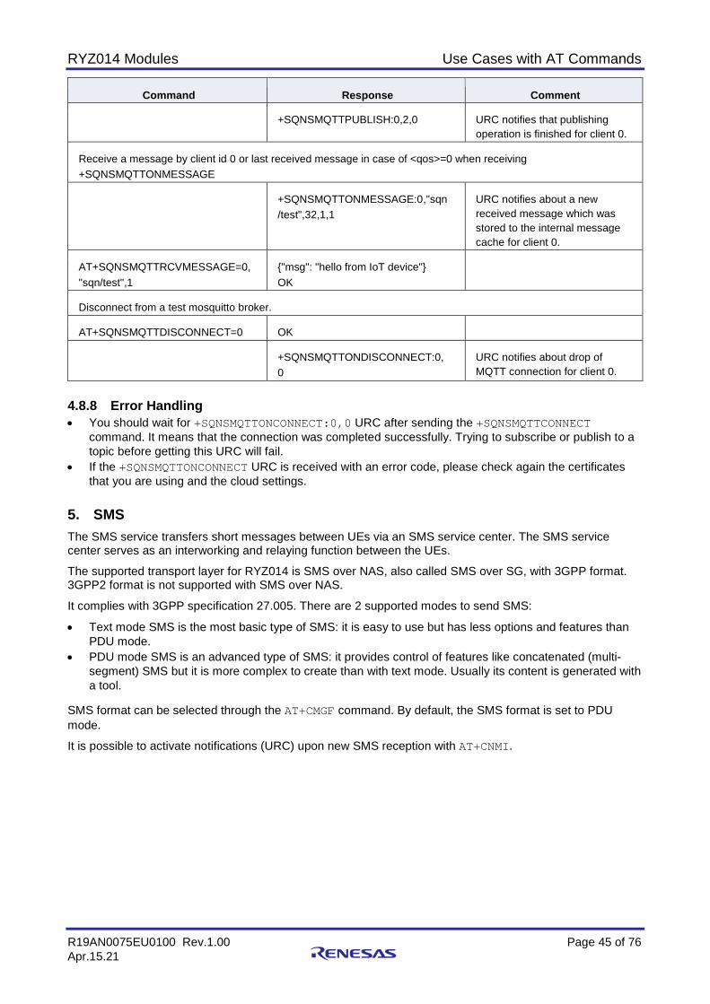
RYZ014 Modules Use Cases with AT Commands
R19AN0075EU0100 Rev.1.00 Page 45 of 76 Apr.15.21
Command Response Comment
+SQNSMQTTPUBLISH:0,2,0 URC notifies that publishing operation is finished for client 0.
Receive a message by client id 0 or last received message in case of <qos>=0 when receiving +SQNSMQTTONMESSAGE
+SQNSMQTTONMESSAGE:0,"sqn /test",32,1,1
URC notifies about a new received message which was stored to the internal message cache for client 0.
AT+SQNSMQTTRCVMESSAGE=0, "sqn/test",1
{"msg": "hello from IoT device"} OK
Disconnect from a test mosquitto broker.
AT+SQNSMQTTDISCONNECT=0 OK
+SQNSMQTTONDISCONNECT:0, 0
URC notifies about drop of MQTT connection for client 0.
4.8.8 Error Handling • You should wait for +SQNSMQTTONCONNECT:0,0 URC after sending the +SQNSMQTTCONNECT
command. It means that the connection was completed successfully. Trying to subscribe or publish to a topic before getting this URC will fail.
• If the +SQNSMQTTONCONNECT URC is received with an error code, please check again the certificates that you are using and the cloud settings.
5. SMS The SMS service transfers short messages between UEs via an SMS service center. The SMS service center serves as an interworking and relaying function between the UEs.
The supported transport layer for RYZ014 is SMS over NAS, also called SMS over SG, with 3GPP format. 3GPP2 format is not supported with SMS over NAS.
It complies with 3GPP specification 27.005. There are 2 supported modes to send SMS:
• Text mode SMS is the most basic type of SMS: it is easy to use but has less options and features than PDU mode.
• PDU mode SMS is an advanced type of SMS: it provides control of features like concatenated (multi-segment) SMS but it is more complex to create than with text mode. Usually its content is generated with a tool.
SMS format can be selected through the AT+CMGF command. By default, the SMS format is set to PDU mode.
It is possible to activate notifications (URC) upon new SMS reception with AT+CNMI.
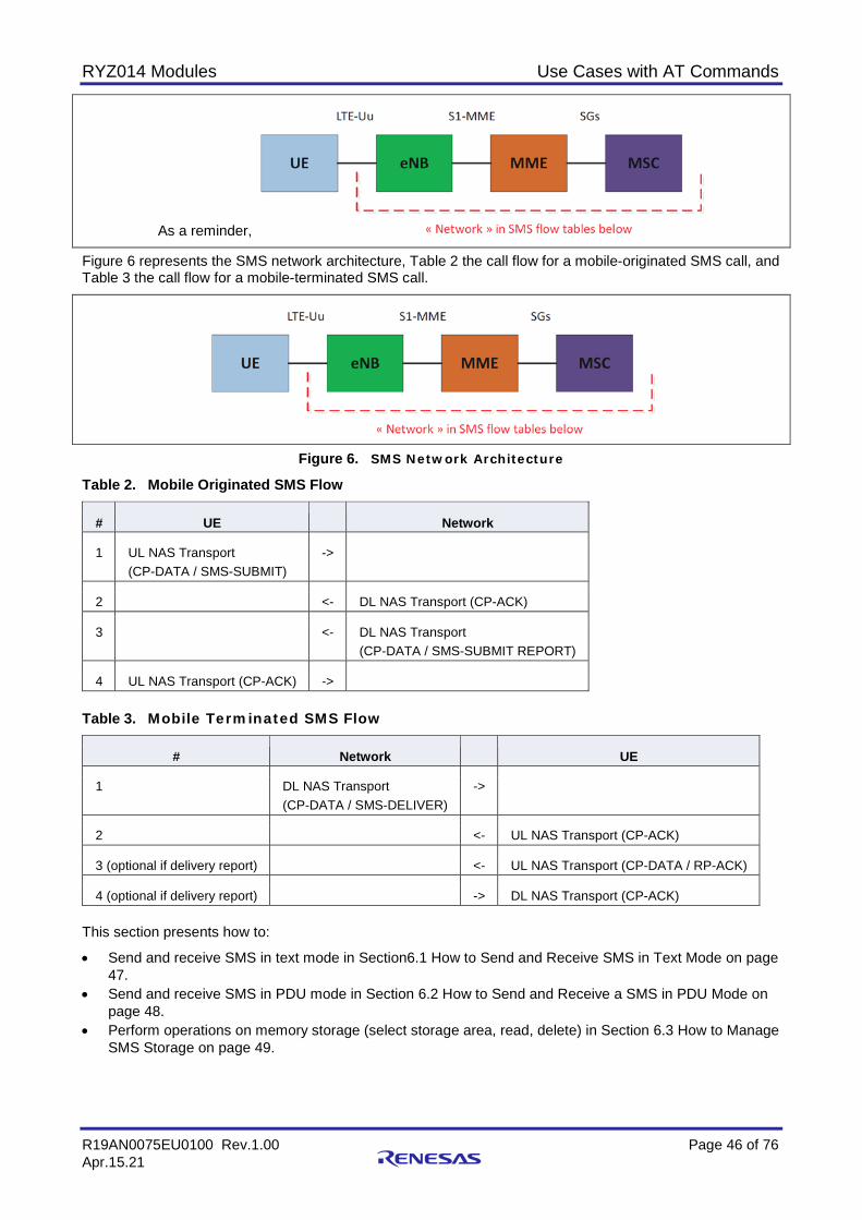
RYZ014 Modules Use Cases with AT Commands
R19AN0075EU0100 Rev.1.00 Page 46 of 76 Apr.15.21
As a reminder,
Figure 6 represents the SMS network architecture, Table 2 the call flow for a mobile-originated SMS call, and Table 3 the call flow for a mobile-terminated SMS call.
Figure 6. SMS Network Architecture
Table 2. Mobile Originated SMS Flow
# UE Network
1 UL NAS Transport (CP-DATA / SMS-SUBMIT)
->
2 <- DL NAS Transport (CP-ACK)
3 <- DL NAS Transport (CP-DATA / SMS-SUBMIT REPORT)
4 UL NAS Transport (CP-ACK) -> Table 3. Mobile Terminated SMS Flow
# Network UE
1 DL NAS Transport (CP-DATA / SMS-DELIVER)
->
2 <- UL NAS Transport (CP-ACK)
3 (optional if delivery report) <- UL NAS Transport (CP-DATA / RP-ACK)
4 (optional if delivery report) -> DL NAS Transport (CP-ACK) This section presents how to:
• Send and receive SMS in text mode in Section6.1 How to Send and Receive SMS in Text Mode on page 47.
• Send and receive SMS in PDU mode in Section 6.2 How to Send and Receive a SMS in PDU Mode on page 48.
• Perform operations on memory storage (select storage area, read, delete) in Section 6.3 How to Manage SMS Storage on page 49.
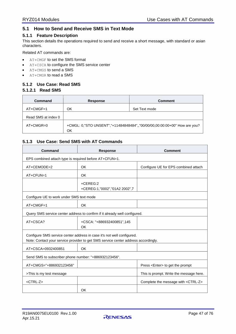
RYZ014 Modules Use Cases with AT Commands
R19AN0075EU0100 Rev.1.00 Page 47 of 76 Apr.15.21
5.1 How to Send and Receive SMS in Text Mode 5.1.1 Feature Description This section details the operations required to send and receive a short message, with standard or asian characters.
Related AT commands are:
• AT+CMGF to set the SMS format • AT+CSCA to configure the SMS service center • AT+CMGS to send a SMS • AT+CMGR to read a SMS 5.1.2 Use Case: Read SMS 5.1.2.1 Read SMS
Command Response Comment
AT+CMGF=1 OK Set Text mode
Read SMS at index 0
AT+CMGR=0 +CMGL: 0,"STO UNSENT","+11484848484",,"00/00/00,00:00:00+00" How are you? OK
5.1.3 Use Case: Send SMS with AT Commands
Command Response Comment
EPS combined attach type is required before AT+CFUN=1.
AT+CEMODE=2 OK Configure UE for EPS combined attach
AT+CFUN=1 OK
+CEREG:2 +CEREG:1,”0002”,”01A2 2002”,7
Configure UE to work under SMS text mode
AT+CMGF=1 OK
Query SMS service center address to confirm if it already well configured.
AT+CSCA? +CSCA: "+886932400851",145 OK
Configure SMS service center address in case it's not well configured. Note: Contact your service provider to get SMS service center address accordingly.
AT+CSCA=0932400851 OK
Send SMS to subscriber phone number: "+886932123456".
AT+CMGS="+886932123456" Press <Enter> to get the prompt
>This is my test message This is prompt. Write the message here.
<CTRL-Z> Complete the message with <CTRL-Z>
OK
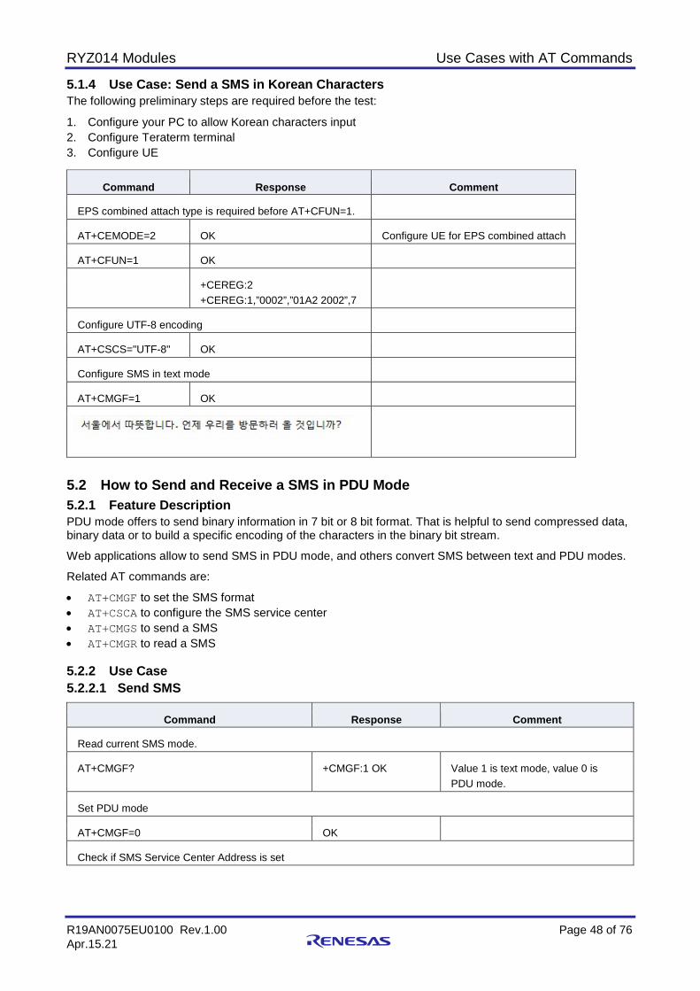
RYZ014 Modules Use Cases with AT Commands
R19AN0075EU0100 Rev.1.00 Page 48 of 76 Apr.15.21
5.1.4 Use Case: Send a SMS in Korean Characters The following preliminary steps are required before the test:
1. Configure your PC to allow Korean characters input 2. Configure Teraterm terminal 3. Configure UE
Command Response Comment
EPS combined attach type is required before AT+CFUN=1.
AT+CEMODE=2 OK Configure UE for EPS combined attach
AT+CFUN=1 OK
+CEREG:2 +CEREG:1,”0002”,”01A2 2002”,7
Configure UTF-8 encoding
AT+CSCS="UTF-8" OK
Configure SMS in text mode
AT+CMGF=1 OK
5.2 How to Send and Receive a SMS in PDU Mode 5.2.1 Feature Description PDU mode offers to send binary information in 7 bit or 8 bit format. That is helpful to send compressed data, binary data or to build a specific encoding of the characters in the binary bit stream.
Web applications allow to send SMS in PDU mode, and others convert SMS between text and PDU modes.
Related AT commands are:
• AT+CMGF to set the SMS format • AT+CSCA to configure the SMS service center • AT+CMGS to send a SMS • AT+CMGR to read a SMS 5.2.2 Use Case 5.2.2.1 Send SMS
Command Response Comment
Read current SMS mode.
AT+CMGF? +CMGF:1 OK Value 1 is text mode, value 0 is PDU mode.
Set PDU mode
AT+CMGF=0 OK
Check if SMS Service Center Address is set
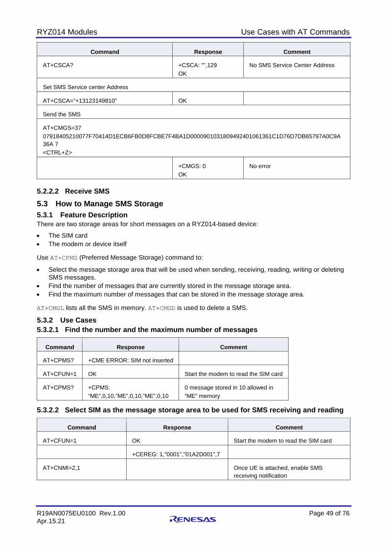
RYZ014 Modules Use Cases with AT Commands
R19AN0075EU0100 Rev.1.00 Page 49 of 76 Apr.15.21
Command Response Comment
AT+CSCA? +CSCA: "",129 OK
No SMS Service Center Address
Set SMS Service center Address
AT+CSCA="+13123149810" OK
Send the SMS
AT+CMGS=37 07918405210077F70414D1ECB6FB0D8FCBE7F4BA1D0000901031809492401061361C1D76D7DB65797A0C9A36A 7 <CTRL+Z>
+CMGS: 0 OK
No error
5.2.2.2 Receive SMS 5.3 How to Manage SMS Storage 5.3.1 Feature Description There are two storage areas for short messages on a RYZ014-based device:
• The SIM card • The modem or device itself Use AT+CPMS (Preferred Message Storage) command to:
• Select the message storage area that will be used when sending, receiving, reading, writing or deleting SMS messages.
• Find the number of messages that are currently stored in the message storage area. • Find the maximum number of messages that can be stored in the message storage area. AT+CMGL lists all the SMS in memory. AT+CMGD is used to delete a SMS.
5.3.2 Use Cases 5.3.2.1 Find the number and the maximum number of messages
Command Response Comment
AT+CPMS? +CME ERROR: SIM not inserted
AT+CFUN=1 OK Start the modem to read the SIM card
AT+CPMS? +CPMS: “ME”,0,10,”ME”,0,10,”ME”,0,10
0 message stored in 10 allowed in “ME” memory
5.3.2.2 Select SIM as the message storage area to be used for SMS receiving and reading
Command Response Comment
AT+CFUN=1 OK Start the modem to read the SIM card
+CEREG: 1,"0001","01A2D001",7
AT+CNMI=2,1 Once UE is attached, enable SMS receiving notification
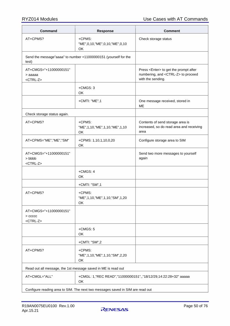
RYZ014 Modules Use Cases with AT Commands
R19AN0075EU0100 Rev.1.00 Page 50 of 76 Apr.15.21
Command Response Comment
AT+CPMS? +CPMS: "ME",0,10,"ME",0,10,"ME",0,10 OK
Check storage status
Send the message”aaaa” to number +11000000151 (yourself for the test)
AT+CMGS="+11000000151" > aaaaa <CTRL-Z>
Press <Enter> to get the prompt after numbering, and <CTRL-Z> to proceed with the sending.
+CMGS: 3 OK
+CMTI: "ME",1 One message received, stored in ME
Check storage status again.
AT+CPMS? +CPMS: "ME",1,10,"ME",1,10,"ME",1,10 OK
Contents of send storage area is increased, so do read area and receiving area
AT+CPMS="ME","ME","SM" +CPMS: 1,10,1,10,0,20 OK
Configure storage area to SIM
AT+CMGS="+11000000151" > bbbb <CTRL-Z>
Send two more messages to yourself again
+CMGS: 4 OK
+CMTI: "SM",1
AT+CPMS? +CPMS: "ME",1,10,"ME",1,10,"SM",1,20 OK
AT+CMGS="+11000000151" > ccccc <CTRL-Z>
+CMGS: 5 OK
+CMTI: "SM",2
AT+CPMS? +CPMS: "ME",1,10,"ME",1,10,"SM",2,20 OK
Read out all message, the 1st message saved in ME is read out
AT+CMGL="ALL" +CMGL: 1,"REC READ","11000000151",,"18/12/29,14:22:28+32" aaaaa OK
Configure reading area to SIM. The next two messages saved in SIM are read out
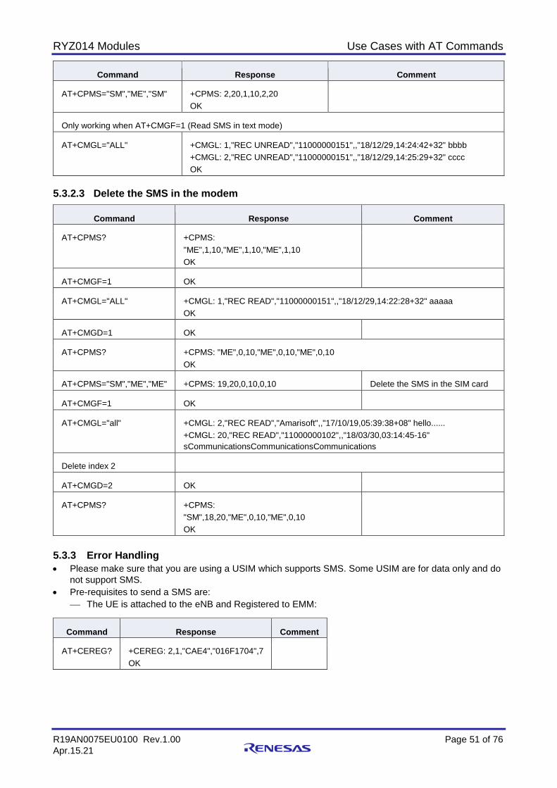
RYZ014 Modules Use Cases with AT Commands
R19AN0075EU0100 Rev.1.00 Page 51 of 76 Apr.15.21
Command Response Comment
AT+CPMS="SM","ME","SM" +CPMS: 2,20,1,10,2,20 OK
Only working when AT+CMGF=1 (Read SMS in text mode)
AT+CMGL="ALL" +CMGL: 1,"REC UNREAD","11000000151",,"18/12/29,14:24:42+32" bbbb +CMGL: 2,"REC UNREAD","11000000151",,"18/12/29,14:25:29+32" cccc OK
5.3.2.3 Delete the SMS in the modem
Command Response Comment
AT+CPMS? +CPMS: "ME",1,10,"ME",1,10,"ME",1,10 OK
AT+CMGF=1 OK
AT+CMGL="ALL" +CMGL: 1,"REC READ","11000000151",,"18/12/29,14:22:28+32" aaaaa OK
AT+CMGD=1 OK
AT+CPMS? +CPMS: "ME",0,10,"ME",0,10,"ME",0,10 OK
AT+CPMS="SM","ME","ME" +CPMS: 19,20,0,10,0,10 Delete the SMS in the SIM card
AT+CMGF=1 OK
AT+CMGL="all" +CMGL: 2,"REC READ","Amarisoft",,"17/10/19,05:39:38+08" hello...... +CMGL: 20,"REC READ","11000000102",,"18/03/30,03:14:45-16" sCommunicationsCommunicationsCommunications
Delete index 2
AT+CMGD=2 OK
AT+CPMS? +CPMS: "SM",18,20,"ME",0,10,"ME",0,10 OK
5.3.3 Error Handling • Please make sure that you are using a USIM which supports SMS. Some USIM are for data only and do
not support SMS. • Pre-requisites to send a SMS are:
The UE is attached to the eNB and Registered to EMM:
Command Response Comment
AT+CEREG? +CEREG: 2,1,"CAE4","016F1704",7 OK
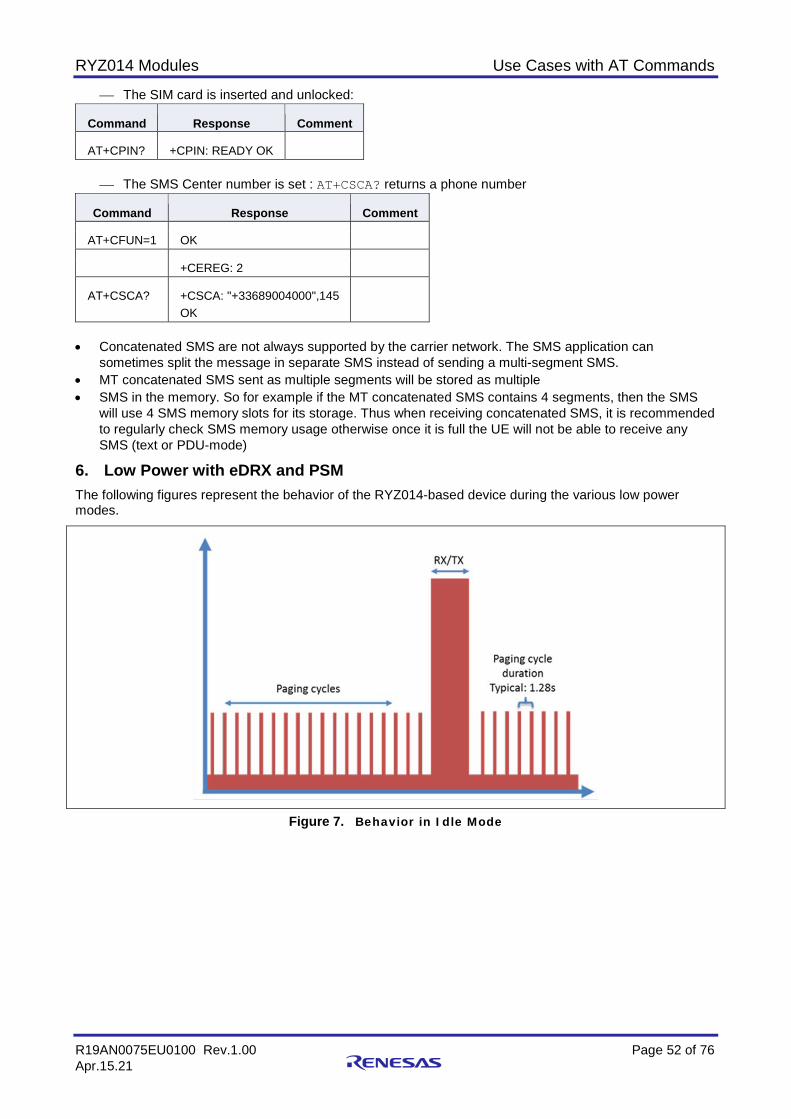
RYZ014 Modules Use Cases with AT Commands
R19AN0075EU0100 Rev.1.00 Page 52 of 76 Apr.15.21
The SIM card is inserted and unlocked:
Command Response Comment
AT+CPIN? +CPIN: READY OK
The SMS Center number is set : AT+CSCA? returns a phone number
Command Response Comment
AT+CFUN=1 OK
+CEREG: 2
AT+CSCA? +CSCA: "+33689004000",145 OK
• Concatenated SMS are not always supported by the carrier network. The SMS application can
sometimes split the message in separate SMS instead of sending a multi-segment SMS. • MT concatenated SMS sent as multiple segments will be stored as multiple • SMS in the memory. So for example if the MT concatenated SMS contains 4 segments, then the SMS
will use 4 SMS memory slots for its storage. Thus when receiving concatenated SMS, it is recommended to regularly check SMS memory usage otherwise once it is full the UE will not be able to receive any SMS (text or PDU-mode)
6. Low Power with eDRX and PSM The following figures represent the behavior of the RYZ014-based device during the various low power modes.
Figure 7. Behavior in Idle Mode
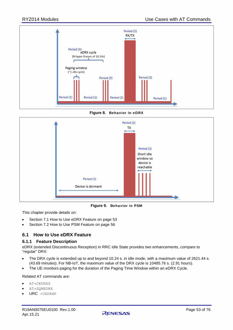
RYZ014 Modules Use Cases with AT Commands
R19AN0075EU0100 Rev.1.00 Page 53 of 76 Apr.15.21
Figure 8. Behavior in eDRX
Figure 9. Behavior in PSM This chapter provide details on:
• Section 7.1 How to Use eDRX Feature on page 53 • Section 7.2 How to Use PSM Feature on page 56 6.1 How to Use eDRX Feature 6.1.1 Feature Description eDRX (extended Discontinuous Reception) in RRC Idle State provides two enhancements, compare to “regular” DRX:
• The DRX cycle is extended up to and beyond 10.24 s. in idle mode, with a maximum value of 2621.44 s. (43.69 minutes). For NB-IoT, the maximum value of the DRX cycle is 10485.76 s. (2.91 hours).
• The UE monitors paging for the duration of the Paging Time Window within an eDRX Cycle. Related AT commands are:
• AT+CEDRXS • AT+SQNEDRX • URC +CEDRXP
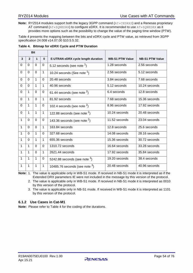
RYZ014 Modules Use Cases with AT Commands
R19AN0075EU0100 Rev.1.00 Page 54 of 76 Apr.15.21
Note: RYZ014 modules support both the legacy 3GPP command (AT+CEDRXS) and a Renesas proprietary AT command (AT+SQNEDRX) to configure eDRX. It is recommended to use AT+SQNEDRX as it provides more options such as the possibility to change the value of the paging time window (PTW).
Table 4 presents the mapping between the bits and eDRX cycle and PTW value, as retrieved from 3GPP specification 24.008 v14.07.00 §10.5.5.32.
Table 4. Bitmap for eDRX Cycle and PTW Duration
Bit
E-UTRAN eDRX cycle length duration WB-S1 PTW Value NB-S1 PTW Value 3 2 1 0
0 0 0 0 5.12 seconds (see note 1) 1.28 seconds 2.56 seconds
0 0 0 1 10.24 seconds (See note 1) 2.56 seconds 5.12 seconds
0 0 1 0 20.48 seconds 3.84 seconds 7.68 seconds
0 0 1 1 40.96 seconds 5.12 seconds 10.24 seconds
0 1 0 0 61.44 seconds (see note 2) 6.4 seconds 12.8 seconds
0 1 0 1 81.92 seconds 7.68 seconds 15.36 seconds
0 1 1 0 102.4 seconds (see note 2) 8.96 seconds 17.92 seconds
0 1 1 1 122.88 seconds (see note 2) 10.24 seconds 20.48 seconds
1 0 0 0 143.36 seconds (see note 2) 11.52 seconds 23.04 seconds
1 0 0 1 163.84 seconds 12.8 seconds 25.6 seconds
1 0 1 0 327.68 seconds 14.08 seconds 28.16 seconds
1 0 1 1 655.36 seconds 15.36 seconds 30.72 seconds
1 1 0 0 1310.72 seconds 16.64 seconds 33.28 seconds
1 1 0 1 2621.44 seconds 17.92 seconds 35.84 seconds
1 1 1 0 5242.88 seconds (see note 3) 19.20 seconds 38.4 seconds
1 1 1 1 10485.76 seconds (see note 3) 20.48 seconds 40.96 seconds
Note: 1. The value is applicable only in WB-S1 mode. If received in NB-S1 mode it is interpreted as if the Extended DRX parameters IE were not included in the message by this version of the protocol.
2. The value is applicable only in WB-S1 mode. If received in NB-S1 mode it is interpreted as 0010 by this version of the protocol.
3. The value is applicable only in NB-S1 mode. If received in WB-S1 mode it is interpreted as 1101 by this version of the protocol.
6.1.2 Use Cases in Cat-M1 Note: Please refer to Table 4 for the coding of the durations.

RYZ014 Modules Use Cases with AT Commands
R19AN0075EU0100 Rev.1.00 Page 55 of 76 Apr.15.21
6.1.2.1 Enable eDRX, set and query eDRX cycle and PTW value in Cat-M1.
Command Response Comment
Enable eDRX and set requested eDRX cycle to 10.24 s (requested PTW will use the default value of 1.28 s.).
AT+CEDRXS=2,4,"0001" OK 4: E-UTRAN (WB-S1 mode) requested eDRX cycle (10.24s)
AT+CEDRXS? +CEDRXS:4,”0001” OK
Enable eDRX and set requested eDRX cycle to 20.48 s, requested PTW to 2.56 s
AT+SQNEDRX=2,4,"0010","0001" OK 4: E-UTRAN (WB-S1 mode) eDRX cycle 20.48s TW 2.56s
AT+SQNEDRX? +SQNEDRX:2,4,”0010”,”0001” OK
Get used eDRX cycle and PTW value, check the enabled URC +CEDRXP
+CEDRXP: 4,"0010","0010","0011"
4: E-UTRAN (WB-S1 mode) Requested eDRX cycle (20.48 s) Network provided eDRX cycle (20.48 s) PTW (10.24 s )
Query current configured eDRX parameters. Note: The used eDRX cycle and PTW value may be different than the ones configured with AT+CEDRXS or AT+SQNEDRX. Get the values set in the system only through the URC +CEDRXP.
AT+CEDRXS? +CEDRXS: 4,"0001" OK
4: E-UTRAN (WB-S1 mode) Requested eDRX cycle (10.24 s)
6.1.2.2 Disable eDRX
Command Response Comment
AT+CEDRXS=0 or AT+SQNEDRX=0
OK 0: Disable the use of eDRX Both commands are equivalent
6.1.3 Use Cases in Cat-NB1 Note: Please refer to Table 4 for the coding of the durations.
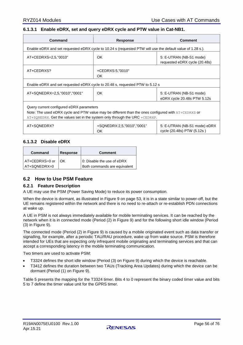
RYZ014 Modules Use Cases with AT Commands
R19AN0075EU0100 Rev.1.00 Page 56 of 76 Apr.15.21
6.1.3.1 Enable eDRX, set and query eDRX cycle and PTW value in Cat-NB1.
Command Response Comment
Enable eDRX and set requested eDRX cycle to 10.24 s (requested PTW will use the default value of 1.28 s.).
AT+CEDRXS=2,5,"0010" OK 5: E-UTRAN (NB-S1 mode) requested eDRX cycle (20.48s)
AT+CEDRXS? +CEDRXS:5,”0010” OK
Enable eDRX and set requested eDRX cycle to 20.48 s, requested PTW to 5.12 s
AT+SQNEDRX=2,5,"0010","0001" OK 5: E-UTRAN (NB-S1 mode) eDRX cycle 20.48s PTW 5.12s
Query current configured eDRX parameters Note: The used eDRX cycle and PTW value may be different than the ones configured with AT+CEDRXS or AT+SQNEDRX. Get the values set in the system only through the URC +CEDRXP.
AT+SQNEDRX? +SQNEDRX:2,5,”0010”,”0001” OK
5: E-UTRAN (NB-S1 mode) eDRX cycle (20.48s) PTW (5.12s )
6.1.3.2 Disable eDRX
Command Response Comment
AT+CEDRXS=0 or AT+SQNEDRX=0
OK 0: Disable the use of eDRX Both commands are equivalent
6.2 How to Use PSM Feature 6.2.1 Feature Description A UE may use the PSM (Power Saving Mode) to reduce its power consumption.
When the device is dormant, as illustrated in Figure 9 on page 53, it is in a state similar to power-off, but the UE remains registered within the network and there is no need to re-attach or re-establish PDN connections at wake up.
A UE in PSM is not always immediately available for mobile terminating services. It can be reached by the network when it is in connected mode (Period (2) in Figure 9) and for the following short idle window (Period (3) in Figure 9).
The connected mode (Period (2) in Figure 9) is caused by a mobile originated event such as data transfer or signalling, for example, after a periodic TAU/RAU procedure, wake up from wake source. PSM is therefore intended for UEs that are expecting only infrequent mobile originating and terminating services and that can accept a corresponding latency in the mobile terminating communication.
Two timers are used to activate PSM:
• T3324 defines the short idle window (Period (3) on Figure 9) during which the device is reachable. • T3412 defines the duration between two TAUs (Tracking Area Updates) during which the device can be
dormant (Period (1) on Figure 9). Table 5 presents the mapping for the T3324 timer. Bits 4 to 0 represent the binary coded timer value and bits 5 to 7 define the timer value unit for the GPRS timer.
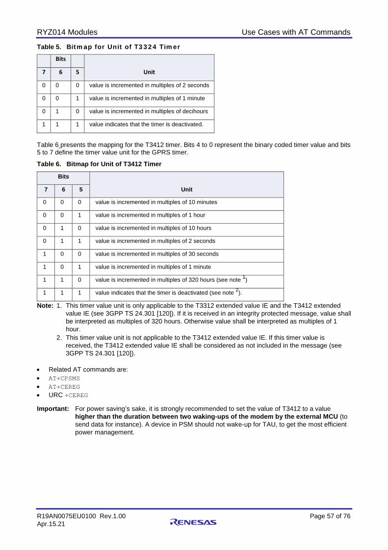
RYZ014 Modules Use Cases with AT Commands
R19AN0075EU0100 Rev.1.00 Page 57 of 76 Apr.15.21
Table 5. Bitmap for Unit of T3324 Timer
Bits
Unit 7 6 5
0 0 0 value is incremented in multiples of 2 seconds
0 0 1 value is incremented in multiples of 1 minute
0 1 0 value is incremented in multiples of decihours
1 1 1 value indicates that the timer is deactivated.
Table 6 presents the mapping for the T3412 timer. Bits 4 to 0 represent the binary coded timer value and bits 5 to 7 define the timer value unit for the GPRS timer.
Table 6. Bitmap for Unit of T3412 Timer
Bits
Unit 7 6 5
0 0 0 value is incremented in multiples of 10 minutes
0 0 1 value is incremented in multiples of 1 hour
0 1 0 value is incremented in multiples of 10 hours
0 1 1 value is incremented in multiples of 2 seconds
1 0 0 value is incremented in multiples of 30 seconds
1 0 1 value is incremented in multiples of 1 minute
1 1 0 value is incremented in multiples of 320 hours (see note 1)
1 1 1 value indicates that the timer is deactivated (see note 2).
Note: 1. This timer value unit is only applicable to the T3312 extended value IE and the T3412 extended value IE (see 3GPP TS 24.301 [120]). If it is received in an integrity protected message, value shall be interpreted as multiples of 320 hours. Otherwise value shall be interpreted as multiples of 1 hour.
2. This timer value unit is not applicable to the T3412 extended value IE. If this timer value is received, the T3412 extended value IE shall be considered as not included in the message (see 3GPP TS 24.301 [120]).
• Related AT commands are: • AT+CPSMS • AT+CEREG • URC +CEREG Important: For power saving’s sake, it is strongly recommended to set the value of T3412 to a value
higher than the duration between two waking-ups of the modem by the external MCU (to send data for instance). A device in PSM should not wake-up for TAU, to get the most efficient power management.
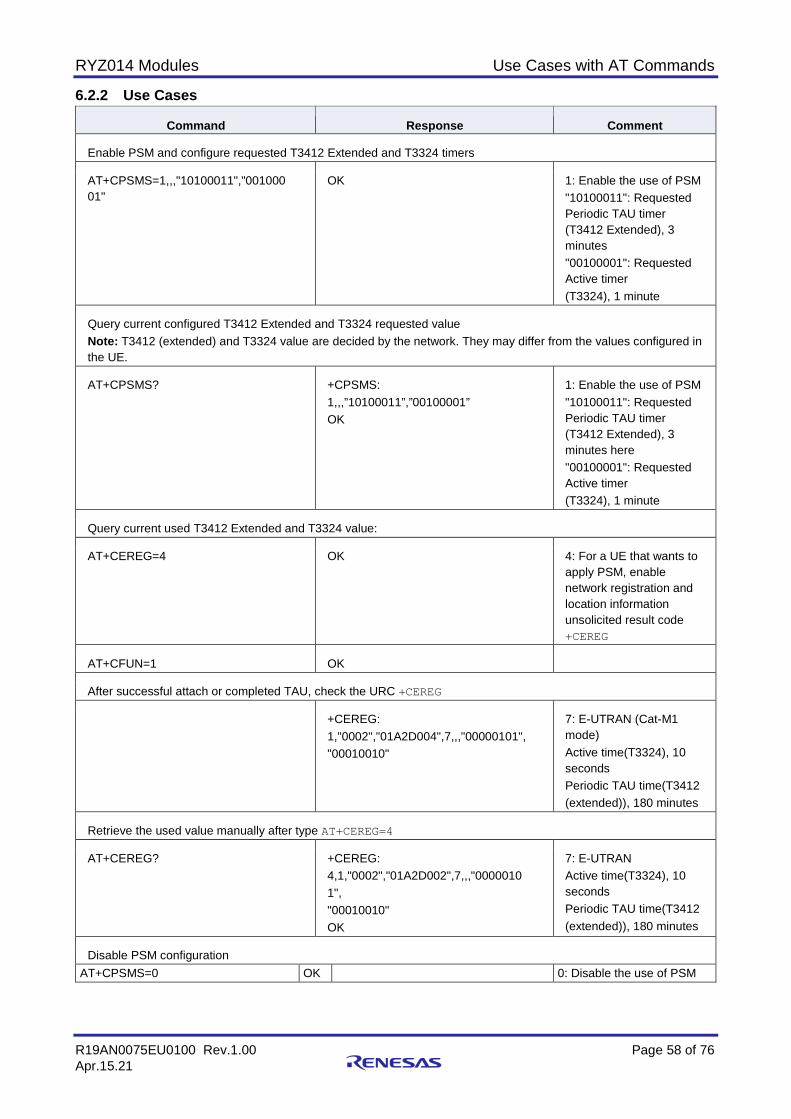
RYZ014 Modules Use Cases with AT Commands
R19AN0075EU0100 Rev.1.00 Page 58 of 76 Apr.15.21
6.2.2 Use Cases
Command Response Comment
Enable PSM and configure requested T3412 Extended and T3324 timers
AT+CPSMS=1,,,"10100011","001000 01"
OK 1: Enable the use of PSM "10100011": Requested Periodic TAU timer (T3412 Extended), 3 minutes "00100001": Requested Active timer (T3324), 1 minute
Query current configured T3412 Extended and T3324 requested value Note: T3412 (extended) and T3324 value are decided by the network. They may differ from the values configured in the UE.
AT+CPSMS? +CPSMS: 1,,,”10100011”,”00100001” OK
1: Enable the use of PSM "10100011": Requested Periodic TAU timer (T3412 Extended), 3 minutes here "00100001": Requested Active timer (T3324), 1 minute
Query current used T3412 Extended and T3324 value:
AT+CEREG=4 OK 4: For a UE that wants to apply PSM, enable network registration and location information unsolicited result code +CEREG
AT+CFUN=1 OK
After successful attach or completed TAU, check the URC +CEREG
+CEREG: 1,"0002","01A2D004",7,,,"00000101", "00010010"
7: E-UTRAN (Cat-M1 mode) Active time(T3324), 10 seconds Periodic TAU time(T3412 (extended)), 180 minutes
Retrieve the used value manually after type AT+CEREG=4
AT+CEREG? +CEREG: 4,1,"0002","01A2D002",7,,,"0000010 1", "00010010" OK
7: E-UTRAN Active time(T3324), 10 seconds Periodic TAU time(T3412 (extended)), 180 minutes
Disable PSM configuration AT+CPSMS=0 OK 0: Disable the use of PSM
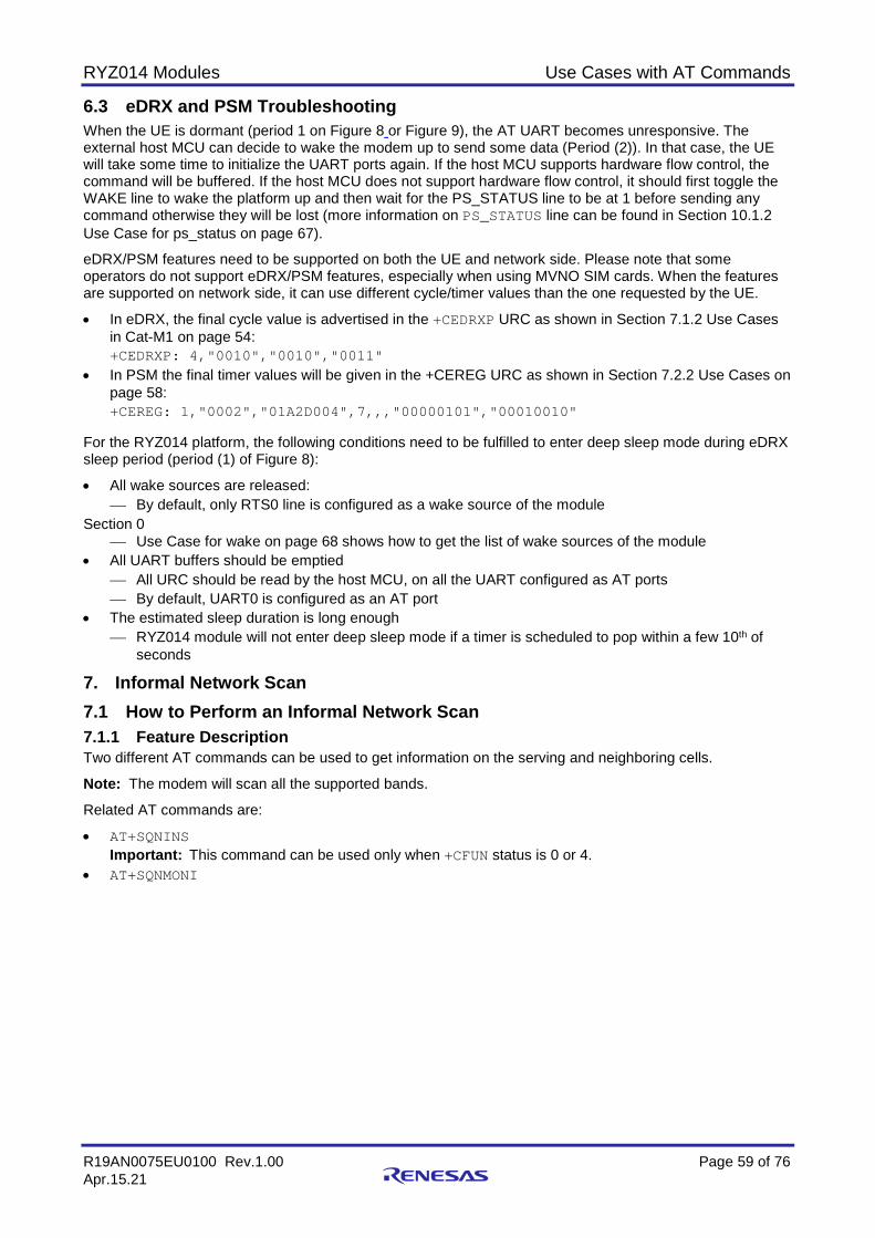
RYZ014 Modules Use Cases with AT Commands
R19AN0075EU0100 Rev.1.00 Page 59 of 76 Apr.15.21
6.3 eDRX and PSM Troubleshooting When the UE is dormant (period 1 on Figure 8 or Figure 9), the AT UART becomes unresponsive. The external host MCU can decide to wake the modem up to send some data (Period (2)). In that case, the UE will take some time to initialize the UART ports again. If the host MCU supports hardware flow control, the command will be buffered. If the host MCU does not support hardware flow control, it should first toggle the WAKE line to wake the platform up and then wait for the PS_STATUS line to be at 1 before sending any command otherwise they will be lost (more information on PS_STATUS line can be found in Section 10.1.2 Use Case for ps_status on page 67).
eDRX/PSM features need to be supported on both the UE and network side. Please note that some operators do not support eDRX/PSM features, especially when using MVNO SIM cards. When the features are supported on network side, it can use different cycle/timer values than the one requested by the UE.
• In eDRX, the final cycle value is advertised in the +CEDRXP URC as shown in Section 7.1.2 Use Cases in Cat-M1 on page 54: +CEDRXP: 4,"0010","0010","0011"
• In PSM the final timer values will be given in the +CEREG URC as shown in Section 7.2.2 Use Cases on page 58: +CEREG: 1,"0002","01A2D004",7,,,"00000101","00010010"
For the RYZ014 platform, the following conditions need to be fulfilled to enter deep sleep mode during eDRX sleep period (period (1) of Figure 8):
• All wake sources are released: By default, only RTS0 line is configured as a wake source of the module
Section 0 Use Case for wake on page 68 shows how to get the list of wake sources of the module
• All UART buffers should be emptied All URC should be read by the host MCU, on all the UART configured as AT ports By default, UART0 is configured as an AT port
• The estimated sleep duration is long enough RYZ014 module will not enter deep sleep mode if a timer is scheduled to pop within a few 10th of
seconds
7. Informal Network Scan 7.1 How to Perform an Informal Network Scan 7.1.1 Feature Description Two different AT commands can be used to get information on the serving and neighboring cells.
Note: The modem will scan all the supported bands.
Related AT commands are:
• AT+SQNINS Important: This command can be used only when +CFUN status is 0 or 4.
• AT+SQNMONI

RYZ014 Modules Use Cases with AT Commands
R19AN0075EU0100 Rev.1.00 Page 60 of 76 Apr.15.21
7.1.2 Use Cases 7.1.2.1 AT+SQNINS usage
Command Response Comment
AT+CFUN=0 OK
Report on all bands, fast informal network scanning (reporting of information extracted from Master information Block only).
AT+SQNINS=1 +SQNINS: 1,3,7,"0","0000","000000",1825,154,1.4,-90.70,-9.40 +SQNINS: 1,3,7,"0","0000","000000",1825,211,15,-97.30,-17.40 +SQNINS: 1,1,7,"0","0000","000000",100,154,1.4,-100.90,-15.30 +SQNINS: 1,4,7,"0","0000","000000",2050,154,1.4,-101.90,-15.60 +SQNINS: 1,3,7,"0","0000","000000",1650,214,1.4,-82.40,-14.60 +SQNINS: 1,1,7,"0","0000","000000",450,268,1.4,-104.50,-16.50 +SQNINS: 1,1,7,"0","0000","000000",450,212,1.4,-100.60,-13.10 +SQNINS: 1,1,7,"0","0000","000000",450,218,20,-103.50,-15.30 +SQNINS: 1,3,7,"0","0000","000000",1275,414,15,-89.80,-9.50 OK
7.1.2.2 AT+SQNMONI usage
Command Response Comment
Report on serving cell only.
AT+SQNMONI =0
+SQNMONI: Verizon Wireless USA Cc:311 Nc:480 RSRP:-70.80 RSRQ:-9.50 TAC:22533 Id:350 EARFCN:5230 PWR:-53.52 PAGING:128 OK
Command Response Comment
Report information for the serving cell only with RSRP/CINR on main antenna.
AT+SQNMONI =9
+SQNMONI: Orange F Cc:208 Nc:01 RSRP:-100.10 CINR:2.10 RSRQ:-13.90 TAC:51940 Id:309 EARFCN:6400 PWR:-78.42 PAGING:128 OK
7.1.3 Error Handling During PSM sleep and eDRX sleep, the UE is not monitoring the network, therefore +SQNMONI will return ERROR. In that case, it is recommended to make sure that the UE attaches to the network with a ping (AT+PING="www.Renesas.com",1,32 for example).
8. Hardware Configuration 8.1 UART Interfaces on RYZ014 RYZ014 modules can be controlled via a serial interface UART using standard AT commands. The serial AT interface can be connected using HW flow control or not. Here are the HW architectures in both cases:
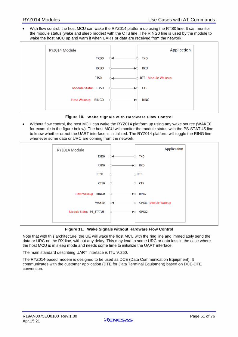
RYZ014 Modules Use Cases with AT Commands
R19AN0075EU0100 Rev.1.00 Page 61 of 76 Apr.15.21
• With flow control, the host MCU can wake the RYZ014 platform up using the RTS0 line. It can monitor the module status (wake and sleep modes) with the CTS line. The RING0 line is used by the module to wake the host MCU up and warn it when UART or data are received from the network
Figure 10. Wake Signals with Hardware Flow Control • Without flow control, the host MCU can wake the RYZ014 platform up using any wake source (WAKE0
for example in the figure below). The host MCU will monitor the module status with the PS-STATUS line to know whether or not the UART interface is initialized. The RYZ014 platform will toggle the RING line whenever some data or URC are coming from the network.
Figure 11. Wake Signals without Hardware Flow Control Note that with this architecture, the UE will wake the host MCU with the ring line and immediately send the data or URC on the RX line, without any delay. This may lead to some URC or data loss in the case where the host MCU is in sleep mode and needs some time to initialize the UART interface.
The main standard describing UART interface is ITU V.250.
The RYZ014-based modem is designed to be used as DCE (Data Communication Equipment). It communicates with the customer application (DTE for Data Terminal Equipment) based on DCE-DTE convention.
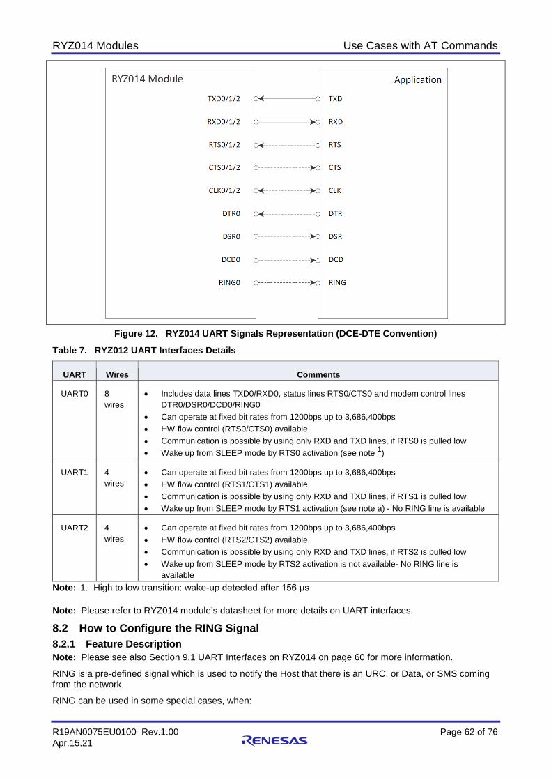
RYZ014 Modules Use Cases with AT Commands
R19AN0075EU0100 Rev.1.00 Page 62 of 76 Apr.15.21
Figure 12. RYZ014 UART Signals Representation (DCE-DTE Convention)
Table 7. RYZ012 UART Interfaces Details
UART Wires Comments
UART0 8 wires
• Includes data lines TXD0/RXD0, status lines RTS0/CTS0 and modem control lines DTR0/DSR0/DCD0/RING0
• Can operate at fixed bit rates from 1200bps up to 3,686,400bps • HW flow control (RTS0/CTS0) available • Communication is possible by using only RXD and TXD lines, if RTS0 is pulled low • Wake up from SLEEP mode by RTS0 activation (see note 1)
UART1 4 wires
• Can operate at fixed bit rates from 1200bps up to 3,686,400bps • HW flow control (RTS1/CTS1) available • Communication is possible by using only RXD and TXD lines, if RTS1 is pulled low • Wake up from SLEEP mode by RTS1 activation (see note a) - No RING line is available
UART2 4 wires
• Can operate at fixed bit rates from 1200bps up to 3,686,400bps • HW flow control (RTS2/CTS2) available • Communication is possible by using only RXD and TXD lines, if RTS2 is pulled low • Wake up from SLEEP mode by RTS2 activation is not available- No RING line is
available Note: 1. High to low transition: wake-up detected after 156 μs Note: Please refer to RYZ014 module’s datasheet for more details on UART interfaces.
8.2 How to Configure the RING Signal 8.2.1 Feature Description Note: Please see also Section 9.1 UART Interfaces on RYZ014 on page 60 for more information.
RING is a pre-defined signal which is used to notify the Host that there is an URC, or Data, or SMS coming from the network.
RING can be used in some special cases, when:

RYZ014 Modules Use Cases with AT Commands
R19AN0075EU0100 Rev.1.00 Page 63 of 76 Apr.15.21
• Immediate URC presentation is impossible, for instance UART running a long AT command or in online data connection mode
• Immediate data transmission to host when AT channel in data mode (PPP, transparent socket) is impossible
• Host not ready to receive on UART interface (RTS line high level or in sleep mode) RING behavior can be configured by using the AT command AT+SQNRICFG.
The following behaviors are set by default:
• Events (URC and data) are indicated by toggling the RING line on the same interface where the URC appears. This means that if an event happens on an AT channel not mapped to UART0, then the RING line will remain silent.
• The default duration of RING activation is 1 second as shown on Figure 13.
Figure 13. RING Signal Activation • The signal polarity is negative which means that RING is active low. 8.2.2 Use Cases
Command Response Comment
All events are indicated by activated RING0 line of the UART0 interface, whatever event AT channel origin.
AT+SQNRICFG=1,3 OK
AT+SQNRICFG? +SQNRICFG: 1,3,1000 OK
RING activation triggered by general URC events only, and only the event on UART0 triggers RING signal.
AT+SQNRICFG=2,1 OK
AT+SQNRICFG? +SQNRICFG: 2,1,1000 OK
Change the duration to 2s, and keep others default settings.
AT+SQNRICFG=,,2000 OK
AT+SQNRICFG? +SQNRICFG: 2,3,1000 OK
8.3 How to Configure Modem Alarms 8.3.1 Feature Description In some cases, MCU needs to set timers in the module and get an alarm when expired.
AT+CALA and AT+CALD are 3GPP standard AT commands defined in specification 27.007.
Related AT commands are:
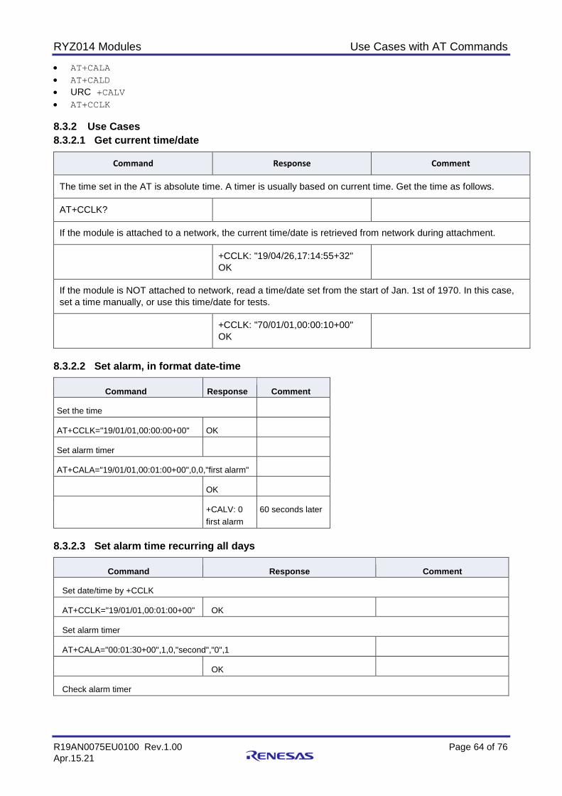
RYZ014 Modules Use Cases with AT Commands
R19AN0075EU0100 Rev.1.00 Page 64 of 76 Apr.15.21
• AT+CALA • AT+CALD • URC +CALV • AT+CCLK 8.3.2 Use Cases 8.3.2.1 Get current time/date
Command Response Comment
The time set in the AT is absolute time. A timer is usually based on current time. Get the time as follows.
AT+CCLK?
If the module is attached to a network, the current time/date is retrieved from network during attachment.
+CCLK: "19/04/26,17:14:55+32" OK
If the module is NOT attached to network, read a time/date set from the start of Jan. 1st of 1970. In this case, set a time manually, or use this time/date for tests.
+CCLK: "70/01/01,00:00:10+00" OK
8.3.2.2 Set alarm, in format date-time
Command Response Comment
Set the time
AT+CCLK="19/01/01,00:00:00+00" OK
Set alarm timer
AT+CALA="19/01/01,00:01:00+00",0,0,"first alarm"
OK
+CALV: 0 first alarm
60 seconds later
8.3.2.3 Set alarm time recurring all days
Command Response Comment
Set date/time by +CCLK
AT+CCLK="19/01/01,00:01:00+00" OK
Set alarm timer
AT+CALA="00:01:30+00",1,0,"second","0",1
OK
Check alarm timer
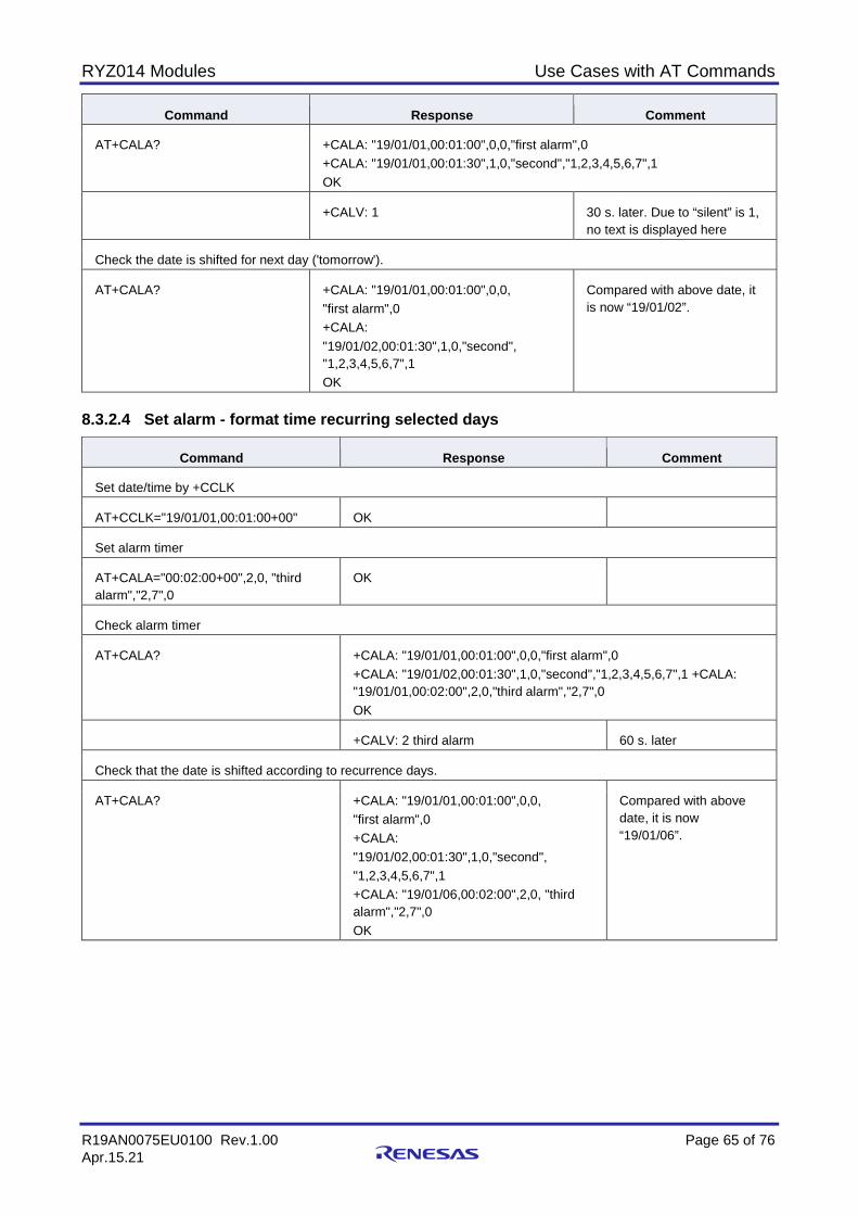
RYZ014 Modules Use Cases with AT Commands
R19AN0075EU0100 Rev.1.00 Page 65 of 76 Apr.15.21
Command Response Comment
AT+CALA? +CALA: "19/01/01,00:01:00",0,0,"first alarm",0 +CALA: "19/01/01,00:01:30",1,0,"second","1,2,3,4,5,6,7",1 OK
+CALV: 1 30 s. later. Due to “silent” is 1, no text is displayed here
Check the date is shifted for next day ('tomorrow').
AT+CALA? +CALA: "19/01/01,00:01:00",0,0, "first alarm",0 +CALA: "19/01/02,00:01:30",1,0,"second", "1,2,3,4,5,6,7",1 OK
Compared with above date, it is now “19/01/02”.
8.3.2.4 Set alarm - format time recurring selected days
Command Response Comment
Set date/time by +CCLK
AT+CCLK="19/01/01,00:01:00+00" OK
Set alarm timer
AT+CALA="00:02:00+00",2,0, "third alarm","2,7",0
OK
Check alarm timer
AT+CALA? +CALA: "19/01/01,00:01:00",0,0,"first alarm",0 +CALA: "19/01/02,00:01:30",1,0,"second","1,2,3,4,5,6,7",1 +CALA: "19/01/01,00:02:00",2,0,"third alarm","2,7",0 OK
+CALV: 2 third alarm 60 s. later
Check that the date is shifted according to recurrence days.
AT+CALA? +CALA: "19/01/01,00:01:00",0,0, "first alarm",0 +CALA: "19/01/02,00:01:30",1,0,"second", "1,2,3,4,5,6,7",1 +CALA: "19/01/06,00:02:00",2,0, "third alarm","2,7",0 OK
Compared with above date, it is now “19/01/06”.
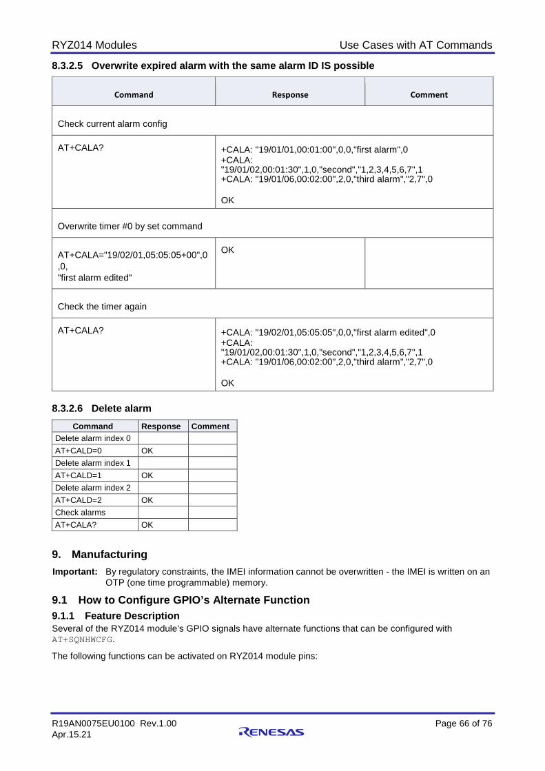
RYZ014 Modules Use Cases with AT Commands
R19AN0075EU0100 Rev.1.00 Page 66 of 76 Apr.15.21
8.3.2.5 Overwrite expired alarm with the same alarm ID IS possible
Command Response Comment
Check current alarm config
AT+CALA? +CALA: "19/01/01,00:01:00",0,0,"first alarm",0 +CALA: "19/01/02,00:01:30",1,0,"second","1,2,3,4,5,6,7",1 +CALA: "19/01/06,00:02:00",2,0,"third alarm","2,7",0
OK
Overwrite timer #0 by set command
AT+CALA="19/02/01,05:05:05+00",0 ,0, "first alarm edited"
OK
Check the timer again
AT+CALA? +CALA: "19/02/01,05:05:05",0,0,"first alarm edited",0 +CALA: "19/01/02,00:01:30",1,0,"second","1,2,3,4,5,6,7",1 +CALA: "19/01/06,00:02:00",2,0,"third alarm","2,7",0
OK
8.3.2.6 Delete alarm
Command Response Comment Delete alarm index 0 AT+CALD=0 OK Delete alarm index 1 AT+CALD=1 OK Delete alarm index 2 AT+CALD=2 OK Check alarms AT+CALA? OK
9. Manufacturing Important: By regulatory constraints, the IMEI information cannot be overwritten - the IMEI is written on an
OTP (one time programmable) memory.
9.1 How to Configure GPIO’s Alternate Function 9.1.1 Feature Description Several of the RYZ014 module’s GPIO signals have alternate functions that can be configured with AT+SQNHWCFG.
The following functions can be activated on RYZ014 module pins:
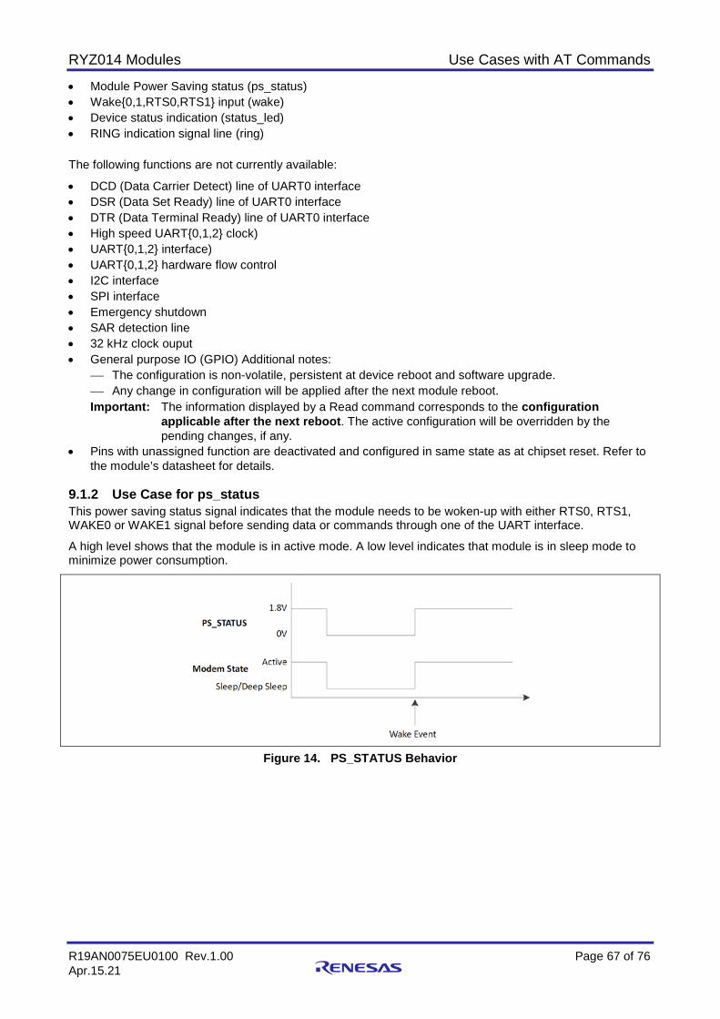
RYZ014 Modules Use Cases with AT Commands
R19AN0075EU0100 Rev.1.00 Page 67 of 76 Apr.15.21
• Module Power Saving status (ps_status) • Wake{0,1,RTS0,RTS1} input (wake) • Device status indication (status_led) • RING indication signal line (ring)
The following functions are not currently available:
• DCD (Data Carrier Detect) line of UART0 interface • DSR (Data Set Ready) line of UART0 interface • DTR (Data Terminal Ready) line of UART0 interface • High speed UART{0,1,2} clock) • UART{0,1,2} interface) • UART{0,1,2} hardware flow control • I2C interface • SPI interface • Emergency shutdown • SAR detection line • 32 kHz clock ouput • General purpose IO (GPIO) Additional notes:
The configuration is non-volatile, persistent at device reboot and software upgrade. Any change in configuration will be applied after the next module reboot. Important: The information displayed by a Read command corresponds to the configuration
applicable after the next reboot. The active configuration will be overridden by the pending changes, if any.
• Pins with unassigned function are deactivated and configured in same state as at chipset reset. Refer to the module’s datasheet for details.
9.1.2 Use Case for ps_status This power saving status signal indicates that the module needs to be woken-up with either RTS0, RTS1, WAKE0 or WAKE1 signal before sending data or commands through one of the UART interface.
A high level shows that the module is in active mode. A low level indicates that module is in sleep mode to minimize power consumption.
Figure 14. PS_STATUS Behavior

RYZ014 Modules Use Cases with AT Commands
R19AN0075EU0100 Rev.1.00 Page 68 of 76 Apr.15.21
Command Response Comment
AT+SQNHWCFG="ps_status" +SQNHWCFG: "ps_status",1 OK
The write command issued with <function> parameter only is equivalent to read command output filtered out for selected <function>. Read the function (enabled)
AT+SQNHWCFG="ps_status",0 OK Disable the function
Reboot the device
AT^RESET OK
+SYSSHDN +SYSTART
AT+SQNHWCFG="ps_status" +SQNHWCFG: "ps_status",0 OK
Read the function (disabled)
Then the module power saving status by the defined GPIO is deactivated. 9.1.3 Use Case for wake WAKE0, WAKE1, RTS0 and RTS1 pins are used as external sources to wake up the modem from low power mode.
The external wake sources have two different roles:
• If a wake signal is enabled, active and the platform wants to perform a LPM cycle, this wake signal will prevent to enter in low-power.
• If a wake signal is enabled, active and the platform is in low power, this wake signal will wake up the module.
WAKE inputs are detected on level that must last at least 100 µs.
Important: If the second parameter <enable> of the write command is 1, then the third parameter <polarity> is a must.

RYZ014 Modules Use Cases with AT Commands
R19AN0075EU0100 Rev.1.00 Page 69 of 76 Apr.15.21
Command Response Comment
Check wake sources configuration.
AT+SQNHWCFG? +SQNHWCFG: "ps_status",1 +SQNHWCFG: "wake0",0 +SQNHWCFG: "wake1",0 +SQNHWCFG: "wakeRTS0",1,0 +SQNHWCFG: "wakeRTS1",0 +SQNHWCFG: "status_led",1 +SQNHWCFG: "ring0",1, 0 +SQNHWCFG: "dcd0",undefined +SQNHWCFG: "dsr0",1 +SQNHWCFG: "dtr0",undefined +SQNHWCFG: "rtscts0",1 +SQNHWCFG: "rtscts1",0 +SQNHWCFG: "rtscts2",1 OK
The read command returns the list of supported pin functions state and detailed configuration (when applicable). wake0 and wake1 are both disabled, wakeRTS0 and wakeRTS1 are enabled with inverted polarity.
Enable wake1 with inverted polarity (negative polarity)
AT+SQNHWCFG="wake1",1,0 OK
Reboot the device
AT^RESET OK
+SYSSHDN +SYSTART
Check the configuration
AT+SQNHWCFG="wake1" +SQNHWCFG: "wake1",1,0 OK
Disable wakeRTS1
AT+SQNHWCFG="wakeRTS1",0 OK
Reboot the device
AT^RESET OK
+SYSSHDN +SYSTART
Check the configuration
AT+SQNHWCFG="wakeRTS1" +SQNHWCFG: "wakeRTS1",0 OK
9.1.4 Use Case for status_led This configures the device status indication function control.
This function is disabled by default (pin configured in input mode).
STATUS_LED signal polarity is positive (active high level).
The device status indication function behavior can also be configured with AT+SQNLED command.

RYZ014 Modules Use Cases with AT Commands
R19AN0075EU0100 Rev.1.00 Page 70 of 76 Apr.15.21
Command Response Comment
AT+SQNHWCFG? +SQNHWCFG: "ps_status",1 +SQNHWCFG: "wake0",0 +SQNHWCFG: "wake1",0 +SQNHWCFG: "wakeRTS0",1,0 +SQNHWCFG: "wakeRTS1",0 +SQNHWCFG: "status_led",1 +SQNHWCFG: "ring0",1, 0 +SQNHWCFG: "dcd0",undefined +SQNHWCFG: "dsr0",1 +SQNHWCFG: "dtr0",undefined +SQNHWCFG: "rtscts0",1 +SQNHWCFG: "rtscts1",0 +SQNHWCFG: "rtscts2",1 OK
The read command returns the list of supported pin functions state and detailed configuration (when applicable). status_led is enabled by default.
AT+SQNHWCFG="status_led",0 OK Disable the function
Reboot the device
AT^RESET OK
+SYSSHDN +SYSTART
AT+SQNHWCFG="status_led" +SQNHWCFG: "status_led",0 OK
Read the function (disabled)
9.1.5 Use Case for ring0 The RING function is enabled by default.
The default signal polarity is negative (RING active at low level).
RING function behavior can also be configured with AT+SQNRICFG command. See Section 9.2 How to Configure the RING Signal on page 62.

RYZ014 Modules Use Cases with AT Commands
R19AN0075EU0100 Rev.1.00 Page 71 of 76 Apr.15.21
Command Response Comment
AT+SQNHWCFG? +SQNHWCFG: "ps_status",1 +SQNHWCFG: "wake0",0 +SQNHWCFG: "wake1",0 +SQNHWCFG: "wakeRTS0",1,0 +SQNHWCFG: "wakeRTS1",0 +SQNHWCFG: "status_led",1 +SQNHWCFG: "ring0",1, 0 +SQNHWCFG: "dcd0",undefined +SQNHWCFG: "dsr0",1 +SQNHWCFG: "dtr0",undefined +SQNHWCFG: "rtscts0",1 +SQNHWCFG: "rtscts1",0 +SQNHWCFG: "rtscts2",1 OK
The read command returns the list of supported pin functions state and detailed configuration (when applicable). ring0 is enabled by default.
AT+SQNHWCFG="ring0",0 OK Disable the function
Reboot the device
AT^RESET OK
+SYSSHDN +SYSTART
AT+SQNHWCFG="ring0" +SQNHWCFG: "ring0",0 OK
Read the function (disabled)
9.1.6 Behavior at Factory Reset The configuration is not persistent at device factory reset (by
AT+SQNSFACTORYRESET) except if AT+PSISAVECURRENT was called before.
The following example illustrates the behavior on wake1 signal.
Command Response Comment
Check wake1 configuration
AT+SQNHWCFG? +SQNHWCFG: "ps_status",1 +SQNHWCFG: "wake0",0 +SQNHWCFG: "wake1",0 +SQNHWCFG: "wakeRTS0",1,0 +SQNHWCFG: "wakeRTS1",0 +SQNHWCFG: "status_led",1 +SQNHWCFG: "ring0",1, 0 +SQNHWCFG: "dcd0",undefined +SQNHWCFG: "dsr0",1 +SQNHWCFG: "dtr0",undefined +SQNHWCFG: "rtscts0",1 +SQNHWCFG: "rtscts1",0 +SQNHWCFG: "rtscts2",1 OK
The read command returns the list of supported pin functions state and detailed configuration (when applicable). wake1 is disabled
AT+SQNHWCFG="wake1",1,0 OK Enable wake1 with inverted polarity (negative polarity)

RYZ014 Modules Use Cases with AT Commands
R19AN0075EU0100 Rev.1.00 Page 72 of 76 Apr.15.21
Command Response Comment
AT^RESET OK Reboot the device
+SYSSHDN +SYSTART
Check the configuration
AT+SQNHWCFG="wake1" +SQNHWCFG: "wake1",1,0 OK
wake1 is enabled
AT+SQNSFACTORYRESET OK Execute factory reset
AT^RESET OK Reboot the device
+SYSSHDN +SYSTART
AT+SQNHWCFG? +SQNHWCFG: "ps_status",1 +SQNHWCFG: "wake0",0 +SQNHWCFG: "wake1",0 +SQNHWCFG: "wakeRTS0",1,0 +SQNHWCFG: "wakeRTS1",0 +SQNHWCFG: "status_led",1 +SQNHWCFG: "ring0",1, 0 +SQNHWCFG: "dcd0",undefined +SQNHWCFG: "dsr0",1 +SQNHWCFG: "dtr0",undefined +SQNHWCFG: "rtscts0",1 +SQNHWCFG: "rtscts1",0 +SQNHWCFG: "rtscts2",1 OK
wake1 is disabled again
Re-run the procedure above with AT+PSISAVECURRENT before the factory reset.
AT+SQNHWCFG="wake1",1,0 OK Re-enable wake1 with inverted polarity (negative polarity)
AT^RESET OK Reboot the device
+SYSSHDN +SYSTART
Check the configuration
AT+SQNHWCFG="wake1" +SQNHWCFG: "wake1",1,0 OK
wake1 is enabled
AT+PSISAVECURRENT OK Save the current configuration
AT+SQNSFACTORYRESET OK Execute factory reset
AT^RESET OK Reboot the device
+SYSSHDN +SYSTART
AT+SQNHWCFG="wake1" +SQNHWCFG: "wake1",1,0 OK
Read the configuration: wake1 is kept enabled
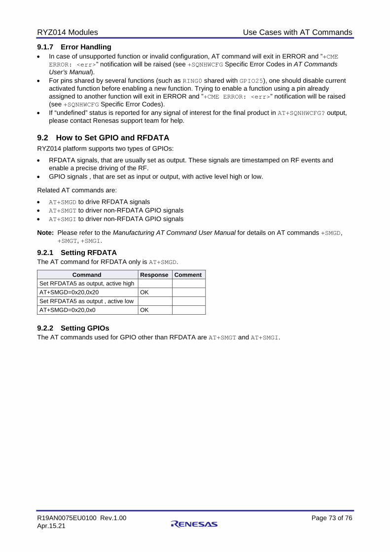
RYZ014 Modules Use Cases with AT Commands
R19AN0075EU0100 Rev.1.00 Page 73 of 76 Apr.15.21
9.1.7 Error Handling • In case of unsupported function or invalid configuration, AT command will exit in ERROR and ”+CME
ERROR: <err>” notification will be raised (see +SQNHWCFG Specific Error Codes in AT Commands User’s Manual).
• For pins shared by several functions (such as RING0 shared with GPIO25), one should disable current activated function before enabling a new function. Trying to enable a function using a pin already assigned to another function will exit in ERROR and ”+CME ERROR: <err>” notification will be raised (see +SQNHWCFG Specific Error Codes).
• If “undefined” status is reported for any signal of interest for the final product in AT+SQNHWCFG? output, please contact Renesas support team for help.
9.2 How to Set GPIO and RFDATA RYZ014 platform supports two types of GPIOs:
• RFDATA signals, that are usually set as output. These signals are timestamped on RF events and enable a precise driving of the RF.
• GPIO signals , that are set as input or output, with active level high or low. Related AT commands are:
• AT+SMGD to drive RFDATA signals • AT+SMGT to driver non-RFDATA GPIO signals • AT+SMGI to driver non-RFDATA GPIO signals Note: Please refer to the Manufacturing AT Command User Manual for details on AT commands +SMGD,
+SMGT, +SMGI.
9.2.1 Setting RFDATA The AT command for RFDATA only is AT+SMGD.
Command Response Comment Set RFDATA5 as output, active high AT+SMGD=0x20,0x20 OK Set RFDATA5 as output , active low AT+SMGD=0x20,0x0 OK
9.2.2 Setting GPIOs The AT commands used for GPIO other than RFDATA are AT+SMGT and AT+SMGI.

RYZ014 Modules Use Cases with AT Commands
R19AN0075EU0100 Rev.1.00 Page 74 of 76 Apr.15.21
9.2.2.1 Examples with GPIO as output
Command Response Comment
Set GPIO 0 to High with normal polarity
AT+SMGT=0,0,0x1,0,0,0x1 OK
Set GPIO 24 to High with inversed polarity
AT+SMGT=0,0,0x1000000,0,0, 0x1000000,0,0,0x1000000 OK
Set GPIO 35 to High with normal polarity
AT+SMGT=0,0x8,0,0,0x8,0 OK
Set GPIO 32 and 24 to High with inversed polarity at the same time
AT+SMGT=0,0x1,0x1000000,0,0x1, 0x1000000,0,0x1,0x1000000 OK
Set GPIO 24 to Low, GPIO 32 is unchanged
AT+SMGT=0,0,0x1000000,0,0,0,0,0, 0x1000000 OK Important: AT+SMGT? does NOT return significant values. Use an external equipment to read the output
values of a GPIO.
9.2.2.2 Examples with GPIO as input
Command Response Comment
Set GPIO 4 as input with normal polarity
AT+SMGI=0,0,0x10 OK
Connect 1V8 to GPIO 4 and read GPIOs
AT+SMGI? +SMGI:0x0020 20000010 OK
Bit for GPIO 4 is set to 1
Connect 0V to GPIO 4 and read GPIOs
AT+SMGI? +SMGI:0x0020 20000000 OK
Bit for GPIO 4 is set to 0
9.3 How to Use ADC 9.3.1 Feature Description Note: The ADC feature might be available on specific software releases only. Please confirm its availability
with your Renesas’ technical contact.
Auxiliary ADC is used to measure analog signal by converting measured values into digital values. RYZ014 offers 4 external lines for Auxiliary ADC.
• TEMPDET is dedicated to temperature measurement with a thermistor. • AUXADC1 is aimed to measure the power VBATT supplied to the RYZ014 module. • AUXADC2 and AUXADC3 are dependent on the customer board design. The processing of the measured analog values depends on the design of the final product.
9.3.2 Use Cases Note: The commands in this section are applicable for manufacturing tests only.
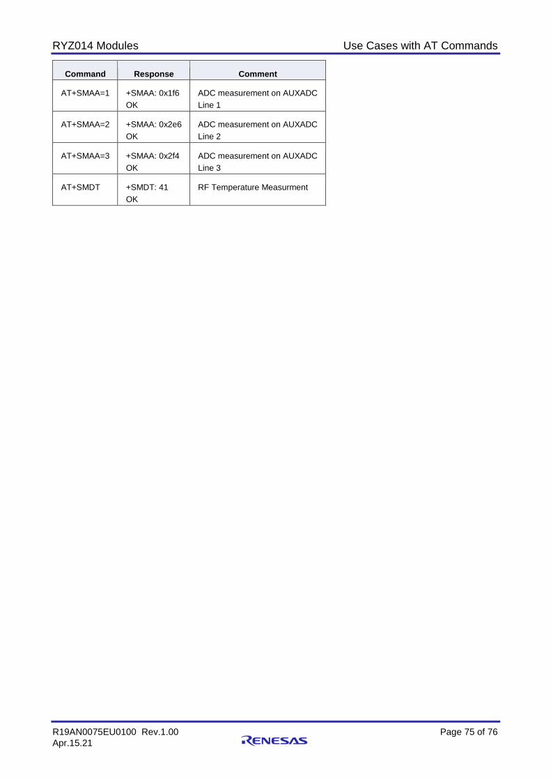
RYZ014 Modules Use Cases with AT Commands
R19AN0075EU0100 Rev.1.00 Page 75 of 76 Apr.15.21
Command Response Comment
AT+SMAA=1 +SMAA: 0x1f6 OK
ADC measurement on AUXADC Line 1
AT+SMAA=2 +SMAA: 0x2e6 OK
ADC measurement on AUXADC Line 2
AT+SMAA=3 +SMAA: 0x2f4 OK
ADC measurement on AUXADC Line 3
AT+SMDT +SMDT: 41 OK
RF Temperature Measurment
RYZ014 Modules Use Cases with AT Commands
R19AN0075EU0100 Rev.1.00 Page 76 of 76 Apr.15.21
Revision History
Rev. Date Description
Page Summary 1.00 Apr.15.21 — Initial release
© 2021 Renesas Electronics Corporation. All rights reserved.
Notice 1. Descriptions of circuits, software and other related information in this document are provided only to illustrate the operation of semiconductor products
and application examples. You are fully responsible for the incorporation or any other use of the circuits, software, and information in the design of your product or system. Renesas Electronics disclaims any and all liability for any losses and damages incurred by you or third parties arising from the use of these circuits, software, or information.
2. Renesas Electronics hereby expressly disclaims any warranties against and liability for infringement or any other claims involving patents, copyrights, or other intellectual property rights of third parties, by or arising from the use of Renesas Electronics products or technical information described in this document, including but not limited to, the product data, drawings, charts, programs, algorithms, and application examples.
3. No license, express, implied or otherwise, is granted hereby under any patents, copyrights or other intellectual property rights of Renesas Electronics or others.
4. You shall not alter, modify, copy, or reverse engineer any Renesas Electronics product, whether in whole or in part. Renesas Electronics disclaims any and all liability for any losses or damages incurred by you or third parties arising from such alteration, modification, copying or reverse engineering.
5. Renesas Electronics products are classified according to the following two quality grades: “Standard” and “High Quality”. The intended applications for each Renesas Electronics product depends on the product’s quality grade, as indicated below. "Standard": Computers; office equipment; communications equipment; test and measurement equipment; audio and visual equipment; home
electronic appliances; machine tools; personal electronic equipment; industrial robots; etc. "High Quality": Transportation equipment (automobiles, trains, ships, etc.); traffic control (traffic lights); large-scale communication equipment; key
financial terminal systems; safety control equipment; etc. Unless expressly designated as a high reliability product or a product for harsh environments in a Renesas Electronics data sheet or other Renesas Electronics document, Renesas Electronics products are not intended or authorized for use in products or systems that may pose a direct threat to human life or bodily injury (artificial life support devices or systems; surgical implantations; etc.), or may cause serious property damage (space system; undersea repeaters; nuclear power control systems; aircraft control systems; key plant systems; military equipment; etc.). Renesas Electronics disclaims any and all liability for any damages or losses incurred by you or any third parties arising from the use of any Renesas Electronics product that is inconsistent with any Renesas Electronics data sheet, user’s manual or other Renesas Electronics document.
6. When using Renesas Electronics products, refer to the latest product information (data sheets, user’s manuals, application notes, “General Notes for Handling and Using Semiconductor Devices” in the reliability handbook, etc.), and ensure that usage conditions are within the ranges specified by Renesas Electronics with respect to maximum ratings, operating power supply voltage range, heat dissipation characteristics, installation, etc. Renesas Electronics disclaims any and all liability for any malfunctions, failure or accident arising out of the use of Renesas Electronics products outside of such specified ranges.
7. Although Renesas Electronics endeavors to improve the quality and reliability of Renesas Electronics products, semiconductor products have specific characteristics, such as the occurrence of failure at a certain rate and malfunctions under certain use conditions. Unless designated as a high reliability product or a product for harsh environments in a Renesas Electronics data sheet or other Renesas Electronics document, Renesas Electronics products are not subject to radiation resistance design. You are responsible for implementing safety measures to guard against the possibility of bodily injury, injury or damage caused by fire, and/or danger to the public in the event of a failure or malfunction of Renesas Electronics products, such as safety design for hardware and software, including but not limited to redundancy, fire control and malfunction prevention, appropriate treatment for aging degradation or any other appropriate measures. Because the evaluation of microcomputer software alone is very difficult and impractical, you are responsible for evaluating the safety of the final products or systems manufactured by you.
8. Please contact a Renesas Electronics sales office for details as to environmental matters such as the environmental compatibility of each Renesas Electronics product. You are responsible for carefully and sufficiently investigating applicable laws and regulations that regulate the inclusion or use of controlled substances, including without limitation, the EU RoHS Directive, and using Renesas Electronics products in compliance with all these applicable laws and regulations. Renesas Electronics disclaims any and all liability for damages or losses occurring as a result of your noncompliance with applicable laws and regulations.
9. Renesas Electronics products and technologies shall not be used for or incorporated into any products or systems whose manufacture, use, or sale is prohibited under any applicable domestic or foreign laws or regulations. You shall comply with any applicable export control laws and regulations promulgated and administered by the governments of any countries asserting jurisdiction over the parties or transactions.
10. It is the responsibility of the buyer or distributor of Renesas Electronics products, or any other party who distributes, disposes of, or otherwise sells or transfers the product to a third party, to notify such third party in advance of the contents and conditions set forth in this document.
11. This document shall not be reprinted, reproduced or duplicated in any form, in whole or in part, without prior written consent of Renesas Electronics. 12. Please contact a Renesas Electronics sales office if you have any questions regarding the information contained in this document or Renesas
Electronics products.
(Note1) “Renesas Electronics” as used in this document means Renesas Electronics Corporation and also includes its directly or indirectly controlled subsidiaries.
(Note2) “Renesas Electronics product(s)” means any product developed or manufactured by or for Renesas Electronics.
(Rev.4.0-1 November 2017)
Corporate Headquarters Contact information TOYOSU FORESIA, 3-2-24 Toyosu, Koto-ku, Tokyo 135-0061, Japan www.renesas.com
For further information on a product, technology, the most up-to-date version of a document, or your nearest sales office, please visit: www.renesas.com/contact/.
Trademarks Renesas and the Renesas logo are trademarks of Renesas Electronics Corporation. All trademarks and registered trademarks are the property of their respective owners.