Research Article Optimal Energy Consumption for Mobile ...
12
Research Article Optimal Energy Consumption for Mobile Manipulators Executing Door-Opening Task Changyou Ma , 1,2 Haibo Gao , 1 Liang Ding , 1 Jianguo Tao, 1 Kerui Xia, 1 Haitao Yu, 1 and Zongquan Deng 1 1 State Key Laboratory of Robotics and System, Harbin Institute of Technology, Harbin 150001, China 2 College of Mechanical Engineering, Jiamusi University, Jiamusi 154007, China Correspondence should be addressed to Haibo Gao; [email protected] and Liang Ding; [email protected] Received 17 November 2017; Accepted 26 March 2018; Published 25 June 2018 Academic Editor: Marco Spadini Copyright © 2018 Changyou Ma et al. is is an open access article distributed under the Creative Commons Attribution License, which permits unrestricted use, distribution, and reproduction in any medium, provided the original work is properly cited. As a substitute for humans, the mobile manipulator has become increasingly vital for on-site rescues at Nuclear Power Plants (NPPs) in recent years. e high energy efficiency of the mobile manipulator when executing specific rescue tasks is of great importance for the mobile manipulator. is paper focuses on the energy consumption of a robot executing the door-opening task, in a scenario mimicking an NPP rescue. We present an energy consumption optimization scheme to determine the optimal base position and joint motion of the manipulator. We developed a two-step procedure to solve the optimization problem, taking the quadric terms of the joint torques as the objective function. Firstly, the rotational motion of the door is parameterized by using piecewise fiſth-order polynomials, and the parameters of the polynomials are optimized by minimizing the joint torques at the specified base position using the Quasi-Newton method. Second, the global optimal movement of the manipulator for executing the door-opening task is acquired by means of searching a grid for feasible base positions. Comprehensive door-opening experiments using a mobile manipulator platform were conducted. e effectiveness of the proposed method has been demonstrated by the results of physical experiments. 1. Introduction Mobile manipulators, as a replacement for humans, play a key role when they perform rescue tasks in the extreme environ- ment of a nuclear power plant (NPP), such as door-open- ing and turning a valve. e energy optimization of rescue tasks performed by a robotic arm, in particular that of the fundamental task of door-opening, is of great importance when the energy supply is restricted by the capacity of the battery with which the robot can be equipped, unlike in traditional methods where energy is supplied via a cable. e Fukushima Daiichi NPP accident in Japan on March 11, 2011, was triggered by an earthquake of magnitude 9.0 and the resultant tsunami marked the beginning of the worst nuclear accident of the last two decades [1–3]. Nuclear power is an important resource and (NPPs) have recently undergone rapid development in China [4]. e complexity of the NPP’s structure, the radioactive working environment, and some special characteristics, such as high temperatures and high pressure, render nuclear disaster rescue very difficult. e dangers caused by such an accident mean that mobile robot plays an important role in the NPP rescue process. Aſter the Fukushima Daiichi NPP accident, the Defense Advanced Research Projects Agency (DARPA) initiated a new challenge in 2012, the DARPA Robotics Challenge (DRC) [5], including eight rescue tasks to test the capabilities of teams, as well as of individuals. e tasks were ranked by DARPA in terms of difficulty as Valve (easiest), Terrain and Hose (easier), Door, Debris, Wall, and Ladder (harder), and Vehicle (hardest) [6]. In this paper, we focus on the energy consumption of a mobile manipulator performing the door-opening task. Nagatani and Yuto proposed a method that allows a mobile manipulator, named the “YAMABICO-10” robot, to open a door and pass through the doorway. In their approach, they applied to the mobile manipulator control system the concept of action primitives, which control the “YAMABICO-10” Hindawi Mathematical Problems in Engineering Volume 2018, Article ID 8987953, 11 pages https://doi.org/10.1155/2018/8987953
-
Upload
khangminh22 -
Category
Documents
-
view
1 -
download
0
Transcript of Research Article Optimal Energy Consumption for Mobile ...
Research ArticleOptimal Energy Consumption for Mobile ManipulatorsExecuting Door-Opening Task
ChangyouMa 12 Haibo Gao 1 Liang Ding 1 Jianguo Tao1 Kerui Xia1
Haitao Yu1 and Zongquan Deng1
1State Key Laboratory of Robotics and System Harbin Institute of Technology Harbin 150001 China2College of Mechanical Engineering Jiamusi University Jiamusi 154007 China
Correspondence should be addressed to Haibo Gao gaohaibohiteducn and Liang Ding liangdinghiteducn
Received 17 November 2017 Accepted 26 March 2018 Published 25 June 2018
Academic Editor Marco Spadini
Copyright copy 2018 Changyou Ma et al This is an open access article distributed under the Creative Commons Attribution Licensewhich permits unrestricted use distribution and reproduction in any medium provided the original work is properly cited
As a substitute for humans themobilemanipulator has become increasingly vital for on-site rescues atNuclear Power Plants (NPPs)in recent yearsThe high energy efficiency of themobile manipulator when executing specific rescue tasks is of great importance forthe mobile manipulator This paper focuses on the energy consumption of a robot executing the door-opening task in a scenariomimicking an NPP rescue We present an energy consumption optimization scheme to determine the optimal base position andjoint motion of themanipulatorWe developed a two-step procedure to solve the optimization problem taking the quadric terms ofthe joint torques as the objective function Firstly the rotational motion of the door is parameterized by using piecewise fifth-orderpolynomials and the parameters of the polynomials are optimized by minimizing the joint torques at the specified base positionusing the Quasi-Newton method Second the global optimal movement of the manipulator for executing the door-opening taskis acquired by means of searching a grid for feasible base positions Comprehensive door-opening experiments using a mobilemanipulator platform were conducted The effectiveness of the proposed method has been demonstrated by the results of physicalexperiments
1 Introduction
Mobilemanipulators as a replacement for humans play a keyrole when they perform rescue tasks in the extreme environ-ment of a nuclear power plant (NPP) such as door-open-ing and turning a valve The energy optimization of rescuetasks performed by a robotic arm in particular that of thefundamental task of door-opening is of great importancewhen the energy supply is restricted by the capacity of thebattery with which the robot can be equipped unlike intraditional methods where energy is supplied via a cable
The Fukushima Daiichi NPP accident in Japan on March11 2011 was triggered by an earthquake of magnitude 90and the resultant tsunami marked the beginning of the worstnuclear accident of the last two decades [1ndash3] Nuclear poweris an important resource and (NPPs) have recently undergonerapid development in China [4]The complexity of the NPPrsquosstructure the radioactive working environment and some
special characteristics such as high temperatures and highpressure render nuclear disaster rescue very difficult Thedangers caused by such an accident mean that mobile robotplays an important role in the NPP rescue process Afterthe Fukushima Daiichi NPP accident the Defense AdvancedResearch Projects Agency (DARPA) initiated a new challengein 2012 the DARPARobotics Challenge (DRC) [5] includingeight rescue tasks to test the capabilities of teams as well asof individuals The tasks were ranked by DARPA in terms ofdifficulty as Valve (easiest) Terrain and Hose (easier) DoorDebris Wall and Ladder (harder) and Vehicle (hardest) [6]
In this paper we focus on the energy consumption ofa mobile manipulator performing the door-opening taskNagatani and Yuto proposed a method that allows a mobilemanipulator named the ldquoYAMABICO-10rdquo robot to open adoor and pass through the doorway In their approach theyapplied to themobilemanipulator control system the conceptof action primitives which control the ldquoYAMABICO-10rdquo
HindawiMathematical Problems in EngineeringVolume 2018 Article ID 8987953 11 pageshttpsdoiorg10115520188987953
2 Mathematical Problems in Engineering
robot according to sequences of planned motion primitivesHowever each action primitive was designed with an erroradjustment mechanism to handle the accumulated position-ing error of the mobile base [7ndash9] Peterson et al presentedthe design and implementation of a door-opening controllerusing a hybrid dynamic system model when using thissimple controller the radius and center of rotation of thedoor are estimated online The results of their experimentsdemonstrated that off-the-shelf algorithms for forcetorquecontrol are very effective for solving the task of grasping thehandle and opening the door [10] Chung et al [11] proposeda control strategy for the door-opening procedure executedby a service robot PSR1 which utilized a three-fingered robothand for grasping the door handle Two active-sensing strate-gies were proposed to estimate the kinematic parameters ina real environment An integrated strategy of motion coor-dination was presented based on the components of threesubsystems a robotic hand a robotic arm and amobile robotThe force and position control were successfully achieved byusing the contact force of the three-fingered robotic handduring the door-opening procedures
Ahmad et al designed a modular and reconfigurablerobot (MRR)mounted on a wheeledmobile platform [12 13]They proposed a newmethod that utilizes the multiple work-ing modes of the MRR modules to prevent the occurrence oflarge internal forces that arise because of positioning errorsor imprecise modeling of the robot or its environments Byselectively switching the joints of the MRR to work in passivemode during the door-opening operation the controllerdesignwas significantly simplified Zhang et al [14] presenteda multiple mode control system of a two-degree-of-freedom(DOFs) compact wrist that can work in active mode withposition or torque control or in passive mode with wrist-environment interactive force compensationThey verified intheir door-opening experiments that the wrist could movefreely without generating excessive internal force Kobayashiet al [15] designed a rescue robot series named UMRS Therobot had a special end-effector which can grip and rotatecylindrical type and lever type door handles The robotequipped with a door-opening system was capable of movingfreely through rooms even if there were doors between themKlingbeil et al [16] proposed a method that used vision toidentify a small number of key positions such as the axis ofrotation of the door handle and the end-point of the doorhandle to allow amanipulator to open various types of doorswithout prior knowledge of their parameters Karayiannidiset al [17] developed an algorithm that can be implemented ina velocity-controlled manipulator the end- effector which isequippedwith force sensing capabilitiesThemethod consistsof a velocity controller which uses force measurements andan estimation of the radial direction based on adaptiveestimates of the position of the door hingeThe control actioncan be decomposed into an estimated radial and tangentialdirection following the concept of hybrid forcemotion con-trol Endres et al [18] presented an approach for learninga dynamic model of a door from sensor observations andutilizing it for effectively swinging the door open to thedesired angle The learned models enable the realization ofdynamic door-opening strategies and reduce the complexityof the door-opening task
As proposed in [19] a power efficiency estimation-basedhealth monitoring and fault detection method has been de-veloped for a modular and reconfigurable robot (MRR) Thepower efficiency of each of the robotrsquos joints ismeasured usingsensors Luo et al [20] presented the Lagrange interpolationmethod to express each joint trajectory function to realize tra-jectory planning that achieves energyminimization of indus-trial robotic manipulators Field and Stepanenko presentedan iterative dynamic programming method that is modifiedto perform a series of dynamic programming passing overa small reconfigurable grid that covers only a portion of thesolution space at any one pass to plan minimum energy con-sumption trajectories for robotic manipulators [21] Liu et al[22] proposed the fourth-order Runge-Kutta method mul-tiple shooting methods and traversing method to solveoptimal energy trajectory planning for palletizing robot
The objective of this study was to develop an energy con-sumption optimization method for the door-opening proce-dure The main contributions of this paper are summarizedas follows An energy consumption optimization scheme thatfinds the optimal base position and joint motion of the mani-pulator for optimizing energy consumption is presentedSince the end-effector trajectory is assigned according to thetrajectory of the door handle the problem of searching theoptimal manipulator movement by using the parameters ofthe doorrsquos fifth-order splines transforms to a simple paramet-ric optimization problem at each base position The globaloptimal energy-efficient movement of the robotic arm isfinally obtained by exhaustively searching the entire baseposition grid
The rest of the paper is organized as follows In Section 2we introduce the door-opening task and establish the energyconsumption optimization objective function Section 3 pro-vides a description of the mobile modular robot and intro-duces the kinematic and the dynamics model of the manipu-lators In the Section 4 we address the optimization methodand describe numerical simulations The results of our ex-periments are discussed in Section 5 and conclusions are pre-sented in Section 6
2 Formulation of Optimization Problem
21 Door-Opening Operation In this section we proposea door- opening method The following assumptions weremade (1) the door-opening and door handle rotating direc-tions are known (the door is opened toward the left-side andthe door handle is rotated toward the right-side) (2) the dooraxis of rotation is perpendicular to the floor (3) the doormoves in the horizontal 119909119910 plane (4) the mobile platformtravels on the ground which can always be adjusted for astructured laboratory environment and (5) the axis of rota-tion of the first manipulator module is perpendicular to theground
A brief explanation of the door-opening procedure is asfollows
(a) The mobile manipulator moves such that it is posi-tioned in front of the door and grasps the door handle
Mathematical Problems in Engineering 3
Door Trajectory
zdOd xdyd
rdrk
zexe
Oeyezb
xbOb
yb
1205911
1205912
12059131205914
12059151205916
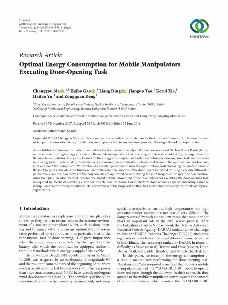
Figure 1 Model of the door-opening procedure with a mobile ma-nipulator
(b) Themobile base remains staticThemanipulator real-izes turning the door handle by tracking a plannedtrajectory
(c) The mobile base still remains static The manipulatorrealizes pulling the door by tracking a planned trajec-tory in the horizontal 119909119910 plane
Amodel of the door-opening procedure using themobilemanipulator is depicted in Figure 1 The figure shows the ori-gin of the reference frame 119874119889 set at the intersection pointof the door hinge the horizontal plane that crosses the originof the reference frame of the mobile manipulator 119874119887 andthe reference frame 119874119890 located at the position of the ma-nipulator end-effector which is used to grasp the door han-dle
In order to plan the path of the mobile manipulator wefirst need to know the accurate value of the door handle radius(119903119896) and the door radius (119903119889) the initial base position of themobile manipulator (119909119887 119910119887 119911119887) and the position of the end-effector which holds the door handle firmly (119909119890 119910119890 119911119890) Thedoormotion is conformed to follow the door trajectory in the119909119910 plane with the center of rotation at (119909119889 119910119889) and a radius 119903119889as shown in the Figure 1 The trajectory radius of pulling thedoor is derived as follows
[119909119890 (119905) minus 119909119889]2 + [119910119890 (119905) minus 119910119889]2 = 1199031198892 (1)
22 Path Planning of Door-Opening In this section we focuson pulling the door handle to open the door During thisprocedure the home position of the mobile base the doorradius and the height of the door handle aremeasuredThesemeasured parameters are then used for planning the path ofthe mobile manipulator that allows it to open the door to thedesired angle
door
door knob
wall
Door Trajectory
The manipulatorJoint(1ndash6)
(0 0) xd rd 120579d(0)
yd120579d(t)
P1
120579d (te) = 120579t119890d
P2
P3
yb
Ob xb
Figure 2 Planar model of pulling door
Themobilemanipulator achieves the action of pulling thedoor by tracking the circle arc represented by the doortrajectory as shown in Figure 2The arc of the door trajectorycan be acquired by using the interpolation points 1198751 1198752 and1198753 In Figure 2 we show the optimal base position (119909119887 119910119887)during the door-opening procedureThemobile manipulatorapproaches the door and stops at any position near the doorThe end-effector is fixed at the same position as the doorhandle during the door-opening procedure and each jointof the manipulator rotates in accordance with the motionplanning The door is pulled in the horizontal 119909119910 plane andthe initial and final angles of the door are consistent Theangles of Joints 1 2 3 4 5 and 6 are denoted as 1205791 1205792 1205793 12057941205795 and 1205796 respectively The input torques of each joint of themanipulator are expressed as 1205911 1205912 1205913 1205914 1205915 and 1205916 respec-tively The angles and the torques are represented in matrixforms as 120579 = [1205791 1205792 1205793 1205794 1205795 1205796]T and 120591 = [1205911 1205912 1205913 1205914 12059151205916]T The angle of the door is expressed as 120579119889 and theconditions on 120579119889 at the start time 119905 = 0 and the end time119905 = 119905119890 are written as
(120579119889 120579119889)10038161003816100381610038161003816119905=0 = (0 0) (120579119889 120579119889)10038161003816100381610038161003816119905=119905
119890
= (120579119905119890119889 0) (2)
The positions of the end-effector at points P1 P2 and P3are computed as follows
120579119889 = 120579door3 119899 119899 = 1 2 3
P123 = [[[
119901119909119901119910119901119911]]]= [[[
119903119889 (1 minus cos 120579119889)1199101 minus 119903119889 sin 120579119889
1199111]]]
(3)
where 119903119889 denotes the rotation radius of the door 120579119889 denotesthe rotation angle of the door when reaching points P1 P2and P3 and 120579door denotes the rotation angle of the door thatallows the mobile manipulator to enter the doorway
The orientations of the end-effector and the door arethe same during the process of pulling the door When theposition of the end-effector remains constant with respect tothe door handle as shown in Figure 1 the variation in therotation matrix during the process denoted by 0119890R
(0)
119889 0119890R(0)
119889
4 Mathematical Problems in Engineering
X1
X2 X3
X4
X5
X6
X7
Y1
Y2 Y3
Y4
Y5
Y6
Y7
Z1
Z2 Z3
Z4
Z5
Z6
Z7
l1 l2 l3 l4
Figure 3 Kinematics configuration of the 6DoF manipulator
denotes the initial rotation matrix of the end-effector afterturning the door handle which can be acquired by usingforward kinematics [23] Then at time t this matrix is multi-plied by a rotationmatrix parameterized by the rotation angleof the door 120579(119905)
119889
0119890R(119905)
119889 = [[[[
cos 120579(119905)119889
minus sin 120579(119905)119889
0sin 120579(119905)119889
cos 120579(119905)119889
00 0 1
]]]]0119890R(0)
119889 (4)
23 Objective Formulation of Energy Consumption The ener-getic cost is an important metric of the energy consumptionof the manipulator We experimentally evaluated the effect ofdifferent base positions of the robot on the energy consump-tion of the manipulator during the door-opening procedureThe input energy 119864119898 of the motor is as follows
119864119898 = int1199051198900119880in sdot 119868119898119889119905 (5)
where 119880in is the power supply voltage and 119868119898 is the instanta-neous current of the DC motor The total energy consumedby the robotrsquos actuators includes the generated mechanicalpower (119875mech) heat power (119875heat) and power losses (Δ loss)This can be described as
119875in = 119875mech + 119875heat + Δ loss (6)
The mechanical power generated by each actuator isrelated to the rotation angular velocity and torqueThereforethe total instantaneous mechanical power during the move-ment of the manipulator can be stated as
119875mech =6sum119895=1
120591119895 sdot 120596119895 (7)
where 119875mech is the total mechanical power of the actuators120591119895 is the torque of each actuators in Nsdotm 120596119895 is the rotationangular velocity of motors in rads and 119895 is the number ofmanipulator joints
The torque 120591 of each actuator is related to the torqueconstant 119870119898 where 119894 is the gear ratio of the joint 120578 is theefficiency of the transmission mechanism and 119868119898 is theinstantaneous current 120591 is provided by
120591 = 119870119898 sdot 119868119898 sdot 119894 sdot 120578 (8)
As shown in (7) the mechanical power consists of thetorque of each actuators and the rotation angular velocity ofthe motors However the angular velocity range of the jointtrajectory planning of the manipulator is relatively smallTherefore the problem of energy optimization becomes thejoint torque optimization problem For the trajectory opti-mization procedure the integral of squared joint torques asthe cost function is known from studies in the literature [25]We introduce the following objective function as a standardfor optimization
119864con (120589) =6sum119895=1
int119905e119905=0
1205912119895119889119905 (9)
Here 120589 denotes the optimal parameter which is chosen asthe position of mobile platform base and the trajectory of thedoor angle To solve the problemof energy consumption opti-mization during the door-opening procedure we determinethe parameters that minimize 119864con
120589lowast = arg min119864con (10)
3 Description of the Mobile Manipulator
31 Kinematics of the Robot The kinematics model configu-ration of the 6-DOF Schunk modular manipulator is shownin Figure 3
The forward kinematics is developed by using the D-Hmethod and represented by 60T
60T = [[
[R3times3 p1times3
0 0 0 1]]]=[[[[[[
11990311 11990312 11990313 11990111990911990321 11990322 11990323 11990111991011990331 11990332 11990333 1199011199110 0 0 1
]]]]]] (11)
where R3times3 and p1times3 are the rotation and translation matrixBased on (11) the joint angles by inverse kinematics calcula-tions can be derived as
Mathematical Problems in Engineering 5
[[[[[[[[[[
120579112057921205793120579412057951205796
]]]]]]]]]]
=[[[[[[[[[[[[
atan 2 (119901119910 119901119909) minus atan 2 (0 plusmnradic1199012119909 + 1199012119910)12057923 minus 1205793
atan 2 (119870 plusmnradic11989723 minus 1198702)atan 2 (minus119903131199041 + 119903231198881 minus11990313119888111988823 minus 11990323119904111988823 + 1199033311990423)
atan 2 [minus11990313 (1198881119888231198884 + 11990411199044) minus 11990323 (1199041119888231198884 minus 11988811199044) 11990333119904231198884 minus11990313119888111990423 minus 11990323119904111990423 minus 1199033311988823]atan 2 (1199046 1198886)
]]]]]]]]]]]]
(12)
where
119870 = 1199012119909 + 1199012119910 + 1199012119911 minus 11988622 minus 1198972321198862
12057923 = atan 2 [minus11988621198883119901119911minus (1198881119901119909 + 1199041119901119910) (1198973 minus 11988621199043) (11988621199043 minus 1198973) 119901zminus (1198863 + 11988621198883) (1198881119901119909 + 1199041119901119910)]
119888119894 = cos (120579119894) 119904119894 = sin (120579119894)
(13)
Because of the redundancy there are eight groups of jointangles through the inverse kinematics for giving the positionof the end-effector An algorithm that canminimize the Eulerdistance in joint space from the initial state should be chosenfrom the eight solutions [23] The Jacobin matrix of the 6-DOF manipulator is
J =[[[[[[[[[[[[
11986911 11986912 11986913 11986914 11986915 1198691611986921 11986922 11986923 11986924 11986925 1198692611986931 11986932 11986933 11986934 11986935 119869360 0 0 11986944 11986945 119869460 0 0 11986954 11986955 00 0 0 0 0 1
]]]]]]]]]]]]
(14)
Based on (14) the angular velocity 120579119894 and acceleration 120579119894of the joint can be derived as
[ 1205791 1205792 1205793 1205794 1205795 1205796]T = Jminus1P
[ 1205791 1205792 1205793 1205794 1205795 1205796]T = Jminus1P + Jminus1P(15)
where P is the position and orientation vector of the end-effector of the manipulator
32 Dynamics of the Robot From the inverse kinematics inthe previous subsection the equations for the motion of thesystem can be written by using 120579119889(119905)
[1205911 1205912 1205913 1205914 1205915 1205916 0]T minus BF = Ψ (120579119889 120579119889 120579119889) (16)
where F = [1198651 1198652 1198653119872111987221198723]T is the force and torqueof the 119909119910119911 direction used for grasping the door handle Ψdenotes the dynamics parameter matrix of the door in (16)including the symmetric positive definitemanipulator inertiamatrix M(120579119889) the vector of centripetal and Coriolis torquesC(120579119889 120579119889) and the vector of gravitational torques g(120579119889) Thematrix B can be obtained as
[B]T = [120597Φ120597120579 120597Φ120597120579119889 ] = [J 120597Φ120597120579119889 ] (17)
where Φ is a function of the relationship between theangle of the door-opening and the joint angle of themanipulatorΦ(120579 120579119889) = 1198912(120579) minus 1198911(120579119889) = 0
1198911 (120579119889) = [[[
119903119889 cos (120579119889)119903119889 sin (120579119889)
119911119889]]]
1198912 (120579) = [[[
119909119887 + 1198894 (119888211990411199043 + 119888311990411199042) + 1198896 (1199045 (11988811199044 minus 1198884 (119904111990421199043 minus 119888211988831199041)) + 1198885 (119888211990411199043 + 119888311990411199042)) + 119886211990411199042119910119887 + 1198896 (1199045 (11990411199044 + 1198884 (119888111990421199043 minus 119888111988821198883)) minus 1198885 (119888111988821199043 + 119888111988831199042)) minus 1198894 (119888111988821199043 + 119888111988831199042) minus 119886211988811199042
119911119889]]]
(18)
where 119911119889 is the coordinate value of the 119911 direction in thecoordinate system of the door 119888119894 and 119904119894 are the abbreviations
for cos(120579119894) and sin(120579119894) respectively and 1198971 1198972 1198973 and 1198974 are thelengths of the links in Figure 3
6 Mathematical Problems in Engineering
We cannot determine 120591 in (16) which means that the sys-tem is indeterminate F can bemeasured by using the six-axisFT sensor and the forward six rows of (16) can be rewrittenas
120591 minus JTF = M (120579) 120579 + V (120579 120579) + G (120579) (19)
where M(120579) is the 6 times 6 inertia matrix of the manipulatorV(120579 120579) is the 6times1 vector of the centrifugal force and Coriolisforce and G(120579) is the 6 times 1 vector of the gravity4 Optimization Method
In this part we focus on the optimal method for the door-opening procedure Since 120579119889(119905) is an infinite dimensionalparameter it is difficult to find the optimal solution that min-imizes119864con rigorouslyTherefore we approximate 120579119889(119905) as thefifth-order spline functions of time and find the coefficients ofsplines that minimize the cost function The position of themobile manipulators base (119909119887 119910119887) is discretized into a gridand at each grid point the quasi-optimal motion of the dooris calculated by using the spline functions
41 Optimal Motion of Door We divide the time interval[0 119905119890] by 119899 and assume that the trajectory of 120579119889(119905) in eachtime interval [119905119894 119905119894+1] (119894 = 0 119899 minus 1 and 119905119895 = 119895119905119890119899 for119895 = 0 119899) is expressed by a fifth-order polynomial functionof time X119894(119905) as
X119894 (119905) = 120579119889119894 + 1198861119894 (119905 minus 119905119894) + 1198862119894 (119905 minus 119905119894)2 + 1198863119894 (119905 minus 119905119894)3+ 1198864119894 (119905 minus 119905119894)4 + 1198865119894 (119905 minus 119905119894)5
(20)
where 1198861119894 1198862119894 1198863119894 1198864119894 and 1198865119894 are the coefficients of the poly-nomial In order to make the input torque 120591 continuous wechoose the function such thatX119894(119905119894+1) = X119894+1(119905119894+1) X119894(119905119894+1) =X119894+1(119905119894+1) X119894(119905119894+1) = X119894+1(119905119894+1) for 119894 = 0 119899 minus 2 and(20) satisfies (2) The coefficients 1198861119894 1198862119894 and 1198863119894 are constantTherefore there are 3119899minus 1 independent parameters and theycan be shown as
Ζ = (1205791198891 120579119889119899minus1 11988640 1198864119899minus1 11988650 1198865119899minus1) (21)
We assume that the door angle 120579119889(119905) is a monotonicallyincreasing function at 119905 = 119905119894 with constraint 0 le 1205791198890 le sdot sdot sdot le120579119889119899minus1 le 120579119889119905
119890
At each position of the mobile manipulatorrsquosbase we search for the values of Ζ that minimize the 119864con byusing the Quasi-Newton method We can find a vector h =[ℎ1 ℎ2 ℎ3 ℎ4 ℎ5 ℎ6 ℎ7]T that conforms to hTB = 0 Eq (16)is multiplied by the vector ℎ and thus we obtain
ℎ11205911 + ℎ21205912 + ℎ31205913 + ℎ41205914 + ℎ51205915 + ℎ61205916 = hTΨ (22)
The manipulator joint torque 120591 satisfying (22) can obtaina specified motion of the door 120579119889(119905) When 120591 is minimized120591 can be shown as
120591 = 119896120591 [ℎ1 ℎ2 ℎ3 ℎ4 ℎ5 ℎ6]T (23)
where 119896120591 is a scalar parameter By using (23) we cancalculate 120591 uniquely We propose a method as shown inAlgorithm 1 to acquire the optimal motion of the door andthe corresponding torque of each joint
42 Optimal Position of the Mobile Manipulatorrsquos Base Wedetermine the optimal position of the mobile manipulatorrsquosbase and the end-effectorrsquos grasp by using the exhaustivemethod The region of (119909119887 119910119887) defined by [119909min
119887 119909max119887 ] times[119910min
119887 119910max119887 ] is divided into a grid where each rectangle is
given by Δ119909 times Δ119910 By calculating the objective function ateach grid point using the method in Section 41 with a setof [120591119894 119883119887119894 119884119887119894] we can determine the optimal position of themobile manipulatorrsquos base The scheme for optimizing theposition is shown in Algorithm 2
43 Numerical Simulations In this section we describethe acquisition of the optimal solution by using numericalsimulations We used MATLAB to find the optimal valuesof 119885 under the constraint that 0 le 1205791198890 le sdot sdot sdot le 120579119889119899minus1 le120579119889119905 The open angle of the door 120579119889(119905) was set to be 1205873 at119905119890 = 20 s The time of the door pulling interval [0 20] wasdivided into ten subintervals that is 119899 = 10 The measuredlength of the door was 085 [m] The mass and inertia ofthe door were set to 357 [kg] and 8598 [kgsdotm2] respectivelyThe lengths of 1198971 1198972 1198973 and 1198974 shown in Figure 3 were03 [m] 03 [m] 0305 [m] and 0415 [m] respectively Themass and inertia of the manipulator were as provided in [26]In the simulation calculation we chose the grid points of(119909119887 119910119887) that is Δ119909 and Δ119910 as 002 [m] the search area of[119909min119887 119909max119887 ]times [119910min
119887 119910max119887 ]was [07m 11m]times [03m 09m]
and the objective function defined by (9) was calculated ateach point Figure 4 shows the contour plot of the objectivefunction119864con It shows that the position of theminimum119864conis (119909119887 119910119887) = (082m 048m) and the value of 119864con is 828 times105 [N2m2s] Figure 5 shows the motion process of the doorin the planning time
5 Experimental Results
51 Robot System The mobile robot system (see Figure 6)consists of a 6-DOF modular manipulator produced bythe SCHUNK Company a four-wheeled platform with twodrive wheels and a two free wheels and two-finger grippermounted on the arm wrist module The 6-DOF modularmanipulator comprises three types ofmodules and each jointmodule consists of a brushless DC motor a harmonic drivea braking system and an encoderThemobile robot system isequippedwith various types of sensors including two six-axisforce sensors and a cameraThe two six-axis force sensors aremounted on themanipulatorwristmodule and the basemod-ule respectively to measure the mechanics date of the door-opening procedure A joystick with associated force feedbackcontrol from the base-mounted 6-axis forcetorque sensoris used for teleoperation A camera is mounted on top of theframe to support 3D displays for continuous teleportationand object recognition An API T3 (Automated PrecisionInc) laser tracker system was used to measure the baseposition in the experiment
52 Controller Description The structure of the proposedcontroller scheme is illustrated in Figure 7 The control
Mathematical Problems in Engineering 7
Input the spline functions119883119894(119905) for all time internalsOutput the torques 120591 and the parameters of Eq (21)For 119894 in range (1 119899)
Based on Quasi-Newton methodwith constraint min119864con
Obtain 119885119894 = (120579119889119894 1198864119894 1198865119894)solve
[120579(119894)1 120579(119894)2 120579(119894)6 ] = Inverse Kinematics (119883119894 (119905))[120591(119894)1 120591(119894)2 120591(119894)6 ] = eq (23) ([120579(119894)1 120579(119894)2 120579(119894)6 120579(119894)119889 ])120591 = sum(120591(119894))119894 = 119894 + 1
EndReturn 120591 119885119894 = (120579119889119894 1198864119894 1198865119894)
Algorithm 1 Select the optimal motion of door
Input [120591119894 119883119887119894 119884119887119894]Output the minimum 119864con and the corresponding base position [119883119887min 119884119887min]119864conmin = infinFor 119894 in range (1 119899)119864119894con
If 119864119894con lt 119864conminthen 119864conmin = 119864119894con 119883119887min = 119883119887119894 119884119887min = 119884119887119894119894 = 119894 + 1
EndReturn 119864conmin (119883119887min 119884119887min)
Algorithm 2 Search the optimal position of robot base
080911112131415
G1G2G3
G4
08 09 10 1107xb (m)
03
04
05
06
07
08
09
yb
(m)
target (xb yb)
times106 (N2m2S)
Figure 4 Objective for base position(119909119887 119910119887)
system is shown in terms of the composition of the PD-computed torque controller The computed torque controller(CTC) uses a feedback linearization method It is assumedthat the desired motion trajectory for the manipulator is de-termined by a path planner [27]The tracking error is definedas
119890 (119905) = 120579119903 (119905) minus 120579 (119905) (24)
where 119890(119905) is the error of the plant 120579119903(119905) is the desired inputvariable which is the desired joint angular displacement in
2 4 6 8 10 12 14 16 18 200Time (s)
minus25minus2
minus15minus1
minus050
051
152
25
120579 d(t) (
rad )
120579 d(t) (
rad
s )120579
d(t) (
rad
s2)
120579d(t)120579d(t)120579d(t)
Figure 5 Optimal moment of the door
the control system and 120579(119905) is the actual joint angular dis-placement
The control torque is described as
= V (120579 120579) 120579 + G (120579) +M (120579) u (25)
The dynamic model in (19) is equivalent to a decoupledlinear time-invariant system
8 Mathematical Problems in Engineering
(a) Guest computerand power pack inProtective housing
(f) API T3 laser trackersystem
(c) Host computer andjoy stick
(d) Six-axisforcetorque sensor
(e) Gripper
(b) Vision
Figure 6 Software and hardware of the mobile manipulator
Trajectoryplanning
Optimalalgorithm
Mobilemanipulator
KinematicsModel
The computed torque control
Off-line Trajectory planning
On-line Trajectory tracking
120579d 120579d 120579d
120579r
120579r
minus+
+
++
+
e Kds + Kpu
M(120579)
C(120579 120579) 120579 + G(120579)
120591
120579
120579
Figure 7 Block diagram of the computed torque controller
= u (26)
Considering that the desired trajectory 120579119903(119905) is deter-mined 120579119903 and 120579119903 are known This is a nonlinear feedbackcontrol law that guarantees tracking of the desired door-opening trajectory Selecting PD feedback for 119906(119905) results inthe PD-computed torque controller
u = r + Kd (r minus ) + Kp (120579d minus 120579)= r + Kde + Kpe
(27)
whereKd andKp are the controller gains and are positive defi-nite diagonal matricesKp = diag(82 104 85 74 125 90)Kd = diag(70 95 80 70 115 85) The closed-loop systemequation is
r + Kde + Kpe = 0 (28)
By substituting (27) into (25) we obtain the completeexpression of the control law
= M (120579) ( 120579119903 + Kd 119890 + Kp119890) + V (120579 120579) 120579 + G (120579) (29)
53 Experimental Setup The experiments were conductedin a simulated NPPs internal environment and a real NPPs
fire door with a door closer was used The trajectory duringdoor-opening was calculated using the method described inSection 22 The entire door-opening procedure was realizedusing C++ programming with a cycle of 20ms Four groupsof experiments using different base positionswere conductedIn the first group the base position denoted by G1 was(119909119887 = 082m 119910119887 = 048m)This is the point of the minimumobjective function according to the numerical simulationsIn the second group denoted by G2 was (119909119887 = 085m119910119887 = 055m) In the third group the base position denoted byG3 was (119909119887 = 072m 119910119887 = 055m) In the fourth group thebase position denoted by G4 was (119909119887 = 095m 119910119887 = 07m)The points G1 G2 G3 andG4 have been pointed andmarkedin Figure 4G1 is the point of theminimumobjective functionas shown in Figure 4
Figure 8 shows sequential pictures of the door-openingexperiments The duration of the door-opening procedureis 20 s which is the same as that the numerical simulationdescribed in Section 43 The mobile robot system can mea-sure the instantaneous current in the door-opening proce-dureThe torque of each joint was calculated using the valuesof the instantaneous current and (8) Therefore the valueof 119864con could be calculated in the various groups of experi-ments The test data were acquired at a sampling frequencyof 50Hz The experiments were conducted more than threetimes under the same conditions to ensure the repeatability
Mathematical Problems in Engineering 9
(a) (b)
Figure 8 Door-opening experiment (a) initial moments (b) pulling the door
and effectiveness of the experimental results During the com-parison of the energy consumption in the different groups ofexperiments the end-effector grasped the door handle in thesame positions according to the door-opening path planningprovided in Section 2
The performance parameters of the motors and actuatingdevices of joints are shown in Table 1
54 Comparison of the Different Base Positions Thematrix 120591119895when the robot base is positioned at G1 G2 G3 and G4 canbe calculated by using (8) and the performance parametersof the joints shown in Table 1 The values of sum6119895=1 1205912119895 duringthe door-opening procedure are shown in Figure 9The sumsof the objective function for the different base positions areshown in Table 2
The119864con curves shown in Figure 9 demonstrate that ener-gy consumption is optimized at base position G1 Figure 9shows that the torque is increased during the start and endof the door-opening procedure because of the resistance ofthe door handle and the door closer It can be clearly seenin Figure 9 that in comparison with other selected positionsover time G1 is better than the other selected base positionsminimizing the objective function not only in terms of theaccumulated value of119864con shown in Table 2 but also in termsof sustaining the lowest value of sum6119895=1 1205912119895 This verifies theeffectiveness of the proposed algorithm The experimentvalue of 119864con is larger than the simulation value at the samebase position (G1) because the simulation only consideredthe mechanical power of (6) however the experiment valueincluded the generated mechanical power heat power andpower losses due to factors such as friction
Figures 10 and 11 show the optimal trajectories of the jointangle 120579119894 and the torque 120591 of each joint for G1 It can be seen inFigure 11 that the values of the jointsrsquo torques 1205912 1205913 are largerthan those of the other torques Figure 10 shows that in themotion during the door-opening procedure the angle degreeof Joints 2 and 3 is larger than that of the other joints
0 5 10 15 200
Time (s)
G1G2
G3G4
1
2
3
4
5(times10
4N2m
2)
sum6 j=
11206492 j
Figure 9 Comparison of the square sums of joint torque at thedifferent base positions
6 Conclusion
In this paper we proposed a novel energy consumptionoptimization scheme for a mobile manipulator executing thedoor-opening task Focusing on the power consumption ofthe manipulator during the entire task period we chose thequadric terms of the joint torques as the objective functionFurthermore in this study a two-step optimization procedurewas developed to solve the corresponding joint trajectories ofthe manipulator In the first step the feasible base positionsof the manipulator are decentralized into a grid in order tosimplify the entire optimization process A piecewise fifth-order polynomials over time is utilized to parameterize therotational motion of the door By applying the Quasi-Newtonmethod the local optimal trajectories of the manipulator areobtained for a given base position In the second step theoptimal base position is attained via searching the decen-tralized grid of the feasible base positions The numericalresults when the proposed method was applied showed that
10 Mathematical Problems in Engineering
Table 1 Performance parameters of drive devices and actuating devices of joints
Joint of arm 119895 119880119894119899(V) 119870119898119895(mNsdotm) 119894119895 119877119895(Ω) 120578119895()Joints 1 and 2 24 314 596 15 085Joints 3 and 4 24 38 625 06 085Joints 5 and 6 24 16 552 01 085
Table 2 Value of 119864con at different base positions
Objective function G1 G2 G3 G4119864con (N2m2s) 297 times 106 165 times 107 279 times 107 295 times 107
minus150
minus100
minus50
0
50
100
120579(d
eg)
5 10 15 200Time (s)
120579112057921205793
120579412057951205796
Figure 10 Angle of each joint (G1)
energy consumption was optimized at base position G1 Theexperimental results for door-opening at the different basepositions demonstrate the effectiveness of the method pro-posed in this study The proposed method will be useful forthe development of the NPP rescue robots
Conflicts of Interest
The authors declare no potential conflicts of interest withrespect to the research authorship andor publication of thisarticle
Acknowledgments
This work was supported by the National Key Basic ResearchDevelopment Plan Project of China (973) (2013CB035502)Project supported by the Foundation for Innovative ResearchGroups of the National Natural Science Foundation of China(Grant no 51521003) Research Project of State Key Labo-ratory of Mechanical System and Vibration (MSV201610)Harbin Talent Program for Distinguished Young Scholars
5 10 15 200Time (s)
minus50
minus40
minus30
minus20
minus10
0
10
20
30
40
120591(N
m)
120591112059121205913
120591412059151205916
Figure 11 Torque of each joint (G1)
(no 2014RFYXJ001) Heilongjiang Province Higher Edu-cation Project of Basic Scientific Research (2017-KYYWF-0568) Harbin Applied Technology Project of Research andDevelopment (2015RQQXJ081) and ldquo111rdquo Project (B07018)
References
[1] E Sciubba ldquoFukushima There are lessons to be learnt on bothsidesrdquo Energies vol 4 no 5 pp 818ndash825 2011
[2] N Sasaki T Owari and F E Putz ldquoTime to substitute woodbioenergy for nuclear power in Japanrdquo Energies vol 4 no 7 pp1051ndash1057 2011
[3] J Ma J Luo H Pu Y Peng S Xie and J Gu ldquoDesign simu-lation and manufacturing of a tracked robot for nuclear acci-dentsrdquo in Proceedings of the 2014 IEEE International Conferenceon Robotics and Biomimetics IEEE ROBIO 2014 pp 1828ndash1833Indonesia December 2014
[4] G Wu P Ju X Song C Xie and W Zhong ldquoInteraction andcoordination among nuclear power plants power grids andtheir protection systemsrdquo Energies vol 9 no 4 article no 3062016
[5] M DeDonato V Dimitrov R Du et al ldquoHuman-in-the-loopcontrol of a humanoid robot for disaster response A reportfrom the DARPA robotics challenge trialsrdquo Journal of FieldRobotics vol 32 no 2 pp 275ndash292 2015
[6] H A Yanco A Norton W Ober D Shane A Skinner and JVice ldquoAnalysis of human-robot interaction at the DARPA ro-botics challenge trialsrdquo Journal of Field Robotics vol 32 no 3pp 420ndash444 2015
Mathematical Problems in Engineering 11
[7] K Nagatani and S Yuta ldquoDesigning a behavior to open adoor and to pass through a door-way using a mobile robotequippedwith amanipulatorrdquo inProceedings of the IEEERSJGIInternational Conference on Intelligent Robots and Systems Part3 (of 3) pp 847ndash853 September 1994
[8] K Nagatani and S Yuta ldquoDesigning strategy and implementa-tion of mobile manipulator control system for opening doorrdquoin Proceedings of the 1996 13th IEEE International Conferenceon Robotics and Automation Part 1 (of 4) pp 2828ndash2834 April1996
[9] K Nagatani and S Yuta ldquoExperiment on opening-door-be-havior by an autonomous mobile robot with a manipulatorrdquoin Proceedings of the 1995 IEEERSJ International Conference onIntelligent Robots and Systems Part 3 (of 3) pp 45ndash50 August1995
[10] L Peterson D Austin and D Kragic ldquoHigh-level control of amobilemanipulator for door openingrdquo inProceedings of the Pro-ceedings 2000 IEEERSJ International Conference on IntelligentRobots and Systems (IROS 2000) pp 2333ndash2338 TakamatsuJapan
[11] W Chung C Rhee Y Shim H Lee and S Park ldquoDoor-Open-ing control of a service robot using the multifingered robothandrdquo IEEE Transactions on Industrial Electronics vol 56 no10 pp 3975ndash3984 2009
[12] S Ahmad and G Liu ldquoA door opening method by modular re-configurable robot with joints working on passive and activemodesrdquo inProceedings of the 2010 IEEE International Conferenceon Robotics and Automation ICRA 2010 pp 1480ndash1485 USAMay 2010
[13] S Ahmad H Zhang and G Liu ldquoMultiple working mode con-trol of door-opening with a mobile modular and reconfigurablerobotrdquo IEEEASME Transactions on Mechatronics vol 18 no 3pp 833ndash844 2013
[14] H Zhang Y Liu and G Liu ldquoMultiple mode control of acompact wrist with application to door openingrdquoMechatronicsvol 23 no 1 pp 10ndash20 2013
[15] S Kobayashi Y Kobayashi Y Yamamoto et al ldquoDevelopmentof a door opening system on rescue robot for search ldquoUMRS-2007rdquordquo in Proceedings of the SICE Annual Conference 2008- International Conference on Instrumentation Control andInformation Technology pp 2062ndash2065 Japan August 2008
[16] E Klingbeil A Saxena and A Y Ng ldquoLearning to open newdoorsrdquo in Proceedings of the 23rd IEEERSJ 2010 InternationalConference on Intelligent Robots and Systems IROS 2010 pp2751ndash2757 Taiwan October 2010
[17] Y Karayiannidis C Smith F E Vina P Ogren and D KragicldquoldquoOpen sesamerdquo adaptive forcevelocity control for openingunknown doorsrdquo in Proceedings of the 25th IEEERSJ Interna-tional Conference on Robotics and Intelligent Systems IROS 2012pp 4040ndash4047 Portugal October 2012
[18] F Endres J Trinkle and W Burgard ldquoLearning the dynamicsof doors for robotic manipulationrdquo in Proceedings of the 201326th IEEERSJ International Conference on Intelligent Robotsand Systems New Horizon IROS 2013 pp 3543ndash3549 JapanNovember 2013
[19] J Yuan G Liu and B Wu ldquoPower efficiency estimation-basedhealth monitoring and fault detection of modular and reconfig-urable robotrdquo IEEE Transactions on Industrial Electronics vol58 no 10 pp 4880ndash4887 2011
[20] L-P Luo C Yuan R-J Yan et al ldquoTrajectory planning forenergy minimization of industry robotic manipulators usingthe Lagrange interpolation methodrdquo International Journal of
Precision Engineering and Manufacturing vol 16 no 5 pp 911ndash917 2015
[21] G Field and Y Stepanenko ldquoIterative dynamic programmingan approach tominimumenergy trajectory planning for roboticmanipulatorsrdquo in Proceedings of the IEEE International Confer-ence on Robotics and Automation vol 3 pp 2755ndash2760 IEEEMinneapolis Minn USA April 1996
[22] Y Liu L Liang H Han and S Zhang ldquoA method of energy-optimal trajectory planning for palletizing robotrdquoMathematicalProblems in Engineering vol 2017 10 pages 2017
[23] J Li J Tao L DingHGao Z Deng andK Xia ldquoTwisting doorhandles and pulling open doors with a mobile manipulatorrdquo inProceedings of the IEEE International Conference onRobotics andBiomimetics IEEE-ROBIO 2015 pp 686ndash691 China December2015
[24] H Zhuang H Gao L Ding Z Liu and Z Deng ldquoMethod foranalyzing articulated torques of heavy-duty six-legged robotrdquoChinese Journal of Mechanical Engineering vol 26 no 4 pp801ndash812 2013
[25] A Vergnano C Thorstensson B Lennartson et al ldquoModelingand optimization of energy consumption in cooperative multi-robot systemsrdquo IEEE Transactions on Automation Science andEngineering vol 9 no 2 pp 423ndash428 2012
[26] L Ding K Xia H Gao G Liu and Z Deng ldquoRobust adaptivecontrol of door opening by a mobile rescue manipulator basedon unknown-force-related constraints estimationrdquo Roboticavol 36 no 1 pp 119ndash140 2018
[27] S Soltani and F Piltan ldquoDesign artificial nonlinear controllerbased on computed torque like controller with tunable gainrdquoWorld Applied Sciences Journal vol 14 no 9 pp 1306ndash1312 2011
Hindawiwwwhindawicom Volume 2018
MathematicsJournal of
Hindawiwwwhindawicom Volume 2018
Mathematical Problems in Engineering
Applied MathematicsJournal of
Hindawiwwwhindawicom Volume 2018
Probability and StatisticsHindawiwwwhindawicom Volume 2018
Journal of
Hindawiwwwhindawicom Volume 2018
Mathematical PhysicsAdvances in
Complex AnalysisJournal of
Hindawiwwwhindawicom Volume 2018
OptimizationJournal of
Hindawiwwwhindawicom Volume 2018
Hindawiwwwhindawicom Volume 2018
Engineering Mathematics
International Journal of
Hindawiwwwhindawicom Volume 2018
Operations ResearchAdvances in
Journal of
Hindawiwwwhindawicom Volume 2018
Function SpacesAbstract and Applied AnalysisHindawiwwwhindawicom Volume 2018
International Journal of Mathematics and Mathematical Sciences
Hindawiwwwhindawicom Volume 2018
Hindawi Publishing Corporation httpwwwhindawicom Volume 2013Hindawiwwwhindawicom
The Scientific World Journal
Volume 2018
Hindawiwwwhindawicom Volume 2018Volume 2018
Numerical AnalysisNumerical AnalysisNumerical AnalysisNumerical AnalysisNumerical AnalysisNumerical AnalysisNumerical AnalysisNumerical AnalysisNumerical AnalysisNumerical AnalysisNumerical AnalysisNumerical AnalysisAdvances inAdvances in Discrete Dynamics in
Nature and SocietyHindawiwwwhindawicom Volume 2018
Hindawiwwwhindawicom
Dierential EquationsInternational Journal of
Volume 2018
Hindawiwwwhindawicom Volume 2018
Decision SciencesAdvances in
Hindawiwwwhindawicom Volume 2018
AnalysisInternational Journal of
Hindawiwwwhindawicom Volume 2018
Stochastic AnalysisInternational Journal of
Submit your manuscripts atwwwhindawicom

2 Mathematical Problems in Engineering
robot according to sequences of planned motion primitivesHowever each action primitive was designed with an erroradjustment mechanism to handle the accumulated position-ing error of the mobile base [7ndash9] Peterson et al presentedthe design and implementation of a door-opening controllerusing a hybrid dynamic system model when using thissimple controller the radius and center of rotation of thedoor are estimated online The results of their experimentsdemonstrated that off-the-shelf algorithms for forcetorquecontrol are very effective for solving the task of grasping thehandle and opening the door [10] Chung et al [11] proposeda control strategy for the door-opening procedure executedby a service robot PSR1 which utilized a three-fingered robothand for grasping the door handle Two active-sensing strate-gies were proposed to estimate the kinematic parameters ina real environment An integrated strategy of motion coor-dination was presented based on the components of threesubsystems a robotic hand a robotic arm and amobile robotThe force and position control were successfully achieved byusing the contact force of the three-fingered robotic handduring the door-opening procedures
Ahmad et al designed a modular and reconfigurablerobot (MRR)mounted on a wheeledmobile platform [12 13]They proposed a newmethod that utilizes the multiple work-ing modes of the MRR modules to prevent the occurrence oflarge internal forces that arise because of positioning errorsor imprecise modeling of the robot or its environments Byselectively switching the joints of the MRR to work in passivemode during the door-opening operation the controllerdesignwas significantly simplified Zhang et al [14] presenteda multiple mode control system of a two-degree-of-freedom(DOFs) compact wrist that can work in active mode withposition or torque control or in passive mode with wrist-environment interactive force compensationThey verified intheir door-opening experiments that the wrist could movefreely without generating excessive internal force Kobayashiet al [15] designed a rescue robot series named UMRS Therobot had a special end-effector which can grip and rotatecylindrical type and lever type door handles The robotequipped with a door-opening system was capable of movingfreely through rooms even if there were doors between themKlingbeil et al [16] proposed a method that used vision toidentify a small number of key positions such as the axis ofrotation of the door handle and the end-point of the doorhandle to allow amanipulator to open various types of doorswithout prior knowledge of their parameters Karayiannidiset al [17] developed an algorithm that can be implemented ina velocity-controlled manipulator the end- effector which isequippedwith force sensing capabilitiesThemethod consistsof a velocity controller which uses force measurements andan estimation of the radial direction based on adaptiveestimates of the position of the door hingeThe control actioncan be decomposed into an estimated radial and tangentialdirection following the concept of hybrid forcemotion con-trol Endres et al [18] presented an approach for learninga dynamic model of a door from sensor observations andutilizing it for effectively swinging the door open to thedesired angle The learned models enable the realization ofdynamic door-opening strategies and reduce the complexityof the door-opening task
As proposed in [19] a power efficiency estimation-basedhealth monitoring and fault detection method has been de-veloped for a modular and reconfigurable robot (MRR) Thepower efficiency of each of the robotrsquos joints ismeasured usingsensors Luo et al [20] presented the Lagrange interpolationmethod to express each joint trajectory function to realize tra-jectory planning that achieves energyminimization of indus-trial robotic manipulators Field and Stepanenko presentedan iterative dynamic programming method that is modifiedto perform a series of dynamic programming passing overa small reconfigurable grid that covers only a portion of thesolution space at any one pass to plan minimum energy con-sumption trajectories for robotic manipulators [21] Liu et al[22] proposed the fourth-order Runge-Kutta method mul-tiple shooting methods and traversing method to solveoptimal energy trajectory planning for palletizing robot
The objective of this study was to develop an energy con-sumption optimization method for the door-opening proce-dure The main contributions of this paper are summarizedas follows An energy consumption optimization scheme thatfinds the optimal base position and joint motion of the mani-pulator for optimizing energy consumption is presentedSince the end-effector trajectory is assigned according to thetrajectory of the door handle the problem of searching theoptimal manipulator movement by using the parameters ofthe doorrsquos fifth-order splines transforms to a simple paramet-ric optimization problem at each base position The globaloptimal energy-efficient movement of the robotic arm isfinally obtained by exhaustively searching the entire baseposition grid
The rest of the paper is organized as follows In Section 2we introduce the door-opening task and establish the energyconsumption optimization objective function Section 3 pro-vides a description of the mobile modular robot and intro-duces the kinematic and the dynamics model of the manipu-lators In the Section 4 we address the optimization methodand describe numerical simulations The results of our ex-periments are discussed in Section 5 and conclusions are pre-sented in Section 6
2 Formulation of Optimization Problem
21 Door-Opening Operation In this section we proposea door- opening method The following assumptions weremade (1) the door-opening and door handle rotating direc-tions are known (the door is opened toward the left-side andthe door handle is rotated toward the right-side) (2) the dooraxis of rotation is perpendicular to the floor (3) the doormoves in the horizontal 119909119910 plane (4) the mobile platformtravels on the ground which can always be adjusted for astructured laboratory environment and (5) the axis of rota-tion of the first manipulator module is perpendicular to theground
A brief explanation of the door-opening procedure is asfollows
(a) The mobile manipulator moves such that it is posi-tioned in front of the door and grasps the door handle
Mathematical Problems in Engineering 3
Door Trajectory
zdOd xdyd
rdrk
zexe
Oeyezb
xbOb
yb
1205911
1205912
12059131205914
12059151205916
Figure 1 Model of the door-opening procedure with a mobile ma-nipulator
(b) Themobile base remains staticThemanipulator real-izes turning the door handle by tracking a plannedtrajectory
(c) The mobile base still remains static The manipulatorrealizes pulling the door by tracking a planned trajec-tory in the horizontal 119909119910 plane
Amodel of the door-opening procedure using themobilemanipulator is depicted in Figure 1 The figure shows the ori-gin of the reference frame 119874119889 set at the intersection pointof the door hinge the horizontal plane that crosses the originof the reference frame of the mobile manipulator 119874119887 andthe reference frame 119874119890 located at the position of the ma-nipulator end-effector which is used to grasp the door han-dle
In order to plan the path of the mobile manipulator wefirst need to know the accurate value of the door handle radius(119903119896) and the door radius (119903119889) the initial base position of themobile manipulator (119909119887 119910119887 119911119887) and the position of the end-effector which holds the door handle firmly (119909119890 119910119890 119911119890) Thedoormotion is conformed to follow the door trajectory in the119909119910 plane with the center of rotation at (119909119889 119910119889) and a radius 119903119889as shown in the Figure 1 The trajectory radius of pulling thedoor is derived as follows
[119909119890 (119905) minus 119909119889]2 + [119910119890 (119905) minus 119910119889]2 = 1199031198892 (1)
22 Path Planning of Door-Opening In this section we focuson pulling the door handle to open the door During thisprocedure the home position of the mobile base the doorradius and the height of the door handle aremeasuredThesemeasured parameters are then used for planning the path ofthe mobile manipulator that allows it to open the door to thedesired angle
door
door knob
wall
Door Trajectory
The manipulatorJoint(1ndash6)
(0 0) xd rd 120579d(0)
yd120579d(t)
P1
120579d (te) = 120579t119890d
P2
P3
yb
Ob xb
Figure 2 Planar model of pulling door
Themobilemanipulator achieves the action of pulling thedoor by tracking the circle arc represented by the doortrajectory as shown in Figure 2The arc of the door trajectorycan be acquired by using the interpolation points 1198751 1198752 and1198753 In Figure 2 we show the optimal base position (119909119887 119910119887)during the door-opening procedureThemobile manipulatorapproaches the door and stops at any position near the doorThe end-effector is fixed at the same position as the doorhandle during the door-opening procedure and each jointof the manipulator rotates in accordance with the motionplanning The door is pulled in the horizontal 119909119910 plane andthe initial and final angles of the door are consistent Theangles of Joints 1 2 3 4 5 and 6 are denoted as 1205791 1205792 1205793 12057941205795 and 1205796 respectively The input torques of each joint of themanipulator are expressed as 1205911 1205912 1205913 1205914 1205915 and 1205916 respec-tively The angles and the torques are represented in matrixforms as 120579 = [1205791 1205792 1205793 1205794 1205795 1205796]T and 120591 = [1205911 1205912 1205913 1205914 12059151205916]T The angle of the door is expressed as 120579119889 and theconditions on 120579119889 at the start time 119905 = 0 and the end time119905 = 119905119890 are written as
(120579119889 120579119889)10038161003816100381610038161003816119905=0 = (0 0) (120579119889 120579119889)10038161003816100381610038161003816119905=119905
119890
= (120579119905119890119889 0) (2)
The positions of the end-effector at points P1 P2 and P3are computed as follows
120579119889 = 120579door3 119899 119899 = 1 2 3
P123 = [[[
119901119909119901119910119901119911]]]= [[[
119903119889 (1 minus cos 120579119889)1199101 minus 119903119889 sin 120579119889
1199111]]]
(3)
where 119903119889 denotes the rotation radius of the door 120579119889 denotesthe rotation angle of the door when reaching points P1 P2and P3 and 120579door denotes the rotation angle of the door thatallows the mobile manipulator to enter the doorway
The orientations of the end-effector and the door arethe same during the process of pulling the door When theposition of the end-effector remains constant with respect tothe door handle as shown in Figure 1 the variation in therotation matrix during the process denoted by 0119890R
(0)
119889 0119890R(0)
119889
4 Mathematical Problems in Engineering
X1
X2 X3
X4
X5
X6
X7
Y1
Y2 Y3
Y4
Y5
Y6
Y7
Z1
Z2 Z3
Z4
Z5
Z6
Z7
l1 l2 l3 l4
Figure 3 Kinematics configuration of the 6DoF manipulator
denotes the initial rotation matrix of the end-effector afterturning the door handle which can be acquired by usingforward kinematics [23] Then at time t this matrix is multi-plied by a rotationmatrix parameterized by the rotation angleof the door 120579(119905)
119889
0119890R(119905)
119889 = [[[[
cos 120579(119905)119889
minus sin 120579(119905)119889
0sin 120579(119905)119889
cos 120579(119905)119889
00 0 1
]]]]0119890R(0)
119889 (4)
23 Objective Formulation of Energy Consumption The ener-getic cost is an important metric of the energy consumptionof the manipulator We experimentally evaluated the effect ofdifferent base positions of the robot on the energy consump-tion of the manipulator during the door-opening procedureThe input energy 119864119898 of the motor is as follows
119864119898 = int1199051198900119880in sdot 119868119898119889119905 (5)
where 119880in is the power supply voltage and 119868119898 is the instanta-neous current of the DC motor The total energy consumedby the robotrsquos actuators includes the generated mechanicalpower (119875mech) heat power (119875heat) and power losses (Δ loss)This can be described as
119875in = 119875mech + 119875heat + Δ loss (6)
The mechanical power generated by each actuator isrelated to the rotation angular velocity and torqueThereforethe total instantaneous mechanical power during the move-ment of the manipulator can be stated as
119875mech =6sum119895=1
120591119895 sdot 120596119895 (7)
where 119875mech is the total mechanical power of the actuators120591119895 is the torque of each actuators in Nsdotm 120596119895 is the rotationangular velocity of motors in rads and 119895 is the number ofmanipulator joints
The torque 120591 of each actuator is related to the torqueconstant 119870119898 where 119894 is the gear ratio of the joint 120578 is theefficiency of the transmission mechanism and 119868119898 is theinstantaneous current 120591 is provided by
120591 = 119870119898 sdot 119868119898 sdot 119894 sdot 120578 (8)
As shown in (7) the mechanical power consists of thetorque of each actuators and the rotation angular velocity ofthe motors However the angular velocity range of the jointtrajectory planning of the manipulator is relatively smallTherefore the problem of energy optimization becomes thejoint torque optimization problem For the trajectory opti-mization procedure the integral of squared joint torques asthe cost function is known from studies in the literature [25]We introduce the following objective function as a standardfor optimization
119864con (120589) =6sum119895=1
int119905e119905=0
1205912119895119889119905 (9)
Here 120589 denotes the optimal parameter which is chosen asthe position of mobile platform base and the trajectory of thedoor angle To solve the problemof energy consumption opti-mization during the door-opening procedure we determinethe parameters that minimize 119864con
120589lowast = arg min119864con (10)
3 Description of the Mobile Manipulator
31 Kinematics of the Robot The kinematics model configu-ration of the 6-DOF Schunk modular manipulator is shownin Figure 3
The forward kinematics is developed by using the D-Hmethod and represented by 60T
60T = [[
[R3times3 p1times3
0 0 0 1]]]=[[[[[[
11990311 11990312 11990313 11990111990911990321 11990322 11990323 11990111991011990331 11990332 11990333 1199011199110 0 0 1
]]]]]] (11)
where R3times3 and p1times3 are the rotation and translation matrixBased on (11) the joint angles by inverse kinematics calcula-tions can be derived as
Mathematical Problems in Engineering 5
[[[[[[[[[[
120579112057921205793120579412057951205796
]]]]]]]]]]
=[[[[[[[[[[[[
atan 2 (119901119910 119901119909) minus atan 2 (0 plusmnradic1199012119909 + 1199012119910)12057923 minus 1205793
atan 2 (119870 plusmnradic11989723 minus 1198702)atan 2 (minus119903131199041 + 119903231198881 minus11990313119888111988823 minus 11990323119904111988823 + 1199033311990423)
atan 2 [minus11990313 (1198881119888231198884 + 11990411199044) minus 11990323 (1199041119888231198884 minus 11988811199044) 11990333119904231198884 minus11990313119888111990423 minus 11990323119904111990423 minus 1199033311988823]atan 2 (1199046 1198886)
]]]]]]]]]]]]
(12)
where
119870 = 1199012119909 + 1199012119910 + 1199012119911 minus 11988622 minus 1198972321198862
12057923 = atan 2 [minus11988621198883119901119911minus (1198881119901119909 + 1199041119901119910) (1198973 minus 11988621199043) (11988621199043 minus 1198973) 119901zminus (1198863 + 11988621198883) (1198881119901119909 + 1199041119901119910)]
119888119894 = cos (120579119894) 119904119894 = sin (120579119894)
(13)
Because of the redundancy there are eight groups of jointangles through the inverse kinematics for giving the positionof the end-effector An algorithm that canminimize the Eulerdistance in joint space from the initial state should be chosenfrom the eight solutions [23] The Jacobin matrix of the 6-DOF manipulator is
J =[[[[[[[[[[[[
11986911 11986912 11986913 11986914 11986915 1198691611986921 11986922 11986923 11986924 11986925 1198692611986931 11986932 11986933 11986934 11986935 119869360 0 0 11986944 11986945 119869460 0 0 11986954 11986955 00 0 0 0 0 1
]]]]]]]]]]]]
(14)
Based on (14) the angular velocity 120579119894 and acceleration 120579119894of the joint can be derived as
[ 1205791 1205792 1205793 1205794 1205795 1205796]T = Jminus1P
[ 1205791 1205792 1205793 1205794 1205795 1205796]T = Jminus1P + Jminus1P(15)
where P is the position and orientation vector of the end-effector of the manipulator
32 Dynamics of the Robot From the inverse kinematics inthe previous subsection the equations for the motion of thesystem can be written by using 120579119889(119905)
[1205911 1205912 1205913 1205914 1205915 1205916 0]T minus BF = Ψ (120579119889 120579119889 120579119889) (16)
where F = [1198651 1198652 1198653119872111987221198723]T is the force and torqueof the 119909119910119911 direction used for grasping the door handle Ψdenotes the dynamics parameter matrix of the door in (16)including the symmetric positive definitemanipulator inertiamatrix M(120579119889) the vector of centripetal and Coriolis torquesC(120579119889 120579119889) and the vector of gravitational torques g(120579119889) Thematrix B can be obtained as
[B]T = [120597Φ120597120579 120597Φ120597120579119889 ] = [J 120597Φ120597120579119889 ] (17)
where Φ is a function of the relationship between theangle of the door-opening and the joint angle of themanipulatorΦ(120579 120579119889) = 1198912(120579) minus 1198911(120579119889) = 0
1198911 (120579119889) = [[[
119903119889 cos (120579119889)119903119889 sin (120579119889)
119911119889]]]
1198912 (120579) = [[[
119909119887 + 1198894 (119888211990411199043 + 119888311990411199042) + 1198896 (1199045 (11988811199044 minus 1198884 (119904111990421199043 minus 119888211988831199041)) + 1198885 (119888211990411199043 + 119888311990411199042)) + 119886211990411199042119910119887 + 1198896 (1199045 (11990411199044 + 1198884 (119888111990421199043 minus 119888111988821198883)) minus 1198885 (119888111988821199043 + 119888111988831199042)) minus 1198894 (119888111988821199043 + 119888111988831199042) minus 119886211988811199042
119911119889]]]
(18)
where 119911119889 is the coordinate value of the 119911 direction in thecoordinate system of the door 119888119894 and 119904119894 are the abbreviations
for cos(120579119894) and sin(120579119894) respectively and 1198971 1198972 1198973 and 1198974 are thelengths of the links in Figure 3
6 Mathematical Problems in Engineering
We cannot determine 120591 in (16) which means that the sys-tem is indeterminate F can bemeasured by using the six-axisFT sensor and the forward six rows of (16) can be rewrittenas
120591 minus JTF = M (120579) 120579 + V (120579 120579) + G (120579) (19)
where M(120579) is the 6 times 6 inertia matrix of the manipulatorV(120579 120579) is the 6times1 vector of the centrifugal force and Coriolisforce and G(120579) is the 6 times 1 vector of the gravity4 Optimization Method
In this part we focus on the optimal method for the door-opening procedure Since 120579119889(119905) is an infinite dimensionalparameter it is difficult to find the optimal solution that min-imizes119864con rigorouslyTherefore we approximate 120579119889(119905) as thefifth-order spline functions of time and find the coefficients ofsplines that minimize the cost function The position of themobile manipulators base (119909119887 119910119887) is discretized into a gridand at each grid point the quasi-optimal motion of the dooris calculated by using the spline functions
41 Optimal Motion of Door We divide the time interval[0 119905119890] by 119899 and assume that the trajectory of 120579119889(119905) in eachtime interval [119905119894 119905119894+1] (119894 = 0 119899 minus 1 and 119905119895 = 119895119905119890119899 for119895 = 0 119899) is expressed by a fifth-order polynomial functionof time X119894(119905) as
X119894 (119905) = 120579119889119894 + 1198861119894 (119905 minus 119905119894) + 1198862119894 (119905 minus 119905119894)2 + 1198863119894 (119905 minus 119905119894)3+ 1198864119894 (119905 minus 119905119894)4 + 1198865119894 (119905 minus 119905119894)5
(20)
where 1198861119894 1198862119894 1198863119894 1198864119894 and 1198865119894 are the coefficients of the poly-nomial In order to make the input torque 120591 continuous wechoose the function such thatX119894(119905119894+1) = X119894+1(119905119894+1) X119894(119905119894+1) =X119894+1(119905119894+1) X119894(119905119894+1) = X119894+1(119905119894+1) for 119894 = 0 119899 minus 2 and(20) satisfies (2) The coefficients 1198861119894 1198862119894 and 1198863119894 are constantTherefore there are 3119899minus 1 independent parameters and theycan be shown as
Ζ = (1205791198891 120579119889119899minus1 11988640 1198864119899minus1 11988650 1198865119899minus1) (21)
We assume that the door angle 120579119889(119905) is a monotonicallyincreasing function at 119905 = 119905119894 with constraint 0 le 1205791198890 le sdot sdot sdot le120579119889119899minus1 le 120579119889119905
119890
At each position of the mobile manipulatorrsquosbase we search for the values of Ζ that minimize the 119864con byusing the Quasi-Newton method We can find a vector h =[ℎ1 ℎ2 ℎ3 ℎ4 ℎ5 ℎ6 ℎ7]T that conforms to hTB = 0 Eq (16)is multiplied by the vector ℎ and thus we obtain
ℎ11205911 + ℎ21205912 + ℎ31205913 + ℎ41205914 + ℎ51205915 + ℎ61205916 = hTΨ (22)
The manipulator joint torque 120591 satisfying (22) can obtaina specified motion of the door 120579119889(119905) When 120591 is minimized120591 can be shown as
120591 = 119896120591 [ℎ1 ℎ2 ℎ3 ℎ4 ℎ5 ℎ6]T (23)
where 119896120591 is a scalar parameter By using (23) we cancalculate 120591 uniquely We propose a method as shown inAlgorithm 1 to acquire the optimal motion of the door andthe corresponding torque of each joint
42 Optimal Position of the Mobile Manipulatorrsquos Base Wedetermine the optimal position of the mobile manipulatorrsquosbase and the end-effectorrsquos grasp by using the exhaustivemethod The region of (119909119887 119910119887) defined by [119909min
119887 119909max119887 ] times[119910min
119887 119910max119887 ] is divided into a grid where each rectangle is
given by Δ119909 times Δ119910 By calculating the objective function ateach grid point using the method in Section 41 with a setof [120591119894 119883119887119894 119884119887119894] we can determine the optimal position of themobile manipulatorrsquos base The scheme for optimizing theposition is shown in Algorithm 2
43 Numerical Simulations In this section we describethe acquisition of the optimal solution by using numericalsimulations We used MATLAB to find the optimal valuesof 119885 under the constraint that 0 le 1205791198890 le sdot sdot sdot le 120579119889119899minus1 le120579119889119905 The open angle of the door 120579119889(119905) was set to be 1205873 at119905119890 = 20 s The time of the door pulling interval [0 20] wasdivided into ten subintervals that is 119899 = 10 The measuredlength of the door was 085 [m] The mass and inertia ofthe door were set to 357 [kg] and 8598 [kgsdotm2] respectivelyThe lengths of 1198971 1198972 1198973 and 1198974 shown in Figure 3 were03 [m] 03 [m] 0305 [m] and 0415 [m] respectively Themass and inertia of the manipulator were as provided in [26]In the simulation calculation we chose the grid points of(119909119887 119910119887) that is Δ119909 and Δ119910 as 002 [m] the search area of[119909min119887 119909max119887 ]times [119910min
119887 119910max119887 ]was [07m 11m]times [03m 09m]
and the objective function defined by (9) was calculated ateach point Figure 4 shows the contour plot of the objectivefunction119864con It shows that the position of theminimum119864conis (119909119887 119910119887) = (082m 048m) and the value of 119864con is 828 times105 [N2m2s] Figure 5 shows the motion process of the doorin the planning time
5 Experimental Results
51 Robot System The mobile robot system (see Figure 6)consists of a 6-DOF modular manipulator produced bythe SCHUNK Company a four-wheeled platform with twodrive wheels and a two free wheels and two-finger grippermounted on the arm wrist module The 6-DOF modularmanipulator comprises three types ofmodules and each jointmodule consists of a brushless DC motor a harmonic drivea braking system and an encoderThemobile robot system isequippedwith various types of sensors including two six-axisforce sensors and a cameraThe two six-axis force sensors aremounted on themanipulatorwristmodule and the basemod-ule respectively to measure the mechanics date of the door-opening procedure A joystick with associated force feedbackcontrol from the base-mounted 6-axis forcetorque sensoris used for teleoperation A camera is mounted on top of theframe to support 3D displays for continuous teleportationand object recognition An API T3 (Automated PrecisionInc) laser tracker system was used to measure the baseposition in the experiment
52 Controller Description The structure of the proposedcontroller scheme is illustrated in Figure 7 The control
Mathematical Problems in Engineering 7
Input the spline functions119883119894(119905) for all time internalsOutput the torques 120591 and the parameters of Eq (21)For 119894 in range (1 119899)
Based on Quasi-Newton methodwith constraint min119864con
Obtain 119885119894 = (120579119889119894 1198864119894 1198865119894)solve
[120579(119894)1 120579(119894)2 120579(119894)6 ] = Inverse Kinematics (119883119894 (119905))[120591(119894)1 120591(119894)2 120591(119894)6 ] = eq (23) ([120579(119894)1 120579(119894)2 120579(119894)6 120579(119894)119889 ])120591 = sum(120591(119894))119894 = 119894 + 1
EndReturn 120591 119885119894 = (120579119889119894 1198864119894 1198865119894)
Algorithm 1 Select the optimal motion of door
Input [120591119894 119883119887119894 119884119887119894]Output the minimum 119864con and the corresponding base position [119883119887min 119884119887min]119864conmin = infinFor 119894 in range (1 119899)119864119894con
If 119864119894con lt 119864conminthen 119864conmin = 119864119894con 119883119887min = 119883119887119894 119884119887min = 119884119887119894119894 = 119894 + 1
EndReturn 119864conmin (119883119887min 119884119887min)
Algorithm 2 Search the optimal position of robot base
080911112131415
G1G2G3
G4
08 09 10 1107xb (m)
03
04
05
06
07
08
09
yb
(m)
target (xb yb)
times106 (N2m2S)
Figure 4 Objective for base position(119909119887 119910119887)
system is shown in terms of the composition of the PD-computed torque controller The computed torque controller(CTC) uses a feedback linearization method It is assumedthat the desired motion trajectory for the manipulator is de-termined by a path planner [27]The tracking error is definedas
119890 (119905) = 120579119903 (119905) minus 120579 (119905) (24)
where 119890(119905) is the error of the plant 120579119903(119905) is the desired inputvariable which is the desired joint angular displacement in
2 4 6 8 10 12 14 16 18 200Time (s)
minus25minus2
minus15minus1
minus050
051
152
25
120579 d(t) (
rad )
120579 d(t) (
rad
s )120579
d(t) (
rad
s2)
120579d(t)120579d(t)120579d(t)
Figure 5 Optimal moment of the door
the control system and 120579(119905) is the actual joint angular dis-placement
The control torque is described as
= V (120579 120579) 120579 + G (120579) +M (120579) u (25)
The dynamic model in (19) is equivalent to a decoupledlinear time-invariant system
8 Mathematical Problems in Engineering
(a) Guest computerand power pack inProtective housing
(f) API T3 laser trackersystem
(c) Host computer andjoy stick
(d) Six-axisforcetorque sensor
(e) Gripper
(b) Vision
Figure 6 Software and hardware of the mobile manipulator
Trajectoryplanning
Optimalalgorithm
Mobilemanipulator
KinematicsModel
The computed torque control
Off-line Trajectory planning
On-line Trajectory tracking
120579d 120579d 120579d
120579r
120579r
minus+
+
++
+
e Kds + Kpu
M(120579)
C(120579 120579) 120579 + G(120579)
120591
120579
120579
Figure 7 Block diagram of the computed torque controller
= u (26)
Considering that the desired trajectory 120579119903(119905) is deter-mined 120579119903 and 120579119903 are known This is a nonlinear feedbackcontrol law that guarantees tracking of the desired door-opening trajectory Selecting PD feedback for 119906(119905) results inthe PD-computed torque controller
u = r + Kd (r minus ) + Kp (120579d minus 120579)= r + Kde + Kpe
(27)
whereKd andKp are the controller gains and are positive defi-nite diagonal matricesKp = diag(82 104 85 74 125 90)Kd = diag(70 95 80 70 115 85) The closed-loop systemequation is
r + Kde + Kpe = 0 (28)
By substituting (27) into (25) we obtain the completeexpression of the control law
= M (120579) ( 120579119903 + Kd 119890 + Kp119890) + V (120579 120579) 120579 + G (120579) (29)
53 Experimental Setup The experiments were conductedin a simulated NPPs internal environment and a real NPPs
fire door with a door closer was used The trajectory duringdoor-opening was calculated using the method described inSection 22 The entire door-opening procedure was realizedusing C++ programming with a cycle of 20ms Four groupsof experiments using different base positionswere conductedIn the first group the base position denoted by G1 was(119909119887 = 082m 119910119887 = 048m)This is the point of the minimumobjective function according to the numerical simulationsIn the second group denoted by G2 was (119909119887 = 085m119910119887 = 055m) In the third group the base position denoted byG3 was (119909119887 = 072m 119910119887 = 055m) In the fourth group thebase position denoted by G4 was (119909119887 = 095m 119910119887 = 07m)The points G1 G2 G3 andG4 have been pointed andmarkedin Figure 4G1 is the point of theminimumobjective functionas shown in Figure 4
Figure 8 shows sequential pictures of the door-openingexperiments The duration of the door-opening procedureis 20 s which is the same as that the numerical simulationdescribed in Section 43 The mobile robot system can mea-sure the instantaneous current in the door-opening proce-dureThe torque of each joint was calculated using the valuesof the instantaneous current and (8) Therefore the valueof 119864con could be calculated in the various groups of experi-ments The test data were acquired at a sampling frequencyof 50Hz The experiments were conducted more than threetimes under the same conditions to ensure the repeatability
Mathematical Problems in Engineering 9
(a) (b)
Figure 8 Door-opening experiment (a) initial moments (b) pulling the door
and effectiveness of the experimental results During the com-parison of the energy consumption in the different groups ofexperiments the end-effector grasped the door handle in thesame positions according to the door-opening path planningprovided in Section 2
The performance parameters of the motors and actuatingdevices of joints are shown in Table 1
54 Comparison of the Different Base Positions Thematrix 120591119895when the robot base is positioned at G1 G2 G3 and G4 canbe calculated by using (8) and the performance parametersof the joints shown in Table 1 The values of sum6119895=1 1205912119895 duringthe door-opening procedure are shown in Figure 9The sumsof the objective function for the different base positions areshown in Table 2
The119864con curves shown in Figure 9 demonstrate that ener-gy consumption is optimized at base position G1 Figure 9shows that the torque is increased during the start and endof the door-opening procedure because of the resistance ofthe door handle and the door closer It can be clearly seenin Figure 9 that in comparison with other selected positionsover time G1 is better than the other selected base positionsminimizing the objective function not only in terms of theaccumulated value of119864con shown in Table 2 but also in termsof sustaining the lowest value of sum6119895=1 1205912119895 This verifies theeffectiveness of the proposed algorithm The experimentvalue of 119864con is larger than the simulation value at the samebase position (G1) because the simulation only consideredthe mechanical power of (6) however the experiment valueincluded the generated mechanical power heat power andpower losses due to factors such as friction
Figures 10 and 11 show the optimal trajectories of the jointangle 120579119894 and the torque 120591 of each joint for G1 It can be seen inFigure 11 that the values of the jointsrsquo torques 1205912 1205913 are largerthan those of the other torques Figure 10 shows that in themotion during the door-opening procedure the angle degreeof Joints 2 and 3 is larger than that of the other joints
0 5 10 15 200
Time (s)
G1G2
G3G4
1
2
3
4
5(times10
4N2m
2)
sum6 j=
11206492 j
Figure 9 Comparison of the square sums of joint torque at thedifferent base positions
6 Conclusion
In this paper we proposed a novel energy consumptionoptimization scheme for a mobile manipulator executing thedoor-opening task Focusing on the power consumption ofthe manipulator during the entire task period we chose thequadric terms of the joint torques as the objective functionFurthermore in this study a two-step optimization procedurewas developed to solve the corresponding joint trajectories ofthe manipulator In the first step the feasible base positionsof the manipulator are decentralized into a grid in order tosimplify the entire optimization process A piecewise fifth-order polynomials over time is utilized to parameterize therotational motion of the door By applying the Quasi-Newtonmethod the local optimal trajectories of the manipulator areobtained for a given base position In the second step theoptimal base position is attained via searching the decen-tralized grid of the feasible base positions The numericalresults when the proposed method was applied showed that
10 Mathematical Problems in Engineering
Table 1 Performance parameters of drive devices and actuating devices of joints
Joint of arm 119895 119880119894119899(V) 119870119898119895(mNsdotm) 119894119895 119877119895(Ω) 120578119895()Joints 1 and 2 24 314 596 15 085Joints 3 and 4 24 38 625 06 085Joints 5 and 6 24 16 552 01 085
Table 2 Value of 119864con at different base positions
Objective function G1 G2 G3 G4119864con (N2m2s) 297 times 106 165 times 107 279 times 107 295 times 107
minus150
minus100
minus50
0
50
100
120579(d
eg)
5 10 15 200Time (s)
120579112057921205793
120579412057951205796
Figure 10 Angle of each joint (G1)
energy consumption was optimized at base position G1 Theexperimental results for door-opening at the different basepositions demonstrate the effectiveness of the method pro-posed in this study The proposed method will be useful forthe development of the NPP rescue robots
Conflicts of Interest
The authors declare no potential conflicts of interest withrespect to the research authorship andor publication of thisarticle
Acknowledgments
This work was supported by the National Key Basic ResearchDevelopment Plan Project of China (973) (2013CB035502)Project supported by the Foundation for Innovative ResearchGroups of the National Natural Science Foundation of China(Grant no 51521003) Research Project of State Key Labo-ratory of Mechanical System and Vibration (MSV201610)Harbin Talent Program for Distinguished Young Scholars
5 10 15 200Time (s)
minus50
minus40
minus30
minus20
minus10
0
10
20
30
40
120591(N
m)
120591112059121205913
120591412059151205916
Figure 11 Torque of each joint (G1)
(no 2014RFYXJ001) Heilongjiang Province Higher Edu-cation Project of Basic Scientific Research (2017-KYYWF-0568) Harbin Applied Technology Project of Research andDevelopment (2015RQQXJ081) and ldquo111rdquo Project (B07018)
References
[1] E Sciubba ldquoFukushima There are lessons to be learnt on bothsidesrdquo Energies vol 4 no 5 pp 818ndash825 2011
[2] N Sasaki T Owari and F E Putz ldquoTime to substitute woodbioenergy for nuclear power in Japanrdquo Energies vol 4 no 7 pp1051ndash1057 2011
[3] J Ma J Luo H Pu Y Peng S Xie and J Gu ldquoDesign simu-lation and manufacturing of a tracked robot for nuclear acci-dentsrdquo in Proceedings of the 2014 IEEE International Conferenceon Robotics and Biomimetics IEEE ROBIO 2014 pp 1828ndash1833Indonesia December 2014
[4] G Wu P Ju X Song C Xie and W Zhong ldquoInteraction andcoordination among nuclear power plants power grids andtheir protection systemsrdquo Energies vol 9 no 4 article no 3062016
[5] M DeDonato V Dimitrov R Du et al ldquoHuman-in-the-loopcontrol of a humanoid robot for disaster response A reportfrom the DARPA robotics challenge trialsrdquo Journal of FieldRobotics vol 32 no 2 pp 275ndash292 2015
[6] H A Yanco A Norton W Ober D Shane A Skinner and JVice ldquoAnalysis of human-robot interaction at the DARPA ro-botics challenge trialsrdquo Journal of Field Robotics vol 32 no 3pp 420ndash444 2015
Mathematical Problems in Engineering 11
[7] K Nagatani and S Yuta ldquoDesigning a behavior to open adoor and to pass through a door-way using a mobile robotequippedwith amanipulatorrdquo inProceedings of the IEEERSJGIInternational Conference on Intelligent Robots and Systems Part3 (of 3) pp 847ndash853 September 1994
[8] K Nagatani and S Yuta ldquoDesigning strategy and implementa-tion of mobile manipulator control system for opening doorrdquoin Proceedings of the 1996 13th IEEE International Conferenceon Robotics and Automation Part 1 (of 4) pp 2828ndash2834 April1996
[9] K Nagatani and S Yuta ldquoExperiment on opening-door-be-havior by an autonomous mobile robot with a manipulatorrdquoin Proceedings of the 1995 IEEERSJ International Conference onIntelligent Robots and Systems Part 3 (of 3) pp 45ndash50 August1995
[10] L Peterson D Austin and D Kragic ldquoHigh-level control of amobilemanipulator for door openingrdquo inProceedings of the Pro-ceedings 2000 IEEERSJ International Conference on IntelligentRobots and Systems (IROS 2000) pp 2333ndash2338 TakamatsuJapan
[11] W Chung C Rhee Y Shim H Lee and S Park ldquoDoor-Open-ing control of a service robot using the multifingered robothandrdquo IEEE Transactions on Industrial Electronics vol 56 no10 pp 3975ndash3984 2009
[12] S Ahmad and G Liu ldquoA door opening method by modular re-configurable robot with joints working on passive and activemodesrdquo inProceedings of the 2010 IEEE International Conferenceon Robotics and Automation ICRA 2010 pp 1480ndash1485 USAMay 2010
[13] S Ahmad H Zhang and G Liu ldquoMultiple working mode con-trol of door-opening with a mobile modular and reconfigurablerobotrdquo IEEEASME Transactions on Mechatronics vol 18 no 3pp 833ndash844 2013
[14] H Zhang Y Liu and G Liu ldquoMultiple mode control of acompact wrist with application to door openingrdquoMechatronicsvol 23 no 1 pp 10ndash20 2013
[15] S Kobayashi Y Kobayashi Y Yamamoto et al ldquoDevelopmentof a door opening system on rescue robot for search ldquoUMRS-2007rdquordquo in Proceedings of the SICE Annual Conference 2008- International Conference on Instrumentation Control andInformation Technology pp 2062ndash2065 Japan August 2008
[16] E Klingbeil A Saxena and A Y Ng ldquoLearning to open newdoorsrdquo in Proceedings of the 23rd IEEERSJ 2010 InternationalConference on Intelligent Robots and Systems IROS 2010 pp2751ndash2757 Taiwan October 2010
[17] Y Karayiannidis C Smith F E Vina P Ogren and D KragicldquoldquoOpen sesamerdquo adaptive forcevelocity control for openingunknown doorsrdquo in Proceedings of the 25th IEEERSJ Interna-tional Conference on Robotics and Intelligent Systems IROS 2012pp 4040ndash4047 Portugal October 2012
[18] F Endres J Trinkle and W Burgard ldquoLearning the dynamicsof doors for robotic manipulationrdquo in Proceedings of the 201326th IEEERSJ International Conference on Intelligent Robotsand Systems New Horizon IROS 2013 pp 3543ndash3549 JapanNovember 2013
[19] J Yuan G Liu and B Wu ldquoPower efficiency estimation-basedhealth monitoring and fault detection of modular and reconfig-urable robotrdquo IEEE Transactions on Industrial Electronics vol58 no 10 pp 4880ndash4887 2011
[20] L-P Luo C Yuan R-J Yan et al ldquoTrajectory planning forenergy minimization of industry robotic manipulators usingthe Lagrange interpolation methodrdquo International Journal of
Precision Engineering and Manufacturing vol 16 no 5 pp 911ndash917 2015
[21] G Field and Y Stepanenko ldquoIterative dynamic programmingan approach tominimumenergy trajectory planning for roboticmanipulatorsrdquo in Proceedings of the IEEE International Confer-ence on Robotics and Automation vol 3 pp 2755ndash2760 IEEEMinneapolis Minn USA April 1996
[22] Y Liu L Liang H Han and S Zhang ldquoA method of energy-optimal trajectory planning for palletizing robotrdquoMathematicalProblems in Engineering vol 2017 10 pages 2017
[23] J Li J Tao L DingHGao Z Deng andK Xia ldquoTwisting doorhandles and pulling open doors with a mobile manipulatorrdquo inProceedings of the IEEE International Conference onRobotics andBiomimetics IEEE-ROBIO 2015 pp 686ndash691 China December2015
[24] H Zhuang H Gao L Ding Z Liu and Z Deng ldquoMethod foranalyzing articulated torques of heavy-duty six-legged robotrdquoChinese Journal of Mechanical Engineering vol 26 no 4 pp801ndash812 2013
[25] A Vergnano C Thorstensson B Lennartson et al ldquoModelingand optimization of energy consumption in cooperative multi-robot systemsrdquo IEEE Transactions on Automation Science andEngineering vol 9 no 2 pp 423ndash428 2012
[26] L Ding K Xia H Gao G Liu and Z Deng ldquoRobust adaptivecontrol of door opening by a mobile rescue manipulator basedon unknown-force-related constraints estimationrdquo Roboticavol 36 no 1 pp 119ndash140 2018
[27] S Soltani and F Piltan ldquoDesign artificial nonlinear controllerbased on computed torque like controller with tunable gainrdquoWorld Applied Sciences Journal vol 14 no 9 pp 1306ndash1312 2011
Hindawiwwwhindawicom Volume 2018
MathematicsJournal of
Hindawiwwwhindawicom Volume 2018
Mathematical Problems in Engineering
Applied MathematicsJournal of
Hindawiwwwhindawicom Volume 2018
Probability and StatisticsHindawiwwwhindawicom Volume 2018
Journal of
Hindawiwwwhindawicom Volume 2018
Mathematical PhysicsAdvances in
Complex AnalysisJournal of
Hindawiwwwhindawicom Volume 2018
OptimizationJournal of
Hindawiwwwhindawicom Volume 2018
Hindawiwwwhindawicom Volume 2018
Engineering Mathematics
International Journal of
Hindawiwwwhindawicom Volume 2018
Operations ResearchAdvances in
Journal of
Hindawiwwwhindawicom Volume 2018
Function SpacesAbstract and Applied AnalysisHindawiwwwhindawicom Volume 2018
International Journal of Mathematics and Mathematical Sciences
Hindawiwwwhindawicom Volume 2018
Hindawi Publishing Corporation httpwwwhindawicom Volume 2013Hindawiwwwhindawicom
The Scientific World Journal
Volume 2018
Hindawiwwwhindawicom Volume 2018Volume 2018
Numerical AnalysisNumerical AnalysisNumerical AnalysisNumerical AnalysisNumerical AnalysisNumerical AnalysisNumerical AnalysisNumerical AnalysisNumerical AnalysisNumerical AnalysisNumerical AnalysisNumerical AnalysisAdvances inAdvances in Discrete Dynamics in
Nature and SocietyHindawiwwwhindawicom Volume 2018
Hindawiwwwhindawicom
Dierential EquationsInternational Journal of
Volume 2018
Hindawiwwwhindawicom Volume 2018
Decision SciencesAdvances in
Hindawiwwwhindawicom Volume 2018
AnalysisInternational Journal of
Hindawiwwwhindawicom Volume 2018
Stochastic AnalysisInternational Journal of
Submit your manuscripts atwwwhindawicom
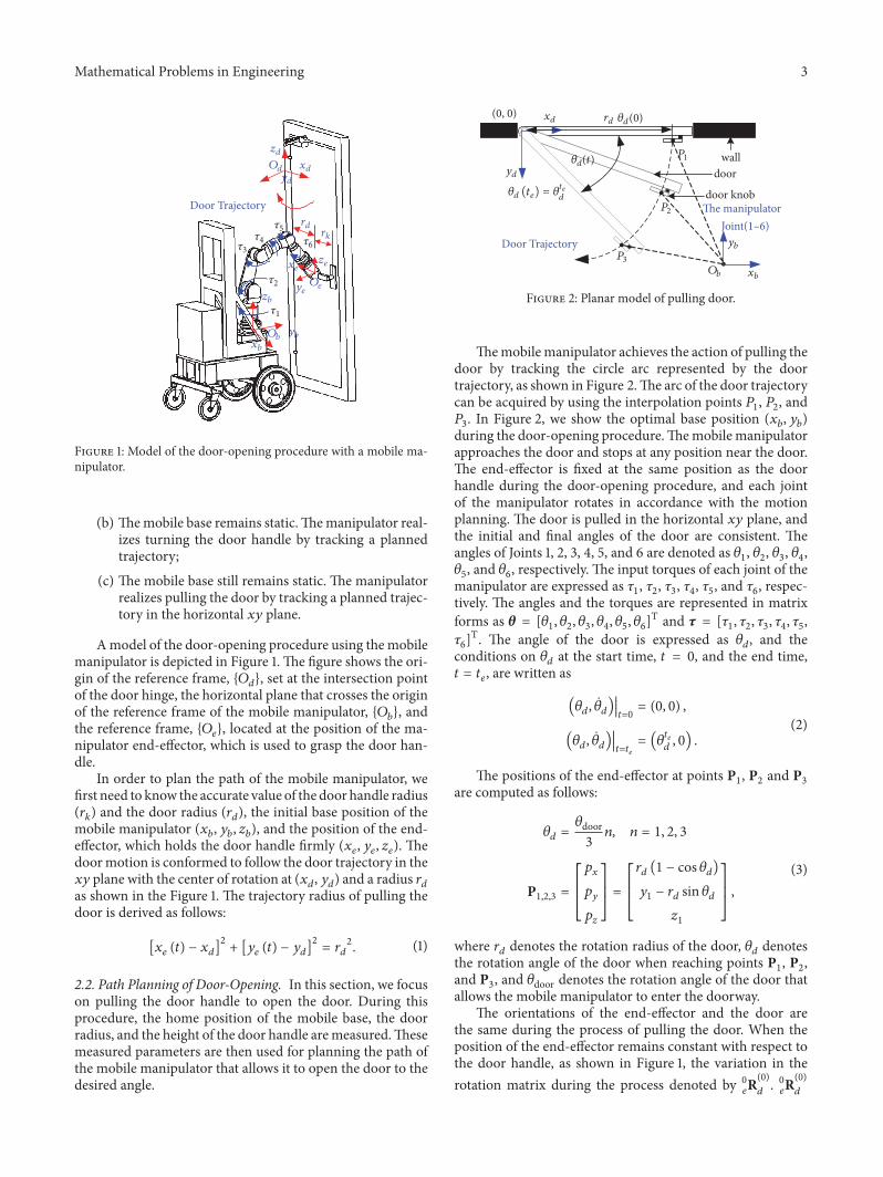
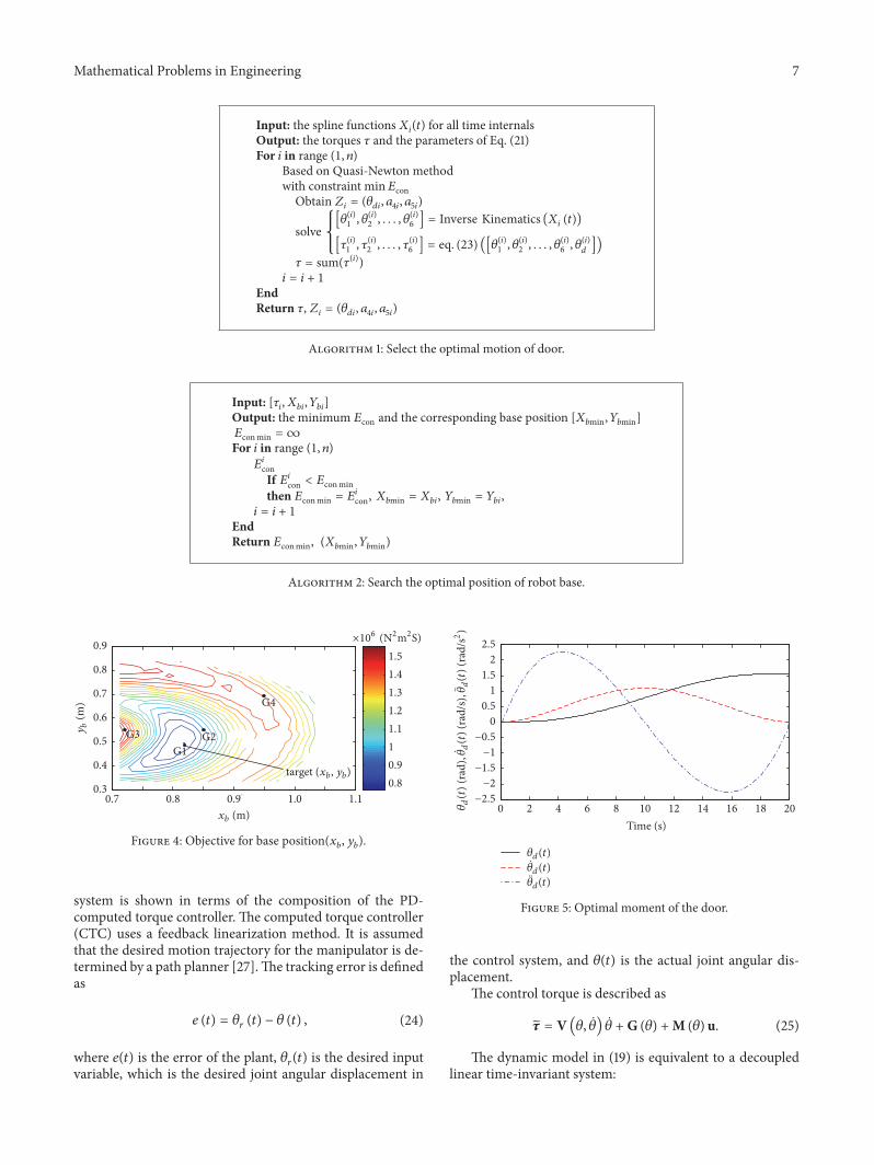
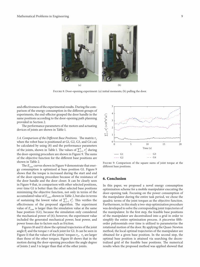

Hindawiwwwhindawicom Volume 2018
MathematicsJournal of
Hindawiwwwhindawicom Volume 2018
Mathematical Problems in Engineering
Applied MathematicsJournal of
Hindawiwwwhindawicom Volume 2018
Probability and StatisticsHindawiwwwhindawicom Volume 2018
Journal of
Hindawiwwwhindawicom Volume 2018
Mathematical PhysicsAdvances in
Complex AnalysisJournal of
Hindawiwwwhindawicom Volume 2018
OptimizationJournal of
Hindawiwwwhindawicom Volume 2018
Hindawiwwwhindawicom Volume 2018
Engineering Mathematics
International Journal of
Hindawiwwwhindawicom Volume 2018
Operations ResearchAdvances in
Journal of
Hindawiwwwhindawicom Volume 2018
Function SpacesAbstract and Applied AnalysisHindawiwwwhindawicom Volume 2018
International Journal of Mathematics and Mathematical Sciences
Hindawiwwwhindawicom Volume 2018
Hindawi Publishing Corporation httpwwwhindawicom Volume 2013Hindawiwwwhindawicom
The Scientific World Journal
Volume 2018
Hindawiwwwhindawicom Volume 2018Volume 2018
Numerical AnalysisNumerical AnalysisNumerical AnalysisNumerical AnalysisNumerical AnalysisNumerical AnalysisNumerical AnalysisNumerical AnalysisNumerical AnalysisNumerical AnalysisNumerical AnalysisNumerical AnalysisAdvances inAdvances in Discrete Dynamics in
Nature and SocietyHindawiwwwhindawicom Volume 2018
Hindawiwwwhindawicom
Dierential EquationsInternational Journal of
Volume 2018
Hindawiwwwhindawicom Volume 2018
Decision SciencesAdvances in
Hindawiwwwhindawicom Volume 2018
AnalysisInternational Journal of
Hindawiwwwhindawicom Volume 2018
Stochastic AnalysisInternational Journal of
Submit your manuscripts atwwwhindawicom