
Microwave-Assisted Functionalization of Carbon Nanostructures in Ionic Liquids

reprint
Tailoring the efficiency of3D wire-shaped photovoltaiccells (WPVCs) by functionalizationof solid–liquid interfacial properties
Jin Yan1, M. Jasim Uddin1, Tarik J. Dickens1,2, Deborah E. Daramola1, David Olawale1,2, and Okenwa I. Okoli*,1
1 High Performance Materials Institute, Florida State University, 2005 Levy Ave., Tallahassee, FL 32303, USA2NPGroup Inc., Tallahassee, FL 32311, USA
Received 23 August 2013, revised 26 September 2013, accepted 11 October 2013Published online 27 November 2013
Keywords 3D PV cells, 3D photosensor, sol–gel method, wire-shaped cells
* Corresponding author: e-mail [email protected], Phone: þ1 850 645 8997, Fax: þ1 850 410 6342
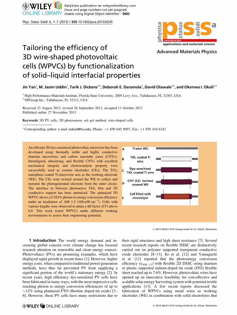
An efficient 3D dye-sensitized photovoltaic microwire has beendeveloped using thermally stable and highly conductivetitanium microwires and carbon nanotube yarns (CNYs).Interaligned, ultrastrong, and flexible CNYs with excellentmechanical integrity and electrocatalytic property weresuccessfully used as counter electrodes (CEs). The TiO2
nanophase coated Ti-microwire acts as the working electrode(WE). The CEs were twisted around the WE to collect andtransmit the photogenerated electrons from the outer circuit.The interface in between photoactive TiO2 film and 3Dconductive support has been optimized. The optimized 3DWPVC shows a 0.583% photon to energy conversion efficiencyunder an irradiation of AM 1.5 (100mWcm�2). Cells withvarious lengths were observed to attain a fill factor (FF) above0.8. This work tested WPVCs under different workingenvironments to assess their engineering potential.
� 2013 WILEY-VCH Verlag GmbH & Co. KGaA, Weinheim
1 Introduction The world energy demand and in-creasing global concern over climate change has focusedresearch attention on renewable and clean energy sources.Photovoltaics (PVs) are promising examples, which havedisplayed rapid growth in recent times [1]. However, higherenergy costs, when compared to traditional power generationmethods, have thus far prevented PV from supplying asignificant portion of the world’s stationary energy [2]. Inrecent years, high efficiency dye-sensitized PV cells havebeen fabricated in many ways, with the most impressive cellsreaching photon to energy conversion efficiencies of up to�12% using platinized FTO (fluorine doped tin oxide) [3–6]. However, these PV cells have many restrictions due to
their rigid structures and high sheet resistance [7]. Severalrecent research reports on flexible DSSC are distinctivelycarried out on polymer supported transparent conductiveoxide electrodes [8–11]. Ito et al. [12] and Yamaguchiet al. [11] reported that the photoenergy conversionefficiency (hAM 1.5) with flexible 2D DSSC using titaniumor plastic supported indium-doped tin oxide (ITO) flexiblesheet reached up to 7.6%. However, photovoltaic wires haveopened up an innovative feasibility for cost-effective andscalable solar energy harvesting system with potential textileapplications [13]. A few recent reports discussed thefabrication of WPVCs using metal wires as workingelectrodes (WE) in combination with solid electrolytes that
Phys. Status Solidi A, 1–7 (2013) / DOI 10.1002/pssa.201330245
Advanced Materials Physics
applications and materials science
a
statu
s
soli
di
www.pss-a.comph
ysi
ca
� 2013 WILEY-VCH Verlag GmbH & Co. KGaA, Weinheim
show energy conversion efficiencies of up to 0.2% [14].Some reports indicate that the efficiency could be increasedif the DSSCs are assembled with liquid electrolyte and glasscladding [15–17], which yields limited sustainability duringtransportation and installation. The rapid developingoptoelectronic industry, especially for the portable andhighly integrated micro-electronic equipment, shows spacelimitations and necessitates cell flexibility and capability forchanging shapes [18, 19]. Moreover, overcoming operatingrestrictions in the synthesis of these highly efficient flexiblephotovoltaic wires, with 3D features exhibiting long-termstability and reproducibility, remains a great challenge [7].The progress in the wire-shaped solar cells has beensummarized recently [20], especially; the carbon nanotubes(CNTs) have outstanding functions on enriching theWPVCs [7]. Even though the cells using Pt wire as CEshave already reached up to 5–7%, carbon materials can stillmaintain good flexibility and long life time whenmeeting the
practical engineering application [7, 16, 21]. The CE plays akey role in receiving electrons from the outer circuit andreducing the electrolyte redox mediator (I�/I3
�) [22–25].However, CNTs are proved to have a catalytic effect on thecouple of I�/I3
�. Therefore, it is worth noting that, coatedwith Pt particles, CNYs become functional to enrich thereciprocity between Pt particles and electrolyte by decreas-ing resistance for electron transportation [7, 26–28]. Thetwisted cell structure not only ensures an efficient interfacebetween CEs and sensitizers, but also supports the 3Dsensing features. This paper reports on the (a) anchoringprocess of TiO2 film around the Ti-microwire, (b)optimization of TiO2 film thickness, (c) stability of the3D cells with different thermal conditions, and (d) 3D featurewith inter-cell connectivity and flexibility.
2 Materials and methods Ti-microwires (AlfaAesar, F¼ 127mm) were ultrasonicatied successively in
Jin Yan received the B.S. degree in Applied Physics from the Nankai University in China in2011, and is expected to obtain her Ph.D. degree in Industrial &Manufacturing Engineering fromFlorida State University in May 2015. She has participated in a number of research programs atvarious institutions including: Nankai University; Institute of Physics & Beijing National Lab.for Condensed Matter Physics, Chinese Academy of Sciences. She is now working in HighPerformance Materials Institute, Florida State University, under the supervision of Dr. OkenwaOkoli. Her current research interests include design and fabrication of 3D photovoltaic sensorsfor in situ structure health monitoring (SHM) systems.
M. Jasim Uddin obtained his Ph.D. degree in Materials Science and Technology from theUniversity of Turin, Italy. He is currently a visiting Assistant Professor in the Department ofIndustrial and Manufacturing Engineering at the FAMU-FSU College of Engineering and High-Performance Materials Institute, Florida State University, USA. Prior to joining in The FloridaState University; he worked at Tulane University, LA and Shahjalal University of Science andTechnology, Sylhet. He discovered metal centered hybrid catalyst, self-cleaning andphotochromic textiles during his doctoral research. His research focus lies on the developmentof nanostructured hybrid materials for energy conversion, storage and integrated structural health
monitoring. In recognition of his outstanding discovery in hybrid functional materials, the Government of PeoplesRepublic of Bangladesh honored him with UGCAward in 2010. The extraordinary contributions that his doctoral researchmade to the advanced materials for engineering application have recently been adopted in a college text book (ISBN: 978-1-84755-870-1) published by the Royal Society of Chemistry Publishing, London.
Okenwa Okoli is Professor and Department Chair of Industrial and Manufacturing Engineeringat the FAMU-FSU College of Engineering. He has worked extensively in the development ofaffordable and functional composite manufacturing technologies for which he has receivedseveral awards. With the increased utilization of composites in critical structures, Dr. Okoli’sinnovative research efforts include the development of integrated structural health sensing withinadvanced composites and concrete structures. He also focuses on the development of scalabletechnologies for the manufacture of customizable multiscale and multifunctional compositestructures, integrated PV sensors and innovative 3D energy conversion systems. He has extensiveexperience in the transient nonlinear dynamic analysis of fiber reinforced composite structures.He has 7 US patent applications (awarded and pending) in the areas of advanced composites and
multiscale composites manufacture, structural ceramics, and ubiquitous real-time structural health monitoring. He is achartered engineer and a chartered scientist.
2 J. Yan et al.: Tailoring the efficiency of 3D wire-shaped photovoltaic cells
� 2013 WILEY-VCH Verlag GmbH & Co. KGaA, Weinheim www.pss-a.com
ph
ysic
a ssp stat
us
solid
i a
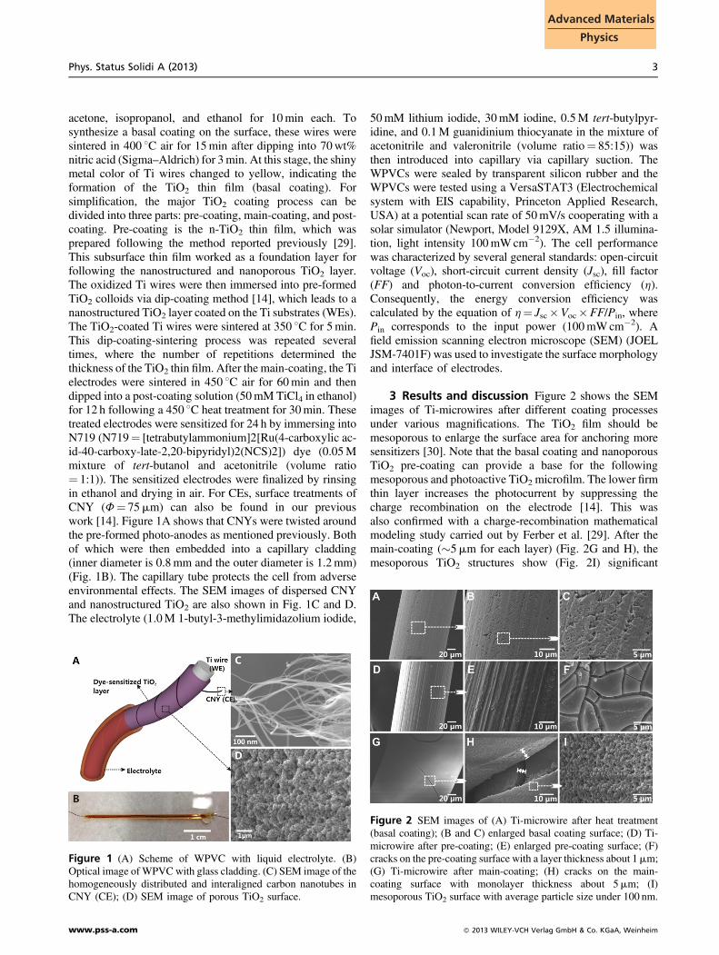
acetone, isopropanol, and ethanol for 10min each. Tosynthesize a basal coating on the surface, these wires weresintered in 400 8C air for 15min after dipping into 70wt%nitric acid (Sigma–Aldrich) for 3min. At this stage, the shinymetal color of Ti wires changed to yellow, indicating theformation of the TiO2 thin film (basal coating). Forsimplification, the major TiO2 coating process can bedivided into three parts: pre-coating, main-coating, and post-coating. Pre-coating is the n-TiO2 thin film, which wasprepared following the method reported previously [29].This subsurface thin film worked as a foundation layer forfollowing the nanostructured and nanoporous TiO2 layer.The oxidized Ti wires were then immersed into pre-formedTiO2 colloids via dip-coating method [14], which leads to ananostructured TiO2 layer coated on the Ti substrates (WEs).The TiO2-coated Ti wires were sintered at 350 8C for 5min.This dip-coating-sintering process was repeated severaltimes, where the number of repetitions determined thethickness of the TiO2 thin film. After the main-coating, the Tielectrodes were sintered in 450 8C air for 60min and thendipped into a post-coating solution (50mM TiCl4 in ethanol)for 12 h following a 450 8C heat treatment for 30min. Thesetreated electrodes were sensitized for 24 h by immersing intoN719 (N719¼ [tetrabutylammonium]2[Ru(4-carboxylic ac-id-40-carboxy-late-2,20-bipyridyl)2(NCS)2]) dye (0.05Mmixture of tert-butanol and acetonitrile (volume ratio¼ 1:1)). The sensitized electrodes were finalized by rinsingin ethanol and drying in air. For CEs, surface treatments ofCNY (F¼ 75mm) can also be found in our previouswork [14]. Figure 1A shows that CNYs were twisted aroundthe pre-formed photo-anodes as mentioned previously. Bothof which were then embedded into a capillary cladding(inner diameter is 0.8mm and the outer diameter is 1.2mm)(Fig. 1B). The capillary tube protects the cell from adverseenvironmental effects. The SEM images of dispersed CNYand nanostructured TiO2 are also shown in Fig. 1C and D.The electrolyte (1.0M 1-butyl-3-methylimidazolium iodide,
50mM lithium iodide, 30mM iodine, 0.5M tert-butylpyr-idine, and 0.1M guanidinium thiocyanate in the mixture ofacetonitrile and valeronitrile (volume ratio¼ 85:15)) wasthen introduced into capillary via capillary suction. TheWPVCs were sealed by transparent silicon rubber and theWPVCs were tested using a VersaSTAT3 (Electrochemicalsystem with EIS capability, Princeton Applied Research,USA) at a potential scan rate of 50mV/s cooperating with asolar simulator (Newport, Model 9129X, AM 1.5 illumina-tion, light intensity 100mWcm�2). The cell performancewas characterized by several general standards: open-circuitvoltage (Voc), short-circuit current density (Jsc), fill factor(FF) and photon-to-current conversion efficiency (h).Consequently, the energy conversion efficiency wascalculated by the equation of h¼ Jsc�Voc�FF/Pin, wherePin corresponds to the input power (100mWcm�2). Afield emission scanning electron microscope (SEM) (JOELJSM-7401F) was used to investigate the surface morphologyand interface of electrodes.
3 Results and discussion Figure 2 shows the SEMimages of Ti-microwires after different coating processesunder various magnifications. The TiO2 film should bemesoporous to enlarge the surface area for anchoring moresensitizers [30]. Note that the basal coating and nanoporousTiO2 pre-coating can provide a base for the followingmesoporous and photoactive TiO2 microfilm. The lower firmthin layer increases the photocurrent by suppressing thecharge recombination on the electrode [14]. This wasalso confirmed with a charge-recombination mathematicalmodeling study carried out by Ferber et al. [29]. After themain-coating (�5mm for each layer) (Fig. 2G and H), themesoporous TiO2 structures show (Fig. 2I) significant
Figure 1 (A) Scheme of WPVC with liquid electrolyte. (B)Optical image of WPVCwith glass cladding. (C) SEM image of thehomogeneously distributed and interaligned carbon nanotubes inCNY (CE); (D) SEM image of porous TiO2 surface.
Figure 2 SEM images of (A) Ti-microwire after heat treatment(basal coating); (B and C) enlarged basal coating surface; (D) Ti-microwire after pre-coating; (E) enlarged pre-coating surface; (F)cracks on the pre-coating surface with a layer thickness about 1mm;(G) Ti-microwire after main-coating; (H) cracks on the main-coating surface with monolayer thickness about 5mm; (I)mesoporous TiO2 surface with average particle size under 100 nm.
Phys. Status Solidi A (2013) 3
www.pss-a.com � 2013 WILEY-VCH Verlag GmbH & Co. KGaA, Weinheim
Advanced Materials
Physics
roughness throughout the film. This feature allows moredye molecules to be adsorbed into the active surface sites,which efficiently sensitizes the film in generating photo-electrons [31]. In addition, the mesoporous nature providesmultidimensional channels for photogenerated electrontransportation.
SEM images of CNYs (CE) before and after surfacetreatment are shown in Fig. 3A–D. The images are clearlyindicative of the average diameter (f¼ 20 nm) of theindividual carbon nanotubes (CNTs). The CNYs consist ofnumerous interaligned CNTs (Fig. 3D and 3D-inset), whichis reported to exhibit high electrical conductivity, excellentelectrocatalytic properties, outstanding mechanical proper-ties [32], and significant structural flexibility [33–35]. Thesephysiochemical characteristics of CNYs ensure operationalflexibility and charge transportation feasibility of theWPVCs. From the comparison of high-resolution SEMimages (Fig. 3B and D), it can be summarized that surfacetreatment of CNYs removes the sizing agent and function-alizes the exposed surface sites. Thus, the platinumnanoparticles are easily anchored to the external surfaceand make CNTs potentially electronegative in collectingphotoelectrons from the outer circuits. In addition, the redoxmediator (I�/I3
�) in the electrolyte deoxidizes the dye(N719) and the platinized CNY catalyzes the regenerationreaction of the mediator [36]. The large surface area issuitable for the reduction of triiodide (I�3 ), which actuallyimproves the charge transportation and cell performance,correspondingly.
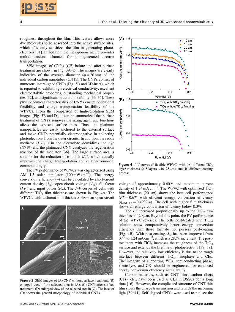
The PV performance ofWPVCs was characterized usingAM 1.5 solar simulator (100mWcm�2). The energyconversion efficiency (h) can be calculated by short-circuitcurrent density (Jsc), open-circuit voltage (Voc), fill factor(FF), and input power (Pin). The J–V curves of cells withdifferent TiO2 film thickness are shown in Fig. 4A. TheWPVCs with different film thickness show an open-circuit
voltage of approximately 0.60V and maximum currentdensity of 1.24mA cm�2. The WPVC with optimized TiO2
film thickness (20mm) shows the best cell performance(FF¼ 0.67) with efficient energy conversion efficiency(hAM 1.5¼ 0.4999%). The cell with higher film thicknessshows an energy conversion efficiency below 0.3%.
The FF increased proportionally up to the TiO2 filmthickness of 20mm. Beyond this point, the PV performanceof the WPVC reverses. The cells post-treated with TiCl4solution show comparatively better energy conversionefficiency than those that do not possess post-coating(Fig. 4B). With post-coating, Jsc has been improved from0.44 to 1.24mA cm�2, which is a 282% increment. The post-treatment with TiCl4 increases the roughness of the TiO2
surface and extends the lifetime of photoelectrons [37, 38].However, the relatively low efficiency is due to the roughinterface between different TiO2 nanophase and CEs.The integrity of supporting WEs, semiconducting phase,electrolyte, and CEs should be engineered for enhancedenergy conversion efficiency and stability.
Carbon materials, such as CNT films, carbon fibers(CFs), etc., have been used as CEs in DSSCs for a longtime [16]. However, the complicated structure of CNT thinfilm slows the charge transmission and retards the incominglight [39–41]. Self-aligned CNYs were used to replace the
Figure 3 SEM images of (A) CNY without surface treatment; (B)enlarged view of the selected area in (A); (C) CNY after surfacetreatment; (D) enlarged view of the selected area in (C). The inset of(D) shows the general morphology of individual CNTs.
Figure 4 J–V curves of flexible WPVCs with (A) different TiO2
layer thickness (2–5 layers �10–25mm); and (B) different coatingprocess.
4 J. Yan et al.: Tailoring the efficiency of 3D wire-shaped photovoltaic cells
� 2013 WILEY-VCH Verlag GmbH & Co. KGaA, Weinheim www.pss-a.com
ph
ysic
a ssp stat
us
solid
i a

conventional CEs. As mentioned above, the interaligned andentangled CNYs exhibit effective electrocatalytic activitywith excellent electron transportation capability. In compar-ison with CFs, the CNYs show larger effective surface area.This feature potentially enhances the PV properties of theWPVCs [7, 16]. The interfacial properties of the CEwas compared with control cells, which uses CNY atHPMI [42, 43] and silver wire as a CE. SEM characterizationof our individual CNYs also indicates a porous and self-aligned network structure of the MWCNT yarn that isvirtually free of catalyst particles or amorphous carbonparticulates (Fig. 3D). Though the control WPVCwith silvermicrowire exhibits the highest Jsc (2.29mA cm�2), itprovides remarkably lower Voc (70mV), fill factor (FF¼ 0.33), and energy conversion efficiency of only 0.0525%.The WPVC with single CNY produces the highest energyconversion efficiency (0.499%). However, the cells with 3CNYs and the HPMI CNYs show similar FF and energyconversion efficiencies (hAM 1.5¼ 0.40%) (Fig. 5A and B).As mentioned before, surface treatment functionalizesthe CNTs and tailors the PV performance of the cells.The comparison of the energy conversion efficiency withother technical specifications is summarized in Fig. 5C.The WPVC with virgin CNY (CE) shows Jsc and Voc
of 0.37mA cm�2 and 0.465V, respectively. With thisremarkable decrement in Voc (DVoc¼ 0.13V) and Jsc(DJsc¼ 0.868mA cm�2), this cell produced a photoconver-sion efficiency of 0.1222%. Furthermore, the conventionalmetal microwire shaped CEs (Pt, Ag wire, etc) are costly andeasily corroded by liquid electrolytes [44–46]. However, theWPVC with virgin CNY (CEs) has adverse catalytic effectson the redox mediator (I�/I3
�), which allows light-generatedelectrons to react with I�3 in the electrolyte [16, 47]. To avoid
these reverse catalytic effects and further improve the cellperformance, platinized CNYs were introduced to theWPVC as a replacement of conventional CEs. CNYs withPt nanoparticles become functional to enrich the reciprocitybetween electrolyte and Pt particles by decreasing resistanceof charge-transfer [47]. The cells with platinized CNYsenhance the Jsc from 0.57 to 1.24mA cm�2 (a 218%improvement) (Fig. 5D), which was indicative of doublephoton to current conversion efficiency obtained withoutplatinized CEs.
The PV performance of the WPVCs with variablelengths (2.0–4.5 cm) are summarized in Fig. 6. In Fig. 6A, itis may be observed that short-circuit current (Isc) is directlyproportional to the cell length (from 0.0365 to 0.0448mA),while Jsc decreases from 1.50 to 0.82mA cm�2 with anincrease in cell length. The results indicate that the increasingin Isc cannot compete with increasing effective surface area.However, the FF and Voc of these WPVCs remain stable.The variation in Voc (�0.47V) with different cell lengths isnegligible. Besides the 4.5mm cell (FF¼ 0.78), all the othercells exhibit excellent FFs (>0.80) (Fig. 6B). J–V curves ofWPVCs with different cell lengths are shown in Fig. 6C andthe observable decrease in cell efficiency can be found inFig. 6D. To further improve the efficiency stability at theapplicable length, more self-aligned and interconnectedCNTs could be taken into consideration to ensure fastelectron transport capability [48].
Two WPVCs with similar J–V performance wereconnected in parallel and series. The corresponding I–Vcurves are included in Fig. 7A along with their individualI–V curves. It is evident that the Isc of two parallel cells(70.99mA) is approximately the sum of their own Isc, whilethe Voc of two series cells (0.99V) is equal to the sum of their
Figure 5 J–V curves of flexible WPVCs with (A and B) differentCEs (1CNY, 3CNY, HPMI CNY, 1 silver wire); (C) different CEsurface treatment methods (if apply surface treatment for CNYs);(D) different treatment for CEs (if apply Pt coating on CNYs).
Figure 6 (A) Relative short-circuit current and current density ofWPVCs with different cell lengths; (B) relative open-circuit voltageand fill factor of PV cells with different cell lengths; (C) J–V curvesof PV cells using 1 CNY as CE with different cell lengths; (D)change in PV cells’ performance with different cell lengths.
Phys. Status Solidi A (2013) 5
www.pss-a.com � 2013 WILEY-VCH Verlag GmbH & Co. KGaA, Weinheim
Advanced Materials
Physics
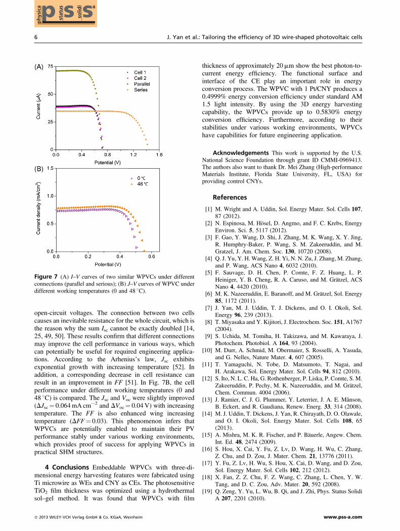
open-circuit voltages. The connection between two cellscauses an inevitable resistance for the whole circuit, which isthe reason why the sum Isc cannot be exactly doubled [14,25, 49, 50]. These results confirm that different connectionsmay improve the cell performance in various ways, whichcan potentially be useful for required engineering applica-tions. According to the Arhenius’s law, Jsc exhibitsexponential growth with increasing temperature [52]. Inaddition, a corresponding decrease in cell resistance canresult in an improvement in FF [51]. In Fig. 7B, the cellperformance under different working temperatures (0 and48 8C) is compared. The Jsc and Voc were slightly improved(DJsc¼ 0.064mA cm�2 and DVoc¼ 0.04V) with increasingtemperature. The FF is also enhanced wing increasingtemperature (DFF¼ 0.03). This phenomenon infers thatWPVCs are potentially enabled to maintain their PVperformance stably under various working environments,which provides proof of success for applying WPVCs inpractical SHM structures.
4 Conclusions Embeddable WPVCs with three-di-mensional energy harvesting features were fabricated usingTi microwire as WEs and CNY as CEs. The photosensitiveTiO2 film thickness was optimized using a hydrothermalsol–gel method. It was found that WPVCs with film
thickness of approximately 20mm show the best photon-to-current energy efficiency. The functional surface andinterface of the CE play an important role in energyconversion process. The WPVC with 1 Pt/CNY produces a0.4999% energy conversion efficiency under standard AM1.5 light intensity. By using the 3D energy harvestingcapability, the WPVCs provide up to 0.5830% energyconversion efficiency. Furthermore, according to theirstabilities under various working environments, WPVCshave capabilities for future engineering application.
Acknowledgements This work is supported by the U.S.National Science Foundation through grant ID CMMI-0969413.The authors also want to thank Dr. Mei Zhang (High-performanceMaterials Institute, Florida State University, FL, USA) forproviding control CNYs.
References
[1] M. Wright and A. Uddin, Sol. Energy Mater. Sol. Cells 107,87 (2012).
[2] N. Espinosa, M. Hösel, D. Angmo, and F. C. Krebs, EnergyEnviron. Sci. 5, 5117 (2012).
[3] F. Gao, Y. Wang, D. Shi, J. Zhang, M. K. Wang, X. Y. Jing,R. Humphry-Baker, P. Wang, S. M. Zakeeruddin, and M.Gratzel, J. Am. Chem. Soc. 130, 10720 (2008).
[4] Q. J. Yu, Y. H.Wang, Z. H. Yi, N. N. Zu, J. Zhang, M. Zhang,and P. Wang, ACS Nano 4, 6032 (2010).
[5] F. Sauvage, D. H. Chen, P. Comte, F. Z. Huang, L. P.Heiniger, Y. B. Cheng, R. A. Caruso, and M. Grätzel, ACSNano 4, 4420 (2010).
[6] M. K. Nazeeruddin, E. Baranoff, and M. Grätzel, Sol. Energy85, 1172 (2011).
[7] J. Yan, M. J. Uddin, T. J. Dickens, and O. I. Okoli, Sol.Energy 96, 239 (2013).
[8] T. Miyasaka and Y. Kijitori, J. Electrochem. Soc. 151, A1767(2004).
[9] S. Uchida, M. Tomiha, H. Takizawa, and M. Kawaraya, J.Photochem. Photobiol. A 164, 93 (2004).
[10] M. Durr, A. Schmid, M. Obermaier, S. Rosselli, A. Yasuda,and G. Nelles, Nature Mater. 4, 607 (2005).
[11] T. Yamaguchi, N. Tobe, D. Matsumoto, T. Nagai, andH. Arakawa, Sol. Energy Mater. Sol. Cells 94, 812 (2010).
[12] S. Ito, N. L. C. Ha, G. Rothenberger, P. Liska, P. Comte, S. M.Zakeeruddin, P. Pechy, M. K. Nazeeruddin, and M. Grätzel,Chem. Commun. 4004 (2006).
[13] J. Ramier, C. J. G. Plummer, Y. Leterrier, J. A. E. Månson,B. Eckert, and R. Gaudiana, Renew. Energ. 33, 314 (2008).
[14] M. J. Uddin, T. Dickens, J. Yan, R. Chirayath, D. O. Olawale,and O. I. Okoli, Sol. Energy Mater. Sol. Cells 108, 65(2013).
[15] A. Mishra, M. K. R. Fischer, and P. Bäuerle, Angew. Chem.Int. Ed. 48, 2474 (2009).
[16] S. Hou, X. Cai, Y. Fu, Z. Lv, D. Wang, H. Wu, C. Zhang,Z. Chu, and D. Zou, J. Mater. Chem. 21, 13776 (2011).
[17] Y. Fu, Z. Lv, H. Wu, S. Hou, X. Cai, D. Wang, and D. Zou,Sol. Energy Mater. Sol. Cells 102, 212 (2012).
[18] X. Fan, Z. Z. Chu, F. Z. Wang, C. Zhang, L. Chen, Y. W.Tang, and D. C. Zou, Adv. Mater. 20, 592 (2008).
[19] Q. Zeng, Y. Yu, L. Wu, B. Qi, and J. Zhi, Phys. Status SolidiA 207, 2201 (2010).
Figure 7 (A) I–V curves of two similar WPVCs under differentconnections (parallel and serious); (B) J–V curves of WPVC underdifferent working temperatures (0 and 48 8C).
6 J. Yan et al.: Tailoring the efficiency of 3D wire-shaped photovoltaic cells
� 2013 WILEY-VCH Verlag GmbH & Co. KGaA, Weinheim www.pss-a.com
ph
ysic
a ssp stat
us
solid
i a
[20] T. Chen, L. Qiu, Z. Yang, and H. Peng, Chem. Soc. Rev. 42,5031 (2013).
[21] Y. Fu, M. Peng, Z. Lv, X. Cai, S. Hou, H. Wu, X. Yu,H. Kafafy, and D. Zou, Nano Energy. 2, 537 (2013).
[22] N. Papageorgiou Coordin. Chem. Rev. 248, 1421 (2004).[23] T.N. Murakami and M. Grätzel, Inorg. Chim. Acta 361, 572
(2008).[24] S. C. Hou, X. Cai, Y. P. Fu, Z. B. Lv, D. Wang, H. W. Wu,
C. Zhang, Z. Z. Chu, and D. C. Zou, J. Mater. Chem. 21,13776 (2011).
[25] M. J. Uddin, B. Davies, T. J. Dickens, and O. I. Okoli, Sol.Energy Mater. Sol. Cells 115, 166 (2013).
[26] T. Chen, L. Qiu, Z. Yang, Z. Cai, J. Ren, H. Li, H. Lin,X. Sun, and H. Peng, Angew. Chem. Int. Ed. 51, 11977(2012).
[27] Z. Yang, H. Sun, T. Chen, L. Qiu, Y. Luo, and H. Peng,Angew. Chem. Int. Ed. 52, 7545 (2013).
[28] S. Pan, Z. Yang, H. Li, L. Qiu, H. Sun, and H. Peng, J. Am.Chem. Soc. 135, 10622 (2013).
[29] J. Ferber, R. Stangl, and J. Luther, Sol. Energy Mater. Sol.Cells 53, 29–54 (1998).
[30] M. Grätzel J. Photochem. Photobiol. A 164, 3 (2004).[31] T. Dittrich Phys. Status Solidi A 182, 447 (2000).[32] M. D. Lima, S. Fang, X. Lepró, C. Lewis, R. Ovalle-Robles,
J. Carretero-González, E. Castillo-Martínez, M. E. Kozlov,J. Oh, N. Rawat, C. S. Haines, M. H. Haque, V. Aare,S. Stoughton, A. A. Zakhidov, and R. H. Baughman, Science331, 51 (2011).
[33] O. Topon, D. Inaguma, K. Matsumoto, and N. T. Naoe, ECSTrans. 25, 87 (2010).
[34] E. Frackowiak and F. Beguin, Carbon 39, 937 (2001).[35] T. Chen, L. B. Qiu, H. P. Li, and H. S. Peng, J. Mater. Chem.
22, 23655 (2012).[36] J. H. Wu, Z. Lan, S. C. Hao, P. J. Li, J. M. Lin, M. L. Huang,
L. Q. Fang, and Y. F. Huang, Pure. Appl. Chem. 80, 2241(2008).
[37] B. C. O’Regan, J. R. Durrant, P. M. Sommeling, and N. J.Bakker, J. Phys. Chem. C 111, 14001 (2007).
[38] S. Ito, P. Liska, P. Comte, R. L. Charvet, P. Pechy, U. Bach, L.Schmidt-Mende, S. M. Zakeeruddin, A. Kay, M. K.Nazeeruddin, and M. Gratzel, Chem. Commun. 4351 (2005).
[39] S. Barazzouk, S. Hotchandani, K. Vinodgopal, and P. V.Kamat, J. Phys. Chem. B 108, 17015 (2004).
[40] S. Zhang, C. Y. Ji, Z. Q. Bian, R. H. Liu, X. Y. Xia, D. Q. Yun,L. H. Zhang, C. H. Huang, and A. Y. Cao, Nano. Lett. 11,3383 (2011).
[41] S. Huang, L. Li, Z. Yang, L. Zhang, H. Saiyin, T. Chen, andH. Peng, Adv. Mater. 23, 4707 (2011).
[42] M. Zhang, K. R. Atkinson, and R. H. Baughman, Science 306,1358 (2004).
[43] D. Zhao, T. Liu, J. G. Park, M. Zhang, J.-M. Chen, and B.Wang, Microelectron. Eng. 96, 71 (2012).
[44] D. Zou, D. Wang, Z. Chu, Z. Lv, and X. Fan, Coord. Chem.Rev. 254, 1169 (2010).
[45] D. Y. Liu, M. Y. Zhao, Y. Li, Z. Q. Bian, L. H. Zhang, Y. Y.Shang, X. Y. Xia, S. Zhang, D. Q. Yun, Z. W. Liu, A. Y. Cao,and C. H. Huang, ACS Nano 6, 11027 (2012).
[46] L. Yuan, F. Chen, C. Zheng, J. Liu, and N. Alemu, Phys.Status Solidi A 209, 1376 (2012).
[47] S. Zhang, C. Y. Ji, Z. Q. Bian, P. R. Yu, L. H. Zhang,D. Y. Liu, E. Z. Shi, Y. Y. Shang, H. T. Peng, Q. Cheng,D. Wang, C. H. Huang, and A. Y. Cao, ACS Nano 6, 7191(2012).
[48] A. Kongkanand and P. V. Kamat, ACS Nano 1, 13(2007).
[49] J. Wan, G. Fang, P. Qin, Q. Zheng, N. Liu, N. Sun, Y. Tu,X. Fan, F. Cheng, and X. Zhao, Sol. Energy Mater. Sol. Cells101, 289 (2012).
[50] J. Y. Tang, Z. Y. Huo, S. Brittman, H. W. Gao, and P. D.Yang, Nature Nanotechnol. 6, 568 (2011).
[51] M. Berginc, U. O. Krasovec, M. Jankovec, and M. Topic, Sol.Energy Mater. Sol. Cells 91, 821 (2007).
Phys. Status Solidi A (2013) 7
www.pss-a.com � 2013 WILEY-VCH Verlag GmbH & Co. KGaA, Weinheim
Advanced Materials
Physics
Copyright © 2022 FDOKUMEN