S80 USA reprint version w640.book
262
-
Upload
khangminh22 -
Category
Documents
-
view
0 -
download
0
Transcript of S80 USA reprint version w640.book


THANK YOU FOR CHOOSING VOLVOWelcome to the world-wide family of Volvo owners. We trust that you will enjoy many years of safe driving in your Volvo, an automobile designed with your safety and comfort in mind. To help ensure your satisfaction with this vehicle, we encourage you to familiarize yourself with the equipment descriptions, operating instructions and maintenance requirements/recom-mendations in this manual. We also urge you and your passengers to wear seat belts at all times in this (or any other) automobile. And, of course, please do not operate a vehicle if you may be affected by alcohol, medication or any impairment that could hinder your ability to drive.
Your Volvo is designed to meet all applicable safety and emission standards, as evidenced by the certification labels attached to the driver's door opening and on the left wheel housing in the engine compartment. For further information please contact your retailer, or:
In the USA
Volvo Cars of North America, LLCCustomer Care CenterP.O. Box 914Rockleigh, New Jersey 07647-09141-800-458-1552www.volvocars.us
In Canada
Volvo Cars of Canada Corp.National Customer Service175 Gordon Baker RoadNorth York, Ontario M2H 2N71-800-663-8255www.volvocanada.com
2006 © Volvo Car Corporation. All rights reserved.
S80 USA reprint version w640.book Page 1 Friday, June 1, 2007 10:44 AM

Contents
2
00 01 0200 IntroductionImportant information .................................. 6Important warnings ...................................... 7Environment ................................................. 9
01 SafetyOccupant safety......................................... 14Reporting safety defects............................ 15Safety in the passenger compartment....... 16Crash mode ............................................... 30Child safety ................................................ 31Child restraint systems .............................. 34Infant seats ................................................ 36Convertible seats ....................................... 38Booster cushions ....................................... 41ISOFIX lower anchors ................................ 42Top tether anchors ..................................... 43Integrated booster cushion........................ 44Child safety locks....................................... 47
02 Locks and alarmRemote key and key blade ........................ 50Keyless drive.............................................. 58Locks ......................................................... 61Alarm.......................................................... 64
S80 USA reprint version w640.book Page 2 Friday, June 1, 2007 10:44 AM

04 0503
Contents
3
03 Your driving environmentInstruments and controls............................ 70Ignition modes............................................ 77Seats .......................................................... 79Steering wheel............................................ 84Lighting....................................................... 86Wipers and washers ................................... 92Power windows .......................................... 94Mirrors ........................................................ 96Power moonroof......................................... 98HomeLink® Universal Transceiver (option) ..... 100Starting the engine ................................... 104Transmission............................................. 107Brakes ...................................................... 109Parking brake ........................................... 112
04 Comfort and driving pleasureMenus and messages .............................. 116Climate system......................................... 120Audio system............................................ 127Trip computer ........................................... 138Compass .................................................. 139Stability system ........................................ 141Active chassis system–Four C ................. 143Cruise control ........................................... 144Adaptive Cruise Control–ACC.................. 146Collision warning system (option) ............ 152Park assist (option)................................... 155Blind Spot Information System (option) ..................................................... 157Passenger compartment convenience..... 160
05 During your tripDriving recommendations ........................ 166Refueling .................................................. 170Loading .................................................... 175Towing a trailer ......................................... 178Emergency towing.................................... 181
S80 USA reprint version w640.book Page 3 Friday, June 1, 2007 10:44 AM

Contents
4
06 0706 Maintenance and
specificationsVolvo maintenance................................... 186Maintaining your car ................................ 187Hood and engine compartment ............... 189Engine oil.................................................. 190Fluids........................................................ 192Replacing bulbs ....................................... 194Wiper blades and washer fluid................. 201Battery...................................................... 203Fuses........................................................ 206Wheels and tires....................................... 212Vehicle care.............................................. 238Label information ..................................... 243Specifications........................................... 245Volvo programs ........................................ 252
07 Index
S80 USA reprint version w640.book Page 4 Friday, June 1, 2007 10:44 AM

5
S80 USA reprint version w640.book Page 5 Friday, June 1, 2007 10:44 AM

Introduction
6
Important information
Points to keep in mind
• Before you operate your vehicle for the first time, please familiarize yourself with the information in chapter 3.
• Information contained in the balance of the manual is extremely useful and should be read after operating the vehicle for the first time.
• The manual is structured so that it can be used for reference. For this reason, it should be kept in the vehicle for ready access.
• Do not export your Volvo to another coun-try before investigating that country's ap-plicable safety and emission control requirements. In some cases it may be difficult or impossible to comply with these requirements. Modifications to the emission control system(s) may render your Volvo not certifiable for legal opera-tion in the U.S., Canada and other coun-tries.
• All information, illustrations and specifica-tions contained in this manual are based on the latest product information available at the time of publication. This information is subject to change without prior notice. Please note that some vehicles may be equipped differently, depending on spe-cial legal requirements. Optional equip-ment described in this manual may not be available in all markets.
• Volvo reserves the right to make model changes at any time, or to change specifi-cations or design without notice and with-out incurring obligation
Vehicle event data (Black box)Your vehicle's driving and safety systems employ computers that monitor, and share with each other, information about your vehi-cle's operation. One or more of these com-puters may store what they monitor, either during normal vehicle operation or in a crash or near-crash event. Stored information may be read and used by:
• Volvo Car Corporation
• service and repair facilities
• law enforcement or government agencies
• others who may assert a legal right to know, or who obtain your consent to know such information.
WARNING
If your vehicle is involved in an accident, un-seen damage may affect its drivability and safety.
S80 USA reprint version w640.book Page 6 Friday, June 1, 2007 10:44 AM
Introduction
7
Important warnings
Driver distraction
A driver has a responsibility to do everything possible to ensure his or her own safety and the safety of passengers in the vehicle and others sharing the roadway. Avoiding dis-tractions is part of that responsibility.
• Driver distraction results from driver activi-ties that are not directly related to control-ling the vehicle in the driving environment. Your new Volvo is, or can be, equipped with many feature-rich entertainment and communication systems. These include hands-free cellular telephones, navigation systems, and multipurpose audio sys-tems. You may also own other portable electronic devices for your own conve-nience. When used properly and safely, they enrich the driving experience. Im-properly used, any of these could cause a distraction.
• For all of these systems, we want to provide the following warning that reflects the strong Volvo concern for your safety:
• Never use these devices or any feature of your vehicle in a way that distracts you from the task of driving safely. Distraction can lead to a serious accident. In addition to this general warning, we offer the fol-lowing guidance regarding specific newer features that may be found in your vehicle:
• Never use a hand-held cellular telephone while driving. Some jurisdictions prohibit cellular telephone use by a driver while the vehicle is moving.
• If your vehicle is equipped with a naviga-tion system, set and make changes to your travel itinerary only with the vehicle parked.
• Never program your audio system while the vehicle is moving. Program radio pre-sets with the vehicle parked, and use your programmed presets to make radio use quicker and simpler.
• Never use portable computers or personal digital assistants while the vehicle is mov-ing.
Accessory installation• We strongly recommend that Volvo own-
ers install only genuine, Volvo-approved accessories, and that accessory installa-tions be performed only by the factory-trained technicians at your authorized Volvo retailer.
• Genuine Volvo accessories are tested to ensure compatibility with the perfor-mance, safety, and emission systems in your vehicle. Additionally, your authorized Volvo retailer knows where accessories may and may not be safely installed in your Volvo. In all cases, please consult your authorized Volvo retailer before in-stalling any accessory in or on your vehi-cle.
• Accessories that have not been approved by Volvo may or may not be specifically tested for compatibility with your vehicle. Additionally, an inexperienced installer may not be familiar with some of your car’s systems.
• Any of your car’s performance and safety systems could be adversely affected if you install accessories that Volvo has not test-ed, or if you allow accessories to be installed by someone unfamiliar with your vehicle.
• Damage caused by unapproved or im-properly installed accessories may not be covered by your new vehicle warranty.
S80 USA reprint version w640.book Page 7 Friday, June 1, 2007 10:44 AM

Introduction
8
Important warnings
See your Warranty and Service Records Information booklet for more warranty in-formation. Volvo assumes no responsibili-ty for death, injury, or expenses that may result from the installation of non-genuine accessories.
S80 USA reprint version w640.book Page 8 Friday, June 1, 2007 10:44 AM

Introduction
9
Environment
Volvo and the environment
Volvo is committed to the well being of its customers. As a natural part of this commit-ment, we care about the environment in which we all live. Caring for the environment means an everyday involvement in reducing our environmental impact. Volvo's environ-mental activities are based on a holistic view, which means we consider the overall envi-ronmental impact of a product throughout its complete life cycle. In this context, design, production, product use, and recycling are all important considerations. In production, Volvo has partly or completely phased out several chemicals including CFCs, lead chro-mates, asbestos, and cadmium; and reduced the number of chemicals used in our plants 50% since 1991.
Volvo was the first in the world to introduce into production a three-way catalytic con-verter with a Lambda sond, now called the heated oxygen sensor, in 1976. The current version of this highly efficient system reduces emissions of harmful substances (CO, HC, NOx) from the exhaust pipe by approximately 95-99% and the search to eliminate the remaining emissions continues. Volvo is the only automobile manufacturer to offer CFC-free retrofit kits for the air conditioning sys-tem of all models as far back as the 1975
model 240. Advanced electronic engine con-trols and cleaner fuels are bringing us closer to our goal. After Volvo vehicles and parts have fulfilled their use, recycling is the next critical step in completing the life cycle. The metal content is about 75% of the total weight of a vehicle, which makes the vehicle among the most recycled industrial products. In order to have efficient and well controlled recycling, all Volvo variants have printed dis-mantling manuals, indicating the weight and material of individual components. For Volvo, all homogeneous plastic parts weighing more than 3.4 oz. (100 grams) are marked with international symbols that indicate how the component is to be sorted for recycling. In addition to continuous environmental refine-ment of conventional gasoline-powered internal combustion engines, Volvo is actively looking at advanced technology alternative-fuel vehicles.
When you drive a Volvo, you become our partner in the work to lessen the car's impact on the environment. To reduce your vehicle's environmental impact, you can:
• Maintain proper air pressure in your tires. Tests have shown decreased fuel econo-my with improperly inflated tires.
• Follow the recommended maintenance schedule in your Warranty and Service Records Information booklet.
• Drive at a constant speed whenever possi-ble.
• See a trained and qualified Volvo service technician as soon as possible for inspec-tion if the check engine (malfunction indi-cator) light illuminates, or stays on after the vehicle has started.
• Properly dispose of any vehicle-related waste such as used motor oil, used batter-ies, brake pads, etc.
• When cleaning your vehicle, please use genuine Volvo car care products. All Volvo car care products are formulated to be environmentally friendly.
WARNING
PROPOSITION 65 WARNING! Engine exhaust, some of its constituents, and certain vehicle components contain or emit chemicals known to the state of Cali-fornia to cause cancer, and birth defects or other reproductive harm. In addition, certain fluids contained in vehicles and certain products of component wear contain or emit chemicals known to the State of Cali-fornia to cause cancer, and birth defects or other reproductive harm.
S80 USA reprint version w640.book Page 9 Friday, June 1, 2007 10:44 AM

Introduction
10
Environment
WARNING
Certain components of this vehicle such as air bag modules, seat belt pretensioners, adaptive steering columns, and button cell batteries may contain Perchlorate material. Special handling may apply for service or vehicle end of life disposal.See www.dtsc.ca.gov/hazardouswaste/perchlorate.
S80 USA reprint version w640.book Page 10 Friday, June 1, 2007 10:44 AM

Introduction
11
S80 USA reprint version w640.book Page 11 Friday, June 1, 2007 10:44 AM

12
Occupant safety....................................................................................... 14
Reporting safety defects.......................................................................... 15
Safety in the passenger compartment..................................................... 16
Crash mode.............................................................................................. 30
Child safety .............................................................................................. 31
Child restraint systems............................................................................. 34
Infant seats............................................................................................... 36
Convertible seats ..................................................................................... 38
Booster cushions ..................................................................................... 41
ISOFIX lower anchors .............................................................................. 42
Top tether anchors ................................................................................... 43
Integrated booster cushion ...................................................................... 44
Child safety locks..................................................................................... 47
S80 USA reprint version w640.book Page 12 Friday, June 1, 2007 10:44 AM

01SAFETY
S80 USA reprint version w640.book Page 13 Friday, June 1, 2007 10:44 AM

01 Safety
14
Occupant safety01
Volvo's concern for safety
Safety is Volvo's cornerstone. Our concern dates back to 1927 when the first Volvo rolled off the production line. Three-point seat belts (a Volvo invention), safety cages, and energy-absorbing impact zones were designed into Volvo vehicles long before it was fashionable or required by government regulation.
We will not compromize our commitment to safety. We continue to seek out new safety features and to refine those already in our vehicles. You can help. We would appreciate hearing your suggestions about improving automobile safety. We also want to know if you ever have a safety concern with your vehicle. Call us in the U.S. at: 1-800-458-1552 or in Canada at: 1-800-663-8255.
Occupant safety remindersHow safely you drive doesn’t depend on how old you are but rather on:
• How well you see.
• Your ability to concentrate.
• How quickly you make decisions under stress to avoid an accident.
The following suggestions are intended to help you cope with the ever changing traffic environment.
• Never drink and drive.
• If you are taking any medication, consult your physician about its potential effects on your driving abilities.
• Take a driver-retraining course.
• Have your eyes checked regularly.
• Keep your windshield and headlights clean.
• Replace wiper blades when they start to leave streaks.
• Take into account the traffic, road, and weather conditions, particularly with re-gard to stopping distance.
S80 USA reprint version w640.book Page 14 Friday, June 1, 2007 10:44 AM

01 Safety
15
Reporting safety defects 01
Reporting safety defects in the U.S.
If you believe that your vehicle has a defect which could cause a crash or could cause injury or death, you should immediately inform the Na-tional Highway Traffic Safety Admin-istration (NHTSA) in addition to notifying Volvo Cars of North Ameri-ca, LLC. If NHTSA receives similar complaints, it may open an investi-gation, and if it finds that a safety de-fect exists in a group of vehicles, it may order a recall and remedy cam-paign. However, NHTSA cannot be-come involved in individual problems between you, your retailer, or Volvo Cars of North America, LLC. To con-tact NHTSA, you may either call the Auto Safety Hotline toll-free at
1-888-327-4236
(TTY: 1-800-424-9153) or write to: NHTSA, U.S. Department of Trans-portation, Washington D.C. 20590.
You can also obtain other informa-tion about motor vehicle safety from:
http://www.safecar.gov
Volvo strongly recommends that if your vehicle is covered under a ser-vice campaign, safety or emission recall or similar action, it should be completed as soon as possible. Please check with your local retailer or Volvo Cars of North America, LLC if your vehicle is covered under these conditions.
NHTSA can be reached at:
Internet:
http://www.nhtsa.gov
Telephone:
1-888-DASH-2-DOT (1-888-327-4236).
Reporting safety defects in CanadaIf you believe your vehicle has a defect that could cause a crash or could cause injury or death, you should immediately inform Trans-port Canada in addition to notifying Volvo Cars of Canada Corp.
To contact Transport Canada, call (800) 333-0510, or (613) 993-9851 if you are calling from the Ottawa region.
S80 USA reprint version w640.book Page 15 Friday, June 1, 2007 10:44 AM

01 Safety
16
Safety in the passenger compartment01
Seat belts
Adjusting the seat belt
Using seat beltsVolvo, the inventor of the three-point seat belt, urges you and all occupants of your vehicle to wear seat belts and ensure that children are properly restrained, using an infant, convertible, or booster seat deter-mined by age, weight and height.
Volvo also believes no child should sit in the front seat of a vehicle.
Most states and provinces make it manda-tory for occupants of a vehicle to use seat belts.
Seat belt tensionersAll seat belts are equipped with tensioners that reduce slack in the belts. These tension-ers are triggered in situations where the front airbags deploy. The front seat belts also include a tension reducing device which, in the event of a collision, limits the peak forces exerted by the seat belt on the occupant.
Buckling a seat beltPull the belt out far enough to insert the latch plate into the receptacle until a distinct click is heard. The seat belt retractor is normally “unlocked” and you can move freely, pro-vided that the shoulder belt is not pulled out too far.
The retractor will lock up as follows:
• if the belt is pulled out rapidly
• during braking and acceleration
• if the vehicle is leaning excessively
• when driving in turns.
To make child seat installation easier, each seat belt (except for the driver's belt) is equipped with a locking mechanism to help keep the seat belt taut. See page 33 for more information regarding the Automatic Locking Retractor (ALR).
When wearing the seat belt remember:• The belt should not be twisted or turned.
• The lap section of the belt must be posi-tioned low on the hips (not pressing against the abdomen).
• Make sure that the shoulder belt is rolled up into its retractor and that the shoulder and lap belts are taut.
8803
512j
S80 USA reprint version w640.book Page 16 Friday, June 1, 2007 10:44 AM

01 Safety
17
Safety in the passenger compartment 01
Seat belt reminder light in ceiling console
Seat belt reminder The seat belt reminder consists of an audible signal, an indicator light above the rearview mirror, and a symbol in the instrument panel that alert the driver if his/her seat belt is not fastened.
Unbuckling the seat beltTo remove the seat belt, press the red sec-tion on the seat belt receptacle. Before exit-ing the vehicle, check that the seat belt retracts fully after being unbuckled. If neces-sary, guide the belt back into the retractor slot.
Seat belt maintenanceCheck periodically that the seat belts are in good condition. Use water and a mild deter-gent for cleaning. Check seat belt mecha-nism function as follows: attach the seat belt and pull rapidly on the strap.
3905
547s
WARNING
Never use a seat belt for more than one oc-cupant. Never wear the shoulder portion of the belt under the arm, behind the back or otherwise out of position. Such use could cause injury in the event of an accident. As seat belts lose much of their strength when exposed to violent stretching, they should be replaced after any collision, even if they appear to be undamaged.
WARNING
• Never repair the belt yourself; have this work done by a trained and qualified Volvo service technician only. • Any device used to induce slack into the shoulder belt portion of the three-point belt system will have a detrimental effect on the amount of protection available to you in the event of a collision.
• The seat back should not be tilted too far back. The shoulder belt must be taut in order to function properly.• Do not use child safety seats or child booster cushions/backrests in the front passenger’s seat. We also recommend that children who have outgrown these devices sit in the rear seat with the seat belt properly fastened.
S80 USA reprint version w640.book Page 17 Friday, June 1, 2007 10:44 AM

01 Safety
18
Safety in the passenger compartment01
Seat belt use during pregnancy
The seat belt should always be worn during pregnancy. But it is crucial that it be worn in the correct way. The diagonal section should wrap over the shoulder then be routed between the breasts and to the side of the belly. The lap section should lay flat over the thighs and as low as possible under the belly. It must never be allowed to ride upward. Remove all slack from the belt and ensure that it fits close to the body without any twists.
As a pregnancy progresses, pregnant drivers should adjust their seats and steering wheel such that they can easily maintain control of the vehicle as they drive (which means they must be able to easily operate the foot ped-als and steering wheel). Within this context,
they should strive to position the seat with as large a distance as possible between their belly and the steering wheel.
Child seatsPlease refer to page 34 for information on securing child seats with the seat belts.
8704
370s
S80 USA reprint version w640.book Page 18 Friday, June 1, 2007 10:44 AM

01 Safety
19
Safety in the passenger compartment 01
Supplemental restraint system
Warning symbols in the instrument panel As an enhancement to the three-point seat belts, your Volvo is equipped with a Supple-mental Restraint System (SRS). Volvo's SRS consists of seat belt tensioners, front air-bags, side impact airbags, a front passenger occupant weight sensor, and inflatable cur-tains. All of these systems are monitored by the SRS control module. An SRS warning light in the instrument panel (see the illustra-tion above) illuminates when the ignition is in modes I, II, or III, and will normally go out after approximately 6 seconds if no faults are detected in the system.
Where applicable, a text message will also be displayed when the SRS warning light illumi-nates. If this warning symbol is not function-ing properly, the general warning symbol illu-minates and a text message will be dis-played. See also pages 73 and 74 for more information about indicator and warning symbols.
3801
302s
0 1
WARNING
• If the SRS warning light stays on after the engine has started or if it illuminates while you are driving, have the vehicle inspected by a trained and qualified Volvo service technician as soon as possible.
• Never try to repair any component or part of the SRS yourself. Any interference in the system could cause malfunction and seri-ous injury. All work on these systems should be performed by a trained and quali-fied Volvo service technician.
WARNING
If your vehicle has been subjected to flood conditions (e.g. soaked carpeting/standing water on the floor of the vehicle) or if your vehicle has become flood-damaged in any way, do not attempt to start the vehicle or insert the remote control into the ignition slot before disconnecting the battery (see below). This may cause airbag deployment which could result in personal injury. Have the vehicle towed to a trained and qualified Volvo service technician for repairs.
Automatic transmission:Before attempting to tow the vehicle, use the following procedure to override the shiftlock system to move the gear selector to the neutral position:• Switch off the ignition for at least 10 min-utes and disconnect the battery
• Wait at least one minute.• Insert the remote control into the ignition slot and press the Start button (without de-pressing brake pedal) to go to ignition mode II. See page 77 for more information.• Press firmly on the brake pedal.
• Move the gear selector from Park (P) to the Neutral (N) position. See page 108 for information on manually overriding the shift-lock system.
S80 USA reprint version w640.book Page 19 Friday, June 1, 2007 10:44 AM
01 Safety
20
Safety in the passenger compartment01
Front airbags
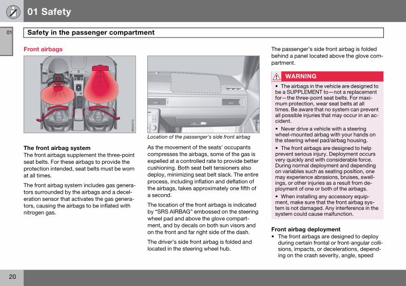
The front airbag system The front airbags supplement the three-point seat belts. For these airbags to provide the protection intended, seat belts must be worn at all times.
The front airbag system includes gas genera-tors surrounded by the airbags and a decel-eration sensor that activates the gas genera-tors, causing the airbags to be inflated with nitrogen gas.
Location of the passenger's side front airbag
As the movement of the seats' occupants compresses the airbags, some of the gas is expelled at a controlled rate to provide better cushioning. Both seat belt tensioners also deploy, minimizing seat belt slack. The entire process, including inflation and deflation of the airbags, takes approximately one fifth of a second.
The location of the front airbags is indicated by “SRS AIRBAG” embossed on the steering wheel pad and above the glove compart-ment, and by decals on both sun visors and on the front and far right side of the dash.
The driver’s side front airbag is folded and located in the steering wheel hub.
The passenger’s side front airbag is folded behind a panel located above the glove com-partment.
Front airbag deployment• The front airbags are designed to deploy
during certain frontal or front-angular colli-sions, impacts, or decelerations, depend-ing on the crash severity, angle, speed
8803
417d
8803
560s
WARNING
• The airbags in the vehicle are designed to be a SUPPLEMENT to—not a replacement for—the three-point seat belts. For maxi-mum protection, wear seat belts at all times. Be aware that no system can prevent all possible injuries that may occur in an ac-cident.
• Never drive a vehicle with a steering wheel-mounted airbag with your hands on the steering wheel pad/airbag housing.
• The front airbags are designed to help prevent serious injury. Deployment occurs very quickly and with considerable force. During normal deployment and depending on variables such as seating position, one may experience abrasions, bruises, swell-ings, or other injuries as a result from de-ployment of one or both of the airbags.• When installing any accessory equip-ment, make sure that the front airbag sys-tem is not damaged. Any interference in the system could cause malfunction.
S80 USA reprint version w640.book Page 20 Friday, June 1, 2007 10:44 AM
01 Safety
21
Safety in the passenger compartment 01
and object impacted. The airbags may also deploy in certain non-frontal colli-sions where rapid deceleration occurs.
• The SRS sensors, which trigger the front airbags, are designed to react to both the impact of the collision and the inertial forces generated by it, and to determine if the intensity of the collision is sufficient for the seat belt tensioners and/or airbags to be deployed.
However, not all frontal collisions activate the front airbags.
• If the collision involves a nonrigid object (e.g., a snow drift or bush), or a rigid, fixed object at a low speed, the front airbags will not necessarily deploy.
• Front airbags do not normally deploy in a side impact collision, in a collision from the rear or in a rollover situation.
• The amount of damage to the bodywork does not reliably indicate if the airbags should have deployed or not.
Should you have questions about any com-ponent in the SRS system, please contact a trained and qualified Volvo service technician or Volvo Customer Support:
In the USA
Volvo Cars of North America, LLC Customer Care Center P.O. Box 914 Rockleigh, New Jersey 07647-0914 1-800-458-155www.volvocars.us
In Canada
Volvo Cars of Canada Corp. National Customer Service 175 Gordon Baker Road North York, Ontario M2H 2N7 1-800-663-8255 www.volvocanada.com
WARNING
• Do not use child safety seats or child booster cushions/backrests in the front passenger’s seat. We also recommend that occupants under 4 feet 7 inches (140 cm) in height who have outgrown these devices sit in the rear seat with the seat belt fastened1.• Never drive with the airbags deployed. The fact that they hang out can impair the steering of your vehicle. Other safety sys-tems can also be damaged.• The smoke and dust formed when the airbags are deployed can cause skin and eye irritation in the event of prolonged ex-posure.
1 See also the Occupant Weight Sensor infor-mation on page 23.
NOTE
• Deployment of front airbags occurs only one time during an accident. In a collision where deployment occurs, the airbags and seat belt tensioners activate. Some noise occurs and a small amount of powder is re-leased. The release of the powder may ap-pear as smoke-like matter. This is a normal characteristic and does not indicate fire.• Volvo's dual-threshold, dual-stage front airbags use special sensors that are inte-grated with the front seat belt buckles. The point at which the airbag deploys is deter-mined by whether or not the seat belt is being used, as well as the severity of the collision.
• Collisions can occur where only one of the airbags deploys. If the impact is less se-vere, but severe enough to present a clear injury risk, the dual-stage airbags are trig-gered at 70% of their total capacity. If the impact is more severe, the dual-stage air-bags are triggered at full capacity.
S80 USA reprint version w640.book Page 21 Friday, June 1, 2007 10:44 AM

01 Safety
22
Safety in the passenger compartment01
Airbag decals
Airbag decal on the far right end of the passen-ger’s dashboard
Airbag decal on the outside of both sun visors
Airbag decal on passenger’s side dashboard
FAIL
UR
E T
O F
OLL
OW
TH
ES
EIN
STR
UC
TIO
NS
CA
N R
ES
ULT
ININ
JUR
Y T
O T
HE
VE
HIC
LEO
CC
UPA
NTS
IN A
N A
CC
IDE
NT.
Fo
r fu
rthe
r in
form
atio
n se
e o
wne
r´s
man
ual
NO
CH
ILD
RE
N O
R O
CC
UP
AN
TS
SH
OR
TE
R T
HA
N 1
40cm
IN T
HE
FR
ON
T P
AS
SE
NG
ER
SE
AT W
ITH
AN
AC
TIV
ATE
D A
IR B
AG
.N
O A
DU
LT P
AS
SE
NG
ER
LO
NG
ER
TH
AN
140
cm IN
TH
E F
RO
NT
PA
SS
EN
GE
R S
EAT
WIT
H A
IR B
AG
DE
AC
TIV
ATE
D B
Y T
HE
PA
SS
EN
GE
R A
IR B
AG
CU
T O
FF
SW
ITC
H.
ALW
AY
S P
LAC
E C
HIL
DR
EN
IN A
PP
RO
VE
D C
HIL
DR
ES
TR
AIN
TS
.A
LWA
YS
US
E S
EAT
BE
LTS
Thi
s ca
r is
eq
uip
ped
with
a f
ull f
ront
alS
upp
lem
enta
l Res
trai
nt S
yste
m (S
RS
)w
ith A
IR B
AG
S in
fro
nt o
f th
e d
rive
ran
d f
ront
pas
seng
er.
8803
632sWARNING
• Children must never be allowed in the front passenger’s seat. Volvo recommends that ALL occupants (adults and children) shorter than 4 feet 7 inches (140 cm) be seated in the back seat of any vehicle with a passenger-side front airbag. See page 33 for guidelines.• Occupants in the front passenger's seat must never sit on the edge of the seat, sit leaning toward the instrument panel or oth-erwise sit out of position.• The occupant's back must be as upright as comfort allows and be against the seat back with the seat belt properly fastened.
Feet must be on the floor, e.g., not on the dash, seat or out of the window.
Children can be killed or seriously injured by the air bag.The back seat is the safest place for children.
Never put a rear-facing child seat in front.Always use seat belts and child restraints.
See owner's manual for more information about air bags.
WARNING
• No objects or accessory equipment, e.g. dashboard covers, may be placed on, at-tached to, or installed near the air bag hatch (the area above the glove compartment) or the area affected by airbag deployment (see the illustration on page 20).• There should be no loose articles, e.g. coffee cups, on the floor, seat, or dash-board area.• Never try to open the airbag cover on the steering wheel or the passenger’s side dashboard. This should only be done by a trained and qualified Volvo service techni-cian.• Failure to follow these instructions can result in injury to the vehicle occupants.
S80 USA reprint version w640.book Page 22 Friday, June 1, 2007 10:44 AM
01 Safety
23
Safety in the passenger compartment 01
Occupant Weight Sensor
Occupant Weight Sensor (OWS) indicator light
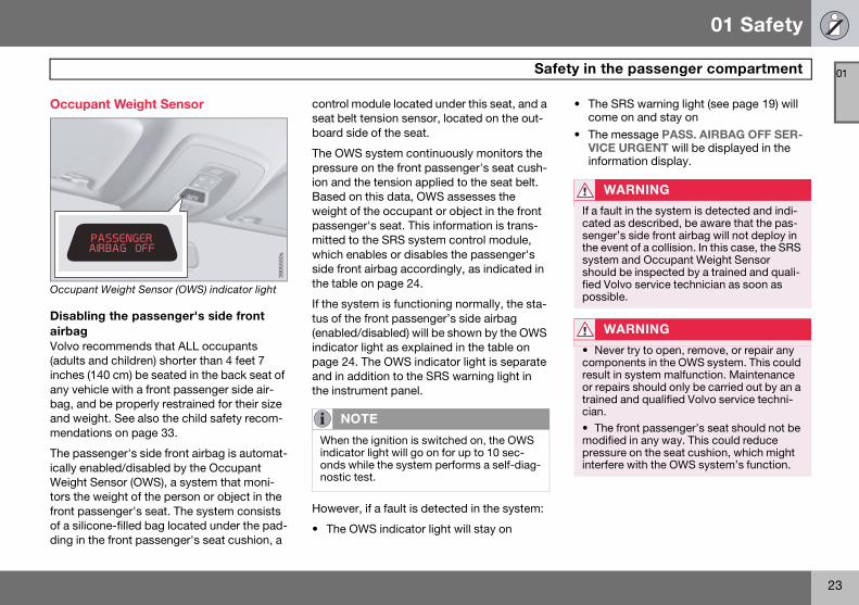
Disabling the passenger's side front airbagVolvo recommends that ALL occupants (adults and children) shorter than 4 feet 7 inches (140 cm) be seated in the back seat of any vehicle with a front passenger side air-bag, and be properly restrained for their size and weight. See also the child safety recom-mendations on page 33.
The passenger's side front airbag is automat-ically enabled/disabled by the Occupant Weight Sensor (OWS), a system that moni-tors the weight of the person or object in the front passenger's seat. The system consists of a silicone-filled bag located under the pad-ding in the front passenger's seat cushion, a
control module located under this seat, and a seat belt tension sensor, located on the out-board side of the seat.
The OWS system continuously monitors the pressure on the front passenger's seat cush-ion and the tension applied to the seat belt. Based on this data, OWS assesses the weight of the occupant or object in the front passenger's seat. This information is trans-mitted to the SRS system control module, which enables or disables the passenger's side front airbag accordingly, as indicated in the table on page 24.
If the system is functioning normally, the sta-tus of the front passenger’s side airbag (enabled/disabled) will be shown by the OWS indicator light as explained in the table on page 24. The OWS indicator light is separate and in addition to the SRS warning light in the instrument panel.
However, if a fault is detected in the system:
• The OWS indicator light will stay on
• The SRS warning light (see page 19) will come on and stay on
• The message PASS. AIRBAG OFF SER-VICE URGENT will be displayed in the information display.
3905
550s
NOTE
When the ignition is switched on, the OWS indicator light will go on for up to 10 sec-onds while the system performs a self-diag-nostic test.
WARNING
If a fault in the system is detected and indi-cated as described, be aware that the pas-senger’s side front airbag will not deploy in the event of a collision. In this case, the SRS system and Occupant Weight Sensor should be inspected by a trained and quali-fied Volvo service technician as soon as possible.
WARNING
• Never try to open, remove, or repair any components in the OWS system. This could result in system malfunction. Maintenance or repairs should only be carried out by an a trained and qualified Volvo service techni-cian.
• The front passenger’s seat should not be modified in any way. This could reduce pressure on the seat cushion, which might interfere with the OWS system’s function.
S80 USA reprint version w640.book Page 23 Friday, June 1, 2007 10:44 AM

01 Safety
24
Safety in the passenger compartment01
The OWS is designed to enable (may inflate) the passenger's side front airbag anytime the system senses that a person of adult size is sitting properly in the front passenger’s seat. The PASSENGER AIRBAG OFF indicator lamp will be off and remain off.
If a person of adult size is sitting in the front passenger's seat, but the PASSENGER AIR-BAG OFF indicator lamp is on, it is possible that the person isn't sitting properly in the seat. If this happens:
• Turn the vehicle off and ask the person to place the seatback in an upright position.
• Have the person sit upright in the seat, centered on the seat cushion, with the person's legs comfortably extended.
• Restart the vehicle and have the person remain in this position for about two min-utes. This will allow the system to detect that person and enable the passenger's frontal airbag.
• If the PASSENGER AIRBAG OFF indicator lamp remains on even after this, the per-son should be advised to ride in the rear seat.
This condition reflects limitations of the OWS classification capability. It does not indicate OWS malfunction.
ModificationsIf you are considering modifying your vehicle in any way to accommodate a disability, for example by altering or adapting the driver's or front passenger's seat(s) and/or airbag systems, please contact Volvo at:
In the USA
Volvo Cars of North America, LLC Customer Care Center P.O. Box 914 Rockleigh, New Jersey 07647-0914 1-800-458-1552
In Canada
Volvo Cars of Canada Corp. National Customer Service 175 Gordon Baker Road North York, Ontario M2H 2N7 1-800-663-8255
Passenger’s seat occupancy status
OWS indicator light status
Passenger’s side front airbag status
Seat unoccupied
OWS indicator light lights up.
Passenger’s side front airbag disabled
Seat occupied by low weight occupant/object1
OWS indicator light lights up
Passenger’s side front airbag disabled
Seat occupied by heavy occupant/object
OWS indicator light is not lit
Passenger’s side front airbag enabled
1Volvo recommends that children always be properly restrained in appropriate child restraints in the rear seats. Do not assume that the passenger’s side front airbag is disabled unless the PASSENGER AIRBAG OFF indicator lamp is lit. Make sure the child restraint is properly installed. If there is any doubt as to the status of the passenger’s side front airbag, move the child restraint to the rear seat.
S80 USA reprint version w640.book Page 24 Friday, June 1, 2007 10:44 AM

01 Safety
25
Safety in the passenger compartment 01
WARNING
• No objects that add to the total weight on the seat should be placed on the front passenger’s seat. If a child is seated in the front passenger’s seat with any additional weight, this extra weight could cause the OWS system to enable the airbag, which might cause it to deploy in the event of a collision, thereby injuring the child.• The seat belt should never be wrapped around an object on the front passenger’s seat. This could interfere with the OWS sys-tem’s function.• The front passenger’s seat belt should never be used in a way that exerts more pressure on the passenger than normal. This could increase the pressure exerted on the weight sensor by a child, and could re-sult in the airbag being enabled, which might cause it to deploy in the event of a collision, thereby injuring the child.
WARNING
• Keep the following points in mind with re-spect to the OWS system. Failure to follow these instructions could adversely affect the system’s function and result in serious injury to the occupant of the front passen-ger’s seat:
• The full weight of the front seat passen-ger should always be on the seat cushion. The passenger should never lift him/herself off the seat cushion using the armrest in the door or the center console, by pressing the feet on the floor, by sitting on the edge of the seat cushion, or by pressing against the backrest in a way that reduces pressure on the seat cushion. This could cause OWS to disable the front, passenger’s side airbag.
• Do not place any type of object on the front passenger's seat in such a way that jamming, pressing, or squeezing occurs be-tween the object and the front seat, other than as a direct result of the correct use of the ALR/ELR seat belt (see page 33).• No objects should be placed under the front passenger’s seat. This could interfere with the OWS system’s function.
S80 USA reprint version w640.book Page 25 Friday, June 1, 2007 10:44 AM

01 Safety
26
Safety in the passenger compartment01
Side impact protection (SIPS) airbags
Location of the side impact (SIPS) airbag
Side impact airbags - front seats only As an enhancement to the structural side impact protection built into your vehicle, it is also equipped with Side Impact Protection System (SIPS) airbags.
The SIPS airbag system is designed to help increase occupant protection in the event of certain side impact collisions. The SIPS air-bags are designed to deploy only during cer-tain side-impact collisions, depending on the crash severity, angle, speed and point of impact.
SIPS decal on the front of the driver’s door opening
SIPS airbag deployment (one airbag) occurs only on the side of the vehicle affected by the impact. The airbags are not designed to deploy in all side impact situations.
Components in the SIPS airbag systemThis SIPS airbag system consists of a gas generator, the side airbag modules built into
the outboard sides of both front seat back-rests, and electronic sensors/wiring.
8803
566s
NOTE
SIPS airbag deployment (one airbag) oc-curs only on the side of the vehicle affected by the impact. The airbags are not designed to deploy in all side impact situations.
BA
G
THIS
CAR
USE
EQU
IPPE
D W
ITH
SIPS
BAG
IN E
ACH
FRON
T SE
AT
DO N
OT
INST
ALL A
NY A
CCES
SORI
ES O
N TH
E SI
DE O
R NE
AR T
HE S
IPSB
AG
DO N
OT
USE
EXCE
SSIV
E FO
RCE
ON
THE
SIDE
OF
THE
SEAT
DO
NO
T US
E AS
SESS
OY
SEAT
CO
VERS
UNL
ESS
THEY
MEE
T VO
LVO
´S S
PECI
FICA
TIO
N US
E O
F O
THER
SEA
T CO
VERS
CO
ULD
REDU
CE T
HE E
FFEC
T O
F TH
E SY
STEM
FO
R FU
RTHE
R IN
FORM
ATIO
N SE
E OW
NER´
S M
ANUA
L
8803
559s
WARNING
• The SIPS airbag system is a supplement to the structural Side Impact Protection System and the three-point seat belt sys-tem. It is not designed to deploy during col-lisions from the front or rear of the vehicle or in rollover situations.
• The use of seat covers on the front seats may impede SIPS airbag deployment.
• No objects, accessory equipment or stickers may be placed on, attached to or installed near the SIPS airbag system or in the area affected by SIPS airbag deploy-ment.
• Never try to open or repair any compo-nents of the SIPS airbag system. This should be done only by a trained and quali-fied Volvo service technician.
• In order for the SIPS airbag to provide its best protection, both front seat occupants should sit in an upright position with the seat belt properly fastened.
• Failure to follow these instructions can result in injury to the occupants of the vehi-cle in the event of an accident.
S80 USA reprint version w640.book Page 26 Friday, June 1, 2007 10:44 AM

01 Safety
27
Safety in the passenger compartment 01
Volvo Inflatable Curtain (VIC)
The Volvo Inflatable Curtain system This system consists of inflatable curtains located along the sides of the roof liners, stretching from the center of both front side windows to the rear edge of the rear side door windows. It is designed to help protect the heads of the occupants of the front seats and the occupant of the outboard rear seat-ing positions in certain side impact collisions.
In certain side impacts, both the Inflatable Curtain (VIC) and the Side Impact Airbag System (SIPS-bag) will deploy, whereas, in some cases, only the Inflatable Curtain (VIC) will deploy. In cases where both the VIC and the SIPS-bag deploy, this will occur simulta-neously.
8803
556s
NOTE
If the inflatable curtain deploys, it remains inflated for approximately 3 seconds.
WARNING
• The VIC system is a supplement to the Side Impact Protection System. It is not de-signed to deploy during collisions from the front or rear of the vehicle or in rollover situ-ations.
• Never try to open or repair any compo-nents of the VIC system. This should be done only by a trained and qualified Volvo service technician.
• Never hang heavy items from the ceiling handles. This could impede deployment of the Inflatable Curtain.
WARNING
In order for the VIC to provide its best pro-tection, both front seat occupants and both outboard rear seat occupants should sit in an upright position with the seat belt prop-erly fastened; adults using the seat belt and children using the proper child restraint sys-tem. Only adults should sit in the front seats. Children must never be allowed in the front passenger seat. See page 33 for guidelines. Failure to follow these instruc-tions can result in injury to the vehicle occu-pants in an accident.
S80 USA reprint version w640.book Page 27 Friday, June 1, 2007 10:44 AM

01 Safety
28
Safety in the passenger compartment01
Whiplash Protection System – WHIPS Whiplash Protection System (WHIPS) - front seats only The WHIPS system consists of specially designed hinges and brackets on the front seat backrests designed to help absorb some of the energy generated in a collision from the rear (when the vehicle is rear-ended).
In the event of a collision of this type, the hinges and brackets of the front seat back-rests are designed to change position slightly to allow the backrest/head restraint to help support the occupant's head before moving slightly rearward. This movement helps absorb some of the forces that could result in whiplash.
8803
529j
WARNING
• The WHIPS system is designed to sup-plement the other safety systems in your vehicle. For this system to function proper-ly, the three-point seat belt must be worn. Please be aware that no system can pre-vent all possible injuries that may occur in an accident.• The WHIPS system is designed to func-tion in certain collisions from the rear, de-pending on the crash severity, angle and speed.
WARNING
Occupants in the front seats must never sit out of position. The occupant's back must be as upright as comfort allows and be against the seat back with the seat belt properly fastened.
WARNING
• If your vehicle has been involved in a rear-end collision, the front seat backrests must be inspected by a trained and quali-fied Volvo service technician, even if the seats appear to be undamaged. Certain components in the WHIPS system may need to be replaced.• Do not attempt to service any component in the WHIPS system yourself.
S80 USA reprint version w640.book Page 28 Friday, June 1, 2007 10:44 AM

01 Safety
29
Safety in the passenger compartment 01
WARNING
• Boxes, suitcases, etc. wedged behind the front seats could impede the function of the WHIPS system. • If the rear seat backrests are folded down, cargo must be secured to prevent it from sliding forward against the front seat backrests in the event of a collision from the rear. This could interfere with the action of the WHIPS system.
8803
530j
WARNING
Any contact between the front seat back-rests and the folded rear seat or a rear-fac-ing child seat could impede the function of the WHIPS system. If the rear seat is folded down, the occupied front seats must be ad-justed forward so that they do not touch the folded rear seat.
8803
531j
S80 USA reprint version w640.book Page 29 Friday, June 1, 2007 10:44 AM
01 Safety
30
Crash mode01
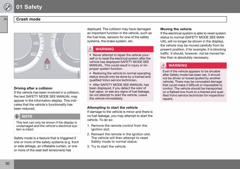
Driving after a collisionIf the vehicle has been involved in a collision, the text SAFETY MODE SEE MANUAL may appear in the information display. This indi-cates that the vehicle's functionality has been reduced.
Safety mode is a feature that is triggered if one or more of the safety systems (e.g. front or side airbags, an inflatable curtain, or one or more of the seat belt tensioners) has
deployed. The collision may have damaged an important function in the vehicle, such as the fuel lines, sensors for one of the safety systems, the brake system, etc.
Attempting to start the vehicleIf damage to the vehicle is minor and there is no fuel leakage, you may attempt to start the vehicle. To do so:
1. Remove the remote control from the ignition slot.
2. Reinsert the remote in the ignition slot. The vehicle will then attempt to reset Safety mode to normal status.
3. Try to start the vehicle.
Moving the vehicle If the electrical system is able to reset system status to normal (SAFETY MODE SEE MAN-UAL will no longer be shown in the display), the vehicle may be moved carefully from its present position, if for example, it is blocking traffic. It should, however, not be moved far-ther than is absolutely necessary.
NOTE
This text can only be shown if the display is undamaged and the vehicle's electrical sys-tem is intact.
3801
303s
WARNING
• Never attempt to repair the vehicle your-self or to reset the electrical system after the vehicle has displayed SAFETY MODE SEE MANUAL. This could result in injury or im-proper system function.• Restoring the vehicle to normal operating status should only be done by a trained and qualified Volvo service technician.
• After SAFETY MODE SEE MANUAL has been displayed, if you detect the odor of fuel vapor, or see any signs of fuel leakage, do not attempt to start the vehicle. Leave the vehicle immediately.
WARNING
Even if the vehicle appears to be drivable after Safety mode has been set, it should not be driven or towed (pulled by another vehicle). There may be concealed damage that could make it difficult or impossible to control. The vehicle should be transported on a flatbed tow truck to a trained and qual-ified Volvo service technician for inspection/repairs.
S80 USA reprint version w640.book Page 30 Friday, June 1, 2007 10:44 AM

01 Safety
31
Child safety 01
Children should be seated safely
Volvo recommends the proper use of restraint systems for all occupants including children. Remember that, regardless of age and size, a child should always be properly restrained in a vehicle.
Your vehicle is also equipped with ISOFIX/LATCH attachments, which make it more convenient to install child seats.
Some restraint systems for children are designed to be secured in the vehicle by lap belts or the lap portion of a lap-shoulder belt. Such child restraint systems can help protect children in vehicles in the event of an acci-dent only if they are used properly. However, children could be endangered in a crash if the child restraints are not properly secured in the vehicle. Failure to follow the installation instructions for your child restraint can result in your child striking the vehicle's interior in a sudden stop.
Holding a child in your arms is NOT a suitable substitute for a child restraint system. In an accident, a child held in a person's arms can be crushed between the vehicle's interior and an unrestrained person. The child could also be injured by striking the interior, or by being ejected from the vehicle during a sud-den maneuver or impact. The same can also
happen if the infant or child rides unre-strained on the seat. Other occupants should also be properly restrained to help reduce the chance of injuring or increasing the injury of a child.
All states and provinces have legislation gov-erning how and where children should be carried in a vehicle. Find out the regulations existing in your state or province. Recent accident statistics have shown that children are safer in rear seating positions than front seating positions when properly restrained. A child restraint system can help protect a child in a vehicle. Here's what to look for when selecting a child restraint system:
It should have a label certifying that it meets applicable Federal Motor Vehicle Safety Standards (FMVSS 213) - or in Canada, CMVSS 213.
Make sure the child restraint system is approved for the child's height, weight and development - the label required by the stan-dard or regulation, or instructions for infant restraints, typically provide this information.
In using any child restraint system, we urge you to carefully look over the instructions that are provided with the restraint. Be sure you understand them and can use the device properly and safely in this vehicle. A misused
child restraint system can result in increased injuries for both the infant or child and other occupants in the vehicle.
When a child has outgrown the child safety seat, you should use the rear seat with the standard seat belt fastened. The best way to help protect the child here is to place the child on a cushion so that the seat belt is properly located on the hips (see the illustra-tion on page 41). Legislation in your state or province may mandate the use of a child seat or cushion in combination with the seat belt, depending on the child's age and/or size. Please check local regulations.
A specially designed and tested booster cushion (not available in Canada) can be obtained from your Volvo retailer for children weighing 33 - 80 lb. (15 - 36 kg) and 38-54 inches (97 - 137 cm) in height.
S80 USA reprint version w640.book Page 31 Friday, June 1, 2007 10:44 AM

01 Safety
32
Child safety01
WARNING
• Do not use child safety seats or child booster cushions/backrests in the front passenger’s seat. We also recommend that children under 4 feet 7 inches (140 cm) in height who have outgrown these devices sit in the rear seat with the seat belt fastened.
• Keep vehicle doors and trunk locked and keep remote controls out of a child’s reach. Unsupervised children could lock them-selves in an open trunk and risk injury. Chil-dren should be taught not to play in vehicles.• On hot days, the temperature in the trunk or vehicle interior can rise very quickly. Ex-posure to these high temperatures for even a short period of time can cause heat-relat-ed injury or death. Small children are partic-ularly at risk.
S80 USA reprint version w640.book Page 32 Friday, June 1, 2007 10:44 AM

01 Safety
33
Child safety 01
Automatic Locking Retractor/Emergency Locking Retractor
To make child seat installation easier, each seat belt (except for the driver's belt) is equipped with a locking mechanism to help keep the seat belt taut.
When attaching the seat belt to a child seat:1. Attach the seat belt to the child seat
according to the child seat manufacturer's instructions.
2. Pull the seat belt out as far as possible.
3. Insert the seat belt latch plate into the buckle (lock) in the usual way.
4. Release the seat belt and pull it taut around the child seat.
A sound from the seat belt retractor will be audible at this time and is normal. The belt will now be locked in place. This function is automatically disabled when the seat belt is unlocked and the belt is fully retracted.
Volvo's recommendationsWhy does Volvo believe that no child should sit in the front seat of a vehicle? It's quite simple really. A front airbag is a very powerful device designed, by law, to help protect an adult.
Because of the size of the airbag and its speed of inflation, a child should never be placed in the front seat, even if he or she is properly belted or strapped into a child safety seat. Volvo has been an innovator in safety for over seventy-five years, and we'll con-tinue to do our part. But we need your help. Please remember to put your children in the back seat, and buckle them up.
Volvo has some very specific recom-mendations:• Always wear your seat belt.
• Airbags are a SUPPLEMENTAL safety de-vice which, when used with a three-point seat belt can help reduce serious injuries during certain types of accidents. Volvo recommends that you do not disconnect the airbag system in your vehicle.
• Volvo strongly recommends that everyone in the vehicle be properly restrained.
• Volvo recommends that ALL occupants (adults and children) shorter than 4 feet 7 inches (140 cm) be seated in the back seat
of any vehicle with a front passenger side airbag.
Drive safely!
WARNING
Do not use child safety seats or child boost-er cushions/backrests in the front passen-ger’s seat. We also recommend that children who have outgrown these devices sit in the rear seat with the seat belt properly fastened.
S80 USA reprint version w640.book Page 33 Friday, June 1, 2007 10:44 AM

01 Safety
34
Child restraint systems01
Child restraints
Infant seat
There are three main types of child restraint systems: infant seats, convertible seats, and booster cushions. They are classified according to the child's age and size.
The following section provides general information on securing a child restraint using a three-point seat belt. Refer to pages 42-43 for information on securing a child restraint using ISOFIX lower anchors and/or top tether anchorages.
Convertible seat Booster cushion
WARNING
A child seat should never be used in the front passenger seat of any vehicle with a front passenger airbag - not even if the "Passenger airbag off" symbol near the rear-view mirror is illuminated (on vehicles equipped with Occupant Weight Sensor). If the severity of an accident were to cause the airbag to inflate, this could lead to seri-ous injury or death to a child seated in this position.
8302
693s
WARNING
Always refer to the child restraint manufac-turer’s instructions for detailed information on securing the restraint.
S80 USA reprint version w640.book Page 34 Friday, June 1, 2007 10:44 AM

01 Safety
35
Child restraint systems 01
WARNING
• When not in use, keep the child restraint system secured or remove it from the pas-senger compartment to help prevent it from injuring passengers in the event of a sudden stop or collision.
• A small child’s head represents a consid-erable part of its total weight and its neck is still very weak. Volvo recommends that chil-dren up to age 4 travel, properly restrained, facing rearward. In addition, Volvo recom-mends that children should ride rearward facing, properly restrained, as long as possible.
S80 USA reprint version w640.book Page 35 Friday, June 1, 2007 10:44 AM

01 Safety
36
Infant seats01
Securing an infant seat with a seat belt
Do not place the infant seat in the front passen-ger’s sea
1. Place the infant seat in the rear seat of the vehicle.
2. Attach the seat belt to the infant seat according to the manufacturer's instruc-tions.
3. Fasten the seat belt by inserting the latch plate into the buckle (lock) until a distinct click is audible.
Positioning the seat belt through the infant seat Fasten the seat belt
NOTE
Refer to pages 42-43 for information on se-curing a child restraint using ISOFIX lower anchors and/or top tether anchorages.
8302
695s
WARNING
• An infant seat must be in the rear-facing position only.• The infant seat should not be positioned behind the driver’s seat unless there is ade-quate space for safe installation.
WARNING
A child seat should never be used in the front passenger seat of any vehicle with a front passenger airbag - not even if the "Passenger airbag off" symbol near the rear-view mirror is illuminated (on vehicles equipped with Occupant Weight Sensor). If the severity of an accident were to cause the airbag to inflate, this could lead to seri-ous injury or death to a child seated in this position.
S80 USA reprint version w640.book Page 36 Friday, June 1, 2007 10:44 AM

01 Safety
37
Infant seats 01
Pull out the shoulder section of the seat belt
4. Pull the shoulder section of the seat belt out as far as possible to activate the belt’s automatic locking function.
5. Press the infant seat firmly in place, let the seat belt retract and pull it taut. A sound from the seat belt retractor’s automatic locking function will be audi-ble at this time and is normal. The seat belt should now be locked in place.
Ensure that the seat is securely in place
6. Push and pull the infant seat to ensure that it is held securely in place by the seat belt.
The infant seat can be removed by unbuck-ling the seat belt and letting it retract com-pletely.
NOTE
The locking retractor will automatically re-lease when the seat belt is unbuckled and allowed to retract fully.
WARNING
It should not be possible to move the child restraint more than 1 in. (2.5 cm) in any di-rection.
S80 USA reprint version w640.book Page 37 Friday, June 1, 2007 10:44 AM

01 Safety
38
Convertible seats01
Securing a convertible seat with a seat belt
Do not place the convertible seat in the front passenger’s seat
Convertible seats can be used in either a for-ward or rearward-facing position, depending on the age and size of the child.
Route the seat belt through the convertible seat
1. Place the convertible seat in the rear seat of the vehicle.
2. Attach the seat belt to the convertible seat according to the manufacturer's instructions.
NOTE
Refer to pages 42-43 for information on se-curing a child restraint using ISOFIX lower anchors and/or top tether anchorages.
G01
8630
WARNING
Always use a convertible seat that is suit-able for the child’s age and size. See the convertible seat manufacturer’s recommen-dations.
8302
693s
WARNING
• A small child’s head represents a consid-erable part of its total weight and its neck is still very weak. Volvo recommends that chil-dren up to age 4 travel, properly restrained, facing rearward. In addition, Volvo recom-mends that children should ride rearward facing, properly restrained, as long as pos-sible.• Convertible child seats should be in-stalled in the rear seat only.
• A rear-facing convertible seat should not be positioned behind the driver’s seat un-less there is adequate space for safe instal-lation.
S80 USA reprint version w640.book Page 38 Friday, June 1, 2007 10:44 AM

01 Safety
39
Convertible seats 01
Fasten the seat belt
3. Fasten the seat belt by inserting the latch plate into the buckle (lock) until a distinct click is audible.
4. Pull the shoulder section of the seat belt out as far as possible to activate the belt’s automatic locking function.
5. Press the convertible seat firmly in place, let the seat belt retract and pull it taut. A sound from the seat belt retrac-tor’s automatic locking function will be audible at this time and is normal. The seat belt should now be locked in place.
Pull out the shoulder section of the seat belt
6. Push and pull the convertible seat to ensure that it is held securely in place by the seat belt.
The convertible seat can be removed by unbuckling the seat belt and letting it retract completely.
NOTE
The locking retractor will automatically re-lease when the seat belt is unbuckled and allowed to retract fully.
WARNING
It should not be possible to move the child restraint more than 1 in. (2.5 cm) in any di-rection.
S80 USA reprint version w640.book Page 39 Friday, June 1, 2007 10:44 AM

01 Safety
40
Convertible seats01
Ensure that the seat is securely in place
WARNING
A child seat should never be used in the front passenger seat of any vehicle with a front passenger airbag - not even if the "Passenger airbag off" symbol near the rear-view mirror is illuminated (on vehicles equipped with Occupant Weight Sensor). If the severity of an accident were to cause the airbag to inflate, this could lead to seri-ous injury or death to a child seated in this position.
S80 USA reprint version w640.book Page 40 Friday, June 1, 2007 10:44 AM

01 Safety
41
Booster cushions 01
Securing a booster cushion
Position the child correctly on the booster cush-ion
1. Booster cushions are recommended for children who have outgrown convertible seats.
2. Place the booster cushion in the rear seat of the vehicle.
3. With the child properly seated on the booster cushion, attach the seat belt to or around the cushion according to the manufacturer's instructions.
Fasten the seat belt by inserting the latch plate into the buckle (lock) until a distinct click is audible.
Positioning the seat belt
4. Ensure that the seat belt is pulled taut and fits snugly around the child.
WARNING
• The hip section of the three-point seat belt must fit snugly across the child’s hips, not across the stomach. • The shoulder section of the three-point seat belt should be positioned across the chest and shoulder. • The shoulder belt must never be placed behind the child’s back or under the arm.
S80 USA reprint version w640.book Page 41 Friday, June 1, 2007 10:44 AM

01 Safety
42
ISOFIX lower anchors01
Using the ISOFIX lower child seat anchors
ISOFIX lower child restraint anchors
Lower anchors for ISOFIX-equipped child seats are located in the rear, outboard seats, hidden below the backrest cushions. Sym-bols on the seat back upholstery mark the anchor positions as shown. To access the anchors, kneel on the seat cushion and locate the anchors by feel. Always follow your child seat manufacturer's installation instructions, and use both ISOFIX lower anchors and top tethers whenever possible.
To access the anchors1. Put the child restraint in position.
2. Kneel on the child restraint to press down the seat cushion and locate the anchors by feel.
3. Fasten the attachment on the child re-straint’s lower straps to the ISOFIX lower anchors.
4. Firmly tension the lower child seat straps according to the manufacturer’s instructions.
Fasten the attachment correctly to the ISOFIX lower anchors
8704
364s
NOTE
• The rear seat’s center position is not equipped with ISOFIX lower anchors. When installing a child restraint in this position, at-tach the restraint’s top tether strap (if it is so equipped) to the top tether anchorage point (see the information on page 43) and secure the restraint with the vehicle’s center seat belt (see the information beginning on page 34).• Always follow your child seat manufac-turer's installation instructions, and use both ISOFIX lower anchors and top tethers whenever possible.
WARNING
• Be sure to fasten the attachment correct-ly to the anchor (see the illustration above). If the attachment is not correctly fastened, the child restraint may not be properly se-cured in the event of a collision.• The ISOFIX lower child restraint anchors are only intended for use with child seats positioned in the outboard seating posi-tions. These anchors are not certified for use with any child restraint that is posi-tioned in the center seating position. When securing a child restraint in the center seat-ing position, use only the vehicle's center seat belt.
G01
8631
S80 USA reprint version w640.book Page 42 Friday, June 1, 2007 10:44 AM

01 Safety
43
Top tether anchors 01
Child restraint anchorages
Your Volvo is equipped with child restraint top tether anchorages in the rear seat.
Securing a child seat 1. Place the child restraint on the rear seat.
2. Fold up the plastic cover over the an-chorage to be used.
3. Route the top tether strap under the head restraint and attach it to the an-chor.
4. Attach lower tether straps to the lower ISOFIX/LATCH anchors. If the child re-straint is not equipped with lower tether straps, or the restraint is used in the center seating position, follow instruc-tions for securing a child restraint using
the Automatic Locking Retractor seat belt (see page 33).
5. Firmly tension all straps.
Refer also to the child seat manufacturer’s instructions for information on securing the child seat.
8904
139s
NOTE
Child restraints could be recalled for safety reasons. You must register your child re-straint to be reached in a recall. To stay in-formed about child safety seat recalls, be sure to fill out and return the registration card that comes with new child restraints.Child restraint recall information is readily available in both the U.S. and Canada. For recall information in the U.S., call the U.S. Government's Auto Safety Hotline at 1-800-424-9393. In Canada, visit Transport Cana-da's Child Safety website at http://www.tc.gc.ca/roadsafety/childsafety/menu.htm.
WARNING
• Never route a top tether strap over the top of the head restraint. The strap should be routed beneath the head restraint.• Child restraint anchorages are designed to withstand only those loads imposed by correctly fitted child restraints. Under no circumstances are they to be used for adult seat belts or harnesses. The anchorages are not able to withstand excessive forces on them in the event of collision if full har-ness seat belts or adult seat belts are in-stalled to them. An adult who uses a belt anchored in a child restraint anchorage runs a great risk of suffering severe injuries should a collision occur.
• Do not install rear speakers that require the removal of the top tether anchors or in-terfere with the proper use of the top tether strap.
S80 USA reprint version w640.book Page 43 Friday, June 1, 2007 10:44 AM

01 Safety
44
Integrated booster cushion01
Integrated booster cushion (option)1
Volvo's optional integrated booster cushion is located in the center seating position. This booster cushion has been specially designed to help safeguard a child seated in the rear seat. This cushion should be stowed (folded up into the rear seat backrest) when not in use. When using an integrated booster cush-ion, the child must be secured with the vehi-cle's three-point seat belt.
Use this booster cushion only with children who weigh between 33 and 80 lbs (15 and 36 kg) and whose height is between 38 and 54 in (97 and 137 cm). In Canada, Transport
Canada's weight recommendation is 40-80 lbs (18-36 kg).
The booster cushion is designed to raise the child higher, so that the shoulder strap crosses over the child's collarbone, not over the child's neck. If using a booster cushion does not result in proper positioning of the shoulder strap, then the child should be placed in a properly secured child restraint (see the information beginning on page 34). The shoulder belt must never be placed behind the child’s back or under the arm.
1 Canada only: This cushion may be referred to as a built-in booster cushion.
8803
565s
S80 USA reprint version w640.book Page 44 Friday, June 1, 2007 10:44 AM

01 Safety
45
Integrated booster cushion 01
Using the integrated booster cushion Fold down the booster cushion from the rear seat backrest.
Loosen the Velcro strip.
Fold up the backrest section of the booster cushion into the upright position.
Stowing the integrated booster cushion
Fold down the backrest section of the booster cushion.
Fasten the Velcro strip.
Fold up the booster cushion into the rear seat backrest
1
8505
333s
285
0533
0s
3
8505
343s
1
8505
334s
2
8505
344s
NOTE
See also the instructions on the integrated booster cushion.
3
8505
335s
S80 USA reprint version w640.book Page 45 Friday, June 1, 2007 10:44 AM

01 Safety
46
Integrated booster cushion01
WARNING
DEATH or SERIOUS INJURY can occurFollow all instructions on the booster cushion and in the vehi-cle's owner's manual.MAKE SURE THE BOOSTER CUSHION IS SECURELY LOCKED BEFORE THE CHILD IS SEATED.• Use this booster cushion only with chil-dren who weigh between 33 and 80 lbs (15 and 36 kg) and whose height is between 38 and 54 in (97 and 137 cm). In Canada, Transport Canada's weight recommenda-tion is 40-80 lbs (18-36 kg).
• In the event of a collision while the inte-grated booster cushion was occupied, the entire booster cushion and seat belt must be replaced. The booster cushion should also be replaced if it is badly worn or dam-aged in any way. This work should be per-formed by a trained and qualified Volvo service technician only
S80 USA reprint version w640.book Page 46 Friday, June 1, 2007 10:44 AM
01 Safety
47
Child safety locks 01
Child safety locks
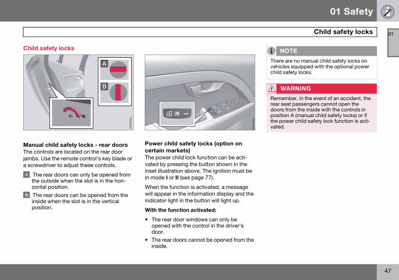
Manual child safety locks - rear doors The controls are located on the rear door jambs. Use the remote control’s key blade or a screwdriver to adjust these controls.
The rear doors can only be opened from the outside when the slot is in the hori-zontal position.
The rear doors can be opened from the inside when the slot is in the vertical position.
Power child safety locks (option on certain markets)The power child lock function can be acti-vated by pressing the button shown in the inset illustration above. The ignition must be in mode I or II (see page 77).
When the function is activated, a message will appear in the information display and the indicator light in the button will light up.
With the function activated:
• The rear door windows can only be opened with the control in the driver’s door.
• The rear doors cannot be opened from the inside.
8302
555s s9873063
NOTE
There are no manual child safety locks on vehicles equipped with the optional power child safety locks.
WARNING
Remember, in the event of an accident, the rear seat passengers cannot open the doors from the inside with the controls in position A (manual child safety locks) or if the power child safety lock function is acti-vated.
S80 USA reprint version w640.book Page 47 Friday, June 1, 2007 10:44 AM

48
Remote key and key blade ...................................................................... 50
Keyless drive ............................................................................................ 58
Locks........................................................................................................ 61
Alarm........................................................................................................ 64
S80 USA reprint version w640.book Page 48 Friday, June 1, 2007 10:44 AM
02LOCKS AND ALARM
S80 USA reprint version w640.book Page 49 Friday, June 1, 2007 10:44 AM

02 Locks and alarm
50
Remote key and key blade
02
Introduction
Two remote keys or optional Personal Car Communicators (PCC) are provided with your vehicle. They enable you to unlock the doors and trunk, and also function as ignition keys to start the vehicle or operate electrical components. The remote keys contain detachable metal key blades for manually locking or unlocking the driver's door, trunk, and the glove compartment. Up to six remotes can be programmed for use on the same vehicle.
The PCCs have enhanced functionality com-pared with the standard remote control.
Detachable key bladeEach remote key or PCC contains a detach-able metal key blade for mechanically locking or unlocking the driver’s door, trunk, and the glove compartment, and to enable the valet
locking function. See page 55 for more infor-mation on the key blade and page 56 for information on the valet locking function. The key blades have a unique code, which is used if new ones need to be produced. This code is available at an authorized Volvo retailer.
Loss of a remote keyIf a remote key is lost, the other one must be taken with the vehicle to a trained and quali-fied Volvo service technician. As an anti-theft measure, the code of the lost remote must be erased from the system.
The number of registered keys for the vehicle can be found in the vehicle’s menu. under Car settings Car key memory Num-ber of keys. See page 117 for a description of the menu system.
NOTE
In the remainder of this chapter, all refer-ences to the remote key also pertain to the PCC unless otherwise stated.
WARNING
Never leave the remote key in the ignition if children are to remain in the vehicle.
USA—5WK49264 FCC ID:KR55WK49264 + Siemens VDO 5WK49236 FCC ID:KR55WK49236, 5WK49266 FCC ID:KR55WK49266 + Siemens VDO 5WK49233 FCC ID:KR55WK49233
This device complies with part 15 of the FCC rules and RSS-210. Operation is subject to the following conditions: (1) This device may not cause harmful inter-ference, and (2) this device must accept any interference received, including inter-ference that may cause undesired opera-tion.
Canada—5WK49264 IC:267T-5WK49264 + Siemens VDO 5WK49236 IC:267T-5WK49236, 5WK49266 IC:267T-5WK49266 + Siemens VDO 5WK49233 IC:267T-5WK49233
Operation is subject to the following con-ditions: (1) this device may not cause interference, and (2) this device must accept any interference, including inter-ference that may cause undesired opera-tion of the device.
S80 USA reprint version w640.book Page 50 Friday, June 1, 2007 10:44 AM
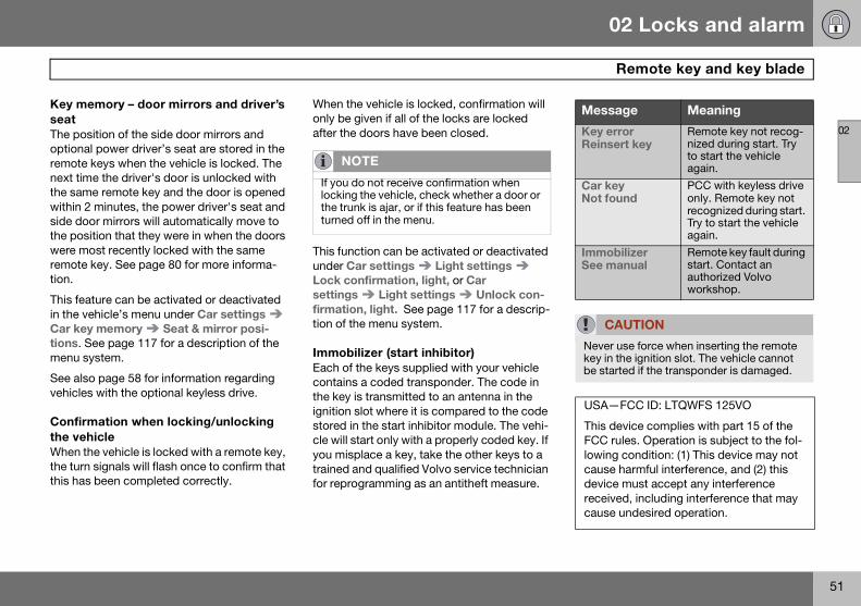
02 Locks and alarm
51
Remote key and key blade
02
Key memory – door mirrors and driver’s seatThe position of the side door mirrors and optional power driver’s seat are stored in the remote keys when the vehicle is locked. The next time the driver's door is unlocked with the same remote key and the door is opened within 2 minutes, the power driver's seat and side door mirrors will automatically move to the position that they were in when the doors were most recently locked with the same remote key. See page 80 for more informa-tion.
This feature can be activated or deactivated in the vehicle’s menu under Car settings Car key memory Seat & mirror posi-tions. See page 117 for a description of the menu system.
See also page 58 for information regarding vehicles with the optional keyless drive.
Confirmation when locking/unlocking the vehicleWhen the vehicle is locked with a remote key, the turn signals will flash once to confirm that this has been completed correctly.
When the vehicle is locked, confirmation will only be given if all of the locks are locked after the doors have been closed.
This function can be activated or deactivated under Car settings Light settings Lock confirmation, light, or Car settings Light settings Unlock con-firmation, light. See page 117 for a descrip-tion of the menu system.
Immobilizer (start inhibitor)Each of the keys supplied with your vehicle contains a coded transponder. The code in the key is transmitted to an antenna in the ignition slot where it is compared to the code stored in the start inhibitor module. The vehi-cle will start only with a properly coded key. If you misplace a key, take the other keys to a trained and qualified Volvo service technician for reprogramming as an antitheft measure.
NOTE
If you do not receive confirmation when locking the vehicle, check whether a door or the trunk is ajar, or if this feature has been turned off in the menu.
Message Meaning
Key errorReinsert key
Remote key not recog-nized during start. Try to start the vehicle again.
Car keyNot found
PCC with keyless drive only. Remote key not recognized during start. Try to start the vehicle again.
ImmobilizerSee manual
Remote key fault during start. Contact an authorized Volvo workshop.
CAUTION
Never use force when inserting the remote key in the ignition slot. The vehicle cannot be started if the transponder is damaged.
USA—FCC ID: LTQWFS 125VO
This device complies with part 15 of the FCC rules. Operation is subject to the fol-lowing condition: (1) This device may not cause harmful interference, and (2) this device must accept any interference received, including interference that may cause undesired operation.
S80 USA reprint version w640.book Page 51 Friday, June 1, 2007 10:44 AM

02 Locks and alarm
52
Remote key and key blade
02
See page 104 for information on starting the vehicle.
Replacing the battery in the remote keyThe batteries should be replaced if:
• The information symbol illuminates and Replace car key battery is shown in the display and/or
• if the locks do not react after several attempts to unlock or lock the vehicle.
See page 57 for information on replacing the battery.
Common functions – Remote key/Personal Car Communicator (PCC)
Remote key
Personal Car Communicator (PCC)- option
Lock
Unlock
Approach lighting
Trunk unlock
Panic alarm
Buttons on the remoteLock - Press the Lock button on the remote once to lock all doors and the trunk. The turn signals will flash once to confirm locking.
Unlock – Press the Unlock button on the remote once to unlock the driver's door. The turn signals will flash twice to confirm unlocking.
After a short pause, press the Unlock but-ton a second time within 10 seconds to unlock the other doors and the trunk.
This function can be changed so that all doors unlock at the same time under Car settings lock settings Doors, unlock. See page 117 for a description of the menu system.
Approach lighting - As you approach the vehicle, press button on the remote con-trol to light the interior lighting, parking lights, license plate lighting and the lights in the door mirrors (option).
Canada—IC: 3659A-WFS125VO
Operation is subject to the following con-ditions: (1) this device may not cause interference, and (2) this device must accept any interference, including inter-ference that may cause undesired opera-tion of the device.
NOTE
The remote key’s range is normally approxi-mately 60 ft (20 m) from the vehicle.
2
4
5
1
3
3905
616s
3603
821s
2
4
5
1
3
S80 USA reprint version w640.book Page 52 Friday, June 1, 2007 10:44 AM

02 Locks and alarm
53
Remote key and key blade
02
These lights will switch off automatically after 30, 60 or 90 seconds. See page 117 for more information.
Unlock trunk- Press the button once to disarm the alarm system and optional movement sen-sor (the alarm indicator light on the dashboard will go out), and unlock only the trunk. See also page 63 for information on opening the trunk from the inside.
After closing, the trunk will not automati-cally relock. Press Lock to relock it and rearm the alarm.
Panic alarm - This button can be used to attract attention during emergency situa-tions.
To activate the panic alarm, press and hold button for at least 3 seconds or press it twice within 3 seconds. The turn signals and horn will be activated. The panic alarm will stop automatically after 2 minutes and 45 seconds.
To deactivate, wait approximately 5 seconds and press the button again.
RangeThe remote key has a range of approximately 60 ft. (20 m) from the vehicle.
Unique functions – PCC
Information button
Indicator lights
Pressing the information button provides certain information about the vehicle with the help of the indicator lights .
Using the information button1. Press the information button .
2. All of the indicator lights will flash sequentially for approximately 7 seconds to indicate that the PCC is receiving information from the vehicle. If any of the buttons are pressed during this 7-second period, transmission of
NOTE
• This function will not open the trunk.• As an added safety precaution, the park-ing lights will come on automatically for a short period when the trunk has been opened.
NOTE
• This button will not unlock the vehicle.• Buildings or other obstacles may inter-fere with the function of the remote key. The vehicle can also be locked or unlocked with the key blade, see page 55. 36
0384
0s
2
2
2
1
S80 USA reprint version w640.book Page 53 Friday, June 1, 2007 10:44 AM

02 Locks and alarm
54
Remote key and key blade
02
information to the PCC will be interrupted.
The indicator lights provide information according to the illustration below.
Steady green light: the vehicle is correct-ly locked.
Steady yellow light: the vehicle is not locked.
Steady red light: the alarm has been triggered.
Flashing red lights (Heartbeat sensor): if the two heartbeat sensor lights flash, this indicates that someone may be inside the vehicle. These lights are only activated if the alarm has been triggered.
RangeThe PCC’s lock and unlock functions have a range of approximately 60 ft. (20 m) from the vehicle.
Outside of the PCC´s rangeIf the PCC is more than approximately 300 ft (100 m) from the vehicle when the informa-tion button is pressed, no new information will be received. The PCC most recently used to lock or unlock the vehicle will show the vehicle’s most recently received status. The indicator lights will not flash when the infor-mation button is pressed while the PCC is out of range.
Heartbeat SensorThe heartbeat sensor function is a com-plement to the vehicle’s standard alarm, and indicates at a distance of up to 300 ft (100 m) that someone may be in the vehicle. The heartbeat sensor only functions if the alarm has been triggered.
Keyless driveVehicles equipped with the optional Personal Car Communicator have the keyless drive function. See page 58 for detailed informa-tion.
NOTE
If none of the indicator lights flash when the information button has been pressed sever-al times from different places in relation to the vehicle, contact an authorized Volvo service technician.
3603
841s
1
4
2
3
NOTE
• The approach lighting, panic alarm, and the functions controlled by the information button have a range of approximately 300 ft (100 m) from the vehicle.
• Buildings or other obstacles may inter-fere with the function of the PCC.
NOTE
If none of the indicator lights illuminate when the information button is pressed, this may be because the most recent transmis-sion between the vehicle and the PCC was interrupted or impeded by buildings or oth-er objects.
NOTE
The heartbeat sensor registers a person’s heartbeat in the form of vibrations in the ve-hicle’s chassis. For this reason, the sensor’s function may be impaired in areas with high levels of noise or vibrations.
S80 USA reprint version w640.book Page 54 Friday, June 1, 2007 10:44 AM

02 Locks and alarm
55
Remote key and key blade
02
Detachable key bladeThe key blade can be removed from the remote control. When removed, the key blade can be used as follows:
• To lock/unlock the driver’s door
• To lock/unlock the trunk (see page 63)
• To lock/unlock the glove compartment (see page 62
• To enable/disable the valet locking func-tion (see page 56)
Unlocking the doors with the detached key bladeInsert the key blade as far as possible in the driver’s door lock. Turn the key blade clock-wise approximately one-quarter turn to unlock the driver's door only.
To disable the alarm:Insert the remote key in the ignition slot.
Locking the doors with the detached key blade1. Lock the rear doors and the front passen-
ger’s door by pressing the lock button on each door.
2. Turn the key blade one-quarter turn counter-clockwise to lock the driver’s door.
Removing the key blade
Slide the spring loaded catch to the side and pull the key blade out of the remote control .
Reinserting the key blade in the remote control1. Hold the remote control with the slot for
the key blade up.
2. Carefully slide the key blade into its groove.
3. Gently press the key blade in the groove until it clicks into place.
NOTE
After unlocking the driver’s door with the key blade, opening the door will trigger the alarm.
NOTE
This does not arm the alarm or lock the trunk. The trunk has a separate lock that can be locked with the key blade, see page 63.
3603
822s
1
2
S80 USA reprint version w640.book Page 55 Friday, June 1, 2007 10:44 AM

02 Locks and alarm
56
Remote key and key blade
02
Valet locking
Normal locking/unlocking points
Locking/unlocking points with valet locking acti-vated.
By utilizing the remote key with the key blade removed, the valet locking feature enables
you to block access to the trunk and glove compartment for e.g., valet parking or when the vehicle is brought to the retailer for ser-vice.
With the valet locking function activated:
• The vehicle's doors can be locked or unlocked with the remote
• The engine can be started
• The glove compartment cannot be un-locked
• Access to the trunk is blocked (the trunk lid cannot be unlocked or opened with the remote, and the rear seat backrests can-not be lowered
Activating the valet locking function1. Remove the key blade from the remote
control.
2. Turn the key blade 180° clockwise in the glove compartment lock to lock the glove compartment and disconnect the trunk lock from the central locking sys-tem. Valet lock activated will appear in the information display.
Deactivating the valet locking functionTurn the key blade 180° counterclockwise in the glove compartment lock to deactivate valet locking.
See page 62 for information on locking the glove compartment normally, without acti-vating the valet parking function.
8302
565s
8302
564s
S80 USA reprint version w640.book Page 56 Friday, June 1, 2007 10:44 AM

02 Locks and alarm
57
Remote key and key blade
02
Replacing the battery in the remote key key
Battery type CR 2430, 3 V (one battery in the remote key, two batteries in the PCC)
Opening the remote key/PCCSlide the spring loaded catch to the
side and pull the key blade out of the remote control .
Insert a small screwdriver in the hole behind the spring loaded catch and care-fully pry up the cover .
Note the position of the battery’s (+) or (–) sides. Use the screw driver to pry out the old battery and insert a new one.
Re-assembling the remote key1. Press the remote key’s cover into place.
2. Hold the remote control with the slot for the key blade up.
3. Carefully slide the key blade into its groove.
4. Gently press the key blade in the groove until it clicks into place.
Old batteries should be properly recycled.
1
3603
816s
1
2
236
0381
7s
3
NOTE
Turn the remote key with the buttons down-ward so that the battery does not fall out when the cover is removed.
CAUTION
When handling batteries, avoid touching their contact surfaces as this could result in poor battery function in the remote key.
3
3603
818s
S80 USA reprint version w640.book Page 57 Friday, June 1, 2007 10:44 AM

02 Locks and alarm
58
Keyless drive
02
Keyless drive (models with Personal Car Communicator only)
Keyless locking and unlocking
Range of the keyless drive remote control—5 ft (1.5 meters)
This system makes it possible to unlock and lock the vehicle without having to press any buttons on the Personal Car Communicators (PCC). It is only necessary to have a keyless drive remote control in your possession to operate the central locking system.
Both of the PCCs provided with the vehicle have the keyless function, and additional ones can be ordered. The system can accommodate up to six PCCs.
The red rings in the illustration indicate the area around the vehicle covered by the key-less drive antennas.
Unlocking the vehicle• A keyless drive remote control must be on
the same side of the vehicle as the door to be opened, and be within 5 feet (1.5 meters) of the lock or the trunk opening control (see the shaded areas in the illus-tration above left).
• Pull a door handle to unlock and open the door or press the trunk opening control on the trunk lid.
The number of doors that are unlocked at the same time can be set in the vehicle’s menu system, under Car settings Lock settings Keyless entry. See page 117 for a description of the menu system.
Locking the vehicleThe doors and the trunk can be locked by pressing the lock button in any of the outside door handles.
Keyless drive remote control and driver's seat memory • When you leave the vehicle with a PCC in
your possession and lock any door, the position of the driver's seat will be stored in the seat's memory.
• The next time a door is opened by a person with the same PCC in his/her possession, the driver's seat will automati-cally move to the position that it was in when the door was most recently locked.
NOTE
The buttons on the keyless drive remote control can also be used to lock and unlock the vehicle. See page 52 for more informa-tion.
8302
561s
NOTE
If the PCC does not function normally (weak battery, etc.), the vehicle can be unlocked with the detachable key blade. See page 55.
NOTE
All doors and the trunk must be closed when the lock button is pressed. Otherwise, the vehicle will not lock.
NOTE
If several people carrying PCCs approach the vehicle at the same time, the driver's seat will assume the position it was in for the person who opens a door first.
S80 USA reprint version w640.book Page 58 Friday, June 1, 2007 10:44 AM

02 Locks and alarm
59
Keyless drive
02
See also page 80 for information on adjusting and storing the seat’s position in the seat memory.
Keyless drive information messagesIf anyone leaves the vehicle with the only keyless drive remote control in his or her possession while the ignition is switched on, a message will be shown in the information display and an audible signal will sound.
The message will be erased from the display and the audible signal will stop when the PCC has been returned to the vehicle and one of the following has occurred:
• A door has been opened and closed
• The PCC has been inserted in the ignition slot
• The READ button (see page 118 for the location of this button) has been pressed.
NOTE
This message will only be displayed if the start control is in mode I or II.
CAUTION
• Keyless drive remote controls should never be left in the vehicle. In the event of a break-in, a remote found in the vehicle could make it possible to start the engine.• Electromagnetic fields or metal obstruc-tions can interfere with the keyless drive system. Avoid placing the remote control near cellular phones, metallic objects or e.g., in a metal briefcase.
USA - FCC ID:KR55WK48952, KR55WK48964
NOTE
This device complies with part 15 of the FCC Rules. Operation is subject to the fol-lowing two conditions: (1) This device may not cause harmful interference, and (2) this device must accept interference received, including interference that may cause undesired operation.
CAUTION
Changes or modifications not expressly approved by the manufacturer could void the user's authority to operate the equip-ment.
Siemens VDO5WK48891Tested To Comply With FCC StandardsFor Automobile Use
S80 USA reprint version w640.book Page 59 Friday, June 1, 2007 10:44 AM

02 Locks and alarm
60
Keyless drive
02
Canada - IC:267T- 5WK48952, 267T- 5WK48964, 267T-5WK48891
NOTE
This device complies with RSS -210 of Industry Canada. Operation is subject to the following two conditions: (1) This device may not cause harmful interference, and (2) this device must accept interference received, including interference that may cause undesired operation.
CAUTION
Changes or modifications not expressly approved by the manufacturer could void the user's authority to operate the equip-ment.
S80 USA reprint version w640.book Page 60 Friday, June 1, 2007 10:44 AM

02 Locks and alarm
61
Locks
02
Locking and unlocking the vehicle
From outside the vehicleThe remote key locks all of the doors and the trunk at the same time.
The first press on the unlock button unlocks the driver’s door first, and a second press unlocks the other doors and the trunk (see also page 52).
From inside the vehicle
The lock buttons on the door panel can be used to lock or unlock all doors and the trunk at the same time.
UnlockingPress the unlock button.
LockingPress the lock button after the front doors have been closed.
• Each door can be locked individually with the lock button on the respective doors. The door must be closed first.
• The door can be unlocked and opened by pulling on the door handle twice.
Automatic relockingIf the doors are unlocked, the locks will auto-matically reengage (re-lock) and the alarm
will rearm after 2 minutes unless a door or the trunk has been opened.
Automatic lockingWhen the vehicle starts to move, the doors and trunk can be locked automatically. This feature can be turned on or off under Car settings Lock settings Doors auto-matic lock. See page 117 for a description of the menu system.
NOTE
The vehicle cannot be locked if a door is open.
8302
562s
S80 USA reprint version w640.book Page 61 Friday, June 1, 2007 10:44 AM

02 Locks and alarm
62
Locks
02
Glove compartment
The glove compartment can only be locked and unlocked using the detachable key blade in the remote key. See page 55 for informa-tion on removing the key blade from the remote key.
Unlock the glove compartment by turn-ing the key a quarter of a turn (90°) counterclockwise. The key slot is vertical when the glove compartment is unlocked.
Lock the glove compartment by turning the key a quarter of a turn (90°) clockwise. The key slot is horizontal when the glove compartment is locked.
Locking/unlocking the trunk
Unlocking the trunk with the remote keyPress the trunk unlock button on the remote. See also page 52.
Locking the trunk with the remote keyPress the lock button on the remote. See also page 52.
Unlocking the trunk from inside the vehicle
Press the button on the lighting panel to unlock (but not open) the trunk.
A B
8302
560s
NOTE
This function does not open the trunk.
3905
612s
NOTE
The taillights will illuminate automatically for a short period when the trunk has been opened.
3603
904s1
S80 USA reprint version w640.book Page 62 Friday, June 1, 2007 10:44 AM

02 Locks and alarm
63
Locks
02
Unlocking the trunk with the key blade
If the remote key is not functioning properly, the trunk can be unlocked with the detach-able key blade. See page 55 for information on removing the key blade from the remote key.
Pull out the cover over the trunk’s key-hole.
Unlock the trunk by inserting the key blade in the keyhole and turning a half
turn counterclockwise as shown in the illustration.
Opening the trunk from the inside (U.S. models only)
Opening the trunk from the inside
The S80 is equipped with a florescent handle on the inside of the trunk lid, which can be used in an emergency situation to open the trunk from the inside. Pull the handle down to release the trunk lid. After use, the handle must be pushed back into its original position before the trunk can be closed.
This handle is not intended to be used to anchor the trunk lid when long loads are being transported.
1
8302
568s
283
0256
9s
WARNING
• Keep vehicle doors and trunk locked and keep keys out of a child’s reach. Unsuper-vised children could lock themselves in an open trunk and risk injury. Children should be taught not to play in vehicles.
• On hot days, the temperature in the trunk or vehicle interior can rise very quickly. Ex-posure of people to these high tempera-tures for even a short period of time can cause heat-related injury or death. Small children are particularly at risk.
S80 USA reprint version w640.book Page 63 Friday, June 1, 2007 10:44 AM

02 Locks and alarm
64
Alarm
02
The alarm system
The alarm is automatically armed whenever the vehicle is locked with the remote key or optional Personal Car Communicator.
When armed, the alarm continuously moni-tors a number of points on the vehicle. The following conditions will trigger the alarm:
• The hood is forced open.
• The trunk is forced open.
• A door is forced open.
• The ignition slot is tampered with
• An attempt is made to start the vehicle with a non-approved key (a key not coded to the car's ignition).
• If there is movement in the passenger compartment (if the vehicle is equipped with the accessory movement sensor).
• The vehicle is lifted or towed (if the vehicle is equipped with the accessory inclination sensor)
• The battery is disconnected (while the alarm is armed).
• The siren is disconnected when the alarm is disarmed.
A message will appear in the information dis-play if a fault should occur in the alarm sys-tem. Contact an authorized Volvo service technician.
The alarm indicator light
The status of the alarm system is indicated by the indicator light on the dashboard (see illustration):
• Indicator light off - the alarm is not armed
• The indicator light flashes at one-second intervals - the alarm is armed
• The indicator light flashes rapidly before the remote key is inserted in the ignition slot - the alarm has been triggered.
Arming the alarmPress the Lock button on the remote key. One long flash of the turn signals will confirm that the alarm is armed.
Alarm confirmation settings can be changed under Car settings Lock settings Keyless entry. See page 117 for a descrip-tion of the menu system.
NOTE
Do not attempt to repair any of the compo-nents in the alarm system yourself. This could affect the insurance policy on the ve-hicle.
8302
563s
USA FCC ID: MAYDA 5823(3)
This device complies with part 15 of the FCC rules. Operation is subject to the fol-lowing conditions: (1) This device may not cause harmful interference, and (2) this device must accept any interference received, including interference that may cause undesired operation.
Canada IC: 4405A-DA 5823(3)
Movement sensor DA5823 by Dynex Operation is subject to the following con-ditions: (1) this device may not cause interference, and (2) this device must accept any interference, including inter-ference that may cause undesired opera-tion of the device.
S80 USA reprint version w640.book Page 64 Friday, June 1, 2007 10:44 AM

02 Locks and alarm
65
Alarm
02
Disarming the alarmPress the Unlock button on the remote key. Two short flashes from the car's direction indicators confirm that the alarm has been deactivated and that all doors are unlocked.
Turning off (stopping) the alarmIf the alarm is sounding, it can be stopped by pressing the Unlock button on the remote control or by inserting the remote key in the ignition slot. Two short flashes from the car's direction indicators confirm that the alarm has been turned off.
Other alarm-related functions
Automatic re-armingIf the doors are unlocked, the locks will auto-matically reengage (re-lock) and the alarm will re-arm after 2 minutes unless a door or the trunk has been opened.
Audible/visual alarm signal• An audible alarm signal is given by a
battery powered siren. The alarm cycle lasts for 30 seconds.
• The visual alarm signal is given by flashing all turn signals for approximately 5 min-utes or until the alarm is turned off.
Remote key not functioningIf the remote key is not functioning properly, the alarm can be turned off and the vehicle can be started as follows:
1. Open the driver’s door with the key blade. This will trigger the alarm.
2. Insert the remote key into the ignition slot. This will turn off the alarm.
S80 USA reprint version w640.book Page 65 Friday, June 1, 2007 10:44 AM

02 Locks and alarm
66
Alarm
02
Temporarily disarming the alarm
Turning off the accessory alarm sensor(s)
In certain situations it may be desirable to turn off the accessory inclination and move-ment alarm sensors if, for example, you drive your vehicle onto a ferry where the rocking of the boat could trigger the alarm or if a pet is left in the vehicle with the doors locked.
• Press the button shown in the illustration above (within 1 minute after the ignition has been switched off).
A message will be displayed for 10 seconds or until the vehicle is locked, indicating that the sensors are disconnected.
G01
8375
NOTE
The accessory sensors are automatically reconnected to the alarm system the next time the vehicle is unlocked and then locked again.
S80 USA reprint version w640.book Page 66 Friday, June 1, 2007 10:44 AM

02 Locks and alarm
67
02
S80 USA reprint version w640.book Page 67 Friday, June 1, 2007 10:44 AM

68
Instruments and controls ......................................................................... 70
Ignition modes ......................................................................................... 77
Seats ........................................................................................................ 79
Steering wheel ......................................................................................... 84
Lighting .................................................................................................... 86
Wipers and washers................................................................................. 92
Power windows........................................................................................ 94
Mirrors ...................................................................................................... 96
Power moonroof ...................................................................................... 98
HomeLink® Universal Transceiver(option) ................................................................................................... 100
Starting the engine................................................................................. 104
Transmission .......................................................................................... 107
Brakes .................................................................................................... 109
Parking brake ......................................................................................... 111
S80 USA reprint version w640.book Page 68 Friday, June 1, 2007 10:44 AM
03G016371
YOUR DRIVING ENVIRONMENT
S80 USA reprint version w640.book Page 69 Friday, June 1, 2007 10:44 AM

03 Your driving environment
70
Instruments and controls
03
Instrument overview
8505
311s
1 2 3
18 17 16 15
4 5 6 7 8
10
9
10
11
12
13
14
19
9
20
S80 USA reprint version w640.book Page 70 Friday, June 1, 2007 10:44 AM
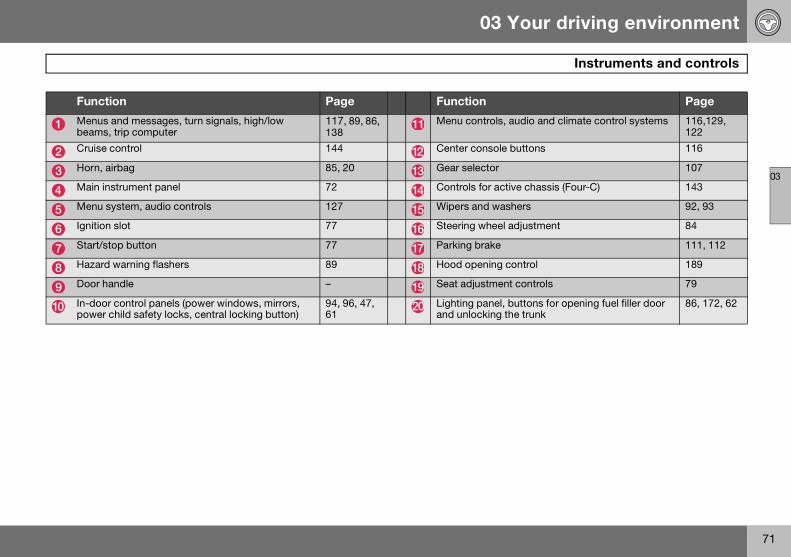
03 Your driving environment
71
Instruments and controls
03
Function Page Function Page
Menus and messages, turn signals, high/low beams, trip computer
117, 89, 86, 138
Menu controls, audio and climate control systems 116,129, 122
Cruise control 144 Center console buttons 116
Horn, airbag 85, 20 Gear selector 107
Main instrument panel 72 Controls for active chassis (Four-C) 143
Menu system, audio controls 127 Wipers and washers 92, 93
Ignition slot 77 Steering wheel adjustment 84
Start/stop button 77 Parking brake 111, 112
Hazard warning flashers 89 Hood opening control 189
Door handle – Seat adjustment controls 79
In-door control panels (power windows, mirrors, power child safety locks, central locking button)
94, 96, 47, 61
Lighting panel, buttons for opening fuel filler door and unlocking the trunk
86, 172, 62
S80 USA reprint version w640.book Page 71 Friday, June 1, 2007 10:44 AM

03 Your driving environment
72
Instruments and controls
03
Information displays
Information displays in the instrument panel
The information displays show informa-tion on some of the vehicle’s functions, such as cruise control, the trip computer and mes-sages. The information is shown with text and symbols.
More detailed information can be found in the descriptions of the functions that use the information displays.
Gauges
Gauges in the instrument panel
Speedometer
Fuel gauge, see also the section on refu-eling beginning on page 171.
The tachometer shows engine speed in thousands of revolutions per minute (rpm). Do not drive continuously with the needle in the red area of the gauge. The engine management system will automat-ically prevent excessively high engines speeds. This will be noticeable as a pro-nounced unevenness in engine speed.
Indicator, information, and warning symbols
Indicator and warning symbols
Indicator and information symbols
Indicator and warning symbols
High beam and turn signal indicators
Function checkAll indicator and warning symbols light up in ignition mode II or when the engine is started. When the engine has started, all the symbols should go out except the parking brake symbol, which only goes out when the brake is disengaged.
If the engine does not start or if the function check is carried out in ignition mode II, all symbols go out after 5 seconds except the
32 F0 1
1G
0106
04
1 2 3
0 1
32 F
G01
0605
1 234561 2.3 1 2:34
P 32 F
T2
211 2
3
G01
0598
S80 USA reprint version w640.book Page 72 Friday, June 1, 2007 10:44 AM
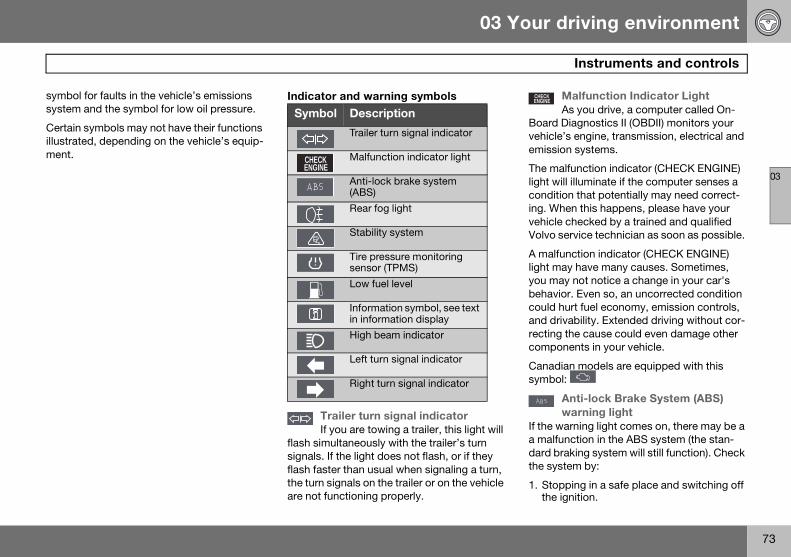
03 Your driving environment
73
Instruments and controls
03
symbol for faults in the vehicle’s emissions system and the symbol for low oil pressure.
Certain symbols may not have their functions illustrated, depending on the vehicle’s equip-ment.
Indicator and warning symbols
Trailer turn signal indicatorIf you are towing a trailer, this light will
flash simultaneously with the trailer’s turn signals. If the light does not flash, or if they flash faster than usual when signaling a turn, the turn signals on the trailer or on the vehicle are not functioning properly.
Malfunction Indicator LightAs you drive, a computer called On-
Board Diagnostics II (OBDII) monitors your vehicle’s engine, transmission, electrical and emission systems.
The malfunction indicator (CHECK ENGINE) light will illuminate if the computer senses a condition that potentially may need correct-ing. When this happens, please have your vehicle checked by a trained and qualified Volvo service technician as soon as possible.
A malfunction indicator (CHECK ENGINE) light may have many causes. Sometimes, you may not notice a change in your car's behavior. Even so, an uncorrected condition could hurt fuel economy, emission controls, and drivability. Extended driving without cor-recting the cause could even damage other components in your vehicle.
Canadian models are equipped with this symbol:
Anti-lock Brake System (ABS) warning light
If the warning light comes on, there may be a a malfunction in the ABS system (the stan-dard braking system will still function). Check the system by:
1. Stopping in a safe place and switching off the ignition.
Symbol Description
Trailer turn signal indicator
Malfunction indicator light
Anti-lock brake system (ABS)
Rear fog light
Stability system
Tire pressure monitoring sensor (TPMS)
Low fuel level
Information symbol, see text in information display
High beam indicator
Left turn signal indicator
Right turn signal indicator
CHECKENGINE
CHECKENGINE
S80 USA reprint version w640.book Page 73 Friday, June 1, 2007 10:44 AM

03 Your driving environment
74
Instruments and controls
03
2. Restart the engine.
3. If the warning light goes off, no further action is required.
If the warning light remains on, the vehicle should be driven to a trained and qualified Volvo service technician for inspection. See page 109 for additional information.
Canadian models are equipped with this symbol:
Rear fog lightThis symbol indicates that the rear fog
light (located in the driver’s side tail light cluster) is on.
Stability systemThis indicator symbol flashes when
the DSTC (Dynamic Stability and Traction Control system) is actively working to stabi-lize the vehicle. See page 141 for more detailed information.
Tire pressure monitoring system (TPMS) - option
This symbol illuminates to indicate that tire pressure in one or more tires is low. See page 219 for detailed information.
Low fuel levelWhen this light comes on, there are
approximately 2.1 US gallons (8 liters) of fuel remaining in the tank.
Information symbolThe information symbol illuminates
and a text message is displayed if a fault is detected in one of the vehicle’s systems. The message can be erased and the symbol can be turned off by pressing the READ button (see page 118 for information) or this will take place automatically after a short time (the length of time varies, depending on the func-tion affected).
The information symbol may also illuminate together with other symbols.
High beam indicatorThis symbol illuminates when the high beam headlights are on, or if the high beam flash function is used.
Left turn signal indicator
Right turn signal indicator
Indicator and warning symbols
Low oil pressureIf the light comes on while driving,
stop the vehicle, stop the engine immedi-ately, and check the engine oil level. If the oil level is normal and the light stays on after restart, have the vehicle towed to the nearest trained and qualified Volvo service techni-cian. This is normal, provided it goes off when the engine speed is increased.
Parking brake appliedThis symbol illuminates when the
parking brake is applied. On models
NOTE
• Both turn signal indicators will flash when the hazard warning flashers are used.
• If either of these indicators flash faster than normal, the direction indicators are not functioning properly.
Symbol Description
Low oil pressure
Parking brake apply
SRS airbags
Seat belt reminder
Generator not charging
Fault in the brake system
Warning symbol
BRAKEPARK
BRAKE
BRAKEPARK
S80 USA reprint version w640.book Page 74 Friday, June 1, 2007 10:44 AM

03 Your driving environment
75
Instruments and controls
03
equipped with the electric parking brake, this symbol flashes while the brake is being applied and then glows steadily.
A flashing symbol means that a fault has been detected. See the message in the infor-mation display.
Canadian models are equipped with this symbol:
Airbags – SRSIf this light comes on while the vehicle
is being driven, or remains on for longer than approximately 10 seconds after the vehicle has been started, the SRS system’s diagnos-tic functions have detected a fault in a seat belt lock or tensioner, a front airbag, side impact airbag, and/or an inflatable curtain. Have the system(s) inspected by a trained and qualified Volvo service technician as soon as possible.
Seat belt reminderThis symbol comes on for approxi-
mately 6 seconds if the driver has not fas-tened his or her seat belt.
Generator not chargingThis symbol comes on during driving if
a fault has occurred in the electrical system. Contact an authorized Volvo workshop.
Fault in brake systemIf this symbol lights, the brake fluid
level may be too low. Stop the vehicle in a safe place and check the level in the brake fluid reservoir, see page 189. If the level in the reservoir is below MIN, the vehicle should be transported to an authorized Volvo workshop to have the brake system checked.
If the brake and ABS symbols come on at the same time, there may be a fault in the brake force distribution system.
1. Stop the vehicle in a safe place and turn off the engine.
2. Restart the engine.
• If both symbols extinguish, continue driv-ing.
• If the symbols remain on, check the level in the brake fluid reservoir. See page 189. If the brake fluid level is normal but the symbols are still lit, the vehicle can be driven, with great care, to an authorized Volvo workshop to have the brake system checked.
• If the level in the reservoir is below MIN, the vehicle should be transported to an authorized Volvo workshop to have the brake system checked.
Warning symbolThe red warning symbol comes on
when a fault has been indicated which could affect the safety and/or drivability of the vehi-cle. An explanatory text is shown on the information display at the same time. The symbol remains visible until the fault has been rectified but the text message can be cleared with the READ button, see page 118. The warning symbol can also come on in conjunction with other symbols.
Action:
1. Stop in a safe place. Do not drive the vehicle further.
NOTE
This symbol also comes on when the me-chanical parking brake is only slightly ap-plied.
BRAKE WARNING
• If the fluid level is below the MIN mark in the reservoir or if a warning message is dis-played in the text window: DO NOT DRIVE. Have the vehicle towed to an authorized Volvo retailer and have the brake system in-spected.
• If the ABS and Brake system lights are on at the same time, there is a risk of reduced vehicle stability.
S80 USA reprint version w640.book Page 75 Friday, June 1, 2007 10:44 AM

03 Your driving environment
76
Instruments and controls
03
2. Read the information on the information display. Implement the action in accor-dance with the message in the display. Clear the message using READ.
Reminder – doors not closedIf one of the doors, the hood or trunk lid is not closed properly, the information or warning symbol comes on together with an explana-tory text message in the instrument panel. Stop the vehicle in a safe place as soon as possible and close the door, hood or trunk.
If the vehicle is driven at a speed lower than approximately 5 mph (7 km/h),
the information symbol comes on.
If the vehicle is driven at a speed higher than approximately 5 mph (7 km/h), the
warning symbol comes on.
Trip odometers
Trip odometers and reset button
The trip odometers are used to measure short distances. A short press on switches between the two trip odometers T1 and T2. A long press (more than 2 seconds) resets an active trip odometer to zero. The distance is shown in the display .
Clock
Clock and setting control
Turn the control clockwise/counterclock-wise to set the time. The set time is shown in the information display .
The clock may be temporarily replaced by a symbol in conjunction with a message, see page 118.
1
2
o
G01
0608
2 1
G01
0609
S80 USA reprint version w640.book Page 76 Friday, June 1, 2007 10:44 AM

03 Your driving environment
77
Ignition modes
03
Functions
Ignition slot with remote key, start/stop button
Inserting and removing the remote keyThe various ignition modes are accessed by inserting the remote key into the ignition slot.
The remote key can be removed from the ignition slot by pressing the key in. It will then be ejected slightly and can be removed from the slot.The gear selector must be in position P (Park).
Ignition mode 0Insert the remote key in the ignition slot.
Ignition mode IPress the remote key into the ignition slot and press START/STOP.
Ignition mode IIPress the remote key into the ignition slot and press START/STOP for approx. 2 seconds.
Ignition mode III (engine start)Start the engine, see page 104.
Stopping the enginePress START/STOP. (If the engine is running and the vehicle is moving, keep the button depressed until the engine stops).
Return to ignition mode 0Press START/STOP to return from I, II, or III to ignition mode 0.
NOTE
The brake pedal must not be depressed when accessing ignition modes I or II.
3905
610s
CAUTION
Foreign objects in the ignition slot can im-pair function or damage the lock.
NOTE
During towing, ignition mode II should be used so that the lighting can be switched on.
Position Function
0Odometer, clock and temperature gauge are illuminated. Steering lock is deactivated. The audio system can be used.
IMoonroof, power windows, climate system blower, ECC, windshield wipers can be used.
IIThe headlights come on. Warning/indicator lights come on for 5 seconds. All equipment operates apart from heated seats and rear window defroster, which only work when the engine is running.
III The starter motor will operate until the engine has started.
S80 USA reprint version w640.book Page 77 Friday, June 1, 2007 10:44 AM

03 Your driving environment
78
Ignition modes
03
Functions with timerThe audio system can be operated without a key for 15 minutes at a time by pressing the POWER button. The power windows work for several minutes after the key has been removed, although not after the door has been opened.
NOTE
Use the POWER button for the audio sys-tem when the engine is not running to avoid discharging the battery.
S80 USA reprint version w640.book Page 78 Friday, June 1, 2007 10:44 AM

03 Your driving environment
79
Seats
03
Front seats
Lumbar support: turn the control for firm-er or softer lumbar support.
Front-rear adjustment: lift the bar and move the seat to the position of your choice.
Raise/lower front edge of seat cushion, pump up/down.
Backrest tilt: turn the control to adjust the angle of the backrest.
Raise/lower the seat, pump up/down.
Control panel for power seat.
Folding the front seat backrest
The front passenger seat backrest can be folded to a horizontal position to make room for a long load. Fold the backrest as follows:
Move the seat as far back as possible.
Adjust the backrest to an upright posi-tion.
Lift the catches on the rear of the back-rest.
Without releasing the catches, push the backrest forward.
Move the seat as far forward as possible so that the head restraint slides under the glove compartment.
4
5
6
1
2
385
0531
5s
WARNING
• Do not adjust the seat while driving. The seat should be adjusted so that the brake pedal can be depressed fully. In addition, position the seat as far rearward as comfort and control allow.
• Check that the seat is securely locked into position after adjusting.
8505
326s
1 3
3
2
WARNING
Cover sharp edges on the load to help pre-vent injury to occupants. Secure the load to help prevent shifting during sudden stops.
S80 USA reprint version w640.book Page 79 Friday, June 1, 2007 10:44 AM

03 Your driving environment
80
Seats
03
Power seat (option)
Front edge of seat cushion up/down
Seat forward/backward and up/down
Backrest tilt
OperationThe seats can be adjusted for a short period after unlocking the door with the remote con-trol without the key in the ignition slot. Seat adjustment is normally made when the igni-tion is on and can always be made when the engine is running.
Seat with memory function (option)
Stored seat position
Stored seat position
Stored seat position
Memory button
Programming the memoryThree different seating and door mirror posi-tions can be stored in the driver seat's mem-ory.
The following example explains how button can be programmed. Buttons and can be programmed in the same way.
To program (store) a seat position and door mirror position in button :
1. Move the seat (and door mirrors) to the desired position using the seat and mirror adjustment controls.
2. Press and hold down the M (memory) button .
3. With the memory button depressed, press button briefly to store the cur-rent position for the seat/mirrors.
To move the seat and mirrors to the po-sition that they were in when button was programmed:1. Press and hold down button until the
seat and mirrors stop moving.
3603
820s
1 2 3
NOTE
• Only one of the power seat’s controls can be used at the same time.• The power seats have an overload pro-tector that activates if a seat is blocked by any object. If this occurs, switch off the igni-tion (key in position 0) and wait for a short period before operating the seat again.
8505
312s
1 2 3 4
NOTE
As a safety precaution, the seat will stop au-tomatically if the button is released before the seat has reached the preset position.
S80 USA reprint version w640.book Page 80 Friday, June 1, 2007 10:44 AM

03 Your driving environment
81
Seats
03
Remote keyless entry system and the driver’s seatThe remote control transmitter also controls the position of the power driver’s seat in the following way:
1. Adjust the seat to your preferences.
2. When you leave your vehicle, lock it using the remote control.
The position of the driver’s seat is now stored in the remote control’s memory.
Automatic seat adjustmentTo move the seat to the position in which you left it:
1. Unlock the driver’s door with the same remote control (the one used to lock the doors)
2. Open the driver’s door within 2 minutes.
The driver’s seat will automatically move to the position in which you left it.
The function can be activated/deactivated under Car key memory Seat & mirror positions. For a description of the menu sys-tem, see the information beginning on page 117.
Emergency stopIf the seat accidentally begins to move, press one of the buttons to stop the seat.
Heated/ventilated seats (option)See page 123.
NOTE
• The key memory is independent of the seat memory.• The seat will Move to this position even if someone else has moved it to a different seating position and locked the vehicle with a different remote control.• This feature will work in the same way with all of the remote control transmitters that you use with your vehicle.
WARNING
• Because the driver's seat can be adjust-ed with the ignition off, children should never be left unattended in the vehicle.
• Movement of the seat can be STOPPED at any time by pressing any button on the power seat control panel.
• Do not adjust the seat while driving. The seat should be adjusted so that the brake pedal can be depressed fully. In addition, position the seat as far rearward as comfort and control allow.
• The seat rails on the floor must not be ob-structed in any way when the seat is in mo-tion.
S80 USA reprint version w640.book Page 81 Friday, June 1, 2007 10:44 AM

03 Your driving environment
82
Seats
03
Rear seats
Folding down the rear seat backrests
The rear seat backrests can be folded down together, or separately, to make it easier to transport long objects.
1. Pull the release control handle(s).
2. Fold the backrest forward. Adjust the center seat head restraint if necessary.
Rear center head restraint
The center head restraint should be adjusted according to the passenger’s height. The restraint should be carefully adjusted to sup-port the occupant’s head.
Pull the head restraint up as required. To lower, press the button at the base of the head restraint’s left support while pressing the head restrain down.
NOTE
The outboard head restraints must be fold-ed up (in the upright position) before lower-ing the backrests.
8505
314s
WARNING
• Keep vehicle doors and the trunk locked and keep keys out of a child’s reach. Unsu-pervised children could lock themselves in an open trunk and risk injury. Children should be taught not to play in vehicles.
• On hot days, the temperature in the trunk or vehicle interior can rise very quickly. Ex-posure of people to these high tempera-tures for even a short period of time can cause heat-related injury or death. Small children are particularly at risk.
WARNING
• When the backrest is returned to the up-right position, check that it is properly locked in place. Return the head restraints to the upright position.• Long loads should always be securely anchored to help avoid injury in the event of a sudden stop.
• Always turn the engine off and apply the parking brake when loading/unloading the vehicle.
• Place the transmission in the Park (P) po-sition to help prevent inadvertent movement of the gear selector.• The vehicle features a 60/40 split fold-down rear seat. The backrest(s) can be fold-ed down by pulling the release control han-dles inside the trunk.
8505
332s
S80 USA reprint version w640.book Page 82 Friday, June 1, 2007 10:44 AM
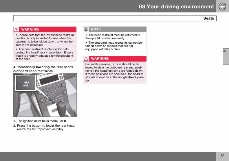
03 Your driving environment
83
Seats
03
Automatically lowering the rear seat’s outboard head restraints
1. The ignition must be in mode I or II.2. Press the button to lower the rear head
restraints for improved visibility.
WARNING
• Please note that the lowest head restraint position is only intended for use when the backrest is to be folded down, or when the seat is not occupied.• The head restraint is intended to help protect the head/neck in a collision. Ensure that it is properly adjusted for the occupant of the seat.
G01
8376
NOTE
• The head restraint must be returned to the upright position manually.• The outboard head restraints cannot be folded down on models that are not equipped with this button.
WARNING
For safety reasons, no one should be al-lowed to sit in the outboard rear seat posi-tions if the head restraints are folded down. If these positions are occupied, the head re-straints should be in the upright (fixed) posi-tion.
S80 USA reprint version w640.book Page 83 Friday, June 1, 2007 10:44 AM

03 Your driving environment
84
Steering wheel
03
Adjusting
Adjusting the steering wheel
The steering wheel can be adjusted for both height and reach:
1. Pull the lever toward you to release the steering wheel.
2. Adjust the steering wheel to the position that suits you.
3. Push back the lever to fix the steer-ing wheel in place. If the lever is difficult to push into place, press the steering wheel lightly at the same time as you push the lever.
With speed-dependent power steering (option) the level of steering force can be adjusted, see page 143.
Keypads
Keypads in the steering wheel
Cruise control, see page 144Adaptive cruise control (option), see page 146.
Audio controls, see page 116.
WARNING
Never adjust the steering wheel while driv-ing.
6401
073s
1
2
1 2
G01
8597
S80 USA reprint version w640.book Page 84 Friday, June 1, 2007 10:44 AM

03 Your driving environment
85
Steering wheel
03
Horn
Horn
Press the steering wheel hub to sound the horn.
3603
793s
S80 USA reprint version w640.book Page 85 Friday, June 1, 2007 10:44 AM

03 Your driving environment
86
Lighting
03
Lighting panel
Overview, light switches
Thumb wheel for adjusting display and instrument lighting
Rear fog light
Front fog lights
Headlights/parking lights
Instrument lightingIllumination of the display and instrument lights will vary, depending on ignition mode.
The display lighting is automatically sub-dued in darkness and the sensitivity is set with the thumb wheel .
The intensity of the instrument lighting is adjusted with the thumb wheel.
High/low beam headlights
Headlight switch and lever
Low beamsWhen the engine is started, the low beams are activated automatically (daytime running lights) if the headlight control is in position or .
Daytime running lights can be deactivated by an authorized Volvo workshop.
High beam flashMove the lever toward the steering wheel to position . The high beams come on until the lever is released.
High/low beam headlights
Continuous high beamsSet the ignition to mode II.
With the light switch in position , pull the turn signal lever toward the steering wheel to position to toggle between high and low beams (this also applies on models equipped with the optional Active Bi-Xenon headlights).
The symbol illuminates in the instrument panel to indicate that the high beams are on.
3501
930s1 2 3 4
Daytime running lights/no high beamsParking lights
Low beams
3501
933s
12
NOTE
• The use of daytime running lights is man-datory in Canada.• Continuous high beams cannot be acti-vated when the headlight switch is in position or . High beam flash will function in these positions.
S80 USA reprint version w640.book Page 86 Friday, June 1, 2007 10:44 AM

03 Your driving environment
87
Lighting
03
Active Bi-Xenon Lights (ABL)–option
Headlight pattern with ABL deactivated (left) and activated (right) respectively
When the ABL function is activated, the headlight beams adjust laterally to help light up a curve according to movements of the steering wheel (see the right-pointing beam in the illustration above).
This function is activated automatically when the engine is started and can be deactivated/reactivated by pressing the ABL button in the center console.
Parking lights
Headlight control in position for parking lights
The front and rear parking lights can be turned on even when the ignition is switched off.
Turn the headlight control to the center posi-tion (the license plate lighting comes on at the same time).
The lighting also comes on when the trunk lid is opened in order to alert anyone traveling behind your vehicle.
NOTE
Active Bi-Xenon headlights (option): Turn the headlight switch to position to acti-vate a daylight sensor, which automatically switches the low beams on or off, depend-ing on ambient light conditions. When driv-ing in daylight, the headlights will switch off and the daytime running lights will come on. In darkness, the daytime running lights will switch off and the Active Bi-Xenon head-lights will switch on.
NOTE
This function is only active in twilight or dark conditions, and only when the vehicle is in motion.
3501
889s
3603
902s
S80 USA reprint version w640.book Page 87 Friday, June 1, 2007 10:44 AM

03 Your driving environment
88
Lighting
03
Brake lightsThe brake lights come on automatically when the brakes are applied.
Emergency brake light (EBL)Emergency Brake Lights, EBL are activated in the event of sudden braking or if the ABS brakes are activated. This function causes the brake lights to glow more intensely to alert vehicles traveling behind.
The system is activated if ABS is used for more than approximately a half second or in the event of sudden braking, although only at speeds above approximately 6 mph (10 km/h).
When the vehicle stops, the brake lights and other taillights remain on and glow brighter than normal for as long as the brake pedal is depressed or until braking force on the vehi-cle is reduced.
Front fog lights
Button for front fog lights
The front fog lights can be switched on together with high/low beams or the parking lights.
Press the button to switch the fog lights on/off. The light in the button comes on when the fog lights are on.
Rear fog light
Button for rear fog light
The single rear fog light is located in the driver's side taillight cluster.
The rear fog light will only function in combi-nation with the high/low beam headlights or the optional front fog lights.
Press the button to switch the rear fog light on/off. The rear fog light indicator symbol on the instrument panel and the light in the button come on when the rear fog light is switched on.
NOTE
Regulations regarding the use of the front fog lights may vary, depending on where you drive.
G01
4402
G01
4403
S80 USA reprint version w640.book Page 88 Friday, June 1, 2007 10:44 AM

03 Your driving environment
89
Lighting
03
Hazard warning flashers
Location of the hazard warning flasher button
The hazard warning flasher should be used to indicate that the vehicle has become a traffic hazard. To activate the flashers, press the button in the center dash. Press the but-ton again to turn off the flashers.
Turn signals
Turn signals
When changing lanesThe driver can automatically flash the turn signals 3 times by moving the turn signal lever up or down to position and releas-ing it.
When turningMove the lever as far up or down as possible to position to start the turn signals. The turn signals will be cancelled automatically by the movement of the steering wheel, or the lever can be returned to its initial position by hand.
NOTE
The rear fog light is considerably brighter than the normal tail lights and should be used only when conditions such as fog, rain, snow, smoke or dust reduce visibility for other vehicles to less than 500 ft. (150 meters).
NOTE
Regulations regarding the use of the hazard warning flasher may vary, depending on where you live.
s9291053
21
12
3603
798s
S80 USA reprint version w640.book Page 89 Friday, June 1, 2007 10:44 AM

03 Your driving environment
90
Lighting
03
Interior lighting, front
Light switches, front roof lighting
Drivers side front reading light, on/off
Passenger’s side front reading light, on/off
Overhead courtesy lighting.
The lighting in the front part of the passenger compartment is controlled with the buttons and in the roof console.
Switch has three positions for all passen-ger compartment lighting:
• Off – right side depressed, automatic light-ing off.
• Neutral position.
• On – left side depressed, passenger com-partment lighting on.
Interior lighting, rear
Rear reading lights
The lights are switched on or off by pressing each respective button.
Courtesy lights/door step lighting (option)The courtesy lights/door step lighting switches on/off automatically when one of the front doors is opened/closed.
Glove compartment lightingThe glove compartment lighting switches on/off automatically when the lid is opened/closed.
NOTE
• This automatic flashing sequence can be interrupted by immediately moving the lever in the opposite direction.• If the turn signal indicator flashes faster than normal, check for a burned-out turn signal bulb.
3501
882s
1 2
3
3501
886s
S80 USA reprint version w640.book Page 90 Friday, June 1, 2007 10:44 AM

03 Your driving environment
91
Lighting
03
Overhead courtesy lightingThe passenger compartment lighting is switched on and off automatically when button is in the neutral position.
The lighting comes on and remains on for 30 seconds if:
• the vehicle is unlocked from the outside with the key or remote control
• the engine is switched off and the ignition is in mode 0.
The lighting switches off when:
• the engine is started
• the vehicle is locked from the outside.
The lighting comes on and remains on for two minutes if one of the doors is open.
The passenger compartment lighting can be switched on and off manually within 30 minutes after the vehicle has been unlocked.
If the lighting is switched on manually and the vehicle is locked, the courtesy lighting will switch off automatically after one minute.
Home safe lightingWhen you leave your vehicle at night, you can make use of the home safe lighting func-tion to illuminate the area in front of the vehi-cle.
1. Remove the key from the ignition slot.
2. Pull the direction indicator lever as far as possible towards the steering wheel (to position 4) and release it.
3. Exit the vehicle and lock the doors.
The headlights and parking lights will illumi-nate and remain on for 301, 60 or 90 sec-onds. The time interval can be set under Car settings Light settings Home safe lighting. For a description of the menu sys-tem, see page 117.
Approach lightingApproach lighting is activated by pressing the approach light button on the remote key (see the illustration on page 52).
When the function has been activated, the parking lights, indicator lights, door mirror lights, license plate lighting, dome lighting and door step lighting come on.
The time interval for this lighting can be set under Car settings Light settings Approach lighting. For a description of the menu system, see page 117.
1 Factory setting
S80 USA reprint version w640.book Page 91 Friday, June 1, 2007 10:44 AM

03 Your driving environment
92
Wipers and washers
03
Windshield wipers/washers
Windshield wipers and washers
Rain sensor on/off
Thumb wheel sensitivity/frequency
Windshield wipers offMove the lever to position 0 to switch off the windshield wipers.
Single sweepMove the lever upward from position 0 to sweep the wind-
shield one stroke at a time for as long as the lever is held up.
Intermittent wipingWith the lever in this position, you can set the wiper interval by twist-
ing the thumb wheel upward to in-crease wiper speed or downward to decrease the speed.
Continuous wipingThe wipers operate at normal speed.
The wipers operate at high speed.
Rain sensor (option)The rain sensor automatically regulates wiper speed according to the amount of water on the windshield.The sensitivity of the rain sen-sor can be adjusted moving the thumb wheel , up (the wipers will sweep the windshield more frequently) or down (the wipers will sweep the windshield less fre-quently).
When the rain sensor is activated, the symbol will illuminate in the instrument panel.
Activating and setting the sensitivityWhen activating the rain sensor, the vehicle must be running or in ignition mode II and the windshield wiper lever must be in position 0.
Activate the rain sensor by pressing the button . The windshield wipers will make one sweep.
Press the lever up for the wipers to make an extra sweep. The rain sensor returns to active mode when the stalk is released back to position 0.
DeactivatingDeactivate the rain sensor by pressing the button or press the lever down to another wiper position.
The rain sensor is automatically deactivated when the key is removed from the ignition slot or five minutes after the ignition has been switched off.
0
2 1
3603
799s
0 NOTE
The wipers will make an extra sweep each time the thumb wheel is adjusted upward.
S80 USA reprint version w640.book Page 92 Friday, June 1, 2007 10:44 AM

03 Your driving environment
93
Wipers and washers
03
Windshield washing
Washing function
Move the lever toward the steering wheel to start the windshield and head-light washers. After the lever is released the wipers make several extra sweeps.
Heated washer nozzles (option)The washer nozzles are heated automatically in cold weather to help prevent the washer fluid from freezing.
High-pressure headlight washing (option)High-pressure headlight washing consumes a large quantity of washer fluid. To save fluid, the headlights are washed using two alterna-tives:
• Low/high beam headlights onThe headlights will be washed the first time the windshield is washed. Thereafter, the headlights will only be washed once for every five times the windshield is washed within a 10-minute period.
• Parking lights onOptional Active Bi-Xenon headlights will be washed once for every five times the windshield is washed.Normal halogen headlights will not be washed.
CAUTION
The rain sensor should be deactivated when washing the car in an automatic car wash, etc. If the rain sensor function is left on, the wipers will start inadvertently in the car wash and could be damaged.
1 36
0380
5s
CAUTION
Use ample washer fluid when washing the windshield. The windshield should be thor-oughly wet when the wipers are in opera-tion.
NOTE
One headlight is washed at a time.
S80 USA reprint version w640.book Page 93 Friday, June 1, 2007 10:44 AM

03 Your driving environment
94
Power windows
03
Power windows
Driver’s door control panel
Switch for power child safety locks1 and disengaging rear power window buttons, see page 47
Rear window controls
Front window controls.
Operating
Operating the power windows
Manual up/down
Auto up/down.
All power windows can be operated using the control panel in the driver’s door. The control panels in the other doors only operate the window in the respective doors.
For the power windows to function, the igni-tion must be in at least mode I. When the vehicle has been running, the power win-dows can be operated for several minutes after the remote key has been removed from
the ignition slot, or until a door has been opened.
Manual up/downMove one of the controls up/down gently. The power windows move up/down as long as the control is held in position.
Auto up/downMove one of the controls up/down as far as possible and release it. The window will open or close completely.
ResettingIf the battery has been disconnected, the auto open function must be reset so that it will work properly.
1. Gently raise the front section of the button to close the window and hold it for one second.
2. Release the button briefly.
3. Raise the front section of the button again for one second.
1 Option on certain markets only.
WARNING
• Always remove the ignition key when the vehicle is unattended.
• Never leave children unattended in the vehicle.
• Make sure that the windows are com-pletely unobstructed before they are oper-ated.
21 3
s0973063
3603
813s
1
12
2
NOTE
Movement of the windows will stop if they are obstructed in any way.
S80 USA reprint version w640.book Page 94 Friday, June 1, 2007 10:44 AM

03 Your driving environment
95
Power windows
03
Laminated glass (option on certain markets only)
This glass is reinforced to help pro-vide protection against break-ins and improved sound insulation in the passenger compartment. The windshield and side windows have laminated glass.
Water and dirt repellent glassThe front side windows are treated with a coating that improves the
view in difficult weather conditions.
S80 USA reprint version w640.book Page 95 Friday, June 1, 2007 10:44 AM

03 Your driving environment
96
Mirrors
03
Power door mirrors
Door mirror controls
Adjusting1. Press the L button for the left door mirror
or the R button for the right door mirror. The light in the button comes on.
2. Adjust the position with the joystick in the center.
3. Press the L or R button again. The light should no longer be on.
Retractable power door mirrors (option on certain markets only)The mirrors can be retracted for parking/driving in narrow spaces:
1. Press down the L and R buttons at the same time.
2. Release them after approximately one second. The mirrors automatically stop in the fully retracted position.
Fold out the mirrors by pressing down the L and R buttons at the same time. The mirrors automatically stop in the fully extended posi-tion.
Storing the position (option) The mirror positions are stored in the key memory when the vehicle has been locked with the remote key. When the vehicle is unlocked with the same remote control the mirrors and the driver’s seat adopt the stored positions when the driver’s door is opened.
The function can be activated/deactivated under Car key memory Seat & mirror positions. For a description of the menu sys-tem, see page 117.
Tilting the door mirror when parking (option)The door mirror can be tilted down for the driver to view the side of the road when park-
ing for example. Engage reverse gear and press the L or R button. The door mirror resets when reverse gear is disengaged.
Automatic retraction when lockingWhen the vehicle is locked/unlocked with the remote key the door mirrors are automati-cally retracted/extended.
The function can be activated/deactivated under Car settings Retract mirrors when locking. For a description of the menu system, see page 117.
Resetting to neutralMirrors that have been moved out of position by an external force must be electrically reset to the neutral position for electric retracting/extending to work.
• Retract the mirrors with the L and R buttons.
• Fold them out again with the L and R buttons.
The mirrors are now reset in neutral position.
Home safe and approach lightingThe light on the door mirrors comes on when approach lighting or home safe lighting is selected, see page 91.
WARNING
Objects seen in the mirrors may appear fur-ther away than they actually are.
3905
556s
S80 USA reprint version w640.book Page 96 Friday, June 1, 2007 10:44 AM

03 Your driving environment
97
Mirrors
03
Rear window and door mirror defrosters
Use the defroster to quickly remove misting and ice from the rear window and the door mirrors.
Press the button once to start simultaneous rear window and door mirror defrosting. The light in the button indicates that the function is active. Defrosting is deactivated automati-cally and its duration is controlled by the out-side temperature.
The rear window is demisted/de-iced auto-matically if the vehicle is started in an outside temperature lower than + 7 °C.
Defrosting can be selected under Climate settings Auto. rear defroster. Select between On or Off.
Interior rearview mirror
Auto-dim function An integrated sensor reacts to headlights from following traffic and automatically reduces glare in the mirror.
G01
8377
S80 USA reprint version w640.book Page 97 Friday, June 1, 2007 10:44 AM
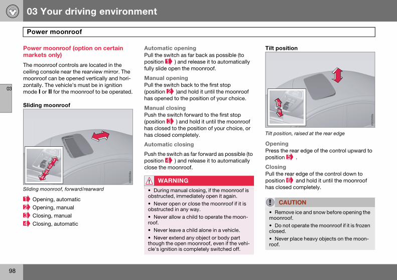
03 Your driving environment
98
Power moonroof
03
Power moonroof (option on certain markets only)
The moonroof controls are located in the ceiling console near the rearview mirror. The moonroof can be opened vertically and hori-zontally. The vehicle’s must be in ignition mode I or II for the moonroof to be operated.
Sliding moonroof
Sliding moonroof, forward/rearward
Opening, automatic
Opening, manual
Closing, manual
Closing, automatic
Automatic openingPull the switch as far back as possible (to position ) and release it to automatically fully slide open the moonroof.
Manual openingPull the switch back to the first stop (position )and hold it until the moonroof has opened to the position of your choice.
Manual closingPush the switch forward to the first stop (position ) and hold it until the moonroof has closed to the position of your choice, or has closed completely.
Automatic closing
Push the switch as far forward as possible (to position ) and release it to automatically close the moonroof.
Tilt position
Tilt position, raised at the rear edge
OpeningPress the rear edge of the control upward to position .
ClosingPull the rear edge of the control down to position and hold it until the moonroof has closed completely.
8302
558s
23
4
1
WARNING
• During manual closing, if the moonroof is obstructed, immediately open it again.
• Never open or close the moonroof if it is obstructed in any way.
• Never allow a child to operate the moon-roof. • Never leave a child alone in a vehicle.
• Never extend any object or body part though the open moonroof, even if the vehi-cle's ignition is completely switched off.
CAUTION
• Remove ice and snow before opening the moonroof. • Do not operate the moonroof if it is frozen closed. • Never place heavy objects on the moon-roof.
s9552038
5
6
S80 USA reprint version w640.book Page 98 Friday, June 1, 2007 10:44 AM

03 Your driving environment
99
Power moonroof
03
Visor The moonroof features a sliding visor. The visor slides open automatically when the moonroof is opened, and must be closed manually.
S80 USA reprint version w640.book Page 99 Friday, June 1, 2007 10:44 AM

03 Your driving environment
100
HomeLink® Universal Transceiver (option)
03
Introduction
HomeLink1 is a system that can be pro-grammed to learn the codes of three different remote controlled-devices (for example, a garage door opener, remote lighting, entry gate). HomeLink's sun visor-mounted trans-ceiver, powered by your car's electrical sys-tem, may then be used in place of your hand-held remote controls. The HomeLink trans-ceiver consists of three programmable but-tons and an indicator light.
Operating the HomeLink Universal TransceiverOnce programmed, the HomeLink Universal Transceiver can be used in place of your handheld transmitters.
Press the programmed HomeLink button to activate the garage door, driveway gate, security lightning, home security system etc.
Your original hand-held transmitters may, of course, be used at any time.
Programming the transceiver for the first time (U.S. residents)1. For first time training, press and hold the
two outer HomeLink buttons, releasing only when the HomeLink indicator light begins to flash after 20 seconds. (Do not perform this step when training the addi-tional HomeLink buttons.)
2. Position the hand-held transmitter 1-3 inches away from the HomeLink surface
1 HomeLink is a registered trademark of Johnson Controls, Intl.
© JCI, All rights reserved
G01
8635
NOTE
• For your security, the HomeLink Univer-sal Transceiver is designed to not function if you lock your car from the outside.• Retain the original transmitter(s) for future programming procedures (for example, if you purchase a new vehicle). • For your own security, erase all pro-grammed buttons on the HomeLink Univer-sal Transceiver when you sell your vehicle. • Metallic sun protection films should not be used on any windows in a vehicle equipped with HomeLink Universal Trans-ceiver. This could interfere with the trans-ceivers function.
NOTE
The HomeLink universal transceiver will function for 30 minutes after the driver’s door has been opened without switching on the vehicle’s ignition.
WARNING
• If you use HomeLink to open a garage door or gate, be sure no one is near the gate or door while it is in motion. • Do not use the HomeLink Universal Transceiver with any garage door opener that lacks safety "stop" and "reverse" fea-tures as required by federal safety stan-dards. (This includes any garage door opener model manufactured before April 1, 1982). A garage door opener that cannot "detect" an object, signalling the door to "stop" and "reverse" does not meet current federal safety standards. Using a garage door opener without these features increas-es the risk of serious injury or death. For more information on this matter, call toll-free 1-800-355-3515. (Internet: www.HomeLink.com).
S80 USA reprint version w640.book Page 100 Friday, June 1, 2007 10:44 AM
03 Your driving environment
101
HomeLink® Universal Transceiver (option)
03
(located on your sun visor), keeping the HomeLink indicator light in view.
Using both hands, simultaneously press and hold both the desired HomeLink but-ton and hand held transmitter button. DO NOT release until the HomeLink indicator light flashes slowly and then rapidly. When the indicator light flashes rapidly, both but-tons may be released. (The rapid flashing indicates successful training.)
3. Press and hold the trained HomeLink button and observe the indicator light.
• If the indicator light is solid/continuous, training is complete and your device should activate when the HomeLink but-ton is pressed and released.
• If the indicator light blinks rapidly for 2 seconds and then turns a solid/continuous light, proceed with the following training instructions for a rolling code device. A second person may make the following steps quicker and easier. Please use a
ladder or other device. Do not stand on your vehicle to perform the next steps.
4. At the garage door opener receiver (mo-torhead unit) in the garage, locate the "learn" or "smart" button (usually near where the hanging antenna wire is at-tached to the unit). If there is difficulty locating the training button, reference the garage door opener's manual or contact us toll-free 1-800-355-3515 (In-ternet: www.HomeLink.com).
5. Press and release the "learn" or "smart" button (the name and color of the button may vary by manufacturer).
6. Return to the vehicle and firmly press and hold the trained HomeLink button for two seconds and release. Repeat the "press/hold/release" sequence up to 3 times to complete the training process.
To train additional HomeLink buttons, begin with step two.
Programming the transceiver for the first time (Canadian residents)1. For first time training, press and hold the
two outer HomeLink buttons releasing only when the HomeLink indicator light begins to flash after 20 seconds. (Do not perform this step when training the addi-tional HomeLink buttons.)
2. Position the hand-held transmitter 1-3 inches (2.5-7.5 cm) away from the HomeLink surface (located on your) keeping the HomeLink indicator light in view.
3. Using both hands, simultaneously press and hold both the desired HomeLink button and hand held transmitter but-ton. During programming, your hand-held transmitter may automatically stop transmitting. Continue to press and hold the desired HomeLink button while you press and re-press (“cycle”) your hand-held transmitter every two seconds until the frequency signal has been learned. The indicator light will flash slowly and then rapidly after several seconds upon successful training. DO NOT release until the HomeLink indicator light flash-es slowly and then rapidly. When the indicator light flashes rapidly, both but-tons may be released. (The rapid flash-ing indicates successful training.)
NOTE
Some garage door openers may require you to replace step 3 with the "cycling" proce-dure noted in the "Programming the trans-ceiver for the first time (Canadian residents)" section.
NOTE
Once the button is pressed, there are 30 seconds in which to initiate the next step.
S80 USA reprint version w640.book Page 101 Friday, June 1, 2007 10:44 AM

03 Your driving environment
102
HomeLink® Universal Transceiver (option)
03
4. Press and hold the trained HomeLink button and observe the indicator light.
If the indicator light is solid/continuous, train-ing is complete and your device should acti-vate when the HomeLink button is pressed and released.
• If the indicator light blinks rapidly for 2 seconds and then turns a solid/continuous light, proceed with the following training instructions for a rolling code device. A second person may make the following steps quicker and easier. Please use a ladder or other device. Do not stand on your vehicle to perform the next steps.
5. At the garage door opener receiver (motorhead unit) in the garage, locate the “learn” or “smart” button (usually near where the hanging antenna wire is attached to the unit). If there is difficulty locating the training button reference the garage door opener’s manual or contact us.
6. Press and release the “learn” or “smart” button (the name and color of the button may vary by manufacturer).
7. Return to the vehicle and firmly press and hold the trained HomeLink button for two seconds and release. Repeat the “press/hold/release” sequence up to 3 times to complete the training process.
To train additional HomeLink buttons, begin with step two.
Rolling Code ProgrammingRolling code garage door openers that are "code-protected" and manufactured after 1996 may be determined by the-following:
• Reference the garage door opener own-er's manual for verification.
• The handheld transmitter appears to pro-gram the HomeLink Universal Transceiver but does not activate the garage door.
• Press and hold the trained HomeLink but-ton. The garage door opener has the rolling code feature if the indicator light flashes rapidly and then turns solid after 2 seconds.
To train a garage door with the rolling code feature, follow these instructions (the aid of a second person may make the training quicker and easier):
1. Locate the training button on the garage door opener motor head unit. Exact loca-tion and color of the button may vary by garage door opener brand. If there is difficulty locating the training button, refer-ence the garage door opener owner's manual or please visit our Web site at www.homelink.com.
2. Press the training button on the garage door opener motor head unit (which activates the "training light").
3. Firmly press and release the pro-grammed HomeLink® button. Press and release the HomeLink button a second time to complete the training process. (Some garage door openers may require
NOTE
Once the button is pressed, there are 30 seconds in which to initiate the next step.
NOTE
During programming, your hand-held trans-mitter may automatically stop transmitting. Continue to press and hold the desired HomeLink button while you press and re-press (“cycle”) your hand-held transmitter every two seconds until the frequency sig-nal has been learned. The indicator light will flash slowly and then rapidly after several seconds upon successful training. If neces-sary, follow steps 5-7 to complete the train-ing for a rolling code device.
NOTE
Following step 2, there are 30 seconds in which to initiate step 3.
S80 USA reprint version w640.book Page 102 Friday, June 1, 2007 10:44 AM

03 Your driving environment
103
HomeLink® Universal Transceiver (option)
03
you to do this procedure a third time to complete the training.)
The garage door opener should now recog-nize the HomeLink Wireless Control System. The remaining two buttons may now be trained if this has not previously been done. Refer to the Programming portion of this text. The HomeLink Wireless Control System (once programmed) or the original handheld transmitter may be used to activate the garage door. In the event that there are still difficulties in programming the HomeLink Wireless Control System, please visit our Web site, www.homelink.com.
Reprogramming a Single HomeLink ButtonTo program a device to HomeLink using a HomeLink button previously trained, follow these steps:
1. Press and hold the desired HomeLink button. Do NOT release until step 4 has been completed.
2. When the indicator light begins to flash slowly (after 20 seconds), position the handheld transmitter 1 to 3 inches away from the HomeLink surface.
3. Press and hold the handheld transmitter button. The HomeLink indicator light will flash, first slowly and then rapidly.
4. When the indicator light begins to flash rapidly, release both buttons.
The previous device has now been erased and the new device can be activated by pushing the HomeLink button that has just been programmed. This procedure will not affect any other programmed HomeLink.
Erasing ChannelsIndividual buttons cannot be erased. How-ever, to erase all three programmed buttons:
1. Press and hold the two outside buttons until the indicator light begins to flash (after 20 seconds).
2. Release both buttons.
The HomeLink® Wireless Control System is now in the training (learning) mode and can be programmed at any time following steps 2 through 4 in the Programming section.
S80 USA reprint version w640.book Page 103 Friday, June 1, 2007 10:44 AM
03 Your driving environment
104
Starting the engine
03
Starting the engine
1. Fasten the seat belt.
2. Insert the remote key into the ignition slot. Press the key until it is drawn into the slot1.
3. Depress the brake pedal2.
4. Press and release the start/stop button. The autostart function will operate the starter motor until the engine starts.
The starter motor operates for a maximum of 10 seconds. If the engine has not started, repeat the procedure.
WARNING
Before starting the engine, check that the seat, steering wheel and mirrors are adjust-ed properly. Make sure the brake pedal can be depressed completely. Adjust the seat if necessary.
NOTE
The remote key should be inserted into the ignition slot with the key blade end of the re-mote pointing out. See the illustration on page 77.
1 On vehicles with the optional keyless drive, it is only necessary to have a remote control in the passenger’s compartment.
WARNING
An extra mat on the driver’s floor can cause the accelerator and/or brake pedal to catch. Check that the movement of these pedals is not impeded. Not more than one protective floor covering may be used at one time.
2 If the vehicle is moving, it is only necessary to press the start/stop button to start the vehi-cle.
WARNING
• Always remove the remote key from the ignition slot when leaving the vehicle, espe-cially if there are children in the vehicle.• Never remove the remote key from the ig-nition slot while driving or when the vehicle is being towed. The steering lock could oth-erwise be activated, making it impossible to steer the vehicle. Never remove the remote key with keyless drive function (option) from the vehicle while driving or during towing.
• Always place the gear selector in Park and apply the parking brake before leaving the vehicle. Never leave the vehicle unat-tended with the engine running.
• Always open garage doors fully before starting the engine inside a garage to en-sure adequate ventilation. The exhaust gases contain carbon monoxide, which is invisible and odorless but very poisonous.
NOTE
• The idling speed can be noticeably higher than normal during cold starts. This is to en-able emission control system can reach normal operating temperature as quickly as possible, which helps reduce exhaust emis-sions.
• Keylock: Your vehicle is equipped with a keylock system. When the engine is switched off, the gear selector must be in the Park position before the key can be re-moved1 from the ignition slot.
1Does not apply to vehicles with the optional keyless drive.
S80 USA reprint version w640.book Page 104 Friday, June 1, 2007 10:44 AM

03 Your driving environment
105
Starting the engine
03
Keyless drive (option)Follow steps 3–4 for starting the engine.
Steering wheel lockThe steering wheel lock is deactivated when the remote key is inserted into the ignition slot1 and activated when the remote key is removed from the ignition slot.
Always take the remote key or keyless drive remote when leaving the vehicle to help reduce the risk of theft.
CAUTION
• When starting in cold weather, the auto-matic transmission may shift up at slightly higher engine speeds than normal until the automatic transmission fluid reaches nor-mal operating temperature.
• Do not race a cold engine immediately after starting. Oil flow may not reach some lubrication points fast enough to prevent engine damage.
• The engine should be idling when you move the gear selector. Never accelerate until after you feel the transmission engage. Accelerating immediately after selecting a gear will cause harsh engagement and pre-mature transmission wear.
• Selecting P or N when idling at a stand-still for prolonged periods of time will help prevent overheating of the automatic trans-mission fluid.
NOTE
For the vehicle to start, one of the vehicle’s remote keys must be in the passenger com-partment.
1 On vehicles with the optional keyless drive, the steering lock is deactivated when the start button is pressed for the first time (assuming that a remote control is in the passenger’s compartment). It is activated when the ignition is switched off and the driver’s door is opened.
S80 USA reprint version w640.book Page 105 Friday, June 1, 2007 10:44 AM

03 Your driving environment
106
Starting the engine
03
Jump starting
Connecting the jumper cables
Follow these instructions to jump start your vehicle's dead battery or to jump start another vehicle's dead battery using your vehicle. If the 12-volt auxiliary battery to be used is in another vehicle, check that the vehicles are not touching to prevent prema-ture completion of a circuit. Be sure to follow jump starting instructions provided for the other vehicle.
To jump start your vehicle:
1. Switch off the ignition (set the ignition to mode 0, see page 77).
2. First connect the red jumper cable to the auxiliary battery’s positive (+) terminal .
3. Fold back the cover over the positive (+) terminal on your vehicle's battery , marked with a "+" sign, located under a folding cover.
4. Connect the black jumper cable to the auxiliary battery's negative (-) terminal and to the ground point in your vehicle's engine compartment (right engine mount at the top, on the outer screw) .
5. Start the engine in the assisting vehicle, then start the engine in the vehicle with dead battery.
6. After the engine has started, first re-move the negative (-) terminal jumper cable (black). Then remove the positive (+) terminal jumper cable (red).
3100
230s1 3
4
2
+ -
WARNING
PROPOSITION 65 WARNING! Battery posts, terminals, and related acces-sories contain lead and lead compounds, chemicals known to the state of California to cause cancer and reproductive harm. Wash hands after handling.
CAUTION
Connect the jumper cables carefully to avoid short circuits with other components in the engine compartment.
WARNING
• Do not connect the jumper cable to any part of the fuel system or to any moving parts. Avoid touching hot manifolds.• Batteries generate hydrogen gas, which is flammable and explosive. • Battery fluid contains sulfuric acid. Do not allow battery fluid to contact eyes, skin, fabrics or painted surfaces. If contact oc-curs, flush the affected area immediately with water. Obtain medical help immediate-ly if eyes are affected. • Never expose the battery to open flame or electric spark. • Do not smoke near the battery.
• Failure to follow the instructions for jump starting can lead to injury.
S80 USA reprint version w640.book Page 106 Friday, June 1, 2007 10:44 AM

03 Your driving environment
107
Transmission
03
Automatic transmission
Shiftgate positions
Depress the button on the front of the gear selector knob to move the gear selector between the R, N, D, and P positions.
The gear selector can be moved freely between the Geartronic (manual shifting) and Drive (D) positions while driving.
Park position (P)Select the P position when starting or park-ing.
KeylockTo remove the remote key from the ignition slot, the gear selector must be in the P posi-tion. The remote key is locked in the slot in all other positions.
Gear selector positions
Shiftlock
When P has been selected, the transmission is mechanically blocked in this position. The brake pedal must be depressed before the gear lever can be moved from the P position.
Always apply the parking brake when the vehicle is parked, see page 111. If the vehicle is equipped with the optional electric parking brake, press the control to apply the brake, see page 112.
Reverse (R)The vehicle must be stationary when position R is selected.
Neutral position (N)No gear is engaged and the engine can be started with the gear selector in this position. Apply the parking brake if the vehicle is sta-tionary with the gear selector in position N.
Drive (D)D is the normal driving position. The car automatically shifts between the various for-ward gears, based on the level of accelera-tion and speed. The car must be at a stand-still when shifting from position R to position D.
Geartronic–manual shiftingGeartronic allows you to manually shift between your vehicle's six forward speeds. Geartronic can be selected at any time, including while the vehicle is moving.
• To access the (M)anual shifting position from Drive (D), move the gear selector to the right to M.
• To return to the Drive (D) position from M, move the gear selector to the left.
4304
164s
CAUTION
The vehicle must be stationary when posi-tion P is selected.
4304
157s
S80 USA reprint version w640.book Page 107 Friday, June 1, 2007 10:44 AM

03 Your driving environment
108
Transmission
03
While driving • If you select the M position while driving,
the gear that was being used in the Drive position will also initially be selected in the M position.
• Move the gear selector forward (toward "+") to shift to a higher gear or rearward (toward "-") to shift to a lower gear.
• If you hold the gear selector toward "-", the transmission will downshift one gear at a time and will utilize the braking power of the engine. If the current speed is too high for using a lower gear, the downshift will not occur until the speed has decreased enough to allow the lower gear to be used.
• If you slow to a very low speed, the transmission will automatically shift down.
Shiftlock – Neutral (N)If the gear selector is in the N position and the vehicle has been stationary for at least 3 seconds (irrespective of whether the engine is running) then the gear selector is locked.
To be able to move the gear selector from N to another gear position, the brake pedal must be depressed and the ignition must be in position II, see page 77.
Shiftlock override
If the vehicle cannot be driven, for example because of a dead battery, the gear selector must be moved from the P position so that the vehicle can be moved1.
Lift away the rubber mat on the floor of the storage compartment behind the cen-ter console and open the hatch.
Insert the key blade into the opening as far as possible. Press the key blade down and keep it held down. Move the gear selector from the P position. For informa-tion on the key blade, see page 50.
All Wheel Drive – AWD2
Your Volvo can be equipped with permanent All Wheel Drive, which means that power is distributed automatically between the front and rear wheels. Under normal driving condi-tions, most of the engine's power is directed to the front wheels. However, if there is any tendency for the front wheels to spin, an electronically controlled coupling distributes power to the wheels that have the best trac-tion.
1 If the battery is dead, the optional electric parking brake cannot be applied or released. Connect an auxiliary battery if the battery volt-age is too low, see page 106.
4900
001s
2
1
2 Standard on certain models.
S80 USA reprint version w640.book Page 108 Friday, June 1, 2007 10:44 AM
03 Your driving environment
109
Brakes
03
Brake system
The brake system is a hydraulic system con-sisting of two separate brake circuits. If a problem should occur in one of these cir-cuits, it is still possible to stop the vehicle with the other brake circuit.
If the brake pedal must be depressed farther than normal and requires greater foot pres-sure, the stopping distance will be longer.
A warning light in the instrument panel will light up to warn the driver that a fault has occurred.
If this light comes on while driving or braking, stop immediately and check the brake fluid level in the reservoir.
Power brakes function only when the engine is running The power brakes utilize vacuum pressure which is only created when the engine is run-ning. Never let the vehicle roll to a stop with the engine switched off.
If the power brakes are not working, the brake pedal must be pressed approximately five times harder than usual to make up for the lack of power assistance. This can hap-pen for example when towing your vehicle or if the engine is switched off when the vehicle is rolling. The brake pedal feels harder than usual.
Water on brake discs and brake pads affects braking Driving in rain and slush or passing through an automatic car wash can cause water to collect on the brake discs and pads. This will cause a delay in braking effect when the pedal is depressed. To avoid such a delay when the brakes are needed, depress the pedal occasionally when driving through rain, slush, etc. This will remove the water from the brakes. Check that brake application feels normal. This should also be done after washing or starting in very damp or cold weather.
Severe strain on the brake system The brakes will be subject to severe strain when driving in mountains or hilly areas, or when towing a trailer. Vehicle speed is usu-ally slower, which means that the cooling of the brakes is less efficient than when driving on level roads. To reduce the strain on the brakes, shift into a lower gear and let the engine help with the braking. Do not forget that if you are towing a trailer, the brakes will be subjected to a greater than normal load.
Anti-lock braking systemThe Anti-lock Braking System (ABS) helps to improve vehicle control (stopping and steer-ing) during severe braking conditions by lim-iting brake lockup. When the system "senses" impending lockup, braking pres-sure is automatically modulated in order to help prevent lockup that could lead to a skid.
The system performs a self-diagnostic test when the engine is started and when the vehicle first reaches a speed of approxi-mately 12 mph (20 km/h). The brake pedal will pulsate several times and a sound may be audible from the ABS control module. This is normal.
NOTE
Press the brake pedal hard and maintain pressure on the pedal - do not pump the brakes.
WARNING
If the fluid level is below the MIN mark in the reservoir or if a brake system message is shown in the information display: DO NOT DRIVE. Have the vehicle towed to a trained and qualified Volvo service technician and have the brake system inspected.
S80 USA reprint version w640.book Page 109 Friday, June 1, 2007 10:44 AM
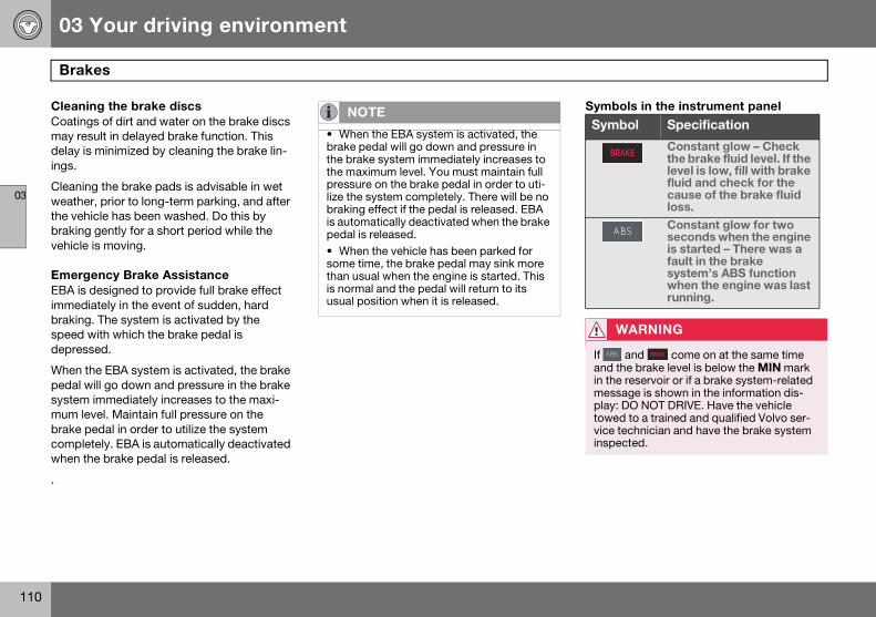
03 Your driving environment
110
Brakes
03
Cleaning the brake discsCoatings of dirt and water on the brake discs may result in delayed brake function. This delay is minimized by cleaning the brake lin-ings.
Cleaning the brake pads is advisable in wet weather, prior to long-term parking, and after the vehicle has been washed. Do this by braking gently for a short period while the vehicle is moving.
Emergency Brake AssistanceEBA is designed to provide full brake effect immediately in the event of sudden, hard braking. The system is activated by the speed with which the brake pedal is depressed.
When the EBA system is activated, the brake pedal will go down and pressure in the brake system immediately increases to the maxi-mum level. Maintain full pressure on the brake pedal in order to utilize the system completely. EBA is automatically deactivated when the brake pedal is released.
.
Symbols in the instrument panel NOTE
• When the EBA system is activated, the brake pedal will go down and pressure in the brake system immediately increases to the maximum level. You must maintain full pressure on the brake pedal in order to uti-lize the system completely. There will be no braking effect if the pedal is released. EBA is automatically deactivated when the brake pedal is released.• When the vehicle has been parked for some time, the brake pedal may sink more than usual when the engine is started. This is normal and the pedal will return to its usual position when it is released.
Symbol Specification
Constant glow – Check the brake fluid level. If the level is low, fill with brake fluid and check for the cause of the brake fluid loss.
Constant glow for two seconds when the engine is started – There was a fault in the brake system’s ABS function when the engine was last running.
WARNING
If and come on at the same time and the brake level is below the MIN mark in the reservoir or if a brake system-related message is shown in the information dis-play: DO NOT DRIVE. Have the vehicle towed to a trained and qualified Volvo ser-vice technician and have the brake system inspected.
BRAKE
BRAKE
S80 USA reprint version w640.book Page 110 Friday, June 1, 2007 10:44 AM
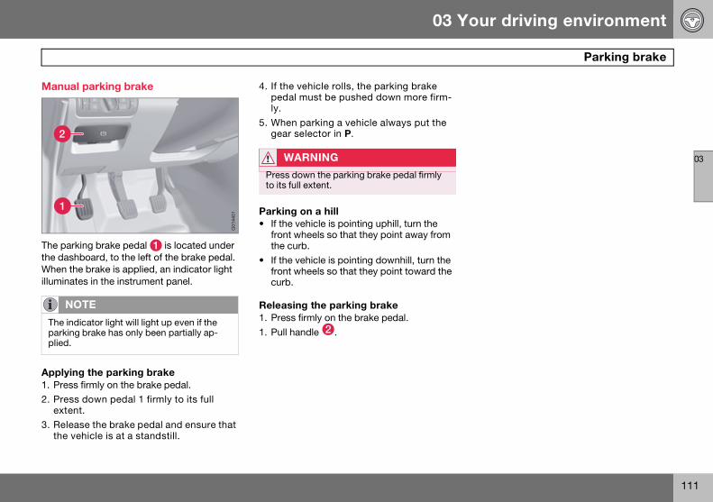
03 Your driving environment
111
Parking brake
03
Manual parking brake
The parking brake pedal is located under the dashboard, to the left of the brake pedal. When the brake is applied, an indicator light illuminates in the instrument panel.
Applying the parking brake1. Press firmly on the brake pedal.
2. Press down pedal 1 firmly to its full extent.
3. Release the brake pedal and ensure that the vehicle is at a standstill.
4. If the vehicle rolls, the parking brake pedal must be pushed down more firm-ly.
5. When parking a vehicle always put the gear selector in P.
Parking on a hill• If the vehicle is pointing uphill, turn the
front wheels so that they point away from the curb.
• If the vehicle is pointing downhill, turn the front wheels so that they point toward the curb.
Releasing the parking brake1. Press firmly on the brake pedal.
1. Pull handle .
NOTE
The indicator light will light up even if the parking brake has only been partially ap-plied.
1
2
G01
4401
WARNING
Press down the parking brake pedal firmly to its full extent.
S80 USA reprint version w640.book Page 111 Friday, June 1, 2007 10:44 AM

03 Your driving environment
112
Parking brake
03
Electric parking brake (option1)
An electric parking brake has the same func-tion as a manual parking brake.
Low battery voltageIf the battery voltage is too low, the parking brake cannot be applied or released. Con-nect an auxiliary battery if the battery voltage is too low, see page 106.
Applying the electric parking brake
Parking brake control
1. Press firmly on the brake pedal.
2. Press the control.
3. Release the brake pedal and ensure that the vehicle is at a standstill.
4. When the vehicle is parked, the gear selector must be in position P.
The symbol in the instrument panel flashes while the parking bake is being applied, and glows steadily when the parking brake has been fully applied.
Parking on a hill• If the vehicle is pointing uphill, turn the
front wheels so that they point away from the curb.
• If the vehicle is pointing downhill, turn the front wheels so that they point toward the curb.
Releasing the electric parking brake
Manual release1. Insert the remote key in the ignition slot.
2. Press firmly on the brake pedal.
3. Pull the parking brake control.
Vehicles with Keyless drive (option)1. Press the START/STOP button.
2. Press firmly on the brake pedal.
3. Pull the parking brake control.
Automatic release1. Start the engine.
1 The electric parking brake is available as an option on certain models.
NOTE
• A faint sound from the parking brake’s electric motor can be heard when the park-ing brake is being applied. This sound can also be heard during the automatic function check of the parking brake.• The brake pedal will move slightly when the electric parking brake is applied or re-leased.
5500
133s
BRAKEPARK
NOTE
• In an emergency the parking brake can be applied when the vehicle is moving by holding in the control. Braking will be inter-rupted when the accelerator pedal is de-pressed or the control is released.
• An audible signal will sound during this procedure if the vehicle is moving at speeds above 6 mph (10 km/h).
S80 USA reprint version w640.book Page 112 Friday, June 1, 2007 10:44 AM
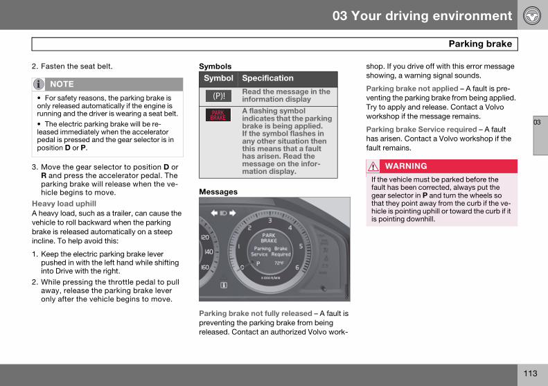
03 Your driving environment
113
Parking brake
03
2. Fasten the seat belt.
3. Move the gear selector to position D or R and press the accelerator pedal. The parking brake will release when the ve-hicle begins to move.
Heavy load uphillA heavy load, such as a trailer, can cause the vehicle to roll backward when the parking brake is released automatically on a steep incline. To help avoid this:
1. Keep the electric parking brake lever pushed in with the left hand while shifting into Drive with the right.
2. While pressing the throttle pedal to pull away, release the parking brake lever only after the vehicle begins to move.
Symbols
Messages
Parking brake not fully released – A fault is preventing the parking brake from being released. Contact an authorized Volvo work-
shop. If you drive off with this error message showing, a warning signal sounds.
Parking brake not applied – A fault is pre-venting the parking brake from being applied. Try to apply and release. Contact a Volvo workshop if the message remains.
Parking brake Service required – A fault has arisen. Contact a Volvo workshop if the fault remains.
NOTE
• For safety reasons, the parking brake is only released automatically if the engine is running and the driver is wearing a seat belt.
• The electric parking brake will be re-leased immediately when the accelerator pedal is pressed and the gear selector is in position D or P.
Symbol Specification
Read the message in the information display
A flashing symbol indicates that the parking brake is being applied.If the symbol flashes in any other situation then this means that a fault has arisen. Read the message on the infor-mation display.
(P)!
BRAKEPARK
G01
6556
WARNING
If the vehicle must be parked before the fault has been corrected, always put the gear selector in P and turn the wheels so that they point away from the curb if the ve-hicle is pointing uphill or toward the curb if it is pointing downhill.
S80 USA reprint version w640.book Page 113 Friday, June 1, 2007 10:44 AM

114
Menus and messages ............................................................................ 116
Climate system ...................................................................................... 120
Audio system ......................................................................................... 127
Trip computer ......................................................................................... 138
Compass................................................................................................ 139
Stability system...................................................................................... 141
Active chassis system–Four C ............................................................... 143
Cruise control......................................................................................... 144
Adaptive Cruise Control–ACC................................................................ 146
Collision warning system (option) .......................................................... 152
Park assist (option)................................................................................. 155
Blind Spot Information System (option) ................................................................................................... 157
Passenger compartment convenience .................................................. 160
S80 USA reprint version w640.book Page 114 Friday, June 1, 2007 10:44 AM
04COMFORT AND DRIVING PLEASURE
S80 USA reprint version w640.book Page 115 Friday, June 1, 2007 10:44 AM

04 Comfort and driving pleasure
116
Menus and messages
04
Center consoleCertain functions are controlled from the center console via the menu system or from the optional keypad in the steering wheel. Each function is described under its respec-tive section.
The current menu level is shown at the top right of display in the center console.
Center console controls
Center console with information display and controls for menus
Navigation button – scrolls and selects among menu options
ENTER – selects menu options
MENU – accesses the menu system
EXIT – leads back one step in the menu structure. A long press exits the menu system.
Steering wheel keypad
ENTER EXIT
Navigation buttons.
If the steering wheel keypad has ENTER and EXIT, the buttons to have the same function as those in the center console.
Search pathsAccess to some functions is provided directly via the function buttons and others are access through the menu system.
Search paths to the menu system functions are listed as follows: Car settings Lock
settings, if the following steps have been taken first:
1. Press MENU.
2. Scroll to Menu and press ENTER.
3. Scroll to Submenu and press ENTER.
The navigation button can be used instead of ENTER and EXIT when navigating the menu hierarchy. The right arrow is equal to ENTER and the left arrow to EXIT.
The menu options are numbered and can also be selected directly with the numerical keypad (1–9 only).
3
41
2
G01
8378
21
3
G01
8379
S80 USA reprint version w640.book Page 116 Friday, June 1, 2007 10:44 AM

04 Comfort and driving pleasure
117
Menus and messages
04
Menu overviewCar key memory
Seat & mirror positions
Car settings
Fold mirr. when locking (option on cer-tain markets only)
Collision warning settings (option)
Light settings
Lock settings
Parking camera settings (accessory)
Steering force level (option)
Information
Climate settings
Automatic blower adjust
Recirculation timer
Auto. rear defroster
Reset climate settings
Main menu AMAudio settings1
Sound stage
Equalizer, front
Equalizer, rear
Auto. volume control
Resets all audio settings.
Main menu FMFM settings
Radio text
Advanced radio settings
Audio settings
Main menu CDRandom
Off
Folder
Disc
Single disc
All discs
CD settings
Disc text (option)
Audio settings
Main menu AUXVolume, AUX input
Audio settings
1 The menu option for audio settings is avail-able in all audio sources.
S80 USA reprint version w640.book Page 117 Friday, June 1, 2007 10:44 AM
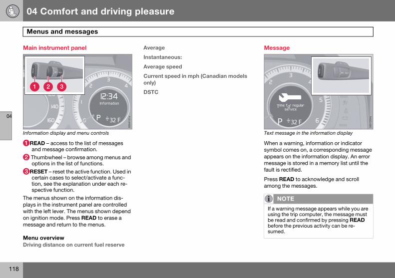
04 Comfort and driving pleasure
118
Menus and messages
04
Main instrument panel
Information display and menu controls
READ – access to the list of messages and message confirmation.
Thumbwheel – browse among menus and options in the list of functions.
RESET – reset the active function. Used in certain cases to select/activate a func-tion, see the explanation under each re-spective function.
The menus shown on the information dis-plays in the instrument panel are controlled with the left lever. The menus shown depend on ignition mode. Press READ to erase a message and return to the menus.
Menu overviewDriving distance on current fuel reserve
Average
Instantaneous:
Average speed
Current speed in mph (Canadian models only)
DSTC
Message
Text message in the information display
When a warning, information or indicator symbol comes on, a corresponding message appears on the information display. An error message is stored in a memory list until the fault is rectified.
Press READ to acknowledge and scroll among the messages.
8904
151s
1 2 3
32 F
NOTE
If a warning message appears while you are using the trip computer, the message must be read and confirmed by pressing READ before the previous activity can be re-sumed.
3801
304s
P 32 F
Time for regularservice
S80 USA reprint version w640.book Page 118 Friday, June 1, 2007 10:44 AM

04 Comfort and driving pleasure
119
Menus and messages
04
Message Description
Stop safely Stop and switch off the engine. Serious risk of damage. Contact an autho-rized Volvo workshop.
Stopping the engine
Stop and switch off the engine. Serious risk of damage. Contact an autho-rized Volvo workshop.
Service urgent Have the vehicle checked by an autho-rized Volvo workshop immediately.
Service required
Have the vehicle checked by an autho-rized Volvo workshop as soon as possible.
See manual Read the owner’s manual.
Time for regular service
Time for regular service at an autho-rized Volvo workshop. The timing is determined by the number of miles driven, number of months since the last service, engine running time.
Maintenance overdue
If the service intervals are not followed, the warranty does not cover any damaged parts. Contact an authorized Volvo workshop for service.
Temporarily OFF
A function has been temporarily switched off and is reset automatically while driving or after starting again.
Power save mode
The audio system is switched off to save current. Charge the battery.
Message Description
S80 USA reprint version w640.book Page 119 Friday, June 1, 2007 10:44 AM

04 Comfort and driving pleasure
120
Climate system
04
Introduction
Air conditioningThe vehicle is equipped with Electronic Cli-mate Control (ECC). The climate control sys-tem cools, heats or dehumidifies the air in the passenger compartment.
Sensor location• The sun sensor is located on the top side
of the dashboard.
• The temperature sensor for the passenger compartment is located below the climate control panel.
• The outside temperature sensor is located on the door mirror.
• The humidity sensor (option) is located in the interior rearview mirror.
Side windows and moonroof
To ensure that the air conditioning works optimally, the side windows, and the optional moonroof should be closed.
Misting windows
Remove misting on the insides of the windows by primarily using the defroster function.
To reduce the risk of misting, clean the win-dows with a normal window cleaning agent.
Vents in the parcel shelf
Temporary shut-off of the air conditioningThe air conditioning is momentarily disen-gaged during full-throttle acceleration or when driving uphill with a trailer. This may result in a temporary increase in cabin tem-perature.
Ice and snow
Always keep the air intake grille at the base of the windshield free of snow.
Climate system maintenance
Special tools and equipment are required to maintain and carry out repairs on the climate system. Work of this type should only be done by a trained and qualified Volvo service technician.
Refrigerant
Volvo cares about the environment. The air conditioning system in your car contains a CFC-free refrigerant - R134a. This substance will not deplete the ozone layer. The air condi-tioning system contains 1.59 lbs (720 g) of R134a. The systems uses PAG oil.
Passenger compartment filterReplace the cabin air filter with a new one at the recommended intervals. Please refer to your Warranty and Service Records Informa-tion booklet, or consult a trained and quali-fied Volvo service technician for these inter-vals. The filter should be replaced more often when driving under dirty and dusty condi-tions. The filter cannot be cleaned and there-fore should always be replaced with a new one.
NOTE
• The air conditioning can be switched off, but to ensure the best possible climate comfort in the passenger compartment and to prevent the windows from misting, it should always be on.• In warm weather, a small amount of water may accumulate under the car when it has been parked. This water is condensation from the A/C system and is normal.
NOTE
Do not cover or block the sensors with clothing or other objects.
NOTE
The air vents at the rear of the parcel shelf should never be obstructed.
S80 USA reprint version w640.book Page 120 Friday, June 1, 2007 10:44 AM
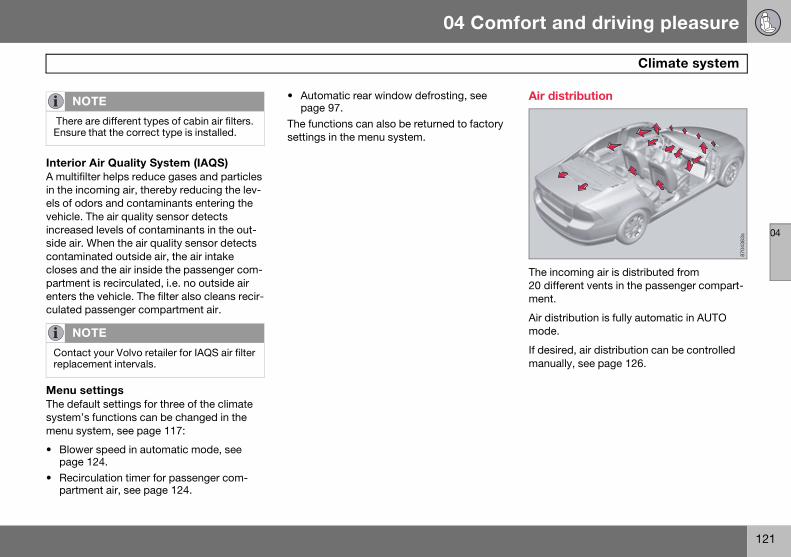
04 Comfort and driving pleasure
121
Climate system
04
Interior Air Quality System (IAQS) A multifilter helps reduce gases and particles in the incoming air, thereby reducing the lev-els of odors and contaminants entering the vehicle. The air quality sensor detects increased levels of contaminants in the out-side air. When the air quality sensor detects contaminated outside air, the air intake closes and the air inside the passenger com-partment is recirculated, i.e. no outside air enters the vehicle. The filter also cleans recir-culated passenger compartment air.
Menu settingsThe default settings for three of the climate system’s functions can be changed in the menu system, see page 117:
• Blower speed in automatic mode, see page 124.
• Recirculation timer for passenger com-partment air, see page 124.
• Automatic rear window defrosting, see page 97.
The functions can also be returned to factory settings in the menu system.
Air distribution
The incoming air is distributed from 20 different vents in the passenger compart-ment.
Air distribution is fully automatic in AUTO mode.
If desired, air distribution can be controlled manually, see page 126.
NOTE
There are different types of cabin air filters. Ensure that the correct type is installed.
NOTE
Contact your Volvo retailer for IAQS air filter replacement intervals.
8704
363s
S80 USA reprint version w640.book Page 121 Friday, June 1, 2007 10:44 AM

04 Comfort and driving pleasure
122
Climate system
04
Air vents in the dashboard
Open
Closed
Horizontal airflow
Vertical airflow
Direct the outer air vents toward the side win-dows to defrost.
Air vents in the door pillars
Open
Closed
Horizontal airflow
Vertical airflow
Direct the outer air vents toward the side win-dows to defrost.
Direct the vents into the passenger compart-ment to maintain a comfortable climate in the rear seat.
Electronic climate control, ECC
Ventilated front driver’s seat (option)
Blower
Heated front driver’s seat (option)
Air distribution
Heated front passenger’s seat (option)
Auto
Ventilated front passenger’s seat (option)
Temperature control, passenger’s side
A/C – On/Off
Heated rear window and door mirrors, see page 97.
Defroster
Recirculation/Air quality system
Temperature control, driver’s side
A
B
D
D
CC
8704
343s
8704
365s
CC
D
D
AB
8704
366s
12
2 6
11
4
10 9
13 8
1 3 5 7
S80 USA reprint version w640.book Page 122 Friday, June 1, 2007 10:44 AM

04 Comfort and driving pleasure
123
Climate system
04
Ventilated front seats (option)The ventilation system consists of fans in the seats and backrests that draw air through the seat upholstery. The cooling effect increases as the air in the passenger compartment becomes cooler.
The ventilation is controlled by the ECC sys-tem, which takes into account the seat tem-perature, sunlight in the passenger compart-ment, and the ambient temperature.
The ventilation can be used at the same time as seat heating. For example, the function can be used to dry damp clothing.
The ventilation system can be activated when the engine is running. There are three comfort levels that produce different cooling and dehumidification effects:
• Level three: press the button once for maximum output – three indicator lights come on.
• Level two: press the button twice for a lower output – two indicator lights come on.
• Level one: press the button three times for the lowest output – one indicator light comes on.
• Press the button a fourth time to switch off the function – the indicator light will go out.
Blower controlTurn the control clockwise to increase or counter-clockwise to decrease the blower speed. Pressing the AUTO switch will automati-cally regulate blower speed and override manual adjust-ment.
Heated front seats (option)• Press the button once for the highest heat level – three indicator lights come on.
• Press the button twice for a lower heat level – two indicator lights come on.
• Press the button three times for the lowest heat level – one indicator light comes on.
• Press the button four times to switch off the heat – no indicator lights come on.
Heated rear seats1
Heat control for the outboard seating posi-tions takes place in the same way as for the front seat.
Air distributionThe figure consists of three buttons. When the buttons are pressed, an indicator light in front of the respec-tive part of the figure illumi-nates and shows which air distribution is selected, see page 126.
NOTE
If the blower is turned off completely, the air conditioning is disengaged.
8704
352s
8704
369s
1 Option on Canadian models only.
3603
819s
8704
361s
S80 USA reprint version w640.book Page 123 Friday, June 1, 2007 10:44 AM
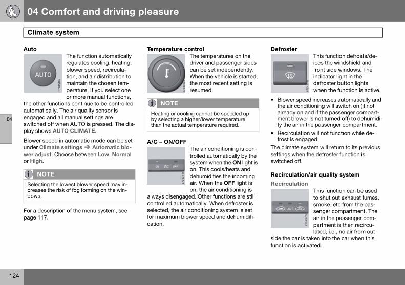
04 Comfort and driving pleasure
124
Climate system
04
AutoThe function automatically regulates cooling, heating, blower speed, recircula-tion, and air distribution to maintain the chosen tem-perature. If you select one or more manual functions,
the other functions continue to be controlled automatically. The air quality sensor is engaged and all manual settings are switched off when AUTO is pressed. The dis-play shows AUTO CLIMATE.
Blower speed in automatic mode can be set under Climate settings Automatic blo-wer adjust. Choose between Low, Normal or High.
For a description of the menu system, see page 117.
Temperature controlThe temperatures on the driver and passenger sides can be set independently. When the vehicle is started, the most recent setting is resumed.
A/C – ON/OFFThe air conditioning is con-trolled automatically by the system when the ON light is on. This cools/heats and dehumidifies the incoming air. When the OFF light is on, the air conditioning is
always disengaged. Other functions are still controlled automatically. When defroster is selected, the air conditioning system is set for maximum blower speed and dehumidifi-cation.
DefrosterThis function defrosts/de-ices the windshield and front side windows. The indicator light in the defroster button lights when the function is active.
• Blower speed increases automatically and the air conditioning will switch on (if not already on and if the passenger compart-ment blower is not turned off) to dehumidi-fy the air in the passenger compartment.
• Recirculation will not function while de-frost is engaged.
The climate system will return to its previous settings when the defroster function is switched off.
Recirculation/air quality system
RecirculationThis function can be used to shut out exhaust fumes, smoke, etc from the pas-senger compartment. The air in the passenger com-partment is then recircu-lated, i.e., no air from out-
side the car is taken into the car when this function is activated.
NOTE
Selecting the lowest blower speed may in-creases the risk of fog forming on the win-dows.
8704
348s
NOTE
Heating or cooling cannot be speeded up by selecting a higher/lower temperature than the actual temperature required.
8704
362s
8704
344s
8704
354s
8704
347s
S80 USA reprint version w640.book Page 124 Friday, June 1, 2007 10:44 AM

04 Comfort and driving pleasure
125
Climate system
04
If the air in the car recirculates for too long, there is a risk of condensation forming on the insides of the windows, especially in winter.
TimerThe timer function minimizes the risk of fog-ging, or stale air when the recirculation func-tion is selected by automatically switching off the function after a certain length of time, depending on the ambient temperature. Acti-vate/deactivate the function under Climate control settings Recirculation timer. For a description of the menu system, see page 117.
Interior Air Quality System–IAQS (option)
This system consists of a multifilter and an air quality sensor. The filter helps remove gases and particles from the incoming air, thereby reducing the amounts of odors and con-
taminants entering the vehicle. The air quality sensor detects increased levels of contami-nants in the outside air. When the air quality
sensor detects contaminated outside air, the air intake closes and the air inside the pas-senger compartment is recirculated, i.e., no outside air enters the vehicle. The filter also cleans recirculated passenger compartment air. When the AUTO button is depressed the air quality sensor is always engaged.
Activating the air quality sensorSwitch between the three functions by pressing the button repeatedly.
• The left orange light comes on – the air quality sensor is disengaged.
• The center green light comes on – recircu-lation not engaged, providing it is not required for cooling in hot weather.
• The right orange light comes on – recircu-lation is engaged.
NOTE
When Defroster is selected, recirculation is always deactivated.
8704
345s
8704
346s
NOTE
• The air quality sensor should always be engaged in order to obtain the best air in the passenger compartment.• Recirculation is limited in cold weather to avoid fogging.• If the insides of the windows start fog-ging, disengage the air quality sensor. Use the defroster function to increase airflow to the front, side, and rear windows.
S80 USA reprint version w640.book Page 125 Friday, June 1, 2007 10:44 AM

04 Comfort and driving pleasure
126
Climate system
04
Air distribution table
Air distribution Use Air distribution Use
Air to windows. Some air flows from the dashboard air vents. The air is not recircu-lated. Air conditioning is always engaged.
To remove de-fog/de-ice the front side windows and windshield quickly.
Air to the floor and windows. Some air flows from the dashboard air vents.
To ensure comfortable conditions and good de-fogging in cold or humid weather.
Air to windshield and side windows. Some air flows from the air dashboard vents.
In cold or humid weather (blower speed should be moderate to high).
Air to floor and from dashboard air vents.
In sunny weather with cool outside tempera-tures.
Airflow to windows and from dashboard air vents.
To ensure good comfort in warm, dry weather.
Air to floor. Some air flows to the dashboard air vents and windows.
To warm or cool the feet.
Airflow to the head and chest from the dashboard air vents.
To ensure efficient cooling in warm weather.
Airflow to windows, from dashboard air vents and to the floor.
To cool the feet or provide warmer air to the upper body in cold weather or hot, dry weather.
8704
354s
8704
358s
8704
355s
8704
359s
8704
356s
8704
360s
8704
358s
8704
353s
S80 USA reprint version w640.book Page 126 Friday, June 1, 2007 10:44 AM

04 Comfort and driving pleasure
127
Audio system
04
Introduction
The audio system is available in two versions: High Performance och Premium Sound. The system version is shown in the display when the audio system is switched on.
If the audio system is on when the ignition is switched off, it will come on automatically the next time the ignition is put in mode I or higher. The audio system can be operated without a key in the ignition slot for 15 minutes at a time by pressing the POWER button (the driver’s door must be closed on vehicles with the optional keyless drive).
Some functions are controlled from the menu system in the center console. For more infor-mation on menus, see page 117.
Dolby Surround Pro Logic II and the symbol are trademarks of Dolby Laboratories
Licensing Corporation. The Dolby Surround Pro Logic II System is manufactured under license from Dolby Laboratories Licensing Corporation.
Overview
Socket for external audio source (AUX)
Steering wheel keypad
Center console control panel
Control panel with headphones socket (option)
Steering wheel keypad
Confirm selection in menu system.
Go higher in the menu system. Interrupt current function.
Volume
A short press scrolls between CD tracks or preset radio stations. A long press searches within CD tracks or searches for radio stations automatically.
3905
596s
12
4
3
2
3
1
4
G01
8380
S80 USA reprint version w640.book Page 127 Friday, June 1, 2007 10:44 AM

04 Comfort and driving pleasure
128
Audio system
04
Rear control panel with headphones socket (option) Headphones with an impedance of 16–32 ohm and sensitivity of 102 dB or higher are recommended for best sound reproduction.
Volume
Scroll/search forward and backward
Audio source, activating
Headphones sockets (3.5 mm) - acces-sory
Activating/deactivatingThe control panel is activated by pressing MODE when the audio system is switched on. It is switched off automatically when the
audio system is switched off or by a long press on MODE.
Scroll/search forward and backwardShort presses on are used to scroll between CD tracks or preset radio stations. Long presses are used to fast-wind CD tracks or to search for radio stations auto-matically.
LimitationsThe audio source (FM, AM, CD, etc.) being played in the speakers cannot be controlled from the rear control panel.
Menu control and MY KEYCertain functions can be controlled from the menu system in the center console. For more information on menus, see page 117.
Storing your favorite functions with MY KEY.
1. Select the function in the menu to be stored. Only certain functions can be stored.
2. Press and hold MY KEY for more than two seconds.
Activate the stored function by pressing MY KEY briefly.
3905
594s
1 12
33 4
G01
8381
S80 USA reprint version w640.book Page 128 Friday, June 1, 2007 10:44 AM

04 Comfort and driving pleasure
129
Audio system
04
Audio functions
Center console, controls for audio functions
Internal audio sources: AM, FM and CD
External audio source. For connection, see page 127
Push button and knob controls for mak-ing sound settings
Navigation button for AUX volume and equalizer
Volume and on/off
Audio volume and automatic volume controlThe audio system compensates for disrupt-ing noises in the passenger compartment by increasing the volume according to the speed of the vehicle. The level of sound com-pensation can be set at low, medium or high.
Select the level under Audio settings Auto volume control.
External audio source audio volumeExternal devices such as an MP3 player can be connected to the AUX input, see page 127. The volume of the external sound source AUX may be different from the vol-ume of the internal sound sources such as the CD player or the radio. If the external sound source's volume is too high, the qual-ity of the sound may be impaired. To help prevent this, adjust the input volume of the external audio source:
1. Set the audio system in AUX mode using MODE and go to Volume, AUX input.
2. Turn the control or press / the navigation button.
Sound settingsPress the control repeatedly to toggles among the sound settings. Adjustments are made by turning the control .
• Bass – Bass level.
• Treble – Treble level.
• Fader – Balance between the front and rear speakers.
• Balance – Balance between the right and left speakers.
• Subwoofer (option on certain markets only) – Level for the bass speaker.
• Surround (option) – Surround settings.
Under Surround, 3 channel stereo or Dolby pro logic II can be activated by select-ing 3-ch or Dpl2 respectively. This enables the following options:
• Center level 1 – Level for the center speaker.
• Surround level 1 – Level for surround sound.
EqualizerSound levels for different frequencies can be adjusted separately using the equalizer2.
1. Go to Audio settings and select Equalizer Front or Equalizer Rear.
The sound level for the frequency is adjusted with / on the navigation button. Press
/ to select another frequency.
2. Use ENTER to save or EXIT to close.
Sound stage1
The sound experience can be optimized for the driver’s seat, both front seats or the rear seat. Select one of the options under Audio settings Soundstage.
5
1
2
34G
0000
00
1 Premium Sound2 Certain audio systems
S80 USA reprint version w640.book Page 129 Friday, June 1, 2007 10:44 AM

04 Comfort and driving pleasure
130
Audio system
04
CD functions
Center console, controls for CD functions
CD insert and eject
CD slot
Navigation button for changing CD tracks
Fast-back and change CD track
CD changer position selection (option)
Scan CD
Playing a CD (CD player1)If a music CD is in the player when CD is pressed, it will be played automatically. Oth-erwise, insert a disc and press CD.
Playing a CD (CD changer)If a CD position with a music CD is already selected when CD is pressed, it will be played automatically. Otherwise select a disc with the number buttons 1-6 or /
on the navigation button.
Insert a CD (CD changer)1. Select an empty position with the number
buttons 1-6 or / on the navigation button.
An empty position is marked on the display. The text Insert disc shows that a new disc can be inserted. The CD changer can hold up to six CDs.
2. Insert a CD in the CD changer slot.
Disc ejectFor reasons of traffic safety, an ejected CD must be removed within 12 seconds or it will be automatically drawn back into the slot and the CD player will enter pause mode. Press the CD button to restart the disc.
Eject individual discs by pressing the eject button.
Eject all discs with a long press on the eject button. The entire magazine is emptied disc by disc.
PauseWhen the audio system volume is turned off completely, the CD player will pause and will resume playing when the volume is turned up again.
Sound filesIn addition to playing normal music CDs, the CD player/changer can also play discs con-taining files in mp3 or wma format.
When a CD containing sound files is inserted into the player the disc’s directory structure is scanned before the CD begins playing. The length of time that this takes depends on the quality of the disc.
1 Certain markets only.
1 2
3 4
5 6G
0183
83
NOTE
The Eject all function can only be used while the vehicle is at a standstill and will be can-celled if the vehicle begins to move.
NOTE
Some copy protected sound files may not be read by the player.
S80 USA reprint version w640.book Page 130 Friday, June 1, 2007 10:44 AM
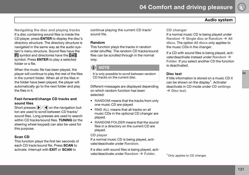
04 Comfort and driving pleasure
131
Audio system
04
Navigating the disc and playing tracksIf a disc containing sound files is inside the CD player, press ENTER to display the disc’s directory structure. The directory structure is navigated in the same way as the audio sys-tem’s menu structure. Sound files have the
symbol and directories have the symbol. Press ENTER to play a selected folder or a file.
When the music file has been played, the player will continue to play the rest of the files in the current folder. When all of the files in the folder have been played, the player will automatically go to the next folder and play the files in it.
Fast-forward/change CD tracks and sound filesShort presses / on the navigation but-ton are used to scroll between CD tracks/sound files. Long presses are used to search within CD tracks/sound files. TUNING (or the steering wheel keypad) can also be used for this purpose.
Scan CDThis function plays the first ten seconds of each CD track/sound file. Press SCAN to activate. Interrupt with EXIT or SCAN to
continue playing the current CD track/sound file.
RandomThis function plays the tracks in random order (shuffle). The random CD tracks/sound files can be scrolled through in the normal way.
Different messages are displayed depending on which random function has been selected:
• RANDOM means that the tracks from only one music CD are played
• RND ALL means that all tracks on all music CDs in the optional CD changer are played.
• RANDOM FOLDER means that the sound files in a directory on the current CD are played.
CD playerIf a normal music CD is being played, acti-vate/deactivate under Random.
If a disc with sound files is being played, acti-vate/deactivate under Random Folder.
CD changerIf a normal music CD is being played under Random Single disc or Random All discs. The option All discs only applies to the music CDs in the changer.
If a CD with sound files is being played, acti-vate/deactivate instead under Random Folder. If you select another CD the function is deactivated.
Disc textIf title information is stored on a music CD it can be shown on the display1. Activate/deactivate in CD mode under CD settings
Disc text.
NOTE
It is only possible to scroll between random CD tracks on the current disc.
1 Only applies to CD changer.
S80 USA reprint version w640.book Page 131 Friday, June 1, 2007 10:44 AM

04 Comfort and driving pleasure
132
Audio system
04
Radio functions
Center console, controls for radio functions
Navigation button for automatic tuning
Press to cancel a menu selection or a selected function
Manual tuning
Scan the current wave band
Auto store the strongest radio stations in the area in which you are driving
Station preset buttons
Select wave band AM and FM (FM1 and FM2)
Automatic tuning1. Select a wave band using FM or AM.
2. Press / on the navigation button.
Manual tuning1. Select a wave band using FM or AM.
2. Turn TUNING to select a station.
PresetTen station presets can be stored for each wave band. FM has two memories for pre-sets: FM1 and FM2. Only radio stations played through the car’s speakers can be stored as presets. The stored presets are selected using the preset buttons.
Preset storage can be carried out manually or automatically.
Manually storing preset stations1. Tune into a station.
2. Hold in one of the preset buttons until the message Channel stored appears on the display.
Automatically storing preset stationsThe function is especially useful in areas where the radio stations and their frequen-cies are unfamiliar. The ten strongest radio stations are stored automatically in a sepa-rate memory.
1. Select a wave band using FM or AM.
2. Hold in AUTO until Autostoring... ap-pears on the display.
Once Autostoring... disappears from the display, the stations are stored. The radio
continues in Auto mode and Auto appears on the display. The automatically stored pre-sets can now be selected using the preset buttons. Automatic preset storage can be cancelled using EXIT.
Auto mode is cancelled by pressing for example AUTO or FM.
Returning to Auto mode provides access to the autostored presets:
1. Press AUTO.
Auto appears on the display.
2. Press a preset button.
ScanThe function automatically searches the cur-rent wave band for strong stations. When a station is found, it is played for approx. eight seconds before scanning is resumed. While the station is playing it can be stored as a preset as usual.
1. Select a wave band using AM or FM.
2. Press SCAN.
SCAN appears on the display. Close using SCAN or EXIT.
3905
552s
321
5 4
6
7
G01
8384
S80 USA reprint version w640.book Page 132 Friday, June 1, 2007 10:44 AM

04 Comfort and driving pleasure
133
Audio system
04
Radio textSome stations transmit information on pro-gram content, artists, etc. This information can be shown on the display.
Activate/deactivate in FM mode under Radio text.
S80 USA reprint version w640.book Page 133 Friday, June 1, 2007 10:44 AM

04 Comfort and driving pleasure
134
Audio system
04
Sirius satellite radio (option)
Listening to satellite radio The Sirius satellite system consists of a num-ber of high elevation satellites in geosynchro-nous orbit.
Selecting Sirius radio mode1. Press Power to switch on the audio sys-
tem (see pages 129 and 132 for informa-tion on the standard audio and radio functions).
2. Press the MODE button repeatedly until Sirius 1 or 2 is displayed.
Activating Sirius radio1. Tune to a satellite channel that has no
audio, which means that the channel is unsubscribed and the text "Call 888-539-SIRIUS TO SUBSCRIBE" is displayed (see also "Selecting a channel".
2. Call Sirius at 1-888-539-SIRIUS (7474).
3. When asked for the Sirius ID number press AUTO to display this number. It is
also possible to retrieve the Sirius ID from the menu.
4. UPDATING SUBSCRIPTION will be dis-played while the subscription is being updated, after which the display will return to the normal view.
SIRUS IDThe SIRIUS ID is required when contacting the Sirius Call Center. It is used to activate your account and when making any account transactions. The SIRIUS ID is sometimes referred to as the Electronic Serial Number (ESN).
Selecting a channel category1. Select Sirius radio mode as described
above.
2. Press ENTER.
3. Use the up/down arrow keys to scroll through the list of categories.
4. Press ENTER or the right arrow key to select a category.
The first channel in the selected category will then be played.
Selecting a channelThere are three ways of tuning in a channel:
• Using the left and right arrow keys
• By turning the tuning control
• Through direct channel entry.
NOTE
The digital signals from the Sirius satellites are line-of-sight, which means that physical obstructions such as bridges, tunnels, etc, may temporarily interfere with signal recep-tion.
NOTE
• The category ALL is default, which en-ables you to scroll through the entire list of available satellite channels.
• The channel categories are automatically updated several times a year. This takes ap-proximately two minutes and will interrupt normal broadcasting. A message will be displayed while updating is in progress. In-formation on channel or feature updates is available at www.sirius.com.
NOTE
• The numbers of skipped or locked chan-nels will not be displayed.
• If a channel is locked, the access code must be entered before the channel can be selected. See “Unlocking a channel” on page 136.
S80 USA reprint version w640.book Page 134 Friday, June 1, 2007 10:44 AM

04 Comfort and driving pleasure
135
Audio system
04
Direct channel entryThe Sirius satellite channels are in numerical order throughout all of the categories. To access a channel directly:
1. Press MENU and scroll to Direct channel entry.
2. Use the numerical keypad to enter the channel’s number.
3. Press ENTER. The radio will tune to this channel, even if it belongs to a category other than the currently selected one.
ScanningSCAN automatically searches through the list of satellite channels. The search will only be carried out in the selected category. See page 132 for more detailed information.
Storing a channelA total of 20 satellite channels can be stored; 10 channels each for Sirius 1 and 2. See page 132 for detailed information on storing channels.
• A long press on one of the number keys stores the currently tuned channel on that key.
• A short press on a number key while the radio is in Sirius 1or 2 mode will tune to the preset satellite channel stored on that
button, regardless of the currently select-ed channel category.
Song Seek and Song MemoryThe Song Seek and Song Memory func-tions provide both audio and visual notifica-tion when Sirius is broadcasting your favorite songs. Song Seek enables you to store the name of the song for future advance notifica-tion when that song is being played. The Song Memory feature makes it possible to view all of the current songs that are stored in memory.
Song memoryUp to ten songs can be saved in the system’s memory.
1. Press MENU.
2. Scroll to Add song to song mem. and follow the instructions shown in the display.
If a new song is selected when the memory is full, you will be prompted to press ENTER to delete the last song on the list.
Song seekWhen a satellite radio channel plays one of the songs stored in the song memory, the lis-tener will be alerted by a text message and an audible signal.
Press ENTER to listen to the song or EXIT to cancel.
To activate/deactivate the song seek func-tion:
1. Press MENU2. Scroll to Song seek3. Press ENTER to activate or deactivate
the function.
Radio textThe text that is displayed about the song that is currently playing can be changed. Use the AUTO button or the menu to display the Art-ist, Title, Composer, or switch radio text off.NOTE
The remaining songs in the list will move down one position, and the newly added song will be placed at the top of the list.
NOTE
When the song has ended, the radio will re-main tuned to the channel on which the song was played.
S80 USA reprint version w640.book Page 135 Friday, June 1, 2007 10:44 AM

04 Comfort and driving pleasure
136
Audio system
04
Advanced settingsThis menu function enables you to make set-tings on certain Sirius satellite radio func-tions. To access this menu:
1. Press MENU.
2. Scroll to the Sirius menu.
3. Select Advanced Sirius settings.
The following settings can be made in the Sirius menu:
• The list of saved songs can be displayed
• Channel skip settings can be made
• Channel lock settings can be made
• The channel access code can be dis-played or changed
• Your Sirius ID can be displayed
Skip optionsThis function is used to remove a channel from the list of available channels.
Skipping a channel1. Select CHANNEL SKIP LIST and press
ENTER.
2. Select a category in the list and press ENTER.
3. Skip channels in the list presented by pressing ENTER or right arrow key.
Unskip all channels
This permanently removes all channels from the skip list and makes them available for selection.
Temp. unskip all ch.
This function will temporarily unskip all chan-nels and make them available for selection. The channels remain on the skip list and will again be skipped the next time the ignition is switched on.
Channel lockAccess to specific channels can be restricted (locked). A locked channel will not provide audio, song titles, or artist information.
Locking a channel:1. Select Sirius ID in the menu and select
LOCK OPTIONS and press ENTER.
2. Select CHANNEL LOCK LIST and press ENTER
3. Enter the channel access code1 and press ENTER.
4. Select a category in the list and press ENTER.
5. Lock channels in the list presented by pressing ENTER or right arrow.
The channel is now locked and a checked box will be displayed to indicate this. It will be necessary to enter the channel access code1 in order to listen to a locked channel.
Unlocking a channelA channel’s access code1 is required to unlock a channel.
Unlock all channels
This permanently removes all channels from the locked list and makes them available for selection.
Temp. unlock all ch.
This function will temporarily unlock all chan-nels and make them available for selection. The channels remain on the locked list and will again be locked the next time the ignition is switched on.
WARNING
Settings should be made when the vehicle is at a standstill.
NOTE
All channels are initially unlocked.
1 The default code is 0000. If you have changed the code and forgotten it, see the section “If you have forgotten the access code.”
S80 USA reprint version w640.book Page 136 Friday, June 1, 2007 10:44 AM

04 Comfort and driving pleasure
137
Audio system
04
CHANGE CODE
This function makes it possible to change the channel access code. The default code is 0000.
To change the code:
1. Select CHANGE CODE and press EN-TER.
2. Enter the current code and press EN-TER.
3. Enter the new code and press ENTER.
4. Confirm the new code and press EN-TER.
If an incorrect code is entered, the text WRONG CODE! is displayed.
If you have forgotten the access code:1. Select SIRIUS ID in the Sirius settings
menu and press ENTER.
2. Press and hold the ENTER button for 2 seconds.
3. The current code will be displayed.
Your Volvo retailer can also provide you with assistance.
SIRUS ID
This function displays the 12-digit Sirius acti-vation ID.
S80 USA reprint version w640.book Page 137 Friday, June 1, 2007 10:44 AM
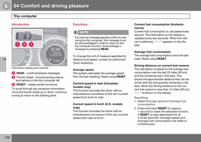
04 Comfort and driving pleasure
138
Trip computer
04
Introduction
Information display and controls
READ – confirms/erases messages
Thumb wheel – browse among menus and options in the trip computer list
RESET – resets certain functions
To scroll through trip computer information, move the thumb wheel up or down. Continue turning to return to the starting point.
Functions
To change the unit of measure specified for distance and speed, contact an authorized Volvo workshop.
Average speed The system calculates the average speed from the last resetting. Reset using RESET.
Current speed in mph (Canadian models only) This function provides the driver with an instantaneous conversion of the car's current speed from km/h to mph.
Current speed in km/h (U.S. models only) This function provides the driver with an instantaneous conversion of the car's current speed from mph to km/h.
Current fuel consumption (Instanta-neous)Current fuel consumption is calculated every second. The information on the display is updated every few seconds. When the vehi-cle is stationary, "----" appears on the dis-play.
Average fuel consumptionThe average fuel consumption since the last reset. Reset using RESET.
Driving distance on current fuel reserve The calculation is based on the average fuel consumption over the last 20 miles (30 km) and the remaining fuel in the tank. This shows the approximate distance that can be driven with the fuel quantity remaining in the tank. When the driving distance on the cur-rent fuel reserve is less than 12 miles (20 km),"----" is shown on the display.
Resetting1. Select Average speed or Average fuel
consumption.
2. Press and hold RESET for approx. 1 second to reset the selected function. If RESET is kept depressed for at 3 three seconds, Average speed and Average fuel consumption are reset si-multaneously.
3603
899s
1 2 3
miles
NOTE
If a warning message appears while you are using the trip computer, this message must be acknowledged in order to return to the trip computer function. Acknowledge a message by pressing READ.
S80 USA reprint version w640.book Page 138 Friday, June 1, 2007 10:44 AM
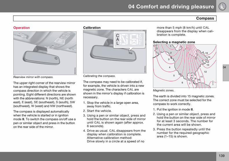
04 Comfort and driving pleasure
139
Compass
04
Operation
Rearview mirror with compass.
The upper right corner of the rearview mirror has an integrated display that shows the compass direction in which the vehicle is pointing. Eight different directions are shown with the abbreviations: N (north), NE (north east), E (east), SE (southeast), S (south), SW (southwest), W (west) and NW (northwest).
The compass is displayed automatically when the vehicle is started or in ignition mode II. To switch the compass on/off use a pen or similar object and press in the button on the rear side of the mirror.
Calibration
Calibrating the compass.
The compass may need to be calibrated if, for example, the vehicle is driven into a new magnetic zone. The characters CAL are shown in the mirror’s display if calibration is necessary.
1. Stop the vehicle in a large open area, away from traffic.
2. Start the vehicle.
3. Using a pen or similar object, press and hold the button on the rear side of mirror until CAL is shown again (after approx. 6 seconds).
4. Drive as usual. CAL disappears from the display when calibration is complete.Alternative calibration method: Drive slowly in a circle at a speed of no
more than 5 mph (8 km/h) until CAL disappears from the display when cali-bration is complete.
Selecting a magnetic zone
Magnetic zones.
The earth is divided into 15 magnetic zones. The correct zone must be selected for the compass to work correctly.
1. Put the ignition in mode II.2. Using a pen or similar object, press and
hold the button on the rear side of mirror for at least 3 seconds. The number for the current area will be shown.
3. Press the button repeatedly until the number for the required geographic area (1–15) is shown.
8803
554s
8803
562s
15
14
13
12
119
8
76
5
4
3
2
1
10
G01
8632
S80 USA reprint version w640.book Page 139 Friday, June 1, 2007 10:44 AM

04 Comfort and driving pleasure
140
Compass
04
4. The display will revert to showing the compass direction after several sec-onds.
S80 USA reprint version w640.book Page 140 Friday, June 1, 2007 10:44 AM

04 Comfort and driving pleasure
141
Stability system
04
Introduction
The Dynamic Stability and Traction Control system (DSTC) consists of a number of func-tions designed help reduce wheel spin, counteract skidding, and to generally help improve directional stability.
Traction control (TC)This function is designed to help reduce wheel spin by transferring power from a drive wheel that begins to lose traction to the wheel on the opposite side of the vehicle (on the same axle).
TC is most active at low speeds.
This is one of DSTC's permanent functions and cannot be switched off.
Active Yaw Control (AYC)This function helps maintain directional sta-bility, for example when cornering, by brak-ing one or more of the wheels if the vehicle shows a tendency to skid or slide laterally.
This is one of DSTC's permanent functions and cannot be switched off.
Spin control (SC)The spin control function is designed to help prevent the drive wheels from spinning while the vehicle is accelerating.
Under certain circumstances, such as when driving with snow chains, or driving in deep snow or loose sand, it may be advisable to temporarily switch off this function for maxi-mum tractive force.
Operation
Temporarily switching off Spin control1. Turn the thumbwheel until the DSTC
menu is shown.
2. Hold down the RESET button to toggle between DSTC SPIN CONTROL ON or OFF.
Messages in the information displayDSTC Temporarily OFF – system function has been temporarily reduced due to high brake disc temperature. The function is acti-vated automatically when the brakes have cooled.
DSTC Service required – the system has been disabled due to a fault. If this occurs:
CAUTION
A pulsating sound will be audible when the system is actively operating and is normal. WARNING
The car's handling and stability characteris-tics will be altered if the spin control func-tion has been disabled.
1
3603
838s
S80 USA reprint version w640.book Page 141 Friday, June 1, 2007 10:44 AM

04 Comfort and driving pleasure
142
Stability system
04
1. Stop the vehicle in a safe place and turn off the engine.
2. Restart the engine.
If the message remains when the engine is restarted, drive to an authorized Volvo work-shop to have the system inspected.
Symbols in the instrument panelIf the symbols and are displayed at the same time, read the message in the infor-mation display.
If the symbol appears alone, it may appear as follows:
• If the symbol flashes, this indicates that the stability system is actively functioning to help counteract wheel spin and/or a skid.
• If the symbol remains on for approximately 2 seconds after the engine has been start-ed, this indicates that the system is per-forming a self-diagnostic test.
WARNING
The stability system is intended to help im-prove driving safety. It supplements, but can never replace, the driver's judgment and responsibility when operating the vehi-cle. Speed and driving style should always be adapted to traffic and road conditions.
S80 USA reprint version w640.book Page 142 Friday, June 1, 2007 10:44 AM

04 Comfort and driving pleasure
143
Active chassis system–Four C
04
Active chassis (Four C)–option
Active chassis, Four-C (Continuously Con-trolled Chassis Concept), regulates the char-acteristics of the shock absorbers so that the car’s driving characteristics can be adjusted. There are three settings: Comfort, Sport and Advanced.
ComfortThe Comfort mode chassis setting offers the greatest amount of shock absorption and the softest ride. This mode is recommended for long-distance driving, or when driving in slip-pery conditions. The indicator light in the but-ton will be on when this mode is selected.
SportIn this mode, shock absorption is stiffer to reduce the vehicle’s body sway during cor-nering and to provide more immediate steer-ing response. The indicator light in the button will be on to indicate that Sport mode has been selected.
AdvancedIn this mode, movement of the shock absorbers is minimal and body sway in curves or when cornering is sharply reduced.
Operation
Chassis settings
Use the buttons in the center console to change setting. The setting in use when the engine is switched off is activated the next time the engine is started.
Speed-dependent steering force (option)Steering force increases with the speed of the vehicle to give the driver enhanced sensi-tivity. At low speed the vehicle is easy to steer in order to facilitate parking, etc.
Steering force can be changed under Car settings Steering force level. For a description of the menu system, see page 117 .
3801
181s
NOTE
This menu function cannot be accessed when the vehicle is in motion.
S80 USA reprint version w640.book Page 143 Friday, June 1, 2007 10:44 AM

04 Comfort and driving pleasure
144
Cruise control
04
Operation
Steering wheel-mounted controls and display
Standby mode
Resume set speed
Deactivating
Activate/set speed
Set speed indicator
Engaging the cruise control functionBefore a speed can be set, the cruise control system must be engaged (put in standby mode).
To do so, press CRUISE. The symbol illuminates and the text (---) mph indicates that cruise control is in standby mode.
Setting a speedUse the or buttons set the vehicle’s current speed. The set speed is shown in the display.
Adjusting the set speedAfter a speed has been set, it can be increased or decreased by using the or
buttons.
• Press and hold down or until the vehicle reaches the desired speed. This will become the set speed when the but-ton is released.
• Press or for approximately a half second and release the button to increase or decrease vehicle speed by approxi-mately 1 mph (1.6 km/h).
Automatic deactivationCruise control is automatically deactivated temporarily if one of the following occurs:
• If the speed drops below approximately 20 mph (30 km/h).
• When the brake pedal is depressed.
• If the gear selector is moved to position N.
• During wheel spin or wheel lock-up.
• If the vehicle’s speed is increased by using the accelerator pedal for more than 1 minute.
The currently set speed will be saved in the system’s memory.
2700
815s
___
2
1
3
4
5
0 1
NOTE
This does not set the vehicle’s speed.
NOTE
Cruise control cannot be engaged at speeds below 20 mph (30 km/h).
NOTE
• A temporary increase in speed, for less than 1 minute (e.g. when passing another car), does not affect the current cruise con-trol setting. The vehicle will automatically return to the previously set speed when the accelerator pedal is released.
• If one of the cruise control buttons is kept depressed for more than approx. 1 minute cruise control is disengaged. The engine must then be switched off in order to reset cruise control.
S80 USA reprint version w640.book Page 144 Friday, June 1, 2007 10:44 AM

04 Comfort and driving pleasure
145
Cruise control
04
Temporary deactivationThe driver can temporarily deactivate cruise control by pressing 0. The saved speed is shown in brackets in the information display.
Resume set speedIf cruise control has been deactivated tem-porarily, it can be reactivated by pressing . The vehicle’s speed returns to the most recently set speed.
DeactivationCruise control is disengaged with CRUISE, by putting the gear selector in Neutral, or by switching off the engine. The set speed is cleared.
WARNING
There may be a significant increase in speed after the button has been pressed.
WARNING
Cruise control should not be used in heavy traffic or when driving on wet or slippery roads. Cruise control may not maintain set speed on steep downgrades.
S80 USA reprint version w640.book Page 145 Friday, June 1, 2007 10:44 AM

04 Comfort and driving pleasure
146
Adaptive Cruise Control–ACC
04
Introduction
Adaptive Cruise Control (ACC) is an optional system designed to assist the driver by main-taining a set speed or a set distance to the vehicle ahead. It is primarily intended for use on long straight roads in steady traffic, such as on highways and other main roads.
.
Function
Function overview
Warning light, braking by driver required
Controls
Radar sensor in front grille
Adaptive cruise control consists of:
• A cruise control system to maintain a set speed
• A system to maintain a set distance to the vehicle ahead (expressed as a time inter-val. For example, you can choose to re-main approximately 2 seconds behind the vehicle ahead).
WARNING
• Do not use the adaptive cruise control system in demanding driving conditions such as city traffic, winding roads, at inter-sections, on slippery surfaces, in poor visi-bility, heavy rain, etc.• Maintenance of cruise control compo-nents must only be performed by an autho-rized Volvo workshop.
WARNING
• Adaptive cruise control cannot cover all driving situations and traffic, weather and road conditions. The Function section pro-vides information about limitations that the driver must be aware of before using the adaptive cruise control.
• This system is designed to be a supple-mentary driving aid. It is not, however, in-tended to replace the driver’s attention and judgement. The driver is responsible for maintaining a safe distance and speed and must intervene if adaptive cruise control does not maintain a suitable speed or suit-able distance.
3905
615s
1
2 3
S80 USA reprint version w640.book Page 146 Friday, June 1, 2007 10:44 AM

04 Comfort and driving pleasure
147
Adaptive Cruise Control–ACC
04
The distance to the vehicle ahead (in the same lane) is measured by a radar sensor. Your vehicle’s speed is regulated by acceler-ation and braking. The brakes may emit a sound when they are being modulated by the adaptive cruise control system. This is nor-mal.
The adaptive cruise control system is designed to follow the vehicle ahead of you in the same lane, at a set time interval.
If the radar sensor has not detected a vehicle ahead, the system will then attempt to main-tain the set speed. This is also the case if the speed of the vehicle ahead exceeds the speed that you have set.
The adaptive cruise control system is designed to smoothly regulate speed. How-ever, the driver must apply the brakes in situ-ations that require immediate braking. This applies when there are great differences in speed between vehicles, or if the vehicle ahead brakes suddenly.
Adaptive cruise control can only be activated at speeds above 20 mph (30 km/h). If speed falls below 20 mph (30 km/h) or if engine speed (rpm) becomes too low, adaptive cruise control disengages and will no longer modulate the brakes. In situations when adaptive cruise control cannot be activated Cruise Control Unavailable is shown in the display, see page 151.
Warning light–driver braking requiredAdaptive cruise control has a braking capac-ity that is equivalent to approximately 30% of the vehicle’s total braking capacity. In situa-tions requiring more brake force than ACC can provide, if the driver does not apply the brakes, an audible signal will sound and a red warning light will illuminate in the windshield.
Automatic deactivationAdaptive cruise control is linked to other sys-tems such as the stability and traction con-trol system (DSTC). If any of these systems are not functioning properly, adaptive cruise control is automatically deactivated.
In the event of automatic deactivation a sig-nal will sound and the message Cruise Con-trol Canceled is shown in the display. The
WARNING
• Adaptive cruise control is not a collision avoidance system. The driver is always re-sponsible for applying the brakes if the sys-tem does not detect another vehicle.• Adaptive cruise control does not react to slow moving or stationary vehicles.
WARNING
The brake pedal moves when the adaptive cruise control system modulates the brakes. Do not rest your foot under the brake pedal.
WARNING
Due to limitations in the radar sensor, brak-ing may occur unexpectedly or not at all, see page 148.
WARNING
When adaptive cruise control disengages, the brakes will not be modulated automati-cally. The driver must assume full control over the vehicle.
NOTE
The red warning light may be difficult to see in strong sunlight or when sunglasses are being worn.
WARNING
Cruise control only warns of vehicles de-tected by the radar sensor, see page 148. In some cases there may be no warning or the warning may be delayed. The driver should always apply the brakes when necessary.
S80 USA reprint version w640.book Page 147 Friday, June 1, 2007 10:44 AM

04 Comfort and driving pleasure
148
Adaptive Cruise Control–ACC
04
driver must then intervene and adapt the vehicle’s speed to the surrounding traffic.
Automatic deactivation may be caused if:
• the vehicle’s speed falls below 20 mph (30 km/h)
• the wheels lose traction or if the anti-lock brake system is activated
• brake temperature is high
• engine speed (rpm) is too low
• the radar sensor is obstructed by, for example, wet snow or rain.
The radar sensor and its limitations The radar sensor is used both by the adap-tive cruise control and the collision warning system. It is designed to detect vehicles or larger vehicles driving in the same direction as your vehicle. The radar sensor does not detect pedestrians, or oncoming, slow or stationary vehicles and objects. Warnings are not given and the brakes are not applied in such cases.
The radar sensor’s capacity to detect vehi-cles ahead is impeded:
• if the radar sensor is obstructed and can-not detect other vehicles, for example in heavy rain, or if snow or other objects are obscuring the radar sensor.
• if the speed of vehicles ahead is signifi-cantly different from your own speed.
The radar sensor has a limited field of vision. In some situations it may detect a vehicle other than the one expected or not detect vehicles at all.
Radar sensor field of vision (gray)
In certain situations, the radar sensor cannot detect vehicles at close quarters, for example a vehicle that suddenly en-ters the lanes between your vehicle and the one that the system has already de-tected.
Small vehicles, such as motorcycles, or vehicles not driving in the center of the lane may remain undetected.
WARNING
Accessories or other objects must not be installed in front of the grille.Modification of the radar sensor could make its use illegal.
NOTE
Keep the area in front of the radar sensor clean.
3905
614s
1
2
3
S80 USA reprint version w640.book Page 148 Friday, June 1, 2007 10:44 AM

04 Comfort and driving pleasure
149
Adaptive Cruise Control–ACC
04
In curves, the radar sensor may detect the wrong vehicle or lose a detected vehicle from view.
Operation
Steering wheel-mounted controls and display
Activate and resume settings, increase speed
Standby mode, on/off
Set distance
Activating and setting the speed
Driver operationAdaptive cruise control is disengaged (goes into standby mode):
• If the speed drops below approximately 20 mph (30 km/h).
• When the brake pedal is depressed.
• If the gear selector is moved to position N.
• During wheel spin or wheel lock-up.
• If the vehicle’s speed is increased by using the accelerator pedal for more than 1 minute.
When ACC is disengaged, the driver must assume full control of the vehicle.
Engaging the cruise control functionBefore ACC can be used, it must first be put in standby mode.
To do so, press . The set time interval is briefly shown in the display.
Setting a speedUse the or buttons to store (set) the vehicle’s current speed. The set speed is shown in the display.
2700
816s
60 mph
2 1
4 0 1/2 1
3 NOTE
If the accelerator pedal is depressed for a short period, such as when passing another vehicle, adaptive cruise control is tempo-rarily disengaged and re-engages when the accelerator pedal is released.
NOTE
Adaptive cruise control cannot be engaged at speeds below 20 mph (30 km/h).
S80 USA reprint version w640.book Page 149 Friday, June 1, 2007 10:44 AM

04 Comfort and driving pleasure
150
Adaptive Cruise Control–ACC
04
Adjusting the set speedAfter a speed has been set, it can be increased or decreased by using the or
buttons.
• Press and hold down or to increase or decrease the set speed. This will be-come the set speed when the button is released.
• Press or for approximately a half second and release the button to increase or decrease the set speed by approxi-mately 5 mph (8 km/h)
• When the system is in active mode, the button has the same function as , but results in a smaller increase in speed.
Setting a time interval• The set time interval to vehicles ahead is
increased with and decreased with . The current time interval is shown briefly in the display following ad-justment.
Five different time intervals can be selected.
• A longer time interval results in smoother speed control. The recommended time interval is three to five.
• Time intervals one and two are primarily intended for driving in queues in heavy traffic, in which case you must intervene more often.
Deactivating and resuming settingsCruise control is deactivated, either with a short press on , or by action taken by the driver, such as braking, etc. The set speed is then shown in parentheses. Speed and time interval are resumed with one press on .
A short press on in standby mode or a long press in active mode deactivates cruise control. The set speed is then cleared and cannot be resumed.
Symbols on the display
NOTE
• If adaptive cruise control does not react to activation, this may be because the set time interval to the closest vehicle prevents an increase in speed.
• In some situations cruise control cannot be activated. Cruise Control Unavailable is shown in the display, see page 151.
WARNING
Only use the time interval that is permitted by local traffic regulations.
WARNING
There may be a significant increase in speed after the button has been pressed.
Symbol Description
Standby mode or active mode when no other vehicle has been detected
Active mode with a detected vehicle to which cruise control adapts the speed.
Set distance
S80 USA reprint version w640.book Page 150 Friday, June 1, 2007 10:44 AM

04 Comfort and driving pleasure
151
Adaptive Cruise Control–ACC
04
Messages in the display
Message Description
Radar blocked see manual
Cruise control has been temporarily discon-nected because the radar is obstructed by, for example, wet snow, and cannot detect other vehicles.
Cruise Control Canceled
In the event of automatic deactivation a signal will sound and the message Cruise Control Canceled is shown in the display.
Cruise Control Service required
Cruise control not functioning. Contact an authorized Volvo service technician.
Cruise Control Unavailable
Cruise control cannot be activated. This could be due to:- The stability system (DSTC) has been reduced, see 141- High brake temper-ature- The radar sensor is obscured by dirt, snow, etc.
S80 USA reprint version w640.book Page 151 Friday, June 1, 2007 10:44 AM

04 Comfort and driving pleasure
152
Collision warning system (option)
04
Introduction
The Collision Warning with Brake Support, (CW) is designed to assist the driver by warn-ing of collision risk. The brake support helps reduce the collision speed.
Function
Function overview
Visual warning signal, collision risk
Sensor
The radar sensor detects vehicles ahead that are moving in the same direction as your vehicle. In the event of a collision risk, you will be alerted by a red warning light and an audible warning signal.
If the risk of collision increases after the warning, brake support is activated.
The brake support prepares the brake sys-tem for rapid braking and the brakes are applied gently, which may be noticeable. If the brake pedal is depressed quickly then braking is implemented with full brake func-tion, even if the force on the pedal is light.
WARNING
• The collision warning system does not work in all driving situations and traffic, weather and road conditions. • The system does not react to slow mov-ing or stationary vehicles, or vehicles that are not traveling in the same direction as your vehicle.• Warnings are only provided when the risk of collision is high. The Function section provides information about limitations that the driver must be aware of before use.• The collision warning system’s brake support can only reduce the speed at which a collision occurs if the driver applies the vehicle's brakes.
WARNING
• Never wait for a collision warning. This system is designed to be a supplementary driving aid. It is not, however, intended to replace the driver’s attention and judge-ment. The driver is responsible for maintain-ing a safe distance and speed, even when the collision warning system is in use.• Maintenance of the collision warning sys-tem components must only be performed by a trained and qualified Volvo technician.
3905
613s
1
2
S80 USA reprint version w640.book Page 152 Friday, June 1, 2007 10:44 AM

04 Comfort and driving pleasure
153
Collision warning system (option)
04
The collision warning system is active at speeds above approximately 5 mph (7 km/h).
LimitationsThe visual warning signal may be difficult to see in strong sunlight or when sunglasses are being worn. For this reason always activate the audible warning signal in such condi-tions.
Warnings may not appear if the distance to the vehicle ahead is very small or if steering wheel and pedal movements are large, for example, due to a very active driving style.
The collision warning system uses the same radar sensors as adaptive cruise control. For
more information on the radar sensor and its limitations, see page 148.
The false warnings may be in the form of both audio and visual signals.
OperationSome settings are controlled from the center console via a menu system. For information on how the menu system is used, see page 116.
Button for activating/deactivating the warning signals
Activating/deactivating warning signalsThe collision warning system’s audible and visual signals can be activated/deactivated using . The light in the button indicates that the warning signals are activated.
NOTE
The visual warning signal may be temporari-ly disengaged in the event of high passen-ger compartment temperature due to strong sunlight, etc. If this occurs, the audi-ble warning signal will be used, even if it has been deactivated in the menu system.
WARNING
• In certain situations, the system cannot provide warnings, the warning may be de-layed, or false warnings may be given if traf-fic conditions make it impossible for the radar sensor to detect the vehicle ahead.
• If no warning is given, no brake support is provided.• A delayed warning means that brake sup-port will also be delayed.
NOTE
The number of false warnings can be limited by reducing the warning distance. See the section “Set warning distance.” NOTE
The following settings apply to the collision warning system only and do not affect brake support.
G01
8385
S80 USA reprint version w640.book Page 153 Friday, June 1, 2007 10:44 AM

04 Comfort and driving pleasure
154
Collision warning system (option)
04
By default, the audible warning signal and warning light are both activated automati-cally when the vehicle is started. Automatic activation can be switched off under Car settings Collision warn. settings
On at start up.
The audible warning signal can be separately activated/deactivated separately under Car settings Collision warn. settings Warning sound.
Set warning distanceThe sensitivity determines how quickly the visual and any audible warning is triggered. Select one of the options under Car settings
Collision warn. settings Warning distance.
Checking settingsThe current settings are most easily checked by pressing twice on in quick succes-sion. The settings are shown in the display.
Messages in the displayRadar blocked see manual – The collision warning system is temporarily disengaged. The message is shown temporarily if for example slush has collected in front of the radar sensor.
Collision warn. Service required – The colli-sion warning system is disengaged. Contact an authorized Volvo workshop if the mes-sage remains.
S80 USA reprint version w640.book Page 154 Friday, June 1, 2007 10:44 AM

04 Comfort and driving pleasure
155
Park assist (option)
04
Introduction
The park assist system(s) are designed to assist you when driving into parking spaces, garages, etc. They utilize ultrasound sensors located in the bumpers to measure the dis-tance to a vehicle or other object, or a person who may be close to the front or rear of the vehicle.
FunctionThe system is activated automatically when the vehicle is started. The indicator light in the button in the center console illuminates. The text Park Assist ON is shown in the cen-ter console display if reverse gear is selected or if the front sensors detect an object.
• The front park assist system is active from the time the engine is started until the vehicle exceeds a speed of approximately 10 mph (15 km/h). It is also active when the vehicle is backing up.
• Rear park assist is active when the engine is running and reverse gear has been selected.
An intermittent audio signal becomes audible when your vehicle approaches an object. The frequency of the signal increases as you come closer to the object in front of or behind the vehicle. If the volume of another audio source from the audio system is high, this will be automatically lowered.
The tone becomes constant at a distance of approximately 1 ft (30 cm). If there are objects within this distance both behind and in front of the vehicle, the signal alternates between front and rear speakers.
Rear park assist
The distance monitored behind the vehicle is approximately 5 ft (1.5 m). The signal comes from the rear speakers.
The system must be deactivated when tow-ing a trailer, carrying bicycles in a rear-mounted carrier, etc, which could trigger the rear park assist system’s sensors.
Front park assist
The distance monitored in front of the vehicle is approximately 2.5 ft (0.8 m). The signal comes from the front speakers.
It may not be possible to combine auxiliary headlights and front park assist since these lights could trigger the system’s sensors.
WARNING
These systems are designed to be a sup-plementary aid when parking the vehicle. They are not, however, intended to replace the driver’s attention and judgement.
3603
802s
NOTE
Rear park assist is deactivated automatical-ly when towing a trailer if Volvo genuine trailer wiring is used.
3603
803s
S80 USA reprint version w640.book Page 155 Friday, June 1, 2007 10:44 AM

04 Comfort and driving pleasure
156
Park assist (option)
04
Faults in the systemIf the information symbol illuminates and Park Assist syst Service required is shown on the information display, this indicates that the system is not functioning properly and has been disengaged. Consult a Volvo retailer or authorized Volvo service techni-cian.
Activating/deactivating
Press the Park assist button on the center console to temporarily deactivate the sys-tem(s). The indicator light in the button will go out when the system(s) have been deacti-vated.
If the vehicle is equipped with front and rear park assist, both systems will be deactivated by pressing the button.
Park assist will be automatically reactivated the next time the engine is started, or if the button is pressed (the indicator light in the button will illuminate).
Cleaning the sensors
The sensors must be cleaned regularly to ensure that they work properly. Clean them with water and a suitable car washing deter-gent.
Ice and snow covering the sensors may cause incorrect warning signals.
CAUTION
In certain circumstances, the park assist system may give unexpected warning sig-nals that can be caused by external sound sources that use the same ultrasound fre-quencies as the system. This may include such things as the horns of other vehicles, wet tires on asphalt, pneumatic brakes, mo-torcycle exhaust pipes, etc. This does not indicate a fault in the system.
NOTE
Front park assist is disengaged automati-cally when the parking brake is applied.
G01
8386
3603
804s
S80 USA reprint version w640.book Page 156 Friday, June 1, 2007 10:44 AM

04 Comfort and driving pleasure
157
Blind Spot Information System (option)
04
Introduction
BLIS camera
Indicator light
BLIS symbol
The Blind Spot Information System (BLIS) is an information system that indicates the presence of another vehicle moving in the same direction as your vehicle in the side-view mirror's "blind area."
The system is based on digital camera tech-nology. The cameras are located beneath the side-view mirrors.
When one (or both) of the cameras have detected a vehicle in the blind area (up to approximately 10 ft. (3 meters) from the side of your vehicle, and up to approximately 31 ft. (9.5 meters) behind the side-view mirror), see the illustration in the right column, the indicator light in the door panel illumi-nates. The light will glow continuously to alert the driver of the vehicle in the blind area.
BLIS has an integrated function that alerts the driver if a fault should occur with the sys-tem. For example, if one or both of the sys-tem’s cameras are obscured, a message (see the table on page 159) will appear in the information display in the instrument panel. If this occurs, clean the camera lenses. If nec-essary, the system can be temporarily switched off (for instructions, see page 159).
Areas monitored by BLISDistance A = approx. 10 ft. (3 meters)Distance B = approx. 31 ft. (9.5 meters)
8401
361s
WARNING
• BLIS is an information system, NOT a warning or safety system.• BLIS does not eliminate the need for you to visually confirm the conditions around you, and the need for you to turn your head and shoulders to make sure that you can safely change lanes. • As the driver, you have full responsibility for changing lanes in a safe manner.
NOTE
The door panel indicator light illuminates on the side of the vehicle where the system has detected another vehicle. If your vehicle is passed on both sides at the same time, both lights will illuminate.
3603
842s
A
B
S80 USA reprint version w640.book Page 157 Friday, June 1, 2007 10:44 AM

04 Comfort and driving pleasure
158
Blind Spot Information System (option)
04
When does BLIS functionThe system functions when your vehicle is moving at speeds above 6 mph (10 km/h).
When you pass another vehicle:The system reacts when you pass another vehicle at a speed of up to 6 mph (10 km/h) faster than that vehicle.
When you are passed by another vehi-cle:The system reacts if your vehicle is passed by another vehicle at a speed of up to 43 mph (70 km/h) faster than your vehicle.
How BLIS functions in daylight and darkness
DaylightBLIS reacts to the shape of surrounding vehicles. The system is designed to help detect motor vehicles such as cars, trucks, buses, motorcycles, etc.
DarknessBLIS reacts to the headlights of surrounding vehicles. In order to be detected by BLIS, a vehicle in the blind area must have its head-lights on. This means, for example, that the system will not detect a trailer without head-lights that is being towed behind a car or truck.
WARNING
• BLIS does not function in sharp curves.
• BLIS does not function when your vehicle is backing up.
• If you are towing a wide trailer, this may prevent the BLIS cameras from detecting other vehicles in adjacent lanes.
WARNING
• BLIS does not react to cyclists or mo-peds.• BLIS does not react to vehicles that are standing still.
• The function of the BLIS cameras may be affected by intense light, or when driving at night in areas where there are no external sources of light (e.g., street lights, other ve-hicles, etc.). In such cases, the system may react as if the cameras were obscured.• In both of the above mentioned condi-tions, a message will appear in the informa-tion display.• When driving in such conditions, the sys-tem’s function will be limited or it may be temporarily switched off. See page 159 for instructions.• When the message is no longer dis-played, BLIS will return to normal function.
• The BLIS cameras have the same limita-tion as the human eye. In other words, their "vision is impaired" by adverse weather conditions such as heavy snowfall, dense fog, etc.
S80 USA reprint version w640.book Page 158 Friday, June 1, 2007 10:44 AM
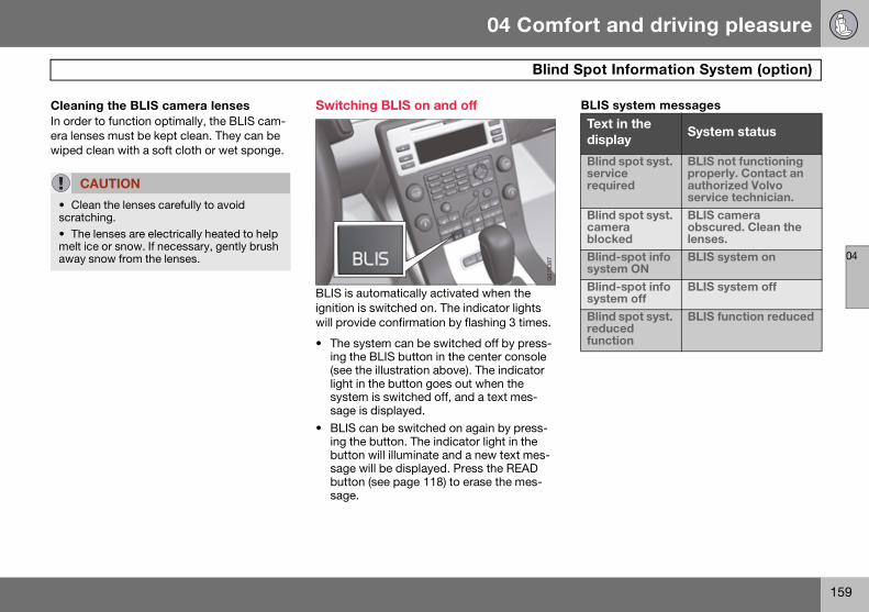
04 Comfort and driving pleasure
159
Blind Spot Information System (option)
04
Cleaning the BLIS camera lensesIn order to function optimally, the BLIS cam-era lenses must be kept clean. They can be wiped clean with a soft cloth or wet sponge.
Switching BLIS on and off
BLIS is automatically activated when the ignition is switched on. The indicator lights will provide confirmation by flashing 3 times.
• The system can be switched off by press-ing the BLIS button in the center console (see the illustration above). The indicator light in the button goes out when the system is switched off, and a text mes-sage is displayed.
• BLIS can be switched on again by press-ing the button. The indicator light in the button will illuminate and a new text mes-sage will be displayed. Press the READ button (see page 118) to erase the mes-sage.
BLIS system messages
CAUTION
• Clean the lenses carefully to avoid scratching.• The lenses are electrically heated to help melt ice or snow. If necessary, gently brush away snow from the lenses.
G01
8387
Text in the display
System status
Blind spot syst. service required
BLIS not functioning properly. Contact an authorized Volvo service technician.
Blind spot syst. camera blocked
BLIS camera obscured. Clean the lenses.
Blind-spot info system ON
BLIS system on
Blind-spot info system off
BLIS system off
Blind spot syst. reduced function
BLIS function reduced
S80 USA reprint version w640.book Page 159 Friday, June 1, 2007 10:44 AM
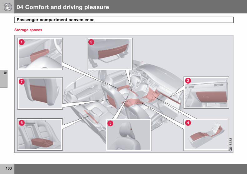
04 Comfort and driving pleasure
160
Passenger compartment convenience
04
Storage spaces
7
1 2
3
46 5
G01
8388
S80 USA reprint version w640.book Page 160 Friday, June 1, 2007 10:44 AM

04 Comfort and driving pleasure
161
Passenger compartment convenience
04
Compartment in door panel
Storage pocket on the front edge of the front seat cushions
Glove compartment
Storage compartment, 12 V socket and AUX input
Jacket holder
Cup holder in armrest, rear seat
Storage pocket
Tunnel console
Storage compartment (for CDs, etc.) under armrest.
Includes cup holder for driver and pas-senger, 12 V socket and small storage compartment.
Cigarette lighter and ashtray (option)Your Volvo retailer has lighters and ashtrays available as accessories.
Glove compartment
The owner’s manual and maps can be kept here. There are also holders for pens and fuel cards. The glove compartment can be locked manually with the key blade, see page 62.
1 2
8505
331s
A B
8302
560s
S80 USA reprint version w640.book Page 161 Friday, June 1, 2007 10:44 AM
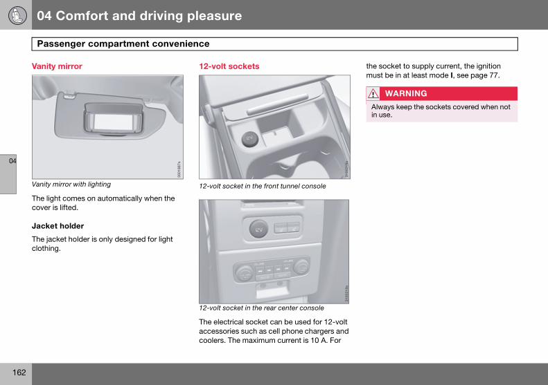
04 Comfort and driving pleasure
162
Passenger compartment convenience
04
Vanity mirror
Vanity mirror with lighting
The light comes on automatically when the cover is lifted.
Jacket holder
The jacket holder is only designed for light clothing.
12-volt sockets
12-volt socket in the front tunnel console
.
12-volt socket in the rear center console
The electrical socket can be used for 12-volt accessories such as cell phone chargers and coolers. The maximum current is 10 A. For
the socket to supply current, the ignition must be in at least mode I, see page 77.
3501
887s
3100
219s
31
0021
8s
WARNING
Always keep the sockets covered when not in use.
S80 USA reprint version w640.book Page 162 Friday, June 1, 2007 10:44 AM

04 Comfort and driving pleasure
163
Passenger compartment convenience
04
Electrical socket in the trunk (option)
Fold down the cover to access the electrical socket. It works whether or not the ignition is switched on. Use the electrical socket with the engine running to avoid draining the bat-tery.
3603
814s
S80 USA reprint version w640.book Page 163 Friday, June 1, 2007 10:44 AM

164
Driving recommendations ...................................................................... 166
Refueling ................................................................................................ 170
Loading .................................................................................................. 175
Towing a trailer ....................................................................................... 178
Emergency towing ................................................................................. 181
S80 USA reprint version w640.book Page 164 Friday, June 1, 2007 10:44 AM

05During your trip
S80 USA reprint version w640.book Page 165 Friday, June 1, 2007 10:44 AM

05 During your trip
166
Driving recommendations
05
General information
Economical driving conserves natural resourcesBetter driving economy may be obtained by thinking ahead, avoiding rapid starts and stops and adjusting the speed of your vehicle to immediate traffic conditions.
Observe the following rules:
• Bring the engine to normal operating tem-perature as soon as possible by driving with a light foot on the accelerator pedal for the first few minutes of operation. A cold engine uses more fuel and is subject to increased wear.
• Whenever possible, avoid using the vehi-cle for driving short distances. This does not allow the engine to reach normal oper-ating temperature.
• Drive carefully and avoid rapid accelera-tion and hard braking.
• Use the transmission's Drive (D) position as often as possible and avoid using kick-down.
• Do not exceed posted speed limits.
• Avoid carrying unnecessary items (extra load) in the vehicle.
• Maintain correct tire pressure. Check tire pressure regularly (when tires are cold).
• Remove snow tires when threat of snow or ice has ended.
• Note that roof racks, ski racks, etc, in-crease air resistance and also fuel con-sumption.
• At highway driving speeds, fuel consump-tion will be lower with the air conditioning on and the windows closed than with the air conditioning off and the windows open.
• Using the onboard trip computer's fuel consumption modes can help you learn how to drive more economically.
Other factors that decrease gas mileage are:
• Dirty air cleaner
• Dirty engine oil and clogged oil filter
• Dragging brakes
• Incorrect front end alignment
Some of the above mentioned items and oth-ers are checked at the standard maintenance intervals.
Weight distribution affects handling At the specified curb weight your vehicle has a tendency to understeer, which means that the steering wheel has to be turned more than might seem appropriate for the curva-ture of a bend. This ensures good stability and reduces the risk of rear wheel skid. Remember that these properties can alter with the vehicle load. The heavier the load in the cargo area, the less the tendency to understeer.
Handling, roadholding Vehicle load, tire design and inflation pres-sure all affect vehicle handling. Therefore, check that the tires are inflated to the recom-mended pressure according to the vehicle load. See the "Tire pressure" section. Loads should be distributed so that capacity weight
WARNING
Driving with the trunk open: Driving with the trunk open could lead to poisonous ex-haust gases entering the passenger com-partment. If the trunk must be kept open for any reason, proceed as follows:
• Close the windows • Set the ventilation system control to air flow to floor, windshield and side windows and the blower control to its highest setting.
S80 USA reprint version w640.book Page 166 Friday, June 1, 2007 10:44 AM
05 During your trip
167
Driving recommendations
05
or maximum permissible axle loads are not exceeded.
Driving through water The vehicle can be driven through water up to a depth of approximately 9 in. (25 cm), at a maximum speed of 6 mph (10 km/h).
Take particular care when driving through flowing water.
Clean the electrical connections for trailer wiring after driving in mud or water
When driving through water, maintain low speed and do not stop in the water.
Engine and cooling system Under special conditions, for example when driving in hilly terrain, extreme heat or with heavy loads, there is a risk that the engine and cooling system will overheat. Proceed as follows to avoid overheating the engine.
• Maintain a low speed when driving with a trailer up long, steep hills.
• Do not turn the engine off immediately you stop after a hard drive.
• Remove any auxiliary lights from in front of the grille when driving in hot weather conditions.
• Do not exceed engine speeds of 4500 rpm if driving with a trailer in hilly terrain. The oil temperature could become too high.
Conserving electrical currentKeep the following in mind to help minimize battery drain:
• When the engine is not running, avoid using ignition mode II. Many electrical systems (the audio system, the optional navigation system, power windows, etc) will function in ignition modes 0 and I. These modes reduce drain on the battery.
• Please keep in mind that using systems, accessories, etc., that consume a great deal of current when the engine is not running could result in the battery being completely drained.
• The optional 12 volt socket in the trunk provides electrical current even with the ignition switched off, which drains the battery.
Before a long distance trip It is always worthwhile to have your vehicle checked by a trained and qualified Volvo ser-vice technician before driving long distances. Your retailer will also be able to supply you with bulbs, fuses, spark plugs and wiper blades for your use in the event that prob-lems occur.
WARNING
After driving through water, press lightly on the brake pedal to ensure that the brakes are functioning normally. Water or mud can make the brake linings slippery, resulting in delayed braking effect.
CAUTION
• Engine damage will occur if water is drawn into the air cleaner.• If the vehicle is driven through water deeper than 9 in (25 cm), water may enter the differential and the transmission. This reduces the oil's lubricating capacity and may shorten the service life of these com-ponents.
• Do not allow the vehicle to stand in water up to the door sills longer than absolutely necessary. This could result in electrical malfunctions.
• If the engine has been stopped while the vehicle is in water, do not attempt to restart the engine. Have the vehicle towed out of the water.
S80 USA reprint version w640.book Page 167 Friday, June 1, 2007 10:44 AM

05 During your trip
168
Driving recommendations
05
As a minimum, the following items should be checked before any long trip:
• Check that engine runs smoothly and that fuel consumption is normal.
• Check for fuel, oil, and fluid leakage
• Have the transmission oil level checked.
• Check condition of drive belts.
• Check state of the battery's charge.
• Examine tires carefully (the spare tire as well), and replace those that are worn. Check tire pressures.
• The brakes, front wheel alignment, and steering gear should be checked by a trained and qualified Volvo service techni-cian only.
• Check all lights, including high beams.
• Reflective warning triangles are legally re-quired in some states/provinces.
• Have a word with a trained and qualified Volvo service technician if you intend to drive in countries where it may be difficult to obtain the correct fuel.
• Consider your destination. If you will be driving through an area where snow or ice are likely to occur, consider snow tires.
Cold weather precautionsIf you wish to check your vehicle before the approach of cold weather, the following advice is worth noting:
• Make sure that the engine coolant con-tains 50 percent antifreeze. Any other mix-ture will reduce freeze protection. This gives protection against freezing down to -31°F (-35°C). The use of "recycled" anti-freeze is not approved by Volvo. Different types of antifreeze must not be mixed.
• Volvo recommends using only genuine Volvo antifreeze in your vehicle's radiator.
• Try to keep the fuel tank well filled - this helps prevent the formation of condensa-tion in the tank. In addition, in extremely cold weather conditions it is worthwhile to add fuel line de-icer before refueling.
• The viscosity of the engine oil is important. Oil with low viscosity (thinner oil) improves cold-weather starting as well as decreas-ing fuel consumption while the engine is warming up. For winter use, 5W-30 oil, particularly the synthetic type, is recom-mended. Be sure to use good quality oil but do not use cold-weather oil for hard
driving or in warm weather. See page 248 for more information on engine oil.
• The load placed on the battery is greater during the winter since the windshield wipers, lighting, etc. are used more often. Moreover, the capacity of the battery de-creases as the temperature drops. In very cold weather, a poorly charged battery can freeze and be damaged. It is therefore advisable to check the state of charge more frequently and spray an anti-rust oil on the battery posts.
• Volvo recommends the use of snow tires on all four wheels for winter driving. See the information on page 227.
• To prevent the washer fluid reservoir from freezing, add washer solvents containing antifreeze. This is important since dirt is often splashed on the windshield during winter driving, requiring the frequent use of the washers and wipers. Volvo Washer Solvent should be diluted as follows: Down to 14° F (-10° C): 1 part washer solvent and 4 parts water Down to 5° F (-15° C): 1 part washer solvent and 3 parts
NOTE
Synthetic oil is not used when the oil is changed at the normal maintenance inter-vals except at owner request and at addi-tional charge.
S80 USA reprint version w640.book Page 168 Friday, June 1, 2007 10:44 AM
05 During your trip
169
Driving recommendations
05
water Down to 0° F (-18° C): 1 part washer solvent and 2 parts water Down to -18° F (-28° C): 1 part washer solvent and 1 part water.
• Use Volvo Teflon Lock Spray in the locks.
• Avoid using de-icing sprays as they can cause damage to the locks.
S80 USA reprint version w640.book Page 169 Friday, June 1, 2007 10:44 AM

05 During your trip
170
Refueling
05
Fuel requirements
Deposit control gasoline (detergent additives)Volvo recommends the use of detergent gas-oline to control engine deposits. Detergent gasoline is effective in keeping injectors and intake valves clean. Consistent use of deposit control gasolines will help ensure good drivability and fuel economy. If you are not sure whether the gasoline contains deposit control additives, check with the ser-vice station operator.
Unleaded fuelEach Volvo has a three-way catalytic con-verter and must use only unleaded gasoline. U.S. and Canadian regulations require that pumps delivering unleaded gasoline be labelled “UNLEADED”. Only these pumps have nozzles which fit your vehicle’s filler inlet. It is unlawful to dispense leaded fuel into a vehicle labelled “unleaded gasoline only”. Leaded gasoline damages the three-way catalytic converter and the heated oxy-gen sensor system. Repeated use of leaded
gasoline will lessen the effectiveness of the emission control system and could result in loss of emission warranty coverage. State and local vehicle inspection programs will make detection of misfueling easier, possibly resulting in emission test failure for misfueled vehicles.
Gasoline containing alcohol and ethers, “Oxygenated fuels”Some fuel suppliers sell gasoline containing “oxygenates” which are usually alcohols or ethers. In some areas, state or local laws require that the service pump be marked indicating use of alcohols or ethers. How-ever, there are areas in which the pumps are unmarked. If you are not sure whether there is alcohol or ethers in the gasoline you buy, check with the service station operator. To
meet seasonal air quality standards, some areas require the use of “oxygenated” fuel.
Volvo allows the use of the following “oxy-genated” fuels; however, the octane ratings listed on page 171 must still be met.
Alcohol — EthanolFuels containing up to 10% ethanol by vol-ume may be used. Ethanol may also be referred to as Ethyl alcohol, or “Gasohol”.
Ethers — MTBE: Fuels containing up to 15% MTBE may be used.
MethanolDo not use gasolines containing methanol (methyl alcohol, wood alcohol). This practice can result in vehicle performance deteriora-tion and can damage critical parts in the fuel system. Such damage may not be covered under the New Vehicle Limited Warranty.
NOTE
Volvo does not recommend the use of ex-ternal fuel injector cleaning systems.
NOTE
Some U.S. and Canadian gasolines contain an octane enhancing additive called meth-yl-cyclopentadienyl manganese tricarbonyl (MMT). If such fuels are used, your Emission Control System performance may be affect-ed, and the Check Engine Light (malfunc-tion indicator light) located on your instrument panel may light. If this occurs, please return your vehicle to an authorized Volvo retailer for service.
S80 USA reprint version w640.book Page 170 Friday, June 1, 2007 10:44 AM

05 During your trip
171
Refueling
05
RECOMMENDED
Typical pump octane label
Octane ratingVolvo engines are designed to achieve rated horsepower, torque, and fuel economy per-formance using premium 91 octane fuel.
Volvo recommends premium for best perfor-mance, but using 87 octane or above will not affect engine reliability.
In demanding driving conditions, such as operating the vehicle in hot weather, towing a trailer, or driving for extended periods at higher altitudes than normal, it may be advis-able to switch to higher octane fuel (91 or higher) or to change gasoline brands to fully utilize your engine's capacity, and for the smoothest possible operation.
MINIMUM
Typical pump octane label
Fuel FormulationsDo not use gasoline that contains lead as a knock inhibitor, and do not use lead addi-tives. Besides damaging the exhaust emis-sion control systems on your vehicle, lead has been strongly linked to certain forms of cancer.
Many fuels contain benzene as a solvent. Unburned benzene has been strongly linked to certain forms of cancer. If you live in an area where you must fill your own gas tank, take precautions. These may include:
• standing upwind away from the filler noz-zle while refueling
• refueling only at gas stations with vapor recovery systems that fully seal the mouth of the filler neck during refueling
• wearing neoprene gloves while handling a fuel filler nozzle.
Use of AdditivesWith the exception of gas line antifreeze dur-ing winter months, do not add solvents, thickeners, or other store-bought additives to your vehicle’s fuel, cooling, or lubricating systems. Overuse may damage your engine, and some of these additives contain organi-cally volatile chemicals. Do not needlessly expose yourself to these chemicals.
MINIMUM OCTANE RATING(R + M)/2 METHOD
91MINIMUM OCTANE RATING
(R + M)/2 METHOD
87NOTE
When switching to higher octane fuel or changing gasoline brands, it may be neces-sary to fill the tank more than once before a difference in engine operation is noticeable.
WARNING
Never carry a cell phone that is switched on while refueling your vehicle. If the phone rings, this may cause a spark that could ig-nite gasoline fumes, resulting in fire and in-jury.
S80 USA reprint version w640.book Page 171 Friday, June 1, 2007 10:44 AM

05 During your trip
172
Refueling
05
Opening/closing the fuel filler door
The fuel filler door is located on the right rear fender (indicated by an arrow beside the fuel tank symbol on the information display )
With the ignition switched off, press the but-ton on the lighting panel to unlock the fuel filler door. Please note that the fuel filler door will remain unlocked until the vehicle begins
to move forward. An audible click will be heard when the fuel filler door relocks.
• If you intend to leave your vehicle while it is being refueled, this feature enables you to lock the doors/trunk while leaving the fuel filler door unlocked.
• You can also keep the vehicle locked if you remain inside it during refueling. The central locking button does not lock the fuel filler door.
• Be sure the fuel filler door is not obstruct-ed and is completely closed after refuel-ing.
• Open the fuel filler cap slowly during hot weather.
Close the fuel filler door by pressing it a click indicates that it is closed.
WARNING
• Carbon monoxide is a poisonous, color-less, and odorless gas. It is present in all ex-haust gases. If you ever smell exhaust fumes inside the vehicle, make sure the passenger compartment is ventilated, and immediately return the vehicle to your retail-er for correction.
3603
903s
CAUTION
• Avoid spilling gasoline during refueling. In addition to causing damage to the environ-ment, gasolines containing alcohol can cause damage to painted surfaces, which may not be covered under the New Vehicle Limited Warranty.
S80 USA reprint version w640.book Page 172 Friday, June 1, 2007 10:44 AM

05 During your trip
173
Refueling
05
Opening/closing the fuel cap
Fuel vapor expands in hot weather. Open the filler cap slowly.
After refueling, close the fuel filler cap by turning it clockwise until it clicks into place.
Emission controls
Three-way catalytic converter• Keep your engine properly tuned. Certain
engine malfunctions, particularly involving the electrical, fuel or distributor ignition systems, may cause unusually high three-way catalytic converter temperatures. Do not continue to operate your vehicle if you detect engine misfire, noticeable loss of power or other unusual operating condi-tions, such as engine overheating or back-firing. A properly tuned engine will help avoid malfunctions that could damage the three-way catalytic converter.
• Do not park your vehicle over combustible materials, such as grass or leaves, which can come into contact with the hot ex-haust system and cause such materials to ignite under certain wind and weather conditions.
• Excessive starter cranking (in excess of one minute), or an intermittently firing or flooded engine can cause three-way cata-lytic converter or exhaust system over-heating.
• Remember that tampering or unauthorized modifications to the engine, the Engine Control Module, or the vehicle may be illegal and can cause three-way catalytic converter or exhaust system overheating. This includes: altering fuel injection set-
CAUTION
• Do not refuel with the engine running1. Turn the ignition off or to position I. If the ig-nition is on, an incorrect reading could occur in the fuel gauge.• Avoid overfilling the fuel tank. Do not press the handle on the filler nozzle more than one extra time. Too much fuel in the tank in hot weather conditions can cause the fuel to overflow. Overfilling could also cause damage to the emission control sys-tems.
1If the fuel filler cap is not closed tightly or if the engine is running when the vehicle is refueled, the Check Engine Light (malfunction indicator lamp) may indicate a fault. However, your vehicle’s performance will not be affected. Use only Volvo original or approved fuel filler caps.
S80 USA reprint version w640.book Page 173 Friday, June 1, 2007 10:44 AM

05 During your trip
174
Refueling
05
tings or components, altering emission system components or location or remov-ing components, and/or repeated use of leaded fuel.
Heated oxygen sensors The heated oxygen sensors monitor the oxy-gen content of the exhaust gases. Readings are fed into a control module that continu-ously monitors engine functions and con-trols fuel injection. The ratio of fuel to air into the engine is continuously adjusted for effi-cient combustion to help reduce harmful emissions.
NOTE
Unleaded fuel is required for vehicles with three-way catalytic converters.
S80 USA reprint version w640.book Page 174 Friday, June 1, 2007 10:44 AM

05 During your trip
175
Loading
05
Introduction
The load carrying capacity of your vehicle is determined by factors such as the number of passengers, the amount of cargo, the weight of any accessories that may be installed, etc.
The trunk lid can be unlocked via the button located on the lighting panel, see page 62.
• Load the cargo in the trunk against the backrest.
• Load wide cargo in the trunk on both sides of the rear seat split.
• Unstable loads can be secured to the load anchoring eyelets with straps or web lash-ings to help keep them from shifting.
Loading the cargo areaStop the engine and apply the parking brake when loading or unloading long objects. The gear selector can be knocked out of position by long loads, which could set the vehicle in motion. To increase loading space, the rear seat backrests can be folded down, see page 82.
Load anchoring eyelets
The load anchoring eyelets are used to fasten straps to help anchor items in the trunk.
NOTE
To increase loading space, the rear seat backrests can be folded down, see page 82.
WARNING
• The vehicle’s driving characteristics may change depending on the weight and distri-bution of the load.• A 44-pound (20 kg) object produces a force of 2,200 pounds (1,000 kg) in a head-on collision at 30 mph (50 km/h).
WARNING
• Stop the engine, put the gear selector in P, and apply the parking brake when load-ing or unloading long objects.• The rear seat should not be loaded to a level higher than 2 in. (5 cm) below the upper edge of the rear side windows. Ob-jects placed higher than this level could im-pede the function of the Volvo Inflatable Curtain.
WARNING
• Cover sharp edges on long loads to help prevent injury to occupants. Secure the load to help prevent shifting during sudden stops.• Always secure large and heavy objects with a seat belt or cargo retaining straps.
8505
313s
S80 USA reprint version w640.book Page 175 Friday, June 1, 2007 10:44 AM

05 During your trip
176
Loading
05
Grocery bag holder1
The grocery bag holder holds shopping bags in place.
1. Open the hatch in the trunk.
2. Secure the shopping bags.
Ski hatch There is a hatch in the right section of the rear seat backrest that can be opened for transportation.
Fold the right backrest forward.
Release the hatch in the rear seat back-rest by sliding the catch up while folding the hatch forward.
Return the backrest to the upright posi-tion with the hatch open.
Use the seat belt to prevent the load from moving.
1 Available on certain markets only.
8904
104s
8505
327s
1
8505
328s
2
8505
329s
3
WARNING
• Always secure the load to help prevent it from moving in the event of sudden.
• Switch off the engine, apply the parking brake and put the gear selector in P when loading and unloading the vehicle.
NOTE
If the vehicle is equipped with the optional integrated booster cushion, fold it out first.
S80 USA reprint version w640.book Page 176 Friday, June 1, 2007 10:44 AM

05 During your trip
177
Loading
05
The cover on the rear seat armrest/child seat has no hinge. The cover must be removed before the ski hatch is used.
Removal:
Open the cover 30 degrees and lift straight up.
Installation:
Insert the cover in the grooves behind the upholstery and close the cover.
Roof loads
Using load carriersLoad carriers are available as Volvo accesso-ries. Observe the following points when in use:
• To avoid damaging your vehicle and to achieve maximum safety when driving, we recommend using the load carriers that Volvo has developed especially for your vehicle.
• Volvo-approved removable roof racks are designed to carry the maximum allowable roof load for this vehicle: 220 lbs (100 kg). For non-Volvo roof racks, check the man-ufacturer’s weight limits for the rack.
• Never exceed the rack manufacturer’s weigh limits and never exceed the maxi-mum rated roof load of 220 lbs (100 kg).
• Avoid single-point loads. Distribute loads evenly.
• Place heavier cargo at the bottom of the load.
• Secure the cargo correctly with appropri-ate tie-down equipment.
• Check periodically that the load carriers and load are properly secured.
• Remember that the vehicle's center of gravity and handling change when you carry a load on the roof.
• The vehicle's wind resistance and fuel consumption will increase with the size of the load.
• Drive smoothly. Avoid rapid starts, fast cornering and hard braking.
S80 USA reprint version w640.book Page 177 Friday, June 1, 2007 10:44 AM

05 During your trip
178
Towing a trailer
05
Introduction
Volvo recommends the use of Volvo trailer hitches that are specially designed for the vehicle.
• Observe the legal requirements of the state/province in which the vehicles are
• All Volvo models are equipped with ener-gy-absorbing shock-mounted bumpers. Trailer hitch installation should not inter-fere with the proper operation of this bumper system.
Trailer towing does not normally present any particular problems, but take into consider-ation:
• Increase tire pressure to recommended full. See the tire inflation tables on pages 217 and 218.
• When your vehicle is new, avoid towing heavy trailers during the first 620 miles (1,000 km).
• Maximum speed when towing a trailer: 50 mph (80 km/h).
• Engine and transmission are subject to increased loads. Therefore, engine coolant
temperature should be closely watched when driving in hot climates or hilly terrain. Use a lower gear and turn off the air conditioner if the temperature gauge nee-dle enters the red range.
• If the automatic transmission begins to overheat, a message will be displayed in the text window.
• Avoid overload and other abusive opera-tion.
• Hauling a trailer affects handling, durabili-ty, and economy.
• It is necessary to balance trailer brakes with the towing vehicle brakes to provide a safe stop (check and observe state/local regulations).
• Do not connect the trailer’s brake system directly to the vehicle’s brake system.
• More frequent vehicle maintenance is re-quired.
• Remove the ball and drawbar assembly when the hitch is not being used.
• Volvo recommends the use of synthetic engine oil when towing a trailer over long distances or in mountainous areas.
NOTE
See page 246 for the maximum trailer and tongue weights recommended by Volvo.
WARNING
• Bumper-attached trailer hitches must not be used on Volvos, nor should safety chains be attached to the bumper.• Trailer hitches attaching to the vehicle rear axle must not be used.• Never connect a trailer’s hydraulic brake system directly to the vehicle brake system, nor a trailer’s lighting system directly to the vehicle lighting system. Consult your near-est authorized Volvo retailer for correct in-stallation.• When towing a trailer, the trailer’s safety wire must be correctly fastened to the hole or hook provided in the trailer hitch on the vehicle. The safety wire should never be fastened to or wound around the drawbar ball.
S80 USA reprint version w640.book Page 178 Friday, June 1, 2007 10:44 AM

05 During your trip
179
Towing a trailer
05
Trailer cableAn adapter is required if the vehicle’s trailer hitch has a 13-pin connector and the trailer has 7 pins. Use an adapter cable approved by Volvo. Make sure the cable does not drag on the ground.
NOTE
• When parking the vehicle with a trailer on a hill, apply the parking brake before putting the gear selector in P. Always follow the trailer manufacturer's recommendations for wheel chocking. • When starting on a hill, put the gear se-lector in D before releasing the parking brake. See also page 113 for more detailed information about starting off on a hill while towing a trailer.
• If you use the manual (Geartronic) shift positions while towing a trailer, make sure the gear you select does not put too much strain on the engine (using too high a gear).
• The drawbar assembly/trailer hitch may be rated for trailers heavier than the vehicle is designed to tow. Please adhere to Vol-vo’s recommended trailer weights.
• Avoid driving with a trailer on inclines of more than 15 %.
S80 USA reprint version w640.book Page 179 Friday, June 1, 2007 10:44 AM

05 During your trip
180
Towing a trailer
05
Detachable trailer hitch (accessory)
A - ball holder (1 7/8” ball), B - locking bolt, C - cotter pin, D - hitch assembly, E - safety wire attachment
Installing the ball holder1. If necessary, remove the cotter pin from
the locking bolt and slide the locking bolt out of the hitch assembly.
2. Slide the ball holder into the hitch as-sembly.
3. Align the hole in the ball holder with the one in the hitch assembly.
4. Slide the locking bolt through the hitch assembly/ball holder.
5. Insert the cotter pin in the hole at the end of the locking bolt.
Removing the ball holder1. Remove the cotter pin from the locking
bolt and slide the locking bolt out of the ball holder/hitch assembly.
2. Pull the ball holder out of the hitch assembly.
A
C
BD
E
G01
0496
NOTE
A cover for the hitch assembly is also in-cluded in the kit.
S80 USA reprint version w640.book Page 180 Friday, June 1, 2007 10:44 AM

05 During your trip
181
Emergency towing
05
Location of the towing eyelet
Attaching the towing eyelet
The towing eyelet is located under the floor of the trunk, with the spare tire. This eyelet must be screwed into the positions provided on the right sides of either the front or rear bumper (see illustration).
Attaching the towing eyelet1. Use a coin to pry open the lower edge of
the cover.
2. Screw the towing eyelet in place, first by hand and then using the tire iron until it is securely in place.
After the vehicle has been towed, the eyelet should be removed and returned to its stor-age location.
Press the cover for the attachment point back into position.
Precautions when the vehicle is in tow• The steering wheel must be unlocked. The
remote key must be in the ignition slot1.
• Attach jumper cables (see page 106) to provide current for releasing the optional electric parking brake and to move the gear selector from the P position.
• The gear selector must be in position N.
• Maximum speed: 50 mph (80 km/h). Do not exceed the maximum allowable tow-ing speed.
• Maximum distance with front wheels on ground: 50 miles (80 km).
• While the vehicle is being towed, try to keep the tow rope taut at all times.
• The vehicle should only be towed in the forward direction.
Towing vehicles with front wheel drive/All Wheel Drive Volvo recommends the use of flat bed equip-ment.
• If wheel lift equipment must be used, please use extreme caution to help avoid damage to the vehicle. In this case, the vehicle should be towed with the rear wheels on the ground if at all possible.
8601
528s
1
8601
529s
2
1 On vehicles with the optional keyless drive, the remote key must be in the passenger compartment.
CAUTION
• Please check with state and local authori-ties before attempting this type of towing, as vehicles being towed are subject to reg-ulations regarding maximum towing speed, length and type of towing device, lighting, etc.• If the vehicle’s battery is dead, do not at-tempt to start the vehicle by pushing or pull-ing it as this will damage the three-way catalytic converter(s). The engine must be jump started using an auxiliary battery (see page 106).
• If the vehicle is being towed on a flat bed truck, the towing eyelets must not be used to secure the vehicle on the flat bed. Con-sult the tow truck operator.
S80 USA reprint version w640.book Page 181 Friday, June 1, 2007 10:44 AM

05 During your trip
182
Emergency towing
05
• If it is absolutely necessary to tow the vehicle with the front wheels on the ground, please refer to the towing infor-mation on the page 181.
CAUTION
• Sling-type equipment applied at the front will damage radiator and air conditioning lines.
• It is equally important not to use sling-type equipment at the rear or apply lifting equipment inside the rear wheels; serious damage to the rear axle may result.
• If the vehicle is being towed on a flat bed truck, the towing eyelets must not be used to secure the vehicle on the flat bed. Con-sult the tow truck operator.
S80 USA reprint version w640.book Page 182 Friday, June 1, 2007 10:44 AM

05 During your trip
183
05
S80 USA reprint version w640.book Page 183 Friday, June 1, 2007 10:44 AM

184
Volvo maintenance................................................................................. 186
Maintaining your car............................................................................... 187
Hood and engine compartment ............................................................. 189
Engine oil................................................................................................ 190
Fluids...................................................................................................... 192
Replacing bulbs ..................................................................................... 194
Wiper blades and washer fluid............................................................... 201
Battery.................................................................................................... 203
Fuses...................................................................................................... 206
Wheels and tires..................................................................................... 212
Vehicle care ............................................................................................ 238
Label information ................................................................................... 243
Specifications......................................................................................... 245
Volvo programs ...................................................................................... 252
S80 USA reprint version w640.book Page 184 Friday, June 1, 2007 10:44 AM

06MAINTENANCE AND SPECIFICATIONS
S80 USA reprint version w640.book Page 185 Friday, June 1, 2007 10:44 AM

06 Maintenance and specifications
186
Volvo maintenance
06
Introduction
Volvo advises you to follow the maintenance program outlined in the Warranty and Service Records Information booklet. This mainte-nance program contains inspections and ser-vices necessary for the proper function of your vehicle. The maintenance services con-tain several checks that require special tools and training, and therefore must be per-formed by a qualified technician. To keep your Volvo in top condition, specify time-tested and proven Genuine Volvo Parts and Accessories.
The Federal Clean Air Act - U.SThe Federal Clean Air Act requires vehicle manufacturers to furnish written instructions to the ultimate purchaser to assure the proper servicing and function of the compo-nents that control emissions. These services, which are listed in the "Warranty and Service Records Information” booklet, are not cov-ered by the warranty. You will be required to pay for labor and material used.
MaintenanceYour Volvo passed several major inspec-tions before it was delivered to you, in accor-dance with Volvo specifications. The mainte-nance procedures outlined in the Warranty
and Service Records Information booklet, many of which will positively affect your vehi-cle's emissions, should be performed as indi-cated. It is recommended that receipts for vehicle emission maintenance be retained in case questions arise concerning mainte-nance. Inspection and maintenance should also be performed anytime a malfunction is observed or suspected.
Applicable warranties - U.S/CanadaIn accordance with applicable U.S. and Canadian regulations, the following list of warranties is provided.
• New Vehicle Limited Warranty
• Parts and Accessories Limited Warranty
• Corrosion Protection Limited Warranty
• Seat Belt and Supplemental Restraint Systems Limited Warranty
• Emission Design and Defect Warranty
• Emission Performance Warranty
These are the federal warranties; other war-ranties are provided as required by state/pro-vincial law. Refer to your separate Warranty and Service Records Information booklet for detailed information concerning each of the warranties.
Periodic maintenance helps minimize emissionsPeriodic maintenance will help keep your vehicle running well. Your Warranty and Ser-vice Records Information booklet provides a comprehensive periodic maintenance sched-ule up to 150,000 miles (240,000 km) of vehi-cle maintenance. The schedule includes components that affect vehicle emissions. This page describes some of the emission-related components.
Vehicle Event Data (Black Box)Your vehicle's driving and safety systems employ computers that monitor, and share with each other, information about your vehi-cle's operation. One or more of these com-puters may store what they monitor, either during normal vehicle operation or in a crash or near-crash event. Stored information may be read and used by:
• Volvo Car Corporation
• service and repair facilities
• law enforcement or government agencies
• others who may assert a legal right to know, or who obtain your consent to know such information.
S80 USA reprint version w640.book Page 186 Friday, June 1, 2007 10:44 AM

06 Maintenance and specifications
187
Maintaining your car
06
Owner maintenance
Periodic maintenance requirements and intervals are described in your vehicle’s War-ranty and Service Records Information book-let.
The following points can be carried out between the normally scheduled mainte-nance services.
Each time the car is refueled:• Check the engine oil level.
• Clean the windshield, windshield wipers, headlights, and tail lights.
Monthly:• Check cold tire pressure in all tires. In-
spect the tires for wear.
• Check that engine coolant and other fluid levels are between the indicated “min” and “max” markings.
• Clean interior glass surfaces with a glass cleaner and soft paper towels.
• Wipe driver information displays with a soft cloth.
• Visually inspect battery terminals for cor-rosion. Corrosion may indicate a loose terminal connector, or a battery near the end of its useful service life. Consult your Volvo retailer for additional information.
As needed:Wash the car, including the undercarriage, to reduce wear that can be caused by a buildup of dirt, and corrosion that can be caused by salt residues.
Clean leaves and twigs from air intake vents at the base of the windshield, and from other places where they may collect.
NOTE
Complete service information for qualified technicians is available online for purchase or subscription at www.volvotechinfo.com.
S80 USA reprint version w640.book Page 187 Friday, June 1, 2007 10:44 AM

06 Maintenance and specifications
188
Maintaining your car
06
Emission inspection readiness
What is an Onboard Diagnostic System (OBD II)? OBD II is part of your vehicle's computerized engine management system. It stores diag-nostic information about your vehicle's emis-sion controls. It can light the Check Engine light (MIL) if it detects an emission control "fault." A "fault" is a component or system that is not performing within an expected range. A fault may be permanent or tempo-rary. OBD II will store a message about any fault.
How do states use OBD II for emission inspections?Many states connect a computer directly to a vehicle's OBD II system. The inspector can then read "faults." In some states, this type of inspection has replaced the tailpipe emis-sion test.
How can my vehicle fail OBD II emission inspection?Your vehicle can fail OBD II emission inspec-tion for any of the following reasons.
• If your Check Engine (MIL) light is lit, your vehicle may fail inspection.
• If your vehicle's Check Engine light was lit, but went out without any action on your part, OBD II will still have a recorded fault. Your vehicle may pass or fail, depending on the inspection practices in your area.
• If you had recent service that required disconnecting the battery, OBD II diag-nostic information may be incomplete and "not ready" for inspection. A vehicle that is not ready may fail inspection.
How can I prepare for my next OBD II emission inspection?• If your Check Engine (MIL) light is lit - or
was lit but went out without service, have your vehicle diagnosed and, if necessary, serviced by a qualified Volvo technician.
• If you recently had service for a lit Check Engine light, or if you had service that required disconnecting the battery, a peri-od of driving is necessary to bring the OBD II system to "ready" for inspection. A half-hour trip of mixed stop-and-go/high-way driving is typically needed to allow OBD II to reach readiness. Your Volvo retailer can provide you with more infor-mation on planning a trip.
• Maintain your vehicle in accordance with your vehicle's maintenance schedule.
S80 USA reprint version w640.book Page 188 Friday, June 1, 2007 10:44 AM

06 Maintenance and specifications
189
Hood and engine compartment
06
Opening and closing the hood
Pull the lever located under the left side of the dash to release the hood lock.
Lift the hood slightly. Press the release control (located under the right front edge of the hood) to the left, and lift the hood
Engine compartment, overview
The appearance of the engine compartment may vary depending on engine model.
Coolant expansion tank
Power steering fluid reservoir
Engine oil dipstick
Radiator
Air cleaner
Filler cap for engine oil
Brake fluid reservoir
Battery
Relay and fuse box
Washer fluid reservoir WARNING
Check that the hood locks properly when closed.
2002
68s
1
2G
0109
51
2000
480s
1
3
5
4
2
76
9
10
8
WARNING
The cooling fan may start or continue to op-erate (for up to 6 minutes) after the engine has been switched off.
WARNING
The distributor ignition system operates at very high voltages. Special safety precau-tions must be followed to prevent injury. Al-ways turn the ignition off when:• Replacing distributor ignition compo-nents e.g. plugs, coil, etc.• Do not touch any part of the distributor ignition system while the engine is running. This may result in unintended movements and body injury.
S80 USA reprint version w640.book Page 189 Friday, June 1, 2007 10:44 AM

06 Maintenance and specifications
190
Engine oil
06
Checking the engine oilThe oil level should be checked every time the vehicle is refueled. This is especially important during the period up to the first scheduled maintenance service.
• See page 248 for oil specifications.
• Refer to the Warranty and Service Records Information booklet for informa-tion on the oil change intervals.
Volvo recommends oil products.
Checking and adding oil
Location of the filler cap and dipstick
The oil level must be between the MIN and MAX marks on the dipstick
Checking the oil1. Pull out the dipstick and wipe it with a lint-
free rag.
2. Reinsert the dipstick, pull it out, and check the oil level. The level must be between the MIN and MAX marks.
3. Add oil if necessary. If the level is close to the MIN mark, add approximately 0.5 US quarts (0.5 liters) of oil.
4. Recheck the level and add more oil if necessary until the level is near the MAX mark.
CAUTION
• Not checking the oil level regularly can result in serious engine damage if the oil level becomes too low.• Oil that is lower than the specified quality can damage the engine.• Volvo does not recommend the use of oil additives.
• Always add oil of the same type and vis-cosity as already used.
• Never fill oil above the MAX mark. This could cause an increase in oil consumption.
NOTE
Before checking the oil:
• The car should be parked on a level sur-face when the oil is checked.
• If the engine is warm, wait for at least 10-15 minutes after the engine has been switched off before checking the oil.
2200
328s
2200
330s
MIN MAX
S80 USA reprint version w640.book Page 190 Friday, June 1, 2007 10:44 AM

06 Maintenance and specifications
191
Engine oil
06
WARNING
Do not allow oil to spill onto or come into contact with hot exhaust pipe surfaces.
NOTE
Synthetic oil is not used when the oil is changed at the normal maintenance inter-vals except at owner request and at addi-tional charge. Please consult your Volvo retailer.
S80 USA reprint version w640.book Page 191 Friday, June 1, 2007 10:44 AM

06 Maintenance and specifications
192
Fluids
06
Coolant
Location of the coolant reservoir
Normally, the coolant does not need to be changed. If the system must be drained, con-sult your Volvo retailer.
See page 250 for information on cooling sys-tem capacities.
2600
518s
CAUTION
• Do not top off with water only. This re-duces the rust-protective and antifreeze qualities of the coolant and has a lower boil-ing point. It can also cause damage to the cooling system if it should freeze. Top off with Volvo Genuine Coolant/Antifreeze only (a 50/50 mix of water and antifreeze).• The cooling system must always be kept filled to the correct level, and the level must be between the MIN and MAX marks. If it is not kept filled, there can be high local tem-peratures in the engine which could result in damage. Different types of antifreeze/cool-ant may not be mixed. Check coolant regu-larly.
WARNING
• Never remove the radiator cap while the engine is warm. Wait until the vehicle cools.• If it is necessary to top off the coolant when the engine is warm, unscrew the ex-pansion tank cap slowly so that the over-pressure dissipates.
S80 USA reprint version w640.book Page 192 Friday, June 1, 2007 10:44 AM

06 Maintenance and specifications
193
Fluids
06
Brake fluid
Location of the brake fluid reservoir
Checking the levelThe fluid reservoir is concealed under the round cover at the rear of the engine com-partment. The round cover must be removed first before the reservoir cap can be accessed.
The brake fluid should always be between the MIN and MAX marks on the side of the reservoir. Check, without removing the cap, that there is sufficient fluid in the reservoir.
Fluid type: DOT 4+ boiling point >536°F
(280°C), P/N 9437433
Replace: The fluid should be replaced according to the intervals specified in the
Warranty and Service Records Information booklet.
When driving under extremely hard condi-tions (mountain driving, etc), it may be nec-essary to replace the fluid more often. Con-sult your Volvo retailer.
Always entrust brake fluid changing to a trained and qualified Volvo service techni-cian.
FillingTurn and open the cover.
Unscrew the reservoir cap and fill the fluid. The level must be between the MIN and MAX marks.
Power steering fluid
Check the level frequently. The fluid does not require changing. The fluid level must be between the MIN and MAX marks. For capacities and recommended fluid grade, see page 250.
1
2
5200
696s WARNING
If the fluid level is below the MIN mark in the reservoir or if a brake-related message is shown in the information display: DO NOT DRIVE. Have the car towed to a trained and qualified Volvo service technician and have the brake system inspected.
WARNING
If a problem should occur in the power steering system or if the vehicle has no electrical current and must be towed, it is still possible to steer the vehicle. However, keep in mind that greater effort will be re-quired to turn the steering wheel.
CAUTION
Keep the area around the power steering fluid reservoir clean when checking.
MaxMin
5200
697s
S80 USA reprint version w640.book Page 193 Friday, June 1, 2007 10:44 AM

06 Maintenance and specifications
194
Replacing bulbs
06
Introduction
All bulb specifications are listed on page 200. The following bulbs should only be replaced by a trained and qualified Volvo service tech-nician:
• Dome lighting
• Reading lights
• Glove compartment lighting
• Turn signals in the door mirror
• Approach lighting in the door mirror
• Brake lights
• Active Bi-Xenon and LED bulbs
Headlight housing
The entire headlight housing must be lifted out when replacing all front bulbs (except for the fog lights).
Removing the headlight housing1. Switch off the ignition by pressing quickly
on the start/stop button and remove the remote key from the ignition slot1.
2. Withdraw the headlight housing’s lock-ing pins .
3. Pull the headlight housing straight out .
4. Unplug the wiring connector by holding down the clip with your thumb and pulling the connector out.
5. Lift out the housing and place it on a soft surface to avoid scratching the lens.
WARNING
• Active Bi-Xenon headlights (option) - due to the high voltage used by these head-lights, these bulbs should only be replaced by a trained and qualified Volvo service technician.• Turn off the lights and remove the remote key from the ignition before changing any bulbs.
CAUTION
Never touch the glass of bulbs with your fin-gers. Grease and oils from your fingers va-porize in the heat and will leave a deposit on the reflector, which will damage it.
G01
0479
G01
0325
NOTE
• Always switch off the ignition before starting to replace a bulb.• The optional Bi-Xenon headlight bulbs contain trace amounts of mercury. These bulbs should always be disposed of by a trained and qualified Volvo service techni-cian.
1 Does not apply to vehicles with the optional keyless drive.
CAUTION
Pull the connector, not the wiring.
S80 USA reprint version w640.book Page 194 Friday, June 1, 2007 10:44 AM

06 Maintenance and specifications
195
Replacing bulbs
06
6. Replace the defective bulb(s), see page 200.
Reinserting the headlight housing1. Plug in the connector until it clicks into
place.
2. Reinstall the headlight housing and locking pins. Check that they are cor-rectly inserted. The headlight housing must be properly inserted and secured in place before the lighting is switched on or the remote key is inserted into the ignition slot.
3. Check that the lights function properly.
Removing the cover to access the headlights and parking lights
1. Open the retaining clamp by pressing it to the side.
2. Press down the clips on the upper edge of the cover and remove it.
Reinstall the cover in the reverse order.
Low beam, halogen
1. Remove the headlight housing from the vehicle (see the instructions on page 194.
2. Remove the cover over the bulbs.
3. Detach the bulb by pressing the upper section of the retaining spring down-ward and to the side.
4. Unplug the connector from the bulb.
5. Replace the bulb and reinsert it into the headlight housing.
6. Put the cover back into position and reinstall the headlight housing.
NOTE
Before starting to replace a bulb, see page 194.
3501
876s
3501
875s
S80 USA reprint version w640.book Page 195 Friday, June 1, 2007 10:44 AM

06 Maintenance and specifications
196
Replacing bulbs
06
High beam, Halogen
1. Remove the headlight housing from the vehicle (see the instructions on page 194.
2. Remove the cover over the bulbs (see page 195.
3. Pull the bulb holder out of the headlight housing.
4. Pull the defective bulb out of the socket.
5. Press the new bulb into the socket until it snaps into place. It can only be se-cured in one position.
6. Return the bulb holder into position in the headlight housing.
7. Put the cover back into position and reinstall the headlight housing.
Parking lights
1. Remove the headlight housing from the vehicle (see the instructions on page 194.
2. Remove the cover over the bulbs (see page 195.
3. To access the bulb, first remove the high beam bulb
4. Pull the wire to withdraw the bulb hold-er.
5. Remove the burned out bulb and install a new one. It can only be secured in one position.
6. Press the bulb holder into the socket and press until it clicks into place.
7. Put the cover back into position and reinstall the headlight housing.
Turn signals
1. Remove the headlight housing from the vehicle (see the instructions on page 194).
2. Remove the round cover by pulling the tab until the cover comes off.
3. Pull out the holder to access the bulb.
4. Remove the burned out bulb by press-ing it in slightly and turning out before pulling it out. Press a new bulb into the socket.
5. Press the bulb holder into the socket and press until it clicks into place.
6. Press the cover until it clicks into posi-tion.
7. Reinstall the headlight housing.
3501
897s
3501
879s
3501
872s
S80 USA reprint version w640.book Page 196 Friday, June 1, 2007 10:44 AM

06 Maintenance and specifications
197
Replacing bulbs
06
Side marker lights
1. Remove the headlight housing from the vehicle (see the instructions on page 194.
2. Remove the round cover.
3. Pull the wire to withdraw the bulb hold-er.
4. Pull out the burned out bulb and install a new one. It can only be secured in one position.
5. Press the bulb holder into the socket and press until it clicks into place.
6. Press the cover until it clicks into posi-tion.
Fog lights
1. Remove the cover by pressing in the clips and pulling straight out.
2. Unscrew the fog light housing screw and pull it out.
3. Turn the bulb counterclockwise and re-move it.
4. Install a new bulb by turning clockwise.
5. Press the bulb into the holder. (The profile of the bulb holder corresponds to the profile of the foot of the bulb.)
6. Reinstall the bulb holder. The TOP mark on the bulb holder must always be upward.
7. Put the cover back into place.
Taillight housing
The bulbs in the taillight cluster are replaced from inside the cargo area (not the LED func-tions).
1. Remove the covers in the left/right panel to access the bulbs. The bulbs are located in separate bulb holders.
2. Press the catches together and pull out the bulb holder.
3. Remove the defective bulb by pressing it in slightly and turning it before pulling it out.
4. Plug in the connector.
5. Press the bulb holder until it clicks into place and reinstall the cover.
3501
880s
3501
874s
3501
878s
S80 USA reprint version w640.book Page 197 Friday, June 1, 2007 10:44 AM

06 Maintenance and specifications
198
Replacing bulbs
06
Location of taillight bulbs
Taillight lens, right side
Parking lights (LED)
Turn signals
Side maker lights (LED)
Brake lights
Rear fog light (driver’s side only)
Backup light
Rear taillight bulb holder, left side
Brake lights
Turn signal
Rear fog light (driver’s side only)
Backup light
License plate lighting
1. Remove the screws with a screwdriver.
2. Carefully detach the entire bulb housing and pull it out.
3. Replace the bulb.
4. Refit the entire bulb housing and screw it into place.
NOTE
If an error message remains in the display after a faulty bulb has been replaced, con-tact an authorized Volvo workshop.
3501
894s
62
1
54
3
2 6
54
3501
885s
3501
910s
S80 USA reprint version w640.book Page 198 Friday, June 1, 2007 10:44 AM
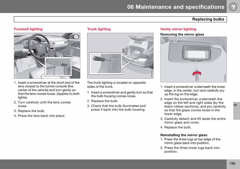
06 Maintenance and specifications
199
Replacing bulbs
06
Footwell lighting
1. Insert a screwdriver at the short end of the lens closest to the tunnel console (the center of the vehicle) and turn gently so that the lens comes loose. (Applies to both lights).
2. Turn carefully until the lens comes loose.
3. Replace the bulb.
4. Press the lens back into place.
Trunk lighting
The trunk lighting is located on opposite sides of the trunk.
1. Insert a screwdriver and gently turn so that the bulb housing comes loose.
2. Replace the bulb.
3. Check that the bulb illuminates and press it back into the bulb housing.
Vanity mirror lightingRemoving the mirror glass
1. Insert a screwdriver underneath the lower edge, in the center, turn and carefully pry up the lug on the edge.
2. Insert the screwdriver underneath the edge on the left and right sides (by the black rubber sections), and pry carefully so that the glass comes loose in the lower edge.
3. Carefully detach and lift aside the entire mirror glass and cover.
4. Replace the bulb.
Reinstalling the mirror glass1. Press the three lugs at top edge of the
mirror glass back into position.
2. Press the three lower lugs back into position.
3501
902s
3501
903s
3501
883s
S80 USA reprint version w640.book Page 199 Friday, June 1, 2007 10:44 AM

06 Maintenance and specifications
200
Replacing bulbs
06
Specification, bulbs
Lighting function
Output/voltage(W/V)
Bulb
Bi Xenon (high and low beam)
35/12 D1S
Bi-Xenon (extra high beam)
55/12 H7 LL
Low beam (halogen)
55/12 H11
High beam (halogen)
65/12 H9
Brake lights 21/12 P21W LL
Backup light 21/12 P21W LL
Rear fog light 21/12 P21W LL
Rear turn signals (amber)
21/12 PY21W LL
Front turn signals
21/12 H21WLL
Rear parking lights, rear side marker lights
– LED
Courtesy lighting, cargo area lighting, license plate lighting
5 SV8.5
Vanity mirror 1.2 SV5.5
Front parking lights
5/12 W5W LL
Front side marker lights
5/12 W5WLL
Turn signals, door mirror (amber)
5 WY5W LL
Front fog lights 35/12 H8
Glove compartment lighting
5 BA9
Lighting function
Output/voltage(W/V)
Bulb
S80 USA reprint version w640.book Page 200 Friday, June 1, 2007 10:44 AM

06 Maintenance and specifications
201
Wiper blades and washer fluid
06
Wiper blades
Service positionThe wiper blades must be in the service (ver-tical) position for replacement or washing.
1. Switch off the ignition (ignition mode 0, see page 77) and keep the remote key in the ignition slot1.
2. Move the right steering wheel lever up and hold it for at least 1 second. The wipers will then move to the vertical position on the windshield.
The wipers return to the starting position when the vehicle is started.
Replacing the wiper blades
With the wipers in the service position, fold out the wiper arm from the wind-shield. Press the button on the wiper blade attachment and pull the wiper blade straight out, parallel with the wiper arm.
Slide in the new wiper blade until it clicks into place.
Check that the blade is securely in place.
1 Does not apply to vehicles with the optional keyless drive.
1
3603
785s
2
0378
6s
3
3603
787s
S80 USA reprint version w640.book Page 201 Friday, June 1, 2007 10:44 AM

06 Maintenance and specifications
202
Wiper blades and washer fluid
06
Cleaning
Clean the wiper blades with a lukewarm soap solution or car washing detergent.
Filling washer fluid
Location of the washer fluid reservoir
The windshield and headlight washers share a common reservoir.
The washer fluid reservoir is located on the driver’s side of the engine compartment. During cold weather, the reservoir should be filled with windshield washer solvent contain-ing antifreeze. For capacities, see page 250.
NOTE
The wiper blades are different lengths. The blade on the driver’s side is longer than the blade on the passenger side.
3603
784s
3603
783s
S80 USA reprint version w640.book Page 202 Friday, June 1, 2007 10:44 AM
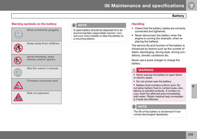
06 Maintenance and specifications
203
Battery
06
Warning symbols on the battery Handling• Check that the battery cables are correctly
connected and tightened.
• Never disconnect the battery when the engine is running (for example, when re-placing the battery).
The service life and function of the battery is influenced by factors such as the number of starts, discharging, driving style, driving con-ditions, climatic conditions etc.
Never use a quick charger to charge the battery.
Wear protective goggles.
Keep away from children.
Avoid smoking, open flames, and/or sparks.
See the owner’s manual.
Contains corrosive acid.
Risk of explosion
i
NOTE
A used battery should be disposed of in an environmentally responsible manner. Con-sult your Volvo retailer or take the battery to a recycling station.
WARNING
• Never expose the battery to open flame or electric spark.• Do not smoke near the battery.
• Battery fluid contains sulfuric acid. Do not allow battery fluid to contact eyes, skin, fabrics or painted surfaces. If contact oc-curs, flush the affected area immediately with water. Obtain medical help immediate-ly if eyes are affected.
NOTE
The life of the battery is shortened if it be-comes discharged repeatedly.
S80 USA reprint version w640.book Page 203 Friday, June 1, 2007 10:44 AM

06 Maintenance and specifications
204
Battery
06
Maintenance
• Regularly check that the electrolyte level is correct and never fill above the level mark.
• Check all cells. Use a large screwdriver or a coin to remove the cell caps. Each cell has its own maximum and minimum level mark.
• If necessary, top up with distilled water to the battery’s maximum mark.
• Tighten the cell caps thoroughly.
Changing
CAUTION
• Always use distilled or deionized water (battery water).• Never fill above the level mark in the cell.
A
3100
217s
0022
0s
1
0022
1s
2
0222
s
3WARNING
Connect and disconnect the positive and negative cables in the correct sequence.
0223
s
4 2
13
4
0022
5s
5
2
1
S80 USA reprint version w640.book Page 204 Friday, June 1, 2007 10:44 AM

06 Maintenance and specifications
205
Battery
06
RemovalSwitch off the ignition and wait at least 5 min-utes before disconnecting the battery so that all information in the vehicle's electrical sys-tem can be stored in the control modules.
Open the clips on the front cover and remove the cover.
Release the rubber moulding so that the rear cover is free.
Remove the rear cover by pulling it away.
Detach the black negative cable . De-tach the red positive cable , detach the ventilation hose from the battery and loosen the screw holding the battery clamp .
Move the battery to the side and lift it up.
Installation1. Lower the battery into the battery box.
2. Move the battery inward and to the side until it reaches the rear edge of the box.
3. Screw in the battery with the screw in the clamp.
4. Connect the ventilation hose.
5. Connect the red positive cable.
6. Connect the black negative cable.
7. Press in the rear cover. (See Removal).
8. Reinstall the cold section moulding. (See Removal).
9. Reinstall the front cover and secure it with the clips. (See Removal).
WARNING
PROPOSITION 65 WARNING! Battery posts, terminals, and related acces-sories contain lead and lead compounds, chemicals known to the state of California to cause cancer and reproductive harm. Wash hands after handling.
3100
224s
S80 USA reprint version w640.book Page 205 Friday, June 1, 2007 10:44 AM

06 Maintenance and specifications
206
Fuses
06
Replacing fuses
There are relay/fuse boxes located in the engine compartment, the passenger com-partment, and the trunk.
If an electrical component fails to function, this may be due to a blown fuse. The easiest way to see if a fuse is blown is to remove it.
To do so:
1. Pull the fuse straight out. If a fuse is difficult to remove, special fuse removal tools are located on the inside of the fuse box covers.
2. From the side, examine the curved metal wire in the fuse to see if it is intact.
If the wire is broken, insert a new fuse of the same color and amperage (written on the fuse).
If fuses burn out repeatedly, have the electri-cal system inspected by a trained and quali-fied Volvo service technician.
Location of the fuse boxes
Under the glove compartment
Engine compartment
Trunk
WARNING
Never use fuses with higher amperage than those stated in the following tables. Doing so could overload the vehicle's electrical system.
3703
828s
2 3
1
S80 USA reprint version w640.book Page 206 Friday, June 1, 2007 10:44 AM

06 Maintenance and specifications
207
Fuses
06
Engine compartment
Engine compartment, upper
Engine compartment, front
Engine compartment, lower
Positions
These fuses are all located in the engine compartment box. Fuses in are located under .
3703
824s
1 3
2
G01
0503
3703
832d
1
44
3541 38
40 37
39 36
34
43
33
32
31
30
42
2
3
4
5
6
7
1
2
1520 16
21 17
22 18
23 19
27 24
28 25
29 26
NOTE
• Fuses 16—33 are 35—41 may be changed at any time when necessary.• Fuses 1—15, 34, and 42—44 are relays/circuit breakers and should only be re-moved or replaced by a trained and quali-fied Volvo service technician.• There is a special fuse removal tool on the underside of the cover.
3703
833d
S80 USA reprint version w640.book Page 207 Friday, June 1, 2007 10:44 AM

06 Maintenance and specifications
208
Fuses
06
Function A
Circuit breaker 60
Circuit breaker 60
Circuit breaker 60
Circuit breaker 60
Circuit breaker 50
-
-
-
Windshield wipers 30
-
Climate system blower 40
-
ABS pump 30
ABS valves 20
-
Active Bi-Xenon Lights. Headlight leveling (option)
10
Central electrical module 20
Radar. ACC control module (option)
5
Speed related power steering 5
Engine Control Module (ECM), transm. SRS
10
Heated washer nozzles 10
Vacuum pump I5T 20
Lighting panel 5
Headlight washers 15
12-volt socket, front and rear seat
15
Moonroof (option), ceiling console/ECC (option)
10
Engine compartment box 5
Auxiliary lights (option) 20
Horn 15
Engine Control Module (ECM) 10
Control module, automatic transmission
15
Compressor A/C 15
Coils 5
Starter motor relay 30
Ignition coils 20
Engine Control Module (ECM) 10
Injection system 15
Engine valves 10
EVAP/heated oxygen sensor/Injection
15
Function A
Water pump V8Crank case ventilation heater
1020
Fuel leakage detection 5
-
Cooling fan 50
Cooling fan 60
Function A
S80 USA reprint version w640.book Page 208 Friday, June 1, 2007 10:44 AM

06 Maintenance and specifications
209
Fuses
06
Under the glove compartment
Fold aside the interior trim covering the fuse box.
Press the cover’s lock and fold it up.
The fuses are accessible.
Positions
1
3501
898s
235
0189
9s
Function A
Rain sensor 5
SRS system 10
ABS brakes. Electric parking brake
5
Accelerator pedal, heated seats (option)
7.5
-
ICM display. CD & Radio 15
Steering wheel module 7.5
-
10 11 12 13 141 2 3 4 5 6 7 8 9
232221201918171615 24 25 26 27 28
High beam 15
Moonroof (option) 20
Backup lights 7.5
-
Front fog light (option) 15
Windshield washers 15
Adaptive cruise control ACC (option)
10
-
Overhead courtesy lighting. Control panel driver’s door/Power passenger seat (option)
7.5
Information display 5
Power driver’s seat (option) 5
Folding head restraint, rear (option)
15
Remote key receiver. Alarm sensors
5
Fuel pump 20
Electric steering column lock 20
- 15
Lock, tank/trunk lid 10
Alarm siren. ECC 5
Function A
S80 USA reprint version w640.book Page 209 Friday, June 1, 2007 10:44 AM

06 Maintenance and specifications
210
Fuses
06
Start/stop button 5
Brake light switch 5
Function A
S80 USA reprint version w640.book Page 210 Friday, June 1, 2007 10:44 AM

06 Maintenance and specifications
211
Fuses
06
Trunk
The fuse box is located behind the upholstery on the left side of the trunk
Positions
BAD
4 3 2 1
8 7 6 5
1012
11
9
Module A (black). Function A
Switches in driver’s door 25
Switches in passenger’s door 25
Switches in rear door, driver’s side
25
Switches in rear door, passenger’s side
25
-
12 V socket in trunk, cooler (option)
15
Rear window defroster 30
-
Trailer socket 2 (option) 15
Power driver’s seat (option) 25
Trailer socket 1 (option) 40
-
Module B (white). Function A
Park assist (option) 5
Control module Four C (option) 15
Heated driver’s seat (option) 15
Heated passenger’s seat (option)
15
Rear seat heater, passenger’s side (option)
15
AWD control module 10
Rear seat heater, driver’s side (option)
15
-
Power passenger’s seat (option) 25
Keyless drive (option) 20
Electric parking brake - driver’s side (option)
30
Electric parking brake - passenger’s side (option)
30
Module D (blue). Function A
Navigation system display (option)
10
-
-
SIRIUS satellite radio (option) 5
Audio amplifier 25
Audio system 15
-
Reserve -
Module B (white). Function A
S80 USA reprint version w640.book Page 211 Friday, June 1, 2007 10:44 AM
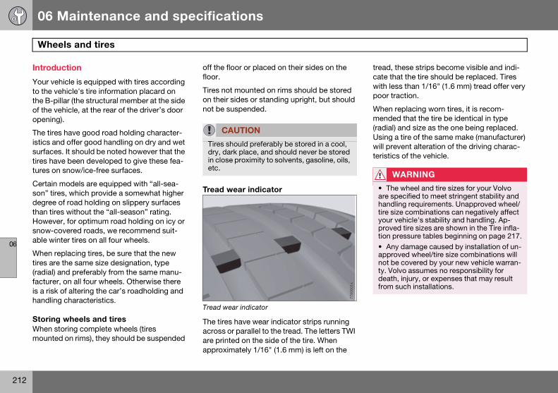
06 Maintenance and specifications
212
Wheels and tires
06
Introduction
Your vehicle is equipped with tires according to the vehicle's tire information placard on the B-pillar (the structural member at the side of the vehicle, at the rear of the driver’s door opening).
The tires have good road holding character-istics and offer good handling on dry and wet surfaces. It should be noted however that the tires have been developed to give these fea-tures on snow/ice-free surfaces.
Certain models are equipped with “all-sea-son” tires, which provide a somewhat higher degree of road holding on slippery surfaces than tires without the “all-season” rating. However, for optimum road holding on icy or snow-covered roads, we recommend suit-able winter tires on all four wheels.
When replacing tires, be sure that the new tires are the same size designation, type (radial) and preferably from the same manu-facturer, on all four wheels. Otherwise there is a risk of altering the car’s roadholding and handling characteristics.
Storing wheels and tires When storing complete wheels (tires mounted on rims), they should be suspended
off the floor or placed on their sides on the floor.
Tires not mounted on rims should be stored on their sides or standing upright, but should not be suspended.
Tread wear indicator
Tread wear indicator
The tires have wear indicator strips running across or parallel to the tread. The letters TWI are printed on the side of the tire. When approximately 1/16" (1.6 mm) is left on the
tread, these strips become visible and indi-cate that the tire should be replaced. Tires with less than 1/16" (1.6 mm) tread offer very poor traction.
When replacing worn tires, it is recom-mended that the tire be identical in type (radial) and size as the one being replaced. Using a tire of the same make (manufacturer) will prevent alteration of the driving charac-teristics of the vehicle.
CAUTION
Tires should preferably be stored in a cool, dry, dark place, and should never be stored in close proximity to solvents, gasoline, oils, etc.
7700
601s
WARNING
• The wheel and tire sizes for your Volvo are specified to meet stringent stability and handling requirements. Unapproved wheel/tire size combinations can negatively affect your vehicle's stability and handling. Ap-proved tire sizes are shown in the Tire infla-tion pressure tables beginning on page 217.
• Any damage caused by installation of un-approved wheel/tire size combinations will not be covered by your new vehicle warran-ty. Volvo assumes no responsibility for death, injury, or expenses that may result from such installations.
S80 USA reprint version w640.book Page 212 Friday, June 1, 2007 10:44 AM

06 Maintenance and specifications
213
Wheels and tires
06
New tires
Remember that tires are perishable goods. As of 2000, the manufacturing week and year (Department of Transportation (DOT) stamp) will be indicated with 4 digits (e.g. 1502 means that the tire illustrated was manufac-tured during week 15 of 2002).
Tire age• Tires degrade over time, even when they
are not being used. It is recommended that tires generally be replaced after 6 years of normal service. Heat caused by hot climates, frequent high loading condi-tions or Ultra Violet (U.V.) exposure can accelerate the aging process.
• You should replace the spare tire when you replace the other road tires due to the aging of the spare.
• A tire's age can be determined by the DOT stamp on the sidewall (see the illustration above).
• A tire with e.g., visible cracks or discolora-tion should be replaced immediately.
Improving tire economy• Maintain correct tire pressure. See the tire
pressure tables beginning on page 217.
• Drive smoothly: avoid fast starts, hard braking and tire screeching.
• Tire wear increases with speed.
• Correct front wheel alignment is very im-portant.
• Unbalanced wheels impair tire economy and driving comfort.
• Tires must maintain the same direction of rotation throughout their lifetime.
• When replacing tires, the tires with the most tread should be mounted on the rear wheels to reduce the chance of oversteer during hard braking.
• Hitting curbs or potholes can damage the tires and/or wheels permanently.
1502
7700
607s
S80 USA reprint version w640.book Page 213 Friday, June 1, 2007 10:44 AM

06 Maintenance and specifications
214
Wheels and tires
06
Tire inflation
Tire inflation placard on U.S. models
Tire inflationCheck tire inflation pressure regularly.
Tables listing the recommended inflation pressure for your vehicle can be found on pages 217 and 218. A tire inflation pressure placard is also located on the driver’s side B-pillar (the structural member at the side of the vehicle, at the rear of the driver’s door open-ing). This placard indicates the designation of the factory-mounted tires on your vehicle, as well as load limits and inflation pressure.
• Use a tire gauge to check the tire inflation pressure, including the spare, at least once a month and before long trips. You are strongly urged to buy a reliable tire pressure gauge, as automatic service sta-tion gauges may be inaccurate.
• Use the recommended cold inflation pres-sure for optimum tire performance and wear.
• Under-inflation or over-inflation may cause uneven treadwear patterns.
Tire inflation placard on Canadian models
When weather temperature changes occur, tire inflation pressures also change. A 10-degree temperature drop causes a corre-sponding drop of 1 psi (7 kPa) in inflation pressure. Check your tire pressures fre-quently and adjust them to the proper pres-sure, which can be found on the vehicle's tire information placard or certification label.
Checking tire pressure
Cold tiresInflation pressure should be checked when the tires are cold.
The tires are considered to be cold when they have the same temperature as the surrounding (ambient) air.
TIRE AND LOADING INFORMATIONTIRE AND LOADING INFORMATION
SEE OWNERSEE OWNER SMANUAL FORMANUAL FORADDITIONALADDITIONALINFORMATIONINFORMATION
SEATING CAPACITYSEATING CAPACITY TOTAL 5TOTAL 5 FRONT2FRONT2 REAR3REAR3The combinad waight of occupants and cargo should never exeed xxx kg or xxx pounds
COLD TIRE PRESSURE
FRONT
200KPA,29PSI
200KPA,29PSI200KPA,29PSI
200KPA,29PSI
200KPA,29PSI 200KPA,29PSI
REAR
SPARE
TIRE SIZE
G01
4376
NOTE
• The placards shown indicate inflation pressure for the tires installed on the vehicle at the factory only.• A certain amount of air seepage from the tires occurs naturally and tire pressure fluc-tuates with seasonal changes in tempera-ture. Always check tire pressure regularly.
WARNING
• Under-inflation is the most common cause of tire failure and may result in severe tire cracking, tread separation, or "blow-out," with unexpected loss of vehicle con-trol and increased risk of injury.• Under-inflated tires reduce the load car-rying capacity of your vehicle.
VEHICLECAPACITYVEHICLECAPACITY OCCUPANTSOCCUPANTS
OPTIONAL PRESSUREOPTIONAL PRESSURE
38 3838 38
32 3232 32
FRONT REAR TOTALFRONT REAR TOTAL FRONT REAR FRONT REAR
2 3 5 2 3 5
2 3 5 2 3 5
RECOMMENDED FOR FUEL ECONOMYRECOMMENDED FOR FUEL ECONOMY
COLD TIRE PRESSURECOLD TIRE PRESSUREWEIGHTWEIGHT
MAXMAX
INFLATIONINFLATIONIf tires are hot from driving add 4psi (28kPa) to these recommended pressuresIf tires are hot from driving add 4psi (28kPa) to these recommended pressures
TIRETIRE
SPARE TIRESPARE TIRE
SEE OWNERS MANUAL FOR ADDITIONAL INFORMATIONSEE OWNERS MANUAL FOR ADDITIONAL INFORMATION
LOADLOAD
PRESSUREPRESSURE6161
SIZESIZE
1000Kg1000Kg
235/45R17235/45R17
T125/80R17T125/80R17
G01
4377
S80 USA reprint version w640.book Page 214 Friday, June 1, 2007 10:44 AM

06 Maintenance and specifications
215
Wheels and tires
06
This temperature is normally reached after the vehicle has been parked for at least 3 hours.
After driving a distance of approximately 1 mile (1.6 km), the tires are considered to be hot. If you have to drive farther than this dis-tance to pump your tire(s), check and record the tire pressure first and add the appropriate air pressure when you get to the pump.
If checking tire pressure when the tire is hot, never "bleed" or reduce air pressure. The tires are hot from driving and it is normal for pressures to increase above recommended cold pressures. A hot tire at or below recom-mended cold inflation pressure could be sig-nificantly under-inflated.
To check inflation pressure:1. Remove the cap from the valve on one
tire, then firmly press the tire gauge onto the valve.
2. Add air to reach the recommended air pressure.
3. Replace the valve cap.
4. Repeat this procedure for each tire, including the spare.
5. Visually inspect the tires to make sure there are no nails or other objects em-bedded that could puncture the tire and cause an air leak.
6. Check the sidewalls to make sure there are no gouges, cuts, bulges or other irregularities.
NOTE
• If you overfill the tire, release air by push-ing on the metal stem in the center of the valve. Then recheck the pressure with your tire gauge.• Some spare tires require higher inflation pressure than the other tires. Consult the tire inflation tables beginning on page 217 or see the inflation pressure placard.
S80 USA reprint version w640.book Page 215 Friday, June 1, 2007 10:44 AM

06 Maintenance and specifications
216
Wheels and tires
06
Tire specifications
Speed ratingsThe speed ratings in the table below translate as follow:
Load ratingsThe speed ratings in the table below translate as follow:
See also page 222 for an explanation of the designations on the sidewall of the tire.
Speed ratings
M 81 mph (130 km/h)
Q 100 mph (160 km/h)
T 118 mph (190 km/h)H 130 mph (210 km/h)
W 168 mph (270 km/h)
V 149 mph (240 km/h)Y 186 mph (300 km/h)
Load ratings
91 1365 lbs (615 kg)93 1433 lbs (650 kg)
99 1709 lbs (755 kg)
S80 USA reprint version w640.book Page 216 Friday, June 1, 2007 10:44 AM
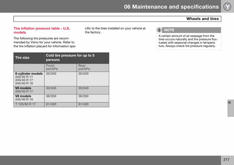
06 Maintenance and specifications
217
Wheels and tires
06
Tire inflation pressure table - U.S. models
The following tire pressures are recom-mended by Volvo for your vehicle. Refer to the tire inflation placard for information spe-
cific to the tires installed on your vehicle at the factory.
NOTE
A certain amount of air seepage from the tires occurs naturally and tire pressure fluc-tuates with seasonal changes in tempera-ture. Always check tire pressure regularly.
Tire sizeCold tire pressure for up to 5 persons
Front psi/kPa
Rear psi/kPa
6-cylinder models225/50 R 17245/45 R 17245/40 R 18
35/240 35/240
V8 models245/45 R 17
35/240 35/240
V8 models245/40 R 18
36/250 36/250
T 125/80 R 17 61/420 61/420
S80 USA reprint version w640.book Page 217 Friday, June 1, 2007 10:44 AM
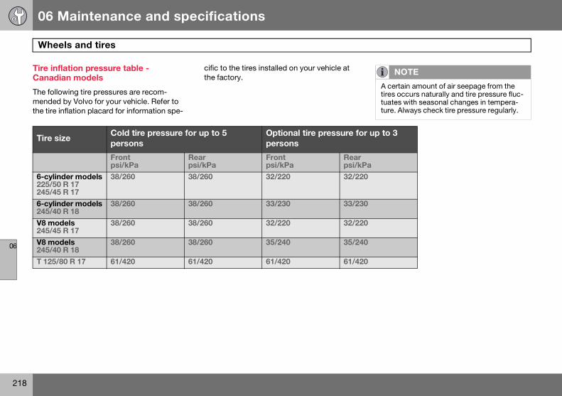
06 Maintenance and specifications
218
Wheels and tires
06
Tire inflation pressure table - Canadian models
The following tire pressures are recom-mended by Volvo for your vehicle. Refer to the tire inflation placard for information spe-
cific to the tires installed on your vehicle at the factory.
NOTE
A certain amount of air seepage from the tires occurs naturally and tire pressure fluc-tuates with seasonal changes in tempera-ture. Always check tire pressure regularly.
Tire sizeCold tire pressure for up to 5 persons
Optional tire pressure for up to 3 persons
Front psi/kPa
Rear psi/kPa
Front psi/kPa
Rear psi/kPa
6-cylinder models225/50 R 17245/45 R 17
38/260 38/260 32/220 32/220
6-cylinder models245/40 R 18
38/260 38/260 33/230 33/230
V8 models245/45 R 17
38/260 38/260 32/220 32/220
V8 models245/40 R 18
38/260 38/260 35/240 35/240
T 125/80 R 17 61/420 61/420 61/420 61/420
S80 USA reprint version w640.book Page 218 Friday, June 1, 2007 10:44 AM

06 Maintenance and specifications
219
Wheels and tires
06
Tire Pressure Monitoring System (TPMS)—U.S models only
The tire pressure monitoring system uses sensors mounted in the tire valves to check inflation pressure levels. When the vehicle is moving at a speed of approximately 20 mph (30 km/h) or faster, these sensors transmit inflation pressure data to a receiver located in the vehicle.
When low inflation pressure is detected, TPMS will light up the tire pressure warning light ( ) (also referred to as a telltale) in the instrument panel, and will display a message in the text window. The wording of this mes-sage is determined by the degree of inflation pressure loss.
Each tire, including the spare (if provided), should be checked monthly when cold and inflated to the inflation pressure recom-mended by the vehicle manufacturer on the vehicle placard or tire inflation pressure label. (If your vehicle has tires of a different size than the size indicated on the vehicle placard or tire inflation pressure label, you should determine the proper tire inflation pressure for those tires.)
As an added safety feature, your vehicle has been equipped with a tire pressure monitor-ing system (TPMS) that illuminates a low tire pressure telltale when one or more of your tires is significantly under-inflated. Accord-ingly, when the low tire pressure telltale illu-minates, you should stop and check your tires as soon as possible, and inflate them to the proper pressure. Driving on a significantly under-inflated tire causes the tire to overheat and can lead to tire failure. Under-inflation also reduces fuel efficiency and tire tread life, and may affect the vehicle's handling and stopping ability.
Please note that the TPMS is not a substitute for proper tire maintenance, and it is the driver's responsibility to maintain correct tire pressure, even if under-inflation has not reached the level to trigger illumination of the TPMS low tire pressure telltale.
Your vehicle has also been equipped with a TPMS malfunction indicator to indicate when the system is not operating properly. The TPMS malfunction indicator is combined with the low tire pressure telltale. When the system detects a malfunction, the telltale will flash for approximately one minute and then remain continuously illuminated. This sequence will continue upon subsequent vehicle start-ups as long as the malfunction exists. When the malfunction indicator is illu-minated, the system may not be able to detect or signal low tire pressure as intended. TPMS malfunctions may occur for a variety of reasons, including the installation of replacement or alternate tires or wheels on the vehicle that prevent the TPMS from func-tioning properly. Always check the TPMS malfunction telltale after replacing one or more tires or wheels on your vehicle to ensure that the replacement or alternate tires and wheels allow the TPMS to continue to function properly.
NOTE
USA - FCC ID: KR5S122780002This device complies with part 15 of the FCC rules. Operation is subject to the fol-lowing conditions: (1) This device may not cause harmful interference, and (2) this de-vice must accept any interference received, including interference that may cause un-desired operation.
NOTE
If a fault occurs in TPMS, the tire pressure warning light will flash for approximately 1 minute and TIRE PRESS SYST SERVICE REQUIRED will be displayed.
S80 USA reprint version w640.book Page 219 Friday, June 1, 2007 10:44 AM

06 Maintenance and specifications
220
Wheels and tires
06
Erasing warning messagesWhen a low tire pressure warning message has been displayed, and the tire pressure warning light has come on:
1. Use a tire pressure gauge to check the inflation pressure of all four tires.
2. Re-inflate the tire(s) to the correct pres-sure (consult the tire pressure placard or the tables beginning on page 217).
3. In certain cases, it may be necessary to drive the vehicle for several minutes at a speed of 20 mph (30 km/h) or faster. This will erase the warning text and the warning light will go out.
Changing wheels with TPMSPlease note the following when changing or replacing the factory installed TPMS wheels/tires on the vehicle:
• Only the factory-mounted wheels are equipped with TPMS sensors in the valves.
• If the vehicle is equipped with a temporary spare tire, this tire does not have a TPMS sensor.
• If wheels without TPMS sensors are mounted on the vehicle, TIRE PRESS SYST SERVICE REQUIRED will be dis-played each time the vehicle is driven above 25 mph (40 km/h) for 10 minutes or more.
• Once TPMS sensors are properly in-stalled, the warning message should not reappear. If the message is still displayed, drive the vehicle for several minutes at a speed of 20 mph (30 km/h) or faster to erase the message.
• Volvo recommends that TPMS sensors be fitted on all wheels used on the vehicle. Volvo does not recommend moving sen-
sors back and forth between sets of wheels.NOTE
• TPMS indicates low tire pressure but does not replace normal tire maintenance. For information on correct tire pressure, please refer to the tables beginning on page 217, or consult your Volvo retailer.
• The tire pressure warning light will not identify which tire is underinflated. Be sure to check all four tires.
• A certain amount of air seepage from the tires occurs naturally and tire pressure fluc-tuates with seasonal changes in tempera-ture. Always check tire pressure regularly.
WARNING
Incorrect inflation pressure could lead to tire failure, resulting in a loss of control of the vehicle.
NOTE
• If you change to tires with a different rec-ommended inflation pressure, the TPMS system must be recalibrated to these tires. This must be done by an authorized Volvo retailer or workshop.• If a tire is changed, or if the TPMS sensor is moved to another wheel, the sensor’s seal, nut, and valve core should be re-placed.• When installing TPMS sensors, the vehi-cle must be parked for at least 15 minutes with the ignition off. if the vehicle is driven within 15 minutes, a TPMS error message will be displayed.
CAUTION
When inflating tires with TPMS valves, press the pump's mouthpiece straight onto the valve to help avoid bending or otherwise damaging the valve.
S80 USA reprint version w640.book Page 220 Friday, June 1, 2007 10:44 AM
06 Maintenance and specifications
221
Wheels and tires
06
Self supporting run flat tires
Certain models equipped with the Tire Pres-sure Monitoring System (TPMS) can also be equipped with self supporting run flat tires.
Tires of this type have specially reinforced sidewalls that make it possible to continue driving in the event of a drop in inflation pres-sure. Tires of this type are mounted on spe-cial rims.
If a self supporting run flat tire should lose inflation pressure, the yellow TPMS warning symbol ( ) in the instrument panel lights up to alert the driver, and a message will be shown in the text window in the instrument panel.
If this occurs, reduce vehicle speed to a max-imum of 50 mph (80 km/h). The vehicle can be driven approximately 50 miles (80 km), or somewhat farther if the vehicle is not heavily loaded. The tire should be replaced as soon as possible.
Hard braking and sudden steering maneu-vers should be avoided.
In certain cases, it may be difficult to see which self supporting run flat tire is defective. To determine which tire is damaged, check the inflation pressure of all four tires.
NOTE
Self supporting run flat tires are only avail-able in conjunction with TPMS.
WARNING
• Only specially trained persons should mount self supporting run flat tires.• If self supporting run flat tires are mount-ed, the vehicle must be equipped with a Tire Pressure Monitoring System.• After a low pressure warning has been displayed, do not exceed 50 mph (80 km/h).• Avoid severe cornering and hard braking, and minimize the distance traveled before replacing the self supporting run flat tire.
• Self supporting run flat tires cannot be re-paired. They must be replaced if damaged or punctured.
S80 USA reprint version w640.book Page 221 Friday, June 1, 2007 10:44 AM
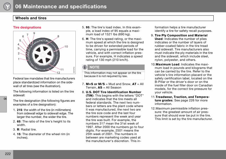
06 Maintenance and specifications
222
Wheels and tires
06
Tire designations
Federal law mandates that tire manufacturers place standardized information on the side-wall of all tires (see the illustration).
The following information is listed on the tire sidewall:
The tire designation (the following figures are examples of a tire designation):
1. 215: the width of the tire (in millimeters) from sidewall edge to sidewall edge. The larger the number, the wider the tire.
2. 65: The ratio of the tire's height to its width.
3. R: Radial tire.
4. 15: The diameter of the wheel rim (in inches).
5. 95: The tire’s load index. In this exam-ple, a load index of 95 equals a maxi-mum load of 1521 lbs (690 kg).
6. H: The tire's speed rating, or the maxi-mum speed at which the tire is designed to be driven for extended periods of time, carrying a permissible load for the vehicle, and with correct inflation pres-sure. For example, H indicates a speed rating of 130 mph (210 km/h).
7. M+S or M/S = Mud and Snow, AT = All Terrain, AS = All Season
8. U.S. DOT Tire Identification Number (TIN): This begins with the letters "DOT" and indicates that the tire meets all federal standards. The next two num-bers or letters are the plant code where it was manufactured, the next two are the tire size code and the last four numbers represent the week and year the tire was built. For example, the numbers 317 mean the 31st week of 1997. After 2000 the numbers go to four digits. For example, 2501 means the 25th week of 2001. The numbers in between are marketing codes used at the manufacturer's discretion. This in-
formation helps a tire manufacturer identify a tire for safety recall purposes.
9. Tire Ply Composition and Material Used: Indicates the number of plies indicates or the number of layers of rubber-coated fabric in the tire tread and sidewall. Tire manufacturers also must indicate the ply materials in the tire and the sidewall, which include steel, nylon, polyester, and others.
10.Maximum Load: Indicates the maxi-mum load in pounds and kilograms that can be carried by the tire. Refer to the vehicle's tire information placard or the safety certification label, located on the B-Pillar or the driver's door or on the inside of the fuel filler door on Canadian models, for the correct tire pressure for your vehicle.
11.Treadwear, Traction, and Tempera-ture grades: See page 226 for more information.
12.Maximum permissible inflation pres-sure: the greatest amount of air pres-sure that should ever be put in the tire. This limit is set by the tire manufacturer.
G01
0753 NOTE
This information may not appear on the tire because it is not required by law.
S80 USA reprint version w640.book Page 222 Friday, June 1, 2007 10:44 AM

06 Maintenance and specifications
223
Wheels and tires
06
Glossary of tire terminologyThe tire suppliers may have additional mark-ings, notes or warnings such as standard load, radial tubeless, etc.
• Tire information placard: A placard showing the OE (Original Equipment) tire sizes, recommended inflation pressure, and the maximum weight the vehicle can carry.
• Tire Identification Number (TIN): A num-ber on the sidewall of each tire providing information about the tire brand and man-ufacturing plant, tire size and date of man-ufacturer.
• Inflation pressure: A measure of the amount of air in a tire.
• Standard load: A class of P-metric or Metric tires designed to carry a maximum load at 35 psi [37 psi (2.5 bar) for Metric tires]. Increasing the inflation pressure be-yond this pressure will not increase the tires load carrying capability.
• Extra load: A class of P-metric or Metric tires designed to carry a heavier maximum load at 41 psi [43 psi (2.9 bar) for Metric tires]. Increasing the inflation pressure be-yond this pressure will not increase the tire’s load carrying capability.
• kPa: Kilopascal, a metric unit of air pres-sure.
• PSI: Pounds per square inch, a standard unit of air pressure.
• B-pillar: The structural member at the side of the vehicle behind the front door.
• Bead area of the tire: Area of the tire next to the rim.
• Sidewall of the tire: Area between the bead area and the tread.
• Tread area of the tire: Area of the perim-eter of the tire that contacts the road when mounted on the vehicle.
• Rim: The metal support (wheel) for a tire or a tire and tube assembly upon which the tire beads are seated.
• Maximum load rating: a figure indicating the maximum load in pounds and kilo-grams that can be carried by the tire. This rating is established by the tire manufac-turer.
• Maximum permissible inflation pres-sure: the greatest amount of air pressure that should ever be put in the tire. This limit is set by the tire manufacturer.
• Recommended tire inflation pressure: inflation pressure, established by Volvo, which is based on the type of tires that are mounted on a vehicle at the factory. This inflation pressure is affected by the num-ber of occupants in the vehicle, the amount of cargo, and the speed at which the vehicle will be driven for a prolonged
period. This information can be found on the tire inflation placard(s) located on the driver’s side B-pillar or on the inside of the fuel filler door on Canadian models, and in the tire inflation table in this chapter.
• Cold tires: The tires are considered to be cold when they have the same temperature as the surrounding (ambient) air. This tem-perature is normally reached after the vehicle has been parked for at least 3 hours.
S80 USA reprint version w640.book Page 223 Friday, June 1, 2007 10:44 AM

06 Maintenance and specifications
224
Wheels and tires
06
Vehicle loading
Properly loading your vehicle will provide maximum return of vehicle design perfor-mance.
Before loading your vehicle, familiarize your-self with the following terms for determining your vehicle's weight ratings, with or without a trailer, from the vehicle's Federal/Canadian Motor Vehicle Safety Standards (FMVSS/CMVSS) label, and the vehicle's tire informa-tion placard:
Curb weight The weight of the vehicle including a full tank of fuel and all standard equipment. It does not include passengers, cargo, or optional equipment.
Capacity weight All weight added to the curb weight, includ-ing cargo and optional equipment. When towing, trailer hitch tongue load is also part of cargo weight.
Permissible axle weightThe maximum allowable weight that can be carried by a single axle (front or rear). These numbers are shown on the Federal/Canadian Motor Vehicle Safety Standards (FMVSS/CMVSS) label. The total load on each axle must never exceed its maximum permissible weight.
Gross vehicle weight (GVW)The vehicle's curb weight + cargo + passengers.
Steps for Determining Correct Load Limit1. Locate the statement ''the combined
weight of occupants and cargo should never exceed XXX pounds'' on your vehi-cle's placard.
2. Determine the combined weight of the driver and passengers that will be riding in your vehicle.
3. Subtract the combined weight of the driver and passengers from XXX kilo-grams or XXX pounds.
4. The resulting figure equals the available amount of cargo and luggage load ca-pacity. For example, if the ''XXX'' amount equals 1400 lbs. and there will be five 150 lb. passengers in your vehi-cle, the amount of available cargo and luggage load capacity is 650 lbs. (1400-750 (5 x 150) = 650 lbs.)
5. Determine the combined weight of lug-gage and cargo being loaded on the vehicle. That weight may not safely ex-ceed the available cargo and luggage load capacity calculated in Step 4.
6. If your vehicle will be towing a trailer, load from your trailer will be transferred to your vehicle. Consult this manual1 to determine how this reduces the avail-able cargo and luggage load capacity of your vehicle.
NOTE
For trailer towing information, please refer to the section "Towing a trailer" on page 178.
NOTE
• The location of the various labels in your vehicle can be found on page 243. • A table listing important weight limits for your vehicle can be found on page 246.
1 See "Towing a trailer" on page 178.
S80 USA reprint version w640.book Page 224 Friday, June 1, 2007 10:44 AM

06 Maintenance and specifications
225
Wheels and tires
06
WARNING
• Exceeding the permissible axle weight, gross vehicle weight, or any other weight rating limits can cause tire overheating re-sulting in permanent deformation or cata-strophic failure.
• Do not use replacement tires with lower load carrying capacities than the tires that were original equipment on the vehicle be-cause this will lower the vehicle’s GVW rat-ing. Replacement tires with a higher limit than the originals do not increase the vehi-cle’s GVW rating limitations.
S80 USA reprint version w640.book Page 225 Friday, June 1, 2007 10:44 AM

06 Maintenance and specifications
226
Wheels and tires
06
Uniform Tire Quality Grading
ALL PASSENGER VEHICLE TIRES MUST CONFORM TO FEDERAL SAFETY REQUIREMENTS IN ADDITION TO THESE GRADES
Quality grades can be found, where appli-cable, on the tire sidewall between the tread shoulder and maximum section width. For example:
Treadwear 200 Traction AA Temperature A
TREADWEARThe treadwear grade is a comparative rating based on the wear rate of the tire when tested under controlled conditions on a specified government test course. For exam-ple, a tire graded 150 would wear one and one half (1 1/2) times as well on the govern-ment course as a tire graded 100. The rela-tive performance of tires depends upon the actual conditions of their use, however, and many depart significantly from the norm due to variation in driving habits, maintenance practices and differences in road character-istics and climate.
TRACTIONThe traction grades, from highest to lowest, are AA, A, B, and C, as measured under con-
trolled conditions on specified government test surfaces of asphalt and concrete. A tire marked C may have poor traction perfor-mance. The traction grade assigned to this tire is based on braking (straight-ahead) trac-tion tests and is not a measure of cornering (turning) traction.
TEMPERATUREThe temperature grades are AA (the highest), A, B, and C, representing the tire's resistance to the generation of heat and its ability to dis-sipate heat when tested under controlled conditions on a specified indoor laboratory test wheel. Sustained high temperature can cause the material of the tire to degenerate and reduce tire life, and excessive tempera-ture can lead to sudden tire failure. The grade C corresponds to a minimum level of perfor-mance that all passenger vehicle tires must meet under the Federal Motor Safety Stan-dard No. 109. Grades B and A represent higher levels of performance on the labora-
tory test wheel than the minimum required by law.
WARNING
The traction grade assigned to this tire is based on braking (straight-ahead) traction tests and is not a measure of cornering (turning) traction.
WARNING
The temperature grade for this tire is estab-lished for a tire that is properly inflated and not overloaded. Excessive speed, under-in-flation, or excessive loading, either sepa-rately or in combination, can cause heat buildup and tire failure.
S80 USA reprint version w640.book Page 226 Friday, June 1, 2007 10:44 AM

06 Maintenance and specifications
227
Wheels and tires
06
Snow chains, snow tires, studded tires
Snow chainsSnow chains can be used on your Volvo with the following restrictions:
• Snow chains should be installed on front wheels only. Use only Volvo approved snow chains.
• If accessory, aftermarket or “custom” tires and wheels are installed and are of a size different than the original tires and wheels, chains in some cases CANNOT be used. Sufficient clearances between chains and brakes, suspension and body compo-nents must be maintained.
• Some strap-on type chains will interfere with brake components and therefore CANNOT be used.
• All Wheel Drive models: Snow chains should only be installed on the front wheels. Only chains adapted for AWD models should be used.
Consult your Volvo retailer for additional snow chain information.
Snow tires, studded tires1
Tires for winter use:• Owners who live in or regularly commute
through areas with sustained periods of snow or icy driving conditions are strongly advised to fit suitable winter tires to help retain the highest degree of traction.
• It is important to install winter tires on all four wheels to help retain traction during cornering, braking, and accelerating. Fail-
ure to do so could reduce traction to an unsafe level or adversely affect handling.
• Do not mix tires of different design as this could also negatively affect overall tire road grip.
• Winter tires wear more quickly on dry roads in warm weather. They should be removed when the winter driving season has ended.
• Studded tires should be run-in 300-600 miles (500-1000 km) during which the ve-hicle should be driven as smoothly as possible to give the studs the opportunity to seat properly in the tires. The tires should have the same rotational direction throughout their entire lifetime.
CAUTION
• Check local regulations regarding the use of snow chains before installing. • Always follow the chain manufacturer’s installation instructions carefully. Install chains as tightly as possible and retighten periodically. • Never exceed the chain manufacturer’s specified maximum speed limit. (Under no circumstances should you exceed 31 mph (50 km/h). • Avoid bumps, holes or sharp turns when driving with snow chains.
• The handling of the vehicle can be ad-versely affected when driving with chains. Avoid fast or sharp turns as well as locked wheel braking.
1 Where permitted
NOTE
Please consult state or provincial regula-tions restricting the use of studded winter tires before installing such tires.
S80 USA reprint version w640.book Page 227 Friday, June 1, 2007 10:44 AM

06 Maintenance and specifications
228
Wheels and tires
06
Temporary Spare
The spare tire in your vehicle is called a "Temporary Spare".
Recommended tire pressure (see the placard on the B-pillar or on the fuel filler door) should be maintained irrespective of which position on the vehicle the temporary spare tire is used on.
In the event of damage to this tire, a new one can be purchased from your Volvo retailer.
WARNING
Current legislation prohibits the use of the "Temporary Spare" tire other than as a tem-porary replacement for a punctured tire. It must be replaced as soon as possible by a standard tire. Road holding and handling may be affected with the "Temporary Spare" in use. Do not exceed 50 mph (80 km/h). Do not drive farther than 50 miles (80 km) on a temporary spare tire.
CAUTION
The vehicle must not be driven with wheels of different dimensions or with a spare tire other than the one that came with the vehi-cle. The use of different size wheels can se-riously damage your car's transmission.
S80 USA reprint version w640.book Page 228 Friday, June 1, 2007 10:44 AM

06 Maintenance and specifications
229
Wheels and tires
06
The arrow shows the direction of rotation of the tire
Summer and winter tires• When switching between summer and
winter tires, mark the tires to indicate where they were mounted on the vehicle, e.g. LF = left front, RR = right rear.
• Tires with tread designed to roll in only one direction are marked with an arrow on the sidewall.
• Incorrectly mounted tires impair the car’s braking properties and ability to force aside rain, snow and slush.
• The tires with the most tread should al-ways be at the rear (to reduce the risk of skidding).
• Contact a Volvo workshop if you are un-sure about the tread depth.
Tire rotationYour vehicle has no recommended tire rota-tion. The following information is intended to help you understand why.
Tread setAs a tire ages and the rubber cures, front and rear tires set at different angles. Therefore, if tires are rotated, the tread will eventually set at an angle that is a compromise. Even if ride, handling, and road noise may still seem acceptable, they may not be optimal. Fur-ther, tires that are rotated, but not on a regu-lar basis, may actually cause more tire noise, faster tire wear, and unpleasant changes in steering feel and vehicle handling.
A tire that can fully adapt to its position will provide better steering feel, lower tire noise, and better fuel economy.
Braking stability performanceYour vehicle is driven mainly by the front tires, which will wear faster. This can be ben-eficial. Having more tread on the rear tires will help reduce oversteer. Oversteer is when a vehicle wants to keep turning because of momentum and dynamic forces on its sus-pension.
Suspension wear diagnosticsEvery suspension needs periodic inspection and maintenance. A tire's wear pattern can be an aid in detecting a suspension problem. Each tire, if left in place, tells a story about the suspension. Tire rotation, on the other hand, could make suspension wear harder to detect. Early detection is very important, because suspension problems can make tire wear worse.
If you do rotate your tires…Please follow the tire manufacturer's recom-mendations, as outlined in the tire manufac-turers tire warranty pamphlet.
7700
600s
S80 USA reprint version w640.book Page 229 Friday, June 1, 2007 10:44 AM
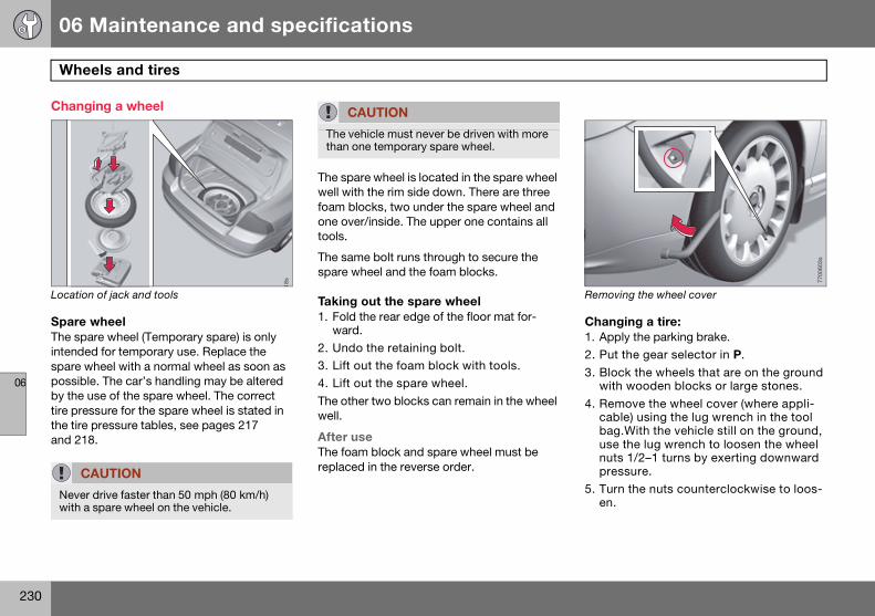
06 Maintenance and specifications
230
Wheels and tires
06
Changing a wheel
Location of jack and tools
Spare wheelThe spare wheel (Temporary spare) is only intended for temporary use. Replace the spare wheel with a normal wheel as soon as possible. The car’s handling may be altered by the use of the spare wheel. The correct tire pressure for the spare wheel is stated in the tire pressure tables, see pages 217 and 218.
The spare wheel is located in the spare wheel well with the rim side down. There are three foam blocks, two under the spare wheel and one over/inside. The upper one contains all tools.
The same bolt runs through to secure the spare wheel and the foam blocks.
Taking out the spare wheel1. Fold the rear edge of the floor mat for-
ward.
2. Undo the retaining bolt.
3. Lift out the foam block with tools.
4. Lift out the spare wheel.
The other two blocks can remain in the wheel well.
After useThe foam block and spare wheel must be replaced in the reverse order.
Removing the wheel cover
Changing a tire:1. Apply the parking brake.
2. Put the gear selector in P.
3. Block the wheels that are on the ground with wooden blocks or large stones.
4. Remove the wheel cover (where appli-cable) using the lug wrench in the tool bag.With the vehicle still on the ground, use the lug wrench to loosen the wheel nuts 1/2–1 turns by exerting downward pressure.
5. Turn the nuts counterclockwise to loos-en.
CAUTION
Never drive faster than 50 mph (80 km/h) with a spare wheel on the vehicle.
18s
CAUTION
The vehicle must never be driven with more than one temporary spare wheel.
7700
603s
S80 USA reprint version w640.book Page 230 Friday, June 1, 2007 10:44 AM

06 Maintenance and specifications
231
Wheels and tires
06
Jack attachment points
6. There are two jack attachment points on each side of the vehicle. Position the jack correctly in the attachment (see illustration above) and crank while si-multaneously guiding the base of the jack to the ground. The base of the jack must be flat on a level, firm, non-slip-pery surface. Before raising the vehicle, check that the jack is still correctly positioned in the attachment.
7. Raise the vehicle until the wheel to be changed is lifted off the ground.
8. Unscrew the wheel nuts completely and carefully remove the wheel so as not to damage the threads on the studs.
9. Raise the vehicle until the wheel to be changed is lifted off the ground.
10.Unscrew the wheel nuts completely and carefully remove the wheel so as not to damage the threads on the studs.
Re-installing the wheel1. Clean the contact surfaces on the wheel
and hub.
2. Lift the wheel and place it on the hub.
Tighten the lug nuts
3. Install the wheel nuts and tighten hand-tight. Using the lug wrench, tighten crosswise until all nuts are snug.
4. Lower the vehicle to the ground and alternately tighten the bolts crosswise to 62 ft. lbs. (85 Nm).
5. Install the wheel cap (where applicable).
7700
602s
WARNING
• The jack must correctly engage the jack attachment. • Be sure the jack is on a firm, level, non-slippery surface.
• Never allow any part of your body to be extended under a vehicle supported by a jack.
• Use the jack intended for the vehicle when changing a tire. For any other job, use stands to support the vehicle.
• Apply the parking brake and put the gear selector in the Park (P) position.
• Block the wheels standing on the ground, use rigid wooden blocks or large stones.
• The jack should be kept well-greased.
7700
605s
S80 USA reprint version w640.book Page 231 Friday, June 1, 2007 10:44 AM

06 Maintenance and specifications
232
Wheels and tires
06
Tire sealing system (certain models)
Location of the tire sealing kit
Certain models are equipped with a tire seal-ing system that enables you to temporarily seal a hole in the tread surface and reinflate a flat tire, or to adjust a tire’s inflation pressure.
The system consists of an air compressor, an integrated container for the sealing com-pound, wiring to connect the system to the vehicle’s electrical system via one of the 12-volt sockets, and a hose used to connect the system to the tire’s inflation valve.
The 12-volt sockets are located in the front tunnel console, on the rear side of the center console in the rear seat, and in the trunk (option). See pages 162 and 163.
The tire sealing system is stowed under the floor of the trunk. To access it:
1. Fold up the floor carpeting, starting at the rear and working forward.
2. Remove the retaining screws
3. Lift out the foam plastic block holding the jack and lug wrench.
4. Lift out the tire sealing system.
7700
608s
NOTE
• The tire sealing system is only intended to seal holes on the tire’s tread area, not the sidewall.• Tires with large holes or tears cannot be repaired with the tire sealing system.
WARNING
• After using the tire sealing system, the vehicle should not be driven farther than ap-proximately 120 miles (200 km). Have the tire replaced as soon as possible. • The vehicle should not be driven faster than 50 mph (80 km/h) while using a tire that has been temporarily repaired with the tire sealing system.
• After using the tire sealing system, drive carefully and avoid abrupt steering maneu-vers and sudden stops.• A tire that has been temporarily inflated with the tire sealing kit cannot be repaired and re-used. It must be replaced.
S80 USA reprint version w640.book Page 232 Friday, June 1, 2007 10:44 AM
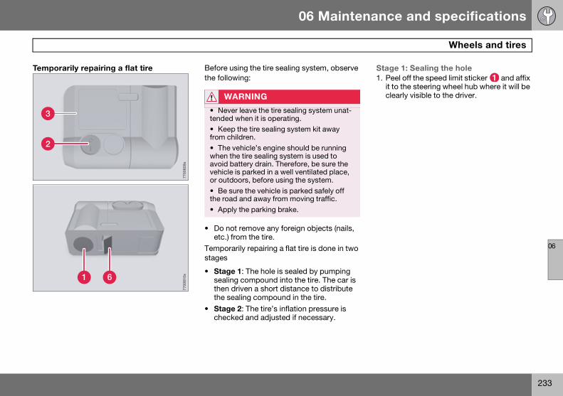
06 Maintenance and specifications
233
Wheels and tires
06
Temporarily repairing a flat tire
Before using the tire sealing system, observe the following:
• Do not remove any foreign objects (nails, etc.) from the tire.
Temporarily repairing a flat tire is done in two stages
• Stage 1: The hole is sealed by pumping sealing compound into the tire. The car is then driven a short distance to distribute the sealing compound in the tire.
• Stage 2: The tire’s inflation pressure is checked and adjusted if necessary.
Stage 1: Sealing the hole1. Peel off the speed limit sticker and affix
it to the steering wheel hub where it will be clearly visible to the driver.
3
2
7700
609s
1 6
7700
610s
WARNING
• Never leave the tire sealing system unat-tended when it is operating.• Keep the tire sealing system kit away from children.
• The vehicle’s engine should be running when the tire sealing system is used to avoid battery drain. Therefore, be sure the vehicle is parked in a well ventilated place, or outdoors, before using the system.
• Be sure the vehicle is parked safely off the road and away from moving traffic.
• Apply the parking brake.
S80 USA reprint version w640.book Page 233 Friday, June 1, 2007 10:44 AM

06 Maintenance and specifications
234
Wheels and tires
06
2. Ensure that the orange switch is in position 0 (the 0 side of the switch should be pressed down).
3. Pull out the electrical wire and hose from the side compartment .
4. Remove the valve cap from the tire’s inflation valve and screw the hose con-nector onto the valve as tightly as possi-ble by hand.
5. Connect the electrical wire to the near-est 12-volt socket in the vehicle.
6. Release the safety catch and turn the orange colored section of the sealing kit , which holds the sealing com-pound container, 90 degrees until it clicks into the vertical position.
7. Start the vehicle’s engine.
8. Start the tire sealing system’s compres-sor by pressing the switch to position I.
9. Within seven minutes, inflate the tire to between 22 - 50 psi (1.8 - 3.5 bar). Switch off the compressor briefly to get
a clear reading from the pressure gauge.
10.Disconnect the electrical wire from the 12-volt socket.
11.Unscrew the hose from the tire’s infla-tion valve and reinstall the valve cap.
12.Fold down the orange section of the tire sealing system to its original (horizontal) position and press the safety catch into place.
13.Safely stow the tire sealing system kit in a convenient place as it will soon be used again to check the tire’s inflation pressure.
14.Immediately drive the vehicle for ap-proximately 2 miles (3 km) to distribute the sealing compound in the tire.
5
4 8
7
7700
611s
NOTE
The air pressure gauge will temporarily show an increase in pressure to approxi-mately 59 psi (4 bar) while the sealing com-pound is being pumped into the tire. The pressure should return to a normal level af-ter approximately one minute.
WARNING
• Contact with the sealing compound may cause skin irritation. If contact occurs, wash the affected area immediately.• Never stand next to the tire being inflated when the compressor is in operation.
• If cracks, bubbles, etc. form on the tire, switch off the compressor immediately.• If there is visible damage to the sidewall or the rim, the tire cannot be repaired. The vehicle should not be driven if this occurs. Contact a towing service or Volvo On Call Roadside Assistance if applicable.
CAUTION
If the pressure remains below 22 psi (1.8 bar) after approximately seven min-utes, turn off the compressor. In this case, the hole is too large to be sealed and the vehicle should not be driven.
S80 USA reprint version w640.book Page 234 Friday, June 1, 2007 10:44 AM

06 Maintenance and specifications
235
Wheels and tires
06
Stage 2: Checking inflation pressure1. Park the car in a safe place.
2. Ensure that the orange switch is in position 0 (the 0 side of the switch should be pressed down).
3. Remove the valve cap from the tire’s inflation valve and screw the hose con-nector onto the valve as tightly as possi-ble by hand.
4. Connect the electrical wire to the near-est 12-volt socket in the vehicle.
5. Start the vehicle’s engine.
6. Check the tire’s inflation pressure on the gauge.
7. Inflate the tire to the correct pressure as indicated in the tire inflation tables on pages 217 and 218. If the tire needs to be inflated, start the tire sealing sys-tem’s compressor. If necessary, release air from the tire by pressing the vent button .
8. Turn off the compressor (press switch to the 0 position) when the correct inflation pressure has been reached.
9. Unscrew the hose from the tire’s infla-tion valve and reinstall the valve cap.
10.Disconnect the electrical wire from the 12-volt socket.
11.Return the hose and electrical wire to the compartment on the side of the unit.
After use, return the tire sealing system to its storage compartment under the floor of the trunk.
WARNING
If heavy vibrations, unsteady steering be-havior, or noises should occur while driv-ing, reduce speed and park the vehicle in a safe place. Recheck the tire for bumps, cracks, or other visible damage, and recheck its inflation pressure. If the pressure is below 16 psi (1.3 bar), do not continue driving. Have the vehicle towed to a workshop or Volvo retailer.
NOTE
In dark conditions, switching on the tire sealing system’s compressor will illumi-nate the pressure gauge.
CAUTION
The compressor should not be used for more than 10 minutes at a time to avoid overheating.
NOTE
When the tire sealing system has been used to seal a flat tire, the tank contain-ing the sealing compound, and the hose must be replaced. See the instructions on page 236. Contact a Volvo retailer for replacement parts.
WARNING
If you interrupt your trip for more than 1 hour, check the inflation pressure in the damaged tire again before continuing. See the section “Stage 2: Checking infla-tion pressure.”
S80 USA reprint version w640.book Page 235 Friday, June 1, 2007 10:44 AM

06 Maintenance and specifications
236
Wheels and tires
06
Replacing the sealing compound containerThe sealing compound container must be replaced if:
• the tire sealing system has been used to repair a tire
• the container’s expiration date has passed (see the date on decal ).
After use, the container , its retaining bracket , and the hose must be replaced. Please consult your Volvo retailer for replacement parts.
See also the safety regulations on the bottom of the container.
Replacing the container and hose after use1. Unscrew the two screws on the orange
casing.
2. Remove the speed limit sticker and the expiration date decal .
3. Release the safety catch and remove the casing from the tire sealing sys-tem unit.
4. Press down the button while twisting the container and retaining bracket clockwise approximately 2/3 of a turn and remove them.
5. To remove the hose , first press it into housing and then pull it out from the opposite side.
WARNING
Be sure that the compressor is not con-nected to a 12-volt socket while replacing the container.
4 5
1
3
2
7700
616s
10
7700
615s
6
8
9
7700
614s
S80 USA reprint version w640.book Page 236 Friday, June 1, 2007 10:44 AM

06 Maintenance and specifications
237
Wheels and tires
06
6. Wipe away any remaining sealing com-pound, or scrape it off if it has already hardened.
7. Insert a new air hose and check that it is properly seated.
8. Unscrew the cap from the new sealing compound container and check that the seal is intact and undamaged.
9. Screw the container firmly into the re-taining bracket.
10.Mount the bracket on the housing and twist it counterclockwise until it clicks into place.
11.Reinsert the casing. Check that it is correctly in place and tighten the screws, and press the safety catch into position.
12.Affix the speed limit decal and a new expiration date decal.
The empty container and used hose can be discarded as normal refuse, or recycled. Consult local regulations.
Replacing the container after its expira-tion date has passed1. Unscrew the two screws on the orange
casing.
2. Remove the speed limit sticker and the expiration date decal .
3. Release the safety catch and remove the casing from the tire sealing sys-tem unit.
4. Unscrew and remove the container.
5. Unscrew the cap from the new sealing compound container and check that the seal is intact and undamaged.
6. Screw the container firmly into the re-taining bracket .
7. Reinsert the casing. Check that it is correctly in place and tighten the screws, and press the safety catch into position.
8. Affix the speed limit decal and a new expiration date decal.
The empty container can be discarded as normal refuse, or recycled. Consult local regulations.
S80 USA reprint version w640.book Page 237 Friday, June 1, 2007 10:44 AM

06 Maintenance and specifications
238
Vehicle care
06
Washing the car
The following points should be kept in mind when washing and cleaning the car:
• The car should be washed at regular inter-vals since dirt, dust, insects and tar spots adhere to the paint and may cause dam-age. To help prevent corrosion, it is partic-ularly important to wash the car frequently in the wintertime.
• Avoid washing your car in direct sunlight. Doing so may cause detergents and wax to dry out and become abrasive. To avoid scratching, use lukewarm water to soften the dirt before you wash with a soft sponge, and plenty of sudsy water.
• Bird droppings: Remove from paintwork as soon as possible. Otherwise the finish may be permanently damaged.
• A detergent can be used to facilitate the softening of dirt and oil.
• A water-soluble grease solvent may be used in cases of sticky dirt. However, use a wash place equipped with a drainage separator.
• Dry the car with a clean chamois and remember to clean the drain holes in the doors and rocker panels.
• Tar spots can be removed with kerosene or tar remover after the car has been washed.
• A stiff-bristle brush and lukewarm soapy water can be used to clean the wiper blades. Frequent cleaning improves visi-bility considerably.
• Wash off the dirt from the underside (wheel housings, fenders, etc).
• In areas of high industrial fallout, more frequent washing is recommended.
• After cleaning the engine, the spark plug wells should be inspected for water and blown dry if necessary.
Exterior plastic components Cleaning exterior plastic components should be done with a cleaning agent specially designed for this purpose. Solvents or stain removers should not be used. Consult your Volvo retailer.
Automatic car wash • We do NOT recommend washing your car
in an automatic wash during the first six months (because the paint will not have hardened sufficiently).
• An automatic wash is a simple and quick way to clean your car, but it is worth
NOTE
When washing the car, remember to re-move dirt from the drain holes in the doors and sills.
CAUTION
• During high pressure washing, the spray mouthpiece must never be closer to the ve-hicle than 13" (30 cm). Do not spray into the locks. • When washing or steam cleaning the en-gine, avoid spraying water or steam directly on the electrical components or toward the rear side of the engine. Special moonroof cautions:
• Always close the moonroof and sun shade before washing your vehicle. • Never use abrasive cleaning agents on the moonroof.• Never use wax on the rubber seals around the moonroof.
S80 USA reprint version w640.book Page 238 Friday, June 1, 2007 10:44 AM
06 Maintenance and specifications
239
Vehicle care
06
remembering that it may not be as thor-ough as when you yourself go over the car with sponge and water. Keeping the un-derbody clean is most important, espe-cially in the winter. Some automatic washers do not have facilities for washing the underbody.
Exterior lightingCondensation may form temporarily on the inside of the lenses of exterior lights such as headlights, fog lights, or taillights. This is nor-mal and the lights are designed to withstand moisture. Normally, condensation will dissi-pate after the lights have been on for a short time.
Polishing and waxing• Normally, polishing is not required during
the first year after delivery, however, wax-ing may be beneficial.
• Before applying polish or wax the vehicle must be washed and dried. Tar spots can be removed with kerosene or tar remover. Difficult spots may require a fine rubbing compound.
• After polishing use liquid or paste wax.
• Several commercially available products contain both polish and wax.
• Waxing alone does not substitute for pol-ishing a dull surface.
• A wide range of polymer-based waxes can be purchased today. These waxes are easy to use and produce a long-lasting, high-gloss finish that protects the body-work against oxidation, road dirt and fad-ing.
• Do not polish or wax your vehicle in direct sunlight (the surface of the vehicle should not be warmer than 113° F (45° C).
CAUTION
• Before driving into an automatic car wash, turn off the optional rain sensor to avoid damaging the windshield wipers.
• Make sure that side view mirrors, auxilia-ry lamps, etc, are secure, and that any an-tenna(s) are retracted or removed. Otherwise there is risk of the machine dis-lodging them.
• Chromed wheels: Clean chrome-plated wheels using the same detergents used for the body of the vehicle. Aggressive wheel-cleaning agents can permanently stain chrome-plated wheels.
WARNING
• When the vehicle is driven immediately after being washed, apply the brakes sever-al times in order to remove any moisture from the brake linings. • Engine cleaning agents should not be used when the engine is warm. This consti-tutes a fire risk.
S80 USA reprint version w640.book Page 239 Friday, June 1, 2007 10:44 AM

06 Maintenance and specifications
240
Vehicle care
06
Side windows with the water repellent coating (option) • Do not apply wax, degreasing agents, etc.
to this glass. This could damage the coat-ing.
• Clean the glass surface with care to avoid scratching.
• Use only suitable plastic scrapers to re-move ice or snow from the windows.
Cleaning the interiorOnly use cleaning agents and car care prod-ucts recommended by Volvo. Clean regu-larly and follow the instructions included with the car care product.
Upholstery care
FabricClean with soapy water or a detergent. For more difficult spots caused by oil, ice cream, shoe polish, grease, etc., use a clothing/fab-ric stain remover. Consult your Volvo retailer.
Alcantera™ suede-like materialSuede-like upholstery can be cleaned with a soft cloth and mild soap solution.
Leather careVolvo's leather upholstery is manufactured with a protectant to repel soiling. Over time, sunlight, grease and dirt can break down the protection. Staining, cracking, scuffing, and fading can result.
Volvo offers an easy-to-use, non-greasy leather care kit formulated to clean and beautify your vehicle's leather, and to renew the protective qualities of its finish. The cleaner removes dirt and oil buildup. The light cream protectant restores a barrier against soil and sunlight.
CAUTION
Volvo does not recommend the use of long-life or durable paint protection coatings, some of which may claim to prevent pitting, fading, oxidation, etc. These coatings have not been tested by Volvo for compatibility with your vehicle's clear coat. Some of them may cause the clear coat to soften, crack, or cloud. Damage caused by appli-cation of paint protection coatings may not be covered under your vehicle's paint war-ranty.
NOTE
The water repellent coating is subject to natural wear.• In order to maintain the coating’s water repellent characteristics, it should be treat-ed with a special compound that is avail-able at your Volvo retailer.• This treatment should be carried out for the first time after three years, and thereaf-ter once a year.
S80 USA reprint version w640.book Page 240 Friday, June 1, 2007 10:44 AM

06 Maintenance and specifications
241
Vehicle care
06
Volvo also offers a special leather softener that should be applied after the cleaner and protectant. It leaves leather soft and smooth, and reduces friction between leather and other finishes in the vehicle.
Volvo recommends cleaning, protecting and conditioning your vehicle's leather two to four times a year. Ask your Volvo retailer about Leather Care Kit 951 0251 and Leather Softener 943 7429.
Cleaning the seat beltsClean only with lukewarm water and a mild soap solution.
Cleaning floor mats The floor mats should be vacuumed or brushed clean regularly, especially during winter when they should be taken out for dry-ing. Spots on textile mats can be removed with a mild detergent. For best protection in winter, Volvo recommends the use of Volvo rubber floor mats. Consult your Volvo retailer.
Spots on interior plastic parts and surfacesCleaning interior plastic components should be done with a cleaning agent specially designed for this purpose. Consult your Volvo retailer.
CAUTION
• Under no circumstances should gasoline, naphtha or similar cleaning agents be used on the plastic or the leather since these can cause damage.• Take extra care when removing stains such as ink or lipstick since the coloring can spread.• Use solvents sparingly. Too much solvent can damage the seat padding.
• Start from the outside of the stain and work toward the center.
• Sharp objects (e.g. pencils or pens in a pocket) or Velcro fasteners on clothing may damage the textile upholstery.
• Clothing that is not colorfast, such as new jeans or suede garments, may stain the upholstery.
S80 USA reprint version w640.book Page 241 Friday, June 1, 2007 10:44 AM

06 Maintenance and specifications
242
Vehicle care
06
Touching up paintwork
Paint code on the model plate1
Paint damage requires immediate attention to avoid rusting. Make it a habit to check the finish regularly, for instance washing the vehicle. Touch-up if necessary.
Paint repairs require special equipment and skill. Contact your Volvo retailer for any extensive damage.
Minor scratches can be repaired by using Volvo touch-up paint.
Color code Make sure you have the right color. The color code number is stated on the model plate.
Minor stone chips and scratchesMaterial:
• Primer - can
• Paint - touch-up pen
• Brush
• Masking tape
If the stone chip has not gone down to the bare metal and an undamaged color coat remains, you can add paint immediately after removing dirt.
Minor scratches on the surfaceIf the stone chip has not penetrated down to the metal and an undamaged layer of paint remains, the touch-up paint can be applied as soon as the spot has been cleaned.
Repairing stone chips
1. Place a strip of masking tape over the damaged surface. Pull the tape off so that any loose flakes of paint adhere to it.
2. Thoroughly mix the primer and apply it with a small brush.
3. When the primer surface is dry, the paint can be applied using a brush. Mix the paint thoroughly; apply several thin paint coats and let dry after each appli-cation.
4. If there is a longer scratch, you may want to protect surrounding paint by masking it off
5. After a few days, polish the touched-up areas. Use a soft rag and a small amount of polish.
1 See page 243 for the location of the model plate.
0300
443s
NOTE
When touching up the vehicle, it should be clean and dry. The surface temperature should be above 60° F (15° C).
1700
382s
S80 USA reprint version w640.book Page 242 Friday, June 1, 2007 10:44 AM

06 Maintenance and specifications
243
Label information
06
Location of labels
TEST GROUP: 7VVXB03.2U2N
THIS VEHICLE CONFORMS TO USE EPA TIER 2 BIN 5 REGULATIONS AND CALIFORNIA REGULATIONS APPLICABLE TO 2007 MODEL YEAR NEW LEVII ULEV PASSENGER CARS. IT ALSO CONFORMS TO APPLICABLE CANADIAN EMISSION STANDARDS.
SFI, 2HO2S, SHA/FS, 2TWC(2) EXHAUST EMISSION CONTROL SYSTEM: EVAPORATIVE/REFUELING FAMILY:7VVXR0130EVX
TUNE-UP SPECIFICATIONS: NO ADJUSTMENTS NEEDED
FILTER
VALVE PURGE
CANISTER
OIL P
UMP
FROM FUEL TANK
ENGINE DISPLACEMENT:3.2 LITERS ENGINE: B6324S MANUFACTURER: VOLVO CAR CORP. SWEDEN
30760010 VACUM
ROUTING HOUSE
5
4
200KPA, 29PSI 200KPA, 29PSI SPARE
FRONT
REAR
TIRE
RECOMMENDED FOR FUEL ECONOMY
200KPA, 29PSI
200KPA, 29PSI
The combinad waight of occupants and cargo should never exeed xxx Kg or xxx pounds
If tires are hot from driving add 4pal (28kPa) to these recommended pressures
SEE OWNERS MANUAL FOR ADDITIONAL INFORMATION
COLD TIRE PRESSURE
200KPA, 29PSI
200KPA, 29PSI
SIZE
TIRE
235/45R17
SPARE
SIZE TIRE
T125/80R17
2 PRESSURE
INFLATION PRESSURE
OPTIONAL 5 3 32
61
32
FRONT OCCUPANTS VEHICLECAPACITY
1000Kg WEIGHTS
LOAD MAX
2 FRONT
TIRE TOTAL REAR
3
COLD
38 5
PRESSURE REAR
38
3
GAWR FRONT (PBBE AVANT): 1130 KG GAWR REAR (PNBE ARRIERE): 1190 KG
VIN: YV1CZ91451192792 TYPE: PC/VT
GVWR (PNBV):2220 KG
DATE: 0303
30760250
COMPLIES: ICES-2
THIS VEHICLE CONFORMS TO ALL APPLICABLE FEDERAL MOTOR VEHICLE SAFTY, BUMPER AND THEFT PREVENTION STANDARDA IN EFFECT ON THE DATE OF MANUFACTURE SHOWN ABOVE. VIN: YV1TS90D3Y1144849 TYPE:PASS CAR
DATE: 04/00 GAWR FRONT: 2491 LB
30760248
GAWR:4630 LB GAWR REAR: 2293 LB GAWG
T A R
T S N R
P O
V
C M
S
S
984
C A A N D A
V
C
A
N S
2
3074
8043
1
G016396
S80 USA reprint version w640.book Page 243 Friday, June 1, 2007 10:44 AM

06 Maintenance and specifications
244
Label information
06
List of labels
Model plateVehicle Identification Number (VIN). Codes for color and upholstery, etc.
Federal Motor Vehicle Safety Stan-dards (FMVSS) specifications (USA) and Ministry of Transport (CMVSS) standards (Canada) Your Volvo is designed to meet all appli-cable safety standards, as evidenced by the certification label on the facing side of the driver’s door. For further information regarding these regulations, please con-sult your Volvo retailer.
Loads and Tire PressuresThe appearance of the decal will vary, depending on the market for which the vehicle is intended. See also page 214.
Vehicle Identification Number (VIN)The VIN plate is located on the top left surface of the dashboard. The Vehicle Identification Number (VIN) should always be quoted in all correspondence con-cerning your vehicle with the retailer and when ordering parts.
Vehicle Emission Control Information/Vacuum hose routingYour Volvo is designed to meet all appli-cable emission standards, as evidenced by the certification label on the underside of the hood. For further information re-
garding these regulations, please consult your Volvo retailer.
S80 USA reprint version w640.book Page 244 Friday, June 1, 2007 10:44 AM

06 Maintenance and specifications
245
Specifications
06
Dimensions
Dimensions
Length 191 in (485 cm)
Height 58.8 in. (149 cm)
Width 73.3 in. (186 cm)
Wheelbase 111.6 in (284 cm)
Front track 62.1-62.5 in (158-159 cm)
Rear track 62-62.4 in. (158-159 cm)
Turning circle 36.7-40 ft. (11.2-12.2 m)
Cargo capacity (trunk)
17 cu. ft. (480 liters)
S80 USA reprint version w640.book Page 245 Friday, June 1, 2007 10:44 AM

06 Maintenance and specifications
246
Specifications
06
Weights
Category USA Canada
Gross vehicle weight 6-cyl. FWD: 4820 lbs6-cyl. AWD: -8-cyl. AWD: 5110 lbs
6-cyl. FWD: 2190 kg6-cyl. AWD: 2270 kg8-cyl. AWD: 2320 kg
Capacity weight 6-cyl. FWD: 905 lbs6-cyl. AWD: -8-cyl. AWD: 890 lbs.
6-cyl. FWD: 410 kg6-cyl. AWD: 410 kg8-cyl. AWD: 400 kg
Permissible axle weights, front
6-cyl. FWD: 2690 lbs6-cyl. AWD: -8-cyl. AWD: 2860 lbs.
6-cyl. FWD: 1220 kg6-cyl. AWD: 1250 kg8-cyl. AWD: 1300 kg
Permissible axle weights, rear
6-cyl. FWD: 2270 lbs6-cyl. AWD: -8-cyl. AWD: 2380 lbs.
6-cyl. FWD: 1030 kg6-cyl. AWD: 1080 kg8-cyl. AWD: 1080 kg
Curb weight 3725–4090 lbs 1700–1855 kg
Max. roof load 220 lbs 100 kg
Max. trailer weights Without brakes: 1650 lbsWith brakes, 1 7/8” ball: 2,000 lbsWith brakes, 2” ball: 3,300 lbs
Without brakes: 750 kgWith brakes, 1 7/8” ball: 900 kgWith brakes, 2” ball: 1500 kg
Max. tongue weight 165 lbs 75 kg
S80 USA reprint version w640.book Page 246 Friday, June 1, 2007 10:44 AM
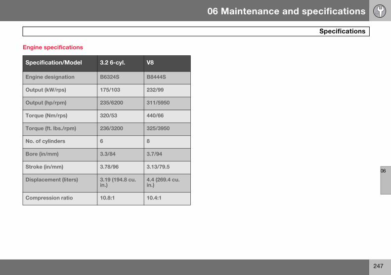
06 Maintenance and specifications
247
Specifications
06
Engine specifications
Specification/Model 3.2 6-cyl. V8
Engine designation B6324S B8444S
Output (kW/rps) 175/103 232/99
Output (hp/rpm) 235/6200 311/5950
Torque (Nm/rps) 320/53 440/66
Torque (ft. lbs./rpm) 236/3200 325/3950
No. of cylinders 6 8
Bore (in/mm) 3.3/84 3.7/94
Stroke (in/mm) 3.78/96 3.13/79.5
Displacement (liters) 3.19 (194.8 cu. in.)
4.4 (269.4 cu. in.)
Compression ratio 10.8:1 10.4:1
S80 USA reprint version w640.book Page 247 Friday, June 1, 2007 10:44 AM

06 Maintenance and specifications
248
Specifications
06
Engine oil
Engine oil must meet the minimum ILSAC specification GF-3, API SL, or ACEA A1/B1. Lower quality oils may not offer the same fuel economy, engine performance, or engine protection.
Volvo recommends oil products.
Depending on your driving habits, premium or synthetic oils may provide superior fuel economy and engine protection. Consult your Volvo retailer for recommendations on premium or synthetic oils.
Oil additives must not be used.
Synthetic oil is not used when the oil is changed at the normal maintenance ser-vices. This oil is only used at customer request, at additional charge. Please consult your Volvo retailer.
Oil viscosity (stable ambient tempera-tures)Operation in hot climates
When temperatures exceed 86° F (30° C) in your area, Volvo recommends, for the pro-tection of your engine, that you use a heavier weight oil, such as such as SAE 5W-40 or 0W-40. See the viscosity chart.
Viscosity table
Operation in temperate climates
Incorrect viscosity oil can shorten engine life. Under normal use when temperatures do not exceed 86° F (30° C), SAE 5W-30 will provide good fuel economy and engine protection. See the viscosity chart.
Extreme engine operation
Synthetic oils meeting SAE 0W-30 or 0W-40 and complying with oil quality requirements are recommended for driving in areas of sus-tained temperature extremes (hot or cold), when towing a trailer over long distances, and for prolonged driving in mountainous areas.
American Petroleum Institute (API) symbol
American Petroleum Institute (API) symbolThe API Service Symbol “donut” is divided into three parts:
• The upper section describes the oil’s per-formance level.
• The center identifies the oil’s viscosity.
• The lower section indicates whether the oil has demonstrated energy-conserving properties in a standard test in compari-son to a reference oil.
0300
449s
S80 USA reprint version w640.book Page 248 Friday, June 1, 2007 10:44 AM

06 Maintenance and specifications
249
Specifications
06
Oil volume
Engine variantOil volume between MIN and MAX (liters)
Volume (liters)
3.2 6-cyl. B6324S 0.8 7.3
V8 B8444S 1.1 7.0
S80 USA reprint version w640.book Page 249 Friday, June 1, 2007 10:44 AM
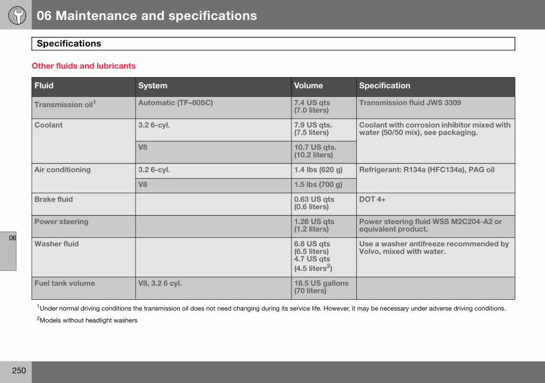
06 Maintenance and specifications
250
Specifications
06
Other fluids and lubricants
Fluid System Volume Specification
Transmission oil1 Automatic (TF–80SC) 7.4 US qts (7.0 liters)
Transmission fluid JWS 3309
Coolant 3.2 6-cyl. 7.9 US qts. (7.5 liters)
Coolant with corrosion inhibitor mixed with water (50/50 mix), see packaging.
V8 10.7 US qts. (10.2 liters)
Air conditioning 3.2 6-cyl. 1.4 lbs (620 g) Refrigerant: R134a (HFC134a), PAG oil
V8 1.5 lbs (700 g)
Brake fluid 0.63 US qts (0.6 liters)
DOT 4+
Power steering 1.26 US qts (1.2 liters)
Power steering fluid WSS M2C204-A2 or equivalent product.
Washer fluid 6.8 US qts (6.5 liters)4.7 US qts (4.5 liters2)
Use a washer antifreeze recommended by Volvo, mixed with water.
Fuel tank volume V8, 3.2 6 cyl. 18.5 US gallons (70 liters)
1Under normal driving conditions the transmission oil does not need changing during its service life. However, it may be necessary under adverse driving conditions.
2Models without headlight washers
S80 USA reprint version w640.book Page 250 Friday, June 1, 2007 10:44 AM

06 Maintenance and specifications
251
Specifications
06
Electrical system
General information12 volt system with a voltage-regulated alter-nator. Single pole system in which the chas-sis and engine block are used as conductors. The negative terminal is connected to the chassis.
.
Performance, battery
Engine 3.2 6-cyl.
V8
Voltage (V) 12 12
Cold start capacity (A)
520 8001
1Certain models may be equipped with 600 or 700 A batteries, depending on the options chosen.
Reserve capacity (min)
100 120
WARNING
PROPOSITION 65 WARNING! Battery posts, terminals, and related acces-sories contain lead and lead compounds, chemicals known to the state of California to cause cancer and reproductive harm. Wash hands after handling.
CAUTION
If the battery is replaced, replace it with a battery of the same cold start capacity and reserve capacity as the original (see the de-cal on the battery).
S80 USA reprint version w640.book Page 251 Friday, June 1, 2007 10:44 AM
06 Maintenance and specifications
252
Volvo programs
06
Volvo On Call Roadside Assistance
Your new Volvo comes with a four year ON CALL roadside assistance. Additional infor-mation, features, and benefits are described in a separate information package in your glove compartment.
If you have misplaced your package, dial:
In the U.S.A.
1-800-638-6586 (1-800-63-VOLVO)
In Canada:
1-800-263-0475
Technician certificationIn addition to Volvo factory training, Volvo supports certification by the National Insti-tute for Automotive Service Excellence (A.S.E.). Certified technicians have demon-strated a high degree of competence in spe-cific areas. Besides passing exams, each technician must also have worked in the field for two or more years before a certificate is issued. These professional technicians are best able to analyze vehicle problems and perform the necessary maintenance proce-dures to keep your Volvo at peak operating condition.
S80 USA reprint version w640.book Page 252 Friday, June 1, 2007 10:44 AM
06 Maintenance and specifications
253
06
S80 USA reprint version w640.book Page 253 Friday, June 1, 2007 10:44 AM

Index
254
12-volt sockets ................................. 162-163
AAccessory installation warning .....................7
Active Bi-Xenon headlights ........................87
Active chassis system ..............................143
Active yaw control ....................................141
Adaptive cruise control ............................................... 146-150
Air conditioning .........................................124
Air distribution ...........................................121
Air distribution table ..................................126
Air vents ....................................................122
Airbags
disconnecting the front passenger’s side .................................................. 23-25front ................................................. 20-22inflatable curtain ....................................27side impact ............................................26
Alarm system ........................................ 64-66
All wheel drive ...........................................108
Anti-freeze ....................................... 168, 192
Anti-lock brake system .............................109
warning light ..........................................73Approach lighting ................................ 52, 91
Audio system
audio functions ................................... 129CD player/changer .......................130-131menu control ....................................... 128overview .............................................. 127radio functions .................................... 132Sirius satellite radio ......................134-137sound settings .................................... 129steering wheel keypad ........................ 127
Auto-dim rearview mirror ........................... 97
Automatic locking ...................................... 61
Automatic locking retractor ........................ 33
Automatic transmission
Geartronic ....................................107-108general description ......................107-108oil ........................................................ 250shiftlock override ................................. 108
Axle weight ............................................... 224
BBattery
changing ......................................204-205maintenance ....................................... 204remote control, replacing ...................... 57specifications ...................................... 251warning symbols ................................. 203
Black box .............................................6, 186
Blind Spot Information System (BLIS) .................................................157-159
Booster cushion, integrated ................. 44-46
Booster cushions ........................................ 41
Brake lights ................................................. 88
Brake support ........................................... 152
Brake system
checking fluid level .............................. 193emergency brake assistance ............... 110fluid ...................................................... 250general information .............................. 109warning light .......................................... 75
Bulbs
footwell lighting ................................... 199headlights .................................... 194-196introduction ......................................... 194license plate lights ............................... 198side marker lights ................................ 197specifications ...................................... 200taillight ......................................... 197-198trunk lighting ........................................ 199
CCapacity weight ........................................ 224
Catalytic converter ................................... 173
CD player/changer ........................... 130-131
Central locking system, introduction .......... 50
Chains ...................................................... 227
Check engine light ...................................... 73
Child restraint systems ......................... 34-35
S80 USA reprint version w640.book Page 254 Friday, June 1, 2007 10:44 AM

Index
255
booster cushions ...................................41convertible seats ............................. 38-40infant seats ...................................... 36-37ISOFIX/LATCH anchors .........................42top tether anchors .................................43
Child safety ........................................... 31-33
booster cushions ...................................41child restraint systems ..................... 34-35convertible seats ............................. 38-40infant seats ...................................... 36-37
Child safety locks .......................................47
Climate system
air distribution ......................................121air vents ...............................................122Interior Air Quality System ...................121introduction .........................................120passenger compartment filter .............120refrigerant ............................................120
Clock, setting ..............................................76
Cold weather driving .................................168
Collision warning system .................. 152-154
Compass in rearview mirror ......................139
Conserving electrical current ....................167
Convertible seats .................................. 38-40
Coolant ............................................ 192, 250
Cooling system, general information ........167
Courtesy lighting ................................... 90-91
Crash mode ................................................ 30
Cruise control ....................................144-145
adaptive .......................................146-150Curb weight .............................................. 224
Current, conserving .................................. 167
DDefroster .................................................. 124
Detachable key blade ...........................55-56
Dimensions .............................................. 245
Disconnecting the front passenger’s airbag ....................................................23-25
Dome lighting ........................................90-91
Door mirrors ............................................... 96
Driver distraction warning ............................ 7
Driving economically ................................ 166
Driving in cold weather ............................ 168
Driving through water ............................... 167
EECC ...................................................122-126
Economical driving ................................... 166
Electric parking brake .............................. 112
Electronic Climate Control ................122-126
air distribution table ............................ 126Interior Air Quality System .................. 125
ventilated seats ................................... 123Emergency brake lights .............................. 88
Emergency locking retractor ...................... 33
Emergency starting .................................. 106
Emergency towing .................................... 181
Emission inspection readiness ................. 188
Engine
specifications ...................................... 247starting ................................................ 104starting with keyless drive ................... 105
Engine compartment overview ................. 189
Engine oil
checking .............................................. 190low pressure warning light .................... 74specifications ...................................... 248volumes ............................................... 249
Environment ................................................. 9
Eyelets for anchoring loads ...................... 175
FFederal Clean Air Act ................................ 186
Flat tires, tire sealing system .................... 232
Fluid specifications ................................... 250
Fog lights
front ....................................................... 74front, changing bulbs .......................... 197front/rear ................................................ 88
S80 USA reprint version w640.book Page 255 Friday, June 1, 2007 10:44 AM

Index
256
Four C (active chassis system) .................143
Front airbags ......................................... 20-22
disconnecting passenger’s side airbag ............................................... 23-25
Front fog lights ..................................... 74, 88
changing bulbs ....................................197Front park assist ............................... 155-156
Front seats ..................................................81
heated ..................................................123Fuel filler cap ............................................173
Fuel filler door, opening ............................172
Fuel level warning light ...............................74
Fuel requirements ............................. 170-171
Fuel tank volume ......................................250
Fuses ................................................ 206-211
GGas tank volume .......................................250
Gasoline requirements ..............................171
Gauges .......................................................72
Geartronic automatic transmission ... 107-108
General warnings ..........................................7
Generator warning light ..............................75
Glossary of tire terminology ......................223
Glove compartment, locking ......................62
Grocery bag holder ...................................176
Gross vehicle weight ................................ 224
HHazard warning flashers ............................ 89
Headlight washers ..................................... 93
Headlights
active bi-xenon lights ............................ 87changing bulbs ............................195-196high beam flash ..................................... 86high/low beams ..................................... 86switch .................................................... 86
Heartbeat sensor (alarm system) ............... 54
Heated front seats .................................... 123
Heated oxygen sensors ........................... 174
Heated rear seats ..................................... 123
High beams ................................................ 86
indicator light ........................................ 74Home safe lighting ..................................... 91
HomeLink universal transceiver .........................................100-103
Hood ........................................................ 189
Horn ........................................................... 85
IIgnition modes ........................................... 77
Immobilizer ................................................. 51
Important information ................................... 6
Indicator lights ...................................... 72-75
Infant seats ........................................... 36-37
Inflatable curtain ......................................... 27
Inflation pressure .............................. 214-215
Inflation pressure tables ................... 217-218
Information lights .................................. 72-75
Information symbol ..................................... 74
Inspection readiness ................................ 188
Instrument lighting ...................................... 86
Instrument overview ............................. 70-72
Instrument panel ............................... 118-119
Integrated booster cushion .................. 44-46
Interior Air Quality System ............... 121, 125
Interior lighting ...................................... 90-91
ISOFIX anchors .......................................... 42
JJack
attaching .............................................. 231location of ............................................ 230
Jump starting ........................................... 106
KKey blade ........................................50, 55-56
valet locking .......................................... 56Keyless drive
S80 USA reprint version w640.book Page 256 Friday, June 1, 2007 10:44 AM

Index
257
locking and unlocking the vehicle ... 58-59starting the engine ...............................105
LLabels
list of ....................................................244location of ............................................243
LATCH anchors ..........................................42
Leather care ..............................................240
Lighting panel .............................................86
Load anchoring eyelets ............................175
Loading the vehicle .................. 175-176, 224
roof loads .............................................177Locking
automatic ...............................................61from the inside .......................................61from the outside ....................................61glove compartment ...............................62trunk .......................................................62
Locking the vehicle .....................................52
Locks, child safety ......................................47
Long loads, ski hatch ................................176
Low beams .................................................86
Low fuel level warning light ........................74
Low oil pressure warning light ....................74
MMain instrument panel .......................118-119
Maintenance ............................................. 186
performed by the owner ..................... 187Malfunction indicator light .......................... 73
Manual parking brake .............................. 111
Menu system ............................................ 116
overview .............................................. 117Messages in the instrument panel ....118-119
Mirrors
defroster ................................................ 97power door ............................................ 96rearview, auto-dim function .................. 97retractable ............................................. 96vanity ................................................... 162
Moonroof ...............................................98-99
Motor oil
checking .............................................. 190specifications ...................................... 248volumes ............................................... 249
OOccupant safety ......................................... 14
Occupant weight sensor .......................23-25
Octane recommendations ........................ 171
Odometer, trip ............................................ 76
Oil
checking .............................................. 190low pressure warning light .................... 74specifications ...................................... 248volumes ............................................... 249
On Call Roadside Assistance ................... 252
Opening the trunk from the inside .............. 63
Overhead courtesy lighting .................. 90-91
Oxygen sensors, heated ........................... 174
PPaint, touching up .................................... 242
Panic alarm ................................................. 53
Park assist ........................................ 155-156
Parking brake
electric, applying/releasing .................. 112manual, applying/releasing ................. 111warning light .......................................... 74
Parking lights .............................................. 87
changing bulbs ............................ 195-196Personal Car Communicator, unique functions ................................... 53-54
Power front seat
memory function ................................... 80with keyless drive .................................. 81
Power mirrors ............................................. 96
defroster ................................................ 97
S80 USA reprint version w640.book Page 257 Friday, June 1, 2007 10:44 AM

Index
258
Power moonroof ................................... 98-99
Power steering
fluid ............................................. 193, 250speed-dependent ................................143
Power windows .................................... 94-95
laminated glass ......................................95water repellent glass ..............................95
Pregnancy, using seat belts during ............18
Proposition 65 warning .......9, 106, 205, 251
RRadio
functions ..............................................132Sirius satellite radio ..................... 134-137
Rain sensor .................................................92
READ button ..................................... 118-119
Rear fog light ..............................................88
Rear park assist ................................ 155-156
Rear seats
center head restraint ..............................82folding ....................................................82heated ..................................................123lowering outboard head restraints .........83
Rear window defroster ...............................97
Rearview mirror
auto-dim function ..................................97compass ..............................................139
Refrigerant ................................................ 250
Refueling ...........................................170-171
fuel filler cap ........................................ 173fuel filler door ...................................... 172fuel tank volume .................................. 250octane ratings ..................................... 171
Remote control .......................................... 50
approach lighting .................................. 52common functions ................................ 52immobilizer ............................................ 51key blade ...................................50, 55-56key memory .......................................... 51locking the vehicle ................................ 52panic alarm ........................................... 53Personal Car Communicator ...........52-54replacing battery ................................... 57unlocking the trunk ............................... 53unlocking the vehicle ............................ 52valet locking .......................................... 56
Reporting safety defects ............................ 15
Roadside Assistance ................................ 252
Roof loads ................................................ 177
SSafety defects, reporting ............................ 15
Safety, occupant ........................................ 14
Seat belts
Automatic locking retractor/
Emergency locking retractor ................. 33buckling ................................................. 16maintenance .......................................... 17reminder ................................................ 17reminder warning light ........................... 75securing child restraint systems ....................................36, 38, 41tensioners .............................................. 16unbuckling ............................................. 17use during pregnancy ............................ 18using ...................................................... 16
Seats, front ........................................... 79-80
Self supporting run flat tires ..................... 221
Shiftlock override ...................................... 108
Side door mirrors ........................................ 96
Side impact airbags .................................... 26
Side marker lights, changing bulbs .......... 197
Sirius satellite radio .......................... 134-137
Ski hatch ................................................... 176
Snow chains ............................................. 227
Snow tires ................................................. 227
Sound settings, audio system .................. 129
Spare tire .................................................. 228
Speed-dependent steering ....................... 143
Spin control .............................................. 141
SRS ............................................................ 19
Stability system ........................................ 142
S80 USA reprint version w640.book Page 258 Friday, June 1, 2007 10:44 AM

Index
259
indicator light .........................................74overview ..............................................141
Start inhibitor (immobilizer) .........................51
Starting the engine ...................................104
with keyless drive ................................105Starting the vehicle ...................................104
after a crash (crash mode) .....................30Steering wheel
adjusting ................................................84horn .......................................................85keypad ................................. 84, 116, 127lock ......................................................105
Storage spaces .........................................160
Studded tires ............................................227
Sunroof (moonroof) ............................... 98-99
Supplemental restraint system ...................19
warning light ..........................................75
TTaillights, changing bulbs .........................198
Temporary spare tire ................................228
Three-way catalytic converter ..................173
Tire pressure monitoring system ..............219
indicator light .........................................74Tires
age .......................................................213changing from summer to winter .........229
designations ........................................ 222glossary of terms ................................ 223improving economy ............................ 213inflation pressure ..........................214-215inflation pressure tables ...............217-218self supporting run flat tires ................ 221snow .................................................... 227spare ................................................... 228specifications ...................................... 216storing ................................................. 212studded ............................................... 227tire pressure monitoring system ..219-220tire sealing system .............................. 232uniform tire quality grading ................. 226
Top tether anchors (child restraint systems) ..................................................... 43
Touching up paint .................................... 242
Towing a trailer ..................................178-179
trailer hitch .......................................... 180Towing the vehicle ................................... 181
Traction control ........................................ 141
Trailer towing .....................................178-179
trailer hitch .......................................... 180Transmission
Geartronic ........................................... 107general description ......................107-108oil ........................................................ 250shiftlock override ................................. 108
Tread wear indicator ................................ 212
Trip computer ........................................... 138
Trip odometers ........................................... 76
Trips, long distance .................................. 167
Trunk
changing bulbs .................................... 199driving with it open .............................. 166locking/unlocking .................................. 62opening from the inside ......................... 63
Turn signals
changing bulbs .................................... 196indicator lights ....................................... 74using ...................................................... 89
UUniform Tire Quality Grading .................... 226
Unlocking the trunk .................................... 53
Unlocking the vehicle ................................. 52
Upholstery care ........................................ 240
VValet locking ............................................... 56
Vanity mirror ............................................. 162
changing bulbs .................................... 199Vehicle dimensions ................................... 245
Vehicle event data ............................... 6, 186
Vehicle loading .........................175-176, 224
roof loads ............................................ 177
S80 USA reprint version w640.book Page 259 Friday, June 1, 2007 10:44 AM

Index
260
Vehicle maintenance .................................186
performed by the owner ......................187Vehicle weights .........................................246
Ventilated seats ........................................123
Volvo and the environment ...........................9
Volvo Inflatable curtain ...............................27
Volvo maintenance ...................................186
Volvo On Call Roadside Assistance .........252
Volvo programs ........................................252
WWarning flashers, hazard ............................89
Warning lights ....................................... 72-75
Warning symbol ..........................................75
Warning system, collision ................. 152-154
Warnings, general .........................................7
Warranties .................................................186
Washer fluid ..................................... 202, 250
Washers
headlight ................................................93windshield ..............................................92
Water repellent glass
cleaning ...............................................240description of .........................................95
Water, driving through ..............................167
Weights .....................................................246
Wheels
changing ......................................230-231storing ................................................. 212
Wheels and tires, introduction ................. 212
Whiplash protection system ..................28-29
Windows
laminated glass ..................................... 95power ...............................................94-95water repellent glass ............................. 95
Windshield
rain sensor ............................................ 92washer fluid .................................202, 250washers ................................................. 93wipers/washers ..................................... 92
Wiper blades, replacing ........................... 201
S80 USA reprint version w640.book Page 260 Friday, June 1, 2007 10:44 AM

Volvo. for life
Volvo Car Corporation TP 9138 (uSa & Canada), aT 0640, Printed in Sweden, Göteborg 2006, Copyright © 2000-2006 Volvo Car Corporation