Effects of Compositional Tailoring on Drug Delivery ... - CORE
Upload
khangminh22Category
view
0download
0
7234 | Chem. Soc. Rev., 2015, 44, 7234--7261 This journal is©The Royal Society of Chemistry 2015
Cite this: Chem. Soc. Rev., 2015,
44, 7234
Tailoring and visualizing the pore architecture ofhierarchical zeolites
Ying Wei,* Tanja E. Parmentier, Krijn P. de Jong and Jovana Zecevic*
Recently the concept of hierarchical zeolites invoked more explicit attention to enhanced accessibility of
zeolites. By realizing additional meso-/macroporosity with the intrinsic microporosity of zeolites, a hierarchical
pore system arises which facilitates mass transport while maintaining the zeolite shape selectivity. A great
number of synthesis strategies have been developed for tailoring the pore architecture of hierarchical
zeolites. In this review, we give a general overview of different synthesis methods for introduction of
additional porosity. Advantages and limitations of these different synthesis approaches are addressed. The
assessment of pore structure is essential to build the link between the zeolite pore structure and its
functionality. A variety of 2D and 3D microscopy techniques are crucial to visualize the hierarchical pore
structure, providing unique and comprehensive information that, however, should be linked to the results of
bulk characterization techniques as much as possible. The microscopy techniques are classified and
discussed according to the different probes used, such as optical light, X-rays and electrons. Representative
work is reviewed to elucidate the capability of each technique and their drawbacks.
1. Introduction
Zeolites are crystalline aluminosilicates of various structurescontaining ordered micropore networks and large active surfaces,rendering these materials their great importance as shape-selective adsorbents and catalysts in a wide range of industrial
applications such as refinery and petrochemical processes.1–3
Zeolite micropores have the same dimensions as most moleculesinvolved in the catalytic reactions they are applied for. Reactantsthat have larger dimensions than the channels in the zeoliteswill not be able to enter the pore system and diffuse to theseactive sites. This is called reactant shape selectivity and isillustrated in Fig. 1a. The shape of the zeolite pores can alsoinfluence the selectivity towards certain products. This is calledtransition state selectivity since a certain transition state isfavoured over others due to the limited space in the pores, as
Inorganic Chemistry and Catalysis, Debye Institute for Nanomaterials Science,
Utrecht University, Universiteitsweg 99, 3584 CG, Utrecht, Netherlands.
E-mail: [email protected], [email protected]; Fax: +31 30 2511027; Tel: +31 62 8834480
Ying Wei
Ying Wei (1981) received hisBachelor degree (2004) in chemicalengineering from Dalian Universityof Technology and PhD degree(2011) in industrial catalysis fromDalian Institute of Chemical Physics,Chinese Academy of Sciences. Hecontinued with his first post-doctoral research in Prof. HermannGies’ group in Crystal Chemistry,Ruhr University Bochum. In 2013,he joined Prof. Krijn P. de Jong’sgroup as a postdoctoral researchfellow in the Chemistry department
of Utrecht University, focusing on hierarchical zeolites and theirapplication in methanol conversion. His research interests includezeolitic materials synthesis, structure analysis and catalytic application.
Tanja E. Parmentier
Tanja E. Parmentier (1991)completed her MSc (2014) inChemistry (Cum Laude) at theUniversity of Utrecht in theNetherlands. She performed herMaster’s research under thesupervision of Professor Krijn deJong. The research was focused onthe deactivation of a methanolsynthesis catalyst. In addition, shestudied cobalt Fischer–Trøpschcatalysts using XAS (X-rayabsorption spectroscopy) during aresearch internship under the
supervision of Professor Magnus Rønning at the Norwegian Universityof Science and Technology. Both research projects have been published.
Received 18th February 2015
DOI: 10.1039/c5cs00155b
www.rsc.org/chemsocrev
Chem Soc Rev
REVIEW ARTICLE
Ope
n A
cces
s A
rtic
le. P
ublis
hed
on 2
6 M
ay 2
015.
Dow
nloa
ded
on 1
/29/
2022
10:
06:0
9 PM
. T
his
artic
le is
lice
nsed
und
er a
Cre
ativ
e C
omm
ons
Attr
ibut
ion
3.0
Unp
orte
d L
icen
ce.
View Article OnlineView Journal | View Issue

This journal is©The Royal Society of Chemistry 2015 Chem. Soc. Rev., 2015, 44, 7234--7261 | 7235
shown in Fig. 1b. The last type is product shape selectivity, whichis shown in Fig. 1c. Generated molecules that are relatively largewill have a limited diffusivity to reach the end of the pores. Thesemolecules will probably be converted to smaller products insidethe zeolite or even contribute to the deactivation of the zeolite byblocking the pores or the formation of coke.4 According to theInternational Zeolite Association (IZA), to date over 200 zeolites withdifferent structures have been discovered in nature or synthesized inthe laboratory.5 Although there is such a variety of zeolites withdifferent microporous systems, the zeolite with optimal structurecan find utilization in different catalytic reactions.
Zeolite micropores are beneficial for the unique shapeselectivity in catalysis; however, the sole presence of the micro-porous network also imposes significant diffusion limitation.The diffusion of the bulky molecules into and from the activesites confined in the zeolite crystals is impeded. Even when the
size of micropores is larger than the molecules of the reactants andproducts, slow mass transport of these molecules through the poresystem may be apparent. Diffusion limitation due to restrictedaccess and low diffusion coefficients will lower the effectiveness ofthe zeolite and reduce the reaction rate. Furthermore, it may alsocause pore blocking due to the large molecules or coke formationthat contributes to deactivation of the catalysts.
Great efforts have been made to explore new materials withimproved pore architecture to solve the diffusion limitationproblem associated with conventional microporous zeolites.Ordered mesoporous aluminosilicates with pore size between2 and 50 nm have gathered considerable research interest assolid acid catalysts and adsorbents, especially if bulky moleculesare involved in the process.6–8 Unfortunately, their amorphousstructure and correspondingly low hydrothermal stability andlow acidity limit their practical application. Another strategy isto prepare novel zeolite structures with larger micropore size.A large number of new extra-large pore zeolites have beendiscovered by using complex organic compounds as structuredirecting agents and germanium as framework atoms.9,10 How-ever, such extra-large pore zeolites are still limited in industrialapplication because of their low acidity, high production cost,and inferior thermal and hydrothermal stability.
Alternatively, zeolites featuring hierarchical porosity with atleast two levels of pore size, i.e. inherent zeolite microporosityand additional mesoporosity (or macroporosity), have beendeveloped. This can be achieved either by generating intracrystallinemesopores in the microporous zeolite crystals or by inducingintercrystalline mesopores in between the intergrown nano-sizedzeolite crystals. Hierarchical zeolites, also referred to as meso-porous zeolites, integrate shape selectivity that is provided by theintracrystalline micropores and efficient mass transfer that isfacilitated by the mesopore structure due to the increaseddiffusivity and reduced diffusion path length. In recent years,
Fig. 1 Different types of shape selectivity in zeolites. (a) Reactant shapeselectivity: molecules that are too large to enter the zeolite pores cannotreach acid sites for reaction and are therefore not converted into products.(b) Transition state shape selectivity: molecules (and transition states) thatare too large to fit inside a pore do not form. (c) Product shape selectivity:new molecules are formed in the adsorbed phase, but are too large todesorb as a product. (Reprinted from ref. 4 with permission, CopyrightNature Publishing Group.)
Krijn P. de Jong
Krijn P. de Jong (1954) obtainedhis BSc (1976), MSc (1978), andPhD (1982) degrees in chemistry,all degrees cum laude and atUtrecht University. In 1987, healso obtained an MSc degree inchemical engineering from TwenteUniversity. From 1982 to 1997, hewas with Shell Research workingon a.o. catalyst preparation, heavyoil conversion and synthesis gasproduction and conversion. In1997, he was appointed as fullprofessor of inorganic chemistry
and catalysis at Utrecht University. His current research interestsare catalyst preparation, hydrocarbon conversions over zeolites andconversion of synthesis gas. He has published over 200 scientificpapers and holds more than 20 patents.
Jovana Zecevic
Jovana Zecevic (1983) receivedher MSc degree (2008) inchemical engineering from theUniversity of Belgrade. Shejoined the group of InorganicChemistry and Catalysis atUtrecht University in 2009 whereshe obtained her PhD degree(2013) under the supervision ofProf. Krijn de Jong. From 2013 to2014 she worked as apostdoctoral researcher, and in2014 she was appointed asassistant professor in the same
group. Her research interests include catalyst synthesis andapplication of advanced electron microscopy tools, such aselectron tomography and in situ liquid-phase transmissionelectron microscopy, for characterization of catalysts and relatednanomaterials.
Review Article Chem Soc Rev
Ope
n A
cces
s A
rtic
le. P
ublis
hed
on 2
6 M
ay 2
015.
Dow
nloa
ded
on 1
/29/
2022
10:
06:0
9 PM
. T
his
artic
le is
lice
nsed
und
er a
Cre
ativ
e C
omm
ons
Attr
ibut
ion
3.0
Unp
orte
d L
icen
ce.
View Article Online

7236 | Chem. Soc. Rev., 2015, 44, 7234--7261 This journal is©The Royal Society of Chemistry 2015
there has been a rapid development of new synthesis strategiesfor the tailoring of hierarchical zeolite pore architecture in orderto maximize the zeolite functionality. A number of excellentreviews highlighting various aspects of the recent developmentsin this field have been published.11–21 In the second section of thisreview, we will give a summary on the progress of the synthesisstrategies with emphasis on the pioneering examples and the mostrecent developments. It is to be noted that packed nanozeoliteswith transient mesoporosity22–24 and supported zeolite compositeswith mesoporosity derived from the presence of the non-zeoliticmaterials11,25,26 will not be covered in this review.
Hierarchical pore architecture with different levels of organiza-tion and interconnectivity of pores in three dimensions is highlyrelevant to the diffusion and adsorption of molecules and thusthe performance of the materials in practical applications.These characteristics can be assessed according to several poremorphology properties, such as size, shape, connectivity, acces-sibility and tortuosity. A wide range of techniques have beenused to unravel hierarchical zeolite structures, but perhaps themost intuitive of all are the microscopy techniques, providingvisualization in 2D and 3D and at different length scales, frommacro to nanometer, depending on the probes used (e.g., opticalphotons, X-rays or electrons). In the recent years, with theimprovement of these techniques and development of imageprocessing, unprecedented information about the hierarchicalstructure at both qualitative and quantitative levels has beenobtained. In the third section, we will focus on these differenttechniques that have been used for visualizing the pore architectureof hierarchical zeolites.
2. Tailoring the pore architectureof hierarchical zeolites
Various synthesis strategies have been developed for tailoringthe pore architecture of hierarchical zeolites, which can beclassified into assembly, demetallization and mixed methods.The assembly methods, also referred to as ‘bottom-up’ methods,create the mesopore structure by the assembly of zeolite precursorunits or nanocrystals. They can be categorized into hard templating,soft templating and indirect templating routes. The former two aredefined according to the nature of the mesopore templates employedduring the synthesis, while the latter one represents the synthesismethod without using a mesopore template. The demetallizationmethods, also referred to as ‘top-down’ methods, mainly coverdealumination and desilication routes, in which the mesoporestructure is introduced through selective removal of frameworkaluminium or silicon atoms from the pre-synthesized zeolite crystals.The mixed method denotes a combination of assembly and deme-tallization methods, i.e. zeolite recrystallization route, in whichmesoporosity forms via dissolution and recrystallization of thepreformed zeolite most often with the aid of surfactants.
2.1 Assembly methods
Several synthesis approaches representing the assembly methodhave been developed. A large proportion of these synthesis
approaches involve the use of mesopore templates for thegeneration of mesopore structure, in addition to the traditionalmicropore templates or structure-directing agents (SDA) employedin the zeolite synthesis. Depending on the flexibility of mesoporetemplates, these synthesis strategies can be classified as hard andsoft templating. The hard and soft mesopore templates are usuallyencapsulated within the zeolite during the synthesis and removedafterwards by calcination to give rise to mesoporosity. In addition tothe hard and soft templating, a range of indirect templatingsynthesis strategies introducing mesoporosity without theemployment of mesopore templates have also been explored.In this case, the mesoporous structures are formed by theintergrowth of the zeolite nanocrystal without the encapsulationof mesopore templates.
2.1.1 Hard templating. The hard templating route involvesthe use of solid materials with a relatively rigid structureserving as mesopore templates during zeolite crystallization.In the past fifteen years, various kinds of solid materials havebeen exploited as hard templates, among which carbonaceousmaterials have been the most extensively investigated, exhibitingsuperior characteristics such as chemical inertness, structuraldiversity and ease of removal by combustion. By using differentforms of carbonaceous materials, such as carbon nanoparticles,nanotubes, nanofibers, aerogels and ordered mesoporous carbons,various hierarchical zeolites with tailored pore architecture havebeen obtained.
Carbon nanoparticles were first applied as a matrix for theconfined space synthesis of nanozeolites, in which the amountof zeolite synthesis gel was required to be equal to or lower thanthe pore volume of the matrix and thus zeolites were confined togrow in the voids of the carbon matrix.27,28 Later on, Jacobsenet al. found that when an excess of the zeolite synthesis gel wasused, carbon nanoparticles can be encapsulated in zeolite crystalsduring the growth, which gave rise to mesoporous zeolite singlecrystals with a broad mesopore size distribution in the range of5–50 nm (Fig. 2a).29 The wide applicability of this approach wasfurther demonstrated by the subsequent success in the synthesisof different structures and compositions of zeolites and zeo-types, such as MFI (TS-1 and Silicalite-1), MEL (ZSM-11, TS-2 andSilicalite-2), MTW (ZSM-12), BEA (Beta), AFI (AlPO-5) and CHA(AlPO-34).30–33 These mesoporous zeolites exhibited significantlyimproved diffusion properties and catalytic performance com-pared with the conventional microporous counterpart due to theformation of extra mesoporosity in the structure. However, it isalso found that the size distribution of the resulting mesoporesis generally broad and cavity-like mesopores always form whichare accessible only via the micropores and do not contributemuch to the improvement of mass transfer.
The use of carbon nanotubes and nanofibers instead offersan improved control over the size and shape of the resultantmesopores.34–37 Schmidt et al. first used commercial multiwallcarbon nanotubes with 12 nm diameter and several micrometreslength to prepare zeolite silicalite-1, leading to the formation ofstraight and uniformly sized mesoporous channels penetratingthe zeolite single crystals (Fig. 2b).34 Carbon nanofibers asmore cost-effective choices were also used by Janssen et al.,
Chem Soc Rev Review Article
Ope
n A
cces
s A
rtic
le. P
ublis
hed
on 2
6 M
ay 2
015.
Dow
nloa
ded
on 1
/29/
2022
10:
06:0
9 PM
. T
his
artic
le is
lice
nsed
und
er a
Cre
ativ
e C
omm
ons
Attr
ibut
ion
3.0
Unp
orte
d L
icen
ce.
View Article Online

This journal is©The Royal Society of Chemistry 2015 Chem. Soc. Rev., 2015, 44, 7234--7261 | 7237
which produced cylindrical mesopores with low tortuosity.36
Kaskel et al. found that a significant improvement in thekinetic uptake of n-butane and in the methanol conversioncould be achieved with the mesoporous SAPO-34 templated bycarbon nanotubes, as compared with carbon nanoparticletemplated counterpart, due to the better accessibility of thehierarchical pore system.37
Alternatively, carbon aerogels were employed as hard templatesto fabricate hierarchical zeolite monoliths with interconnectedmesoporous channels. Tao et al. made use of the carbon aerogels,prepared by sequential CO2 supercritical drying and thermalpyrolysis of resorcinol–formaldehyde gels, to obtain mesoporouszeolite ZSM-5 (MFI structure), A (LTA structure) and Y (FAUstructure) monoliths (Fig. 2c).38–40 The resultant mesoporouschannels had a good interconnection and a narrow distributionof pore size corresponding well to the thickness of the pore wall ofcarbon aerogels. Li et al. modified this approach with two steps ofimpregnation to ensure a high loading of zeolite precursors, whichresulted in a high mechanical stability of the Silicalite-1 monolithproduct.41 Similarly to carbon aerogels, mesoporous carbonmaterials derived from cheap precursor sugar, such as sucroseand glucose, were also tested in some studies.42–45 Kustova et al.developed in situ generation of carbon templates from sugar bydecomposition directly onto the silica raw material for thehierarchical zeolite synthesis.42 This also leads to the formationof highly interconnected intracrystalline mesopores, but of adisordered nature. Additionally, the pore size of mesopores canbe tuned by changing the molar carbon/silica ratio. Recently, abiomass-derived, N-doped carbon aerogel, prepared by the hydro-thermal carbonization of glucose in the presence of ovalbumin(an N-rich glycoprotein), was also used to synthesize hierarchical
ZSM-5 zeolite single crystals with intracrystalline mesopores of12–16 nm diameter.45 The N-doped carbonaceous monoliths werehierarchically porous and their texture, dimensions, and chemistrycould be directed via precursor ratio, solvent volume, and post-synthesis thermal annealing, potentially offering a cost-effectiveand highly flexible manner of synthesis.
When ordered mesoporous carbons, nanocast from orderedmesoporous silicates or imprinted from colloid silica, wereused as hard templates, zeolites with ordered mesoporouschannels were claimed to be prepared.46–53 It should be notedthat there is some debate over whether they have been attained, orcomposites were formed instead. Yang and Liu et al. respectivelydeveloped the synthesis of mesoporous zeolites by using orderedmesoporous carbons, such as CMK-1 and CMK-3, replicated fromordered mesoporous silicates MCM-48 and SBA-15.46,47 However,the obtained products had disordered meso- or microporosity,which was ascribed to the difficulties of the small pore size ofCMK carbon materials in accommodating stable zeolite nano-crystals. Hu et al. reported success in the preparation of anordered mesoporous aluminosilicate with completely crystallinezeolite pore wall structure.48 Here the key to the success was thatthe replicated ordered mesopore carbon template CMK-5 wasin situ used as a hard template for the recrystallization of SBA-15.However, it was also noted that slightly less ordered mesoporeswere found in the products. Ryoo et al. systematically studied thesynthesis of an ordered mesoporous MFI zeolite using CMK-typemesoporous carbons as a template under dry-gel synthesisconditions.49 The results show that the success of the replicadepends on the pore size, humidity, framework rigidity, etc. Onthe other hand, ordered mesoporous carbon imprinted from thecolloidal mesoporous silica was also exploited as a template forthe synthesis of nano- or mesoporous zeolites.50–53 Fan et al. firstreported the synthesis of ordered cubic mesoporous (20–40 nm)zeolite silicalite-1, templated from an ordered cubic mesoporous(20–40 nm) carbon.52 They demonstrated that a wide range ofcrystal morphologies can be realized through such confinedgrowth within three dimensional ordered mesoporous (3DOm)carbons which are synthesized by the replication of colloidalcrystals composed of size-tunable (about 10–40 nm) silica nano-particles. Confined crystal growth within these templates leadsto size-tunable, uniformly shaped Silicalite-1 nanocrystals as wellas 3DOm-imprinted single-crystal zeolite particles. In thisapproach, steam-assisted crystallization (SAC) was requiredbecause zeolite precursors tend to migrate from mesopores toexternal surfaces during the course of zeolite crystallization.Chen et al. developed a hydrothermal synthesis method for the3DOm-imprint of a number of zeolites including BEA, FAU, LTAand LTL with highly ordered, tunable mesopores between 3 and7 nm (Fig. 2d).53 Though the practical application of this strategyis limited due to the time-consuming and costly preparationprocess, it may be useful for the fundamental studies of theeffect of hierarchical mesopore structures on the catalytic per-formance of zeolites.
Zeolites featuring hierarchical structures can also be synthesizedusing other hard templates, for example, polystyrene beads,54,55
resin beads,56,57 urea–formaldehyde resin,58,59 CaCO360 and
Fig. 2 Schematic diagram showing mesoporous zeolite templated bydifferent forms of carbon materials: (a) carbon nanoparticles, (b) carbonnanotubes, (c) carbon aerogel and (d) 3D ordered mesoporous (3DOm)carbon. (Adapted from ref. 29, 34, 38 and 53.)
Review Article Chem Soc Rev
Ope
n A
cces
s A
rtic
le. P
ublis
hed
on 2
6 M
ay 2
015.
Dow
nloa
ded
on 1
/29/
2022
10:
06:0
9 PM
. T
his
artic
le is
lice
nsed
und
er a
Cre
ativ
e C
omm
ons
Attr
ibut
ion
3.0
Unp
orte
d L
icen
ce.
View Article Online

7238 | Chem. Soc. Rev., 2015, 44, 7234--7261 This journal is©The Royal Society of Chemistry 2015
even biological materials like bacteria,61 wood,62,63 sugarcanebagasse64 and leaves.65,66 In most of the cases, the zeolites areformed around the templates, and occur as nanosized poly-crystalline ensembles.
2.1.2 Soft templating. In contrast to hard templating, softtemplating routes employ relatively flexible species such assurfactants and polymers acting as mesopore templates. Theordinary organic surfactants for the synthesis of ordered mesoporousmaterials were firstly used together with the zeolite microporetemplate and proved difficult to fabricate crystalline zeolitescontaining both micro- and mesoporous structures as a resultof the phase-segregation of zeolite crystals and mesoporousmaterials with amorphous pore walls.67–69 Some improvementhas been made when multi-step synthesis strategies or kineticcontrol of zeolite seed formation was applied.70–76 However, thesemethods are either time-consuming or too much dependent onthe synthesis condition. These problems can be overcome bythe elegant choice of novel soft templates, such as silanizedzeolitic seeds, organosilanes, silylane cationic polymers, dual-function polyquaternary ammonium surfactants, and dual-functionpolymers.
Hierarchical zeolites can be prepared by the crystallizationof silanized zeolitic seeds through a multi-step synthesis, whichgenerally includes four steps: (i) synthesis of small zeoliticseeds by refluxing the zeolite gel at 90 1C, (ii) functionalizationof zeolitic seeds through refluxing with organosilanes such asphenylaminopropyl-trimethoxysilane (PHAPTMS), (iii) crystal-lization of the functionalized zeolite gel under hydrothermalconditions, (iv) removal of the structure directing agent (SDA)and organosilane by calcination.77 The organosilanes addedduring the initial stages of zeolite crystallization can anchor onthe external surface of the zeolitic seeds and thus preventzeolite growth into large crystals (Fig. 3). Taking ZSM-5 as anexample, the obtained mesoporous zeolite had particles ofabout 300–400 nm, formed by aggregation of ultrasmall crystal-lites below 10 nm with a significant degree of intergrowth. TheN2 physisorption revealed that the mesopores in between thenanocrystals had a relatively uniform and small size around4.5 nm. It was also found later that the size of the nanocrystalsand the intercrystalline mesopores can be tuned to some extentby changing the synthesis parameters like pre-crystallizationtemperature and the concentration and organic moiety natureof the silanization agent.78,79 Moreover, combining silanizationwith alkoxylation by adding alcohols like 2-propanol or methanolwas also reported to be capable of improving the zeolite texturalproperties, which was ascribed to the strong interaction betweenthe silanization agent and the linear alcohols, increasing thehydrophobicity and stability of the protective layer.80
In contrast to the seed-silanization route, Ryoo et al.reported a one-step synthesis using an amphiphilic organosilaneas the mesopore template to prepare the hierarchical ZSM-5zeolite.81 The amphiphilic organosilanes are positively chargedand constructed from a long-chain hydrophobic group (tail) anda hydrolysable alkoxysilane (head), such as 3-(trimethoxysilyl)propyl hexadecyl dimethyl ammonium chloride (TPHAC). Thepresence of a positive charge and silanol group is favorable for a
strong interaction with the growing crystal domain through theformation of covalent bonds with other SiO2 and Al2O3 sources,and the long-chain hydrophobic group is very helpful in formingmesoscale micelles. The obtained mesoporous ZSM-5 particleswere globular with rugged surfaces, formed by aggregation of verysmall nanocrystals. The mesopore diameters are very uniform asthat of MCM-41 and SBA-15, and can also be finely adjusted inthe range of 2–8 nm by tuning the molecular structure of themesopore-directing silanes and the hydrothermal synthesistemperature. This strategy was also applied to the synthesisof mesoporous LTA and SOD zeolite, aluminophosphate andsilicoaluminophosphate zeolite analogues by using eitheramphiphilic organosilanes or alkylphosphonic acid as mesoporedirectors.82–85 All these mesoporous zeolites exhibited relativelycompact morphology with extra-mesopores uniformly locatedinside the crystallites. In contrast to these examples, Schwiegeret al. reported the synthesis of hierarchical Faujasite-type zeolite Xby using the same organosilane surfactant TPHAC, whichunprecedentedly led to the formation of house-of-cards-likenanosheet assemblies.86 The unique hierarchical pore systemcontained intracrystalline mesopores of about 7 nm within thenanosheets and intercrystalline macropores of about 200 nm inbetween the self-pillared nanosheets, the formation of which wasrelated to the interplay between the surface activity of TPHA+ andcharge-balancing effects of the inorganic cations in the synthesisgel. Additionally, Tsapatsis et al. recently found a small amount ofEMT structure within these FAU-type nanosheets, which plays acrucial role in directing the atypical morphology of interpenetratingsheets with well-defined intersection angles of 70.51.87
Silane-functionalized polyethyleneimine polymer formedfrom the reaction of (3-glycidoxypropyl)trimethoxysilane andpolyethylenimine was also employed by Pinnavaia et al. as amesoporogen to fabricate intracrystalline mesopores within theZSM-5 zeolite.88 The presence of –SiO3 units on the polymerallows it to be grafted to the proto-zeolite surface throughcovalent Si–O–Si linkages during the nucleation stage. As thezeolite crystal grows, the incorporated polymer becomes phase-segregated from the zeolite matrix, forming a polymer networkcovalently linked to the zeolite framework inside the crystal(Fig. 4). The obtained intracrystalline mesopores had a pore
Fig. 3 Schematic diagram showing the distributions of the TPA+ zeolite-structure-directing and PHAPTMS surface-silanization species withrespect to the interior nanopores and exterior surfaces of ZSM-5 zeolitenanocrystals. (Reprinted from ref. 78 with permission, Copyright AmericanChemical Society.)
Chem Soc Rev Review Article
Ope
n A
cces
s A
rtic
le. P
ublis
hed
on 2
6 M
ay 2
015.
Dow
nloa
ded
on 1
/29/
2022
10:
06:0
9 PM
. T
his
artic
le is
lice
nsed
und
er a
Cre
ativ
e C
omm
ons
Attr
ibut
ion
3.0
Unp
orte
d L
icen
ce.
View Article Online

This journal is©The Royal Society of Chemistry 2015 Chem. Soc. Rev., 2015, 44, 7234--7261 | 7239
size of 2.0–3.0 nm and narrow pore size distributions ofca. 1.0–1.5 nm width at half maximum. It was noted that thehydrodynamic radius of polyethylenimine (6.6 nm) didn’tmatch the resultant mesoporous radius (1.5 nm), indicatingthat the zeolite matrix greatly altered the solvation and con-formation of the polymer. This strategy was also applied for thesynthesis of mesoporous FAU zeolite.
Cationic polymers were also verified as a suitable softtemplate for mesoporous zeolite synthesis due to their effectiveinteraction with negatively charged inorganic silica species andhigh stabilities under alkaline conditions at temperatures up to200 1C. Xiao and coworkers for the first time employed amixture of small organic ammonium salts and cationic polymersas micropore and mesopore templates respectively to synthesizemesoporous zeolites.89 By using tetraethylammonium hydroxideand polydiallyldimethylammonium chloride (PDADMAC), theysuccessfully prepared mesoporous Beta zeolite with a relativelywide mesopore size distribution of 5–40 nm. Compared withconventional microporous Beta zeolite, the obtained mesoporousBeta zeolite exhibited much higher catalytic activity in the alkylationreaction, which strongly indicated the improved mass transferinduced by the extra mesopore system. This method was alsoextended to the mesoporous ZSM-5 synthesis when a mixture oftetrapropylamine hydroxide and dimethyldiallyl ammoniumchloride acrylamide copolymer was used. Amphiphilic copolymerpolystyrene-co-4-polyvinylpyridine, when positively charged by treat-ment with methyl iodide, can also be used as a soft template, leadingto ZSM-5 zeolite with b-axis-aligned mesopores of 10–50 nm.90 Thespecific orientation of the obtained mesopores was probably becausethe copolymer template was energetically favourable to occupy the(010) face in the self-assembly. In addition, cationic polymers(PDADMAC) can also act as flocculating agents to create mesoporesin between the zeolite beta nanoparticles, which was highly aggre-gated and easily retrievable as compared to the colloidal nanosizedbeta obtained without the addition of PDADMAC.91 By changing the
polymer concentration, the resultant intercrystalline meso-/macro-pores can be tuned between 40 and 400 nm.
Apart from the above mentioned cases, in which mesoporesand micropores are directed by the soft templates and theconventional zeolite templates respectively, dual-function poly-quaternary ammonium surfactants, which simultaneously generatemicropores and mesopores, were also designed for the synthesisof mesoporous zeolites. Ultrathin MFI zeolite nanosheets wereobtained when C22H45–N+(CH3)2–C6H12–N+(CH3)2–C6H13(Br�)2
(C22-6-6) was used for the first time by Choi et al.92 The hydro-philic part with two quaternary ammonium groups spaced by aC6 alkyl linkage directed the microporous MFI structure, whilethe hydrophobic long-chain C22 alkyl group induced the mesoscalemicellar structure and restricted the excessive growth of zeolite(Fig. 5a). The products were obtained as either multilamellar orunilamellar nanosheets (Fig. 5b and c). The multilamellarnanosheets were 20–40 nm-thick, composed of alternating layersof 2.0 nm-thick MFI zeolite framework and 2.8 nm-thick surfactantmicelles. After calcination, a high mesoporosity with a rather broadmesopore size distribution remained, probably owing to the pillareffect by the crystal intergrowths and the slight deviations of thecrystal orientation preventing the complete condensation of MFIlayers. The unilamellar nanosheets even exhibited a significantlyincreased surface area (720 m2 g�1), compared to their multi-lamellar counterpart (520 m2 g�1).92 A later study showed thatthe unilamellar structure can be transformed into the orderedmultilamellar mesostructure through a dissolution–recrystallizationprocess upon prolonged hydrothermal aging.93
The dual-function surfactant can be tailored by changingthe number of ammonium centers, the length and structure ofthe linkage and the hydrophobic tails, leading to differentmeso- and microporous structures. Significantly, by usingC18H37–N+(CH3)2–C6H12–N+(CH3)2–C6H12–N+(CH3)2–C18H37(Br�)3
(C18–N3–C18) as a template, a zeolite with hexagonally orderedmesopores was synthesized by Ryoo and coworkers.94 The resul-tant zeolite consisted of uniform nano-crystals with a hexagonalarray of mesopores of about 3.5 nm in size and a 1.7 nm-thickMFI-type microporous framework, exhibiting an extremely largespecific surface area of 1190 m2 g�1. When C22–N4–C22 was used,the mesopore size and microporous framework thicknessincreased to 3.8 and 2.3 nm. Beta-like microporous frameworks,but with disordered mesopores, can also be obtained by increas-ing the number of quaternary ammonium groups and inducingphenyl groups in the linkage.94 Although the mesopore orderingdecreased, the mesopore wall thickness and the mesopore sizewere uniform and tunable in terms of the overall length of thesurfactant head groups and the addition of micelle swellingagents, such as 1,3,5-trimethylbenzene. A dual-function amphi-philic surfactant with aromatic groups in the hydrophobic seg-ments was recently designed by Che and co-workers, showingstrong ordered self-assembling ability through pi-stacking.95
When biphenyl and naphthyl were introduced into the alkyl tailof an amphiphilic template with a single quaternary ammoniumhead group, single-crystalline mesostructured MFI zeolitenanosheets with a lamellar structure were synthesized, however,showing a similar external surface area (395 m2 g�1) to the
Fig. 4 Conceptional approach to the synthesis of a zeolite with intracrystalmesopores using a silylated polymer as the mesoporogen. (Reprinted fromref. 88 with permission, Copyright John Wiley & Sons, Inc.)
Review Article Chem Soc Rev
Ope
n A
cces
s A
rtic
le. P
ublis
hed
on 2
6 M
ay 2
015.
Dow
nloa
ded
on 1
/29/
2022
10:
06:0
9 PM
. T
his
artic
le is
lice
nsed
und
er a
Cre
ativ
e C
omm
ons
Attr
ibut
ion
3.0
Unp
orte
d L
icen
ce.
View Article Online

7240 | Chem. Soc. Rev., 2015, 44, 7234--7261 This journal is©The Royal Society of Chemistry 2015
conventional MFI zeolite after calcination due to condensa-tion. When bolaform amphiphilic templates with bi-quaternaryammonium head groups and biphenyl groups were used, meso-structured MFI nanosheets joined with a 901 rotational boundarywere prepared. Remarkably, the bolaform templates with properhydrophobic chain lengths can result in house-of-cards-likemorphologies, leading to well-defined micro–meso–macroporousarchitecture after calcination with a high external surface area(658 m2 g�1) due to the mutual pillaring between ultrathin plates.Multiamines with amphiphilic structures have also been used asdifunctional templates for the synthesis of hierarchical alumino-phosphate materials and their analogues, such as silicoalumino-phosphate, cobalt aluminophosphate, and gallium phosphate.96
Moreover, dual-function surfactant C22H45–N+(CH3)2–(CH2)4–N+(CH3)2–C4H9(Br�)2 (C22-4-4) was used together with a conven-tional micropore template (tetramethyl adamantanehydroxide,TMAdOH) in the synthesis of mesoporous SSZ-13 with CHAtopology.97 The resultant mesopores had a broad size distribu-tion; however the smaller amount of expensive dual-functiontemplates used makes this approach more cost-effective.
In addition to the surfactant, polymers were also recentlyused as dual-function templates to synthesize mesoporouszeolites. Xiao et al. found that the cation polymer PDADMAcan also be used as a dual-function template to synthesizemesoporous Beta single crystals.98 In this case, the quaternaryammonium groups on the polymer act as a micropore templatefor the zeolite, while PDADMA does not self-assemble to formmesoscale micelle structure as the dual-function surfactant, butacts as a ‘‘porogen’’ giving rise to disordered mesopores. Themesopore diameter can be tuned in the range of 4–10 nm bysimply varying the molecular weight of PDADMA. Ryoo et al. used alinear polystyrene functionalized with a random distribution ofmulti-ammonium side groups to synthesize mesoporous zeoliteand AlPO4 analogue nanosponge.99 The electrostatic force bindsthe multi-ammonium groups and the negatively charged inorganicsource along the polymer chains, leading to the polymerization of
the inorganic sources to form a mesostructured gel. Subsequently,multi-ammonium groups function as a micropore templatedirecting the zeolite crystallization, while the polymer backbonesbecome crowded around the surfaces of the zeolite crystal andlimit crystal growth to a thickness of only a few nanometres(Fig. 6). The mesopore diameters can be tailored with thealteration of the functionalization degree.
Alternatively, Ryoo et al. synthesized nanocrystalline zeoliteswith intercrystalline mesopores by a novel route named pseudo-morphic crystallization, which relies on the use of cyclicdiquaternary ammoniums (CDA) acting as a structure directingagent and in the meanwhile suppressing the mobility of silicatesduring crystallization.100 When (3,10-diazoniabicyclo[10.2.2]-hexadeca-12,14,15-triene-3,3,10,10-tetramethyl-dichloride) was used,nanocrystalline Beta zeolite aggregates of crystallites (about 20 nm)were prepared with a high mesopore volume (0.84 mL g�1), micro-pore volume (0.17 mL g�1) and BET surface area of 653 m2 g�1. Thesuppressing effect of CDA was further confirmed when usingdiatomaceous earth as the silica precursor. The original macro-structure was fully retained after complete crystallization of Betazeolite, leading to three levels of porosity at macro-, meso- andmicroscales. This synthesis route is not limited to BEA structure,and in the following study MFI and MTW nanocrystallites withintercrystalline mesopores were also obtained by changing thestructure of CDA.101
Fig. 5 Crystallization of MFI nanosheets. Proposed structure model for a single MFI nanosheet. Surfactant molecules are aligned along the straightchannel of the MFI framework. Two quaternary ammonium groups (indicated as a red sphere) are located at the channel intersections: one is inside theframework, and the other is at the pore mouth of the external surface (a). Many MFI nanosheets form either multilamellar stacking along the b-axis (b) or arandom assembly of unilamellar structure (c). (Reprinted from ref. 92 with permission, Copyright Nature Publishing Group.)
Fig. 6 Description of random-graft polymer-directed mesoporous zeo-lite crystallization. (Reprinted from ref. 99 with permission, Copyright JohnWiley & Sons, Inc.)
Chem Soc Rev Review Article
Ope
n A
cces
s A
rtic
le. P
ublis
hed
on 2
6 M
ay 2
015.
Dow
nloa
ded
on 1
/29/
2022
10:
06:0
9 PM
. T
his
artic
le is
lice
nsed
und
er a
Cre
ativ
e C
omm
ons
Attr
ibut
ion
3.0
Unp
orte
d L
icen
ce.
View Article Online

This journal is©The Royal Society of Chemistry 2015 Chem. Soc. Rev., 2015, 44, 7234--7261 | 7241
Other templates, for example, starch102–105 and sugar,106–108
were also used as cheap alternatives in the preparation ofmesoporous zeolites. However, the mesopores in these sampleswere always located inside the zeolite bodies with low connectivityand played a limited role in the diffusion of gas molecules. Thebenefit of creating mesopores by soft templating methods is thatthe size can easily be controlled by changing the length of thesurfactant that is used. However, the surfactant is burned away tocreate the pores and can’t be reused. This makes this methodrelatively expensive and less attractive for large scale use.
2.1.3 Indirect templating. As reviewed in the above sections,hard and soft templating have achieved great success in tailoringthe pore architecture of hierarchical zeolites. However, thesestrategies are based on the use of mesopore templates, such assolid templates and surfactants, which tend to be expensive.Indirect templating methods, in which hierarchical zeolites aresynthesized without the use of mesopore templates, are thus afavourable strategy with respect to the cost. In the past few years,several synthesis routes have been reported typifying this strategy,such as steam-assisted crystallization, solid-phase crystallization,nanofusion and repetitive branching. In these examples, onlytraditional zeolite micropore SDA was used or even not requiredsometimes.
By using steam-assisted crystallization (SAC), hierarchical zeolitescan be prepared without the use of mesopore templates.109–111
For instance, Bein et al. prepared hierarchical zeolite beta in thepresence of only common zeolite SDA tetraethylammoniumhydroxide (TEAOH) by using the SAC method.109 The obtainedself-sustaining zeolite beta aggregates were assembled from20 nm crystalline domains, which resulted in a mesoporousstructure with pore diameters of about 13 nm, featuring largesurface areas between 630 and 750 m2 g�1 and total porevolumes up to 0.9 mL g�1. It was suggested that the uniformlynanosized crystallites were achieved by the dense-gel synthesisunder SAC treatment to induce a burst of nucleation (Fig. 7). Inthe synthesis, the amount of water was critical for the growthkinetics and needed to be adjusted for a specific temperature,reactor volume and sample loading.
Similar to the SAC method, a quasi-solid-state method by thecrystallization of the zeolite synthesis gel in glycerol mediumwas carried out by Su et al. for the preparation of micro–meso–macroporous zeolitic TS-1.112 The gel was made from theamorphous meso-macroporous titanosilicate SDA impregnatedwith tetrapropylammonium ions (TPA+) and an additional silicasource tetraethyl orthosilicate (TEOS). The preformed macro-porous structure was well preserved during the crystallization,while the amorphous wall was transformed into the aggregatedzeolite TS-1 nanocrystal with evenly sized particles of about200 nm and relatively uniform interparticle mesopores of about4.8 nm. The relatively mild glycerol system employed wasconsidered as a potential reason for the formation of uniformparticles due to the possibility of slowing down the growth rateunder these conditions.
Compared with SAC and quasi-solid-state methods, a moresimple and efficient strategy named ‘‘nanofusion’’ was reportedby Moller et al., in which 20–40 nm nanozeolite Beta particles
were hydrothermally converted from a concentrated precursorgel containing SDA TEAOH and instantly fused into stablehierarchical zeolite aggregates by drying and calcination.113 Itwas proposed that the fusion of the nanozeolites was enabledby the dissolved aluminosilicate species present in the gel. Thefused zeolite Beta sample shows a high surface area, microporevolume, and mesopore volume. The interstitial mesopore sizecan be tuned from 15 to 35 nm when the reaction time wasextended from 6 to 72 hours as a result of the growth of thecrystal domain.
Another different example reported by Zhang et al. involvesrepetitive branching by 901 rotation intergrowth during one-step hydrothermal synthesis. Orthogonal twinning MFI-typenanosheets with ‘‘house-of-cards’’ arrangement were preparedby using only simple zeolite SDA tetrabutylphosphonium(TBP).114 The nanosheets were 2 nanometers thick and self-pillared with a permanent network of 2- to 7-nanometer meso-pores, resulting in a high external surface area. It was inferredthat the MFI twins were connected by a higher-symmetry-related MEL zeolite running through the entire interface.Okubo et al. also obtained plate-like hierarchical MFI zeoliteswith enhanced 901 rotational intergrowths by using a modifiedzeolite SDA (C3H7)3N+–(CH2)5N+(C3H7)3. This SDA can be situatedin the framework with the N–N chains fitted along the straightchannels, which results in framework distortion and limits crystalgrowth along the b axis with a plate-like morphology and a fewintergrowths.115
There are also some other examples that can be classified asindirect templating methods. For instance, Wei et al. synthe-sized hierarchical SAPO-34 zeolite with intergrown nanosheetstructure by using the natural layered material kaolin as the rawmaterial, which appeared to influence zeolite growth withnanoscale confinement effects.116 Inayat et al. reported thatsome simple inorganic salts, such as zinc nitrate and lithiumcarbonate, can be used to direct the growth of FAU-type zeolitesinto nanosheet morphologies, giving rise to the formation ofmesoporosity in the interlayer.117
Compared with hard and soft templating, indirect templatingis still a less general method to extend to different zeolitetopology synthesis and a successful synthesis always depends
Fig. 7 Schematic representation of the formation of hierarchical zeoliteBeta from a dense precursor gel. (a) Dense precursor gel with concen-tration fluctuations leading to nucleation; (b) contraction (densification)and partial conversion of the gel into nanozeolites after short steam-assisted crystallization (SAC) treatment; at this stage, filtration yields acolloidal solution of zeolite Beta; and (c) continued SAC reaction convertsresidual gel completely into small aggregated crystallites; the low mobilityin the nearly dry environment arrests nanocrystals into a hierarchicalzeolite network. (Reprinted from ref. 109 with permission, CopyrightAmerican Chemical Society.)
Review Article Chem Soc Rev
Ope
n A
cces
s A
rtic
le. P
ublis
hed
on 2
6 M
ay 2
015.
Dow
nloa
ded
on 1
/29/
2022
10:
06:0
9 PM
. T
his
artic
le is
lice
nsed
und
er a
Cre
ativ
e C
omm
ons
Attr
ibut
ion
3.0
Unp
orte
d L
icen
ce.
View Article Online

7242 | Chem. Soc. Rev., 2015, 44, 7234--7261 This journal is©The Royal Society of Chemistry 2015
on the rigorous conditions. Furthermore, it has a relatively lowcontrol on the mesopore size. For some cases, the mechanism ofthe formation of mesopores is still not clear.
2.2 Demetallization methods
2.2.1 Dealumination. For decades, dealumination hasbeen widely applied in industry originally as a method toprepare high Si/Al ratio zeolites with enhanced stability, andrealized later to be a way to generate mesoporosity.118,119
Steaming and acid leaching are facile and most commonmethods for dealumination. Steaming is a hydrothermal treat-ment that is generally performed at temperatures above 500 1Cin the presence of steam. Under these conditions, the Si–O–Albonds in the zeolite are broken, leading to the loss of aluminiumfrom the zeolite framework. Some less stable and mobile siliconspecies migrate and condense with silanols at other sites. Such ahealing process results in the filling of some vacancies andgrowth of large voids originating from expelled aluminium andmobile silicon species. In regions of high defect concentrations,spherical mesopores can coalesce into cylindrical pores(Fig. 8).120 Van Bokhoven et al., using in situ, time-dependent,synchrotron radiation XRPD and in situ Al K-edge XAS, foundthat structural changes caused by steaming do not occur at thehighest temperature; however, at much lower temperaturewhen water is able to enter the pores, significant migration offramework Al3+ to extra-framework positions occurs.121 Sinceamorphous debris deposited on the mesopore surface or onthe external surface of the treated zeolite crystals causes partialblockage of the micropores, a mild acid treatment might benecessary after the hydrothermal treatment to remove the debris.Diluted mineral acids such as nitric acid and hydrochloric acid,or organic acids such as oxalate, are commonly used for thispurpose.118 According to such a mechanism, the formation ofmesopores is highly dependent on the Al concentration and thestability of Al sites against hydrolysis. Therefore, most work onsteaming has been performed on zeolites with low pristine Si/Alratios.
Aluminium can also be expelled from the framework by onlyacid leaching with concentrated acid solutions.122,123 Themechanism of mesopore formation is the same as steaming.Tromp et al. compared the activity of an acid-leached Pt/mordenitecatalyst with that of a non-treated Pt/mordenite catalyst based ontheir performance in the hydroisomerisation of n-hexane.124 Theyfound an increased activity in the hydroisomerisation of n-hexanecatalysed by the acid leached zeolite. They attributed this increaseto a better access to the active acid sites and accelerated desorptionby the decrease of the diffusion path length.
Apart from the aforementioned methods, calcination andchemical treatment with ammonium hexafluorosilicate, silicontetrachloride or ethylenediaminetetraacetic acid have also beenreported as dealumination methods in the preparation ofmesoporous zeolites. For details on these routes, we refer to arecent review by van Donk et al. and the references therein.14
During the dealumination process, the number of acid sitesdecreases in the zeolite because aluminium atoms are extractedfrom the framework. Moreover, the hierarchical zeolites prepared
by dealumination were found to contain many isolated cavitiesrather than interconnected mesopores, which could not solvethe diffusion limitation problem of microporous zeolites.
2.2.2 Desilication. To fabricate hierarchical zeolites, it isalso possible to extract silicon from the framework by baseleaching, i.e. desilication. The base leaching method was firstfiled as a patent by Young D.A. in 1960, who claimed that base-treated mordenite exhibited high crystallinity with enhancedbenzene adsorption capacity.125 Cizmek et al. further investigatedthe role of aluminium during the base treatment of ZSM-5.126,127
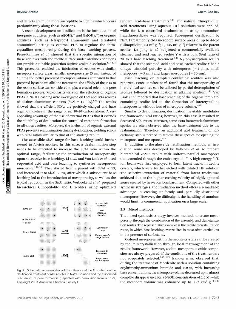
Ogura et al. reported the first explicit evidence of mesoporeformation in ZSM-5 crystals by NaOH treatment.128 Groen et al.reported the detailed investigation of base treatment conditionsfor optimizing the mesopore formation.129–131 They found that forZSM-5 crystals there appears to be an optimal window of Si/Al ratio(50–100 molar ratio) in the parent zeolite which leads to optimalmesoporosity with high mesopore surface areas up to 235 m2 g�1,while still preserving the intrinsic crystalline and acidic properties(Fig. 9). The generated mesopores are typically around 10 nm withrelatively broad size distributions. At lower Si/Al ratios, the meso-pore formation is limited by the repulsion between OH� and thenegatively charged lattice, whereas higher Si/Al ratios open upfor extensive mesopore formation accompanied by a severe lossof crystallinity. The framework aluminium was thus coined asthe ‘‘pore-directing agent’’ (PDA) due to its ability to regulateintracrystalline mesopore formation. Besides Si/Al ratio, themorphology of the original zeolites, consisting of either largesingle crystals or intergrown smaller particles with a largerexternal surface area, also has a strong influence on thedissolution process during desilication.132 Grain boundaries
Fig. 8 Schematic picture of the formation of mesopores. The griddenotes the zeolite framework, the black dots are framework aluminiumatoms, the open circles are aluminium atoms extracted from the frame-work, and the dotted lines indicate the mesopores. (Adapted from ref. 120.)
Chem Soc Rev Review Article
Ope
n A
cces
s A
rtic
le. P
ublis
hed
on 2
6 M
ay 2
015.
Dow
nloa
ded
on 1
/29/
2022
10:
06:0
9 PM
. T
his
artic
le is
lice
nsed
und
er a
Cre
ativ
e C
omm
ons
Attr
ibut
ion
3.0
Unp
orte
d L
icen
ce.
View Article Online
This journal is©The Royal Society of Chemistry 2015 Chem. Soc. Rev., 2015, 44, 7234--7261 | 7243
and defects are much more susceptible to etching which occurspredominantly along those locations.
A recent development on desilication is the introduction ofinorganic additives (such as Al(OH)4
� and Ga(OH)4�) or organic
additives (such as tetrapropyl ammonium and tetrabutylammonium) acting as external PDA to regulate the intra-crystalline mesoporosity during the base leaching process.Perez-Ramırez et al. showed that the specific interaction ofthese additives with the zeolite surface under alkaline conditionscan provide a tunable protection against zeolite dissolution.133–135
This protection enabled the fabrication of zeolites with similarmesopore surface areas, smaller mesopore size (5 nm instead of10 nm) and better preserved micropore volumes compared to thatprepared by standard alkaline treatment. The affinity of the PDA tothe zeolite surface was considered to play a crucial role in the poreformation process. Molecular criteria for the selection of organicPDAs in NaOH leaching were investigated on USY and Beta zeolitesof distinct aluminium contents (Si/Al = 15–385).136 The resultsshowed that the efficient PDAs are positively charged and haveorganic moieties in the range of ca. 10–20 carbon atoms. A veryappealing advantage of the use of external PDA is that it extendsthe suitability of desilication for controlled mesopore formationto all-silica zeolites. Moreover, the inclusion of organic externalPDAs prevents realumination during desilication, yielding solidswith Si/Al ratios similar to that of the starting zeolite.
The accessible Si/Al range for base leaching could furtherextend to Al-rich zeolites. In this case, a dealumination stepneeds to be executed to increase the Si/Al ratio within theoptimal range, facilitating the introduction of mesoporosityupon successive base leaching. Li et al. and Van Laak et al. usedsequential acid and base leaching to synthesize mesoporousmordenite.137,138 They started from a parent with Si/Al B 13,and increased it to Si/Al B 28, after which a subsequent baseleaching led to the introduction of mesoporosity, as well as thetypical reduction in the Si/Al ratio. Verboekend et al. preparedhierarchical Clinoptilolite and L zeolites using optimized
tandem acid–base treatments.139 For natural Clinoptilolite,acid treatments using aqueous HCl solutions were applied,while for L a controlled dealumination using ammoniumhexafluorosilicate was required. Subsequent desilication byNaOH treatment yields mesopore surface areas of up to 4-fold(Clinoptilolite, 64 m2 g�1; L, 135 m2 g�1) relative to the parentzeolite. De Jong et al. subjected a commercially availablesteamed and acid leached zeolite Y with a bulk Si/Al ratio of28 to a base leaching treatment.140 N2 physisorption resultsshowed that the steamed, acid and base leached zeolite Y had aunique trimodal porosity with micropores (B1 nm), smallmesopores (B3 nm) and larger mesopores (B30 nm).
Base leaching on template-containing zeolites was alsoreported. Perez-Ramırez et al. found that the mesoporosity ofhierarchical zeolites can be tailored by partial detemplation ofzeolites followed by desilication in alkaline medium.141 VanLaak et al. reported that base leaching of the organic template-containing zeolite led to the formation of intercrystallinemesoporosity without loss of micropore volume.142
Similar to dealumination, desilication inevitably modulatesthe framework Si/Al ratios; however, in this case it resulted indecreased Si/Al ratios. Moreover, some extra-framework aluminiumspecies are often observed after the base treatment due to therealumination. Therefore, an additional acid treatment or ion-exchange step is needed to remove these species for opening themicropores and mesopores.143
In addition to the above demetallization methods, an irra-diation route was developed by Valtchev et al. to preparehierarchical ZSM-5 zeolite with uniform parallel macroporesthat extended through the entire crystal.144 A high energy 238Uion beam was first employed to form latent tracks in zeolitecrystals, which were further etched with diluted HF solution.The selective extraction of material from latent tracks wasachieved due to the higher etching velocity of highly agitatedzones created by heavy ion bombardment. Compared with othersynthesis strategies, the irradiation method offers a remarkableadvantage in creating uniformly and parallelly distributedmacropores. However, the difficulty in the handling of uraniumwould limit its commercial application on a large scale.
2.3 Mixed methods
The mixed synthesis strategy involves methods to create meso-porosity through the combination of the assembly and demetalliza-tion routes. The representative example is the zeolite recrystallizationroute, in which base leaching over zeolites is most often carried outin the presence of surfactants.
Ordered mesopores within the zeolite crystals can be createdby zeolite recrystallization through local rearrangement of thezeolite framework. However, zeolite–mesoporous oxide compo-sites are always prepared, if the conditions of the treatment arenot adequately selected.145–149 Ivanova et al. observed that,during the treatment of Mordenite with a solution containingcetyltrimethylammonium bromide and NaOH, with increasingbase concentrations, the micropore volume decreased up to almostcomplete disappearance for a NaOH concentration of 1.6 M, whilethe mesopore volume was enhanced up to 0.92 cm3 g�1.145
Fig. 9 Schematic representation of the influence of the Al content on thedesilication treatment of MFI zeolites in NaOH solution and the associatedmechanism of pore formation. (Reprinted with permission from ref. 129,Copyright 2004 American Chemical Society.)
Review Article Chem Soc Rev
Ope
n A
cces
s A
rtic
le. P
ublis
hed
on 2
6 M
ay 2
015.
Dow
nloa
ded
on 1
/29/
2022
10:
06:0
9 PM
. T
his
artic
le is
lice
nsed
und
er a
Cre
ativ
e C
omm
ons
Attr
ibut
ion
3.0
Unp
orte
d L
icen
ce.
View Article Online

7244 | Chem. Soc. Rev., 2015, 44, 7234--7261 This journal is©The Royal Society of Chemistry 2015
Therefore, the zeolite was completely removed and replaced byan ordered mesoporous MCM-41 type material due to the harshconditions employed in the treatment. However, it was notedthat under intermediate conditions, using lower NaOH con-centrations, the recrystallized mordenites exhibited bothmicropores and mesopores suggesting that they might be trulyhierarchical zeolites. A further study revealed that two types ofmesopores formed, in which small mesopores of 3–4 nm wereattributed to surfactant-induced micelle formation involvingdissolved species and larger mesopores of 3–20 nm resultedfrom desilication processes occurring under the alkaline reactionconditions.150 The dual mesopore structure was also found byTsapatsis et al. when they prepared mesoporous ZSM-5 zeolitesthrough desilication and re-assembly processes.151
Remarkably, Garcia-Martinez et al. synthesized mesoporouszeolite Y with uniformly distributed intracrystalline mesoporesof approximately 4 nm by hydrothermal treatment with amixture of zeolite Y, diluted NH4OH and the surfactant CTABat 150 1C for 10–20 h.152 The mesopores can be tuned between2.5 and 4.5 nm by changing the chain length of surfactants.The well-controlled mesoporosity was presumably induced into
zeolite crystals by a crystal-rearrangement mechanism. Thisstructural reorganization took place due to the base-inducedbreaking of Si–O–Si bonds in the presence of a cationic surfactant(Fig. 10). This process allows the prevention of the dissolution ofthe crystals and almost complete recovery of the zeolite material.The performance of this USY FCC catalyst was compared with theperformance of the mesoporous zeolite Y made by soft templating.The catalysts made from mesostructured USY zeolites producedsignificantly more gasoline and light cycle oil (LCO), and lessbottoms and coke. The much improved product selectivity couldbe attributed to the mesostructure introduced into the zeolites thateased the diffusion limitation in the conventional zeolites. Themixed method does not suffer from the typical drawbacks ofthe desilication approach, i.e. significant loss of silica or damageof the zeolite crystals.
In this section, we review the general synthesis methodshitherto developed for tailoring the pore architecture of hierarchicalzeolites. For comparison, these synthesis strategies together withthe structure information of the corresponding hierarchical zeolitesare listed in Table 1.
3. Visualizing the pore architectureof hierarchical zeolites
Mesopores are introduced in zeolites to overcome the diffusionlimitations and improve the accessibility to active acid siteslocated in zeolite micropores. The size, shape and connectivityof the mesopores should be studied if one wants to relate thechange in textural properties to the catalytic performance of thecatalyst. The most common technique to investigate texturalproperties of materials is gas physisorption.153,154 Other techniquesinclude mercury porosimetry,155,156 thermoporometry,157,158
nuclear magnetic resonance,159,160 etc. However, these techniques
Fig. 10 Scheme of the proposed zeolite mesopore formation process: (a)original zeolite Y, (b) Si–O–Si bond opening/reconstruction in basic media,(c) crystal rearrangement to accommodate the surfactant micelles, and (d)removal of the template to expose the mesoporosity introduced. (Repro-duced from ref. 152.)
Table 1 Overview of the pore architecture of hierarchical zeolites obtained by different synthesis methods
Synthesis strategy Mesopore templates Framework Crystal size Type of mesoporosity Ref.
AssemblyHard templating Carbon nanoparticle: BP2000 MFI 0.3–1.2 mm Intracrystalline, 5–50 nm 29
Multi-wall carbon nanotube MFI 0.25–1.0 mm Intracrystalline, 6–15 nm 35Resorcinol–formaldehyde carbon aerogel MFI 10 nm Intercrystalline, 11 � 2 nm 383DOm carbon MFI 0.2–0.3 mm Intracrystalline, 4.5 � 2 nm 53
Soft templating Silylated seed: PHAPTMS MFI o10 nm Intercrystalline, 2–8 nm 77Silylated surfactant: TPHAC MFI o10 nm Intercrystalline, 3.1 � 1 nm 81Silylated polymer: PEI MFI 0.2 mm Intracrystalline, 2–4 nm 88Cationic amphiphilic copolymer: C-PSt-co-P4VP MFI 1–2 mm Intracrystalline, 10–50 nm 90Polyquaternary ammonium surfactants: C22-6-6 MFI 2 nm, thickness Intercrystalline, 5–20 nm 92Polyquaternary ammonium surfactants: 18–N3–18 MFI 1.7 nm, thickness Intracrystalline, 3.5 nm 94Random-graft polymer: linear polystyrene-N3-SDA MFI 4.5 nm Intercrystalline, 2–10 nm 99
Indirect templating Steaming-assisted crystallization: none BEA 20 nm Intercrystalline, 5–20 nm 109Nanofusion: none BEA 20–40 nm Intercrystalline, 15–35 nm 113Repetitive branching: none MFI/MEL 2 nm, thickness Intercrystalline, 2–7 nm 114
DemetallizationDealumination Steaming: none FAU 0.2–0.3 mm Intracrystalline, 15–20 nm 119Desilication Base leaching: none MFI 0.5 mm Intracrystalline, 2–40 nm 130
Steaming and acid–base leaching: none FAU 0.4 mm Intracrystalline, 2–5 and 15–40 nm 140
MixedRecrystallization Base leaching: CTAB FAU 0.4 mm Intracrystalline, 4 nm 152
Chem Soc Rev Review Article
Ope
n A
cces
s A
rtic
le. P
ublis
hed
on 2
6 M
ay 2
015.
Dow
nloa
ded
on 1
/29/
2022
10:
06:0
9 PM
. T
his
artic
le is
lice
nsed
und
er a
Cre
ativ
e C
omm
ons
Attr
ibut
ion
3.0
Unp
orte
d L
icen
ce.
View Article Online

This journal is©The Royal Society of Chemistry 2015 Chem. Soc. Rev., 2015, 44, 7234--7261 | 7245
provide bulk information since the textural properties areaveraged over a relatively large amount of material. For example,the amount of sample used for N2 physisorption is B0.05 g.Furthermore, these techniques provide only limited informationabout size, shape and accessibility of pores. The performance ofthe catalysts is dependent among others on the accessibility ofthe active sites and diffusion of reactants and products towardsand from the active site, that is, on the interconnectivity betweenmicro-, meso- and macropores. Visualizing such complex porousnetwork provides unique opportunity to study in greater detailporous structures. In recent years, the microscopy and imageanalysis techniques have significantly advanced and have beenmore frequently used for elucidating the pore architecture ofporous materials, such as hierarchical zeolites.
Depending on the probe used in microscopy, such as opticallight, X-rays or electrons, one can visualize the zeolites and theporosity at different length scales, ranging from macroscopic tomicroscopic. Various microscopy techniques have been utilizedto obtain a great deal of information about the presence and, tosome extent, the shape and size of mesopores in the sample.The problem of conventional microscopy techniques is thatthey can’t accurately describe the connectivity and provide theexact shape and size of the mesopores since spatial informationis limited when the structural features of 3D porous particlesare overlaid in a 2D image. A method that overcomes thislimitation is tomography, i.e. 3D microscopy, which has beendeveloped more recently. The term ‘‘tomography’’ is derivedfrom the old Greek words ‘‘tomos’’ and ‘‘graphein’’, whichmean ‘‘slice’’ and ‘‘to record’’. By using tomography techniques,the object can be reconstructed in three dimensions based on theinformation from a series of 2D images. With the development ofthese more advanced visualization techniques and image analysisoperations, great improvements have been made in evaluating thepore architecture of hierarchical zeolites, both qualitatively andquantitatively. In this section, we will provide a review of thisrapidly developed field.
3.1 Confocal fluorescence microscopy
Fluorescence microscopy is a type of optical microscopy, whichimages the fluorescence that is emitted from the fluorescentmolecules (dyes) in the sample. Generally, dyes are hit by lightof a specific wavelength, for which lasers are often used, andsubsequently the fluorescent dyes in the sample will emit alower energy of light with a longer wavelength. Making use of adichromatic mirror, only the light emitted from the sample isdetected by the detector, giving rise to a high-contrast of theimages. Confocal fluorescence microscopy (CFM) uses pinholesto collect the light that is emitted from a certain area, while allthe other light is rejected. This technique greatly enhances theoptical resolution. Moreover, by changing the point of focus,images from various depths of the sample can be collected,enabling thus information in 3D.161
Fluorescence microscopy, next to the application in cellularbiology, has proved as a very useful technique in the study ofheterogeneous catalysts.162–164 Recently, it has also been usedfor the visualization of the pore architecture of hierarchical
zeolites.165,166 Aramburo et al. studied the effect of steaming onpore accessibility of large ZSM-5 zeolite crystals (100 � 20 �20 mm3) using CFM with bulky dyes, which enabled the 3Dvisualization of cracks and mesopores connected to the outerzeolite surface.166 The parent ZSM-5 catalyst (ZSM-5-P) afterstaining with proflavine (Fig. 11b) showed only little visiblefluorescence (Fig. 11d) in both the top and middle plane of thecrystal (Fig. 11a), which indicated the absence of mesoporesbecause proflavine cannot enter the micropore system of thecatalysts (Fig. 11f). ZSM-5 catalyst after mild steam treatment(ZSM-5-MT) exhibited strong fluorescence especially in thelateral sub-units as compared to its pyramidal counterparts(Fig. 11d). The heterogeneous distribution of the fluorescenceindicates the different susceptibility of the distinct crystalregions to steaming. After a severe steam treatment, the catalyst(ZSM-5-ST) showed strong and even more broadly distributedfluorescence (Fig. 11d), which reveals the increased pore acces-sibility in the lateral crystal sub-units as well as a partialopening of the crystal sub-unit boundaries. Furthermore, thein situ generation of fluorescein from phthalic acid anhydrideand resorcinol (Fig. 11c) was performed for the detection ofmesoporous cavities within the steamed ZSM-5 zeolite crystals.Because the reactants are non-fluorescent and able to diffusethroughout the crystal, the fluorescein thus can be generated inthe cavities, which are connected with the outer crystal surfaceonly via the micropore system and cannot be accessed byproflavine. The ZSM-5-P crystal showed a lack of fluorescenceas compared to the steamed samples, since only microporesare present in the parent crystal (Fig. 11e). Compared withproflavine stained experiments, more homogeneous distribu-tion of the fluorescence signal was observed in the steamedsamples, which indicates that a large number of cavities aregenerated. Moreover, the intense fluorescence signal originatingfrom the pyramidal crystal sub-units of ZSM-5-ST suggests that asignificant amount of cavities are formed in this region after asevere hydrothermal treatment (Fig. 11f). These results demon-strated that ZSM-5 catalyst consists of different crystal subunitswith diffusion barriers in between them. The different regionshave a different susceptibility towards steaming, so mesoporegeneration will be different in each region.
CFM allows one to study the location and accessibility of themesopores within tens of micrometres large zeolite crystals.However, it cannot image pores directly, but fluorescence ofmolecules within them. Furthermore, no information aboutsize and shape of the mesopores can be obtained becausethe resolution is limited. In this context, X-ray and electron-based microscopy techniques are more advantageous. Besidesimaging porosity, the recently developed optical method basedon microimaging by interference and infrared microscopy wassuccessfully used to monitor diffusion of non-fluorescent guestmolecules, such as methanol and ethanol, through nanoporouszeolites.167
3.2 X-ray tomographic microscopy
X-ray microscopy uses X-rays as a probe to image a sample. Theshort wavelength of X-rays ranging from 0.01 to 10 nanometres
Review Article Chem Soc Rev
Ope
n A
cces
s A
rtic
le. P
ublis
hed
on 2
6 M
ay 2
015.
Dow
nloa
ded
on 1
/29/
2022
10:
06:0
9 PM
. T
his
artic
le is
lice
nsed
und
er a
Cre
ativ
e C
omm
ons
Attr
ibut
ion
3.0
Unp
orte
d L
icen
ce.
View Article Online

7246 | Chem. Soc. Rev., 2015, 44, 7234--7261 This journal is©The Royal Society of Chemistry 2015
renders a higher resolution of X-ray microscopy as compared tooptical microscopy. In addition, X-rays have a stronger ability topenetrate matter than optical light, which allows X-ray micro-scopy to monitor the inside of the specimen without physicallycutting it. X-ray microscopy has proved to be an important toolfor nanoscale structural and chemical imaging.168,169 Manytypes of X-ray microscopy have been developed, among whichX-ray tomography allows non-destructive 3D analysis of bothmorphology and chemical composition. It uses X-rays to record2D images of an object that are later used to reconstruct avirtual 3D model without destroying the original object. Inabsorption-based studies, the image contrast corresponds toX-ray attenuation, which is strongly dependent on the atomicnumber and density of the material. For a laboratory X-raysource, it can provide three-dimensional structural informationdown to the micrometre level.170 With the application of high-flux synchrotron radiation in the hard X-ray range, the spatialresolution down to the sub-micrometre, and even sub-100 nm,level can also be achieved.171–173
Recently, Mitchell et al. used synchrotron radiation X-raytomography microscopy (SRXTM) to visualize the internal porearchitecture of an industrial granule consisting of hierarchicalalkaline-treated ZSM-5 zeolite and the binder attapulgite.174
A whole granule was first analysed by standard SRXTM. Thecomputed two-dimensional virtual slices reflected its long-range structural order, as the pores (black regions) uniformlydispersed throughout the entire granule. High-resolutionSRXTM was further performed to study the details of theinternal structure. For this analysis, columns of B40 mm insize were cut from the sample for the measurement. The round-likeintraparticle macropores with diameters of 3–5 mm can be
distinguished in the 2D virtual slice (Fig. 12a) of the three-dimensional reconstructions (Fig. 12b), which seem to beisolated from the surrounding interparticle network of macro-pores with varying size and orientation extending throughoutthe granule interior.
Using X-ray tomography, the pore architecture can be directlyvisualized without the introduction of additional molecules as in thefluorescence microscopy. Furthermore, it can be used to visualize thesample of hundreds of micrometres thickness without the needof cutting and induces very weak radiation damage, whereasoptical microscopy requires more transparent samples. Thecurrent disadvantage is that synchrotron X-ray sources with veryhigh intensity are necessary, which is inconvenient for routinestudies. Recently, it was reported that large improvements in theresolution have been witnessed using X-ray ptychographic computedtomography.171,175 This, if successfully established with laboratorysources, could become a powerful method for filling the resolution
Fig. 11 (a) Schematic illustration of the crystal regions where the confocal fluorescence microscopy images were recorded. (b) Bulky dye moleculeproflavine used to investigate the changes taking place in the pore accessibility upon steaming. (c) Staining reaction based on the in situ synthesis offluorescein used to visualize mesoporous structural defects. (d) Confocal fluorescence microscopy images obtained from the top and middle plane ofZSM-5-P, ZSM-5-MT and ZSM-5-ST after staining with proflavine. (e) Confocal fluorescence microscopy images obtained from the top and middle planeof ZSM-5-P, ZSM-5-MT and ZSM-5-ST during the in situ synthesis of fluorescein at 200 1C. lex = 488 nm, detection 510–550 nm. Images are presentedas thermal maps; the warmer the colour, the higher the intensity of the fluorescence signal. All the intensities have been boosted with the same factor.(f) Schematic illustration summarizing the main observations described in this study for ZSM-5-P, ZSM-5-MT and ZSM-5-ST zeolite crystals. Themolecular diffusion barriers, depicted in green, red and blue in ZSM-5-P, are substantially modified with increasing steaming temperature. Additionally,steaming induces different modifications in the physicochemical properties of the distinct crystal sub-units. The lateral sub-units undergo significantstructural modifications due to the mild and more severe hydrothermal treatment, whereas the pyramidal sub-units mainly alter their properties as aresult of a severe hydrothermal treatment. (Adapted from ref. 166.)
Fig. 12 Internal structure of a hierarchical zeolite body by high-resolutionSRXTM. (a) Two-dimensional virtual slices obtained from three-dimensional SRXTM (b) can be used for quantitative study of the macro-pore structure within a defined volume. (Reprinted from ref. 174 withpermission, Copyright Nature Publishing Group.)
Chem Soc Rev Review Article
Ope
n A
cces
s A
rtic
le. P
ublis
hed
on 2
6 M
ay 2
015.
Dow
nloa
ded
on 1
/29/
2022
10:
06:0
9 PM
. T
his
artic
le is
lice
nsed
und
er a
Cre
ativ
e C
omm
ons
Attr
ibut
ion
3.0
Unp
orte
d L
icen
ce.
View Article Online

This journal is©The Royal Society of Chemistry 2015 Chem. Soc. Rev., 2015, 44, 7234--7261 | 7247
gap between optical microscopy and electron microscopy, which willmake routine imaging of mesopores feasible.
3.3 Electron microscopy
Electron-based microscopy techniques make use of electronsinstead of previously discussed X-rays. The use of electrons isadvantageous because of their very short wavelength, whichdepends on the accelerating voltage, e.g. at commonly used100 keV and 200 keV, l = B3.8 pm and B2.7 pm respectively.Such short wavelength enables visualization of even the atomicstructure of materials. In fact, the wavelength of the electronsdoesn’t limit the resolution of the microscopes; it is ratherspherical and chromatic aberrations arising from an imperfectlens system, as well as the presence of mechanical vibrations, thatlimit the resolution.176,177 The most commonly used electronmicroscopy techniques include scanning electron microscopy(SEM) and transmission electron microscopy (TEM), while focusion beam scanning electron microscopy (FIB-SEM) and electrontomography (ET) are more specialized techniques. These techni-ques have been extensively used in the characterization of the porearchitecture of hierarchical zeolites and each of them will bediscussed below.
3.3.1 SEM. SEM produces images of a sample by scanningit with a focused beam of electrons in a raster fashion with anenergy that can vary from 0.1 keV to 30 keV. The interactionbetween the sample and the electron probe produces varioustypes of emissions, such as backscattered and secondary electrons,which are captured by different detectors placed in appropriatepositions. Backscattered electrons are created when the incidentbeam is elastically scattered (i.e. without losing the energy) from thesurface of the sample. Heavy atoms backscatter electrons morethan lighter atoms, and as a result contrast between lighter andheavier elements occurs. However, backscattered electrons canescape from several tens of nanometres of depth, which reducesthe resolution. Secondary electrons, with energies smaller than50 eV, are emitted when the incident beam kicks out electrons fromthe inner shells of atoms near the surface (only a few nm escapedepth) of the sample, which results in a greater resolution com-pared to the backscattered image. By raster scanning the sample,secondary electrons carrying information about the topography ofthe surface are collected.
SEM has been a commonly used technique in the study ofthe surface topology of solid materials. Especially, with thedevelopment of through-the-lens detection systems, whichpermit a reduced landing energy (the energy of the primarybeam before impacting the sample) and the selection of high-resolution, topographically specific emitted electrons, the highresolution (HR) SEM technique has been developed as a power-ful tool in the study of the fine structure of nanomaterials. Forinstance, Ryoo and Terasaki et al. demonstrated the merit oflow electron landing energy on the beam damage of meso-porous LTA zeolite templated with an organosilane surfactant,which is highly sensitive to electron-beam irradiation. Theresults showed that the image obtained using a lower landingenergy of 80 eV (Fig. 13a) exhibited very clear characteristics ofthe mesopores on the zeolite surface with a lesser edge effect
because of small interaction volume, while landing energies of1 keV and above produced distinct beam damage on theoriginal pore morphology (Fig. 13b and c).178
SEM has been often employed for the characterization ofhierarchical zeolites. It proved useful in determining thepresence of meso- and macropores, topology of porous zeolitesand, to a lesser extent, allowed estimating the pore size andshape. Matsukata et al. used SEM to study the effect of alkalinetreatments on ZSM-5 catalyst.128 As shown in Fig. 14a,the parent ZSM-5 crystals before alkaline treatments have auniform shape and particle size with a smooth surface. Afterbase leaching (Fig. 14b), a dramatic morphology change wasobserved and grooves and voids appeared on the surface of thezeolite, indicating the etching of the materials by base solution.Christensen et al. studied mesoporous ZSM-5 crystals tem-plated by carbon black with SEM.179 Fig. 14c and d show theSEM images of the conventional zeolite synthesized withoutcarbon and the carbon templated mesoporous zeolite crystals.Although the typical coffin shape of MFI crystals was observedfor both, the surface morphologies were very different, with themesoporous sample showing a much rougher surface. Ryoo et al.synthesized mesoporous ZSM-5 zeolite using an amphiphilicorganosilane as the template.81 SEM images (Fig. 14e) showed thatthe resultant zeolite had regularly globular morphologies withhomogeneously rugged surfaces, which indicated the presence ofuniform mesoporosity and well crystallized zeolite frameworks innature. In another study, they synthesized mesoporous ZSM-5zeolite using dual-function diquaternary ammonium surfactantsas templates.92 The SEM image (Fig. 14f) revealed that the ZSM-5zeolite was composed of flake-like nanosheets of 2 nm in thickness.The nanosheets appeared to be pillared by the intergrowth, formingmesopores in between the crystals.
Compared to X-ray microscopy requiring synchrotron radia-tion, SEM can provide a much higher resolution and beperformed routinely in the laboratory. In addition to imaging,SEM coupled with energy dispersive X-ray (EDX) detectorsallows detection of the characteristic X-rays emitted from thesample upon incident beam bombardment. This provideselemental analysis of the surface of the sample. However, withSEM, it is not possible to visualize the internal structure of thezeolite particles. The pore morphology can only be, to certainextent, deduced from the surface topology of the sampleobserved in the SEM images.
3.3.2 FIB-SEM. To visualize the internal structure, SEM hasbeen used in combination with the sectioning techniques, such
Fig. 13 SEM images of mesoporous LTA acquired at low landing energy,thereby reducing the effect of beam damage. Conditions: specimen bias =�5 kV. Scale bar is 100 nm. (Reprinted from ref. 178 with permission, @2014 Elsevier.)
Review Article Chem Soc Rev
Ope
n A
cces
s A
rtic
le. P
ublis
hed
on 2
6 M
ay 2
015.
Dow
nloa
ded
on 1
/29/
2022
10:
06:0
9 PM
. T
his
artic
le is
lice
nsed
und
er a
Cre
ativ
e C
omm
ons
Attr
ibut
ion
3.0
Unp
orte
d L
icen
ce.
View Article Online

7248 | Chem. Soc. Rev., 2015, 44, 7234--7261 This journal is©The Royal Society of Chemistry 2015
as ultramicrotomy and focused ion beam (FIB). For ultramicrotomy,the sample is embedded in a polymer and a diamond knife is usedto cut thin sections (typically 50–100 nm). Such approach allows oneto examine the internal structure of the catalyst with SEM imaging.However, shear stress occurring during the cutting can lead to theformation of voids or regions with high density of material withinthe slice. This can be limiting, particularly, if porosity of the sampleis studied. In the case of FIB, a beam of ions, such as gallium andargon ions, is scanned across the sample. This causes ‘milling’ ofpart of the material, and leads to the release of secondary ions andneutral atoms from the sample. The secondary electrons generatedby the initial ion collision can be used to obtain images with SEM inan incorporated system. SEM images can also be taken after FIBmilling. The thickness of the milled FIB section can be as low as tennanometres, which is thinner than that of ultramicrotomy. Further-more, compared with ultramicrotomy, no extra porosity is inducedby FIB, making FIB more favourable than ultramicrotomy for thestudy of hierarchical zeolite materials.
FIB-SEM has been recently used for the visualization of thepore architecture of hierarchical zeolites prepared by softtemplating and steaming strategies.165,180,181 Ryoo et al.reported the synthesis of mesoporous zeolites using organosilanesurfactants (OSS) as templates.81 It was found that the size andconcentration of OSS were important parameters influencing themesopore properties. To unravel the exact mechanism for thegeneration of mesopores by OSS, Cho et al. studied mesoporousLTA zeolites synthesized with different concentrations of OSS using
HRSEM combined with an argon ion beam.180 The HRSEMmicrographs as shown in Fig. 15 revealed that the mesoporesfor both samples were located not only on the external surfacesbut also inside the crystals with tunable size depending on theconcentration of OSS. More specifically, NaA-2 prepared with alow concentration of OSS presented randomly branched andinterconnected channels with quite a uniform width (6–9 nm)on the external surface, while radial mesopores of fairly uniformsize were inside the zeolite crystal. In NaA-8, the crystal surfaceswere very rough with wider and more random mesopores thanthat of NaA-2 and the direction of the internal channels wasquite random, which indicated that the OSS micelles expandedwith the excessive OSS molecules. Based on these observations, amechanism for mesopore generation was proposed by theauthors. At a low loading of OSS, the crystal growth seemed toaffect or induce orientation of the OSS micelles along the h100iaxis and single crystals formed with the incorporation of OSSinside, while at a high loading of OSS, the expansion anddisorder of OSS micelles seem to dominantly affect the crystalgrowth process into polycrystalline particles.
Karwacki et al. studied the effect of steaming on the meso-pore distribution within zeolite crystals using FIB-SEM.165,181
Three distinct regions of the parent (ZSM-5-P) and steamed(ZSM-5-ST) ZSM-5 crystal were examined, corresponding to theparts of the crystal with straight and sinusoidal channels opento the surface, and the part where straight channels are covered
Fig. 14 SEM images: comparison between (a) as-received and (b) alkaline-treated ZSM-5. Comparison between (c) conventional and (d) mesoporouszeolite ZSM-5 templated by carbon black. (e) Mesoporous ZSM-5 templatedby an amphiphilic organosilane. (f) MFI nanosheets with a multi-lamellarstructure templated by a dual-function diquaternary ammonium-typesurfactant. (Adapted from ref. 128, 179, 81 and 92.)
Fig. 15 HRSEM micrographs of mesoporous LTA (NaA-n, n represents themoles of OSS with respect to 100 moles of Si in the synthesis gel)synthesized with different concentrations of an organosilane surfactant.The top images were taken from the external surfaces of calcined samples.The others were taken after cross-sectioning by an argon ion beam. TheSEM images at the cross-sectioned planes show mesopores inside thesezeolite particles. (Reprinted from ref. 180 with permission, @ 2011 Elsevier.)
Chem Soc Rev Review Article
Ope
n A
cces
s A
rtic
le. P
ublis
hed
on 2
6 M
ay 2
015.
Dow
nloa
ded
on 1
/29/
2022
10:
06:0
9 PM
. T
his
artic
le is
lice
nsed
und
er a
Cre
ativ
e C
omm
ons
Attr
ibut
ion
3.0
Unp
orte
d L
icen
ce.
View Article Online

This journal is©The Royal Society of Chemistry 2015 Chem. Soc. Rev., 2015, 44, 7234--7261 | 7249
by the 901 rotational barrier.182 The parent sample ZSM-5-P didnot show the presence of mesopores, while severely treatedZSM-5-ST crystal showed vast areas of mesoporosity in all threeregions. The quantitative analysis of the size and number ofmesopores observed in the three studied regions showed thatregion A on the tip of the ZSM-5-ST crystal contained less meso-pores (about 23% of the overall number) than regions B (40%, closeto the tip of the crystal) and C (37%, in the middle of the crystal).This suggests that the straight zeolite channels are less susceptibletowards dealumination. Moreover, the dominating mesopore sizein region A was about 6.2 nm with a maximal mesopore diameterof 20 nm, whereas in regions B and C, the average diameter of allmesopores increased to 8.2 and 8 nm with maximal mesoporediameters of 50 and 35 nm, respectively. Strikingly, more than 84%of all recorded mesopores presented a diameter smaller than10 nm. These qualitative and quantitative results obtained byFIB-SEM indicate a significant dependency between the crystalregions (i.e., internal architecture) and the amount, diameter andorientation of the generated mesopores, which is in line with theresults obtained from the CFM characterization as shown inSection 3.1. Although with FIB-SEM only a small area of the zeolitecan be analysed compared to CFM, it provides straightforward andmore detailed information on the mesoporosity of different regionsof the individual crystal.
FIB-SEM tomography, also called ‘‘slice and view’’, is developedto acquire 3D information in contrast to only 2D information
shown above. In this technique, the sample embedded in resinis repeatedly milled with a focused ion beam (FIB) and eachnewly produced block face is imaged with the SEM, and thus a3D data set of the object under investigation is generated. FIB-SEM tomography is a suitable technique to characterize porouscrystals without the introduction of artifacts as is in the case ofultramicrotomy.
To access the 3D information and study mesopore length,shape and orientation in steamed ZSM-5 crystals, Karwackiet al. also used FIB-SEM tomography.181 A stack of 150 con-secutive FIB milled and SEM imaged cross-sections separatedfrom each other by B10 nm and with a surface area of about5 � 5 mm2 were first collected from an individual steamedZSM-5 crystal of 100� 20� 20 mm3 size (Fig. 16a). 5� 5� 1.5 mm3
volume (Fig. 16b and c) was reconstructed, revealing the presenceof approximately 750 mesopores with length exceeding 10 nm, inwhich approximately 630 of them (85%) were in the range of10 to 100 nm and only 1% rise above 200 nm (Fig. 16d and e).11 mesopores were manually traced, overlaid in the subsequentFIB-SEM images and digital meshing of the pore surface wasapplied (Fig. 16f and g). It was found that the long axis of themesopores always aligned with the direction of the pores opento the crystal surface. This suggests that dealumination waslikely to take place in pores with such specific orientation.These results show that FIB-SEM tomography can providequantitative 3D information, such as length and orientation
Fig. 16 (a) Individual steamed ZSM-5 crystal during FIB-SEM tomography. Focused ion beam (top) subsequently removes (10 � 2) nm thick cross-sections from the plane normal to the crystal’s surface, while the electron-beam images of 5 � 5 mm are indicated with the red square. The inset shows asteamed crystal after FIB cross-section milling. (b, c) SEM images illustrating the beginning and the end of the volume studied by FIB-SEM tomography.The difference between the thickness of the material in images (b) and (c) is 1.5 mm. (d) Mesopore length distribution based on approximately750 reconstructed mesopores from the volume of a steamed ZSM-5 crystal. Inset: zoom-in into the pores longer than 100 nm. The error range for eachpore length data point equals �5 nm (i.e. a slice thickness equal to 10 nm). (e) A reconstructed distribution of mesopores in the 750 � 750 � 200 nm3
sub-volume of a steamed ZSM-5 crystal. The xy plane is shown; the upper right corner inset indicates the orientation of the xy, xz, and yz planes as green,red, and blue rectangles, respectively. The �2 zoomed-in area of the section of the xy plane shown in the right lower corner shows a group of11 reconstructed mesopores. Scale bars = 60 nm. Surface of indicated (traced) mesopores is not rendered allowing visualization of their overlay. (f, g)Projection of the mesopores to the xz and yz planes, respectively. Each layer indicates the consecutive cross-section plane recorded by SEMtomography. Zoomed-in area focuses on two pores with rendered surface. Scale bars are 50 nm. (Adapted from ref. 181.)
Review Article Chem Soc Rev
Ope
n A
cces
s A
rtic
le. P
ublis
hed
on 2
6 M
ay 2
015.
Dow
nloa
ded
on 1
/29/
2022
10:
06:0
9 PM
. T
his
artic
le is
lice
nsed
und
er a
Cre
ativ
e C
omm
ons
Attr
ibut
ion
3.0
Unp
orte
d L
icen
ce.
View Article Online

7250 | Chem. Soc. Rev., 2015, 44, 7234--7261 This journal is©The Royal Society of Chemistry 2015
of the mesopores and thus impart unique insights into thedealumination process. However, it should be noted that themesopores smaller than 10 nm were not taken into accountbecause the resolution was limited to approximately 5.2 nm.
The advantage of FIB-SEM is that it can provide informationabout the mesoporous network from volumes as large as 5 mm3
without limitation on the total size of the zeolite crystal.However, it remains a less commonly used technique becausemore time, effort and specialized expertise for data acquisitionare required. Moreover, during the measurement, the analysedvolume of sample is destroyed by the ion beam.
3.3.3 TEM. In contrast to SEM, TEM relies on transmittedelectrons. The electrons from the incident beam will be scatteredwhen they hit elements in the sample. The extent of scatteringdepends on the atomic weight and the thickness of the sample.One can create images by detecting electrons scattered to highangles or by detecting the direct beam that has not undergonehigh angle scattering. The first will create a dark field image inwhich the thicker areas and heavier atom areas are shown lighterin the image. In the latter mode, a bright field image is obtained,where the thicker areas and heavier atom areas appear darker.The images are typically recorded with a CCD camera. Since TEMoperates in a transmission mode, a thin sample is required sothat a sufficient number of electrons can pass through andcreate an image.
TEM analysis represents one of the most prevailing techniquesand provides a wealth of information on the structures of themesopores in hierarchical zeolites prepared by different strategies.In the study of the desilication process of zeolites by Groen et al.,the clear lighter-areas and lattice fringes in the high resolutionTEM image (Fig. 17a) indicate the presence of intracrystallinemesoporosity and the high crystallinity of the alkaline-treatedzeolite ZSM-5.183 The estimated mesopore size was about 10 nm,which was in excellent agreement with the pore size distributionderived from N2 adsorption. Jacobsen et al. synthesized meso-porous ZSM-5 zeolite single crystals using carbon black asthe hard template.29 The TEM image (Fig. 17b) revealed thatrelatively large and well-shaped crystals were obtained with theexistence of mesoporosity. Diffraction patterns with discretediffraction spots can be well indexed according to the [100]direction of the MFI structure, which proved that the resultantzeolite was a single crystal rather than an agglomerate of smallercrystals. Ryoo et al. synthesized nanosheets of zeolite MFI usingdual-function diquaternary ammonium-type surfactant C22–6–6
as a template.92 HRTEM images (Fig. 17c) revealed that themeso-structured stacking of the nanosheets was composed ofalternating layers of 2.0 nm-thick MFI zeolite framework and2.8 nm-thick surfactant micelles. When changing the template to18–N3–18, hexagonal arrays of mesopores with a diameter of4.51 nm can be clearly distinguished from the HRTEM imageand the corresponding Fourier diffractogram (Fig. 17d).94
A variant of transmission electron microscopy is scanningtransmission electron microscopy (STEM), which has also beenexploited in the visualization of mesoporous structures. STEMuses a focused beam of electrons scanned over the samplesurface in a raster fashion. Images can be recorded in bright
field (BF) STEM mode, high angle annular dark field (HAADF)STEM mode and secondary electron (SE) mode (Fig. 18a). Thesesignals can be obtained simultaneously with different detectorsinstalled in a STEM, therefore allowing direct correlation ofthese images. Moreover, compared with BF-STEM mode,HAADF-STEM mode has a much reduced diffraction contrastalong with the enhanced contrast related to the atomic number(Z-contrast), possibly providing higher resolution images forcrystalline nanostructures. Recently, Milina et al. used anaberration-corrected STEM to study the mesoporous structuresprepared by base leaching of parent ZSM-5 (Z50-C, Si/Al atomicratio 50) in the absence (Z50-H1) and presence (Z50-H2) of pore-directing agent tetrapropylammonium cations (TPA+).184 TPA+
cations have a high level of control over the dissolution processin the base leaching owing to their strong interaction with thecrystal surface, leading to hierarchical zeolites with distinctmesopore topology. The preliminary HRTEM study showed thatZ50-H1 displayed a heavily leached surface, while Z50-H2showed well-preserved crystal facets and discrete homogeneouslydistributed mesopores (Fig. 18b–d). To improve insights into themesopore accessibility, identical-location SE and HAADF STEMimages were taken using an aberration-corrected STEM (Fig. 18e).From high-resolution SE images, it can be seen that Z50-H1 showeda heavily eroded external crystal surface with large open mesopores,while in contrast Z50-H2 displayed the pristine appearance of thecrystal surface with the few readily distinguishable mesoporesidentical to that of the parent zeolite. Alongside, HAADF-STEMimages clearly showed extensive intracrystalline mesoporosity inboth the Z50-H1 and Z50-H2 zeolites as revealed by the darkcontrast areas in comparison to the uniformly bright contrastobserved in the parent zeolite (Fig. 18e). These correlative images
Fig. 17 (HR)TEM of (a) alkaline-treated (0.2 M NaOH, 338 K, 30 min) ZSM-5zeolite. (b) An isolated mesoporous ZSM-5 single crystal templated bycarbon black and the inset with the diffraction pattern obtained from thesame crystal. The size of the selected area aperture for electron diffractionwas B1 mm and covered the entire crystal shown in the figure. (c) MFInanosheets with a multi-lamellar structure templated by dual-functiondiquaternary ammonium-type surfactant C22–6–6. (d) Hexagonally orderedmesoporous MFI zeolite templated by dual-function diquaternaryammonium-type surfactant 18–N3–18 and the inset with Fourier diffracto-gram. (Adapted from ref. 183, 29, 92 and 94.)
Chem Soc Rev Review Article
Ope
n A
cces
s A
rtic
le. P
ublis
hed
on 2
6 M
ay 2
015.
Dow
nloa
ded
on 1
/29/
2022
10:
06:0
9 PM
. T
his
artic
le is
lice
nsed
und
er a
Cre
ativ
e C
omm
ons
Attr
ibut
ion
3.0
Unp
orte
d L
icen
ce.
View Article Online

This journal is©The Royal Society of Chemistry 2015 Chem. Soc. Rev., 2015, 44, 7234--7261 | 7251
provide insights into the impact of demetallation on both theexternal and bulk structure and corroborate the respective intro-duction of open and constricted mesopores in the hierarchical H1and H2 zeolites (Fig. 18f), which agreed well with the resultsobtained by mercury porosimetry.
Clearly, TEM provides much higher imaging resolutioncompared to previously discussed techniques, and insight intothe internal structure of imaged crystals. However, it is limitedto zeolite crystals of only several hundreds of nanometres insize. To overcome this limitation and allow for larger zeolitecrystals to be studied (e.g. ZSM-5 of tens of micrometres in size),thin slices of zeolite samples can be prepared by either FIBsectioning or ultramicrotomy. Xiao and Zou et al. reported thesynthesis of single crystal ZSM-5 zeolites with b-axis-alignedmesopores, using a designed cationic amphiphilic copolymeras a mesoscale template.90 TEM showed that the sample con-sisted of uniformly sized particles (1–2 mm) and the electrondiffraction pattern proved that the entire particle was a singlecrystal (Fig. 19a and b). To unravel the inner pore structures ofthe crystals, FIB was used to prepare thin slices perpendicularto the main crystallographic axes of ZSM-5 crystals (Fig. 19c–e).Round mesopores were observed in the high-resolution imagestaken along the b-axis, indicating the orientation of the meso-porous channels parallel to the b-axis. The HRTEM images takenalong the c- and a-axis further confirm the existence of mesoporechannels running along the b-axis, which were 10–50 nm in size,in good agreement with the N2 adsorption results (6–60 nm). Theb-axis-aligned mesoporous ZSM-5 shows much higher catalyticactivities for bulky substrate conversion than conventionalZSM-5 and ZSM-5 with randomly oriented mesopores. The possiblereason is that almost all b-axis-aligned mesopores in zeolite crystals
are open to the surface of ZSM-5 crystals and are accessible bybulky molecules, whereas a majority of the disordered mesoporesin the ZSM-5 crystals may be located in the interiors of the crystalsand hardly accessible by bulky molecules.
TEM can offer very high-resolution images and providedetailed structure information even at the atomic scale. Inaddition, the incident electron beam–sample interaction givesrise to characteristic X-rays, which can be used for elementalanalysis by EDX. Upon transmission through the sample, theincident electron beam can lose some energy which is element
Fig. 18 (a) The electron microscopic approach enabling the acquisition of information specific to the bulk (TEM, HAADF-STEM) or external surface (SE)structure of a crystal. (b–d) TEM examination of the zeolites. In comparison with the uniform contrast of the purely microporous crystals of aconventional ZSM-5 (Z50-C, b), the intracrystalline mesopores are evidenced in the catalysts prepared by post-synthetic alkaline treatment (Z50-H1, c,and Z50-H2, d). Remarkably, the gaping fissures and jagged crystal edges exhibited by Z50-H1 zeolite relative to the more internally distributed discretemesopores and the better preserved external surface of the crystals of Z50-H2 zeolite illustrate the directing role of TPA+ in the preparation of the lattersample. Scale bar indicates 20 nm. (e) Assessment of mesopore location in alkaline-treated zeolites. The distinct mesopore distribution within thehierarchical zeolites is unequivocally discriminated by identical-location SE and HAADF-STEM imaging: the relatively preserved crystal surface of Z50-H2observed in SE micrographs distinctly contrasts with the highly pitted surface of Z50-H1, appearing unaltered from that of the conventional zeolite, whilethe prominent regions of dark contrast observed in HAADF-STEM projections evidence the presence of extensive mesoporosity in both Z50-H1 and Z50-H2 compared with the solid appearance of Z50-C. Scale bar indicates 50 nm. (f) The distinct 3D structure of the open and constricted mesopores isillustrated schematically to facilitate visualization. (Reprinted from ref. 184 with permission, Copyright Nature Publishing Group.)
Fig. 19 (HR)TEM of ZSM-5 with b-axis-aligned mesopores templated by acationic amphiphilic copolymer. (a, b) TEM images taken along the (a) c- and(b) b-axis. (c–e) HRTEM images of thin slices of ZSM-5 viewed along the(c) b-, (d) c-, and (e) a-axis, with the crystals cut perpendicular to the b-, c-,and a-axis, respectively, by FIB. The b-axis is marked in (a), (d), and (e). Theinset shows the corresponding electron diffraction pattern. (Reprinted fromref. 90 with permission, Copyright American Chemical Society.)
Review Article Chem Soc Rev
Ope
n A
cces
s A
rtic
le. P
ublis
hed
on 2
6 M
ay 2
015.
Dow
nloa
ded
on 1
/29/
2022
10:
06:0
9 PM
. T
his
artic
le is
lice
nsed
und
er a
Cre
ativ
e C
omm
ons
Attr
ibut
ion
3.0
Unp
orte
d L
icen
ce.
View Article Online

7252 | Chem. Soc. Rev., 2015, 44, 7234--7261 This journal is©The Royal Society of Chemistry 2015
specific, and this loss can be measured using electron energy-loss spectroscopy (EELS). By using energy filters, electrons withenergy-loss specific to an element can be selected to form theso-called energy-filtered image (EF-TEM). Therefore, besidesthe structure, TEM can be used for high spatial resolutionelemental mapping. However, the spatial information of thepore architecture is to some extent obscured because the 3Dstructural features are projected in a 2D image. To visualize thestructure in 3D, electron tomography has been developed basedon the TEM technique.
3.3.4 Electron tomography. Electron tomography (ET), alsoreferred to as 3D TEM, is a more recently developed 3D imagingtechnique, which can provide more detailed information,both qualitatively and quantitatively, on e.g. pore size, shape,connectivity, orientation, accessibility and tortuosity of meso-pores.177,185–187 Typically, B150 2D TEM images are recordedover an angular range of about �701 till 701 by rotating thesample. These projection images (tilt series) are then alignedwith respect to a common origin and tilt axis, often with thehelp of gold nanoparticles as markers to be traced during thealignment. Ultimately, 3D reconstruction of the imaged volumeis obtained from the tilt series using specialized algorithms suchas weighted back projection (WBP), the algebraic reconstructiontechnique (ART) and the simultaneous iterative reconstructiontechnique (SIRT). Nanometer scale resolution can be achieved,and improved by increasing the number of projections andthe tilt range. A number of reviews provide a more detaileddiscussion on the ET technique and its application for materialsscience.177,187–189
Originally, ET was mainly used for the study of biologicalsamples. The first application of ET in materials science wasreported by de Jong and co-workers in 2000, focusing on thestudy of the pore architecture of a dealuminated zeolite as wellas the size and location of metal particles on supportedcatalysts.190 In this work, the mesopores (3–20 nm in diameter)inside an industrially important acid-leached Mordenite zeolite,which were hardly distinguishable in conventional TEM imagesdue to the superimposition of the surrounding material and/orthe variant sample thickness, were unequivocally clarified by anET slice from the 3D reconstruction of the crystallite (Fig. 20).
Mesoporous zeolite Y obtained by dealumination is animportant catalyst for oil refining processes such as fluidcatalytic cracking and hydrocracking. From the ET analysis ofthree different zeolite Y catalysts, including a non-treatedzeolite Y (NaY), a steamed NH4Y zeolite (USY) and a NH4Ysubjected to two steaming and one acid leaching treatment(XVUSY), new insights into their mesopore architecture wereobtained.191 As expected, both TEM and ET images of the non-treated sample NaY zeolite confirmed the absence of mesopores(Fig. 21a and b). In contrast, the USY and XVUSY zeolite exhibitedlots of mesopores within the crystals, which had been clearlyresolved in the ET slices (Fig. 21d and f) as compared to theTEM images (Fig. 21c and e). Due to the very clear visualization ofthe mesopores in the ET slices, the diameter of the mesopores canbe determined accordingly: 3–20 nm and 4–34 nm for USY andXVUSY, respectively. The fidelity of these values was confirmed by
the very good agreement with the pore size distribution calcu-lated from the N2 physisorption results: 4–20 nm for USY and4–40 nm for XVUSY. From the ET slice of the USY sample(Fig. 21d), some dark cavities and a dark band on the outersurface of the crystal were also detected. The differencebetween the bulk and surface Si/Al ratio indicated that suchdark areas were amorphous alumina deposited during thesteam treatment. This amorphous material can deterioratethe mass transfer in the porous system. This phenomenonwas absent in XVUSY, because the amorphous material wasremoved by the acid-treatment, as evidenced from the ET slices
Fig. 20 Mesopores in an intact acid-leached H-mordenite crystal. Scalebar is 100 nm. (a) Conventional TEM image indicating the mesopores in thecrystallite (white spots, arrows) and several gold beads (black dots, 5 nm indiameter) on the grid for the alignment. (b) Digital slice (0.6 nm thick)through the 3D reconstruction of the crystallite showing the mesoporesinside the crystallite (arrows). (Reprinted from ref. 190 with permission,Copyright American Chemical Society.)
Fig. 21 (a) 2D TEM image of NaY. (b) Slice of the 3D reconstruction of NaYzeolite. (c) 2D TEM image of USY zeolite. (d) Slice of the 3D reconstructionof USY zeolite. (e) 2D TEM image of XVUSY zeolite. (f) Slice of the 3Dreconstruction of XVUSY zeolite. (Reprinted from ref. 191 with permission,Copyright John Wiley & Sons, Inc.)
Chem Soc Rev Review Article
Ope
n A
cces
s A
rtic
le. P
ublis
hed
on 2
6 M
ay 2
015.
Dow
nloa
ded
on 1
/29/
2022
10:
06:0
9 PM
. T
his
artic
le is
lice
nsed
und
er a
Cre
ativ
e C
omm
ons
Attr
ibut
ion
3.0
Unp
orte
d L
icen
ce.
View Article Online
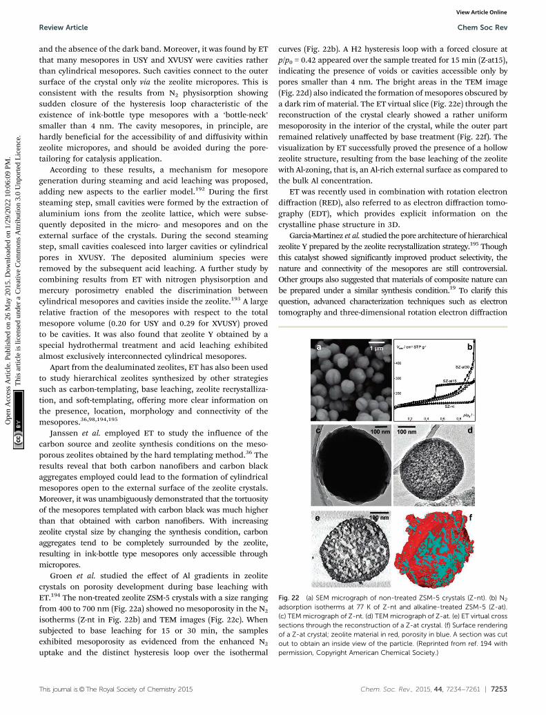
This journal is©The Royal Society of Chemistry 2015 Chem. Soc. Rev., 2015, 44, 7234--7261 | 7253
and the absence of the dark band. Moreover, it was found by ETthat many mesopores in USY and XVUSY were cavities ratherthan cylindrical mesopores. Such cavities connect to the outersurface of the crystal only via the zeolite micropores. This isconsistent with the results from N2 physisorption showingsudden closure of the hysteresis loop characteristic of theexistence of ink-bottle type mesopores with a ‘bottle-neck’smaller than 4 nm. The cavity mesopores, in principle, arehardly beneficial for the accessibility of and diffusivity withinzeolite micropores, and should be avoided during the pore-tailoring for catalysis application.
According to these results, a mechanism for mesoporegeneration during steaming and acid leaching was proposed,adding new aspects to the earlier model.192 During the firststeaming step, small cavities were formed by the extraction ofaluminium ions from the zeolite lattice, which were subse-quently deposited in the micro- and mesopores and on theexternal surface of the crystals. During the second steamingstep, small cavities coalesced into larger cavities or cylindricalpores in XVUSY. The deposited aluminium species wereremoved by the subsequent acid leaching. A further study bycombining results from ET with nitrogen physisorption andmercury porosimetry enabled the discrimination betweencylindrical mesopores and cavities inside the zeolite.193 A largerelative fraction of the mesopores with respect to the totalmesopore volume (0.20 for USY and 0.29 for XVUSY) provedto be cavities. It was also found that zeolite Y obtained by aspecial hydrothermal treatment and acid leaching exhibitedalmost exclusively interconnected cylindrical mesopores.
Apart from the dealuminated zeolites, ET has also been usedto study hierarchical zeolites synthesized by other strategiessuch as carbon-templating, base leaching, zeolite recrystalliza-tion, and soft-templating, offering more clear information onthe presence, location, morphology and connectivity of themesopores.36,98,194,195
Janssen et al. employed ET to study the influence of thecarbon source and zeolite synthesis conditions on the meso-porous zeolites obtained by the hard templating method.36 Theresults reveal that both carbon nanofibers and carbon blackaggregates employed could lead to the formation of cylindricalmesopores open to the external surface of the zeolite crystals.Moreover, it was unambiguously demonstrated that the tortuosityof the mesopores templated with carbon black was much higherthan that obtained with carbon nanofibers. With increasingzeolite crystal size by changing the synthesis condition, carbonaggregates tend to be completely surrounded by the zeolite,resulting in ink-bottle type mesopores only accessible throughmicropores.
Groen et al. studied the effect of Al gradients in zeolitecrystals on porosity development during base leaching withET.194 The non-treated zeolite ZSM-5 crystals with a size rangingfrom 400 to 700 nm (Fig. 22a) showed no mesoporosity in the N2
isotherms (Z-nt in Fig. 22b) and TEM images (Fig. 22c). Whensubjected to base leaching for 15 or 30 min, the samplesexhibited mesoporosity as evidenced from the enhanced N2
uptake and the distinct hysteresis loop over the isothermal
curves (Fig. 22b). A H2 hysteresis loop with a forced closure atp/p0 = 0.42 appeared over the sample treated for 15 min (Z-at15),indicating the presence of voids or cavities accessible only bypores smaller than 4 nm. The bright areas in the TEM image(Fig. 22d) also indicated the formation of mesopores obscured bya dark rim of material. The ET virtual slice (Fig. 22e) through thereconstruction of the crystal clearly showed a rather uniformmesoporosity in the interior of the crystal, while the outer partremained relatively unaffected by base treatment (Fig. 22f). Thevisualization by ET successfully proved the presence of a hollowzeolite structure, resulting from the base leaching of the zeolitewith Al-zoning, that is, an Al-rich external surface as compared tothe bulk Al concentration.
ET was recently used in combination with rotation electrondiffraction (RED), also referred to as electron diffraction tomo-graphy (EDT), which provides explicit information on thecrystalline phase structure in 3D.
Garcia-Martinez et al. studied the pore architecture of hierarchicalzeolite Y prepared by the zeolite recrystallization strategy.195 Thoughthis catalyst showed significantly improved product selectivity, thenature and connectivity of the mesopores are still controversial.Other groups also suggested that materials of composite nature canbe prepared under a similar synthesis condition.19 To clarify thisquestion, advanced characterization techniques such as electrontomography and three-dimensional rotation electron diffraction
Fig. 22 (a) SEM micrograph of non-treated ZSM-5 crystals (Z-nt). (b) N2
adsorption isotherms at 77 K of Z-nt and alkaline-treated ZSM-5 (Z-at).(c) TEM micrograph of Z-nt. (d) TEM micrograph of Z-at. (e) ET virtual crosssections through the reconstruction of a Z-at crystal. (f) Surface renderingof a Z-at crystal; zeolite material in red, porosity in blue. A section was cutout to obtain an inside view of the particle. (Reprinted from ref. 194 withpermission, Copyright American Chemical Society.)
Review Article Chem Soc Rev
Ope
n A
cces
s A
rtic
le. P
ublis
hed
on 2
6 M
ay 2
015.
Dow
nloa
ded
on 1
/29/
2022
10:
06:0
9 PM
. T
his
artic
le is
lice
nsed
und
er a
Cre
ativ
e C
omm
ons
Attr
ibut
ion
3.0
Unp
orte
d L
icen
ce.
View Article Online
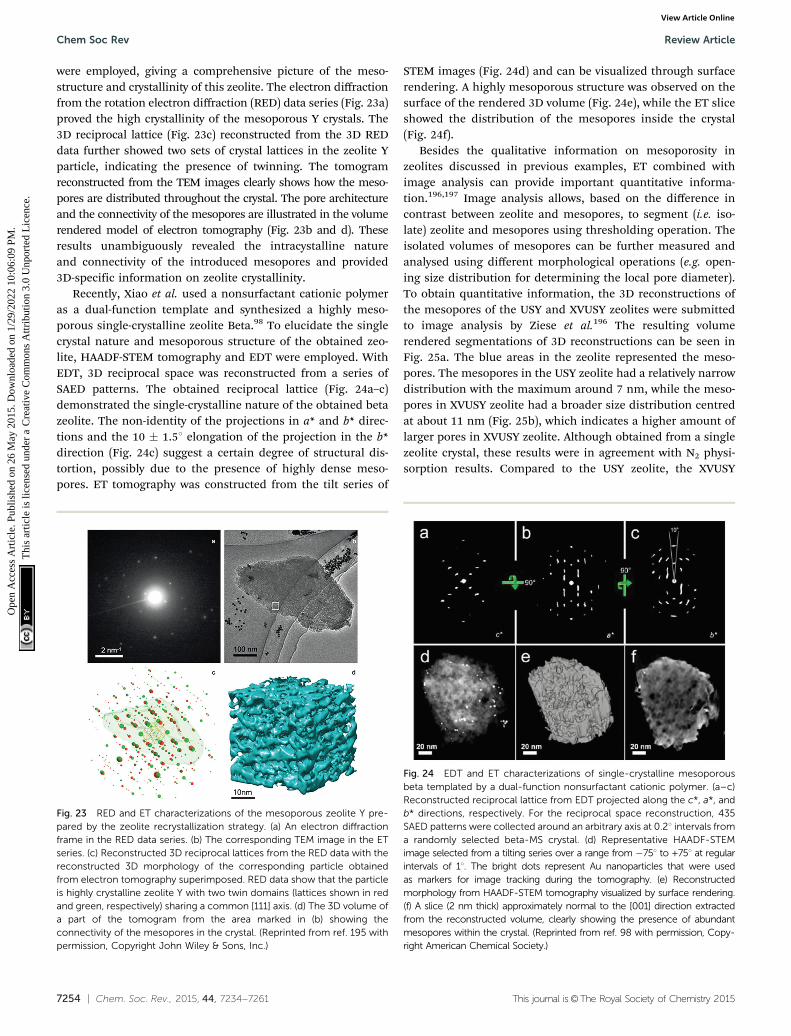
7254 | Chem. Soc. Rev., 2015, 44, 7234--7261 This journal is©The Royal Society of Chemistry 2015
were employed, giving a comprehensive picture of the meso-structure and crystallinity of this zeolite. The electron diffractionfrom the rotation electron diffraction (RED) data series (Fig. 23a)proved the high crystallinity of the mesoporous Y crystals. The3D reciprocal lattice (Fig. 23c) reconstructed from the 3D REDdata further showed two sets of crystal lattices in the zeolite Yparticle, indicating the presence of twinning. The tomogramreconstructed from the TEM images clearly shows how the meso-pores are distributed throughout the crystal. The pore architectureand the connectivity of the mesopores are illustrated in the volumerendered model of electron tomography (Fig. 23b and d). Theseresults unambiguously revealed the intracystalline natureand connectivity of the introduced mesopores and provided3D-specific information on zeolite crystallinity.
Recently, Xiao et al. used a nonsurfactant cationic polymeras a dual-function template and synthesized a highly meso-porous single-crystalline zeolite Beta.98 To elucidate the singlecrystal nature and mesoporous structure of the obtained zeo-lite, HAADF-STEM tomography and EDT were employed. WithEDT, 3D reciprocal space was reconstructed from a series ofSAED patterns. The obtained reciprocal lattice (Fig. 24a–c)demonstrated the single-crystalline nature of the obtained betazeolite. The non-identity of the projections in a* and b* direc-tions and the 10 � 1.51 elongation of the projection in the b*direction (Fig. 24c) suggest a certain degree of structural dis-tortion, possibly due to the presence of highly dense meso-pores. ET tomography was constructed from the tilt series of
STEM images (Fig. 24d) and can be visualized through surfacerendering. A highly mesoporous structure was observed on thesurface of the rendered 3D volume (Fig. 24e), while the ET sliceshowed the distribution of the mesopores inside the crystal(Fig. 24f).
Besides the qualitative information on mesoporosity inzeolites discussed in previous examples, ET combined withimage analysis can provide important quantitative informa-tion.196,197 Image analysis allows, based on the difference incontrast between zeolite and mesopores, to segment (i.e. iso-late) zeolite and mesopores using thresholding operation. Theisolated volumes of mesopores can be further measured andanalysed using different morphological operations (e.g. open-ing size distribution for determining the local pore diameter).To obtain quantitative information, the 3D reconstructions ofthe mesopores of the USY and XVUSY zeolites were submittedto image analysis by Ziese et al.196 The resulting volumerendered segmentations of 3D reconstructions can be seen inFig. 25a. The blue areas in the zeolite represented the meso-pores. The mesopores in the USY zeolite had a relatively narrowdistribution with the maximum around 7 nm, while the meso-pores in XVUSY zeolite had a broader size distribution centredat about 11 nm (Fig. 25b), which indicates a higher amount oflarger pores in XVUSY zeolite. Although obtained from a singlezeolite crystal, these results were in agreement with N2 physi-sorption results. Compared to the USY zeolite, the XVUSY
Fig. 23 RED and ET characterizations of the mesoporous zeolite Y pre-pared by the zeolite recrystallization strategy. (a) An electron diffractionframe in the RED data series. (b) The corresponding TEM image in the ETseries. (c) Reconstructed 3D reciprocal lattices from the RED data with thereconstructed 3D morphology of the corresponding particle obtainedfrom electron tomography superimposed. RED data show that the particleis highly crystalline zeolite Y with two twin domains (lattices shown in redand green, respectively) sharing a common [111] axis. (d) The 3D volume ofa part of the tomogram from the area marked in (b) showing theconnectivity of the mesopores in the crystal. (Reprinted from ref. 195 withpermission, Copyright John Wiley & Sons, Inc.)
Fig. 24 EDT and ET characterizations of single-crystalline mesoporousbeta templated by a dual-function nonsurfactant cationic polymer. (a–c)Reconstructed reciprocal lattice from EDT projected along the c*, a*, andb* directions, respectively. For the reciprocal space reconstruction, 435SAED patterns were collected around an arbitrary axis at 0.21 intervals froma randomly selected beta-MS crystal. (d) Representative HAADF-STEMimage selected from a tilting series over a range from �751 to +751 at regularintervals of 11. The bright dots represent Au nanoparticles that were usedas markers for image tracking during the tomography. (e) Reconstructedmorphology from HAADF-STEM tomography visualized by surface rendering.(f) A slice (2 nm thick) approximately normal to the [001] direction extractedfrom the reconstructed volume, clearly showing the presence of abundantmesopores within the crystal. (Reprinted from ref. 98 with permission, Copy-right American Chemical Society.)
Chem Soc Rev Review Article
Ope
n A
cces
s A
rtic
le. P
ublis
hed
on 2
6 M
ay 2
015.
Dow
nloa
ded
on 1
/29/
2022
10:
06:0
9 PM
. T
his
artic
le is
lice
nsed
und
er a
Cre
ativ
e C
omm
ons
Attr
ibut
ion
3.0
Unp
orte
d L
icen
ce.
View Article Online

This journal is©The Royal Society of Chemistry 2015 Chem. Soc. Rev., 2015, 44, 7234--7261 | 7255
zeolite was treated with an extra steaming step and acid leachingstep, which seems to enlarge the mesopores in the zeolite.
By combining ET with advanced image analysis Zecevic andGommes et al. made a more in-depth quantitative study of themesoporous morphology properties of an industrially relevantmesoporous zeolite Y prepared by steaming and acid leaching.Detailed information on the architecture of the mesoporousnetwork, such as accessibility and tortuosity of mesopores and sizedistribution of microporous domains created upon the introductionof mesopores, was obtained.197 Based on the segmented ETreconstruction and image processing, three types of mesoporeswere distinguished including open mesopores that are accessiblefrom the outer surface of the crystal (Fig. 26a), closed mesoporesthat can only be reached by micropores (Fig. 26b), and con-stricted mesopores that can be reached from the outer surfaceonly through narrower openings (smaller than 4 nm), the size ofwhich cannot be resolved by N2 physisorption. The volume anddiameters of these mesopores can be quantitatively determinedas shown in Fig. 26c. The tortuosity of the mesopore network,that is, how curved the mesopore channels are, is an importantparameter that can greatly influence the mass transfer efficiencyof the mesopore network. For the studied mesopores, the tortu-osity was calculated to be 1.3, which indicates on average ratherstraight pores. Finally, quantitative information about the size ofthe microporous domains between mesopore channels, whichessentially determines the diffusion path length of moleculeswithin the zeolite, was also obtained by measuring the distancebetween any point in the micropore region and the closestmesopore surface. It was found that 90% of the microporeshad a distance smaller than 15 nm from the closest mesoporechannel (Fig. 26d and e). The quantitative information grants amore comprehensive and accurate assessment of the mesoporeproperties and thus greatly improves the understanding of themesoporous architecture of hierarchical zeolites.
From the above examples, we can see that compared toconventional TEM, ET yields unprecedented and unambiguous3D information, both qualitatively and quantitatively, on themesopore characteristics including pore shape, size, connectivity,accessibility and tortuosity inside individual crystals. Such knowl-edge greatly contributes to our understanding of the relationshipbetween the pore architecture and the synthesis method employed,and further enables a rational design of mesoporous zeolites with
improved functionality. However, compared with conventionalSEM and TEM characterization, ET requires much longer timefor data acquisition, which is not only time-consuming but alsoincreases the difficulty for the analysis of electron beam sensitivesamples.
3.4 Integrated approach
From the aforementioned techniques, we can see that differentstructural probes are required to visualize the hierarchicalzeolite materials and study them at different length scales.With optical microscopy such as confocal fluorescence micro-scopy, one can determine the location of mesopores on amacro-scale and within a large area (hundreds of microns).Electron-based techniques, such as SEM, TEM, FIB-SEM tomo-graphy and electron tomography, allow the study of porearchitecture at nanoscales, however, sacrificing the view area(hundreds of nanometres). The resolution of X-ray tomographylies between that of the optical microscopy and the electron-based microscopy, bridging the gaps between these two tech-niques. Perez-Ramırez and co-workers recently showed anintegrated approach to visualize millimetre-sized granules ofa hierarchical MFI type zeolite by a combination of state-of-the-art optical, X-ray and electron-based microscopic and tomo-graphic techniques.174 In this work, digital reflected lightmicroscopy was used to image the macroscopic structure(Fig. 27a). With profilometry, a relatively uniform rough surfaceof the granules was observed (Fig. 27c). Confocal laser scanningmicroscopy (CLSM) showed clear green fluorescence formed by
Fig. 25 (a) 3D representation of XVUSY showing the mesopores throughthe transparent surface of the particle. (b) Mesopore size distributions ofUSY and XVUSY obtained by image analysis of electron tomograms.(Adapted from ref. 196.)
Fig. 26 (a–c) Accessibility of the mesopores described and quantifiedusing image processing. Volume-rendered 3D representations of the openmesopores in green (a) and the ‘‘closed’’ mesopores in red (b) visuallysuggest that an open type of porosity prevails. (c) Pore size distribution ofopen mesopores (white), constricted mesopores (gray), and ‘‘closed’’mesopores (black) defined as Vpore/Vtotal, where Vpore corresponds to thevolume of the considered types of mesopores and Vtotal to the totalvolume of the zeolite crystal. (d, e) Size distribution of microporousdomains created upon introduction of mesopores. (d) Color map of theshortest distances from any point of a micropore region to the nearestmesopore surface. Color bar refers to distances in nm. (e) Size distributionof the microporous domains defined as a fraction of the voxels of themicroporous region with a corresponding shortest distance to the meso-pore surface. (Reprinted from ref. 197 with permission, Copyright JohnWiley & Sons, Inc.)
Review Article Chem Soc Rev
Ope
n A
cces
s A
rtic
le. P
ublis
hed
on 2
6 M
ay 2
015.
Dow
nloa
ded
on 1
/29/
2022
10:
06:0
9 PM
. T
his
artic
le is
lice
nsed
und
er a
Cre
ativ
e C
omm
ons
Attr
ibut
ion
3.0
Unp
orte
d L
icen
ce.
View Article Online

7256 | Chem. Soc. Rev., 2015, 44, 7234--7261 This journal is©The Royal Society of Chemistry 2015
the reaction of thiophene with zeolitic Brønsted acid sites uponillumination with a 488 nm laser, revealing zeolite particleswith varying size in the external surface region of the granules(Fig. 27d). X-ray micro-CT and SRXTM were used to unravel theinternal structure as we have described in Section 3.2 (Fig. 27b,e and g), together with FIB-SEM (Fig. 27f) revealing the homo-geneous internal distribution of the zeolite, binder and themacro-/mesoporosity in between. The high-resolution SEMshowed that the zeolite particles were tightly aggregated poly-crystalline particles of 50–70 nm in size, and the binderparticles were needle-like with a width of 10–20 nm and alength of 0.5–1 mm surrounding the zeolites (Fig. 27h). Energy-dispersive X-ray (EDX) spectroscopy clearly differentiated thezeolite and binder phase with distinct composition throughmapping the silicon and aluminium (Fig. 27i). TEM images ofthe microtomed sample revealed that the binder particles werewedged between the zeolite particles and the intracrystallinemesopores were created in the zeolite crystal by base leaching(Fig. 27k). HAAFD-STEM and HRTEM images further confirmedthe uniform distribution of intracrystalline mesopores withinindividual zeolite aggregates (Fig. 27j and l). The authorsdemonstrated that only by integrating various imaging techni-ques the millimetre sized zeolite-based catalyst body can be
comprehensively studied from macro- to nanoscales, providingthus a full picture of the structure and composition. Suchapproach proves to be a powerful methodology, revealing otherwiseinaccessible information regarding structural organization over thewhole range of length scales.
4. Conclusions
Hierarchical zeolites, coupling meso- and/or macroporositywith the intrinsic microporosity, are considered an attractiveupgrade of conventional zeolites in many established andemerging processes involving catalytic reactions especially withbulky molecules. Over the past years, the ever-increasing inter-est in hierarchical zeolites has fuelled the development andprogress of both synthesis strategies for tailoring the pores andimaging techniques for visualizing the pore architecture.
In this review, we have classified and summarized the so fardeveloped synthesis approaches, including assembly (hard,soft and non-templating), demetallization (dealumination anddesilication) and mixed (zeolite recrystallization) methods. Thedealumination strategy was developed the earliest of all and hasbeen widely applied for industrial zeolite catalysts. However,with the extraction of aluminium from the framework, thenumber of acid sites is decreased together with the formationof many isolated mesoporous cavities, which hardly facilitatethe diffusion. Desilication is an alternative demetallizationmethod to create hierarchical porosity at the expense of removingSi from the zeolite framework. In recent years, it has undergone agreat development. With the aid of extra pore directing agents orcoupling with acid leaching, it now offers increased control over poresize and connectivity and expands the range of the accessible Si/Alratio of the parent zeolite for successful desilication. The loss ofmaterial is a problem of this method with respect to large scaleapplications. The assembly methods mainly rely on the use of hardor soft templates to create mesopores. With the exploration of noveltemplates, a higher control of the additional porosity has beenachieved. However, the economic and environmental costs need tobe considered because most of these templates are expensive andirretrievable. Although assembly methods without the use of meso-pore templates have been reported, it is still difficult to implementthem on a large scale due to the time-consuming preparative processand the rigorous synthesis condition. Zeolite recrystallizationthrough desilication in the presence of conventional surfactants isthe closest to industrial realization at the moment due to theadvantage of high yield and relatively low environmental cost ascompared to the demetallization methods and the assembly meth-ods. Recently, FCC catalysts with mesoporous zeolite Y made by thezeolite recrystallization route were scaled up and successfully per-formed in two separate North American refineries.198,199 Althoughgreat improvements have been made, new synthesis strategies fortailoring hierarchical pore architecture with low economic andenvironmental cost, high controllability and versatility still remainof great interest and challenge.
To optimize the functionality of hierarchical zeolites, com-prehensive assessment and full understanding of the pore
Fig. 27 Integrated approach to the visualization of a hierarchical zeolitebody from macro to nano length scales. (a, b) The macroscopic structureof a hierarchical zeolite granule is observed by optical microscopy (a) andthe internal structure is revealed by X-ray micro-CT (b), providing insightinto the agglomeration behaviour within the shaped body. (c, d) Thestructure of the external surface is further examined by profilometry(c) and CLSM (d). (e–g) SRXTM (e) and FIB-SEM (f) reveal the homogeneousinternal distribution of zeolite and binder phases and permit visualizationand computation of the macro- and mesopore structures (g). (h, i) Thearrangement of binder particles at the external surface of zeolite particlesis seen by SEM (h) and elemental maps of silicon (green) and aluminium(red) are obtained by EDX (i). (j) A HAAFD-STEM image confirms theuniform distribution of intracrystalline mesopores within individual zeoliteaggregates. (k, l) Nanostructural insights are gained through the TEM studyof microtome cross-sections (k) and ultimately by HRTEM (l). (Reprintedfrom ref. 174 with permission, Copyright Nature Publishing Group.)
Chem Soc Rev Review Article
Ope
n A
cces
s A
rtic
le. P
ublis
hed
on 2
6 M
ay 2
015.
Dow
nloa
ded
on 1
/29/
2022
10:
06:0
9 PM
. T
his
artic
le is
lice
nsed
und
er a
Cre
ativ
e C
omm
ons
Attr
ibut
ion
3.0
Unp
orte
d L
icen
ce.
View Article Online
This journal is©The Royal Society of Chemistry 2015 Chem. Soc. Rev., 2015, 44, 7234--7261 | 7257
network structure is a premise. Various microscopy techniqueshave been employed to visualize pore architecture at differentlength scales. With optical microscopy, such as confocalfluorescence microscopy, the whole zeolite crystals can bestudied. By making use of a molecule that can only be synthe-sized in the larger pores of the zeolite, one can map the locationof these pores. However, the mesoporosity cannot be studied ingreat detail due to the limited resolution. A higher resolutionthan optical microscopy can be achieved by X-ray microscopy.X-rays have much higher penetrative power and X-ray tomo-graphy can be used to visualize the sample of hundreds ofmicrometres thickness in 3D without the need of cutting.However, high intensity synchrotron X-ray sources are required,which is inconvenient for routine studies. SEM provides a lot ofinformation about the surface morphology of the crystals. Withthe combination of FIB and SEM, the internal structure ofthe sample can also be studied. FIB-SEM tomography allowsmapping of the internal mesoporous structure in 3D, althoughwith limited resolution. A more detailed technique is TEM, withwhich even atomic resolution can be achieved. A thin sample isrequired for this technique since a beam of electrons must betransmitted through the sample. Although TEM can providesome information about the presence and shape of mesoporesin the sample, it can’t provide information about the connec-tivity of the mesopores as 3D information is lacking. ET hasalready proven to be a very promising technique for the 3Dcharacterization of materials. Quantitative information aboutthe zeolite pore structure, such as the distance from microporesto mesopores and tortuosity, can be derived from the recon-structions. However, challenges remain in reducing the time toacquire tomograms. The electron beam can be destructive forthe zeolite sample, causing it to shrink during the measure-ment and thus reduce tomogram resolution. Elemental analysisby EDX combined with ET could yield very valuable informationon both chemical composition and porous structure. Anotherchallenge lies in the development of in situ TEM and tomogra-phy. Visualization of mesopore formation in zeolites in realtime would provide very valuable information to optimize andcontrol these processes. It is important to note that ET inevi-tably only probes a small amount of the sample, and hence,verification by comparison with bulk physical measurements ismandatory. While techniques such as N2 physisorption and Hgporosimetry are common bulk techniques for assessing poresize distributions, they can only to certain extent describe porenetwork accessibility and connectivity. Recently developedpositron annihilation lifetime spectroscopy, however, showedpromising results in determining the pore connectivity para-meter which correlated to the performance of investigatedcatalysts.200
Acknowledgements
The research of YW has been made possible by support of theBP International Limited. KP and JZ acknowledge support fromNRSCC and an ERC Advanced Grant.
Note and references
1 A. Corma, Chem. Rev., 1995, 95, 559–614.2 J. Weitkamp, Solid State Ionics, 2000, 131, 175–188.3 C. R. Marcilly, Top. Catal., 2000, 13, 357–366.4 B. Smit and T. L. Maesen, Nature, 2008, 451, 671–678.5 http://www.iza-structure.org/databases/.6 C. T. Kresge, M. E. Leonowicz, W. J. Roth, J. C. Vartuli and
J. S. Beck, Nature, 1992, 359, 710–712.7 J. S. Beck, J. C. Vartuli, W. J. Roth, M. E. Leonowicz, C. T.
Kresge, K. D. Schmitt, C. T. W. Chu, D. H. Olson, E. W.Sheppard, S. B. McCullen, J. B. Higgins and J. L. Schlenker,J. Am. Chem. Soc., 1992, 114, 10834–10843.
8 D. Zhao, Science, 1998, 279, 548–552.9 M. E. Davis, Nature, 2002, 417, 813–821.
10 J. Jiang, J. Yu and A. Corma, Angew. Chem., Int. Ed., 2010,49, 3120–3145.
11 S. Lopez-Orozco, A. Inayat, A. Schwab, T. Selvam andW. Schwieger, Adv. Mater., 2011, 23, 2602–2615.
12 D. Verboekend and J. Perez-Ramırez, Catal. Sci. Technol.,2011, 1, 879.
13 Z. L. Hua, J. Zhou and J. L. Shi, Chem. Commun., 2011, 47,10536–10547.
14 R. Chal, C. Gerardin, M. Bulut and S. van Donk, ChemCatChem,2011, 3, 67–81.
15 L. H. Chen, X. Y. Li, J. C. Rooke, Y. H. Zhang, X. Y. Yang,Y. Tang, F. S. Xiao and B. L. Su, J. Mater. Chem., 2012, 22,17381–17403.
16 K. Moller and T. Bein, Chem. Soc. Rev., 2013, 42, 3689–3707.17 D. P. Serrano, J. M. Escola and P. Pizarro, Chem. Soc. Rev.,
2013, 42, 4004–4035.18 K. Na, M. Choi and R. Ryoo, Microporous Mesoporous
Mater., 2013, 166, 3–19.19 I. I. Ivanova and E. E. Knyazeva, Chem. Soc. Rev., 2013, 42,
3671–3688.20 K. Li, J. Valla and J. Garcia-Martinez, ChemCatChem, 2014,
6, 46–66.21 K. Na and G. A. Somorjai, Catal. Lett., 2015, 145, 193–213.22 L. Tosheva and V. P. Valtchev, Chem. Mater., 2005, 17,
2494–2513.23 E. P. Ng, D. Chateigner, T. Bein, V. Valtchev and
S. Mintova, Science, 2012, 335, 70–73.24 H. Awala, J. P. Gilson, R. Retoux, P. Boullay, J. M. Goupil,
V. Valtchev and S. Mintova, Nat. Mater., 2014, 14, 447–451.25 F. Ocampo, H. S. Yun, M. Maciel Pereira, J. P. Tessonnier
and B. Louis, Cryst. Growth Des., 2009, 9, 3721–3729.26 B. Louis, F. Ocampo, H. S. Yun, J. P. Tessonnier and
M. Maciel Pereira, Chem. Eng. J., 2010, 161, 397–402.27 C. Madsen and C. J. H. Jacobsen, Chem. Commun., 1999,
673–674.28 I. Schmidt, C. Madsen and C. J. H. Jacobsen, Inorg. Chem.,
2000, 39, 2279–2283.29 C. J. H. Jacobsen, C. Madsen, J. Houzvicka, I. Schmidt and
A. Carlsson, J. Am. Chem. Soc., 2000, 122, 7116–7117.30 I. Schmidt, A. Krogh, K. Wienberg, A. Carlsson, M. Brorson
and C. J. H. Jacobsen, Chem. Commun., 2000, 2157–2158.
Review Article Chem Soc Rev
Ope
n A
cces
s A
rtic
le. P
ublis
hed
on 2
6 M
ay 2
015.
Dow
nloa
ded
on 1
/29/
2022
10:
06:0
9 PM
. T
his
artic
le is
lice
nsed
und
er a
Cre
ativ
e C
omm
ons
Attr
ibut
ion
3.0
Unp
orte
d L
icen
ce.
View Article Online

7258 | Chem. Soc. Rev., 2015, 44, 7234--7261 This journal is©The Royal Society of Chemistry 2015
31 M. Y. Kustova, P. Hasselriis and C. H. Christensen, Catal.Lett., 2004, 96, 205–211.
32 K. Egeblad, M. Kustova, S. K. Klitgaard, K. Zhu andC. H. Christensen, Microporous Mesoporous Mater., 2007,101, 214–223.
33 X. Wei and P. G. Smirniotis, Microporous MesoporousMater., 2006, 89, 170–178.
34 I. Schmidt, A. Boisen, E. Gustavsson, K. Stahl, S. Pehrson,S. Dahl, A. Carlsson and C. J. H. Jacobsen, Chem. Mater.,2001, 13, 4416–4418.
35 A. Boisen, I. Schmidt, A. Carlsson, S. Dahl, M. Brorson andC. J. H. Jacobsen, Chem. Commun., 2003, 958–959.
36 A. H. Janssen, I. Schmidt, C. J. H. Jacobsen, A. J. Koster andK. P. de Jong, Microporous Mesoporous Mater., 2003, 65,59–75.
37 F. Schmidt, S. Paasch, E. Brunner and S. Kaskel, Micro-porous Mesoporous Mater., 2012, 164, 214–221.
38 Y. S. Tao, H. Kanoh and K. Kaneko, J. Am. Chem. Soc., 2003,125, 6044–6045.
39 Y. S. Tao, H. Kanoh and K. Kaneko, J. Phys. Chem. B, 2003,107, 10974–10976.
40 Y. S. Tao, H. Kanoh and K. Kaneko, Langmuir, 2005, 21,504–507.
41 W. C. Li, A. H. Lu, R. Palkovits, W. Schmidt, B. Spliethoffand F. Schuth, J. Am. Chem. Soc., 2005, 127, 12595–12600.
42 M. Kustova, K. Egeblad, K. Zhu and C. H. Christensen,Chem. Mater., 2007, 19, 2915–2917.
43 K. Zhu, K. Egeblad and C. H. Christensen, Eur. J. Inorg.Chem., 2007, 3955–3960.
44 X. Wang, G. Li, W. Wang, C. Jin and Y. Chen, MicroporousMesoporous Mater., 2011, 142, 494–502.
45 R. J. White, A. Fischer, C. Goebel and A. Thomas, J. Am.Chem. Soc., 2014, 136, 2715–2718.
46 Z. X. Yang, Y. D. Xia and R. Mokaya, Adv. Mater., 2004, 16,727–732.
47 A. Sakthivel, S. J. Huang, W. H. Chen, Z. H. Lan, K. H.Chen, T. W. Kim, R. Ryoo, A. S. T. Chiang and S. B. Liu,Chem. Mater., 2004, 16, 3168–3175.
48 Y. Fang and H. Hu, J. Am. Chem. Soc., 2006, 128,10636–10637.
49 H. S. Cho and R. Ryoo, Microporous Mesoporous Mater.,2012, 151, 107–112.
50 S. S. Kim, J. Shah and T. J. Pinnavaia, Chem. Mater., 2003,15, 1664–1668.
51 H. Li, Y. Sakamoto, Z. Liu, T. Ohsuna, O. Terasaki,M. Thommes and S. Che, Microporous Mesoporous Mater.,2007, 106, 174–179.
52 W. Fan, M. A. Snyder, S. Kumar, P. S. Lee, W. C. Yoo,A. V. McCormick, R. Lee Penn, A. Stein and M. Tsapatsis,Nat. Mater., 2008, 7, 984–991.
53 H. Chen, J. Wydra, X. Zhang, P. S. Lee, Z. Wang, W. Fan andM. Tsapatsis, J. Am. Chem. Soc., 2011, 133, 12390–12393.
54 B. T. Holland, L. Abrams and A. Stein, J. Am. Chem. Soc.,1999, 121, 4308–4309.
55 K. H. Rhodes, S. A. Davis, F. Caruso, B. J. Zhang andS. Mann, Chem. Mater., 2000, 12, 2832–2834.
56 V. Naydenov, L. Tosheva and J. Sterte, Microporous Meso-porous Mater., 2003, 66, 321–329.
57 V. Naydenov, L. Tosheva and J. Sterte, Chem. Mater., 2002,14, 4881–4885.
58 Y. Kang, W. Shan, J. Wu, Y. Zhang, X. Wang, W. Yang andY. Tang, Chem. Mater., 2006, 18, 1861–1866.
59 Y. Shi, X. Li, J. Hu, J. Lu, Y. Ma, Y. Zhang and Y. Tang,J. Mater. Chem., 2011, 21, 16223–16230.
60 H. Zhu, Z. Liu, Y. Wang, D. Kong, X. Yuan and Z. Xie,Chem. Mater., 2008, 20, 1134–1139.
61 B. J. Zhang, S. A. Davis, N. H. Mendelson and S. Mann,Chem. Commun., 2000, 781–782.
62 A. G. Dong, Y. J. Wang, Y. Tang, N. Ren, Y. H. Zhang,J. H. Yue and Z. Gao, Adv. Mater., 2002, 14, 926–929.
63 O. de la Iglesia, J. Luis Sanchez and J. Coronas, Mater. Lett.,2011, 65, 3124–3127.
64 F. Ocampo, J. A. Cunha, M. R. de Lima Santos, J. P. Tessonnier,M. M. Pereira and B. Louis, Appl. Catal., A, 2010, 390, 102–109.
65 V. Valtchev, M. Smaihi, A. C. Faust and L. Vidal, Angew.Chem., Int. Ed., 2003, 42, 2782–2785.
66 V. P. Valtchev, M. Smaihi, A. C. Faust and L. Vidal, Chem.Mater., 2004, 16, 1350–1355.
67 P. Prokesova-Fojokova, S. Mintova, J. Cejka, N. Zilkova andA. Zukal, Microporous Mesoporous Mater., 2006, 92, 154–160.
68 A. Karlsson, M. Stocker and R. Schmidt, MicroporousMesoporous Mater., 1999, 27, 181–192.
69 L. M. Huang, W. P. Guo, P. Deng, Z. Y. Xue and Q. Z. Li,J. Phys. Chem. B, 2000, 104, 2817–2823.
70 Y. Zhu, Z. Hua, J. Zhou, L. Wang, J. Zhao, Y. Gong, W. Wu,M. Ruan and J. Shi, Chem. – Eur. J., 2011, 17, 14618–14627.
71 M. B. Yue, L. B. Sun, T. T. Zhuang, X. Dong, Y. Chun andJ. H. Zhu, J. Mater. Chem., 2008, 18, 2044.
72 Y. Liu, W. Z. Zhang and T. J. Pinnavaia, Angew. Chem., Int.Ed., 2001, 40, 1255–1258.
73 Y. Liu, W. Z. Zhang and T. J. Pinnavaia, J. Am. Chem. Soc.,2000, 122, 8791–8792.
74 Z. T. Zhang, Y. Han, L. Zhu, R. W. Wang, Y. Yu, S. L. Qiu,D. Y. Zhao and F. S. Xiao, Angew. Chem., Int. Ed., 2001, 40,1258–1262.
75 Y. D. Xia and R. Mokaya, J. Mater. Chem., 2004, 14,3427–3435.
76 S. P. Naik, A. S. T. Chiang, R. W. Thompson and F. C.Huang, Chem. Mater., 2003, 15, 787–792.
77 D. P. Serrano, J. Aguado, J. M. Escola, J. M. Rodrıguez andA. Peral, Chem. Mater., 2006, 18, 2462–2464.
78 D. P. Serrano, J. Aguado, G. Morales, J. M. Rodrıguez,A. Peral, M. Thommes, J. D. Epping and B. F. Chmelka,Chem. Mater., 2009, 21, 641–654.
79 D. P. Serrano, J. Aguado, J. M. Escola, J. M. Rodrıguez andA. Peral, J. Mater. Chem., 2008, 18, 4210–4218.
80 D. P. Serrano, J. Aguado, J. M. Escola, A. Peral, G. Moralesand E. Abella, Catal. Today, 2011, 168, 86–95.
81 M. Choi, H. S. Cho, R. Srivastava, C. Venkatesan,D. H. Choi and R. Ryoo, Nat. Mater., 2006, 5, 718–723.
82 G. V. Shanbhag, M. Choi, J. Kim and R. Ryoo, J. Catal.,2009, 264, 88–92.
Chem Soc Rev Review Article
Ope
n A
cces
s A
rtic
le. P
ublis
hed
on 2
6 M
ay 2
015.
Dow
nloa
ded
on 1
/29/
2022
10:
06:0
9 PM
. T
his
artic
le is
lice
nsed
und
er a
Cre
ativ
e C
omm
ons
Attr
ibut
ion
3.0
Unp
orte
d L
icen
ce.
View Article Online

This journal is©The Royal Society of Chemistry 2015 Chem. Soc. Rev., 2015, 44, 7234--7261 | 7259
83 M. Choi, R. Srivastava and R. Ryoo, Chem. Commun., 2006,4380–4382.
84 K. Cho, H. S. Cho, L.-C. de Menorval and R. Ryoo, Chem.Mater., 2009, 21, 5664–5673.
85 Y. Fan, H. Xiao, G. Shi, H. Liu and X. Bao, J. Catal., 2012,285, 251–259.
86 A. Inayat, I. Knoke, E. Spiecker and W. Schwieger, Angew.Chem., Int. Ed., 2012, 51, 1962–1965.
87 M. Khaleel, A. J. Wagner, K. A. Mkhoyan and M. Tsapatsis,Angew. Chem., Int. Ed., 2014, 53, 9456–9461.
88 H. Wang and T. J. Pinnavaia, Angew. Chem., Int. Ed., 2006,45, 7603–7606.
89 F. S. Xiao, L. Wang, C. Yin, K. Lin, Y. Di, J. Li, R. Xu,D. S. Su, R. Schlogl, T. Yokoi and T. Tatsumi, Angew. Chem.,Int. Ed., 2006, 45, 3090–3093.
90 F. Liu, T. Willhammar, L. Wang, L. Zhu, Q. Sun, X. Meng,W. Carrillo-Cabrera, X. Zou and F. S. Xiao, J. Am. Chem.Soc., 2012, 134, 4557–4560.
91 K. Moeller, B. Yilmaz, U. Mueller and T. Beins, Chem.Mater., 2011, 23, 4301–4310.
92 M. Choi, K. Na, J. Kim, Y. Sakamoto, O. Terasaki andR. Ryoo, Nature, 2009, 461, 246–249.
93 K. Na, W. Park, Y. Seo and R. Ryoo, Chem. Mater., 2011, 23,1273–1279.
94 K. Na, C. Jo, J. Kim, K. Cho, J. Jung, Y. Seo, R. J. Messinger,B. F. Chmelka and R. Ryoo, Science, 2011, 333, 328–332.
95 D. Xu, Y. Ma, Z. Jing, L. Han, B. Singh, J. Feng, X. Shen,F. Cao, P. Oleynikov, H. Sun, O. Terasaki and S. Che, Nat.Commun., 2014, 5, 4262–4270.
96 Y. Seo, S. Lee, C. Jo and R. Ryoo, J. Am. Chem. Soc., 2013,135, 8806–8809.
97 L. Wu, V. Degirmenci, P. C. Magusin, B. M. Szyja andE. J. Hensen, Chem. Commun., 2012, 48, 9492–9494.
98 J. Zhu, Y. Zhu, L. Zhu, M. Rigutto, A. van der Made,C. Yang, S. Pan, L. Wang, L. Zhu, Y. Jin, Q. Sun, Q. Wu,X. Meng, D. Zhang, Y. Han, J. Li, Y. Chu, A. Zheng, S. Qiu,X. Zheng and F. S. Xiao, J. Am. Chem. Soc., 2014, 136,2503–2510.
99 C. Jo, Y. Seo, K. Cho, J. Kim, H. S. Shin, M. Lee, J. C. Kim,S. O. Kim, J. Y. Lee, H. Ihee and R. Ryoo, Angew. Chem., Int.Ed., 2014, 53, 5117–5121.
100 M. Choi, K. Na and R. Ryoo, Chem. Commun., 2009,2845–2847.
101 K. Na, M. Choi and R. Ryoo, J. Mater. Chem., 2009, 19,6713–6719.
102 Y. Liu, W. P. Zhang, Z. C. Liu, S. T. Xu, Y. D. Wang,Z. K. Xie, X. W. Han and X. H. Bao, J. Phys. Chem. C,2008, 112, 15375–15381.
103 C. Mei, P. Wen, Z. Liu, H. Liu, Y. Wang, W. Yang, Z. Xie,W. Hua and Z. Gao, J. Catal., 2008, 258, 243–249.
104 L. Wang, C. Yin, Z. Shan, S. Liu, Y. Du and F.-S. Xiao,Colloids Surf., A, 2009, 340, 126–130.
105 H. Tao, C. Li, J. Ren, Y. Wang and G. Lu, J. Solid StateChem., 2011, 184, 1820–1827.
106 Y. Ma, J. Hu, L. Jia, Z. Li, Q. Kan and S. Wu, Mater. Res.Bull., 2013, 48, 1881–1884.
107 W. Wang, G. Li, L. Liu and Y. Chen, Microporous Meso-porous Mater., 2013, 179, 165–171.
108 D. Nandan, S. K. Saxena and N. Viswanadham, J. Mater.Chem. A, 2014, 2, 1054–1059.
109 K. Moeller, B. Yilmaz, R. M. Jacubinas, U. Mueller andT. Bein, J. Am. Chem. Soc., 2011, 133, 5284–5295.
110 G. Majano, S. Mintova, O. Ovsitser, B. Mihailova andT. Bein, Microporous Mesoporous Mater., 2005, 80, 227–235.
111 C. Li, Y. Wang, B. Shi, J. Ren, X. Liu, Y. Wang, Y. Guo,Y. Guo and G. Lu, Microporous Mesoporous Mater., 2009,117, 104–110.
112 L. H. Chen, X. Y. Li, G. Tian, Y. Li, J. C. Rooke, G. S. Zhu,S. L. Qiu, X. Y. Yang and B. L. Su, Angew. Chem., Int. Ed.,2011, 50, 11156–11161.
113 K. Moller, B. Yilmaz, U. Muller and T. Bein, Chem. – Eur. J.,2012, 18, 7671–7674.
114 X. Zhang, D. Liu, D. Xu, S. Asahina, K. A. Cychosz,K. V. Agrawal, Y. Al Wahedi, A. Bhan, S. Al Hashimi,O. Terasaki, M. Thommes and M. Tsapatsis, Science,2012, 336, 1684–1687.
115 W. Chaikittisilp, Y. Suzuki, R. R. Mukti, T. Suzuki,K. Sugita, K. Itabashi, A. Shimojima and T. Okubo, Angew.Chem., Int. Ed., 2013, 52, 3355–3359.
116 J. Zhu, Y. Cui, Y. Wang and F. Wei, Chem. Commun., 2009,3282–3284.
117 A. Inayat, C. Schneider and W. Schwieger, Chem. Commun.,2015, 51, 279–281.
118 A. Zukal, V. Patzelova and U. Lohse, Zeolites, 1986, 6,133–136.
119 Y. Sasaki, T. Suzuki, Y. Takamura, A. Saji and H. Saka,J. Catal., 1998, 178, 94–100.
120 S. van Donk, A. H. Janssen, J. H. Bitter and K. P. de Jong,Catal. Rev., 2003, 45, 297–319.
121 G. Agostini, C. Lamberti, L. Palin, M. Milanesio, N. Danilina,B. Xu, M. Janousch and J. A. van Bokhoven, J. Am. Chem. Soc.,2010, 132, 667–678.
122 D. M. Roberge, H. Hausmann and W. F. Holderich, Phys.Chem. Chem. Phys., 2002, 4, 3128–3135.
123 K. H. Chung, Microporous Mesoporous Mater., 2008, 111,544–550.
124 M. Tromp, J. A. van Bokhoven, M. T. Garriga Oostenbrink,J. H. Bitter, K. P. de Jong and D. C. Koningsberger, J. Catal.,2000, 190, 209–214.
125 D. A. Young, US3326797, 1967.126 A. Cizmek, B. Subotic, R. Aiello, F. Crea, A. Nastro and
C. Tuoto, Microporous Mater., 1995, 4, 159–168.127 A. Cizmek, B. Subotic, I. Smit, A. Tonejc, R. Aiello, F. Crea
and A. Nastro, Microporous Mater., 1997, 8, 159–169.128 M. Ogura, S. Y. Shinomiya, J. Tateno, Y. Nara, E. Kikuchi
and H. Matsukata, Chem. Lett., 2000, 882–883.129 J. C. Groen, J. C. Jansen, J. A. Moulijn and J. Perez-Ramırez,
J. Phys. Chem. B, 2004, 108, 13062–13065.130 J. C. Groen, L. A. Peffer, J. A. Moulijn and J. Perez-Ramırez,
Chem. – Eur. J., 2005, 11, 4983–4994.131 J. C. Groen, J. A. Moulijn and J. Perez-Ramırez, J. Mater.
Chem., 2006, 16, 2121–2131.
Review Article Chem Soc Rev
Ope
n A
cces
s A
rtic
le. P
ublis
hed
on 2
6 M
ay 2
015.
Dow
nloa
ded
on 1
/29/
2022
10:
06:0
9 PM
. T
his
artic
le is
lice
nsed
und
er a
Cre
ativ
e C
omm
ons
Attr
ibut
ion
3.0
Unp
orte
d L
icen
ce.
View Article Online

7260 | Chem. Soc. Rev., 2015, 44, 7234--7261 This journal is©The Royal Society of Chemistry 2015
132 S. Svelle, L. Sommer, K. Barbera, P. N. R. Vennestrøm,U. Olsbye, K. P. Lillerud, S. Bordiga, Y. H. Pan and P. Beato,Catal. Today, 2011, 168, 38–47.
133 S. Abello, A. Bonilla and J. Perez-Ramırez, Appl. Catal., A,2009, 364, 191–198.
134 J. Perez-Ramırez, D. Verboekend, A. Bonilla and S. Abello,Adv. Funct. Mater., 2009, 19, 3972–3979.
135 D. Verboekend and J. Perez-Ramırez, Chem. – Eur. J., 2011,17, 1137–1147.
136 D. Verboekend, G. Vile and J. Perez-Ramırez, Cryst. GrowthDes., 2012, 12, 3123–3132.
137 X. Li, R. Prins and J. A. van Bokhoven, J. Catal., 2009, 262,257–265.
138 A. N. C. van Laak, S. L. Sagala, J. Zecevic, H. Friedrich, P. E. deJongh and K. P. de Jong, J. Catal., 2010, 276, 170–180.
139 D. Verboekend, T. C. Keller, M. Milina, R. Hauert andJ. Perez-Ramırez, Chem. Mater., 2013, 25, 1947–1959.
140 K. P. de Jong, J. Zecevic, H. Friedrich, P. E. de Jongh,M. Bulut, S. van Donk, R. Kenmogne, A. Finiels, V. Huleaand F. Fajula, Angew. Chem., Int. Ed., 2010, 49, 10074–10078.
141 J. Perez-Ramırez, S. Abello, A. Bonilla and J. C. Groen, Adv.Funct. Mater., 2009, 19, 164–172.
142 A. N. C. van laak, L. Zhang, A. N. Parvulescu, P. C. A. Bruijnincx,B. M. Weckhuysen, K. P. de Jong and P. E. de Jongh, Catal.Today, 2011, 168, 48–56.
143 P. Sazama, Z. Sobalik, J. Dedecek, I. Jakubec, V. Parvulescu,Z. Bastl, J. Rathousky and H. Jirglova, Angew. Chem., Int.Ed., 2013, 52, 2038–2041.
144 V. Valtchev, E. Balanzat, V. Mavrodinova, I. Diaz, J. ElFallah and J. M. Goupil, J. Am. Chem. Soc., 2011, 133,18950–18956.
145 I. I. Ivanova, A. S. Kuznetsov, V. V. Yuschenko andE. E. Knyazeva, Pure Appl. Chem., 2004, 76, 1647–1658.
146 S. Wang, T. Dou, Y. Li, Y. Zhang, X. Li and Z. Yan, Catal.Commun., 2005, 6, 87–91.
147 V. V. Ordomsky, V. Y. Murzin, Yu. V. Monakhova,Y. V. Zubavichus, E. E. Knyazeva, N. S. Nesterenko andI. I. Ivanova, Microporous Mesoporous Mater., 2007, 105,101–110.
148 I. I. Ivanova, A. S. Kuznetsov, E. E. Knyazeva, F. Fajula,F. Thibault-Starzyk, C. Fernandez and J. P. Gilson, Catal.Today, 2011, 168, 133–139.
149 Yu. P. Khitev, Yu. G. Kolyagin, I. I. Ivanova, O. A. Ponomareva,F. Thibault-Starzyk, J. P. Gilson, C. Fernandez and F. Fajula,Microporous Mesoporous Mater., 2011, 146, 201–207.
150 I. I. Ivanova, I. A. Kasyanov, A. A. Maerle and V. I. Zaikovskii,Microporous Mesoporous Mater., 2014, 189, 163–172.
151 W. C. Yooa, X. Zhang, M. Tsapatsis and A. Stein, Micro-porous Mesoporous Mater., 2012, 149, 147–157.
152 J. Garcia-Martinez, M. Johnson, J. Valla, K. Li andJ. Y. Ying, Catal. Sci. Technol., 2012, 2, 987–994.
153 K. S. W. Sing, D. H. Everett, R. A. W. Haul, L. Moscou,R. A. Pierotti, J. Rouquerol and T. Siemieniewska, PureAppl. Chem., 1985, 57, 603–619.
154 S. J. Gregg and K. S. W. Sing, Adsorption, Surface Area andPorosity, Academic Press, London, 2nd edn, 1982.
155 J. Rouquerol, D. Avnir, C. W. Fairbridge, D. H. Everett,J. H. Haynes, N. Pernicone, J. D. F. Ramsay, K. S. W. Singand K. K. Unger, Pure Appl. Chem., 1994, 66, 1739–1758.
156 J. C. Groen, S. Brouwer, L. A. A. Peffer and J. Perez-Ramırez,Part. Part. Syst. Charact., 2006, 23, 101–106.
157 M. Brun, A. Lallemand, J. F. Quinson and C. Eyraud,Thermochim. Acta, 1977, 21, 59–88.
158 A. H. Janssen, H. Talsma, M. J. van Steenbergen andK. P. de Jong, Langmuir, 2004, 20, 41–45.
159 J. Karger and D. M. Ruthven, Diffusion in Zeolites and OtherMicroporous Solids, John Wiley & Sons, Inc., New York,1992.
160 P. Kortunov, S. Vasenkov, J. Karger, R. Valiullin, P. Gottschalk,M. F. Elıa, M. Perez, M. Stocker, B. Drescher, G. McElhiney,C. Berger, R. Glaser and J. Weitkamp, J. Am. Chem. Soc., 2005,127, 13055–13059.
161 O. D. Lavrentovich, in Characterization of Materials, ed.E. N. Kaufmann, John Wiley & Sons, Inc., 2nd edn, 2012.
162 M. B. Roeffaers, B. F. Sels, I. H. Uji, F. C. De Schryver,P. A. Jacobs, D. E. De Vos and J. Hofkens, Nature, 2006, 439,572–575.
163 M. B. J. Roeffaers, J. Hofkens, G. De Cremer, F. C. DeSchryver, P. A. Jacobs, D. E. De Vos and B. F. Sels, Catal.Today, 2007, 126, 44–53.
164 I. L. Buurmans and B. M. Weckhuysen, Nat. Chem., 2012, 4,873–886.
165 L. R. Aramburo, L. Karwacki, P. Cubillas, S. Asahina,D. A. de Winter, M. R. Drury, I. L. Buurmans, E. Stavitski,D. Mores, M. Daturi, P. Bazin, P. Dumas, F. Thibault-Starzyk, J. A. Post, M. W. Anderson, O. Terasaki andB. M. Weckhuysen, Chem. – Eur. J., 2011, 17, 13773–13781.
166 L. R. Aramburo, J. Ruiz-Martınez, J. P. Hofmann andB. M. Weckhuysen, Catal. Sci. Technol., 2013, 3, 1208–1214.
167 J. Karger, T. Binder, C. Chmelik, F. Hibbe, H. Krautscheid,R. Krishna and J. Weitkamp, Nat. Mater., 2014, 13,333–343.
168 E. de Smit, I. Swart, J. F. Creemer, G. H. Hoveling, M. K. Gilles,T. Tyliszczak, P. J. Kooyman, H. W. Zandbergen, C. Morin,B. M. Weckhuysen and F. M. de Groot, Nature, 2008, 456,222–225.
169 L. R. Aramburo, E. de Smit, B. Arstad, M. M. van Schoon-eveld, L. Sommer, A. Juhin, T. Yokosawa, H. W. Zandbergen,U. Olsbye, F. M. de Groot and B. M. Weckhuysen, Angew.Chem., Int. Ed., 2012, 51, 3616–3619.
170 A. Tkachuk, M. Feser, H. Cui, F. Duewer, H. Chang and W. Yun,Progr. Biomed. Opt. Imaging Proc. SPIE., 2006, 6318, 63181D.
171 J. C. da Silva, K. Mader, M. Holler, D. Haberthur, A. Diaz,M. Guizar-Sicairos, W.-C. Cheng, Y. Shu, J. Raabe,A. Menzel and J. A. van Bokhoven, ChemCatChem, 2015,7, 413–416.
172 S. R. Bare, M. E. Charochak, S. D. Kelly, B. Lai, J. Wang andY. K. Chen-Wiegart, ChemCatChem, 2014, 6, 1427–1437.
173 F. Meirer, D. T. Morris, S. Kalirai, Y. Liu, J. C. Andrews andB. M. Weckhuysen, J. Am. Chem. Soc., 2015, 137, 102–105.
174 S. Mitchell, N. L. Michels, K. Kunze and J. Perez-Ramırez,Nat. Chem., 2012, 4, 825–831.
Chem Soc Rev Review Article
Ope
n A
cces
s A
rtic
le. P
ublis
hed
on 2
6 M
ay 2
015.
Dow
nloa
ded
on 1
/29/
2022
10:
06:0
9 PM
. T
his
artic
le is
lice
nsed
und
er a
Cre
ativ
e C
omm
ons
Attr
ibut
ion
3.0
Unp
orte
d L
icen
ce.
View Article Online

This journal is©The Royal Society of Chemistry 2015 Chem. Soc. Rev., 2015, 44, 7234--7261 | 7261
175 M. Holler, A. Diaz, M. Guizar-Sicairos, P. Karvinen,E. Farm, E. Harkonen, M. Ritala, A. Menzel, J. Raabe andO. Bunk, Sci. Rep., 2014, 4, 3857–3861.
176 A. Datye, J. Catal., 2003, 216, 144–154.177 H. Friedrich, P. E. de Jongh, A. J. Verkleij and K. P. de Jong,
Chem. Rev., 2009, 109, 1613–1629.178 M. Suga, S. Asahina, Y. Sakuda, H. Kazumori, H. Nishiyama,
T. Nokuo, V. Alfredsson, T. Kjellman, S. M. Stevens,H. S. Cho, M. Cho, L. Han, S. Che, M. W. Anderson,F. Schuth, H. Deng, O. M. Yaghi, Z. Liu, H. Y. Jeong,A. Stein, K. Sakamoto, R. Ryoo and O. Terasaki, Prog. SolidState Chem., 2014, 42, 1–21.
179 C. H. Christensen, K. Johannsen, I. Schmidt andC. H. Christensen, J. Am. Chem. Soc., 2003, 125, 13370–13371.
180 K. Cho, R. Ryoo, S. Asahina, C. Xiao, M. Klingstedt,A. Umemura, M. W. Anderson and O. Terasaki, Solid StateSci., 2011, 13, 750–756.
181 L. Karwacki, D. A. de Winter, L. R. Aramburo, M. N. Lebbink,J. A. Post, M. R. Drury and B. M. Weckhuysen, Angew. Chem.,Int. Ed., 2011, 50, 1294–1298.
182 E. Stavitski, M. R. Drury, D. A. de Winter, M. H. Kox andB. M. Weckhuysen, Angew. Chem., Int. Ed., 2008, 47, 5637–5640.
183 J. C. Groen, L. A. A. Peffer, J. A. Moulijn and J. Perez-Ramırez, Microporous Mesoporous Mater., 2004, 69, 29–34.
184 M. Milina, S. Mitchell, P. Crivelli, D. Cooke and J. Perez-Ramırez, Nat. Commun., 2014, 4, 825–831.
185 F. Nudelman, G. de With and N. A. J. M. Sommerdijk, SoftMatter, 2011, 7, 17–24.
186 A. H. Janssen, Three-dimensional Transmission ElectronMicroscopy of Porous Catalysts, 2003.
187 J. Zecevic, K. P. de Jong and P. E. de Jongh, Curr. Opin.Solid State Mater. Sci., 2013, 17, 115–125.
188 P. A. Midgley, E. P. W. Ward, A. B. Hungria andJ. M. Thomas, Chem. Soc. Rev., 2007, 36, 1477–1494.
189 R. Leary, P. A. Midgley and J. M. Thomas, Acc. Chem. Res.,2012, 45, 1782–1791.
190 A. J. Koster, U. Ziese, A. J. Verkleij, A. H. Janssen andK. P. de Jong, J. Phys. Chem. B, 2000, 104, 9368–9370.
191 A. H. Janssen, A. J. Koster and K. P. de Jong, Angew. Chem.,Int. Ed., 2001, 40, 1102–1104.
192 C. R. Marcilly, Pet. Technol., 1986, 328, 12–18.193 A. H. Janssen, A. J. Koster and K. P. de Jong, J. Phys. Chem.
B, 2002, 106, 11905–11909.194 J. C. Groen, T. Bach, U. Ziese, A. Donk, K. P. de Jong,
J. A. Moulijn and J. Perez-Ramırez, J. Am. Chem. Soc., 2005,127, 10792–10793.
195 J. Garcia-Martinez, C. Xiao, K. A. Cychosz, K. Li, W. Wan,X. Zou and M. Thommes, ChemCatChem, 2014, 6,3110–3115.
196 K. P. de Jong, A. J. Koster, A. H. Janssen and U. Ziese, Stud.Surf. Sci. Catal., 2005, 157, 225–242.
197 J. Zecevic, C. J. Gommes, H. Friedrich, P. E. de Jongh andK. P. de Jong, Angew. Chem., Int. Ed., 2012, 51, 4213–4217.
198 B. Speronello, J. Garcia-Martinez, A. Hansen and R. Hu,Refin. Oper., 2011, 2, 1–6.
199 G. Krishnaiah, B. Speronello, A. Hansen, J. Crosby, AmericanFuels and Petrochemical Maufacturers Annual Meeting, SanAntonio, 2013.
200 M. Milina, S. Mitchell, D. Cooke, P. Crivelli and J. Perez-Ramırez, Angew. Chem., Int. Ed., 2015, 54, 1591–1594.
Review Article Chem Soc Rev
Ope
n A
cces
s A
rtic
le. P
ublis
hed
on 2
6 M
ay 2
015.
Dow
nloa
ded
on 1
/29/
2022
10:
06:0
9 PM
. T
his
artic
le is
lice
nsed
und
er a
Cre
ativ
e C
omm
ons
Attr
ibut
ion
3.0
Unp
orte
d L
icen
ce.
View Article Online
Copyright © 2022 FDOKUMEN