REPAIR MANUAL DACIA COMMERCIAL
654
REPAIR MANUAL DACIA COMMERCIAL RM 502-1 MECHANICS ENGINE: C3L GERBOX: NG1; NG7 TAPV: U75B; U75F Ref: 6001999452 NOVEMBER 2004 English version The reparation methods prescribed by the manufacturer in the present document are established subject to technical specifications in force at the document issuing date. These are subject to modifications brought by the manufacturer at the fabrication of different assemblies, subassemblies or accessories of its vehicles. All rights reserved to SC Automobile Dacia SA. Reproduction or translating even partially of this present document is forbidden without the written authorisation of AUTOMOBILE DACIA S.A. vnx.su
-
Upload
khangminh22 -
Category
Documents
-
view
1 -
download
0
Transcript of REPAIR MANUAL DACIA COMMERCIAL
REPAIR MANUAL
DACIA COMMERCIAL
RM 502-1 MECHANICSENGINE: C3L
GERBOX: NG1; NG7TAPV: U75B; U75F
Ref: 6001999452 NOVEMBER 2004 English version
The reparation methods prescribed by the manufacturer in the present document are established subject totechnical specifications in force at the document issuing date.
These are subject to modifications brought by the manufacturer at the fabrication of different assemblies,subassemblies or accessories of its vehicles.
All rights reserved to SC Automobile Dacia SA. Reproduction or translating even partially of this present document is forbidden without the written
authorisation of AUTOMOBILE DACIA S.A.
vnx.su
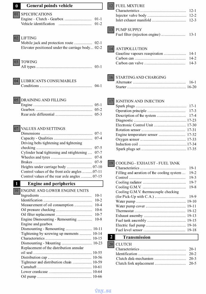
01 SPECIFICATIONSEngine – Clutch - Gearbox ........................... 01-1Vehicle identification ................................. 01-2
02 LIFTINGMobile jack and protection route .................. 02-1Elevator positioned under the carriage body... 02-2
03 TOWINGAll types ........................................................ 03-1
04 LUBRICANTS CONSUMABLESConditions ..................................................... 04-1
05 DRAINING AND FILLINGEngine ............................................................ 05-1Gearbox ......................................................... 05-2Rear axle differential ..................................... 05-3
07 VALUES AND SETTINGSDimensions .................................................... 07-1Capacity - Qualities ....................................... 07-4Driving belts tightening and tighteningchecking ........................................................ 07-5Cylinder head tightening and retightening .... 07-7Wheeles and tyres ......................................... 07-8Brakes ........................................................... 07-9Heights under carriage body ......................... 07-10Control values of the front axle angles ..........07-11Control values of the rear axle angles ........... 07-15
10 ENGINE AND LOWER ENGINE UNITSIngredients .................................................... 10-1Identification ................................................. 10-2Measurement of oil consumption .................. 10-4Oil pressure checking .................................... 10-6Oil filter replacement .................................... 10-7Engine Dismounting - Remounting ............... 10-8Engine and gearboxDismounting - Remounting ........................... 10-11Tightening by screwing up moments ............ 10-14Characteristics .............................................. 10-15Dismounting - Mounting ............................... 10-23Replacement of the distribution annularoil seal ........................................................... 10-55Distribution cap ............................................ 10-56Tightener and distribution chain ................... 10-59Camshaft ....................................................... 10-61Lower crankcase ........................................... 10-64Oil pump ....................................................... 10-66
12 FUEL MIXTURECharacteristics .............................................. 12-1Injector valve body ....................................... 12-2Inlet exhaust manifold .................................. 12-3
13 PUMP SUPPLYFuel filter (injection engine) ........................ 13-1
14 ANTIPOLLUTIONGasoline vapours reaspiration ...................... 14-1Carbon can ................................................... 14-2Carbon can valve ......................................... 14-3
16 STARTING AND CHARGINGAlternator ..................................................... 16-1Starter ........................................................... 16-20
17 IGNITION AND INJECTIONSpark plugs ................................................... 17-1Operation principle ...................................... 17-3Description of the system ............................. 17-4Diagnostic ..................................................... 17-23Electronic Control Unit ................................ 17-30Rotation sensor ............................................ 17-31Engine temperature sensor ........................... 17-32Oxygen sensor .............................................. 17-33Induction coil ................................................17-34Spark plugs set ............................................. 17-35
19 COOLING - EXHAUST - FUEL TANKCharacteristics .............................................. 19-1Filling and aeration of the cooling system ... 19-2Control ......................................................... 19-3Cooling radiator ........................................... 19-7Cooling G.M.V. ............................................ 19-8Cooling G.M.V. thermocouple checking(for Pick-Up with C.A.) ............................... 19-9Water pump .................................................. 19-10Water pump cover ........................................ 19-11Thermostat ................................................... 19-12Exhaust assemby .......................................... 19-13Fuel tank assembly ....................................... 19-15Electric fuel pump ........................................ 19-16Fuel level sensor .......................................... 19-18
20 CLUTCHCharacteristics .............................................. 20-1Identification ................................................ 20-2Clutch disk-mechanism ................................ 20-3Clutch fork replacement ............................... 20-5
Engine and peripherics
General poinds vehicle0
1
Transmission2
vnx.su
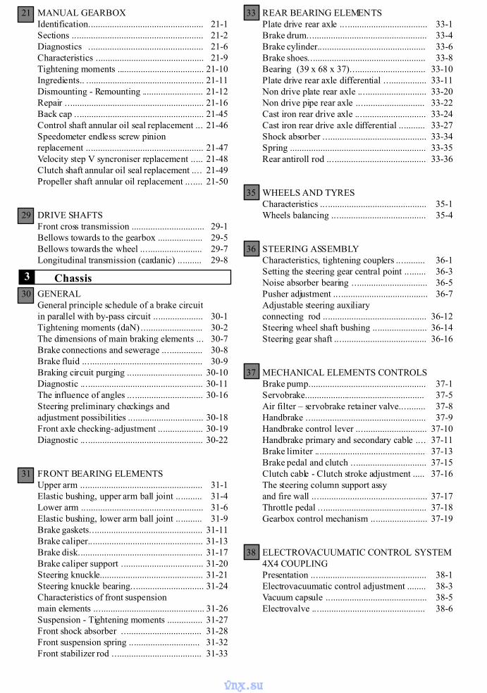
21 MANUAL GEARBOXIdentification................................................. 21-1Sections ........................................................ 21-2Diagnostics ................................................. 21-6Characteristics .............................................. 21-9Tightening moments ..................................... 21-10Ingredients.. .................................................. 21-11Dismounting - Remounting .......................... 21-12Repair ........................................................... 21-16Back cap ....................................................... 21-45Control shaft annular oil seal replacement ... 21-46Speedometer endless screw pinionreplacement .................................................. 21-47Velocity step V syncroniser replacement ..... 21-48Clutch shaft annular oil seal replacement .... 21-49Propeller shaft annular oil replacement ....... 21-50
29 DRIVE SHAFTSFront cross transmission ............................... 29-1Bellows towards to the gearbox ................... 29-5Bellows towards the wheel .......................... 29-7Longitudinal transmission (cardanic) .......... 29-8
30 GENERALGeneral principle schedule of a brake circuitin parallel with by-pass circuit ..................... 30-1Tightening moments (daN) .......................... 30-2The dimensions of main braking elements ... 30-7Brake connections and sewerage ................. 30-8Brake fluid ................................................... 30-9Braking circuit purging ................................ 30-10Diagnostic .................................................... 30-11The influence of angles ................................ 30-16Steering preliminary checkings andadjustment possibilities ................................ 30-18Front axle checking-adjustment ................... 30-19Diagnostic .................................................... 30-22
31 FRONT BEARING ELEMENTSUpper arm .................................................... 31-1Elastic bushing, upper arm ball joint ........... 31-4Lower arm .................................................... 31-6Elastic bushing, lower arm ball joint ........... 31-9Brake gaskets................................................ 31-11Brake caliper................................................. 31-13Brake disk..................................................... 31-17Brake caliper support ................................... 31-20Steering knuckle............................................ 31-21Steering knuckle bearing............................... 31-24Characteristics of front suspensionmain elements ............................................... 31-26Suspension - Tightening moments ............... 31-27Front shock absorber .................................. 31-28Front suspension spring .............................. 31-32Front stabilizer rod ...................................... 31-33
33 REAR BEARING ELEMENTSPlate drive rear axle ..................................... 33-1Brake drum................................................... 33-4Brake cylinder.............................................. 33-6Brake shoes.................................................. 33-8Bearing (39 x 68 x 37)................................ 33-10Plate drive rear axle differential .................. 33-11Non drive plate rear axle ............................. 33-20Non drive pipe rear axle ............................. 33-22Cast iron rear drive axle .............................. 33-24Cast iron rear drive axle differential ........... 33-27Shock absorber ............................................ 33-34Spring .......................................................... 33-35Rear antiroll rod .......................................... 33-36
35 WHEELS AND TYRESCharacteristics ............................................. 35-1Wheels balancing ........................................ 35-4
36 STEERING ASSEMBLYCharacteristics, tightening couplers ............ 36-1Setting the steering gear central point ......... 36-3Noise absorber bearing ................................ 36-5Pusher adjustment ........................................ 36-7Adjustable steering auxiliaryconnecting rod ............................................ 36-12Steering wheel shaft bushing ....................... 36-14Steering gear shaft ....................................... 36-16
37 MECHANICAL ELEMENTS CONTROLSBrake pump.................................................. 37-1Servobrake................................................... 37-5Air filter – servobrake retainer valve........... 37-8Handbrake ................................................... 37-9Handbrake control lever .............................. 37-10Handbrake primary and secondary cable .... 37-11Brake limiter ............................................... 37-13Brake pedal and clutch ................................ 37-15Clutch cable - Clutch stroke adjustment ..... 37-16The steering column support assyand fire wall ................................................. 37-17Throttle pedal .............................................. 37-18Gearbox control mechanism ........................ 37-19
38 ELECTROVACUUMATIC CONTROL SYSTEM4X4 COUPLINGPresentation ................................................. 38-1Electrovacuumatic control adjustment ........ 38-3Vacuum capsule ........................................... 38-5Electrovalve ................................................ 38-6
Chassis3
vnx.su
SPECIFICATIONS 01
01 - 1
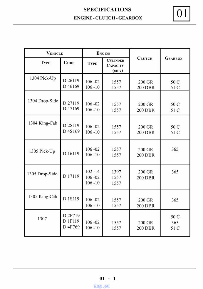
ENGINE - CLUTCH - GEARBOX
VEHICLE ENGINE
TYPE CODE TYPECYLINDER
CAPACITY
(cmc)
CLUTCH GEARBOX
1304 Pick-Up
1304 Drop-Side
1304 King-Cab
1305 Pick-Up
1305 Drop-Side
1305 King-Cab
1307
D 26119D 46169
D 27119D 47169
D 2S119D 4S169
D 16119
D 17119
D 1S119
D 2F719D 1F119D 4F769
106 -02106 -10
106 -02106 -10
106 -02106 -10
106 -02106 -10
102 -14106 -02106 -10
106 -02106 -10
106 -02106 -10
15571557
15571557
15571557
15571557
139715571557
15571557
15571557
200 GR200 DBR
200 GR200 DBR
200 GR200 DBR
200 GR200 DBR
200 GR200 DBR
200 GR200 DBR
200 GR200 DBR
50 C51 C
50 C51 C
50 C51 C
365
365
365
50 C36551 C
vnx.su
SPECIFICATIONS01
01 - 2
VEHICLE IDENTIFICATION
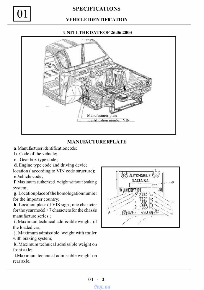
a. Manufacturer identification code; b. Code of the vehicle; c. Gear box type code; d. Engine type code and driving devicelocation ( according to VIN code structure); e.Vehicle code; f. Maximum authorized weight without brakingsystem; g. Location place of the homologation numberfor the importer country; h. Location place of VIS sign ; one characterfor the year model + 7 characters for the chassismanufacture series ; i. Maximum technical admissible weight ofthe loaded car; j. Maximum admissible weight with trailerwith braking system; k. Maximum technical admissible weight onfront axle; l.Maximum technical admissible weight onrear axle.
MANUFACTURER PLATE
Identification number VINManufacturer plate
UNITL THE DATE OF 26.06.2003
vnx.su
SPECIFICATIONS 01
01 - 3
VEHICLE IDENTIFICATION
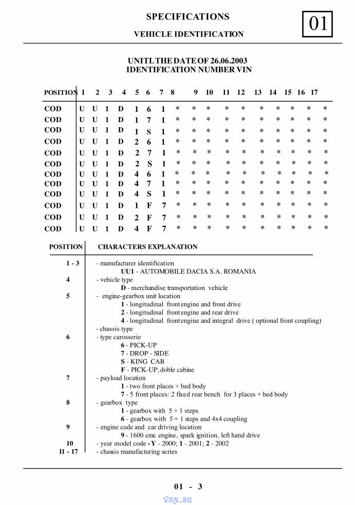
IDENTIFICATION NUMBER VIN
COD U U 1 D 1 6 1 * * * * * * * * * *
4 S 1 * * * * * * * * * *
1 S 1 * * * * * * * * * * 2 6 1 * * * * * * * * * * 2 7 1 * * * * * * * * * * 2 S 1 * * * * * * * * * * 4 6 1 * * * * * * * * * * 4 7 1 * * * * * * * * * *
1 7 1 * * * * * * * * * *
1 F 7 * * * * * * * * * * 2 F 7 * * * * * * * * * * 4 F 7 * * * * * * * * * *
COD U U 1 DCOD U U 1 DCOD U U 1 DCOD U U 1 DCOD U U 1 DCOD U U 1 DCOD U U 1 DCOD U U 1 DCOD U U 1 DCOD U U 1 D
POSITION CHARACTERS EXPLANATION
1 - 3 - manufacturer identificationUU1 - AUTOMOBILE DACIA S.A. ROMANIA
4 - vehicle typeD - merchandise transportation vehicle
5 - engine-gearbox unit location1 - longitudinal front engine and front drive2 - longitudinal front engine and rear drive4 - longitudinal front engine and integral drive ( optional front coupling)
- chassis type6 - type carosserie
6 - PICK-UP7 - DROP - SIDES - KING CABF - PICK-UP, doble cabine
7 - payload location1 - two front places + bed body7 - 5 front places: 2 fixed rear bench for 3 places + bed body
8 - gearbox type1 - gearbox with 5 + 1 steps6 - gearbox with 5 + 1 steps and 4x4 coupling
9 - engine code and car driving location9 - 1600 cmc engine, spark ignition, left hand drive
10 - year model code - Y - 2000; 1 - 2001; 2 - 2002 11 - 17 - chassis manufacturing series
POSITION 1 2 3 4 5 6 7 8 9 10 11 12 13 14 15 16 17
COD U U 1 D
UNITL THE DATE OF 26.06.2003
vnx.su
SPECIFICATIONS01
01 - 4
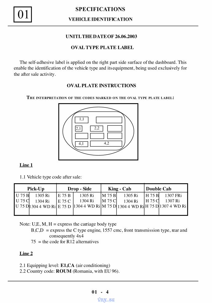
OVAL TYPE PLATE LABEL
The self-adhesive label is applied on the right part side surface of the dashboard. Thisenable the identification of the vehicle type and its equipment, being used exclusively forthe after sale activity.
OVAL PLATE INSTRUCTIONS
THE INTERPRETATION OF THE CODES MARKED ON THE OVAL TYPE PLATE LABEL:
Line 1
1.1 Vehicle type code after sale:
Pick-Up Drop - Side King - Cab Double CabU 75 BU 75 CU 75 D
1305 Ri1304 Ri
1304 4 WD Ri
E 75 BE 75 CE 75 D
1305 Ri1304 Ri
1304 4 WD Ri
M 75 BM 75 CM 75 D
1305 Ri1304 Ri
1304 4 WD Ri
H 75 BH 75 CH 75 D
1307 FRi1307 Ri
1307 4 WD Ri
Note: U,E, M, H = express the carriage body type B,C,D = express the C type engine, 1557 cmc, front transmission type, rear and
consequently 4x4 75 = the code for R12 alternatives
Line 2
2.1 Equipping level: E1,CA (air conditioning)2.2 Country code: ROUM (Romania, with EU 96).
1,1
2,1 2,2
4,1 4,2
UNITL THE DATE OF 26.06.2003
VEHICLE IDENTIFICATION
vnx.su
SPECIFICATIONS 01
01 - 5
OVAL TYPE PLATE LABEL
Line 4
4.1 Tehnical definition code, driving post:S2: Left hand drive
4.2 Optional equipping code:A: Normal suspensionC: Temperate climateE: Warm climateF: Normal heatingG: Air conditioningK: Without pre-filterM: Mechanical steering systemR: Without adjustable shock absorberT: Without plate correctorV: Without wheels ABS ( anti-blocking )
ATTENTION!
Do not unstuck or damage the label of the right side par t surface of thedashboard.This label represents the only way of vehicle identification, needed by theafter-sale services, for a period of 8 ( eight ) years from the purchasing date.
UNITL THE DATE OF 26.06.2003
VEHICLE IDENTIFICATION
vnx.su
SPECIFICATIONS01
01 - 6
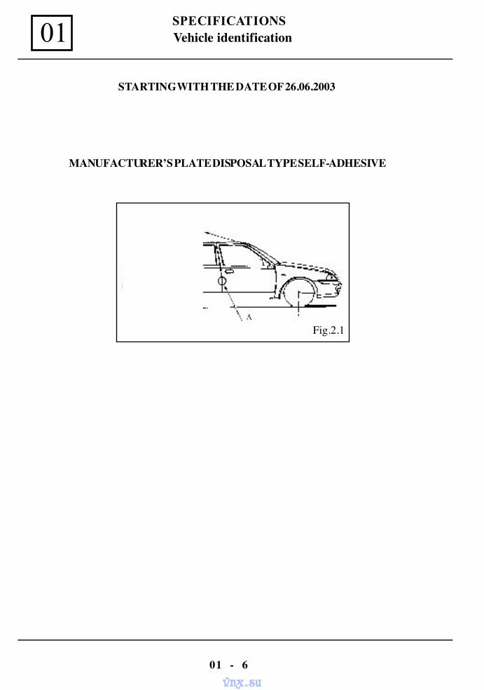
Fig.2.1
Vehicle identification
MANUFACTURER’S PLATE DISPOSAL TYPE SELF-ADHESIVE
STARTING WITH THE DATE OF 26.06.2003
vnx.su
SPECIFICATIONS 01
01 - 7
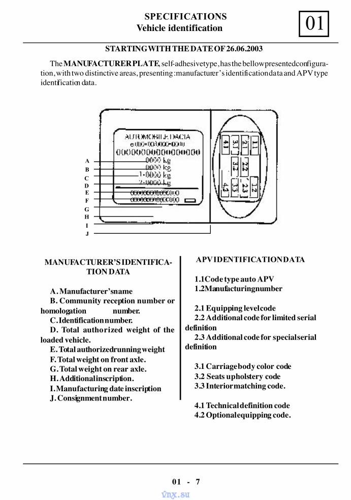
APV IDENTIFICATION DATA
1.1Code type auto APV1.2Manufacturing number
2.1 Equipping level code2.2 Additional code for limited serial
definition2.3 Additional code for special serial
definition
3.1 Carriage body color code3.2 Seats upholstery code3.3 Interior matching code.
4.1 Technical definition code4.2 Optional equipping code.
A
CD
F
B
HG
IJ
E
MANUFACTURER’S IDENTIFICA-TION DATA
A. Manufacturer’s nameB. Community reception number or
homologation number.C. Identification number.D. Total authorized weight of the
loaded vehicle.E. Total authorized running weightF. Total weight on front axle.G. Total weight on rear axle.H. Additional inscription.I. Manufacturing date inscriptionJ. Consignment number.
The MANUFACTURER PLATE, self-adhesive type, has the bellow presented configura-tion, with two distinctive areas, presenting :manufacturer’s identification data and APV typeidentification data.
STARTING WITH THE DATE OF 26.06.2003
Vehicle identification
vnx.su
LIFTING 02
02 - 1
MOBILE JACK AND PROTECTION ROUTE
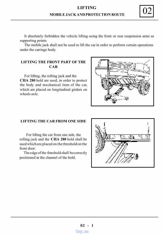
It absolutely forbidden the vehicle lifting using the front or rear suspension arms assupporting points.
The mobile jack shall not be used to lift the car in order to perform certain operationsunder the carriage body.
LIFTING THE FRONT PART OF THECAR
For lifting, the rolling jack and theCHA 280 hold are used, in order to protectthe body and mechanical item of the car,which are placed on longitudinal girders onwheels axle.
LIFTING THE CAR FROM ONE SIDE
For lifting the car from one side, therolling jack and the CHA 280 hold shall beused which are placed on the threshold on thefront door. The edge of the threshold shall be correctlypositioned in the channel of the hold.
vnx.su
LIFTING02
02 - 2
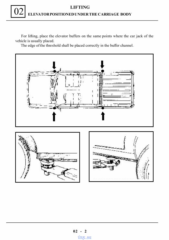
For lifting, place the elevator buffers on the same points where the car jack of thevehicle is usually placed.
The edge of the threshold shall be placed correctly in the buffer channel.
ELEVATOR POSITIONED UNDER THE CARRIAGE BODY
vnx.su
TOWING 03
03 - 1
ALL TYPES
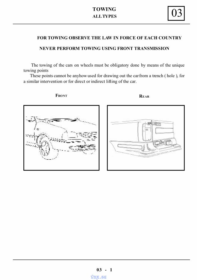
FOR TOWING OBSERVE THE LAW IN FORCE OF EACH COUNTRY
NEVER PERFORM TOWING USING FRONT TRANSMISSION
The towing of the cars on wheels must be obligatory done by means of the uniquetowing points These points cannot be anyhow used for drawing out the car from a trench ( hole ), fora similar intervention or for direct or indirect lifting of the car.
FRONT REAR
vnx.su
LUBRICANTS CONSUMABLES 04
04 - 1
CONDITIONS
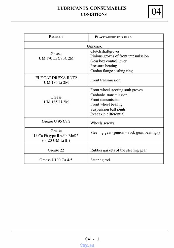
PRODUCT PLACE WHERE IT IS USED
GREASING
GreaseUM 170 Li Ca Pb 2M
ELF CARDREXA RNT2UM 185 Li 2M
GreaseUM 185 Li 2M
Grease U 95 Ca 2
GreaseLi Ca Pb type II with MoS2
(or 20 UM Li III)
Grease 22
Grease U100 Ca 4-5
Clutch shaft grovesPinions groves of front transmissionGear box control leverPressure bearingCardan flange sealing ring
Front transmission
Front wheel steering stub grovesCardanic transmissionFront transmissionFront wheel bearingSuspension ball jointsRear axle differential
Wheels screws
Steering gear (pinion – rack gear, bearings)
Rubber gaskets of the steering gear
Steering rod
vnx.su
LUBRICANTS CONSUMABLES04
04 - 2
CONDITIONS
PRODUCT PLACE WHERE IT IS USED
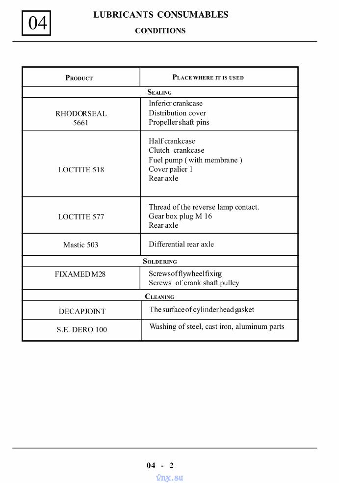
SEALING
RHODORSEAL5661
LOCTITE 518
LOCTITE 577
Mastic 503
Inferior crankcaseDistribution coverPropeller shaft pins
Half crankcaseClutch crankcaseFuel pump ( with membrane )Cover palier 1Rear axle
Thread of the reverse lamp contact.Gear box plug M 16Rear axle
Differential rear axle
SOLDERING
FIXAMED M28 Screws of flywheel fixingScrews of crank shaft pulley
CLEANING
DECAPJOINT
S.E. DERO 100
The surface of cylinder head gasket
Washing of steel, cast iron, aluminum parts
vnx.su
DRAINING AND FILLING 05
05 - 1
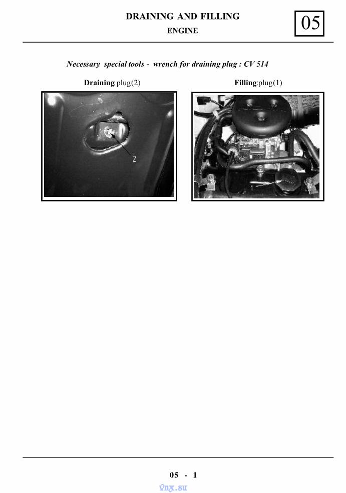
ENGINE
Draining: plug (2) Filling: plug (1)
Necessary special tools - wrench for draining plug : CV 514
vnx.su
DRAINING AND FILLING05
05 - 2
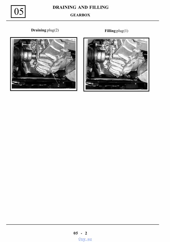
GEARBOX
Draining: plug (2) Filling: plug (1)
vnx.su
DRAINING AND FILLING 05
05 - 3
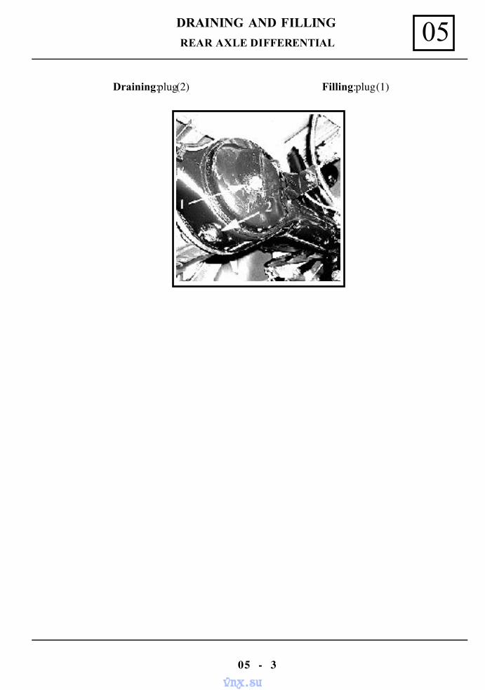
REAR AXLE DIFFERENTIAL
Draining: plug(2) Filling: plug (1)
vnx.su
VALUES AND SETTINGS 07
07 - 1
DIMENSIONS
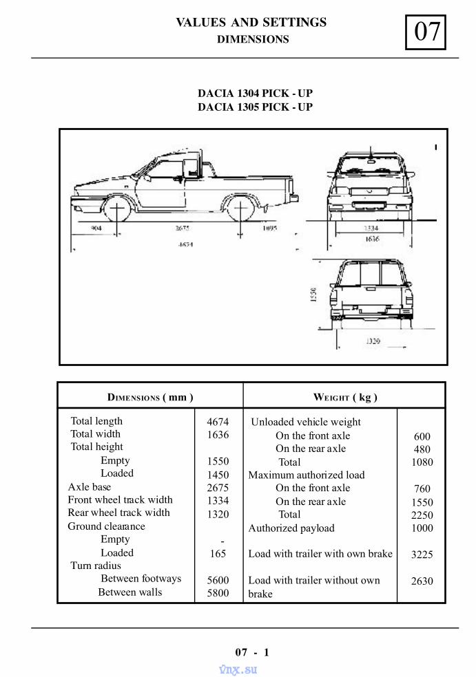
DACIA 1304 PICK - UPDACIA 1305 PICK - UP
DIMENSIONS ( mm ) WEIGHT ( kg )
Total length Total width Total height
EmptyLoaded
Axle baseFront wheel track widthRear wheel track widthGround clearance
EmptyLoaded
Turn radiusBetween footways
Between walls
Unloaded vehicle weight On the front axle On the rear axle TotalMaximum authorized load On the front axle On the rear axle TotalAuthorized payload
Load with trailer with own brake
Load with trailer without ownbrake
46741636
15501450267513341320
-165
56005800
6004801080
760155022501000
3225
2630
vnx.su
VALUES AND SETTINGS07
07 - 2
DIMENSIONS
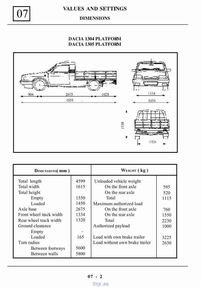
DACIA 1304 PLATFORMDACIA 1305 PLATFORM
DIMENSIONS( mm ) WEIGHT ( kg )
Total lengthTotal widthTotal height Empty LoadedAxle baseFront wheel track widthRear wheel track widthGround clearance Empty LoadedTurn radius Between footways Between walls
Unloaded vehicle weight On the front axle On the rear axle TotalMaximum authorized load On the front axle On the rear axle TotalAuthorized payload
Load with own brake trailerLoad without own brake trailer
45991615
15501450267513341320
-165
56005800
5955201115
760155022301000
32252630
vnx.su
VALUES AND SETTINGS 07
07 - 3
DIMENSIONS
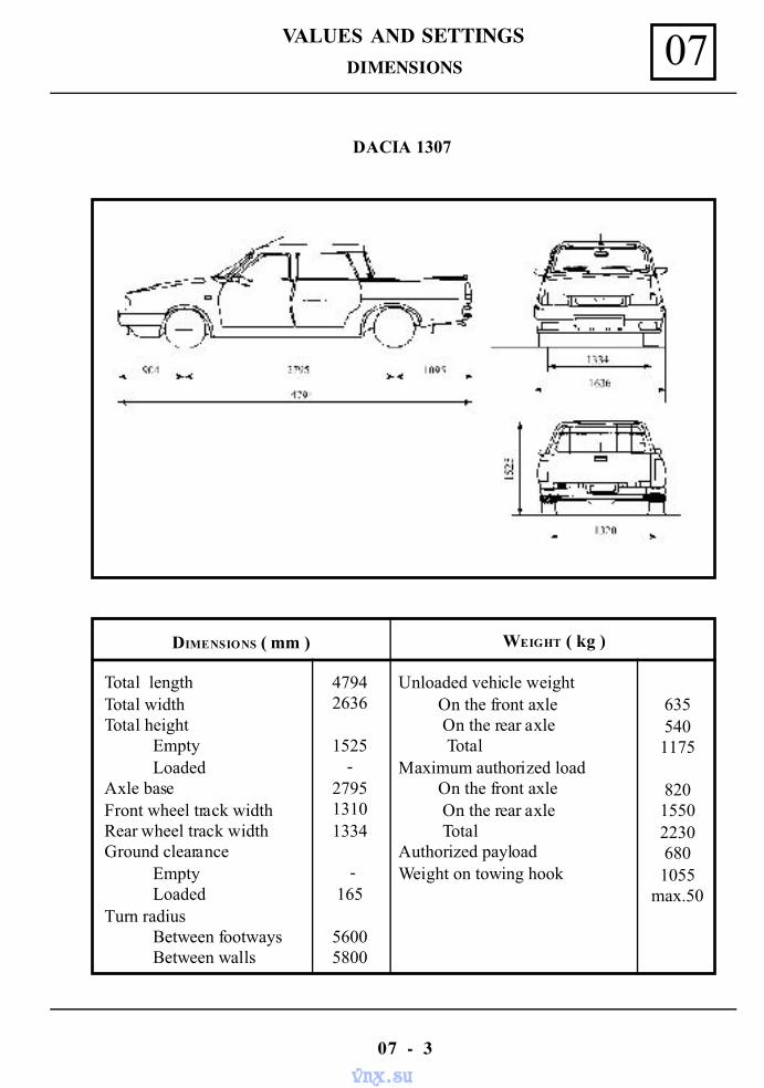
DACIA 1307
DIMENSIONS ( mm ) WEIGHT ( kg )
Total lengthTotal widthTotal height Empty LoadedAxle baseFront wheel track widthRear wheel track widthGround clearance Empty LoadedTurn radius Between footways Between walls
Unloaded vehicle weight On the front axle On the rear axle TotalMaximum authorized load On the front axle On the rear axle TotalAuthorized payloadWeight on towing hook
47942636
1525-
279513101334
-165
56005800
6355401175
820155022306801055
max.50
vnx.su
VALUES AND SETTINGS07
07 - 4
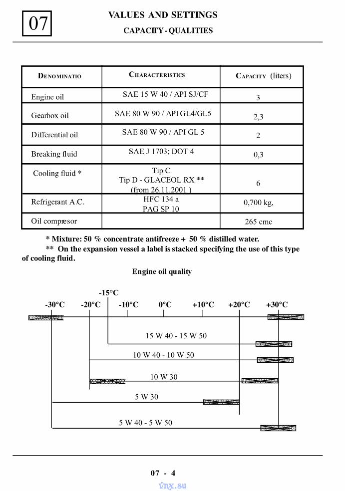
CAPACITY - QUALITIES
DENOMINATIO CAPACITY (liters)
Engine oil
Gearbox oil
Differential oil
Breaking fluid
Cooling fluid *
Refrigerant A.C.
Oil compresor
SAE 15 W 40 / API SJ/CF
SAE 80 W 90 / API GL4/GL5
SAE 80 W 90 / API GL 5
SAE J 1703; DOT 4
Tip CTip D - GLACEOL RX **
(from 26.11.2001 )HFC 134 aPAG SP 10
3
2,3
2
0,3
6
0,700 kg,
265 cmc
CHARACTERISTICS
* Mixture: 50 % concentrate antifreeze + 50 % distilled water.** On the expansion vessel a label is stacked specifying the use of this type
of cooling fluid.Engine oil quality
-30°C -20°C -10°C 0°C +10°C +20°C +30°C-15°C
15 W 40 - 15 W 50
10 W 40 - 10 W 50
10 W 30
5 W 30
5 W 40 - 5 W 50
vnx.su
VALUES AND SETTINGS 07
07 - 5
DRIVING BELTS TIGHTENING AND TIGHTENING CHECKING
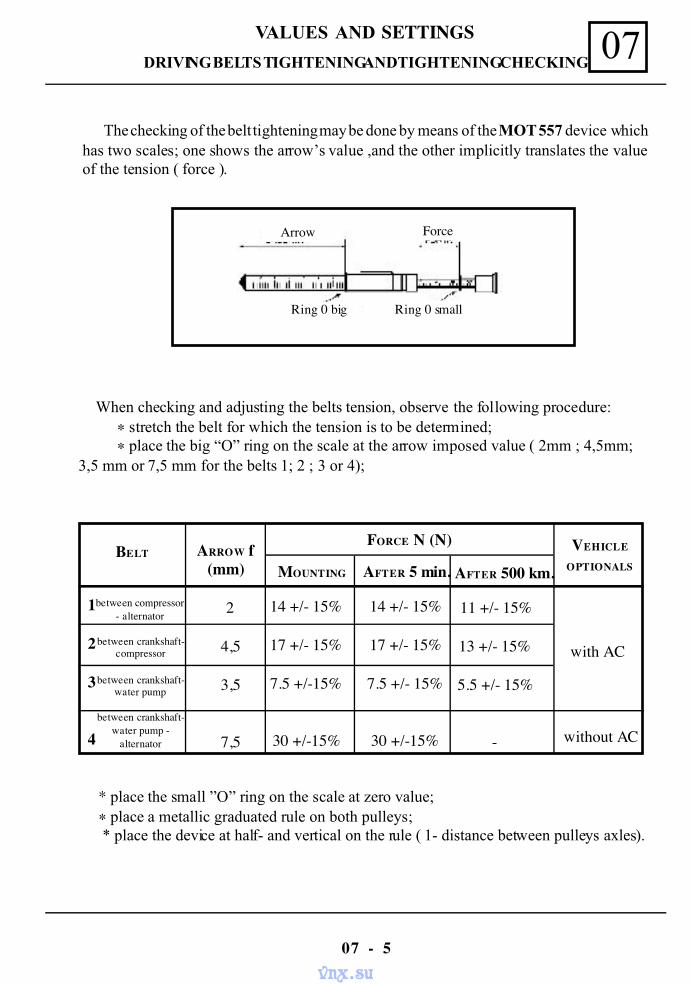
The checking of the belt tightening may be done by means of the MOT 557 device whichhas two scales; one shows the arrow’s value ,and the other implicitly translates the valueof the tension ( force ).
When checking and adjusting the belts tension, observe the following procedure:∗ stretch the belt for which the tension is to be determined;∗ place the big “O” ring on the scale at the arrow imposed value ( 2mm ; 4,5mm;
3,5 mm or 7,5 mm for the belts 1; 2 ; 3 or 4);
* place the small ”O” ring on the scale at zero value;∗ place a metallic graduated rule on both pulleys; * place the device at half- and vertical on the rule ( 1- distance between pulleys axles).
BELT ARROW f(mm)
FORCE N (N)
MOUNTING AFTER 5 min. AFTER 500 km.
1
2
3
4
between compressor- alternator
between crankshaft-compressor
between crankshaft-water pump
between crankshaft-water pump -
alternator
2
4,5
3,5
7,5
14 +/- 15%
17 +/- 15%
7.5 +/-15%
30 +/-15%
14 +/- 15%
17 +/- 15%
7.5 +/- 15%
30 +/-15%
11 +/- 15%
13 +/- 15%
5.5 +/- 15%
-
VEHICLE
OPTIONALS
with AC
without AC
ForceArrow
Ring 0 big Ring 0 small
vnx.su
VALUES AND SETTINGS07
07 - 6
DRIVING BELTS TIGHTENING AND TIGHTENING CHECKING
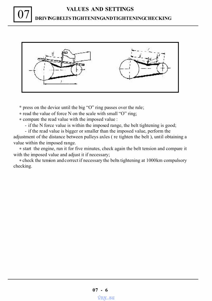
* press on the device until the big “O” ring passes over the rule;∗ read the value of force N on the scale with small “O” ring;∗ compare the read value with the imposed value :
- if the N force value is within the imposed range, the belt tightening is good;- if the read value is bigger or smaller than the imposed value, perform the
adjustment of the distance between pulleys axles ( re tighten the belt ), until obtaining avalue within the imposed range.
∗ start the engine, run it for five minutes, check again the belt tension and compare itwith the imposed value and adjust it if necessary;
∗ check the tension and correct if necessary the belts tightening at 1000 km compulsorychecking.
vnx.su
VALUES AND SETTINGS 07
07 - 7
CYLIDER HEAD TIGHTENING AND RETIGHTENING
ATTENTION!
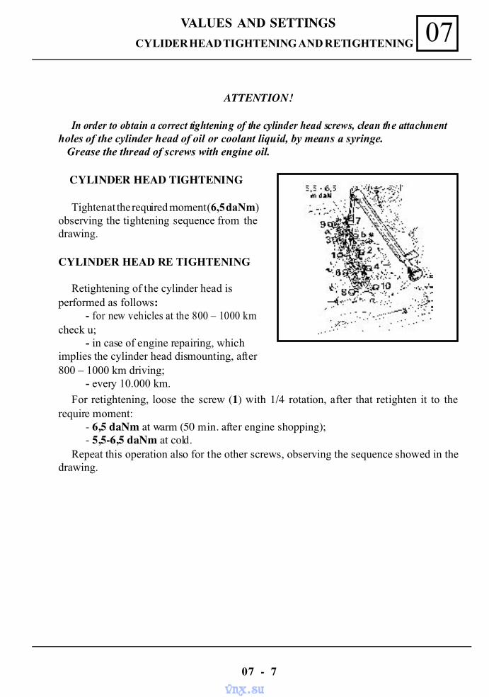
In order to obtain a correct tightening of the cylinder head screws, clean the attachmentholes of the cylinder head of oil or coolant liquid, by means a syringe. Grease the thread of screws with engine oil.
CYLINDER HEAD TIGHTENING
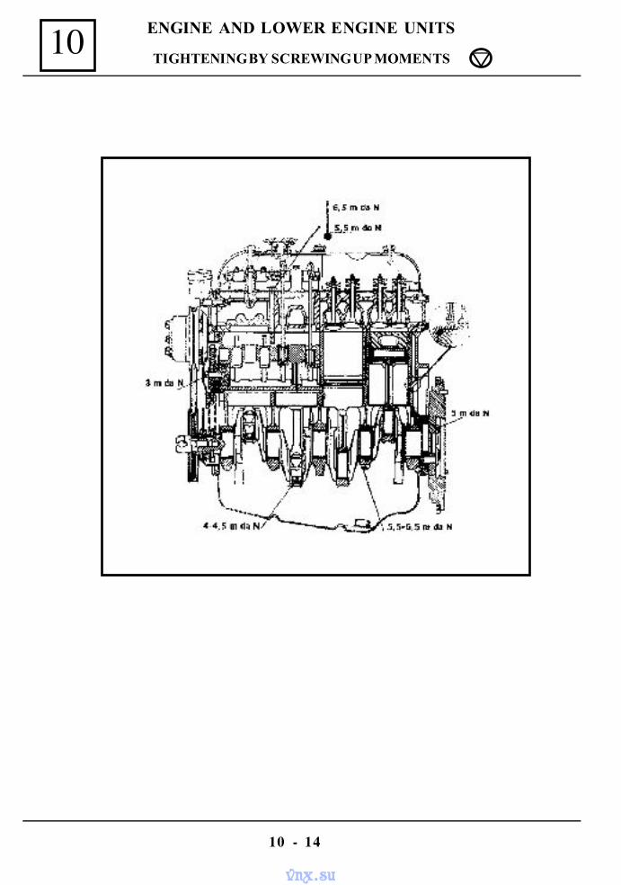
Tighten at the required moment (6,5 daNm)observing the tightening sequence from thedrawing.
CYLINDER HEAD RE TIGHTENING
Retightening of the cylinder head isperformed as follows:
- for new vehicles at the 800 – 1000 kmcheck u;
- in case of engine repairing, whichimplies the cylinder head dismounting, after800 – 1000 km driving;
- every 10.000 km.
For retightening, loose the screw (1) with 1/4 rotation, after that retighten it to therequire moment:
- 6,5 daNm at warm (50 min. after engine shopping);- 5,5-6,5 daNm at cold.
Repeat this operation also for the other screws, observing the sequence showed in thedrawing.
vnx.su
VALUES AND SETTINGS07
07 - 8
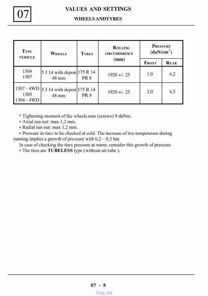
WHEELS AND TYRES
TYPE
VEHICLEWHEELS TYRES
ROLLING
CIRCUMFERENCE
(mm)
PRESSURE
(daN/cm )2
FRONT REAR
13041307
1307 - 4WD1305
1304 - 4WD
5 J 14 with deport48 mm
5 J 14 with deport48 mm
175 R 14PR 8
175 R 14PR 8
1920 +/- 25
1920 +/- 25
1,9
2,0
4,2
4,5
* Tightening moment of the wheels nuts (screws) 9 daNm.∗ Axial run out: max 1,2 mm.∗ Radial run out: max 1,2 mm.∗ Pressure in tires to be checked at cold. The increase of tire temperature during
running implies a growth of pressure with 0,2 – 0,3 bar. In case of checking the tires pressure at warm, consider this growth of pressure.
∗ The tires are TUBELESS type ( without air tube ).
vnx.su
VALUES AND SETTINGS 07
07 - 9
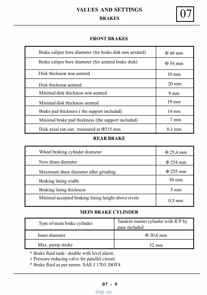
BRAKES
FRONT BRAKES
REAR BRAKE
MEIN BRAKE CYLINDER
* Brake fluid tank– double with level alarm.∗ Pressure reducing valve for parallel circuit.* Brake fluid as per norms SAE J 1703, DOT4.
Brake caliper bore diameter (for brake disk non aerated)
Brake caliper bore diameter (for aerated brake disk)
Disk thickness non aerated
Disk thickness aerated
Minimal disk thickness non aerated
Minimal disk thickness aerated
Brake pad thickness ( the support included)
Minimal brake pad thickness (the support included)
Disk axial run out, measured at Φ215 mm
Φ 48 mm
Φ 54 mm
10 mm
20 mm
9 mm
19 mm
14 mm
7 mm
0,1 mm
Wheel braking cylinder diameter
New drum diameter
Maximum drum diameter after grinding
Braking lining width
Braking lining thickness
Minimal accepted braking lining height above rivets
Φ 25,4 mm
Φ 254 mm
Φ 255 mm
50 mm
5 mm
0,5 mm
Type of main brake cylinder Tandem master cylinder with ICP bypass included
Inner diameter
Max. pump stroke
Φ 20,6 mm
32 mm
vnx.su
VALUES AND SETTINGS07
07 - 10
HEIGHTS UNDER CARRIAGE BODY
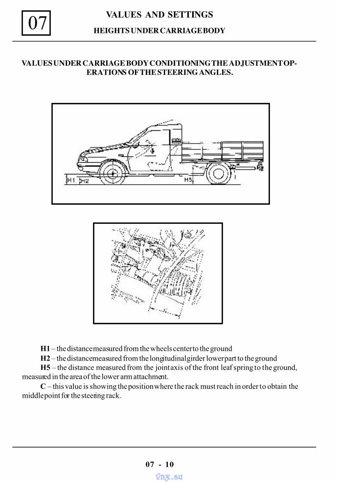
VALUES UNDER CARRIAGE BODY CONDITIONING THE ADJUSTMENT OP-ERATIONS OF THE STEERING ANGLES.
H1 – the distance measured from the wheels center to the groundH2 – the distance measured from the longitudinal girder lower part to the groundH5 – the distance measured from the joint axis of the front leaf spring to the ground,
measured in the area of the lower arm attachment.C – this value is showing the position where the rack must reach in order to obtain the
middle point for the steering rack.
vnx.su
VALUES AND SETTINGS 07
07 - 11
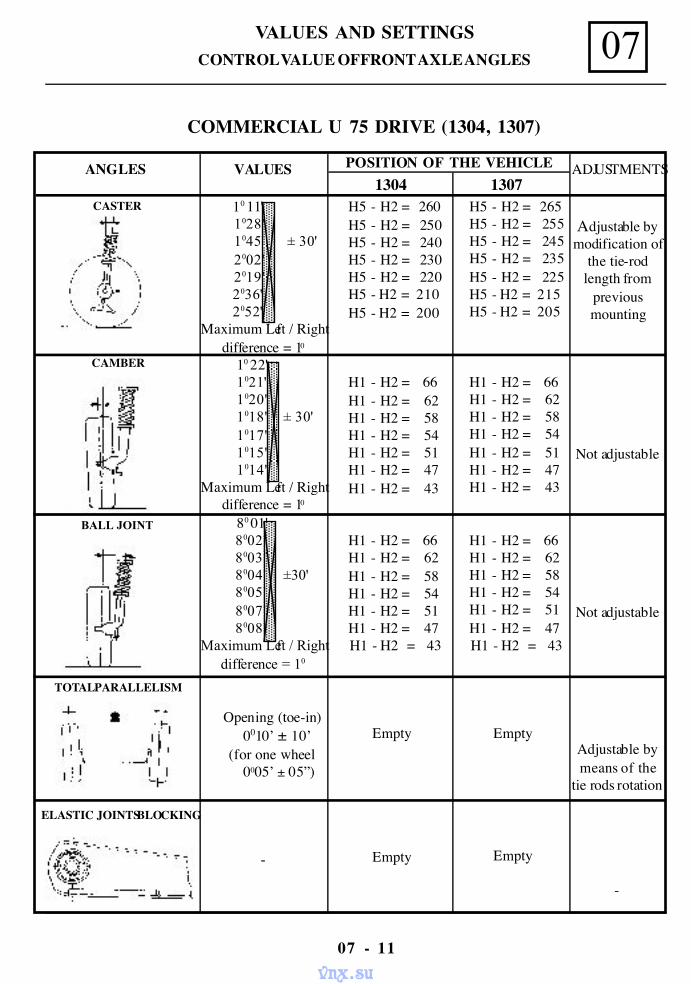
CONTROL VALUE OF FRONT AXLE ANGLES
Adjustable bymodification of
the tie-rodlength from
previousmounting
Not adjustable
Not adjustable
Adjustable bymeans of the
tie rods rotation
-
H5 - H2 = 265H5 - H2 = 255H5 - H2 = 245H5 - H2 = 235H5 - H2 = 225
H5 - H2 = 215 H5 - H2 = 205
H1 - H2 = 66H1 - H2 = 62H1 - H2 = 58H1 - H2 = 54H1 - H2 = 51H1 - H2 = 47H1 - H2 = 43
H1 - H2 = 66H1 - H2 = 62H1 - H2 = 58H1 - H2 = 54H1 - H2 = 51H1 - H2 = 47
H1 - H2 = 43
Empty
Empty
VALUES
10 11'1028'
1045' ± 30'2002'2019'
2036' 2052'Maximum Left / Right
difference = 10
10 22' 1021'
1020'1018' ± 30'1017'1015'1014'
Maximum Left / Rightdifference = 10
80 01'8002'8003'8004' ±30'8005'8007'8008'
Maximum Left / Rightdifference = 10
Opening (toe-in) 0010’ ± 10’ (for one wheel 0005’ ± 05”)
-
ANGLES
CASTER
CAMBER
BALL JOINT
TOTAL PARALLELISM
ELASTIC JOINTS BLOCKING
H5 - H2 = 260H5 - H2 = 250H5 - H2 = 240H5 - H2 = 230H5 - H2 = 220
H5 - H2 = 210 H5 - H2 = 200
H1 - H2 = 66H1 - H2 = 62H1 - H2 = 58H1 - H2 = 54H1 - H2 = 51H1 - H2 = 47H1 - H2 = 43
H1 - H2 = 66H1 - H2 = 62H1 - H2 = 58H1 - H2 = 54H1 - H2 = 51H1 - H2 = 47
H1 - H2 = 43
Empty
Empty
POSITION OF THE VEHICLE ADJUSTMENTS1304 1307
COMMERCIAL U 75 DRIVE (1304, 1307)
vnx.su
VALUES AND SETTINGS07
07 - 12
CONTROL VALUE OF FRONT AXLE ANGLES
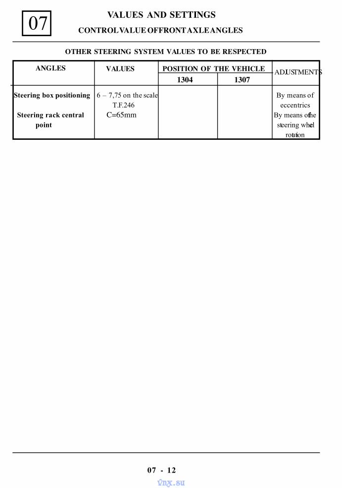
Steering box positioning 6 – 7,75 on the scale By means of T.F.246 eccentrics
Steering rack central C=65mm By means of thepoint steering wheel
rotation
ANGLES POSITION OF THE VEHICLE ADJUSTMENTS1304 1307
VALUES
OTHER STEERING SYSTEM VALUES TO BE RESPECTED
vnx.su
VALUES AND SETTINGS 07
07 - 13
CONTROL VALUE OF FRONT AXLE ANGLES
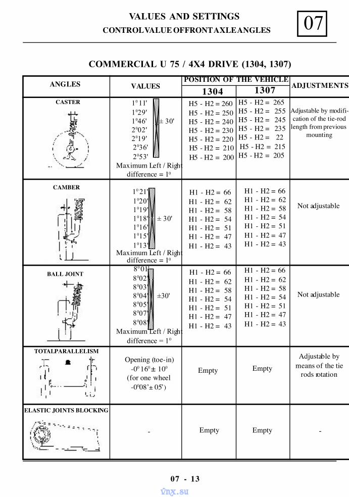
COMMERCIAL U 75 / 4X4 DRIVE (1304, 1307)
Adjustable by modifi-cation of the tie-rod
length from previousmounting
Not adjustable
Not adjustable
Adjustable bymeans of the tie
rods rotation
H5 - H2 = 265 H5 - H2 = 255 H5 - H2 = 245 H5 - H2 = 235 H5 - H2 = 22H5 - H2 = 215
H5 - H2 = 205
H1 - H2 = 66H1 - H2 = 62H1 - H2 = 58H1 - H2 = 54H1 - H2 = 51H1 - H2 = 47H1 - H2 = 43
H1 - H2 = 66H1 - H2 = 62H1 - H2 = 58H1 - H2 = 54H1 - H2 = 51H1 - H2 = 47H1 - H2 = 43
Empty
Empty
10 11'1029'
1046' ± 30'2002'2019'
2036' 2053'Maximum Left / Right
difference = 10
10 21'1020'1019'1018' ± 30'1016'1015'1013'
Maximum Left / Rightdifference = 10
80 01'8002'8003'8004' ±30'8005'8007'8008'
Maximum Left / Rightdifference = 10
Opening (toe-in)-00 160 ± 100
(for one wheel-0008’± 05’)
-
ANGLES
CASTER
CAMBER
PIVOT
TOTAL PARALLELISM
ELASTIC JOINTS BLOCKING
H5 - H2 = 260H5 - H2 = 250H5 - H2 = 240H5 - H2 = 230H5 - H2 = 220
H5 - H2 = 210 H5 - H2 = 200
H1 - H2 = 66H1 - H2 = 62H1 - H2 = 58H1 - H2 = 54H1 - H2 = 51H1 - H2 = 47H1 - H2 = 43
H1 - H2 = 66H1 - H2 = 62H1 - H2 = 58H1 - H2 = 54H1 - H2 = 51H1 - H2 = 47H1 - H2 = 43
Empty
1304 1307POSITION OF THE VEHICLE
ADJUSTMENTSVALUES
BALL JOINT
-Empty
vnx.su

VALUES AND SETTINGS07
07 - 14
CONTROL VALUE OF FRONT AXLE ANGLES
Steering box positioning 6 – 7,75 on the scale By means of T.F.246 eccentrics
Steering rack central C=65mm By means of the
point steering wheelrotation
ANGLES POSITION OF THE VEHICLE ADJUSTMENTS1304 1307
VALUES
OTHER STEERING SYSTEM VALUES TO BE RESPECTED
vnx.su
VALUES AND SETTINGS 07
07 - 15
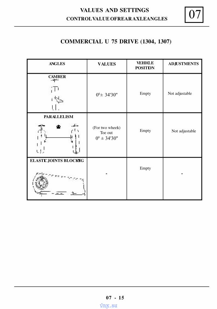
CONTROL VALUE OF REAR AXLE ANGLES
Not adjustable
Not adjustable
Empty
Empty
Empty
Empty
00± 34'30''
(For two wheels)Toe out
00 ± 34'30''
ANGLES
CAMBER
PARALLELISM
ELASTIC JOINTS BLOCKING
COMMERCIAL U 75 DRIVE (1304, 1307)
- -
VALUES VEHICLEPOSITION
ADJUSTMENTS
vnx.su
VALUES AND SETTINGS07
07 - 16
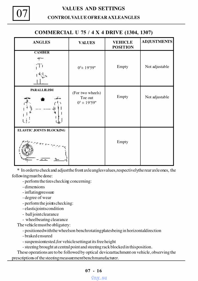
CONTROL VALUE OF REAR AXLE ANGLES
* In order to check and adjust the front axle angles values, respectively the rear axle ones, thefollowing must be done:
- perform the tires checking concerning:- dimensions- inflating pressure- degree of wear- perform the joints checking:- elastic joints condition- ball joint clearance- wheel bearing clearance
The vehicle must be obligatory:- positioned with the wheels on bench rotating plates being in horizontal direction- braked ensured- suspension tested, for vehicle setting at its free height- steering brought at central point and steering rack blocked in this position.
These operations are to be followed by optical device attachment on vehicle, observing theprescriptions of the steering measurement bench manufacturer.
COMMERCIAL U 75 / 4 X 4 DRIVE (1304, 1307)
Not adjustable
Not adjustable
Empty
Empty
Empty
00± 19'59''
(For two wheels)Toe out
00 ± 19'59''
ANGLES
CAMBER
PARALLELISM
ELASTIC JOINTS BLOCKING
VALUES VEHICLEPOSITION
ADJUSTMENTS
vnx.su
10
10 - 1
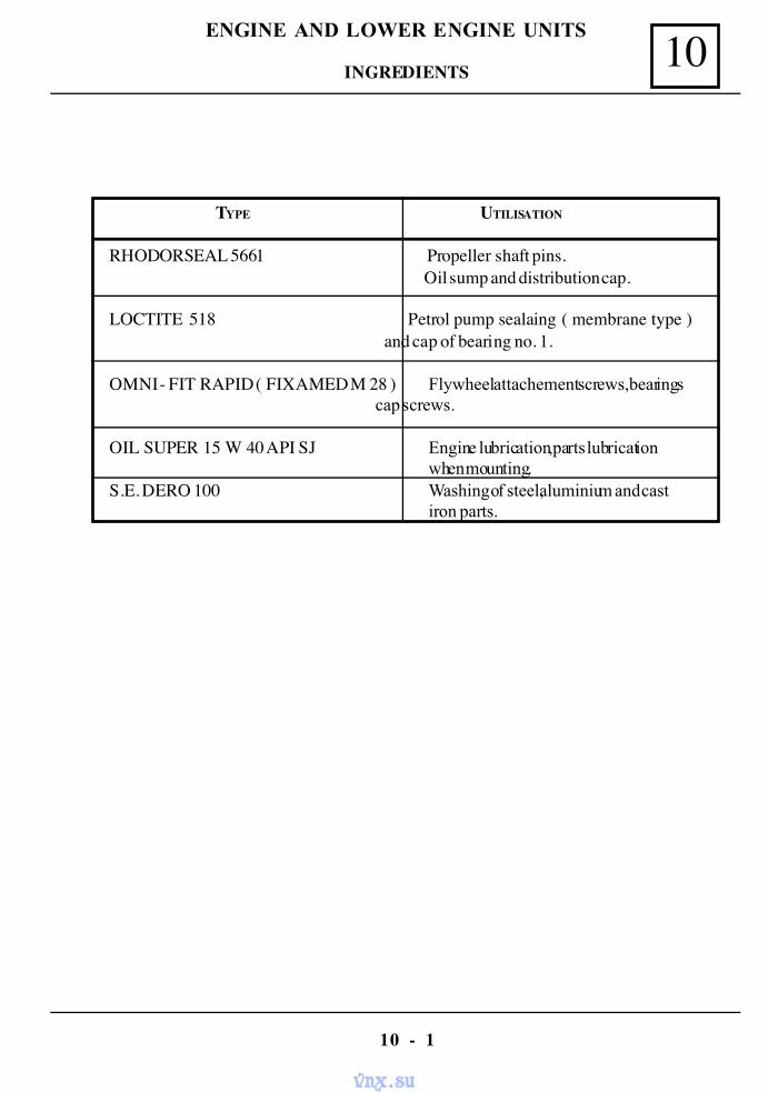
ENGINE AND LOWER ENGINE UNITS
INGREDIENTS
TYPE UTILISATION
RHODORSEAL 5661 Propeller shaft pins. Oil sump and distribution cap.
LOCTITE 518 Petrol pump sealaing ( membrane type ) and cap of bearing no. 1.
OMNI - FIT RAPID ( FIXAMED M 28 ) Flywheel attachement screws,bearingscap screws.
OIL SUPER 15 W 40 API SJ Engine lubrication,parts lubricationwhen mounting.
S.E. DERO 100 Washing of steel,aluminium and castiron parts.
vnx.su
10
10 - 2
ENGINE AND LOWER ENGINE UNITS
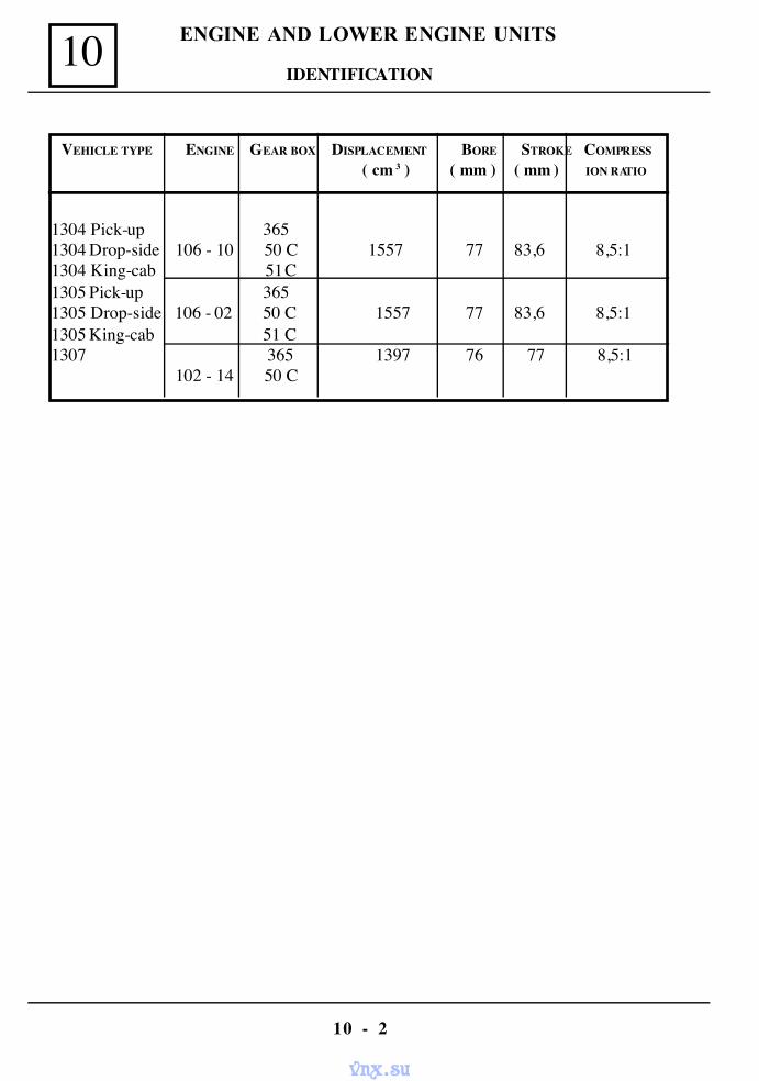
IDENTIFICATION
VEHICLE TYPE ENGINE GEAR BOX DISPLACEMENT BORE STROKE COMPRESS
( cm 3 ) ( mm ) ( mm ) ION RATIO
1304 Pick-up 3651304 Drop-side 106 - 10 50 C 1557 77 83,6 8,5:11304 King-cab 51 C1305 Pick-up 3651305 Drop-side 106 - 02 50 C 1557 77 83,6 8,5:11305 King-cab 51 C1307 365 1397 76 77 8,5:1
102 - 14 50 C
vnx.su
10
10 - 3
ENGINE AND LOWER ENGINE UNITS
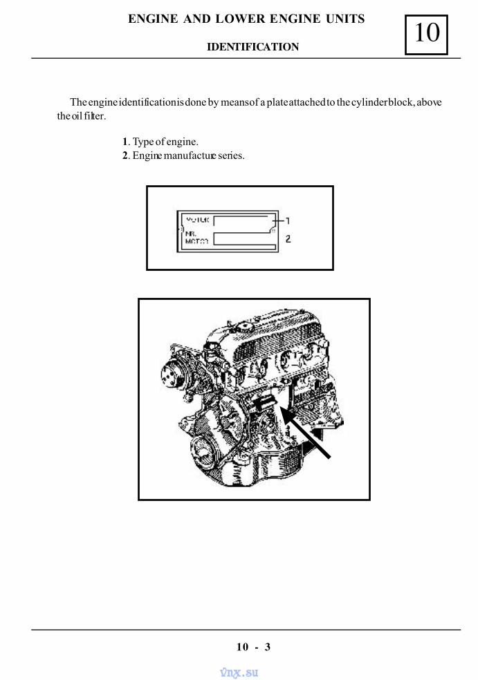
The engine identification is done by means of a plate attached to the cylinder block, abovethe oil filter.
1. Type of engine.2. Engine manufacture series.
IDENTIFICATION
vnx.su
10
10 - 4
ENGINE AND LOWER ENGINE UNITS
PREPARATION FOR TEST
Place the car on the elevator,dismount the engine shield,check the presence of oil leaks.If there are any leaks,eliminate it and then check again.Drain the oil from the engine.Fill the engine with 2,750 l new oil 15 W 40, start the engine and let it run in force
( 1000 - 1200 rpm. ) during aprox. 10 minutes, then stop the engine.
CONSUMPTION TEST
Drain the oil previously filled,as per following procedures:- emptying plug removed;- piston of cylinder 1 at the upper dead point;- draining time 20 min;- the oil is collected in a special vessel which can be used both for filling and draining of the
oil.Mount the emptying plug.Weigh the vessel with the ollected oil by means of a scale.Mark this value G1.The oil is filled back in the engine,directelly from the special vesel.Check the sealing of the emptying plug.Keep the vessel with the oil traces remained after oil filling.
ROAD TEST
Driving conditions to be constant as far as speed and charge are concerned, equivalent witha 80 km/h speed on a horizontal road.
Do not force the acceleration.Length of the route: 100 +/- 5 km.
OIL COLLECTING
Place the car on the elevator.Drain the oil respecting the previous conditions.The oil is collected in the same special vessel used for oil filling.Weigh the vessel with the collected oil on the same scale and mark this value with G2.
MEASUREMENT OF OIL CONSUMPTION
vnx.su
10
10 - 5
ENGINE AND LOWER ENGINE UNITS
CONSUMPTION CALCULATION
The oil consumption is given by the difference between the first weighing and the secondweighing.
Oil consumption G1 - G2.
ADMISSIBLE CONSUMPTION
The admissible consumption is determinated by:- the wear general condition of the engine;- the oil quality;- driving style, rpm;- engine tuning: carburattion.
The engines with a oil consumption greater of 100 grams at 100 km need to be adjusted.For the cars within the warranty period,the maximum admissible oil consumption is 75 grams
at 100 km.
MEASUREMENT OF OIL CONSUMPTION
vnx.su
10
10 - 6
ENGINE AND LOWER ENGINE UNITS
The oil pressure checking is done in the following conditions:oil to be up to the required leveland of a adequate quality; oil temperature to be 80 ºC.
To check the oil pressure use the following procedure :- check the oil level and fill in until the required level is reached (if this is necessary); if the
oil is unsuitable (used) it shal be replaced.- start the engine and let it run until the oil temperature reach 80 ºC.- stop the engine and dismount the oil pressure transmitter;- mount the MOT 73-01 manometer;- connect a rotation meter;- start the engine and check the pressure.
The recommended pressure is:- 750-800 rpm - 0,7 bars- 4000 rpm - 3,5 - 4 bars- stop the engine,dismount the MOT 73-01 manometer and mount the oil pressure
transmitter;- disonnect the rotation meter;- chek the oil level and fill in up to the required level.
OIL PRESSURE CHECKING
vnx.su
10
10 - 7
ENGINE AND LOWER ENGINE UNITS
DISMOUNTNG
Disconnect the battery.Loosen the filter by means of the MOT 445 .Hand dismount the filter.
REMOUNTING
Lubricate the gasket of the new filter with oil.Tighten the filter by hand untill the asket comes in the contact with the block.Tighten 1/2 rotation more by means of the MOT 445 wrench.Loosen the filter,bring the gasket into contact with the block and tighten 1/2 -3/4 more rotations.Check and fill with oil up to the required level in the engine.
OIL FILTER REPLACEMENT
vnx.su
10
10 - 8
ENGINE AND LOWER ENGINE UNITS
The engine may be independently dismounted by taking it out through the upper partof theengine compartment.
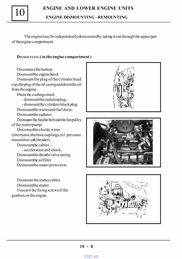
DISMOUNTING ( in the engine compartment )
Disconnect the battery.Dismount the engine hood.Dismount the plug of the cylinder head
cap,the plug of the oil casing and drain the oilfrom the engine.
Drain the cooling circuit:- dismount the radiator plug;- dismount the cylinders block plug.
Dismount the watter and fuel ducts.Dismount the radiator.Dismount the fan,the belt and the fan pulley
of the watter pump.Disconect the electric wires
(alternator,thermocouplings,oil pressuretransmitter,coil;breaker);
Dismount the cables:- acceleration and shock;
Dismount the throttle valve spring.Dismount the air filter.Dismount the starter protection.
Dismount the starter cables.Dismount the starter.Unscrew the fixing screws of the
gearbox on the engine.
ENGINE DISMOUNTING - REMOUNTING
vnx.su
10
10 - 9
ENGINE AND LOWER ENGINE UNITS
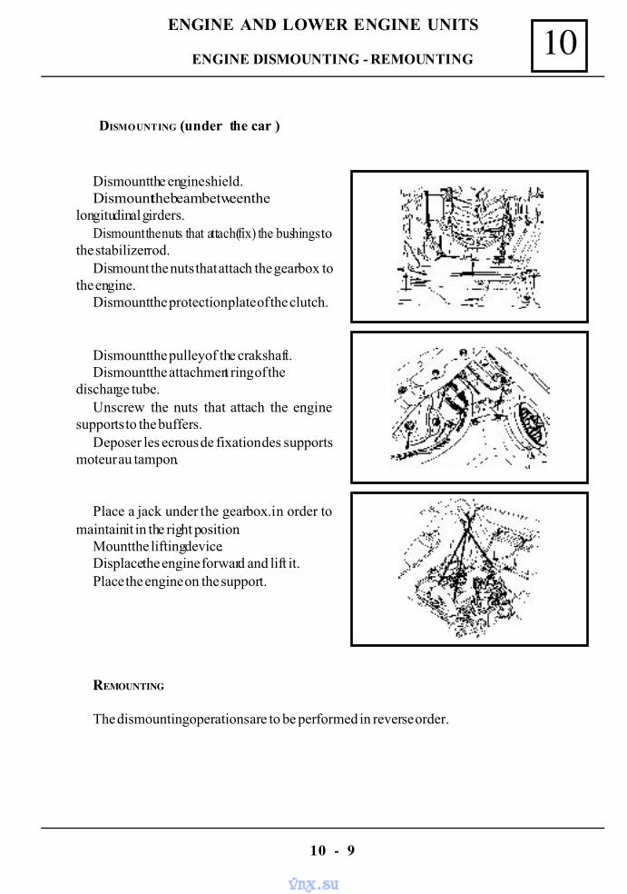
DISMOUNTING (under the car )
Dismount the engine shield.Dismount the beam between the
longitudinal girders.Dismount the nuts that attach(fix) the bushings to
the stabilizer rod.Dismount the nuts that attach the gearbox to
the engine.Dismount the protection plate of the clutch.
Dismount the pulley of the crakshaft.Dismount the attachment ring of the
discharge tube.Unscrew the nuts that attach the engine
supports to the buffers.Deposer les ecrous de fixation des supports
moteur au tampon.
Place a jack under the gearbox.in order tomaintain it in the right position.
Mount the lifting device.Displace the engine forward and lift it.Place the engine on the support.
REMOUNTING
The dismounting operations are to be performed in reverse order.
ENGINE DISMOUNTING - REMOUNTING
vnx.su
10
10 - 10
ENGINE AND LOWER ENGINE UNITS
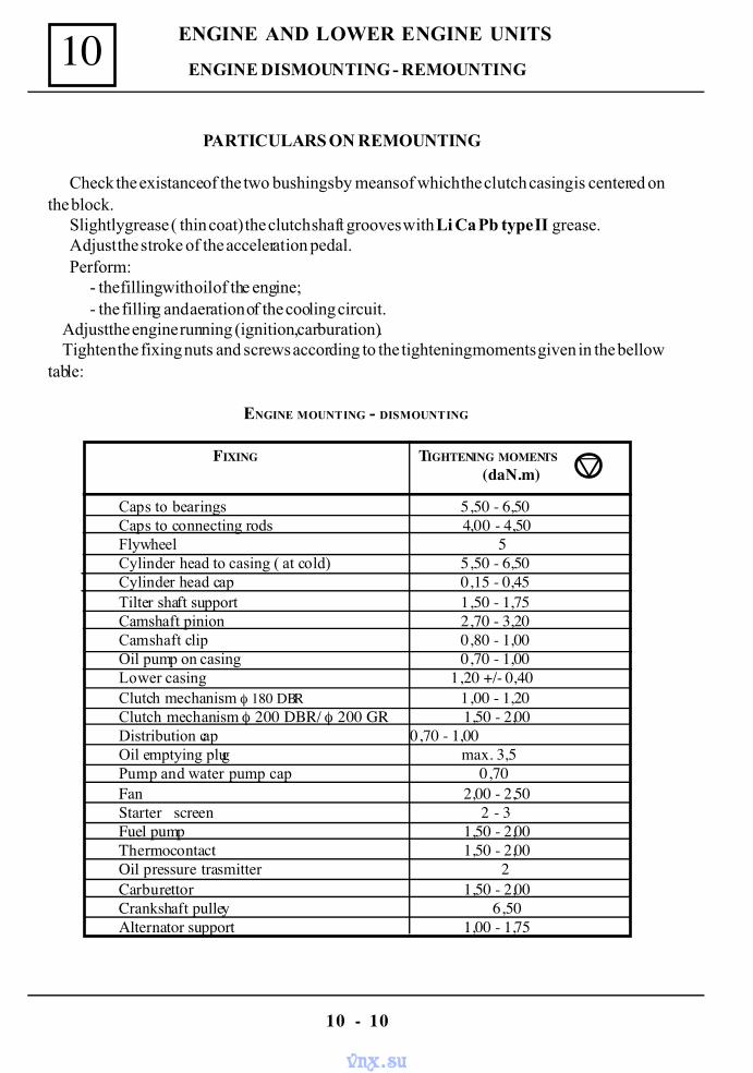
PARTICULARS ON REMOUNTING
Check the existance of the two bushings by means of which the clutch casing is centered onthe block.
Slightly grease ( thin coat) the clutch shaft grooves with Li Ca Pb type II grease.Adjust the stroke of the acceleration pedal.Perform:
- the filling with oil of the engine;- the filling and aeration of the cooling circuit.
Adjust the engine running (ignition ,carburation). Tighten the fixing nuts and screws according to the tightening moments given in the bellowtable:
ENGINE MOUNTING - DISMOUNTING
Caps to bearings 5,50 - 6,50Caps to connecting rods 4,00 - 4,50Flywheel 5Cylinder head to casing ( at cold) 5,50 - 6,50Cylinder head cap 0,15 - 0,45Tilter shaft support 1,50 - 1,75Camshaft pinion 2,70 - 3,20Camshaft clip 0,80 - 1,00Oil pump on casing 0,70 - 1,00Lower casing 1,20 +/- 0,40Clutch mechanism φ 180 DBR 1,00 - 1,20Clutch mechanism φ 200 DBR/ φ 200 GR 1,50 - 2,00Distribution cap 0,70 - 1,00Oil emptying plug max. 3,5Pump and water pump cap 0,70Fan 2,00 - 2,50Starter screen 2 - 3Fuel pump 1,50 - 2,00Thermocontact 1,50 - 2,00Oil pressure trasmitter 2Carburettor 1,50 - 2,00Crankshaft pulley 6,50Alternator support 1,00 - 1,75
ENGINE DISMOUNTING - REMOUNTING
FIXING TIGHTENING MOMENTS (daN.m)
vnx.su
10
10 - 11
ENGINE AND LOWER ENGINE UNITS
The engine-gearbox assembly may be dismounted from the car only by taking it out at theuper part of the engine compartment.
DISMOUNTING ( inside the engine compartment )
Perform the operations described for the sole engine dismounting,except the followingoperations:
- dismounting of the starter protection;- dismounting of starter;- dismounting of the screws fixing the gearbox to the engine.
Perform additionally:- dismounting of the clutch cable.
DISMOUNTING ( under the car )
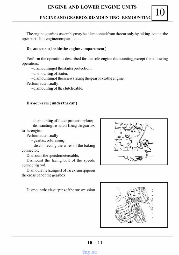
- dismounting of clutch protection plate;- dismounting the nuts of fixing the gearbox
to the engine.Perform additionally:
- gearbox oil draining;- disconnecting the wires of the baking
connector.Dismount the speedometer cable;Dismount the fixing bolt of the speeds
connecting rod.Dismount the fixing nut of the exhaust pipe on
the cross bar of the gearbox.
Dismount the elastic pins of the transmission.
ENGINE AND GEARBOX DISMOUNTING - REMOUNTING
vnx.su
10
10 - 12
ENGINE AND LOWER ENGINE UNITS
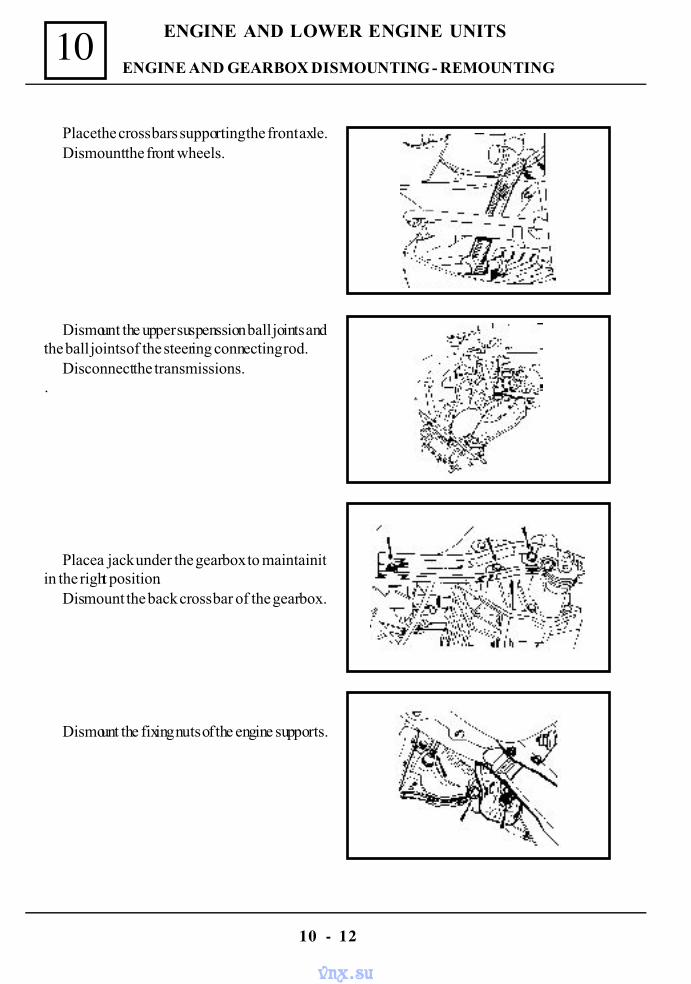
Place the cross bars supporting the front axle.Dismount the front wheels.
Dismount the upper suspenssion ball joints andthe ball joints of the steering connecting rod.
Disconnect the transmissions..
Place a jack under the gearbox to maintain itin the right position.
Dismount the back cross bar of the gearbox.
Dismount the fixing nuts of the engine supports.
ENGINE AND GEARBOX DISMOUNTING - REMOUNTING
vnx.su
10
10 - 13
ENGINE AND LOWER ENGINE UNITS
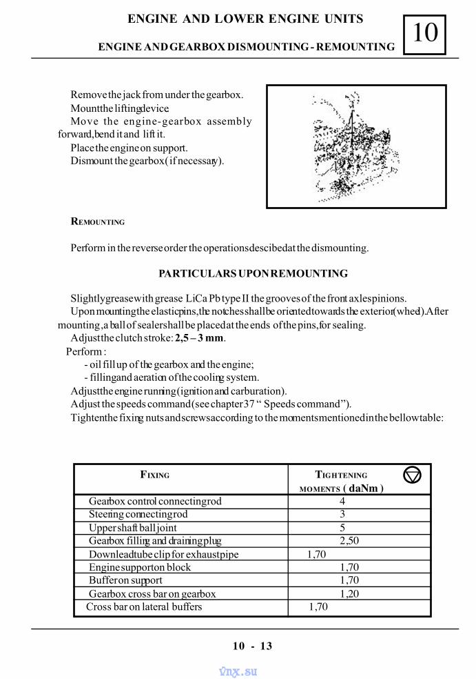
Remove the jack from under the gearbox.Mount the lifting device.Move the engine-gearbox assembly
forward,bend it and lift it.Place the engine on support.Dismount the gearbox ( if necessary).
REMOUNTING
Perform in the reverse order the operations descibed at the dismounting.
PARTICULARS UPON REMOUNTING
Slightly grease with grease Li Ca Pb type II the grooves of the front axles pinions.Upon mounting the elastic pins,the notches shall be oriented towards the exterior (wheel).After
mounting ,a ball of sealer shall be placed at the ends of the pins,for sealing.Adjust the clutch stroke: 2,5 – 3 mm.
Perform :- oil fill up of the gearbox and the engine;- filling and aeration of the cooling system.
Adjust the engine running (ignition and carburation).Adjust the speeds command (see chapter 37 “ Speeds command ”).Tighten the fixing nuts and screws according to the moments mentioned in the bellow table:
FIXING TIGHTENING
MOMENTS ( daNm )Gearbox control connecting rod 4Steering connecting rod 3Upper shaft ball joint 5Gearbox filling and draining plug 2,50Downlead tube clip for exhaust pipe 1,70Engine support on block 1,70Buffer on support 1,70Gearbox cross bar on gearbox 1,20
Cross bar on lateral buffers 1,70
ENGINE AND GEARBOX DISMOUNTING - REMOUNTING
vnx.su
10
10 - 14
ENGINE AND LOWER ENGINE UNITS
TIGHTENING BY SCREWING UP MOMENTS
vnx.su
10
10 - 15
ENGINE AND LOWER ENGINE UNITS
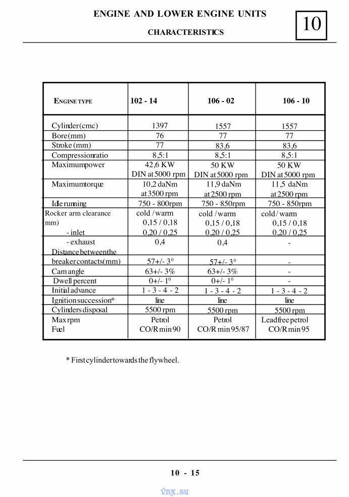
CHARACTERISTICS
ENGINE TYPE 102 - 14 106 - 02 106 - 10
Cylinder (cmc)Bore (mm)Stroke (mm)Compression ratioMaximum power
Maximum torque
Idle running Rocker arm clearance(mm)
- inlet- exhaust
Distance between thebreaker contacts (mm)Cam angle Dwell percentInitial advanceIgnition succession *Cylinders disposalMax rpmFuel
13977677
8,5:142,6 KW
DIN at 5000 rpm10,2 daNmat 3500 rpm
750 - 800rpm cold / warm
0,15 / 0,180,20 / 0,25
0,4
57+/- 30
63+/- 3%0+/- 10
1 - 3 - 4 - 2line
5500 rpmPetrol
CO/R min 90
155777
83,68,5:1
50 KWDIN at 5000 rpm
11,9 daNmat 2500 rpm
750 - 850rpm cold / warm
0,15 / 0,180,20 / 0,25
0,4
57+/- 30
63+/- 3%0+/- 10
1 - 3 - 4 - 2line
5500 rpmPetrol
CO/R min 95/87
155777
83,68,5:1
50 KWDIN at 5000 rpm
11,5 daNmat 2500 rpm
750 - 850rpmcold / warm
0,15 / 0,180,20 / 0,25
-
---
1 - 3 - 4 - 2line
5500 rpmLeadfree petrol
CO/R min 95
* First cylinder towards the flywheel.
vnx.su
10
10 - 16
ENGINE AND LOWER ENGINE UNITS
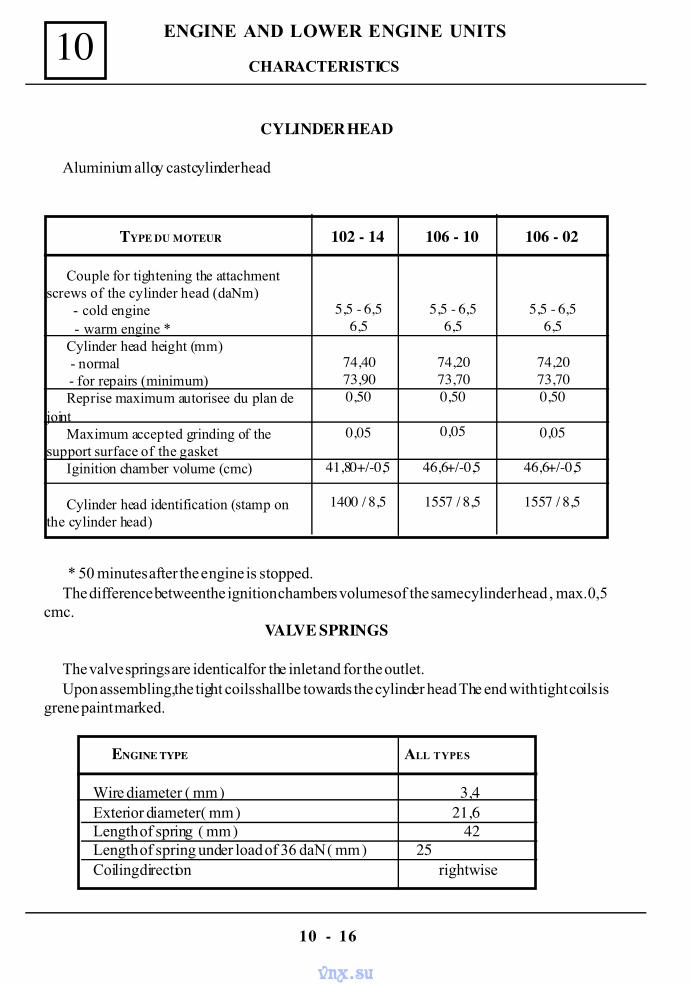
CYLINDER HEAD
Aluminium alloy cast cylinder head
TYPE DU MOTEUR
Couple for tightening the attachmentscrews of the cylinder head (daNm) - cold engine - warm engine *
Cylinder head height (mm) - normal - for repairs (minimum)
Reprise maximum autorisee du plan dejoint
Maximum accepted grinding of thesupport surface of the gasket
Iginition chamber volume (cmc)
Cylinder head identification (stamp onthe cylinder head)
102 - 14
5,5 - 6,56,5
74,4073,900,50
0,05
41,80+/-0,5
1400 / 8,5
106 - 10
5,5 - 6,56,5
74,2073,700,50
0,05
46,6+/-0,5
1557 / 8,5
106 - 02
5,5 - 6,56,5
74,2073,700,50
0,05
46,6+/-0,5
1557 / 8,5
* 50 minutes after the engine is stopped.The difference between the ignition chambers volumes of the same cylinder head , max. 0,5
cmc.VALVE SPRINGS
The valve springs are identical for the inlet and for the outlet.Upon assembling, the tight coils shall be towards the cylinder head The end with tight coils is
grene paint marked.
ENGINE TYPE ALL TYPES
Wire diameter ( mm ) 3,4Exterior diameter ( mm ) 21,6Length of spring ( mm ) 42Length of spring under load of 36 daN ( mm ) 25Coiling direction rightwise
CHARACTERISTICS
vnx.su
10
10 - 17
ENGINE AND LOWER ENGINE UNITS
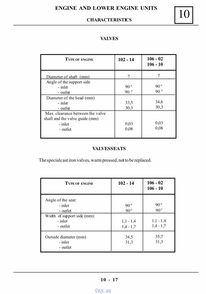
VALVES
TYPE OF ENGINE
Diameter of shaft (mm) Angle of the support side
- inlet- outlet
Diameter of the head (mm)- inlet- outlet
Max. clearance between the valveshaft and the valve guide (mm)
- inlet - outlet
102 - 14
7
90 090 0
33,530,3
0,030,08
106 - 02106 - 10
7
90 090 0
34,630,3
0,030,08
VALVES SEATS
The special cast iron valves, warm pressed, not to be replaced.
TYPE OF ENGINE
Angle of the seat: - inlet - outlet
Width of support side (mm): - inlet - outlet
Outside diameter (mm) - inlet - outlet
102 - 14
90 090 0
1,1 - 1,41,4 - 1,7
34,531,3
106 - 02106 - 10
90 090 0
1,1 - 1,41,4 - 1,7
35,731,3
CHARACTERISTICS
vnx.su
10
10 - 18
ENGINE AND LOWER ENGINE UNITS
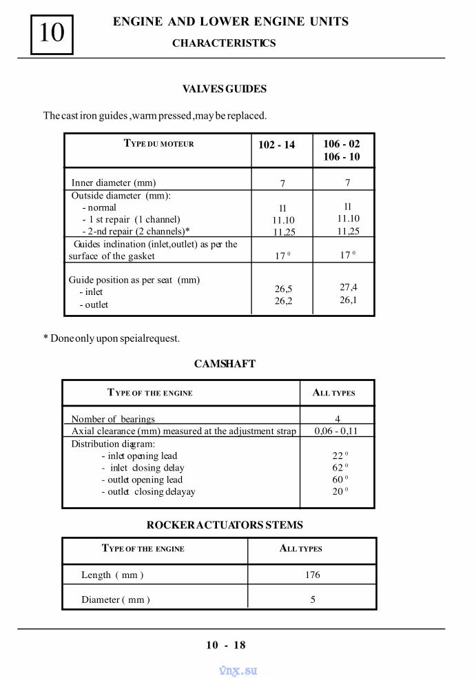
VALVES GUIDES
The cast iron guides ,warm pressed ,may be replaced.
TYPE DU MOTEUR
Inner diameter (mm) Outside diameter (mm): - normal - 1 st repair (1 channel) - 2-nd repair (2 channels)* Guides inclination (inlet,outlet) as per thesurface of the gasket
Guide position as per seat (mm) - inlet - outlet
102 - 14
7
1111.1011,25
17 0
26,526,2
106 - 02106 - 10
7
1111.1011,25
17 0
27,426,1
TYPE OF THE ENGINE ALL TYPES
Nomber of bearings 4 Axial clearance (mm) measured at the adjustment strap 0,06 - 0,11 Distribution diagram:
- inlet opening lead 22 0- inlet closing delay 62 0- outlet opening lead 60 0- outlet closing delayay 20 0
CAMSHAFT
ROCKER ACTUATORS STEMS
TYPE OF THE ENGINE ALL TYPES
Length ( mm ) 176
Diameter ( mm ) 5
* Done only upon speial request.
CHARACTERISTICS
vnx.su
10
10 - 19
ENGINE AND LOWER ENGINE UNITS
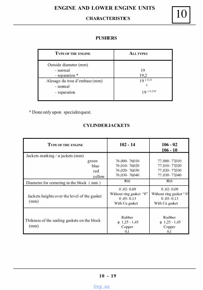
PUSHERS
TYPE OF THE ENGINE ALL TYPES
Outside diameter (mm)- normal 19- reparation * 19,2
Alesage du trou d’embase (mm) 19 + 0,21
- normal 0
- reparation 19 + 0,210
* Done only upon special request.
CYLINDER JACKETS
TYPE OF THE ENGINE
Jackets marking / ø jackets (mm) green
blue red yellow
Diametre for centering in the block ( mm )
Jackets heights over the level of the gasket(mm)
Thikness of the sealing gaskets on the block(mm)
102 - 14
76 ,000 - 76,01076 ,010 - 76,02076 ,020 - 76,03076 ,030 - 76,040
80,6
0 ,02 - 0,09 Without ring gasket “0”
0 ,05 - 0,13 With Cu gasket
Rubberφ 1,25 - 1,45
Copper0,1
106 - 02106 - 10
77 ,000 - 77,01077 ,010 - 77,02077 ,020 - 77,03077 ,030 - 77,040
80,6
0 ,02 - 0,09 Without ring gasket “ 0“
0 ,05 - 0,13 With Cu gasket
Ruibberφ 1,25 - 1,45
Copper0,1
CHARACTERISTICS
vnx.su
10
10 - 20
ENGINE AND LOWER ENGINE UNITS
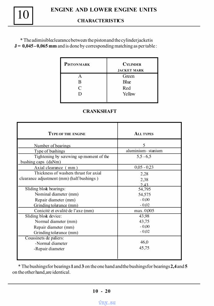
* The adimisible clearance between the piston and the cylinder jacket isJ = 0,045 - 0,065 mm and is done by corresponding matching as per table :
PISTON MARK CYLINDER
JACKET MARK
A GreenB BlueC RedD Yellow
CRANKSHAFT
TYPE OF THE ENGINE
Number of bearingsType of bushingsTightening by screwing up moment of the
bushing caps (daNm)Axial clearance ( mm )Thickness of washers thrust for axial
clearance adjustment (mm) (half bushings )
Sliding block bearings: Nominal diameter (mm) Repair diameter (mm)Grinding tolerance (mm)Conicité et ovalité de l’axe (mm)
Sliding block device: Normal diameter (mm)Repair diameter (mm)Grinding tolerance (mm)
Coussinets de paliers: -Normal diameter-Repair diameter
ALL TYPES
5aluminium - stanium
5,5 - 6,5
0,05 - 0,232,282,382,43
54,79554,575- 0,00- 0,02
max. 0,00543,9843,75- 0,00- 0,02
46,045,75
* The bushings for bearings 1 and 3 on the one hand and the bushings for bearings 2,4 and 5on the other hand,are identical.
CHARACTERISTICS
vnx.su
10
10 - 21
ENGINE AND LOWER ENGINE UNITS
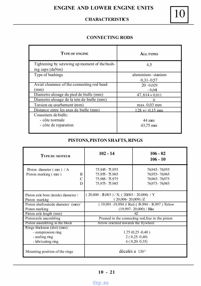
CONNECTING RODS
TYPE OF ENGINE
Tightening by screwing up moment of the bush-ing caps (daNm)Type of bushings
Axial clearance of the connecting rod head(mm)Diametre alesage du pied de bielle (mm)Diametre alesage de la tete de bielle (mm)Torsion ou courbement (mm)Distance entre les axes de bielle (mm)Coussinets de bielle: - côte normale - côte de reparation
ALL TYPES
4,5
aluminium - stanium0,31- 0,5720 - 0,029
- 0,04147, 614 + 0,011
0max. 0,03 mm
128 +/- 0,15 mm
44 mm43,75 mm
PISTONS, PISTON SHAFTS, RINGS
TYPE DU MOTEUR
Piston diameter ( mm ) / A Piston marking ( mm ) B
CD
Piston axle bore (inside) diameter / Piston marking Piston shaft outside diameter (mm)/ Piston marking Piston axle length (mm)
Piston axle assembling
Piston assembling in the block Rings thickness (slot) (mm): - compression ring - sealing ring - lubricating ring
Mounting position of the rings
102 - 14
75,945 - 75,95575,955 - 75,96575,965 - 75,97575,975 - 75,985
106 - 02106 - 10
76,945 - 76,955 76,955 - 76,965 76,965 - 76,975 76,975 - 76,985
( 20,000 - 20,003 ) / X ; ( 20,003 - 20,006 ) / Y( 20,006 - 20,009 ) / Z
( 19,991 - 19,994 ) / Red ;( 19,994 - 19,997 ) / Yelow(19,997 - 20,000 ) / Blue
62Pressed in the connecting rod,free in the piston
Arrow oriented towards the flywheel
1,75 ( 0,25 - 0,40 )2 ( 0,25 - 0,40 )4 ( 0,20 - 0,35 )
décalés a 120 0
CHARACTERISTICS
vnx.su
10
10 - 22
ENGINE AND LOWER ENGINE UNITS
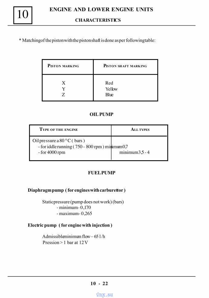
* Matching of the piston with the piston shaft is done as per following table:
OIL PUMP
PISTON MARKING PISTON SHAFT MARKING
X RedY YellowZ Blue
TYPE OF THE ENGINE ALL TYPES
Oil pressure a 80 0 C ( bars )- for iddle running ( 750 - 800 rpm ) minimum 0,7- for 4000 rpm minimum 3,5 - 4
FUEL PUMP
Diaphragm pump ( for engines with carburettor )
Static pressure (pump does not work) (bars)- minimum - 0,170- maximum - 0,265
Electric pump ( for engine with injection )
Admissible minimum flow – 65 l /h Pression > 1 bar at 12 V
CHARACTERISTICS
vnx.su
10
10 - 23
ENGINE AND LOWER ENGINE UNITS
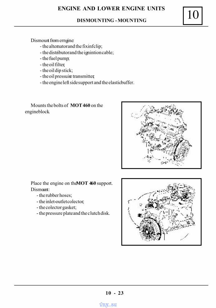
Dismount from erngine:- the alternator and the fixinf clip;- the distributor and the ignintion cable;- the fuel pump;- the oil filter;- the oil dip stick;- the oil pressuire transmitter;- the engine left side support and the elastic buffer.
Mounts the bolts of MOT 460 on theengine block.
Place the engine on the MOT 460 support.Dismount:
- the rubber hoses;- the inlet-outlet colector;- the colector gasket;- the pressure plate and the clutch disk.
DISMOUNTING - MOUNTING
vnx.su
10
10 - 24
ENGINE AND LOWER ENGINE UNITS
DISMOUNTING - MOUNTING
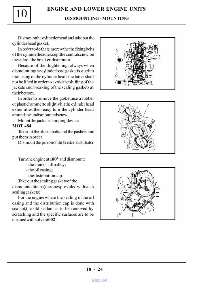
Dismount the cylineder head and take out thecylinder head gasket.
In order to do that,unscrew the the fixing boltsof the cylinder head,except the central screw,onthe side of the breaker-distributor.
Because of the thightening, always whendismounting,the cylinder head gasket is stuck tothe casing or the cylinder head the latter shallnot be lifted in order to avoid the shifting of thejackets and breaking of the sealing gaskets attheir bottom.
In order to remove the gasket,use a rubberor plastic hammer to slightly hit the cylinder headextremities,then easy turn the cylinder headaround the undismounted screw.
Mount the jackets clamping deviceMOT 484.
Take out the tilters shafts and the pushers andput them in order.
Dismount the pinion of the breaker distributor.
Turn the engine at 180 0 and dismount:- the crankshaft pulley;- the oil casing;- the distribution cap.
Take out the sealing gaskets of thedismounted items (the ones provided with suchsealing gaskets).
For the engine where the sealing of the oilcasing and the distribution cap is done withsealant,the old sealant is to be removed byscratching and the specific surfaces are to becleaned with solvent 002.
vnx.su
10
10 - 25
ENGINE AND LOWER ENGINE UNITS
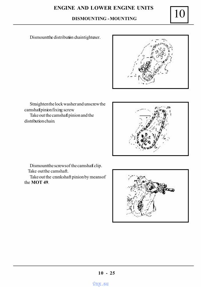
Dismount the distribution chain tightener.
Straighten the lock washer and unscrew thecamshaft pinion fixing screw.
Take out the camshaft pinion and thedistribution chain.
Dismount the screws of the camshaft clip. Take out the camshaft.
Take out the crankshaft pinion by means ofthe MOT 49.
DISMOUNTING - MOUNTING
vnx.su
10
10 - 26
ENGINE AND LOWER ENGINE UNITS
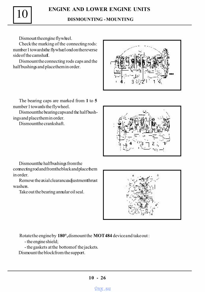
Dismount the engine flywheel.Check the marking of the connecting rods:
number 1 towards the flywheel ond on the reverseside of the camshaft.
Dismount the connecting rods caps and thehalf bushings and place them in order.
The bearing caps are marked from 1 to 5number 1 towards the flywheel.
Dismount the bearing caps and the half bush-ings and place them in order.
Dismount the crankshaft.
Dismount the half bushings from theconnecting rod and from the block and place themin order.
Remove the axial clearance adjustment thrustwashers.
Take out the bearing annular oil seal.
Rotate the engine by 180°, dismount the MOT 484 device and take out :- the engine shield;- the gaskets at the bottom of the jackets.
Dismount the block from the support.
DISMOUNTING - MOUNTING
vnx.su
10
10 - 27
ENGINE AND LOWER ENGINE UNITS
RETIGHTENING OF THE CYLINDER HEAD SCREWS
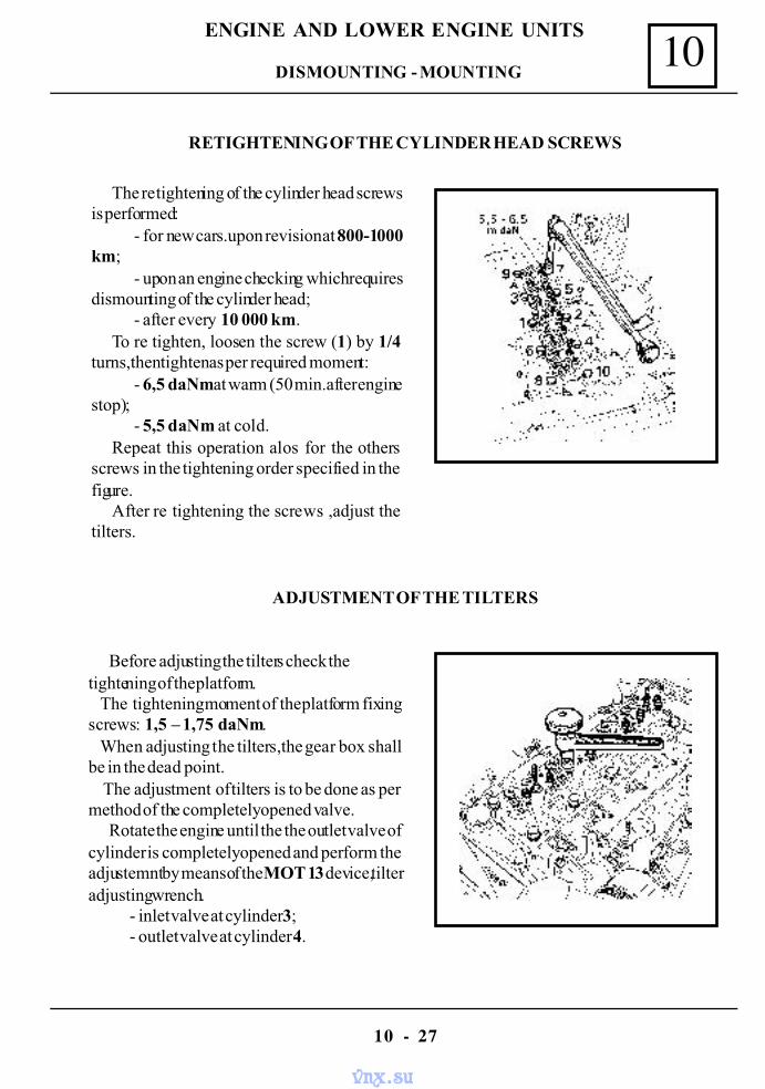
The re tightening of the cylinder head screwsis performed:
- for new cars.upon revision at 800-1000km;
- upon an engine checking which requiresdismounting of the cylinder head;
- after every 10 000 km.To re tighten, loosen the screw (1) by 1/4
turns,then tighten as per required moment:- 6,5 daNm at warm (50 min.after engine
stop);- 5,5 daNm at cold.
Repeat this operation alos for the othersscrews in the tightening order specified in thefigure.
After re tightening the screws ,adjust thetilters.
ADJUSTMENT OF THE TILTERS
Before adjusting the tilters check thetightening of the platform. The tightening moment of the platform fixingscrews: 1,5 – 1,75 daNm. When adjusting the tilters,the gear box shallbe in the dead point. The adjustment of tilters is to be done as permethod of the completely opened valve.
Rotate the engine until the the outlet valve ofcylinder is completely opened and perform theadjustemnt by means of the MOT 13 device,tilteradjusting wrench.
- inlet valve at cylinder 3;- outlet valve at cylinder 4.
DISMOUNTING - MOUNTING
vnx.su
10
10 - 28
ENGINE AND LOWER ENGINE UNITS
Repeat the operation for the cylinders 3 - 4 - 2 according to the table:
OUTLET VALVE COMPLETELY OPENED VALVE TO BE ADJUSTED
INLET OUTLET
1 3 43 4 24 2 12 1 3
Tilters clearance : at cold - inlet 0,15 mm; - outlet 0,20 mm;at warm - inlet 0,18 mm;
- outlet 0,25 mm.The checking of the distance between the tilter and the valve is done by means of a distance
calliper (spy) at the corresponding dimension of the constructive cleranace.The callipper should glide with easy friction between surfaces ( for a correct checking).
CYLINDER HEAD
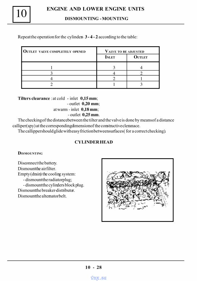
DISMOUNTING
Disconnect the battery.Dismount the air filter.Empty (drain) the cooling system:
- dismount the radiator plug;- dismount the cylinders block plug.
Dismount the breaker-distributor.Dismount the alternator belt.
DISMOUNTING - MOUNTING
vnx.su
10
10 - 29
ENGINE AND LOWER ENGINE UNITS
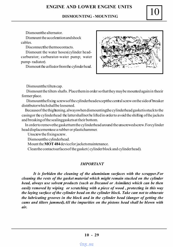
Dismount the alternator.Dismount the acceleration and shock
cables.Disconnect the thermocontacts.Dismount the water hoses(cylinder head-
carburator; carburator-water pump; waterpump- radiator).
Dismount the collector from the cylinder head.
Dismount the tilters cap.Dismount the tilters shafts. Place them in order so that they may be mounted again in theeir
former place.Dismount the fixing screws of the cylinder head except the central screw on the side of breaker
distributor which shall be loosened. Because of the thightening, always when dismounting,the cylinder head gasket is stuck to thecasing or the cylinder head the latter shall not be lifted in order to avoid the shifting of the jacketsand breaking of the sealing gaskets at their bottom. In order to remove the gasket turn the cylinder head around the unscrewed screw.For cylinderhead displacement use a rubber or plastic hammer.
Unscrew the fixing screw.Dismount the cylinder head.Mount the MOT 484 device for jackets maintenance.Clean the contact surfaces of the gasket ( cylinder block and cylinder head).
IMPORTANT
It is forbiden the cleaning of the aluminium surfaces with the scrapper.Forcleaning the rests of the gasket material which might remain stucked on the cylinderhead, always use solvent products (such as Decanol or Asimilate) which can be theneasily removed by wiping or scratching with a piece of wood , protecting in this waythe laying surface of the cylinder head on the cylinder block. Take care not to obturatethe lubricating grooves in the block and in the cylinder head (danger of getting thecams and tilters jammed).All the impurities on the pistons head shall be blown withair.
DISMOUNTING - MOUNTING
vnx.su
10
10 - 30
ENGINE AND LOWER ENGINE UNITS
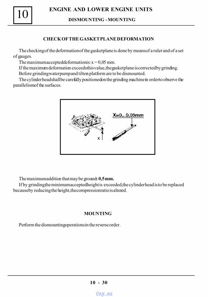
CHECK OF THE GASKET PLANE DEFORMATION
The checking of the deformation of the gasket plane is done by means of a ruler and of a setof gauges.
The maximum accepted deformation is: x = 0,05 mm.If the maximum deformation exceeds this value,the gasket plane is corrected by grinding.Before grinding water pump and tilters platform are to be dismounted.The cylinder head shall be carefully positioned on the grinding machine in order to observe the
parallelism of the surfaces.
The maximum addition that may be ground: 0,5 mm.If by grinding,the minimum accepted height is exceeded, the cylinder head is to be replaced
because by reducing the height,the compression ratio is altered.
MOUNTING
Perform the dismounting operations in the reverse order.
DISMOUNTING - MOUNTING
vnx.su
10
10 - 31
ENGINE AND LOWER ENGINE UNITS
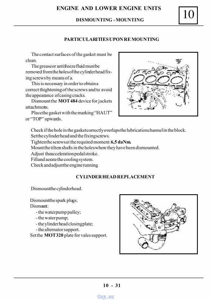
PARTICULARITIES UPON RE MOUNTING
The contact surfaces of the gasket must beclean.
The grease or antifreeze fluid must beremoved from the holes of the cylinder head fix-ing screws by means of a.
This is necessary in order to obtain acorrect thightening of the screws and to avoidthe appearance of casing cracks.
Dismount the MOT 484 device for jacketsattachments.
Place the gasket with the marking “HAUT”or “TOP” upwards.
Check if the hole in the gasket correctly overlaps the lubrication channel in the block.Set the cylinder head and the fixing screws.Tighten the screws at the required moment: 6,5 daNm.Mount the tilters shafts in the holes where they have been dismounted.Adjust the acceleration pedal stroke.Fill and aerate the cooling system.Check and adjust the engine running.
CYLINDER HEAD REPLACEMENT
Dismount the cylinder head.
Dismount the spark plugs.Dismount:
- the water pump pulley;- the water pump;- the ylinder head closing plate;- the alternator support.
Set the MOT 320 plate for vales support.
DISMOUNTING - MOUNTING
vnx.su
10
10 - 32
ENGINE AND LOWER ENGINE UNITS
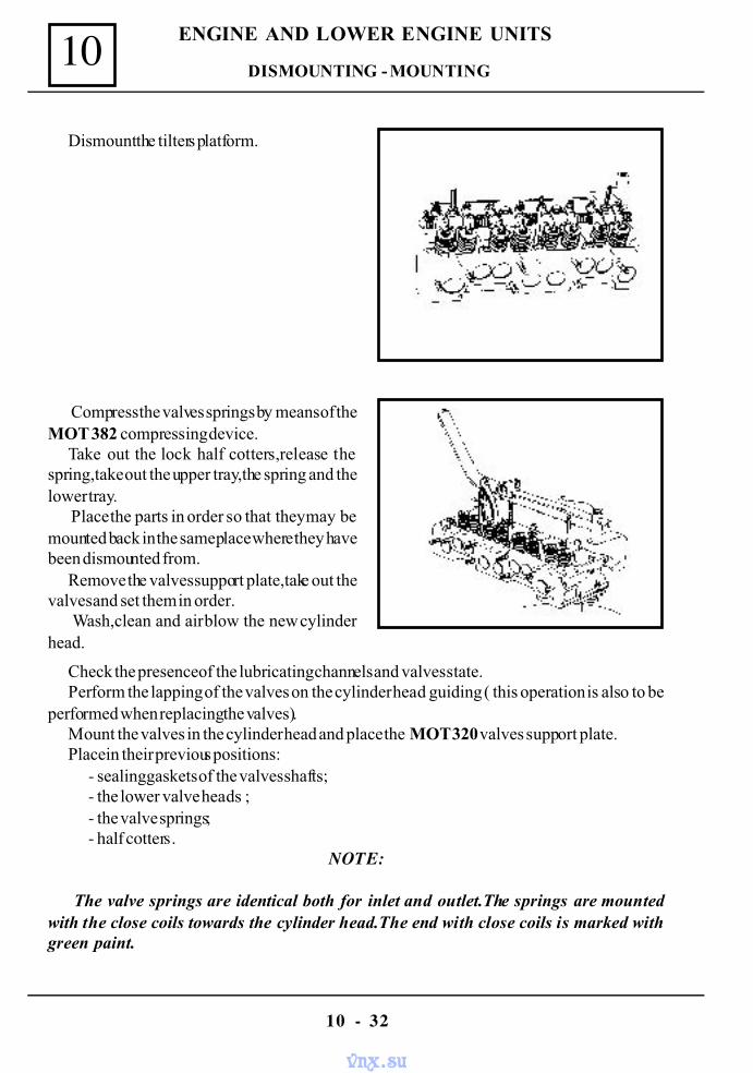
Dismount the tilters platform.
Compress the valves springs by means of theMOT 382 compressing device.
Take out the lock half cotters,release thespring,take out the upper tray,the spring and thelower tray.
Place the parts in order so that they may bemounted back in the same place where they havebeen dismounted from.
Remove the valves support plate,take out thevalves and set them in order.
Wash,clean and air blow the new cylinderhead.
Check the presence of the lubricating channels and valves state.Perform the lapping of the valves on the cylinder head guiding ( this operation is also to be
performed when replacing the valves).Mount the valves in the cylinder head and place the MOT 320 valves support plate.Place in their previous positions:
- sealing gaskets of the valves shafts;- the lower valve heads ;- the valve springs;- half cotters.
NOTE:
The valve springs are identical both for inlet and outlet.The springs are mountedwith the close coils towards the cylinder head.The end with close coils is marked withgreen paint.
DISMOUNTING - MOUNTING
vnx.su
10
10 - 33
ENGINE AND LOWER ENGINE UNITS
Compress the springs by means of the MOT 382 compression device and mount the lockhalf cotters.
Mount the cylinder head closing plate and the water pump with new gaskets.Mount the alternator support.Mount the cylinder head with new gasket observing the mounting instructions.Mount the tilter shafts in the place where they have been removed from.Adjust the tilters.Mount the tilters cap.Adjust the acceleration pedal stroke.Fill and aerate the cooling system.Check and adjust the engine(ignition,carburation).Retightem the cylinder head after 800 km of driving.
VALVE SPRING REPLACEENT ( on car )
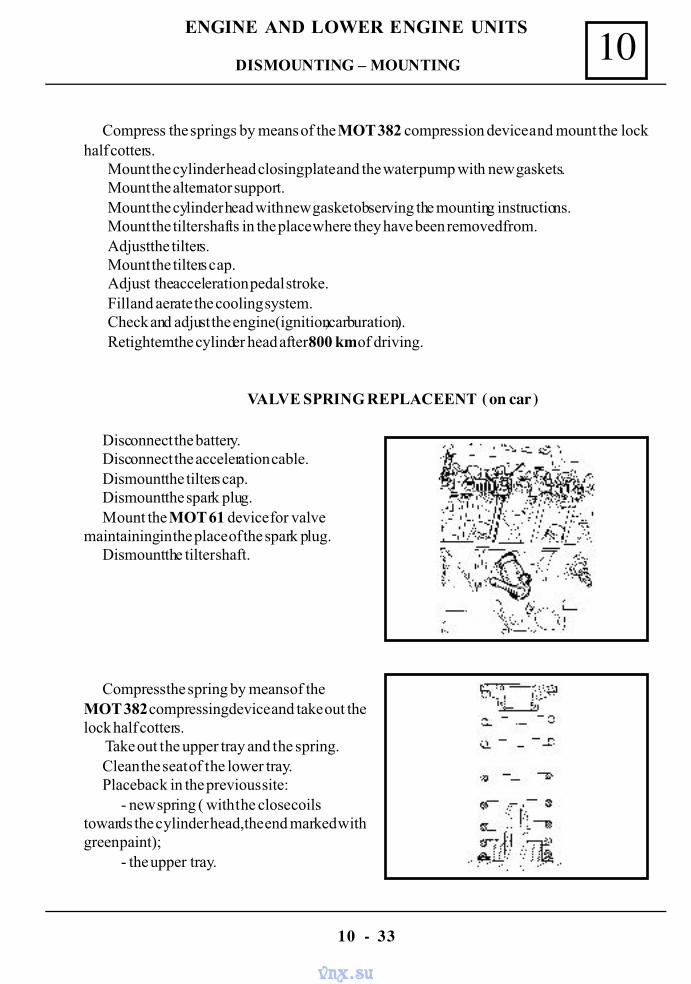
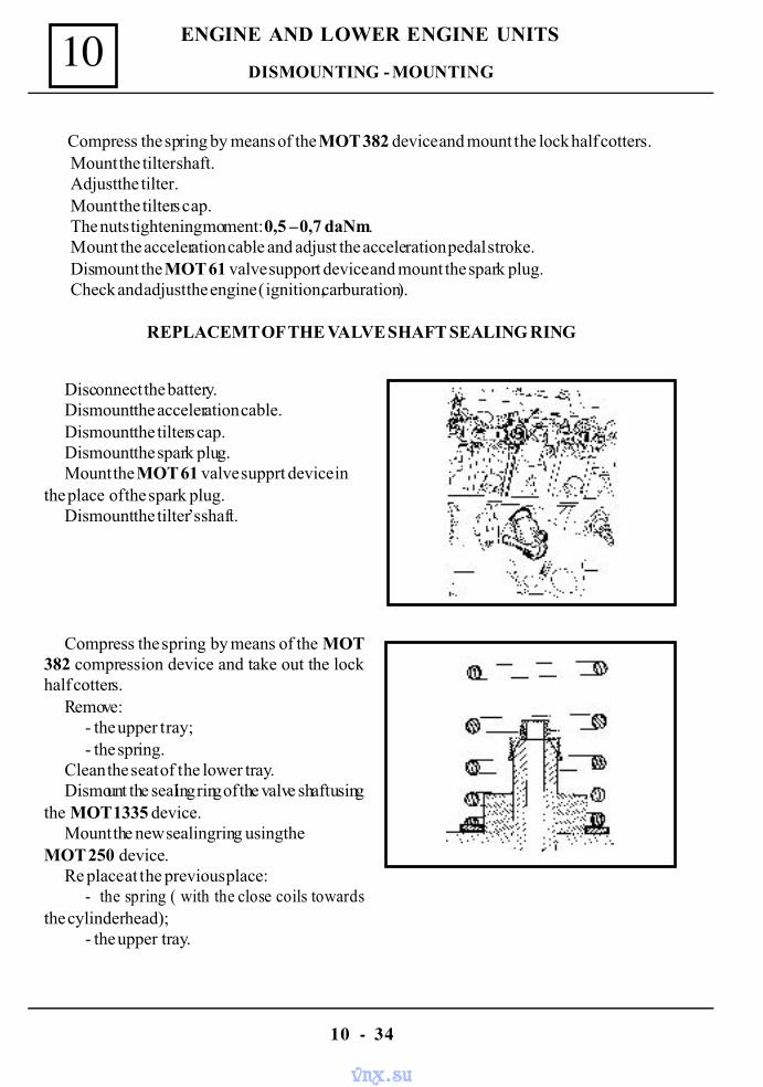
Disconnect the battery.Disconnect the acceleration cable.Dismount the tilters cap.Dismount the spark plug.Mount the MOT 61 device for valve
maintaining in the place of the spark plug.Dismount the tilter shaft.
Compress the spring by means of theMOT 382 compressing device and take out thelock half cotters.
Take out the upper tray and the spring.Clean the seat of the lower tray.Place back in the previous site:
- new spring ( with the close coilstowards the cylinder head,the end marked withgreen paint);
- the upper tray.
DISMOUNTING – MOUNTING
vnx.su
10
10 - 34
ENGINE AND LOWER ENGINE UNITS
Compress the spring by means of the MOT 382 device and mount the lock half cotters.Mount the tilter shaft.Adjust the tilter.Mount the tilters cap.The nuts tightening moment: 0,5 – 0,7 daNm.Mount the acceleration cable and adjust the acceleration pedal stroke.Dismount the MOT 61 valve support device and mount the spark plug.Check and adjust the engine ( ignition,carburation).
REPLACEMT OF THE VALVE SHAFT SEALING RING
Disconnect the battery.Dismount the acceleration cable.Dismount the tilters cap.Dismount the spark plug.Mount the MOT 61 valve supprt device in
the place of the spark plug.Dismount the tilter’s shaft.
Compress the spring by means of the MOT382 compression device and take out the lockhalf cotters.
Remove:- the upper tray;- the spring.
Clean the seat of the lower tray.Dismount the sealing ring of the valve shaft using
the MOT 1335 device.Mount the new sealing ring using the
MOT 250 device.Re place at the previous place:
- the spring ( with the close coils towardsthe cylinder head);
- the upper tray.
DISMOUNTING - MOUNTING
vnx.su
10
10 - 35
ENGINE AND LOWER ENGINE UNITS
Compress the spring by means of the MOT 382 and mount the lock half cotters.Mount the tilters shaft.Mount the tilters cap.The nuts tihtening moment is : 0,5 - 0,7 daNm. Mount the acceleration cable and adjust the acceleration pedal stroke.Dismount the valve maintainin device MOT 61 and mount the spark plug.Check and adjust the engine (ignition,carburation).
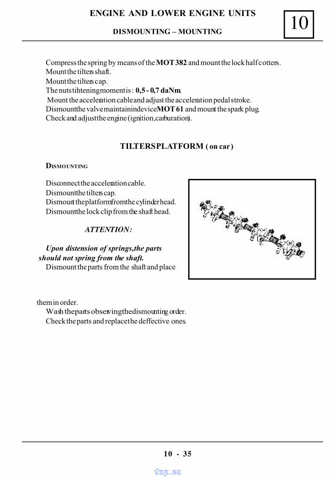
TILTERS PLATFORM ( on car )
DISMOUNTING
Disconnect the acceleration cable.Dismount the tilters cap.Dismount the platform from the cylinder head.Dismount the lock clip from the shaft head.
ATTENTION:
Upon distension of springs,the parts should not spring from the shaft.
Dismount the parts from the shaft and place
them in order.Wash the parts observing the dismounting order.Check the parts and replace the deffective ones.
DISMOUNTING – MOUNTING
vnx.su
10
10 - 36
ENGINE AND LOWER ENGINE UNITS
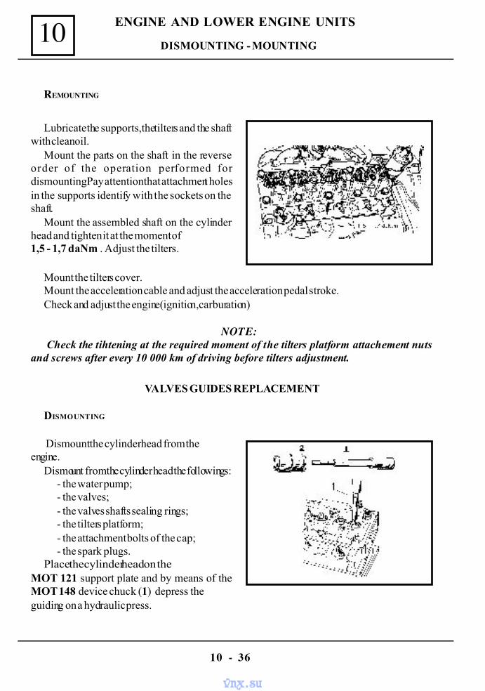
REMOUNTING
Lubricate the supports,the tilters and the shaftwith clean oil.
Mount the parts on the shaft in the reverseorder of the operation performed fordismounting.Pay attention that attachment holesin the supports identify with the sockets on theshaft.
Mount the assembled shaft on the cylinderhead and tighten it at the moment of1,5 - 1,7 daNm . Adjust the tilters.
VALVES GUIDES REPLACEMENT
DISMOUNTING
Dismount the cylinder head from theengine.
Dismount from the cylinder head the followings:- the water pump;- the valves;- the valves shafts sealing rings;- the tilters platform;- the attachment bolts of the cap;- the spark plugs.
Place the cylinder head on theMOT 121 support plate and by means of theMOT 148 device chuck (1) depress theguiding on a hydraulic press.
Mount the tilters cover.Mount the acceleration cable and adjust the acceleration pedal stroke.Check and adjust the engine(ignition,carburation)
NOTE: Check the tihtening at the required moment of the tilters platform attachement nuts
and screws after every 10 000 km of driving before tilters adjustment.
DISMOUNTING - MOUNTING
vnx.su
10
10 - 37
ENGINE AND LOWER ENGINE UNITS
Check the diameter of the depressed guiding:- nominal value 11 mm;- value 1-st repair 11,1 mm;- value 2-nd repair 11,25 mm;
NOTE: The guiding at the repair value are supplied only by request
REMOUNTING
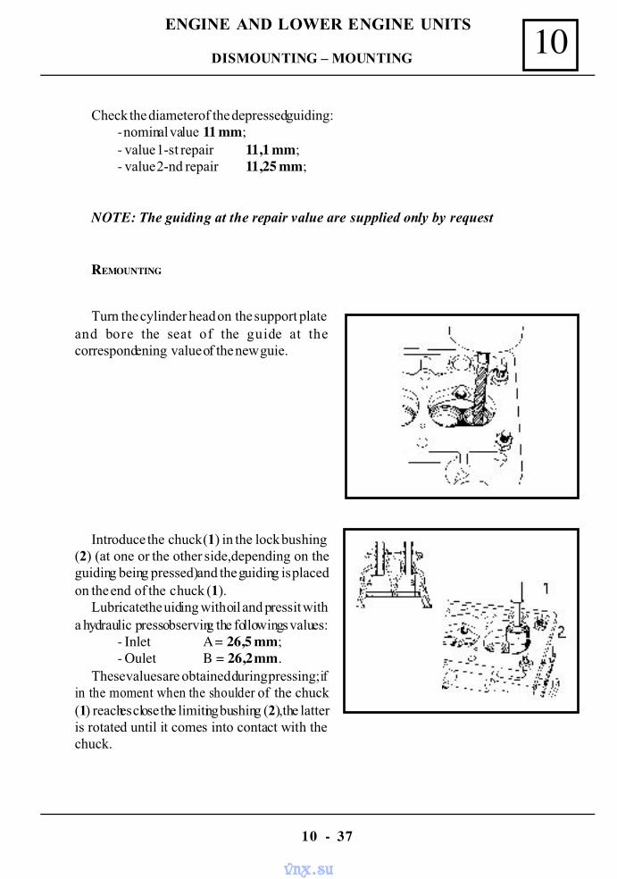
Turn the cylinder head on the support plateand bore the seat of the guide at thecorrespondening value of the new guie.
Introduce the chuck (1) in the lock bushing(2) (at one or the other side,depending on theguiding being pressed) and the guiding is placedon the end of the chuck (1).
Lubricate the uiding with oil and press it witha hydraulic press observing the followings values:
- Inlet A = 26,5 mm;- Oulet B = 26,2 mm.
These values are obtained during pressing; ifin the moment when the shoulder of the chuck(1) reaches close the limiting bushing (2),the latteris rotated until it comes into contact with thechuck.
DISMOUNTING – MOUNTING
vnx.su
10
10 - 38
ENGINE AND LOWER ENGINE UNITS
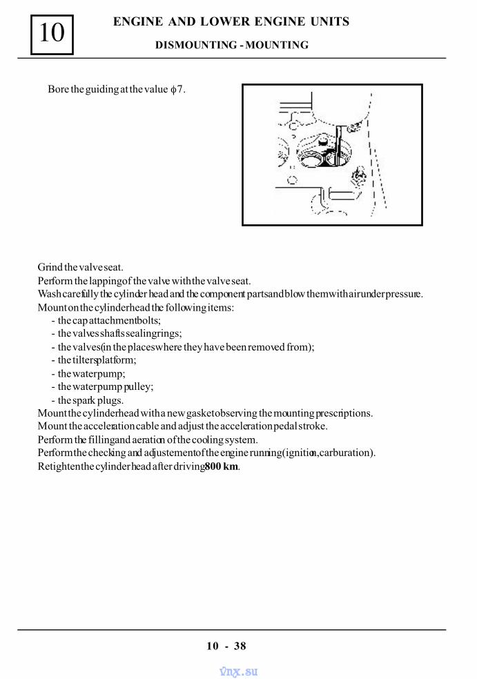
Bore the guiding at the value φ 7.
Grind the valve seat.Perform the lapping of the valve with the valve seat.Wash carefully the cylinder head and the component parts and blow them with air under pressure.Mount on the cylinder head the following items:
- the cap attachment bolts;- the valves shafts sealing rings;- the valves(in the places where they have been removed from);- the tilters platform;- the water pump;- the water pump pulley;- the spark plugs.
Mount the cylinder head with a new gasket observing the mounting prescriptions.Mount the acceleration cable and adjust the acceleration pedal stroke.Perform the filling and aeration of the cooling system.Perform the checking and adjustement of the engine running(ignition,carburation).Retighten the cylinder head after driving 800 km.
DISMOUNTING - MOUNTING
vnx.su
10
10 - 39
ENGINE AND LOWER ENGINE UNITS
VALVE SEATS GRINDING
Dismount the cylinder head from the engine.Dismount from the cylinder head:
- the water pump;- the valves;- the valves shafts sealing rings;- the tilters platform;- the cap attachment bolts;- the spark plugs.
Place the cylinder head on the MOT 121support plate.
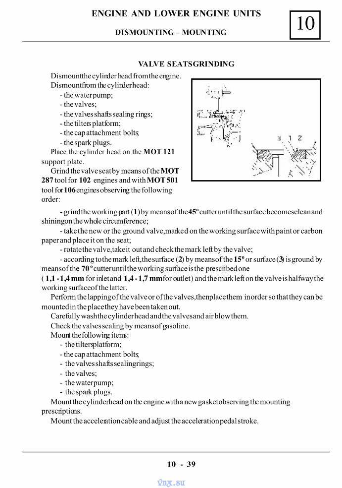
Grind the valve seat by means of the MOT287 tool for 102 engines and with MOT 501tool for 106 engines observing the followingorder:
- grind the working part (1) by means of the 45º cutter until the surface becomes clean andshining on the whole circumference;
- take the new or the ground valve,marked on the working surface with paint or carbonpaper and place it on the seat;
- rotate the valve,take it out and check the mark left by the valve;- according to the mark left,the surface (2) by means of the 15 0 or surface (3) is ground by
means of the 70 º cutter until the working surface is the prescribed one( 1,1 - 1,4 mm for inlet and 1,4 - 1,7 mm for outlet ) and the mark left on the valve is halfway theworking surface of the latter.
Perform the lapping of the valve or of the valves,then place them in order so that they can bemounted in the place they have been taken out.
Carefully wash the cylinder head and the valves and air blow them.Check the valves sealing by means of gasoline.Mount the following items:
- the tilters platform;- the cap attachment bolts;- the valves shafts sealing rings;- the valves;- the water pump;- the spark plugs.
Mount the cylinder head on the engine with a new gasket observing the mountingprescriptions.
Mount the acceleration cable and adjust the acceleration pedal stroke.
DISMOUNTING – MOUNTING
vnx.su
10
10 - 40
ENGINE AND LOWER ENGINE UNITS
Perform the filling and aeration of the cooling system.Perform the checking and adjustment of engine operation (ignition,carburation).Re tighten the cylinder head after driving 800 km.
ENGINE KIT REPLACEMENT ( on car )
DISMOUNTING
Disconnect the battery.Drain the cooling circuit and the oil from
the engine.Dismount:
- the tilters cap;- the cylinder head;- the oil sump;- the oil pump.
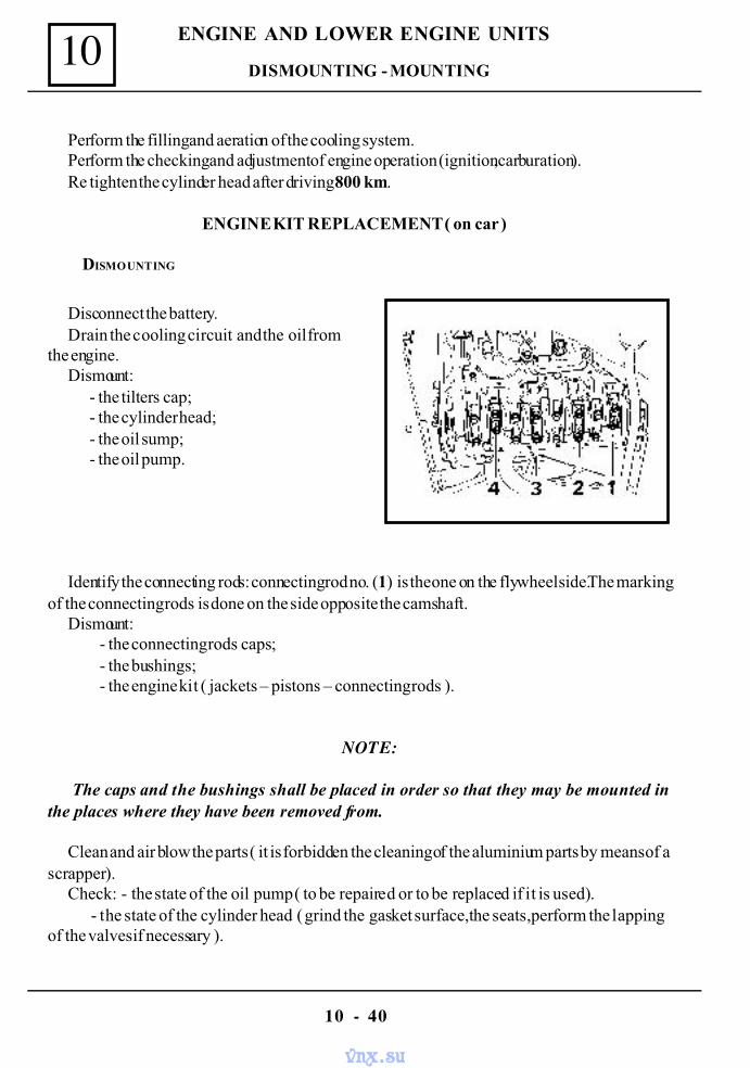
Identify the connecting rods: connecting rod no. (1) is the one on the flywheel side.The markingof the connecting rods is done on the side opposite the camshaft.
Dismount:- the connecting rods caps;- the bushings;- the engine kit ( jackets – pistons – connecting rods ).
NOTE:
The caps and the bushings shall be placed in order so that they may be mounted inthe places where they have been removed from.
Clean and air blow the parts ( it is forbidden the cleaning of the aluminium parts by means of ascrapper).
Check: - the state of the oil pump ( to be repaired or to be replaced if it is used). - the state of the cylinder head ( grind the gasket surface,the seats,perform the lappingof the valves if necessary ).
DISMOUNTING - MOUNTING
vnx.su
10
10 - 41
ENGINE AND LOWER ENGINE UNITS
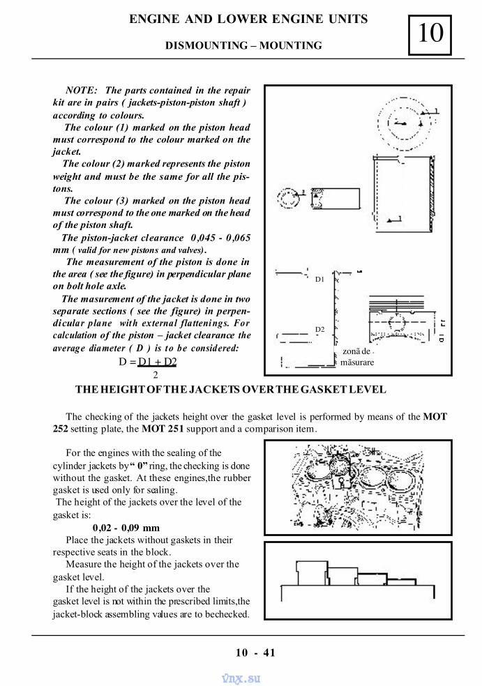
NOTE: The parts contained in the repairkit are in pairs ( jackets-piston-piston shaft )according to colours. The colour (1) marked on the piston headmust correspond to the colour marked on thejacket. The colour (2) marked represents the pistonweight and must be the same for all the pis-tons. The colour (3) marked on the piston headmust correspond to the one marked on the headof the piston shaft. The piston-jacket clearance 0,045 - 0,065mm ( valid for new pistons and valves).
The measurement of the piston is done inthe area ( see the figure) in perpendicular planeon bolt hole axle. The masurement of the jacket is done in twoseparate sections ( see the figure) in perpen-dicular plane with external flattenings. Forcalculation of the piston – jacket clearance theaverage diameter ( D ) is t o be considered:
D = D1 + D22
For the engines with the sealing of thecylinder jackets by “ 0” ring, the checking is donewithout the gasket. At these engines,the rubbergasket is used only for sealing. The height of the jackets over the level of thegasket is:
0,02 - 0,09 mmPlace the jackets without gaskets in their
respective seats in the block.Measure the height of the jackets over the
gasket level.If the height of the jackets over the
gasket level is not within the prescribed limits,thejacket-block assembling values are to be checked.
THE HEIGHT OF THE JACKETS OVER THE GASKET LEVEL
The checking of the jackets height over the gasket level is performed by means of the MOT252 setting plate, the MOT 251 support and a comparison item.
zonã demãsurare
D2
D1
DISMOUNTING – MOUNTING
vnx.su
10
10 - 42
ENGINE AND LOWER ENGINE UNITS
For all types of engines,the jackets shall be positioned as follows:- the maximum difference between the heights of two adjoing jackets shall be
maximum 0,02 mm,within the limit of the prescribed tolerance;- the jackets shall be placed in growing order ( by steps ).
After obtaining the correct height,the position of the jackets in the block is marked so that itmay be paired with the corresponding connecting rods. For the engines where sealing is done by “ Cu “ made gaskets,the checking is done withgaskets fitted. Overheight of the gaskets over the gasket level : 0,05 – 0,13 mm. If the height of the jacketsover the gasket level is not within the prescribed limits, the jacket-block assembling values are tobe checked.
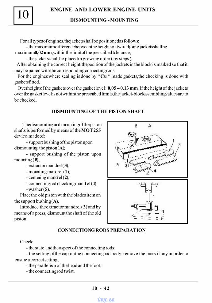
DISMOUNTING OF THE PISTON SHAFT
The dismounting and mounting of the pistonshafts is performed by means of the MOT 255device ,made of:
- support bushing of the piston upondismounting the piston (A);
- support bushing of the piston uponmounting (B);
- extractor mandrel (3);- mounting mandrel (1);- centering mandrel (2);- connecting rod checking mandrel (4);- washer (5).
Place the old piston with the blades item onthe support bushing (A).
Introduce the extractor mandrel (3) and bymeans of a press, dismount the shaft of the oldpiston.
CONNECTIONG RODS PREPARATION
Check:- the state and the aspect of the connecting rods;- the setting of the cap on the connecting rod body; remove the burrs if any in order to
ensure a correct setting;- the parallelism of the head and the foot;- the connecting rod twist.
DISMOUNTING - MOUNTING
vnx.su
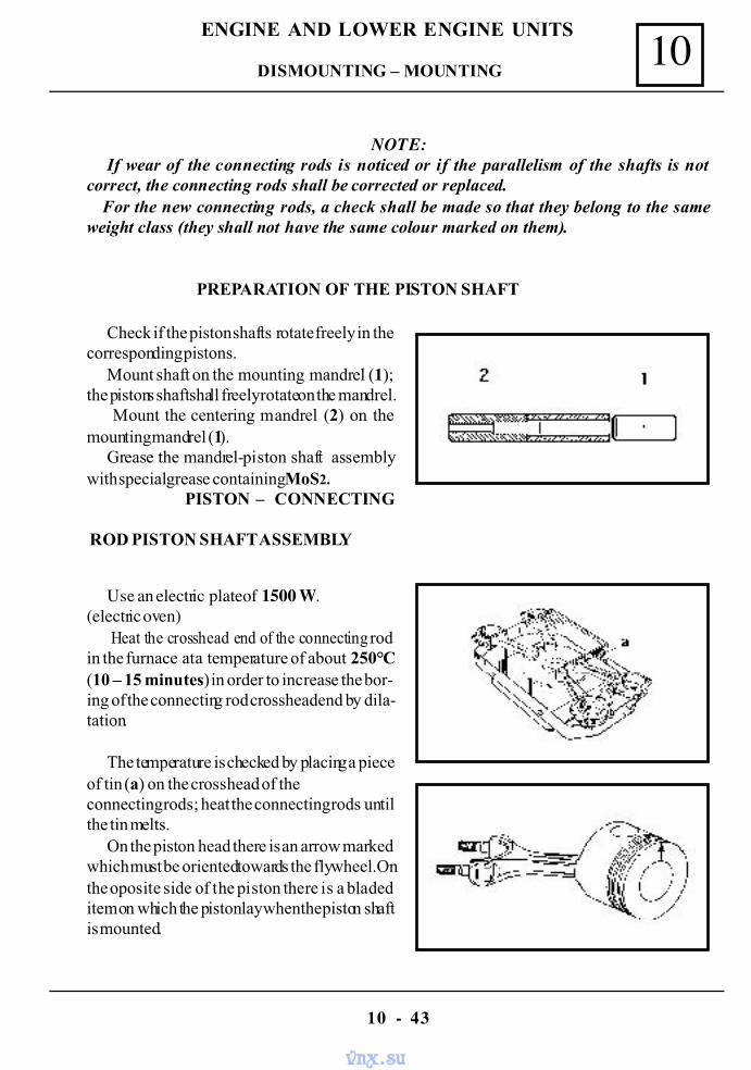
10
10 - 43
ENGINE AND LOWER ENGINE UNITS
NOTE:If wear of the connecting rods is noticed or if the parallelism of the shafts is not
correct, the connecting rods shall be corrected or replaced. For the new connecting rods, a check shall be made so that they belong to the sameweight class (they shall not have the same colour marked on them).
PREPARATION OF THE PISTON SHAFT
Check if the piston shafts rotate freely in thecorresponding pistons.
Mount shaft on the mounting mandrel (1);the pistons shaft shall freely rotate on the mandrel.
Mount the centering mandrel (2) on themounting mandrel (1).
Grease the mandrel-piston shaft assemblywith special grease containing MoS2.
PISTON – CONNECTING
Use an electric plate of 1500 W.(electric oven)
Heat the crosshead end of the connecting rodin the furnace at a temperature of about 250°C(10 – 15 minutes) in order to increase the bor-ing of the connecting rod crosshead end by dila-tation.
The temperature is checked by placing a pieceof tin (a) on the crosshead of theconnecting rods; heat the connecting rods untilthe tin melts.
On the piston head there is an arrow markedwhich must be oriented towards the flywheel.Onthe oposite side of the piston there is a bladeditem on which the piston lay when the piston shaftis mounted.
ROD PISTON SHAFT ASSEMBLY
DISMOUNTING – MOUNTING
vnx.su
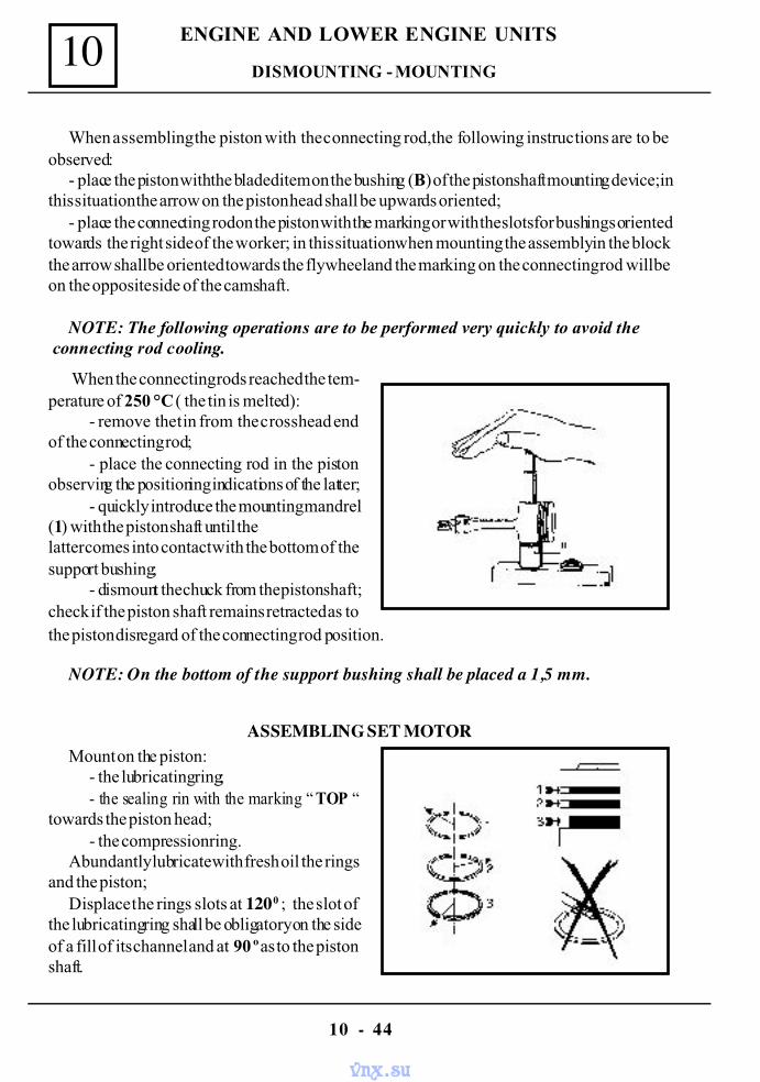
10
10 - 44
ENGINE AND LOWER ENGINE UNITS
When assembling the piston with the connecting rod,the following instructions are to beobserved:
- place the piston with the bladed item on the bushing (B) of the piston shaft mounting device;inthis situation the arrow on the piston head shall be upwards oriented;
- place the connecting rod on the piston with the marking or with the slots for bushings orientedtowards the right side of the worker; in this situation when mounting the assembly in the blockthe arrow shall be oriented towards the flywheel and the marking on the connecting rod will beon the opposite side of the camshaft.
NOTE: The following operations are to be performed very quickly to avoid the connecting rod cooling.
When the connecting rods reached the tem-perature of 250 °C ( the tin is melted):
- remove the tin from the crosshead endof the connecting rod;
- place the connecting rod in the pistonobserving the positioning indications of the latter;
- quickly introduce the mounting mandrel(1) with the piston shaft until thelatter comes into contact with the bottom of thesupport bushing;
- dismount the chuck from the piston shaft;check if the piston shaft remains retracted as tothe piston disregard of the connecting rod position.
NOTE: On the bottom of the support bushing shall be placed a 1,5 mm.
Mount on the piston:- the lubricating ring;- the sealing rin with the marking “ TOP “
towards the piston head;- the compression ring.
Abundantly lubricate with fresh oil the ringsand the piston;
Displace the rings slots at 120 0 ; the slot ofthe lubricating ring shall be obligatory on the sideof a fill of its channel and at 90 º as to the pistonshaft.
ASSEMBLING SET MOTOR
DISMOUNTING - MOUNTING
vnx.su
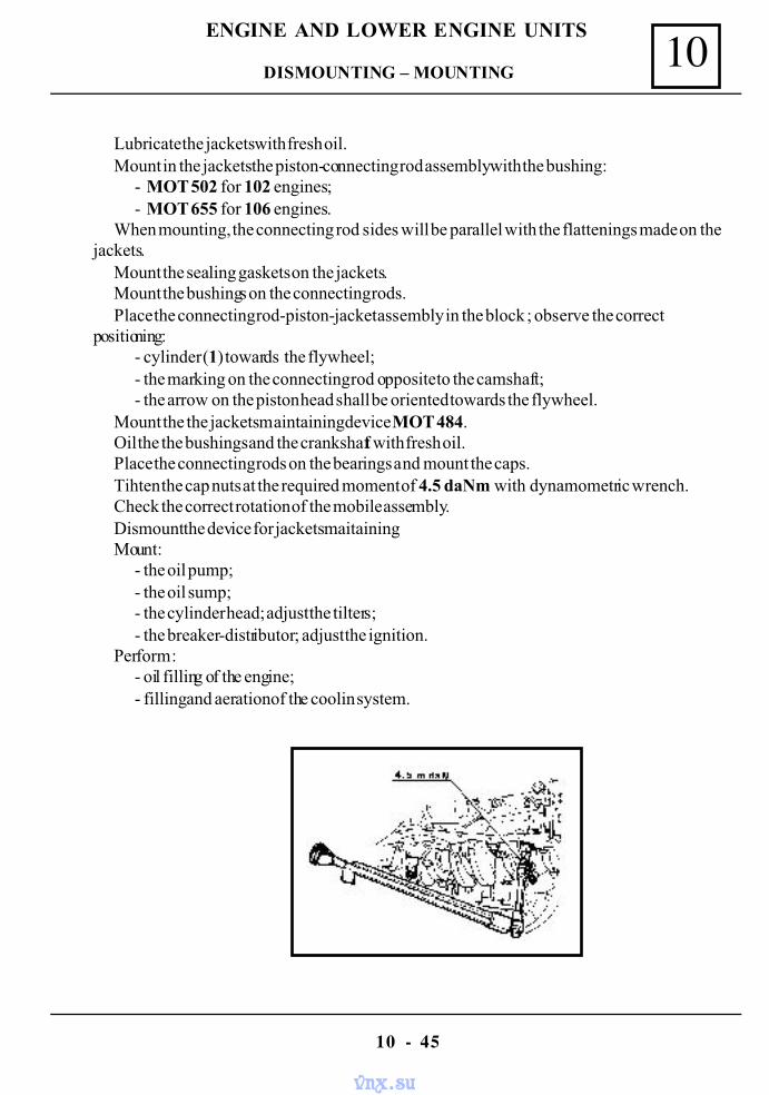
10
10 - 45
ENGINE AND LOWER ENGINE UNITS
Lubricate the jackets with fresh oil.Mount in the jackets the piston-connecting rod assembly with the bushing:
- MOT 502 for 102 engines;- MOT 655 for 106 engines.
When mounting, the connecting rod sides will be parallel with the flattenings made on thejackets.
Mount the sealing gaskets on the jackets.Mount the bushings on the connecting rods.Place the connecting rod-piston-jacket assembly in the block ; observe the correct
positioning:- cylinder (1) towards the flywheel;- the marking on the connecting rod opposite to the camshaft;- the arrow on the piston head shall be oriented towards the flywheel.
Mount the the jackets maintaining device MOT 484.Oil the the bushings and the crankshaft with fresh oil.Place the connecting rods on the bearings and mount the caps.Tihten the cap nuts at the required moment of 4.5 daNm with dynamometric wrench.Check the correct rotation of the mobile assembly.Dismount the device for jackets maitaining.Mount:
- the oil pump;- the oil sump;- the cylinder head; adjust the tilters;- the breaker-distributor; adjust the ignition.
Perform :- oil filling of the engine;- filling and aeration of the coolin system.
DISMOUNTING – MOUNTING
vnx.su
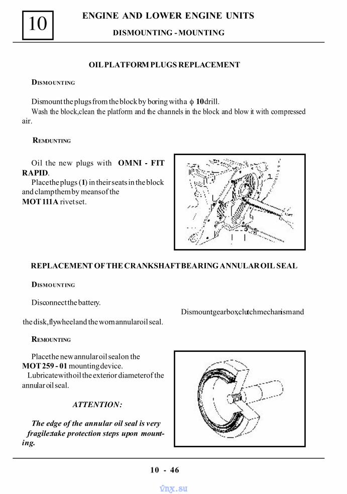
10
10 - 46
ENGINE AND LOWER ENGINE UNITS
OIL PLATFORM PLUGS REPLACEMENT
DISMOUNTING
Dismount the plugs from the block by boring with a φ 10 drill.Wash the block,clean the platform and the channels in the block and blow it with compressed
air.
REMOUNTING
Oil the new plugs with OMNI - FITRAPID.
Place the plugs (1) in their seats in the blockand clamp them by means of theMOT 111A rivet set.
REPLACEMENT OF THE CRANKSHAFT BEARING ANNULAR OIL SEAL
DISMOUNTING
Disconnect the battery.Dismount:gearbox,clutch mechanism and
the disk,flywheel and the worn annular oil seal.
REMOUNTING
Place the new annular oil seal on theMOT 259 - 01 mounting device. Lubricate with oil the exterior diameter of theannular oil seal.
ATTENTION:
The edge of the annular oil seal is very fragile:take protection steps upon mount-ing.
DISMOUNTING - MOUNTING
vnx.su
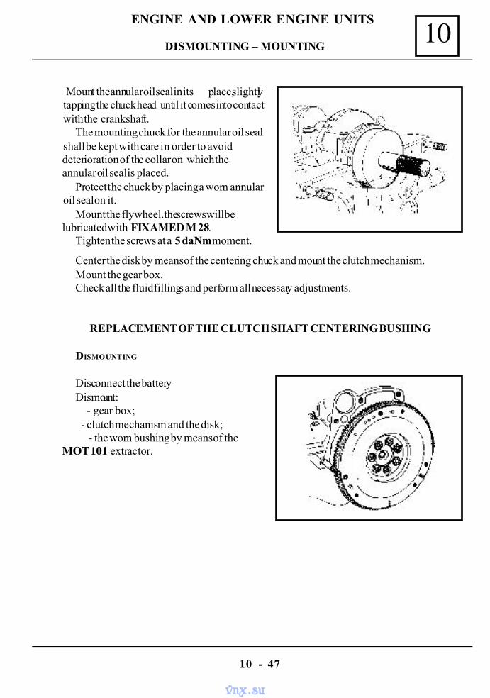
10
10 - 47
ENGINE AND LOWER ENGINE UNITS
Mount the annular oil seal in its place,slightlytapping the chuck head until it comes into contactwith the crankshaft.
The mounting chuck for the annular oil sealshall be kept with care in order to avoiddeterioration of the collar on which theannular oil seal is placed.
Protect the chuck by placing a worn annularoil seal on it.
Mount the flywheel.the screws will belubricated with FIXAMED M 28.
Tighten the screws at a 5 daNm moment.
Center the disk by means of the centering chuck and mount the clutch mechanism.Mount the gear box.Check all the fluid fillings and perform all necessary adjustments.
REPLACEMENT OF THE CLUTCH SHAFT CENTERING BUSHING
DISMOUNTING
Disconnect the batteryDismount:
- gear box; - clutch mechanism and the disk;
- the worn bushing by means of theMOT 101 extractor.
DISMOUNTING – MOUNTING
vnx.su
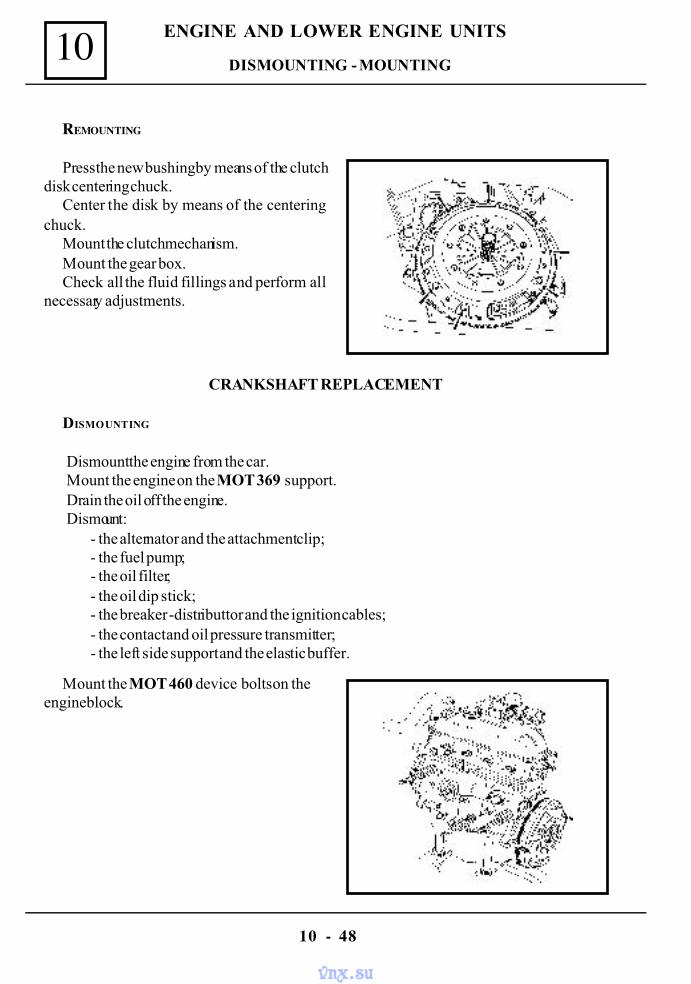
10
10 - 48
ENGINE AND LOWER ENGINE UNITS
Press the new bushing by means of the clutchdisk centering chuck.
Center the disk by means of the centeringchuck.
Mount the clutch mechanism.Mount the gear box.Check all the fluid fillings and perform all
necessary adjustments.
REMOUNTING
CRANKSHAFT REPLACEMENT
DISMOUNTING
Dismount the engine from the car.Mount the engine on the MOT 369 support.Drain the oil off the engine.Dismount:
- the alternator and the attachment clip;- the fuel pump;- the oil filter;- the oil dip stick;- the breaker -distributtor and the ignition cables;- the contact and oil pressure transmitter;- the left side support and the elastic buffer.
Mount the MOT 460 device bolts on theengine block.
DISMOUNTING - MOUNTING
vnx.su
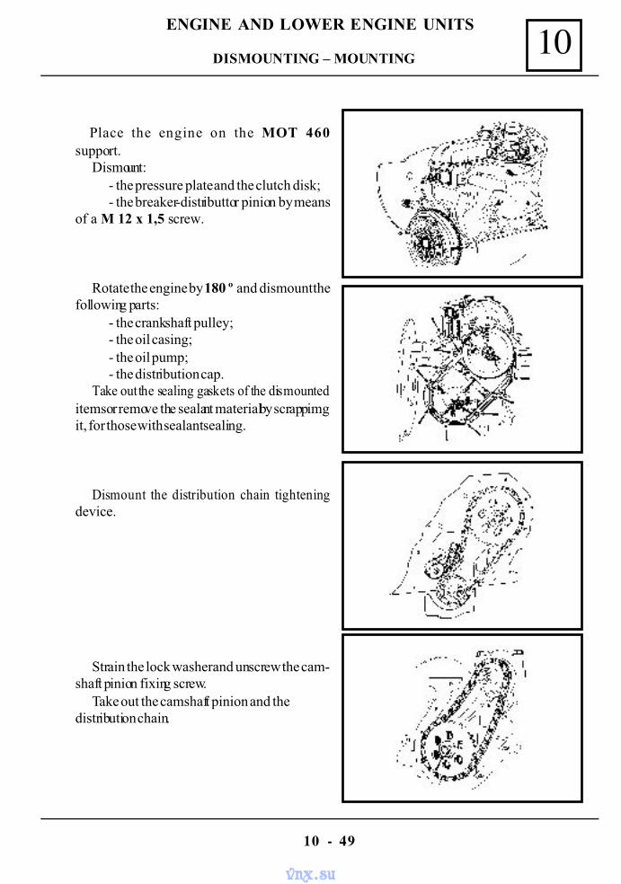
10
10 - 49
ENGINE AND LOWER ENGINE UNITS
Place the engine on the MOT 460suPlace the engine on the MOT 460support.pport.
Dismount:- the pressure plate and the clutch disk;- the breaker-distributtor pinion by means
of a M 12 x 1,5 screw.
Rotate the engine by 180 º and dismount thefollowing parts:
- the crankshaft pulley;- the oil casing;- the oil pump;- the distribution cap.
Take out the sealing gaskets of the dismounteditems or remove the sealant material by scrappimgit, for those with sealant sealing.
Dismount the distribution chain tighteningdevice.
Strain the lock washer and unscrew the cam-shaft pinion fixing screw.
Take out the camshaft pinion and thedistribution chain.
DISMOUNTING – MOUNTING
vnx.su
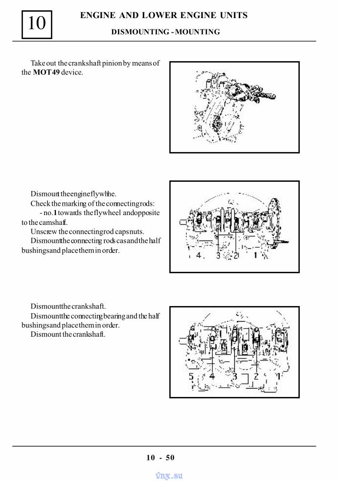
10
10 - 50
ENGINE AND LOWER ENGINE UNITS
Take out the crankshaft pinion by means ofthe MOT 49 device.
Dismount the engine flywhhe.Check the marking of the connecting rods:
- no.1 towards the flywheel and oppositeto the camshaft.
Unscrew the connecting rod caps nuts.Dismount the connecting rods cas and the half
bushings and place them in order.
Dismount the crankshaft.Dismount the connecting bearing and the half
bushings and place them in order.Dismount the crankshaft.
DISMOUNTING - MOUNTING
vnx.su
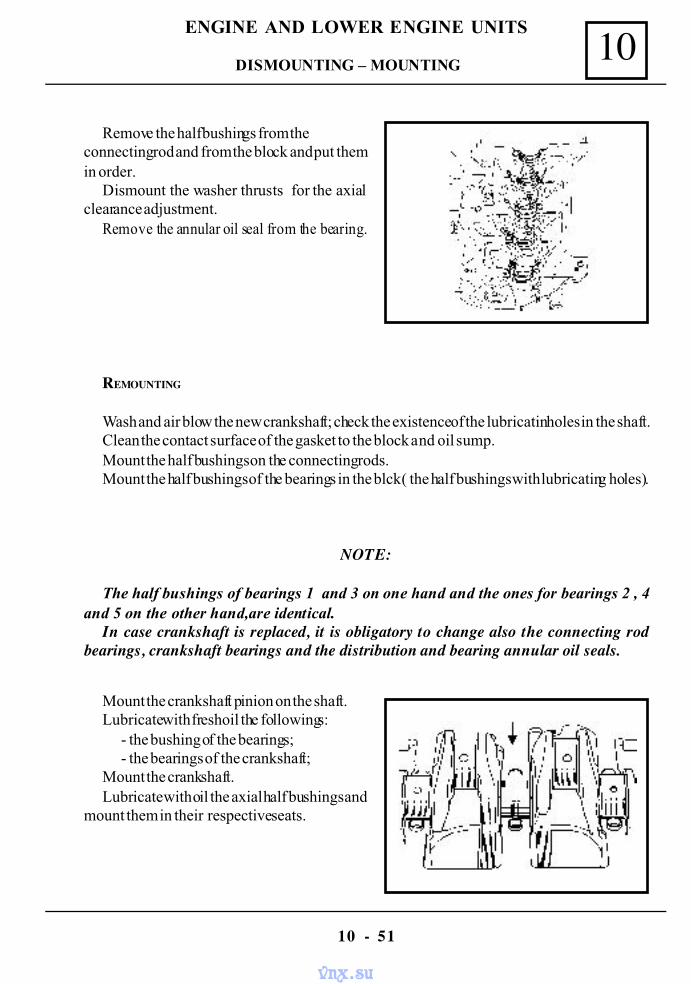
10
10 - 51
ENGINE AND LOWER ENGINE UNITS
Remove the half bushings from theconnecting rod and from the block and put themin order.
Dismount the washer thrusts for the axialclearance adjustment.
Remove the annular oil seal from the bearing.
REMOUNTING
Wash and air blow the new crankshaft; check the existence of the lubricatin holes in the shaft.Clean the contact surface of the gasket to the block and oil sump.Mount the half bushings on the connecting rods.Mount the half bushings of the bearings in the blck ( the half bushings with lubricating holes).
NOTE:
The half bushings of bearings 1 and 3 on one hand and the ones for bearings 2 , 4and 5 on the other hand,are identical.
In case crankshaft is replaced, it is obligatory to change also the connecting rodbearings, crankshaft bearings and the distribution and bearing annular oil seals.
Mount the crankshaft pinion on the shaft.Lubricate with fresh oil the followings:
- the bushing of the bearings;- the bearings of the crankshaft;
Mount the crankshaft.Lubricate with oil the axial half bushings and
mount them in their respective seats.
DISMOUNTING – MOUNTING
vnx.su
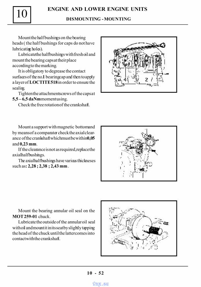
10
10 - 52
ENGINE AND LOWER ENGINE UNITS
Mount the half bushings on the bearingheads ( the half bushings for caps do not havelubricating holes).
Lubricate the half bushings with fresh oil andmount the bearing caps at their placeaccording to the marking.
It is obligatory to degrease the contactsurfaces of the no.1 bearing cap and then to applya layer of LOCTITE 518 in order to ensure thesealing.
Tighten the attachment screws of the caps at5,5 – 6,5 daNm moment using.
Check the free rotation of the crankshaft.
Mount a support with magnetic bottom andby means of a comparator check the axial clear-ance of the crankshaft which must be within 0,05and 0,23 mm.
If the clearance is not as required,replace theaxial half bushings.
The axial half bushings have various thicknesessuch as: 2,28 ; 2,38 ; 2,43 mm .
Mount the bearing annular oil seal on theMOT 259-01 chuck.
Lubricate the outside of the annular oil sealwith oil and mount it in its seat by slightly tappingthe head of the chuck until the latter comes intocontact with the crankshaft.
DISMOUNTING - MOUNTING
vnx.su
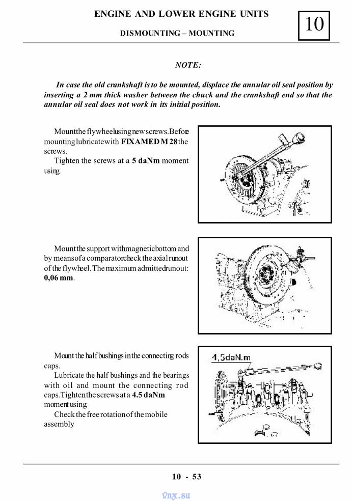
10
10 - 53
ENGINE AND LOWER ENGINE UNITS
NOTE:
In case the old crankshaft is to be mounted, displace the annular oil seal position byinserting a 2 mm thick washer between the chuck and the crankshaft end so that theannular oil seal does not work in its initial position.
Mount the flywheel using new screws.Beforemounting lubricate with FIXAMED M 28 thescrews.
Tighten the screws at a 5 daNm momentusing.
Mount the support with magnetic bottom andby means of a comparator check the axial runoutof the flywheel. The maximum admitted runout:0,06 mm.
Mount the half bushings in the connecting rodscaps.
Lubricate the half bushings and the bearingswith oil and mount the connecting rodcaps.Tighten the screws at a 4.5 daNmmoment using.
Check the free rotation of the mobileassembly.
DISMOUNTING – MOUNTING
vnx.su
10
10 - 54
ENGINE AND LOWER ENGINE UNITS
Mount : the il pump and the distribution,the oil sump and the distribution cap with new gasketsor sealant, the disk and mechanism clutch.
Place the engine on MOT 369 support and mount :- the left side support and elastic buffer;- the anometer and the oil pressure transmitter;- the oil filter;- the oil dip stick;- the drive pinion of the breaker- distributtor, the breaker- distributtor and the spark
plugs cables;- the fuel pump;- the attachment clip and the alternator.
Mount the engine on the vehicle. Perform:
- the oil filling of the engine;- the filing and aeration of the cooling circuit;- engine checking and adjustment ( ignition,carburation).
DISMOUNTING - MOUNTING
vnx.su
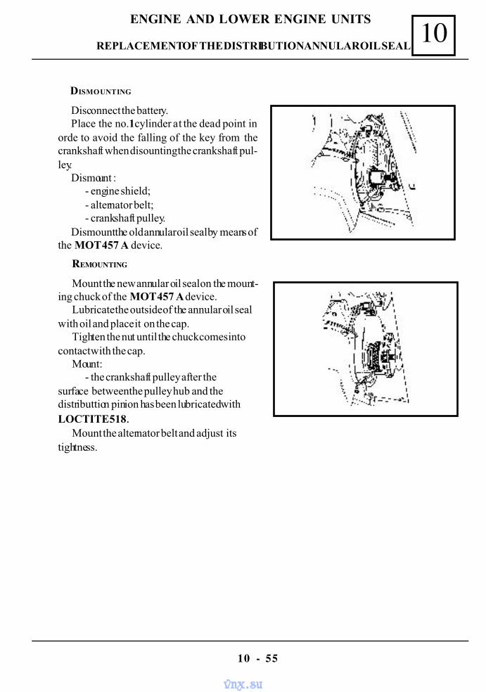
10
10 - 55
ENGINE AND LOWER ENGINE UNITS
Disconnect the battery.Place the no.1 cylinder at the dead point in
orde to avoid the falling of the key from thecrankshaft when disounting the crankshaft pul-ley.
Dismount :- engine shield;- alternator belt;- crankshaft pulley.
Dismount the old annular oil seal by means ofthe MOT 457 A device.
REPLACEMENT OF THE DISTRIBUTION ANNULAR OIL SEAL
DISMOUNTING
Mount the new annular oil seal on the mount-ing chuck of the MOT 457 A device.
Lubricate the outside of the annular oil sealwith oil and place it on the cap.
Tighten the nut until the chuck comes intocontact with the cap.
Mount:- the crankshaft pulley after the
surface between the pulley hub and thedistributtion pinion has been lubricated withLOCTITE 518.
Mount the alternator belt and adjust itstightness.
REMOUNTING
vnx.su
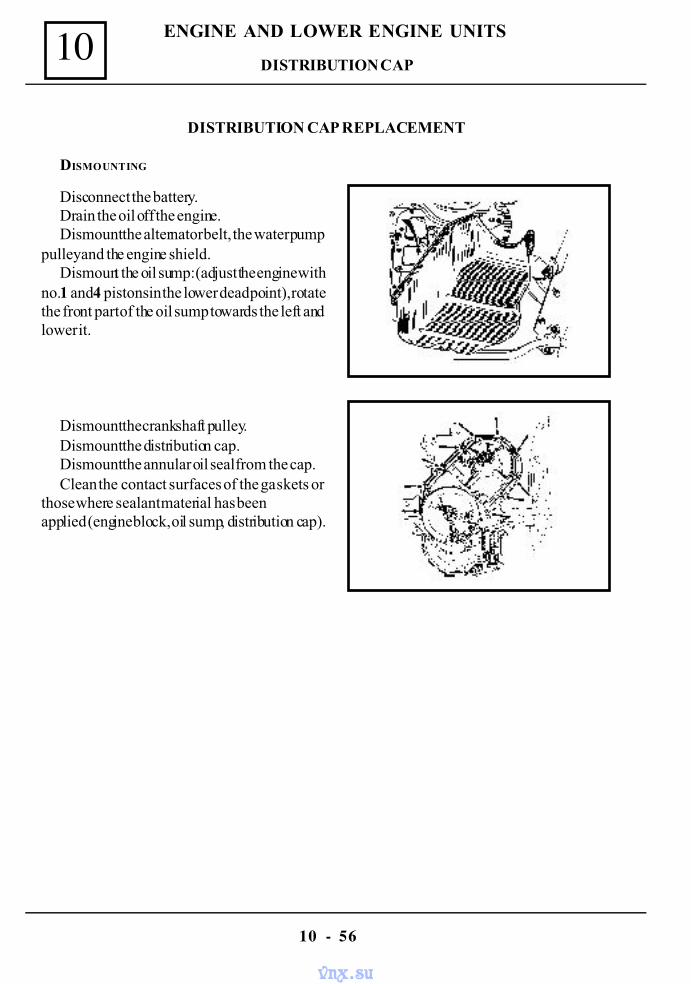
10
10 - 56
ENGINE AND LOWER ENGINE UNITS
DISTRIBUTION CAP REPLACEMENT
DISMOUNTING
Disconnect the battery.Drain the oil off the engine.Dismount the alternator belt, the water pump
pulley and the engine shield.Dismount the oil sump: (adjust the engine with
no.1 and 4 pistons in the lower dead point), rotatethe front part of the oil sump towards the left andlower it.
Dismount the crankshaft pulley.Dismount the distribution cap.Dismount the annular oil seal from the cap.Clean the contact surfaces of the gaskets or
those where sealant material has beenapplied (engine block, oil sump, distribution cap).
DISTRIBUTION CAP
vnx.su
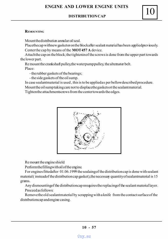
10
10 - 57
ENGINE AND LOWER ENGINE UNITS
REMOUNTING
Mount the distribution annular oil seal.Place the cap with new gasket or on the block after sealant material has been applied previously.Center the cap by means of the MOT 457 A device.Attach the cap on the block; the tightenin of the screws is done from the upper part towards
the lower part.Re mount the crankshaft pulley,the water pump pulley, the alternator belt.Place:
- the rubber gaskets of the bearings;- the side gaskets of the oil sump.
In case sealant material is used , this is to be applied as per bellow described procedure.Mount the oil sump taking care not to displacethe gaskets ot the sealant material.Tighten the attachment screws from the center towards the edges.
Re mount the engine shield.Perform the filling with oil of the engine.For engines fitted after 01.06.1999 the sealaing of the distribution cap is done with sealant
material ( instead of the distribution cap gasket ),the necessary quantity of sealant material is 15grams.
Any dismounting of the distribution cap nrequires the replacing of the sealant material layer.Proceed as follows:Remove the old sealant material by scrapping with a knife from the contact surface of the
distribution cap and engine casing.
DISTRIBUTION CAP
vnx.su
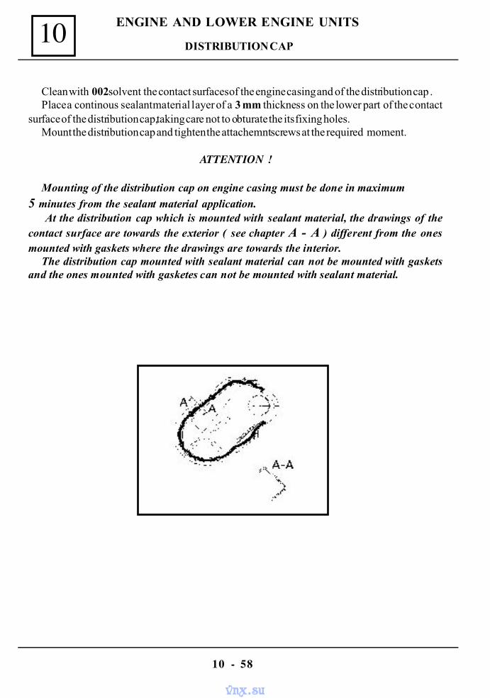
10
10 - 58
ENGINE AND LOWER ENGINE UNITS
Clean with 002 solvent the contact surfaces of the engine casing and of the distribution cap .Place a continous sealant material layer of a 3 mm thickness on the lower part of the contact
surface of the distribution cap,taking care not to obturate the its fixing holes.Mount the distribution cap and tighten the attachemnt screws at the required moment.
ATTENTION !
Mounting of the distribution cap on engine casing must be done in maximum
5 minutes from the sealant material application. At the distribution cap which is mounted with sealant material, the drawings of the
contact surface are towards the exterior ( see chapter A - A ) different from the onesmounted with gaskets where the drawings are towards the interior.
The distribution cap mounted with sealant material can not be mounted with gasketsand the ones mounted with gasketes can not be mounted with sealant material.
DISTRIBUTION CAP
vnx.su
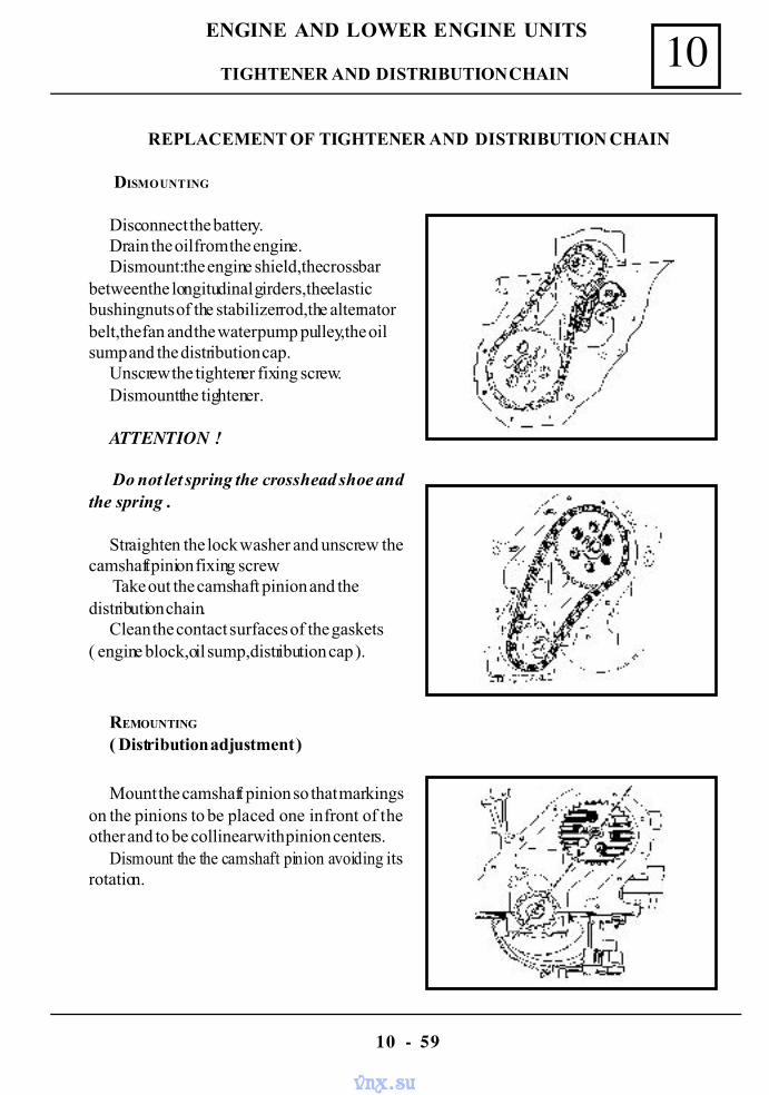
10
10 - 59
ENGINE AND LOWER ENGINE UNITS
REPLACEMENT OF TIGHTENER AND DISTRIBUTION CHAIN
DISMOUNTING
Disconnect the battery.Drain the oil from the engine.Dismount: the engine shield,the cross bar
between the longitudinal girders,the elasticbushing nuts of the stabilizer rod,the alternatorbelt,the fan and the water pump pulley,the oilsump and the distribution cap.
Unscrew the tightener fixing screw.Dismount the tightener.
ATTENTION !
Do not let spring the crosshead shoe andthe spring .
Straighten the lock washer and unscrew thecamshaft pinion fixing screw.
Take out the camshaft pinion and thedistribution chain.
Clean the contact surfaces of the gaskets( engine block,oil sump,distribution cap ).
REMOUNTING
( Distribution adjustment )
Mount the camshaft pinion so that markingson the pinions to be placed one in front of theother and to be collinear with pinion centers.
Dismount the the camshaft pinion avoiding itsrotation.
TIGHTENER AND DISTRIBUTION CHAIN
vnx.su
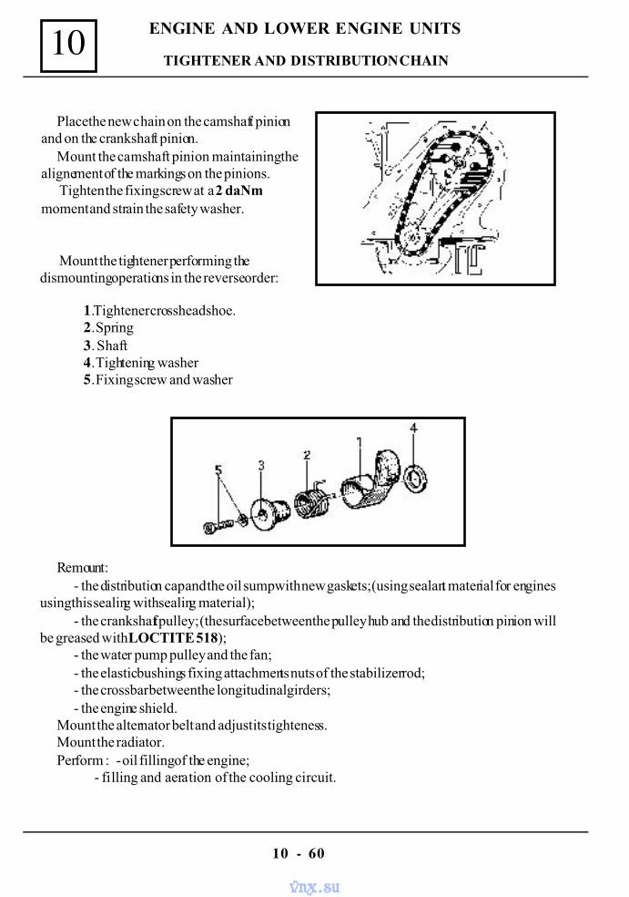
10
10 - 60
ENGINE AND LOWER ENGINE UNITS
Place the new chain on the camshaft pinionand on the crankshaft pinion.
Mount the camshaft pinion maintaining thealignement of the markings on the pinions.
Tighten the fixing screw at a 2 daNmmoment and strain the safety washer.
Mount the tightener performing thedismounting operations in the reverse order:
1.Tightener crosshead shoe.2. Spring3. Shaft4. Tightening washer5. Fixing screw and washer
Remount:- the distribution cap and the oil sump with new gaskets; (using sealant material for engines
using this sealing with sealing material);- the crankshaft pulley; (the surface between the pulley hub and the distribution pinion will
be greased with LOCTITE 518);- the water pump pulley and the fan;- the elastic bushings fixing attachments nuts of the stabilizer rod;- the crossbar between the longitudinal girders;- the engine shield.
Mount the alternator belt and adjust its tighteness.Mount the radiator.Perform : - oil filling of the engine;
- filling and aeration of the cooling circuit.
TIGHTENER AND DISTRIBUTION CHAIN
vnx.su
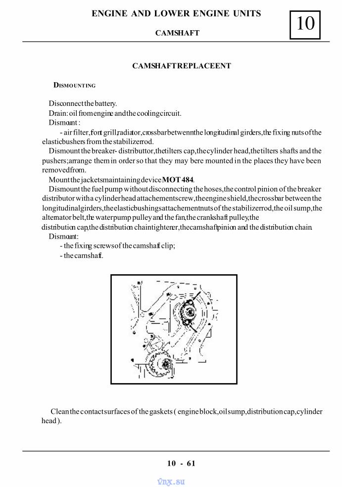
10
10 - 61
ENGINE AND LOWER ENGINE UNITS
CAMSHAFT REPLACEENT
DISMOUNTING
Disconnect the battery.Drain: oil from engine and the cooling circuit.Dismount :
- air filter,front grill,radiator,crossbar betwenn the longitudinal girders,the fixing nuts of theelastic bushers from the stabilizer rod.
Dismount the breaker- distributtor,the tilters cap,the cylinder head,the tilters shafts and thepushers;arrange them in order so that they may be re mounted in the places they have beenremoved from.
Mount the jackets maintaining device MOT 484.Dismount the fuel pump without disconnecting the hoses,the control pinion of the breaker
distributor with a cylinder head attachement screw,the engine shield,the crossbar between thelongitudinal girders,the elastic bushings attachement nuts of the stabilizer rod,the oil sump,thealternator belt,the water pump pulley and the fan,the crankshaft pulley,thedistribution cap,the distribution chain tightener,the camshaft pinion and the distribution chain.
Dismount:- the fixing screws of the camshaft clip;- the camshaft.
Clean the contact surfaces of the gaskets ( engine block,oil sump,distribution cap,cylinderhead ).
CAMSHAFT
vnx.su
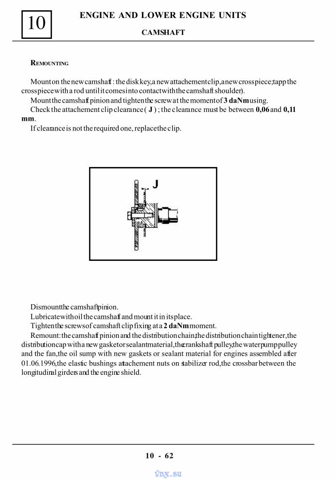
10
10 - 62
ENGINE AND LOWER ENGINE UNITS
REMOUNTING
Mount on the new camshaft : the disk key,a new attachement clip,a new cross piece;tapp thecross piece with a rod until it comes into contact with the camshaft shoulder).
Mount the camshaft pinion and tighten the screw at the moment of 3 daNm using.Check the attachement clip clearance ( J ) ; the clearance must be between 0,06 and 0,11
mm.If clearance is not the required one, replace the clip.
Dismount the camshaft pinion.Lubricate with oil the camshaft and mount it in its place.Tighten the screws of camshaft clip fixing at a 2 daNm moment.Remount: the camshaft pinion and the distribution chain,the distribution chain tightener, the
distribution cap with a new gasket or sealant material,the crankshaft pulley,the water pump pulleyand the fan,the oil sump with new gaskets or sealant material for engines assembled after01.06.1996,the elastic bushings attachement nuts on stabilizer rod,the crossbar between thelongitudinal girders and the engine shield.
CAMSHAFT
vnx.su
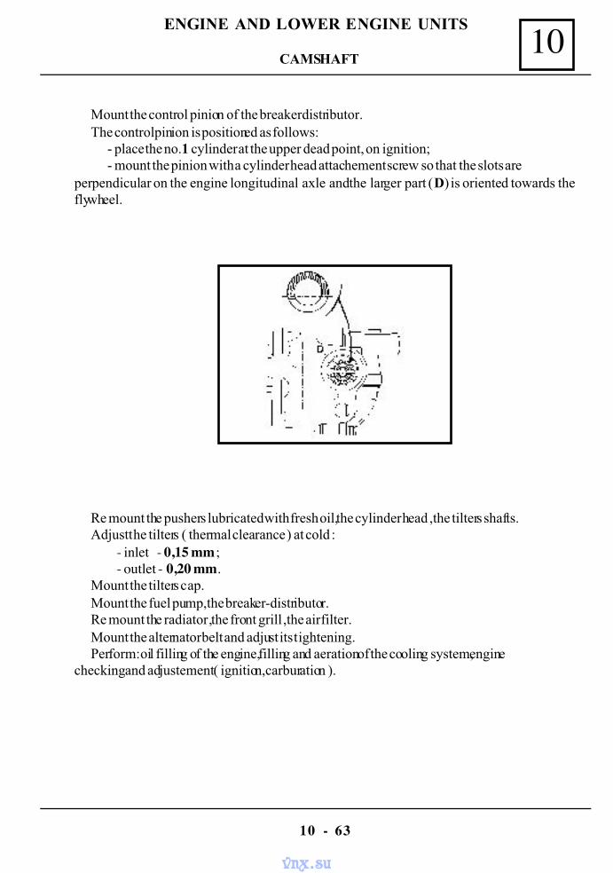
10
10 - 63
ENGINE AND LOWER ENGINE UNITS
Mount the control pinion of the breaker distributor.The control pinion is positioned as follows:
- place the no.1 cylinder at the upper dead point, on ignition;- mount the pinion with a cylinder head attachement screw so that the slots are
perpendicular on the engine longitudinal axle and the larger part (D) is oriented towards theflywheel.
Re mount the pushers lubricated with fresh oil,the cylinder head ,the tilters shafts.Adjust the tilters ( thermal clearance ) at cold :
- inlet - 0,15 mm ;- outlet - 0,20 mm.
Mount the tilters cap.Mount the fuel pump,the breaker-distributor.Re mount the radiator ,the front grill ,the air filter.Mount the alternator belt and adjust its tightening.Perform: oil filling of the engine,filling and aeration of the cooling system,engine
checking and adjustement ( ignition,carburation ).
CAMSHAFT
vnx.su
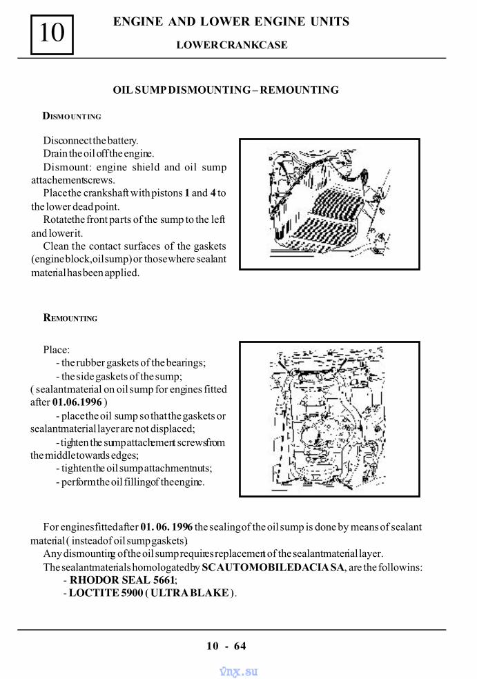
10
10 - 64
ENGINE AND LOWER ENGINE UNITS
REMOUNTING
Disconnect the battery.Drain the oil off the engine.Dismount: engine shield and oil sump
attachement screws.Place the crankshaft with pistons 1 and 4 to
the lower dead point.Rotatethe front parts of the sump to the left
and lower it.Clean the contact surfaces of the gaskets
(engine block,oil sump) or those where sealantmaterial has been applied.
OIL SUMP DISMOUNTING – REMOUNTING
DISMOUNTING
Place :- the rubber gaskets of the bearings;- the side gaskets of the sump;
( sealant material on oil sump for engines fittedafter 01.06.1996 )
- place the oil sump so that the gaskets orsealant material layer are not displaced;
- tighten the sump attachement screws fromthe middle towards edges;
- tighten the oil sump attachment nuts;- perform the oil filling of the engine.
For engines fitted after 01. 06. 1996 the sealing of the oil sump is done by means of sealantmaterial ( instead of oil sump gaskets).
Any dismounting of the oil sump requires replacement of the sealant material layer.The sealant materials homologated by SC AUTOMOBILE DACIA SA, are the followins:
- RHODOR SEAL 5661;- LOCTITE 5900 ( ULTRA BLAKE ).
LOWER CRANKCASE
vnx.su
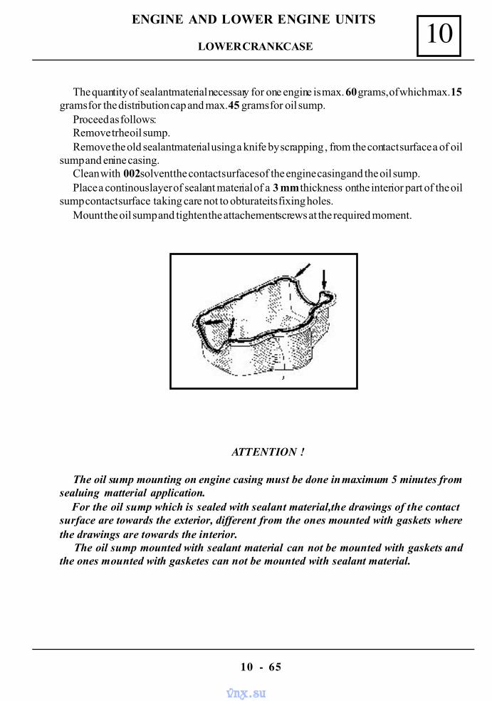
10
10 - 65
ENGINE AND LOWER ENGINE UNITS
The quantity of sealant material necessary for one engine is max. 60 grams, of which max. 15grams for the distribution cap and max. 45 grams for oil sump.
Proceed as follows:Remove trhe oil sump.Remove the old sealant material using a knife by scrapping , from the contact surface a of oil
sump and enine casing.Clean with 002 solvent the contact surfaces of the engine casing and the oil sump.Place a continous layer of sealant material of a 3 mm thickness on the interior part of the oil
sump contact surface taking care not to obturate its fixing holes.Mount the oil sump and tighten the attachement screws at the required moment.
ATTENTION !
The oil sump mounting on engine casing must be done in maximum 5 minutes fromsealuing matterial application. For the oil sump which is sealed with sealant material,the drawings of the contactsurface are towards the exterior, different from the ones mounted with gaskets wherethe drawings are towards the interior. The oil sump mounted with sealant material can not be mounted with gaskets andthe ones mounted with gasketes can not be mounted with sealant material.
LOWER CRANKCASE
vnx.su
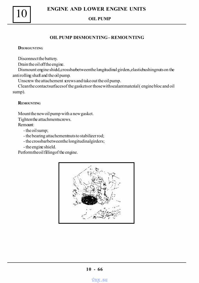
10
10 - 66
ENGINE AND LOWER ENGINE UNITS
OIL PUMP DISMOUNTING – REMOUNTING
DISMOUNTING
Disconnect the battery.Drain the oil off the engine.Dismount :engine shield,crossbar between the longitudinal girders,elastic bushing nuts on the
anti rolling shaft and the oil pump.Unscrew the attachement screws and take out the oil pump.Clean the contact surfaces of the gaskets or those with sealant material ( engine bloc and oil
sump).
REMOUNTING
Mount the new oil pump with a new gasket.Τighten the attachment screws.Remount:
- the oil sump;- the bearing attachement nuts to stabilizer rod;- the crossbar between the longitudinal girders;- the engine shield.
Perform the oil filling of the engine.
OIL PUMP
vnx.su
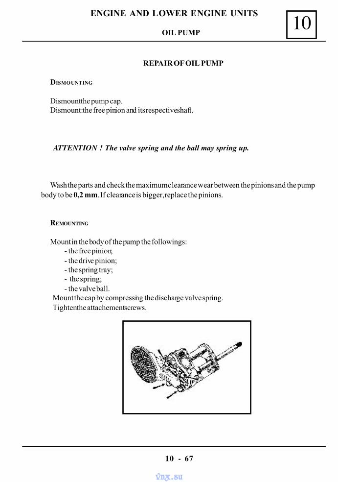
10
10 - 67
ENGINE AND LOWER ENGINE UNITS
REPAIR OF OIL PUMP
DISMOUNTING
Dismount the pump cap.Dismount: the free pinion and its respective shaft.
ATTENTION ! The valve spring and the ball may spring up.
Wash the parts and check the maximum clearance wear between the pinions and the pumpbody to be 0,2 mm. If clearance is bigger, replace the pinions.
REMOUNTING
Mount in the body of the pump the followings:- the free pinion;- the drive pinion;- the spring tray;- the spring;- the valve ball.
Mount the cap by compressing the discharge valve spring.Tighten the attachement screws.
OIL PUMP
vnx.su
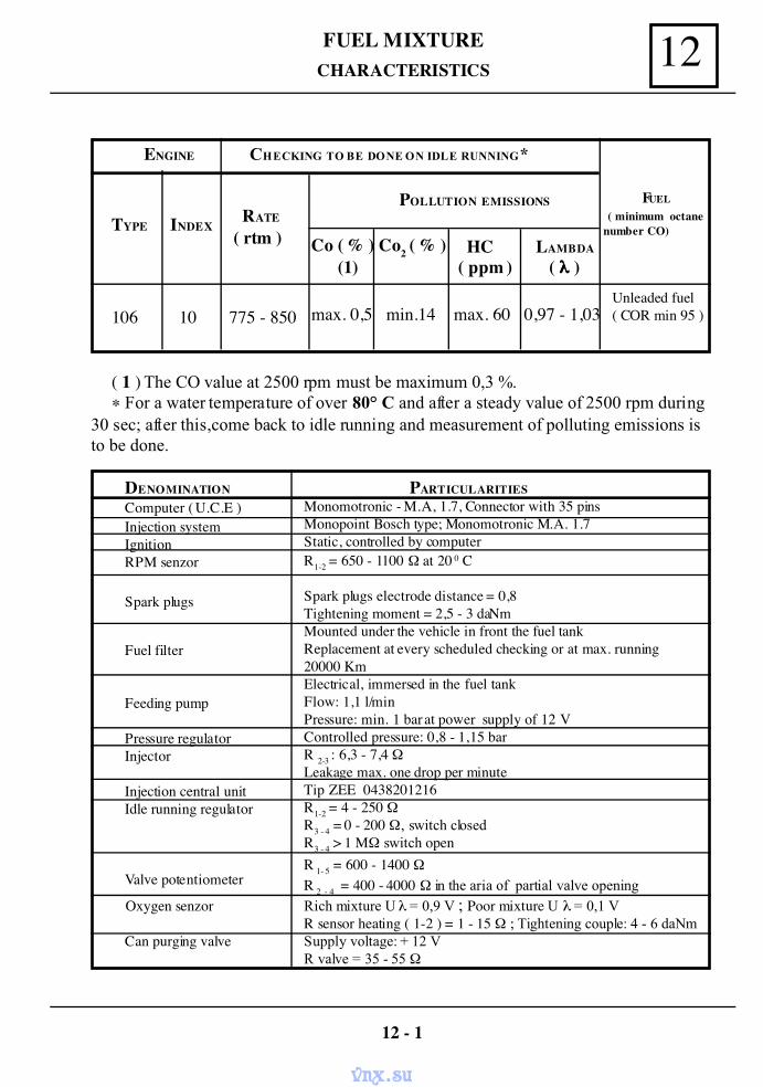
FUEL MIXTURE 12CHARACTERISTICS
12 - 1
ENGINE CHECKING TO BE DONE ON IDLE RUNNING*
TYPE INDEX RATE
( rtm )
POLLUTION EMISSIONS FUEL
( minimum octanenumber CO)
Co ( % ) (1)
Co2 ( % ) HC( ppm )
LAMBDA
( λλλλ )
106 10 775 - 850 max. 0,5 min.14 0,97 - 1,03max. 60Unleaded fuel( COR min 95 )
( 1 ) The CO value at 2500 rpm must be maximum 0,3 %.∗ For a water temperature of over 80° C and after a steady value of 2500 rpm during
30 sec; after this,come back to idle running and measurement of polluting emissions isto be done.
DENOMINATIONComputer ( U.C.E )Injection systemIgnitionRPM senzor
Spark plugs
Fuel filter
Feeding pump
Pressure regulatorInjector
Injection central unitIdle running regulator
Valve potentiometer
Oxygen senzor
Can purging valve
PARTICULARITIESMonomotronic - M.A, 1.7, Connector with 35 pinsMonopoint Bosch type; Monomotronic M.A. 1.7Static, controlled by computerR1-2 = 650 - 1100 Ω at 20 0 C
Spark plugs electrode distance = 0,8Tightening moment = 2,5 - 3 daNmMounted under the vehicle in front the fuel tankReplacement at every scheduled checking or at max. running20000 KmElectrical, immersed in the fuel tankFlow: 1,1 l/minPressure: min. 1 bar at power supply of 12 VControlled pressure: 0,8 - 1,15 barR 2-3 : 6,3 - 7,4 ΩLeakage max. one drop per minuteTip ZEE 0438201216R1-2 = 4 - 250 ΩR3 - 4 = 0 - 200 Ω, switch closedR3 - 4 > 1 MΩ switch openR 1- 5 = 600 - 1400 ΩR 2 - 4 = 400 - 4000 Ω in the aria of partial valve openingRich mixture U λ = 0,9 V ; Poor mixture U λ = 0,1 VR sensor heating ( 1-2 ) = 1 - 15 Ω ; Tightening couple: 4 - 6 daNmSupply voltage: + 12 VR valve = 35 - 55 Ω
vnx.su
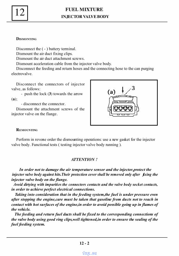
12 FUEL MIXTURE
DISMONTING
Disconnect the ( - ) battery terminal.Dismount the air duct fixing clips.Dismount the air duct attachment screws.Dismount acceleration cable from the injector valve body.Disconnect the feeding and return hoses and the connecting hose to the can purging
electrovalve.
Disconnect the connectors of injectorvalve, as follows:
- push the lock (3) towards the arrow(a);
- disconnect the connector.Dismount the attachment screws of the
injector valve on the flange.
REMOUNTING
Perform in reverse order the dismounting operations: use a new gasket for the injectorvalve body. Functional tests ( testing injector valve body running ).
ATTENTION !
In order not to damage the air temperature sensor and the injector,protect the injector valve body against hits.Their protection cover shall be removed only after fixing theinjector valve body on the flange. Avoid dirtying with impurities the connectors contacts and the valve body socket contacts,in order to achieve perfect electrical connections. Taking into consideration that in the feeding system,the fuel is under pressure evenafter stopping the engine,care must be taken that gasoline from ducts not to reach incontact with hot surfaces of the engine,in order to avoid possible going up in flames ofthe vehicle. The feeding and return fuel ducts shall be fixed to the corresponding connections ofthe valve body using good ring clips,well tightened,in order to ensure the sealing of thefuel feeding system.
INJECTOR VALVE BODY
12 - 2
vnx.su
FUEL MIXTURE 12
12 - 3
DISMOUNTING
Disconnect the battery.Dismount the injector valve body ( see chapt.” Replacement of the injector valve body” ).Dismount the starter protection shield.Dismount the 3 attachment nuts of the inlet-exhaust manifold.Extract the inlet-exhaust manifold.
REMOUNTING
Perform in reverse order the dismounting operations.Clean the assembly surface.Replace the gasket of the inlet-exhaust manifold.Replace the gasket of the tube.Tighten the nuts at the required moment.
INLET EXHAUST MANIFOLD
TIGHTENING TORQUES ( daNm )
Inlet exhaust manifold nuts ....................................................................1,8Attachment nuts of the tube on the inlet exhaust manifold ....................1,8
vnx.su
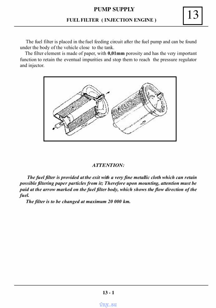
13PUMP SUPPLY
The fuel filter is placed in the fuel feeding circuit after the fuel pump and can be foundunder the body of the vehicle close to the tank. The filter element is made of paper, with 0,01mm porosity and has the very importantfunction to retain the eventual impurities and stop them to reach the pressure regulatorand injector.
ATTENTION:
The fuel filter is provided at the exit with a very fine metallic cloth which can retainpossible filtering paper particles from it; Therefore upon mounting, attention must bepaid at the arrow marked on the fuel filter body, which shows the flow direction of thefuel.
The filter is to be changed at maximum 20 000 km.
FUEL FILTER ( INJECTION ENGINE )
13 - 1
vnx.su
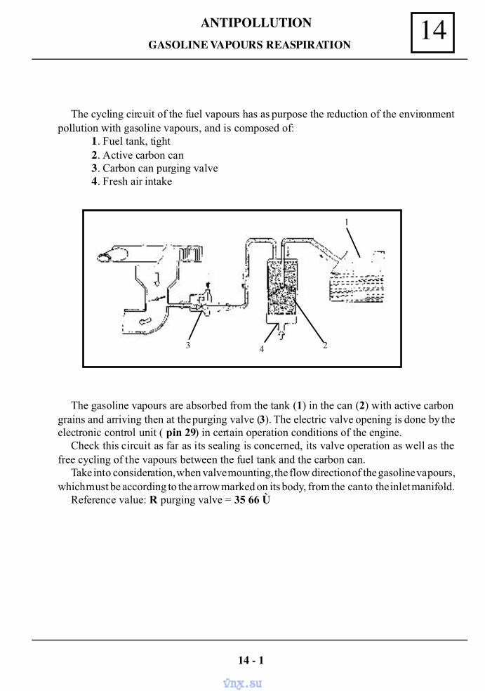
14ANTIPOLLUTION
The cycling circuit of the fuel vapours has as purpose the reduction of the environmentpollution with gasoline vapours, and is composed of:
1. Fuel tank, tight2. Active carbon can3. Carbon can purging valve4. Fresh air intake
The gasoline vapours are absorbed from the tank (1) in the can (2) with active carbongrains and arriving then at the purging valve (3). The electric valve opening is done by theelectronic control unit ( pin 29) in certain operation conditions of the engine.
Check this circuit as far as its sealing is concerned, its valve operation as well as thefree cycling of the vapours between the fuel tank and the carbon can.
Take into consideration, when valve mounting, the flow direction of the gasoline vapours,which must be according to the arrow marked on its body, from the can to the inlet manifold.
Reference value: R purging valve = 35 66 Ù
GASOLINE VAPOURS REASPIRATION
14 - 1
1
3 4 2
vnx.su
ANTIPOLLUTION14
DISMOUNTING
Remove the can from its fixing support by pulling up.Dismount the fixing ring clips of the hoses to the can and disconnect the hoses.
REMOUNTING
Perform in reverse order the dismounting operations.
ATTENTION:
Take into consideration when mounting, about the hoses connection direction (thegasoline vapour cycling is from the duct to the carbon can purge valve). Use good ringclips,which must be well tightened.
14 - 2
CARBON CAN
vnx.su
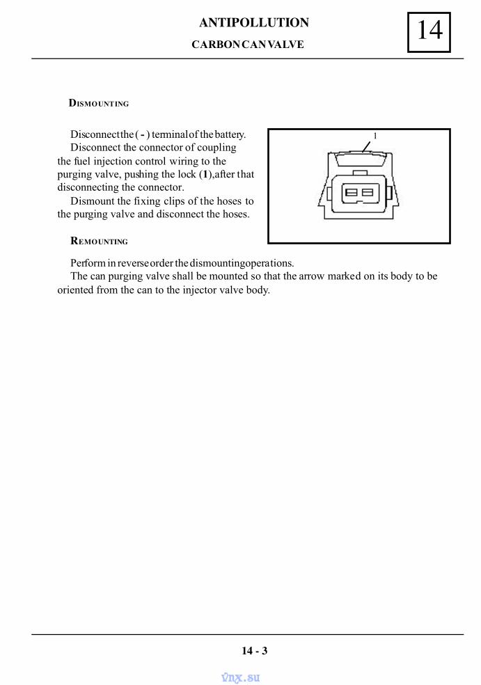
14ANTIPOLLUTION
DISMOUNTING
Disconnect the ( - ) terminal of the battery.Disconnect the connector of coupling
the fuel injection control wiring to thepurging valve, pushing the lock (1),after thatdisconnecting the connector.
Dismount the fixing clips of the hoses tothe purging valve and disconnect the hoses.
REMOUNTING
14 - 3
Perform in reverse order the dismounting operations.The can purging valve shall be mounted so that the arrow marked on its body to be
oriented from the can to the injector valve body.
1
CARBON CAN VALVE
vnx.su
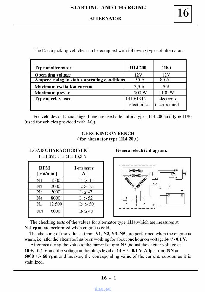
16STARTING AND CHARGING
16 - 1
The Dacia pick-up vehicles can be equipped with following types of alternators:
For vehicles of Dacia range, there are used alternators type 1114.200 and type 1180(used for vehicles provided with AC).
CHECKING ON BENCH( for alternator type 1114.200 )
LOAD CHARACTERISTIC General electric diagram:I = f (n); U = ct = 13,5 V
RPM INTENSITY
[ rot/min ] [ A ]N1 1300 I1 > 11N2 3000 I2 > 43N3 5000 I3 > 47N4 8000 I4 > 52N5 12 500 I5 > 50NN 6000 IN > 40
The checking tests of the values for alternator type 1114,which are measures atN 4 rpm, are performed when engine is cold. The checking of the values at rpm N1, N2, N3, N5, are performed when the engine iswarm, i.e. after the alternator has been working for about one hour on voltage14 +/ - 0,1 V. After measuring the value of the current at rpm N5 ,adjust the exciter voltage at10 +/- 0,1 V and the voltage at the plugs level at 14 + / - 0,1 V. Adjust rpm NN at6000 +/- 60 rpm and measure the corresponding value of the current, as soon as it isstabilized.
Type of alternator 1114.200 1180Operating voltage 12V 12VAmpere rating in stable operating conditions 50 A 80 AMaximum excitation current 3,9 A 5 AMaximum power 700 W 1100 WType of relay used 1410;1342 electronic
electronic incorporated
ALTERNATOR
vnx.su
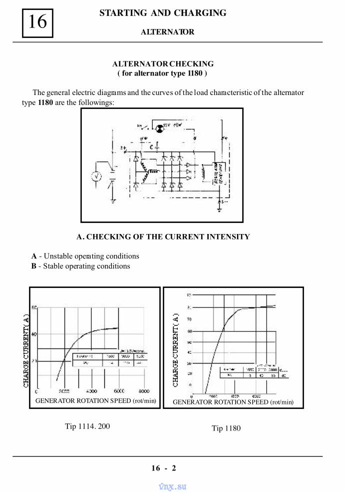
STARTING AND CHARGING16
16 - 2
ALTERNATOR CHECKING( for alternator type 1180 )
The general electric diagrams and the curves of the load characteristic of the alternatortype 1180 are the followings:
A. CHECKING OF THE CURRENT INTENSITY
A - Unstable operating conditionsB - Stable operating conditions
Tip 1114. 200 Tip 1180
GENERATOR ROTATION SPEED (rot/min) GENERATOR ROTATION SPEED (rot/min)
ALTERNATOR
vnx.su
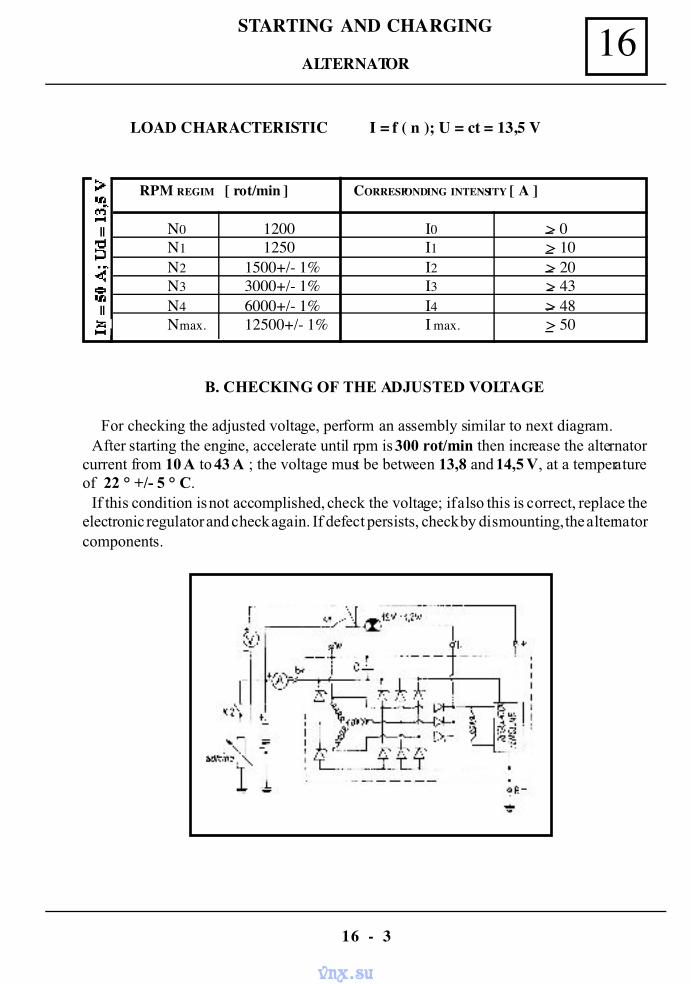
16STARTING AND CHARGING
16 - 3
LOAD CHARACTERISTIC I = f ( n ); U = ct = 13,5 V
RPM REGIM [ rot/min ] CORRESPONDING INTENSITY [ A ]
N0N1N2N3N4Nmax.
12001250
1500+/- 1%3000+/- 1%6000+/- 1%12500+/- 1%
I0I1I2I3I4I max.
> 0> 10> 20> 43> 48> 50
B. CHECKING OF THE ADJUSTED VOLTAGE
For checking the adjusted voltage, perform an assembly similar to next diagram. After starting the engine, accelerate until rpm is 300 rot/min then increase the alternatorcurrent from 10 A to 43 A ; the voltage must be between 13,8 and 14,5 V, at a temperatureof 22 ° +/- 5 ° C. If this condition is not accomplished, check the voltage; if also this is correct, replace theelectronic regulator and check again. If defect persists, check by dismounting, the alternatorcomponents.
ALTERNATOR
vnx.su
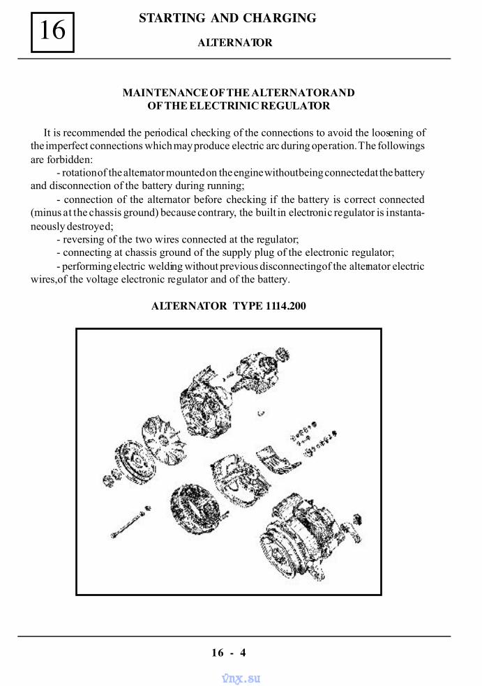
STARTING AND CHARGING16
16 - 4
MAINTENANCE OF THE ALTERNATOR ANDOF THE ELECTRINIC REGULATOR
It is recommended the periodical checking of the connections to avoid the loosening ofthe imperfect connections which may produce electric arc during operation. The followingsare forbidden:
- rotation of the alternator mounted on the engine without being connected at the batteryand disconnection of the battery during running;
- connection of the alternator before checking if the battery is correct connected(minus at the chassis ground) because contrary, the built in electronic regulator is instanta-neously destroyed;
- reversing of the two wires connected at the regulator;- connecting at chassis ground of the supply plug of the electronic regulator;- performing electric welding without previous disconnecting of the alternator electric
wires,of the voltage electronic regulator and of the battery.
ALTERNATOR TYPE 1114.200
ALTERNATOR
vnx.su
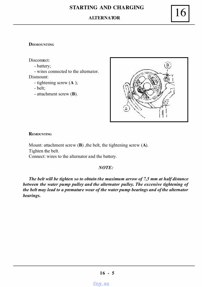
16STARTING AND CHARGING
16 - 5
DISMOUNTING
Disconnect:- battery;- wires connected to the alternator.
Dismount:- tightening screw (A );- belt;- attachment screw (B).
REMOUNTING
Mount: attachment screw (B) ,the belt, the tightening screw (A).Tighten the belt.Connect: wires to the alternator and the battery.
NOTE:
The belt will be tighten so to obtain the maximum arrow of 7,5 mm at half distancebetween the water pump pulley and the alternator pulley. The excessive tightening ofthe belt may lead to a premature wear of the water pump bearings and of the alternatorbearings.
ALTERNATOR
vnx.su
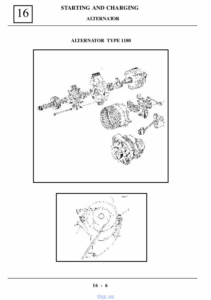
STARTING AND CHARGING16
16 - 6
ALTERNATOR TYPE 1180
ALTERNATOR
vnx.su
16STARTING AND CHARGING
16 - 7
DISMOUNTING
Disconnect: battery, wires connected to the alternator and the connections box from thevoltage electronic regulator.
Dismount: tightening screw (2) by acting on the locking nut, the tightened (3) byunscrewing, the belt; pushing down the alternator,take out the alternator belt from thepulley and the alternator attachment screw (1).
REMOUNTING
Mount: attachment screw (1), the V-belt, the tightening screw (2) and the tightener (3).
NOTE:
For dismounting/re mounting the alternator type 1180,perform same operations asfor alternator type 1114.200.For tightening and checking of the belt tightening seechapt.07.
ATTENTION !
Do not tension exaggeratedly the belt ! Danger of premature wear both of alternatorbearings and of water pump bearings.
Connect: supply wires and chassis ground wires to the alternator, the connections boxat the electronic voltage regulator and the battery.
ALTERNATOR
vnx.su
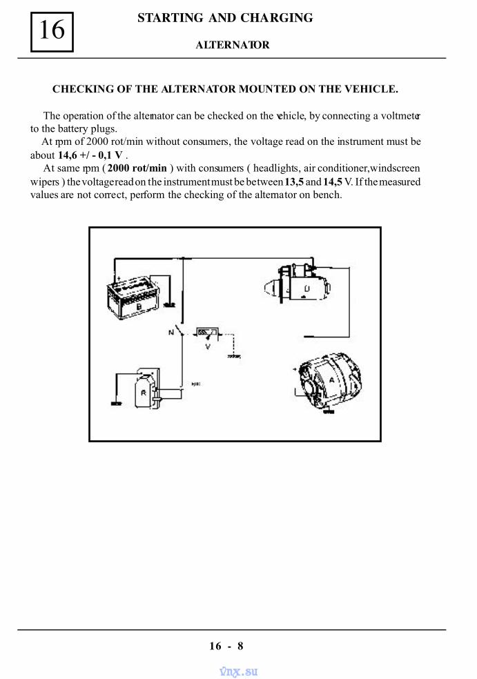
STARTING AND CHARGING16
16 - 8
CHECKING OF THE ALTERNATOR MOUNTED ON THE VEHICLE.
The operation of the alternator can be checked on the vehicle, by connecting a voltmeterto the battery plugs. At rpm of 2000 rot/min without consumers, the voltage read on the instrument must beabout 14,6 +/ - 0,1 V .
At same rpm ( 2000 rot/min ) with consumers ( headlights, air conditioner,windscreenwipers ) the voltage read on the instrument must be between 13,5 and 14,5 V. If the measuredvalues are not correct, perform the checking of the alternator on bench.
ALTERNATOR
vnx.su
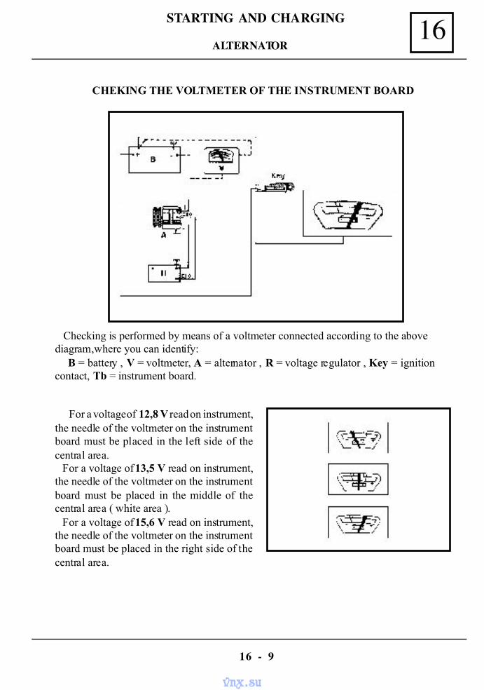
16STARTING AND CHARGING
16 - 9
Checking is performed by means of a voltmeter connected according to the abovediagram,where you can identify:
B = battery , V = voltmeter, A = alternator , R = voltage regulator , Key = ignitioncontact, Tb = instrument board.
For a voltage of 12,8 V read on instrument,the needle of the voltmeter on the instrumentboard must be placed in the left side of thecentral area. For a voltage of 13,5 V read on instrument,the needle of the voltmeter on the instrumentboard must be placed in the middle of thecentral area ( white area ). For a voltage of 15,6 V read on instrument,the needle of the voltmeter on the instrumentboard must be placed in the right side of thecentral area.
CHEKING THE VOLTMETER OF THE INSTRUMENT BOARD
ALTERNATOR
vnx.su
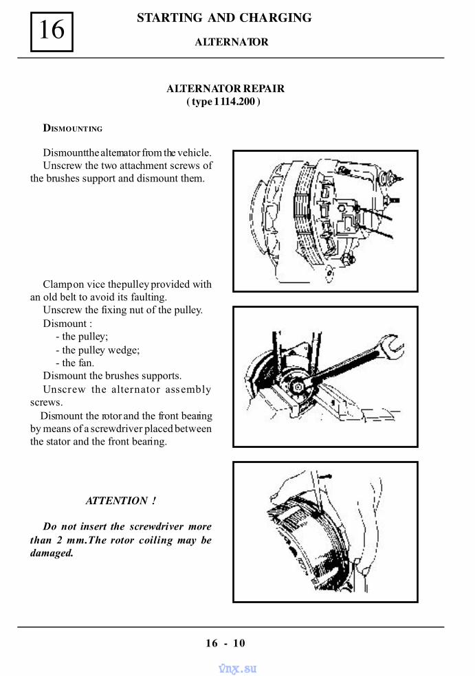
STARTING AND CHARGING16
16 - 10
ALTERNATOR REPAIR( type 1114.200 )
DISMOUNTING
Dismount the alternator from the vehicle.Unscrew the two attachment screws of
the brushes support and dismount them.
Clamp on vice the pulley provided withan old belt to avoid its faulting.
Unscrew the fixing nut of the pulley.Dismount :
- the pulley;- the pulley wedge;- the fan.
Dismount the brushes supports.Unscrew the alternator assembly
screws. Dismount the rotor and the front bearingby means of a screwdriver placed betweenthe stator and the front bearing.
ATTENTION !
Do not insert the screwdriver morethan 2 mm.The rotor coiling may bedamaged.
ALTERNATOR
vnx.su
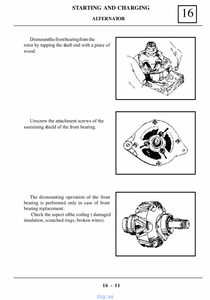
16STARTING AND CHARGING
16 - 11
Dismount the front bearing from therotor by tapping the shaft end with a piece ofwood.
Unscrew the attachment screws of thesustaining shield of the front bearing.
The dismounting operation of the frontbearing is performed only in case of frontbearing replacement.
Check the aspect of the coiling ( damagedinsulation, scratched rings, broken wires).
ALTERNATOR
vnx.su
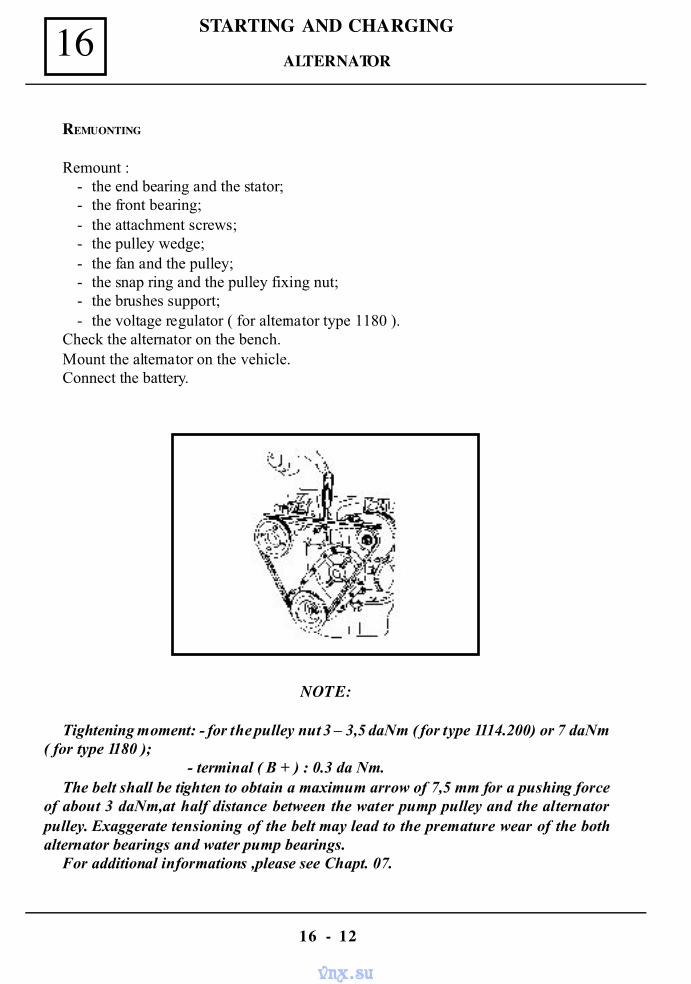
STARTING AND CHARGING16
16 - 12
REMUONTING
Remount :- the end bearing and the stator;- the front bearing;- the attachment screws;- the pulley wedge;- the fan and the pulley;- the snap ring and the pulley fixing nut;- the brushes support;- the voltage regulator ( for alternator type 1180 ).
Check the alternator on the bench.Mount the alternator on the vehicle.Connect the battery.
NOTE:
Tightening moment: - for the pulley nut 3 – 3,5 daNm ( for type 1114.200) or 7 daNm( for type 1180 );
- terminal ( B + ) : 0.3 da Nm.The belt shall be tighten to obtain a maximum arrow of 7,5 mm for a pushing force
of about 3 daNm,at half distance between the water pump pulley and the alternatorpulley. Exaggerate tensioning of the belt may lead to the premature wear of the bothalternator bearings and water pump bearings.
For additional informations ,please see Chapt. 07.
ALTERNATOR
vnx.su
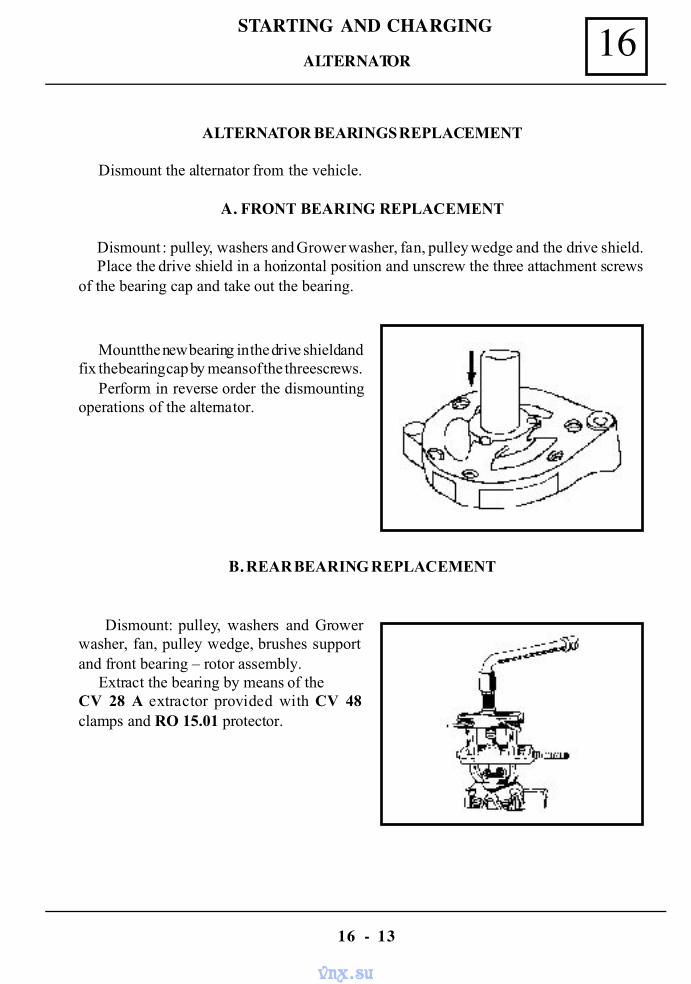
16STARTING AND CHARGING
16 - 13
ALTERNATOR BEARINGS REPLACEMENT
Dismount the alternator from the vehicle.
A. FRONT BEARING REPLACEMENT
Dismount : pulley, washers and Grower washer, fan, pulley wedge and the drive shield.Place the drive shield in a horizontal position and unscrew the three attachment screws
of the bearing cap and take out the bearing.
Mount the new bearing in the drive shield andfix the bearing cap by means of the three screws.
Perform in reverse order the dismountingoperations of the alternator.
B. REAR BEARING REPLACEMENT
Dismount: pulley, washers and Growerwasher, fan, pulley wedge, brushes supportand front bearing – rotor assembly.
Extract the bearing by means of theCV 28 A extractor provided with CV 48clamps and RO 15.01 protector.
ALTERNATOR
vnx.su
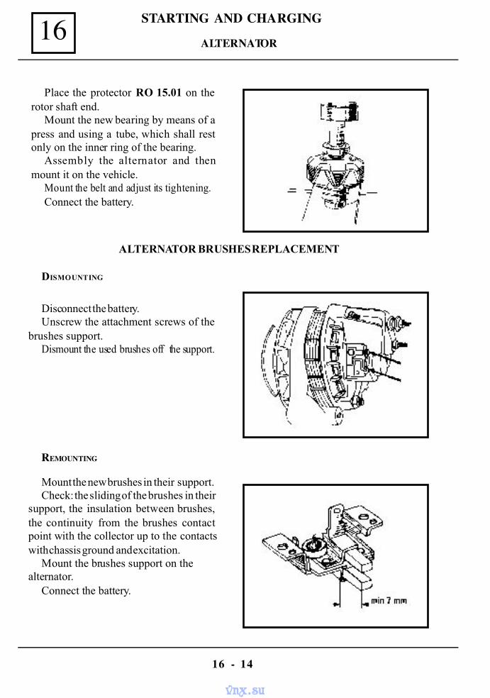
STARTING AND CHARGING16
16 - 14
Place the protector RO 15.01 on therotor shaft end.
Mount the new bearing by means of apress and using a tube, which shall restonly on the inner ring of the bearing.
Assembly the alternator and thenmount it on the vehicle.
Mount the belt and adjust its tightening.Connect the battery.
ALTERNATOR BRUSHES REPLACEMENT
DISMOUNTING
Disconnect the battery.Unscrew the attachment screws of the
brushes support.Dismount the used brushes off the support.
REMOUNTING
Mount the new brushes in their support.Check: the sliding of the brushes in their
support, the insulation between brushes,the continuity from the brushes contactpoint with the collector up to the contactswith chassis ground and excitation.
Mount the brushes support on thealternator.
Connect the battery.
ALTERNATOR
vnx.su
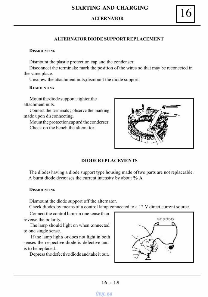
16STARTING AND CHARGING
16 - 15
ALTERNATOR DIODE SUPPORT REPLACEMENT
DISMOUNTING
Dismount the plastic protection cap and the condenser.Disconnect the terminals: mark the position of the wires so that may be reconected in
the same place.Unscrew the attachment nuts;dismount the diode support.
REMOUNTING
Mount the diode support ; tighten theattachment nuts.
Connect the terminals ; observe the markingmade upon disconnecting.
Mount the protection cap and the condenser.Check on the bench the alternator.
DIODE REPLACEMENTS
The diodes having a diode support type housing made of two parts are not replaceable. A burnt diode decreases the current intensity by about % A.
DISMOUNTING
Dismount the diode support off the alternator.Check diodes by means of a control lamp connected to a 12 V direct current source.
Connect the control lamp in one sense thanreverse the polarity.
The lamp should light on when connectedto one single sense.
If the lamp lights or does not light in bothsenses the respective diode is defective andis to be replaced.
Depress the defective diode and take it out.
ALTERNATOR
vnx.su
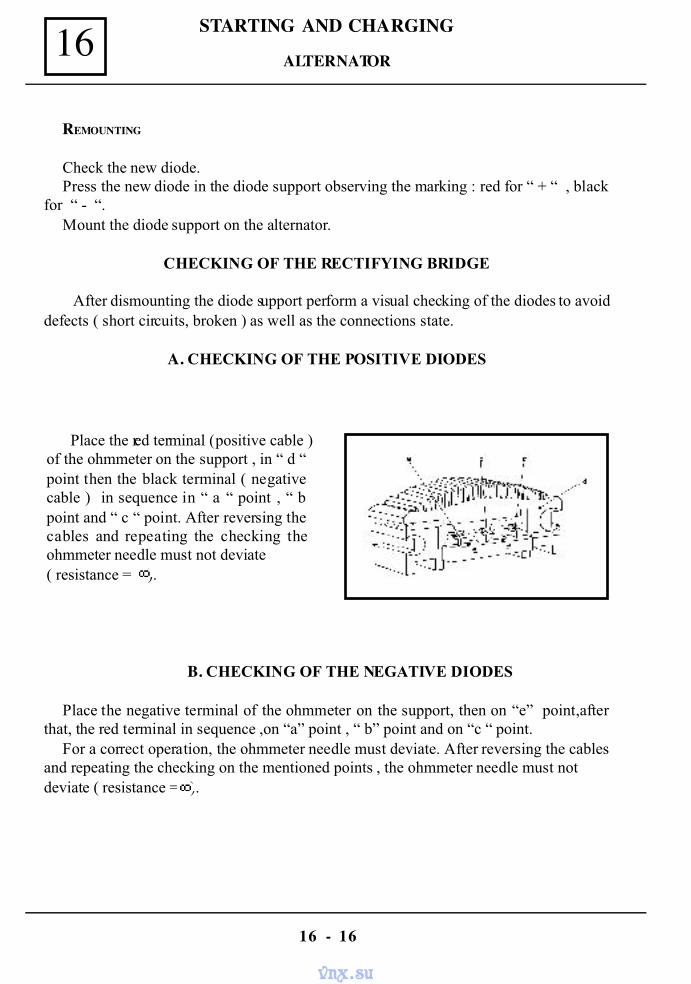
STARTING AND CHARGING16
16 - 16
REMOUNTING
Check the new diode.Press the new diode in the diode support observing the marking : red for “ + “ , black
for “ - “.Mount the diode support on the alternator.
CHECKING OF THE RECTIFYING BRIDGE
After dismounting the diode support perform a visual checking of the diodes to avoiddefects ( short circuits, broken ) as well as the connections state.
A. CHECKING OF THE POSITIVE DIODES
Place the red terminal ( positive cable )of the ohmmeter on the support , in “ d “point then the black terminal ( negativecable ) in sequence in “ a “ point , “ bpoint and “ c “ point. After reversing thecables and repeating the checking theohmmeter needle must not deviate( resistance = ).
B. CHECKING OF THE NEGATIVE DIODES
Place the negative terminal of the ohmmeter on the support, then on “e” point,afterthat, the red terminal in sequence ,on “a” point , “ b” point and on “c “ point.
For a correct operation, the ohmmeter needle must deviate. After reversing the cablesand repeating the checking on the mentioned points , the ohmmeter needle must notdeviate ( resistance = ).
ALTERNATOR
vnx.su
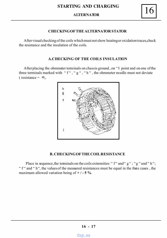
16STARTING AND CHARGING
16 - 17
CHECKING OF THE ALTERNATOR STATOR
After visual checking of the coils which must not show heating or oxidation traces,checkthe resistance and the insulation of the coils.
A.CHECKING OF THE COILS INSULATION
After placing the ohmmeter terminals on chassis ground , on “ I point and on one of thethree terminals marked with “ f “ , “ g “ , “ h “ , the ohmmeter needle must not deviate( resistance = ).
B. CHECKING OF THE COIL RESISTANCE
Place in sequence ,the terminals on the coils extremities: “ f “ and “ g “ ; “ g “ and “ h “;“ f “ and “ h “, the values of the measured resistances must be equal in the three cases , themaximum allowed variation being of + / - 5 %.
ALTERNATOR
vnx.su
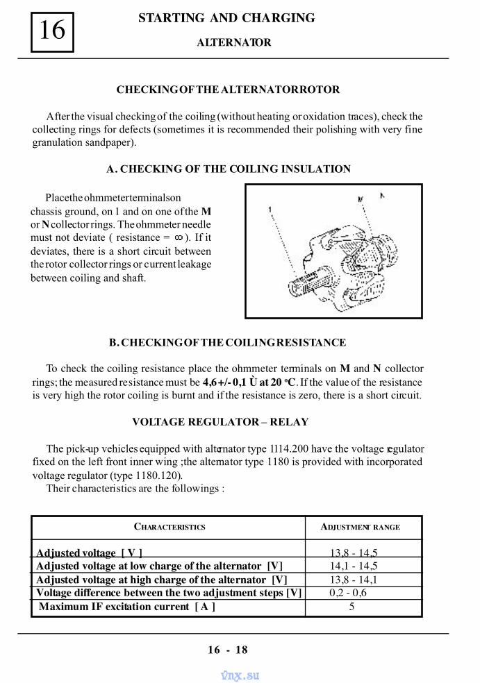
STARTING AND CHARGING16
16 - 18
CHECKING OF THE ALTERNATOR ROTOR
After the visual checking of the coiling (without heating or oxidation traces), check thecollecting rings for defects (sometimes it is recommended their polishing with very finegranulation sandpaper).
A. CHECKING OF THE COILING INSULATION
Place the ohmmeter terminals onchassis ground, on 1 and on one of the Mor N collector rings. The ohmmeter needlemust not deviate ( resistance = ). If itdeviates, there is a short circuit betweenthe rotor collector rings or current leakagebetween coiling and shaft.
B. CHECKING OF THE COILING RESISTANCE
To check the coiling resistance place the ohmmeter terminals on M and N collectorrings; the measured resistance must be 4,6 +/- 0,1 Ù at 20 oC. If the value of the resistanceis very high the rotor coiling is burnt and if the resistance is zero, there is a short circuit.
VOLTAGE REGULATOR – RELAY
The pick-up vehicles equipped with alternator type 1114.200 have the voltage regulatorfixed on the left front inner wing ;the alternator type 1180 is provided with incorporatedvoltage regulator (type 1180.120).
Their characteristics are the followings :
CHARACTERISTICS ADJUSTMENT RANGE
Adjusted voltage [ V ] 13,8 - 14,5 Adjusted voltage at low charge of the alternator [V] 14,1 - 14,5 Adjusted voltage at high charge of the alternator [V] 13,8 - 14,1 Voltage difference between the two adjustment steps [V] 0,2 - 0,6 Maximum IF excitation current [ A ] 5
ALTERNATOR
vnx.su
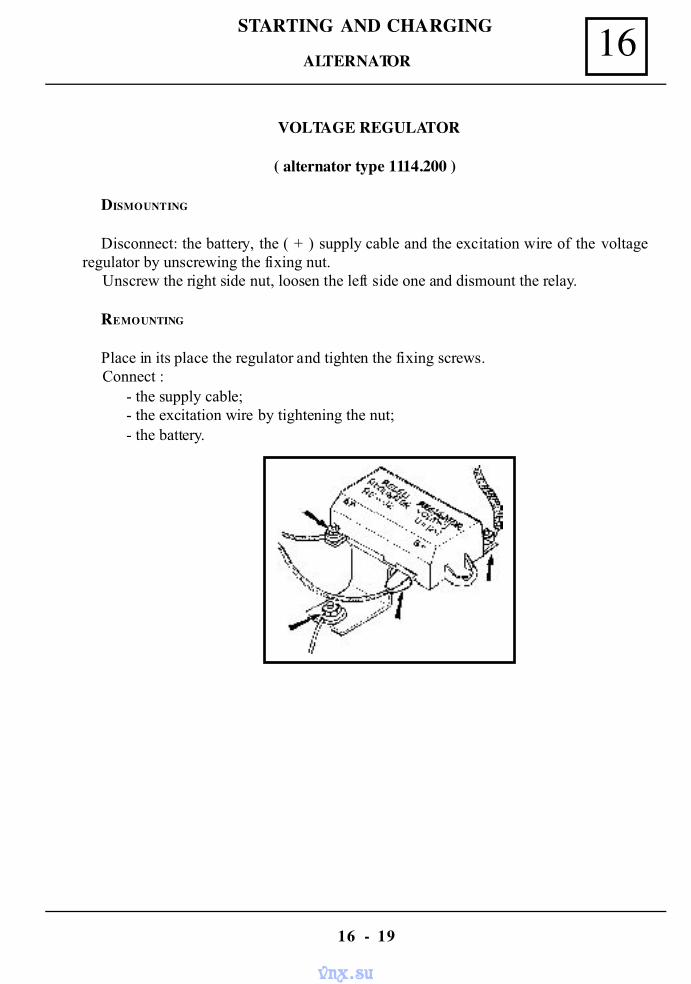
16STARTING AND CHARGING
16 - 19
VOLTAGE REGULATOR
( alternator type 1114.200 )
DISMOUNTING
Disconnect: the battery, the ( + ) supply cable and the excitation wire of the voltageregulator by unscrewing the fixing nut.
Unscrew the right side nut, loosen the left side one and dismount the relay.
REMOUNTING
Place in its place the regulator and tighten the fixing screws.Connect :
- the supply cable;- the excitation wire by tightening the nut;- the battery.
ALTERNATOR
vnx.su
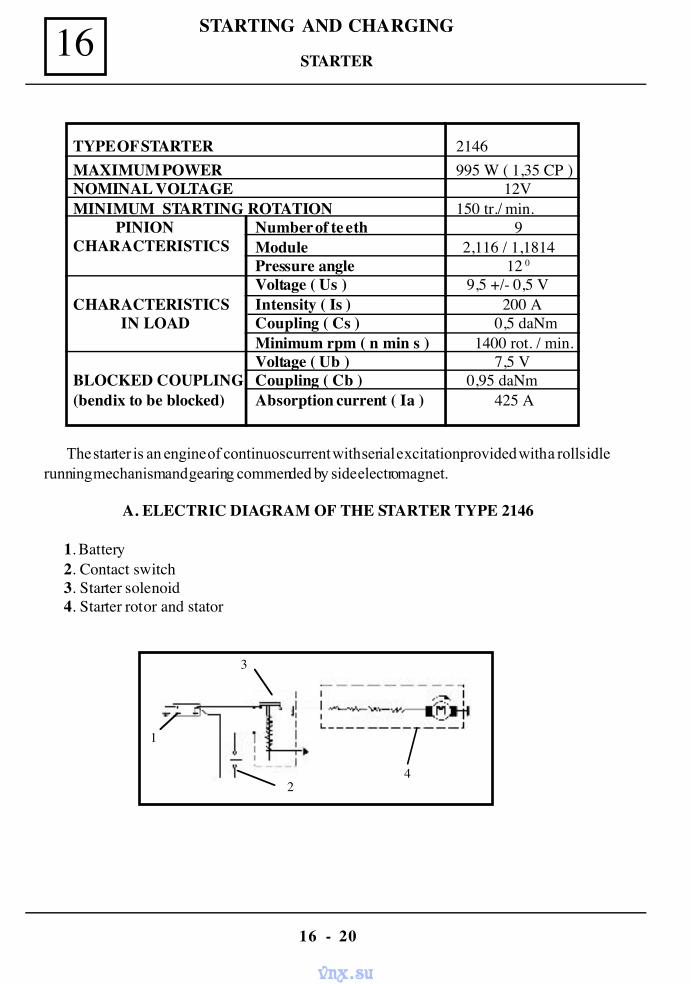
STARTING AND CHARGING16
16 - 20
1
2
3
4
TYPE OF STARTER 2146MAXIMUM POWER 995 W ( 1,35 CP )NOMINAL VOLTAGE 12VMINIMUM STARTING ROTATION 150 tr./ min.
Number of te eth 9Module 2,116 / 1,1814Pressure angle 12 0
Voltage ( Us ) 9,5 +/- 0,5 VIntensity ( Is ) 200 ACoupling ( Cs ) 0,5 daNmMinimum rpm ( n min s ) 1400 rot. / min.Voltage ( Ub ) 7,5 VCoupling ( Cb ) 0,95 daNmAbsorption current ( Ia ) 425 A
PINIONCHARACTERISTICS
CHARACTERISTICSIN LOAD
BLOCKED COUPLING(bendix to be blocked)
The starter is an engine of continuos current with serial excitation provided with a rolls idlerunning mechanism and gearing commended by side electromagnet.
A. ELECTRIC DIAGRAM OF THE STARTER TYPE 2146
1. Battery2. Contact switch3. Starter solenoid4. Starter rotor and stator
STARTER
vnx.su
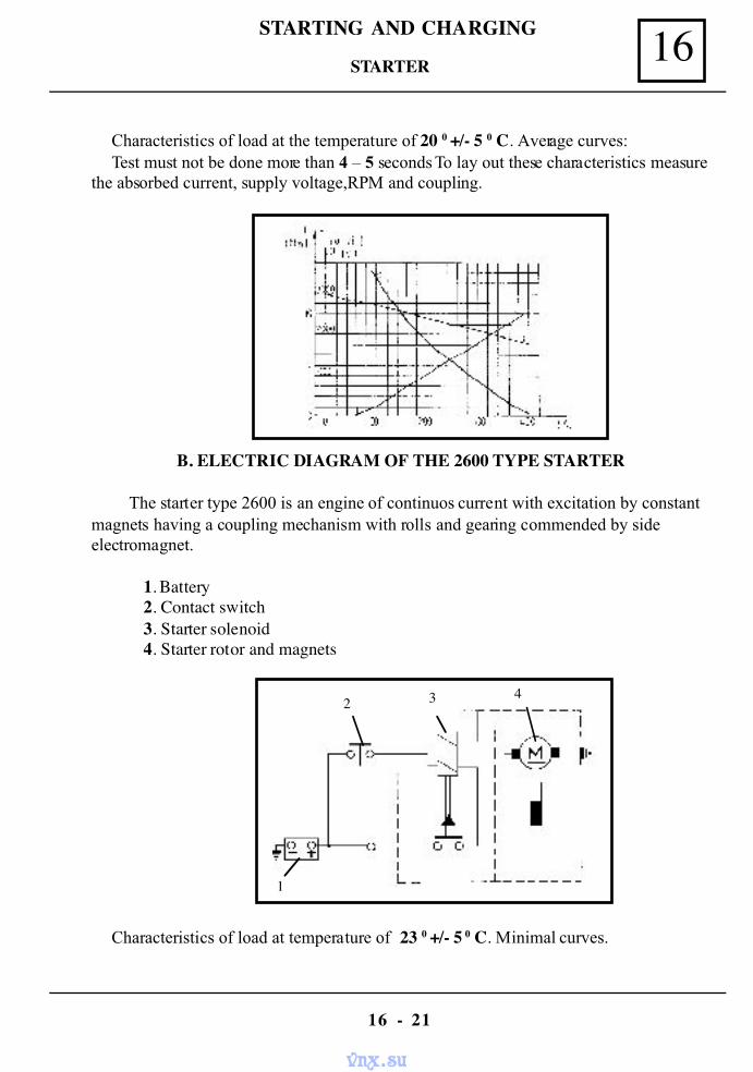
16STARTING AND CHARGING
16 - 21
Characteristics of load at the temperature of 20 0 +/- 5 0 C. Average curves:Test must not be done more than 4 – 5 seconds To lay out these characteristics measure
the absorbed current, supply voltage,RPM and coupling.
B. ELECTRIC DIAGRAM OF THE 2600 TYPE STARTER
The starter type 2600 is an engine of continuos current with excitation by constantmagnets having a coupling mechanism with rolls and gearing commended by sideelectromagnet.
1. Battery2. Contact switch3. Starter solenoid4. Starter rotor and magnets
Characteristics of load at temperature of 23 0 +/- 5 0 C. Minimal curves.
1
2 3 4
STARTER
vnx.su
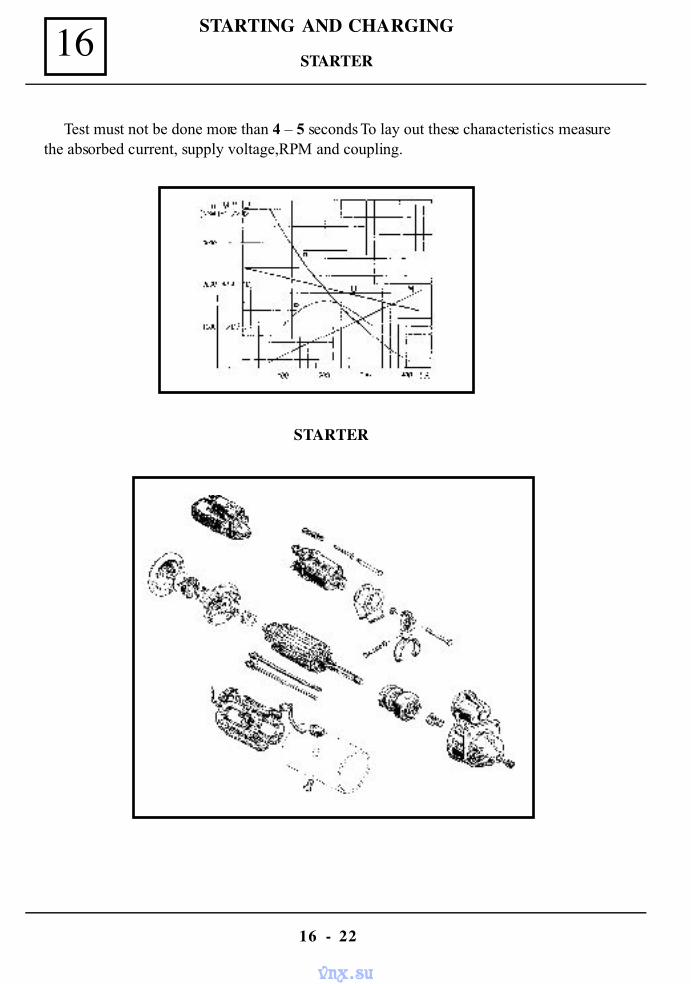
STARTING AND CHARGING16
16 - 22
Test must not be done more than 4 – 5 seconds To lay out these characteristics measurethe absorbed current, supply voltage,RPM and coupling.
STARTER
STARTER
vnx.su
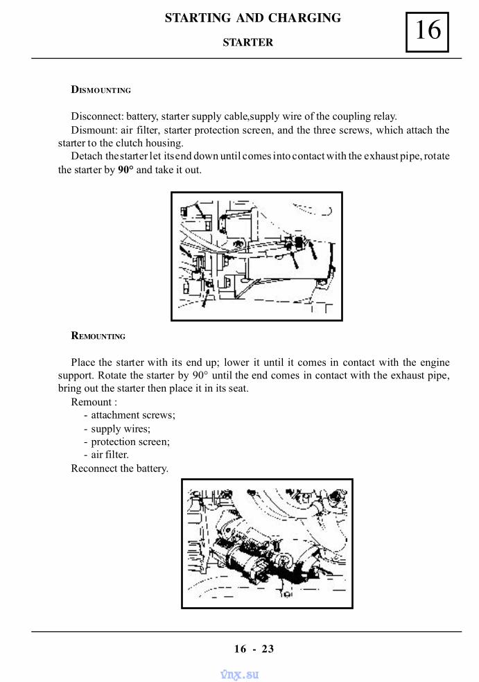
16STARTING AND CHARGING
16 - 23
DISMOUNTING
Disconnect: battery, starter supply cable,supply wire of the coupling relay.Dismount: air filter, starter protection screen, and the three screws, which attach the
starter to the clutch housing.Detach the starter let its end down until comes into contact with the exhaust pipe, rotate
the starter by 90° and take it out.
REMOUNTING
Place the starter with its end up; lower it until it comes in contact with the enginesupport. Rotate the starter by 90° until the end comes in contact with the exhaust pipe,bring out the starter then place it in its seat.
Remount :- attachment screws;- supply wires;- protection screen;- air filter.
Reconnect the battery.
STARTER
vnx.su
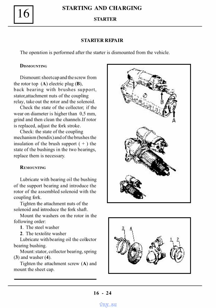
STARTING AND CHARGING16
16 - 24
STARTER REPAIR
The operation is performed after the starter is dismounted from the vehicle.
DISMOUNTING
Dismount: sheet cap and the screw fromthe rotor top (A) electric plug (B),back bearing with brushes support,stator,attachment nuts of the couplingrelay, take out the rotor and the solenoid.
Check the state of the collector; if thewear on diameter is higher than 0,5 mm,grind and then clean the channels.If rotoris replaced, adjust the fork stroke.
Check: the state of the couplingmechanism (bendix) and of the brushes theinsulation of the brush support ( + ) thestate of the bushings in the two bearings,replace them is necessary.
REMOUNTING
Lubricate with bearing oil the bushingof the support bearing and introduce therotor of the assembled solenoid with thecoupling fork.
Tighten the attachment nuts of thesolenoid and introduce the fork shaft.
Mount the washers on the rotor in thefollowing order:
1. The steel washer2. The textolite washerLubricate with bearing oil the collector
bearing bushing.Mount: stator, collector bearing, spring
(3) and washer (4).Tighten the attachment screw (A) and
mount the sheet cap.
STARTER
vnx.su
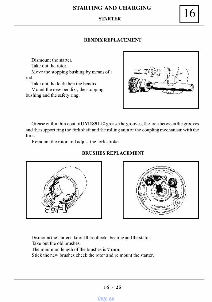
16STARTING AND CHARGING
16 - 25
BENDIX REPLACEMENT
Dismount the starter.Take out the rotor.Move the stopping bushing by means of a
rod.Take out the lock then the bendix.Mount the new bendix , the stopping
bushing and the safety ring.
Grease with a thin coat of UM 185 Li2 grease the grooves, the area between the groovesand the support ring the fork shaft and the rolling area of the coupling mechanism with thefork.
Remount the rotor and adjust the fork stroke.
BRUSHES REPLACEMENT
Dismount the starter take out the collector bearing and the stator.Take out the old brushes.The minimum length of the brushes is 7 mm.Stick the new brushes check the rotor and re mount the starter.
STARTER
vnx.su
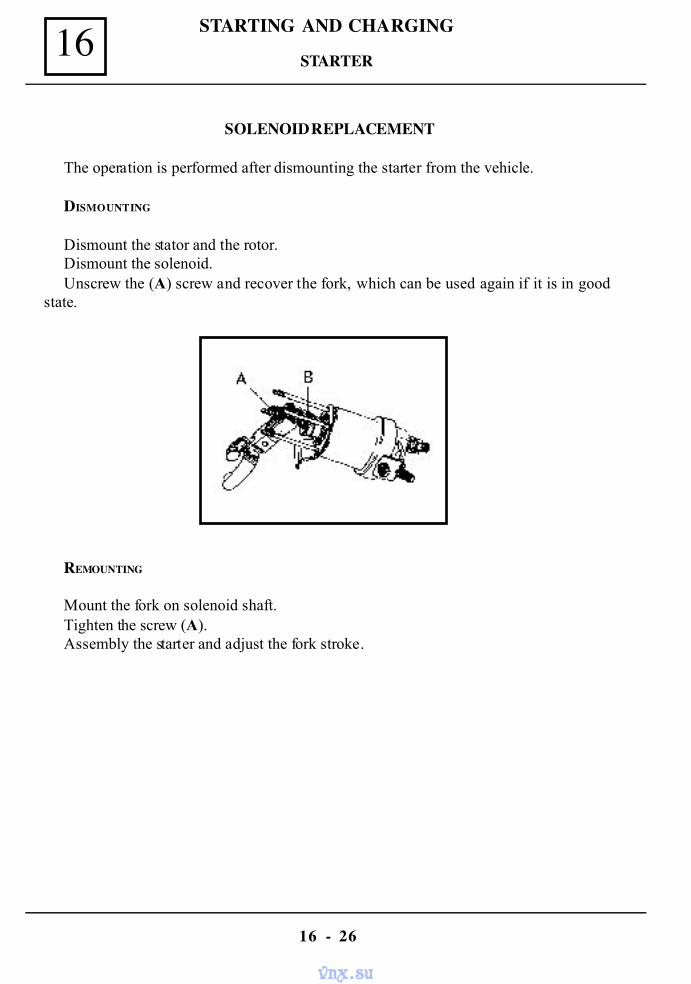
STARTING AND CHARGING16
16 - 26
SOLENOID REPLACEMENT
The operation is performed after dismounting the starter from the vehicle.
DISMOUNTING
Dismount the stator and the rotor.Dismount the solenoid.Unscrew the (A) screw and recover the fork, which can be used again if it is in good
state.
REMOUNTING
Mount the fork on solenoid shaft.Tighten the screw (A).Assembly the starter and adjust the fork stroke.
STARTER
vnx.su
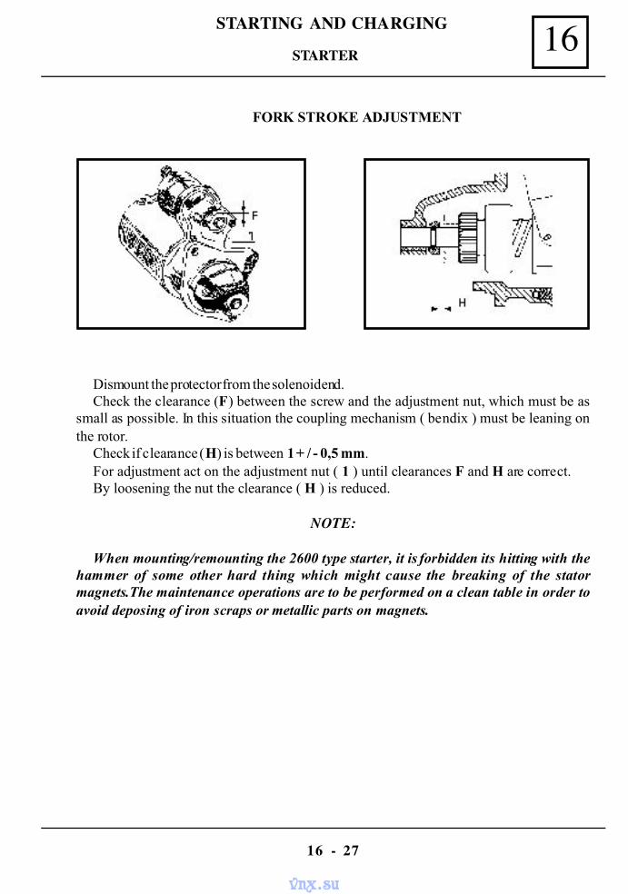
16STARTING AND CHARGING
16 - 27
FORK STROKE ADJUSTMENT
Dismount the protector from the solenoid end.Check the clearance (F) between the screw and the adjustment nut, which must be as
small as possible. In this situation the coupling mechanism ( bendix ) must be leaning onthe rotor.
Check if clearance (H) is between 1 + / - 0,5 mm.For adjustment act on the adjustment nut ( 1 ) until clearances F and H are correct.By loosening the nut the clearance ( H ) is reduced.
NOTE:
When mounting/remounting the 2600 type starter, it is forbidden its hitting with thehammer of some other hard thing which might cause the breaking of the statormagnets.The maintenance operations are to be performed on a clean table in order toavoid deposing of iron scraps or metallic parts on magnets.
STARTER
vnx.su
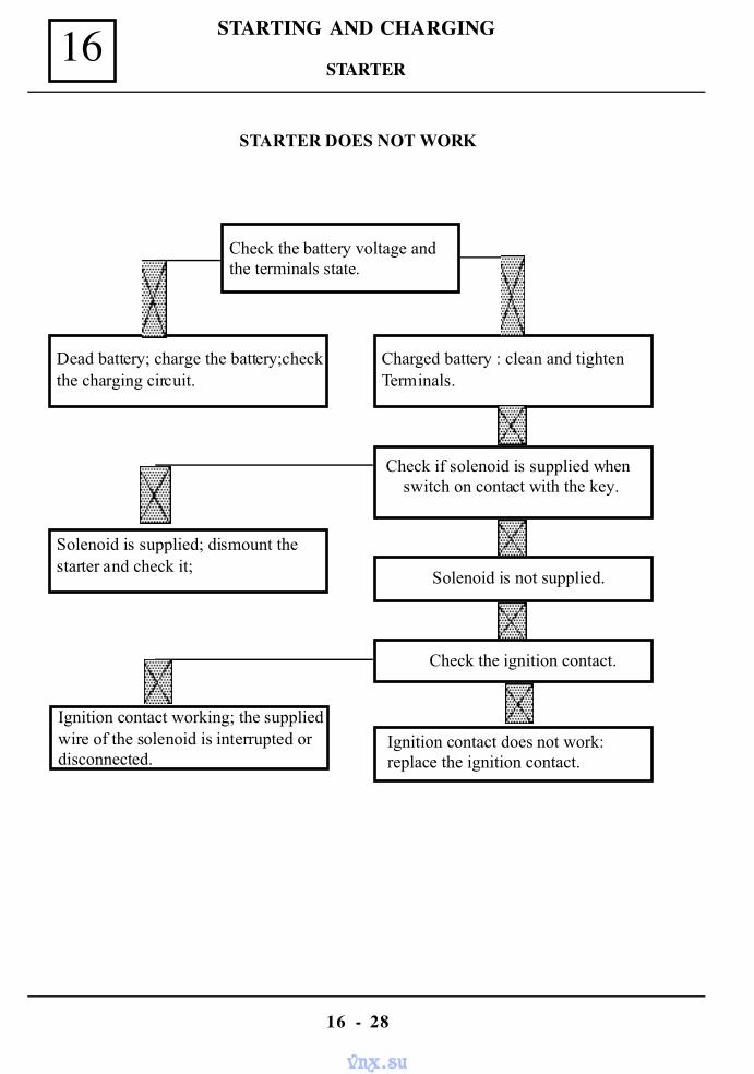
STARTING AND CHARGING16
16 - 28
STARTER DOES NOT WORK
Check the battery voltage andthe terminals state.
Dead battery; charge the battery;checkthe charging circuit.
Charged battery : clean and tightenTerminals.
Check if solenoid is supplied when switch on contact with the key.
Solenoid is not supplied.
Check the ignition contact.
Ignition contact does not work:replace the ignition contact.
Solenoid is supplied; dismount thestarter and check it;
Ignition contact working; the suppliedwire of the solenoid is interrupted ordisconnected.
STARTER
vnx.su
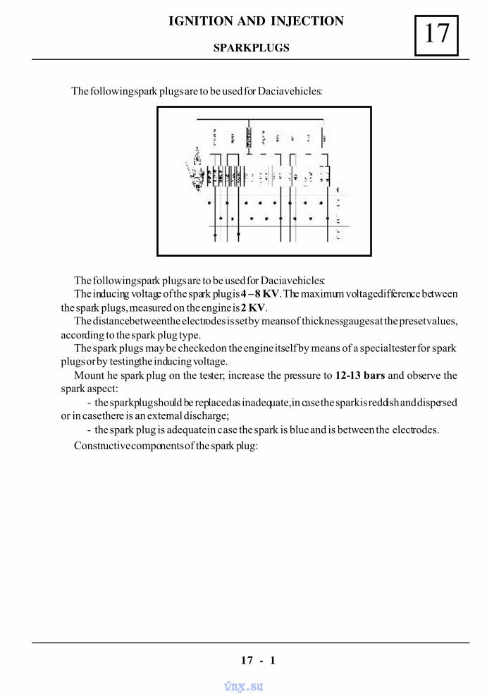
17IGNITION AND INJECTION
17 - 1
The following spark plugs are to be used for Dacia vehicles:The inducing voltage of the spark plug is 4 – 8 KV. The maximum voltage difference between
the spark plugs, measured on the engine is 2 KV.The distance between the electrodes is set by means of thickness gauges at the preset values,
according to the spark plug type.The spark plugs may be checked on the engine itself by means of a special tester for spark
plugs or by testing the inducing voltage.Mount he spark plug on the tester; increase the pressure to 12-13 bars and observe the
spark aspect:- the spark plug should be replaced as inadequate, in case the spark is reddish and dispersed
or in case there is an external discharge;- the spark plug is adequate in case the spark is blue and is between the electrodes.
Constructive components of the spark plug:
The following spark plugs are to be used for Dacia vehicles:
SPARK PLUGS
vnx.su
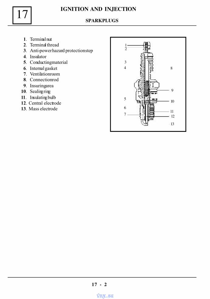
IGNITION AND INJECTION17
17 - 2
SPARK PLUGS
1. Terminal nut 2. Terminal thread 3. Anti-power hazard protection step 4. Insulator 5. Conducting material 6. Internal gasket 7. Ventilation room 8. Connection rod 9. Insuring area10. Sealing ring11. Insulating bulb12. Central electrode13. Mass electrode
111
1
34
5
67
2
8
9
10
1112
13
vnx.su
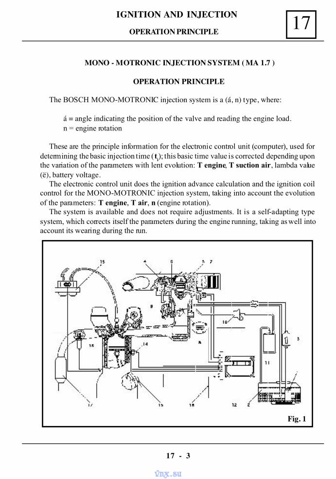
17IGNITION AND INJECTION
17 - 3
MONO - MOTRONIC INJECTION SYSTEM ( MA 1.7 )
OPERATION PRINCIPLE
The BOSCH MONO-MOTRONIC injection system is a (á, n) type, where:
á = angle indicating the position of the valve and reading the engine load.n = engine rotation
These are the principle information for the electronic control unit (computer), used fordetermining the basic injection time (t
i); this basic time value is corrected depending upon
the variation of the parameters with lent evolution: T engine, T suction air, lambda value(ë), battery voltage.
The electronic control unit does the ignition advance calculation and the ignition coilcontrol for the MONO-MOTRONIC injection system, taking into account the evolutionof the parameters: T engine, T air, n (engine rotation).
The system is available and does not require adjustments. It is a self-adapting typesystem, which corrects itself the parameters during the engine running, taking as well intoaccount its wearing during the run.
Fig. 1
OPERATION PRINCIPLE
vnx.su
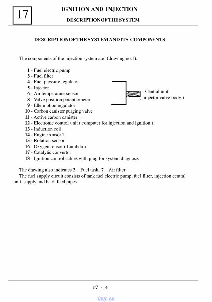
IGNITION AND INJECTION17
17 - 4
The components of the injection system are: (drawing no.1).
1 - Fuel electric pump 3 - Fuel filter 4 - Fuel pressure regulator 5 - Injector 6 - Air temperature sensor 8 - Valve position potentiometer 9 - Idle motion regulator10 - Carbon canister purging valve11 - Active carbon canister12 - Electronic control unit ( computer for injection and ignition ).13 - Induction coil14 - Engine sensor T15 - Rotation sensor16 - Oxygen sensor ( Lambda ).17 - Catalytic convertor18 - Ignition control cables with plug for system diagnosis
The drawing also indicates 2 – Fuel tank, 7 – Air filter.The fuel supply circuit consists of tank fuel electric pump, fuel filter, injection central
unit, supply and back-feed pipes.
Central unit( injector valve body )
DESCRIPTION OF THE SYSTEM
DESCRIPTION OF THE SYSTEM AND ITS COMPONENTS
vnx.su
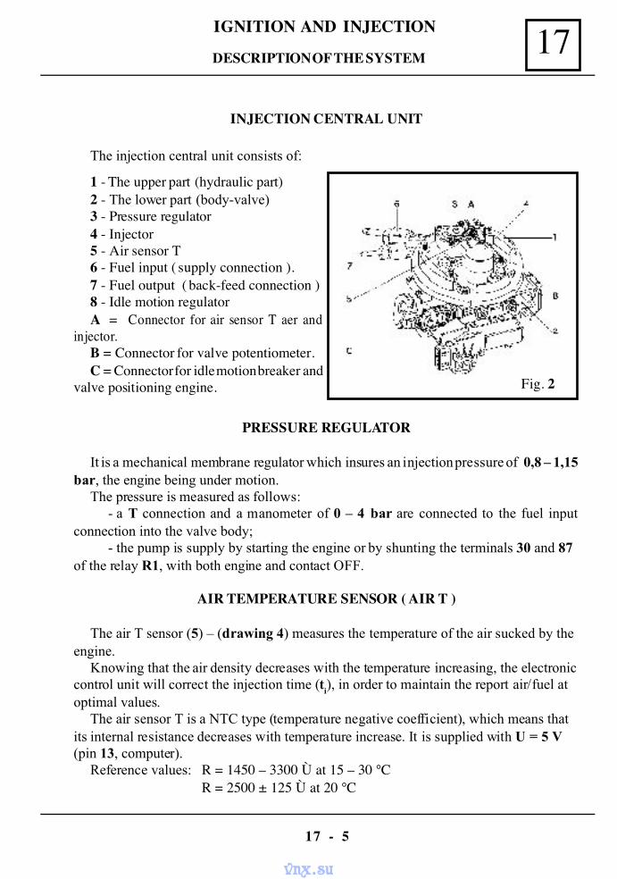
17IGNITION AND INJECTION
17 - 5
1 - The upper part (hydraulic part)2 - The lower part (body-valve)3 - Pressure regulator4 - Injector5 - Air sensor T6 - Fuel input ( supply connection ).7 - Fuel output ( back-feed connection )8 - Idle motion regulatorA = Connector for air sensor T aer and
injector.B = Connector for valve potentiometer.C = Connector for idle motion breaker and
valve positioning engine.
INJECTION CENTRAL UNIT
PRESSURE REGULATOR
It is a mechanical membrane regulator which insures an injection pressure of 0,8 – 1,15bar, the engine being under motion.
The pressure is measured as follows:- a T connection and a manometer of 0 – 4 bar are connected to the fuel input
connection into the valve body;- the pump is supply by starting the engine or by shunting the terminals 30 and 87
of the relay R1, with both engine and contact OFF.
AIR TEMPERATURE SENSOR ( AIR T )
The air T sensor (5) – (drawing 4) measures the temperature of the air sucked by theengine.
Knowing that the air density decreases with the temperature increasing, the electroniccontrol unit will correct the injection time (ti
), in order to maintain the report air/fuel atoptimal values.
The air sensor T is a NTC type (temperature negative coefficient), which means thatits internal resistance decreases with temperature increase. It is supplied with U = 5 V(pin 13, computer).
Reference values: R = 1450 – 3300 Ù at 15 – 30 °CR = 2500 ± 125 Ù at 20 °C
The injection central unit consists of:
Fig. 2
DESCRIPTION OF THE SYSTEM
vnx.su
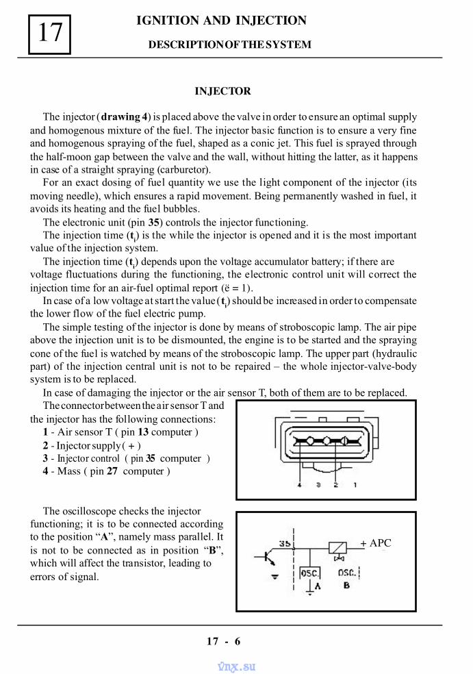
IGNITION AND INJECTION17
17 - 6
INJECTOR
The injector (drawing 4) is placed above the valve in order to ensure an optimal supplyand homogenous mixture of the fuel. The injector basic function is to ensure a very fineand homogenous spraying of the fuel, shaped as a conic jet. This fuel is sprayed throughthe half-moon gap between the valve and the wall, without hitting the latter, as it happensin case of a straight spraying (carburetor).
For an exact dosing of fuel quantity we use the light component of the injector (itsmoving needle), which ensures a rapid movement. Being permanently washed in fuel, itavoids its heating and the fuel bubbles.
The electronic unit (pin 35) controls the injector functioning.The injection time (ti
) is the while the injector is opened and it is the most importantvalue of the injection system.
The injection time (ti) depends upon the voltage accumulator battery; if there are
voltage fluctuations during the functioning, the electronic control unit will correct theinjection time for an air-fuel optimal report (ë = 1).
In case of a low voltage at start the value (ti) should be increased in order to compensate
the lower flow of the fuel electric pump.The simple testing of the injector is done by means of stroboscopic lamp. The air pipe
above the injection unit is to be dismounted, the engine is to be started and the sprayingcone of the fuel is watched by means of the stroboscopic lamp. The upper part (hydraulicpart) of the injection central unit is not to be repaired – the whole injector-valve-bodysystem is to be replaced.
In case of damaging the injector or the air sensor T, both of them are to be replaced.The connector between the air sensor T and
the injector has the following connections:1 - Air sensor T ( pin 13 computer )2 - Injector supply ( + )3 - Injector control ( pin 35 computer )4 - Mass ( pin 27 computer )
The oscilloscope checks the injectorfunctioning; it is to be connected accordingto the position “A”, namely mass parallel. Itis not to be connected as in position “B”,which will affect the transistor, leading toerrors of signal.
+ APC
DESCRIPTION OF THE SYSTEM
vnx.su
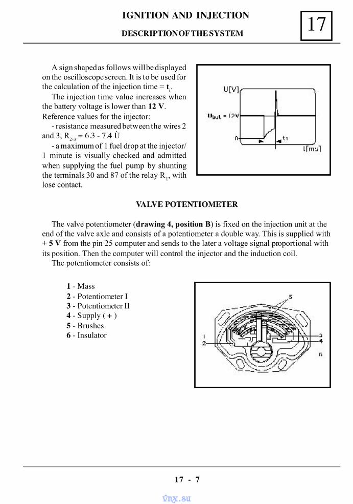
17IGNITION AND INJECTION
17 - 7
A sign shaped as follows will be displayedon the oscilloscope screen. It is to be used forthe calculation of the injection time = t
i.
The injection time value increases whenthe battery voltage is lower than 12 V.Reference values for the injector:
- resistance measured between the wires 2and 3, R
2-3 = 6.3 - 7.4 Ù
- a maximum of 1 fuel drop at the injector/1 minute is visually checked and admittedwhen supplying the fuel pump by shuntingthe terminals 30 and 87 of the relay R
1, with
lose contact.
VALVE POTENTIOMETER
The valve potentiometer (drawing 4, position B) is fixed on the injection unit at theend of the valve axle and consists of a potentiometer a double way. This is supplied with+ 5 V from the pin 25 computer and sends to the later a voltage signal proportional withits position. Then the computer will control the injector and the induction coil.
The potentiometer consists of:
1 - Mass2 - Potentiometer I3 - Potentiometer II4 - Supply ( + )5 - Brushes6 - Insulator
DESCRIPTION OF THE SYSTEM
vnx.su
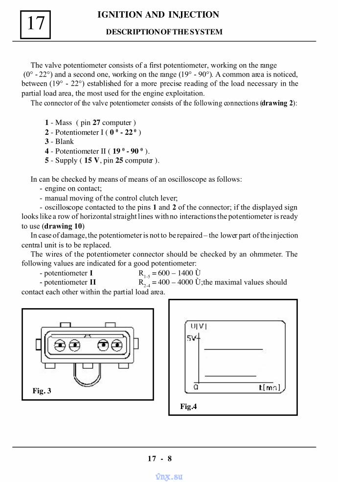
IGNITION AND INJECTION17
17 - 8
Fig. 3
The valve potentiometer consists of a first potentiometer, working on the range (0° - 22°) and a second one, working on the range (19° - 90°). A common area is noticed,between (19° - 22°) established for a more precise reading of the load necessary in thepartial load area, the most used for the engine exploitation.
The connector of the valve potentiometer consists of the following connections (drawing 2):
1 - Mass ( pin 27 computer )2 - Potentiometer I ( 0 0 - 22 0 )3 - Blank4 - Potentiometer II ( 19 0 - 90 0 ).5 - Supply ( 15 V, pin 25 computer ).
In can be checked by means of means of an oscilloscope as follows:- engine on contact;- manual moving of the control clutch lever;- oscilloscope contacted to the pins 1 and 2 of the connector; if the displayed sign
looks like a row of horizontal straight lines with no interactions the potentiometer is readyto use (drawing 10)
In case of damage, the potentiometer is not to be repaired – the lower part of the injectioncentral unit is to be replaced.
The wires of the potentiometer connector should be checked by an ohmmeter. Thefollowing values are indicated for a good potentiometer:
- potentiometer I R1-5
= 600 – 1400 Ù- potentiometer II R
2-4 = 400 – 4000 Ù;the maximal values should
contact each other within the partial load area.
Fig.4
DESCRIPTION OF THE SYSTEM
vnx.su
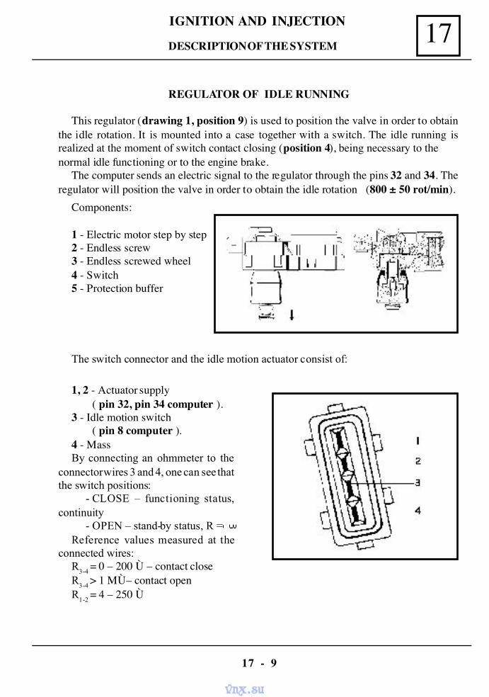
17IGNITION AND INJECTION
17 - 9
REGULATOR OF IDLE RUNNING
This regulator (drawing 1, position 9) is used to position the valve in order to obtainthe idle rotation. It is mounted into a case together with a switch. The idle running isrealized at the moment of switch contact closing (position 4), being necessary to thenormal idle functioning or to the engine brake.
The computer sends an electric signal to the regulator through the pins 32 and 34. Theregulator will position the valve in order to obtain the idle rotation (800 ± 50 rot/min).
Components:
1 - Electric motor step by step2 - Endless screw3 - Endless screwed wheel4 - Switch5 - Protection buffer
The switch connector and the idle motion actuator consist of:
1, 2 - Actuator supply( pin 32, pin 34 computer ).
3 - Idle motion switch( pin 8 computer ).
4 - MassBy connecting an ohmmeter to the
connector wires 3 and 4, one can see thatthe switch positions:
- CLOSE – functioning status,continuity
- OPEN – stand-by status, R =Reference values measured at the
connected wires:R3-4
= 0 – 200 Ù – contact closeR
3-4 > 1 MÙ– contact open
R1-2
= 4 – 250 Ù
DESCRIPTION OF THE SYSTEM
vnx.su
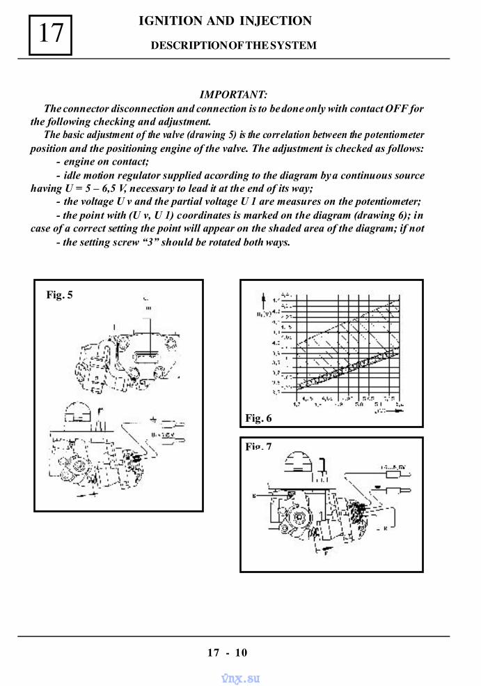
IGNITION AND INJECTION17
17 - 10
IMPORTANT:The connector disconnection and connection is to be done only with contact OFF for
the following checking and adjustment.The basic adjustment of the valve (drawing 5) is the correlation between the potentiometer
position and the positioning engine of the valve. The adjustment is checked as follows:- engine on contact;- idle motion regulator supplied according to the diagram by a continuous source
having U = 5 – 6,5 V, necessary to lead it at the end of its way;- the voltage U v and the partial voltage U 1 are measures on the potentiometer;- the point with (U v, U 1) coordinates is marked on the diagram (drawing 6); in
case of a correct setting the point will appear on the shaded area of the diagram; if not- the setting screw “3” should be rotated both ways.
Fig. 5
Fig. 7
Fig. 6
DESCRIPTION OF THE SYSTEM
vnx.su
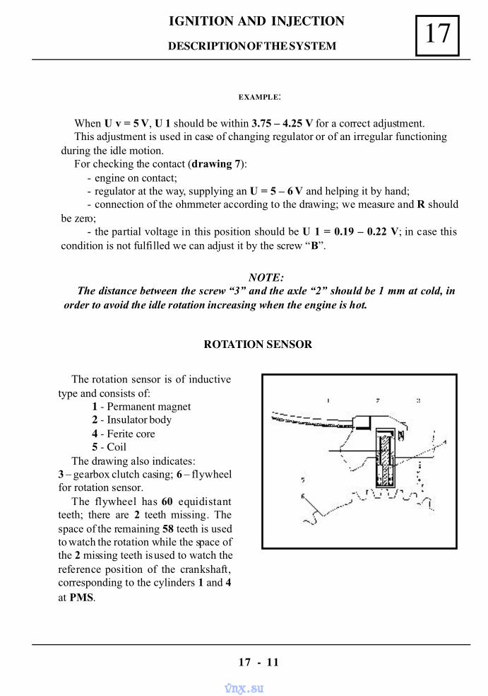
17IGNITION AND INJECTION
17 - 11
EXAMPLE:
When U v = 5 V, U 1 should be within 3.75 – 4.25 V for a correct adjustment.This adjustment is used in case of changing regulator or of an irregular functioning
during the idle motion.For checking the contact (drawing 7):
- engine on contact;- regulator at the way, supplying an U = 5 – 6 V and helping it by hand;- connection of the ohmmeter according to the drawing; we measure and R should
be zero;- the partial voltage in this position should be U 1 = 0.19 – 0.22 V; in case this
condition is not fulfilled we can adjust it by the screw “B”.
NOTE:The distance between the screw “3” and the axle “2” should be 1 mm at cold, in
order to avoid the idle rotation increasing when the engine is hot.
The rotation sensor is of inductivetype and consists of:
1 - Permanent magnet2 - Insulator body4 - Ferite core5 - Coil
The drawing also indicates:3 – gearbox clutch casing; 6 – flywheelfor rotation sensor.
The flywheel has 60 equidistantteeth; there are 2 teeth missing. Thespace of the remaining 58 teeth is usedto watch the rotation while the space ofthe 2 missing teeth is used to watch thereference position of the crankshaft,corresponding to the cylinders 1 and 4at PMS.
ROTATION SENSOR
DESCRIPTION OF THE SYSTEM
vnx.su
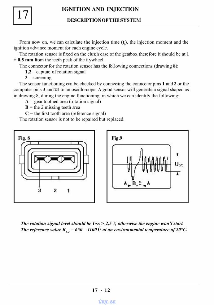
IGNITION AND INJECTION17
17 - 12
From now on, we can calculate the injection time (ti), the injection moment and the
ignition advance moment for each engine cycle.The rotation sensor is fixed on the clutch case of the gearbox therefore it should be at 1
± 0,5 mm from the teeth peak of the flywheel.The connector for the rotation sensor has the following connections (drawing 8):
1,2 – capture of rotation signal3 – screening
The sensor functioning can be checked by connecting the connector pins 1 and 2 or thecomputer pins 3 and 21 to an oscilloscope. A good sensor will generate a signal shaped asin drawing 8, during the engine functioning, in which we can identify the following:
A = gear toothed area (rotation signal)B = the 2 missing teeth areaC = the first tooth area (reference signal)
The rotation sensor is not to be repaired but replaced.
Fig. 8 Fig.9
The rotation signal level should be Uss > 2,5 V, otherwise the engine won’t start.The reference value R
1-2 = 650 – 1100 Ù at an environmental temperature of 20°C.
DESCRIPTION OF THE SYSTEM
vnx.su
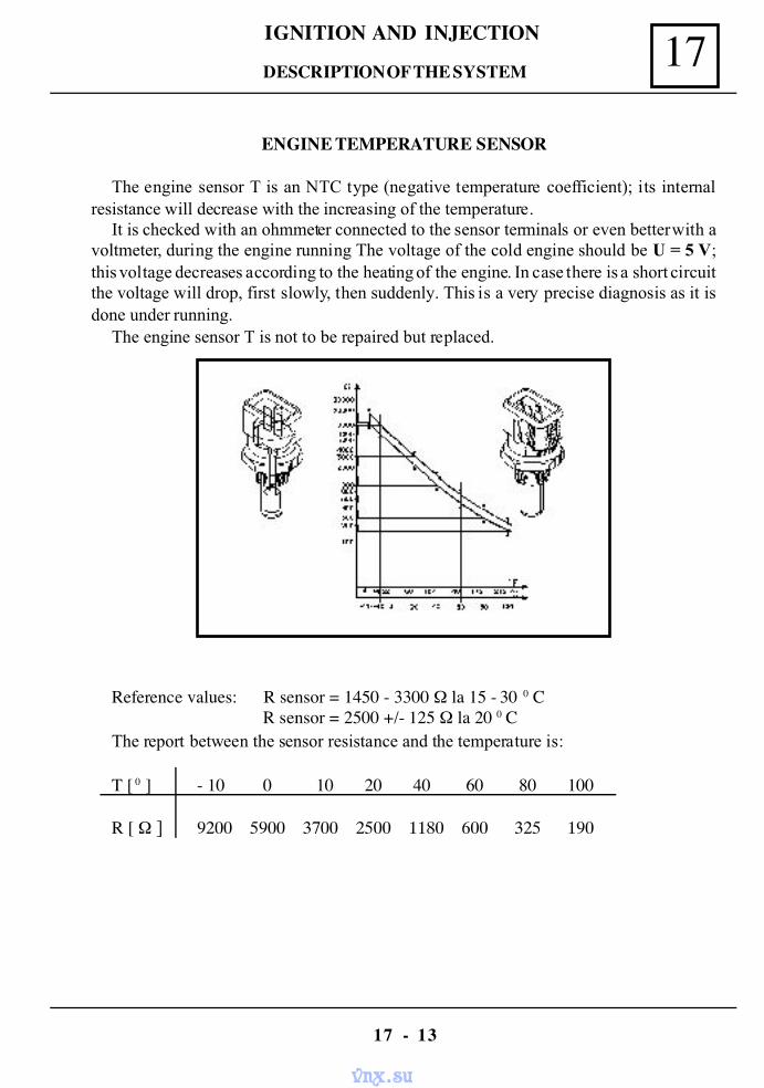
17IGNITION AND INJECTION
17 - 13
ENGINE TEMPERATURE SENSOR
The engine sensor T is an NTC type (negative temperature coefficient); its internalresistance will decrease with the increasing of the temperature.
It is checked with an ohmmeter connected to the sensor terminals or even better with avoltmeter, during the engine running The voltage of the cold engine should be U = 5 V;this voltage decreases according to the heating of the engine. In case there is a short circuitthe voltage will drop, first slowly, then suddenly. This is a very precise diagnosis as it isdone under running.
The engine sensor T is not to be repaired but replaced.
Reference values: R sensor = 1450 - 3300 Ω la 15 - 30 0 C R sensor = 2500 +/- 125 Ω la 20 0 C
The report between the sensor resistance and the temperature is:
T [ 0 ] - 10 0 10 20 40 60 80 100
R [ Ω ] 9200 5900 3700 2500 1180 600 325 190
DESCRIPTION OF THE SYSTEM
vnx.su
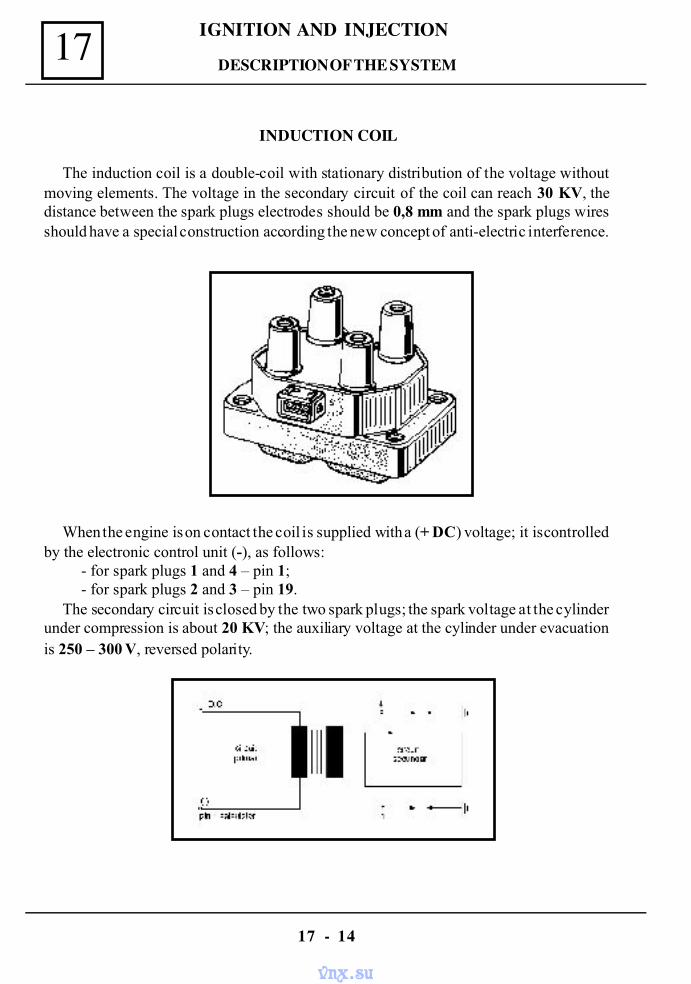
IGNITION AND INJECTION17
17 - 14
INDUCTION COIL
The induction coil is a double-coil with stationary distribution of the voltage withoutmoving elements. The voltage in the secondary circuit of the coil can reach 30 KV, thedistance between the spark plugs electrodes should be 0,8 mm and the spark plugs wiresshould have a special construction according the new concept of anti-electric interference.
When the engine is on contact the coil is supplied with a (+ DC) voltage; it is controlledby the electronic control unit (-), as follows:
- for spark plugs 1 and 4 – pin 1;- for spark plugs 2 and 3 – pin 19.
The secondary circuit is closed by the two spark plugs; the spark voltage at the cylinderunder compression is about 20 KV; the auxiliary voltage at the cylinder under evacuationis 250 – 300 V, reversed polarity.
DESCRIPTION OF THE SYSTEM
vnx.su
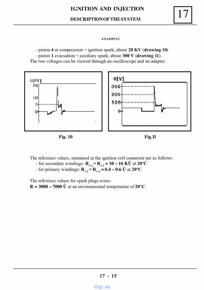
17IGNITION AND INJECTION
17 - 15
EXAMPLE:
- piston 4 at compression = ignition spark; about 20 KV (drawing 10).- piston 1 evacuation = auxiliary spark; about 300 V (drawing 11).
The two voltages can be viewed through an oscilloscope and an adapter.
Fig. 10 Fig.11
The reference values, measured at the ignition coil connector are as follows:- for secondary windings: R1-4
= R1-3
= 10 – 16 KÙ at 20°C- for primary windings: R
1-2 = R
3-4 = 0.4 – 0.6 Ù at 20°C
The reference values for spark plugs wires:R = 3000 – 7000 Ù at an environmental temperature of 20°C
DESCRIPTION OF THE SYSTEM
vnx.su
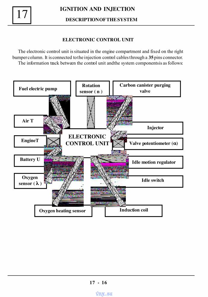
IGNITION AND INJECTION17
17 - 16
ELECTRONIC CONTROL UNIT
The electronic control unit is situated in the engine compartment and fixed on the rightbumper column. It is connected to the injection control cables through a 35 pins connector.
The information track between the control unit and the system components is as follows:
Fuel electric pumpCarbon canister purging
valve
Air T
EngineT
Battery U
Oxygensensor ( λλλλ )
ELECTRONICCONTROL UNIT
Oxygen heating sensor Induction coil
Injector
Valve potentiometer (αααα)
Idle motion regulator
Idle switch
Rotationsensor ( n )
DESCRIPTION OF THE SYSTEM
vnx.su
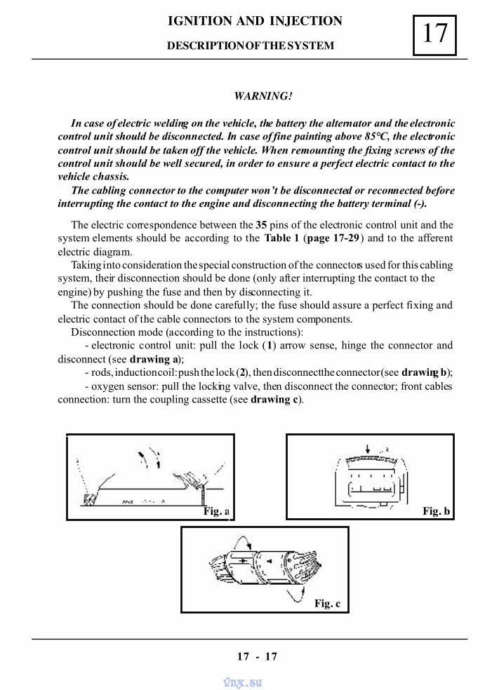
17IGNITION AND INJECTION
17 - 17
WARNING!
In case of electric welding on the vehicle, the battery the alternator and the electroniccontrol unit should be disconnected. In case of fine painting above 85°C, the electroniccontrol unit should be taken off the vehicle. When remounting the fixing screws of thecontrol unit should be well secured, in order to ensure a perfect electric contact to thevehicle chassis.
The cabling connector to the computer won’t be disconnected or reconnected beforeinterrupting the contact to the engine and disconnecting the battery terminal (-).
The electric correspondence between the 35 pins of the electronic control unit and thesystem elements should be according to the Table 1 (page 17-29) and to the afferentelectric diagram.
Taking into consideration the special construction of the connectors used for this cablingsystem, their disconnection should be done (only after interrupting the contact to theengine) by pushing the fuse and then by disconnecting it.
The connection should be done carefully; the fuse should assure a perfect fixing andelectric contact of the cable connectors to the system components.
Disconnection mode (according to the instructions):- electronic control unit: pull the lock (1) arrow sense, hinge the connector and
disconnect (see drawing a);- rods, induction coil: push the lock (2), then disconnect the connector (see drawing b);- oxygen sensor: pull the locking valve, then disconnect the connector; front cables
connection: turn the coupling cassette (see drawing c).
Fig. c
Fig. bFig. a
DESCRIPTION OF THE SYSTEM
vnx.su
IGNITION AND INJECTION17
17 - 18
The pin 23 should be tightly fixed to the mass.The pin 16 is very important; it ensures a permanent supply (+) to the computer in order
to keep in its memory all the damages which might occur during the running and to introducethe necessary connection at starting up for the ignition and injection system.The system takes into consideration the wearing in time of the engine, introducing thenecessary correction factors for engine functioning under optimal parameters. Whenreconnecting the battery, the computer rememorizes all the data sent by the sensors and thepossible damages of the system, after about 20 minutes of engine running.
The pins 33 and 18 are very important; they ensure the link between the computermass and the vehicle body.
DESCRIPTION OF THE SYSTEM
vnx.su
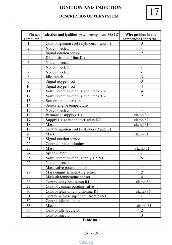
17IGNITION AND INJECTION
17 - 19
Pin no. Injection and ignition system component MA 1.7 Wire position in the computer component connector
1 Control ignition coil ( cylinders 1 and 4 ) 3 2 Not connected - 3 Signal rotation sensor 2 4 Diagnosis plug ( line K ) 1 5 Not connected - 6 Not connected - 7 Not connected - 8 Idle switch 3 9 Signal oxygen rod 310 Signal oxygen rod 411 Valve potentiometer ( signal track 2 ) 412 Valve potentiometer ( signal track 1 ) 213 Sensor air temperature 114 Sensor engine temperature 115 Not connected -16 Permanent supply ( + ) clamp 3017 Supply ( + ) after contact, relay R2 clamp 8718 Mass clamp 3119 Control ignition coil ( cylinders 2 and 3 ) 120 Mass clamp 3121 Signal rotation sensor 122 Control air conditioning -23 Mass clamp 3124 Speed-meter -25 Valve potentiometer ( supply + 5 V) 526 Not connected -
Mass valve potentiometer 127 Mass engine temperature sensor 2
Mass air temperature sensor 428 Control relay fuel pump R1 clamp 8629 Control canister purging valve 130 Control relay air conditioning R3 clamp 8631 Control witness injection ( front panel ) -32 Control idle regulator 133 Mass clamp 3134 Control idle regulator 235 Control injector 3
Table no. 1
DESCRIPTION OF THE SYSTEM
vnx.su
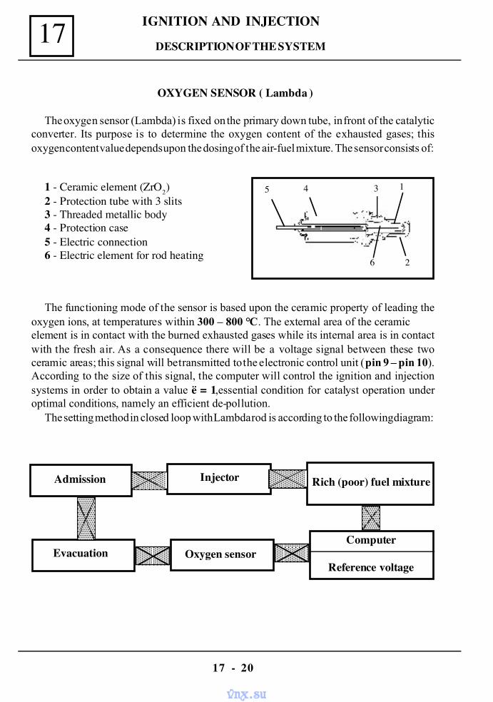
IGNITION AND INJECTION17
17 - 20
OXYGEN SENSOR ( Lambda )
The oxygen sensor (Lambda) is fixed on the primary down tube, in front of the catalyticconverter. Its purpose is to determine the oxygen content of the exhausted gases; thisoxygen content value depends upon the dosing of the air-fuel mixture. The sensor consists of:
1 - Ceramic element (ZrO2)2 - Protection tube with 3 slits3 - Threaded metallic body4 - Protection case5 - Electric connection6 - Electric element for rod heating
The functioning mode of the sensor is based upon the ceramic property of leading theoxygen ions, at temperatures within 300 – 800 °C. The external area of the ceramicelement is in contact with the burned exhausted gases while its internal area is in contactwith the fresh air. As a consequence there will be a voltage signal between these twoceramic areas; this signal will be transmitted to the electronic control unit (pin 9 – pin 10).According to the size of this signal, the computer will control the ignition and injectionsystems in order to obtain a value ë = 1,essential condition for catalyst operation underoptimal conditions, namely an efficient de-pollution.
The setting method in closed loop with Lambda rod is according to the following diagram:
Admission Injector
Evacuation
Rich (poor) fuel mixture
Oxygen sensorComputer
Reference voltage
5 4 3 1
6 2
DESCRIPTION OF THE SYSTEM
vnx.su
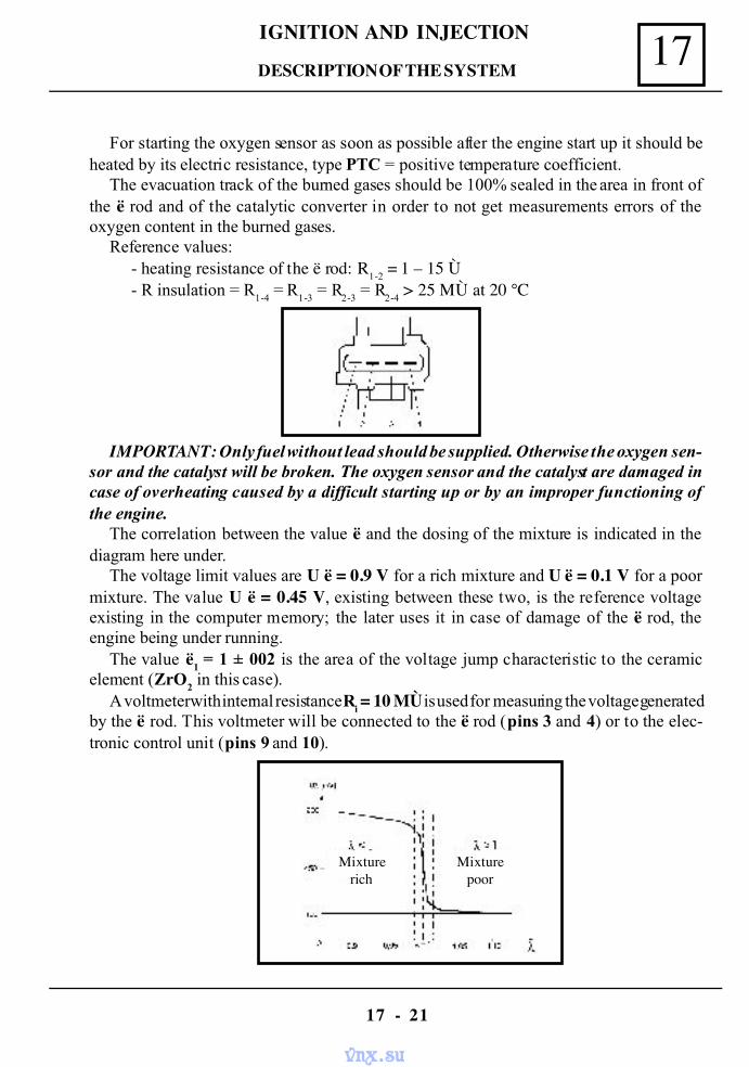
17IGNITION AND INJECTION
17 - 21
For starting the oxygen sensor as soon as possible after the engine start up it should beheated by its electric resistance, type PTC = positive temperature coefficient.
The evacuation track of the burned gases should be 100% sealed in the area in front ofthe ë rod and of the catalytic converter in order to not get measurements errors of theoxygen content in the burned gases.
Reference values:- heating resistance of the ë rod: R
1-2 = 1 – 15 Ù
- R insulation = R1-4
= R1-3
= R2-3
= R2-4
> 25 MÙ at 20 °C
IMPORTANT: Only fuel without lead should be supplied. Otherwise the oxygen sen-sor and the catalyst will be broken. The oxygen sensor and the catalyst are damaged incase of overheating caused by a difficult starting up or by an improper functioning ofthe engine.
The correlation between the value ë and the dosing of the mixture is indicated in thediagram here under.
The voltage limit values are U ë = 0.9 V for a rich mixture and U ë = 0.1 V for a poormixture. The value U ë = 0.45 V, existing between these two, is the reference voltageexisting in the computer memory; the later uses it in case of damage of the ë rod, theengine being under running.
The value ë1 = 1 ± 002 is the area of the voltage jump characteristic to the ceramic
element (ZrO2 in this case).
A voltmeter with internal resistance Ri = 10 MÙ is used for measuring the voltage generated
by the ë rod. This voltmeter will be connected to the ë rod (pins 3 and 4) or to the elec-tronic control unit (pins 9 and 10).
Mixturerich
Mixturepoor
DESCRIPTION OF THE SYSTEM
vnx.su
IGNITION AND INJECTION17
17 - 22
CATALYTIC CONVERTER
The catalytic converter (drawing 1, position 17) is placed on the burned gases evacuationtrack between the primary down tube and the detector it is three ways type and it is used forsimultaneous transformation of the three gases existing in the evacuation gas, according to thefollowing chemical reactions:
C m Hn + ( m+n/4 ) O2 m CO2 + n/2 H2 O2 CO + O2 2CO22 NO + 2 CO N2 + 2CO2
The catalytic converter is honeycomb shaped, in ceramic, covered with a very thin film ofactive catalytic substances (Platinum, Rhodium and Palladium). It accelerates theoxidation and chemical reaction of the noxious substances existing in the evacuated burned gases.This ceramic structure is protected by a stainless steel case, resisting to hightemperatures and environmental agent action.
WARNING !
Knowing that the catalytic converter reaches high temperatures during the func-tioning it is forbidden to install it in areas storing inflammable materials – fire hazard.
In order not to damage the catalyst during a difficult engine starting, do not insistin repetitiously trying to start the engine; pushing the vehicle it is also forbidden, onecan use a helping battery.
The engine shouldn’t run without sparking at one of its cylinders, even during test-ing; a not burned fuel can reach and damage the catalyst.
The maximal permitted values of the noxious substances (vehicle technical checking):
- CO < 0,4 % vol.- HC < 100 ppm- CO 2 > 12 % vol.- 0,97 < λ < 1,03
The above mentioned formula determination is done at an idle rotation of 800 ± 50 rot/minafter a minimum period of 5 minutes since the engine start up (engine T = 85 – 90 °C).
DESCRIPTION OF THE SYSTEM
vnx.su
17IGNITION AND INJECTION
17 - 23
WORKING MODEIN CASE OF INTERVENTION ON THE MONO-MOTRONIC INJECTION
SYSTEM
Prior to the engine start up one should check the correct connection of the battery; the batteryshould be well loaded and its terminals should be cleaned and well tightened up.
The maximum supplying voltage of the system should not excel 15 V.The battery should be disconnected only after stopping the engine, the contact key being on
the position “St” (contact closed).The electronic control unit can be disconnected only after closing the contact and
disconnecting the battery terminal (-).For checking the cylinders compression one should interrupt the power supply of the relays
(R1 – R
2) of the injection system.
The ignition system should be disconnected, turning the contact key on the position “0”, priorthe interventions at the ignition system.
For instance:- changing the engine system components- connection to the engine tester- connection to the checking bench
The cables in the engine compartment should be well placed in order not to be incontact with the hot areas or with the moving parts of the engine.In case of charging the battery form a redresser, the battery should be first disconnected from theelectric system of the vehicle.
WARNING !
1 – Only fuel without lead should be supplied, otherwise the catalytic converter willbe damaged. Use only fuel or oil additives recommended by the constructor.
2 – You should avoid bumping the catalytic converter3 – The engine should be fit for working with the catalytic converter under normal
conditions (injection, ignition). In case of miss-ignition, supplying problems and powerlosses stop the car, for avoiding the overheating of the catalytic converter; the later canalso be damaged by the too extended use of the starter in case of difficult start up.
4 – In case that fuel with lead is used by mistake, prior to changing the ë rod or thecatalytic converter one should refill the tank twice with no-lead fuel.
5 – Taking into consideration the high pressure of the fuel supplying system, all thejoints between pipes and hoses should be well tightened up with the adequate gaskets,in order to avoid the possible fuel losses, which might lead to vehicle fire hazard.
DIAGNOSTIC
vnx.su
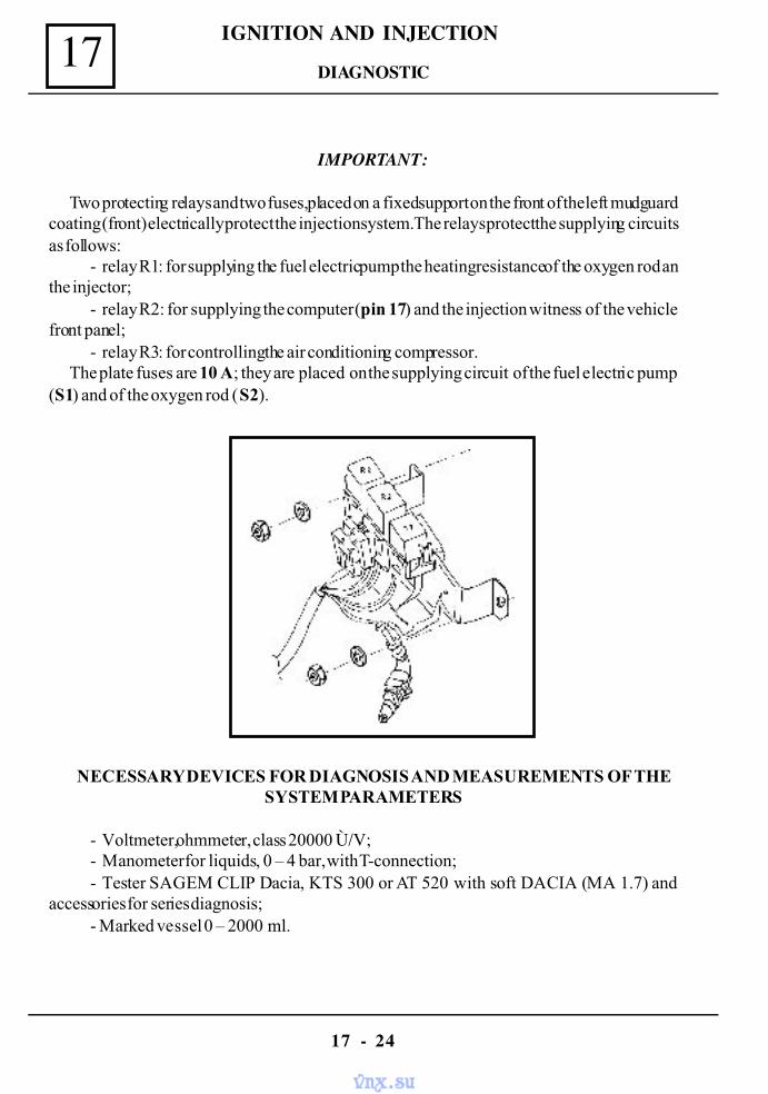
IGNITION AND INJECTION17
17 - 24
IMPORTANT:
Two protecting relays and two fuses, placed on a fixed support on the front of the left mudguardcoating (front) electrically protect the injection system. The relays protect the supplying circuitsas follows:
- relay R1: for supplying the fuel electric pump the heating resistance of the oxygen rod anthe injector;
- relay R2: for supplying the computer (pin 17) and the injection witness of the vehiclefront panel;
- relay R3: for controlling the air conditioning compressor.The plate fuses are 10 A; they are placed on the supplying circuit of the fuel electric pump
(S1) and of the oxygen rod (S2).
NECESSARY DEVICES FOR DIAGNOSIS AND MEASUREMENTS OF THESYSTEM PARAMETERS
- Voltmeter, ohmmeter, class 20000 Ù/V;- Manometer for liquids, 0 – 4 bar, with T-connection;- Tester SAGEM CLIP Dacia, KTS 300 or AT 520 with soft DACIA (MA 1.7) and
accessories for series diagnosis;- Marked vessel 0 – 2000 ml.
DIAGNOSTIC
vnx.su
17IGNITION AND INJECTION
17 - 25
PRELIMINARY CHECKING OPERATIONSPRIOR THE DIAGNOSIS
The starting up electric circuit components should be under best conditions:- Starter battery and cables;- Fuel in accordance with the indications (without lead), sufficient quantity
(minimum 5 l);- Fuel filter according to the indications and correctly installed;- Correct recirculation circuit (fuel vapors) with no clogging;- Supplying circuit: good sealing between the components, air filter in order;- Acceleration cable should not be tensioned;- The stroke of the acceleration pedal should be set to permit the complete opening of the
valve;- The vacuum circuit for servo brakes and its valves should be in order;- The engine should be in good mechanical order: compression tappet-levers setting, dis-
tribution steps, etc;.- The spark plugs should be according to the constructor specifications;- The control cables for fuel injection should be firmly fixed on the mass points (gearbox
case, direction column) and on supplying points (+12 V) – at starter;- The exhausting track should be sealed mainly between the evacuation gallery, down tube
and ë rod.
CONNECTING THE DIAGNOSIS TESTER
The diagnosis tester is connected to the vehicle injection cables, provided with the two waysconnector (AMP type, code 282189-1). This connector is placed on the left front mudguardcoating next to the relay and fuses block and fixed by a sealing clip. Theconnector is provided with a protection gate valve. This protection is dismounted when connect-ing the tester; the corresponding connector of the diagnosis tester is mounted in its place. Thetester is also connected to the 12 V battery of the vehicle.
WARNING !
During the diagnosis the control lever of the gearbox should be on neutral and thehand break should be pulled, to avoid the hazard risk.
The tester-connecting table should be not in contact with the hot components of thevehicle (collectors, exhausting system, etc.) or the moving components (engine shaftpulley, water pump pulley, and ventilation propeller).
When connecting the tester the contact key should be on “0”; at diagnosis thecontact key should be turned on “M” (contact ON).
DIAGNOSTIC
vnx.su

IGNITION AND INJECTION17
17 - 26
A. DIAGNOSIS BY SAGEM CLIP TESTER
The injection and ignition system diagnosis can be done by using the SAGEM CLIP tester,after connecting it to the diagnosis plug of the vehicle and after its + 12 V supply from the batteryterminals and from the lighter plug.
The detailed description of the tester as well as the diagnosis soft DACIA installing and theiroperation mode are written on the CD no.1 joint to the tester purchase.
Additionally this tester can be purchased as a complex variant (CLIP TEHNIC), which servesto the diagnosis of the injection system; it also serves for physical measurements of differentparameters of the injection and ignition system components.
B. DIAGNOSIS BY TESTER KTS 300
The injection and the ignition system diagnosis can also be done by means of the “Pocket –System Tester KTS 300 – Bosch”.
The tester KTS 300 executes the following operations:* processing of the communication structures;* processing of the communication by electronic control unit (computer);* selection of the memorized damages;* selection of helping menu (HELP);* processing of damage code by comparing the real and the set up values;* checking of acting elements (actuators test).The tester is provided with the following keys:
- the keys 1, 2, 3, are used for selecting a line from the option list, proposed by theprogram at a certain moment;
- the keys > and < are used for shifting to the following screen or for returning to theprevious screen;
- the key H is the helping key for the following;- screen lighting;- meter stopping;- displaying the data concerning the ignition and injection system;- printer setting up;- working speed setting for data transfer;- the memorized data operations (printing, canceling).- the key “ N ” - is used for shifting to the previous level of the program;- the key “ - - > ” for data memorizing;- the key “ - - > ” for memorized data reading.
DIAGNOSTIC
vnx.su
17IGNITION AND INJECTION
17 - 27
After accessing the diagnosis menu by pressing the key >, a submenu is displayed, with thefollowing options:
- press key 1 for reading the memorized damages;- press key 2 for displaying the real values of the checked measures;- press key 3 for checking the functioning of the acting items;- press key H for displaying the helping menu;- press key N for returning to the diagnosis menu.
In case of choosing the option “reading of the memorized damages”, when pushing key “ 1 ”,the screen will display a message with a total amount of the possible memorized damages.
When pressing key “ > ”, the following message will be displayed:- the damage track;- the damage type;- the damage code.
When pressing again the key “ > ” further information about the damages type(sporadic orpermanent) will be displayed.
From now on the list of the memorized damages can be explored by pressing the key“ > ”, when selecting a damage, one presses key “ 1 ” the damages possible causes can beidentified.
Each time one presses the key “ N ” the previous message will be displayed.After displaying the data about the last damage of the list by pressing the key “ > ” the
computer sends a message to the user, asking if the damage has been rectified.The following options are displayed:
- press key “ 1 ” for YES;- press key “ 3 ” for NO.
When pressing key “ 1 ”a message concerning the memorized damages will be displayed,with two options:
- press key “ 1 ” for canceling it;- press key “ 3 ” for keeping it.
After pressing key “ 1 ” the message “memorized damages cancelled” will be displayed.For turning to the diagnosis menu, one presses key “ 3 ” or the keys “ 1 ”, “ N ” in a raw.When choosing the option of action items checking (injector, electric-valve, idle
motion regulator etc.), one presses the key “ 3 ” and two options for selection of the action itemswill be displayed:
- pressing key “ 1 ” - an action item is selected;- pressing key “ 3 ” the unit list is explored from the first on.
Once selecting an item its action is done under pulsing regime, for viewing it or for listening to;the question “Is the item pulsing?” is displayed, with the following options:
- press key “ 1 ” for YES;- press key “ 3 ” for NO.
DIAGNOSTIC
vnx.su
IGNITION AND INJECTION17
17 - 28
The next unit is activated with each pressing of the key “ 1 ”.When pressing key “ 3 ” the working instructions for canceling the malfunctioning cause of
the unit will be displayed and by pressing the key “ > ” the unit is reselected.When pressing key “ N ”during the activation of a unit, one returns to the checking sub-range
of the activation units.In case of choosing the displaying of the real values of the measured checking two options for
real values selection will be displayed by pressing the key “ 2 ”:- press key “ 1 ” for selecting three parameters wit real values;- press key “ 2 ” for exploring one parameter in a raw, starting with the first one.- press key “ > ” for selecting the next item of the list;- press key “ N ” for returning to the sub-menu displaying the real values of the measured
elements.Further information concerning the KTS 300 Tester are provided in the Instructions Book
“Pocket – System Tester KTS 300 Bosch”.
DIAGNOSTIC
vnx.su
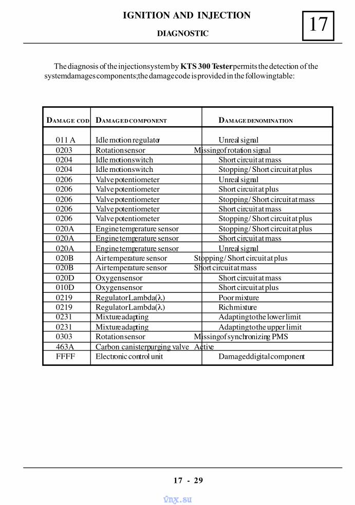
17IGNITION AND INJECTION
17 - 29
The diagnosis of the injection system by KTS 300 Tester permits the detection of thesystem damages components; the damage code is provided in the following table:
DAMAGE COD DAMAGED COMPONENT DAMAGE DENOMINATION
011 A Idle motion regulator Unreal signal0203 Rotation sensor Missing of rotation signal0204 Idle motion switch Short circuit at mass0204 Idle motion switch Stopping / Short circuit at plus0206 Valve potentiometer Unreal signal0206 Valve potentiometer Short circuit at plus0206 Valve potentiometer Stopping / Short circuit at mass0206 Valve potentiometer Short circuit at mass0206 Valve potentiometer Stopping / Short circuit at plus020A Engine temperature sensor Stopping / Short circuit at plus020A Engine temperature sensor Short circuit at mass020A Engine temperature sensor Unreal signal020B Air temperature sensor Stopping / Short circuit at plus020B Air temperature sensor Short circuit at mass020D Oxygen sensor Short circuit at mass010D Oxygen sensor Short circuit at plus0219 Regulator Lambda (λ) Poor mixture0219 Regulator Lambda (λ) Rich mixture0231 Mixture adapting Adapting to the lower limit0231 Mixture adapting Adapting to the upper limit0303 Rotation sensor Missing of synchronizing PMS463A Carbon canister purging valve ActiveFFFF Electronic control unit Damaged digital component
DIAGNOSTIC
vnx.su
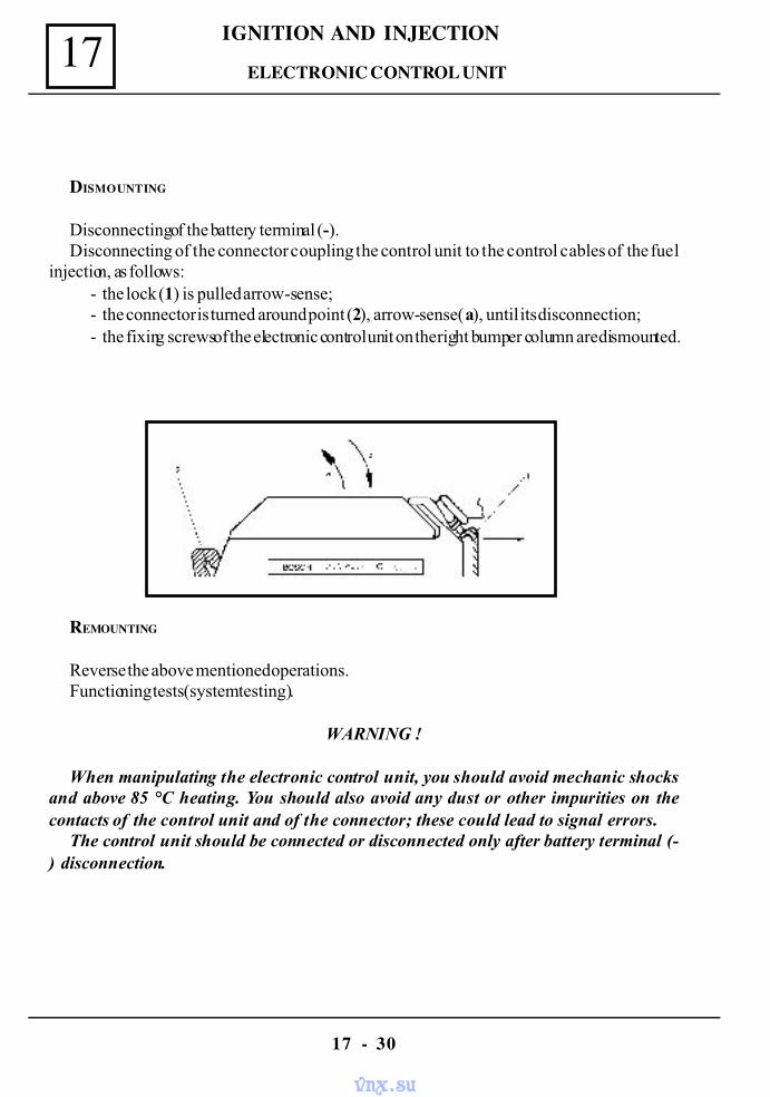
IGNITION AND INJECTION17
17 - 30
DISMOUNTING
Disconnecting of the battery terminal (-).Disconnecting of the connector coupling the control unit to the control cables of the fuel
injection, as follows:- the lock (1) is pulled arrow-sense;- the connector is turned around point (2), arrow-sense (a), until its disconnection;- the fixing screws of the electronic control unit on the right bumper column are dismounted.
REMOUNTING
Reverse the above mentioned operations.Functioning tests (system testing).
WARNING !
When manipulating the electronic control unit, you should avoid mechanic shocksand above 85 °C heating. You should also avoid any dust or other impurities on thecontacts of the control unit and of the connector; these could lead to signal errors.
The control unit should be connected or disconnected only after battery terminal (-) disconnection.
ELECTRONIC CONTROL UNIT
vnx.su
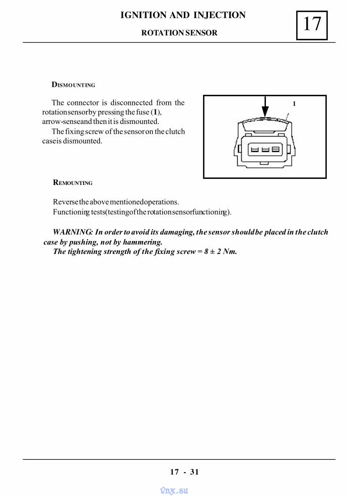
17IGNITION AND INJECTION
17 - 31
DISMOUNTING
The connector is disconnected from therotation sensor by pressing the fuse (1),arrow-sense and then it is dismounted.
The fixing screw of the sensor on the clutchcase is dismounted.
REMOUNTING
Reverse the above mentioned operations.Functioning tests (testing of the rotation sensor functioning).
WARNING: In order to avoid its damaging, the sensor should be placed in the clutchcase by pushing, not by hammering.
The tightening strength of the fixing screw = 8 ± 2 Nm.
1
ROTATION SENSOR
vnx.su
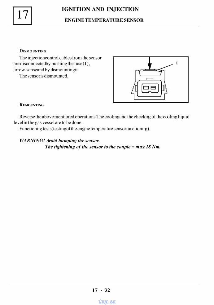
IGNITION AND INJECTION17
17 - 32
DISMOUNTING
The injection control cables from the sensorare disconnected by pushing the fuse (1),arrow-sense and by dismounting it.
The sensor is dismounted.
REMOUNTING
Reverse the above mentioned operations. The cooling and the checking of the cooling liquidlevel in the gas vessel are to be done.
Functioning tests (testing of the engine temperature sensor functioning).
WARNING! Avoid bumping the sensor. The tightening of the sensor to the couple = max.18 Nm.
1
ENGINE TEMPERATURE SENSOR
vnx.su
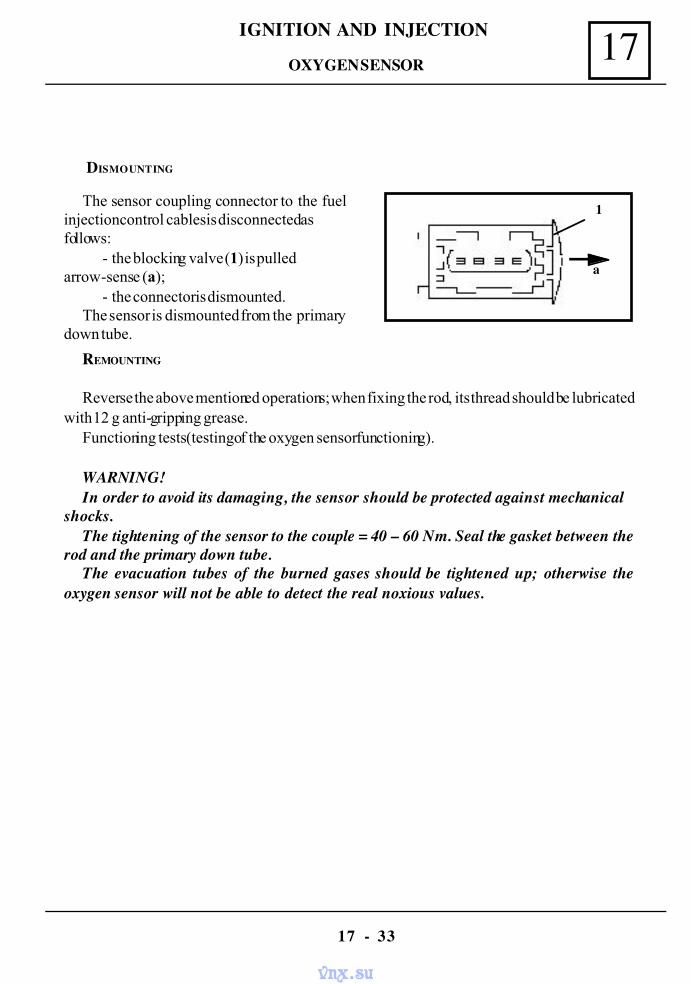
17IGNITION AND INJECTION
17 - 33
DISMOUNTING
The sensor coupling connector to the fuelinjection control cables is disconnected asfollows:
- the blocking valve (1) is pulledarrow-sense (a);
- the connector is dismounted.The sensor is dismounted from the primary
down tube.
REMOUNTING
Reverse the above mentioned operations; when fixing the rod, its thread should be lubricatedwith 12 g anti-gripping grease.
Functioning tests (testing of the oxygen sensor functioning).
WARNING!In order to avoid its damaging, the sensor should be protected against mechanical
shocks.The tightening of the sensor to the couple = 40 – 60 Nm. Seal the gasket between the
rod and the primary down tube.The evacuation tubes of the burned gases should be tightened up; otherwise the
oxygen sensor will not be able to detect the real noxious values.
1
a
OXYGEN SENSOR
vnx.su
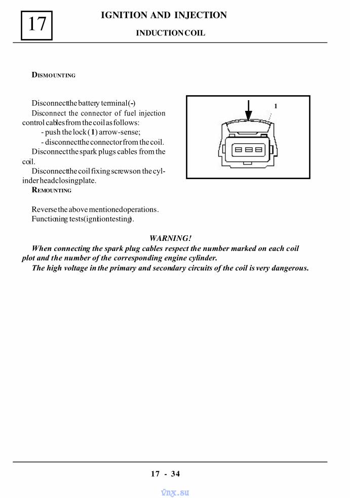
IGNITION AND INJECTION17
17 - 34
REMOUNTING
Reverse the above mentioned operations.Functioning tests (ignition testing).
WARNING!When connecting the spark plug cables respect the number marked on each coil
plot and the number of the corresponding engine cylinder.The high voltage in the primary and secondary circuits of the coil is very dangerous.
Disconnect the battery terminal (-)Disconnect the connector of fuel injection
control cables from the coil as follows:- push the lock (1) arrow-sense;- disconnect the connector from the coil.
Disconnect the spark plugs cables from thecoil.
Disconnect the coil fixing screws on the cyl-inder head closing plate.
1
DISMOUNTING
INDUCTION COIL
vnx.su
17IGNITION AND INJECTION
17 - 35
DISMOUNTING
Disconnect the spark plugs and the coil cables.
RISMOUNTING
Connect the cables to the spark plugs and to the corresponding plots of the induction coil.Functioning tests (testing of ignition system).
WARNING!When mounting the cables, they should be connected to the cylinder corresponding
to the number marked near the coil plot.Tightening couple for the spark plugs 20 – 40 Nm.
SPARK PLUGS SET
vnx.su
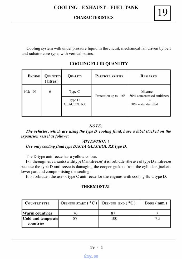
19COOLING - EXHAUST - FUEL TANK
19 - 1
Cooling system with under pressure liquid in the circuit, mechanical fan driven by beltand radiator core type, with vertical basins .
COOLING FLUID QUANTITY
ENGINE QUANTITY QUALITY PARTICULARITIES REMARKS
( litres )
102; 106 6 Type C Mixture: Protection up to - 400 50% concentrated antifreeze
Type D + GLACEOL RX 50% water distilled
COUNTRY TYPE OPENING START ( 0 C ) OPENING END ( 0 C ) BORE ( mm )
Warm countries 76 87 7Cold and temperate 87 100 7,5
countries
NOTE:The vehicles, which are using the type D cooling fluid, have a label stacked on the
expansion vessel as follows:ATTENTION !
Use only cooling fluid type DACIA GLACEOL RX type D.
The D-type antifreeze has a yellow colour.For the engines variants (with type C antifreeze) it is forbidden the use of type D antifreeze
because the type D antifreeze is damaging the cooper gaskets from the cylinders jacketslower part and compromising the sealing.
It is forbidden the use of type C antifreeze for the engines with cooling fluid type D.
THERMOSTAT
CHARACTERISTICS
vnx.su
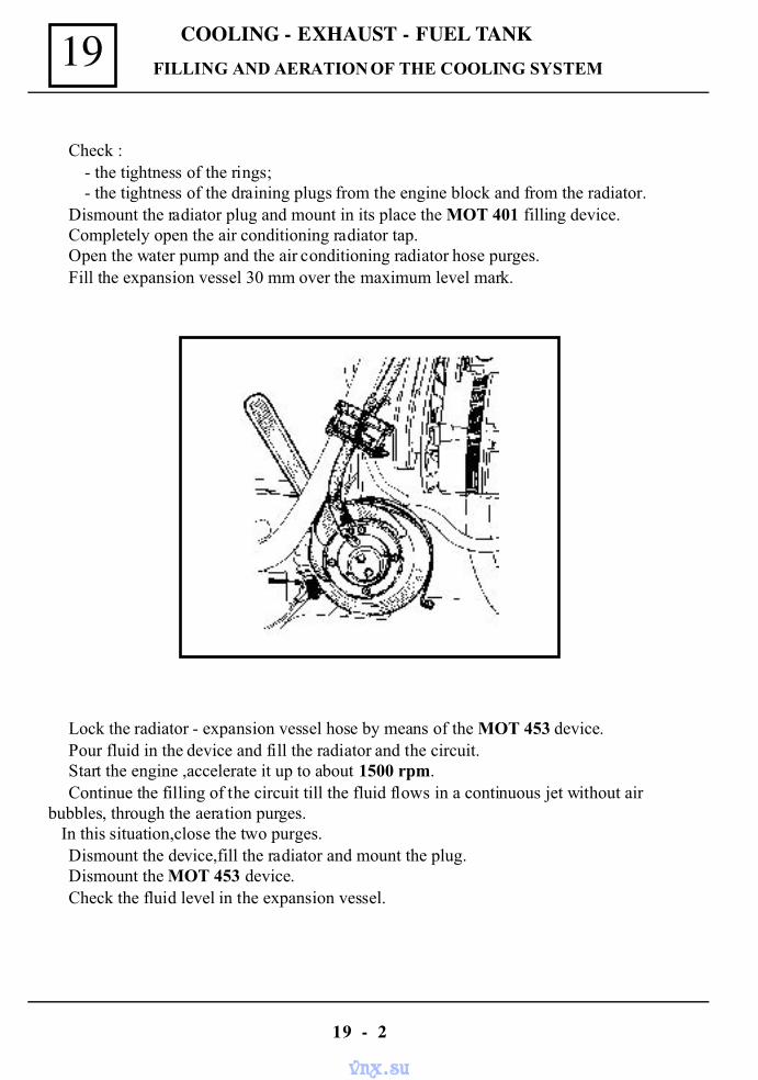
COOLING - EXHAUST - FUEL TANK19
19 - 2
FILLING AND AERATION OF THE COOLING SYSTEM
Check :- the tightness of the rings;- the tightness of the draining plugs from the engine block and from the radiator.
Dismount the radiator plug and mount in its place the MOT 401 filling device.Completely open the air conditioning radiator tap.Open the water pump and the air conditioning radiator hose purges.Fill the expansion vessel 30 mm over the maximum level mark.
Lock the radiator - expansion vessel hose by means of the MOT 453 device.Pour fluid in the device and fill the radiator and the circuit.Start the engine ,accelerate it up to about 1500 rpm.Continue the filling of the circuit till the fluid flows in a continuous jet without air
bubbles, through the aeration purges. In this situation,close the two purges.
Dismount the device,fill the radiator and mount the plug.Dismount the MOT 453 device.Check the fluid level in the expansion vessel.
vnx.su
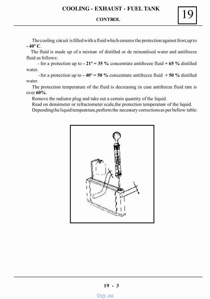
19COOLING - EXHAUST - FUEL TANK
19 - 3
The cooling circuit is filled with a fluid which ensures the protection against frost,up to- 40º C. The fluid is made up of a mixture of distilled or de mineralised water and antifreezefluid as follows:
- for a protection up to - 21º = 35 % concentrate antifreeze fluid + 65 % distilledwater.
- for a protection up to - 40º = 50 % concentrate antifreeze fluid + 50 % distilledwater.
The protection temperature of the fluid is decreasing in case antifreeze fluid rate isover 60%.
Remove the radiator plug and take out a certain quantity of the liquid.Read on densimeter or refractometer scale,the protection temperature of the liquid.Depending the liquid temperature,perform the necessary corrections as per bellow table:
CONTROL
vnx.su
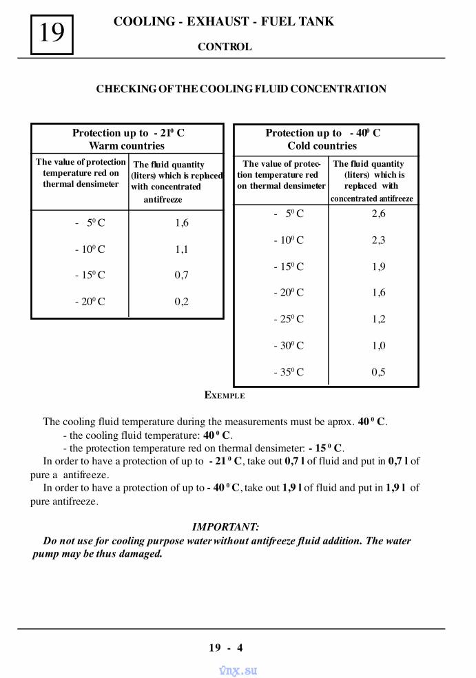
COOLING - EXHAUST - FUEL TANK19
19 - 4
EXEMPLE
The cooling fluid temperature during the measurements must be aprox. 40 0 C.- the cooling fluid temperature: 40 0 C.- the protection temperature red on thermal densimeter: - 15 0 C.
In order to have a protection of up to - 21 0 C, take out 0,7 l of fluid and put in 0,7 l ofpure a antifreeze.
In order to have a protection of up to - 40 0 C, take out 1,9 l of fluid and put in 1,9 l ofpure antifreeze.
IMPORTANT:Do not use for cooling purpose water without antifreeze fluid addition. The water
pump may be thus damaged.
Protection up to - 210 CWarm countries
The value of protectiontemperature red onthermal densimeter
The fluid quantity(liters) which is replacedwith concentrated
antifreeze
- 50 C
- 100 C
- 150 C
- 200 C
1,6
1,1
0,7
0,2
Protection up to - 400 CCold countries
- 50 C
- 100 C
- 150 C
- 200 C
- 250 C
- 300 C
- 350 C
2,6
2,3
1,9
1,6
1,2
1,0
0,5
CHECKING OF THE COOLING FLUID CONCENTRATION
The fluid quantity(liters) which isreplaced with
concentrated antifreeze
The value of protec-tion temperature redon thermal densimeter
CONTROL
vnx.su
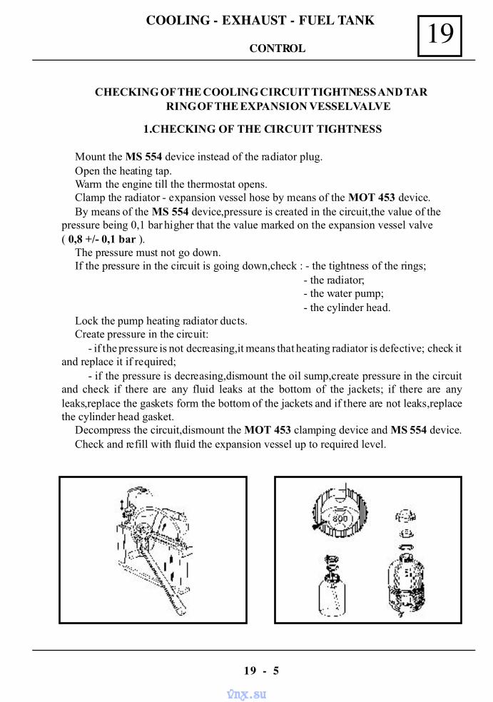
19COOLING - EXHAUST - FUEL TANK
19 - 5
1.CHECKING OF THE CIRCUIT TIGHTNESS
Mount the MS 554 device instead of the radiator plug.Open the heating tap.Warm the engine till the thermostat opens.Clamp the radiator - expansion vessel hose by means of the MOT 453 device.By means of the MS 554 device,pressure is created in the circuit,the value of the
pressure being 0,1 bar higher that the value marked on the expansion vessel valve( 0,8 +/- 0,1 bar ).
The pressure must not go down.If the pressure in the circuit is going down,check : - the tightness of the rings;
- the radiator; - the water pump; - the cylinder head.
Lock the pump heating radiator ducts.Create pressure in the circuit:
- if the pressure is not decreasing,it means that heating radiator is defective; check itand replace it if required;
- if the pressure is decreasing,dismount the oil sump,create pressure in the circuitand check if there are any fluid leaks at the bottom of the jackets; if there are anyleaks,replace the gaskets form the bottom of the jackets and if there are not leaks,replacethe cylinder head gasket.
Decompress the circuit,dismount the MOT 453 clamping device and MS 554 device.Check and refill with fluid the expansion vessel up to required level.
CHECKING OF THE COOLING CIRCUIT TIGHTNESS AND TARRING OF THE EXPANSION VESSEL VALVE
CONTROL
vnx.su
COOLING - EXHAUST - FUEL TANK19
19 - 6
2. CHECKING OF EXPANSION VESSEL VALVE TARRING
After checking the tightness of the cooling circuit, release the radiator-expansionvessel hose.
Create pressure in the circuit,value of the pressure shall be 0,1 bar higher that the valuemarked on the valve.
In this situation,the pressure must decrease.If the pressure does not decrease,the valveis blocked and shall be replaced.The valve shall be also be replaced in case it permits thefluid passing.
The mark on the expansion vessel valve is in milibars ( 800 = 0,8 bars ).
CONTROL
vnx.su
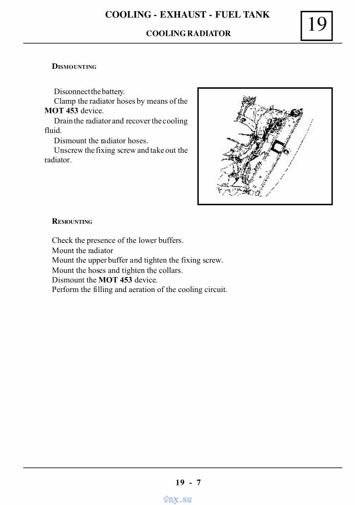
19COOLING - EXHAUST - FUEL TANK
19 - 7
Disconnect the battery.Clamp the radiator hoses by means of the
MOT 453 device.Drain the radiator and recover the cooling
fluid.Dismount the radiator hoses.Unscrew the fixing screw and take out the
radiator.
REMOUNTING
Check the presence of the lower buffers.Mount the radiatorMount the upper buffer and tighten the fixing screw.Mount the hoses and tighten the collars.Dismount the MOT 453 device.Perform the filling and aeration of the cooling circuit.
DISMOUNTING
COOLING RADIATOR
vnx.su
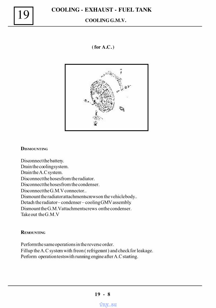
COOLING - EXHAUST - FUEL TANK19
19 - 8
( for A.C. )
DISMOUNTING
Disconnect the battery.Drain the cooling system.Drain the A.C system.Disconnect the hoses from the radiator.Disconnect the hoses from the condenser.Disconnect the G.M.V connector..Dismount the radiator attachment screws on the vehicle body..Detach the radiator – condenser – cooling GMV assembly.Dismount the G.M.V attachment screws on the condenser.Take out the G.M.V
REMOUNTING
Perform the same operations in the reverse order.Fill up the A.C system with freon ( refrigerant ) and check for leakage.Perform operation tests with running engine after A.C starting.
COOLING G.M.V.
vnx.su
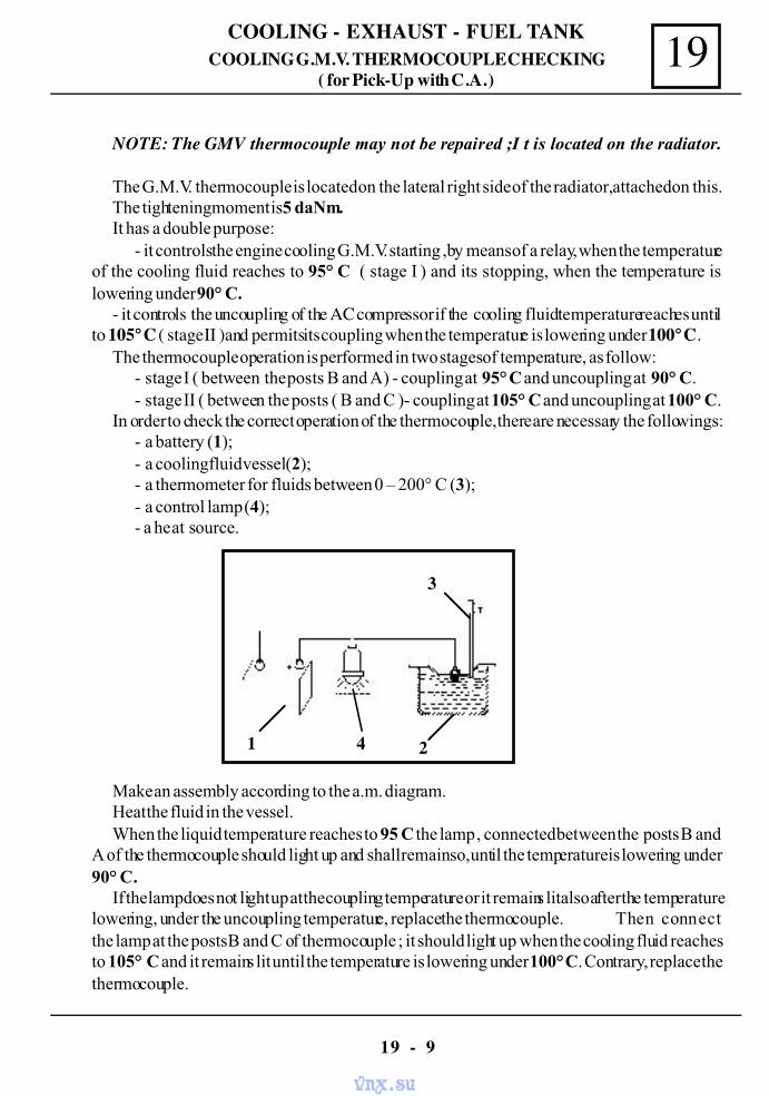
19COOLING - EXHAUST - FUEL TANK
19 - 9
NOTE: The GMV thermocouple may not be repaired ;I t is located on the radiator.
The G.M.V. thermocouple is located on the lateral right side of the radiator, attached on this.The tightening moment is 5 daNm.It has a double purpose:
- it controls the engine cooling G.M.V. starting ,by means of a relay, when the temperatureof the cooling fluid reaches to 95° C ( stage I ) and its stopping, when the temperature islowering under 90° C.
- it controls the uncoupling of the AC compressor if the cooling fluid temperature reaches untilto 105° C ( stage II )and permits its coupling when the temperature is lowering under 100° C.
The thermocouple operation is performed in two stages of temperature, as follow:- stage I ( between the posts B and A) - coupling at 95° C and uncoupling at 90° C.- stage II ( between the posts ( B and C )- coupling at 105° C and uncoupling at 100° C.
In order to check the correct operation of the thermocouple, there are necessary the followings:- a battery (1);- a cooling fluid vessel (2);- a thermometer for fluids between 0 – 200° C (3);- a control lamp (4);- a heat source.
Make an assembly according to the a.m. diagram.Heat the fluid in the vessel.When the liquid temperature reaches to 95 C the lamp , connected between the posts B and
A of the thermocouple should light up and shall remain so, until the temperature is lowering under90° C.
If the lamp does not light up at the coupling temperature or it remains lit also after the temperaturelowering, under the uncoupling temperature, replace the thermocouple. Then connectthe lamp at the posts B and C of thermocouple ; it should light up when the cooling fluid reachesto 105° C and it remains lit until the temperature is lowering under 100° C. Contrary, replace thethermocouple.
1 4 2
3
COOLING G.M.V. THERMOCOUPLE CHECKING( for Pick-Up with C.A. )
vnx.su
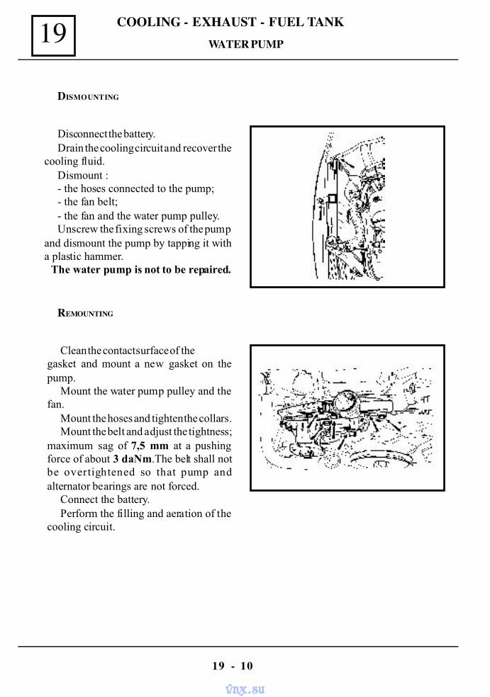
COOLING - EXHAUST - FUEL TANK19
19 - 10
Disconnect the battery.Drain the cooling circuit and recover the
cooling fluid.Dismount :- the hoses connected to the pump;- the fan belt;- the fan and the water pump pulley.Unscrew the fixing screws of the pump
and dismount the pump by tapping it witha plastic hammer. The water pump is not to be repaired.
DISMOUNTING
Clean the contact surface of thegasket and mount a new gasket on thepump.
Mount the water pump pulley and thefan.
Mount the hoses and tighten the collars.Mount the belt and adjust the tightness;
maximum sag of 7,5 mm at a pushingforce of about 3 daNm.The belt shall notbe overtightened so that pump andalternator bearings are not forced.
Connect the battery.Perform the filling and aeration of the
cooling circuit.
REMOUNTING
WATER PUMP
vnx.su
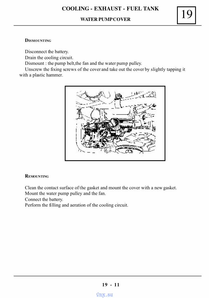
19COOLING - EXHAUST - FUEL TANK
19 - 11
DISMOUNTING
Disconnect the battery.Drain the cooling circuit.Dismount : the pump belt,the fan and the water pump pulley.Unscrew the fixing screws of the cover and take out the cover by slightly tapping it
with a plastic hammer.
REMOUNTING
Clean the contact surface of the gasket and mount the cover with a new gasket.Mount the water pump pulley and the fan.Connect the battery.Perform the filling and aeration of the cooling circuit.
WATER PUMP COVER
vnx.su
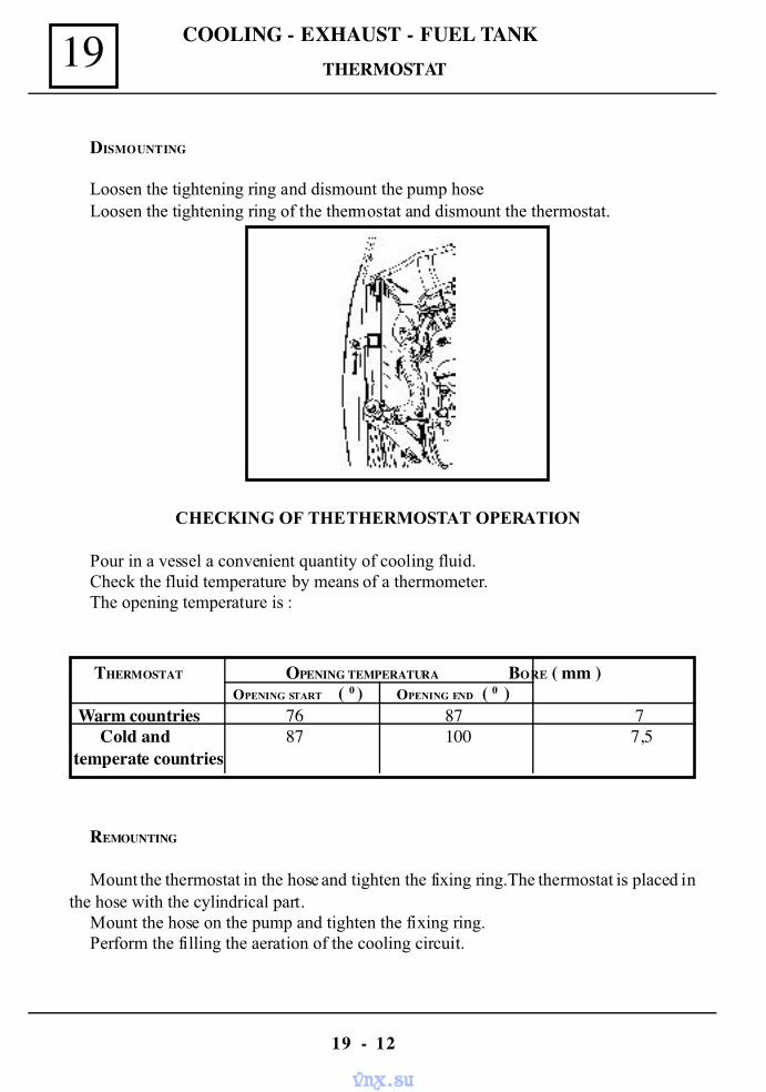
COOLING - EXHAUST - FUEL TANK19
19 - 12
CHECKING OF THE THERMOSTAT OPERATION
Pour in a vessel a convenient quantity of cooling fluid.Check the fluid temperature by means of a thermometer.The opening temperature is :
THERMOSTAT OPENING TEMPERATURA BORE ( mm )OPENING START ( 0 ) OPENING END ( 0 )
Warm countries 76 87 7 Cold and 87 100 7,5temperate countries
DISMOUNTING
Loosen the tightening ring and dismount the pump hoseLoosen the tightening ring of the thermostat and dismount the thermostat.
REMOUNTING
Mount the thermostat in the hose and tighten the fixing ring.The thermostat is placed inthe hose with the cylindrical part.
Mount the hose on the pump and tighten the fixing ring.Perform the filling the aeration of the cooling circuit.
THERMOSTAT
vnx.su
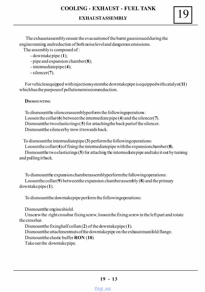
19COOLING - EXHAUST - FUEL TANK
19 - 13
The exhaust assembly ensure the evacuation of the burnt gases issued during theengine running and reduction of both noise level and dangerous emissions. The assembly is composed of :
- downtake pipe (1);- pipe and expansion chamber (8);- intermediate pipe (4);- silencer (7).
For vehicles equipped with injection system the downtake pipe is equipped with catalyst (11)which has the purpose of pollution emissions reduction.
DISMOUNTING
To dismount the silencer assembly perform the following operations :Loosen the collar (6) between the intermediate pipe (4) and the silencer (7).Dismount the two elastic rings (5) for attaching the back part of the silencer.Dismount the silencer by trow it towards back.
To dismount the intermediate pipe (3) perform the following operations:Loosen the collar (4) of fixing the intermediate pipe with the expansion chamber (8).Dismount the two elastic rings (5) for attaching the intermediate pipe and take it out by turning
and pulling it back.
To dismount the expansion chamber assembly perform the following operations:Loosen the collar (9) between the expansion chamber assembly (8) and the primary
downtake pipe (1).
To dismount the downtake pipe perform the following operations:
Dismount the engine shield.Unscrew the right crossbar fixing screw, loosen the fixing screw in the left part and rotate
the crossbar.Dismount the fixing half collars (2) of the downtake pipe (1).Dismount the attachment nuts of the downtake pipe on the exhaust manifold flange.Dismount the elastic buffer RON (10).Take out the downtake pipe.
EXHAUST ASSEMBLY
vnx.su
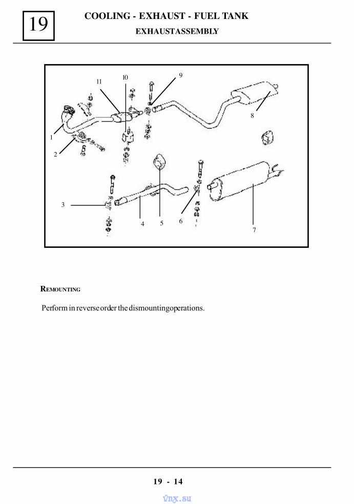
COOLING - EXHAUST - FUEL TANK19
19 - 14
REMOUNTING
Perform in reverse order the dismounting operations.
91011
8
7654
3
1
2
EXHAUST ASSEMBLY
vnx.su
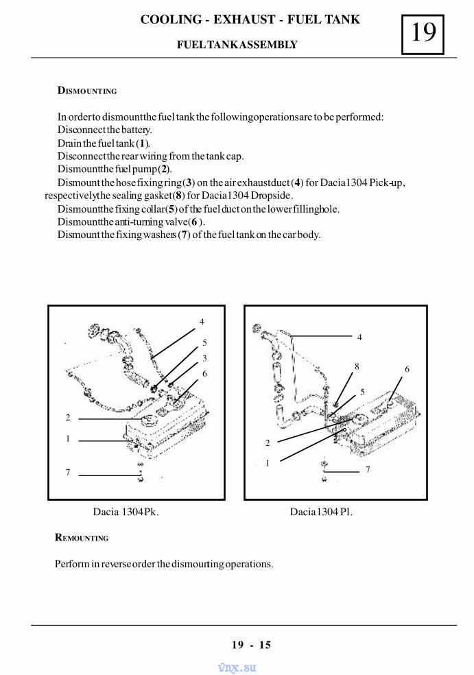
19COOLING - EXHAUST - FUEL TANK
19 - 15
DISMOUNTING
In order to dismount the fuel tank the following operations are to be performed:Disconnect the battery.Drain the fuel tank (1).Disconnect the rear wiring from the tank cap.Dismount the fuel pump (2).Dismount the hose fixing ring (3) on the air exhaust duct (4) for Dacia 1304 Pick-up,
respectively the sealing gasket (8) for Dacia 1304 Dropside.Dismount the fixing collar (5) of the fuel duct on the lower filling hole.Dismount the anti-turning valve (6 ).Dismount the fixing washers (7) of the fuel tank on the car body.
REMOUNTING
Perform in reverse order the dismounting operations.
Dacia 1304 Pk. Dacia 1304 Pl.
4
5
3
6
2
1
7
4
5
8 6
2
71
FUEL TANK ASSEMBLY
vnx.su
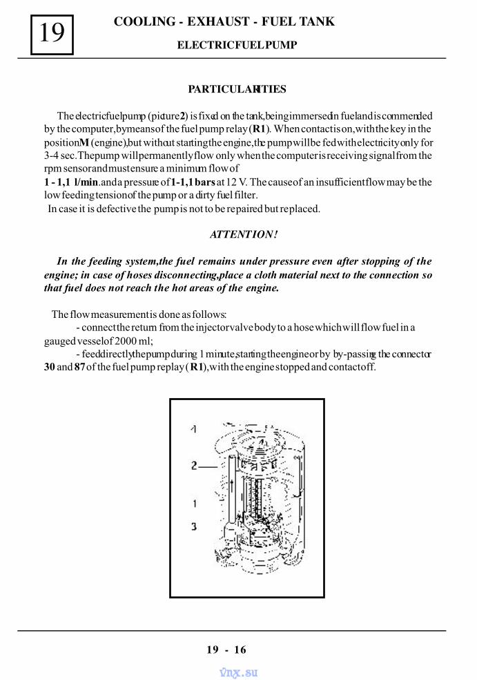
COOLING - EXHAUST - FUEL TANK19
19 - 16
PARTICULARITIES
The electric fuel pump (picture 2) is fixed on the tank,being immersed in fuel and is commendedby the computer,by means of the fuel pump relay (R1). When contact is on,with the key in theposition M (engine),but without starting the engine,the pump will be fed with electricity only for3-4 sec.The pump will permanently flow only when the computer is receiving signal from therpm sensor and must ensure a minimum flow of1 - 1,1 l/min.and a pressure of 1-1,1 bars at 12 V. The cause of an insufficient flow may be thelow feeding tension of the pump or a dirty fuel filter. In case it is defective the pump is not to be repaired but replaced.
ATTENTION!
In the feeding system,the fuel remains under pressure even after stopping of theengine; in case of hoses disconnecting,place a cloth material next to the connection sothat fuel does not reach the hot areas of the engine.
The flow measurement is done as follows:- connect the return from the injector valve body to a hose which will flow fuel in a
gauged vessel of 2000 ml;- feed directly the pump during 1 minute,starting the engine or by by-passing the connector
30 and 87 of the fuel pump replay (R1),with the engine stopped and contact off.
ELECTRIC FUEL PUMP
vnx.su
19COOLING - EXHAUST - FUEL TANK
19 - 17
( dismounting the tank from the vehicle not required )
DISMOUNTING
Unscrew the fixing screws of the fuel tank visiting cap.Disconnect the rear wiring from the tank cap.Dismount the fixing rings of the hoses and disconnect the hoses from the tank cap.Dismount by turning counter clockwisedirection,the blocking ring of the tank cap.Lift a little bet the tank cap,to enable unlocking the fixing clamp of the pump support in the
protector vessel; unlock the clamp and take out from the tank its cap together with support withthe electric pump and the fuel level transmitter.
Disconnect the feeding wiring from pump and fuel level transmitter.Dismount the fixing ring of the hose going to the pump.Unscrew the fixing screws of upper and lower rings of the fuel pump.Take out the pump from the collars with gaskets.
REMOUNTING
Perform in reverse order the dismounting operations.
ATTENTION:
When mounting,good fixing rings are to be used and these will be well tightened.The feeding wiring terminals of the pump and of the fuel level transmitter shall be wellfixed, to enable perfect electric contacts. The maximum applied force on connectorsterminals on axial direction of the pump shall not exceed 80 N.
ELECTRIC FUEL PUMP
vnx.su
COOLING - EXHAUST - FUEL TANK19
19 - 18
( dismounting the tank from the vehicle not required )
DISMOUNTING
Unscrew the fixing screws of the fuel tank visiting cap.Disconnect the rear wiring from the tank cap.Dismount the hoses fixing rings and dismount the hoses from the tank cap.Dismount,by turning counter clockwise direction,the fixing ring of the tank cap.Lift a little bet the tank cap, to enable unlocking the fixing clamp of the pump support in the
protector vessel; unlock the clamp and take out from the tank its cap together with support withthe electric pump and the fuel level transmitter.
Disconnect the wiring of the fuel level sensor.Unscrew the sensor fixing screws.
REMOUNTING
Perform in reverse order the dismounting operations.
ATTENTION!
When mounting,good fixing rings are to be used and these will be well tightened.The feeding wiring terminals of the pump and of the fuel level transmitter shall bewell fixed, to enable perfect electric contacts. The maximum applied force on connec-tors terminals on axial direction of the pump shall not exceed 80 N.
The blocking ring of the fuel cap shall ensure the perfect sealing of it.
FUEL LEVEL SENSOR
vnx.su
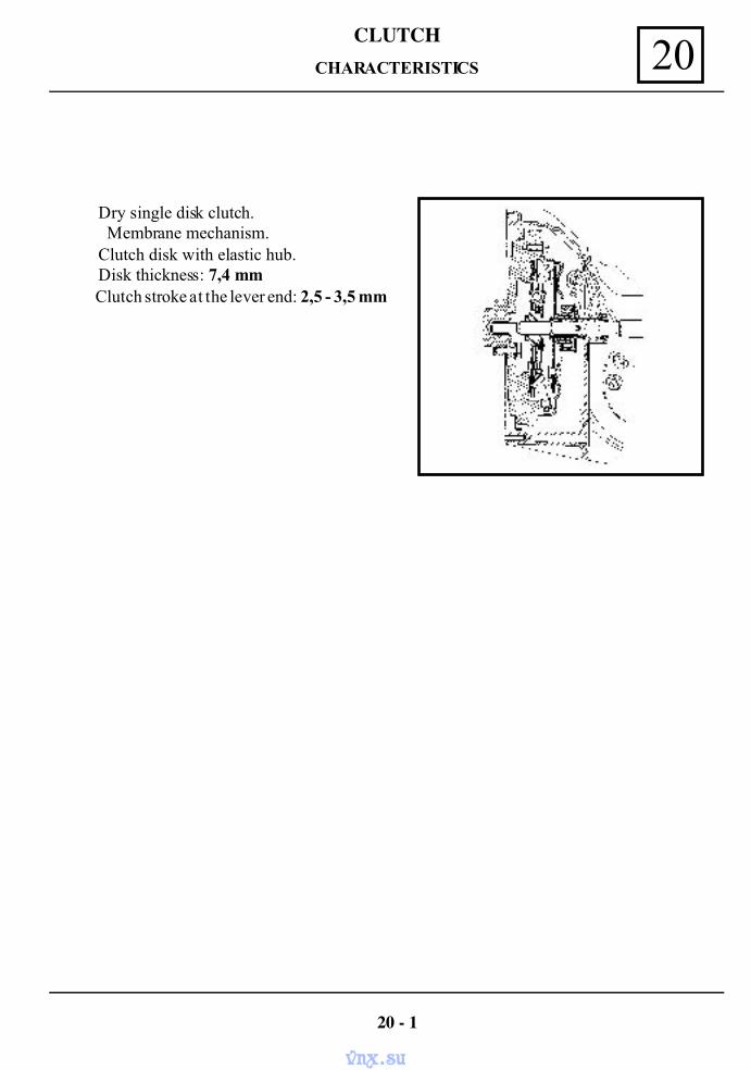
CLUTCH20CHARACTERISTICS
Dry single disk clutch.Membrane mechanism.
Clutch disk with elastic hub. Disk thickness: 7,4 mm Clutch stroke at the lever end: 2,5 - 3,5 mm
20 - 1
vnx.su
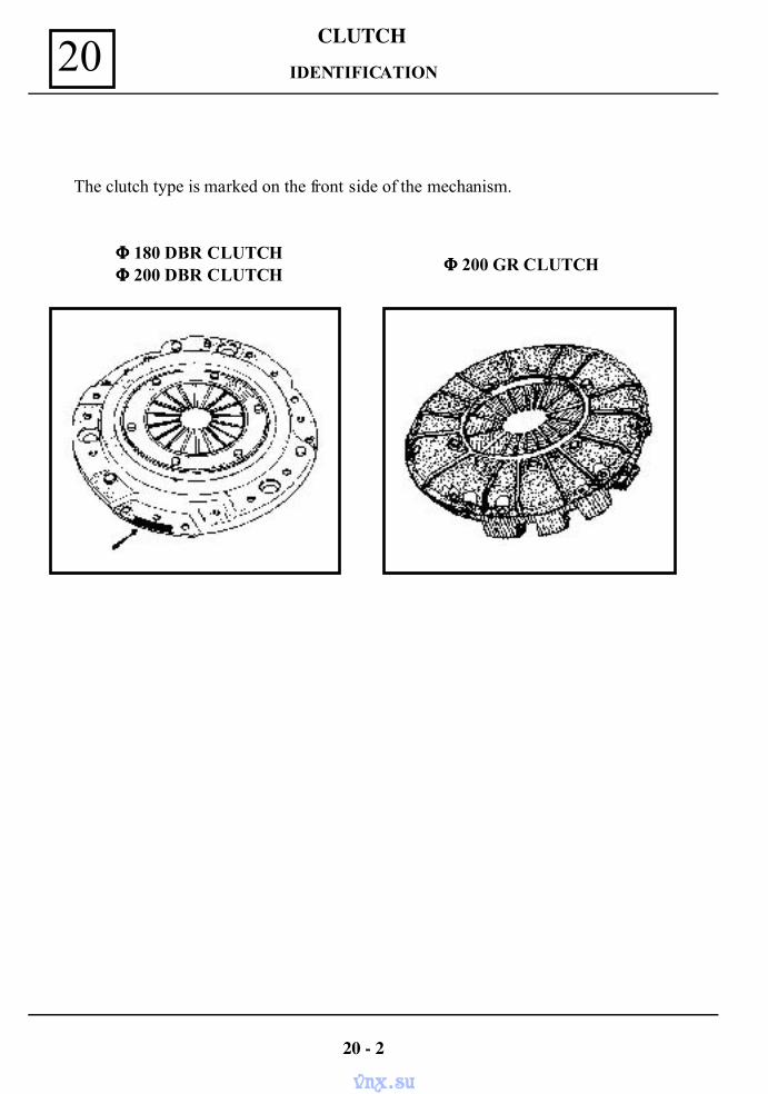
CLUTCH20 IDENTIFICATION
The clutch type is marked on the front side of the mechanism.
ΦΦΦΦ 180 DBR CLUTCH ΦΦΦΦ 200 DBR CLUTCH
ΦΦΦΦ 200 GR CLUTCH
20 - 2
vnx.su
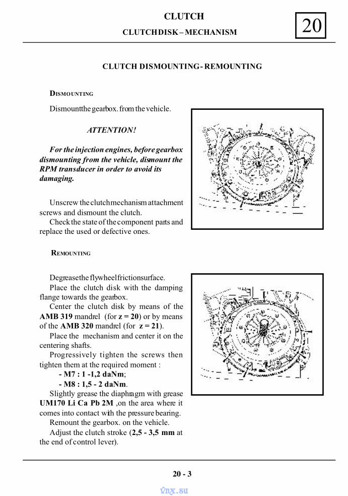
CLUTCH20
CLUTCH DISMOUNTING - REMOUNTING
Dismount the gearbox. from the vehicle.
Degrease the flywheel friction surface.Place the clutch disk with the damping
flange towards the gearbox.Center the clutch disk by means of the
AMB 319 mandrel (for z = 20) or by meansof the AMB 320 mandrel (for z = 21).
Place the mechanism and center it on thecentering shafts.
Progressively tighten the screws thentighten them at the required moment :
- M7 : 1 -1,2 daNm;- M8 : 1,5 - 2 daNm.
Slightly grease the diaphragm with greaseUM170 Li Ca Pb 2M ,on the area where itcomes into contact with the pressure bearing.
Remount the gearbox. on the vehicle.Adjust the clutch stroke (2,5 - 3,5 mm at
the end of control lever).
DISMOUNTING
ATTENTION!
For the injection engines, before gearboxdismounting from the vehicle, dismount theRPM transducer in order to avoid itsdamaging.
Unscrew the clutch mechanism attachmentscrews and dismount the clutch.
Check the state of the component parts andreplace the used or defective ones.
REMOUNTING
20 - 3
CLUTCH DISK – MECHANISM
vnx.su
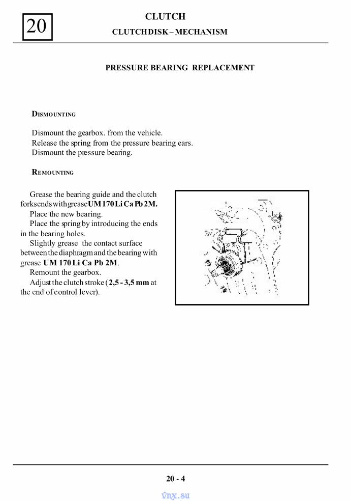
CLUTCH20
PRESSURE BEARING REPLACEMENT
DISMOUNTING
Dismount the gearbox. from the vehicle.Release the spring from the pressure bearing ears.Dismount the pressure bearing.
REMOUNTING
Grease the bearing guide and the clutchforks ends with grease UM 170 Li Ca Pb 2M.
Place the new bearing.Place the spring by introducing the ends
in the bearing holes.Slightly grease the contact surface
between the diaphragm and the bearing withgrease UM 170 Li Ca Pb 2M.
Remount the gearbox.Adjust the clutch stroke (2,5 - 3,5 mm at
the end of control lever).
20 - 4
CLUTCH DISK – MECHANISM
vnx.su
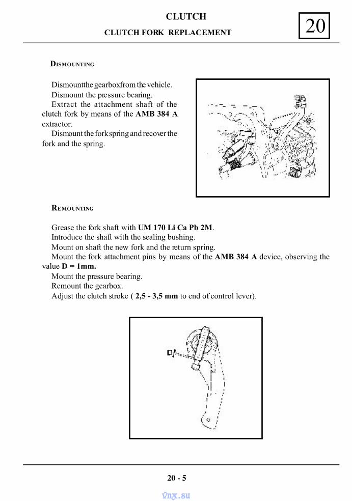
CLUTCH20 CLUTCH FORK REPLACEMENT
Grease the fork shaft with UM 170 Li Ca Pb 2M.Introduce the shaft with the sealing bushing.Mount on shaft the new fork and the return spring.Mount the fork attachment pins by means of the AMB 384 A device, observing the
value D = 1mm.Mount the pressure bearing.Remount the gearbox.Adjust the clutch stroke ( 2,5 - 3,5 mm to end of control lever).
REMOUNTING
20 - 5
DISMOUNTING
Dismount the gearbox from the vehicle.Dismount the pressure bearing.Extract the attachment shaft of the
clutch fork by means of the AMB 384 Aextractor.
Dismount the fork spring and recover thefork and the spring.
vnx.su
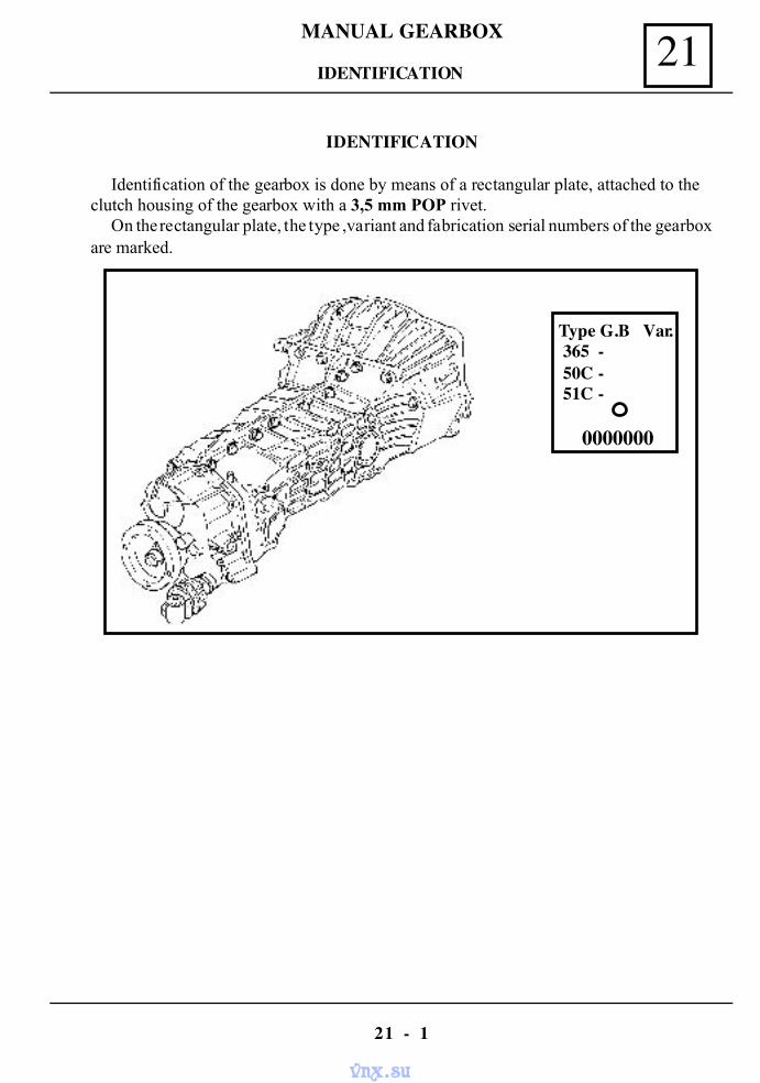
MANUAL GEARBOX 21
21 - 1
IDENTIFICATION
Identification of the gearbox is done by means of a rectangular plate, attached to theclutch housing of the gearbox with a 3,5 mm POP rivet.
On the rectangular plate, the type ,variant and fabrication serial numbers of the gearboxare marked.
Type G.B Var. 365 - 50C - 51C -
0000000
IDENTIFICATION
vnx.su
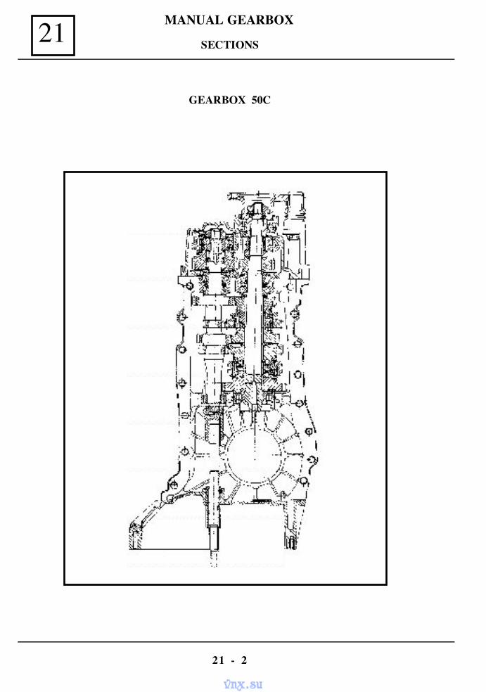
MANUAL GEARBOX21
21 - 2
GEARBOX 50C
SECTIONS
vnx.su
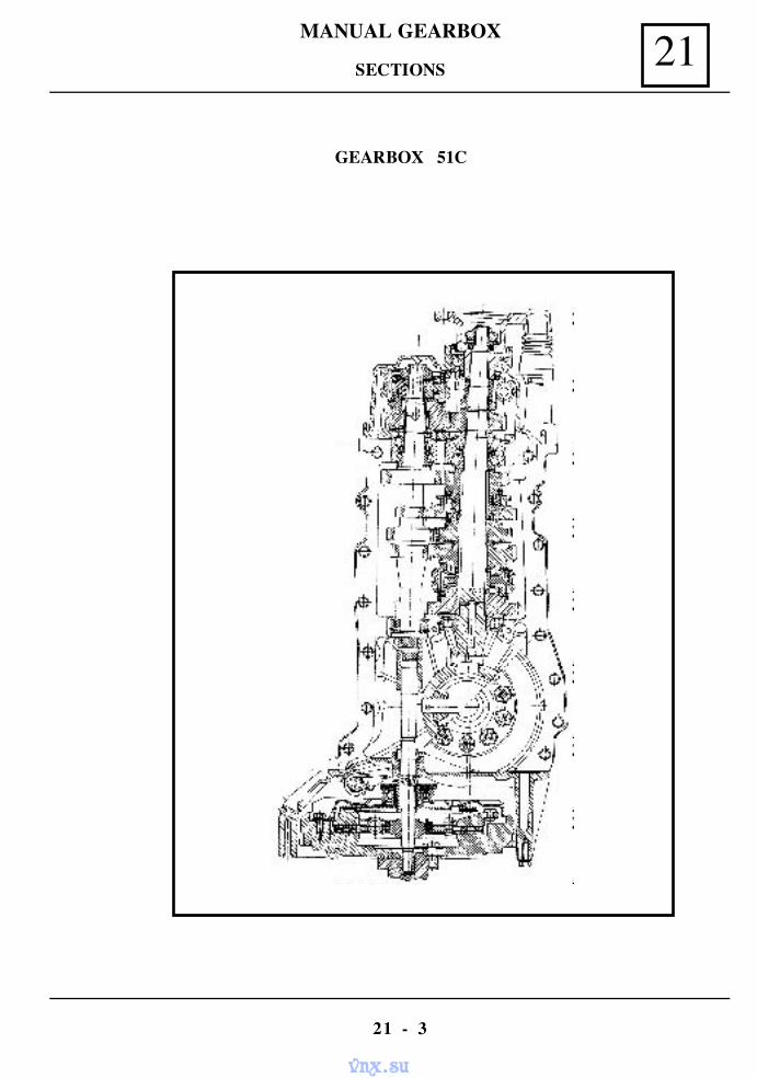
MANUAL GEARBOX 21
21 - 3
SECTIONS
GEARBOX 51C
vnx.su
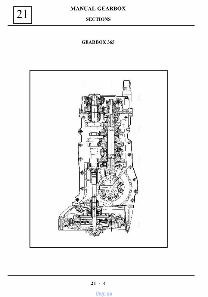
MANUAL GEARBOX21
21 - 4
GEARBOX 365
SECTIONS
vnx.su
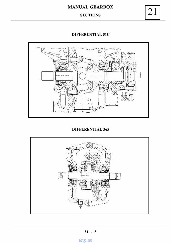
MANUAL GEARBOX 21
21 - 5
DIFFERENTIAL 51C
DIFFERENTIAL 365
SECTIONS
vnx.su
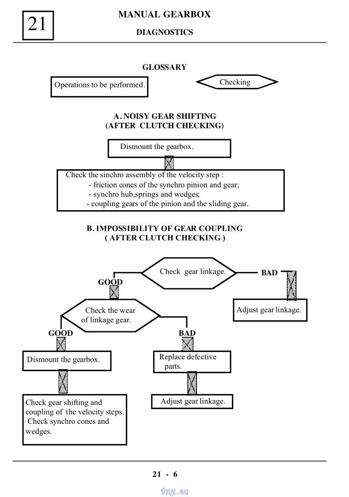
MANUAL GEARBOX21
21 - 6
GLOSSARY
Operations to be performed. Checking
A. NOISY GEAR SHIFTING(AFTER CLUTCH CHECKING)
Dismount the gearbox.
Check the sinchro assembly of the velocity step : - friction cones of the synchro pinion and gear; - synchro hub,springs and wedges; - coupling gears of the pinion and the sliding gear.
B. IMPOSSIBILITY OF GEAR COUPLING( AFTER CLUTCH CHECKING )
Check gear linkage.
Adjust gear linkage. Check the wear of linkage gear.
Dismount the gearbox.
Check gear shifting andcoupling of the velocity steps. Check synchro cones andwedges.
Replace defectiveparts.
Adjust gear linkage.
BADGOOD
GOOD BAD
DIAGNOSTICS
vnx.su
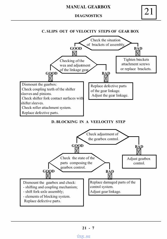
MANUAL GEARBOX 21
21 - 7
DIAGNOSTICS
C. SLIPS OUT OF VELOCITY STEPS OF GEAR BOX
D. BLOCKING IN A VEELOCITY STEP
Check the situationof brackets of assembly.
Checking of thewea and adjustmentof the linkage gear
Tighten bracketsattachment screws
or replace brackets.
Dismount the gearbox: Check coupling teeth of the shiftersleeves and pinions. Check shifter fork contact surfaces withshifter sleeves. Check roller attachment system. Replace defective parts.
Replace defective partsof the gear linkage. Adjust the gear linkage.
GOOD
GOOD
BAD
BAD
Check adjustment of the gearbox control.
Check the state of theparts composing thegearbox control.
Adjust gearboxcontrol.
Dismount the gearbox and check:- shifting and coupling mechanism;- shift fork-axle assembly;- elements of blocking system. Replace defective parts.
Replace damaged parts of thecontrol system.Adjust gear linkage.
GOOD BAD
GOOD BAD
vnx.su

MANUAL GEARBOX21
21 - 8
DIAGNOSTICS
E. UNUSUAL NOISES DURING DRIVING
Stop the vehicle. Bring the gear shifting handle todead point. Let the engine running.
The noise stops.
Check the state ofclutch stroke.
Check transmissionstate.
Check the clutch control system. Replace defective parts.
Check the level of thegearbox oil.Fill to proper level ifneeded.
Repair the transmission.
The noise stops.
Check the wear ofwheels bearings.
Declutching, press theclutch pedal to end ofstroke.
STOP
The noise stops.
Replace thewheels bearings.
Dismount the gearbox andset it in working state.
Search for noise source atthe engine assembly level.
YES
YES
YES
NO
NO
NO
GOOD
GOOD
GOODBAD
BAD
BAD
vnx.su
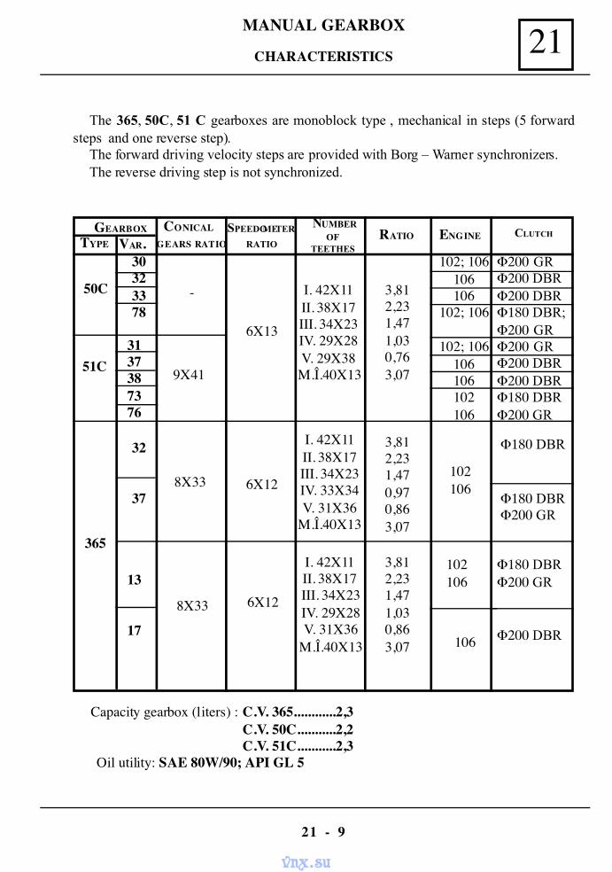
MANUAL GEARBOX 21
21 - 9
CHARACTERISTICS
The 365, 50C, 51 C gearboxes are monoblock type , mechanical in steps (5 forwardsteps and one reverse step).
The forward driving velocity steps are provided with Borg – Warner synchronizers.The reverse driving step is not synchronized.
Capacity gearbox (liters) : C.V. 365............2,3C.V. 50C...........2,2C.V. 51C...........2,3
Oil utility: SAE 80W/90; API GL 5
GEARBOXTYPE VAR.
CONICAL
GEARS RATIOSPEEDOMETER
RATIORATIO ENGINE CLUTCH
50C
30323378
-
6X13
I. 42X11II. 38X17III. 34X23IV. 29X28V. 29X38M.Î.40X13
3,812,231,471,030,763,0751C
3137387376
9X41
102; 106106106
102; 106
102; 106106106102106
Φ200 GRΦ200 DBRΦ200 DBRΦ180 DBR;Φ200 GRΦ200 GRΦ200 DBRΦ200 DBRΦ180 DBRΦ200 GR
365
32
37
13
17
8X33 6X12
I. 42X11II. 38X17III. 34X23IV. 29X28V. 31X36
M.Î.40X13
I. 42X11II. 38X17III. 34X23IV. 33X34V. 31X36
M.Î.40X13
3,812,231,470,970,863,07
3,812,231,471,030,863,07
102106
102106
106
Φ180 DBR
Φ200 GR
Φ180 DBRΦ200 GR
8X33 6X12
Φ180 DBR
Φ200 DBR
NUMBEROF
TEETHES
vnx.su
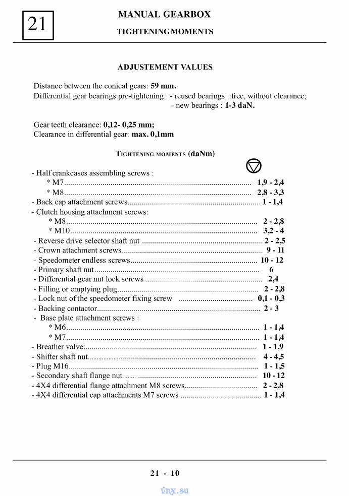
MANUAL GEARBOX21
21 - 10
TIGHTENING MOMENTS
ADJUSTEMENT VALUES
Distance between the conical gears: 59 mm. Differential gear bearings pre-tightening : - reused bearings : free, without clearance;
- new bearings : 1-3 daN.
Gear teeth clearance: 0,12- 0,25 mm; Clearance in differential gear: max. 0,1mm
TIGHTENING MOMENTS (daNm)
- Half crankcases assembling screws :* M7............................................................................................. 1,9 - 2,4* M8............................................................................................. 2,8 - 3,3
- Back cap attachment screws.................................................................. 1 - 1,4- Clutch housing attachment screws:
* M8............................................................................................... 2 - 2,8 * M10............................................................................................. 3,2 - 4
- Reverse drive selector shaft nut ............................................................ 2 - 2,5 - Crown attachment screws...................................................................... 9 - 11 - Speedometer endless screws............................................................... 10 - 12 - Primary shaft nut.................................................................................. 6 - Differential gear nut lock screws .......................................................... 2,4 - Filling or emptying plug...................................................................... 2 - 2,8 - Lock nut of the speedometer fixing screw ..................................... 0,1 - 0,3 - Backing contactor................................................................................. 2 - 3 - Base plate attachment screws :
* M6................................................................................................ 1 - 1,4 * M7................................................................................................ 1 - 1,4
- Breather valve...................................................................................... 1 - 1,9- Shifter shaft nut...................................................................................... 4 - 4,5- Plug M16.............................................................................................. 1 - 1,5- Secondary shaft flange nut........ ........................................................... 10 - 12- 4X4 differential flange attachment M8 screws.................................... 2 - 2,8- 4X4 differential cap attachments M7 screws ........................................ 1 - 1,4
vnx.su
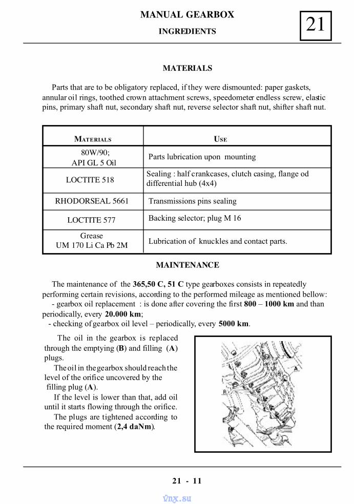
MANUAL GEARBOX 21
21 - 11
INGREDIENTS
MATERIALS
Parts that are to be obligatory replaced, if they were dismounted: paper gaskets,annular oil rings, toothed crown attachment screws, speedometer endless screw, elasticpins, primary shaft nut, secondary shaft nut, reverse selector shaft nut, shifter shaft nut.
MATERIALS USE
80W/90;API GL 5 Oil
Parts lubrication upon mounting
LOCTITE 518Sealing : half crankcases, clutch casing, flange oddifferential hub (4x4)
RHODORSEAL 5661 Transmissions pins sealing
LOCTITE 577 Backing selector; plug M 16
GreaseUM 170 Li Ca Pb 2M Lubrication of knuckles and contact parts.
MAINTENANCE
The maintenance of the 365,50 C, 51 C type gearboxes consists in repeatedlyperforming certain revisions, according to the performed mileage as mentioned bellow:
- gearbox oil replacement : is done after covering the first 800 – 1000 km and thanperiodically, every 20.000 km; - checking of gearbox oil level – periodically, every 5000 km.
The oil in the gearbox is replacedthrough the emptying (B) and filling (A)plugs.
The oil in the gearbox should reach thelevel of the orifice uncovered by the filling plug (A).
If the level is lower than that, add oiluntil it starts flowing through the orifice.
The plugs are tightened according tothe required moment (2,4 daNm).
vnx.su
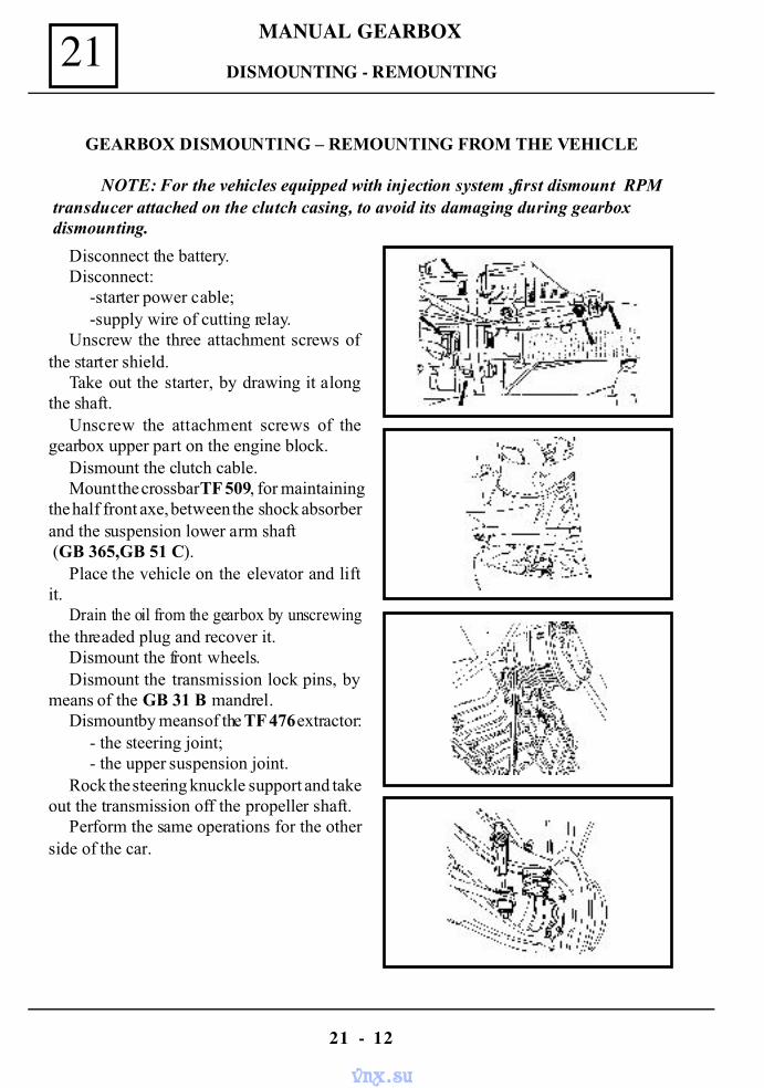
MANUAL GEARBOX21
21 - 12
DISMOUNTING - REMOUNTING
GEARBOX DISMOUNTING – REMOUNTING FROM THE VEHICLE
NOTE: For the vehicles equipped with injection system ,first dismount RPM transducer attached on the clutch casing, to avoid its damaging during gearbox dismounting.
Disconnect the battery.Disconnect:
-starter power cable;-supply wire of cutting relay.
Unscrew the three attachment screws ofthe starter shield.
Take out the starter, by drawing it alongthe shaft.
Unscrew the attachment screws of thegearbox upper part on the engine block.
Dismount the clutch cable.Mount the crossbar TF 509, for maintaining
the half front axe, between the shock absorberand the suspension lower arm shaft (GB 365,GB 51 C).
Place the vehicle on the elevator and liftit.
Drain the oil from the gearbox by unscrewingthe threaded plug and recover it.
Dismount the front wheels.Dismount the transmission lock pins, by
means of the GB 31 B mandrel.Dismount by means of the TF 476 extractor:
- the steering joint;- the upper suspension joint.
Rock the steering knuckle support and takeout the transmission off the propeller shaft.
Perform the same operations for the otherside of the car.
vnx.su
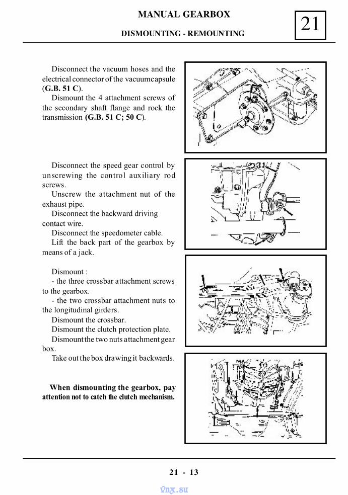
MANUAL GEARBOX 21
21 - 13
DISMOUNTING - REMOUNTING
Disconnect the vacuum hoses and theelectrical connector of the vacuum capsule(G.B. 51 C).
Dismount the 4 attachment screws ofthe secondary shaft flange and rock thetransmission (G.B. 51 C; 50 C).
Disconnect the speed gear control byunscrewing the control auxiliary rodscrews.
Unscrew the attachment nut of theexhaust pipe.
Disconnect the backward drivingcontact wire.
Disconnect the speedometer cable.Lift the back part of the gearbox by
means of a jack.
Dismount :- the three crossbar attachment screws
to the gearbox.- the two crossbar attachment nuts to
the longitudinal girders.Dismount the crossbar.Dismount the clutch protection plate.Dismount the two nuts attachment gear
box.Take out the box drawing it backwards.
When dismounting the gearbox, payattention not to catch the clutch mechanism.
vnx.su
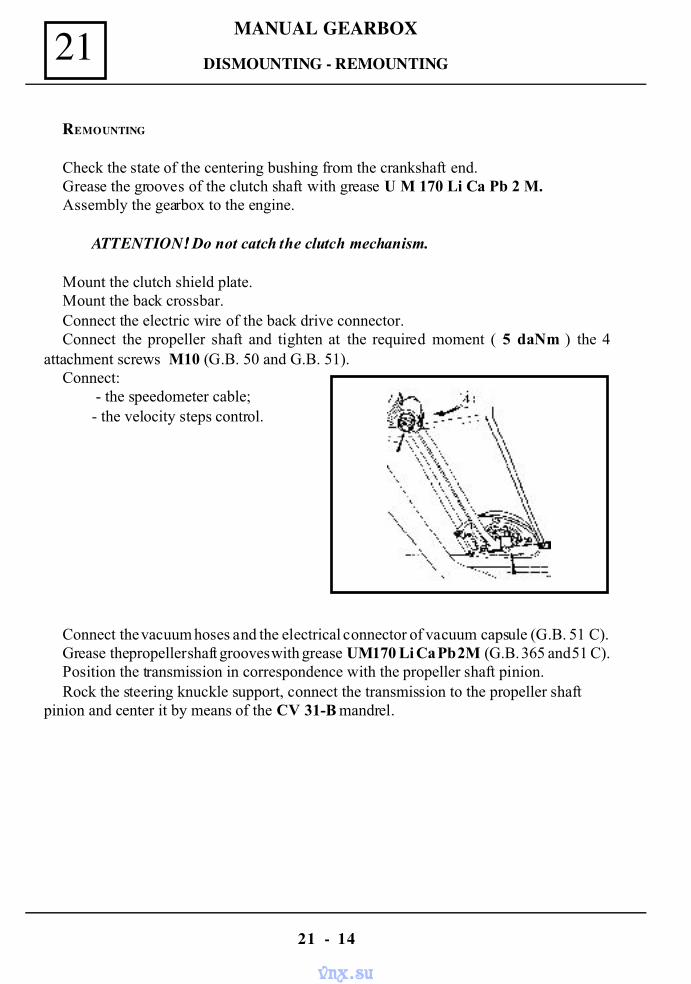
MANUAL GEARBOX21
21 - 14
DISMOUNTING - REMOUNTING
REMOUNTING
Check the state of the centering bushing from the crankshaft end.Grease the grooves of the clutch shaft with grease U M 170 Li Ca Pb 2 M.Assembly the gearbox to the engine.
ATTENTION!!!! Do not catch the clutch mechanism.
Mount the clutch shield plate.Mount the back crossbar.Connect the electric wire of the back drive connector.Connect the propeller shaft and tighten at the required moment ( 5 daNm ) the 4
attachment screws M10 (G.B. 50 and G.B. 51).Connect:
- the speedometer cable;- the velocity steps control.
Connect the vacuum hoses and the electrical connector of vacuum capsule (G.B. 51 C).Grease the propeller shaft grooves with grease UM 170 Li Ca Pb 2M (G.B. 365 and 51 C).Position the transmission in correspondence with the propeller shaft pinion.Rock the steering knuckle support, connect the transmission to the propeller shaft
pinion and center it by means of the CV 31-B mandrel.
vnx.su
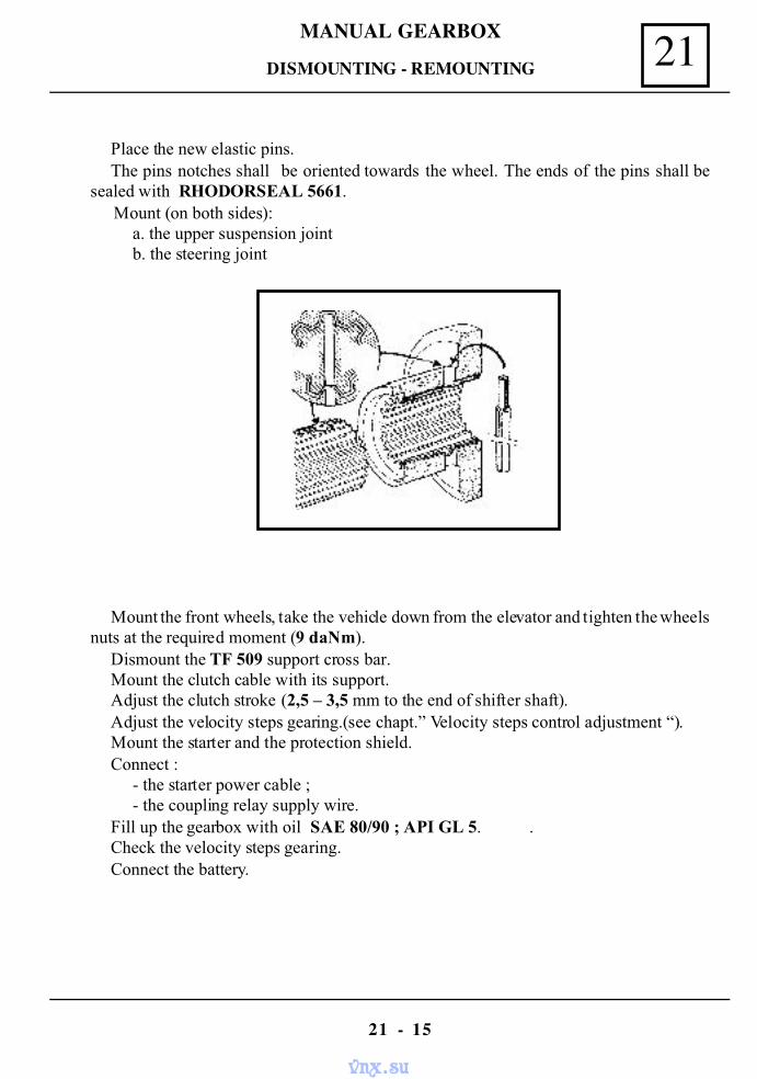
MANUAL GEARBOX 21
21 - 15
Place the new elastic pins.The pins notches shall be oriented towards the wheel. The ends of the pins shall be
sealed with RHODORSEAL 5661. Mount (on both sides):
a. the upper suspension jointb. the steering joint
Mount the front wheels, take the vehicle down from the elevator and tighten the wheelsnuts at the required moment (9 daNm).
Dismount the TF 509 support cross bar.Mount the clutch cable with its support.Adjust the clutch stroke (2,5 – 3,5 mm to the end of shifter shaft).Adjust the velocity steps gearing.(see chapt.” Velocity steps control adjustment “).Mount the starter and the protection shield.Connect :
- the starter power cable ;- the coupling relay supply wire.
Fill up the gearbox with oil SAE 80/90 ; API GL 5. .Check the velocity steps gearing.Connect the battery.
DISMOUNTING - REMOUNTING
vnx.su
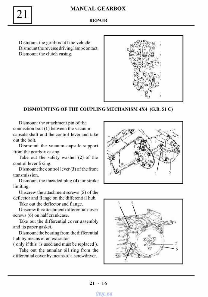
MANUAL GEARBOX21
21 - 16
REPAIR
Dismount the gearbox off the vehicleDismount the reverse driving lamp contact.Dismount the clutch casing.
DISMOUNTING OF THE COUPLING MECHANISM 4X4 (G.B. 51 C)
Dismount the attachment pin of theconnection bolt (1) between the vacuumcapsule shaft and the control lever and takeout the bolt.
Dismount the vacuum capsule supportfrom the gearbox casing.
Take out the safety washer (2) of thecontrol lever fixing.
Dismount the control lever (3) of the fronttransmission.
Dismount the threaded plug (4) for strokelimiting.
Unscrew the attachment screws (5) of thedeflector and flange on the differential hub.
Take out the deflector and flange.Unscrew the attachment differential cover
screws (6) on half crankcase.Take out the differential cover assembly
and its paper gasket.Dismount the bearing from the differential
hub by means of an extractor( only if this is used and must be replaced ).
Take out the annular oil ring from thedifferential cover by means of a screwdriver.
2
1 2
65
3 4
vnx.su
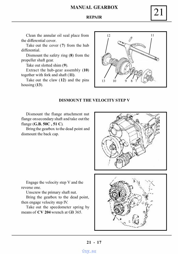
MANUAL GEARBOX 21
21 - 17
Clean the annular oil seal place fromthe differential cover.
Take out the cover (7) from the hubdifferential.
Dismount the safety ring (8) from thepropeller shaft gear.
Take out slotted shim (9).Extract the hub-gear assembly (10)
together with fork and shaft (11).Take out the claw (12) and the pins
housing (13).
REPAIR
DISMOUNT THE VELOCITY STEP V
Dismount the flange attachment nutflange on secondary shaft and take out theflange (G.B. 50C , 51 C).
Bring the gearbox to the dead point anddismount the back cap.
Engage the velocity step V and thereverse one.
Unscrew the primary shaft nut.Bring the gearbox to the dead point,
then engage velocity step IV.Take out the speedometer spring by
means of CV 204 wrench at GB 365.
12
13 10 9 8 7
11
vnx.su
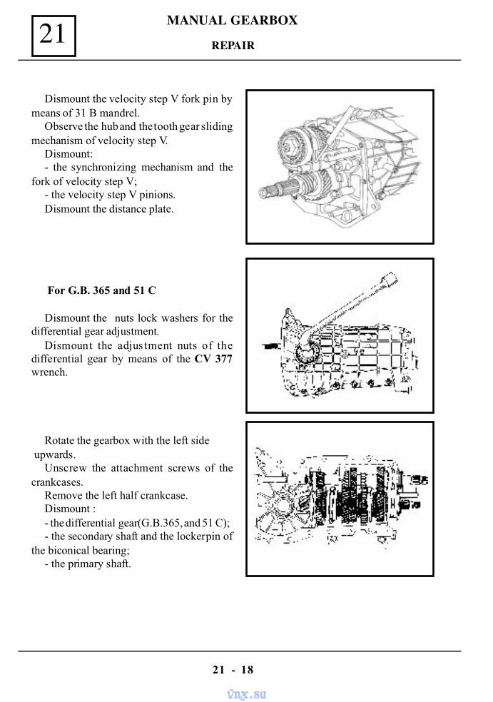
MANUAL GEARBOX21
21 - 18
REPAIR
Dismount the velocity step V fork pin bymeans of 31 B mandrel.
Observe the hub and the tooth gear slidingmechanism of velocity step V.
Dismount:- the synchronizing mechanism and the
fork of velocity step V;- the velocity step V pinions.Dismount the distance plate.
For G.B. 365 and 51 C
Dismount the nuts lock washers for thedifferential gear adjustment.
Dismount the adjus tment nuts of thedifferential gear by means of the CV 377wrench.
Rotate the gearbox with the left side upwards.
Unscrew the attachment screws of thecrankcases.
Remove the left half crankcase.Dismount :- the differential gear (G.B.365, and 51 C);- the secondary shaft and the locker pin of
the biconical bearing;- the primary shaft.
vnx.su
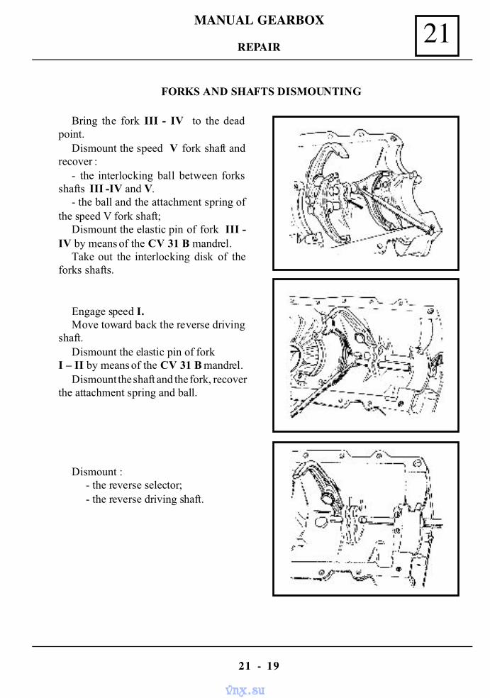
MANUAL GEARBOX 21
21 - 19
REPAIR
FORKS AND SHAFTS DISMOUNTING
Bring the fork III - IV to the deadpoint.
Dismount the speed V fork shaft andrecover :
- the interlocking ball between forksshafts III -IV and V.
- the ball and the attachment spring ofthe speed V fork shaft;
Dismount the elastic pin of fork III -IV by means of the CV 31 B mandrel.
Take out the interlocking disk of theforks shafts.
Engage speed I.Move toward back the reverse driving
shaft.Dismount the elastic pin of fork
I – II by means of the CV 31 B mandrel.Dismount the shaft and the fork, recover
the attachment spring and ball.
Dismount :- the reverse selector;- the reverse driving shaft.
vnx.su
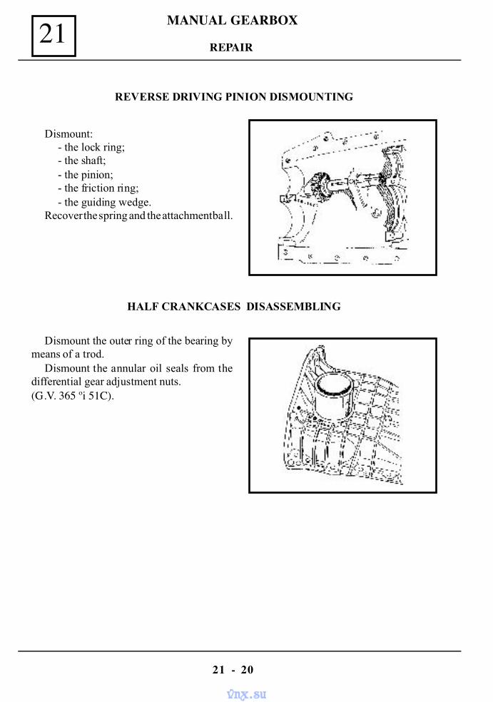
MANUAL GEARBOX21
21 - 20
REPAIR
REVERSE DRIVING PINION DISMOUNTING
Dismount:- the lock ring;- the shaft;- the pinion;- the friction ring;- the guiding wedge.
Recover the spring and the attachment ball.
HALF CRANKCASES DISASSEMBLING
Dismount the outer ring of the bearing bymeans of a trod.
Dismount the annular oil seals from thedifferential gear adjustment nuts.(G.V. 365 ºi 51C).
vnx.su
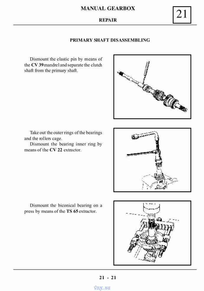
MANUAL GEARBOX 21
21 - 21
REPAIR
PRIMARY SHAFT DISASSEMBLING
Dismount the elastic pin by means ofthe CV 39 mandrel and separate the clutchshaft from the primary shaft.
Take out the outer rings of the bearingsand the rollers cage.
Dismount the bearing inner ring bymeans of the CV 22 extractor.
Dismount the biconical bearing on apress by means of the TS 65 extractor.
vnx.su
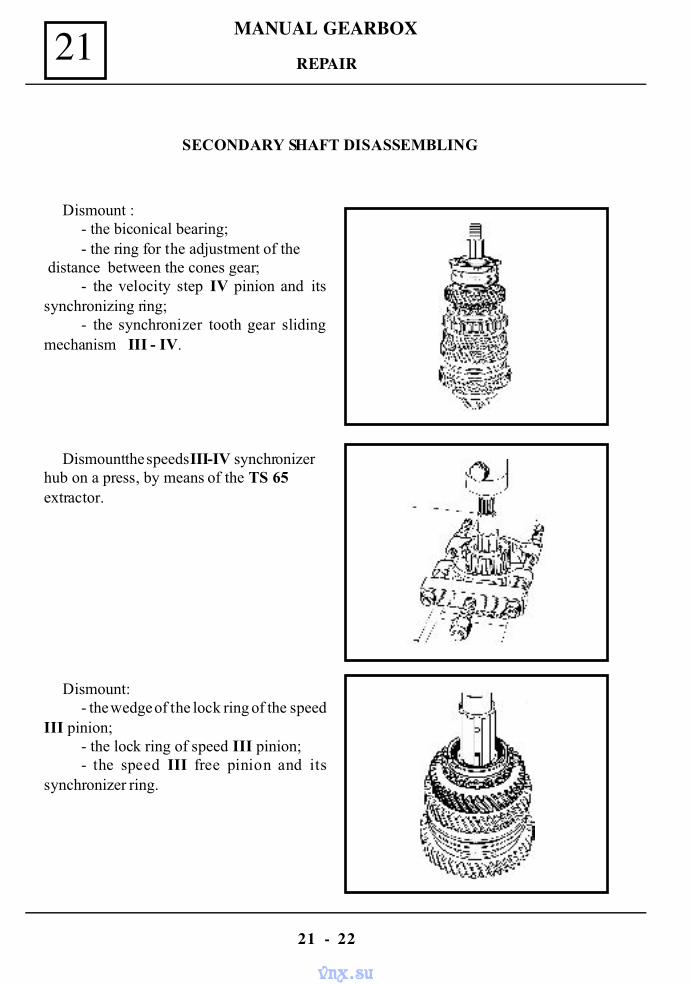
MANUAL GEARBOX21
21 - 22
REPAIR
SECONDARY SHAFT DISASSEMBLING
Dismount :- the biconical bearing;- the ring for the adjustment of the
distance between the cones gear;- the velocity step IV pinion and its
synchronizing ring;- the synchronizer tooth gear sliding
mechanism III - IV.
Dismount the speeds III-IV synchronizerhub on a press, by means of the TS 65extractor.
Dismount:- the wedge of the lock ring of the speed
III pinion;- the lock ring of speed III pinion;- the speed III free pinion and its
synchronizer ring.
vnx.su
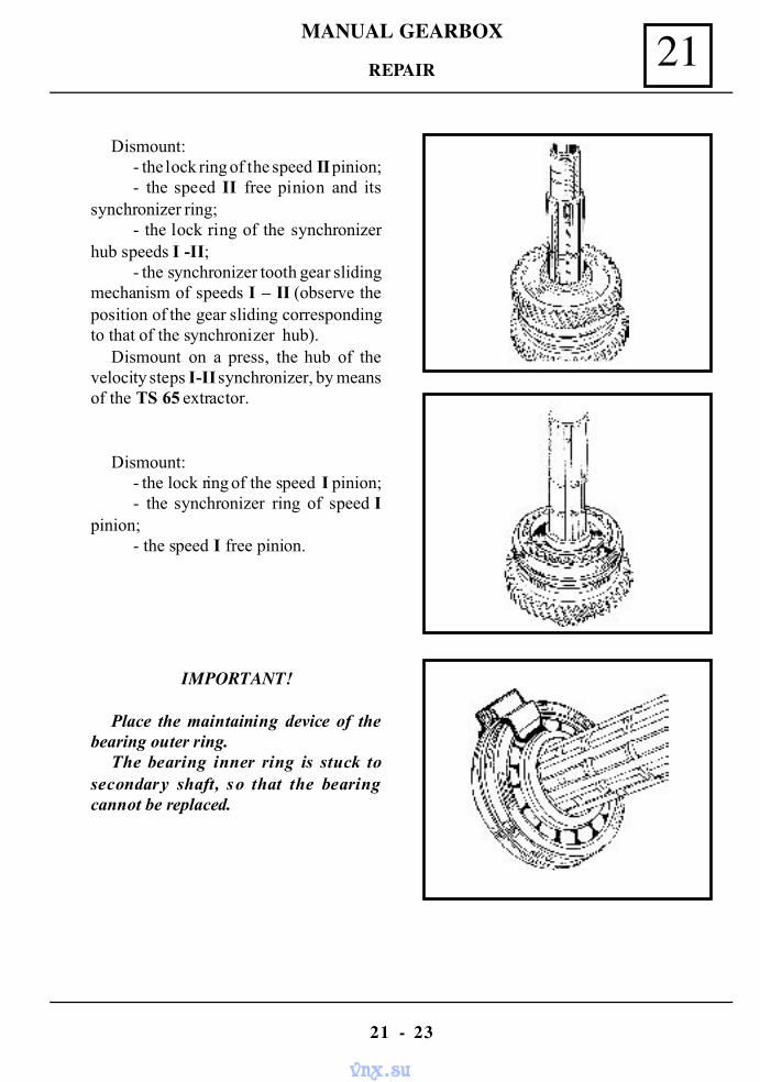
MANUAL GEARBOX 21
21 - 23
REPAIR
Dismount:- the lock ring of the speed II pinion;- the speed II free pinion and its
synchronizer ring;- the lock ring of the synchronizer
hub speeds I -II;- the synchronizer tooth gear sliding
mechanism of speeds I – II (observe theposition of the gear sliding correspondingto that of the synchronizer hub).
Dismount on a press, the hub of thevelocity steps I-II synchronizer, by meansof the TS 65 extractor.
Dismount:- the lock ring of the speed I pinion;- the synchronizer ring of speed I
pinion;- the speed I free pinion.
IMPORTANT!
Place the maintaining device of thebearing outer ring.
The bearing inner ring is stuck tosecondary shaft, so that the bearingcannot be replaced.
vnx.su
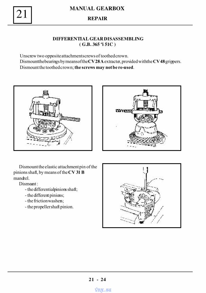
MANUAL GEARBOX21
21 - 24
REPAIR
DIFFERENTIAL GEAR DISASSEMBLING( G.B. 365 ºi 51C )
Unscrew two opposite attachment screws of toothed crown.Dismount the bearings by means of the CV 28 A extractor, provided with the CV 48 grippers.Dismount the toothed crown; the screws may not be re-used.
Dismount the elastic attachment pin of thepinions shaft, by means of the CV 31 Bmandrel.
Dismount :- the differential pinions shaft;- the different pinions;- the friction washers;- the propeller shaft pinion.
vnx.su
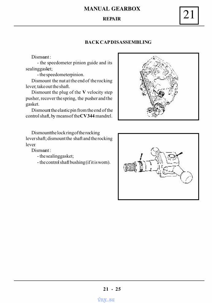
MANUAL GEARBOX 21
21 - 25
REPAIR
BACK CAP DISASSEMBLING
Dismount :- the speedometer pinion guide and its
sealing gasket;- the speedometer pinion.
Dismount the nut at the end of the rockinglever; take out the shaft.
Dismount the plug of the V velocity steppusher, recover the spring, the pusher and thegasket.
Dismount the elastic pin from the end of thecontrol shaft, by means of the CV 344 mandrel.
Dismount the lock ring of the rockinglever shaft; dismount the shaft and the rockinglever.
Dismount :- the sealing gasket;- the control shaft bushing (if it is worn).
vnx.su
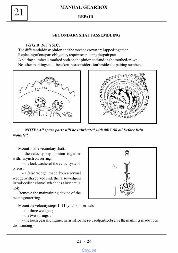
MANUAL GEARBOX21
21 - 26
SECONDARY SHAFT ASSEMBLING
For G.B. 365 ºi 51C.The differential drive pinion and the toothed crown are lapped together.Replacing of one part obligatory requires replacing the pair part.A pairing number is marked both on the pinion end and on the toothed crown.No other markings shall be taken into consideration besides the pairing number.
NOTE: All spare parts will be lubricated with 80W 90 oil before beinmounted.
Mount on the secondary shaft:- the velocity step I pinion together
with its synchroniser ring ;- the lock washer of the velocity step I
pinion ;- a false wedge, made from a normal
wedge ,with a curved end ; the false wedge isintroduced in a channel which has a lubricatinghole.
Remove the maintaining device of thebearing outer ring.
Mount the velocity steps I – II synchroniser hub:- the three wedges ;- the two springs ;- the tooth gear sliding mechanism (for the re-used parts, observe the markings made upon
dismounting ).
REPAIR
vnx.su
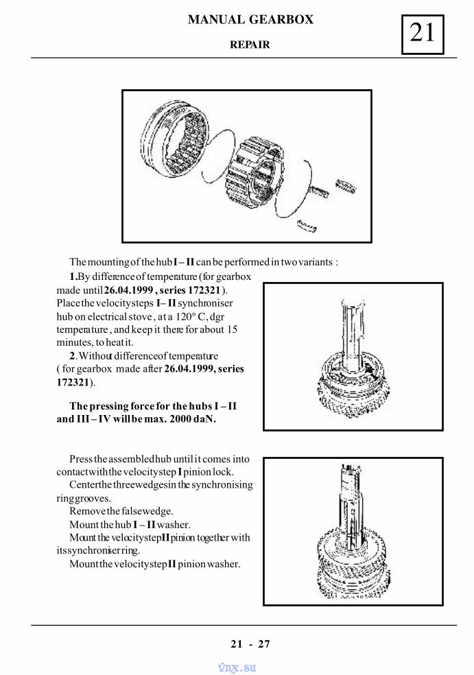
MANUAL GEARBOX 21
21 - 27
REPAIR
The mounting of the hub I – II can be performed in two variants :1.By difference of temperature (for gearbox
made until 26.04.1999 , series 172321).Place the velocity steps I – II synchroniserhub on electrical stove , at a 120° C, dgrtemperature , and keep it there for about 15minutes , to heat it.
2. Without difference of temperature( for gearbox made after 26.04.1999, series172321).
The pressing force for the hubs I – IIand III – IV will be max. 2000 daN.
Press the assembled hub until it comes intocontact with the velocity step I pinion lock.
Center the three wedges in the synchronisingring grooves.
Remove the false wedge.Mount the hub I – II washer.Mount the velocity step II pinion together with
its synchroniser ring.Mount the velocity step II pinion washer.
vnx.su
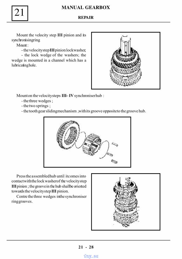
MANUAL GEARBOX21
21 - 28
Mount the velocity step III pinion and itssynchronising ring.
Mount :- the velocity step III pinion lock washer;- the lock wedge of the washers; the
wedge is mounted in a channel which has alubricating hole.
Mount on the velocity steps III – IV synchroniser hub :- the three wedges ;- the two springs ;- the tooth gear sliding mechanism , with its groove opposite to the groove hub.
Press the assembled hub until it comes intocontact with the lock washer of the velocity stepIII pinion ; the groove in the hub shall be orientedtowards the velocity step III pinion.
Centre the three wedges in the synchroniserring grooves.
REPAIR
vnx.su
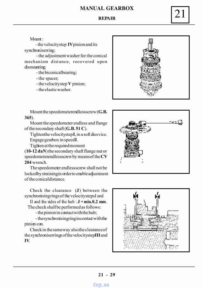
MANUAL GEARBOX 21
21 - 29
Mount :- the velocity step IV pinion and its
synchroniser ring; - the adjustment washer for the conical
mechanism dist ance, recovered upondismounting;
- the biconical bearing; - the spacer; - the velocity step V pinion; - the elastic washer.
Mount the speedometer endless screw (G.B.365).
Mount the speedometer endless and flangeof the secondary shaft (G.B. 51 C).
Tighten the velocity step I, in a soft dies vice.Engage gearbox in speed I.Tighten at the required moment
(10-12 daN) the secondary shaft flange nut orspeedometer endless screw by means of the CV204 wrench.
The speedometer endless screw shall not belocked by straining in order to enable adjustmentof the conical distance.
Check the clearance (J) between thesynchronising rings of the velocity steps I and
II and the sides of the hub : J = min.0,2 mm. The check shall be performed as follows:
- the pinion in contact with the hub;- the synchronising ring in contact with the
pinion con.Check in the same way also the clearance of
the synchroniser rings of the velocity step III andIV.
REPAIR
vnx.su
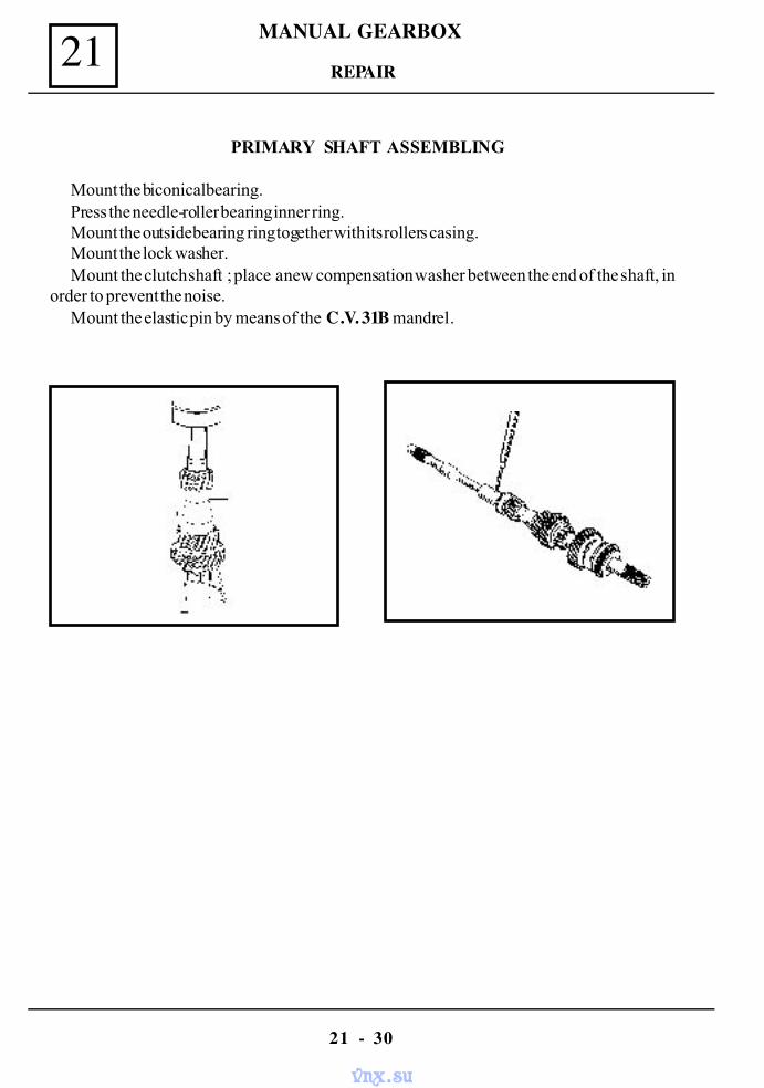
MANUAL GEARBOX21
21 - 30
PRIMARY SHAFT ASSEMBLING
Mount the biconical bearing.Press the needle-roller bearing inner ring.Mount the outside bearing ring together with its rollers casing.Mount the lock washer.Mount the clutch shaft ; place a new compensation washer between the end of the shaft, in
order to prevent the noise.Mount the elastic pin by means of the C.V. 31B mandrel.
REPAIR
vnx.su
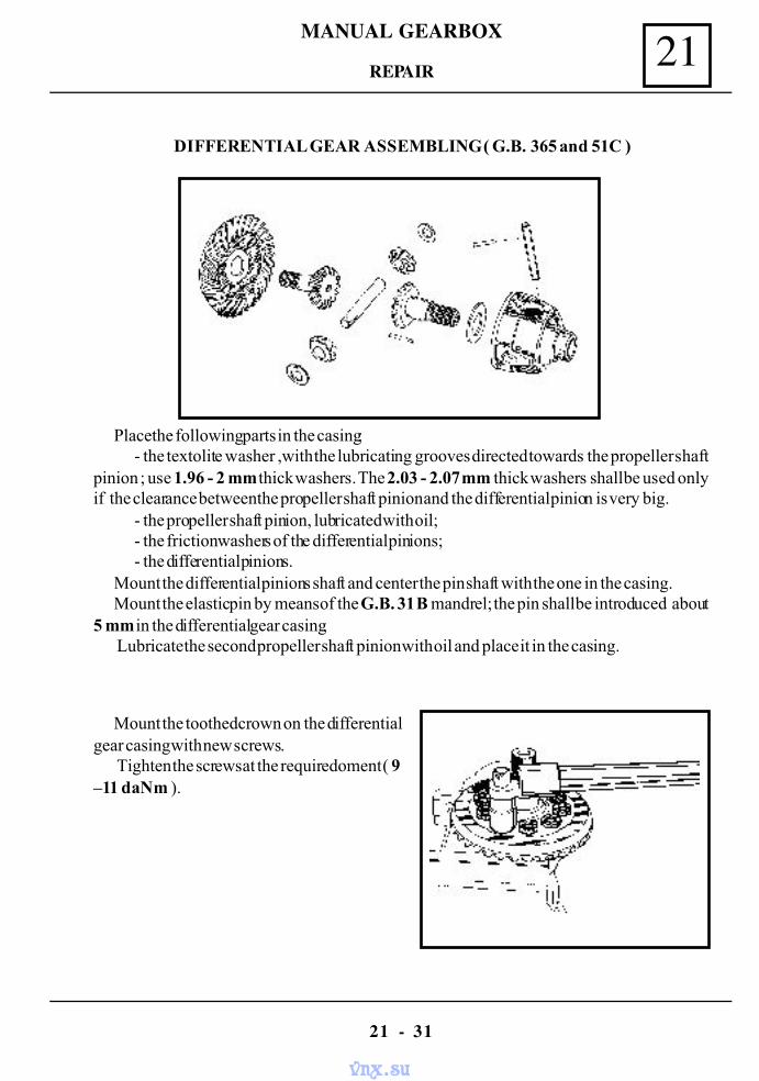
MANUAL GEARBOX 21
21 - 31
DIFFERENTIAL GEAR ASSEMBLING ( G.B. 365 and 51C )
Place the following parts in the casing:- the textolite washer ,with the lubricating grooves directed towards the propeller shaft
pinion ; use 1.96 - 2 mm thick washers. The 2.03 - 2.07 mm thick washers shall be used onlyif the clearance between the propeller shaft pinion and the differential pinion is very big.
- the propeller shaft pinion, lubricated with oil;- the friction washers of the differential pinions;- the differential pinions.
Mount the differential pinions shaft and center the pin shaft with the one in the casing.Mount the elastic pin by means of the G.B. 31 B mandrel; the pin shall be introduced about
5 mm in the differential gear casing. Lubricate the second propeller shaft pinion with oil and place it in the casing.
Mount the toothed crown on the differentialgear casing with new screws.
Tighten the screws at the requiredoment ( 9–11 daNm ).
REPAIR
vnx.su
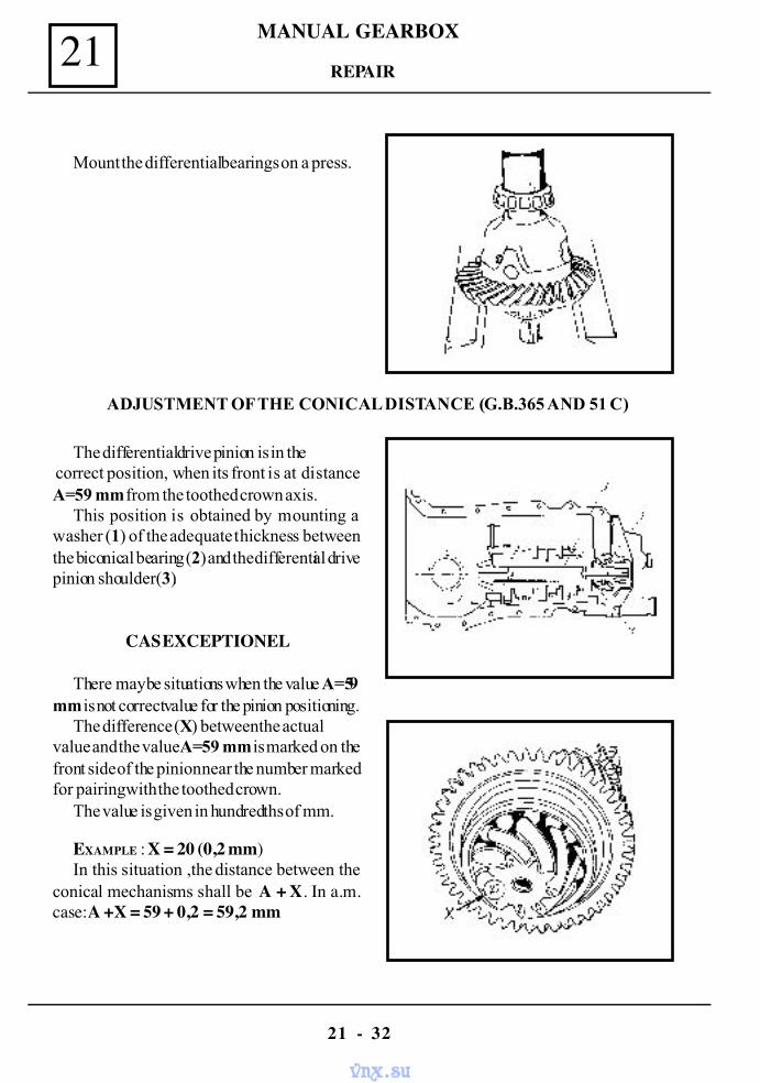
MANUAL GEARBOX21
21 - 32
Mount the differential bearings on a press.
ADJUSTMENT OF THE CONICAL DISTANCE (G.B.365 AND 51 C)
The differential drive pinion is in the correct position, when its front is at distanceA=59 mm from the toothed crown axis.
This position is obtained by mounting awasher (1) of the adequate thickness betweenthe biconical bearing (2) and the differential drivepinion shoulder(3).
CAS EXCEPTIONEL
There may be situations when the value A=59mm is not correct value for the pinion positioning.
The difference (X) between the actualvalue and the value A=59 mm is marked on thefront side of the pinion near the number markedfor pairing with the toothed crown.
The value is given in hundredths of mm.
EXAMPLE : X = 20 (0,2 mm)In this situation ,the distance between the
conical mechanisms shall be A + X. In a.m.case:A +X = 59 + 0,2 = 59,2 mm
REPAIR
vnx.su
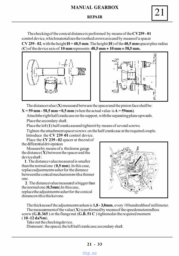
MANUAL GEARBOX 21
21 - 33
The checking of the conical distance is performed by means of the CV239 - 01control device, which materializes the toothed crown axis and by means of a spacerCV 239 - 02, with the height H = 48,5 mm. The height (H) of the 48,5 mm spacer plus radius(C) of the device axis of 10 mm represents: 48,5 mm + 10 mm = 58,5 mm.
The distance value (X) measured between the spacer and the pinion face shall be:X = 59 mm - 58,5 mm = 0,5 mm (when the actual value is A = 59mm).
Attach the right half crankcase on the support, with the separating plane upwards.Place the secondary shaft.Place the left (1) half crankcase and tighten it by means of several screws.Tighten the attachment spacer screws on the half crankcase at the required couple.
Introduce the CV 239 -01 control device.Place the CV 239 - 02 spacer at the end of
the differential drive pinionMeasure by means of a thickness gauge
the distance (X) between the spacer and thedevice shaft : 1. The distance value measured is smallerthan the normal one (0,5 mm) .In this case,replace adjustment washer for the distancebetween the conical mechanisms with a thinnerone. 2. The distance value measured is bigger thanthe normal one (0,5mm).In this case,replace the adjustment washer for the conicaldistance with a thicker one.
The thickness of the adjustment washers is 1,8 - 3,8mm, every 10 hundredths of millimeter.The measurement of the value (X) is performed by means of the speedometer endless
screw (G.B. 365 ) or the flange nut (G.B. 51 C ) tightened at the required moment( 10 -12 daNm).
Take out the checking device.Dismount : the spacer; the left half crankcase; secondary shaft.
REPAIR
vnx.su
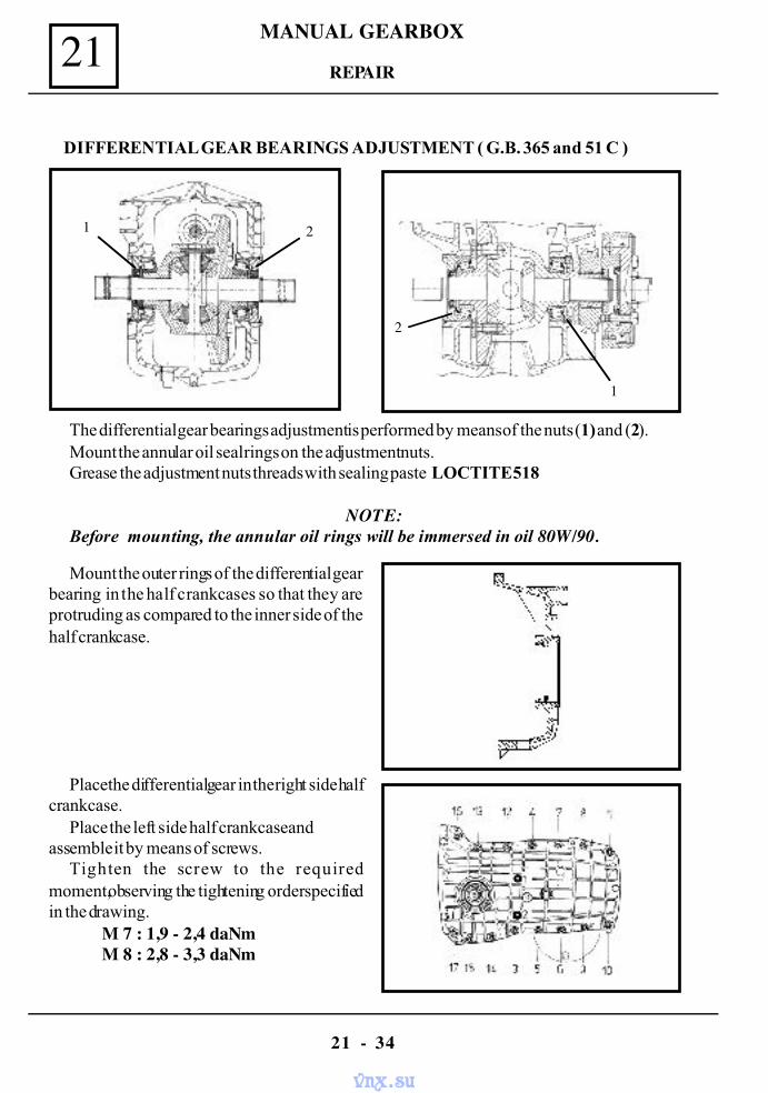
MANUAL GEARBOX21
21 - 34
DIFFERENTIAL GEAR BEARINGS ADJUSTMENT ( G.B. 365 and 51 C )
The differential gear bearings adjustment is performed by means of the nuts (1) and (2).Mount the annular oil seal rings on the adjustment nuts.Grease the adjustment nuts threads with sealing paste LOCTITE 518
NOTE:Before mounting, the annular oil rings will be immersed in oil 80W/90.
Mount the outer rings of the differential gearbearing in the half crankcases so that they areprotruding as compared to the inner side of thehalf crankcase.
Place the differential gear in the right side halfcrankcase.
Place the left side half crankcase andassemble it by means of screws.
Tighten the screw to the requiredmoment,observing the tightening order specifiedin the drawing.
M 7 : 1,9 - 2,4 daNmM 8 : 2,8 - 3,3 daNm
REPAIR
1 2
2
1
vnx.su
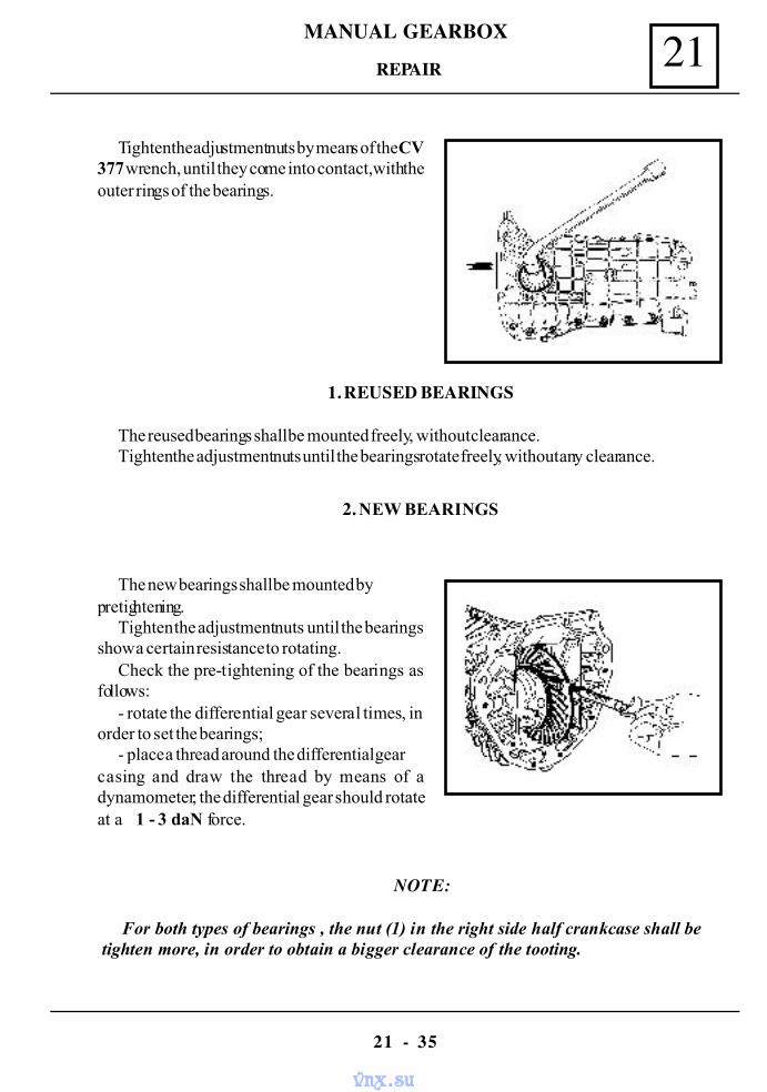
MANUAL GEARBOX 21
21 - 35
Tighten the adjustment nuts by means of the CV377 wrench, until they come into contact,with theouter rings of the bearings.
1. REUSED BEARINGS
The reused bearings shall be mounted freely, without clearance.Tighten the adjustment nuts until the bearings rotate freely, without any clearance.
The new bearings shall be mounted bypretightening.
Tighten the adjustment nuts until the bearingsshow a certain resistance to rotating.
Check the pre-tightening of the bearings asfollows:
- rotate the differential gear several times, inorder to set the bearings;
- place a thread around the differential gearcasing and draw the thread by means of adynamometer; the differential gear should rotateat a 1 - 3 daN force.
NOTE:
For both types of bearings , the nut (1) in the right side half crankcase shall betighten more, in order to obtain a bigger clearance of the tooting.
REPAIR
2. NEW BEARINGS
vnx.su
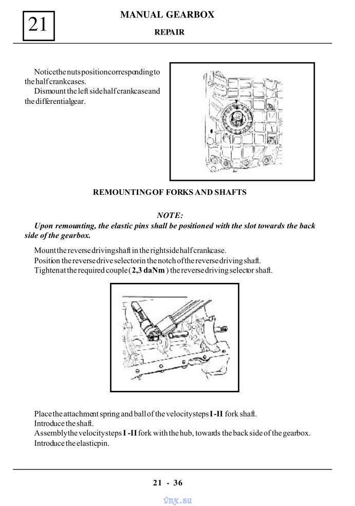
MANUAL GEARBOX21
21 - 36
Notice the nuts position corresponding tothe half crankcases.
Dismount the left side half crankcase andthe differential gear.
REMOUNTING OF FORKS AND SHAFTS
Mount the reverse driving shaft in the right side half crankcase.Position the reverse drive selector in the notch of the reverse driving shaft.Tighten at the required couple ( 2,3 daNm ) the reverse driving selector shaft.
Place the attachment spring and ball of the velocity steps I -II fork shaft.Introduce the shaft.Assembly the velocity steps I -II fork with the hub, towards the back side of the gearbox.Introduce the elastic pin.
REPAIR
NOTE:Upon remounting, the elastic pins shall be positioned with the slot towards the back
side of the gearbox.
vnx.su
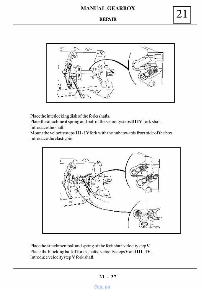
MANUAL GEARBOX 21
21 - 37
Place the interlocking disk of the forks shafts.Place the attachment spring and ball of the velocity steps III IV fork shaft.Introduce the shaft.Mount the velocity steps III - IV fork with the hub towards front side of the box.Introduce the elastic pin.
Place the attachment ball and spring of the fork shaft velocity step V.Place the blocking ball of forks shafts, velocity steps V and III - IV.Introduce velocity step V fork shaft.
REPAIR
vnx.su
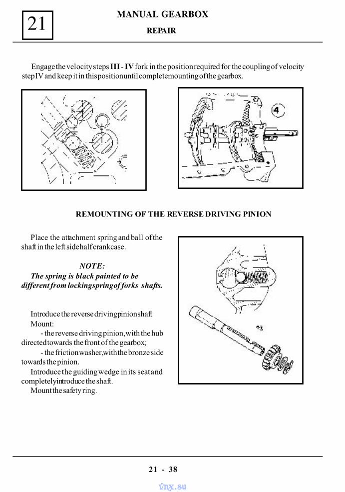
MANUAL GEARBOX21
21 - 38
Engage the velocity steps III - IV fork in the position required for the coupling of velocitystep IV and keep it in this position until complete mounting of the gearbox.
REMOUNTING OF THE REVERSE DRIVING PINION
Place the attachment spring and ball of theshaft in the left side half crankcase.
NOTE:The spring is black painted to be
different from locking spring of forks shafts.
Introduce the reverse driving pinion shaftMount :
- the reverse driving pinion, with the hubdirected towards the front of the gearbox;
- the friction washer, with the bronze sidetowards the pinion.
Introduce the guiding wedge in its seat andcompletely introduce the shaft.
Mount the safety ring.
REPAIR
vnx.su
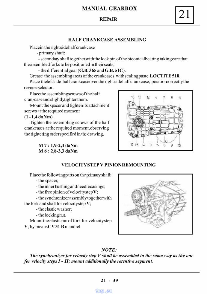
MANUAL GEARBOX 21
21 - 39
HALF CRANKCASE ASSEMBLING
Place in the right side half crankcase - primary shaft;
- secondary shaft together with the lock pin of the biconical bearing taking care thatthe assembled forks to be positioned in their seats;
- the differential gear (G.B. 365 and G.B. 51C).Grease the assembling areas of the crankcases with sealing paste LOCTITE 518.Place the left side half crankcase over the right side half crankcase; position correctly the
reverse selector.Place the assembling screws of the half
crankcase and slightly tighten them.Mount the spacer and tighten its attachment
screws at the required moment(1 - 1,4 daNm).
Tighten the assembling screws of the halfcrankcases at the required moment, observingthe tightening order specified in the drawing.
M 7 : 1,9-2,4 daNmM 8 : 2,8-3,3 daNm
VELOCITY STEP V PINION REMOUNTING
Place the following parts on the primary shaft:- the spacer;- the inner bushing and needle casings;- the free pinion of velocity step V;- the synchronizer assembly together with
the fork and shaft for velocity step V;- the elastic washer;- the locking nut.
Mount the elastic pin of fork for. velocity stepV, by means CV 31 B mandrel.
NOTE:The synchronizer for velocity step V shall be assembled in the same way as the one
for velocity steps I - II; mount additionally the retentive segment.
REPAIR
vnx.su
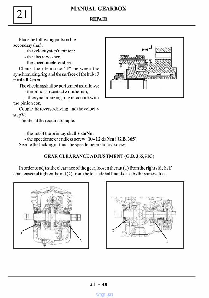
MANUAL GEARBOX21
21 - 40
Place the following parts on thesecondary shaft:
- the velocity step V pinion;- the elastic washer;- the speedometer endless.
Check the clearance “J” between thesynchronizing ring and the surface of the hub : J= min 0,2 mm
The checking shall be performed as follows:- the pinion in contact with the hub;- the synchronizing ring in contact with
the pinion con.Couple the reverse driving and the velocity
step V. Tighten at the required couple:
REPAIR
- the nut of the primary shaft: 6 daNm- the speedometer endless screw: 10 - 12 daNm ( G.B. 365).
Secure the locking nut and the speedometer endless screw.
GEAR CLEARANCE ADJUSTMENT (G.B. 365,51C)
In order to adjust the clearance of the gear, loosen the nut (1) from the right side halfcrankcase and tighten the nut (2) from the left side half crankcase by the same value.
1
2
2
1
vnx.su
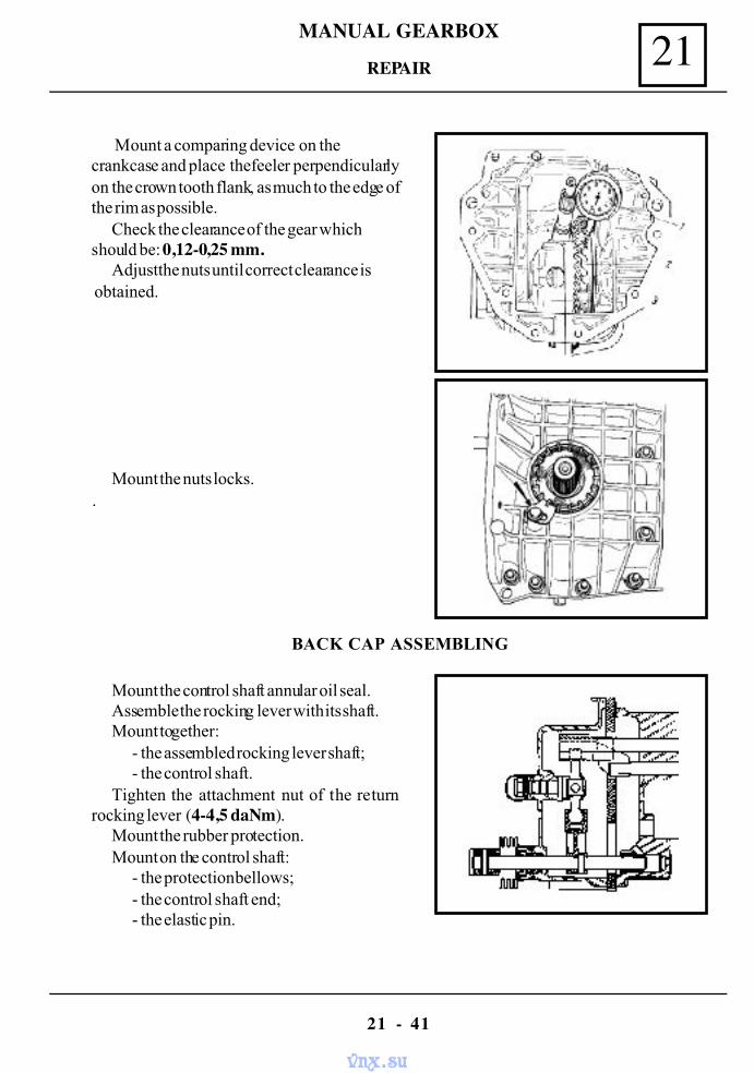
MANUAL GEARBOX 21
21 - 41
Mount a comparing device on thecrankcase and place the feeler perpendicularlyon the crown tooth flank, as much to the edge ofthe rim as possible.
Check the clearance of the gear whichshould be: 0,12-0,25 mm.
Adjust the nuts until correct clearance is obtained.
Mount the nuts locks..
BACK CAP ASSEMBLING
Mount the control shaft annular oil seal.Assemble the rocking lever with its shaft.Mount together:
- the assembled rocking lever shaft;- the control shaft.
Tighten the attachment nut of the returnrocking lever (4-4,5 daNm).
Mount the rubber protection.Mount on the control shaft:
- the protection bellows;- the control shaft end;- the elastic pin.
REPAIR
vnx.su
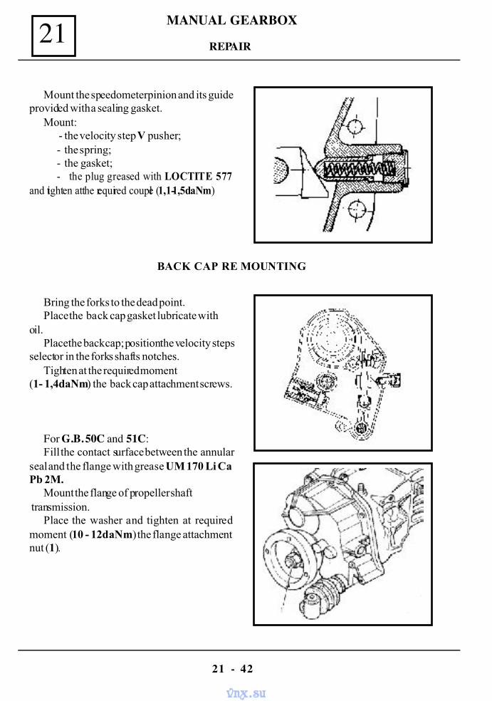
MANUAL GEARBOX21
21 - 42
Mount the speedometer pinion and its guideprovided with a sealing gasket.
Mount : - the velocity step V pusher;- the spring;- the gasket;- the plug greased with LOCTITE 577
and tighten at the required couple (1,1-1,5daNm)
Bring the forks to the dead point.Place the back cap gasket lubricate with
oil.Place the back cap; position the velocity steps
selector in the forks shafts notches.Tighten at the required moment
(1- 1,4daNm) the back cap attachment screws.
For G.B. 50C and 51C:Fill the contact surface between the annular
seal and the flange with grease UM 170 Li CaPb 2M.
Mount the flange of propeller shaft transmission.
Place the washer and tighten at requiredmoment (10 - 12daNm) the flange attachmentnut (1).
REPAIR
BACK CAP RE MOUNTING
vnx.su
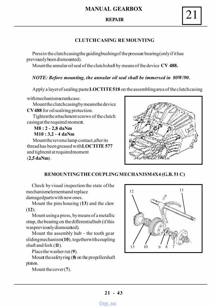
MANUAL GEARBOX 21
21 - 43
CLUTCH CASING RE MOUNTING
Press in the clutch casing the guiding bushing of the pressure bearing (only if it haspreviously been dismounted).
Mount the annular oil seal of the clutch shaft by means of the device CV 488.
NOTE: Before mounting, the annular oil seal shall be immersed in 80W/90.
Apply a layer of sealing paste LOCTITE 518 on the assembling area of the clutch casing
REMOUNTING THE COUPLING MECHANISM 4X4 (G.B. 51 C)
Check by visual inspection the state of themechanism elements and replacedamaged parts with new ones.
Mount the pins housing (13) and the claw(12).
Mount using a press, by means of a metallicstrap, the bearing on the differential hub (if thiswas previously dismounted).
Mount the assembly hub - the tooth gearsliding mechanism (10), together with couplingshaft and fork (11).
Place the washer rut (9).Mount the safety ring (8) on the propeller shaft
pinion.Mount the cover (7).
REPAIR
with mechanisms crankcase.Mount the clutch casing by means the device
CV 488 for oil seal ring protection.Tighten the attachment screws of the clutch
casing at the required moment. M8 : 2 - 2,8 daNm M10 : 3,2 - 4 daNmMount the reverse lamp contact, after its
thread has been greased with LOCTITE 577and tighten it at required moment(2,5 daNm).
12 11
13 10 9 8 7
vnx.su
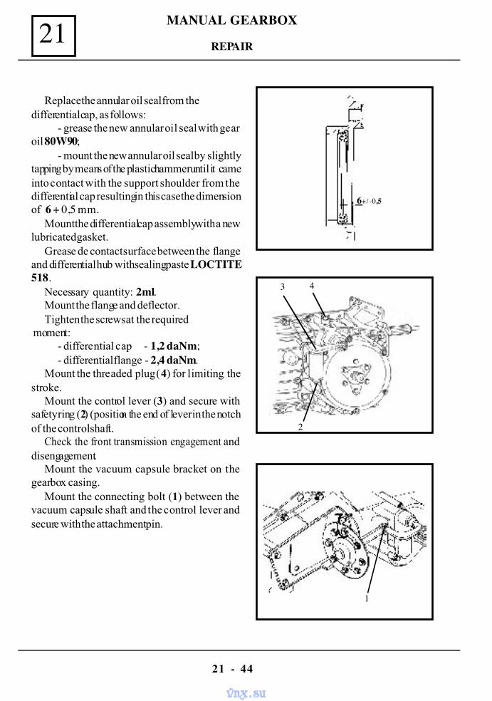
MANUAL GEARBOX21
21 - 44
REPAIR
Replace the annular oil seal from thedifferential cap, as follows:
- grease the new annular oil seal with gearoil 80W90;
- mount the new annular oil seal by slightlytapping by means of the plastic hammer until it cameinto contact with the support shoulder from thedifferential cap resulting in this case the dimensionof 6 + 0,5 mm.
Mount the differential cap assembly with a newlubricated gasket.
Grease de contact surface between the flangeand differential hub with sealing paste LOCTITE518.
Necessary quantity: 2 ml.Mount the flange and deflector.Tighten the screws at the required
moment:- differential cap - 1,2 daNm;- differential flange - 2,4 daNm.
Mount the threaded plug (4) for limiting thestroke.
Mount the control lever (3) and secure withsafety ring (2) (position the end of lever in the notchof the control shaft.
Check the front transmission engagement anddisengagement.
Mount the vacuum capsule bracket on thegearbox casing.
Mount the connecting bolt (1) between thevacuum capsule shaft and the control lever andsecure with the attachment pin.
3 4
2
1
6+/-0,5
vnx.su
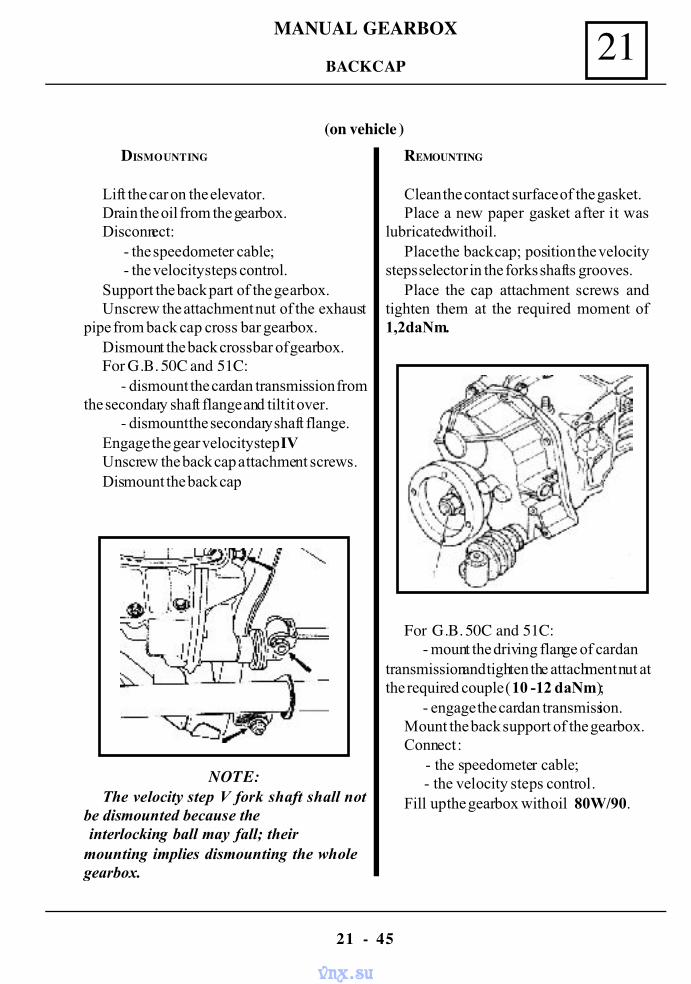
MANUAL GEARBOX 21
21 - 45
BACK CAP
DISMOUNTING
Lift the car on the elevator.Drain the oil from the gearbox.Disconnect:
- the speedometer cable; - the velocity steps control.
Support the back part of the gearbox.Unscrew the attachment nut of the exhaust
pipe from back cap cross bar gearbox.Dismount the back crossbar of gearbox.For G.B. 50C and 51C:
- dismount the cardan transmission fromthe secondary shaft flange and tilt it over.
- dismount the secondary shaft flange.Engage the gear velocity step IVUnscrew the back cap attachment screws.Dismount the back cap
NOTE:The velocity step V fork shaft shall not
be dismounted because the interlocking ball may fall; theirmounting implies dismounting the wholegearbox.
REMOUNTING
Clean the contact surface of the gasket.Place a new paper gasket after it was
lubricated with oil.Place the back cap; position the velocity
steps selector in the forks shafts grooves.Place the cap attachment screws and
tighten them at the required moment of1,2daNm.
For G.B. 50C and 51C:- mount the driving flange of cardan
transmission and tighten the attachment nut atthe required couple (10 -12 daNm);
- engage the cardan transmission.Mount the back support of the gearbox.Connect :
- the speedometer cable; - the velocity steps control.
Fill up the gearbox with oil 80W/90.
(on vehicle )
vnx.su
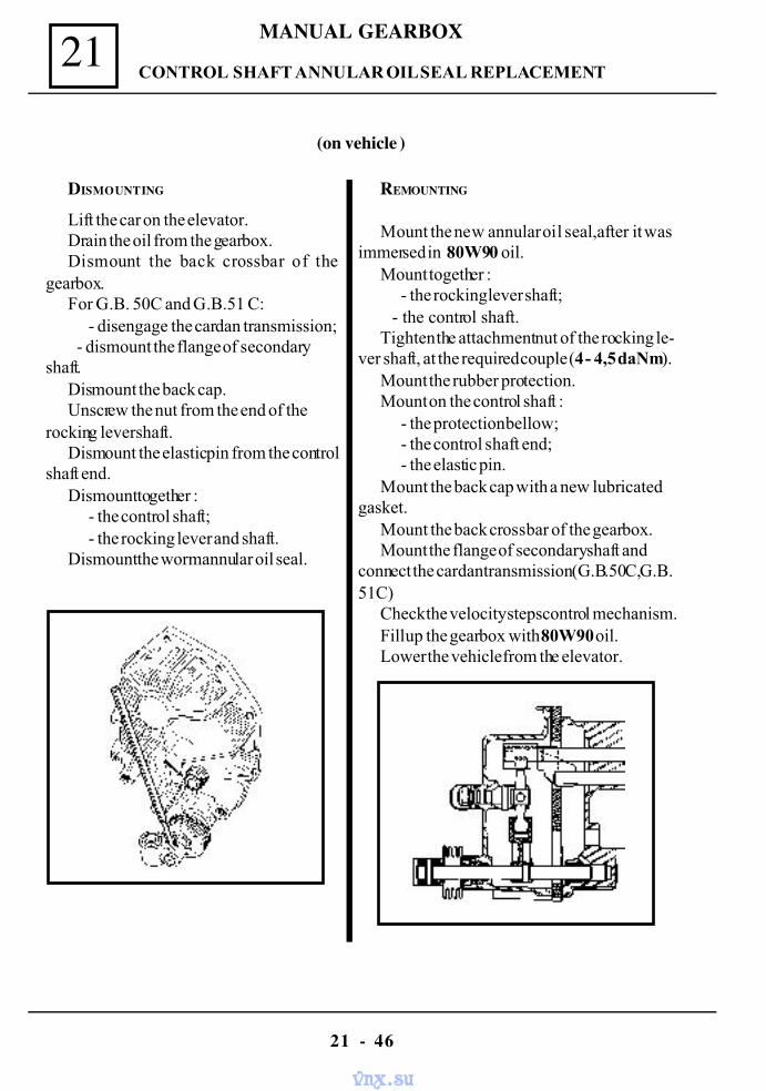
MANUAL GEARBOX21
21 - 46
CONTROL SHAFT ANNULAR OIL SEAL REPLACEMENT
Lift the car on the elevator.Drain the oil from the gearbox.Dismount the back crossbar of the
gearbox.For G.B. 50C and G.B.51 C:
- disengage the cardan transmission; - dismount the flange of secondary
shaft.Dismount the back cap.Unscrew the nut from the end of the
rocking lever shaft.Dismount the elastic pin from the control
shaft end.Dismount together :
- the control shaft;- the rocking lever and shaft.
Dismount the worm annular oil seal.
DISMOUNTING REMOUNTING
Mount the new annular oil seal,after it wasimmersed in 80W90 oil.
Mount together :- the rocking lever shaft;
- the control shaft.Tighten the attachment nut of the rocking le-
ver shaft, at the required couple (4 - 4,5 daNm).Mount the rubber protection.Mount on the control shaft :
- the protection bellow;- the control shaft end;- the elastic pin.
Mount the back cap with a new lubricatedgasket.
Mount the back crossbar of the gearbox.Mount the flange of secondary shaft and
connect the cardan transmission (G.B.50C,G.B.51C)
Check the velocity steps control mechanism.Fill up the gearbox with 80W90 oil.Lower the vehicle from the elevator.
(on vehicle )
vnx.su
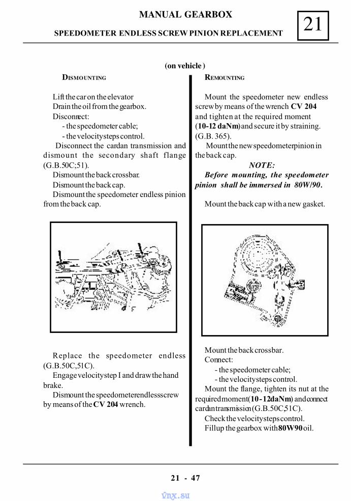
MANUAL GEARBOX 21
21 - 47
SPEEDOMETER ENDLESS SCREW PINION REPLACEMENT
DISMOUNTING
Lift the car on the elevatorDrain the oil from the gearbox.Disconnect:
- the speedometer cable;- the velocity steps control.
Disconnect the cardan transmission anddismount the secondary shaft flange(G.B.50C;51).
Dismount the back crossbar.Dismount the back cap.Dismount the speedometer endless pinion
from the back cap.
Replace the speedometer endless(G.B.50C,51C).
Engage velocity step I and draw the handbrake.
Dismount the speedometer endless screwby means of the CV 204 wrench.
REMOUNTING
Mount the speedometer new endlessscrew by means of the wrench CV 204and tighten at the required moment(10-12 daNm) and secure it by straining.(G.B. 365).
Mount the new speedometer pinion inthe back cap.
NOTE:Before mounting, the speedometer
pinion shall be immersed in 80W/90.
Mount the back cap with a new gasket.
Mount the back crossbar.Connect:
- the speedometer cable;- the velocity steps control.
Mount the flange, tighten its nut at therequired moment (10 - 12daNm) and connectcardan transmission (G.B.50C,51C).
Check the velocity steps control.Fill up the gearbox with 80W90 oil.
(on vehicle )
vnx.su
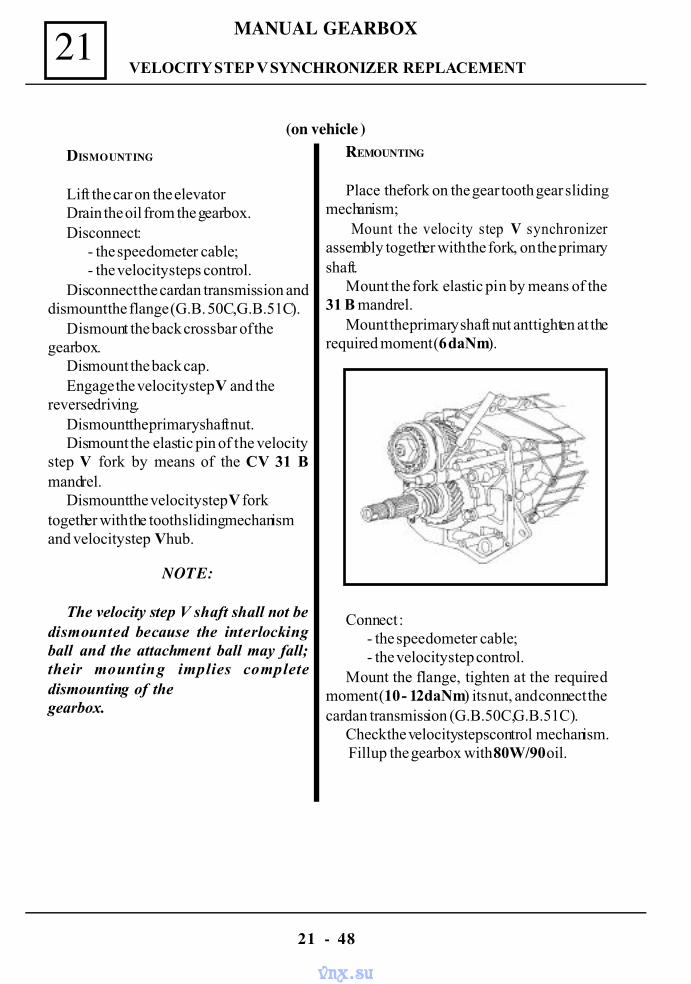
MANUAL GEARBOX21
21 - 48
VELOCITY STEP V SYNCHRONIZER REPLACEMENT
DISMOUNTING
Lift the car on the elevatorDrain the oil from the gearbox.Disconnect :
- the speedometer cable; - the velocity steps control.
Disconnect the cardan transmission anddismount the flange (G.B. 50C,G.B.51C).
Dismount the back crossbar of thegearbox.
Dismount the back cap.Engage the velocity step V and the
reverse driving.Dismount the primary shaft nut.Dismount the elastic pin of the velocity
step V fork by means of the CV 31 Bmandrel.
Dismount the velocity step V forktogether with the tooth sliding mechanismand velocity step V hub.
NOTE:
The velocity step V shaft shall not bedismounted because the interlockingball and the attachment ball may fall;their mounting implies completedismounting of thegearbox.
REMOUNTING
Place the fork on the gear tooth gear slidingmechanism;
Mount the velocity step V synchronizerassembly together with the fork, on the primaryshaft.
Mount the fork elastic pin by means of the31 B mandrel.
Mount the primary shaft nut ant tighten at therequired moment (6 daNm).
Connect : - the speedometer cable; - the velocity step control.
Mount the flange, tighten at the requiredmoment (10 - 12daNm) its nut, and connect thecardan transmission (G.B.50C,G.B.51C).
Check the velocity steps control mechanism. Fill up the gearbox with 80W/90 oil.
(on vehicle )
vnx.su
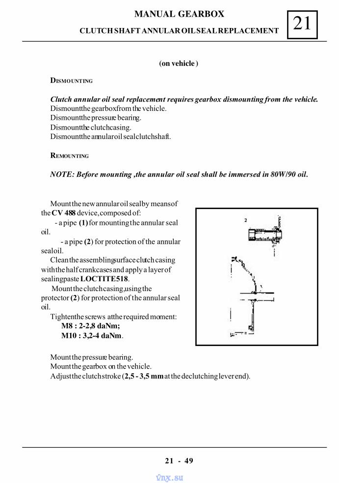
MANUAL GEARBOX 21
21 - 49
CLUTCH SHAFT ANNULAR OIL SEAL REPLACEMENT
DISMOUNTING
Clutch annular oil seal replacement requires gearbox dismounting from the vehicle.Dismount the gearbox from the vehicle.Dismount the pressure bearing.Dismount the clutch casing.Dismount the annular oil seal clutch shaft.
REMOUNTING
NOTE: Before mounting ,the annular oil seal shall be immersed in 80W/90 oil.
Mount the new annular oil seal by means ofthe CV 488 device, composed of: - a pipe (1) for mounting the annular sealoil.
- a pipe (2) for protection of the annularseal oil.
Clean the assembling surface clutch casingwith the half crankcases and apply a layer ofsealing paste LOCTITE 518.
Mount the clutch casing ,using theprotector (2) for protection of the annular sealoil.
Tighten the screws at the required moment: M8 : 2-2,8 daNm; M10 : 3,2-4 daNm.
Mount the pressure bearing.Mount the gearbox on the vehicle.Adjust the clutch stroke (2,5 - 3,5 mm at the declutching lever end).
(on vehicle )
vnx.su
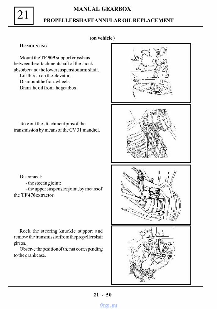
MANUAL GEARBOX21
21 - 50
DISMOUNTING
Mount the TF 509 support crossbarsbetween the attachment shaft of the shockabsorber and the lower suspension arm shaft.
Lift the car on the elevator.Dismount the front wheels.Drain the oil from the gearbox.
Take out the attachment pins of thetransmission by means of the CV 31 mandrel.
Disconnect:- the steering joint;- the upper suspension joint, by means of
the TF 476 extractor.
Rock the steering knuckle support andremove the transmission from the propeller shaftpinion.
Observe the position of the nut correspondingto the crankcase.
PROPELLER SHAFT ANNULAR OIL REPLACEMENT
(on vehicle )
vnx.su
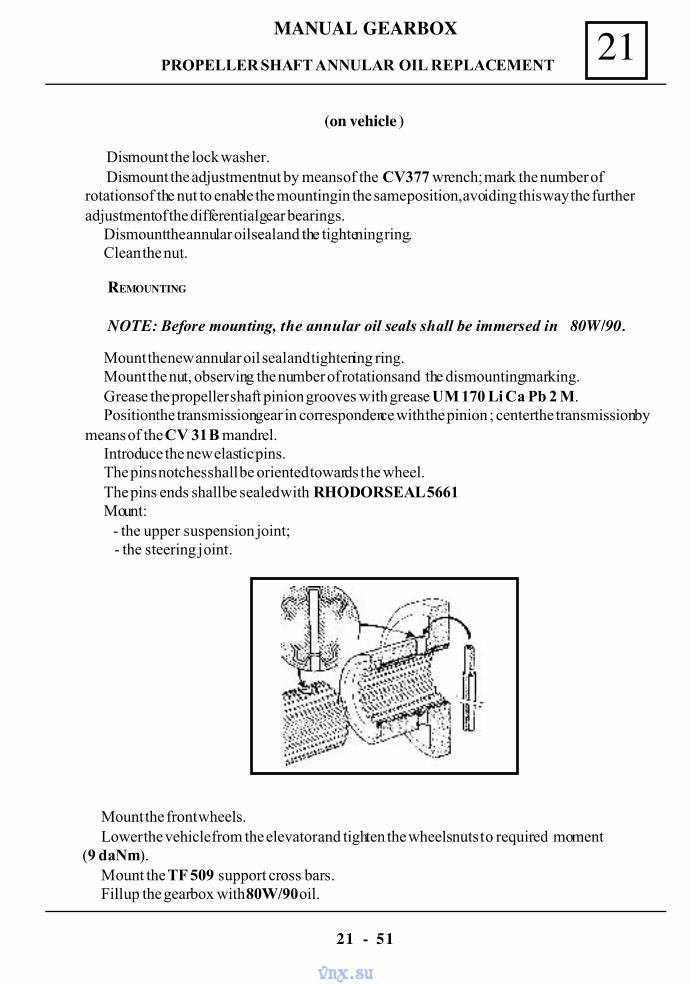
MANUAL GEARBOX 21
21 - 51
PROPELLER SHAFT ANNULAR OIL REPLACEMENT
Dismount the lock washer. Dismount the adjustment nut by means of the CV 377 wrench; mark the number of
rotations of the nut to enable the mounting in the same position, avoiding this way the furtheradjustment of the differential gear bearings.
Dismount the annular oil seal and the tightening ring.Clean the nut.
REMOUNTING
NOTE: Before mounting, the annular oil seals shall be immersed in 80W/90.
Mount the new annular oil seal and tightening ring.Mount the nut, observing the number of rotations and the dismounting marking.Grease the propeller shaft pinion grooves with grease UM 170 Li Ca Pb 2 M.Position the transmission gear in correspondence with the pinion ; center the transmission by
means of the CV 31 B mandrel.Introduce the new elastic pins.The pins notches shall be oriented towards the wheel.The pins ends shall be sealed with RHODORSEAL 5661Mount:
- the upper suspension joint; - the steering joint.
Mount the front wheels.Lower the vehicle from the elevator and tighten the wheels nuts to required moment
(9 daNm).Mount the TF 509 support cross bars.Fill up the gearbox with 80W/90 oil.
(on vehicle )
vnx.su
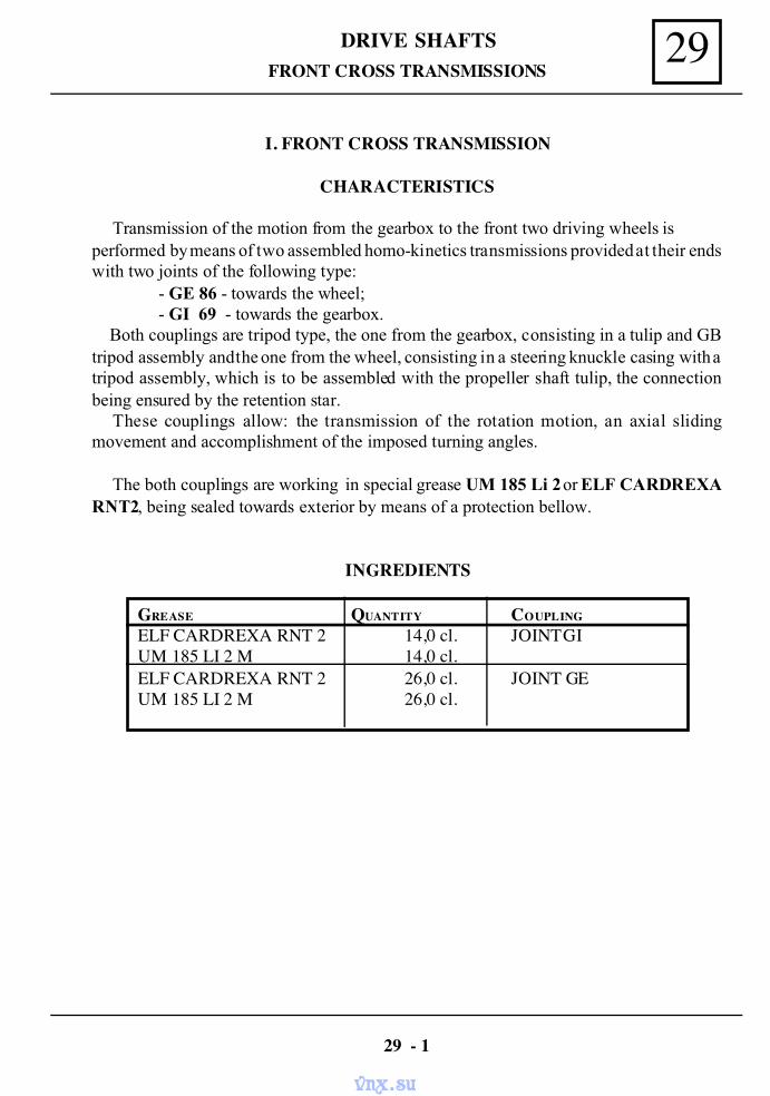
29DRIVE SHAFTSFRONT CROSS TRANSMISSIONS
I. FRONT CROSS TRANSMISSION
CHARACTERISTICS
Transmission of the motion from the gearbox to the front two driving wheels isperformed by means of two assembled homo-kinetics transmissions provided at their endswith two joints of the following type: - GE 86 - towards the wheel; - GI 69 - towards the gearbox. Both couplings are tripod type, the one from the gearbox, consisting in a tulip and GBtripod assembly and the one from the wheel, consisting in a steering knuckle casing with atripod assembly, which is to be assembled with the propeller shaft tulip, the connectionbeing ensured by the retention star.
These couplings allow: the transmission of the rotation motion, an axial slidingmovement and accomplishment of the imposed turning angles.
The both couplings are working in special grease UM 185 Li 2 or ELF CARDREXARNT2, being sealed towards exterior by means of a protection bellow.
INGREDIENTS
GREASE QUANTITY COUPLING
ELF CARDREXA RNT 2 14,0 cl. JOINT GIUM 185 LI 2 M 14,0 cl.ELF CARDREXA RNT 2 26,0 cl. JOINT GEUM 185 LI 2 M 26,0 cl.
29 - 1
vnx.su
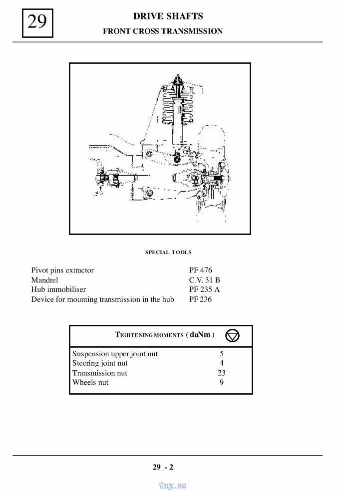
DRIVE SHAFTS29
SPECIAL TOOLS
Pivot pins extractor PF 476Mandrel C.V. 31 BHub immobiliser PF 235 ADevice for mounting transmission in the hub PF 236
FRONT CROSS TRANSMISSION
TIGHTENING MOMENTS ( daNm )
Suspension upper joint nut 5Steering joint nut 4Transmission nut 23Wheels nut 9
29 - 2
vnx.su
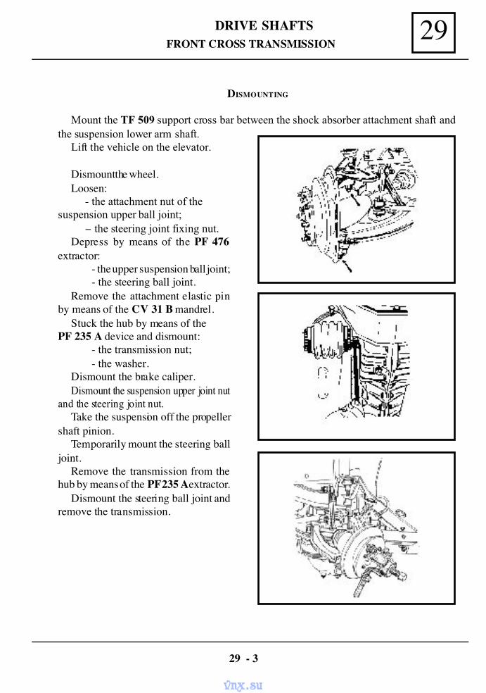
29DRIVE SHAFTSFRONT CROSS TRANSMISSION
DISMOUNTING
Mount the TF 509 support cross bar between the shock absorber attachment shaft andthe suspension lower arm shaft.
Lift the vehicle on the elevator.
Dismount the wheel.Loosen:
- the attachment nut of thesuspension upper ball joint;
− the steering joint fixing nut.Depress by means of the PF 476
extractor:- the upper suspension ball joint;- the steering ball joint.
Remove the attachment elastic pinby means of the CV 31 B mandrel.
Stuck the hub by means of thePF 235 A device and dismount:
- the transmission nut;- the washer.
Dismount the brake caliper.Dismount the suspension upper joint nut
and the steering joint nut.Take the suspension off the propeller
shaft pinion.Temporarily mount the steering ball
joint.Remove the transmission from the
hub by means of the PF 235 A extractor.Dismount the steering ball joint and
remove the transmission.
29 - 3
vnx.su
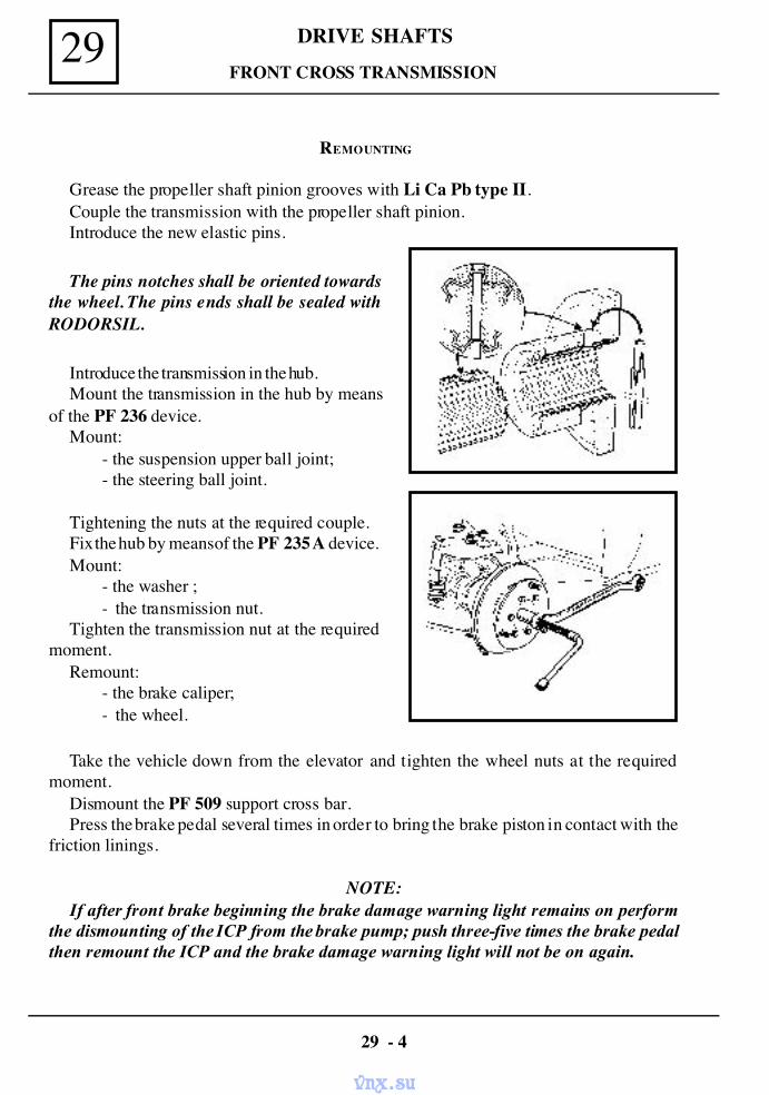
DRIVE SHAFTS29FRONT CROSS TRANSMISSION
REMOUNTING
Grease the propeller shaft pinion grooves with Li Ca Pb type II.Couple the transmission with the propeller shaft pinion.Introduce the new elastic pins.
The pins notches shall be oriented towardsthe wheel. The pins ends shall be sealed withRODORSIL.
Introduce the transmission in the hub.Mount the transmission in the hub by means
of the PF 236 device.Mount:
- the suspension upper ball joint;- the steering ball joint.
Tightening the nuts at the required couple.Fix the hub by means of the PF 235 A device.Mount:
- the washer ;- the transmission nut.
Tighten the transmission nut at the requiredmoment.
Remount:- the brake caliper;- the wheel.
Take the vehicle down from the elevator and tighten the wheel nuts at the requiredmoment.
Dismount the PF 509 support cross bar.Press the brake pedal several times in order to bring the brake piston in contact with the
friction linings.
NOTE:If after front brake beginning the brake damage warning light remains on perform
the dismounting of the ICP from the brake pump; push three-five times the brake pedalthen remount the ICP and the brake damage warning light will not be on again.
29 - 4
vnx.su
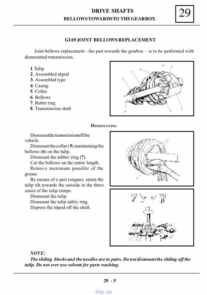
29DRIVE SHAFTSBELLOWS TOWARDS TO THE GEARBOX
GI 69 JOINT BELLOWS REPLACEMENT
Joint bellows replacement - the part towards the gearbox – is to be performed withdismounted transmission.
1. Tulip2. Assembled tripod3. Assembled type4. Casing5. Collar6. Bellows7. Ruber ring8. Transmission shaft
DISMOUNTING
Dismount the transmission off thevehicle.
Dismount the collar (5) maintaining thebellows (6) on the tulip.
Dismount the rubber ring (7).Cut the bellows on the entire length.Remove maximum possible of the
grease.By means of a pair tongues, strain the
tulip tilt towards the outside in the threezones of the tulip ramps.
Dismount the tulip.Dismount the tulip safety ring.Depress the tripod off the shaft.
NOTE:The sliding blocks and the needles are in pairs. Do not dismount the sliding off the
tulip. Do not ever use solvent for parts washing.
29 - 5
vnx.su
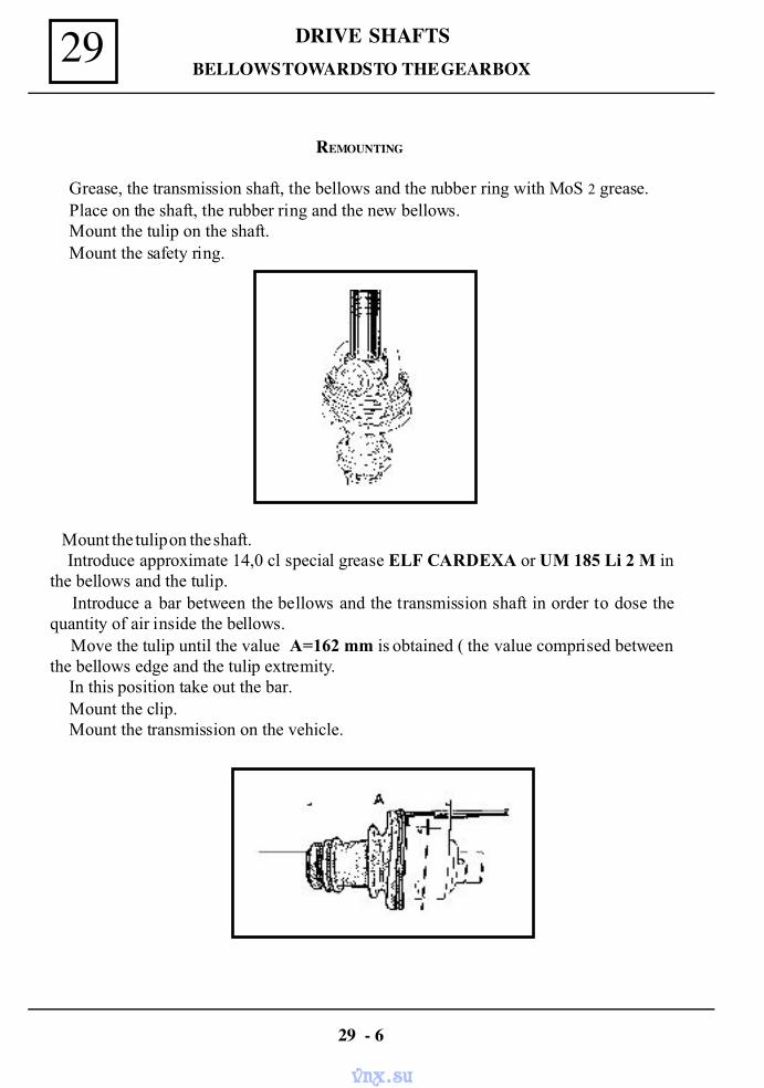
DRIVE SHAFTS29
REMOUNTING
Grease, the transmission shaft, the bellows and the rubber ring with MoS 2 grease.Place on the shaft, the rubber ring and the new bellows.Mount the tulip on the shaft.Mount the safety ring.
BELLOWS TOWARDS TO THE GEARBOX
Mount the tulip on the shaft. Introduce approximate 14,0 cl special grease ELF CARDEXA or UM 185 Li 2 M inthe bellows and the tulip. Introduce a bar between the bellows and the transmission shaft in order to dose thequantity of air inside the bellows. Move the tulip until the value A=162 mm is obtained ( the value comprised betweenthe bellows edge and the tulip extremity.
In this position take out the bar.Mount the clip.Mount the transmission on the vehicle.
29 - 6
vnx.su
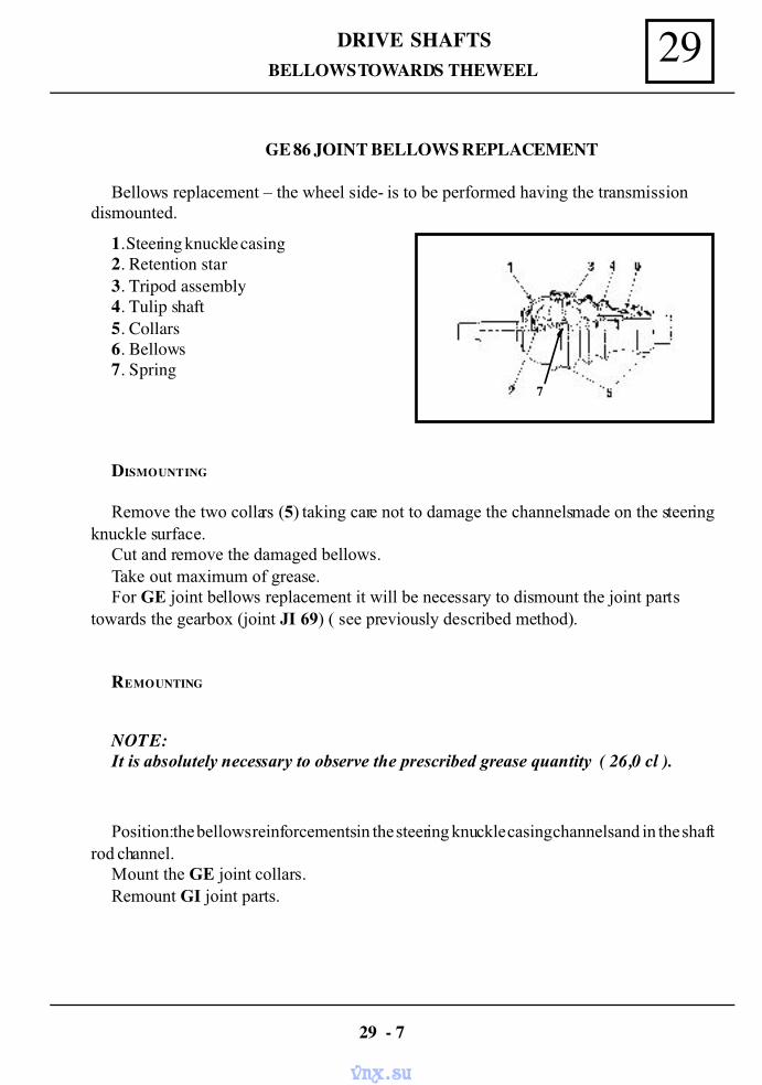
29DRIVE SHAFTSBELLOWS TOWARDS THE WEEL
GE 86 JOINT BELLOWS REPLACEMENT
Bellows replacement – the wheel side- is to be performed having the transmissiondismounted.
1. Steering knuckle casing2. Retention star3. Tripod assembly4. Tulip shaft5. Collars6. Bellows7. Spring
DISMOUNTING
Remove the two collars (5) taking care not to damage the channels made on the steeringknuckle surface.
Cut and remove the damaged bellows.Take out maximum of grease.For GE joint bellows replacement it will be necessary to dismount the joint parts
towards the gearbox (joint JI 69) ( see previously described method).
REMOUNTING
NOTE:It is absolutely necessary to observe the prescribed grease quantity ( 26,0 cl ).
Position: the bellows reinforcements in the steering knuckle casing channels and in the shaftrod channel.
Mount the GE joint collars.Remount GI joint parts.
29 - 7
7
vnx.su
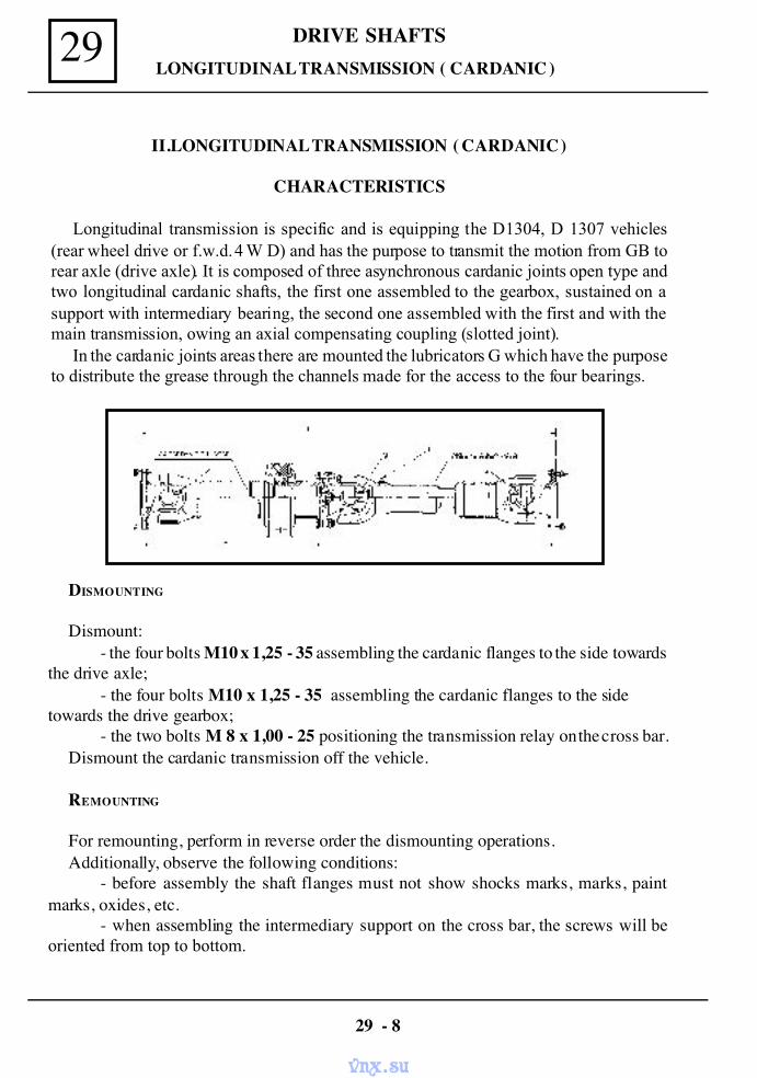
DRIVE SHAFTS29 LONGITUDINAL TRANSMISSION ( CARDANIC )
II.LONGITUDINAL TRANSMISSION ( CARDANIC )
CHARACTERISTICS
Longitudinal transmission is specific and is equipping the D1304, D 1307 vehicles(rear wheel drive or f.w.d. 4 W D) and has the purpose to transmit the motion from GB torear axle (drive axle). It is composed of three asynchronous cardanic joints open type andtwo longitudinal cardanic shafts, the first one assembled to the gearbox, sustained on asupport with intermediary bearing, the second one assembled with the first and with themain transmission, owing an axial compensating coupling (slotted joint).
In the cardanic joints areas there are mounted the lubricators G which have the purposeto distribute the grease through the channels made for the access to the four bearings.
DISMOUNTING
Dismount:- the four bolts M10 x 1,25 - 35 assembling the cardanic flanges to the side towards
the drive axle;- the four bolts M10 x 1,25 - 35 assembling the cardanic flanges to the side
towards the drive gearbox;- the two bolts M 8 x 1,00 - 25 positioning the transmission relay on the cross bar.
Dismount the cardanic transmission off the vehicle.
REMOUNTING
For remounting, perform in reverse order the dismounting operations.Additionally, observe the following conditions:
- before assembly the shaft flanges must not show shocks marks, marks, paintmarks, oxides, etc.
- when assembling the intermediary support on the cross bar, the screws will beoriented from top to bottom.
29 - 8
vnx.su
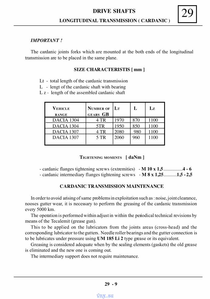
29DRIVE SHAFTS LONGITUDINAL TRANSMISSION ( CARDANIC )
IMPORTANT !
The cardanic joints forks which are mounted at the both ends of the longitudinaltransmission are to be placed in the same plane.
SIZE CHARACTERISTIS [ mm ]
Lt - total length of the cardanic transmissionL - lengt of the cardanic shaft with bearingL z - length of the assembled cardanic shaft
VEHICLE NUMBER OF LT L LZ
RANGE GEARS GBDACIA 1304 4 TR 1970 870 1100DACIA 1304 5TR 1950 850 1100DACIA 1307 4 TR 2080 980 1100DACIA 1307 5 TR 2060 960 1100
TIGHTENING MOMENTS [ daNm ]
- cardanic flanges tightening screws (extremities) - M 10 x 1,5................4 - 6- cardanic intermediary flanges tightening screws - M 8 x 1,25...........1,5 - 2,5
CARDANIC TRANSMISSION MAINTENANCE
In order to avoid arising of same problems in exploitation such as : noise, joint clearance,nooses gutter wear, it is necessary to perform the greasing of the cardanic transmissionevery 5000 km.
The operation is performed within adjust in within the periodical technical revisions bymeans of the Tecalemit (grease gun).
This to be applied on the lubricators from the joints areas (cross-head) and thecorresponding lubricator to the gutters. Needle roller bearings and the gutter connection isto be lubricates under pressure using UM 185 Li 2 type grease or its equivalent.
Greasing is considered adequate when by the sealing elements (gaskets) the old greaseis eliminated and the new one is coming out.
The intermediary support does not require maintenance.
29 - 9
vnx.su
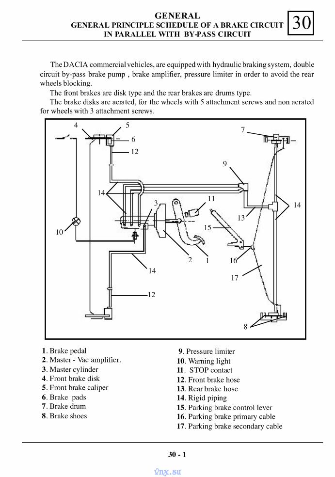
GENERAL 30GENERAL PRINCIPLE SCHEDULE OF A BRAKE CIRCUITIN PARALLEL WITH BY-PASS CIRCUIT
The DACIA commercial vehicles, are equipped with hydraulic braking system, doublecircuit by-pass brake pump , brake amplifier, pressure limiter in order to avoid the rearwheels blocking. The front brakes are disk type and the rear brakes are drums type. The brake disks are aerated, for the wheels with 5 attachment screws and non aeratedfor wheels with 3 attachment screws.
30 - 1
4 5
612
143
2 1
1513
16
12
14
10
11
17
9
7
8
14
1. Brake pedal 2. Master - Vac amplifier. 3. Master cylinder 4. Front brake disk 5. Front brake caliper 6. Brake pads 7. Brake drum 8. Brake shoes
9. Pressure limiter10. Warning light11. STOP contact12. Front brake hose13. Rear brake hose14. Rigid piping15. Parking brake control lever16. Parking brake primary cable17. Parking brake secondary cable
vnx.su
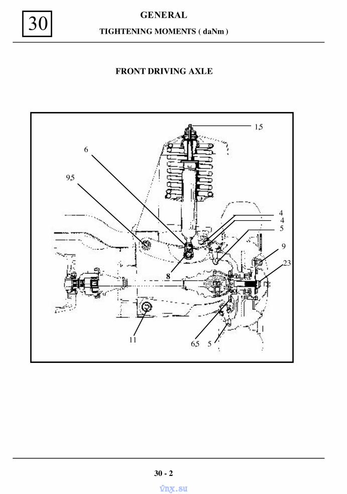
GENERAL30 TIGHTENING MOMENTS ( daNm )
FRONT DRIVING AXLE
30 - 2
1,5
6
445
9
23
56,511
9,5
8
vnx.su
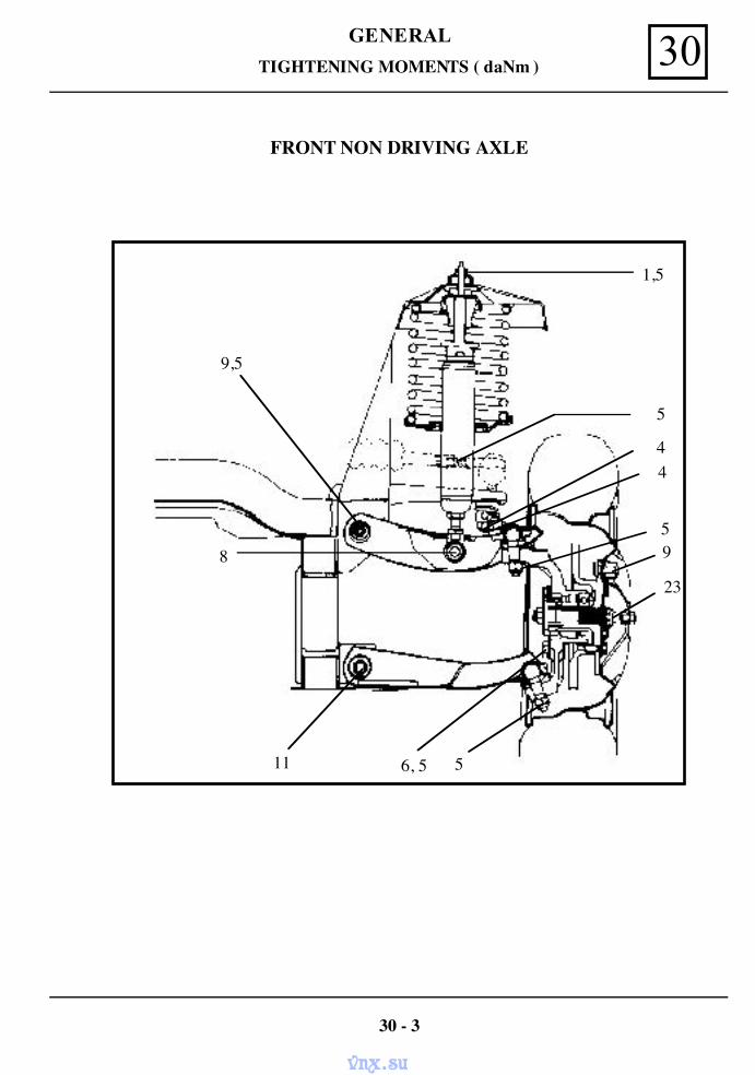
GENERAL 30TIGHTENING MOMENTS ( daNm )
FRONT NON DRIVING AXLE
30 - 3
1,5
5
11
9,5
8 59
23
44
56, 5
vnx.su
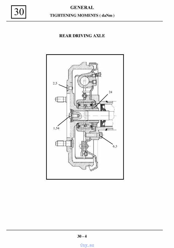
GENERAL30 TIGHTENING MOMENTS ( daNm )
REAR DRIVING AXLE
30 - 4
1,54
2,5
24
6,3
vnx.su
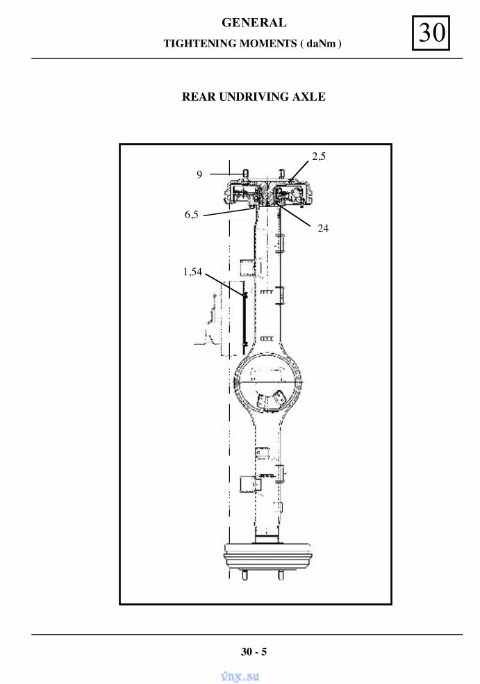
GENERAL 30TIGHTENING MOMENTS ( daNm )
REAR UNDRIVING AXLE
30 - 5
2,5
9
6,524
1,54
vnx.su
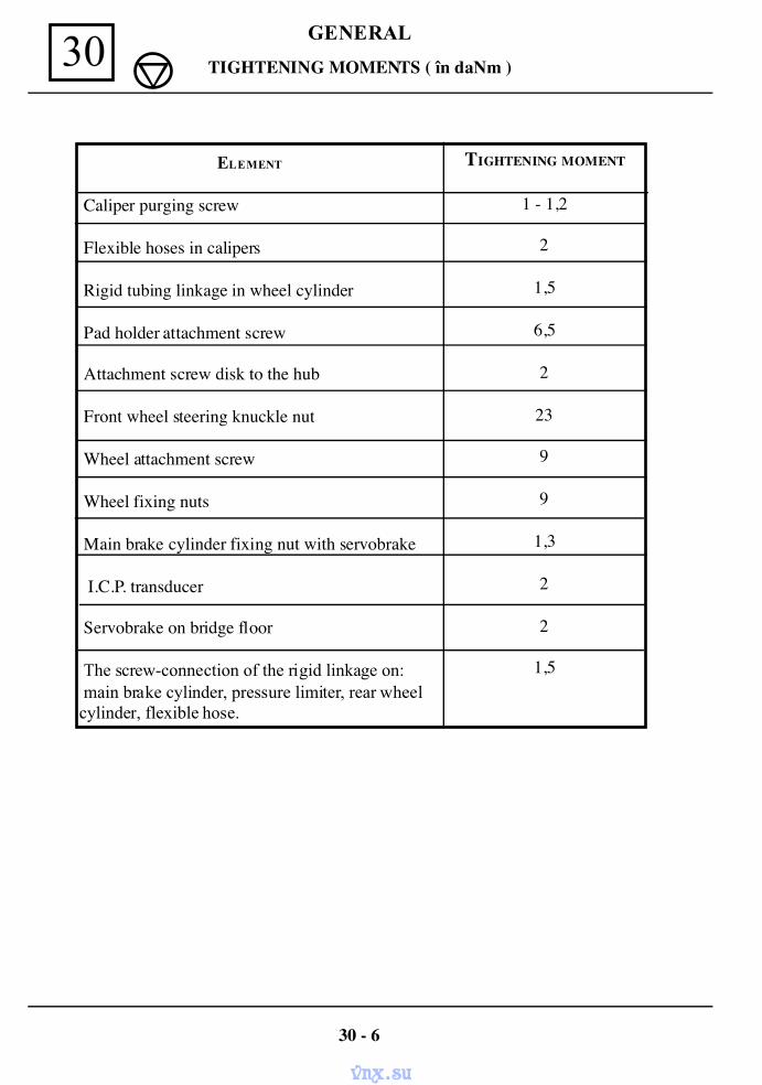
GENERAL30 TIGHTENING MOMENTS ( în daNm )
ELEMENT
Caliper purging screw
Flexible hoses in calipers
Rigid tubing linkage in wheel cylinder
Pad holder attachment screw
Attachment screw disk to the hub
Front wheel steering knuckle nut
Wheel attachment screw
Wheel fixing nuts
Main brake cylinder fixing nut with servobrake
I.C.P. transducer
Servobrake on bridge floor
The screw-connection of the rigid linkage on: main brake cylinder, pressure limiter, rear wheel cylinder, flexible hose.
TIGHTENING MOMENT
1 - 1,2
2
1,5
6,5
2
23
9
9
1,3
2
2
1,5
30 - 6
vnx.su
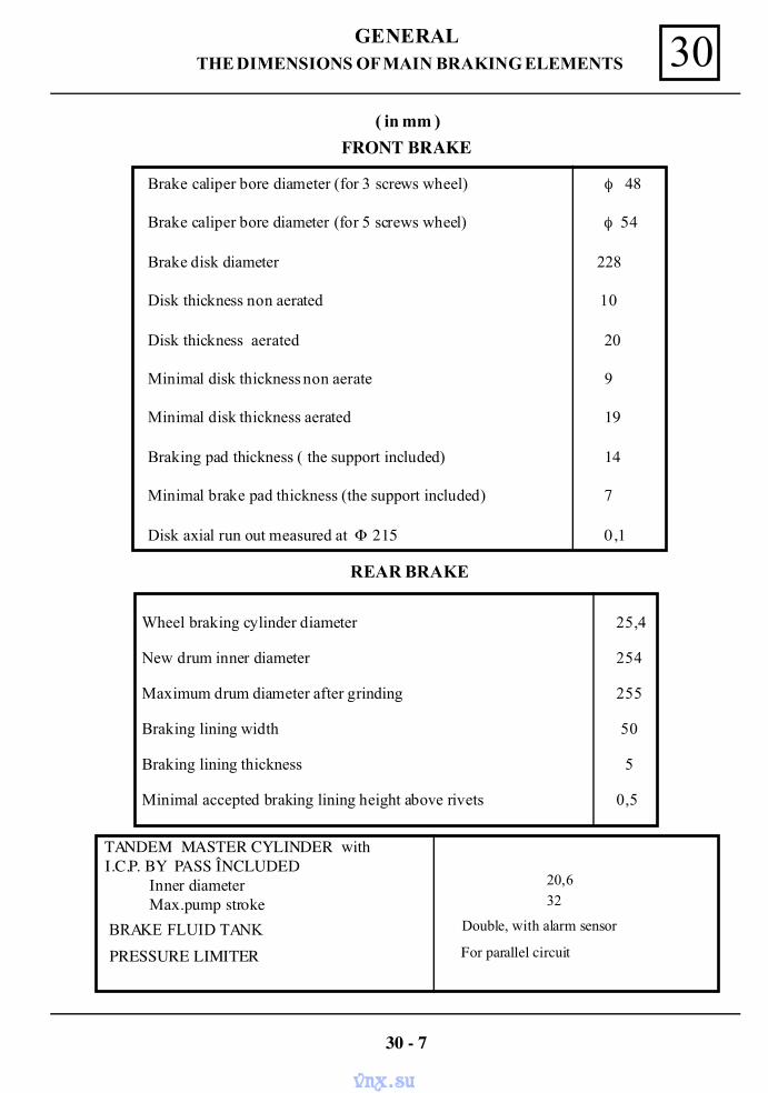
GENERAL 30THE DIMENSIONS OF MAIN BRAKING ELEMENTS
FRONT BRAKE
REAR BRAKE
TANDEM MASTER CYLINDER with I.C.P. BY PASS ÎNCLUDED
Inner diameterMax.pump stroke
BRAKE FLUID TANK
PRESSURE LIMITER
20,632
Double, with alarm sensor
For parallel circuit
30 - 7
Wheel braking cylinder diameter 25,4
New drum inner diameter 254
Maximum drum diameter after grinding 255
Braking lining width 50
Braking lining thickness 5
Minimal accepted braking lining height above rivets 0,5
Brake caliper bore diameter (for 3 screws wheel) φ 48
Brake caliper bore diameter (for 5 screws wheel) φ 54
Brake disk diameter 228
Disk thickness non aerated 10
Disk thickness aerated 20
Minimal disk thickness non aerate 9
Minimal disk thickness aerated 19
Braking pad thickness ( the support included) 14
Minimal brake pad thickness (the support included) 7
Disk axial run out measured at Φ 215 0,1
( in mm )
vnx.su
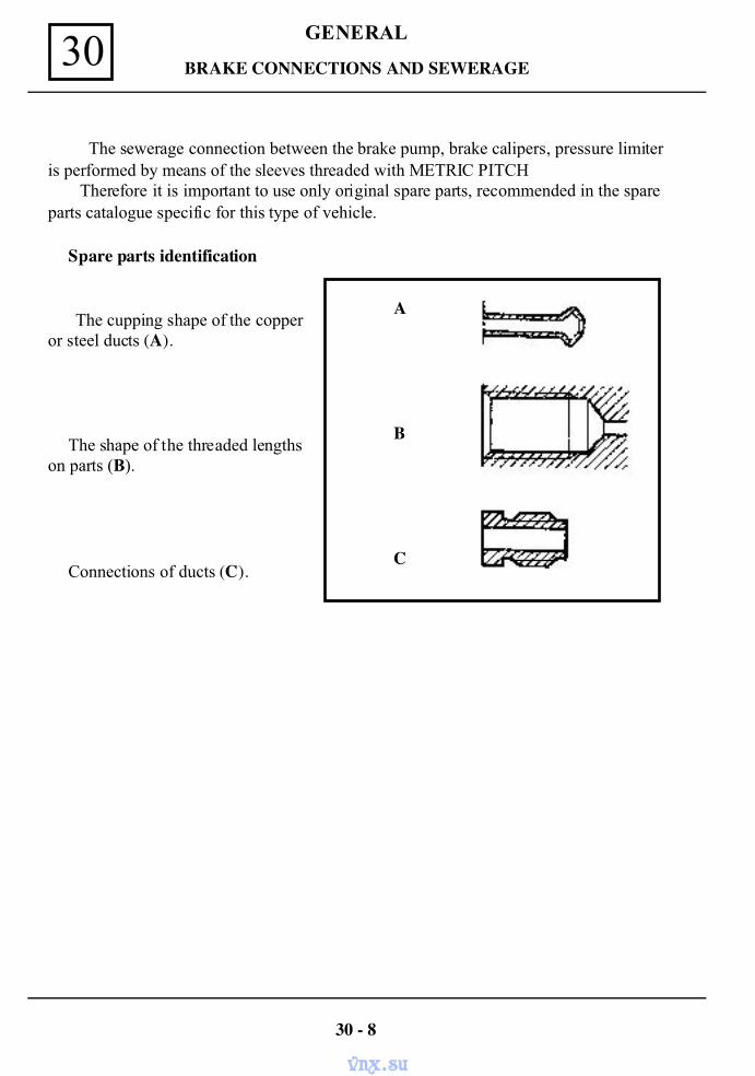
GENERAL30 BRAKE CONNECTIONS AND SEWERAGE
The sewerage connection between the brake pump, brake calipers, pressure limiteris performed by means of the sleeves threaded with METRIC PITCH
Therefore it is important to use only original spare parts, recommended in the spareparts catalogue specific for this type of vehicle.
Spare parts identification
The cupping shape of the copperor steel ducts (A).
The shape of the threaded lengthson parts (B).
Connections of ducts (C).
30 - 8
A
B
C
vnx.su
GENERAL 30
PERIODIC CHANGE OF THE BREAK FLUID
The manufacturing conception of the brakes equipping the Dacia vehicles especiallythe disk brake type (inner empty pistons, low quantity of fluid with cylinder, sliding calipersavoiding existence of a fluid reserve in the less cooled area of the wheel) enable the maxi-mum rejection of fluid vaporization even in case of intensive using of brakes(mountain area). The current brake fluids suffer in all cases a slight degradations during the first monthsof use by a slight humidity absorption series (see the Vehicle Warranty andMaintenance Booklet, for brake fluid change)
COMPLETION OF THE BRAKE FLUID LEVEL
The wear of brakes pads and shoes leads to a gradually diminution of brake fluid levelin the brake fluid tank. It is not necessary to compensate this diminution , because the level will be restoredwhen changing the brake pads and shoes. Obviously, in the meantime, the level of brake fluid in tank must not go down bellowthe minimal mark.
HOMOLOGATED BRAKE FLUIDS
The mixture in the braking circuit of two non compatible brake fluids may leads to im-portant risks mainly due to gasket damage In order to avoid such risks, it is important touse brake fluids checked and homologated by our laboratories and which are conformedwith Norm SAEJ 1703, DOT 4.
BRAKE FLUID
30 - 9
vnx.su
GENERAL30
AIR ELIMINATION FROM THE HYDRAULIC CIRCUIT ( PURGING )
The air existence in the hydraulic circuit may be noticed by an elastic displacement of thebrake pedal, sometimes even, close to the floor. This fact is more evident with the enginestopped.
GENERAL RECOMMENDATIONS
Always use for completion or total changing the brake fluid Norm SAE J 1703, DOT 4.In case of changing the brake fluid it is necessary to wash the system with one liter of
industrial alcohol.During the purging, the brake fluid from the tank must not go down bellow the
minimal level marked on the tank. To perform the purging, one person will stay on the driver place, to push the brakepedal and the other one will perform the purging (bleeding) at the wheel using a 500 mlvessel, a transparent plastic tube and brake fluid for completion.
PROCEDURE
Place on the bleeding (purging )screw, a transparent tube with its end in a vessel withbrake fluid and proceed as follows:press the brake pedal slowly, dismount the bleedingscrew, maintaining the full stroke of the pedal, then tighten the bleeding screw and slowlyrelease the brake pedal. Repeat the same procedure until complete cease of bubbles. Proceed in the same wayalso for the other purging places.( Take into consideration the existence all the time of thebrake fluid in the tank ).
ATTENTION : Before beginning the purging procedure dismount the I.C.P. fromthe brake pump. It shall be remounted at the end of the operation.
PROCEDURE IN PARALLEL SYSTEM
It is important to observe the following sequence of the purging points:
1,6. Main cylinder with I.C.P. incorporated; 2. Left rear wheel brake cylinder; 3. Right rear wheel brake cylinder; 4. Caliper of front right wheel; 5. Caliper of front left wheel.
OPERATING CONDITIONS
The vehicle is on wheels. If the fuel tank is empty, place on the rear bench of the vehicle one or two persons toenable the possibility of the circuit opening ( the passing of a larger fluid flow through thebrake limiter).
CHECKING THE BRAKE SYSTEM SEALING
After purging the front and rear circuits, check if the level of brake fluid in tank iswithin the prescribed limits, than press the brake pedal for 30 s ,during this time the pedalshall not change its place.
Leaking in the brake system is not acceptable.
BRAKING CIRCUIT PURGING
30 - 10
vnx.su
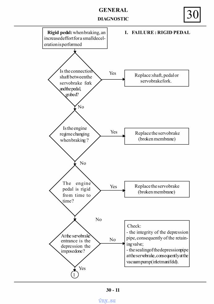
GENERAL 30DIAGNOSTIC
30 - 11
Rigid pedal: when braking, anincreased effort for a small decel-eration is performed
Yes Replace: shaft, pedal orservobrake fork.
Yes
Yes
Yes
No
No
No
No
Replace the servobrake(broken membrane)
Replace the servobrake(broken membrane)
Check:- the integrity of the depressionpipe, consequently of the retain-ing valve;- the sealing of the depression pipeat the servobrake, consequently at thevacuum pump (inlet manifold).
Is the engineregime changingwhen braking ?
The enginepedal is rigidfrom time totime ?
1
Is the connectionshaft between theservobrake forkand the pedal, grabed?
At the servobrakeentrance is thedepression theimposed one ?
I. FAILURE : RIGID PEDAL
vnx.su
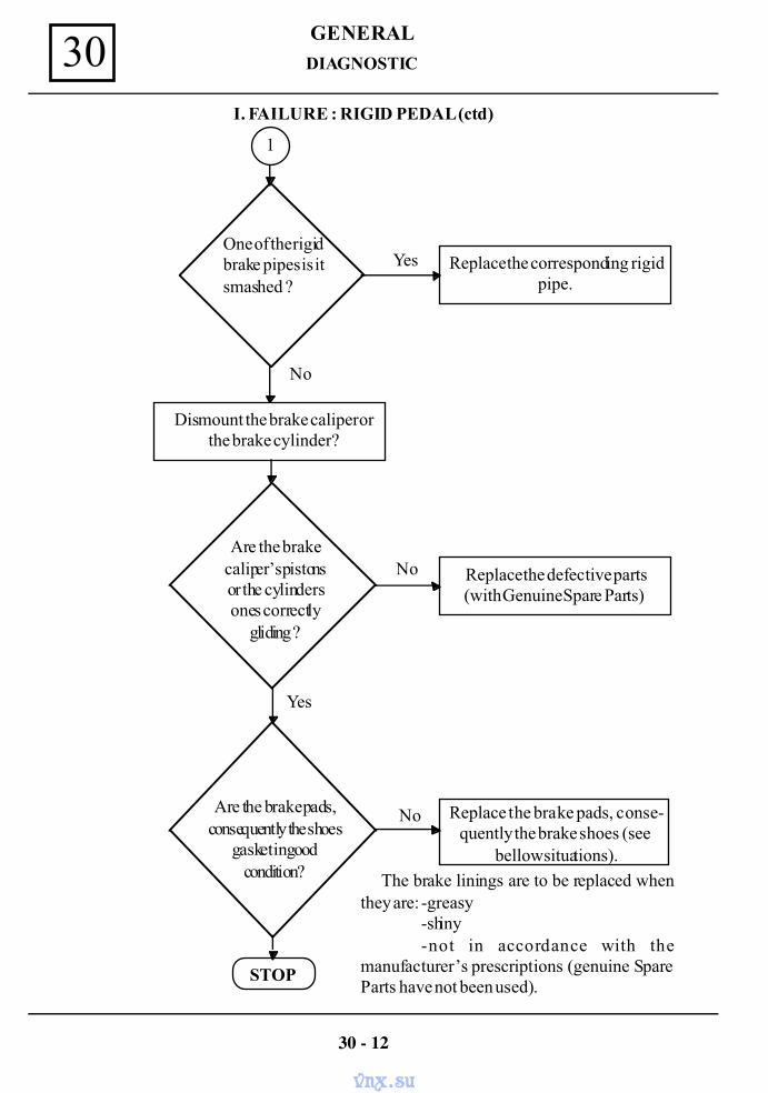
GENERAL30
1
I. FAILURE : RIGID PEDAL (ctd)
One of the rigidbrake pipes is itsmashed ?
Dismount the brake caliper orthe brake cylinder?
Replace the corresponding rigidpipe.
Are the brakecaliper’s pistonsor the cylindersones correctly
gliding ?
STOP
Replace the defective parts(with Genuine Spare Parts)
Replace the brake pads, conse-quently the brake shoes (see
bellow situations).
Are the brake pads,consequently the shoes
gasket in goodcondition? The brake linings are to be replaced when
they are: -greasy-shiny-not in accordance with the
manufacturer’s prescriptions (genuine SpareParts have not been used).
Yes
Yes
No
No
No
DIAGNOSTIC
30 - 12
vnx.su
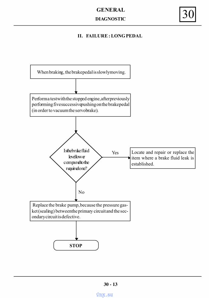
GENERAL 30
II. FAILURE : LONG PEDAL
When braking, the brake pedal is slowly moving.
Perform a test with the stopped engine, after previouslyperforming five successive pushing on the brake pedal(in order to vacuum the servobrake).
Locate and repair or replace theitem where a brake fluid leak isestablished.
Yes
No
Is the brake fluidlevel lower
compared to therequired one?
Replace the brake pump, because the pressure gas-ket (sealing) between the primary circuit and the sec-ondary circuit is defective.
STOP
DIAGNOSTIC
30 - 13
vnx.su
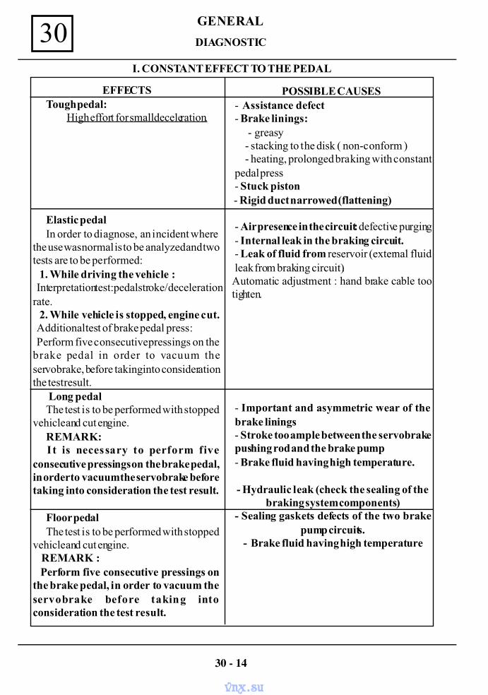
GENERAL30
I. CONSTANT EFFECT TO THE PEDAL
EFFECTSTough pedal:
High effort for small deceleration.
Elastic pedalIn order to diagnose, an incident where
the use was normal is to be analyzed and twotests are to be performed: 1. While driving the vehicle : Interpretation test: pedal stroke/ decelerationrate. 2. While vehicle is stopped, engine cut. Additional test of brake pedal press: Perform five consecutive pressings on thebrake pedal in order to vacuum theservobrake, before taking into considerationthe test result.
Long pedalThe test is to be performed with stopped
vehicle and cut engine.REMARK:
I t is necessary to perform fiveconsecutive pressings on the brake pedal,in order to vacuum the servobrake beforetaking into consideration the test result.
Floor pedalThe test is to be performed with stopped
vehicle and cut engine. REMARK : Perform five consecutive pressings onthe brake pedal, in order to vacuum theservobrake before taking intoconsideration the test result.
POSSIBLE CAUSES- Assistance defect- Brake linings: - greasy - stacking to the disk ( non-conform ) - heating, prolonged braking with constantpedal press- Stuck piston - Rigid duct narrowed (flattening)
- Air presence in the circuit: defective purging- Internal leak in the braking circuit.- Leak of fluid from reservoir (external fluidleak from braking circuit).Automatic adjustment : hand brake cable tootighten.
- Important and asymmetric wear of thebrake linings- Stroke too ample between the servobrakepushing rod and the brake pump- Brake fluid having high temperature.
- Hydraulic leak (check the sealing of thebraking system components)
- Sealing gaskets defects of the two brakepump circuits.
- Brake fluid having high temperature
30 - 14
DIAGNOSTIC
vnx.su
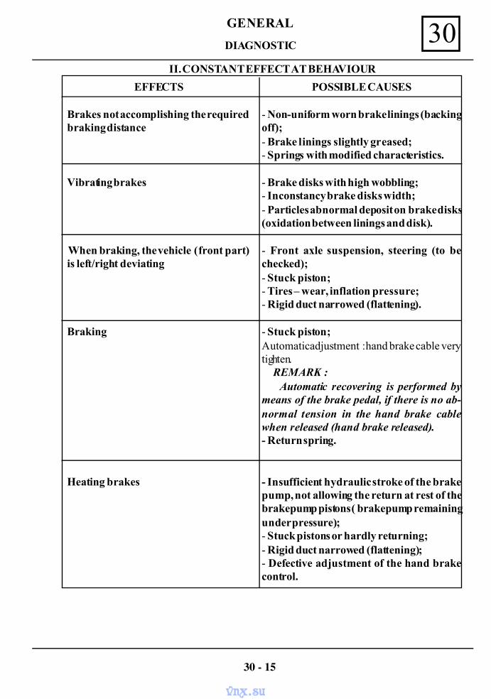
GENERAL 30II. CONSTANT EFFECT AT BEHAVIOUR
EFFECTS
Brakes not accomplishing the requiredbraking distance
Vibrating brakes
When braking, the vehicle ( front part)is left/right deviating
Braking
Heating brakes
POSSIBLE CAUSES
- Non-uniform worn brake linings (backingoff);- Brake linings slightly greased;- Springs with modified characteristics.
- Brake disks with high wobbling;- Inconstancy brake disks width;- Particles abnormal deposit on brake disks(oxidation between linings and disk).
- Front axle suspension, steering (to bechecked);- Stuck piston;- Tires – wear, inflation pressure;- Rigid duct narrowed (flattening).
- Stuck piston;Automatic adjustment : hand brake cable verytighten. REMARK : Automatic recovering is performed bymeans of the brake pedal, if there is no ab-normal tension in the hand brake cablewhen released (hand brake released).- Return spring.
- Insufficient hydraulic stroke of the brakepump, not allowing the return at rest of thebrake pump pistons ( brake pump remainingunder pressure);- Stuck pistons or hardly returning;- Rigid duct narrowed (flattening);- Defective adjustment of the hand brakecontrol.
30 - 15
DIAGNOSTIC
vnx.su
GENERAL30
31 - 16
FRONT AXLE ANGLES
CAMBER ANGLE 10 30’ +/- 30’
It is formed by the wheel plane with the vertical that crosses the wheel axis.A difference higher that 1°between the two camber angles (left side and right side) leads to:
- the deviation from the trajectory that must adjusted by means of the steering wheel;- abnormal wear of the tires and bearings.
This angle results from building may not be adjusted.
THE CASTER ANGLE 40+/- 10
This angle is formed in the vehicle longitudinal plane , by the axis of the attach-ment point of the steering knuckle by means of the suspension ball joint and the ver-
tical that passes through the front wheel shaft.A difference higher than 1° between the two angles (left side and right side) leads to:
- the deviation to the trajectory that must be adjusted by means of the steering wheel;- irregular wear of the tires.
STEERING GEAR BOX POSITION
The steering gear box should be placed at a certain height from the attachment points of thesteering auxiliary connecting rod ball joints.
The position of the steering gear box influences the variation of the parallelism.The steering box is mounted in the position for which the variation of the parallelism is
minimal.The modification of the parallelism between left side and right side leads to:
- the deviation of the vehicle from trajectory in one sense upon accelerating;- the deviation of motor car in the opposite side upon braking;- the deviation of the trajectory on the hilly ground;- the premature wear of the tires.
The horizontally of the steering box is ensured by the producer.
THE INFLUENCE OF ANGLES
vnx.su
GENERAL 30
31 - 17
PARALLELISM
It is measured in horizontal plane as a difference between the front and rear part of the wheelsof same axle.
The wheels of the front axle are :- divergent for DACIA commercial vehicles with front drive (opening 1 – 4 mm);- convergent for DACIA commercial vehicles with rear drive or four wheels drive
(closing 1 – 3 mm).
ATTENTION!A too much opening causes the wear of the tires towards the interior.A too much closing causes the wear of the tires towards the exterior.
THE TRANSVERSAL INCLINATION ANGLE OF THE BALL JOINTT 80+/- 30’
It is formed by the ball joint axle and the vertical, measured in transversal plane.The purpose of this angle is the same with the one of the caster angle: retrieve the wheels after
turning, in the corresponding position for rectilinear driving and to maintain this movement.This angle is not adjustable.
NOTE :The parallelism, the transversal inclination of the ball joint and the parallelism
variation are adjustable.
THE INFLUENCE OF ANGLES
vnx.su
GENERAL30
31 - 18
ADJUSTMENT POSIBILITIES
Only the following parameters may be adjusted:- the caster angle, by means of the rod;- the parallelism and the distribution, from the connecting rod pipe;- the steering gear box position, by means of the eccentrics (positioning will be adjusted
only if the steering gear box has been dismounted DIR 487).
PRELIMINARY CHECKINGS
Before checking and adjustment of the front axle geometry, perform the followings operations:The checking of tires concerning:
- dimensions;- air pressure;- the state of wear.
NOTE:The tires must be of same type, with the same state of wear, air pressured at the
prescribed pressure.
The check of joints- the wear of elastic bushings;- ball joints clearance;- connecting rod clearance;- wheels bearings clearance.
STEERING PRELIMINARY CHECKINGS AND ADJUSTMENTPOSSIBILITIES
vnx.su
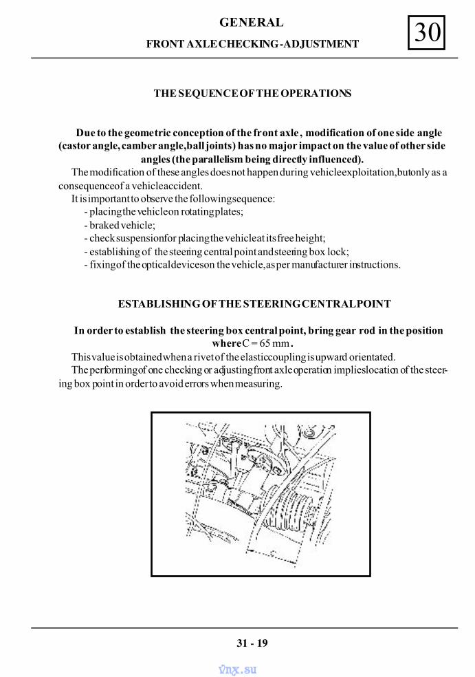
GENERAL 30
31 - 19
FRONT AXLE CHECKING -ADJUSTMENT
THE SEQUENCE OF THE OPERATIONS
Due to the geometric conception of the front axle , modification of one side angle(castor angle, camber angle,ball joints) has no major impact on the value of other side
angles (the parallelism being directly influenced).The modification of these angles does not happen during vehicle exploitation,but only as a
consequence of a vehicle accident.It is important to observe the following sequence:
- placing the vehicle on rotating plates;- braked vehicle;- check suspension for placing the vehicle at its free height;- establishing of the steering central point and steering box lock;- fixing of the optical devices on the vehicle, as per manufacturer instructions.
ESTABLISHING OF THE STEERING CENTRAL POINT
In order to establish the steering box central point, bring gear rod in the positionwhere C = 65 mm .
This value is obtained when a rivet of the elastic coupling is upward orientated.The performing of one checking or adjusting front axle operation implies location of the steer-
ing box point in order to avoid errors when measuring.
vnx.su
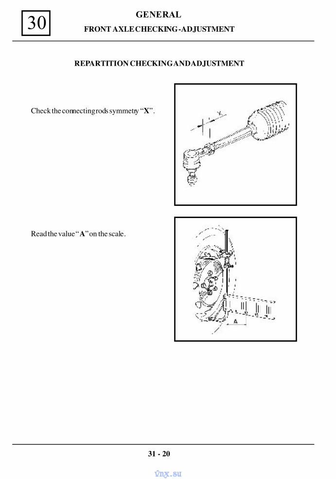
GENERAL30
31 - 20
Check the connecting rods symmetry “X”.
Read the value “A” on the scale.
REPARTITION CHECKING AND ADJUSTMENT
FRONT AXLE CHECKING -ADJUSTMENT
vnx.su
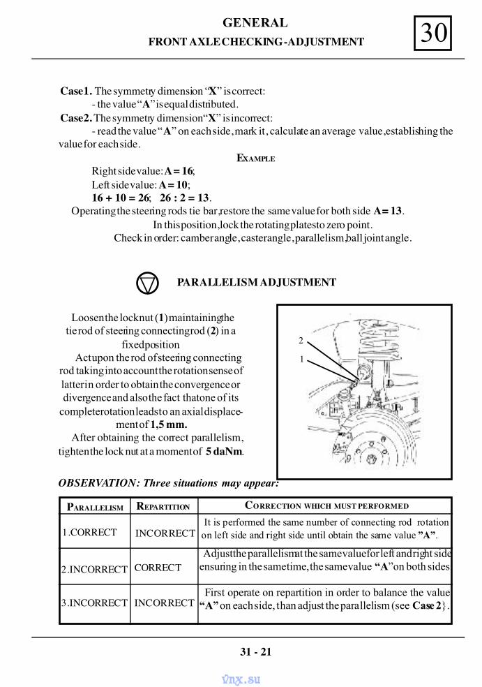
GENERAL 30
31 - 21
FRONT AXLE CHECKING -ADJUSTMENT
Case 1. The symmetry dimension “X” is correct:- the value “A” is equal distributed.
Case 2. The symmetry dimension “X” is incorrect:- read the value “A” on each side, mark it, calculate an average value, establishing the
value for each side.EXAMPLE
Right side value: A = 16;Left side value: A = 10;16 + 10 = 26; 26 : 2 = 13.
Operating the steering rods tie bar, restore the same value for both side A = 13.In this position, lock the rotating plates to zero point.
Check in order: camber angle, caster angle, parallelism, ball joint angle.
PARALLELISM ADJUSTMENT
Loosen the lock nut (1) maintaining thetie rod of steering connecting rod (2) in a
fixed position.Act upon the rod of steering connecting
rod taking into account the rotation sense oflatter in order to obtain the convergence ordivergence and also the fact that one of its
complete rotation leads to an axial displace-ment of 1,5 mm.
After obtaining the correct parallelism,tighten the lock nut at a moment of 5 daNm.
OBSERVATION: Three situations may appear:
PARALLELISM REPARTITION CORRECTION WHICH MUST PERFORMED
1.CORRECT
2.INCORRECT
3.INCORRECT
INCORRECT
CORRECT
INCORRECT
It is performed the same number of connecting rod rotationon left side and right side until obtain the same value ”A”.
Adjust the parallelism at the same value for left and right sideensuring in the same time, the same value “A” on both sides.
First operate on repartition in order to balance the value“A” on each side, than adjust the parallelism (see Case 2.
1
2
vnx.su
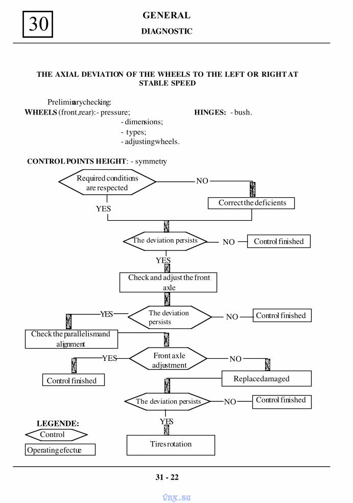
GENERAL30
THE AXIAL DEVIATION OF THE WHEELS TO THE LEFT OR RIGHT ATSTABLE SPEED
Preliminary checking: WHEELS (front,rear):- pressure; HINGES: - bush.
- dimensions;- types;- adjusting wheels.
CONTROL POINTS HEIGHT: - symmetry
Required conditionsare respected
Correct the deficients
The deviation persists Control finished
Check and adjust the frontaxle
Control finishedThe deviationpersists
Check the parallelism andalignment
Front axleadjustment
Replace damagedControl finished
The deviation persists Control finished
Control
Operating efectue
LEGENDE:
Tires rotation
NO
NO
NO
NO
NO
YES
YES
YES
YES
YES
31 - 22
DIAGNOSTIC
vnx.su
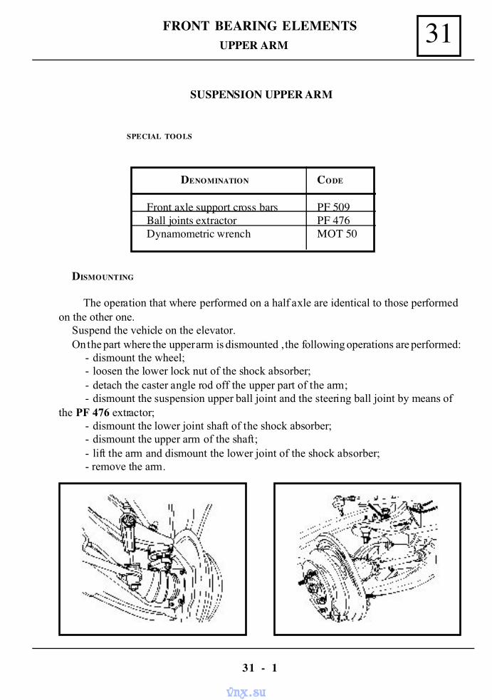
31FRONT BEARING ELEMENTS
31 - 1
UPPER ARM
SUSPENSION UPPER ARM
SPECIAL TOOLS
DENOMINATION CODE
Front axle support cross bars PF 509Ball joints extractor PF 476Dynamometric wrench MOT 50
DISMOUNTING
The operation that where performed on a half axle are identical to those performedon the other one.
Suspend the vehicle on the elevator.On the part where the upper arm is dismounted , the following operations are performed:
- dismount the wheel;- loosen the lower lock nut of the shock absorber;- detach the caster angle rod off the upper part of the arm;- dismount the suspension upper ball joint and the steering ball joint by means of
the PF 476 extractor;- dismount the lower joint shaft of the shock absorber;- dismount the upper arm of the shaft;- lift the arm and dismount the lower joint of the shock absorber;- remove the arm.
vnx.su
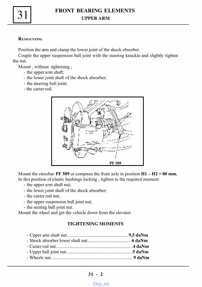
FRONT BEARING ELEMENTS
31 - 2
31
REMOUNTING
Position the arm and clamp the lower joint of the shock absorber.Couple the upper suspension ball joint with the steering knuckle and slightly tighten
the nut.Mount , without tightening ;
- the upper arm shaft;- the lower joint shaft of the shock absorber; - the steering ball joint;- the caster rod.
Mount the crossbar PF 509 or compress the front axle in position H1 – H2 = 80 mm.In this position of elastic bushings locking , tighten to the required moment:
- the upper arm shaft nut;- the lower joint shaft of the shock absorber;- the caster rod nut;- the upper suspension ball joint nut;- the seering ball joint nut.
Mount the wheel and get the vehicle down from the elevator.
TIGHTENING MOMENTS
- Upper arm shaft nut.................................................... 9,5 daNm- Shock absorber lower shaft nut..................................... 6 daNm- Caster rod nut..................................................................4 daNm- Upper ball joint nut........................................................ 5 daNm- Wheels nut...................................................................... 9 daNm
UPPER ARM
PF 509
vnx.su
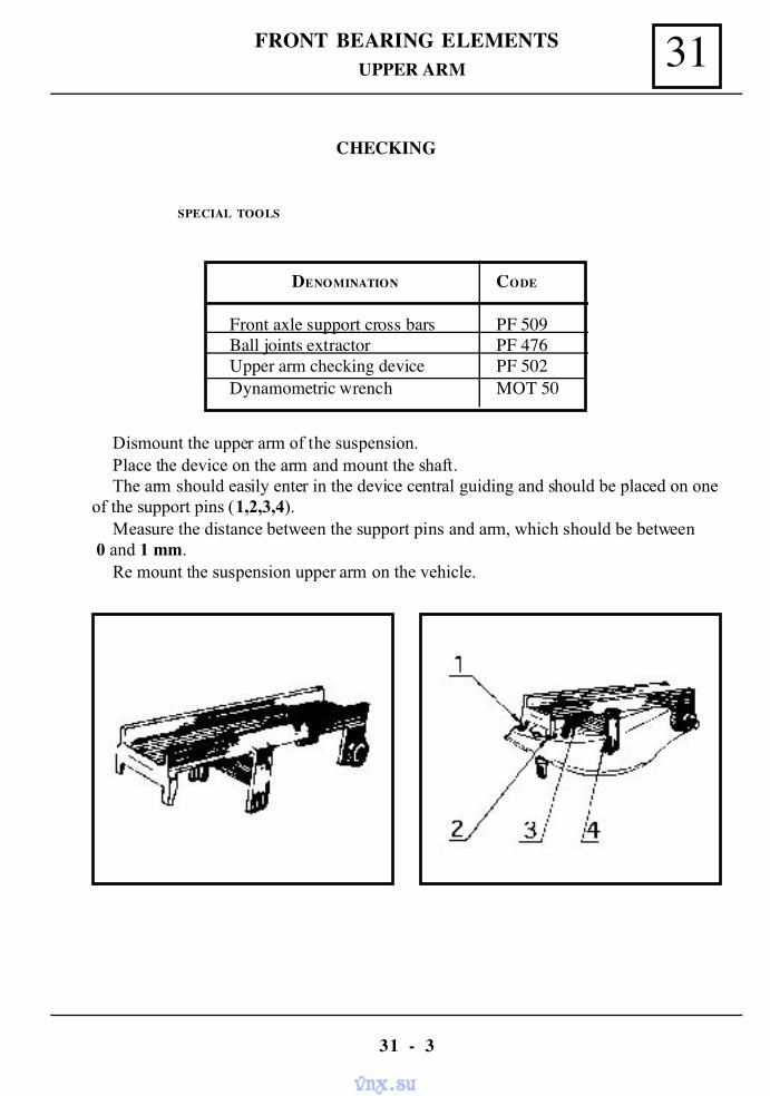
31FRONT BEARING ELEMENTS
31 - 3
CHECKING
SPECIAL TOOLS
DENOMINATION CODE
Front axle support cross bars PF 509Ball joints extractor PF 476Upper arm checking device PF 502Dynamometric wrench MOT 50
Dismount the upper arm of the suspension.Place the device on the arm and mount the shaft.The arm should easily enter in the device central guiding and should be placed on one
of the support pins (1,2,3,4).Measure the distance between the support pins and arm, which should be between
0 and 1 mm.Re mount the suspension upper arm on the vehicle.
UPPER ARM
vnx.su
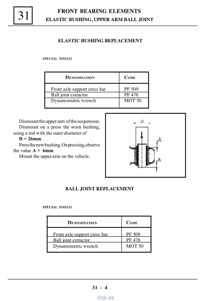
FRONT BEARING ELEMENTS
31 - 4
31 ELASTIC BUSHING, UPPER ARM BALL JOINT
ELASTIC BUSHING REPLACEMENT
SPECIAL TOOLS:
DENOMINATION CODE
Front axle support cross bar PF 509Ball joint extractor PF 476Dynamometric wrench MOT 50
Dismount the upper arm of the suspension.Dismount on a press the worn bushing,
using a rod with the outer diameter ofD = 26mm.Press the new bushing. On pressing, observe
the value A = 6mm.Mount the upper arm on the vehicle.
BALL JOINT REPLACEMENT
SPECIAL TOOLS:
DENOMINATION CODE
Front axle support cross bar PF 509Ball joint extractor PF 476Dynamometric wrench MOT 50
vnx.su
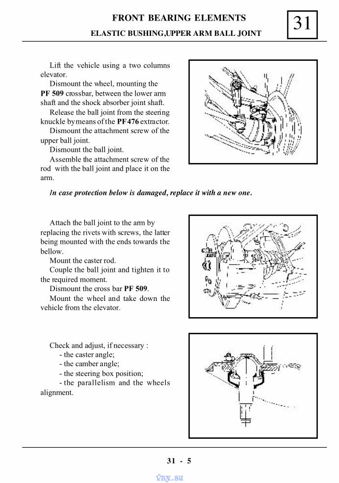
31FRONT BEARING ELEMENTS
31 - 5
Lift the vehicle using a two columnselevator.
Dismount the wheel, mounting thePF 509 crossbar, between the lower armshaft and the shock absorber joint shaft.
Release the ball joint from the steeringknuckle by means of the PF 476 extractor.
Dismount the attachment screw of theupper ball joint.
Dismount the ball joint.Assemble the attachment screw of the
rod with the ball joint and place it on thearm.
ELASTIC BUSHING,UPPER ARM BALL JOINT
Attach the ball joint to the arm byreplacing the rivets with screws, the latterbeing mounted with the ends towards thebellow.
Mount the caster rod.Couple the ball joint and tighten it to
the required moment.Dismount the cross bar PF 509.Mount the wheel and take down the
vehicle from the elevator.
Check and adjust, if necessary :- the caster angle;- the camber angle;- the steering box position;- the parallelism and the wheels
alignment.
In case protection below is damaged, replace it with a new one.
vnx.su
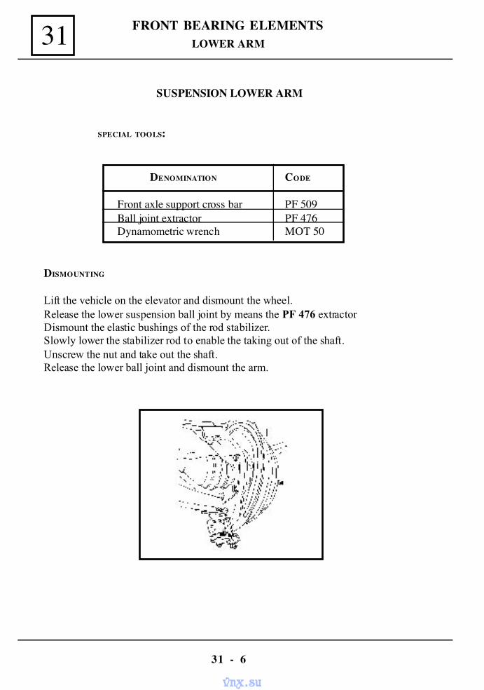
FRONT BEARING ELEMENTS
31 - 6
31 LOWER ARM
SUSPENSION LOWER ARM
SPECIAL TOOLS:
DENOMINATION CODE
Front axle support cross bar PF 509Ball joint extractor PF 476Dynamometric wrench MOT 50
DISMOUNTING
Lift the vehicle on the elevator and dismount the wheel.Release the lower suspension ball joint by means the PF 476 extractorDismount the elastic bushings of the rod stabilizer.Slowly lower the stabilizer rod to enable the taking out of the shaft.Unscrew the nut and take out the shaft.Release the lower ball joint and dismount the arm.
vnx.su
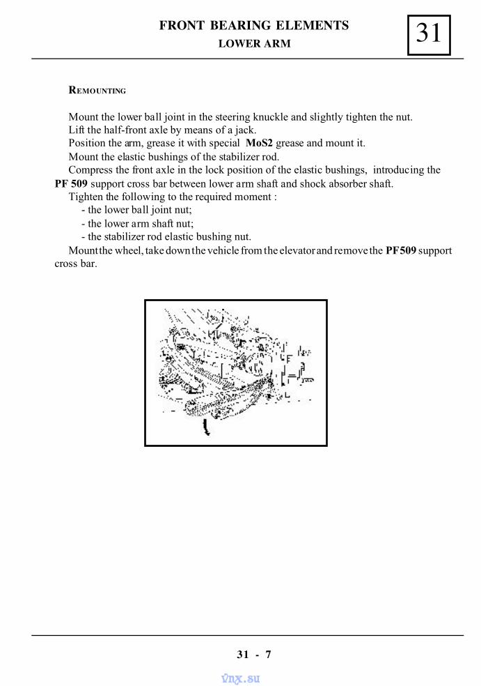
31FRONT BEARING ELEMENTS
31 - 7
REMOUNTING
Mount the lower ball joint in the steering knuckle and slightly tighten the nut.Lift the half-front axle by means of a jack.Position the arm, grease it with special MoS2 grease and mount it.Mount the elastic bushings of the stabilizer rod.Compress the front axle in the lock position of the elastic bushings, introducing the
PF 509 support cross bar between lower arm shaft and shock absorber shaft.Tighten the following to the required moment :
- the lower ball joint nut;- the lower arm shaft nut;- the stabilizer rod elastic bushing nut.
Mount the wheel, take down the vehicle from the elevator and remove the PF 509 supportcross bar.
LOWER ARM
vnx.su
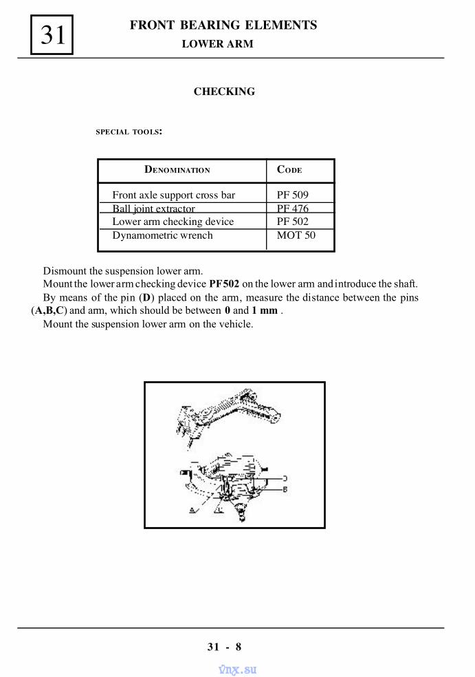
FRONT BEARING ELEMENTS
31 - 8
31
CHECKING
SPECIAL TOOLS:
DENOMINATION CODE
Front axle support cross bar PF 509Ball joint extractor PF 476Lower arm checking device PF 502Dynamometric wrench MOT 50
LOWER ARM
Dismount the suspension lower arm.Mount the lower arm checking device PF 502 on the lower arm and introduce the shaft.By means of the pin (D) placed on the arm, measure the distance between the pins
(A,B,C) and arm, which should be between 0 and 1 mm .Mount the suspension lower arm on the vehicle.
vnx.su
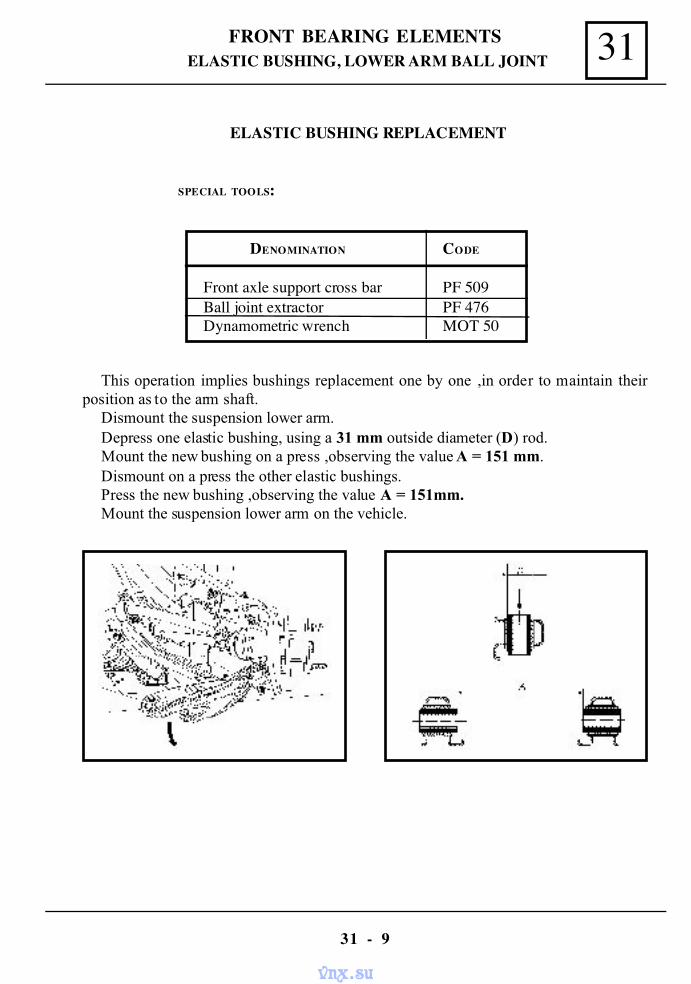
31FRONT BEARING ELEMENTS
31 - 9
ELASTIC BUSHING, LOWER ARM BALL JOINT
ELASTIC BUSHING REPLACEMENT
SPECIAL TOOLS:
DENOMINATION CODE
Front axle support cross bar PF 509Ball joint extractor PF 476Dynamometric wrench MOT 50
This operation implies bushings replacement one by one ,in order to maintain theirposition as to the arm shaft.
Dismount the suspension lower arm.Depress one elastic bushing, using a 31 mm outside diameter (D) rod.Mount the new bushing on a press ,observing the value A = 151 mm.Dismount on a press the other elastic bushings.Press the new bushing ,observing the value A = 151mm.Mount the suspension lower arm on the vehicle.
vnx.su
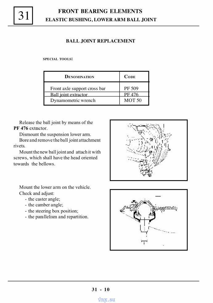
FRONT BEARING ELEMENTS
31 - 10
31
BALL JOINT REPLACEMENT
SPECIAL TOOLS:
DENOMINATION CODE
Front axle support cross bar PF 509Ball joint extractor PF 476Dynamometric wrench MOT 50
Release the ball joint by means of thePF 476 extractor.
Dismount the suspension lower arm.Bore and remove the ball joint attachment
rivets.Mount the new ball joint and attach it with
screws, which shall have the head orientedtowards the bellows.
Mount the lower arm on the vehicle.Check and adjust:
- the caster angle;- the camber angle;- the steering box position;- the parallelism and repartition.
ELASTIC BUSHING, LOWER ARM BALL JOINT
vnx.su
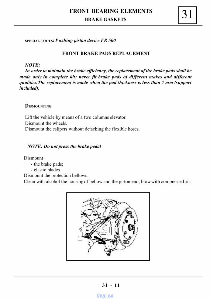
31FRONT BEARING ELEMENTS
31 - 11
BRAKE GASKETS
SPECIAL TOOLS: Pushing piston device FR 500
FRONT BRAKE PADS REPLACEMENT
NOTE:In order to maintain the brake efficiency, the replacement of the brake pads shall be
made only in complete kit; never fit brake pads of different makes and differentqualities.The replacement is made when the pad thickness is less than 7 mm (supportincluded).
DISMOUNTING
Lift the vehicle by means of a two columns elevator.Dismount the wheels.Dismount the calipers without detaching the flexible hoses.
NOTE: Do not press the brake pedal
Dismount :- the brake pads;- elastic blades.
Dismount the protection bellows.Clean with alcohol the housing of bellow and the piston end; blow with compressed air.
vnx.su
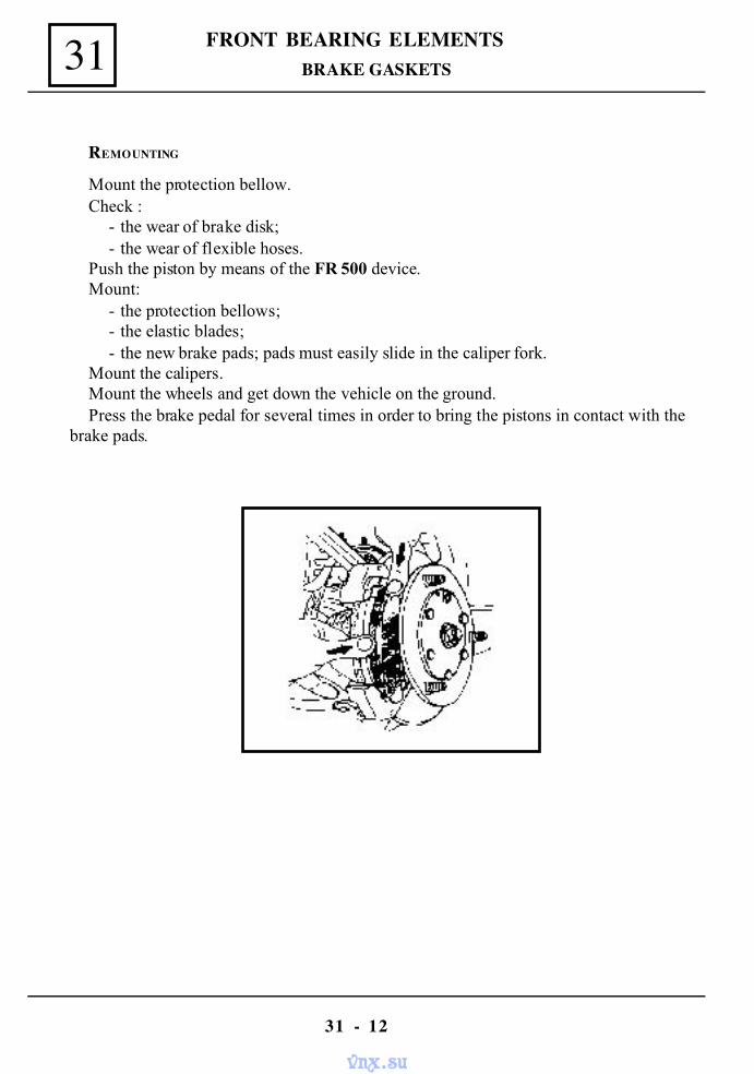
FRONT BEARING ELEMENTS
31 - 12
31 BRAKE GASKETS
REMOUNTING
Mount the protection bellow.Check :
- the wear of brake disk;- the wear of flexible hoses.
Push the piston by means of the FR 500 device.Mount:
- the protection bellows;- the elastic blades;- the new brake pads; pads must easily slide in the caliper fork.
Mount the calipers.Mount the wheels and get down the vehicle on the ground.Press the brake pedal for several times in order to bring the pistons in contact with the
brake pads.
vnx.su
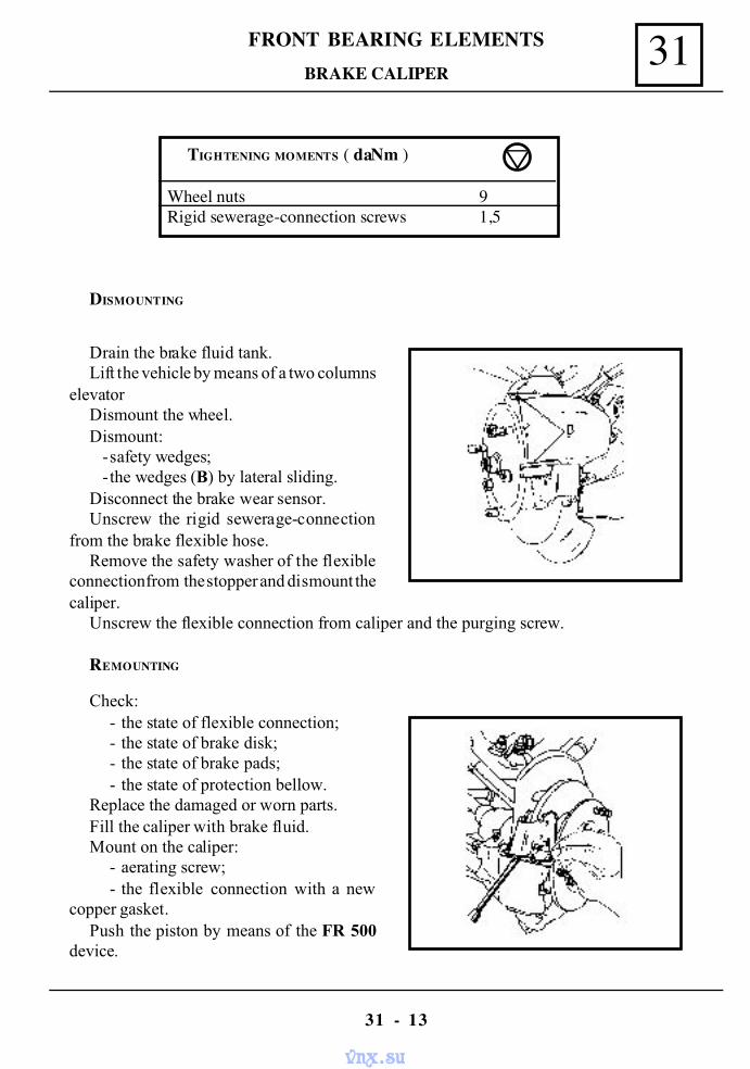
31FRONT BEARING ELEMENTS
31 - 13
BRAKE CALIPER
TIGHTENING MOMENTS ( daNm )
Wheel nuts 9Rigid sewerage-connection screws 1,5
DISMOUNTING
Drain the brake fluid tank.Lift the vehicle by means of a two columns
elevatorDismount the wheel.Dismount:
-safety wedges;-the wedges (B) by lateral sliding.
Disconnect the brake wear sensor.Unscrew the rigid sewerage-connection
from the brake flexible hose.Remove the safety washer of the flexible
connection from the stopper and dismount thecaliper.
Check:- the state of flexible connection;- the state of brake disk;- the state of brake pads;- the state of protection bellow.
Replace the damaged or worn parts.Fill the caliper with brake fluid.Mount on the caliper:
- aerating screw;- the flexible connection with a new
copper gasket.Push the piston by means of the FR 500
device.
Unscrew the flexible connection from caliper and the purging screw.
REMOUNTING
vnx.su
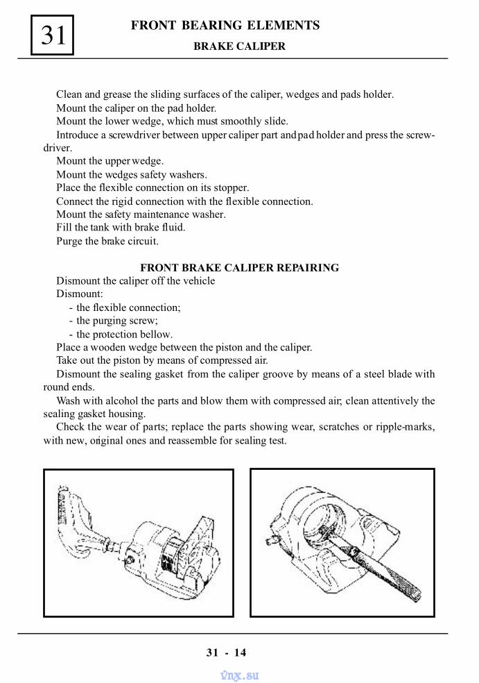
FRONT BEARING ELEMENTS
31 - 14
31
Clean and grease the sliding surfaces of the caliper, wedges and pads holder.Mount the caliper on the pad holder.Mount the lower wedge, which must smoothly slide.Introduce a screwdriver between upper caliper part and pad holder and press the screw-
driver.Mount the upper wedge.Mount the wedges safety washers.Place the flexible connection on its stopper.Connect the rigid connection with the flexible connection.Mount the safety maintenance washer.Fill the tank with brake fluid.Purge the brake circuit.
FRONT BRAKE CALIPER REPAIRINGDismount the caliper off the vehicleDismount:
- the flexible connection;- the purging screw;- the protection bellow.
Place a wooden wedge between the piston and the caliper.Take out the piston by means of compressed air.Dismount the sealing gasket from the caliper groove by means of a steel blade with
round ends.Wash with alcohol the parts and blow them with compressed air; clean attentively the
sealing gasket housing.Check the wear of parts; replace the parts showing wear, scratches or ripple-marks,
with new, original ones and reassemble for sealing test.
BRAKE CALIPER
vnx.su
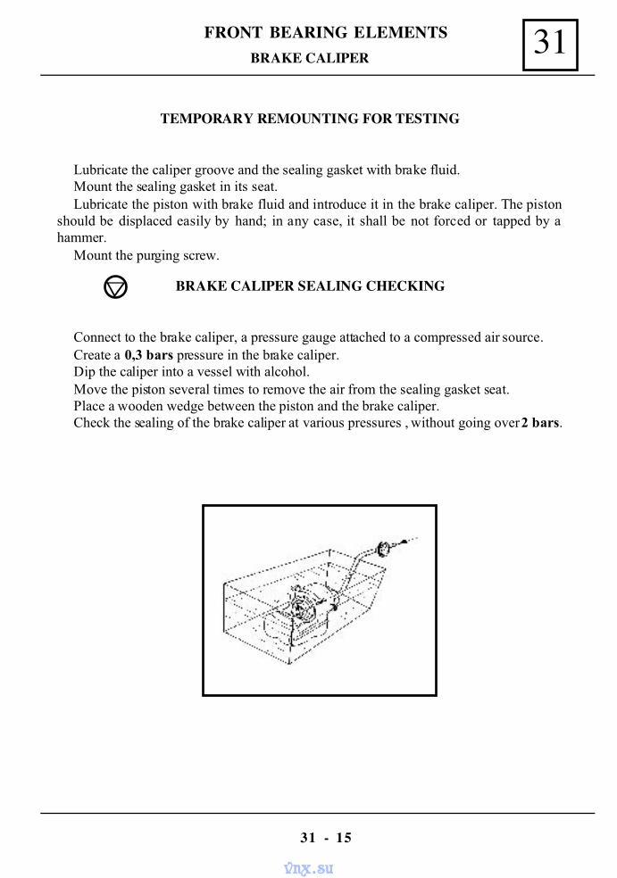
31FRONT BEARING ELEMENTS
31 - 15
TEMPORARY REMOUNTING FOR TESTING
Lubricate the caliper groove and the sealing gasket with brake fluid.Mount the sealing gasket in its seat.Lubricate the piston with brake fluid and introduce it in the brake caliper. The piston
should be displaced easily by hand; in any case, it shall be not forced or tapped by ahammer.
Mount the purging screw.
BRAKE CALIPER SEALING CHECKING
Connect to the brake caliper, a pressure gauge attached to a compressed air source.Create a 0,3 bars pressure in the brake caliper.Dip the caliper into a vessel with alcohol.Move the piston several times to remove the air from the sealing gasket seat.Place a wooden wedge between the piston and the brake caliper.Check the sealing of the brake caliper at various pressures , without going over 2 bars.
BRAKE CALIPER
vnx.su
FRONT BEARING ELEMENTS
31 - 16
31
If the brake caliper lets the air flow by the piston, dismount the caliper brake once more.If the piston has been reused, it shall be replaced, and if has been replaced, it shall be
recovered and the brake caliper shall be replaced with a new assembly.Perform again the sealing test.After having performed the sealing test, dismount the brake caliper and blow it with
compressed air.If the brake caliper is in a good state, it shall be mounted.Grease the pinion and the inside of the caliper brake grease.Mount:
- the sealing gasket;- the piston;- the protection bellow;- the purging screw;- the flexible connection, with a new copper gasket.
Fill up the caliper with brake fluid.Mount the caliper brake on the vehicle.Purge the braking circuit.
BRAKE CALIPER
vnx.su
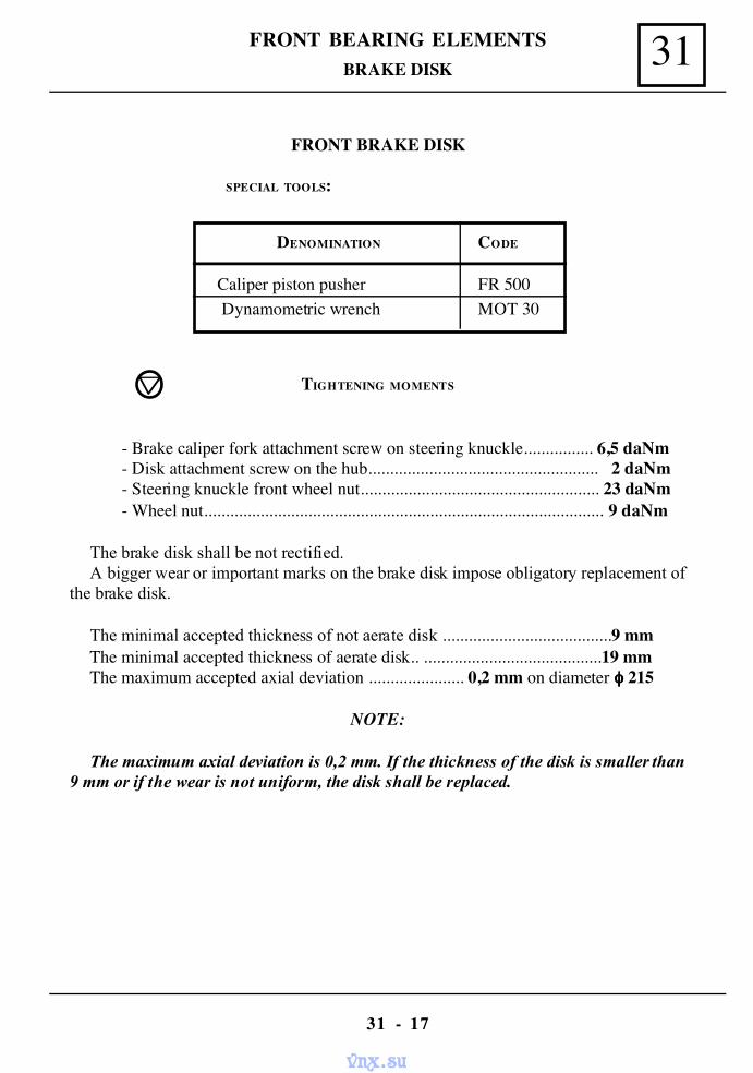
31FRONT BEARING ELEMENTS
31 - 17
BRAKE DISK
DENOMINATION CODE
Caliper piston pusher FR 500 Dynamometric wrench MOT 30
FRONT BRAKE DISK
SPECIAL TOOLS:
TIGHTENING MOMENTS
- Brake caliper fork attachment screw on steering knuckle................ 6,5 daNm- Disk attachment screw on the hub..................................................... 2 daNm- Steering knuckle front wheel nut....................................................... 23 daNm- Wheel nut............................................................................................ 9 daNm
The brake disk shall be not rectified.A bigger wear or important marks on the brake disk impose obligatory replacement of
the brake disk.
The minimal accepted thickness of not aerate disk .......................................9 mmThe minimal accepted thickness of aerate disk.. .........................................19 mmThe maximum accepted axial deviation ...................... 0,2 mm on diameter φφφφ 215
NOTE:
The maximum axial deviation is 0,2 mm. If the thickness of the disk is smaller than9 mm or if the wear is not uniform, the disk shall be replaced.
vnx.su
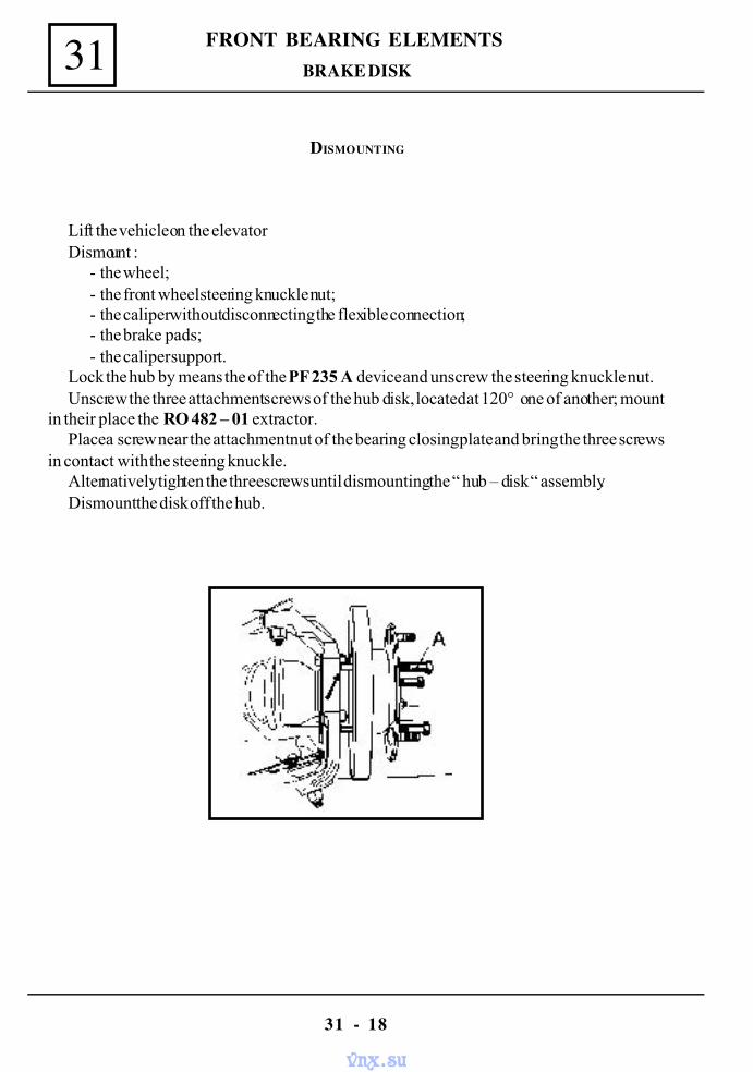
FRONT BEARING ELEMENTS
31 - 18
31
DISMOUNTING
Lift the vehicle on the elevatorDismount :
- the wheel;- the front wheel steering knuckle nut;- the caliper without disconnecting the flexible connection;- the brake pads;- the caliper support.
Lock the hub by means the of the PF 235 A device and unscrew the steering knuckle nut.Unscrew the three attachment screws of the hub disk, located at 120° one of another; mount
in their place the RO 482 – 01 extractor.Place a screw near the attachment nut of the bearing closing plate and bring the three screws
in contact with the steering knuckle.Alternatively tighten the three screws until dismounting the “ hub – disk “ assembly.Dismount the disk off the hub.
BRAKE DISK
vnx.su
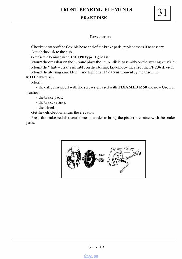
31FRONT BEARING ELEMENTS
31 - 19
REMOUNTING
Check the state of the flexible hose and of the brake pads; replace them if necessary.Attach the disk to the hub.Grease the bearing with LiCaPb type II grease.Mount the cross bar on the hub and place the “hub – disk” assembly on the steering knuckle.Mount the “ hub – disk” assembly on the steering knuckle by means of the PF 236 device.Mount the steering knuckle nut and tighten at 23 daNm moment by means of the
MOT 50 wrench.Mount:
- the caliper support with the screws greased with FIXAMED R 58 and new Growerwasher;
- the brake pads;- the brake caliper;- the wheel.
Get the vehicle down from the elevator.Press the brake pedal several times, in order to bring the piston in contact with the brake
pads.
BRAKE DISK
vnx.su
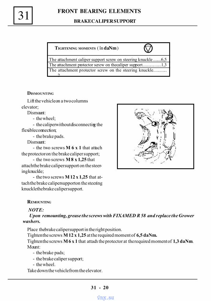
FRONT BEARING ELEMENTS
31 - 20
31 BRAKE CALIPER SUPPORT
DISMOUNTING
Lift the vehicle on a two columnselevator;
Dismount:- the wheel;- the caliper without disconnecting the
flexible connection;- the brake pads.
Dismount:- the two screws M 6 x 1 that attach
the protector on the brake caliper support;- the two screws M 8 x 1,25 that
attach the brake caliper support on the steer-ing knuckle;
- the two screws M 12 x 1,25 that at-tach the brake caliper support on the steeringknucklethe brake caliper support.
REMOUNTING
NOTE: Upon remounting, grease the screws with FIXAMED R 58 and replace the Grower
washers.
Place the brake caliper support in the right position.Tighten the screws M 12 x 1,25 at the required moment of 6,5 daNm.Tighten the screws M 6 x 1 that attach the protector at the required moment of 1,3 daNm.Mount:
- the brake pads;- the brake caliper support;- the wheel.
Take down the vehicle from the elevator.
TIGHTENING MOMENTS ( în daNm )
The attachment caliper support screw on steering knuckle .......6,5The attachment protector screw on the caliper support.................1,3The attachment protector screw on the steering knuckle...................2
vnx.su
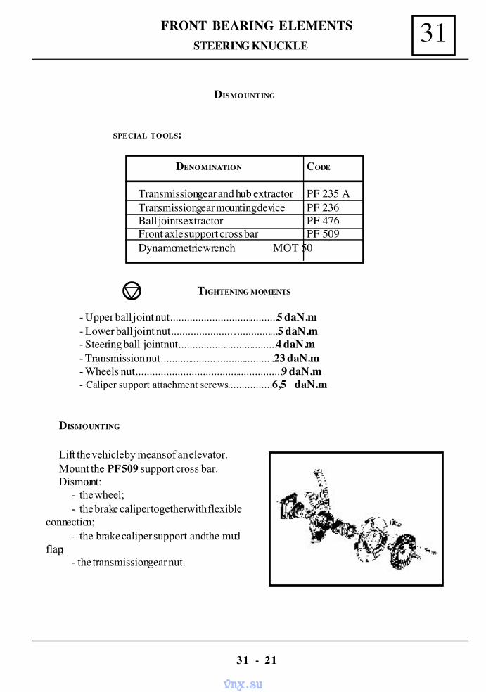
31FRONT BEARING ELEMENTS
31 - 21
STEERING KNUCKLE
DISMOUNTING
SPECIAL TOOLS:
DENOMINATION CODE
Transmission gear and hub extractor PF 235 ATransmission gear mounting device PF 236Ball joints extractor PF 476Front axle support cross bar PF 509Dynamometric wrench MOT 50
TIGHTENING MOMENTS
- Upper ball joint nut.......................................5 daN.m- Lower ball joint nut.......................................5 daN.m- Steering ball joint nut....................................4 daN.m- Transmission nut..........................................23 daN.m- Wheels nut.....................................................9 daN.m- Caliper support attachment screws................6,5 daN.m
DISMOUNTING
Lift the vehicle by means of an elevator.Mount the PF 509 support cross bar.Dismount:
- the wheel;- the brake caliper together with flexible
connection;- the brake caliper support and the mud
flap;- the transmission gear nut.
vnx.su
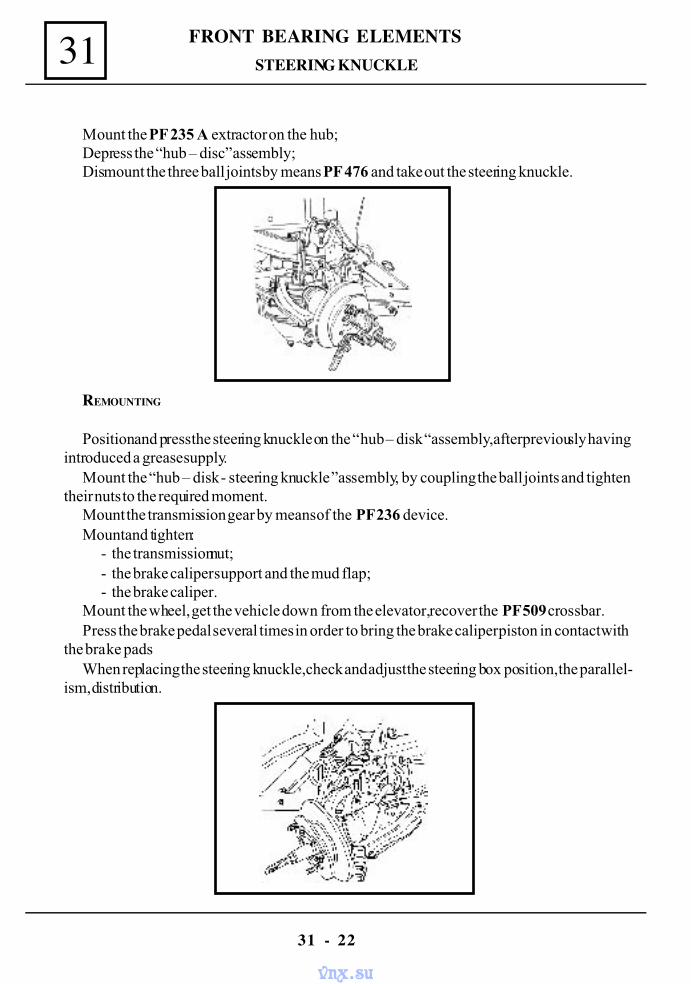
FRONT BEARING ELEMENTS
31 - 22
31 STEERING KNUCKLE
Mount the PF 235 A extractor on the hub;Depress the “hub – disc” assembly;Dismount the three ball joints by means PF 476 and take out the steering knuckle.
REMOUNTING
Position and press the steering knuckle on the “ hub – disk “assembly ,after previously havingintroduced a grease supply.
Mount the “hub – disk - steering knuckle ”assembly, by coupling the ball joints and tightentheir nuts to the required moment.
Mount the transmission gear by means of the PF 236 device.Mount and tighten:
- the transmission nut;- the brake caliper support and the mud flap;- the brake caliper.
Mount the wheel, get the vehicle down from the elevator, recover the PF 509 crossbar.Press the brake pedal several times in order to bring the brake caliper piston in contact with
the brake padsWhen replacing the steering knuckle, check and adjust the steering box position, the parallel-
ism, distribution.
vnx.su
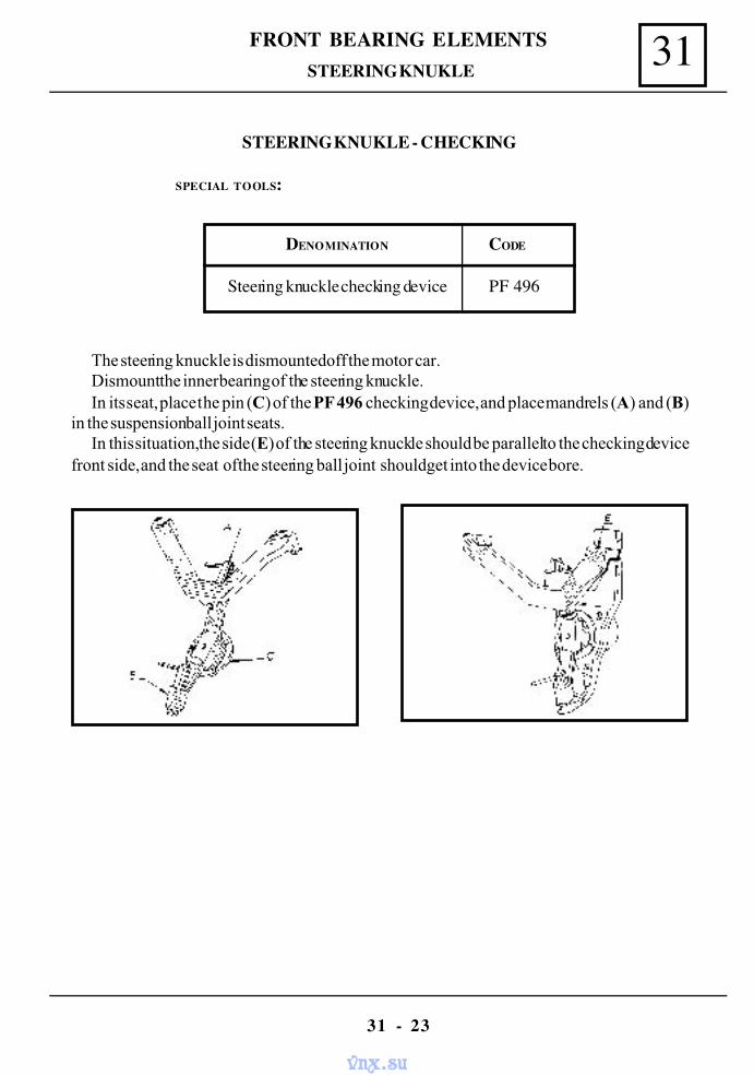
31FRONT BEARING ELEMENTS
31 - 23
STEERING KNUKLE
STEERING KNUKLE - CHECKING
SPECIAL TOOLS:
DENOMINATION CODE
Steering knuckle checking device PF 496
The steering knuckle is dismounted off the motor car.Dismount the inner bearing of the steering knuckle.In its seat, place the pin (C) of the PF 496 checking device, and place mandrels (A) and (B)
in the suspension ball joint seats.In this situation, the side (E) of the steering knuckle should be parallel to the checking device
front side, and the seat of the steering ball joint should get into the device bore.
vnx.su
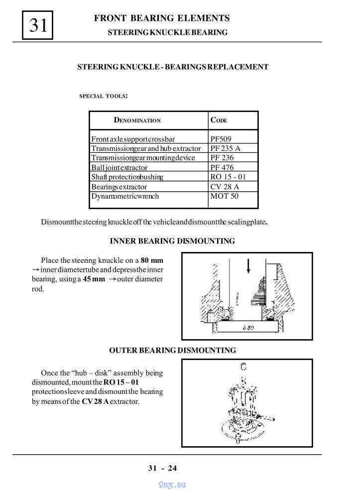
FRONT BEARING ELEMENTS
31 - 24
31 STEERING KNUCKLE BEARING
STEERING KNUCKLE - BEARINGS REPLACEMENT
SPECIAL TOOLS:
DENOMINATION CODE
Front axle support crossbar PF509Transmission gear and hub extractor PF 235 ATransmission gear mounting device PF 236Ball joint extractor PF 476Shaft protection bushing RO 15 - 01Bearings extractor CV 28 ADynamometric wrench MOT 50
Dismount the steering knuckle off the vehicle and dismount the sealing plate.
INNER BEARING DISMOUNTING
Place the steering knuckle on a 80 mm→ inner diameter tube and depress the innerbearing, using a 45 mm → outer diameterrod.
OUTER BEARING DISMOUNTING
Once the “hub – disk” assembly beingdismounted, mount the RO 15 – 01protection sleeve and dismount the bearingby means of the CV 28 A extractor.
vnx.su
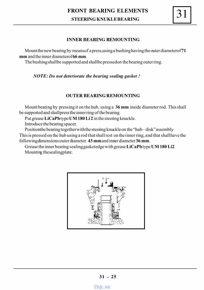
31FRONT BEARING ELEMENTS
31 - 25
STEERING KNUKLE BEARING
INNER BEARING REMOUNTING
Mount the new bearing by means of a press, using a bushing having the outer diameter of 71mm and the inner diameter of 66 mm.
The bushing shall be supported and shall be pressed on the bearing outer ring.
NOTE: Do not deteriorate the bearing sealing gasket !
OUTER BEARING REMOUNTING
Mount bearing by pressing it on the hub, using a 36 mm inside diameter rod. This shallbe supported and shall press the inner ring of the bearing.
Put grease LiCaPb type UM 180 Li 2 in the steering knuckle.Introduce the bearing spacer.Position the bearing together with the steering knuckle on the “hub – disk” assembly.
This is pressed on the hub using a rod that shall rest on the inner ring, and that shall have thefollowing dimensions: outer diameter: 43 mm and inner diameter 36 mm.
Grease the inner bearing sealing gasket edge with grease LiCaPb type UM 180 Li2.Mounting the sealing plate.
vnx.su
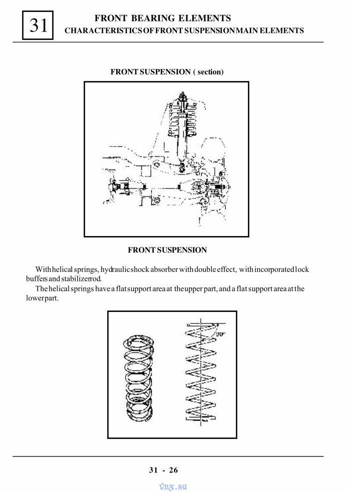
FRONT BEARING ELEMENTS
31 - 26
31 CHARACTERISTICS OF FRONT SUSPENSION MAIN ELEMENTS
FRONT SUSPENSION
With helical springs, hydraulic shock absorber with double effect, with incorporated lockbuffers and stabilizer rod.
The helical springs have a flat support area at the upper part, and a flat support area at thelower part.
FRONT SUSPENSION ( section)
vnx.su
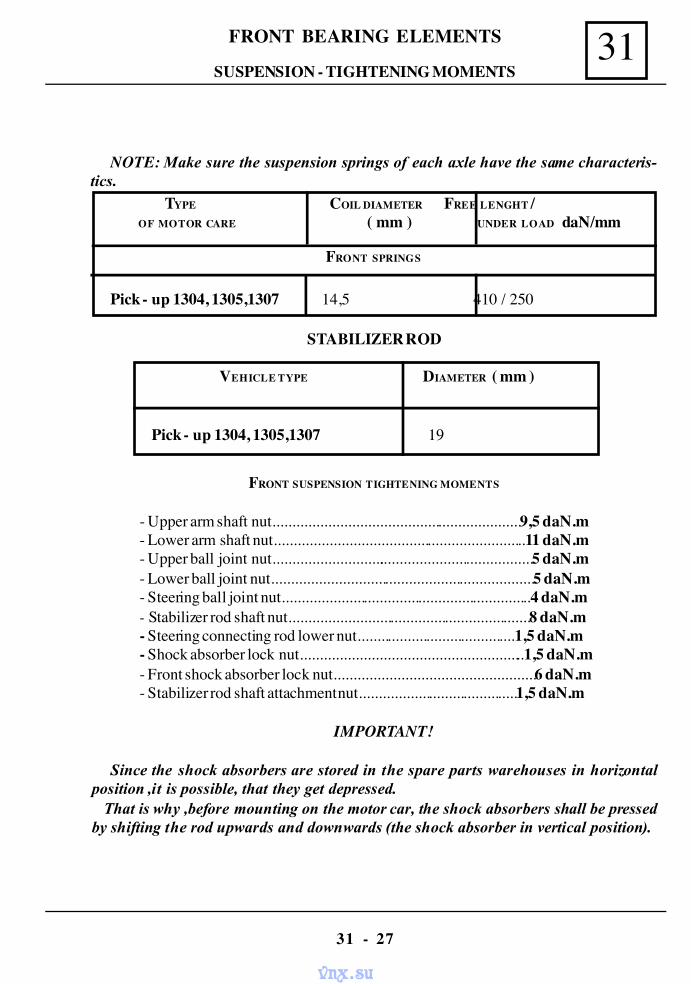
31FRONT BEARING ELEMENTS
31 - 27
FRONT SUSPENSION TIGHTENING MOMENTS
- Upper arm shaft nut...............................................................9,5 daN.m- Lower arm shaft nut................................................................11 daN.m- Upper ball joint nut...................................................................5 daN.m- Lower ball joint nut...................................................................5 daN.m- Steering ball joint nut................................................................4 daN.m- Stabilizer rod shaft nut..............................................................8 daN.m- Steering connecting rod lower nut.........................................1,5 daN.m- Shock absorber lock nut.........................................................1,5 daN.m- Front shock absorber lock nut...................................................6 daN.m- Stabilizer rod shaft attachment nut.........................................1,5 daN.m
IMPORTANT!
Since the shock absorbers are stored in the spare parts warehouses in horizontalposition ,it is possible, that they get depressed. That is why ,before mounting on the motor car, the shock absorbers shall be pressedby shifting the rod upwards and downwards (the shock absorber in vertical position).
SUSPENSION - TIGHTENING MOMENTS
STABILIZER ROD
VEHICLE TYPE DIAMETER ( mm )
Pick - up 1304, 1305,1307 19
NOTE: Make sure the suspension springs of each axle have the same characteris-tics.
TYPE COIL DIAMETER FREE LENGHT / OF MOTOR CARE ( mm ) UNDER LOAD daN/mm
FRONT SPRINGS
Pick - up 1304, 1305,1307 14,5 410 / 250
vnx.su
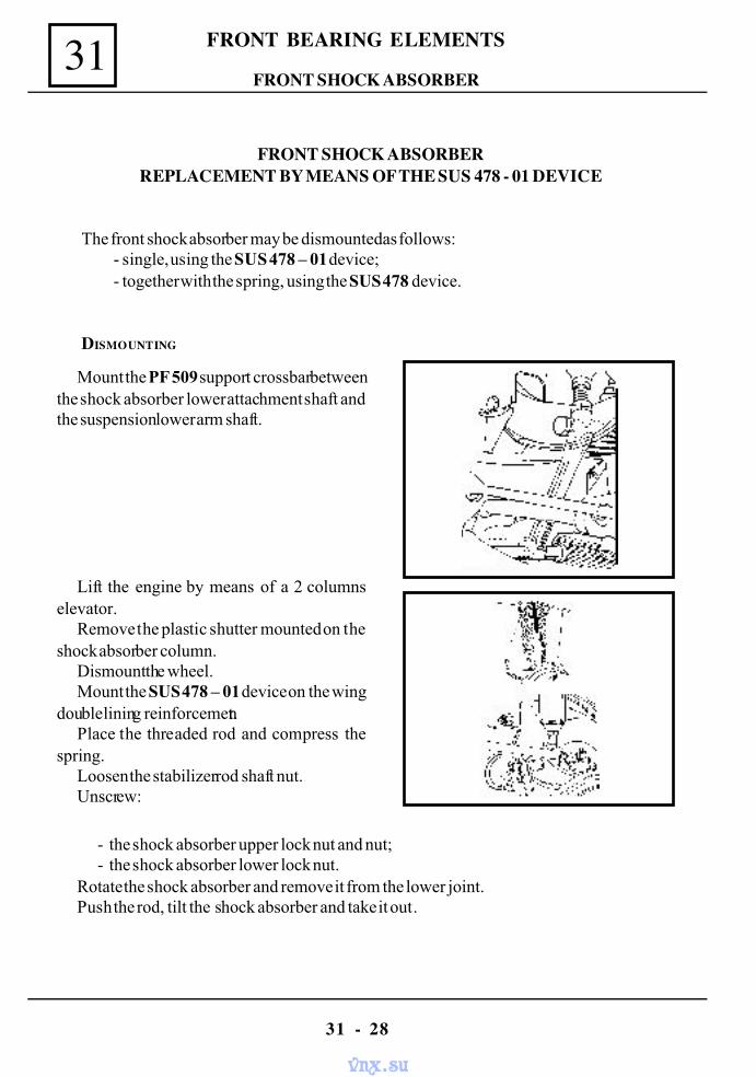
FRONT BEARING ELEMENTS
31 - 28
31FRONT SHOCK ABSORBER
FRONT SHOCK ABSORBERREPLACEMENT BY MEANS OF THE SUS 478 - 01 DEVICE
The front shock absorber may be dismounted as follows:- single, using the SUS 478 – 01 device;- together with the spring, using the SUS 478 device.
DISMOUNTING
Mount the PF 509 support crossbar betweenthe shock absorber lower attachment shaft andthe suspension lower arm shaft.
Lift the engine by means of a 2 columnselevator.
Remove the plastic shutter mounted on theshock absorber column.
Dismount the wheel.Mount the SUS 478 – 01 device on the wing
double lining reinforcement.Place the threaded rod and compress the
spring.Loosen the stabilizer rod shaft nut.Unscrew:
- the shock absorber upper lock nut and nut;- the shock absorber lower lock nut.
Rotate the shock absorber and remove it from the lower joint.Push the rod, tilt the shock absorber and take it out.
vnx.su
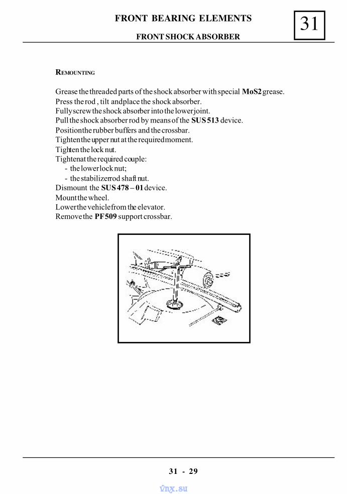
31FRONT BEARING ELEMENTS
31 - 29
REMOUNTING
Grease the threaded parts of the shock absorber with special MoS2 grease.Press the rod , tilt and place the shock absorber.Fully screw the shock absorber into the lower joint.Pull the shock absorber rod by means of the SUS 513 device.Position the rubber buffers and the crossbar.Tighten the upper nut at the required moment.Tighten the lock nut.Tighten at the required couple:
- the lower lock nut;- the stabilizer rod shaft nut.
Dismount the SUS 478 – 01 device.Mount the wheel.Lower the vehicle from the elevator.Remove the PF 509 support crossbar.
FRONT SHOCK ABSORBER
vnx.su
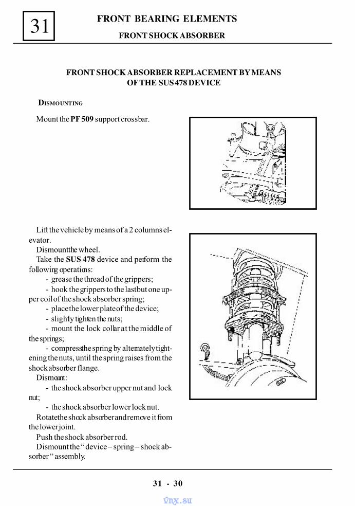
FRONT BEARING ELEMENTS
31 - 30
31
FRONT SHOCK ABSORBER REPLACEMENT BY MEANSOF THE SUS 478 DEVICE
DISMOUNTING
Mount the PF 509 support crossbar.
FRONT SHOCK ABSORBER
Lift the vehicle by means of a 2 columns el-evator.
Dismount the wheel.Take the SUS 478 device and perform the
following operations:- grease the thread of the grippers;- hook the grippers to the last but one up-
per coil of the shock absorber spring;- place the lower plate of the device;- slightly tighten the nuts;- mount the lock collar at the middle of
the springs;- compress the spring by alternately tight-
ening the nuts, until the spring raises from theshock absorber flange.
Dismount:- the shock absorber upper nut and lock
nut;- the shock absorber lower lock nut.
Rotate the shock absorber and remove it fromthe lower joint.
Push the shock absorber rod.Dismount the “ device – spring – shock ab-
sorber “ assembly.
vnx.su
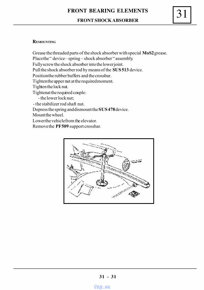
31FRONT BEARING ELEMENTS
31 - 31
FRONT SHOCK ABSORBER
REMOUNTING
Grease the threaded parts of the shock absorber with special MoS2 grease.Place the “ device – spring – shock absorber “ assembly.Fully screw the shock absorber into the lower joint.Pull the shock absorber rod by means of the SUS 513 device.Position the rubber buffers and the crossbar.Tighten the upper nut at the required moment.Tighten the lock nut.Tighten at the required couple:
- the lower lock nut; - the stabilizer rod shaft nut.
Depress the spring and dismount the SUS 478 device.Mount the wheel.Lower the vehicle from the elevator.Remove the PF 509 support crossbar.
vnx.su
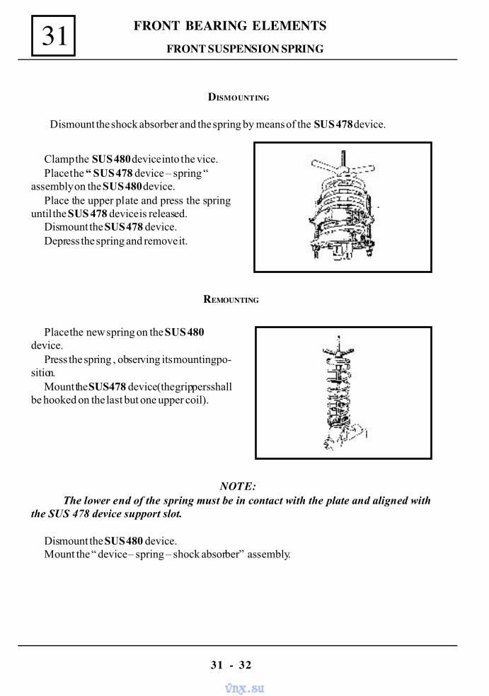
FRONT BEARING ELEMENTS
31 - 32
31 FRONT SUSPENSION SPRING
DISMOUNTING
Dismount the shock absorber and the spring by means of the SUS 478 device.
Clamp the SUS 480 device into the vice.Place the “ SUS 478 device – spring “
assembly on the SUS 480 device.Place the upper plate and press the spring
until the SUS 478 device is released.Dismount the SUS 478 device.Depress the spring and remove it.
REMOUNTING
NOTE: The lower end of the spring must be in contact with the plate and aligned with
the SUS 478 device support slot.
Dismount the SUS 480 device.Mount the “ device – spring – shock absorber” assembly.
Place the new spring on the SUS 480device.
Press the spring , observing its mounting po-sition.
Mount the SUS 478 device (the grippers shallbe hooked on the last but one upper coil).
vnx.su
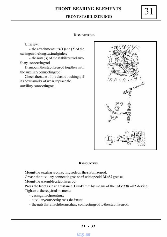
31FRONT BEARING ELEMENTS
31 - 33
FRONT STABILIZER ROD
DISMOUNTING
Unscrew :- the attachment nuts (1)and (2) of the
casing on the longitudinal girder;- the nuts (3) of the stabilizer rod aux-
iliary connecting rod.Dismount the stabilizer rod together with
the auxiliary connecting rod.Check the state of the elastic bushings; if
it shows marks of wear, replace theauxiliary connecting rod.
REMOUNTING
Mount the auxiliary connecting rods on the stabilizer rod.Grease the auxiliary connecting rod shaft with special MoS2 grease.Mount the assembled stabilizer rod.Press the front axle at a distance D = 45 mm by means of the TAV 238 – 02 device.Tighten at the required moment:
- casing attachment nut;- auxiliary connecting rods shaft nuts;- the nuts that attach the auxiliary connecting rod to the stabilizer rod.
vnx.su
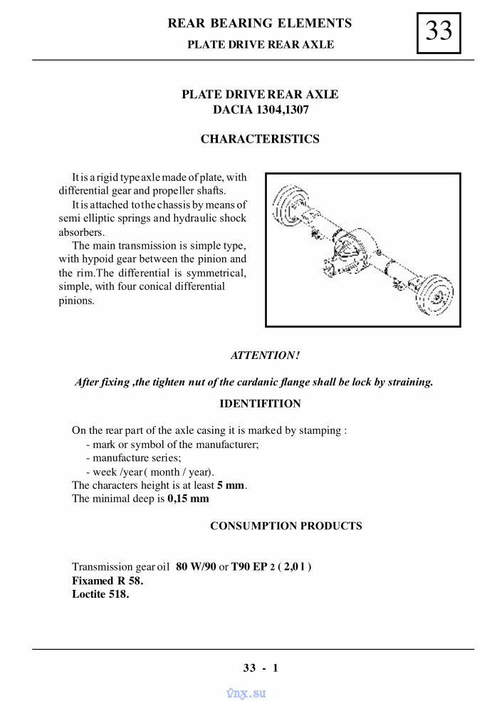
33REAR BEARING ELEMENTS
33 - 1
PLATE DRIVE REAR AXLE
PLATE DRIVE REAR AXLEDACIA 1304,1307
CHARACTERISTICS
It is a rigid type axle made of plate, withdifferential gear and propeller shafts.
It is attached to the chassis by means ofsemi elliptic springs and hydraulic shockabsorbers.
The main transmission is simple type,with hypoid gear between the pinion andthe rim.The differential is symmetrical,simple, with four conical differentialpinions.
ATTENTION!
After fixing ,the tighten nut of the cardanic flange shall be lock by straining.
IDENTIFITION
On the rear part of the axle casing it is marked by stamping :- mark or symbol of the manufacturer;- manufacture series;- week /year ( month / year).
The characters height is at least 5 mm.The minimal deep is 0,15 mm
CONSUMPTION PRODUCTS
Transmission gear oil 80 W/90 or T90 EP 2 ( 2,0 l )Fixamed R 58.Loctite 518.
vnx.su
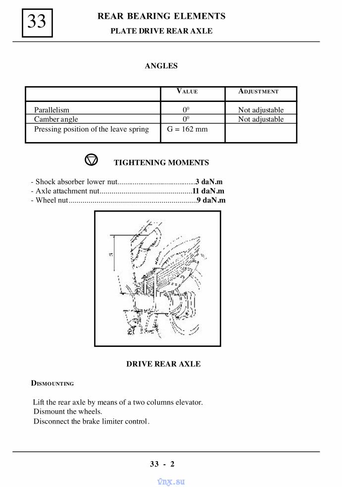
REAR BEARING ELEMENTS33
33 - 2
PLATE DRIVE REAR AXLE
ANGLES
VALUE ADJUSTMENT
Parallelism 00 Not adjustableCamber angle 00 Not adjustablePressing position of the leave spring G = 162 mm
TIGHTENING MOMENTS
- Shock absorber lower nut..........................................3 daN.m- Axle attachment nut...............................................11 daN.m- Wheel nut.................................................................9 daN.m
DRIVE REAR AXLE
DISMOUNTING
Lift the rear axle by means of a two columns elevator.Dismount the wheels.Disconnect the brake limiter control.
vnx.su
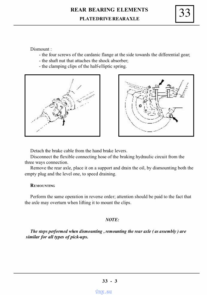
33REAR BEARING ELEMENTS
33 - 3
PLATE DRIVE REAR AXLE
Detach the brake cable from the hand brake levers.Disconnect the flexible connecting hose of the braking hydraulic circuit from the
three ways connection.Remove the rear axle, place it on a support and drain the oil, by dismounting both the
empty plug and the level one, to speed draining.
REMOUNTING
Perform the same operation in reverse order; attention should be paid to the fact thatthe axle may overturn when lifting it to mount the clips.
NOTE:
The steps performed when dismounting , remounting the rear axle ( as assembly ) are similar for all types of pick-ups.
Dismount :- the four screws of the cardanic flange at the side towards the differential gear;- the shaft nut that attaches the shock absorber;- the clamping clips of the half-elliptic spring.
vnx.su
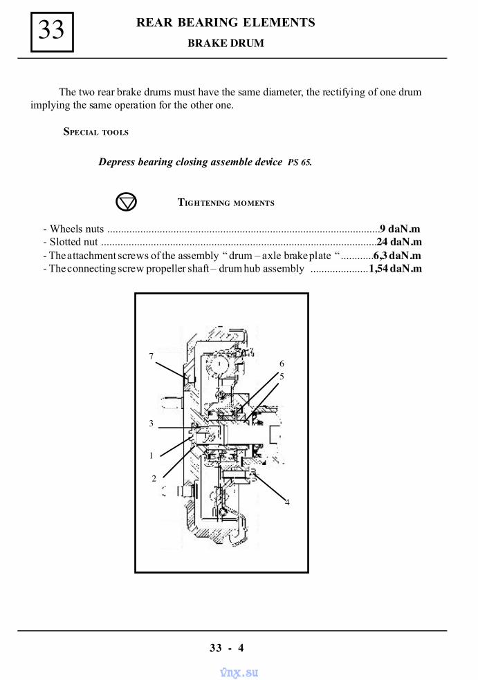
REAR BEARING ELEMENTS33
33 - 4
BRAKE DRUM
The two rear brake drums must have the same diameter, the rectifying of one drumimplying the same operation for the other one.
SPECIAL TOOLS
Depress bearing closing assemble device PS 65.
TIGHTENING MOMENTS
- Wheels nuts ...................................................................................................9 daN.m- Slotted nut ....................................................................................................24 daN.m- The attachment screws of the assembly “ drum – axle brake plate “............6,3 daN.m- The connecting screw propeller shaft – drum hub assembly .....................1,54 daN.m
65
4
1
2
3
7
vnx.su
33REAR BEARING ELEMENTS
33 - 5
DISMOUNTING
Dismount the M 8 x 1,25 - ( 1 ) screw.Dismount the elastic ring 32 and washer 8,1 x 12,7 - ( 3 ).Dismount the four 4 screws M 10 x 1,5 - ( 4 ).Dismount the “ hub drum – brake plate “ assembly and place it on a bench.Straighten the shoulder of the slotted nut ( 5 ).Unscrew the slotted nut and take out the bearing washer ( 6 ).Separate the brake plate from the drum-hub assembly.Dismount :
- the sunk screw ( 7 ) and separating the drum from the hub assembly;- the safety ring AI 68;- depress the bearing casing assembly from the hub by means of the PS 65 device.
REMOUNTING
Clean of dust the drum and brake shoes by means of a cleaner ( vacuum cleaner) forbrake.
For remounting, perform the mounting operations in reverse order, respecting therequired tightening moments;
The clearance adjustment shall be perform as follows :- by means of a wrench, rotate the eccentric downwards until the drum locks, than
rotate it upwards with 1/12 rotations ( 30’ );- after performing the adjustment, the drum must easily hand rotate. Begin with the
compression brake shoe;- the brake shoes by pressing several times the brake pedal;- the hand brake ( see chapter 37 “Controls”).
BRAKE DRUM
vnx.su
REAR BEARING ELEMENTS33
33 - 6
BRAKE CYLINDER
TIGHTENING MOMENTS
- Wheels nuts ..................................................................................................9 daN.m- Slotted nut .....................................................................................................24 daN.m- Attachment screws of the assembly “ drum – axle brake plate “…...............6,3 daN.m- Connecting screw propeller shaft – drum hub assembly ..........................1,54 daN.m- Connection screw of the rigid duct..............................................................1,5 daN.m- Cylinder attachment screws on the brake plate ...............................0,53...0,99 daN.m
DISMOUNTING
Dismount :- the rigid duct connection from brake cylinder by means of a wrench;- the connection of secondary cable with the hand brake lever;- the brake drum ( see corresponding chapter);
The brake plate being placed on bench, dismount:- the upper return spring (see the corresponding paragraph);- the assembly rod assembled with the hand brake lever;
Distance the shoes in the cylinder area.Unscrew the two cylinder attachment screws on the plate by dismounting it.Check the state of the shoes linings and if oil trace are present, replace the brake shoes.
REMOUNTING
Clean of dust the drums and the brake shoes by means of a cleaner(vacuum cleaner) forbrake.
Perform in reverse order the dismounting operations.Adjust the drum clearance.Aerate the brake system.Check the pressure in braking system.
vnx.su
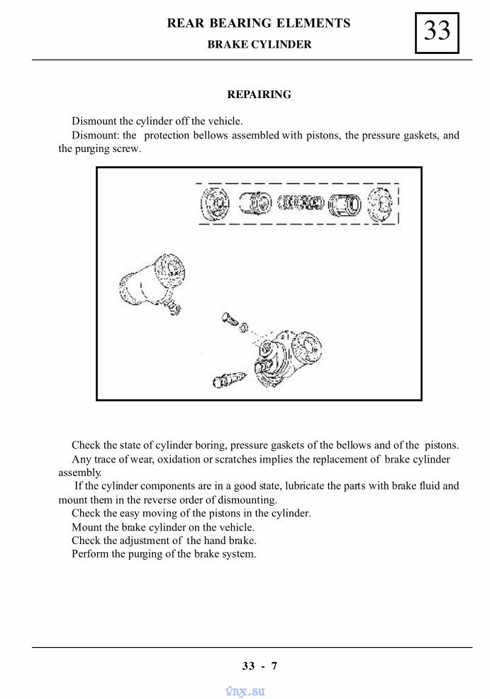
33REAR BEARING ELEMENTS
33 - 7
BRAKE CYLINDER
REPAIRING
Dismount the cylinder off the vehicle.Dismount: the protection bellows assembled with pistons, the pressure gaskets, and
the purging screw.
Check the state of cylinder boring, pressure gaskets of the bellows and of the pistons.Any trace of wear, oxidation or scratches implies the replacement of brake cylinder
assembly. If the cylinder components are in a good state, lubricate the parts with brake fluid and
mount them in the reverse order of dismounting.Check the easy moving of the pistons in the cylinder.Mount the brake cylinder on the vehicle.Check the adjustment of the hand brake.Perform the purging of the brake system.
vnx.su
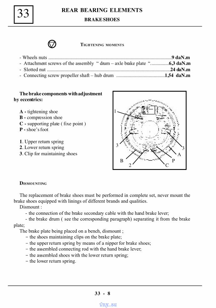
REAR BEARING ELEMENTS33
33 - 8
BRAKE SHOES
TIGHTENING MOMENTS
- Wheels nuts ...................................................................................................9 daN.m- Attachment screws of the assembly “ drum – axle brake plate “...............6,3 daN.m- Slotted nut ...................................................................................................24 daN.m- Connecting screw propeller shaft – hub drum .......................................1,54 daN.m
DISMOUNTING
The replacement of brake shoes must be performed in complete set, never mount thebrake shoes equipped with linings of different brands and qualities.
Dismount :- the connection of the brake secondary cable with the hand brake lever;- the brake drum ( see the corresponding paragraph) separating it from the brake
plate;The brake plate being placed on a bench, dismount ;- the shoes maintaining clips on the brake plate;- the upper return spring by means of a nipper for brake shoes;- the assembled connecting rod with the hand brake lever;- the assembled shoes with the lower return spring;- the lower return spring.
The brake components with adjustmentby eccentrics:
A - tightening shoeB - compression shoeC - supporting plate ( fixe point )P - shoe’s foot
1. Upper return spring2. Lower return spring3. Clip for maintaining shoes
1
3
B 2 C
PA 3
vnx.su
33REAR BEARING ELEMENTS
33 - 9
BRAKE SHOES
REMOUNTING
The shoes assembled with the lower return spring is attached on the plate ( the shoes Pfoots in contact with supporting plate C).
Remount the auxiliary connecting rod assembled with the hand brake lever.By means of a brake shoes nipper, set the upper connection of shoes by means of the
upper return spring. Mount the brake shoes maintaining clips.Apply a sealant layer ( ROMTIX 1502 ) in the areas of the maintain clips with the
brake plate.Assembly the brake plate with the drum – hub assembly.Tighten at the required moment the attachment screw of the assembly “drum - rear axle
brake plate”.
Drum clearance adjustment:
- rotate downward the eccentric until the drum is locked than rotate it upward with1/12 rotations ( aprox. 30’).
- after performing drum adjustment, it must be easy rotating by hand.- begin with the compression shoe.
vnx.su
REAR BEARING ELEMENTS33
33 - 10
SPECIAL TOOLS
Depressing device for bearing casing assembly PS 702
TIGHTENING MOMENTS
- Wheels nuts ...........................................................................................9 daN.m- Slotted nut ............................................................................................24 daN.m- Attachment screws of the assembly “drum axle brake plate” .............6,3 daN.m- Connecting screw propeller shaft – hub drum ..................................1,54 daN.m
CHECKING
Check by means of a comparator device attached on the drum, the axial clearance: 0 - 0,15 mm max.
DISMOUNTING
Dismount :- the connection of the secondary cable with the hand brake lever;- the assembly hub drum-brake plate.
Take out from the assembled bearing casing :- the safety ring by means of adequate nippers;- the bearing by means of a tube.
REMOUNTING
Clean the inside of the bearing casing.Mount the bearing by means of a tube and a press; Set in its place:
- the safety ring for boring by means of special nippers.Press the bearing casing on the hub – drum assembly, tighten at the required moment
the slotted nut.Set the assembly hub drum –rear brake and mount it on the axle.Fix the secondary hand brake cable.Adjust:
- the drum clearance ( see the corresponding chapter );- the hand brake.
BEARING ( 39X68X37 )
vnx.su
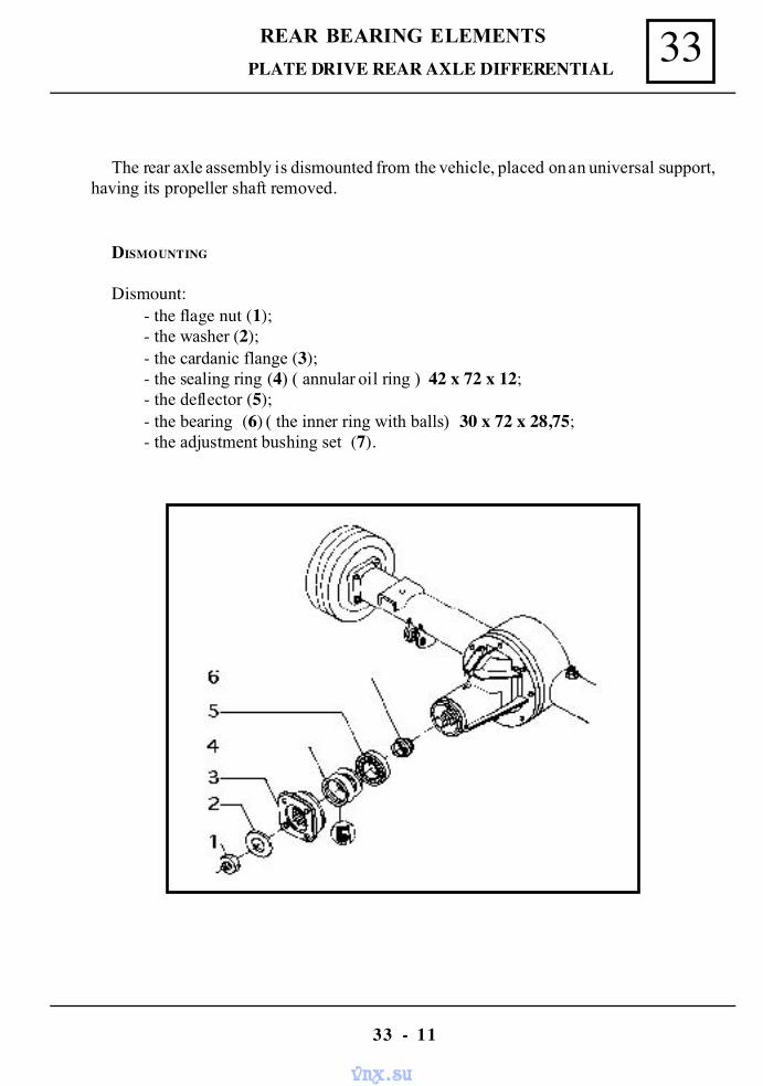
33REAR BEARING ELEMENTS
33 - 11
PLATE DRIVE REAR AXLE DIFFERENTIAL
The rear axle assembly is dismounted from the vehicle, placed on an universal support,having its propeller shaft removed.
DISMOUNTING
Dismount:- the flage nut (1);- the washer (2);- the cardanic flange (3);- the sealing ring (4) ( annular oil ring ) 42 x 72 x 12;- the deflector (5);- the bearing (6) ( the inner ring with balls) 30 x 72 x 28,75;- the adjustment bushing set (7).
vnx.su
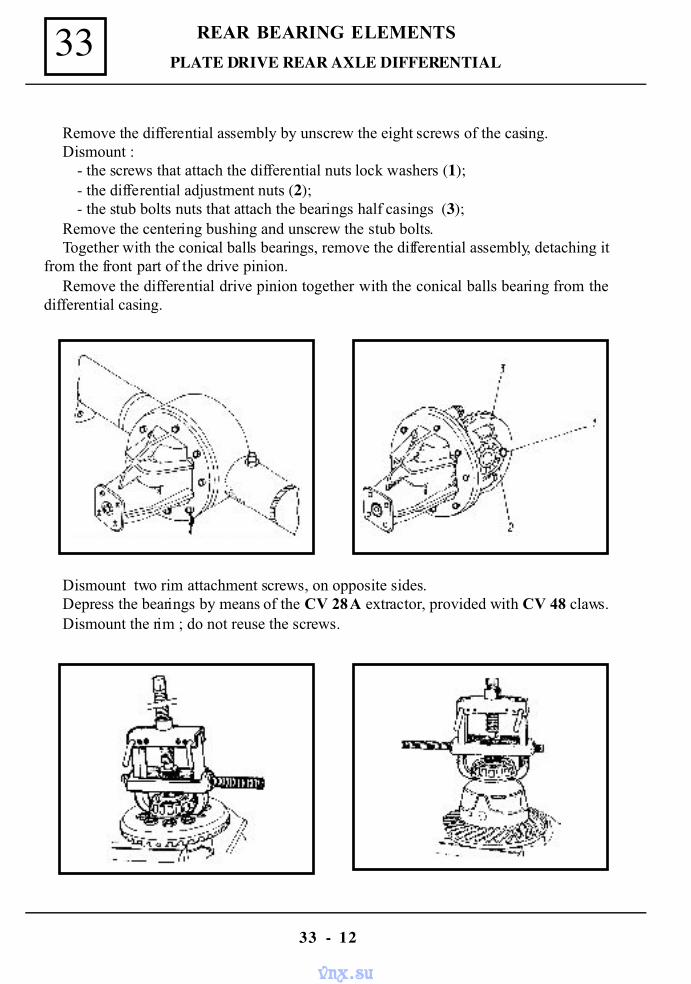
REAR BEARING ELEMENTS33
33 - 12
PLATE DRIVE REAR AXLE DIFFERENTIAL
Remove the differential assembly by unscrew the eight screws of the casing.Dismount :
- the screws that attach the differential nuts lock washers (1);- the differential adjustment nuts (2);- the stub bolts nuts that attach the bearings half casings (3);
Remove the centering bushing and unscrew the stub bolts.Together with the conical balls bearings, remove the differential assembly, detaching it
from the front part of the drive pinion.Remove the differential drive pinion together with the conical balls bearing from the
differential casing.
Dismount two rim attachment screws, on opposite sides.Depress the bearings by means of the CV 28 A extractor, provided with CV 48 claws.Dismount the rim ; do not reuse the screws.
vnx.su
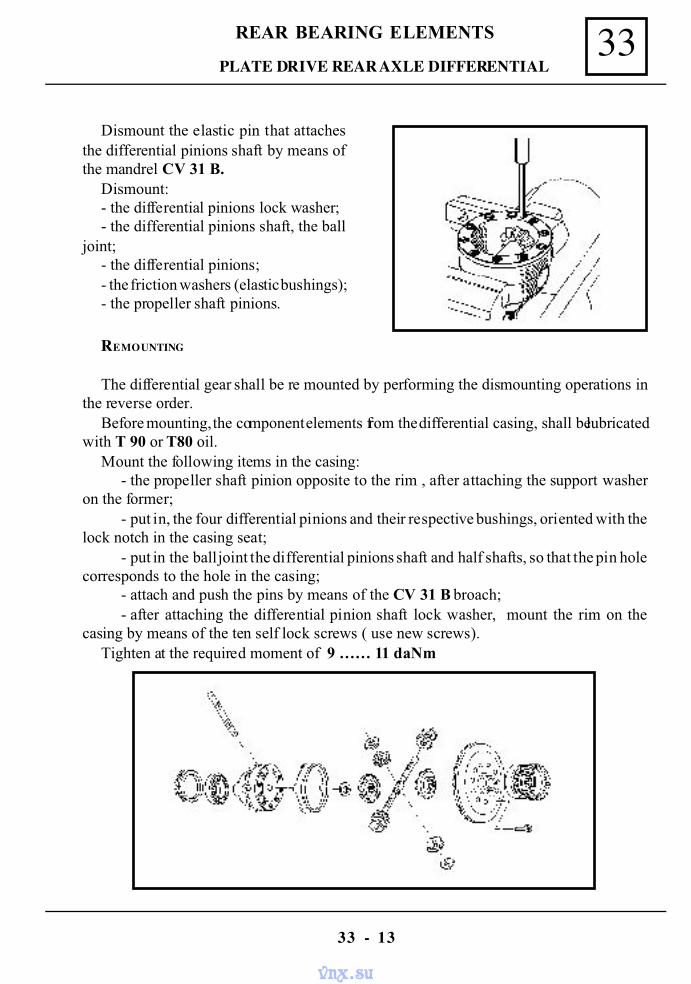
33REAR BEARING ELEMENTS
33 - 13
Dismount the elastic pin that attachesthe differential pinions shaft by means ofthe mandrel CV 31 B.
Dismount:- the differential pinions lock washer;- the differential pinions shaft, the ball
joint;- the differential pinions;- the friction washers (elastic bushings);- the propeller shaft pinions.
PLATE DRIVE REAR AXLE DIFFERENTIAL
REMOUNTING
The differential gear shall be re mounted by performing the dismounting operations inthe reverse order.
Before mounting, the component elements from the differential casing, shall be lubricatedwith T 90 or T80 oil.
Mount the following items in the casing:- the propeller shaft pinion opposite to the rim , after attaching the support washer
on the former;- put in, the four differential pinions and their respective bushings, oriented with the
lock notch in the casing seat;- put in the ball joint the differential pinions shaft and half shafts, so that the pin hole
corresponds to the hole in the casing;- attach and push the pins by means of the CV 31 B broach;- after attaching the differential pinion shaft lock washer, mount the rim on the
casing by means of the ten self lock screws ( use new screws).Tighten at the required moment of 9 …… 11 daNm
vnx.su
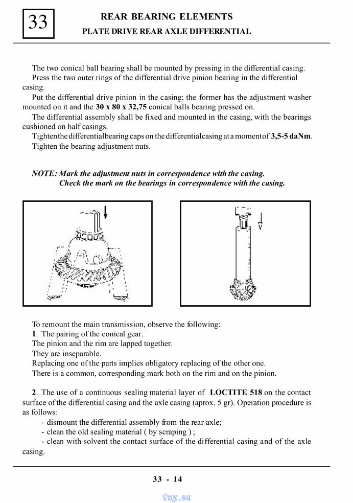
REAR BEARING ELEMENTS33
33 - 14
The two conical ball bearing shall be mounted by pressing in the differential casing.Press the two outer rings of the differential drive pinion bearing in the differential
casing.Put the differential drive pinion in the casing; the former has the adjustment washer
mounted on it and the 30 x 80 x 32,75 conical balls bearing pressed on.The differential assembly shall be fixed and mounted in the casing, with the bearings
cushioned on half casings.Tighten the differential bearing caps on the differential casing at a moment of 3,5-5 daNm.Tighten the bearing adjustment nuts.
NOTE: Mark the adjustment nuts in correspondence with the casing. Check the mark on the bearings in correspondence with the casing.
To remount the main transmission, observe the following:1. The pairing of the conical gear.The pinion and the rim are lapped together.They are inseparable.Replacing one of the parts implies obligatory replacing of the other one.There is a common, corresponding mark both on the rim and on the pinion.
2. The use of a continuous sealing material layer of LOCTITE 518 on the contactsurface of the differential casing and the axle casing (aprox. 5 gr). Operation procedure isas follows:
- dismount the differential assembly from the rear axle;- clean the old sealing material ( by scraping ) ;- clean with solvent the contact surface of the differential casing and of the axle
casing.
PLATE DRIVE REAR AXLE DIFFERENTIAL
vnx.su
33REAR BEARING ELEMENTS
33 - 15
PLATE DRIVE REAR AXLE DIFFERENTIAL
- place continuos sealant material layer on the whole contact surface of the rear axletaking care not to close the attachment wholes of differential casing;
- mount the differential assembly and tighten the screws at the required couple of2 - 2,5 daNm.
NOTE: The interchangeable of the gasket with the layer is not affected.
DIFFERENTIAL REMOUNTING – ADJUSTMENT
Continue the attachment and mounting of the following items :- the new adjustment bushing of the bearing;- the 30 x 72 x 28,75 conical balls bearing;- the deflector ;- the 42 x 72 x 12 annular oil seal.
Attach and tighten:- the washer;- the flange nut.
NOTE: When assembling the cardanic flange, check the wear degree of the surfacein contact with the annular oil seal.
After remounting , the rear axle must be sealed.The sealing test is performed by blowing air at a 0,15 – 0,20 bars pressure through
the aeration valve seat.No air leaking is accepted.
TIGHTENING MOMENTS
- The screws for the attachment of gear rim to the differential box ..............9- 11 daN.m- The two screws of the differential bearings adjustment nuts lock washer........ 2 daN.m- The four nuts of the attachment stud bolts of the bearing cups..............3,5 - 5 daN.m- The differential drive pinion nut tightening moment ................ .........9 - 11 daN.m
ATTENTION: After tightening ,the nut shall be locked by straining.
vnx.su
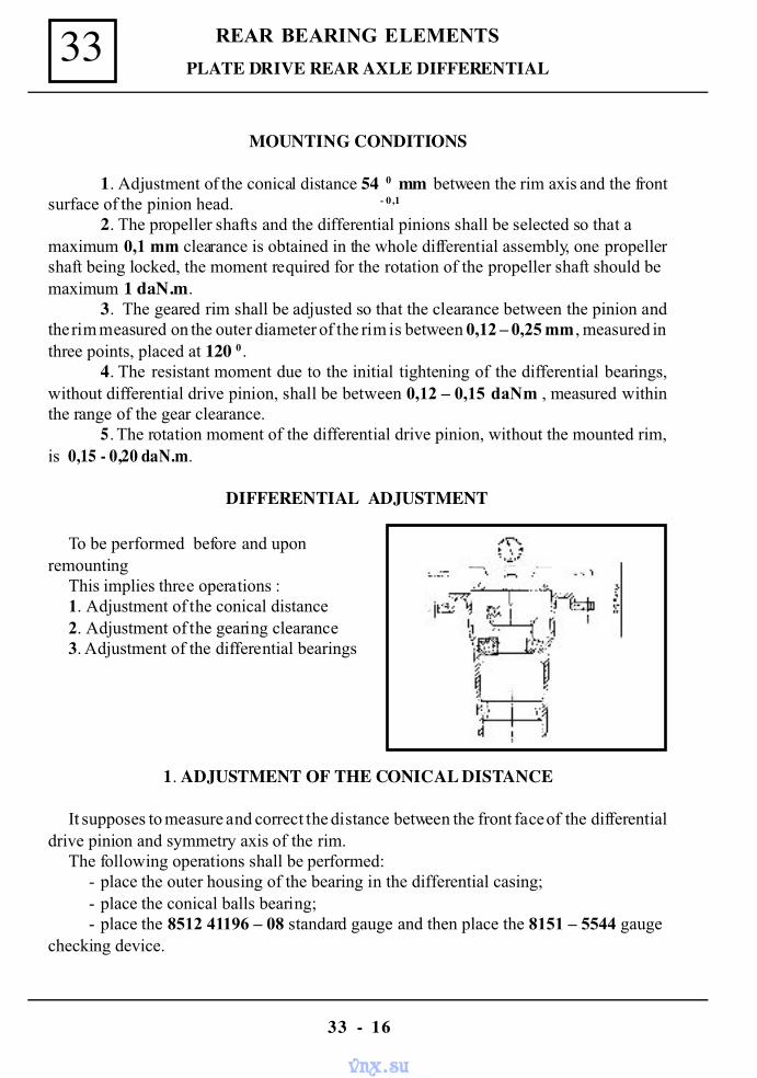
REAR BEARING ELEMENTS33
33 - 16
PLATE DRIVE REAR AXLE DIFFERENTIAL
MOUNTING CONDITIONS
1. Adjustment of the conical distance 54 0 mm between the rim axis and the frontsurface of the pinion head. - 0,1
2. The propeller shafts and the differential pinions shall be selected so that amaximum 0,1 mm clearance is obtained in the whole differential assembly, one propellershaft being locked, the moment required for the rotation of the propeller shaft should bemaximum 1 daN.m.
3. The geared rim shall be adjusted so that the clearance between the pinion andthe rim measured on the outer diameter of the rim is between 0,12 – 0,25 mm , measured inthree points, placed at 120 0.
4. The resistant moment due to the initial tightening of the differential bearings,without differential drive pinion, shall be between 0,12 – 0,15 daNm , measured withinthe range of the gear clearance.
5. The rotation moment of the differential drive pinion, without the mounted rim,is 0,15 - 0,20 daN.m.
DIFFERENTIAL ADJUSTMENT
To be performed before and uponremounting
This implies three operations :1. Adjustment of the conical distance2. Adjustment of the gearing clearance3. Adjustment of the differential bearings
1. ADJUSTMENT OF THE CONICAL DISTANCE
It supposes to measure and correct the distance between the front face of the differentialdrive pinion and symmetry axis of the rim.
The following operations shall be performed:- place the outer housing of the bearing in the differential casing;- place the conical balls bearing;- place the 8512 41196 – 08 standard gauge and then place the 8151 – 5544 gauge
checking device.
vnx.su
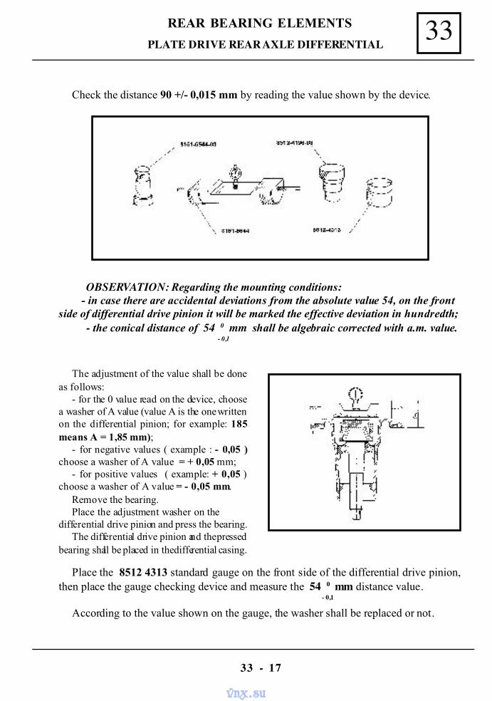
33REAR BEARING ELEMENTS
33 - 17
PLATE DRIVE REAR AXLE DIFFERENTIAL
Check the distance 90 +/- 0,015 mm by reading the value shown by the device.
OBSERVATION: Regarding the mounting conditions: - in case there are accidental deviations from the absolute value 54, on the frontside of differential drive pinion it will be marked the effective deviation in hundredth;
- the conical distance of 54 0 mm shall be algebraic corrected with a.m. value. - 0,1
The adjustment of the value shall be doneas follows:
- for the 0 value read on the device, choosea washer of A value (value A is the one writtenon the differential pinion; for example: 185means A = 1,85 mm);
- for negative values ( example : - 0,05 )choose a washer of A value = + 0,05 mm;
- for positive values ( example: + 0,05 )choose a washer of A value = - 0,05 mm.
Remove the bearing.Place the adjustment washer on the
differential drive pinion and press the bearing.The differential drive pinion and the pressed
bearing shall be placed in the differential casing.
Place the 8512 4313 standard gauge on the front side of the differential drive pinion,then place the gauge checking device and measure the 54 0 mm distance value.
- 0,1
According to the value shown on the gauge, the washer shall be replaced or not.
vnx.su
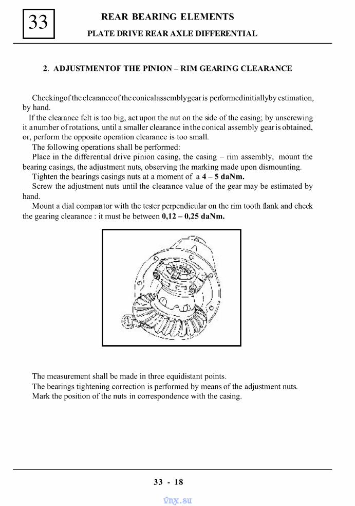
REAR BEARING ELEMENTS33
33 - 18
PLATE DRIVE REAR AXLE DIFFERENTIAL
2. ADJUSTMENTOF THE PINION – RIM GEARING CLEARANCE
Checking of the clearance of the conical assembly gear is performed initially by estimation,by hand. If the clearance felt is too big, act upon the nut on the side of the casing; by unscrewingit a number of rotations, until a smaller clearance in the conical assembly gear is obtained,or, perform the opposite operation clearance is too small.
The following operations shall be performed:Place in the differential drive pinion casing, the casing – rim assembly, mount the
bearing casings, the adjustment nuts, observing the marking made upon dismounting.Tighten the bearings casings nuts at a moment of a 4 – 5 daNm.Screw the adjustment nuts until the clearance value of the gear may be estimated by
hand.Mount a dial comparator with the tester perpendicular on the rim tooth flank and check
the gearing clearance : it must be between 0,12 – 0,25 daNm.
The measurement shall be made in three equidistant points.The bearings tightening correction is performed by means of the adjustment nuts.Mark the position of the nuts in correspondence with the casing.
vnx.su
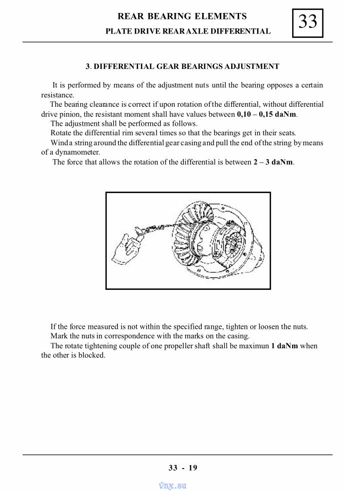
33REAR BEARING ELEMENTS
33 - 19
3. DIFFERENTIAL GEAR BEARINGS ADJUSTMENT
It is performed by means of the adjustment nuts until the bearing opposes a certainresistance. The bearing clearance is correct if upon rotation of the differential, without differentialdrive pinion, the resistant moment shall have values between 0,10 – 0,15 daNm.
The adjustment shall be performed as follows.Rotate the differential rim several times so that the bearings get in their seats.Wind a string around the differential gear casing and pull the end of the string by means
of a dynamometer. The force that allows the rotation of the differential is between 2 – 3 daNm.
PLATE DRIVE REAR AXLE DIFFERENTIAL
If the force measured is not within the specified range, tighten or loosen the nuts.Mark the nuts in correspondence with the marks on the casing.The rotate tightening couple of one propeller shaft shall be maximun 1 daNm when
the other is blocked.
vnx.su
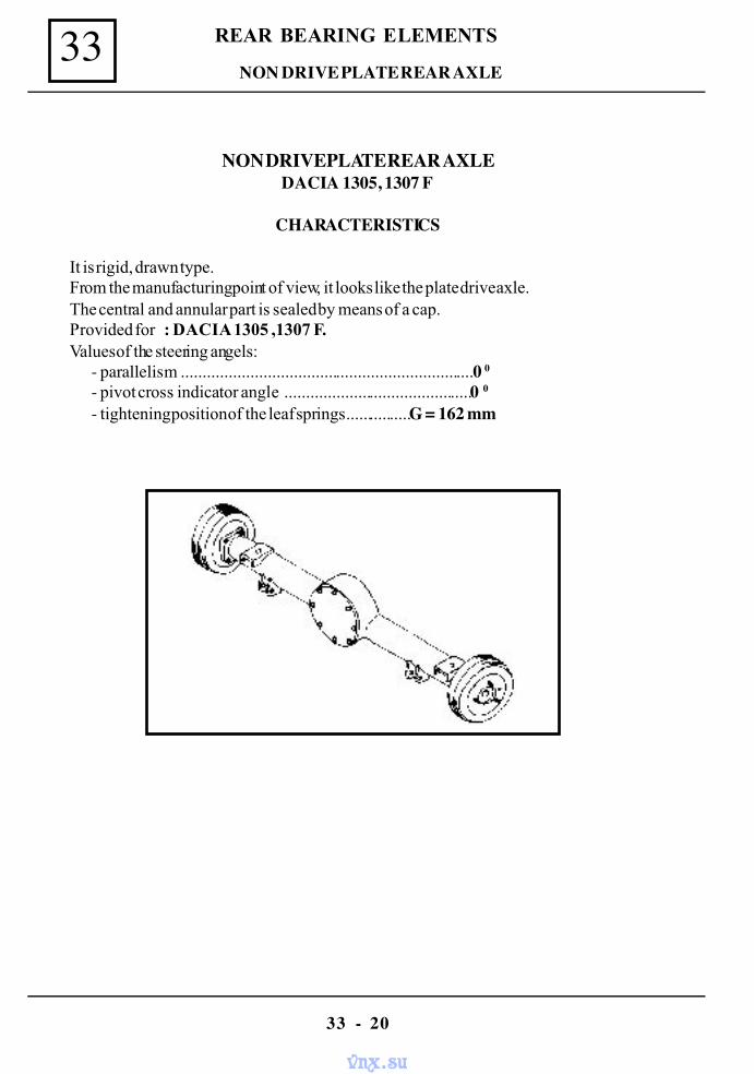
REAR BEARING ELEMENTS33
33 - 20
NON DRIVE PLATE REAR AXLE
NON DRIVE PLATE REAR AXLEDACIA 1305, 1307 F
CHARACTERISTICS
It is rigid, drawn type.From the manufacturing point of view, it looks like the plate drive axle.The central and annular part is sealed by means of a cap.Provided for : DACIA 1305 ,1307 F.Values of the steering angels:
- parallelism ....................................................................0 0- pivot cross indicator angle ............................................0 0
- tightening position of the leaf springs................G = 162 mm
vnx.su
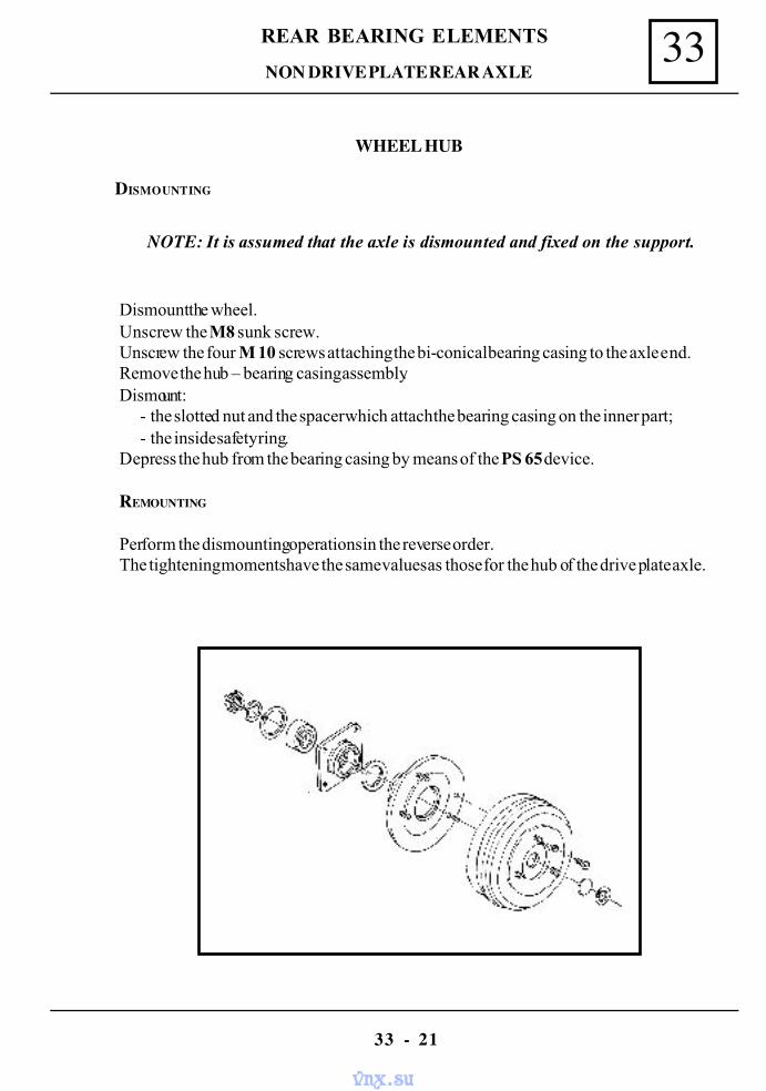
33REAR BEARING ELEMENTS
33 - 21
NON DRIVE PLATE REAR AXLE
WHEEL HUB
DISMOUNTING
NOTE: It is assumed that the axle is dismounted and fixed on the support.
Dismount the wheel.Unscrew the M8 sunk screw.Unscrew the four M 10 screws attaching the bi-conical bearing casing to the axle end.Remove the hub – bearing casing assembly.Dismount:
- the slotted nut and the spacer which attach the bearing casing on the inner part;- the inside safety ring.
Depress the hub from the bearing casing by means of the PS 65 device.
REMOUNTING
Perform the dismounting operations in the reverse order.The tightening moments have the same values as those for the hub of the drive plate axle.
vnx.su
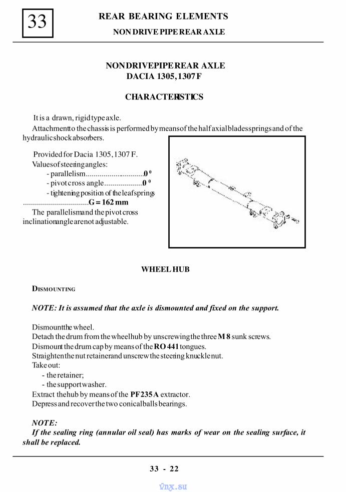
REAR BEARING ELEMENTS33
33 - 22
NON DRIVE PIPE REAR AXLE
NON DRIVE PIPE REAR AXLEDACIA 1305, 1307 F
CHARACTERISTICS
It is a drawn, rigid type axle.Attachment to the chassis is performed by means of the half axial blades springs and of the
hydraulic shock absorbers.
Provided for Dacia 1305, 1307 F.Values of steering angles:
- parallelism..............................0 0- pivot cross angle....................0 0
- tightening position of the leaf springs.................................G = 162 mm
The parallelism and the pivot crossinclination angle are not adjustable.
WHEEL HUB
DISMOUNTING
NOTE: It is assumed that the axle is dismounted and fixed on the support.
Dismount the wheel.Detach the drum from the wheel hub by unscrewing the three M 8 sunk screws.Dismount the drum cap by means of the RO 441 tongues.Straighten the nut retainer and unscrew the steering knuckle nut.Take out:
- the retainer;- the support washer.
Extract the hub by means of the PF 235 A extractor.Depress and recover the two conical balls bearings.
NOTE:If the sealing ring (annular oil seal) has marks of wear on the sealing surface, it
shall be replaced.
vnx.su
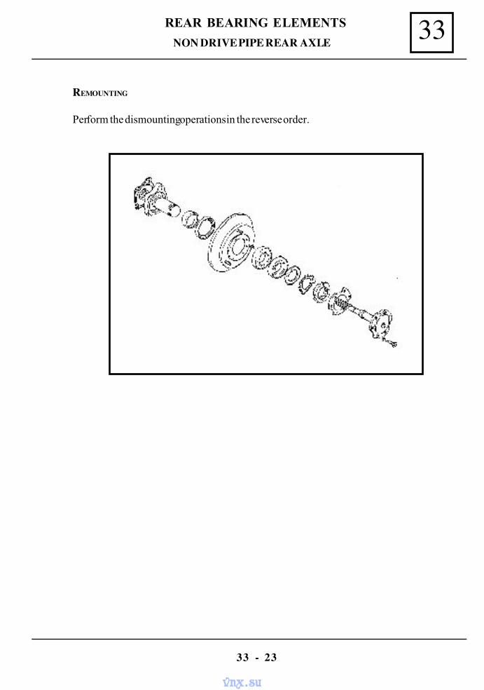
33REAR BEARING ELEMENTS
33 - 23
REMOUNTING
Perform the dismounting operations in the reverse order.
NON DRIVE PIPE REAR AXLE
vnx.su
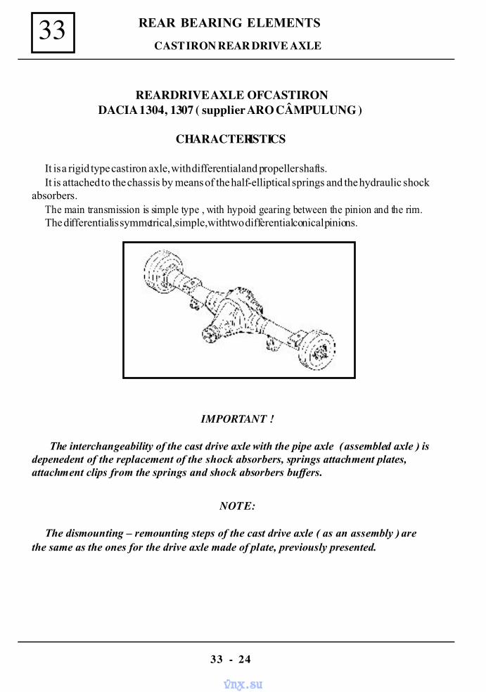
REAR BEARING ELEMENTS33
33 - 24
CAST IRON REAR DRIVE AXLE
REAR DRIVE AXLE OF CAST IRONDACIA 1304, 1307 ( supplier ARO CÂMPULUNG )
CHARACTERISTICS
It is a rigid type cast iron axle, with differential and propeller shafts.It is attached to the chassis by means of the half-elliptical springs and the hydraulic shock
absorbers.The main transmission is simple type , with hypoid gearing between the pinion and the rim.The differential is symmetrical, simple, with two differential conical pinions.
IMPORTANT !
The interchangeability of the cast drive axle with the pipe axle ( assembled axle ) isdepenedent of the replacement of the shock absorbers, springs attachment plates,attachment clips from the springs and shock absorbers buffers.
NOTE:
The dismounting – remounting steps of the cast drive axle ( as an assembly ) arethe same as the ones for the drive axle made of plate, previously presented.
vnx.su
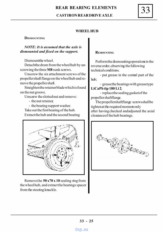
33REAR BEARING ELEMENTS
33 - 25
WHEEL HUB
CAST IRON REAR DRIVE AXLE
Remove the 50 x70 x 10 sealing ring fromthe wheel hub, and extract the bearings spacerfrom the steering knuckle.
DISMOUNTING
NOTE: It is assumed that the axle isdismounted and fixed on the support.
Dismount the wheel.Detach the drum from the wheel hub by un-
screwing the three M8 sunk screws.Unscrew the six attachment screws of the
propeller shaft flange on the wheel hub and re-move the propeller shaft.
Straighten the retainer blade which is foundon the nut groove.
Unscrew the slotted nut and remove :- the nut retainer;- the bearing support washer.
Take out the first bearing of the hub.Extract the hub and the second bearing
REMOUNTING
Perform the dismounting operations in thereverse order, observing the followingtechnical conditions.
- put grease in the central part of thehub;
- grease the bearings with grease typeLiCaPb tip 180 Li 2;
- replace the sealing gasket of thepropeller shaft flange.
The propeller shaft flange screws shall betighten at the required moment onlyafter having checked and adjusted the axialclearance of the hub bearings.
vnx.su
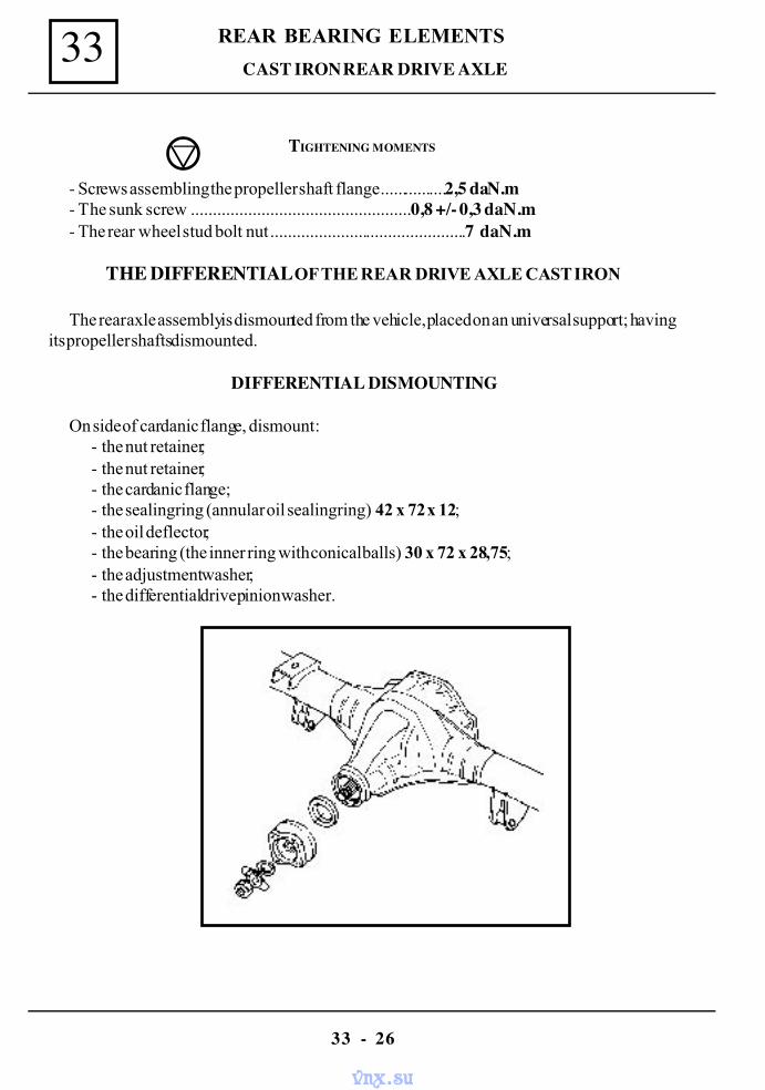
REAR BEARING ELEMENTS33
33 - 26
CAST IRON REAR DRIVE AXLE
TIGHTENING MOMENTS
- Screws assembling the propeller shaft flange................2,5 daN.m- The sunk screw ..................................................0,8 +/- 0,3 daN.m- The rear wheel stud bolt nut.............................................7 daN.m
THE DIFFERENTIAL OF THE REAR DRIVE AXLE CAST IRON
The rear axle assembly is dismounted from the vehicle, placed on an universal support; havingits propeller shafts dismounted.
DIFFERENTIAL DISMOUNTING
On side of cardanic flange, dismount :- the nut retainer;- the nut retainer;- the cardanic flange;- the sealing ring (annular oil sealing ring) 42 x 72 x 12;- the oil deflector;- the bearing (the inner ring with conical balls) 30 x 72 x 28,75;- the adjustment washer;- the differential drive pinion washer.
vnx.su
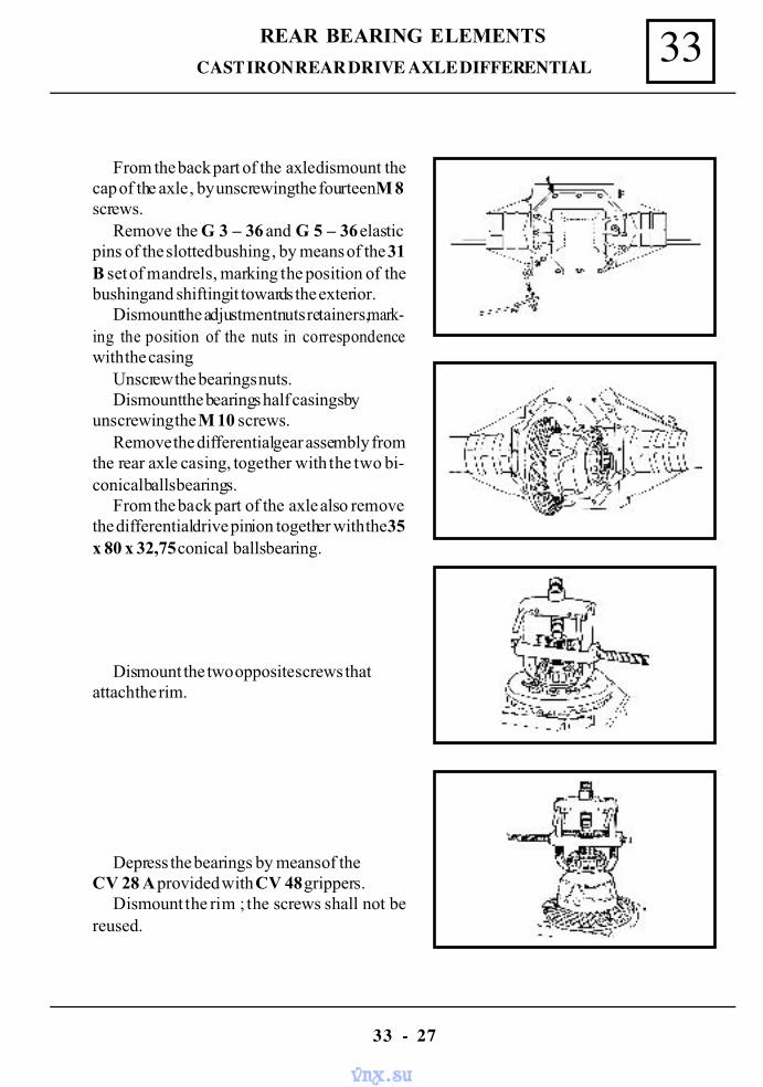
33REAR BEARING ELEMENTS
33 - 27
CAST IRON REAR DRIVE AXLE DIFFERENTIAL
From the back part of the axle dismount thecap of the axle , by unscrewing the fourteen M 8screws.
Remove the G 3 – 36 and G 5 – 36 elasticpins of the slotted bushing , by means of the 31B set of mandrels, marking the position of thebushing and shifting it towards the exterior.
Dismount the adjustment nuts retainers, mark-ing the position of the nuts in correspondencewith the casing.
Unscrew the bearings nuts.Dismount the bearings half casings by
unscrewing the M 10 screws.Remove the differential gear assembly from
the rear axle casing, together with the two bi-conical balls bearings.
From the back part of the axle also removethe differential drive pinion together with the 35x 80 x 32,75 conical balls bearing.
Dismount the two opposite screws thatattach the rim.
Depress the bearings by means of theCV 28 A provided with CV 48 grippers.
Dismount the rim ; the screws shall not bereused.
vnx.su
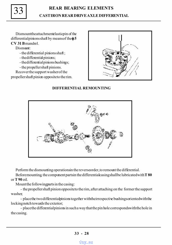
REAR BEARING ELEMENTS33
33 - 28
CAST IRON REAR DRIVE AXLE DIFFERENTIAL
Dismount the attachment elastic pin of thedifferential pinions shaft by means of the φφφφ 5CV 31 B mandrel.
Dismount:- the differential pinions shaft ;- the differential pinions;- the differential pinions bushings;- the propeller shaft pinions.
Recover the support washer of thepropeller shaft pinion opposite to the rim.
DIFFERENTIAL REMOUNTING
Perform the dismounting operations in the reverse order, to remount the differential.Before mounting, the component parts in the differential casing shall be lubricated with T 80
or T 90 oil.Mount the following parts in the casing :
- the propeller shaft pinion opposite to the rim, after attaching on the former the supportwasher;
- place the two differential pinions together with their respective bushings oriented with thelocking notch towards the exterior;
- place the differential pinions in such a way that the pin hole corresponds with the hole inthe casing.
vnx.su
33REAR BEARING ELEMENTS
33 - 29
CAST IRON REAR DRIVE AXLE DIFFERENTIAL
By means of a → 5 mandrel, attach and push the G 5 – 40 elastic pin.Mount the second propeller shaft pinion in the rim.Mount the rim on the casing by means of the ten M 11 x 22 screws ( use new ,self locking
screws).Tighten them at the moment of 9 – 11 daNm.On the side towards the flange mount the following items:
- the adjustment washer ( the values of the adjustment washers are measured every 5/100 and are within the range: 1,45 – 2,85 mm )
- the bearing washer;- the 30 x 72 x 28,75 conical balls bearing;- the oil deflector;- the 42 x 72 x 12 annular oil seal.
NOTE: When assembling the cardanic flange, check the wear of the contact surface with
the annular oil seal.
Attach the nut retainer , tighten the flange nut and lock it.After remounting and performing the required adjustment operations, make the sealing test,
and than fill up with T 90 oil the drive axle differential casing.
TIGHTENING MOMENTS
- Axle cap attachment screws................................................... 1,5 - 2daN.m- Tooth rim attachment screws................................................... 9 - 11 daN.m- The screws of the differential adjustment nuts retainers................ 2 daN.m- The differential drive pinion nut............................................ 9 - 11 daN.m
The two conical balls bearings shall be mounted by pressing on the differential casing.Press the outer ring of the small bearing and the outer ring of the big bearing in the differential
casing; for which, previously ,the adjustment washer required for the conical distance measure-ment has been selected and attached.
Place the differential drive pinion in the casing; the 35 x 80 x 32,75 conical ballsbearing being already mounted on it.
The differential assembly is attached and mounted in the casing, with the bearings resting in thehalf bearings.
The screws from the bearings caps shall be tightened at a moment of 4 – 5 daNm.Tighten the bearings adjustment nuts.
vnx.su
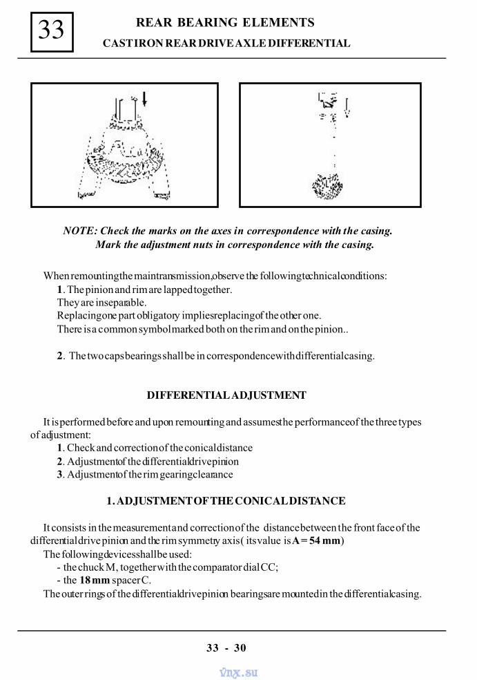
REAR BEARING ELEMENTS33
33 - 30
CAST IRON REAR DRIVE AXLE DIFFERENTIAL
NOTE: Check the marks on the axes in correspondence with the casing.Mark the adjustment nuts in correspondence with the casing.
When remounting the main transmission, observe the following technical conditions:1. The pinion and rim are lapped together.They are inseparable.Replacing one part obligatory implies replacing of the other one.There is a common symbol marked both on the rim and on the pinion..
2. The two caps bearings shall be in correspondence with differential casing.
DIFFERENTIAL ADJUSTMENT
It is performed before and upon remounting and assumes the performance of the three typesof adjustment :
1. Check and correction of the conical distance2. Adjustment of the differential drive pinion3. Adjustment of the rim gearing clearance
1. ADJUSTMENT OF THE CONICAL DISTANCE
It consists in the measurement and correction of the distance between the front face of thedifferential drive pinion and the rim symmetry axis ( its value is A = 54 mm)
The following devices shall be used:- the chuck M, together with the comparator dial CC;- the 18 mm spacer C.
The outer rings of the differential drive pinion bearings are mounted in the differential casing.
vnx.su
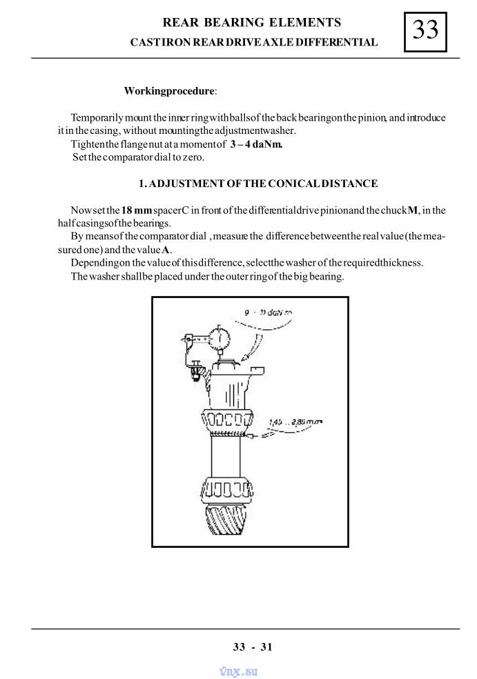
33REAR BEARING ELEMENTS
33 - 31
Working procedure:
Temporarily mount the inner ring with balls of the back bearing on the pinion, and introduceit in the casing , without mounting the adjustment washer.
Tighten the flange nut at a moment of 3 – 4 daNm. Set the comparator dial to zero.
1. ADJUSTMENT OF THE CONICAL DISTANCE
Now set the 18 mm spacer C in front of the differential drive pinion and the chuck M, in thehalf casings of the bearings.
By means of the comparator dial , measure the difference between the real value (the mea-sured one) and the value A.
Depending on the value of this difference, select the washer of the required thickness.The washer shall be placed under the outer ring of the big bearing.
CAST IRON REAR DRIVE AXLE DIFFERENTIAL
vnx.su
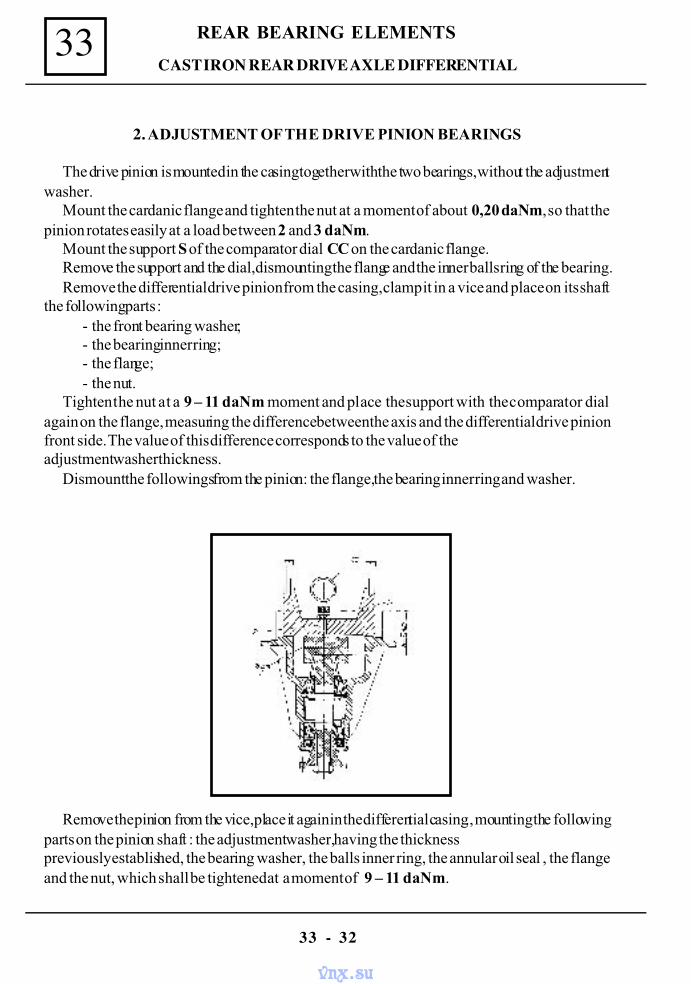
REAR BEARING ELEMENTS33
33 - 32
CAST IRON REAR DRIVE AXLE DIFFERENTIAL
2. ADJUSTMENT OF THE DRIVE PINION BEARINGS
The drive pinion is mounted in the casing together with the two bearings, without the adjustmentwasher.
Mount the cardanic flange and tighten the nut at a moment of about 0,20 daNm, so that thepinion rotates easily at a load between 2 and 3 daNm.
Mount the support S of the comparator dial CC on the cardanic flange.Remove the support and the dial, dismounting the flange and the inner balls ring of the bearing.Remove the differential drive pinion from the casing, clamp it in a vice and place on its shaft
the following parts :- the front bearing washer;- the bearing inner ring;- the flange;- the nut.
Tighten the nut at a 9 – 11 daNm moment and place the support with the comparator dialagain on the flange, measuring the difference between the axis and the differential drive pinionfront side. The value of this difference corresponds to the value of theadjustment washer thickness.
Dismount the followings from the pinion: the flange ,the bearing inner ring and washer.
Remove the pinion from the vice, place it again in the differential casing., mounting the followingparts on the pinion shaft : the adjustment washer, having the thicknesspreviously established, the bearing washer , the balls inner ring, the annular oil seal , the flangeand the nut, which shall be tightened at a moment of 9 – 11 daNm.
vnx.su
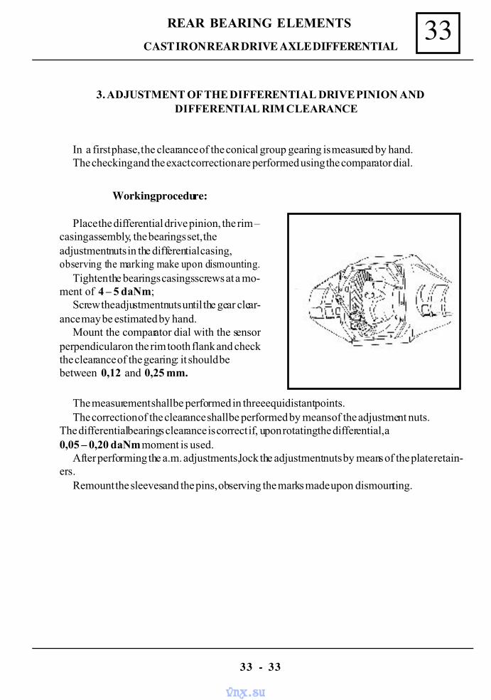
33REAR BEARING ELEMENTS
33 - 33
3. ADJUSTMENT OF THE DIFFERENTIAL DRIVE PINION ANDDIFFERENTIAL RIM CLEARANCE
In a first phase, the clearance of the conical group gearing is measured by hand.The checking and the exact correction are performed using the comparator dial.
Working procedure:
Place the differential drive pinion, the rim –casing assembly, the bearings set, theadjustment nuts in the differential casing,observing the marking make upon dismounting.
Tighten the bearings casings screws at a mo-ment of 4 – 5 daNm;
Screw the adjustment nuts until the gear clear-ance may be estimated by hand.
Mount the comparator dial with the sensorperpendicular on the rim tooth flank and checkthe clearance of the gearing: it should bebetween 0,12 and 0,25 mm.
The measurement shall be performed in three equidistant points.The correction of the clearance shall be performed by means of the adjustment nuts.
The differential bearings clearance is correct if, upon rotating the differential, a0,05 – 0,20 daNm moment is used.
After performing the a.m. adjustments, lock the adjustment nuts by means of the plate retain-ers.
Remount the sleeves and the pins, observing the marks made upon dismounting.
CAST IRON REAR DRIVE AXLE DIFFERENTIAL
vnx.su
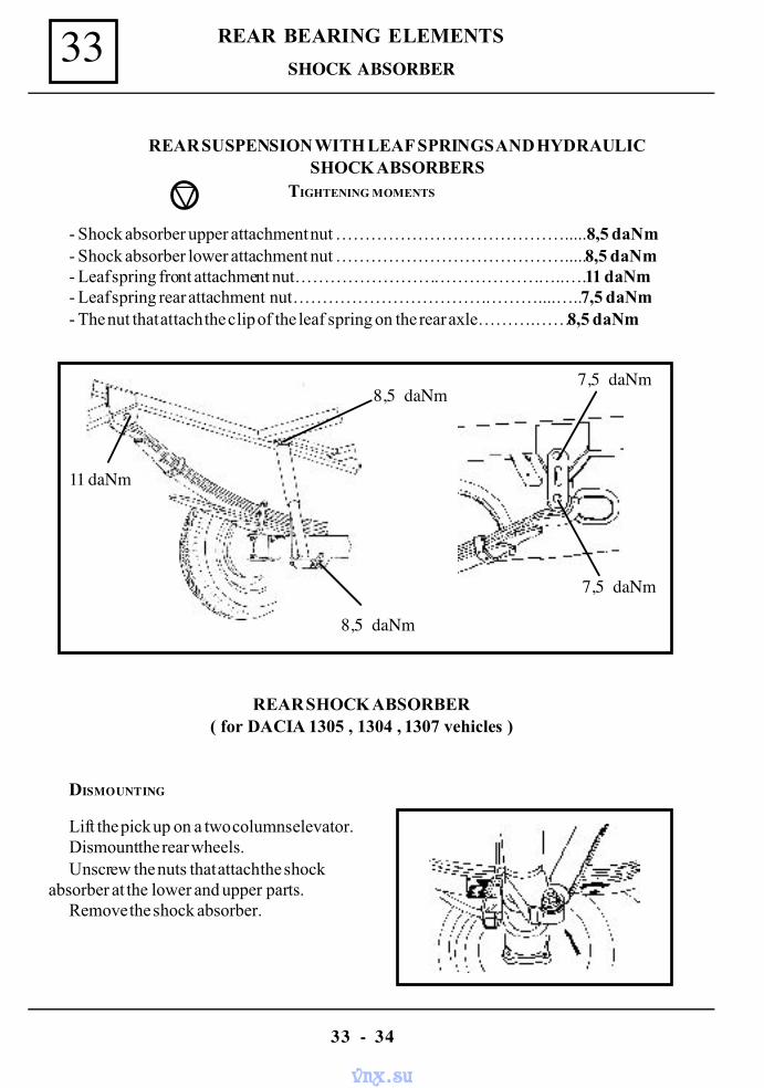
REAR BEARING ELEMENTS33
33 - 34
SHOCK ABSORBER
REAR SUSPENSION WITH LEAF SPRINGS AND HYDRAULICSHOCK ABSORBERS
TIGHTENING MOMENTS
- Shock absorber upper attachment nut ………………………………….....8,5 daNm- Shock absorber lower attachment nut ………………………………….....8,5 daNm- Leaf spring front attachment nut………………………………………..….11 daNm- Leaf spring rear attachment nut ……………………………………....…..7,5 daNm- The nut that attach the clip of the leaf spring on the rear axle……….……8,5 daNm
REAR SHOCK ABSORBER( for DACIA 1305 , 1304 , 1307 vehicles )
DISMOUNTING
Lift the pick up on a two columns elevator.Dismount the rear wheels.Unscrew the nuts that attach the shock
absorber at the lower and upper parts.Remove the shock absorber.
11 daNm
8,5 daNm
8,5 daNm7,5 daNm
7,5 daNm
vnx.su
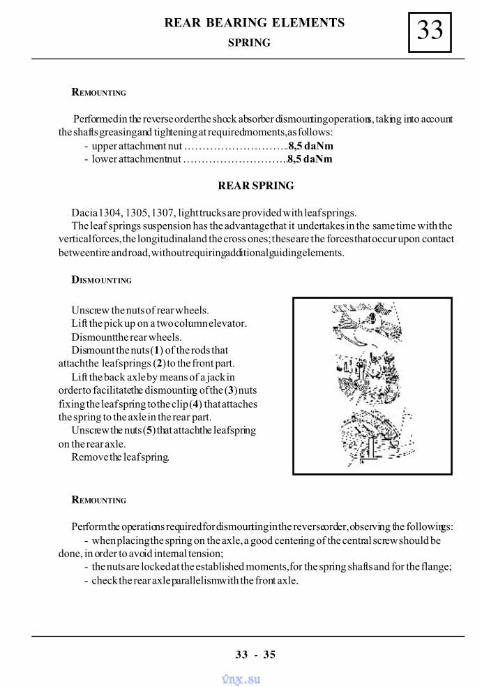
33REAR BEARING ELEMENTS
33 - 35
SPRING
REMOUNTING
Performed in the reverse order the shock absorber dismounting operations, taking into accountthe shafts greasing and tightening at required moments, as follows:
- upper attachment nut ………………………..8,5 daNm- lower attachment nut ………………………..8,5 daNm
REAR SPRING
Dacia 1304, 1305, 1307, light trucks are provided with leaf springs.The leaf springs suspension has the advantage that it undertakes in the same time with the
vertical forces, the longitudinal and the cross ones; these are the forces that occur upon contactbetween tire and road, without requiring additional guiding elements.
DISMOUNTING
Unscrew the nuts of rear wheels.Lift the pick up on a two column elevator.Dismount the rear wheels.Dismount the nuts (1) of the rods that
attach the leaf springs (2) to the front part.Lift the back axle by means of a jack in
order to facilitate the dismounting of the (3) nutsfixing the leaf spring to the clip (4) that attachesthe spring to the axle in the rear part.
Unscrew the nuts (5) that attach the leaf springon the rear axle.
Remove the leaf spring.
REMOUNTING
Perform the operations required for dismounting in the reverse order, observing the followings:- when placing the spring on the axle, a good centering of the central screw should be
done, in order to avoid internal tension;- the nuts are locked at the established moments, for the spring shafts and for the flange;- check the rear axle parallelism with the front axle.
vnx.su
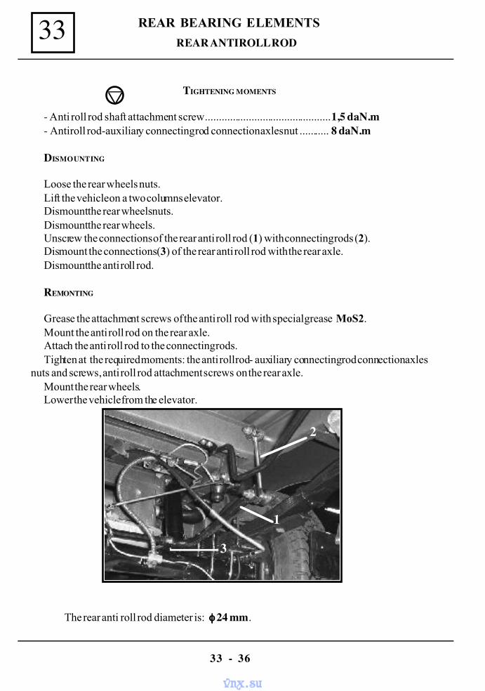
REAR BEARING ELEMENTS33
33 - 36
REAR ANTIROLL ROD
TIGHTENING MOMENTS
- Anti roll rod shaft attachment screw.............................................. 1,5 daN.m- Anti roll rod-auxiliary connecting rod connection axles nut ........... 8 daN.m
DISMOUNTING
Loose the rear wheels nuts.Lift the vehicle on a two columns elevator.Dismount the rear wheels nuts.Dismount the rear wheels.Unscrew the connections of the rear anti roll rod (1) with connecting rods (2).Dismount the connections (3) of the rear anti roll rod with the rear axle.Dismount the anti roll rod.
REMONTING
Grease the attachment screws of the anti roll rod with special grease MoS2.Mount the anti roll rod on the rear axle.Attach the anti roll rod to the connecting rods.Tighten at the required moments : the anti roll rod- auxiliary connecting rod connection axles
nuts and screws, anti roll rod attachment screws on the rear axle.Mount the rear wheels.Lower the vehicle from the elevator.
The rear anti roll rod diameter is: φφφφ 24 mm.
3
1
2
1
3
2
vnx.su
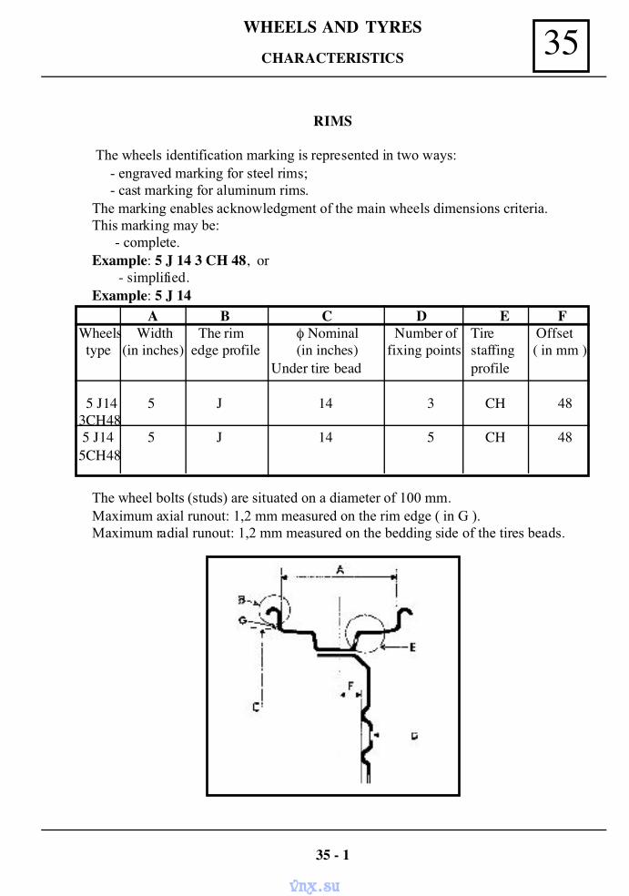
35WHEELS AND TYRES
RIMS
The wheels identification marking is represented in two ways:- engraved marking for steel rims;- cast marking for aluminum rims.
The marking enables acknowledgment of the main wheels dimensions criteria.This marking may be:
- complete.Example: 5 J 14 3 CH 48, or
- simplified.Example: 5 J 14
A B C D E FWheels Width The rim φ Nominal Number of Tire Offset type (in inches) edge profile (in inches) fixing points staffing ( in mm )
Under tire bead profile
5 J14 5 J 14 3 CH 483CH48 5 J14 5 J 14 5 CH 485CH48
The wheel bolts (studs) are situated on a diameter of 100 mm.Maximum axial runout: 1,2 mm measured on the rim edge ( in G ).Maximum radial runout: 1,2 mm measured on the bedding side of the tires beads.
35 - 1
CHARACTERISTICS
vnx.su
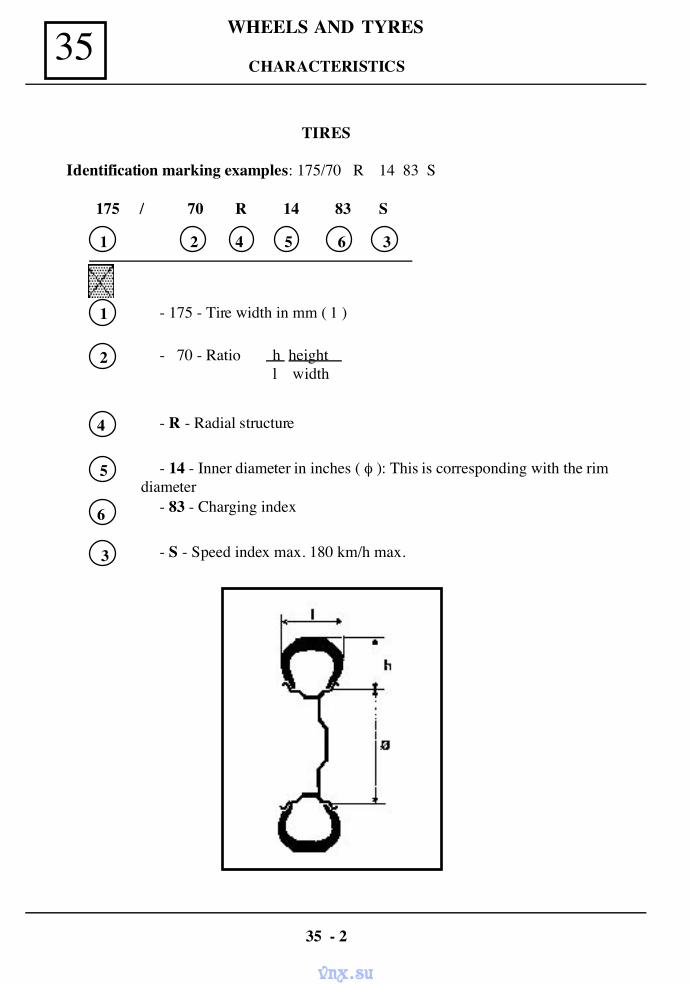
WHEELS AND TYRES35
TIRES
Identification marking examples: 175/70 R 14 83 S
175 / 70 R 14 83 S
1 2 4 5 6
1 - 175 - Tire width in mm ( 1 )
2 - 70 - Ratio h height l width
4 - R - Radial structure
5 - 14 - Inner diameter in inches ( φ ): This is corresponding with the rimdiameter
6 - 83 - Charging index
3
3 - S - Speed index max. 180 km/h max.
35 - 2
CHARACTERISTICS
vnx.su
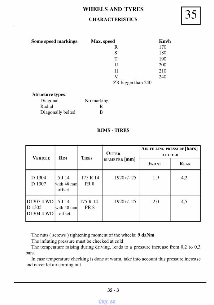
35WHEELS AND TYRES
Some speed markings: Max. speed Km/hR 170S 180T 190U 200H 210V 240
ZR bigger than 240
Structure types:Diagonal No markingRadial RDiagonally belted B
RIMS - TIRES
VEHICLE RIM TIRES OUTER
DIAMETER [mm]
AIR FILLING PRESSURE [bars] AT COLD
FRONT REAR
D 1304 5 J 14 175 R 14 1920+/- 25 1,9 4,2D 1307 with 48 mm PR 8
offset
D1307 4 WD 5 J 14 175 R 14 1920+/- 25 2,0 4,5 D 1305 with 48 mm PR 8 D1304 4 WD offset
The nuts ( screws ) tightening moment of the wheels: 9 daNm.The inflating pressure must be checked at coldThe temperature raising during driving, leads to a pressure increase from 0,2 to 0,3
bars.In case temperature checking is done at warm, take into account this pressure increase
and never let air coming out.
35 - 3
CHARACTERISTICS
vnx.su
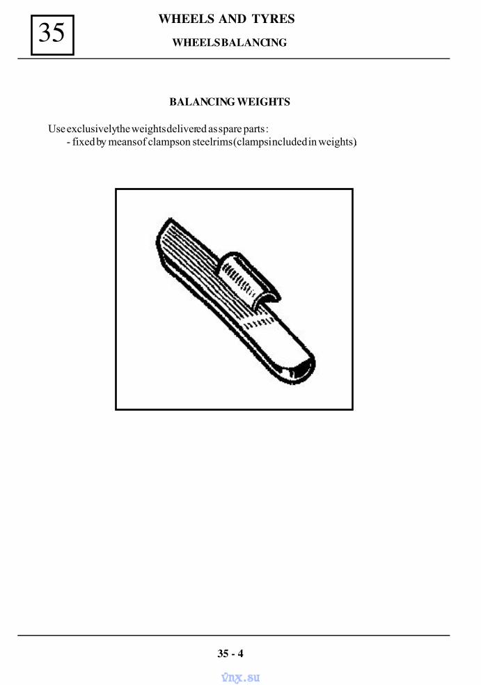
WHEELS AND TYRES35 WHEELS BALANCING
BALANCING WEIGHTS
Use exclusively the weights delivered as spare parts :- fixed by means of clamps on steel rims (clamps included in weights).
35 - 4
vnx.su
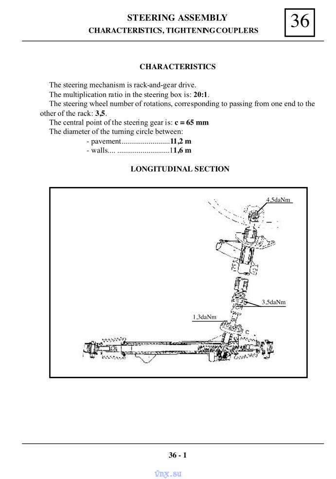
36STEERING ASSEMBLYCHARACTERISTICS, TIGHTENING COUPLERS
CHARACTERISTICS
The steering mechanism is rack-and-gear drive.The multiplication ratio in the steering box is: 20:1.The steering wheel number of rotations, corresponding to passing from one end to the
other of the rack: 3,5.The central point of the steering gear is: c = 65 mmThe diameter of the turning circle between:
- pavement.........................11,2 m- walls.... ...........................11,6 m
LONGITUDINAL SECTION
36 - 1
1,3daNm
3,5daNm
4,5daNm
vnx.su
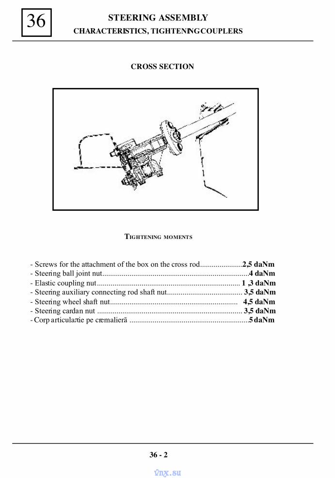
STEERING ASSEMBLY36
36 - 2
CHARACTERISTICS, TIGHTENING COUPLERS
TIGHTENING MOMENTS
- Screws for the attachment of the box on the cross rod......................2,5 daNm- Steering ball joint nut............................................................................4 daNm- Elastic coupling nut.......................................................................... 1 ,3 daNm- Steering auxiliary connecting rod shaft nut....................................... 3,5 daNm- Steering wheel shaft nut.................................................................. 4,5 daNm- Steering cardan nut ........................................................................... 3,5 daNm- Corp articulaπie pe cremalierã ..............................................................5 daNm
CROSS SECTION
vnx.su
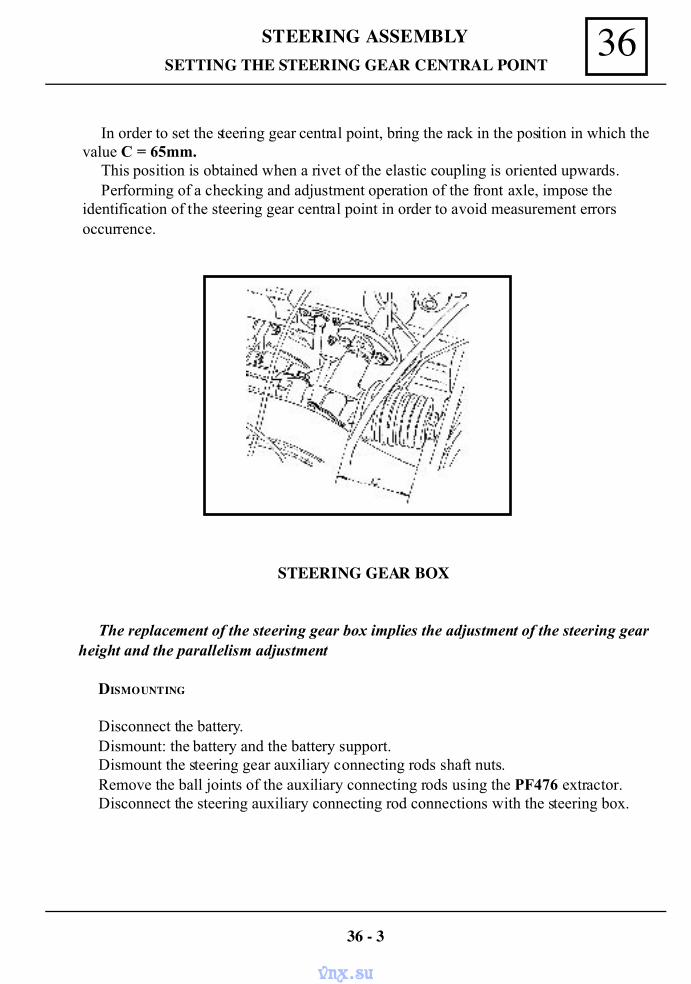
36STEERING ASSEMBLY
In order to set the steering gear central point, bring the rack in the position in which thevalue C = 65mm.
This position is obtained when a rivet of the elastic coupling is oriented upwards.Performing of a checking and adjustment operation of the front axle, impose the
identification of the steering gear central point in order to avoid measurement errorsoccurrence.
STEERING GEAR BOX
The replacement of the steering gear box implies the adjustment of the steering gearheight and the parallelism adjustment
DISMOUNTING
Disconnect the battery.Dismount: the battery and the battery support.Dismount the steering gear auxiliary connecting rods shaft nuts.Remove the ball joints of the auxiliary connecting rods using the PF476 extractor.Disconnect the steering auxiliary connecting rod connections with the steering box.
36 - 3
SETTING THE STEERING GEAR CENTRAL POINT
vnx.su
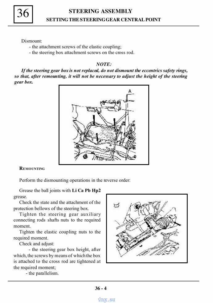
STEERING ASSEMBLY36
Dismount:- the attachment screws of the elastic coupling;- the steering box attachment screws on the cross rod.
NOTE: If the steering gear box is not replaced, do not dismount the eccentrics safety rings,
so that, after remounting, it will not be necessary to adjust the height of the steeringgear box.
REMOUNTING
Perform the dismounting operations in the reverse order:
Grease the ball joints with Li Ca Pb Hp2grease.
Check the state and the attachment of theprotection bellows of the steering box.
Tighten the steering gear auxiliaryconnecting rods shafts nuts to the requiredmoment.
Tighten the elastic coupling nuts to therequired moment.
Check and adjust: - the steering gear box height, afterwhich, the screws by means of which the boxis attached to the cross rod are tightened atthe required moment; - the parallelism.
36 - 4
SETTING THE STEERING GEAR CENTRAL POINT
vnx.su
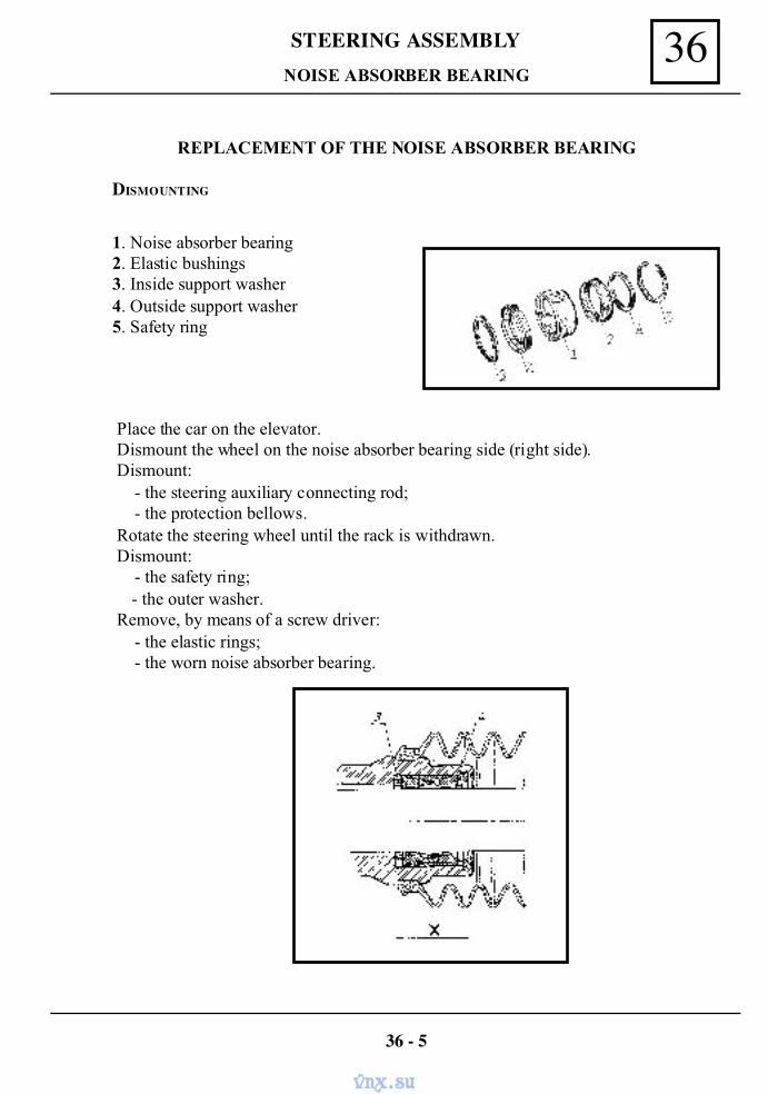
36STEERING ASSEMBLY
REPLACEMENT OF THE NOISE ABSORBER BEARING
DISMOUNTING
1. Noise absorber bearing2. Elastic bushings3. Inside support washer4. Outside support washer5. Safety ring
36 - 5
Place the car on the elevator. Dismount the wheel on the noise absorber bearing side (right side). Dismount:
- the steering auxiliary connecting rod;- the protection bellows.
Rotate the steering wheel until the rack is withdrawn. Dismount:
- the safety ring; - the outer washer.
Remove, by means of a screw driver:- the elastic rings;- the worn noise absorber bearing.
NOISE ABSORBER BEARING
vnx.su
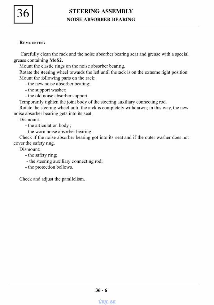
STEERING ASSEMBLY36
REMOUNTING
Carefully clean the rack and the noise absorber bearing seat and grease with a specialgrease containing MoS2.
Mount the elastic rings on the noise absorber bearing.Rotate the steering wheel towards the left until the rack is on the extreme right position.Mount the following parts on the rack:
- the new noise absorber bearing;- the support washer;- the old noise absorber support.
Temporarily tighten the joint body of the steering auxiliary connecting rod.Rotate the steering wheel until the rack is completely withdrawn; in this way, the new
noise absorber bearing gets into its seat.Dismount:
- the articulation body ;- the worn noise absorber bearing.
Check if the noise absorber bearing got into its seat and if the outer washer does notcover the safety ring.
Dismount:- the safety ring; - the steering auxiliary connecting rod;- the protection bellows.
Check and adjust the parallelism.
NOISE ABSORBER BEARING
36 - 6
vnx.su
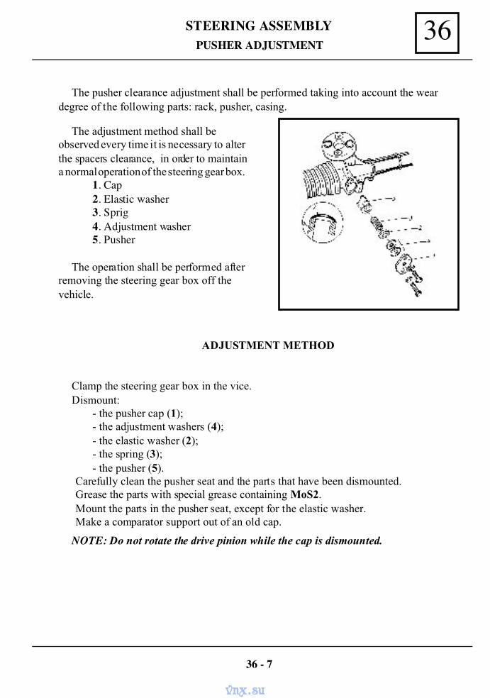
36STEERING ASSEMBLYPUSHER ADJUSTMENT
The pusher clearance adjustment shall be performed taking into account the weardegree of the following parts: rack, pusher, casing.
The adjustment method shall beobserved every time it is necessary to alterthe spacers clearance, in order to maintaina normal operation of the steering gear box.
1. Cap2. Elastic washer3. Sprig4. Adjustment washer5. Pusher
The operation shall be performed afterremoving the steering gear box off thevehicle.
ADJUSTMENT METHOD
Clamp the steering gear box in the vice.Dismount:
- the pusher cap (1);- the adjustment washers (4);- the elastic washer (2);- the spring (3);- the pusher (5).
Carefully clean the pusher seat and the parts that have been dismounted.Grease the parts with special grease containing MoS2.Mount the parts in the pusher seat, except for the elastic washer.Make a comparator support out of an old cap.
NOTE: Do not rotate the drive pinion while the cap is dismounted.
36 - 7
vnx.su
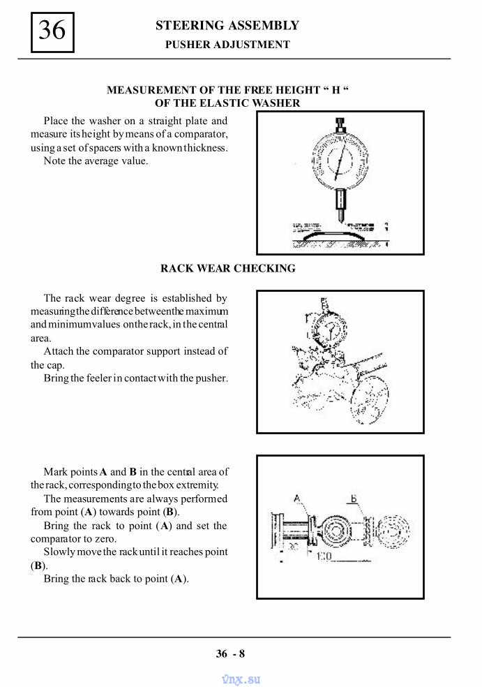
STEERING ASSEMBLY36PUSHER ADJUSTMENT
MEASUREMENT OF THE FREE HEIGHT “ H “OF THE ELASTIC WASHER
Place the washer on a straight plate andmeasure its height by means of a comparator,using a set of spacers with a known thickness.
Note the average value.
RACK WEAR CHECKING
The rack wear degree is established bymeasuring the difference between the maximumand minimum values on the rack, in the centralarea.
Attach the comparator support instead ofthe cap.
Bring the feeler in contact with the pusher.
Mark points A and B in the central area ofthe rack, corresponding to the box extremity.
The measurements are always performedfrom point (A) towards point (B).
Bring the rack to point (A) and set thecomparator to zero.
Slowly move the rack until it reaches point(B).
Bring the rack back to point (A).
36 - 8
vnx.su
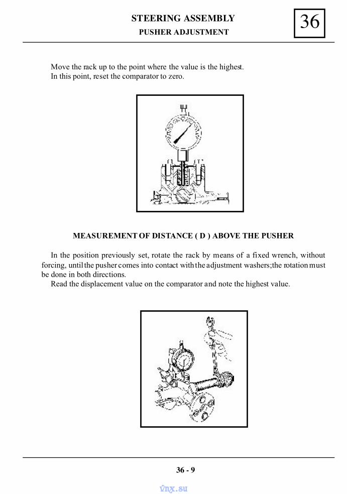
36STEERING ASSEMBLY
Move the rack up to the point where the value is the highest.In this point, reset the comparator to zero.
MEASUREMENT OF DISTANCE ( D ) ABOVE THE PUSHER
In the position previously set, rotate the rack by means of a fixed wrench, withoutforcing, until the pusher comes into contact with the adjustment washers;the rotation mustbe done in both directions.
Read the displacement value on the comparator and note the highest value.
PUSHER ADJUSTMENT
36 - 9
vnx.su
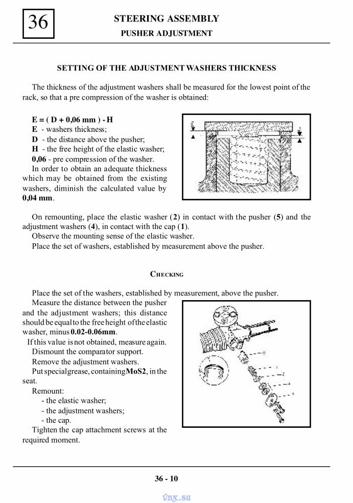
STEERING ASSEMBLY36PUSHER ADJUSTMENT
SETTING OF THE ADJUSTMENT WASHERS THICKNESS
The thickness of the adjustment washers shall be measured for the lowest point of therack, so that a pre compression of the washer is obtained:
E = ( D + 0,06 mm ) - HE - washers thickness;D - the distance above the pusher;H - the free height of the elastic washer;0,06 - pre compression of the washer.In order to obtain an adequate thickness
which may be obtained from the existingwashers, diminish the calculated value by0,04 mm.
On remounting, place the elastic washer (2) in contact with the pusher (5) and theadjustment washers (4), in contact with the cap (1).
Observe the mounting sense of the elastic washer.Place the set of washers, established by measurement above the pusher.
CHECKING
Place the set of the washers, established by measurement, above the pusher.Measure the distance between the pusher
and the adjustment washers; this distanceshould be equal to the free height of the elasticwasher, minus 0.02-0.06mm. If this value is not obtained, measure again.
Dismount the comparator support.Remove the adjustment washers.Put special grease, containing MoS2, in the
seat.Remount:
- the elastic washer;- the adjustment washers;- the cap.
Tighten the cap attachment screws at therequired moment.
36 - 10
vnx.su
36STEERING ASSEMBLYPUSHER ADJUSTMENT
ADJUSTMENT EXAMPLE
The distance between the pusher and the adjustment washers: D = 1,48 mmFree height of the elastic washer: H = 1,32 mmThickness of the adjustment spacer: E = ( D + 0,06 ) - H = ( 1,48 + 0,06 ) - 1,32
E = 0,22 mm
PARTICULAR CASE
It may happen that value found for the adjustment washers thickness is negative.
EXAMPLE
The distance between the pusher and the adjustment washers : D = 1,17 mmFree height of the elastic washer: H = 1,35 mmThickness of the adjustment spacer: E = ( D + 0,06 ) - H = ( 1,17 + 0,06 ) - 1,35
E = - 0,12 mmIn this case, take out a 0,15mm thick washer from the washers set, after which perform
measurement again to establish the thickness of the adjustment washers.
36 - 11
vnx.su
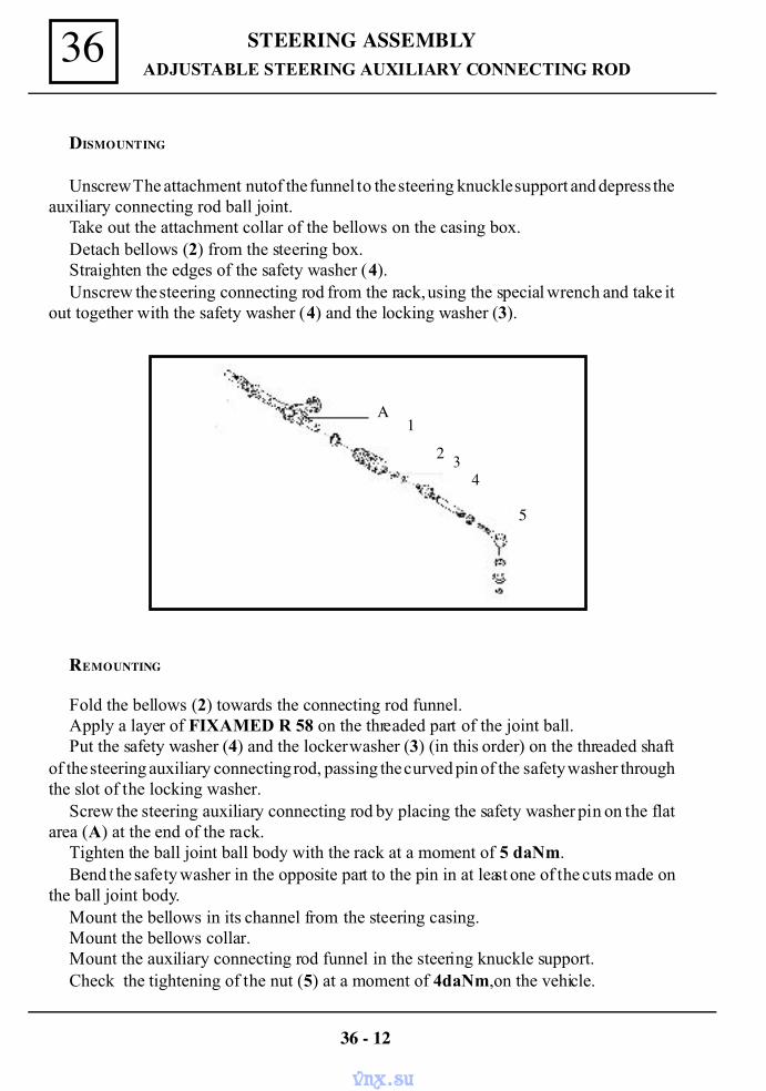
STEERING ASSEMBLY36ADJUSTABLE STEERING AUXILIARY CONNECTING ROD
REMOUNTING
Fold the bellows (2) towards the connecting rod funnel.Apply a layer of FIXAMED R 58 on the threaded part of the joint ball.Put the safety washer (4) and the locker washer (3) (in this order) on the threaded shaft
of the steering auxiliary connecting rod, passing the curved pin of the safety washer throughthe slot of the locking washer.
Screw the steering auxiliary connecting rod by placing the safety washer pin on the flatarea (A) at the end of the rack.
Tighten the ball joint ball body with the rack at a moment of 5 daNm.Bend the safety washer in the opposite part to the pin in at least one of the cuts made on
the ball joint body.Mount the bellows in its channel from the steering casing.Mount the bellows collar.Mount the auxiliary connecting rod funnel in the steering knuckle support.Check the tightening of the nut (5) at a moment of 4daNm,on the vehicle.
36 - 12
DISMOUNTING
Unscrew The attachment nut of the funnel to the steering knuckle support and depress theauxiliary connecting rod ball joint.
Take out the attachment collar of the bellows on the casing box.Detach bellows (2) from the steering box.Straighten the edges of the safety washer (4).Unscrew the steering connecting rod from the rack, using the special wrench and take it
out together with the safety washer (4) and the locking washer (3).
4
5
32
1A
vnx.su
36STEERING ASSEMBLY
36 - 13
The tightening at the moment of 5 daNm shall be performed with the 6902-4105special wrench.
AUXILIARY CONNECTING ROD FUNNEL
In case only the auxiliary connecting rod funnel is worn, this may be replaced.
DISMOUNTING
Dismount the attachment nut of the auxiliary connecting rod funnel ball joint on thesteering knuckle support.
Depress the funnel ball joint from the steering knuckle supportLoosen the nut (5).Unscrew the auxiliary connecting rod funnel from the assembled auxiliary connecting
rod end.
REMOUNTING
Remount the new funnel performing the dismounting operations in the reverse order.See that the nut (5) is tightened to the moment of 4daNm.
ADJUSTABLE AUXILIARY CONNECTING ROD
vnx.su
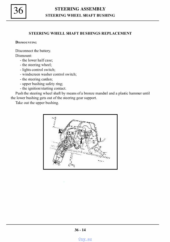
STEERING ASSEMBLY36
36 - 14
STEERING WHELL SHAFT BUSHINGS REPLACEMENT
DISMOUNTING
Disconnect the battery.Dismount:
- the lower half case;- the steering wheel;- lights control switch;- windscreen washer control switch;- the steering cardan;- upper bushing safety ring;- the ignition/starting contact.
Push the steering wheel shaft by means of a bronze mandrel and a plastic hammer untilthe lower bushing gets out of the steering gear support.
Take out the upper bushing.
STEERING WHEEL SHAFT BUSHING
vnx.su
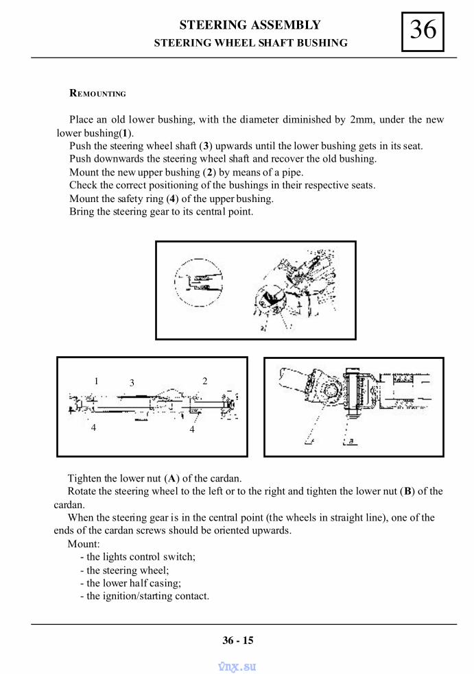
36STEERING ASSEMBLY
Tighten the lower nut (A) of the cardan.Rotate the steering wheel to the left or to the right and tighten the lower nut (B) of the
cardan.When the steering gear is in the central point (the wheels in straight line), one of the
ends of the cardan screws should be oriented upwards.Mount:
- the lights control switch;- the steering wheel;- the lower half casing;- the ignition/starting contact.
REMOUNTING
Place an old lower bushing, with the diameter diminished by 2mm, under the newlower bushing(1).
Push the steering wheel shaft (3) upwards until the lower bushing gets in its seat.Push downwards the steering wheel shaft and recover the old bushing.Mount the new upper bushing (2) by means of a pipe.Check the correct positioning of the bushings in their respective seats.Mount the safety ring (4) of the upper bushing.Bring the steering gear to its central point.
STEERING WHEEL SHAFT BUSHING
36 - 15
1 3 2
4 4
vnx.su
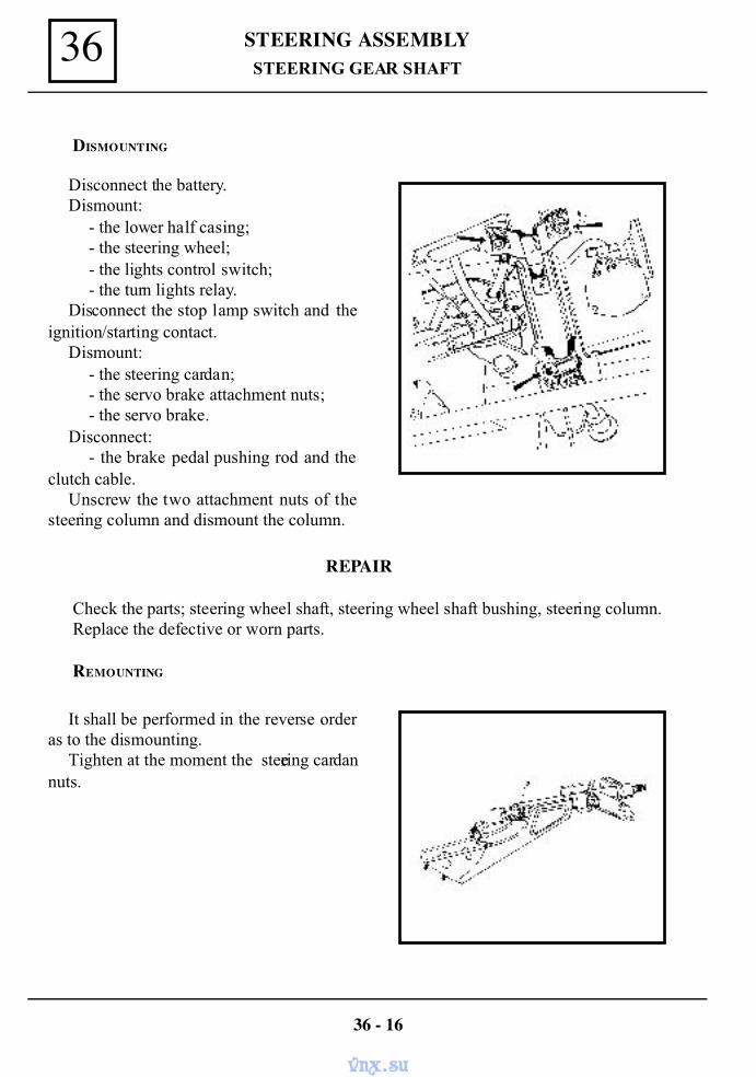
STEERING ASSEMBLY36STEERING GEAR SHAFT
DISMOUNTING
Disconnect the battery.Dismount:
- the lower half casing;- the steering wheel;- the lights control switch;- the turn lights relay.
Disconnect the stop lamp switch and theignition/starting contact.
Dismount:- the steering cardan;- the servo brake attachment nuts;- the servo brake.
Disconnect:- the brake pedal pushing rod and the
clutch cable.Unscrew the two attachment nuts of the
steering column and dismount the column.
REPAIR
Check the parts; steering wheel shaft, steering wheel shaft bushing, steering column.Replace the defective or worn parts.
REMOUNTING
It shall be performed in the reverse orderas to the dismounting.
Tighten at the moment the steering cardannuts.
36 - 16
vnx.su
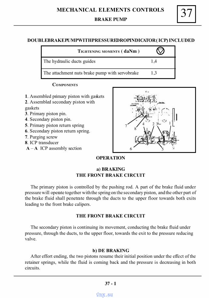
37MECHANICAL ELEMENTS CONTROLS
DOUBLE BRAKE PUMP WITH PRESSURE DROP INDICATOR ( ICP ) INCLUDED
COMPONENTS
1. Assembled primary piston with gaskets2. Assembled secondary piston withgaskets3. Primary piston pin.4. Secondary piston pin.5. Primary piston return spring6. Secondary piston return spring.7. Purging screw8. ICP transducer A – A ICP assembly section
OPERATION
a) BRAKINGTHE FRONT BRAKE CIRCUIT
The primary piston is controlled by the pushing rod. A part of the brake fluid underpressure will operate together with the spring on the secondary piston, and the other part ofthe brake fluid shall penetrate through the ducts to the upper floor towards both exitsleading to the front brake calipers.
THE FRONT BRAKE CIRCUIT
The secondary piston is continuing its movement, conducting the brake fluid underpressure, through the ducts, to the upper floor, towards the exit to the pressure reducingvalve.
b) DE BRAKINGAfter effort ending, the two pistons resume their initial position under the effect of the
retainer springs, while the fluid is coming back and the pressure is decreasing in bothcircuits.
BRAKE PUMP
TIGHTENING MOMENTS ( daNm )
The hydraulic ducts guides 1,4
The attachment nuts brake pump with servobrake 1,3
37 - 1
1248
7
6 5
3
vnx.su
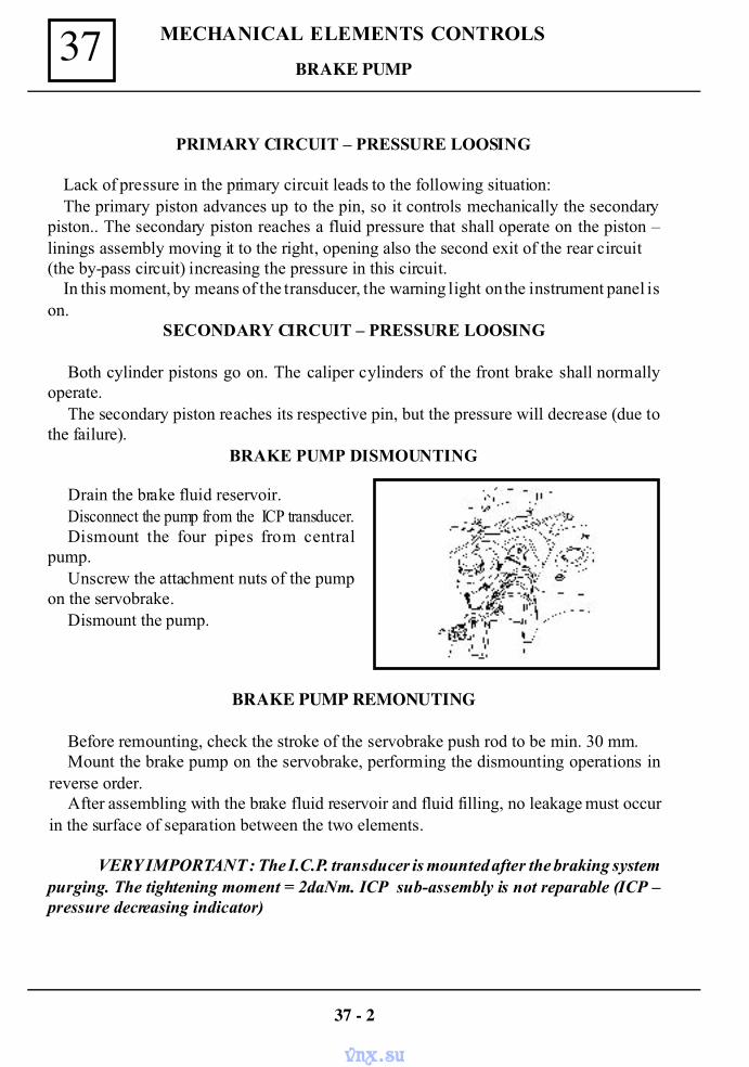
MECHANICAL ELEMENTS CONTROLS37
PRIMARY CIRCUIT – PRESSURE LOOSING
Lack of pressure in the primary circuit leads to the following situation:The primary piston advances up to the pin, so it controls mechanically the secondary
piston.. The secondary piston reaches a fluid pressure that shall operate on the piston –linings assembly moving it to the right, opening also the second exit of the rear circuit(the by-pass circuit) increasing the pressure in this circuit.
In this moment, by means of the transducer, the warning light on the instrument panel ison.
SECONDARY CIRCUIT – PRESSURE LOOSING
Both cylinder pistons go on. The caliper cylinders of the front brake shall normallyoperate.
The secondary piston reaches its respective pin, but the pressure will decrease (due tothe failure).
BRAKE PUMP DISMOUNTING
Drain the brake fluid reservoir.Disconnect the pump from the ICP transducer.Dismount the four pipes from central
pump.Unscrew the attachment nuts of the pump
on the servobrake.Dismount the pump.
BRAKE PUMP REMONUTING
Before remounting, check the stroke of the servobrake push rod to be min. 30 mm.Mount the brake pump on the servobrake, performing the dismounting operations in
reverse order.After assembling with the brake fluid reservoir and fluid filling, no leakage must occur
in the surface of separation between the two elements.
VERY IMPORTANT : The I.C.P. transducer is mounted after the braking systempurging. The tightening moment = 2daNm. ICP sub-assembly is not reparable (ICP –pressure decreasing indicator)
BRAKE PUMP
37 - 2
vnx.su
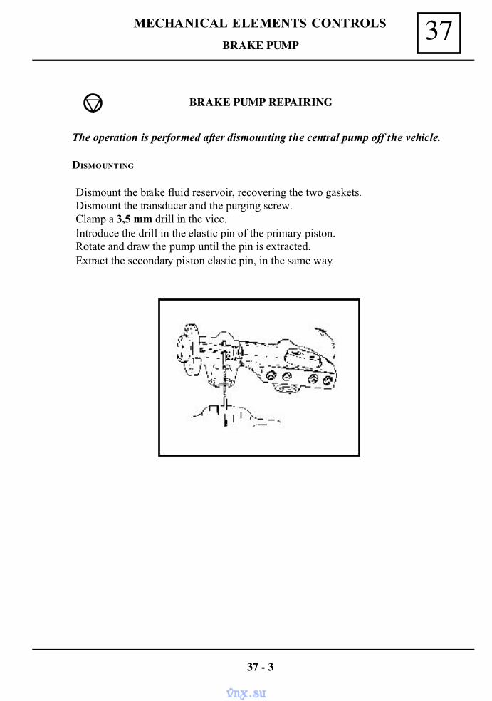
37MECHANICAL ELEMENTS CONTROLS
BRAKE PUMP REPAIRING
The operation is performed after dismounting the central pump off the vehicle.
DISMOUNTING
Dismount the brake fluid reservoir, recovering the two gaskets.Dismount the transducer and the purging screw.Clamp a 3,5 mm drill in the vice.Introduce the drill in the elastic pin of the primary piston.Rotate and draw the pump until the pin is extracted.Extract the secondary piston elastic pin, in the same way.
BRAKE PUMP
37 - 3
vnx.su
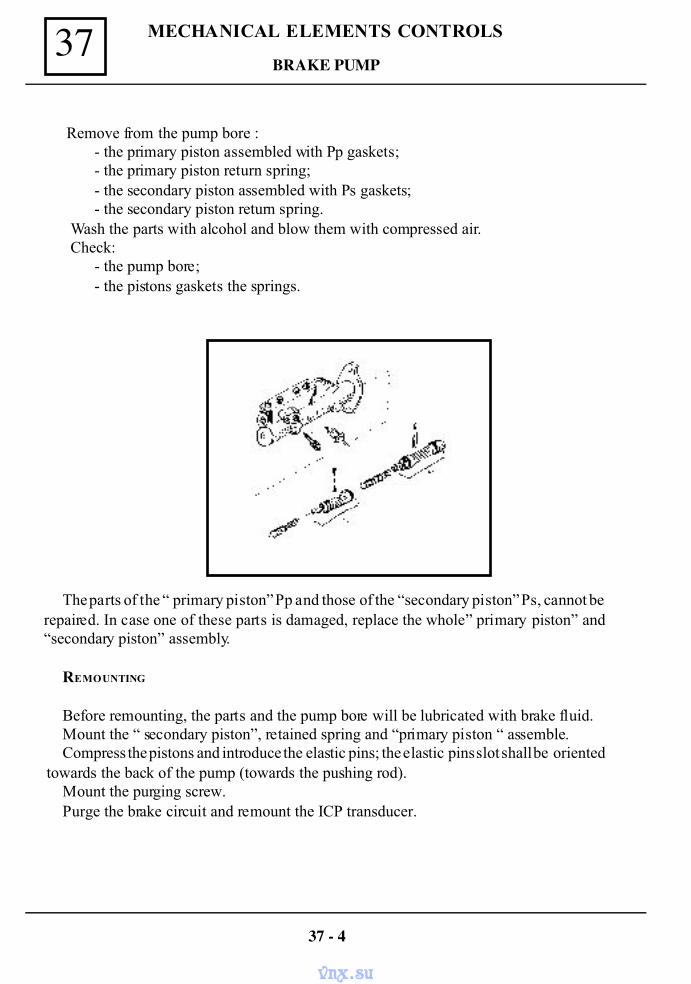
MECHANICAL ELEMENTS CONTROLS37
Remove from the pump bore :- the primary piston assembled with Pp gaskets;- the primary piston return spring;- the secondary piston assembled with Ps gaskets;- the secondary piston return spring.
Wash the parts with alcohol and blow them with compressed air.Check:
- the pump bore;- the pistons gaskets the springs.
The parts of the “ primary piston” Pp and those of the “secondary piston” Ps, cannot berepaired. In case one of these parts is damaged, replace the whole” primary piston” and“secondary piston” assembly.
REMOUNTING
Before remounting, the parts and the pump bore will be lubricated with brake fluid.Mount the “ secondary piston”, retained spring and “primary piston “ assemble.Compress the pistons and introduce the elastic pins; the elastic pins slot shall be oriented
towards the back of the pump (towards the pushing rod).Mount the purging screw.Purge the brake circuit and remount the ICP transducer.
BRAKE PUMP
37 - 4
vnx.su
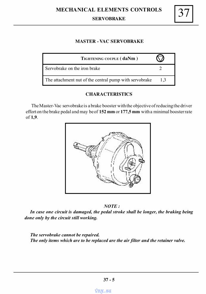
37MECHANICAL ELEMENTS CONTROLS
MASTER - VAC SERVOBRAKE
NOTE :In case one circuit is damaged, the pedal stroke shall be longer, the braking being
done only by the circuit still working.
The servobrake cannot be repaired.The only items which are to be replaced are the air filter and the retainer valve.
SERVOBRAKE
TIGHTENING COUPLE ( daNm )
Servobrake on the iron brake 2
The attachment nut of the central pump with servobrake 1,3
CHARACTERISTICS
The Master-Vac servobrake is a brake booster with the objective of reducing the drivereffort on the brake pedal and may be of 152 mm or 177,5 mm with a minimal booster rateof 1,9.
37 - 5
vnx.su
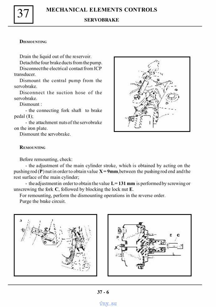
MECHANICAL ELEMENTS CONTROLS37
DISMOUNTING
Drain the liquid out of the reservoir.Detach the four brake ducts from the pump.Disconnect the electrical contact from ICP
transducer.Dismount the central pump from the
servobrake.Disconnect t he suction hose of the
servobrake.Dismount :
- the connecting fork shaft to brakepedal (1);
- the attachment nuts of the servobrakeon the iron plate.
Dismount the servobrake.
REMOUNTING
Before remounting, check:- the adjustment of the main cylinder stroke, which is obtained by acting on the
pushing rod (P) nut in order to obtain value X = 9mm,between the pushing rod end and therest surface of the main cylinder;
- the adjustment in order to obtain the value L = 131 mm is performed by screwing orunscrewing the fork C, followed by blocking the lock nut E.
For remounting, perform the dismounting operations in the reverse order.Purge the brake circuit.
SERVOBRAKE
37 - 6
vnx.su
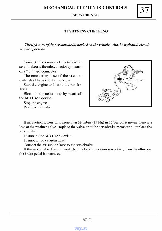
37MECHANICAL ELEMENTS CONTROLS
TIGHTNESS CHECKING
The tightness of the servobrake is checked on the vehicle, with the hydraulic circuitunder operation.
Connect the vacuum meter between theservobrake and the inlet collector by meansof a “ T ” type connector.
The connecting hose of the vacuummeter shall be as short as possible.
Start the engine and let it idle run for1min.
Block the air suction hose by means ofthe MOT 453 device.
Stop the engine.Read the indicator.
SERVOBRAKE
If air suction lowers with more than 33 mbar (25 Hg) in 15’period, it means there is aloss:at the retainer valve - replace the valve or at the servobrake membrane - replace theservobrake.
Dismount the MOT 453 device.Dismount the vacuum hose.Connect the air suction hose to the servobrake.If the servobrake does not work, but the braking system is working, then the effort on
the brake pedal is increased.
37- 7
vnx.su
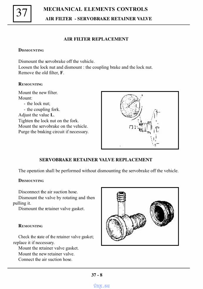
MECHANICAL ELEMENTS CONTROLS37
AIR FILTER REPLACEMENT
DISMOUNTING
Dismount the servobrake off the vehicle.Loosen the lock nut and dismount : the coupling brake and the lock nut.Remove the old filter, F.
REMOUNTING
AIR FILTER - SERVOBRAKE RETAINER VALVE
Mount the new filter.Mount:
- the lock nut;- the coupling fork.
Adjust the value L.Tighten the lock nut on the fork.Mount the servobrake on the vehicle.Purge the braking circuit if necessary.
SERVOBRAKE RETAINER VALVE REPLACEMENT
The operation shall be performed without dismounting the servobrake off the vehicle.
DISMOUNTING
Disconnect the air suction hose.Dismount the valve by rotating and then
pulling it.Dismount the retainer valve gasket.
REMOUNTING
Check the state of the retainer valve gasket;replace it if necessary.
Mount the retainer valve gasket.Mount the new retainer valve.Connect the air suction hose.
37 - 8
vnx.su
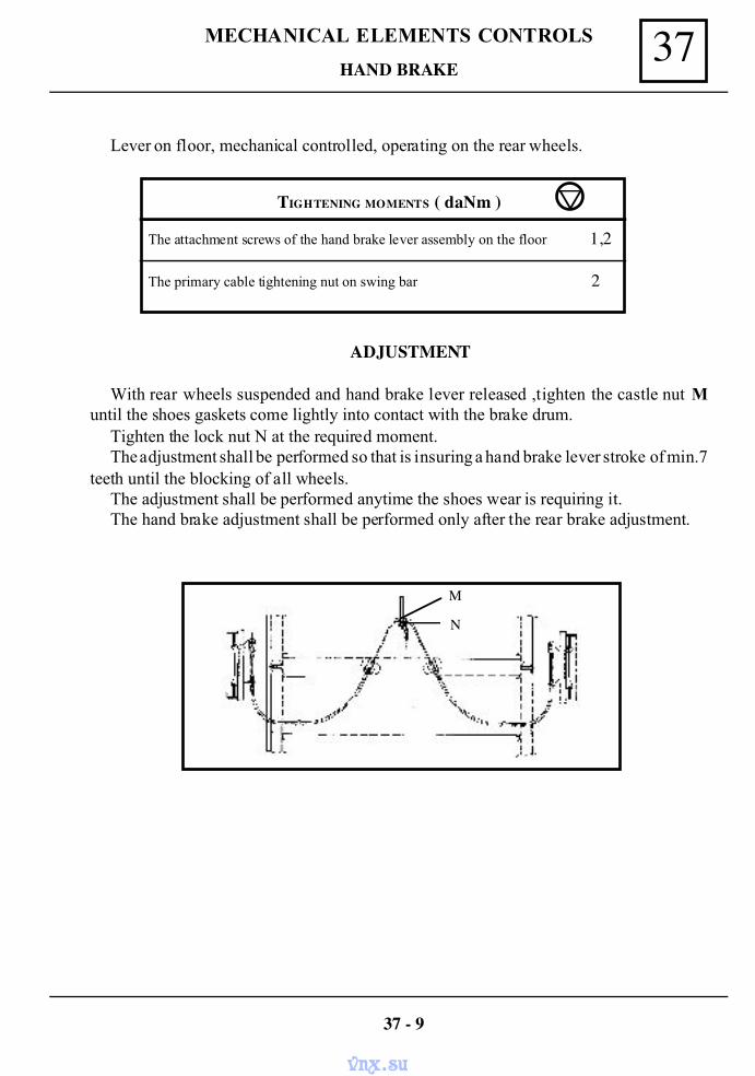
37MECHANICAL ELEMENTS CONTROLS
HAND BRAKE
Lever on floor, mechanical controlled, operating on the rear wheels.
TIGHTENING MOMENTS ( daNm )
The attachment screws of the hand brake lever assembly on the floor 1,2
The primary cable tightening nut on swing bar 2
ADJUSTMENT
With rear wheels suspended and hand brake lever released ,tighten the castle nut Muntil the shoes gaskets come lightly into contact with the brake drum.
Tighten the lock nut N at the required moment.The adjustment shall be performed so that is insuring a hand brake lever stroke of min.7
teeth until the blocking of all wheels.The adjustment shall be performed anytime the shoes wear is requiring it.The hand brake adjustment shall be performed only after the rear brake adjustment.
37 - 9
M
N
vnx.su
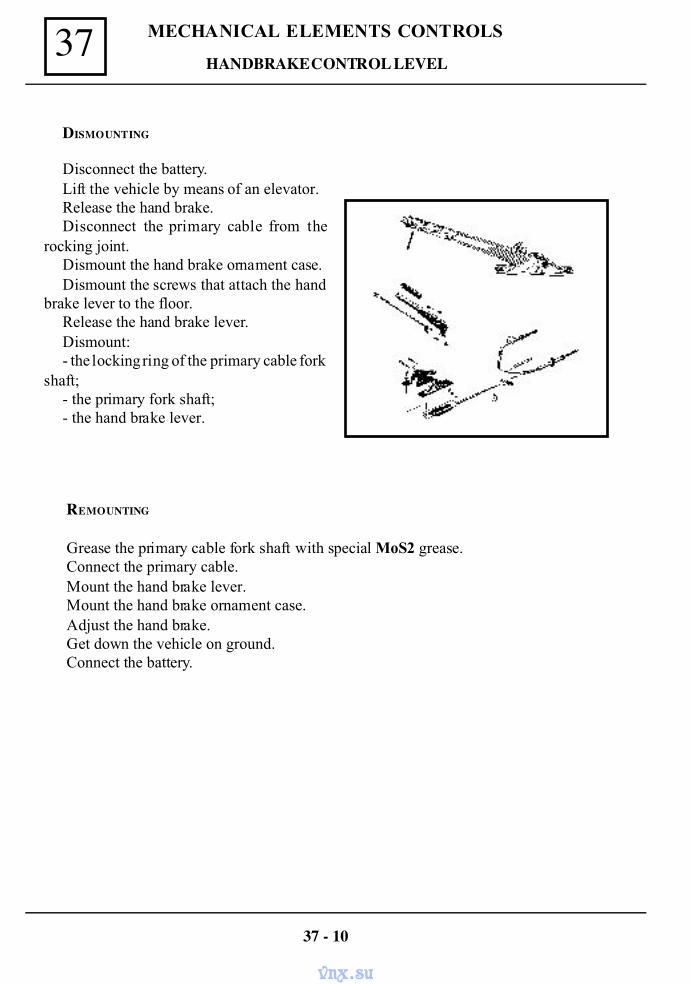
MECHANICAL ELEMENTS CONTROLS37HANDBRAKE CONTROL LEVEL
DISMOUNTING
Disconnect the battery.Lift the vehicle by means of an elevator.Release the hand brake.Disconnect the primary cable from the
rocking joint.Dismount the hand brake ornament case.Dismount the screws that attach the hand
brake lever to the floor.Release the hand brake lever.Dismount:- the locking ring of the primary cable fork
shaft;- the primary fork shaft;- the hand brake lever.
REMOUNTING
Grease the primary cable fork shaft with special MoS2 grease.Connect the primary cable.Mount the hand brake lever.Mount the hand brake ornament case.Adjust the hand brake.Get down the vehicle on ground.Connect the battery.
37 - 10
vnx.su
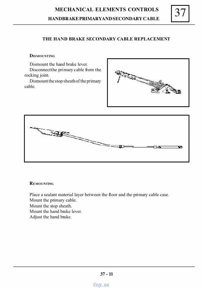
37MECHANICAL ELEMENTS CONTROLS
HANDBRAKE PRIMARY AND SECONDARY CABLE
THE HAND BRAKE SECONDARY CABLE REPLACEMENT
DISMOUNTING
Dismount the hand brake lever.Disconnect the primary cable from the
rocking joint.Dismount the stop sheath of the primary
cable.
REMOUNTING
Place a sealant material layer between the floor and the primary cable case.Mount the primary cable.Mount the stop sheath.Mount the hand brake lever.Adjust the hand brake.
37 - 11
vnx.su
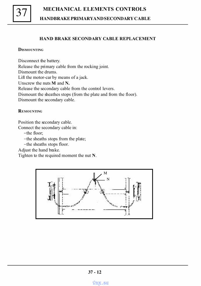
MECHANICAL ELEMENTS CONTROLS37
HAND BRAKE SECONDARY CABLE REPLACEMENT
DISMOUNTING
Disconnect the battery.Release the primary cable from the rocking joint.Dismount the drums.Lift the motor-car by means of a jack.Unscrew the nuts M and N.Release the secondary cable from the control levers.Dismount the sheathes stops (from the plate and from the floor).Dismount the secondary cable.
REMOUNTING
Position the secondary cable.Connect the secondary cable in:-the floor;-the sheaths stops from the plate;-the sheaths stops floor.
Adjust the hand brake.Tighten to the required moment the nut N.
HANDBRAKE PRIMARY AND SECONDARY CABLE
37 - 12
MN
vnx.su
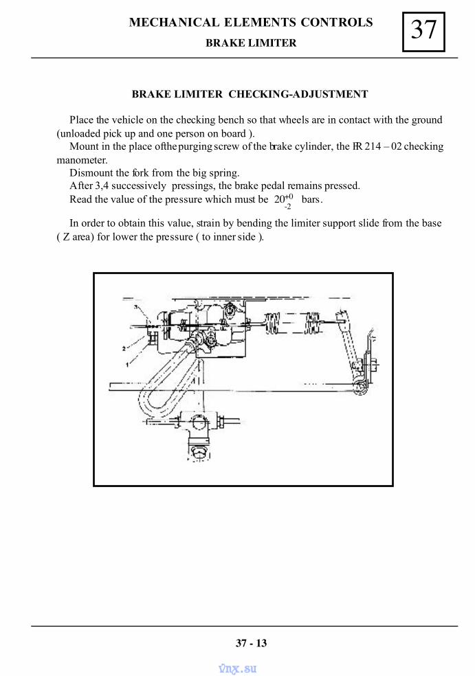
37MECHANICAL ELEMENTS CONTROLS
BRAKE LIMITER CHECKING-ADJUSTMENT
Place the vehicle on the checking bench so that wheels are in contact with the ground(unloaded pick up and one person on board ).
Mount in the place of the purging screw of the brake cylinder, the FR 214 – 02 checkingmanometer.
Dismount the fork from the big spring.After 3,4 successively pressings, the brake pedal remains pressed.Read the value of the pressure which must be 20 bars.
In order to obtain this value, strain by bending the limiter support slide from the base( Z area) for lower the pressure ( to inner side ).
BRAKE LIMITER
+0 -2
37 - 13
vnx.su
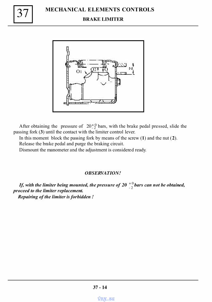
MECHANICAL ELEMENTS CONTROLS37BRAKE LIMITER
After obtaining the pressure of 20 bars, with the brake pedal pressed, slide thepassing fork (3) until the contact with the limiter control lever.
In this moment block the passing fork by means of the screw (1) and the nut (2).Release the brake pedal and purge the braking circuit.Dismount the manometer and the adjustment is considered ready.
OBSERVATION!
If, with the limiter being mounted, the pressure of 20 bars can not be obtained,proceed to the limiter replacement.
Repairing of the limiter is forbidden !
+ 0- 2
+ 0- 2
37 - 14
O1 O2 O
vnx.su
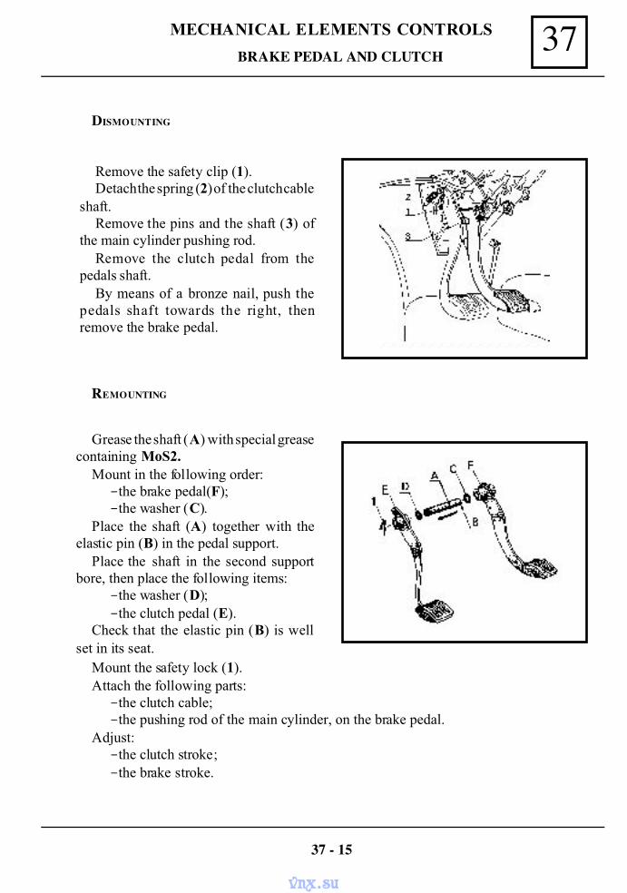
37MECHANICAL ELEMENTS CONTROLS
BRAKE PEDAL AND CLUTCH
DISMOUNTING
Remove the safety clip (1).Detach the spring (2) of the clutch cable
shaft.Remove the pins and the shaft (3) of
the main cylinder pushing rod.Remove the clutch pedal from the
pedals shaft.By means of a bronze nail, push the
pedals shaft towards the right, thenremove the brake pedal.
REMOUNTING
Grease the shaft (A) with special greasecontaining MoS2.
Mount in the following order:-the brake pedal(F);-the washer (C).
Place the shaft (A) together with theelastic pin (B) in the pedal support.
Place the shaft in the second supportbore, then place the following items:
-the washer (D);-the clutch pedal (E).
Check that the elastic pin (B) is wellset in its seat.
Mount the safety lock (1).Attach the following parts:
-the clutch cable;-the pushing rod of the main cylinder, on the brake pedal.
Adjust:-the clutch stroke;-the brake stroke.
37 - 15
vnx.su
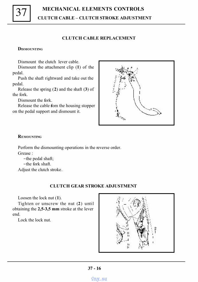
MECHANICAL ELEMENTS CONTROLS37CLUTCH CABLE – CLUTCH STROKE ADJUSTMENT
CLUTCH CABLE REPLACEMENT
DISMOUNTING
Dismount the clutch lever cable.Dismount the attachment clip (1) of the
pedal.Push the shaft rightward and take out the
pedal.Release the spring (2) and the shaft (3) of
the fork.Dismount the fork.Release the cable from the housing stopper
on the pedal support and dismount it.
REMOUNTING
Perform the dismounting operations in the reverse order.Grease :-the pedal shaft;-the fork shaft.
Adjust the clutch stroke.
CLUTCH GEAR STROKE ADJUSTMENT
Loosen the lock nut (1).Tighten or unscrew the nut (2) until
obtaining the 2,5-3,5 mm stroke at the leverend.
Lock the lock nut.
37 - 16
vnx.su
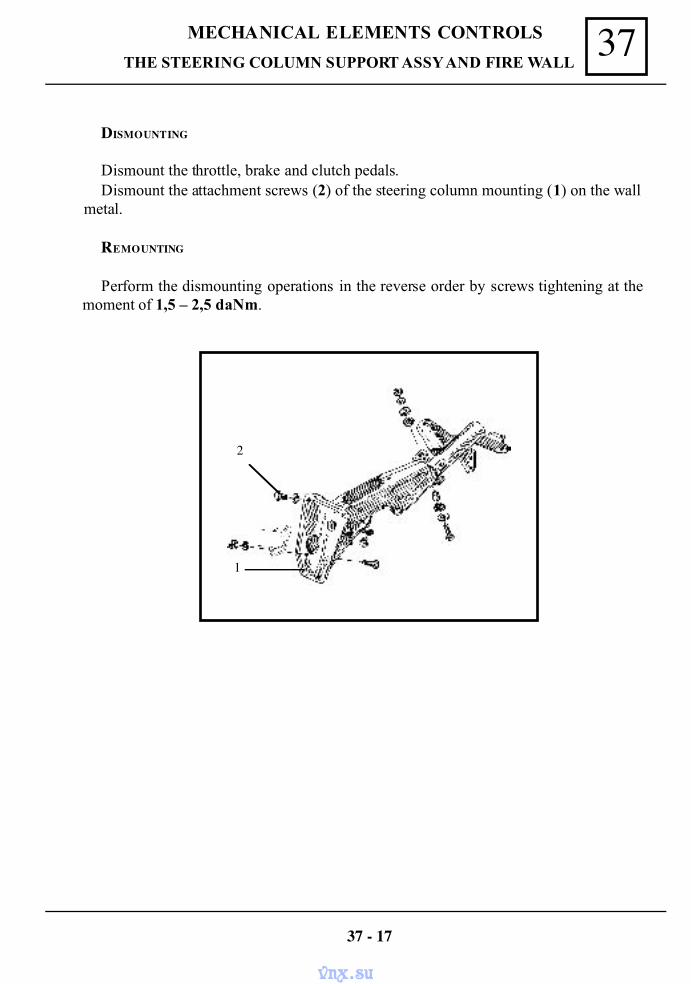
37MECHANICAL ELEMENTS CONTROLS
THE STEERING COLUMN SUPPORT ASSY AND FIRE WALL
DISMOUNTING
Dismount the throttle, brake and clutch pedals.Dismount the attachment screws (2) of the steering column mounting (1) on the wall
metal.
REMOUNTING
Perform the dismounting operations in the reverse order by screws tightening at themoment of 1,5 – 2,5 daNm.
37 - 17
2
1
vnx.su
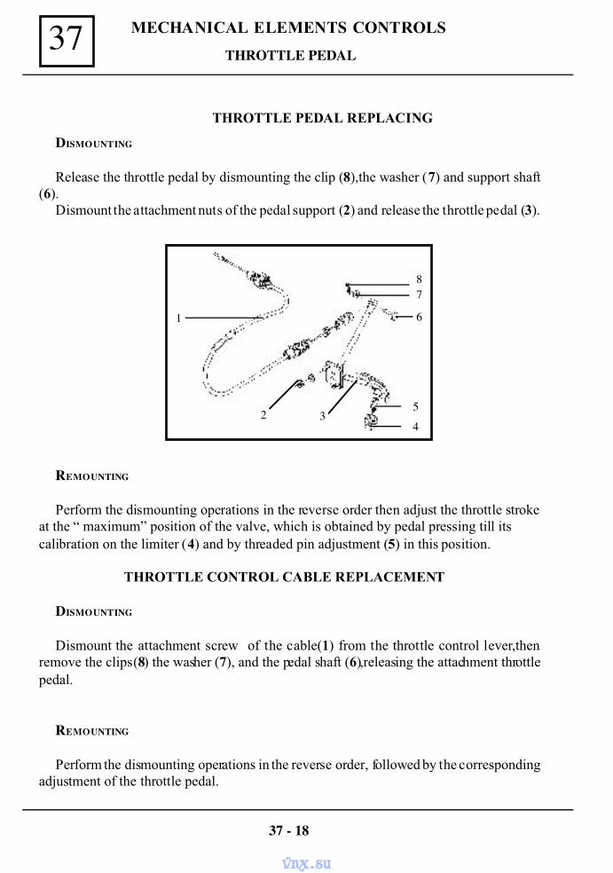
MECHANICAL ELEMENTS CONTROLS37
THROTTLE PEDAL REPLACING
DISMOUNTING
Release the throttle pedal by dismounting the clip (8),the washer (7) and support shaft(6).
Dismount the attachment nuts of the pedal support (2) and release the throttle pedal (3).
REMOUNTING
Perform the dismounting operations in the reverse order then adjust the throttle strokeat the “ maximum” position of the valve, which is obtained by pedal pressing till itscalibration on the limiter (4) and by threaded pin adjustment (5) in this position.
THROTTLE CONTROL CABLE REPLACEMENT
DISMOUNTING
Dismount the attachment screw of the cable(1) from the throttle control lever,thenremove the clips (8) the washer (7), and the pedal shaft (6),releasing the attachment throttlepedal.
REMOUNTING
Perform the dismounting operations in the reverse order, followed by the correspondingadjustment of the throttle pedal.
37 - 18
THROTTLE PEDAL
1
2 34
6
78
5
vnx.su
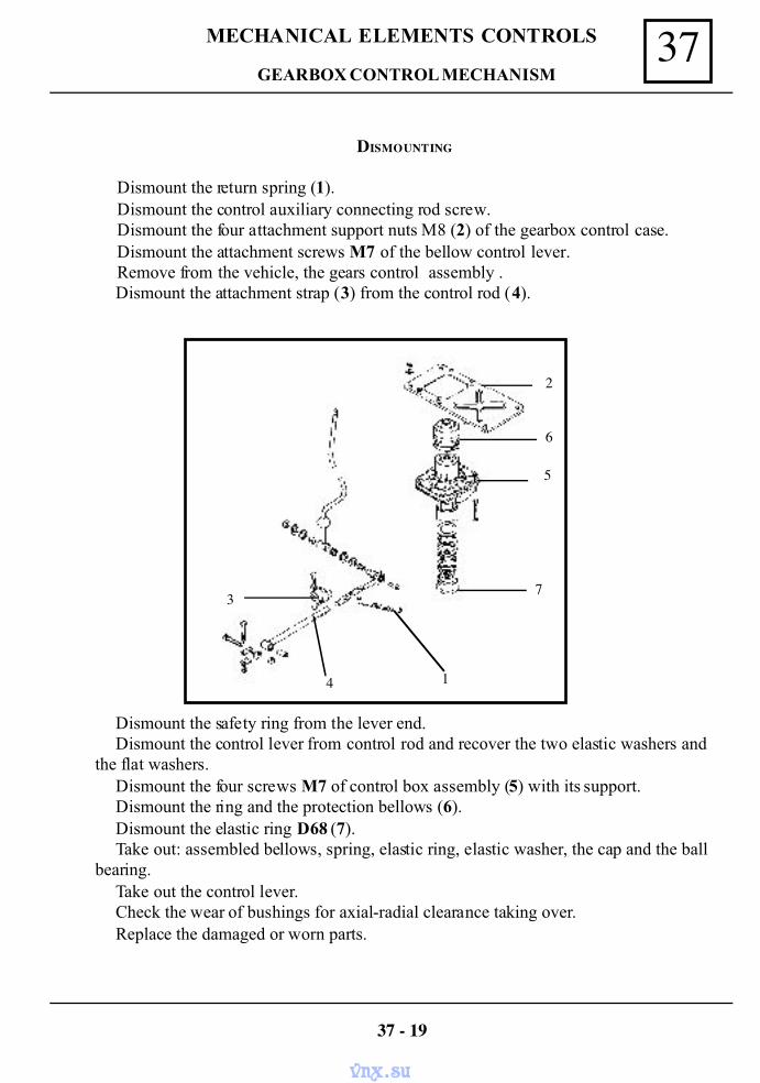
37MECHANICAL ELEMENTS CONTROLS
DISMOUNTING
Dismount the return spring (1).Dismount the control auxiliary connecting rod screw.Dismount the four attachment support nuts M8 (2) of the gearbox control case.Dismount the attachment screws M7 of the bellow control lever.Remove from the vehicle, the gears control assembly .
Dismount the attachment strap (3) from the control rod (4).
Dismount the safety ring from the lever end.Dismount the control lever from control rod and recover the two elastic washers and
the flat washers.Dismount the four screws M7 of control box assembly (5) with its support.Dismount the ring and the protection bellows (6).Dismount the elastic ring D68 (7).Take out: assembled bellows, spring, elastic ring, elastic washer, the cap and the ball
bearing.Take out the control lever.Check the wear of bushings for axial-radial clearance taking over.Replace the damaged or worn parts.
GEARBOX CONTROL MECHANISM
37 - 19
3
4 1
7
5
6
2
vnx.su
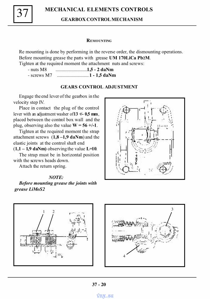
MECHANICAL ELEMENTS CONTROLS37
REMOUNTING
Re mounting is done by performing in the reverse order, the dismounting operations.Before mounting grease the parts with grease UM 170LiCa Pb2M.Tighten at the required moment the attachment nuts and screws:
- nuts M8 ..........................1,5 - 2 daNm- screws M7 .......................... 1 - 1,5 daNm
GEARS CONTROL ADJUSTMENT
Engage the end lever of the gearbox in thevelocity step IV.
Place in contact the plug of the controllever with an adjustment washer of 13 +/- 0,5 mm ,placed between the control box wall and theplug, observing also the value W = 56 +/-1.
Tighten at the required moment the strapattachment screws (1,8 –1,9 daNm) and theelastic joints at the control shaft end(1,1 – 1,9 daNm) observing the value L=10.
The strap must be in horizontal positionwith the screws heads down.
Attach the return spring.
NOTE:Before mounting grease the joints with
grease LiMoS2
GEARBOX CONTROL MECHANISM
37 - 20
1 2
10 4
3
13 +/- 0,5
vnx.su
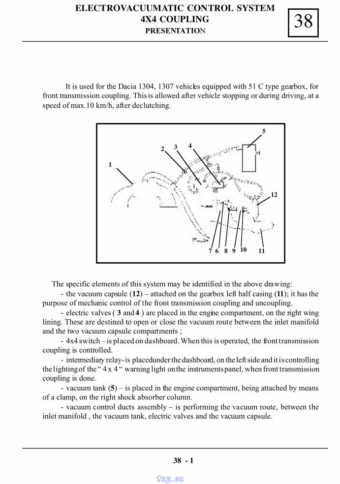
38ELECTROVACUUMATIC CONTROL SYSTEM
4X4 COUPLING
It is used for the Dacia 1304, 1307 vehicles equipped with 51 C type gearbox, forfront transmission coupling. This is allowed after vehicle stopping or during driving, at aspeed of max.10 km/h, after declutching.
The specific elements of this system may be identified in the above drawing:- the vacuum capsule (12) – attached on the gearbox left half casing (11); it has the
purpose of mechanic control of the front transmission coupling and uncoupling.- electric valves ( 3 and 4 ) are placed in the engine compartment, on the right wing
lining. These are destined to open or close the vacuum route between the inlet manifoldand the two vacuum capsule compartments ;
- 4x4 switch – is placed on dashboard. When this is operated, the front transmissioncoupling is controlled.
- intermediary relay- is placed under the dashboard, on the left side and it is controllingthe lighting of the “ 4 x 4 “ warning light on the instruments panel, when front transmissioncoupling is done.
- vacuum tank (5) – is placed in the engine compartment, being attached by meansof a clamp, on the right shock absorber column.
- vacuum control ducts assembly – is performing the vacuum route, between theinlet manifold , the vacuum tank, electric valves and the vacuum capsule.
38 - 1
1
2 3 4
5
12
7 6 8 9 10 11
PRESENTATION
vnx.su
ELECTROVACUUMATIC CONTROL SYSTEM4X4 COUPLING38
- one-way vacuum valve ( 2 ) – is placed on the connection hose between the inletmanifold and the electric valves.
- “ 4x4 ” coupling control wiring – is performing the connection of the systemcomponents to the vehicle electrical equipment.
The system is working based on the vacuum from the inlet manifold (1), which, duringengine running, is acting on the membrane separating the two vacuum capsule compartments(12). This will impose the longitudinal movement of the capsule axle, which by means ofthe control lever (6) will act upon the front transmission coupling control axle (7), placedin the gearbox right front part (1) . In this way is performed the front transmission couplingand the transit from rear drive to all wheel drive (4 x 4).
38 - 2
PRESENTATION
vnx.su
38ELECTROVACUUMATIC CONTROL SYSTEM
4X4 COUPLINGELECTROVACUUMATIC CONTROL ADJUSTMENT
Suspend the vehicle on an elevator.Dismount the fixing lock pin of the connection bolt (8) between the capsule axle and the
control lever (6), then remove the bolt from its place.Rotate the front right wheel and set the positions coupled-uncoupled acting upon the front
transmission control axle. The front transmission control axle stroke = 11,5 mm.Operate the front transmission axle (7) in the position uncoupled, then rotate the threaded
bushing (9) placed on the capsule axle, so that the hole from the capsule axle fork is correspond-ing with the hole from the control lever.
Place the bolt (8) in this position and ensure it by means of the lock pin.Check the uncoupled position of the front transmission; the uncoupling condition is performed
when the front right wheel will be freely turning and in the gearbox no gears engagement noisescan be heard.
Block the threaded bushing position from the capsule axle by means of the near by nut.For the good operation of this system, in case of the reparation, the following requirements
must be observed:-The system sealing condition ( piping, vacuum tank, electric valves, vacuum
capsule) must be performed at a depression of 0,07 Mpa = 0,7 bar, which must be maintainedfor 30 seconds.
-The vacuum valve – is to be mounted so that the arrow marked on its body to beoriented from the electric valves towards the inlet manifold.
-The tightening moment for vacuum capsule attachment = 1,8 – 2 daN.m-The tightening moments for capsule support attachment are :
-1,8 – 2 daN.m for the screws M8 x 1,25 x 18 and-1,9 – 2,2 daNm for the screw M10 x 1,5 x 20
-The tightening moment of the vacuum tank attachment screw = 0,32 – 0,6 daN.m.
38 - 3
vnx.su
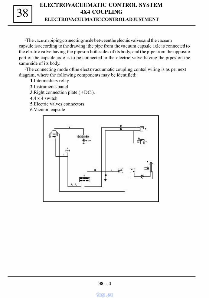
ELECTROVACUUMATIC CONTROL SYSTEM4X4 COUPLING38
-The vacuum piping connecting mode between the electric valves and the vacuumcapsule is according to the drawing: the pipe from the vacuum capsule axle is connected tothe electric valve having the pipes on both sides of its body, and the pipe from the oppositepart of the capsule axle is to be connected to the electric valve having the pipes on thesame side of its body.
-The connecting mode of the electrovacuumatic coupling control wiring is as per nextdiagram, where the following components may be identified:
1.Intermediary relay2.Instruments panel3.Right connection plate ( +DC ).4.4 x 4 switch5.Electric valves connectors6.Vacuum capsule
38 - 4
ELECTROVACUUMATIC CONTROL ADJUSTMENT
vnx.su
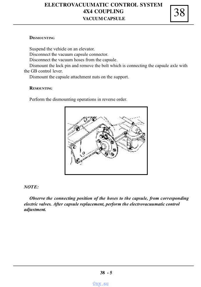
38ELECTROVACUUMATIC CONTROL SYSTEM
4X4 COUPLING
DISMOUNTING
Suspend the vehicle on an elevator.Disconnect the vacuum capsule connector.Disconnect the vacuum hoses from the capsule.Dismount the lock pin and remove the bolt which is connecting the capsule axle with
the GB control lever.Dismount the capsule attachment nuts on the support.
38 - 5
VACUUM CAPSULE
REMOUNTING
Perform the dismounting operations in reverse order.
NOTE:
Observe the connecting position of the hoses to the capsule, from correspondingelectric valves. After capsule replacement, perform the electrovacuumatic controladjustment.
vnx.su
ELECTROVACUUMATIC CONTROL SYSTEM4X4 COUPLING38
DISMOUNTING
Disconnect the connector from the electric valve.Disconnect the hoses from the electric valve.Dismount the electric valve attachment screw.
REMOUNTING
Perform the dismounting operations in the reverse order.
NOTE: Observe the connection position of the hoses to the electric valve, before disconnecting.
38 - 6
ELECTROVALVE
vnx.su
REPAIR MANUAL
DACIA COMMERCIAL
RM 502-2 BODYENGINE: C3L
GERBOX: NG1; NG3TAPV: U75B; U75F
Ref: 6001999454 NOVEMBER 2004 English version
The reparation methods prescribed by the manufacturer in the present document are established subject totechnical specifications in force at the document issuing date.
These are subject to modifications brought by the manufacturer at the fabrication of different assemblies,subassemblies or accessories of its vehicles.
All rights reserved to SC Automobile Dacia SA. Reproduction or translating even partially of this present document is forbidden without the written
authorisation of AUTOMOBILE DACIA S.A.
vnx.su
GENERAL
Designation of parts (blow-up) ........................... 40-1Openings clearances ...................................... 40-7Repairing general conditions ............................. 40-8Welding types and parameters ............................ 40-9Collision diagnosis ....................................... 40-11Body checking/straightening benchtype CELETTE ................................................... 40-14
LOWER STRUCTURE
Lower longitudinal girder .................................... 41-1Assembled front longitudinal girder .................... 41-2Intermediary longitudinal girder ......................... 41-4Rear longitudinal girder (Dacia 1304) ................ 41-5Rear longitudinal girder (Dacia 1307) ................ 41-6
UPPER FRONT STRUCTURE
Front wing ........................................................... 42-1Front unit carriage body ..................................... 42-2Front wing lining ................................................ 42-3Head lamp support .............................................. 42-4Radiator upper cross member ........................... 42-5Aeration grill ...................................................... 42-6
UPPER SIDE STRUCTURE
Front pillar lining ............................................... 43-1Front pillar ........................................................... 43-2Front lower panel ............................................... 43-3Middle pillar ..................................................... 43-4
REAR UPPER STRUCTURE
Side panel Dacia 1304 Pick-Up, 1307 ................ 44-1Side panel Dacia 1304 Drop-Side ...................... 44-2Rear wheel passage ............................................ 44-3Rear plate ............................................................ 44-4
TOP OF BODY
Roof .................................................................. 45-1
SIDE OPPENING ELEMENTS
Front door .......................................................... 47-1Front door outside panel ................................... 47-2
NON SIDE OPPENING ELEMENTS
Front bonnet ....................................................... 48-1Drop Side Dacia 1304 platform .......................... 48-2Drop Side Dacia 1304 Pick-Up, 1307 ................. 48-3
SIDE OPPENING ELEMENTSMECHANISMS
Door lock front /rear ........................................... 51-1Front/ rear door opening mechanism .................. 51-2Front door window regulator ............................. 51-3Rear door window regulator ............................... 51-5
NON SIDE OPPENING ELEMENTSMECHANISMS
Front hood lock ................................................. 52-1Rear Drop Side locking system ........................... 52-2
WINDOWS
Windows .............................................................. 54-1
EXTERNAL PROTECTIONS
Front bumper ..................................................... 55-1Rear bumper ........................................................ 55-2
EXTERNAL ACCESSORIES
Outside rear view mirror .................................... 56-1
Body4
40
41
42
43
44
45
47
48
Mechanisms and accessories5
51
52
55
54
56
vnx.su
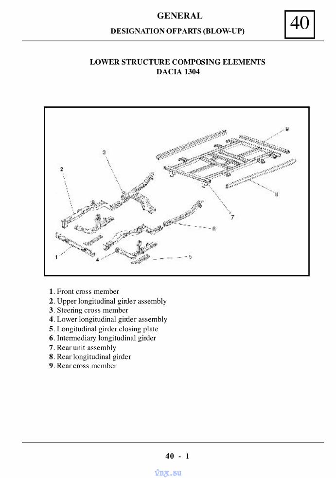
40GENERAL
40 - 1
LOWER STRUCTURE COMPOSING ELEMENTSDACIA 1304
1. Front cross member2. Upper longitudinal girder assembly3. Steering cross member4. Lower longitudinal girder assembly5. Longitudinal girder closing plate6. Intermediary longitudinal girder7. Rear unit assembly8. Rear longitudinal girder9. Rear cross member
DESIGNATION OF PARTS (BLOW-UP)
vnx.su
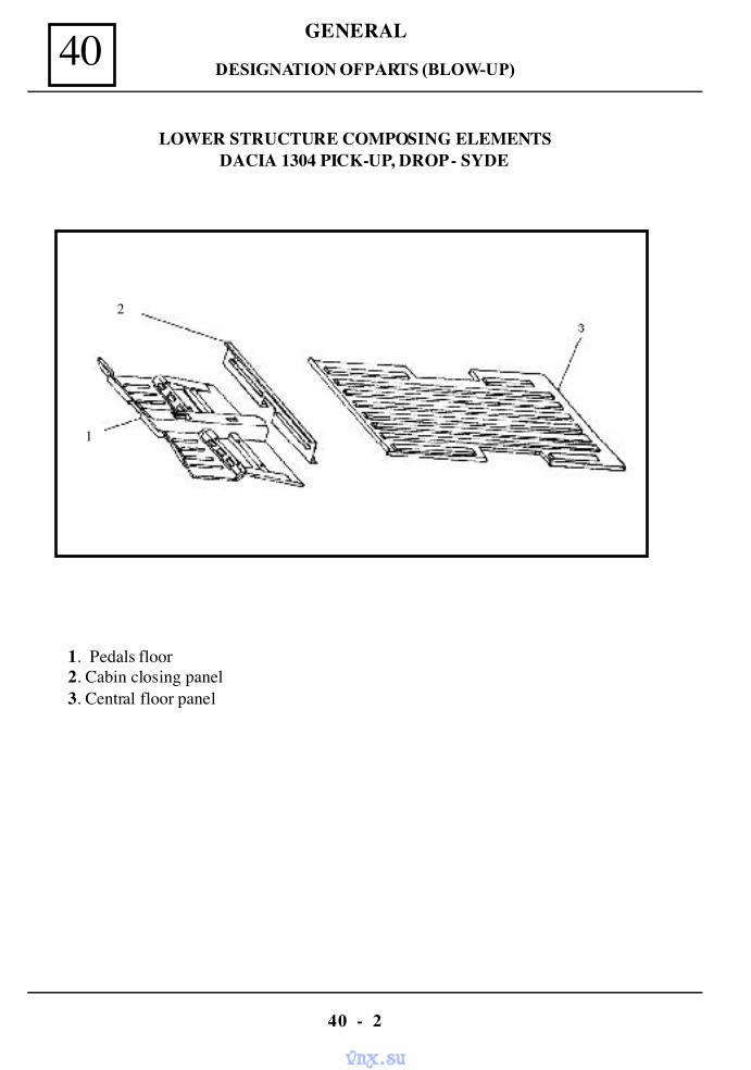
40 GENERAL
40 - 2
1. Pedals floor2. Cabin closing panel3. Central floor panel
LOWER STRUCTURE COMPOSING ELEMENTSDACIA 1304 PICK-UP, DROP - SYDE
2
1
DESIGNATION OF PARTS (BLOW-UP)
vnx.su
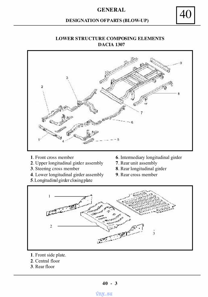
40GENERAL
40 - 3
LOWER STRUCTURE COMPOSING ELEMENTS DACIA 1307
1. Front cross member2. Upper longitudinal girder assembly3. Steering cross member4. Lower longitudinal girder assembly5. Longitudinal girder closing plate
6. Intermediary longitudinal girder7. Rear unit assembly8. Rear longitudinal girder9. Rear cross member
1. Front side plate.2. Central floor3. Rear floor
2
3
1
DESIGNATION OF PARTS (BLOW-UP)
vnx.su
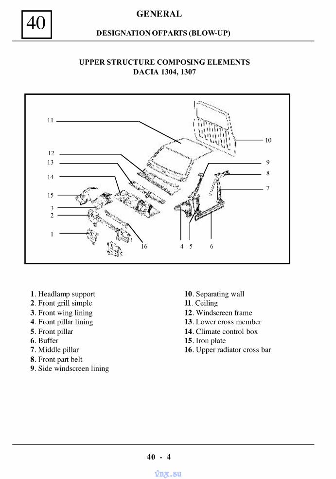
40 GENERAL
40 - 4
UPPER STRUCTURE COMPOSING ELEMENTSDACIA 1304, 1307
1. Headlamp support 10. Separating wall2. Front grill simple 11. Ceiling3. Front wing lining 12. Windscreen frame4. Front pillar lining 13. Lower cross member5. Front pillar 14. Climate control box6. Buffer 15. Iron plate7. Middle pillar 16. Upper radiator cross bar8. Front part belt9. Side windscreen lining
1
23
4 5 6
7
8
9
10
11
1213
14
15
16
DESIGNATION OF PARTS (BLOW-UP)
vnx.su
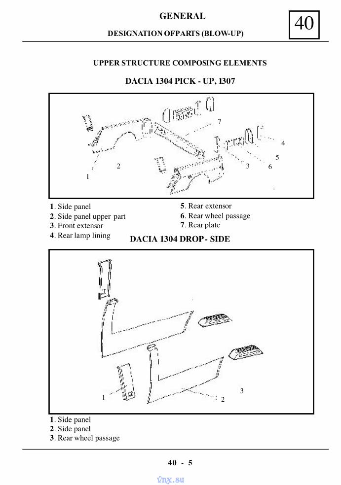
40GENERAL
40 - 5
UPPER STRUCTURE COMPOSING ELEMENTS
1. Side panel2. Side panel upper part3. Front extensor4. Rear lamp lining
1. Side panel2. Side panel3. Rear wheel passage
21
7
3 65
4
1 23
DACIA 1304 PICK - UP, 1307
5. Rear extensor6. Rear wheel passage7. Rear plate
DACIA 1304 DROP - SIDE
DESIGNATION OF PARTS (BLOW-UP)
vnx.su
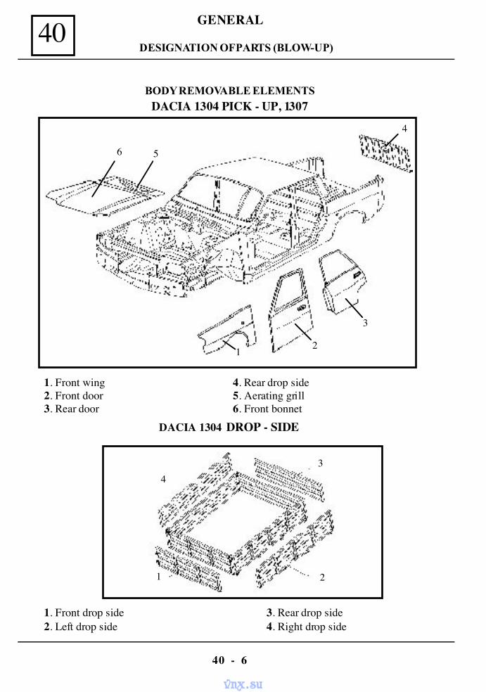
40 GENERAL
40 - 6
BODY REMOVABLE ELEMENTS
1. Front wing 4. Rear drop side2. Front door 5. Aerating grill3. Rear door 6. Front bonnet
DACIA 1304 DROP - SIDE
1. Front drop side 3. Rear drop side2. Left drop side 4. Right drop side
2
34
1
3
21
4
56
DACIA 1304 PICK - UP, 1307
DESIGNATION OF PARTS (BLOW-UP)
vnx.su
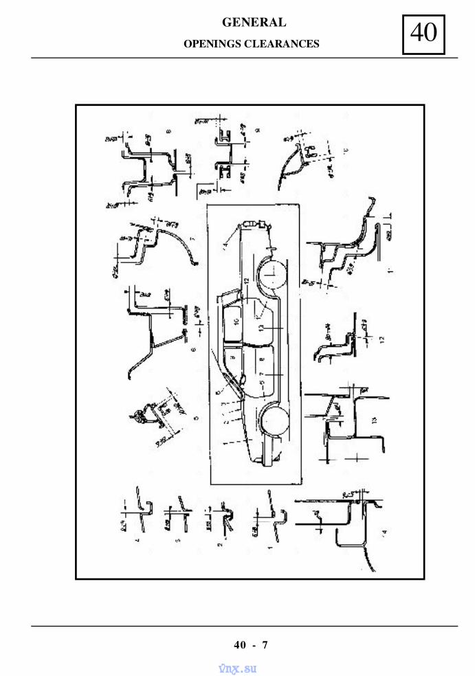
40GENERAL
40 - 7
OPENINGS CLEARANCES
vnx.su
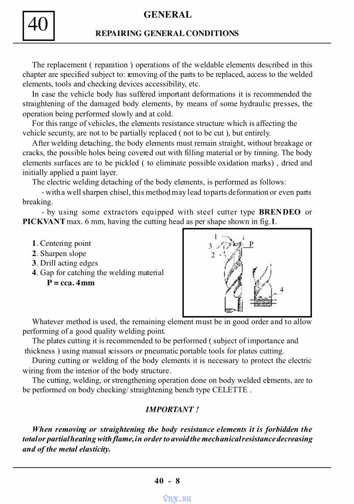
40 GENERAL
40 - 8
REPAIRING GENERAL CONDITIONS
The replacement ( reparation ) operations of the weldable elements described in thischapter are specified subject to: removing of the parts to be replaced, access to the weldedelements, tools and checking devices accessibility, etc.
In case the vehicle body has suffered important deformations it is recommended thestraightening of the damaged body elements, by means of some hydraulic presses, theoperation being performed slowly and at cold.
For this range of vehicles, the elements resistance structure which is affecting thevehicle security, are not to be partially replaced ( not to be cut ), but entirely.
After welding detaching, the body elements must remain straight, without breakage orcracks, the possible holes being covered out with filling material or by tinning. The bodyelements surfaces are to be pickled ( to eliminate possible oxidation marks) , dried andinitially applied a paint layer.
The electric welding detaching of the body elements, is performed as follows:- with a well sharpen chisel, this method may lead to parts deformation or even parts
breaking.- by using some extractors equipped with steel cutter type BRENDEO or
PICKVANT max. 6 mm, having the cutting head as per shape shown in fig.1.
1. Centering point2. Sharpen slope3. Drill acting edges4. Gap for catching the welding material
P = cca. 4 mm
Whatever method is used, the remaining element must be in good order and to allowperforming of a good quality welding point.
The plates cutting it is recommended to be performed ( subject of importance and thickness ) using manual scissors or pneumatic portable tools for plates cutting.
During cutting or welding of the body elements it is necessary to protect the electricwiring from the interior of the body structure.
The cutting, welding, or strengthening operation done on body welded elements, are tobe performed on body checking/ straightening bench type CELETTE .
IMPORTANT !
When removing or straightening the body resistance elements it is forbidden thetotal or partial heating with flame, in order to avoid the mechanical resistance decreasingand of the metal elasticity.
23
1
4
P
vnx.su
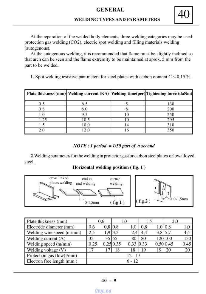
40GENERAL
40 - 9
WELDING TYPES AND PARAMETERS
At the reparation of the welded body elements, three welding categories may be used:protection gas welding (CO2), electric spot welding and filling materials welding(autogenous).
At the autogenous welding, it is recommended that flame must be slightly inclined sothat arch can be seen and the flame extremity to be maintained at aprox. 5 mm from thepart to be welded.
1. Spot welding resistive parameters for steel plates with carbon content C < 0,15 %.
Plate thickness (mm) Welding current (KA) Welding time(per) Tightening force (daNm)
0,5 6,5 5 1300,8 8,0 8 2001,0 9,5 10 2501,25 10,5 10 2951,5 10,0 14 3102,0 12,0 16 350
NOTE : 1 period = 1/50 part of a second
2.Welding parameters for the welding in protector gas for carbon steel plates or lowalloyedsteel.
Horizontal welding position ( fig. 1 )
Plate thickness (mm) 0,6 1,0 1,5 2,0Electrode diameter (mm) 0,6 0,8 0,8 1,0 0,8 1,0 0,8 1,0Welding wire speed (m/min) 2,5 1,9 3,2 2,4 4,4 3,8 5,7 4,4Welding current (A) 35 35 55 80 80 120 100 130Welding speed (m/min) 0,25 0,25 0,35 0,33 0,33 0,50 0,45 0,45Welding voltage (V) 17 17 18 18 19 19 20 20Protection gas flow(l/min) 12 - 17Electron free length (mm ) 6 - 12
( fig.1 ) ( fig.2 )
cross linkedplates welding
end toend welding
cornerwelding
0-1,5mm0-1,5mm
vnx.su
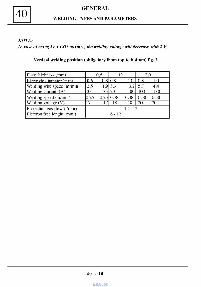
40 GENERAL
40 - 10
NOTE:In case of using Ar + CO2 mixture, the welding voltage will decrease with 2 V.
Vertical welding position (obligatory from top to bottom) fig. 2
Plate thickness (mm) 0,6 12 2,0Electrode diameter (mm) 0,6 0,8 0,8 1,0 0,8 1,0Welding wire speed (m/min) 2,5 1,9 3,3 3,2 5,7 4,4Welding current (A) 35 35 70 100 100 130Welding speed (m/min) 0,25 0,25 0,38 0,48 0,50 0,50Welding voltage (V) 17 17 18 18 20 20Protection gas flow (l/min) 12 - 17Electron free lenght (mm ) 6 - 12
WELDING TYPES AND PARAMETERS
vnx.su
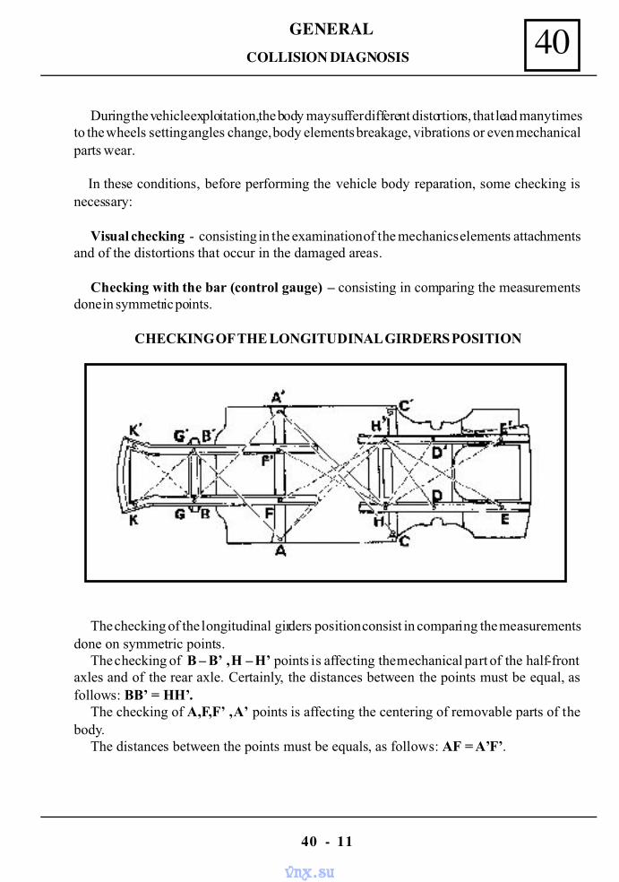
40GENERAL
40 - 11
During the vehicle exploitation, the body may suffer different distortions, that lead many timesto the wheels setting angles change, body elements breakage, vibrations or even mechanicalparts wear.
In these conditions, before performing the vehicle body reparation, some checking isnecessary:
Visual checking - consisting in the examination of the mechanics elements attachmentsand of the distortions that occur in the damaged areas.
Checking with the bar (control gauge) – consisting in comparing the measurementsdone in symmetric points.
CHECKING OF THE LONGITUDINAL GIRDERS POSITION
The checking of the longitudinal girders position consist in comparing the measurementsdone on symmetric points.
The checking of B – B’ , H – H’ points is affecting the mechanical part of the half-frontaxles and of the rear axle. Certainly, the distances between the points must be equal, asfollows: BB’ = HH’.
The checking of A,F,F’ , A’ points is affecting the centering of removable parts of thebody.
The distances between the points must be equals, as follows: AF = A’F’.
COLLISION DIAGNOSIS
vnx.su
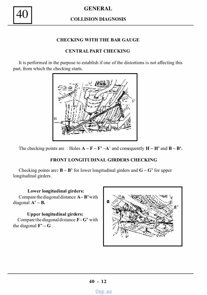
40 GENERAL
40 - 12
COLLISION DIAGNOSIS
CHECKING WITH THE BAR GAUGE
CENTRAL PART CHECKING
It is performed in the purpose to establish if one of the distortions is not affecting thispart, from which the checking starts.
The checking points are : Holes A – F – F’ – A’ and consequently H – H’ and B – B’.
FRONT LONGITUDINAL GIRDERS CHECKING
Checking points are: B – B’ for lower longitudinal girders and G – G’ for upperlongitudinal girders.
Lower longitudinal girders:Compare the diagonal distance A – B’ with
diagonal A’ – B.
Upper longitudinal girders:Compare the diagonal distance F – G’ with
the diagonal F’ – G .
H
F’
vnx.su
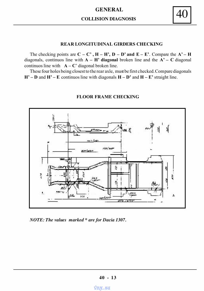
40GENERAL
40 - 13
COLLISION DIAGNOSIS
REAR LONGITUDINAL GIRDERS CHECKING
The checking points are C – C’ , H – H’, D – D’ and E – E’. Compare the A’ – Hdiagonals, continuos line with A – H’ diagonal broken line and the A’ – C diagonalcontinuos line with A – C’ diagonal broken line.
These four holes being closest to the rear axle, must be first checked. Compare diagonalsH’ – D and H’ – E continuos line with diagonals H – D’ and H – E’ straight line.
FLOOR FRAME CHECKING
NOTE: The values marked * are for Dacia 1307.
vnx.su
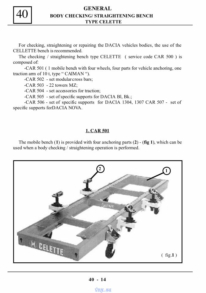
40 GENERAL
40 - 14
BODY CHECKING/ STRAIGHTENING BENCHTYPE CELETTE
For checking, straightening or repairing the DACIA vehicles bodies, the use of theCELLETTE bench is recommended.
The checking / straightening bench type CELETTE ( service code CAR 500 ) iscomposed of:
-CAR 501 ( 1 mobile bench with four wheels, four parts for vehicle anchoring, onetraction arm of 10 t, type “ CAIMAN “).
-CAR 502 - set modular cross bars;-CAR 503 - 22 towers MZ;-CAR 504 - set accessories for traction;-CAR 505 - set of specific supports for DACIA Bl, Bk.;-CAR 506 - set of specific supports for DACIA 1304, 1307 CAR 507 - set of
specific supports forDACIA NOVA.
1. CAR 501
The mobile bench (1) is provided with four anchoring parts (2) - (fig 1), which can beused when a body checking / straightening operation is performed.
12
( fig.1 )
vnx.su
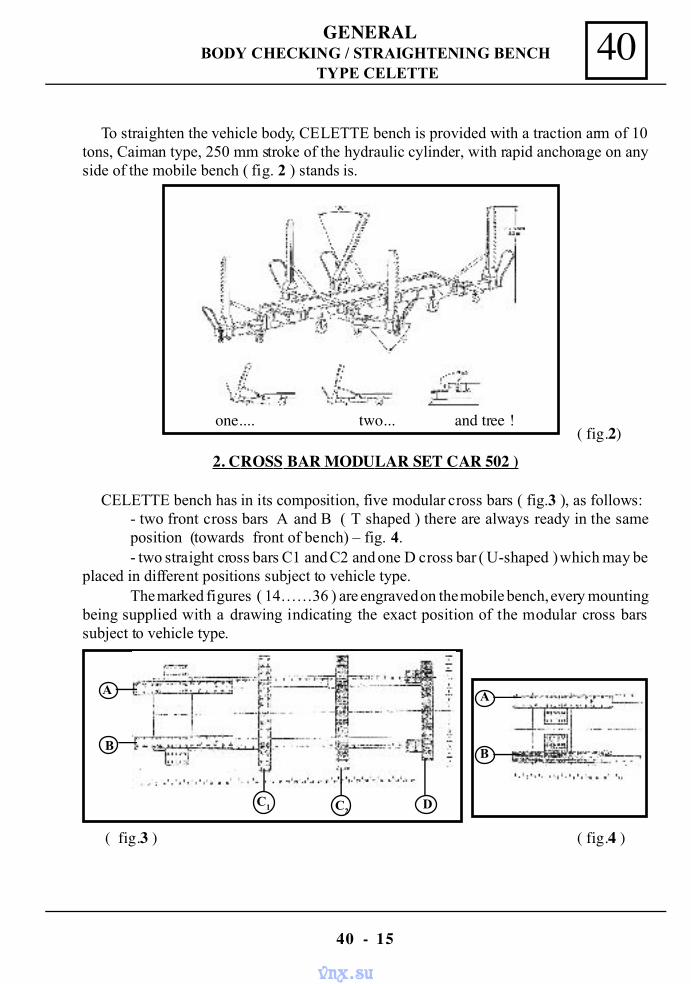
40GENERAL
40 - 15
BODY CHECKING / STRAIGHTENING BENCHTYPE CELETTE
To straighten the vehicle body, CELETTE bench is provided with a traction arm of 10tons, Caiman type, 250 mm stroke of the hydraulic cylinder, with rapid anchorage on anyside of the mobile bench ( fig. 2 ) stands is.
2. CROSS BAR MODULAR SET CAR 502 )
CELETTE bench has in its composition, five modular cross bars ( fig.3 ), as follows:- two front cross bars A and B ( T shaped ) there are always ready in the sameposition (towards front of bench) – fig. 4.- two straight cross bars C1 and C2 and one D cross bar ( U-shaped ) which may be
placed in different positions subject to vehicle type.The marked figures ( 14……36 ) are engraved on the mobile bench, every mounting
being supplied with a drawing indicating the exact position of the modular cross barssubject to vehicle type.
( fig.3 ) ( fig.4 )
( fig.2)one.... two... and tree !
A
B
C2C1 D
A
B
vnx.su
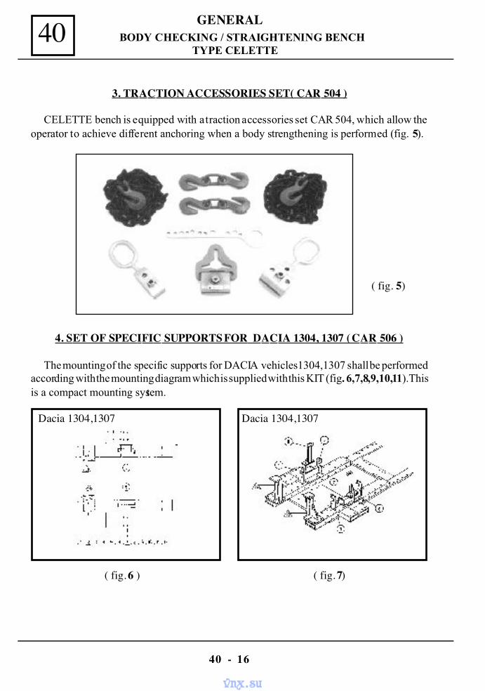
40 GENERAL
40 - 16
BODY CHECKING / STRAIGHTENING BENCHTYPE CELETTE
3. TRACTION ACCESSORIES SET( CAR 504 )
CELETTE bench is equipped with a traction accessories set CAR 504, which allow theoperator to achieve different anchoring when a body strengthening is performed (fig. 5).
4. SET OF SPECIFIC SUPPORTS FOR DACIA 1304, 1307 ( CAR 506 )
The mounting of the specific supports for DACIA vehicles 1304,1307 shall be performedaccording with the mounting diagram which is supplied with this KIT (fig. 6,7,8,9,10,11).Thisis a compact mounting system.
( fig. 6 ) ( fig. 7)
Dacia 1304,1307 Dacia 1304,1307
( fig. 5)
vnx.su
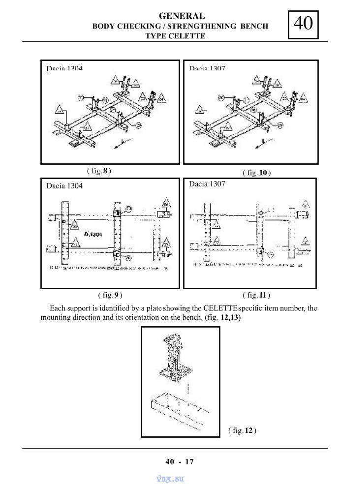
40GENERAL
40 - 17
BODY CHECKING / STRENGTHENING BENCHTYPE CELETTE
( fig. 8 ) ( fig. 10 )
Dacia 1304 Dacia 1307
Dacia 1304 Dacia 1307
( fig. 9 ) ( fig. 11 )Each support is identified by a plate showing the CELETTE specific item number, the
mounting direction and its orientation on the bench. (fig. 12,13)
( fig. 12 )
vnx.su
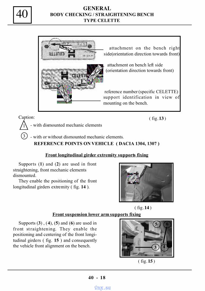
40 GENERAL
40 - 18
BODY CHECKING / STRAIGHTENING BENCHTYPE CELETTE
( fig. 13 )Caption:
3 - with or without dismounted mechanic elements.
- with dismounted mechanic elements1
REFERENCE POINTS ON VEHICLE ( DACIA 1304, 1307 )
Front longitudinal girder extremity supports fixing
Supports (1) and (2) are used in frontstraightening, front mechanic elementsdismounted.
They enable the positioning of the frontlongitudinal girders extremity ( fig. 14 ).
( fig. 14 )
( fig. 15 )
Front suspension lower arm supports fixing
Supports (3) , (4), (5) and (6) are used infront st raightening. They enable thepositioning and centering of the front longi-tudinal girders ( fig. 15 ) and consequentlythe vehicle front alignment on the bench.
attachment on the bench rightside(orientation direction towards front)
attachment on bench left side (orientation direction towards front)
reference number (specific CELETTE)support identification in view ofmounting on the bench.
4
5 6
3
vnx.su
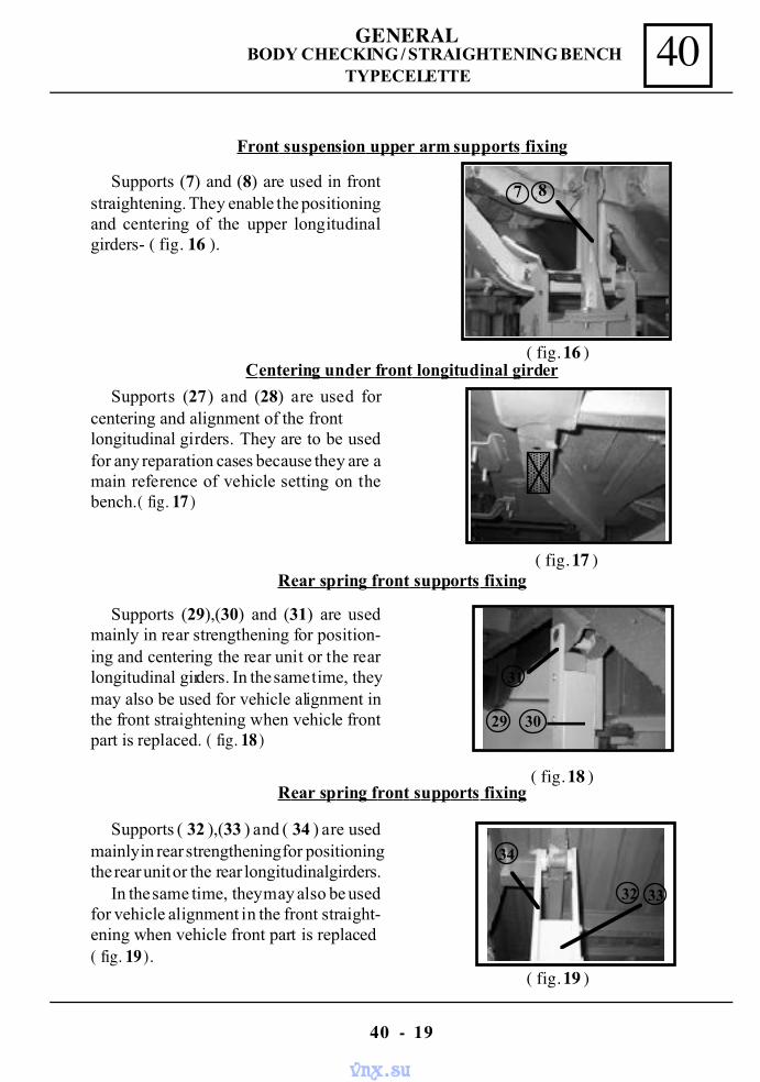
40GENERAL
40 - 19
BODY CHECKING / STRAIGHTENING BENCHTYPE CELETTE
Supports (7) and (8) are used in frontstraightening. They enable the positioningand centering of the upper longitudinalgirders- ( fig. 16 ).
( fig. 16 )
Front suspension upper arm supports fixing
Supports (27) and (28) are used forcentering and alignment of the frontlongitudinal girders. They are to be usedfor any reparation cases because they are amain reference of vehicle setting on thebench.( fig. 17 )
( fig. 17 )
Centering under front longitudinal girder
Supports (29),(30) and (31) are usedmainly in rear strengthening for position-ing and centering the rear unit or the rearlongitudinal girders. In the same time, theymay also be used for vehicle alignment inthe front straightening when vehicle frontpart is replaced. ( fig. 18 )
( fig. 19 )
Rear spring front supports fixing
Supports ( 32 ),(33 ) and ( 34 ) are usedmainly in rear strengthening for positioningthe rear unit or the rear longitudinal girders.
In the same time, they may also be usedfor vehicle alignment in the front straight-ening when vehicle front part is replaced( fig. 19 ).
( fig. 18 )Rear spring front supports fixing
31
29 30
7 8
34
32 33
vnx.su
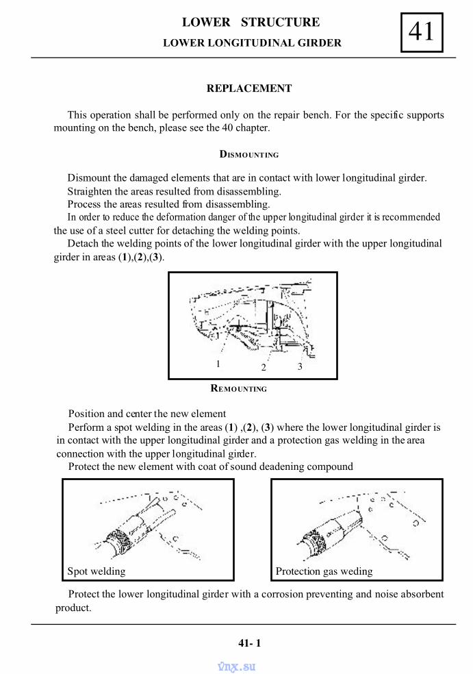
41LOWER STRUCTURE
REPLACEMENT
This operation shall be performed only on the repair bench. For the specific supportsmounting on the bench, please see the 40 chapter.
DISMOUNTING
Dismount the damaged elements that are in contact with lower longitudinal girder.Straighten the areas resulted from disassembling.Process the areas resulted from disassembling.In order to reduce the deformation danger of the upper longitudinal girder it is recommended
the use of a steel cutter for detaching the welding points.Detach the welding points of the lower longitudinal girder with the upper longitudinal
girder in areas (1),(2),(3).
REMOUNTING
Position and center the new elementPerform a spot welding in the areas (1) ,(2), (3) where the lower longitudinal girder is
in contact with the upper longitudinal girder and a protection gas welding in the areaconnection with the upper longitudinal girder.
Protect the new element with coat of sound deadening compound
Protect the lower longitudinal girder with a corrosion preventing and noise absorbentproduct.
LOWER LONGITUDINAL GIRDER
41- 1
1 2 3
Spot welding Protection gas weding
vnx.su
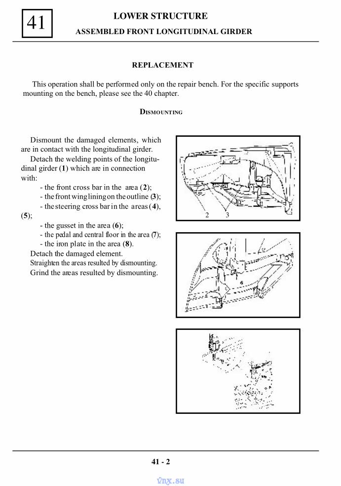
LOWER STRUCTURE41 ASSEMBLED FRONT LONGITUDINAL GIRDER
REPLACEMENT
This operation shall be performed only on the repair bench. For the specific supportsmounting on the bench, please see the 40 chapter.
Dismount the damaged elements, whichare in contact with the longitudinal girder.
Detach the welding points of the longitu-dinal girder (1) which are in connectionwith:
- the front cross bar in the area (2);- the front wing lining on the outline (3);- the steering cross bar in the areas (4),
(5);- the gusset in the area (6);- the pedal and central floor in the area (7);- the iron plate in the area (8).
Detach the damaged element.Straighten the areas resulted by dismounting.Grind the areas resulted by dismounting.
41 - 2
DISMOUNTING
2 3
vnx.su
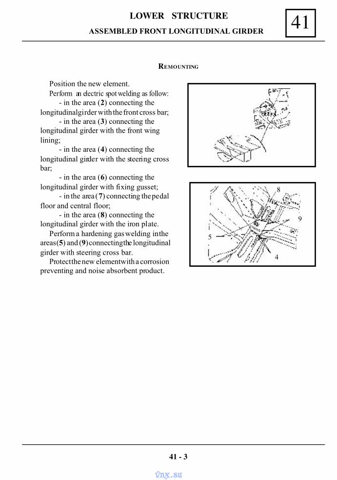
41LOWER STRUCTURE ASSEMBLED FRONT LONGITUDINAL GIRDER
Position the new element.Perform an electric spot welding as follow:
- in the area (2) connecting thelongitudinal girder with the front cross bar;
- in the area (3) connecting thelongitudinal girder with the front winglining;
- in the area (4) connecting thelongitudinal girder with the steering crossbar;
- in the area (6) connecting thelongitudinal girder with fixing gusset;
- in the area (7) connecting the pedalfloor and central floor;
- in the area (8) connecting thelongitudinal girder with the iron plate.
Perform a hardening gas welding in theareas (5) and (9) connecting the longitudinalgirder with steering cross bar.
Protect the new element with a corrosionpreventing and noise absorbent product.
41 - 3
REMOUNTING
4
5
9
8
vnx.su
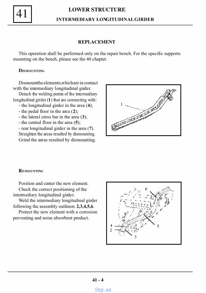
LOWER STRUCTURE41 INTERMEDIARY LONGITUDINAL GIRDER
REPLACEMENT
This operation shall be performed only on the repair bench. For the specific supportsmounting on the bench, please see the 40 chapter.
DISMOUNTING
Dismount the elements, which are in contactwith the intermediary longitudinal girder.
Detach the welding points of the intermediarylongitudinal girder (1) that are connecting with:
- the longitudinal girder in the area (4);- the pedal floor in the area (2);- the lateral cross bar in the area (3);- the central floor in the area (5);- rear longitudinal girder in the area (7).Straighten the areas resulted by dismounting.Grind the areas resulted by dismounting.
Position and center the new element.Check the correct positioning of the
intermediary longitudinal girder.Weld the intermediary longitudinal girder
following the assembly outliners 2,3,4,5,6.Protect the new element with a corrosion
preventing and noise absorbent product.
REMOUNTING
41 - 4
1
5
6
42
3
vnx.su
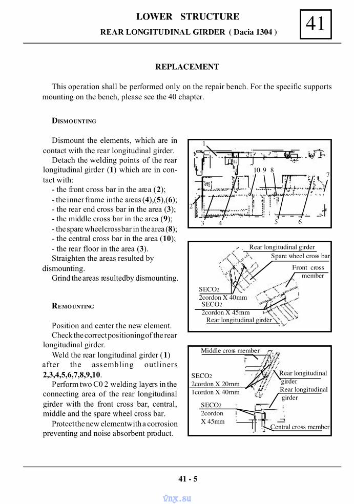
41LOWER STRUCTURE REAR LONGITUDINAL GIRDER ( Dacia 1304 )
REPLACEMENT
This operation shall be performed only on the repair bench. For the specific supportsmounting on the bench, please see the 40 chapter.
DISMOUNTING
Dismount the elements, which are incontact with the rear longitudinal girder.
Detach the welding points of the rearlongitudinal girder (1) which are in con-tact with:
- the front cross bar in the area (2);- the inner frame in the areas (4),(5),(6);- the rear end cross bar in the area (3);- the middle cross bar in the area (9);- the spare wheel cross bar in the area (8);- the central cross bar in the area (10);- the rear floor in the area (3).Straighten the areas resulted by
dismounting.Grind the areas resulted by dismounting.
REMOUNTING
Position and center the new element.Check the correct positioning of the rear
longitudinal girder.Weld the rear longitudinal girder (1)
after the assembling outliners2,3,4,5,6,7,8,9,10.
Perform two C0 2 welding layers in theconnecting area of the rear longitudinalgirder with the front cross bar, central,middle and the spare wheel cross bar.
Protect the new element with a corrosionpreventing and noise absorbent product.
41 - 5
Rear longitudinal girderSpare wheel cross bar
Front crossmember
Rear longitudinal girder
SECO22cordon X 40mmSECO22cordon X 45mm
Middle cross member
SECO22cordon X 20mm1cordon X 40mm
SECO22cordonX 45mm
Central cross member
1
2
3 4 5 6
7910 8
Rear longitudinal girderRear longitudinal girder
vnx.su
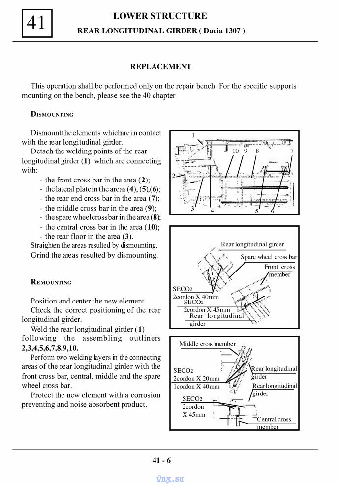
LOWER STRUCTURE41 REAR LONGITUDINAL GIRDER ( Dacia 1307 )
REPLACEMENT
This operation shall be performed only on the repair bench. For the specific supportsmounting on the bench, please see the 40 chapter
DISMOUNTING
Dismount the elements which are in contactwith the rear longitudinal girder.
Detach the welding points of the rearlongitudinal girder (1) which are connectingwith:
- the front cross bar in the area (2);- the lateral plate in the areas (4), (5),(6);- the rear end cross bar in the area (7);- the middle cross bar in the area (9);- the spare wheel cross bar in the area (8);- the central cross bar in the area (10);- the rear floor in the area (3).
Straighten the areas resulted by dismounting.Grind the areas resulted by dismounting.
REMOUNTING
Position and center the new element.Check the correct positioning of the rear
longitudinal girder.Weld the rear longitudinal girder (1)
following the assembling outliners2,3,4,5,6,7,8,9,10.
Perform two welding layers in the connectingareas of the rear longitudinal girder with thefront cross bar, central, middle and the sparewheel cross bar.
Protect the new element with a corrosionpreventing and noise absorbent product.
41 - 6
Middle cross member
Rear longitudinalgirderRear longitudinalgirder
SECO22cordon X 20mm1cordon X 40mm
SECO22cordonX 45mm
Central crossmember
Rear longitudinal girder
Spare wheel cross bar Front cross
member
Rear longitudinalgirder
SECO22cordon X 40mm
SECO22cordon X 45mm
1
2
3 4
10 9 8 7
65
vnx.su
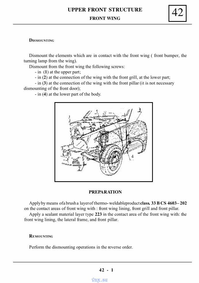
42UPPER FRONT STRUCTURE
42 - 1
DISMOUNTING
FRONT WING
Dismount the elements which are in contact with the front wing ( front bumper, theturning lamp from the wing).
Dismount from the front wing the following screws:- in (1) at the upper part;- in (2) at the connection of the wing with the front grill, at the lower part;- in (3) at the connection of the wing with the front pillar (it is not necessary
dismounting of the front door);- in (4) at the lower part of the body.
PREPARATION
Apply by means of a brush a layer of thermo- weldable product class. 33 B CS 4603 – 202on the contact areas of front wing with : front wing lining, front grill and front pillar.
Apply a sealant material layer type 223 in the contact area of the front wing with: thefront wing lining, the lateral frame, and front pillar.
REMOUNTING
Perform the dismounting operations in the reverse order.
4
vnx.su
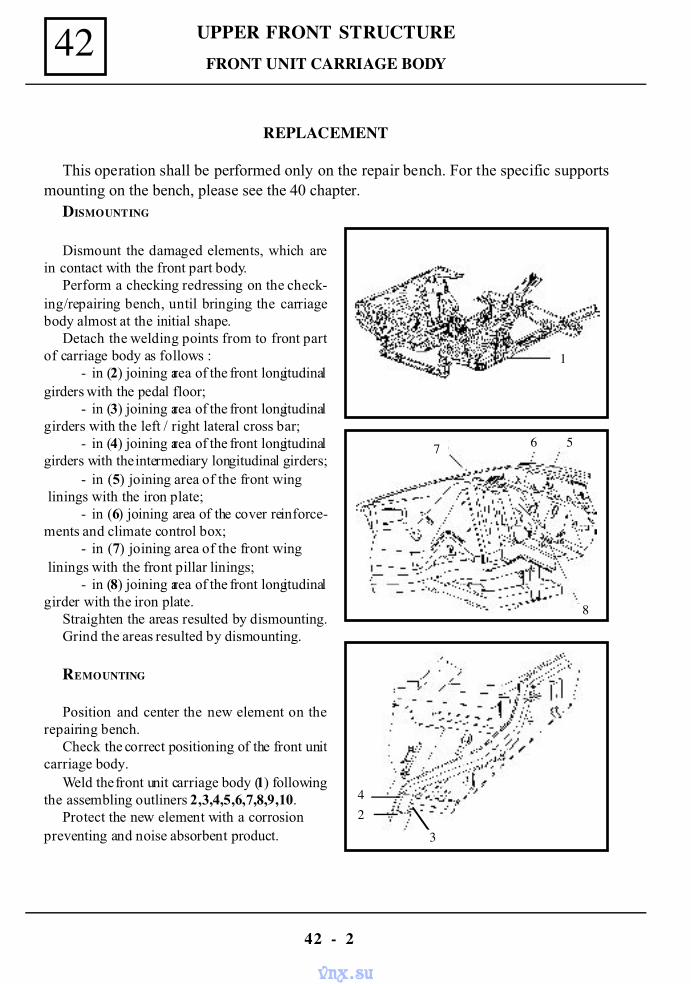
UPPER FRONT STRUCTURE42
42 - 2
FRONT UNIT CARRIAGE BODY
REPLACEMENT
This operation shall be performed only on the repair bench. For the specific supportsmounting on the bench, please see the 40 chapter.
DISMOUNTING
Dismount the damaged elements, which arein contact with the front part body.
Perform a checking redressing on the check-ing/repairing bench, until bringing the carriagebody almost at the initial shape.
Detach the welding points from to front partof carriage body as follows :
- in (2) joining area of the front longitudinalgirders with the pedal floor;
- in (3) joining area of the front longitudinalgirders with the left / right lateral cross bar;
- in (4) joining area of the front longitudinalgirders with the intermediary longitudinal girders;
- in (5) joining area of the front wing linings with the iron plate;
- in (6) joining area of the cover reinforce-ments and climate control box;
- in (7) joining area of the front wing linings with the front pillar linings;
- in (8) joining area of the front longitudinalgirder with the iron plate.
Straighten the areas resulted by dismounting.Grind the areas resulted by dismounting.
REMOUNTING
Position and center the new element on therepairing bench.
Check the correct positioning of the front unitcarriage body.
Weld the front unit carriage body (1) followingthe assembling outliners 2,3,4,5,6,7,8,9,10.
Protect the new element with a corrosionpreventing and noise absorbent product.
1
7 6 5
8
42
3
vnx.su
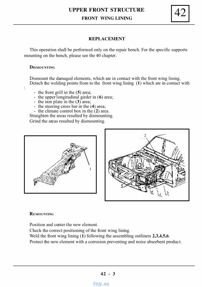
42UPPER FRONT STRUCTURE
42 - 3
FRONT WING LINING
REPLACEMENT
This operation shall be performed only on the repair bench. For the specific supportsmounting on the bench, please see the 40 chapter.
DISMOUNTING
Dismount the damaged elements, which are in contact with the front wing lining.Detach the welding points from to the front wing lining (1) which are in contact with
:- the front grill in the (5) area;- the upper longitudinal girder in (6) area;- the iron plate in the (3) area;- the steering cross bar in the (4) area;- the climate control box in the (2) area.
Straighten the areas resulted by dismounting.Grind the areas resulted by dismounting.
REMOUNTING
Position and center the new element.Check the correct positioning of the front wing lining.Weld the front wing lining (1) following the assembling outliners 2,3,4,5,6.Protect the new element with a corrosion preventing and noise absorbent product.
1
22
vnx.su
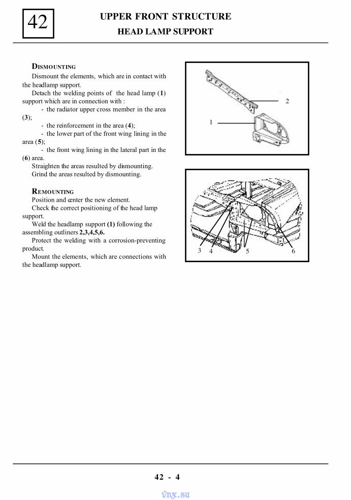
UPPER FRONT STRUCTURE42
42 - 4
HEAD LAMP SUPPORT
DISMOUNTING
Dismount the elements, which are in contact withthe headlamp support.
Detach the welding points of the head lamp (1)support which are in connection with :
- the radiator upper cross member in the area(3);
- the reinforcement in the area (4);- the lower part of the front wing lining in the
area (5);- the front wing lining in the lateral part in the
(6) area.Straighten the areas resulted by dismounting.Grind the areas resulted by dismounting.
REMOUNTINGPosition and center the new element.Check the correct positioning of the head lamp
support.Weld the headlamp support (1) following the
assembling outliners 2,3,4,5,6.Protect the welding with a corrosion-preventing
product.Mount the elements, which are connections with
the headlamp support.
1
2
3 4 5 6
vnx.su
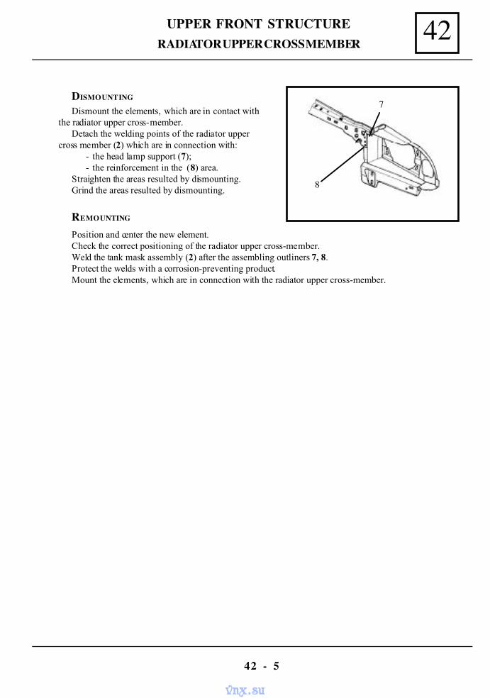
42UPPER FRONT STRUCTURE
42 - 5
RADIATOR UPPER CROSS MEMBER
DISMOUNTING
Dismount the elements, which are in contact withthe radiator upper cross-member.
Detach the welding points of the radiator uppercross member (2) which are in connection with:
- the head lamp support (7);- the reinforcement in the (8) area.
Straighten the areas resulted by dismounting.Grind the areas resulted by dismounting.
REMOUNTING
Position and center the new element.Check the correct positioning of the radiator upper cross-member.Weld the tank mask assembly (2) after the assembling outliners 7, 8.Protect the welds with a corrosion-preventing product.Mount the elements, which are in connection with the radiator upper cross-member.
7
8
vnx.su
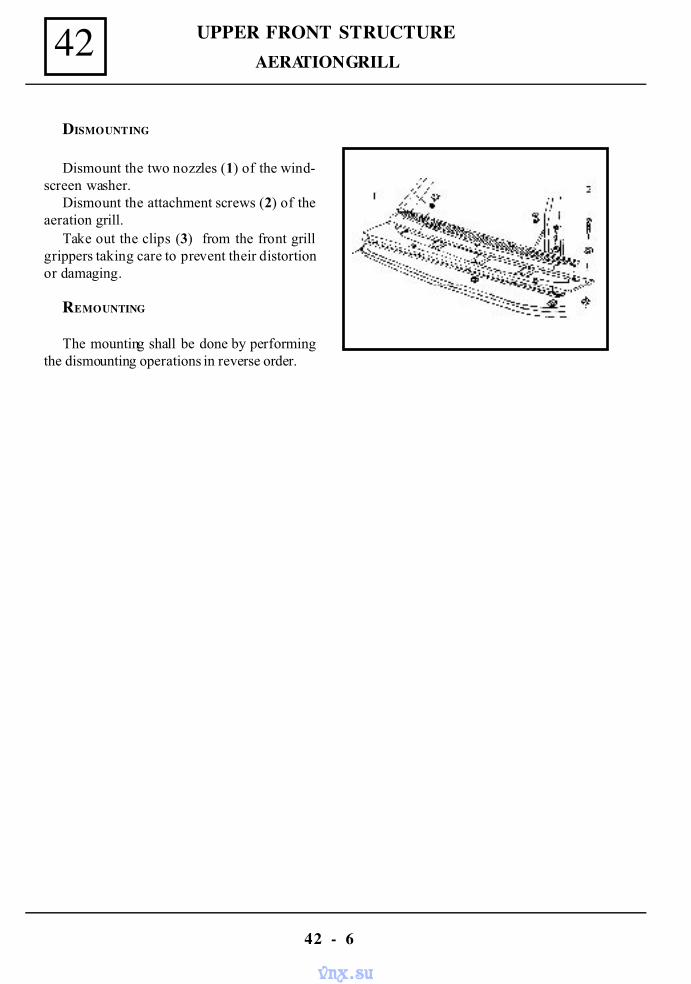
UPPER FRONT STRUCTURE42
42 - 6
AERATION GRILL
DISMOUNTING
Dismount the two nozzles (1) of the wind-screen washer.
Dismount the attachment screws (2) of theaeration grill.
Take out the clips (3) from the front grillgrippers taking care to prevent their distortionor damaging.
REMOUNTING
The mounting shall be done by performingthe dismounting operations in reverse order.
vnx.su
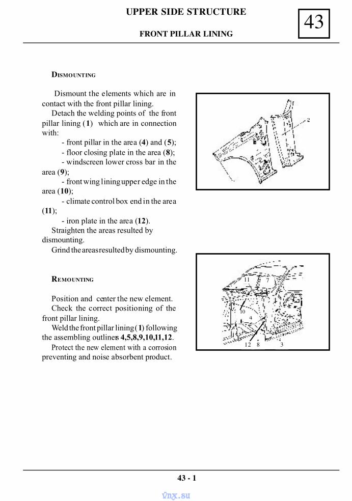
DISMOUNTING
Dismount the elements which are incontact with the front pillar lining.
Detach the welding points of the frontpillar lining (1) which are in connectionwith:
- front pillar in the area (4) and (5);- floor closing plate in the area (8);- windscreen lower cross bar in the
area (9);- front wing lining upper edge in the
area (10);- climate control box end in the area
(11);- iron plate in the area (12).
Straighten the areas resulted bydismounting.
Grind the areas resulted by dismounting.
REMOUNTING
Position and center the new element.Check the correct positioning of the
front pillar lining.Weld the front pillar lining (1) following
the assembling outliners 4,5,8,9,10,11,12.Protect the new element with a corrosion
preventing and noise absorbent product.
43 - 1
43UPPER SIDE STRUCTURE
FRONT PILLAR LINING
711
10
8 3
4
12
vnx.su
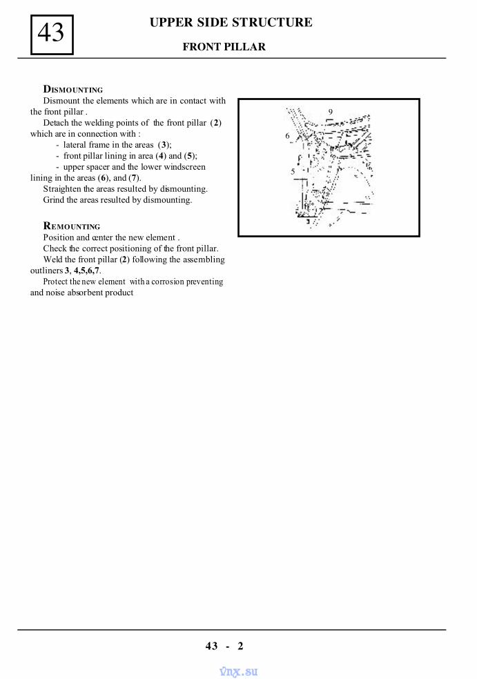
UPPER SIDE STRUCTURE43
43 - 2
FRONT PILLAR
DISMOUNTINGDismount the elements which are in contact with
the front pillar .Detach the welding points of the front pillar (2)
which are in connection with :- lateral frame in the areas (3);- front pillar lining in area (4) and (5);- upper spacer and the lower windscreen
lining in the areas (6), and (7).Straighten the areas resulted by dismounting.Grind the areas resulted by dismounting.
REMOUNTINGPosition and center the new element .Check the correct positioning of the front pillar.Weld the front pillar (2) following the assembling
outliners 3, 4,5,6,7.Protect the new element with a corrosion preventing
and noise absorbent product
9
6
5
vnx.su
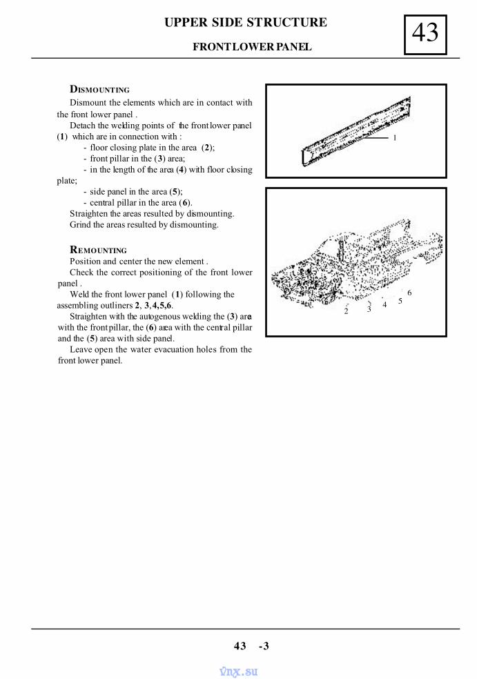
43UPPER SIDE STRUCTURE
43 -3
FRONT LOWER PANEL
DISMOUNTING
Dismount the elements which are in contact withthe front lower panel .
Detach the welding points of the front lower panel(1) which are in connection with :
- floor closing plate in the area (2);- front pillar in the (3) area;- in the length of the area (4) with floor closing
plate;- side panel in the area (5);- central pillar in the area (6).
Straighten the areas resulted by dismounting.Grind the areas resulted by dismounting.
REMOUNTINGPosition and center the new element .Check the correct positioning of the front lower
panel .Weld the front lower panel (1) following the
assembling outliners 2, 3, 4,5,6.Straighten with the autogenous welding the (3) area
with the front pillar, the (6) area with the central pillarand the (5) area with side panel.
Leave open the water evacuation holes from thefront lower panel.
1
2 3 4 56
vnx.su
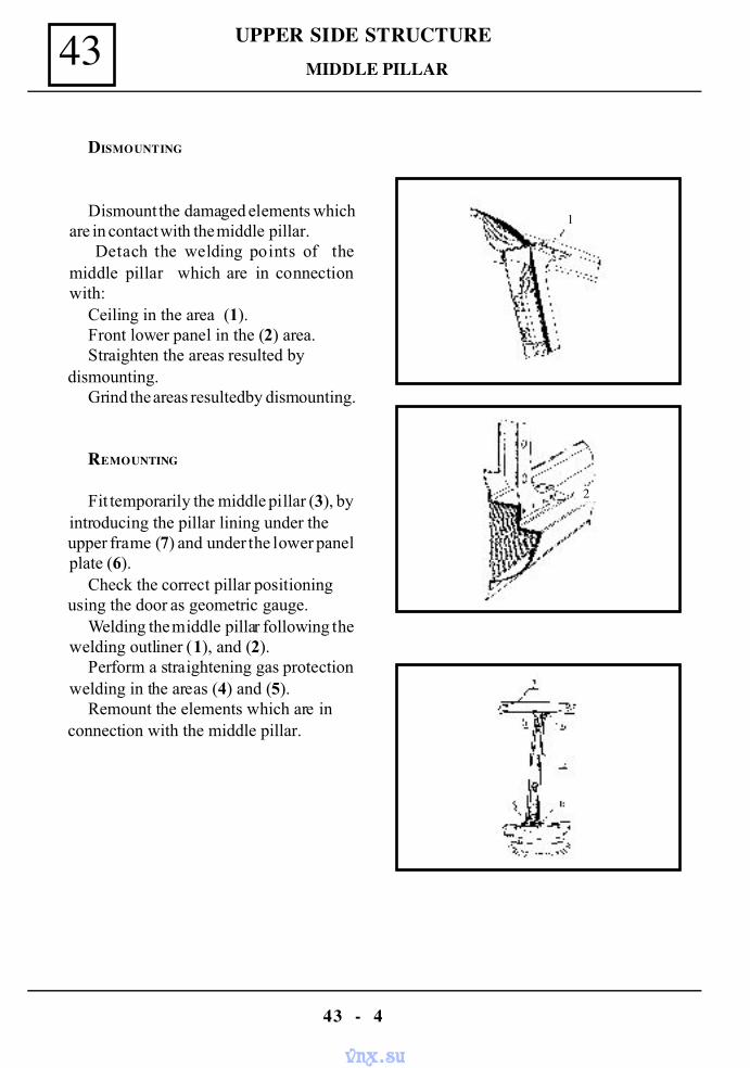
UPPER SIDE STRUCTURE43
43 - 4
MIDDLE PILLAR
DISMOUNTING
Dismount the damaged elements whichare in contact with the middle pillar.
Detach the welding points of themiddle pillar which are in connectionwith:
Ceiling in the area (1).Front lower panel in the (2) area.Straighten the areas resulted by
dismounting.Grind the areas resulted by dismounting.
REMOUNTING
Fit temporarily the middle pillar (3), byintroducing the pillar lining under theupper frame (7) and under the lower panelplate (6).
Check the correct pillar positioningusing the door as geometric gauge.
Welding the middle pillar following thewelding outliner (1), and (2).
Perform a straightening gas protectionwelding in the areas (4) and (5).
Remount the elements which are inconnection with the middle pillar.
1
2
vnx.su
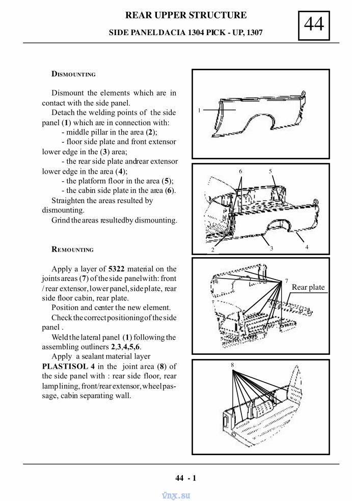
44REAR UPPER STRUCTURE
DISMOUNTING
Dismount the elements which are incontact with the side panel.
Detach the welding points of the sidepanel (1) which are in connection with:
- middle pillar in the area (2);- floor side plate and front extensor
lower edge in the (3) area;- the rear side plate and rear extensor
lower edge in the area (4);- the platform floor in the area (5);- the cabin side plate in the area (6).
Straighten the areas resulted bydismounting.
Grind the areas resulted by dismounting.
REMOUNTING
Apply a layer of 5322 material on thejoints areas (7) of the side panel with: front/ rear extensor, lower panel, side plate, rearside floor cabin, rear plate.
Position and center the new element.Check the correct positioning of the side
panel .Weld the lateral panel (1) following the
assembling outliners 2,3,4,5,6.Apply a sealant material layer
PLASTISOL 4 in the joint area (8) ofthe side panel with : rear side floor, rearlamp lining, front/rear extensor, wheel pas-sage, cabin separating wall.
SIDE PANEL DACIA 1304 PICK - UP, 1307
44 - 1
1
6 5
2 3 4
7 Rear plate
8
vnx.su
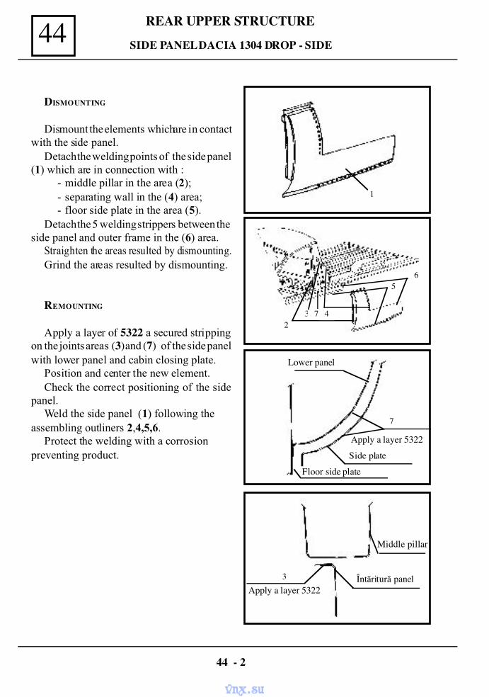
REAR UPPER STRUCTURE44
DISMOUNTING
Dismount the elements which are in contactwith the side panel.
Detach the welding points of the side panel(1) which are in connection with :
- middle pillar in the area (2);- separating wall in the (4) area;- floor side plate in the area (5).
Detach the 5 welding strippers between theside panel and outer frame in the (6) area.
Straighten the areas resulted by dismounting.Grind the areas resulted by dismounting.
REMOUNTING
Apply a layer of 5322 a secured strippingon the joints areas (3) and (7) of the side panelwith lower panel and cabin closing plate.
Position and center the new element.Check the correct positioning of the side
panel.Weld the side panel (1) following the
assembling outliners 2,4,5,6.Protect the welding with a corrosion
preventing product.
SIDE PANEL DACIA 1304 DROP - SIDE
44 - 2
1
23 7 4
5 6
Lower panel
7
Side plate
Floor side plate
3 Întãriturã panel
Middle pillar
Apply a layer 5322
Apply a layer 5322
vnx.su
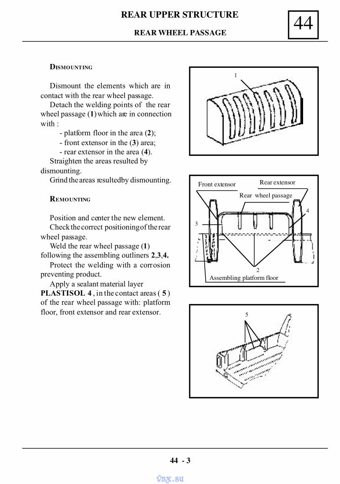
44REAR UPPER STRUCTURE
DISMOUNTING
Dismount the elements which are incontact with the rear wheel passage.
Detach the welding points of the rearwheel passage (1) which are in connectionwith :
- platform floor in the area (2);- front extensor in the (3) area;- rear extensor in the area (4).
Straighten the areas resulted bydismounting.
Grind the areas resulted by dismounting.
REMOUNTING
Position and center the new element.Check the correct positioning of the rear
wheel passage.Weld the rear wheel passage (1)
following the assembling outliners 2,3,4.Protect the welding with a corrosion
preventing product.Apply a sealant material layer
PLASTISOL 4 , in the contact areas ( 5 )of the rear wheel passage with: platformfloor, front extensor and rear extensor.
REAR WHEEL PASSAGE
44 - 3
5
1
4
3
2
Rear wheel passage
Front extensor Rear extensor
Assembling platform floor
vnx.su
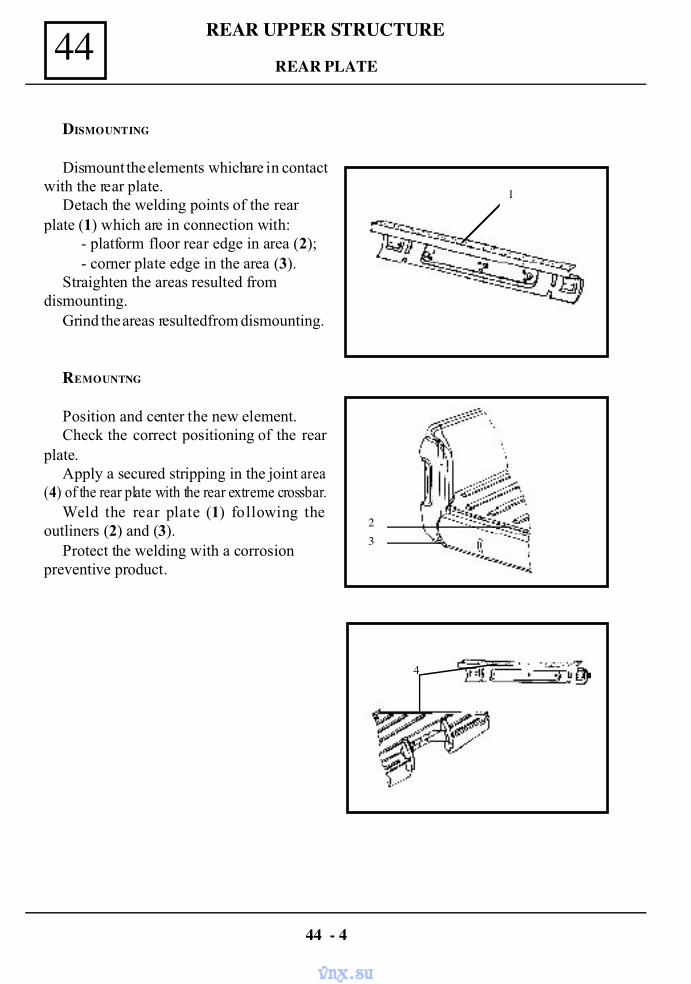
REAR UPPER STRUCTURE44
DISMOUNTING
Dismount the elements which are in contactwith the rear plate.
Detach the welding points of the rearplate (1) which are in connection with:
- platform floor rear edge in area (2);- corner plate edge in the area (3).
Straighten the areas resulted fromdismounting.
Grind the areas resulted from dismounting.
REMOUNTNG
Position and center the new element.Check the correct positioning of the rear
plate.Apply a secured stripping in the joint area
(4) of the rear plate with the rear extreme crossbar.Weld the rear plate (1) following the
outliners (2) and (3).Protect the welding with a corrosion
preventive product.
REAR PLATE
44 - 4
1
23
4
vnx.su
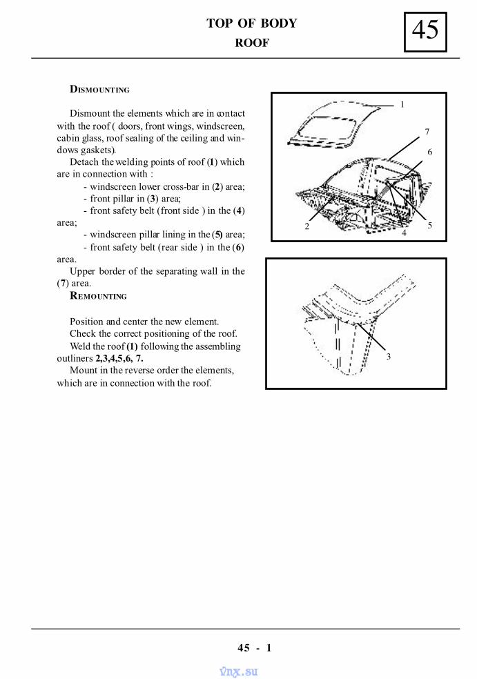
45TOP OF BODY
45 - 1
ROOF
DISMOUNTING
Dismount the elements which are in contactwith the roof ( doors, front wings, windscreen,cabin glass, roof sealing of the ceiling and win-dows gaskets).
Detach the welding points of roof (1) whichare in connection with :
- windscreen lower cross-bar in (2) area;- front pillar in (3) area;- front safety belt (front side ) in the (4)
area;- windscreen pillar lining in the (5) area;- front safety belt (rear side ) in the (6)
area.Upper border of the separating wall in the
(7) area.REMOUNTING
Position and center the new element.Check the correct positioning of the roof.Weld the roof (1) following the assembling
outliners 2,3,4,5,6, 7.Mount in the reverse order the elements,
which are in connection with the roof.
3
1
7
6
54
2
vnx.su
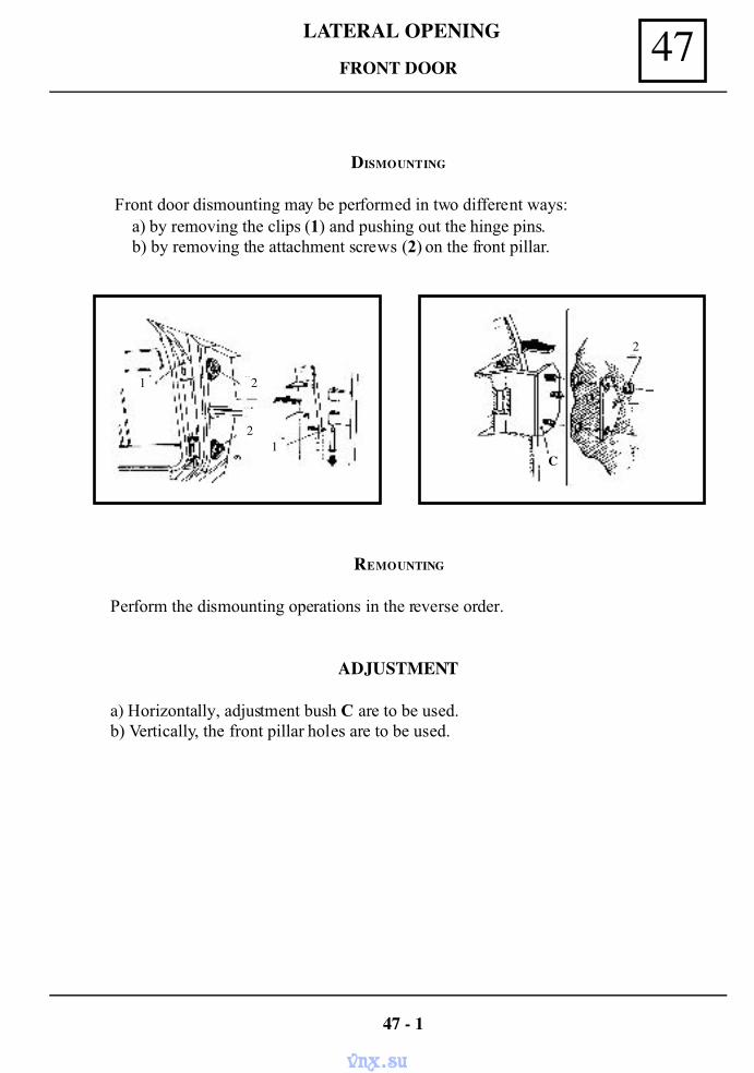
FRONT DOOR
DISMOUNTING
Front door dismounting may be performed in two different ways:a) by removing the clips (1) and pushing out the hinge pins.b) by removing the attachment screws (2) on the front pillar.
47 - 1
REMOUNTING
Perform the dismounting operations in the reverse order.
ADJUSTMENT
a) Horizontally, adjustment bush C are to be used.b) Vertically, the front pillar holes are to be used.
1
2
2
1
2
C
LATERAL OPENING 47
vnx.su
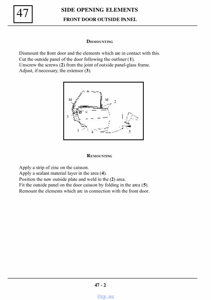
SIDE OPENING ELEMENTS47
DISMOUNTING
Dismount the front door and the elements which are in contact with this.Cut the outside panel of the door following the outliner (1).Unscrew the screws (2) from the joint of outside panel-glass frame.Adjust, if necessary, the extensor (3).
FRONT DOOR OUTSIDE PANEL
REMOUNTING
Apply a strip of zinc on the caisson.Apply a sealant material layer in the area (4).Position the new outside plate and weld in the (2) area.Fit the outside panel on the door caisson by folding in the area (5).Remount the elements which are in connection with the front door.
47 - 2
2
541
3
M M
vnx.su
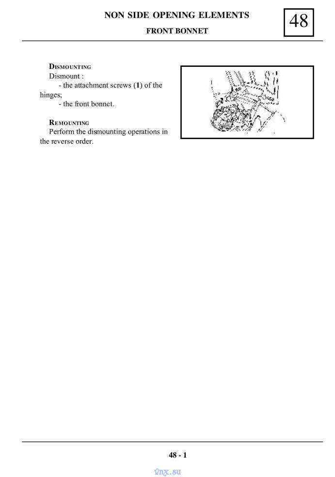
48NON SIDE OPENING ELEMENTS
DISMOUNTING
Dismount :- the attachment screws (1) of the
hinges;- the front bonnet.
REMOUNTING
Perform the dismounting operations inthe reverse order.
FRONT BONNET
48 - 1
1
vnx.su
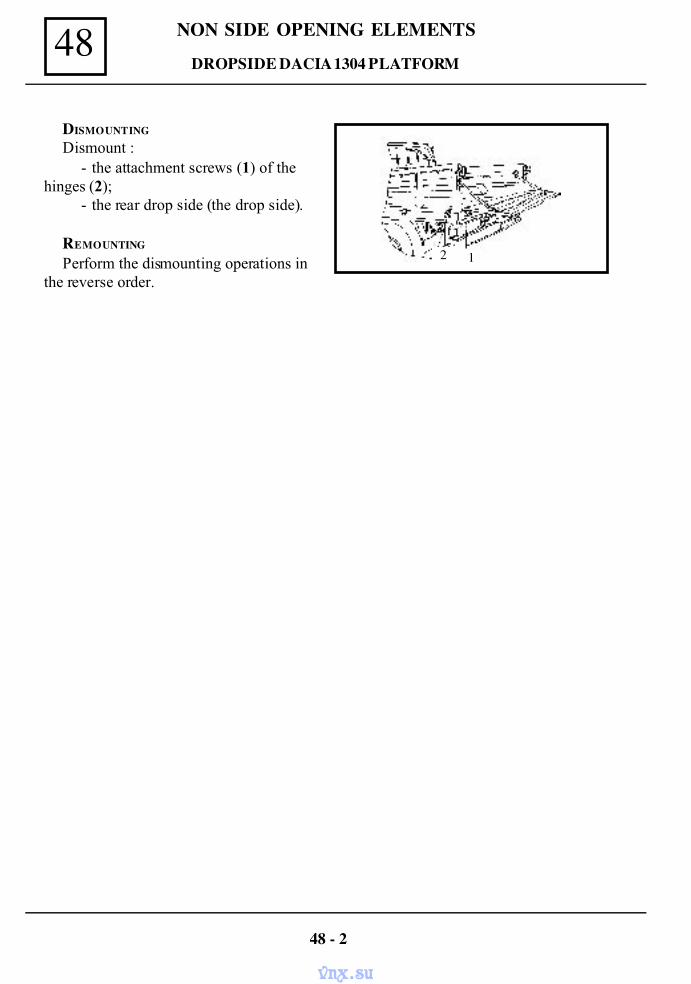
NON SIDE OPENING ELEMENTS48
DISMOUNTING
Dismount :- the attachment screws (1) of the
hinges (2);- the rear drop side (the drop side).
REMOUNTING
Perform the dismounting operations inthe reverse order.
DROP SIDE DACIA 1304 PLATFORM
48 - 2
12
vnx.su
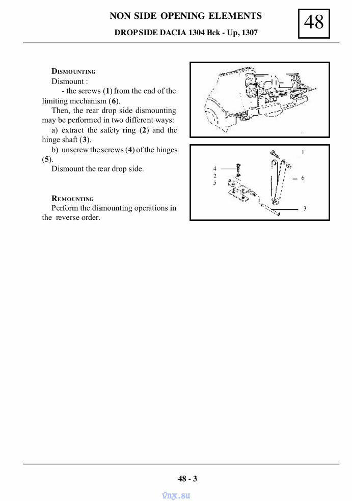
48NON SIDE OPENING ELEMENTS
DISMOUNTING
Dismount :- the screws (1) from the end of the
limiting mechanism (6).Then, the rear drop side dismounting
may be performed in two different ways:a) extract the safety ring (2) and the
hinge shaft (3).b) unscrew the screws (4) of the hinges
(5).Dismount the rear drop side.
REMOUNTING
Perform the dismounting operations inthe reverse order.
DROP SIDE DACIA 1304 Pick - Up, 1307
48 - 3
1
6
3
425
vnx.su
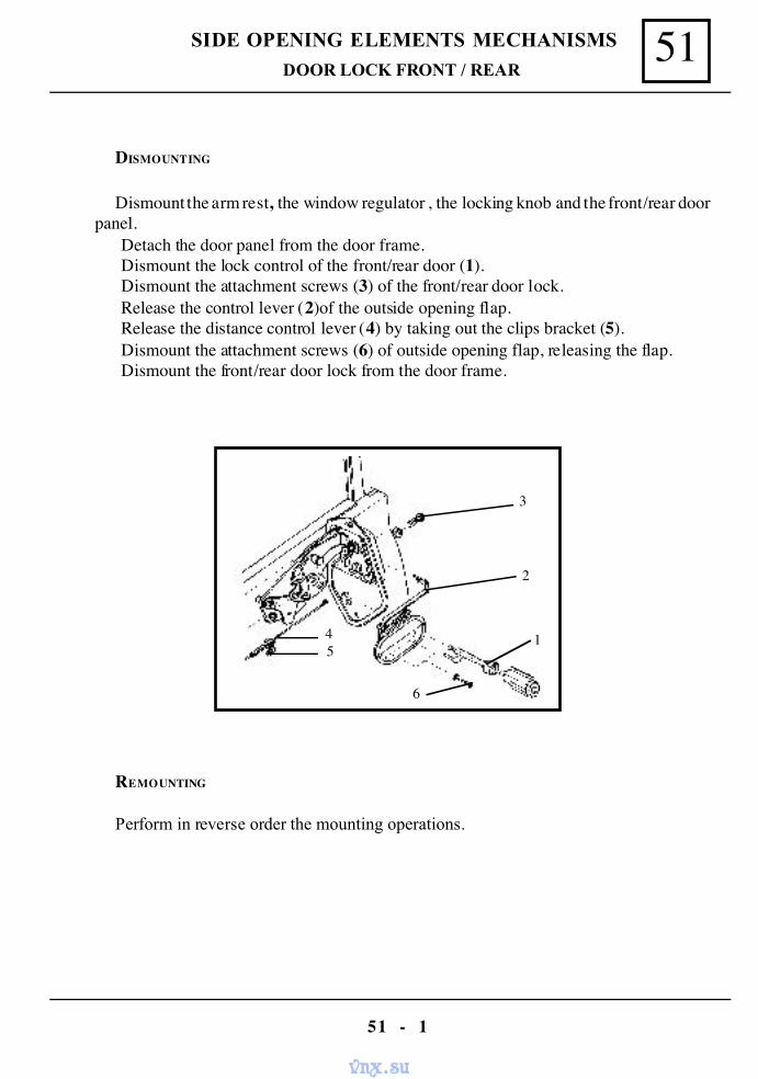
51SIDE OPENING ELEMENTS MECHANISMS
51 - 1
DISMOUNTING
Dismount the arm rest, the window regulator , the locking knob and the front/rear doorpanel.
Detach the door panel from the door frame.Dismount the lock control of the front/rear door (1).Dismount the attachment screws (3) of the front/rear door lock.Release the control lever (2)of the outside opening flap.Release the distance control lever (4) by taking out the clips bracket (5).Dismount the attachment screws (6) of outside opening flap, releasing the flap.Dismount the front/rear door lock from the door frame.
REMOUNTING
Perform in reverse order the mounting operations.
DOOR LOCK FRONT / REAR
1
2
3
6
45
vnx.su
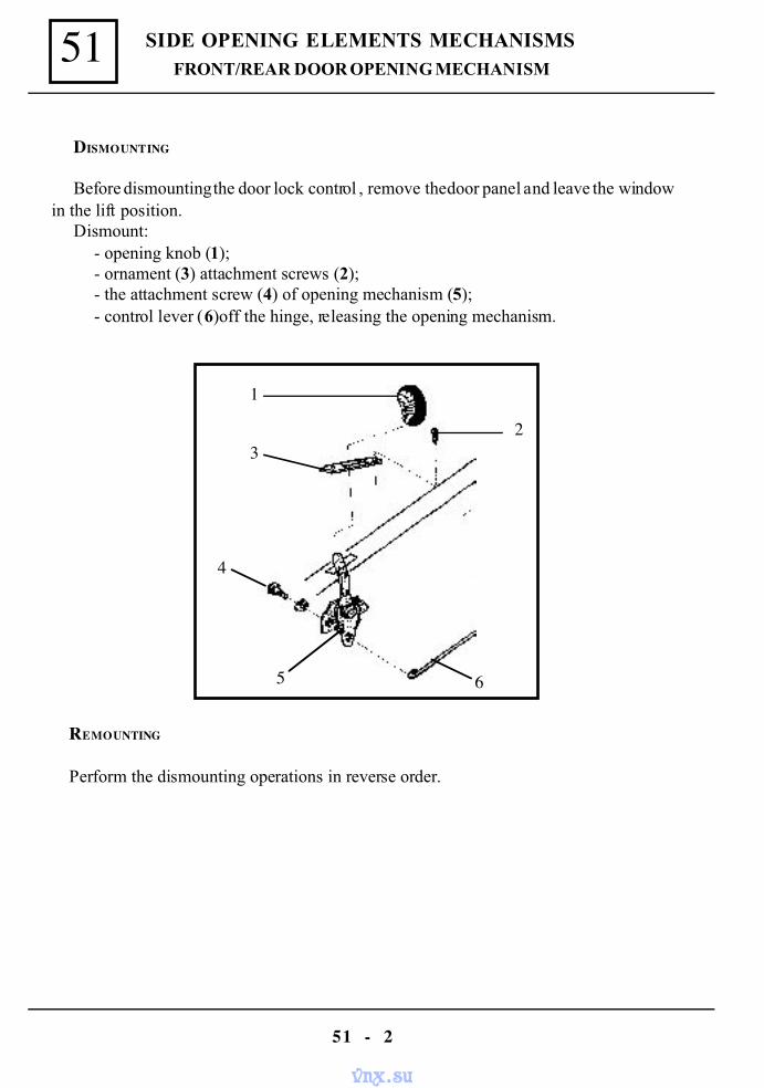
SIDE OPENING ELEMENTS MECHANISMS51
51 - 2
FRONT/REAR DOOR OPENING MECHANISM
DISMOUNTING
Before dismounting the door lock control , remove the door panel and leave the windowin the lift position.
Dismount:- opening knob (1);- ornament (3) attachment screws (2);- the attachment screw (4) of opening mechanism (5);- control lever (6)off the hinge, releasing the opening mechanism.
REMOUNTING
Perform the dismounting operations in reverse order.
1
3
4
2
5 6
vnx.su
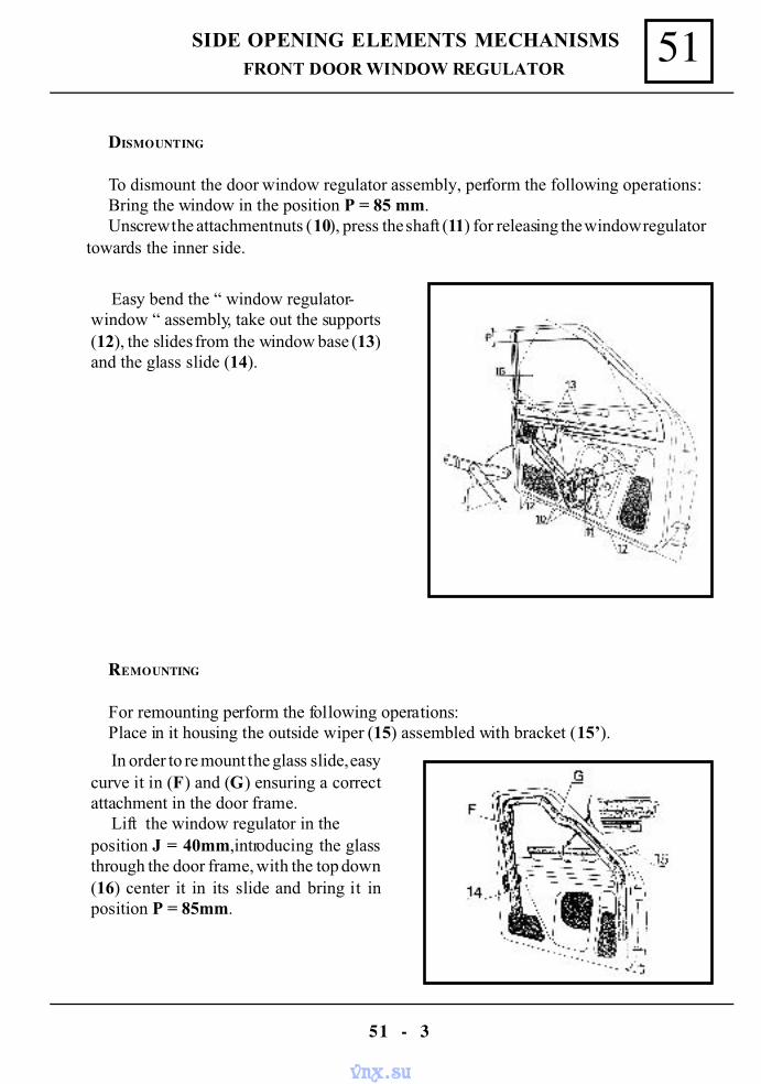
51SIDE OPENING ELEMENTS MECHANISMS
51 - 3
DISMOUNTING
To dismount the door window regulator assembly, perform the following operations:Bring the window in the position P = 85 mm.Unscrew the attachment nuts (10), press the shaft (11) for releasing the window regulator
towards the inner side.
REMOUNTING
For remounting perform the following operations:Place in it housing the outside wiper (15) assembled with bracket (15’).
Easy bend the “ window regulator-window “ assembly, take out the supports(12), the slides from the window base (13)and the glass slide (14).
In order to re mount the glass slide, easycurve it in (F) and (G) ensuring a correctattachment in the door frame.
Lift the window regulator in theposition J = 40mm,introducing the glassthrough the door frame, with the top down(16) center it in its slide and bring it inposition P = 85mm.
FRONT DOOR WINDOW REGULATOR
vnx.su
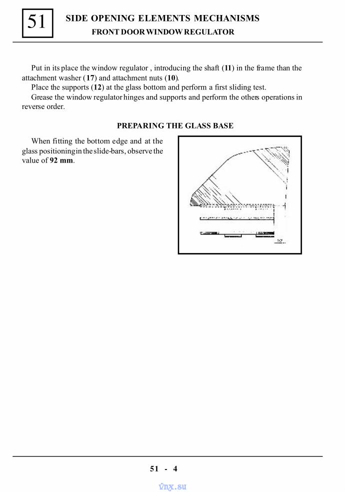
SIDE OPENING ELEMENTS MECHANISMS51
51 - 4
Put in its place the window regulator , introducing the shaft (11) in the frame than theattachment washer (17) and attachment nuts (10).
Place the supports (12) at the glass bottom and perform a first sliding test.Grease the window regulator hinges and supports and perform the others operations in
reverse order.
PREPARING THE GLASS BASE
When fitting the bottom edge and at theglass positioning in the slide-bars, observe thevalue of 92 mm.
FRONT DOOR WINDOW REGULATOR
vnx.su
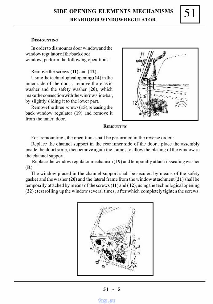
51SIDE OPENING ELEMENTS MECHANISMS
51 - 5
In order to dismount a door window and thewindow regulator of the back doorwindow, perform the following operations:
Remove the screws (11) and (12).Using the technological opening (14) in the
inner side of the door , remove the elasticwasher and the safety washer (20), whichmake the connection with the window slide-bar,by slightly sliding it to the lower part.
Remove the three screws (15),releasing theback window regulator (19) and remove itfrom the inner door.
DISMOUNTING
REAR DOOR WINDOW REGULATOR
REMOUNTING
For remounting , the operations shall be performed in the reverse order :Replace the channel support in the rear inner side of the door , place the assembly
inside the door frame, then remove again the frame , to allow the placing of the window inthe channel support.
Replace the window regulator mechanism (19) and temporally attach its sealing washer(R).
The window placed in the channel support shall be secured by means of the safetygasket and the washer (20) and the lateral frame from the window attachment (21) shall betemporally attached by means of the screws (11) and (12), using the technological opening(22) ; test rolling up the window several times , after which completely tighten the screws.
vnx.su
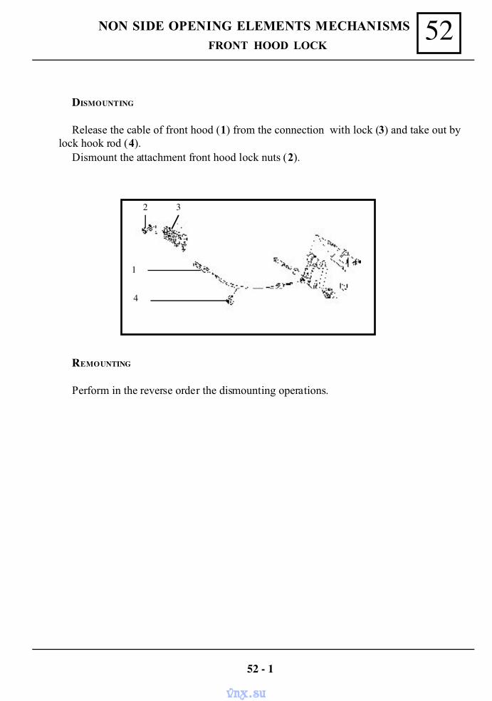
52NON SIDE OPENING ELEMENTS MECHANISMS
DISMOUNTING
Release the cable of front hood (1) from the connection with lock (3) and take out bylock hook rod (4).
Dismount the attachment front hood lock nuts (2).
REMOUNTING
Perform in the reverse order the dismounting operations.
FRONT HOOD LOCK
52 - 1
32
1
4
vnx.su
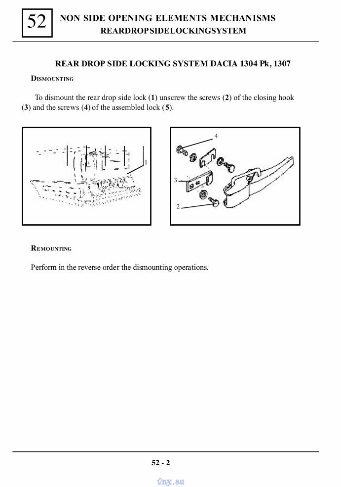
NON SIDE OPENING ELEMENTS MECHANISMS52
DISMOUNTING
To dismount the rear drop side lock (1) unscrew the screws (2) of the closing hook(3) and the screws (4) of the assembled lock (5).
52 - 2
REAR DROP SIDE LOCKING SYSTEM DACIA 1304 Pk, 1307
REMOUNTING
Perform in the reverse order the dismounting operations.
1
4
3
2
REAR DROP SIDE LOCKING SYSTEM
vnx.su
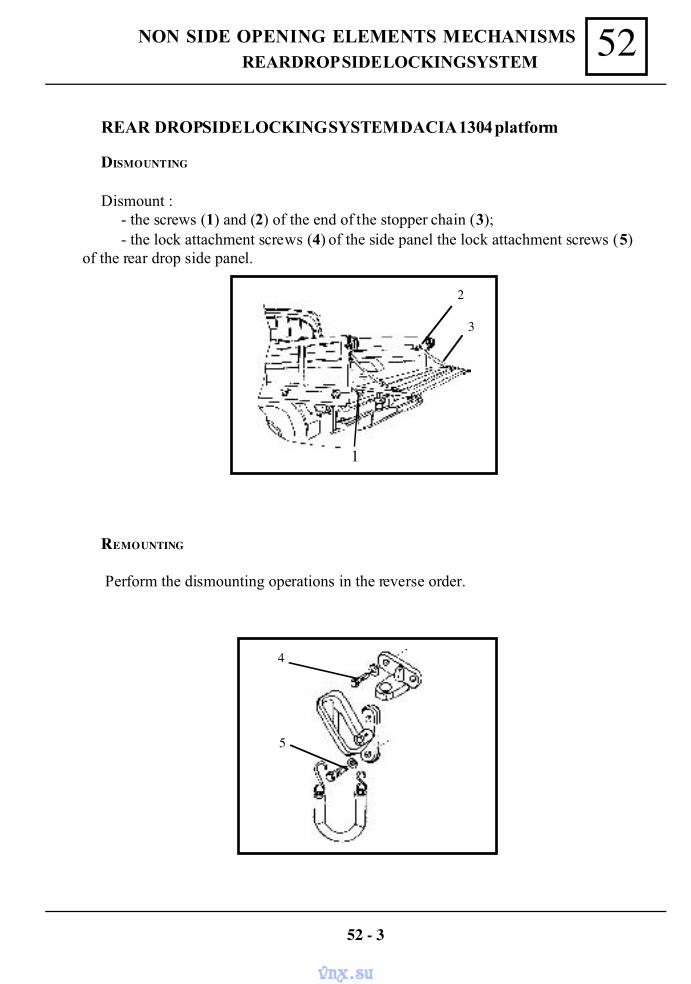
52NON SIDE OPENING ELEMENTS MECHANISMS
REMOUNTING
Perform the dismounting operations in the reverse order.
52 - 3
DISMOUNTING
Dismount :- the screws (1) and (2) of the end of the stopper chain (3);- the lock attachment screws (4) of the side panel the lock attachment screws (5)
of the rear drop side panel.
REAR DROP SIDE LOCKING SYSTEM DACIA 1304 platform
5
4
1
2
3
REAR DROP SIDE LOCKING SYSTEM
vnx.su
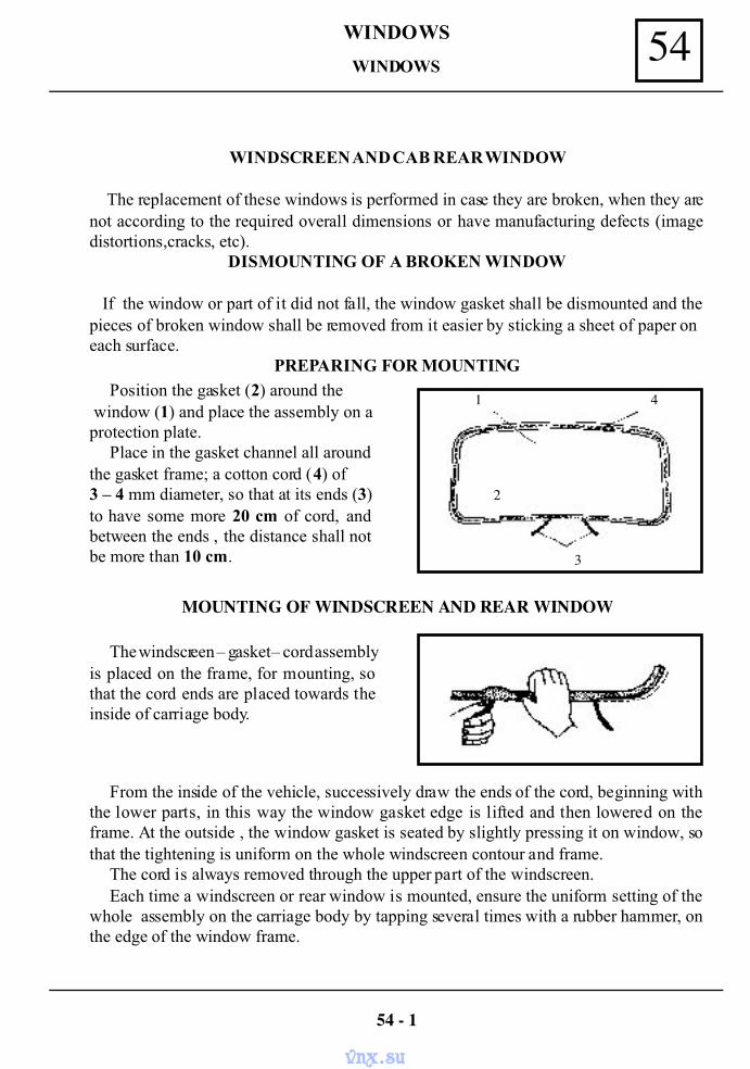
54WINDOWS
WINDSCREEN AND CAB REAR WINDOW
The replacement of these windows is performed in case they are broken, when they arenot according to the required overall dimensions or have manufacturing defects (imagedistortions,cracks, etc).
DISMOUNTING OF A BROKEN WINDOW
If the window or part of it did not fall, the window gasket shall be dismounted and thepieces of broken window shall be removed from it easier by sticking a sheet of paper oneach surface.
PREPARING FOR MOUNTINGPosition the gasket (2) around the
window (1) and place the assembly on aprotection plate.
Place in the gasket channel all aroundthe gasket frame; a cotton cord (4) of3 – 4 mm diameter, so that at its ends (3)to have some more 20 cm of cord, andbetween the ends , the distance shall notbe more than 10 cm.
MOUNTING OF WINDSCREEN AND REAR WINDOW
The windscreen – gasket – cord assemblyis placed on the frame, for mounting, sothat the cord ends are placed towards theinside of carriage body.
54 - 1
From the inside of the vehicle, successively draw the ends of the cord, beginning withthe lower parts, in this way the window gasket edge is lifted and then lowered on theframe. At the outside , the window gasket is seated by slightly pressing it on window, sothat the tightening is uniform on the whole windscreen contour and frame.
The cord is always removed through the upper part of the windscreen.Each time a windscreen or rear window is mounted, ensure the uniform setting of the
whole assembly on the carriage body by tapping several times with a rubber hammer, onthe edge of the window frame.
1 4
3
2
WINDOWS
vnx.su
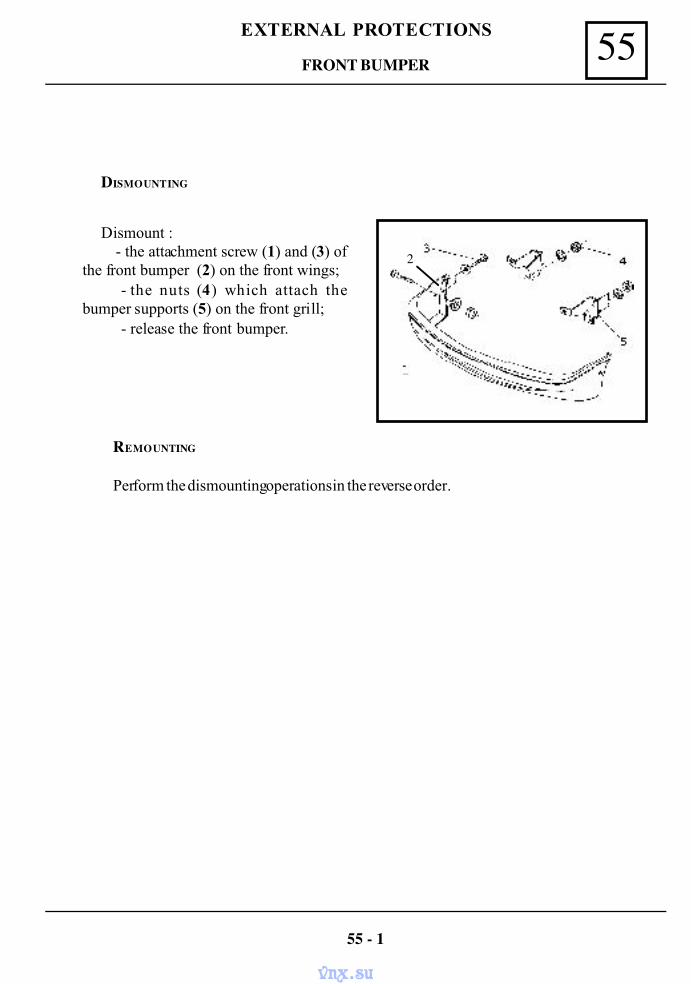
55EXTERNAL PROTECTIONS
DISMOUNTING
Dismount : - the attachment screw (1) and (3) ofthe front bumper (2) on the front wings;
- the nuts (4) which attach thebumper supports (5) on the front grill;
- release the front bumper.
REMOUNTING
Perform the dismounting operations in the reverse order.
55 - 1
2
FRONT BUMPER
vnx.su
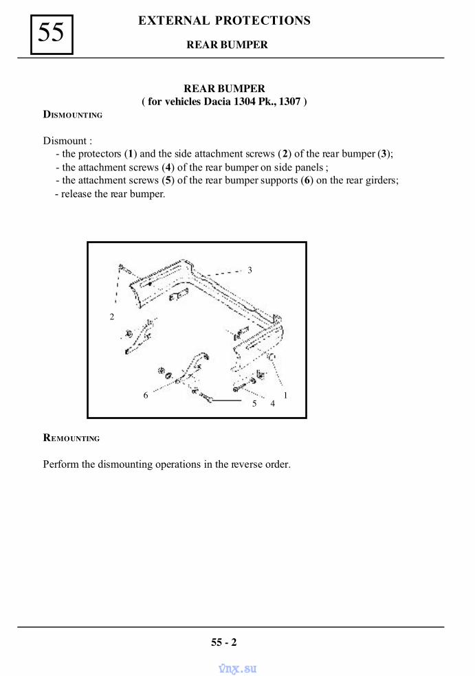
EXTERNAL PROTECTIONS55
REAR BUMPER( for vehicles Dacia 1304 Pk., 1307 )
REMOUNTING
Perform the dismounting operations in the reverse order.
55 - 2
DISMOUNTING
Dismount :- the protectors (1) and the side attachment screws (2) of the rear bumper (3);- the attachment screws (4) of the rear bumper on side panels ;- the attachment screws (5) of the rear bumper supports (6) on the rear girders;
- release the rear bumper.
2
65 4
1
3
REAR BUMPER
vnx.su
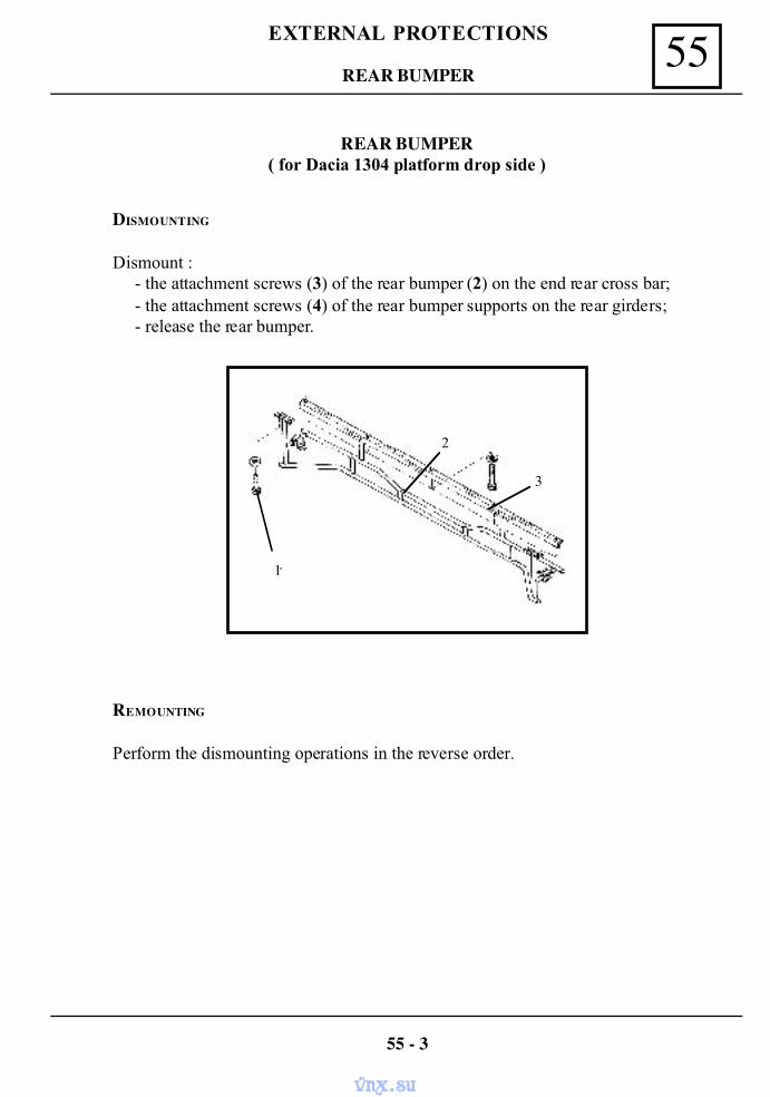
55EXTERNAL PROTECTIONS
REAR BUMPER( for Dacia 1304 platform drop side )
REMOUNTING
Perform the dismounting operations in the reverse order.
55 - 3
DISMOUNTING
Dismount :- the attachment screws (3) of the rear bumper (2) on the end rear cross bar;- the attachment screws (4) of the rear bumper supports on the rear girders;- release the rear bumper.
1
2
3
REAR BUMPER
vnx.su
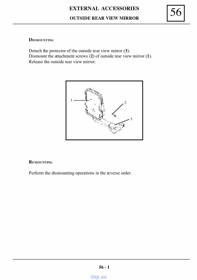
56EXTERNAL ACCESSORIES
OUTSIDE REAR VIEW MIRROR
REMOUNTING
Perform the dismounting operations in the reverse order.
56 - 1
DISMOUNTING
Detach the protector of the outside rear view mirror (3).Dismount the attachment screws (2) of outside rear view mirror (1).Release the outside rear view mirror.
1 2
3
vnx.su
REPAIR MANUAL
DACIA COMMERCIAL
RM 502-3 SEALING, ELECTRICITYENGINE: C3L
GEARBOX: NG1; NG7TAPV: U75B; U75F
Ref: 6001999453 NOVEMBER 2004 English version
The reparation methods prescribed by the manufacturer in the present document are established subject totechnical specifications in force at the document issuing date.
These are subject to modifications brought by the manufacturer at the fabrication of different assemblies,subassemblies or accessories of its vehicles.
All rights reserved to SC Automobile Dacia SA. Reproduction or translating even partially of this present document is forbidden without the written
authorisation of AUTOMOBILE DACIA S.A.
vnx.su
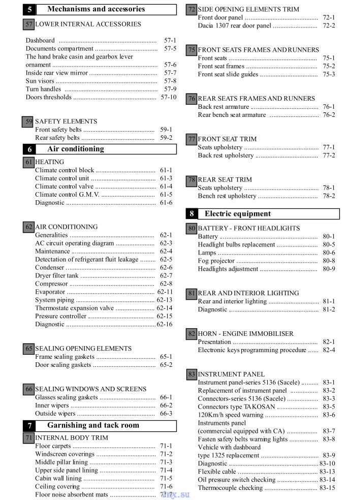
Mechanisms and accessories5
Garnishing and tack room7
Electric equipment8
57 LOWER INTERNAL ACCESSORIES
Dashboard .......................................................... 57-1Documents compartment ..................................... 57-5The hand brake casin and gearbox leverornament .............................................................. 57-6Inside rear view mirror ........................................ 57-7Sun visors ............................................................ 57-8Turn handles ....................................................... 57-9Doors thresholds ................................................. 57-10
59 SAFETY ELEMENTSFront safety belts .......................................... 59-1Rear safety belts ........................................... 59-2
61 HEATINGClimate control block ................................... 61-1Climate control unit ...................................... 61-3Climate control valve .................................... 61-4Climate control G.M.V. ................................ 61-5Diagnostic ..................................................... 61-6
62 AIR CONDITIONINGGeneralities .................................................. 62-1AC circuit operating diagram ....................... 62-3Maintenance ................................................. 62-4Detectation of refrigerant fluit leakage ......... 62-5Condenser ..................................................... 62-6Dryer filter tank ............................................ 62-7Compressor .................................................. 62-8Evaporator .................................................... 62-11System piping ............................................... 62-13Thermostate expansion valve ....................... 62-14Pressure controller ....................................... 62-15Diagnostic .....................................................62-16
65 SEALING OPENING ELEMENTSFrame sealing gaskets ................................... 65-1Door sealing gaskets ..................................... 65-2
66 SEALING WINDOWS AND SCREENSGlasses sealing gaskets ................................. 66-1Inner wipers .................................................. 66-2Outside wipers .............................................. 66-3
71 INTERNAL BODY TRIMFloor carpets ................................................. 71-1Windscreen coverings ................................... 71-2Middle pillar lining ....................................... 71-3Upper side panel lining ................................. 71-4Cabin wall lining .......................................... 71-5Ceiling covering ........................................... 71-6Floor noise absorbent mats ........................... 71-7
72 SIDE OPENING ELEMENTS TRIMFront door panel ........................................... 72-1Dacia 1307 rear door panel .......................... 72-2
75 FRONT SEATS FRAMES AND RUNNERSFront seats .................................................... 75-1Front seat frames .......................................... 75-2Front seat slide guides .................................. 75-3
76 REAR SEATS FRAMES AND RUNNERSBack rest armature ........................................ 76-1Rear bench seat armature ............................. 76-2
77 FRONT SEAT TRIMSeats upholstery ............................................ 77-1Back rest upholstery ..................................... 77-2
78 REAR SEAT TRIMSeats upholstery ............................................ 78-1Bench rest upholstery ................................... 78-2
80 BATTERY - FRONT HEADLIGHTSBattery .......................................................... 80-1Headlight bulbs replacement ........................ 80-5Lamps ........................................................... 80-6Fog projector ................................................ 80-8Headlights adjustment .................................. 80-9
81 REAR AND INTERIOR LIGHTINGRear and interior lighting .............................. 81-1Diagnostic ..................................................... 81-2
82 HORN - ENGINE IMMOBILISERPresentation .................................................. 82-1Electronic keys programming procedure ...... 82-4
83 INSTRUMENT PANELInstrument panel-series 5136 (Sacele) .......... 83-1Replacement of instrument panel ................ 83-2Connectors-series 5136 (Sacele) .................. 83-3Connectors type TAKOSAN ........................ 83-5120Km/h speed warning ............................... 83-6Instruments panel(commercial equipped with CA) .................. 83-7Fasten safety belts warning lights ................. 83-8Vehicle with dashboardtype 1325 replacement .................................. 83-9Diagnostic ..................................................... 83-10Flexible cable ............................................... 83-13Oil pressure switch checking ........................ 83-14Thermocouple checking ............................... 83-15
Air conditioning6
vnx.su
Temperature transmitter checking ................ 83-16Fuel level transmitter .................................... 83-17
84 CONTROLS - SIGNALLINGStarting-ignition switch ................................. 84-1Under wheel control module ........................ 84-3Switches dashboard ...................................... 84-5
85 WINDSCREEN WIPERSWindscreen wiper mechanism ...................... 85-1Windscreen wiper drive motor ..................... 85-4Windscreen washer assembly ....................... 85-6Diagnostic ..................................................... 85-7
.
89 ELECTRICAL DIAGRAMSGeneralites .................................................... 89-1Functional diagrams list ................................ 89-6Electric components index ........................... 89-8Couplings list. Mass index ............................ 89-9Location of electric coupling on the vehicle ..89-10Fixation of electric mass on the vehicle ....... 89-11Electric components location onthe vehicle .....................................................89-12Cockpit fuse box............................................89-15Engine compartment fuse box ...................... 89-16Wire functions index in connectors andcouplings ...................................................... 89-18Wire functions in connectors andcouplings ...................................................... 89-21Wire functions explanation ........................... 89-92
vnx.su
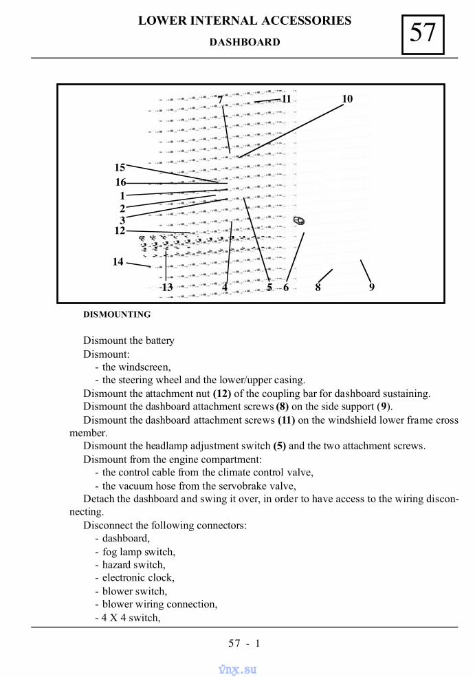
57LOWER INTERNAL ACCESSORIES
57 - 1
DISMOUNTING
Dismount the batteryDismount:
- the windscreen,- the steering wheel and the lower/upper casing.
Dismount the attachment nut (12) of the coupling bar for dashboard sustaining.Dismount the dashboard attachment screws (8) on the side support (9).Dismount the dashboard attachment screws (11) on the windshield lower frame cross
member.Dismount the headlamp adjustment switch (5) and the two attachment screws.Dismount from the engine compartment:
- the control cable from the climate control valve,- the vacuum hose from the servobrake valve,
Detach the dashboard and swing it over, in order to have access to the wiring discon-necting.
Disconnect the following connectors:- dashboard,- fog lamp switch,- hazard switch,- electronic clock,- blower switch,- blower wiring connection,- 4 X 4 switch,
123
4 5 6 8 9
10117
1516
12
13
14
DASHBOARD
vnx.su
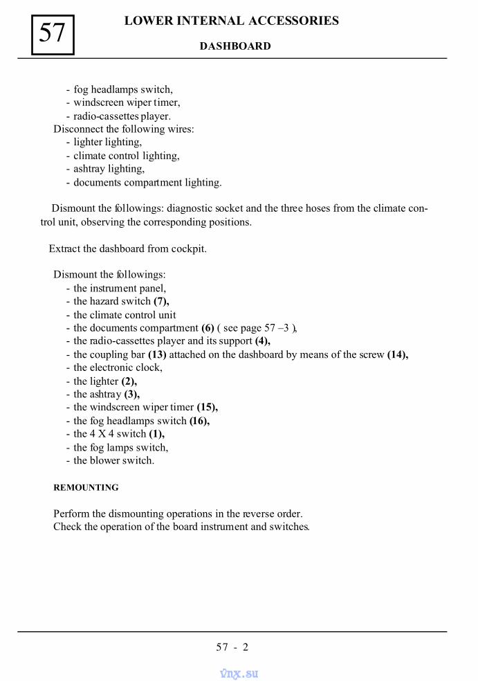
LOWER INTERNAL ACCESSORIES57
57 - 2
- fog headlamps switch,- windscreen wiper timer,- radio-cassettes player.
Disconnect the following wires:- lighter lighting,- climate control lighting,- ashtray lighting,- documents compartment lighting.
Dismount the followings: diagnostic socket and the three hoses from the climate con-trol unit, observing the corresponding positions.
Extract the dashboard from cockpit.
Dismount the followings:- the instrument panel,- the hazard switch (7),- the climate control unit- the documents compartment (6) ( see page 57 –3 ),- the radio-cassettes player and its support (4),- the coupling bar (13) attached on the dashboard by means of the screw (14),- the electronic clock,- the lighter (2),- the ashtray (3),- the windscreen wiper timer (15),- the fog headlamps switch (16),- the 4 X 4 switch (1),- the fog lamps switch,- the blower switch.
REMOUNTING
Perform the dismounting operations in the reverse order.Check the operation of the board instrument and switches.
DASHBOARD
vnx.su
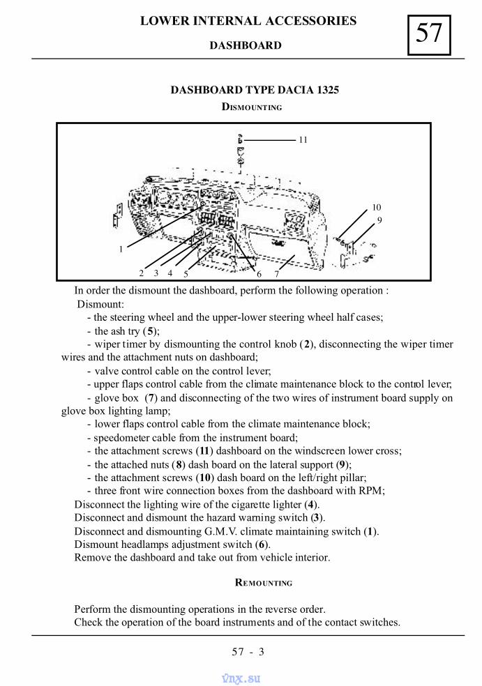
57LOWER INTERNAL ACCESSORIES
57 - 3
DASHBOARD
In order the dismount the dashboard, perform the following operation : Dismount:
- the steering wheel and the upper-lower steering wheel half cases;- the ash try (5);- wiper timer by dismounting the control knob (2), disconnecting the wiper timer
wires and the attachment nuts on dashboard;- valve control cable on the control lever;- upper flaps control cable from the climate maintenance block to the control lever;- glove box (7) and disconnecting of the two wires of instrument board supply on
glove box lighting lamp;- lower flaps control cable from the climate maintenance block;- speedometer cable from the instrument board;- the attachment screws (11) dashboard on the windscreen lower cross;- the attached nuts (8) dash board on the lateral support (9);- the attachment screws (10) dash board on the left/right pillar;- three front wire connection boxes from the dashboard with RPM;
Disconnect the lighting wire of the cigarette lighter (4).Disconnect and dismount the hazard warning switch (3).Disconnect and dismounting G.M.V. climate maintaining switch (1).Dismount headlamps adjustment switch (6).Remove the dashboard and take out from vehicle interior.
REMOUNTING
Perform the dismounting operations in the reverse order.Check the operation of the board instruments and of the contact switches.
DISMOUNTING
11
10 9
6 75432
1
DASHBOARD TYPE DACIA 1325
vnx.su
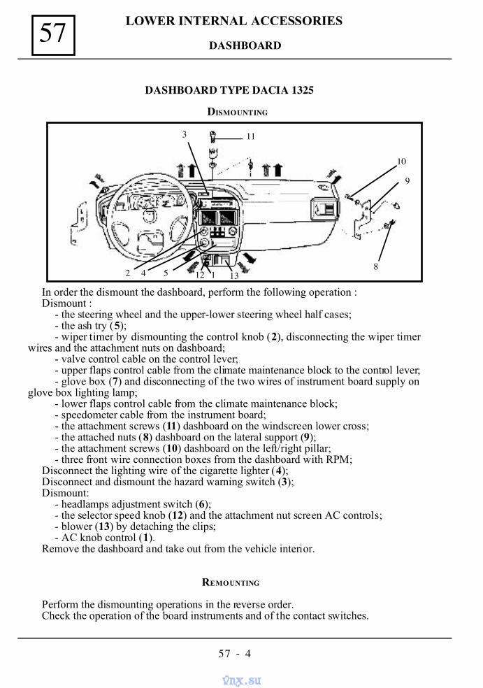
LOWER INTERNAL ACCESSORIES57
57 - 4
DASHBOARD
In order the dismount the dashboard, perform the following operation :Dismount :
- the steering wheel and the upper-lower steering wheel half cases;- the ash try (5);- wiper timer by dismounting the control knob (2), disconnecting the wiper timer
wires and the attachment nuts on dashboard;- valve control cable on the control lever;- upper flaps control cable from the climate maintenance block to the control lever;- glove box (7) and disconnecting of the two wires of instrument board supply on
glove box lighting lamp;- lower flaps control cable from the climate maintenance block;- speedometer cable from the instrument board;- the attachment screws (11) dashboard on the windscreen lower cross;- the attached nuts (8) dashboard on the lateral support (9);- the attachment screws (10) dashboard on the left/right pillar;- three front wire connection boxes from the dashboard with RPM;
Disconnect the lighting wire of the cigarette lighter (4);Disconnect and dismount the hazard warning switch (3);Dismount:
- headlamps adjustment switch (6);- the selector speed knob (12) and the attachment nut screen AC controls;- blower (13) by detaching the clips;- AC knob control (1).
Remove the dashboard and take out from the vehicle interior.
REMOUNTING
Perform the dismounting operations in the reverse order.Check the operation of the board instruments and of the contact switches.
DISMOUNTING
2 4 5 12 1 13
113
10
9
8
DASHBOARD TYPE DACIA 1325
vnx.su
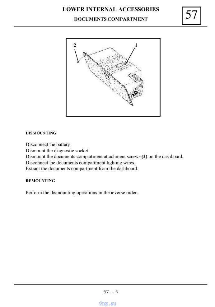
57LOWER INTERNAL ACCESSORIES
57 - 5
DOCUMENTS COMPARTMENT
DISMOUNTING
Disconnect the battery.Dismount the diagnostic socket.Dismount the documents compartment attachment screws (2) on the dashboard.Disconnect the documents compartment lighting wires.Extract the documents compartment from the dashboard.
REMOUNTING
Perform the dismounting operations in the reverse order.
12
vnx.su
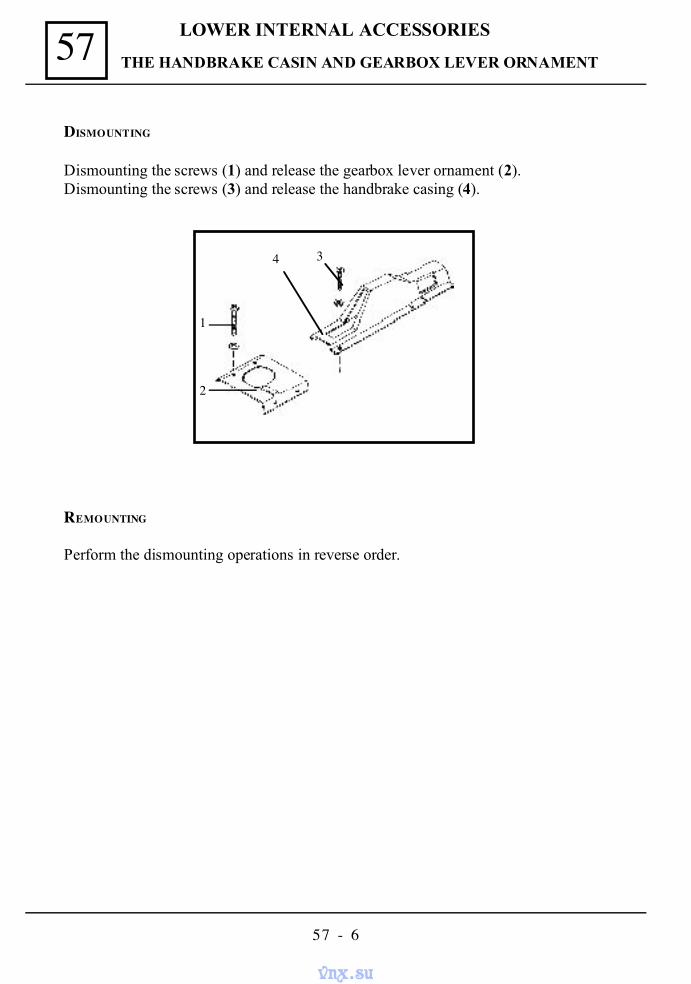
LOWER INTERNAL ACCESSORIES57
57 - 6
THE HANDBRAKE CASIN AND GEARBOX LEVER ORNAMENT
DISMOUNTING
Dismounting the screws (1) and release the gearbox lever ornament (2).Dismounting the screws (3) and release the handbrake casing (4).
REMOUNTING
Perform the dismounting operations in reverse order.
1
2
4 3
vnx.su
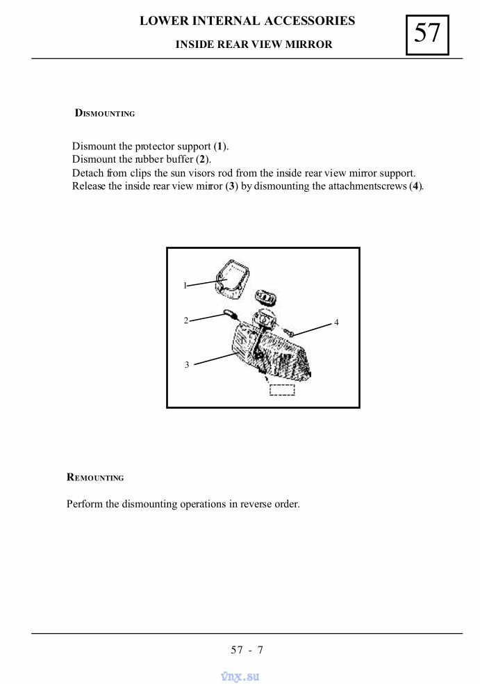
57LOWER INTERNAL ACCESSORIES
57 - 7
DISMOUNTING
Dismount the protector support (1).Dismount the rubber buffer (2).Detach from clips the sun visors rod from the inside rear view mirror support.Release the inside rear view mirror (3) by dismounting the attachment screws (4).
REMOUNTING
Perform the dismounting operations in reverse order.
INSIDE REAR VIEW MIRROR
1
1
2
3
4
vnx.su
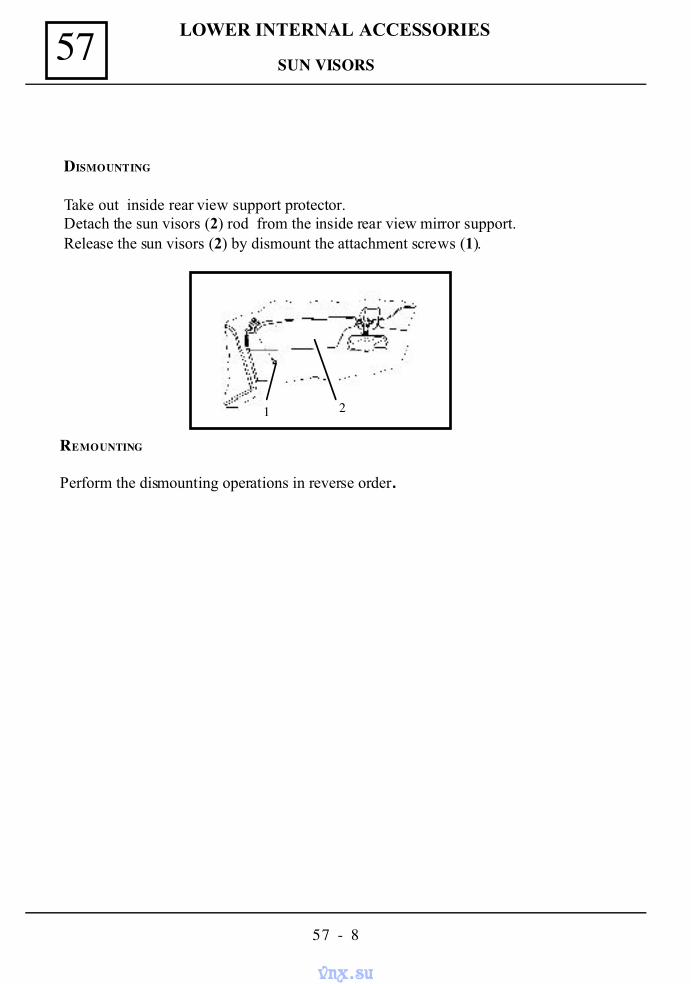
LOWER INTERNAL ACCESSORIES57
57 - 8
DISMOUNTING
Take out inside rear view support protector.Detach the sun visors (2) rod from the inside rear view mirror support.Release the sun visors (2) by dismount the attachment screws (1).
REMOUNTING
Perform the dismounting operations in reverse order.
1 2
SUN VISORS
vnx.su
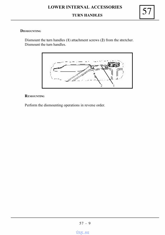
57LOWER INTERNAL ACCESSORIES
57 - 9
REMOUNTING
Perform the dismounting operations in reverse order.
2 1
TURN HANDLES
DISMOUNTING
Dismount the turn handles (1) attachment screws (2) from the stretcher.Dismount the turn handles.
vnx.su
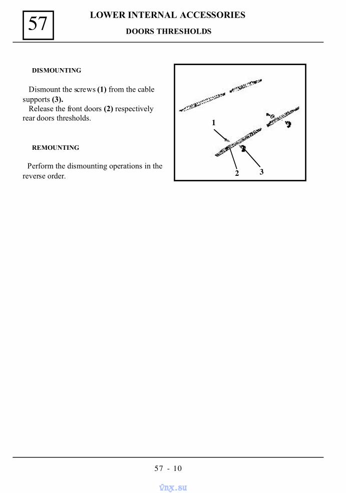
LOWER INTERNAL ACCESSORIES57
57 - 10
DOORS THRESHOLDS
DISMOUNTING
Dismount the screws (1) from the cablesupports (3). Release the front doors (2) respectivelyrear doors thresholds.
REMOUNTING
Perform the dismounting operations in thereverse order.
1
32
vnx.su
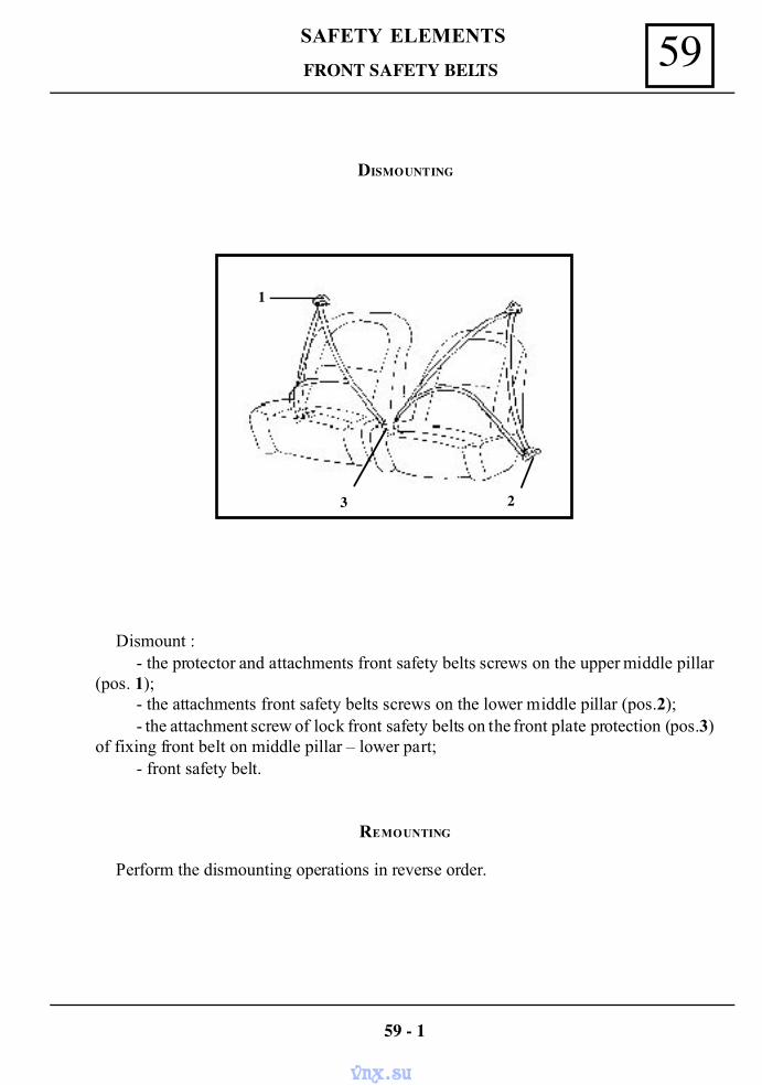
59SAFETY ELEMENTS
FRONT SAFETY BELTS
Dismount :- the protector and attachments front safety belts screws on the upper middle pillar
(pos. 1);- the attachments front safety belts screws on the lower middle pillar (pos.2);- the attachment screw of lock front safety belts on the front plate protection (pos.3)
of fixing front belt on middle pillar – lower part;- front safety belt.
REMOUNTING
Perform the dismounting operations in reverse order.
59 - 1
DISMOUNTING
1
3 2
vnx.su
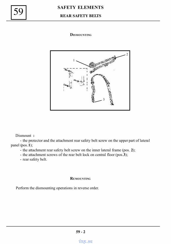
SAFETY ELEMENTS59 REAR SAFETY BELTS
Dismount :- the protector and the attachment rear safety belt screw on the upper part of lateral
panel (pos.1);- the attachment rear safety belt screw on the inner lateral frame (pos. 2);- the attachment screws of the rear belt lock on central floor (pos.3);- rear safety belt.
REMOUNTING
Perform the dismounting operations in reverse order.
59 - 2
DISMOUNTING
1
3
2
vnx.su
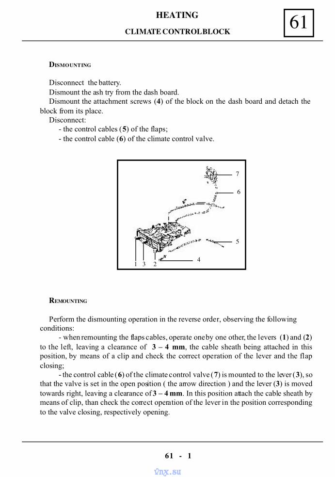
61HEATING
61 - 1
DISMOUNTING
Disconnect the battery.Dismount the ash try from the dash board.Dismount the attachment screws (4) of the block on the dash board and detach the
block from its place.Disconnect:
- the control cables (5) of the flaps;- the control cable (6) of the climate control valve.
REMOUNTING
Perform the dismounting operation in the reverse order, observing the followingconditions:
- when remounting the flaps cables, operate one by one other, the levers (1) and (2)to the left, leaving a clearance of 3 – 4 mm, the cable sheath being attached in thisposition, by means of a clip and check the correct operation of the lever and the flapclosing;
- the control cable (6) of the climate control valve (7) is mounted to the lever (3), sothat the valve is set in the open position ( the arrow direction ) and the lever (3) is movedtowards right, leaving a clearance of 3 – 4 mm. In this position attach the cable sheath bymeans of clip, than check the correct operation of the lever in the position correspondingto the valve closing, respectively opening.
CLIMATE CONTROL BLOCK
1 3 24
5
6
7
vnx.su
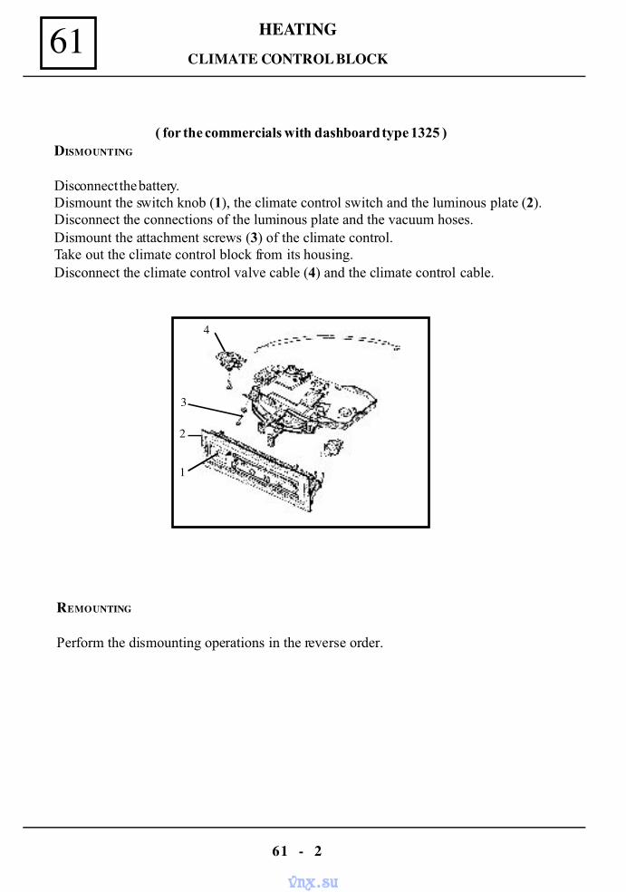
HEATING61
61 - 2
( for the commercials with dashboard type 1325 )DISMOUNTING
Disconnect the battery.Dismount the switch knob (1), the climate control switch and the luminous plate (2).Disconnect the connections of the luminous plate and the vacuum hoses.Dismount the attachment screws (3) of the climate control.Take out the climate control block from its housing.Disconnect the climate control valve cable (4) and the climate control cable.
REMOUNTING
Perform the dismounting operations in the reverse order.
CLIMATE CONTROL BLOCK
1
2
3
4
vnx.su
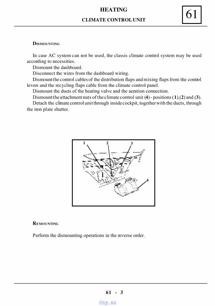
61HEATING
61 - 3
DISMOUNTING
In case AC system can not be used, the classis climate control system may be usedaccording to necessities.
Dismount the dashboard.Disconnect the wires from the dashboard wiring.Dismount the control cables of the distribution flaps and mixing flaps from the control
levers and the recycling flaps cable from the climate control panel.Dismount the ducts of the heating valve and the aeration connection.Dismount the attachment nuts of the climate control unit (4) - positions (1),(2) and (3).Detach the climate control unit through inside cockpit, together with the ducts, through
the iron plate shutter.
REMOUNTING
Perform the dismounting operations in the reverse order.
CLIMATE CONTROL UNIT
1 2 3
4
vnx.su
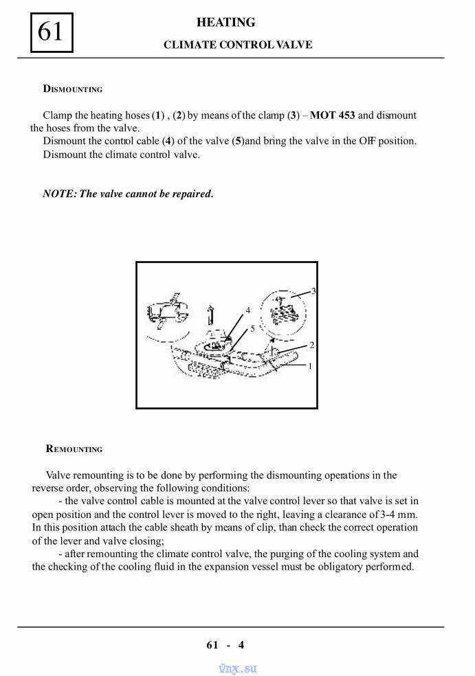
HEATING61
61 - 4
DISMOUNTING
Clamp the heating hoses (1) , (2) by means of the clamp (3) – MOT 453 and dismountthe hoses from the valve.
Dismount the control cable (4) of the valve (5) and bring the valve in the OFF position.Dismount the climate control valve.
NOTE: The valve cannot be repaired.
REMOUNTING
Valve remounting is to be done by performing the dismounting operations in thereverse order, observing the following conditions:
- the valve control cable is mounted at the valve control lever so that valve is set inopen position and the control lever is moved to the right, leaving a clearance of 3-4 mm.In this position attach the cable sheath by means of clip, than check the correct operationof the lever and valve closing;
- after remounting the climate control valve, the purging of the cooling system andthe checking of the cooling fluid in the expansion vessel must be obligatory performed.
CLIMATE CONTROL VALVE
1
2
3
4
5
vnx.su
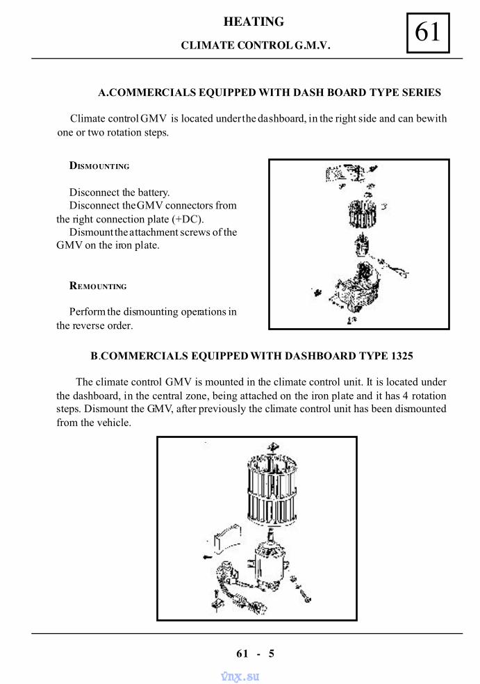
61HEATING
61 - 5
CLIMATE CONTROL G.M.V.
A.COMMERCIALS EQUIPPED WITH DASH BOARD TYPE SERIES
Climate control GMV is located under the dashboard, in the right side and can be withone or two rotation steps.
DISMOUNTING
Disconnect the battery.Disconnect the GMV connectors from
the right connection plate (+DC).Dismount the attachment screws of the
GMV on the iron plate.
REMOUNTING
Perform the dismounting operations inthe reverse order.
B.COMMERCIALS EQUIPPED WITH DASHBOARD TYPE 1325
The climate control GMV is mounted in the climate control unit. It is located underthe dashboard, in the central zone, being attached on the iron plate and it has 4 rotationsteps. Dismount the GMV, after previously the climate control unit has been dismountedfrom the vehicle.
vnx.su
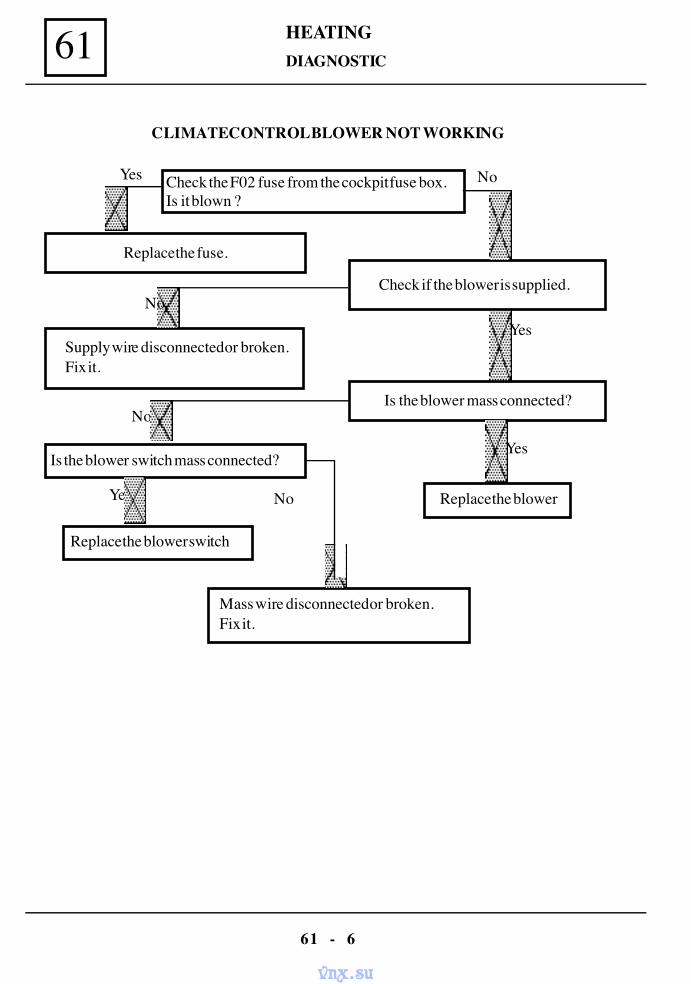
HEATING61
61 - 6
CLIMATE CONTROL BLOWER NOT WORKING
Check the F02 fuse from the cockpit fuse box.Is it blown ?
Replace the fuse.
Supply wire disconnected or broken.Fix it.
Check if the blower is supplied.
Replace the blower
Is the blower mass connected?
Is the blower switch mass connected?
Replace the blower switch
Mass wire disconnected or broken.Fix it.
Yes
No
Yes
No
No
No
Yes
Yes
DIAGNOSTIC
vnx.su
AIR CONDITIONING 62
62 - 1
The purpose of the air conditioning unit is to produce a decrease of the temperature in thepassengers compartment and to maintain this temperature at an inferior value compared to theenvironment one, reducing in the same time the air moisture.
Basically, the AC unit is operating in a closed circuit and it is composed of the following mainelements:
- evaporator- compressor- condenser- thermostatic expansion valve- connection pipes.
GENERALITIES
vnx.su
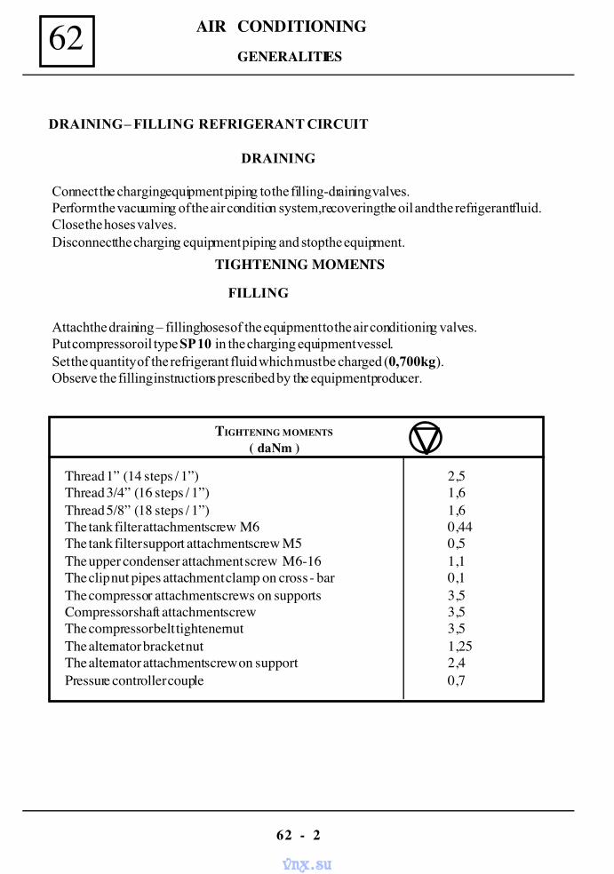
AIR CONDITIONING62
62 - 2
TIGHTENING MOMENTS
Thread 1” (14 steps / 1”) 2,5Thread 3/4” (16 steps / 1”) 1,6Thread 5/8” (18 steps / 1”) 1,6The tank filter attachment screw M6 0,44The tank filter support attachment screw M5 0,5The upper condenser attachment screw M6-16 1,1The clip nut pipes attachment clamp on cross - bar 0,1The compressor attachment screws on supports 3,5Compressor shaft attachment screw 3,5The compressor belt tightener nut 3,5The alternator bracket nut 1,25The alternator attachment screw on support 2,4Pressure controller couple 0,7
TIGHTENING MOMENTS
( daNm )
DRAINING – FILLING REFRIGERANT CIRCUIT
DRAINING
Connect the charging equipment piping to the filling-draining valves.Perform the vacuuming of the air condition system, recovering the oil and the refrigerant fluid.Close the hoses valves.Disconnect the charging equipment piping and stop the equipment.
FILLING
Attach the draining – filling hoses of the equipment to the air conditioning valves.Put compressor oil type SP 10 in the charging equipment vessel.Set the quantity of the refrigerant fluid which must be charged (0,700 kg).Observe the filling instructions prescribed by the equipment producer.
GENERALITIES
vnx.su
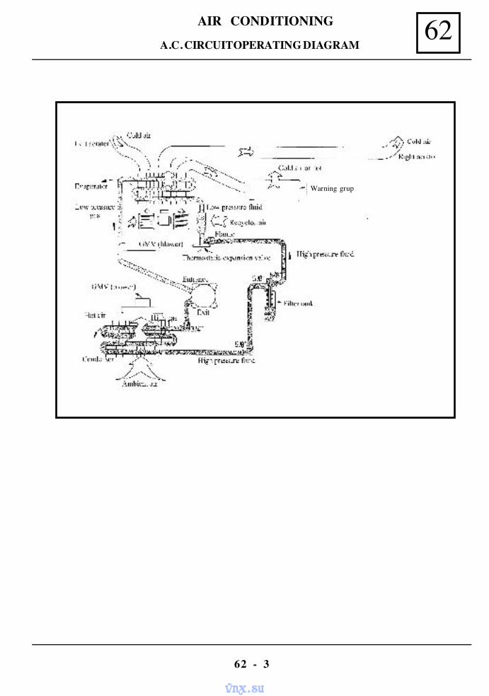
AIR CONDITIONING 62
62 - 3
A.C. CIRCUIT OPERATING DIAGRAM
Warning grup
vnx.su

AIR CONDITIONING62
62 - 4
For important leakage removal, for any components replacement (compressor,condenser, etc ) and if moisture was noticed in the air conditioning circuit, the dryer filter tank isto be replaced and the unit draining is to be done. The same is valid also when the conditioningcircuit still open without protection covers more than 10 minutes.
For component replacement implying the circuit draining, it is absolutely necessary the use ofnew parts and of a special oil for compressor.
ATTENTION !
The new components must be obligatory provided with protection covers. In order toavoid the moisture penetration, protect with protection covers the parts dismountedfrom the unit.
The vehicle equipped with an air conditioning system will be not exposed for morethan 20 minutes in painting cabin where there are temperatures higher than 80 grd C.
It is absolutely forbidden to perform welding on the elements of the air conditioncircuits.
It is essential using the type of the refrigerating agent and of the compressor oilprescribed by the producer.
The filling of the conditioning system can be performed only in authorized servicestations, observing the producer’s instructions.
For mechanical or body operations it is recommended piping protection in order toavoid their disconnection by accident.
Avoid the drip of the oil compressor on the painted vehicle body.Avoid the contact between the refrigerant liquid and the body skin because this can
produce a refrigerant effect ( temp. of – 26 dgr C).The filling up with oil for different repairs is to be performed by adding in the
charging equipment container, the recovered oil quantity, plus an oil quantity, as perfollowing:
- Condenser replacement ......................................30 g- Evaporator replacement......................................30 g- Dryer filter replacement......................................10 g
MAINTENANCE
vnx.su
AIR CONDITIONING 62
62 - 5
In order to detect the refrigerant liquid leakage, the detector INFICON type HDL 300 (orsimilar) may be used, calibrated to detect leakage of aprox. 9gr./an.
Start the engine and switch on the air conditioning unit. Check through the sight glass of thedryer filter tank if there are any air bubbles; if through the sight glass air bubbles can not be seen,the unit is in good operation, but if air bubbles are occurring and they remain during operation,this shows the lack of refrigerant fluid.
If there are not air bubbles and the air conditioning system is not operating, the refrigerantfluid must be checked.
The lack of refrigerant fluid can be confirmed by measuring the circuit pressure, at a fillingstation.
IMPORTANT :
When starting each time the compressor, air bubbles appearance through the sightglass, for few seconds, is normal.
DETECTION OF REFRIGERANT FLUID LEAKAGE
vnx.su
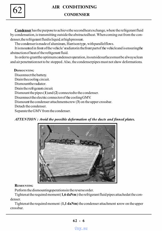
AIR CONDITIONING62
62 - 6
Condenser has the purpose to achieve the second heat exchange, where the refrigerant fluidby condensation, is transmitting outside the abstracted heat. When coming out from the con-denser, the refrigerant fluid is liquid, at high pressure.
The condenser is made of aluminum, Harrison type, with parallel flows.It is mounted in front of the vehicle’s radiator in the front part of the vehicle and is ensuring the
abstraction of heat of the refrigerant fluid.In order to grant the optimum condenser operation, its outside surfaces must be always clean
and air penetration not to be stopped. Also, the condenser pipes must not show deformations.
DISMOUNTING
Disconnect the battery.Drain the cooling circuit.Dismount the radiator.Drain the refrigerant circuit.Dismount the pipes (1) and (2) connected to the condenser.Disconnect the electric connector of the cooling GMV.Dismount the condenser attachment screw (3) on the upper crossbar.Detach the condenser.Separate the GMV from the condenser.
ATTENTION : Avoid the possible deformation of the ducts and finned plates.
REMOUNTING
Perform the dismounting operations in the reverse order.Tighten at the required moment (1,6 daNm ) the refrigerant fluid pipes attached at the con-
denser.Tighten at the required moment (1,1 daNm) the condenser attachment screw on the upper
crossbar.
CONDENSER
vnx.su
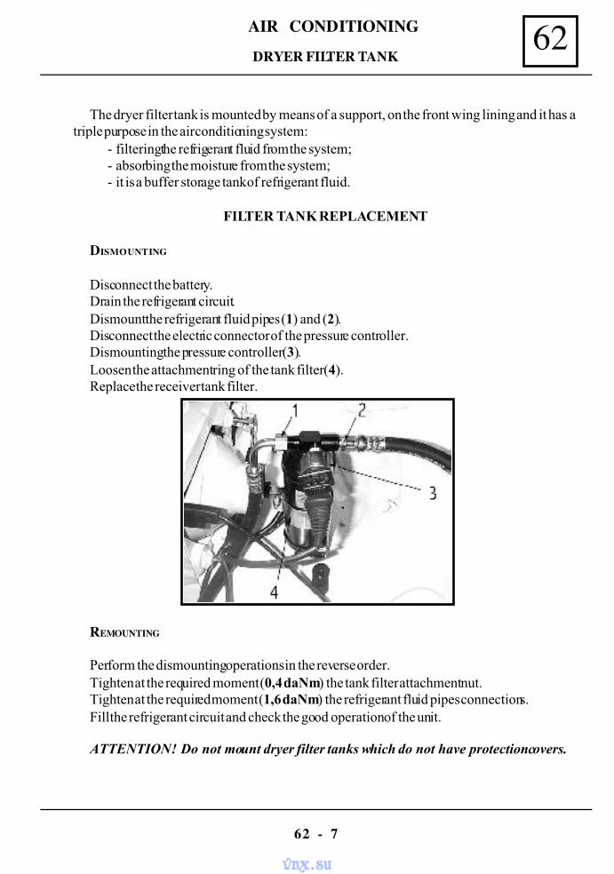
AIR CONDITIONING 62
62 - 7
The dryer filter tank is mounted by means of a support, on the front wing lining and it has atriple purpose in the air conditioning system:
- filtering the refrigerant fluid from the system;- absorbing the moisture from the system;- it is a buffer storage tank of refrigerant fluid.
FILTER TANK REPLACEMENT
DISMOUNTING
Disconnect the battery.Drain the refrigerant circuit.Dismount the refrigerant fluid pipes (1) and (2).Disconnect the electric connector of the pressure controller.Dismounting the pressure controller (3).Loosen the attachment ring of the tank filter (4).Replace the receiver tank filter.
REMOUNTING
Perform the dismounting operations in the reverse order.Tighten at the required moment (0,4 daNm) the tank filter attachment nut.Tighten at the required moment (1,6 daNm) the refrigerant fluid pipes connections.Fill the refrigerant circuit and check the good operation of the unit.
ATTENTION ! Do not mount dryer filter tanks which do not have protection covers.
DRYER FILTER TANK
vnx.su
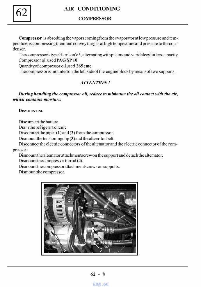
AIR CONDITIONING62
62 - 8
Compressor is absorbing the vapors coming from the evaporator at low pressure and tem-perature, is compressing them and convey the gas at high temperature and pressure to the con-denser.
The compressor is type Harrison V5, alternating, with pistons and variable cylinders capacity.Compressor oil used PAG SP 10Quantity of compressor oil used 265 cmcThe compressor is mounted on the left side of the engine block by means of two supports.
ATTENTION !
During handling the compressor oil, reduce to minimum the oil contact with the air,which contains moisture.
DISMOUNTING
Disconnect the battery.Drain the refrigerant circuit.Disconnect the pipes (1) and (2) from the compressor.Dismount the tensioning clip (3) and the alternator belt.Disconnect the electric connectors of the alternator and the electric connector of the com-
pressor.Dismount the alternator attachment screw on the support and detach the alternator.Dismount the compressor tie rod (4).Dismount the compressor attachment screws on supports.Dismount the compressor.
COMPRESSOR
vnx.su
AIR CONDITIONING 62
62 - 9
COMPRESSOR
REMOUNTING
Position the compressor on the attachment supports.Tighten the compressor on the supports, by means of 3 screws, which are to be initial screwed
in the following order : front upper left, rear lower right, front lower left.Position and tighten the tie rod on the compressor upper support and on the cylinders hous-
ing.Screw and tighten at the required moment the compressor attachment screws in the following
order : front upper left, front lower left, rear upper right, rear lower right(3,5 daNm).
Tighten at the required moment the tie rod attachment screw on the cylinder housing (3,5daNm).
Mount and tension the alternator belt by acting upon the tightener screw (see chapt.” Belts tightening checking and tensioning “), then lock it, by tightening the tightener nut at therequired moment (3,5 daNm).
Tension the alternator belt (see chapt.”Belts tightening checking and tensioning “) and tightenat the required moment (1,25 daNm) the alternator clamp attachment nut. and the clamp foralternator belt tightener.
Tighten at the required moment the alternator attachment screw on the support(2,4 daNm).
Mount the pipes to the compressor and tighten them at the required moment (2,5 daNm).
ATTENTION !
The compressor – evaporator pipe of ˚”, is the suction pipe, and the compressor –condenser pipe of 13/32 ”, is the discharging pipe ( in case mounting is not correct, thesystem is not working).
Fill the refrigerant circuit and check the climate control system operation.
NOTE : When compressor is replaced, obligatory replace also the tank filter.
vnx.su
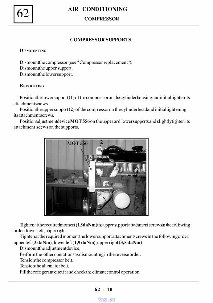
AIR CONDITIONING62
62 - 10
DISMOUNTING
Dismount the compressor (see “ Compressor replacement “).Dismount the upper support.Dismount the lower support.
REMOUNTING
Position the lower support (1) of the compressor on the cylinder housing and initial tighten itsattachment screws.
Position the upper support (2) of the compressor on the cylinder head and initial tighteningits attachment screws.
Position adjustment device MOT 556 on the upper and lower supports and slightly tighten itsattachment screws on the supports.
Tighten at the required moment (1,9daNm) the upper support attachment screws in the followingorder: lower left, upper right.
Tighten at the required moment the lower support attachment screws in the following order:upper left (3 daNm), lower left (1,9 daNm), upper right (3,5 daNm).
Dismount the adjustment device.Perform the other operations as dismounting in the reverse order.Tension the compressor belt.Tension the alternator belt.Fill the refrigerant circuit and check the climate control operation.
1
2MOT 556
COMPRESSOR
COMPRESSOR SUPPORTS
vnx.su
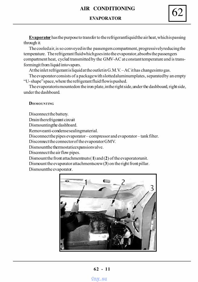
AIR CONDITIONING 62
62 - 11
Evaporator has the purpose to transfer to the refrigerant liquid the air heat, which is passingthrough it.
The cooled air, is so conveyed in the passengers compartment, progressively reducing thetemperature. The refrigerant fluid which goes into the evaporator, absorbs the passengerscompartment heat, cycled transmitted by the GMV-AC at constant temperature and is trans-forming it from liquid into vapors.
At the inlet refrigerant is liquid at the outlet in G.M.V. – AC it has changes into gas.The evaporator consists of a package with slotted aluminum plates, separated by an empty
“U- shape” space, where the refrigerant fluid flow is pushed.The evaporator is mounted on the iron plate, in the right side, under the dashboard, right side,
under the dashboard.
DISMOUNTING
Disconnect the battery.Drain the refrigerant circuitDismounting the dashboard.Remove anti-condense sealing material.Disconnect the pipes evaporator – compressor and evaporator – tank filter.Disconnect the connector of the evaporator GMV.Dismount the thermostatic expansion valve.Disconnect the air flow pipes.Dismount the front attachment nuts (1) and (2) of the evaporator unit.Dismount the evaporator attachment screw (3) on the right front pillar.Dismount the evaporator.
EVAPORATOR
vnx.su
AIR CONDITIONING62
62 - 12
REMOUNTING
Perform the dismounting operations in the reverse order.Fill the refrigerant circuit and check the good operation of the climate control system.
NOTE :Ensure that evaporator finned plates are not deformed and they are not excessive
dirty.ATTENTION !
For mounting or remounting the piping connections from refrigerant circuit, usetwo wrenches to balance the tightening moment in order to avoid the piping spin-ning.
EVAPORATOR
vnx.su
AIR CONDITIONING 62
62 - 13
The air conditioning system piping ensure the refrigerant fluid circulation between the systemcomponents.
When pipes are replaced, check the existence of the protective covers. Lubricate the con-nections and gaskets with compressor oil and fill up with compressor oil.
The system filling and draining valves are placed on the compressor piping and have differentdiameters, so that they can not be reversed.
When one air conditioning pipe is replaced, it is compulsory that its mounting to be performedimmediately after dismounting the protection cover.
Piping compressor – condenser ................................ 13/32”Piping compressor – evaporator ................................ 1/2”Piping condenser - tank filter ............................... 5/16”Piping tank filter – evaporator .................................... 5/16”
SYSTEM PIPING
vnx.su
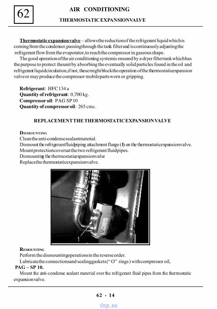
AIR CONDITIONING62
62 - 14
REPLACEMENT THE THERMOSTATIC EXPANSION VALVE
DISMOUNTING
Clean the anti-condense sealant material.Dismount the refrigerant fluid piping attachment flange (1) on the thermostatic expansion valve.Mount protection covers at the two refrigerant fluid pipes.Dismounting the thermostatic expansion valveReplace the thermostatic expansion valve.
REMOUNTING
Perform the dismounting operations in the reverse order.Lubricate the connections and sealing gaskets (“ O” rings ) with compressor oil,
PAG – SP 10.Mount the anti-condense sealant material over the refrigerant fluid pipes from the thermostatic
expansion valve.
Thermostatic expansion valve – allows the reduction of the refrigerant liquid which iscoming from the condenser, passing through the tank filter and is continuously adjusting the refrigerant flow from the evaporator, to reach the compressor in gaseous shape.
The good operation of the air conditioning system is ensured by a dryer filter tank which hasthe purpose to protect the unit by absorbing the eventually solid particles found in the oil andrefrigerant liquid circulation, if not, these might block the operation of the thermostatic expansionvalve or may produce the compressor mobile parts worn or gripping.
Refrigerant: HFC 134 aQuantity of refrigerant: 0,700 kg.Compressor oil: PAG SP 10Quantity of compressor oil: 265 cmc.
THERMOSTATIC EXPANSION VALVE
vnx.su
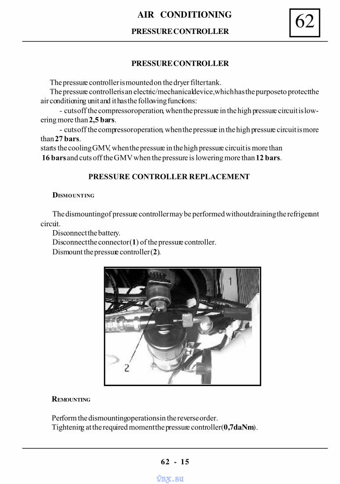
AIR CONDITIONING 62
62 - 15
PRESSURE CONTROLLER
The pressure controller is mounted on the dryer filter tank.The pressure controller is an electric/mechanical device, which has the purpose to protect the
air conditioning unit and it has the following functions:- cuts off the compressor operation, when the pressure in the high pressure circuit is low-
ering more than 2,5 bars.- cuts off the compressor operation, when the pressure in the high pressure circuit is more
than 27 bars.starts the cooling GMV, when the pressure in the high pressure circuit is more than 16 bars and cuts off the GMV when the pressure is lowering more than 12 bars.
PRESSURE CONTROLLER REPLACEMENT
DISMOUNTING
The dismounting of pressure controller may be performed without draining the refrigerantcircuit.
Disconnect the battery.Disconnect the connector (1) of the pressure controller.Dismount the pressure controller (2).
REMOUNTING
Perform the dismounting operations in the reverse order.Tightening at the required moment the pressure controller (0,7daNm).
PRESSURE CONTROLLER
vnx.su
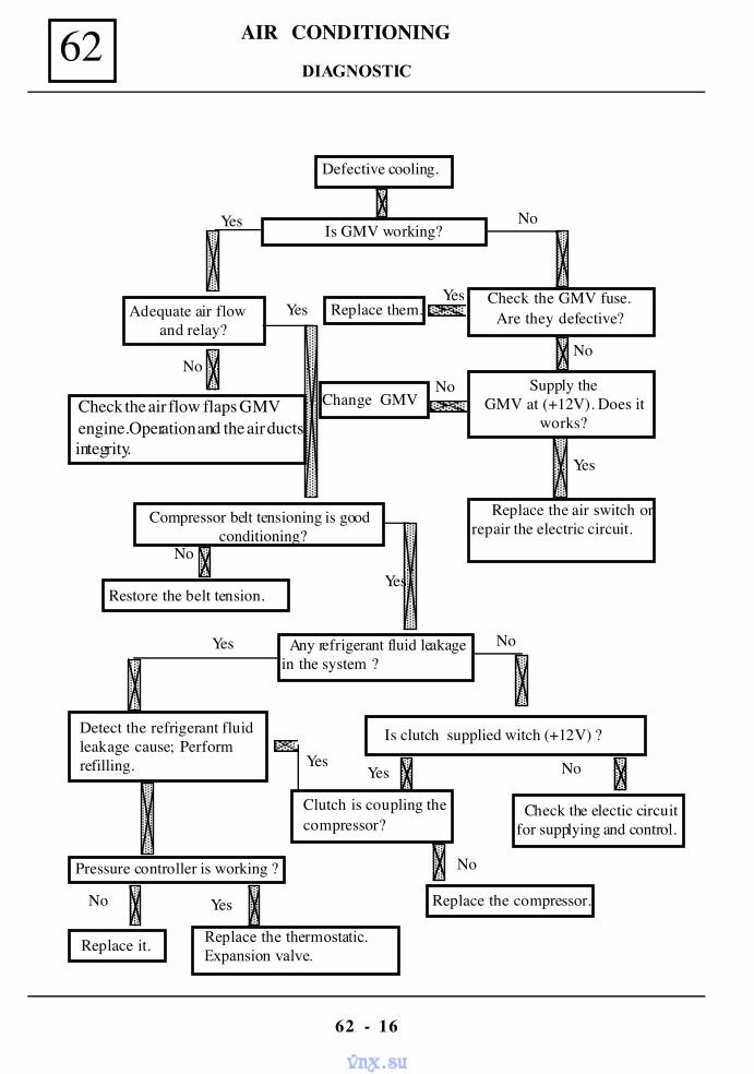
AIR CONDITIONING62
62 - 16
Defective cooling.
Is GMV working?
Check the GMV fuse. Are they defective?
Supply theGMV at (+12V). Does it
works?
Replace the air switch orrepair the electric circuit.
Replace them.
No
Yes
Yes
Change GMVNo
No
Adequate air flow and relay?
Check the air flow flaps GMV engine.Operation and the air ductsintegrity.
Compressor belt tensioning is goodconditioning?
Yes
Yes
No
Any refrigerant fluid leakagein the system ?
No
Yes
Yes
Is clutch supplied witch (+12V) ?
No
Yes No
Clutch is coupling thecompressor?
Replace the thermostatic. Expansion valve.
YesNo
Check the electic circuitfor supplying and control.
Detect the refrigerant fluidleakage cause; Performrefilling.
Pressure controller is working ?
Replace it.
Restore the belt tension.
Replace the compressor.
No
Yes
DIAGNOSTIC
vnx.su
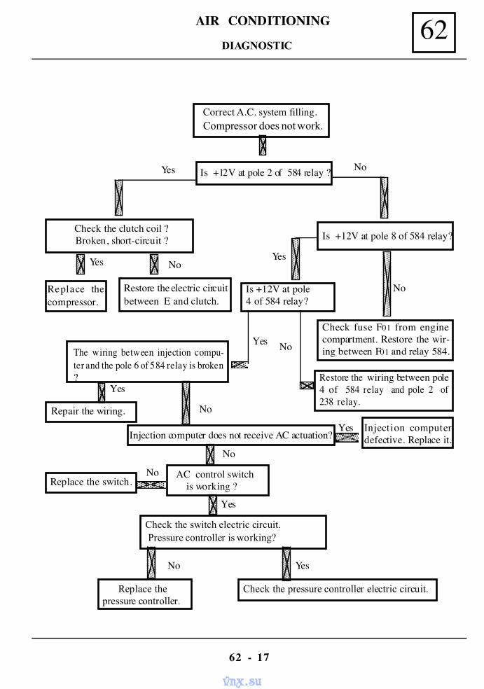
AIR CONDITIONING 62
62 - 17
Correct A.C. system filling.Compressor does not work.
Yes
Yes NoYes
Check the clutch coil ?Broken, short-circuit ?
Replace thecompressor.
Restore the electric circuitbetween E and clutch.
Is +12V at pole 2 of 584 relay ?
Is +12V at pole 8 of 584 relay?
Is +12V at pole4 of 584 relay?
Check fuse F01 from enginecompartment. Restore the wir-ing between F01 and relay 584.
No
Restore the wiring between pole4 of 584 relay and pole 2 of238 relay.
NoThe wiring between injection compu-ter and the pole 6 of 584 relay is broken?
Yes
Repair the wiring.
Yes
No
Injection computerdefective. Replace it.Injection computer does not receive AC actuation?
Yes
Check the switch electric circuit. Pressure controller is working?
No
Replace the switch. AC control switch
is working ?No
Yes
Yes
Check the pressure controller electric circuit.
No
Replace thepressure controller.
No
DIAGNOSTIC
vnx.su
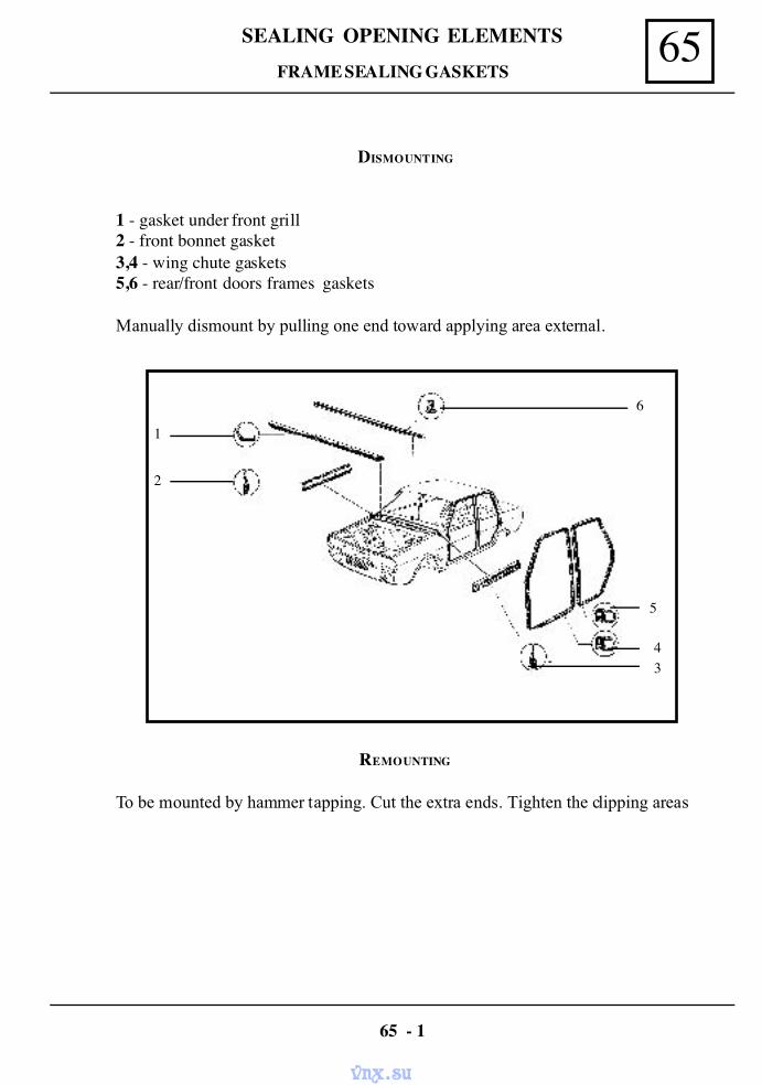
65SEALING OPENING ELEMENTS
DISMOUNTING
1 - gasket under front grill2 - front bonnet gasket3,4 - wing chute gaskets5,6 - rear/front doors frames gaskets
Manually dismount by pulling one end toward applying area external.
REMOUNTING
To be mounted by hammer tapping. Cut the extra ends. Tighten the clipping areas
FRAME SEALING GASKETS
65 - 1
5
43
6
2
1
vnx.su
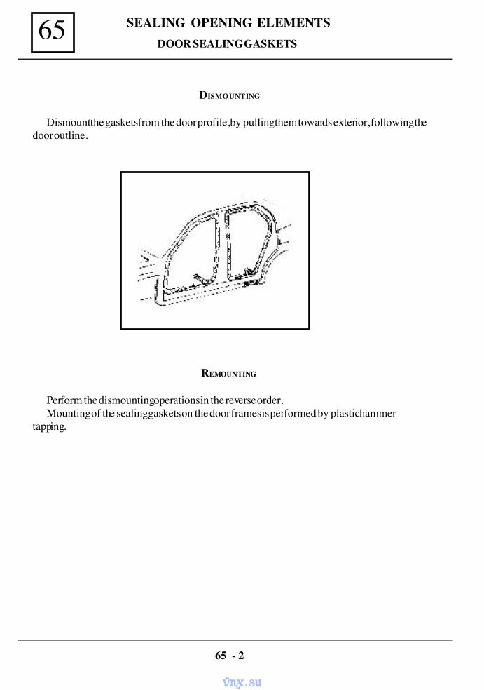
SEALING OPENING ELEMENTS65
DISMOUNTING
Dismount the gaskets from the door profile, by pulling them towards exterior, following thedoor outline.
REMOUNTING
Perform the dismounting operations in the reverse order.Mounting of the sealing gaskets on the door frames is performed by plastic hammer
tapping.
65 - 2
DOOR SEALING GASKETS
vnx.su
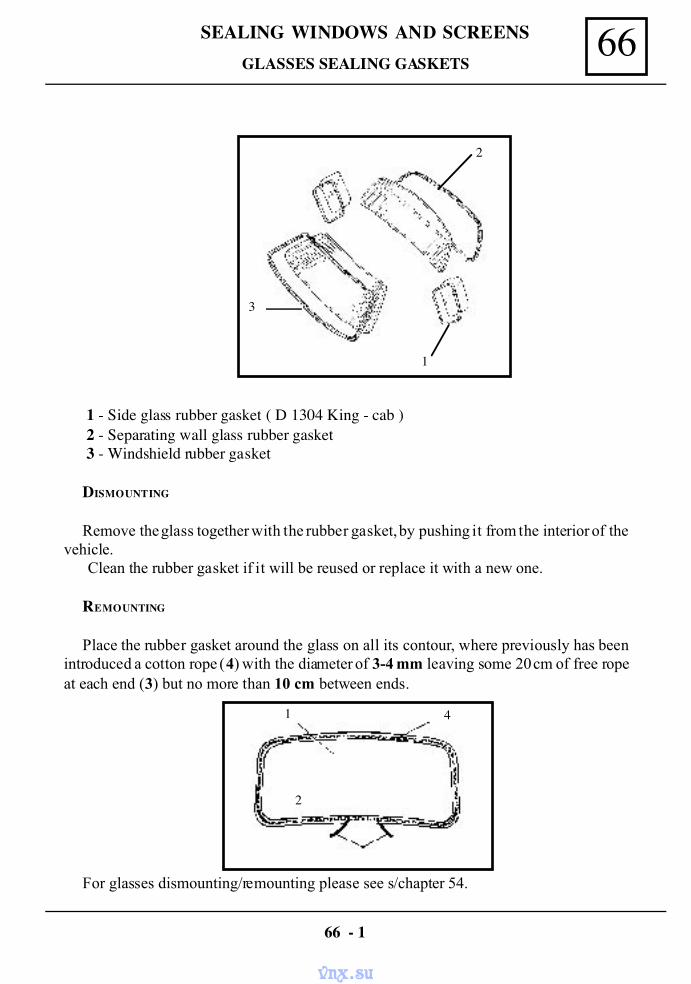
66SEALING WINDOWS AND SCREENS
1 - Side glass rubber gasket ( D 1304 King - cab ) 2 - Separating wall glass rubber gasket 3 - Windshield rubber gasket
DISMOUNTING
Remove the glass together with the rubber gasket, by pushing it from the interior of thevehicle.
Clean the rubber gasket if it will be reused or replace it with a new one.
REMOUNTING
Place the rubber gasket around the glass on all its contour, where previously has beenintroduced a cotton rope (4) with the diameter of 3-4 mm leaving some 20 cm of free ropeat each end (3) but no more than 10 cm between ends.
GLASSES SEALING GASKETS
66 - 1
For glasses dismounting/remounting please see s/chapter 54.
1
3
2
3
4
2
1
vnx.su
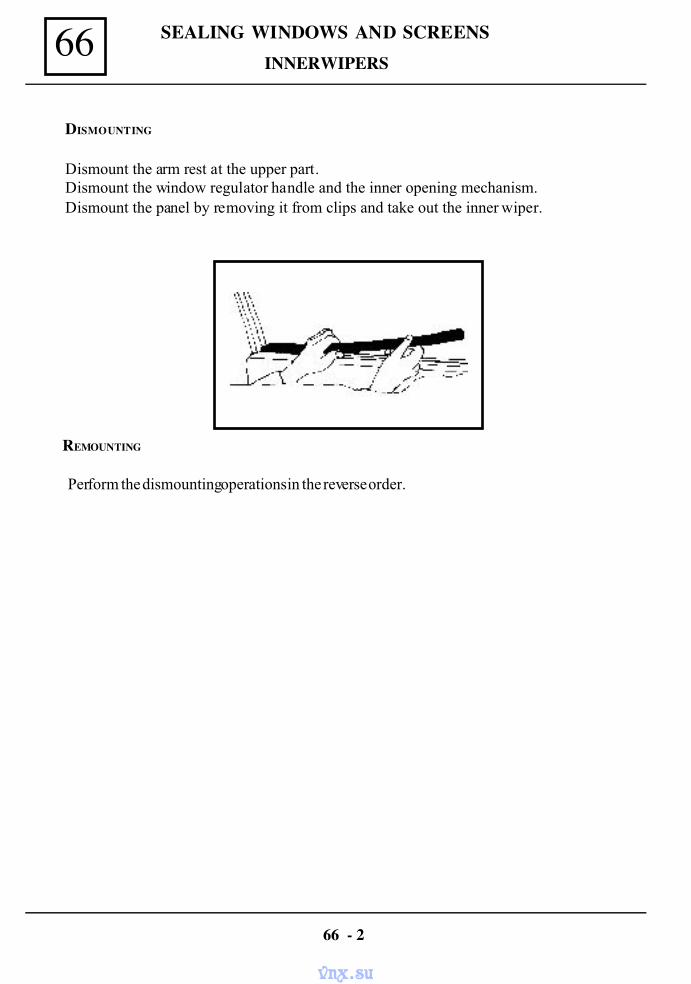
SEALING WINDOWS AND SCREENS66
DISMOUNTING
Dismount the arm rest at the upper part.Dismount the window regulator handle and the inner opening mechanism.Dismount the panel by removing it from clips and take out the inner wiper.
REMOUNTING
Perform the dismounting operations in the reverse order.
66 - 2
INNER WIPERS
vnx.su
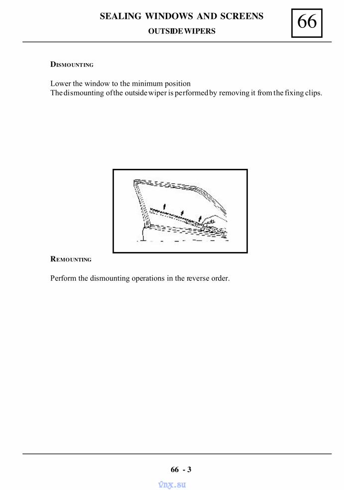
66SEALING WINDOWS AND SCREENS
DISMOUNTING
Lower the window to the minimum positionThe dismounting of the outside wiper is performed by removing it from the fixing clips.
REMOUNTING
Perform the dismounting operations in the reverse order.
66 - 3
OUTSIDE WIPERS
vnx.su
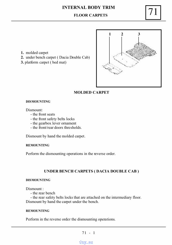
71INTERNAL BODY TRIM
71 - 1
FLOOR CARPETS
1. molded carpet2. under bench carpet ( Dacia Double Cab)3. platform carpet ( bed mat)
MOLDED CARPET
DISMOUNTING
Dismount:- the front seats- the front safety belts locks- the gearbox lever ornament- the front/rear doors thresholds.
Dismount by hand the molded carpet.
REMOUNTING
Perform the dismounting operations in the reverse order.
UNDER BENCH CARPETS ( DACIA DOUBLE CAB )
DISMOUNTING
Dismount :- the rear bench- the rear safety belts locks that are attached on the intermediary floor.
Dismount by hand the carpet under the bench.
REMOUNTING
Perform in the reverse order the dismounting operations.
1 2 3
vnx.su
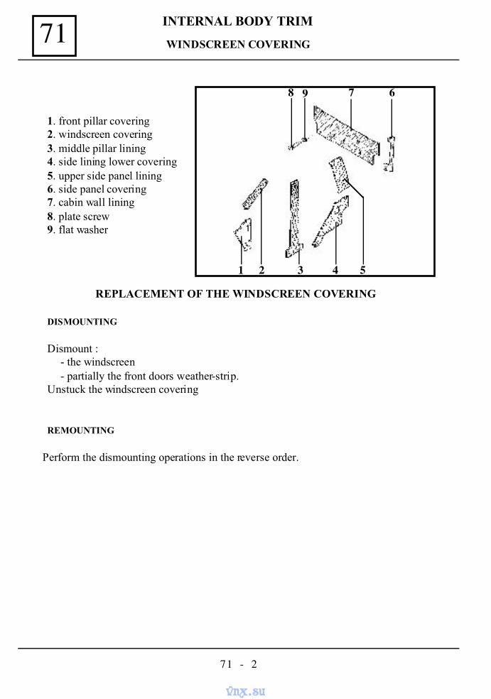
INTERNAL BODY TRIM71
71 - 2
WINDSCREEN COVERING
1. front pillar covering2. windscreen covering3. middle pillar lining4. side lining lower covering5. upper side panel lining6. side panel covering7. cabin wall lining8. plate screw9. flat washer
REPLACEMENT OF THE WINDSCREEN COVERING
DISMOUNTING
Dismount :- the windscreen- partially the front doors weather-strip.
Unstuck the windscreen covering
REMOUNTING
Perform the dismounting operations in the reverse order.
68 9 7
54321
vnx.su
71INTERNAL BODY TRIM
71 - 3
REPLACEMENT OF THE MIDDLE PILLAR LINING
DISMOUNTING
Move ahead the front seat, in order to enable the access at the middle pillar.
Dismount :- the front thresholds- partially the front/rear doors weather-strips- the front safety belts at their upper/lower part attachment on the middle pillar.
Unstuck in the reverse order of the dismounting operations.
REMOUNTING
Perform the dismounting operations in the reverse order.
MIDDLE PILLAR LINING
vnx.su
INTERNAL BODY TRIM71
71 - 4
REPLACEMENT OF THE UPPER SIDE PANEL LINING
DISMOUNTING
Swing over the rear bench backDismount :
- the rear safety belts at the upper part.- partially the rear doors weather-strip.
Unstuck the upper side panel lining.
REMOUNTING
Perform the dismounting operations in the reverse order.
UPPER SIDE PANEL LINING
vnx.su
71INTERNAL BODY TRIM
71 - 5
REPLACEMENT OF THE CABIN WALL LINING
DISMOUNTING
Swing over the rear bench backDismount :
- the rear glass grill- the rear cabin glass- the screws and washers attaching the cabin wall lining.
REMOUNTING
Perform the dismounting operations in the reverse order.
CABIN WALL LINING
vnx.su
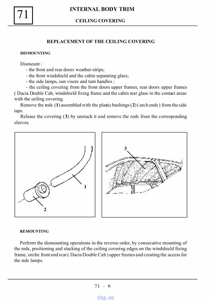
INTERNAL BODY TRIM71
71 - 6
REPLACEMENT OF THE CEILING COVERING
DISMOUNTING
Dismount :- the front and rear doors weather-strips;- the front windshield and the cabin separating glass;- the side lamps, sun visors and turn handles ;- the ceiling covering from the front doors upper frames, rear doors upper frames
( Dacia Double Cab, windshield fixing frame and the cabin rear glass in the contact areaswith the ceiling covering.
Remove the rods (1) assembled with the plastic bushings (2) ( arch ends ) from the sidetaps.
Release the covering (3) by unstuck it and remove the rods from the correspondingsleeves.
REMOUNTING
Perform the dismounting operations in the reverse order, by consecutive mounting ofthe rods, positioning and stacking of the ceiling covering edges on the windshield fixingframe, on the front and rear ( Dacia Double Cab ) upper frames and creating the access forthe side lamps.
2
1
3
CEILING COVERING
vnx.su
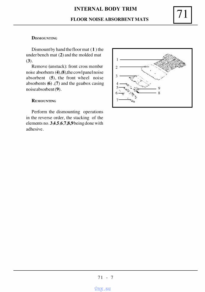
71INTERNAL BODY TRIM
71 - 7
FLOOR NOISE ABSORBENT MATS
DISMOUNTING
Dismount by hand the floor mat (1 ) theunder bench mat (2) and the molded mat(3).
Remove (unstuck): front cross membernoise absorbents (4),(8),the cowl panel noiseabsorbent (5), the front wheel noiseabsorbents (6) ,(7) and the gearbox casingnoise absorbent (9).
REMOUNTING
Perform the dismounting operationsin the reverse order, the stacking of theelements no. 3,4,5,6,7,8,9 being done withadhesive.
1
2
3
456
7
89
vnx.su
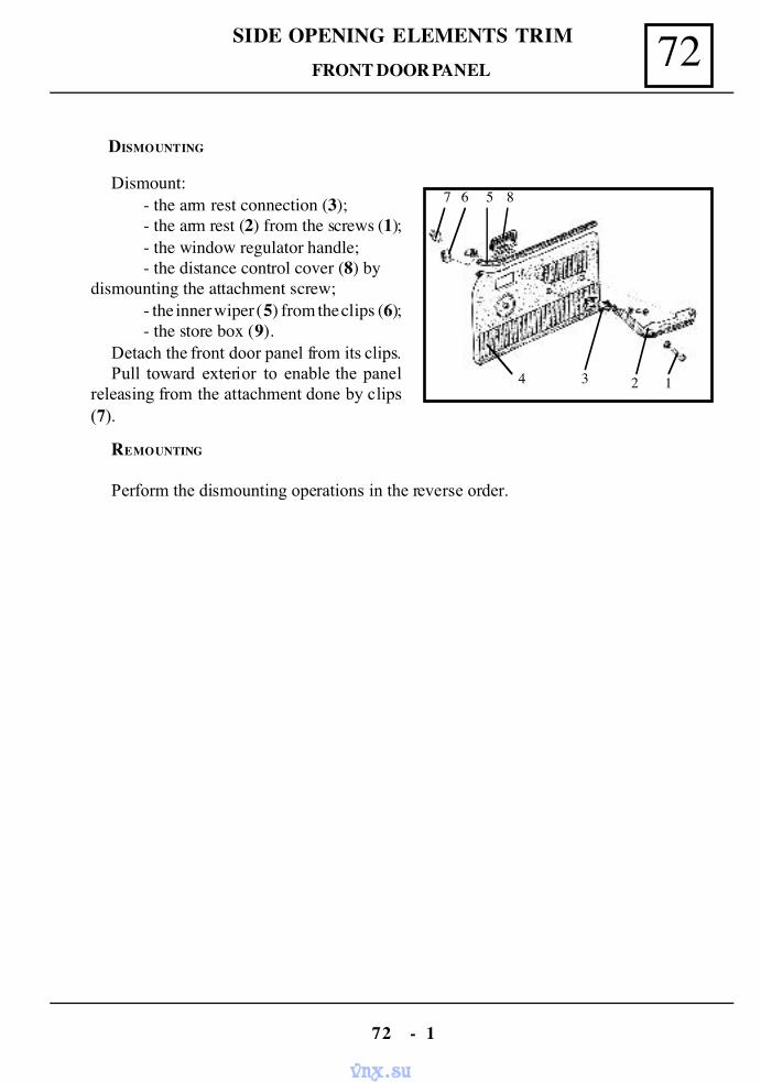
72SIDE OPENING ELEMENTS TRIM
72 - 1
Dismount:- the arm rest connection (3);- the arm rest (2) from the screws (1);- the window regulator handle;- the distance control cover (8) by
dismounting the attachment screw;- the inner wiper (5) from the clips (6);- the store box (9).
Detach the front door panel from its clips.Pull toward exterior to enable the panel
releasing from the attachment done by clips(7).
DISMOUNTING
REMOUNTING
Perform the dismounting operations in the reverse order.
7 6 5 8
4 3 2 1
FRONT DOOR PANEL
vnx.su
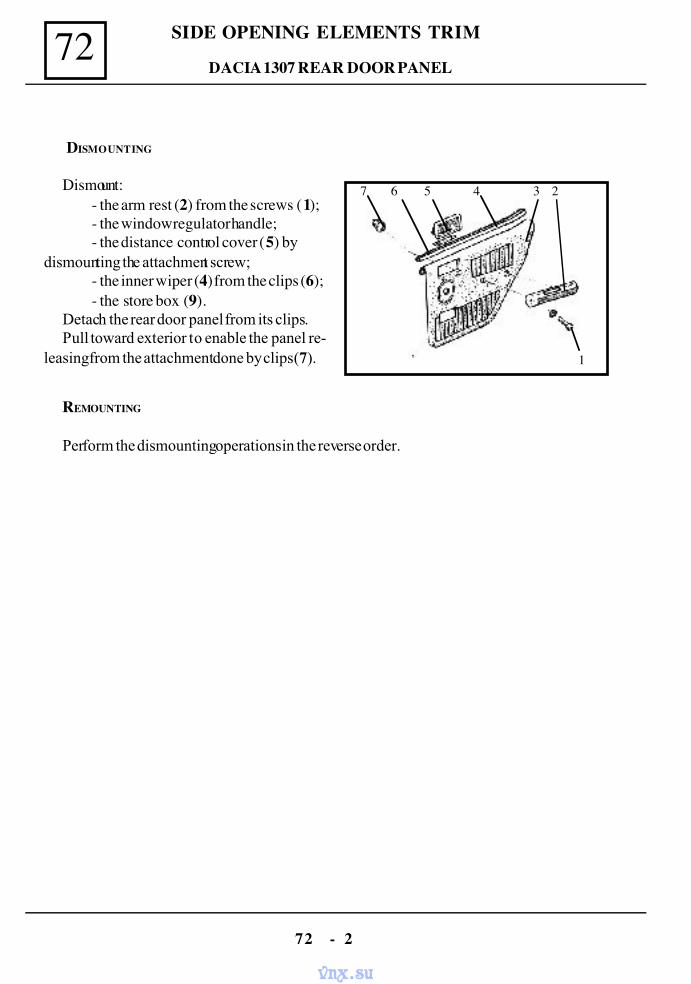
SIDE OPENING ELEMENTS TRIM72
72 - 2
DACIA 1307 REAR DOOR PANEL
DISMOUNTING
Dismount:- the arm rest (2) from the screws (1);- the window regulator handle;- the distance control cover (5) by
dismounting the attachment screw;- the inner wiper (4) from the clips (6);- the store box (9).
Detach the rear door panel from its clips.Pull toward exterior to enable the panel re-
leasing from the attachment done by clips (7).
REMOUNTING
Perform the dismounting operations in the reverse order.
1
7 6 5 4 3 2
vnx.su
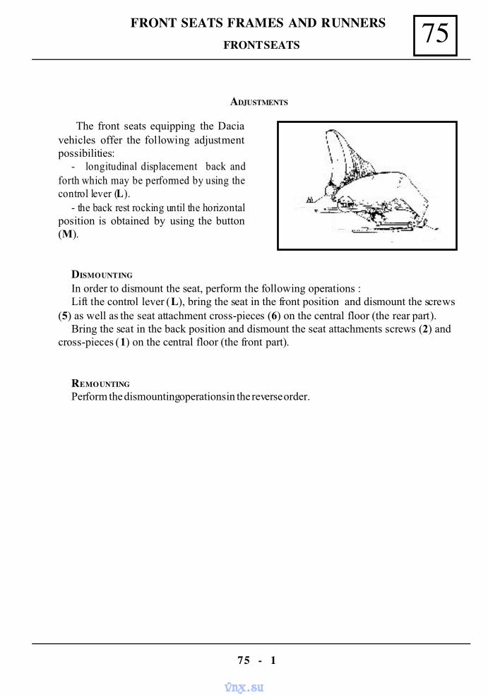
75FRONT SEATS FRAMES AND RUNNERS
75 - 1
FRONT SEATS
ADJUSTMENTS
The front seats equipping the Daciavehicles offer the following adjustmentpossibilities:
- longitudinal displacement back andforth which may be performed by using thecontrol lever (L).
- the back rest rocking until the horizontalposition is obtained by using the button(M).
DISMOUNTING
In order to dismount the seat, perform the following operations :Lift the control lever (L), bring the seat in the front position and dismount the screws
(5) as well as the seat attachment cross-pieces (6) on the central floor (the rear part).Bring the seat in the back position and dismount the seat attachments screws (2) and
cross-pieces (1) on the central floor (the front part).
REMOUNTING
Perform the dismounting operations in the reverse order.
vnx.su

FRONT SEATS FRAMES AND RUNNERS75
75 - 2
REPLACEMENT
DISMOUNTING
Dismount the seat off the vehicle.Dismount the slide guides from the front seat.Remove the upholstery and the clothing from the armature.
REMOUNTING
Perform the dismounting operations in the reverse order.
FRONT SEATS FRAMES
vnx.su
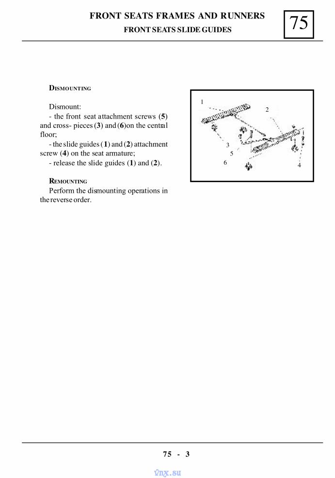
75FRONT SEATS FRAMES AND RUNNERS
75 - 3
DISMOUNTING
Dismount:- the front seat attachment screws (5)
and cross- pieces (3) and (6)on the centralfloor;
- the slide guides (1) and (2) attachmentscrew (4) on the seat armature;
- release the slide guides (1) and (2).
REMOUNTING
Perform the dismounting operations inthe reverse order.
1
35
6
2
4
FRONT SEATS SLIDE GUIDES
vnx.su
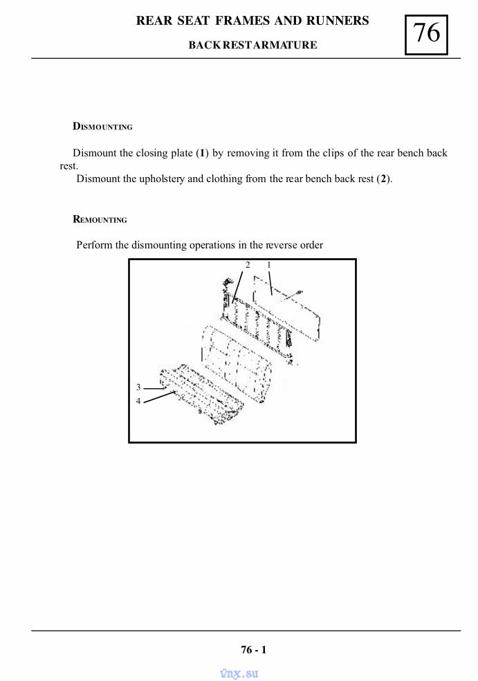
76REAR SEAT FRAMES AND RUNNERS
DISMOUNTING
Dismount the closing plate (1) by removing it from the clips of the rear bench backrest.
Dismount the upholstery and clothing from the rear bench back rest (2).
REMOUNTING
Perform the dismounting operations in the reverse order
76 - 1
34
2 1
BACK REST ARMATURE
vnx.su
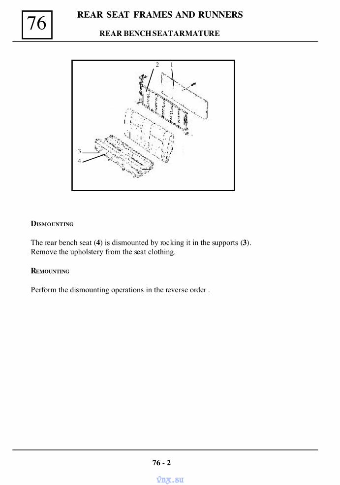
76 REAR SEAT FRAMES AND RUNNERS
DISMOUNTING
The rear bench seat (4) is dismounted by rocking it in the supports (3).Remove the upholstery from the seat clothing.
REMOUNTING
Perform the dismounting operations in the reverse order .
76 - 2
34
2 1
REAR BENCH SEAT ARMATURE
vnx.su
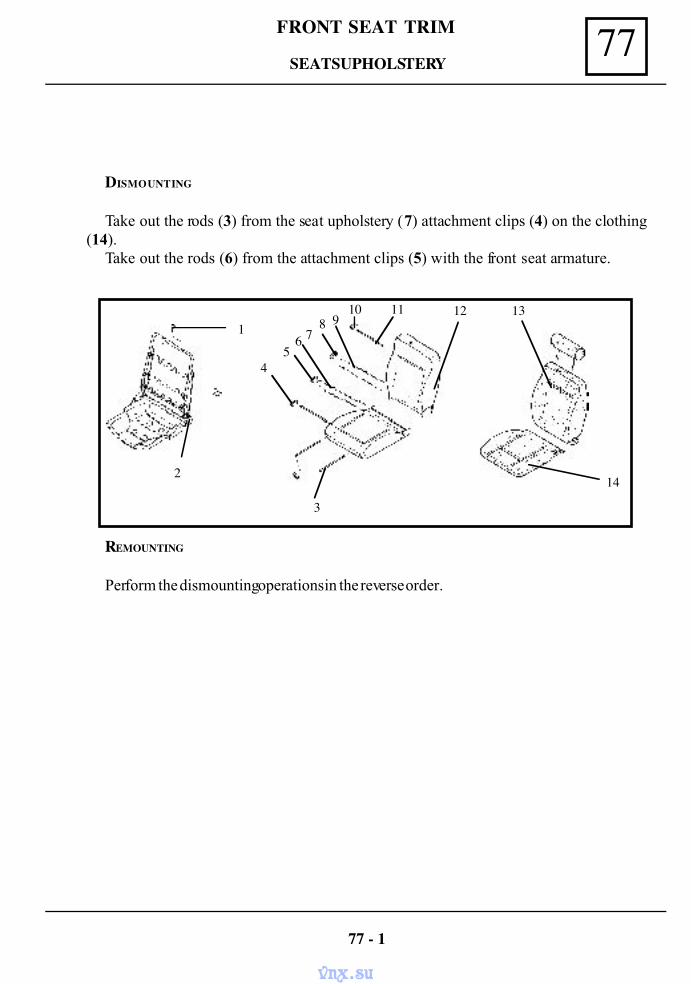
77FRONT SEAT TRIM
DISMOUNTING
Take out the rods (3) from the seat upholstery (7) attachment clips (4) on the clothing(14).
Take out the rods (6) from the attachment clips (5) with the front seat armature.
77 - 1
REMOUNTING
Perform the dismounting operations in the reverse order.
13
142
1
45
6 78 9
10 11 12
3
SEATS UPHOLSTERY
vnx.su
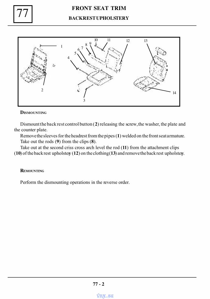
77 FRONT SEAT TRIM
77 - 2
DISMOUNTING
Dismount the back rest control button (2) releasing the screw, the washer, the plate andthe counter plate.
Remove the sleeves for the headrest from the pipes (1) welded on the front seat armature.Take out the rods (9) from the clips (8).Take out at the second criss cross arch level the rod (11) from the attachment clips
(10) of the back rest upholstery (12) on the clothing (13) and remove the back rest upholstery.
REMOUNTING
Perform the dismounting operations in the reverse order.
13
142
1
45
6 78 9
10 11 12
3
BACK REST UPHOLSTERY
vnx.su
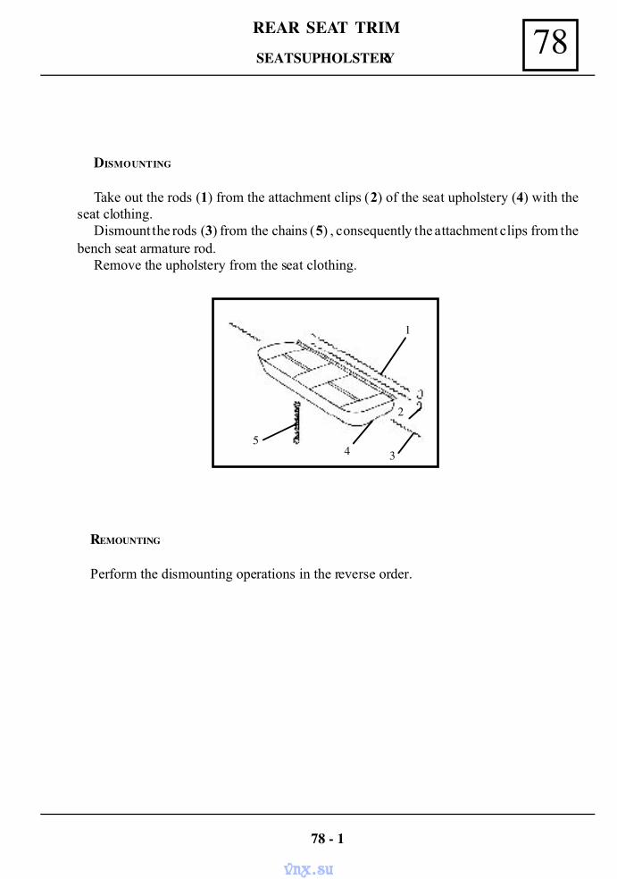
78REAR SEAT TRIM
DISMOUNTING
Take out the rods (1) from the attachment clips (2) of the seat upholstery (4) with theseat clothing.
Dismount the rods (3) from the chains (5) , consequently the attachment clips from thebench seat armature rod.
Remove the upholstery from the seat clothing.
78 - 1
REMOUNTING
Perform the dismounting operations in the reverse order.
4
1
53
2
SEATS UPHOLSTERY
vnx.su
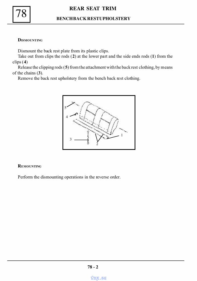
REAR SEAT TRIM78
REMOUNTING
Perform the dismounting operations in the reverse order.
78 - 2
DISMOUNTING
Dismount the back rest plate from its plastic clips.Take out from clips the rods (2) at the lower part and the side ends rods (1) from the
clips (4)Release the clipping rods (5) from the attachment with the back rest clothing, by means
of the chains (3).Remove the back rest upholstery from the bench back rest clothing.
13
2
4
5
BENCH BACK REST UPHOLSTERY
vnx.su
80BATTERY - FRONT HEADLIGHTS
80 - 1
ELECTRIC EQUIPMENT PROTECTION
When performing a reparation at the vehicle, a set of actions must be taken to protect theelectric equipments of damages or to avoid a short-circuit which may lead to vehicleburning.The battery is always disconnected by first disconnecting the negative terminaland then the positive one.The connecting is done in reverse order.
Before starter operation, check if the battery is correctly connected ( negative terminalconnected at the mass, if the terminals are clean and well tightened. Never disconnect thebattery when engine is running order to avoid damages on voltage regulator or the alternator.
Disconnecting of the alternator, the voltage regulator, the battery and the repairs at theirconnections are to be performed only when the engine is stopped ( the alternator is notturning ).
In case of the battery connection to a charging rectifier, for charging purpose,( withoutdismounting the battery from the vehicle), it is obligatory to disconnect the heavy wiringfrom the battery terminals.In case electric welding is performed on vehicle body, disconnect the battery terminalsand the connections plugs to the alternator
Some external or functional factors have a direct impact on the electric equipment,which has as effect the modification in time of the nominal parameters of the componentelements of the electric equipment, affecting their reliability and operating safety.
The main affecting factors are:
- Temperature – some elements being placed next to the engine, are obliged to operateat high temperatures.
- Humidity – the electric equipment components are operating in a an environmentwhere they may be in contact with water, oil or fuel, consequently there is the danger ofcontacts oxidation and destruction of the electric wires insulation.
- Variable running condition – the running condition of the engine being variable, itsignifies that electric equipment elements which are geared by the engine will also have avariable running condition.
- Requests of energy sources – when starting the engine by means of the starter, thebattery is requested at high currents and after engine starting, due to the variable numberof consumers and to the variable rotation regime of the alternator, the battery is forced topass, in a short period of time, from unloading regime to loading regime and viceversa.
BATTERY
vnx.su
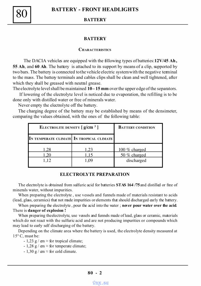
80
80 - 2
BATTERY - FRONT HEADLIGHTS
BATTERY
CHARACTERISTICS
The DACIA vehicles are equipped with the following types of batteries:12V/45 Ah ,55 Ah, and 60 Ah. The battery is attached to its support by means of a clip, supported bytwo bars. The battery is connected to the vehicle electric system with the negative terminalto the mass. The battery terminals and cables clips shall be clean and well tightened, afterwhich they shall be greased with neutral grease.The electrolyte level shall be maintained 10 – 15 mm over the upper edge of the separators.
If lowering of the electrolyte level is noticed due to evaporation, the refilling is to bedone only with distilled water or free of minerals water.
Never empty the electrolyte off the battery.The charging degree of the battery may be established by means of the densimeter,
comparing the values obtained, with the ones of the following table:
ELECTROLYTE PREPARATION
The electrolyte is obtained from sulfuric acid for batteries STAS 164 /75 and distilled or free ofminerals water, without impurities.
When preparing the electrolyte , use vessels and funnels made of materials resistant to acids(lead, glass, ceramics) that not made impurities or elements that should discharged early the battery.
When preparing the electrolyte , pour the acid into the water ; never pour water over the acid.There is danger of explosion !
When preparing the electrolyte, use vessels and funnels made of lead, glass or ceramic, materialswhich do not react with the sulfuric acid and are not producing impurities or compounds whichmay lead to early self discharging of the battery.
Depending on the climate area where the battery is used, the electrolyte density measured at15° C, must be:
- 1,23 g / cm ≈ for tropical climate;- 1,28 g / cm ≈ for temperate climate;- 1,30 g / cm ≈ for cold climate.
ELECTROLITE DENSITY [ g/cm 3 ] BATTERY CONDITION
IN TEMPERATE CLIMATE IN TROPICAL CLIMATE
1,28 1,23 100 % charged1,20 1,15 50 % charged1,12 1,09 discharged
BATTERY
vnx.su
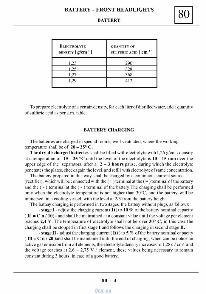
80BATTERY - FRONT HEADLIGHTS
80 - 3
ELECTROLYTE QUANTITY OF
DENSITY [ g/cm 3 ] SULFURIC ACID [ cm 3 ]
1,23 2901,25 3281,27 3681,29 412
To prepare electrolyte of a certain density, for each liter of distilled water, add a quantityof sulfuric acid as per a.m. table.
BATTERY CHARGING
The batteries are charged in special rooms, well ventilated, where the workingtemperature shall be of 20 – 25° C.
The dry-discharged batteries shall be filled with electrolyte with 1,26 g/cm≈ densityat a temperature of 15 – 25 °C until the level of the electrolyte is 10 – 15 mm over theupper edge of the separators; after a 2 – 3 hours pause, during which the electrolytepenetrates the plates, check again the level, and refill with electrolyte of same concentration.
The battery prepared in this way, shall be charged by a continuous current source(rectifier), which will be connected with the ( + ) terminal at the ( = ) terminal of the batteryand the ( - ) terminal at the ( - ) terminal of the battery.The charging shall be performedonly when the electrolyte temperature is not higher than 30°C, and the battery will beimmersed in a cooling vessel, with the level at 2/3 from the battery height.
The battery charging is performed in two stages, the battery without plugs, as follows:- stage I - adjust the charging current ( I I ) to 10 % of the battery nominal capacity
( II = C n / 10 ) - and shall be maintained at a constant value until the voltage per elementreaches 2,4 V. The temperature of electrolyte shall not be over 30° C; in this case thecharging shall be stopped in first stage I and follows the charging in second stage II.
- stage II - adjust the charging current ( III ) to 5 % of the battery nominal capacity( III = C n / 20 )and shall be maintained until the end of charging, when can be notice anactive gas emission from all elements, the electrolyte density increases to 1,28 c / cm≈ andthe voltage reaches at 2,6 – 2,75 V / element, these values being necessary to remainconstant during 3 hours, in case of a good battery.
BATTERY
vnx.su
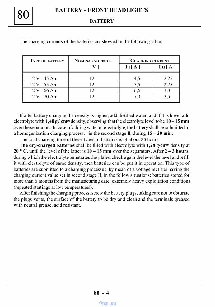
80
80 - 4
BATTERY - FRONT HEADLIGHTS
The charging currents of the batteries are showed in the following table:
If after battery charging the density is higher, add distilled water, and if it is lower addelectrolyte with 1,40 g / cm≈ density, observing that the electrolyte level to be 10 – 15 mmover the separators. In case of adding water or electrolyte, the battery shall be submitted toa homogenization charging process, in the second stage II, during 15 – 20 min.
The total charging time of these types of batteries is of about 35 hours.The dry-charged batteries shall be filled with electrolyte with 1,28 g/cm≈ density at
20 ° C, until the level of the latter is 10 – 15 mm over the separators. After 2 – 3 hours,during which the electrolyte penetrates the plates, check again the level the level and refillit with electrolyte of same density, then batteries can be put it in operation. This type ofbatteries are submitted to a charging processus, by mean of a voltage rectifier having thecharging current value set in second stage II, in the follow situations: batteries stored formore than 6 months from the manufacturing date; extremely heavy exploitation conditions(repeated startings at low temperatures).
After finishing the charging process, screw the battery plugs, taking care not to obturatethe plugs vents, the surface of the battery to be dry and clean and the terminals greasedwith neutral grease, acid resistant.
TYPE OF BATTERY NOMINAL VOLTAGE CHARGING CURRENT
[ V ] I I [ A ] I II [ A ]
12 V - 45 Ah 12 4,5 2,2512 V - 55 Ah 12 5,5 2,7512 V - 66 Ah 12 6,6 3,312 V - 70 Ah 12 7,0 3,5
BATTERY
vnx.su
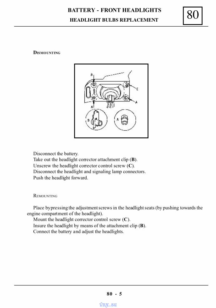
80BATTERY - FRONT HEADLIGHTS
80 - 5
DISMOUNTING
Disconnect the battery.Take out the headlight corrector attachment clip (B).Unscrew the headlight corrector control screw (C).Disconnect the headlight and signaling lamp connectors.Push the headlight forward.
REMOUNTING
Place by pressing the adjustment screws in the headlight seats (by pushing towards theengine compartment of the headlight).
Mount the headlight corrector control screw (C).Insure the headlight by means of the attachment clip (B).Connect the battery and adjust the headlights.
HEADLIGHT BULBS REPLACEMENT
vnx.su
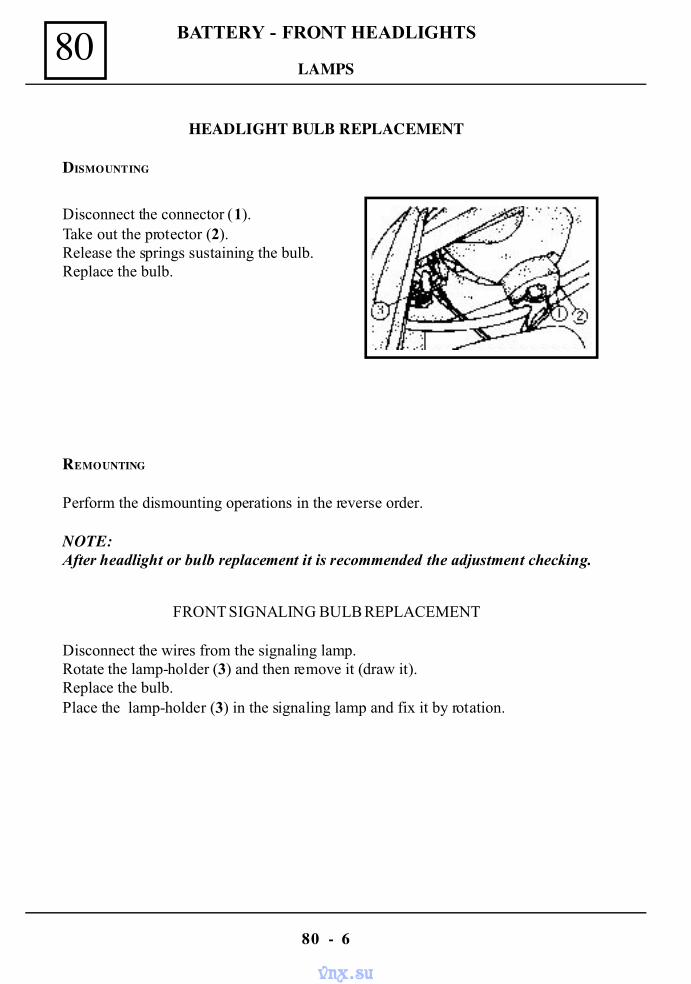
80
80 - 6
BATTERY - FRONT HEADLIGHTS
HEADLIGHT BULB REPLACEMENT
DISMOUNTING
Disconnect the connector (1).Take out the protector (2).Release the springs sustaining the bulb.Replace the bulb.
REMOUNTING
Perform the dismounting operations in the reverse order.
NOTE:After headlight or bulb replacement it is recommended the adjustment checking.
FRONT SIGNALING BULB REPLACEMENT
Disconnect the wires from the signaling lamp.Rotate the lamp-holder (3) and then remove it (draw it).Replace the bulb.Place the lamp-holder (3) in the signaling lamp and fix it by rotation.
LAMPS
vnx.su
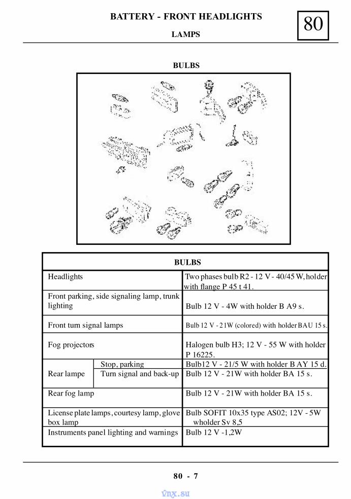
80BATTERY - FRONT HEADLIGHTS
80 - 7
BULBS
LAMPS
BULBS
Headlights
Front parking, side signaling lamp, trunklighting
Front turn signal lamps
Fog projectors
Stop, parkingRear lampe Turn signal and back-up
Rear fog lamp
License plate lamps, courtesy lamp, glovebox lampInstruments panel lighting and warnings
Two phases bulb R2 - 12 V - 40/45 W, holderwith flange P 45 t 41.
Bulb 12 V - 4W with holder B A9 s.
Bulb 12 V - 21W (colored) with holder BAU 15 s.
Halogen bulb H3; 12 V - 55 W with holder P 16225. Bulb12 V - 21/5 W with holder B AY 15 d. Bulb 12 V - 21W with holder BA 15 s.
Bulb 12 V - 21W with holder BA 15 s.
Bulb SOFIT 10x35 type AS02; 12V - 5Wwholder Sv 8,5
Bulb 12 V -1,2W
vnx.su
80
80 - 8
BATTERY - FRONT HEADLIGHTS
FOG PROJECTOR DISMOUNTING – REMOUNTING
Disconnect the battery.Detach the projector supply wires from the front wiring.Dismount the attachment screws of the projector from front bumper.Mounting is done by performing in the reverse order the dismounting operations.
FOG PROJECTOR
vnx.su
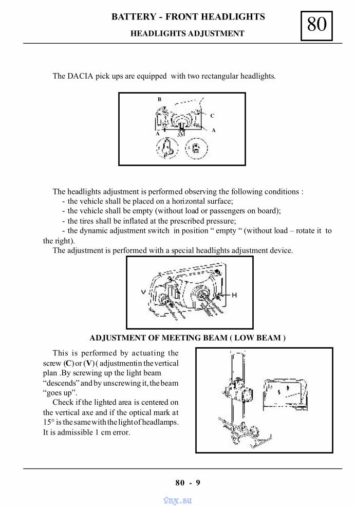
80BATTERY - FRONT HEADLIGHTS
80 - 9
The DACIA pick ups are equipped with two rectangular headlights.
The headlights adjustment is performed observing the following conditions :- the vehicle shall be placed on a horizontal surface;- the vehicle shall be empty (without load or passengers on board);- the tires shall be inflated at the prescribed pressure;- the dynamic adjustment switch in position “ empty “ (without load – rotate it to
the right).The adjustment is performed with a special headlights adjustment device.
ADJUSTMENT OF MEETING BEAM ( LOW BEAM )
This is performed by actuating thescrew (C) or (V) ( adjustment in the verticalplan .By screwing up the light beam“descends” and by unscrewing it, the beam“goes up”.
Check if the lighted area is centered onthe vertical axe and if the optical mark at15° is the same with the light of headlamps.It is admissible 1 cm error.
C
A
B
A
HEADLIGHTS ADJUSTMENT
vnx.su
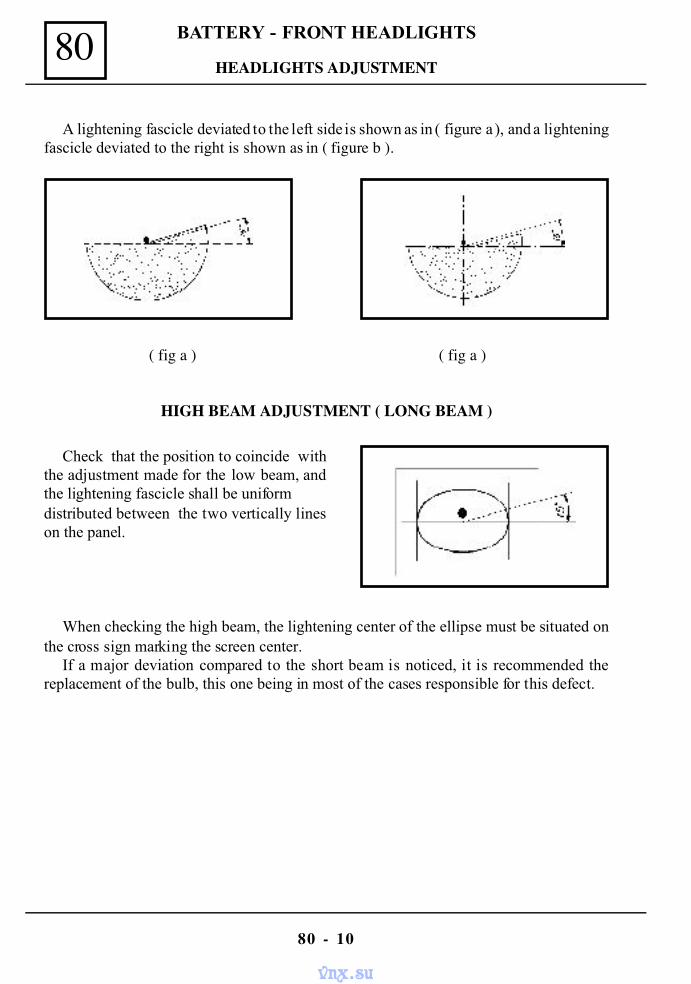
80
80 - 10
BATTERY - FRONT HEADLIGHTS
HEADLIGHTS ADJUSTMENT
A lightening fascicle deviated to the left side is shown as in ( figure a ), and a lighteningfascicle deviated to the right is shown as in ( figure b ).
( fig a ) ( fig a )
HIGH BEAM ADJUSTMENT ( LONG BEAM )
Check that the position to coincide withthe adjustment made for the low beam, andthe lightening fascicle shall be uniformdistributed between the two vertically lineson the panel.
When checking the high beam, the lightening center of the ellipse must be situated onthe cross sign marking the screen center.
If a major deviation compared to the short beam is noticed, it is recommended thereplacement of the bulb, this one being in most of the cases responsible for this defect.
vnx.su
81REAR AND INTERIOR LIGHTING
MOUNTING – REMOUNTING LICENCE PLATE LAMP.
Dismount the protector of the license plate lamp, then the attachment screws of thelamp on the body.
Disconnect the lamp from the vehicle wiring.Mounting is done by performing the dismounting operations in the reverse order.
REAR LAMP DISMOUNTING – REMOUNTING
Dismount the screws that attach the protector ( DACIA 1304 Pick – up ).Dismount the screws that attach the lamp body on the vehicle body (DACIA 1304 Pick – up).Dismount the nuts that attach the lamp body on the vehicle body ( DACIA 1304 Drop-
Side )Disconnect the lamp from the vehicle wiring.Perform the dismounting operations in the reverse order.
80 - 1
REAR AND INTERIOR LIGHTING
vnx.su
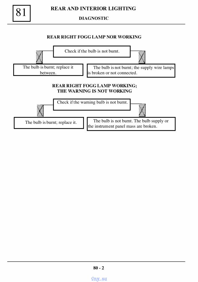
REAR AND INTERIOR LIGHTING81
REAR RIGHT FOGG LAMP NOR WORKING
Check if the bulb is not burnt.
The bulb is burnt; replace itbetween.
The bulb is not burnt; the supply wire lampsis broken or not connected.
REAR RIGHT FOGG LAMP WORKING;THE WARNING IS NOT WORKING
Check if the warning bulb is not burnt.
The bulb is burnt; replace it. The bulb is not burnt. The bulb supply orthe instrument panel mass are broken.
80 - 2
DIAGNOSTIC
vnx.su
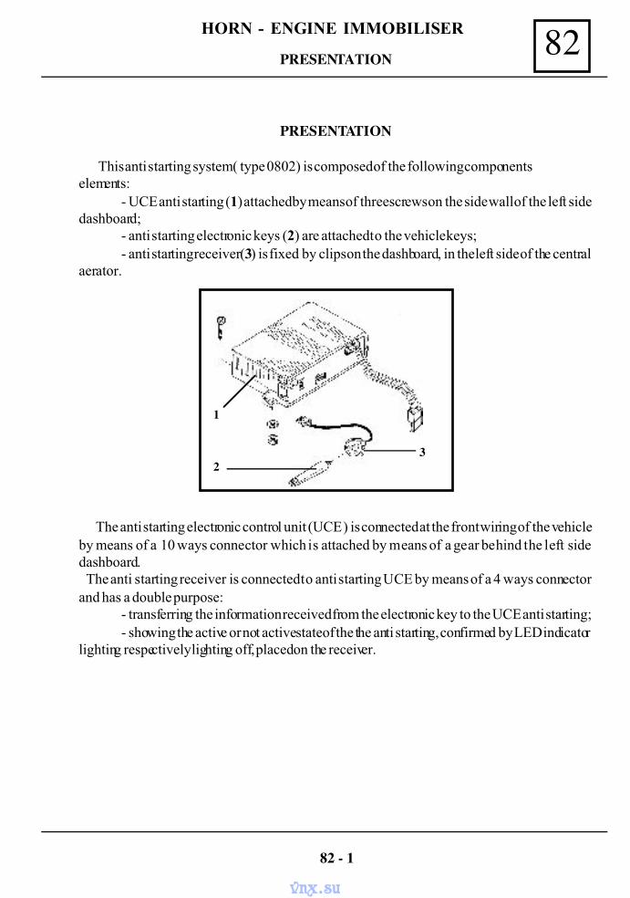
82HORN - ENGINE IMMOBILISER
PRESENTATION
This anti starting system ( type 0802) is composed of the following componentselements:
- UCE anti starting (1) attached by means of three screws on the side wall of the left sidedashboard;
- anti starting electronic keys (2) are attached to the vehicle keys;- anti starting receiver (3) is fixed by clips on the dashboard, in the left side of the central
aerator.
The anti starting electronic control unit (UCE ) is connected at the front wiring of the vehicleby means of a 10 ways connector which is attached by means of a gear behind the left sidedashboard. The anti starting receiver is connected to anti starting UCE by means of a 4 ways connectorand has a double purpose:
- transferring the information received from the electronic key to the UCE anti starting;- showing the active or not active state of the the anti starting, confirmed by LED indicator
lighting respectively lighting off, placed on the receiver.
82 - 1
1
23
PRESENTATION
vnx.su
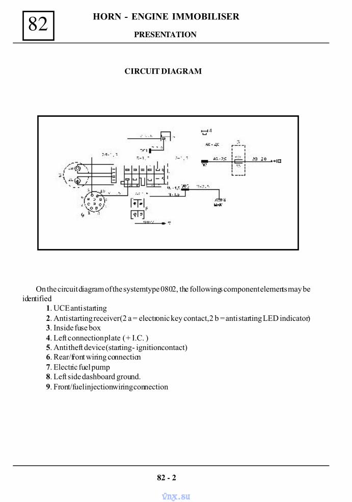
HORN - ENGINE IMMOBILISER82
CIRCUIT DIAGRAM
On the circuit diagram of the system type 0802, the followings component elements may beidentified:
1. UCE anti starting2. Anti starting receiver (2 a = electronic key contact, 2 b = anti starting LED indicator)3. Inside fuse box4. Left connection plate ( + I.C. )5. Anti theft device (starting - ignition contact)6. Rear/front wiring connection7. Electric fuel pump8. Left side dashboard ground.9. Front/fuel injection wiring connection
82 - 2
PRESENTATION
vnx.su
82HORN - ENGINE IMMOBILISER
OPERATING CONDITIONS
The anti starting has the purpose to block the supply of the electric fuel pump and the ignitionand injection system.
The anti starting system is automatically armed after 30 seconds from the ignitioncontact off.( bringing the key on “S” position or taking out the key from the anti theft device); theLED indicator will light, showing in this way that anti starting system has been activated.
To turn off the anti starting, consequently to start the engine, it is necessary the bringing of theelectronic key end in the contact with the anti starting receiver. In this moment the LED indicatorplaced on the dashboard will light off confirming in this way that the anti starting system has beenturned off and the vehicle starting is now authorised.
If the LED indicator does not light off, then the electronic key does not belong to the vehicle orthere is a defect in the anti starting system.
ATTENTION !
The system activation may be also obtained without waiting the 30 seconds timingafter engine stopping. To do that it is necessary the bringing of the electronic key endin contact with the anti starting receiver; in this moment the LED indicator will lighton, and the anti starting will become active.
UCE anti starting is provided with a safety circuit which restrains the anti startingactivation when the engine is not started.
The electronic keys are not provided with batteries for operation .These keys arecoded and consequently specific for only one vehicle, their using for another vehiclewill not enable that engine starting.
82 - 3
PRESENTATION
vnx.su
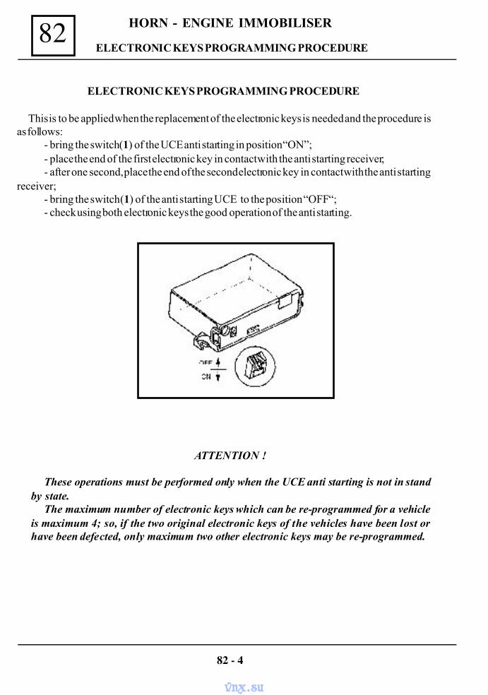
HORN - ENGINE IMMOBILISER82
ATTENTION !
These operations must be performed only when the UCE anti starting is not in standby state.
The maximum number of electronic keys which can be re-programmed for a vehicleis maximum 4; so, if the two original electronic keys of the vehicles have been lost orhave been defected, only maximum two other electronic keys may be re-programmed.
82 - 4
ELECTRONIC KEYS PROGRAMMING PROCEDURE
ELECTRONIC KEYS PROGRAMMING PROCEDURE
This is to be applied when the replacement of the electronic keys is needed and the procedure isas follows:
- bring the switch (1) of the UCE anti starting in position “ON”;- place the end of the first electronic key in contact with the anti starting receiver;- after one second, place the end of the second electronic key in contact with the anti starting
receiver;- bring the switch (1) of the anti starting UCE to the position “OFF“;- check using both electronic keys the good operation of the anti starting.
vnx.su
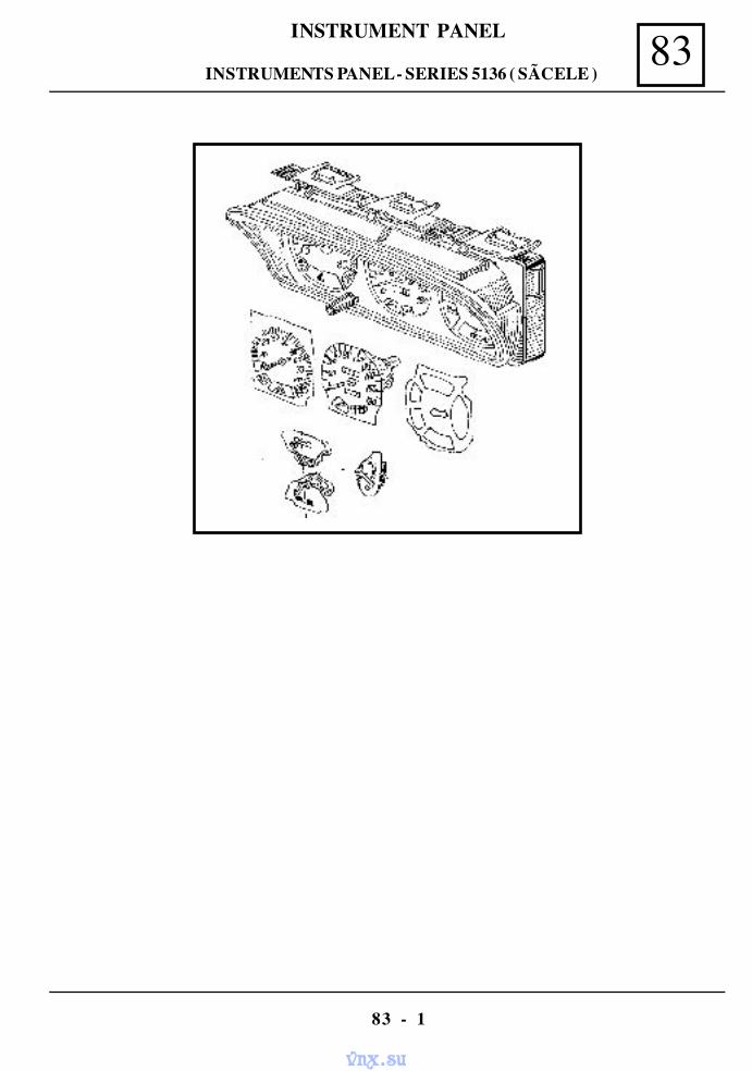
83INSTRUMENT PANEL
83 - 1
INSTRUMENTS PANEL - SERIES 5136 ( SÃCELE )
vnx.su
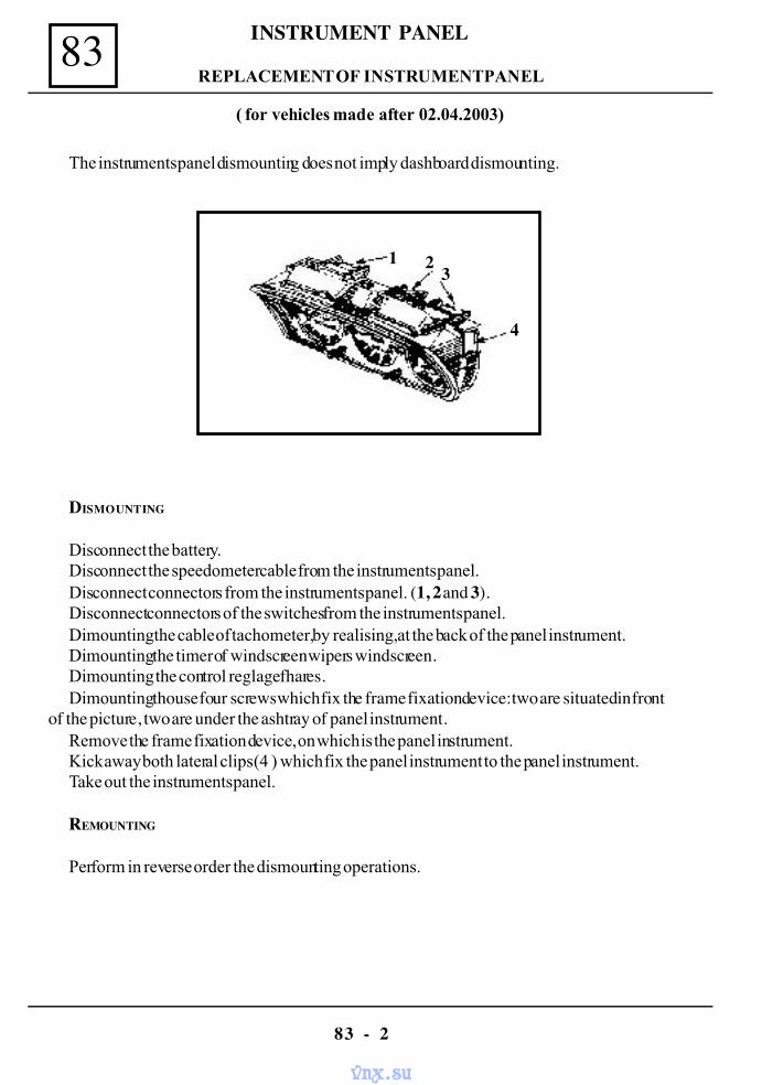
INSTRUMENT PANEL83
83 - 2
The instruments panel dismounting does not imply dashboard dismounting.
DISMOUNTING
Disconnect the battery.Disconnect the speedometer cable from the instruments panel.Disconnect connectors from the instruments panel. (1, 2 and 3).Disconnect connectors of the switches from the instruments panel.Dimounting the cable of tachometer, by realising, at the back of the panel instrument.Dimounting the timer of windscreen wipers windscreen.Dimounting the control reglage fhares.Dimounting thouse four screws which fix the frame fixation device: two are situated in front
of the picture, two are under the ashtray of panel instrument.Remove the frame fixation device, on which is the panel instrument.Kick away both lateral clips (4 ) which fix the panel instrument to the panel instrument.Take out the instruments panel.
REMOUNTING
Perform in reverse order the dismounting operations.
REPLACEMENT OF INSTRUMENT PANEL
( for vehicles made after 02.04.2003)
1 2 3
4
vnx.su
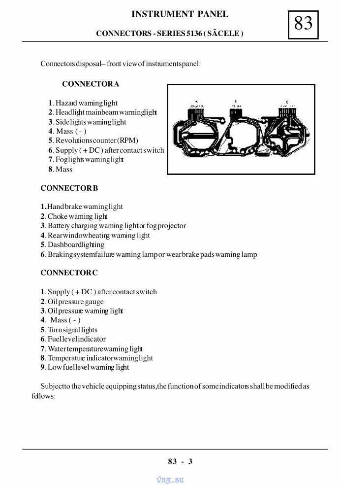
83INSTRUMENT PANEL
83 - 3
CONNECTOR B
1. Hand brake warning light2. Choke warning light3. Battery charging warning light or fog projector4. Rear window heating warning light5. Dashboard lighting6. Braking system failure warning lamp or wear brake pads warning lamp
CONNECTOR C
1. Supply ( + DC ) after contact switch2. Oil pressure gauge3. Oil pressure warning light4. Mass ( - )5. Turn signal lights6. Fuel level indicator7. Water temperature warning light8. Temperature indicator warning light9. Low fuel level warning light
Subject to the vehicle equipping status, the function of some indicators shall be modified asfollows :
CONNECTOR A
1. Hazard warning light2. Headlight main beam warning light3. Side lights warning light4. Mass ( - )5. Revolutions counter (RPM)6. Supply ( + DC ) after contact switch7. Fog lights warning light8. Mass
Connectors disposal – front view of instruments panel:
CONNECTORS - SERIES 5136 ( SÃCELE )
vnx.su
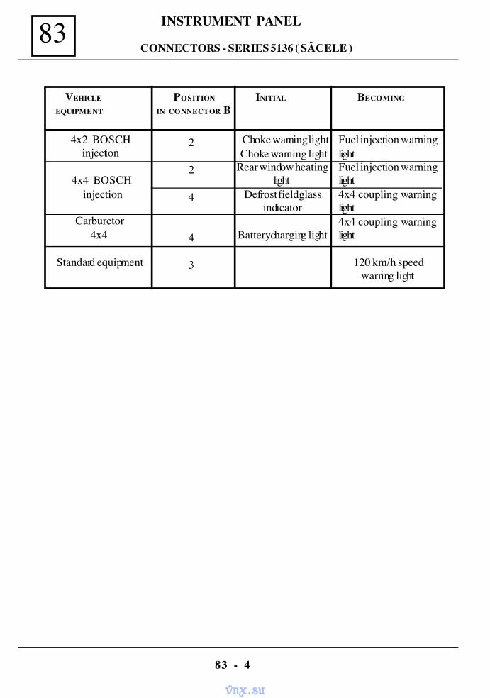
INSTRUMENT PANEL83
83 - 4
VEHICLE POSITION INITIAL BECOMING
EQUIPMENT IN CONNECTOR B
4x2 BOSCH injection
4x4 BOSCH injection
Carburetor4x4
Standard equipment
2
2
4
4
3
Choke warning light Choke warning lightRear window heating
lightDefrost field glass
indicator
Battery charging light
Fuel injection warninglightFuel injection warninglight4x4 coupling warninglight4x4 coupling warninglight
120 km/h speedwarning light
CONNECTORS - SERIES 5136 ( SÃCELE )
vnx.su
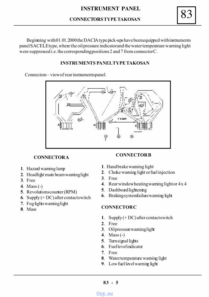
83INSTRUMENT PANEL
83 - 5
Beginning with 01.01.2000 the DACIA type pick-ups have been equipped with instrumentspanel SACELE type, where the oil pressure indicator and the water temperature warning lightwere suppressed i.e. the corresponding positions 2 and 7 from connector C.
INSTRUMENTS PANEL TYPE TAKOSAN
Connectors – view of rear instruments panel.
CONNECTOR A
1. Hazard warning lamp 2. Headlight main beam warning light 3. Free 4. Mass (-) 5. Revolutions counter (RPM) 6. Supply (+ DC) after contact switch 7. Fog lights warning light 8. Mass
CONNECTOR B
1. Hand brake warning light2. Choke warning light or fuel injection3. Free4. Rear window heating warning light or 4 x 45. Dashboard lightening6. Braking system failure warning light
CONNECTOR C
1. Supply (+ DC) after contact switch2. Free3. Oil pressure warning light4. Mass (-)5. Turn signal lights6. Fuel level indicator7. Free8. Water temperature warning light9. Low fuel level warning light
CONNECTORS TYPE TAKOSAN
vnx.su
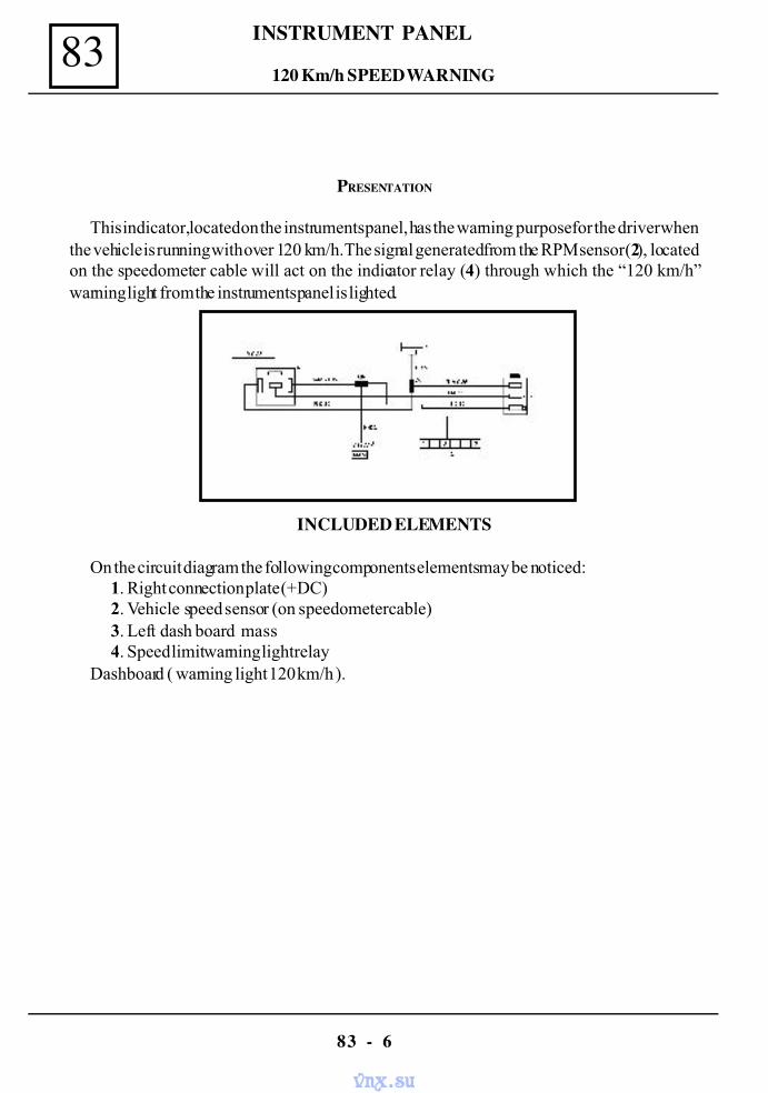
INSTRUMENT PANEL83
83 - 6
PRESENTATION
This indicator, located on the instruments panel, has the warning purpose for the driver whenthe vehicle is running with over 120 km/h. The signal generated from the RPM sensor (2), locatedon the speedometer cable will act on the indicator relay (4) through which the “120 km/h”warning light from the instruments panel is lighted.
INCLUDED ELEMENTS
On the circuit diagram the following components elements may be noticed:1. Right connection plate (+DC)2. Vehicle speed sensor (on speedometer cable)3. Left dash board mass4. Speed limit warning light relay
Dashboard ( warning light 120 km/h ).
120 Km/h SPEED WARNING
vnx.su
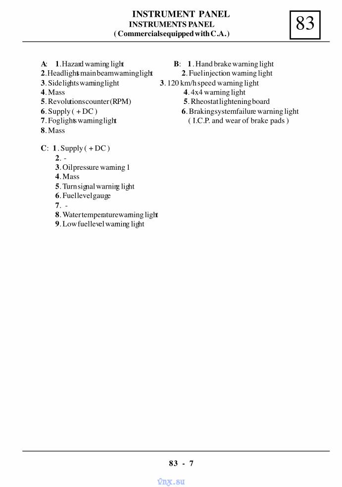
83INSTRUMENT PANEL
83 - 7
A: 1. Hazard warning light B: 1 . Hand brake warning light2. Headlights main beam warning light 2. Fuel injection warning light3. Side lights warning light 3. 120 km/h speed warning light4. Mass 4. 4x4 warning light5. Revolutions counter (RPM) 5. Rheostat lightening board6. Supply ( + DC ) 6. Braking system failure warning light7. Fog lights warning light ( I.C.P. and wear of brake pads )8. Mass
INSTRUMENTS PANEL( Commercials equipped with C.A. )
C: 1 . Supply ( + DC )2. -3. Oil pressure warning 14. Mass5. Turn signal warning light6. Fuel level gauge7. -8. Water temperature warning light9. Low fuel level warning light
vnx.su
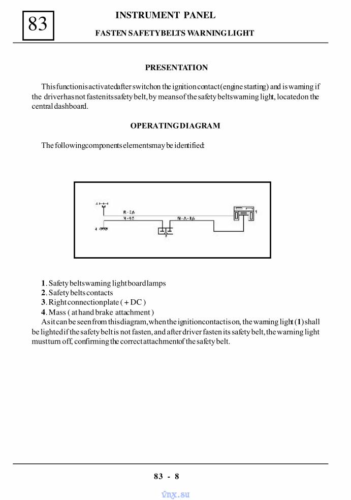
INSTRUMENT PANEL83
83 - 8
PRESENTATION
This function is activated after switch on the ignition contact (engine starting) and is warning ifthe driver has not fasten its safety belt, by means of the safety belts warning light, located on thecentral dashboard.
OPERATING DIAGRAM
The following components elements may be identified:
1. Safety belts warning light board lamps2. Safety belts contacts3. Right connection plate ( + DC )4. Mass ( at hand brake attachment )As it can be seen from this diagram, when the ignition contact is on, the warning light (1) shall
be lighted if the safety belt is not fasten, and after driver fasten its safety belt, the warning lightmust turn off, confirming the correct attachment of the safety belt.
FASTEN SAFETY BELTS WARNING LIGHT
vnx.su
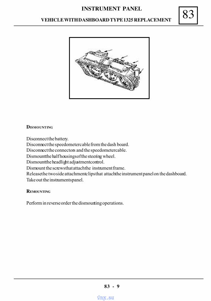
83INSTRUMENT PANEL
83 - 9
DISMOUNTING
Disconnect the battery.Disconnect the speedometer cable from the dash board.Disconnect the connectors and the speedometer cable.Dismount the half housings of the steering wheel.Dismount the headlight adjustment control.Dismount the screws that attach the instrument frame.Release the two side attachment clips that attach the instrument panel on the dashboard.Take out the instruments panel.
REMOUNTING
Perform in reverse order the dismounting operations.
VEHICLE WITH DASHBOARD TYPE 1325 REPLACEMENT
vnx.su
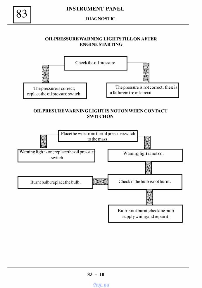
INSTRUMENT PANEL83
83 - 10
OIL PRESSURE WARNING LIGHT STILL ON AFTERENGINE STARTING
Check the oil pressure.
The pressure is not correct; there isa failure in the oil circuit.
The pressure is correct;replace the oil pressure switch.
OIL PRESURE WARNING LIGHT IS NOT ON WHEN CONTACTSWITCH ON
Place the wire from the oil pressure switchto the mass.
Warning light is on; replace the oil pressureswitch.
Warning light is not on.
Bulb is not burnt;check the bulbsupply wiring and repair it.
Burnt bulb; replace the bulb. Check if the bulb is not burnt.
DIAGNOSTIC
vnx.su
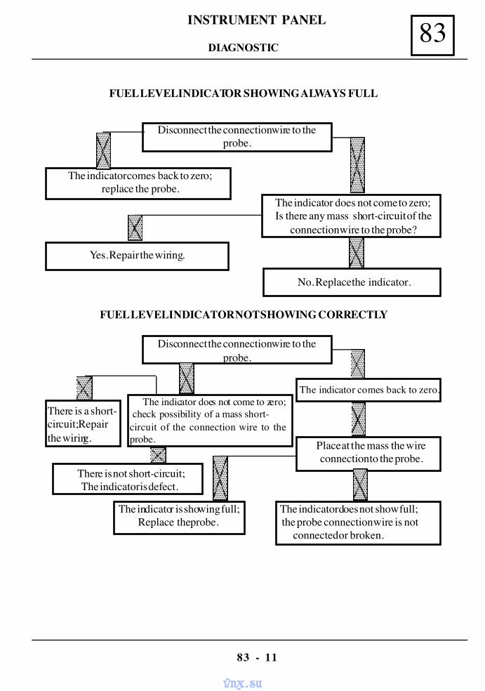
83INSTRUMENT PANEL
83 - 11
FUEL LEVEL INDICATOR SHOWING ALWAYS FULL
Disconnect the connection wire to theprobe.
The indicator comes back to zero; replace the probe.
Yes. Repair the wiring.
The indicator does not come to zero; Is there any mass short-circuit of the
connection wire to the probe?
No. Replace the indicator.
FUEL LEVEL INDICATOR NOT SHOWING CORRECTLY
Disconnect the connection wire to theprobe.
The indicator does not come to zero; check possibility of a mass short-circuit of the connection wire to theprobe.
There is not short-circuit;The indicator is defect.
The indicator comes back to zero.
Place at the mass the wireconnection to the probe.
The indicator does not show full; the probe connection wire is not
connected or broken.
The indicator is showing full;Replace the probe.
There is a short-circuit; Repairthe wiring.
DIAGNOSTIC
vnx.su
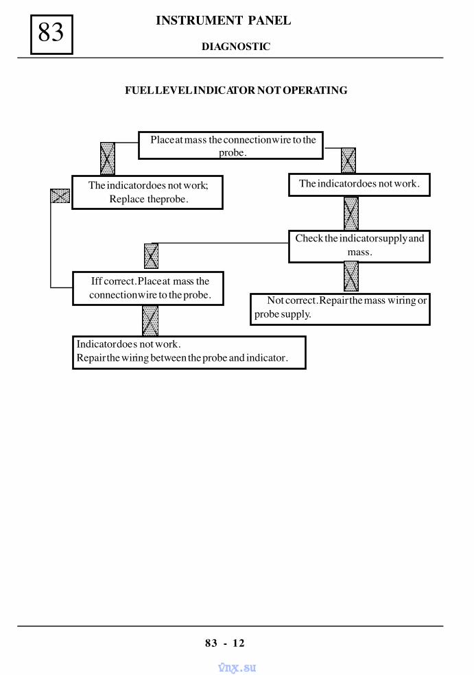
INSTRUMENT PANEL83
83 - 12
FUEL LEVEL INDICATOR NOT OPERATING
Place at mass the connection wire to theprobe.
The indicator does not work;Replace the probe.
The indicator does not work.
Check the indicator supply andmass.
Not correct. Repair the mass wiring orprobe supply.
Iff correct. Place at mass theconnection wire to the probe.
Indicator does not work. Repair the wiring between the probe and indicator.
DIAGNOSTIC
vnx.su
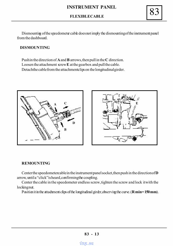
83INSTRUMENT PANEL
83 - 13
Dismounting of the speedometer cable does not imply the dismounting of the instrument panelfrom the dashboard.
DISMOUNTING
Push in the direction of A and B arrows, then pull in the C direction.Loosen the attachment screw E at the gearbox and pull the cable.Detach the cable from the attachment clips on the longitudinal girder.
REMOUNTING
Center the speedometer cable in the instrument panel socket, then push in the direction of Darrow, until a “click” is heard, confirming the coupling.
Center the cable in the speedometer endless screw, tighten the screw and lock it with thelocking nut.
Position it in the attachment clips of the longitudinal girder, observing the curve. (R min = 150 mm).
FLEXIBLE CABLE
A
B
C
D
E
vnx.su
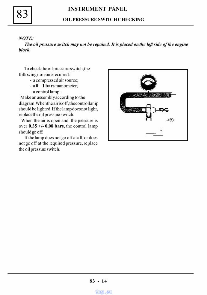
INSTRUMENT PANEL83
83 - 14
NOTE:The oil pressure switch may not be repaired. It is placed on the left side of the engine
block.
To check the oil pressure switch, thefollowing items are required:
- a compressed air source;- a 0 – 1 bars manometer;- a control lamp.
Make an assembly according to thediagram. When the air is off, the control lampshould be lighted. If the lamp does not light,replace the oil pressure switch. When the air is open and the pressure isover 0,35 +/- 0,08 bars, the control lampshould go off.
If the lamp does not go off at all, or doesnot go off at the required pressure, replacethe oil pressure switch.
OIL PRESSURE SWITCH CHECKING
vnx.su
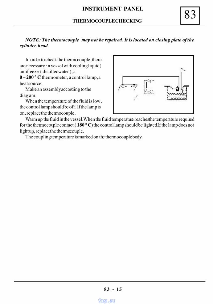
83INSTRUMENT PANEL
83 - 15
THERMOCOUPLE CHECKING
NOTE: The thermocouple may not be repaired. It is located on closing plate of thecylinder head.
In order to check the thermocouple, thereare necessary : a vessel with cooling liquid(antifreeze + distilled water ), a0 – 200 ° C thermometer, a control lamp, aheat source.
Make an assembly according to thediagram.
When the temperature of the fluid is low,the control lamp should be off. If the lamp ison, replace the thermocouple.
Warm up the fluid in the vessel. When the fluid temperature reaches the temperature requiredfor the thermocouple contact ( 180 ° C) the control lamp should be lighted.If the lamp does notlight up, replace the thermocouple.
The coupling temperature is marked on the thermocouple body.
vnx.su
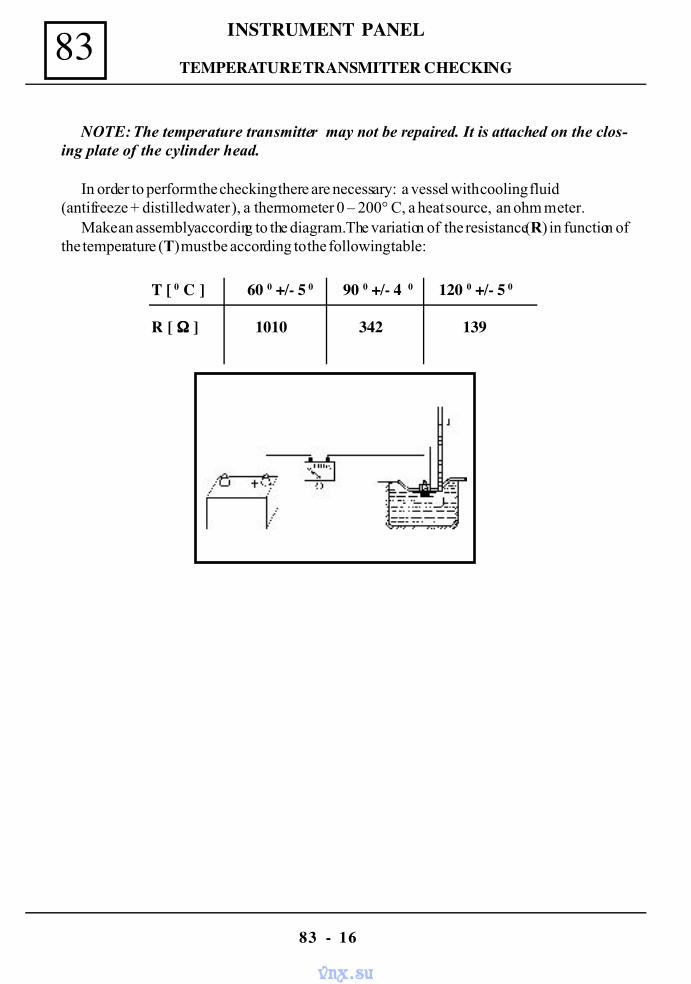
INSTRUMENT PANEL83
83 - 16
NOTE: The temperature transmitter may not be repaired. It is attached on the clos-ing plate of the cylinder head.
In order to perform the checking there are necessary: a vessel with cooling fluid(antifreeze + distilled water ), a thermometer 0 – 200° C, a heat source, an ohm meter.
Make an assembly according to the diagram. The variation of the resistance (R) in function ofthe temperature (T) must be according to the following table:
T [ 0 C ] 60 0 +/- 5 0 90 0 +/- 4 0 120 0 +/- 5 0
R [ ΩΩΩΩ ] 1010 342 139
TEMPERATURE TRANSMITTER CHECKING
vnx.su
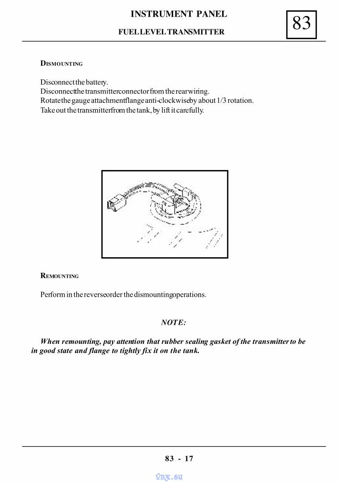
83INSTRUMENT PANEL
83 - 17
DISMOUNTING
Disconnect the battery.Disconnect the transmitter connector from the rear wiring.Rotate the gauge attachment flange anti-clockwise by about 1/3 rotation.Take out the transmitter from the tank, by lift it carefully.
REMOUNTING
Perform in the reverse order the dismounting operations.
NOTE:
When remounting, pay attention that rubber sealing gasket of the transmitter to bein good state and flange to tightly fix it on the tank.
FUEL LEVEL TRANSMITTER
vnx.su
84CONTROLS - SIGNALLING
84 - 1
ANTI THEFT MECHANISM REPLACEMENT( STARTING - IGNITION SWITCH )
The anti theft mechanism is placed on the right part of the steering column and has thepurpose to starter control when electric wiring is connected, being provided in the sametime also with a steering locking device, with anti theft lock.
CONTACT KEY POSITIONS
POSITION INTERPRETATION OBSERVATIONS
S
A
I
M
D
Stop anti theft ( parking )
Accessories
Intermediary
Engine contact
Starter contact
This position enables the introduction and taking out ofthe key from the contact switch. When key is taken outfrom the contact switch, the steering is blocking. Unblock-ing is obtained by introducing the key in the contact switchand if necessary, the easy rotation in both senses of thesteering wheel. In this position, accessories are voltage supplied,protected by means of a bridge fuse F 02 This position enables the removing of the anti theftmechanism, after its attachment screw on the steeringcolumn has been dismounted and the mechanismblocking pin has been pressed. In this position, the steering is not blocked and allconsumers are voltage supplied, protected by meansof the bridge fuse F 01 ( inside fuse box) as well asthe injection system relays. This position enables the voltage supply of thestarter and engine starting, after that key is returningin M position The mechanism is such built not to enable the passagein succession of the contact key in the D positionwithout returning in S position
Subject to the vehicle manufacturing variant, on the anti theft mechanism there is notany more marked G position ( garage ) because does not enable the taking out of the key inthis position but helps in pin unblocking for removing the mechanism from the steeringcolumn.
STARTING - IGNITION SWITCH
vnx.su
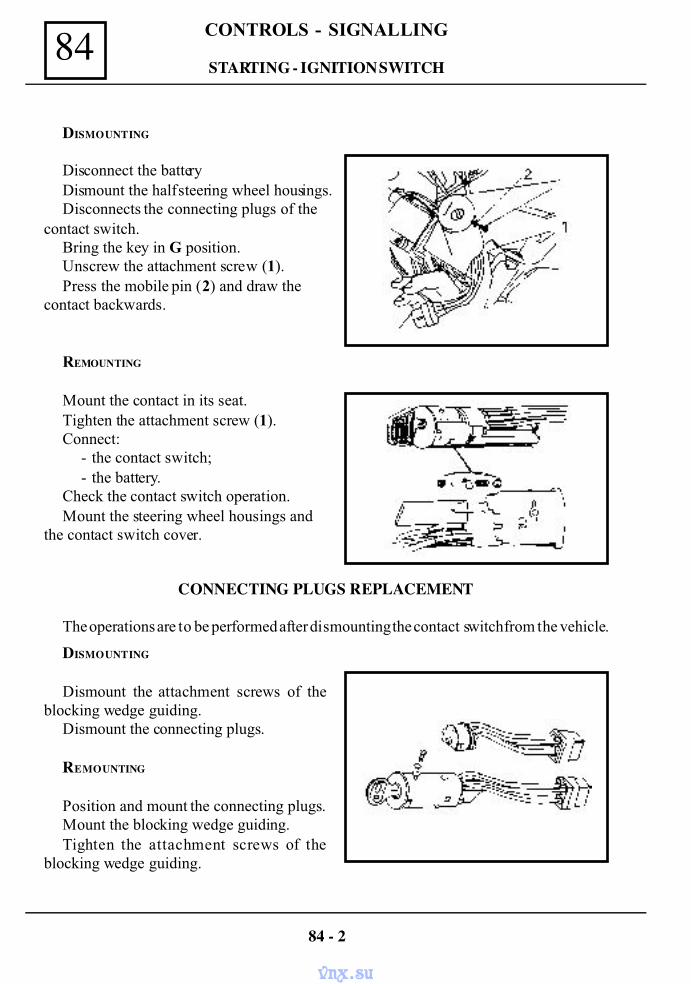
CONTROLS - SIGNALLING84
DISMOUNTING
Disconnect the batteryDismount the half steering wheel housings.Disconnects the connecting plugs of the
contact switch.Bring the key in G position.Unscrew the attachment screw (1).Press the mobile pin (2) and draw the
contact backwards.
REMOUNTING
Mount the contact in its seat.Tighten the attachment screw (1).Connect:
- the contact switch;- the battery.
Check the contact switch operation.Mount the steering wheel housings and
the contact switch cover.
CONNECTING PLUGS REPLACEMENT
The operations are to be performed after dismounting the contact switch from the vehicle.
DISMOUNTING
Dismount the attachment screws of theblocking wedge guiding.
Dismount the connecting plugs.
REMOUNTING
Position and mount the connecting plugs.Mount the blocking wedge guiding.Tighten the attachment screws of the
blocking wedge guiding.
84 - 2
STARTING - IGNITION SWITCH
vnx.su
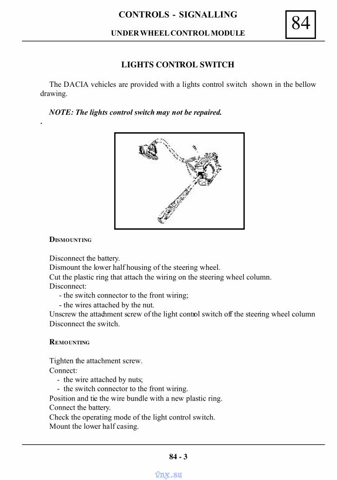
84CONTROLS - SIGNALLING
LIGHTS CONTROL SWITCH
The DACIA vehicles are provided with a lights control switch shown in the bellowdrawing.
NOTE: The lights control switch may not be repaired..
DISMOUNTING
Disconnect the battery.Dismount the lower half housing of the steering wheel.Cut the plastic ring that attach the wiring on the steering wheel column.Disconnect:
- the switch connector to the front wiring;- the wires attached by the nut.
Unscrew the attachment screw of the light control switch off the steering wheel columnDisconnect the switch.
REMOUNTING
Tighten the attachment screw.Connect:
- the wire attached by nuts;- the switch connector to the front wiring.
Position and tie the wire bundle with a new plastic ring.Connect the battery.Check the operating mode of the light control switch.Mount the lower half casing.
84 - 3
UNDER WHEEL CONTROL MODULE
vnx.su
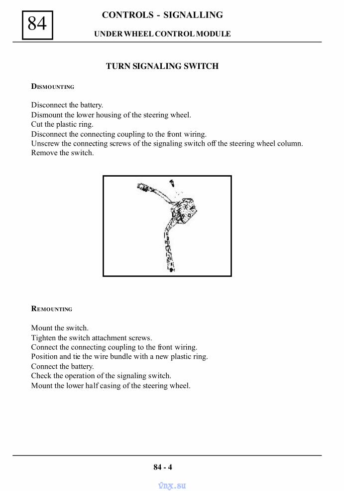
CONTROLS - SIGNALLING84
TURN SIGNALING SWITCH
DISMOUNTING
Disconnect the battery.Dismount the lower housing of the steering wheel.Cut the plastic ring.Disconnect the connecting coupling to the front wiring.Unscrew the connecting screws of the signaling switch off the steering wheel column.Remove the switch.
REMOUNTING
Mount the switch.Tighten the switch attachment screws.Connect the connecting coupling to the front wiring.Position and tie the wire bundle with a new plastic ring.Connect the battery.Check the operation of the signaling switch.Mount the lower half casing of the steering wheel.
84 - 4
UNDER WHEEL CONTROL MODULE
vnx.su
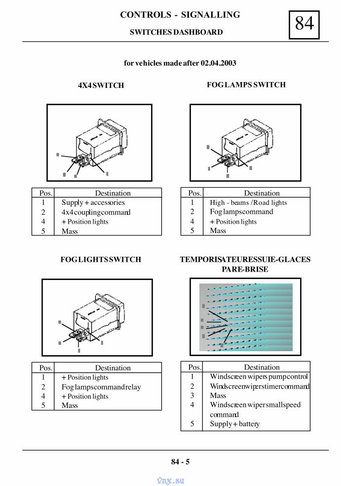
84CONTROLS - SIGNALLING
SWITCHES DASHBOARD
Pos. Destination 1 Supply + accessories 2 4x4 coupling command 4 + Position lights 5 Mass
4X4 SWITCH FOG LAMPS SWITCH
Pos. Destination 1 + Position lights 2 Fog lamps command relay 4 + Position lights 5 Mass
FOG LIGHTS SWITCH
Pos. Destination 1 High - beams / Road lights 2 Fog lamps command 4 + Position lights 5 Mass
Pos. Destination 1 Windscreen wipers pump control 2 Windscreen wipers timer command 3 Mass 4 Windscreen wiper small speed
command 5 Supply + battery
TEMPORISATEUR ESSUIE-GLACESPARE-BRISE
for vehicles made after 02.04.2003
84 - 5
vnx.su
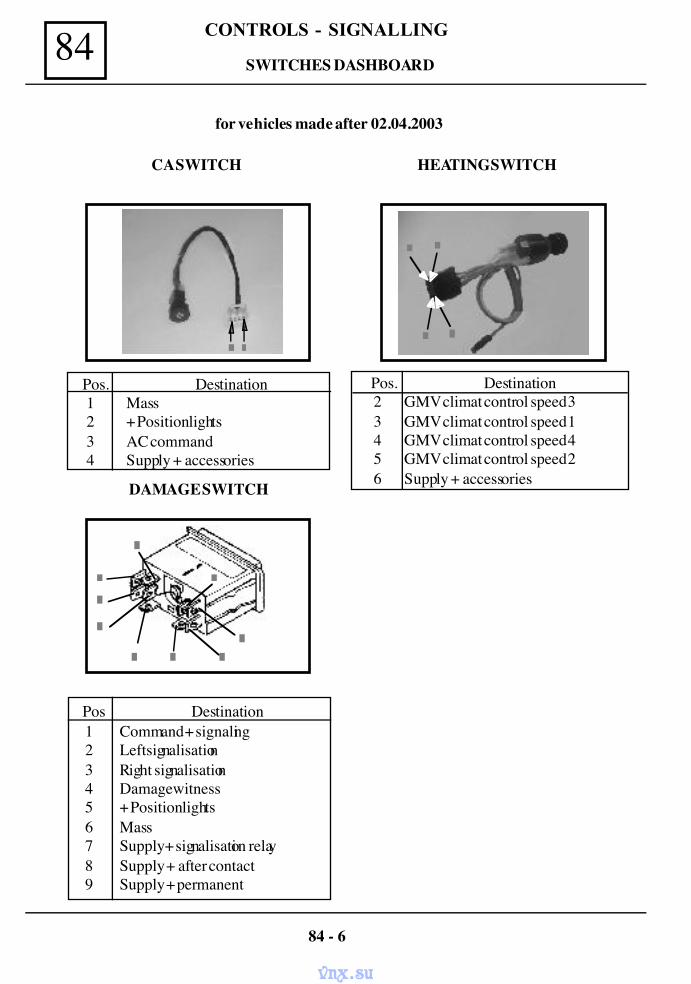
CONTROLS - SIGNALLING84 SWITCHES DASHBOARD
DAMAGE SWITCH
Pos Destination1 Command + signaling2 Left signalisation3 Right signalisation4 Damage witness5 + Position lights6 Mass7 Supply + signalisation relay8 Supply + after contact9 Supply + permanent
Pos. Destination 1 Mass 2 + Position lights 3 AC command 4 Supply + accessories
Pos. Destination2 GMV climat control speed 33 GMV climat control speed 14 GMV climat control speed 45 GMV climat control speed 26 Supply + accessories
HEATING SWITCHCA SWITCH
for vehicles made after 02.04.2003
84 - 6
vnx.su
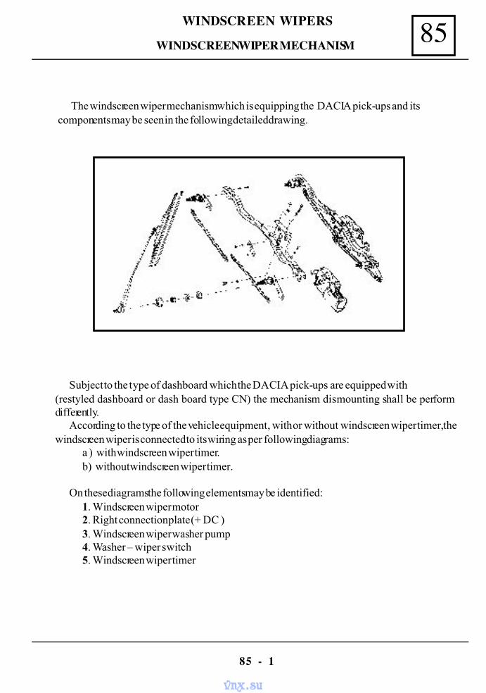
85WINDSCREEN WIPERS
85 - 1
The windscreen wiper mechanism which is equipping the DACIA pick-ups and itscomponents may be seen in the following detailed drawing.
Subject to the type of dashboard which the DACIA pick-ups are equipped with(restyled dashboard or dash board type CN) the mechanism dismounting shall be performdifferently.
According to the type of the vehicle equipment , with or without windscreen wiper timer, thewindscreen wiper is connected to its wiring as per following diagrams:
a ) with windscreen wiper timer.b) without windscreen wiper timer.
On these diagrams the following elements may be identified:1. Windscreen wiper motor2. Right connection plate (+ DC )3. Windscreen wiper washer pump4. Washer – wiper switch5. Windscreen wiper timer
WINDSCREEN WIPER MECHANISM
vnx.su
WINDSCREEN WIPERS85
85 - 2
VEHICLE WITH DASH BOARD TYPE 1325
DISMOUNTING
Disconnect the battery.Dismount the attachment nuts of the windscreen wiper arms and the blades.Unscrew the attachment nuts of the shafts on the lower frame of the windscreen, recover the
rubber washers and bushings.Dismount the dashboard.Disconnect the wiring connector from the windscreen wiper drive motor.Unscrew the attachment screws of the mechanism on the plate.Draw the mechanism backwards and then take it out from the right side of the steering wheel.
REMOUNTING
Perform the dismounting operations in the reverse order.
NOTE: When mounting the windscreen wiper arms, the wiper drive engine mustbe in position “stop at fixe point “.
WINDSCREEN WIPER MECHANISM
vnx.su
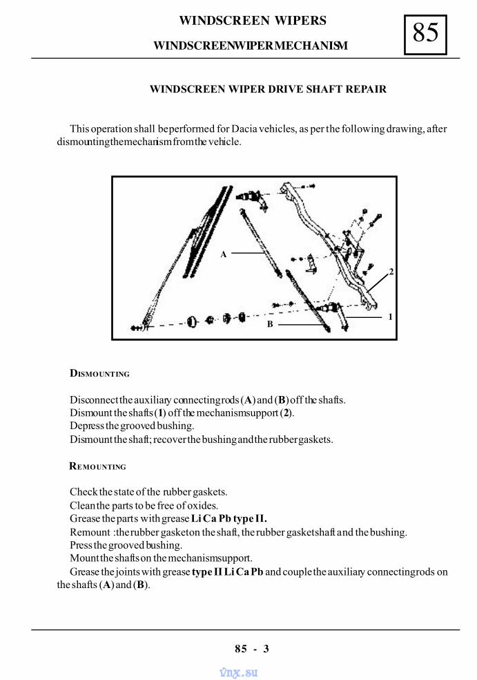
85WINDSCREEN WIPERS
85 - 3
WINDSCREEN WIPER MECHANISM
WINDSCREEN WIPER DRIVE SHAFT REPAIR
This operation shall be performed for Dacia vehicles, as per the following drawing, afterdismounting the mechanism from the vehicle.
DISMOUNTING
Disconnect the auxiliary connecting rods (A) and (B) off the shafts.Dismount the shafts (1) off the mechanism support (2).Depress the grooved bushing.Dismount the shaft; recover the bushing and the rubber gaskets.
REMOUNTING
Check the state of the rubber gaskets.Clean the parts to be free of oxides.Grease the parts with grease Li Ca Pb type II.Remount :the rubber gasket on the shaft, the rubber gasket shaft and the bushing.Press the grooved bushing.Mount the shafts on the mechanism support.Grease the joints with grease type II Li Ca Pb and couple the auxiliary connecting rods on
the shafts (A) and (B).
A
B1
2
vnx.su
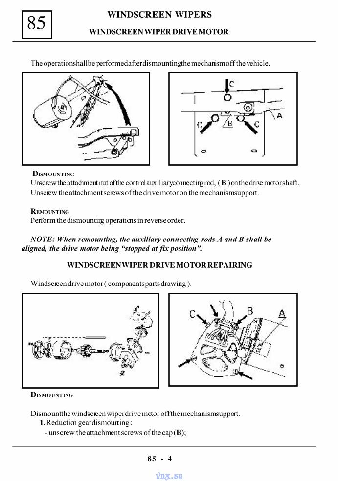
WINDSCREEN WIPERS85
85 - 4
DISMOUNTING
Unscrew the attachment nut of the control auxiliary connecting rod, ( B ) on the drive motor shaft.Unscrew the attachment screws of the drive motor on the mechanism support.
REMOUNTING
Perform the dismounting operations in reverse order.
NOTE: When remounting, the auxiliary connecting rods A and B shall bealigned, the drive motor being “stopped at fix position”.
WINDSCREEN WIPER DRIVE MOTOR REPAIRING
Windscreen drive motor ( components parts drawing ).
DISMOUNTING
Dismount the windscreen wiper drive motor off the mechanism support.1. Reduction gear dismounting :
- unscrew the attachment screws of the cap (B);
The operation shall be performed after dismounting the mechanism off the vehicle.
WINDSCREEN WIPER DRIVE MOTOR
vnx.su
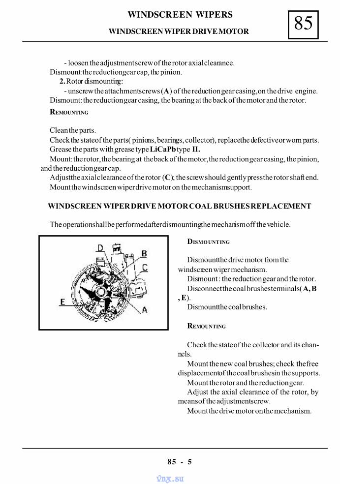
85WINDSCREEN WIPERS
85 - 5
REMOUNTING
Clean the parts.Check the state of the parts ( pinions, bearings, collector ), replace the defective or worn parts.Grease the parts with grease type LiCaPb type II.Mount: the rotor, the bearing at the back of the motor, the reduction gear casing, the pinion,
and the reduction gear cap.Adjust the axial clearance of the rotor (C); the screw should gently press the rotor shaft end.Mount the windscreen wiper drive motor on the mechanism support.
WINDSCREEN WIPER DRIVE MOTOR COAL BRUSHES REPLACEMENT
The operation shall be performed after dismounting the mechanism off the vehicle.
DISMOUNTING
Dismount the drive motor from thewindscreen wiper mechanism.
Dismount : the reduction gear and the rotor.Disconnect the coal brushes terminals (A, B
, E).Dismount the coal brushes.
REMOUNTING
Check the state of the collector and its chan-nels.
Mount the new coal brushes; check the freedisplacement of the coal brushes in the supports.
Mount the rotor and the reduction gear.Adjust the axial clearance of the rotor, by
means of the adjustment screw.Mount the drive motor on the mechanism.
- loosen the adjustment screw of the rotor axial clearance.Dismount: the reduction gear cap, the pinion.
2. Rotor dismounting:- unscrew the attachment screws (A) of the reduction gear casing, on the drive engine.
Dismount: the reduction gear casing, the bearing at the back of the motor and the rotor.
WINDSCREEN WIPER DRIVE MOTOR
vnx.su
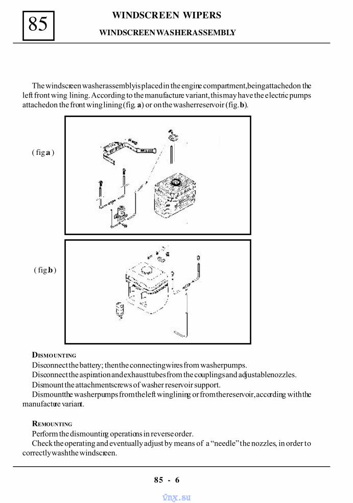
WINDSCREEN WIPERS85
85 - 6
The windscreen washer assembly is placed in the engine compartment, being attached on theleft front wing lining. According to the manufacture variant, this may have the electric pumpsattached on the front wing lining (fig. a) or on the washer reservoir (fig. b).
( fig.a )
( fig.b )
DISMOUNTING
Disconnect the battery; then the connecting wires from washer pumps.Disconnect the aspiration and exhaust tubes from the couplings and adjustable nozzles.Dismount the attachment screws of washer reservoir support.Dismount the washer pumps from the left wing lining or from the reservoir, according with the
manufacture variant.
REMOUNTING
Perform the dismounting operations in reverse order.Check the operating and eventually adjust by means of a “needle” the nozzles, in order to
correctly wash the windscreen.
WINDSCREEN WASHER ASSEMBLY
vnx.su
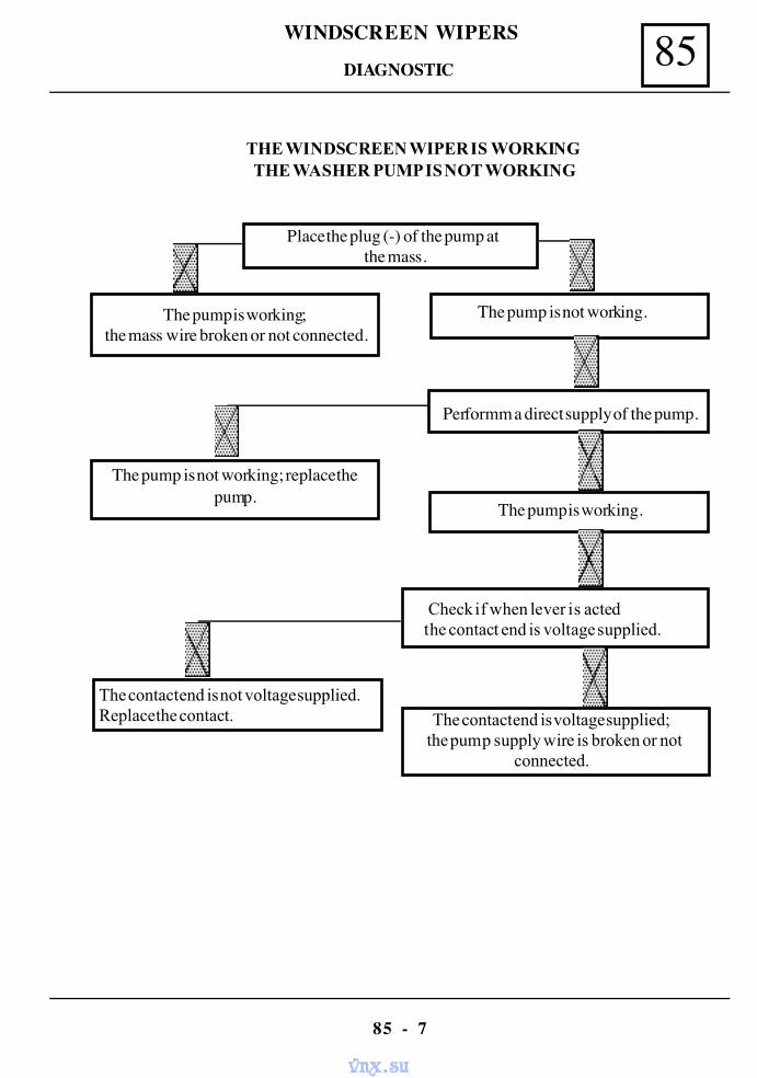
85WINDSCREEN WIPERS
85 - 7
THE WINDSCREEN WIPER IS WORKINGTHE WASHER PUMP IS NOT WORKING
Place the plug (-) of the pump at the mass.
The pump is working;the mass wire broken or not connected.
The pump is not working; replace thepump.
The pump is not working.
The pump is working.
Performm a direct supply of the pump.
Check if when lever is acted the contact end is voltage supplied.
The contact end is voltage supplied; the pump supply wire is broken or not
connected.
The contact end is not voltage supplied.Replace the contact.
DIAGNOSTIC
vnx.su
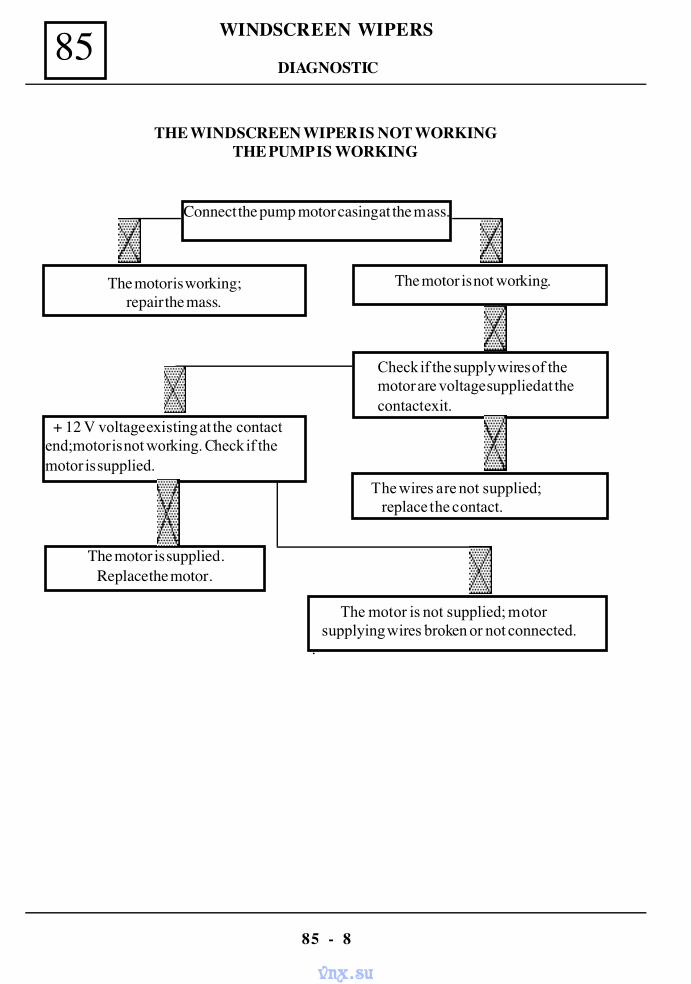
WINDSCREEN WIPERS85
85 - 8
THE WINDSCREEN WIPER IS NOT WORKINGTHE PUMP IS WORKING
Connect the pump motor casing at the mass.
The motor is working;repair the mass.
+ 12 V voltage existing at the contactend;motor is not working. Check if themotor is supplied.
The motor is not working.
The wires are not supplied; replace the contact.
Check if the supply wires of themotor are voltage supplied at thecontact exit.
The motor is not supplied; motor supplying wires broken or not connected..
The motor is supplied.Replace the motor.
DIAGNOSTIC
vnx.su
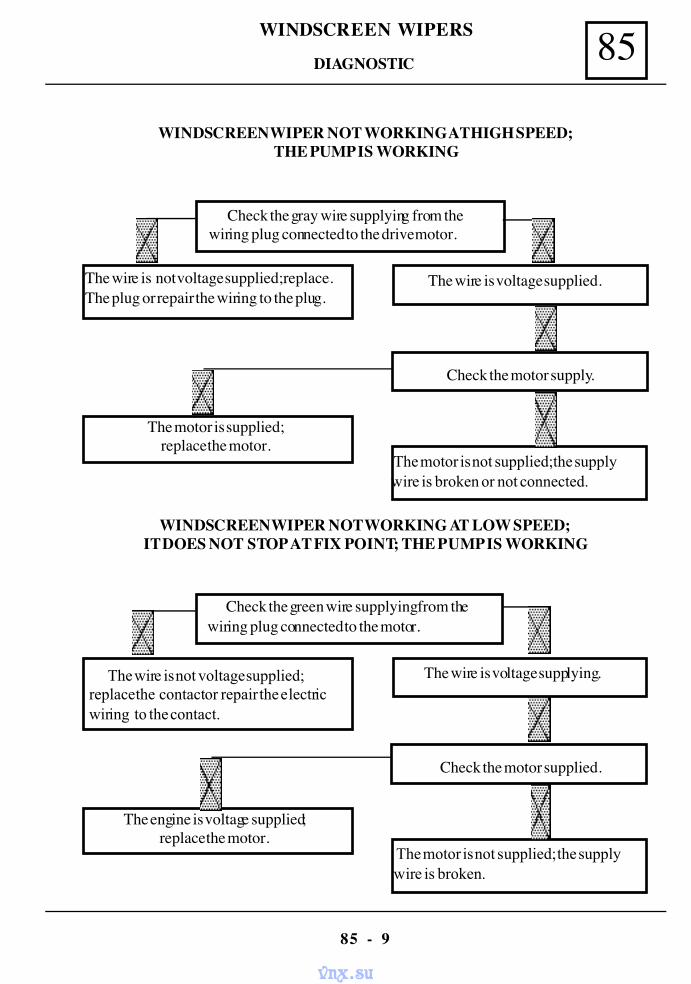
85WINDSCREEN WIPERS
85 - 9
WINDSCREEN WIPER NOT WORKING AT HIGH SPEED;THE PUMP IS WORKING
Check the gray wire supplying from thewiring plug connected to the drive motor.
The wire is not voltage supplied; replace.The plug or repair the wiring to the plug.
The motor is supplied;replace the motor.
The wire is voltage supplied.
The motor is not supplied; the supplywire is broken or not connected.
Check the motor supply.
WINDSCREEN WIPER NOT WORKING AT LOW SPEED;IT DOES NOT STOP AT FIX POINT; THE PUMP IS WORKING
Check the green wire supplying from thewiring plug connected to the motor.
The wire is not voltage supplied;replace the contact or repair the electricwiring to the contact.
The engine is voltage supplied;replace the motor.
The wire is voltage supplying.
The motor is not supplied; the supply wire is broken.
Check the motor supplied.
DIAGNOSTIC
vnx.su
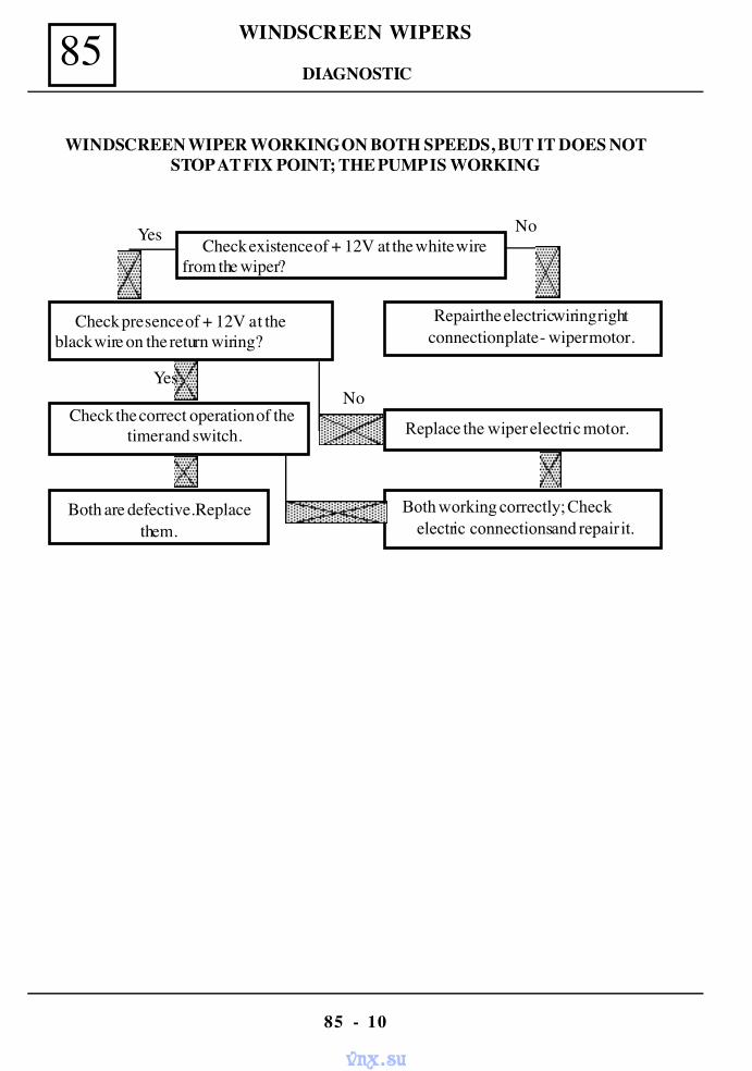
WINDSCREEN WIPERS85
85 - 10
WINDSCREEN WIPER WORKING ON BOTH SPEEDS, BUT IT DOES NOTSTOP AT FIX POINT; THE PUMP IS WORKING
Check existence of + 12V at the white wirefrom the wiper?
Check presence of + 12V at theblack wire on the return wiring?
Check the correct operation of thetimer and switch.
Repair the electric wiring rightconnection plate - wiper motor.
Both working correctly; Check electric connections and repair it.
Replace the wiper electric motor.
Yes No
Both are defective. Replacethem.
NoYes
DIAGNOSTIC
vnx.su
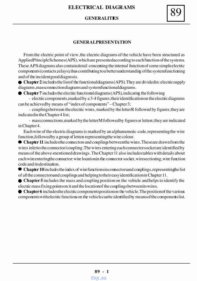
89ELECTRICAL DIAGRAMS
89 - 1
GENERAL PRESENTATION
From the electric point of view, the electric diagrams of the vehicle have been structured asApplied Principle Schemes (APS), which are presented according to each function of the systems.These APS diagrams also contain detail concerning the internal function of some simple electriccomponents (contacts, relays), thus contributing to a better understanding of the system functioningand of the incident good diagnosis.
Chapter 2 includes the list of the functional diagrams (APS). They are divided in: electric supplydiagrams, mass connection diagrams and system functional diagrams.
Chapter 7 includes the electric functional diagrams (APS), indicating the following:- electric components, marked by a 3-4 figures; their identification on the electric diagrams
can be achieved by means of “index of components” – Chapter 3;- couplings between the electric wires, marked by the letter R followed by figures; they are
indicated in the Chapter 4 list;- mass connections, marked by the letter M followed by figures or letters; they are indicated
in Chapter 4.Each wire of the electric diagrams is marked by an alphanumeric code, representing the wire
function, followed by a group of letters representing the wire colour.Chapter 11 includes the connectors and couplings between the wires. These are drawn from the
wires inlet to the connector/coupling. The wires entering each connector socket are identified bymeans of the above-mentioned drawings. The Chapter 11 also includes tables with details abouteach wire entering the connector: wire location in the connector socket, wire sectioning, wire functioncode and its destination.
Chapter 10 includes the index of wire functions in connectors and couplings, representing the listof all the connectors and couplings and helping to their easy identification in Chapter 11.
Chapter 5 includes the mass and coupling position on the vehicle and helps to identify theelectric mass fixing points on it and the location of the couplings between its wires.
Chapter 6 includes the electric components position on the vehicle. The position of the variouscomponents with electric functions on the vehicle can be identified by means of the components list.
GENERALITIES
vnx.su
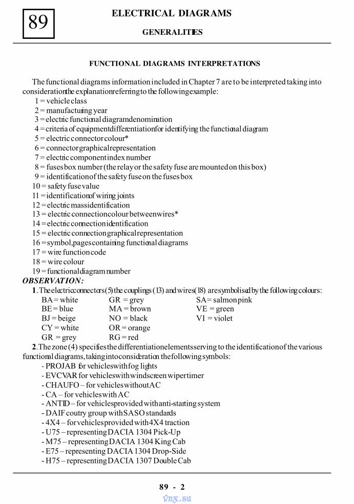
89 ELECTRICAL DIAGRAMS
89 - 2
FUNCTIONAL DIAGRAMS INTERPRETATIONS
The functional diagrams information included in Chapter 7 are to be interpreted taking intoconsideration the explanation referring to the following example:
1 = vehicle class 2 = manufacturing year 3 = electric functional diagram denomination 4 = criteria of equipment differentiation for identifying the functional diagram 5 = electric connector colour* 6 = connector graphical representation 7 = electric component index number 8 = fuses box number (the relay or the safety fuse are mounted on this box) 9 = identification of the safety fuse on the fuses box10 = safety fuse value11 = identification of wiring joints12 = electric mass identification13 = electric connection colour between wires*14 = electric connection identification15 = electric connection graphical representation16 = symbol, pages containing functional diagrams17 = wire function code18 = wire colour19 = functional diagram number
OBSERVATION:1. The electric connectors (5) the couplings (13) and wires (18) are symbolised by the following colours:
BA = white GR = grey SA = salmon pinkBE = blue MA = brown VE = greenBJ = beige NO = black VI = violetCY = white OR = orangeGR = grey RG = red
2.The zone (4) specifies the differentiation elements serving to the identification of the variousfunctional diagrams, taking into consideration the following symbols:
- PROJAB for vehicles with fog lights- EVCVAR for vehicles with windscreen wiper timer- CHAUFO – for vehicles without AC- CA – for vehicles with AC- ANTID – for vehicles provided with anti-starting system- DAIF coutry group with SASO standards- 4X4 – for vehicles provided with 4X4 traction- U75 – representing DACIA 1304 Pick-Up- M75 – representing DACIA 1304 King Cab- E75 – representing DACIA 1304 Drop-Side- H75 – representing DACIA 1307 Double Cab
GENERALITIES
vnx.su
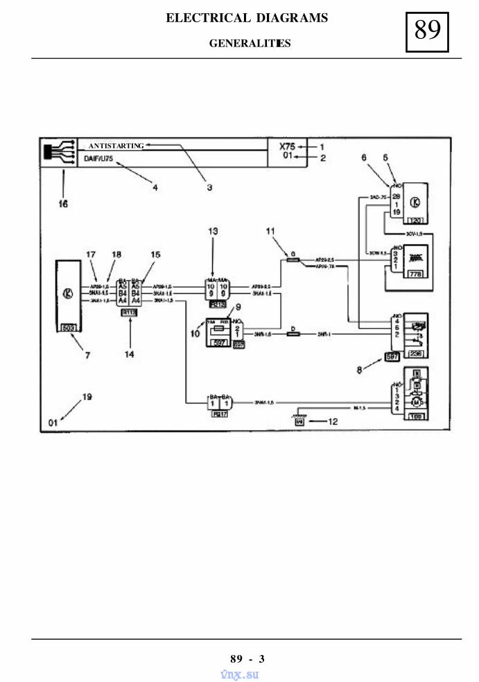
89ELECTRICAL DIAGRAMS
89 - 3
ANTISTARTING
GENERALITIES
vnx.su
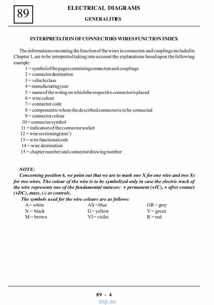
89 ELECTRICAL DIAGRAMS
89 - 4
INTERPRETATION OF CONNECTORS WIRES FUNCTION INDEX
The information concerning the function of the wires in connecters and couplings included inChapter 1, are to be interpreted taking into account the explanations based upon the followingexample:
1 = symbol of the pages containing connectors and couplings2 = connector destination3 = vehicle class4 = manufacturing year5 = name of the wiring on which the respective connector is placed6 = wire colour7 = connector code8 = component to whom the described connector is to be connected9 = connector colour
10 = connector symbol 11 = indication of the connector socket 12 = wire sectioning (mm ) 13 = wire functional code
14 = wire destination 15 = chapter number and connector drawing number
NOTE:Concerning position 6, we point out that we are to mark one X for one wire and two Xs
for two wires. The colour of the wire is to be symbolized only in case the electric track ofthe wire represents one of the fundamental statuses: + permanent (+IC), + after contact(+DC), mass, (-) or controls. The symbols used for the wire colours are as follows:
A = white AS = blue GR = greyN = black G = yellow V = greenM = brown VI = violet R = red
GENERALITIES
vnx.su
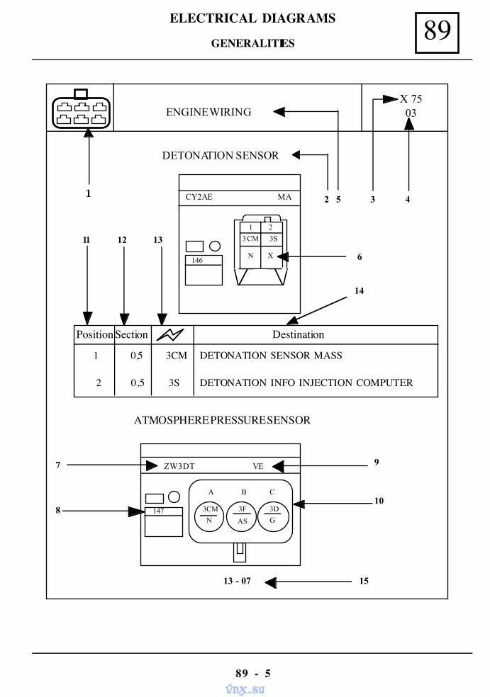
89ELECTRICAL DIAGRAMS
89 - 5
ATMOSPHERE PRESSURE SENSOR
Position Section Destination
1 0,5 3CM DETONATION SENSOR MASS
2 0,5 3S DETONATION INFO INJECTION COMPUTER
ENGINE WIRING X 75 03
DETONATION SENSOR
11 12 13
2 5 3 4
6
14
7
8
9
10
13 - 07 15
1111
1 2
3CM 3S
N X
CY2AE MA
146
147 3CM 3F 3D
N AS G
A B C
ZW3DT VE
GENERALITIES
vnx.su
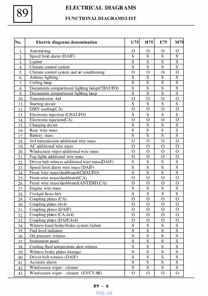
89 ELECTRICAL DIAGRAMS
89 - 6
FUNCTIONAL DIAGRAMS LIST
Antistarting O O O OSpeed limit alarm (DAIF) S S S SLighter S S S SClimate control system S S S SClimate control system and air conditioning O O O OAshtray lighting S S S SCeiling lamp S S S SDocuments compartment lighting lamp(CHAUFO) S S S SDocuments compartment lighting lamp S S S STransmission 4x4 O O O OStarting circuit S S S SGMV cooling(CA) O O O OElectronic injection (CHAUFO) S S S SElectronic injection(CA) O O O OCharging circuit S S S SRear wire mass S S S SBattery mass S S S S4x4 transmission additional wire mass O O O OAC additional wire mass O O O O
Windscreen wiper additional wire mass O O O OFog lights additional wire mass O O O ODriver belt witness additional wire mass(DAIF) S S S SSpeed limit alarm wire mass (DAIF) S S S SFront wire mass/dashboard(CHAUFO) S S S SFront wire mass/dashboard(CA) O O O OFront wire mass/dashboard(ANTIDID,CA) O O O OEngine wire mass S S S SCockpit fuses box S S S SCoupling plates (CA) O O O OCoupling plates (4x4) O O O OCoupling plates (DAIF) O O O OCoupling plates (CA,4x4) O O O OCoupling plates (DAIF,4x4) O O O OWitness hand brake/brake system failure S S S SFuel level indicator S S S SOil pressure witness S S S SInstrument panel S S S SCooling fluid temperature alert witness S S S SWitness brake plates damage S S S SDriver belt witness (DAIF) S S S SAcoustic alarm S S S SWindscreen wiper - cleaner S S S SWindscreen wiper - cleaner (EVCVAR) O O O O
1.2.3.4.5.6.7.8.9.
10.11.12.13.14.15.16.17.18.19.20.21.22.23.24.25.26.27.28.29.30.31.32.33.34.35.36.37.38.39.40.41.42.43.
No. Electric diagrams denomination U75 H75 E75 M75
vnx.su
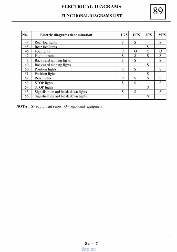
89ELECTRICAL DIAGRAMS
89 - 7
FUNCTIONAL DIAGRAMS LIST
Rear fog lights S S SRear fog lights SFog lights O O O OHigh - beams S S S SBackward running lights S S SBackward running lights SPosition lights S S SPosition lights SRoad lights S S S SSTOP lights S S SSTOP lights SSignalisation and break down lights S S SSignalisation and break down lights S
44.45.46.47.48.49.50.51.52.53.54.55.56.
No. Electric diagrams denomination U75 H75 E75 M75
NOTA : S = equipment series; O = opπional equipment
vnx.su
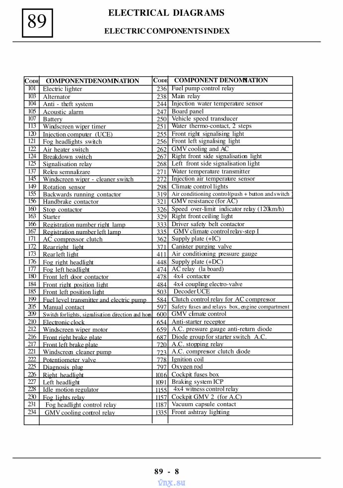
89 ELECTRICAL DIAGRAMS
89 - 8
101103104105107113120121122124125137145149155156160163166167171172173176177180184185199205209210212216217221222225226227228230231234
Electric lighterAlternatorAnti - theft systemAcoustic alarmBatteryWindscreen wiper timerInjection computer (UCE)Fog headlights switchAir heater switchBreakdown switchSignalisation relayReleu semnalizareWindscreen wiper - cleaner switchRotation sensorBackwards running contactorHandbrake contactorStop contactorStarterRegistration number right lampRegistration number left lampAC compressor clutchRear right lightRear left lightFog right headlightFog left headlightFront left door contactorFront right position lightFront left position lightFuel level transmitter and electric pumpManual contactSwitch for lights, signalisation direction and hornElectronic clockWindscreen wiper motorFront right brake plateFront left brake plateWindscreen cleaner pumpPotentiometer valveDiagnosis plugRight headlightLeft headlightIdle motion regulatorFog lights relay Fog headlight control relay GMV cooling control relay
Fuel pump control relayMain relayInjection water temperature sensorBoard panelVehicle speed transducerWater thermo-contact, 2 stepsFront right signalising lightFront left signalising lightGMV cooling and ACRight front side signalisation lightLeft front side signalisation lightWater temperature transmitterInjection air temperature sensorClimate control lightsAir conditioning control(push + button and switch )GMV resistance (for AC)Speed over-limit indicator relay (120km/h)Right front ceiling lightDriver safety belt contactor GMV climate control relay-step ISupply plate (+IC)Canister purging valveAir conditioning pressure gaugeSupply plate (+DC)AC relay (la board) 4x4 contactor 4x4 coupling electro-valve Decoder UCEClutch control relay for AC compressorSafety fuses and relays box, engine compartmentGMV climate controlAnti-starter receptorA.C. pressure gauge anti-return diodeDiode group for starter switch A.C.A.C. stopping relayA.C. compressor clutch diodeIgnition coilOxygen rodCockpit fuses boxBraking system ICP 4x4 witness control relayCockpit GMV 2 (for A.C)Vacuum capsule contactFront ashtray lighting
236 238 244 247 250 251 255 256 262 267 268 271 272 298 319 321 326 329 333 335 362 371 411 448 474 478 484 503 584 597 600 654 659 687 720 723 778 797101610911155115711871335
CODE COMPONENT DENOMINATION CODE COMPONENT DENOMINATION
ELECTRIC COMPONENTS INDEX
vnx.su
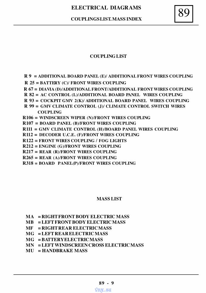
89ELECTRICAL DIAGRAMS
89 - 9
COUPLING LIST
R 9 = ADDITIONAL BOARD PANEL (E)/ ADDITIONAL FRONT WIRES COUPLING R 25 = BATTERY (C)/ FRONT WIRES COUPLING R 67 = DIAVIA (D)/ADDITIONAL FRONT/ADDITIONAL FRONT WIRES COUPLING R 82 = AC CONTROL (L)/ADDITIONAL BOARD PANEL WIRES COUPLING R 93 = COCKPIT GMV 2(K)/ ADDITIONAL BOARD PANEL WIRES COUPLING R 99 = GMV CLIMATE CONTROL (J)/ CLIMATE CONTROL SWITCH WIRES
COUPLINGR106 = WINDSCREEN WIPER (N)/FRONT WIRES COUPLINGR107 = BOARD PANEL (B)/FRONT WIRES COUPLINGR111 = GMV CLIMATE CONTROL (H)/BOARD PANEL WIRES COUPLINGR112 = DECODER U.C.E. (F)/FRONT WIRES COUPLINGR122 = FRONT WIRES COUPLING / FOG LIGHTSR212 = ENGINE (G)/FRONT WIRES COUPLINGR217 = REAR (R)/FRONT WIRES COUPLINGR265 = REAR (A)/FRONT WIRES COUPLINGR318 = BOARD PANEL(P)/FRONT WIRES COUPLING
MASS LIST
MA = RIGHT FRONT BODY ELECTRIC MASSMB = LEFT FRONT BODY ELECTRIC MASSMF = RIGHT REAR ELECTRIC MASSMG = LEFT REAR ELECTRIC MASSMG = BATTERY ELECTRIC MASSMN = LEFT WINDSCREEN CROSS ELECTRIC MASSMU = HANDBRAKE MASS
COUPLINGS LIST. MASS INDEX
vnx.su
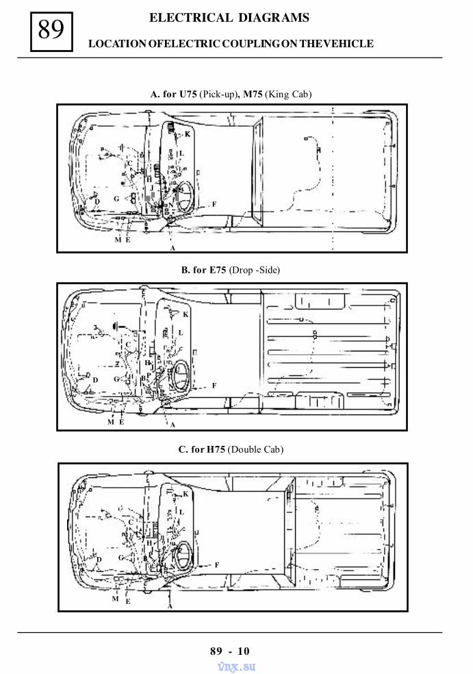
89 ELECTRICAL DIAGRAMS
89 - 10
LOCATION OF ELECTRIC COUPLING ON THE VEHICLE
A. for U75 (Pick-up), M75 (King Cab)
B. for E75 (Drop -Side)
C. for H75 (Double Cab)
K
L
N F
M AE
D G
C
HJBP
K
L
F
MA
D GN
HJPB
E
C
ΚΚΚΚ
L
HJ
FN
AE
GD
C
M
vnx.su
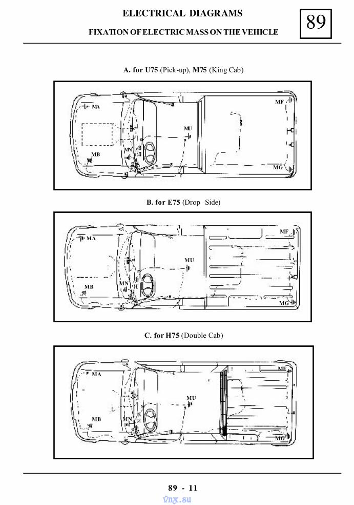
89ELECTRICAL DIAGRAMS
89 - 11
FIXATION OF ELECTRIC MASS ON THE VEHICLE
A. for U75 (Pick-up), M75 (King Cab)
B. for E75 (Drop -Side)
C. for H75 (Double Cab)
MU
MF
MG
MB
MA
MN
MA
MB MN
MU
MF
MG
MA
MB MN
MU
MG
MF
vnx.su
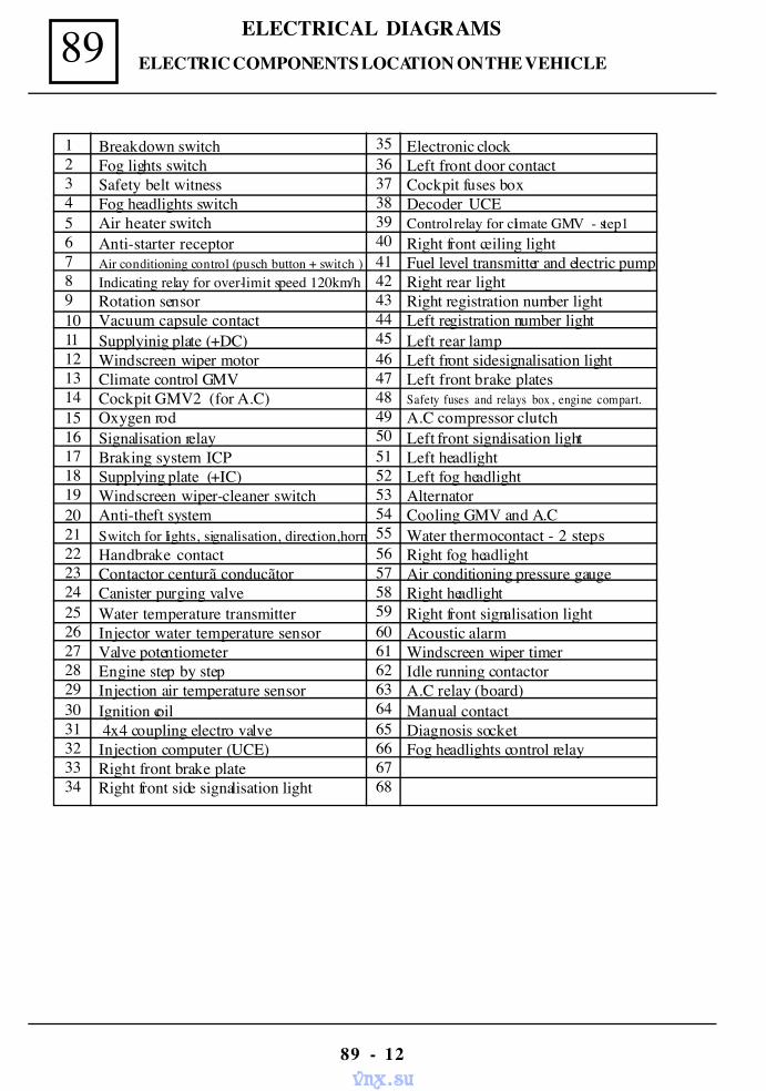
89 ELECTRICAL DIAGRAMS
89 - 12
Electronic clockLeft front door contactCockpit fuses boxDecoder UCEControl relay for climate GMV - step1Right front ceiling lightFuel level transmitter and electric pumpRight rear lightRight registration number lightLeft registration number lightLeft rear lampLeft front side signalisation lightLeft front brake platesSafety fuses and relays box , engine compart.A.C compressor clutchLeft front signalisation lightLeft headlightLeft fog headlightAlternatorCooling GMV and A.CWater thermocontact - 2 stepsRight fog headlightAir conditioning pressure gaugeRight headlightRight front signalisation lightAcoustic alarmWindscreen wiper timerIdle running contactorA.C relay (board)Manual contactDiagnosis socketFog headlights control relay
ELECTRIC COMPONENTS LOCATION ON THE VEHICLE
Breakdown switchFog lights switchSafety belt witnessFog headlights switchAir heater switchAnti-starter receptorAir conditioning control (pusch button + switch )Indicating relay for over-limit speed 120km/hRotation sensorVacuum capsule contactSupplyinig plate (+DC)Windscreen wiper motorClimate control GMVCockpit GMV2 (for A.C)Oxygen rodSignalisation relayBraking system ICPSupplying plate (+IC)Windscreen wiper-cleaner switchAnti-theft systemSwitch for lights, signalisation, direction,hornHandbrake contactContactor centurã conducãtorCanister purging valveWater temperature transmitterInjector water temperature sensorValve potentiometerEngine step by stepInjection air temperature sensorIgnition coil 4x4 coupling electro valveInjection computer (UCE)Right front brake plateRight front side signalisation light
12345678910111213141516171819202122232425262728293031323334
35363738394041424344454647484950515253545556575859606162636465666768
vnx.su
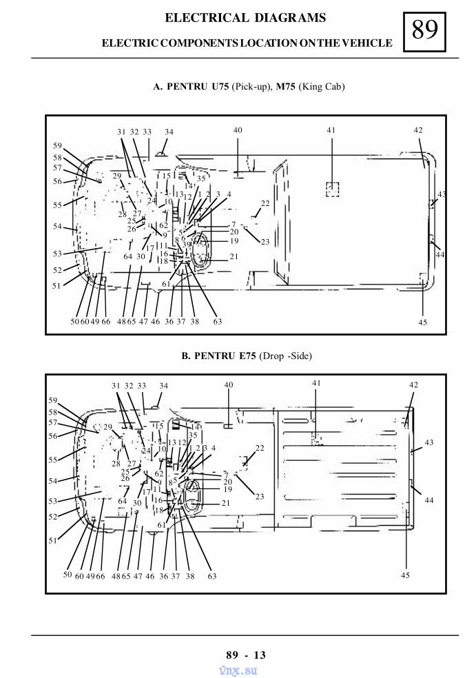
89ELECTRICAL DIAGRAMS
89 - 13
B. PENTRU E75 (Drop -Side)
A. PENTRU U75 (Pick-up), M75 (King Cab)
41 42
43
44
45
40
23
22
2019
21
4321
58
1618
61
1117
633837364647654866496050
51
52
53
54
55
56
575859
29
27282526
3064
24
15
10
629
13
14
31 32 33 34
35
39
7
12
41 42
43
44
45
40
23
22
72019
21
4321
568 39
1618
61
1117
633837364647654866496050
51
52
53
54
55
56
575859
29
27282526
3064
24
15
10
629
1314
31 32 33 34
35
12
ELECTRIC COMPONENTS LOCATION ON THE VEHICLE
vnx.su
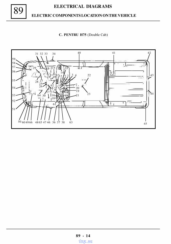
89 ELECTRICAL DIAGRAMS
89 - 14
C. PENTRU H75 (Double Cab)
40
23
22
201921
43212
568
1618
61
1117
633837364647654866496050
51
52
53
54
55
56575859
29
27282526
3064
24
15
10
629
1314
31 32 33 34
35
39
7
41 42
43
44
45
1
ELECTRIC COMPONENTS LOCATION ON THE VEHICLE
vnx.su
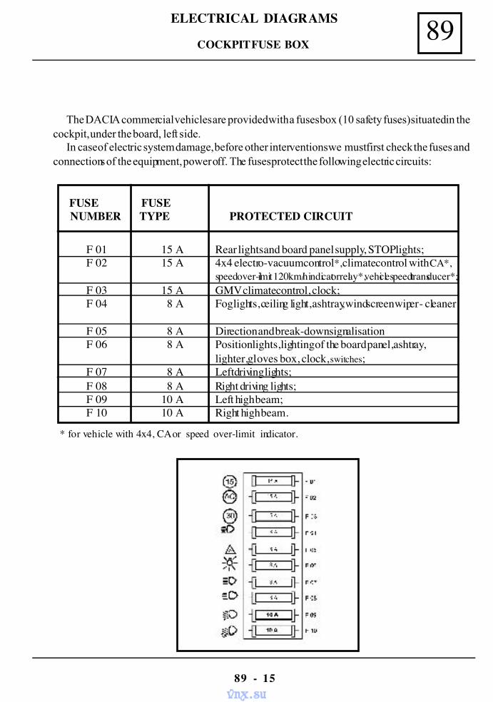
89ELECTRICAL DIAGRAMS
89 - 15
The DACIA commercial vehicles are provided with a fuses box (10 safety fuses) situated in thecockpit, under the board, left side.
In case of electric system damage, before other interventions we must first check the fuses andconnections of the equipment, power off. The fuses protect the following electric circuits:
COCKPIT FUSE BOX
FUSE FUSE NUMBER TYPE PROTECTED CIRCUIT
F 01 15 A Rear lights and board panel supply, STOP lights;F 02 15 A 4x4 electro-vacuum control*, climate control with CA*,
speed over-limit 120 km/h indicator relay*, vehicle speed transducer*;F 03 15 A GMV climate control, clock;F 04 8 A Fog lights, ceiling light, ashtray, windscreen wiper - cleaner
F 05 8 A Direction and break-down signalisationF 06 8 A Position lights, lighting of the board panel,ashtray,
lighter, gloves box, clock, switches;F 07 8 A Left driving lights;F 08 8 A Right driving lights;F 09 10 A Left high beam;F 10 10 A Right high beam.
* for vehicle with 4x4, CA or speed over-limit indicator.
vnx.su
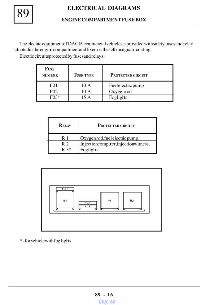
89 ELECTRICAL DIAGRAMS
89 - 16
The electric equipment of DACIA commercial vehicles is provided with safety fuses and relay,situated in the engine compartment and fixed on the left mudguard coating.
Electric circuits protected by fuses and relays:
FUSE
NUMBER FUSE TYPE PROTECTED CIRCUIT
F01 10 A Fuel electric pumpF02 10 A Oxygen rodF03* 15 A Fog lights
R 1 Oxygen rod, fuel electric pump. R 2 Injection computer, injection witness. R 3* Fog lights
RELAY PROTECTED CIRCUIT
ENGINE COMPARTMENT FUSE BOX
* -for vehicle with fog lights
vnx.su
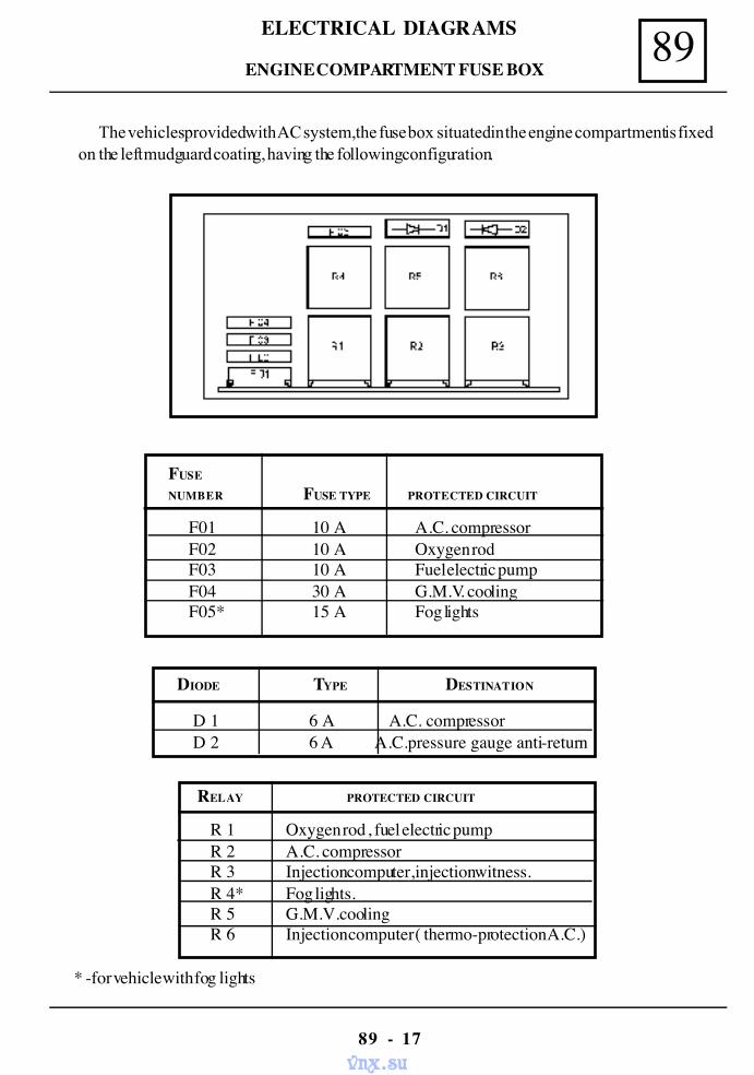
89ELECTRICAL DIAGRAMS
89 - 17
ENGINE COMPARTMENT FUSE BOX
The vehicles provided with AC system, the fuse box situated in the engine compartment is fixedon the left mudguard coating, having the following configuration.
F01 10 A A.C. compressorF02 10 A Oxygen rodF03 10 A Fuel electric pumpF04 30 A G.M.V. coolingF05* 15 A Fog lights
RELAY PROTECTED CIRCUIT
R 1 Oxygen rod , fuel electric pump R 2 A.C. compressor R 3 Injection computer, injection witness. R 4* Fog lights. R 5 G.M.V. cooling R 6 Injection computer ( thermo-protection A.C.)
FUSE
NUMBER FUSE TYPE PROTECTED CIRCUIT
D 1 6 A A.C. compressorD 2 6 A A.C.pressure gauge anti-return
DIODE TYPE DESTINATION
* -for vehicle with fog lights
vnx.su
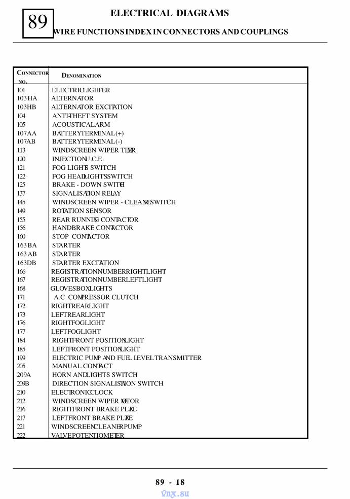
89 ELECTRICAL DIAGRAMS
89 - 18
DENOMINATIONCONNECTOR
NO.101 ELECTRIC LIGHTER 89 - 123103 HA ALTERNATOR 89 - 121103 HB ALTERNATOR EXCITATION 89 - 121104 ANTI-THEFT SYSTEM 89 - 114105 ACOUSTIC ALARM 89 - 108107AA BATTERY TERMINAL (+) 89 - 101107AB BATTERY TERMINAL (-) 89 - 101113 WINDSCREEN WIPER TIMER 89 - 139120 INJECTION U.C.E. 89 - 91121 FOG LIGHTS SWITCH 89 - 126122 FOG HEADLIGHTS SWITCH 89 - 124125 BRAKE - DOWN SWITCH 89 - 127137 SIGNALISATION RELAY 89 - 106145 WINDSCREEN WIPER - CLEANER SWITCH 89 - 140149 ROTATION SENSOR 89 - 93155 REAR RUNNING CONTACTOR 89 - 108156 HANDBRAKE CONTACTOR 89 - 129160 STOP CONTACTOR 89 - 109163 BA STARTER 89 - 120163 AB STARTER 89 - 120163 DB STARTER EXCITATION 89 - 120166 REGISTRATION NUMBER RIGHT LIGHT 89 - 129167 REGISTRATION NUMBER LEFT LIGHT 89 - 129168 GLOVES BOX LIGHTS171 A.C. COMPRESSOR CLUTCH 89 - 100172 RIGHT REAR LIGHT 89 - 131173 LEFT REAR LIGHT 89 - 131176 RIGHT FOG LIGHT 89 - 113177 LEFT FOG LIGHT 89 - 113184 RIGHT FRONT POSITION LIGHT 89 - 112185 LEFT FRONT POSITION LIGHT 89 - 112199 ELECTRIC PUMP AND FUEL LEVEL TRANSMITTER 89 - 133205 MANUAL CONTACT 89 - 114209A HORN AND LIGHTS SWITCH 89 - 105209B DIRECTION SIGNALISATION SWITCH 89 - 105210 ELECTRONIC CLOCK 89 - 141212 WINDSCREEN WIPER MOTOR 89 - 139216 RIGHT FRONT BRAKE PLATE 89 - 104217 LEFT FRONT BRAKE PLATE 89 - 104221 WINDSCREEN CLEANER PUMP 89 - 140222 VALVE POTENTIOMETER
WIRE FUNCTIONS INDEX IN CONNECTORS AND COUPLINGS
vnx.su
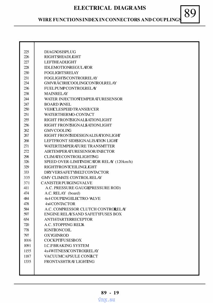
89ELECTRICAL DIAGRAMS
89 - 19
225 DIAGNOSIS PLUG 89 - 95226 RIGHTS HEADLIGHT 89 - 102227 LEFT HEADLIGHT 89 - 102228 IDLE MOTION REGULATOR 89 - 92230 FOG LIGHTS RELAY 89 - 123231 FOG LIGHTS CONTROL RELAY 89 - 107234 GMV RÃCIRE COOLING CONTROL RELAY 89 - 111236 FUEL PUMP CONTROL RELAY 89 - 96238 MAIN RELAY 89 - 97244 WATER INJECTION TEMPERATURE SENSOR 89 - 95247 BOARD PANEL 89 - 117250 VEHICLE SPEED TRANSDUCER 89 - 136251 WATER THERMO-CONTACT 89 - 110255 RIGHT FRONT SIGNALISATION LIGHT 89 - 102256 RIGHT FRONT SIGNALISATION LIGHT 89 - 103262 GMV COOLING 89 - 111267 RIGHT FRONT SIDE SIGNALISATION LIGHT 89 - 103268 LEFT FRONT SIDE SIGNALISATION LIGHT 89 - 103271 WATER TEMPERATURE TRANSMITTER 89 - 117272 AIR TEMPERATURE SENSOR/INJECTOR 89 - 92298 CLIMATE CONTROL LIGHTING 89 - 128326 SPEED OVER-LIMIT INDICATOR RELAY (120 km/h) 89 - 136329 RIGHT FRONT CEILING LIGHT 89 - 137333 DRYVER SAFETY BELT CONTACTOR 89 - 138335 GMV CLIMATE CONTROL RELAY 89 - 122371 CANISTER PURGING VALVE 89 - 94411 A.C. PRESSURE GAUGE (PRESSURE ROD) 89 - 109474 A.C. RELAY (board) 89 - 122484 4x4 COUPLING ELECTRO-VALVE 89 - 135478 4x4 CONTACTOR 89 - 135584 A.C. COMPRESSOR CLUTCH CONTROL RELAY 89 - 97597 ENGINE RELAYS AND SAFETY FUSES BOX 89 - 98654 ANTI-STARTER RECEPTOR 89 - 106720 A.C. STOPPING RELAY 89 - 107778 IGNITION COIL 89 - 93797 OXYGEN ROD 89 - 941016 COCKPIT FUSES BOX 89 - 1151091 I.C.P. BRAKING SYSTEM 89 - 1041155 4x4 WITNESS CONTROL RELAY 89 - 1341187 VACUUM CAPSULE CONTACT 89 - 1341335 FRONT ASHTRAY LIGHTING 89 - 124
WIRE FUNCTIONS INDEX IN CONNECTORS AND COUPLINGS
vnx.su
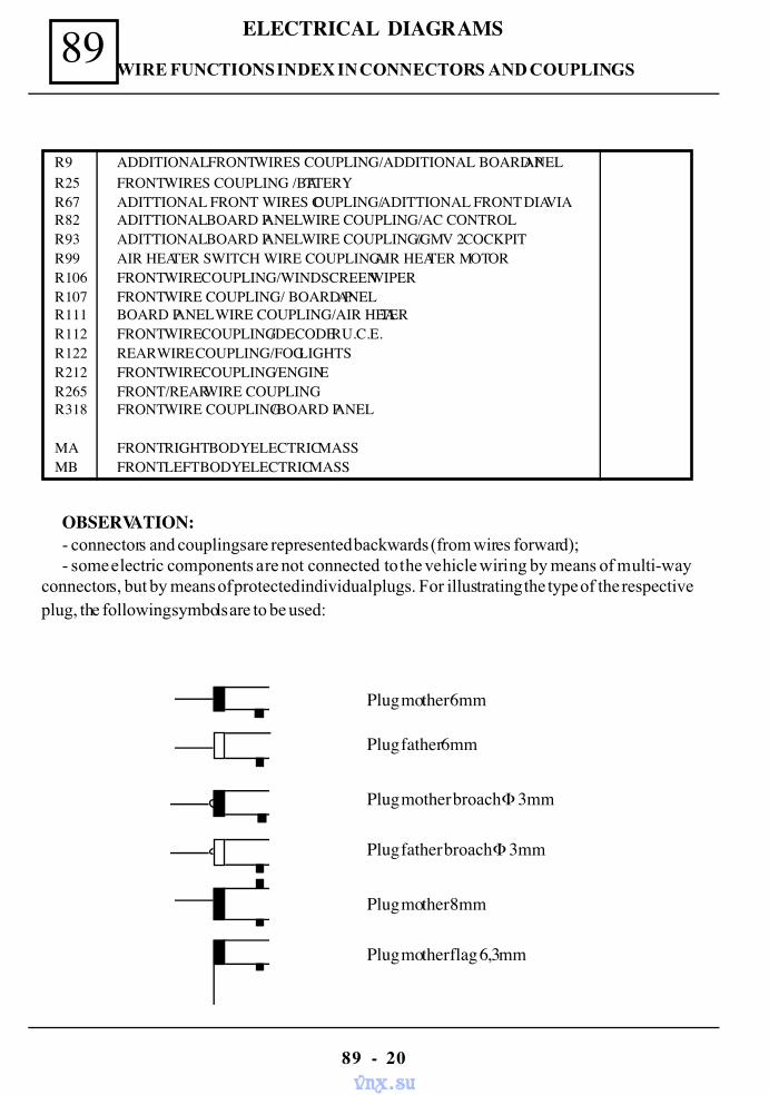
89 ELECTRICAL DIAGRAMS
89 - 20
R 9 ADDITIONAL FRONT WIRES COUPLING/ADDITIONAL BOARD PANEL 89 -158R 25 FRONT WIRES COUPLING /BATTERY 89 -153R 67 ADITTIONAL FRONT WIRES COUPLING/ADITTIONAL FRONT DIAVIA 89 -159R 82 ADITTIONAL BOARD PANEL WIRE COUPLING/AC CONTROL 89 -157R 93 ADITTIONAL BOARD PANEL WIRE COUPLING//GMV 2 COCKPIT 89 -156R 99 AIR HEATER SWITCH WIRE COUPLING /AIR HEATER MOTOR 89 -142R 106 FRONT WIRE COUPLING/WINDSCREEN WIPER 89 -154R 107 FRONT WIRE COUPLING/ BOARD PANEL 89 -146R 111 BOARD PANEL WIRE COUPLING/AIR HEATER 89 -155R 112 FRONT WIRE COUPLING/DECODER U.C.E. 89 -143R 122 REAR WIRE COUPLING/FOG LIGHTS 89 -163R 212 FRONT WIRE COUPLING /ENGINE 89 -160R 265 FRONT/REAR WIRE COUPLING 89 -151R 318 FRONT WIRE COUPLING/BOARD PANEL 89 -144
MA FRONT RIGHT BODY ELECTRIC MASSMB FRONT LEFT BODY ELECTRIC MASS
OBSERVATION:- connectors and couplings are represented backwards (from wires forward);- some electric components are not connected to the vehicle wiring by means of multi-way
connectors, but by means of protected individual plugs. For illustrating the type of the respectiveplug, the following symbols are to be used:
Plug mother 6mm
Plug father 6mm
Plug mother broach Φ 3mm
Plug father broach Φ 3mm
Plug mother flag 6,3mm
Plug mother 8mm
WIRE FUNCTIONS INDEX IN CONNECTORS AND COUPLINGS
vnx.su
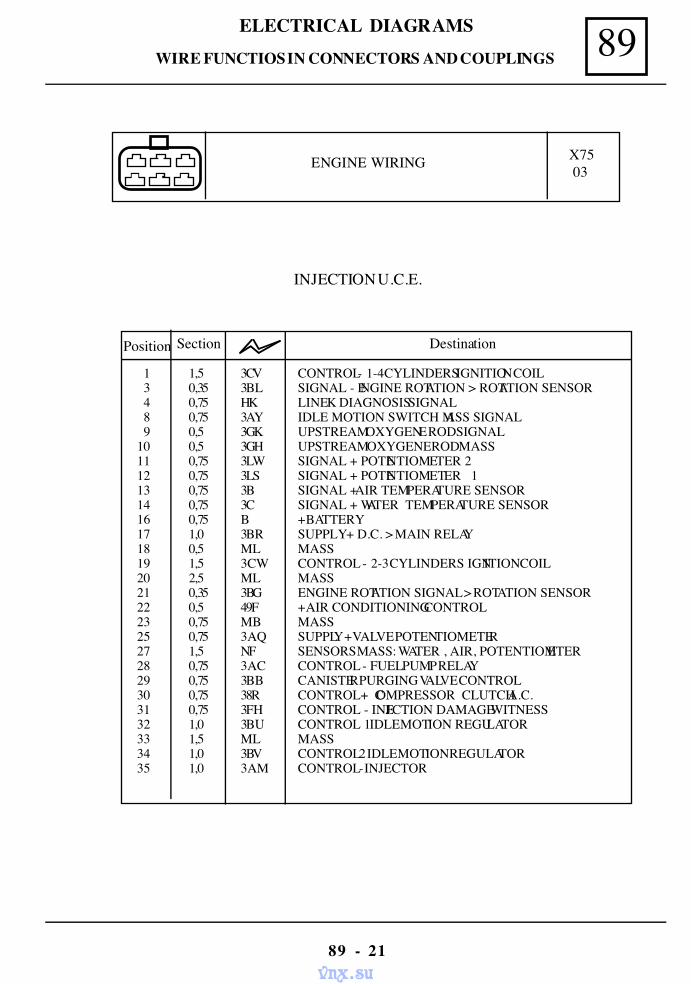
89ELECTRICAL DIAGRAMS
89 - 21
WIRE FUNCTIOS IN CONNECTORS AND COUPLINGS
INJECTION U.C.E.
ENGINE WIRING X7503
Position Section Destination
1 1,5 3CV CONTROL - 1-4 CYLINDERS IGNITION COIL3 0,35 3BL SIGNAL - ENGINE ROTATION > ROTATION SENSOR4 0,75 HK LINE K DIAGNOSIS SIGNAL8 0,75 3AY IDLE MOTION SWITCH MASS SIGNAL9 0,5 3GK UPSTREAM OXYGENE ROD SIGNAL
10 0,5 3GH UPSTREAM OXYGENE ROD MASS 11 0,75 3LW SIGNAL + POTENTIOMETER 2 12 0,75 3LS SIGNAL + POTENTIOMETER 1 13 0,75 3B SIGNAL + AIR TEMPERATURE SENSOR 14 0,75 3C SIGNAL + WATER TEMPERATURE SENSOR 16 0,75 B + BATTERY 17 1,0 3BR SUPPLY + D.C. > MAIN RELAY 18 0,5 ML MASS 19 1,5 3CW CONTROL - 2-3 CYLINDERS IGNITION COIL 20 2,5 ML MASS 21 0,35 3BG ENGINE ROTATION SIGNAL > ROTATION SENSOR 22 0,5 49F + AIR CONDITIONING CONTROL 23 0,75 MB MASS 25 0,75 3AQ SUPPLY + VALVE POTENTIOMETER 27 1,5 NF SENSORS MASS: WATER , AIR, POTENTIOMETER 28 0,75 3AC CONTROL - FUEL PUMP RELAY 29 0,75 3BB CANISTER PURGING VALVE CONTROL 30 0,75 38R CONTROL+ COMPRESSOR CLUTCH A.C. 31 0,75 3FH CONTROL - INJECTION DAMAGE WITNESS 32 1,0 3BU CONTROL 1 IDLE MOTION REGULATOR 33 1,5 ML MASS 34 1,0 3BV CONTROL 2 IDLE MOTION REGULATOR 35 1,0 3AM CONTROL - INJECTOR
vnx.su
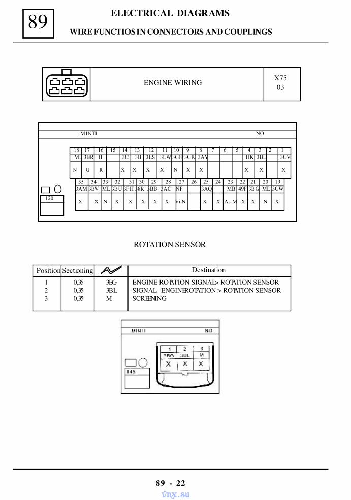
89 ELECTRICAL DIAGRAMS
89 - 22
ENGINE WIRING X7503
MINTI NO
120
18 17 16 15 14 13 12 11 10 9 8 7 6 5 4 3 2 1 ML 3BR B 3C 3B 3LS 3LW 3GH 3GK 3AY HK 3BL 3CV
N G R X X X X N X X X X X
X X N X X X X X Vi-N X X As-M X X N X
35 34 33 32 31 30 29 28 27 26 25 24 23 22 21 20 193AM 3BV ML 3BU 3FH 38R 3BB 3AC NF 3AQ MB 49F 3BG ML 3CW
ROTATION SENSOR
Position Sectioning Destination1 0,35 3BG ENGINE ROTATION SIGNAL > ROTATION SENSOR2 0,35 3BL SIGNAL -ENGINE ROTATION > ROTATION SENSOR3 0,35 M SCREENING
WIRE FUNCTIOS IN CONNECTORS AND COUPLINGS
vnx.su
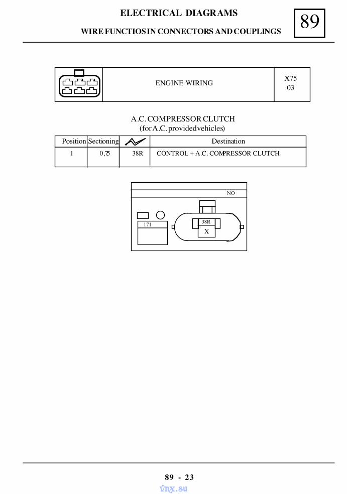
89ELECTRICAL DIAGRAMS
89 - 23
ENGINE WIRING X7503
A.C. COMPRESSOR CLUTCH(for A.C. provided vehicles)
Position Sectioning Destination1 0,75 38R CONTROL + A.C. COMPRESSOR CLUTCH
NO
171 38R
X
WIRE FUNCTIOS IN CONNECTORS AND COUPLINGS
vnx.su
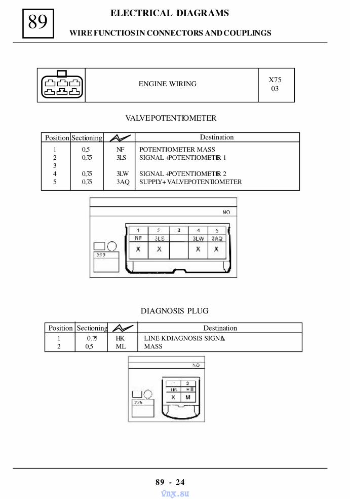
89 ELECTRICAL DIAGRAMS
89 - 24
VALVE POTENTIOMETER
Position Sectioning Destination1 0,5 NF POTENTIOMETER MASS2 0,75 3LS SIGNAL + POTENTIOMETER 134 0,75 3LW SIGNAL + POTENTIOMETER 25 0,75 3AQ SUPPLY + VALVE POTENTIOMETER
ENGINE WIRING X7503
DIAGNOSIS PLUG
Position Sectioning Destination1 0,75 HK LINE K DIAGNOSIS SIGNAL2 0,5 ML MASS
WIRE FUNCTIOS IN CONNECTORS AND COUPLINGS
vnx.su
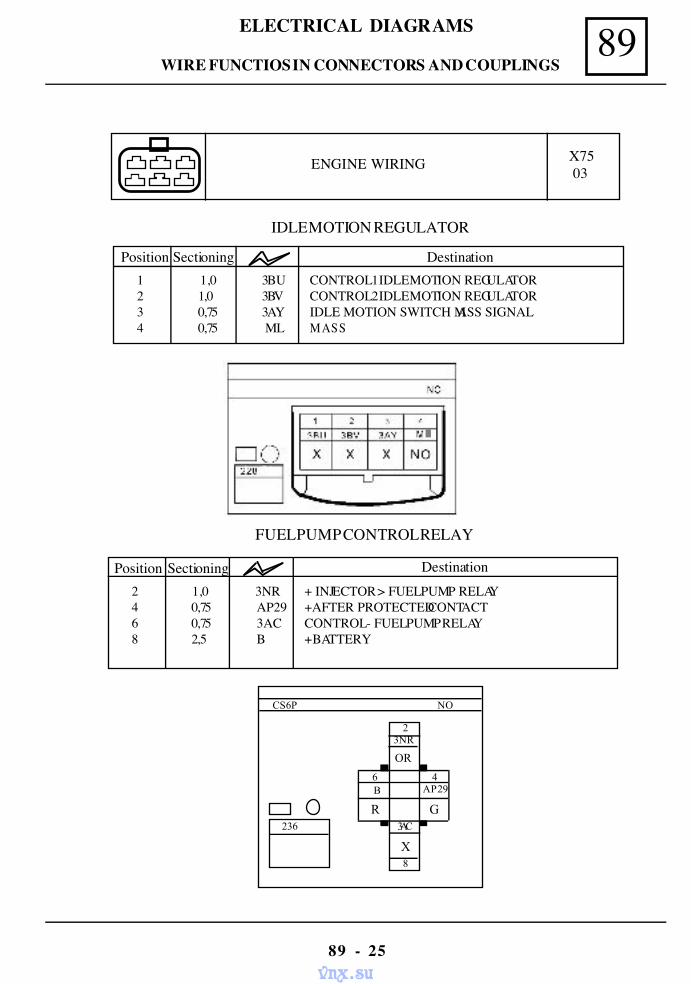
89ELECTRICAL DIAGRAMS
89 - 25
ENGINE WIRING X7503
IDLE MOTION REGULATOR
Position Sectioning Destination1 1,0 3BU CONTROL 1 IDLE MOTION REGULATOR2 1,0 3BV CONTROL 2 IDLE MOTION REGULATOR3 0,75 3AY IDLE MOTION SWITCH MASS SIGNAL4 0,75 ML MASS
FUEL PUMP CONTROL RELAY
Position Sectioning Destination2 1,0 3NR + INJECTOR > FUEL PUMP RELAY4 0,75 AP29 +AFTER PROTECTED CONTACT6 0,75 3AC CONTROL - FUEL PUMP RELAY8 2,5 B + BATTERY
NO
2
X
OR
AP29
8
3AC
3NR
46B
GR
CS6P
236
WIRE FUNCTIOS IN CONNECTORS AND COUPLINGS
vnx.su
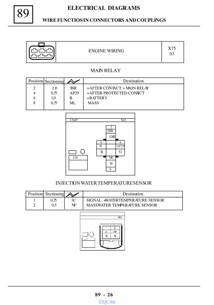
89 ELECTRICAL DIAGRAMS
89 - 26
MAIN RELAY
Position Sectioning Destination2 1,0 3BR + AFTER CONTACT > MAIN RELAY4 0,75 AP29 + AFTER PROTECTED CONTACT6 1,0 B + BATTERY8 0,75 ML MASS
ENGINE WIRING X7503
NO
2
N
OR
AP29
ML
3BR
4 6 B
G R
CS6P
238
8
INJECTION WATER TEMPERATURE SENSOR
Destination1 0,75 3C SIGNAL + WATER TEMPERATURE SENSOR2 0,5 NF MASS WATER TEMPERATURE SENSOR
SectioningPosition
WIRE FUNCTIOS IN CONNECTORS AND COUPLINGS
vnx.su
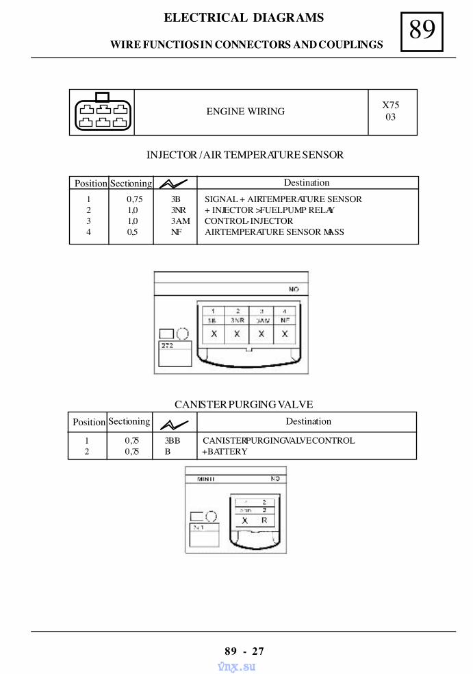
89ELECTRICAL DIAGRAMS
89 - 27
ENGINE WIRING X7503
INJECTOR / AIR TEMPERATURE SENSOR
Position Sectioning Destination1 0,75 3B SIGNAL + AIR TEMPERATURE SENSOR2 1,0 3NR + INJECTOR > FUEL PUMP RELAY3 1,0 3AM CONTROL - INJECTOR4 0,5 NF AIR TEMPERATURE SENSOR MASS
CANISTER PURGING VALVEPosition Sectioning Destination
1 0,75 3BB CANISTER PURGING VALVE CONTROL2 0,75 B + BATTERY
WIRE FUNCTIOS IN CONNECTORS AND COUPLINGS
vnx.su
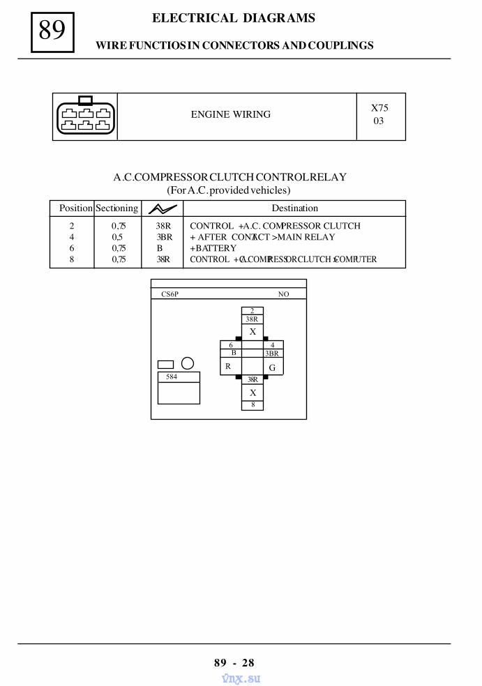
89 ELECTRICAL DIAGRAMS
89 - 28
A.C.COMPRESSOR CLUTCH CONTROL RELAY(For A.C. provided vehicles)
ENGINE WIRING X7503
2 0,75 38R CONTROL + A.C. COMPRESSOR CLUTCH4 0,5 3BR + AFTER CONTACT > MAIN RELAY6 0,75 B + BATTERY8 0,75 38R CONTROL + A.C. COMPRESSOR CLUTCH > COMPUTER
Position Sectioning Destination
NOCS6P
584
2
X
X
3BR
8
38R
38R
4 6 B
GR
WIRE FUNCTIOS IN CONNECTORS AND COUPLINGS
vnx.su
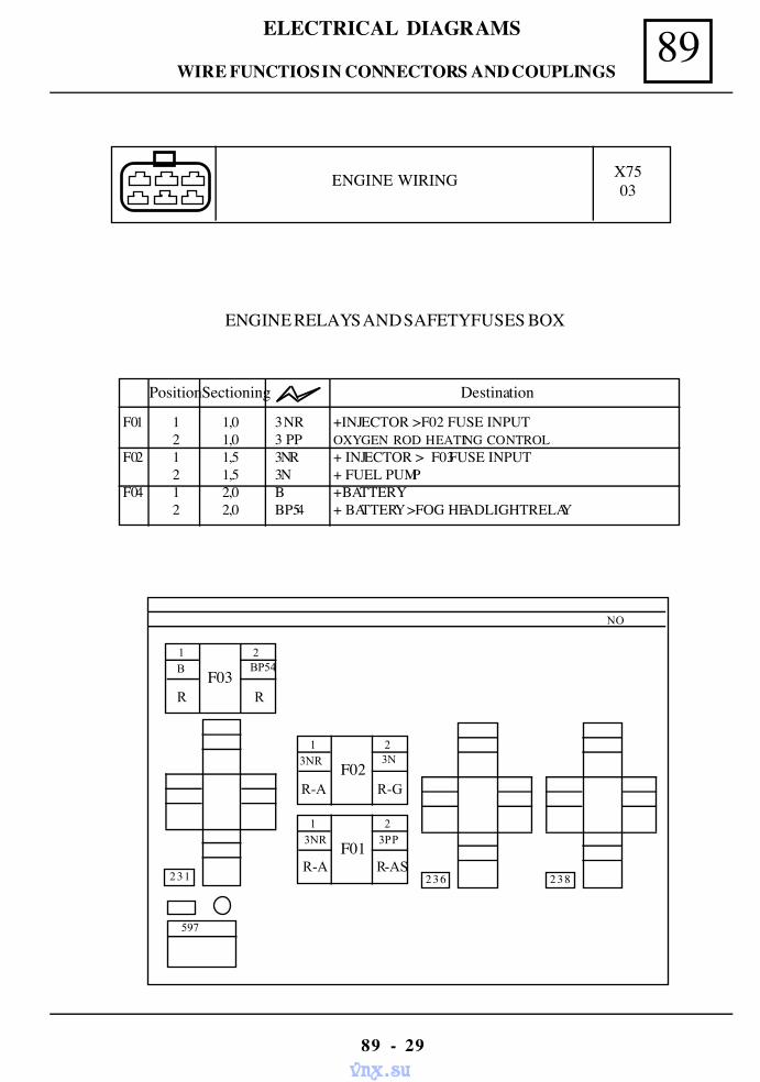
89ELECTRICAL DIAGRAMS
89 - 29
ENGINE RELAYS AND SAFETY FUSES BOX
PositionSectioning Destination
F01 1 1,0 3 NR +INJECTOR > F02 FUSE INPUT2 1,0 3 PP OXYGEN ROD HEATING CONTROL
F02 1 1,5 3NR + INJECTOR > F03 FUSE INPUT2 1,5 3N + FUEL PUMP
F04 1 2,0 B + BATTERY2 2,0 BP54 + BATTERY > FOG HEADLIGHT RELAY
ENGINE WIRING X7503
NO
597
238 R-AS
236R-A
3NR 1 2
3PPF01
R-A
3NR 1 2
3N
R-GF02
231
R
B 1 2
BP54
RF03
WIRE FUNCTIOS IN CONNECTORS AND COUPLINGS
vnx.su
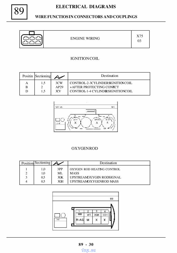
89 ELECTRICAL DIAGRAMS
89 - 30
ENGINE WIRING X7503
OXYGEN ROD
IGNITION COIL
Positin Sectioning Destination
A 1,5 3CW CONTROL - 2-3 CYLINDERS IGNITION COILB 2 AP29 + AFTER PROTECTING CONTACTD 1,5 3CV CONTROL - 1-4 CYLINDERS IGNITION COIL
Position Sectioning Destination1 1,0 3PP OXYGEN ROD HEATING CONTROL2 1,0 ML MASS3 0,5 3GK UPSTREAM OXYGEN ROD SIGNAL4 0,5 3GH UPSTREAM OXYGEN ROD MASS
L
WIRE FUNCTIOS IN CONNECTORS AND COUPLINGS
vnx.su
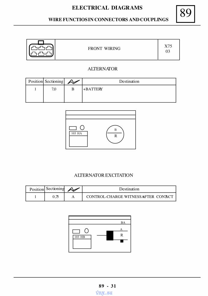
89ELECTRICAL DIAGRAMS
89 - 31
FRONT WIRING X7503
ALTERNATOR
Position Sectioning Destination
1 7,0 B + BATTERY
103 HAB
R
BA
R
A
103 HB
ALTERNATOR EXCITATION
Position Destination
1 0,75 A CONTROL-CHARGE WITNESS + AFTER CONTACT
Sectioning
WIRE FUNCTIOS IN CONNECTORS AND COUPLINGS
vnx.su
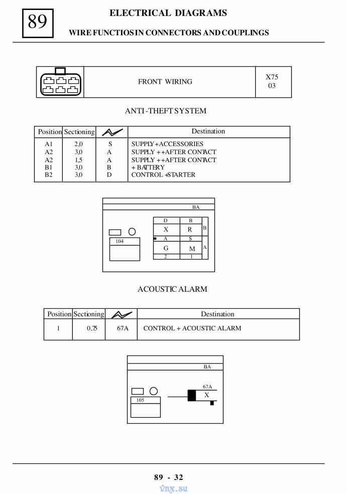
89 ELECTRICAL DIAGRAMS
89 - 32
FRONT WIRING X7503
ANTI -THEFT SYSTEM
Position Sectioning Destination
A1 2,0 S SUPPLY + ACCESSORIESA2 3,0 A SUPPLY + + AFTER CONTACTA2 1,5 A SUPPLY + + AFTER CONTACTB1 3,0 B + BATTERYB2 3,0 D CONTROL + STARTER
B
A
BA
2 1
X R
M
D B
A S 104G
Position Sectioning Destination
1 0,75 67A CONTROL + ACOUSTIC ALARM
ACOUSTIC ALARM
BA
105X
67A
WIRE FUNCTIOS IN CONNECTORS AND COUPLINGS
vnx.su
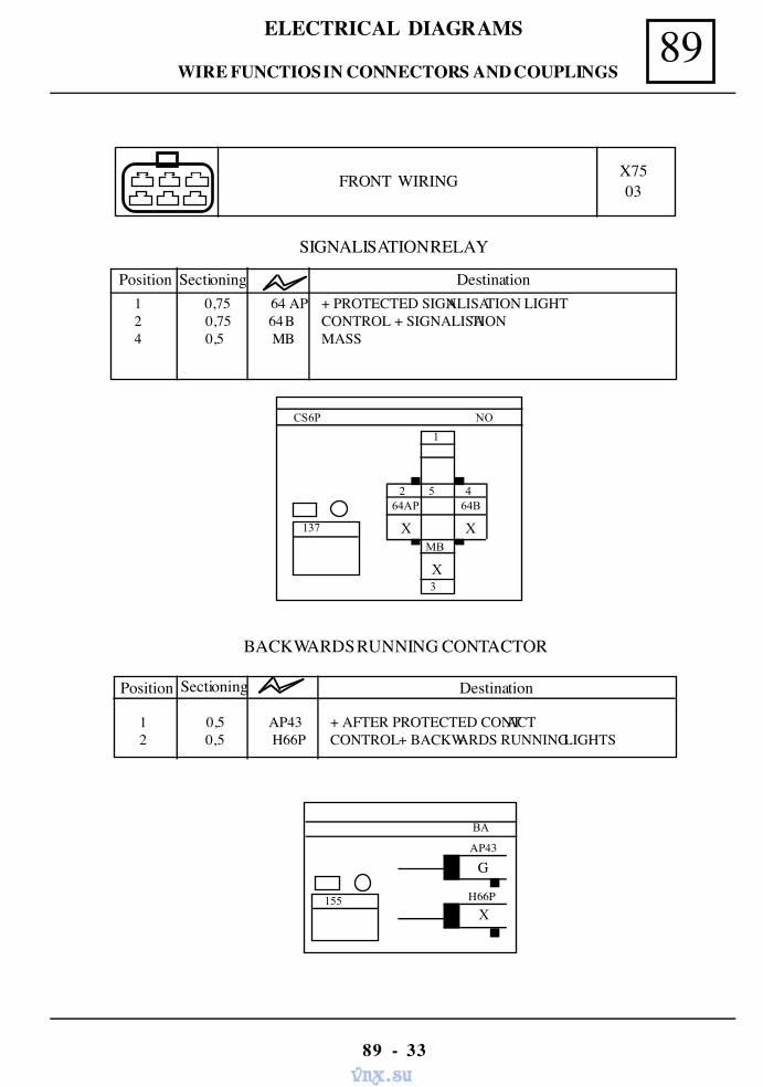
89ELECTRICAL DIAGRAMS
89 - 33
FRONT WIRING X7503
NO
1
X3
MB
2 5 4 64AP 64B
X X
CS6P
137
SIGNALISATION RELAY
1 0,75 64 AP + PROTECTED SIGNALISATION LIGHT 2 0,75 64 B CONTROL + SIGNALISATION 4 0,5 MB MASS
Position Sectioning Destination
BACKWARDS RUNNING CONTACTOR
Position Sectioning Destination
1 0,5 AP43 + AFTER PROTECTED CONTACT2 0,5 H66P CONTROL + BACKWARDS RUNNING LIGHTS
BA
G
X H66P 155
AP43
WIRE FUNCTIOS IN CONNECTORS AND COUPLINGS
vnx.su
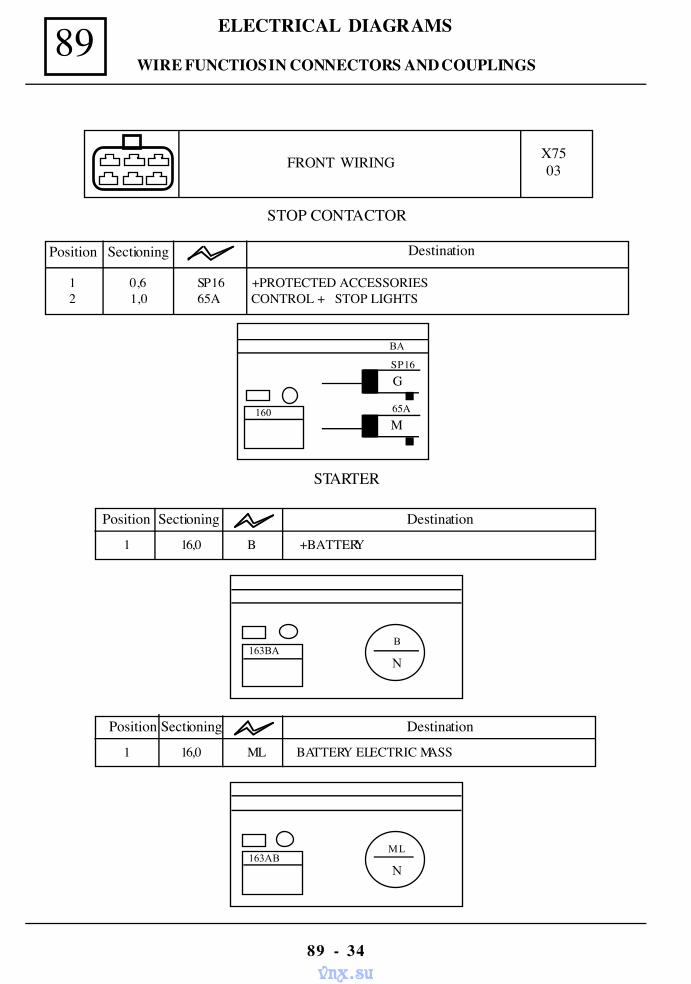
89 ELECTRICAL DIAGRAMS
89 - 34
BA
G
M 65A 160
SP16
FRONT WIRING X7503
STOP CONTACTOR
Position Sectioning Destination
1 0,6 SP16 + PROTECTED ACCESSORIES2 1,0 65A CONTROL + STOP LIGHTS
STARTER
Position Sectioning Destination
1 16,0 B + BATTERY
Position Sectioning Destination
1 16,0 ML BATTERY ELECTRIC MASS
163BAB
N
163ABML
N
WIRE FUNCTIOS IN CONNECTORS AND COUPLINGS
vnx.su
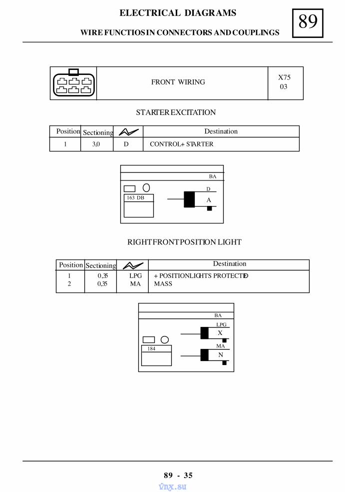
89ELECTRICAL DIAGRAMS
89 - 35
Position Sectioning Destination
1 3,0 D CONTROL + STARTER
STARTER EXCITATION
BA
163 DB A
D
FRONT WIRING X7503
RIGHT FRONT POSITION LIGHT
Position Sectioning Destination1 0,35 LPG + POSITION LIGHTS PROTECTED2 0,35 MA MASS
BA
184
X
N MA
LPG
WIRE FUNCTIOS IN CONNECTORS AND COUPLINGS
vnx.su
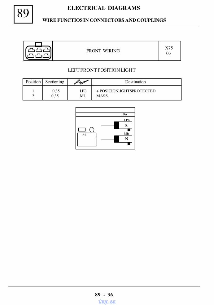
89 ELECTRICAL DIAGRAMS
89 - 36
FRONT WIRING X7503
BA
X
N MB 185
LPG
LEFT FRONT POSITION LIGHT
1 0,35 LPG + POSITION LIGHTS PROTECTED2 0,35 ML MASS
Position Sectioning Destination
WIRE FUNCTIOS IN CONNECTORS AND COUPLINGS
vnx.su
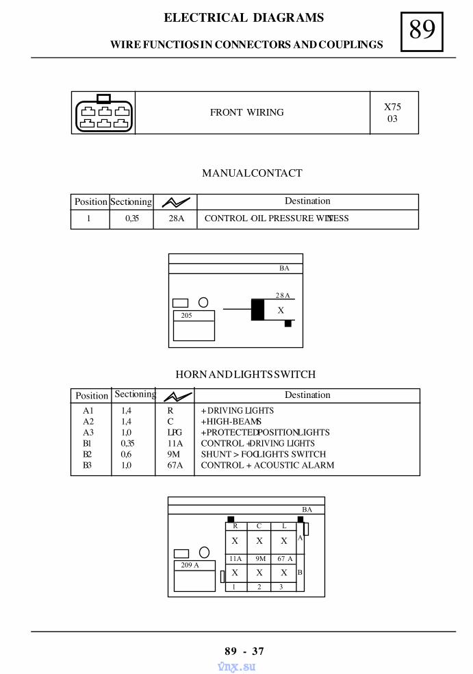
89ELECTRICAL DIAGRAMS
89 - 37
FRONT WIRING X7503
MANUAL CONTACT
Position Sectioning Destination
1 0,35 28A CONTROL - OIL PRESSURE WITNESS
BA
205
28A
X
HORN AND LIGHTS SWITCH
BA
R C L
X X X
209 A11A 9M 67 A
X X X
1 2 3
A
B
A1 1,4 R + DRIVING LIGHTSA2 1,4 C + HIGH-BEAMSA3 1,0 LPG + PROTECTED POSITION LIGHTSB1 0,35 11A CONTROL + DRIVING LIGHTSB2 0,6 9M SHUNT > FOG LIGHTS SWITCHB3 1,0 67A CONTROL + ACOUSTIC ALARM
Position Sectioning Destination
WIRE FUNCTIOS IN CONNECTORS AND COUPLINGS
vnx.su
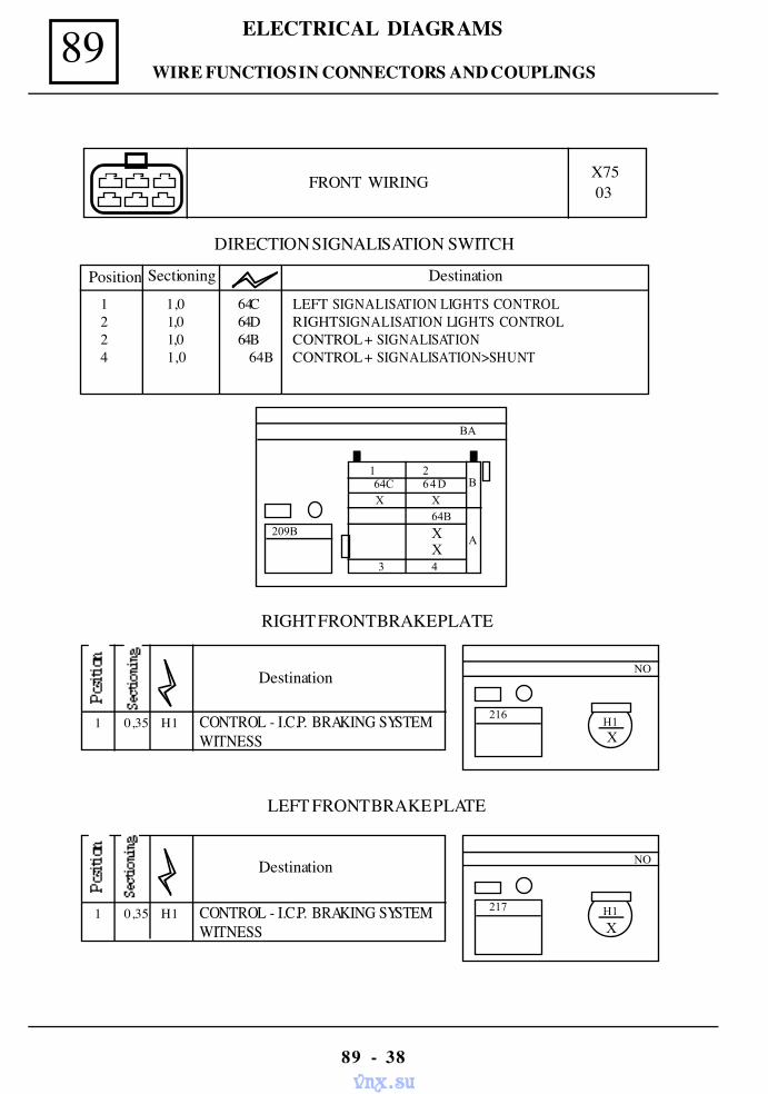
89 ELECTRICAL DIAGRAMS
89 - 38
FRONT WIRING X7503
DIRECTION SIGNALISATION SWITCH
1 1,0 64C LEFT SIGNALISATION LIGHTS CONTROL2 1,0 64D RIGHT SIGNALISATION LIGHTS CONTROL2 1,0 64B CONTROL + SIGNALISATION4 1,0 64B CONTROL + SIGNALISATION>SHUNT
BA
XX
1 2 64C 64D X X
209B
B
A
3 4
64B
Position Sectioning Destination
LEFT FRONT BRAKE PLATE
Destination
1 0,35 H1 CONTROL - I.C.P. BRAKING SYSTEMWITNESS
NO
H1
X
217
RIGHT FRONT BRAKE PLATE
Destination
1 0,35 H1 CONTROL - I.C.P. BRAKING SYSTEMWITNESS
NO
H1 X
216
WIRE FUNCTIOS IN CONNECTORS AND COUPLINGS
vnx.su
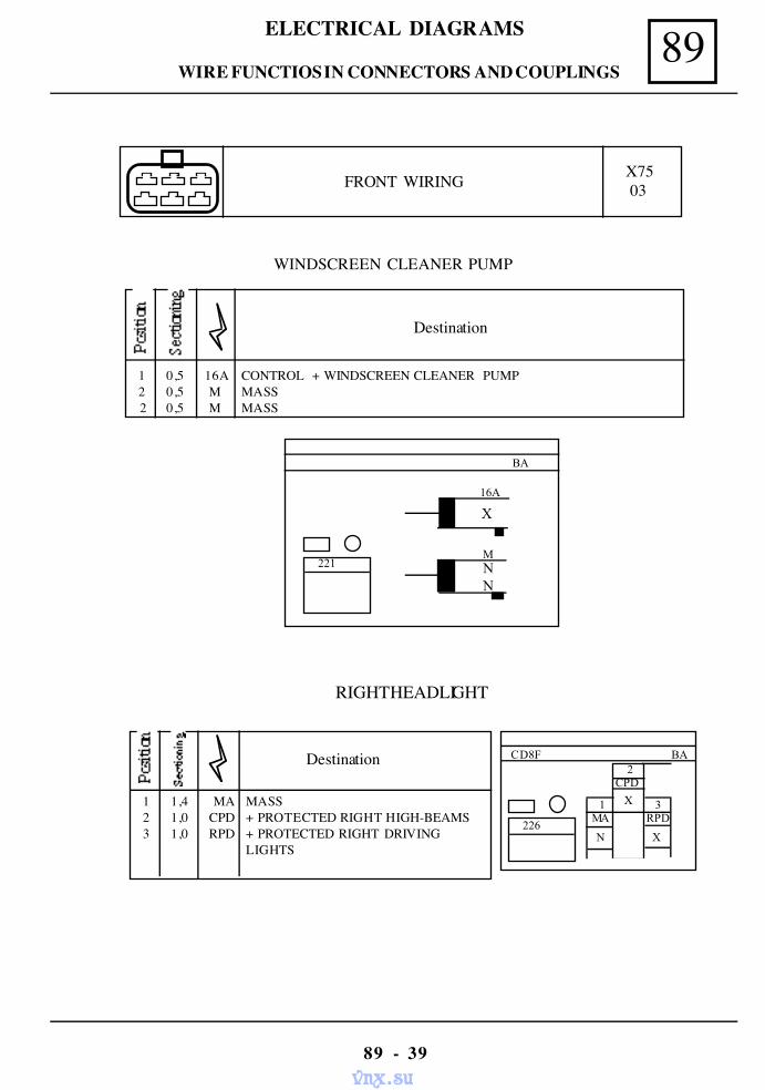
89ELECTRICAL DIAGRAMS
89 - 39
WINDSCREEN CLEANER PUMP
Destination
1 0,5 16A CONTROL + WINDSCREEN CLEANER PUMP 2 0,5 M MASS
2 0,5 M MASS
BA
16A
X
MNN
221
FRONT WIRING X7503
RIGHT HEADLIGHT
Destination
1 1,4 MA MASS 2 1,0 CPD + PROTECTED RIGHT HIGH-BEAMS 3 1,0 RPD + PROTECTED RIGHT DRIVING
LIGHTS
BA
N
1 MA
2
X
3 RPD
CD8F
CPD
X
226
WIRE FUNCTIOS IN CONNECTORS AND COUPLINGS
vnx.su
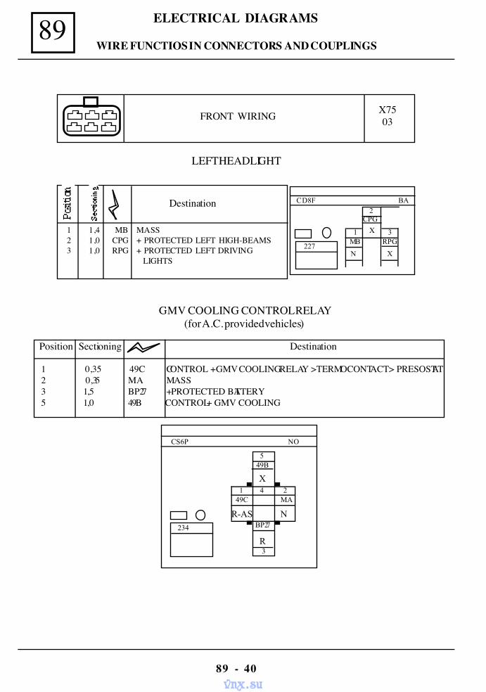
89 ELECTRICAL DIAGRAMS
89 - 40
FRONT WIRING X7503
LEFT HEADLIGHT
Destination
1 1,4 MB MASS 2 1,0 CPG + PROTECTED LEFT HIGH-BEAMS 3 1,0 RPG + PROTECTED LEFT DRIVING
LIGHTS
BA
N
1 MB
2
X
3 RPG
CD8F
CPG
X
227
GMV COOLING CONTROL RELAY(for A.C. provided vehicles)
NO
5
X
3
49B
1 4 2 49C MA
R-AS N
CS6P
BP27
R
234
Position Sectioning Destination
1 0,35 49C CONTROL + GMV COOLING RELAY >TERMOCONTACT > PRESOSTAT2 0,35 MA MASS3 1,5 BP27 + PROTECTED BATTERY5 1,0 49B CONTROL + GMV COOLING
WIRE FUNCTIOS IN CONNECTORS AND COUPLINGS
vnx.su
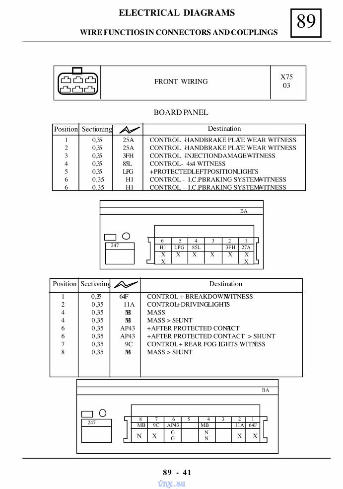
89ELECTRICAL DIAGRAMS
89 - 41
BOARD PANEL
Position Sectioning Destination1 0,35 25A CONTROL - HANDBRAKE PLATE WEAR WITNESS2 0,35 25A CONTROL - HANDBRAKE PLATE WEAR WITNESS3 0,35 3FH CONTROL - INJECTION DAMAGE WITNESS4 0,35 85L CONTROL- 4x4 WITNESS5 0,35 LPG + PROTECTED LEFT POSITION LIGHTS6 0,35 H1 CONTROL - I.C.P. BRAKING SYSTEM WITNESS6 0,35 H1 CONTROL - I.C.P. BRAKING SYSTEM WITNESS
BA
6 5 4 3 2 1 H1 LPG 85L 3FH 27A
X X X X X XX X
247
FRONT WIRING X7503
1 0,35 64F CONTROL + BREAKDOWN WITNESS2 0,35 11A CONTROL + DRIVING LIGHTS4 0,35 MB MASS4 0,35 MB MASS > SHUNT6 0,35 AP43 + AFTER PROTECTED CONTACT6 0,35 AP43 + AFTER PROTECTED CONTACT > SHUNT7 0,35 9C CONTROL + REAR FOG LIGHTS WITNESS8 0,35 MB MASS > SHUNT
BA
8 7 6 5 4 3 2 1 MB 9C AP43 MB 11A 64F
N X X X
247
GG
NN
Position Sectioning Destination
WIRE FUNCTIOS IN CONNECTORS AND COUPLINGS
vnx.su
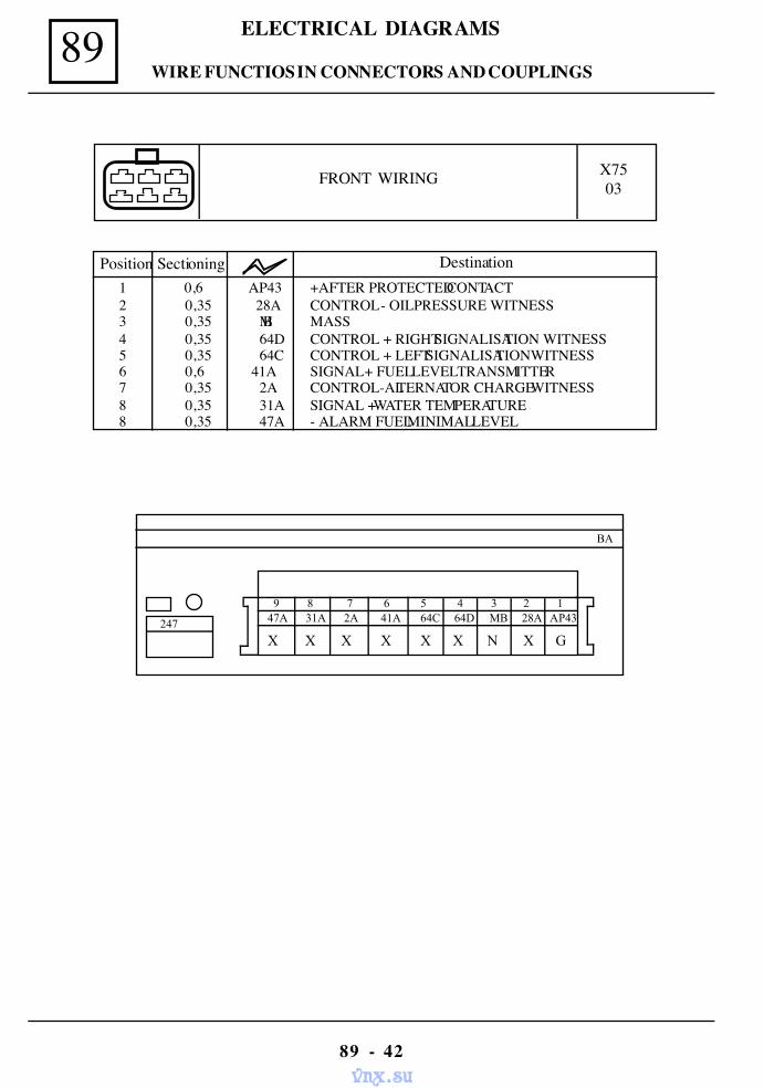
89 ELECTRICAL DIAGRAMS
89 - 42
FRONT WIRING X7503
BA
9 8 7 6 5 4 3 2 1 47A 31A 2A 41A 64C 64D MB 28A AP43
X X X X X X N X G 247
Position Sectioning Destination1 0,6 AP43 +AFTER PROTECTED CONTACT2 0,35 28A CONTROL - OIL PRESSURE WITNESS3 0,35 MB MASS4 0,35 64D CONTROL + RIGHT SIGNALISATION WITNESS5 0,35 64C CONTROL + LEFT SIGNALISATION WITNESS6 0,6 41A SIGNAL + FUEL LEVEL TRANSMITTER7 0,35 2A CONTROL-ALTERNATOR CHARGE WITNESS8 0,35 31A SIGNAL + WATER TEMPERATURE8 0,35 47A - ALARM FUEL MINIMAL LEVEL
WIRE FUNCTIOS IN CONNECTORS AND COUPLINGS
vnx.su
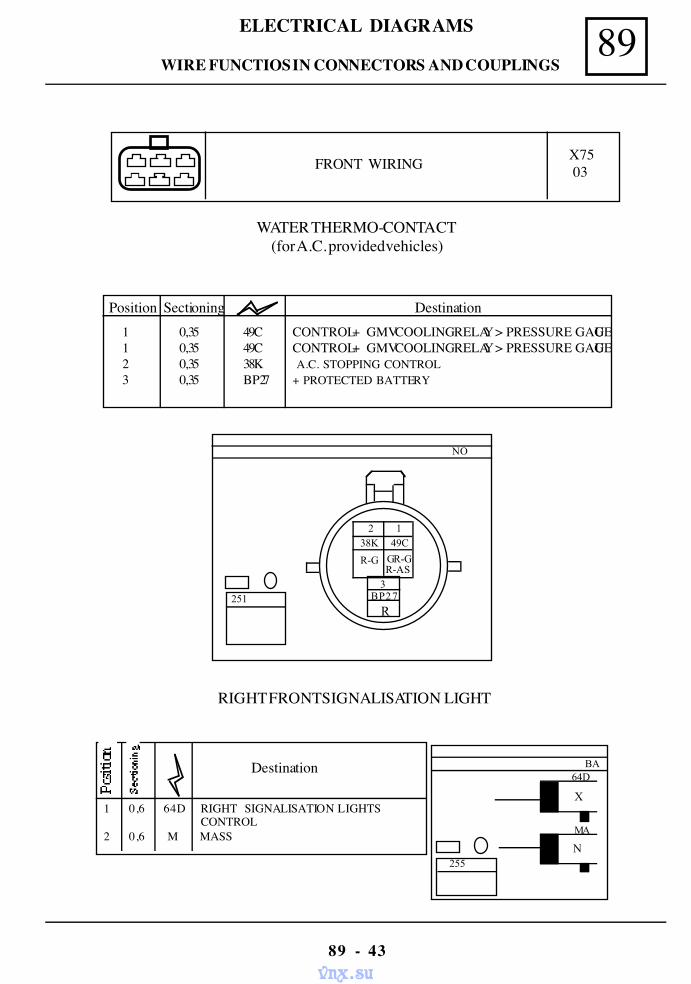
89ELECTRICAL DIAGRAMS
89 - 43
FRONT WIRING X7503
WATER THERMO-CONTACT(for A.C. provided vehicles)
Position Sectioning Destination1 0,35 49C CONTROL + GMV COOLING RELAY > PRESSURE GAUGE1 0,35 49C CONTROL + GMV COOLING RELAY > PRESSURE GAUGE2 0,35 38K A.C. STOPPING CONTROL3 0,35 BP27 + PROTECTED BATTERY
NO
251
R-AS3
BP27
R
R-G
38K1
49C
GR-G
2
RIGHT FRONT SIGNALISATION LIGHT
Destination
1 0,6 64D RIGHT SIGNALISATION LIGHTS CONTROL
2 0,6 M MASS
BA
N
64D
MA
X
255
WIRE FUNCTIOS IN CONNECTORS AND COUPLINGS
vnx.su
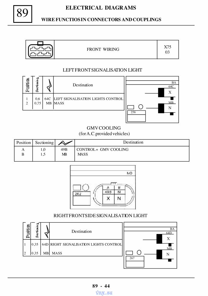
89 ELECTRICAL DIAGRAMS
89 - 44
FRONT WIRING X75 03
LEFT FRONT SIGNALISATION LIGHT
Destination
1 0,6 64C LEFT SIGNALISATION LIGHTS CONTROL2 0,75 MB MASS
BA
N
64C
MB
X
256
GMV COOLING(for A.C.provided vehicles)
Position Sectioning DestinationA 1,0 49B CONTROL + GMV COOLINGB 1,5 MB MASS
RIGHT FRONT SIDE SIGNALISATION LIGHT
Destination
1 0,35 64D RIGHT SIGNALISATION LIGHTS CONTROL
2 0,35 MB MASS
BA
N
64D
MB
X
267
WIRE FUNCTIOS IN CONNECTORS AND COUPLINGS
vnx.su
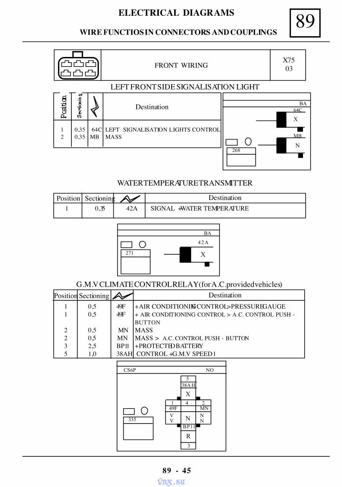
89ELECTRICAL DIAGRAMS
89 - 45
FRONT WIRING
LEFT FRONT SIDE SIGNALISATION LIGHT
Destination
1 0,35 64C LEFT SIGNALISATION LIGHTS CONTROL 2 0,35 MB MASS
BA
N
64C
MB
X
268
X75 03
WATER TEMPERATURE TRANSMITTER
Position Sectioning Destination1 0,35 42A SIGNAL + WATER TEMPERATURE
BA
42A
271 X
G.M.V CLIMATE CONTROL RELAY (for A.C.provided vehicles)
1 0,5 49F + AIR CONDITIONING CONTROL > PRESSURE GAUGE 1 0,5 49F + AIR CONDITIONING CONTROL > A.C. CONTROL PUSH -
BUTTON 2 0,5 MN MASS 2 0,5 MN MASS > A.C. CONTROL PUSH - BUTTON 3 2,5 BP11 + PROTECTED BATTERY 5 1,0 38AH CONTROL + G.M.V SPEED 1
Position Sectioning Destination
NO
5
X
3
38A H
1 4 2 49F MN
N
CS6P
335 V N V N
BP11
R
WIRE FUNCTIOS IN CONNECTORS AND COUPLINGS
vnx.su
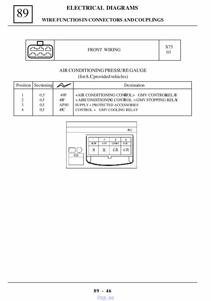
89 ELECTRICAL DIAGRAMS
89 - 46
AIR CONDITIONING PRESSURE GAUGE(forA.C.provided vehicles)
Position Sectioning Destination
1 0,5 49F + AIR CONDITIONING CONTROL > GMV CONTROL RELAY2 0,5 49F + AIR CONDITIONING CONTROL > GMV STOPPING RELAY3 0,5 AP40 SUPPLY + PROTECTED ACCESSORIES4 0,5 49C CONTROL + GMV COOLING RELAY
FRONT WIRING X7503
WIRE FUNCTIOS IN CONNECTORS AND COUPLINGS
vnx.su
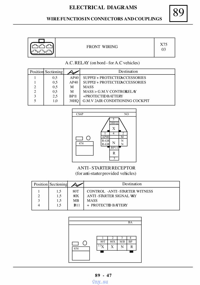
89ELECTRICAL DIAGRAMS
89 - 47
A.C. RELAY (on bord - for A.C vehicles)
1 0,5 AP40 SUPPLY + PROTECTED ACCESSORIES 1 0,5 AP40 SUPPLY + PROTECTED ACCESSORIES 2 0,5 M MASS 2 0,5 M MASS > G.M.V CONTROL RELAY 3 2,5 BP11 + PROTECTED BATTERY 5 1,0 38HQ G.M.V 2 AIR CONDITIONING COCKPIT
Position Sectioning Destination
NO
5
X
3
38H Q
1 4 2 AP40 M
N
CS6P
474 R-GR N R-GR N
BP11
R
FRONT WIRING X7503
BA
654
1 2 3 4
X X N R 80T 80X MB BP11
ANTI - STARTER RECEPTOR(for anti-starter provided vehicles)
1 1,5 80T CONTROL - ANTI -STARTER WITNESS 2 1,5 80X ANTI -STARTER SIGNAL WAY 3 1,5 MB MASS 4 1,5 BP11 + PROTECTED BATTERY
Position Sectioning Destination
WIRE FUNCTIOS IN CONNECTORS AND COUPLINGS
vnx.su
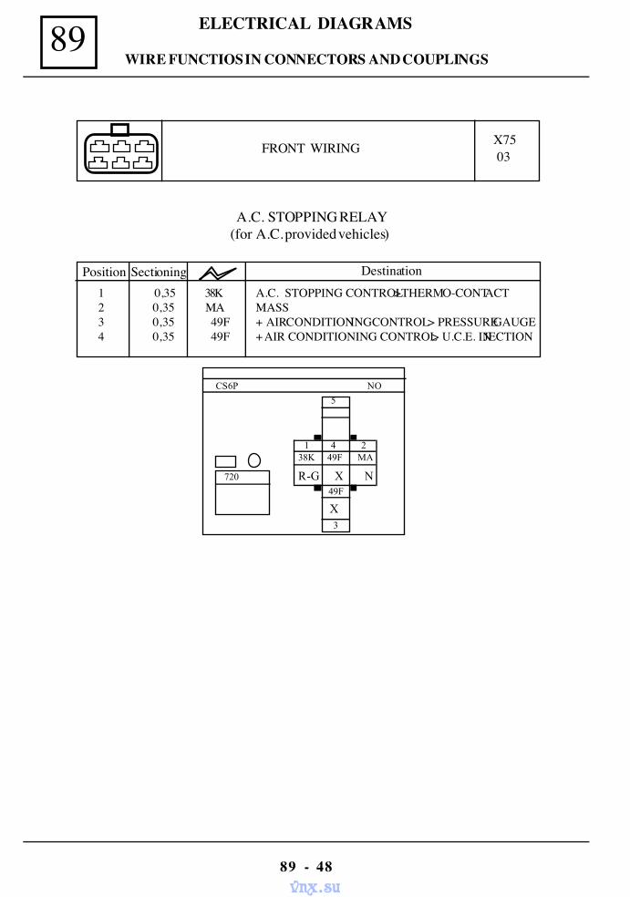
89 ELECTRICAL DIAGRAMS
89 - 48
FRONT WIRING X7503
A.C. STOPPING RELAY(for A.C. provided vehicles)
NO
5
3
1 4 2 38K 49F MA
R-G X N
CS6P
720
49F
X
Position Sectioning Destination1 0,35 38K A.C. STOPPING CONTROL > THERMO-CONTACT2 0,35 MA MASS3 0,35 49F + AIR CONDITIONING CONTROL > PRESSURE GAUGE4 0,35 49F + AIR CONDITIONING CONTROL > U.C.E. INJECTION
WIRE FUNCTIOS IN CONNECTORS AND COUPLINGS
vnx.su
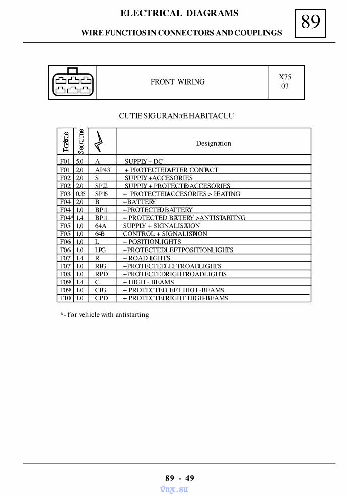
89ELECTRICAL DIAGRAMS
89 - 49
FRONT WIRING X7503
CUTIE SIGURANπE HABITACLU
Designation
F01 5,0 A SUPPLY + DC F01 2,0 AP43 + PROTECTED AFTER CONTACT F02 2,0 S SUPPLY + ACCESORIES F02 2,0 SP22 SUPPLY + PROTECTED ACCESORIES F03 0,35 SP16 + PROTECTED ACCESORIES > HEATING F04 2,0 B + BATTERY F04 1,0 BP11 + PROTECTED BATTERY F04* 1,4 BP11 + PROTECTED BATTERY > ANTISTARTING F05 1,0 64A SUPPLY + SIGNALISATION F05 1,0 64B CONTROL + SIGNALISATION F06 1,0 L + POSITION LIGHTS F06 1,0 LPG + PROTECTED LEFT POSITION LIGHTS F07 1,4 R + ROAD LIGHTS F07 1,0 RPG + PROTECTED LEFTROAD LIGHTS F08 1,0 RPD + PROTECTED RIGHT ROAD LIGHTS F09 1,4 C + HIGH - BEAMS F09 1,0 CPG + PROTECTED LEFT HIGH - BEAMS F10 1,0 CPD + PROTECTED RIGHT HIGH - BEAMS
*- for vehicle with antistarting
WIRE FUNCTIOS IN CONNECTORS AND COUPLINGS
vnx.su
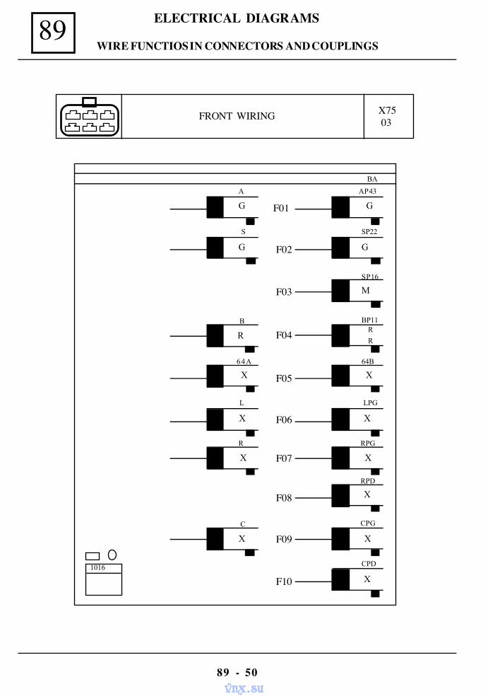
89 ELECTRICAL DIAGRAMS
89 - 50
FRONT WIRING X7503
BA
L
G
SP22
LPG
S
F02
1016 CPD
XF10
A
F01 G
AP43
G
G
X
R
X
X
RPD
RPG
F07
F08
X XF06
64A
X
64B
F05
X
C
X
CPG
F09
M
SP16
F03
B
R
BP11R
RF04
X
WIRE FUNCTIOS IN CONNECTORS AND COUPLINGS
vnx.su
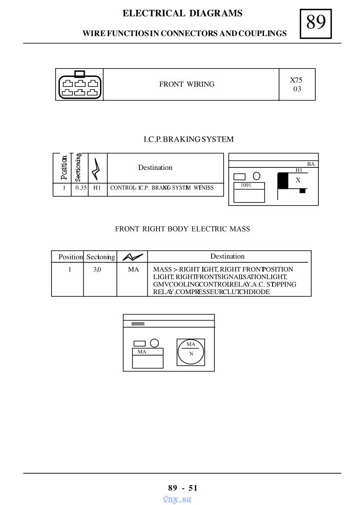
89ELECTRICAL DIAGRAMS
89 - 51
FRONT WIRING X75 03
I.C.P. BRAKING SYSTEM
Destination
1 0,35 H1 CONTROL - I.C.P. BRAKING SYSTEM WITNESS
BA H1
X 1091
FRONT RIGHT BODY ELECTRIC MASS
Position Sectioning Destination
1 3,0 MA MASS > RIGHT LIGHT, RIGHT FRONT POSITIONLIGHT, RIGHT FRONT SIGNALISATION LIGHT,GMV COOLING CONTROL RELAY, A.C. STOPPINGRELAY, COMPRESSEUR CLUTCH DIODE
MA MA
N
WIRE FUNCTIOS IN CONNECTORS AND COUPLINGS
vnx.su
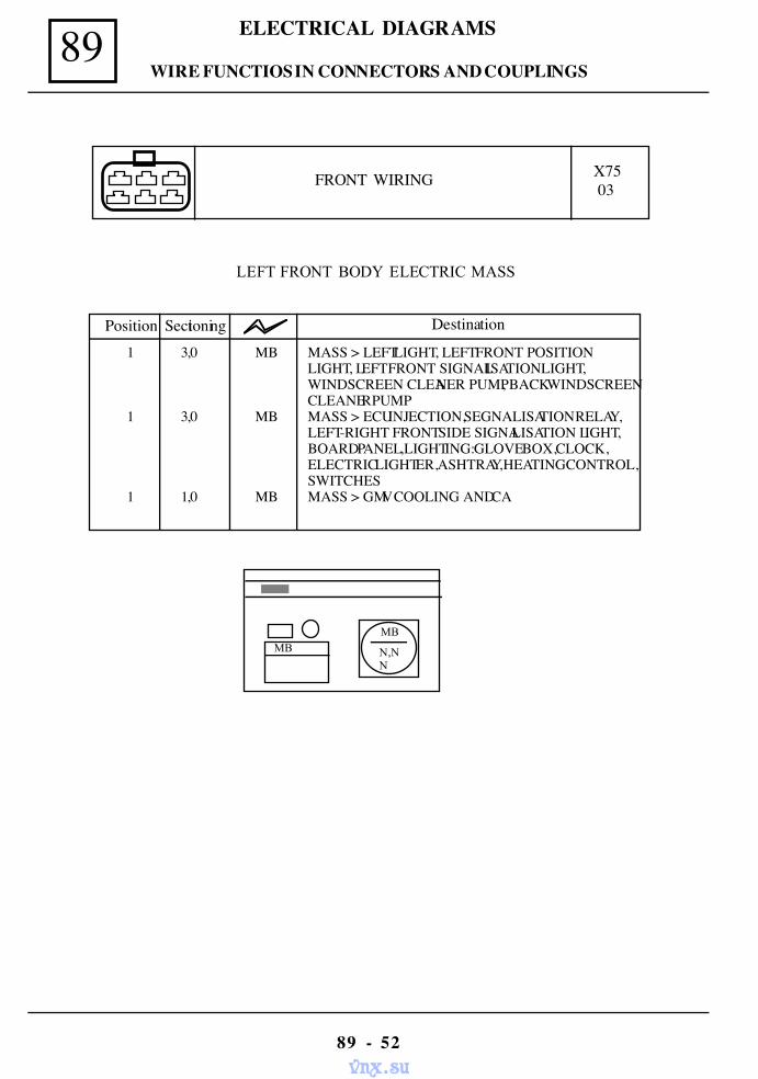
89 ELECTRICAL DIAGRAMS
89 - 52
FRONT WIRING X7503
LEFT FRONT BODY ELECTRIC MASS
Position Sectioning Destination
1 3,0 MB MASS > LEFT LIGHT, LEFT FRONT POSITIONLIGHT, LEFT FRONT SIGNALISATION LIGHT,WINDSCREEN CLEANER PUMP, BACK WINDSCREENCLEANER PUMP
1 3,0 MB MASS > ECU INJECTION, SEGNALISATION RELAY,LEFT-RIGHT FRONT SIDE SIGNALISATION LIGHT,BOARD PANEL, LIGHTING: GLOVE BOX, CLOCK,ELECTRIC LIGHTER, ASHTRAY, HEATING CONTROL,SWITCHES
1 1,0 MB MASS > GMV COOLING AND CA
MB MB
N,NN
WIRE FUNCTIOS IN CONNECTORS AND COUPLINGS
vnx.su
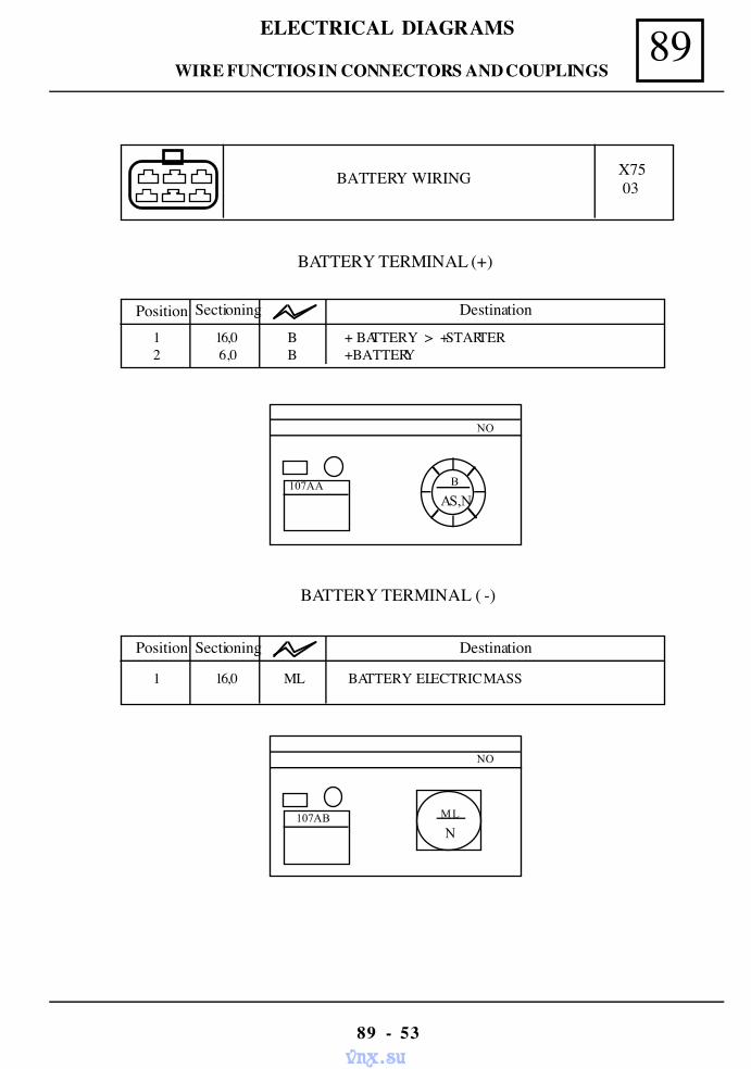
89ELECTRICAL DIAGRAMS
89 - 53
BATTERY WIRING X7503
BATTERY TERMINAL (+)
Position Sectioning Destination
1 16,0 B + BATTERY > + STARTER2 6,0 B + BATTERY
BATTERY TERMINAL ( -)
NO
107AA B
AS,N
NO
107AB ML
N
Position Sectioning Destination
1 16,0 ML BATTERY ELECTRIC MASS
WIRE FUNCTIOS IN CONNECTORS AND COUPLINGS
vnx.su
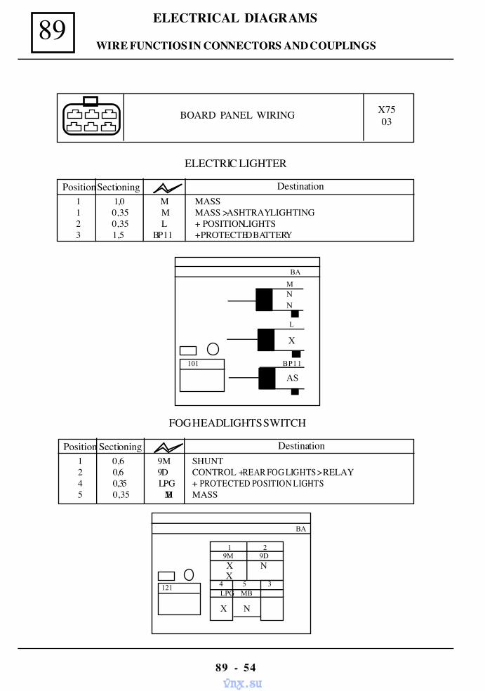
89 ELECTRICAL DIAGRAMS
89 - 54
ELECTRIC LIGHTER
1 1,0 M MASS 1 0,35 M MASS > ASHTRAY LIGHTING 2 0,35 L + POSITION LIGHTS 3 1,5 BP11 + PROTECTED BATTERY
PositionSectioning Destination
BA
M
101
NN
L
BP11
AS
X
BOARD PANEL WIRING X7503
FOG HEADLIGHTS SWITCH
1 0,6 9M SHUNT 2 0,6 9D CONTROL + REAR FOG LIGHTS > RELAY 4 0,35 LPG + PROTECTED POSITION LIGHTS 5 0,35 MB MASS
Position Sectioning Destination
BA
1 29M 9D
121 4 5 3 LPG MB
X N X
X N
WIRE FUNCTIOS IN CONNECTORS AND COUPLINGS
vnx.su
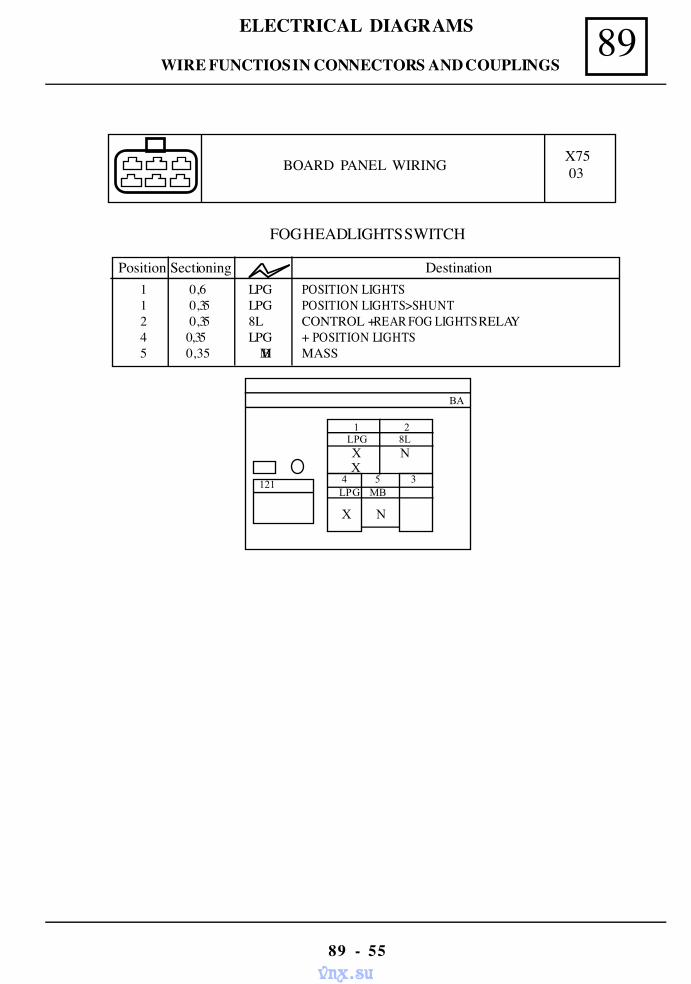
89ELECTRICAL DIAGRAMS
89 - 55
FOG HEADLIGHTS SWITCH
1 0,6 LPG POSITION LIGHTS 1 0,35 LPG POSITION LIGHTS>SHUNT 2 0,35 8L CONTROL + REAR FOG LIGHTS RELAY 4 0,35 LPG + POSITION LIGHTS 5 0,35 MB MASS
Position Sectioning Destination
BA
1 2LPG 8L
121 4 5 3 LPG MB
X N X
X N
BOARD PANEL WIRING X7503
WIRE FUNCTIOS IN CONNECTORS AND COUPLINGS
vnx.su
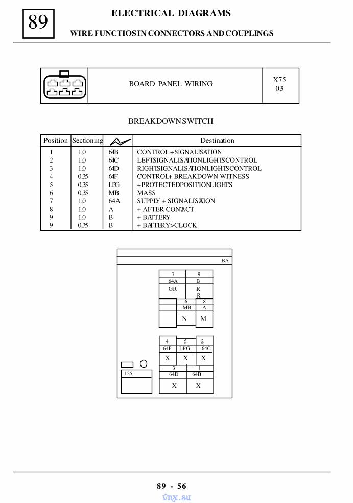
89 ELECTRICAL DIAGRAMS
89 - 56
BOARD PANEL WIRING X7503
BREAKDOWN SWITCH
1 1,0 64B CONTROL + SIGNALISATION2 1,0 64C LEFT SIGNALISATION LIGHTS CONTROL3 1,0 64D RIGHT SIGNALISATION LIGHTS CONTROL4 0,35 64F CONTROL + BREAKDOWN WITNESS5 0,35 LPG + PROTECTED POSITION LIGHTS6 0,35 MB MASS7 1,0 64A SUPPLY + SIGNALISATION8 1,0 A + AFTER CONTACT9 1,0 B + BATTERY9 0,35 B + BATTERY>CLOCK
Position Sectioning Destination
BA
7 964A B
6 8 MB A
GR R R
N M
3 1 64D 64B
X X
4 5 264F LPG 64C
X X X
125
WIRE FUNCTIOS IN CONNECTORS AND COUPLINGS
vnx.su
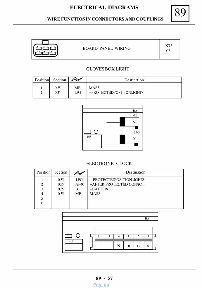
89ELECTRICAL DIAGRAMS
89 - 57
BOARD PANEL WIRING X7503
GLOVES BOX LIGHT
BA
MB
168
N
X
LPG
Position Section Destination
1 0,35 MB MASS2 0,35 LPG + PROTECTED POSITION LIGHTS
ELECTRONIC CLOCK
BA
6 5 4 3 2 1
N R G X
210
Position Section Destination
1 0,35 LPG + PROTECTED POSITION LIGHTS2 0,35 AP40 + AFTER PROTECTED CONTACT3 0,35 B + BATTERY4 0,35 MB MASS56
WIRE FUNCTIOS IN CONNECTORS AND COUPLINGS
vnx.su
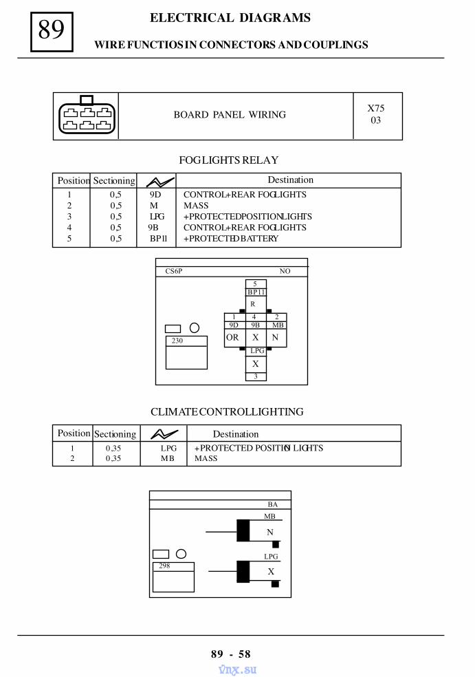
89 ELECTRICAL DIAGRAMS
89 - 58
BOARD PANEL WIRING X7503
FOG LIGHTS RELAY
1 0,5 9D CONTROL + REAR FOG LIGHTS 2 0,5 M MASS 3 0,5 LPG + PROTECTED POSITION LIGHTS 4 0,5 9B CONTROL + REAR FOG LIGHTS 5 0,5 BP11 + PROTECTED BATTERY
Position Sectioning Destination
NO
5
R
3
BP11
1 4 2 9D 9B MB
OR X N
CS6P
230 LPG
X
CLIMATE CONTROL LIGHTING
Position Sectioning Destination1 0,35 LPG + PROTECTED POSITION LIGHTS2 0,35 MB MASS
BA
MB
298
N
X
LPG
WIRE FUNCTIOS IN CONNECTORS AND COUPLINGS
vnx.su
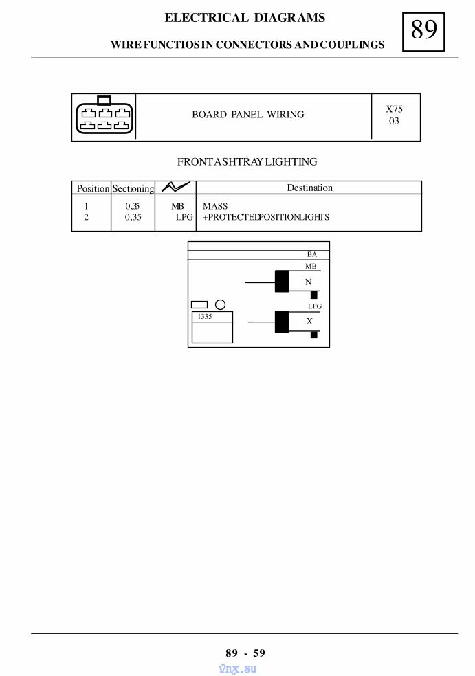
89ELECTRICAL DIAGRAMS
89 - 59
BOARD PANEL WIRING X7503
FRONT ASHTRAY LIGHTING
BA
MB
1335
N
X
LPG
Position Sectioning Destination
1 0,35 MB MASS2 0,35 LPG +PROTECTED POSITION LIGHTS
WIRE FUNCTIOS IN CONNECTORS AND COUPLINGS
vnx.su
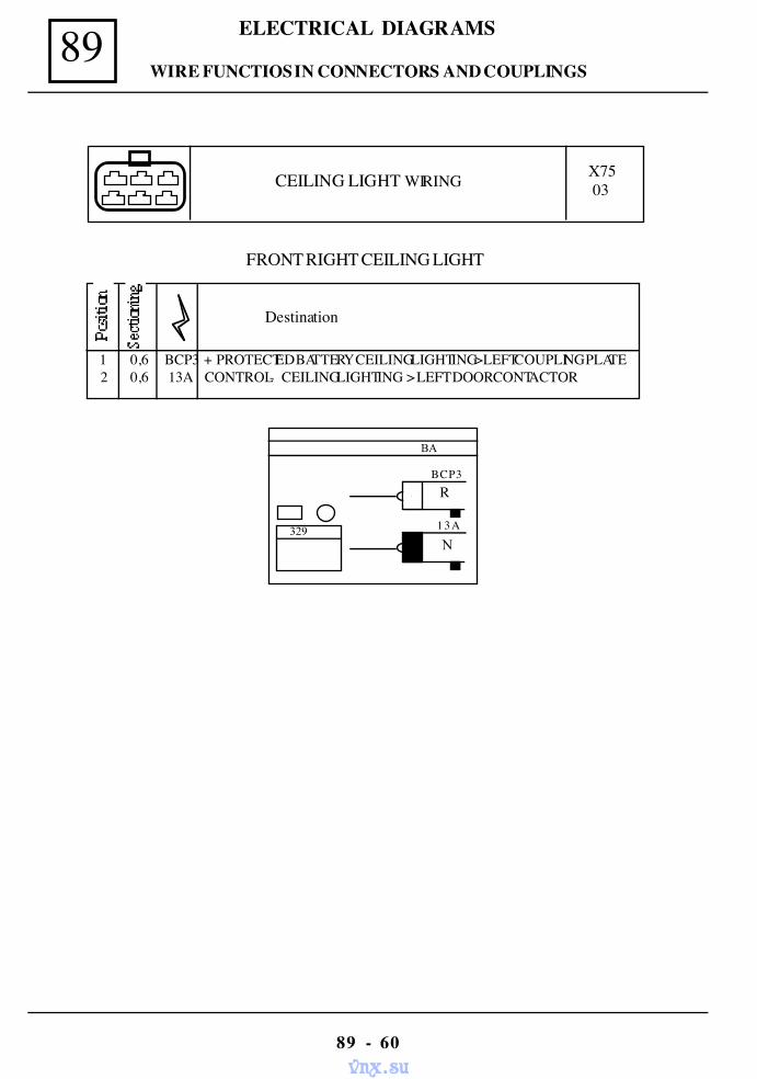
89 ELECTRICAL DIAGRAMS
89 - 60
CEILING LIGHT WIRING X7503
BA
BCP3
329 13A
N
R
FRONT RIGHT CEILING LIGHT
Destination
1 0,6 BCP3 + PROTECTED BATTERY CEILING LIGHTING>LEFT COUPLING PLATE2 0,6 13A CONTROL - CEILING LIGHTING > LEFT DOOR CONTACTOR
WIRE FUNCTIOS IN CONNECTORS AND COUPLINGS
vnx.su
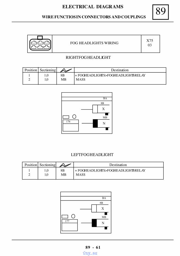
89ELECTRICAL DIAGRAMS
89 - 61
FOG HEADLIGHTS WIRING X7503
RIGHT FOG HEADLIGHT
LEFT FOG HEADLIGHT
BA
MB
N
8B
X
176
BA
MB
N
8B
X
177
Position Sectioning Destination1 1,0 8B + FOG HEADLIGHTS>FOG HEADLIGHTS RELAY2 1,0 MB MASS
Position Sectioning Destination1 1,0 8B + FOG HEADLIGHTS>FOG HEADLIGHTS RELAY2 1,0 MB MASS
WIRE FUNCTIOS IN CONNECTORS AND COUPLINGS
vnx.su
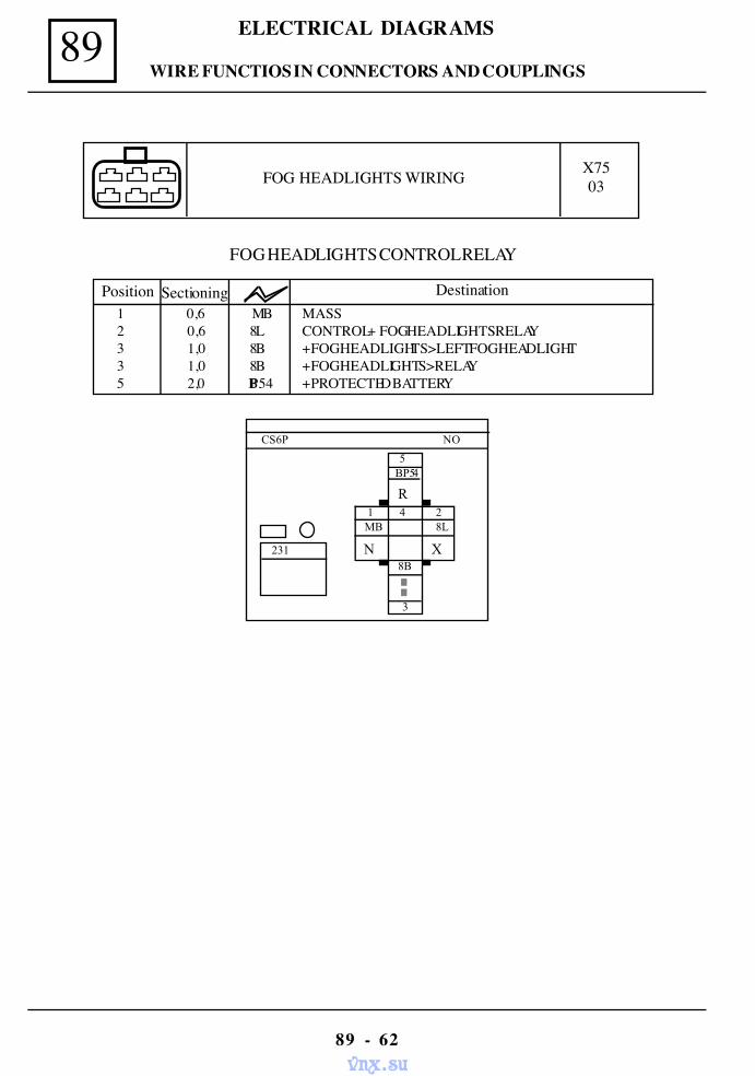
89 ELECTRICAL DIAGRAMS
89 - 62
NO
5
R
3
BP54
1 4 2 MB 8L
N X
CS6P
231 8B
FOG HEADLIGHTS CONTROL RELAY
1 0,6 MB MASS 2 0,6 8L CONTROL + FOG HEADLIGHTS RELAY 3 1,0 8B + FOG HEADLIGHTS>LEFT FOG HEADLIGHT 3 1,0 8B + FOG HEADLIGHTS>RELAY 5 2,0 BP54 + PROTECTED BATTERY
Position Sectioning Destination
FOG HEADLIGHTS WIRING X7503
WIRE FUNCTIOS IN CONNECTORS AND COUPLINGS
vnx.su
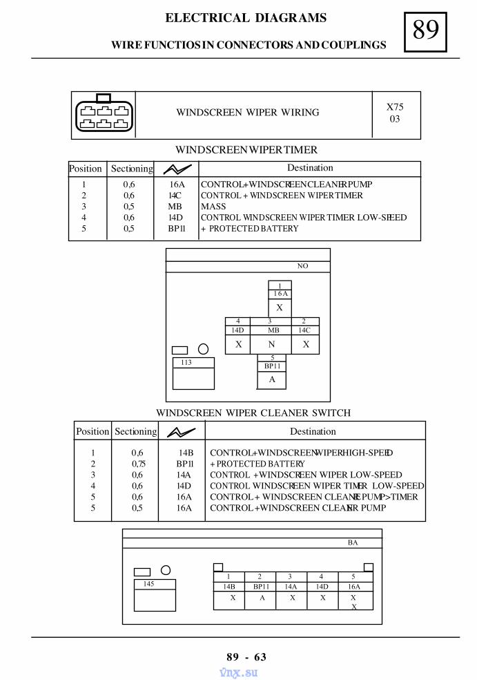
89ELECTRICAL DIAGRAMS
89 - 63
WINDSCREEN WIPER WIRING X7503
Position Sectioning Destination1 0,6 16A CONTROL + WINDSCREEN CLEANER PUMP2 0,6 14C CONTROL + WINDSCREEN WIPER TIMER3 0,5 MB MASS4 0,6 14D CONTROL WINDSCREEN WIPER TIMER LOW-SPEED5 0,5 BP11 + PROTECTED BATTERY
NO
4 3 2 14D MB 14C
5 BP11
X N X
X
1
113
16A
A
BA
1 2 3 4 5 14B BP11 14A 14D 16A
X A X X XX
145
WINDSCREEN WIPER CLEANER SWITCH
Position Sectioning Destination
1 0,6 14B CONTROL +WINDSCREEN WIPER HIGH-SPEED2 0,75 BP11 + PROTECTED BATTERY3 0,6 14A CONTROL + WINDSCREEN WIPER LOW-SPEED4 0,6 14D CONTROL WINDSCREEN WIPER TIMER LOW-SPEED5 0,6 16A CONTROL + WINDSCREEN CLEANER PUMP >TIMER5 0,5 16A CONTROL + WINDSCREEN CLEANER PUMP
WINDSCREEN WIPER TIMER
WIRE FUNCTIOS IN CONNECTORS AND COUPLINGS
vnx.su
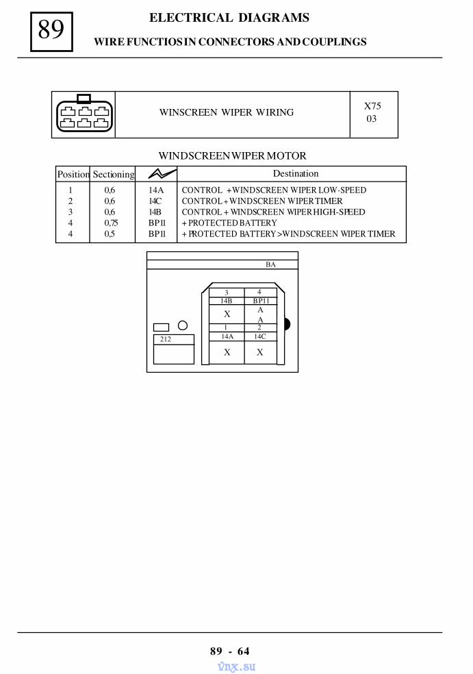
89 ELECTRICAL DIAGRAMS
89 - 64
WINSCREEN WIPER WIRING X7503
WINDSCREEN WIPER MOTOR
Position Sectioning Destination1 0,6 14A CONTROL + WINDSCREEN WIPER LOW-SPEED2 0,6 14C CONTROL + WINDSCREEN WIPER TIMER3 0,6 14B CONTROL + WINDSCREEN WIPER HIGH-SPEED4 0,75 BP11 + PROTECTED BATTERY4 0,5 BP11 + PROTECTED BATTERY > WINDSCREEN WIPER TIMER
BA
X
X X
3 4
1 214A 14C
14B BP11
212
AA
WIRE FUNCTIOS IN CONNECTORS AND COUPLINGS
vnx.su
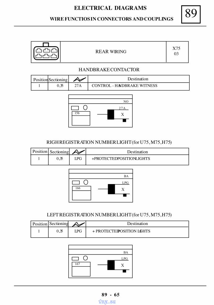
89ELECTRICAL DIAGRAMS
89 - 65
REAR WIRINGX7503
X
BA
LPG
166
X
BA
LPG
167
Position Sectioning Destination1 0,35 LPG + PROTECTED POSITION LIGHTS
LEFT REGISTRATION NUMBER LIGHT (for U75, M75, H75)
Position Sectioning Destination1 0,35 LPG +PROTECTED POSITION LIGHTS
RIGH REGISTRATION NUMBER LIGHT (for U75, M75, H75)
PositionSectioning Destination1 0,35 27A CONTROL - HANDBRAKE WITNESS
HANDBRAKE CONTACTOR
X
NO
27A
156
WIRE FUNCTIOS IN CONNECTORS AND COUPLINGS
vnx.su
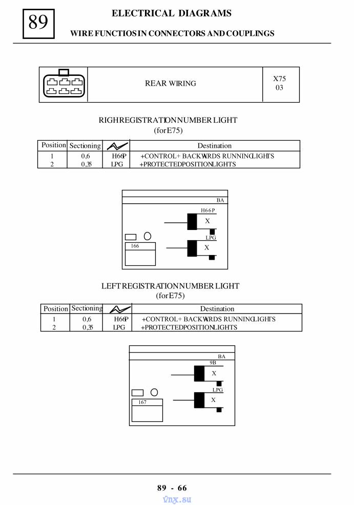
89 ELECTRICAL DIAGRAMS
89 - 66
REAR WIRING X7503
Position Sectioning Destination1 0,6 H66P +CONTROL+ BACKWARDS RUNNING LIGHTS2 0,35 LPG +PROTECTED POSITION LIGHTS
LEFT REGISTRATION NUMBER LIGHT(for E75)
Position Sectioning Destination1 0,6 H66P +CONTROL+ BACKWARDS RUNNING LIGHTS2 0,35 LPG +PROTECTED POSITION LIGHTS
RIGH REGISTRATION NUMBER LIGHT(for E75)
BA
X
9B
LPG
X
167
BA
166 X
H66P
LPG
X
WIRE FUNCTIOS IN CONNECTORS AND COUPLINGS
vnx.su
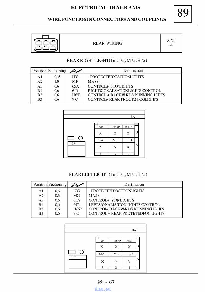
89ELECTRICAL DIAGRAMS
89 - 67
REAR WIRING X7503
REAR LEFT LIGHT (for U75, M75, H75)
Position Sectioning DestinationA1 0,6 LPG + PROTECTED POSITION LIGHTSA2 0,6 MG MASSA3 0,6 65A CONTROL + STOP LIGHTSB1 0,6 64C LEFT SIGNALISATION LIGHTS CONTROLB2 0,6 H66P CONTROL+ BACKWARDS RUNNING LIGHTSB3 0,6 9 C CONTROL + REAR PROTECTED FOG LIGHTS
BA
B
A
X X X
3 2 1
9P H66P 64C
172 65A MG LPG
X N X
REAR RIGHT LIGHT(for U75, M75, H75)
Position Sectioning DestinationA1 0,35 LPG + PROTECTED POSITION LIGHTSA2 1,0 MF MASSA3 0,6 65A CONTROL + STOP LIGHTSB1 0,6 64D RIGHT SIGNALISATION LIGHTS CONTROLB2 0,6 H66P CONTROL + BACKWARDS RUNNING LIGHTSB3 0,6 9 C CONTROL + REAR PROCTED FOG LIGHTS
BA
B
A
X X X
3 2 1
9P H66P 64D
173 65A MF LPG
X N X
WIRE FUNCTIOS IN CONNECTORS AND COUPLINGS
vnx.su
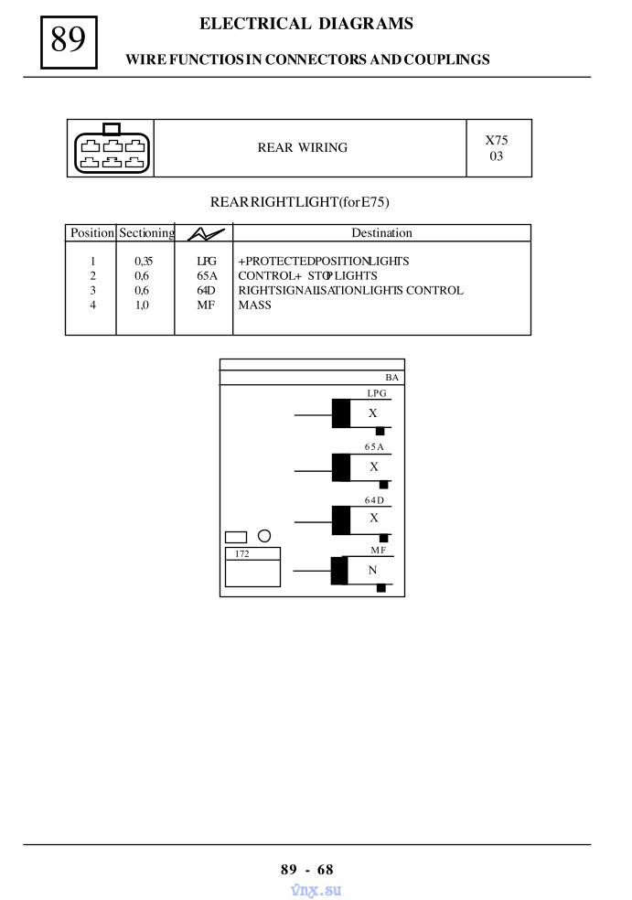
89 ELECTRICAL DIAGRAMS
89 - 68
REAR WIRING X7503
REAR RIGHT LIGHT(for E75)
Position Sectioning Destination
BA
X
LPG
MF
N
X
64D
X
65A
172
1 0,35 LPG + PROTECTED POSITION LIGHTS2 0,6 65A CONTROL + STOP LIGHTS3 0,6 64D RIGHT SIGNALISATION LIGHTS CONTROL4 1,0 MF MASS
WIRE FUNCTIOS IN CONNECTORS AND COUPLINGS
vnx.su
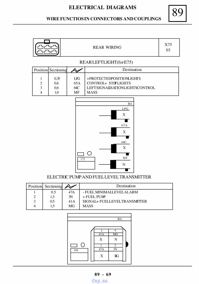
89ELECTRICAL DIAGRAMS
89 - 69
REAR WIRING X7503
REAR LEFT LIGHT(for E75)
Position Sectioning Destination
BA
X
LPG
MF
N
X
64C
X
65A
173
1 0,35 LPG + PROTECTED POSITION LIGHTS2 0,6 65A CONTROL + STOP LIGHTS3 0,6 64C LEFT SIGNALISATION LIGHTS CONTROL4 1,0 MF MASS
ELECTRIC PUMP AND FUEL LEVEL TRANSMITTER
Position Sectioning Destination1 0,5 47A - FUEL MINIMAL LEVEL ALARM2 1,5 3N + FUEL PUMP3 0,5 41A SIGNAL + FUEL LEVEL TRANSMITTER4 1,5 MG MASS
BA
X N
X R-G
3 4
1 247A 3N
41A MG
199
WIRE FUNCTIOS IN CONNECTORS AND COUPLINGS
vnx.su
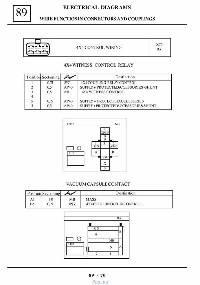
89 ELECTRICAL DIAGRAMS
89 - 70
4X4 CONTROL WIRING X75 03
4X4 WITNESS CONTROL RELAY
NO
5
3
AP40
1 4 2 85G AP40
CS6P
1155 A R 85L
X
RR
1 0,75 85G 4X4 COUPLING RELAY CONTROL2 0,5 AP40 SUPPLY + PROTECTED ACCESSORIES >SHUNT3 0,5 85L 4X4 WITNESS CONTROL45 0,75 AP40 SUPPLY + PROTECTED ACCESSORIES5 0,5 AP40 SUPPLY +PROTECTED ACCESSORIES >SHUNT
Position Sectioning Destination
VACUUM CAPSULE CONTACT
A1 1,0 MB MASSB2 0,75 85G 4X4 COUPLING RELAY CONTROL
Position Sectioning Destination
BA
N
85G
A
1187
B
A
2 1
MB
WIRE FUNCTIOS IN CONNECTORS AND COUPLINGS
vnx.su
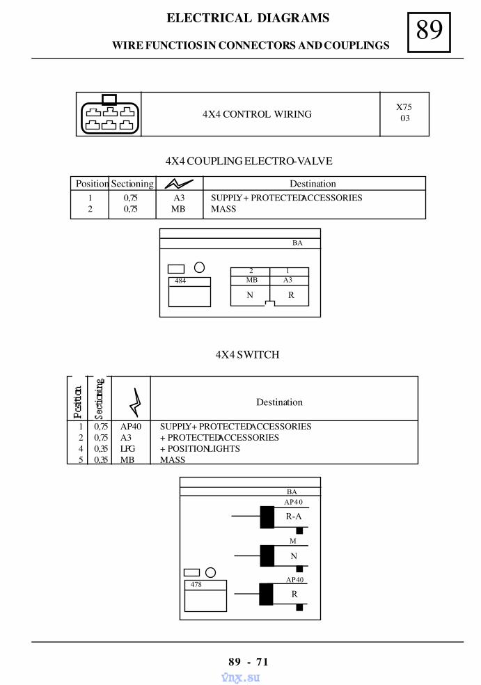
89ELECTRICAL DIAGRAMS
89 - 71
4X4 COUPLING ELECTRO-VALVE
4X4 CONTROL WIRING X75 03
Destination
4X4 SWITCH
1 0,75 A3 SUPPLY + PROTECTED ACCESSORIES2 0,75 MB MASS
Position Sectioning Destination
BA
2 1 MB A3
N R
484
BA
N
AP40
M
R
AP40 478
R-A
1 0,75 AP40 SUPPLY+ PROTECTED ACCESSORIES2 0,75 A3 + PROTECTED ACCESSORIES4 0,35 LPG + POSITION LIGHTS5 0,35 MB MASS
WIRE FUNCTIOS IN CONNECTORS AND COUPLINGS
vnx.su
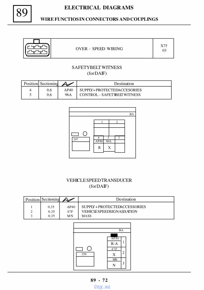
89 ELECTRICAL DIAGRAMS
89 - 72
BA
1AP40
MN
250
47FR-A
X
N
2
3
OVER - SPEED WIRING X75 03
VEHICLE SPEED TRANSDUCER(for DAIF)
Position Sectioning Destination
1 0,35 AP40 SUPPLY + PROTECTED ACCESSORIES2 0,35 47F VEHICLE SPEED SIGNALISATION3 0,35 MN MASS
SAFETY BELT WITNESS(for DAIF)
Position Sectioning Destination4 0,6 AP40 SUPPLY + PROTECTED ACCESORIES5 0,6 96A CONTROL - SAFETY BELT WITNESS
BA
1 2
247 4 5 3 AP40 96A
R X
WIRE FUNCTIOS IN CONNECTORS AND COUPLINGS
vnx.su
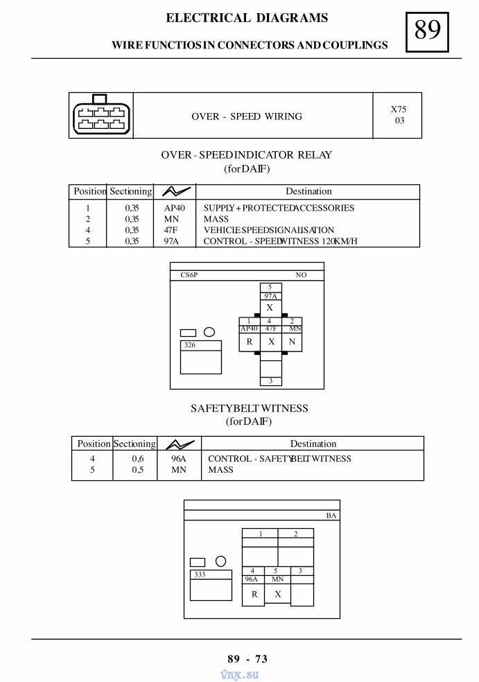
89ELECTRICAL DIAGRAMS
89 - 73
OVER - SPEED WIRING X75 03
OVER - SPEED INDICATOR RELAY(for DAIF)
NO
5
3
97A
1 4 2AP40 47F MN
CS6P
326 R X N
X
1 0,35 AP40 SUPPLY + PROTECTED ACCESSORIES2 0,35 MN MASS4 0,35 47F VEHICLE SPEED SIGNALISATION5 0,35 97A CONTROL - SPEED WITNESS 120 KM/H
Position Sectioning Destination
SAFETY BELT WITNESS(for DAIF)
Position Sectioning Destination4 0,6 96A CONTROL - SAFETY BELT WITNESS5 0,5 MN MASS
BA
1 2
333 4 5 3 96A MN
R X
WIRE FUNCTIOS IN CONNECTORS AND COUPLINGS
vnx.su
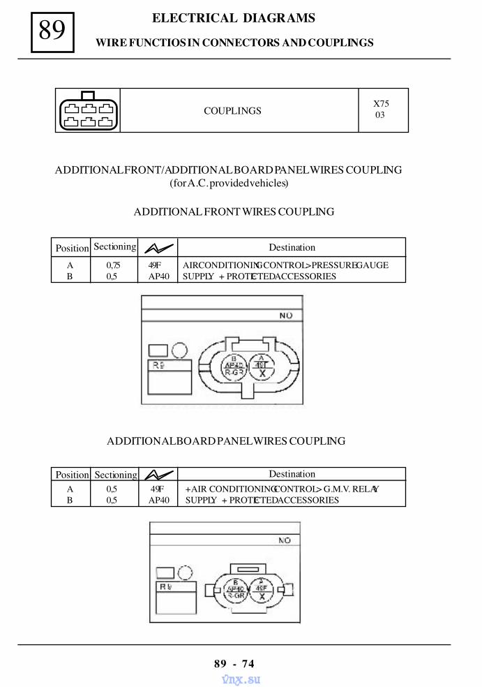
89 ELECTRICAL DIAGRAMS
89 - 74
ADDITIONAL FRONT/ADDITIONAL BOARD PANEL WIRES COUPLING(for A.C. provided vehicles)
Position Sectioning Destination
A 0,75 49F AIR CONDITIONING CONTROL > PRESSURE GAUGEB 0,5 AP40 SUPPLY + PROTECTED ACCESSORIES
COUPLINGS X75 03
ADDITIONAL BOARD PANEL WIRES COUPLING
Position Sectioning DestinationA 0,5 49F + AIR CONDITIONING CONTROL > G.M.V. RELAYB 0,5 AP40 SUPPLY + PROTECTED ACCESSORIES
ADDITIONAL FRONT WIRES COUPLING
WIRE FUNCTIOS IN CONNECTORS AND COUPLINGS
vnx.su
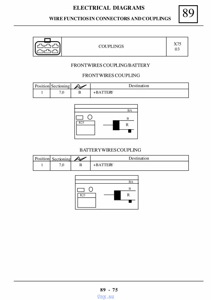
89ELECTRICAL DIAGRAMS
89 - 75
COUPLINGS X75 03
Position Sectioning Destination1 7,0 B + BATTERY
FRONT WIRES COUPLING/BATTERY
R
BA
B R25
Position Sectioning Destination1 7,0 B + BATTERY
BATTERY WIRES COUPLING
R
BA
B
R25
FRONT WIRES COUPLING
WIRE FUNCTIOS IN CONNECTORS AND COUPLINGS
vnx.su
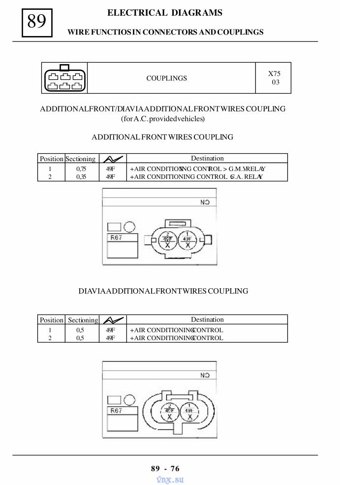
89 ELECTRICAL DIAGRAMS
89 - 76
COUPLINGS X75 03
ADDITIONAL FRONT/DIAVIA ADDITIONAL FRONT WIRES COUPLING(for A.C. provided vehicles)
ADDITIONAL FRONT WIRES COUPLING
Position Sectioning Destination1 0,75 49F + AIR CONDITIONING CONTROL > G.M.V. RELAY2 0,35 49F + AIR CONDITIONING CONTROL > C.A. RELAY
DIAVIA ADDITIONAL FRONT WIRES COUPLING
Position Sectioning Destination1 0,5 49F + AIR CONDITIONING CONTROL2 0,5 49F + AIR CONDITIONING CONTROL
WIRE FUNCTIOS IN CONNECTORS AND COUPLINGS
vnx.su
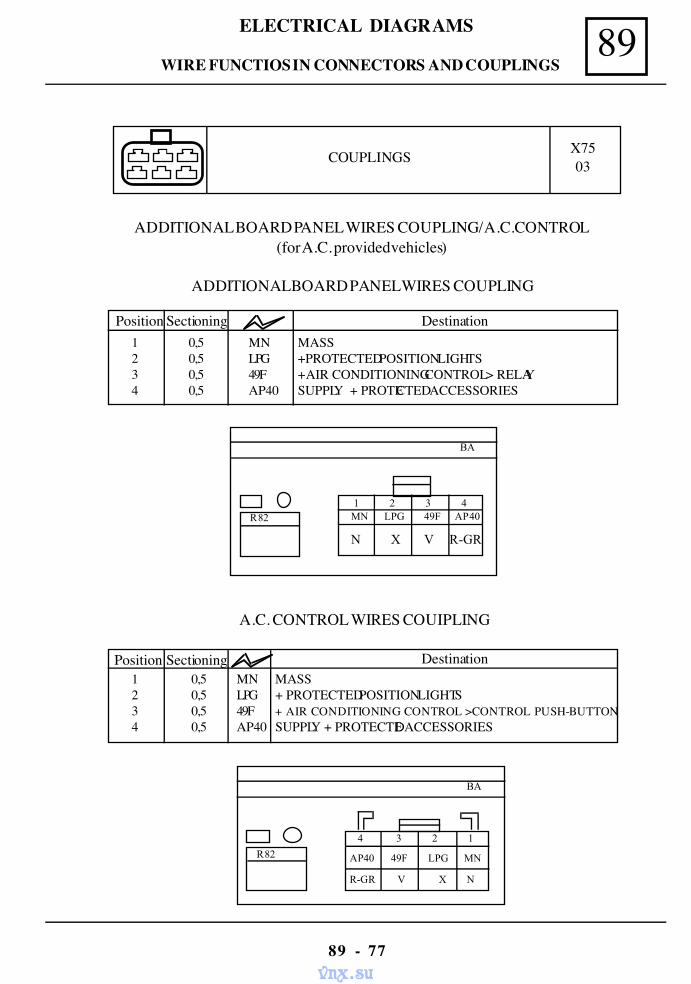
89ELECTRICAL DIAGRAMS
89 - 77
COUPLINGS X7503
A.C. CONTROL WIRES COUIPLING
BA
4 3 2 1
R82 AP40 49F LPG MN
R-GR V X N
Position Sectioning Destination1 0,5 MN MASS2 0,5 LPG + PROTECTED POSITION LIGHTS3 0,5 49F + AIR CONDITIONING CONTROL >CONTROL PUSH-BUTTON4 0,5 AP40 SUPPLY + PROTECTED ACCESSORIES
ADDITIONAL BOARD PANEL WIRES COUPLING/ A.C.CONTROL(for A.C. provided vehicles)
ADDITIONAL BOARD PANEL WIRES COUPLING
Position Sectioning Destination1 0,5 MN MASS2 0,5 LPG +PROTECTED POSITION LIGHTS3 0,5 49F + AIR CONDITIONING CONTROL > RELAY4 0,5 AP40 SUPPLY + PROTECTED ACCESSORIES
BA
1 2 3 4 R82 MN LPG 49F AP40
N X V R-GR
WIRE FUNCTIOS IN CONNECTORS AND COUPLINGS
vnx.su
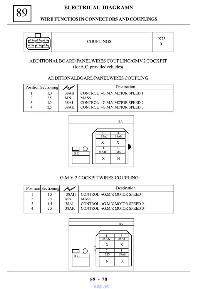
89 ELECTRICAL DIAGRAMS
89 - 78
G.M.V. 2 COCKPIT WIRES COUPLING
Position Sectioning Destination1 1,5 38AH CONTROL + G.M.V. MOTOR SPEED 12 2,5 MN MASS3 1,5 38AJ CONTROL + G.M.V. MOTOR SPEED 24 2,5 38AK CONTROL + G.M.V. MOTOR SPEED 3
BA
X X
N X
4 3
R93
2 1 MN 38AH
38AK 38AJ
COUPLINGS X7501
ADDITIONAL BOARD PANEL WIRES COUPLING/GMV 2 COCKPIT(for A.C. provided vehicles)
ADDITIONAL BOARD PANEL WIRES COUPLING
Position Sectioning Destination1 1,0 38AH CONTROL + G.M.V. MOTOR SPEED 12 2,5 MN MASS3 1,5 38AJ CONTROL + G.M.V. MOTOR SPEED 24 2,5 38AK CONTROL + G.M.V. MOTOR SPEED 3
BA
X X
X N
3 438AJ 38AK
R93
1 238AH MN
WIRE FUNCTIOS IN CONNECTORS AND COUPLINGS
vnx.su
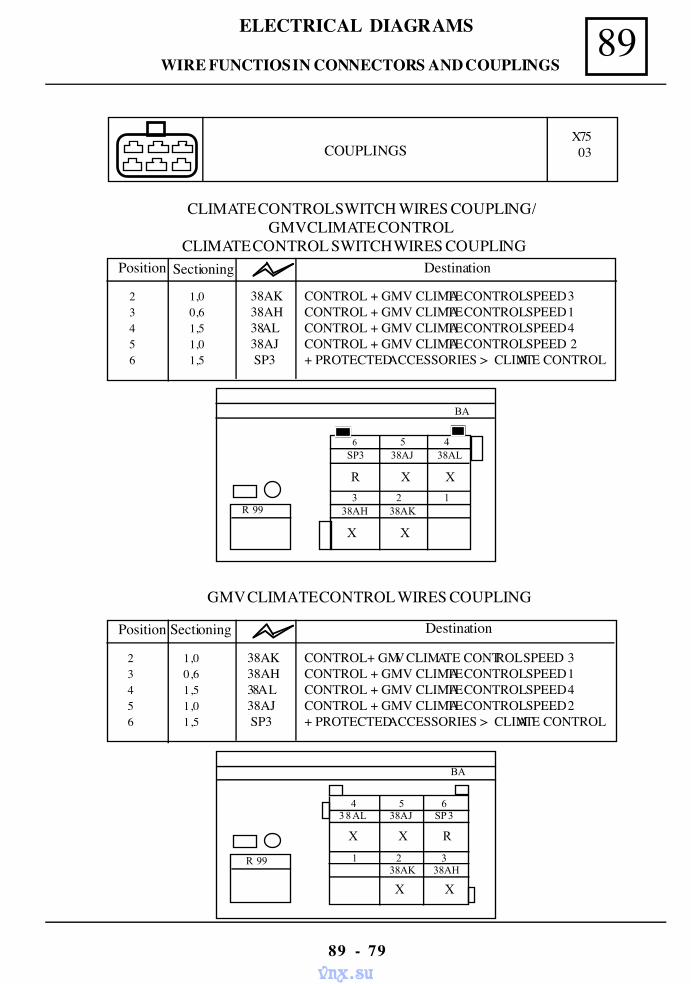
89ELECTRICAL DIAGRAMS
89 - 79
CLIMATE CONTROL SWITCH WIRES COUPLING/GMV CLIMATE CONTROL
COUPLINGSX75 03
CLIMATE CONTROL SWITCH WIRES COUPLING
BA
X X
6 5 4 SP3 38AJ 38AL
3 2 1 38AH 38AK
R X X
R 99
GMV CLIMATE CONTROL WIRES COUPLING
2 1,0 38AK CONTROL + GMV CLIMATE CONTROL SPEED 3 3 0,6 38AH CONTROL + GMV CLIMATE CONTROL SPEED 1 4 1,5 38AL CONTROL + GMV CLIMATE CONTROL SPEED 4 5 1,0 38AJ CONTROL + GMV CLIMATE CONTROL SPEED 2 6 1,5 SP3 + PROTECTED ACCESSORIES > CLIMATE CONTROL
Position Sectioning Destination
2 1,0 38AK CONTROL+ GMV CLIMATE CONTROL SPEED 33 0,6 38AH CONTROL + GMV CLIMATE CONTROL SPEED 14 1,5 38AL CONTROL + GMV CLIMATE CONTROL SPEED 45 1,0 38AJ CONTROL + GMV CLIMATE CONTROL SPEED 26 1,5 SP3 + PROTECTED ACCESSORIES > CLIMATE CONTROL
Position Sectioning Destination
BA
R 99
X X
4 5 638AL 38AJ SP 3
1 2 3 38AK 38AH
X X R
WIRE FUNCTIOS IN CONNECTORS AND COUPLINGS
vnx.su
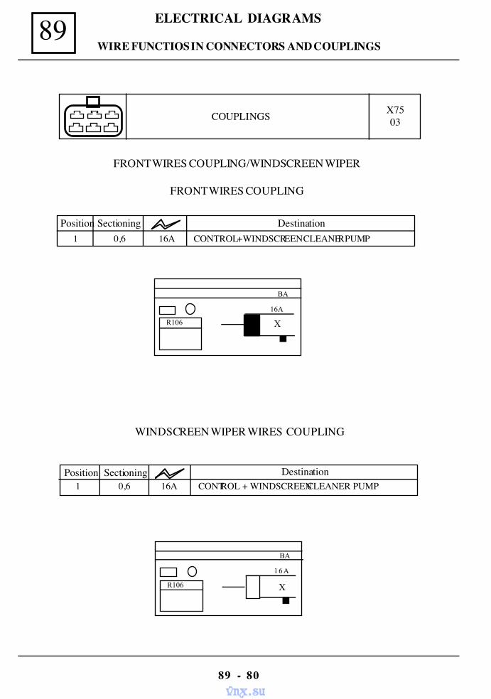
89 ELECTRICAL DIAGRAMS
89 - 80
COUPLINGS X7503
WINDSCREEN WIPER WIRES COUPLING
X
BA
16A
R106
Position Sectioning Destination 1 0,6 16A CONTROL + WINDSCREEN CLEANER PUMP
Position Sectioning Destination 1 0,6 16A CONTROL + WINDSCREEN CLEANER PUMP
FRONT WIRES COUPLING/WINDSCREEN WIPER
FRONT WIRES COUPLING
X
BA
16A
R106
WIRE FUNCTIOS IN CONNECTORS AND COUPLINGS
vnx.su
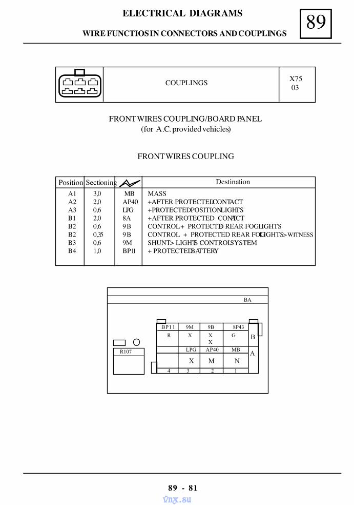
89ELECTRICAL DIAGRAMS
89 - 81
COUPLINGS X7503
FRONT WIRES COUPLING/BOARD PANEL (for A.C. provided vehicles)
FRONT WIRES COUPLING
BA
R X X GX
BP11 9M 9B 8P43
LPG AP40 MB
X M N 4 3 2 1
B
A R107
A1 3,0 MB MASS A2 2,0 AP40 +AFTER PROTECTED CONTACT A3 0,6 LPG + PROTECTED POSITION LIGHTS B1 2,0 8A + AFTER PROTECTED CONTACT B2 0,6 9 B CONTROL + PROTECTED REAR FOG LIGHTS B2 0,35 9 B CONTROL + PROTECTED REAR FOG LIGHTS > WITNESS B3 0,6 9M SHUNT > LIGHTS CONTROL SYSTEM B4 1,0 BP11 + PROTECTED BATTERY
Position Sectioning Destination
WIRE FUNCTIOS IN CONNECTORS AND COUPLINGS
vnx.su

89 ELECTRICAL DIAGRAMS
89 - 82
COUPLINGS X7503
BOARD PANEL WIRES COUPLING
BA
R107
AP43 9B 9M BP11
M X X
1 2 3 4
B
A
MB AP40 LPG 15B
X
R R
N N
X X
A1 3,0 MB MASSA1 0,6 MB MASS > FOG LIGHTS RELAYA2 2,0 AP40 + AFTER PROTECTED CONTACTA2 1,0 AP40 + AFTER PROTECTED CONTACT> WINDSCREEN WIPER CONTROLA3 1,0 L + PROTECTED POSITION LIGHTSA3 1,0 L + PROTECTED POSITION LIGHTS > FOG LIGHTS RELAYB1 2,0 AP43 +AFTER PROTECTED CONTACTB2 0,6 9B CONTROL + PROTECTED REAR FOG LIGHTSB3 0,6 9M SHUNT > FOG LIGHTS SWITCHB4 1,4 BP11 + PROTECTED BATTERY > ELECTRIC LIGHTERB4 0,6 BP11 + PROTECTED BATTERY > FOG LIGHTS RELAY
Position Sectioning Destination
GG
WIRE FUNCTIOS IN CONNECTORS AND COUPLINGS
vnx.su
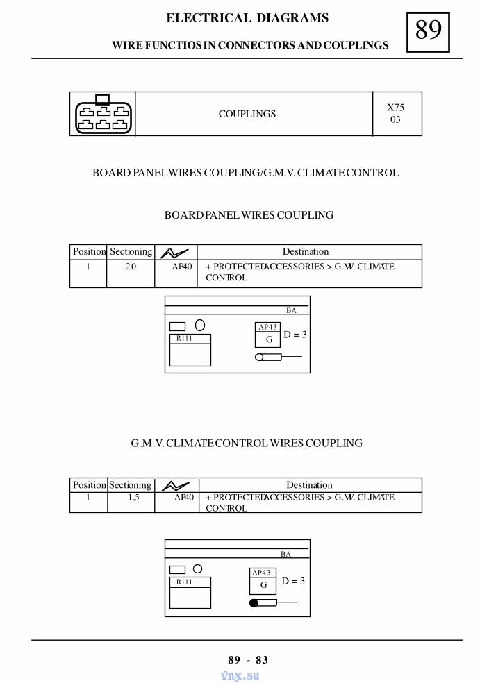
89ELECTRICAL DIAGRAMS
89 - 83
COUPLINGS X7503
Position Sectioning Destination1 1,5 AP40 + PROTECTED ACCESSORIES > G.M.V. CLIMATE
CONTROL
G.M.V. CLIMATE CONTROL WIRES COUPLING
BA
R111 D = 3
BOARD PANEL WIRES COUPLING/G.M.V. CLIMATE CONTROL
G
BA
AP43
R111 D = 3
BOARD PANEL WIRES COUPLING
Position Sectioning Destination1 2,0 AP40 + PROTECTED ACCESSORIES > G.M.V. CLIMATE
CONTROL
GAP43
WIRE FUNCTIOS IN CONNECTORS AND COUPLINGS
vnx.su
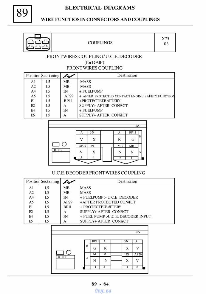
89 ELECTRICAL DIAGRAMS
89 - 84
COUPLINGSX75 03
BA
R 112
G R X V
1 2 4 5
B
A N N
BP11 A 3N A
M M 3N AP29
X V
R 112
A 3NB
A
A BP11
V X R G AP29 3N
V X MB MB
N N 2 1 5 4
Position Sectioning DestinationA1 1,5 MB MASSA2 1,5 MB MASSA4 1,5 3N + FUEL PUMPA5 1,5 AP29 + AFTER PROTECTED CONTACT ENGINE SAFETY FUNCTIONB1 1,5 BP11 + PROTECTED BATTERYB2 1,5 A SUPPLY + AFTER CONTACTB4 1,5 3N + FUEL PUMPB5 1,5 A SUPPLY + AFTER CONTACT
BA
PositionSectioning DestinationA1 1,5 MB MASSA2 1,5 MB MASSA4 1,5 3N + FUEL PUMP > U.C.E. DECODERA5 1,5 AP29 + AFTER PROTECTED CONTACTB1 1,5 BP11 + PROTECTED BATTERYB2 1,5 A SUPPLY + AFTER CONTACTB4 1,5 3N + FUEL PUMP > U.C.E. DECODER INPUTB5 1,5 A SUPPLY + AFTER CONTACT
FRONT WIRES COUPLING / U.C.E. DECODER(for DAIF)
FRONT WIRES COUPLING
U.C.E. DECODER FRONT WIRES COUPLING
WIRE FUNCTIOS IN CONNECTORS AND COUPLINGS
vnx.su
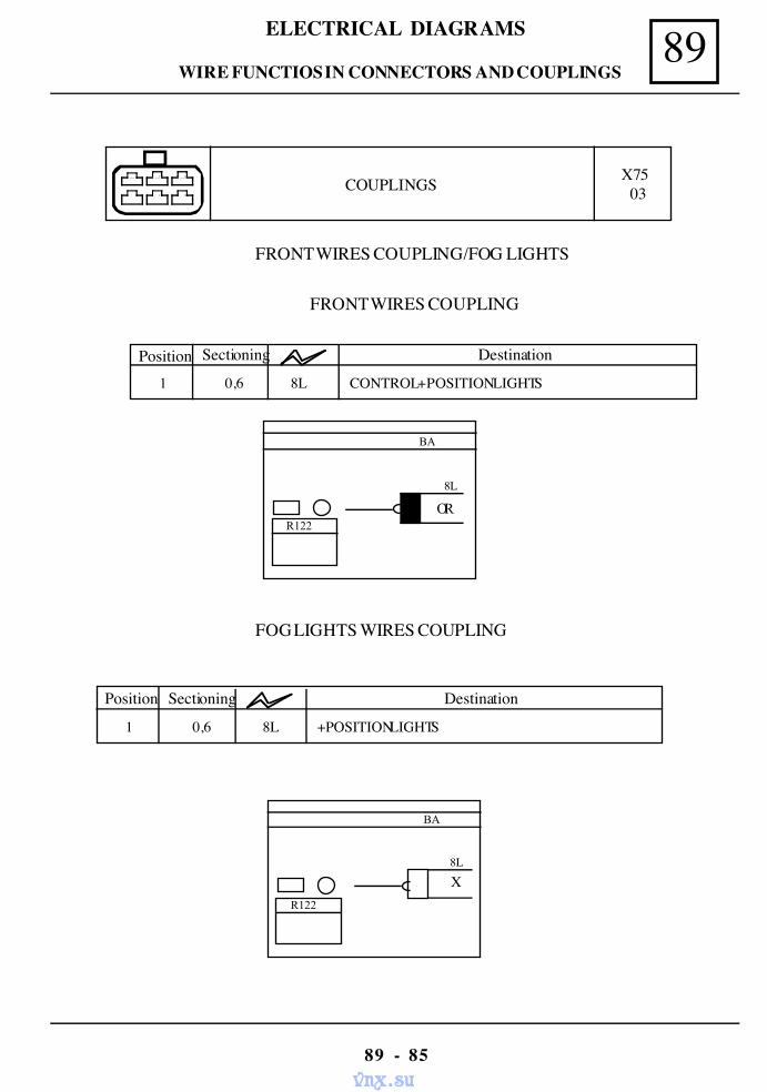
89ELECTRICAL DIAGRAMS
89 - 85
COUPLINGS X75 03
FRONT WIRES COUPLING/FOG LIGHTS
FRONT WIRES COUPLING
Position Sectioning Destination
1 0,6 8L CONTROL + POSITION LIGHTS
FOG LIGHTS WIRES COUPLING
Position Sectioning Destination
1 0,6 8L +POSITION LIGHTS
BA
R122
8L
OR
BA
8L
R122
X
WIRE FUNCTIOS IN CONNECTORS AND COUPLINGS
vnx.su
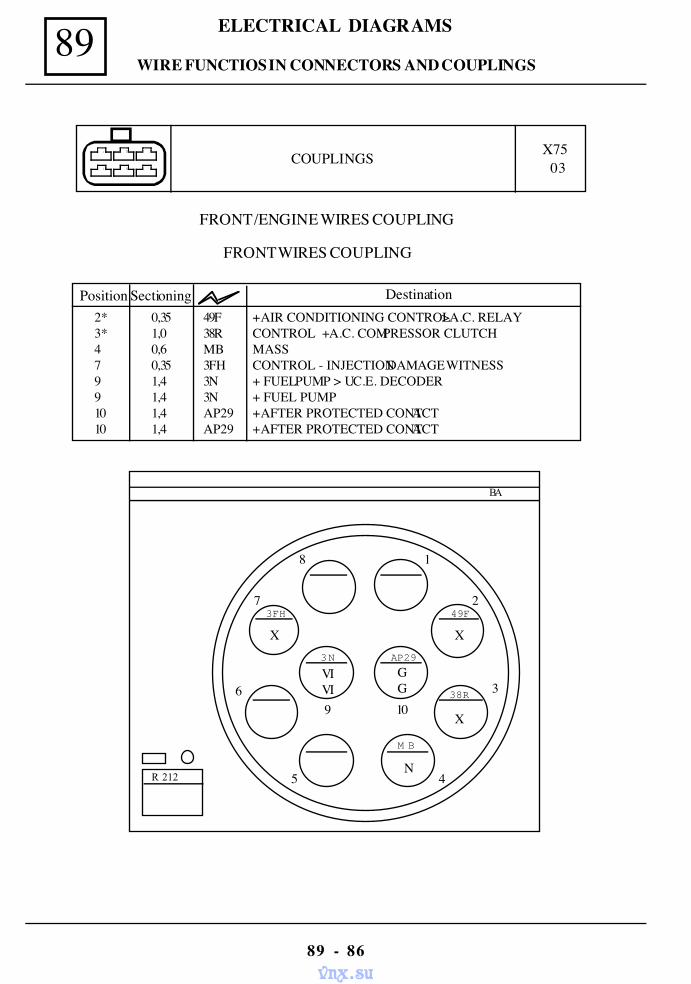
89 ELECTRICAL DIAGRAMS
89 - 86
COUPLINGS X75 03
FRONT /ENGINE WIRES COUPLING
49F
AP29
38R
M B
3 N
3FH
X
GG
X
N
VIVI
X
BA
R 212
8 1
7
6
5
2
39 10
4
2* 0,35 49F + AIR CONDITIONING CONTROL > A.C. RELAY3* 1,0 38R CONTROL + A.C. COMPRESSOR CLUTCH4 0,6 MB MASS7 0,35 3FH CONTROL - INJECTION DAMAGE WITNESS9 1,4 3N + FUEL PUMP > U.C.E. DECODER9 1,4 3N + FUEL PUMP10 1,4 AP29 + AFTER PROTECTED CONTACT10 1,4 AP29 + AFTER PROTECTED CONTACT
Position Sectioning Destination
FRONT WIRES COUPLING
WIRE FUNCTIOS IN CONNECTORS AND COUPLINGS
vnx.su
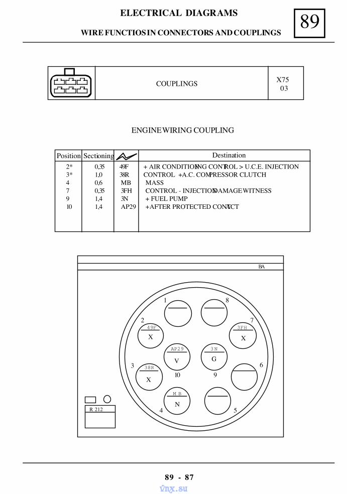
89ELECTRICAL DIAGRAMS
89 - 87
COUPLINGS X75 03
ENGINE WIRING COUPLING
2* 0,35 49F + AIR CONDITIONING CONTROL > U.C.E. INJECTION3* 1,0 38R CONTROL + A.C. COMPRESSOR CLUTCH4 0,6 MB MASS7 0,35 3FH CONTROL - INJECTION DAMAGE WITNESS9 1,4 3N + FUEL PUMP10 1,4 AP29 + AFTER PROTECTED CONTACT
Position Sectioning Destination
49F
AP29
38R
M B
3 N
3FH
X
V
X
N
G
X
BA
R 212
1 8
2
3
4
7
610 9
5
WIRE FUNCTIOS IN CONNECTORS AND COUPLINGS
vnx.su
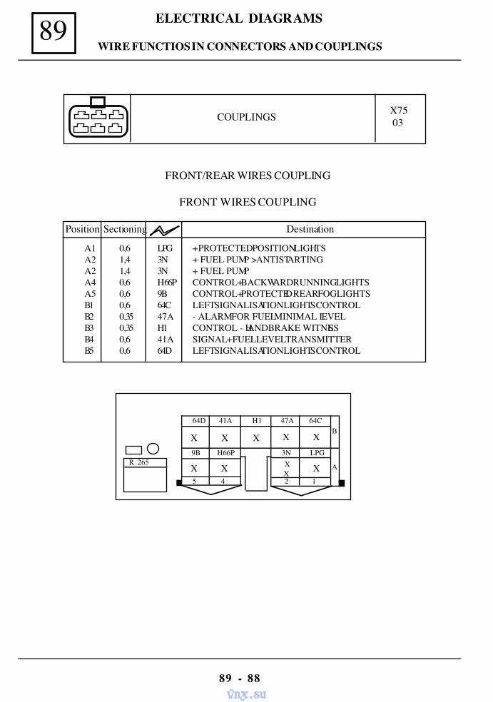
89 ELECTRICAL DIAGRAMS
89 - 88
COUPLINGS X7503
FRONT/REAR WIRES COUPLING
FRONT WIRES COUPLING
Position Sectioning Destination
R 265
64D 41A H1B
A
47A 64C
X X X X X 9B H66P
X X
3N LPG
X 2 1 5 4
A1 0,6 LPG + PROTECTED POSITION LIGHTSA2 1,4 3N + FUEL PUMP > ANTISTARTINGA2 1,4 3N + FUEL PUMPA4 0,6 H66P CONTROL+ BACKWARD RUNNING LIGHTSA5 0,6 9B CONTROL+ PROTECTED REAR FOG LIGHTSB1 0,6 64C LEFT SIGNALISATION LIGHTS CONTROLB2 0,35 47A - ALARM FOR FUEL MINIMAL LEVELB3 0,35 H1 CONTROL - HANDBRAKE WITNESSB4 0,6 41A SIGNAL + FUEL LEVEL TRANSMITTERB5 0,6 64D LEFT SIGNALISATION LIGHTS CONTROL
X X
WIRE FUNCTIOS IN CONNECTORS AND COUPLINGS
vnx.su
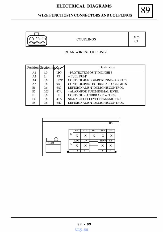
89ELECTRICAL DIAGRAMS
89 - 89
COUPLINGS X7503
REAR WIRES COUPLING
BA
R 265
X X X X XB
A X X
64C 47A H1 41A 64D
LPG 3N H66P 9B
X X
1 2 4 5
Position Sectioning DestinationA1 1,0 LPG + PROTECTED POSITION LIGHTSA2 1,4 3N + FUEL PUMPA4 0,6 H66P CONTROL+ BACKWARD RUNNING LIGHTSA5 0,6 9B CONTROL+ PROTECTED REAR FOG LIGHTSB1 0,6 64C LEFT SIGNALISATION LIGHTS CONTROLB2 0,35 47A - ALARM FOR FUEL MINIMAL LEVELB3 0,6 H1 CONTROL - HANDBRAKE WITNESSB4 0,6 41A SIGNAL + FUEL LEVEL TRANSMITTERB5 0,6 64D LEFT SIGNALISATION LIGHTS CONTROL
WIRE FUNCTIOS IN CONNECTORS AND COUPLINGS
vnx.su
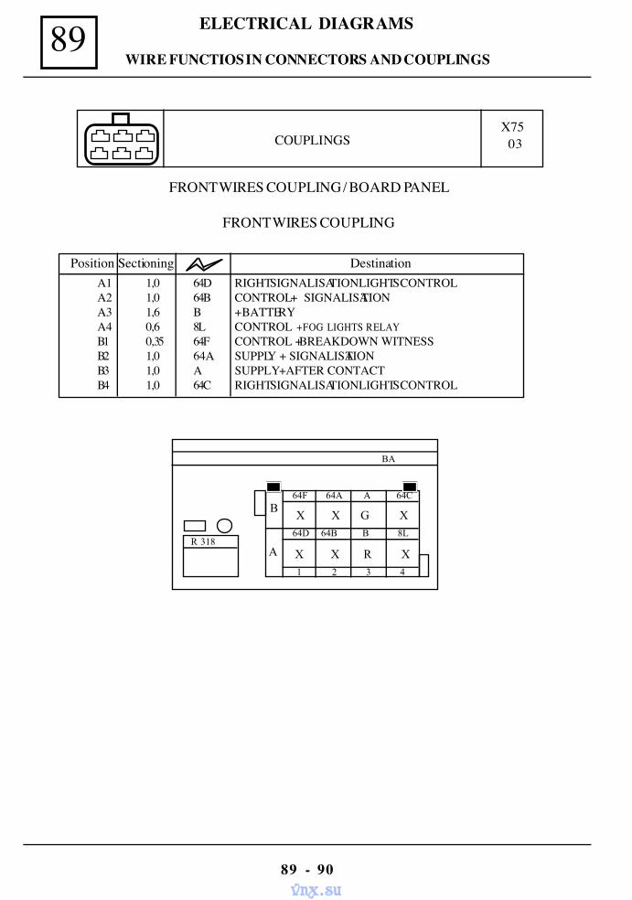
89 ELECTRICAL DIAGRAMS
89 - 90
FRONT WIRES COUPLING / BOARD PANEL
FRONT WIRES COUPLING
BA
R 318
1 2 3 4
64D 64B B 8L
B
A
X X G X
X X R X
64F 64A A 64C
Position Sectioning DestinationA1 1,0 64D RIGHT SIGNALISATION LIGHTS CONTROLA2 1,0 64B CONTROL + SIGNALISATIONA3 1,6 B + BATTERYA4 0,6 8L CONTROL +FOG LIGHTS RELAYB1 0,35 64F CONTROL + BREAKDOWN WITNESSB2 1,0 64A SUPPLY + SIGNALISATIONB3 1,0 A SUPPLY + AFTER CONTACTB4 1,0 64C RIGHT SIGNALISATION LIGHTS CONTROL
COUPLINGSX75 03
WIRE FUNCTIOS IN CONNECTORS AND COUPLINGS
vnx.su
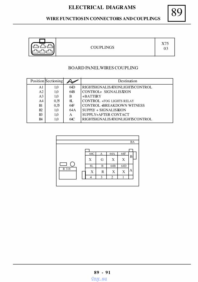
89ELECTRICAL DIAGRAMS
89 - 91
BOARD PANEL WIRES COUPLING
COUPLINGSX75 03
BA
R 318
64C A 64A 64F
4 3 2 1
8L B 64B 64D
B
A
X G X X
X R X X
Position Sectioning DestinationA1 1,0 64D RIGHT SIGNALISATION LIGHTS CONTROLA2 1,0 64B CONTROL + SIGNALISATIONA3 1,0 B + BATTERYA4 0,35 8L CONTROL +FOG LIGHTS RELAYB1 0,35 64F CONTROL + BREAKDOWN WITNESSB2 1,0 64A SUPPLY + SIGNALISATIONB3 1,0 A SUPPLY + AFTER CONTACTB4 1,0 64C RIGHT SIGNALISATION LIGHTS CONTROL
WIRE FUNCTIOS IN CONNECTORS AND COUPLINGS
vnx.su
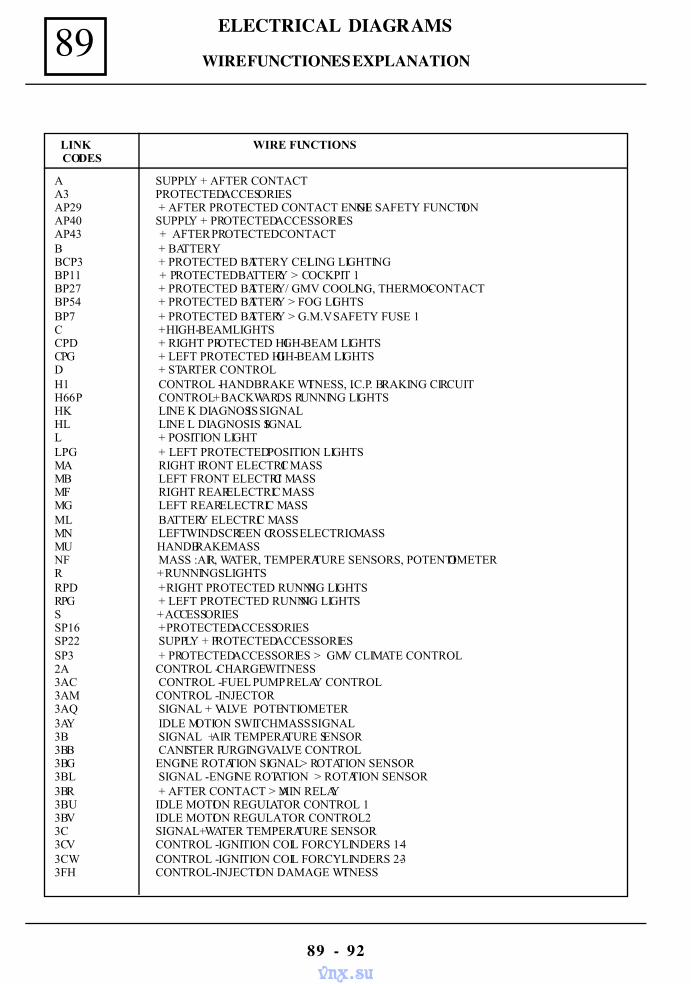
89 ELECTRICAL DIAGRAMS
89 - 92
LINK WIRE FUNCTIONS
CODES
A SUPPLY + AFTER CONTACTA3 PROTECTED ACCESORIESAP29 + AFTER PROTECTED CONTACT ENGINE SAFETY FUNCTIONAP40 SUPPLY + PROTECTED ACCESSORIESAP43 + AFTER PROTECTED CONTACTB + BATTERYBCP3 + PROTECTED BATTERY CEILING LIGHTINGBP11 + PROTECTED BATTERY > COCKPIT 1BP27 + PROTECTED BATTERY/ GMV COOLING, THERMO-CONTACTBP54 + PROTECTED BATTERY > FOG LIGHTSBP7 + PROTECTED BATTERY > G.M.V. SAFETY FUSE 1C + HIGH-BEAM LIGHTSCPD + RIGHT PROTECTED HIGH-BEAM LIGHTSCPG + LEFT PROTECTED HIGH-BEAM LIGHTSD + STARTER CONTROLH1 CONTROL - HANDBRAKE WITNESS, I.C.P. BRAKING CIRCUITH66P CONTROL + BACKWARDS RUNNING LIGHTSHK LINE K DIAGNOSIS SIGNALHL LINE L DIAGNOSIS SIGNALL + POSITION LIGHTLPG + LEFT PROTECTED POSITION LIGHTSMA RIGHT FRONT ELECTRIC MASSMB LEFT FRONT ELECTRIC MASSMF RIGHT REAR ELECTRIC MASSMG LEFT REAR ELECTRIC MASSML BATTERY ELECTRIC MASSMN LEFT WINDSCREEN CROSS ELECTRIC MASSMU HANDBRAKE MASSNF MASS :AIR, WATER, TEMPERATURE SENSORS, POTENTIOMETERR + RUNNINGS LIGHTSRPD + RIGHT PROTECTED RUNNING LIGHTSRPG + LEFT PROTECTED RUNNING LIGHTSS + ACCESSORIESSP16 + PROTECTED ACCESSORIESSP22 SUPPLY + PROTECTED ACCESSORIESSP3 + PROTECTED ACCESSORIES > GMV CLIMATE CONTROL2A CONTROL - CHARGE WITNESS3AC CONTROL - FUEL PUMP RELAY CONTROL3AM CONTROL - INJECTOR3AQ SIGNAL + VALVE POTENTIOMETER3AY IDLE MOTION SWITCH MASS SIGNAL3B SIGNAL + AIR TEMPERATURE SENSOR3BB CANISTER PURGING VALVE CONTROL3BG ENGINE ROTATION SIGNAL > ROTATION SENSOR3BL SIGNAL - ENGINE ROTATION > ROTATION SENSOR3BR + AFTER CONTACT > MAIN RELAY3BU IDLE MOTION REGULATOR CONTROL 13BV IDLE MOTION REGULATOR CONTROL23C SIGNAL+ WATER TEMPERATURE SENSOR3CV CONTROL - IGNITION COIL FOR CYLINDERS 1-43CW CONTROL - IGNITION COIL FOR CYLINDERS 2-33FH CONTROL- INJECTION DAMAGE WITNESS
WIRE FUNCTIONES EXPLANATION
vnx.su
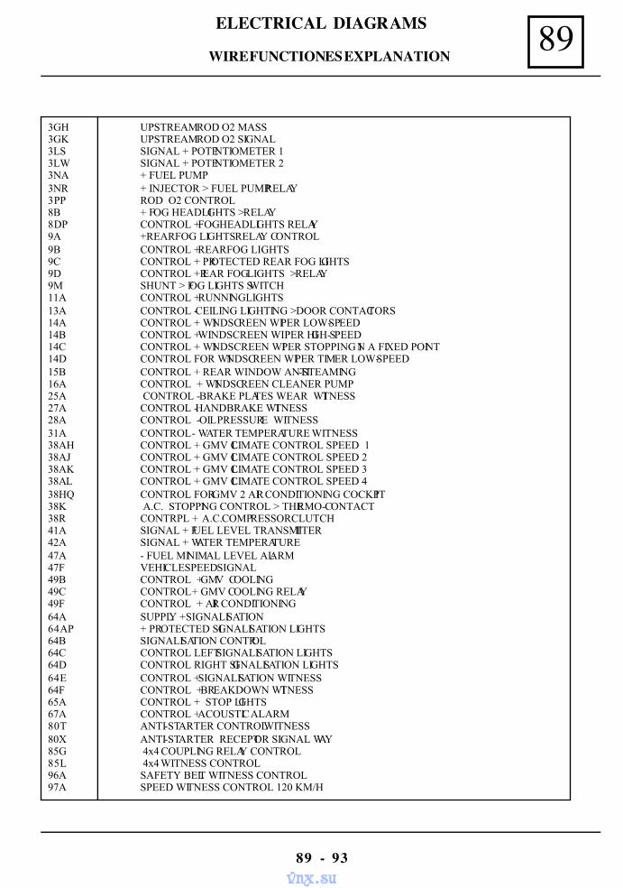
89ELECTRICAL DIAGRAMS
89 - 93
3GH UPSTREAM ROD O2 MASS3GK UPSTREAM ROD O2 SIGNAL3LS SIGNAL + POTENTIOMETER 13LW SIGNAL + POTENTIOMETER 23NA + FUEL PUMP3NR + INJECTOR > FUEL PUMP RELAY3PP ROD O2 CONTROL8B + FOG HEADLIGHTS > RELAY8DP CONTROL + FOG HEADLIGHTS RELAY9A +REAR FOG LIGHTS RELAY CONTROL9B CONTROL + REAR FOG LIGHTS9C CONTROL + PROTECTED REAR FOG LIGHTS9D CONTROL +REAR FOG LIGHTS > RELAY9M SHUNT > FOG LIGHTS SWITCH11A CONTROL + RUNNING LIGHTS13A CONTROL - CEILING LIGHTING > DOOR CONTACTORS14A CONTROL + WINDSCREEN WIPER LOW-SPEED14B CONTROL + WINDSCREEN WIPER HIGH-SPEED14C CONTROL + WINDSCREEN WIPER STOPPING IN A FIXED POINT14D CONTROL FOR WINDSCREEN WIPER TIMER LOW-SPEED15B CONTROL + REAR WINDOW ANTI-STEAMING16A CONTROL + WINDSCREEN CLEANER PUMP25A CONTROL - BRAKE PLATES WEAR WITNESS27A CONTROL - HANDBRAKE WITNESS28A CONTROL - OIL PRESSURE WITNESS31A CONTROL - WATER TEMPERATURE WITNESS38AH CONTROL + GMV CLIMATE CONTROL SPEED 138AJ CONTROL + GMV CLIMATE CONTROL SPEED 238AK CONTROL + GMV CLIMATE CONTROL SPEED 338AL CONTROL + GMV CLIMATE CONTROL SPEED 438HQ CONTROL FOR GMV 2 AIR CONDITIONING COCKPIT38K A.C. STOPPING CONTROL > THERMO-CONTACT38R CONTRPL + A.C. COMPRESSOR CLUTCH41A SIGNAL + FUEL LEVEL TRANSMITTER42A SIGNAL + WATER TEMPERATURE47A - FUEL MINIMAL LEVEL ALARM47F VEHICLE SPEED SIGNAL49B CONTROL + GMV COOLING49C CONTROL + GMV COOLING RELAY49F CONTROL + AIR CONDITIONING64A SUPPLY + SIGNALISATION64AP + PROTECTED SIGNALISATION LIGHTS64B SIGNALISATION CONTROL64C CONTROL LEFT SIGNALISATION LIGHTS64D CONTROL RIGHT SIGNALISATION LIGHTS64E CONTROL + SIGNALISATION WITNESS64F CONTROL + BREAKDOWN WITNESS65A CONTROL + STOP LIGHTS67A CONTROL + ACOUSTIC ALARM80T ANTI-STARTER CONTROL WITNESS80X ANTI-STARTER RECEPTOR SIGNAL WAY85G 4x4 COUPLING RELAY CONTROL85L 4x4 WITNESS CONTROL96A SAFETY BELT WITNESS CONTROL97A SPEED WITNESS CONTROL 120 KM/H
WIRE FUNCTIONES EXPLANATION
vnx.su