repair manual - Bikes.cz
387
REPAIR MANUAL REPARATURANLEITUNG MANUALE DI RIPARAZIONE MANUEL DE RÉPARATION MANUAL DE REPARACIÓN ART.NR.: 3.206.006-E KTM Group Partner 400-660LC42003
-
Upload
khangminh22 -
Category
Documents
-
view
1 -
download
0
Transcript of repair manual - Bikes.cz

REPAIR MANUALREPARATURANLEITUNG
MANUALE DI RIPARAZIONE
MANUEL DE RÉPARATION
MANUAL DE REPARACIÓN
ART.
NR.
: 3.2
06.0
06-E
KTM Group Partner
400-660LC42003


400-660LC4
REPAIRMANUAL


1 SERVICE-INFORMATIONS
2 GENERAL INFORMATION
3 REMOVING AND REFITTING ENGINE
4 DISASSEMBLING THE ENGINE
5 SERVICING ON INDIVIDUAL COMPONENTS
6 ASSEMBLING THE ENGINE
7 ELECTRICAL
8 FUEL SYSTEM
9 TROUBLE SHOOTING
10 TECHNICAL SPECIFICATIONS
11 PERIODIC MAINTENANCE SCHEDULE
12 WIRING DIAGRAMS
13
14
15
16


Remove page (s) Replace by page (s) Insert page (s) after page
2-1C to 2-3C 2-1D to 2-3D 2-5D
2-5C to 2-11C 2-6D to 2-13D
3-3 3-3D
4-1A 4-1D
4-5 to 4-16 4-5D to 4-17D
5-1A to 5-2A 5-1D to 5-2D
5-12 5-12D
5-14B to 5-17 5-14D to 5-17D
5-21 / 5-25 5-21D / 5-25D
6-1A to 6-2 6-1D to 6-2D
6-5C to 6-19C 6-5D to 6-21D
7-1 to 7-49C 7-1D to 7-51D
8-1C to 8-37C 8-1D to 8-49D
9-1 9-1D
10-1.1C 10-2D 10-62D to 10-72D
11-1C 11-1D 11-22D to 11-27D
12-2C 12-2D 12-57D to 12-66D
IMPORTANT INFORMATION/UPDATING INSTRUCTIONS
To be able to continue using the existing loose-leaf repair instructions, simply print thefollowing pages and insert them in the existing repair instructions:
15-18, 20-28, 32, 35, 40-54, 64, 66-69, 73, 77, 79-81, 84-207, 219, 280-291,314-319, 323, 378-387
KTM REPAIR MANUAL IN LOOSE-LEAF FORM
STORING THE REPAIR MANUAL IN THE BINDER– Put the index into the binder.– Put the front page of the repair manual (210x297 mm) into the transparent pocket provided
for this purpose on the outside of the binder.– Put the spine label (170x45 mm) into the transparent pocket provided for this purpose on the
spine of the binder.– Put the summary list of contents (150x297 mm) into the transparent pocket provided for this
purpose on the inside of the binder or insert this page on the beginning of the manual.– Then insert the individual chapters of the manual between the sheets of the index according to
the page number printed in the right bottom corner of each page. Example: page no. 3-5 3 = chapter 3 5 = page 5All pages with a page number that begins with the digit 3, for example, must be put under theindex heading „Chapter 3“.
– Index sheets that have not been marked with a certain chapter are for your personal convenience.The respective headings can be entered in the list of contents.


Rep
air
man
ual
KTM
LC
4 A
rt.-
Nr.
3.2
06.0
06 -
E
EXPLANATION - UPDATING
Edition 4/2003
3.205.49-E Repair Manual LC4 6/1998Basicversion Modelyear 1998(Engine number with first digit „8“)
3.205.73-E Updating of Rep.Manual LC4 7/1999Modelyear 1999(Engine number with first digit „9“)
3.205.89-E Updating of Rep.Manual LC4 9/2000Modelyear 2000/2001(Engine number with first digit „0“ and „1“)
3.210.30-E Updating of Rep.Manual LC4 12/2001Modelljahr 2002(Engine number with first digit „2“)
3.206.006-E Updating of Rep.Manual LC4 4/2003Modelljahr 2003(Engine number with first digit „3“)
Modification / Updating:Special tools, hydraulic clutch, Keihin carburator,technical details model 2003, technical specification, Maintenance schedule and wiring diagrams for modell 2003


INTRODUCTION
This repair manual offers extensiv repair-instructions and is an up-to-date version that describes thelatest models of the series. However, the right to modifications in the interest of technical improvement is reserved without updating the current issue of this manual.
A description of general working modes common in work shops has not been included. Safety rulescommon in the work shop have also not been listed. We take it for granted that the repairs aremade by qualified profesionally trained mechanics.
Read through the repair manual before beginning with the repair work.
WARNING STRICT COMPLIANCE WITH THESE INSTRUCTIONS IS ESSENTIAL TO AVOID DANGER TO LIFE AND LIMB.
! CAUTION !
NON-COMPLIANCE WITH THESE INSTRUCTIONS CAN LEADTO DAMAGE OF MOTORCYCLE COMPONENTS OR RENDERMOTORCYCLES UNFIT FOR TRAFFIC !
„NOTE” POINTS OUT USEFUL TIPS.
Use only ORIGINAL KTM SPARE PARTS when replacing parts.
The KTM high performance engine is only able to meet user expectations if the maintenance workis performed regularly and professionally.
KTM Austria’s certificate of achievement for its quality system ISO 9001 is the beginning of an ongoing total reengineered quality plan for a brighter tomorrow.
KTM Sportmotorcycle AG5230 Mattighofen, Austria
All design and assembly modification rights reserved.
C by KTM SPORTMOTORCYCLE AG, AUSTRIA All rights reserved


REPLY FAX FOR REPAIR MANUALS
We have made every effort to make our repair manuals as accurate as possible but it is always possible fora mistake or two to creep in.
To keep improving the quality of our repair manuals, we request mechanics and shop foremen to assist usas follows:
If you find any errors or inaccuracies in one of our repair manual – whether these are technical errors, incorrect or unclear repair procedures, tool problems, missing technical data or torques, inaccurate or incorrect translations or wording, etc. – please enter the error(s) in the table below and fax the completedform to us at 0043/7742/6000/5349.
NOTE to table:– Enter the complete item no. for the repair manual in column 1 (e.g.: 3.210.66-E).
You will find the number on the cover page or in the left margin on each right page of the manual.
– Enter the corresponding page number in the repair manual (e.g.: 5-7c) in column 2.
– Enter the current text (inaccurate or incomplete) in column 3 by quoting or describing the respective passage of the text. If your text deviates from the text contained in the repair manual, please writeyour text in German or English if possible.
– Enter the correct text in column 4.
Your corrections will be reviewed and incorporated in the next issue of our repair manual.
Item no. of repair manual Page Current text Correct text
Additional suggestions, requests or comments on our Repair Manuals (in German or English):
Name mechanic/shop foreman Company/work shop


MODELS WITHOUT FRAME OIL
CHANGING THE ENGINE OIL . . . . . . . . . . . . . . . . . . . . . . . . . . . . . . . . . .2-2
CHANGING THE OIL FILTER . . . . . . . . . . . . . . . . . . . . . . . . . . . . . . . . . . .2-2
CHANGING THE MICROFILTER . . . . . . . . . . . . . . . . . . . . . . . . . . . . . . . .2-3
OIL CIRCUIT . . . . . . . . . . . . . . . . . . . . . . . . . . . . . . . . . . . . . . . . . . . . . .2-4
OIL CIRCUIT 660 SMC . . . . . . . . . . . . . . . . . . . . . . . . . . . . . . . . . . . . . . .2-5
MODELS WITH FRAME OIL
CHANGING THE ENGINE OIL . . . . . . . . . . . . . . . . . . . . . . . . . . . . . . . . . .2-6
CHANGING THE FINE SCREEN FILTER . . . . . . . . . . . . . . . . . . . . . . . . . . . .2-6
CHANGING THE OIL FILTER . . . . . . . . . . . . . . . . . . . . . . . . . . . . . . . . . . .2-7
OIL CIRCUIT . . . . . . . . . . . . . . . . . . . . . . . . . . . . . . . . . . . . . . . . . . . . . .2-8
SECONDARY AIR SYSTEM . . . . . . . . . . . . . . . . . . . . . . . . . . . . . . . . . . . .2-9
EPC-SYSTEM . . . . . . . . . . . . . . . . . . . . . . . . . . . . . . . . . . . . . . . . . . . . .2-10
SPECIAL TOOLS . . . . . . . . . . . . . . . . . . . . . . . . . . . . . . . . . . . . . . . . . . .2-11
BLEEDING OF THE HYDRAULIC CLUTCH . . . . . . . . . . . . . . . . . . . . . . . .2-13
Rep
air
man
ual
KTM
LC
4 A
rt.-
Nr.
3.2
06.0
06 -
E
GENERAL INFORMATION
INDEX
2-1D
2


Rep
air
man
ual
KTM
LC
4 A
rt.-
Nr.
3.2
06.0
06 -
E2-2D
Changing the engine oil (models without frame oil)NOTE: The engine oil change is to be carried out when the engine isstill warm.
WARNING AN ENGINE HAVING BEEN RUN WARM, AND THE ENGINE OIL IN IT ARE VERY HOT -DO NOT BURN YOURSELF.
– Place the motorbike on a horizontal surface. Remove the two plugs (1 and 2), and drain oil into a container.
NOTE: A third plug was installed in the 660 SMC model. Tighteningtorque: 20 Nm
! CAUTION !THE SCREW PLUG A MUST NOT BE REMOVED, THIS IS PART OF THE BY-PASS VALVE.
– Clean the plugs thoroughly with a fireproof solvent and compressedair, in order to remove the metal abrasion.
– After all the oil has drained through, clean raised and flat faces andinstall plugs with seals. Tighten plug 1 with 30 Nm (22 ft.lb) andplug 2 with 20 Nm (15ft.lb).
– Remove the oil dipstick at the clutch cover, pour in engine oil andreplace the oil dipstick.
Oil capacity (up to model 2002) : 1.40 lOil capacity (from model 2003 on) : 1.50 l
Changing the oil filterReplace the oil filter when changing the engine oil.– Press the foot brake pedal and place a screwdriver or similar between
foot brake pedal and stopper roll so that the oil filter cover is moreaccessible.
– Remove banjo bolt 3 and the three bolts 4.– Remove oil filter cover 5 and oil filter.– Clean filter housing, oil filter cover and sealing surfaces. Check oil
duct in oil filter cover if clogged.
– Press the new O-ring 6 into the groove of the filter cover (if necessary fix with grease). Mount a new oil filter 7 on theconnection piece of the oil filter cover an mount the whole unit.
NOTE: From model 2001 onwards the gasket 8 is mounted with achanged filter cover 5. If the new gasket 8 should be used on olderengines, the filter cover must be flat regrinded or renewed (seeTechnical Info Nr. 0201/30/01).
– Mount three bolts and tighten with 5 Nm (4 ft.lb). – Mount hollow bolt with seal rings and tighten with 15 Nm
(11 ft.lb).
1
1
A A
2
up to Modell 2001 from Modell 2002 on
2
3
4
5 6
78
3
4
5

2-3D
Changing the microfilterReplace the microfilter while changing the engine oil. – To do so, remove bolts 1 and take off the microfilter cover 2.– Remove the microfilter, clean its parts and check the O-ring on the
microfilter cover for signs of damage.– Insert a new microfilter into the filter housing, tilt the motorcycle
sideways and fill the microfilter housing with engine oil.– Slightly grease the O-ring and mount the microfilter cover. Then put
the motorcycle back on its stand.
– It is necessary to bleed the microfilter so that all lubricating pointscan be quickly supplied with engine oil.
– To do this, fill with oil and remove the jet screw from the oil line onthe clutch cover.
– Start the engine and close off the bore on the clutch cover with arag.
– Allow the engine to run at idle until oil runs out of the oil line 3. – Turn off the engine. Mount the jet screw, using two new seal rings.– Torque the jet screw to 10 Nm and check for leaks.
– Start the engine and let it idle for 1 - 2 minutes.
! CAUTION !DO NOT REV UP THE ENGINE IMMEDIATELY AFTER AN OIL CHANGE ! KEEP IN MINDTHAT IT TAKES SOME TIME UNTIL ALL LUBRICATING POINTS ARE PROPERLY PROVIDEDWITH ENGINE OIL.
– Allow the engine to run until warm. Then, turn off the engine, andplace the motorbike on a flat, level surface in an upright position(center stand). Wait for 5 minutes. Unscrew and remove the oil dipstick, and wipe it clean with a cloth.
– Screw the dipstick in all the way and remove it again. The oil levelshould be between the two marks on the oil dipstick, however, itmust never rise above the MAX mark. Otherwise, engine oil wouldget into the air filter box by way of the engine venting system. Addengine oil, if necessary.
– Finally, check oil system and engine for leaks.
! CAUTION !– ONLY USE HIGH-QUALITY OILS MEETING OR SURPASSING THE QUALITY
REQUIREMENTS OF JASO T903 MA (FOR SPECIFICATIONS SEE CONTAINERS). – INSUFFICIENT OIL OR POOR QUALITY OIL RESULTS IN PREMATURE WEAR OF THE
ENGINE.– YOU MAY USE EITHER MINERAL OILS OR SYNTHETIC OILS FULFILLING THE ABOVE
CRITERIA.
NOTE: Dispose of used oil properly !Under no circumstances may used oil be disposed of in the sewagesystem or in the open countryside.1 liter oil contaminates 1.000.000 liter water.
3
1
1
2
0°C32°F
10W/505W/40
JASO T903 MA
TEMPERATURE

2-4DR
epai
r m
anua
l K
TM L
C4
Art
.-N
r. 3
.206
.006
-E
8
7
1
2
3
4
5
6
9
10 11
Oil circuitThe oil pump 1 pumps the engine oil past the by-pass valve 2 through the oil filter 3. After the oil filter, an oil lead branchesoff to a jet 4 which sprays engine oil onto the piston pin bearing and piston head. The second oil lead takes the main flow of oilto the microfilter 5, which filters out even the finest impurities. The cleaned engine oil is pumped through the oil lead and theclutch cover into the crankshaft to the connecting rod bearing 6 and drips into the crankcase. An additional oil pump 7 sucksthe engine oil out of the crankcase and pumps it through the oil line 8 to the gear wheels of the 4th and 5th gear. Via the gearwheels, the engine oil reaches the oil sump. The timing chain 9 runs through the oil sump and transports the engine oil upwardsto the cylinder head. Through the bore bk the oil reaches the camshaft bl and the valves.

2-5D
8
7
1
2
3
4
4
5
6
9
10 11
Oil circuit 660 SMCThe oil pump 1 pumps the engine oil past the by-pass valve 2 through the oil filter 3. After the oil filter, an oil lead branchesoff to a jet 4 which sprays engine oil onto the piston pin bearing and piston head. The second oil lead takes the main flow of oilto the second jet 4 and the microfilter 5, which filters out even the finest impurities. The cleaned engine oil is pumped throughthe oil lead and the clutch cover into the crankshaft to the connecting rod bearing 6 and drips into the crankcase. An additionaloil pump 7 sucks the engine oil out of the crankcase and pumps it through the oil line 8 to the gear wheels of the 4th and 5thgear. Via the gear wheels, the engine oil reaches the oil sump. The timing chain 9 runs through the oil sump and transports theengine oil upwards to the cylinder head. Through the bore bk the oil reaches the camshaft bl and the valves.

2-6DR
epai
r m
anua
l K
TM L
C4
Art
.-N
r. 3
.206
.006
-E
Changing the engine oil (models with frame oil)NOTE: For improved cooling of the engine oil, the front tube of theframe was integrated into the oil circuit.Thus, when you change the oil,you also have to drain the engine oil from the front tube and bleed theoil system.
If the oil system is not bled at all or bled insufficiently, the bearings ofthe engine will not get enough lubrication, which in turn may result inengine failure.
The engine oil change is to be carried out when the engine is still warm.
WARNING AN ENGINE HAVING BEEN RUN WARM, AND THE ENGINE OIL IN IT ARE VERY HOT -DO NOT BURN YOURSELF.
– Place the motorcycle on a horizontal surface. When working on amotorcycle with engine guard, remove the latter before commencingto change the engine oil.
– Remove the two plugs 1 and 2, and drain oil into a container.
! CAUTION !PLUG A MUST NOT BE REMOVED, THIS IS PART OF THE BY-PASS VALVE.
Changing the fine screen filter Replace the fine screen 3 filter when changing the engine oil.– Loosen the three bolts and remove the cover. – Undo the spin-on filter 3 with the corresponding special tool, twist
it off manually and let the engine oil out of the front pipe of theframe.
– Unscrew plug 4 at the lower end of the front pipe and drain oil (upto model 2000).
– Clean sealing surfaces on the front pipe 5, fill new fine screen filterwith engine oil, and oil rubber gasket 6. Replace fine screen filterand screw it back in place, your bare hand will do.
! CAUTION !USE ONLY ORIGINAL KTM FINE SCREEN FILTERS. USING ANOTHER FILTER BRAND CANRESULT IN DAMAGE TO THE ENGINE!
– From model 2001 onwards the drain plug 7 of the frame oil islocated in the oil filter flange, draining is only possible after removingthe oil filter.
– Clean all 3 plugs thoroughly with a fireproof solvent and compressedair, in order to remove the metal abrasion.
– After all the oil has drained through, clean sealing areas and installplugs with gaskets. Tighten plug 1 with 30 Nm (23 ft.lb), plug 2with 20 Nm and plug 4 with 10 Nm (up to model 2000). Drain plugof frame oil (model 2001 onwards) is to be mounted without agasket and tightened to 10 Nm (7 lb.ft).
1
1
A A
2
up to Modell 2001 from Modell 2002 on
2
5
3
4
6
7

2-7D
Changing the oil filterReplace the oil filter when changing the engine oil.– Press the foot brake pedal and place a screwdriver or similar between
foot brake pedal and stopper roll so that the oil filter cover is moreaccessible.
– Remove banjo bolt 1 and the three bolts 2.– Remove oil filter cover 3 and oil filter.– Clean filter housing, oil filter cover and sealing surfaces. Check oil
duct in oil filter cover if clogged.
– Press the new O-ring 4 into the groove of the filter cover (ifnecessary fix with grease). Mount a new oil filter 5 on theconnection piece of the oil filter cover an mount the whole unit.
NOTE: From model 2001 onwards the gasket 6 is mounted with achanged filter cover 3. If the new gasket 6 should be used on olderengines, the filter cover must be flat regrinded or renewed (seeTechnical Info Nr. 0201/30/01).
– Mount three bolts and tighten with 5 Nm (4 ft.lb). – Mount banjo bolt with seal rings and tighten with 15 Nm
(11 ft.lb).
– Remove the oil dipstick at the clutch cover, pour in engine oil andreplace the oil dipstick.
Oil quantity (engine only) : 1.40 liter
! CAUTION !IF THE ENGINE OIL HAS BEEN DRAINED FROM THE FRONT PIPE OF THE FRAME, YOUMUST BLEED THE OIL SYSTEM!
– Remove the plug 7 next to the steering head and use a lubricatingsyringe 8 (see special tools) to fill the front pipe with approx. 0.6 lengine oil. Add oil until it begins to emerge at bore B.
– Mount the plug, using a new seal ring.
! CAUTION !DO NOT REV UP THE ENGINE IMMEDIATELY AFTER AN OIL CHANGE. KEEP IN MINDTHAT IT TAKES SOME TIME UNTIL ALL LUBRICATING POINTS ARE PROPERLY PROVIDEDWITH ENGINE OIL.
– Allow the engine to run until warm. Then, turn off the engine, andplace the motorbike on a flat, level surface in an upright position(center stand). Wait for 5 minutes. Unscrew and remove the oil dipstick, and wipe it clean with a cloth.
– Screw the dipstick in all the way and remove it again. The oil levelshould be between the two marks on the oil dipstick, however, itmust never rise above the MAX mark. Otherwise, engine oil wouldget into the air filter box by way of the engine venting system. Addengine oil, if necessary.
– Finally, check oil system and engine for leaks.
! CAUTION !– ONLY USE HIGH-QUALITY OILS MEETING OR SURPASSING THE QUALITY
REQUIREMENTS OF JASO T903 MA (FOR SPECIFICATIONS SEE CONTAINERS).– INSUFFICIENT OIL OR POOR QUALITY OIL RESULTS IN PREMATURE WEAR OF THE
ENGINE.– YOU MAY USE EITHER MINERAL OILS OR SYNTHETIC OILS FULFILLING THE ABOVE
CRITERIA.
NOTE: Dispose of used oil properly !Under no circumstances may used oil be disposed of in the sewagesystem or in the open countryside !1 liter oil contaminates 1.000.000 liter water !
B
1
2
3 4
56
31
2
7
8

2-8DR
epai
r m
anua
l K
TM L
C4
Art
.-N
r. 3
.206
.006
-E
Oil circuitThe oil pump 1 pumps the engine oil past the by-pass valve 2 through the oil filter 3. After the oil filter, an oil line branches offto a jet 4 which sprays engine oil onto the piston pin bearing and piston head. The second oil line takes the main flow of oil intothe front pipe of the frame 5, where the engine oil is cooled down. Afterwards the engine oil runs through the fine screen filter6, which filters out even the finest impurities. The cleaned engine oil is pumped through the oil line and the clutch cover into thecrankshaft to the conrod bearing 7 and drips into the crankcase. An additional oil pump 8 sucks the engine oil out of thecrankcase and pumps it through the oil line 9 to the gear wheels of the 4th and 5th gear. Via the gear wheels, the engine oilreaches the oil sump. The timing chain bk runs through the oil sump and transports the engine oil upwards to the cylinder head.Through the bore hole bl the oil reaches the camshaft bm and the valves.
8
7
5
6
9
10
1211
1
2
3
4Drain plug - frame oil up to Model 2000
Drain plug - frame oil Model 2001 onwards

2-9D
Functional characteristics of the secondary air system (SLS)When the exhaust valve is open, the hot exhaust gases flow through the exhaust port 1 at a very high speed. As a consequenceof the flow conditions in the exhaust port and due to the influence exerted by the entire exhaust system on the escaping gases,the pressure in the exhaust port drops temporarily (underpressure).
During these cyclic underpressure phases, the secondary air valve 2 opens, thus adding oxygen of the air to the hot exhaustgases through pipe 3.At higher engine speeds, the secondary air valve interrupts the oxygen supply to prevent overheating of the catalytic converter.Additionally, the secondary air valve prevents the exhaust gases from flowing back into the air filter box 4.
When the motorcycle is pushed (high underpressure in the intake port) the control valve (ASV) 5 interrupts the air flow into theexhaust port to prevent exhaust detonations.
The control valve is controlled via a control pipe 6. This control pipe transmits the underpressure from the intake port 7 to thecontrol valve.During normal operation (slight underpressure in the intake port), the control valve is open.
The reaction between the oxygen of the air and the harmful components of the exhaust gases (CO - carbon monoxide, HC -hydrocarbon) reduces the content of harmful substances by approximately 50%. The use of a catalytic converter, in combinationwith the SLS, allows an additional significant reduction of pollutant emissions.
6
5
7
3
2
1
4
Rep
air
man
ual
KTM
LC
4 A
rt.-
Nr.
3.2
06.0
06 -
E2-10D
Electronic Power Control System (EPC)Main components of the EPC system:
– Constant-pressure carburetor– Control device– Solenoid valve– 2 contact screws at the engine– Micro-switch (at carburetor)
FUNCTIONAL CHARACTERISTICS:The EPC system is not activated during normal operation of the motorcycle.It is, however, activated as soon as the throttle is fully opened at a speed of 45 - 55 km/h while the second or third gear areengaged. The EPC control device opens the solenoid valve, directing an appropriate flow of fresh air onto the upper side of the slide membrane of the constant-pressure carburetor, thus reducing the opening speed of the slide. This mechanism significantly reducesthe exhaust gas emissions of the vehicle.
SOLENOID VALVE

2-11D
SPECIAL TOOLS
13035
65
1505
70
27
16
6
4
3
26
12
20
7
15
23
2
11
1
39
Th
reeBo
nd
1215
Silicone Liquid GasketSilicone Flüssige Dichtung
18
17
648
4#
5#5
22
48
19
8#
8
10
9
1449

Rep
air
man
ual
KTM
LC
4 A
rt.-
Nr.
3.2
06.0
06 -
E2-12D
FIG. PART NO. DESCRIPTION1 560.12.001.000 Universal engine work stand2 583.29.003.000 Clutch holder3 580.12.005.025 Mounting sleeve for crankshaft seal ring Ø 25 mm4 584.29.009.000 Magneto extractor (Kokusan)4# 580.12.009.000 Magneto extractor (SEM)5 510.12.016.000 Protection cover for crankshaft (SEM)5# 584.29.031.000 Protection cover for crankshaft (Kokusan)6 580.12.015.089 Piston ringspanner Ø 89 mm
580.12.015.095 Piston ringspanner Ø 95 mm580.12.015.100 Piston ringspanner Ø 100 mm580.12.015.101 Piston ringspanner Ø 101 mm585.29.015.102 Piston ringspanner Ø 102 mm
7 590.29.021.044 Extractor for primary gear and clutch hub8 580.12.019.000 Valve mounting set8# 590.29.019.000 Valve mounting set9 6.276.470 Valve spring-push insert10 590.29.041.000 Feeler gauge for valve clearance11 6.899.785 Loctite 243 blue 6 ml12 584.29.059.000 Loctite 648 red 20 ml14 590.29.034.000 Wrench for mixture regulating screw15 151.12.017.000 Gear puller16 151.12.018.000 Internal bearing puller 12 - 16 mm16 151.12.018.100 Internal bearing puller 18 - 23 mm17 584.29.012.000 Flywheel holding spanner (Kokusan)18 3090.98 Seal (Three-Bond)19 584.29.037.040 Mounting tool inner ring NJ207 (all versions of LC4)19 584.29.037.043 Mounting tool inner ring NJ306 (LC4-E)20 580.30.080.000 Crankshaft locking bolt22 510.12.012.000 Chain sprocket holder23 546.29.027.000 Clutch rivetting tool26 580.29.026.007 Limit plug gauge Ø 7,05 mm39 583.29.039.000 Oil filter wrench48 584.29.048.000 Syringe for pipe oil49 503.29.050.000 Bleeding syringe for hydraulic clutch

2-13D
Checking the oil level of the hydraulic clutch To check the oil level in the master cylinder of the clutch remove thecover. For this purpose, remove screws 1 and cover 2 togetherwith the rubber boot 3. The oil level in the horizontal-standingmaster cylinder should be 4 mm below the upper edge. If necessary, fill up with biodegradable hydraulic oil SAE 10 (f.ex.Motorex Kupplungs-Fluid 75).
! CAUTION !– KTM USES BIODEGRADABLE HYDRAULIC OIL FOR THE HYDRAULIC CLUTCH
CONTROL. NEVER MIX BIODEGRADABLE HYDRAULIC OILS WITH MINERAL OILS.– ALWAYS USE BIODEGRADABLE HYDRAULIC OIL SAE 10 TO FILL UP THE MASTER
CYLINDER. NEVER REFILL WITH MINERAL HYDRAULIC OIL OR BRAKE FLUID.
Bleeding of the hydraulic clutchTo bleed, the cover of the master cylinder of the clutch needs to beremoved. For this purpose, remove screws 1 and take off cover 2together with rubber bellows 3. At the slave cylinder of the clutch,remove the bleeder nipple 4. In its place, mount the bleeder syringe 5which is filled with SAE 10 hydraulic oil. Refill oil until oil is dischargedfrom the bore 6 of the master cylinder in a bubble-free state. Makesure that the oil does not overflow. The bleeder syringe can bepurchased from your KTM dealer.
Having completed the bleeding procedure, you have to verify that theoil level in the master cylinder is correct. If necessary, fill up withbiodegradable hydraulic oil SAE 10 (f.ex. Motorex Kupplungs-Fluid75).
! CAUTION !– KTM USES BIODEGRADABLE HYDRAULIC OIL FOR THE HYDRAULIC CLUTCH
CONTROL. NEVER MIX BIODEGRADABLE HYDRAULIC OILS WITH MINERAL OILS.– ALWAYS USE BIODEGRADABLE HYDRAULIC OIL SAE 10 TO FILL UP THE MASTER
CYLINDER. NEVER REFILL WITH MINERAL HYDRAULIC OIL OR BRAKE FLUID.
21
3
4
6
5

Rep
air
man
ual
KTM
LC
4 A
rt.-
Nr.
3.2
06.0
06 -
E
REMOVING THE ENGINE . . . . . . . . . . . . . . . . . . . . . . . . . . . . . . . . . . . . .3-2
REFITTING THE ENGINE . . . . . . . . . . . . . . . . . . . . . . . . . . . . . . . . . . . . . .3-4
REMOVING AND REFITTING ENGINE
INDEX
3-1D
3


Rep
air
man
ual
KTM
LC
4 A
rt.-
Nr.
3.2
06.0
06 -
E
Removing the engine– Thoroughly clean the entire motorcycle.– When working on a motorcycle with engine guard, remove the
latter.– Jack the motorcycle up on a stable supporting device.– Remove the seat, the side covers as well as the tank and the spoilers.– Disconnect the negative pole of the battery.
– Undo the 2 hose clamps 1 as well as hose clamp 2. Pull thecarburetor backwards out of the intake flange and swing it aside.
– Unhook the 4 springs 3 at the exhaust manifold.– Undo bolt 4.
– Undo bolt 5 and remove the exhaust manifold.
– Disconnect water hoses 6 and 7 from the water pump and let outthe cooling liquid.
– Remove the two bolts 8, disconnect and remove the fan.– Unhook the clutch cable and the decompression cable.– Disconnect the bleeder hose at the valve cover.
3-2D
12
3
4
5
78
6

– Remove the two bolts 1 and take off the chain guard.– Remove the chain damping plate 6.– Remove the chain joint and take off the chain.
From model 2003 on:– Remove the 3 bolts 3 of the clutch slave cylinder and pull the clutch
slave cylinder off the casing.
– Disconnect the bleeder hose 4.– Disconnect the positive cable 5 from the electric starter motor.
– Disconnect all electric plug and socket connections from the engine.– Remove the banjo bolt 6.
– Disconnect the water hose 7.
3-3D
1
1
2
3
3
4
5
6
7

Rep
air
man
ual
KTM
LC
4 A
rt.-
Nr.
3.2
06.0
06 -
E
– Remove the jet screw 1.– Remove the left as well as the right engine retaining bracket 2.
– Remove bolt 3 as well as the swingarm pivot 4.– Then lift the engine out of the frame.
Installing the engine
NOTE: To install the engine reverse the procedure indicated above.
– When working on a model with an engine guard keep in mind thatopening A must be located on the right side and face the engine.
Tightening torques:
Swingarm pivot: 100 Nm 74 ft.lbEngine mounting bolts M8: 40 Nm 30 ft.lbEngine mounting bolts M10: 70 Nm 50 ft.lbBanjo bolt (oil pipe on the frame): 15 Nm 11 ft.lbJet screw (clutch cover): 10 Nm 7 ft.lbAll other M6 bolts: 10 Nm 7 ft.lbAll other M8 bolts: 25 Nm 19 ft.lbAll other M10 bolts: 45 Nm 33 ft.lb
NOTE: Use only high-quality antifreeze (e.g. Shell Advance Coolant) forthe cooling system. The frame oil should always be changed afterengine repair.
! CAUTION !AFTER INSTALLING THE ENGINE CAREFULLY BLEED THE OIL SYSTEM (SEE OIL CHANGEINSTRUCTIONS). DO NOT REV THE ENGINE DURING THE BLEEDING PROCESS !
– The motorcycle can be tested as soon as the engine is runningsmoothly. After the test run check and, if necessary, correct all liquidlevels.
3-4D
12
3
4
A

DRAIN ENGINE OIL . . . . . . . . . . . . . . . . . . . . . . . . . . . . . . . . . . . . . . . . .4-2
REMOVING THE ELECTRIC STARTER MOTOR . . . . . . . . . . . . . . . . . . . . .4-2
REMOVING THE CLUTCH RELEASE LEVER AND THE OIL HOSES . . . . . . .4-3
REMOVING THE OIL FILTER . . . . . . . . . . . . . . . . . . . . . . . . . . . . . . . . . . .4-3
REMOVING THE EPC WIRING HARNESS . . . . . . . . . . . . . . . . . . . . . . . . . .4-3
REMOVING THE IGNITION (KOKUSAN 4K-2) . . . . . . . . . . . . . . . . . . . . . .4-3
REMOVING THE IGNITION (SEM) . . . . . . . . . . . . . . . . . . . . . . . . . . . . . .4-5
REMOVING THE IGNITION (KOKUSAN 4K-3) . . . . . . . . . . . . . . . . . . . . . .4-5
REMOVING THE ELECTRIC STARTER DRIVE . . . . . . . . . . . . . . . . . . . . . . .4-6
REMOVING THE CYLINDER HEAD TOP SECTION . . . . . . . . . . . . . . . . . . .4-7
BLOCKING THE CRANKSHAFT . . . . . . . . . . . . . . . . . . . . . . . . . . . . . . . . .4-8
REMOVING THE CAMSHAFT AND THE AUTOMATIC TENSIONER . . . . . .4-8
REMOVING CYLINDER HEAD . . . . . . . . . . . . . . . . . . . . . . . . . . . . . . . . .4-10
REMOVING CYLINDER AND PISTON . . . . . . . . . . . . . . . . . . . . . . . . . . .4-10
REMOVING ENGINE SPROCKET . . . . . . . . . . . . . . . . . . . . . . . . . . . . . . .4-11
REMOVING CLUTCH AND PRIMARY DRIVE . . . . . . . . . . . . . . . . . . . . . .4-11
REMOVING THE OIL PUMPS . . . . . . . . . . . . . . . . . . . . . . . . . . . . . . . . .4-13
REMOVING THE TIMING CHAIN AND THE TIMING GEAR . . . . . . . . . . .4-14
REMOVING THE CLUTCH RELEASE SHAFT . . . . . . . . . . . . . . . . . . . . . . .4-14
PARTING OF ENGINE HOUSING . . . . . . . . . . . . . . . . . . . . . . . . . . . . . . .4-15
REMOVING THE SHIFT MECHANISM . . . . . . . . . . . . . . . . . . . . . . . . . . .4-15
REMOVING THE TRANSMISSION SHAFTS . . . . . . . . . . . . . . . . . . . . . . .4-17
REMOVING THE KICKSTARTER SHAFT . . . . . . . . . . . . . . . . . . . . . . . . . .4-17
Rep
air
man
ual
KTM
LC
4 A
rt.-
Nr.
3.2
06.0
06 -
E
DISASSEMBLING THE ENGINE
INDEX
4-1D
4


Rep
air
man
ual
KTM
LC
4 A
rt.-
Nr.
3.2
06.0
06 -
E4-2D
– Fit engine to engine work stand.
– Remove bolt 1 together with the washers. Then remove the shiftlever together with the V-seal ring behind.
– Remove bolt 2 together with the washer. Then remove the kickstarter.
– Remove spark plug
Drain engine oil– Remove oil drain plug 3 and magnetic plug 4 and drain oil.
Removing the electric starter motor– Undo 2 bolts 5 and remove the electric starter motor from the
flange.
1
2
5
up to model 2001 from modell 2002 on
3
34 4

4-3D
Removing the clutch release lever and the oil hoses– Undo bolt 1 and remove the clutch release lever.
– Remove the two banjo bolts 2 together with the seal rings andremove both oil hoses.
Removing the oil filter– Remove all three bolts 3 and take off the oil filter cover together
with the O-ring or gasket.– Take the oil filter out of the engine housing.
Removing the EPC wiring harness– Undo the 3 bolts 4 and remove the EPC wiring harness.
Removing the ignition (Kokusan 4K-2)– Undo 4 bolts and remove the ignition cover with the stator incl.
gasket.
1
2
2
3
4
4

Rep
air
man
ual
KTM
LC
4 A
rt.-
Nr.
3.2
06.0
06 -
E4-4D
– Undo 6 bolts and remove starter flange incl. gasket.
– Insert the holding spanner 2 into the 2 bores of the flywheel.– Hold the flywheel and remove the hexagon nut (LH thread).– Remove the disc.
! CAUTION !TO AVOID DISTORTION OF THE CRANK WEB, NEVER MOUNT THE CRANKSHAFTLOCKING BOLT TO STEADY THE FLYWHEEL.
– Put the protection cover 1 onto the crankshaft and mount theflywheel extractor.
– Pull off the flywheel and take the woodruff key out of thecrankshaft.
! CAUTION !NEVER USE A HAMMER OR ANY OTHER TOOL ON THE FLYWHEEL TO AVOIDLOOSENING OF THE MAGNETS.
1
2

4-5D
Removing the ignition (SEM)– Undo the 4 bolts and remove ignition cover and O-ring.– Use the crankshaft locking bolt to block the crankshaft.
– Unscrew collar nut (LH thread) and remove spring disc.– Fit extractor and pull off flywheel. Use protective sleeve.– Remove woodruff key from the crankshaft.– Twist the crankshaft locking bolt out until the crankshaft is no longer
blocked.
! CAUTION !NEVER USE A HAMMER OR ANY OTHER TOOL ON THE FLYWHEEL TO AVOIDLOOSENING OF THE MAGNETS.
Removing the ignition (Kokusan 4K-3)– Undo the 4 bolts and take off the ignition cover together with the
O-ring.– Use the crankshaft locking bolt to block the crankshaft.
– Undo the collar nut (LH thread) and remove the spring washer.
– Mount the extractor and pull off the flywheel.– Take the woodruff key out of the crankshaft.– Finally, twist out the crankshaft locking bolt until the crankshaft is no
longer blocked.
! CAUTION !NEVER USE A HAMMER OR SIMILAR TOOL ON THE FLYWHEEL TO PREVENTLOOSENING OF THE MAGNETS.

Rep
air
man
ual
KTM
LC
4 A
rt.-
Nr.
3.2
06.0
06 -
E
Removing the electric starter drive– Pull the reduction gear 1 off the bearing bolt.– Remove both needle bearings 2 and pull the bearing bolt 3 out of
the engine housing.
– Remove the freewheel gear 4 and the needle bearing 5.
4-6D
1 2
3
4
5

4-7D
Removing the cylinder head top section– Unscrew plug 1 with gasket and remove pressure spring from
automatic tensioner.
– Undo the 4 hose clamps and remove both hoses (2 and 3).
– Remove all 6 bolts 4 together with the seal rings and take off bothvalve covers together with the gaskets.
– Remove the hexagon nut 5 and take off the retaining bracket of thesolenoid valve 6.
NOTE: A retaining bracket is only used in engines with EPC.
– Remove all 11 bolts. Then remove the cylinder head top section.
! CAUTION !WHEN REMOVING CYLINDER HEAD TOP SECTION DO NOT CHOCK IT. THIS WOULDDAMAGE THE HOUSING OF THE WATER PUMP.
NOTE: The control valve of SLS models can be removed after undoingthe bolts of the cylinder head top section.
1
2
3
4
5
6

4-8DR
epai
r m
anua
l K
TM L
C4
Art
.-N
r. 3
.206
.006
-E
– Pull water pump upward and simultaneously turn crankshaft.
NOTE: When groove A in the HH bolt is vertical, the water pump canbe pulled upward and taken out of the cylinder head without the application of force.
Blocking the crankshaft– Turn the piston to position TDC (mark B must coincide with the
plane surface of the cylinder head).
– Undo the crankshaft locking bolt 1.– Remove the copper disc 2.
NOTE: Same engines are equipped with a normal bolt M8x16 and acopper washer 8x12x1 instead of the crankshaft locking bolt M8 and acopper washer 8x14x3. In this case the special tool 580.30.080.000must be used.
– Reinsert crankshaft locking bolt by hand.– If the bolt does not slide smoothly into its bore, slightly move the
camshaft gear (if cylinder head top section is mounted turn theflywheel) back and forth until the crankshaft locking bolt engages inits bore.
– Tighten crankshaft locking bolt with 20 Nm.
! CAUTION !UNDER NO CIRCUMSTANCES APPLY FORCE TO bolt IN CRANKSHAFT LOCKING BOLTAS THIS WILL DAMAGE THE CRANKSHAFT.
Removing the camshaft and the automatic tensioner– Remove the driving bolt 3 together with the two washers.
– Remove the two bolt 4 and take off the automatic tensioner 5 andthe clamp 6.
A
B
1 2
4
3
5
6

4-9D– Using a screwdriver, lever circlip 1 out of the groove.
– Tilt camshaft and remove needle bushing 2.
– While tilted, pull camshaft from camshaft gear and remove togetherwith grooved ball bearing and circlip.
– Take the camshaft gear out of the timing chain as indicated in theillustration.
1
2

4-10DR
epai
r m
anua
l K
TM L
C4
Art
.-N
r. 3
.206
.006
-E
Removing cylinder head– Unscrew chain guide bolt 1 incl. gasket, bolts 2 and collar nuts 3.
– Unscrew the 4 collar bolts 4 and detach cylinder head with gasket.
Removing cylinder and piston– Unscrew the 4 collar nuts at the cylinder base 5.– Remove cylinder and cylinder base gasket.
– When working on an engine with a microfilter, remove the AH bolt6 before taking off the cylinder.
– Disconnect the oil hose at the clutch cover and remove themicrofilter together with the holder.
6
1
3
4
5
2

4-11D– Remove two wire circlips and press piston pin out of piston.– Remove piston.
Removing engine sprocket– Remove collar bolt 1 and spring washer.– Remove the sprocket from the counteshaft.– Remove the distance bushing from the countershaft.
NOTE: If the gear-box and the clutch of the engine are in goodcondition, throw it into gear in order to block the take-off shaft(frictional connection to the blocked crankshaft is present). If the take-off shaft cannot be blocked as described above, a chain sprocket holdermust be applied for the removal of the chain sprocket nut.
Removing clutch and primary drive– Remove the 11 bolts and detach clutch cover with gasket.
– Unscrew the bolts 3 of the clutch crosswise to prevent the clutchdiscs from jamming when the springs are relieved of tension.
– Remove bolts, spring retainer and springs.– Remove pressure cap with push rod.
– Remove the disc package and take the O-ring 2 also off the innerclutch hub.
2
1
3
4-12DR
epai
r m
anua
l K
TM L
C4
Art
.-N
r. 3
.206
.006
-E
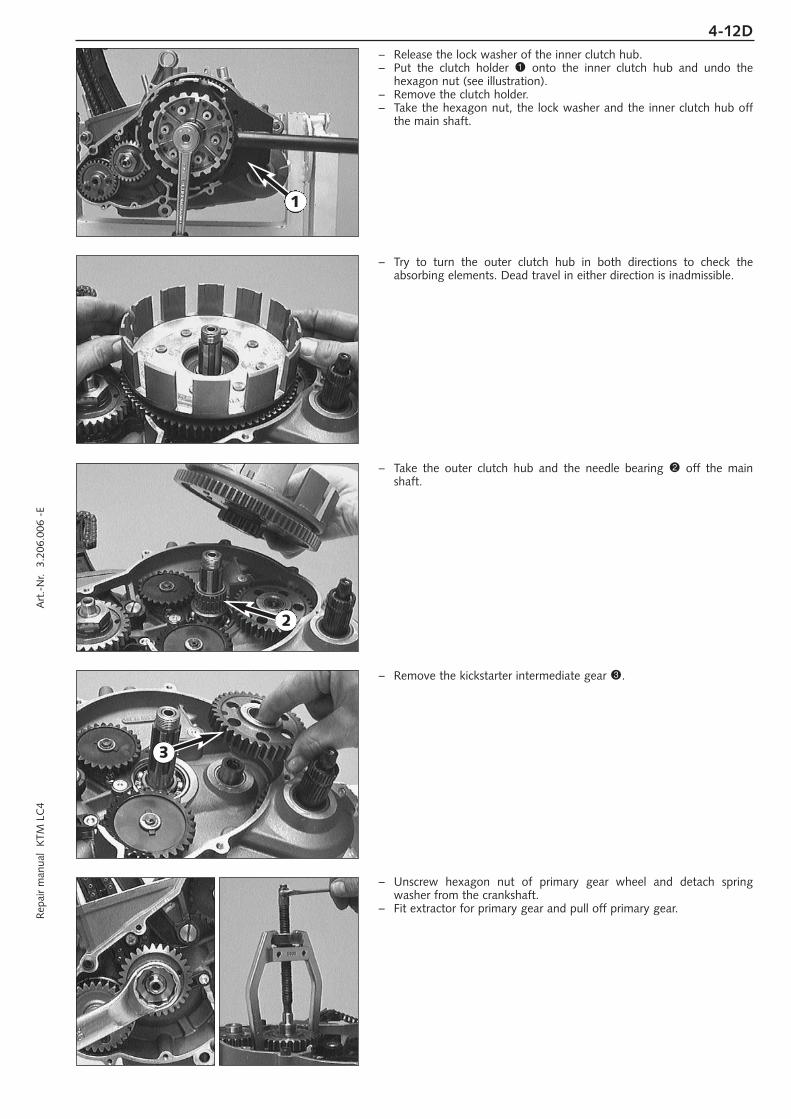
– Release the lock washer of the inner clutch hub.– Put the clutch holder 1 onto the inner clutch hub and undo the
hexagon nut (see illustration).– Remove the clutch holder.– Take the hexagon nut, the lock washer and the inner clutch hub off
the main shaft.
– Try to turn the outer clutch hub in both directions to check theabsorbing elements. Dead travel in either direction is inadmissible.
– Take the outer clutch hub and the needle bearing 2 off the mainshaft.
– Remove the kickstarter intermediate gear 3.
– Unscrew hexagon nut of primary gear wheel and detach springwasher from the crankshaft.
– Fit extractor for primary gear and pull off primary gear.
1
2
3

4-13D– Remove the balancer shaft from the bearing by hand.
Removing the oil pumpsNOTE: The following procedure must always be performed on both oilpumps.
– Remove the locking washer 1.– Remove stop disc 2 and the oil pump gear 3.
– Remove the needle roll 4 and stop disc 5.
– Twist out the 6 bolts 6 and remove the oil pumps from the housing.
NOTE: For better access to bolt 7 remove bolts 8 and take off theretaining bracket.
1
2
4
6
7
3
5
8

4-14DR
epai
r m
anua
l K
TM L
C4
Art
.-N
r. 3
.206
.006
-E
Removing the timing chain and the timing gear– Remove allan head bolt 1 and remove timing chain guide from the
casing.– Unscrew flat-head screw 2 and remove timing chain tensioner.– Unscrew allan head bolt 3 and remove timing chain securing guide.– Insert timing chain into the clutch compartment of the engine
housing and disengage from timing gear.
– Remove the primary gear woodruff key 4 from the crankshaft.– Withdraw the timing pinion from crankshaft with a 2-jaw puller.– Take the woodruff key of the timing gear out of the crankshaft.
Removing the clutch release shaft– Remove bolt(s) 5 and take off the retaining bracket 6.
– Pull the clutch release shaft 7 out of the housing.– Remove the grooved ring 8.
1 2
3
4
5
6
7 8

4-15D
Parting of engine housing– Loosen the crankshaft locking bolt.– Tip ignition side upwards and remove all the housing bolts.– Release engine mount on engine repair stand.– Lift right hand housing half with suitable tools bearing on the bosses
provided, or part with a few light plastic mallet blows against thecounter shaft.
! CAUTION !LEVERING APART WITH A SCREW-DRIVER OR SIMILAR TOOL MUST BE AVOIDED, SINCETHE SEALING SURFACES ARE EASILY DAMAGED.
– Remove housing-half and gasket.
– Take the stop disc 1 off the main shaft (can stick to the inside of thehousing).
– Take the O-ring 2 off the countershaft.– Remove the crankshaft from the bearing by hand.
– Take the inner ring 3 of the roller bearing and the O-ring below 4off the countershaft.
Removing the shift mechanism– Push back slide plate 5 and pull shift shaft out of the kickstarter
shaft.– Remove allan head bolt 6 and detach locking piece.
1
2
3
4
5
6

4-16DR
epai
r m
anua
l K
TM L
C4
Art
.-N
r. 3
.206
.006
-E
– Remove the 3 bolts 1 and detach the shift mechanism support 2.
– Pull out the shift rails 3 and swing the shift forks aside, taking careof the shift rolls 6 on the driving pins of the shift forks.
– Pull the shift roller 4 out of the bearing seat.
– Take the shift forks 5 together with the shift rolls 6 out of theengine housing.
NOTE: Although the counter shaft shift forks are identical they shouldbe refitted in the same position as before if reused. Therefore markaccordingly upon removal.
11
2
3
3
4
5
6

4-17D
Removing the transmission shafts– Pull both transmission shafts out of the bearing seats.
– Take the 3rd gear/sliding gear and the 1st gear/idler gear out of theengine housing together with the needle bearing and the stop disc.
NOTE: A roller bearing was installed in the 660 SMC model, thus a stopdisc is unnecessary.
Removing the kickstarter shaft– Put kickstarter onto kickstarter shaft and hold in this position.– Unscrew stop bolt 1 and relieve starter spring tension by releasing
the kickstarter.
– Remove kickstarter shaft assembly from housing.
– Take the starter gear out of the housing bag together with theneedle bearing and the stop discs.
– Clean all parts and check for wear, replace if necessary.
NOTE: When an engine is completely overhauled it is recommendedthat all gaskets, shaft seal rings, O-rings and, possibly, all bearings arerenewed.
1

WORKING ON THE RIGHT HOUSING HALF . . . . . . . . . . . . . . . . . . . . . . .5-3
WORKING ON THE LEFT HOUSING HALF . . . . . . . . . . . . . . . . . . . . . . . .5-5
CRANKSHAFT . . . . . . . . . . . . . . . . . . . . . . . . . . . . . . . . . . . . . . . . . . . . .5-6
MEASURING AND ADJUSTING OF CRANKSHAFT AXIAL PLAY . . . . . . . . .5-7
CHECKING THE PISTON . . . . . . . . . . . . . . . . . . . . . . . . . . . . . . . . . . . . . .5-7
MOUNTING INSTRUCTIONS FOR PISTON RINGS . . . . . . . . . . . . . . . . . . .5-8
PISTON RING END GAP . . . . . . . . . . . . . . . . . . . . . . . . . . . . . . . . . . . . . .5-8
MEASURING PISTON AND CYLINDER, DETERMINING
THE PISTON FITTING CLEARANCE . . . . . . . . . . . . . . . . . . . . . . . . . . . . . .5-8
CYLINDER – NIKASIL COATING . . . . . . . . . . . . . . . . . . . . . . . . . . . . . . . .5-9
RECOATED CYLINDER . . . . . . . . . . . . . . . . . . . . . . . . . . . . . . . . . . . . . . .5-9
DISASSEMBLING THE CYLINDER HEAD AND CHECKING
THE COMPONENTS FOR WEAR . . . . . . . . . . . . . . . . . . . . . . . . . . . . . . .5-10
DISASSEMBLING THE CYLINDER HEAD TOP SECTION AND
CHECKING COMPONENTS FOR WEAR . . . . . . . . . . . . . . . . . . . . . . . . .5-11
PRE-ASSEMBLING THE CYLINDER HEAD TOP SECTION . . . . . . . . . . . . .5-11
CHECKING THE COMPONENTS OF THE TIMING MECHANISM FOR WEAR . . .5-12
DISASSEMBLING THE CAMSHAFT AND CHECKING THE
COMPONENTS FOR WEAR . . . . . . . . . . . . . . . . . . . . . . . . . . . . . . . . . .5-12
PRE-ASSEMBLING THE CAMSHAFT . . . . . . . . . . . . . . . . . . . . . . . . . . . .5-12
AUTOMATIC TENSIONER . . . . . . . . . . . . . . . . . . . . . . . . . . . . . . . . . . . .5-13
PREASSEMBLY OF AUTOMATIC TENSIONER . . . . . . . . . . . . . . . . . . . . .5-13
DISASSEMBLING THE OIL PUMPS AND CHECKING THE
COMPONENTS FOR WEAR . . . . . . . . . . . . . . . . . . . . . . . . . . . . . . . . . .5-13
OIL LINES (SX, SXC) . . . . . . . . . . . . . . . . . . . . . . . . . . . . . . . . . . . . . . . .5-14
OIL LINES (SC) . . . . . . . . . . . . . . . . . . . . . . . . . . . . . . . . . . . . . . . . . . . .5-14
OIL LINES (660 SMC) . . . . . . . . . . . . . . . . . . . . . . . . . . . . . . . . . . . . . . .5-15
OIL LINES (MODELS WITH FRAME OIL) . . . . . . . . . . . . . . . . . . . . . . . . .5-15
CHECKING THE KICKSTARTER COMPONENTS FOR WEAR . . . . . . . . . . .5-16
PREASSEMBLY OF KICKSTARTER SHAFT . . . . . . . . . . . . . . . . . . . . . . . . .5-16
CLUTCH COVER . . . . . . . . . . . . . . . . . . . . . . . . . . . . . . . . . . . . . . . . . .5-16
REPLACING ABSORBING ELEMENTS OF THE OUTER CLUTCH HUB . . . .5-16
Rep
air
man
ual
KTM
LC
4 A
rt.-
Nr.
3.2
06.0
06 -
E
SERVICING ON INDIVIDUAL COMPONENTS
INDEX
5-1D
5

CHECKING THE CLUTCH COMPONENTS FOR WEAR . . . . . . . . . . . .5-17
CHECKING THE SHIFT MECHANISM COMPONENTS FOR WEAR . . . .5-18
PREASSEMBLY OF SHIFT SHAFT . . . . . . . . . . . . . . . . . . . . . . . . . . .5-18
SHIFT MECHANISM SUPPORT . . . . . . . . . . . . . . . . . . . . . . . . . . . .5-19
BALANCER SHAFT . . . . . . . . . . . . . . . . . . . . . . . . . . . . . . . . . . . . .5-19
DISASSEMBLING AND REASSEMBLING THE WATER PUMP . . . . . . . .5-19
IMPORTANT NOTE REGARDS WORKING ON TRANSMISSION . . . . .5-20
ASSEMBLING THE MAIN SHAFT . . . . . . . . . . . . . . . . . . . . . . . . . . .5-20
ASSEMBLING THE COUNTER SHAFT . . . . . . . . . . . . . . . . . . . . . . . .5-21
REMOVING THE INTERMEDIATE GEAR . . . . . . . . . . . . . . . . . . . . . .5-22
CHECKING THE FREEWHEEL . . . . . . . . . . . . . . . . . . . . . . . . . . . . . .5-22
REPLACING THE FREEWHEEL HUB . . . . . . . . . . . . . . . . . . . . . . . . .5-22
ELECTRIC STARTER MOTOR . . . . . . . . . . . . . . . . . . . . . . . . . . . . . .5-22
IGNITION (KOKUSAN 4K-2) . . . . . . . . . . . . . . . . . . . . . . . . . . . . . .5-23
CHECKING THE STATOR AND THE PULSE GENERATOR (KOKUSAN 4K-2) . . .5-23
REPLACING THE STATOR (KOKUSAN 4K-2) . . . . . . . . . . . . . . . . . . .5-23
IGNITION (SEM) . . . . . . . . . . . . . . . . . . . . . . . . . . . . . . . . . . . . . .5-24
CHECKING THE STATOR (SEM) . . . . . . . . . . . . . . . . . . . . . . . . . . . .5-24
REPLACING THE STATOR (SEM) . . . . . . . . . . . . . . . . . . . . . . . . . . .5-24
CHECKING THE STATOR (KOKUSAN 4K-3) . . . . . . . . . . . . . . . . . . .5-25
REPLACING THE STATOR (KOKUSAN 4K-3) . . . . . . . . . . . . . . . . . . .5-25
INDEX
5-2D
IMPORTANT NOTE REGARDS WORKING ON ENGINE HOUSING
Read through the following section before commencing work. Then determine the assembly sequence sothat the engine housing halves only need to be heated up once before replacing the bearings.
Having first removed the dowels, in order to expel the bearings or remove them with light mallet blows,the housing halves must be placed on a suitably large plane surface, supporting the whole of the sealingsurface without damaging it. A wooden panel is best used as a base.
Bearings or shaft seal rings should not be hammered into their seats. If no suitable press is available,use a suitable mandrel and hammer them in with great care. Cold bearings will practically drop intotheir seats at an engine housing temperature of approx. 150° C.
After cooling, should the bearings fail to lock in the bore, they are bound to rotate after warming. Inthat event the housing must be replaced.

Rep
air
man
ual
KTM
LC
4 A
rt.-
Nr.
3.2
06.0
06 -
E
Working on the right housing halfRemove shaft seal rings and heat housing half to approx. 150° C bymeans of a hot-plate.
Roller bearing of crankshaft 1Proceed as for left housing half.
Cylinder roller bearing of counter shaft 2Remove shaft seal ring. Press old bearing inwards. Press in new bearingfrom inside as far as stop.
Oil ducts 3Use compressed air to clean all oil ducts. Ensure that the oil ducts arenot clogged.
Counter shaft seal ring 4Press in new shaft seal ring from outside until flush.
Crankshaft seal ring 8Press in new shaft seal ring from outside until flush.
NOTE: Engine with an electric starter have a stop disk instead of theshaft seal ring 5. Do not remove this disk.
Needle bearing of main shaft 6Pull old bearing from bearing seat using bearing extracto and insert. Inorder to apply the bearing extractor in an vertical position, a steel plate(see special tools) must be laid on the sealing area of the housing. Thebearing extractor jaws should fit as close as possible up to the housingwalls. Then press in new bearing from inside until flush.
Oil nozzle 7For the cleaning of the oil nozzle and the oil duct simply blow itthrough with compressed air from the nozzle side. If the oil nozzle isdisassembled, secure it with Loctite 243 when mounting again.Then check the lubrication bore A of the crankshaft roller bearing forfree passage.
After the case half has cooled down, check bearings for secure fit.
5-3D
1 2
33
54
6
6
7
A
8
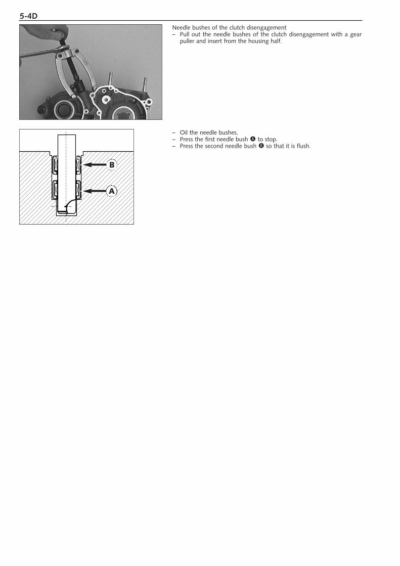
Needle bushes of the clutch disengagement– Pull out the needle bushes of the clutch disengagement with a gear
puller and insert from the housing half.
– Oil the needle bushes.– Press the first needle bush A to stop.– Press the second needle bush B so that it is flush.
5-4D
A
B

Rep
air
man
ual
KTM
LC
4 A
rt.-
Nr.
3.2
06.0
06 -
E5-5D
Working on the left half of the housing Remove shaft seal rings and heat housing half to approx. 150° C bymeans of a hot-plate.
Needle bearing of counter shaft 1Press in new needle bearing from inside until flush.
Shaft seal ring of kickstarter shaft 2Press in new shaft seal ring from outside with sealing lip facing inwardsuntil flush.
Grooved ball bearing of the balancer shaft 3.Use an extractor and insert to remove the grooved ball bearing fromthe housing half.
Shaft seal ring of crankshaft 4Press in new shaft seal ring from outside with sealing lip facing inwardsuntil flush.
Retaining plate for main shaft grooved ball bearing 5If the retaining plate has been removed, use Loctite 243 for the twocountersunk bolts during assembly.
Oil ducts 6Use compressed air to clean all oil ducts. Ensure that the oil ducts arenot clogged.
Roller bearing of crankshaft 7From outside press crankshaft roller bearing inwards using a suitablemandrel. Press in new roller bearing from inside up to the stop.
Grooved ball bearing of main shaft 8Press in new grooved ball bearing from inside up to the stop.
! CAUTION !DO NOT USE FORCE WHEN PRESSING THE GROOVED BALL BEARING AGAINST THERETAINING PLATE 5 TO AVOID A BENDING OF THE PLATE, WHICH WOULD RESULT INEXCESSIVE AXIAL PLAY OF THE MAIN SHAFT.
Needle bearing of kickstarter shaft 9Press in new needle bearing from inside until flush.
Bypass valveTest valve piston, tight fit and pressure spring for damage.
Minimum length of the pressure spring bk: 23,5 mm
NOTE: The opening pressure of the bypass valve is reduced when thelength of the pressure spring decreases below 23,5 mm. This reducesthe oil pressure and causes engine damage.
Ensure that neither the lubrication bore of the roller bearing A nor theoil ducts of the oil pumps are clogged.
– After the housing half has cooled down, check bearings for tight fit.– Finally, insert both dowels so that the dowel with internal diameter
15.4 mm is mounted at the rear (swingarm pivot).
10
A
1
23
45
6
78
6
9
3

5-6D
CrankshaftIf the conrod bearing is replaced, take care to properly position thecrankpin. The bores of the crank web B and crank pin C mustcoincide.
! CAUTION !IF THE CRANK PIN IS PRESSED IN THE WRONG POSITION, THE CONROD BEARING ISSUPPLIED INSUFFICIENTLY OR NOT AT ALL WITH ENGINE OIL, WHICH RESULTS INBEARING DAMAGE.
If the crankshaft is continued to be used, check crankshaft journals forrun out. Place crankshaft on a roller block or a similar device and checkthe outer end of the journals for run out with a dial gauge.
run out of crankshaft journals: max. 0.04 mm (0.0016 in)
The radial clearance and axial clearance on the conrod bearing must bechecked.
radial clearance: max. 0.05 mm (0.0019 in)axial clearance: max. 1.00 mm (0.04 in)
– If the crankshaft roller bearings are replaced, the inner rings on thecrankshaft should also be changed.
– Heat special tool on a heating pad up to approx. 150°C and slip it onthe inner ring immediately. Press the special tool together tightly toobtain a good heat transfer and pull the inner ring off the crankshaft.
– To mount the new inner ring, heat the special tool again to approx.150°C, engage the inner ring and slip it on the crankshaft journalimmediately.
– In order to safely press on new rings, a middle panel should be inserted between the crankshaft webs. This panel should be bigenough to be supported on both sides, so that the crankshaft liesfree and accessible.
NOTE: Because LC4-E models have different diameters of innercrankshaft bearing rings, it is necessary to have both special tools(584.29.037.040 and 584.29.037.043).
! CAUTION !NEVER CLAMP THE CRANKSHAFT WITH A CRANKSHAFT JOURNAL OR WEB IN THEVICE, AND NEVER TRY TO KNOCK THE INNER RING FREE. THE CRANKSHAFT WEBSMAY BE COMPRESSED THEREBY MAKING THE CRANKSHAFT UNUSEABLE.
B
C

Rep
air
man
ual
KTM
LC
4 A
rt.-
Nr.
3.2
06.0
06 -
E5-7D
Measuring and adjusting of crankshaft axial clearance– Should the crankshaft, engine housing, or a roller bearing be
replaced, the axial clearance of the crankshaft should also bechecked.
– The housing should be laid inside upwards, then measure thedistance from the sealing area to the inner rings of the rollerbearings. Note the readings and then add on 0.3 mm to allow forgasket thickness.
– Measure the crankshaft at touching points and then subtract themeasured value from the housing dimensions. This figure will be theaxial play of the crankshaft, which should be 0.03- 0.12 mm (0.001-0.005 in).
EXAMPLE:Left-hand housing half 33.0 mm 1.300 ( in)Right-hand housing half + 32.8 mm 1.290 ( in)Gasket + 0.3 mm 0.012 ( in)Total housing dimension = 66.1 mm 2.602 ( in)Crankshaft dimension – 65.8 mm 2.590 ( in)Axial play present = 0.3 mm 0.012 ( in)
The compensating washers should be equally distributed between thetwo sides of the crankshaft. In our example, one compensation washer(≠ 0.1 mm / 0.004 in.) must be mounted on either side.
Checking the piston– Replace the piston in the case of excessive oil consumption or
grooves in the piston skirt.– If reinstalling the old piston perform the following steps:
1. Piston bearing surface - check for damage2. Piston ring grooves - the piston rings must move easily in the
groove. Old piston rings or sandpaper (400 grit) may be used toclean the piston ring grooves.
3. Piston rings - check for damage and end gap (see below).4. The piston pin must move freely in the piston when mounted. If the
piston pin changed its color badly or shows running traces, it mustbe replaced. Insert piston pin also into the conrod and check for clearance. Maximum clearance in the conrod eye 0.08 mm (0.003in).
NOTE: When in place, the piston pin may not have any play. It must bepossible to shift it with slight counterpressure.

5-8D
xy
Mounting instructions for piston rings– Insert the oil scraper ring in the lower ring groove. Side of ring
marked facing piston head.– Mount compression ring (tapered compression piston ring) in middle
ring groove. Side of ring marked facing piston head.– Insert the compression ring (rectangular ring) in the upper piston ring
groove (the surface marked must be on top).
Piston ring end gap– Insert pisto ring into the cylinder and adjust. Piston ring must be
approx. 10 mm (1/2 inch) from top of cylinder. – The end gap B can now be checked which a feeler gauge.
Compression rings: max. 0.60 mm (0.023 in)Oil scraper ring: max. 0.80 mm (0.03 in)
If the end gap is greater check piston and cylinder for wear. If pistonand cylinder wear are within the permitted tolerance limits, replace thepiston ring.
Measuring piston and cylinder, determining the pistonfitting clearance– In order to determine the wear of the cylinder, measure the cylinder
center of the running area with a micrometer. – Measure the diameter of the x-axis and the y-axis in order to check
for oval wear, if any.
– The piston is measured on the piston skirt across to the piston pin asshown in the illustration.
– The cylinder diameter minus the piston diameter yields the pistonassembly clearance.
Piston assembly clearence: see Technical Specification
ELKO ELKO ELKO ARIASØ 89 mm Ø 95 mm Ø 101 mm Ø 101 mm
Compression ring O O O N 100
Tapered ring TOP TOP TOP N 101
Oil scraper ring ELKO TOP TOP –––

Rep
air
man
ual
KTM
LC
4 A
rt.-
Nr.
3.2
06.0
06 -
E
Cylinder – nikasil coatingNikasil is the brand name for a cylinder coating process, developed bythe piston manufacturer Mahle. The name is derived from the twomaterials used in this process - a nickel layer into which the particularlyhard silicon carbide is embedded. The main advantages of the Nikasilcoating are excellent heat dissipation and thus better power output, lowwear and low weight of the cylinder. The worn coating can beregenerated at low cost provided that the running surface of cylinder isflawless.
Recoated cylinderIf the Nikasil coating of your cylinder is worn but undamaged, you mayobtain a recoated cylinder at your KTM dealer (new Nikasil coating onused cylinder).It may be that your spare cylinder shows color changes on the exteriorside.
5-9D

Three-Bond DichtmasseThree-Bond Gasket
Disassembling the cylinder head and checking thecomponents for wear
– Mount cylinder head in vice using the studs. Do not allow it to reston sealing surface.
– Mark valves and remove using special tool (see illustration).– Clean all parts.
Sealing areaCheck spark plug threads and valve seats for damage or cracks. Checkthe sealing area to the cylinder for distortions with a straightedge and afeeler gauge. Distortion limit 0.10 mm (0.004 in).
Valve guidesThe valve guides are checked with a limit plug gauge 1 (Ø 7.05 mm).If the limit plug gauge can be easily inserted into the valve guide, theguide must be replaced in a specialized workshop.
Valve seatsThe valve seats must not be pocketed. Seat sealing width: intake max. 1.5 mm (0.059 in); exhaust max. 2.0 mm (0.079 in). Grind valves ifnecessary.
ValvesCheck valve heads for wear and run out. Max. run-out on valve heads0.03 mm (0.001 in). Valve seats should not be pocketed. The sealingarea must be located in the center of the valve seat. The valve stem ishard-chrome plated. Experience shows that wear appears primarily onthe valve guide.
Valve springsOnly visual check for breakage or wear is necessary.
Valve stem sealsAlways renew valve stem seals when the valves are removed.
Intake flangeCheck flange surface for distortion, scrape on glas plate if necessary.
5-10D
1

Rep
air
man
ual
KTM
LC
4 A
rt.-
Nr.
3.2
06.0
06 -
E
Disassembling the cylinder head top section and checkingthe components for wear– Simply pull the rocker arm axles 1 out of the cylinder head top
section. Then take both rocker arms 2 together with thrust washers3 and bn out of the cylinder head top section.
Undo bolt 4 and remove the following components: Washer 5
Decompression shaft lever 6Covering disc 7O-ring 8Decompression lever spring 9
– Press the decompression shaft bk inwards and take it out of thecylinder head top section together with the washers bl.
– Clean all components.
Rocker arm shafts 1The rocker arm shafts must be free of grooves and should turn easilywithin the rocker arms 2.
Rocker arm rollers bmThe rocker arm rollers must move smoothly. Rocker arm rollers must beremoved in the case of radial clearance.
Adjusting screws boThe contact surfaces of the adjusting screws must be plane.
Decompression shaft bkCheck for smooth operation and clearance in the bearing bore.
Pre-assembling the cylinder head top section– Insert decompression shaft bk with compensation washers bl into the
top section. – Mount the new O-ring 8, the decompression lever spring 9 and
the cover disc 7 in such a way that the O-ring fits into the recess ofthe cover disc.
– Mount the decompression shaft lever 6.– Apply Loctite 243 to the thread of bolt 4 and mount the bolt
together with washer 5.– Hook the decompression lever spring onto the decompression shaft
lever.
! CAUTION !THE DECOMPRESSION SHAFT MUST EXHIBIT NO AXIAL PLAY WHEN THE ALLAN HEADBOLT 4 IS TIGHTENED. TO ENSURE THAT THE O-RING 8 fORMS A SEAL, IT MUST BESLIGHTLY PRESSED AGAINST THE TOP SECTION BY THE COVER DISC 7. HOWEVER,THE PRESSURE ON THE O-RING MUST NOT BE EXCESSIVELY HIGH AS THEDECOMPRESSION SHAFT WILL BECOME SLUGGISH. ADJUST OUT WITHCOMPENSATION WASHERS bl IF NECESSARY.
NOTE: Discs bl are available 0.15 mm, 0.30 mm and 0.50 mm thick.
– Mount new O-rings bp on rocker arm shafts 1.– Mount rocker arms 2, thrust washers 3 and rocker arm shafts 1.– On the side of the water pump one thrust washer bn ≠ 1.0 mm (0.04
in) must be mounted.– The axial play on the opposite side is roughly equalized with thrust
washers 3 ≠ 1.0 (0.04 in) and ≠ 0.5 mm (0.02 in).
The axial clearance of the rocker arm axles must be 0.20 - 0.30 mm.
5-11D
13
31112
1515
10
12 1414
2 13
32
67
8 9
10
11
45
13
LOCTITE 243
LOCTITE 243 LOCTITE 243
LOCTITE 243
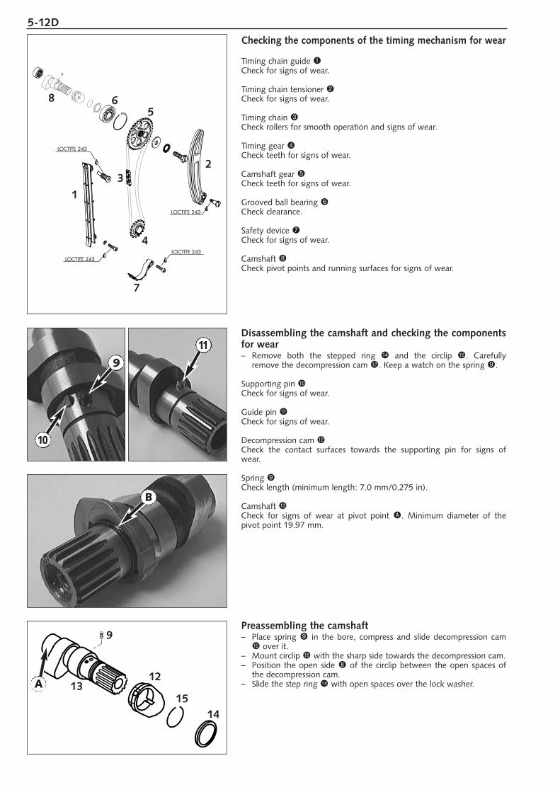
Checking the components of the timing mechanism for wear
Timing chain guide 1Check for signs of wear.
Timing chain tensioner 2Check for signs of wear.
Timing chain 3Check rollers for smooth operation and signs of wear.
Timing gear 4Check teeth for signs of wear.
Camshaft gear 5Check teeth for signs of wear.
Grooved ball bearing 6Check clearance.
Safety device 7Check for signs of wear.
Camshaft 8Check pivot points and running surfaces for signs of wear.
Disassembling the camshaft and checking the componentsfor wear– Remove both the stepped ring bo and the circlip bp. Carefully
remove the decompression cam bm. Keep a watch on the spring 9.
Supporting pin bkCheck for signs of wear.
Guide pin blCheck for signs of wear.
Decompression cam bmCheck the contact surfaces towards the supporting pin for signs ofwear.
Spring 9Check length (minimum length: 7.0 mm/0.275 in).
Camshaft bnCheck for signs of wear at pivot point A. Minimum diameter of thepivot point 19.97 mm.
Preassembling the camshaft– Place spring 9 in the bore, compress and slide decompression cam
bm over it.– Mount circlip bp with the sharp side towards the decompression cam.– Position the open side B of the circlip between the open spaces of
the decompression cam.– Slide the step ring bo with open spaces over the lock washer.
5-12D
8
13
9
12
1514
6
4
5
2
7
1
3
9
10
11
B
A

Rep
air
man
ual
KTM
LC
4 A
rt.-
Nr.
3.2
06.0
06 -
E5-13D
Automatic tensioner– Check ratcheting pawl 1 for smooth operation and wear.– Check thrust bolt 2 for wear at teeth.
Preassembly of automatic tensioner– Insert thrust bolt into tensioner housing and engage ratcheting pawl
into first notch (see illustration).
! CAUTION !IF THE RATCHETING PAWL IS NOT ENGAGED INTO THE FIRST NOTCH THIS WILL CAUSEEXCESSIVE TENSION OF THE CHAIN.
Disassembling the oil pumps and checking the componentsfor wear
NOTE: The two oil pumps are similar in design but work at differentspeeds. Disassemble and check the oil pumps separately to avoid mixingup of components.
– Remove screw 3 and take off the oil pump cover 4.– Pull the oil pump shaft 5 out of the oil pump housing together with
the bearing needle.– Take the inner rotor 6 and the outer rotor 7 out of the oil pump
housing.
– Clean all components and check for signs of wear.
– When reassembling the unit insert the inner rotor and the outer rotorinto the oil pump housing, making sure that the point faces theinside.
– Mount oil pump shaft and bearing needle
– Now perform the following measurements to determine the degreeof wear:
Outer rotor - oil pump housing: max. 0.20 mmOuter rotor - inner rotor: max. 0.20 mm
– Fill the oil pump housing with oil and mount the oil pump cover.– Apply Loctite 243 to the thread of screw 3 and mount the screw.
! CAUTION !FILL OIL PUMPS WITH OIL BEFORE PREASSEMBLING.
1
2
2
1
3
4
5
6
7

5-14D
150
LOCTITE 243
LOCTITE 243
150
LOCTITE 243
LOCTITE 243
Oil lines (SX, SXC)– Check oil lines and banjo bolts for damage and clear passage.– When repairing the engine, the microfilter 1 and the oil filter 2
must be replaced.
Oil lines (SC)– Check oil lines and banjo bolts for damage and clear passage.– When repairing the engine, the microfilter 3 and the oil filter 4
must be replaced.
3
4
1
2

Rep
air
man
ual
KTM
LC
4 A
rt.-
Nr.
3.2
06.0
06 -
E5-15D
Oil lines (660 SMC)– Check oil lines and banjo bolts for damage and clear passage.– When repairing the engine, the microfilter 1 and the oil filter 2
must be replaced.
Oil lines (Models with frame oil)– Check oil lines and banjo bolts for damage and clear passage.– When repairing the engine, the fine filter 3 and the oil filter 4
must be replaced.
LOCTITE 243
150
LOCTITE 243
3
4
LOCTITE 243
LOCTITE 243
LC4
1
2

5-16D
Checking the kickstarter components for wearStarter gear 1Check the bearing for clearance (the starter gear must be in permanentmesh with the outer clutch hub).
Intermediate starter gear 2Check the bearing for clearance.
Kick starter shaft 3Check the toothing for signs of wear.
Ratchet gear 4Check the ascending surface and the toothing for signs of wear.
Stop bolt 5Check for signs of wear.
Replace the seal ring 6
NOTE: Due to a parts change from 2000 onwards the seal ring is blue-green and is to be mounted with the seal lip to the outer side.
Preassembly of kickstarter shaft– Clamp kickstarter shaft with toothed end in vice (use soft jaw-
covers).– Mount circlip 7 in lower ring groove.– Fit spring guide 8 with collar facing downwards and circlip 9 with
sharp edge facing upwards. – Remove kickstarter shaft from vice and fit ratchet gear spring.– Mount the ratchet gear 4 on the kickstarter shaft in such a way that
the markings A and B coincide.
Clutch coverBalancer shaft bearing bkUse the bearing extractor tool with insert to remove the grooved ballbearing from the bearing seat.Insert the new bearing into the seat and ensure flush fit.
Seal ring blUse a screwdriver to lever the old shaft seal ring out of the clutch cover.Insert the new shaft seal ring and ensure flush fit.
Replacing absorbing elements of the outer clutch hub– Drill open the clutch rivets bm in area of the retaining bracket bn and
take off the parts.
NOTE: When performing repair work always exchange all 8 absorbingelements.
! CAUTION !THE DAMPING ELEMENTS ARE WIDER THAN THE PRIMARY GEAR CROWN bo. TOENSURE THAT THE OUTER CLUTCH HUB AND RETAINING BRACKET ARE POSITIONEDDIRECTLY ON THE PRIMARY GEAR CROWN, THE PARTS MUST BE HELD IN POSITIONUNDER TENSION WITH THE CLUTCH RIVETTING TOOL C BEFORE RIVETTING.
– Apply the special tool as shown, screw together and lock the rivetswith a pointed mandrel and a round mandrel.
Locking pressure for the pointed mandrel: approx. 4000 kgLocking pressure for the round mandrel: approx. 5000 kg
2
5
6
1
8
7
34
9
A
B
A
B
1011
12
14
13
C

Rep
air
man
ual
KTM
LC
4 A
rt.-
Nr.
3.2
06.0
06 -
E
Checking the clutch components for wearThrust bearing 1 – Check for signs of wear.
Push rod 2 – Check the face side for signs of wear.
Clutch release shaft 3, sealing cup 4 and needle bearing 5 – Check for damage and signs of wear.
Clutch pressure springs 6 – Minimum length: 34.5 mm (1.36 in) (length/new spring: 37 mm (1.457 in)).Replace all 6 springs if necessary.
Clutch discs 7 – Clutch discs must be plane.7 steel discs ≠ 1.5 mm (0.066 in) must be free of grooves.8 lining discs ≠ 2.7 mm (0.106 in), wear limit: 2.5 mm (0.1 in)
Inner clutch hub 8 – Check both the exterior and the interior toothing for signs of wear.
Needle bearing 9 – Check for signs of wear.
Outer clutch hub bk – Check if all rivets bm are tight.
Absorbing elements blPower transmission from the primary drive to the clutch is cushioned by rubber elements bl. These rubber elements must bechecked in the course of normal checking for signs of wear. It is recommended to check the elements while disassembling theengine. Try to turn the outer clutch hub after removing the inner clutch hub (engine will lock). Dead travel should be impossible.
Check O-ring bo for brittleness and cracks. If the cross section of the O-ring is oval (deformed) replace the O-ring.
5-17D
LOCTITE 243
1
2
3
4
5
6
8
9
10
14
11
12
13
7
From model 2003 on

5-18D
Checking the shift mechanism components forwearShift forks 1Check the fork leaf for signs of wear.Check the shift roller driving pin 2 for signs of wear.
Shift rolls 3Check the shift rolls for hairline cracks and pressure marks.Additionally, make sure that the shift rolls turn easily on thedriving pins 2 of the shift forks.
Shift roller 4Check the shift grooves for signs of wear.Check the two grooved ball bearings of the shift roller forwear.
Slide plate 5Check the contact surfaces for signs of wear.Check the return surface of the slide plate for signs of wear(replace in the case of deep grooves).
Slide guidesCheck clearance (maximum clearance between guide boltand slider 0.70 mm / 0.027 in.).
Guide bolt 7Check for tight fit and signs of wear.
1
1
1
2
B
3
5
78
910
11
3
3
4
Preassembly of shift shaft– Push steel disc 8 (14x28x2 mm) onto shift shaft.
– Mount the return spring 9, positioning the offset A on the side ofthe shift quadrant.
– Mount spring sleeve bk with shallower collar facing shift quadrant.– Cross return spring legs and hook in shift quadrant. – Grease and mount both O-rings bl.
A

Rep
air
man
ual
KTM
LC
4 A
rt.-
Nr.
3.2
06.0
06 -
E5-19D
Shift mechanism support– If the grooved ball bearing 1 of the shift roller must be exchanged,
press the new grooved ball bearing all the way into the seat.
! CAUTION !TO PREVENT DAMAGING OF THE SHIFT MECHANISM SUPPORT, DO NOT APPLYEXCESSIVE FORCE WHEN INSERTING THE GROOVED BALL BEARINGS.
– Apply Loctite 243 to the screw and fix the bearing.– The new needle bearing of the kickstarter shaft 2 has to be pressed
in flush.
Balancer shaftCheck bearing seat A for wear and tear.
Check three allan head bolts 3 for tight fit.
Disassembling and reassembling the water pumpRemove the water pump cover 4 together with the gasket.– Remove circlip 5 from the water pump shaft 6 and pull shaft and
water pump wheel 7 out of the grooved ball bearings.
– If grooved ball bearings 8 are replaced, remove circlip 9 and shaftseal ring bk and press out bearing.
– Properly lubricate new grooved ball bearings and press in to stopwith the open sides facing each to them.
– Mount circlip 9.– Cover new shaft seal ring with Loctite 648 and press in with the
printing facing outward.– Lubricate water pump shaft and mount carefully so as to not
damage sealing lips of shaft seal ring and check for smooth working.– Mount circlip 5 and water pump cover 4 with gasket.– Finally, remove silicone from the sealing flange and mount 2 new
O-rings bl.
5
4
610
11
7
9
8
1
2
A3

5-20D
Important note regards working on transmission– Fix the main shaft or countershaft, respectively, in the vise (use
special vise jaws to avoid damaging of the shafts) and remove thegear wheels.
– Clean and check all parts.
Always use new lock washers when performing repair work on thetransmission !
Check the tooth profiles of transmission shafts and sliding gears forsigns of wear.
Slide the sliding gears onto the transmission shafts and check thetoothing for easy operation.
Check the pivot points of the transmission shafts.
Mount the idler gears with the bearings on the transmission shafts andcheck for clearance.
Check the needle bearings of the idler gears.
Assembling the main shaft– Mount the main shaft in a vise with the gearwheel facing
downwards (use protective jaws).– Mount the needle cage 1 and slide the 3rd gear 2 with the shift
dogs facing upwards.– Mount stop disc 3 (22.7x32x1.5 mm) and the circlip 4 with the
sharp edge facing up.– Mount 4th gear 5 with the shift groove facing down.– Secure it with the circlip 6 with the sharp edge down and mount
the stop disc 7 (22.7x32x1.5 mm).– Mount needle cage 8 and 5th gear 9 with the shift dogs down. – Mount 2nd gear bk and stop disc bl (20.2x35x1 mm).
NOTE: Check all gears for smooth operation.
1
5
6
7
8
9
10
11
2
3
4

Rep
air
man
ual
KTM
LC
4 A
rt.-
Nr.
3.2
06.0
06 -
E5-21D
Important note regards working on transmission– Fix the main shaft or countershaft, respectively, in the vise (use
special vise jaws to avoid damaging of the shafts) and remove thegear wheels.
– Clean and check all parts.
Always use new lock washers when performing repair work on thetransmission !
Check the tooth profiles of transmission shafts and sliding gears forsigns of wear.
Slide the sliding gears onto the transmission shafts and check thetoothing for easy operation.
Check the pivot points of the transmission shafts.
Mount the idler gears with the bearings on the transmission shafts andcheck for clearance.
Check the needle bearings of the idler gears.
Assembling the counter shaft– Mount counter shaft in vise with collar facing downwards.– Oil and mount needle cage 1. – Slide 2nd gear 2 over needle cage with collar facing downwards.– Mount stop disc 3 (22.7x32.0x1.50 mm) with clearance towards
gear wheel and circlip 4 with sharp edge facing upwards.– Mount 5th gear 5 with shift groove facing upwards.– Fit circlip 6 with sharp edge down and stop disc 7 (22.7x32.0x1.50
mm).– Mount needle cage 8 and fit 4th gear 9 with shift dogs facing up. – Mount stop disc bk (22.7x32.0x1.50 mm) and circlip bl with sharp
edge facing up. – Fit 3rd gear bm with shift groove down and mount stop disc
(22.2x35.0x1.50 mm) bn.– Mount needle cage bo, 1st gear bp with collar facing up and fit stop
disc (20.2x35.0x1.0 mm) bq.
NOTE: A roller bearing was installed in the 660 SMC model, thus a stopdisc is unnecessary.
Check all gears for smooth operation.
1
3
2
4
5
6
7
8
9
10
11
12
13
14
15
16

5-22D
Removing the intermediate gear– Remove the starter cover.– Pull out the bearing bolt 1.– Remove the intermediate gear and the needle bearing.– Check the parts for signs of wear.
– Insert the intermediate gear with the collar downward into thehousing for preassembly.
– Oil the needle bearing and install it with the bearing bolt.– Do not yet replace the starter cover.
Checking the freewheel– Insert the freewheel gear 2 into the freewheel. – The freewheel gear must turn clockwise.– The freewheel gear must lock without empty run if turned
anticlockwise.– Check the reduction gear 3 and the needle bearings for signs of
wear.– Check the needle bearing of the freewheel gear for signs of wear.
Replacing the freewheel hub– Squeeze the spreader ring 4 with the circlip pliers and remove it
together with the freewheel.– Check the freewheel segments for signs of wear.– Check the freewheel hub sections at the freewheel running surface
for signs of wear.– Heat the flywheel to a temperature of approx. 80° C (176° F) and
remove the 6 bolts.
! CAUTION !MAKE SURE THAT THE FLYWHEEL IS NOT HEATED BEYOND 80° C (176° F) TOAVOID LOOSENING OF THE MAGNETS.
– Carefully tap the side of the freewheel hub with a plastic hammerand take off the freewheel hub.
– Apply Loctite 648 to the flange surface A of the flywheel and thefreewheel hub.
– Mount the freewheel hub on the flywheel.– Apply Loctite 648 to the thread of the bolts and tighten them
crosswise (18 Nm).
! CAUTION !ALWAYS USE NEW BOLTS (12.9) AND APPLY LOCTITE 648 TO THE THREADS.
– Thoroughly oil the free-wheel and insert it into the freewheel hub.– Insert the spreader ring into the groove with a pair of circlip pliers
and make sure that it properly rests in the groove.
Electric starter motor– The starter showed only slight signs of wear after 10.000 starting
processes, and exchanging individual parts must be considereduneconomical. Therefore, such work is not described in the presentdocumentation.
– Exchange the O-ring 5 at the starter flange (incl. in the gasket set).
1
4
A
23
5

Rep
air
man
ual
KTM
LC
4 A
rt.-
Nr.
3.2
06.0
06 -
E
LOCTITE 648
LOCTITE 648
LOCTITE 243
LOCTITE 243
SILICON
5-23D
Checking the stator and the pulse generator (Kokusan 4K2)Use an ohmmeter to perform the following measurements:
NOTE: The measuring must be performed at a temperature of 20° C.Otherwise significant deviations must be expected.
Replace the stator and/or the pulse generator if the measured valuesdeviate significantly from the setpoint values or in the case of continuitybetween one of the cables and ground.
Replacing the stator (Kokusan 4K2)– Loosen the 3 bolts and remove the stator.
– Insert a new stator into the ignition cover.– Apply Loctite 243 to 3 new bolts and tighten the bolts.– Insert the cable guide in the opening provided for that purpose in
the ignition cover.
Ignition (Kokusan 4K2)General informationThe measurements described below will only reveal severeproblems. Coil short circuits leading to weak ignition sparksor low generator output, respectively, can only be detectedwith the help of an ignition test bench. In the case ofmalfunction always check the cables and the plug and socketconnections of the ignition system first.Make sure to select the correct measuring range whenperforming measurements.
MEASUREMENT CABLE COLORS RESISTANCEred/black – black/red
Stator yellow – black/red 0.45 – 0.56 Ωyellow – red/black
Pulse generator white – green 80 – 120 Ω

Checking the stator (SEM)Perform the measurements indicated to the left with an ohmmeter.
NOTE: The measuring must be performed at a temperature of 20° C.Otherwise significant deviations must be expected.
The stator must be exchanged if any of the measured values deviatessignificantly from the respective nominal value or in the case ofcontinuity between one of the cables and ground.
Replacing the stator (SEM)– Remove bolt 1 with retaining bracket.– Remove the three clamp bolts 2 and lift the stator out of the
ignition cover.
– Mount the new stator in such a way that the timing mark A isvisible in the checking hole on the rear side.
– Apply Loctite 243 to the threads of the bolts 2 and insert the boltswithout, however, tightening them yet.
– Apply Loctite 243 to the thread of bolt 1, turn the stator clockwiseall the way to the stop.
– Fix the cable strand with retaining clips and insert the rubber cableguide into the opening provided for that purpose.
– Turn the stator until the mark becomes visible in the peephole. Thentighten the bolts 2.
5-24D
Ignition (SEM)General informationThe measurements described below will only reveal severeproblems. Coil short circuits leading to weak ignition sparksor low generator output, respectively, can only be detectedwith the help of an ignition test bench. In the case ofmalfunction always check the cables and the plug and socketconnections of the ignition system first.Make sure to select the correct measuring range whenperforming measurements.
12
A
+ POLE – POLE MEASURE VALUE
black red 1.7 kΩ
red black 1.7 kΩ
black green 165 Ω +/- 20 Ω
green red 1.7 kΩ
yellow yellow 1.0 Ω

Rep
air
man
ual
KTM
LC
4 A
rt.-
Nr.
3.2
06.0
06 -
E5-25D
Installing a new stator (Kokusan 4K-3)– Remove the 2 bolts 1 and take the cover plate 2 out of the ignition
cover.– Remove the 2 bolts 3 of the pulse generator and the 2 bolts 4 of
the stator.– Undo bolt 5 and take the retaining platelet out of the ignition
cover. Take the stator and the pulse generator out of the ignitioncover.
NOTE: When reassembling the unit, degrease and apply Loctite 243 tothe threads of all bolts.
– Put the new stator into the ignition cover and fix it with the twobolts 4.
– Position the pulse generator in the ignition cover and fix it with thetwo bolts 3.
– Put the cable guide into the recess provided for this purpose and fixthe cover plate 2 with the two bolts 1.
– Position the wiring harness, taking care to avoid tension, and use theretaining platelet and the bolt 5 to fix it in the ignition cover.
Ignition (Kokusan 4K-3)General informationThe measurements described below will only reveal severeproblems. Coil short circuits leading to weak ignition sparksor low generator output, respectively, can only be detectedwith the help of an ignition test bench. In the case ofmalfunction always check the cables and the plug and socketconnections of the ignition system first.Make sure to select the correct measuring range whenperforming measurements.
Checking the stator (Kokusan 4K-3)Use an ohmmeter to perform the following measurements.
Note: The measuring must be performed at a temperature of20° C. Otherwise significant deviations must be expected.
Replace the stator if the measured values deviate significantlyfrom the setpoint values.
LOCTITE 243
LOCTITE 243
LOCTITE 243
1
12
3
3
4
4
5
Ignition Measure Cable colours Resistance
Pulser coil red – green 100 Ω 20%
4K-3Stator black/red – red/white 12,7 Ω 20%
Charging coil ground – yellow 0,65 Ω 20%
white – yellow 0,16 Ω 20%


MOUNTING THE KICKSTARTER UNIT . . . . . . . . . . . . . . . . . . . . . . . . . . . .6-2MOUNTING TRANSMISSION AND SHIFT MECHANISM . . . . . . . . . . . . . .6-2ADJUSTMENT OF RETURN SPRING . . . . . . . . . . . . . . . . . . . . . . . . . . . . .6-4PRETENSIONING OF THE STARTER SPRING . . . . . . . . . . . . . . . . . . . . . . .6-4MOUNTING CRANKSHAFT . . . . . . . . . . . . . . . . . . . . . . . . . . . . . . . . . . . .6-4ASSEMBLY OF ENGINE HOUSING . . . . . . . . . . . . . . . . . . . . . . . . . . . . . . .6-5MOUNTING OIL FILTER . . . . . . . . . . . . . . . . . . . . . . . . . . . . . . . . . . . . . .6-6MOUNTING THE ENGINE SPROCKET . . . . . . . . . . . . . . . . . . . . . . . . . . . .6-6MOUNTING THE TIMING GEAR AND THE TIMING CHAIN . . . . . . . . . . . .6-7MOUNTING THE OIL PUMPS . . . . . . . . . . . . . . . . . . . . . . . . . . . . . . . . . .6-7MOUNTING THE BALANCER SHAFT AND THE PRIMARY PINION . . . . . . .6-8MOUNTING THE CLUTCH . . . . . . . . . . . . . . . . . . . . . . . . . . . . . . . . . . . .6-8MOUNTING THE CLUTCH DISCS . . . . . . . . . . . . . . . . . . . . . . . . . . . . . . .6-9INSTALLING THE CLUTCH RELEASE SHAFT . . . . . . . . . . . . . . . . . . . . . . . .6-9ADJUSTING THE CLUTCH RELEASE . . . . . . . . . . . . . . . . . . . . . . . . . . . .6-10MEASURE DIMENSION „Y“ . . . . . . . . . . . . . . . . . . . . . . . . . . . . . . . . . .6-10MOUNTING PISTON AND CYLINDER . . . . . . . . . . . . . . . . . . . . . . . . . . .6-10MOUNTING THE CYLINDER HEAD . . . . . . . . . . . . . . . . . . . . . . . . . . . . .6-11MOUNTING THE CAMSHAFT, TIMING MARKS . . . . . . . . . . . . . . . . . . . .6-12MOUNTING THE WATER PUMP . . . . . . . . . . . . . . . . . . . . . . . . . . . . . . .6-13MOUNTING THE CYLINDER HEAD TOP SECTION . . . . . . . . . . . . . . . . .6-14MOUNTING THE AUTOMATIC TENSIONER . . . . . . . . . . . . . . . . . . . . . .6-14AUTOMATIC DECOMPRESSION TESTING . . . . . . . . . . . . . . . . . . . . . . . .6-14ADJUSTMENT OF VALVE CLEARANCE . . . . . . . . . . . . . . . . . . . . . . . . . .6-15MOUNTING THE CLUTCH COVER . . . . . . . . . . . . . . . . . . . . . . . . . . . . .6-15MOUNTING THE ELECTRIC STARTER DRIVE . . . . . . . . . . . . . . . . . . . . . .6-16MOUNTING THE IGNITION (KOKUSAN) . . . . . . . . . . . . . . . . . . . . . . . .6-16ADJUSTING THE PULSE GENERATOR . . . . . . . . . . . . . . . . . . . . . . . . . . .6-17MOUNTING THE IGNITION (SEM) . . . . . . . . . . . . . . . . . . . . . . . . . . . . .6-17ADJUSTMENT OF IGNITION POINT (SEM) . . . . . . . . . . . . . . . . . . . . . . .6-18MOUNTING THE EPC WIRING HARNESS . . . . . . . . . . . . . . . . . . . . . . . .6-18MOUNTING THE IGNITION (KOKUSAN 4K-3) . . . . . . . . . . . . . . . . . . . .6-19ADJUSTMENT OF IGNITION POINT (KOKUSAN 4K-3) . . . . . . . . . . . . . .6-19MOUNTING THE OIL HOSES . . . . . . . . . . . . . . . . . . . . . . . . . . . . . . . . .6-20MOUNTING THE CLUTCH RELEASE LEVER . . . . . . . . . . . . . . . . . . . . . . .6-20MOUNTING THE ELECTRIC STARTER MOTOR . . . . . . . . . . . . . . . . . . . .6-20MOUNTING THE WATER HOSES . . . . . . . . . . . . . . . . . . . . . . . . . . . . . .6-20POURING IN ENGINE OIL . . . . . . . . . . . . . . . . . . . . . . . . . . . . . . . . . . . .6-21MOUNTING THE KICKSTARTER AND THE SHIFT LEVER . . . . . . . . . . . . .6-21
Rep
air
man
ual
KTM
LC
4 A
rt.-
Nr.
3.2
06.0
06 -
E
ASSEMBLING THE ENGINE
INDEX
6-1D
6


Rep
air
man
ual
KTM
LC
4 A
rt.-
Nr.
3.2
06.0
06 -
E– Place left-hand housing half in engine work stand.
Mounting the kickstarter unit– Insert stop disc (22.2x35x2 mm), starter gear 1, needle bearing and
stop disc 2 (22.2x30x1.5 mm) into housing.
– Insert the pre-assembled kickstarter shaft into the bearing seat,putting it through the starter gear. Make sure that the starter springslips into opening A of the housing.
Mounting transmission and shift mechanism– Insert stop disc (20.2x35x1 mm), 1st gear wheel 3 with collar facing
down into the housing and the needle bearing into the idler gear.
NOTE: A roller bearing was installed in the 660 SMC model, thus a stopdisc is unnecessary.
– Mount transmission shafts together and slightly turn them.
– Grease the driving pins of the shift forks and mount the shift rollers 4.– Hook shift fork with legs of same length in the sliding gear of the
main shaft. – Fit the other two shift forks into the gears of the counter shaft,
paying attention to the marks applied during disassembly.
! CAUTION !USED SHIFT FORKS SHOULD BE MOUNTED IN THE SAME SLIDING GEAR AS BEFORE.
6-2D
1
2
A
3
4

– Insert shift roller 1 into the housing with the holder for the lockingpiece facing up.
– Hook the shift forks into the shift roller and mount shift rails 2 + 3.The shorter shift rail 3 must be fitted to the main shaft.
– Before mounting the shift mechanism support, check whether thetwo dowels have been fitted.
– Mount shift mechanism support, secure the two bolts 4 with Loctite243 and tighten.
– Put the washer (6.2x18x2 mm), the locking lever, the locking springbushing and the locking lever spring onto the third bolt.
– Apply Loctite 243 to the thread of the bolt and mount it.
– Pull locking lever 5 away from the shift roller.– Put the shift drum locating device 6 onto the shift roller, apply
Loctite 243 to the thread of the bolt and fix the shift drum locatingdevice.
– Oil the O-rings and grease the shank of the shift shaft.– Slide preassembled shift shaft into kickstarter shaft.– At the same time, push back the slide plate 7 and make sure that
the ends of the return spring 9 are resting against the centering cupof the shift mechanism support 8.
6-3D
12
3
4
4
5
6
78
9

Rep
air
man
ual
KTM
LC
4 A
rt.-
Nr.
3.2
06.0
06 -
E6-4D
Adjustment of return spring– Engage second or third gear.– Check free travel of slide plate and check shift pin play.– The free travel of the slide plate is the path this component travels
until the shift roller is moved. The return spring pressure will be felt.Proceeding from the basic position, this free travel A should be identical for upward and downward movement.
– If necessary, the free travel must be readjusted by adjusting thereturn spring.
– For this purpose, remove the shift shaft and bend the return springby an appropriate amount at points B using a pair of pliers. Refitshift shaft. After the shifting shaft has been fitted, the return springmust rest against shift pin 1 and against the centering cup on theshift mechanism support.
– If necessary, bend the return spring accordingly.
Pretensioning of the starter spring– Fit kickstarter onto kickstarter shaft, turn one revolution in starting
direction and hold in this position. – Mount the stop bolt 2 together with a new seal ring and tighten it
manually.
! CAUTION !IT MUST BE POSSIBLE TO MOUNT THE STOP BOLT WITHOUT APPLYING EXCESSIVEFORCE. IF IT IS NOT POSSIBLE TO MOUNT THE STOP BOLT MANUALLY, TURN THEKICKSTARTER SHAFT FURTHER AGAINST THE FORCE OF THE SPRING UNTIL THE STOPBOLT CAN BE MOUNTED.
– Move kickstarter to stop and remove.– Tighten stop bolt 2 with 50 Nm.
– Place O-ring 3 (22x1 mm) and inner ring 4 of roller bearing on thecounter shaft with the collar facing the gear.
– Mount stop disc 5 (20.2x35x1 mm) onto the main shaft.
Mounting crankshaft– Grease the shaft seal ring of the crankshaft and thoroughly oil the
roller bearing of the crankshaft.– Fit mounting sleeve onto crankshaft and place crankshaft into
bearing.
1
B
2
3
4
5

6-5DAssembly of engine housing– Make sure both dowels are in place in the left housing half, and put
gasket on the sealing surface. Use a little bit of grease to hold thegasket in place.
– Grease all shaft seal rings in the left side of the housing.– Oil all bearings in the right side of the housing and put on the
housing half. If necessary, tap lightly with a plastic mallet and turntransmission shafts.
– Check to make sure that the gasket is in the proper position beforefinal assembly.
– Grease housing bolts (threads and contact surfaces of bolts heads).Insert bolts and assemble the housing (see sketch for bolt lengths).
– Check all the shafts for smooth operation before and after tighteningwith 7-8 Nm.
– Mount case in mounting rack and check function of gear-change byengaging all gears.
– Check crankshaft axial clearance (0.03 - 0.12 mm) (0.0012 - 0.0047in) and fit crankshaft locking bolt.
NOTE: On Adventure-models bolts M6x35 are used instead of the twoupper bolts M6x30.
NOTE: On Adventure-models bolts M6x35 are used instead of the twoupper bolts M6x30.
SX, SXC
M6x30 M6x55
SC
LC4-E
M6x30M6x55
M6x65
M6x95
M6x30/35
M6x30
M6x65
M6X55
640 LC4 2003 on
M6x55M6x30
M6x55
M6x65
M6x30/35

6-6DR
epai
r m
anua
l K
TM L
C4
Art
.-N
r. 3
.206
.006
-E
1
2
3
SXC/SMC 2003 on
M6x55M6x30
M6x65
4
5
Mounting oil filter– Fit oil filter with rubber gasket onto the connection in the oil filter
cover.– Fit a new O-ring into the oil filter cover groove or use new gasket
and fix the oil filter cover with the 3 bolts, tighten bolts with 5 Nm.
Mounting the engine sprocket– Lubricate O-ring (25x2 mm) with oil and slide over countershaft. – Slide distance bushing 1 in position so that O-ring is in correct
position.
NOTE: The distance bushing for Duke and Supermoto-models is 2mmthicker.
! CAUTION !DO NOT REVERSE DUST LIP OF THE SHAFT SEAL.
– Fit the engine sprocket with the collar facing the housing.
NOTE: For Duke and Supermoto-models an additional 2 mm washer isused.
– Apply Loctite 243 to thread of sprocket bolt.– Mount spring retainer 2 and sprocket bolt 3.– Apply counterpressure with the sprocket holding spanner and tighten
sprocket bolt.
NOTE: Tighten bolts with quality 8.8 to 40 Nm, bolts with quality 10.9to 60 Nm.
NOTE (from model 2003 on):A collar nut 4 and a lock washer 5 are installed in some of the modelsinstead of a collar screw.
Tightening torque off the collar nut: 60 Nm

6-7D
Mount the timing gear and the timing chain– Insert woodruff key for timing gear into crankshaft and fit timing
gear onto crankshaft with high collar towards housing.– Fit timing chain onto timing gear and draw up through chain tunnel.
– Insert the timing chain guide 1, apply Loctite 243 to the Allen headbolt 2 and mount.
– Apply Loctite 243 to the thread of the flat-head screw 4.– Fasten timing chain tensioner 3 with flat head screw.– Check timing chain tensioner for smooth operation.
– Insert the safety device 5, apply Loctite 243 to the Allen head bolt6 and mount.
Mounting the oil pumps– Clean the sealing surfaces and install the oil pumps in the engine
housing (A M6x25!)– Degrease the threads and use Loctite 243 to secure the bolts in their
position.
– Degrease the threads of both bolts 7, apply Loctite 243 and mountthe retaining bracket 8.
– Put the stop discs (8.1x15x0.5 mm) onto the oil pump shafts. – Insert the bearing needles into the oil pump shafts and slide on the
oil pump gears (high collars must face the casing; the small oil pumpgear must face the upper oil pump).
NOTE: From model 2002 onwards both oil pumps are fitted with thesame size of oil pump gear.
– Put on the upper stop discs 9 (8.1x15x0.5 mm) and mount thelocking discs bk.
1
2
3
4
5
6
7
8
9
10
A

6-8DR
epai
r m
anua
l K
TM L
C4
Art
.-N
r. 3
.206
.006
-E
Mounting the balancer shaft and the primary pinion– Fit balancer shaft in the bearing.– Mount woodruff key in crankshaft and place primary pinion on the
crankshaft. When doing so, adjust the teeth of the primary pinionand the balancer shaft in such a way that the markings A and Bcoincide.
– Apply Loctite 243 to the crankshaft thread.– Mount spring ring and hexagon nut and tighten hexagon nut to 170
Nm.
! CAUTION !IF THE BALANCER SHAFT IS NOT INSTALLED ALSO REMOVE BOTH GROOVED BALLBEARINGS (IN THE CLUTCH COVER AND IN THE ENGINE HOUSING). OTHERWISE THEGROOVED BALL BEARINGS WOULD DROP OUT OF THE BEARING SEATS AND CAUSEENGINE DAMAGE AS SOON AS THE ENGINE HEATS UP.
Mounting the clutch– Fit kickstarter intermediate gear 1 onto counter shaft with clearance
space towards housing.– Slide the inner ring and the needle bearing 2 onto the main shaft.
– Fit outer clutch hub and outer stop disc 3 (22.2x35x3 mm).
– Degrease the thread of the main shaft.– Place inner clutch hub and a new safety plate on the main shaft.– Coat the thread of the main shaft with Loctite 243 and mount
hexagon nut.– Fit clutch holder and tighten hexagon nut to 100 Nm (60 ft.lb.).– Remove clutch holder. – Check clutch hub and main shaft for smooth operation and axial
clearance.
– Secure outer clutch hub hexagon nut by bending the safety plate upinto place.
A
B
1
2
3

6-9D
Mounting the clutch discs– Thoroughly oil the O-ring 1 and put it onto the inner clutch hub.– Oil the lining disc 2 (internal diameter: 127 mm) and mount it,
making sure that the disc encircles the O-ring (see illustration).
– Thoroughly oil all clutch discs before mounting.– Alternately mount 1 steel disc and one lining disc.
NOTE: The last disc must be a lining disc.
! CAUTION !MOUNT ALL STEEL DISKS WITH THE SHARP EDGE FACING DOWNWARD.
– Grease the end of the push rod with Molykote grease and fit thepressure cap together with the push rod.
– When mounting the pressure cap make sure that bore A in thepressure cap and the pin B of the inner clutch hub coincide.
– Place the springs in the pressure cap and fit the HH srews with springretainers.
– Secure carefully to 6 Nm in a diagonal pattern, to avoid any damageto the inner clutch hub thread.
NOTE:– Use offset instead of flat spring retainers for 640 ccm engines.– From model 2000 onwards spring retainers 6,5x20x2 replaced spring
retainers 6,2x20x3,2, these can be used for all models with 540, 620and 640 engines.
Installing the clutch release shaft– Oil needle bushings in engine housing.– Insert the grooved ring 3 into the housing with the open side up.– Check for the right position of the circlip 4 on the clutch release
shaft.– Slide the release shaft into the housing until it lies on the clutch push
rod.
1
2
A
B
3
4

6-10DR
epai
r m
anua
l K
TM L
C4
Art
.-N
r. 3
.206
.006
-E
– Turn the release shaft clockwise until it glides a bit further into thehousing. The push rod now sits on the release shaft.
– Apply Loctite 243 to the bolt (s).– Fasten the retaining bracket for the clutch release 1 with bolt(s).
Adjusting the clutch release– Turn the clutch release shaft clockwise to stop.– The slot on the front side of the release shaft should now be parallel
to the sealing surface of the housing (see ill.).
– To adjust the clutch release remove pin 2 and turn the push rod 3with a screwdriver until the desired setting is achieved.
– Once you have completed the adjustment, the push rod is to besecured with a pin.
! CAUTION !TO MAKE SURE THAT THE CLUTCH DISENGAGES PERFECTLY, THE CLUTCH RELEASEMUST BE PROPERLY ADJUSTED.
Measure the dimension „Y" (from model 2003 on)NOTE: The dimension „Y" must be adjusted to make sure the clutchrelease operates correctly.The dimension „Y" is the distance between the sealing area of theclutch slave cylinder and the pushrod.– Oil the pushrod and insert in the main shaft all the way in to the
stop.– Measure the distance between the mounting face (without the
gasket) of the clutch slave cylinder to the pushrod using a depthgauge.
– To adjust, remove the splint 2 and turn the pushrod 3 with ascrewdriver.
– After making the adjustment, lock the pushrod with the splint again.Dimension „Y" = 2.75 mm
Mounting piston and cylinder– Lubricate the piston pin eye in the connecting rod and the piston pin
with oil.– Mount piston and secure piston pin with 2 new wire circlips.
! CAUTION !THE ARROW ON THE PISTON HEAD MUST POINT IN THE DIRECTION OF TRAVEL.MOUNT WIRE CIRCLIPS IN „6 O’CLOCK” OR „12 O’CLOCK” POSITION (SEE ILL.).
1
PPAARRAALLLLEELL
2
3
DIM
ENSI
ON
„Y
“
Sealing surface of the clutchslave cylinder
pushrod
12 o’clock-pos. 6 o’clock-pos.

6-11D– Cut off the section of the housing gasket protruding around the
cylinder flange and mount 2 dowels.– Apply sealing compound to the sections near the chain tunnel and
mount the cylinder base gasket.
NOTE:– To facilitate the installation of the cylinder it is recommended to
place a rubber band (see illustration) around the timing chain guideand the timing chain tensioner.
– Oil the piston, adjust the piston rings (piston rings must be turned120 ° against each other) and mount the piston mounting ring.
– Only for 640 LC4 engines a black cylinder base gasket (0,7 mmthickness) is used, the other LC4 engines need the green gasket(0,5mm thickness).
– Slide the cylinder over the piston and remove the mounting ring.
! CAUTION !APPLY PARTICULAR CARE WHEN MOUNTING THE CYLINDER! THE OIL SCRAPER RINGIS EXTREMELY FRAGILE.
– Hook in the preassembled microfilter with the holding device ontothe rear studs and mount the collar nuts 1 at the cylinder base.
– Tighten collar nuts with 40 Nm (30 ft.lb.) crosswise.– Then mount the bracket 2 and attach the microfilter.
NOTE: The upper edge of the piston is higher than the upper edge ofthe cylinder when the cylinder is screwed down.
Mounting the cylinder head– Check both dowels within the cylinder for proper fit.– Mount cylinder head gasket and fit cylinder head. – Oil the 4 bolt (threads and contact surfaces of bolt head) and then
mount with new copper seal rings.– Tighten collar bolts crosswise in three rounds up to the prescribed
torque of 50 Nm. During the first round only tighten until a slightresistance is felt.
– Mount M8 collar nuts 3 on the front and rear side of cylinder andtighten.
– Mount and tighten bolts 4.– Put a new seal ring on the chain guide bolt 5 and degrease the
thread.– Apply Loctite 243 to the thread of the chain guide bolt, mount and
tighten it (30 Nm).
! CAUTION !BEFORE MOUNTING THE CHAIN GUIDE BOLT MAKE SURE THAT THE OPENING OF THETIMING CHAIN GUIDE IS VISIBLE THROUGH THE THREADED HOLE. IF THIS IS THE CASETHE CHAIN GUIDE BOLT CAN EASILY BE MOUNTED WITHOUT EXERTING EXCESSIVEFORCE.
1
2
3
4
5

6-12DR
epai
r m
anua
l K
TM L
C4
Art
.-N
r. 3
.206
.006
-E
Mounting the camshaft, timing marks– Fit the camshaft gear into the timing chain so that mark A (a point)
is aligned with the top surface of the cylinder head when the timingchain strand tensioned.
– Tilt engine to one side and place circlip 1 on camshaft gear.
– Slide grooved ball bearing flush onto the preassembled camshaft andfit the camshaft into the camshaft gear so that the mark B and markC are aligned.
AB
C
tensioned
AB
C
1

6-13D– Lubricate the needle bushing 1 with oil and slide it onto the
camshaft. – Mount camshaft together with bearing and circlip 2 into cylinder
head.
– Degrease the threads in the camshaft and the driving bolt and applyLoctite 243.
– Mount the driving bolt together with the lock washer and thewasher (10x28x3 mm) and tighten (35 Nm/25 ft.lb).
Mounting the water pump– Loosen crankshaft locking bolt and turn crankshaft until groove 3 is
at a position vertical to the sealing surface for the cylinder head topsection.
– Coat O-ring of water pump with sealing compound (Three-Bond)and carefully mount the water pump. The flat part of the waterpump shaft must be introduced into the groove of the HH bolt.
! CAUTION !THE MARKING 4 LOCATED ON THE HOUSING OF THE WATER PUMP MUST BE FLUSHTO THE SEAL SURFACE.
1
2
3
4

6-14DR
epai
r m
anua
l K
TM L
C4
Art
.-N
r. 3
.206
.006
-E
Mounting the cylinder head top section– Clean the sealing area of the cylinder head top section and apply a
thin layer of sealing compound. – Fit dowel in the area of the spark plug. – Carefully position cylinder head top section (do not jam with water
pump) and mount bolts.
! CAUTION !COPPER SEAL RINGS MUST BE FITTED TO THE 5 ALLEN HEAD BOLTS 1, 2 AND 3.
– Tighten bolts 1 and 2 to 8 Nm diagonally.– Tighten bolts 2 to 15 Nm.– Tighten all other bolts of the cylinder head top section with 8 Nm.
Mounting the automatic tensioner– Fit preassembled automatic tensioner with gasket into the cylinder.– Mount the clamp 4 and two bolts with copper seal rings.
! CAUTION !IF THE RATCHETING PAWL IS NOT ENGAGED INTO THE FIRST NOTCH THIS WILL CAUSEEXCESSIVE TENSION OF THE CHAIN.
– Fit pressure spring and plug 5 with gasket and tighten with 20 Nm.
Automatic decompression testing– Rotate the crankshaft in the usual direction of rotation (i.e. forward).
After every other rotation, the decompression cam must be clearlyheard to click as it disengages.
NOTE: If turning of the engine does not produce a click of the decompression cam, first of all check the tightening torque of thedriving bolt (camshaft gear).
11
3
4
22
5

6-15D
Adjustment of valve clearance– Adjust piston to ignition top dead center (check marks of flywheel)
and screw crankshaft locking bolt back in.
! CAUTION !IF THE PISTON IS NOT IN IGNITION TDC, VALVES ARE OPENED AND A CORRECTADJUSTMENT IS NOT POSSIBLE - IN THAT CASE CRANKSHAFT MUST BE MOVED A FULLTURN.
– Valve clearance A is measured at cold engine between valve stemand adjusting screw.
VALVE CLEARANCE 400 : INTAKE 0.20 mm / EXHAUST 0.20 mmVALVE CLEARANCE 540 : INTAKE 0.15 mm / EXHAUST 0.15 mmVALVE CLEARANCE 620 : INTAKE 0.15 mm / EXHAUST 0.15 mmVALVE CLEARANCE 625 : INTAKE 0.15 mm / EXHAUST 0.15 mmVALVE CLEARANCE 640 : INTAKE 0.15 mm / EXHAUST 0.15 mmVALVE CLEARANCE 660 : INTAKE 0.15 mm / EXHAUST 0.15 mm
– Tighten counternuts with 20 Nm.– Remove the crankshaft locking bolt.
– Mount both valve covers with new gaskets and bolts with copperseal rings.
– Tighten bolts with 8 Nm.– Insert and tighten spark plug with 20 Nm.
Mounting the clutch cover– Pour approx. 30 ml of oil into the crankshaft journal hole.
– Make sure that the two dowels are mounted.– Fit new gasket and fix with dabs of grease.– Apply grease to the shaft seal ring in the clutch cover and mount
clutch cover.– Fit bolts and bump rubber 1 for kickstarter.
NOTE: Bolts 2 must each be provided with a copper seal ring.
– Tighten bolts with 8 Nm.
1
22
A

6-16DR
epai
r m
anua
l K
TM L
C4
Art
.-N
r. 3
.206
.006
-E
Mounting the electric starter drive– Insert the woodruff key into the crankshaft.– Slide 2 needle bearings 1 onto the bearing pin of the reduction gear.– Slide the needle bearing 2 onto the crankshaft.– Oil the needle bearings.
– Mount the freewheel gear 3 and the reduction gear 4.
Mounting the ignition (Kokusan 4K-2)– Degrease the cones of flywheel and crankshaft.– Thoroughly oil the freewheel and mount the flywheel.
NOTE: Turn the reduction gear for easier mounting of the flywheel.
– Mount disk with the nut.– Use the holding tool 5 to hold the flywheel and tighten the
hexagon nut with 150 Nm.
! CAUTION !TO AVOID DISTORTION OF THE CRANK WEB, NEVER MOUNT THE CRANKSHAFTLOCKING BOLT TO TIGHTEN THE HEXAGON NUT OF THE FLYWHEEL.
– Insert 2 dowels into the housing.– Apply silicone to both sealing surfaces and mount a new gasket.– Mount the preassembled starter flange and use 4 bolts to fasten the
starter flange.
1 2
34
4
5

6-17D
Adjusting the pulse generator– Turn the flywheel until the elevated section of the flywheel 1
coincides with the pulse generator 2.– Use a feeler gauge to measure the distance between the pulse
generator and the flywheel.
Setpoint value: 0.75 mm (0.03 in) +/- 0.2 mm (0.008 in)
– If necessary undo the two bolts 3 and adjust the distance bymoving the pulse generator. When mounting the two bolts securethem with Loctite 243.
– Insert 2 dowels.– Apply silicone to both sealing surfaces and mount a new gasket.– Mount ignition cover and tighten all bolts.
– Insert a new O-ring 4 into the groove of the starter cover andfasten the starter cover with 3 bolts.
Mounting the ignition (SEM)– Block crankshaft with crankshaft locking bolt. – Place woodruff key in crankshaft.– Clean cones of crankshaft and flywheel and mount flywheel.– Fit spring washer and collar nut.– Tighten collar nut to 60 Nm.– Place the O-ring into the groove of the engine housing.
– Fit preassembled ignition cover and mount the 4 bolts but do nottighten.
1
2
3
4

6-18DR
epai
r m
anua
l K
TM L
C4
Art
.-N
r. 3
.206
.006
-E
Adjustment of ignition point (SEM)NOTE: The ignition point is adjusted after the crankshaft locking bolthas been mounted.
– Remove the plug at the ignition cover.– Turn ignition cover so that the mark C on the stator and the mark
A on the flywheel are aligned.– Tighten the 4 bolts of the ignition cover.– Finally, mount the ignition cover plug.
NOTE: The 400 LC4 engine needs more preignition than the other LC4engines. As all LC4 engines are equipped with the same ignition system,the flywheel is provided with an additional mark (groove) for the 400LC4 engine. The ignition adjustment procedure is exactly the same.
– In the 400 LC4 model the marking B (notch) must coincide with themarking on the stator.
– In the 540 LC4, 620 LC4 and 640 LC4 model the marking A (2 mmbore) must coincide with the marking on the stator.
Mounting the EPC wiring harness– Put the wiring harness through the clip at the automatic tensioner
and connect all 3 cable lugs to the contact screws, making sure toconnect each cable to the corresponding screw:
– Connect the black/orange cable to contact screw 1.– Connect the black/green cable to contact screw 2.– Connect the black/blue cable to contact screw 3.
A
B
A
C
12
3

6-19D
Installing the ignition (Kokusan 4K-3)– Block the crankshaft with the crankshaft locking bolt.– Insert the woodruff key into the crankshaft.– Clean the cone of the flywheel and the crankshaft and mount the
flywheel.– Mount the spring washer and the collar nut (LH thread).– Tighten the collar nut with 60 Nm.– Insert the O-ring 1 into the groove in the engine housing.
– Mount the pre-assembled ignition cover. Insert the 4 bolts withouttightening them yet.
Adjusting the ignition point (Kokusan 4K-3)NOTE: The ignition point is adjusted while the crankshaft locking bolt isstill twisted in.
– Remove the plug at the clutch cover.– Turn the clutch cover until mark C on the pulse generator and mark
A or B, respectively, on the flywheel coincide.
NOTE: In 400 LC4 engines mark B must coincide with the mark on thepulse generator.In 620/660 LC4 engines mark A must coincide with the mark on thepulse generator.
– Tighten the 4 bolts of the ignition cover.– Finally, mount the plug.
1
A
BC
A
B

6-20DR
epai
r m
anua
l K
TM L
C4
Art
.-N
r. 3
.206
.006
-E
Mounting the oil hoses– Mount the two oil hoses.– Tighten banjo bolt 1 with 10 Nm and banjo bolt 2 with 15 Nm.
Mounting the clutch release lever– To mount the clutch release lever 3, turn the clutch release shaft
clockwise as far as stop and fit the release lever as illustrated. – Tighten clamp bolt 4.
Mounting the electric starter motor– Slightly oil the O-ring on the flange of the electric starter motor.– Mount the electric starter motor and fix it with 2 bolts 5.
Mounting the water hoses– Mount the two water hoses and use the four hose clamps to fasten.
1
2
3
4
5

6-21D
Pouring in engine oil– Mount oil drain plug 1 with seal ring and tighten with 30 Nm.– Mount the magnetic plug 2 and tighten with 20 Nm.
NOTE: A third plug was installed in the 660 SMC model. Tighteningtorque: 20 Nm
– Remove the oil dipstick or the oil filler screw on the clutch cover andadd engine oil (see below for quality and viscosity). Remount the oildipstick or the oil filler screw.
! CAUTION !– ONLY USE HIGH-QUALITY OILS MEETING OR SURPASSING THE QUALITY
REQUIREMENTS OF JASO T903 MA (FOR SPECIFICATIONS SEE CONTAINERS). – INSUFFICIENT OIL OR POOR QUALITY OIL RESULTS IN PREMATURE WEAR OF THE
ENGINE.– YOU MAY USE EITHER MINERAL OILS OR SYNTHETIC OILS FULFILLING THE ABOVE
CRITERIA.
Oil capacity (up to model 2002) : 1.40 lOil capacity (from model 2003 on) : 1.50 l
Mounting the kickstarter and the shift lever– Put the kickstarter onto the kickstarter shaft, then mount bolt 3
together with a new Schnorr lock washer 4 and tighten it. – Put the V- seal ring 5 and the shift lever onto the shifting shaft.– Mount bolt 6 together with 2 Nordlock discs 7 and washer 8.– Adjust the stop rubber for the kickstarter so that it rests against the
kickstarter.
NOTE: As soon as the engine is assembled close all openings providingaccess to the engine (intake port, exhaust port, water connections,bleeding openings ...) with appropriate plugs to prevent small partsfrom slipping into the interior of the engine during the furtherinstallation process.
3
4
5 8
76
1
12
up to model 2001 from model 2002 on
2
0°C32°F
10W/505W/40
JASO T903 MA
TEMPERATURE

ELECTRICAL – SUPER COMPETITION . . . . . . . . . . . . . . . . . . . . . . . . .7-4
CHECKING THE VOLTAGE REGULATOR-RECTIFIER . . . . . . . . . . . . . . . . . .7-4
CHECKING THE VOLTAGE REGULATOR . . . . . . . . . . . . . . . . . . . . . . . . . .7-4
CHECKING THE CAPACITOR . . . . . . . . . . . . . . . . . . . . . . . . . . . . . . . . . .7-4
ELECTRICAL – LC4 COMPETITION . . . . . . . . . . . . . . . . . . . . . . . . . . .7-5
CHARGING SYSTEM . . . . . . . . . . . . . . . . . . . . . . . . . . . . . . . . . . . . . . . . .7-5
LEAKAGE INSPECTION . . . . . . . . . . . . . . . . . . . . . . . . . . . . . . . . . . . . . . .7-5
REMOVING THE BATTERY . . . . . . . . . . . . . . . . . . . . . . . . . . . . . . . . . . . .7-6
CHARGING THE BATTERY . . . . . . . . . . . . . . . . . . . . . . . . . . . . . . . . . . . .7-6
CHARGING VOLTAGE / CHECKING THE VOLTAGE REGULATOR . . . . . . . .7-6
CHECKING THE CAPACITOR . . . . . . . . . . . . . . . . . . . . . . . . . . . . . . . . . .7-7
CHECKING THE NEUTRAL SWITCH . . . . . . . . . . . . . . . . . . . . . . . . . . . . .7-7
ELECTRICAL – LC4 . . . . . . . . . . . . . . . . . . . . . . . . . . . . . . . . . . . . . . . .7-8
CHARGING SYSTEM . . . . . . . . . . . . . . . . . . . . . . . . . . . . . . . . . . . . . . . . .7-8
LEAKAGE INSPECTION . . . . . . . . . . . . . . . . . . . . . . . . . . . . . . . . . . . . . . .7-8
REMOVING THE BATTERY . . . . . . . . . . . . . . . . . . . . . . . . . . . . . . . . . . . .7-9
CHARGING THE BATTERY . . . . . . . . . . . . . . . . . . . . . . . . . . . . . . . . . . . .7-9
CHARGING VOLTAGE / CHECKING THE VOLTAGE REGULATOR . . . . . . . .7-9
CHECKING THE CAPACITOR . . . . . . . . . . . . . . . . . . . . . . . . . . . . . . . . .7-10
ELECTRIC STARTER SYSTEM . . . . . . . . . . . . . . . . . . . . . . . . . . . . . . . . . .7-11
CHECKING THE START AUXILIARY RELAY . . . . . . . . . . . . . . . . . . . . . . . .7-12
CHECKING THE AUXILIARY STARTING RELAY FOR FAULTLESS OPERATION . .7-12
CHECKING THE DIODE . . . . . . . . . . . . . . . . . . . . . . . . . . . . . . . . . . . . .7-12
CHECKING THE STARTER RELAY . . . . . . . . . . . . . . . . . . . . . . . . . . . . . . .7-13
CHECKING THE ELECTRIC STARTER MOTOR . . . . . . . . . . . . . . . . . . . . .7-13
CHECKING THE CLUTCH SWITCH . . . . . . . . . . . . . . . . . . . . . . . . . . . . .7-14
CHECKING THE EMERGENCY OFF SWITCH . . . . . . . . . . . . . . . . . . . . . .7-14
TROUBLE SHOOTING IN THE ELECTRIC STARTER SYTEM . . . . . . . . . . . .7-14
IGNITION SYSTEM . . . . . . . . . . . . . . . . . . . . . . . . . . . . . . . . . . . . . . . . .7-15
CDI UNIT . . . . . . . . . . . . . . . . . . . . . . . . . . . . . . . . . . . . . . . . . . . . . . . .7-16
CHECKING THE IGNITION COIL . . . . . . . . . . . . . . . . . . . . . . . . . . . . . . .7-16
TROUBLE SHOOTING IN THE IGNITION SYSTEM . . . . . . . . . . . . . . . . . .7-16
EPC SYSTEM . . . . . . . . . . . . . . . . . . . . . . . . . . . . . . . . . . . . . . . . . . . . . .7-17
Rep
air
man
ual
KTM
LC
4 A
rt.-
Nr.
3.2
06.0
06 -
E
ELECTRICAL
INDEX
7-1D
7


DISMOUNT / RENEW SOLENOID VALVE FOR EPC . . . . . . . . . . . . . . . . .7-18
CHECK OF SOLENOID VALVE FOR EPC . . . . . . . . . . . . . . . . . . . . . . . . .7-18
CONTROLLER OF THE EPC SYSTEM . . . . . . . . . . . . . . . . . . . . . . . . . . . .7-18
CHECK OF EPC SYSTEM MICROSWITCH . . . . . . . . . . . . . . . . . . . . . . . .7-19
REPLACING THE EPC SYSTEM MICROSWITCH . . . . . . . . . . . . . . . . . . . .7-19
CHECK OF IDLE SWITCH / CONTACT SCREWS . . . . . . . . . . . . . . . . . . .7-19
ELECTRICAL – DUKE-E . . . . . . . . . . . . . . . . . . . . . . . . . . . . . . . . . . . .7-20
CHARGING SYSTEM . . . . . . . . . . . . . . . . . . . . . . . . . . . . . . . . . . . . . . . .7-20
LEAKAGE INSPECTION . . . . . . . . . . . . . . . . . . . . . . . . . . . . . . . . . . . . . .7-20
CHARGING VOLTAGE / CHECKING THE VOLTAGE REGULATOR . . . . . . .7-21
REMOVING THE BATTERY . . . . . . . . . . . . . . . . . . . . . . . . . . . . . . . . . . .7-21
CHARGING THE BATTERY . . . . . . . . . . . . . . . . . . . . . . . . . . . . . . . . . . .7-21
CHECKING THE CAPACITOR . . . . . . . . . . . . . . . . . . . . . . . . . . . . . . . . .7-22
ELECTRIC STARTER SYSTEM . . . . . . . . . . . . . . . . . . . . . . . . . . . . . . . . . .7-23
CHECKING THE START AUXILIARY RELAY . . . . . . . . . . . . . . . . . . . . . . . .7-24
CHECKING THE AUXILIARY STARTING RELAY FOR FAULTLESS OPERATION . . .7-24
CHECKING THE DIODES . . . . . . . . . . . . . . . . . . . . . . . . . . . . . . . . . . . . .7-25
CHECKING THE CLUTCH SWITCH . . . . . . . . . . . . . . . . . . . . . . . . . . . . .7-25
CHECKING THE EMERGENCY OFF SWITCH . . . . . . . . . . . . . . . . . . . . . .7-25
CHECKING THE STARTER RELAY . . . . . . . . . . . . . . . . . . . . . . . . . . . . . . .7-26
CHECKING THE ELECTRIC STARTER MOTOR . . . . . . . . . . . . . . . . . . . . .7-26
TROUBLE SHOOTING IN THE ELECTRIC STARTER SYTEM . . . . . . . . . . . .7-26
IDLE SWITCH . . . . . . . . . . . . . . . . . . . . . . . . . . . . . . . . . . . . . . . . . . . . .7-26
IGNITION SYSTEM . . . . . . . . . . . . . . . . . . . . . . . . . . . . . . . . . . . . . . . . .7-27
CDI UNIT . . . . . . . . . . . . . . . . . . . . . . . . . . . . . . . . . . . . . . . . . . . . . . . .7-28
CHECKING THE IGNITION COIL . . . . . . . . . . . . . . . . . . . . . . . . . . . . . . .7-28
SPARK PLUG CONNECTOR . . . . . . . . . . . . . . . . . . . . . . . . . . . . . . . . . .7-28
CHECKING THE SIDE STAND RELAY . . . . . . . . . . . . . . . . . . . . . . . . . . . .7-28
CHECKING THE SIDE STAND SWITCH . . . . . . . . . . . . . . . . . . . . . . . . . . .7-29
TROUBLE SHOOTING IN THE IGNITION SYSTEM . . . . . . . . . . . . . . . . . .7-29
ELECTRICAL – SXC ‘99 . . . . . . . . . . . . . . . . . . . . . . . . . . . . . . . . . . . .7-30
CHECKING THE VOLTAGE REGULATOR . . . . . . . . . . . . . . . . . . . . . . . . .7-30
CHECKING THE CAPACITOR . . . . . . . . . . . . . . . . . . . . . . . . . . . . . . . . .7-30
Rep
air
man
ual
KTM
LC
4 A
rt.-
Nr.
3.2
06.0
06 -
E
INDEX
7-2D


Rep
air
man
ual
KTM
LC
4 A
rt.-
Nr.
3.2
06.0
06 -
E
ELECTRICAL – SC ‘99 . . . . . . . . . . . . . . . . . . . . . . . . . . . . . . . . . . . . .7-31
CHECKING THE VOLTAGE REGULATOR . . . . . . . . . . . . . . . . . . . . . . . . .7-31
CHECKING THE CAPACITOR . . . . . . . . . . . . . . . . . . . . . . . . . . . . . . . . .7-31
CHECKING THE IGNITION COIL . . . . . . . . . . . . . . . . . . . . . . . . . . . . . . .7-31
ELECTRICAL – DUKE ‘99 . . . . . . . . . . . . . . . . . . . . . . . . . . . . . . . . . .7-32
CHARGING SYSTEM . . . . . . . . . . . . . . . . . . . . . . . . . . . . . . . . . . . . . . . .7-32
LEAKAGE INSPECTION . . . . . . . . . . . . . . . . . . . . . . . . . . . . . . . . . . . . . .7-32
CHARGING VOLTAGE / CHECKING THE VOLTAGE REGULATOR . . . . . . .7-33
REMOVING THE BATTERY . . . . . . . . . . . . . . . . . . . . . . . . . . . . . . . . . . .7-33
CHARGING THE BATTERY . . . . . . . . . . . . . . . . . . . . . . . . . . . . . . . . . . .7-33
CHECKING THE CAPACITOR . . . . . . . . . . . . . . . . . . . . . . . . . . . . . . . . .7-34
ELECTRIC STARTER SYSTEM . . . . . . . . . . . . . . . . . . . . . . . . . . . . . . . . . .7-35
CHECKING THE START AUXILIARY RELAY . . . . . . . . . . . . . . . . . . . . . . . .7-36
CHECKING THE AUXILIARY STARTING RELAY FOR FAULTLESS OPERATION . . .7-36
CHECKING THE DIODES . . . . . . . . . . . . . . . . . . . . . . . . . . . . . . . . . . . . .7-37
CHECKING THE CLUTCH SWITCH . . . . . . . . . . . . . . . . . . . . . . . . . . . . .7-37
CHECKING THE EMERGENCY OFF SWITCH . . . . . . . . . . . . . . . . . . . . . .7-37
CHECKING THE STARTER RELAY . . . . . . . . . . . . . . . . . . . . . . . . . . . . . . .7-38
CHECKING THE ELECTRIC STARTER MOTOR . . . . . . . . . . . . . . . . . . . . .7-38
TROUBLE SHOOTING IN THE ELECTRIC STARTER SYTEM . . . . . . . . . . . .7-38
CHECKING THE IDLE SWITCH . . . . . . . . . . . . . . . . . . . . . . . . . . . . . . . .7-38
IGNITION SYSTEM . . . . . . . . . . . . . . . . . . . . . . . . . . . . . . . . . . . . . . . . .7-39
CDI UNIT . . . . . . . . . . . . . . . . . . . . . . . . . . . . . . . . . . . . . . . . . . . . . . . .7-40
CHECKING THE IGNITION COIL . . . . . . . . . . . . . . . . . . . . . . . . . . . . . . .7-40
SPARK PLUG CONNECTOR . . . . . . . . . . . . . . . . . . . . . . . . . . . . . . . . . .7-40
CHECKING THE SIDE STAND RELAY . . . . . . . . . . . . . . . . . . . . . . . . . . . .7-40
CHECKING THE SIDE STAND SWITCH . . . . . . . . . . . . . . . . . . . . . . . . . . .7-41
TROUBLE SHOOTING IN THE IGNITION SYSTEM . . . . . . . . . . . . . . . . . .7-41
MEASUREMENTS WITH PEAK VOLTAGE ADAPTER
(FROM MODEL 2000 ON)DYNAMIC GENERATOR VALUES 400/640 LC4-E, 625 SXC, DUKE, ADVENTURE . . .7-42STATIC IGNITION VALUES 400/640 LC4-E, 625 SXC, DUKE, ADVENTURE . . .7-43STATIC GENERATOR VALUES 400/640 LC4-E, 625 SXC, DUKE, ADVENTURE . . .7-45STATIC IGNITION VALUES 400/620/625 SC, 660 SMC . . . . . . . . . . . . . . . .7-47STATIC GENERATOR VALUES 400/620/625 SC, 660 SMC . . . . . . . . . . . . . .7-49
CHECKING SPEEDOMETER AND SPEEDOMETER SENSOR . . . . . . . . . . . .7-51
INDEX
7-3D


Rep
air
man
ual
KTM
LC
4 7-4D
Art
Nr
320
549-
D
Checking the voltage regulator-rectifier– Start the engine and switch on the low beam.– Connect a voltmeter to the two terminals of the capacitor (red/white
cable = positive, brown cable = negative).– Accelerate the engine to a speed of 5000 r.p.m. and read off the
voltage.
Nominal value: 14.0 - 15.0 V
If the reading significantly deviates from the nominal value above,check the capacitor. If the capacitor is intact, replace the voltageregulator-rectifier.
Checking the voltage regulatorThe two voltage regulators are located under the right side cover at theair filter box.The voltage regulators are connected downstream of the switches. Oneof the voltage regulators regulates only the brake light circuit, the otherregulates the circuit for the head light, the tail light, the speedometerillumination and the horn.
A defect voltage regulator can cause different kinds of trouble:
No voltage in the circuitIn this case, the voltage regulator must be disconnected at idle speed.The voltage regulator is defect if the power consumers now workproperly.If the power consumers are still not supplied with power, the switch, thewiring harness or the ignition system must be checked for defects.
Excessive voltage in the circuitThe bulbs burn out.Connect a voltmeter (yellow cable = positive, brown cable = negative)to check the voltage. Start the engine and switch on the powerconsumers.
At an engine speed of 3000 r.p.m, the voltage regulator must supply avoltage of 12.0 - 14.0 V A.C. At higher engine speeds, the limit of 14 Vshould not be exceeded either.
If the reading significantly deviates from the nominal value, replace thevoltage regulator.
Checking the capacitor– Discharge the capacitor 1 by bridging the two terminals with a
screwdriver and remove.– Connect the negative pole of a 12V battery with the negative
terminal of the capacitor. The connection between the positive poleof the battery and the positive terminal of the capacitor (marked +)is made with a test lamp 1.
– When the power circuit is closed, the test lamp must begin to lightup. As capacitor charging increases, the brightness of the test lampmust decrease.
– The test lamp must go out after 0,5-2 seconds (depending on thelamp capacity).
– If the test lamp does not go out or does not light up at all, thecapacitor is faulty.
! CAUTION !DISCHARGE THE CAPACITOR BEFORE AND AFTER EACH TEST.WHEN INSTALLING THE CAPACITOR, MAKE SURE THAT THE TERMINALS ARECONNECTED IN ACCORDANCE WITH THEIR MARKINGS. CONNECT RED/WHITE CABLETO + TERMINAL.
1
ELECTRICAL – SUPER COMPETITION

7-5D
ELECTRICAL – LC4 COMPETITION
bl . . . . . . . . .bluebr . . . . . . . . .brownge . . . . . . . .yellowgr . . . . . . . . .greyg . . . . . . . . .greeno . . . . . . . . .oranger . . . . . . . . . .redra . . . . . . . . .pinks . . . . . . . . . .blackv . . . . . . . . .violetw . . . . . . . . .white
Charging system1 Generator2 Regulator-rectifier3 Main fuse (20 A)4 Battery (12V / 8 Ah)5 Capacitor
Leakage inspectionThe drop test must be performed before checking the voltageregulator/rectifier– Turn off the ignition and disconnect the ground wire from the
battery.– Insert an amperemeter between the ground wire and the negative
pole of the battery.
Setpoint value: max. 1 mA
– Check for power consumers, should the measured value exceed theindicated maximum value.
Example: defective voltage regulator-rectifier leak currents in the socket connectors, in the ignition lock or in the
starter relay.
0,00
2
4
3
5
1
ignitionlock
ge-r
br
bl
ge

Rep
air
man
ual
KTM
LC
4 A
rt.-
Nr.
3.2
06.0
06 -
E7-6D
Removing the battery– Remove the seat.– Disconnect first the negative and then the positive pole of the
battery.– Remove the bolts 1 and swing the battery support with the voltage
regulator-rectifier sideways.– Remove the battery.– When reinstalling the battery, connect the negative pole last.
! CAUTION !FOLLOW THE INSTRUCTIONS OF THE MANUFACTURER WHEN FILLING A NEW BATTERY. THE RELEVANT SAFETY INSTRUCTIONS ARE ALSO CONTAINED IN THE USER MANUALSUPPLIED WITH THE BATTERY.
Charging the battery– Remove the battery and check the charging level. Use a voltmeter to
measure the voltage between the battery poles (off-load voltage).– Accurate results can only be obtained if the battery has neither been
charged nor discharged during a period of 30 minutes preceding themeasuring.
– If the battery is empty, it can be recharged for a maximum period of10 hours at 0.8 A and a maximum of 14.4 V.
! CAUTION !– TO AVOID DAMAGE, DO NOT REMOVE THE LOCKING BAR– ALWAYS CONNECT THE BATTERY TO THE CHARGING UNIT BEFORE TURNING THE
CHARGING UNIT ON.– WHEN RECHARGING THE BATTERY IN CLOSED ROOMS ENSURE SUFFICIENT
VENTILATION. EXPLOSIVE GASES ARE RELEASED DURING THE BATTERY CHARGINGPROCESS.
– CHARGING TIME AND CHARGING VOLTAGE SHOULD NOT EXCEED THE STATEDVALUES. OTHERWISE ELECTROLYTE WILL BE RELEASED THROUGH THE SAFETYVALVES.
– AVOID QUICK CHARGING IF POSSIBLE.
Charging voltage / checking the voltage regulator-rectifier
NOTE: The values stated below apply only to fully charged batteries(minimum charging level 90%).
– Start the engine and switch on the low beam.– Connect a voltmeter to both battery connections.– Accelerate the engine to a speed of 5000 rpm and read off the
voltage.
Nominal value: 14.0 - 15.0 V
In the case of a significant deviation from the nominal value:– Check the connector between the stator and the voltage regulator-
rectifier and the connector between the voltage regulator-rectifierand the cable tree.
– Check the stator.– Replace the voltage regulator-rectifier.
1
off load voltage charging level charging time charging voltageVolt % 0.8 A
>12.7 100 ––~12.5 75 4 h
max.~12.2 50 7 h
14.4 V~12.0 25 11 h~11.8 0 14 h

7-7D
Checking the capacitor– Pull main fuse out of the fuse holder.– Discharge the capacitor 1 by bridging the two terminals with a
screwdriver and remove.– Connect the negative pole of a 12V battery with the negative
terminal of the capacitor. The connection between the positive poleof the battery and the positive terminal of the capacitor (marked +)is made with a test lamp 3.
– When the power circuit is closed, the test lamp must begin to lightup. As capacitor charging increases, the brightness of the test lampmust decrease.
– The test lamp must go out after 0,5-2 seconds (depending on thelamp capacity).
– If the test lamp does not go out or does not light up at all, thecapacitor is faulty.
! CAUTION !DISCHARGE THE CAPACITOR BEFORE AND AFTER EACH TEST.WHEN INSTALLING THE CAPACITOR, MAKE SURE THAT THE TERMINALS ARECONNECTED IN ACCORDANCE WITH THEIR MARKINGS. CONNECT RED/WHITE CABLETO + TERMINAL.
Checking the neutral switch– Remove the chain cover.– Connect one terminal of a test lamp to the positive pole of the
battery and the other to connection 1 of the neutral switch.– The test lamp must light up when the transmission is switched to
neutral.– The test lamp must go out as soon as a gear is put in.
3
1

Rep
air
man
ual
KTM
LC
4 A
rt.-
Nr.
3.2
06.0
06 -
E7-8D
ELECTRICAL – LC4
bl . . . . . . . . .bluebr . . . . . . . . .brownge . . . . . . . .yellowgr . . . . . . . . .greyg . . . . . . . . .greeno . . . . . . . . .oranger . . . . . . . . . .redra . . . . . . . . .pinks . . . . . . . . . .blackv . . . . . . . . .violetw . . . . . . . . .white
Charging system1 Generator2 Regulator-rectifier3 Main fuse (20 A)4 Battery (12V / 8 Ah)5 Capacitor
Leakage inspectionThe drop test must be performed before checking the voltageregulator/rectifier– Turn off the ignition and disconnect the ground wire from the
battery.– Insert an amperemeter between the ground wire and the negative
pole of the battery.
Setpoint value: max. 1 mA
– Check for power consumers, should the measured value exceed theindicated maximum value.Example:
defective voltage regulator-rectifier leak currents in the socket connectors, in the ignition lock or in the
starter relay.
0,00
2
4
3
5
ignitionlock
startrelay
CDI
ge-r
br
s-r
ge
r-s

7-9D
Removing the battery– Remove the seat.– Disconnect first the negative and then the positive pole of the
battery.– Remove the bolts 1 and swing the battery support with the voltage
regulator-rectifier sideways.– Remove the battery.– When reinstalling the battery, connect the negative pole last.
! CAUTION !FOLLOW THE INSTRUCTIONS OF THE MANUFACTURER WHEN FILLING A NEW BATTERY. THE RELEVANT SAFETY INSTRUCTIONS ARE ALSO CONTAINED IN THE USER MANUALSUPPLIED WITH THE BATTERY. ANY FAILURE TO OBSERVE THESE INSTRUCTIONS MAYRESULT IN SEVERE INJURIES.
Charging the battery– Remove the battery and check the charging level. Use a voltmeter to
measure the voltage between the battery poles (off-load voltage).– Accurate results can only be obtained if the battery has neither been
charged nor discharged during a period of 30 minutes preceding themeasuring.
– If the battery is empty, it can be recharged for a maximum period of10 hours at 0.8 A and a maximum of 14.4 V.
! CAUTION !– TO AVOID DAMAGE, DO NOT REMOVE THE LOCKING BAR.– ALWAYS CONNECT THE BATTERY TO THE CHARGING UNIT BEFORE TURNING THE
CHARGING UNIT ON.– WHEN RECHARGING THE BATTERY IN CLOSED ROOMS ENSURE SUFFICIENT
VENTILATION. EXPLOSIVE GASES ARE RELEASED DURING THE BATTERY CHARGINGPROCESS.
– CHARGING TIME AND CHARGING VOLTAGE SHOULD NOT EXCEED THE STATEDVALUES. OTHERWISE ELECTROLYTE WILL BE RELEASED THROUGH THE SAFETYVALVES.
– AVOID QUICK CHARGING IF POSSIBLE.
Charging voltage / checking the voltage regulator-rectifier
NOTE: The values stated below apply only to fully charged batteries(minimum charging level 90%).
– Start the engine and switch on the low beam.– Connect a voltmeter to both battery connections.– Accelerate the engine to a speed of 5000 rpm and read off the
voltage.
Nominal value: 14.0 - 15.0 V
In the case of a significant deviation from the nominal value:– Check the connector between the stator and the voltage regulator-
rectifier and the connector between the voltage regulator-rectifierand the cable tree.
– Check the stator.– Replace the voltage regulator-rectifier.
1
off load voltage charging level charging time charging voltageVolt % 0.8 A
>12.7 100 ––~12.5 75 4 h
max.~12.2 50 7 h
14.4 V~12.0 25 11 h~11.8 0 14 h

Rep
air
man
ual
KTM
LC
4 A
rt.-
Nr.
3.2
06.0
06 -
E7-10D
Checking the capacitor– Pull main fuse out of the fuse holder.– Discharge the capacitor 1 by bridging the two terminals with a
screwdriver and remove.– Connect the negative pole of a 12V battery with the negative
terminal of the capacitor. The connection between the positive poleof the battery and the positive terminal of the capacitor (marked +)is made with a test lamp 1.
– When the power circuit is closed, the test lamp must begin to lightup. As capacitor charging increases, the brightness of the test lampmust decrease.
– The test lamp must go out after 0,5-2 seconds (depending on thelamp capacity).
– If the test lamp does not go out or does not light up at all, thecapacitor is faulty.
! CAUTION !DISCHARGE THE CAPACITOR BEFORE AND AFTER EACH TEST.WHEN INSTALLING THE CAPACITOR, MAKE SURE THAT THE TERMINALS ARECONNECTED IN ACCORDANCE WITH THEIR MARKINGS. CONNECT RED/WHITE CABLETO + TERMINAL.
1

7-11D
Electric Starter system
NOTE: The electric starter system is equipped with a safety mechanism.Starting is possible only in the following conditions:
ignition lock in position or emergency OFF switch in position transmission set to idle, or clutch is pulled
Function of the electric starter system:From the battery 1, battery voltage is supplied via the ignition lock 2and the emergency OFF switch 3 to the coil of the auxiliary starterrelay 4 and the tip switch 5.The contact of the auxiliary starter relay will enable starting only if atleast one of the following conditions is met :
transmission is set to idle (idle switch 6 closed) clutch is pulled (clutch switch 7 closed)
If the tip switch 5 is actuated, the electric starter motor 9 is turned onby way of the starter relay 8.
bl . . . . . . . . .bluebr . . . . . . . . .brownge . . . . . . . .yellowgr . . . . . . . . .greyg . . . . . . . . .greeno . . . . . . . . .oranger . . . . . . . . . .redra . . . . . . . . .pinks . . . . . . . . . .blackv . . . . . . . . .violetw . . . . . . . . .white
GM
1
2 3
4
5
67
8
9
1 Battery2 Ignition lock3 Emergency off switch4 Auxiliary relay5 Tip switch built in emergency off switch6 Neutral switch7 Clutch switch8 Starter relay9 Starter motor
ge-r
ge-bl
o
r s
ge-b
l
geger-
w
bl-w
g-s
br
to EPC controlunit
20 A
10 A

Rep
air
man
ual
KTM
LC
4 A
rt.-
Nr.
3.2
06.0
06 -
E7-12D
Check start auxiliary relay– Remove headlight mask and remove the start auxiliary relay.
– Connect the start auxiliary relay to a 12 V battery as shown in theillustration.
– Use an ohmmeter to measure the continuity between the terminalsA and B.
Reading 0 Ω relay intactReading ∞ Ω relay defect
Checking the auxiliary starting relay for faultless operationPreparation:– Pull the auxiliary starter relay out of its holder.– Connect an ohmmeter or a continuity tester to the cables of the
auxiliary starting relay (colors: red and red/white).
– Perform the tests in the order indicated below. The auxiliary startingrelay must respond in either of the following two cases:
Put in a gear and slowly pull the clutch lever. The auxiliary startingrelay should respond when the lever is pulled approximately half ofthe overall distance. If this is not the case, please check the clutchswitch. Keep an eye on the neutral control lamp while performingthis test. The neutral control lamp should not light up. If it lights up,check the diode.
Switch the transmission to neutral without previously pulling theclutch. The auxiliary starting relay should now connect and betripped as soon as a gear is put in. If this is not the case, pleasecheck the diode and the neutral switch.
NOTE: Connecting of the auxiliary starting relay is always accompaniedby a faint clicking sound. The ohmmeter or continuity tester indicatescontinuity while the auxiliary starting relay is on.
Checking the diodeNOTE: Diodes conduct current only in the direction indicated by thearrow, preventing the conduction of current in the opposite direction.
Two different kinds of diode defects can be distinguished:– The diode conducts no current at all.– The diode conducts current in both directions.Diode defects can lead to different kinds of trouble, depending on thetype of defect.
NOTE: The diode is located in a 2-pole connector.
Checking for faultless operation:– Remove the headlight mask.– Pull the diode 2 out of the connector.– Connect an appropriate ohmmeter to the diode and check for
continuity.– Connect the ohmmeter in the opposite direction and check if the
diode prevents current conduction in the opposite direction.
A
B
1
2

7-13D
Checking the starter relay– Remove the seat and the right side cover and disconnect the
combination connector 1 of the starter relay.– Disconnect negative terminal at battery and the two cables at the
starter relay.
– Connect the starter relay to a 12 V battery as indicated in thediagram.
– Check continuity between terminals C and D using an ohmmeter.
Reading: 0 Ω OKReading: ∞ Ω defect
NOTE: The response of the starter relay is accompanied by a faintclicking sound.
Checking the electric starter motor– Switch off the ignition.– Disconnect the negative pole of the battery and remove the electric
starter motor.– Connect the negative pole of a 12 V battery to the housing of the E
starter motor and briefly connect the positive pole of the battery toconnection 2 of the electric starter motor (use thick cables).
– The starter must turn as soon as the circuit is closed.– If this is not the case, replace the starter motor.
1
C
D
2

Rep
air
man
ual
KTM
LC
4 A
rt.-
Nr.
3.2
06.0
06 -
E7-14D
Checking the clutch switch– Disconnect the clutch switch from the cable tree.– Connect the ohmmeter to the 2-pole connector 2 (cable colors:
yellow/yellow) of the clutch switch and slowly pull the clutch lever.– The switch must connect when the lever is pulled approximately half
of the overall distance.
Checking the tip switch and the emergency OFF switch– Remove the headlight mask.– Disconnect the 4-pole connector 3 of the tip switch/emergency OFF
switch from the cable tree.– Use an ohmmeter and test both switches according to the table
below (please refer to the sketch for the configuration of theconnector).
– Then check all lines for ground contact.
Trouble shooting in the electric starter systemWhen the starter motor fails to turn upon operation of the tip switch,perform the following checks first:
Is the ignition lock in position or ? Is the emergency OFF switch position ? Is the neutral control lamp on while the ignition is on? Can the engine be started with the clutch pulled? Is the battery charged? Has the main fuse blown? Has the fuse for startsystem and ignition blown? Fuse for starter system and ignition has melted?
Check the auxiliary starting relay Check the starter relay Check the electric starter motor
Circuit Position ConditionEmergency off switch ductEmergency off switch no ductTip switch operated ductTip switch not operated no duct
startswitch
emergency off
switch
2
3

7-15D
GM
Ignition systemFrom the battery 1, battery voltage is delivered via the main fuse 2,through the activated ignition lock 3 and the activated emergency OFFswitch 4 to the CDI unit 6.
During each revolution of the crankshaft, the pulse generator 7supplies a signal to the CDI unit 6. In the CDI unit, this signal isprocessed so as to calculate the ignition point.This ignition pulse is passed on to the ignition coil 8 (the ignition sparkis produced).
The ignition system is a digital high voltage capacitor ignition thatreceives its power supply from the battery. Therefore, it works only withan intact battery.When the battery is discharged below the threshold level, the voltagecan, due to the starting process, drop below the minimum supplyvoltage required by the ignition. In this case, turn off the light, and usethe kickstarter.
! CAUTION !SAFE AND FAULTLESS OPERATION OF THE DIGITAL IGNITION REQUIRES SPARK PLUGCONNECTORS AND SPARK PLUGS WITH INTEGRATED RESISTANCE TYPE SUPPRESSORS.
bl . . . . . . . . .bluebr . . . . . . . . .brownge . . . . . . . .yellowgr . . . . . . . . .greyg . . . . . . . . .greeno . . . . . . . . .oranger . . . . . . . . . .redra . . . . . . . . .pinks . . . . . . . . . .blackv . . . . . . . . .violetw . . . . . . . . .white
1
2
3 4
6
to EPC-control-unit
7
8
1 Battery2 Main fuse (20 A)3 Ignition lock4 Emergency-off switch5 Auxiliary relay6 CDI7 Pulse generator8 Ignition coil
s-rr-s
bl-w
s
wg

Rep
air
man
ual
KTM
LC
4 A
rt.-
Nr.
3.2
06.0
06 -
E7-16D
CDI unitCheck the cables and plug and socket connections of the CDI unit 1.The CDI unit function can only be checked on an ignition test bench.
! CAUTION !NEVER USE A COMMERCIAL MEASURING DEVICE TO CHECK THE CDI UNIT.COMMERCIAL MEASURING DEVICES CAN DESTROY HIGHLY SENSITIVE ELECTRONICCOMPONENTS.
Checking the ignition coil– Disconnect all cables and remove the spark plug connector.– Use an ohmmeter to measure the following values.
NOTE: The indicated setpoint values correspond to a temperature of20° C.
Replace the ignition coil if the measured values deviate significantlyfrom the setpoint values.
Trouble shooting in the ignition systemBefore checking the ignition system check:
if the ignition lock is in position or if the emergency off switch is in position if the neutral control lamp is on if the motorcycle can be started with the clutch pulled if the battery is charged the main fuse
Check if an ignition spark is produced when the starter is operated.Proceed as follows:– Pull off the spark plug connector.– Disconnect the spark plug connector from the ignition cable.– Hold the free end of the ignition cable approximately 5 mm from
ground.– A strong spark should be visible when the electric starter is now
operated. If the battery level is low, turn off the light, and use thekick starter.
– If a spark is visible, replace the spark plug connector.– Twist out the spark plug and insert it into the spark plug connector.– Connect the spark plug to ground. A strong spark should be visible
at the electrode when the electric starter is now operated. If this isnot the case, the spark plug connector or the spark plug is defect.
– If no spark is produced during the first test, perform the followingchecks:
Does the ignitionís power supply line (orange) carry battery voltage? If this is not the case, check the ignition lock, the emergency OFF
switch and, if applicable, the side stand relay as well as thecorresponding parts of the cable tree.
– If the ignition is sufficiently supplied with power and no spark isproduced, check:
ground connection of CDI unit and ignition coil the cable between CDI unit and ignition coil pulse generator stator ignition coil
NOTE: The CDI unit can’t be tested with simple devices. It can only bereplaced. It can only be tested on an ignition test bench.
1
2
RESISTANCE
0,425 – 0,575 Ω
10,80 – 16,20 kΩ
MEASUREMENT
primary coil
secondary coil
COLOURS
blue/white – ground
blue/white – ignition wire

7-17D
EPC system
Function:From the battery 1, battery voltage is supplied to the EPC controller 5via the main fuse 2, the activated ignition lock 3, and the fuse 4.
The blue/white cable leading to the ignition coil 6 provides an r.p.m.signal to the EPC controller 5. Using this signal, the EPC controller willthen calculate the current speed.
When the throttle grip is opened all the way (microswitch 9 closes) ata certain speed, the EPC controller will activate the solenoid valve bk,provided that either the 2nd or the 3rd gear has been engaged.By opening the solenoid valve bk, a dosed amount of fresh air will getto the upper end of the slide membranes of the carburetor. This causesthe throttle slide to open slowly. Thereby, the operating noise of themotorbike is reduced.
NOTE: If malfunctions develop in the EPC system, the EPC controllercan be unplugged. This will not cause damage to any other parts of themotorcycle.
bl . . . . . . . . .bluebr . . . . . . . . .brownge . . . . . . . .yellowgr . . . . . . . . .greyg . . . . . . . . .greeno . . . . . . . . .oranger . . . . . . . . . .redra . . . . . . . . .pinks . . . . . . . . . .blackv . . . . . . . . .violetw . . . . . . . . .white
1 Battery (12V / 8 Ah)2 Main fuse (20 A)3 Ignition lock4 Fuse for ignition and start system5 EPC-control unit6 Ignition lock7 Contact screw 2nd gear8 Contact screw 3rd gear9 Micro switchbk Solenoid valve
7 861
2
3
4
5
10
9
br
bl-s
s-o
r-s
g-r
ge-bl
br
bl-w

Rep
air
man
ual
KTM
LC
4 A
rt.-
Nr.
3.2
06.0
06 -
E7-18D
Dismount / renew solenoid valve for EPC– Remove seat, side covers, and tank with spoilers.– Unplug the solenoid-valve connector.– Disconnect the two hoses, and pull solenoid valve 1 upwards and
out of the holder.
– Insert new solenoid valve into the holder.– Connect the two hoses, and plug in connector.
Check of solenoid valve for EPC
NOTE: When you turn on the ignition, the solenoid valve must open forapprox. 1 second. During this process, you can hear a slight clickingnoise.
– For checking, disconnect the 2-pole connector 2 at the solenoidvalve.
– Now, connect a 12V battery to both terminals of the solenoid valve.– When closing the power circuit, a clicking noise must be audible in the
solenoid valve (the membrane opens).
– If you cannot hear any clicking noise, you have to replace the solenoidvalve.
Controller of the EPC system
NOTE: The controller 3 cannot be checked by means of standardmeasuring methods.
If malfunctions develop in the EPC system, start by checking:
solenoid valvemicroswitchplug-and-socket connection 4 and cablescontact screws at enginehose from magnetic valve to carburetor
– If the above components are okay, the controller has to be replaced.
! CAUTION !BEFORE CONNECTING THE CONTROLLER, IT IS ABSOLUTELY NECESSARY THAT YOUTURN OFF THE IGNITION. OTHERWISE, MALFUNCTIONS IN THE ELECTRONIC SYSTEMMAY DEVELOP.
1
2
3
4

7-19D
Check of EPC system microswitch
NOTE: The microswitch is arranged on the left side of the constant-depression carburetor in the area of the throttle valve. If the throttlevalve is opened all the way, the microswitch will close the power circuit.
– Remove seat and tank.– Disconnect the 2-pole plug 2 of the microswitch.– Connect an ohmmeter to both terminals of the microswitch.
– With the throttle valve closed, the ohmmeter must indicate zerocontinuity.
– Open throttle valve all the way by twisting the throttle grip as far aspossible. In this case, you will hear a slight clicking noise of themicroswitch. In this position, the ohmmeter must indicate conductivecontinuity.
Replacing the EPC system microswitch– Remove seat and tank.– Disconnect the microswitch plug.– Remove the 2 screws 3, and take off the microswitch.
– Apply Loctite 243 to the threads of the two screws.– Position the new microswitch, and fasten it with the two screws.– Connect the plug, mount tank and seat.
Check of idle switch / contact screwsNOTE: The contact screw having the cable colors black/blue closes thecontact, when the 2nd gear is engaged.
The contact screw having the cable colors black/orange closes thecontact, when the 3rd gear is engaged.
The contact screw having the cable colors black/green closes thecontact, when the idle gear is engaged.
– Before you start with the check, disconnect the plug-and-socketconnection 1 to the EPC controller.
– For checking of the contact screws, connect a test lamp to thepositive terminal of the battery.
– Touch the connection of the central contact screw 6 with the testprobe. With the transmission set to idle, the test lamp has to be lit.
– When a gear is engaged, the test lamp must cease to be lit.
– Shift to 2nd gear, and touch the connection of the lower contactscrew 5 with the test probe. The test lamp must light up.
– With the transmission set to idle, the test lamp must not be lit.
– Shift to 3rd gear, and touch the connection of the upper contactscrew 4 with the test probe. The test lamp must light up.
– With the transmission set to idle, the test lamp must not be lit.
2
3
1
4
5
6

Rep
air
man
ual
KTM
LC
4 A
rt.-
Nr.
3.2
06.0
06 -
E7-20D
Charging system1 Generator2 Regulator-rectifier3 Main fuse (20 A)4 Battery (12V / 8 Ah)5 Capacitor
Leakage inspectionThe drop test must be performed before checking the voltageregulator/rectifier– Turn off the ignition and disconnect the ground wire from the
battery.– Insert an amperemeter between the ground wire and the negative
pole of the battery.
Setpoint value: max. 1 mA
– Check for power consumers, should the measured value exceed theindicated maximum value.Example:
defective voltage regulator-rectifier leak currents in the socket connectors, in the ignition lock or in the
starter relay.
bl . . . . . . . . .bluebr . . . . . . . . .brownge . . . . . . . .yellowgr . . . . . . . . .greyg . . . . . . . . .greeno . . . . . . . . .oranger . . . . . . . . . .redra . . . . . . . . .pinks . . . . . . . . . .blackv . . . . . . . . .violetw . . . . . . . . .white
0,00
1
2
5
4
3
ignitionlock
startrelay
tachometer
CDI
ge-r
br
s-r
ge
ge
r-s
ELECTRICAL – DUKE-E

7-21D
Charging voltage / checking the voltage regulator-rectifierNOTE: The values stated below apply only to fully charged batteries(minimum charging level 90 %).
– Start the engine and switch on the low beam.– Connect a voltmeter to both battery connections.– Accelerate the engine to a speed of 5000 rpm and read off the
voltage.
Nominal value: 14.0 - 15.0 V
In the case of a significant deviation from the nominal value:– Check the connector between the stator and the voltage regulator-
rectifier and the connector between the voltage regulator-rectifierand the cable tree.
– Check the stator.– Replace the voltage regulator-rectifier.
Removing the battery– Remove the seat.– Disconnect first the negative and then the positive pole of the
battery.– Remove the bolts 1 and swing the battery support with the voltage
regulator-rectifier sideways.– Remove the battery.– When reinstalling the battery, connect the negative pole last.
! CAUTION !FOLLOW THE INSTRUCTIONS OF THE MANUFACTURER WHEN FILLING A NEW BATTERY. THE RELEVANT SAFETY INSTRUCTIONS ARE ALSO CONTAINED IN THE USER MANUALSUPPLIED WITH THE BATTERY.
Charging the battery– Remove the battery and check the charging level. Use a voltmeter to
measure the voltage between the battery poles (off-load voltage).– Accurate results can only be obtained if the battery has neither been
charged nor discharged during a period of 30 minutes preceding themeasuring.
– If the battery is empty, it can be recharged for a maximum period of10 hours at 0.8 A and a maximum of 14.4 V.
! CAUTION !– TO AVOID DAMAGE, DO NOT REMOVE THE LOCKING BAR– ALWAYS CONNECT THE BATTERY TO THE CHARGING UNIT BEFORE TURNING THE
CHARGING UNIT ON.– WHEN RECHARGING THE BATTERY IN CLOSED ROOMS ENSURE SUFFICIENT
VENTILATION. EXPLOSIVE GASES ARE RELEASED DURING THE BATTERY CHARGINGPROCESS.
– CHARGING TIME AND CHARGING VOLTAGE SHOULD NOT EXCEED THE STATEDVALUES. OTHERWISE ELECTROLYTE WILL BE RELEASED THROUGH THE SAFETYVALVES.
– AVOID QUICK CHARGING IF POSSIBLE.
1 1
off load voltage charging level charging time charging voltageVolt % 0.8 A
>12.7 100 ––~12.5 75 4 h
max.~12.2 50 7 h
14.4 V~12.0 25 11 h~11.8 0 14 h

Rep
air
man
ual
KTM
LC
4 A
rt.-
Nr.
3.2
06.0
06 -
E7-22D
Checking the capacitor– Pull main fuse out of the fuse holder.– Discharge the capacitor by bridging the two terminals with a
screwdriver and remove.– Connect the negative pole of a 12V battery with the negative
terminal of the capacitor. The connection between the positive poleof the battery and the positive terminal of the capacitor (marked +)is made with a test lamp 1.
– When the power circuit is closed, the test lamp must begin to lightup. As capacitor charging increases, the brightness of the test lampmust decrease.
– The test lamp must go out after 0,5-2 seconds (depending on thelamp capacity).
– If the test lamp does not go out or does not light up at all, thecapacitor is faulty.
! CAUTION !DISCHARGE THE CAPACITOR BEFORE AND AFTER EACH TEST.WHEN INSTALLING THE CAPACITOR, MAKE SURE THAT THE TERMINALS ARECONNECTED IN ACCORDANCE WITH THEIR MARKINGS. CONNECT RED/WHITE CABLETO + TERMINAL.
1

7-23D
bl . . . . . . . . .bluebr . . . . . . . . .brownge . . . . . . . .yellowgr . . . . . . . . .greyg . . . . . . . . .greeno . . . . . . . . .oranger . . . . . . . . . .redra . . . . . . . . .pinks . . . . . . . . . .blackv . . . . . . . . .violetw . . . . . . . . .white
GM
1
2 3
4
5
67
8
9
1 Battery2 Ignition lock3 Emergency off switch4 Auxiliary relay5 Tip switch built in emergency off switch6 Neutral switch7 Clutch switch8 Start relay9 Starter motor
ge-r
ge-bl
r s
ge-b
l
geger-
w
g-s
brElectric starter systemThe system is equipped with a safety mechanism. Electric starting is onlypossible when
the ignition lock is in the position the emergency OFF switch is in the position the transmission is switched to neutral or the clutch is pulled.
Function of the electric starter system:From the battery 1 the battery voltage is transmitted via the ignitionlock 2 and the emergency OFF switch 3 to the coil of the auxiliarystarting relay 4 and to the tip switch 5.The contact of the auxiliary starting relay prevents starting unless atleast one of the following requirements is met :
The transmission must be switched to neutral (neutral switch 6 isclosed).
The clutch must be pulled (clutch switch 7 must be closed).
When the tip switch 5 is operated, the starter motor 9 is switched onvia the starter relay 8.

Rep
air
man
ual
KTM
LC
4 A
rt.-
Nr.
3.2
06.0
06 -
E7-24D
Check start auxiliary relay– Remove headlight mask and remove the start auxiliary relay (cable
colours red and red-white).
– Connect the start auxiliary relay to a 12 V battery as shown in theillustration.
– Use an ohmmeter to measure the continuity between the terminalsA and B.
Reading 0 Ω relay intactReading ∞ Ω relay defect
Checking the auxiliary starting relay for faultlessoperationPreparation:– Connect an ohmmeter or a continuity tester to the cables of the
auxiliary starting relay (colors: red and red/white).
– Perform the tests in the order indicated below. The auxiliary startingrelay must respond in either of the following two cases:
Put in a gear and slowly pull the clutch lever. The auxiliary startingrelay should respond when the lever is pulled approximately half ofthe overall distance. If this is not the case, please check the clutchswitch. Keep an eye on the neutral control lamp while performingthis test. The neutral control lamp should not light up. If it lights up,check the diode with the cable colors yellow and green/black.
Switch the transmission to neutral without previously pulling theclutch. The auxiliary starting relay should now connect and betripped as soon as a gear is put in. If this is not the case, pleasecheck the diode in the connector with the cable colors yellow andgreen/black and the neutral switch.
NOTE: Connecting of the auxiliary starting relay is always accompaniedby a faint clicking sound. The ohmmeter or continuity tester indicatescontinuity while the auxiliary starting relay is on.
A
B

7-25D
Checking the diodesNOTE: Diodes conduct current only in the direction indicated by thearrow, preventing the conduction of current in the opposite direction.
Two different kinds of diode defects can be distinguished:– The diode conducts no current at all.– The diode conducts current in both directions.Diode defects can lead to different kinds of trouble, depending on thetype of defect.
NOTE: Both diodes are the same type and require the same testingprocedure. They are each located in a 2-pole connector and can beidentified by the color of the cables leading up to and away from therespective connector.
Checking the diodes for faultless operation:– Remove the headlight mask.– Pull the diode to be tested out of the connector.– Connect an appropriate ohmmeter to the diode and check for
continuity.– Connect the ohmmeter in the opposite direction and check if the
diode prevents current conduction in the opposite direction.
Checking the clutch switch– Disconnect the clutch switch from the cable tree.– Connect the ohmmeter to the 2-pole connector 3 (cable colors:
yellow/yellow) of the clutch switch and slowly pull the clutch lever.– The switch must connect when the lever is pulled approximately half
of the overall distance.
Checking the tip switch and the emergency off switch– Remove the headlight mask.– Disconnect the 4-pole connector 4 of the tip switch/emergency OFF
switch from the cable tree.– Use an ohmmeter and test both switches according to the table
below (please refer to the sketch for the configuration of theconnector).
– Then check all lines for ground contact.
startertip
switch
emergency off
switch
3
4
Circuit Position ConditionEmergency off switch duct Emergency off switch no ductTip switch operated ductTip switch not operated no duct

Rep
air
man
ual
KTM
LC
4 A
rt.-
Nr.
3.2
06.0
06 -
E7-26D
Checking the starter relay– Remove the seat and the right side cover and disconnect the
combination connector 1 of the starter relay.– Disconnect negative terminal at battery and the two cables at the
starter relay.
– Connect the starter relay to a 12 V battery as indicated in thediagram.
– Check continuity between terminals C and D using an ohmmeter.
Reading: 0 Ω OKReading: ∞ Ω defect
NOTE: The response of the starter relay is accompanied by a faintclicking sound.
Checking the electric starter motor– Switch off the ignition.– Disconnect the negative pole of the battery and remove the electric
starter motor.– Connect the negative pole of a 12 V battery to the housing of the E
starter motor and briefly connect the positive pole of the battery toconnection 2 of the electric starter motor (use thick cables).
– The starter must turn as soon as the circuit is closed.– If this is not the case, replace the starter.
Checking the neutral switch– Remove the chain cover.– Connect one terminal of a test lamp to the positive pole of the
battery and the other to connection 3 of the neutral switch.– The test lamp must light up when the transmission is switched to
neutral.– The test lamp must go out as soon as a gear is put in.
Trouble shooting in the electric starter systemWhen the starter motor fails to turn upon operation of the tip switch,perform the following checks first:
Is the ignition lock switched to ? Is the emergency OFF switch in the position ? Is the neutral control lamp on while the ignition is on? Can the engine be started with the clutch pulled? Is the battery charged? Has the main fuse blown?
Check the auxiliary starting relay Check the starter relay Check the starter motor
1
C
D
2
3

7-27D
GM
Ignition systemFrom the battery 1 the battery voltage is conducted via the main fuse2 through the ignition lock 3 and the emergency OFF switch 4,which are both ON, to the side stand relay 5.The side stand relay conducts the battery voltage to the CDI unit 6, ifat least one of the following requirements is met :
The side stand is up (side stand switch closed). The transmission is switched to neutral (neutral switch closed). The clutch is pulled (clutch switch closed).
The pulse generator 7 transmits a signal to the CDI unit 6 upon everyrotation of the crankshaft. In the CDI unit, the ignition point iscomputed from this signal.The ignition pulse is transmitted to the ignition coil 8 (i.e. an ignitionspark is generated).
NOTE: The ignition system is a digital high voltage capacitor ignitionthat receives its power supply from the battery. Therefore, it works onlywith an intact battery.When the battery is discharged below the threshold level, the voltagecan, due to the starting process, drop below the minimum supplyvoltage required by the ignition.
! CAUTION !SAFE AND FAULTLESS OPERATION OF THE DIGITAL IGNITION REQUIRES SPARK PLUGCONNECTORS AND SPARK PLUGS WITH INTEGRATED RESISTANCE TYPE SUPPRESSORS.
bl . . . . . . . . .bluebr . . . . . . . . .brownge . . . . . . . .yellowgr . . . . . . . . .greyg . . . . . . . . .greeno . . . . . . . . .oranger . . . . . . . . . .redra . . . . . . . . .pinks . . . . . . . . . .blackv . . . . . . . . .violetw . . . . . . . . .white
1
2
3 4
5
6
7
89
1 Battery2 Main fuse3 Ignition lock4 Emergency-off switch5 Auxiliary relay6 CDI7 Pulse generator8 Ignition coil9 Side stand switch
ge-bl
ra
s-r
r-s
r
r
0s
wg
ge
ra

Rep
air
man
ual
KTM
LC
4 A
rt.-
Nr.
3.2
06.0
06 -
E7-28D
CDI unitCheck the cables and plug and socket connections of the CDI unit 1.The CDI unit function can only be checked on an ignition test bench.
! CAUTION !NEVER USE A COMMERCIAL MEASURING DEVICE TO CHECK THE CDI UNIT.COMMERCIAL MEASURING DEVICES CAN DESTROY HIGHLY SENSITIVE ELECTRONICCOMPONENTS.
Check ignition coil– Disconnect all cables and remove the spark plug connector.– Use an ohmmeter to measure the following values.
NOTE: The indicated setpoint values correspond to a temperature of20° C.
Replace the ignition coil if the measured values deviate significantlyfrom the setpoint values.
Spark plug connector– Check the spark plug connector for cracks and fissures.– Measure spark plug connector resistance.
Setpoint value: 3.0 – 7.5 kΩ
Checking the side stand relayPreparation:– Remove the seat, the right side cover and the headlight mask.– Disconnect the power supply from the CDI (orange cable).– To check the current status of the relay connect the orange cable
coming from the cable tree either to the positive line of a voltmeteror to a test lamp.
– The negative line of the voltmeter or test lamp is connected toground.
– Switch on the ignition lock and the emergency OFF switch.
Perform the following tests in the order indicated below:– The relay must connect in either of the following three cases: Put a gear in but do not pull the clutch. Slowly swing up the side
stand. When the side stand is approximately halfway up, the sidestand relay should respond. If this is not the case, please check therelay, the side stand switch 2 as well as the corresponding parts ofthe cable tree.
With the side stand down and a gear put in, slowly pull the clutchlever. The side stand relay should respond when the lever is pulledapproximately half of the overall distance. If this is not the case,please check the diode in the connector with the yellow and the pinkcable and the neutral switch.
With the side stand down and the clutch not pulled, switch thetransmission to neutral. The relay should connect when thetransmission is switched to neutral and be tripped when a gear isput in. If this is not the case, please check the diode in the connectorwith the yellow and the green/black cable and the neutral switch.
NOTE: Responding of the relay is accompanied by a faint clicking soundand the CDI’s power supply is switched on. The voltmeter or the testlamp indicates a battery voltage. After testing, reconnect the CDI unit’spower supply (orange cable).
1
2
RESISTANCE
0,425 – 0,575 Ω
10,80 – 16,20 kΩ
MEASUREMENT
primary coil
secondary coil
COLOURS
blue/white – ground
blue/white – ignition wire

7-29D
Checking the side stand switch– Disconnect the 2 connectors connecting the side stand switch 2
with the cable tree (below the tank).– Connect an ohmmeter to the side stand cable.– Slowly swing up the side stand.– The switch must be open while the side stand is down.– The side stand switch must connect when the side stand is
approximately halfway up.– If this is not the case, replace the side stand switch.
! CAUTION !NEVER SHORT-CIRCUIT THE SIDE STAND SWITCH SO AS TO BE ABLE TO DRIVE ON.THIS WOULD DEACTIVATE THE IGNITION CUT-OFF WITH THE SIDE STAND DOWN,AND YOUR MOTORCYCLE WOULD NO LONGER COMPLY WITH THE APPLICABLESAFETY STANDARDS.
NOTE: If the side stand is removed, for example when subsequentlyinstalling a center stand, the two connectors of the cable tree that leadto the side stand switch must also be connected.
Trouble shooting in the ignition systemBefore checking the ignition system check if the ignition lock is in position if the emergency off switch is in the position if the neutral control lamp is on if the motorcycle can be started with the clutch pulled if the battery is charged the main fuse
Check if an ignition spark is produced when the starter is operated.Proceed as follows:– Pull the spark plug connector.– Disconnect the spark plug connector from the ignition cable.– Hold the free end of the ignition cable approximately 5 mm from
ground.– A strong spark should be visible when the electric starter is now
operated. If the battery is discharged below the threshold levelrequired for electric starting, please use the kickstarter.
– If a spark is visible, replace the spark plug connector.– Twist out the spark plug and insert it into the spark plug connector.– Connect the spark plug to ground. A strong spark should be visible
at the electrode when the electric starter is now operated. If this isnot the case, the spark plug connector or the spark plug is defect.
– If no spark is produced during the first test, perform the followingchecks:
Does the ignition’s power supply line (orange) carry battery voltage? If this is not the case, check the ignition lock, the emergency off
switch and, if applicable, the side stand relay as well as thecorresponding parts of the cable tree.
– If the ignition is sufficiently supplied with power and no spark isproduced, check:
ground connection of CDI unit and ignition coil the cable between CDI unit and ignition coil pulse generator stator ignition coil
2

Rep
air
man
ual
KTM
LC
4 7-30D
Art
Nr
320
549-
D
Checking the voltage regulator-rectifier– Start the engine and switch on the low beam.– Connect a voltmeter to the two terminals of the capacitor (red/white
cable = positive, brown cable = negative).– Accelerate the engine to a speed of 5000 r.p.m. and read off the
voltage.
Nominal value: 14.0 - 15.0 V
If the reading significantly deviates from the nominal value above,check the capacitor. If the capacitor is intact, replace the voltageregulator-rectifier.
Checking the capacitor– Discharge the capacitor by bridging the two terminals with a
screwdriver and remove.– Connect the negative pole of a 12V battery with the negative
terminal of the capacitor. The connection between the positive poleof the battery and the positive terminal of the capacitor (marked +)is made with a test lamp 3.
– When the power circuit is closed, the test lamp must begin to lightup. As capacitor charging increases, the brightness of the test lampmust decrease.
– The test lamp must go out after 0,5-2 seconds (depending on thelamp capacity).
– If the test lamp does not go out or does not light up at all, thecapacitor is faulty.
! CAUTION !DISCHARGE THE CAPACITOR BEFORE AND AFTER EACH TEST.WHEN INSTALLING THE CAPACITOR, MAKE SURE THAT THE TERMINALS ARECONNECTED IN ACCORDANCE WITH THEIR MARKINGS. CONNECT RED/WHITE CABLETO + TERMINAL.
3
ELECTRICAL – SXC ‘99

Checking the voltage regulator (Kokusan)A defect voltage regulator can cause different kinds of trouble:
No voltage in the circuitIn this case, the voltage regulator must be disconnected at idlespeed. The voltage regulator is defect if the power consumers nowwork properly.If the power consumers are still not supplied with power, the switch,the wiring harness or the ignition system must be checked fordefects.
Excessive voltage in the circuitThe bulbs burn out. In this case the voltage regulator must bereplaced.
Checking the capacitor– Discharge the capacitor 1 by bridging the two terminals with a
screwdriver and remove.– Connect the negative pole of a 12V battery with the negative
terminal of the capacitor. The connection between the positive poleof the battery and the positive terminal of the capacitor (marked +)is made with a test lamp 3.
– When the power circuit is closed, the test lamp must begin to lightup. As capacitor charging increases, the brightness of the test lampmust decrease.
– The test lamp must go out after 0,5-2 seconds (depending on thelamp capacity).
– If the test lamp does not go out or does not light up at all, thecapacitor is faulty.
! CAUTION !DISCHARGE THE CAPACITOR BEFORE AND AFTER EACH TEST.WHEN INSTALLING THE CAPACITOR, MAKE SURE THAT THE TERMINALS ARECONNECTED IN ACCORDANCE WITH THEIR MARKINGS. CONNECT RED/WHITE CABLETO + TERMINAL.
Check ignition coil– Disconnect all cables and remove the spark plug connector.– Use an ohmmeter to measure the following values.
NOTE: The indicated setpoint values correspond to a temperature of20° C.
Replace the ignition coil if the measured values deviate significantlyfrom the setpoint values.
7-30
ELECTRICAL – SC ‘99
RESISTANCE
0,425 – 0,575 Ω
10,80 – 16,20 kΩ
MEASUREMENT
primary coil
secondary coil
COLOURS
blue/white – ground
blue/white – ignition wire
3

Rep
air
man
ual
KTM
LC
4 A
rt.-
Nr.
3.2
06.0
06 -
E7-32D
Leakage inspectionThe drop test must be performed before checking the voltageregulator/rectifier.– Turn off the ignition and disconnect the ground wire from the
battery.– Insert an amperemeter between the ground wire and the negative
pole of the battery.
Setpoint value: max. 1 mA
– Check for power consumers, should the measured value exceed theindicated maximum value.Example:
defective voltage regulator-rectifier leak currents in the socket connectors, in the ignition lock or in the
starter relay.
bl . . . . . . . . .bluebr . . . . . . . . .brownge . . . . . . . .yellowgr . . . . . . . . .greyg . . . . . . . . .greeno . . . . . . . . .oranger . . . . . . . . . .redra . . . . . . . . .pinks . . . . . . . . . .blackv . . . . . . . . .violetw . . . . . . . . .white
Charging system1 Generator2 Regulator-rectifier3 Main fuse (20 A)4 Battery (12V / 8 Ah)5 Capacitor
0,00
1
2
5
4
3
ignitionlock
startrelay
tachometer
CDI
ge-r
br
s-r
ge
ge
r-s
ELECTRICAL – DUKE ‘99

7-33D
Charging voltage / checking the voltage regulator-rectifierNOTE: The values stated below apply only to fully charged batteries(minimum charging level 90 %).
– Start the engine and switch on the low beam.– Connect a voltmeter to both battery connections.– Accelerate the engine to a speed of 5000 rpm and read off the
voltage.
Nominal value: 14.0 - 15.0 V
In the case of a significant deviation from the nominal value:– Check the connector between the stator and the voltage regulator-
rectifier and the connector between the voltage regulator-rectifierand the cable tree.
– Check the stator.– Replace the voltage regulator-rectifier.
Removing the battery– Remove the seat.– Disconnect first the negative and then the positive pole of the
battery.– Remove the bolts 1 and swing the battery support with the voltage
regulator-rectifier sideways.– Remove the battery.– When reinstalling the battery, connect the negative pole last.
! CAUTION !FOLLOW THE INSTRUCTIONS OF THE MANUFACTURER WHEN FILLING A NEW BATTERY. THE RELEVANT SAFETY INSTRUCTIONS ARE ALSO CONTAINED IN THE USER MANUALSUPPLIED WITH THE BATTERY.
Charging the battery– Remove the battery and check the charging level. Use a voltmeter to
measure the voltage between the battery poles (off-load voltage).– Accurate results can only be obtained if the battery has neither been
charged nor discharged during a period of 30 minutes preceding themeasuring.
– If the battery is empty, it can be recharged for a maximum period of10 hours at 0.8 A and a maximum of 14.4 V.
! CAUTION !– TO AVOID DAMAGE, DO NOT REMOVE THE LOCKING BAR– ALWAYS CONNECT THE BATTERY TO THE CHARGING UNIT BEFORE TURNING THE
CHARGING UNIT ON.– WHEN RECHARGING THE BATTERY IN CLOSED ROOMS ENSURE SUFFICIENT
VENTILATION. EXPLOSIVE GASES ARE RELEASED DURING THE BATTERY CHARGINGPROCESS.
– CHARGING TIME AND CHARGING VOLTAGE SHOULD NOT EXCEED THE STATEDVALUES. OTHERWISE ELECTROLYTE WILL BE RELEASED THROUGH THE SAFETYVALVES.
– AVOID QUICK CHARGING IF POSSIBLE.
off load voltage charging level charging time charging voltageVolt % 0.8 A
>12.7 100 ––~12.5 75 4 h
max.~12.2 50 7 h
14.4 V~12.0 25 11 h~11.8 0 14 h
1

Rep
air
man
ual
KTM
LC
4 A
rt.-
Nr.
3.2
06.0
06 -
E7-34D
Checking the capacitor– Pull main fuse out of the fuse holder.– Discharge the capacitor by bridging the two terminals with a
screwdriver and remove.– Connect the negative pole of a 12V battery with the negative
terminal of the capacitor. The connection between the positive poleof the battery and the positive terminal of the capacitor (marked +)is made with a test lamp 1.
– When the power circuit is closed, the test lamp must begin to lightup. As capacitor charging increases, the brightness of the test lampmust decrease.
– The test lamp must go out after 0,5-2 seconds (depending on thelamp capacity).
– If the test lamp does not go out or does not light up at all, thecapacitor is faulty.
! CAUTION !DISCHARGE THE CAPACITOR BEFORE AND AFTER EACH TEST.WHEN INSTALLING THE CAPACITOR, MAKE SURE THAT THE TERMINALS ARECONNECTED IN ACCORDANCE WITH THEIR MARKINGS. CONNECT RED/WHITE CABLETO + TERMINAL.
1

7-35D
bl . . . . . . . . .bluebr . . . . . . . . .brownge . . . . . . . .yellowgr . . . . . . . . .greyg . . . . . . . . .greeno . . . . . . . . .oranger . . . . . . . . . .redra . . . . . . . . .pinks . . . . . . . . . .blackv . . . . . . . . .violetw . . . . . . . . .white
GM
1
2 3
4
5
67
8
9
1 Battery2 Ignition lock3 Emergency off switch4 Auxiliary relay5 Tip switch built in emergency off switch6 Neutral switch7 Clutch switch8 Start relay9 Starter motor
ge-r
ge-bl
r s
ge-b
l
geger-
w
g-s
brElectric starter systemThe system is equipped with a safety mechanism. Electric starting is onlypossible when
the ignition lock is in the position the emergency OFF switch is in the position the transmission is switched to neutral or the clutch is pulled.
Function of the electric starter system:From the battery 1 the battery voltage is transmitted via the ignitionlock 2 and the emergency OFF switch 3 to the coil of the auxiliarystarting relay 4 and to the tip switch 5.The contact of the auxiliary starting relay prevents starting unless atleast one of the following requirements is met :
The transmission must be switched to neutral (neutral switch 6 isclosed).
The clutch must be pulled (clutch switch 7 must be closed).
When the tip switch 5 is operated, the starter motor 9 is switched onvia the starter relay 8.

Rep
air
man
ual
KTM
LC
4 A
rt.-
Nr.
3.2
06.0
06 -
E7-36D
Check start auxiliary relay– Remove headlight mask and remove the start auxiliary relay (cable
colours red and red-white).
– Connect the start auxiliary relay to a 12 V battery as shown in theillustration.
– Use an ohmmeter to measure the continuity between the terminalsA and B.
Reading 0 Ω relay intactReading ∞ Ω relay defect
Checking the auxiliary starting relay for faultlessoperationPreparation:– Connect an ohmmeter or a continuity tester to the cables of the
auxiliary starting relay (colors: red and red/white).
– Perform the tests in the order indicated below. The auxiliary startingrelay must respond in either of the following two cases:
Put in a gear and slowly pull the clutch lever. The auxiliary startingrelay should respond when the lever is pulled approximately half ofthe overall distance. If this is not the case, please check the clutchswitch. Keep an eye on the neutral control lamp while performingthis test. The neutral control lamp should not light up. If it lights up,check the diode with the cable colors yellow and green/black.
Switch the transmission to neutral without previously pulling theclutch. The auxiliary starting relay should now connect and betripped as soon as a gear is put in. If this is not the case, pleasecheck the diode in the connector with the cable colors yellow andgreen/black and the neutral switch.
NOTE: Connecting of the auxiliary starting relay is always accompaniedby a faint clicking sound. The ohmmeter or continuity tester indicatescontinuity while the auxiliary starting relay is on.
A
B

7-37D
Checking the diodesNOTE: Diodes conduct current only in the direction indicated by thearrow, preventing the conduction of current in the opposite direction.
Two different kinds of diode defects can be distinguished:– The diode conducts no current at all.– The diode conducts current in both directions.Diode defects can lead to different kinds of trouble, depending on thetype of defect.
NOTE: Both diodes are the same type and require the same testingprocedure. They are each located in a 2-pole connector and can beidentified by the color of the cables leading up to and away from therespective connector.
Checking the diodes for faultless operation:– Remove the headlight mask.– Pull the diode to be tested out of the connector.– Connect an appropriate ohmmeter to the diode and check for
continuity.– Connect the ohmmeter in the opposite direction and check if the
diode prevents current conduction in the opposite direction.
Checking the clutch switch– Disconnect the clutch switch from the cable tree.– Connect the ohmmeter to the 2-pole connector 3 (cable colors:
yellow/yellow) of the clutch switch and slowly pull the clutch lever.– The switch must connect when the lever is pulled approximately half
of the overall distance.
Checking the tip switch and the emergency off switch– Remove the headlight mask.– Disconnect the 4-pole connector 4 of the tip switch/emergency OFF
switch from the cable tree.– Use an ohmmeter and test both switches according to the table
below (please refer to the sketch for the configuration of theconnector).
– Then check all lines for ground contact.
startertip
switch
emergency off
switch
Circuit Position ConditionEmergency off switch ductEmergency off switch no ductTip switch operated ductTip switch not operated no duct
3
4

Rep
air
man
ual
KTM
LC
4 A
rt.-
Nr.
3.2
06.0
06 -
E7-38D
Checking the starter relay– Remove the seat and disconnect the combination connector 1 of
the starter relay.– Disconnect negative terminal at battery and the two cables at the
starter relay.
– Connect the starter relay to a 12 V battery as indicated in thediagram.
– Check continuity between terminals C and D using an ohmmeter.
Reading: 0 Ω OKReading: ∞ Ω defect
NOTE: The response of the starter relay is accompanied by a faintclicking sound.
Checking the electric starter motor– Switch off the ignition.– Disconnect the negative pole of the battery and remove the electric
starter motor.– Connect the negative pole of a 12 V battery to the housing of the E
starter motor and briefly connect the positive pole of the battery toconnection 2 of the electric starter motor (use thick cables).
– The starter must turn as soon as the circuit is closed.– If this is not the case, replace the starter.
Checking the neutral switch– Remove the chain cover.– Connect one terminal of a test lamp to the positive pole of the
battery and the other to connection 3 of the neutral switch.– The test lamp must light up when the transmission is switched to
neutral.– The test lamp must go out as soon as a gear is put in.
Trouble shooting in the electric starter systemWhen the starter motor fails to turn upon operation of the tip switch,perform the following checks first:
Is the ignition lock switched to ? Is the emergency OFF switch in the position ? Is the neutral control lamp on while the ignition is on? Can the engine be started with the clutch pulled? Is the battery charged? Has the main fuse blown? Has the fuse under headlight mask blown?
Check the auxiliary starting relay Check the starter relay Check the starter motor
3
1
C
D
2

7-39D
GM
Ignition systemFrom the battery 1 the battery voltage is conducted via the main fuse2 through the ignition lock 3 and the emergency OFF switch 4,which are both ON, to the side stand relay 5.The side stand relay conducts the battery voltage to the CDI unit 6, ifat least one of the following requirements is met :
The side stand is up (side stand switch closed). The transmission is switched to neutral (neutral switch closed). The clutch is pulled (clutch switch closed).
The pulse generator 7 transmits a signal to the CDI unit 6 upon everyrotation of the crankshaft. In the CDI unit, the ignition point iscomputed from this signal.The ignition pulse is transmitted to the ignition coil 8 (i.e. an ignitionspark is generated).
NOTE: The ignition system is a digital high voltage capacitor ignitionthat receives its power supply from the battery. Therefore, it works onlywith an intact battery.When the battery is discharged below the threshold level, the voltagecan, due to the starting process, drop below the minimum supplyvoltage required by the ignition.
! CAUTION !SAFE AND FAULTLESS OPERATION OF THE DIGITAL IGNITION REQUIRES SPARK PLUGCONNECTORS AND SPARK PLUGS WITH INTEGRATED RESISTANCE TYPE SUPPRESSORS.
bl . . . . . . . . .bluebr . . . . . . . . .brownge . . . . . . . .yellowgr . . . . . . . . .greyg . . . . . . . . .greeno . . . . . . . . .oranger . . . . . . . . . .redra . . . . . . . . .pinks . . . . . . . . . .blackv . . . . . . . . .violetw . . . . . . . . .white
1
2
3 4
5
6
7
89
1 Battery2 Main fuse3 Ignition lock4 Emergency-off switch5 Auxiliary relay6 CDI7 Pulse generator8 Ignition coil9 Side stand switch
ge-bl
ra
s-r
r-s
r
r
0s
wg
ge
ra

Rep
air
man
ual
KTM
LC
4 A
rt.-
Nr.
3.2
06.0
06 -
E7-40D
CDI unitCheck the cables and plug and socket connections of the CDI unit 1.The CDI unit function can only be checked on an ignition test bench.
! CAUTION !NEVER USE A COMMERCIAL MEASURING DEVICE TO CHECK THE CDI UNIT.COMMERCIAL MEASURING DEVICES CAN DESTROY HIGHLY SENSITIVE ELECTRONICCOMPONENTS.
Check ignition coil– Disconnect all cables and remove the spark plug connector.– Use an ohmmeter to measure the following values.
NOTE: The indicated setpoint values correspond to a temperature of20° C.
Replace the ignition coil if the measured values deviate significantlyfrom the setpoint values.
Spark plug connector– Check the spark plug connector for cracks and fissures.– Measure spark plug connector resistance.
Setpoint value: 3.0 – 7.5 kΩ
Checking the side stand relayPreparation:– Remove the seat, the right side cover. Swing the headlight mask
forward.– Disconnect the power supply from the CDI (orange cable).– To check the current status of the relay connect the orange cable
coming from the cable tree either to the positive line of a voltmeteror to a test lamp.
– The negative line of the voltmeter or test lamp is connected toground.
– Switch on the ignition lock and the emergency OFF switch.
Perform the following tests in the order indicated below:– The relay must connect in either of the following three cases: Put a gear in but do not pull the clutch. Slowly swing up the side
stand. When the side stand is approximately halfway up, the sidestand relay should respond. If this is not the case, please check therelay, the side stand switch 2 as well as the corresponding parts ofthe cable tree.
With the side stand down and a gear put in, slowly pull the clutchlever. The side stand relay should respond when the lever is pulledapproximately half of the overall distance. If this is not the case,please check the diode in the connector with the yellow and the pinkcable and the neutral switch.
With the side stand down and the clutch not pulled, switch thetransmission to neutral. The relay should connect when thetransmission is switched to neutral and be tripped when a gear isput in. If this is not the case, please check the diode in the connectorwith the yellow and the green/black cable and the neutral switch.
NOTE: Responding of the relay is accompanied by a faint clicking soundand the CDI’s power supply is switched on. The voltmeter or the testlamp indicates a battery voltage. After testing, reconnect the CDI unit’spower supply (orange cable).
RESISTANCE
0,425 – 0,575 Ω
10,80 – 16,20 kΩ
MEASUREMENT
primary coil
secondary coil
COLOURS
blue/white – ground
blue/white – ignition wire
2
1

7-41D
Checking the side stand switch– Disconnect the 2 connectors connecting the side stand switch 2
with the cable tree (below the tank).– Connect an ohmmeter to the side stand cable.– Slowly swing up the side stand.– The switch must be open while the side stand is down.– The side stand switch must connect when the side stand is
approximately halfway up.– If this is not the case, replace the side stand switch.
! CAUTION !NEVER SHORT-CIRCUIT THE SIDE STAND SWITCH SO AS TO BE ABLE TO DRIVE ON.THIS WOULD DEACTIVATE THE IGNITION CUT-OFF WITH THE SIDE STAND DOWN,AND YOUR MOTORCYCLE WOULD NO LONGER COMPLY WITH THE APPLICABLESAFETY STANDARDS.
NOTE: If the side stand is removed, for example when subsequentlyinstalling a center stand, the two connectors of the cable tree that leadto the side stand switch must also be connected.
Trouble shooting in the ignition systemBefore checking the ignition system check if the ignition lock is in position if the emergency off switch is in the position if the neutral control lamp is on if the motorcycle can be started with the clutch pulled if the battery is charged the main fuse and the fuse under the headlight mask
Check if an ignition spark is produced when the starter is operated.Proceed as follows:– Pull the spark plug connector.– Disconnect the spark plug connector from the ignition cable.– Hold the free end of the ignition cable approximately 5 mm from
ground.– A strong spark should be visible when the electric starter is now
operated. If the battery is discharged below the threshold levelrequired for electric starting, please use the kickstarter.
– If a spark is visible, replace the spark plug connector.– Twist out the spark plug and insert it into the spark plug connector.– Connect the spark plug to ground. A strong spark should be visible
at the electrode when the electric starter is now operated. If this isnot the case, the spark plug connector or the spark plug is defect.
– If no spark is produced during the first test, perform the followingchecks:
Does the ignition’s power supply line (orange) carry battery voltage? If this is not the case, check the ignition lock, the emergency off
switch and, if applicable, the side stand relay as well as thecorresponding parts of the cable tree.
– If the ignition is sufficiently supplied with power and no spark isproduced, check:
ground connection of CDI unit and ignition coil the cable between CDI unit and ignition coil pulse generator stator ignition coil

Rep
air
man
ual
KTM
LC
4 A
rt.-
Nr.
3.2
06.0
06 -
E7-42D
DYNAMIC GENERATOR VALUES 400/640 LC4-E / 625 SXC (KOKUSAN 4K-2)
Measuring conditions:– remove seat (also side trim and left side cover for Racing model)– all connectors and the ground connection in a non-corroding condition, connectors tightly connected– battery in a startable condition, not fully loaded (start several times for fully loaded battery)
Regulator rectifier output – measure the voltage with the measuringleads of the peak voltage adapter directly on the poles of the vehiclebattery:
– unstressed and stressed for the entire speed range
Multimeter display: 14 volts +/- 1 volt
NOTE: The black measuring lead on the peak voltage adapter should beapplied to the ground (negative terminal).
Check the charge current – remove main fuse, apply the multimetermeasuring leads (without the peak voltage adapter) to both connectorson the fuse carrier 1 and measure the current (set the multimeter DCAto 10 amperes):
– Unstressed (no electric consumer switched on), engine running atidle speed (1400 +/-50 rpm)
Multimeter display: 6 amperes +/- 0.1 ampere
– Stressed (light switched on, horn and brake actuated), enginerunning at idle speed
Multimeter display: 0 amperes +/- 0.1 ampere
– Stressed (light switched on, horn and brake actuated), enginerunning at increasing speed (up to 8000 rpm)
Multimeter display: 2 amperes +/- 0.1 ampere
1

1 2
5
s–g
s–g3
6
7-43D

Rep
air
man
ual
KTM
LC
4 A
rt.-
Nr.
3.2
06.0
06 -
E7-44D
1
3
4
5
S
NOTE: Before performing a test with the peak voltage adapter, makesure that the orange cable (battery voltage) is applied to the CDI unitand the black and white/black cables are applied to the ground.
Check the pulse generator for an output signal – two-pin connector 1with green and white cable colors (also see circuit diagram on oppositepage):
– Apply the red measuring lead of the peak voltage adapter to thegreen cable and the black measuring lead to the white cable, disconnect connector 1 to disconnect the CDI unit 2.
Multimeter display: 7 volts +/- 1 volt
– Same measurement with CDI unit connected
Multimeter display: 4 volts +/- 1 volt
Check the generator phase for detection of the direction of rotationthree-pin connector 3 with red/black and black/yellow cables (also seecircuit diagram on opposite page):
– Apply the red measuring lead of the peak voltage adapter to thered/black cable and the black measuring lead to the black/yellowcable, disconnect connectors 3 and 4
Multimeter display: 17 volts +/- 1 volt
– Same measurement with connectors 3 and 4 connected
Multimeter display: 12.5 volts +/- 0.5 volt
Check the primary voltage output for ignition coil control for output voltage – one-pin connector 5 with blue/white cable (also see circuit diagram on opposite page):
– Apply the red measuring lead of the peak voltage adapter to theground and the black measuring lead S to the blue/white cable, CDIunit 2 and ignition coil 6 connected
Multimeter display: 220 volts +/- 10 volts
STATIC IGNITION VALUES 400/640 LC4-E / 625 SXC (KOKUSAN 4K-2)
Measuring conditions:– cold engine– seat, side trim and tank removed– all connectors and the ground connection in a non-corroding condition, connectors tightly connected– battery loaded, ignition switch to position 1 (without light)– the gap between the rotor and pulse generator must be set to 0.75 mm– compression release lever pulled– kick the kick starter forcefully at least 5 times for each measurement

7
8
9
s–g
s–g3
7-45D

Rep
air
man
ual
KTM
LC
4 A
rt.-
Nr.
3.2
06.0
06 -
E7-46D
3
4
79
STATIC GENERATOR VALUES 400/640 LC4-E / 625 SXC (KOKUSAN 4K-2)
Check the generator output for voltage between the following cablecolors
– three-pin connector 3 (also see circuit diagram on opposite page),connectors 3 and 4 disconnected; this disconnects the regulator rectifier 7 and the CDI unit:
– between black/yellow and red/black– between black/yellow and yellow– between red/black and yellow
Multimeter display: 17 volts +/- 1 volt
NOTE: The measuring leads of the peak voltage adapter can berandomly applied.
Check generator output for voltage to ground – three-pin connector 3(also see circuit diagram on opposite page), connectors 3 and 4connected; this connects the regulatorl rectifier 7 and the CDI unit:
– between black/yellow and ground– between yellow and ground– between red/black and ground
Multimeter display: 12.5 volts +/- 0.5 volt
NOTE: The black measuring lead of the peak voltage adapter must beapplied to the ground.
Check regulator rectifier output voltage 8 - two-pin connector 9 withcable colors red and black/white disconnected, connectors 3 and 4connected (also see circuit diagram on opposite page):
– between red and black/white (ground)
Multimeter display: 13 volts +/- 0.5 volt
Measuring conditions:– cold engine– seat, side trim and tank removed– all connectors and the ground connection in a non-corroding condition, connectors tightly connected– battery loaded, ignition switch to position 1 (without light)– compression release lever pulled– kick the kick starter forcefully at least 5 times for each measurement

12
3
4
5
7-47D

Rep
air
man
ual
KTM
LC
4 A
rt.-
Nr.
3.2
06.0
06 -
E7-48D
1
1
3
4 5
S
R
Check the pulse generator for an output signal – two one-pinconnectors 1 with green and red cable colors (also see circuit diagramon opposite page):
– Apply the red measuring lead of the peak voltage adapter to thegreen cable and the black measuring lead to the red cable,disconnect both connectors 1 to disconnect the CDI unit 2
Multimeter display: 4.5 volts +/- 0.5 volt
– Same measurement with CDI unit connected
Multimeter display: 3 volts +/- 0.5 voltNOTE: On 625 SC-models one two-pin connector is used instead of the two one-pin connectors, the colors of the cable are the same.
Check the generator charging coil for ignition capacitor charge for anoutput signal– two-pin connector 3 with black/red and red/white cablecolors (also see circuit diagram on opposite page):
– Apply the red measuring lead of the peak voltage adapter to theblack/red cable and the black measuring lead to the red/white cable, disconnect connector 3 to disconnect the CDI unit 2
Multimeter display: 30 volts +/- 5 volts
– Same measurement with connectors CDI unit connected
Multimeter display: 180 volts +/- 10 volts
Check the primary voltage output 4 for ignition coil control (also seecircuit diagram on opposite page) for output voltage (blue/white cablecolor):
– Apply the red measuring lead R of the peak voltage adapter toground and the black measuring lead S to the blue/white cable, CDIunit 2 and ignition coil 5 connected
Multimeter display: 180 volts +/- 10 volts
STATIC IGNITION VALUES 400/620/625 SC / 660 SMC (KOKUSAN 4K-3, 3C)
Measuring conditions:– cold engine– seat, right side trim and tank removed– all connectors and the ground connection in a non-corroding condition, connectors tightly connected– light switch turned off– the gap between the rotor and pulse generator must be set to 0.75 mm– compression release lever pulled– kick the kick starter forcefully at least 5 times for each measurement

6
910
11
7-49D

Rep
air
man
ual
KTM
LC
4 A
rt.-
Nr.
3.2
06.0
06 -
E7-50D
7 8
10
S
STATIC GENERATOR VALUES 400/620/625 SC / 660 SMC (KOKUSAN 4K-3, 3C)
Check the generator output 6 (also see circuit diagram on oppositepage) for voltage between the following cable colors:
– between yellow and brown (ground), connector 7 disconnected
Multimeter display: 15 volts +/- 1 volt
– between white and brown (ground), connector 8 disconnected
Multimeter display: 19 volts +/- 1 volt
– Repeat both measurements with connector 7 and 8 connected.The measured values should be the same.
NOTE: The black measuring lead of the peak voltage adapter must beapplied to the ground.
Check regulator rectifier output voltage 9 (also see circuit diagram onopposite page, cable colors yellow/red), regulator rectifier bk
connected, capacitor bl disconnected:
– between yellow/red and brown (ground)
Multimeter display: 14 volts +/- 1 volt
NOTE:– The black measuring lead S of the peak voltage adapter must be
applied to the ground.– The regulator rectifier bk is located on the right behind the side trim.
Measuring conditions:– cold engine– seat, right side trim and tank removed– all connectors and the ground connection in a non-corroding condition, connectors tightly connected– light switch turned off– compression release lever pulled– kick the kick starter forcefully at least 5 times for each measurement

7-51D
Checking the speedometer sensor and the speedometer(Adventure – from the 2002 model)Checking the speedometer:
– Disconnect the connector 1 from the speedometer.
NOTE: The connector 1 is located under the cockpit covering.
– Switch on the ignition.– Briefly connect pins 2 and 3 (cable colors black/brown and
black/orange) with a cable several times while you observe the speedreading. If the speedometer is functioning correctly, the speed shouldbe indicated.
Checking the speedometer sensor:
NOTE: The measurement must be made with the ignition switched onand the plug and socket connection connected.
– Use a digital multimeter to measure the voltage at the black cable onconnector 1 against the ground.
– Slowly turn the front wheel.– The measured value should be over 4.5 volts when the wheel is
turned or less than 1 volt when the magnet on the front-wheel hubis within the range of the speed sensor.
! CAUTION !SINCE YOU MUST MEASURE WITH THE CONNECTOR ATTACHED, MAKE SURE TOCAREFULLY PUSH THE MEASURING TIPS ON THE MULTIMETER THROUGH THE SEALINGFROM THE CABLE SIDE AND NOT TO DAMAGE ANY PART OF THE CONNECTOR.
1
2
3
1

Rep
air
man
ual
KTM
LC
4 A
rt.-
Nr.
3.2
06.0
06 -
E
FUEL SYSTEM
MIKUNI BST 40PART-LOAD SYSTEM . . . . . . . . . . . . . . . . . . . . . . . . . . . . . . . . . . . . . . . .8-4FULL-LOAD SYSTEM . . . . . . . . . . . . . . . . . . . . . . . . . . . . . . . . . . . . . . . .8-5DISASSEMBLING THE CARBURETOR . . . . . . . . . . . . . . . . . . . . . . . . . . . .8-6ASSEMBLING THE CARBURETOR . . . . . . . . . . . . . . . . . . . . . . . . . . . . . . .8-8CHECKING/ADJUSTING THE THROTTLE SENSOR . . . . . . . . . . . . . . . . . . .8-9ADJUST IDLING SPEED . . . . . . . . . . . . . . . . . . . . . . . . . . . . . . . . . . . . . .8-10ADJUSTING THE THROTTLE CABLE . . . . . . . . . . . . . . . . . . . . . . . . . . . .8-10CHECK FLOAT LEVEL . . . . . . . . . . . . . . . . . . . . . . . . . . . . . . . . . . . . . . .8-10
DELL’ORTODISASSEMBLING THE CARBURETOR (DELL’ORTO PHM 40 SD) . . . . . . .8-12ASSEMBLING THE CARBURETOR (DELL’ORTO PHM 40 SD) . . . . . . . . . .8-13DISASSEMBLING THE CARBURETOR (DELL’ORTO PHM 38 ND) . . . . . . .8-16ASSEMBLING THE CARBURETOR (DELL’ORTO PHM 38 ND) . . . . . . . . . .8-18DISASSEMBLING THE CARBURETOR (DELL’ORTO VHSB 38 QS) . . . . . . .8-21ASSEMBLING THE CARBURETOR (DELL’ORTO VHSB 38 QS) . . . . . . . . .8-22CHECK FLOAT LEVEL (DELL’ORTO 38 ND / 40 SD) . . . . . . . . . . . . . . . . .8-25CHECKING AXIAL CLEARANCE OF FLOAT (DELL’ORTO 38 ND / 40 SD) . .8-25ADJUST HOT START DEVICE (DELL’ORTO 40 SD) . . . . . . . . . . . . . . . . . .8-25ADJUSTING THE THROTTLE CABLE . . . . . . . . . . . . . . . . . . . . . . . . . . . .8-26ADJUSTING THE CHOKE CABLE . . . . . . . . . . . . . . . . . . . . . . . . . . . . . . .8-26
KEIHIN FCR 41DISASSEMBLING THE CARBURETOR . . . . . . . . . . . . . . . . . . . . . . . . . . .8-28CHECKING THE CHOKE SLIDE . . . . . . . . . . . . . . . . . . . . . . . . . . . . . . . .8-31CHECKING THE ACCELERATOR PUMP . . . . . . . . . . . . . . . . . . . . . . . . . .8-31CHECKING THE JET NEEDLE . . . . . . . . . . . . . . . . . . . . . . . . . . . . . . . . . .8-31CHECKING THE FLOAT NEEDLE VALVE . . . . . . . . . . . . . . . . . . . . . . . . . .8-31CHECKING THE THROTTLE VALVE . . . . . . . . . . . . . . . . . . . . . . . . . . . . .8-31ASSEMBLING THE CARBURETOR . . . . . . . . . . . . . . . . . . . . . . . . . . . . . .8-32ADJUSTING THE POSITION OF THE THROTTLE VALVE SENSOR . . . . . . .8-35CHECKING THE THROTTLE VALVE SENSOR . . . . . . . . . . . . . . . . . . . . . .8-36DISMOUNTING AND INSTALLING THE THROTTLE VALVE SENSOR . . . . .8-36ADJUST IDLING SPEED . . . . . . . . . . . . . . . . . . . . . . . . . . . . . . . . . . . . . .8-37CHECKING/ADJUSTING THE FLOAT HEIGHT . . . . . . . . . . . . . . . . . . . . .8-38
INDEX
8-1D
8


8-2DR
epai
r m
anua
l K
TM L
C4
Art
.-N
r. 3
.206
.006
-E
KEIHIN FCR-MX 41DISASSEMBLING THE CARBURETOR . . . . . . . . . . . . . . . . . . . . . . . . . . .8-40CHECKING THE CHOKE SLIDE . . . . . . . . . . . . . . . . . . . . . . . . . . . . . . . .8-43CHECKING THE ACCELERATOR PUMP . . . . . . . . . . . . . . . . . . . . . . . . . .8-43CHECKING THE JET NEEDLE . . . . . . . . . . . . . . . . . . . . . . . . . . . . . . . . . .8-43CHECKING THE FLOAT NEEDLE VALVE . . . . . . . . . . . . . . . . . . . . . . . . . .8-43CHECKING THE THROTTLE VALVE . . . . . . . . . . . . . . . . . . . . . . . . . . . . .8-43ASSEMBLING THE CARBURETOR . . . . . . . . . . . . . . . . . . . . . . . . . . . . . .8-44ADJUSTING THE POSITION OF THE THROTTLE VALVE SENSOR . . . . . . .8-47CHECKING THE THROTTLE VALVE SENSOR . . . . . . . . . . . . . . . . . . . . . .8-48DISMOUNTING AND INSTALLING THE THROTTLE VALVE SENSOR . . . . .8-48ADJUST IDLING SPEED . . . . . . . . . . . . . . . . . . . . . . . . . . . . . . . . . . . . . .8-49CHECKING/ADJUSTING THE FLOAT HEIGHT . . . . . . . . . . . . . . . . . . . . .8-49
INDEX


Rep
air
man
ual
KTM
LC
4 A
rt.-
Nr.
3.2
06.0
06 -
E8-3D
CARBURETOR - MIKUNI BST 40

Part-load system (Mikuni BST 40)
The part-load system supplies the engine with fuel while the throttle slide is closed or only slightlyopened.
From the float chamber the fuel enters the mixture pipe through the idling jet. There the fuelmixes with the air that flows in through the idling air jet.Then the fuel air mixture reaches the idle adjusting screw and the bypass bores through themixture pipe.A certain amount of the fuel air mixture is sucked into the intake pipe through the bypass bores.The remaining fuel air mixture is adjusted by the idle adjusting screw and enters the intake pipethrough the idling bore.
8-4D
AIR
FUEL AIR MIXTURE
FUEL

Rep
air
man
ual
KTM
LC
4 A
rt.-
Nr.
3.2
06.0
06 -
E
Full-load system (Mikuni BST 40)
When the throttle valve is opened the engine speed increases and the negative pressure in theventuri pipe grows. The same negative pressure is transferred to the upper side of the slidemembrane and pulls the throttle slide upwards.At the same time the fuel flows from the float chamber through the main jet into the needle jet.There it mixes with the air flowing in through the main air jet. The result is a fuel air mixture.Negative pressure causes this fuel air mixture to flow through the space between the needle jetand the jet needle into the venturi pipe. There it meets the main air flow sucked in by theengine.
The precise amount of the mixture released is adjusted in the needle jet. The space through whichthe mixture passes changes depending on the position of the throttle slide.
Throttle slide in top position: large spaceThrottle slide in bottom position: small space
8-5D
AIR
FUEL AIR MIXTURE
FUEL

8-6D
Disassembling the carburetor (Mikuni BST-40)
NOTE: Before commencing to disassemble the carburetor make surethat your workplace is clean and large enough to properly arrange allcarburetor components before you.
! CAUTION !TO PREVENT DAMAGING OF THE SLIDE MEMBRANE DO NOT APPLY COMPRESSED AIRTO CLEAN THE CARBURETOR BEFORE REMOVING THE MEMBRANE.
– Remove the two screws 1 and take off the membrane cover.– Remove the throttle stop.
– Take the throttle slide out of the carburetor together with the spring.
– Pull the jet needle 2 out of the throttle slide.
– Remove the 2 screws 3 and take off the float chamber togetherwith the gasket.
1
2
3

Rep
air
man
ual
KTM
LC
4 A
rt.-
Nr.
3.2
06.0
06 -
E8-7D
– Take the entire float unit 1 out of the carburetor.
– Then remove the main jet 2 together with the distance bushing.– Remove the idling jet 3.– Twist the mixture adjusting screw 4 clockwise all the way in. Count
and write down the number of twists.Twist out the mixture adjusting screw and remove it together withthe spring, the O-ring and the washer.
– Use a screwdriver to push the needle jet 5 upwards out of thecarburetor.
– Clean all jets and blow them through with compressed air.– Clean the carburetor housing and use compressed air to blow through
all ducts within the carburetor.
1
2
3
4
5

8-8D
Assembling the carburetor (Mikuni BST 40)– Put the needle jet into the carburetor, making sure that the flat
portion A is located next to the jet needle.
– Put the distance bushing 1 onto the needle jet and mount the mainjet 2.
– Mount the spring, the washer and a new O-ring on the mixtureadjusting screw 3 and twist the mixture adjusting screw all the wayin.
– Then twist the mixture adjusting screw back out, applying the samenumber of twists you have written down when disassembling thedevice.
– Mount the idling jet 4.
– Insert the float unit 5 into the carburetor.
– Mount the float chamber together with a new gasket and tightenboth screws 6.
A
1
23
4
5
6

Rep
air
man
ual
KTM
LC
4 A
rt.-
Nr.
3.2
06.0
06 -
E8-9D
– Mount the throttle slide, making sure that the membrane of thethrottle slide rests properly against the round wall of the carburetorhousing.
– Insert the spring into the throttle slide.
– Put the throttle stop 1 into the membrane cover.
NOTE: The throttle stop shown in the picture is fitted in a restrictedversion.
– Mount the membrane cover and fasten it with the two screws 2.
Checking the throttle sensor (from model 2003 on)NOTE: the adjustment must be made in a mounted condition with thecable connected and the ignition switched on.
– Use a digital multimeter to measure the voltage between the blackand yellow cables at the connector 3 (CDI).
! CAUTION !SINCE YOU MUST MEASURE WITH THE CONNECTOR ATTACHED, MAKE SURE TOCAREFULLY PUSH THE MEASURING TIPS ON THE MULTIMETER THROUGH THE SEALINGFROM THE CABLE SIDE AND NOT TO DAMAGE ANY PART OF THE CONNECTOR.
– Reading with closed throttle (neutral position): 0.88 +/- 0,075 volts– Slowly open the throttle valve with the throttle grip, the measured
voltage should increase uniformly up to the full load reading.– Reading with fully opened throttle grip (full throttle position):
3,88 +/- 0,1 volts.
Adjusting the throttle sensor– Loosen the screw on the throttle sensor 4 and turn the throttle
sensor until you reach the reading for the neutral position.
– Tighten the screw on the throttle sensor.
22
1
4
3

8-10D
3-5 mm
1
23
4
5
6
7
Adjust idling speedNOTE: Warm up the engine before adjusting the idle speed.
Use the adjusting screw 1 to adjust the basic position of the throttlevalve and, thus, the idle speed. Turning in clockwise direction willincrease the idling speed, turning in counterclockwise direction willreduce the idling speed. Normal idling speed 1400 - 1500 rpm.
Adjusting the throttle cableA play of 3-5 mm must at any time be left in the throttle cables. Tocheck the play of the throttle cables, first push back the protective cap2 on the throttle twist grip. Now it should be possible to lift the outersleeve of one of the two cables 3-5 mm off the adjusting screw 4before resistance is felt. The play of the throttle cables can be adjusted,if necessary, using the two adjusting screws.For this purpose, undo counter nut 3 and turn the adjusting screw untilthe desired play is achieved. Then tighten the counter nut and replacethe protective cap.
After adjusting the throttle cables turn the handlebar all the way to theleft and to the right while the engine is still running. The idle speedshould not change.
Check float levelTake off the float chamber, press down the float frame and holdcarburator as shown in the picture. The float 5 mooves downwards.
Turn carburator slowly until the float moves towards the carburator. Inthis position the edge of the float 6 must be parallel to the sealingsurface of the carburator 7.
! CAUTION !IF YOU HOLD ON TURNING THE CARBURATOR, THE FLOAT WILL PRESS AGAINST THESPRING OF THE NEEDLE VALVE AND A CORRECT CHECK IS NOT POSSIBLE. IN THATCASE THE CARBURATOR IS TO BE TURNED BACK AND THE CHECK MUST BE DONETWICE.
If the two edges are not parallel, correction can be done by bending thelever of the needle valve. At the end a check is necessary again.
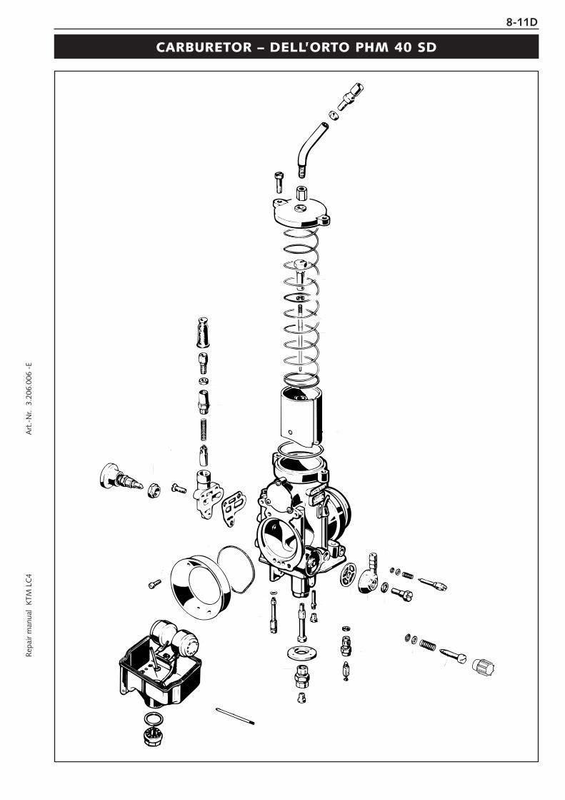
Rep
air
man
ual
KTM
LC
4 A
rt.-
Nr.
3.2
06.0
06 -
E8-11D
CARBURETOR – DELL’ORTO PHM 40 SD

Disassembling the carburetor (Dell’Orto PHM 40 SD)
NOTE: Before commencing to disassemble the carburetor make surethat your workplace is clean and large enough to properly arrange allcarburetor components before you.
– Remove the two screws and pull the carburetor cover out of thecarburetor together with the throttle slide.
– Wrap the throttle slide in a clean piece of cloth and put it onto theair filter box.
– Undo screw bk and take the starting piston out of the carburetor.
– Remove the plug 1 together with the seal ring and take off the floatchamber.
– Remove the main jet 2, the main jet holder 3 and the baffle 4.– Twist out the starting jet 5.
– Remove the idling jet 6 together with the idle mixture pipe below.– Twist out the needle jet 7.
– Pull out the pin 8 and remove the float.– Remove the entire needle valve 9 together with the gasket behind.
8-12D
1
2
3
4
5
6
7
89
10

Rep
air
man
ual
KTM
LC
4 A
rt.-
Nr.
3.2
06.0
06 -
E
– Twist the mixture adjusting screw 1 clockwise all the way in,counting and writing down the number of twists. Twist out themixture regulating screw and remove it together with the spring, thewasher and the O-ring.
– Twist the adjusting screw 2 clockwise all the way in, counting andwriting down the number of twists. Twist out the adjusting screwand remove it together with the spring, the O-ring and the washer.
– Remove screw 3, and take off the hose connection together withthe fuel filter 4.
– Clean all jets and other components and blow them through withcompressed air.
– Clean the carburetor housing and use compressed air to blowthrough all ducts within the carburetor.
– Check all gaskets for damage and exchange them, if necessary.
Assembling the carburetor (Dell’Orto PHM 40 SD)– Put the spring, the washer and the O-ring onto the mixture adjusting
screw 1 and twist the mixture adjusting screw all the way in.– Twist out the mixture adjusting screw, applying the same number of
twists previously written down during the disassembly of the device.
– Put the spring, the washer and the O-ring onto the adjusting screw2 and twist the adjusting screw all the way in.
– Twist out the adjusting screw, applying the same number of twistspreviously written down during the disassembly of the device.
– Insert the fuel filter into the carburetor. Properly position the hoseconnection and mount screw 3 together with the seal ring.
– Insert the seal ring into the carburetor bore and mount the needlevalve 5.
8-13D
12
3
12
3
3
4
5

– Position the float and mount the pin 1. When mounting the floatmake sure that the needle valve properly engages with the float.Check by moving the float upwards: the needle valve must movewith the float.
– Mount the idling mixture pipe and the idling jet 2.– Mount the needle jet 3.
– Position the baffle 4 and fasten it with the main jet holder 5.– Mount and tighten the main jet 6.– Mount and tighten the starting jet 7.
Check the O-ring 8 in the float chamber for proper fit.
– Position the float chamber and fasten it with the plug 9. Do notforget the seal ring.
8-14D
1
2
3
4
5
6
7
8
9

Rep
air
man
ual
KTM
LC
4 A
rt.-
Nr.
3.2
06.0
06 -
E8-15D
CARBURETOR – DELL’ORTO PHM 38 ND

Disassembling the carburetor (Dell’Orto PHM 38 ND)
NOTE: Before commencing to disassemble the carburetor make surethat your workplace is clean and large enough to properly arrange allcarburetor components before you.
– Remove the two screws and pull the carburetor cover out of thecarburetor together with the throttle slide.
– Wrap the throttle slide in a clean piece of cloth and put it onto theair filter box.
– Undo screw and take the starting piston out of the carburetor.
– Remove the plug 1 together with the seal ring and take off the floatchamber.
– Remove the main jet 2, the main jet holder 3 and the baffle 4.– Twist out the starting jet 6.– Twist out the return valve 5.
– Remove the idling jet 8 together with the idle mixture pipe below.– Twist out the needle jet 7.
– Pull out the pin 9 and remove the float.– Remove the entire needle valve bk together with the gasket behind.
8-16D
1
2
345
6
7
8
9
10

Rep
air
man
ual
KTM
LC
4 A
rt.-
Nr.
3.2
06.0
06 -
E8-17D
– Twist the mixture adjusting screw 1 clockwise all the way in,counting and writing down the number of twists. Twist out themixture regulating screw and remove it together with the spring, thewasher and the O-ring.
– Twist the adjusting screw 2 clockwise all the way in, counting andwriting down the number of twists. Twist out the adjusting screwand remove it together with the spring, the O-ring and the washer.
– Remove screw 3, and take off the hose connection together withthe fuel filter.
– Twist out the jet holder 4 together with the accelerating jet 5.
– Remove the 3 screws 6 and take off the entire pump housing 7together with the gasket.
! CAUTION !– DO NOT DAMAGE THE MEMBRANE WHEN REMOVING THE PUMP HOUSING.
REMOVE THE MEMBRANE BEFORE CLEANING THE PUMP HOUSING.– ADJUSTMENT SCREW 8 IS FACTORY CALIBRATED AND MUST NOT BE TURNED.
– Clean all jets and other components and blow them through withcompressed air.
– Clean the carburetor housing and use compressed air to blowthrough all ducts within the carburetor.
– Check all gaskets for damage and exchange them, if necessary.
12
3
45
67
8

8-18D
Assembling the carburetor (Dell’Orto PHM 38 ND)– Position the pump housing 1 together with the gasket and fasten
them with the 3 screws. Make sure that the membrane is properlypositioned in the pump housing.
– Put the seal ring onto the jet holder 3 and mount the jet holdertogether with the accelerating jet 4. The flat section of theaccelerating jet must face backwards.
– Insert the fuel filter into the carburetor. Position the hose connectionand mount screw 5 together with the seal ring.
– Put the spring, the washer and the O-ring onto the mixture adjustingscrew 6 and twist the mixture adjusting screw all the way in.
– Twist out the mixture adjusting screw, applying the same number oftwists previously written down during the disassembly of the device.
– Put the spring, the washer and the O-ring onto the adjusting screw7 and twist the adjusting screw all the way in.
– Twist out the adjusting screw, applying the same number of twistspreviously written down during the disassembly of the device.
– Insert the seal ring into the carburetor bore and mount the needlevalve 8.
1
2
3 4
5
6
7
8

Rep
air
man
ual
KTM
LC
4 A
rt.-
Nr.
3.2
06.0
06 -
E
– Position the float and mount the pin 1. When mounting the floatmake sure that the needle 2 valve properly engages with the float.Check by moving the float upwards: the needle valve must movewith the float.
– Mount the idling mixture pipe and the idling jet 4.– Mount the needle jet 3.
– Position the baffle 5 and fasten it with the main jet holder 6.– Mount and tighten the main jet 7.– Mount and tighten the starting jet 8.– Mount the return valve 9.
Check the O-ring bk in the float chamber for proper fit.
– Position the float chamber and fasten it with the plug bl. Do notforget the seal ring.
8-19D
1
2
3
4
56
7
89
10
11

8-20D
CARBURETOR – DELL’ORTO VHSB 38 QS

Rep
air
man
ual
KTM
LC
4 A
rt.-
Nr.
3.2
06.0
06 -
E
Disassembling the carburetor (Dell’Orto VHSB 38 QS)
NOTE: Before commencing to disassemble the carburetor make surethat your workplace is clean and large enough to properly arrange allcarburetor components before you.
– Open the cap and pull the carburetor cover out of the carburetortogether with the throttle slide.
– Wrap the throttle slide in a clean piece of cloth and put it onto theair filter box.
– Undo the screw and pull the entire cold-starting device out of thecarburetor.
– Remove the three screws 1 and take off the float chamber togetherwith the gasket.
– Take the two floats out of the carburetor.– Take the perforated bushing off the baffle.
– Remove the main jet 2 and the baffle 3.– Twist out the starting jet 4 and the idling jet 5.
– Pull out pin 6 and remove the float arm 7.
– Remove the entire needle valve 8 together with the seal ringbehind.
8-21D
1
2
3
4
5
6
7
8

– Twist out the needle jet 1.
– Twist the mixture adjusting screw 2 clockwise all the way in,counting and writing down the number of twists. Twist out themixture regulating screw and remove it together with the spring, thewasher and the O-ring.
– Twist the adjusting screw 3 clockwise all the way in, counting andwriting down the number of twists. Twist out the adjusting screwand remove it together with the spring.
– Remove plug 5 together with the seal ring and take off the fuelfilter 4.
– Clean all jets and other components and blow them through withcompressed air.
– Clean the carburetor housing and use compressed air to blowthrough all ducts within the carburetor.
– Check all gaskets for damage and exchange them, if necessary.
Assembling the carburetor (VHSB 38 QS)– Put the spring, the washer and the O-ring onto the mixture adjusting
screw 2 and twist the mixture adjusting screw all the way in.– Twist out the mixture adjusting screw, applying the same number of
twists previously written down during the disassembly of the device.
– Put the spring, the washer and the O-ring onto the adjusting screw3 and twist the adjusting screw all the way in.
– Twist out the adjusting screw, applying the same number of twistspreviously written down during the disassembly of the device.
– Insert the fuel filter 4 into the plug 5 and mount the plug togetherwith the seal ring.
8-22D
1
2
3
4
5
2
3
4
5

Rep
air
man
ual
KTM
LC
4 A
rt.-
Nr.
3.2
06.0
06 -
E
– Mount the needle jet 1.– Insert the seal ring into the carburetor bore and mount the needle
valve 2.
– Position the float arm 3 and mount pin 4.
– Mount the idling jet 5 and the starting jet 6.– Position the baffle 7 and fasten it with the main jet 8.
– Put the perforated bushing 9 onto the baffle and mount the gasket.
– Insert the two floats bk into the float chamber and mount the floatchamber.
8-23D
1
2
3
4
56
7
8
9
10

8-24D
Idling range – AOperation with closed throttle valve. This range is influenced by the position of the air control screw 1 and the idle adjustingscrew 2. Idling adjustment of the carburetor strongly affects the engine’s starting behavior. That is, an engine whose idling speedis adjusted correctly will be easier to start than one whose idling speed has not been adjusted correctly.
The throttle stop screw is used to adjust the basic position of the throttle. The mixture control screw is used to control the idlemixture which arrives at the engine via the idle system. Turning it clockwise will reduce the amount of gasoline (lean mixture),turning it counterclockwise will increase the amount of gasoline (rich mixture).
TO ADJUST IDLING CORRECTLY, PROCEED AS FOLLOWS:1 Turn in mixture control screw up to the stop, and turn it back out by 1.5 turns2 Warm up the engine3 Use throttle stop screw to adjust normal idling speed (1400-1500 r.p.m.)4 Turn mixture control screw slowly clockwise until idling speed starts to decrease. Memorize this position, and turn mixture
control screw slowly counterclockwise until the idling speed will decrease again. Adjust the point of the highest idling speedbetween these two positions. (The highly competitive user will make his adjustment 1/4 turn leaner because his engine willheat up more in competitive use).
NOTE: If you fail to obtain a satisfying result by following the procedure described above, an incorrectly dimensioned idlingnozzle may be the cause. In case:a) the mixture control screw has been screwed in up to the stop without causing any change in rotational speed, a smalleridling jet has to be installed;b) the engine dies when the mixture control screw is still open by 2 turns, a larger idling jet needs to be selected;Naturally, in cases of jet changes, you have to start your adjusting work from the beginning.
5 Now, use the slide stop screw to adjust the desired idling speed6 In cases of greater changes in outside temperature and extremely different altitudes, the idling speed should be readjusted.
Opening up – BEngine behavior when the throttle opens. The idle jet and the shape of the throttle valve influences this range. If, despite goodidling-speed and part-throttle setting, the engine sputters when the throttle is fully opened and develops its full power notsmoothly but suddenly at high engine speeds, the mixture to the carburetor will be too rich, the fuel level too high or the floatneedle is leaking.
Part-throttle range – COperation with partly open throttle valve. This range is only influenced by the jet needle (shape and position). The optimum part-throttle setting is controlled by the idling setting in the lower range and by the main jet in the upper range.
Full throttle range – DOperation with the throttle fully open (flat out). This range is influenced by the main jet and the jet needle. If the porcelain of thenew spark plug is found to have a very bright or white coating after a short distance of riding flat out, a larger main jet isrequired. If the porcelain is dark brown or black with soot the main jet must be replaced by a smaller one.
Basic information on carburetor wearAs a result of engine vibrations, throttle valve, jet needle, and needle jet are subjected to increased wear. This wear may causecarburetor malfunction (e.g., overly rich mixture). Therefore, these parts should be replaced after 10000 kilometers (6000 miles).
main jetjet needle
jet needle
mixture regulating screwidle adjusting screw
idling jetthrottle valve

Rep
air
man
ual
KTM
LC
4 A
rt.-
Nr.
3.2
06.0
06 -
E8-25D
Check float level (Dell’Orto PHM 38ND / 40SD)Stand the carburettor diagonally at about 60° so that the spring in thefloat needle valve is not pressed together. In this position, the edge ofthe float should be parallel with the float bowl sealing surface (seeillustration).
Checking axial play of float (Dell’Orto PHM 38ND / 40SD)For proper functioning of the float, there must be an axial play of 0.8mm (0,03 in). If necessary, slightly abrade and deburr lateral float guide.
Adjust hot start device (Dell’Orto PHM 40SD)If the hot start button was removed when cleaning the carburetor,readjust the hot start device.Install carburetor and adjust idling as discribed above. Then unlock nut1, press in hot start device 2 and adjust engine rev with adjustingscrew 3 to 2000-2500 rpm. Tighten locking nut.
Mixture too lean:Not enough fuel in proportion to air
Mixture too rich:Too much fuel in proportion to air
60°
0,8 mm
12
12
3

Adjusting the throttle cableThere must always be a 3-5 mm (0.1-0.2 in) play in the throttle cable.To check this, move back the protective cover 1 on the throttle grip.You must be able to lift the outer covering of the cable 3-5 mm fromthe adjusting screw 2, until resistance is felt.To adjust, loosen the counter nut 3 and turn the adjusting screwaccordingly. Finally tighten counter nut and slide the protective coverback on.
Adjusting the choke cableAt the choke cable, there must always exist a play of approx. 2 mm (0.1in). To check this, push choke lever fully forward and pull protectivecover 4 from the adjuster piece 5. Now, it must be possible to lift theouter covering of the cable by approx. 2 mm from the adjuster pieceuntil feeling a resistance. If necessary, loosen counter nut and readjustplay by turning the adjuster piece. Tighten counter nut, and slide onprotective cover.
Adjusting the choke cableThe choke cable must have a play of approximately 2 mm at all times.To check the play turn the knob 6 into the initial position. Now itshould be possible to lift the exterior case of the choke cableapproximately 2 mm from the supporting surface of the choke knobbefore the upward movement is blocked by resistance.
To adjust, remove the seat and the gastank, push the protective coverupwards, loosen the counter nut and turn the adjustment screw 7accordingly. Turn the adjustment screw clockwise for more play oranticlockwise for less play.Tighten the counter nut, replace the protective cover and mount thegas-tank and the seat.
8-26D
3-5 mm
2 mm
7
45
123
2 mm
6

Rep
air
man
ual
KTM
LC
4 A
rt.-
Nr.
3.2
06.0
06 -
E8-27D
CARBURATOR - KEIHIN FCR 41

8-28D
Disassembling the carburetorNOTE: Before you start disassembling the carburetor, you should lookfor a clean work place. It should offer you enough space to lay out allindividual components of the carburetor in perfect order.
– Dismount the carburetor and remove any coarse dirt.
– Remove the wire clip 1 and pull the ventilation hoses out of the carburetor.
– Disconnect the hose 2.– Loosen the 2 screws 3 and dismount all ventilation hoses from the
carburetor.
– Remove the 2 screws 4 and dismount the slide cover together withits gasket.
– Remove the screw 5 and take the jet needle out of the throttlevalve.
– Remove the screw 6.
1
2
3
3
4
56

Rep
air
man
ual
KTM
LC
4 A
rt.-
Nr.
3.2
06.0
06 -
E8-29D
– Now, pull the cable disc approx. 5 mm outward and turn it until thethrottle valve can be lifted out of the carburetor and detach therollers 1 at the throttle valve.
– Take the throttle valve together with the 4 rollers 2 and the valvepaddle out of the carburetor.
NOTE: When you turn the cable disc, it must not be blocked by thestop bolt (see photo). Otherwise, pull the shaft further outward.
– Turn the carburetor around, remove the 3 screws and remove thecover of the accelerator pump.
NOTE: When dismounting the cover, watch out for the spring and thesealing rings as they may get lost easily.
– Remove the 2 sealing rings, the spring and the diaphragm from thepump housing.
– Remove the screw and dismount the float chamber.– Unhitch the push rod 3 of the accelerator pump and dismount it.
– Take the plastic part 4 off the needle jet.– Loosen the screw 5, pull out the float hinge pin 6 and dismount
the float together with the float needle valve.
– Remove the screw 7 and use pliers to carefully extract the seat ofthe float needle valve from the carburetor.
– Turn out the idling jet 8, the starting jet 9 and the needle jettogether with the main jet bk.
– Turn in the mixture control screw bl down to the stop, count thenumber of turns and write it down.
– Turn out the mixture control screw and dismount it together with thespring, the washer, and the O-ring.
NOTE: The spring, the washer, and the O-ring will usually remain in thebore. These parts can be removed with the help of compressed air.
1
2
3
4
56
7
11
8910
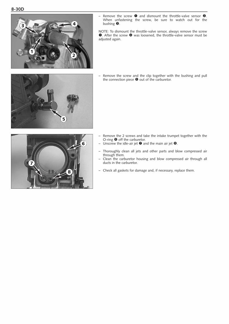
8-30D– Remove the screw 1 and dismount the throttle-valve sensor 2.
When unfastening the screw, be sure to watch out for the bushing 3.
NOTE: To dismount the throttle-valve sensor, always remove the screw1. After the screw 4 was loosened, the throttle-valve sensor must beadjusted again.
– Remove the screw and the clip together with the bushing and pullthe connection piece 5 out of the carburetor.
– Remove the 2 screws and take the intake trumpet together with theO-ring 6 off the carburetor.
– Unscrew the idle-air jet 7 and the main air jet 8.
– Thoroughly clean all jets and other parts and blow compressed airthrough them.
– Clean the carburetor housing and blow compressed air through allducts in the carburetor.
– Check all gaskets for damage and, if necessary, replace them.
5
6
7
8
21
3 4

Rep
air
man
ual
KTM
LC
4 A
rt.-
Nr.
3.2
06.0
06 -
E8-31D
Checking the choke slideIt must be easy to actuate the choke slide.The piston 1 of the choke slide must not have any pronounced scoremarks or deposits.
Checking the accelerator pumpCheck the membranes for cracking or brittleness.Check gaskets for damage.Check if the bores 2 are unobstructed.
Checking the jet needleCheck the jet needle for bending and wear.
Checking the float needle valveCheck the sealing surface of the needle valve for notches.There must not be any dirt between valve seat and float needle.
Checking the throttle valveCheck the throttle valve paddles 3 for damage.The rollers 4 at the throttle valve must be easy to turn and must nothave any flat spots.
1
2
2
34

8-32D
Assembling the carburetor– Mount the idle-air jet 1 and the main air jet 2.– Place the O-ring 3 in the groove and secure the intake trumpet to
the carburetor by means of the 2 screws.
– Insert the fuel connection 4 into the carburetor and secure it withthe clip.
NOTE: In the mounted state, the connection piece must be easy toturn.
– Mount the choke slide 5 and actuate it several times, checkingwhether it can be moved smoothly. Besides, check whether thechoke locks properly.
– Thread the spring, the washer and the O-ring onto the mixturecontrol screw 6 and screw the mixture control screw in as far as itwill go.
– Now, unscrew the mixture control screw the number of turns writtendown during disassembly.
NOTE: Basic setting see technical spezifications.
– Mount idling jet 7, starting jet 8 and needle jet together with mainjet 9.
– Insert the needle jet bk into bore and secure it by means of the screwbl.
12
3
4
5
6
789
10
11

Rep
air
man
ual
KTM
LC
4 A
rt.-
Nr.
3.2
06.0
06 -
E8-33D
– Position the float, mount the float hinge pin and secure it by meansof the screw.
– Check the float level.– Stick the plastic component 1 on the needle jet.
– Engage the push rod 2 of the accelerator pump at the lever.
– Mount the float chamber and at first secure it with only 1 screw.When positioning the float chamber, make sure that the push rod 2of the accelerator pump slides into the bore.
– Place the membrane 3 with the labeling facing upwards and thespring into the pump housing.
– Place the O-ring 4 into the groove. Secure the sealing ring 5 withsome grease in the cover and fasten the cover by means of 3 screws.
– Turn the cable disc and push the throttle valve into the carburetorsuch that the rollers 6 engage the throttle valve (see photo). Pushthe throttle valve all the way into the carburetor.
– Turn the cable disc several times and while doing so check whetherthe throttle valve moves smoothly.
1
2
2
34
5
6

8-34D– Coat the thread of the screw 1 with Loctite 243 and mount the
screw, however, do not tighten it yet.– Push the slide pin 2 inward. At the same time, push the slide lever
3 to the extreme right and tighten the screw 1.
– Now, the distances A on the left and on the right should beidentical. Then, turn the cable disc and check if the throttle valvemoves smoothly.
– Mount the jet needle and secure it with the screw 4.
– Position the slide cover together with its gasket and fasten it bymeans of the 2 screws 5.
– Secure the ventilation hoses with the 2 screws 6 of the floatchamber and connect the hose 7.
– Insert the 2 hose connections into the bores and fasten them withthe retaining clip 8.
A A
12
4
5
6
6
3
7
8

Rep
air
man
ual
KTM
LC
4 A
rt.-
Nr.
3.2
06.0
06 -
E8-35D
– Mount the throttle valve sensor such that the flat spot at the carburetor engages the groove of the throttle valve sensor andsecure it by means of the screw.
Adjusting the position of the throttle valve sensorNOTE: Before checking the position of the throttle valve sensor, youhave to adjust the idle speed correctly.
– Disengage the plug-and-socket connection of the throttle valvesensor.
– Connect a multimeter (measuring range Ω x 1k) to the blue (+) andthe black (-) cable of the throttle valve sensor and measure thethrottle valve resistance.
– Now, multiply this value by 0.15. This yields the adjustment value forthe throttle valve sensor.
Example:throttle valve sensor resistance (bl/s) = 5 kΩ
throttle valve sensor resistance (ge/s) = 5 kΩ x 0.15 = 750 Ω ± 50 Ω
– Connect the multimeter (measuring range Ωx100) to the yellow (+)and the black (-) cable of the throttle valve sensor and measure thethrottle valve sensor resistance with the throttle grip closed.According to the above example, this value should be 750 Ω ± 50 Ω.
– If the value measured does not correspond to the desired value,loosen the screw 1 and turn the throttle valve sensor 2 until theinstrument displays the desired value.
– Secure the throttle valve sensor in this position by fastening thescrew and check the value once more.
– Connect the throttle valve sensor to the wiring harness.
bl
bl
ge
ges
s
1 2

8-36D
Checking the throttle valve sensor
NOTE: The following measurement must be taken at a component temperature of approx. 20°C.
– Open the plug-and-socket connection of the throttle valve sensor.– Connect a multimeter (measuring range Ω x 1k) to the blue (+) and
the black (-) cable of the throttle valve sensor.
throttle valve sensor resistance: 4 - 6 kΩ
– Now, connect the multimeter to the yellow (+) and the black (-)cable of the throttle valve sensor.
– As you open the throttle grip slowly, the resistance must changeevenly.
throttle valve sensor resistance: 0-5 kΩ ±1 kΩ(while opening the throttle grip)
Dismounting and installing the throttle valve sensor– Disconnect the plug-and-socket connection of the throttle valve
sensor and remove the bolt 1.– Take the throttle valve sensor off the carburetor.
– When mounting the throttle valve sensor, make sure that the flatspot at the throttle valve pin 2 engages the groove on the throttlevalve sensor.
– Mount the bolt, however, do not yet tighten fully and adjust theposition of the throttle valve sensor. Secure the bolt with Loctite 243.
bl
bl
ge
ges
sbl = bluege = yellows = black
1
2

Rep
air
man
ual
KTM
LC
4 A
rt.-
Nr.
3.2
06.0
06 -
E8-37D
Adjust idlingIdling adjustment of the carburetor strongly affects the engine’s startingbehavior. That is, an engine whose idling speed is adjusted correctly willbe easier to start than one whose idling speed has not been adjustedcorrectly.
The idle speed is controlled by means of the adjusting wheel 1 and themixture control screw 2. The adjusting wheel is used to adjust the basicsetting of the slide. The mixture control screw is used to control the idlemixture which arrives at the engine by way of the idle system.Clockwise turning reduces the fuel quantity (lean mixture),counterclockwise turning increases the fuel quantity (rich mixture).
TO ADJUST IDLING CORRECTLY, PROCEED AS FOLLOWS:1 Turn in mixture control screw 2 up to the stop, and turn it back out
to the basic position (see technical data engine)2 Warm up the engine3 Use the adjusting wheel 1 to set the normal idle speed (1400 - 1500
rpm).4 Turn mixture control screw 2 slowly clockwise until idling speed
starts to decrease. Memorize this position, and turn mixture controlscrew slowly counterclockwise until the idling speed will decreaseagain. Adjust the point of the highest idling speed between thesetwo positions. If, in the course of this procedure, the speedundergoes a relatively high increase, reduce the idle speed to anormal level and repeat the procedure specified in 4. Seriouscompetitive racers will choose a setting approx. 1/4 turn (clockwise)leaner than this ideal value because their engine will heat up morewhen used in competitions.
NOTE: If you fail to obtain a satisfying result by following the proceduredescribed above, an incorrectly dimensioned idling nozzle may be thecause.
a) If the mixture control screw has been screwed in up to the stopwithout causing any change in rotational speed, a smaller idling jethas to be installed;b) If the engine dies when the mixture control screw is still open by 2 turns, a larger idling jet needs to be selected;Naturally, in cases of jet changes, you have to start your adjustingwork from the beginning.
5 Then, use the adjusting wheel to set the desired idle speed.6 In cases of greater changes in outside temperature and extremely
different altitudes, the idling speed should be readjusted.
1
2
2

8-38D
Adjusting the mixture control screwThe mixture control screw is difficult to reach. For this reasons, we havecreated an appropriate special tool 590.29.034.000.Introduce the special tool into the bore at the carburetor bottom. Pressthe tool slightly upward and turn the adjusting wheel 1 until the toolengages the slot of the mixture control screw 2.Now, you can go about adjusting the screw. Marks were provided onthe adjusting wheel, making it easier to keep track of the turns.
Checking the float level (float height) For this purpose, dismount the carburetor and remove the floatchamber. Hold the carburetor in a slanted position such that the floatwill abut the float needle valve but not compress it (see photo).Now, use a sliding caliper to measure the distance H between thecasing edge and the float's upper edge.The float height H is to be 9 mm.If the float height does not correspond to the desired value, check thefloat needle valve and, if necessary, replace it.
If the float needle valve is correct, you can adjust the float height bybending of the float lever 3.
Mount the float chamber, install the carburetor, and adjust the idlespeed.
H
3
1
2
8-39DR
epai
r m
anua
l K
TM L
C4
Art
.-N
r. 3
.206
.006
-E
CARBURETOR - KEIHIN FCR-MX 41

8-40D
Disassembling the carburetor Keihin FCR - MX 41
NOTE: Before you start disassembling the carburetor, you should lookfor a clean workplace. It should offer you enough space to lay out allindividual components of the carburetor in perfect order.
– Dismount the carburetor and remove any coarse dirt.
– Loosen both bolts 1 and remove all of the vent hoses from thecarburetor.
– Remove both bolts 2 and remove the slide cover and gasket fromthe carburetor.
– Remove screw 3 and pull the jet needle out of the throttle slide.– Remove screw 4.
– Pull the throttle slide arm up and take the throttle slide roller 5 andthe slide shim out of the carburetor.
11
2 2
4
3
5

8-41DR
epai
r m
anua
l K
TM L
C4
Art
.-N
r. 3
.206
.006
-E
– Turn the carburetor around, remove the 3 screws and remove thecover of the accelerator pump.
NOTE: When dismounting the cover, watch out for the spring and thesealing rings as they may get lost easily.
– Remove the 2 sealing rings, the spring and the diaphragm from thepump housing.
– Remove the screws on the float chamber and remove the housing.
– Pull out the float hinge pin 1 and remove the float together withthe float needle valve.
– Remove the main jet 2.
– Remove the screw 3 and use pliers to carefully extract the seat ofthe float needle valve from the carburetor.
– Screw out the idling jet 4, the starting jet 5 and the needle jet 6.
– Turn in the mixture control screw 7 down to the stop, count thenumber of turns and write it down.
– Turn out the mixture control screw and dismount it together with thespring, the washer, and the O-ring.
NOTE: The spring, the washer, and the O-ring will usually remain in thebore. These parts can be removed with the help of compressed air.
1
2
3
7
5
46

8-42D– Remove bolts 1 and the throttle sensor 2.
NOTE: the throttle sensor should only be dismounted if defective. If thebolts 1 are loosened, the throttle sensor must be adjusted again.
– Remove screw 3 and pull the connecting piece out of thecarburetor.
– Remove the 2 screws and take the intake trumpet together with theO-ring 4 off the carburetor.
– Unscrew the idle-air jet 5 and the main air jet 6.
– Thoroughly clean all jets and other parts and blow compressed airthrough them.
– Clean the carburetor housing and blow compressed air through allthe ducts in the carburetor.
– Check all gaskets for damage and, if necessary, replace them.
6
3
1
1
2
4
5

8-43DR
epai
r m
anua
l K
TM L
C4
Art
.-N
r. 3
.206
.006
-E
Checking the choke slide and hot start knobChoke slide:The choke slide must be easy to actuate .The piston 1 of the choke slide must not have any pronounced scoremarks or deposits.
Hot start knob:The hot start knob must be easily actuated.The piston on the hot start knob may not have any scores or deposits.
Checking the accelerator pumpCheck the membranes for cracking or brittleness.Check gaskets for damage.Check if the bores 2 are unobstructed.
Checking the jet needleCheck the jet needle for bending and wear.
Checking the float needle valveCheck the sealing surface of the needle valve for notches.There must not be any dirt between the valve seat and the float needle.
Checking the throttle valveThe rollers 3 at the throttle valve must be easy to turn and must nothave any flat spots.Check the throttle valve paddles 4 for damage.
1
2
2
43

8-44D
Assembling the carburetor Keihin FCR-MX 41– Mount the idle-air jet 1 and the main air jet 2.– Place the O-ring 3 in the groove and secure the intake trumpet to
the carburetor by means of the 2 screws.
– Insert the fuel port in the carburetor and fix with screw 4.
NOTE: In the mounted state, the connection piece must be easy toturn.
– Mount the choke slide 5, the hot start knob 6 and actuate severaltimes, checking for smooth operation. Also make sure the choke andthe hot start knob lock into place.
– Thread the spring, the washer and the O-ring onto the mixturecontrol screw 7 and screw the mixture control screw in as far as itwill go.
– Now, unscrew the mixture control screw the number of turns writtendown during disassembly.
NOTE: See the Technical Specifications for the basic carburetor setting.
– Mount idling jet 8, starting jet 9 and needle jet together with mainjet bk.
– Insert the needle valve seat bl in the bore and fix with screw bm.
5
11
3
21
4
7
8
9
6
10
12

8-45DR
epai
r m
anua
l K
TM L
C4
Art
.-N
r. 3
.206
.006
-E
– Position the float and the float needle valve and mount the floathinge pin 1.
– Check the float level (see page 8-21).
– Mount the float chamber and the gasket, position the bracket for the adjustment screw 2 and fix the float chamber with the screws 3.
NOTE: When positioning the float chamber, make sure that the pushrod 4 of the accelerator pump slides into the bore.
– Place the membrane 5 with the labeling facing upwards and thespring into the pump housing.
– Place the O-ring 6 into the groove. Secure the sealing ring 7 withsome grease in the cover and fasten the cover by means of 3 screws.
– Mount the throttle valve sensor such that the flat spot at the carburetor engages the groove of the throttle valve sensor andsecure it by means of the bolt.
– Pull up the throttle slide arm, push the throttle slide together withroll 8 and the slide shim into the carburetor so that the rolls 9engage in the throttle slide (see illustration).
– Check the throttle slide for smooth operation.
5
1
3
2
4
6
7
89

8-46D– Apply Loctite 243 to the screw 1 and tighten.– Mount the jet needle and fix with the screw 2.
– Position the slide cover with the gasket and fasten with the 2 screws3.
– Fix the vent hoses on the float chamber with the 2 bolts 4.
1
2
33
4 4

8-47DR
epai
r m
anua
l K
TM L
C4
Art
.-N
r. 3
.206
.006
-E
Adjusting the position of the throttle valve sensorNOTE: Before checking the position of the throttle valve sensor, youhave to adjust the idle speed correctly.
– Disengage the plug-and-socket connection of the throttle valvesensor.
– Connect a multimeter (measuring range Ω x 1k) to the blue (+) andthe black (-) cable of the throttle valve sensor and measure thethrottle valve resistance.
– Now, multiply this value by 0.15. This yields the adjustment value forthe throttle valve sensor.
Example:Throttle valve sensor resistance (bl/s) = 5kΩ
Throttle valve sensor resistance (ge/s) = 5 kΩ x 0.15 = 750 Ω ± 50 Ω
– Connect the multimeter (measuring range Ωx100) to the yellow (+)and the black (-) cable of the throttle valve sensor and measure thethrottle valve sensor resistance with the throttle grip closed.According to the above example, this value should be 750Ω ± 50Ω.
– If the value measured does not correspond to the desired value,loosen the 2 bolts 1 and turn the throttle valve sensor 2 until theinstrument displays the desired value.
– Secure the throttle valve sensor in this position by fastening the boltsand check the value once more.
– Connect the throttle valve sensor to the wiring harness.
bl
bl
ge
ges
s
1
1
2
bl = bluege = yellows = black

8-48D
Checking the throttle valve sensorNOTE: The following measurement must be taken at a component temperature of approx. 20°C.
– Open the plug-and-socket connection of the throttle valve sensor.– Connect a multimeter (measuring range Ω x 1k) to the blue (+) and
the black (-) cable of the throttle valve sensor.
Resistance of throttle valve sensor: 4 - 6 kΩ
– Now, connect the multimeter to the yellow (+) and the black (-)cable of the throttle valve sensor.
– As you open the throttle grip slowly, the resistance must changeevenly.
Resistance of throttle valve sensor: 0-5 kΩ ±1 kΩ(while opening the throttle grip)
Dismounting and installing the throttle valve sensor– Disconnect the plug-and-socket connection of the throttle valve
sensor and remove the bolts 1.– Take the throttle valve sensor off the carburetor.
– When mounting the throttle valve sensor, make sure that the flatspot at the throttle valve pin engages the groove on the throttlevalve sensor.
– Mount the 2 bolts, however, do not yet tighten them fully and adjustthe position of the throttle valve sensor. Secure the 2 bolts withLoctite 243.
bl
bl
ge
ges
sbl = bluege = yellows = black
1
1

8-49DR
epai
r m
anua
l K
TM L
C4
Art
.-N
r. 3
.206
.006
-E
CARBURETOR – Adjust idling (Keihin FCR-MX 41)Idling adjustment of the carburetor strongly affects the engine’s startingbehavior. That is, an engine whose idling speed is adjusted correctly willbe easier to start than one whose idling speed has not been adjustedcorrectly.The idle speed is controlled by means of the adjusting wheel 1 and themixture control screw 2. The adjusting wheel is used to adjust the basicsetting of the slide. The mixture control screw is used to control the idlemixture which arrives at the engine by way of the idle system.Clockwise turning reduces the fuel quantity (lean mixture),counterclockwise turning increases the fuel quantity (rich mixture).TO ADJUST IDLING CORRECTLY, PROCEED AS FOLLOWS:1 Turn in mixture control screw 2 up to the stop, and turn it back out
to the basic position (see technical date-engine)2 Warm up the engine3 Use the adjusting wheel 1 to set the normal idle speed (1400 -
1500 rpm).4 Turn mixture control screw 2 slowly clockwise until idling speed
starts to decrease. Memorize this position, and turn mixture controlscrew slowly counterclockwise until the idling speed decreases again.Adjust the point of the highest idling speed between these twopositions. If, in the course of this procedure, the speed undergoes arelatively high increase, reduce the idle speed to a normal level andrepeat the procedure specified in 4. Serious competitive racers willchoose a setting approx. 1/4 turn (clockwise) leaner than this idealvalue because their engine will heat up more when used incompetitions.NOTE: If you fail to obtain a satisfying result by following theprocedure described above, an incorrectly dimensioned idling nozzlemay be the cause. If:a) the mixture control screw has been screwed in up to the stopwithout causing any change in rotational speed, a smaller idling jethas to be installed;b) the engine dies when the mixture control screw is still open by 2 turns, a larger idling jet needs to be selected.Naturally, in cases of jet changes, you have to start your adjustingwork from the beginning.
5 Then, use the adjusting wheel to set the desired idle speed.6 In cases of greater changes in the outside temperature and extremely
different altitudes, the idling speed should be readjusted.
Basic information on carburetor wearAs a result of engine vibrations, the throttle valve, jet needle, andneedle jet are subjected to increased wear. This wear may cause thecarburetor to malfunction (e.g., overly rich mixture). Therefore, theseparts should be replaced after 200 hours.
Adjusting the mixture control screwEspecially on the EXC models, accessing the mixture control screw isdifficult. For this reasons, we have created an appropriate special tool.
Introduce the special tool on the mixture control screw 2 at thecarburetor bottom. Press the tool slightly upward and turn the adjustingwheel 3 until the tool engages the slot of the mixture control screw.Now, you can go about adjusting the screw. Marks were provided onthe adjusting wheel, making it easier to keep track of the turns.
Checking the float level (float height)For this purpose, dismount the carburetor and remove the floatchamber. Hold the carburetor in a slanted position such that the floatwill abut the float needle valve but not compress it.In this position, the edge of the float should be parallel with thefloat chamber sealing surface (see illustration).If the float height does not correspond to the desired value, check thefloat needle valve and, if necessary, replace it.
If the float needle valve is o.k., you can adjust the float height bybending the float lever 4.
Mount the float chamber, install the carburetor, and adjust the idlespeed.
2
4
1
3


Rep
air
man
ual
KTM
LC
4 A
rt.-
Nr.
3.2
06.0
06 -
E
TROUBLE SHOOTING
TROUBLE SHOOTING (SX, SXC, SC, SMC) . . . . . . . . . . . . . . . . . . . .9-2
TROUBLE SHOOTING (LC4 COMPETITION) . . . . . . . . . . . . . . . . . . .9-4
TROUBLE SHOOTING (LC4) . . . . . . . . . . . . . . . . . . . . . . . . . . . . . . .9-7
INDEX
9-1D
9


Rep
air
man
ual
KTM
LC
4 A
rt.-
Nr.
3.2
06.0
06 -
E9-2
TROUBLE
Engine will not start
Engine will not idle
Engine does not rev high
CAUSE
Operating error
Fuel supply interrupted
Flooded engine
Sooty or wet spark plug
Electrode gap too large
Spark plug connector or spark plugfaulty
If connector oxidates fromgenerator to ignition coil
Short circuit cable scored in wiringharness, ignition lock, emergency OFFswitch or short circuit button faulty
The plug connection of the CDI-unit, the pulse generator or theignition coil has oxydized
Water in short emergency OFF switch
Water in carburettor or jets blocked
Carburettor does not fit in properlyat intake flange
Idling jet blocked
Adjusting screws on carburettoruncorrect adjusted
Ignition system faulty
Carburettor fuel level too highbecause float needle valve is dirtyor worn out
Loose carburettor jets
Electronical ignition timing faulty
REMEDY
Switch on ignition, switch on emergency OFF switch, openfuel tap, tank fuel, do not use choke i.e. the hotstart device.Pay attention to starting off information (see drivinginstructions).
Close fuel tap, loosen fuel hose at carburettor, lead into abasin and open fuel tap,– if fuel leaks out, clean carburettor– if no fuel leaks out, check tank ventilation, i.e. clean fuel
tap
See driving instructions
Clean or replace spark plug
Adjust spark plug electrode gap to 0,6 mm
Dismount spark plug, connect ignition cable, hold to ground(blank place on engine) and actuate kickstarter, a strongspark must be produced at the spark plug– If no spark is produced, loosen spark plug cap from ignition
cable, hold about 5 mm from ground and actuatekickstarter
– If a spark now occurs, replace spark plug cap– If no spark is produced, control ignition system
Remove fuel tank, clean connector and treat with contactspray
Remove fuel tank, draw off blue/black cable from orangecable of ignition coil and check spark.– If a spark is produced, seek fault in short circuit current
Remove the seat, the right side cover and the fuel tank.Clean the plug connection and treat it with contact spray
Remove 2-pole connector located underneath the headlightmask, treat emergency OFF switch with contact spray
Dismount and clean carburettor
Check if carburettor is fitted in correctly
Dismount carburettor and clean jets
Adjust carburettor
Check ignition system
Dismount carburettor and check if worn out
Tighten jets
Check ignition system
TROUBLE SHOOTING – SX, SXC, SC, SMC

9-3D
TROUBLE
Engine will not reach fullpower
Engine stops or spluttersin carburettor
Engine gets to hot,
High oil consumption
All switched on lampsblown out
CAUSE
Fuel supply partically interrupted orcarburettor dirty
Float is not tight, or no axial play
Air filter very dirty
Exhaust leaking or blocked
Valve gap to small
Loss of compression because handdecompressor has no play
Electronical ignition timing faulty
Insuffient fuel
Engine takes air out of control
Insufficient cooling liquid
Not enough air stream
Radiators very dirty
Foam formation in cooling system
Bent cooling hose
Thermostat defective
Buckling gearing ventilation hose
Engine oil level too high
Motor oil too thin (viscosity)
Capacitor or voltage regulatorfaulty
REMEDY
Clean and check fuel system as well as carburettor
Replace or abrade the float
Clean or replace air filter
Check if exhaust is damaged, replace glas fibre yarn inexhaust silencer
Adjust valve gap
Check setting of the hand decompression cable
Check ignition system
Clean and check fuel system and carburettor
Check intake flange and carburettor if firmly setted
Refill cooling liquid (see maintenace work), check coolingsystem for leaks
Drive on briskly
Clean radiators with water jet
Replace cooling liquid, use anti freeze liquid with brandname
Shorten or replace cooling hose
Dismount and check thermostat (opening temperature 70°C, 158° F) or replace it
Dislocate i.e. replace non-buckling vetilation hose
Check engine oil level when the engine is warm; correct if necessary
Use thicker engine oil; see chapter „Engine oil“
Remove right side cover and control connections. Checkcapacitor and voltage regulator

Rep
air
man
ual
KTM
LC
4 A
rt.-
Nr.
3.2
06.0
06 -
E9-4D
TROUBLE
Engine will not start
Engine will not idle
CAUSE
Operating error
The motorcycle has been out ofoperation for a longer period oftime. Therefore the float chamberis filled with old fuel.
Fuel supply interrupted
Flooded engine
Sooty or wet spark plug
Electrode gap too large
Spark plug connector or spark plugfaulty
If connector oxidates fromgenerator to ignition coil
Short circuit cable scored in wiringharness, ignition lock, emergencyOFF switch faulty
Water in short emergency OFFswitch
Water in carburetor or jets blocked
Carburetor does not fit in properlyat intake flange
Idling jet blocked
Adjusting screws on carburetoruncorrect adjusted
Spark plug faulty
Ignition system faulty
REMEDY
Switch on ignition, switch on emergency OFF switch, openfuel tap, tank fuel, do not use choke i.e. the hotstart device.Pay attention to starting off information (see drivinginstructions).
The easily inflammable components of the new fuelsevaporate during longer periods of standstill. When themotorcycle has been out of operation for more than a week,it is therefore recommended to drain the old fuel from thefloat chamber. The engine will immediately start off when thefloat chamber is filled with new fuel.
Close fuel tap, loosen fuel hose at carburetor, lead into abasin and open fuel tap,– if fuel leaks out, clean carburetor– if no fuel leaks out, check tank ventilation, i.e. clean fuel
tap
Fully open the throttle when starting or replace the sparkplug, respectively.
Clean / dry or replace spark plug.
Adjust spark plug electrode gap to 0,7 mm
Dismount spark plug, connect ignition cable, hold to ground(blank place on engine) and actuate kickstarter, a strongspark must be produced at the spark plug– If no spark is created exchange the spark plug.– If the new spark plug doesn’t produce a spark either,
disconnect the spark plug connector from the ignitioncable, hold it approx. 5 mm from ground and start.
– If a spark now occurs, replace spark plug cap– If no spark is produced, control ignition system
Remove fuel tank, clean connector and treat with contactspray
Remove fuel tank, draw off blue/black cable from orangecable of ignition coil and check spark.– If a spark is produced, seek fault in short circuit current
Remove 2-pole connector located underneath the headlightmask, treat emergency OFF switch with contact spray
Dismount and clean carburetor
Check if carburetor is fitted in correctly
Dismount carburetor and clean jets
Adjust carburetor
Exchange the spark plug
Check ignition system
TROUBLE SHOOTING – LC4 COMPETITION

9-5D
TROUBLE
Engine does not rev high
Engine will not reach fullpower
Engine gets to hot, cooling liquid tmperaturewarning lamp lights up
High oil consumption
All lamps that were onhave burned out.
Headlight and parkinglight fail.
Flasher lights, brake light,fan and horn fail.
CAUSE
Carburetor fuel level too highbecause
Float needle is dirty or worn out
Float leaks
The cold starting system ispermanently activated due to alack of play in the choke cable.
Carburetor jets have loosened.
Defective electronic ignition timingdevice.
Fuel supply partically interrupted orcarburetor dirty
Float is not tight
Air filter very dirty
Valve gap to small
Loss of compression because handdecompressor has no play
Electronical ignition timing faulty
Insufficient cooling liquid
Radiators very dirty
Foam formation in cooling system
Bent cooling hose
Thermostat defective
Buckling gearing ventilation hose
Engine oil level too high
Motor oil too thin (viscosity)
Defective voltage regulator.
Blown fuse.
Blown fuse
REMEDY
Dismount carburetor and check if worn out
Replace float needle
Replace float
Adjust choke cable.
Retighten jets.
Check ignition system
Clean and check fuel system as well as carburetor
Replace the float
Clean or replace air filter
Adjust valve gap
Check setting of the hand decompression cable
Check ignition system
Refill cooling liquid (see maintenace work), check coolingsystem for leaks
Clean radiators with water jet
Replace cooling liquid, use anti freeze liquid with brand name
Shorten or replace cooling hose
Dismount and check thermostat (opening temperature 70°C,158°F) or replace it
Dislocate i.e. replace non-buckling ventilation hose
Check engine oil level when the engine is warm; correct ifnecessary
Use thicker engine oil; see chapter „Engine oil“
Remove seat, check connections, Check the voltageregulator
Replace fuse (below the headlight mask).
Replace fuse (below the headlight mask).
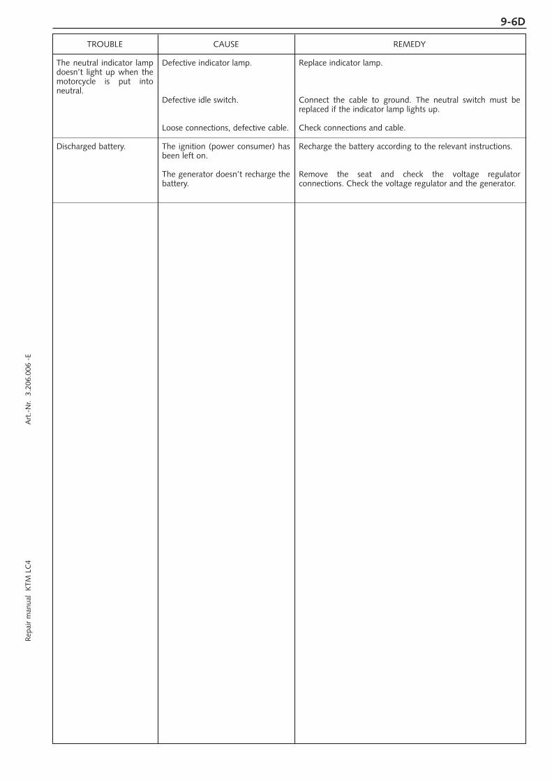
Rep
air
man
ual
KTM
LC
4 A
rt.-
Nr.
3.2
06.0
06 -
E9-6D
TROUBLE
The neutral indicator lampdoesn’t light up when themotorcycle is put intoneutral.
Discharged battery.
CAUSE
Defective indicator lamp.
Defective idle switch.
Loose connections, defective cable.
The ignition (power consumer) hasbeen left on.
The generator doesn’t recharge thebattery.
REMEDY
Replace indicator lamp.
Connect the cable to ground. The neutral switch must bereplaced if the indicator lamp lights up.
Check connections and cable.
Recharge the battery according to the relevant instructions.
Remove the seat and check the voltage regulatorconnections. Check the voltage regulator and the generator.

9-7D
TROUBLE SHOOTING LC4
TROUBLE
Engine doesn’t crank.
The engine doesn't crank.The neutral indicatorlamp doesn't light up.
The engine cranks onlywith pulled clutch lever
Engine cranks with gearengaged.
Engine cranks but doesn’tstart.
CAUSE
Operating errror
Discharged battery.
Defect ignition lock or emergencyOFF switch
Blown fuse safe-starting system.
Blown main fuse.
Defect safe-starting system.
Defect safe-starting system.
Operating error
The motorcycle has been out ofoperation for a longer period oftime. Therefore old fuel hasaccumulated in the float chamber
Fuel supply interrupted
Flooded engine
Sooty or wet spark plug
Electrode gap too large
Spark plug connector or spark plugfaulty
The plug connection of the CDI-unit, the pulse generator or theignition coil has oxydized
Water in carburetor or jets blocked
REMEDY
Turn on the ignition, switch the gear to neutral and switchthe emergency OFF switch on.
Recharge the battery and investigate the causes fordischarging.
Check ignition lock and emergency OFF switch.
Replace fuse (below the headlight mask).
Remove seat and replace the main fuse.
Check the components of the safe-starting system.
Check the components of the safe-starting system.
Open fuel tap, tank fuel, you did not use choke i.e. thewarmstart device. Pay attention to starting off information(see driving instructions).
The easily inflammable components of the new fuelsevaporate during longer periods of standstill.When the motorcycle has been out of operation for morethan a week, it is therefore recommended to drain the oldfuel from the float chamber. The engine will immediately startoff when the float chamber is filled with new fuel.
Loosen fuel hose at carburettor, lead into a basin and openfuel tap – if fuel leaks out, the carburetor might need cleaning– if no fuel leaks out, check tank ventilation, i.e. clean fuel tap
Fully open the throttle when starting or exchange the sparkplug, respectively
Clean and dry the spark plug or exchange it, respectively
Adjust spark plug electrode gap to 0,7 mm
Dismount spark plug, connect ignition cable, hold to ground(blank place on engine) and actuate starter, a strong sparkmust be produced at the spark plug– If no spark is created exchange the spark plug.– If the new spark plug doesn't produce a spark either,
disconnect the spark plug connector from the ignition cable,hold it a distance of approx. 5 mm from ground and start.
– If a spark now occurs, replace spark plug cap– If no spark is produced, control ignition system
Remove the seat, the right side cover and the fuel tank.Clean the plug connection and treat it with contact spray
Dismount and clean carburetor

Rep
air
man
ual
KTM
LC
4 A
rt.-
Nr.
3.2
06.0
06 -
E9-8D
TROUBLE
Engine fails to idle
Engine does not rev high
Engine will not reach fullpower
Engine overheats
High oil consumption
CAUSE
Glogged idling jet
Uncorrect adjustment of adjusting screws on carburetor
Defective spark plug
Defective ignition system
Carburetor fuel level too highbecause
Float needle is dirty or worn out
Float leaks
The cold starting system ispermanently activated due to alack of play in the choke cable.
Defective membrane of slide (640)
Loose carburettor jets
Electronic ignition timing faulty
Fuel supply partically interrupted orcarburetor dirty
Float leaks
Defective membrane of slide (640)
Air filter very dirty
Valve clearance to small
Loss of compression because handdecompressor has no play
Electronic ignition timing faulty
Insufficient cooling liquid
Radiator fins are extremely dirty
Foam forms in cooling system
Bent cooling hose
Thermostat defective
Blown fan fuse
Defect thermo switch
Fan defective
Buckling gear ventilation hose
Engine oil level too high
Engine oil too thin (viscosity)
REMEDY
Disassemble carburetor and clean jets
Adjust carburetor
Replace spark plug
Check ignition system
Dismount carburetor and check if worn out
Replace float needle
Replace float
Adjust choke cable.
Replace membrane
Tighten jets
Check pulse generator and ignition system
Clean and check fuel system as well as carburetor
Replace the float
Replace membrane
Clean or replace air filter
Adjust valve clearance
Check setting of the hand decompression cable
Check pulse generator and ignition system
Refill cooling liquid (see maintenace work), check coolingsystem for leaks
Clean radiator with water jet
Replace cooling liquid, use antifreezer with brand name
Shorten or replace cooling hose
Remove and check thermostat (opening temperature 70°C(158°F) or replace it.
Replace fuse and check if fan operates properly (see below)
Replace thermo switch
Check if fan operates properly. To do this, start the engine,then bypass the connections to the thermo switch (bottomright radiator).
Readjust or replace ventilation hose
Check engine oil level when the engine is warm; correct ifnecessary
Use thicker engine oil; see chapter „Engine oil“

9-9D
TROUBLE
All switched on lampsblown out
Headlight and parkinglight fail
Flasher lights, brake light,fan and horn fail
The NEUTRAL lamp isnot on even though thegear is in NEUTRAL
The battery is discharged
CAUSE
Voltage regulator faulty
Blown fuse
Blown fuse
Defect indicator lamp.
Defect neutral switch.
Loose connections, defect cable.
The ignition (power consumer)hasn’t been switched off
The battery isn’t charged by thegenerator
REMEDY
Remove seat and check connections. Check voltage regulator
Replace fuse (below the headlight mask).
Replace fuse (below the headlight mask).
Replace indicator lamp
Connect cable to ground; neutral switch must be replaced ifindicator lamp lights up.
Check connections and cables.
Recharge the battery according to the relevant instructions.
Remove seat and check voltage regulator connections; Checkvoltage regulator and generator.
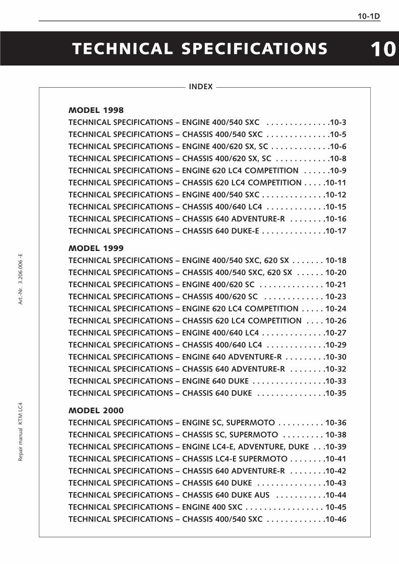
Rep
air
man
ual
KTM
LC
4 A
rt.-
Nr.
3.2
06.0
06 -
E
TECHNICAL SPECIFICATIONS
MODEL 1998
TECHNICAL SPECIFICATIONS – ENGINE 400/540 SXC . . . . . . . . . . . . . .10-3
TECHNICAL SPECIFICATIONS – CHASSIS 400/540 SXC . . . . . . . . . . . . . .10-5
TECHNICAL SPECIFICATIONS – ENGINE 400/620 SX, SC . . . . . . . . . . . . .10-6
TECHNICAL SPECIFICATIONS – CHASSIS 400/620 SX, SC . . . . . . . . . . . .10-8
TECHNICAL SPECIFICATIONS – ENGINE 620 LC4 COMPETITION . . . . . .10-9
TECHNICAL SPECIFICATIONS – CHASSIS 620 LC4 COMPETITION . . . . .10-11
TECHNICAL SPECIFICATIONS – ENGINE 400/540 SXC . . . . . . . . . . . . . .10-12
TECHNICAL SPECIFICATIONS – CHASSIS 400/640 LC4 . . . . . . . . . . . . .10-15
TECHNICAL SPECIFICATIONS – CHASSIS 640 ADVENTURE-R . . . . . . . .10-16
TECHNICAL SPECIFICATIONS – CHASSIS 640 DUKE-E . . . . . . . . . . . . . .10-17
MODEL 1999
TECHNICAL SPECIFICATIONS – ENGINE 400/540 SXC, 620 SX . . . . . . . 10-18
TECHNICAL SPECIFICATIONS – CHASSIS 400/540 SXC, 620 SX . . . . . . 10-20
TECHNICAL SPECIFICATIONS – ENGINE 400/620 SC . . . . . . . . . . . . . . 10-21
TECHNICAL SPECIFICATIONS – CHASSIS 400/620 SC . . . . . . . . . . . . . 10-23
TECHNICAL SPECIFICATIONS – ENGINE 620 LC4 COMPETITION . . . . . 10-24
TECHNICAL SPECIFICATIONS – CHASSIS 620 LC4 COMPETITION . . . . 10-26
TECHNICAL SPECIFICATIONS – ENGINE 400/640 LC4 . . . . . . . . . . . . . .10-27
TECHNICAL SPECIFICATIONS – CHASSIS 400/640 LC4 . . . . . . . . . . . . .10-29
TECHNICAL SPECIFICATIONS – ENGINE 640 ADVENTURE-R . . . . . . . . .10-30
TECHNICAL SPECIFICATIONS – CHASSIS 640 ADVENTURE-R . . . . . . . .10-32
TECHNICAL SPECIFICATIONS – ENGINE 640 DUKE . . . . . . . . . . . . . . . .10-33
TECHNICAL SPECIFICATIONS – CHASSIS 640 DUKE . . . . . . . . . . . . . . .10-35
MODEL 2000
TECHNICAL SPECIFICATIONS – ENGINE SC, SUPERMOTO . . . . . . . . . . 10-36
TECHNICAL SPECIFICATIONS – CHASSIS SC, SUPERMOTO . . . . . . . . . 10-38
TECHNICAL SPECIFICATIONS – ENGINE LC4-E, ADVENTURE, DUKE . . .10-39
TECHNICAL SPECIFICATIONS – CHASSIS LC4-E SUPERMOTO . . . . . . . .10-41
TECHNICAL SPECIFICATIONS – CHASSIS 640 ADVENTURE-R . . . . . . . .10-42
TECHNICAL SPECIFICATIONS – CHASSIS 640 DUKE . . . . . . . . . . . . . . .10-43
TECHNICAL SPECIFICATIONS – CHASSIS 640 DUKE AUS . . . . . . . . . . .10-44
TECHNICAL SPECIFICATIONS – ENGINE 400 SXC . . . . . . . . . . . . . . . . . 10-45
TECHNICAL SPECIFICATIONS – CHASSIS 400/540 SXC . . . . . . . . . . . . .10-46
INDEX
10-1D
10


Rep
air
man
ual
KTM
LC
4 A
rt.-
Nr.
3.2
06.0
06 -
E
MODEL 2001TECHNICAL SPECIFICATIONS – ENGINE 620 SC, SUPERMOTO . . . . . . 10-47TECHNICAL SPECIFICATIONS – CHASSIS 620 SC, SUPERMOTO . . . . . . 10-49TECHNICAL SPECIFICATIONS – ENGINE LC4-E, ADVENTURE, DUKE . . .10-50TECHNICAL SPECIFICATIONS – CHASSIS LC4-E, SUPERMOTO . . . . . . .10-52TECHNICAL SPECIFICATIONS – CHASSIS 640 LC4 ADVENTURE . . . . . .10-53TECHNICAL SPECIFICATIONS – CHASSIS 640 DUKE . . . . . . . . . . . . . . .10-54TECHNICAL SPECIFICATIONS – CHASSIS 640 DUKE USA, AUS . . . . . . .10-55
MODELL 2002TECHNICAL SPECIFICATIONS – ENGINE 625 SC, SUPERMOTO . . . . . . 10-56TECHNICAL SPECIFICATIONS – CHASSIS 625 SC, SUPERMOTO . . . . . . 10-57TECHNICAL SPECIFICATIONS – ENGINE 640 LC4, ADVENTURE, DUKE . . . 10-58TECHNICAL SPECIFICATIONS – CHASSIS 640 LC4, SUPERMOTO . . . . . 10-59TECHNICAL SPECIFICATIONS – CHASSIS 640 ADVENTURE . . . . . . . . . 10-60TECHNICAL SPECIFICATIONS – CHASSIS 640 DUKE . . . . . . . . . . . . . . . 10-61
MODELL 2003TECHNICAL SPECIFICATIONS – ENGINE 625 SXC . . . . . . . . . . . . . . . . . 10-62TECHNICAL SPECIFICATIONS – CHASSIS 625 SXC . . . . . . . . . . . . . . . . 10-63TECHNICAL SPECIFICATIONS – ENGINE 640 LC4, ADVENTURE, DUKE . . . 10-64TECHNICAL SPECIFICATIONS – CHASSIS 640 LC4, SUPERMOTO . . . . . 10-65TECHNICAL SPECIFICATIONS – CHASSIS 640 LC4 ADVENTURE . . . . . . 10-66TECHNICAL SPECIFICATIONS – CHASSIS 640 DUKE . . . . . . . . . . . . . . . 10-67TECHNICAL SPECIFICATIONS – ENGINE 660 SMC . . . . . . . . . . . . . . . . 10-68TECHNICAL SPECIFICATIONS – CHASSIS 660 SMC . . . . . . . . . . . . . . . 10-69
TIGHTENING TORQUESENGINE . . . . . . . . . . . . . . . . . . . . . . . . . . . . . . . . . . . . . . . . . . . . . . . .10-70CHASSIS . . . . . . . . . . . . . . . . . . . . . . . . . . . . . . . . . . . . . . . . . . . . . . . .10-71
ASSEMBLY CLEARANCE, WEAR LIMIT . . . . . . . . . . . . . . . . . . . . . . . . .10-72
INDEX
10-2D


Rep
air
man
ual
KTM
LC
4 A
rt.-
Nr.
3.2
06.0
06 -
E10-3D
Engi
ne40
0 LC
454
0 LC
4D
esig
nLi
quid
-coo
led
sing
le c
ylin
der
4-st
roke
eng
ine
with
and
with
out
bala
ncer
sha
ftD
ispl
acem
ent
398
cm3
538,
5 cm
3
Bore
/St
roke
89 /
64
mm
95 /
76
mm
Rat
io10
,8 :
111
,1 :
1Fu
elun
lead
ed p
rem
ium
gas
olin
e w
ith a
leas
t R
ON
95Va
lve
timin
g4
valv
es o
ver
rock
er a
rm a
nd 1
ove
rhea
d ca
msh
aft,
cam
shaf
t dr
ive
thro
ugh
sing
le c
hain
Cam
shaf
t24
9°(2
49/1
)Va
lve
timin
g by
1 m
mIO
22°
BTD
C
E
O 6
0°BB
DC
IO13
°BT
DC
EO
53°
BBD
Cva
lve
clea
renc
eIC
42°
ABD
C
E
C4°
ATD
CIC
51°
ABD
C
E
C 1
1°AT
DC
Valv
e di
amet
erIn
take
: 36
mm
Exh
aust
: 30
mm
Va
lve
clea
renc
e co
ldIn
take
: 0,2
0 m
m
Ex
haus
t: 0
,20
mm
Inta
ke: 0
,15
mm
Exha
ust:
0,1
5 m
mC
rank
sha
ft b
earin
g2
cylin
der
rolle
r be
arin
gC
onne
ctin
g ro
d be
arin
gne
edle
bea
ring
Top
end
bear
ing
bron
ze b
ushi
ngPi
ston
forg
ed/c
ast
alum
iniu
m a
lloy
Pist
on r
ings
1 co
mpr
essi
on r
ing,
1 t
aper
fac
e rin
g, 1
oil
scra
per
ring
Engi
ne lu
bric
atio
nfo
rced
-fee
d lu
bric
atio
n th
roug
h tw
o Ea
ton-
Oilp
umps
with
oil
sum
pEn
gine
oil
see
bello
w #
Engi
ne o
il qu
antit
y1,
40lit
ers
Prim
ary
ratio
stra
ight
gea
red
spur
whe
els
30
: 81
teet
hC
lutc
hm
ulti
disc
clu
tch
in o
il ba
thTr
ansm
issi
on5-
spee
d cl
aw s
hift
edG
ear
ratio
1st
14:3
52n
d15
:24
3rd
18:2
14t
h20
:19
5th
22:1
8Ig
nitio
n sy
stem
cont
actle
ss t
hyris
tor
igni
tion
with
ele
ctro
nic
adva
nced
sys
tem
typ
e SE
MIg
nitio
n tim
ing
400
SXC
: ad
just
men
t to
max
. 38
°BT
DC
at
6000
rpm
540
SXC
: ad
just
men
t to
max
. 32
°BT
DC
at
6000
rpm
Gen
erat
or12
V
130W
Spar
k pl
ugN
GK
D8E
ASp
ark
plug
gap
0,6
mm
Coo
ling
syst
emliq
uid
cool
ed, p
erm
anen
t ro
tatio
n of
coo
ling
liqui
d th
roug
h m
echa
nic
driv
en w
ater
pum
pC
oolin
g liq
uid
1lit
er, 4
0% a
ntifr
eeze
, 60%
wat
er, a
t le
ast
–25
°C
(–
13 °
F)St
artin
g eq
uipm
ent
deco
mpr
esso
r au
tom
atic
and
han
d ac
tuat
ed, c
old
and
hot
star
t kn
ob o
n ca
rbur
etor
TEC
HN
ICA
L S
PEC
IFIC
ATI
ON
S –
EN
GIN
E
400/5
40 S
XC
‘9
8
Cra
nk s
haft
axia
l pla
y....
......
......
......
......
......
.....0
,03
- 0,
12 m
m(0
,001
-0,0
05 in
)ru
n ou
t of
cra
nk s
tud
......
......
......
....m
ax. 0
,04
mm
(0,0
016
in)
Conn
ectin
g ro
d be
arin
gra
dial
pla
y...
......
......
......
......
......
......
max
. 0,0
5 m
m(0
,001
9 in
)ax
ial p
lay.
......
......
......
......
......
......
....m
ax. 1
,00
mm
(0,0
4 in
)
Pist
onas
sem
bly
clea
ranc
e 40
0/54
0/62
0...
max
. 0,1
2 m
m(0
,005
in)
Pist
on r
ings
end
gap
com
pres
sion
rings
......
......
......
......
....m
ax. 0
,60
mm
(0,0
23 in
)oi
l scr
aper
rin
g...
......
......
......
......
.....m
ax. 0
,80
mm
(0,0
31 in
)
Valv
es
seat
sea
ling
inta
ke...
......
......
......
......
max
. 1,5
0 m
m0,
059
in)
seat
sea
ling
exha
ust.
......
......
......
.....m
ax. 2
,00
mm
(0,0
79 in
)ru
n ou
t of
val
ve h
eads
......
......
......
..max
. 0,0
3 m
m(0
,001
in)
valv
e gu
ides
dia
met
er...
......
......
......
max
. 7,0
5 m
m(0
,277
in)
Oil
pum
pcl
eara
nce
oute
r ro
tor
- ho
usin
g...
....m
ax. 0
,20
mm
(0,0
08 in
)cl
eara
nce
oute
r ro
tor
- in
ner
roto
r...m
ax. 0
,20
mm
(0,0
08 in
)
Bypa
ß va
lve
min
imum
spr
ing
leng
ht...
......
......
......
......
....2
5 m
m(1
in)
Clu
tch
disc
sw
ear
limit
orga
nic
......
......
......
......
......
......
..2,5
mm
(0,1
in)
Tran
smiss
ion
shaf
tsax
ial p
lay.
......
......
......
......
......
......
......
0,1
- 0,
4 m
m(0
,004
in)
Clu
tch
min
imum
clu
tchs
prin
g le
nght
......
...34
,5 mm
(new
37 m
m)(1
,36 in
- ne
w 1,4
5 in)
TOLER
AN
CE,
ASSEM
BLY
CLEA
RA
NC
E

10-4D
Engi
ne o
ilU
se o
nly
oil b
rand
s, w
hich
mee
t qu
ality
req
uire
men
tsof
API
-cla
sses
SF,
SG
or
SH (
info
rmat
ions
on
bott
les)
or h
ighe
r. Bo
th,
min
eral
and
syn
thet
ic o
ils w
ith a
bove
spec
ifica
tions
can
be
used
.
! C
AU
TIO
N!
POO
RO
ILQ
UA
LITY
OR
MIN
OR
QU
AN
TITY
EFFE
CT
EAR
LYEN
GIN
E-W
EAR.
BA
SIC
CA
RB
UR
ETO
R S
ETT
ING
Car
bure
tor
Car
bure
tor
sett
ing
num
ber
Mai
n je
t
Nee
dle
jet
Idlin
g je
t
Jet
need
le
Nee
dle
posi
tion
from
top
Mix
ture
.adj
u. s
crew
ope
n
Thro
ttle
val
ve
Star
ting
jet
Perf
orm
ance
res
tric
tor
PHM
38
ND
1201
98
140
AB
265
50 K 3
2
II
1,5
turn
50/1
45 –
PHM
38
ND
1201
98
140
AB
265
50 K 3
2
II
1,5
turn
50/1
45
slid
e st
op 5
6mm
VH
SB 3
8 Q
S
0812
97
185
FN 2
60
33 K 3
2
II
1,5
turn
50 40 –
400
SXC
400
SXC
(20
kW
)54
0 SX
C
VH
SB 3
8 Q
S
0912
97
140
(185
)
FN 2
60
33 K 3
2
II
1,5
turn
50 40
slid
e st
op 3
6mm
540
SXC
(20
kW
)
#
–
+0°
C32
°F
15W
40
15W
50
15W
60
10W
40
10W
50
10W
60
API:
SF,
SG
, SH
TEM
PER
ATU
RE
Hex
agon
nut
at
prim
ary
gear
M20
x1,5
Loct
ite 2
43 +
170
Nm
(125
ft.
lb)
Col
lar
nut
flyw
heel
M12
x1 L
H t
hrea
d60
Nm
(44
ft.lb
)
Hex
agon
nut
for
inne
r cl
utch
hub
M18
x1,5
Loct
ite 2
43 +
80
Nm
(59
ft.lb
)
Kic
ksta
rter
sto
p bo
ltM
12x1
,550
Nm
(37
ft.lb
)
AH
bol
ts o
il pu
mp
M6
Loct
ite 2
43 +
8 N
m(6
ft.
lb)
Hex
agon
bol
t ca
msh
aft
gear
M10
Loct
ite 2
43 +
35
Nm
(26
ft.lb
)
AH
bol
t cy
linde
r he
ad t
op s
ect.
M6x
258
Nm
(6 f
t.lb
)
AH
bol
t cy
linde
r he
ad t
op s
ect.
M6x
50/M
6x55
(12
.9)
20 N
m(1
5 ft
.lb)
AH
bol
t cy
linde
r he
ad t
op s
ect.
M6x
65/M
6x70
(8.
8)8
Nm
(6 f
t.lb
)
Cyl
inde
r he
ad b
olts
M10
50 N
m(3
7 ft
.lb)
Col
lar
nuts
at
cylin
der
base
M10
40 N
m(3
0 ft
.lb)
Hex
agon
bol
t ch
ain
spro
cket
M10
Loct
ite 2
43 +
40
Nm
(30
ft.lb
)
Oil
drai
n pl
ugM
22x1
,530
Nm
(22
ft.lb
)
Mag
netic
plu
gM
12x1
,520
Nm
(15
ft.lb
)
Plug
byp
ass
valv
eM
12x1
,520
Nm
(15
ft.lb
)
Banj
o bo
lts o
il lin
esM
8x1
10 N
m(7
ft.
lb)
Banj
o bo
lt oi
l lin
esM
10x1
15 N
m(1
1 ft
.lb)
Jet
scre
w c
lutc
h co
ver
M8x
110
Nm
(7 f
t.lb
)
Bolt
plug
tim
ing-
chai
n te
nsio
ner
M12
x1,5
20 N
m(1
5 ft
.lb)
Cou
nter
nuts
val
ve a
djus
ting
scre
ws
M7x
0,75
20 N
m(1
5 ft
.lb)
Spar
k Pl
ugM
1220
Nm
(15
ft.lb
)
TIG
HTE
NIN
G T
OR
QU
ES -
EN
GIN
E

Rep
air
man
ual
KTM
LC
4 A
rt.-
Nr.
3.2
06.0
06 -
E10-5D
TEC
HN
ICA
L S
PEC
IFIC
ATI
ON
S -
CH
ASSIS
400/5
40
SXC
‘9
8
400
/540
SX
C
Fram
eC
entr
al c
hrom
e-m
oly-
stee
l fra
me
Fork
WP
Extr
eme
Whe
el t
rave
l fro
nt/r
ear
285/
320
mm
(11
,2/1
2,6
in)
Rea
r su
spen
sion
Cen
tral
sho
ck a
bsor
ber
(WP)
with
PR
O-L
EVER
link
age
to r
ear-
swin
garm
with
nee
dle
bear
ing
Fron
t br
ake
Dis
c br
ake
with
car
bon-
stee
l bra
ke d
isc
, bra
ke c
alip
er f
loat
ed
brak
e di
sc Ø
= 2
60 m
m (
10,2
in)
Rea
r br
ake
Dis
c br
ake
with
car
bon-
stee
l bra
ke d
isc
Ø22
0 m
m (
8,7
in),
bra
ke c
alip
er f
loat
ed
Tyre
sfr
ont
90/9
0-
21A
ir pr
essu
re o
ffro
ad1,
0 ba
r (1
4 ps
i)A
ir pr
ess.
road
, driv
er o
nly
1,5
bar
(21
psi)
Air p
ress
. roa
d w
ith p
asse
nger
–
Tyre
s re
ar14
0/80
- 18
Air
pres
sure
off
road
1,2
bar
(17
psi)
Air
pres
s. ro
ad, d
river
onl
y2,
0 ba
r (2
8 ps
i)Ai
r pre
ss. r
oad
with
pas
seng
er–
Fuel
tan
k ca
paci
ty9
liter
(3
US
gallo
ns)
of t
hat
1,5
liter
(0,
4 U
Sga
llons
) re
serv
e
Fina
l driv
e ra
tio40
0: 1
4:50
54
0:15
:50
Cha
in5 /8
x1 /4
" O
-Rin
g
Stee
ring
angl
e62
,5°
Whe
el b
ase
1510
±10
mm
(
59,4
±0,
4 in
)
Seat
hig
h94
0 m
m (
37 in
)
Gro
und
clea
ranc
e35
0 m
m (
13,8
in)
Dea
d w
eigh
t with
out f
uel
400:
12
1 kg
(26
7 lb
s)
540:
12
2 kg
(26
9 lb
s)
Col
lar
bolt
fron
t ax
leM
10
40 N
m(3
0 ft
.lb)
Brak
e ca
liper
fro
ntM
8Lo
ctite
243
+ 2
5 Nm
(18
ft.lb
)
Col
lar
nut
rear
axl
eM
20x
1,5
80 N
m(5
9 ft
.lb)
Hex
. nut
sw
ing
arm
bol
tM
14x
1,5
100
Nm
(74
ft.lb
)
Cla
mpi
ng b
olt
top
trip
le c
lam
pM
815
Nm
(11
ft.lb
)
Cla
mpi
ng b
olt
bott
om t
riple
cla
mp
M 8
20 N
m(1
5 ft
.lb)
Cla
mpi
ng b
olts
fork
leg
axle
pas
sage
M 8
10 N
m
(7,4
ft.
lb)
Oth
er b
olts
cha
ssis
M 6
10 N
m(7
,4 f
t.lb
)M
825
Nm
(18
ft.lb
)M
10
45 N
m(3
3 ft
.lb)
TOR
QU
ES
WP
09.1
8.S7
.44
Com
pres
sion
adj
uste
r12
Reb
ound
adj
uste
r12
Sprin
g4,
2 N
/mm
Sprin
g pr
eloa
d7
mm
Air
cham
ber
leng
th15
5 m
m
Cap
acity
per
for
k le
gca
800
ccm
Fork
oil
SAE
5
STA
ND
AR
D A
DJU
STM
EN
T -
FOR
K
NO
TE F
OR
WH
ITE
POW
ER F
OR
KS:
The
dam
ping
uni
ts in
the
left
and
the
rig
ht f
ork
leg
are
of d
iffer
ent
desi
gn.
Mak
esu
re n
ot t
o m
ix t
hem
up
in c
ase
of r
epai
r or
ser
vice
wor
ks.
WP
01.1
8.Q
7.82
Com
pres
sion
adj
uste
r3
Reb
ound
adj
uste
r4
Sprin
g63
/260
Sprin
g pr
eloa
d23
mm
STA
ND
AR
D-A
DJU
STM
EN
T -
SH
OC
K A
BSO
RB
ER

10-6D
Engi
ne40
0 LC
462
0 LC
4
Des
ign
Liqu
id-c
oole
d si
ngle
cyl
inde
r 4-
stro
ke e
ngin
e w
ith b
alan
cer
shaf
tD
ispl
acem
ent
398
cm3
609
cm3
Bore
/St
roke
89 /
64
mm
101
/ 76
mm
Rat
io10
,8 :
1SX
: 11,
5 : 1
SC
: 10,
4 : 1
Fuel
unle
aded
pre
miu
m g
asol
ine
with
a le
ast
RO
N95
Valv
e tim
ing
4 va
lves
ove
r ro
cker
arm
and
1 o
verh
ead
cam
shaf
t, c
amsh
aft
driv
e th
roug
h si
ngle
cha
inC
amsh
aft
249°
(249
)Va
lve
timin
g by
1 m
mIO
22°
BTD
C
E
O 5
9°BB
DC
IO14
°BT
DC
EO
56°
BBD
Cva
lve
clea
renc
eIC
47°
ABD
C
E
C10
°AT
DC
IC 5
5°A
BDC
EC
13°
ATD
CVa
lve
diam
eter
Inta
ke: 3
6 m
m
E
xhau
st: 3
0 m
m
Valv
e cl
eare
nce
cold
Inta
ke: 0
,20
mm
Exha
ust:
0,2
0 m
mIn
take
: 0,1
5 m
m
Ex
haus
t: 0
,15
mm
Cra
nk s
haft
bea
ring
2 cy
linde
r ro
ller
bear
ing
Con
nect
ing
rod
bear
ing
need
le b
earin
gTo
p en
d be
arin
gbr
onze
bus
hing
Pist
onfo
rged
/cas
t al
umin
ium
allo
yPi
ston
rin
gs1
com
pres
sion
rin
g, 1
tap
er f
ace
ring,
1 o
il sc
rape
r rin
gEn
gine
lubr
icat
ion
forc
ed-f
eed
lubr
icat
ion
thro
ugh
Eato
n-O
ilpum
p w
ith o
il su
mp
Engi
ne o
ilse
e be
llow
#En
gine
oil
quan
tity
1,40
lit
ers
Prim
ary
ratio
stra
ight
gea
red
spur
whe
els
30
: 81
teet
hC
lutc
hm
ulti
disc
clu
tch
in o
il ba
thTr
ansm
issi
on5-
spee
d cl
aw s
hift
edG
ear
ratio
1st
14:3
52n
d15
:24
3rd
18:2
14t
h20
:19
5th
22:1
8Ig
nitio
n sy
stem
cont
actle
ss t
hyris
tor
igni
tion
with
ele
ctro
nic
adva
nced
sys
tem
typ
e SE
MIg
nitio
n tim
ing
adju
stm
ent
to m
ax. 3
8 °
BTD
C a
t 60
00 r
pmSX
: ad
just
men
t to
max
. 38
°BT
DC
at
6000
rpm
SC:
adju
stm
ent
to m
ax. 3
2 °
BTD
C a
t 60
00 r
pmG
ener
ator
12V
13
0WSp
ark
plug
NG
K D
8EA
Spar
k pl
ug g
ap0,
6 m
mC
oolin
g sy
stem
liqui
d co
oled
, per
man
ent
rota
tion
of c
oolin
g liq
uid
thro
ugh
mec
hani
c dr
iven
wat
er p
ump
Coo
ling
liqui
d1
liter
, 40%
ant
ifree
ze, 6
0% w
ater
, at
leas
t –
25 °
C
(–13
°F)
Star
ting
equi
pmen
tde
com
pres
sor
auto
mat
ic a
nd h
and
actu
ated
, col
d an
d ho
t st
art
knob
on
carb
uret
or
TEC
HN
ICA
L S
PEC
IFIC
ATI
ON
S –
EN
GIN
E
400/6
20 S
X,
SC
‘9
8
Hex
agon
nut
at
prim
ary
gear
M20
x1,5
Loct
ite 2
43 +
170
Nm
(125
ft.
lb)
Col
lar
nut
flyw
heel
M12
x1 L
H t
hrea
d60
Nm
(44
ft.lb
)
Hex
agon
nut
for
inne
r cl
utch
hub
M18
x1,5
Loct
ite 6
48 +
80
Nm
(59
ft.lb
)
Kic
ksta
rter
sto
p bo
ltM
12x1
,570
Nm
(52
ft.lb
)
AH
bol
ts o
il pu
mp
M6
Loct
ite 2
43 +
8 N
m(6
ft.
lb)
Hex
agon
bol
t ca
msh
aft
gear
M10
35 N
m(2
6 ft
.lb)
AH
bol
t cy
linde
r he
ad t
op s
ect.
M6x
258
Nm
(6 f
t.lb
)
AH
bol
t cy
linde
r he
ad t
op s
ect.
M6x
50/M
6x55
(12
.9)
20 N
m(1
5 ft
.lb)
AH
bol
t cy
linde
r he
ad t
op s
ect.
M6x
65/M
6x70
(8.
8)8
Nm
(6 f
t.lb
)
Cyl
inde
r he
ad b
olts
M10
50 N
m(3
7 ft
.lb)
Col
lar
nuts
at
cylin
der
base
M10
40 N
m(3
0 ft
.lb)
Hex
agon
bol
t ch
ain
spro
cket
M10
Loct
ite 2
43 +
40
Nm
(30
ft.lb
)
Oil
drai
n pl
ugM
22x1
,530
Nm
(22
ft.lb
)
Mag
netic
plu
gM
12x1
,520
Nm
(15
ft.lb
)
Plug
byp
ass
valv
eM
12x1
,520
Nm
(15
ft.lb
)
Banj
o bo
lts o
il lin
esM
8x1
10 N
m(7
ft.
lb)
Banj
o bo
lt oi
l lin
esM
10x1
15 N
m(1
1 ft
.lb)
Jet
scre
w c
lutc
h co
ver
M8x
110
Nm
(7 f
t.lb
)
Bolt
plug
tim
ing-
chai
n te
nsio
ner
M12
x1,5
20 N
m(1
5 ft
.lb)
Cou
nter
nuts
val
ve a
djus
ting
scre
ws
M7x
0,75
20 N
m(1
5 ft
.lb)
Spar
k pl
ugM
1220
Nm
(15
ft.lb
)
TIG
HTE
NIN
G T
OR
QU
ES -
EN
GIN
E
Cra
nk s
haft
axia
l pla
y....
......
......
......
......
......
.....0
,03
- 0,
12 m
m(0
,001
-0,0
05 in
)ru
n ou
t of
cra
nk s
tud
......
......
......
....m
ax. 0
,04
mm
(0,0
016
in)
Conn
ectin
g ro
d be
arin
gra
dial
pla
y...
......
......
......
......
......
......
max
. 0,0
5 m
m(0
,001
9 in
)ax
ial p
lay.
......
......
......
......
......
......
....m
ax. 1
,00
mm
(0,0
4 in
)
Pist
onas
sem
bly
clea
ranc
e 40
0/62
0...
......
..max
. 0,1
2 m
m(0
,005
in)
Pist
on r
ings
end
gap
com
pres
sion
rings
......
......
......
......
....m
ax. 0
,60
mm
(0,0
23 in
)oi
l scr
aper
rin
g...
......
......
......
......
.....m
ax. 0
,80
mm
(0,0
31 in
)
Valv
es
seat
sea
ling
inta
ke...
......
......
......
......
max
. 1,5
0 m
m0,
059
in)
seat
sea
ling
exha
ust.
......
......
......
.....m
ax. 2
,00
mm
(0,0
79 in
)ru
n ou
t of
val
ve h
eads
......
......
......
..max
. 0,0
3 m
m(0
,001
in)
valv
e gu
ides
dia
met
er...
......
......
......
max
. 7,0
5 m
m(0
,277
in)
Oil
pum
pcl
eara
nce
oute
r ro
tor
- ho
usin
g...
....m
ax. 0
,20
mm
(0,0
08 in
)cl
eara
nce
oute
r ro
tor
- in
ner
roto
r...m
ax. 0
,20
mm
(0,0
08 in
)
Bypa
ß va
lve
min
imum
spr
ing
leng
ht...
......
......
......
......
....2
5 m
m(1
in)
Clu
tch
disc
sw
ear
limit
orga
nic
......
......
......
......
......
......
..2,5
mm
(0,1
in)
Tran
smiss
ion
shaf
tsax
ial p
lay.
......
......
......
......
......
......
......
0,1
- 0,
4 m
m(0
,004
in)
Clu
tch
min
imum
clu
tchs
prin
g le
nght
......
...34
,5 mm
(new
37 m
m)(1
,36 in
- ne
w 1,4
5 in)
TOLER
AN
CE,
ASSEM
BLY
CLEA
RA
NC
E

Rep
air
man
ual
KTM
LC
4 A
rt.-
Nr.
3.2
06.0
06 -
E10-7D
Engi
ne o
ilU
se o
nly
oil b
rand
s, w
hich
mee
t qu
ality
req
uire
men
tsof
API
-cla
sses
SF,
SG
or
SH (
info
rmat
ions
on
bott
les)
or h
ighe
r. Bo
th,
min
eral
and
syn
thet
ic o
ils w
ith a
bove
spec
ifica
tions
can
be
used
.
! C
AU
TIO
N!
POO
RO
ILQ
UA
LITY
OR
MIN
OR
QU
AN
TITY
EFFE
CT
EAR
LYEN
GIN
E-W
EAR.
BA
SIC
CA
RB
UR
ETO
R S
ETT
ING
Car
bure
tor
Car
bure
tor
sett
ing
num
ber
Mai
n je
t
Nee
dle
jet
Idlin
g je
t
Jet
need
le
Nee
dle
posi
tion
from
top
Mix
ture
.adj
u. s
crew
ope
n
Thro
ttle
val
ve
Star
ting
jet
Perf
orm
ance
res
tric
tor
PHM
38
SD
3008
96
150
DR
266
45 K 5
1
3 rd
1,5
turn
40 45
slid
e st
op 2
2 m
m
PHM
38
SD
4894
/6
190
DR
270
45 K 5
1
2 nd
1,5
turn
40 45 –
PHM
40
SD
1109
96
155
DR
268
45 K 5
1
3 rd
1,5
turn
40 45
slid
e st
op 2
6 m
m
PHM
40
SD
4922
195
DR
272
45 K 5
1
2 nd
1,5
turn
40 45 –
400
SC(2
0 kW
)40
0 SC
620
SC (
20 k
W)
620
SX62
0 SC
–
+0°C
32°F
15W
40
15W
50
15W
60
10W
40
10W
50
10W
60
API:
SF,
SG
, SH
TEM
PER
ATU
RE
#

10-8D
TEC
HN
ICA
L S
PEC
IFIC
ATI
ON
S -
CH
ASSIS
400 /
620
SX,
SC
‘9
8
620
SX40
0/6
20SC
Fram
eC
entr
al c
hrom
e-m
oly-
stee
l fra
me
Fork
WP
Extr
eme
Whe
el t
rave
l fro
nt/r
ear
285/
320
mm
(11
,2/1
2,6
in)
Rea
r su
spen
sion
Cen
tral
sho
ck a
bsor
ber
(WP)
with
PR
O-L
EVER
link
age
to r
ear-
swin
garm
with
nee
dle
bear
ing
Fron
t br
ake
Dis
c br
ake
with
car
bon-
stee
l bra
ke d
isc
, bra
ke c
alip
er f
loat
edbr
ake
disc
Ø =
260
mm
(10
,2 in
)
Rea
r br
ake
Dis
c br
ake
with
car
bon-
stee
l bra
ke d
isc
Ø22
0 m
m (
8,7
in),
bra
ke c
alip
er f
loat
ed
Tyre
sfr
ont
80/1
00-2
190
/90-
21A
ir pr
essu
re o
ffro
ad1,
0 ba
r (1
4 ps
i)1,
0 ba
r (1
4 ps
i)A
ir pr
ess.
roa
d, d
river
onl
y–
1,5
bar
(21
psi)
Tyre
s re
ar11
0/90
-19
140/
80-1
8 70
RA
ir pr
essu
re o
ffro
ad1,
2 ba
r (1
7 ps
i)1,
2 ba
r (1
7 ps
i)A
ir pr
ess.
roa
d, d
river
onl
y–
2,0
bar
(28
psi)
Fuel
tan
k ca
paci
ty9
liter
(3
US
gallo
ns)
of t
hat
1,5
liter
(0,
4 U
Sga
llons
) re
serv
e
Fina
l driv
e ra
tio14
:48,
14
:50,
15
:40,
15
:45,
15
:48
15:
50,
16:4
0,
16:4
5
Cha
in5 /8
x1 /4
"
Stee
ring
angl
e62
,5°
Whe
el b
ase
1510
±10
mm
(
59,4
±0,
4 in
)
Seat
hig
h94
0 m
m (
37 in
)
Gro
und
clea
ranc
e35
0 m
m (
13,8
in)
Dea
d w
eigh
t w
ithou
t fu
el11
5 kg
(25
4 lb
s)40
0 :
121
kg (
267
lbs)
620
: 12
2 kg
(26
9 lb
s)
Max
. per
miss
ible
front
axle
load
211
kg (
466
lbs)
Max
. per
miss
ible
rear
axl
e lo
ad33
5 kg
(73
7 lb
s)
Max
. per
miss
ible
lade
n w
eigh
t35
0 kg
(77
0 lb
s)
Col
lar
bolt
fron
t ax
leM
10
40 N
m(3
0 ft
.lb)
Brak
e ca
liper
fro
ntM
825
Nm
(19
ft.lb
)
+ L
octit
e 24
3
Col
lar
nut
rear
axl
eM
20x
1,5
80 N
m(5
9 ft
.lb)
Hex
. nut
sw
ing
arm
bol
tM
14x
1,5
100
Nm
(74
ft.lb
)
Cla
mpi
ng b
olt
top
trip
le c
lam
pM
8 (
Extr
eme)
15 N
m(1
1 ft
.lb)
M8
(USD
)15
Nm
(11
ft.lb
)
Cla
mpi
ng b
olt
bott
om t
riple
cla
mp
M 8
(Ex
trem
e)20
Nm
(15
ft.lb
)M
8 (U
SD)
15 N
m(1
1 ft
.lb)
Clam
ping
bol
ts fo
rk le
g ax
le p
assa
geM
7/M
87/
10 N
m
(5/7
ft.
lb)
Oth
er b
olts
cha
ssis
M6
10 N
m(7
ft.
lb)
M8
25 N
m(1
9 ft
.lb)
M10
45 N
m(3
3 ft
.lb)
TOR
QU
ES
WP
09.1
8.S7
.40
WP
09.1
8.S7
.44
Com
pres
sion
adj
uste
r8
12
Reb
ound
adj
uste
r12
12
Sprin
g4,
4 N
/mm
4,2
N/m
m
Sprin
g pr
eloa
d8
mm
7 m
m
Air
cham
ber
leng
th14
0 m
m15
5 m
m
Cap
acity
per
for
k le
gca
800
ccm
ca 8
00 c
cm
Fork
oil
SAE
5SA
E 5
STA
ND
AR
D A
DJU
STM
EN
T -
FOR
K
NO
TE F
OR
WH
ITE
POW
ER F
OR
KS:
The
dam
ping
uni
ts in
the
left
and
the
rig
ht f
ork
leg
are
of d
iffer
ent
desi
gn. M
ake
sure
not
to
mix
the
m u
p in
cas
e of
rep
air
or s
ervi
ce w
orks
.
WP
01.1
8.Q
7.82
WP
01.1
8.Q
7.81
Com
pres
sion
adj
uste
r3
3
Reb
ound
adj
uste
r4
4
Sprin
g63
/260
66/2
60
Sprin
g pr
eloa
d23
mm
23 m
m
STA
ND
AR
T-A
DJU
STM
EN
T -
SH
OC
K A
BSO
RB
ER

Rep
air
man
ual
KTM
LC
4 A
rt.-
Nr.
3.2
06.0
06 -
E10-9D
Engi
ne62
0 LC
4 C
OM
P.D
esig
nLi
quid
-coo
led
sing
le c
ylin
der
4-st
roke
eng
ine
with
bal
ance
r sh
aft
Dis
plac
emen
t60
9 cm
3
Bore
/St
roke
101
/ 76
mm
Rat
io10
,4 :
1Fu
elun
lead
ed p
rem
ium
gas
olin
e w
ith a
leas
t R
ON
95Va
lve
timin
g4
valv
es o
ver
rock
er a
rm a
nd 1
ove
rhea
d ca
msh
aft,
cam
shaf
t dr
ive
thro
ugh
sing
le c
hain
Cam
shaf
t24
9°(2
49/1
)Va
lve
timin
g by
1 m
mIO
15°
BTD
C
E
O 5
2°BB
DC
valv
e cl
eare
nce
IC 5
4°A
BDC
EC
17°
ATD
CVa
lve
diam
eter
Inta
ke: 3
6 m
m
E
xhau
st: 3
0 m
m
Valv
e cl
eare
nce
cold
Inta
ke: 0
,15
mm
Exha
ust:
0,1
5 m
mC
rank
sha
ft b
earin
g2
cylin
der
rolle
r be
arin
gC
onne
ctin
g ro
d be
arin
gne
edle
bea
ring
Top
end
bear
ing
bron
ze b
ushi
ngPi
ston
forg
ed/c
ast
alum
iniu
m a
lloy
Pist
on r
ings
1 co
mpr
essi
on r
ing,
1 t
aper
fac
e rin
g, 1
oil
scra
per
ring
Engi
ne lu
bric
atio
nfo
rced
-fee
d lu
bric
atio
n th
roug
h Ea
ton-
Oilp
ump
with
oil
sum
pEn
gine
oil
see
bello
w #
Engi
ne o
il qu
antit
y2,
1 li
ters
incl
udin
g fr
ame
Prim
ary
ratio
stra
ight
gea
red
spur
whe
els
30
: 81
teet
hC
lutc
hm
ulti
disc
clu
tch
in o
il ba
thTr
ansm
issi
on5-
spee
d cl
aw s
hift
edG
ear
ratio
1st
14:3
52n
d15
:24
3rd
18:2
14t
h20
:19
5th
22:1
8Ig
nitio
n sy
stem
cont
actle
ss t
hyris
tor
igni
tion
with
ele
ctro
nic
adva
nced
sys
tem
typ
e SE
MIg
nitio
n tim
ing
adju
stm
ent
to m
ax. 3
2 °
BTD
C a
t 60
00 r
pmG
ener
ator
12V
13
0WSp
ark
plug
NG
K D
R8E
ASp
ark
plug
gap
0,7
mm
Coo
ling
syst
emliq
uid
cool
ed, p
erm
anen
t ro
tatio
n of
coo
ling
liqui
d th
roug
h m
echa
nic
driv
en w
ater
pum
pC
oolin
g liq
uid
1lit
er, 4
0% a
ntifr
eeze
, 60%
wat
er, a
t le
ast
–25
°C
(–
13 °
F)St
artin
g eq
uipm
ent
deco
mpr
esso
r au
tom
atic
and
han
d ac
tuat
ed, c
old
and
hot
star
t kn
ob o
n ca
rbur
etor
TEC
HN
ICA
L S
PEC
IFIC
ATI
ON
S –
EN
GIN
E
620 L
C4 C
OM
PETI
TIO
N
‘98
Cra
nk s
haft
axia
l pla
y....
......
......
......
......
......
.....0
,03
- 0,
12 m
m(0
,001
-0,0
05 in
)ru
n ou
t of
cra
nk s
tud
......
......
......
....m
ax. 0
,08
mm
(0,0
031
in)
Conn
ectin
g ro
d be
arin
gra
dial
pla
y...
......
......
......
......
......
......
max
. 0,0
5 m
m(0
,001
9 in
)ax
ial p
lay.
......
......
......
......
......
......
....m
ax. 1
,00
mm
(0,0
4 in
)
Pist
onas
sem
bly
clea
ranc
e ...
......
......
......
....m
ax. 0
,12
mm
(0,0
05 in
)Pi
ston
rin
gs e
nd g
apco
mpr
essio
n rin
gs...
......
......
......
......
.max
. 0,6
0 m
m(0
,023
in)
oil s
crap
er r
ing
......
......
......
......
......
..max
. 0,8
0 m
m(0
,031
in)
Valv
es
seat
sea
ling
inta
ke...
......
......
......
......
max
. 1,5
0 m
m0,
059
in)
seat
sea
ling
exha
ust.
......
......
......
.....m
ax. 2
,00
mm
(0,0
79 in
)ru
n ou
t of
val
ve h
eads
......
......
......
..max
. 0,0
5 m
m(0
,002
in)
valv
e gu
ides
dia
met
er...
......
......
......
max
. 7,0
5 m
m(0
,277
in)
Oil
pum
pcl
eara
nce
oute
r ro
tor
- ho
usin
g...
....m
ax. 0
,20
mm
(0,0
08 in
)cl
eara
nce
oute
r ro
tor
- in
ner
roto
r...m
ax. 0
,20
mm
(0,0
08 in
)
Bypa
ß va
lve
min
imum
spr
ing
leng
ht...
......
......
......
......
....2
5 m
m(1
in)
Clu
tch
disc
sw
ear
limit
orga
nic
......
......
......
......
......
......
..2,5
mm
(0,1
in)
Tran
smiss
ion
shaf
tsax
ial p
lay.
......
......
......
......
......
......
......
0,1
- 0,
4 m
m(0
,004
in)
Clu
tch
min
imum
clu
tchs
prin
g le
nght
......
...34
,5 mm
(new
37 m
m)(1
,36 in
- ne
w 1,4
5 in)
ASSEM
BLY
CLEA
RA
NC
E,
WEA
R L
IMIT

10-10D
BA
SIC
CA
RB
UR
ETO
R S
ETT
ING
Car
bure
tor
Car
bure
tor
sett
ing
num
ber
Mai
n je
t
Nee
dle
jet
Idlin
g je
t
Jet
need
le
Nee
dle
posi
tion
from
top
Mix
ture
.adj
u. s
crew
ope
n
Thro
ttle
val
ve
Star
ting
jet
Perf
orm
ance
res
tric
tor
PHM
40
SD
1109
96
155
DR
268
45 K 5
1
3 rd
1,5
turn
40 45
slid
e st
op 2
6 m
m
620 L
C4 C
OM
P.
Hex
agon
nut
at
prim
ary
gear
M20
x1,5
Loct
ite 2
43 +
170N
m(1
25 f
t.lb
)
Col
lar
nut
flyw
heel
M12
x1 L
H t
hrea
d60
Nm
(44
ft.lb
)
Hex
agon
nut
for
inne
r cl
utch
hub
M18
x1,5
Loct
ite 2
43 +
80
Nm
(59
ft.lb
)
Kic
ksta
rter
sto
p bo
ltM
12x1
,550
Nm
(37
ft.lb
)
AH
bol
ts o
il pu
mp
M6
Loct
ite 2
43
+ 8
Nm
(6 f
t.lb
)
Hex
agon
bol
t ca
msh
aft
gear
M10
Loct
ite 2
43 +
35
Nm
(26
ft.lb
)
AH
bol
t cy
linde
r he
ad t
op s
ect.
M6x
258
Nm
(6 f
t.lb
)
AH
bol
t cy
linde
r he
ad t
op s
ect.
M6x
50/M
6x55
(12
.9)
20 N
m(1
5 ft
.lb)
AH
bol
t cy
linde
r he
ad t
op s
ect.
M6x
65/M
6x70
(8.
8)8
Nm
(6 f
t.lb
)
Cyl
inde
r he
ad b
olts
M10
50 N
m(3
7 ft
.lb)
Col
lar
nuts
at
cylin
der
base
M10
40 N
m(3
0 ft
.lb)
Hex
agon
bol
t ch
ain
spro
cket
M10
Loct
ite 2
43 +
40
Nm
(30
ft.lb
)
Oil
drai
n pl
ugM
22x1
,530
Nm
(22
ft.lb
)
Mag
netic
plu
gM
12x1
,520
Nm
(15
ft.lb
)
Plug
byp
ass
valv
eM
12x1
,520
Nm
(15
ft.lb
)
Banj
o bo
lts o
il lin
esM
8x1
10 N
m(7
ft.
lb)
Banj
o bo
lt oi
l lin
esM
10x1
15 N
m(1
1 ft
.lb)
Jet
scre
w c
lutc
h co
ver
M8x
110
Nm
(7 f
t.lb
)
Bolt
plug
tim
ing-
chai
n te
nsio
ner
M12
x1,5
20 N
m(1
5 ft
.lb)
Cou
nter
nuts
val
ve a
djus
ting
scre
ws
M7x
0,75
20 N
m(1
5 ft
.lb)
Spar
k pl
ugM
12
20 N
m(1
5 ft
.Ib)
TIG
HTEN
ING
TO
RQ
UES -
EN
GIN
E
Engi
ne o
ilU
se o
nly
oil b
rand
s, w
hich
mee
t qu
ality
req
uire
men
tsof
API
-cla
sses
SF,
SG
or
SH (
info
rmat
ions
on
bott
les)
or h
ighe
r. Bo
th,
min
eral
and
syn
thet
ic o
ils w
ith a
bove
spec
ifica
tions
can
be
used
.
! C
AU
TIO
N!
POO
RO
ILQ
UA
LITY
OR
MIN
OR
QU
AN
TITY
EFFE
CT
EAR
LYEN
GIN
E-W
EAR.
–
+0°C
32°F
15W
40
15W
50
15W
60
10W
40
10W
50
10W
60
API:
SF,
SG
, SH
TEM
PER
ATU
RE
#

Rep
air
man
ual
KTM
LC
4 A
rt.-
Nr.
3.2
06.0
06 -
E10-11D
TECHNICAL SPECIFICATIONS - CHASSIS 620 LC4 COMP. ‘98
620 LC4 COMP.
Frame Central chrome-moly-steel frame
Fork WP Extreme
Wheel travel front/rear 280 / 320 mm (11,0 / 12,6 in)
Rear suspension Central shock absorber (WP) with PRO-LEVER linkage to rear-swingarm with needle bearing
Front brake Disc brake with carbon-steel brake disc , brake caliper floated
brake disc Ø = 300 mm (11,8 in)
Rear brake Disc brake with carbon-steel brake disc Ø 220 mm (8,7 in), brake caliper floated
Tyres front 90/90-21 T63Air press. road, driver only 1,5 bar (21 psi)Air press. road with passenger 2,0 bar (28 psi)
Tyres rear 130/80-18 T63Air press. road, driver only 2,0 bar (28 psi)Air press. road with passenger 2,2 bar (31 psi)
Fuel tank capacity 12 liter (3,2 US gallons)of that 2,5 liter (0,7 US gallons) res
Final drive ratio 16:40
Chain O-ring 5/8 x 1/4"
Battery maintenance-free battery 12V 8Ah
Steering angle 62,5°
Wheel base 1510 ± 10 mm (59,4 ± 0,4 in)
Seat high 955 mm (37,6 in)
Ground clearance 335 mm (13,2 in)
Dead weight without fuel 133 kg (293 lbs)
Max. permissible front axle load 211 kg (466 lbs)
Max. permissible rear axle load 335 kg (737 lbs)
Max. permissible laden weight 350 kg (770 lbs)
Collar bolt front axle M 10 40 Nm (30 ft.lb)
Brake caliper front M 8 25 Nm (19 ft.lb)
+ Loctite 243
Collar nut rear axle M 20x1,5 80 Nm (59 ft.lb)
Hex. nut swing arm bolt M 14x1,5 100 Nm (74 ft.lb)
Clamping bolt top triple clamp M 8 15 Nm (11 ft.lb)
Clamping bolt bottom triple clamp M 8 20 Nm (15 ft.lb)
Clamping bolts fork leg axle passage M8 10 Nm (7 ft.lb)
Other bolts chassis M6 10 Nm (7 ft.lb)M8 25 Nm (19 ft.lb)M10 45 Nm (33 ft.lb)
TORQUES
918 S 757
Compression adjuster 12
Rebound adjuster 12
Spring 4,4 N/mm
Spring preload 10 mm
Air chamber length 160 mm
Capacity per fork leg ca. 800 ccm
Fork oil SAE 5
STANDARD ADJUSTMENT - FORK
NOTE FOR WP EXTREME FORKS:The damping units in the left and the right fork legare of different design. Make sure not to mix themup in case of repair or service works.
118 S 701Compression adjuster 3
Rebound adjuster 5
Spring 66/260
Spring preload 23 mm
STANDARD-ADJUSTMENT - SHOCK ABSORBER

10-12D
TECHNICAL DATA – ENGINE 400 / 640 LC4 ‘98
Engine 400 LC4 640 LC4
Design Liquid-cooled single cylinder 4-stroke engine with balancer shaft and electric starter
Displacement 398 ccm 624.6 ccm
Bore / Stroke 89 / 64 mm 101 / 78 mm
Ratio 10,8 : 1 11 : 1
Fuel unleaded premium gasoline with a least RON 95
Valve timing 4 valves over rocker arm and 1 overhead camshaft, camshaft drive through single chain
Camshaft 249° (249/1)
Valve timing by 1 mm IO 22° BTDC EO 60° BBDC IO 13° BTDC EO 53° BBDC
valve clearence IC 47° ABDC EC 4° ATDC IC 51° ABDC EC 11° ATDC
Valve diameter Intake: 36 mm Exhaust: 30 mm
Valve clearence cold Intake: 0,20 mm Exhaust: 0,20 mm 0,15 mm Exhaust: 0,15 mm
Crank shaft bearing 2 cylinder roller bearing
Connecting rod bearing needle bearing
Top end bearing bronze bushing
Piston forged/cast aluminium alloy
Piston rings 1 compression ring, 1 taper face ring, 1 oil scraper ring
Engine lubrication two Eaten-oilpumps
Engine oil see bellow #
Engine oil quantity appr. 2,1 liters including frame
Primary ratio straight geared spur wheels 30 : 81 teeth
Clutch multi disc clutch in oil bath
Transmission 5-speed claw shifted
Ignition system contactless DC-CDI ignition with digital advanced system type KOKUSAN
Ignition timing adjustment to max. 38° BTDC at 6000 rpm
Generator 12V 200W
Spark plug NGK DR8EA
Spark plug gap 0,7 mm
Cooling system liquid cooled, permanent rotation of cooling liquid through mechanic driven water pump
Cooling liquid 1 liter, 40% antifreeze, 60% water, at least –25 ° C (–13 ° F)
Starting equipment electric starter and kickstarter
Crank shaft axial play.............................................................................................0,03 - 0,12 mm (0,001-0,005 in)
run out of crank stud ............................................................................max. 0,08 mm (0,0031 in)
Connecting rod bearing radial play .............................................................................................max. 0,05 mm (0,0019 in)
axial play...............................................................................................max. 1,00 mm (0,04 in)
Piston assembly clearance ..............................................................................max. 0,12 mm (0,005 in)
Piston rings end gap compression rings .................................................................................max. 0,60 mm (0,023 in)
oil scraper ring ......................................................................................max. 0,80 mm (0,031 in)
Valves seat sealing intake.................................................................................max. 1,50 mm 0,059 in)
seat sealing exhaust ..............................................................................max. 2,00 mm (0,079 in)
run out of valve heads ..........................................................................max. 0,05 mm (0,002 in)
valve guides diameter ...........................................................................max. 7,05 mm (0,277 in)
Oil pump clearance outer rotor - housing .............................................................max. 0,20 mm (0,008 in)
clearance outer rotor - inner rotor.........................................................max. 0,20 mm (0,008 in)
Bypaß valve minimum spring lenght.....................................................................................25 mm (1 in)
Clutch discs wear limit organic ............................................................................................2,5 mm (0,1 in)
Transmission shafts axial play.................................................................................................0,1 - 0,4 mm (0,004 in)
Clutch minimum clutch spring lenght .................................................34,5 mm (new 37 mm)(1,36 in - new 1,45 in)
ASSEMBLY CLEARANCE, WEAR LIMIT

Rep
air
man
ual
KTM
LC
4 A
rt.-
Nr.
3.2
06.0
06 -
E10-13D
Engine oilUse only oil brands (Shell Advance Ultra 4), whichmeet quality requirements of API-classes SF, SG or SH(informations on bottles) or higher. Both, mineral andsynthetic oils with above specifications can be used.
! CAUTION !POOR OIL QUALITY OR MINOR QUANTITY EFFECT EARLYENGINE-WEAR.
Hexagon nut at primary gear M20x1,5 Loctite 243 + 170Nm (125 ft.lb)
Hexagon nut flywheel M16x1,25 LH thread 150 Nm (110 ft.lb)
Hexagon nut for inner clutch hub M18x1,5 80 Nm (59 ft.lb)
Kickstarter stop bolt M12x1,5 50 Nm (37 ft.lb)
Allen head bolts oil pump M6 Loctite 243 + 8 Nm (6 ft.lb)
Hexagon bolt camshaft gear M10 Loctite 243 + 35 Nm (26 ft.lb)
Allen head bolts outer race M6x12/M6x12,5 Loctite 648 + 18 Nm (13 ft.lb)
Allen head bolt cylinder head top sect. M6x50/M6x55 (12.9) 20 Nm (15 ft.lb)
Allen head bolt cylinder head top sect. M6x25/M6x65/M6x70 (8.8) 8 Nm (6 ft.lb)
Cylinder head bolts M10 50 Nm (37 ft.lb)
Collar nuts at cylinder base M10 40 Nm (30 ft.lb)
Hexagon bolt chain sprocket M10 Loctite 243 + 40 Nm (30 ft.lb)
Oil drain plug M22x1,5 30 Nm (22 ft.lb)
Magnetic plug M12x1,5 20 Nm (15 ft.lb)
Plug bypass valve M12x1,5 20 Nm (15 ft.lb)
Crankshaft locating bolt M8 25 Nm (18 ft.lb)
Hollow bolts oil lines M8x1 10 Nm (7 ft.lb)
Hollow bolts oil lines M10x1 15 Nm (11 ft.lb)
Jet screw clutch cover M8 10 Nm (7 ft.lb)
Bolt plug timing-chain tensioner M12x1,5 20 Nm (15 ft.lb)
Counternuts valve adjusting screws M7x0,75 20 Nm (15 ft.lb)
Engine fastening bolt M8 40 Nm (30 ft.lb)
M10 70 Nm (52 ft.lb)
TIGHTENING TORQUES - ENGINE
for chain5/8 x 1/4"
151617
3840424548
for chain5/8 x 1/4"
30:81
Primaryratio
Transmission Available chaindrive sprockets
Available finaldrive sprockets
GEAR RATIOS
1st gear 14:352nd gear 15:243rd gear 18:214th gear 20:195th gear 22:18
Original finaldrive ratio
15:4516:4016:4217:38
– +0°C32°F
15W 4015W 5015W 60
10W 4010W 5010W 60
API: SF, SG, SHTEMPERATURE
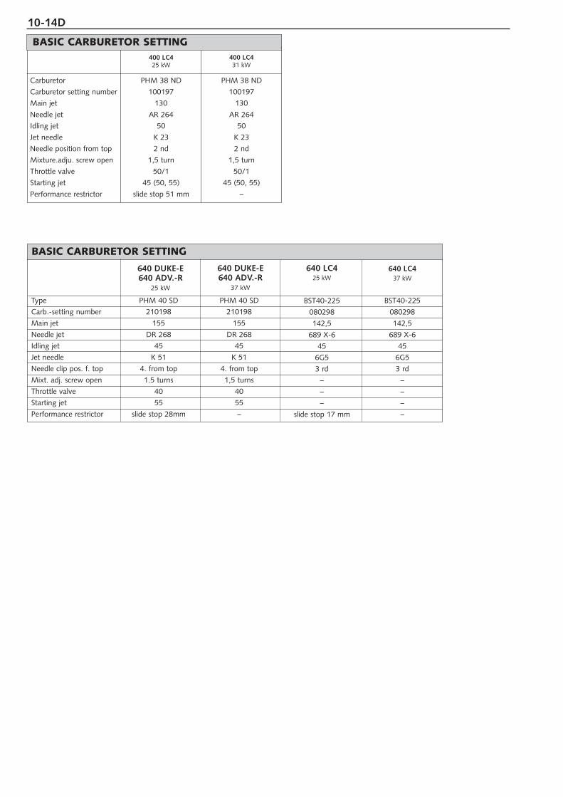
10-14D
BASIC CARBURETOR SETTING
Carburetor
Carburetor setting number
Main jet
Needle jet
Idling jet
Jet needle
Needle position from top
Mixture.adju. screw open
Throttle valve
Starting jet
Performance restrictor
PHM 38 ND
100197
130
AR 264
50
K 23
2 nd
1,5 turn
50/1
45 (50, 55)
slide stop 51 mm
PHM 38 ND
100197
130
AR 264
50
K 23
2 nd
1,5 turn
50/1
45 (50, 55)
–
400 LC425 kW
400 LC431 kW
BST40-225
080298
142,5
689 X-6
45
6G5
3 rd
–
–
–
slide stop 17 mm
BST40-225
080298
142,5
689 X-6
45
6G5
3 rd
–
–
–
–
640 LC425 kW
640 LC437 kW
BASIC CARBURETOR SETTING
Type PHM 40 SD PHM 40 SD
Carb.-setting number 210198 210198
Main jet 155 155
Needle jet DR 268 DR 268
Idling jet 45 45
Jet needle K 51 K 51
Needle clip pos. f. top 4. from top 4. from top
Mixt. adj. screw open 1.5 turns 1,5 turns
Throttle valve 40 40
Starting jet 55 55
Performance restrictor slide stop 28mm –
640 DUKE-E640 ADV.-R
25 kW
640 DUKE-E640 ADV.-R
37 kW
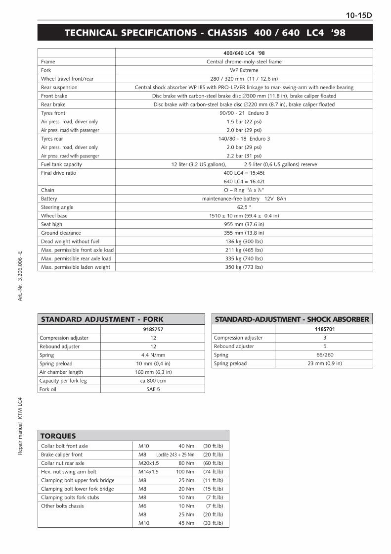
Rep
air
man
ual
KTM
LC
4 A
rt.-
Nr.
3.2
06.0
06 -
E10-15D
TECHNICAL SPECIFICATIONS - CHASSIS 400 / 640 LC4 ‘98
400/640 LC4 ‘98
Frame Central chrome-moly-steel frame
Fork WP Extreme
Wheel travel front/rear 280 / 320 mm (11 / 12.6 in)
Rear suspension Central shock absorber WP IBS with PRO-LEVER linkage to rear- swing-arm with needle bearing
Front brake Disc brake with carbon-steel brake disc 300 mm (11.8 in), brake caliper floated
Rear brake Disc brake with carbon-steel brake disc 220 mm (8.7 in), brake caliper floated
Tyres front 90/90 - 21 Enduro 3
Air press. road, driver only 1.5 bar (22 psi)
Air press. road with passenger 2.0 bar (29 psi)
Tyres rear 140/80 - 18 Enduro 3
Air press. road, driver only 2.0 bar (29 psi)
Air press. road with passenger 2.2 bar (31 psi)
Fuel tank capacity 12 liter (3.2 US gallons), 2.5 liter (0,6 US gallons) reserve
Final drive ratio 400 LC4 = 15:45t
640 LC4 = 16:42t
Chain O – Ring 5/8 x 1/4"
Battery maintenance-free battery 12V 8Ah
Steering angle 62,5 °
Wheel base 1510 ± 10 mm (59.4 ± 0.4 in)
Seat high 955 mm (37.6 in)
Ground clearance 355 mm (13.8 in)
Dead weight without fuel 136 kg (300 lbs)
Max. permissible front axle load 211 kg (465 lbs)
Max. permissible rear axle load 335 kg (740 lbs)
Max. permissible laden weight 350 kg (773 lbs)
118S701
Compression adjuster 3
Rebound adjuster 5
Spring 66/260
Spring preload 23 mm (0,9 in)
STANDARD-ADJUSTMENT - SHOCK ABSORBER918S757
Compression adjuster 12
Rebound adjuster 12
Spring 4,4 N/mm
Spring preload 10 mm (0,4 in)
Air chamber length 160 mm (6,3 in)
Capacity per fork leg ca 800 ccm
Fork oil SAE 5
STANDARD ADJUSTMENT - FORK
Collar bolt front axle M10 40 Nm (30 ft.lb)
Brake caliper front M8 Loctite 243 + 25 Nm (20 ft.lb)
Collar nut rear axle M20x1,5 80 Nm (60 ft.lb)
Hex. nut swing arm bolt M14x1,5 100 Nm (74 ft.lb)
Clamping bolt upper fork bridge M8 25 Nm (11 ft.lb)
Clamping bolt lower fork bridge M8 20 Nm (15 ft.lb)
Clamping bolts fork stubs M8 10 Nm (7 ft.lb)
Other bolts chassis M6 10 Nm (7 ft.lb)
M8 25 Nm (20 ft.lb)
M10 45 Nm (33 ft.lb)
TORQUES

10-16D
TEC
HN
ICA
L SP
ECIF
ICA
TIO
NS
- C
HA
SSIS
6
40
AD
VEN
TUR
E R
‘9
8
640
AD
VEN
TUR
E R
Fram
eC
entr
al c
hrom
e-m
oly-
stee
l fra
me
Fork
WP-
Extr
eme
Ø 5
0 m
m
Whe
el t
rave
l fro
nt/r
ear
300
/ 32
0 m
m
(11,
8 /
12,6
in)
Rea
r su
spen
sion
Cen
tral
sho
ck a
bsor
ber
WP
IBS
with
PR
O-L
EVER
link
age
to r
ear-
sw
ing-
arm
with
nee
dle
bear
ing
Fron
t br
ake
Dis
c br
ake
with
car
bon-
stee
l bra
ke d
isc
30
0 m
m (
11,8
in),
bra
ke c
alip
er f
loat
ed
Rea
r br
ake
Dis
c br
ake
with
car
bon-
stee
l bra
ke d
isc
22
0 m
m (
8,7
in),
bra
ke c
alip
er f
loat
ed
Tyre
s fr
ont
90/9
0 -
21
54S
En
duro
3
Air
pres
s. ro
ad, d
river
onl
y1,
5 ba
r (2
2 ps
i)
Air p
ress
. roa
d w
ith p
asse
nger
2,0
bar
(29
psi)
Tyre
s re
ar14
0/80
- 1
8 7
0R
Endu
ro 3
Air
pres
s. ro
ad, d
river
onl
y2,
0 ba
r (2
9 ps
i)
Air p
ress
. roa
d w
ith p
asse
nger
2,2
bar
(31
psi)
Fuel
tan
k ca
paci
ty28
lite
r (7
,4 U
S ga
llons
),
3,8
lite
r (1
US
gallo
ns)
rese
rve
Fina
l driv
e ra
tio16
:40
t
Cha
inO
– R
ing
5 /8x
1 /4"
Batt
ery
mai
nten
ance
-fre
e ba
tter
y
12V
8A
h
Stee
ring
angl
e62
,5 °
Whe
el b
ase
1510
±10
mm
(59
,4 ±
0,4
in)
Seat
hig
h94
0 m
m (
37 in
)
Gro
und
clea
ranc
e32
0 m
m (
12,6
in)
Dea
d w
eigh
t w
ithou
t fu
el15
4kg
(340
lbs)
Max
. per
miss
ible
front
axle
load
150
kg (
331
lbs)
Max
. per
miss
ible
rear
axle
load
230
kg (
507
lbs)
Max
. per
miss
ible
laden
weig
ht38
0 kg
(83
9 lb
s)
01.1
8.R
7.97
Com
pres
sion
adj
uste
r3
Reb
ound
adj
uste
r5
Sprin
g70
/260
Sprin
g pr
eloa
d23
mm
(0,
9 in
)
STA
ND
AR
D-A
DJU
STM
EN
T -
SH
OC
K A
BSO
RB
ER
09.1
8.S7
.55
Com
pres
sion
adj
uste
r14
Reb
ound
adj
uste
r12
Sprin
g4,
4 N
/mm
Sprin
g pr
eloa
d10
mm
(0,
4 in
)
Air
cham
ber
leng
th15
5 m
m (
5,9
in)
Cap
acity
per
for
k le
gca
800
ccm
Fork
oil
SAE5
STA
ND
AR
D A
DJU
STM
EN
T -
FOR
K
Col
lar
bolt
fron
t ax
leM
10
40 N
m(3
0 ft
.lb)
Col
lar
nut
rear
axl
eM
20x
1,5
80 N
m(5
9 ft
.lb)
Hex
. nut
sw
ing
arm
bol
tM
14x
1,5
100
Nm
(74
ft.lb
)
Cla
mpi
ng b
olt
uppe
r fo
rk b
ridge
M 8
15 N
m(1
1 ft
.lb)
Cla
mpi
ng b
olt
low
er f
ork
brid
geM
820
Nm
(15
ft.lb
)
Cla
mpi
ng b
olts
for
k st
ubs
M 8
10 N
m
(7 f
t.lb
)
Oth
er b
olts
cha
ssis
M6
10 N
m(7
ft.
lb)
M8
25 N
m(1
9 ft
.lb)
M10
45 N
m(3
3 ft
.lb)
TOR
QU
ES

Rep
air
man
ual
KTM
LC
4 A
rt.-
Nr.
3.2
06.0
06 -
E10-17D
TECHNICAL SPECIFICATIONS - CHASSIS KTM 640 DUKE-E ‘98
Type 640 DUKE last edition
Frame Central chrome-moly-steel frame
Fork type WP - 4054 Roma Top adjusterwheel travel 140 mm (5,5 in)standard adjustment compression driver only = 14, with passenger = 14standard adjustment rebound driver only = 14, with passenger = 14fork leg projection upper fork bridge 10 mm (0,4 in)oil capacity per fork leg appr. 740 ccm (45 cubic in) / SAE 5air chamber lenght 100 mm (4 in)
Rear suspension WP central shock absorber with PRO-LEVER linkage to rear- swing-arm with needle bearing
Shock absorber . . . . . . . . . . . . . . . . . . . . . . . . . . . . . . . . . . . . . . . . . . . . . typeWP central shock absorber BAVP
. . . . . . . . . . . . . . . . . . . . . . . . . . . . . . . . . . . . . . . . . . . . . . . . rear wheel travel170 mm (6.7 in)
. . . . . . . . . . . . . . . . . . . . . . . . . . . . . . . . . . . standard adjustment compressiondriver only = 3, with passenger = 5
. . . . . . . . . . . . . . . . . . . . . . . . . . . . . . . . . . . . . . standard adjustment rebounddriver only = 5, with passenger = 3 . . . . . . . . . . . . . . . . . . . . . . . . . . . . . . . . . . . . . . . . . . . . . . . . . . . . . . . . . . . .
spring preload . . . . . . . . . . . . . . driver only = 23 mm (0.9 in),with passenger = 28 mm (1.1 in). . . . . . . . . . . . . . . . . . . . . . . . . . . . . . . . . . . . . . . . . . . . . . . . . . . . spring type
70 - 260
Front brake Disc brake with carbon-steel brake disc Ø 320 mm (12,6 in) and 4-piston brake caliper
Rear brake Disc brake with carbon-steel brake disc Ø 220 mm (8,7 in) and single-piston brake caliper floated
Tyres front: 120/70 R 17 58H rear: 160/60 R 17 69HAir pressure rider only 2.0 bar (29 psi) 2.2 bar (32 psi)Air pressure with passenger 2.2 bar (32 psi) 2.4 bar (35 psi)
Fuel tank capacity 11,3 liter (3 US gallons), out of this 1,5 liter (0,42 US gallons) reserve
Final drive ratio 17 : 38
Chain o-ring 5/8 x 1/4"
Lamps low beam H1 12V 55W (socket P14,5s) HS1 12V 35/35W (socket Px43t)high beam H1 12V 55W (socket P14,5s) HS1 12V 35/55W (socket Px43t)parking light 12V 4W (socket Ba9s) 12V 4W (socket W2.1 9,5D)speedometer, tachometer light 12V 1,2W (socket W2x4,6d) 12V 1,2W (socket W2x4.6d)indicator lamp 12V 1,2W (socket W2x4,6d) 12V 1,2W (socket W2x4.6d)stop and taillight 12V 21/5W (socket BaY15d) 12V 21/5W (socket BaY15d)flasher 12V 10W (socket Ba15s) 12V 10W (socket Ba15s)
Battery maintenance-free battery 12V 8Ah
Steering angle 62,5°
Wheel base 1460 ± 15 mm (57.5 ± 0.6 in)
Seat high 860 mm (33.9 in)
Ground clearance 250 mm (9.9 in)
Front axle M 17 40 Nm (30 ft.lb)
Rear axle M 20x1.5 80 Nm (59 ft.lb)
Hex. nut swing arm bolt M 14x1.5 100 Nm (74 ft.lb)
Clamping bolt upper fork bridge M 8 15 Nm (18 ft.lb)
Clamping bolt lower fork bridge M 8 15 Nm (11 ft.lb)
AH bolts front brake caliper M10 40 Nm (30 ft.lb)
AH bolt rear brake caliper support M10 40 Nm (30 ft.lb)
Collar nuts chain tension eccentrics M10 40 Nm (30 ft.lb)
Clamping bolts fork stubs M 8 15 Nm (11 ft.lb)
Other bolts chassis M6 10 Nm (7 ft.lb)M8 25 Nm (22 ft.lb)M10 45 Nm (33 ft.lb)
TORQUES

10-18D
Carburetor
Carburetor setting number
Main jet
Needle jet
Idling jet
Jet needle
Needle position from top
Mixture.adju. screw open
Throttle valve
Starting jet
Performance restrictor
Pump jet
PHM 38 ND
120198
150 (155)
AB 265
52 (50)
K 11
I
1,5 turn
50/1
45
–
33 (38)
PHM 38 ND
120198
150 (155)
AB 265
52 (50)
K 11
I
1,5 turn
50/1
45
slide stop 48mm
33 (38)
VHSB 38 QS
081297
185
FN 260 (FN 258)
33
K 35 (K 32)
II
1,5 turn
50
40
–
–
VHSB 38 QS
091297
140 (185)
FN 260 (FN 258)
33
K 35 (K32)
II
1,5 turn
50
40
slide stop 36mm
–
PHM 40 SD
4922
195
DR 272
45
K 51
II
1,5 turn
40
45
–
–
400 SXC 400 SC (20 kW) 540 SXC 540 SXC (20 kW) 620 SX
Engine 400 SXC 540 SXC 620 SX
Design Liquid-cooled single cylinder 4-stroke engine
Displacement 398 ccm 538,5 ccm 609 ccm
Bore / Stroke 89 / 64 mm 101 / 76 mm
Ratio 10,8 : 1 11,3 : 1 11,5 : 1
Fuel unleaded premium gasoline with at least RON 95
Valve timing 4 valves over rocker arm and 1 overhead camshaft, camshaft drive through single chain
Camshaft 249/1
Valve timing by 1 mm IO 22° BTDC EO 60° BBDC IO 13° BTDC EO 53° BBDC
valve clearance IC 42° ABDC EC 4° ATDC IC 51° ABDC EC 11° ATDC
Valve diameter Intake: 36 mm Exhaust: 30 mm
Valve clearance cold Intake: 0,20 mm Exhaust: 0,20 mm Intake: 0,15 mm Exhaust: 0,15 mm
Crankshaft bearing 2 cylinder roller bearing
Conrod bearing needle bearing
Top end bearing bronze bushing
Piston forged/cast aluminium alloy
Piston rings 1 compression ring, 1 taper face ring, 1 oil scraper ring
Engine lubrication forced-feed lubrication through 2 Eaten-oilpumps
Engine oil see bellow #
Engine oil quantity 1,45 liters (0,38 US gallons)
Primary ratio straight geared spur wheels 30 : 81 teeth
Clutch multi disc clutch in oil bath
Transmission 5-speed claw shifted
Gear ratio 1st 14:35
2nd 15:24
3rd 18:21
4th 20:19
5th 22:18
Ignition system contactless thyristor ignition with electronic advanced system type SEM
Ignition timing 400 SXC/620 SX: adjustment to max. 38 ° BTDC at 6000 rpm
540 SXC: adjustment to max. 32 ° BTDC at 6000 rpm
Generator 12V 130W
Spark plug NGK D8EA NGK DPR8 EA-9
Spark plug gap 0,90 mm
Cooling system liquid cooled, permanent rotation of cooling liquid through mechanic driven water pump
Cooling liquid 1 liter, 40% antifreeze, 60% water, at least –25°C (–13°F)
Starting equipment decompressor automatic and hand actuated, cold and hot start knob on carburetor
TECHNICAL SPECIFICATIONS – ENGINE 400/540 SXC, 620 SX ‘99
BASIC CARBURETOR SETTING

10-19DR
epai
r m
anua
l K
TM L
C4
Art
.-N
r. 3
.206
.006
-E
Engine oilUse only oil brands, (Shell Advance Ultra 4) which meetquality requirements of API-classes SF, SG or SH(informations on bottles) or higher. Both, mineral andsynthetic oils with above specifications can be used.
! CAUTION !POOR OIL QUALITY OR MINOR QUANTITY EFFECT EARLY ENGINE-WEAR.
#
Hexagon nut at primary gear M 20x1,5 Loctite 243 +170 Nm (125 ft.lb)
Collar nut flywheel M 12x1 LH thread 60 Nm (44 ft.lb)
Hexagon nut for inner clutch hub M 18x1,5 Loctite 648 + 80 Nm (59 ft.lb)
Kickstarter stop bolt M 12x1,5 50 Nm (37 ft.lb)
AH bolts oil pump M 6 Loctite 243 + 8 Nm (6 ft.lb)
Hexagon bolt camshaft gear M 10 Loctite 243 + 35 Nm (26 ft.lb)
AH bolt cylinder head top sect. M 6x25 8 Nm (6 ft.lb)
AH bolt cylinder head top sect. M 6x50/M 6x55 (12.9) 20 Nm (15 ft.lb)
AH bolt cylinder head top sect. M 6x65/M 6x70 (8.8) 8 Nm (6 ft.lb)
Cylinder head bolts M 10 50 Nm (37 ft.lb)
Collar nuts at cylinder base M 10 40 Nm (30 ft.lb)
Hexagon bolt chain sprocket M 10 Loctite 243 + 40 Nm (30 ft.lb)
Oil drain plug M 22x1,5 30 Nm (22 ft.lb)
Magnetic plug M 12x1,5 20 Nm (15 ft.lb)
Plug bypass valve M 12x1,5 20 Nm (15 ft.lb)
Banjo bolts oil lines M 8x1 10 Nm (7 ft.lb)
Banjo bolt oil lines M 10x1 15 Nm (11 ft.lb)
Jet screw clutch cover M 8x1 10 Nm (7 ft.lb)
Bolt plug timing-chain tensioner M 12x1,5 20 Nm (15 ft.lb)
Counternuts valve adjusting screws M 7x0,75 20 Nm (15 ft.lb)
Spark plug M 12x1,25 20 Nm (15 ft.Ib)
Crankshaft locking bolt M 8 25 Nm 18 ft.lb)
Engine fastening bolt M 8 40 Nm (30 ft.lb)
M 10 70 Nm (51 ft.lb)
TIGHTENING TORQUES - ENGINE
Crank shaft axial play..................................................0,03 - 0,12 mm (0,001-0,005 in)
run out of crank stud .................................max. 0,08 mm (0,003 in)
Conrod bearing radial play ..................................................max. 0,05 mm (0,002 in)
axial play ...................................................max. 1,00 mm (0,04 in)
Piston forged assembly clearance ...................................max. 0,12 mm (0,005 in)
Piston cast assembly clearance ...................................max. 0,05 mm (0,002 in)
Piston rings end gap compression rings ......................................max. 0,60 mm (0,023 in)
oil scraper ring ...........................................max. 0,80 mm (0,031 in)
Valves seat sealing intake......................................max. 1,50 mm 0,059 in)
seat sealing exhaust ...................................max. 2,00 mm (0,080 in)
run out of valve heads ...............................max. 0,03 mm (0,001 in)
valve guides diameter ................................max. 7,05 mm (0,277 in)
Oil pump clearance outer rotor - housing..................max. 0,20 mm (0,008 in)
clearance outer rotor - inner rotor..............max. 0,20 mm (0,008 in)
Bypaß valve minimum spring length..........................................25 mm (1 in)
Clutch discs wear limit organic .................................................2,5 mm (0,1 in)
Clutch springs minimum length...........................34,5 mm (new 37 mm) (1,36 in - new 1,45 in)
Transmission shafts axial play......................................................0,1 - 0,4 mm (0,004 - 0,016 in)
ASSEMBLY CLEARANCE, WEAR LIMIT
– +0°C32°F
15W 4015W 5015W 60
10W 4010W 5010W 60
API: SF, SG, SHTEMPERATUR

10-20D
TECHNICAL SPECIFICATIONS - CHASSIS 400/540 SXC, 620 SX ‘99
400/540 SXC 620 SX
Frame Central chrome-moly-steel frame
Fork WP Extreme
Wheel travel front/rear 280/320 mm (11/12,6 in)
Rear suspension Central shock absorber (WP) with PRO-LEVER linkage to rear-swingarm with needle bearing
Front brake Disc brake with carbon-steel brake disc Ø 260 mm (10,2 in), brake caliper floated
Rear brake Disc brake with carbon-steel brake disc Ø 220 mm (8,7 in), brake caliper floated
Tyres front 90/90-21 54R 80/100-21 51M
Air pressure offroad 1,0 bar (14 psi) 1,0 bar (14 psi)
Air press. road, driver only – 1,5 bar (21 psi)
Tyres rear 140/80-18 70R 110/90-19 62M
Air pressure offroad 1,2 bar (17 psi) 1,2 bar (17 psi)
Air press. road, driver only 2,0 bar (28 psi) –
Fuel tank capacity 9 liter (3 US gallons) of that 1,5 liter (0,4 US gallons) reserve
Final drive ratio 400 = 14 : 50, 540 = 15 : 50 15 : 50
Chain 5/8 x 1/4 "
Steering angle 62,5°
Wheel base 1510 ± 10 mm (59,4 ± 0,4 in)
Seat high 940 mm (37 in)
Ground clearance 375 mm (14,8 in)
Dead weight without fuel 121 kg (267 lbs) 117 kg (258 lbs)
09.18.S7.40 09.18.S7.44
Compression adjuster 8 12
Rebound adjuster 12 12
Spring 4,4 N/mm 4,2 N/mm
Spring preload 8 mm 7 mm
Air chamber length 140 mm 155 mm
Capacity per fork leg ca 800 ccm ca 800 ccm
Fork oil SAE 5 SAE 5
STANDARD ADJUSTMENT - FORK
NOTE FOR WHITE POWER FORKS:The damping units in the left and the right fork leg are of differentdesign. Make sure not to mix them up in case of repair or service works.
01.18.S7.98 01.18.Q7.82
Compression adjuster 3 3
Rebound adjuster 5 4
Spring 66/260 63/260
Spring preload 17 mm 23 mm
Collar bolt front axle M 10 40 Nm (30 ft.lb)
Brake caliper front M 8 Loctite 243 + 25 Nm (18 ft.lb)
Collar nut rear axle M 20x1,5 80 Nm (59 ft.lb)
Hex. nut swing arm bolt M 14x1,5 100 Nm (74 ft.lb)
Clamping bolt top triple clamp M 8 15 Nm (11 ft.lb)
Clamping bolt bottom triple clamp M 8 20 Nm (15 ft.lb)
Clamping bolts fork leg axle passage M 8 10 Nm (7 ft.lb)
Other bolts chassis M 6 10 Nm (7 ft.lb)
M 8 25 Nm (18 ft.lb)
M 10 45 Nm (33 ft.lb)
TIGHTENING TORQUES - CHASSIS
STANDARD ADJUSTMENT - SHOCK ABSORBER

10-21DR
epai
r m
anua
l K
TM L
C4
Art
.-N
r. 3
.206
.006
-E
Engine 400 LC4 620 LC4
Design Liquid-cooled single cylinder 4-stroke engine with balancer shaft
Displacement 398 ccm 609 ccm
Bore / Stroke 89 / 64 mm 101 / 76 mm
Ratio 10,8 : 1 10,4 : 1
Fuel unleaded premium gasoline with a least RON 95
Valve timing 4 valves over rocker arm and 1 overhead camshaft, camshaft drive through single chain
Camshaft 249/1
Valve timing by 1 mm IO 22° BTDC EO 60° BBDC IO 15° BTDC EO 52° BBDC
valve clearance IC 42° ABDC EC 4° ATDC IC 54° ABDC EC 17° ATDC
Valve diameter Intake: 36 mm Exhaust: 30 mm
Valve clearance cold Intake: 0,20 mm Exhaust: 0,20 mm Intake: 0,15 mm Exhaust: 0,15 mm
Crank shaft bearing 2 cylinder roller bearing
Conrod bearing needle bearing
Top end bearing bronze bushing
Piston cast aluminium alloy
Piston rings 1 compression ring, 1 taper face ring, 1 oil scraper ring
Engine lubrication forced-feed lubrication through 2 Eaten-oilpumps
Engine oil see bellow #
Engine oil quantity 1,6 liters (0,42 US gallons)
Primary ratio straight geared spur wheels 30 : 81 teeth
Clutch multi disc clutch in oil bath
Transmission 5-speed claw shifted
Gear ratio 1st 14:35
2nd 15:24
3rd 18:21
4th 20:19
5th 22:18
Ignition system contactless thyristor ignition with electronic advanced system type KOKUSAN
Ignition timing adjustment to max. 40 ° BTDC at 5000 rpm adjustment to max. 36 ° BTDC at 5000 rpm
Generator 12V 110W
Spark plug NGK DPR8 EA-9
Spark plug gap 0,90 mm
Cooling system liquid cooled, permanent rotation of cooling liquid through mechanic driven water pump
Cooling liquid 1 liter, 40% antifreeze, 60% water, at least –25°C (–13°F)
Starting equipment decompressor automatic and hand actuated, cold and hot start knob on carburetor
TECHNICAL SPECIFICATIONS – ENGINE 400/620 Supercompetition ‘99
Carburetor
Carburetor setting number
Main jet
Needle jet
Idling jet
Jet needle
Needle position from top
Mixture.adj. screw open
Throttle valve
Starting jet
Performance restrictor
PHM 38 SD
300896
150
DR 266
45
K 51
3 rd
1,5 turn
40
45
slide stop 22 mm
PHM 38 SD
4894/6
190
DR 270 (DR 272)
45
K 51
2 nd
1,5 turn
40
45
–
PHM 40 SD
110996
155
DR 268
45
K 51
3 rd
1,5 turn
40
45
slide stop 26 mm
PHM 40 SD
4922
195
DR 272
45
K 51
2 nd
1,5 turn
40
45
–
400 SC (20 kW) 400 SC 620 SC (20 kW) 620 SC
BASIC CARBURETOR SETTING

10-22D
Engine oilUse only oil brands (Shell Advance Ultra 4), whichmeet quality requirements of API-classes SF, SG or SH(informations on bottles) or higher. Both, mineral andsynthetic oils with above specifications can be used.
! CAUTION !POOR OIL QUALITY OR MINOR QUANTITY EFFECT EARLYENGINE-WEAR.
#
Hexagon nut at primary gear M 20x1,5 Loctite 243 +170 Nm (125 ft.lb)
Collar nut flywheel M 12x1 LH thread 60 Nm (44 ft.lb)
Hexagon nut for inner clutch hub M 18x1,5 Loctite 648 + 80 Nm (59 ft.lb)
Kickstarter stop bolt M 12x1,5 50 Nm (37 ft.lb)
AH bolts oil pump M 6 Loctite 243 + 8 Nm (6 ft.lb)
Hexagon bolt camshaft gear M 10 Loctite 243 + 35 Nm (26 ft.lb)
AH bolt cylinder head top sect. M 6x25 8 Nm (6 ft.lb)
AH bolt cylinder head top sect. M 6x50/M 6x55 (12.9) 20 Nm (15 ft.lb)
AH bolt cylinder head top sect. M 6x65/M6x70 (8.8) 8 Nm (6 ft.lb)
Cylinder head bolts M 10 50 Nm (37 ft.lb)
Collar nuts at cylinder base M 10 40 Nm (30 ft.lb)
Hexagon bolt chain sprocket M 10 Loctite 243 + 40 Nm (30 ft.lb)
Oil drain plug M 22x1,5 30 Nm (22 ft.lb)
Magnetic plug M 12x1,5 20 Nm (15 ft.lb)
Plug bypass valve M 12x1,5 20 Nm (15 ft.lb)
Banjo bolts oil lines M 8x1 10 Nm (7 ft.lb)
Banjo bolt oil lines M 10x1 15 Nm (11 ft.lb)
Jet screw clutch cover M 8x1 10 Nm (7 ft.lb)
Bolt plug timing-chain tensioner M 12x1,5 20 Nm (15 ft.lb)
Counternuts valve adjusting screws M 7x0,75 20 Nm (15 ft.lb)
Spark plug M 12x1,25 20 Nm (15 ft.Ib)
Crankshaft locking bolt M 8 25 Nm 18 ft.lb)
Engine fastening bolt M 8 40 Nm (30 ft.lb)
M 10 70 Nm (51 ft.lb)
TIGHTENING TORQUES - ENGINE
Crank shaft axial play..................................................0,03 - 0,12 mm (0,001-0,005 in)
run out of crank stud .................................max. 0,04 mm (0,002 in)
Conrod bearing radial play ..................................................max. 0,05 mm (0,002 in)
axial play ...................................................max. 1,00 mm (0,04 in)
Piston forged assembly clearance ...................................max. 0,12 mm (0,005 in)
Piston cast assembly clearance ...................................max. 0,05 mm (0,002 in)
Piston rings end gap compression rings ......................................max. 0,60 mm (0,023 in)
oil scraper ring ...........................................max. 0,80 mm (0,031 in)
Valves seat sealing intake......................................max. 1,50 mm 0,059 in)
seat sealing exhaust ...................................max. 2,00 mm (0,080 in)
run out of valve heads ...............................max. 0,03 mm (0,001 in)
valve guides diameter ................................max. 7,05 mm (0,277 in)
Oil pump clearance outer rotor - housing..................max. 0,20 mm (0,008 in)
clearance outer rotor - inner rotor..............max. 0,20 mm (0,008 in)
Bypaß valve minimum spring length..........................................25 mm (1 in)
Clutch discs wear limit organic .................................................2,5 mm (0,1 in)
Clutch springs minimum length...........................34,5 mm (new 37 mm) (1,36 in - new 1,45 in)
Transmission shafts axial play......................................................0,1 - 0,4 mm (0,004 - 0,016 in)
ASSEMBLY CLEARANCE, WEAR LIMIT
– +0°C32°F
15W 4015W 5015W 60
10W 4010W 5010W 60
API: SF, SG, SHTEMPERATURE

10-23DR
epai
r m
anua
l K
TM L
C4
Art
.-N
r. 3
.206
.006
-E
TECHNICAL SPECIFICATIONS - CHASSIS 400 / 620 Supercompetition ‘99
400 SC 620 SC
Frame Central chrome-moly-steel frame
Fork White Power – Up Side Down 43
Wheel travel front/rear 295 / 320 mm (11,6 / 12,6 in)
Rear suspension Central shock absorber (WP) with PRO-LEVER linkage to rear-swingarm with needle bearing
Front brake Disc brake with carbon-steel brake disc Ø 260 mm (10,2 in), brake caliper floated
Rear brake Disc brake with carbon-steel brake disc Ø 220 mm (8,7 in), brake caliper floated
Tyres front 90/90-21 54R
Air pressure offroad 1,0 bar (14 psi)
Air press. road, driver only 1,5 bar (21 psi)
Tyres rear 140/80-18 70R
Air pressure offroad 1,2 bar (17 psi)
Air press. road, driver only 2,0 bar (28 psi)
Fuel tank capacity 9 liter (2,38 US gallons) of that 2,5 liter (0,66 US gallons) reserve
Final drive ratio 16:48 (14:50) 16:40 (15:50)
Chain 5/8 x 1/4 " O-Ring
Steering angle 62,5°
Wheel base 1510 ± 10 mm (59,4 ± 0,4 in)
Seat high 940 mm (37 in)
Ground clearance 375 mm (14,8 in)
Dead weight without fuel 122 kg (269 lbs)
NOTE FOR WHITE POWER FORKS:The damping units in the left and the right fork leg are of differentdesign. Make sure not to mix them up in case of repair or service works.
01.18.T7.05
Compression adjuster 3
Rebound adjuster 5
Spring 63 / 260
Spring preload 23 mm (0,9 in)
STANDARD-ADJUSTMENT - SHOCK ABSORBER05.18.T7.81
Compression adjuster 10
Rebound adjuster 12
Spring 4,2 N/mm
Spring preload 6 mm (0,24 in)
Air chamber length 130 mm (5,1 in)
Capacity per fork leg app. 700 ccm
Fork oil SAE 5
STANDARD ADJUSTMENT - FORK
Collar bolt front axle M 10 40 Nm (30 ft.lb)
Brake caliper front M 8 Loctite 243 + 25 Nm (18 ft.lb)
Collar nut rear axle M 20x1,5 80 Nm (59 ft.lb)
Hex. nut swing arm bolt M 14x1,5 100 Nm (74 ft.lb)
Collar bolts handlebar clamps M 8 20 Nm (15 ft.lb)
Collar bolts handlebar support M 10 40 Nm (30 ft.lb)
Clamping bolt top triple clamp M 8 23 Nm (17 ft.lb)
Clamping bolt bottom triple clamp M 8 18 Nm (13 ft.lb)
Clamping bolts fork leg axle passage M 8 10 Nm (7 ft.lb)
Other bolts chassis M 6 10 Nm (7 ft.lb)
M 8 25 Nm (18 ft.lb)
M 10 45 Nm (33 ft.lb)
TIGHTENING TORQUES - CHASSIS

10-24D
Engine 620 LC4 COMPETITIONDesign Liquid-cooled single cylinder 4-stroke engine with balancer shaftDisplacement 609 cm3
Bore / Stroke 101 / 76 mmRatio 10,4 : 1Fuel unleaded premium gasoline with a least RON 95Valve timing 4 valves over rocker arm and 1 overhead camshaft, camshaft drive through single chainCamshaft 249/1Valve timing by 1 mm IO 15° BTDC EO 52° BBDCvalve clearance IC 54° ABDC EC 17° ATDCValve diameter Intake: 36 mm Exhaust: 30 mm Valve clearance cold Intake: 0,15 mm Exhaust: 0,15 mmCrankshaft bearing 2 cylinder roller bearingConrod bearing needle bearingTop end bearing bronze bushingPiston cast aluminium alloyPiston rings 1 compression ring, 1 taper face ring, 1 oil scraper ringEngine lubrication forced-feed lubrication through 2 Eaten-oilpumpsEngine oil see bellow #Engine oil quantity 2,1 liters including framePrimary ratio straight geared spur wheels 30 : 81 teethClutch multi disc clutch in oil bathTransmission 5-speed claw shiftedGear ratio 1st 14:35
2nd 15:243rd 18:214th 20:195th 22:18
Ignition system contactless thyristor ignition with electronic advanced system type SEMIgnition timing adjustment to max. 32 ° BTDC at 6000 rpmGenerator 12V 130WSpark plug NGK DPR8 EA-9Spark plug gap 0,90 mmCooling system liquid cooled, permanent rotation of cooling liquid through mechanic driven water pumpCooling liquid 1 liter, 40% antifreeze, 60% water, at least –25 ° C (–13 ° F)Starting equipment decompressor automatic and hand actuated, cold and hot start knob on carburetor
TECHNICAL SPECIFICATIONS – ENGINE 620 LC4 COMPETITION ‘99
Hexagon nut at primary gear M 20x1,5 Loctite 243 +170 Nm (125 ft.lb)Collar nut flywheel M 12x1 LH thread 60 Nm (44 ft.lb)Hexagon nut for inner clutch hub M 18x1,5 Loctite 648 + 80 Nm (59 ft.lb)Kickstarter stop bolt M 12x1,5 50 Nm (37 ft.lb)AH bolts oil pump M 6 Loctite 243 + 8 Nm (6 ft.lb)Hexagon bolt camshaft gear M 10 Loctite 243 + 35 Nm (26 ft.lb)AH bolt cylinder head top sect. M 6x25 8 Nm (6 ft.lb)AH bolt cylinder head top sect. M 6x50/M 6x55 (12.9) 20 Nm (15 ft.lb)AH bolt cylinder head top sect. M 6x65/M 6x70 (8.8) 8 Nm (6 ft.lb)Cylinder head bolts M 10 50 Nm (37 ft.lb)Collar nuts at cylinder base M 10 40 Nm (30 ft.lb)Hexagon bolt chain sprocket M 10 Loctite 243 + 40 Nm (30 ft.lb)Oil drain plug M 22x1,5 30 Nm (22 ft.lb)Magnetic plug M 12x1,5 20 Nm (15 ft.lb)Plug bypass valve M 12x1,5 20 Nm (15 ft.lb)Banjo bolts oil lines M 8x1 10 Nm (7 ft.lb)Banjo bolt oil lines M 10x1 15 Nm (11 ft.lb)Jet screw clutch cover M 8x1 10 Nm (7 ft.lb)Bolt plug timing-chain tensioner M 12x1,5 20 Nm (15 ft.lb)Counternuts valve adjusting screws M 7x0,75 20 Nm (15 ft.lb)Spark plug M 12 20 Nm (15 ft.Ib)
TIGHTENING TORQUES - ENGINE

10-25DR
epai
r m
anua
l K
TM L
C4
Art
.-N
r. 3
.206
.006
-E
Crank shaft axial play..................................................0,03 - 0,12 mm (0,001-0,005 in)
run out of crank stud .................................max. 0,08 mm (0,0031 in)Conrod bearing radial play ..................................................max. 0,05 mm (0,0019 in)
axial play ...................................................max. 1,00 mm (0,04 in)
Piston assembly clearance ...................................max. 0,12 mm (0,005 in)Piston ring end gap compression rings ......................................max. 0,60 mm (0,023 in)
oil scraper ring ...........................................max. 0,80 mm (0,031 in)
Valves seat sealing intake......................................max. 1,50 mm 0,059 in)seat sealing exhaust ...................................max. 2,00 mm (0,079 in)run out of valve heads ...............................max. 0,05 mm (0,002 in)valve guides diameter ................................max. 7,05 mm (0,277 in)
Oil pump clearance outer rotor - housing..................max. 0,20 mm (0,008 in)clearance outer rotor - inner rotor..............max. 0,20 mm (0,008 in)
Bypaß valve minimum spring length..........................................25 mm (1 in)
Clutch discs wear limit organic .................................................2,5 mm (0,1 in)
Transmission shafts axial play......................................................0,1 - 0,4 mm (0,004 in)
Clutch minimum clutchspring length...........34,5 mm (new 37 mm) (1,36 in - new 1,45 in)
ASSEMBLY CLEARANCE, WEAR LIMIT
Engine oilUse only oil brands,(Shell Advance Ultra 4) whichmeet quality requirements of API-classes SF, SG or SH(informations on bottles) or higher. Both, mineral andsynthetic oils with above specifications can be used.
! CAUTION !POOR OIL QUALITY OR MINOR QUANTITY EFFECT EARLYENGINE-WEAR.
– +0°C32°F
15W 4015W 5015W 60
10W 4010W 5010W 60
API: SF, SG, SHTEMPERATUR
#
BASIC CARBURETOR SETTING
CarburetorCarburetor setting numberMain jetNeedle jetIdling jetJet needleNeedle position from topMixture.adju. screw openThrottle valveStarting jetPerformance restrictor
PHM 40 SD110996
155DR 268
45K 513 rd
1,5 turn4045
slide stop 26 mm
PHM 40 SD110996
155DR 268
45K 513 rd
1,5 turn4045–
620 LC4 COMP.24 kW
620 LC4 COMP.37 kW

10-26D
TECHNICAL SPECIFICATIONS - CHASSIS 620 LC4 COMPETITION ‘99
620 LC4 COMPETITION
Frame Central chrome-moly-steel frame
Fork WP Extreme
Wheel travel front/rear 280 / 320 mm (11,0 / 12,6 in)
Rear suspension Central shock absorber (WP) with PRO-LEVER linkage to rear-swingarm with needle bearing
Front brake Disc brake with carbon-steel brake disc , brake caliper floated
brake disc Ø = 300 mm (11,8 in)
Rear brake Disc brake with carbon-steel brake disc Ø 220 mm (8,7 in), brake caliper floated
Tyres front 90/90-21 T63Air press. road, driver only 1,5 bar (21 psi)Air press. road with passenger 2,0 bar (28 psi)
Tyres rear 130/80-18 T63Air press. road, driver only 2,0 bar (28 psi)Air press. road with passenger 2,2 bar (31 psi)
Fuel tank capacity 12 liter (3,2 US gallons)of that 2,5 liter (0,7 US gallons) res
Final drive ratio 16:40
Chain O-ring 5/8 x 1/4"
Battery maintenance-free battery 12V 8Ah
Steering angle 62,5°
Wheel base 1510 ± 10 mm (59,4 ± 0,4 in)
Seat high 955 mm (37,6 in)
Ground clearance 335 mm (13,2 in)
Dead weight without fuel 133 kg (293 lbs)
Max. permissible front axle load 211 kg (466 lbs)
Max. permissible rear axle load 335 kg (737 lbs)
Max. permissible laden weight 350 kg (770 lbs)
Collar bolt front axle M 10 40 Nm (30 ft.lb)Brake caliper front M 8 25 Nm (19 ft.lb)
+ Loctite 243Collar nut rear axle M 20x1,5 80 Nm (59 ft.lb)Hex. nut swing arm bolt M 14x1,5 100 Nm (74 ft.lb)Clamping bolt top triple clamp M 8 15 Nm (11 ft.lb)Clamping bolt bottom triple clamp M 8 20 Nm (15 ft.lb)Clamping bolts fork leg axle passage M 8 10 Nm (7 ft.lb)Other bolts chassis M 6 10 Nm (7 ft.lb)
M 8 25 Nm (19 ft.lb)M 10 45 Nm (33 ft.lb)
TIGHTENING TORQUES - CHASSIS
918 S 757Compression adjuster 12Rebound adjuster 12Spring 4,4 N/mmSpring preload 10 mmAir chamber length 160 mmCapacity per fork leg app. 800 ccmFork oil SAE 5
STANDARD ADJUSTMENT - FORK
NOTE FOR WP EXTREME FORKS:The damping units in the left and the right fork leg are ofdifferent design. Make sure not to mix them up in case ofrepair or service works.
118 S 701Compression adjuster 3Rebound adjuster 5Spring 66/260Spring preload 23 mm
STANDARD-ADJUSTMENT - SHOCK ABSORBER

10-27DR
epai
r m
anua
l K
TM L
C4
Art
.-N
r. 3
.206
.006
-E
TECHNICAL DATA – ENGINE 400 / 640 LC4 ‘99
Engine 400 LC4-E 640 LC4-E
Design Liquid-cooled single cylinder 4-stroke engine with balancer shaft and electric starter
Displacement 398 ccm 625 ccm
Bore / Stroke 89 / 64 mm 101 / 78 mm
Ratio 10,8 : 1 11 : 1
Fuel unleaded premium gasoline with at least RON 95
Valve timing 4 valves over rocker arm and 1 overhead camshaft, camshaft drive through single chain
Camshaft 249/1
Valve timing by 1 mm IO 22° BTDC EO 60° BBDC IO 13° BTDC EO 53° BBDC
valve clearance IC 47° ABDC EC 4° ATDC IC 51° ABDC EC 11° ATDC
Valve diameter Intake: 36 mm Exhaust: 30 mm
Valve clearance cold Intake: 0,20 mm Exhaust: 0,20 mm Intake: 0,15 mm Exhaust: 0,15 mm
Crank shaft bearing 2 cylinder roller bearing
Conrod bearing needle bearing
Top end bearing bronze bushing
Piston forged/cast aluminium alloy
Piston rings 1 compression ring, 1 taper face ring, 1 oil scraper ring
Engine lubrication two Eaten-oilpumps
Engine oil see bellow #
Engine oil quantity appr. 2,1 liters including frame
Primary ratio straight geared spur wheels 30 : 81 teeth
Clutch multi disc clutch in oil bath
Transmission 5-speed claw shifted
Gear ratio 1st 14:35
2nd 15:24
3rd 18:21
4th 20:19
5th 22:18
Ignition system contactless DC-CDI ignition with digital advanced system type KOKUSAN
Ignition timing adjustment to max. 38° BTDC at 6000 rpm
Generator 12V 200W
Spark plug NGK DPR8 EA-9
Spark plug gap 0,90 mm
Cooling system liquid cooled, permanent rotation of cooling liquid through mechanic driven water pump
Cooling liquid 1 liter, 40% antifreeze, 60% water, at least –25 ° C (–13 ° F)
Starting equipment electric starter and kickstarter
Engine oilUse only oil brands (Shell Advance Ultra 4), whichmeet quality requirements of API-classes SF, SG or SH(informations on bottles) or higher. Both, mineral andsynthetic oils with above specifications can be used.
! CAUTION !POOR OIL QUALITY OR MINOR QUANTITY EFFECT EARLYENGINE-WEAR.
#
– +0°C32°F
15W 4015W 5015W 60
10W 4010W 5010W 60
API: SF, SG, SHTEMPERATURE

10-28D
640 LC425 kW
400 LC431 kW
400 LC425 kW
BASIC CARBURETOR SETTING
Carburetor
Carburetor setting number
Main jet
Needle jet
Idling jet
Jet needle
Needle position from top
Mixture adj. screw open
Throttle valve
Starting jet
Performance restrictor
PHM 38 ND
100197
130
AR 264
50
K 23
2 nd
1,5 turn
50/1
45 (50, 55)
slide stop 51 mm
PHM 38 ND
100197
130
AR 264
50
K 23
2 nd
1,5 turn
50/1
45 (50, 55)
–
BST40-225
080298
142,5
689 X-6
45
6G5
3 rd
–
–
–
slide stop 17 mm
BST40-225
090298
142,5
689 X-6
45
6G5
3 rd
–
–
–
–
640 LC437 kW
Hexagon nut at primary gear M 20x1,5 Loctite 243 + 170 Nm (125 ft.lb)
Hexagon nut flywheel M 16x1,25 LH thread 150 Nm (110 ft.lb)
Hexagon nut for inner clutch hub M 18x1,5 80 Nm (59 ft.lb)
Kickstarter stop bolt M 12x1,5 50 Nm (37 ft.lb)
Allen head bolts oil pump M 6 Loctite 243 + 8 Nm (6 ft.lb)
Hexagon bolt camshaft gear M 10 Loctite 243 + 35 Nm (26 ft.lb)
Allen head bolts outer race M 6x12/M 6x12,5 Loctite 648 + 18 Nm (13 ft.lb)
Allen head bolt cylinder head top sect. M 6x50/M 6x55 (12.9) 20 Nm (15 ft.lb)
Allen head bolt cylinder head top sect. M 6x25/M 6x65/M 6x70 (8.8) 8 Nm (6 ft.lb)
Cylinder head bolts M 10 50 Nm (37 ft.lb)
Collar nuts at cylinder base M 10 40 Nm (30 ft.lb)
Hexagon bolt chain sprocket M 10 Loctite 243 + 40 Nm (30 ft.lb)
Oil drain plug M 22x1,5 30 Nm (22 ft.lb)
Magnetic plug M 12x1,5 20 Nm (15 ft.lb)
Plug bypass valve M 12x1,5 20 Nm (15 ft.lb)
Crankshaft locating bolt M 8 25 Nm (18 ft.lb)
Hollow bolts oil lines M 8x1 10 Nm (7 ft.lb)
Hollow bolts oil lines M 10x1 15 Nm (11 ft.lb)
Jet screw clutch cover M 8 10 Nm (7 ft.lb)
Bolt plug timing-chain tensioner M 12x1,5 20 Nm (15 ft.lb)
Counternuts valve adjusting screws M 7x0,75 20 Nm (15 ft.lb)
Engine fastening bolt M 8 40 Nm (30 ft.lb)
M 10 70 Nm (52 ft.lb)
Crank shaft axial play ....................0,03 - 0,12 mm (0,0012 - 0,0047 in)
run out of crank stud ..................max. 0,04 mm (0,0031 in)
Conrod bearing radial play .....................................max. 0,05 mm (0,002 in)
axial play .......................................max. 1,00 mm (0,043 in)
Cylinder bore diameter..........................max. 101,04 mm (3,9779 in)
Piston assembly clearance......................max. 0,12 mm (0,0047 in)
Piston ring end gap compression rings........................max. 0,80 mm (0,0315 in)
oil scraper ring...............................max. 1,0 mm (0,0394 in)
Valves seat sealing intake .......................max. 1,50 mm (0,0591 in)
seat sealing exhaust ....................max. 2,00 mm (0,0788 in)
run out of valve heads ................max. 0,05 mm (0,0019 in)
valve guides diameter..................max. 7,05 mm (0,2778 in)
Oil pump clearance outer rotor - housing ......max. 0,20 mm (0,0079 in)
clearance outer rotor - inner rotor .....max. 0,20 mm (0,0079 in)
Bypaß valve minimum spring length .............................25 mm (0,985 in)
Clutch clutchspring length...min. 34,5 mm (1,36 in), new 37 mm (1,458 in)
wear limit organic............................min. 2,5 mm (0,0985 in)
Camshaft diameter of bearing bolt.............min. 19,97 mm (0,7868 in)(needle bearing)
Transmission shafts axial play........................0,1 – 0,4 mm (0,0039 – 0,0158 in)
ASSEMBLY CLEARANCE, WEAR LIMIT
TIGHTENING TORQUES - ENGINE

10-29DR
epai
r m
anua
l K
TM L
C4
Art
.-N
r. 3
.206
.006
-E
TECHNICAL SPECIFICATIONS - CHASSIS 400 LC4 / 640 LC4 (R) / SUPERMOTO ‘99
400 LC4 / 640 LC4 640 Supermoto 400 LC4 R / 640 LC4 R
Frame Central chrome-moly-steel frame
Fork WP Extreme
Wheel travel front/rear 280 / 320 mm (11 / 12.6 in) 250 / 290 mm (10 / 11.4 in)
Rear suspension Central shock absorber (WP) with PRO-LEVER linkage to rear- swing-arm with needle bearing
Front brake Disc brake with carbon-steel brake disc 300 mm (11.8 in), brake caliper floated
Rear brake Disc brake with carbon-steel brake disc 220 mm (8.7 in), brake caliper floated
Tyres front 90/90-21 120/70-17 90/90-21
Air press. road, driver only 1.5 bar (22 psi) 2.0 bar (29 psi 1.5 bar (22 psi)
Air press. road with passenger 2.0 bar (29 psi) 2.2 bar (31 psi) 2.0 bar (29 psi)
Tyres rear 140/80-18 160/60-17 140/80-18
Air press. road, driver only 2.0 bar (29 psi) 2.2 bar (31 psi) 2.0 bar (29 psi)
Air press. road with passenger 2.2 bar (31 psi) 2.4 bar (34 psi) 2.2 bar (31 psi)
Fuel tank capacity 12 or 18 liter (3.2 or 4.8 US gallons), 2.5 liter (0,6 US gallons) reserve
Final drive ratio 400 LC4 - 15:45 640 LC4 - 16:42 17:40 16:42
Chain O – Ring 5/8 x 1/4"
Battery maintenance-free battery 12V 8Ah
Steering angle 62,5 ° 63° 62.5°
Wheel base 1510 ± 10 mm (59.4 ± 0.4 in)
Seat high 955 mm (37.6 in) 935 mm (36.8 in)
Ground clearance 375 mm (14.8 in) 355 mm (13.9 in)
Dead weight without fuel 136kg (300 lbs) 137 kg (302 Ibs) 135 kg (298 Ibs)
Max. permissible front axle load 211 kg (465 lbs)
Max. permissible rear axle load 335 kg (740 lbs)
Max. permissible loaden weight 350 kg (773 lbs)
118S701 118Q784
Compression adjuster 3 3
Rebound adjuster 5 4
Spring 66/260 63/260
Spring preload 23 mm (0,9 in) 23 mm (0,9 in)
STANDARD-ADJUSTMENT - SHOCK ABSORBER918S757 918S776
Compression adjuster 12 12
Rebound adjuster 12 12
Spring 4,4 N/mm 4,4 N/mm
Spring preload 10 mm (0,4 in) 15 mm (0,6 in)
Air chamber length 160 mm (6,3 in) 160 mm (6,3 in)
Capacity per fork leg app. 800 ccm app. 800 ccm
Fork oil SAE 5 SAE 5
STANDARD ADJUSTMENT - FORK
Collar bolt front axle M 10 40 Nm (30 ft.lb)
Brake caliper front M 8 Loctite 243 + 25 Nm (20 ft.lb)
Collar nut rear axle M 20x1,5 80 Nm (60 ft.lb)
Hexagon nut swingarm bolt M 14x1,5 100 Nm (74 ft.lb)
Clamping bolt upper triple clamp M 8 15 Nm (11 ft.lb)
Clamping bolt lower triple clamp M 8 20 Nm (15 ft.lb)
Clamping bolts fork stubs M 8 10 Nm (7 ft.lb)
Other bolts chassis M 6 10 Nm (7 ft.lb)
M 8 25 Nm (20 ft.lb)
M 10 45 Nm (33 ft.lb)
TIGHTENING TORQUES - CHASSIS

10-30D
TECHNICAL DATA – ENGINE 640 LC4-E ADVENTURE R ‘99
Engine 640 LC4-E
Design Liquid-cooled single cylinder 4-stroke engine with balancer shaft and electric starter
Displacement 625 ccm
Bore / Stroke 101 / 78 mm
Ratio 11,0 : 1
Fuel unleaded premium gasoline with a least RON 95
Valve timing 4 valves over rocker arm and 1 overhead camshaft, camshaft drive through single chain
Camshaft 249° (249/1)
Valve timing by 1 mm IO 13° BTDC EO 53° BBDC
valve clearance IC 51° ABDC EC 11° ATDC
Valve diameter Intake: 36 mm Exhaust: 30 mm
Valve clearance cold 0,15 mm Exhaust: 0,15 mm
Crank shaft bearing 2 cylinder roller bearing
Conrod bearing needle bearing
Top end bearing bronze bushing
Piston cast aluminium alloy
Piston rings 1 compression ring, 1 taper face ring, 1 oil scraper ring
Engine lubrication two Eaten-oilpumps
Engine oil see below #
Engine oil quantity appr. 2,1 liters including frame
Primary ratio straight geared spur wheels 30 : 81 teeth
Clutch multi disc clutch in oil bath
Transmission 5-speed claw shifted
Gear ratio 1st 14:35
2nd 15:24
3rd 18:21
4th 20:19
5th 22:18
Ignition system contactless DC-CDI ignition with digital advanced system type KOKUSAN
Ignition timing adjustment to max. 38° BTDC at 6000 rpm
Generator 12V 200W
Spark plug NGK DPR8 EA-9
Spark plug gap 0,90 mm
Cooling system liquid cooled, permanent rotation of cooling liquid through mechanic driven water pump
Cooling liquid 1 liter, 40% antifreeze, 60% water, at least –25 ° C (–13 ° F)
Starting equipment electric starter and kickstarter
BASIC CARBURETOR SETTING
Carburetor BST40-225 BST40-225Carburetor setting number 080298 090298Main jet 142,5 142,5Needle jet 689 X-6 689 X-6Idling jet 45 45Jet needle 6G5 6G5Needle position from top 3 rd 3 rd
Mixt. adj. screw open – –Throttle valve – –Starting jet – –Permormance restrictor slide stop 17 mm –
640 ADVENTURE36 kW
640 ADVENTURE25 kW

10-31DR
epai
r m
anua
l K
TM L
C4
Art
.-N
r. 3
.206
.006
-E
Hexagon nut at primary gear M 20x1,5 Loctite 243 + 170 Nm (125 ft.lb)
Hexagon nut flywheel M 16x1,25 LH thread 150 Nm (110 ft.lb)
Hexagon nut for inner clutch hub M 18x1,5 80 Nm (59 ft.lb)
Kickstarter stop bolt M 12x1,5 50 Nm (37 ft.lb)
Allen head bolts oil pump M 6 Loctite 243 + 8 Nm (6 ft.lb)
Hexagon bolt camshaft gear M 10 Loctite 243 + 35 Nm (26 ft.lb)
Allen head bolts outer race M 6x12/M 6x12,5 Loctite 648 + 18 Nm (13 ft.lb)
Allen head bolt cylinder head top sect. M 6x50/M 6x55 (12.9) 20 Nm (15 ft.lb)
Allen head bolt cylinder head top sect. M 6x25/M 6x65/M 6x70 (8.8) 8 Nm (6 ft.lb)
Cylinder head bolts M 10 50 Nm (37 ft.lb)
Collar nuts at cylinder base M 10 40 Nm (30 ft.lb)
Hexagon bolt chain sprocket M 10 Loctite 243 + 40 Nm (30 ft.lb)
Oil drain plug M 22x1,5 30 Nm (22 ft.lb)
Magnetic plug M 12x1,5 20 Nm (15 ft.lb)
Plug bypass valve M 12x1,5 20 Nm (15 ft.lb)
Crankshaft locating bolt M 8 25 Nm (18 ft.lb)
Hollow bolts oil lines M 8x1 10 Nm (7 ft.lb)
Hollow bolts oil lines M 10x1 15 Nm (11 ft.lb)
Jet screw clutch cover M 8 10 Nm (7 ft.lb)
Bolt plug timing-chain tensioner M 12x1,5 20 Nm (15 ft.lb)
Counternuts valve adjusting screws M 7x0,75 20 Nm (15 ft.lb)
Engine fastening bolt M 8 40 Nm (30 ft.lb)
M 10 70 Nm (52 ft.lb)
Crank shaft axial play ....................0,03 - 0,12 mm (0,0012 - 0,0047 in)
run out of crank stud ..................max. 0,08 mm (0,0031 in)
Conrod bearing radial play .....................................max. 0,05 mm (0,002 in)
axial play .......................................max. 1,10 mm (0,043 in)
Cylinder bore diameter..........................max. 101,04 mm (3,9779 in)
Piston assembly clearance......................max. 0,12 mm (0,0047 in)
Piston ring end gap compression rings........................max. 0,80 mm (0,0315 in)
oil scraper ring...............................max. 1,0 mm (0,0394 in)
Valves seat sealing intake .......................max. 1,50 mm (0,0591 in)
seat sealing exhaust ....................max. 2,00 mm (0,0788 in)
run out of valve heads ................max. 0,05 mm (0,0019 in)
valve guides diameter..................max. 7,05 mm (0,2778 in)
Oil pump clearance outer rotor - housing ......max. 0,20 mm (0,0079 in)
clearance outer rotor - inner rotor .....max. 0,20 mm (0,0079 in)
Bypaß valve minimum spring length .............................25 mm (0,985 in)
Clutch clutchspring length...min. 34,5 mm (1,36 in), new 37 mm (1,458 in)
Wear limit organic ...........................min. 2,5 mm (0,0985 in)
Camshaft diameter of bearing bolt.............min. 19,97 mm (0,7868 in)(needle bearing)
Transmission shafts axial play........................0,1 – 0,4 mm (0,0039 – 0,0158 in)
ASSEMBLY CLEARANCE, WEAR LIMIT
Engine oilUse only oil brands, which meet quality requirementsof API-classes SF, SG or SH (informations on bottles)or higher. Both, mineral and synthetic oils with abovespecifications can be used.
! CAUTION !POOR OIL QUALITY OR MINOR QUANTITY EFFECT EARLYENGINE-WEAR.
– +0°C32°F
15W 4015W 5015W 60
10W 4010W 5010W 60
API: SF, SG, SHTEMPERATURE
#
TIGHTENING TORQUES - ENGINE

10-32D
TECHNICAL SPECIFICATIONS - CHASSIS 640 ADVENTURE R ‘99
640 ADVENTURE R
Frame Central chrome-moly-steel frame
Fork WP-Extreme Ø 50 mm
Wheel travel front/rear 300 / 320 mm (11,8 / 12,6 in)
Rear suspension Central shock absorber WP IBS with PRO-LEVER linkage to rear- swing-arm with needle bearing
Front brake Disc brake with carbon-steel brake disc 300 mm (11,8 in), brake caliper floated
Rear brake Disc brake with carbon-steel brake disc 220 mm (8,7 in), brake caliper floated
Tyres front 90/90 - 21 54S Enduro 3
Air press. road, driver only 1,5 bar (22 psi)
Air press. road with passenger 2,0 bar (29 psi)
Tyres rear 140/80 - 18 70R Enduro 3
Air press. road, driver only 2,0 bar (29 psi)
Air press. road with passenger 2,2 bar (31 psi)
Fuel tank capacity 28 liter (7,4 US gallons), 3,8 liter (1 US gallons) reserve
Final drive ratio 16:40 t
Chain O – Ring 5/8 x 1/4"
Battery maintenance-free battery 12V 8Ah
Steering angle 62,5 °
Wheel base 1510 ± 10 mm (59,4 ± 0,4 in)
Seat high 940 mm (37 in)
Ground clearance 320 mm (12,6 in)
Dead weight without fuel 154 kg (340 lbs)
Max. permissible front axle load 150 kg (331 lbs)
Max. permissible rear axle load 230 kg (507 lbs)
Max. permissible loaden weight 380 kg (839 lbs)
01.18.R7.97
Compression adjuster 3
Rebound adjuster 5
Spring 70/260
Spring preload 23 mm (0,9 in)
STANDARD-ADJUSTMENT - SHOCK ABSORBER
09.18.S7.55
Compression adjuster 14
Rebound adjuster 12
Spring 4,4 N/mm
Spring preload 10 mm (0,4 in)
Air chamber length 155 mm (5,9 in)
Capacity per fork leg app. 800 ccm
Fork oil SAE 5
STANDARD ADJUSTMENT - FORK
Collar bolt front axle M 10 40 Nm (30 ft.lb)
Brake caliper front M 8 Loctite 243 + 25 Nm (18 ft.lb)
Collar nut rear axle M 20x1,5 80 Nm (59 ft.lb)
Hexagon nut swingarm bolt M 14x1,5 100 Nm (74 ft.lb)
Clamping bolt upper triple clamp M 8 15 Nm (11 ft.lb)
Clamping bolt lower triple clamp M 8 20 Nm (15 ft.lb)
Clamping bolts fork stubs M 8 10 Nm (7 ft.lb)
Other bolts chassis M 6 10 Nm (7 ft.lb)
M 8 25 Nm (19 ft.lb)
M 10 45 Nm (33 ft.lb)
TORQUES

10-33DR
epai
r m
anua
l K
TM L
C4
Art
.-N
r. 3
.206
.006
-E
TECHNICAL DATA – ENGINE KTM 640 DUKE ‘99
Type 640 LC4-E
Design Liquid-cooled single cylinder 4-stroke engine with balancer shaft and electric starter
Displacement 625 ccm
Bore / Stroke 101 / 78 mm
Ratio 11,0 : 1
Fuel unleaded premium gasoline with a least RON 95
Valve timing 4 valves over rocker arm and 1 overhead camshaft, camshaft drive through single chain
Camshaft 249° (249/1)
Valve timing by 1 mm IO 13° BTDC EO 53° BBDC
valve clearence IC 53° ABDC EC 11° ATDC
Valve diameter Intake: 36 mm Exhaust: 30 mm
Valve clearence cold Intake: 0.15 mm Exhaust: 0.15 mm
Crank shaft bearing 2 cylinder roller bearing
Connecting rod bearing needle bearing
Top end bearing bronze bushing
Piston cast aluminium alloy
Piston rings 1 compression ring, 1 taper face ring, 1 oil scraper ring
Engine lubrication 2 Eaton-Oilpumps
Quantity of engine oil see below #
Engine oil 2.1 liters including frame
Primary ratio straight geared spur wheels 30 : 81 teeth
Clutch multi disc clutch in oil bath
Transmission 5-speed claw shifted
Gear ratio 1st 14:35
2nd 15:24
3rd 18:21
4th 20:19
5th 22:18
Ignition system contactless DC- CDI ignition with digital advanced system type KOKUSAN
Ignition timing adjustment to max. 38° BTDC at 6000 rpm
Generator 12V 200W
Spark plug NGK DPR8 EA-9
Spark plug gap 0.90 mm
Cooling system liquid cooled, permanent rotation of cooling liquid through mechanic driven water pump
Cooling liquid 1 liter, 40% antifreeze, 60% water, at least –25° C (–13° F)
Starting equipment electric starter, kick starter
Engine oilUse only oil brands (Shell Advance Ultra 4), whichmeet quality requirements of API-classes SF, SG or SH(informations on bottles) or higher. Both, mineral andsynthetic oils with above specifications can be used.
! CAUTION !POOR OIL QUALITY OR MINOR QUANTITY EFFECT EARLYENGINE-WEAR.
– +0°C32°F
15W 4015W 5015W 60
10W 4010W 5010W 60
API: SF, SG, SH
TEMPERATURE
BASIC CARBURETOR SETTING
Carburetor
Carburetor setting number
Main jet
Needle jet
Idling jet
Jet needle
Needle position from top
Mixture.adju. screw open
BST40-225
100299
145
689 X-6
45
6G5
3 rd
2,25 turn
640 DUKE40 kW
#

10-34D
Hexagon nut at primary gear M 20x1,5 Loctite 243 + 170 Nm (125 ft.lb)
Hexagon nut flywheel M 16x1,25 LH thread 150 Nm (110 ft.lb)
Hexagon nut for inner clutch hub M 18x1,5 Loctite 243 + 80 Nm (59 ft.lb)
Kickstarter stop bolt M 12x1,5 50 Nm (37 ft.lb)
Allen head bolts oil pump M 6 Loctite 243 + 8 Nm (6 ft.lb)
Hexagon bolt camshaft gear M 10 Loctite 243 + 35 Nm (26 ft.lb)
Allen head bolts outer race M 6x12/M 6x12,5 Loctite 648 + 18 Nm (13 ft.lb)
Allen head bolt cylinder head top sect. M 6x50/M 6x55 (12.9) 20 Nm (15 ft.lb)
Allen head bolt cylinder head top sect. M 6x25/M 6x65/M 6x70 (8.8) 8 Nm (6 ft.lb)
Cylinder head bolts M 10 50 Nm (37 ft.lb)
Collar nuts at cylinder base M 10 40 Nm (30 ft.lb)
Hexagon bolt chain sprocket M 10 Loctite 243 + 40 Nm (30 ft.lb)
Oil drain plug M 22x1,5 30 Nm (22 ft.lb)
Magnetic plug M 12x1,5 20 Nm (15 ft.lb)
Plug bypass valve M 12x1,5 20 Nm (15 ft.lb)
Crankshaft locating bolt M 8 25 Nm (18 ft.lb)
Hollow bolts oil lines M 8x1 10 Nm (7 ft.lb)
Hollow bolts oil lines M 10x1 15 Nm (11 ft.lb)
Jet screw clutch cover M 8 10 Nm (7 ft.lb)
Bolt plug timing-chain tensioner M 12x1,5 20 Nm (15 ft.lb)
Counternuts valve adjusting screws M 7x0,75 20 Nm (15 ft.lb)
Engine fastening bolt M 8 40 Nm (30 ft.lb)
M 10 70 Nm (52 ft.lb)
Crankshaft axial play ....................0,03 - 0,12 mm (0,0012 - 0,0047 in)
run out of crank stud ..................max. 0,08 mm (0,0031 in)
Conrod bearing radial play .....................................max. 0,05 mm (0,002 in)
axial play .......................................max. 1,10 mm (0,043 in)
Cylinder bore diameter..........................max. 101,04 mm (3,9779 in)
Piston assembly clearance......................max. 0,12 mm (0,0047 in)
Piston ring end gap compression rings........................max. 0,80 mm (0,0315 in)
oil scraper ring...............................max. 1,0 mm (0,0394 in)
Valves seat sealing intake .......................max. 1,50 mm (0,0591 in)
seat sealing exhaust ....................max. 2,00 mm (0,0788 in)
run out of valve heads ................max. 0,05 mm (0,0019 in)
valve guides diameter..................max. 7,05 mm (0,2778 in)
Oil pump clearance outer rotor - housing ......max. 0,20 mm (0,0079 in)
clearance outer rotor - inner rotor .....max. 0,20 mm (0,0079 in)
Bypaß valve minimum spring length .............................25 mm (0,985 in)
Clutch clutchspring length...min. 34,5 mm (1,36 in), new 37 mm (1,458 in)
Wear limit organic ...........................min. 2,5 mm (0,0985 in)
Camshaft diameter of bearing bolt.............min. 19,97 mm (0,7868 in)(needle bearing)
Transmission shafts axial play........................0,1 – 0,4 mm (0,0039 – 0,0158 in)
ASSEMBLY CLEARANCE, WEAR LIMIT
TIGHTENING TORQUES - ENGINE

10-35DR
epai
r m
anua
l K
TM L
C4
Art
.-N
r. 3
.206
.006
-E
TECHNICAL SPECIFICATIONS - CHASSIS KTM 640 DUKE ‘99
Frame Central chrome-moly-steel frame
Fork type . . . . . . . . . . . . . . . . . . . . . . . . . . . . . . . . WP - USD 43 Top adjuster 518T780
wheel travel . . . . . . . . . . . . . . . . . . . . . . . . . . 140 mm (5,5 in)
standard adjustment compression. . . . . . . . . . . driver only = 14, with passenger = 14
standard adjustment rebound. . . . . . . . . . . . . . driver only = 14, with passenger = 14
fork leg projection upper fork bridge . . . . . . . . 3 mm (0.12 in)
oil capacity per fork leg . . . . . . . . . . . . . . . . . . appr. 750 ccm (45 cubic in) / SAE 5
air chamber lenght . . . . . . . . . . . . . . . . . . . . . 100 mm (4 in)
Rear suspension WP central shock absorber with PRO-LEVER linkage to rear- swing-arm with needle bearing
Shock absorber type . . . . . . . . . . . . . . . . . . . . . . . . . . . . . . . . WP central shock absorber BAVP 118Q785
rear wheel travel . . . . . . . . . . . . . . . . . . . . . . . 170 mm (6.7 in)
standard adjustment compression. . . . . . . . . . . driver only = 3, with passenger = 5
standard adjustment rebound. . . . . . . . . . . . . . driver only = 5, with passenger = 3
spring preload . . . . . . . . . . . . . . . . . . . . . . . . . driver only = 23 mm (0.9 in),with passenger = 28 mm (1.1 in)
spring type . . . . . . . . . . . . . . . . . . . . . . . . . . . 70 - 260
Front brake Disc brake with carbon-steel brake disc Ø 320 mm (12,6 in) and 4-piston brake caliper
Rear brake Disc brake with carbon-steel brake disc Ø 220 mm (8,7 in) and single-piston brake caliper floated
Tyres front: 120/70 R 17 58H rear: 160/60 R 17 69H
Air pressure rider only 2.0 bar (29 psi) 2.2 bar (32 psi)
Air pressure with passenger 2.2 bar (32 psi) 2.4 bar (35 psi)
Fuel tank capacity 12 liter (3,2 US gallons), out of this 2,5 liter (0,6 US gallons) reserve
Final drive ratio 17 : 38
Chain o-ring 5/8 x 1/4"
Lamps low beam . . . . . . . . . . . . . . . . . . . . . . . . . . . . HB3 12V 65W (socket P20d)
high beam . . . . . . . . . . . . . . . . . . . . . . . . . . . HB3 12V 65W (socket P20d)
parking light . . . . . . . . . . . . . . . . . . . . . . . . . . 12V 5W (socket W2,1x9,5d)
speedometer, tachometer light . . . . . . . . . . . . . 12V 1,2W (socket W2x4,6d)
indicator lamp . . . . . . . . . . . . . . . . . . . . . . . . . 12V 1,2W (socket W2x4,6d)
stop and taillight . . . . . . . . . . . . . . . . . . . . . . . 12V 21/5W (socket BaY15d)
flasher . . . . . . . . . . . . . . . . . . . . . . . . . . . . . . 12V 10W (socket Ba15s)
Battery maintenance-free battery 12V 8Ah
Steering angle 64,2°
Wheel base 1460 ± 15 mm (57.5 ± 0.6 in)
Seat high 860 mm (33.9 in)
Ground clearance 250 mm (9.9 in)
Dead weight without fuel 145 kg (3 lbs)
Max. permissible front axle load 150 kg (2 lbs)
Max. permissible rear axle load 200 kg (4 lbs)
Max. permissible laden weight 350 kg (773 lbs)
Front axle M 17 40 Nm (30 ft.lb)
Rear axle M20x1.5 80 Nm (59 ft.lb)
Hex. nut swing arm bolt M14x1.5 100 Nm (74 ft.lb)
Clamping bolt upper fork bridge M8 15 Nm (11 ft.lb)
Clamping bolt lower fork bridge M8 15 Nm (11 ft.lb)
Clamping bolts fork stubs M8 15 Nm (11 ft.lb)
AH bolts front brake caliper M10x1,25 Loctite 243 + 40 Nm (30 ft.lb)
AH bolt rear brake caliper support M10 40 Nm (30 ft.lb)
Collar nuts chain tension eccentrics M10 40 Nm (30 ft.lb)
Collar nut conrod pro lever system M12x1,75 60 Nm (44 ft.lb)
Bolts handlebar clamps M8 25 Nm (15 lb.ft)
Bolt adjusting ring spring preload shock absorber M6 8 Nm (6 ft.lb9
Other bolts chassis M6 10 Nm (7 ft.lb)
M8 25 Nm (22 ft.lb)
M10 45 Nm (33 ft.lb)
TIGHTENING TORQUES - CHASSIS

10-36D
Engine 400 LC4 620 LC4
Design Liquid-cooled single cylinder 4-stroke engine with balancer shaft
Displacement 398 ccm 609 ccm
Bore / Stroke 89 / 64 mm 101 / 76 mm
Ratio 10,8 : 1 10,4 : 1
Fuel unleaded premium gasoline with a least RON 95
Valve timing 4 valves over rocker arm and 1 overhead camshaft, camshaft drive through single chain
Camshaft 249/1
Valve timing by 1 mm IO 22° BTDC EO 60° BBDC IO 15° BTDC EO 52° BBDC
valve clearence IC 42° ABDC EC 4° ATDC IC 54° ABDC EC 17° ATDC
Valve diameter Intake: 36 mm Exhaust: 30 mm
Valve clearence cold Intake: 0,20 mm Exhaust: 0,20 mm Intake: 0,15 mm Exhaust: 0,15 mm
Crank shaft bearing 2 cylinder roller bearing
Conrod bearing needle bearing
Top end bearing bronze bushing
Piston cast aluminium alloy
Piston rings 1 compression ring, 1 taper face ring, 1 oil scraper ring
Engine lubrication forced-feed lubrication through 2 Eaten-oilpumps with oil sump
Engine oil see below #
Engine oil quantity 1,6 liters (0,42 US gallons)
Primary ratio straight geared spur wheels 30 : 81 teeth
Clutch multi disc clutch in oil bath
Transmission 5-speed claw shifted
Gear ratio 1st 14:35
2nd 15:24
3rd 18:21
4th 20:19
5th 22:18
Ignition system contactless thyristor ignition with electronic advanced system type KOKUSAN 4K-3
Ignition timing adjustment to max. 40 ° BTDC at 5000 rpm adjustment to max. 36 ° BTDC at 5000 rpm
Generator 12V 110W
Spark plug NGK DPR8 EA-9
Spark plug gap 0,90 mm
Cooling system liquid cooled, permanent rotation of cooling liquid through mechanic driven water pump
Cooling liquid 1 liter, 40% antifreeze, 60% water, at least –25°C (–13°F)
Starting equipment decompressor automatic and hand actuated, cold and hot start knob on carburetor
TECHNICAL SPECIFICATIONS – ENGINE 400/620 SC, Supermoto 2000
BASIC CARBURETOR SETTING
Carburetor
Carburetor setting number
Main jet
Needle jet
Idling jet
Jet needle
Needle position from top
Mixture.adju. screw open
Throttle valve
Starting jet
Performance restrictor
PHM 38 SD
300896
150
DR 266
45
K 51
3 rd
1,5 turn
40
45
slide stop 22 mm
PHM 38 SD
4894/6
190
DR 270 (DR 272)
45
K 51
2 nd
1,5 turn
40
45
–
PHM 40 SD
110996
155
DR 268
45
K 51
3 rd
1,5 turn
40
45
slide stop 26 mm
PHM 40 SD
4922
195
DR 272
45
K 51
2 nd
1,5 turn
40
45
–
400 SC (20 kW) 400 SC 620 SC (20 kW) 620 SC

10-37DR
epai
r m
anua
l K
TM L
C4
Art
.-N
r. 3
.206
.006
-E
Crank shaft axial play..................................................0.03 - 0.12 mm (0.001-0.005 in)
run out of crank stud .................................max. 0.04 mm (0.002 in)
Conrod bearing radial play ..................................................max. 0.05 mm (0.002 in)
axial play ...................................................max. 1.00 mm (0.04 in)
Piston forged assembly clearance ...................................max. 0.12 mm (0.005 in)
Piston cast assembly clearance ...................................max. 0.05 mm (0.002 in)
Piston rings end gap compression rings ......................................max. 0.60 mm (0.023 in)
oil scraper ring ...........................................max. 0.80 mm (0.031 in)
Valves seat sealing intake......................................max. 1.50 mm 0.059 in)
seat sealing exhaust ...................................max. 2.00 mm (0.080 in)
run out of valve heads ...............................max. 0.03 mm (0.001 in)
valve guides diameter ................................max. 7.05 mm (0.277 in)
Oil pump clearance outer rotor - housing..................max. 0.20 mm (0.008 in)
clearance outer rotor - inner rotor..............max. 0.20 mm (0.008 in)
Bypaß valve minimum spring length..........................................25 mm (1 in)
Clutch discs wear limit organic .................................................2.5 mm (0.1 in)
Clutch springs minimum length...........................34.5 mm (new 37 mm) (1.36 in - new 1.45 in)
Transmission shafts axial play......................................................0.1 - 0.4 mm (0.004 - 0.016 in)
ASSEMBLY CLEARANCE, WEAR LIMIT
Engine oilUse only synthetic oil (Shell Advance Ultra 4), which meetquality requirements of API-classes SG or SH (informationson bottles) or higher.
! CAUTION !POOR OIL QUALITY OR MINOR QUANTITY EFFECT EARLY ENGINE-WEAR.
#
– +0°C32°F
15W 4015W 50
10W 4010W 50
API: SG, SHTEMPERATURE

10-38D
TECHNICAL SPECIFICATIONS - CHASSIS 400 / 620 SC, Supermoto 2000
400/620 SC 620 Supermoto
Frame Central chrome-moly-steel frame
Fork White Power – Up Side Down 43
Wheel travel front/rear 295 / 320 mm (11.6 / 12.6 in)
Rear suspension Central shock absorber (WP) with PRO-LEVER linkage to rear-swingarm with needle bearing
Front brake Disc brake with carbon-steel brake disc Disc brake with carbon-steel brake disc
Ø 260 mm (10.2 in), brake caliper floated Ø 320 mm (12.6 in), brake caliper floated
Rear brake Disc brake with carbon-steel brake disc Ø 220 mm (8.7 in), brake caliper floated
Tyres front 90/90-21 Pirelli MT 21 120/70-17 Pirelli MT 60
Air pressure offroad 1.0 bar (14 psi) –
Air press. road, driver only 1.5 bar (21 psi) 2.0 bar (28 psi)
Tyres rear 140/80-18 Pirelli MT 21 160/60-17 Pirelli MT 60
Air pressure offroad 1.2 bar (17 psi) –
Air press. road, driver only 2.0 bar (28 psi) 2.2 bar (31 psi)
Fuel tank capacity 9 liter (2.38 US gallons) of that 2.5 liter (0.66 US gallons) reserve
Final drive ratio 400: 16:48 620: 16:40 17:38
Chain 5/8 x 1/4 " O-Ring
Steering angle 62.5°
Wheel base 1510 ± 10 mm (59.4 ± 0.4 in)
Seat height 940 mm (37 in) 920 mm (36 in)
Ground clearance 375 mm (14.8 in) 355 mm (14 in)
Dead weight without fuel 122 kg (269 lbs) 123 kg (271 lbs)
01.18.T7.05
Compression adjuster 3
Rebound adjuster 5
Spring 63 / 260
Spring preload 23 mm (0.9 in)
STANDARD ADJUSTMENT - SHOCK ABSORBER05.18.U7.82
Compression adjuster 14
Rebound adjuster 14
Spring 4.2 N/mm
Spring preload 7 mm (0.28 in)
Air chamber length 120 mm (4.72 in)
Capacity per fork leg app. 420 ccm
Fork oil SAE 5
STANDARD ADJUSTMENT - FORK
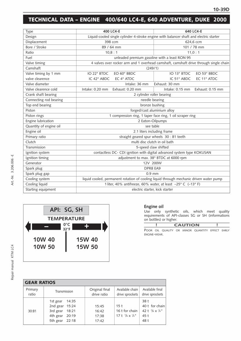
10-39DR
epai
r m
anua
l K
TM L
C4
Art
.-N
r. 3
.206
.006
-E
TECHNICAL DATA – ENGINE 400/640 LC4-E, 640 ADVENTURE, DUKE 2000
Type 400 LC4-E 640 LC4-EDesign Liquid-cooled single cylinder 4-stroke engine with balancer shaft and electric starterDisplacement 398 ccm 624,6 ccmBore / Stroke 89 / 64 mm 101 / 78 mmRatio 10,8 : 1 11,0 : 1Fuel unleaded premium gasoline with a least RON 95Valve timing 4 valves over rocker arm and 1 overhead camshaft, camshaft drive through single chainCamshaft (249/1)Valve timing by 1 mm IO 22° BTDC EO 60° BBDC IO 13° BTDC EO 53° BBDCvalve clearence IC 42° ABDC EC 4° ATDC IC 51° ABDC EC 11° ATDCValve diameter Intake: 36 mm Exhaust: 30 mm Valve clearence cold Intake: 0.20 mm Exhaust: 0.20 mm Intake: 0.15 mm Exhaust: 0.15 mmCrank shaft bearing 2 cylinder roller bearingConnecting rod bearing needle bearingTop end bearing bronze bushingPiston forged/cast aluminium alloyPiston rings 1 compression ring, 1 taper face ring, 1 oil scraper ringEngine lubrication 2 Eaton-Oilpumps Quantity of engine oil see tableEngine oil 2.1 liters including framePrimary ratio straight geared spur wheels 30 : 81 teethClutch multi disc clutch in oil bathTransmission 5-speed claw shiftedIgnition system contactless DC- CDI ignition with digital advanced system type KOKUSANIgnition timing adjustment to max. 38° BTDC at 6000 rpmGenerator 12V 200WSpark plug DPR8 EA9Spark plug gap 0.9 mmCooling system liquid cooled, permanent rotation of cooling liquid through mechanic driven water pumpCooling liquid 1 liter, 40% antifreeze, 60% water, at least –25° C (–13° F)Starting equipment electric starter, kick starter
Engine oilUse only synthetic oils, which meet qualityrequirements of API-classes SG or SH (informationson bottles) or higher.
! CAUTION !POOR OIL QUALITY OR MINOR QUANTITY EFFECT EARLYENGINE-WEAR.
– +0°C32°F
15W 4015W 50
10W 4010W 50
API: SG, SHTEMPERATURE
15 t16 t for chain17 t 5/8 x 1/4"
38 t40 t for chain42 t 5/8 x 1/4"45 t48 t
30:81
Primaryratio
Transmission Available chaindrive sprockets
Available finaldrive sprockets
GEAR RATIOS
1st gear 14:352nd gear 15:243rd gear 18:214th gear 20:195th gear 22:18
Original finaldrive ratio
15:4516:4217:3817:42

10-40D
ASSEMBLY CLEARANCE, WEAR LIMITCrank shaft axial play . . . . . . . . . . . . . . . . . . . . . . . . . . . . . . . . . . . . . . . . .0.03 - 0.12 mm
run out of crank stud . . . . . . . . . . . . . . . . . . . . . . . . . . . . . . . . .max. 0.08 mmConnecting rod bearing radial play . . . . . . . . . . . . . . . . . . . . . . . . . . . . . . . . . . . . . . . . .max. 0.05 mm
axial play . . . . . . . . . . . . . . . . . . . . . . . . . . . . . . . . . . . . . . . . . .max. 1.10 mmCylinder 400 bore . . . . . . . . . . . . . . . . . . . . . . . . . . . . . . . . . . . . . . . . . . . . .max. 89.04 mmCylinder 640 bore . . . . . . . . . . . . . . . . . . . . . . . . . . . . . . . . . . . . . . . . . . . .max. 101.04 mmPiston forged assembly clearance . . . . . . . . . . . . . . . . . . . . . . . . . . . . . . . . . .max. 0.12 mmPiston cast assembly clearance . . . . . . . . . . . . . . . . . . . . . . . . . . . . . . . . . .max. 0.05 mmPiston rings end gap compression rings . . . . . . . . . . . . . . . . . . . . . . . . . . . . . . . . . . . .max. 0.80 mm
oil scraper ring . . . . . . . . . . . . . . . . . . . . . . . . . . . . . . . . . . . . . .max. 1.00 mmValves seat sealing intake . . . . . . . . . . . . . . . . . . . . . . . . . . . . . . . . . . .max. 1.50 mm
seat sealing exhaust . . . . . . . . . . . . . . . . . . . . . . . . . . . . . . . . . .max. 2.00 mmrun out of valve heads . . . . . . . . . . . . . . . . . . . . . . . . . . . . . . . .max. 0.05 mmvalve guides diameter . . . . . . . . . . . . . . . . . . . . . . . . . . . . . . . . .max. 7.05 mm
Oil pumps clearance outer rotor - housing . . . . . . . . . . . . . . . . . . . . . . . . . .max. 0.20 mmclearance outer rotor - inner rotor . . . . . . . . . . . . . . . . . . . . . . . .max. 0.20 mm
Bypaß valve minimum spring length . . . . . . . . . . . . . . . . . . . . . . . . . . . . . . . . . . .25.00 mmClutch Length of springs . . . . . . . . . . . . . . . . . . . . . . .min. 34.5 mm (new 37.00 mm)
wear limit organic . . . . . . . . . . . . . . . . . . . . . . . . . . . . . . . . . . . .min. 2.50 mmCamshaft diameter of bearing bolt (needle bearing) . . . . . . . . . . . . . . . . . .min. 19.97 mmTransmission shafts axial play . . . . . . . . . . . . . . . . . . . . . . . . . . . . . . . . . . . . . . . . .0.10 - 0.40 mm
BASIC CARBURETOR SETTING
Type PHM 38 ND PHM 38 ND BST40-225Carb.-setting number 100197 100197 090298Main jet 130 130 142,5Needle jet AR 264 AR 264 689 X-6Idling jet 50 50 45Jet needle K 23 K 23 6G5Needle clip pos. f. top 2. from top 2. from top 3. from topMixt. adj. screw open 1.5 turns 1,5 turns 2,25 turnsThrottle valve 50/1 50/1 –Starting jet 45(50,55) 45(50,55) –Performance restrictor slide stop 51mm – –
400 LC4-E25 kW
400 LC4-E31 kW
400 LC4-EUSA
BASIC CARBURETOR SETTING
Type BST40-225 BST40-225 BST40-225Carb.-setting number 080298 090298 100299Main jet 142,5 142,5 145Needle jet 689 X-6 689 X-6 689 X-6Idling jet 45 45 45Jet needle 6G5 6G5 6G5Needle clip pos. f. top 3. from top 3. from top 3. from topMixt. adj. screw open 2,25 turns 2,25 turns 2,25 turnsThrottle valve – – –Starting jet – – –Performance restrictor slide stop 17mm – –
640 LC4-E, Adventure25 kW
640 LC4-E, Adventure36 kW
640 Duke40 kW

10-41DR
epai
r m
anua
l K
TM L
C4
Art
.-N
r. 3
.206
.006
-E
TECHNICAL SPECIFICATIONS - CHASSIS 400/640 LC4-E, 640 LC4-E SUPERMOTO 2000
400 LC4-E 640 LC4-E 640 LC4-E SUPERMOTO
Frame Central chrome-moly-steel frame
Fork White Power – Up Side Down 43
Wheel travel front/rear 270 / 300 mm (10,6 / 11,8 in)
Rear suspension Central shock absorber (WP) with PRO-LEVER linkage to rear-swingarm with needle bearing
Front brake Disc brake with carbon-steel brake disc, brake caliper floated
Brake Disk front Ø 300 mm (11,8 in) Ø 320 mm ( 12,6 in)
Rear brake Disc brake with carbon-steel brake disc Ø 220 mm (8,7 in), brake caliper floated
Tyres front 90/90-21 120/70-17
Air press. road, driver only 1,5 bar (21 psi) 2,0 bar (28 psi)
Air press. road, with passenger 2,0 bar (28 psi) 2,2 bar (31 psi)
Tyres rear 140/80-18 160/60-17
Air press. road, driver only 2,0 bar (28 psi) 2,2 bar (31 psi)
Air press. road, with passenger 2,2 bar (31 psi) 2,4 bar (34 psi)
Fuel tank capacity 11 liter (2,9 US gallons) / 18 liter (4,75 US gallons)
2,5 liter (0,66 US gallons) reserve
Final drive ratio 15:45 16:42 17:42
Chain 5/8 x 1/4 " O-RingLamps head light . . . . . . . . . . . . . . . . . . . . . . . . H4 12V 60/55W (socket P43t)
parking light . . . . . . . . . . . . . . . . . . . . . . 12V 5W (socket W2,1x9,5d)speedometer, tachometer light . . . . . . . . . 12V 1,2W (socket W2x4,6d)indicator lamp . . . . . . . . . . . . . . . . . . . . . 12V 1,2W (socket W2x4,6d)stop and taillight . . . . . . . . . . . . . . . . . . . 12V 21/5W (socket BaY15d)flasher . . . . . . . . . . . . . . . . . . . . . . . . . . 12V 10W (socket Ba15s)license plate illumination . . . . . . . . . . . . . 12V 5W (socket W2,1x9,5d)
Battery 12V 8Ah
Steering angle 62,5°
Wheel base 1510 ± 10 mm (59,4 ± 0,4 in)
Seat high 935 mm (36,8 in) 915 mm (36 in)
Ground clearance 355 mm (14 in) 335 mm (13,2 in)
Dead weight without fuel 136 kg (300 lbs) 137 kg (302 lbs)
Max. permissable front axe load 211 kg (466 lbs)
Max. permissable rear axe load 335 kg (740 lbs)
Max. permissable laden weigth 350 kg (773 lbs)
WP 0518U790
Compression adjuster 20Rebound adjuster 12Spring 4,4 N/mmSpring preload 6 mm (0,25 in)Air chamber length 150 mm (5,9 in)Capacity per fork leg ca 410 ccmFork oil SAE5
STANDARD ADJUSTMENT - FORKWP 0118U707
Compression adjuster 6Rebound adjuster 7Spring 66 / 260Spring preload 27 mm (1,1 in)
STANDARD-ADJUSTMENT - SHOCK ABSORBER

10-42D
TECHNICAL SPECIFICATIONS - CHASSIS LC4 ADVENTURE R 640 2000
LC4 Adventure R 640
Frame Central chrome-moly-steel frame
Fork WP Extreme
Wheel travel front/rear 280/320 mm (11/12,6 in)
Rear suspension Central shock absorber (WP) with PRO-LEVER linkage to rear-swingarm with needle bearing
Front brake Disc brake with carbon-steel brake disc Ø 300 mm (11,8 in), brake caliper floated
Rear brake Disc brake with carbon-steel brake disc Ø 220 mm (8,7 in), brake caliper floated
Tyres front 90/90-21 Enduro3
Air pressure offroad 1,5 bar (21 psi)
Air press. road, driver only 2,0 bar (29 psi)
Tyres rear 140/80-18 Enduro3
Air press. road, driver only 2,0 bar (29 psi)
Air press. road, with passenger 2,2 bar (32 psi)
Fuel tank capacity 28 liter (7,4 US gallons) of that 3,5 liter (1 US gallons) reserve
Final drive ratio 16 : 42
Chain 5/8 x 1/4 " O-Ring
Battery maintenance-free battery 12V 8Ah
Steering angle 62,5°
Wheel base 1510 ± 10 mm (59,4 ± 0,4 in)
Seat high 955 mm (37,7 in)
Ground clearance 375 mm (14,8 in)
Dead weight without fuel 154 kg (340 lbs)
Max. permissible front axle load 150 kg (331 lbs)
Max. permissible rear axle load 230 kg (507 lbs)
Max. permissible laden weight 380 kg (839 lbs)
01.18.R7.97
Compression adjuster 3
Rebound adjuster 5
Spring 70/260
Spring preload 23 mm (0,9 in)
STANDARD-ADJUSTMENT - SHOCK ABSORBER09.18.S7.55
Compression adjuster 14
Rebound adjuster 12
Spring 4,4 N/mm
Spring preload 10 mm (0,4 in)
Air chamber length 155 mm (5,9 in)
Capacity per fork leg ca 400 ccm
Fork oil SAE5
STANDARD ADJUSTMENT - FORK

10-43DR
epai
r m
anua
l K
TM L
C4
Art
.-N
r. 3
.206
.006
-E
TECHNICAL SPECIFICATIONS - CHASSIS KTM 640 DUKE 2000
Frame Central chrome-moly-steel frame
Fork type . . . . . . . . . . . . . . . . . . . . . . . . . . . . . . . . WP - USD 43 Multi adjuster 0518U795
wheel travel . . . . . . . . . . . . . . . . . . . . . . . . . . 140 mm (5,5 in)
standard adjustment compression. . . . . . . . . . . driver only = 14, with passenger = 14
standard adjustment rebound. . . . . . . . . . . . . . driver only = 16, with passenger = 16
fork leg projection upper fork bridge . . . . . . . . 3 mm (0,12 in)
oil capacity per fork leg . . . . . . . . . . . . . . . . . . appr. 400 ccm (24 cubic in) / SAE 5
air chamber lenght . . . . . . . . . . . . . . . . . . . . . 100 mm (4 in)
Rear suspension WP central shock absorber with PRO-LEVER linkage to rear- swing-arm with needle bearing
Shock absorber type . . . . . . . . . . . . . . . . . . . . . . . . . . . . . . . . WP central shock absorber BAVP 118Q785
rear wheel travel . . . . . . . . . . . . . . . . . . . . . . . 170 mm (6.7 in)
standard adjustment compression. . . . . . . . . . . driver only = 3, with passenger = 5
standard adjustment rebound. . . . . . . . . . . . . . driver only = 5, with passenger = 3
spring preload . . . . . . . . . . . . . . . . . . . . . . . . . driver only = 23 mm (0.9 in),with passenger = 28 mm (1.1 in)
spring type . . . . . . . . . . . . . . . . . . . . . . . . . . . 70 - 260
Front brake Disc brake with carbon-steel brake disc Ø 320 mm (12,6 in) and 4-piston brake caliper
Rear brake Disc brake with carbon-steel brake disc Ø 220 mm (8,7 in) and single-piston brake caliper floated
Tyres front: 120/70 R 17 58H rear: 160/60 R 17 69H
Air pressure rider only 2.0 bar (29 psi) 2.2 bar (32 psi)
Air pressure with passenger 2.2 bar (32 psi) 2.4 bar (35 psi)
Fuel tank capacity 11 liter (2,9 US gallons), out of this 2,5 liter (0,6 US gallons) reserve
Final drive ratio 17 : 38
Chain O-ring 5/8 x 1/4"
Lamps low beam . . . . . . . . . . . . . . . . . . . . . . . . . . . . HB3 12V 65W (socket P20d)
high beam . . . . . . . . . . . . . . . . . . . . . . . . . . . HB3 12V 65W (socket P20d)
parking light . . . . . . . . . . . . . . . . . . . . . . . . . . 12V 5W (socket W2,1x9,5d)
speedometer, tachometer light . . . . . . . . . . . . . 12V 1,2W (socket W2x4,6d)
indicator lamp . . . . . . . . . . . . . . . . . . . . . . . . . 12V 1,2W (socket W2x4,6d)
stop and taillight . . . . . . . . . . . . . . . . . . . . . . . 12V 21/5W (socket BaY15d)
flasher . . . . . . . . . . . . . . . . . . . . . . . . . . . . . . 12V 10W (socket Ba15s)
Battery maintenance-free battery 12V 8Ah
Steering angle 64,2°
Wheel base 1460 ± 15 mm (57.5 ± 0.6 in)
Seat high 860 mm (33.9 in)
Ground clearance 250 mm (9.9 in)
Dead weight without fuel 145 kg (3 lbs)
Max. permissible front axle load 150 kg (2 lbs)
Max. permissible rear axle load 200 kg (4 lbs)
Max. permissible laden weight 350 kg (773 lbs)

10-44D
TECHNICAL SPECIFICATIONS - CHASSIS 640 DUKE 2000 USA, AUS
Frame Central chrome-moly-steel frame
Fork type . . . . . . . . . . . . . . . . . . . . . . . . . . . . . . . . WP - USD 43 Top adjuster 518T780
wheel travel . . . . . . . . . . . . . . . . . . . . . . . . . . 140 mm (5,5 in)
standard adjustment compression. . . . . . . . . . . driver only = 14, with passenger = 14
standard adjustment rebound. . . . . . . . . . . . . . driver only = 14, with passenger = 14
fork leg projection upper fork bridge . . . . . . . . 3 mm (0,12 in)
oil capacity per fork leg . . . . . . . . . . . . . . . . . . appr. 400 ccm (45 cubic in) / SAE 5
air chamber lenght . . . . . . . . . . . . . . . . . . . . . 100 mm (4 in)
Rear suspension WP central shock absorber with PRO-LEVER linkage to rear- swing-arm with needle bearing
Shock absorber type . . . . . . . . . . . . . . . . . . . . . . . . . . . . . . . . WP central shock absorber BAVP 118Q785
rear wheel travel . . . . . . . . . . . . . . . . . . . . . . . 170 mm (6.7 in)
standard adjustment compression. . . . . . . . . . . driver only = 3, with passenger = 5
standard adjustment rebound. . . . . . . . . . . . . . driver only = 5, with passenger = 3
spring preload . . . . . . . . . . . . . . . . . . . . . . . . . driver only = 23 mm (0.9 in),with passenger = 28 mm (1.1 in)
spring type . . . . . . . . . . . . . . . . . . . . . . . . . . . 70 - 260
Front brake Disc brake with carbon-steel brake disc Ø 320 mm (12,6 in) and 4-piston brake caliper
Rear brake Disc brake with carbon-steel brake disc Ø 220 mm (8,7 in) and single-piston brake caliper floated
Tyres front: 120/70 R 17 58H rear: 160/60 R 17 69H
Air pressure rider only 2.0 bar (29 psi) 2.2 bar (32 psi)
Air pressure with passenger 2.2 bar (32 psi) 2.4 bar (35 psi)
Fuel tank capacity 12 liter (3,2 US gallons), out of this 2,5 liter (0,6 US gallons) reserve
Final drive ratio 17 : 38
Chain O-ring 5/8 x 1/4"
Lamps low beam . . . . . . . . . . . . . . . . . . . . . . . . . . . . HB3 12V 65W (socket P20d)
high beam . . . . . . . . . . . . . . . . . . . . . . . . . . . HB3 12V 65W (socket P20d)
parking light . . . . . . . . . . . . . . . . . . . . . . . . . . 12V 5W (socket W2,1x9,5d)
speedometer, tachometer light . . . . . . . . . . . . . 12V 1,2W (socket W2x4,6d)
indicator lamp . . . . . . . . . . . . . . . . . . . . . . . . . 12V 1,2W (socket W2x4,6d)
stop and taillight . . . . . . . . . . . . . . . . . . . . . . . 12V 21/5W (socket BaY15d)
flasher . . . . . . . . . . . . . . . . . . . . . . . . . . . . . . 12V 10W (socket Ba15s)
Battery maintenance-free battery 12V 8Ah
Steering angle 64,2°
Wheel base 1460 ± 15 mm (57.5 ± 0.6 in)
Seat high 860 mm (33.9 in)
Ground clearance 250 mm (9.9 in)
Dead weight without fuel 145 kg (3 lbs)
Max. permissible front axle load 150 kg (2 lbs)
Max. permissible rear axle load 200 kg (4 lbs)
Max. permissible laden weight 350 kg (773 lbs)

10-45DR
epai
r m
anua
l K
TM L
C4
Art
.-N
r. 3
.206
.006
-E
Engine 400 SXC
Design Liquid-cooled single cylinder 4-stroke engine
Displacement 398 ccm
Bore / Stroke 89 / 64 mm
Ratio 10,8 : 1
Fuel unleaded premium gasoline with a least RON 95
Valve timing 4 valves over rocker arm and 1 overhead camshaft, camshaft drive through single chain
Camshaft 249/1
Valve timing by 1 mm IO 22° BTDC EO 60° BBDC
valve clearence IC 42° ABDC EC 4° ATDC
Valve diameter Intake: 36 mm Exhaust: 30 mm
Valve clearence cold Intake: 0,20 mm Exhaust: 0,20 mm
Crank shaft bearing 2 cylinder roller bearing
Connecting rod bearing needle bearing
Top end bearing bronze bushing
Piston cast aluminium alloy
Piston rings 1 compression ring, 1 taper face ring, 1 oil scraper ring
Engine lubrication forced-feed lubrication through Eaton-Oilpump with oil sump
Engine oil see bellow
Engine oil quantity 1,45 liters (0,38 US gallons)
Primary ratio straight geared spur wheels 30 : 81 teeth
Clutch multi disc clutch in oil bath
Transmission 5-speed claw shifted
Gear ratio 1st 14:35
2nd 15:24
3rd 18:21
4th 20:19
5th 22:18
Ignition system contactless thyristor ignition with electronic advanced system type SEM
Ignition timing adjustment to max. 38 ° BTDC at 6000 rpm
Generator 12V 130W
Spark plug NGK D8EA
Spark plug gap 0,6 mm
Cooling system liquid cooled, permanent rotation of cooling liquid through mechanic driven water pump
Cooling liquid 1 liter, 40% antifreeze, 60% water, at least –25°C (–13°F)
Starting equipment decompressor automatic and hand actuated, cold and hot start knob on carburetor
TECHNICAL SPECIFICATIONS – ENGINE 400 SXC USA 2000
Crank shaft axial play..................................................0,03 - 0,12 mm (0,001-0,005 in)
run out of crank stud .................................max. 0,08 mm (0,003 in)
Connecting rod bearing radial play ..................................................max. 0,05 mm (0,002 in)
axial play ...................................................max. 1,00 mm (0,04 in)
Piston cast assembly clearance ...................................max. 0,05 mm (0,002 in)
Piston rings end gap compression rings ......................................max. 0,60 mm (0,023 in)
oil scraper ring ...........................................max. 0,80 mm (0,031 in)
Valves seat sealing intake......................................max. 1,50 mm 0,059 in)
seat sealing exhaust ...................................max. 2,00 mm (0,080 in)
run out of valve heads ...............................max. 0,03 mm (0,001 in)
valve guides diameter ................................max. 7,05 mm (0,277 in)
Oil pump clearance outer rotor - housing..................max. 0,20 mm (0,008 in)
clearance outer rotor - inner rotor..............max. 0,20 mm (0,008 in)
Bypaß valve minimum spring lenght..........................................25 mm (1 in)
Clutch discs wear limit organic .................................................2,5 mm (0,1 in)
Clutch springs minimum lenght...........................34,5 mm (new 37 mm) (1,36 in - new 1,45 in)
Transmission shafts axial play......................................................0,1 - 0,4 mm (0,004 - 0,016 in)
ASSEMBLY CLEARANCE, WEAR LIMIT

10-46D
TECHNICAL SPECIFICATIONS - CHASSIS 400 SXC USA 2000
400 SXC
Frame Central chrome-moly-steel frame
Fork White Power – EXTREME
Wheel travel front/rear 295 / 320 mm (11,6 / 12,6 in)
Rear suspension Central shock absorber (WP) with PRO-LEVER linkage to rear-swingarm with needle bearing
Front brake Disc brake with carbon-steel brake disc Ø 260 mm (10,2 in), brake caliper floated
Rear brake Disc brake with carbon-steel brake disc Ø 220 mm (8,7 in), brake caliper floated
Tyres front 90/90-21 54R
Air pressure offroad 1,0 bar (14 psi)
Air press. road, driver only 1,5 bar (21 psi)
Tyres rear 140/80-18 70R
Air pressure offroad 1,2 bar (17 psi)
Air press. road, driver only 2,0 bar (28 psi)
Fuel tank capacity 9 liter (3 US gallons) of that 1,5 liter (0,4 US gallons) reserve
Final drive ratio 15 : 50
Chain 5/8 x 1/4 "
Steering angle 62,5°
Wheel base 1510 ± 10 mm (59,4 ± 0,4 in)
Seat high 940 mm (37 in)
Ground clearance 375 mm (14,8 in)
Dead weight without fuel 121 kg (267 lbs)
01.18.Q7.82
Compression adjuster 3
Rebound adjuster 4
Spring 63/260
Spring preload 23 mm
STANDART-ADJUSTMENT - SHOCK ABSORBER
NOTE FOR WHITE POWER FORKS:The damping units in the left and the right fork leg are of differentdesign. Make sure not to mix them up in case of repair or service works.
05.18.T7.81
Compression adjuster 10
Rebound adjuster 12
Spring 4,2 N/mm
Spring preload 6 mm (0,24 in)
Air chamber length 130 mm (5,1 in)
Capacity per fork leg ca 350 ccm
Fork oil SAE5
STANDARD ADJUSTMENT - FORK
BASIC CARBURETOR SETTINGType BST40-225Carb.-setting number 040599Main jet 160Needle jet 689 X-6Idling jet 45Jet needle 6G5Needle clip pos. f. top 3. from topMixt. adj. screw open 2,25 turnsThrottle valve –Starting jet –Performance restrictor –

10-47DR
epai
r m
anua
l K
TM L
C4
Art
.-N
r. 3
.206
.006
-E
Engine 620
Design Liquid-cooled single cylinder 4-stroke engine with balancer shaft
Displacement 609 ccm
Bore / Stroke 101 / 76 mm
Ratio 10,4 : 1
Fuel unleaded premium gasoline with a least RON 95
Valve timing 4 valves over rocker arm and 1 overhead camshaft, camshaft drive through single chain
Camshaft 249/1
Valve diameter Intake: 36 mm Exhaust: 30 mm
Valve clearence cold Intake: 0,15 mm Exhaust: 0,15 mm
Crank shaft bearing 2 cylinder roller bearing
Connecting rod bearing needle bearing
Top end bearing bronze bushing
Piston forged aluminium
Piston rings 1 compression ring, 1 taper face ring, 1 oil scraper ring
Engine lubrication forced-feed lubrication through Eaton-Oilpump with oil sump
Engine oil see table
Engine oil quantity 1,6 liters (0,42 US gallons)
Primary ratio straight geared spur wheels 30 : 81 teeth
Clutch multi disc clutch in oil bath
Transmission 5-speed claw shifted
Gear ratio 1st 14:35
2nd 15:24
3rd 18:21
4th 20:19
5th 22:18
Ignition system contactless thyristor ignition with electronic advanced system type KOKUSAN 4K3
Ignition timing adjustment to max. 36 ° BTDC at 5000 rpm
Generator 12V 110W
Spark plug NGK DPR8 EA-9
Spark plug gap 0,9 mm
Cooling system liquid cooled, permanent rotation of cooling liquid through mechanic driven water pump
Cooling liquid 1 liter, 40% antifreeze, 60% water, at least –25°C (–13°F)
Starting equipment decompressor automatic and hand actuated, cold and hot start knob on carburetor
TECHNICAL SPECIFICATIONS – ENGINE 620 SC, 620 SC SUPERMOTO 2001
620 SC,620 SC SUPERMOTO
BASIC CARBURETOR SETTING
Carburetor
Carburetor setting number
Main jet
Needle jet
Idling jet
Jet needle
Needle position from top
Mixture.adju. screw open
Throttle valve
Starting jet
Performance restrictor
PHM 40 SD
080600
155
DR 266
45
K 51
3 rd
1,5 turns
40
45
Slide stop 24mm

10-48D
Crank shaft axial play..................................................0,03 - 0,12 mm (0,001-0,005 in)
run out of crank stud .................................max. 0,04 mm (0,002 in)
Connecting rod bearing radial play ..................................................max. 0,05 mm (0,002 in)
axial play ...................................................max. 1,00 mm (0,04 in)
Piston forged assembly clearance ...................................max. 0,12 mm (0,005 in)
Piston rings end gap compression rings ......................................max. 0,60 mm (0,023 in)
oil scraper ring ...........................................max. 0,80 mm (0,031 in)
Valves seat sealing intake......................................max. 1,50 mm 0,059 in)
seat sealing exhaust ...................................max. 2,00 mm (0,080 in)
run out of valve heads ...............................max. 0,03 mm (0,001 in)
valve guides diameter ................................max. 7,05 mm (0,277 in)
Oil pump clearance outer rotor - housing..................max. 0,20 mm (0,008 in)
clearance outer rotor - inner rotor..............max. 0,20 mm (0,008 in)
Bypaß valve minimum spring lenght..........................................25 mm (1 in)
Clutch discs wear limit organic .................................................2,5 mm (0,1 in)
Clutch springs minimum lenght...........................34,5 mm (new 37 mm) (1,36 in - new 1,45 in)
Transmission shafts axial play......................................................0,1 - 0,4 mm (0,004 - 0,016 in)
ASSEMBLY CLEARANCE, WEAR LIMIT
– +0°C32°F
15W 4015W 50
10W 4010W 50
API: SG, SHTEMPERATURE
Engine oilUse only oil brands, which meet quality requirements(Shell Advance Ultra 4) of API-classes SG or SH (informations onbottles) or higher.
! CAUTION !POOR OIL QUALITY OR MINOR QUANTITY EFFECT EARLYENGINE-WEAR.

10-49DR
epai
r m
anua
l K
TM L
C4
Art
.-N
r. 3
.206
.006
-E
TECHNICAL SPECIFICATIONS - CHASSIS 620 SC, 620 SC SUPERMOTO 2001
620 SC 620 SC SUPERMOTO
Frame Central chrome-moly-steel frame
Fork White Power – Up Side Down 43
Wheel travel front/rear 295 / 320 mm (11,6 / 12,6 in)
Rear suspension Central shock absorber (WP) with PRO-LEVER linkage to rear-swingarm with needle bearing
Front brake Disc brake with carbon-steel brake disc, brake caliper floated
Brake Disk Ø 260 mm (10,2 in) Ø 320 mm ( 12,6 in)
Rear brake Disc brake with carbon-steel brake disc Ø 220 mm (8,7 in), brake caliper floated
Tyres front 90/90-21 120/70-17
Air pressure offroad 1,0 bar (14 psi) –
Air press. road, driver only 1,8 bar (21 psi) 2,0 bar (28 psi)
Tyres rear 140/80-18 160/60-17
Air pressure offroad 1,2 bar (17 psi) –
Air press. road, driver only 2,0 bar (28 psi) 2,2 bar (32 psi)
Fuel tank capacity 9 liter (2,38 US gallons) of that 2,5 liter (0,66 US gallons) reserve
Final drive ratio 16:40 17:38
Chain 5/8 x 1/4 " O-Ring
Steering angle 62,5°
Wheel base 1510 ± 10 mm (59,4 ± 0,4 in)
Seat high 940 mm (37 in) 920 mm (36 in)
Ground clearance 375 mm (14,8 in) 355 mm (14 in)
Dead weight without fuel 122 kg (269 lbs) 123 kg (271 lbs)
620 SC SC SUPERMOTOWP 0518V706 WP 0518V721
Compression adjuster 14 14Rebound adjuster 12 14Spring 4,2 N/mm 5,0 N/mmSpring preload 6 mm 9 mmAir chamber length 150 mm 130 mmFork oil SAE 5 SAE 5
STANDARD ADJUSTMENT - FORK
620 SC SC SUPERMOTOWP 0118V712 WP 0118V720
Compression adjuster 3 5Rebound adjuster 5 7Spring 63 / 260 75 / 260Spring preload 23 mm 15 mm
STANDARD-ADJUSTMENT - SHOCK ABSORBER

10-50D
TECHNICAL DATA – ENGINE 400/640 LC4-E, 640 ADVENTURE, DUKE 2001
Type 400 LC4-E 640 LC4-EDesign Liquid-cooled single cylinder 4-stroke engine with balancer shaft and electric starterDisplacement 398 ccm 624,6 ccmBore / Stroke 89 / 64 mm 101 / 78 mmRatio 10,8 : 1 11,0 : 1Fuel unleaded premium gasoline with a least RON 95Valve timing 4 valves over rocker arm and 1 overhead camshaft, camshaft drive through single chainCamshaft 249/1Valve diameter Intake: 36 mm Exhaust: 30 mm Valve clearence cold Intake: 0.20 mm Exhaust: 0.20 mm Intake: 0.15 mm Exhaust: 0.15 mmCrank shaft bearing 2 cylinder roller bearingConnecting rod bearing needle bearingTop end bearing bronze bushingPiston forged/cast aluminium alloyPiston rings 1 compression ring, 1 taper face ring, 1 oil scraper ringEngine lubrication 2 Eaton-Oilpumps Quantity of engine oil see tableEngine oil 2.1 liters including framePrimary ratio straight geared spur wheels 30 : 81 teethClutch multi disc clutch in oil bathTransmission 5-speed claw shiftedIgnition system contactless DC- CDI ignition with digital advanced system type KOKUSANIgnition timing adjustment to max. 38° BTDC at 6000 rpmGenerator 12V 200WSpark plug NGK DPR8 EA9Spark plug gap 0.9 mmCooling system liquid cooled, permanent rotation of cooling liquid through mechanic driven water pumpCooling liquid 1 liter, 40% antifreeze, 60% water, at least –25° C (–13° F)Starting equipment electric starter, kick starter
ASSEMBLY CLEARANCE, WEAR LIMITCrank shaft axial play . . . . . . . . . . . . . . . . . . . . . . . . . . . . . . . . . . . . . . . . .0.03 - 0.12 mm
run out of crank stud . . . . . . . . . . . . . . . . . . . . . . . . . . . . . . . . .max. 0.08 mmConnecting rod bearing radial play . . . . . . . . . . . . . . . . . . . . . . . . . . . . . . . . . . . . . . . . .max. 0.05 mm
axial play . . . . . . . . . . . . . . . . . . . . . . . . . . . . . . . . . . . . . . . . . .max. 1.10 mmCylinder 400 bore . . . . . . . . . . . . . . . . . . . . . . . . . . . . . . . . . . . . . . . . . . . . .max. 89.04 mmCylinder 640 bore . . . . . . . . . . . . . . . . . . . . . . . . . . . . . . . . . . . . . . . . . . . .max. 101.04 mmPiston forged assembly clearance . . . . . . . . . . . . . . . . . . . . . . . . . . . . . . . . . .max. 0.12 mmPiston cast assembly clearance . . . . . . . . . . . . . . . . . . . . . . . . . . . . . . . . . .max. 0.05 mmPiston rings end gap compression rings . . . . . . . . . . . . . . . . . . . . . . . . . . . . . . . . . . . .max. 0.80 mm
oil scraper ring . . . . . . . . . . . . . . . . . . . . . . . . . . . . . . . . . . . . . .max. 1.00 mmValves seat sealing intake . . . . . . . . . . . . . . . . . . . . . . . . . . . . . . . . . . .max. 1.50 mm
seat sealing exhaust . . . . . . . . . . . . . . . . . . . . . . . . . . . . . . . . . .max. 2.00 mmrun out of valve heads . . . . . . . . . . . . . . . . . . . . . . . . . . . . . . . .max. 0.05 mmvalve guides diameter . . . . . . . . . . . . . . . . . . . . . . . . . . . . . . . . .max. 7.05 mm
Oil pumps clearance outer rotor - housing . . . . . . . . . . . . . . . . . . . . . . . . . .max. 0.20 mmclearance outer rotor - inner rotor . . . . . . . . . . . . . . . . . . . . . . . .max. 0.20 mm
Bypaß valve minimum spring length . . . . . . . . . . . . . . . . . . . . . . . . . . . . . . . . . . .25.00 mmClutch Length of springs . . . . . . . . . . . . . . . . . . . . . . .min. 34.5 mm (new 37.00 mm)
wear limit organic . . . . . . . . . . . . . . . . . . . . . . . . . . . . . . . . . . . .min. 2.50 mmCamshaft diameter of bearing bolt (needle bearing) . . . . . . . . . . . . . . . . . .min. 19.97 mmTransmission shafts axial play . . . . . . . . . . . . . . . . . . . . . . . . . . . . . . . . . . . . . . . . .0.10 - 0.40 mm

10-51DR
epai
r m
anua
l K
TM L
C4
Art
.-N
r. 3
.206
.006
-E
15 t16 t for chain17 t 5/8 x 1/4"
38 t40 t for chain42 t 5/8 x 1/4"45 t48 t
30:81
Primaryratio
Transmission Available chaindrive sprockets
Available finaldrive sprockets
GEAR RATIOS
1st gear 14:352nd gear 15:243rd gear 18:214th gear 20:195th gear 22:18
Original finaldrive ratio
15:4516:4217:3817:42
– +0°C32°F
15W 4015W 50
10W 4010W 50
API: SG, SHTEMPERATURE
Engine oilUse only oil brands, which meet quality requirements (Shell Advance Ultra 4) of API-classes SG or SH (informations on bottles) or higher.
! CAUTION !POOR OIL QUALITY OR MINOR QUANTITY EFFECT EARLY ENGINE-WEAR.
BASIC CARBURETOR SETTING
Type PHM 38 ND PHM 38 ND BST40-225Carb.-setting number 100197 100197 090298Main jet 130 130 142,5Needle jet AR 264 AR 264 689 X-6Idling jet 50 50 45Jet needle K 23 K 23 6G5Needle clip pos. f. top 2. from top 2. from top 3. from topMixt. adj. screw open 1.5 turns 1,5 turns 2,25 turnsThrottle valve 50/1 50/1 –Starting jet 45(50,55) 45(50,55) –Performance restrictor slide stop 51mm – –
400 LC4-E25 kW
400 LC4-E31 kW
400 LC4-EUSA
BASIC CARBURETOR SETTING
Type BST40-225 BST40-225 BST40-225Carb.-setting number 080298 090298 100299Main jet 142,5 142,5 145Needle jet 689 X-6 689 X-6 689 X-6Idling jet 45 45 45Jet needle 6G5 6G5 6G5Needle clip pos. f. top 3. from top 3. from top 3. from topMixt. adj. screw open 2,25 2,25 2,25Throttle valve – – –Starting jet – – –Performance restrictor slide stop 17mm – –
640 LC4-E, Adventure25 kW
640 LC4-E, Adventure36 kW
640 Duke40 kW

10-52D
TECHNICAL SPECIFICATIONS - CHASSIS 400/640 LC4-E, 640 LC4-E SUPERMOTO 2001
400 LC4-E 640 LC4-E 640 LC4-E SUPERMOTO
Frame Central chrome-moly-steel frame
Fork White Power – Up Side Down 43
Wheel travel front/rear 270 / 300 mm (10,6 / 11,8 in)
Rear suspension Central shock absorber (WP) with PRO-LEVER linkage to rear-swingarm with needle bearing
Front brake Disc brake with carbon-steel brake disc, brake caliper floated
Brake Disk front Ø 300 mm (11,8 in) Ø 320 mm ( 12,6 in)
Rear brake Disc brake with carbon-steel brake disc Ø 220 mm (8,7 in), brake caliper floated
Tyres front 90/90-21 120/70-17
Air press. road, driver only 1,5 bar (21 psi) 2,0 bar (28 psi)
Air press. road, with passenger 2,0 bar (28 psi) 2,2 bar (31 psi)
Tyres rear 140/80-18 160/60-17
Air press. road, driver only 2,0 bar (28 psi) 2,2 bar (31 psi)
Air press. road, with passenger 2,2 bar (31 psi) 2,4 bar (34 psi)
Fuel tank capacity 11 liter (2,9 US gallons) / 18 liter (4,75 US gallons)
2,5 liter (0,66 US gallons) reserve
Final drive ratio 15:45 16:42 17:42
Chain 5/8 x 1/4 " O-RingLamps head light . . . . . . . . . . . . . . . . . . . . . . . . H4 12V 60/55W (socket P43t)
parking light . . . . . . . . . . . . . . . . . . . . . . 12V 5W (socket W2,1x9,5d)speedometer, tachometer light . . . . . . . . . 12V 1,2W (socket W2x4,6d)indicator lamp . . . . . . . . . . . . . . . . . . . . . 12V 1,2W (socket W2x4,6d)stop and taillight . . . . . . . . . . . . . . . . . . . 12V 21/5W (socket BaY15d)flasher . . . . . . . . . . . . . . . . . . . . . . . . . . 12V 10W (socket Ba15s)license plate illumination . . . . . . . . . . . . . 12V 5W (socket W2,1x9,5d)
Battery 12V 8Ah
Steering angle 62,5° 63°
Wheel base 1510 ± 10 mm (59,4 ± 0,4 in)
Seat high 955 mm (37,6 in) 935 mm (36,8 in)
Ground clearance 355 mm (14 in) 335 mm (13,2 in)
Dead weight without fuel 136 kg (300 lbs) 137 kg (302 lbs)
Max. permissable front axe load 211 kg (466 lbs)
Max. permissable rear axe load 335 kg (740 lbs)
Max. permissable laden weigth 350 kg (773 lbs)
400/640 LC4-E 640 LC4-ESUPERMOTO
WP 0518V707 WP 0518V721
Compression adjuster 20 14Rebound adjuster 12 14Spring 4,4 N/mm 5,0 N/mmSpring preload 6 mm 9 mmAir chamber length 150 mm 130 mmFork oil SAE 5 SAE 5
STANDARD ADJUSTMENT - FORK400/640 LC4-E 640 LC4-E
SUPERMOTOWP 0118V710 WP 0118V720
Compression adjuster 6 5Rebound adjuster 7 7Spring 66 / 260 75 / 260Spring preload 27 mm 15 mm
STANDARD-ADJUSTMENT - SHOCK ABSORBER

10-53DR
epai
r m
anua
l K
TM L
C4
Art
.-N
r. 3
.206
.006
-E
TECHNICAL SPECIFICATIONS - CHASSIS 640 LC4 ADVENTURE 2001
640 LC4 Adventure
Frame Central chrome-moly-steel frame
Fork WP USD
Wheel travel front/rear 275/300 mm (10,5/12 in)
Rear suspension Central shock absorber (WP) with PRO-LEVER linkage to rear-swingarm with needle bearing
Front brake Disc brake with carbon-steel brake disc Ø 320 mm (11,8 in), brake caliper floated
Rear brake Disc brake with carbon-steel brake disc Ø 220 mm (8,7 in), brake caliper floated
Tyres front 90/90-21 Enduro3
Air pressure offroad 1,8 bar (21 psi)
Air press. road, driver only 2,0 bar (29 psi)
Tyres rear 140/80-18 Enduro3
Air press. road, driver only 2,0 bar (29 psi)
Air press. road, with passenger 2,2 bar (32 psi)
Fuel tank capacity 28 liter (7,4 US gallons) of that 3,5 liter (1 US gallons) reserve
Final drive ratio 16 : 42
Chain 5/8 x 1/4 " O-Ring
Battery maintenance-free battery 12V 8Ah
Steering angle 62,5°
Wheel base 1510 ± 10 mm (59,4 ± 0,4 in)
Seat high 955 mm (37,7 in)
Ground clearance 355 mm (14,2 in)
Dead weight without fuel 154 kg (340 lbs)
Max. permissible front axle load 150 kg (331 lbs)
Max. permissible rear axle load 230 kg (507 lbs)
Max. permissible laden weight 380 kg (839 lbs)
01.18.V709
Compression adjuster 3
Rebound adjuster 5
Spring 66/260
Spring preload 27 mm (0,9 in)
STANDARD-ADJUSTMENT - SHOCK ABSORBER14.18.V704
Compression adjuster 14
Rebound adjuster 14
Spring 4,4 N/mm
Spring preload 4 mm
Air chamber length 120 mm
Capacity per fork leg ca 420 ccm
Fork oil SAE 5
STANDARD ADJUSTMENT - FORK

10-54D
TECHNICAL SPECIFICATIONS - CHASSIS KTM 640 DUKE 2001
Frame Central chrome-moly-steel frame
Fork type . . . . . . . . . . . . . . . . . . . . . . . . . . . . . . . . WP - USD 43 Multi adjuster 0518U795
wheel travel . . . . . . . . . . . . . . . . . . . . . . . . . . 140 mm (5,5 in)
standard adjustment compression. . . . . . . . . . . driver only = 14, with passenger = 14
standard adjustment rebound. . . . . . . . . . . . . . driver only = 16, with passenger = 16
fork leg projection upper fork bridge . . . . . . . . 3 mm (0,12 in)
oil capacity per fork leg . . . . . . . . . . . . . . . . . . appr. 400 ccm (24 cubic in) / SAE 5
air chamber lenght . . . . . . . . . . . . . . . . . . . . . 100 mm (4 in)
Rear suspension WP central shock absorber with PRO-LEVER linkage to rear- swing-arm with needle bearing
Shock absorber type . . . . . . . . . . . . . . . . . . . . . . . . . . . . . . . . WP central shock absorber BAVP 118Q785
rear wheel travel . . . . . . . . . . . . . . . . . . . . . . . 170 mm (6.7 in)
standard adjustment compression. . . . . . . . . . . driver only = 3, with passenger = 5
standard adjustment rebound. . . . . . . . . . . . . . driver only = 5, with passenger = 3
spring preload . . . . . . . . . . . . . . . . . . . . . . . . . driver only = 23 mm (0.9 in),with passenger = 28 mm (1.1 in)
spring type . . . . . . . . . . . . . . . . . . . . . . . . . . . 70 - 260
Front brake Disc brake with carbon-steel brake disc Ø 320 mm (12,6 in) and 4-piston brake caliper
Rear brake Disc brake with carbon-steel brake disc Ø 220 mm (8,7 in) and single-piston brake caliper floated
Tyres front: 120/70 R 17 58H rear: 160/60 R 17 69H
Air pressure rider only 2.0 bar (29 psi) 2.2 bar (32 psi)
Air pressure with passenger 2.2 bar (32 psi) 2.4 bar (35 psi)
Fuel tank capacity 11 liter (2,9 US gallons), out of this 2,5 liter (0,6 US gallons) reserve
Final drive ratio 17 : 38
Chain O-ring 5/8 x 1/4"
Lamps low beam . . . . . . . . . . . . . . . . . . . . . . . . . . . . HB3 12V 65W (socket P20d)
high beam . . . . . . . . . . . . . . . . . . . . . . . . . . . HB3 12V 65W (socket P20d)
parking light . . . . . . . . . . . . . . . . . . . . . . . . . . 12V 5W (socket W2,1x9,5d)
speedometer, tachometer light . . . . . . . . . . . . . 12V 1,2W (socket W2x4,6d)
indicator lamp . . . . . . . . . . . . . . . . . . . . . . . . . 12V 1,2W (socket W2x4,6d)
stop and taillight . . . . . . . . . . . . . . . . . . . . . . . 12V 21/5W (socket BaY15d)
flasher . . . . . . . . . . . . . . . . . . . . . . . . . . . . . . 12V 10W (socket Ba15s)
Battery maintenance-free battery 12V 8Ah
Steering angle 64,2°
Wheel base 1460 ± 15 mm (57.5 ± 0.6 in)
Seat high 860 mm (33.9 in)
Ground clearance 250 mm (9.9 in)
Dead weight without fuel 145 kg (3 lbs)
Max. permissible front axle load 150 kg (2 lbs)
Max. permissible rear axle load 200 kg (4 lbs)
Max. permissible laden weight 350 kg (773 lbs)

10-55DR
epai
r m
anua
l K
TM L
C4
Art
.-N
r. 3
.206
.006
-E
TECHNICAL SPECIFICATIONS - CHASSIS 640 DUKE 2001 USA, AUS
Frame Central chrome-moly-steel frame
Fork type . . . . . . . . . . . . . . . . . . . . . . . . . . . . . . . . WP - USD 43 Top adjuster 518T780
wheel travel . . . . . . . . . . . . . . . . . . . . . . . . . . 140 mm (5,5 in)
standard adjustment compression. . . . . . . . . . . driver only = 14, with passenger = 14
standard adjustment rebound. . . . . . . . . . . . . . driver only = 14, with passenger = 14
fork leg projection upper fork bridge . . . . . . . . 3 mm (0,12 in)
oil capacity per fork leg . . . . . . . . . . . . . . . . . . appr. 400 ccm (45 cubic in) / SAE 5
air chamber lenght . . . . . . . . . . . . . . . . . . . . . 100 mm (4 in)
Rear suspension WP central shock absorber with PRO-LEVER linkage to rear- swing-arm with needle bearing
Shock absorber type . . . . . . . . . . . . . . . . . . . . . . . . . . . . . . . . WP central shock absorber BAVP 118Q785
rear wheel travel . . . . . . . . . . . . . . . . . . . . . . . 170 mm (6.7 in)
standard adjustment compression. . . . . . . . . . . driver only = 3, with passenger = 5
standard adjustment rebound. . . . . . . . . . . . . . driver only = 5, with passenger = 3
spring preload . . . . . . . . . . . . . . . . . . . . . . . . . driver only = 23 mm (0.9 in),with passenger = 28 mm (1.1 in)
spring type . . . . . . . . . . . . . . . . . . . . . . . . . . . 70 - 260
Front brake Disc brake with carbon-steel brake disc Ø 320 mm (12,6 in) and 4-piston brake caliper
Rear brake Disc brake with carbon-steel brake disc Ø 220 mm (8,7 in) and single-piston brake caliper floated
Tyres front: 120/70 R 17 58H rear: 160/60 R 17 69H
Air pressure rider only 2.0 bar (29 psi) 2.2 bar (32 psi)
Air pressure with passenger 2.2 bar (32 psi) 2.4 bar (35 psi)
Fuel tank capacity 12 liter (3,2 US gallons), out of this 2,5 liter (0,6 US gallons) reserve
Final drive ratio 17 : 38
Chain O-ring 5/8 x 1/4"
Lamps low beam . . . . . . . . . . . . . . . . . . . . . . . . . . . . HB3 12V 65W (socket P20d)
high beam . . . . . . . . . . . . . . . . . . . . . . . . . . . HB3 12V 65W (socket P20d)
parking light . . . . . . . . . . . . . . . . . . . . . . . . . . 12V 5W (socket W2,1x9,5d)
speedometer, tachometer light . . . . . . . . . . . . . 12V 1,2W (socket W2x4,6d)
indicator lamp . . . . . . . . . . . . . . . . . . . . . . . . . 12V 1,2W (socket W2x4,6d)
stop and taillight . . . . . . . . . . . . . . . . . . . . . . . 12V 21/5W (socket BaY15d)
flasher . . . . . . . . . . . . . . . . . . . . . . . . . . . . . . 12V 10W (socket Ba15s)
Battery maintenance-free battery 12V 8Ah
Steering angle 64,2°
Wheel base 1460 ± 15 mm (57.5 ± 0.6 in)
Seat high 860 mm (33.9 in)
Ground clearance 250 mm (9.9 in)
Dead weight without fuel 145 kg (3 lbs)
Max. permissible front axle load 150 kg (2 lbs)
Max. permissible rear axle load 200 kg (4 lbs)
Max. permissible laden weight 350 kg (773 lbs)

10-56D
Engine 625 LC4Design Liquid-cooled single cylinder 4-stroke engine with balancer shaftDisplacement 625 ccmBore / Stroke 101 / 78 mmRatio 11,0 : 1Fuel unleaded premium gasoline with a least RON 95Valve timing 4 valves over rocker arm and 1 overhead camshaft, camshaft drive through single chainCamshaft 249/1Valve diameter Intake: 36 mm Exhaust: 30 mm Valve clearence cold Intake: 0,15 mm Exhaust: 0,15 mmCrank shaft bearing 2 cylinder roller bearingConnecting rod bearing needle bearingTop end bearing bronze bushingPiston forged aluminium alloyPiston rings 1 compression ring, 1 taper face ring, 1 oil scraper ringEngine lubrication two oilpumpsEngine oil 10W-40 (Shell Advance Ultra 4)Engine oil quantity 1,6 liters (0,42 US gallons)Primary ratio straight geared spur wheels 30 : 81 teethClutch multi disc clutch in oil bathTransmission 5-speed claw shiftedGear ratio 1st 14:35
2nd 15:243rd 18:214th 20:195th 22:18
Ignition system contactless DC-CDI ignition with digital advanced system type KOKUSAN 4K-3CIgnition timing adjustment to max. 38 ° BTDC at 6000 rpmGenerator 12V 150 WSpark plug NGK DPR8 EA-9Spark plug gap 0,9 mmCooling system liquid cooled, permanent rotation of cooling liquid through mechanic driven water pumpCooling liquid 1 liter, 40% antifreeze, 60% water, at least –25°C (–13°F)Starting equipment Kickstarter, cold start knob on carburetor
TECHNICAL SPECIFICATIONS – ENGINE 625 SC, 625 SC SUPERMOTO 2002
625 SC,625 SC SUPERMOTO
BASIC CARBURETOR SETTING
CarburetorCarburetor setting numberMain jetNeedle jetIdling jet
Main air jetIdling air jetNeedle position from topThrottle valveStarting jetPerformance restrictor
Stop pump membrane
Keihin FCR41140501
180OBDVT
452001005th1585
Slide stop 23mm3,2mm

10-57DR
epai
r m
anua
l K
TM L
C4
Art
.-N
r. 3
.206
.006
-E
625 SC 625 SC SUPERMOTOFrame Central chrome-moly-steel frameFork White Power 4357 MXMAWheel travel front/rear 295 / 320 mm (11,8 / 12,8 in) 270 / 320 (10,8 / 12.8 in)Rear suspension Central shock absorber (WP BAVP3612) with PRO-LEVER linkage to rear- swing-arm with needle bearingFront brake Disc brake with carbon-steel brake disc, brake caliper floatedFront brake disc Ø 260 mm (10,4 in) Ø 320 mm (12.8 in)Rear brake Disc brake with carbon-steel brake disc 220 mm (8.8 in), brake caliper floatedTyres front 90/90-21 120/70-17Air press. offroad 1,0 bar (14 psi) -Air press. road 1,8 bar (26 psi) 2,0 bar (29 psi)Tyres rear 140/80-18 160/60-17Air press offroad 1,2 bar (17 psi) -Air press. road 2,0 bar (29 psi) 2,2 bar (32 psi)Fuel tank capacity 9 liter (2,3 US gallons), 1.5 liter (0,4 US gallons) reserveFinal drive ratio 16:40 (15:50) t 17:38tChain X – Ring 5/8 x 1/4"Bulps headlight . . . . . . . . . . . . . H4 12V 60/55W (socket P43t)
parking light . . . . . . . . . . . 12V 5W (socket W2,1x9,5d)indicator lamps . . . . . . . . . 12V 1,2W (socket W2x4,6d)brake – rear light . . . . . . . 12V 21/5 W (socket BaY15d)flasher light . . . . . . . . . . . 12V 10W (socket Ba15s)license plate illmination . . . 12V 5W (socket W2,1x9,5 d)
Steering angle 62,5 ° 63°Wheel base 1510 ± 10 mm (59.4 ± 0.4 in)Seat high 950 mm (38 in) 920 mm (36.8 in)Ground clearance 340 mm (13,6 in) 300 mm (12 in)Dead weight without fuel 122 kg (269 lbs) 123 kg (271 Ibs)
TECHNICAL SPECIFICATIONS - CHASSIS 625 SC, 625 SC SUPERMOTO 2002
625 SC 625 SC SUPERMOTOWP 0518W712 WP 0518W722
Compression adjuster 20 14Rebound adjuster 12 14Spring 4,2 N/mm 5,0 N/mmSpring preload 5 mm 9 mmAir chamber length 140 mm 130 mmFork oil SAE 5 SAE 5
STANDARD ADJUSTMENT - FORK
625 SC 625 SC SUPERMOTOWP 0118W714 WP 0118W721
Compression adjuster 3 5Rebound adjuster 5 7Spring 63 / 260 75 / 260Spring preload 23 mm 15 mm
STANDARD-ADJUSTMENT - SHOCK ABSORBER

10-58D
TECHNICAL DATA – ENGINE 640 LC4 2002
Engine 640 LC4Design Liquid-cooled single cylinder 4-stroke engine with balancer shaft and electric starterDisplacement 624,6 ccmBore / Stroke 101 / 78 mmRatio 11 : 1Fuel unleaded premium gasoline with a least RON 95Valve timing 4 valves over rocker arm and 1 overhead camshaft, camshaft drive through single chainCamshaft 249/1Valve diameter Intake: 36 mm Exhaust: 30 mmValve clearence cold 0,15 mm Exhaust: 0,15 mmCrank shaft bearing 2 cylinder roller bearingConnecting rod bearing needle bearingTop end bearing bronze bushingPiston forged aluminium alloyPiston rings 1 compression ring, 1 taper face ring, 1 oil scraper ringEngine lubrication two oilpumpsEngine oil 10W-40 (Shell Advance Ultra 4)Engine oil quantity appr. 2,1 liters including framePrimary ratio straight geared spur wheels 30 : 81 teethClutch multi disc clutch in oil bathTransmission 5-speed claw shiftedGear ratio 1st 14:35
2nd 15:243rd 18:214th 20:195th 22:18
Ignition system contactless DC-CDI ignition with digital advanced system type KOKUSAN 4K-2Ignition timing adjustment to max. 38° BTDC at 6000 rpmGenerator 12V 200WSpark plug NGK DPR8 EA9Spark plug gap 0,9 mmCooling system liquid cooled, permanent rotation of cooling liquid through mechanic driven water pumpCooling liquid 1 liter, 40% antifreeze, 60% water, at least –25 ° C (–13 ° F)Starting equipment electric starter and kickstarter
640 LC4, SUPERMOTO
640 LC4 ADVENTURE
BASIC CARBURETOR SETTING
TypeCarb.-setting numberMain jetNeedle jetIdling jetJet needleNeedle clip pos. f. topMixt. adj. screw open
BST40-225090298142,5
689 X-645
6G53.
2,25
640 DUKE
40 kW
BST40-225100299
145689 X-6
456G53.
2,25

10-59DR
epai
r m
anua
l K
TM L
C4
Art
.-N
r. 3
.206
.006
-E
TECHNICAL SPECIFICATIONS - CHASSIS 640 LC4, 640 LC4 SUPERMOTO 2002
640 LC4 640 LC4 SupermotoFrame Central chrome-moly-steel frameFork White Power – Up Side Down 4357 MXMAWheel travel front/rear 270 / 300 mm (10,6 / 11.8 in)Rear suspension Central shock absorber (WP BAVP3612) with PRO-LEVER linkage to rear- swing-arm with needle bearingFront brake Disc brake with carbon-steel brake disc, brake caliper floatedFront brake disc Ø 300 mm (11.8 in) Ø 320 mm (12.6 in)Rear brake Disc brake with carbon-steel brake disc 220 mm (8.7 in), brake caliper floatedTyres front 90/90-21 120/70-17Air press. road, driver only 1.8 bar (26 psi) 2.0 bar (29 psi)Air press. road with passenger 2.0 bar (29 psi) 2.2 bar (31 psi)Tyres rear 140/80-18 160/60-17Air press. road, driver only 2.0 bar (29 psi) 2.2 bar (31 psi)Air press. road with passenger 2.2 bar (31 psi) 2.4 bar (34 psi)Fuel tank capacity 11 or 18 liter (2.9 or 4.8 US gallons), 2.5 liter (0,6 US gallons) reserveFinal drive ratio 16:42t 17:42tChain X – Ring 5/8 x 1/4"Bulps headlight . . . . . . . . . . . . . H4 12V 60/55W (socket P43t)
parking light . . . . . . . . . . . 12V 5W (socket W2,1x9,5d)instrument lights . . . . . . . . 12V 1,2W (socket W2x4,6d)indicator lamps . . . . . . . . . 12V 1,2W (socket W2x4,6d)brake – rear light . . . . . . . 12V 21/5 W (socket BaY15d)flasher light . . . . . . . . . . . 12V 10W (socket Ba15s)license plate illmination . . . 12V 5W (socket W2,1x9,5 d)
Battery maintenance-free battery 12V 8AhSteering angle 62,5 ° 63°Wheel base 1510 ± 10 mm (59.4 ± 0.4 in)Seat high 940 mm (37.6 in) 910 mm (36.4 in)Ground clearance 355 mm (14.0 in) 335 mm (13.2 in)Dead weight without fuel 136kg (300 lbs) 137 kg (302 Ibs)Max. permissible front axle load 211 kg (465 lbs)Max. permissible rear axle load 335 kg (740 lbs)Max. permissible laden weight 350 kg (773 lbs)
640 LC4 640 LC4SUPERMOTO
WP 0518W714 WP 0518W722Compression adjuster 20 14Rebound adjuster 12 14Spring 4,2 N/mm 5,0 N/mmSpring preload 6 mm (0,24in) 9 mm (0,36in)Air chamber length 150 mm (5,9in) 130 mm (5,1in)Fork oil SAE 5 SAE 5
STANDARD ADJUSTMENT - FORK640 LC4 640 LC4
SUPERMOTOWP 0118W724 WP 0118W721
Compression adjuster 3 5Rebound adjuster 7 7Spring 66 / 260 75 / 260Spring preload 23,5 mm(0,94in) 15 mm(0,6in)
STANDARD-ADJUSTMENT - SHOCK ABSORBER

10-60D
TECHNICAL SPECIFICATIONS - CHASSIS 640 LC4 ADVENTURE 2002
640 LC4 AdventureFrame Central chrome-moly-steel frameFork WP USD MXMA 4860 Wheel travel front/rear 275/300 mm (10,5/12 in)Rear suspension Central shock absorber (WP BAVP3612) with PRO-LEVER linkage to rear-swingarm with need
bearingFront brake Disc brake with carbon-steel brake disc Ø 320 mm (11,8 in), brake caliper floatedRear brake Disc brake with carbon-steel brake disc Ø 220 mm (8,7 in), brake caliper floatedTyres front 90/90-21 Enduro3Air pressure offroad 1,8 bar (21 psi)Air press. road, driver only 2,0 bar (29 psi)Tyres rear 140/80-18 Enduro3Air press. road, driver only 2,0 bar (29 psi)Air press. road, with passenger 2,2 bar (32 psi)Fuel tank capacity 28 liter (7,4 US gallons) of that 2 liter (0,5 US gallons) reserveFinal drive ratio 16 : 42Chain 5/8 x 1/4 "X-RingLampenbestückung head light . . . . . . . . . . . . . . . . . . . . . .H1 12V 55W (Sockel P14,5S)
parking light . . . . . . . . . . . . . . . . . . . .12V 2W (Sockel Ba9s)brake- rear light . . . . . . . . . . . . . . . . .12V 21/5W (Sockel BaY15d)flasher light . . . . . . . . . . . . . . . . . . . . .12V 10W (Sockel Ba15s)license plate illintion . . . . . . . . . . . . . .12V 5W (Sockel W2,1x9,5d)
Battery maintenance-free battery 12V 8AhSteering angle 62,5°Wheel base 1510 ± 10 mm (59,4 ± 0,4 in)Seat high 955 mm (37,7 in)Ground clearance 355 mm (14,2 in)Dead weight without fuel 154 kg (340 lbs)Max. permissible front axle load 150 kg (331 lbs)Max. permissible rear axle load 230 kg (507 lbs)Max. permissible laden weight 380 kg (839 lbs)
WP BAVP36120118W715
Compression adjuster 6Rebound adjuster 7Spring 70/260Spring preload 27 mm (0,9 in)
STANDARD-ADJUSTMENT - SHOCK ABSORBERWP 4860 MXMA
1418W711Compression adjuster 14Rebound adjuster 14Spring 4,4 N/mmSpring preload 4 mm Air chamber length 120 mm Capacity per fork leg approx. 420 ccmFork oil SAE 5
STANDARD ADJUSTMENT - FORK

10-61DR
epai
r m
anua
l K
TM L
C4
Art
.-N
r. 3
.206
.006
-E
TECHNICAL SPECIFICATIONS - CHASSIS 640 DUKE II 2002
Frame Central chrome-moly-steel frameFork type . . . . . . . . . . . . . . . . . . . . . . . . . . . . WP 4357 ROMA 0518716
wheel travel . . . . . . . . . . . . . . . . . . . . . . 140 mm (5,5 in)standard adjustment compression. . . . . . . driver only = 14, with passenger = 14standard adjustment rebound. . . . . . . . . . driver only = 16, with passenger = 16fork leg projection upper fork bridge . . . . 3 mm (0,12 in)oil capacity per fork leg . . . . . . . . . . . . . . appr. 400 ccm (24 cubic in) / SAE 5air chamber lenght . . . . . . . . . . . . . . . . . 100 mm (4 in)
Rear suspension WP central shock absorber with PRO-LEVER linkage to rear- swing-arm with needle bearingShock absorber type . . . . . . . . . . . . . . . . . . . . . . . . . . . . WP central shock absorber BAVP 4681
0118W71rear wheel travel . . . . . . . . . . . . . . . . . . . 170 mm (6.7 in)standard adjustment compression. . . . . . . driver only = 3, with passenger = 5standard adjustment rebound. . . . . . . . . . driver only = 5, with passenger = 3spring preload . . . . . . . . . . . . . . . . . . . . . driver only = 23 mm (0.9 in),with passenger = 28
mm (1.1 in)spring type . . . . . . . . . . . . . . . . . . . . . . . 70 - 260
Front brake Disc brake with carbon-steel brake disc Ø 320 mm (12,6 in) and 4-piston brake caliperRear brake Disc brake with carbon-steel brake disc Ø 220 mm (8,7 in) and single-piston brake caliper floatedTyres front: 120/70 R 17 58H rear: 160/60 R 17 69HAir pressure rider only 2.0 bar (29 psi) 2.2 bar (32 psi)Air pressure with passenger 2.2 bar (32 psi) 2.4 bar (35 psi)Fuel tank capacity 11 liter (2,9 US gallons), out of this 2,5 liter (0,6 US gallons) reserveFinal drive ratio 17 : 38Chain X-ring 5/8 x 1/4"Lamps low beam . . . . . . . . . . . . . . . . . . . . . . . . HB3 12V 65W (socket P20d)
high beam . . . . . . . . . . . . . . . . . . . . . . . HB3 12V 65W (socket P20d)parking light . . . . . . . . . . . . . . . . . . . . . . 12V 5W (socket W2,1x9,5d)speedometer, tachometer light . . . . . . . . . 12V 1,2W (socket W2x4,6d)indicator lamp . . . . . . . . . . . . . . . . . . . . . 12V 1,2W (socket W2x4,6d)stop and taillight . . . . . . . . . . . . . . . . . . . 12V 21/5W (socket BaY15d)flasher . . . . . . . . . . . . . . . . . . . . . . . . . . 12V 10W (socket Ba15s)
Battery maintenance-free battery 12V 8AhSteering angle 64,2°Wheel base 1460 ± 15 mm (57.5 ± 0.6 in)Seat high 880 mm (34,7 in)Ground clearance 250 mm (9.9 in)Dead weight without fuel 145 kg (3 lbs)Max. permissible front axle load 150 kg (2 lbs)Max. permissible rear axle load 200 kg (4 lbs)Max. permissible laden weight 350 kg (773 lbs)

10-62D
Engine 625 SXCDesign Liquid-cooled single cylinder 4-stroke engine with balancer shaftDisplacement 625 ccmBore / Stroke 101 / 78 mmRatio 11,5 : 1Fuel unleaded premium gasoline with a least RON 95Valve timing 4 valves over rocker arm and 1 overhead camshaft, camshaft drive through single chainCamshaft 584-V03/1Valve diameter Intake: 36 mm Exhaust: 32 mm Valve clearence cold Intake: 0,15 mm Exhaust: 0,15 mmCrank shaft bearing 2 cylinder roller bearingConnecting rod bearing needle bearingTop end bearing bronze bushingPiston forged aluminium alloyPiston rings 1 compression ring, 1 taper face ring, 1 oil scraper ringEngine lubrication two Eaton-oilpumpsEngine oil SAE 5W/40, 10W-50 (f.ex. Motorex Power Synt 4T)Engine oil quantity 1,6 liters (0,42 US gallons)Primary ratio straight geared spur wheels 31 : 79 teethClutch multi disc clutch in oil bathTransmission 5-speed claw shiftedGear ratio 1st 14:35
2nd 15:243rd 18:214th 20:195th 22:18
Ignition system contactless DC-CDI ignition with digital advanced system type KOKUSANIgnition timing adjustment to max. 38 ° BTDC at 6000 rpmGenerator 12V 200WSpark plug NGK DCPR8 ESpark plug gap 0,9 mmCooling system liquid cooled, permanent rotation of cooling liquid through mechanic driven water pumpCooling liquid 1 liter, 40% antifreeze, 60% water, at least –25°C (–13°F)Starting equipment kick - electric starter
TECHNICAL SPECIFICATIONS – ENGINE 625 SXC 2003
BASIC CARBURATOR SETTING
Type Keihin FCR-MX 41Carburator-setting number 4138AMain jet 165Jet needle OBDVTIdling jet 42Main air jet 200Idling air jet 100Needle position 5. rd from topStarting jet 85Mixture control screw open 2Slide 15Performance restrictor Slide stopStop pump membrane 858 / 2,15 mmHot start device 3,8 mm
625 SXC
BASIC CARBURETOR SETTING
Type Mikuni BST40-266Main jet 152,5Needle jet X-6 689Idling jet 45Jet needle 6G5Needle clip pos. f. top 3. from topMixt. adj. screw open 2,25
625 SXCUSA

10-63DR
epai
r m
anua
l K
TM L
C4
Art
.-N
r. 3
.206
.006
-E
625 SXCFrame Central chrome-moly-steel frameFork White Power 4357 MXMAWheel travel front/rear 295 / 320 mm (11,8 / 12,8 in)Rear suspension Central shock absorber (WP BAVP4681) with PRO-LEVER linkage to rear- swing-arm with needle bearingFront brake Disc brake with carbon-steel brake disc, brake caliper floatedFront brake disc Ø 260 mm (10,4 in)Rear brake Disc brake with carbon-steel brake disc 220 mm (8.8 in), brake caliper floatedTyres front 90/90-21Air press. offroad 1,0 bar (14 psi)Air press. road 1,8 bar (26 psi)Tyres rear 140/80-18Air press offroad 1,2 bar (17 psi)Air press. road 2,0 bar (29 psi)Fuel tank capacity 9 liter (2,3 US gallons), 2.5 liter (0,6 US gallons) reserveFinal drive ratio 16:40 ( USA 15:50) tChain X – Ring 5/8 x 1/4"Bulps headlight . . . . . . . . . . . . . HS1 12V 35/35W (socket PX43t)
parking light . . . . . . . . . . . 12V 5W (socket W2,1x9,5d)indicator lamps . . . . . . . . . 12V 1,2W (socket W2x4,6d)brake – rear light . . . . . . . 12V 21/5 W (socket BaY15d)flasher light . . . . . . . . . . . 12V 10W (socket Ba15s)license plate illmination . . . 12V 5W (socket W2,1x9,5 d)
Battery maintenance-free battery 12V 8,6 AhSteering angle 62,5 °Wheel base 1510 ± 10 mm (59.4 ± 0.4 in)Seat high 980 mm (39,2 in)Ground clearance 360 mm (14,4 in)Dead weight without fuel 132 kg (291 lbs)
TECHNICAL SPECIFICATIONS - CHASSIS 625 SXC 2003
625 SXCWP 0518X729
Compression adjuster 20Rebound adjuster 12Spring 4,2 N/mmSpring preload 5 mmAir chamber length 140 mmFork oil SAE 5
STANDARD ADJUSTMENT - FORK625 SXC
WP 0118X725
Compression adjuster 3Rebound adjuster 5Spring 63 / 260Spring preload 23 mm
STANDARD-ADJUSTMENT-SHOCK ABSORBER

10-64D
Engine 640 LC4Design Liquid-cooled single cylinder 4-stroke engine with balancer shaft and electric starterDisplacement 625 ccmBore / Stroke 101 / 78 mmRatio 11.5 : 1Fuel unleaded premium gasoline with a least RON 95Valve timing 4 valves over rocker arm and 1 overhead camshaft, camshaft drive through single chainCamshaft 584-V03/1Valve diameter Intake: 36 mm Exhaust: 32 mmValve clearence cold 0,15 mm Exhaust: 0,15 mmCrank shaft bearing 2 cylinder roller bearingConnecting rod bearing needle bearingTop end bearing bronze bushingPiston forged/cast aluminium alloyPiston rings 1 compression ring, 1 taper face ring, 1 oil scraper ringEngine lubrication two Eaton-oilpumpsEngine oil SAE 5W/40, 10W-50 (f.ex. Motorex Power Synt 4T)Engine oil quantity appr. 2,1 liters including framePrimary ratio straight geared spur wheels 31 : 79 teethClutch multi disc clutch in oil bath, hydraulically operatedTransmission 5-speed claw shiftedGear ratio 1st 14:35
2nd 15:243rd 18:214th 20:195th 22:18
Ignition system contactless DC-CDI ignition with digital advanced system type KOKUSAN 4K5Ignition timing adjustment to max. 38° BTDC at 6000 rpmGenerator 12V 200WSpark plug NGK DCPR 8 ESpark plug gap 0,9 mmCooling system liquid cooled, permanent rotation of cooling liquid through mechanic driven water pumpCooling liquid 1 liter, 40% antifreeze, 60% water, at least –25 ° C (–13 ° F)Starting equipment electric starter and kickstarter
TECHNICAL DATA – ENGINE 640 LC4, 640 LC4 Supermoto 2003
BASIC CARBURETOR SETTING
Type BST40-266Main jet 152,5Needle jet X-6 689Idling jet 45Jet needle 6G5Needle clip pos. f. top 3. from topMixt. adj. screw open 2,25
640 LC4640 LC4 Supermoto
BASIC CARBURETOR SETTING
Carburetor BST40-258Main jet 145Needle jet 689 X-6Idling jet 45Jet needle 6G5Needle position from top 3 rdMixture.adju. screw open 2.25 turn
640 DUKE40 kW
BASIC CARBURETOR SETTING
Type BST40-266Main jet 152,5Needle jet X-6 689Idling jet 45Jet needle 6G5Needle clip pos. f. top 3. from topMixt. adj. screw open 2,25
640 LC4 Adventure

10-65DR
epai
r m
anua
l K
TM L
C4
Art
.-N
r. 3
.206
.006
-E
TECHNICAL SPECIFICATIONS - CHASSIS 640 LC4, 640 LC4 SUPERMOTO 2003
640 LC4 640 LC4 SupermotoFrame Central chrome-moly-steel frameFork White Power – Up Side Down 4357 MXMA White Power – Up Side Down 4860 MXMAWheel travel front/rear 270 / 300 mm (10,6 / 11.8 in) 265 / 310 mm (10,4 / 12,2 in)Rear suspension Central shock absorber (WP BAVP3612) with PRO-LEVER linkage to rear- swing-arm with needle bearingFront brake Disc brake with carbon-steel brake disc, Disc brake with carbon-steel brake disc,
2-piston brake caliper floated 4-piston brake caliperFront brake disc Ø 300 mm (11.8 in) Ø 320 mm (12.6 in)Rear brake Disc brake with carbon-steel brake disc 220 mm (8.7 in), brake caliper floatedTyres front 90/90-21 120/70-17Air press. road, driver only 1.8 bar (26 psi) 2.0 bar (29 psi)Air press. road with passenger 2.0 bar (29 psi) 2.2 bar (31 psi)Tyres rear 130/80-18 160/60-17Air press. road, driver only 2.0 bar (29 psi) 2.2 bar (31 psi)Air press. road with passenger 2.2 bar (31 psi) 2.4 bar (34 psi)Fuel tank capacity 11 liter (2.9 US gallons), 2.5 liter (0.6 US gallons) reserveFinal drive ratio 16:42t 17:42tChain X – Ring 5/8 x 1/4"Bulps headlight . . . . . . . . . . . . . H4 12V 60/55W (socket P43t)
parking light . . . . . . . . . . . 12V 5W (socket W2,1x9,5d)instrument lights . . . . . . . . 12V 1,2W (socket W2x4,6d)indicator lamps . . . . . . . . . 12V 1,2W (socket W2x4,6d)brake – rear light . . . . . . . 12V 21/5 W (socket BaY15d)flasher light . . . . . . . . . . . 12V 10W (socket Ba15s)license plate illmination . . . 12V 5W (socket W2,1x9,5 d)
Battery maintenance-free battery 12V 8,6AhSteering angle 62° 63°Wheel base 1510 ± 10 mm (59.4 ± 0.4 in)Seat high 925 mm (36.4 in) 910 mm (35.9 in)Ground clearance 310 mm (12.2 in) 290 mm (11.4 in)Dead weight without fuel 149kg (329 lbs) 149 kg (329 Ibs)Max. permissible front axle load 150 kg (331 lbs)Max. permissible rear axle load 230 kg (508 lbs)Max. permissible laden weight 350 kg (773 lbs)
640 LC4 640 LC4SUPERMOTO
WP 0518X730 WP 0518X738Compression adjuster 20 20Rebound adjuster 12 15Spring 4,2 N/mm 4,4 N/mmSpring preload 6 mm (0.24in) 28 mm (1.1in)Air chamber length 150 mm (5,9in) 110 mm (4.3in)Fork oil SAE 5 SAE 5
STANDARD ADJUSTMENT - FORK640 LC4 640 LC4
SUPERMOTOWP 0118X729 WP 0118X730
Compression adjuster 3 4Rebound adjuster 7 8Spring 66 / 260 70 / 260Spring preload 23,5 mm(0,93in) 16 mm(0,63in)
STANDARD-ADJUSTMENT - SHOCK ABSORBER

10-66D
TECHNICAL SPECIFICATIONS - CHASSIS 640 LC4 ADVENTURE 2003
640 LC4 Adventure
Frame Central chrome-moly-steel frame
Fork WP USD MXMA 4860
Wheel travel front/rear 275/300 mm (10,5/12 in)
Rear suspension Central shock absorber (WP BAVP3612) with PRO-LEVER linkage to rear-swingarm with needle bearing
Front brake Disc brake with carbon-steel brake disc Ø 320 mm (11,8 in), brake caliper floated
Rear brake Disc brake with carbon-steel brake disc Ø 220 mm (8,7 in), brake caliper floated
Tyres front 90/90-21 Enduro3
Air pressure offroad 1,8 bar (21 psi)
Air press. road, driver only 2,0 bar (29 psi)
Tyres rear 140/80-18 Enduro3
Air press. road, driver only 2,0 bar (29 psi)
Air press. road, with passenger 2,2 bar (32 psi)
Fuel tank capacity 28 liter (7,4 US gallons) of that 3,5 liter (0,9 US gallons) reserve
Final drive ratio 16 : 42
Chain 5/8 x 1/4 "X-Ring
Bulbs head light . . . . . . . . . . . . . . . . . . . . . .H1 12V 55W (Sockel P14,5S)
parking light . . . . . . . . . . . . . . . . . . . .12V 2W (Sockel Ba9s)
brake- rear light . . . . . . . . . . . . . . . . .12V 21/5W (Sockel BaY15d)
flasher light . . . . . . . . . . . . . . . . . . . . .12V 10W (Sockel Ba15s)
license plate illintion . . . . . . . . . . . . . .12V 5W (Sockel W2,1x9,5d)
Battery maintenance-free battery 12V 8Ah
Steering angle 62,5°
Wheel base 1510 ± 10 mm (59,4 ± 0,4 in)
Seat high 945 mm (37,2 in)
Ground clearance 315 mm (12,4 in)
Dead weight without fuel 158 kg (340 lbs)
Max. permissible front axle load 150 kg (331 lbs)
Max. permissible rear axle load 230 kg (507 lbs)
Max. permissible laden weight 380 kg (839 lbs)
WP BAVP36120118X726
Compression adjuster 6Rebound adjuster 7Spring 70/260Spring preload 27 mm (0,9 in)
STANDARD-ADJUSTMENT - SHOCK ABSORBER
WP 4860 MXMA1418X728
Compression adjuster 14Rebound adjuster 14Spring 4,4 N/mmSpring preload 4 mm Air chamber length 120 mm Capacity per fork leg ca 420 ccmFork oil SAE 5
STANDARD ADJUSTMENT - FORK

10-67DR
epai
r m
anua
l K
TM L
C4
Art
.-N
r. 3
.206
.006
-E
TECHNICAL SPECIFICATIONS - CHASSIS 640 DUKE II 2003
Frame Central chrome-moly-steel frameFork type . . . . . . . . . . . . . . . . . . . . . . . . . . . . . . . . . WP 4357 ROMA 0518X732
wheel travel . . . . . . . . . . . . . . . . . . . . . . . . . . . 140 mm (5.5 in)standard adjustment compression . . . . . . . . . . . driver only = 14, with passenger = 14standard adjustment rebound . . . . . . . . . . . . . . driver only = 16, with passenger = 16fork leg projection upper fork bridge . . . . . . . . . 3 mm (0.12 in)oil capacity per fork leg . . . . . . . . . . . . . . . . . . . appr. 400 ccm (24 cubic in) / SAE 5air chamber lenght . . . . . . . . . . . . . . . . . . . . . . 100 mm (4 in)
Rear suspension WP central shock absorber with PRO-LEVER linkage to rear- swing-arm with needle bearingShock absorber type . . . . . . . . . . . . . . . . . . . . . . . . . . . . . . . . . WP central shock absorber BAVP 4681 0118X728
rear wheel travel . . . . . . . . . . . . . . . . . . . . . . . . 170 mm (6.7 in)standard adjustment compression . . . . . . . . . . . driver only = 3, with passenger = 5standard adjustment rebound . . . . . . . . . . . . . . driver only = 5, with passenger = 3spring preload . . . . . . . . . . . . . . . . . . . . . . . . . . . . . . . . driver only = 23 mm (0.9 in),with passenger = 28 mm (1.1 in)spring type . . . . . . . . . . . . . . . . . . . . . . . . . . . . 70 - 260
Front brake Disc brake with carbon-steel floated brake disc Ø 320 mm (12.6 in) and 4-piston brake caliperRear brake Disc brake with carbon-steel brake disc Ø 220 mm (8.7 in) and single-piston brake caliper floatedTyres front: 120/70 R 17 58H rear: 160/60 R 17 69HAir pressure rider only 2.0 bar (29 psi) 2.2 bar (32 psi)Air pressure with passenger 2.2 bar (32 psi) 2.4 bar (35 psi)Fuel tank capacity 11 liters (2.9 US gallons), out of this 2.5 liters (0.6 US gallons) reserveFinal drive ratio 16 : 38Chain X-ring 5/8 x 1/4"Lamps low beam . . . . . . . . . . . . . . . . . . . . . . . . HB3 12V 65W (socket P20d)
high beam . . . . . . . . . . . . . . . . . . . . . . . HB3 12V 65W (socket P20d)parking light . . . . . . . . . . . . . . . . . . . . . . 12V 5W (socket W2,1x9,5d)speedometer, tachometer light . . . . . . . . . 12V 1,2W (socket W2x4,6d)indicator lamp . . . . . . . . . . . . . . . . . . . . . 12V 1,2W (socket W2x4,6d)stop and taillight . . . . . . . . . . . . . . . . . . . 12V 21/5W (socket BaY15d)flasher . . . . . . . . . . . . . . . . . . . . . . . . . . 12V 10W (socket Ba15s)
Battery maintenance-free battery 12V 8AhSteering angle 63.5°Wheel base 1460 ± 15 mm (57.5 ± 0.6 in)Seat high 900 mm (35.5 in)Ground clearance 270 mm (10.6 in)Dead weight without fuel 149 kg (329 lbs)Max. permissible front axle load 150 kg (331 lbs)Max. permissible rear axle load 200 kg (441 lbs)Max. permissible laden weight 350 kg (773 lbs)

10-68D
BASIC CARBURATOR SETTING
Type Keihin FCR-MX 41Carburator-setting number 4138AMain jet 165Jet needle OBDVTIdling jet 42Main air jet 200Idling air jet 100Needle position 5. rd from topStarting jet 85Mixture control screw open 2Slide 15Performance restrictor Slide stopStop pump membrane 858 / 2,15 mmHot start device 3,8 mm
660 SMC
Engine 660 SMCDesign Liquid-cooled single cylinder 4-stroke engine with balancer shaftDisplacement 653 ccmBore / Stroke 102 / 80 mmRatio 11,5 : 1Fuel unleaded premium gasoline with a least RON 95Valve timing 4 valves over rocker arm and 1 overhead camshaft, camshaft drive through single chainCamshaft 586-V039Valve diameter Intake: 36 mm Exhaust: 32 mm Valve clearence cold Intake: 0,15 mm Exhaust: 0,15 mmCrank shaft bearing 2 cylinder roller bearingConnecting rod bearing needle bearingTop end bearing bronze bushingPiston forged aluminium alloyPiston rings 1 compression ring, 1 taper face ring, 1 oil scraper ringEngine lubrication two Eaton-oilpumpsEngine oil SAE 5W/40, 10W-50 (f.ex. Motorex Power Synt 4T)Engine oil quantity 1,6 liters (0,42 US gallons)Primary ratio straight geared spur wheels 31 : 79 teethClutch multi disc clutch in oil bathTransmission 5-speed claw shiftedGear ratio 1st 14:35
2nd 15:243rd 18:214th 20:195th 22:18
Ignition system contactless DC-CDI ignition with digital advanced system type KOKUSANIgnition timing adjustment to max. 38 ° BTDC at 6000 rpmGenerator 12V 200WSpark plug NGK DCPR8 ESpark plug gap 0,9 mmCooling system liquid cooled, permanent rotation of cooling liquid through mechanic driven water pumpCooling liquid at least –25°C (–13°F)Starting equipment kickstarter
TECHNICAL SPECIFICATIONS – ENGINE 660 SMC 2003

10-69DR
epai
r m
anua
l K
TM L
C4
Art
.-N
r. 3
.206
.006
-E
660 SMCFrame Central chrome-moly-steel frameFork White Power 4860 MXMAWheel travel front/rear 265 / 310 mm (10,6 / 12,4 in)Rear suspension Central shock absorber (WP BAVP4681) with PRO-LEVER linkage to rear- swing-arm with needle bearingFront brake Disc brake with carbon-steel brake disc, and 4 piston brake caliperFront brake disc Ø 320 mm (12,8 in)Rear brake Disc brake with carbon-steel brake disc 220 mm (8.8 in), brake caliper floatedTyres front 120/70-17Air press. 2 bar (29 psi)Tyres rear 160/60-17Air press. 2,2 bar (31 psi)Fuel tank capacity 9 liter (2,3 US gallons), 2.5 liter (0,6 US gallons) reserveFinal drive ratio 16:38Chain X – Ring 5/8 x 1/4"Bulps headlight . . . . . . . . . . . . . HS1 12V 35/35W (socket PX43t)
parking light . . . . . . . . . . . 12V 5W (socket W2,1x9,5d)indicator lamps . . . . . . . . . 12V 1,2W (socket W2x4,6d)brake – rear light . . . . . . . 12V 21/5 W (socket BaY15d)flasher light . . . . . . . . . . . 12V 10W (socket Ba15s)license plate illmination . . . 12V 5W (socket W2,1x9,5 d)
Steering angle 63 °Wheel base 1510 ± 10 mm (59.4 ± 0.4 in)Seat high 910 mm (36,4 in)Ground clearance 290 mm (11,6 in)Dead weight without fuel 131 kg (289 lbs)
TECHNICAL SPECIFICATIONS - CHASSIS 660 SMC 2003
660 SMCWP 1418X738
Compression adjuster 20Rebound adjuster 15Spring 4,4 N/mmSpring preload 28 mmAir chamber length 110 mmFork oil SAE 5
STANDARD ADJUSTMENT - FORK660 SMC
WP 0118X730
Compression adjuster 4Rebound adjuster 8Spring 70 / 260Spring preload 22 mm
STANDARD-ADJUSTMENT-SHOCK ABSORBER

10-70D
Hexagon nut at primary gear M20x1,5 Loctite 243 + 170 NmCollar nut flywheel (LC4, ADVENTURE, DUKE) M16x1,25 links 80° C + 150 NmCollar nut flywheel (SC, SXC) M12x1 left 60 NmHexagon nut for inner clutch hub M18x1,5 Loctite 243 + 100 NmCollar bolt clutch springs M6 10 NmKickstarter stop bolt M12x1,5 50 NmAllen head bolt freewheel hub (E-STARTER) M6x12/M6x12,5 Loctite 648 + 12/16 NmAllen head bolts oil pumps M6 Loctite 243 + 8 NmCollar bolts oil pumps (from modell 2003 on) M6 Loctite 243 + 10 NmHexagon bolt camshaft gear M10 Loctite 243 + 35 NmAllen head bolts cylinder head top section M6x25/M6x35/M6x65/M6x70 (8.8) 8 NmAllen head bolts cylinder head top section M6x50/M6x55 (12.9) 15 NmBolts cylinder head top section (from model 2003 on) M6 (8.8) 10 NmBolts cylinder head top section (from model 2003 on) M7 (12.9) 15 NmCylinder head to cylinder M8 25 NmCylinder head to cylinder M6 8 NmCylinder head to cylinder (from model 2003 on) M6 10 NmCylinder head bolts M10 50 NmCollar nuts at cylinder base M10 40 NmPlug at cylinder head (SC) M10 20 NmHexagon bolt chain sprocket 8.8 M10 Loctite 243 + 40 NmHexagon bolt chain sprocket 12.9 M10 Loctite 243 + 60 NmNut chain sprocket M20x1,5 60 NmOil drain plug M22x1,5 30 NmMagnetic plug M12x1,5 20 NmPlug bypass valve M12x1,5 20 NmBanjo bolts oil lines M8x1 10 NmBanjo bolts oil lines M10x1 15 NmJet screw clutch cover M8 10 NmPlug timing-chain tensioner M12x1,5 20 NmTiming-chain tensioner to cylinder M6 Loctite 243 + 8 NmTiming-chain tensioner to cylinder (from model 2003 on) M6 10 NmTiming-chain guide to cylinder M12x1,25 Loctite 243 + 8 NmHexagon bolt timing-chain guide M6 Loctite 243 + 10 NmTension guide M8 Loctite 243 + 15 NmTiming-chain securing guide M6 8 NmAllen head bolt timing-chain securing guide (from model 2003 on) M6 Loctite 243 + 10 NmCounternuts valve adjusting screws M7x0,75 16 NmCrankshaft locking bolt M8 25 NmSpark plug M12x1,25 20 NmEngine mounting bolt M8 40 NmEngine mounting bolt M10 70 NmRetaining plate for main shaft bearing M6 Loctite 648 + 8 NmRetaining plate for main shaft bearing (from model 2003 on) M6 Loctite 648 + 10 NmShift mechanism support, securing device for bearing M5 Loctite 243 + 6 NmShift mechanism support M6 Loctite 243 + 8 NmShift mechanism support (from model 2003 on) M6 Loctite 243 + 10 NmShift drum locating M6 Loctite 243 + 8 NmEngine housing, clutch cover, ignition cover M6 10 NmWater pump cover M6 10 NmBolts of impuls generator M5 Loctite 243 + 6 NmStator (SC) M6 Loctite 243 + 8 NmStator (E-Start) M5 Loctite 243 + 6 NmKick starter M8 25 NmShifting lever M6 Loctite 243 + 10 NmOil filter cover M6 10 NmMicrofilter cover (SC) M5 6 NmStarter flange, starter cover M6 10 NmAH bolt for slave cylinder M6 10 NmStarter M6 10 NmValve cover M6 10 NmExhaust flange M6 10 NmAH screw for decompression shaft lever M6 Loctite 243 + 10 NmRetaining shim for ignition (SC) M5 Loctite 243 + 6 NmOther bolts, engine M5 6 Nm
M6 10 Nm
TIGHTENING TORQUE - ENGINE

10-71DR
epai
r m
anua
l K
TM L
C4
Art
.-N
r. 3
.206
.006
-E
Collar nut front axle M16x1,5, M17 40 Nm
Collar nut front axle (400 SXC) M10 40 Nm
Collar nut front axle M24x1,5 40 Nm
Collar nut rear axle M20x1,5 80 Nm
Shock absorber top M10 45 Nm
Shock absorber bottom M10 45 Nm
Collar bolts brake disk front M6 Loctite 243 + 10 Nm
Collar bolts brake disk front M6 Loctite 243 + 10 Nm
Bolts brake caliper front M8 Loctite 243 + 25 Nm
Bolts brake caliper front (LC4 Supermoto) M10 Loctite 243 + 40 Nm
Allen head bolts brake caliper front (DUKE) M10x1,25 Loctite 243 + 45 Nm
Allen head bolt brake caliper support rear (DUKE) M10 40 Nm
Allen head bolts brake caliper front (660 SMC) M10 60 Nm
Bearing bolt linkage arm/frame M12 60 Nm
Collar nuts rocker arm bolts M14x1,5 100 Nm
Engine mounting bolt M10 45 Nm
Ball joint for push rod M8 Loctite 243 + 25 Nm
Sprocket bolts with nuts M8 Loctite 243 + 35 Nm
Collar nut swingarm bolt M14x1,5 100 Nm
Clamping bolts top triple clamp (USD 43) M8 20 Nm
Clamping bolts top triple clamp (EXTREME) M8 15 Nm
Clamping bolts top triple clamp (USD 48) M8 20 Nm
Clamping bolts bottom triple clamp (USD 43) M8 15 Nm
Clamping bolts bottom triple clamp (EXTREME) M8 20 Nm
Clamping bolts bottom triple clamp (USD 48) M8 15 Nm
Clamp bolts for front wheel axle clamp M8 10 Nm
Collar nut for eccentric chain adjuster (DUKE) M10 40 Nm
Bolts, handlebar clamp M8 Loctite 243 + 20 Nm
Allen head bolts handle bar support, damped M10 Loctite 243 + 20 Nm
(LC4, LC4-SM, SMC, ADVENTURE, DUKE)
Allen head bolts handle bar support, not damped (SC, SC-SM, SXC) M10 Loctite 243 + 40 Nm
Rim lock M8 5 Nm
Clamping of steering stemm M8 20 Nm
Subframe M8 Loctite 243 + 35 Nm
Spoke nipple M4 4 Nm
Blocking bolt of adjusting ring for spring preload M6 8 Nm
Other bolts on chassis M6 10 Nm
M8 25 Nm
M10 45 Nm
Other collar nuts on chassis M6 15 Nm
M8 30 Nm
M10 50 Nm
TIGHTENING TORQUE - CHASSIS

10-72D
ASSEMBLY CLEARANCE, WEAR LIMITCrank shaft axial play . . . . . . . . . . . . . . . . . . . . . . . . . . . . . . . . . . . . . . . . .0.03 - 0.12 mm
run out of crank stud . . . . . . . . . . . . . . . . . . . . . . . . . . . . . . . . .max. 0.08 mmConnecting rod bearing radial play . . . . . . . . . . . . . . . . . . . . . . . . . . . . . . . . . . . . . . . . .max. 0.05 mm
axial play . . . . . . . . . . . . . . . . . . . . . . . . . . . . . . . . . . . . . . . . . .max. 1.10 mmCylinder 400 bore . . . . . . . . . . . . . . . . . . . . . . . . . . . . . . . . . . . . . . . . . . . . .max. 89.04 mmCylinder 640 bore . . . . . . . . . . . . . . . . . . . . . . . . . . . . . . . . . . . . . . . . . . . .max. 101.04 mmCylinder 660 bore . . . . . . . . . . . . . . . . . . . . . . . . . . . . . . . . . . . . . . . . . . . . max. 102.04 mmPiston forged assembly clearance . . . . . . . . . . . . . . . . . . . . . . . . . . . . . . . . . .max. 0.12 mmPiston cast assembly clearance . . . . . . . . . . . . . . . . . . . . . . . . . . . . . . . . . .max. 0.05 mmPiston rings end gap compression rings . . . . . . . . . . . . . . . . . . . . . . . . . . . . . . . . . . . .max. 0.80 mm
oil scraper ring . . . . . . . . . . . . . . . . . . . . . . . . . . . . . . . . . . . . . .max. 1.00 mmValves seat sealing intake . . . . . . . . . . . . . . . . . . . . . . . . . . . . . . . . . . .max. 1.50 mm
seat sealing exhaust . . . . . . . . . . . . . . . . . . . . . . . . . . . . . . . . . .max. 2.00 mmrun out of valve heads . . . . . . . . . . . . . . . . . . . . . . . . . . . . . . . .max. 0.05 mmvalve guides diameter . . . . . . . . . . . . . . . . . . . . . . . . . . . . . . . . .max. 7.05 mm
Oil pumps clearance outer rotor - housing . . . . . . . . . . . . . . . . . . . . . . . . . .max. 0.20 mmclearance outer rotor - inner rotor . . . . . . . . . . . . . . . . . . . . . . . .max. 0.20 mm
Bypaß valve minimum spring length . . . . . . . . . . . . . . . . . . . . . . . . . . . . . . . . . . .25.00 mmClutch Length of springs . . . . . . . . . . . . . . . . . . . . . . .min. 34.5 mm (new 37.00 mm)
wear limit organic . . . . . . . . . . . . . . . . . . . . . . . . . . . . . . . . . . . .min. 2.50 mmLength of the clutch spring 660 SMC . . . . . . . . . . min. 31.5 mm (new 33.5 mm)
Camshaft diameter of bearing bolt (needle bearing) . . . . . . . . . . . . . . . . . .min. 19.97 mmTransmission shafts axial play . . . . . . . . . . . . . . . . . . . . . . . . . . . . . . . . . . . . . . . . .0.10 - 0.40 mmCrankshaft webs – outer dimension . . . . . . . . . . . . . . . . . . . . . . . . . . . . . . . . . . . . . . . . . . . .66 mm +/- 0.05 mm

PERIODIC MAINTENANCE SCHEDULE
Rep
air
man
ual
KTM
LC
4 A
rt.-
Nr.
321
030-
E
MODEL 1998
PERIODIC MAINTENANCE SCHEDULE SX, SXC, SC . . . . . . . . . . . . . . .11-2
PERIODIC MAINTENANCE SCHEDULE LC4 COMPETITION, LC4 . . . . .11-3
PERIODIC MAINTENANCE SCHEDULE ADVENTURE-R . . . . . . . . . . . .11-4
PERIODIC MAINTENANCE SCHEDULE DUKE . . . . . . . . . . . . . . . . . . . .11-5
MODEL1999
PERIODIC MAINTENANCE SCHEDULE SX, SXC, SC . . . . . . . . . . . . . . .11-6
PERIODIC MAINTENANCE SCHEDULE LC4 COMPETITION, LC4 . . . . .11-7
PERIODIC MAINTENANCE SCHEDULE ADVENTURE-R . . . . . . . . . . . .11-8
PERIODIC MAINTENANCE SCHEDULE DUKE . . . . . . . . . . . . . . . . . . . .11-9
MODEL 2001
PERIODIC MAINTENANCE SCHEDULE 620 SC . . . . . . . . . . . . . . . . . .11-10
PERIODIC MAINTENANCE SCHEDULE LC4-E, ADVENTURE . . . . . . . .11-12
PERIODIC MAINTENANCE SCHEDULE DUKE . . . . . . . . . . . . . . . . . . .11-14
MODEL 2002
PERIODIC MAINTENANCE SCHEDULE 625 SC . . . . . . . . . . . . . . . . . .11-16
PERIODIC MAINTENANCE SCHEDULE LC4, ADVENTURE . . . . . . . . . .11-18
PERIODIC MAINTENANCE SCHEDULE DUKE . . . . . . . . . . . . . . . . . . .11-20
MODEL 2003
PERIODIC MAINTENANCE SCHEDULE 625 SXC, 660 SMC . . . . . . . . .11-22
PERIODIC MAINTENANCE SCHEDULE 640 LC4, 640 LC4 ADVENTURE . . .11-24
PERIODIC MAINTENANCE SCHEDULE DUKE . . . . . . . . . . . . . . . . . . .11-26
INDEX
11-1D
11


Rep
air
man
ual
KTM
LC
4 A
rt.-
Nr.
3.2
06.0
06 -
E11-2D
Check engine oil level Change engine oil Clean oil screen and magnet of the drain plugs whenever you exchange the engine oil
Change oil filter unit Change microfilter Check oil lines for leakage and proper instalment Check valve clearance Clean spark plug and adjust electrode gap Change spark plug after 10 000 kilometers (6 200 miles)Check valve clearance Drain and clean carburator float bowl Adjust idling Check breather hoses of engine gase and gas tank for correct position without buckles Clean air filter and air filter box Check sprockets, chain guides and chain for wear Clean and lube chain Check chain tension Check cooling liquid level Check quality of antifreeze Check cooling system for leaks Check exhaust system for leakage Change exhaust muffler packing Check exhaust brackets Disassemble and clean spark arrestor discs (USA models) Check brake fluid level front and rear Change brake fluid Check brake pad thickness Check brake discs Check condition and correct instalment of brake hoses Check freeplay and easy operation of hand brake lever and foot brake lever Check adjustment and function of fork Check fork for leaks Loosen breather screws at fork legs (overpressure)
Change fork oil Perform a full maintenance job for the telescopic fork
Clean dust scrabber on forks Check steering head bearing clearance / adjust Clean and grease steering head bearings and its seals Check adjustment and funktion of shock absorber Check O-ring of the shock absorber for wear
Servicing the shock absorber Grease lubricating nipple of the Pro Lever suspension system
Disassemble the Pro Lever suspension system and perform a full maintenance job on it
Servicing swingarm pivots Check tightness of spokes and rim join Check wheel bearings for clearance Check chock absorber rubbers on the rear wheel hub Check tire condition and air pressure Check cables for damage and easy working Lube and adjust cables Check the electrical system Check adjustment of head light Spray ignition lock, short circuit button, and light switch with contact spray
Check all bolts, nuts and hose clamps for proper tightness Grease or lube all pivot points and sliding components
PERIODIC MAINTENANCE SCHEDULE
befo
re e
ach
star
t
afte
r w
ashi
ng
1st
serv
ice,
a
fter
10
00 k
m (
600
mile
s)or
10
hour
saf
ter
2500
km
(1
500
mile
s)or
25
hour
s
afte
r 50
00 k
m
(300
0 m
iles)
or
once
a y
ear
at le
ast
once
a y
ear
KTMrider
KTMdealer
IF THE MOTORCYCLE IS USED PRIMARILI FOR OFF ROAD RIDINGOR COMPETITIVE RACING, THE 5000 KM (3000 MILES) SERVICE
NEEDS TO BE CARRIED OUT AFTER EACH RIDE OR RACE
SX, SXC, SC9.97

11-3D
Check engine oil level
Change engine oil
Clean oil screen and magnet of the drain plugs whenever you exchange the engine oil
Change oil filter insert
Change fine screen filter (screwed filter) at front pipe (of the frame)
Check oil lines for leakage and proper instalment without kinks
Check valve clearance
Clean spark plug and adjust electrode gap
Change spark plug after 10 000 kilometers (6 200 miles)
Drain and clean carburetor float chamber
Adjust idling
Check all air supply and ventilation hoses of of the engine and of the carburetor for kinks
Clean air filter and air filter box
Check sprockets, chain guides and chain for wear
Clean and lube chain
Check chain tension
Check cooling liquid level
Check quality of antifreezer
Check cooling system for leaks – visual check
Check exhaust system for leakage
Check exhaust brackets
Disassemble and clean spark arrestor discs (USA models)
Check brake fluid level front and rear
Change brake fluid
Check brake pad thickness
Check brake discs
Check condition and correct instalment of brake hoses
Check free play and easy operation of foot brake pedal
Check adjustment and function of telescopic fork
Check telescopic fork for leaks
Loosen bleeder screws at fork legs (overpressure)
Change telescopic fork oil
Perform a full maintenance job for the telescopic fork
Clean dust scrabber of telescopic fork
Check steering head bearing clearance / adjust
Clean and grease steering head bearings and its seals
Check adjustment and funktion of shock absorber
Check O-ring of the shock absorber for wear
Service the shock absorber
Grease nipple of the Pro Lever suspension system
Disassemble the Pro Lever suspension system linkage and perform a full maintenance job on it
Service swingarm pivot
Check spoke tension and join
Check wheel bearings for clearance
Check shock absorber rubbers on the rear hub
Check tire condition and air pressure
Check cables for damage and easy working
Lube and adjust cables
Check the electrical system
Check battery holder, battery and connections
Check adjustment of headlight
Spray ignition lock, emergency off switch, and light switch with contact spray
Check all bolts, nuts and hose clamps for proper tightness
Grease or lube all pivot points and sliding points
PERIODIC MAINTENANCE SCHEDULE
befo
re e
ach
star
t
afte
r w
ashi
ng
1st
serv
ice,
a
fter
50
0 km
(30
0 m
iles)
afte
r 50
00 k
m
(300
0 m
iles)
or
once
a y
ear
at le
ast
once
a y
ear
KTMrider
KTMdealer
IF THE MOTORCYCLE IS USED PRIMARILI FOR OFF ROAD RIDING ORCOMPETITIVE RACING, THE 5000 KM (3000 MILES) SERVICE NEEDS TO
BE CARRIED OUT AFTER EACH RIDE OR RACE
400/640 LC4’98620 LC4 Comp.’98
4. 98

Rep
air
man
ual
KTM
LC
4 A
rt.-
Nr.
3.2
06.0
06 -
E11-4D
Check engine oil level
Change engine oil
Clean oil screen and magnet of the drain plugs whenever you exchange the engine oil
Change oil filter insert
Change fine screen filter (screwed filter) at front pipe (of the frame)
Check oil lines for leakage and proper instalment without kinks
Check valve clearance
Clean spark plug and adjust electrode gap
Change spark plug after 10 000 kilometers (6 200 miles)
Check ignition point
Drain and clean carburetor float chamber
Adjust idling
Check breather hoses of engine gase and gas tank for correct position without buckles
Clean air filter and air filter box
Check sprockets, chain guides and chain for wear
Clean and lube chain
Check chain tension
Check cooling liquid level
Check quality of antifreezer
Check cooling system for leaks – visual check
Check exhaust system for leakage
Check exhaust brackets
Disassemble and clean spark arrestor discs (USA models)
Check brake fluid level front and rear
Change brake fluid
Check brake pad thickness
Check brake discs
Check condition and correct instalment of brake hoses
Check free play and easy operation of foot brake pedal
Check adjustment and function of telescopic fork
Check telescopic fork for leaks
Loosen bleeder screws at fork legs (overpressure)
Change telescopic fork oil
Perform a full maintenance job for the telescopic fork
Clean dust scrabber of telescopic fork
Check steering head bearing clearance / adjust
Clean and grease steering head bearings and its seals
Check adjustment and funktion of shock absorber
Check O-ring of the shock absorber for wear
Service the shock absorber
Grease nipple of the Pro Lever suspension system
Disassemble the Pro Lever suspension system linkage and perform a full maintenance job on it
Service swingarm pivot
Check spoke tension and join
Check wheel bearings for clearance
Check shock absorber rubbers on the rear hub
Check tire condition and air pressure
Check cables for damage and easy working
Lube and adjust cables
Check the electrical system
Check battery holder, battery and connections
Check adjustment of headlight
Spray ignition lock, emergency off switch, and light switch with contact spray
Check all bolts, nuts and hose clamps for proper tightness
Grease or lube all pivot points and sliding points
PERIODIC MAINTENANCE SCHEDULE
befo
re e
ach
star
t
afte
r w
ashi
ng
1st
serv
ice,
a
fter
50
0 km
(30
0 m
iles)
afte
r 25
00 k
m
(150
0 m
iles)
afte
r 50
00 k
m
(300
0 m
iles)
or
once
a y
ear
at le
ast
once
a y
ear
KTMrider
KTMdealer
IF THE MOTORCYCLE IS USED PRIMARILI FOR OFF ROAD RIDINGOR COMPETITIVE RACING, THE 5000 KM (3000 MILES) SERVICE
NEEDS TO BE CARRIED OUT AFTER EACH RIDE OR RACE
Adventure-R 3.98

11-5D
Check engine oil level
Change engine oil
Clean oil screen and magnet of the drain plugs whenever you exchange the engine oil
Change oil filter insert
Change fine screen filter (screwed filter) at front pipe (of the frame)
Check oil lines for leakage and proper instalment without kinks
Check valve clearance
Clean spark plug and adjust electrode gap
Change spark plug after 10 000 kilometers (6 200 miles)Check ignition point
Drain and clean carburetor float chamber
Adjust idling
Check breather hoses of engine gase and gas tank for correct position without buckles
Clean air filter and air filter box
Check sprockets, chain guides and chain for wear
Maintain chain tension eccentrics
Clean and lube chain
Check chain tension
Check cooling liquid level
Check quality of antifreezer
Check cooling system for leaks – visual check
Check exhaust system for leakage
Check exhaust brackets
Disassemble and clean spark arrestor discs (USA models)Check brake fluid level front and rear
Change brake fluid
Check brake pad thickness
Check brake discs
Check condition and correct instalment of brake hoses
Check free play and easy operation of foot brake pedal
Check adjustment and function of telescopic fork
Check telescopic fork for leaks
Change telescopic fork oil
Perform a full maintenance job for the telescopic fork
Clean dust scrabber of telescopic fork
Check steering head bearing clearance / adjust
Clean and grease steering head bearings and its seals
Check adjustment and funktion of shock absorber
Check O-ring of the shock absorber for wear
Service the shock absorber
Grease nipple of the Pro Lever suspension system
Disassemble the Pro Lever suspension system linkage and perform a full maintenance job on it
Service swingarm pivot
Check spoke tension and join
Check wheel bearings for clearance
Check shock absorber rubbers on the rear hub
Check tire condition and air pressure
Check cables for damage and easy working
Lube and adjust cables
Check the electrical system
Check battery holder, battery and connections
Check adjustment of headlight
Spray ignition lock, emergency off switch, and light switch with contact spray
Check all bolts, nuts and hose clamps for proper tightness
Grease or lube all pivot points and sliding points
PERIODIC MAINTENANCE SCHEDULE
befo
re e
ach
star
t
afte
r w
ashi
ng
1st
serv
ice,
a
fter
50
0 km
(30
0 m
iles)
afte
r 25
00 k
m
(150
0 m
iles)
afte
r 50
00 k
m
(300
0 m
iles)
or
once
a y
ear
at le
ast
once
a y
ear
KTMrider
KTMdealer
IF THE MOTORCYCLE IS USED PRIMARILI FOR OFF ROAD RIDINGOR COMPETITIVE RACING, THE 5000 KM (3000 MILES) SERVICE
NEEDS TO BE CARRIED OUT AFTER EACH RIDE OR RACE
DUKE-E 2.98

Rep
air
man
ual
KTM
LC
4 A
rt.-
Nr.
3.2
06.0
06 -
E11-6D
Check engine oil level
Change engine oil
Clean oil screen and magnet of the drain plugs whenever you exchange the engine oil
Change oil filter unit
Change microfilter
Check oil lines for leakage and proper instalment
Check valve clearance
Clean spark plug and adjust electrode gap
Change spark plug after 10 000 kilometers (6 200 miles)
Check valve clearance
Drain and clean carburetor float bowl
Adjust idling
Check breather hoses of engine gase and gas tank for correct position without buckles
Clean air filter and air filter box
Check sprockets, chain guides and chain for wear
Clean and lube chain
Check chain tension
Check cooling liquid level
Check quality of antifreeze
Check cooling system for leaks
Check exhaust system for leakage
Change exhaust muffler packing (aluminium-muffler)
Check exhaust brackets
Disassemble and clean spark arrestor discs (USA models)
Check brake fluid level front and rear
Change brake fluid
Check brake pad thickness
Check brake discs
Check condition and correct instalment of brake hoses
Check freeplay and easy operation of hand brake lever and foot brake lever
Check adjustment and function of fork
Check fork for leaks
Loosen breather screws at fork legs (overpressure)
Change fork oil
Perform a full maintenance job for the telescopic fork
Clean dust scrabber on forks
Check steering head bearing clearance / adjust
Clean and grease steering head bearings and its seals
Check adjustment and function of shock absorber
Check O-ring of the shock absorber for wear
Servicing the shock absorber
Grease lubricating nipple of the Pro Lever suspension system
Disassemble the Pro Lever suspension system and perform a full maintenance job on it
Servicing swingarm pivots
Check tightness of spokes and rim join
Check wheel bearings for clearance
Check tire condition and air pressure
Check cables for damage and easy working
Lube and adjust cables
Check the electrical system
Check adjustment of head light
Spray ignition lock, emergency OFF switch, short circuit button, and light switch with contact spray
Check all bolts, nuts and hose clamps for proper tightness
Grease or lube all pivot points and sliding components
PERIODIC MAINTENANCE SCHEDULE
befo
re e
ach
star
t
afte
r w
ashi
ng
1st
serv
ice,
a
fter
10
00 k
m (
600
mile
s)or
10
hour
s
afte
r 25
00 k
m
(150
0 m
iles)
or 2
5 ho
urs
afte
r 50
00 k
m
(300
0 m
iles)
or
once
a y
ear
at le
ast
once
a y
ear
KTMrider
KTMdealer
IF THE MOTORCYCLE IS USED PRIMARILI FOR OFF ROAD RIDING OR COMPETITIVE RACING, THE 5000 KM (3000 MILES)
SERVICE NEEDS TO BE CARRIED OUT AFTER EACH RIDE OR RACE
2.99620 SX
400/540 SXC400/620 SC

11-7D
Check engine oil level
Change engine oil
Clean oil screen and magnet of the drain plugs whenever you exchange the engine oil
Change oil filter insert
Change fine screen filter (screwed filter) at front pipe (of the frame)
Check oil lines for leakage and proper instalment without kinks
Check valve clearance
Clean spark plug and adjust electrode gap
Change spark plug after 10 000 kilometers (6 200 miles)
Drain and clean carburetor float chamber
Adjust idling
Check all air supply and ventilation hoses of the engine and of the carburetor for kinks.
Clean air filter and air filter box
Check sprockets, chain guides and chain for wear
Clean and lube chain
Check chain tension
Check cooling liquid level
Check quality of antifreezer
Check cooling system for leaks – visual check
Check exhaust system for leakage
Check exhaust brackets
Disassemble and clean spark arrestor discs (USA models)
Check brake fluid level front and rear
Change brake fluid
Check brake pad thickness
Check brake discs
Check condition and correct instalment of brake hoses
Check free play and easy operation of foot brake pedal
Check adjustment and function of telescopic fork
Check telescopic fork for leaks
Loosen bleeder screws at fork legs (overpressure)
Change telescopic fork oil
Perform a full maintenance job for the telescopic fork
Clean dust scrabber of telescopic fork
Check steering head bearing clearance / adjust
Clean and grease steering head bearings and its seals
Check adjustment and function of shock absorber
Check O-ring of the shock absorber for wear
Service the shock absorber
Grease nipple of the Pro Lever suspension system
Disassemble the Pro Lever suspension system linkage and perform a full maintenance job on it
Service swingarm pivot
Check spoke tension and join
Check wheel bearings for clearance
Check shock absorber rubbers on the rear hub
Check tire condition and air pressure
Check cables for damage and easy working
Lube and adjust cables
Check the electrical system
Check battery holder, battery and connections
Check adjustment of headlight
Spray ignition lock, emergency off switch, and light switch with contact spray
Check all bolts, nuts and hose clamps for proper tightness
Grease or lube all pivot points and sliding points
PERIODIC MAINTENANCE SCHEDULE
befo
re e
ach
star
t
afte
r w
ashi
ng
1st
serv
ice,
a
fter
50
0 km
(30
0 m
iles)
afte
r 50
00 k
m
(300
0 m
iles)
or
once
a y
ear
at le
ast
once
a y
ear
KTMrider
KTMdealer
IF THE MOTORCYCLE IS USED PRIMARILI FOR OFF ROAD RIDING OR COMPETITIVE RACING, THE 5000 KM (3000 MILES)
SERVICE NEEDS TO BE CARRIED OUT AFTER EACH RIDE OR RACE
400/640 LC4 ’99400/640 LC4 R ’99620 LC4 Comp.’99
620/640 Supermoto ‘9910. 98

Rep
air
man
ual
KTM
LC
4 A
rt.-
Nr.
3.2
06.0
06 -
E11-8D
Check engine oil level
Change engine oil
Clean oil screen and magnet of the drain plugs whenever you exchange the engine oil
Change oil filter insert
Change fine screen filter (screwed filter) at front pipe (of the frame)
Check oil lines for leakage and proper instalment without kinks
Check valve clearance
Clean spark plug and adjust electrode gap
Change spark plug after 10 000 kilometers (6 200 miles)
Check ignition point
Drain and clean carburetor float chamber
Adjust idling
Check breather hoses of engine case and gas tank for correct position without buckles
Clean air filter and air filter box
Check sprockets, chain guides and chain for wear
Clean and lube chain
Check chain tension
Check cooling liquid level
Check quality of antifreezer
Check cooling system for leaks – visual check
Check exhaust system for leakage
Check exhaust brackets
Disassemble and clean spark arrestor discs (USA models)
Check brake fluid level front and rear
Change brake fluid
Check brake pad thickness
Check brake discs
Check condition and correct instalment of brake hoses
Check free play and easy operation of foot brake pedal
Check adjustment and function of telescopic fork
Check telescopic fork for leaks
Loosen bleeder screws at fork legs (overpressure)
Change telescopic fork oil
Perform a full maintenance job for the telescopic fork
Clean dust scrabber of telescopic fork
Check steering head bearing clearance / adjust
Clean and grease steering head bearings and its seals
Check adjustment and function of shock absorber
Check O-ring of the shock absorber for wear
Service the shock absorber
Grease nipple of the Pro Lever suspension system
Disassemble the Pro Lever suspension system linkage and perform a full maintenance job on it
Service swingarm pivot
Check spoke tension and join
Check wheel bearings for clearance
Check shock absorber rubbers on the rear hub
Check tire condition and air pressure
Check cables for damage and easy working
Lube and adjust cables
Check the electrical system
Check battery holder, battery and connections
Check adjustment of headlight
Spray ignition lock, emergency off switch, and light switch with contact spray
Check all bolts, nuts and hose clamps for proper tightness
Grease or lube all pivot points and sliding points
PERIODIC MAINTENANCE SCHEDULE
befo
re e
ach
star
t
afte
r w
ashi
ng
1st
serv
ice,
a
fter
50
0 km
(30
0 m
iles)
afte
r 50
00 k
m
(300
0 m
iles)
or
once
a y
ear
at le
ast
once
a y
ear
KTMrider
KTMdealer
IF THE MOTORCYCLE IS USED PRIMARILI FOR OFF ROAD RIDING OR COMPETITIVE RACING, THE 5000 KM (3000 MILES)
SERVICE NEEDS TO BE CARRIED OUT AFTER EACH RIDE OR RACE
Adventure 09.98


11-9DR
epai
r m
anua
l K
TM L
C4
Art
.-N
r. 3
.206
.006
-E
Check engine oil level
Change engine oil
Clean oil screen and magnet of the drain plugs whenever you exchange the engine oil
Change oil filter insert
Change fine screen filter (screwed filter) at front pipe (of the frame)
Check oil lines for leakage and proper instalment without kinks
Check valve clearance
Clean spark plug and adjust electrode gap
Change spark plug after 10 000 kilometers (6 200 miles)
Drain and clean carburetor float chamber
Adjust idling
Check breather hoses of engine gase and gas tank for correct position without buckles
Clean air filter and air filter box
Check sprockets, chain guides and chain for wear
Maintain chain tension eccentrics
Clean and lube chain
Check chain tension
Check cooling liquid level
Check quality of antifreezer
Check cooling system for leaks – visual check
Check exhaust system for leakage
Check exhaust brackets
Clean spark arrestor discs (USA model)
Check brake fluid level front and rear
Change brake fluid
Check brake pad thickness
Check wear of brake discs
Check condition and correct instalment of brake hoses
Check free play and easy operation of foot brake pedal
Check adjustment and function of telescopic fork
Check telescopic fork for leaks
Loosen breather screws at fork legs (overpressure)
Change telescopic fork oil
Perform a full maintenance job for the telescopic fork
Check steering head bearing clearance / adjust
Clean and grease steering head bearings and its seals
Check adjustment and funktion of shock absorber
Check O-ring of the shock absorber for wear
Service the shock absorber
Grease nipple of the Pro Lever suspension system
Disassemble the Pro Lever suspension system linkage and perform a full maintenance job on it
Service swingarm pivot
Check spoke tension and join
Check wheel bearings for clearance
Check shock absorber rubbers on the rear hub
Check tire condition and air pressure
Check cables for damage and easy working
Lube and adjust cables
Check the electrical system
Check battery holder, battery and connections
Check adjustment of headlight
Spray ignition lock, emergency off switch, and light switch with contact spray
Check all bolts, nuts and hose clamps for proper tightness
Grease or lube all pivot points and sliding points
PERIODIC MAINTENANCE SCHEDULE
befo
re e
ach
star
t
afte
r w
ashi
ng
1st
serv
ice,
a
fter
50
0 km
(30
0 m
iles)
afte
r 50
00 k
m
(300
0 m
iles)
or
once
a y
ear
at le
ast
once
a y
ear
KTMrider
KTMdealer
IF THE MOTORCYCLE IS USED FOR COMPETITIVE RACING, THE 5000 KM (3000 MILES) SERVICE NEEDS TO BE CARRIED OUT AFTER EVERY RACE
Duke 5.99

11-10D
PERIODIC MAINTENANCE SCHEDULEafter / every
2500 kmor
25 hours
1. Service after1000 km
or10 hours
after / every5000 km
oronce a year
IF MOTORCYCLE IS USED FOR COMPETITION 5000 KM SERVICE SHOULD BE CARRIED OUT AFTER EVERY RACE!SERVICE INTERVALLS SHOULD NEVER BE EXCEED BY MOOR THAN 5 HOURS OR 500 KM.MAINTENANCE WORK DONE BY KTM AUTHORISED WORKSHOPS IS NOT A SUBSTITUTE OF CARE AND CHECKS DONE BY THE RIDER!
A washed motorcycle can be checked more quickly which saves money!
Change engine oil, oil filter, and micro-filter
Clean oil screens and magnet of drain plug
Check oil lines for damage and kink-less arrangement
Check and adjust spark plug, replace it every 10,000 km
Check and adjust valve clearance
Check engine fastening bolts for tight fit
Check carburetor connection boots for cracks and leaks
Check idle setting
Check bleeder hoses for damage and kink-free arrangement
Check cooling system for leaks, antifreeze protection
Check exhaust system for leaks and suspension
Check actuating cables for damage, smooth operation, and kink-less
arrangement, adjust and lubricateClean air filter and air filter box
Check cables for damage and kink-less arrangement
Check headlamp adjustment
Check electrical system for function; (low/high beams, stop light, turn indicators,
tell-tale lamps, speedometer illumination, horn, emergency-off switch)Check brake fluid level, lining thickness, and brake discs
Check brake lines for damage and leaks
Check/adjust smooth operation, free travel of handbrake/footbrake levers
Check bolts of brake system for tight fit
Check suspension strut and fork for leaks and proper function
Check O-ring of suspension strut for wear
Clean dust sleeves
Bleed fork legs
Check swinging-fork pivot
Check/adjust steering-head bearing
Lubricate reversing lever
Check all chassis bolts for tight fit (fork plates, fork leg, axle nuts/bolts,
swinging-fork pivot, reversing lever, suspension strut)Check spoke tension and rim join
Check tire condition and inflation pressure
Check chain, chain wheels, chain wheel guides for wear, tight fit, and tension
Lubricate chain
Check wheel bearings and jerk damper for play
IMPORTANT RECOMMENDED MAINTENANCE PROCEDURES TO BE PERFORMED BASED ON A SEPARATE SUPPLEMENTARY ORDER
Perform complete fork maintenance
Perform complete suspension strut maintenance
Perform complete reversing lever maintenance
Replace glass-fiber yarn packing of main silencer
Clean and lubricate steering-head bearing and sealing elements
Clean and adjust the carburetor
Treat the electrical contacts and switches with contact spray
Change brake fluid
WH
EELS
CH
ASS
ISBR
AK
ESA
DD
-ON
-PA
RTS
CARB
URAT
OREN
GIN
E620 SC
every 2 yearsor 20000 km
at leastonce a year
every 2500 kmor 25 hours

11-11DR
epai
r m
anua
l K
TM L
C4
Art
.-N
r. 3
.206
.006
-E
VITAL CHECKS AND CARE PROCEDURES TO BE CONDUCTED BY THE OWNER OR THE MECHANIC
Check oil level
Check brake fluid level
Check brake pads for wear
Check lighting system for proper operation
Check horn for proper operation
Lubricate and adjust actuating cables and nipples
Bleed fork legs in regular intervals
Remove and clean dust sleeves in regular intervals
Clean and lubricate chain as necessary
Check chain tension
Clean air filter and filter box
Check tire pressure and wear
Check coolant level
Check fuel lines for leaks
Drain float chamber
Verify smooth operation of all controls
Check brake performance
Btreat exposed metal components (except for the braking and exhaust
systems) with wax-based anti-corrosion agentsTreat ignition/steering lock and light switch with contact spray
Check all bolts, nuts, and hose clamps for their tight fit
once a yearfor crosscountry use
after everycleaning
before eachstart

11-12D
PERIODIC MAINTENANCE SCHEDULE
1. Serviceafter
1000 km
2. Service after5000 km, then
every 5000 km oronce a year
IF MOTORCYCLE IS USED FOR COMPETITION 5000 KM SERVICE SHOULD BE CARRIED OUT AFTER EVERY RACE!SERVICE INTERVALLS SHOULD NEVER BE EXCEED BY MOOR THAN 500 KM.MAINTENANCE WORK DONE BY KTM AUTHORISED WORKSHOPS IS NOT A SUBSTITUTE OF CARE AND CHECKS DONE BY THE RIDER!
A washed motorcycle can be checked more quickly which saves money!
Change engine oil, oil filter, and fine filter
Clean oil screens and magnet of drain plug
Check oil lines for damage and kink-less arrangement
Check and adjust spark plug, replace it every 10,000 km
Check and adjust valve clearance
Check engine fastening bolts for tight fit
Check carburetor connection boots for cracks and leaks
Check idle setting
Check bleeder hoses for damage and kink-free arrangement
Check cooling system for leaks, antifreeze protection
Check radiator fan for proper operation
Check exhaust system for leaks and suspension
Check actuating cables for damage, smooth operation, and kink-less arrangement,
and adjust and lubricate themClean air filter and air filter box
Check cables for damage and kink-less arrangement
Check headlamp adjustment
Check electrical system for function (low/high beams, stop light, turn indicators,
headlamp flasher, tell-tale lamps, speedometer illumination, horn, side-stand switch, clutch switch, emergency-off switch)Check brake fluid level, lining thickness, and brake discs
Check brake lines for damage and leaks
Check/adjust smooth operation, free travel of handbrake/footbrake levers
Check bolts of brake system for tight fit
Check suspension strut and fork for leaks and proper operation
Check O-ring of suspension strut for wear
Clean dust sleeves
Bleed fork legs
Check swinging-fork pivot
Check/adjust steering-head bearing
Lubricate reversing lever
Check all chassis bolts for tight fit (fork plates, fork leg, axle nuts/bolts,
swinging-fork pivot, reversing lever, suspension strut)Check spoke tension and rim join
Check tire condition and inflation pressure
Check chain, chain wheels, chain wheel guides for wear, tight fit, and tension
Lubricate chain
Check wheel bearings and jerk damper for play
IMPORTANT RECOMMENDED MAINTENANCE PROCEDURES TO BE PERFORMED BASED ON A SEPARATE SUPPLEMENTARY ORDER
Perform complete fork maintenance
Perform complete suspension strut maintenance
Perform complete reversing lever maintenance
Clean and lubricate steering-head bearing and sealing elements
Clean and adjust the carburetor
Treat the electrical contacts and switches with contact spray
Treat battery connections with contact grease
Change the brake fluid
WH
EELS
CH
ASS
ISBR
AK
ESA
DD
-ON
-PA
RTS
CARB
URET
OREN
GIN
E400/640 LC4-E
640 LC4 Adventure
every 2 yearsor 20000 km
at leastonce a year

11-13DR
epai
r m
anua
l K
TM L
C4
Art
.-N
r. 3
.206
.006
-E
VITAL CHECKS AND CARE PROCEDURES TO BE CONDUCTED BY THE OWNER OR THE MECHANIC
Check oil level
Check brake fluid level
Check brake pads for wear
Check lighting system for proper operation
Check horn for proper operation
Lubricate and adjust actuating cables and nipples
Bleed fork legs in regular intervals
Remove and clean dust sleeves in regular intervals
Clean and lubricate chain as necessary
Check chain tension
Clean air filter and filter box
Check tire pressure and wear
Check coolant level
Check fuel lines for leaks
Drain float chamber
Verify smooth operation of all controls
Check brake performance
Treat exposed metal components (except for the braking and exhaust
systems) with wax-based anti-corrosion agentsTreat ignition/steering lock and light switch with contact spray
Check all bolts, nuts, and hose clamps for their tight fit
once a yearfor crosscountry use
after everycleaning
before eachstart

11-14D
PERIODIC MAINTENANCE SCHEDULE
1. Serviceafter
1000 km
2. Service after5000 km, then
every 5000 km oronce a year
IF MOTORCYCLE IS USED FOR COMPETITION 5000 KM SERVICE SHOULD BE CARRIED OUT AFTER EVERY RACE!SERVICE INTERVALLS SHOULD NEVER BE EXCEED BY MOOR THAN 500 KM!MAINTENANCE WORK DONE BY KTM AUTHORISED WORKSHOPS IS NOT A SUBSTITUTE OF CARE AND CHECKS DONE BY THE RIDER!
A washed motorcycle can be checked more quickly which saves money!
Change engine oil, oil filter, and fine filter
Clean oil screens and magnet of drain plug
Check oil lines for damage and kink-less arrangement
Check and adjust spark plug, replace it every 10,000 km
Check and adjust valve clearance
Check engine fastening bolts for tight fit
Check carburetor connection boots for cracks and leaks
Check idle setting
Check bleeder hoses for damage and kink-free arrangement
Check cooling system for leaks, antifreeze protection
Check radiator fan for proper function
Check exhaust system for leaks and suspension
Check actuating cables for damage, smooth operation, and kink-less arrangement,
adjust and lubricateClean air filter and air filter box
Check cables for damage and kink-less arrangement
Check headlamp adjustment
Check electrical system for function (low/high beams, stop light, turn indicators,
headlamp flasher, tell-tale lamps, speedometer illumination, horn, side-stand switch, clutch switch, emergency-off switch)Check brake fluid level, lining thickness, and brake discs
Check brake lines for damage and leaks
Check/adjust smooth operation, free travel of handbrake/footbrake levers
Check bolts of brake system for tight fit
Check suspension strut and fork for leaks and proper function
Check O-ring of suspension strut for wear
Clean dust sleeves
Bleed fork legs
Check swinging-fork pivot
Check/adjust steering-head bearing
Service eccentric for chain tension
Lubricate reversing lever
Check all chassis bolts for tight fit (fork plates, fork leg, axle nuts/bolts,
swinging-fork pivot, reversing lever, suspension strut)Check tire condition, inflation pressure, and rim condition
Check chain, chain wheels, chain wheel guides for wear, tight fit, and tension
Lubricate chain
Check wheel bearings and jerk damper for play
IMPORTANT RECOMMENDED MAINTENANCE PROCEDURES TO BE PERFORMED BASED ON A SEPARATE SUPPLEMENTARY ORDER
Perform complete fork maintenance
Perform complete suspension strut maintenance
Perform complete reversing lever maintenance
Replace glass-fiber yarn packing of the silencers
Clean and lubricate steering-head bearing and sealing elements
Clean and adjust the carburetor
Treat the electrical contacts and switches with contact spray
Treat battery connections with contact grease
Change the brake fluid
WH
EELS
CH
ASS
ISBR
AK
ESA
DD
-ON
-PA
RTS
CARB
UTAT
OREN
GIN
E640 Duke II
every 2 yearsor 20000 km
at leastonce a year

11-15DR
epai
r m
anua
l K
TM L
C4
Art
.-N
r. 3
.206
.006
-E
VITAL CHECKS AND CARE PROCEDURES TO BE CONDUCTED BY THE OWNER OR THE MECHANIC
Check oil level
Check brake fluid level
Check brake pads for wear
Check lighting system for proper function
Check horn for proper function
Lubricate and adjust actuating cables and nipples
Bleed fork legs in regular intervals
Remove and clean dust sleeves in regular intervals
Clean and lubricate chain as necessary
Check chain tension
Clean air filter and filter box
Check tire pressure and wear
Check coolant level
Check fuel lines for leaks
Drain float chamber
Verify smooth operation of all controls
Check braking performance
Treat exposed metal components (except for the braking and exhaust
systems) with wax-based anti-corrosion agentsTreat ignition/steering lock and light switch with contact spray
Check all bolts, nuts, and hose clamps for their tight fit
once a yearfor com-petition use
after everycleaning
before eachstart

11-16D
PERIODIC MAINTENANCE SCHEDULE 2002after / every
2500 kmor
25 hours
1. Service after1000 km
or10 hours
after / every5000 km
oronce a year
IF MOTORCYCLE IS USED FOR COMPETITION 5000 KM SERVICE SHOULD BE CARRIED OUT AFTER EVERY RACE!SERVICE INTERVALLS SHOULD NEVER BE EXCEED BY MOOR THAN 5 HOURS OR 500 KM.MAINTENANCE WORK DONE BY KTM AUTHORISED WORKSHOPS IS NOT A SUBSTITUTE OF CARE AND CHECKS DONE BY THE RIDER!
A washed motorcycle can be checked more quickly which saves money!
Change engine oil, oil filter, and micro-filter
Clean oil screens and magnet of drain plug
Check oil lines for damage and kink-less arrangement
Check and adjust spark plug, replace every 10,000 km
Check and adjust valve clearance
Check engine fastening bolts for tight fit
Check all engine bolts accessible from the outside for tight fit
Check carburetor connection boots for cracks and leaks
Check idle setting
Check bleeder hoses for damage and kink-free arrangement
Check cooling system for leaks, antifreeze protection
Check exhaust system for leaks and suspension
Check actuating cables for damage, smooth operation, and kink-less
arrangement, adjust and lubricateClean air filter and air filter box
Check cables for damage and kink-less arrangement
Check headlamp adjustment
Check electrical system for function; (low/high beams, stop light, turn indicators,
tell-tale lamps, horn)
Make sure all bolts and nuts are tight.
Check brake fluid level, lining thickness, and brake discs
Check brake lines for damage and leaks
Check/adjust smooth operation, free travel of handbrake/footbrake levers
Check bolts of brake system for tight fit
Check suspension strut and fork for leaks and proper function
Check O-ring of suspension strut for wear
Clean dust sleeves
Bleed fork legs
Check swinging-fork pivot
Check/adjust steering-head bearing
Lubricate reversing lever
Check all chassis bolts for tight fit (fork plates, fork leg, axle nuts/bolts,
swinging-fork pivot, reversing lever, suspension strut)Check spoke tension and rim join
Check tire condition and inflation pressure
Check chain and chain guides for wear, force fit and tension.
Check bolts on pinion and chain sprocket for locking devices and a tight fit.
Lubricate chain
Check wheel bearings and jerk damper for play
IMPORTANT RECOMMENDED MAINTENANCE PROCEDURES TO BE PERFORMED BASED ON A SEPARATE SUPPLEMENTARY ORDER
Perform complete fork maintenance
Perform complete suspension strut maintenance
Perform complete reversing lever maintenance
Replace glass-fiber yarn packing of main silencer
Clean and lubricate steering-head bearing and sealing elements
Clean and adjust the carburetor
Treat the electrical contacts and switches with contact spray
Change brake fluid
WH
EELS
CH
ASS
ISBR
AK
ESA
DD
-ON
-PA
RTS
CARB
URAT
OREN
GIN
E625 SC
625 SC SUPERMOTO
every 2 yearsor 20000 km
at leastonce a year
every 2500 kmor 25 hours

11-17DR
epai
r m
anua
l K
TM L
C4
Art
.-N
r. 3
.206
.006
-E
VITAL CHECKS AND CARE PROCEDURES TO BE CONDUCTED BY THE OWNER OR THE MECHANIC
Check oil level
Check brake fluid level
Check brake pads for wear
Check lighting system for proper operation
Check horn for proper operation
Lubricate and adjust actuating cables and nipples
Bleed fork legs in regular intervals
Remove and clean dust sleeves in regular intervals
Clean and lubricate chain as necessary
Check chain tension
Clean air filter and filter box
Check tire pressure and wear
Check coolant level
Check fuel lines for leaks
Drain float chamber
Verify smooth operation of all controls
Check brake performance
Treat exposed metal components (except for the braking and exhaust
systems) with wax-based anti-corrosion agentsTreat steering lock and light switch with contact spray
Check all bolts, nuts, and hose clamps for tight fit
once a yearfor crosscountry use
after everycleaning
before eachstart

11-18D
PERIODIC MAINTENANCE SCHEDULE 20021. Service
after1000 km
2. Service after5000 km, then
every 5000 km oronce a year
IF MOTORCYCLE IS USED FOR COMPETITION 5000 KM SERVICE SHOULD BE CARRIED OUT AFTER EVERY RACE!SERVICE INTERVALLS SHOULD NEVER BE EXCEED BY MOOR THAN 500 KM.MAINTENANCE WORK DONE BY KTM AUTHORISED WORKSHOPS IS NOT A SUBSTITUTE OF CARE AND CHECKS DONE BY THE RIDER!
A washed motorcycle can be checked more quickly which saves money!
Change engine oil and oil filter
Clean oil screens and magnet of drain plug
Check oil lines for damage and kink-less arrangement
Check and adjust spark plug, replace it every 10,000 km
Check and adjust valve clearance
Check engine fastening bolts for tight fit
Check all engine bolts accessible from the outside for tight fit
Check carburetor connection boots for cracks and leaks
Check idle setting
Check bleeder hoses for damage and kink-free arrangement
Check cooling system for leaks, antifreeze protection
Check radiator fan for proper operation
Check exhaust system for leaks and suspension
Check actuating cables for damage, smooth operation, and kink-less arrangement,adjust and lubricate them
Clean air filter and air filter box
Check cables for damage and kink-less arrangement
Check headlamp adjustment
Check electrical system for function (low/high beams, stop light, turn indicators,headlamp flasher,
tell-tale lamps, speedometer illumination, horn, side-stand switch, clutch switch, emergency-off switch)Make sure all bolts and nuts are tight.
Check brake fluid level, lining thickness, and brake discs
Check brake lines for damage and leaks
Check/adjust smooth operation, free travel of handbrake/footbrake levers
Check bolts of brake system for tight fit
Check suspension strut and fork for leaks and proper operation
Check O-ring of suspension strut for wear
Clean fork dust sleeves
Bleed fork legs
Check swinging-fork pivot
Check/adjust steering-head bearing
Lubricate reversing lever
Check all chassis bolts for tight fit (fork plates, fork leg, axle nuts/bolts,
swinging-fork pivot, reversing lever, suspension strut)Check spoke tension and rim joint
Check tire condition and inflation pressure
Check chain and chain guides for wear, force fit and tension.
Check bolts on pinion and chain sprocket for locking devices and a tight fit.
Lubricate chain
Check wheel bearings and jerk damper for play
IMPORTANT RECOMMENDED MAINTENANCE PROCEDURES TO BE PERFORMED BASED ON A SEPARATE SUPPLEMENTARY ORDER
Perform complete fork maintenance
Perform complete suspension strut maintenance
Perform complete reversing lever maintenance
Clean and lubricate steering-head bearing and sealing elements
Clean and adjust the carburetor
Treat the electrical contacts and switches with contact spray
Treat battery connections with contact grease
Change the brake fluid
WH
EELS
CH
ASS
ISBR
AK
ESA
DD
-ON
-PA
RTS
CARB
URET
OREN
GIN
E640 LC4, LC4 SUPERMOTO
640 LC4 ADVENTURE
every 2 yearsor 20000 km
at leastonce a year

11-19DR
epai
r m
anua
l K
TM L
C4
Art
.-N
r. 3
.206
.006
-E
VITAL CHECKS AND CARE PROCEDURES TO BE CONDUCTED BY THE OWNER OR THE MECHANIC
Check oil level
Check brake fluid level
Check brake pads for wear
Check lighting system for proper operation
Check horn for proper operation
Lubricate and adjust actuating cables and nipples
Bleed fork legs in regular intervals
Remove and clean fork dust sleeves in regular intervals
Clean and lubricate chain as necessary
Check chain tension
Clean air filter and filter box
Check tire pressure and wear
Check coolant level
Check fuel lines for leaks
Drain float chamber
Check all control elements for smooth running
Check brake performance
Treat exposed metal components (except for the braking and exhaust
systems) with wax-based anti-corrosion agentsTreat ignition/steering lock and light switch with contact spray
Check all bolts, nuts, and hose clamps for their tight fit
once a yearfor crosscountry use
after everycleaning
before eachstart

11-20D
PERIODIC MAINTENANCE SCHEDULE 2002
1. Serviceafter
1000 km
2. Service after5000 km, then
every 5000 km oronce a year
IF MOTORCYCLE IS USED FOR COMPETITION 5000 KM SERVICE SHOULD BE CARRIED OUT AFTER EVERY RACE!SERVICE INTERVALLS SHOULD NEVER BE EXCEED BY MOOR THAN 500 KM!MAINTENANCE WORK DONE BY KTM AUTHORISED WORKSHOPS IS NOT A SUBSTITUTE OF CARE AND CHECKS DONE BY THE RIDER!
A washed motorcycle can be checked more quickly which saves money!
Change engine oil, oil filter, and fine filter
Clean oil screens and magnet of drain plug
Check oil lines for damage and kink-less arrangement
Check and adjust spark plug, replace it every 10,000 km
Check and adjust valve clearance
Check engine fastening bolts for tight fit
Check carburetor connection boots for cracks and leaks
Check idle setting
Check bleeder hoses for damage and kink-free arrangement
Check cooling system for leaks, antifreeze protection
Check radiator fan for proper function
Check exhaust system for leaks and suspension
Check actuating cables for damage, smooth operation, and kink-less arrangement,
adjust and lubricateClean air filter and air filter box
Check cables for damage and kink-less arrangement
Check headlamp adjustment
Check electrical system for function (low/high beams, stop light, turn indicators,
headlamp flasher, tell-tale lamps, speedometer illumination, horn, side-stand switch, clutch switch, emergency-off switch)Check brake fluid level, lining thickness, and brake discs
Check brake lines for damage and leaks
Check/adjust smooth operation, free travel of handbrake/footbrake levers
Check bolts of brake system for tight fit
Check suspension strut and fork for leaks and proper function
Check O-ring of suspension strut for wear
Clean dust sleeves
Bleed fork legs
Check swinging-fork pivot
Check/adjust steering-head bearing
Service eccentric for chain tension
Lubricate reversing lever
Check all chassis bolts for tight fit (fork plates, fork leg, axle nuts/bolts,
swinging-fork pivot, reversing lever, suspension strut)Check tire condition, inflation pressure, and rim condition
Check chain, chain wheels, chain wheel guides for wear, tight fit, and tension
Lubricate chain
Check wheel bearings and jerk damper for play
IMPORTANT RECOMMENDED MAINTENANCE PROCEDURES TO BE PERFORMED BASED ON A SEPARATE SUPPLEMENTARY ORDER
Perform complete fork maintenance
Perform complete suspension strut maintenance
Perform complete reversing lever maintenance
Replace glass-fiber yarn packing of the silencers
Clean and lubricate steering-head bearing and sealing elements
Clean and adjust the carburetor
Treat the electrical contacts and switches with contact spray
Treat battery connections with contact grease
Change the brake fluid
WH
EELS
CH
ASS
ISBR
AK
ESA
DD
-ON
-PA
RTS
CARB
UTAT
OREN
GIN
E640 Duke II
every 2 yearsor 20000 km
at leastonce a year

11-21DR
epai
r m
anua
l K
TM L
C4
Art
.-N
r. 3
.206
.006
-E
VITAL CHECKS AND CARE PROCEDURES TO BE CONDUCTED BY THE OWNER OR THE MECHANIC
Check oil level
Check brake fluid level
Check brake pads for wear
Check lighting system for proper operation
Check horn for proper operation
Lubricate and adjust actuating cables and nipples
Bleed fork legs in regular intervals
Remove and clean fork dust sleeves in regular intervals
Clean and lubricate chain as necessary
Check chain tension
Clean air filter and filter box
Check tire pressure and wear
Check coolant level
Check fuel lines for leaks
Drain float chamber
Check all control elements for smooth running.
Check brake performance
Treat exposed metal components (except for the braking and exhaust
systems) with wax-based anti-corrosion agentsTreat ignition/steering lock and light switch with contact spray
Check all bolts, nuts, and hose clamps for their tight fit
once a yearafter everycleaning
before eachstart

11-22D
PERIODIC MAINTENANCE SCHEDULE 2003after / every
2500 kmor
25 hours
1. Service after1000 km
or10 hours
after / every5000 km
oronce a year
IF MOTORCYCLE IS USED FOR COMPETITION 5000 KM SERVICE SHOULD BE CARRIED OUT AFTER EVERY RACE!SERVICE INTERVALLS SHOULD NEVER BE EXCEED BY MOOR THAN 5 HOURS OR 500 KM.MAINTENANCE WORK DONE BY KTM AUTHORISED WORKSHOPS IS NOT A SUBSTITUTE OF CARE AND CHECKS DONE BY THE RIDER!
A washed motorcycle can be checked more quickly which saves money!
Change engine oil, oil filter, and micro-filter
Clean oil screens and magnet of drain plug
Check oil lines for damage and kink-less arrangement
Check and adjust spark plug, replace every 10,000 km
Check and adjust valve clearance
Check engine fastening bolts for tight fit
Make sure all engine bolts accessible from the outside are screwed tight
Check carburetor connection boots for cracks and leaks
Check idle setting
Check bleeder hoses for damage and kink-free arrangement
Check cooling system for leaks, antifreeze protection
Check exhaust system for leaks and suspension
Check actuating cables for damage, smooth operation, and kink-less
arrangement, adjust and lubricateClean air filter and air filter box
Check cables for damage and kink-less arrangement
Check headlamp adjustment
Check electrical system for function; (low/high beams, stop light, turn indicators,
tell-tale lamps, horn, emergency-off switch)
Make sure all bolts and nuts are tight
Check brake fluid level, lining thickness, and brake discs
Check brake lines for damage and leaks
Check/adjust smooth operation, free travel of handbrake/footbrake levers
Check bolts of brake system for tight fit
Check suspension strut and fork for leaks and proper function
Check O-ring of suspension strut for wear
Clean dust sleeves
Bleed fork legs
Check swinging-fork pivot
Check/adjust steering-head bearing
Lubricate reversing lever
Check all chassis bolts for tight fit (fork plates, fork leg, axle nuts/bolts,
swinging-fork pivot, reversing lever, suspension strut)Check spoke tension and rim join
Check tire condition and inflation pressure
Check chain and chain guides for wear, force fit and tension
Check bolts on pinion and chain sprocket for locking devices and a tight fit
Lubricate chain
Check wheel bearings and jerk damper for play
IMPORTANT RECOMMENDED MAINTENANCE PROCEDURES TO BE PERFORMED BASED ON A SEPARATE SUPPLEMENTARY ORDER
Perform complete fork maintenance
Perform complete suspension strut maintenance
Perform complete reversing lever maintenance
Replace glass-fiber yarn packing of main silencer
Clean and lubricate steering-head bearing and sealing elements
Clean and adjust the carburetor
Treat the electrical contacts and switches with contact spray
Change brake fluid
WH
EELS
CH
ASS
ISBR
AK
ESA
DD
-ON
-PA
RTS
CARB
URAT
OREN
GIN
E625 SXC
660 SMC
every 2 yearsor 20000 km
at leastonce a year
every 2500 kmor 25 hours

11-23DR
epai
r m
anua
l K
TM L
C4
Art
.-N
r. 3
.206
.006
-E
VITAL CHECKS AND CARE PROCEDURES TO BE CONDUCTED BY THE OWNER OR THE MECHANIC
Check oil level
Check brake fluid level
Check brake pads for wear
Check lighting system for proper operation
Check horn for proper operation
Lubricate and adjust actuating cables and nipples
Bleed fork legs in regular intervals
Remove and clean dust sleeves in regular intervals
Clean and lubricate chain as necessary
Check chain tension
Clean air filter and filter box (depending on the dirt accumulation)
Check tire pressure and wear
Check coolant level
Check fuel lines for leaks
Drain float chamber
Verify smooth operation of all controls
Check brake performance
Treat exposed metal components (except for the braking and exhaust
systems) with wax-based anti-corrosion agentsTreat steering lock and light switch with contact spray
Check all bolts, nuts, and hose clamps for tight fit
once a yearfor crosscountry use
after everycleaning
before eachstart

11-24D
PERIODIC MAINTENANCE SCHEDULE 20031. Service
after1000 km
2. Service after5000 km, then
every 5000 km oronce a year
IF MOTORCYCLE IS USED FOR COMPETITION 5000 KM SERVICE SHOULD BE CARRIED OUT AFTER EVERY RACE!SERVICE INTERVALLS SHOULD NEVER BE EXCEED BY MOOR THAN 500 KM.MAINTENANCE WORK DONE BY KTM AUTHORISED WORKSHOPS IS NOT A SUBSTITUTE OF CARE AND CHECKS DONE BY THE RIDER!
A washed motorcycle can be checked more quickly which saves money!
Change engine oil, oil filter, and fine filter
Clean oil screens and magnet of drain plug
Check oil lines for damage and kink-less arrangement
Check and adjust spark plug, replace it every 10,000 km
Check and adjust valve clearance
Check engine fastening bolts for tight fit
Make sure all engine bolts accessible from the outside are screwed tight
Check carburetor connection boots for cracks and leaks
Check idle setting
Check bleeder hoses for damage and kink-free arrangement
Check cooling system for leaks, antifreeze protection
Check radiator fan for proper operation
Check exhaust system for leaks and suspension
Check actuating cables for damage, smooth operation, and kink-less arrangement,adjust and lubricate them
Clean air filter and air filter box
Check cables for damage and kink-less arrangement
Check headlamp adjustment
Check electrical system for function (low/high beams, stop light, turn indicators,headlamp flasher,
tell-tale lamps, speedometer illumination, horn, side-stand switch, clutch switch, emergency-off switch)Make sure all bolts and nuts are tight.
Check brake fluid level, lining thickness, and brake discs
Check brake lines for damage and leaks
Check/adjust smooth operation, free travel of handbrake/footbrake levers
Check bolts of brake system for tight fit
Check suspension strut and fork for leaks and proper operation
Check O-ring of suspension strut for wear
Clean fork dust sleeves
Bleed fork legs
Check swinging-fork pivot
Check/adjust steering-head bearing
Lubricate reversing lever
Check all chassis bolts for tight fit (fork plates, fork leg, axle nuts/bolts,
swinging-fork pivot, reversing lever, suspension strut)Check spoke tension and rim joint
Check tire condition and inflation pressure
Check chain and chain guides for wear, force fit and tension.
Check bolts on pinion and chain sprocket for locking devices and a tight fit.
Lubricate chain
Check wheel bearings and jerk damper for play
IMPORTANT RECOMMENDED MAINTENANCE PROCEDURES TO BE PERFORMED BASED ON A SEPARATE SUPPLEMENTARY ORDER
Perform complete fork maintenance
Perform complete suspension strut maintenance
Perform complete reversing lever maintenance
Clean and lubricate steering-head bearing and sealing elements
Clean and adjust the carburetor
Treat the electrical contacts and switches with contact spray
Treat battery connections with contact grease
Change the brake fluid
WH
EELS
CH
ASS
ISBR
AK
ESA
DD
-ON
-PA
RTS
CARB
URET
OREN
GIN
E640 LC4, 640 LC4 SUPERMOTO
640 LC4 ADVENTURE
every 2 yearsor 20000 km
at leastonce a year

11-25DR
epai
r m
anua
l K
TM L
C4
Art
.-N
r. 3
.206
.006
-E
VITAL CHECKS AND CARE PROCEDURES TO BE CONDUCTED BY THE OWNER OR THE MECHANIC
Check oil level
Check brake fluid level
Check brake pads for wear
Check lighting system for proper operation
Check horn for proper operation
Lubricate and adjust actuating cables and nipples
Bleed fork legs in regular intervals
Remove and clean fork dust sleeves in regular intervals
Clean and lubricate chain as necessary
Check chain tension
Clean air filter and filter box (depending on the dirt accumulation)
Check tire pressure and wear
Check coolant level
Check fuel lines for leaks
Drain float chamber
Check all control elements for smooth running.
Check brake performance
Treat exposed metal components (except for the braking and exhaust
systems) with wax-based anti-corrosion agentsTreat ignition/steering lock and light switch with contact spray
Check all bolts, nuts, and hose clamps for their tight fit
once a yearfor crosscountry use
after everycleaning
before eachstart

11-26D
PERIODIC MAINTENANCE SCHEDULE 2003
1st Serviceafter
1000 km
2nd Service after5000 km, then
every 5000 km oronce a year
IF MOTORCYCLE IS USED FOR COMPETITION 5000 KM SERVICE SHOULD BE CARRIED OUT AFTER EVERY RACE!SERVICE INTERVALLS SHOULD NEVER BE EXCEED BY MORE THAN 500 KM!MAINTENANCE WORK DONE BY KTM AUTHORISED WORKSHOPS IS NOT A SUBSTITUTE OF CARE AND CHECKS DONE BY THE RIDER!
A washed motorcycle can be checked more quickly which saves money!
Change engine oil, oil filters, and fine filter
Clean oil screens and magnet of drain plug
Check oil lines for damage and kink-less arrangement
Check and adjust spark plug, replace it every 10,000 km
Check and adjust valve clearance
Check engine fastening bolts for tight fit
Check carburetor connection boots for cracks and leaks
Check idle setting
Check bleeder hoses for damage and kink-free arrangement
Check cooling system for leaks, antifreeze protection
Check radiator fan for proper function
Check exhaust system for leaks and suspension
Check actuating cables for damage, smooth operation, and kink-less arrangement,
adjust and lubricateClean air filter and air filter box
Check cables for damage and kink-less arrangement
Check headlamp adjustment
Check electrical system for function (low/high beams, stop light, turn indicators,
headlamp flasher, tell-tale lamps, speedometer illumination, horn, side-stand switch, clutch switch, emergency-off switch)Check brake fluid level, lining thickness, and brake discs
Check brake lines for damage and leaks
Check/adjust smooth operation, free travel of handbrake/foot brake levers
Check bolts of brake system for tight fit
Check suspension strut and fork for leaks and proper function
Check O-ring of suspension strut for wear
Clean dust sleeves
Bleed fork legs
Check swinging-fork pivot
Check/adjust steering-head bearing
Service eccentric for chain tension
Lubricate reversing lever
Check all chassis bolts for tight fit (fork plates, fork leg, axle nuts/bolts,
swinging-fork pivot, reversing lever, suspension strut)Check tire condition, inflation pressure, and rim condition
Check chain, chain wheels, chain wheel guides for wear, tight fit, and tension
Lubricate chain
Check wheel bearings and jerk damper for play
IMPORTANT RECOMMENDED MAINTENANCE PROCEDURES TO BE PERFORMED BASED ON A SEPARATE SUPPLEMENTARY ORDER
Perform complete fork maintenance
Perform complete suspension strut maintenance
Perform complete reversing lever maintenance
Replace glass-fiber yarn packing of the silencers
Clean and lubricate steering-head bearing and sealing elements
Clean and adjust the carburetor
Treat the electrical contacts and switches with contact spray
Treat battery connections with contact grease
Change the brake fluid
WH
EELS
CH
ASS
ISBR
AK
ESA
DD
-ON
-PA
RTS
CARB
UTAT
OREN
GIN
E640 Duke
every 2 yearsor 20000 km
at leastonce a year

11-27DR
epai
r m
anua
l K
TM L
C4
Art
.-N
r. 3
.206
.006
-E
VITAL CHECKS AND CARE PROCEDURES TO BE CONDUCTED BY THE OWNER OR THE MECHANIC
Check oil level
Check brake fluid level
Check brake pads for wear
Check lighting system for proper operation
Check horn for proper operation
Lubricate and adjust actuating cables and nipples
Bleed fork legs in regular intervals
Remove and clean fork dust sleeves in regular intervals
Clean and lubricate chain as necessary
Check chain tension
Clean air filter and filter box
Check tire pressure and wear
Check coolant level
Check fuel lines for leaks
Drain float chamber
Check all control elements for smooth running.
Check brake performance
Treat exposed metal components (except for the braking and exhaust
systems) with wax-based anti-corrosion agentsTreat ignition/steering lock and light switch with contact spray
Check all bolts, nuts, and hose clamps for their tight fit
once a yearafter everycleaning
before eachstart


Rep
air
man
ual
KTM
LC
4 A
rt.-
Nr.
3.2
06.0
06 -
E
MODEL1998
WIRING DIAGRAM 400 / 540 SXC . . . . . . . . . . . . . . . . . . . . . .12-3
WIRING DIAGRAM 400 / 620 SC (For Competition) . . . . . . . . .12-5
WIRING DIAGRAM 400 / 620 SC (For Australia) . . . . . . . . . . . .12-7
WIRING DIAGRAM 400 / 620 SC (For Germany) . . . . . . . . . . . .12-9
WIRING DIAGRAM 640 LC4 (For USA) . . . . . . . . . . . . . . . . . . .1211
WIRING DIAGRAM 640 ADVENTURE-R (Dell Orto) . . . . . . . . .12-13
WIRING DIAGRAM 640 DUKE-E . . . . . . . . . . . . . . . . . . . . . . .12-15
WIRING DIAGRAM 620 LC4 COMPETITION . . . . . . . . . . . . . .12-17
WIRING DIAGRAM 400 LC4 . . . . . . . . . . . . . . . . . . . . . . . . .12-19
WIRING DIAGRAM 640 LC4 . . . . . . . . . . . . . . . . . . . . . . . . .12-21
MODEL 1999
WIRING DIAGRAM 400 / 540 SXC . . . . . . . . . . . . . . . . . . . . .12-23
WIRING DIAGRAM 400 / 540 SXC (Australia) . . . . . . . . . . . . .12-25
WIRING DIAGRAM 400 / 620 SC . . . . . . . . . . . . . . . . . . . . .12-27
WIRING DIAGRAM 400 / 620 SC (Australia) . . . . . . . . . . . . . .12-29
WIRING DIAGRAM 640 ADVENTURE-R (Dell Orto) . . . . . . . . .12-13
WIRING DIAGRAM 640 ADVENTURE-R (Mikuni) . . . . . . . . . . .12-31
WIRING DIAGRAM 640 DUKE . . . . . . . . . . . . . . . . . . . . . . . .12-33
WIRING DIAGRAM 620 LC4 COMPETITION . . . . . . . . . . . . . .12-17
WIRING DIAGRAM 400 LC4 . . . . . . . . . . . . . . . . . . . . . . . . .12-19
WIRING DIAGRAM 640 LC4, SUPERMOTO . . . . . . . . . . . . . . .12-21
WIRING DIAGRAM 640 LC4 (USA) . . . . . . . . . . . . . . . . . . . . .12-11
MODEL 2000
WIRING DIAGRAM 400 / 620 SC / 620 SC SUPERMOTO . . . . .12-27
WIRING DIAGRAM 640 ADVENTURE-R . . . . . . . . . . . . . . . . .12-31
WIRING DIAGRAM 640 DUKE . . . . . . . . . . . . . . . . . . . . . . . .12-33
WIRING DIAGRAM 400 LC4-E . . . . . . . . . . . . . . . . . . . . . . . .12-19
WIRING DIAGRAM 640 LC4-E, SUPERMOTO . . . . . . . . . . . . .12-21
WIRING DIAGRAM 400 / 640 LC4-E (USA) . . . . . . . . . . . . . . .12-35
WIRING DIAGRAMS
INDEX
12-1D
12


Rep
air
man
ual
KTM
LC
4 A
rt.-
Nr.
3.2
06.0
06 -
E
MODEL 2001
WIRING DIAGRAM 620 SC / 620 SC SUPERMOTO . . . . . . . . .12-37
WIRING DIAGRAM 640 LC4 ADVENTURE . . . . . . . . . . . . . . .12-39
WIRING DIAGRAM 640 DUKE . . . . . . . . . . . . . . . . . . . . . . . .12-41
WIRING DIAGRAM 400 LC4-E, 400 / 640 LC4-E USA . . . . . . .12-43
WIRING DIAGRAM 640 LC4-E, SUPERMOTO . . . . . . . . . . . . .12-45
MODEL 2002
WIRING DIAGRAM 625 SC / 625 SC SUPERMOTO . . . . . . . . .12-47
WIRING DIAGRAM 640 LC4 ADVENTURE . . . . . . . . . . . . . . .12-49
WIRING DIAGRAM 640 DUKE . . . . . . . . . . . . . . . . . . . . . . . .12-51
WIRING DIAGRAM 640 LC4, 640 LC4 SUPERMOTO . . . . . . . .12-53
WIRING DIAGRAM 640 LC4, 640 LC4 SUPERMOTO USA . . . .12-55
MODEL 2003
WIRING DIAGRAM 625 SXC . . . . . . . . . . . . . . . . . . . . . . . . .12-57
WIRING DIAGRAM 640 LC4, 640 LC4 SUPERMOTO . . . . . . . .12-59
WIRING DIAGRAM 640 LC4 ADVENTURE . . . . . . . . . . . . . . .12-61
WIRING DIAGRAM 640 DUKE . . . . . . . . . . . . . . . . . . . . . . . .12-63
WIRING DIAGRAM 660 SMC . . . . . . . . . . . . . . . . . . . . . . . . .12-64
12-2D
INDEX

12-3D

Rep
air
man
ual
KTM
LC
4 A
rt.-
Nr.
3.2
06.0
06 -
E12-4D

12-5D

Rep
air
man
ual
KTM
LC
4 A
rt.-
Nr.
3.2
06.0
06 -
E12-6D

12-7D

Rep
air
man
ual
KTM
LC
4 A
rt.-
Nr.
3.2
06.0
06 -
E12-8D

12-9D

Rep
air
man
ual
KTM
LC
4 A
rt.-
Nr.
3.2
06.0
06 -
E12-10D
KTM 400 / 640 SC 1998

12-11D

Rep
air
man
ual
KTM
LC
4 A
rt.-
Nr.
3.2
06.0
06 -
E12-12D

12-13D

Rep
air
man
ual
KTM
LC
4 A
rt.-
Nr.
3.2
06.0
06 -
E12-14D

12-15D

Rep
air
man
ual
KTM
LC
4 A
rt.-
Nr.
3.2
06.0
06 -
E12-16D

12-17D

Rep
air
man
ual
KTM
LC
4 A
rt.-
Nr.
3.2
06.0
06 -
E12-18D

12-19D

Rep
air
man
ual
KTM
LC
4 A
rt.-
Nr.
3.2
06.0
06 -
E12-20D

12-21D

Rep
air
man
ual
KTM
LC
4 A
rt.-
Nr.
3.2
06.0
06 -
E12-22D

12-23D

Rep
air
man
ual
KTM
LC
4 A
rt.-
Nr.
3.2
06.0
06 -
E12-24D

12-25D

Rep
air
man
ual
KTM
LC
4 A
rt.-
Nr.
3.2
06.0
06 -
E12-26D

12-27D

Rep
air
man
ual
KTM
LC
4 A
rt.-
Nr.
3.2
06.0
06 -
E12-28D

12-29D

Rep
air
man
ual
KTM
LC
4 A
rt.-
Nr.
3.2
06.0
06 -
E12-30D

12-31D
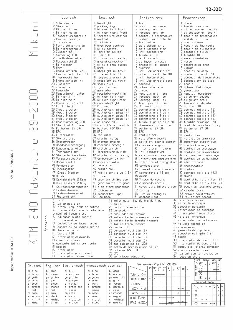
Rep
air
man
ual
KTM
LC
4 A
rt.-
Nr.
3.2
06.0
06 -
E12-32D

12-33D

Rep
air
man
ual
KTM
LC
4 A
rt.-
Nr.
3.2
06.0
06 -
E12-34D

12-35D
400/640 LC4 USA

Rep
air
man
ual
KTM
LC
4 A
rt.-
Nr.
3.2
06.0
06 -
E12-36D
400/
640
LC4
USA
200
0

12-37D

Rep
air
man
ual
KTM
LC
4 A
rt.-
Nr.
3.2
06.0
06 -
E12-38D
KTM 620 SC 2001
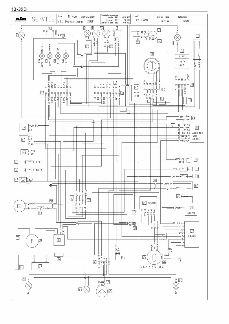
12-39D

Rep
air
man
ual
KTM
LC
4 A
rt.-
Nr.
3.2
06.0
06 -
E12-40D

12-41D

Rep
air
man
ual
KTM
LC
4 A
rt.-
Nr.
3.2
06.0
06 -
E12-42D

12-43D

Rep
air
man
ual
KTM
LC
4 A
rt.-
Nr.
3.2
06.0
06 -
E12-44D

12-45D

Rep
air
man
ual
KTM
LC
4 A
rt.-
Nr.
3.2
06.0
06 -
E12-46D
KTM
64
0 L
C4-
E 2
001

12-47D
625 SuperComp. 2002SERVICE

Rep
air
man
ual
KTM
LC
4 A
rt.-
Nr.
3.2
06.0
06 -
E12-48D
KTM 625 SUPER COMPETITION 2002

12-49D
SERVICE 640 LC4 ADVENTURE

Rep
air
man
ual
KTM
LC
4 A
rt.-
Nr.
3.2
06.0
06 -
E12-50D
KTM
64
0 L
C4
AD
VEN
TUR
E 2
002

12-51D
SERVICE DUKE 2002

Rep
air
man
ual
KTM
LC
4 A
rt.-
Nr.
3.2
06.0
06 -
E12-52D
KTM
D
UK
E 2
002

SERVICE
28
28
39
51
53
48
52
26
12
11
31
48
46
45
11
13
13
11
29
43
42
44
40
35
27
50
49
28
32
133738
13 34
14
18
15
17
19
16
29
33
3
5 6 78 9
31 47
12
10
30
4
30
2524
hinten: 584.11.176.200
Kabelstrangnummer: Datum, Name: Dateiname:Land:
23
KOKUSAN 12V 200W
22
20
21
G
36
41
axax
MOTORCYCLE
br
oo
g-ss
svwbrg-w
br g bl
br
w
s-ge
g-s r-
w
CONTROL
POWER-
ELECTRONIC
brge-r
bl-ss-o
ge-s g-s
g-s
ge-s
s-o
bl-s
s-o
sr-sbr
r
ger-wo
ge-blg-r
br gebl-w
r-s
br
bl-sge-bl
g-r
bl-w
s
s-wKOKUSAN
w
og
r-ss-r
geg-s
bl-s
s-obr
br
brge-r
M
brr-w
rs
o
ge-bl
ge-s
ge-blgr
g-s
ge-bl
g-w
ge-bl
g-w
br br
AUS
NOT-
START
rs-
w
ge-b
l
oo
blo
s
v
br
brge-b
l
ge-b
l
vv
v
ge-s g-s wbl s
brwsblg-
sge
-sge
-bl
brwsblg-s
ge-s
ge-b
l
ggrsvo
ge-b
lwblg br
bl-s
bl-r
g-br
g-r
wge r-br
ge-b
lge
-rge
-r
bloggeg-s
s
svwbrg-w
brbr
sv
400/640 LC4-E 2002Modell
KOKUSAN
KOKUSAN
r-s
s-r
ge
wg
ges-
wr
ge ge
bl-w
br
ge-bl
br
vorne: 584.11.175.30010.05.01 KE LC42002DIV. LÄNDER640 LC4 2002SERVICE
12-53D

Rep
air
man
ual
KTM
LC
4 A
rt.-
Nr.
3.2
06.0
06 -
E12-54D
Start- Notaus- Schalter
Domino
Z ndschlo§ (Typ Zadi)
Kombischalterw
s-sbl
s-geo
r- blg-geo
wsg
SpanischFranz sischItalienischEnglischDeutsch
Span
isch
Franz sischItalienischEnglischDeutsch
KTM
400
/640
LC4
-E 2
002
sg-g- g
r
PASSING
HORN
H HI
H LO
LIGHTS
TURN R
TURN L
brbl-
sbl-wge
br
53 commut de bequille later52 relaise com de bequ lat
53 int del cavalleto later52 rele del cavalleto later
53 side stand switch52 sidestand relay
53 Seitenst nderschalter52 Seitenst nderrelais
53 int.del caballete lateral
51 conector multiple (3)
35 EPC18 interruptor temperatura
39 luz plaza de matricula
39 ecl.plaque d.immat.39 illuminat.de.targa39 licence plate lighting39 Kennzeichenbeleuchtung
52 rele del caballete lateral
51 connect.multiple (3)51 connettore a 3 poli51 multip.cont.plug (3)51 3-pol.Stecker
50 interruptor de cambio (2)49 interruptor de cambio (3)
50 cont.d.bolte.d.vites.(2)49 cont.d.boite d.vites.(3)
50 2.secondo marcia49 3.secondo marcia
50 gear switch 2th gear49 gear switch 3rd gear
50 Kontaktstift 2.Gang 49 Kontaktstift 3.Gang
48 diodo47 conector multiple (12)46 generado de impulsos
48 diode47 connect.multiple (12)46 capteur
48 diodo47 connettore a 12 poli46 trasmettitore d’impulsi
48 diode47 multip.cont.plug (12)46 pulser coil
48 Diode47 12-pol.Stecker46 Impulsgeber
45 condensador
45 condensateur45 condensatore45 capacitor45 Kondensator
ra rosadora rosera rosara pinkra rosa
v violeta
gr gris
w blanco
s negro
r rojoo naranja
br marronbl azul
ge amarillo
g verde
v violet
gr gris
w blanc
s noir
r rougeo orange
br brunbl bleu
ge jaune
g vert
v violetto
gr grigio
w bianco
s nero
r rossoo arancione
br marronebl blu
ge giallo
g verde
v violet
gr grey
w white
s black
r redo orange
br brownbl blue
ge yellow
g green
v violett
gr grau
w wei§
s schwarz
r roto orange
br braunbl blau
ge gelb
g gr n
13 conector a masa
11 fusible 10A
14 conjunto del intermitente15 claxon
12 interruptor combinado
10 llave de contacto 9 lampara aviso intermitentes 8 lampara aviso luces largas 7 luz tacometro 6 indicador punto muerto 5 control temperatura 4 intermitente derecho delantero 3 interm. izquierdo delantero 2 luz de posicion 1 faro
43 interruptor de carburador44 valvola magnetica
42 rele del arranque41 interruptor temperatura40 interruptor de embraque
30 conector multiple (6)
38 motor de arranque37 rele de arranque
36 ventilador electrica
28 conecdor multiple (2)
33 boton de arranque par.de urg.
26 luz de freno trasero25 intermitente derecho trasero24 intermitente izquierdo trasero
31 conector multiple (9)32 fusible principal 20A
34 bateria 12V 8 Ah
23 regulador de tension
27 unidad cdi
22 generador21 bobina de encendido20 bujia19 interruptor luz de frendo tras
17 interruptor punto muerto16 interruptor
29 conector multiple (4)
30 connect.multiple (6)30 connettore a 6 poli30 multip.cont.plug (6)30 6-pol.Stecker
43 contact.de carburateur44 electrovanne
42 relaise auxi demarrage41 contact.de temperature 40 contact.de embrayage
43 interrutore carburatore44 valvola elettromagnetica
42 rele avviam. ausiliario41 int. temperatura40 interrutore frizione
44 magnetic valve43 carburetor switch42 startar auxil. relay41 temperature switch40 clutch switch
43 Vergaserschalter44 Magnetventil
42 Starterhilfsrelais41 Thermoschalter40 Kupplungsschalter
38 demarreur electrique37 relaise de demarreur36 ventilateur 35 EPC
28 connect.multiple (2)
13 masse
33 bout.de demar/arr.d’urg
26 feu arr.et de stop25 clign.arr.droit24 clign.arr.gauche
31 connect.multiple (9)32 fusible principal 20A
34 batterie 12V 8Ah
23 regulat.redresseur
27 boitier CDI
22 generateur21 bobine d’allumage20 bougie
11 fusible 10A
14 centrale clignot.15 klaxon
19 contact.arr.de stop18 contact. de temperature17 contact.pt.mort (N)16 cont.av de stop
12 vers commutateur
10 contact.d’allum.
29 connect.multiple (4)
9 temoin de clignoteur 8 temoin de feu route 7 eclair.comp.vitesse 6 ind.de point mort 5 temoin de temperature 4 clignoteur av. droit 3 clignoteur av. gauche 2 feu de position 1 phare
38 mot.d’avviamento elettr.37 rele d’avviamento36 ventilatore35 EPC
28 connettore a 2 poli
13 collegam. a massa
33 disinseritor/partire
26 fanal.post.di freno25 lampegg. post. dx.24 lampegg. post. sn.
31 connettore a 9 poli32 fusibile principale 20A
34 batteria 12V 8Ah
23 regolatore di tens
27 CDI-seatola
22 dinamo21 bobina d’accens.20 candela
11 fusibile 10A
14 trasmett. di lampeg.15 clacson
19 int.luce arresto post18 int. temperatura17 interr.luce folle (N)16 int.luce arresto ant.
12 multicomando
10 int. accensione
29 connettore a 4 poli
9 spia lampeggiatori 8 spia abbagliante 7 luce di tachimetro 6 indicat.marcia folle 5 controllo temperatura 4 lampegg. ant. dx. 3 lampegg. ant. sn. 2 luce di posizione 1 faro
38 starter engine37 starter relay36 fan motor35 EPC
28 multip.cont.plug (2)
13 ground connection
33 run-off/start switch
14 blink signal system
4 blinker right front 3 blinker left front 2 parking light 1 headlight
26 rear-stoplight25 blinker right rear24 blinker left rear
31 multip.cont.plug (9)32 mainfuse 20A
34 battery 12V 8Ah
23 regulator-rectifier
27 CDI-unit
22 generator21 ignition coil20 spark plug
11 fuse 10A
15 horn
19 stoplight switch r.18 temperature switch17 idle switch (N)16 stoplight switch f.
12 to combinat. switch
10 ignition switch
29 multip.cont.plug (4)
9 blink control 8 high beam control 7 tachometer light 6 neutral 5 temperature control
18 Thermoschalter
38 Startermotor37 Startrelaise36 L ftermotor35 EPC
28 2-pol.Stecker
13 Masseanschlu§
33 Starttast.Notaussch.
26 Brems-Schlu§licht25 Blinker re hi24 Blinker li hi
31 9-pol.Stecker32 Hauptsicherung 20A
34 Batterie 12V 8Ah
23 Regelgleichrichter
27 CDI-Einheit
22 Generator21 Z ndspule20 Z ndkerze
11 Sicherung 10A
14 Blinkgeber15 Horn
19 Bremslichtsch. hi
17 Leerlaufschalter (N)16 Bremslichtsch. vo
12 zum Kombischalter
10 Z ndschlo§
29 4-pol.Stecker
9 Blinkerkontrolle 8 Fernlichtkontrolle 7 Tachobeleuchtung 6 Leerlaufanzeige 5 Temperaturkontrolle 4 Blinker re vo 3 Blinker li vo 2 Standlicht 1 Scheinwerfer
KTM
64
0 L
C4
200
2

12-55D
SERVICE
28
28
39
51
53
48
52
26
12
11
31
48
46
45
11
13
13
11
29
42
40
2728
32
133738
13 34
14
18
15
17
19
16
29
33
3
5 6 78 9
31 47
12
10
30
4
30
2524
hinten: 584.11.176.200
Kabelstrangnummer: Datum, Name: Dateiname:Land:
23
KOKUSAN 12V 200W
22
20
21
G
36
41
axax
MOTORCYCLE
br
oo
g-ss
svwbrg-w
br g bl
br
w
s-ge
g-s r-
w
brge-r
bl-ss-o
ge-s g-s
g-s
ge-s
s-o
bl-s
sr-sbr
r
ger-wo
ge-blg-r
br ge
bl-w
s
s-wKOKUSAN
w
og
r-ss-r
geg-s
bl-s
s-obr
br
brge-r
M
brr-w
rs
o
ge-bl
ge-s
ge-blgr
g-s
ge-bl
g-w
ge-bl
g-w
br br
AUS
NOT-
START
rs-
w
ge-b
l
oo
blo
s
v
br
brge-b
l
ge-b
l
vv
v
ge-s g-s wbl s
brwsblg-
sge
-sge
-bl
brwsblg-s
ge-s
ge-b
l
ggrsvo
ge-b
lwblg br
bl-s
bl-r
g-br
g-r
wge r-br
ge-b
lge
-rge
-r
bloggeg-s
s
svwbrg-w
brbr
sv
640 LC4-E USA 2002Modell
KOKUSAN
KOKUSAN
r-s
s-r
ge
wg
ges-
wr
ge ge
bl-w
br
ge-bl
br
vorne: 584.11.175.30010.05.01 KE LC42002USA640 LC4 USA 2002SERVICE

Rep
air
man
ual
KTM
LC
4 A
rt.-
Nr.
3.2
06.0
06 -
E12-56D
Start- Notaus- Schalter
Domino
Z ndschlo§Æ (Typ Zadi)
Kombischalterw
s-sbl
s-geo
r- blg-geo
wsg
SpanischFranz sischItalienischEnglischDeutsch
Span
isch
Franz sischItalienischEnglischDeutsch
KTM
640
LC4
-E U
SA 2
002
sg-g- g
r
PASSING
HORN
H HI
H LO
LIGHTS
TURN R
TURN L
brbl-
sbl-wge
br
53 commut de bequille later52 relaise com de bequ lat
53 int del cavalleto later52 rele del cavalleto later
53 side stand switch52 sidestand relay
53 Seitenst nderschalter52 Seitenst nderrelais
53 int.del caballete lateral
51 conector multiple (3)
18 interruptor temperatura
39 luz plaza de matricula
39 ecl.plaque d.immat.39 illuminat.de.targa39 licence plate lighting39 Kennzeichenbeleuchtung
52 rele del caballete lateral
51 connect.multiple (3)51 connettore a 3 poli51 multip.cont.plug (3)51 3-pol.Stecker
48 diodo47 conector multiple (12)46 generado de impulsos
48 diode47 connect.multiple (12)46 capteur
48 diodo47 connettore a 12 poli46 trasmettitore d’impulsi
48 diode47 multip.cont.plug (12)46 pulser coil
48 Diode47 12-pol.Stecker46 Impulsgeber
45 condensador
45 condensateur45 condensatore45 capacitor45 Kondensator
ra rosadora rosera rosara pinkra rosa
v violeta
gr gris
w blanco
s negro
r rojoo naranja
br marronbl azul
ge amarillo
g verde
v violet
gr gris
w blanc
s noir
r rougeo orange
br brunbl bleu
ge jaune
g vert
v violetto
gr grigio
w bianco
s nero
r rossoo arancione
br marronebl blu
ge giallo
g verde
v violet
gr grey
w white
s black
r redo orange
br brownbl blue
ge yellow
g green
v violett
gr grau
w wei§
s schwarz
r roto orange
br braunbl blau
ge gelb
g gr n
13 conector a masa
11 fusible 10A
14 conjunto del intermitente15 claxon
12 interruptor combinado
10 llave de contacto 9 lampara aviso intermitentes 8 lampara aviso luces largas 7 luz tacometro 6 indicador punto muerto 5 control temperatura 4 intermitente derecho delantero 3 interm. izquierdo delantero 2 luz de posicion 1 faro
42 rele del arranque41 interruptor temperatura40 interruptor de embraque
30 conector multiple (6)
38 motor de arranque37 rele de arranque
36 ventilador electrica
28 conecdor multiple (2)
33 boton de arranque par.de urg.
26 luz de freno trasero25 intermitente derecho trasero24 intermitente izquierdo trasero
31 conector multiple (9)32 fusible principal 20A
34 bateria 12V 8 Ah
23 regulador de tension
27 unidad cdi
22 generador21 bobina de encendido20 bujia19 interruptor luz de frendo tras
17 interruptor punto muerto16 interruptor
29 conector multiple (4)
30 connect.multiple (6)30 connettore a 6 poli30 multip.cont.plug (6)30 6-pol.Stecker
42 relaise auxi demarrage41 contact.de temperature 40 contact.de embrayage
42 rele avviam. ausiliario41 int. temperatura40 interrutore frizione
42 startar auxil. relay41 temperature switch40 clutch switch
42 Starterhilfsrelais41 Thermoschalter40 Kupplungsschalter
38 demarreur electrique37 relaise de demarreur36 ventilateur
28 connect.multiple (2)
13 masse
33 bout.de demar/arr.d’urg
26 feu arr.et de stop25 clign.arr.droit24 clign.arr.gauche
31 connect.multiple (9)32 fusible principal 20A
34 batterie 12V 8Ah
23 regulat.redresseur
27 boitier CDI
22 generateur21 bobine d’allumage20 bougie
11 fusible 10A
14 centrale clignot.15 klaxon
19 contact.arr.de stop18 contact. de temperature17 contact.pt.mort (N)16 cont.av de stop
12 vers commutateur
10 contact.d’allum.
29 connect.multiple (4)
9 temoin de clignoteur 8 temoin de feu route 7 eclair.comp.vitesse 6 ind.de point mort 5 temoin de temperature 4 clignoteur av. droit 3 clignoteur av. gauche 2 feu de position 1 phare
38 mot.d’avviamento elettr.37 rele d’avviamento36 ventilatore
28 connettore a 2 poli
13 collegam. a massa
33 disinseritor/partire
26 fanal.post.di freno25 lampegg. post. dx.24 lampegg. post. sn.
31 connettore a 9 poli32 fusibile principale 20A
34 batteria 12V 8Ah
23 regolatore di tens
27 CDI-seatola
22 dinamo21 bobina d’accens.20 candela
11 fusibile 10A
14 trasmett. di lampeg.15 clacson
19 int.luce arresto post18 int. temperatura17 interr.luce folle (N)16 int.luce arresto ant.
12 multicomando
10 int. accensione
29 connettore a 4 poli
9 spia lampeggiatori 8 spia abbagliante 7 luce di tachimetro 6 indicat.marcia folle 5 controllo temperatura 4 lampegg. ant. dx. 3 lampegg. ant. sn. 2 luce di posizione 1 faro
38 starter engine37 starter relay36 fan motor
28 multip.cont.plug (2)
13 ground connection
33 run-off/start switch
14 blink signal system
4 blinker right front 3 blinker left front 2 parking light 1 headlight
26 rear-stoplight25 blinker right rear24 blinker left rear
31 multip.cont.plug (9)32 mainfuse 20A
34 battery 12V 8Ah
23 regulator-rectifier
27 CDI-unit
22 generator21 ignition coil20 spark plug
11 fuse 10A
15 horn
19 stoplight switch r.18 temperature switch17 idle switch (N)16 stoplight switch f.
12 to combinat. switch
10 ignition switch
29 multip.cont.plug (4)
9 blink control 8 high beam control 7 tachometer light 6 neutral 5 temperature control
18 Thermoschalter
38 Startermotor37 Startrelaise36 L ftermotor
28 2-pol.Stecker
13 Masseanschlu§
33 Starttast.Notaussch.
26 Brems-Schlu§licht25 Blinker re hi24 Blinker li hi
31 9-pol.Stecker32 Hauptsicherung 20A
34 Batterie 12V 8Ah
23 Regelgleichrichter
27 CDI-Einheit
22 Generator21 Z ndspule20 Z ndkerze
11 Sicherung 10A
14 Blinkgeber15 Horn
19 Bremslichtsch. hi
17 Leerlaufschalter (N)16 Bremslichtsch. vo
12 zum Kombischalter
10 Z ndschlo§
29 4-pol.Stecker
9 Blinkerkontrolle 8 Fernlichtkontrolle 7 Tachobeleuchtung 6 Leerlaufanzeige 5 Temperaturkontrolle 4 Blinker re vo 3 Blinker li vo 2 Standlicht 1 Scheinwerfer
KTM
64
0 L
C4
USA
20
02

12-57D

12-58DR
epai
r m
anua
l K
TM L
C4
Art
.-N
r. 3
.206
.006
-E

12-59D
640 LC4 2003

12-60DR
epai
r m
anua
l K
TM L
C4
Art
.-N
r. 3
.206
.006
-E K
TM
640
LC
4 2
003
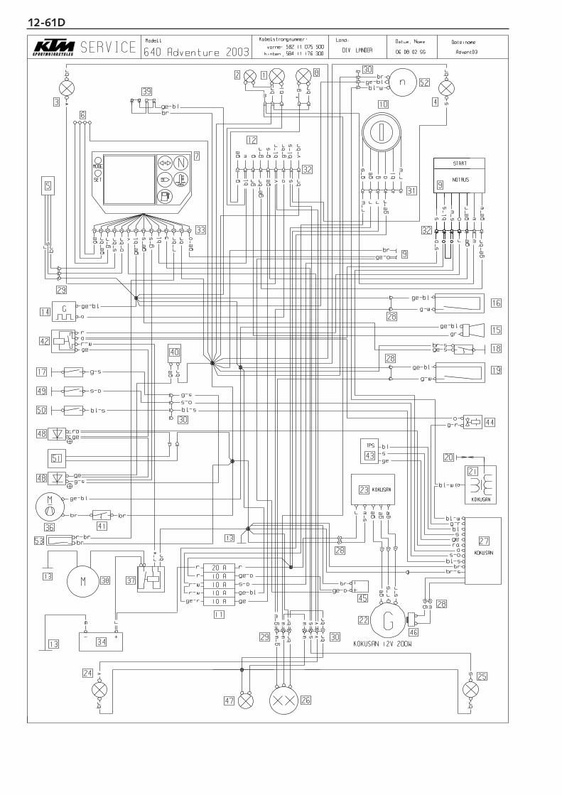
12-61D

12-62DR
epai
r m
anua
l K
TM L
C4
Art
.-N
r. 3
.206
.006
-E


12-63DR
epai
r m
anua
l K
TM L
C4
Art
.-N
r. 3
.206
.006
-E
ye-re
MA
Pic
k up
wh
sta
rt a
uxill
ary
rela
y
TP
S
or
br
re-wh
re
re-gn
wh
gn
bu
ye
bl
br
ye
bu
brbr-bl
br-bl
or
or
wh
wh
bl
ge
ne
rato
r
or
br
re
G3
D
C
bu-re
bu-bl
pi
br-pi
I
gn-bl
wh
ye
gn-regn-br
bl-bu
bl-wh
bl
ye-wh
wh
re-ye
re-w
h
or
rear light/brakelight
licence
pla
te la
mp
left
ra
er f
lash
er
rig
ht
rear
fla
sher
igniti
on s
witc
h
10
10
fuse
box
EP
C
sta
rte
r m
otor
star
t re
lay
batt
ery
AA
A10
capaci
tor
M
_
driving light lamp
temperature switch
coolin
g fan
idle control lamp
flasher control lamp temperature control lamp
C_A
F1/4
flash
er
rela
y
clutc
h s
witc
h
G
ho
rn
hig
h/lo
w b
eam
sw
itch
head light flascher
start
/sto
p s
witc
hhorn
sw
itch
flash
er
switc
h0
12
light
switc
h
dio
de
rear
bra
ke s
witc
h
ignition coil
dio
de
2n
d3
thN
sidest
and s
witc
h3
th g
ear
2n
d g
ear
neutr
al s
witc
h
rig
ht
fron
t fla
sher
frontbrake switch
headlight
tem
pera
ture
senso
r
left fro
nt fla
sher
t∞
tachometer
n
br
speedometer
v
ye-b
u
bu-w
h
whbrwh
pi
ye
gn-bl
ye
ye-bu
or
ye-b
u
gn-b
l
ye-b
u
blpu
wiri
ng d
iagr
am
br
pu
bubr
ye-b
l
br
br
brbu
brwh
ye-bl
pi
br
gn
bl
re-gn
bu-wh
gn-bl
or-bl
bu-bl
gnbu
ye-b
u
gn-w
h
brye
bu-w
h
ye-b
u
blpuor
gr
whye-b
l
gn-b
l
br
or
ye-br
gn
bu
ye
ye-b
l
ye-br
bl-or
gr
bl
pu
br-bl
br
ye-bu
br-bl
ye
re-ye
ye
ye-bu
re-wh
re-wh
bl-or
or
re
br
re
re
br gn-w
hgn-w
h
ye-b
u
ye
bu-wh
gn
wh
blpu br
reg
ula
tor-
rect
ifier
bu-bl
or-bl
U
oct
ane s
ele
ctor
bl
gn
20
re
br
re
re
re-wh
+
640-D
uke 0
3m
ain
harn
ess
- 58
7.11
.075
.100
cock
pit -
587
.11.
082.
000
rear
- 5
87.1
1.07
6.20
0fu
se b
ox -
587
.11.
087.
000

12-64D
660 SMC 2003

12-65DR
epai
r m
anua
l K
TM L
C4
Art
.-N
r. 3
.206
.006
-E
KTM 660 SMC 2003