KTM 250/300 repair manual 2004-2010 (2-strokes)
899
REPAIR MANUAL 2004-2010 BEDIENUNGSANLEITUNGEN OWNER’S MANUAL MANUALE O’USO MANUEL D’UTILISATION MANUAL DE INSTRUCCIONES REPARATURANLEITUNG REPAIR MANUAL MANUALE DI REPARAZIONE MANUEL DE REPARATION MANUAL DE REPARACION FEDERBEIN SHOCK ABSORBER AMMORTIZZATORE AMMORTISSEUR AMORTIGUADOR GABEL FORK FORCELLA FOURCHE HORQUILLA
-
Upload
khangminh22 -
Category
Documents
-
view
0 -
download
0
Transcript of KTM 250/300 repair manual 2004-2010 (2-strokes)

REPAIRMANUAL2004-2010BEDIENUNGSANLEITUNGENOWNER’S MANUALMANUALE O’USOMANUEL D’UTILISATIONMANUAL DE INSTRUCCIONES
REPARATURANLEITUNGREPAIR MANUALMANUALE DI REPARAZIONEMANUEL DE REPARATIONMANUAL DE REPARACION
FEDERBEINSHOCK ABSORBERAMMORTIZZATOREAMMORTISSEURAMORTIGUADOR
GABELFORKFORCELLAFOURCHEHORQUILLA

OWNERSMANUAL2010250 SX
250/300 XC,XC-W,EXC,EXC SixDays

OWNER'S MANUAL 2010
125 SX150 SX250 SX
Art. no. 3211480en

TABLE OF CONTENTS 2
TABLE OF CONTENTS
MEANS OF REPRESENTATION ............................................ 4IMPORTANT INFORMATION ................................................ 5VIEW OF VEHICLE............................................................... 7
View of the vehicle from the left front (example) ................. 7View of the vehicle from the right rear (example) ................ 8
LOCATION OF SERIAL NUMBERS ........................................ 9Chassis number............................................................... 9Type label....................................................................... 9Engine number................................................................ 9Fork part number............................................................. 9Shock absorber part number............................................. 9
CONTROLS....................................................................... 10Clutch lever .................................................................. 10Hand brake lever ........................................................... 10Short circuit button ....................................................... 10Throttle grip.................................................................. 10Fuel tap........................................................................ 11Opening the filler cap .................................................... 11Closing the filler cap...................................................... 11Choke........................................................................... 11Shift lever..................................................................... 12Kickstarter .................................................................... 12Foot brake lever............................................................. 12Plug-in stand ................................................................ 13
GENERAL TIPS AND HINTS ON PUTTING INTOOPERATION...................................................................... 14
Advice on first use......................................................... 14Running in the engine.................................................... 15Preparing the vehicle for difficult operating conditions ...... 15Preparations for riding on dry sand.................................. 15Preparations for riding on wet sand ................................. 16Preparations for riding on wet and muddy surfaces ........... 17Preparations for riding at high temperatures and ridingslowly........................................................................... 18Preparations for riding at low temperatures and in snow .... 18
RIDING INSTRUCTIONS .................................................... 19Checks before putting into operation ............................... 19Starting ........................................................................ 19Starting up ................................................................... 20Shifting, riding.............................................................. 20Braking ........................................................................ 20Stopping, parking .......................................................... 21Refueling...................................................................... 21
SERVICE SCHEDULE......................................................... 23Important maintenance work that must be done in anauthorized KTM workshop .............................................. 23Important maintenance work to be carried out by anauthorized KTM workshop (as additional order)................. 24Important checks and maintenance work to be carriedout by the rider ............................................................. 24
MAINTENANCE WORK ON CHASSIS AND ENGINE.............. 26Jacking up the motorcycle .............................................. 26Removing the motorcycle from the work stand.................. 26Checking the basic chassis setting with the rider'sweight .......................................................................... 26Compression damping of shock absorber.......................... 26Adjusting the high-speed compression damping of theshock absorber .............................................................. 26Adjusting the low-speed compression damping of theshock absorber .............................................................. 27Adjusting the rebound damping of the shock absorber....... 28Measuring the sag of the unloaded rear wheel .................. 28
Checking the static sag of the shock absorber .................. 29Checking the riding sag of the shock absorber .................. 29Adjusting the spring preload of the shock absorberx ...... 29Adjusting the riding sagx............................................. 30Removing the shock absorberx..................................... 30Installing the shock absorberx ..................................... 31Checking the basic setting of the fork.............................. 31Adjusting the compression damping of the fork ................ 31Adjusting the rebound damping of the fork....................... 32Bleeding the fork legs .................................................... 32Cleaning the dust boots of the fork legs ........................... 32Loosening the fork protection.......................................... 33Positioning the fork protection ........................................ 33Checking the play of the steering head bearing................. 33Adjusting the play of the steering head bearingx............ 34Removing the fork legsx .............................................. 34Installing the fork legsx............................................... 35Removing the fork protectorx....................................... 35Installing the fork protectorx ....................................... 35Removing the lower triple clampx ................................ 36Installing the lower triple clampx ................................. 36Greasing the steering head bearingx............................. 37Removing the front fender .............................................. 37Installing the front fender............................................... 37Removing the start number plate .................................... 37Installing the start number plate ..................................... 38Handlebar position ........................................................ 38Adjusting the handlebar positionx ................................ 38Checking the play in the throttle cable............................. 39Adjusting the play in the throttle cablex ....................... 39Checking the chain for dirt ............................................. 39Cleaning the chain......................................................... 39Checking the chain tension ............................................ 40Checking the rear sprocket/engine sprocket for wear ......... 40Checking chain wear...................................................... 40Adjusting the chain tension ............................................ 41Adjusting the chain guidex .......................................... 42Checking the brake discs................................................ 42Checking the free travel of the hand brake lever ............... 43Adjusting the basic position of the hand brake lever.......... 43Checking the front brake fluid level ................................. 43Adding front brake fluidx ............................................ 44Checking the front brake linings...................................... 44Removing the front brake liningsx ................................ 45Installing the front brake liningsx................................. 45Changing the front brake liningsx................................. 46Checking the free play of the foot brake lever ................... 46Adjusting the basic position of the foot brake leverx ...... 47Checking the rear brake fluid level .................................. 47Adding rear brake fluidx.............................................. 48Checking the rear brake linings ....................................... 48Removing the rear brake liningsx ................................. 49Installing the rear brake liningsx .................................. 49Changing the rear brake liningsx .................................. 50Removing the front wheelx .......................................... 50Installing the front wheelx........................................... 51Removing the rear wheelx ........................................... 52Installing the rear wheelx ............................................ 52Checking the tire condition............................................. 53Checking the tire air pressure ......................................... 54Checking the spoke tension ............................................ 54

TABLE OF CONTENTS 3
Ignition curve plug connection ........................................ 54Changing the ignition curve ............................................ 55Engine characteristic - auxiliary spring (250 SX)............... 55Engine characteristic - adjusting the auxiliary springx(250 SX) ...................................................................... 55Removing the seat ......................................................... 56Mounting the seat ......................................................... 56Removing the fuel tankx ............................................. 56Installing the fuel tankx .............................................. 57Cooling system.............................................................. 58Checking the antifreeze and coolant level ........................ 58Checking the coolant level.............................................. 59Draining the coolantx.................................................. 59Refilling with coolantx ................................................ 60Removing the main silencer............................................ 61Installing the main silencer ............................................ 61Glass fiber yarn filling of main silencer ............................ 61Changing the glass fiber yarn filling of the mainsilencerx ................................................................... 61Removing the glass fiber yarn filling of the mainsilencerx ................................................................... 62Installing the glass fiber yarn filling of the mainsilencerx ................................................................... 62Removing the air filter box lid......................................... 62Installing the air filter box lid.......................................... 62Removing the air filterx............................................... 63Installing the air filterx ............................................... 63Cleaning the air filterx ................................................ 63Adjusting the basic position of the clutch lever................. 64Checking the fluid level of the hydraulic clutch ................ 64Changing the hydraulic clutch fluidx ............................ 65Checking the basic position of the shift lever.................... 66Adjusting the basic position of the shift leverx .............. 66Carburetor .................................................................... 66Carburetor - adjusting the idle speedx .......................... 67Emptying the carburetor float chamberx ....................... 68Checking the gear oil level.............................................. 68Changing the gear oilx ................................................ 69Draining the gear oilx ................................................. 69Refilling with gear oilx ................................................ 70Adding gear oilx ......................................................... 70
TROUBLESHOOTING......................................................... 72CLEANING........................................................................ 74
Cleaning the motorcycle ................................................. 74STORAGE ......................................................................... 75
Storage......................................................................... 75Putting into operation after storage ................................. 75
TECHNICAL DATA - ENGINE.............................................. 76125 SX......................................................................... 76150 SX......................................................................... 76250 SX......................................................................... 77Capacity - gear oil.......................................................... 77Capacity - coolant.......................................................... 77
TECHNICAL DATA - ENGINE TIGHTENING TORQUES.......... 78125 SX, 150 SX............................................................ 78250 SX......................................................................... 78
TECHNICAL DATA - CARBURETOR..................................... 80125 SX......................................................................... 80Carburetor - basic setting for sandy surfaces (125 SX) ...... 80Carburetor configuration (125 SX)................................... 81150 SX......................................................................... 82
Carburetor - basic setting for sandy surfaces (150 SX) ...... 82Carburetor configuration (150 SX)................................... 83250 SX......................................................................... 84Carburetor - basic setting for sandy surfaces (250 SX) ...... 84Carburetor configuration (250 SX)................................... 85
TECHNICAL DATA - CHASSIS ............................................ 86Tires ............................................................................ 86Capacity - fuel............................................................... 86
TECHNICAL DATA - FORK.................................................. 87125 SX, 150 SX............................................................ 87250 SX......................................................................... 87
TECHNICAL DATA - SHOCK ABSORBER ............................. 88125 SX, 150 SX............................................................ 88250 SX......................................................................... 88
TECHNICAL DATA - TIGHTENING TORQUES FORCHASSIS .......................................................................... 90WIRING DIAGRAM ............................................................ 92
Wiring diagram.............................................................. 92SUBSTANCES................................................................... 94AUXILIARY SUBSTANCES.................................................. 96STANDARDS..................................................................... 98INDEX .............................................................................. 99

MEANS OF REPRESENTATION 4
Symbols usedThe symbols used are explained below.
Indicates an expected reaction (e.g. of a work step or a function).
Indicates an unexpected reaction (e.g. of a work step or a function).
All work marked with this symbol requires specialist knowledge and technical understanding. In the interest ofyour own safety, have these jobs done in an authorized KTM workshop! There, your motorcycle will be servicedoptimally by specially trained experts using the specialist tools required.
Identifies a page reference (more information is provided on the specified page).
Formats usedThe typographical and other formats used are explained below.
Specific name Identifies a specific name.
Name® Identifies a protected name.
Brand™ Identifies a brand available on the open market.

IMPORTANT INFORMATION 5
Use definitionKTM sport motorcycles are designed and built to withstand the normal stresses and strains of competitive use. The motorcycles com-ply with currently valid regulations and categories of the top international motorsport organizations.
InfoThe motorcycle must be used only in closed off areas remote from public road traffic.
MaintenanceA prerequisite for perfect operation and prevention of wear is that the engine and chassis maintenance and adjustment work describedin the owner's manual are properly carried out. Poor adjustment and tuning of the engine and chassis can lead to damage and break-age of components.Using the motorcycle in difficult conditions such as on sand or very muddy or wet terrain can lead to above-average wear of compo-nents such as the transmission train or the brakes. For this reason, it may be necessary to service or replace worn parts before thelimit specified in the service schedule is reached.Pay careful attention to the prescribed running-in period, inspection and maintenance intervals. If you observe these exactly, you willensure a much longer service life for your motorcycle.
WarrantyThe work prescribed in the service schedule must be carried out in an authorized KTM workshop only and confirmed in the customer'sservice record, since otherwise no warranty claims will be honored. No warranty claims can be considered for damage resulting frommanipulations and/or alterations to the vehicle.
Fuel, oils, etc.You should use the fuels, oils and greases according to specifications as listed in the owner's manual.
Spare parts, accessoriesFor your own safety, only use spare parts and accessory products that have been approved and/or recommended by KTM and havethem installed by an authorized KTM workshop. KTM accepts no liability for other products and any resulting damage or loss.Certain spare parts and accessories are specified in parentheses in the descriptions. Your KTM dealer will be glad to advise you.
You will find the current KTM PowerParts for your vehicle on the KTM website.International KTM Website: http://www.ktm.com
Work rulesSpecial tools are needed for certain tasks. They are not included with the vehicle but can be ordered under the number in parenthe-ses. E.g.: bearing puller (15112017000)When the vehicle is assembled, non-reusable parts (e.g., self-locking screws and nuts, gaskets, seal rings, O-rings, splints, lock wash-ers) must be replaced with new parts.Where thread lockers are used on screw connections (e.g., Loctite®), follow the instructions for use from the manufacturer.After disassembly, clean the parts that are to be reused and check them for damage and wear. Replace damaged or worn parts.After you complete the repair or maintenance work, check the roadworthiness of the vehicle.
Transport
NoteDanger of damage The parked vehicle can roll away or fall over.
– Always place the vehicle on a firm and even surface.
NoteFire hazard Some vehicle components become very hot when the vehicle is operated.
– Do not park the vehicle near flammable or explosive substances. Do not place objects on the vehicle while it is still warm frombeing run. Always let the vehicle cool first.
– Switch off the engine.
– Turn handle of the fuel tap to the OFF position. (Figure B00003-10 p. 11)
– Use straps or other suitable devices to secure the motorcycle against accidents or falling over.

IMPORTANT INFORMATION 6
EnvironmentMotorcycling is a wonderful sport and we naturally hope that you can enjoy it to the full. However, it is a potential problem for theenvironment and can lead to conflicts with other persons. But if you use your motorcycle responsibly, you can ensure that such prob-lems and conflicts do not have to occur. To protect the future of motorcycle sport, make sure that you use your motorcycle legally, dis-play environmental consciousness, and respect the rights of others.
Notes/warningsPay close attention to the notes/warnings.
InfoVarious information and warning labels are affixed to the vehicle. Do not remove information/warning labels. If they are miss-ing, you or others may not recognize potential hazards and may therefore be injured.
Grades of risks
DangerIdentifies a danger that will immediately and invariably lead to fatal or serious permanent injury if the appropriate measuresare not taken.
WarningIdentifies a danger that is likely to lead to fatal or serious injury if the appropriate measures are not taken.
NoteIdentifies a danger that will lead to considerable machine and material damage if the appropriate measures are not taken.
WarningIdentifies a danger that will lead to environmental damage if the appropriate measures are not taken.
Owner's manual– It is important that you read this owner's manual carefully and completely before making your first trip. It contains information and
tips that will assist you in operating and handling your motorcycle properly. Only then will you learn how to adjust the motorcycleto your own requirements and how to protect yourself from injury. The owner's manual also contains important information on ser-vicing the motorcycle.
– The owner's manual is an important component of the motorcycle and should be handed over to the new owner if the vehicle issold.

VIEW OF VEHICLE 7
3.1View of the vehicle from the left front (example)
B00010-10
1 Hand brake lever
2 Short circuit button
3 Clutch lever
4 Air filter box lid
5 Fuel tap
6 Choke button
7 Shift lever
8 Chain guide

VIEW OF VEHICLE 8
3.2View of the vehicle from the right rear (example)
B00014-10
1 Shock absorber rebound adjustment
2 Level viewer for brake fluid, rear
3 Fork rebound adjustment
4 Foot brake lever
5 Kickstarter
6 Shock absorber compression adjustment
7 Throttle grip
8 Fork compression adjustment
9 Filler cap

LOCATION OF SERIAL NUMBERS 9
4.1Chassis number
B00015-10
The chassis number is stamped on the right side of the steering head.
4.2Type label
400284-10
The type label is fixed to the front of the steering head.
4.3Engine number
B00016-10
The engine number is stamped on the left side of the engine under the enginesprocket.
4.4Fork part number
500082-10
The fork part number is stamped on the inner side of the fork stub.
4.5Shock absorber part number
500083-10
The shock absorber part number is stamped on the top of the shock absorber abovethe adjusting ring on the engine side.

CONTROLS 10
5.1Clutch lever
B00001-10
(125 SX, 150 SX)The clutch lever is fitted on the left side of the handlebar.The clutch is hydraulically operated and self-adjusting.
B00009-10
(250 SX)The clutch lever is fitted on the left side of the handlebar.The clutch is hydraulically operated and self-adjusting.
5.2Hand brake lever
400196-10
Hand brake lever is located on the right side of the handlebar.The hand brake lever is used to activate the front brake.
5.3Short circuit button
B00002-10
Short circuit button is fitted on the left side of the handlebar.
Possible states• Short circuit button in basic position – In this position, the ignition circuit is
closed, and the engine can be started.• Short circuit button pressed – In this position, the ignition circuit is interrupted,
a running engine stops, and a non-running engine will not start.
5.4Throttle grip
B00060-10
Throttle grip is fitted on the right side of the handlebar.

CONTROLS 11
5.5Fuel tap
B00003-10
The fuel tap is on the left side of the fuel tank.With tap handle on the fuel tap, you can open or close the supply of fuel to the car-buretor.
Possible states• Fuel supply closed OFF – No fuel can flow from the tank to the carburetor.• Fuel supply open ON – Fuel can flow from the tank to the carburetor. The fuel tank
empties completely.
5.6Opening the filler cap
400199-10
– Press release button , turn the filler cap counterclockwise and lift it free.
5.7Closing the filler cap
400199-11
– Replace the filler cap and turn clockwise until the release button locks in place.
InfoRun the fuel tank breather hose without kinks.
5.8Choke
B00004-10
The choke is fitted on the left side of the carburetor.Activating the choke function frees an opening through which the engine can drawextra fuel. This gives a richer fuel-air mixture, which is needed for a cold start.
InfoIf the engine is warm, the choke function must be deactivated.
Possible states• Choke function activated – The choke lever is pulled out to the stop.• Choke function deactivated – The choke lever is pushed in to the stop.

CONTROLS 12
5.9Shift lever
B00005-10
Shift lever is mounted on the left side of the engine.
B00005-12
(125 SX, 150 SX)The gear positions can be seen in the photograph.The neutral or idle position is between the first and second gears.
B00005-11
(250 SX)The gear positions can be seen in the photograph.The neutral or idle position is between the first and second gears.
5.10Kickstarter
B00006-10
The kickstarter is fitted on the right side of the engine. The top part can beswiveled.
5.11Foot brake lever
B00007-10
Foot brake lever is located in front of the right footrest.The foot brake lever is used to activate the rear brake.

CONTROLS 13
5.12Plug-in stand
400203-10
NoteDanger of damage The parked vehicle can roll away or fall over.
– Always place the vehicle on a firm and even surface.
To park the motorcycle, insert plug-in stand into the left side of the wheel spindle.
InfoRemove the plug-in stand before riding.

GENERAL TIPS AND HINTS ON PUTTING INTO OPERATION 14
6.1Advice on first use
DangerDanger of accidents Danger arising from the rider's judgement being impaired.
– Do not use the vehicle if you are inexperienced or if you have consumed alcohol or drugs.
WarningRisk of injury Missing or poor protective clothing present an increased safety risk.
– Wear protective clothing (helmet, boots, gloves, pants and jacket with protectors) every time you ride the vehicle. Alwayswear protective clothing, which must be undamaged and meet legal requirements.
WarningDanger of crashing Poor vehicle handling due to different tire tread patterns on front and rear wheels.
– The front and rear wheels must be fitted with tires with similar tread patterns to prevent loss of control over the vehicle.
WarningDanger of accidents Critical handling characteristic due to inappropriate riding style.
– Adapt your riding speed to the road conditoins and your riding ability.
WarningDanger of accidents Accident risk caused by presence of a passenger.
– Your vehicle is not designed to carry passengers. Do not ride with a passenger.
WarningDanger of accidents Failure of brake system.
– If the foot brake lever is not released, the brake linings drag permanently. The rear brake can fail due to overheating. Takeyour foot off the foot brake lever if you do not want to brake.
WarningDanger of accidents Unstable riding behavior.
– Do not exceed the maximum permissible weight and axle loads.
WarningRisk of misappropriation Usage by unauthorized persons.
– Never leave the vehicle while the engine is running. Secure the vehicle against use by unauthorized persons.
InfoWhen using your motorcycle, remember that others may feel disturbed by excessive noise.
– Make sure that the pre-delivery inspection work has been carried out by an authorized KTM workshop.
You receive a delivery certificate and the service record at vehicle handover.
– Before your first trip, read the entire operating instructions carefully.
– Get to know the controls.
– Adjust the basic position of the clutch lever. ( p. 64)
– Adjust the basic position of the hand brake lever. ( p. 43)
– Adjust the basic position of the foot brake lever.x ( p. 47)
– Become accustomed to the handling of the motorcycle on suitable terrain.
InfoYour motorcycle is not authorized for riding on public roads.Offroad, you should be accompanied by another person on another machine so that you can help each other.
– Try also to ride as slowly as possible and in a standing position to get a better feeling for the vehicle.
– Do not make any offroad trips that over-stress your ability and experience.
– Hold the handlebar firmly with both hands and keep your feet on the footrests when riding.
– Do not transport luggage.
– Do not exceed the overall maximum permitted weight and the axle loads.

GENERAL TIPS AND HINTS ON PUTTING INTO OPERATION 15
Guideline
Maximum permissible overall weight 335 kg (739 lb.)
Maximum permissible front axle load 145 kg (320 lb.)
Maximum permissible rear axle load 190 kg (419 lb.)
– Check the spoke tension. ( p. 54)
InfoThe spoke tension must be checked after riding the motorcycle for one half hour.
– Run the engine in.
6.2Running in the engine– During the running-in phase, do not exceed the specified engine performance.
Guideline
Maximum engine performance
During the first 3 service hours < 70 %
During the first 5 service hours < 100 %
– Avoid fully opening the throttle!
6.3Preparing the vehicle for difficult operating conditions– The use of motorcycles under difficult operating conditions can lead to above-average wear of components such as the drive train
or brakes. For this reason, it may be necessary to service or replace worn parts before the limit specified in the service schedule isreached.
Difficult operating conditions are:– Riding on dry sand. ( p. 15)
– Riding on wet sand. ( p. 16)
– Riding on wet and muddy surfaces. ( p. 17)
– Riding at high temperatures and riding slowly. ( p. 18)
– Riding at low temperatures and in snow. ( p. 18)
6.4Preparations for riding on dry sand
600872-10
– Check the radiator cap.
Value on radiator cap 1.8 bar (26 psi)
» If the value displayed does not meet specifications:
WarningDanger of scalding During motorcycle operation, the coolant getsvery hot and is under pressure.
– Do not remove the radiator cap, radiator hoses or other coolingsystem components when the engine is hot. Allow the engineand cooling system to cool down. In case of scalding, rinseimmediately with lukewarm water.
– Change the radiator cap.
– Seal the air filter box.x
TipSeal the air filter box at the edges to prevent dirt from entering.
– Clean the air filter.x ( p. 63)
InfoCheck the air filter approx. every 30 minutes.

GENERAL TIPS AND HINTS ON PUTTING INTO OPERATION 16
600869-01
– Mount the dust cover for the air filter.
Dust cover for air filter (59006019000)
InfoFollow the KTM PowerParts mounting instructions.
600871-01
– Mount the sand cover for the air filter.
Sand cover for air filter (59006022000)
InfoFollow the KTM PowerParts mounting instructions.
– Adjust the carburetor jetting and setting.
InfoThe recommended carburetor tuning is available from your authorized KTMworkshop.
600868-01
– Clean the chain.
Chain cleaner ( p. 96)
– Mount the steel sprocket.
TipDo not lubricate the chain.
– Clean the radiator fins.
– Carefully align bent radiator fins.
6.5Preparations for riding on wet sand
600872-10
– Check the radiator cap.
Value on radiator cap 1.8 bar (26 psi)
» If the value displayed does not meet specifications:
WarningDanger of scalding During motorcycle operation, the coolant getsvery hot and is under pressure.
– Do not remove the radiator cap, radiator hoses or other coolingsystem components when the engine is hot. Allow the engineand cooling system to cool down. In case of scalding, rinseimmediately with lukewarm water.
– Change the radiator cap.
– Seal the air filter box.x
TipSeal the air filter box at the edges to prevent dirt from entering.
– Clean the air filter.x ( p. 63)
InfoCheck the air filter approx. every 30 minutes.

GENERAL TIPS AND HINTS ON PUTTING INTO OPERATION 17
600870-01
– Mount the rain cover for the air filter.
Rain cover for air filter (59006021000)
InfoFollow the KTM PowerParts mounting instructions.
– Adjust the carburetor jetting and setting.
InfoThe recommended carburetor tuning is available from your authorized KTMworkshop.
600868-01
– Clean the chain.
Chain cleaner ( p. 96)
– Mount the steel sprocket.
TipDo not lubricate the chain.
– Clean the radiator fins.
– Carefully align bent radiator fins.
6.6Preparations for riding on wet and muddy surfaces– Seal the air filter box.x
TipSeal the air filter box at the edges to prevent dirt from entering.
– Clean the air filter.x ( p. 63)
InfoCheck the air filter approx. every 30 minutes.
600870-01
– Mount the rain cover for the air filter.
Rain cover for air filter (59006021000)
InfoFollow the KTM PowerParts mounting instructions.
– Adjust the carburetor jetting and setting.
InfoThe recommended carburetor tuning is available from your authorized KTMworkshop.
600868-01
– Mount the steel sprocket.
– Clean the motorcycle. ( p. 74)
– Carefully align bent radiator fins.

GENERAL TIPS AND HINTS ON PUTTING INTO OPERATION 18
6.7Preparations for riding at high temperatures and riding slowly
600872-10
– Check the radiator cap.
Value on radiator cap 1.8 bar (26 psi)
» If the value displayed does not meet specifications:
WarningDanger of scalding During motorcycle operation, the coolant getsvery hot and is under pressure.
– Do not remove the radiator cap, radiator hoses or other coolingsystem components when the engine is hot. Allow the engineand cooling system to cool down. In case of scalding, rinseimmediately with lukewarm water.
– Change the radiator cap.
– Seal the air filter box.x
TipSeal the air filter box at the edges to prevent dirt from entering.
– Clean the air filter.x ( p. 63)
InfoCheck the air filter approx. every 30 minutes.
600868-01
– Adjust the secondary ratio to the nature of the terrain.
InfoThe engine oil heats up quickly if the clutch needs to be activatedfrequently because the secondary ratio is too long.
– Clean the chain.
Chain cleaner ( p. 96)
– Clean the radiator fins.
– Carefully align bent radiator fins.
– Check the coolant level. ( p. 59)
6.8Preparations for riding at low temperatures and in snow– Seal the air filter box.x
TipSeal the air filter box at the edges to prevent dirt from entering.
– Clean the air filter.x ( p. 63)
InfoCheck the air filter approx. every 30 minutes.
600870-01
– Mount the rain cover for the air filter.
Rain cover for air filter (59006021000)
InfoFollow the KTM PowerParts mounting instructions.
– Adjust the carburetor jetting and setting.
InfoThe recommended carburetor tuning is available from your authorized KTMworkshop.

RIDING INSTRUCTIONS 19
7.1Checks before putting into operation
InfoMake sure that the motorcycle is in a perfect technical condition before use.In the interests of riding safety, make a habit of making a general check before you ride.
– Check the gear oil level. ( p. 68)
– Check the chain tension. ( p. 40)
– Check the chain for dirt. ( p. 39)
– Check the tire condition. ( p. 53)
– Check the tire air pressure. ( p. 54)
– Check the front brake fluid level. ( p. 43)
– Check the rear brake fluid level. ( p. 47)
– Check the front brake linings. ( p. 44)
– Check the rear brake linings. ( p. 48)
– Check the brake system function.
– Check the coolant level. ( p. 59)
– Check the settings of all controls and ensure that they can be operated smoothly.
7.2Starting
DangerDanger of poisoning Exhaust gases are poisonous and inhaling them may result in unconsciousness and/or death.
– When running the engine, always make sure there is sufficient ventilation, and do not start or run the engine in an enclosedspace without an effective exhaust extraction system.
NoteEngine failure High engine speeds in cold engines have a negative effect on the service life of the engine.
– Always warm up the engine at low engine speeds.
InfoIf the motorcycle is unwilling to start, the cause can be old fuel in the float chamber. The flammable elements of the fuelevaporate after a long time of standing.If the float chamber is filled with fresh fuel, the engine starts immediately.
Engine has been out of use for more than one week– Empty the carburetor float chamber.x ( p. 68)
– Turn handle of the fuel tap to the ON position. (Figure B00003-10 p. 11)
Fuel can flow from the fuel tank to the carburetor.
– Remove the motorcycle from the stand.
– Shift gear to neutral.
The engine is cold– Pull choke lever out as far as possible.
– Forcefully step on the kickstarter, pushing it all the way down.
InfoDo not open the throttle.

RIDING INSTRUCTIONS 20
7.3Starting up
InfoThe plug-in stand must be removed before riding.
– Pull the clutch lever, engage 1st gear, release the clutch lever slowly and simultaneously open the throttle carefully.
7.4Shifting, riding
WarningDanger of accidents If you change down at high engine speed, the rear wheel can lock up.
– Do not change into a low gear at high engine speed. The engine overspeeds and the rear wheel can block.
InfoIf you hear unusual noises while riding, stop immediately, switch off the engine and contact an authorized KTM workshop.First gear is used for starting off or for steep inclines.
– When conditions allow (incline, road situation, etc.), you can shift into a higher gear. To do so, release the throttle while simulta-neously pulling the clutch lever, shift into the next gear, release the clutch and open the throttle.
– If the choke function was activated, deactivate it after the engine has warmed up.
– When you reach maximum speed after fully opening the throttle, turn back the throttle to about ¾ of its range. This barely reducesvehicle speed but lowers fuel consumption considerably.
– Always open the throttle only as much as the engine can handle – abrupt throttle opening increases fuel consumption.
– To shift down, brake and close the throttle at the same time.
– Pull the clutch lever and shift into a lower gear, release the clutch lever slowly and open the throttle or shift again.
– Switch off the engine if you expect to be standing for a long time.
Guideline
≥ 2 min
– Avoid frequent and longer slipping of the clutch. This heats the engine oil, the engine and the cooling system.
– Ride with a lower engine speed instead of with a high engine speed and a slipping clutch.
7.5Braking
WarningDanger of accidents If you brake too hard, the wheels can lock.
– Adapt your braking to the traffic situation and the road conditions.
WarningDanger of accidents Reduced braking efficiency caused by spongy pressure point of front or rear brake.
– Check the brake system and do not continue riding. (Your authorized KTM workshop will be glad to help.)
WarningDanger of accidents Reduced braking due to wet or dirty brakes.
– Clean or dry dirty or wet brakes by riding and braking gently.
– On sandy, wet or slippery surfaces, use the rear brake.
– Braking should always be completed before you go into a bend. Change down to a lower gear appropriate to your road speed.
– On long downhill stretches, use the braking effect of the engine. Change down one or two gears, but do not overstress the engine.In this way, you have to brake far less and the brakes do not overheat.

RIDING INSTRUCTIONS 21
7.6Stopping, parking
WarningRisk of misappropriation Usage by unauthorized persons.
– Never leave the vehicle while the engine is running. Secure the vehicle against use by unauthorized persons.
WarningDanger of burns Some vehicle components get very hot when the vehicle is in use.
– Do not touch hot components such as exhaust system, radiator, engine, shock absorber and brakes. Allow these compo-nents to cool down before starting work on them.
NoteDanger of damage The parked vehicle can roll away or fall over.
– Always place the vehicle on a firm and even surface.
NoteFire hazard Some vehicle components become very hot when the vehicle is operated.
– Do not park the vehicle near flammable or explosive substances. Do not place objects on the vehicle while it is still warm frombeing run. Always let the vehicle cool first.
NoteMaterial damage Damage and destruction of components by excessive load.
– The side stand is designed for the weight of the motorcycle only. Do not sit on the motorcycle when it is supported by the sidestand only. The side stand and/or the frame could be damaged and the motorcycle could fall over.
– Brake the motorcycle.
– Shift gear to neutral.
– Press and hold the short circuit button while the engine is idling until the engine stops.
– Turn handle of the fuel tap to the OFF position. (Figure B00003-10 p. 11)
– Insert the plug-in stand on the left side of the wheel spindle.
– Park the motorcycle on firm ground.
7.7Refueling
DangerFire hazard Fuel is highly flammable.
– Never refuel the vehicle near open flames or burning cigarettes, and always switch off the engine first. Be careful that nofuel is spilt, especially on hot vehicle components. Clean up spilt fuel immediately.
– Fuel in the fuel tank expands when warm and can escape if the tank is overfilled. See the notes on refueling.
WarningDanger of poisoning Fuel is poisonous and a health hazard.
– Avoid contact of the fuel with skin, eyes and clothing. Do not inhale fuel vapors. If fuel gets into your eyes, rinse imme-diately with water and contact a doctor. Wash affected skin areas immediately with soap and water. If fuel is swallowed,contact a doctor immediately. Change clothing that has come into contact with fuel.
WarningEnvironmental hazard Improper handling of fuel is a danger to the environment.
– Do not allow fuel to get into the ground water, the ground, or the sewage system.
– Switch off the engine.
– Open the filler cap. ( p. 11)

RIDING INSTRUCTIONS 22
AA
400382-10
– Fill the fuel tank with fuel up to measurement .
Guideline
Measurement of 35 mm (1.38 in)
Total fuel tankcapacity, approx.
8 l (2.1 US gal) Super unleaded gasoline, mixed with2-stroke engine oil (1:40) ( p. 95)(125 SX, 150 SX)
Super unleaded gasoline, mixed with2-stroke engine oil (1:60) ( p. 95)(250 SX)
– Close the filler cap. ( p. 11)

SERVICE SCHEDULE 23
8.1Important maintenance work that must be done in an authorized KTM workshop
S10N S20A S40A
Engine Check the gear oil level. ( p. 68) • •
Change the gear oil.x ( p. 69) • •
Check spark plug and replace if required.x • • •
Clean the spark plug connectors and check for tightness.x • •
Check that the screws in the shift lever and the kickstarter are tight. • • •
Check the engine mounting screws for tightness. • • •
Carburetor Check intake flange and carburetor connection boot for cracks and leakage. • •
Check idle. • •
Check vent hoses for damage and routing without sharp bends. • •
Attachments Check the cooling system for leakage. • •
Check the antifreeze and coolant level. ( p. 58) • •
Check the exhaust system for leakage and looseness. • •
Check the cables for damage, smooth operation and routing without sharp bends. • • •
Check the fluid level of the hydraulic clutch. ( p. 64) • • •
Clean the air filter.x ( p. 63) • • •
Check the cables for damage and routing without sharp bends. • •
Brakes Check the front brake linings. ( p. 44) • •
Check the rear brake linings. ( p. 48) • •
Check the brake discs. ( p. 42) • •
Check the front brake fluid level. ( p. 43) • • •
Check the rear brake fluid level. ( p. 47) • • •
Check the brake lines for damage and leakage. • •
Check the free travel of the hand brake lever. ( p. 43) • • •
Check the free play of the foot brake lever. ( p. 46) • • •
Check the brake system function. • • •
Check the screws and guide bolts of the brake system for tightness. • • •
Chassis Check the shock absorber and fork for leakage and functioning.x • • •
Clean the dust boots of the fork legs. ( p. 32) • • •
Bleed the fork legs. ( p. 32) • • •
Check the swingarm bearing. • •
Check the frame and swingarm for damage. • •
Check the play of the steering head bearing. ( p. 33) • •
Check all screws to see if they are tight. • •
Wheels Check the spoke tension. ( p. 54) • • •
Check the wheel hubs for damage. • • •
Check rim run-out. • • •
Check the tire condition. ( p. 53) • • •
Check the tire air pressure. ( p. 54) • • •
Check chain wear. ( p. 40) • • •
Check the chain tension. ( p. 40) • • •
Clean the chain. ( p. 39) • • •
Check the wheel bearing for play. • •
Clean and grease the adjusting screws of chain adjuster. • • •
S10N: Once after 10 service hours - corresponds to about 70 liters of fuel (18.5 US gal)S20A: Every 20 service hours - corresponds to about 140 liters of fuel (37 US gal)S40A: Every 40 service hours - corresponds to about 280 liters of fuel (74 US gal) / after a race

SERVICE SCHEDULE 24
8.2Important maintenance work to be carried out by an authorized KTM workshop (as additional order)
S10A S20N S20A S30A S40A S80A J1A
Check/set the carburetor components.x •
Check the intake diaphragm.x • • •
Check the clutch lining discs.x • • •
Check the length of the clutch springs.x • • •
Check the cylinder and piston.x • • •
Check the seating of the piston pin.x • • •
Check exhaust control for functioning and smooth operation,clean.x • • •
Change the crankshaft main bearing.x •
Change the conrod bearing.x • •
Fully check the transmission.x • •
Check the shift mechanism.x • •
Conduct a major fork service.x •
Conduct a minor fork service.x • • • • •
Perform a shock absorber service.x • • •
Grease the steering head bearing.x ( p. 37) •
Change the foot brake cylinder seals.x • •
Change the glass fiber yarn filling of the main silencer.x( p. 61)
• • •
Change the hydraulic clutch fluid.x ( p. 65) •
Change the front brake fluid. •
Change the rear brake fluid. •
Treat electric contacts with contact spray. •
S10A: Every 10 service hours - corresponds to about 70 liters of fuel (18.5 US gal)S20N: Once after 20 service hours - corresponds to about 140 liters of fuel (37 US gal)S20A: Every 20 service hours - corresponds to about 140 liters of fuel (37 US gal)S30A: Every 30 service hours - corresponds to about 210 liters of fuel (55.5 US gal)S40A: Every 40 service hours - corresponds to about 280 liters of fuel (74 US gal)S80A: Every 80 service hours - corresponds to about 560 liters of fuel (148 US gal)J1A: annually
8.3Important checks and maintenance work to be carried out by the rider
NB1A
Check the gear oil level. ( p. 68) •
Check the front brake fluid level. ( p. 43) •
Check the rear brake fluid level. ( p. 47) •
Check the front brake linings. ( p. 44) •
Check the rear brake linings. ( p. 48) •
Check and adjust the cables. •
Bleed the fork legs. ( p. 32) •
Clean the dust boots of the fork legs. ( p. 32) •
Clean the chain. ( p. 39) •
Check the chain tension. ( p. 40) •
Check chain wear. ( p. 40) •
Check the rear sprocket/engine sprocket for wear. ( p. 40) •
Clean the air filter.x ( p. 63) •
Check the tire air pressure. ( p. 54) •
Check the tire condition. ( p. 53) •

SERVICE SCHEDULE 25
NB1A
Check the coolant level. ( p. 59) •
Empty the carburetor float chamber.x ( p. 68) •
Check all controls for smooth operation. •
Check braking. •
Check all screws, nuts and hose clamps regularly for tightness. •
NB1A: Depending on conditions of use according to requirements.

MAINTENANCE WORK ON CHASSIS AND ENGINE 26
9.1Jacking up the motorcycle
B00011-10
NoteDanger of damage The parked vehicle can roll away or fall over.
– Always place the vehicle on a firm and even surface.
– Jack up the motorcycle underneath the engine. The wheels must no longer touchthe ground.
Work stand (54829055000)
– Secure the motorcycle against falling over.
9.2Removing the motorcycle from the work stand
NoteDanger of damage The parked vehicle can roll away or fall over.
– Always place the vehicle on a firm and even surface.
– Remove the motorcycle from the work stand.
– Remove the work stand.
9.3Checking the basic chassis setting with the rider's weight
InfoWhen adjusting the basic chassis setting, first adjust the shock absorber and then the fork.
– For optimal motorcycle riding characteristics and to avoid damage to forks, shock absorbers, swing arm and frame, the basic set-tings of the suspension components must match your body weight.
– As delivered, KTM offroad motorcycles are adjusted for a standard rider weight (with full protective clothing).
Guideline
Standard rider weight 75… 85 kg (165… 187 lb.)
– If your weight is above or below the standard range, you need to adjust the basic setting of the suspension components accord-ingly.
– Small weight differences can be compensated by adjusting the spring preload, but in the case of large weight differences, thesprings must be replaced.
9.4Compression damping of shock absorberThe shock absorber can separately regulate compression damping in the low- and high-speed ranges (Dual Compression Control).Here, low-speed and high-speed refer to the movement of the shock absorber during compression and not the riding speed of themotorcycle.Changes in the settings in the low-speed range have an impact on the high-speed range and vice versa.
9.5Adjusting the high-speed compression damping of the shock absorber
DangerDanger of accidents Disassembly of pressurized parts can lead to injury.
– The shock absorber is filled with high density nitrogen. Adhere to the description provided. (Your authorized KTM workshopwill be glad to help.)
InfoThe high-speed setting can be seen during the fast compression of the shock absorber.

MAINTENANCE WORK ON CHASSIS AND ENGINE 27
400208-10
– Turn adjusting screw all the way clockwise with a ring wrench.
InfoDo not loosen nut !
– Turn back counterclockwise by the number of turns corresponding to the shockabsorber type.
Guideline(125 SX, 150 SX)
Compression damping, high-speed
Comfort 2 turns
Standard 1.5 turns
Sport 1 turn
(250 SX)
Compression damping, high-speed
Comfort 2 turns
Standard 1.5 turns
Sport 1 turn
InfoTurn clockwise to increase damping, turn counterclockwise to reduce damp-ing.
9.6Adjusting the low-speed compression damping of the shock absorber
DangerDanger of accidents Disassembly of pressurized parts can lead to injury.
– The shock absorber is filled with high density nitrogen. Adhere to the description provided. (Your authorized KTM workshopwill be glad to help.)
InfoThe low-speed setting can be seen during the slow to normal compression of the shock absorber.
400209-10
– Turn adjusting screw clockwise with a screwdriver up to the last perceptibleclick.
InfoDo not loosen nut !
– Turn back counterclockwise by the number of clicks corresponding to the shockabsorber type.
Guideline(125 SX, 150 SX)
Compression damping, low-speed
Comfort 17 clicks
Standard 15 clicks
Sport 13 clicks
(250 SX)
Compression damping, low-speed
Comfort 17 clicks
Standard 15 clicks
Sport 13 clicks
InfoTurn clockwise to increase damping, turn counterclockwise to reduce damp-ing.

MAINTENANCE WORK ON CHASSIS AND ENGINE 28
9.7Adjusting the rebound damping of the shock absorber
DangerDanger of accidents Disassembly of pressurized parts can lead to injury.
– The shock absorber is filled with high density nitrogen. Adhere to the description provided. (Your authorized KTM workshopwill be glad to help.)
400210-10
– Turn adjusting screw clockwise up to the last perceptible click.
InfoDo not loosen nut !
– Turn back counterclockwise by the number of clicks corresponding to the shockabsorber type.
Guideline(125 SX, 150 SX)
Rebound damping
Comfort 24 clicks
Standard 22 clicks
Sport 22 clicks
(250 SX)
Rebound damping
Comfort 24 clicks
Standard 22 clicks
Sport 22 clicks
InfoTurn clockwise to increase damping, turn counterclockwise to reduce damp-ing.
9.8Measuring the sag of the unloaded rear wheel– Jack up the motorcycle. ( p. 26)
00AA
400220-10
– Measure the distance – as vertical as possible – between the rear axle and a fixedpoint, for example, a mark on the side cover.
– Make a note of the value as measurement .
– Remove the motorcycle from the work stand. ( p. 26)

MAINTENANCE WORK ON CHASSIS AND ENGINE 29
9.9Checking the static sag of the shock absorber
000BB
00AA
400221-10
– Measure distance of the unloaded rear wheel. ( p. 28)
– Ask someone to help you by holding the motorcycle upright.
– Measure the distance between the rear axle and the fixed point again.
– Make a note of the value as measurement .
InfoThe static sag is the difference between measurements and .
– Check the static sag.
(125 SX, 150 SX)
Static sag 33 mm (1.3 in)
(250 SX)
Static sag 33 mm (1.3 in)
» If the static sag is less or more than the specified value:
– Adjust the spring preload of the shock absorber.x ( p. 29)
9.10Checking the riding sag of the shock absorber
CC
00AA
400222-10
– Measure distance of the unloaded rear wheel. ( p. 28)
– With another person holding the motorcycle, the rider, wearing a full set of protec-tive clothing, sits on the saddle in the normal sitting position (feet on footrests) andbounces up and down a few times until the rear suspension levels out.
– The other person now measures the distance between the rear axle and a fixedpoint.
– Make a note of the value as measurement .
InfoThe riding sag is the difference between measurements and .
– Check the riding sag.
Guideline(125 SX, 150 SX)
Riding sag 107 mm (4.21 in)
(250 SX)
Riding sag 105 mm (4.13 in)
» If the riding sag differs from the specified measurement:
– Adjust the riding sag.x ( p. 30)
9.11Adjusting the spring preload of the shock absorberx
DangerDanger of accidents Disassembly of pressurized parts can lead to injury.
– The shock absorber is filled with high density nitrogen. Adhere to the description provided. (Your authorized KTM workshopwill be glad to help.)
InfoBefore changing the spring preload, make a note of the present setting, e.g., by measuring the length of the spring.
– Remove the shock absorber.x ( p. 30)
– After removing the shock absorber, clean it thoroughly.

MAINTENANCE WORK ON CHASSIS AND ENGINE 30
AA
22
11
400216-10
– Unscrew screw .
– Turn adjusting ring until the spring is no longer under tension.
Combination wrench (50329080000)
Hook wrench (T106S)
– Measure the overall spring length when not under tension.
– Tighten the spring by turning adjusting ring to measurement .
Guideline(125 SX, 150 SX)
Spring preload 5 mm (0.2 in)
(250 SX)
Spring preload 6 mm (0.24 in)
InfoDepending on the static sag and/or the riding sag, it may be necessary toincrease or decrease the spring preload.
– Tighten screw .
Guideline
Screw, shock absorber adjusting ring M6 5 Nm (3.7 lbf ft)
– Install the shock absorber.x ( p. 31)
9.12Adjusting the riding sagx– Remove the shock absorber.x ( p. 30)
– After removing the shock absorber, clean it thoroughly.
– Choose and mount a suitable spring.
Guideline(125 SX, 150 SX)
Spring rate
Weight of rider: 65… 75 kg (143… 165 lb.) 60 N/mm (343 lb/in)
Weight of rider: 75… 85 kg (165… 187 lb.) 63 N/mm (360 lb/in)
Weight of rider: 85… 95 kg (187… 209 lb.) 66 N/mm (377 lb/in)
(250 SX)
Spring rate
Weight of rider: 65… 75 kg (143… 165 lb.) 66 N/mm (377 lb/in)
Weight of rider: 75… 85 kg (165… 187 lb.) 69 N/mm (394 lb/in)
Weight of rider: 85… 95 kg (187… 209 lb.) 72 N/mm (411 lb/in)
InfoThe spring rate is shown on the outside of the spring.
– Install the shock absorber.x ( p. 31)
– Check the static sag of the shock absorber. ( p. 29)
– Check the riding sag of the shock absorber. ( p. 29)
– Adjust the rebound damping of the shock absorber. ( p. 28)
9.13Removing the shock absorberx– Jack up the motorcycle. ( p. 26)
B00012-10
– Remove screw and lower the rear wheel with the swing arm as far as possiblewithout blocking the rear wheel. Fix the rear wheel in this position.
– Remove screw , push splash protector to the side, and remove the shockabsorber.

MAINTENANCE WORK ON CHASSIS AND ENGINE 31
9.14Installing the shock absorberx
B00012-11
– Push splash protector to the side and position the shock absorber. Mount andtighten screw .
Guideline
Screw, top shock absorber M12 80 Nm(59 lbf ft)
Loctite® 243™
– Mount and tighten screw .
Guideline
Screw, bottom shockabsorber
M12 80 Nm(59 lbf ft)
Loctite® 243™
InfoThe heim joint for the shock absorber at the swing arm is Teflon coated. Itmust not be greased with grease or with other lubricants. Lubricants dis-solve the Teflon coating, thereby drastically reducing the service life.
– Remove the motorcycle from the work stand. ( p. 26)
9.15Checking the basic setting of the fork
InfoFor various reasons, no exact riding sag can be determined for the forks.
400189-01
– As with the shock absorber, smaller weight differences can be compensated by thespring preload.
– However, if your fork often bottoms out (hard end stop on compression), you mustfit harder springs to avoid damage to the fork and frame.
9.16Adjusting the compression damping of the fork
InfoThe hydraulic compression damping determines the fork suspension behavior.
B00018-11
– Turn adjusting screws clockwise all the way.
InfoAdjusting screws are located at the top end of the fork legs.Make the same adjustment on both fork legs.
– Turn back counterclockwise by the number of clicks corresponding to the fork type.
Guideline(125 SX, 150 SX)
Compression damping
Comfort 14 clicks
Standard 12 clicks
Sport 10 clicks
(250 SX)
Compression damping
Comfort 14 clicks
Standard 12 clicks
Sport 10 clicks

MAINTENANCE WORK ON CHASSIS AND ENGINE 32
InfoTurn clockwise to increase damping, turn counterclockwise to reduce damp-ing.
9.17Adjusting the rebound damping of the fork
InfoThe hydraulic rebound damping determines the fork suspension behavior.
B00067-10
– Remove protection covers .
– Turn adjusting screws clockwise all the way.
InfoThe adjusting screws are located at the bottom end of the fork legs.Make the same adjustment on both fork legs.
– Turn back counterclockwise by the number of clicks corresponding to the fork type.
Guideline(125 SX, 150 SX)
Rebound damping
Comfort 14 clicks
Standard 12 clicks
Sport 10 clicks
(250 SX)
Rebound damping
Comfort 14 clicks
Standard 12 clicks
Sport 10 clicks
InfoTurn clockwise to increase damping, turn counterclockwise to reduce damp-ing.
– Mount protection covers .
9.18Bleeding the fork legs– Jack up the motorcycle. ( p. 26)
B00018-10
– Remove bleeder screws briefly.
Any excess pressure escapes from the interior of the fork.
– Mount and tighten bleeder screws.
– Remove the motorcycle from the work stand. ( p. 26)
9.19Cleaning the dust boots of the fork legs– Jack up the motorcycle. ( p. 26)
– Loosen the fork protection. ( p. 33)

MAINTENANCE WORK ON CHASSIS AND ENGINE 33
500088-10
– Push dust boots of both fork legs downwards.
InfoThe dust boots should remove dust and coarse dirt particles from the forktubes. Over time, dirt can penetrate behind the dust boots. If this dirt is notremoved, the oil seals behind can start to leak.
WarningDanger of accidents Reduced braking efficiency due to oil or grease on thebrake discs.
– Always keep the brake discs free of oil and grease, and clean them withbrake cleaner when necessary.
– Clean and oil the dust boots and inner fork tube of both fork legs.
Universal oil spray ( p. 97)
– Press the dust boots back into their normal position.
– Remove excess oil.
– Position the fork protection. ( p. 33)
– Remove the motorcycle from the work stand. ( p. 26)
9.20Loosening the fork protection
B00013-11
– Remove screws and take off the clamp.
– Remove screws on the left fork leg. Push the fork protection downwards.
– Remove the screws on the right fork leg. Push the fork protection downwards.
9.21Positioning the fork protection
B00013-10
– Position the fork protection on the left fork leg. Mount and tighten screws .
Guideline
Remaining screws, chassis M6 10 Nm (7.4 lbf ft)
– Position the brake line. Position the clamp and mount and tighten screws .
– Position the fork protection on the right fork leg. Mount and tighten the screws.
Guideline
Remaining screws, chassis M6 10 Nm (7.4 lbf ft)
9.22Checking the play of the steering head bearing
WarningDanger of accidents Unstable vehicle handling from incorrect steering head bearing play.
– Adjust the steering head bearing play without delay. (Your authorized KTM workshop will be glad to help.)
InfoIf the bike is ridden for a lengthy period with play in the steering head bearing, the bearing and the bearing seats in the framecan be damaged after time.
– Jack up the motorcycle. ( p. 26)

MAINTENANCE WORK ON CHASSIS AND ENGINE 34
400387-10
– Move the handlebar to the straight-ahead position. Move the fork legs to and fro inthe direction of travel.
No play should be noticeable in the steering head bearing.
» If there is noticeable play present:
– Adjust the play of the steering head bearing.x ( p. 34)
– Move the handlebar to and fro over the entire steering range.
The handlebar must be able to move easily over the entire steering range. Thereshould be no perceptible detent positions.
» If detent positions are noticeable:
– Adjust the play of the steering head bearing.x ( p. 34)
– Check the steering head bearing and replace if required.
– Remove the motorcycle from the work stand. ( p. 26)
9.23Adjusting the play of the steering head bearingx– Jack up the motorcycle. ( p. 26)
B00019-10
– Loosen screws . Remove screw .
– Loosen and retighten screw .
Guideline
Screw, top steering head M20x1.5 10 Nm (7.4 lbf ft)
– Using a plastic hammer, tap lightly on the upper triple clamp to avoid strains.
– Tighten screws .
Guideline
Screw, top triple clamp M8 17 Nm(12.5 lbf ft)
– Mount and tighten screw .
Guideline
Screw, top steering stem M8 17 Nm(12.5 lbf ft)
Loctite® 243™
– Check the play of the steering head bearing. ( p. 33)
9.24Removing the fork legsx– Remove the front wheel.x ( p. 50)
B00020-10
– Remove screws and take off the clamp.
– Remove screws and take off the brake caliper.
– Allow the brake caliper and brake line to hang tension-free to the side.
B00021-10
– Unscrew screws . Take out the left fork leg.
– Unscrew screws . Take out the right fork leg.

MAINTENANCE WORK ON CHASSIS AND ENGINE 35
9.25Installing the fork legsx
B00018-10
– Position the fork legs.
InfoThe topmost milled groove in the fork leg must be flush to the upper edge ofthe upper triple clamp.Position bleeder screws toward the front.
B00021-11
– Tighten screws .
Guideline
Screw, top triple clamp M8 17 Nm(12.5 lbf ft)
– Tighten screws .
Guideline
Screw, bottom triple clamp M8 12 Nm (8.9 lbf ft)
B00020-11
– Position the brake caliper and mount and tighten screws .
Guideline
Screw, front brake caliper M8 25 Nm(18.4 lbf ft)
Loctite® 243™
– Position the brake line. Put the clamp on, and mount and tighten screws .
– Install the front wheel.x ( p. 51)
9.26Removing the fork protectorx– Remove the fork legs.x ( p. 34)
500105-10
– Remove screws on the left fork leg. Lift off the fork protector.
– Remove the screws on the right fork leg. Lift off the fork protector.
9.27Installing the fork protectorx
500105-10
– Position the fork protection on the left fork leg. Mount and tighten screws .
Guideline
Remaining screws, chassis M6 10 Nm (7.4 lbf ft)
– Position the fork protection on the right fork leg. Mount and tighten the screws.
Guideline
Remaining screws, chassis M6 10 Nm (7.4 lbf ft)
– Install the fork legs.x ( p. 35)

MAINTENANCE WORK ON CHASSIS AND ENGINE 36
9.28Removing the lower triple clampx– Remove the fork legs.x ( p. 34)
– Remove the start number plate. ( p. 37)
– Remove the front fender. ( p. 37)
B00022-10
– Remove screws and hang the CDI control unit to the side.
InfoDo not unplug the CDI control unit.
– Remove screw . Remove screw , take off the top triple clamp with the handle-bar and place it on one side.
InfoProtect the motorcycle and its attachments against damage by coveringthem.Do not bend the cables and lines.
B00023-11
– Remove O-ring . Remove protective ring .
– Take out the lower triple clamp with the steering stem.
– Take out the upper steering head bearing.
9.29Installing the lower triple clampx
0022
0011
0033
B00024-10
– Clean the bearing and sealing elements, check for damage, and grease.
Long-life grease ( p. 96)
– Insert the lower triple clamp with the steering stem. Mount the upper steering headbearing.
InfoCheck whether the top steering head seal is correctly positioned.
– Push up protective ring and O-ring .
B00022-11
– Position the upper triple clamp with the steering.
– Mount and tighten screw .
Guideline
Screw, top steering head M20x1.5 10 Nm (7.4 lbf ft)
– Position the clutch line, wiring harness and CDI control unit. Mount and tightenscrews .
Guideline
Remaining screws, chassis M6 10 Nm (7.4 lbf ft)
– Install the front fender. ( p. 37)
– Install the start number plate. ( p. 38)
– Install the fork legs.x ( p. 35)

MAINTENANCE WORK ON CHASSIS AND ENGINE 37
B00019-11
– Mount and tighten screw .
Guideline
Screw, top steering stem M8 17 Nm(12.5 lbf ft)
Loctite® 243™
– Check that the wiring harness, throttle cables and brake and clutch lines can movefreely and are routed correctly.
– Check the play of the steering head bearing. ( p. 33)
9.30Greasing the steering head bearingx
800010-10
– Remove the lower triple clamp.x ( p. 36)
– Install the lower triple clamp.x ( p. 36)
9.31Removing the front fender
500092-10
– Remove screws . Remove the front fender.
– Make sure the spacers remain in place.
9.32Installing the front fender
500092-10
– Ensure that the spacers are mounted in the fender.
– Position the front fender. Mount and tighten screws .
Guideline
Remaining screws, chassis M6 10 Nm (7.4 lbf ft)
InfoMake sure the holding lugs engage in the start number plate.
9.33Removing the start number plate
500123-10
– Remove screw and take off the clamp.
– Remove screw . Take off the start number plate.

MAINTENANCE WORK ON CHASSIS AND ENGINE 38
9.34Installing the start number plate
500123-11
– Position the start number plate. Mount and tighten screw .
Guideline
Remaining screws, chassis M6 10 Nm (7.4 lbf ft)
InfoEnsure that the holding lugs engage in the fender.
– Position the brake line. Position the clamp and mount and tighten screw .
9.35Handlebar position
00BB00AA
B00025-11
On the upper triple clamp, there are two holes a distance of apart.
Hole distance A 15 mm (0.59 in)
The holes on the handlebar support are placed at a distance of from the center.
Hole distance B 3.5 mm (0.138 in)
The handlebar can be mounted in four different positions. In this way, the handlebarcan be mounted in the position that is most comfortable for the rider.
9.36Adjusting the handlebar positionx
0022
0011
B00025-10
– Remove the four screws . Remove the handlebar clamp. Remove the handlebarand lay it to one side.
InfoProtect the motorcycle and its attachments against damage by coveringthem.Do not bend the cables and lines.
– Remove the two screws . Remove the handlebar support.
– Place the handlebar support in the required position. Mount and tighten the twoscrews .
Guideline
Screw, handlebar support M10 40 Nm(29.5 lbf ft)
Loctite® 243™
InfoPosition the left and right handlebar supports evenly.
– Position the handlebar.
InfoMake sure cables and wiring are positioned correctly.
– Position the handlebar clamp. Mount and evenly tighten the four screws .
Guideline
Screw, handlebar clamp M8 20 Nm(14.8 lbf ft)

MAINTENANCE WORK ON CHASSIS AND ENGINE 39
9.37Checking the play in the throttle cable
B00026-10
– Move the handlebar to the straight-ahead position.
– Push back bellows .
– Pull back the throttle cable casing until you sense a resistance.
– Now check throttle cable play .
Play in throttle cable 3… 5 mm (0.12… 0.2 in)
» If the throttle cable play does not meet specifications:
– Adjust the play in the throttle cable.x ( p. 39)
– Push on bellows . Check the throttle grip for smooth operation.
9.38Adjusting the play in the throttle cablex
B00026-11
– Move the handlebar to the straight-ahead position.
– Push back bellows .
– Loosen nut . Turn adjusting screw in as far as possible.
– Turn the adjusting screw so that there is play at the outer casing of the throttlecable.
Guideline
Play in throttle cable 3… 5 mm (0.12… 0.2 in)
– Tighten the nut.
– Push on bellows . Check the throttle grip for smooth operation.
9.39Checking the chain for dirt
400678-01
– Check the chain for heavy soiling.
» If the chain is very dirty:
– Clean the chain. ( p. 39)
9.40Cleaning the chain
WarningDanger of accidents Oil or grease on the tires reduces their grip.
– Remove oil and grease with a suitable cleaning material.
WarningDanger of accidents Reduced braking efficiency due to oil or grease on the brake discs.
– Always keep the brake discs free of oil and grease, and clean them with brake cleaner when necessary.
WarningEnvironmental hazard Hazardous substances cause environmental damage.
– Oil, grease, filters, fuel, cleaners, brake fluid, etc., should be disposed of as stipulated in applicable regulations.
InfoThe service life of the chain depends largely on its maintenance.

MAINTENANCE WORK ON CHASSIS AND ENGINE 40
400725-01
– Clean the chain regularly and then treat with chain spray.
Chain cleaner ( p. 96)
Off-road chain spray ( p. 96)
9.41Checking the chain tension
WarningDanger of accidents Danger caused by incorrect chain tension.
– If the chain tension is too high, the components of the secondary power train (chain, engine sprocket, rear sprocket, bear-ings in transmission and rear wheel) are under additional load. Apart from premature wear, in extreme cases the chain canrupture or the countershaft of the transmission can break. On the other hand, if the chain is loose, it can fall off the enginesprocket or the rear sprocket and block the rear wheel or damage the engine. Check the chain tension and correct if neces-sary.
– Jack up the motorcycle. ( p. 26)
400213-10
– Push the chain at the end of the chain sliding component upwards to measurechain tension .
InfoThe upper chain section must be taut.Chain wear is not always even, so you should repeat this measurement atdifferent chain positions.
Chain tension 8… 10 mm (0.31… 0.39 in)
» If the chain tension does not meet specifications:
– Adjust the chain tension. ( p. 41)
– Remove the motorcycle from the work stand. ( p. 26)
9.42Checking the rear sprocket/engine sprocket for wear
400227-01
– Check the rear sprocket/engine sprocket for wear.
» If the rear sprocket/engine sprocket are worn:
– Replace the rear sprocket/engine sprocket.
InfoWhen fitting the chain joint, always make sure that the closed sideof the joint faces forward (riding direction).The engine sprocket, rear sprocket and chain should always bereplaced together.
– Check the chain guide for tightness and wear.
9.43Checking chain wear– Jack up the motorcycle. ( p. 26)

MAINTENANCE WORK ON CHASSIS AND ENGINE 41
000BB
00AA
1 2 3 16 17 18400226-10
– Shift gear to neutral.
– Pull on the upper part of the chain with the specified weight .
Guideline
Weight, chain wear measurement 10… 15 kg (22… 33 lb.)
– Measure the distance of 18 chain links in the lower chain section.
InfoChain wear is not always even, so you should repeat this measurement atdifferent chain positions.
Maximum distance at the longestchain section
272 mm (10.71 in)
» If the distance is greater than the specified measurement:
– Replace the chain.
InfoWhen you replace the chain, you should also replace rear sprocketand engine sprocket.New chains wear out faster on old, worn sprockets.
– Remove the motorcycle from the work stand. ( p. 26)
9.44Adjusting the chain tension
WarningDanger of accidents Danger caused by incorrect chain tension.
– If the chain tension is too high, the components of the secondary power train (chain, engine sprocket, rear sprocket, bear-ings in transmission and rear wheel) are under additional load. Apart from premature wear, in extreme cases the chain canrupture or the countershaft of the transmission can break. On the other hand, if the chain is loose, it can fall off the enginesprocket or the rear sprocket and block the rear wheel or damage the engine. Check the chain tension and correct if neces-sary.
– Jack up the motorcycle. ( p. 26)
400213-10
– Push the chain at the end of the chain sliding component upwards to measurechain tension .
InfoThe upper chain section must be taut.Chain wear is not always even, so you should repeat this measurement atdifferent chain positions.

MAINTENANCE WORK ON CHASSIS AND ENGINE 42
400225-10
– Loosen nut .
– Loosen nuts .
– Adjust the chain tension by turning the adjusting screws to the left and right.
Guideline
Chain tension 8… 10 mm (0.31… 0.39 in)
Turn adjusting screws on the left and right so that the markings on the leftand right chain adjusters are in the same position relative to reference marks .The rear wheel is then correctly aligned.
– Tighten nuts .
– Make sure that chain adjusters are fitted correctly on adjusting screws .
– Tighten nut .
Guideline
Nut, rear wheel spindle M20x1.5 80 Nm (59 lbf ft)
InfoThe wide adjustment range of the chain adjusters (32 mm) enables differentsecondary ratios with the same chain length.Chain adjusters can be turned by 180°.
– Remove the motorcycle from the work stand. ( p. 26)
9.45Adjusting the chain guidex
400224-10
– Unscrew screw . Remove screw . Swing the chain guide down.
ConditionNumber of teeth: ≤ 44 teeth
– Insert collar bushing in hole . Position the chain guide.
– Mount and tighten screw . Tighten screw .
Guideline
Remaining screws, chassis M6 10 Nm(7.4 lbf ft)
ConditionNumber of teeth: ≥ 45 teeth
– Insert collar bushing in hole . Position the chain guide.
– Mount and tighten screw . Tighten screw .
Guideline
Remaining screws, chassis M6 10 Nm(7.4 lbf ft)
9.46Checking the brake discs
WarningDanger of accidents Reduced braking efficiency due to worn brake disc(s).
– Change the worn brake disc(s) without delay. (Your authorized KTM workshop will be glad to help.)
AA
400257-10
– Check the thickness of the front and rear brake discs at several places on the discto see if it conforms to measurement .
InfoWear reduces the thickness of the brake disc around the area used by thebrake linings.
Brake discs - wear limit
Front 2.5 mm (0.098 in)
Rear 3.5 mm (0.138 in)

MAINTENANCE WORK ON CHASSIS AND ENGINE 43
» If the brake disc thickness is less than the specified value:
– Change the brake disc.
– Check the front and rear brake discs for damage, cracking and deformation.
» If the brake disc exhibits damage, cracking or deformation:
– Change the brake disc.
9.47Checking the free travel of the hand brake lever
WarningDanger of accidents Brake system failure.
– If there is no free travel on the hand brake lever, pressure builds up in the front brake circuit. The front brake can fail dueto overheating. Adjust free travel on hand brake lever according to specifications.
400196-11
– Push the hand brake lever forward and check free travel .
Free play of hand brake lever ≥ 3 mm (≥ 0.12 in)
» If the free travel does not meet specifications:
– Adjust the basic position of the hand brake lever. ( p. 43)
9.48Adjusting the basic position of the hand brake lever
400196-12
– Check the free travel of the hand brake lever. ( p. 43)
– Adjust the basic setting of the hand brake lever to your hand size by turning adjust-ing screw .
InfoTurn the adjusting screw clockwise to increase the distance between thehand brake lever and the handlebar.Turn the adjusting screw counterclockwise to decrease the distance betweenthe hand brake lever and the handlebar.The range of adjustment is limited.Turn the adjusting screw by hand only, and do not apply any force.Do not make any adjustments while riding!
9.49Checking the front brake fluid level
WarningDanger of accidents Failure of the brake system.
– If the brake fluid level falls below the MIN mark, this indicates a leakage in the brake system or worn-out brake linings.Check the brake system and do not continue riding. (Your authorized KTM workshop will be glad to help.)
WarningDanger of accidents Reduced braking effect caused by old brake fluid.
– Change the brake fluid of the front and rear brakes according to the service schedule. (Your authorized KTM workshop willbe glad to help.)
B00070-10
– Move the brake fluid reservoir mounted on the handlebar to a horizontal position.
– Check the brake fluid level in the viewer .
» If the brake fluid is below the MIN marking:
– Add front brake fluid.x ( p. 44)

MAINTENANCE WORK ON CHASSIS AND ENGINE 44
9.50Adding front brake fluidx
WarningDanger of accidents Failure of the brake system.
– If the brake fluid level falls below the MIN mark, this indicates a leakage in the brake system or worn-out brake linings.Check the brake system and do not continue riding. (Your authorized KTM workshop will be glad to help.)
WarningSkin irritation Brake fluid can cause skin irritation on contact.
– Avoid contact with skin and eyes, and keep out of the reach of children.
– Wear suitable protective clothing and goggles.
– If brake fluid gets into your eyes, rinse thoroughly with water and contact a doctor immediately.
WarningDanger of accidents Reduced braking effect caused by old brake fluid.
– Change the brake fluid of the front and rear brakes according to the service schedule. (Your authorized KTM workshop willbe glad to help.)
WarningEnvironmental hazard Hazardous substances cause environmental damage.
– Oil, grease, filters, fuel, cleaners, brake fluid, etc., should be disposed of as stipulated in applicable regulations.
InfoNever user DOT 5 brake fluid! This is based on silicone oil and is colored purple. Oil seals and brake lines are not designed forDOT 5 brake fluid.Avoid contact between brake fluid and painted parts. Brake fluid attacks paint!Use only clean brake fluid from a sealed container!
600706-10
– Move the brake fluid reservoir mounted on the handlebar to a horizontal position.
– Remove screws .
– Remove cover with membrane .
– Add brake fluid to level .
Guideline
Dimension (brake fluid level belowtop edge of container)
5 mm (0.2 in)
Brake fluid DOT 4 / DOT 5.1 ( p. 94)
– Position the cover with the membrane. Mount and tighten the screws.
InfoClean up overflowed or spilt brake fluid immediately with water.
9.51Checking the front brake linings
WarningDanger of accidents Reduced braking efficiency caused by worn brake linings.
– Change worn brake linings immediately. (Your authorized KTM workshop will be glad to help.)

MAINTENANCE WORK ON CHASSIS AND ENGINE 45
400235-10
– Check the brake linings for minimum thickness .
Minimum thickness ≥ 1 mm (≥ 0.04 in)
» If the minimum thickness is less than specified:
– Change the front brake linings.x ( p. 46)
– Check the brake linings for damage and cracking.
» If damage or cracking is visible:
– Change the front brake linings.x ( p. 46)
9.52Removing the front brake liningsx
WarningDanger of accident Brake system failure.
– Maintenance work and repairs must be carried out professionally. (Your authorized KTM workshop will be glad to help.)
B00055-11
– Press the brake caliper onto the brake disc by hand in order to push back the brakepistons.
InfoMake sure when pushing back the brake pistons that you do not press thebrake caliper against the spokes.
– Remove locking split pins , withdraw bolt , and take out the brake linings.
– Remove screws and take off the brake caliper.
– Clean the brake caliper and brake caliper support.
9.53Installing the front brake liningsx
WarningDanger of accidents Reduced braking efficiency due to oil or grease on the brake discs.
– Always keep the brake discs free of oil and grease, and clean them with brake cleaner when necessary.
WarningDanger of accidents Reduced braking efficiency due to use of non-approved brake linings.
– Brake linings available from accessory suppliers are often not tested and approved for use on KTM vehicles. The construc-tion and friction factor of the brake linings and therefore the brake power can differ considerably from the original KTMbrake linings. If brake linings are used that differ from the originals, there is no guarantee that they comply with the origi-nal license. The vehicle no longer corresponds to the condition at delivery, and the warranty is no longer valid.
– Check the brake discs. ( p. 42)
400255-10
– Check that leaf spring in the brake caliper and sliding plate in the brakecaliper support are seated correctly.
InfoThe arrow on the leaf spring points in the rotation direction of the brakedisc.
B00055-12
– Insert the brake linings, insert bolt , and mount locking split pins .
– Position the brake caliper and mount and tighten screws .
Guideline
Screw, front brake caliper M8 25 Nm(18.4 lbf ft)
Loctite® 243™
– Operate the hand brake lever repeatedly until the brake linings lie on the brake discand there is a pressure point.

MAINTENANCE WORK ON CHASSIS AND ENGINE 46
9.54Changing the front brake liningsx
WarningSkin irritation Brake fluid can cause skin irritation on contact.
– Avoid contact with skin and eyes, and keep out of the reach of children.
– Wear suitable protective clothing and goggles.
– If brake fluid gets into your eyes, rinse thoroughly with water and contact a doctor immediately.
WarningDanger of accidents Reduced braking effect caused by old brake fluid.
– Change the brake fluid of the front and rear brakes according to the service schedule. (Your authorized KTM workshop willbe glad to help.)
WarningEnvironmental hazard Hazardous substances cause environmental damage.
– Oil, grease, filters, fuel, cleaners, brake fluid, etc., should be disposed of as stipulated in applicable regulations.
InfoNever user DOT 5 brake fluid! This is based on silicone oil and is colored purple. Oil seals and brake lines are not designed forDOT 5 brake fluid.Avoid contact between brake fluid and painted parts. Brake fluid attacks paint!Use only clean brake fluid from a sealed container!
600706-10
– Remove the front brake linings.x ( p. 45)
– Move the brake fluid reservoir mounted on the handlebar to a horizontal position.
– Remove screws .
– Remove cover with membrane .
– Press the brake piston back to its basic position and make sure that no brake fluidoverflows from the brake fluid reservoir.
– Install the front brake linings.x ( p. 45)
– Add brake fluid to level .
Guideline
Dimension (brake fluid level belowtop edge of container)
5 mm (0.2 in)
Brake fluid DOT 4 / DOT 5.1 ( p. 94)
– Position the cover with the membrane. Mount and tighten the screws.
InfoClean up overflowed or spilt brake fluid immediately with water.
9.55Checking the free play of the foot brake lever
WarningDanger of accidents Brake system failure.
– If there is no free travel on the foot brake pedal, pressure builds up on the rear brake circuit. The rear brake can fail due tooverheating. Adjust free travel on foot brake pedal according to specifications.
B00028-10
– Disconnect spring .
– Move the foot brake lever back and forth between the end stop and the foot brakecylinder piston bracket and check free travel .
Guideline
Free play of foot brake lever 3… 5 mm (0.12… 0.2 in)
» If the free travel does not meet specifications:

MAINTENANCE WORK ON CHASSIS AND ENGINE 47
– Adjust the basic position of the foot brake lever.x ( p. 47)
– Attach spring .
9.56Adjusting the basic position of the foot brake leverx
WarningDanger of accidents Brake system failure.
– If there is no free travel on the foot brake pedal, pressure builds up on the rear brake circuit. The rear brake can fail due tooverheating. Adjust free travel on foot brake pedal according to specifications.
B00008-10
– Disconnect spring .
– Loosen nut and, with push rod , turn it back until you have maximum freetravel.
– To adjust the basic position of the foot brake lever individually, loosen nut andturn screw accordingly.
InfoThe range of adjustment is limited.
– Turn push rod accordingly until you have free travel . If necessary, adjust thebasic position of the foot brake lever.
Guideline
Free play of foot brake lever 3… 5 mm (0.12… 0.2 in)
– Hold screw and tighten nut .
Guideline
Remaining screws, chassis M8 25 Nm(18.4 lbf ft)
– Hold push rod and tighten nut .
Guideline
Remaining nuts, chassis M6 15 Nm(11.1 lbf ft)
– Attach spring .
9.57Checking the rear brake fluid level
WarningDanger of accidents Failure of the brake system.
– If the brake fluid level falls below the MIN mark, this indicates a leakage in the brake system or worn-out brake linings.Check the brake system and do not continue riding. (Your authorized KTM workshop will be glad to help.)
WarningDanger of accidents Reduced braking effect caused by old brake fluid.
– Change the brake fluid of the front and rear brakes according to the service schedule. (Your authorized KTM workshop willbe glad to help.)
400234-10
– Stand the vehicle upright.
– Check the brake fluid level in the viewer .
» If an air bubble is visible in viewer :
– Add rear brake fluid.x ( p. 48)

MAINTENANCE WORK ON CHASSIS AND ENGINE 48
9.58Adding rear brake fluidx
WarningDanger of accidents Failure of the brake system.
– If the brake fluid level falls below the MIN mark, this indicates a leakage in the brake system or worn-out brake linings.Check the brake system and do not continue riding. (Your authorized KTM workshop will be glad to help.)
WarningSkin irritation Brake fluid can cause skin irritation on contact.
– Avoid contact with skin and eyes, and keep out of the reach of children.
– Wear suitable protective clothing and goggles.
– If brake fluid gets into your eyes, rinse thoroughly with water and contact a doctor immediately.
WarningDanger of accidents Reduced braking effect caused by old brake fluid.
– Change the brake fluid of the front and rear brakes according to the service schedule. (Your authorized KTM workshop willbe glad to help.)
WarningEnvironmental hazard Hazardous substances cause environmental damage.
– Oil, grease, filters, fuel, cleaners, brake fluid, etc., should be disposed of as stipulated in applicable regulations.
InfoNever user DOT 5 brake fluid! This is based on silicone oil and is colored purple. Oil seals and brake lines are not designed forDOT 5 brake fluid.Avoid contact between brake fluid and painted parts. Brake fluid attacks paint!Use only clean brake fluid from a sealed container!
400233-10
– Stand the vehicle upright.
– Remove screw cap with membrane and the O-ring.
– Add brake fluid to level .
Brake fluid DOT 4 / DOT 5.1 ( p. 94)
– Mount the screw cap with the membrane and the O-ring.
InfoClean up overflowed or spilt brake fluid immediately with water.
9.59Checking the rear brake linings
WarningDanger of accidents Reduced braking efficiency caused by worn brake linings.
– Change worn brake linings immediately. (Your authorized KTM workshop will be glad to help.)
400238-10
– Check the brake linings for minimum thickness .
Minimum thickness ≥ 1 mm (≥ 0.04 in)
» If the minimum thickness is less than specified:
– Change the rear brake linings.x ( p. 50)
– Check the brake linings for damage and cracking.
» If damage or cracking is visible:
– Change the rear brake linings.x ( p. 50)

MAINTENANCE WORK ON CHASSIS AND ENGINE 49
9.60Removing the rear brake liningsx
WarningDanger of accident Brake system failure.
– Maintenance work and repairs must be carried out professionally. (Your authorized KTM workshop will be glad to help.)
400236-10
– Press the brake caliper onto the brake disc by hand in order to push back the brakepiston.
InfoMake sure when pushing back the brake piston that you do not press thebrake caliper against the spokes.
– Remove locking split pins , withdraw bolt , and take out the brake linings.
– Clean the brake caliper and brake caliper support.
9.61Installing the rear brake liningsx
WarningDanger of accidents Reduced braking efficiency due to oil or grease on the brake discs.
– Always keep the brake discs free of oil and grease, and clean them with brake cleaner when necessary.
WarningDanger of accidents Reduced braking efficiency due to use of non-approved brake linings.
– Brake linings available from accessory suppliers are often not tested and approved for use on KTM vehicles. The construc-tion and friction factor of the brake linings and therefore the brake power can differ considerably from the original KTMbrake linings. If brake linings are used that differ from the originals, there is no guarantee that they comply with the origi-nal license. The vehicle no longer corresponds to the condition at delivery, and the warranty is no longer valid.
– Check the brake discs. ( p. 42)
500122-10
– Check that leaf spring in the brake caliper and sliding plate in the brakecaliper support are seated correctly.
InfoThe arrow on the leaf spring points in the rotation direction of the brakedisc.
400237-10
– Insert the brake linings, insert bolt , and mount locking split pins .
InfoMake sure that the decoupling plate is mounted on the piston side of thebrake lining.
– Operate the foot brake lever repeatedly until the brake linings lie on the brake discand there is a pressure point.

MAINTENANCE WORK ON CHASSIS AND ENGINE 50
9.62Changing the rear brake liningsx
WarningSkin irritation Brake fluid can cause skin irritation on contact.
– Avoid contact with skin and eyes, and keep out of the reach of children.
– Wear suitable protective clothing and goggles.
– If brake fluid gets into your eyes, rinse thoroughly with water and contact a doctor immediately.
WarningDanger of accidents Reduced braking effect caused by old brake fluid.
– Change the brake fluid of the front and rear brakes according to the service schedule. (Your authorized KTM workshop willbe glad to help.)
WarningEnvironmental hazard Hazardous substances cause environmental damage.
– Oil, grease, filters, fuel, cleaners, brake fluid, etc., should be disposed of as stipulated in applicable regulations.
InfoNever user DOT 5 brake fluid! This is based on silicone oil and is colored purple. Oil seals and brake lines are not designed forDOT 5 brake fluid.Avoid contact between brake fluid and painted parts. Brake fluid attacks paint!Use only clean brake fluid from a sealed container!
400233-10
– Remove the rear brake linings.x ( p. 49)
– Stand the vehicle upright.
– Remove screw cap with membrane and the O-ring.
– Press the brake piston back to its basic position and make sure that no brake fluidoverflows from the brake fluid reservoir.
– Install the rear brake linings.x ( p. 49)
– Add brake fluid to level .
Brake fluid DOT 4 / DOT 5.1 ( p. 94)
– Mount the screw cap with the membrane and the O-ring.
InfoClean up overflowed or spilt brake fluid immediately with water.
9.63Removing the front wheelx– Jack up the motorcycle. ( p. 26)
B00055-10
– Press the brake caliper onto the brake disc by hand in order to push back the brakepistons.
InfoMake sure when pushing back the brake pistons that you do not press thebrake caliper against the spokes.
500084-10
– Remove screw .
– Loosen screws .

MAINTENANCE WORK ON CHASSIS AND ENGINE 51
500085-10
– Holding the front wheel, withdraw the wheel spindle. Take the front wheel out ofthe fork.
InfoDo not pull the hand brake lever when the front wheel is removed.Always lay the wheel down in such a way that the brake disc is not dam-aged.
500086-10
– Remove spacers .
9.64Installing the front wheelx
WarningDanger of accidents Reduced braking efficiency due to oil or grease on the brake discs.
– Always keep the brake discs free of oil and grease, and clean them with brake cleaner when necessary.
500086-11
– Clean and grease shaft seal rings and bearing surface of the spacers.
Long-life grease ( p. 96)
– Insert the spacers.
500084-11
– Lift the front wheel into the fork, position it, and insert the wheel spindle.
– Mount and tighten screw .
Guideline
Screw, front wheel spindle M24x1.5 45 Nm(33.2 lbf ft)
– Operate the hand brake lever several times until the brake linings are lying correctlyon the brake disc.
– Remove the motorcycle from the work stand. ( p. 26)
– Pull the front wheel brake and push down hard on the fork several times to alignthe fork legs.
– Tighten screws .
Guideline
Screw, fork stub M8 15 Nm(11.1 lbf ft)

MAINTENANCE WORK ON CHASSIS AND ENGINE 52
9.65Removing the rear wheelx– Jack up the motorcycle. ( p. 26)
400258-10
– Press the brake caliper onto the brake disc by hand in order to push back the brakepiston.
InfoMake sure when pushing back the brake piston that you do not press thebrake caliper against the spokes.
– Remove nut .
– Remove chain adjuster . Withdraw wheel spindle only enough to allow the rearwheel to be pushed forward.
– Push the rear wheel forward as far as possible. Remove the chain from the rearsprocket.
– Holding the rear wheel, withdraw the wheel spindle. Take the rear wheel out of theswingarm.
InfoDo not operate the foot brake when the rear wheel is removed.Always lay the wheel down in such a way that the brake disc is not dam-aged.
400260-11
– Remove spacers .
9.66Installing the rear wheelx
WarningDanger of accidents Reduced braking efficiency due to oil or grease on the brake discs.
– Always keep the brake discs free of oil and grease, and clean them with brake cleaner when necessary.
400260-10
– Clean and grease shaft seal rings and bearing surface of the spacers.
Long-life grease ( p. 96)
– Insert the spacers.
400259-10
– Lift the rear wheel into the swing arm, position it, and insert wheel spindle .
– Apply the chain.

MAINTENANCE WORK ON CHASSIS AND ENGINE 53
400225-12
– Position chain adjuster . Mount nut , but do not tighten it yet.
– Check the chain tension. ( p. 40)
– Make sure that chain adjusters are fitted correctly on adjusting screws .
– Tighten nut .
Guideline
Nut, rear wheel spindle M20x1.5 80 Nm (59 lbf ft)
InfoThe wide adjustment range of the chain adjusters (32 mm) enables differentsecondary transmissions with the same chain length.Chain adjusters can be turned by 180°.
– Operate the foot brake lever repeatedly until the brake linings lie on the brake discand there is a pressure point.
– Remove the motorcycle from the work stand. ( p. 26)
9.67Checking the tire condition
InfoOnly mount tires approved and/or recommended by KTM.Other tires could have a negative effect on handling characteristics.The type, condition and air pressure of the tires all have an important impact on the handling characteristics of the motorcycle.The front and rear wheels must be mounted with tires with similar profiles.Worn tires have a negative effect on handling characteristics, especially on wet surfaces.
400602-10
– Check the front and rear tires for cuts, run-in objects and other damage.
» If the tires exhibit cuts, run-in objects or other damage:
– Change the tire.
– Check the depth of the tread.
InfoNote local national regulations concerning the minimum tread depth.
Minimum tread depth ≥ 2 mm (≥ 0.08 in)
» If the tread depth is less than the minimum permissible depth:
– Change the tire.
– Check the age of the tires.
InfoThe tire's date of manufacture is usually part of the tire markings and isindicated by the last four digits of the DOT marking. The first two digits indi-cate the week of manufacture and the last two digits the year of manufac-ture.KTM recommends that the tires are changed at the latest after 5 years,regardless of the actual state of wear.
» If the tires are older than five years:
– Change the tire.

MAINTENANCE WORK ON CHASSIS AND ENGINE 54
9.68Checking the tire air pressure
InfoLow tire air pressure leads to abnormal wear and overheating of the tire.Correct tire air pressure ensures optimal riding comfort and maximum tire service life.
400695-01
– Remove the dust cap.
– Check the tire air pressure when the tires are cold.
Tire air pressure off road
Front 1.0 bar (15 psi)
Rear 1.0 bar (15 psi)
» If the tire pressure does not meet specifications:
– Correct the tire pressure.
– Mount the dust cap.
9.69Checking the spoke tension
WarningDanger of accidents Instable handling due to incorrect spoke tension.
– Ensure that the spoke tension is correct. (Your authorized KTM workshop will be glad to help.)
InfoA loose spoke causes wheel imbalance and rapidly leads to more loose spokes.If the spokes are too tight, they can break due to local overload.Check the spoke tension regularly, especially on a new motorcycle.
400694-01
– Briefly strike each spoke with the tip of a screwdriver.
InfoThe tone frequency depends on the length of the spoke and the spoke diam-eter.If you hear different tone frequencies from different spokes of equal lengthand diameter, this is an indication of different spoke tensions.
You should hear a high note.
» If the spoke tension varies:
– Correct the spoke tension.x– Check the spoke torque.
Guideline
Spoke nipple, front wheel M4.5 5… 6 Nm (3.7…4.4 lbf ft)
Spoke nipple, rear wheel M5 5… 6 Nm (3.7…4.4 lbf ft)
Torque wrench with various accessories in set (58429094000)
9.70Ignition curve plug connection
B00029-10
Plug connection is located in front of the fuel tank on the left side of the frame.
Possible states• Soft – The plug connection is disconnected to achieve better rideability.• Performance – The plug connection is connected to achieve better performance.

MAINTENANCE WORK ON CHASSIS AND ENGINE 55
9.71Changing the ignition curveChange the ignition curve from Performance to Soft.
– Disconnect plug connection . (Figure B00029-10 p. 54)
Soft – better rideability
Change the ignition curve from Soft to Performance.– Connect plug connection . (Figure B00029-10 p. 54)
Performance – better performance
9.72Engine characteristic - auxiliary spring (250 SX)
00011
B00056-10
The auxiliary spring is located on the right side of the engine below the water pumpcover.
Possible states• Auxiliary spring with yellow marking – Auxiliary spring mounted at the factory with
medium tuning (standard) for good rideability.• Auxiliary spring with green marking – Auxiliary spring contained in the separate
enclosure for softer performance.• Auxiliary spring with red marking – Auxiliary spring contained in the separate
enclosure for more aggressive performance.
The engine characteristic can be influenced by different spring strengths of the auxil-iary spring .
9.73Engine characteristic - adjusting the auxiliary springx (250 SX)
WarningDanger of burns Some vehicle components get very hot when the vehicle is in use.
– Do not touch hot components such as exhaust system, radiator, engine, shock absorber and brakes. Allow these compo-nents to cool down before starting work on them.
– Tilt the motorcycle approx. 45º to the left and fix it in this position.
B00057-10
– Remove screws .
00044
0033
0055
0022
B00056-11
– Take locking cap , adjusting spring , auxiliary spring and spring insert outof the clutch cover.
– Pull both springs out of the spring insert.
B00058-10
– Mount the required auxiliary spring and adjusting spring and slide them intothe clutch cover together.
Auxiliary spring with yellow marking (54837072300)
Auxiliary spring with green marking (54837072100)
Auxiliary spring with red marking (54837072000)
The notch in the spring insert engages in the angle lever.
InfoIt is important that screw is not turned as this would be detrimental tothe engine characteristic.

MAINTENANCE WORK ON CHASSIS AND ENGINE 56
– Check the O-ring in the locking cap.
– Position the locking cap.
– Mount and tighten the screws.
Guideline
Remaining screws, engine M5 6 Nm (4.4 lbf ft)
9.74Removing the seat
500080-10
– Remove screw . Lift up the seat at the rear, pull it back and then remove fromabove.
9.75Mounting the seat
500068-01
– Hook in the front of the seat at the collar bushing of the fuel tank, lower at the rearand simultaneously push forward.
– Make sure that the seat is correctly locked in.
– Mount and tighten the screw of the seat fixing.
Guideline
Remaining screws, chassis M6 10 Nm (7.4 lbf ft)
9.76Removing the fuel tankx
DangerFire hazard Fuel is highly flammable.
– Never refuel the vehicle near open flames or burning cigarettes, and always switch off the engine first. Be careful that nofuel is spilt, especially on hot vehicle components. Clean up spilt fuel immediately.
– Fuel in the fuel tank expands when warm and can escape if the tank is overfilled. See the notes on refueling.
WarningDanger of poisoning Fuel is poisonous and a health hazard.
– Avoid contact between fuel and skin, eyes and clothing. Do not inhale fuel vapors. If fuel gets into your eyes, rinse immedi-ately with water and contact a doctor. Wash affected skin areas immediately with soap and water. If fuel is swallowed, con-tact a doctor immediately. Change clothing that has come into contact with fuel. Store fuel in a suitable canister accordingto regulations and keep it out of the reach of children.
– Remove the seat. ( p. 56)
B00031-10
– Close the fuel tap.
– Pull off the fuel hose.
InfoRemaining fuel may run out of the fuel hose.
– Remove screws with the collar sleeve.

MAINTENANCE WORK ON CHASSIS AND ENGINE 57
B00033-10
– Remove screw with the collar sleeve.
– Remove the tube from the fuel tank vent line.
B00032-10
– Pull both spoilers sideways off of radiator bracket and lift off the fuel tank.
9.77Installing the fuel tankx
DangerFire hazard Fuel is highly flammable.
– Never refuel the vehicle near open flames or burning cigarettes, and always switch off the engine first. Be careful that nofuel is spilt, especially on hot vehicle components. Clean up spilt fuel immediately.
– Fuel in the fuel tank expands when warm and can escape if the tank is overfilled. See the notes on refueling.
WarningDanger of poisoning Fuel is poisonous and a health hazard.
– Avoid contact of the fuel with skin, eyes and clothing. Do not inhale fuel vapors. If fuel gets into your eyes, rinse imme-diately with water and contact a doctor. Wash affected skin areas immediately with soap and water. If fuel is swallowed,contact a doctor immediately. Change clothing that has come into contact with fuel.
B00032-01
– Position the fuel tank and fit the two spoilers to the sides of the radiator bracket.
– Make sure that no cables are trapped or damaged.
B00033-11
– Mount the fuel tank vent hose.
– Mount and tighten with the collar sleeve.
Guideline
Remaining screws, chassis M6 10 Nm (7.4 lbf ft)

MAINTENANCE WORK ON CHASSIS AND ENGINE 58
B00031-11
– Mount and tighten screws with the collar sleeve.
Guideline
Remaining screws, chassis M6 10 Nm (7.4 lbf ft)
– Connect the fuel hose.
– Mount the seat. ( p. 56)
9.78Cooling system
B00043-10
(125 SX, 150 SX)Water pump in the engine circulates the coolant.The pressure resulting from the warming of the cooling system is regulated by avalve in radiator cap . This ensures that operating the vehicle at the specifiedcoolant temperature will not result in a risk of malfunctions.
120 °C (248 °F)
Cooling is effected by the air stream.The lower the speed, the less the cooling effect. Dirty cooling fins also reduce thecooling effect.
B00044-10
(250 SX)Water pump in the engine circulates the coolant.The pressure resulting from the warming of the cooling system is regulated by avalve in radiator cap . This ensures that operating the vehicle at the specifiedcoolant temperature will not result in a risk of malfunctions.
120 °C (248 °F)
Cooling is effected by the air stream.The lower the speed, the less the cooling effect. Dirty cooling fins also reduce thecooling effect.
9.79Checking the antifreeze and coolant level
WarningDanger of scalding During motorcycle operation, the coolant gets very hot and is under pressure.
– Do not remove the radiator cap, radiator hoses or other cooling system components when the engine is hot. Allow theengine and cooling system to cool down. In case of scalding, rinse immediately with lukewarm water.
WarningDanger of poisoning Coolant is poisonous and a health hazard.
– Avoid contact between coolant and skin, eyes and clothing. If fuel gets into your eyes, rinse immediately with water andcontact a doctor. Wash affected skin areas immediately with soap and water. If coolant is swallowed, contact a doctorimmediately. Change clothes that have come into contact with coolants. Keep coolant out of the reach of children.
ConditionThe engine is cold.
400243-10
– Stand the motorcycle upright on a horizontal surface.
– Remove the radiator cap.
– Check the coolant antifreeze.
−25… −45 °C (−13… −49 °F)
» If the coolant antifreeze does not meet specifications:
– Correct the coolant antifreeze.
– Check the coolant level in the radiator.
Coolant level above the radiator fins. 10 mm (0.39 in)
» If the level of the coolant does not meet specifications:

MAINTENANCE WORK ON CHASSIS AND ENGINE 59
– Correct the coolant level.
Alternative 1
Coolant ( p. 94)
Alternative 2
Coolant (mixed ready to use) ( p. 94)
– Mount the radiator cap.
9.80Checking the coolant level
WarningDanger of scalding During motorcycle operation, the coolant gets very hot and is under pressure.
– Do not remove the radiator cap, radiator hoses or other cooling system components when the engine is hot. Allow theengine and cooling system to cool down. In case of scalding, rinse immediately with lukewarm water.
WarningDanger of poisoning Coolant is poisonous and a health hazard.
– Avoid contact between coolant and skin, eyes and clothing. If fuel gets into your eyes, rinse immediately with water andcontact a doctor. Wash affected skin areas immediately with soap and water. If coolant is swallowed, contact a doctorimmediately. Change clothes that have come into contact with coolants. Keep coolant out of the reach of children.
ConditionThe engine is cold.
400243-10
– Stand the motorcycle upright on a horizontal surface.
– Remove the radiator cap.
– Check the coolant level in the radiator.
Coolant level above the radiator fins. 10 mm (0.39 in)
» If the level of the coolant does not meet specifications:
– Correct the coolant level.
Alternative 1
Coolant ( p. 94)
Alternative 2
Coolant (mixed ready to use) ( p. 94)
– Mount the radiator cap.
9.81Draining the coolantx
WarningDanger of scalding During motorcycle operation, the coolant gets very hot and is under pressure.
– Do not remove the radiator cap, radiator hoses or other cooling system components when the engine is hot. Allow theengine and cooling system to cool down. In case of scalding, rinse immediately with lukewarm water.
WarningDanger of poisoning Coolant is poisonous and a health hazard.
– Avoid contact between coolant and skin, eyes and clothing. If fuel gets into your eyes, rinse immediately with water andcontact a doctor. Wash affected skin areas immediately with soap and water. If coolant is swallowed, contact a doctorimmediately. Change clothes that have come into contact with coolants. Keep coolant out of the reach of children.
ConditionThe engine is cold.
– Stand the motorcycle upright.
– Place a suitable container under the water pump cover.

MAINTENANCE WORK ON CHASSIS AND ENGINE 60
B00043-11
(125 SX, 150 SX)– Remove screw . Remove radiator cap .
– Completely drain the coolant.
– Mount screw with a new seal ring and tighten it.
Guideline
Drain plug, water pump cover M10x1 15 Nm(11.1 lbf ft)
B00044-11
(250 SX)– Remove screw . Remove radiator cap .
– Completely drain the coolant.
– Mount screw with a new seal ring and tighten it.
Guideline
Drain plug, water pump cover M10x1 15 Nm(11.1 lbf ft)
9.82Refilling with coolantx
WarningDanger of poisoning Coolant is poisonous and a health hazard.
– Avoid contact between coolant and skin, eyes and clothing. If fuel gets into your eyes, rinse immediately with water andcontact a doctor. Wash affected skin areas immediately with soap and water. If coolant is swallowed, contact a doctorimmediately. Change clothes that have come into contact with coolants. Keep coolant out of the reach of children.
B00071-10
(125 SX, 150 SX)– Make sure that screw is tightened.
B00072-10
(250 SX)– Make sure that screw is tightened.
B00073-10
– Stand the motorcycle upright.
– Fill the radiator completely with coolant.
Coolant 1.2 l (1.3 qt.) Coolant ( p. 94)
Coolant (mixed ready to use) ( p. 94)
– Mount radiator cap .
– Run the engine until it is warm.
– Check the coolant level. ( p. 59)

MAINTENANCE WORK ON CHASSIS AND ENGINE 61
9.83Removing the main silencer
WarningDanger of burns The exhaust system gets very hot when the vehicle is driven.
– Allow the exhaust system to cool down. Do not touch hot components.
B00036-10
– Remove screws .
– Pull the main silencer off of the manifold at the rubber sleeve .
9.84Installing the main silencer
B00036-11
– Mount the main silencer with rubber sleeve .
– Mount and tighten screws .
Guideline
Remaining screws, chassis M6 10 Nm (7.4 lbf ft)
9.85Glass fiber yarn filling of main silencer
B00063-10
The main silencer is filled with glass fiber yarn .Over a period, the fibers of the insulating material vanish into the air, and the silencer"burns out".Not only is the noise level higher, the performance characteristic changes.
9.86Changing the glass fiber yarn filling of the main silencerx
B00063-00
– Remove the glass fiber yarn filling of the main silencer.x ( p. 62)
– Install the glass fiber yarn filling of the main silencer.x ( p. 62)

MAINTENANCE WORK ON CHASSIS AND ENGINE 62
9.87Removing the glass fiber yarn filling of the main silencerx
WarningDanger of burns The exhaust system gets very hot when the vehicle is driven.
– Allow the exhaust system to cool down. Do not touch hot components.
– Remove the main silencer. ( p. 61)
0033
0022 0011
B00037-10
– Remove nut .
– Remove the locking cap and outer tube .
– Pull the glass fiber yarn filling from the inner tube.
– Clean the parts that are to be reinstalled.
9.88Installing the glass fiber yarn filling of the main silencerx
0033 0044
0022
0011
B00074-10
– Slide the glass fiber yarn filling over the inner tube.
– Slide the outer tube over the glass fiber yarn filling.
InfoEnsure that the O-rings are seated properly.
– Insert locking cap into the outer tube.
– Mount and tighten nut .
– Install the main silencer. ( p. 61)
9.89Removing the air filter box lid
B00038-10
– Pull off the air filter box lid in area sideways and remove it toward the front.
9.90Installing the air filter box lid
B00038-11
– Insert the air filter box lid into the rear area and clip it into the front area .

MAINTENANCE WORK ON CHASSIS AND ENGINE 63
9.91Removing the air filterx
NoteEngine failure Unfiltered intake air has a negative effect on the service life of the engine.
– Never ride the vehicle without an air filter since dust and dirt can get into the engine and result in increased wear.
WarningEnvironmental hazard Hazardous substances cause environmental damage.
– Oil, grease, filters, fuel, cleaners, brake fluid, etc., should be disposed of as stipulated in applicable regulations.
– Remove the air filter box lid. ( p. 62)
B00039-10
– Detach air filter holder at the bottom and swing it to one side. Remove the airfilter with the air filter support.
– Remove the air filter from the air filter support.
9.92Installing the air filterx
301262-10
– Mount the clean air filter onto the air filter support.
– Grease the air filter in area .
Long-life grease ( p. 96)
B00039-10
– Put in both parts together, position them, and fix them with air filter holder .
InfoIf the air filter is not correctly mounted, dust and dirt can penetrate into theengine and can cause damage.
– Install the air filter box lid. ( p. 62)
9.93Cleaning the air filterx
WarningEnvironmental hazard Hazardous substances cause environmental damage.
– Oil, grease, filters, fuel, cleaners, brake fluid, etc., should be disposed of as stipulated in applicable regulations.
InfoDo not clean the air filter with fuel or petroleum since these substances attack the foam.
– Remove the air filter.x ( p. 63)
– Wash the air filter thoroughly in special cleaning liquid and allow it to dry properly.
Air filter cleaner ( p. 96)
InfoOnly press the air filter to dry it; never wring it out.

MAINTENANCE WORK ON CHASSIS AND ENGINE 64
– Oil the dry air filter with a high quality filter oil.
Oil for foam air filter ( p. 96)
– Clean the air filter box.
– Check the carburetor connection boot for damage and tightness.
– Install the air filter.x ( p. 63)
9.94Adjusting the basic position of the clutch lever
B00001-11
(125 SX, 150 SX)– Adjust the basic setting of the clutch lever to your hand size by turning adjust-
ing screw .
InfoTurn the adjusting screw counterclockwise to increase the distancebetween the clutch lever and the handlebar.Turn the adjusting screw clockwise to decrease the distance betweenthe clutch lever and the handlebar.The range of adjustment is limited.Turn the adjusting screw by hand only, and do not apply any force.Do not make any adjustments while riding!
B00009-11
(250 SX)– Adjust the basic setting of the clutch lever to your hand size by turning adjust-
ing screw .
InfoTurn the adjusting screw counterclockwise to decrease the distancebetween the clutch lever and the handlebar.Turn the adjusting screw clockwise to increase the distance between theclutch lever and the handlebar.The range of adjustment is limited.Turn the adjusting screw by hand only, and do not apply any force.Do not make any adjustments while riding!
9.95Checking the fluid level of the hydraulic clutch
InfoThe fluid level rises with increasing wear of the clutch lining discs.
400245-10
(125 SX, 150 SX)– Move the clutch fluid reservoir mounted on the handlebar to a horizontal posi-
tion.
– Remove screws .
– Remove cover with membrane .
– Check the fluid level.
Fluid level under top edge of con-tainer
4 mm (0.16 in)
» If the level of the fluid does not meet specifications:
– Correct the fluid level of the hydraulic clutch.
Hydraulic fluid (15) ( p. 94)
– Position the cover with the membrane. Mount and tighten the screws.
B00040-10
(250 SX)– Move the clutch fluid reservoir mounted on the handlebar to a horizontal posi-
tion.
– Remove screws .
– Remove cover with membrane .
– Check the fluid level.
Fluid level under top edge of con-tainer
4 mm (0.16 in)

MAINTENANCE WORK ON CHASSIS AND ENGINE 65
» If the level of the fluid does not meet specifications:
– Correct the fluid level of the hydraulic clutch.
Brake fluid DOT 4 / DOT 5.1 ( p. 94)
– Position the cover with the membrane. Mount and tighten the screws.
9.96Changing the hydraulic clutch fluidx
WarningEnvironmental hazard Hazardous substances cause environmental damage.
– Oil, grease, filters, fuel, cleaners, brake fluid, etc., should be disposed of as stipulated in applicable regulations.
400245-10
(125 SX, 150 SX)– Move the clutch fluid reservoir mounted on the handlebar to a horizontal posi-
tion.
– Remove screws .
– Remove cover with membrane .
B00041-10
– Fill bleeding syringe with the appropriate hydraulic fluid.
Bleed syringe (50329050000)
Hydraulic fluid (15) ( p. 94)
– On the slave cylinder, remove bleeder screw and mount bleeding syringe .
400247-10
– Inject the liquid into the system until it escapes from hole of the mastercylinder without bubbles.
– To prevent overflow, drain fluid occasionally from the master cylinder reservoir.
– Remove the bleeding syringe. Mount and tighten the bleeder screw.
– Correct the fluid level of the hydraulic clutch.
Guideline
Fluid level under top edge of con-tainer
4 mm (0.16 in)
– Position the cover with the membrane. Mount and tighten the screws.
B00040-10
(250 SX)– Move the clutch fluid reservoir mounted on the handlebar to a horizontal posi-
tion.
– Remove screws .
– Remove cover with membrane .
B00064-10
– Fill bleeding syringe with the appropriate hydraulic fluid.
Bleed syringe (50329050000)
Brake fluid DOT 4 / DOT 5.1 ( p. 94)
– On the slave cylinder, remove bleeder screw and mount bleeding syringe .

MAINTENANCE WORK ON CHASSIS AND ENGINE 66
B00042-10
– Inject the liquid into the system until it escapes from hole of the mastercylinder without bubbles.
– To prevent overflow, drain fluid occasionally from the master cylinder reservoir.
– Remove the bleeding syringe. Mount and tighten the bleeder screw.
– Correct the fluid level of the hydraulic clutch.
Guideline
Fluid level under top edge of con-tainer
4 mm (0.16 in)
– Position the cover with the membrane. Mount and tighten the screws.
9.97Checking the basic position of the shift lever
000AA
400692-10
– Sit on the vehicle in the riding position and determine the distance between theupper edge of your boot and shift lever .
Distance between shift lever and upperedge of boot
10… 20 mm (0.39… 0.79 in)
» If the distance does not meet specifications:
– Adjust the basic position of the shift lever.x ( p. 66)
9.98Adjusting the basic position of the shift leverx
B00065-10
– Remove screw and remove shift lever .
B00066-10
– Clean gear teeth of the shift lever and shift shaft.
– Mount the shift lever on the shift shaft in the required position and engage thegearing.
InfoWhen positioning the shift lever, ensure that there is sufficient distance tothe adjacent components.
– Mount and tighten the screw.
Guideline
Screw, shift lever M6 14 Nm(10.3 lbf ft)
Loctite® 243™
9.99Carburetor
B00048-11
The idle setting of the carburetor has a big influence on the starting behavior, idlingstability and the response to opening of the throttle. An engine with a correctly set idlespeed is easier to start than if the idle is set wrongly.
InfoThe carburetor and its components are subject to increased wear caused byengine vibration. Wear can result in malfunctioning.
The carburetor factory settings are as follows.
(125 SX, 150 SX)
Altitude above sea level 500 m (1,640 ft)
Ambient temperature 20 °C (68 °F)
Super unleaded gasoline, mixed with 2-stroke engine oil (1:40) ( p. 95)

MAINTENANCE WORK ON CHASSIS AND ENGINE 67
(250 SX)
Altitude above sea level 500 m (1,640 ft)
Ambient temperature 20 °C (68 °F)
Super unleaded gasoline, mixed with 2-stroke engine oil (1:60) ( p. 95)
The idle speed is adjusted with adjustment screw .The idle mixture is adjusted with idle adjusting screw .
000DD
00CC
00BB00AA
500282-01
Idle range AOperation with the throttle slide closed. The range is influenced by the adjustmentscrew and the idle air adjusting screw .
Transition range BBehavior of the engine when the throttle slide is opened. This range is influenced bythe idling jet and the shape of the throttle slide.If the engine stutters and smokes heavily when the throttle slide is opened despite agood idle and part-load setting, and if it achieves full power abruptly at high enginespeeds, the carburetor setting is too rich, the float level is too high or the float needlevalve is not tight.
Part-load range COperation with the throttle slide partially opened. This range is influenced by the jetneedle (shape and position). In the lower range, the engine tuning is influenced by theidle setting and in the upper range by the main jet.If the engine stutters when accelerating with the throttle slide partially opened, the jetneedle must be lowered by one step. If the engine knocks during acceleration whenit reaches full power engine speed, the jet needle must be raised. If the behaviordescribed above is exhibited while in idle or just above idle, the idle system must berun leaner if there is stuttering and richer if there is knocking.
Full-load range DOperation with the throttle slide fully opened (full throttle). This range is influenced bythe main jet and jet needle.If the insulator of a new spark plug is very light or white after riding full throttle for ashort period, or if the engine knocks, a larger main jet needs to be used. If the insula-tor is dark brown or sooty, a smaller main jet needs to be used.
9.100Carburetor - adjusting the idle speedx
B00048-11
– Screw in idle air adjusting screw all the way and turn it to the specified basicposition.
Guideline
Idle air adjusting screw (125 SX, 150 SX)
Open 1.5 turns
Idle air adjusting screw (250 SX)
Open 1.0 turn
– Run the engine until warm.
Guideline
Warm-up time ≥ 5 min
DangerDanger of poisoning Exhaust gases are poisonous and inhaling them mayresult in unconsciousness and/or death.
– When running the engine, always make sure there is sufficient ventila-tion, and do not start or run the engine in an enclosed space without aneffective exhaust extraction system.
– Adjust the idle speed with adjusting screw .
Guideline
Choke function deactivated – The choke lever is pushed in to the stop. ( p. 11)
Idle speed 1,400… 1,500 rpm
– Turn idle air adjusting screw slowly in a clockwise direction until the idle speedbegins to fall.
– Note the position and turn the idle air adjusting screw slowly counterclockwise untilthe idle speed falls again.

MAINTENANCE WORK ON CHASSIS AND ENGINE 68
– Adjust to the point between these two positions with the highest idle speed.
InfoIf there is a large engine speed rise, reduce the idle speed to a normal leveland repeat the above steps.If the procedure described here does not lead to satisfactory results, thecause may be a wrongly dimensioned idling jet.If you can turn the idle air adjusting screw to the end without any change ofengine speed, you need to install a smaller idling jet.After changing the idling jet, repeat the adjusting steps from the beginning.Following extreme air temperature or altitude changes, adjust the idle speedagain.
9.101Emptying the carburetor float chamberx
DangerFire hazard Fuel is highly flammable.
– Never refuel the vehicle near open flames or burning cigarettes, and always switch off the engine first. Be careful that nofuel is spilt, especially on hot vehicle components. Clean up spilt fuel immediately.
– Fuel in the fuel tank expands when warm and can escape if the tank is overfilled. See the notes on refueling.
WarningDanger of poisoning Fuel is poisonous and a health hazard.
– Avoid contact between fuel and skin, eyes and clothing. Do not inhale fuel vapors. If fuel gets into your eyes, rinse immedi-ately with water and contact a doctor. Wash affected skin areas immediately with soap and water. If fuel is swallowed, con-tact a doctor immediately. Change clothing that has come into contact with fuel. Store fuel in a suitable canister accordingto regulations and keep it out of the reach of children.
WarningEnvironmental hazard Improper handling of fuel is a danger to the environment.
– Do not allow fuel to get into the ground water, the ground, or the sewage system.
InfoCarry out this work with a cold engine.Water in the float chamber results in malfunctioning.
– Turn handle of the fuel tap to the OFF position. (Figure B00003-10 p. 11)
No more fuel flows from the tank to the carburetor.
B00047-10
– Place a cloth beneath the carburetor to soak up emerging fuel.
– Remove plug .
– Completely drain the fuel.
– Mount and tighten the plug.
9.102Checking the gear oil level
InfoThe gear oil level must be checked when the engine is cold.
– Stand the motorcycle upright on a horizontal surface.

MAINTENANCE WORK ON CHASSIS AND ENGINE 69
B00049-10
(125 SX, 150 SX)– Remove gear oil level check screw .
– Check the gear oil level.
A small amount of gear oil should flow out of the hole.
» If no gear oil flows out:
– Add gear oil.x ( p. 70)
– Mount and tighten the gear oil level check screw.
Guideline
Screw, gear oil level check M6 10 Nm(7.4 lbf ft)
B00050-10
(250 SX)– Remove gear oil level check screw .
– Check the gear oil level.
A small amount of gear oil should flow out of the hole.
» If no gear oil flows out:
– Add gear oil.x ( p. 70)
– Mount and tighten the gear oil level check screw.
Guideline
Screw, gear oil level check M6 10 Nm(7.4 lbf ft)
9.103Changing the gear oilx
400721-01
– Drain the gear oil.x ( p. 69)
400722-01
– Refill with gear oil.x ( p. 70)
9.104Draining the gear oilx
WarningDanger of scalding Engine oil and gear oil get very hot when the motorcycle is ridden.
– Wear appropriate protective clothing and safety gloves. In case of burns, rinse immediately with lukewarm water.
WarningEnvironmental hazard Hazardous substances cause environmental damage.
– Oil, grease, filters, fuel, cleaners, brake fluid, etc., should be disposed of as stipulated in applicable regulations.
InfoDrain the gear oil only when the engine is warm.

MAINTENANCE WORK ON CHASSIS AND ENGINE 70
– Place the motorcycle on a level surface.
– Place a suitable container under the engine.
B00051-10
(125 SX, 150 SX)– Remove the gear oil drain plug with magnet .
– Remove the gear oil drain plug .
– Completely drain the gear oil.
– Clean the gear oil drain plug thoroughly.
– Clean the sealing area on the engine.
– Mount the gear oil drain plug with magnet and the seal ring and tighten it.
Guideline
Gear oil drain plug with magnet M12x1.5 20 Nm(14.8 lbf ft)
– Mount gear oil drain plug with the seal ring and tighten it.
Guideline
Gear oil drain plug M10x1 15 Nm(11.1 lbf ft)
B00052-10
(250 SX)– Remove the gear oil drain plug with magnet .
– Completely drain the gear oil.
– Thoroughly clean the gear oil drain plug with a magnet.
– Clean the sealing area on the engine.
– Mount the gear oil drain plug with magnet and the seal ring and tighten it.
Guideline
Gear oil drain plug with magnet M12x1.5 20 Nm(14.8 lbf ft)
9.105Refilling with gear oilx
InfoToo little gear oil or poor-quality oil results in premature wear of the transmission.
B00053-10
– Remove screw cap and fill up gear oil.
Gear oil 0.70 l (0.74 qt.) Engine oil (15W/50) ( p. 94)
– Mount and tighten the screw cap.
DangerDanger of poisoning Exhaust gases are poisonous and inhaling them mayresult in unconsciousness and/or death.
– When running the engine, always make sure there is sufficient ventila-tion, and do not start or run the engine in an enclosed space without aneffective exhaust extraction system.
– Start the engine and check that it is oil-tight.
– Check the gear oil level. ( p. 68)
9.106Adding gear oilx
InfoToo little gear oil or poor-quality oil results in premature wear of the transmission.The gear oil must be added when the engine is cold.
– Place the motorcycle on a level surface.

MAINTENANCE WORK ON CHASSIS AND ENGINE 71
B00049-10
(125 SX, 150 SX)– Remove gear oil level check screw .
B00050-10
(250 SX)– Remove gear oil level check screw .
B00053-11
– Remove screw cap .
– Add gear oil until it flows out of the hole of the gear oil level check screw.
Engine oil (15W/50) ( p. 94)
– Mount and tighten the gear oil level check screw.
Guideline
Screw, gear oil level check M6 10 Nm (7.4 lbf ft)
– Mount and tighten screw cap .
DangerDanger of poisoning Exhaust gases are poisonous and inhaling them mayresult in unconsciousness and/or death.
– When running the engine, always make sure there is sufficient ventila-tion, and do not start or run the engine in an enclosed space without aneffective exhaust extraction system.
– Start the engine and check that it is oil-tight.

TROUBLESHOOTING 72
Faults Possible cause Action
Engine turns but does not start Operating error – Go through the steps of starting the engine.( p. 19)
Motorcycle was out of use for a longtime and there is old fuel in the floatchamber
– Empty the carburetor float chamber.x( p. 68)
Fuel feed interrupted – Check the fuel tank breather.
– Clean the fuel tap.
– Check/set the carburetor components.
Engine flooded – Clean and dry the spark plug, or change it ifnecessary.
Spark plug oily or wet – Clean and dry the spark plug, or change it ifnecessary.
Electrode distance (plug gap) of sparkplug too wide
– Adjust the plug gap.
Guideline(125 SX, 150 SX)
Spark plug electrode gap0.60 mm (0.0236 in)
(250 SX)Spark plug electrode gap0.60 mm (0.0236 in)
Fault in ignition system – Check the ignition system.xShort circuit cable in cable harnessfrayed, short circuit button defective
– Check the short circuit button.x
Socket connector or ignition coil isloose or oxidized
– Clean the plug-in connector and treat it withcontact spray.
Water in carburetor or jets blocked – Check/set the carburetor components.
Engine has no idle Idling jet blocked – Check/set the carburetor components.
Adjusting screws on carburetor dis-torted
– Carburetor - adjust the idle speed.x( p. 67)
Spark plug defective – Change the spark plug.
Ignition system defective – Check the ignition coil.x– Check the spark plug connector.x
Engine does not speed up Carburetor running over because floatneedle dirty or worn
– Check/set the carburetor components.
Loose carburetor jets – Check/set the carburetor components.
Fault in ignition system – Check the ignition system.xEngine has too little power Fuel feed interrupted – Check the fuel tank breather.
– Clean the fuel tap.
– Check/set the carburetor components.
Air filter very dirty – Clean the air filter.x ( p. 63)
Exhaust system leaky, deformed ortoo little glass fiber yarn filling inmain silencer
– Check exhaust system for damage.
– Change the glass fiber yarn filling of the mainsilencer.x ( p. 61)
Fault in ignition system – Check the ignition system.xDiaphragm or reed valve housingdamaged
– Check the diaphragm and reed valve housing.
Engine stalls or is popping into thecarburetor
Lack of fuel – Turn handle of the fuel tap to the ON posi-tion. (Figure B00003-10 p. 11)
– Refuel. ( p. 21)
Engine takes in bad air – Check the intake flange and carburetor fortightness.
Socket connector or ignition coil isloose or oxidized
– Clean the plug-in connector and treat it withcontact spray.
Engine overheats Too little coolant in cooling system – Check the cooling system for leakage.
– Check the coolant level. ( p. 59)
Too little air stream – Switch off engine when stationary.

TROUBLESHOOTING 73
Faults Possible cause Action
Engine overheats Radiator fins very dirty – Clean the radiator fins.
Foam formation in cooling system – Drain the coolant.x ( p. 59)
– Refill with coolant.x ( p. 60)
Damaged cylinder head or cylinderhead gasket
– Check the cylinder head or cylinder head gas-ket.
Bent radiator hose – Change the radiator hose.xIncorrect ignition point due to loosestator
– Adjust the ignition.x
White smoke emission (steam inexhaust gas)
Damaged cylinder head or cylinderhead gasket
– Check the cylinder head or cylinder head gas-ket.
Gear oil exits at the vent hose Too much gear oil added – Check the gear oil level. ( p. 68)
Water in the gear oil Damaged shaft seal ring or waterpump
– Check the shaft seal ring and water pump.

CLEANING 74
11.1Cleaning the motorcycle
NoteMaterial damage Damage and destruction of components by high-pressure cleaning equipment.
– Never clean the vehicle with high-pressure cleaning equipment or a strong water-jet. The excessive pressure can penetrate electri-cal components, socket connects, throttle cables, and bearings, etc., and can damage or destroy these parts.
WarningEnvironmental hazard Hazardous substances cause environmental damage.
– Oil, grease, filters, fuel, cleaners, brake fluid, etc., should be disposed of as stipulated in applicable regulations.
InfoIf you clean the motorcycle regularly, its value and appearance are maintained over a long period.Avoid direct sunlight on the motorcycle during cleaning.
– Close off the exhaust system to prevent water from entering.
– Remove coarse dirt particles by spraying gently with water.
– Spray very dirty areas with a normal motorcycle cleaner and then clean with a soft brush.
Motorcycle cleaner ( p. 96)
InfoUse warm water containing normal motorcycle cleaner and a soft sponge.
– After rinsing the motorcycle with a gentle water spray, allow it to dry thoroughly.
– Empty the carburetor float chamber.x ( p. 68)
WarningDanger of accidents Reduced braking due to wet or dirty brakes.
– Clean or dry dirty or wet brakes by riding and braking gently.
– After cleaning, take a short ride until the engine reaches operating temperature.
InfoThe heat produced causes water at inaccessible positions in the engine and the brakes to evaporate.
– Push back the protective covers from the handlebar armatures to allow the water to evaporate.
– After the motorcycle has cooled off, oil or grease all moving parts and bearings.
– Clean the chain. ( p. 39)
– Treat bare metal parts (except for brake discs and exhaust system) with anti-corrosion materials.
Cleaning and polishing materials for metal, rubber and plastic ( p. 96)
– Treat all plastic parts and powder-coated parts with a mild cleaning and care product.
Cleaning and polishing materials for metal, rubber and plastic ( p. 96)
– To prevent electrical problems, treat electric contacts and switches with contact spray.
Contact spray ( p. 96)

STORAGE 75
12.1Storage
WarningDanger of poisoning Fuel is poisonous and a health hazard.
– Avoid contact between fuel and skin, eyes and clothing. Do not inhale fuel vapors. If fuel gets into your eyes, rinse immedi-ately with water and contact a doctor. Wash affected skin areas immediately with soap and water. If fuel is swallowed, con-tact a doctor immediately. Change clothing that has come into contact with fuel. Store fuel in a suitable canister accordingto regulations and keep it out of the reach of children.
InfoIf you want to put the motorcycle into storage for a longer period, take the following actions.Before storing the motorcycle, check all parts for function and wear. If service, repairs or replacements are necessary, youshould do this during the storage period (less workshop overload). In this way, you can avoid long workshop waiting times at thestart of the new season.
– Clean the motorcycle. ( p. 74)
– Change the gear oil.x ( p. 69)
– Check the antifreeze and coolant level. ( p. 58)
– Drain the fuel from the tank into a suitable container.
– Empty the carburetor float chamber.x ( p. 68)
– Check the tire air pressure. ( p. 54)
– Store the vehicle in a dry location that is not subject to large fluctuations in temperature.
InfoKTM recommends jacking up the motorcycle.
– Jack up the motorcycle. ( p. 26)
– Cover the vehicle with a tarp or cover that is permeable to air.
InfoDo not use non-porous materials since they prevent humidity from escaping, thus causing corrosion.Avoid running the engine for a short time only. Because the engine will not warm up sufficiently, the water vapor producedduring combustion will condense, causing engine parts and the exhaust system to rust.
12.2Putting into operation after storage– Remove the motorcycle from the work stand. ( p. 26)
– Refuel. ( p. 21)
– Checks before putting into operation. ( p. 19)
– Make a test ride.

TECHNICAL DATA - ENGINE 76
13.1125 SX
Design 1-cylinder 2-stroke engine, water-cooled, with reed intake andexhaust control
Displacement 124.8 cm³ (7.616 cu in)
Stroke 54.5 mm (2.146 in)
Bore 54 mm (2.13 in)
Crankshaft bearing 1 grooved ball bearing/1 roller bearing
Conrod bearing Needle bearing
Piston pin bearing Needle bearing
Pistons Aluminum cast
Piston rings 2 half keystone rings
X (upper edge of piston to upper edge of cylinder) 0… 0.10 mm (0… 0.0039 in)
Z (height of control flap) 43.5 mm (1.713 in)
Primary transmission 23:73
Clutch Multidisc clutch in oil bath/hydraulically activated
Gearbox 6-gear, claw shifted
Transmission ratio
1st gear 13:32
2nd gear 15:30
3rd gear 17:28
4th gear 20:28
5th gear 19:23
6th gear 22:24
Ignition Kokusan 2K-1
Ignition point (BTDC) 1.4 mm (0.055 in)
Spark plug NGK BR9 ECMVX
Spark plug electrode gap 0.60 mm (0.0236 in)
Starting aid Kickstarter
13.2150 SX
Design 1-cylinder 2-stroke engine, water-cooled, with reed intake andexhaust control
Displacement 143.6 cm³ (8.763 cu in)
Stroke 58.4 mm (2.299 in)
Bore 56 mm (2.2 in)
Crankshaft bearing 1 grooved ball bearing/1 roller bearing
Conrod bearing Needle bearing
Piston pin bearing Needle bearing
Pistons Aluminum cast
Piston rings 2 half keystone rings
X (upper edge of piston to upper edge of cylinder) 0… 0.10 mm (0… 0.0039 in)
Z (height of control flap) 43.1 mm (1.697 in)
Primary transmission 23:73
Clutch Multidisc clutch in oil bath/hydraulically activated
Gearbox 6-gear, claw shifted
Transmission ratio
1st gear 13:32
2nd gear 15:30
3rd gear 17:28
4th gear 20:28
5th gear 19:23
6th gear 22:24

TECHNICAL DATA - ENGINE 77
Ignition Kokusan 2K-1
Ignition point (BTDC) 1.4 mm (0.055 in)
Spark plug NGK BR9 ECMVX
Spark plug electrode gap 0.60 mm (0.0236 in)
Starting aid Kickstarter
13.3250 SX
Design 1-cylinder 2-stroke engine, water-cooled, with reed intake andexhaust control
Displacement 249 cm³ (15.19 cu in)
Stroke 72 mm (2.83 in)
Bore 66.4 mm (2.614 in)
Exhaust valve - Beginning of adjustment 5,500 rpm
Exhaust valve - end of adjustment with red auxiliary spring 7,000 rpm
Exhaust valve - end of adjustment with yellow auxiliary spring 7,500 rpm
Exhaust valve - end of adjustment with green auxiliary spring 7,900 rpm
Crankshaft bearing 1 grooved ball bearing/1 roller bearing
Conrod bearing Needle bearing
Piston pin bearing Needle bearing
Pistons Aluminum cast
Piston rings 2 rectangular rings
X (upper edge of piston to upper edge of cylinder) 0… 0.10 mm (0… 0.0039 in)
Z (height of control flap) 47.5 mm (1.87 in)
Primary transmission 26:72
Clutch Multidisc clutch in oil bath/hydraulically activated
Gearbox 5-gear, claw shifted
Transmission ratio
1st gear 14:28
2nd gear 15:24
3rd gear 18:24
4th gear 21:24
5th gear 22:21
Ignition Kokusan - Stator 2K-1 / Rotor 2K-2
Ignition point (BTDC) 1.9 mm (0.075 in)
Spark plug NGK BR8 ECM
Spark plug electrode gap 0.60 mm (0.0236 in)
Starting aid Kickstarter
13.4Capacity - gear oil
Gear oil 0.70 l (0.74 qt.) Engine oil (15W/50) ( p. 94)
13.5Capacity - coolant
Coolant 1.2 l (1.3 qt.) Coolant ( p. 94)
Coolant (mixed ready to use) ( p. 94)

TECHNICAL DATA - ENGINE TIGHTENING TORQUES 78
14.1125 SX, 150 SX
Remaining screws, engine M5 6 Nm (4.4 lbf ft) –
Screw, alternator cover M5 5 Nm (3.7 lbf ft) –
Screw, exhaust control cover M5 5 Nm (3.7 lbf ft) –
Screw, ignition system/stator M5 6 Nm (4.4 lbf ft) Loctite® 222
Screw, water pump wheel M5 6 Nm (4.4 lbf ft) Loctite® 243™
Remaining screws, engine M6 10 Nm (7.4 lbf ft) –
Screw, clutch cover M6 10 Nm (7.4 lbf ft) –
Screw, clutch spring M6 10 Nm (7.4 lbf ft) –
Screw, engine housing M6 10 Nm (7.4 lbf ft) –
Screw, gear oil level check M6 10 Nm (7.4 lbf ft) –
Screw, shift lever M6 14 Nm (10.3 lbf ft) Loctite® 243™
Screw, water pump cover M6 10 Nm (7.4 lbf ft) Loctite® 243™
Screw, cylinder head M7 18 Nm (13.3 lbf ft) –
Nuts, cylinder base M8 30 Nm (22.1 lbf ft) –
Remaining screws, engine M8 25 Nm (18.4 lbf ft) –
Screw, kickstarter M8 25 Nm (18.4 lbf ft) Loctite® 243™
Screw, shift drum locating M8 25 Nm (18.4 lbf ft) Loctite® 243™
Remaining screws, engine M10 45 Nm (33.2 lbf ft) –
Drain plug, water pump cover M10x1 15 Nm (11.1 lbf ft) –
Gear oil drain plug M10x1 15 Nm (11.1 lbf ft) –
Nut, rotor M12x1 60 Nm (44.3 lbf ft) –
Gear oil drain plug with magnet M12x1.5 20 Nm (14.8 lbf ft) –
Spark plug M14x1.25 25 Nm (18.4 lbf ft) –
Nut, primary gear M16LHx1.5 130 Nm (95.9 lbf ft) Loctite® 243™
Nut, inner clutch hub M18x1.5 130 Nm (95.9 lbf ft) Loctite® 243™
14.2250 SX
Remaining screws, engine M5 6 Nm (4.4 lbf ft) –
Screw, alternator cover M5 5 Nm (3.7 lbf ft) –
Screw, exhaust control cover M5 5 Nm (3.7 lbf ft) –
Screw, ignition system/stator M5 6 Nm (4.4 lbf ft) Loctite® 222
Screw, retaining bracket of exhaustcontrol
M5 7 Nm (5.2 lbf ft) Loctite® 243™
Screw, water pump wheel M5 6 Nm (4.4 lbf ft) Loctite® 243™
Remaining screws, engine M6 10 Nm (7.4 lbf ft) –
Screw, clutch cover M6 10 Nm (7.4 lbf ft) –
Screw, clutch spring M6 10 Nm (7.4 lbf ft) –
Screw, control flap of exhaust control M6 10 Nm (7.4 lbf ft) Loctite® 243™
Screw, engine housing M6 10 Nm (7.4 lbf ft) –
Screw, gear oil level check M6 10 Nm (7.4 lbf ft) –
Screw, intake flange M6 8 Nm (5.9 lbf ft) –
Screw, intermediate wheel bolt M6 8 Nm (5.9 lbf ft) Loctite® 2701
Screw, shift drum locating M6 10 Nm (7.4 lbf ft) Loctite® 243™
Screw, shift lever M6 14 Nm (10.3 lbf ft) Loctite® 243™
Screw, water pump cover M6 10 Nm (7.4 lbf ft) Loctite® 243™
Remaining screws, engine M8 25 Nm (18.4 lbf ft) –
Screw, cylinder head M8 27 Nm (19.9 lbf ft) –
Screw, kickstarter M8 25 Nm (18.4 lbf ft) Loctite® 243™
Nuts, cylinder base M10 35 Nm (25.8 lbf ft) –
Remaining screws, engine M10 45 Nm (33.2 lbf ft) –

TECHNICAL DATA - ENGINE TIGHTENING TORQUES 79
Drain plug, water pump cover M10x1 15 Nm (11.1 lbf ft) –
Nut, rotor M12x1 60 Nm (44.3 lbf ft) –
Gear oil drain plug with magnet M12x1.5 20 Nm (14.8 lbf ft) –
Spark plug M14x1.25 25 Nm (18.4 lbf ft) –
Nut, inner clutch hub M18x1.5 100 Nm (73.8 lbf ft) Loctite® 2701
Nut, primary gear M18LHx1.5 150 Nm (110.6 lbf ft) Loctite® 243™

TECHNICAL DATA - CARBURETOR 80
15.1125 SX
Carburetor type KEIHIN PWK 38S AG
Carburetor identification number AQ7
Needle position 3rd position from top
Jet needle NOZI (NOZH, NOZJ)
Main jet 182 (180, 185)
Idling jet 42 (40, 45)
Starting jet 85
Idle air adjusting screw
Open 1.5 turns
Throttle slide 7 with cut-out
15.2Carburetor - basic setting for sandy surfaces (125 SX)
Idle air adjusting screw
Open 1.5 turns
Idling jet 45
Jet needle NOZH
Needle position 4th position from top
Main jet 208
InfoIf the engine is not running smoothly, use a smaller main jet.

TECHNICAL DATA - CARBURETOR 81
15.3Carburetor configuration (125 SX)
400709-01
M/FT ASL Sea level
TEMP Temperature
ASO Idle air adjusting screw is open
IJ Idling jet
NDL Needle
POS Needle position from above
MJ Main jet
004400330055
00220011
B00075-10
1... 5 Needle position from above
The carburetor configuration depends on the defined ambient and operating conditions.
InfoNot for sandy surfaces

TECHNICAL DATA - CARBURETOR 82
15.4150 SX
Carburetor type KEIHIN PWK 38S AG
Carburetor identification number AQ8
Needle position 2nd position from top
Jet needle NOZI (NOZH, NOZJ)
Main jet 182 (180, 185)
Idling jet 42 (40, 45)
Starting jet 85
Idle air adjusting screw
Open 1.5 turns
Throttle slide 6.5 with cut-out
15.5Carburetor - basic setting for sandy surfaces (150 SX)
Idle air adjusting screw
Open 1.5 turns
Idling jet 45
Jet needle NOZH
Needle position 3rd position from top
Main jet 208
InfoIf the engine is not running smoothly, use a smaller main jet.

TECHNICAL DATA - CARBURETOR 83
15.6Carburetor configuration (150 SX)
400710-01
M/FT ASL Sea level
TEMP Temperature
ASO Idle air adjusting screw is open
IJ Idling jet
NDL Needle
POS Needle position from above
MJ Main jet
004400330055
00220011
B00075-10
1... 5 Needle position from above
The carburetor configuration depends on the defined ambient and operating conditions.
InfoNot for sandy surfaces

TECHNICAL DATA - CARBURETOR 84
15.7250 SX
Carburetor type KEIHIN PWK 36S AG
Carburetor identification number FK0180
Needle position 3rd position from top
Jet needle N1EI (N1EH)
Main jet 158 (155, 160)
Idling jet 42 (40)
Starting jet 85
Idle air adjusting screw
Open 1.0 turn
Throttle slide 6,5
15.8Carburetor - basic setting for sandy surfaces (250 SX)
Idle air adjusting screw
Open 1.0 turn
Idling jet 45
Jet needle NOZG
Needle position 4th position from top
Main jet 175
InfoIf the engine is not running smoothly, use a smaller main jet.

TECHNICAL DATA - CARBURETOR 85
15.9Carburetor configuration (250 SX)
400711-01
M/FT ASL Sea level
TEMP Temperature
ASO Idle air adjusting screw is open
IJ Idling jet
NDL Needle
POS Needle position from above
MJ Main jet
004400330055
00220011
B00075-10
1... 5 Needle position from above
The carburetor configuration depends on the defined ambient and operating conditions.
InfoNot for sandy surfaces

TECHNICAL DATA - CHASSIS 86
Frame Central tube frame made of chrome molybdenum steel tubing
Fork WP Suspension Up Side Down 4860 MXMA CC
Suspension travel
Front 300 mm (11.81 in)
Rear 335 mm (13.19 in)
Fork offset 22 mm (0.87 in)
Shock absorber WP Suspension PDS 5018 DCC
Brake system Disc brakes, brake calipers on floating bearings
Brake discs - diameter
Front 260 mm (10.24 in)
Rear 220 mm (8.66 in)
Brake discs - wear limit
Front 2.5 mm (0.098 in)
Rear 3.5 mm (0.138 in)
Tire air pressure off road
Front 1.0 bar (15 psi)
Rear 1.0 bar (15 psi)
Secondary ratio (125 SX) 13:50
Secondary ratio (150 SX) 14:50
Secondary ratio (250 SX) 13:48
Chain 5/8 x 1/4"
Rear sprockets available 38, 40, 42, 45, 48, 49, 50, 51, 52
Steering head angle 63.5°
Wheelbase (125 SX, 150 SX) 1,471±10 mm (57.91±0.39 in)
Wheelbase (250 SX) 1,475±10 mm (58.07±0.39 in)
Seat height unloaded 985 mm (38.78 in)
Ground clearance unloaded (125 SX, 150 SX) 390 mm (15.35 in)
Ground clearance unloaded (250 SX) 385 mm (15.16 in)
Weight without fuel, approx. (125 SX, 150 SX) 90.8 kg (200.2 lb.)
Weight without fuel, approx. (250 SX) 95.4 kg (210.3 lb.)
Maximum permissible front axle load 145 kg (320 lb.)
Maximum permissible rear axle load 190 kg (419 lb.)
Maximum permissible overall weight 335 kg (739 lb.)
16.1Tires
Validity Front tire Rear tire
(125 SX, 150 SX) 80/100 - 21 51M TTBridgestone M59
100/90 - 19 57M TTBridgestone M70
(250 SX) 80/100 - 21 51M TTBridgestone M59
110/90 - 19 62M TTBridgestone M70
Additional information is available in the Service section under:http://www.ktm.com
16.2Capacity - fuel
Total fuel tank capacity,approx.
8 l (2.1 US gal) Super unleaded gasoline, mixed with 2-stroke engine oil (1:40)( p. 95) (125 SX, 150 SX)
Super unleaded gasoline, mixed with 2-stroke engine oil (1:60)( p. 95) (250 SX)

TECHNICAL DATA - FORK 87
17.1125 SX, 150 SX
Fork part number 14.18.7J.01
Fork WP Suspension Up Side Down 4860 MXMA CC
Compression damping
Comfort 14 clicks
Standard 12 clicks
Sport 10 clicks
Rebound damping
Comfort 14 clicks
Standard 12 clicks
Sport 10 clicks
Spring length with preload spacer(s) 492 mm (19.37 in)
Spring rate
Weight of rider: 65… 75 kg (143… 165 lb.) 4.0 N/mm (22.8 lb/in)
Weight of rider: 75… 85 kg (165… 187 lb.) 4.2 N/mm (24 lb/in)
Weight of rider: 85… 95 kg (187… 209 lb.) 4.4 N/mm (25.1 lb/in)
Gas pressure 1.2 bar (17 psi)
Fork length 940 mm (37.01 in)
Oil capacity per cartridge 195 ml (6.59 fl. oz.) Fork oil (SAE 5) ( p. 94)
Oil capacity fork leg withoutcartridge
350 ml (11.83 fl. oz.) Fork oil (SAE 5) ( p. 94)
17.2250 SX
Fork part number 14.18.7J.03
Fork WP Suspension Up Side Down 4860 MXMA CC
Compression damping
Comfort 14 clicks
Standard 12 clicks
Sport 10 clicks
Rebound damping
Comfort 14 clicks
Standard 12 clicks
Sport 10 clicks
Spring length with preload spacer(s) 492 mm (19.37 in)
Spring rate
Weight of rider: 65… 75 kg (143… 165 lb.) 4.2 N/mm (24 lb/in)
Weight of rider: 75… 85 kg (165… 187 lb.) 4.4 N/mm (25.1 lb/in)
Weight of rider: 85… 95 kg (187… 209 lb.) 4.6 N/mm (26.3 lb/in)
Gas pressure 1.2 bar (17 psi)
Fork length 940 mm (37.01 in)
Oil capacity per cartridge 195 ml (6.59 fl. oz.) Fork oil (SAE 5) ( p. 94)
Oil capacity fork leg withoutcartridge
360 ml (12.17 fl. oz.) Fork oil (SAE 5) ( p. 94)

TECHNICAL DATA - SHOCK ABSORBER 88
18.1125 SX, 150 SX
Shock absorber part number 12.18.7J.01
Shock absorber WP Suspension PDS 5018 DCC
Compression damping, low-speed
Comfort 17 clicks
Standard 15 clicks
Sport 13 clicks
Compression damping, high-speed
Comfort 2 turns
Standard 1.5 turns
Sport 1 turn
Rebound damping
Comfort 24 clicks
Standard 22 clicks
Sport 22 clicks
Spring preload 5 mm (0.2 in)
Spring rate
Weight of rider: 65… 75 kg (143… 165 lb.) 60 N/mm (343 lb/in)
Weight of rider: 75… 85 kg (165… 187 lb.) 63 N/mm (360 lb/in)
Weight of rider: 85… 95 kg (187… 209 lb.) 66 N/mm (377 lb/in)
Spring length 250 mm (9.84 in)
Gas pressure 10 bar (145 psi)
Static sag 33 mm (1.3 in)
Riding sag 107 mm (4.21 in)
Fitted length 411 mm (16.18 in)
Shock absorber oil ( p. 95) SAE 2.5
18.2250 SX
Shock absorber part number 12.18.7J.03
Shock absorber WP Suspension PDS 5018 DCC
Compression damping, low-speed
Comfort 17 clicks
Standard 15 clicks
Sport 13 clicks
Compression damping, high-speed
Comfort 2 turns
Standard 1.5 turns
Sport 1 turn
Rebound damping
Comfort 24 clicks
Standard 22 clicks
Sport 22 clicks
Spring preload 6 mm (0.24 in)
Spring rate
Weight of rider: 65… 75 kg (143… 165 lb.) 66 N/mm (377 lb/in)
Weight of rider: 75… 85 kg (165… 187 lb.) 69 N/mm (394 lb/in)
Weight of rider: 85… 95 kg (187… 209 lb.) 72 N/mm (411 lb/in)
Spring length 250 mm (9.84 in)
Gas pressure 10 bar (145 psi)
Static sag 33 mm (1.3 in)
Riding sag 105 mm (4.13 in)
Fitted length 411 mm (16.18 in)

TECHNICAL DATA - SHOCK ABSORBER 89
Shock absorber oil ( p. 95) SAE 2.5

TECHNICAL DATA - TIGHTENING TORQUES FOR CHASSIS 90
Spoke nipple, front wheel M4.5 5… 6 Nm (3.7… 4.4 lbf ft) –
Spoke nipple, rear wheel M5 5… 6 Nm (3.7… 4.4 lbf ft) –
Remaining nuts, chassis M6 15 Nm (11.1 lbf ft) –
Remaining screws, chassis M6 10 Nm (7.4 lbf ft) –
Screw, ball joint of push rod on foot-brake cylinder
M6 10 Nm (7.4 lbf ft) –
Screw, front brake disc M6 14 Nm (10.3 lbf ft) –
Screw, rear brake disc M6 14 Nm (10.3 lbf ft) –
Screw, shock absorber adjusting ring M6 5 Nm (3.7 lbf ft) –
Nut, rear sprocket screw M8 35 Nm (25.8 lbf ft) Loctite® 243™
Nut, rim lock M8 10 Nm (7.4 lbf ft) –
Remaining nuts, chassis M8 30 Nm (22.1 lbf ft) –
Remaining screws, chassis M8 25 Nm (18.4 lbf ft) –
Screw, bottom triple clamp M8 12 Nm (8.9 lbf ft) –
Screw, engine brace M8 33 Nm (24.3 lbf ft) –
Screw, fork stub M8 15 Nm (11.1 lbf ft) –
Screw, front brake caliper M8 25 Nm (18.4 lbf ft) Loctite® 243™
Screw, handlebar clamp M8 20 Nm (14.8 lbf ft) –
Screw, subframe M8 35 Nm (25.8 lbf ft) Loctite® 243™
Screw, top triple clamp M8 17 Nm (12.5 lbf ft) –
Engine bracket screw M10 60 Nm (44.3 lbf ft) –
Remaining nuts, chassis M10 50 Nm (36.9 lbf ft) –
Remaining screws, chassis M10 45 Nm (33.2 lbf ft) –
Screw, handlebar support M10 40 Nm (29.5 lbf ft) Loctite® 243™
Screw, bottom shock absorber M12 80 Nm (59 lbf ft) Loctite® 243™
Screw, top shock absorber M12 80 Nm (59 lbf ft) Loctite® 243™
Nut, seat fixing M12x1 20 Nm (14.8 lbf ft) –
Nut, swingarm pivot M16x1.5 100 Nm (73.8 lbf ft) –
Nut, rear wheel spindle M20x1.5 80 Nm (59 lbf ft) –
Screw, top steering head M20x1.5 10 Nm (7.4 lbf ft) –
Screw-in nozzles, cooling system M20x1.5 12 Nm (8.9 lbf ft) Loctite® 243™
Screw, front wheel spindle M24x1.5 45 Nm (33.2 lbf ft) –

91

WIRING DIAGRAM 92
20.1Wiring diagram
L2
S9
G3
G2
L1
X1
re-whre-bl
bu-whbr
ye-blbl
gnre
gr-bl
gr
A6
B00059-10

WIRING DIAGRAM 93
Components
A6 CDI controller
G2 Generator
L1 Pulse generator
L2 Ignition coil
X1 Plug-in connector, ignition curve
S9 Short circuit button
Cable colors
gn Green
gr-bl Gray-black
gr Gray
bl Black
ye-bl Yellow-black
bu-wh Blue-white
re Red
re-wh Red-white
re-bl Red-black
br Brown

SUBSTANCES 94
Brake fluid DOT 4 / DOT 5.1according to– DOT
Guideline– Use only brake fluid that complies with the specified standards (see specifications on the container) and that possesses the corre-
sponding properties. KTM recommends Castrol and Motorex® products.
SupplierCastrol– RESPONSE BRAKE FLUID SUPER DOT 4
Motorex®
– Brake Fluid DOT 5.1
CoolantGuideline– Use only suitable coolant (also in countries with high temperatures). Use of low-quality antifreeze can lead to corrosion and foam-
ing. KTM recommends Motorex® products.
Mixture ratio
Antifreeze protection: −25… −45 °C (−13…−49 °F)
50 % corrosion inhibitor/antifreeze50 % distilled water
Coolant (mixed ready to use)
Antifreeze −40 °C (−40 °F)
SupplierMotorex®
– Anti Freeze
Engine oil (15W/50)according to– JASO T903 MA ( p. 98)
– SAE ( p. 98) (15W/50)
Guideline– Use only engine oils that comply with the specified standards (see specifications on the container) and that possess the corre-
sponding properties. KTM recommends Motorex® products.
SupplierMotorex®
– Top Speed 4T
Fork oil (SAE 5)according to– SAE ( p. 98) (SAE 5)
Guideline– Use only oils that comply with the specified standards (see specifications on the container) and that possess the corresponding
properties. KTM recommends Motorex® products.
SupplierMotorex®
– Racing Fork Oil
Hydraulic fluid (15)according to– ISO VG (15)
Guideline– Use only hydraulic fluid that complies with the specified standards (see specifications on the container) and that possesses the
corresponding properties. KTM recommends Motorex® products.
SupplierMotorex®
– Hydraulic Fluid 75

SUBSTANCES 95
Shock absorber oil (SAE 2.5) (50180342S1)according to– SAE ( p. 98) (SAE 2.5)
Guideline– Use only oils that comply with the specified standards (see specifications on the container) and that possess the corresponding
properties.
Super unleaded gasoline, mixed with 2-stroke engine oil (1:40)according to– DIN EN 228
– JASO FC ( p. 98) (1:40)
Mixture ratio
1:40 2-stroke engine oilSuper unleaded (ROZ 95 / RON 95 / PON 91)
Super unleaded gasoline, mixed with 2-stroke engine oil (1:60)according to– DIN EN 228
– JASO FC ( p. 98) (1:60)
Mixture ratio
1:60 2-stroke engine oilSuper unleaded (ROZ 95 / RON 95 / PON 91)

AUXILIARY SUBSTANCES 96
Air filter cleanerGuideline– KTM recommends Motorex® products.
SupplierMotorex®
– Twin Air Dirt Bio Remover
Chain cleanerGuideline– KTM recommends Motorex® products.
SupplierMotorex®
– Chain Clean 611
Cleaning and polishing materials for metal, rubber and plasticGuideline– KTM recommends Motorex® products.
SupplierMotorex®
– Protect & Shine 645
Contact sprayGuideline– KTM recommends Motorex® products.
SupplierMotorex®
– Accu Contact
Long-life greaseGuideline– KTM recommends Motorex® products.
SupplierMotorex®
– Fett 2000
Motorcycle cleanerGuideline– KTM recommends Motorex® products.
SupplierMotorex®
– Moto Clean 900
Off-road chain sprayGuideline– KTM recommends Motorex® products.
SupplierMotorex®
– Chain Lube 622
Oil for foam air filterGuideline– KTM recommends Motorex® products.
SupplierMotorex®
– Twin Air Liquid Bio Power

AUXILIARY SUBSTANCES 97
Universal oil sprayGuideline– KTM recommends Motorex® products.
SupplierMotorex®
– Joker 440 Universal

STANDARDS 98
JASO T903 MADifferent technical development directions required a new specification for 4-stroke motorcycles – the JASO T903 MA Standard. Ear-lier, engine oils from the automobile industry were used for 4-stroke motorcycles because there was no separate motorcycle specifi-cation. Whereas long service intervals are demanded for automobile engines, high performance at high engine speeds are in the fore-ground for motorcycle engines. With most motorcycles, the gearbox and the clutch are lubricated with the same oil as the engine. TheJASO MA Standard meets these special requirements.
SAEThe SAE viscosity classes were defined by the Society of Automotive Engineers and are used for classifying oils according to their vis-cosity. The viscosity describes only one property of oil and says nothing about quality.
JASO FCJASO FC is a classification for a 2-stroke engine oil that was specifically developed for the extreme demands of racing. Thanks to firstrate synthetic esters and specially designed additives, superb combustion is achieved even under extreme operating conditions.

INDEX 99
INDEX
A
Accessories . . . . . . . . . . . . . . . . . . . . . . . . . . . . . . . . . . . 5
Air filtercleaning . . . . . . . . . . . . . . . . . . . . . . . . . . . . . . . . . 63installing . . . . . . . . . . . . . . . . . . . . . . . . . . . . . . . . . 63removing . . . . . . . . . . . . . . . . . . . . . . . . . . . . . . . . . 63
Air filter box lidinstalling . . . . . . . . . . . . . . . . . . . . . . . . . . . . . . . . . 62removing . . . . . . . . . . . . . . . . . . . . . . . . . . . . . . . . . 62
Antifreezechecking . . . . . . . . . . . . . . . . . . . . . . . . . . . . . . . . . 58
B
Basic chassis settingchecking with rider's weight . . . . . . . . . . . . . . . . . . . . 26
Basic position, shift leveradjusting . . . . . . . . . . . . . . . . . . . . . . . . . . . . . . . . . 66
Brake discschecking . . . . . . . . . . . . . . . . . . . . . . . . . . . . . . . . . 42
Brake fluidfront brake, adding . . . . . . . . . . . . . . . . . . . . . . . . . . 44rear brake, adding . . . . . . . . . . . . . . . . . . . . . . . . . . 48
Brake fluid levelfront brake, checking . . . . . . . . . . . . . . . . . . . . . . . . 43rear brake, checking . . . . . . . . . . . . . . . . . . . . . . . . . 47
Brake liningsfront brake, changing . . . . . . . . . . . . . . . . . . . . . . . . 46front brake, checking . . . . . . . . . . . . . . . . . . . . . . . . 44front brake, installing . . . . . . . . . . . . . . . . . . . . . . . . 45front brake, removing . . . . . . . . . . . . . . . . . . . . . . . . 45rear brake, changing . . . . . . . . . . . . . . . . . . . . . . . . . 50rear brake, checking . . . . . . . . . . . . . . . . . . . . . . . . . 48rear brake, installing . . . . . . . . . . . . . . . . . . . . . . . . . 49rear brake, removing . . . . . . . . . . . . . . . . . . . . . . . . . 49
C
Carburetor . . . . . . . . . . . . . . . . . . . . . . . . . . . . . . . . . . . 66float chamber, emptying . . . . . . . . . . . . . . . . . . . . . . 68idle speed, adjusting . . . . . . . . . . . . . . . . . . . . . . . . . 67
Chaincleaning . . . . . . . . . . . . . . . . . . . . . . . . . . . . . . . . . 39
Chain guideadjusting . . . . . . . . . . . . . . . . . . . . . . . . . . . . . . . . . 42
Chain tensionadjusting . . . . . . . . . . . . . . . . . . . . . . . . . . . . . . . . . 41checking . . . . . . . . . . . . . . . . . . . . . . . . . . . . . . . . . 40
Chain wearchecking . . . . . . . . . . . . . . . . . . . . . . . . . . . . . . . . . 40
Chassis number . . . . . . . . . . . . . . . . . . . . . . . . . . . . . . . . 9Choke . . . . . . . . . . . . . . . . . . . . . . . . . . . . . . . . . . . . . 11Cleaning . . . . . . . . . . . . . . . . . . . . . . . . . . . . . . . . . . . . 74
Clutchfluid level, checking . . . . . . . . . . . . . . . . . . . . . . . . . 64fluid, changing . . . . . . . . . . . . . . . . . . . . . . . . . . . . . 65
Clutch lever . . . . . . . . . . . . . . . . . . . . . . . . . . . . . . . . . . 10basic position, adjusting . . . . . . . . . . . . . . . . . . . . . . 64
Compression dampingfork, adjusting . . . . . . . . . . . . . . . . . . . . . . . . . . . . . 31
Compression damping, high-speedshock absorber, adjusting . . . . . . . . . . . . . . . . . . . . . 26
Compression damping, low-speedshock absorber, adjusting . . . . . . . . . . . . . . . . . . . . . 27
Coolantdraining . . . . . . . . . . . . . . . . . . . . . . . . . . . . . . . . . 59refilling . . . . . . . . . . . . . . . . . . . . . . . . . . . . . . . . . . 60
Coolant levelchecking . . . . . . . . . . . . . . . . . . . . . . . . . . . . . . . 58-59
Cooling system . . . . . . . . . . . . . . . . . . . . . . . . . . . . . . . . 58
D
Difficult operating conditions . . . . . . . . . . . . . . . . . . . . . . . 15dry sand . . . . . . . . . . . . . . . . . . . . . . . . . . . . . . . . . 15high temperatures . . . . . . . . . . . . . . . . . . . . . . . . . . 18low temperatures . . . . . . . . . . . . . . . . . . . . . . . . . . . 18muddy surfaces . . . . . . . . . . . . . . . . . . . . . . . . . . . . 17riding slowly . . . . . . . . . . . . . . . . . . . . . . . . . . . . . . 18snow . . . . . . . . . . . . . . . . . . . . . . . . . . . . . . . . . . . . 18wet sand . . . . . . . . . . . . . . . . . . . . . . . . . . . . . . . . . 16wet surfaces . . . . . . . . . . . . . . . . . . . . . . . . . . . . . . 17
E
Enginerunning in . . . . . . . . . . . . . . . . . . . . . . . . . . . . . . . . 15
Engine characteristicauxiliary spring . . . . . . . . . . . . . . . . . . . . . . . . . . . . . 55spring . . . . . . . . . . . . . . . . . . . . . . . . . . . . . . . . . . . 55
Engine number . . . . . . . . . . . . . . . . . . . . . . . . . . . . . . . . . 9Environment . . . . . . . . . . . . . . . . . . . . . . . . . . . . . . . . . . . 6
F
Filler capclosing . . . . . . . . . . . . . . . . . . . . . . . . . . . . . . . . . . 11opening . . . . . . . . . . . . . . . . . . . . . . . . . . . . . . . . . . 11
Filling upfuel . . . . . . . . . . . . . . . . . . . . . . . . . . . . . . . . . . . . 21
Foot brake lever . . . . . . . . . . . . . . . . . . . . . . . . . . . . . . . 12basic position, adjusting . . . . . . . . . . . . . . . . . . . . . . 47free travel, checking . . . . . . . . . . . . . . . . . . . . . . . . . 46
Forkbasic setting, checking . . . . . . . . . . . . . . . . . . . . . . . 31
Fork legsbleeding . . . . . . . . . . . . . . . . . . . . . . . . . . . . . . . . . 32dust boots, cleaning . . . . . . . . . . . . . . . . . . . . . . . . . 32installing . . . . . . . . . . . . . . . . . . . . . . . . . . . . . . . . . 35removing . . . . . . . . . . . . . . . . . . . . . . . . . . . . . . . . . 34
Fork part number . . . . . . . . . . . . . . . . . . . . . . . . . . . . . . . 9
Fork protectorinstalling . . . . . . . . . . . . . . . . . . . . . . . . . . . . . . . . . 35removing . . . . . . . . . . . . . . . . . . . . . . . . . . . . . . . . . 35
Front fenderinstalling . . . . . . . . . . . . . . . . . . . . . . . . . . . . . . . . . 37removing . . . . . . . . . . . . . . . . . . . . . . . . . . . . . . . . . 37
Front wheelinstalling . . . . . . . . . . . . . . . . . . . . . . . . . . . . . . . . . 51

INDEX 100
removing . . . . . . . . . . . . . . . . . . . . . . . . . . . . . . . . . 50
Fuel tankinstalling . . . . . . . . . . . . . . . . . . . . . . . . . . . . . . . . . 57removing . . . . . . . . . . . . . . . . . . . . . . . . . . . . . . . . . 56
Fuel tap . . . . . . . . . . . . . . . . . . . . . . . . . . . . . . . . . . . . 11Fuel, oils, etc. . . . . . . . . . . . . . . . . . . . . . . . . . . . . . . . . . 5
G
Gear oiladding . . . . . . . . . . . . . . . . . . . . . . . . . . . . . . . . . . 70changing . . . . . . . . . . . . . . . . . . . . . . . . . . . . . . . . . 69draining . . . . . . . . . . . . . . . . . . . . . . . . . . . . . . . . . 69refilling . . . . . . . . . . . . . . . . . . . . . . . . . . . . . . . . . . 70
Gear oil levelchecking . . . . . . . . . . . . . . . . . . . . . . . . . . . . . . . . . 68
H
Hand brake lever . . . . . . . . . . . . . . . . . . . . . . . . . . . . . . 10basic position, adjusting . . . . . . . . . . . . . . . . . . . . . . 43free travel, checking . . . . . . . . . . . . . . . . . . . . . . . . . 43
Handlebar position . . . . . . . . . . . . . . . . . . . . . . . . . . . . . 38adjusting . . . . . . . . . . . . . . . . . . . . . . . . . . . . . . . . . 38
I
Ignition curvechanging . . . . . . . . . . . . . . . . . . . . . . . . . . . . . . . . . 55plug connection . . . . . . . . . . . . . . . . . . . . . . . . . . . . 54
K
Kickstarter . . . . . . . . . . . . . . . . . . . . . . . . . . . . . . . . . . 12
L
Lower triple clampinstalling . . . . . . . . . . . . . . . . . . . . . . . . . . . . . . . . . 36removing . . . . . . . . . . . . . . . . . . . . . . . . . . . . . . . . . 36
M
Main silencerglass fiber yarn filling, changing . . . . . . . . . . . . . . . . . 61glass fiber yarn filling, installing . . . . . . . . . . . . . . . . . 62glass fiber yarn filling, removing . . . . . . . . . . . . . . . . . 62installing . . . . . . . . . . . . . . . . . . . . . . . . . . . . . . . . . 61removing . . . . . . . . . . . . . . . . . . . . . . . . . . . . . . . . . 61
Maintenance . . . . . . . . . . . . . . . . . . . . . . . . . . . . . . . . . . 5
Motorcyclecleaning . . . . . . . . . . . . . . . . . . . . . . . . . . . . . . . . . 74
O
Owner's manual . . . . . . . . . . . . . . . . . . . . . . . . . . . . . . . . 6
P
Plug-in stand . . . . . . . . . . . . . . . . . . . . . . . . . . . . . . . . . 13
Putting into operationadvice on first use . . . . . . . . . . . . . . . . . . . . . . . . . . 14after storage . . . . . . . . . . . . . . . . . . . . . . . . . . . . . . 75checks before putting into operation . . . . . . . . . . . . . . 19
R
Rear sprocket/engine sprocketchecking for wear . . . . . . . . . . . . . . . . . . . . . . . . . . . 40
Rear wheelinstalling . . . . . . . . . . . . . . . . . . . . . . . . . . . . . . . . . 52
removing . . . . . . . . . . . . . . . . . . . . . . . . . . . . . . . . . 52
Rebound dampingfork, adjusting . . . . . . . . . . . . . . . . . . . . . . . . . . . . . 32shock absorber, adjusting . . . . . . . . . . . . . . . . . . . . . 28
Riding sagadjusting . . . . . . . . . . . . . . . . . . . . . . . . . . . . . . . . . 30
S
Seatmounting . . . . . . . . . . . . . . . . . . . . . . . . . . . . . . . . 56removing . . . . . . . . . . . . . . . . . . . . . . . . . . . . . . . . . 56
Service schedule . . . . . . . . . . . . . . . . . . . . . . . . . . . . 23-25
Shift lever . . . . . . . . . . . . . . . . . . . . . . . . . . . . . . . . . . . 12basic position, checking . . . . . . . . . . . . . . . . . . . . . . 66
Shock absorberinstalling . . . . . . . . . . . . . . . . . . . . . . . . . . . . . . . . . 31removing . . . . . . . . . . . . . . . . . . . . . . . . . . . . . . . . . 30riding sag, checking . . . . . . . . . . . . . . . . . . . . . . . . . 29static sag, checking . . . . . . . . . . . . . . . . . . . . . . . . . 29
Shock absorber part number . . . . . . . . . . . . . . . . . . . . . . . . 9Short circuit button . . . . . . . . . . . . . . . . . . . . . . . . . . . . . 10Spare parts . . . . . . . . . . . . . . . . . . . . . . . . . . . . . . . . . . . 5
Spoke tensionchecking . . . . . . . . . . . . . . . . . . . . . . . . . . . . . . . . . 54
Spring preloadshock absorber, adjusting . . . . . . . . . . . . . . . . . . . . . 29
Start number plateinstalling . . . . . . . . . . . . . . . . . . . . . . . . . . . . . . . . . 38removing . . . . . . . . . . . . . . . . . . . . . . . . . . . . . . . . . 37
Starting . . . . . . . . . . . . . . . . . . . . . . . . . . . . . . . . . . . . 19
Steering head bearinggreasing . . . . . . . . . . . . . . . . . . . . . . . . . . . . . . . . . 37
Steering head bearing playadjusting . . . . . . . . . . . . . . . . . . . . . . . . . . . . . . . . . 34checking . . . . . . . . . . . . . . . . . . . . . . . . . . . . . . . . . 33
Storage . . . . . . . . . . . . . . . . . . . . . . . . . . . . . . . . . . . . 75
T
Technical datacarburetor . . . . . . . . . . . . . . . . . . . . . . . . . . . . . . 80-85chassis . . . . . . . . . . . . . . . . . . . . . . . . . . . . . . . . . . 86chassis tightening torques . . . . . . . . . . . . . . . . . . . . . 90engine . . . . . . . . . . . . . . . . . . . . . . . . . . . . . . . . 76-77engine tightening torques . . . . . . . . . . . . . . . . . . . 78-79fork . . . . . . . . . . . . . . . . . . . . . . . . . . . . . . . . . . . . 87shock absorber . . . . . . . . . . . . . . . . . . . . . . . . . . . 88-89
Throttle cable playadjusting . . . . . . . . . . . . . . . . . . . . . . . . . . . . . . . . . 39checking . . . . . . . . . . . . . . . . . . . . . . . . . . . . . . . . . 39
Throttle grip . . . . . . . . . . . . . . . . . . . . . . . . . . . . . . . . . . 10
Tire air pressurechecking . . . . . . . . . . . . . . . . . . . . . . . . . . . . . . . . . 54
Tire conditionchecking . . . . . . . . . . . . . . . . . . . . . . . . . . . . . . . . . 53
Transport . . . . . . . . . . . . . . . . . . . . . . . . . . . . . . . . . . . . 5Troubleshooting . . . . . . . . . . . . . . . . . . . . . . . . . . . . . 72-73Type label . . . . . . . . . . . . . . . . . . . . . . . . . . . . . . . . . . . . 9

INDEX 101
U
Use definition . . . . . . . . . . . . . . . . . . . . . . . . . . . . . . . . . 5
V
View of vehicleright rear . . . . . . . . . . . . . . . . . . . . . . . . . . . . . . . . . . 8
W
Warranty . . . . . . . . . . . . . . . . . . . . . . . . . . . . . . . . . . . . . 5Wiring diagram . . . . . . . . . . . . . . . . . . . . . . . . . . . . . 92-93Work rules . . . . . . . . . . . . . . . . . . . . . . . . . . . . . . . . . . . 5

OWNER'S MANUAL 2010
125 EXC EU125 EXC SIX DAYS EU
150 XC USA200 EXC EU
200 EXC AUS200 XC‑W USA
250 EXC EU250 EXC SIX DAYS EU
250 EXC AUS250 XC EU/USA250 XC‑W USA
300 EXC EU300 EXC SIX DAYS EU
300 EXC AUS300 XC EU/USA300 XC‑W USA
Art. no. 3211466en

TABLE OF CONTENTS 2
TABLE OF CONTENTS
MEANS OF REPRESENTATION ............................................ 5IMPORTANT INFORMATION ................................................ 6VIEW OF VEHICLE............................................................... 8
View of the vehicle from the left front (example) ................. 8View of the vehicle from the right rear (example) ................ 9
LOCATION OF SERIAL NUMBERS ...................................... 10Chassis number............................................................. 10Type label..................................................................... 10Key number (EXC, EXC SIX DAYS) .................................. 10Engine number.............................................................. 10Fork part number........................................................... 10Shock absorber part number........................................... 11
CONTROLS....................................................................... 12Clutch lever .................................................................. 12Hand brake lever ........................................................... 12Throttle grip.................................................................. 12Short circuit button (EXC, EXC SIX DAYS)........................ 12Short circuit button (XC‑W/XC)........................................ 13Emergency OFF switch (200 EXC AUS) ........................... 13Emergency OFF switch (250/300 EXC AUS) .................... 13Electric starter button (300 EXC EU,300 EXC SIX DAYS, 250/300 XC-W, 250/300 XC) ........... 13Electric starter button (250/300 EXC AUS)...................... 13Light switch (EXC, EXC SIX DAYS) .................................. 14Light switch (XC-W) ....................................................... 14Horn button (EXC, EXC SIX DAYS) .................................. 14Turn signal switch (EXC, EXC SIX DAYS).......................... 14Overview of indicator lamps (EXC, EXC SIX DAYS) ............ 14
CONTROLS (ALL EXC/XC-W MODELS)................................. 15Speedometer................................................................. 15Speedometer activation and test ..................................... 15Tripmaster switch .......................................................... 15Setting kilometers or miles ............................................. 15Setting the clock ........................................................... 16Adjusting speedometer functions .................................... 16Querying the lap time .................................................... 17Display mode SPEED (speed) ......................................... 17Display mode SPEED/H (service hours)............................ 17Display mode SPEED/CLK (clock) ................................... 18Display mode SPEED/LAP (lap time) ............................... 18Display mode SPEED/ODO (odometer) ............................. 18Display mode SPEED/TR1 (trip master 1) ........................ 18Display mode SPEED/TR2 (trip master 2) ........................ 19Display mode SPEED/A1 (average speed 1)...................... 19Display mode SPEED/A2 (average speed 2)...................... 19Display mode SPEED/S1 (stop watch 1) .......................... 20Display mode SPEED/S2 (stop watch 2) .......................... 20
CONTROLS....................................................................... 22Fuel tap........................................................................ 22Opening the filler cap .................................................... 22Closing the filler cap...................................................... 22Choke (EXC AUS, XC‑W/XC)............................................ 22Choke (EXC EU, EXC SIX DAYS) ..................................... 23Shift lever..................................................................... 23Kickstarter .................................................................... 23Foot brake lever............................................................. 24Side stand .................................................................... 24Steering lock (EXC, EXC SIX DAYS) ................................. 24Locking the steering (EXC, EXC SIX DAYS)....................... 24Unlocking the steering (EXC, EXC SIX DAYS) ................... 25
GENERAL TIPS AND HINTS ON PUTTING INTOOPERATION...................................................................... 26
Advice on first use......................................................... 26Running in the engine.................................................... 27Preparing the vehicle for difficult operating conditions ...... 27Preparations for riding on dry sand.................................. 27Preparations for riding on wet sand ................................. 28Preparations for riding on wet and muddy surfaces ........... 29Preparations for riding at high temperatures and ridingslowly........................................................................... 30Preparations for riding at low temperatures and in snow .... 30
RIDING INSTRUCTIONS .................................................... 31Checks before putting into operation ............................... 31Starting ........................................................................ 31Starting up ................................................................... 32Shifting, riding.............................................................. 32Braking ........................................................................ 32Stopping, parking .......................................................... 33Refueling...................................................................... 33
SERVICE SCHEDULE......................................................... 35Important maintenance work to be carried out by anauthorized KTM workshop .............................................. 35Important maintenance work to be carried out by anauthorized KTM workshop (as additional order)................. 36Important checks and maintenance work to be carriedout by the rider ............................................................. 37
MAINTENANCE WORK ON CHASSIS AND ENGINE.............. 38Jacking up the motorcycle .............................................. 38Removing the motorcycle from the work stand.................. 38Checking the basic chassis setting with the rider'sweight .......................................................................... 38Compression damping of shock absorber.......................... 38Adjusting the high-speed compression damping of theshock absorber .............................................................. 38Adjusting the low-speed compression damping of theshock absorber .............................................................. 39Adjusting the rebound damping of the shock absorber....... 40Measuring the sag of the unloaded rear wheel .................. 41Checking the static sag of the shock absorber .................. 41Checking the riding sag of the shock absorber .................. 42Adjusting the spring preload of the shock absorberx ...... 42Adjusting the riding sagx............................................. 43Removing the shock absorberx..................................... 43Installing the shock absorberx ..................................... 44Checking the basic setting of the fork.............................. 44Adjusting the compression damping of the fork ................ 44Adjusting the rebound damping of the fork....................... 45Adjusting the spring preload of the fork (EXC,EXC SIX DAYS, XC-W).................................................... 46Bleeding the fork legs .................................................... 47Cleaning the dust boots of the fork legs ........................... 47Loosening the fork protection.......................................... 47Positioning the fork protection ........................................ 47Checking the play of the steering head bearing................. 48Adjusting the play of the steering head bearingx............ 48Removing the fork legsx .............................................. 49Installing the fork legsx............................................... 50Removing the fork protectorx....................................... 51Installing the fork protectorx ....................................... 51Removing the front fender .............................................. 51Installing the front fender............................................... 51

TABLE OF CONTENTS 3
Removing the headlight mask with the headlight (EXC,EXC SIX DAYS) ............................................................. 52Refitting the headlight mask with the headlight (EXC,EXC SIX DAYS) ............................................................. 52Removing the start number plate (XC‑W/XC)..................... 52Installing the start number plate (XC‑W/XC)...................... 53Handlebar position ........................................................ 53Adjusting the handlebar positionx ................................ 53Checking the play in the throttle cable............................. 54Adjusting the play in the throttle cablex ....................... 54Checking the chain for dirt ............................................. 54Cleaning the chain......................................................... 54Checking the chain tension ............................................ 55Checking the rear sprocket/engine sprocket for wear ......... 55Checking chain wear...................................................... 55Adjusting the chain tension ............................................ 56Adjusting the chain guidex .......................................... 57Checking the brake discs................................................ 58Checking the free travel of the hand brake lever ............... 58Adjusting the basic position of the hand brake lever(XC‑W/XC)..................................................................... 59Adjusting free travel of hand brake lever (EXC,EXC SIX DAYS) ............................................................. 59Checking the front brake fluid level ................................. 59Adding front brake fluidx ............................................ 60Checking the front brake linings...................................... 60Changing the front brake liningsx................................. 61Checking the free travel of the foot brake lever ................. 62Adjusting the basic position of the foot brake leverx ...... 63Checking the rear brake fluid level .................................. 63Adding rear brake fluidx.............................................. 64Checking the rear brake linings ....................................... 64Removing the rear brake liningsx ................................. 65Installing the rear brake liningsx .................................. 65Changing the rear brake liningsx .................................. 66Removing the front wheelx .......................................... 66Installing the front wheelx........................................... 67Removing the rear wheelx ........................................... 68Installing the rear wheelx ............................................ 68Checking the tire condition............................................. 69Checking the tire air pressure ......................................... 70Checking the spoke tension ............................................ 70Engine characteristic - auxiliary spring(All 250/300 models) .................................................... 71Engine characteristic - adjusting the auxiliary springx(All 250/300 models) .................................................... 71Removing the batteryx (250 EXC AUS/XC‑W/XC,all 300 models)............................................................. 72Installing the batteryx (250 EXC AUS/XC‑W/XC,all 300 models)............................................................. 72Recharging the batteryx (250 EXC AUS/XC‑W/XC,all 300 models)............................................................. 72Removing a fuse (250 EXC AUS/XC‑W/XC,all 300 models)............................................................. 73Replacing the fuse (250 EXC AUS/XC‑W/XC,all 300 models)............................................................. 73Checking the headlight setting (EXC, EXC SIX DAYS) ........ 74Adjusting the headlight range (EXC, EXC SIX DAYS) ......... 74Removing the seat ......................................................... 74Mounting the seat ......................................................... 75Removing the fuel tankx ............................................. 75Installing the fuel tankx .............................................. 76
Cooling system.............................................................. 76Checking the antifreeze and coolant level ........................ 77Checking the coolant level.............................................. 77Draining the coolantx.................................................. 78Refilling with coolantx ................................................ 79Removing the main silencer............................................ 80Installing the main silencer ............................................ 80Glass fiber yarn filling of main silencer ............................ 80Removing the glass fiber yarn filling of the mainsilencerx ................................................................... 80Installing the glass fiber yarn filling of the mainsilencerx ................................................................... 81Changing the glass fiber yarn filling of the mainsilencerx ................................................................... 81Removing the air filter box lid......................................... 81Installing the air filter box lid.......................................... 81Removing the air filterx............................................... 81Installing the air filterx ............................................... 82Cleaning the air filterx ................................................ 82Adjusting the basic position of the clutch lever................. 83Checking the fluid level of the hydraulic clutch ................ 83Changing the hydraulic clutch fluidx ............................ 84Checking the basic position of the shift lever.................... 85Adjusting the basic position of the shift leverx .............. 85Carburetor .................................................................... 85Carburetor - adjusting the idle speedx .......................... 86Emptying the carburetor float chamberx ....................... 87Checking the gear oil level.............................................. 88Changing the gear oilx ................................................ 88Draining the gear oilx ................................................. 89Refilling with gear oilx ................................................ 89Adding gear oilx ......................................................... 90
TROUBLESHOOTING......................................................... 91CLEANING........................................................................ 93
Cleaning the motorcycle ................................................. 93STORAGE ......................................................................... 94
Storage......................................................................... 94Putting into operation after storage ................................. 94
TECHNICAL DATA - ENGINE.............................................. 95125 EXC EU, 125 EXC SIX DAYS EU .............................. 95150 XC USA ................................................................. 95All 200 models ............................................................. 96All 250 models ............................................................. 96All 300 models ............................................................. 97Capacity - gear oil.......................................................... 98Capacity - coolant.......................................................... 98
TECHNICAL DATA - ENGINE TIGHTENING TORQUES.......... 99All 125/150/200 models ............................................... 99All 250/300 models ...................................................... 99
TECHNICAL DATA - CARBURETOR................................... 101125 EXC EU, 125 EXC SIX DAYS EU ............................ 101150 XC USA ............................................................... 101200 EXC EU ............................................................... 101200 EXC AUS ............................................................. 101200 XC‑W USA ........................................................... 102250 EXC EU, 250 EXC SIX DAYS EU ............................ 102250 EXC AUS ............................................................. 102250 XC EU/USA.......................................................... 102250 XC‑W USA ........................................................... 103300 EXC EU, 300 EXC SIX DAYS EU ............................ 103300 EXC AUS ............................................................. 103

TABLE OF CONTENTS 4
300 XC EU/USA, 300 XC‑W USA.................................. 103Carburetor configuration (125 EXC EU,125 EXC SIX DAYS EU)x .......................................... 104Carburetor configuration (150 XC USA)x .................... 105Carburetor configuration (All 200 models)x................. 106Carburetor configuration (250 EXC EU,250 EXC SIX DAYS EU, 250 EXC AUS,250 XC‑W USA)x ..................................................... 107Carburetor configuration (250 XC EU/USA)x ............... 108Carburetor configuration (All 300 models)x................. 109General carburetor configurationx .............................. 110
TECHNICAL DATA - CHASSIS .......................................... 111Lighting equipment ..................................................... 112Tires .......................................................................... 112Capacity - fuel............................................................. 112
TECHNICAL DATA - FORK................................................ 113All 125/200 models .................................................... 113150 XC USA ............................................................... 113All 250/300 EXC/XC-W models ..................................... 114250/300 XC................................................................ 114
TECHNICAL DATA - SHOCK ABSORBER ........................... 115All 125/200 models .................................................... 115150 XC USA ............................................................... 115All 250/300 EXC/XC-W models ..................................... 116250/300 XC................................................................ 116
TECHNICAL DATA - TIGHTENING TORQUES FORCHASSIS ........................................................................ 118WIRING DIAGRAM .......................................................... 121
Wiring diagram (125 EXC EU, 125 EXC SIX DAYS EU,200 EXC EU, 200 EXC AUS, 250 EXC EU,250 EXC SIX DAYS EU) ............................................... 121Wiring diagram (250/300 EXC AUS, 300 EXC EU,300 EXC SIX DAYS EU) ............................................... 124Wiring diagram (150 XC USA, 200 XC‑W USA) .............. 126Wiring diagram (250/300 XC‑W, 250/300 XC) ............... 128
SUBSTANCES................................................................. 130AUXILIARY SUBSTANCES................................................ 132STANDARDS................................................................... 134INDEX ............................................................................ 135

MEANS OF REPRESENTATION 5
Symbols usedThe symbols used are explained below.
Indicates an expected reaction (e.g. of a work step or a function).
Indicates an unexpected reaction (e.g. of a work step or a function).
All work marked with this symbol requires specialist knowledge and technical understanding. In the interest ofyour own safety, have these jobs done in an authorized KTM workshop! There, your motorcycle will be servicedoptimally by specially trained experts using the specialist tools required.
Identifies a page reference (more information is provided on the specified page).
Formats usedThe typographical and other formats used are explained below.
Specific name Identifies a specific name.
Name® Identifies a protected name.
Brand™ Identifies a brand available on the open market.

IMPORTANT INFORMATION 6
Use definition (EXC, EXC SIX DAYS)KTM sport motorcycles are designed and built to withstand the normal stresses and strains of competitive use. The motorcycles com-ply with currently valid regulations and categories of the top international motorsport organizations.
InfoThe motorcycle is authorized for public road traffic in the homologous (reduced) version only.In the derestricted version, the motorcycle must be used only on closed off property remote from public road traffic.The motorcycle is designed for offroad sport endurance competition (Enduro) and not for predominant motocross use.
Use definition (XC‑W/XC)KTM sport motorcycles are designed and built to withstand the normal stresses and strains of competitive use. The motorcycles com-ply with currently valid regulations and categories of the top international motorsport organizations.
InfoThe motorcycle must be used only on closed off property remote from public road traffic.The motorcycle is designed for offroad sport endurance competition (Enduro) and not for predominant motocross use.
MaintenanceA prerequisite for perfect operation and prevention of wear is that the engine and chassis maintenance and adjustment work describedin the owner's manual are properly carried out. Poor adjustment and tuning of the engine and chassis can lead to damage and break-age of components.Using the motorcycle in difficult conditions such as on sand or very muddy or wet terrain can lead to above-average wear of compo-nents such as the transmission train or the brakes. For this reason, it may be necessary to service or replace worn parts before thelimit specified in the service schedule is reached.Pay careful attention to the prescribed running-in period, inspection and maintenance intervals. If you observe these exactly, you willensure a much longer service life for your motorcycle.
WarrantyThe work prescribed in the service schedule must be carried out in an authorized KTM workshop only and confirmed in the customer'sservice record, since otherwise no warranty claims will be honored. No warranty claims can be considered for damage resulting frommanipulations and/or alterations to the vehicle.
Fuel, oils, etc.You should use the fuels, oils and greases according to specifications as listed in the owner's manual.
Spare parts, accessoriesFor your own safety, only use spare parts and accessory products that have been approved and/or recommended by KTM and havethem installed by an authorized KTM workshop. KTM accepts no liability for other products and any resulting damage or loss.Certain spare parts and accessories are specified in parentheses in the descriptions. Your KTM dealer will be glad to advise you.
You will find the current KTM PowerParts for your vehicle on the KTM website.International KTM Website: http://www.ktm.com
Work rulesSpecial tools are needed for certain tasks. They are not included with the vehicle but can be ordered under the number in parenthe-ses. E.g.: bearing puller (15112017000)When the vehicle is assembled, non-reusable parts (e.g., self-locking screws and nuts, gaskets, seal rings, O-rings, splints, lock wash-ers) must be replaced with new parts.Where thread lockers are used on screw connections (e.g., Loctite®), follow the instructions for use from the manufacturer.After disassembly, clean the parts that are to be reused and check them for damage and wear. Replace damaged or worn parts.After you complete the repair or maintenance work, check the roadworthiness of the vehicle.
Transport
NoteDanger of damage The parked vehicle may roll away or fall over.
– Always place the vehicle on a firm and even surface.

IMPORTANT INFORMATION 7
NoteFire hazard Some vehicle components become very hot when the vehicle is operated.
– Do not park the vehicle near flammable or explosive substances. Do not place objects on the vehicle while it is still warm frombeing run. Always let the vehicle cool first.
– Switch off the engine.
– Turn handle of the fuel tap to the OFF position.
– Use straps or other suitable devices to secure the motorcycle against accidents or falling over.
EnvironmentMotorcycling is a wonderful sport and we naturally hope that you can enjoy it to the full. However, it is a potential problem for theenvironment and can lead to conflicts with other persons. But if you use your motorcycle responsibly, you can ensure that such prob-lems and conflicts do not have to occur. To protect the future of motorcycle sport, make sure that you use your motorcycle legally, dis-play environmental consciousness, and respect the rights of others.
Notes/warningsPay close attention to the notes/warnings.
InfoVarious information and warning labels are affixed to the vehicle. Do not remove information/warning labels. If they are miss-ing, you or others may not recognize potential hazards and may therefore be injured.
Grades of risks
DangerIdentifies a danger that will immediately and invariably lead to fatal or serious permanent injury if the appropriate measuresare not taken.
WarningIdentifies a danger that is likely to lead to fatal or serious injury if the appropriate measures are not taken.
NoteIdentifies a danger that will lead to considerable machine and material damage if the appropriate measures are not taken.
WarningIdentifies a danger that will lead to environmental damage if the appropriate measures are not taken.
Owner's manual– It is important that you read this owner's manual carefully and completely before making your first trip. It contains information and
tips that will assist you in operating and handling your motorcycle properly. Only then will you learn how to adjust the motorcycleto your own requirements and how to protect yourself from injury. The owner's manual also contains important information on ser-vicing the motorcycle.
– The owner's manual is an important component of the motorcycle and should be handed over to the new owner if the vehicle issold.

VIEW OF VEHICLE 8
3.1View of the vehicle from the left front (example)
B00077-10
1 Hand brake lever
2 Short circuit button
3 Clutch lever
4 Air filter box lid
5 Fuel tap
6 Shift lever
7 Chain guide
8 Side stand

VIEW OF VEHICLE 9
3.2View of the vehicle from the right rear (example)
B00076-10
1 Shock absorber rebound adjustment
2 Level viewer for brake fluid, rear
3 Foot brake lever
4 Kickstarter
5 Bleeder screw, fork leg
6 Throttle grip
7 Chassis number
8 Filler cap

LOCATION OF SERIAL NUMBERS 10
4.1Chassis number
B00015-10
The chassis number is stamped on the right side of the steering head.
4.2Type label
400284-10
The type label is fixed to the front of the steering head.
4.3Key number (EXC, EXC SIX DAYS)
500125-10
The key number is stamped on the key strap.
4.4Engine number
B00016-10
The engine number is stamped on the left side of the engine under the enginesprocket.
4.5Fork part number
500082-10
The fork part number is stamped on the inner side of the fork stub.

LOCATION OF SERIAL NUMBERS 11
4.6Shock absorber part number
500083-10
The shock absorber part number is stamped on the top of the shock absorber abovethe adjusting ring on the engine side.

CONTROLS 12
5.1Clutch lever
B00001-10
(All 125/150/200 models)The clutch lever is fitted on the left side of the handlebar.The clutch is hydraulically operated and self-adjusting.
B00009-10
(All 250/300 models)The clutch lever is fitted on the left side of the handlebar.The clutch is hydraulically operated and self-adjusting.
5.2Hand brake lever
400196-10
Hand brake lever is located on the right side of the handlebar.The hand brake lever is used to activate the front brake.
5.3Throttle grip
B00060-10
Throttle grip is fitted on the right side of the handlebar.
5.4Short circuit button (EXC, EXC SIX DAYS)
B00078-10
Short circuit button is fitted on the left side of the handlebar.
Possible states• Short circuit button in basic position – In this position, the ignition circuit is
closed, and the engine can be started.• Short circuit button pressed – In this position, the ignition circuit is interrupted,
a running engine stops, and a non-running engine will not start.

CONTROLS 13
5.5Short circuit button (XC‑W/XC)
B00002-10
Short circuit button is fitted on the left side of the handlebar.
Possible states• Short circuit button in basic position – In this position, the ignition circuit is
closed, and the engine can be started.• Short circuit button pressed – In this position, the ignition circuit is interrupted,
a running engine stops, and a non-running engine will not start.
5.6Emergency OFF switch (200 EXC AUS)
B00087-10
The emergency OFF switch is fitted on the right side of the handlebar.
Possible states
Ignition off – In this position, the ignition circuit is interrupted, a run-ning engine stops, and a non-running engine will not start.
Ignition on – In this position, the ignition circuit is closed, and theengine can be started.
5.7Emergency OFF switch (250/300 EXC AUS)
B00079-10
The emergency OFF switch is fitted on the right side of the handlebar.
Possible states
Ignition off – In this position, the ignition circuit is interrupted, a run-ning engine stops, and a non-running engine will not start.
Ignition on – In this position, the ignition circuit is closed, and theengine can be started.
5.8Electric starter button (300 EXC EU, 300 EXC SIX DAYS, 250/300 XC-W, 250/300 XC)
B00080-10
The electric starter button is fitted on the right side of the handlebar.
Possible states• Electric starter button in basic position• Electric starter button pressed – In this position, the electric starter is actuated.
5.9Electric starter button (250/300 EXC AUS)
B00081-10
The electric starter button is fitted on the right side of the handlebar.
Possible states• Electric starter button in basic position• Electric starter button pressed – In this position, the electric starter is actuated.

CONTROLS 14
5.10Light switch (EXC, EXC SIX DAYS)
B00082-10
The light switch is fitted on the left side of the handlebar.
Possible states
Light off – Light switch is turned to the right. In this position, the lightis switched off.
Low beam on – Light switch is in the central position. In this position,the low beam and tail light are switched on.
High beam on – Light switch is turned to the left. In this position, thehigh beam and the tail light are switched on.
5.11Light switch (XC-W)
500146-10
Light switch is located to the right of the speedometer.
Possible states• The light switch has no function when the vehicle is delivered – It can be used to
retrofit the vehicle with a lighting system.
5.12Horn button (EXC, EXC SIX DAYS)
B00083-10
The horn button is fitted on the left side of the handlebar.
Possible states• Horn button in neutral position• Horn button pressed – The horn is operated in this position.
5.13Turn signal switch (EXC, EXC SIX DAYS)
B00088-10
Turn signal switch is fitted on the left side of the handlebar.
Possible states
Turn signal off – The turn signal switch is in the central position.
Left turn signal, on – The turn signal switch is turned to the left.
Right turn signal, on – The turn signal switch is turned to the right.
5.14Overview of indicator lamps (EXC, EXC SIX DAYS)
500147-01
Possible states
High beam indicator lamp lights up blue – High beam is switched on.
Turn signal indicator lamp flashes green – Turn signal light is switchedon.

CONTROLS (ALL EXC/XC-W MODELS) 15
6.1Speedometer
400312-01
– Press the key to change the display mode or change to one of the setup menus.
– Press the button to control different functions.
– Press the button to control different functions.
InfoIn its condition at delivery, the display mode SPEED/H and SPEED/ODO is acti-vated.
6.2Speedometer activation and test
400313-01
Activating the speedometer:The speedometer is activated when one of the keys is pressed or a signal is receivedfrom the wheel speed sensor.Display testFor the function test of the display, all display segments light up briefly.
400314-01
WS (wheel size)After the display function test, the wheel size WS is displayed briefly.
Info2205 mm corresponds to the size of the 21" front wheel with a series produc-tion tire.
The display then changes to the last selected mode.
6.3Tripmaster switch(Option: Tripmaster switch)
You can use the trip master switch to control the functions of the speedometer from the handlebar.
InfoThe trip master is an optional accessory.
6.4Setting kilometers or miles
InfoIf you change the unit, the value ODO is retained and converted accordingly.The values TR1, TR2, A1, A2 and S1 are cleared when the unit of measure is changed.
ConditionThe motorcycle is stationary.
400329-01
– Press the button briefly and repeatedly until H appears at the bottom right of thedisplay.
– Press the button for 3 - 5 seconds.
The setup menu is displayed and the active functions shown.
– Press the button repeatedly until the Km/h/Mph display flashes.
Km/h adjusting– Press the button .
Mph adjusting– Press the button .

CONTROLS (ALL EXC/XC-W MODELS) 16
– Press the button for 3 - 5 seconds.
The settings are stored and the setup menu is closed.
InfoIf no button is actuated for 20 seconds or there is no signal from the wheelspeed sensor, then the settings are automatically stored and the setup menuclosed.
6.5Setting the clockConditionThe motorcycle is stationary.
400330-01
– Press the button briefly and repeatedly until CLK appears at the bottom right ofthe display.
– Press the button for 3 - 5 seconds.
The hour display flashes.
– Set the hour display with the button and/or button .
– Press the button briefly.
The next segment of the display flashes and can be set.
– You can set the following segments in the same way as the hours by pressingthe button and the button .
InfoThe seconds can only be set to zero.
– Press the button for 3 - 5 seconds.
The settings are stored and the setup menu is closed.
InfoIf no button is actuated for 20 seconds or there is no signal from the wheelspeed sensor, then the settings are automatically stored and the setup menuclosed.
6.6Adjusting speedometer functions
InfoIn its condition at delivery, the display mode SPEED/H and SPEED/ODO is activated.
ConditionThe motorcycle is stationary.
400318-01
– Press the button briefly and repeatedly until H appears at the bottom right of thedisplay.
– Press the button for 3 - 5 seconds.
The setup menu is displayed and the active functions shown.
– Switch to the function you require by briefly pressing the button .
The selected function flashes.
Activating a function– Press the button .
The icon remains in the display and the display changes to the next func-tion.
Deactivating a function– Press the button .
The icon disappears from the display and the display changes to the nextfunction.
– Activate or deactivate all functions accordingly
– Press the button for 3 - 5 seconds.
The settings are stored and the setup menu is closed.

CONTROLS (ALL EXC/XC-W MODELS) 17
InfoIf no button is actuated for 20 seconds or there is no signal from the wheelspeed sensor, then the settings are automatically stored and the setup menuclosed.
6.7Querying the lap time
InfoThis function can be called only if lap times are measured.
ConditionThe motorcycle is stationary.
400321-01
– Press the button briefly and repeatedly until LAP appears at the bottom right ofthe display.
– Press the button briefly.
LAP 1 appears on the left side of the display.
– Laps 1-10 can be displayed by pressing the button .
– The button has no function
– Press the button briefly.
Next display mode
InfoIf an impulse is received from the wheel speed sensor, the left side of thedisplay changes back to the SPEED mode.
6.8Display mode SPEED (speed)
400317-02
– Press the button briefly and repeatedly until SPEED appears on the left side ofthe display.
The current speed is displayed in the SPEED display mode.The current speed can be displayed in Km/h or Mph.
InfoMaking the setting according to the country.When an impulse comes from the front wheel, the left side of the speedometerdisplay changes to the SPEED mode and the current speed is shown.
6.9Display mode SPEED/H (service hours)
400316-01
Condition• The motorcycle is stationary
– Press the button briefly and repeatedly until H appears at the bottom right of thedisplay.
In display mode H, the service hours of the engine are displayed.The service hour counter stores the total traveling time.
InfoThe service hour counter is necessary for ensuring that maintenance work is car-ried out at the right intervals.If the speedometer is in H display mode at the start of the journey, it automati-cally changes to the ODO display mode.The H display mode is suppressed during the journey.
Press the button . No function
Press the button . No function
Press the buttonfor 3 - 5 seconds.
The display changes to the Setup menu of the speedometerfunctions.
Press the buttonbriefly.
Next display mode

CONTROLS (ALL EXC/XC-W MODELS) 18
6.10Display mode SPEED/CLK (clock)
400319-01
– Press the button briefly and repeatedly until CLK appears at the bottom right ofthe display.
The time is displayed in CLK display mode.
Press the button . No function
Press the button . No function
Press the buttonfor 3 - 5 seconds.
The display changes to the Setup menu of the clock.
Press the buttonbriefly.
Next display mode
6.11Display mode SPEED/LAP (lap time)
400320-01
– Press the button briefly and repeatedly until LAP appears at the bottom right ofthe display.
In the LAP display mode, up to 10 lap times can be timed with the stop watch.
InfoIf the lap time continues after you press the button , 9 memory locations arealready occupied.Lap 10 must be timed with the button .
Press the button . Starts or stops the clock.
Press the button . Stops the current lap time and saves it, and the stop watchstarts the next lap.
Press the buttonfor 3 - 5 seconds.
The stop watch and the lap time are reset.
Press the buttonbriefly.
Next display mode
6.12Display mode SPEED/ODO (odometer)
400317-01
– Press the button briefly and repeatedly until ODO appears at the bottom right ofthe display.
In ODO display mode, the total number of kilometers ridden is displayed.
Press the button . No function
Press the button . No function
Press the buttonfor 3 - 5 seconds.
–
Press the buttonbriefly.
Next display mode
6.13Display mode SPEED/TR1 (trip master 1)
400323-01
– Press the button briefly and repeatedly until TR1 appears at the top right of thedisplay.
TR1 (trip master 1) runs constantly and counts to 999.9.You can use it to measure trips or the distance between refueling stops.TR1 is coupled with A1 (average speed 1) and S1 (stop watch 1).
InfoIf 999.9 is exceeded, the values of TR1, A1 and S1 are automatically reset to0.0.
Press the button . No function
Press the button . No function
Press the buttonfor 3 - 5 seconds.
The TR1, A1 and S1 displays are reset to 0.0.

CONTROLS (ALL EXC/XC-W MODELS) 19
Press the buttonbriefly.
Next display mode
6.14Display mode SPEED/TR2 (trip master 2)
400324-01
– Press the button briefly and repeatedly until TR2 appears at the top right of thedisplay.
TR2 (trip master 2) runs constantly and counts up to 999.9.The displayed value can be set manually with the button and the button . A verypractical function when riding using the road book.
InfoThe TR2 value can also be corrected manually during the journey with the but-ton and the button .If 999.9 is exceeded, the value of TR2 is automatically reset to 0.0.
Press the button . Increases value of TR2.
Press the button . Reduces value of TR2.
Press the buttonfor 3 - 5 seconds.
Deletes value of TR2.
Press the buttonbriefly.
Next display mode
6.15Display mode SPEED/A1 (average speed 1)
400325-01
– Press the button briefly and repeatedly until A1 appears at the top right of thedisplay.
A1 (average speed 1) shows the average speed calculated on the basis of TR1 (trip mas-ter 1) and S1 (stop watch 1).The calculation of this value is activated by the first impulse of the wheel speed sensorand ends 3 seconds after the last impulse.
Press the button . No function
Press the button . No function
Press the buttonfor 3 - 5 seconds.
The TR1, A1 and S1 displays are reset to 0.0.
Press the buttonbriefly.
Next display mode
6.16Display mode SPEED/A2 (average speed 2)
400326-01
– Press the button briefly and repeatedly until A2 appears at the top right of thedisplay.
A2 (average speed 2) shows the average speed on the basis of the current speed if thestop watch S2 (stop watch 2) is running.
InfoThe displayed value can differ from the actual average speed if S2 was nottimed after the ride.
Press the button . No function
Press the button . No function
Press the buttonfor 3 - 5 seconds.
–
Press the buttonbriefly.
Next display mode

CONTROLS (ALL EXC/XC-W MODELS) 20
6.17Display mode SPEED/S1 (stop watch 1)
400327-01
– Press the button briefly and repeatedly until S1 appears at the top right of thedisplay.
S1 (stop watch 1) displays the journey time on the basis of TR1 and continues when animpulse is received from the wheel speed sensor.The calculation of this value starts with the first impulse of the wheel speed sensor andends 3 seconds after the last impulse.
Press the button . No function
Press the button . No function
Press the buttonfor 3 - 5 seconds.
Displays of TR1, A1 and S1 are reset to 0,0.
Press the buttonbriefly.
Next display mode
6.18Display mode SPEED/S2 (stop watch 2)
400328-01
– Press the button briefly and repeatedly until S2 appears at the top right of thedisplay.
S2 (stop watch 2) is a manual stop watch.If S2 is running in the background, the S2 display flashes in the speedometer display.
Press the button . Starts or stops S2.
Press the button . No function
Press the buttonfor 3 - 5 seconds.
Displays of S2 and A2 are reset to 0.0.
Press the buttonbriefly.
Next display mode
Table of functions
Display Press the button . Press the button . Press the button for 3 -5 seconds.
Press the buttonbriefly.
Display mode SPEED/H(service hours)
No function No function The display changes tothe Setup menu of thespeedometer functions.
Next display mode
Display mode SPEED/CLK(clock)
No function No function The display changes tothe Setup menu of theclock.
Next display mode
Display mode SPEED/LAP(lap time)
Starts or stops theclock.
Stops the current laptime and saves it, andthe stop watch startsthe next lap.
The stop watch and thelap time are reset.
Next display mode
Display modeSPEED/ODO (odometer)
No function No function – Next display mode
Display mode SPEED/TR1(trip master 1)
No function No function The TR1, A1 and S1 dis-plays are reset to 0.0.
Next display mode
Display mode SPEED/TR2(trip master 2)
Increases value of TR2. Reduces value of TR2. Deletes value of TR2. Next display mode
Display mode SPEED/A1(average speed 1)
No function No function The TR1, A1 and S1 dis-plays are reset to 0.0.
Next display mode
Display mode SPEED/A2(average speed 2)
No function No function – Next display mode
Display mode SPEED/S1(stop watch 1)
No function No function Displays of TR1, A1 andS1 are reset to 0,0.
Next display mode
Display mode SPEED/S2(stop watch 2)
Starts or stops S2. No function Displays of S2 and A2are reset to 0.0.
Next display mode
Table of conditions and menu activation
Display The motorcycle isstationary
Menu can be acti-vated
Display mode SPEED/H (service hours) •

CONTROLS (ALL EXC/XC-W MODELS) 21
Table of conditions and menu activation
Display The motorcycle isstationary
Menu can be acti-vated
Display mode SPEED/CLK (clock) •
Display mode SPEED/LAP (lap time) •
Display mode SPEED/TR1 (trip master 1) •
Display mode SPEED/TR2 (trip master 2) •
Display mode SPEED/A1 (average speed 1) •
Display mode SPEED/A2 (average speed 2) •
Display mode SPEED/S1 (stop watch 1) •
Display mode SPEED/S2 (stop watch 2) •

CONTROLS 22
7.1Fuel tap
B00089-10
The fuel tap is on the left side of the fuel tank.Tap handle on the fuel tap is used to open or close the supply of fuel to the carbure-tor.
Possible states• Fuel supply closed OFF – No fuel can flow from the tank to the carburetor.• Fuel supply open ON – Fuel can flow from the tank to the carburetor. The fuel tank
empties down to the reserve.• Reserve fuel supply open RES – Fuel can flow from the tank to the carburetor. The
fuel tank empties completely.
7.2Opening the filler cap
400199-10
– Press release button , turn the filler cap counterclockwise and lift it free.
7.3Closing the filler cap
400199-11
– Replace the filler cap and turn clockwise until the release button locks in place.
InfoRun the fuel tank breather hose without kinks.
7.4Choke (EXC AUS, XC‑W/XC)
B00004-10
The choke lever is fitted on the left side of the carburetor.Activating the choke function frees an opening through which the engine can drawextra fuel. This gives a richer fuel-air mixture, which is needed for a cold start.
InfoIf the engine is warm, the choke function must be deactivated.
Possible states• Choke function activated – The choke lever is pulled out all the way.• Choke function deactivated – The choke lever is pushed in all the way.

CONTROLS 23
7.5Choke (EXC EU, EXC SIX DAYS)
500136-10
The choke lever is fitted on the left side of the handlebar.Activating the choke function frees an opening through which the engine can drawextra fuel. This gives a richer fuel-air mixture, which is needed for a cold start.
InfoIf the engine is warm, the choke function must be deactivated.
Possible states• Choke function activated – The choke lever is pulled to the stop.• Choke function deactivated – The choke lever is pushed back to the stop.
7.6Shift lever
B00005-10
Shift lever is mounted on the left side of the engine.
B00005-12
(All 125/150/200 models)The gear positions can be seen in the photograph.The neutral or idle position is between the first and second gears.
B00005-11
(All 250/300 models)The gear positions can be seen in the photograph.The neutral or idle position is between the first and second gears.
7.7Kickstarter
B00006-10
The kickstarter is fitted on the right side of the engine. The top part can beswiveled.

CONTROLS 24
7.8Foot brake lever
B00007-10
Foot brake lever is located in front of the right footrest.The foot brake lever is used to activate the rear brake.
7.9Side stand
B00085-10
NoteDanger of damage The parked vehicle may roll away or fall over.
– Always place the vehicle on a firm and even surface.
NoteMaterial damage Damage and destruction of components by excessive load.
– The side stand is designed for the weight of the motorcycle only. Do not sit on themotorcycle when it is supported by the side stand only. The side stand and/or theframe could be damaged and the motorcycle could fall over.
To park the motorcycle, press side stand to the ground with your foot and lean themotorcycle on it.
B00086-10
When you are riding, side stand must be folded up and secured with rubberband .
7.10Steering lock (EXC, EXC SIX DAYS)
B00084-10
Steering lock is fitted on the left side of the steering head.The steering lock is used to lock the steering. Steering, and therefore riding, is nolonger possible.
7.11Locking the steering (EXC, EXC SIX DAYS)
NoteDanger of damage The parked vehicle may roll away or fall over.
– Always place the vehicle on a firm and even surface.

CONTROLS 25
400732-01
– Park the vehicle.
– Turn the handlebar as far as possible to the right.
– Insert the key in the steering lock, turn it to the left, press it in and turn it to theright. Remove the key.
Steering is no longer possible.
InfoNever leave the key in the steering lock.
7.12Unlocking the steering (EXC, EXC SIX DAYS)
400731-01
– Insert the key in the steering lock, turn it to the left, pull it out and turn it to theright. Remove the key.
You can now steer the bike again.
InfoNever leave the key in the steering lock.

GENERAL TIPS AND HINTS ON PUTTING INTO OPERATION 26
8.1Advice on first use
DangerDanger of accidents Danger arising from the rider's judgement being impaired.
– Do not use the vehicle if you are inexperienced or if you have consumed alcohol or drugs.
WarningRisk of injury Missing or poor protective clothing present an increased safety risk.
– Wear protective clothing (helmet, boots, gloves, pants and jacket with protectors) every time you ride the vehicle. Alwayswear protective clothing, which must be undamaged and meet legal requirements.
WarningDanger of crashing Poor vehicle handling due to different tire tread patterns on front and rear wheels.
– The front and rear wheels must be fitted with tires with similar tread patterns to prevent loss of control over the vehicle.
WarningDanger of accidents Critical riding behavior due to inappropriate riding.
– Adapt your riding speed to the road conditions and your riding ability.
WarningDanger of accidents Accident risk caused by presence of a passenger.
– Your vehicle is not designed to carry passengers. Do not ride with a passenger.
WarningDanger of accidents Failure of brake system.
– If the foot brake lever is not released, the brake linings drag permanently. The rear brake can fail due to overheating. Takeyour foot off the foot brake lever if you do not want to brake.
WarningDanger of accidents Unstable riding behavior.
– Do not exceed the maximum permissible weight and axle loads.
WarningRisk of misappropriation Usage by unauthorized persons.
– Never leave the vehicle while the engine is running. Secure the vehicle against use by unauthorized persons.
InfoWhen using your motorcycle, remember that others may feel disturbed by excessive noise.
– Make sure that the pre-delivery inspection work has been carried out by an authorized KTM workshop.
You receive a delivery certificate and the service record at vehicle handover.
– Before your first trip, read the entire operating instructions carefully.
– Get to know the controls.
– Adjust the basic position of the clutch lever. ( p. 83)
(XC‑W/XC)– Adjust the basic position of the hand brake lever. ( p. 59)
(EXC, EXC SIX DAYS)– Adjust the free travel of the hand brake lever. ( p. 59)
– Adjust the basic position of the foot brake lever.x ( p. 63)
– Adjust the basic position of the shift lever.x ( p. 85)
– Get used to handling the motorcycle on a suitable piece of land before making a longer trip.
InfoOffroad, you should be accompanied by another person on another machine so that you can help each other.
– Try also to ride as slowly as possible and in a standing position to get a better feeling for the vehicle.
– Do not make any offroad trips that over-stress your ability and experience.
– Hold the handlebar firmly with both hands and keep your feet on the footrests when riding.

GENERAL TIPS AND HINTS ON PUTTING INTO OPERATION 27
– If you carry any baggage, make sure it is fixed firmly as close as possible to the center of the vehicle and ensure even weight dis-tribution between the front and rear wheels.
InfoMotorcycles react sensitively to any changes of weight distribution.
– Do not exceed the overall maximum permitted weight and the axle loads.
Guideline
Maximum permissible overall weight 335 kg (739 lb.)
Maximum permissible front axle load 145 kg (320 lb.)
Maximum permissible rear axle load 190 kg (419 lb.)
– Check the spoke tension. ( p. 70)
InfoThe spoke tension must be checked after riding the motorcycle for one half hour.
– Run the engine in.
8.2Running in the engine– During the running-in phase, do not exceed the specified engine performance.
Guideline
Maximum engine performance
During the first 3 service hours < 70 %
During the first 5 service hours < 100 %
– Avoid fully opening the throttle!
8.3Preparing the vehicle for difficult operating conditions– The use of motorcycles under difficult operating conditions can lead to above-average wear of components such as the drive train
or brakes. For this reason, it may be necessary to service or replace worn parts before the limit specified in the service schedule isreached.
Difficult operating conditions are:– Riding on dry sand. ( p. 27)
– Riding on wet sand. ( p. 28)
– Riding on wet and muddy surfaces. ( p. 29)
– Riding at high temperatures and riding slowly. ( p. 30)
– Riding at low temperatures and in snow. ( p. 30)
8.4Preparations for riding on dry sand
600872-10
– Check the radiator cap.
Value on radiator cap 1.8 bar (26 psi)
» If the value displayed does not meet specifications:
WarningDanger of scalding During motorcycle operation, the coolant getsvery hot and is under pressure.
– Do not remove the radiator cap, radiator hoses or other coolingsystem components when the engine is hot. Allow the engineand cooling system to cool down. In case of scalding, rinseimmediately with lukewarm water.
– Change the radiator cap.
– Seal the air filter box.x
TipSeal the air filter box at the edges to prevent dirt from entering.
– Clean the air filter.x ( p. 82)

GENERAL TIPS AND HINTS ON PUTTING INTO OPERATION 28
InfoCheck the air filter approx. every 30 minutes.
600869-01
– Mount the dust cover for the air filter.
Dust cover for air filter (59006019000)
InfoFollow the KTM PowerParts mounting instructions.
600871-01
– Mount the sand cover for the air filter.
Sand cover for air filter (59006022000)
InfoFollow the KTM PowerParts mounting instructions.
– Adjust the carburetor jetting and setting.
InfoThe recommended carburetor tuning is available from your authorized KTMworkshop.
600868-01
– Clean the chain.
Chain cleaner ( p. 132)
– Mount the steel sprocket.
TipDo not lubricate the chain.
– Clean the radiator fins.
– Carefully align bent radiator fins.
8.5Preparations for riding on wet sand
600872-10
– Check the radiator cap.
Value on radiator cap 1.8 bar (26 psi)
» If the value displayed does not meet specifications:
WarningDanger of scalding During motorcycle operation, the coolant getsvery hot and is under pressure.
– Do not remove the radiator cap, radiator hoses or other coolingsystem components when the engine is hot. Allow the engineand cooling system to cool down. In case of scalding, rinseimmediately with lukewarm water.
– Change the radiator cap.
– Seal the air filter box.x
TipSeal the air filter box at the edges to prevent dirt from entering.
– Clean the air filter.x ( p. 82)
InfoCheck the air filter approx. every 30 minutes.

GENERAL TIPS AND HINTS ON PUTTING INTO OPERATION 29
600870-01
– Mount the rain cover for the air filter.
Rain cover for air filter (59006021000)
InfoFollow the KTM PowerParts mounting instructions.
– Adjust the carburetor jetting and setting.
InfoThe recommended carburetor tuning is available from your authorized KTMworkshop.
600868-01
– Clean the chain.
Chain cleaner ( p. 132)
– Mount the steel sprocket.
TipDo not lubricate the chain.
– Clean the radiator fins.
– Carefully align bent radiator fins.
8.6Preparations for riding on wet and muddy surfaces– Seal the air filter box.x
TipSeal the air filter box at the edges to prevent dirt from entering.
– Clean the air filter.x ( p. 82)
InfoCheck the air filter approx. every 30 minutes.
600870-01
– Mount the rain cover for the air filter.
Rain cover for air filter (59006021000)
InfoFollow the KTM PowerParts mounting instructions.
– Adjust the carburetor jetting and setting.
InfoThe recommended carburetor tuning is available from your authorized KTMworkshop.
600868-01
– Mount the steel sprocket.
– Clean the motorcycle. ( p. 93)
– Carefully align bent radiator fins.

GENERAL TIPS AND HINTS ON PUTTING INTO OPERATION 30
8.7Preparations for riding at high temperatures and riding slowly
600872-10
– Check the radiator cap.
Value on radiator cap 1.8 bar (26 psi)
» If the value displayed does not meet specifications:
WarningDanger of scalding During motorcycle operation, the coolant getsvery hot and is under pressure.
– Do not remove the radiator cap, radiator hoses or other coolingsystem components when the engine is hot. Allow the engineand cooling system to cool down. In case of scalding, rinseimmediately with lukewarm water.
– Change the radiator cap.
– Seal the air filter box.x
TipSeal the air filter box at the edges to prevent dirt from entering.
– Clean the air filter.x ( p. 82)
InfoCheck the air filter approx. every 30 minutes.
600868-01
– Adjust the secondary ratio to the nature of the terrain.
InfoThe engine oil heats up quickly if the clutch needs to be activatedfrequently because the secondary ratio is too long.
– Clean the chain.
Chain cleaner ( p. 132)
– Clean the radiator fins.
– Carefully align bent radiator fins.
– Check the coolant level. ( p. 77)
8.8Preparations for riding at low temperatures and in snow– Seal the air filter box.x
TipSeal the air filter box at the edges to prevent dirt from entering.
– Clean the air filter.x ( p. 82)
InfoCheck the air filter approx. every 30 minutes.
600870-01
– Mount the rain cover for the air filter.
Rain cover for air filter (59006021000)
InfoFollow the KTM PowerParts mounting instructions.
– Adjust the carburetor jetting and setting.
InfoThe recommended carburetor tuning is available from your authorized KTMworkshop.

RIDING INSTRUCTIONS 31
9.1Checks before putting into operation
InfoMake sure that the motorcycle is in a perfect technical condition before use.In the interests of riding safety, make a habit of making a general check before you ride.
– Check the gear oil level. ( p. 88)
– Check the fuel supply.
– Check the chain tension. ( p. 55)
– Check the chain for dirt. ( p. 54)
– Check the tire condition. ( p. 69)
– Check the tire air pressure. ( p. 70)
– Check the front brake fluid level. ( p. 59)
– Check the rear brake fluid level. ( p. 63)
– Check the front brake linings. ( p. 60)
– Check the rear brake linings. ( p. 64)
– Check that the brake system is functioning properly.
– Check the coolant level. ( p. 77)
– Check the settings of all controls and ensure that they can be operated smoothly.
– Check that the electrical equipment is functioning properly.
9.2Starting
DangerDanger of poisoning Exhaust gases are poisonous and inhaling them may result in unconsciousness and/or death.
– When running the engine, always make sure there is sufficient ventilation, and do not start or run the engine in an enclosedspace without an effective exhaust extraction system.
NoteEngine failure High engine speeds in cold engines have a negative effect on the service life of the engine.
– Always warm up the engine at low engine speeds.
InfoIf the motorcycle is unwilling to start, the cause can be old fuel in the float chamber. The flammable elements of the fuelevaporate after a long time of standing.If the float chamber is filled with fresh fuel, the engine starts immediately.
Engine has been out of use for more than one week– Empty the carburetor float chamber.x ( p. 87)
– Turn handle of the fuel tap to the ON position.
Fuel can flow from the fuel tank to the carburetor.
– Remove the motorcycle from the stand.
– Shift gear to neutral.
(250/300 EXC AUS)– Turn the emergency OFF switch to the position .
The engine is cold(EXC EU, EXC SIX DAYS)
– Pull the choke lever to the stop.
(EXC AUS, XC‑W/XC)– Pull out the choke lever all the way.
– Press the electric starter button or press the kickstarter robustly through its full range.
InfoDo not open the throttle.

RIDING INSTRUCTIONS 32
9.3Starting up
InfoBefore riding, switch on the lights if your vehicle is equipped with a lighting system. This will make it easier for other roadusers to see you.When you are riding, the side stand must be folded up and secured with the rubber band.
– Pull the clutch lever, engage 1st gear, release the clutch lever slowly and simultaneously open the throttle carefully.
9.4Shifting, riding
WarningDanger of accidents If you change down at high engine speed, the rear wheel can lock up.
– Do not change into a low gear at high engine speed. The engine overspeeds and the rear wheel can block.
InfoIf you hear unusual noises while riding, stop immediately, switch off the engine and contact an authorized KTM workshop.First gear is used for starting off or for steep inclines.
– When conditions allow (incline, road situation, etc.), you can shift into a higher gear. To do so, release the throttle while simulta-neously pulling the clutch lever, shift into the next gear, release the clutch and open the throttle.
– If the choke function was activated, deactivate it after the engine has warmed up.
– When you reach maximum speed after fully opening the throttle, turn back the throttle to about ¾ of its range. This barely reducesvehicle speed but lowers fuel consumption considerably.
– Always open the throttle only as much as the engine can handle – abrupt throttle opening increases fuel consumption.
– To shift down, brake and close the throttle at the same time.
– Pull the clutch lever and shift into a lower gear, release the clutch lever slowly and open the throttle or shift again.
– Switch off the engine if you expect to be standing for a long time.
Guideline
≥ 2 min
– Avoid frequent and longer slipping of the clutch. This heats the engine oil, the engine and the cooling system.
– Ride with a lower engine speed instead of with a high engine speed and a slipping clutch.
9.5Braking
WarningDanger of accidents If you brake too hard, the wheels can lock.
– Adapt your braking to the traffic situation and the road conditions.
WarningDanger of accidents Reduced braking efficiency caused by spongy pressure point of front or rear brake.
– Check the brake system and do not continue riding. (Your authorized KTM workshop will be glad to help.)
WarningDanger of accidents Reduced braking efficiency due to wet or dirty brakes.
– Clean or dry dirty or wet brakes by riding and braking gently.
– On sandy, wet or slippery surfaces, use the rear brake.
– Braking should always be completed before you go into a bend. Change down to a lower gear appropriate to your road speed.

RIDING INSTRUCTIONS 33
9.6Stopping, parking
WarningRisk of misappropriation Usage by unauthorized persons.
– Never leave the vehicle while the engine is running. Secure the vehicle against use by unauthorized persons.
WarningDanger of burns Some vehicle components get very hot when the vehicle is in use.
– Do not touch hot components such as exhaust system, radiator, engine, shock absorber and brakes. Allow these compo-nents to cool down before starting work on them.
NoteDanger of damage The parked vehicle may roll away or fall over.
– Always place the vehicle on a firm and even surface.
NoteFire hazard Some vehicle components become very hot when the vehicle is operated.
– Do not park the vehicle near flammable or explosive substances. Do not place objects on the vehicle while it is still warm frombeing run. Always let the vehicle cool first.
NoteMaterial damage Damage and destruction of components by excessive load.
– The side stand is designed for the weight of the motorcycle only. Do not sit on the motorcycle when it is supported by the sidestand only. The side stand and/or the frame could be damaged and the motorcycle could fall over.
– Brake the motorcycle.
– Shift gear to neutral.
(EXC, EXC SIX DAYS)– Press and hold the short circuit button while the engine is idling until the engine stops.
(XC‑W/XC)– Press and hold the short circuit button while the engine is idling until the engine stops.
– Turn handle of the fuel tap to the OFF position.
– Park the motorcycle on firm ground.
9.7Refueling
DangerFire hazard Fuel is highly flammable.
– Never refuel the vehicle near open flames or burning cigarettes, and always switch off the engine first. Be careful that nofuel is spilt, especially on hot vehicle components. Clean up spilt fuel immediately.
– Fuel in the fuel tank expands when warm and can escape if the tank is overfilled. See the notes on refueling.
WarningDanger of poisoning Fuel is poisonous and a health hazard.
– Avoid contact of the fuel with skin, eyes and clothing. Do not inhale fuel vapors. If fuel gets into your eyes, rinse imme-diately with water and contact a doctor. Wash affected skin areas immediately with soap and water. If fuel is swallowed,contact a doctor immediately. Change clothing that has come into contact with fuel.
WarningEnvironmental hazard Improper handling of fuel is a danger to the environment.
– Do not allow fuel to get into the ground water, the ground, or the sewage system.
– Switch off the engine.
– Open the filler cap. ( p. 22)

RIDING INSTRUCTIONS 34
AA
400382-10
– Fill the fuel tank with fuel up to measurement .
Guideline
Measurement of 35 mm (1.38 in)
Total fuel tankcapacity, approx.
9.5 l(2.51 US gal)
Super unleaded gasoline, mixed with2-stroke engine oil (1:60) ( p. 131)(EXC EU, EXC SIX DAYS)
Total fuel tankcapacity, approx.
11.5 l(3.04 US gal)
Super unleaded gasoline, mixed with2-stroke engine oil (1:40) ( p. 131)(150 XC USA)
Super unleaded gasoline, mixed with2-stroke engine oil (1:60) ( p. 131)(200/250/300 XC‑W, 250/300 XC,EXC AUS)
– Close the filler cap. ( p. 22)

SERVICE SCHEDULE 35
10.1Important maintenance work to be carried out by an authorized KTM workshop
S10N S20A S40A
Engine Check the gear oil level. ( p. 88) • •
Change the gear oil.x ( p. 88) • •
Check spark plug and replace if required.x • • •
Clean the spark plug connectors and check for tightness.x • •
Check that the screws in the shift lever and the kickstarter are tight. • • •
Check the engine mounting screws for tightness. • • •
Clean the bearing bush in the starter drive, check that it is seated firmly and greaseit.x (250 EXC AUS/XC‑W/XC, all 300 models)
•
Check the starter drive for play.x (250 EXC AUS/XC‑W/XC, all 300 models) •
Carburetor Check intake flange and carburetor connection boot for cracks and leakage. • •
Check the idle. • •
Check the vent hoses for damage and routing without sharp bends. • •
Attachments Check the cooling system for leakage. • •
Check the antifreeze and coolant level. ( p. 77) • •
Check the exhaust system for leakage and looseness. • •
Check the throttle cables for damage, smooth operation and routing without sharpbends.
• • •
Check the fluid level of the hydraulic clutch. ( p. 83) • • •
Clean the air filter.x ( p. 82) • • •
Check the cables for damage and routing without sharp bends. • •
Check that the electrical equipment is functioning properly. • • •
Check the headlight setting. (EXC, EXC SIX DAYS) ( p. 74) • • •
Brakes Check the front brake linings. ( p. 60) • •
Check the rear brake linings. ( p. 64) • •
Check the brake discs. ( p. 58) • •
Check the front brake fluid level. ( p. 59) • • •
Check the rear brake fluid level. ( p. 63) • • •
Check the brake lines for damage and leakage. • •
Check the free travel of the hand brake lever. ( p. 58) • • •
Check the free travel of the foot brake lever. ( p. 62) • • •
Check that the brake system is functioning properly. • • •
Check the screws and guide bolts of the brake system for tightness. • • •
Chassis Check the shock absorber and fork for leakage and functioning.x • • •
Clean the dust boots of the fork legs. ( p. 47) • • •
Bleed the fork legs. ( p. 47) • • •
Check the frame and swingarm for damage. • •
Check the swingarm bearing. • •
Check the play of the steering head bearing. ( p. 48) • •
Check all screws to see if they are tight. • •
Wheels Check the spoke tension. ( p. 70) • • •
Check the wheel hubs for damage. • • •
Check the rim run-out. • • •
Check the tire condition. ( p. 69) • • •
Check the tire air pressure. ( p. 70) • • •
Check chain wear. ( p. 55) • • •
Check the chain tension. ( p. 55) • • •
Clean the chain. ( p. 54) • • •
Check the wheel bearing for play. • •
Clean and grease the adjusting screws of the chain adjuster. • • •
S10N: once after 10 operating hours

SERVICE SCHEDULE 36
S20A: every 20 operating hoursS40A: every 40 operating hours/after every race
10.2Important maintenance work to be carried out by an authorized KTM workshop (as additional order)
Competition use Hobby use S10A S20N S30A J1A
S10A S20A S40A S80A S20A S40A S60A S80A
Perform a forkservice. (EXC,EXC SIX DAYS,XC-W)x
• • • •
Perform ashock absorberservice. (EXC,EXC SIX DAYS,XC-W)x
• • •
Conduct a minorfork service. (XC)x • •
Conduct a majorfork service. (XC)x •
Perform a shockabsorber service.(XC)x
• • • • •
Grease the steeringhead bearing.x •
Change the footbrake cylinderseals.x
• • • • •
Change the glassfiber yarn fillingof the mainsilencer.x( p. 81)
• • • • •
Change thehydraulic clutchfluid.x ( p. 84)
•
Change the frontbrake fluid.
•
Change the rearbrake fluid.
•
Treat electric con-tacts with contactspray.
•
Check/set the car-buretor compo-nents.x
• • •
Check the intakediaphragm.x • • • • •
Check the clutchlining discs.x • • • • •
Check the lengthof the clutchsprings.x
• • • • •
Check the cylinderand piston.x • • • • •
Check the seating ofthe piston pin.x • • • • •

SERVICE SCHEDULE 37
Competition use Hobby use S10A S20N S30A J1A
S10A S20A S40A S80A S20A S40A S60A S80A
Check exhaust con-trol for functioningand smooth opera-tion, clean.x
• • • • • • • •
Change thecrankshaft mainbearing.x
• •
Change the conrodbearing.x • • •
Check the transmis-sion.x • • •
Check the shiftmechanism.x • • •
S10A: every 10 operating hoursS40A: every 40 operating hoursS20A: every 20 operating hoursS60A: every 60 operating hoursS80A: every 80 operating hoursS20N: once after 20 operating hoursS30A: every 30 operating hoursJ1A: annually
10.3Important checks and maintenance work to be carried out by the rider
NB1A
Check the gear oil level. ( p. 88) •
Check the front brake fluid level. ( p. 59) •
Check the rear brake fluid level. ( p. 63) •
Check the front brake linings. ( p. 60) •
Check the rear brake linings. ( p. 64) •
Check and adjust the cables. •
Bleed the fork legs. ( p. 47) •
Clean the dust boots of the fork legs. ( p. 47) •
Clean the chain. ( p. 54) •
Check the chain tension. ( p. 55) •
Check chain wear. ( p. 55) •
Check the rear sprocket/engine sprocket for wear. ( p. 55) •
Clean the air filter.x ( p. 82) •
Check the tire air pressure. ( p. 70) •
Check the tire condition. ( p. 69) •
Check the coolant level. ( p. 77) •
Empty the carburetor float chamber.x ( p. 87) •
Check all controls for smooth operation. •
Check braking. •
Check all screws, nuts and hose clamps regularly for tightness. •
NB1A: Depending on conditions of use according to requirements.

MAINTENANCE WORK ON CHASSIS AND ENGINE 38
11.1Jacking up the motorcycle
B00011-10
NoteDanger of damage The parked vehicle may roll away or fall over.
– Always place the vehicle on a firm and even surface.
– Jack up the motorcycle underneath the engine. The wheels must no longer touchthe ground.
Work stand (54829055000)
– Secure the motorcycle against falling over.
11.2Removing the motorcycle from the work stand
NoteDanger of damage The parked vehicle may roll away or fall over.
– Always place the vehicle on a firm and even surface.
– Remove the motorcycle from the work stand.
– Remove the work stand.
11.3Checking the basic chassis setting with the rider's weight
InfoWhen adjusting the basic chassis setting, first adjust the shock absorber and then the fork.
– For optimal motorcycle riding characteristics and to avoid damage to forks, shock absorbers, swing arm and frame, the basic set-tings of the suspension components must match your body weight.
– As delivered, KTM offroad motorcycles are adjusted for a standard rider weight (with full protective clothing).
Guideline
Standard rider weight 75… 85 kg (165… 187 lb.)
– If your weight is above or below the standard range, you need to adjust the basic setting of the suspension components accord-ingly.
– Small weight differences can be compensated by adjusting the spring preload, but in the case of large weight differences, thesprings must be replaced.
11.4Compression damping of shock absorberThe shock absorber can separately regulate compression damping in the low- and high-speed ranges (Dual Compression Control).Here, low-speed and high-speed refer to the movement of the shock absorber during compression and not the riding speed of themotorcycle.Changes in the settings in the low-speed range have an impact on the high-speed range and vice versa.
11.5Adjusting the high-speed compression damping of the shock absorber
DangerDanger of accidents Disassembly of pressurized parts can lead to injury.
– The shock absorber is filled with high density nitrogen. Adhere to the description provided. (Your authorized KTM workshopwill be glad to help.)
InfoThe high-speed setting can be seen during the fast compression of the shock absorber.

MAINTENANCE WORK ON CHASSIS AND ENGINE 39
400208-10
– Turn adjusting screw all the way clockwise with a ring wrench.
InfoDo not loosen nut !
– Turn back counterclockwise by the number of turns corresponding to the shockabsorber type.
Guideline(All 125/200 models)
Compression damping, high-speed
Comfort 2 turns
Standard 1.5 turns
Sport 1.25 turns
(All 250/300 EXC/XC-W models)
Compression damping, high-speed
Comfort 2 turns
Standard 1.5 turns
Sport 1.25 turns
(150 XC USA)
Compression damping, high-speed
Comfort 2 turns
Standard 1.5 turns
Sport 1 turn
(250/300 XC)
Compression damping, high-speed
Comfort 2 turns
Standard 1.5 turns
Sport 1 turn
InfoTurn clockwise to increase damping; turn counterclockwise to reduce damp-ing.
11.6Adjusting the low-speed compression damping of the shock absorber
DangerDanger of accidents Disassembly of pressurized parts can lead to injury.
– The shock absorber is filled with high density nitrogen. Adhere to the description provided. (Your authorized KTM workshopwill be glad to help.)
InfoThe low-speed setting can be seen during the slow to normal compression of the shock absorber.
400209-10
– Turn adjusting screw clockwise with a screwdriver to the last click.
InfoDo not loosen nut !
– Turn back counterclockwise by the number of clicks corresponding to the shockabsorber type.
Guideline(All 125/200 models)
Compression damping, low-speed
Comfort 22 clicks
Standard 20 clicks
Sport 15 clicks

MAINTENANCE WORK ON CHASSIS AND ENGINE 40
(All 250/300 EXC/XC-W models)
Compression damping, low-speed
Comfort 22 clicks
Standard 20 clicks
Sport 15 clicks
(150 XC USA)
Compression damping, low-speed
Comfort 17 clicks
Standard 15 clicks
Sport 13 clicks
(250/300 XC)
Compression damping, low-speed
Comfort 17 clicks
Standard 15 clicks
Sport 13 clicks
InfoTurn clockwise to increase damping; turn counterclockwise to reduce damp-ing.
11.7Adjusting the rebound damping of the shock absorber
DangerDanger of accidents Disassembly of pressurized parts can lead to injury.
– The shock absorber is filled with high density nitrogen. Adhere to the description provided. (Your authorized KTM workshopwill be glad to help.)
400210-10
– Turn adjusting screw clockwise with a screwdriver to the last click.
InfoDo not loosen nut !
– Turn back counterclockwise by the number of clicks corresponding to the shockabsorber type.
Guideline(All 125/200 models)
Rebound damping
Comfort 26 clicks
Standard 24 clicks
Sport 22 clicks
(All 250/300 EXC/XC-W models)
Rebound damping
Comfort 26 clicks
Standard 24 clicks
Sport 22 clicks
(150 XC USA)
Rebound damping
Comfort 24 clicks
Standard 22 clicks
Sport 22 clicks

MAINTENANCE WORK ON CHASSIS AND ENGINE 41
(250/300 XC)
Rebound damping
Comfort 24 clicks
Standard 22 clicks
Sport 22 clicks
InfoTurn clockwise to increase damping; turn counterclockwise to reduce damp-ing.
11.8Measuring the sag of the unloaded rear wheel– Jack up the motorcycle. ( p. 38)
00AA
400220-10
– Measure the distance – as vertical as possible – between the rear axle and a fixedpoint, for example, a mark on the side cover.
– Make a note of the value as measurement .
– Remove the motorcycle from the work stand. ( p. 38)
11.9Checking the static sag of the shock absorber
000BB
00AA
400221-10
– Measure distance of the unloaded rear wheel. ( p. 41)
– Ask someone to help you by holding the motorcycle upright.
– Measure the distance between the rear axle and the fixed point again.
– Make a note of the value as measurement .
InfoThe static sag is the difference between measurements and .
– Check the static sag.
(All 125/200 models)
Static sag 35 mm (1.38 in)
(All 250/300 EXC/XC-W models)
Static sag 35 mm (1.38 in)
(150 XC USA)
Static sag 33 mm (1.3 in)
(250/300 XC)
Static sag 33 mm (1.3 in)
» If the static sag is less or more than the specified value:
– Adjust the spring preload of the shock absorber.x ( p. 42)

MAINTENANCE WORK ON CHASSIS AND ENGINE 42
11.10Checking the riding sag of the shock absorber
CC
00AA
400222-10
– Measure distance of the unloaded rear wheel. ( p. 41)
– With another person holding the motorcycle, the rider, wearing a full set of pro-tective clothing, sits on the motorcycle in the normal sitting position (feet on thefootrests) and bounces up and down a few times until the rear suspension levelsout.
– The other person now measures the distance between the rear axle and the fixedpoint again.
– Make a note of the value as measurement .
InfoThe riding sag is the difference between measurements and .
– Check the riding sag.
Guideline(All 125/200 models)
Riding sag 105 mm (4.13 in)
(All 250/300 EXC/XC-W models)
Riding sag 105 mm (4.13 in)
(150 XC USA)
Riding sag 107 mm (4.21 in)
(250/300 XC)
Riding sag 107 mm (4.21 in)
» If the riding sag differs from the specified measurement:
– Adjust the riding sag.x ( p. 43)
11.11Adjusting the spring preload of the shock absorberx
DangerDanger of accidents Disassembly of pressurized parts can lead to injury.
– The shock absorber is filled with high density nitrogen. Adhere to the description provided. (Your authorized KTM workshopwill be glad to help.)
InfoBefore changing the spring preload, make a note of the present setting, e.g., by measuring the length of the spring.
– Remove the shock absorber.x ( p. 43)
– After removing the shock absorber, clean it thoroughly.
AA
22
11
400216-10
– Loosen screw .
– Turn adjusting ring until the spring is no longer under tension.
Combination wrench (50329080000)
Hook wrench (T106S)
– Measure the overall spring length when not under tension.
– Tighten the spring by turning adjusting ring to measurement .
Guideline(All 125/200 models)
Spring preload 6 mm (0.24 in)
(All 250/300 EXC/XC-W models)
Spring preload 8 mm (0.31 in)
(150 XC USA)
Spring preload 5 mm (0.2 in)
(250/300 XC)
Spring preload 5 mm (0.2 in)

MAINTENANCE WORK ON CHASSIS AND ENGINE 43
InfoDepending on the static sag and/or the riding sag, it may be necessary toincrease or decrease the spring preload.
– Tighten screw .
Guideline
Screw, shock absorber adjusting ring M6 5 Nm (3.7 lbf ft)
– Install the shock absorber.x ( p. 44)
11.12Adjusting the riding sagx– Remove the shock absorber.x ( p. 43)
– After removing the shock absorber, clean it thoroughly.
– Choose and mount a suitable spring.
Guideline(All 125/200 models)
Spring rate
Weight of rider: 65… 75 kg (143… 165 lb.) 63 N/mm (360 lb/in)
Weight of rider: 75… 85 kg (165… 187 lb.) 66 N/mm (377 lb/in)
Weight of rider: 85… 95 kg (187… 209 lb.) 69 N/mm (394 lb/in)
(All 250/300 EXC/XC-W models)
Spring rate
Weight of rider: 65… 75 kg (143… 165 lb.) 66 N/mm (377 lb/in)
Weight of rider: 75… 85 kg (165… 187 lb.) 69 N/mm (394 lb/in)
Weight of rider: 85… 95 kg (187… 209 lb.) 72 N/mm (411 lb/in)
(150 XC USA)
Spring rate
Weight of rider: 65… 75 kg (143… 165 lb.) 60 N/mm (343 lb/in)
Weight of rider: 75… 85 kg (165… 187 lb.) 63 N/mm (360 lb/in)
Weight of rider: 85… 95 kg (187… 209 lb.) 66 N/mm (377 lb/in)
(250/300 XC)
Spring rate
Weight of rider: 65… 75 kg (143… 165 lb.) 66 N/mm (377 lb/in)
Weight of rider: 75… 85 kg (165… 187 lb.) 69 N/mm (394 lb/in)
Weight of rider: 85… 95 kg (187… 209 lb.) 72 N/mm (411 lb/in)
InfoThe spring rate is shown on the outside of the spring.
– Install the shock absorber.x ( p. 44)
– Check the static sag of the shock absorber. ( p. 41)
– Check the riding sag of the shock absorber. ( p. 42)
– Adjust the rebound damping of the shock absorber. ( p. 40)
11.13Removing the shock absorberx– Jack up the motorcycle. ( p. 38)
B00012-10
– Remove screw and lower the rear wheel with the swing arm as far as possiblewithout blocking the rear wheel. Fix the rear wheel in this position.
– Remove screw , push splash protector to the side, and remove the shockabsorber.

MAINTENANCE WORK ON CHASSIS AND ENGINE 44
11.14Installing the shock absorberx
B00012-11
– Push splash protector to the side and position the shock absorber. Mount andtighten screw .
Guideline
Screw, top shock absorber M12 80 Nm(59 lbf ft)
Loctite® 243™
– Mount and tighten screw .
Guideline
Screw, bottom shockabsorber
M12 80 Nm(59 lbf ft)
Loctite® 243™
InfoThe heim joint for the shock absorber at the swing arm is Teflon coated. Itmust not be greased with grease or with other lubricants. Lubricants dis-solve the Teflon coating, thereby drastically reducing the service life.
– Remove the motorcycle from the work stand. ( p. 38)
11.15Checking the basic setting of the fork
InfoFor various reasons, no exact riding sag can be determined for the forks.
400189-01
– As with the shock absorber, smaller weight differences can be compensated by thespring preload.
– However, if your fork often bottoms out (hard end stop on compression), you mustfit harder springs to avoid damage to the fork and frame.
11.16Adjusting the compression damping of the fork
InfoThe hydraulic compression damping determines the fork suspension behavior.
100020-10
(EXC, EXC SIX DAYS, XC-W)– Remove protection covers .
– Turn adjusting screws clockwise all the way.
InfoAdjusting screws are located at the bottom end of the fork legs.Make the same adjustment on both fork legs.
– Turn back counterclockwise by the number of clicks corresponding to the forktype.
Guideline(All 125/200 models)
Compression damping
Comfort 26 clicks
Standard 22 clicks
Sport 18 clicks
(All 250/300 EXC/XC-W models)
Compression damping
Comfort 26 clicks
Standard 22 clicks
Sport 18 clicks

MAINTENANCE WORK ON CHASSIS AND ENGINE 45
InfoTurn clockwise to increase damping; turn counterclockwise to reducedamping.
– Mount protection covers .
B00018-11
(XC)– Turn adjusting screws clockwise all the way.
InfoAdjusting screws are located at the top end of the fork legs.Make the same adjustment on both fork legs.
– Turn back counterclockwise by the number of clicks corresponding to the forktype.
Guideline(150 XC USA)
Compression damping
Comfort 14 clicks
Standard 12 clicks
Sport 10 clicks
(250/300 XC)
Compression damping
Comfort 14 clicks
Standard 12 clicks
Sport 10 clicks
InfoTurn clockwise to increase damping; turn counterclockwise to reducedamping.
11.17Adjusting the rebound damping of the fork
InfoThe hydraulic rebound damping determines the fork suspension behavior.
800017-10
(EXC, EXC SIX DAYS, XC-W)– Turn adjusting screws clockwise all the way.
InfoAdjusting screws are located at the top end of the fork legs.Make the same adjustment on both fork legs.
– Turn back counterclockwise by the number of clicks corresponding to the forktype.
Guideline(All 125/200 models)
Rebound damping
Comfort 24 clicks
Standard 20 clicks
Sport 20 clicks
(All 250/300 EXC/XC-W models)
Rebound damping
Comfort 24 clicks
Standard 20 clicks
Sport 20 clicks
InfoTurn clockwise to increase damping; turn counterclockwise to reducedamping.

MAINTENANCE WORK ON CHASSIS AND ENGINE 46
B00067-10
(XC)– Remove protection covers .
– Turn adjusting screws clockwise all the way.
InfoAdjusting screws are located at the bottom end of the fork legs.Make the same adjustment on both fork legs.
– Turn back counterclockwise by the number of clicks corresponding to the forktype.
Guideline(150 XC USA)
Rebound damping
Comfort 14 clicks
Standard 12 clicks
Sport 10 clicks
(250/300 XC)
Rebound damping
Comfort 14 clicks
Standard 12 clicks
Sport 10 clicks
InfoTurn clockwise to increase damping; turn counterclockwise to reducedamping.
– Mount protection covers .
11.18Adjusting the spring preload of the fork (EXC, EXC SIX DAYS, XC-W)
800015-10
– Turn the adjusting screws counterclockwise all the way.
InfoMake the same adjustment on both fork legs.
– Turn back clockwise by the number of turns corresponding to the fork type.
Guideline(All 125/200 models)
Spring preload - Preload Adjuster
Comfort 0 turn
Standard 2 turns
Sport 4 turns
(All 250/300 EXC/XC-W models)
Spring preload - Preload Adjuster
Comfort 0 turn
Standard 2 turns
Sport 4 turns
InfoTurn clockwise to increase spring preload; turn counterclockwise to reducespring preload.Adjusting the spring preload has no influence on the absorption setting ofthe rebound damping.Basically, however, you should set the rebound damping higher with ahigher spring preload.

MAINTENANCE WORK ON CHASSIS AND ENGINE 47
11.19Bleeding the fork legs– Jack up the motorcycle. ( p. 38)
B00018-10
– Remove bleeder screws briefly.
Any excess pressure escapes from the interior of the fork.
– Mount and tighten bleeder screws.
– Remove the motorcycle from the work stand. ( p. 38)
11.20Cleaning the dust boots of the fork legs– Jack up the motorcycle. ( p. 38)
– Loosen the fork protection. ( p. 47)
500088-10
– Push dust boots of both fork legs downwards.
InfoThe dust boots should remove dust and coarse dirt particles from the forktubes. Over time, dirt can penetrate behind the dust boots. If this dirt is notremoved, the oil seals behind can start to leak.
WarningDanger of accidents Reduced braking efficiency due to oil or grease on thebrake discs.
– Always keep the brake discs free of oil and grease, and clean them withbrake cleaner when necessary.
– Clean and oil the dust boots and inner fork tube of both fork legs.
Universal oil spray ( p. 133)
– Press the dust boots back into their normal position.
– Remove excess oil.
– Position the fork protection. ( p. 47)
– Remove the motorcycle from the work stand. ( p. 38)
11.21Loosening the fork protection
B00013-11
– Remove screws and take off the clamp.
– Remove screws on the left fork leg. Push the fork protection downwards.
– Remove the screws on the right fork leg. Push the fork protection downwards.
11.22Positioning the fork protection
B00013-10
– Position the fork protection on the left fork leg. Mount and tighten screws .
Guideline
Remaining screws, chassis M6 10 Nm (7.4 lbf ft)
– Position the brake line. Position the clamp and mount and tighten screws .
– Position the fork protection on the right fork leg. Mount and tighten the screws.
Guideline
Remaining screws, chassis M6 10 Nm (7.4 lbf ft)

MAINTENANCE WORK ON CHASSIS AND ENGINE 48
11.23Checking the play of the steering head bearing
WarningDanger of accidents Unstable vehicle handling from incorrect steering head bearing play.
– Adjust the steering head bearing play without delay. (Your authorized KTM workshop will be glad to help.)
InfoIf the bike is ridden for a lengthy period with play in the steering head bearing, the bearing and the bearing seats in the framecan be damaged after time.
– Jack up the motorcycle. ( p. 38)
400387-10
– Move the handlebar to the straight-ahead position. Move the fork legs to and fro inthe direction of travel.
No play should be noticeable in the steering head bearing.
» If there is noticeable play present:
– Adjust the play of the steering head bearing.x ( p. 48)
– Move the handlebar to and fro over the entire steering range.
The handlebar must be able to move easily over the entire steering range. Thereshould be no perceptible detent positions.
» If detent positions are noticeable:
– Adjust the play of the steering head bearing.x ( p. 48)
– Check the steering head bearing and replace if required.
– Remove the motorcycle from the work stand. ( p. 38)
11.24Adjusting the play of the steering head bearingx– Jack up the motorcycle. ( p. 38)
800016-10
(EXC EU/AUS)– Loosen screws and .
– Loosen and retighten screw .
Guideline
Screw, top steering head M20x1.5 10 Nm(7.4 lbf ft)
– Using a plastic hammer, tap lightly on the upper triple clamp to avoid strains.
– Tighten screws .
Guideline
Screw, top triple clamp M8 20 Nm(14.8 lbf ft)
– Tighten screw .
Guideline
Screw, top steering stem M8 20 Nm(14.8 lbf ft)
B00019-10
(XC)– Loosen screws . Remove screw .
– Loosen and retighten screw .
Guideline
Screw, top steering head M20x1.5 10 Nm(7.4 lbf ft)
– Using a plastic hammer, tap lightly on the upper triple clamp to avoid strains.
– Tighten screws .
Guideline
Screw, top triple clamp M8 17 Nm(12.5 lbf ft)

MAINTENANCE WORK ON CHASSIS AND ENGINE 49
– Mount and tighten screw .
Guideline
Screw, top steering stem M8 17 Nm(12.5 lbf ft)
Loctite® 243™
800022-10
(EXC SIX DAYS, XC‑W)– Loosen screws . Remove screw .
– Loosen and retighten screw .
Guideline
Screw, top steering head M20x1.5 10 Nm(7.4 lbf ft)
– Using a plastic hammer, tap lightly on the upper triple clamp to avoid strains.
– Tighten screws .
Guideline
Screw, top triple clamp M8 17 Nm(12.5 lbf ft)
– Mount and tighten screw .
Guideline
Screw, top steering stem M8 17 Nm(12.5 lbf ft)
Loctite® 243™
– Check the play of the steering head bearing. ( p. 48)
11.25Removing the fork legsx– Remove the front wheel.x ( p. 66)
100802-10
– Remove screws and take off the clamp.
(EXC, EXC SIX DAYS, XC-W)– Remove cable binder .
– Remove screws and take off the brake caliper.
– Hang the brake caliper and the brake line loosely to the side.
100804-10
(EXC EU/AUS)– Loosen screws . Remove the fork leg on the left.
– Loosen screws . Remove the fork leg on the right.
100803-10
(EXC SIX DAYS, XC‑W)– Loosen screws . Remove the fork leg on the left.
– Loosen screws . Remove the fork leg on the right.

MAINTENANCE WORK ON CHASSIS AND ENGINE 50
B00021-10
(XC)– Loosen screws . Remove the fork leg on the left.
– Loosen screws . Remove the fork leg on the right.
11.26Installing the fork legsx
B00018-10
– Position the fork legs.
InfoThe topmost sunk nut in the fork leg must be flush to the upper edge of theupper triple clamp.Position bleeder screws toward the front.
100804-11
(EXC EU/AUS)– Tighten screws .
Guideline
Screw, top triple clamp M8 20 Nm(14.8 lbf ft)
– Tighten screws .
Guideline
Screw, bottom triple clamp M8 15 Nm(11.1 lbf ft)
100803-11
(EXC SIX DAYS, XC‑W)– Tighten screws .
Guideline
Screw, top triple clamp M8 17 Nm(12.5 lbf ft)
– Tighten screws .
Guideline
Screw, bottom triple clamp M8 12 Nm(8.9 lbf ft)
B00021-11
(XC)– Tighten screws .
Guideline
Screw, top triple clamp M8 17 Nm(12.5 lbf ft)
– Tighten screws .
Guideline
100802-11
– Position the brake caliper and mount and tighten screws .
Guideline
Screw, front brake caliper M8 25 Nm(18.4 lbf ft)
Loctite® 243™
(EXC, EXC SIX DAYS, XC-W)– Mount cable binder .
– Position the brake line and wiring harness. Put on the clamp and mount andtighten screws .

MAINTENANCE WORK ON CHASSIS AND ENGINE 51
(XC)– Position the brake line. Put on the clamp and mount and tighten screws .
– Install the front wheel.x ( p. 67)
11.27Removing the fork protectorx– Remove the fork legs.x ( p. 49)
500105-10
– Remove screws on the left fork leg. Lift off the fork protector.
– Remove the screws on the right fork leg. Lift off the fork protector.
11.28Installing the fork protectorx
500105-10
– Position the fork protection on the left fork leg. Mount and tighten screws .
Guideline
Remaining screws, chassis M6 10 Nm (7.4 lbf ft)
– Position the fork protection on the right fork leg. Mount and tighten the screws.
Guideline
Remaining screws, chassis M6 10 Nm (7.4 lbf ft)
– Install the fork legs.x ( p. 50)
11.29Removing the front fender
500092-10
– Remove screws . Remove the front fender.
– Make sure the spacers remain in place.
11.30Installing the front fender
500092-10
– Ensure that the spacers are mounted in the fender.
– Position the front fender. Mount and tighten screws .
Guideline
Remaining screws, chassis M6 10 Nm (7.4 lbf ft)
InfoMake sure the holding lugs engage in the start number plate.

MAINTENANCE WORK ON CHASSIS AND ENGINE 52
11.31Removing the headlight mask with the headlight (EXC, EXC SIX DAYS)
600703-10
– Switch off all power consumers.
– Remove screw and take off the clamp.
– Release rubber band . Slide the headlight mask up and swing it forward.
600702-10
– Disconnect the electrical plug-in connection and take off the headlight maskwith the headlight.
11.32Refitting the headlight mask with the headlight (EXC, EXC SIX DAYS)
600702-11
– Connect the electric plug connector .
600703-11
– Position the headlight mask and fix it with the rubber band .
InfoEnsure that the holding lugs engage in the fender.
– Position the brake line and wiring harness. Put on the clamp and mount andtighten screw .
– Check the headlight setting. ( p. 74)
11.33Removing the start number plate (XC‑W/XC)
500123-10
– Remove screw and take off the clamp.
– Remove screw . Remove the start number plate.

MAINTENANCE WORK ON CHASSIS AND ENGINE 53
11.34Installing the start number plate (XC‑W/XC)
500123-11
– Position the start number plate. Mount and tighten screw .
Guideline
Remaining screws, chassis M6 10 Nm (7.4 lbf ft)
InfoEnsure that the holding lugs engage in the fender.
– Position the brake line. Put on the clamp and mount and tighten screw .
11.35Handlebar position
00BB 00BB00AA 00AA
400223-11
On the upper triple clamp, there are two holes a distance of apart.
Hole distance A 15 mm (0.59 in)
The holes on the handlebar support are placed at a distance of from the center.
Hole distance B 3.5 mm (0.138 in)
The handlebar can be mounted in four different positions. In this way, the handlebarcan be mounted in the position that is most comfortable for the rider.
11.36Adjusting the handlebar positionx
WarningDanger of accidents Handlebar breakage.
– If the handlebar is bent or straightened it will cause material fatigue, and the handlebar can break. Always replace handle-bar.
0022
0011
0022
0011
400223-10
– Remove the four screws . Remove the handlebar clamp. Remove the handlebarand lay it to one side.
InfoProtect the motorcycle and its attachments against damage by coveringthem.Do not bend the cables and lines.
– Remove the two screws . Remove the handlebar support.
– Place the handlebar support in the required position. Mount and tighten the twoscrews .
Guideline
Screw, handlebar support M10 40 Nm(29.5 lbf ft)
Loctite® 243™
InfoPosition the left and right handlebar supports evenly.
– Position the handlebar.
InfoMake sure cables and wiring are positioned correctly.
– Position the handlebar clamp. Mount and evenly tighten the four screws .
Guideline
Screw, handlebar clamp M8 20 Nm(14.8 lbf ft)

MAINTENANCE WORK ON CHASSIS AND ENGINE 54
11.37Checking the play in the throttle cable
B00026-10
– Move the handlebar to the straight-ahead position.
– Push back bellows .
– Pull back the throttle cable casing until you sense a resistance.
– Now check throttle cable play .
Play in throttle cable 3… 5 mm (0.12… 0.2 in)
» If the throttle cable play does not meet specifications:
– Adjust the play in the throttle cable.x ( p. 54)
– Push on bellows . Check the throttle grip for smooth operation.
11.38Adjusting the play in the throttle cablex
B00026-11
– Move the handlebar to the straight-ahead position.
– Push back bellows .
– Loosen nut . Turn adjusting screw in as far as possible.
– Turn the adjusting screw so that there is play at the outer casing of the throttlecable.
Guideline
Play in throttle cable 3… 5 mm (0.12… 0.2 in)
– Tighten the nut.
– Push on bellows . Check the throttle grip for smooth operation.
11.39Checking the chain for dirt
400678-01
– Check the chain for heavy soiling.
» If the chain is very dirty:
– Clean the chain. ( p. 54)
11.40Cleaning the chain
WarningDanger of accidents Oil or grease on the tires reduces their grip.
– Remove oil and grease with a suitable cleaning material.
WarningDanger of accidents Reduced braking efficiency due to oil or grease on the brake discs.
– Always keep the brake discs free of oil and grease, and clean them with brake cleaner when necessary.
WarningEnvironmental hazard Hazardous substances cause environmental damage.
– Oil, grease, filters, fuel, cleaners, brake fluid, etc., should be disposed of as stipulated in applicable regulations.
InfoThe service life of the chain depends largely on its maintenance.

MAINTENANCE WORK ON CHASSIS AND ENGINE 55
400725-01
– Clean the chain regularly and then treat with chain spray.
Chain cleaner ( p. 132)
Off-road chain spray ( p. 132)
11.41Checking the chain tension
WarningDanger of accidents Danger caused by incorrect chain tension.
– If the chain tension is too high, the components of the secondary power train (chain, engine sprocket, rear sprocket, bear-ings in transmission and rear wheel) are under additional load. Apart from premature wear, in extreme cases the chain canrupture or the countershaft of the transmission can break. On the other hand, if the chain is loose, it can fall off the enginesprocket or the rear sprocket and block the rear wheel or damage the engine. Check the chain tension and correct if neces-sary.
– Jack up the motorcycle. ( p. 38)
400213-10
– Push the chain at the end of the chain sliding component upwards to measurechain tension .
InfoThe upper chain section must be taut.Chain wear is not always even, so you should repeat this measurement atdifferent chain positions.
Chain tension 8… 10 mm (0.31… 0.39 in)
» If the chain tension does not meet specifications:
– Adjust the chain tension. ( p. 56)
– Remove the motorcycle from the work stand. ( p. 38)
11.42Checking the rear sprocket/engine sprocket for wear
400227-01
– Check the rear sprocket/engine sprocket for wear.
» If the rear sprocket/engine sprocket are worn:
– Replace the rear sprocket/engine sprocket.
InfoWhen fitting the chain joint, always make sure that the closed sideof the joint faces forward (riding direction).The engine sprocket, rear sprocket and chain should always bereplaced together.
– Check the chain guide for tightness and wear.
11.43Checking chain wear– Jack up the motorcycle. ( p. 38)

MAINTENANCE WORK ON CHASSIS AND ENGINE 56
000BB
00AA
1 2 3 16 17 18400226-10
– Shift gear to neutral.
– Pull on the upper part of the chain with the specified weight .
Guideline
Weight, chain wear measurement 10… 15 kg (22… 33 lb.)
– Measure the distance of 18 chain links in the lower chain section.
InfoChain wear is not always even, so you should repeat this measurement atdifferent chain positions.
Maximum distance at the longestchain section
272 mm (10.71 in)
» If the distance is greater than the specified measurement:
– Replace the chain.
InfoWhen you replace the chain, you should also replace rear sprocketand engine sprocket.New chains wear out faster on old, worn sprockets.
– Remove the motorcycle from the work stand. ( p. 38)
11.44Adjusting the chain tension
WarningDanger of accidents Danger caused by incorrect chain tension.
– If the chain tension is too high, the components of the secondary power train (chain, engine sprocket, rear sprocket, bear-ings in transmission and rear wheel) are under additional load. Apart from premature wear, in extreme cases the chain canrupture or the countershaft of the transmission can break. On the other hand, if the chain is loose, it can fall off the enginesprocket or the rear sprocket and block the rear wheel or damage the engine. Check the chain tension and correct if neces-sary.
– Jack up the motorcycle. ( p. 38)
400213-10
– Push the chain at the end of the chain sliding component upwards to measurechain tension .
InfoThe upper chain section must be taut.Chain wear is not always even, so you should repeat this measurement atdifferent chain positions.

MAINTENANCE WORK ON CHASSIS AND ENGINE 57
400225-10
– Loosen nut .
– Loosen nuts .
– Adjust the chain tension by turning the adjusting screws to the left and right.
Guideline
Chain tension 8… 10 mm (0.31… 0.39 in)
Turn adjusting screws on the left and right so that the markings on the leftand right chain adjusters are in the same position relative to reference marks .The rear wheel is then correctly aligned.
– Tighten nuts .
– Make sure that chain adjusters are fitted correctly on adjusting screws .
– Tighten nut .
Guideline
Nut, rear wheel spindle M20x1.5 80 Nm (59 lbf ft)
InfoThe wide adjustment range of the chain adjusters (32 mm) enables differentsecondary ratios with the same chain length.Chain adjusters can be turned by 180°.
– Remove the motorcycle from the work stand. ( p. 38)
11.45Adjusting the chain guidex
400224-10
(XC)– Loosen screw . Remove screw . Swing the chain guide down.
ConditionNumber of teeth: ≤ 44 teeth
– Insert collar bushing in hole . Position the chain guide.
– Mount and tighten screw . Tighten screw .
Guideline
Remaining screws, chassis M6 10 Nm(7.4 lbf ft)
ConditionNumber of teeth: ≥ 45 teeth
– Insert collar bushing in hole . Position the chain guide.
– Mount and tighten screw . Tighten screw .
Guideline
Remaining screws, chassis M6 10 Nm(7.4 lbf ft)

MAINTENANCE WORK ON CHASSIS AND ENGINE 58
400252-10
(EXC, EXC SIX DAYS, XC-W)– Remove screws and . Take off the chain guide.
ConditionNumber of teeth: ≤ 44 teeth
– Insert nut in hole . Position the chain guide.
– Mount and tighten screws and .
Guideline
Remaining screws, chassis M6 10 Nm(7.4 lbf ft)
ConditionNumber of teeth: ≥ 45 teeth
– Insert nut in hole . Position the chain guide.
– Mount and tighten screws and .
Guideline
Remaining screws, chassis M6 10 Nm(7.4 lbf ft)
11.46Checking the brake discs
WarningDanger of accidents Reduced braking efficiency due to worn brake disc(s).
– Change the worn brake disc(s) without delay. (Your authorized KTM workshop will be glad to help.)
AA
400257-10
– Check the thickness of the front and rear brake discs at several places on the discto see if it conforms to measurement .
InfoWear reduces the thickness of the brake disc around the area used by thebrake linings.
Brake discs - wear limit
Front 2.5 mm (0.098 in)
Rear 3.5 mm (0.138 in)
» If the brake disc thickness is less than the specified value:
– Change the brake disc.
– Check the front and rear brake discs for damage, cracking and deformation.
» If the brake disc exhibits damage, cracking or deformation:
– Change the brake disc.
11.47Checking the free travel of the hand brake lever
WarningDanger of accidents Brake system failure.
– If there is no free travel on the hand brake lever, pressure builds up in the front brake circuit. The front brake can fail dueto overheating. Adjust free travel on hand brake lever according to specifications.
400196-11
(XC‑W/XC)– Push the hand brake lever forward and check free travel .
Free play of hand brake lever ≥ 3 mm (≥ 0.12 in)
» If the free travel does not meet specifications:
– Adjust the basic position of the hand brake lever. ( p. 59)

MAINTENANCE WORK ON CHASSIS AND ENGINE 59
400196-13
(EXC, EXC SIX DAYS)– Push the hand brake to the handlebar and check free travel .
Free play of hand brake lever ≥ 3 mm (≥ 0.12 in)
» If the free travel does not meet specifications:
– Adjust the free travel of the hand brake lever. ( p. 59)
11.48Adjusting the basic position of the hand brake lever (XC‑W/XC)
400196-12
– Check the free travel of the hand brake lever. ( p. 58)
– Adjust the basic setting of the hand brake lever to your hand size by turning adjust-ing screw .
InfoTurn the adjusting screw clockwise to increase the distance between thehand brake lever and the handlebar.Turn the adjusting screw counterclockwise to decrease the distance betweenthe hand brake lever and the handlebar.The range of adjustment is limited.Turn the adjusting screw by hand only, and do not apply any force.Do not make any adjustments while riding!
11.49Adjusting free travel of hand brake lever (EXC, EXC SIX DAYS)
400196-12
– Check the free travel of the hand brake lever. ( p. 58)
– Adjust the free travel of the hand brake lever with the adjustment screw .
InfoTurn the adjustment screw clockwise to reduce free travel. The pressurepoint moves away from the handlebar.Turn the adjustment screw counterclockwise to increase free travel. Thepressure point moves towards the handlebar.The range of adjustment is limited.Turn the adjusting screw by hand only, and do not apply any force.Do not make any adjustments while riding!
11.50Checking the front brake fluid level
WarningDanger of accidents Failure of the brake system.
– If the brake fluid level falls below the MIN mark, this indicates a leakage in the brake system or worn-out brake linings.Check the brake system and do not continue riding. (Your authorized KTM workshop will be glad to help.)
WarningDanger of accidents Reduced braking effect caused by old brake fluid.
– Change the brake fluid of the front and rear brakes according to the service schedule. (Your authorized KTM workshop willbe glad to help.)
B00070-10
– Move the brake fluid reservoir mounted on the handlebar to a horizontal position.
– Check the brake fluid level in the viewer .
» If the brake fluid is below the MIN marking:
– Add front brake fluid.x ( p. 60)

MAINTENANCE WORK ON CHASSIS AND ENGINE 60
11.51Adding front brake fluidx
WarningDanger of accidents Failure of the brake system.
– If the brake fluid level falls below the MIN mark, this indicates a leakage in the brake system or worn-out brake linings.Check the brake system and do not continue riding. (Your authorized KTM workshop will be glad to help.)
WarningSkin irritation Brake fluid can cause skin irritation on contact.
– Avoid contact with skin and eyes, and keep out of the reach of children.
– Wear suitable protective clothing and goggles.
– If brake fluid gets into your eyes, rinse thoroughly with water and contact a doctor immediately.
WarningDanger of accidents Reduced braking effect caused by old brake fluid.
– Change the brake fluid of the front and rear brakes according to the service schedule. (Your authorized KTM workshop willbe glad to help.)
WarningEnvironmental hazard Hazardous substances cause environmental damage.
– Oil, grease, filters, fuel, cleaners, brake fluid, etc., should be disposed of as stipulated in applicable regulations.
InfoNever user DOT 5 brake fluid! This is based on silicone oil and is colored purple. Oil seals and brake lines are not designed forDOT 5 brake fluid.Avoid contact between brake fluid and painted parts. Brake fluid attacks paint!Use only clean brake fluid from a sealed container!
600706-10
– Move the brake fluid reservoir mounted on the handlebar to a horizontal position.
– Remove screws .
– Remove cover with membrane .
– Add brake fluid to level .
Guideline
Dimension (brake fluid level belowtop edge of container)
5 mm (0.2 in)
Brake fluid DOT 4 / DOT 5.1 ( p. 130)
– Position the cover with the membrane. Mount and tighten the screws.
InfoClean up overflowed or spilt brake fluid immediately with water.
11.52Checking the front brake linings
WarningDanger of accidents Reduced braking efficiency caused by worn brake linings.
– Change worn brake linings immediately. (Your authorized KTM workshop will be glad to help.)

MAINTENANCE WORK ON CHASSIS AND ENGINE 61
100394-10
– Check the brake linings for minimum thickness .
Minimum thickness ≥ 1 mm (≥ 0.04 in)
» If the minimum thickness is less than specified:
– Change the front brake linings.x ( p. 61)
– Check the brake linings for damage and cracking.
» If damage or cracking is visible:
– Change the front brake linings.x ( p. 61)
11.53Changing the front brake liningsx
WarningDanger of accident Brake system failure.
– Maintenance work and repairs must be carried out professionally. (Your authorized KTM workshop will be glad to help.)
WarningSkin irritation Brake fluid can cause skin irritation on contact.
– Avoid contact with skin and eyes, and keep out of the reach of children.
– Wear suitable protective clothing and goggles.
– If brake fluid gets into your eyes, rinse thoroughly with water and contact a doctor immediately.
WarningDanger of accidents Reduced braking effect caused by old brake fluid.
– Change the brake fluid of the front and rear brakes according to the service schedule. (Your authorized KTM workshop willbe glad to help.)
WarningDanger of accidents Reduced braking efficiency due to oil or grease on the brake discs.
– Always keep the brake discs free of oil and grease, and clean them with brake cleaner when necessary.
WarningDanger of accidents Reduced braking efficiency due to use of non-approved brake linings.
– Brake linings available from accessory suppliers are often not tested and approved for use on KTM vehicles. The construc-tion and friction factor of the brake linings and therefore the brake power can differ considerably from the original KTMbrake linings. If brake linings are used that differ from the originals, there is no guarantee that they comply with the origi-nal license. The vehicle no longer corresponds to the condition at delivery, and the warranty is no longer valid.
WarningEnvironmental hazard Hazardous substances cause environmental damage.
– Oil, grease, filters, fuel, cleaners, brake fluid, etc., should be disposed of as stipulated in applicable regulations.
InfoNever user DOT 5 brake fluid! This is based on silicone oil and is colored purple. Oil seals and brake lines are not designed forDOT 5 brake fluid.Avoid contact between brake fluid and painted parts. Brake fluid attacks paint!Use only clean brake fluid from a sealed container!
100395-10
– Move the brake fluid reservoir mounted on the handlebar to a horizontal position.
– Remove screws .
– Remove cover with membrane .
– Press the brake caliper onto the brake disc by hand in order to push back the brakepistons. Ensure that brake fluid does not overflow from the brake fluid reservoir,using suction to remove it if it does.
InfoMake sure when pushing back the brake pistons that you do not press thebrake caliper against the spokes.

MAINTENANCE WORK ON CHASSIS AND ENGINE 62
100396-10
– Remove locking split pins , withdraw bolt , and take out the brake linings.
– Clean the brake caliper and brake caliper support.
0077
0066
100397-01
– Check that leaf spring in the brake caliper and sliding plate in the brakecaliper support are seated correctly.
100398-10
– Fit the brake linings, insert the bolt, and mount the locking split pins.
– Operate the hand brake lever repeatedly until the brake linings lie on the brake discand there is a pressure point.
100399-10
– Correct the brake fluid quantity to level .
Guideline
Dimension (brake fluid level belowtop edge of container)
5 mm (0.2 in)
Brake fluid DOT 4 / DOT 5.1 ( p. 130)
– Position the cover with the membrane. Mount and tighten the screws.
InfoClean up overflowed or spilt brake fluid immediately with water.
11.54Checking the free travel of the foot brake lever
WarningDanger of accidents Brake system failure.
– If there is no free travel on the foot brake lever, pressure builds up on the rear brake circuit. The rear brake can fail due tooverheating. Adjust free travel on foot brake lever according to specifications.
B00028-10
– Disconnect spring .
– Move the foot brake lever back and forth between the end stop and the foot brakecylinder piston bracket and check free travel .
Guideline
Free play of foot brake lever 3… 5 mm (0.12… 0.2 in)
» If the free travel does not meet specifications:
– Adjust the basic position of the foot brake lever.x ( p. 63)
– Attach spring .

MAINTENANCE WORK ON CHASSIS AND ENGINE 63
11.55Adjusting the basic position of the foot brake leverx
WarningDanger of accidents Brake system failure.
– If there is no free travel on the foot brake lever, pressure builds up on the rear brake circuit. The rear brake can fail due tooverheating. Adjust free travel on foot brake lever according to specifications.
B00008-10
– Disconnect spring .
– Loosen nut and, with push rod , turn it back until you have maximum freetravel.
– To adjust the basic position of the foot brake lever individually, loosen nut andturn screw accordingly.
InfoThe range of adjustment is limited.
– Turn push rod accordingly until you have free travel . If necessary, adjust thebasic position of the foot brake lever.
Guideline
Free play of foot brake lever 3… 5 mm (0.12… 0.2 in)
– Hold screw and tighten nut .
Guideline
Remaining screws, chassis M8 25 Nm(18.4 lbf ft)
– Hold push rod and tighten nut .
Guideline
Remaining nuts, chassis M6 15 Nm(11.1 lbf ft)
– Attach spring .
11.56Checking the rear brake fluid level
WarningDanger of accidents Failure of the brake system.
– If the brake fluid level falls below the MIN mark, this indicates a leakage in the brake system or worn-out brake linings.Check the brake system and do not continue riding. (Your authorized KTM workshop will be glad to help.)
WarningDanger of accidents Reduced braking effect caused by old brake fluid.
– Change the brake fluid of the front and rear brakes according to the service schedule. (Your authorized KTM workshop willbe glad to help.)
400234-10
– Stand the vehicle upright.
– Check the brake fluid level in the viewer .
» If an air bubble is visible in viewer :
– Add rear brake fluid.x ( p. 64)

MAINTENANCE WORK ON CHASSIS AND ENGINE 64
11.57Adding rear brake fluidx
WarningDanger of accidents Failure of the brake system.
– If the brake fluid level falls below the MIN mark, this indicates a leakage in the brake system or worn-out brake linings.Check the brake system and do not continue riding. (Your authorized KTM workshop will be glad to help.)
WarningSkin irritation Brake fluid can cause skin irritation on contact.
– Avoid contact with skin and eyes, and keep out of the reach of children.
– Wear suitable protective clothing and goggles.
– If brake fluid gets into your eyes, rinse thoroughly with water and contact a doctor immediately.
WarningDanger of accidents Reduced braking effect caused by old brake fluid.
– Change the brake fluid of the front and rear brakes according to the service schedule. (Your authorized KTM workshop willbe glad to help.)
WarningEnvironmental hazard Hazardous substances cause environmental damage.
– Oil, grease, filters, fuel, cleaners, brake fluid, etc., should be disposed of as stipulated in applicable regulations.
InfoNever user DOT 5 brake fluid! This is based on silicone oil and is colored purple. Oil seals and brake lines are not designed forDOT 5 brake fluid.Avoid contact between brake fluid and painted parts. Brake fluid attacks paint!Use only clean brake fluid from a sealed container!
400233-10
– Stand the vehicle upright.
– Remove screw cap with membrane and the O-ring.
– Add brake fluid to level .
Brake fluid DOT 4 / DOT 5.1 ( p. 130)
– Mount the screw cap with the membrane and the O-ring.
InfoClean up overflowed or spilt brake fluid immediately with water.
11.58Checking the rear brake linings
WarningDanger of accidents Reduced braking efficiency caused by worn brake linings.
– Change worn brake linings immediately. (Your authorized KTM workshop will be glad to help.)
400238-10
– Check the brake linings for minimum thickness .
Minimum thickness ≥ 1 mm (≥ 0.04 in)
» If the minimum thickness is less than specified:
– Change the rear brake linings.x ( p. 66)
– Check the brake linings for damage and cracking.
» If damage or cracking is visible:
– Change the rear brake linings.x ( p. 66)

MAINTENANCE WORK ON CHASSIS AND ENGINE 65
11.59Removing the rear brake liningsx
WarningDanger of accident Brake system failure.
– Maintenance work and repairs must be carried out professionally. (Your authorized KTM workshop will be glad to help.)
400236-10
– Press the brake caliper onto the brake disc by hand in order to push back the brakepiston.
InfoMake sure when pushing back the brake piston that you do not press thebrake caliper against the spokes.
– Remove locking split pins , withdraw bolt , and take out the brake linings.
– Clean the brake caliper and brake caliper support.
11.60Installing the rear brake liningsx
WarningDanger of accidents Reduced braking efficiency due to oil or grease on the brake discs.
– Always keep the brake discs free of oil and grease, and clean them with brake cleaner when necessary.
WarningDanger of accidents Reduced braking efficiency due to use of non-approved brake linings.
– Brake linings available from accessory suppliers are often not tested and approved for use on KTM vehicles. The construc-tion and friction factor of the brake linings and therefore the brake power can differ considerably from the original KTMbrake linings. If brake linings are used that differ from the originals, there is no guarantee that they comply with the origi-nal license. The vehicle no longer corresponds to the condition at delivery, and the warranty is no longer valid.
– Check the brake discs. ( p. 58)
500122-10
– Check that leaf spring in the brake caliper and sliding plate in the brakecaliper support are seated correctly.
InfoThe arrow on the leaf spring points in the rotation direction of the brakedisc.
400237-10
– Insert the brake linings, insert bolt , and mount locking split pins .
InfoMake sure that the decoupling plate is mounted on the piston side of thebrake lining.
– Operate the foot brake lever repeatedly until the brake linings lie on the brake discand there is a pressure point.

MAINTENANCE WORK ON CHASSIS AND ENGINE 66
11.61Changing the rear brake liningsx
WarningSkin irritation Brake fluid can cause skin irritation on contact.
– Avoid contact with skin and eyes, and keep out of the reach of children.
– Wear suitable protective clothing and goggles.
– If brake fluid gets into your eyes, rinse thoroughly with water and contact a doctor immediately.
WarningDanger of accidents Reduced braking effect caused by old brake fluid.
– Change the brake fluid of the front and rear brakes according to the service schedule. (Your authorized KTM workshop willbe glad to help.)
WarningEnvironmental hazard Hazardous substances cause environmental damage.
– Oil, grease, filters, fuel, cleaners, brake fluid, etc., should be disposed of as stipulated in applicable regulations.
InfoNever user DOT 5 brake fluid! This is based on silicone oil and is colored purple. Oil seals and brake lines are not designed forDOT 5 brake fluid.Avoid contact between brake fluid and painted parts. Brake fluid attacks paint!Use only clean brake fluid from a sealed container!
400233-10
– Remove the rear brake linings.x ( p. 65)
– Stand the vehicle upright.
– Remove screw cap with membrane and the O-ring.
– Press the brake piston back to its basic position and make sure that no brake fluidoverflows from the brake fluid reservoir.
– Install the rear brake linings.x ( p. 65)
– Add brake fluid to level .
Brake fluid DOT 4 / DOT 5.1 ( p. 130)
– Mount the screw cap with the membrane and the O-ring.
InfoClean up overflowed or spilt brake fluid immediately with water.
11.62Removing the front wheelx– Jack up the motorcycle. ( p. 38)
B00055-10
– Press the brake caliper onto the brake disc by hand in order to push back the brakepistons.
InfoMake sure when pushing back the brake pistons that you do not press thebrake caliper against the spokes.
500084-10
– Remove screw .
– Loosen screws .

MAINTENANCE WORK ON CHASSIS AND ENGINE 67
500085-10
– Holding the front wheel, withdraw the wheel spindle. Take the front wheel out ofthe fork.
InfoDo not pull the hand brake lever when the front wheel is removed.Always lay the wheel down in such a way that the brake disc is not dam-aged.
500086-10
– Remove spacers .
11.63Installing the front wheelx
WarningDanger of accidents Reduced braking efficiency due to oil or grease on the brake discs.
– Always keep the brake discs free of oil and grease, and clean them with brake cleaner when necessary.
500086-11
– Clean and grease shaft seal rings and bearing surface of the spacers.
Long-life grease ( p. 132)
– Insert the spacers.
500084-11
– Lift the front wheel into the fork, position it, and insert the wheel spindle.
– Mount and tighten screw .
Guideline
Screw, front wheel spindle M24x1.5 45 Nm(33.2 lbf ft)
– Operate the hand brake lever several times until the brake linings are lying correctlyon the brake disc.
– Remove the motorcycle from the work stand. ( p. 38)
– Pull the front wheel brake and push down hard on the fork several times to alignthe fork legs.
– Tighten screws .
Guideline
Screw, fork stub M8 15 Nm(11.1 lbf ft)

MAINTENANCE WORK ON CHASSIS AND ENGINE 68
11.64Removing the rear wheelx– Jack up the motorcycle. ( p. 38)
400258-10
– Press the brake caliper onto the brake disc by hand in order to push back the brakepiston.
InfoMake sure when pushing back the brake piston that you do not press thebrake caliper against the spokes.
– Remove nut .
– Remove chain adjuster . Withdraw wheel spindle only enough to allow the rearwheel to be pushed forward.
– Push the rear wheel forward as far as possible. Remove the chain from the rearsprocket.
– Holding the rear wheel, withdraw the wheel spindle. Take the rear wheel out of theswingarm.
InfoDo not operate the foot brake when the rear wheel is removed.Always lay the wheel down in such a way that the brake disc is not dam-aged.
400260-11
– Remove spacers .
11.65Installing the rear wheelx
WarningDanger of accidents Reduced braking efficiency due to oil or grease on the brake discs.
– Always keep the brake discs free of oil and grease, and clean them with brake cleaner when necessary.
400260-10
– Clean and grease shaft seal rings and bearing surface of the spacers.
Long-life grease ( p. 132)
– Insert the spacers.
400259-10
– Lift the rear wheel into the swing arm, position it, and insert wheel spindle .
– Apply the chain.

MAINTENANCE WORK ON CHASSIS AND ENGINE 69
400225-12
– Position chain adjuster . Mount nut , but do not tighten it yet.
– Check the chain tension. ( p. 55)
– Make sure that chain adjusters are fitted correctly on adjusting screws .
– Tighten nut .
Guideline
Nut, rear wheel spindle M20x1.5 80 Nm (59 lbf ft)
InfoThe wide adjustment range of the chain adjusters (32 mm) enables differentsecondary transmissions with the same chain length.Chain adjusters can be turned by 180°.
– Operate the foot brake lever repeatedly until the brake linings lie on the brake discand there is a pressure point.
– Remove the motorcycle from the work stand. ( p. 38)
11.66Checking the tire condition
InfoOnly mount tires approved and/or recommended by KTM.Other tires could have a negative effect on handling characteristics.The type, condition and air pressure of the tires all have an important impact on the handling characteristics of the motorcycle.The front and rear wheels must be mounted with tires with similar profiles.Worn tires have a negative effect on handling characteristics, especially on wet surfaces.
400602-10
– Check the front and rear tires for cuts, run-in objects and other damage.
» If the tire exhibits cuts, run-in objects or other damage:
– Change the tire.
– Check the depth of the tread.
InfoNote local national regulations concerning the minimum tread depth.
Minimum tread depth ≥ 2 mm (≥ 0.08 in)
» If the tread depth is less than the minimum permissible depth:
– Change the tire.
– Check the tire age.
InfoThe tire's date of manufacture is usually part of the tire markings and isindicated by the last four digits of the DOT marking. The first two digits indi-cate the week of manufacture and the last two digits the year of manufac-ture.KTM recommends that the tires are changed at the latest after 5 years,regardless of the actual state of wear.
» If the tire is older than five years:
– Change the tire.

MAINTENANCE WORK ON CHASSIS AND ENGINE 70
11.67Checking the tire air pressure
InfoLow tire air pressure leads to abnormal wear and overheating of the tire.Correct tire air pressure ensures optimal riding comfort and maximum tire service life.
400695-01
– Remove the dust cap.
– Check the tire air pressure when the tires are cold.
Tire air pressure off road
Front 1.0 bar (15 psi)
Rear 1.0 bar (15 psi)
Tire air pressure, road (XC-W)
front 1.5 bar (22 psi)
Rear 2.0 bar (29 psi)
» If the tire pressure does not meet specifications:
– Correct the tire pressure.
– Mount the dust cap.
11.68Checking the spoke tension
WarningDanger of accidents Instable handling due to incorrect spoke tension.
– Ensure that the spoke tension is correct. (Your authorized KTM workshop will be glad to help.)
InfoA loose spoke causes wheel imbalance and rapidly leads to more loose spokes.If the spokes are too tight, they can break due to local overload.Check the spoke tension regularly, especially on a new motorcycle.
400694-01
– Briefly strike each spoke with the tip of a screwdriver.
InfoThe tone frequency depends on the length of the spoke and the spoke diam-eter.If you hear different tone frequencies from different spokes of equal lengthand diameter, this is an indication of different spoke tensions.
You should hear a high note.
» If the spoke tension varies:
– Correct the spoke tension.x– Check the spoke torque.
Guideline
Spoke nipple, front wheel M4.5 5… 6 Nm (3.7…4.4 lbf ft)
Spoke nipple, rear wheel M5 5… 6 Nm (3.7…4.4 lbf ft)
Torque wrench with various accessories in set (58429094000)

MAINTENANCE WORK ON CHASSIS AND ENGINE 71
11.69Engine characteristic - auxiliary spring (All 250/300 models)
00011
B00056-10
The auxiliary spring is located on the right side of the engine below the water pumpcover.
Possible states• Auxiliary spring with yellow marking – Auxiliary spring mounted at the factory with
medium tuning (standard) for good rideability.• Auxiliary spring with green marking – Auxiliary spring contained in the separate
enclosure for softer performance.• Auxiliary spring with red marking – Auxiliary spring contained in the separate
enclosure for more aggressive performance.
The engine characteristic can be influenced by different spring strengths of the auxil-iary spring .
11.70Engine characteristic - adjusting the auxiliary springx (All 250/300 models)
WarningDanger of burns Some vehicle components get very hot when the vehicle is in use.
– Do not touch hot components such as exhaust system, radiator, engine, shock absorber and brakes. Allow these compo-nents to cool down before starting work on them.
– Tilt the motorcycle approx. 45º to the left and fix it in this position.
B00057-10
– Remove screws .
00044
0033
0055
0022
B00056-11
– Take locking cap , adjusting spring , auxiliary spring and spring insert outof the clutch cover.
– Pull both springs out of the spring insert.
B00058-10
– Mount the required auxiliary spring and adjusting spring and slide them intothe clutch cover together.
Auxiliary spring with yellow marking (54837072300)
Auxiliary spring with green marking (54837072100)
Auxiliary spring with red marking (54837072000)
The notch in the spring insert engages in the angle lever.
InfoIt is important that screw is not turned as this would be detrimental tothe engine characteristic.
– Check the O-ring in the locking cap.
– Position the locking cap.
– Mount and tighten the screws.
Guideline
Remaining screws, engine M5 6 Nm (4.4 lbf ft)

MAINTENANCE WORK ON CHASSIS AND ENGINE 72
11.71Removing the batteryx (250 EXC AUS/XC‑W/XC, all 300 models)
WarningRisk of injury Battery acid and battery gases cause serious cauterization.
– Keep batteries out of the reach of children.
– Wear suitable protective clothing and goggles.
– Avoid contact with battery acid and battery gases.
– Keep the battery away from sparks or open fire. Charge only in well ventilated rooms.
– In the event of skin contact, rinse with large amounts of water. If battery acid gets in the eyes, rinse with water for at least15 minutes and contact a doctor.
– Switch off all power consumers and switch off the engine.
– Remove the seat. ( p. 74)
500069-10
– Disconnect the negative (minus) cable of the battery.
– Pull back the plus pole cover and disconnect the positive (plus) cable of the bat-tery.
– Hang the rubber band out to the bottom.
– Lift the battery up.
11.72Installing the batteryx (250 EXC AUS/XC‑W/XC, all 300 models)
500069-11
– Place the battery in the battery holder.
Battery (YTX4L-BS) ( p. 111)
– Reconnect the rubber band .
– Attach the plus cable and replace the plus pole cover .
– Attach the minus cable .
– Mount the seat. ( p. 75)
11.73Recharging the batteryx (250 EXC AUS/XC‑W/XC, all 300 models)
WarningRisk of injury Battery acid and battery gases cause serious cauterization.
– Keep batteries out of the reach of children.
– Wear suitable protective clothing and goggles.
– Avoid contact with battery acid and battery gases.
– Keep the battery away from sparks or open fire. Charge only in well ventilated rooms.
– In the event of skin contact, rinse with large amounts of water. If battery acid gets in the eyes, rinse with water for at least15 minutes and contact a doctor.
WarningEnvironmental hazard Battery parts and acid are harmful to the environment.
– Do not discard batteries with the household trash. Dispose of a defective battery in an environmentally compatible manner.Give the battery to your KTM dealer or to a recycling center that accepts used batteries.
WarningEnvironmental hazard Hazardous substances cause environmental damage.
– Oil, grease, filters, fuel, cleaners, brake fluid, etc., should be disposed of as stipulated in applicable regulations.

MAINTENANCE WORK ON CHASSIS AND ENGINE 73
InfoEven when there is no load on the battery, it still loses power steadily.The charge state and the type of charge are very important for the service life of the battery.Rapid recharging with a high charging current shortens the battery's service life.If the charging current, charging voltage and charging time are exceeded, electrolyte escapes through the safety valves. Thisreduces the battery capacity.If the battery is depleted from starting the vehicle repeatedly, the battery must be charged immediately.If the battery is left in a discharged state for an extended period, it will become over-discharged and sulfate, destroying thebattery.The battery is maintenance-free, i.e., the acid level does not have to be checked.
– Switch off all power consumers and switch off the engine.
– Remove the seat. ( p. 74)
– Disconnect the minus (negative) cable of the battery to avoid damage to the motor-cycle's electronics.
400240-10
– Connect the battery charger to the battery. Switch on the battery charger.
Battery charger (58429074000)
You can also use the battery charger to test rest potential and start potential of thebattery, and to test the alternator. With this device, you cannot overcharge the bat-tery.
InfoNever remove the lid .Charge the battery with at most 10% of the capacity specified on the bat-tery .
– Switch off the charger after charging. Disconnect the battery.
Guideline
The charge current, charge voltage and charge time must not be exceeded.
Charge the battery regularly when themotorcycle is not in use
3 months
– Mount the seat. ( p. 75)
11.74Removing a fuse (250 EXC AUS/XC‑W/XC, all 300 models)– Switch off all power consumers and switch off the engine.
– Remove the air filter box lid. ( p. 81)
400270-10
– Remove the protection cover .
InfoThe fuse is located in the starter relay under the filter box cover.
– Remove the fuse .
11.75Replacing the fuse (250 EXC AUS/XC‑W/XC, all 300 models)
WarningFire hazard The electrical system can be overloaded by the use of incorrect fuses.
– Use only fuses with the prescribed amperage. Never by-pass or repair fuses.

MAINTENANCE WORK ON CHASSIS AND ENGINE 74
400273-10
– Refit the fuse.
Fuse (58011109110)
InfoA reserve fuse is located in the starter relay.Replace a burned-out fuse only by an equivalent fuse.
– Replace the protection cover.
– Install the air filter box lid. ( p. 81)
11.76Checking the headlight setting (EXC, EXC SIX DAYS)
00AA
00BB
400726-10
– On a light-colored wall behind a horizontal area, make a mark as high as the centerof the headlight.
– Make another mark a distance under the first mark.
Guideline
Distance 5 cm (2 in)
– Position the motorcycle vertically a distance away from the wall. The rider, wear-ing a full set of protective clothing, sits on the motorcycle in the normal sittingposition (feet on the footrests).
Guideline
Distance 5 m (16 ft)
– Switch on the low beam. Check the headlight setting.
The boundary between light and dark must be exactly on the lower mark for anoperational motorcycle with a rider.
» If the boundary between light and dark does not meet specifications:
– Adjust the headlight range. ( p. 74)
11.77Adjusting the headlight range (EXC, EXC SIX DAYS)– Check the headlight setting. ( p. 74)
301251-10
– Loosen screw .
– Adjust the headlight range by moving the headlight.
Guideline
The boundary between light and dark must be exactly on the lower mark for anoperational motorcycle with a rider (to prepare the mark, see: Checking the head-light setting).
InfoThe headlight range may need to be corrected if luggage is carried on thevehicle.
– Tighten screw .
11.78Removing the seat
500080-10
– Remove screw . Lift up the seat at the rear, pull it back and then remove fromabove.

MAINTENANCE WORK ON CHASSIS AND ENGINE 75
11.79Mounting the seat
500068-01
– Hook in the front of the seat at the collar bushing of the fuel tank, lower at the rearand simultaneously push forward.
– Make sure that the seat is correctly locked in.
– Mount and tighten the screw of the seat fixing.
Guideline
Remaining screws, chassis M6 10 Nm (7.4 lbf ft)
11.80Removing the fuel tankx
DangerFire hazard Fuel is highly flammable.
– Never refuel the vehicle near open flames or burning cigarettes, and always switch off the engine first. Be careful that nofuel is spilt, especially on hot vehicle components. Clean up spilt fuel immediately.
– Fuel in the fuel tank expands when warm and can escape if the tank is overfilled. See the notes on refueling.
WarningDanger of poisoning Fuel is poisonous and a health hazard.
– Avoid contact between fuel and skin, eyes and clothing. Do not inhale fuel vapors. If fuel gets into your eyes, rinse immedi-ately with water and contact a doctor. Wash affected skin areas immediately with soap and water. If fuel is swallowed, con-tact a doctor immediately. Change clothing that has come into contact with fuel. Store fuel in a suitable canister accordingto regulations and keep it out of the reach of children.
– Remove the seat. ( p. 74)
B00090-10
– Turn handle of the fuel tap to the OFF position. (Figure B00089-10 p. 22)
– Pull off the fuel hose.
InfoRemaining fuel may run out of the fuel hose.
– Remove screws with the collar sleeve.
(EXC, EXC SIX DAYS)– Hang the horn and horn bracket to one side.
B00033-10
– Remove screw with the collar sleeve.
– Remove the tube from the fuel tank vent line.
B00032-10
– Pull both spoilers off of the sides of the radiator bracket and lift off the fueltank.

MAINTENANCE WORK ON CHASSIS AND ENGINE 76
11.81Installing the fuel tankx
DangerFire hazard Fuel is highly flammable.
– Never refuel the vehicle near open flames or burning cigarettes, and always switch off the engine first. Be careful that nofuel is spilt, especially on hot vehicle components. Clean up spilt fuel immediately.
– Fuel in the fuel tank expands when warm and can escape if the tank is overfilled. See the notes on refueling.
WarningDanger of poisoning Fuel is poisonous and a health hazard.
– Avoid contact of the fuel with skin, eyes and clothing. Do not inhale fuel vapors. If fuel gets into your eyes, rinse imme-diately with water and contact a doctor. Wash affected skin areas immediately with soap and water. If fuel is swallowed,contact a doctor immediately. Change clothing that has come into contact with fuel.
B00032-01
– Position the fuel tank and fit the two spoilers to the sides of the radiator bracket.
– Make sure that no cables are trapped or damaged.
B00033-11
– Mount the fuel tank vent hose.
– Mount and tighten screw with the collar sleeve.
Guideline
Remaining screws, chassis M6 10 Nm (7.4 lbf ft)
(EXC, EXC SIX DAYS)– Position the horn with the horn bracket.
B00090-11
– Mount and tighten screws with the collar sleeve.
Guideline
Remaining screws, chassis M6 10 Nm (7.4 lbf ft)
– Connect the fuel hose.
– Mount the seat. ( p. 75)
11.82Cooling system
B00043-10
(All 125/150/200 models)Water pump in the engine circulates the coolant.The pressure resulting from the warming of the cooling system is regulated by avalve in radiator cap . This ensures that operating the vehicle at the specifiedcoolant temperature will not result in a risk of malfunctions.
120 °C (248 °F)
Cooling is effected by the air stream.The lower the speed, the less the cooling effect. Dirty cooling fins also reduce thecooling effect.

MAINTENANCE WORK ON CHASSIS AND ENGINE 77
B00044-10
(All 250/300 models)Water pump in the engine circulates the coolant.The pressure resulting from the warming of the cooling system is regulated by avalve in radiator cap . This ensures that operating the vehicle at the specifiedcoolant temperature will not result in a risk of malfunctions.
120 °C (248 °F)
Cooling is effected by the air stream.The lower the speed, the less the cooling effect. Dirty cooling fins also reduce thecooling effect.
11.83Checking the antifreeze and coolant level
WarningDanger of scalding During motorcycle operation, the coolant gets very hot and is under pressure.
– Do not remove the radiator cap, radiator hoses or other cooling system components when the engine is hot. Allow theengine and cooling system to cool down. In case of scalding, rinse immediately with lukewarm water.
WarningDanger of poisoning Coolant is poisonous and a health hazard.
– Avoid contact between coolant and skin, eyes and clothing. If it gets into your eyes, rinse immediately with water and con-tact a doctor. Wash affected skin areas immediately with soap and water. If coolant is swallowed, contact a doctor immedi-ately. Change clothes that have come into contact with coolants. Keep coolant out of the reach of children.
ConditionThe engine is cold.
400243-10
– Stand the motorcycle upright on a horizontal surface.
– Remove the radiator cap.
– Check the coolant antifreeze.
−25… −45 °C (−13… −49 °F)
» If the coolant antifreeze does not meet specifications:
– Correct the coolant antifreeze.
– Check the coolant level in the radiator.
Coolant level above the radiator fins. 10 mm (0.39 in)
» If the level of the coolant does not meet specifications:
– Correct the coolant level.
Alternative 1
Coolant ( p. 130)
Alternative 2
Coolant (mixed ready to use) ( p. 130)
– Mount the radiator cap.
11.84Checking the coolant level
WarningDanger of scalding During motorcycle operation, the coolant gets very hot and is under pressure.
– Do not remove the radiator cap, radiator hoses or other cooling system components when the engine is hot. Allow theengine and cooling system to cool down. In case of scalding, rinse immediately with lukewarm water.
WarningDanger of poisoning Coolant is poisonous and a health hazard.
– Avoid contact between coolant and skin, eyes and clothing. If it gets into your eyes, rinse immediately with water and con-tact a doctor. Wash affected skin areas immediately with soap and water. If coolant is swallowed, contact a doctor immedi-ately. Change clothes that have come into contact with coolants. Keep coolant out of the reach of children.
ConditionThe engine is cold.

MAINTENANCE WORK ON CHASSIS AND ENGINE 78
400243-10
– Stand the motorcycle upright on a horizontal surface.
– Remove the radiator cap.
– Check the coolant level in the radiator.
Coolant level above the radiator fins. 10 mm (0.39 in)
» If the level of the coolant does not meet specifications:
– Correct the coolant level.
Alternative 1
Coolant ( p. 130)
Alternative 2
Coolant (mixed ready to use) ( p. 130)
– Mount the radiator cap.
11.85Draining the coolantx
WarningDanger of scalding During motorcycle operation, the coolant gets very hot and is under pressure.
– Do not remove the radiator cap, radiator hoses or other cooling system components when the engine is hot. Allow theengine and cooling system to cool down. In case of scalding, rinse immediately with lukewarm water.
WarningDanger of poisoning Coolant is poisonous and a health hazard.
– Avoid contact between coolant and skin, eyes and clothing. If it gets into your eyes, rinse immediately with water and con-tact a doctor. Wash affected skin areas immediately with soap and water. If coolant is swallowed, contact a doctor immedi-ately. Change clothes that have come into contact with coolants. Keep coolant out of the reach of children.
ConditionThe engine is cold.
– Stand the motorcycle upright.
– Place a suitable container under the water pump cover.
B00043-11
(All 125/150/200 models)– Remove screw . Remove radiator cap .
– Completely drain the coolant.
– Mount screw with a new seal ring and tighten it.
Guideline
Drain plug, water pump cover M10x1 15 Nm(11.1 lbf ft)
B00044-11
(All 250/300 models)– Remove screw . Remove radiator cap .
– Completely drain the coolant.
– Mount screw with a new seal ring and tighten it.
Guideline
Drain plug, water pump cover M10x1 15 Nm(11.1 lbf ft)

MAINTENANCE WORK ON CHASSIS AND ENGINE 79
11.86Refilling with coolantx
WarningDanger of poisoning Coolant is poisonous and a health hazard.
– Avoid contact between coolant and skin, eyes and clothing. If it gets into your eyes, rinse immediately with water and con-tact a doctor. Wash affected skin areas immediately with soap and water. If coolant is swallowed, contact a doctor immedi-ately. Change clothes that have come into contact with coolants. Keep coolant out of the reach of children.
B00071-10
(All 125/150/200 models)– Make sure that screw is tightened.
– Stand the motorcycle upright.
– Fill the radiator completely with coolant.
Coolant 1.2 l (1.3 qt.) Coolant ( p. 130)
Coolant (mixed ready to use)( p. 130)
B00091-10
– Loosen screw until coolant that does not contain any bubbles escapes.Replace and retighten screw .
Guideline
Remaining screws, engine M6 10 Nm(7.4 lbf ft)
B00072-10
(All 250/300 models)– Make sure that screw is tightened.
– Stand the motorcycle upright.
– Fill the radiator completely with coolant.
Coolant 1.2 l (1.3 qt.) Coolant ( p. 130)
Coolant (mixed ready to use)( p. 130)
00AA
400677-10
– Position the vehicle as shown and secure it against rolling away. A height differ-ence of must be reached.
Guideline
Height difference 75 cm (29.5 in)
InfoTo ensure that all of the air can escape from the cooling system, thefront of the vehicle must be jacked up. A poorly bled cooling system isless effective at cooling and may result in overheating of the engine.
– Place the vehicle back on a level surface.
B00073-10
– Fill the radiator completely with coolant.
– Mount radiator cap .
– Run the engine until it is warm.
– Check the coolant level. ( p. 77)

MAINTENANCE WORK ON CHASSIS AND ENGINE 80
11.87Removing the main silencer
WarningDanger of burns The exhaust system gets very hot when the vehicle is driven.
– Allow the exhaust system to cool down. Do not touch hot components.
B00036-10
– Remove screws .
– Pull the main silencer off of the manifold at the rubber sleeve .
11.88Installing the main silencer
B00036-11
– Mount the main silencer with rubber sleeve .
– Mount and tighten screws .
Guideline
Remaining screws, chassis M6 10 Nm (7.4 lbf ft)
11.89Glass fiber yarn filling of main silencer
B00063-10
The main silencer is filled with glass fiber yarn .Over a period, the fibers of the insulating material vanish into the air, and the silencer"burns out".Not only is the noise level higher, the performance characteristic changes.
11.90Removing the glass fiber yarn filling of the main silencerx
WarningDanger of burns The exhaust system gets very hot when the vehicle is driven.
– Allow the exhaust system to cool down. Do not touch hot components.
– Remove the main silencer. ( p. 80)
0033
0022 0011
B00037-10
– Remove nut .
– Remove the locking cap and outer tube .
– Pull the glass fiber yarn filling from the inner tube.
– Clean the parts that are to be reinstalled.

MAINTENANCE WORK ON CHASSIS AND ENGINE 81
11.91Installing the glass fiber yarn filling of the main silencerx
0033 0044
0022
0011
B00074-10
– Slide the glass fiber yarn filling over the inner tube.
– Slide the outer tube over the glass fiber yarn filling.
InfoEnsure that the O-rings are seated properly.
– Insert locking cap into the outer tube.
– Mount and tighten nut .
– Install the main silencer. ( p. 80)
11.92Changing the glass fiber yarn filling of the main silencerx
B00063-00
– Remove the glass fiber yarn filling of the main silencer.x ( p. 80)
– Install the glass fiber yarn filling of the main silencer.x ( p. 81)
11.93Removing the air filter box lid
B00038-10
– Pull off the air filter box lid in area sideways and remove it toward the front.
11.94Installing the air filter box lid
B00038-11
– Insert the air filter box lid into the rear area and clip it into the front area .
11.95Removing the air filterx
NoteEngine failure Unfiltered intake air has a negative effect on the service life of the engine.
– Never ride the vehicle without an air filter since dust and dirt can get into the engine and result in increased wear.
WarningEnvironmental hazard Hazardous substances cause environmental damage.
– Oil, grease, filters, fuel, cleaners, brake fluid, etc., should be disposed of as stipulated in applicable regulations.
– Remove the air filter box lid. ( p. 81)

MAINTENANCE WORK ON CHASSIS AND ENGINE 82
B00039-10
– Detach air filter holder at the bottom and swing it to one side. Remove the airfilter with the air filter support.
– Remove the air filter from the air filter support.
11.96Installing the air filterx
301262-10
– Mount the clean air filter onto the air filter support.
– Grease the air filter in area .
Long-life grease ( p. 132)
B00039-10
– Put in both parts together, position them, and fix them with air filter holder .
InfoIf the air filter is not correctly mounted, dust and dirt can penetrate into theengine and can cause damage.
– Install the air filter box lid. ( p. 81)
11.97Cleaning the air filterx
WarningEnvironmental hazard Hazardous substances cause environmental damage.
– Oil, grease, filters, fuel, cleaners, brake fluid, etc., should be disposed of as stipulated in applicable regulations.
InfoDo not clean the air filter with fuel or petroleum since these substances attack the foam.
– Remove the air filter.x ( p. 81)
– Wash the air filter thoroughly in special cleaning liquid and allow it to dry properly.
Air filter cleaner ( p. 132)
InfoOnly press the air filter to dry it; never wring it out.
– Oil the dry air filter with a high quality filter oil.
Oil for foam air filter ( p. 132)
– Clean the air filter box.
– Check the carburetor connection boot for damage and tightness.
– Install the air filter.x ( p. 82)

MAINTENANCE WORK ON CHASSIS AND ENGINE 83
11.98Adjusting the basic position of the clutch lever
B00001-11
(All 125/150/200 models)– Adjust the basic setting of the clutch lever to your hand size by turning adjust-
ing screw .
InfoTurn the adjusting screw counterclockwise to increase the distancebetween the clutch lever and the handlebar.Turn the adjusting screw clockwise to decrease the distance betweenthe clutch lever and the handlebar.The range of adjustment is limited.Turn the adjusting screw by hand only, and do not apply any force.Do not make any adjustments while riding!
B00009-11
(All 250/300 models)– Adjust the basic setting of the clutch lever to your hand size by turning adjust-
ing screw .
InfoTurn the adjusting screw counterclockwise to decrease the distancebetween the clutch lever and the handlebar.Turn the adjusting screw clockwise to increase the distance between theclutch lever and the handlebar.The range of adjustment is limited.Turn the adjusting screw by hand only, and do not apply any force.Do not make any adjustments while riding!
11.99Checking the fluid level of the hydraulic clutch
InfoThe fluid level rises with increasing wear of the clutch lining discs.
400245-10
(All 125/150/200 models)– Move the clutch fluid reservoir mounted on the handlebar to a horizontal posi-
tion.
– Remove screws .
– Remove cover with membrane .
– Check the fluid level.
Fluid level under top edge of con-tainer
4 mm (0.16 in)
» If the level of the fluid does not meet specifications:
– Correct the fluid level of the hydraulic clutch.
Hydraulic fluid (15) ( p. 130)
– Position the cover with the membrane. Mount and tighten the screws.
B00040-10
(All 250/300 models)– Move the clutch fluid reservoir mounted on the handlebar to a horizontal posi-
tion.
– Remove screws .
– Remove cover with membrane .
– Check the fluid level.
Fluid level under top edge of con-tainer
4 mm (0.16 in)
» If the level of the fluid does not meet specifications:
– Correct the fluid level of the hydraulic clutch.
Brake fluid DOT 4 / DOT 5.1 ( p. 130)
– Position the cover with the membrane. Mount and tighten the screws.

MAINTENANCE WORK ON CHASSIS AND ENGINE 84
11.100Changing the hydraulic clutch fluidx
WarningEnvironmental hazard Hazardous substances cause environmental damage.
– Oil, grease, filters, fuel, cleaners, brake fluid, etc., should be disposed of as stipulated in applicable regulations.
400245-10
(All 125/150/200 models)– Move the clutch fluid reservoir mounted on the handlebar to a horizontal posi-
tion.
– Remove screws .
– Remove cover with membrane .
B00041-10
– Fill bleeding syringe with the appropriate hydraulic fluid.
Bleed syringe (50329050000)
Hydraulic fluid (15) ( p. 130)
– On the slave cylinder, remove bleeder screw and mount bleeding syringe .
400247-10
– Inject the liquid into the system until it escapes from hole of the mastercylinder without bubbles.
– To prevent overflow, drain fluid occasionally from the master cylinder reservoir.
– Remove the bleeding syringe. Mount and tighten the bleeder screw.
– Correct the fluid level of the hydraulic clutch.
Guideline
Fluid level under top edge of con-tainer
4 mm (0.16 in)
– Position the cover with the membrane. Mount and tighten the screws.
B00040-10
(All 250/300 models)– Move the clutch fluid reservoir mounted on the handlebar to a horizontal posi-
tion.
– Remove screws .
– Remove cover with membrane .
B00064-10
– Fill bleeding syringe with the appropriate hydraulic fluid.
Bleed syringe (50329050000)
Brake fluid DOT 4 / DOT 5.1 ( p. 130)
– On the slave cylinder, remove bleeder screw and mount bleeding syringe .

MAINTENANCE WORK ON CHASSIS AND ENGINE 85
B00042-10
– Inject the liquid into the system until it escapes from hole of the mastercylinder without bubbles.
– To prevent overflow, drain fluid occasionally from the master cylinder reservoir.
– Remove the bleeding syringe. Mount and tighten the bleeder screw.
– Correct the fluid level of the hydraulic clutch.
Guideline
Fluid level under top edge of con-tainer
4 mm (0.16 in)
– Position the cover with the membrane. Mount and tighten the screws.
11.101Checking the basic position of the shift lever
000AA
400692-10
– Sit on the vehicle in the riding position and determine the distance between theupper edge of your boot and shift lever .
Distance between shift lever and upperedge of boot
10… 20 mm (0.39… 0.79 in)
» If the distance does not meet specifications:
– Adjust the basic position of the shift lever.x ( p. 85)
11.102Adjusting the basic position of the shift leverx
B00065-10
– Remove screw and remove shift lever .
B00066-10
– Clean gear teeth of the shift lever and shift shaft.
– Mount the shift lever on the shift shaft in the required position and engage thegearing.
InfoThe range of adjustment is limited.The shift lever must not come into contact with any other vehicle compo-nents during the shift procedure.
– Mount and tighten the screw.
Guideline
Screw, shift lever M6 14 Nm(10.3 lbf ft)
Loctite® 243™
11.103Carburetor
B00048-11
The idle setting of the carburetor has a big influence on the starting behavior, idlingstability and the response to opening of the throttle. An engine with a correctly set idlespeed is easier to start than if the idle is set wrongly.
InfoThe carburetor and its components are subject to increased wear caused byengine vibration. Wear can result in malfunctioning.
The carburetor factory settings are as follows.
(150 XC USA)
Altitude above sea level 500 m (1,640 ft)
Ambient temperature 20 °C (68 °F)

MAINTENANCE WORK ON CHASSIS AND ENGINE 86
Super unleaded gasoline, mixed with 2-stroke engine oil (1:40) ( p. 131)
(EXC, EXC SIX DAYS, XC-W, 250/300 XC)
Altitude above sea level 500 m (1,640 ft)
Ambient temperature 20 °C (68 °F)
Super unleaded gasoline, mixed with 2-stroke engine oil (1:60) ( p. 131)
The idle speed is adjusted with adjustment screw .The idle mixture is adjusted with idle adjusting screw .
000DD
00CC
00BB00AA
500282-01
Idle range AOperation with the throttle slide closed. The range is influenced by the adjustmentscrew and the idle air adjusting screw .
Transition range BBehavior of the engine when the throttle slide is opened. This range is influenced bythe idling jet and the shape of the throttle slide.If the engine stutters and smokes heavily when the throttle slide is opened despite agood idle and part-load setting, and if it achieves full power abruptly at high enginespeeds, the carburetor setting is too rich, the float level is too high or the float needlevalve is not tight.
Part-load range COperation with the throttle slide partially opened. This range is influenced by the jetneedle (shape and position). In the lower range, the engine tuning is influenced by theidle setting and in the upper range by the main jet.If the engine stutters when accelerating with the throttle slide partially opened, the jetneedle must be lowered by one step. If the engine knocks during acceleration whenit reaches full power engine speed, the jet needle must be raised. If the behaviordescribed above is exhibited while in idle or just above idle, the idle system must berun leaner if there is stuttering and richer if there is knocking.
Full-load range DOperation with the throttle slide fully opened (full throttle). This range is influenced bythe main jet and jet needle.If the insulator of a new spark plug is very light or white after riding full throttle for ashort period, or if the engine knocks, a larger main jet needs to be used. If the insula-tor is dark brown or sooty, a smaller main jet needs to be used.
11.104Carburetor - adjusting the idle speedx
B00048-11
– Screw in idle air adjusting screw all the way and turn it to the specified basicposition.
Guideline
Idle air adjusting screw (125 EXC EU, 125 EXC SIX DAYS EU)
Open 2.5 turns
Idle air adjusting screw (150 XC USA)
Open 1.5 turns
Idle air adjusting screw (200 EXC EU)
Open 1.5 turns
Idle air adjusting screw (200/250/300 XC‑W, 250/300 XC, 200 EXC AUS)
Open 1 turn
Idle air adjusting screw (250/300 EXC AUS)
Open 3.5 turns
Idle air adjusting screw (250 EXC EU, 250 EXC SIX DAYS EU)
Open 1.75 turns
Idle air adjusting screw (300 EXC EU, 300 EXC SIX DAYS EU)
Open 1.75 turns
– Run the engine until warm.
Guideline
Warm-up time ≥ 5 min

MAINTENANCE WORK ON CHASSIS AND ENGINE 87
DangerDanger of poisoning Exhaust gases are poisonous and inhaling them mayresult in unconsciousness and/or death.
– When running the engine, always make sure there is sufficient ventila-tion, and do not start or run the engine in an enclosed space without aneffective exhaust extraction system.
– Adjust the idle speed with adjusting screw .
Guideline
Choke function deactivated – The choke lever is pushed in all the way.(EXC AUS, XC‑W/XC) ( p. 22)
Choke function deactivated – The choke lever is pushed back to the stop.(EXC EU, EXC SIX DAYS) ( p. 23)
Idle speed 1,400… 1,500 rpm
– Turn idle air adjusting screw slowly in a clockwise direction until the idle speedbegins to fall.
– Note the position and turn the idle air adjusting screw slowly counterclockwise untilthe idle speed falls again.
– Adjust to the point between these two positions with the highest idle speed.
InfoIf there is a large engine speed rise, reduce the idle speed to a normal leveland repeat the above steps.If the procedure described here does not lead to satisfactory results, thecause may be a wrongly dimensioned idling jet.If you can turn the idle air adjusting screw to the end without any change ofengine speed, you need to install a smaller idling jet.After changing the idling jet, repeat the adjusting steps from the beginning.Following extreme air temperature or altitude changes, adjust the idle speedagain.
11.105Emptying the carburetor float chamberx
DangerFire hazard Fuel is highly flammable.
– Never refuel the vehicle near open flames or burning cigarettes, and always switch off the engine first. Be careful that nofuel is spilt, especially on hot vehicle components. Clean up spilt fuel immediately.
– Fuel in the fuel tank expands when warm and can escape if the tank is overfilled. See the notes on refueling.
WarningDanger of poisoning Fuel is poisonous and a health hazard.
– Avoid contact between fuel and skin, eyes and clothing. Do not inhale fuel vapors. If fuel gets into your eyes, rinse immedi-ately with water and contact a doctor. Wash affected skin areas immediately with soap and water. If fuel is swallowed, con-tact a doctor immediately. Change clothing that has come into contact with fuel. Store fuel in a suitable canister accordingto regulations and keep it out of the reach of children.
WarningEnvironmental hazard Improper handling of fuel is a danger to the environment.
– Do not allow fuel to get into the ground water, the ground, or the sewage system.
InfoCarry out this work with a cold engine.Water in the float chamber results in malfunctioning.
– Turn handle of the fuel tap to the OFF position.
No more fuel flows from the tank to the carburetor.

MAINTENANCE WORK ON CHASSIS AND ENGINE 88
B00047-10
– Place a cloth beneath the carburetor to soak up emerging fuel.
– Remove plug .
– Completely drain the fuel.
– Mount and tighten the plug.
11.106Checking the gear oil level
InfoThe gear oil level must be checked when the engine is cold.
– Stand the motorcycle upright on a horizontal surface.
B00049-10
(All 125/150/200 models)– Remove gear oil level check screw .
– Check the gear oil level.
A small amount of gear oil should flow out of the hole.
» If no gear oil flows out:
– Add gear oil.x ( p. 90)
– Mount and tighten the gear oil level check screw.
Guideline
Screw, gear oil level check M6 10 Nm(7.4 lbf ft)
B00050-10
(All 250/300 models)– Remove gear oil level check screw .
– Check the gear oil level.
A small amount of gear oil should flow out of the hole.
» If no gear oil flows out:
– Add gear oil.x ( p. 90)
– Mount and tighten the gear oil level check screw.
Guideline
Screw, gear oil level check M6 10 Nm(7.4 lbf ft)
11.107Changing the gear oilx
400721-01
– Drain the gear oil.x ( p. 89)
400722-01
– Refill with gear oil.x ( p. 89)

MAINTENANCE WORK ON CHASSIS AND ENGINE 89
11.108Draining the gear oilx
WarningDanger of scalding Engine oil and gear oil get very hot when the motorcycle is ridden.
– Wear appropriate protective clothing and safety gloves. In case of burns, rinse immediately with lukewarm water.
WarningEnvironmental hazard Hazardous substances cause environmental damage.
– Oil, grease, filters, fuel, cleaners, brake fluid, etc., should be disposed of as stipulated in applicable regulations.
InfoDrain the gear oil only when the engine is warm.
– Place the motorcycle on a level surface.
– Place a suitable container under the engine.
B00051-10
(All 125/150/200 models)– Remove the gear oil drain plug with magnet .
– Remove the gear oil drain plug .
– Completely drain the gear oil.
– Clean the gear oil drain plug thoroughly.
– Clean the sealing area on the engine.
– Mount the gear oil drain plug with magnet and the seal ring and tighten it.
Guideline
Gear oil drain plug with magnet M12x1.5 20 Nm(14.8 lbf ft)
– Mount gear oil drain plug with the seal ring and tighten it.
Guideline
Gear oil drain plug M10x1 15 Nm(11.1 lbf ft)
B00052-10
(All 250/300 models)– Remove the gear oil drain plug with magnet .
– Completely drain the gear oil.
– Thoroughly clean the gear oil drain plug with a magnet.
– Clean the sealing area on the engine.
– Mount the gear oil drain plug with magnet and the seal ring and tighten it.
Guideline
Gear oil drain plug with magnet M12x1.5 20 Nm(14.8 lbf ft)
11.109Refilling with gear oilx
InfoToo little gear oil or poor-quality oil results in premature wear of the transmission.
B00053-10
– Remove screw cap and fill up gear oil.
Gear oil 0.70 l (0.74 qt.) Engine oil (15W/50) ( p. 130)
– Mount and tighten the screw cap.
DangerDanger of poisoning Exhaust gases are poisonous and inhaling them mayresult in unconsciousness and/or death.
– When running the engine, always make sure there is sufficient ventila-tion, and do not start or run the engine in an enclosed space without aneffective exhaust extraction system.

MAINTENANCE WORK ON CHASSIS AND ENGINE 90
– Start the engine and check that it is oil-tight.
– Check the gear oil level. ( p. 88)
11.110Adding gear oilx
InfoToo little gear oil or poor-quality oil results in premature wear of the transmission.The gear oil must be added when the engine is cold.
– Place the motorcycle on a level surface.
B00049-10
(All 125/150/200 models)– Remove gear oil level check screw .
B00050-10
(All 250/300 models)– Remove gear oil level check screw .
B00053-11
– Remove screw cap .
– Add gear oil until it flows out of the hole of the gear oil level check screw.
Engine oil (15W/50) ( p. 130)
– Mount and tighten the gear oil level check screw.
Guideline
Screw, gear oil level check M6 10 Nm (7.4 lbf ft)
– Mount and tighten screw cap .
DangerDanger of poisoning Exhaust gases are poisonous and inhaling them mayresult in unconsciousness and/or death.
– When running the engine, always make sure there is sufficient ventila-tion, and do not start or run the engine in an enclosed space without aneffective exhaust extraction system.
– Start the engine and check that it is oil-tight.

TROUBLESHOOTING 91
Faults Possible cause Action
The engine cannot be cranked (elec-tric starter)(250 EXC AUS/XC‑W/XC,all 300 models)
Operating error – Go through the steps of starting the engine.( p. 31)
Battery discharged – Recharge the battery.x ( p. 72)
– Check the charging voltage.x– Check the closed current.x– Check the alternator.x
Fuse blown – Remove the fuse. ( p. 73)
– Replace the fuse. ( p. 73)
Starter relay faulty – Check the starter relay.xStarter motor faulty – Check the starter motor.x
Engine turns but does not start Operating error – Go through the steps of starting the engine.( p. 31)
Motorcycle was out of use for a longtime and there is old fuel in the floatchamber
– Empty the carburetor float chamber.x( p. 87)
Fuel feed interrupted – Check the fuel tank breather.
– Clean the fuel tap.
– Check/set the carburetor components.
Spark plug oily or wet – Clean and dry the spark plug, or change it ifnecessary.
Electrode distance (plug gap) of sparkplug too wide
– Adjust the plug gap.
Guideline(All 125/150/200 models)
Spark plug electrode gap0.60 mm (0.0236 in)
(All 250/300 models)Spark plug electrode gap0.60 mm (0.0236 in)
Fault in ignition system – Check the ignition system.xShort circuit cable in wiring harnessfrayed, short circuit button defective
– Check the short circuit button.x
Socket connector or ignition coil isloose or oxidized
– Clean the plug-in connector and treat it withcontact spray.
Water in carburetor or jets blocked – Check/set the carburetor components.
Engine has no idle Idling jet blocked – Check/set the carburetor components.
Adjusting screws on carburetor dis-torted
– Carburetor - adjust the idle speed.x( p. 86)
Spark plug defective – Change the spark plug.
Ignition system defective – Check the ignition coil.x– Check the spark plug connector.x
Engine does not speed up Carburetor running over because floatneedle dirty or worn
– Check/set the carburetor components.
Loose carburetor jets – Check/set the carburetor components.
Fault in ignition system – Check the ignition system.xEngine has too little power Fuel feed interrupted – Check the fuel tank breather.
– Clean the fuel tap.
– Check/set the carburetor components.
Air filter very dirty – Clean the air filter.x ( p. 82)
Exhaust system leaky, deformed ortoo little glass fiber yarn filling inmain silencer
– Check exhaust system for damage.
– Change the glass fiber yarn filling of the mainsilencer.x ( p. 81)
Fault in ignition system – Check the ignition system.xDiaphragm or reed valve housingdamaged
– Check the diaphragm and reed valve housing.

TROUBLESHOOTING 92
Faults Possible cause Action
Engine stalls or is popping into thecarburetor
Lack of fuel – Turn handle of the fuel tap to the ON posi-tion.
– Refuel. ( p. 33)
Engine takes in bad air – Check the intake flange and carburetor fortightness.
Socket connector or ignition coil isloose or oxidized
– Clean the plug-in connector and treat it withcontact spray.
Engine overheats Too little coolant in cooling system – Check the cooling system for leakage.
– Check the coolant level. ( p. 77)
Too little air stream – Switch off engine when stationary.
Radiator fins very dirty – Clean the radiator fins.
Foam formation in cooling system – Drain the coolant.x ( p. 78)
– Refill with coolant.x ( p. 79)
Damaged cylinder head or cylinderhead gasket
– Check the cylinder head or cylinder head gas-ket.
Bent radiator hose – Change the radiator hose.xIncorrect ignition point due to loosestator
– Adjust the ignition.x
White smoke emission (steam inexhaust gas)
Damaged cylinder head or cylinderhead gasket
– Check the cylinder head or cylinder head gas-ket.
Gear oil exits at the vent hose Too much gear oil added – Check the gear oil level. ( p. 88)
Water in the gear oil Damaged shaft seal ring or waterpump
– Check the shaft seal ring and water pump.

CLEANING 93
13.1Cleaning the motorcycle
NoteMaterial damage Damage and destruction of components by high-pressure cleaning equipment.
– Never clean the vehicle with high-pressure cleaning equipment or a strong water-jet. The excessive pressure can penetrate electri-cal components, socket connects, throttle cables, and bearings, etc., and can damage or destroy these parts.
WarningEnvironmental hazard Hazardous substances cause environmental damage.
– Oil, grease, filters, fuel, cleaners, brake fluid, etc., should be disposed of as stipulated in applicable regulations.
InfoIf you clean the motorcycle regularly, its value and appearance are maintained over a long period.Avoid direct sunlight on the motorcycle during cleaning.
– Close off the exhaust system to prevent water from entering.
– Remove coarse dirt particles by spraying gently with water.
– Spray very dirty areas with a normal motorcycle cleaner and then clean with a soft brush.
Motorcycle cleaner ( p. 132)
InfoUse warm water containing normal motorcycle cleaner and a soft sponge.
– After rinsing the motorcycle with a gentle water spray, allow it to dry thoroughly.
– Empty the carburetor float chamber.x ( p. 87)
WarningDanger of accidents Reduced braking efficiency due to wet or dirty brakes.
– Clean or dry dirty or wet brakes by riding and braking gently.
– After cleaning, take a short ride until the engine reaches operating temperature.
InfoThe heat produced causes water at inaccessible positions in the engine and the brakes to evaporate.
– Push back the protective covers from the handlebar armatures to allow the water to evaporate.
– After the motorcycle has cooled off, oil or grease all moving parts and bearings.
– Clean the chain. ( p. 54)
– Treat bare metal parts (except for brake discs and exhaust system) with anti-corrosion materials.
Cleaning and polishing materials for metal, rubber and plastic ( p. 132)
– Treat all plastic parts and powder-coated parts with a mild cleaning and care product.
Cleaning and polishing materials for metal, rubber and plastic ( p. 132)
– To prevent electrical problems, treat electric contacts and switches with contact spray.
Contact spray ( p. 132)
(EXC, EXC SIX DAYS)– Lubricate the steering lock.
Universal oil spray ( p. 133)

STORAGE 94
14.1Storage
WarningDanger of poisoning Fuel is poisonous and a health hazard.
– Avoid contact between fuel and skin, eyes and clothing. Do not inhale fuel vapors. If fuel gets into your eyes, rinse immedi-ately with water and contact a doctor. Wash affected skin areas immediately with soap and water. If fuel is swallowed, con-tact a doctor immediately. Change clothing that has come into contact with fuel. Store fuel in a suitable canister accordingto regulations and keep it out of the reach of children.
InfoIf you want to put the motorcycle into storage for a longer period, take the following actions.Before storing the motorcycle, check all parts for function and wear. If service, repairs or replacements are necessary, youshould do this during the storage period (less workshop overload). In this way, you can avoid long workshop waiting times at thestart of the new season.
– Clean the motorcycle. ( p. 93)
– Change the gear oil.x ( p. 88)
– Check the antifreeze and coolant level. ( p. 77)
– Drain the fuel from the tank into a suitable container.
– Empty the carburetor float chamber.x ( p. 87)
– Check the tire air pressure. ( p. 70)
(250 EXC AUS/XC‑W/XC, all 300 models)– Remove the battery.x ( p. 72)
(250 EXC AUS/XC‑W/XC, all 300 models)– Recharge the battery.x ( p. 72)
Guideline
Storage temperature of battery without direct sunlight 0… 35 °C (32… 95 °F)
– Store the vehicle in a dry location that is not subject to large fluctuations in temperature.
InfoKTM recommends jacking up the motorcycle.
– Jack up the motorcycle. ( p. 38)
– Cover the vehicle with a tarp or cover that is permeable to air.
InfoDo not use non-porous materials since they prevent humidity from escaping, thus causing corrosion.Avoid running the engine for a short time only. Because the engine will not warm up sufficiently, the water vapor producedduring combustion will condense, causing engine parts and the exhaust system to rust.
14.2Putting into operation after storage– Remove the motorcycle from the work stand. ( p. 38)
(250 EXC AUS/XC‑W/XC, all 300 models)– Install the battery.x ( p. 72)
– Refuel. ( p. 33)
– Perform the checks before putting into operation. ( p. 31)
– Make a test ride.

TECHNICAL DATA - ENGINE 95
15.1125 EXC EU, 125 EXC SIX DAYS EU
Design 1-cylinder 2-stroke engine, water-cooled, with reed intake andexhaust control
Displacement 124.8 cm³ (7.616 cu in)
Stroke 54.5 mm (2.146 in)
Bore 54 mm (2.13 in)
Crankshaft bearing 1 grooved ball bearing/1 roller bearing
Conrod bearing Needle bearing
Piston pin bearing Needle bearing
Pistons Aluminum cast
Piston rings 2 half keystone rings
X (upper edge of piston to upper edge of cylinder) 0… 0.10 mm (0… 0.0039 in)
Z (height of control flap) 43.5 mm (1.713 in)
Primary transmission 23:73
Clutch Multidisc clutch in oil bath/hydraulically activated
Gearbox 6-gear, claw shifted
Transmission ratio
1st gear 12:33
2nd gear 15:31
3rd gear 17:28
4th gear 19:26
5th gear 21:25
6th gear 20:20
Ignition Kokusan 2K-3
Ignition point (BTDC) 1.4 mm (0.055 in)
Spark plug NGK BR9 ECMVX
Spark plug electrode gap 0.60 mm (0.0236 in)
Starting aid Kickstarter
15.2150 XC USA
Design 1-cylinder 2-stroke engine, water-cooled, with reed intake andexhaust control
Displacement 143.6 cm³ (8.763 cu in)
Stroke 58.4 mm (2.299 in)
Bore 56 mm (2.2 in)
Crankshaft bearing 1 grooved ball bearing/1 roller bearing
Conrod bearing Needle bearing
Piston pin bearing Needle bearing
Pistons Aluminum cast
Piston rings 2 half keystone rings
X (upper edge of piston to upper edge of cylinder) 0… 0.10 mm (0… 0.0039 in)
Z (height of control flap) 43.1 mm (1.697 in)
Primary transmission 23:73
Clutch Multidisc clutch in oil bath/hydraulically activated
Gearbox 6-gear, claw shifted
Transmission ratio
1st gear 13:32
2nd gear 15:30
3rd gear 17:28
4th gear 19:26
5th gear 21:25
6th gear 22:23

TECHNICAL DATA - ENGINE 96
Ignition Kokusan 2K-3
Ignition point (BTDC) 1.4 mm (0.055 in)
Spark plug NGK BR9 ECMVX
Spark plug electrode gap 0.60 mm (0.0236 in)
Starting aid Kickstarter
15.3All 200 models
Design 1-cylinder 2-stroke engine, water-cooled, with reed intake andexhaust control
Displacement 193 cm³ (11.78 cu in)
Stroke 60 mm (2.36 in)
Bore 64 mm (2.52 in)
Crankshaft bearing 1 grooved ball bearing/1 roller bearing
Conrod bearing Needle bearing
Piston pin bearing Needle bearing
Pistons Aluminum cast
Piston rings 2 rectangular rings
X (upper edge of piston to upper edge of cylinder) 0… 0.10 mm (0… 0.0039 in)
Z (height of control flap) 47 mm (1.85 in)
Primary transmission 23:73
Clutch Multidisc clutch in oil bath/hydraulically activated
Gearbox 6-gear, claw shifted
Transmission ratio
1st gear 13:33
2nd gear 15:31
3rd gear 17:28
4th gear 19:26
5th gear 17:19
6th gear 22:20
Ignition Kokusan 2K-3
Ignition point (BTDC) 1.6 mm (0.063 in)
Spark plug NGK BR 8 EG
Spark plug electrode gap 0.60 mm (0.0236 in)
Starting aid Kickstarter
15.4All 250 models
Design 1-cylinder 2-stroke engine, water-cooled, with reed intake andexhaust control
Displacement 249 cm³ (15.19 cu in)
Stroke 72 mm (2.83 in)
Bore 66.4 mm (2.614 in)
Exhaust valve - Beginning of adjustment 5,500 rpm
Exhaust valve - end of adjustment with red auxiliary spring 7,300 rpm
Exhaust valve - end of adjustment with yellow auxiliary spring 7,800 rpm
Exhaust valve - end of adjustment with green auxiliary spring 8,300 rpm
Crankshaft bearing 1 grooved ball bearing/1 roller bearing
Conrod bearing Needle bearing
Piston pin bearing Needle bearing
Pistons Aluminum cast
Piston rings 2 rectangular rings
X (upper edge of piston to upper edge of cylinder) 0… 0.10 mm (0… 0.0039 in)
Z (height of control flap) 47.5 mm (1.87 in)

TECHNICAL DATA - ENGINE 97
Primary transmission 26:72
Clutch Multidisc clutch in oil bath/hydraulically activated
Gearbox 5-gear, claw shifted
Transmission ratio (250 XC EU/USA)
1st gear 14:30
2nd gear 16:26
3rd gear 18:24
4th gear 21:24
5th gear 22:21
Transmission ratio (250 EXC EU, 250 EXC SIX DAYS EU, 250 EXC AUS, 250 XC‑W USA)
1st gear 14:30
2nd gear 17:26
3rd gear 19:23
4th gear 20:20
5th gear 29:23
Ignition Kokusan E
Ignition point (BTDC) 1.9 mm (0.075 in)
Spark plug NGK BR 7 ES
Spark plug electrode gap 0.60 mm (0.0236 in)
Starting aid (250 EXC EU, 250 EXC SIX DAYS EU) Kickstarter
Starting aid Kickstarter and electric starter
15.5All 300 models
Design 1-cylinder 2-stroke engine, water-cooled, with reed intake andexhaust control
Displacement 293 cm³ (17.88 cu in)
Stroke 72 mm (2.83 in)
Bore 72 mm (2.83 in)
Exhaust valve - Beginning of adjustment 5,500 rpm
Exhaust valve - end of adjustment with red auxiliary spring 7,300 rpm
Exhaust valve - end of adjustment with yellow auxiliary spring 7,800 rpm
Exhaust valve - end of adjustment with green auxiliary spring 8,300 rpm
Crankshaft bearing 1 grooved ball bearing/1 roller bearing
Conrod bearing Needle bearing
Piston pin bearing Needle bearing
Pistons Aluminum cast
Piston rings 2 rectangular rings
X (upper edge of piston to upper edge of cylinder) 0… 0.10 mm (0… 0.0039 in)
Z (height of control flap) 47.5 mm (1.87 in)
Primary transmission 26:72
Clutch Multidisc clutch in oil bath/hydraulically activated
Gearbox 5-gear, claw shifted
Transmission ratio (300 XC EU/USA)
1st gear 14:30
2nd gear 16:26
3rd gear 18:24
4th gear 21:24
5th gear 22:21
Transmission ratio (300 EXC EU, 300 EXC SIX DAYS EU, 300 EXC AUS, 300 XC‑W USA)
1st gear 14:30
2nd gear 17:26
3rd gear 19:23

TECHNICAL DATA - ENGINE 98
4th gear 20:20
5th gear 29:23
Ignition Kokusan E
Ignition point (BTDC) 1.9 mm (0.075 in)
Spark plug NGK BR 7 ES
Spark plug electrode gap 0.60 mm (0.0236 in)
Starting aid Kickstarter and electric starter
15.6Capacity - gear oil
Gear oil 0.70 l (0.74 qt.) Engine oil (15W/50) ( p. 130)
15.7Capacity - coolant
Coolant 1.2 l (1.3 qt.) Coolant ( p. 130)
Coolant (mixed ready to use) ( p. 130)

TECHNICAL DATA - ENGINE TIGHTENING TORQUES 99
16.1All 125/150/200 models
Remaining screws, engine M5 6 Nm (4.4 lbf ft) –
Screw, alternator cover M5 5 Nm (3.7 lbf ft) –
Screw, exhaust control cover M5 5 Nm (3.7 lbf ft) –
Screw, ignition system/stator M5 6 Nm (4.4 lbf ft) Loctite® 222
Screw, water pump wheel M5 6 Nm (4.4 lbf ft) Loctite® 243™
Remaining screws, engine M6 10 Nm (7.4 lbf ft) –
Screw, clutch cover M6 10 Nm (7.4 lbf ft) –
Screw, clutch spring M6 10 Nm (7.4 lbf ft) –
Screw, engine housing M6 10 Nm (7.4 lbf ft) –
Screw, gear oil level check M6 10 Nm (7.4 lbf ft) –
Screw, shift lever M6 14 Nm (10.3 lbf ft) Loctite® 243™
Screw, water pump cover M6 10 Nm (7.4 lbf ft) Loctite® 243™
Screw, cylinder head M7 18 Nm (13.3 lbf ft) –
Nuts, cylinder base M8 30 Nm (22.1 lbf ft) –
Remaining screws, engine M8 25 Nm (18.4 lbf ft) –
Screw, kickstarter M8 25 Nm (18.4 lbf ft) Loctite® 243™
Screw, shift drum locating M8 25 Nm (18.4 lbf ft) Loctite® 243™
Remaining screws, engine M10 45 Nm (33.2 lbf ft) –
Drain plug, water pump cover M10x1 15 Nm (11.1 lbf ft) –
Gear oil drain plug M10x1 15 Nm (11.1 lbf ft) –
Nut, rotor M12x1 60 Nm (44.3 lbf ft) –
Gear oil drain plug with magnet M12x1.5 20 Nm (14.8 lbf ft) –
Spark plug M14x1.25 25 Nm (18.4 lbf ft) –
Nut, primary gear M16LHx1.5 130 Nm (95.9 lbf ft) Loctite® 243™
Nut, inner clutch hub M18x1.5 130 Nm (95.9 lbf ft) Loctite® 243™
16.2All 250/300 models
Remaining screws, engine M5 6 Nm (4.4 lbf ft) –
Screw, exhaust control cover M5 5 Nm (3.7 lbf ft) –
Screw, ignition pulse generator M5 6 Nm (4.4 lbf ft) Loctite® 243™
Screw, retaining bracket of exhaustcontrol
M5 7 Nm (5.2 lbf ft) Loctite® 243™
Screw, water pump wheel M5 6 Nm (4.4 lbf ft) Loctite® 243™
Remaining screws, engine M6 10 Nm (7.4 lbf ft) –
Screw, alternator cover/electric starter(250 EXC AUS/XC‑W/XC, all 300 mod-els)
M6 8 Nm (5.9 lbf ft) –
Screw, clutch cover M6 10 Nm (7.4 lbf ft) –
Screw, clutch spring M6 10 Nm (7.4 lbf ft) –
Screw, control flap of exhaust control M6 10 Nm (7.4 lbf ft) Loctite® 243™
Screw, engine housing M6 10 Nm (7.4 lbf ft) –
Screw, gear oil level check M6 10 Nm (7.4 lbf ft) –
Screw, intake flange M6 8 Nm (5.9 lbf ft) –
Screw, intermediate wheel bolt M6 8 Nm (5.9 lbf ft) Loctite® 2701
Screw, shift drum locating M6 10 Nm (7.4 lbf ft) Loctite® 243™
Screw, shift lever M6 14 Nm (10.3 lbf ft) Loctite® 243™
Screw, stator bracket M6 8 Nm (5.9 lbf ft) Loctite® 243™
Screw, water pump cover M6 10 Nm (7.4 lbf ft) Loctite® 243™
Remaining screws, engine M8 25 Nm (18.4 lbf ft) –
Screw, cylinder head M8 27 Nm (19.9 lbf ft) –
Screw, kickstarter M8 25 Nm (18.4 lbf ft) Loctite® 243™

TECHNICAL DATA - ENGINE TIGHTENING TORQUES 100
Nuts, cylinder base M10 35 Nm (25.8 lbf ft) –
Remaining screws, engine M10 45 Nm (33.2 lbf ft) –
Drain plug, water pump cover M10x1 15 Nm (11.1 lbf ft) –
Nut, rotor M12x1 60 Nm (44.3 lbf ft) –
Gear oil drain plug with magnet M12x1.5 20 Nm (14.8 lbf ft) –
Spark plug M14x1.25 25 Nm (18.4 lbf ft) –
Nut, inner clutch hub M18x1.5 100 Nm (73.8 lbf ft) Loctite® 2701
Nut, primary gear M18LHx1.5 150 Nm (110.6 lbf ft) Loctite® 243™

TECHNICAL DATA - CARBURETOR 101
17.1125 EXC EU, 125 EXC SIX DAYS EU
Carburetor type KEIHIN PWK 36S AG
Carburetor identification number FK0191
Needle position 5th position from top
Jet needle N84I (NOZE / NOZF)
Main jet 140 (168 / 170 / 172)
Idling jet 38x38 (45 / 48)
Starting jet 50 (85)
Idle air adjusting screw
Open 2.5 turns
Throttle slide 7 with cut-out
Slide stop -
17.2150 XC USA
Carburetor type KEIHIN PWK 38S AG
Carburetor identification number AQ8
Needle position 2nd position from top
Jet needle NOZI (NOZH / NOZJ)
Main jet 182 (180 / 185)
Idling jet 42 (40 / 45)
Starting jet 85
Idle air adjusting screw
Open 1.5 turns
Throttle slide 6.5 with cut-out
Slide stop -
17.3200 EXC EU
Carburetor type KEIHIN PWK 36S AG
Carburetor identification number FK0211
Needle position 4th position from top
Jet needle N84I (NOZG / NOZH)
Main jet 100 (160 / 162 / 165)
Idling jet 35x35 (42)
Starting jet 50 (85)
Idle air adjusting screw
Open 1.5 turns
Throttle slide 7 with cut-out
Slide stop Present
17.4200 EXC AUS
Carburetor type KEIHIN PWK 36S AG
Carburetor identification number FK0121
Needle position 3rd position from top
Jet needle R1475J (NOZG / NOZH)
Main jet 162 (160 / 165)
Idling jet 35 (42)
Starting jet 85
Idle air adjusting screw
Open 1 turn
Throttle slide 7 with cut-out
Slide stop Present

TECHNICAL DATA - CARBURETOR 102
17.5200 XC‑W USA
Carburetor type KEIHIN PWK 36S AG
Carburetor identification number FK0200
Needle position 4th position from top
Jet needle NOZH (NOZG)
Main jet 162 (160 / 165)
Idling jet 42
Starting jet 85
Idle air adjusting screw
Open 1 turn
Throttle slide 7 with cut-out
Slide stop -
17.6250 EXC EU, 250 EXC SIX DAYS EU
Carburetor type KEIHIN PWK 36S AG
Carburetor identification number FK0251
Needle position 3rd position from top
Jet needle N84K (N8RH / N8RJ / N8RW)
Main jet 115 (162 / 165)
Idling jet 38X38 (35)
Starting jet 50 (85)
Idle air adjusting screw
Open 1.75 turns
Throttle slide 7 with cut-out
Slide stop Present
17.7250 EXC AUS
Carburetor type KEIHIN PWK 36S AG
Carburetor identification number 3600C
Needle position 1st position from top
Jet needle N3CJ (N8RH / N8RJ / N8RW / N2ZJ / N2ZW)
Main jet 160 (162 / 165)
Idling jet 35
Starting jet 85
Idle air adjusting screw
Open 3.5 turns
Throttle slide 7 with cut-out
Slide stop Present
17.8250 XC EU/USA
Carburetor type KEIHIN PWK 36S AG
Carburetor identification number FK0220
Needle position 4th position from top
Jet needle N8RH (N8RG)
Main jet 168 (170)
Idling jet 35
Starting jet 85
Idle air adjusting screw
Open 1 turn
Throttle slide 7 with cut-out
Slide stop -

TECHNICAL DATA - CARBURETOR 103
17.9250 XC‑W USA
Carburetor type KEIHIN PWK 36S AG
Carburetor identification number FK0230
Needle position 4th position from top
Jet needle N8RW (N8RH / N8RJ)
Main jet 165 (162)
Idling jet 35
Starting jet 85
Idle air adjusting screw
Open 1 turn
Throttle slide 7 with cut-out
Slide stop -
17.10300 EXC EU, 300 EXC SIX DAYS EU
Carburetor type KEIHIN PWK 36S AG
Carburetor identification number FK0261
Needle position 3rd position from top
Jet needle N84K (N2ZJ / N2ZW / NOZG)
Main jet 115 (162 / 165)
Idling jet 38X38 (35)
Starting jet 50 (85)
Idle air adjusting screw
Open 1.75 turns
Throttle slide 7 with cut-out
Slide stop Present
17.11300 EXC AUS
Carburetor type KEIHIN PWK 36S AG
Carburetor identification number 3600C
Needle position 1st position from top
Jet needle N3CJ (N8RH / N8RJ / N8RW / N2ZJ / N2ZW)
Main jet 160 (162 / 165)
Idling jet 35
Starting jet 85
Idle air adjusting screw
Open 3.5 turns
Throttle slide 7 with cut-out
Slide stop Present
17.12300 XC EU/USA, 300 XC‑W USA
Carburetor type KEIHIN PWK 36S AG
Carburetor identification number FK0240
Needle position 4th position from top
Jet needle N2ZJ (N2ZW)
Main jet 165 (162)
Idling jet 35
Starting jet 85
Idle air adjusting screw
Open 1 turn
Throttle slide 7 with cut-out
Slide stop -

TECHNICAL DATA - CARBURETOR 104
17.13Carburetor configuration (125 EXC EU, 125 EXC SIX DAYS EU)x
DangerLoss of approval for road use and insurance coverage The motorcycle is authorized for public road traffic in the homologous(reduced) version only.
– In the derestricted version, the motorcycle must be used only on closed off property remote from public road traffic.
400748-01
M/FT ASL Sea level
TEMP Temperature
ASO Idle air adjusting screw is open
IJ Idling jet
NDL Needle
POS Needle position from above
MJ Main jet
Does not apply to sand surfaces!

TECHNICAL DATA - CARBURETOR 105
17.14Carburetor configuration (150 XC USA)x
400710-01
M/FT ASL Sea level
TEMP Temperature
ASO Idle air adjusting screw is open
IJ Idling jet
NDL Needle
POS Needle position from above
MJ Main jet
Does not apply to sand surfaces!

TECHNICAL DATA - CARBURETOR 106
17.15Carburetor configuration (All 200 models)x
DangerLoss of approval for road use and insurance coverage The motorcycle is authorized for public road traffic in the homologous(reduced) version only.
– In the derestricted version, the motorcycle must be used only on closed off property remote from public road traffic.
400749-01
M/FT ASL Sea level
TEMP Temperature
ASO Idle air adjusting screw is open
IJ Idling jet
NDL Needle
POS Needle position from above
MJ Main jet
Does not apply to sand surfaces!

TECHNICAL DATA - CARBURETOR 107
17.16Carburetor configuration (250 EXC EU, 250 EXC SIX DAYS EU, 250 EXC AUS, 250 XC‑W USA)x
DangerLoss of approval for road use and insurance coverage The motorcycle is authorized for public road traffic in the homologous(reduced) version only.
– In the derestricted version, the motorcycle must be used only on closed off property remote from public road traffic.
400751-01
M/FT ASL Sea level
TEMP Temperature
ASO Idle air adjusting screw is open
IJ Idling jet
NDL Needle
POS Needle position from above
MJ Main jet
Does not apply to sand surfaces!

TECHNICAL DATA - CARBURETOR 108
17.17Carburetor configuration (250 XC EU/USA)x
400750-01
M/FT ASL Sea level
TEMP Temperature
ASO Idle air adjusting screw is open
IJ Idling jet
NDL Needle
POS Needle position from above
MJ Main jet
Does not apply to sand surfaces!

TECHNICAL DATA - CARBURETOR 109
17.18Carburetor configuration (All 300 models)x
DangerLoss of approval for road use and insurance coverage The motorcycle is authorized for public road traffic in the homologous(reduced) version only.
– In the derestricted version, the motorcycle must be used only on closed off property remote from public road traffic.
400752-01
M/FT ASL Sea level
TEMP Temperature
ASO Idle air adjusting screw is open
IJ Idling jet
NDL Needle
POS Needle position from above
MJ Main jet
Does not apply to sand surfaces!

TECHNICAL DATA - CARBURETOR 110
17.19General carburetor configurationx
004400330055
00220011
B00075-10
1... 5 Needle position from above
The five needle positions are shown here.The carburetor configuration depends on the defined ambient and operating conditions.

TECHNICAL DATA - CHASSIS 111
Frame Central tube frame made of chrome molybdenum steel tubing
Fork (EXC, EXC SIX DAYS, XC-W) WP Suspension Up Side Down 4860 MXMA PA
Fork (XC) WP Suspension Up Side Down 4860 MXMA CC
Suspension travel
Front 300 mm (11.81 in)
Rear 335 mm (13.19 in)
Fork offset 22 mm (0.87 in)
Shock absorber WP Suspension PDS 5018 DCC
Brake system Disc brakes, brake calipers on floating bearings
Brake discs - diameter
Front 260 mm (10.24 in)
Rear 220 mm (8.66 in)
Brake discs - wear limit
Front 2.5 mm (0.098 in)
Rear 3.5 mm (0.138 in)
Tire air pressure off road
Front 1.0 bar (15 psi)
Rear 1.0 bar (15 psi)
Secondary ratio (125 EXC EU, 125 EXC SIX DAYS EU,200 EXC EU, 200 EXC AUS)
14:42
Secondary ratio (250/300 XC‑W, 150 XC USA) 13:50
Secondary ratio (200 XC‑W USA) 14:48
Secondary ratio (250/300 EXC AUS, 250 EXC EU,250 EXC SIX DAYS EU, 300 EXC EU, 300 EXC SIX DAYS EU)
13:40
Secondary ratio (250/300 XC) 14:50
Chain 5/8 x 1/4"
Rear sprockets available 38, 40, 42, 45, 48, 49, 50, 51, 52
Steering head angle 63.5°
Wheelbase (All 125/200 models) 1,471±10 mm (57.91±0.39 in)
Wheelbase (All 200/250/300 models) 1,475±10 mm (58.07±0.39 in)
Seat height unloaded 985 mm (38.78 in)
Ground clearance unloaded (All 125/200 models) 390 mm (15.35 in)
Ground clearance unloaded (All 250/300 models, XC) 385 mm (15.16 in)
Weight without fuel, approx. (125 EXC EU, 200 EXC EU,200 EXC AUS)
97 kg (214 lb.)
Weight without fuel, approx. (150 XC USA) 94.4 kg (208.1 lb.)
Weight without fuel, approx. (200 XC‑W USA) 94.8 kg (209 lb.)
Weight without fuel, approx. (250 EXC EU,250 EXC SIX DAYS EU, 250 EXC AUS)
100.8 kg (222.2 lb.)
Weight without fuel, approx. (250/300 XC‑W) 101.8 kg (224.4 lb.)
Weight without fuel, approx. (250 XC EU/USA) 97.6 kg (215.2 lb.)
Weight without fuel, approx. (300 EXC EU,300 EXC SIX DAYS EU, 300 EXC AUS)
103.1 kg (227.3 lb.)
Weight without fuel, approx. (250/300 XC‑W) 100.4 kg (221.3 lb.)
Weight without fuel, approx. (300 XC EU/USA) 98 kg (216 lb.)
Maximum permissible front axle load 145 kg (320 lb.)
Maximum permissible rear axle load 190 kg (419 lb.)
Maximum permissible overall weight 335 kg (739 lb.)
Battery (250 EXC AUS/XC‑W/XC,all 300 models)
YTX4L-BS Battery voltage: 12 VNominal capacity: 3 Ahmaintenance-free

TECHNICAL DATA - CHASSIS 112
18.1Lighting equipment
Headlight (EXC, EXC SIX DAYS) S2 / socket BA20d 12 V35/35 W
Parking light (EXC, EXC SIX DAYS) W5W / socket W2.1x9.5d 12 V5 W
Indicator lamps (EXC, EXC SIX DAYS) W2.3W / socket W2x4.6d 12 V2.3 W
Turn signal (EXC, EXC SIX DAYS) R10W / socket BA15s 12 V10 W
Brake/tail light (EXC, EXC SIX DAYS) LED
License plate lamp (EXC, EXC SIX DAYS) W5W / socket W2.1x9.5d 12 V5 W
18.2Tires
Validity Front tire Rear tire
(EXC, EXC SIX DAYS) 90/90 - 21 M/C 54M M+S TTMetzeler MCE 6 DAYS EXTREME
140/80 - 18 M/C 70M M+S TTMetzeler MCE 6 DAYS EXTREME
(XC‑W/XC) 80/100 - 21 51M TTBridgestone M59
110/100 - 18 64M TTBridgestone M402
Additional information is available in the Service section under:http://www.ktm.com
18.3Capacity - fuel
Total fuel tank capacity,approx.
9.5 l (2.51 US gal) Super unleaded gasoline, mixed with 2-stroke engine oil (1:60)( p. 131) (EXC EU, EXC SIX DAYS)
Total fuel tank capacity,approx.
11.5 l (3.04 US gal) Super unleaded gasoline, mixed with 2-stroke engine oil (1:40)( p. 131) (150 XC USA)
Super unleaded gasoline, mixed with 2-stroke engine oil (1:60)( p. 131) (200/250/300 XC‑W, 250/300 XC, EXC AUS)
Fuel reserve, approx. 2 l (2 qt.)

TECHNICAL DATA - FORK 113
19.1All 125/200 models
Fork part number 14.18.7J.02
Fork WP Suspension Up Side Down 4860 MXMA PA
Compression damping
Comfort 26 clicks
Standard 22 clicks
Sport 18 clicks
Rebound damping
Comfort 24 clicks
Standard 20 clicks
Sport 20 clicks
Spring length with preload spacer(s)
Weight of rider: 65… 75 kg (143… 165 lb.) 510 mm (20.08 in)
Weight of rider: 75… 85 kg (165… 187 lb.) 513 mm (20.2 in)
Weight of rider: 85… 95 kg (187… 209 lb.) 510 mm (20.08 in)
Spring rate
Weight of rider: 65… 75 kg (143… 165 lb.) 3.8 N/mm (21.7 lb/in)
Weight of rider: 75… 85 kg (165… 187 lb.) 4.0 N/mm (22.8 lb/in)
Weight of rider: 85… 95 kg (187… 209 lb.) 4.2 N/mm (24 lb/in)
Fork length 940 mm (37.01 in)
Air chamber length 110+20−30 mm (4.33+0.79
−1.18 in)
Spring preload - Preload Adjuster
Comfort 0 turn
Standard 2 turns
Sport 4 turns
Fork oil per fork leg Fork oil (SAE 5) ( p. 130)
19.2150 XC USA
Fork part number 14.18.7J.27
Fork WP Suspension Up Side Down 4860 MXMA CC
Compression damping
Comfort 14 clicks
Standard 12 clicks
Sport 10 clicks
Rebound damping
Comfort 14 clicks
Standard 12 clicks
Sport 10 clicks
Spring length with preload spacer(s) 492 mm (19.37 in)
Spring rate
Weight of rider: 65… 75 kg (143… 165 lb.) 4.0 N/mm (22.8 lb/in)
Weight of rider: 75… 85 kg (165… 187 lb.) 4.2 N/mm (24 lb/in)
Weight of rider: 85… 95 kg (187… 209 lb.) 4.4 N/mm (25.1 lb/in)
Gas pressure 1.2 bar (17 psi)
Fork length 940 mm (37.01 in)
Oil capacity per cartridge 195 ml (6.59 fl. oz.) Fork oil (SAE 5) ( p. 130)
Oil capacity fork leg withoutcartridge
365 ml (12.34 fl. oz.) Fork oil (SAE 5) ( p. 130)

TECHNICAL DATA - FORK 114
19.3All 250/300 EXC/XC-W models
Fork part number 14.18.7J.04
Fork WP Suspension Up Side Down 4860 MXMA PA
Compression damping
Comfort 26 clicks
Standard 22 clicks
Sport 18 clicks
Rebound damping
Comfort 24 clicks
Standard 20 clicks
Sport 20 clicks
Spring length with preload spacer(s)
Weight of rider: 65… 75 kg (143… 165 lb.) 510 mm (20.08 in)
Weight of rider: 75… 85 kg (165… 187 lb.) 513 mm (20.2 in)
Weight of rider: 85… 95 kg (187… 209 lb.) 510 mm (20.08 in)
Spring rate
Weight of rider: 65… 75 kg (143… 165 lb.) 4.0 N/mm (22.8 lb/in)
Weight of rider: 75… 85 kg (165… 187 lb.) 4.2 N/mm (24 lb/in)
Weight of rider: 85… 95 kg (187… 209 lb.) 4.4 N/mm (25.1 lb/in)
Fork length 940 mm (37.01 in)
Air chamber length 110+20−30 mm (4.33+0.79
−1.18 in)
Spring preload - Preload Adjuster
Comfort 0 turn
Standard 2 turns
Sport 4 turns
Fork oil per fork leg Fork oil (SAE 5) ( p. 130)
19.4250/300 XC
Fork part number 14.18.7J.28
Fork WP Suspension Up Side Down 4860 MXMA CC
Compression damping
Comfort 14 clicks
Standard 12 clicks
Sport 10 clicks
Rebound damping
Comfort 14 clicks
Standard 12 clicks
Sport 10 clicks
Spring length with preload spacer(s) 492 mm (19.37 in)
Spring rate
Weight of rider: 65… 75 kg (143… 165 lb.) 4.2 N/mm (24 lb/in)
Weight of rider: 75… 85 kg (165… 187 lb.) 4.4 N/mm (25.1 lb/in)
Weight of rider: 85… 95 kg (187… 209 lb.) 4.6 N/mm (26.3 lb/in)
Gas pressure 1.2 bar (17 psi)
Fork length 940 mm (37.01 in)
Oil capacity per cartridge 195 ml (6.59 fl. oz.) Fork oil (SAE 5) ( p. 130)
Oil capacity fork leg withoutcartridge
365 ml (12.34 fl. oz.) Fork oil (SAE 5) ( p. 130)

TECHNICAL DATA - SHOCK ABSORBER 115
20.1All 125/200 models
Shock absorber part number 12.18.7J.02
Shock absorber WP Suspension PDS 5018 DCC
Compression damping, low-speed
Comfort 22 clicks
Standard 20 clicks
Sport 15 clicks
Compression damping, high-speed
Comfort 2 turns
Standard 1.5 turns
Sport 1.25 turns
Rebound damping
Comfort 26 clicks
Standard 24 clicks
Sport 22 clicks
Spring preload 6 mm (0.24 in)
Spring rate
Weight of rider: 65… 75 kg (143… 165 lb.) 63 N/mm (360 lb/in)
Weight of rider: 75… 85 kg (165… 187 lb.) 66 N/mm (377 lb/in)
Weight of rider: 85… 95 kg (187… 209 lb.) 69 N/mm (394 lb/in)
Spring length 250 mm (9.84 in)
Gas pressure 10 bar (145 psi)
Static sag 35 mm (1.38 in)
Riding sag 105 mm (4.13 in)
Fitted length 411 mm (16.18 in)
Shock absorber oil ( p. 131) SAE 2.5
20.2150 XC USA
Shock absorber part number 12.18.7J.27
Shock absorber WP Suspension PDS 5018 DCC
Compression damping, low-speed
Comfort 17 clicks
Standard 15 clicks
Sport 13 clicks
Compression damping, high-speed
Comfort 2 turns
Standard 1.5 turns
Sport 1 turn
Rebound damping
Comfort 24 clicks
Standard 22 clicks
Sport 22 clicks
Spring preload 5 mm (0.2 in)
Spring rate
Weight of rider: 65… 75 kg (143… 165 lb.) 60 N/mm (343 lb/in)
Weight of rider: 75… 85 kg (165… 187 lb.) 63 N/mm (360 lb/in)
Weight of rider: 85… 95 kg (187… 209 lb.) 66 N/mm (377 lb/in)
Spring length 250 mm (9.84 in)
Gas pressure 10 bar (145 psi)
Static sag 33 mm (1.3 in)
Riding sag 107 mm (4.21 in)
Fitted length 411 mm (16.18 in)

TECHNICAL DATA - SHOCK ABSORBER 116
Shock absorber oil ( p. 131) SAE 2.5
20.3All 250/300 EXC/XC-W models
Shock absorber part number 12.18.7J.04
Shock absorber WP Suspension PDS 5018 DCC
Compression damping, low-speed
Comfort 22 clicks
Standard 20 clicks
Sport 15 clicks
Compression damping, high-speed
Comfort 2 turns
Standard 1.5 turns
Sport 1.25 turns
Rebound damping
Comfort 26 clicks
Standard 24 clicks
Sport 22 clicks
Spring preload 8 mm (0.31 in)
Spring rate
Weight of rider: 65… 75 kg (143… 165 lb.) 66 N/mm (377 lb/in)
Weight of rider: 75… 85 kg (165… 187 lb.) 69 N/mm (394 lb/in)
Weight of rider: 85… 95 kg (187… 209 lb.) 72 N/mm (411 lb/in)
Spring length 250 mm (9.84 in)
Gas pressure 10 bar (145 psi)
Static sag 35 mm (1.38 in)
Riding sag 105 mm (4.13 in)
Fitted length 411 mm (16.18 in)
Shock absorber oil ( p. 131) SAE 2.5
20.4250/300 XC
Shock absorber part number 12.18.7J.28
Shock absorber WP Suspension PDS 5018 DCC
Compression damping, low-speed
Comfort 17 clicks
Standard 15 clicks
Sport 13 clicks
Compression damping, high-speed
Comfort 2 turns
Standard 1.5 turns
Sport 1 turn
Rebound damping
Comfort 24 clicks
Standard 22 clicks
Sport 22 clicks
Spring preload 5 mm (0.2 in)
Spring rate
Weight of rider: 65… 75 kg (143… 165 lb.) 66 N/mm (377 lb/in)
Weight of rider: 75… 85 kg (165… 187 lb.) 69 N/mm (394 lb/in)
Weight of rider: 85… 95 kg (187… 209 lb.) 72 N/mm (411 lb/in)
Spring length 250 mm (9.84 in)
Gas pressure 10 bar (145 psi)
Static sag 33 mm (1.3 in)

TECHNICAL DATA - SHOCK ABSORBER 117
Riding sag 107 mm (4.21 in)
Fitted length 411 mm (16.18 in)
Shock absorber oil ( p. 131) SAE 2.5

TECHNICAL DATA - TIGHTENING TORQUES FOR CHASSIS 118
Spoke nipple, front wheel M4.5 5… 6 Nm (3.7… 4.4 lbf ft) –
Screw, spoiler on fuel tank (XC‑W/XC) M5x12 1.5 Nm (1.11 lbf ft) –
Spoke nipple, rear wheel M5 5… 6 Nm (3.7… 4.4 lbf ft) –
Remaining nuts, chassis M6 15 Nm (11.1 lbf ft) –
Remaining screws, chassis M6 10 Nm (7.4 lbf ft) –
Screw, ball joint of push rod on footbrake cylinder
M6 10 Nm (7.4 lbf ft) –
Screw, front brake disc M6 14 Nm (10.3 lbf ft) –
Screw, rear brake disc M6 14 Nm (10.3 lbf ft) –
Screw, shock absorber adjusting ring M6 5 Nm (3.7 lbf ft) –
Nut, rear sprocket screw M8 35 Nm (25.8 lbf ft) Loctite® 243™
Nut, rim lock M8 10 Nm (7.4 lbf ft) –
Remaining nuts, chassis M8 30 Nm (22.1 lbf ft) –
Remaining screws, chassis M8 25 Nm (18.4 lbf ft) –
Screw, bottom triple clamp(EXC EU/AUS)
M8 15 Nm (11.1 lbf ft) –
Screw, bottom triple clamp(EXC SIX DAYS, XC‑W)
M8 12 Nm (8.9 lbf ft) –
Screw, engine brace M8 33 Nm (24.3 lbf ft) –
Screw, fork stub M8 15 Nm (11.1 lbf ft) –
Screw, front brake caliper M8 25 Nm (18.4 lbf ft) Loctite® 243™
Screw, subframe M8 35 Nm (25.8 lbf ft) Loctite® 243™
Screw, top steering stem(EXC EU/AUS)
M8 20 Nm (14.8 lbf ft) –
Screw, top steering stem(EXC SIX DAYS, XC‑W, XC‑W/XC)
M8 17 Nm (12.5 lbf ft) Loctite® 243™
Screw, top triple clamp (EXC EU/AUS) M8 20 Nm (14.8 lbf ft) –
Screw, top triple clamp(EXC SIX DAYS, XC‑W, XC‑W/XC)
M8 17 Nm (12.5 lbf ft) –
Engine bracket screw M10 60 Nm (44.3 lbf ft) –
Remaining nuts, chassis M10 50 Nm (36.9 lbf ft) –
Remaining screws, chassis M10 45 Nm (33.2 lbf ft) –
Screw, handlebar support M10 40 Nm (29.5 lbf ft) Loctite® 243™
Screw, bottom shock absorber M12 80 Nm (59 lbf ft) Loctite® 243™
Screw, top shock absorber M12 80 Nm (59 lbf ft) Loctite® 243™
Nut, seat fixing M12x1 20 Nm (14.8 lbf ft) –
Nut, swingarm pivot M16x1.5 100 Nm (73.8 lbf ft) –
Nut, rear wheel spindle M20x1.5 80 Nm (59 lbf ft) –
Screw, top steering head M20x1.5 10 Nm (7.4 lbf ft) –
Screw-in nozzles, cooling system M20x1.5 12 Nm (8.9 lbf ft) Loctite® 243™
Screw, front wheel spindle M24x1.5 45 Nm (33.2 lbf ft) –

119

WIRING DIAGRAM 120

WIRING DIAGRAM 121
22.1Wiring diagram (125 EXC EU, 125 EXC SIX DAYS EU, 200 EXC EU, 200 EXC AUS, 250 EXC EU,250 EXC SIX DAYS EU)
S8 BT/3
BG
/3
S1 AH
/2 A
K/2
H18
H15
BV
/2B
O/2
S2
AH1/2 AK1/2
H13
BF/1
BA/1
AC
/6
S6 BC
/6
S7 BA
1/1
BF1/1
GK2
AH
2/2
AJ1/3
BG1/3
v A
L/2
AT/2
U
N2
CE/4CA/4
BU
/18
CW/2
CX/2
CW1/2
CX1/2
CW2/2
CX2/2
CW3/2
CX3/2
EI/1
EH/1
12 DI/2
AJ/3
BG/3
BV
/2
BS
/2
123
2.12.2
P1
CY/3
CZ/3
DA/4
DB/4 CW/2 CX/2
G3
G2
L1
CU
/4
AN/4
CR
/1C
R/1
H11
BP/4
DG/4
L2
H1
H3
2
3
4
2
6
3
51
1
1
1
1
1
2
1
12
2
22
2
2
22
4
2
1 1 12 3
1
4
43
3
32
1
3
31
24
12
56
711
10
121 2
121 2
414
re-wh re-bl gn
re
re gn re-bl re-wh
bu-wh br ye-bl
bu-wh
br
ye-bl
ye
br
or pu bl
or ye-re
br re ye gn bu wh
bu gn
ye-re br
ye-re br
or
bl-wh
ye wh
ye-re
br
wh-gn
wh br
ye-re ye wh
br bl
wh
br pu
br bl
br pu
re ye-re
ye-bl ye-bl
ye
bubr
bl pu
bl bl
re bu wh br ye-re br-bl br
br bl pu
wh
grgr-bl
wh-gn
wh-gn br
br
br
A6
H2
H7
H4
B3
S5
H9
H5
S11
B00084-10

WIRING DIAGRAM 122
Components
A6 CDI controller
B3 Wheel speed sensor
G2 Alternator
H1 Right rear turn signal
H2 Left front turn signal
H3 Left rear turn signal
H4 Right front turn signal
H5 Brake/tail light
H7 Parking light
H9 License plate lamp
H11 Low/high beam
H13 Horn
H15 Turn signal indicator light
H18 High beam indicator light
K1 Starter relay with main fuse
K2 Turn signal relay
L1 Ignition pulse generator
L2 Ignition coil
N2 Voltage regulator/rectifier
P1 Speedometer
S1 Rear brake light switch
S2 Front brake light switch
S5 Tripmaster switch (optional)
S6 Light switch
S7 Horn button, short circuit button
S8 Turn signal switch
S11 Emergency OFF switch (EXC OFF)
Cable colors
bl Black
bl-wh Black-white
br Brown
br-bl Brown-black
bu Blue
bu-wh Blue-white
gn Green
gr Gray
or Orange
pu Violet
re Red
re-bl Red-black
re-wh Red-white
wh White
wh-gn White-green
wh-re White-red
ye Yellow
ye-bl Yellow-black
ye-re Yellow-red

WIRING DIAGRAM 123

WIRING DIAGRAM 124
22.2Wiring diagram (250/300 EXC AUS, 300 EXC EU, 300 EXC SIX DAYS EU) S8 S8B
T/3B
G/3
S1 S1
AH
/2 A
KA
K/2
H1
H1
H3 H3
H18 H18 H15 H15
BV
BV
/2B
O/
BO
/2
S2 S2
AH1/2 AK1/2
S7S7 S6 S6A
C/6
BC
/6
BA
1B
A1/1
B BF1/1/1
G K2 K2
AH
2/2
AJ1/3
BG1/3
v
BS
BS
/2
MA 10
G1
G1
K1 K1
M1
M1
AF/4
U
N2
N2
C CE/4 C CA/4
H11 H11
BPBP/4
D DG/4
P1 P1
CY/3
CZ/3
D DA/4
D DB/4 CW/2 CX/2
CW/2
CX/2
CW1/2
CX1/2
CW2/2
CX2/2
CW3/2
CX3/2
L2 L2
G
G2
G2
CU
/4
AN/4
AJAJ/3
BG/3
BV
BV
/2
BS
BS
/2
123
2.12.22.2
12CDI/2
BK
BK
/4B
R/4
12
34
C_B
KB
K/4
C_B
R/4
S10S10
BF/1
BA
BA
/1
12
34
1
4
12
23
2
3
4
2
6
2
51
1
3
1
1
1
1
12
2
2
1
2
2
2
2
1 1 12 3
3
4
43
3
32
1
4
2 121
21 2 1
12
57
611
414
10
H7 H7
ye-r-reye br
blwh
pu
ye-bl
ye
br
ororpubl
ororye-r-re
brreyegnbuwh
br bl
brwh
brpu
bugn
reye-r-re
ye-r-rebr
ye-r-rebr
ye-bl
ye
bubr
bl pu
blbl
rebuwhbrye-r-rebr-bbr-blbr
brye-r-re
brbl
wh-r-reye-r-re
blwh-r-re
ye-r-re
ye-bl
blpu
br
br
whwh-gngn
whwh-gngn
brwh
re-w-whre-bre-blgnre
regnre-bre-blre-w-wh
bubu-whbrye-bl
bubu-wh
br
gr
ye-bl
whwh-gngn
wh
wh-bl
wh
ye
H13
H13
S11S11
S10S10
L1 L1
A6 A6
H2 H2 H4 H4
B3 B3
S5 S5
H5
H5 H
9 H
9
B00085-10

WIRING DIAGRAM 125
Components
A6 CDI controller
B3 Wheel speed sensor
G1 Battery
G2 Alternator
H1 Right rear turn signal
H2 Left front turn signal
H3 Left rear turn signal
H4 Right front turn signal
H5 Brake/tail light
H7 Parking light
H9 License plate lamp
H11 Low/high beam
H13 Horn
H15 Turn signal indicator light
H18 High beam indicator light
K1 Starter relay with main fuse
K2 Turn signal relay
L1 Ignition pulse generator
L2 Ignition coil
M1 Starter motor
N2 Voltage regulator/rectifier
P1 Speedometer
S1 Rear brake light switch
S2 Front brake light switch
S5 Tripmaster switch (optional)
S6 Light switch
S7 Horn button, short circuit button
S8 Turn signal switch
S10 Electric starter button
S11 Emergency OFF switch (EXC OFF)
Cable colors
bl Black
bl-wh Black-white
br Brown
br-bl Brown-black
bu Blue
bu-wh Blue-white
gn Green
gr Gray
or Orange
pu Violet
re Red
re-bl Red-black
re-wh Red-white
wh White
wh-gn White-green
wh-re White-red
ye Yellow
ye-bl Yellow-black
ye-re Yellow-red

WIRING DIAGRAM 126
22.3Wiring diagram (150 XC USA, 200 XC‑W USA)
L2
v
S6 S9
U
N2
P1
G
G2
CU
/4
AN/4
X11
25
76
1110
414
yewh br
whbr
wh
re-whre-bl
gnre
regnre-blre-wh
bu-whbrye-bl
bu-wh
br
br
ye
wh
br
ye-blye-bl
blbl
blbl
rebuwhbr
wh
ye-bl
wh whgrgr-bl
ye
L1
A6
B3
S5
B00086-10

WIRING DIAGRAM 127
Components
A6 CDI controller
B3 Wheel speed sensor (XC-W)
G2 Alternator
L1 Ignition pulse generator
L2 Ignition coil
N2 Voltage regulator/rectifier
P1 Speedometer (XC-W)
S5 Tripmaster switch (optional)
S6 Light switch (XC-W)
S9 Short circuit button
X1 Ignition curve plug connection
Cable colors
bl Black
bl-wh Black-white
br Brown
bu Blue
bu-wh Blue-white
gn Green
gr Gray
re Red
re-bl Red-black
re-wh Red-white
wh White
wh-re White-red
ye Yellow
ye-bl Yellow-black
ye-re Yellow-red

WIRING DIAGRAM 128
22.4Wiring diagram (250/300 XC‑W, 250/300 XC)
v
MA 10
G1
K1 M
1
S10 S6
S9
U
N2
P1
L2
G
G2
CU
/4
AN/4
X1
12
57
611
414
10
ye-reye br
whbr
br
ye
brye-re
br
blbl
rebuwhbr
ye-rewh-re
wh-re
ye-re
brye-re
br
wh
whwh
grwh-bl
re-whre-blgnre
regnre-blre-wh
bu-whbrye-bl
bu-wh
br
ye-blye-bl
ye-bl
wh
ye
wh
A6
B3
S5
B00087-10

WIRING DIAGRAM 129
Components
A6 CDI controller
B3 Wheel speed sensor
G1 Battery
G2 Alternator
K1 Starter relay with main fuse
L1 Ignition pulse generator
L2 Ignition coil
M1 Starter motor
N2 Voltage regulator/rectifier
P1 Speedometer (XC-W)
S5 Tripmaster switch (optional)
S6 Light switch (XC-W)
S9 Short circuit button
S10 Electric starter button
X1 Ignition curve plug connection
Cable colors
bl Black
bl-wh Black-white
br Brown
bu Blue
bu-wh Blue-white
gn Green
gr Gray
re Red
re-bl Red-black
re-wh Red-white
wh White
wh-re White-red
ye Yellow
ye-bl Yellow-black
ye-re Yellow-red

SUBSTANCES 130
Brake fluid DOT 4 / DOT 5.1According to– DOT
Guideline– Use only brake fluid that complies with the specified standards (see specifications on the container) and that possesses the corre-
sponding properties. KTM recommends Castrol and Motorex® products.
SupplierCastrol– RESPONSE BRAKE FLUID SUPER DOT 4
Motorex®
– Brake Fluid DOT 5.1
CoolantGuideline– Use only suitable coolant (also in countries with high temperatures). Use of low-quality antifreeze can lead to corrosion and foam-
ing. KTM recommends Motorex® products.
Mixture ratio
Antifreeze protection: −25… −45 °C (−13…−49 °F)
50 % corrosion inhibitor/antifreeze50 % distilled water
Coolant (mixed ready to use)
Antifreeze −40 °C (−40 °F)
SupplierMotorex®
– Anti Freeze
Engine oil (15W/50)According to– JASO T903 MA ( p. 134)
– SAE ( p. 134) (15W/50)
Guideline– Use only engine oils that comply with the specified standards (see specifications on the container) and that possess the corre-
sponding properties. KTM recommends Motorex® products.
SupplierMotorex®
– Top Speed 4T
Fork oil (SAE 5)According to– SAE ( p. 134) (SAE 5)
Guideline– Use only oils that comply with the specified standards (see specifications on the container) and that possess the corresponding
properties. KTM recommends Motorex® products.
SupplierMotorex®
– Racing Fork Oil
Hydraulic fluid (15)According to– ISO VG (15)
Guideline– Use only hydraulic fluid that complies with the specified standards (see specifications on the container) and that possesses the
corresponding properties. KTM recommends Motorex® products.
SupplierMotorex®
– Hydraulic Fluid 75

SUBSTANCES 131
Shock absorber oil (SAE 2.5) (50180342S1)According to– SAE ( p. 134) (SAE 2.5)
Guideline– Use only oils that comply with the specified standards (see specifications on the container) and that possess the corresponding
properties.
Super unleaded gasoline, mixed with 2-stroke engine oil (1:60)According to– DIN EN 228
– JASO FC ( p. 134) (1:60)
Mixture ratio
1:60 2-stroke engine oilSuper unleaded (ROZ 95 / RON 95 / PON 91)
Super unleaded gasoline, mixed with 2-stroke engine oil (1:40)According to– DIN EN 228
– JASO FC ( p. 134) (1:40)
Mixture ratio
1:40 2-stroke engine oilSuper unleaded (ROZ 95 / RON 95 / PON 91)

AUXILIARY SUBSTANCES 132
Air filter cleanerGuideline– KTM recommends Motorex® products.
SupplierMotorex®
– Twin Air Dirt Bio Remover
Chain cleanerGuideline– KTM recommends Motorex® products.
SupplierMotorex®
– Chain Clean 611
Cleaning and polishing materials for metal, rubber and plasticGuideline– KTM recommends Motorex® products.
SupplierMotorex®
– Protect & Shine 645
Contact sprayGuideline– KTM recommends Motorex® products.
SupplierMotorex®
– Accu Contact
Long-life greaseGuideline– KTM recommends Motorex® products.
SupplierMotorex®
– Fett 2000
Motorcycle cleanerGuideline– KTM recommends Motorex® products.
SupplierMotorex®
– Moto Clean 900
Off-road chain sprayGuideline– KTM recommends Motorex® products.
SupplierMotorex®
– Chain Lube 622
Oil for foam air filterGuideline– KTM recommends Motorex® products.
SupplierMotorex®
– Twin Air Liquid Bio Power

AUXILIARY SUBSTANCES 133
Universal oil sprayGuideline– KTM recommends Motorex® products.
SupplierMotorex®
– Joker 440 Universal

STANDARDS 134
JASO T903 MADifferent technical development directions required a new specification for 4-stroke motorcycles – the JASO T903 MA Standard. Ear-lier, engine oils from the automobile industry were used for 4-stroke motorcycles because there was no separate motorcycle specifi-cation. Whereas long service intervals are demanded for automobile engines, high performance at high engine speeds are in the fore-ground for motorcycle engines. With most motorcycles, the gearbox and the clutch are lubricated with the same oil as the engine. TheJASO MA Standard meets these special requirements.
SAEThe SAE viscosity classes were defined by the Society of Automotive Engineers and are used for classifying oils according to their vis-cosity. The viscosity describes only one property of oil and says nothing about quality.
JASO FCJASO FC is a classification for a 2-stroke engine oil that was specifically developed for the extreme demands of racing. Thanks to firstrate synthetic esters and specially designed additives, superb combustion is achieved even under extreme operating conditions.

INDEX 135
INDEX
A
Accessories . . . . . . . . . . . . . . . . . . . . . . . . . . . . . . . . . . . 6
Air filtercleaning . . . . . . . . . . . . . . . . . . . . . . . . . . . . . . . . . 82installing . . . . . . . . . . . . . . . . . . . . . . . . . . . . . . . . . 82removing . . . . . . . . . . . . . . . . . . . . . . . . . . . . . . . . . 81
Air filter box lidinstalling . . . . . . . . . . . . . . . . . . . . . . . . . . . . . . . . . 81removing . . . . . . . . . . . . . . . . . . . . . . . . . . . . . . . . . 81
Antifreezechecking . . . . . . . . . . . . . . . . . . . . . . . . . . . . . . . . . 77
B
Basic chassis settingchecking with rider's weight . . . . . . . . . . . . . . . . . . . . 38
Batteryinstalling . . . . . . . . . . . . . . . . . . . . . . . . . . . . . . . . . 72recharging . . . . . . . . . . . . . . . . . . . . . . . . . . . . . . . . 72removing . . . . . . . . . . . . . . . . . . . . . . . . . . . . . . . . . 72
Brake discschecking . . . . . . . . . . . . . . . . . . . . . . . . . . . . . . . . . 58
Brake fluidfront brake, adding . . . . . . . . . . . . . . . . . . . . . . . . . . 60rear brake, adding . . . . . . . . . . . . . . . . . . . . . . . . . . 64
Brake fluid levelfront brake, checking . . . . . . . . . . . . . . . . . . . . . . . . 59rear brake, checking . . . . . . . . . . . . . . . . . . . . . . . . . 63
Brake liningsfront brake, changing . . . . . . . . . . . . . . . . . . . . . . . . 61front brake, checking . . . . . . . . . . . . . . . . . . . . . . . . 60rear brake, changing . . . . . . . . . . . . . . . . . . . . . . . . . 66rear brake, checking . . . . . . . . . . . . . . . . . . . . . . . . . 64rear brake, installing . . . . . . . . . . . . . . . . . . . . . . . . . 65rear brake, removing . . . . . . . . . . . . . . . . . . . . . . . . . 65
C
Carburetor . . . . . . . . . . . . . . . . . . . . . . . . . . . . . . . . . . . 85float chamber, emptying . . . . . . . . . . . . . . . . . . . . . . 87idle speed, adjusting . . . . . . . . . . . . . . . . . . . . . . . . . 86
Chaincleaning . . . . . . . . . . . . . . . . . . . . . . . . . . . . . . . . . 54
Chain guideadjusting . . . . . . . . . . . . . . . . . . . . . . . . . . . . . . . . . 57
Chain tensionadjusting . . . . . . . . . . . . . . . . . . . . . . . . . . . . . . . . . 56checking . . . . . . . . . . . . . . . . . . . . . . . . . . . . . . . . . 55
Chain wearchecking . . . . . . . . . . . . . . . . . . . . . . . . . . . . . . . . . 55
Chassis number . . . . . . . . . . . . . . . . . . . . . . . . . . . . . . . 10Choke . . . . . . . . . . . . . . . . . . . . . . . . . . . . . . . . . . . 22-23Cleaning . . . . . . . . . . . . . . . . . . . . . . . . . . . . . . . . . . . . 93
Clutchfluid level, checking . . . . . . . . . . . . . . . . . . . . . . . . . 83fluid, changing . . . . . . . . . . . . . . . . . . . . . . . . . . . . . 84
Clutch lever . . . . . . . . . . . . . . . . . . . . . . . . . . . . . . . . . . 12basic position, adjusting . . . . . . . . . . . . . . . . . . . . . . 83
Compression dampingfork, adjusting . . . . . . . . . . . . . . . . . . . . . . . . . . . . . 44
Compression damping, high-speedshock absorber, adjusting . . . . . . . . . . . . . . . . . . . . . 38
Compression damping, low-speedshock absorber, adjusting . . . . . . . . . . . . . . . . . . . . . 39
Coolantdraining . . . . . . . . . . . . . . . . . . . . . . . . . . . . . . . . . 78refilling . . . . . . . . . . . . . . . . . . . . . . . . . . . . . . . . . . 79
Coolant levelchecking . . . . . . . . . . . . . . . . . . . . . . . . . . . . . . . . . 77
Cooling system . . . . . . . . . . . . . . . . . . . . . . . . . . . . . . . . 76
D
Difficult operating conditions . . . . . . . . . . . . . . . . . . . . . . . 27dry sand . . . . . . . . . . . . . . . . . . . . . . . . . . . . . . . . . 27high temperatures . . . . . . . . . . . . . . . . . . . . . . . . . . 30low temperatures . . . . . . . . . . . . . . . . . . . . . . . . . . . 30muddy surfaces . . . . . . . . . . . . . . . . . . . . . . . . . . . . 29riding slowly . . . . . . . . . . . . . . . . . . . . . . . . . . . . . . 30snow . . . . . . . . . . . . . . . . . . . . . . . . . . . . . . . . . . . . 30wet sand . . . . . . . . . . . . . . . . . . . . . . . . . . . . . . . . . 28wet surfaces . . . . . . . . . . . . . . . . . . . . . . . . . . . . . . 29
E
Electric starter button . . . . . . . . . . . . . . . . . . . . . . . . . . . 13Emergency OFF switch . . . . . . . . . . . . . . . . . . . . . . . . . . . 13
Enginerunning in . . . . . . . . . . . . . . . . . . . . . . . . . . . . . . . . 27
Engine characteristicauxiliary spring . . . . . . . . . . . . . . . . . . . . . . . . . . . . . 71spring . . . . . . . . . . . . . . . . . . . . . . . . . . . . . . . . . . . 71
Engine number . . . . . . . . . . . . . . . . . . . . . . . . . . . . . . . . 10Environment . . . . . . . . . . . . . . . . . . . . . . . . . . . . . . . . . . . 7
F
Filler capclosing . . . . . . . . . . . . . . . . . . . . . . . . . . . . . . . . . . 22opening . . . . . . . . . . . . . . . . . . . . . . . . . . . . . . . . . . 22
Filling upfuel . . . . . . . . . . . . . . . . . . . . . . . . . . . . . . . . . . . . 33
Foot brake lever . . . . . . . . . . . . . . . . . . . . . . . . . . . . . . . 24basic position, adjusting . . . . . . . . . . . . . . . . . . . . . . 63checking free travel . . . . . . . . . . . . . . . . . . . . . . . . . 62
Forkbasic setting, checking . . . . . . . . . . . . . . . . . . . . . . . 44
Fork legsbleeding . . . . . . . . . . . . . . . . . . . . . . . . . . . . . . . . . 47dust boots, cleaning . . . . . . . . . . . . . . . . . . . . . . . . . 47installing . . . . . . . . . . . . . . . . . . . . . . . . . . . . . . . . . 50removing . . . . . . . . . . . . . . . . . . . . . . . . . . . . . . . . . 49
Fork part number . . . . . . . . . . . . . . . . . . . . . . . . . . . . . . 10
Fork protectorinstalling . . . . . . . . . . . . . . . . . . . . . . . . . . . . . . . . . 51removing . . . . . . . . . . . . . . . . . . . . . . . . . . . . . . . . . 51
Front fenderinstalling . . . . . . . . . . . . . . . . . . . . . . . . . . . . . . . . . 51removing . . . . . . . . . . . . . . . . . . . . . . . . . . . . . . . . . 51

INDEX 136
Front wheelinstalling . . . . . . . . . . . . . . . . . . . . . . . . . . . . . . . . . 67removing . . . . . . . . . . . . . . . . . . . . . . . . . . . . . . . . . 66
Fuel tankinstalling . . . . . . . . . . . . . . . . . . . . . . . . . . . . . . . . . 76removing . . . . . . . . . . . . . . . . . . . . . . . . . . . . . . . . . 75
Fuel tap . . . . . . . . . . . . . . . . . . . . . . . . . . . . . . . . . . . . 22Fuel, oils, etc. . . . . . . . . . . . . . . . . . . . . . . . . . . . . . . . . . 6
Fuseinstalling . . . . . . . . . . . . . . . . . . . . . . . . . . . . . . . . . 73removing . . . . . . . . . . . . . . . . . . . . . . . . . . . . . . . . . 73
G
Gear oiladding . . . . . . . . . . . . . . . . . . . . . . . . . . . . . . . . . . 90changing . . . . . . . . . . . . . . . . . . . . . . . . . . . . . . . . . 88draining . . . . . . . . . . . . . . . . . . . . . . . . . . . . . . . . . 89refilling . . . . . . . . . . . . . . . . . . . . . . . . . . . . . . . . . . 89
Gear oil levelchecking . . . . . . . . . . . . . . . . . . . . . . . . . . . . . . . . . 88
H
Hand brake lever . . . . . . . . . . . . . . . . . . . . . . . . . . . . . . 12basic position, adjusting . . . . . . . . . . . . . . . . . . . . . . 59free travel, adjusting . . . . . . . . . . . . . . . . . . . . . . . . . 59free travel, checking . . . . . . . . . . . . . . . . . . . . . . . . . 58
Handlebar position . . . . . . . . . . . . . . . . . . . . . . . . . . . . . 53adjusting . . . . . . . . . . . . . . . . . . . . . . . . . . . . . . . . . 53
Headlightrange, adjusting . . . . . . . . . . . . . . . . . . . . . . . . . . . . 74
Headlight mask with headlightinstalling . . . . . . . . . . . . . . . . . . . . . . . . . . . . . . . . . 52removing . . . . . . . . . . . . . . . . . . . . . . . . . . . . . . . . . 52
Headlight settingchecking . . . . . . . . . . . . . . . . . . . . . . . . . . . . . . . . . 74
Horn button . . . . . . . . . . . . . . . . . . . . . . . . . . . . . . . . . . 14
K
Key number . . . . . . . . . . . . . . . . . . . . . . . . . . . . . . . . . . 10Kickstarter . . . . . . . . . . . . . . . . . . . . . . . . . . . . . . . . . . 23
L
Light switch . . . . . . . . . . . . . . . . . . . . . . . . . . . . . . . . . . 14
M
Main silencerglass fiber yarn filling, changing . . . . . . . . . . . . . . . . . 81glass fiber yarn filling, installing . . . . . . . . . . . . . . . . . 81glass fiber yarn filling, removing . . . . . . . . . . . . . . . . . 80installing . . . . . . . . . . . . . . . . . . . . . . . . . . . . . . . . . 80removing . . . . . . . . . . . . . . . . . . . . . . . . . . . . . . . . . 80
Maintenance . . . . . . . . . . . . . . . . . . . . . . . . . . . . . . . . . . 6
Motorcyclecleaning . . . . . . . . . . . . . . . . . . . . . . . . . . . . . . . . . 93
O
Overview of indicator lamps . . . . . . . . . . . . . . . . . . . . . . . 14Owner's manual . . . . . . . . . . . . . . . . . . . . . . . . . . . . . . . . 7
P
Putting into operationadvice on first use . . . . . . . . . . . . . . . . . . . . . . . . . . 26after storage . . . . . . . . . . . . . . . . . . . . . . . . . . . . . . 94shecks before putting into operation . . . . . . . . . . . . . . 31
R
Rear sprocket/engine sprocketchecking for wear . . . . . . . . . . . . . . . . . . . . . . . . . . . 55
Rear wheelinstalling . . . . . . . . . . . . . . . . . . . . . . . . . . . . . . . . . 68removing . . . . . . . . . . . . . . . . . . . . . . . . . . . . . . . . . 68
Rebound dampingfork, adjusting . . . . . . . . . . . . . . . . . . . . . . . . . . . . . 45shock absorber, adjusting . . . . . . . . . . . . . . . . . . . . . 40
Riding sagadjusting . . . . . . . . . . . . . . . . . . . . . . . . . . . . . . . . . 43
S
Seatmounting . . . . . . . . . . . . . . . . . . . . . . . . . . . . . . . . 75removing . . . . . . . . . . . . . . . . . . . . . . . . . . . . . . . . . 74
Service schedule . . . . . . . . . . . . . . . . . . . . . . . . . . . . 35-37
Shift lever . . . . . . . . . . . . . . . . . . . . . . . . . . . . . . . . . . . 23basic position, adjusting . . . . . . . . . . . . . . . . . . . . . . 85basic position, checking . . . . . . . . . . . . . . . . . . . . . . 85
Shock absorberinstalling . . . . . . . . . . . . . . . . . . . . . . . . . . . . . . . . . 44removing . . . . . . . . . . . . . . . . . . . . . . . . . . . . . . . . . 43riding sag, checking . . . . . . . . . . . . . . . . . . . . . . . . . 42static sag, checking . . . . . . . . . . . . . . . . . . . . . . . . . 41
Shock absorber part number . . . . . . . . . . . . . . . . . . . . . . . 11Short circuit button . . . . . . . . . . . . . . . . . . . . . . . . . . . 12-13Side stand . . . . . . . . . . . . . . . . . . . . . . . . . . . . . . . . . . . 24Spare parts . . . . . . . . . . . . . . . . . . . . . . . . . . . . . . . . . . . 6
Speedometeradjusting . . . . . . . . . . . . . . . . . . . . . . . . . . . . . . . . . 16function description . . . . . . . . . . . . . . . . . . . . . . . . . 15setting kilometers or miles . . . . . . . . . . . . . . . . . . . . . 15setting the clock . . . . . . . . . . . . . . . . . . . . . . . . . . . . 16
Spoke tensionchecking . . . . . . . . . . . . . . . . . . . . . . . . . . . . . . . . . 70
Spring preloadfork, adjusting . . . . . . . . . . . . . . . . . . . . . . . . . . . . . 46shock absorber, adjusting . . . . . . . . . . . . . . . . . . . . . 42
Start number plateinstalling . . . . . . . . . . . . . . . . . . . . . . . . . . . . . . . . . 53removing . . . . . . . . . . . . . . . . . . . . . . . . . . . . . . . . . 52
Starting . . . . . . . . . . . . . . . . . . . . . . . . . . . . . . . . . . . . 31
Steeringlocking . . . . . . . . . . . . . . . . . . . . . . . . . . . . . . . . . . 24unlocking . . . . . . . . . . . . . . . . . . . . . . . . . . . . . . . . 25
Steering head bearing playadjusting . . . . . . . . . . . . . . . . . . . . . . . . . . . . . . . . . 48checking . . . . . . . . . . . . . . . . . . . . . . . . . . . . . . . . . 48
Storage . . . . . . . . . . . . . . . . . . . . . . . . . . . . . . . . . . . . 94

INDEX 137
T
Technical datacarburetor . . . . . . . . . . . . . . . . . . . . . . . . . . . . 101-110chassis . . . . . . . . . . . . . . . . . . . . . . . . . . . . . . 111-112chassis tightening torques . . . . . . . . . . . . . . . . . . . . 118engine . . . . . . . . . . . . . . . . . . . . . . . . . . . . . . . . 95-98engine tightening torques . . . . . . . . . . . . . . . . . . 99-100fork . . . . . . . . . . . . . . . . . . . . . . . . . . . . . . . . 113-114shock absorber . . . . . . . . . . . . . . . . . . . . . . . . . 115-117
Throttle cable playadjusting . . . . . . . . . . . . . . . . . . . . . . . . . . . . . . . . . 54checking . . . . . . . . . . . . . . . . . . . . . . . . . . . . . . . . . 54
Throttle grip . . . . . . . . . . . . . . . . . . . . . . . . . . . . . . . . . . 12
Tire air pressurechecking . . . . . . . . . . . . . . . . . . . . . . . . . . . . . . . . . 70
Tire conditionchecking . . . . . . . . . . . . . . . . . . . . . . . . . . . . . . . . . 69
Transport . . . . . . . . . . . . . . . . . . . . . . . . . . . . . . . . . . . . 6Troubleshooting . . . . . . . . . . . . . . . . . . . . . . . . . . . . . 91-92Turn signal switch . . . . . . . . . . . . . . . . . . . . . . . . . . . . . . 14Type label . . . . . . . . . . . . . . . . . . . . . . . . . . . . . . . . . . . 10
U
Use definition . . . . . . . . . . . . . . . . . . . . . . . . . . . . . . . . . 6
V
View of vehicleright rear . . . . . . . . . . . . . . . . . . . . . . . . . . . . . . . . . . 9
W
Warranty . . . . . . . . . . . . . . . . . . . . . . . . . . . . . . . . . . . . . 6Wiring diagram . . . . . . . . . . . . . . . . . . . . . . . . . . . 120-129Work rules . . . . . . . . . . . . . . . . . . . . . . . . . . . . . . . . . . . 6

250/300SX, SXS, MXC, EXCEXC-E, EXC SIX DAYS,EXC-E SIX DAYS, XC, XC-WREPARATURANLEITUNG
MANUALE DI RIPARAZIONE
MANUEL DE REPARATION
MANUAL DE REPARACION
REPAIRMANUAL2004-2010Ar
t.No.
: 3.2
06.0
88-E

1 SERVICE-INFORMATION
2 GENERAL INFORMATION
3 REMOVING AND REFITTING ENGINE
4 DISASSEMBLING THE ENGINE
5 SERVICING INDIVIDUAL COMPONENTS
6 ASSEMBLING THE ENGINE
7 ELECTRICAL
8 FUEL SYSTEM
9 TROUBLE SHOOTING
10 TECHNICAL SPECIFICATIONS
11 PERIODIC MAINTENANCE SCHEDULE
12 WIRING DIAGRAM
13
14
15
16

2-1A
rt.-
No.
3
.20
6.0
88
-E
GENERAL INFORMATION
Rep
air
man
ual K
TM 2
50
/ 3
00
SPECIAL TOOLS - ENGINE . . . . . . . . . . . . . . . . . . . . . . . . . . . . . . . . . . . . . . . . .2-2
CHECKING THE SETTING OF THE TVC SYSTEM . . . . . . . . . . . . . . . . . . . . . . . . .2-3
ENGINE CHARACTERISTIC . . . . . . . . . . . . . . . . . . . . . . . . . . . . . . . . . . . . . . . .2-3
BLEEDING THE HYDRAULIC CLUTCH (UP TO MODEL 2005) . . . . . . . . . . . . . . . . .2-4
BLEEDING THE HYDRAULIC CLUTCH (AS OF MODEL 2006) . . . . . . . . . . . . . . . . .2-5
CHANGING THE FRONT BRAKE FLUID . . . . . . . . . . . . . . . . . . . . . . . . . . . . . . . .2-6
CHANGING THE REAR BRAKE FLUID . . . . . . . . . . . . . . . . . . . . . . . . . . . . . . . . .2-7
CHECKING BRAKE PADS AND BRAKE DISCS . . . . . . . . . . . . . . . . . . . . . . . . . . . .2-7
2
INDEX

648
140
27
175
60
1
3
5
4
7
11
10
37
13
14
9
18
15
16
19
26
17
2
12
648
140
27
175
60
1
3
5
4
7
11
10
37
13
14
9
18
15
16
19
26
17
2
12
2-2A
rt.-
No.
3
.20
6.0
88
-ER
epai
r m
anua
l KTM
2
50
/ 3
00
Fig. Part no. Description
1 560.12.001.000 Universal engine work stand
2 548.29.001.000 Adjusting plate "dimension X"
3 546.29.003.000 Clutch holder
4 560.12.004.000 Gear wheel segment
5 546.29.009.044 Magneto extractor M 27x1
5 580.12.009.000 Magneto extractor (electric starter)
7 510.12.011.000 Circlip pliers
10 510.12.016.000 Protection cap
11 546.29.012.100 Holding spanner for flywheel
12 551.29.001.000 Holding spanner for flywheel (electric starter)
13 501.12.013.000 Dial gauge 0-10 mm
14 501.12.030.000 Dial gauge support
15 584.29.059.000 Loctite 648 green 24 ccm
16 6 899 785 Loctite 243 blue 6 ccm
17 151.12.017.000 Bearing puller
18 151.12.018.100 Internal bearing puller 18-23 mm
18 151.12.018.000 Internal bearing puller 12-16 mm
18 151.12.018.200 Internal bearing puller 5-7 mm
19 546.29.027.000 Clutch rivetting tool
26 503.29.050.000 Vent syringe for hydraulic clutch
37 584.29.037.043 Mounting tool inner ring NJ 207
SPECIAL TOOLS - ENGINE 250 / 300

1
23
6 5
4
A
2
2-3
Checking the setting of the TVC systemThe function of the TVC system is checked with the engine running.This test checks the start of advance and the end of advance.
– To do this, remove the left control cover.– Connect a rev counter (either to the ignition cable or to the cable in
the electronics box, depending on the rev counter design).– Start engine, accelerate gently and observe when the TVC system
starts to advance (tooth segment creeps upwards).
– If necessary, turn the adjusting screw A. Always note the originalposition (factory setting) of the adjusting screw to be able to turn itback if necessary.
NOTE: Twisting the adjusting screw in delays the commencement ofadjustment by the TVC system, twisting the adjusting screw out meansthat the TVC system will perform the adjustment earlier.
! CAUTION !SINCE EACH ENGINE IS ADJUSTED FOR MAXIMUM PERFORMANCE ON THE
TEST STAND, THE ADJUSTING SCREW SHOULD ONLY BE TURNED OR
ADJUSTED IF ITS POSITION IS ACCIDENTALLY CHANGED.
Engine characteristicNOTE: The engine characteristic can be modified through variousthicknesses of the auxiliary spring 1. An auxiliary spring designed for"good driveability" (smooth power application) is mounted in thecondition at delivery.One of the auxiliary springs can be mounted if you prefer an “even smootherpower application“ or an “aggressive engine characteristic“.
Auxiliary spring for good driveability (mounted in condition at delivery)Spare part number 546.37.072.300, YELLOW color mark
Auxiliary spring for an even smoother power application (included in scopeof supply) Spare part number 548.37.072.100, GREEN color mark
Auxiliary spring for aggressive engine characteristic (included in scope ofsupply). Spare part number 548.37.072.000, RED color mark
– To mount, tilt the motorcycle approx. 45° to the left, remove bothscrews 2 lift off the closing cover 3 lift off the closing cover 4from the clutch cover.
– Pull both springs off the spring insert, mount the desired auxiliaryspring 1 and adjusting spring 5 and slide into the clutch covertogether until the recess in the spring insert 4 engages in the clutchcover.
– Check the O-ring in the closing cover, mount the closing coverensuring that the dolly screw 6 engages in the auxiliary spring.
Make sure you do not turn the dolly screw since as will impair theengine characteristic.
NOTE: If you prefer a smoother engine power application, you canmount a different ignition rotor and a different exhaust. Ask your KTMdealer for more information.

5
6
1
2
1
3
4
2-4A
rt.-
No.
3
.20
6.0
88
-ER
epai
r m
anua
l KTM
2
50
/ 3
00
Bleeding the hydraulic clutch (up to model 2005)– Turn the handlebar until the master cylinder is in a horizontal
position.– Remove the screws 1, the cover 2 and the rubber boot 3.
– Fill the bleeder syringe 4 503.29.050.000 with a suitable fluid (upto model 2005 - Motorex Kupplungs-Fluid 75).
– Remove the bleeder screw 5 from the slave cylinder and mount thebleeder syringe 4.
– Press oil into the system until the fluid runs out of the hole 6 in themaster cylinder without bubbles. Occasionally extract the fluid fromthe master cylinder reservoir to keep it from overflowing.
– After bleeding, remove the bleeder syringe 4 and mount the bleederscrew 5.
– Correct the oil level with the master cylinder in a horizontal positionto 4 mm under the upper edge.
– Mount the rubber boot 3 and cover 2 with the screws 1.
! CAUTION !– KTM USES BIODEGRADABLE, HYDRAULIC MINERAL OIL TO ACTUATE THE
HYDRAULIC CLUTCH UP TO THE 2005 MODEL. DO NOT MIX THIS OIL WITH ANY
OTHER HYDRAULIC OIL. ALWAYS USE ORIGINAL KTM HYDRAULIC OIL TO MAKE
SURE YOUR CLUTCH OPERATES SMOOTHLY. NEVER REFILL WITH BRAKE FLUID.

5
6
1
2
1
3
4
2-5
Bleeding the hydraulic clutch (as of model 2006)– Turn the handlebar until the master cylinder is in a horizontal
position.– Remove the screws 1, the cover 2 and the rubber boot 3.
– Fill the bleeder syringe 4 503.29.050.000 with a suitable fluid (asof modell 2006 - brake fluid DOT 5.1).
– Remove the bleeder screw 5 from the slave cylinder and mount thebleeder syringe 4.
– Press oil into the system until the fluid runs out of the hole 6 in themaster cylinder without bubbles. Occasionally extract the fluid fromthe master cylinder reservoir to keep it from overflowing.
– After bleeding, remove the bleeder syringe 4 and mount the bleederscrew 5.
– Correct the oil level with the master cylinder in a horizontal positionto 4 mm under the upper edge.
– Mount the rubber boot 3 and cover 2 with the screws 1.
– Wash off any overflowing or spilled brake fluid with water.
! CAUTION !– BREMBO CLUTCH FITTINGS ARE INSTALLED STARTING WITH THE 2006 MODEL
AND FILLED WITH DOT 5.1 BRAKE FLUID. TO MAKE SURE THE CLUTCH
OPERATES SMOOTHLY, NEVER ADD HYDRAULIC OIL TO THESE SYSTEMS.– NEVER USE DOT 5 BRAKE FLUID. IT IS BASED ON SILICONE OIL AND DYED
PURPLE. GASKETS AND BRAKE HOSES WILL BE DAMAGED IF DOT 5 BRAKE
FLUID IS USED.– BRAKE FLUID CAN CAUSE SKIN IRRITATIONS. AVOID CONTACT WITH THE SKIN OR
EYES. IF BRAKE FLUID SPLASHES INTO YOUR EYES, RINSE THOROUGHLY WITH
WATER AND CONSULT A DOCTOR.– MAKE SURE NO BRAKE FLUID COMES INTO CONTACT WITH PAINTED PARTS AS
BRAKE FLUID WILL CORRODE THE PAINTWORK!– ONLY USE CLEAN, NEW BRAKE FLUID FROM TIGHTLY SEALED CONTAINERS.

5 mm
1
2
4
3
2-6R
epai
r m
anua
l KTM
2
50
/ 3
00
A
rt.-
No.
3
.20
6.0
88
-EChanging the front brake fluid– Move the hand brake cylinder into a horizontal position.
– Disassemble the cover 1 together with the rubber boot 2 from thebrake fluid reservoir.
– Use a syringe to extract the used brake fluid and add fresh DOT 5.1brake fluid (Motorex Brake Fluid DOT 5.1).
– Use a commercial extractor (shop equipment) to extract the usedbrake fluid out of the system through the bleeder screw 3 on thebrake caliper. Make sure the brake fluid reservoir is always filledwith enough fresh brake fluid.
– Tighten the bleeder screw 3 and attach the dust cap 4 again.
– Add DOT 5.1 brake fluid (Motorex Brake Fluid DOT 5.1) up to 5 mmunder the top edge of the reservoir. Remount the rubber boot, coverand screws.
– Wash off any overflowing or spilled brake fluid with water.
– Actuate the hand brake lever until you feel the point of pressure.
! CAUTION !– NEVER USE DOT 5 BRAKE FLUID. IT IS BASED ON SILICONE OIL AND DYED
PURPLE. GASKETS AND BRAKE HOSES WILL BE DAMAGED IF DOT 5 BRAKE
FLUID IS USED.– BRAKE FLUID CAN CAUSE SKIN IRRITATIONS. AVOID CONTACT WITH THE SKIN OR
EYES. IF BRAKE FLUID SPLASHES INTO YOUR EYES, RINSE THOROUGHLY WITH
WATER AND CONSULT A DOCTOR.– MAKE SURE NO BRAKE FLUID COMES INTO CONTACT WITH PAINTED PARTS AS
BRAKE FLUID WILL CORRODE THE PAINTWORK!– ONLY USE CLEAN, NEW BRAKE FLUID FROM TIGHTLY SEALED CONTAINERS.

1
A
4
3
2
2-7Changing the rear brake fluid– Move the vehicle into a vertical position.
– Disassemble the screw cap 1 together with the rubber boot 2 fromthe brake fluid reservoir.
– Use a syringe to extract the used brake fluid and fill with fresh DOT5.1 brake fluid (Motorex Brake Fluid DOT 5.1).
– Use a commercial extractor (shop equipment) to extract the usedbrake fluid out of the system through the bleeder screw 3 on thebrake caliper. Make sure the brake fluid reservoir is always filledwith enough fresh brake fluid.
– Tighten the bleeder screw 3 and attach the dust cap 4 again.
– Fill with DOT5.1 brake fluid (Motorex Brake Fluid DOT 5.1) up tothe mark A on the inside of the reservoir.
– Check the O-ring of the screw cap for damage, exchange it ifnecessary and remount the screw cap again.
– Wash off any overflowing or spilled brake fluid with water.
– Press the foot brake pedal until you feel the point of pressure.
! CAUTION !– NEVER USE DOT 5 BRAKE FLUID. IT IS BASED ON SILICONE OIL AND DYED
PURPLE. GASKETS AND BRAKE HOSES WILL BE DAMAGED IF DOT 5 BRAKE
FLUID IS USED.– BRAKE FLUID CAN CAUSE SKIN IRRITATIONS. AVOID CONTACT WITH THE SKIN OR
EYES. IF BRAKE FLUID SPLASHES INTO YOUR EYES, RINSE THOROUGHLY WITH
WATER AND CONSULT A DOCTOR.– MAKE SURE NO BRAKE FLUID COMES INTO CONTACT WITH PAINTED PARTS AS
BRAKE FLUID WILL CORRODE THE PAINTWORK!– ONLY USE CLEAN, NEW BRAKE FLUID FROM TIGHTLY SEALED CONTAINERS.
Checking brake pads and brake disks– See Owner's Manual

3-1A
rt.-
No.
3
.20
6.0
88
-E
REMOVING AND REFITTING ENGINE
Rep
air
man
ual K
TM 2
50
/ 3
00
REMOVING THE ENGINE . . . . . . . . . . . . . . . . . . . . . . . . . . . . . . . . . . . . . . . . . .3-2
REFITTING THE ENGINE . . . . . . . . . . . . . . . . . . . . . . . . . . . . . . . . . . . . . . . . . .3-4
INDEX
3

1
2
3
45
3-2A
rt.-
No.
3
.20
6.0
88
-ER
epai
r m
anua
l KTM
2
50
/ 3
00
Removing the engine
NOTE: The cylinder head and the cylinder can be dismounted even ifthe engine remains mounted. Likewise, work on the clutch, primarydrive, gearshift mechanism, and ignition system can also be carried out.
– Clean the motorcycle thoroughly.– Jack up the motorcycle on a suitable stand and allow the engine oil
to drain.– Remove the seat and the tank with the spoilers.
– Remove the sprocket cover 1 and the chain.– Remove the 2 screws 2, and dismount the clutch slave cylinder.
! CAUTION !DO NOT ACTUATE THE CLUTCH LEVER WITH THE CLUTCH SLAVE CYLINDER
DISMOUNTED.
– Dismount the exhaust system.
– Drain the coolant, and disconnect the radiator hoses from theengine.
– Dismount the engine strut 3.– Disconnect the plug-and-socket connector of the ignition system and
spark-plug connector.– Disconnect the transmission vent hose.
– Remove the footbrake cylinder cover 4.– Disengage and remove spring 5.

1
3
2
3-3– Loosen both hose clamps, and pull the caburetor out of the
carburetor connection boot and intake flange.
– Remove the engine fastening screw 1.– Remove the cable ties and loose the ignition cable from the frame.
– Remove the engine fastening screw 2.– Remove the hexagon nut of the swingarm pivot 3.– Remove the swingarm pivot, and pull the swing arm backward out of
the frame so as to make lifting the engine out of the frame easier.– Lift the engine out of frame.

1
2
3
1
4
5
3-4A
rt.-
No.
3
.20
6.0
88
-ER
epai
r m
anua
l KTM
2
50
/ 3
00
Refitting the engine– Lift the engine into the frame and move it into the correct position.– Slightly grease the two engine fixing screws 1 and mount but do not
tighten yet.– Slightly grease the swing arm pivot, mount the hexagon nut 2 and
tighten to 100 Nm.– Tighten the engine brace 3 to 33 Nm and the engine fixing screws1 to torque (see TECHNICAL SPECIFICATIONS).
– Fasten the cables to the frame with two cable ties.
– Connect the plug and socket connection and fasten the cable to theframe with a cable tie 4.
– Connect the spark plug connector to the spark plug.
– Insert the rear end of the carburetor in the carburetor connectionboot and the front end in the intake flange.
– Mount and tighten both hose clamps.
– Mount the radiator hoses.– Fasten the transmission vent hose.
– Attach the spring 5 on the foot brake lever to the clutch cover.– Mount the brake cylinder cover.

1
2
3
3-5– Mount the chain.
WARNING WHEN MOUNTING THE CHAIN JOINT MAKE SURE THAT THE CLOSED SIDE OF THE
RETAINER POINTS IN THE RUNNING DIRECTION.
– Mount the clutch slave cylinder together with the chain guard andtighten the three screws to 10 Nm.
– Tighten the screw 1.
– Mount the exhaust system.
– Mount the tank with the spoiler and seat. When mounting the seat,make sure the locating tab engages in the seat.
– Connect the fuel hose to the carburetor.
Filling up the transmission oil:– Remove the plug 2 and top up with engine oil 15W-50 (i. e.
Motorex TOP SPEED 4T).
Quantity of oil: 0.70 liters
– In order to check the transmission oil level the control screw 3 onthe clutch cover is to be removed. Oil should just barely escape fromthe inspection opening when the motorcycle is in an uprightposition.
! CAUTION !TRANSMISSION AND CLUTCH WILL BE SUBJECT TO EXCESSIVE WEAR AND TEAR, IF
YOU USE TOO LITTLE OR LOW GRADE OIL. USE ONLY HIGH-GRADE OIL (I.E.MOTOREX TOP SPEED 4T).

1
2
3-6A
rt.-
No.
3
.20
6.0
88
-ER
epai
r m
anua
l KTM
2
50
/ 3
00
Filling up the cooling liquid:– Make sure that the drain screw 1 is fastened.– Pour approx. 0.50 litres (0.13 US gallons) of coolant into the
system.
Coolant:50% anti freeze : 50% pure water, at least -25 °C
– Remove the screw 2 on the right radiator and tilt the motorcycle tothe right approx. 30 degree angle.
– Now add cooling liquid until it emerges free of bubbles at the rightradiator. Then immediately mount the screw so that no more air canenter the right radiator.
– Return the motorcycle to its original position and top up the leftradiator until the coolant can be seen approx. 10 mm (0.4 in) abovethe radiator fins.

4-1A
rt.-
No.
3
.20
6.0
88
-E
DISASSEMBLING THE ENGINE
Rep
air
man
ual K
TM 2
50
/ 3
00
PREPARATION . . . . . . . . . . . . . . . . . . . . . . . . . . . . . . . . . . . . . . . . . . . . . . . . .4-2
DRAINING THE GEAR OIL . . . . . . . . . . . . . . . . . . . . . . . . . . . . . . . . . . . . . . . . .4-2
DISMOUNTING THE SPROCKET AND SHIFT LEVER . . . . . . . . . . . . . . . . . . . . . . .4-2
REMOVING THE KICKSTARTER . . . . . . . . . . . . . . . . . . . . . . . . . . . . . . . . . . . . .4-2
REMOVING STARTER DRIVE COVER (WITH ELECTRIC STARTER) . . . . . . . . . . . . .4-2
REMOVING ELECTRIC STARTER MOTOR (WITH ELECTRIC STARTER) . . . . . . . . . .4-3
DISMOUNTING THE CYLINDER HEAD, CYLINDER AND PISTON . . . . . . . . . . . . . . .4-3
DISMOUNTING THE CLUTCH COVER . . . . . . . . . . . . . . . . . . . . . . . . . . . . . . . . .4-3
DISMOUNTING THE PRESSURE CAP AND THE CLUTCH DISCS . . . . . . . . . . . . . . .4-4
DISMOUNTING THE PRIMARY DRIVE . . . . . . . . . . . . . . . . . . . . . . . . . . . . . . . . .4-4
DISMOUNTING THE KICKSTARTER SHAFT . . . . . . . . . . . . . . . . . . . . . . . . . . . . .4-5
DISMOUNTING THE SHIFT LOCK . . . . . . . . . . . . . . . . . . . . . . . . . . . . . . . . . . . .4-5
DISMOUNTING THE IGNITION COVER (WITHOUT ELECTRIC STARTER) . . . . . . . . .4-6
DISMOUNTING THE IGNITION (WITHOUT ELECTRIC STARTER) . . . . . . . . . . . . . . .4-6
REMOVING IGNITION OUTER COVER (WITH ELECTRIC STARTER) . . . . . . . . . . . . .4-7
DISMOUNTING THE IGNITION COVER (WITH ELECTRIC STARTER)) . . . . . . . . . . . .4-7
DISMOUNTING THE REED VALVE HOUSING . . . . . . . . . . . . . . . . . . . . . . . . . . . .4-8
PARTING THE ENGINE HOUSING HALVES . . . . . . . . . . . . . . . . . . . . . . . . . . . . . .4-8
DISMOUNTING THE GEARSHIFT MECHANISM AND TRANSMISSION . . . . . . . . . . .4-8
DISMOUNTING THE CRANKSHAFT . . . . . . . . . . . . . . . . . . . . . . . . . . . . . . . . . . .4-9
INDEX
4

1
2
3
4
4-2A
rt.-
No.
3
.20
6.0
88
-ER
epai
r m
anua
l KTM
2
50
/ 3
00
Preparation– Clean the engine thoroughly.– Clamp the engine into the workstand.– Remove the kickstarter.
Draining the gear oil
NOTE: The transmission oil should already be drained when the engineis dismounted. Otherwise, the transmission oil will leak out of the driveshaft following the removal of the slave cylinder of the clutch.
– Unscrew plug 1, allowing oil to drain.
Dismounting the sprocket and shift lever– Remove circlip 2 from the countershaft using circlip pliers. Slide off
the engine sprocket, distance bushing and O-ring.– Undo the bolt 3 and remove the shift lever.– Pull out the clutch push rod 4 from drive shaft.
5
6
Removing the kickstarter– Remove screw 5 and pull the kickstarter off the kickstarter shaft.
Removing starter drive cover (with electric starter)– Remove the 3 screws 6 and take off the starter drive cover.

2
3
Dismounting the cylinder head, cylinder and piston– Unscrew the 6 collar bolts 2 and remove the cylinder head and the
two O-rings.
– Undo the 3 bolts 3 and remove the left control cover together withthe gasket.
Removing electric starter motor (with electric starter)– Remove the 2 screws 1 and pull off the electric starter.
1
– Undo the bolts 4 and remove the right control cover together withthe gasket.
– Remove the securing clip of the ball socket 5 and unhook the ballsocket 6 from the adjusting lever.
4
5
6
4-3

Rep
air
man
ual
KTM
250
/300
Art
.- N
o. 3
.206
.088
-E
1
2
3
– Remove the 4 collar nuts 1 on cylinder base and remove thecylinder.
– Remove the cylinder base gasket.
– Cover the crankcase.– Place piston on a wooden jig and remove both piston pin locking
pins.– Expel the piston pin from the piston without exerting undue force.
Use a suitable mandrel if necessary.– Remove the piston and the piston pin needle-bearing from the
conrod eye.! CAUTION !
THE PISTON PIN MUST NEVER BE FORCED OUT WITH A PUNCH. THIS WOULD
DAMAGE THE CONROD BEARING.
NOTE:2 PISTON RINGS ARE INSTALLED STARTING WITH THE 2005 MODEL.
Dismounting the clutch cover– Remove the collar bolts and the clutch cover including the gasket.
NOTE:– The water pump cover 3, the outer cover 2 and the cover lid 4 do
not need to be removed.– The water pump and the centrifugal timer remain in the clutch cover.
5
6
Dismounting the pressure cap and the clutch discs– Loosen the collar bolts 5 in a diagonally opposite sequence to
prevent wedging of the discs as the springs expand. – Remove the collar bolts, springs and spring retainers.
– Take the pressure cap and the disc package out of the outer clutchhub.
– Take the thrust bearing 6 off the drive shaft.
4-4
4

1
2
3
4
4-5
Dismounting the primary drive– Block the primary gear with the gear wheel segment 1
560.12.004.000 (see illustration).– Undo the hexagon nut (LH thread) and remove it together with the
detent edged ring.
– Release the lock washer of the inner clutch hub.– Connect the clutch holder 2 546.29.003.000 to the inner clutch
hub and loosen the hexagon nut (see illustration).– Remove the clutch holder.– Remove the inner and the outer clutch hubs together with the
bearing from the main shaft.– Take off the inner ring and the needle cage.
– Pull the primary gear 3 and the distance bushing 4 off thecrankshaft.
5
6
7
Dismounting the kickstarter shaft– Remove the circlip 5 and the kickstarter intermediate gear.– Carefully release the collar bolt 6 the kickstarter spring is tensioned,
release the tension on the kickstarter spring and unhook the springhanger.
! CAUTION !CAREFULLY RELEASE THE KICKSTARTER SPRING! DANGER OF INJURY!
– Pull the kickstarter shaft together with the ratchet gear, spring, anddisc out of the engine casing.
– Take care of the stop disc, which could stay in the housing.
Dismounting the shift lock– Press the sliding plate 7 back with a bolt driver so it no longer
engages with the driver for the shaft roller, at the same time removethe shift shaft from the housing.
NOTE: Watch the stop disc which remains in the housing.

4-6A
rt.-
No.
3
.20
6.0
88
-ER
epai
r m
anua
l KTM
2
50
/ 3
00
2
– Loosen the AH bolt 1 and remove the shift lock.
NOTE: Disassemble locating lever only if the engine case must bereplaced.
– Remove bolt 2 and the locking lever with the spring and bush.
Dismounting the ignition cover (without electric starter)– Undo the 4 bolts and remove the ignition cover together with the
gasket.
1
3
Dismounting the ignition (without electric starter)– Apply the holding spanner 3 546.29.012.100 and undo the
collar nut.– Remove the collar nut and the spreader ring.
– Put the protection cover 510.12.016.000 on the crankshaft thread,screw in the flywheel extractor 546.29.009.044 and remove theflywheel.

1
4-7– Undo the 3 bolts 1 and remove the stator together with the base
plate.
Removing starter drive cover (with electric starter)– Loosen the 2 screws 2 and remove the ignition outer cover with its
gasket.– Take off the layshaft with the crown wheel.
Removing ignition cover (with electric starter)– Loosen the 3 screws 3 and remove the ignition cover with its
gasket.
– Take off the Bendix 4.
– Using the holding wrench 551.29.001.000, fix the rotor and loosenthe collar nut.
– Take off the collar nut with the tab washer.
– Screw on the magneto extractor 5 580.12.009.000.– Using the holding wrench 551.29.001.000, fix the rotor, screw in
the screw of the magneto extractor 6 and pull off the rotor.
2
3
4
5
6

4-8A
rt.-
No.
3
.20
6.0
88
-ER
epai
r m
anua
l KTM
2
50
/ 3
00
2
3
1
Dismounting the reed valve housing– Remove the 4 collar bolts 1.– Remove the reed valve housing with the intake flange or rubber
sleeve.
Parting the engine housing halves– Face ignition-gear upwards and remove all 12 housing bolts.– Loosen the 2 engine fixtures on the engine work stand.
– Lift the left-hand housing half with suitable tools on the bossesprovided, or part with a few light plastic mallet blows against thecountershaft from the right-hand housing half.
! CAUTION !LEVERING APART WITH A SCREW DRIVER OR SIMILAR TOOL MUST BE AVOIDED, AS
THE SEAL FACES ARE EASILY DAMAGED.
NOTE: Pay attention to stop disk 2 on the main shaft when separatingthe engine housing half (it can stick to the inside of the housing).
Dismounting the gearshift mechanism and transmission– Remove stop disk 2 from the main shaft.– Pull the 2 pressure springs 3 out of the shift rails.
4
– Pull out the shift rails and swing the shift forks aside.– Pull the shift roller out of the bearing seat.– Remove the shift forks.
NOTE: When dismounting, pay attention to the needle rollers 4, whichcould stay behind in the shift drum.As the shift forks differ from each other, be sure to mark them accor-dingly when you remove them.

1
2
4-9– Remove the pressure spring 1 from the engine case.
– Pull the drive shaft together with the countershaft out of the bearingseats.
– Remove 1st-gear idler gear 2 with the needle cage and the two stopdiscs from the engine case.
Dismounting the crankshaft– Pull the crankshaft from the bearing seat (if necessary, use a plastic
hammer and tap carefully on the crankshaft journal).
– Remove the O-ring from the crankshaft.
– Clean all parts and check for wear, replace if necessary.
NOTE: When an engine is completely overhauled it is recommendedthat all gaskets, shaft seal rings and O-rings are renewed.

5-1A
rt.-
No.
3
.20
6.0
88
-E
SERVICING INDIVIDUAL COMPONENTS
Rep
air
man
ual K
TM 2
50
/ 3
00
SERVICING THE RIGHT ENGINE HOUSING HALF . . . . . . . . . . . . . . . . . . . . . . . . .5-2
SERVICING THE LEFT ENGINE HOUSING HALF . . . . . . . . . . . . . . . . . . . . . . . . . .5-3
CRANKSHAFT . . . . . . . . . . . . . . . . . . . . . . . . . . . . . . . . . . . . . . . . . . . . . . . . .5-4
CRANKSHAFT WEBS - MEASURE OUTER DIMENSION . . . . . . . . . . . . . . . . . . . . .5-4
CHECK THE PISTON . . . . . . . . . . . . . . . . . . . . . . . . . . . . . . . . . . . . . . . . . . . . .5-4
PISTON RING END GAP . . . . . . . . . . . . . . . . . . . . . . . . . . . . . . . . . . . . . . . . . .5-4
MEASURING PISTONS AND CYLINDERS
- ESTABLISHING THE PISTON MOUNTING CLEARANCE . . . . . . . . . . . . . . . . . . . .5-5
RECOATED CYLINDER . . . . . . . . . . . . . . . . . . . . . . . . . . . . . . . . . . . . . . . . . . . .5-5
NIKASIL COATING OF CYLINDER . . . . . . . . . . . . . . . . . . . . . . . . . . . . . . . . . . . .5-5
CYLINDER EXHAUST CONTROL SYSTEM . . . . . . . . . . . . . . . . . . . . . . . . . . . . . .5-6
CYLINDER PREASSEMBLY . . . . . . . . . . . . . . . . . . . . . . . . . . . . . . . . . . . . . . . .5-6
EXHAUST CONTROL, CLUTCH COVER . . . . . . . . . . . . . . . . . . . . . . . . . . . . . . . .5-8
PREASSEMBLY OF CLUTCH COVER . . . . . . . . . . . . . . . . . . . . . . . . . . . . . . . . . .5-8
REED VALVE HOUSING . . . . . . . . . . . . . . . . . . . . . . . . . . . . . . . . . . . . . . . . . . .5-9
CLUTCH . . . . . . . . . . . . . . . . . . . . . . . . . . . . . . . . . . . . . . . . . . . . . . . . . . . .5-10
REPLACE OUTER CLUTCH HUB . . . . . . . . . . . . . . . . . . . . . . . . . . . . . . . . . . . .5-11
SHIFT MECHANISM . . . . . . . . . . . . . . . . . . . . . . . . . . . . . . . . . . . . . . . . . . . .5-12
PREASSEMBLY THE SHIFT SHAFT . . . . . . . . . . . . . . . . . . . . . . . . . . . . . . . . . .5-12
ASSEMBLY MAINSHAFT . . . . . . . . . . . . . . . . . . . . . . . . . . . . . . . . . . . . . . . . .5-13
ASSEMBLY COUNTERSHAFT . . . . . . . . . . . . . . . . . . . . . . . . . . . . . . . . . . . . . .5-14
CHECKING THE KICKSTARTER FOR WEAR . . . . . . . . . . . . . . . . . . . . . . . . . . . .5-15
ASSEMBLING THE KICKSTARTER SHAFT . . . . . . . . . . . . . . . . . . . . . . . . . . . . .5-15
CHECKING THE ELECTRIC STARTER MOTOR FOR WEAR . . . . . . . . . . . . . . . . . .5-16
ELECTRIC STARTER MOTOR - CHECKING FOR AND ADJUSTING PLAY . . . . . . . . .5-16
INDEX
5
IMPORTANT NOTE REGARDS WORKING ON ENGINE HOUSINGRead through the following section before commencing work. Then determine the assembly sequence so that theengine housing halves only need to be heated up once before replacing the bearings.
Having first removed the dowels, in order to expel the bearings or remove them with light mallet blows, the housinghalves must be placed on a suitably large plane surface, supporting the whole of the sealing surface withoutdamaging it. A wooden panel is best used as a base.
Bearings or shaft seal rings should not be hammered into their seats. If no suitable press is available, use a suitablemandrel and hammer them in with great care. Cold bearings will normally drop into their seats at an engine housingtemperature of approx. 150° C.
After cooling, should the bearings fail to lock in the bore, they are bound to rotate after warming. In this event thehousing must be replaced.

1
2
3
4
5
6
78
9
A
B
6
5-2A
rt.-
No.
3
.20
6.0
88
-ER
epai
r m
anua
l KTM
2
50
/ 3
00
Servicing the right engine housing half– Remove all shaft seal rings and use an oven to heat the casing half
to approx. 150°C.
The bearings usually fall out of their seat of their own accord byknocking the housinq half on a plane piece of wood when the housinghas a temperature of 150° - 180° C. At this housing temperature, thenew (cold) bearings can be inserted in the bearing seats withoutpressing.
Grooved ball bearing of crankshaft 1Press the old grooved ball-bearing inwards. Press in the new groovedball bearing from inside up to the stop.
Grooved ball bearing of main shaft 2Press in the new ball bearing from inside up to the stop.
Grooved ball bearing of countershaft 3Press in the new grooved ball bearing from downward to the stop.
Grooved ball bearing of the shift roller 4Remove bolt A and press bearing towards the inside. Press in the newball bearing from the inside to the stop and secure the retaining boltwith Loctite 243.
Needle bushing of the shift shaft 5Press the old needle bushing inwards, press in the new needle bushingflush from the outside.
Grooved ball bearing of centrifugal timer 6Use a self-made "supporting plate" to support the puller to avoiddamage to the housing (see illustration).Pull out the bearing using a Ø 5-8 mm inside puller 151.12.018.100.Press in the new grooved ball bearing to the stop.
Bearing bolt kickstarter intermediate gear 7Experience has shown that it is never necessary to replace the bearingbolt. It is not recommended to mount a used bearing bolt in a newhousing half, as it is practically impossible to remove it without causingdamage.
Kickstarter release plate 8Secure the screws with Loctite 243 when changing the release plate.
Crankshaft seal ring 9Press in the new shaft seal ring from the outside with the sealing lipfacing inward, until flush.
– Finally check clear passage of the crankshaft ball bearing lubricationbore B.

DD
1
23
4
5
6
7
7
8
A
5-3
Servicing the left engine housing half– Remove all shaft seal rings and use an oven to heat the casing half
to approx. 150°C.
The bearings usually fall out of their seat of their own accord byknocking the housinq half on a plane piece of wood when the housinghas a temperature of 150° - 180° C. At this housing temperature, thenew (cold) bearings can be inserted in the bearing seats withoutpressing.
Crankshaft roller bearing 1Remove the old roller bearing and press in a new roller bearing up tothe stop. The inner ring on the crankshaft must also be renewed (seeparagraph about crankshaft).
Needle bearing of drive shaft 2Press the old grooved ball bearing inward, press the new grooved ballbearing from the inside up to the stop.
Grooved ball bearing of countershaft 3Press the old ball bearing inwards, press in the new ball bearing to thestop from inside.
Crankshaft seal ring 4Press in a new shaft seal ring from the outside until the sealing lip isflush with the inner surface.
Counter shaft seal ring 5Press in the new shaft seal ring, until it is flush with machined surface.
Shift shaft seal ring 6Press in the new shaft seal ring, until it is flush with machined surface.
Needle bushing of shift shaft 7Remove the shaft seal ring and press the old needle bushing inwards.Press in the new needle bushing from the outside to the collar D.
Grooved ball bearing of shift roller 8Heat the shift drum to approx.150° C.The grooved ball bearing should fall out of the bearing seat automa-tically at this temperature.If necessary, tap the shift drum on a flat wooden surface.
NOTE: Never heat the shift roller with a welding torch or similar deviceas you will damage the coating.
Insert a new grooved ball bearing and press it in gently up to the stop.
When the housing half has cooled off, check to see that the bearingsare tight.
– Finally check clear passage of the crankshaft roller bearing lubri-cation bore A.

5-4A
rt.-
No.
3
.20
6.0
88
-ER
epai
r m
anua
l KTM
2
50
/ 3
00
Crankshaft– When replacing the roller bearing, the inner crankshaft ring must
also be renewed. – Heat special tool 584.29.037.043 on a heating pad up to approx.
150°C and slip it on the inner ring immediately. Press the specialtool together tightly to obtain a good heat transfer and pull the innerring off the crankshaft.
– To mount the new inner ring, heat the special tool again to approx.150°C, engage the inner ring and slip it on the crankshaft journalimmediately.
! CAUTION !NEVER CLAMP THE CRANKSHAFT WITH A STUD OR WEB IN THE VICE, AND NEVER TRY
TO KNOCK THE BEARING INNER RING FREE. THE CRANKSHAFT WEBS MAY BE COM-PRESSED AND THE CON-ROD PLUG AND BEARING MAY BE DAMAGED, THEREBY
MAKING THE CRANKSHAFT UNUSABLE.
NOTE: Distance adjustment of the main bearings is not required.
Crankshaft webs - measure outer dimensionCrankshaft webs - measure the outer dimension with a sliding caliper asillustrated.
Crankshaft webs - outer dimension = 60 mm ± 0.05 mm
Check the pistonIf a used piston is to remain in service then the following should bechecked:
1. Piston running surface: Check for pressure marks (seizing marks),minor friction marks can be removed with a fine abrasive stick.
2. Piston ring groove: The piston ring may not jam in the groove. Use anold piston ring or sandpaper (400 grit) to clean the groove.
3. The piston ring anti-rotation device must fit tightly in the piston andmust not be worn.
4. Check the piston rings for wear and check the end gap.
Piston ring end gap– Insert the piston ring into the cylinder and adjust it.The piston ring
must be approx. 10 mm (1/2 inch) from the top of the cylinder.– The end gap B can now be checked with a feeler gauge.
Piston ring end gap: max. 0.40 mm
NOTE: If the end gap is greater, check the piston and cylinder for wear.If the piston and cylinder wear are within the permitted tolerance limits,replace the piston ring.
2 piston rings are installed starting with the 2005 model.

xy
10mm
1
5-5
Measuring pistons and cylinders, establishing the pistonmounting clearance– Measure the cylinder diameter approx. 10 mm below the top of the
cylinder edge.– Check the diameter in several corresponding places to see if the
cylinder has worn oval.
– The piston is measured at the piston skirt transverse to the pistonpin approx. 50 mm under the upper edge of the piston.
Model 250: Piston size I: 66.340 mm - 66.350 mmPiston size II: 66.351 mm - 66.360 mm
Model 300: Piston size I: 71.940 mm - 71.950 mmPiston size II: 71.951 mm - 71.960 mm
– The piston mounting clearance is the difference between thesmallest cylinder diameter and the piston diameter.
Piston mounting clearance: 0.06 mm - 0.1 mm
Recoated cylinderTo recondition the old cylinder all exhaust control components must beremoved. The intermediate flange 1 remains with the cylinder. Thepiston size is stamped into the bottom of the piston.
Nikasil coating of cylinderNikasil is the brand name for a cylinder coating process, developed bythe piston manufacturer Mahle. The name is derived from the twomaterials used in this process - a nickel layer into which the particularlyhard silicon carbide is imbedded.
The main advantages of the Nikasil coating are:excellent heat dissipation and thus better power outputlow wearlow weight of the cylinder.
NOTE: The worn coating can be regenerated at low cost provided thatthe cylinders running surface is flawless.

1
1
2
23
3 4
5
5
9
96
6
7
7
19
18
1011
1213
14
816
17
6 6
77
5-6A
rt.-
No.
3
.20
6.0
88
-ER
epai
r m
anua
l KTM
2
50
/ 3
00
Cylinder exhaust control systemDismantle and clean all the exhaust control components, check for signs of wear and damage.
Control rollers 1 - Check the clearance of the bearings. Remove oil-derived deposits.Check the toothing of the control rollers for signs of wear.
Gear segments 2 - Check the toothing of the gear segments and control rollers for signs of wear.
Bearing sleeves 3 - Check the bearing sleeves of the control flap for play and easy operation.
Control flap 4 - Clean the control flap. The control flap must not graze inside the exhaust port.
O-rings 5,9 + bt - Check the O-rings of the control flap and control rollers for signs of wear. Renew if necessary.
Cylinder preassembly– Mount the O-rings (16x2 mm) 5 on the control rollers and grease.– Place the control rollers 1 in the cylinder and mount the retaining
brackets 6; secure the flat-head screws 7 with Loctite 243.

1413 12
11 102 3 9
49 3 2 8 16
17
bl
bq
br
br
bq
bl
5-7
as of Model2006
Model20042005
– Mount and grease the O-rings (15x1.50 mm) 9 on the control flap and grease.– Slightly grease the bearing sleeves 3 and plug them on the control flap.– Mount the toothed segments 2 (the toothed segment with the cylindrical pin has to be mounted on the right side).
– On the right-hand side, mount the bearing bushing bk with the collar outside, the adjusting lever bl with the ball head on outside,the overload spring bm with the short leg on outside and the spring sleeve bn to the control flap.
– Coat allan head bolt bo with Loctite 243 and bolt up about 5 revolutions, hook the short leg of the overload spring on to thecylinder pin (see illustration) and tighten the allan head bolt.
– Mount the stop plate 8 on the left side. Do not tighten bolts bq + br yet as they will be used to adjust the exhaust control (mea-surement Z).
– Turn the control rollers 1 in the cylinder in such a way the that ports are completely open and no edges protrude.
– Place preassembled control flap in the cylinder, engage the gearsegments in the control rollers in such a manner that, when thecontrol flap is open (pivoted right to the top), the markings of thegear segments and the gear rollers coincide. Please check that thetwo control rollers do not block the cross-section of the port whenthe control flap is open.
– Coat the sealing surface thinly with silicon and mount intermediateflange bs with 4 silicon O-rings (11.3x2.4 mm).
– Finally check the smooth running of the exhaust control system.
NOTE: It must be possible to push adjusting lever bl further upwardsagainst the spring force.

11 7
6
5
2
312
13
14
4
89
1516
10LOCTITE 243
LOCTITE 243
5
1
9
8
A
5-8A
rt.-
No.
3
.20
6.0
88
-ER
epai
r m
anua
l KTM
2
50
/ 3
00
Exhaust control, clutch cover– Remove bolts 1, the spring insert 2, the control spring 3 and the
auxiliary spring 4 from the clutch cover.– Remove bolt 5 with the rocker arm 6 and the control lever 7.– Take off the water pump cover, remove the allen head bolt 8 and
take off the water pump wheel 9.– The centrifugal timer bk can be pulled out of the bearing.– Clean all parts and check for signs of wear.
Check play and easy operatability of the adjusting lever in the bearingbl.
Check pin A of adjusting lever for wear.
Check linkage ball heads bm for clearance.
Remove circlip bn and check the axial bearings bo and washers for signsof wear.
If the water pump shaft seal ring bp is replaced, it should be coatedwith Loctite 243 on the outside.
Check grooved ball bearing bq for clearance
Preassembly of clutch cover– Grease water pump shaft seal ring bp and mount the centrifugal
timer bk.– Apply Loctite 243 to bolt 5 and mount together with rocker arm 6
and control lever 7.– Mount control spring 3, auxiliary spring 4 and spring 2 insert in
the clutch cover and fix with bolts 1.– Mount water pump wheel 9, coat bolt 8 with Loctite 243 and
mount with washer.– Mount dowels of the water pump cover.– Mount a new Form-ring und fix the water pump cover with 2 bolts.

LOCTITE 243
LOCTITE 243
3
5
4
250 SX/SXS
EXC/EXC SIX DAYS/MXC/XC/XC-W
1
2
5-9
Reed valve housing (250 SX/SXS)NOTE: Reed paddles 1 gradually lose tension through operation,resulting in power loss. Damaged or worn reed paddles must bereplaced.
Intake flange 2Check for firm mounting and for signs of damage.
Reed valve housing (EXC/EXC SIX DAYS/MXC/XC/XC-W)NOTE: Reed paddles 3 gradually lose tension through operation,resulting in power loss. Damaged or worn reed paddles must bereplaced.
! CAUTION !– Place the plate 4 with the softer surface on the reed valve housing.– Secure all of the screws on the reed valve housing with Loctite 243.
Rubber sleeve 5Check for firm mounting and for signs of damage.
NOTE: When mounting the rubber sleeve make sure that the arrow onthe sleeve points towards the intake.

LOCTITE 242
13.5 mm
1
A
2
3
4
5
6
11
1314
12
7
8B
10
9
5-10A
rt.-
No.
3
.20
6.0
88
-ER
epai
r m
anua
l KTM
2
50
/ 3
00
ClutchThrust bearing 1check for wear
Push rod 2Check for wear. Minimum length: 192 mm (new: 192.50 mm)
Clutch springs 3New spring length 42 mm / 1.69 in (new 43 mm / 1.73 in). Replace all 6 springs if applicable.
9 Lining discs 4Minimum thickness 2.60 mm (0.102 in) / new disc 2.70 mm (0.106 in). Discs must be plane; there must be minimum spacingof 13.50 mm (0.531 in) between starting surfaces.
8 Steel discs 5Must be plane, check for mechanical damage.
Inner clutch hub 6Check the contact surfaces of steel discs on the inner clutch hub, maximum 0.50 mm (0.02 in) indentations.
Pressure cap 7Check the contact surfaces A between lining disc and pressure cap for signs of mechanical damage and score marks.
Outer clutch hub 8Check the start surfaces B of clutch discs on for wear. If indentations exceed 0.50 mm (0.02 in), replace outer clutch hub (seebelow).
Check the inner ring 9 and needle cage bk for wear.

1113
C
1412
8
blbm
C
5-11
Replace outer clutch hub– Drill open the clutch rivets bl in area of retaining bracket bm and
remove parts.
NOTE: Check the 8 absorbing elements bn for signs of mechanicaldamage, replace all 8 where applicable.
! CAUTION !THE ABSORBING ELEMENTS ARE WIDER THAN THE PRIMARY GEAR CROWN. TO
ENSURE THAT THE OUTER CLUTCH HUB AND RETAINING BRACKET ARE POSITIONED
DIRECTLY ON THE PRIMARY GEAR CROWN bo, THE PARTS MUST BE HELD IN
POSITION UNDER TENSION WITH THE CLUTCH RIVETTING TOOL C WHILE RIVETING.
– Apply the special tool 546.29.027.000 as illustrated, screw on andlock the rivets using a pointed and round mandrel.

LOCTITE 243
LOCTITE 243
LOCTITE 243
LOCTITE 243
0.40 - 0.80mm
1
1
2
3
3
4D
E
C 6
7
8
10
5
1
A
B
9
5-12A
rt.-
No.
3
.20
6.0
88
-ER
epai
r m
anua
l KTM
2
50
/ 3
00
Shift mechanismShift forks 1Check the shift fork blades A and shift roller driving pin B for signs ofwear.
Shift roller 2Check the shift grooves for wear. Check the position of shift roller in grooved ball bearings 3.
Slide plate 4Check the slide plate at meshing points C for wear. Check the return surface D for wear (renew, if strongly notched). Check that the guide pin E is securely fixed and check for wear.
Sliding guides Check the sliding guides (excess between guide pin and shift quadrantnot to be more than 0.7 mm / 0.03 in).
Grooved ball bearings 3Check the grooved ball bearings for easy movement.
Shift mechanism Assemble the shift mechanism (see below) and check free play betweenslide plate 4 and shift quadrant 5. Free play should be 0.40 - 0.80 mm (0.016 - 0.032 in).
Preassembly the shift shaft– Fix the shift shaft in vice at shorter end (use covered clamps).– Mount the slide plate 4 with guide pins downwards, hook guide pins
into shift quadrant 5.– Mount the pressure spring 6.– Slide on spring guide 7, slide on return spring 8 with offset end
upwards over the spring guide and lift offset end over bolt 9 (seeillustration).
– Mount the stop disc bk (14x30x1 mm).

1
4
7
10
11
9
8
6
5
3
2
5-13
TransmissionSecure the mainshaft or countershaft in the vice (using soft jaw-covers).Remove the gears and check the following for wear:– Needle bearing– Mainshaft and countershaft pivot points including idler gears– Shift dogs and gear wheels– Tooth faces of all gears– Tooth profile of mainshaft and countershaft and correspondending
gears– Easy operation of gear-change
Carefully clean components and replace damaged components.
NOTE: Always place circlips with sharp edge facing the componentssecured, ensuring that they are not overexpanded (use special pliers).Check that after any repair of the transmission, circlips should axiallynot move more than 0.20 mm (0.006 in) and must not seize betweenstop discs.
Assembly mainshaft– Fix the mainshaft in a vice with the toothed end upwards (use
covered clamps). – Oil all parts before assembly.– Mount the split needle cage 1 on the mainshaft, push the 5th idler
gear 2 over it with collar downwards. – Place internally toothed stop disc 3 (25.2x32x1 mm) in position
and mount circlip 4 (25x1.64 mm) with sharp edge upwards.– Place the 3rd sliding gear 5 in position with shift groove
downwards, mount circlip 6 (25x1.64 mm) with the sharp edgedownwards and internally toothed stop disc 7 (25.2x32x1.5 mm)
– Mount the split needle cage 8, the 4th idler gear 9 with the shiftdogs downwards 2nd gear bk with the collar downwards and the stopdisc bl (20.2x33x1.5 mm).
– Finally check all gears for easy running.

7
1
8
6
2
3
4
5
9
10
11
12
13
15
16
14
5-14A
rt.-
No.
3
.20
6.0
88
-ER
epai
r m
anua
l KTM
2
50
/ 3
00
Assembly countershaft– Fix the countershaft in a vice with the toothed end (use covered
clamps).– Oil all parts before assembly.– Mount the split needle bearing 1 on the main shaft and slide the
2nd idler gear 2 over the bearing with the collar facing down.– Mount the internally toothed stop disk 3 (25.2x32x1 mm) and
circlip 4 (25x1.64) with the sharp edge facing up.– Mount the 4th sliding gear 5 with the shift groove facing down,
mount circlip 6 (25x1.64) and stop disk 7 (25.2x32x1.5).– Slide on the split needle bearing 8 with the 3rd idler gear 9.– Mount the internally toothed stop disk bk (25.2x32x1.5) over the
bearing and mount circlip bl (25x1.64).– Mount sliding gear 5 bm, slide on the stop disk bn (20x32x1) and
mount needle bearing bo.– Slide on the 1st idler gear bp with the shift groove facing down and
the stop disk bq (17.2x30x1).– Finally check all gears for easy running.
TransmissionSecure the mainshaft or countershaft in the vice (using soft jaw-covers).Remove the gears and check the following for wear:– Needle bearing– Mainshaft and countershaft pivot points including idler gears– Shift dogs and gear wheels– Tooth faces of all gears– Tooth profile of mainshaft and countershaft and correspondending
gears– Easy operation of gear-change
Carefully clean components and replace damaged components.
NOTE: Always place circlips with sharp edge facing the componentssecured, ensuring that they are not overexpanded (use special pliers).Check that after any repair of the transmission, circlips should axiallynot move more than 0.20 mm (0.006 in) and must not seize betweenstop discs.

LOCTITE 243LOCTITE 243
1
2 3
56
87
10
11
12
4
9
3
A
B
5-15
Checking the kickstarter for wearTake all the components off the kickstarter shaft and clean them.
Kickstarter gear 1Check the toothing for wear and the bearing for clearance.
Kickstarter idler gear 2Check the bearing for clearance and seizing marks. Check the toothingfor wear. It is constantly engaged with the outer clutch hub.
Kickstarter ratchet gear 3Check the inclined surface and the toothings for wear.
Kickstarter shaft 4Check the bearing positions and toothings for wear and damage. Checkthe oil bore for the kickstarter gear for unobstructed passage.
Assembling the kickstarter shaft– Clamp the kickstarter shaft 4 with the toothed end facing upward
into a vise (use protection jaws).– Mount stop disc 5, needle bearing 6 and kickstarter gear 1 with
the locking teeth facing downward.– Slip on the stop disc 7 and mount the circlip 8 with the sharp edge
facing upward.– Mount the driving hub 9 such that the recess is located above the
bore in the kickstarter shaft.– Mount the kickstarter spring bk and hook the starter spring leg into
kickstarter shaft bore.– Unclamp the kickstarter shaft.– Slide the kickstarter ratchet gear 3 on the kickstarter shaft until
mark A is one tooth behind mark B (see illustration).– Mount the ratchet gear spring bl and the stop disc bm on the kick-
starter shaft.

5-16R
epai
r m
anua
l KTM
2
50
/ 3
00
Art
.- N
o. 3
.20
6.0
88
-E
Checking the electric starter motor for wear– Check Bendix 1 for smooth operation and signs of wear.– Check the sprocket of the electric starter for wear and radial
clearance.– Replace O-ring 2 of the electric starter.– Replace gasket 3 .– Check starter idler gear 4 for smooth operation and wear, check
that the bearing bushings are seated firmly.
Electric starter motor - checking for and adjusting play– Mount the electric starter and the starter idler gear.– Mount the tighten cover 5.
– Move starter idler gear 4 back and forth in the direction of rotation,the maximum play may not exceed half the width of a tooth.
– If play is larger, cover 5 must be removed and as many shims 6with a thickness of 0.10 mm as necessary must be added to eli-minate all play. Then remove one shim again.
– Check the play again; the maximum play may not exceed more thanhalf of the width of a tooth.
– Lubricate all toothing and lubricating points of the electric starterdrive with T625 (Molykote 33 Medium).
1
2 3
4
5
4
5 6

6-1A
rt.-
No.
3
.20
6.0
88
-E
ASSEMBLING THE ENGINE
Rep
air
man
ual K
TM 2
50
/ 3
00
CRANKSHAFT . . . . . . . . . . . . . . . . . . . . . . . . . . . . . . . . . . . . . . . . . . . . . . . . .6-2
TRANSMISSION . . . . . . . . . . . . . . . . . . . . . . . . . . . . . . . . . . . . . . . . . . . . . . . .6-2
ASSEMBLING THE ENGINE HOUSING . . . . . . . . . . . . . . . . . . . . . . . . . . . . . . . . .6-3
MOUNTING THE SHIFT MECHANISM . . . . . . . . . . . . . . . . . . . . . . . . . . . . . . . . .6-4
MOUNTING THE KICKSTARTER SHAFT . . . . . . . . . . . . . . . . . . . . . . . . . . . . . . . .6-4
MOUNTING THE PRIMARY DRIVE AND CLUTCH . . . . . . . . . . . . . . . . . . . . . . . . .6-5
MOUNTING THE CLUTCH DISCS AND PRESSURE CAP . . . . . . . . . . . . . . . . . . . . .6-6
MOUNTING THE CLUTCH COVER . . . . . . . . . . . . . . . . . . . . . . . . . . . . . . . . . . . .6-6
MOUNTING THE PISTON AND CYLINDER . . . . . . . . . . . . . . . . . . . . . . . . . . . . . .6-7
ADJUSTING DIMENSION “X“ . . . . . . . . . . . . . . . . . . . . . . . . . . . . . . . . . . . . . . .6-7
ADJUSTING THE CONTROL FLAP (DIMENSION “Z“) . . . . . . . . . . . . . . . . . . . . . . .6-8
MOUNTING THE STEERING COVERS . . . . . . . . . . . . . . . . . . . . . . . . . . . . . . . . .6-9
MOUNTING THE CYLINDER HEAD . . . . . . . . . . . . . . . . . . . . . . . . . . . . . . . . . . .6-9
MOUNTING THE REED VALVE HOUSING . . . . . . . . . . . . . . . . . . . . . . . . . . . . . . .6-9
MOUNTING THE ENGINE SPROCKET . . . . . . . . . . . . . . . . . . . . . . . . . . . . . . . .6-10
MOUNTING THE IGNITION (WITHOUT ELECTRIC STARTER) . . . . . . . . . . . . . . . .6-10
MOUNTING THE IGNITION COVER (WITHOUT ELECTRIC STARTER) . . . . . . . . . . .6-11
MOUNTING THE IGNITION (WITH ELECTRIC STARTER) . . . . . . . . . . . . . . . . . . .6-11
MOUNTING THE IGNITION COVER (WITH ELECTRIC STARTER) . . . . . . . . . . . . . .6-11
MOUNTING THE OUTER IGNITION COVER (WITH ELECTRIC STARTER) . . . . . . . .6-11
MOUNTING THE ELECTRIC STARTER . . . . . . . . . . . . . . . . . . . . . . . . . . . . . . . .6-11
FIXING THE STARTER DRIVE COVER (WITH ELECTRIC STARTER) . . . . . . . . . . . .6-11
FITTING THE PUSH ROD . . . . . . . . . . . . . . . . . . . . . . . . . . . . . . . . . . . . . . . . .6-12
MOUNTING THE STARTING LEVER AND SHIFT LEVER . . . . . . . . . . . . . . . . . . . .6-12
FILLING UP THE TRANSMISSION OIL . . . . . . . . . . . . . . . . . . . . . . . . . . . . . . . .6-12
CHECK THE TRANSMISSION OIL LEVEL . . . . . . . . . . . . . . . . . . . . . . . . . . . . . .6-12
INDEX
6

1
2
6-2A
rt.-
No.
3
.20
6.0
88
-ER
epai
r m
anua
l KTM
2
50
/ 3
00
– Secure the right-hand housing half in the engine work stand.
Crankshaft– Insert the crankshaft from above through the grooved ball bearing
and push carefully as far as it will go.! CAUTION !
WHEN PUSHING IN THE CRANKSHAFT, MAKE SURE THE CONROD IS FACING THE
CYLINDER.
NOTE: To make it easier to mount the crankshaft, heat the crankshaftbearing with a hot air blower.
Transmission– Oil the driving pin 1 for the shift forks and mount.– Fix the lower stop disc on the countershaft with a small amount of
grease.– Mount the drive shaft together with the countershaft, and insert
them into the bearings as far as they will go.– Oil the shift forks prior to mounting.
– Shift fork 2 with the shorter shift dog belongs to the main shaft.– Mount the two other shift forks at the countershaft, using the marks
applied before disassembly for better orientation.! CAUTION !
ALL OF THE SHIFT FORKS ARE DIFFERENT SO GO BY THE MARKS MADE DURING
DEMOUNTING WHEN YOU MOUNT THEM AGAIN.
NOTE: If you did not make any marks during demounting, mount theshift forks for the countershaft such that the distance between the shiftbolts is the greatest.
– Attach the shift fork in the sliding gears.– Clean the thread on the shift roller and insert it in to the grooved ball
bearing.– Attach the shift forks to the shift roller.
! CAUTION !WHEN INSERTING THE SHIFT FORKS, MAKE SURE THE DRIVING PINS DO NOT FALL
OUT OF THE SHIFT FORKS.

M6 x ...
55
4040
40
40 40
40
40
40
60
40
55
1
2
6-3– Fix the 3 pressure springs 1 with ample amounts of grease in the
gearshift rails.
NOTE: The bottom of the longer gearshift rail does not have a spring.
– Oil the gearshift rails and insert them into the gearshift forks (shortgearshift rail toward drive shaft). Insert the gearshift rails into thecasing bores as far as they will go.
NOTE: It will now be possible to gently turn gear shafts.
– Mount stop disk 2 (20.2x33x1.5 mm) on the main shaft.
Assembling the engine housing– Remove the engine fastener from the engine work stand.– Make sure both fitting collars are positioned in the right housing
half, the stop disk in the main shaft and the grooved ball bearing inthe shift roller.
– Apply a light coat of grease to the sealing surfaces of the housingand position the new gasket.
– Grease the shaft seal rings in the left-hand half and place the left-hand half in position.
– Position the bolts and tighten to 10 Nm.– Cut off any excess seal length around the cylinder support and the
reed housing.– Fix the engine in the work stand.

1
3
6
7
A
8
9
bk
6-4A
rt.-
No.
3
.20
6.0
88
-ER
epai
r m
anua
l KTM
2
50
/ 3
00
LOCTITE 243
12
3
45
Mounting the shift mechanism– Slip the disc 2, the locking lever 3, the locking spring sleeve 4
and the locking lever spring 5 onto the bolt 1 (M5x20).– Apply Loctite 243 to the thread of the screw 1 and mount all parts
at one time.
– Slide the shift locating drum 6 onto the shift roller. Please note thatthe flat portions are eccentric. Here, the locking lever has be drawnaway from the shift roller.
– Coat allan head bolt 7 with Loctite 243 and mount.
– Grease the pre-mounted shift shaft at the bearing positions and pushinto the bearings together with the stop disk until the shift railtouches the driver for the shaft roller.
– Now squeeze, and push shift shaft in to the stop. – Check that the legs of the return spring surround both the left and
right side of the housing nose A.– Mount the foot shift lever and shift through all gears. When shifting
through the gears, turn the countershaft. Then remove the foot shiftlever.
Mounting the kickstarter shaft– Oil the bearing bore for the kickstarter shaft.– Insert the preassembled kickstarter shaft into the bearing bore such
that the ratchet gear is positioned behind the release plate.– Attach the spring hanger 8 to the starter spring, apply Loctite 243
to the thread of screw 9 (M6x10), pretension the starter springapprox. 90° in a clockwise direction and fix the spring hanger to 10Nm.
– Adjust the starter spring so that the distance to the kickstarter shaftis the same all around.
– Oil the starter idler bk on the inside and mount on the journal withthe high collar facing the engine housing.
– Slip on the stop disc (17.2x25x1 mm) and mount the circlip withthe sharp edge showing upwards.

1
2
3
4
5
6-5
Mounting the primary drive and clutch– Grease the crankshaft seal ring.– Put the oiled O-ring (25x1.50 mm) onto the crankshaft and mount
the distance bushing with the chamfer facing the crank web.– Place primary gear 1 onto crankshaft with the collar downwards.– Put the inner ring onto the main shaft with the collar facing
downwards, then mount the oiled needle cage 2.
– Mount the outer clutch hub and stop disc 3.
– Mount the inner clutch hub, the new lock washer and the hexagonnut to the main shaft.
– Degrease the thread on the shift shaft and apply Loctite 243.– Position clutch holder 4 546.29.003.000 and tighten the hexagon
nut to 100 Nm.– Remove the clutch holder and secure the hexagon nut by bending
both brackets of the lock washer upwards.
– Degrease the thread on the crankshaft and apply Loctite 243.– Fit the locking washer and the hexagon nut (left hand thread) by
hand.– Block the primary drive with gear segment 5 560.12.004.000 and
tighten the primary gear hexagon nut to 150 Nm.– Remove the gear segment and check the easy running of the primary
drive by turning the crankshaft.

M6x ...
60
60
20A
60
2020
20 20
20
20
60
1
6-6A
rt.-
No.
3
.20
6.0
88
-ER
epai
r m
anua
l KTM
2
50
/ 3
00
Mounting the clutch discs and pressure cap– Oil the thrust bearing 1, and slide it over the drive shaft.
– Oil the lining discs before mounting.– Beginning with one lining disc, mount alternately 9 lining discs
(= 2.70 mm / 0.10 in) and 8 intermediate discs (= 1.20 mm /0.047 in), with a lining disc forming the final layer upwards.
NOTE: Mount the clutch disks with the sharp edge facing up.
– Place pressure cap into position; fit the clutch springs, the springretainer and the collar bolts.
– Tighten the collar bolts crosswise. Do not apply more than 10 Nm toprevent damaging the threads in the inner clutch hub.
Mounting the clutch cover– Make sure the 3 dowels are mounted in the engine housing.– Grease the shaft seal ring and kickstarter shaft support and fix the
clutch cover gasket with a small amount of grease.– Apply silicone to area A and carefully mount the preassembled
clutch cover. Turn the crankshaft slightly to allow the centrifugaltimer to engage in the primary pinion.
NOTE: Some of the gaskets already have an incorporated silicone track.If so, no silicone must be applied to area A.
– Fit the collar bolts (see sketch for bolt lengths) and tighten to 10Nm.
– Then check the easy running of all shafts.– Check the seal groove on the outer clutch cover for damage, clean
and mount the outer clutch over together with the gasket (see illust-ration of screw length).
NOTE: If the clutch cover cannot be mounted, verify whether or not thekickstarter spring has been positioned correctly.

1
X
6-7
Mounting the piston and cylinder– Before assembly, oil all parts thoroughly at the sliding points.– Insert the needle bearing in the conrod eye, attach the piston (the
arrow on the base of the piston should point towards the exhaustport) and mount the piston pin.
– Mount 2 new wire circlips with the open side facing down.– Mount the cylinder base gaskets.– Place the piston on a self-made wooden stand and adjust the piston
ring.– Oil the sealing element support 1.
NOTE:2 piston rings are installed starting with the 2005 model.
– Mount the pre-mounted cylinder, remove the wooden stand andtighten all 4 collar nuts crosswise to 35 Nm.
Adjusting dimension “X”NOTE: Dimension "X" is the dimension from the upper edge of piston tothe upper edge of the cylinder with the cylinder under low tension andthe piston in TDC position.The dimension "X" should be adjusted extremely carefully by insertingcylinder base gaskets of suitable thicknesses.
! CAUTION !IF THE DIMENSION “X“ IS TOO LARGE, THE COMPRESSION RATIO WILL BE REDUCED
AND THE ENGINE WILL LOSE POWER. ON THE OTHER HAND, IF THE DIMENSION “X“IS TOO SMALL, THE ENGINE WILL PING AND OVERHEAT.
250 SX/SXSall 2006 250 models – Move the piston to TDC and apply the adjusting gauge
548.29.001.000 to the center of the cylinder, transversal to thedriving direction. Use a feeler gauge to measure the gap between theupper edge of the piston or cylinder and the adjusting gauge.
250 EXC/EXC SIX DAYS 2004/2005all 300 models – Move the piston into the TDC position and place a sliding gauge or
straight edge across the cylinder. Use a feeler gauge to measure thegap between the upper edge of the piston or cylinder and the slidinggauge.
– If correctly adjusted, the adjusting plate or sliding gauge should fitflush against the upper edge of the piston and cylinder.
– Correct by adding or removing cylinder base gaskets.
Dimension “X“ = 0 mm + 0.1 mm
! CAUTION !THE PISTON MUST NOT PROTRUDE BEYOND THE CYLINDER'S UPPER EDGE.

1
2
3
4
5
6
7
6-8A
rt.-
No.
3
.20
6.0
88
-E
controlflap
Rep
air
man
ual K
TM 2
50
/ 3
00
Adjusting the control flap (dimension “Z”)NOTE: Dimension “Z“ is the distance from the lower edge of the controlflap to the upper edge of the cylinder, as measured in the centre of theexhaust port.
250/300 model 2004/2005300 Model 2006/2007
250 model 2006-2010300 model 2008-2010
250/300 model 2011
– Undo the bolts of the stop plate (left side of the cylinder) 1 and 2and apply Loctite 243 to the threads. Then mount both bolts but donot tighten them yet.
– Set the preselected value on the depth gauge and fix.– Swifel control flap upwards and hold depth gauge into cylinder as
shown in the illustration.– The Control flap must rest against depth gauge.
– Allow the bump plate 3 to rest against the retaining bracket 4.– Secure the bump plate fastening bolts 1 and 2.– Having tightened the bolts 1 + 2, you have to check the dimension
“Z“ again and correct it, if necessary.
– Press the control flap all the way down and press the ball socket 5onto the ball of the control lever.
When pressing ball socket do not:• pull the linkage too far up (max. 1 mm).• swivel control flap upwards.
– Adjust the linkage length if necessary. – To do so, loosen the counter nut 6 and turn the ball socket accor-
dingly.– Retighten the counter nut.
– Refit the ball socket and fit the safety device 7.
Dimension “Z“ = 48.5 mm 0-0.2
Dimension “Z“ = 47.5 mm 0-0.2
Dimension “Z“ = 48.0 mm 0-0.2

1
2
3
6-9
Mounting the steering covers– Mount the right control cover 1 including the gasket and fasten with
3 bolts.
– Place the gasket in position and fix the left-hand steering cover 2on the cylinder.
Mounting the cylinder head– Clean the cylinder and the cylinder head sealing surface, place the
O-rings in the grooves.– Mount the cylinder head with the water nozzle on the exhaust side.
– Oil the collar nuts 3 at the threads and contact faces.– Mount the collar screws with new copper seal rings and tighten to
the specified torque in 3 stages.– In the first stage, only tighten until a slight resistance is felt.
Mounting the reed valve housing– Insert the reed valve housing into the intake port together with the
intake flange or rubber sleeve and fasten the 4 screws.

2 A1
3
4
C
B
6-10A
rt.-
No.
3
.20
6.0
88
-ER
epai
r m
anua
l KTM
2
50
/ 3
00
Mounting the engine sprocket– Lubricate O-ring 1 with oil and slide over the counter shaft.– Slide the distance bushing 2 over the countershaft so that the
O-ring rests in bevel A and the dust lip on the shaft seal ring doesnot slip inside.
NOTE: Use a new O-ring (24.8x2.2 mm) starting with the 2005 model.It should also be fit retroactively.
– Slide the sprocket onto the countershaft with the collar facinginward, and fix it with the circlip 3 (sharp edge facing outward).
! CAUTION !THE CHAIN SPROCKET MAY NOT HAVE ANY AXIAL CLEARANCE, OTHERWISE CHECK
WHETHER O-RING 1 WAS MOUNTED.
Mounting the ignition (without electric starter)– Insert the woodruff key into the crankshaft.– Apply Loctite 222 to 3 bolts 4 and fix the stator (do not tighten the
3 bolts yet).
– Turn the stator until mark B on the stator coincides with mark C inthe housing.
– Tighten the 3 bolts on the stator with 6 Nm.
– Mount the rotor.– Mount the detent edged ring and the nut.– Hold the rotor with the holding spanner 546.29.012.100 and
tighten the nut to 60 Nm.

6-11
Mounting the ignition cover (without electric starter)– Put on a new gasket, and fix the ignition cover by means of the 4
bolts.
Mounting the ignition system (with electric starter)– Push the rotor on to the crankshaft.– Mount the tab washer and collar nut.– Using the holding wrench 551.29.001.000, hold the rotor against it
and tighten the collar nut to 60 Nm.
– Fit the Bendix.
Fitting ignition cover (with electric starter)– Lubricate all toothing and lubricating points of the electric starter
drive with T625 (Molykote 33 Medium).
– Using a new gasket, fix the ignition cover with the 3 scews.– Fit the layshaft with the crown wheel.
Mounting the ignition system (with electric starter)– Using a new gasket, fix the ignition outer cover with the 2 scews.
Mounting the electric starter– Push the electric starter into place and fix it with the two screws.
Fixing the starter drive cover (with electric starter)– Fix the starter drive cover with the three screws.

2
3
Rep
air
man
ual
KTM
250
/300
Art
.- N
o. 3
.206
.088
-E
Mounting the starting lever and shift lever– Mount the kickstarter. Secure the kickstarter screw with Loctite 243
and tighten to 25 Nm.– Mount the shift lever. Secure the screw on the shift lever with Loctite
243 and tighten to 14 Nm.– Operate the kickstarter a few times and check if the engine turns
freely.– Oil the push rod, and insert it into the drive shaft.– Mount oil drain plug..
Filling up the transmission oil– Pour in 0.7 litres engine oil (see technical data engine), replace plug2 and check engine for leaks.
! CAUTION !TRANSMISSION AND CLUTCH WILL BE SUBJECT TO EXCESSIVE WEAR AND TEAR, IF
YOU USE TOO LITTLE OR LOW GRADE OIL. USE ONLY HIGH-GRADE OIL (E.G.MOTOREX TOP SPEED 15W/50).
Quantity of oil: 0.70 liter
Check the transmission oil levelIn order to check the transmission oil level the control bolt 3 is to be removed. Oil should just barely escape from the inspection openingwhen the motorcycle is in an upright position. If necessary, remove theplug 2 and top up with oil.
6-12
Fitting the push rod– Fit the push rod 1.
1

7-1A
rt.-
No.
3
.20
6.0
88
-E
ELECTRICAL
Rep
air
man
ual K
TM 2
50
/ 3
00
IGNITION COIL . . . . . . . . . . . . . . . . . . . . . . . . . . . . . . . . . . . . . . . . . . . . . . . . .7-2
CDI UNIT . . . . . . . . . . . . . . . . . . . . . . . . . . . . . . . . . . . . . . . . . . . . . . . . . . . .7-2
CHECKING THE VOLTAGE REGULATOR . . . . . . . . . . . . . . . . . . . . . . . . . . . . . . . .7-2
CHECKING THE CAPACITOR . . . . . . . . . . . . . . . . . . . . . . . . . . . . . . . . . . . . . . .7-3
SPARK PLUG . . . . . . . . . . . . . . . . . . . . . . . . . . . . . . . . . . . . . . . . . . . . . . . . . .7-3
IGNITION . . . . . . . . . . . . . . . . . . . . . . . . . . . . . . . . . . . . . . . . . . . . . . . . . . . .7-4
CHECK THE STATOR AND PULSE GENERATOR (PICK UP) . . . . . . . . . . . . . . . . . .7-4
MEASUREMENTS WITH PEAK VOLTAGE ADAPTER
MODEL 2004
STATIC IGNITION VALUES 250 SX, 250/300 MXC/EXC . . . . . . . . . . . . . . . . . . . .7-5
STATIC GENERATOR VALUES 250/300 MXC/EXC . . . . . . . . . . . . . . . . . . . . . . . .7-7
STATIC IGNITION AND GENERATOR VALUES 250 EXC USA . . . . . . . . . . . . . . . . .7-9
MODEL 2005
STATIC IGNITION VALUES 250 SX, 250/300 MXC/EXC . . . . . . . . . . . . . . . . . . .7-11
STATIC GENERATOR VALUES 250/300 MXC/EXC . . . . . . . . . . . . . . . . . . . . . . .7-13
STATIC IGNITION AND GENERATOR VALUES 250 EXC USA . . . . . . . . . . . . . . . .7-15
MODEL 2006
STATIC IGNITION VALUES
250 SX/SXS, 250/300 EXC/EXC SIX DAYS, 300 XC/XC-W . . . . . . . . . . . . . . . .7-11
STATIC GENERATOR VALUES 250/300 EXC/EXC SIX DAYS, 300 XC-W . . . . . . .7-13
STATIC IGNITION AND GENERATOR VALUES 250 XC/XC-W . . . . . . . . . . . . . . . .7-15
FROM MODEL 2007 ON
STATIC IGNITION VALUES 250/300 EXC-E FROM 2007 . . . . . . . . . . . . . . . . . . . . . .7-17
STATIC GENERATOR VALUES 250/300 EXC-E FROM 2007 . . . . . . . . . . . . . . . . . . . .7-19
DYNAMIC GENERATOR VALUES 250/300 EXC-E FROM 2007 . . . . . . . . . . . . . . .7-21
INDEX
7

1
2004
1
2005 →
7-2A
rt.-
No.
3
.20
6.0
88
-ER
epai
r m
anua
l KTM
2
50
/ 3
00
Measurement Cable colors Resistance
Primary coil white/blue - ground 0.425 - 0.575 Ω
Secondary coil white/blue - ignition wire 10.8 - 16.2 kΩ
Ignition coil– Disconnect all cables and remove the spark plug connector.– Use an ohmmeter to measure the following values.
NOTE: The indicated setpoint values correspond to a temperature of 20° C.Replace the ignition coil if the measured values deviate significantlyfrom the setpoint values.
CDI unit– Check the digital box for damage.– Check the cables, plug and socket connections of the CDI unit 1.
NOTE: The CDI unit function can only be checked on an ignition testbench.
! CAUTION !NEVER USE A COMMERCIAL MEASURING DEVICE TO CHECK THE CDI UNIT. COM-MERCIAL MEASURING DEVICES CAN DESTROY HIGHLY SENSITIVE ELECTRONIC COM-PONENTS.
Checking the voltage regulator– Start the engine and switch on the low beam.– Connect a voltmeter to the two terminals of the capacitor.– Accelerate the engine to a speed of 5000 r.p.m. and read off the
voltage.
Nominal value: 14.0 - 15.0 V
In the case of a significant deviation from the nominal value:– Check the capacitor– Check the connector between the stator and the voltage regulator-
rectifier and between the voltage regulator and the cable tree.– Check the stator.– Replace the voltage regulator-rectifier.
Checking the voltage regulator (250 EXC USA)– Start the engine.– Connect a voltmeter to the two terminals of the capacitor.– Accelerate the engine to a speed of 5000 r.p.m. and read off the
voltage.
Nominal value: 14.0 - 15.0 V
In the case of a significant deviation from the nominal value:– Check the capacitor– Check the connector between the stator and the voltage regulator-
rectifier and between the voltage regulator and the cable tree.– Check the stator.– Replace the voltage regulator-rectifier.

1
–+
7-3
Checking the capacitor– Discharge the capacitor by bridging the two connections with a cable
bridge and dismount it.– Connect the negative pole of a 12V battery with the negative
terminal of the capacitor. The connection between the positive poleof the battery and the positive terminal of the capacitor is made witha test lamp 1.
– When the power circuit is closed, the test lamp must light up brieflyand return to its dark state after 1 second at the latest.
– If the test lamp does not go out or does not light up at all, thecapacitor is faulty.
Spark plug– Set the electrode distance.
Electrode distance: 0.60 mm
InsulatorCheck for cracks and fissures.
! CAUTION !ALWAYS USE A SPARK PLUG WITH RESISTOR. OTHERWISE PROBLEMS CAN OCCUR IN
THE CDI UNIT.
IgnitionGeneral information:The measurements described below will only reveal severe problems.Coil short circuits leading to weak ignition sparks or low generatoroutput, respectively, can only be detected with the help of an ignitiontest bench. In the case of malfunction always check the cables and theplug and socket connections of the ignition system first.Make sure to select the correct measuring range when performing mea-surements.
2K-1
2K-2
2K-3

Kokusan 2K-1
Kokusan 2K-2
Kokusan 2K-3
7-4A
rt.-
No.
3
.20
6.0
88
-ER
epai
r m
anua
l KTM
2
50
/ 3
00
Ignition Measure Cable colors Resistance
2K-1 Pulser coil red - green 100 Ω ±15%Exciter black/red - red/white 24 Ω ±15%
2K-2 Pulser coil red - green 100 Ω ±15%Exciter black/red - red/white 24 Ω ±15%
Charge coil ground - yellow 0.74 Ω ±15%
2K-3 Pulser coil red - green 100 Ω ±15%Exciter black/red - red/white 12.7 Ω ±15%
Charge coil ground - yellow 0.65 Ω ±15%white - yellow 0.16 Ω ±15%
Check the stator and pulse generatorUse an ohmmeter to perform the following measurements:
NOTE: The measuring must be performed at a temperature of 20° C.Otherwise significant deviations must be expected.Replace the stator if the measured values deviate significantly from thesetpoint values.
300 EXC-E 2007From 2008 all models except 250 SX

1
1
3
4
5
S
R
7-5
STATIC IGNITION VALUES 250 SX, 250-300 EXC/MXC (KOKUSAN 2K-1, 2K-3) 2004
Measuring conditions:– cold engine– seat and tank removed– all connectors and the ground connection in a non-corroded condition and connectors tightly connected– spark plug unscrewed and spark plug connector attached to ground– light switch turned off– the gap between the rotor and pulse generator must be set to 0.75 mm– kick the kick starter forcefully at least 5 times for each measurement
Static ignition values 250 SX, 250-300 MXC/EXC (except 250EXC USA)Check the pulse generator for an output signal - two-pin connector 1with green and red cable colors (also see circuit diagram on oppositepage):
– Apply the red measuring lead of the peak voltage adapter to thegreen cable and the black measuring lead to the red cable, dis-connect both connectors 1 to disconnect the CDI unit 2
Multimeter display: 6 volts ± 1 volt(250 SX: 5 volts ± 1 volt)
– Take the same measurement with the CDI unit connected
Multimeter display: 3 volts ± 1 volt(250 SX: 9 volts ± 1 volt)
Check the generator charging coil for ignition capacitor charge andoutput voltage - two-pin connector 3 with black/red and red/whitecable colors (also see circuit diagram on opposite page):
– Apply the red measuring lead of the peak voltage adapter to theblack/red cable and the black measuring lead to the red/white cable,disconnect connector 3 to disconnect the CDI unit 2
Multimeter display: 35 volts ± 5 volts
– Take the same measurement with the CDI unit connected
Multimeter display: 200 volts ± 10 volts
Check the primary voltage output 4 for ignition coil control (also see circuitdiagram on opposite page) and output voltage (blue/white cable color):
– Apply the red measuring lead R of the peak voltage adapter to theblack/white cable (ground) and the black measuring lead S to theblue/white cable, CDI unit 2 and ignition coil 5 connected
Multimeter display: 200 volts ± 10 volts
NOTE: The ignition coil does not need to be removed to take a measu-rement.

pick up
flasher relay
G
stop button
brwh
horn switchhigh/low beam switch
v
bure
blbl
bl
capacitor
bl
horn
front
brak
e sw
itch
wiring diagrammEXC 250-300 2004
flasher switch
I
main harness
DC
503.11.075.850 22.05.2003
ignition coil
flash
er c
ontro
l lam
p
driv
ing
light
lam
p
head
light
posi
tion
light
left rear flasher
right rear flasher
right front flasher
handle bar switch
left front flasher
rearbrake switch
regulator-rectifier
U
rear
ligh
t/bra
kelig
ht
generator
G3
ye-bl ye-bl
brye-re
brye-re
ye-re
re
gnbu
pubr
whbr
br
blbr
br-bl
ye-rebr
wh bu gn ye re br ye-re
or blpuor
br
wh-gn
ye
ye-bl
br
bl-wh ye
-blbrbu
-wh
re-wh
re-bl
gn re
re gn
publ
re-bl
re-wh
ye wh
pubr
brwhgn-wh
brye-re
bl
br
br
bu
br
wh
wh-gnye
yeye-re
speed sensor
mul
ti-fu
nc.-d
igita
l-spe
edom
eter
1
3
25
4
7-6
Art.- No. 3.206.088-E Repair manual KTM 250 / 300

7
8
bk S
7-7
STATIC GENERATOR VALUES 250-300 MXC/EXC (KOKUSAN 2K-3) 2004
Measuring conditions:– cold engine– seat and tank removed– all connectors and the ground connection in a non-corroded condition and connectors tightly connected– light switch turned off– kick the kick starter forcefully at least 5 times for each measurement
Static generator values 250-300 MXC/EXC (except 250 EXCUSA)Check the generator output 6 (also see circuit diagram on oppositepage) for voltage between the following cable colors:
– between yellow and brown (ground), connector 7 disconnected
Multimeter display (250): 19 volts ±2 volts(300): 15 volts ±1 volts
– between white and brown (ground), connector 8 disconnected
Multimeter display (250): 24 volts ±2 volts(300): 19 volts ±1 volts
– Repeat both measurements with connectors 7 and 8 connected.The measured values should be the same.
NOTE: The black measuring lead of the peak voltage adapter must beapplied to the ground.
Check regulator rectifier output voltage 9 (also see circuit diagram onopposite page) cable colors yellow/red, regulator rectifier bk connected,capacitor bl disconnected:
– between yellow/red and brown (ground)
Multimeter display: 14 volts ± 1 volt
NOTE:– The black measuring lead S of the peak voltage adapter must be
applied to the ground.– 300 MXC USA corresponds to 300 EXC Europe but with less acces-
sories (blinkers, horn, no capacitor installed). Features no rectifi-cation, only an over-voltage regulation.

pick up
flasher relay
G
stop button
brwh
horn switchhigh/low beam switch
v
bure
blbl
bl
capacitor
bl
horn
front
brak
e sw
itch
wiring diagrammEXC 250-300 2004
flasher switch
I
main harness
DC
503.11.075.850 22.05.2003
ignition coil
flash
er c
ontro
l lam
p
driv
ing
light
lam
p
head
light
posi
tion
light
left rear flasher
right rear flasher
right front flasher
handle bar switch
left front flasher
rearbrake switch
regulator-rectifier
U
rear
ligh
t/bra
kelig
ht
generator
G3
ye-bl ye-bl
brye-re
brye-re
ye-re
re
gnbu
pubr
whbr
br
blbr
br-bl
ye-rebr
wh bu gn ye re br ye-re
or blpuor
br
wh-gn
ye
ye-bl
br
bl-wh ye
-blbrbu
-wh
re-wh
re-bl
gn re
re gn
publ
re-bl
re-wh
ye wh
pubr
brwhgn-wh
brye-re
bl
br
br
bu
br
wh
wh-gnye
yeye-re
speed sensor
mul
ti-fu
nc.-d
igita
l-spe
edom
eter
bk
9
6bl
7-8
Art.- No. 3.206.088-E Repair manual KTM 250 / 300

3
5
4S
R
1
1
7-9
STATIC IGNITION AND GENERATOR VALUES 250 EXC USA (KOKUSAN 2K-2) 2004
Measuring conditions:– cold engine– seat and tank removed– all connectors and the ground connection in a non-corroded condition and connectors tightly connected– spark plug unscrewed and spark plug connector attached to ground– light switch turned off– the gap between the rotor and pulse generator must be set to 0.75 mm– kick the kick starter forcefully at least 5 times for each measurement
Static ignition values 250 EXC USACheck the pulse generator for an output signal - two one-pin connectors1 with green and red cable colors (also see circuit diagram on oppositepage):
– Apply the red measuring lead of the peak voltage adapter to thegreen cable and the black measuring lead to the red cable, dis-connect both connectors 1 to disconnect the CDI unit 2
Multimeter display: 3.5 volts ± 1 volt
– Take the same measurement with the CDI unit connected
Multimeter display: 2 volts ± 0.5 volt
Check the generator charging coil for ignition capacitor charge andoutput voltage - two-pin connector 3 with black/red and red/whitecable colors (also see circuit diagram on opposite page)
– apply the red measuring lead of the peak voltage adapter to theblack/red cable and the black measuring lead to the red/white cable,disconnect connector 3 to disconnect the CDI unit 2
Multimeter display: 45 volts ± 5 volts
– Take the same measurement with the CDI unit connected
Multimeter display: 220 volts ± 10 volts
Check the primary voltage output 4 for ignition coil control (also seecircuit diagram on opposite page) and output voltage (blue/white cablecolor):
– apply the red measuring lead R of the peak voltage adapter to theblack/white cable (ground) and the black measuring lead S to theblue/white cable, CDI unit 2 and ignition coil 5 connected
Multimeter display: 210 volts ± 10 volts
NOTE: The ignition coil does not need to be removed to measure.
Static generator values 250 EXC USACheck the generator output 6 for the lighting system (also see circuitdiagram on opposite page) for voltage:
– between yellow and brown (ground), connector disconnected
Multimeter display: 10.5 volts ± 1 volt

ye-bl
ye
brwh
v
bure
blbl
blbl
wiring diagrammEXC-USA 250 2004
I
main harness
DC
523.11.075.000 22.05.2003
ignition coil
head
light
handle bar switch
regulator-rectifier
U
rear
ligh
t/bra
kelig
ht
generator
G3
ye-bl ye-bl
stop switchlight switch
yebr
pick up
wh ye
br
br
bl-wh ye
-blbrbu
-wh
re-wh
re-bl
gn re
re gn
re-bl
re-wh
ye wh
brwh
br
whye
speed sensor
mul
ti-fu
nc.-d
igita
l-spe
edom
eter
4
5 2
1
36
7-10
Art.- No. 3.206.088-E Repair manual KTM 250 / 300

S
R
1
3
4
7-11
Measuring conditions:– cold engine– seat and tank removed– all connectors and the ground connection in a non-corroded condition and connectors tightly connected– spark plug unscrewed and spark plug connector attached to ground– light switch turned off– the gap between the rotor and pulse generator must be set to 0.75 mm– kick the kick starter forcefully at least 5 times for each measurement
Static ignition values (except 250 EXC USA)Check the pulse generator for output signal - 4-pole plug 1 with cablecolors green, red, black/red and red/white (also see wiring diagram onopposite page):
– Apply the red measuring tip of the peak voltage adapter to the greencable and the black measuring tip to the red cable, disconnect plug1 to disconnect the CDI unit 2
Multimeter display: 6 volts ± 1 volt(250 SX: 5 volts ± 1 volt)
– Take the same measurement with the CDI unit connected
Multimeter display: 3 volts ± 1 volt(250 SX: 9 volts ± 1 volt)
Check the generator charging coil for the ignition capacitor charge andoutput voltage 4-pole plug 1 with green, red, black/red and red/whitecable colors (also see circuit diagram on opposite page).
– Apply the red measuring lead of the peak voltage adapter to theblack/red cable and the black measuring lead to the red/white cable,disconnect connector 1 to disconnect the CDI unit 2
Multimeter display: 35 volts ± 5 volts
– Take the same measurement with the CDI unit connected
Multimeter display: 200 volts ± 10 volts
Check the primary voltage output 3 for ignition coil control (also see circuitdiagram on opposite page) and output voltage (white/blue cable color):
– Apply the red measuring lead R of the peak voltage adapter to theblack/white cable (ground) and the black measuring lead S to thewhite/blue cable, CDI unit 2 and ignition coil 4 connected
Multimeter display: 200 volts ± 10 volts
NOTE: The ignition coil does not need to be removed to take a measu-rement.
STATIC IGNITION VALUES250 SX, 250/300 MXC/EXC (KOKUSAN 2K-1, 2K-3) 2005
250 SX/SXS, 250/300 EXC/EXC SIX DAYS, 300 XC/XC-W (KOKUSAN 2K-1, 2K-3) 2006

1
2
3
4
7-12
Art.- No. 3.206.088-E Repair manual KTM 250 / 300

8
7
bk
7-13
Measuring conditions:– cold engine– seat and tank removed– all connectors and the ground connection in a non-corroded condition and connectors tightly connected– light switch turned off– kick the kick starter forcefully at least 5 times for each measurement
Static generator values (except 250 EXC USA)Check the generator output 6 (also see circuit diagram on oppositepage) for voltage between the following cable colors:
– between yellow and brown (ground), connector 7 disconnected
Multimeter display (250): 19 volts ±2 volts(300): 15 volts ±1 volts
– between white and brown (ground), connector 8 disconnected
Multimeter display (250): 24 volts ±2 volts(300): 19 volts ±1 volts
– Repeat both measurements with connectors 7 and 8 connected.The measured values should be the same.
NOTE: The black measuring lead of the peak voltage adapter must beapplied to the ground.
Check regulator rectifier output voltage 9 (except 300 XC-W, also seecircuit diagram on opposite page) cable colors yellow/red, regulator rec-tifier bk connected, capacitor bl disconnected:
– between yellow/red and brown (ground)
Multimeter display: 14 volts ± 1 volt
NOTE:– The black measuring lead of the peak voltage adapter must be
applied to the ground.– 300 MXC USA corresponds to 300 EXC Europe but with less acces-
sories (blinkers, horn, no capacitor installed). Features no rectifi-cation, only an over-voltage regulation.
STATIC GENERATOR VALUES250/300 MXC/EXC (KOKUSAN 2K-3) 2005
250/300 EXC/EXC SIX DAYS, 300 XC-W (KOKUSAN 2K-3) 2006

bl
bk
6
7 89
7-14
Art.- No. 3.206.088-E Repair manual KTM 250 / 300

3
4
S
R
1
7-15
Measuring conditions:– cold engine– seat and tank removed– all connectors and the ground connection in a non-corroded condition and connectors tightly connected– spark plug unscrewed and spark plug connector attached to ground– light switch turned off– the gap between the rotor and pulse generator must be set to 0.75 mm– kick the kick starter forcefully at least 5 times for each measurement
Static ignition valuesCheck the pulse generator for output signal - 4-pole plug 1 with cablecolors green, red, black/red and red/white (also see wiring diagram onopposite page):
– Apply the red measuring tip of the peak voltage adapter to the greencable and the black measuring tip to the red cable, disconnect plug1 to disconnect the CDI unit 2
Multimeter display: 3.5 volts ± 1 volt
– Take the same measurement with the CDI unit connected
Multimeter display: 2 volts ± 0.5 volt
Check the generator charging coil for ignition capacitor charge andoutput voltage - two-pin connector 3 with green, red, black/red andred/white cable colors (also see circuit diagram on opposite page)
– apply the red measuring lead of the peak voltage adapter to theblack/red cable and the black measuring lead to the red/white cable,disconnect connector 3 to disconnect the CDI unit 2
Multimeter display: 45 volts ± 5 volts
– Take the same measurement with the CDI unit connected
Multimeter display: 220 volts ± 10 volts
Check the primary voltage output 3 for ignition coil control (also seecircuit diagram on opposite page) and output voltage (blue/white cablecolor):
– apply the red measuring lead R of the peak voltage adapter to theblack/white cable (ground) and the black measuring lead S to theblue/white cable, CDI unit 2 and ignition coil 4 connected
Multimeter display: 210 volts ± 10 volts
NOTE: The ignition coil does not need to be removed to take a measu-rement.
Static generator values 250Check the generator output 5 for the lighting system (also see circuitdiagram on opposite page) for voltage:
– between yellow and brown (ground), connector disconnected
Multimeter display: 10.5 volts ± 1 volt
STATIC IGNITION AND GENERATOR VALUES250 EXC USA (KOKUSAN 2K-2) 2005250 XC/XC-W (KOKUSAN 2K-2) 2006

1
2
3
4
5
7-16
Art.- No. 3.206.088-E Repair manual KTM 250 / 300

7-17
1
3
4
SR
STATIC IGNITION VALUES 250/300 EXC-E FROM 2007
Measuring conditions:– Engine cold– Seat and tank removed– All plug contacts and the ground connections in corrosion-free condition, plugs firmly connected– Spark plug screwed out and fixed, with spark plug cap on, to ground– Light switch off– For each measurement, kick the kickstarter vigorously at least 5 times.
Static ignition valuesCheck ignition pulse generator for output signal - 4-pin plug 1 withcable colors green and red (see also the wiring diagram on the oppositepage):
– Place the red test prod of the peak voltage adapter 584.29.042.000on the green cable, and the black test prod on the red cable, dis-connect the plug 1 ; the CDI unit 2 is now disconnected
Multimeter display: 5 Volt ±1 Volt
– Same measurement with the CDI unit connected
Multimeter display: 3 Volt ±1 Volt
Check the generator charging coil for the ignition condensor charge foroutput voltage, 4-pin plug 1 with cable colors black/red and red/white(see also the wiring diagram on the opposite page):
– Place the red test prod of the peak voltage adapter on the black/redcable and the black test prod on the red/white cable, disconnect theplug 1 ; the CDI unit 2 is now disconnected
Multimeter display: 40 Volt ±5 Volt
– Same measurement with the CDI unit connected
Multimeter display: 220 Volt ±10 Volt
Check the primary voltage output 3 for the ignition coil control (seealso the wiring diagram on the opposite page) for output voltage (cablecolor blue/white):
– Red test prod R of the peak voltage adapter on black/white (ground)and the test prod rod S on the blue/white cable, CDI unit 2 andignition coil 4
Multimeter display: 200 Volt ±10 Volt

Repair manual KTM 250-300 SX/MXC/EXCArt.- No. 3.206.088-E7-
18
8002 SUA / UE metsys retrats - IDC 6/2
03
13
03
13
lioc noitingi
C_B
F/1
C_B
A/1
hctiws maeb wol/hgih
6/CA_C
hctiws nroh
6/CB_C
nottub pots
1/1AB_C
1/1FB_C
M A01
yrettabyaler trats
rotom retrats
4/FA_C
2/SB_C
nottub trats
4/RB_C
4/KB_C
blac
k
C_B
A2/
1
C D I81/UB_C
U
reifitcer-rotaluger
C_C
E/4
C_C
A/4
C_E
I/1C
_EH
/1 12.1G
rotareneg
pu kcip
4/UC_C
4/NA_C
A6/3 egap
4 3 2 1
4 3 2
2 1
2
32
41
12
naf gnilooc
1 2 5 6 117 4101 4 34
syaD xiS E-CXE / E-CXE 003
re-wh
re-bl
gnre
regnre-bl
re-wh
br ye-blbr
lb-eylb-ey
br ye-bl
ye-re
ye wh
hweyrb
er-ey
bl-wh
ye-re
re-wh
blbl
re-wh
ye-reye
-rebr
brye-bl
bu-w
h
grbu-w
h
1
2
4
3

7-19
STATIC GENERATOR VALUES 250/300 EXC-E FROM 2007
Check generator output 1 (see also the wiring diagram on the oppositepage) for voltage between the following cable colors:
– Between yellow and brown (ground), plug 2 disconnected
Multimeter display: 15 Volt +/-1 Volt
– Same measurement but with the plug 2 connected
Multimeter display: 12 Volt +/- 1 Volt
– Between white and brown (ground), plug 3 disconnected
Multimeter display: 19 Volt +/- 1 Volt
– Same measurement but with the plug 3 connected
Multimeter display: 14 Volt +/- 1 Volt
NOTE: The black test prod of the peak voltage adapter must beconnected to brown (earth).
Check the regulator output voltage 4 (see also the wiring diagram onthe opposite page) cable colors yellow/red), regulator 5 connected andfuse 6 removed:
– Between yellow/red and brown (ground)
Multimeter display: 14 Volt +/- 1 Volt
NOTE: The black test prod of the peak voltage adapter must beconnected to brown (earth).
Measuring conditions:– Engine cold– Seat and tank removed– All plug contacts and the ground connections in corrosion-free condition, plugs firmly connected– Spark plug screwed out and fixed, with spark plug cap on, to ground– Light switch off– Battery charged (if fitted) and light switch off– For each measurement, kick the kickstarter vigorously at least 5 times.
23
4

Repair manual KTM 250-300 SX/MXC/EXCArt.- No. 3.206.088-E7-
20
8002 SUA / UE metsys retrats - IDC 6/2
03
13
03
13
lioc noitingi
C_B
F/1
C_B
A/1
hctiws maeb wol/hgih
6/CA_C
hctiws nroh
6/CB_C
nottub pots
1/1AB_C
1/1FB_C
M A01
yrettabyaler trats
rotom retrats
4/FA_C
2/SB_C
nottub trats
4/RB_C
4/KB_C
blac
k
C_B
A2/
1
C D I81/UB_C
U
reifitcer-rotaluger
C_C
E/4
C_C
A/4
C_E
I/1C
_EH
/1 12.1G
rotareneg
pu kcip
4/UC_C
4/NA_C
A6/3 egap
4 3 2 1
4 3 2
2 1
2
32
41
12
naf gnilooc
1 2 5 6 117 4101 4 34
syaD xiS E-CXE / E-CXE 003
re-wh
re-bl
gnre
regnre-bl
re-wh
br ye-blbr
lb-eylb-ey
br ye-bl
ye-re
ye wh
hweyrb
er-ey
bl-wh
ye-re
re-wh
blbl
re-wh
ye-reye
-rebr
brye-bl
bu-w
h
grbu-w
h 1
4
5
6

7-21
DYNAMIC GENERATOR VALUES 250/300 EXC-E FROM 2007
Measuring conditions:– Seat, side fairing and side cover (left) removed– All plug contacts and the ground connections in corrosion-free condition, plugs firmly connected– Battery strong enough to start, but not fully charged (if the battery is fully charged, start the engine a few times!)– Start the engine. The measurement must be made immediately after starting
Regulator output - Measure the voltage with the test prods of the pealvoltage adapter 584.29.042.000 directly on the poles of the vehiclebattery:
– No load (no electrical power-consuming components switched on),engine running at idling speed (1400 +/- 50 U/min)
Multimeter display: 14 Volt +/- 1 Volt
– With a load (light switched on, horn and brake actuated), enginerunning at idling speed
Multimeter display: 12 Volt +/- 1 Volt
– With a load (light switched on, horn and brake actuated), enginerunning at rising speed (- 8000 U/min)
Multimeter display: 13 Volt +/- 1 Volt
NOTE: The black test prod of the peak voltage adapter must beconnected to earth (minus).
Check charging current - Remove main fuse, place the test prods of amultimeter (without the peak voltage adapter!) on the two plug-incontacts of the fuse holder 1 and measure the current (setting onmultimeter DCA up to 10 amps):
– No load (no electrical power-consuming components switched on),engine running at idling speed
Multimeter display: 1,3 amps +/- 0,1 amps
– With a load (horn actuated), engine running at idling speed
Multimeter display: -0,6 amps +/- 0,1 amps
– With a load (horn actuated), engine running at rising speed
Multimeter display: 0,0 amps +/- 0,1 amps
1

8-1A
rt.-
No.
3
.20
6.0
88
-E
FUEL SYSTEM
Rep
air
man
ual K
TM 2
50
/ 3
00
OPERATING RANGES OF THE CARBURETOR . . . . . . . . . . . . . . . . . . . . . . . . . . . .8-2
CARBURETOR ADJUSTMENT . . . . . . . . . . . . . . . . . . . . . . . . . . . . . . . . . . . . . .8-3
DISMOUNTING AND INSTALLING THE CARBURETOR . . . . . . . . . . . . . . . . . . . . . .8-5
DISASSEMBLING THE CARBURETOR . . . . . . . . . . . . . . . . . . . . . . . . . . . . . . . . .8-6
CHECKING THE JET NEEDLE AND THROTTLE SLIDE . . . . . . . . . . . . . . . . . . . . . . .8-7
CHECKING THE STARTING PISTON . . . . . . . . . . . . . . . . . . . . . . . . . . . . . . . . . .8-7
CHECKING THE FLOAT NEEDLE VALVE . . . . . . . . . . . . . . . . . . . . . . . . . . . . . . . .8-7
CHECKING THE CARBURETOR JETS AND GASKETS . . . . . . . . . . . . . . . . . . . . . . .8-7
ASSEMBLING THE CARBURETOR . . . . . . . . . . . . . . . . . . . . . . . . . . . . . . . . . . . .8-8
DRAINING THE CARBURETOR FLOAT CHAMBER . . . . . . . . . . . . . . . . . . . . . . . . .8-9
CHECKING THE FLOAT LEVEL . . . . . . . . . . . . . . . . . . . . . . . . . . . . . . . . . . . . . .8-9
INDEX
8

12
8-2A
rt.-
No.
3
.20
6.0
88
-E
main jetjet needle
jet needle
air control screwidle adjusting screw
idle jetthrottle valve
Rep
air
man
ual K
TM 2
50
/ 3
00
Idling range AOperation with closed throttle valve. This range is influenced by the position of the air control screw 1 and the idle adjustingscrew 2. Only make adjustments when the engine is hot.To adjust, slightly increase the idling speed of the engine by means of the idle adjusting screw. Turning it clockwise produces ahigher idling speed and turning the screw counterclockwise produces a lower idling speed. Create a round and stable enginespeed using the air control screw (basic position of the air control screw = open by 1.0 turns). Then adjust to the normal idlingspeed by means of the idle adjusting screw. NOTE: The engine braking effect will be lost of the idling speed is too high.
Opening up BEngine behavior when the throttle opens. The idle jet and the shape of the throttle valve influences this range. If, despite goodidling-speed and part-throttle setting, the engine sputters and smokes when the throttle is fully opened and develops its fullpower not smoothly but suddenly at high engine speeds, the mixture to the carburetor will be too rich, the fuel level too high orthe float needle is leaking.
Part-throttle range COperation with partly open throttle valve. This range is only influenced by the jet needle (shape and position). The optimum part-throttle setting is controlled by the idling setting in the lower range and by the main jet in the upper range. If the engine runs ona four-stroke cycle or with reduced power when it is accelerated with the throttle partly open, the jet needle must be lowered byone notch. If then the engine pings, especially when accelerating under full power at maximum engine revs, the jet needleshould be raised.If these faults should occur at the lower end of the part throttle range at a four-stroke running, make the idling range leaner; ifthe engine pings, adjust the idling range richer.
Full throttle range DOperation with the throttle fully open (flat out). This range is influenced by the main jet and the jet needle. If the porcelain ofthe new spark plug is found to have a very bright or white coating or if the engine rings, after a short distance of riding flat out, alarger main jet is required. If the porcelain is dark brown or black with soot the main jet must be replaced by a smaller one.
mixture too rich:
too much fuel in proportion to air
mixture too lean:
not enough fuel in proportion to air
OPERATING RANGES OF THE CARBURETOR

8-3
Carburetor adjustmentBasic information on the original carburetor settingThe original carburetor setting was adapted for an altitude of approx. 500 meters (1600 ft.) above sea level, and the ambienttemperature of approx. 20° C (68° F), mainly for off-road use and central European premium-grade fuel (ROZ 95/98). Mixingratio 2-stroke motor oil : super fuel 1:40 - 1:60.Basic information on a change of the carburetor settingAlways start out from the original carburetor setting. Essential requirements are a clean air filter system, air-tight exhaust systemand an intact carburetor. Experience has shown that adjusting the main jet, the idling jet and the jet needle is sufficient and thatchanges of other parts of the carburetor will not greatly affect engine performance.
RULE OF THUMB:high altitude or high temperatures → choose leaner carburetor adjustmentlow altitude or low temperatures → choose richer carburetor adjustment
WARNING – Only use premium-grade gasoline ROZ 95/98 mixed with high-grade two-stroke engine oil. Other types of
gasoline can cause engine failure, and void your warranty.– Only use high-grade 2-stroke engine oil of known brands.– Not enough oil or low-grade oil can cause erosion of the piston. Using too much oil, the engine can start
smoking and foul the spark plug.– In the case of a leaner adjustment of the carburetor proceed cautiously. Always reduce the jet size in steps of
one number to avoid overheating and piston seizure. Too much oil will cause smoke to form, the sparkplug tobecome sooty and the octane number will begin to decrease.
NOTE: If despite a changed adjustment the engine does not run properly, look for mechanical faults and check the ignitionsystem.
Basic information on carburetor wearEngine vibrations subject the throttle slide, jet needle, float needle valve and the needle jet to extreme wear. This wear maycause carburetor malfunction (e.g., overly rich mixture). These parts should be replaced after 100 operating hours. The car-buretor body, main jet holder and the float support should be replaced after 200 operating hours.
Explanation of table - ExampleCompared to the needle NOZI, the jet needle NOZG is two steps leanerin the range from the closed position of the throttle to 1/4 throttle.Otherwise, there are no differences.
! CAUTION !PAY ATTENTION TO THE CORRECT NEEDLE DESIGNATION WHEN REPLACING
THE JET NEEDLE. DETAILED INFORMATION ON THE TYPE OF JET NEEDLE
FOR THE RESPECTIVE MODELS CAN BE FOUND IN THE CARBURETOR
SETTING TABLE.
NOZE
NOZF
NOZG
NOZH
NOZI
JET NEEDLE RANGE OF ACTIONTYPE RICHER LEANER
N1EE
N1EF
N1EG
N1EH
N1EI
JET NEEDLE RANGE OF ACTIONTYPE RICHER LEANER
N8RF
N8RG
N8RH
N8RW
N8RJ
JET NEEDLE RANGE OF ACTIONTYPE RICHER LEANER
N3EG
N3EH
N3EW
JET NEEDLE RANGE OF ACTIONTYPE RICHER LEANER
N2ZH
N2ZW
N2ZJ
JET NEEDLE RANGE OF ACTIONTYPE RICHER LEANER

11
17
4
5
6
8
2 3
9
10
8-4
CARBURETOR KEIHIN PWK 36S AG, PWK 38S AG
DESIGNATION:1 Jet needle 5 Idle adjusting screw 9 Float2 Main jet 6 Air control screw 10 Plug3 Idling jet 7 Choke 11 Clamping spring4 Throttle slide 8 Float needle
Art
.- N
o. 3
.20
6.0
88
-ER
epai
r m
anua
l KTM
2
50
/ 3
00

1
2
3
4
5
A
B
8-5
Dismounting and installing the carburetor
NOTE: Before you start working on the carburetor, you should clean themotorcycle thoroughly.
– Dismount the seat and the tank with the spoilers.
– Loosen the 2 hose clamps 1 + 2 and pull the carburetor out of theconnection boot.
– Unscrew the two screws 3 and remove the carburetor cover togetherwith the throttle slide.
– Press the slide spring 4 together and detach the throttle cable fromthe throttle slide 5.
– When remounting, make sure that the tab A on the spring retainerengages in the nipple groove B.
– To mount, insert the carburetor in the boots and fix with the 2 hoseclamps. Make sure the carburetor is mounted in a position vertical tothe motorcycle and does not touch the engine housing.
– Mount the tank and the seat.– Place the carburetor ventilation hoses correctly.
– Start the engine and check the carburetor for proper functioning.Turn the handlebar all the way to the left and right. The enginespeed should not change, otherwise check whether the throttle cablehas been placed correctly.

1
1
2
4
3
5
6
7
8
8-6R
epai
r m
anua
l KTM
2
50
/ 3
00
A
rt.-
No.
3
.20
6.0
88
-E
– Unscrew the idle adjusting screw 6 together with the spring andremove.
– Screw the air control screw 7 all the way in, counting and making anote of the number of turns.
– Unscrew the air control screw and remove it together with the spring,washer and O-ring.
– Unscrew the starting piston 8.
Disassembling the carburetor
NOTE: Before you start disassembling the carburetor, you should lookfor a clean workplace. It should offer you enough space to lay out allindividual components of the carburetor in perfect order.
– Dismount the carburetor and remove any coarse dirt.
– Loosen the four screws 1 on the float chamber and detach all of thevent hoses from the carburetor.
– Remove the float chamber 2.
– Pull out the float hinge pin 3 and remove the float together with thefloat needle valve.
– Remove the main jet 4.
– Remove the idling jet 5.

3
4
2 1
3
8-7
– Remove the nipple 2 in the throttle slide 3 to be able to removethe jet needle 1.
Checking the jet needle and throttle slideJet needle:Check the jet needle for bending and wear.
Throttle slide:Check for damage and wear.
NOTE: engine vibrations subject the throttle slide, jet needle, floatneedle valve and needle jet to extreme wear. Wear leads to the malfunc-tioning of the carburetor (e.g. over-enrichment). These parts should bereplaced after 100 operating hours. The carburetor body, main jetholder and float support should be replaced after 200 hours.
Checking the starting pistonThe starting piston should be easy to operate.The piston 4 must not have any extreme scores or deposits..
Checking the float needle valveCheck the sealing surface of the needle valve for notches.There must not be any dirt between the valve seat and the float needle.
Checking the carburetor jets and gaskets– Thoroughly clean all jets and other parts and blow compressed air
through them.
– Clean the carburetor housing and blow compressed air through allthe ducts in the carburetor.
– Check all gaskets for damage and replace them if necessary.

6
1
2
3
5
4
8-8A
rt.-
No.
3
.20
6.0
88
-ER
epai
r m
anua
l KTM
2
50
/ 3
00
– Position the float and the float needle valve and mount the floathinge pin 6.
– Check the float level.
– Mount the starting piston 1 and actuate several times, checking forsmooth operation. Also check whether the starting piston locks cor-rectly.
– Mount the idle adjusting screw 2 and spring.
– Mount the spring, washer and O-ring on the air control screw 3 andscrew it all the way in.
– Turn the air control screw back the number of turns that you noteddown when it was dismounted.
NOTE: See the Technical Specifications for the basic carburetor setting.
– Mount the idling jet 4 and the main jet 5.
Assembling the carburetor– Insert the jet needle and clamping spring in the throttle side, screw
on the nipple and tighten to 4Nm.

60°
2
1
8-9
Draining the carburetor float chamber– Close the fuel tap and place a cloth under the carburetor to catch
any draining fuel.– Open the plug 2, drain the remaining gasoline from the float
chamber and clean the plug with compressed air.– Mount the plug and gasket, tighten to 4 Nm, open the fuel tap and
check the float housing for leaks.
Checking the float level– Arrange the carburetor diagonally at about 60° so that the spring in
the float needle valve is not pressed together.– In this position, the edge of the float should be parallel with the float
chamber sealing surface (see illustration).
– Mount all of the vent hoses and position the retaining brackets 1.– Mount the float chamber together with the retaining brackets.

9-1A
rt.-
No.
3
.20
6.0
88
-ER
epai
r m
anua
l KTM
2
50
/ 3
00
TROUBLE SHOOTING
TROUBLE SHOOTING 250 / 300 . . . . . . . . . . . . . . . . . . . . . . . . . . . . . . . . . . . .9-2
INDEX
9

9-2A
rt.-
No.
3
.20
6.0
88
-ER
epai
r m
anua
l KTM
2
50
/ 3
00
TROUBLE SHOOTING
If you let the specified maintenance work on your motorcycle be carried out, disturbances can hardlybe expected. Should an error occur nevertheless, we advise you to use the trouble shooting chart inorder to find the cause of error.
CAUSE
Operating error
Fuel supply interrupted
Electrode distance too great
Plug fouled by oil, wet or bridged
Ignition wire or spark plugconnector damaged
Kill button wire or short-circuit switch faulty
Loose ignition cable connectors
Spark too weak
Water in the carburetor and jetsblocked
Idle adjusting screw out ofadjustment
Ignition system damaged
Wear
Charred glass fiber yarn in silencer
Air filter blocked
Control flap does not work
Fuel supply partly interrupted orblocked
Loss of compression through loosespark plug
Exhaust system damaged
Engine doesn´t have enough preig-nition
REMEDY
Open fuel tap, switch on ignition, refill fuel, do not use choke
Close fuel tap, loosen fuel hose at carburettor, lead into abasin and open fuel tap,– if fuel leaks out, clean carburettor– if no fuel leaks out, check tank ventilation, i.e. cleanfuel tap
Reduce electrode distance (0.60 mm)
Clean spark plug or renew
Dismount spark plug, connect ignition cable, hold to ground(blank place on engine) and kick the kickstarter, a strongspark must be produced at the spark plug– If no spark is produced, loosen spark plug cap from ignition
cable, hold about 5 mm from ground and kick the kick-starter
– If a spark is produced, replace spark plug cap– If no spark is produced, check the ignition system
Disconnect yellow-black coloured cable from CDI and checkignition spark. If the spark is O.K. repair defective part of thecable, ignition lock or ignition switch
Inspect cable connectors
Examine ignition system
Dismantle and clean carburetor
Readjust idle running or replace idle adjusting screw
Examine ignition system
Overhaul engine
Renew filling
Clean or renew airfilter
Check control flap, joint rod and centrifugal timer
Blow through fuel pipe and clean carburetor
Tighten spark plug
Check exhaust system for damage
Check and adjust ignition
TROUBLE
Engine fails to start
Engine fails to idle
Engine lacks power

9-3
TROUBLE
Engine lacks power
Engine does not rev high
High rpm misfiring
Engine splutters
Engine overheating
Emission of white smoke(steam)
Excessive oil escapesfrom transmissionbreather tube
All switched on lampsblown out
CAUSE
Reed paddles tensionless ordamaged, surface of reed valvehousing damaged
Wear
Electronical ignition timing faulty
Carburetor overflows if level isadjusted too high, float needleseating is dirty or enlarged
Loose carburetor jets
Incorrect heat range spark plug or low quality spark plug
Incorrect or faulty spark plugconnector
Loose, corroded or non conductiveignition socket connector
Lack of fuel
Spark plug with incorrect heatvalue (Ignition by incandescence)
Engine takes air out of control
Insufficient liquid in coolingsystem
Cooling system not or insuffi-ciently bled
Radiator fins clogged
Frothing in cooling system
Pinched or kinked water hoses
Incorrect ignition timing becauseof loose stator bolts
Incorrect dimension “X”
Cylinder head or O-ring of cylinderhead gasket leaks
Excessive oil quantity in trans-mission
Water pump shaft seal ring orright-hand crankshaft seal ringdefect
Silicon O-rings of control roller orof control flap leaks
Voltage regulator faulty
REMEDY
Replace reed paddles or reed valve housing
Overhaul engine
Check ignition system
Clean carburetor, if necessary replace float needle andadjust level
Tighten jets
Refer to technical data section
Test and/or replace spark plug connectors with correct type
Check and seal with silicon
Clean fuel pipes, examine tank aeration and clean
Fit correct spark plug
Check intake flange and carburettor if firmly setted
Top up coolant and bleed cooling system check coolingsystem for leaks
Bleed cooling system (see operating instructions)
Clean radiator with water jet
Renew coolant using branded anti-freeze/anti-corrosive
Replace with correct routed hoses
Readjust to correct ignition timing specifications, securescrews properly with Loctite 243
Measure and adjust to correct specifications
Check cylinder head, replace O-ring
Correct transmission oil level
Replace shaft seal ring and change gear oil, check coolant
Replace O-rings
Check control connections of voltage regulator.

10-1A
rt.-
No.
3
.20
6.0
88
-E
TECHNICAL SPECIFICATIONS
Rep
air
man
ual K
TM 2
50
/ 3
00
MODEL 2004
ENGINE . . . . . . . . . . . . . . . . . . . . . . . . . . . . . . . . . . . . . . . . . . . . . . . . . . . . .10-2
CHASSIS . . . . . . . . . . . . . . . . . . . . . . . . . . . . . . . . . . . . . . . . . . . . . . . . . . .10-3
MODEL 2005
ENGINE . . . . . . . . . . . . . . . . . . . . . . . . . . . . . . . . . . . . . . . . . . . . . . . . . . . . .10-4
CHASSIS . . . . . . . . . . . . . . . . . . . . . . . . . . . . . . . . . . . . . . . . . . . . . . . . . . .10-5
MODEL 2006
ENGINE 250 . . . . . . . . . . . . . . . . . . . . . . . . . . . . . . . . . . . . . . . . . . . . . . . . .10-6
ENGINE 300 . . . . . . . . . . . . . . . . . . . . . . . . . . . . . . . . . . . . . . . . . . . . . . . . .10-7
CHASSIS SX / SXS / EXC / EXC SIX DAYS . . . . . . . . . . . . . . . . . . . . . . . . . . . .10-8
CHASSIS XC / XC-W . . . . . . . . . . . . . . . . . . . . . . . . . . . . . . . . . . . . . . . . . . .10-9
MODEL 2007
ENGINE 250 SX . . . . . . . . . . . . . . . . . . . . . . . . . . . . . . . . . . . . . . . . . . . . . .10-10
ENGINE 250/300 XC / XC-W / EXC / EXC SIX DAYS . . . . . . . . . . . . . . . . . . . .10-11
CHASSIS 250 SX . . . . . . . . . . . . . . . . . . . . . . . . . . . . . . . . . . . . . . . . . . . .10-12
CHASSIS 250/300 XC / XC-W / EXC / EXC SIX DAYS . . . . . . . . . . . . . . . . . . .10-13
MODEL 2008
ENGINE 250 SX . . . . . . . . . . . . . . . . . . . . . . . . . . . . . . . . . . . . . . . . . . . . . .10-15
ENGINE 250 XC / XC-W / EXC / EXC SIX DAYS . . . . . . . . . . . . . . . . . . . . . . . .10-16
ENGINE 300 XC / XC-W / EXC / EXC SIX DAYS . . . . . . . . . . . . . . . . . . . . . . . .10-17
CHASSIS 250 SX . . . . . . . . . . . . . . . . . . . . . . . . . . . . . . . . . . . . . . . . . . . .10-18
CHASSIS 250/300 XC / XC-W / EXC / EXC SIX DAYS . . . . . . . . . . . . . . . . . . .10-19
MODEL 2009
ENGINE 250 SX . . . . . . . . . . . . . . . . . . . . . . . . . . . . . . . . . . . . . . . . . . . . . .10-21
ENGINE 250 XC / XC-W / EXC / EXC SIX DAYS . . . . . . . . . . . . . . . . . . . . . . . .10-22
ENGINE 300 XC / XC-W / EXC / EXC SIX DAYS . . . . . . . . . . . . . . . . . . . . . . . .10-23
CHASSIS 250 SX . . . . . . . . . . . . . . . . . . . . . . . . . . . . . . . . . . . . . . . . . . . .10-24
CHASSIS 250/300 XC / XC-W / EXC / EXC SIX DAYS . . . . . . . . . . . . . . . . . . .10-25
INDEX
10

TECHNICAL SPECIFICATIONS
Rep
air
man
ual K
TM 2
50
/ 3
00
Art
.- N
o. 3
.20
6.0
88
-E
MODEL 2010
ENGINE 250 SX . . . . . . . . . . . . . . . . . . . . . . . . . . . . . . . . . . . . . . . . . . . . . .10-27
ENGINE 250 XC / XC-W / EXC / EXC SIX DAYS . . . . . . . . . . . . . . . . . . . . . . . .10-28
ENGINE 300 XC / XC-W / EXC / EXC SIX DAYS . . . . . . . . . . . . . . . . . . . . . . . .10-29
CHASSIS 250 SX . . . . . . . . . . . . . . . . . . . . . . . . . . . . . . . . . . . . . . . . . . . .10-30
CHASSIS 250/300 XC / XC-W / EXC / EXC SIX DAYS . . . . . . . . . . . . . . . . . . .10-31
TIGHTENING TORQUES - ENGINE . . . . . . . . . . . . . . . . . . . . . . . . . . . . . . . . . .10-33
TOLERANCES AND FITTING CLEARANCES . . . . . . . . . . . . . . . . . . . . . . . . . . .10-33
GASKET THICKNESSES . . . . . . . . . . . . . . . . . . . . . . . . . . . . . . . . . . . . . . . .10-33
TIGHTENING TORQUES - CHASSIS . . . . . . . . . . . . . . . . . . . . . . . . . . . . . . . .10-34
CARBURATOR SPECIFICATION
MODEL 2004 . . . . . . . . . . . . . . . . . . . . . . . . . . . . . . . . . . . . . . . . . . . . . . .10-35
MODEL 2005 . . . . . . . . . . . . . . . . . . . . . . . . . . . . . . . . . . . . . . . . . . . . . . .10-37
MODEL 2006 . . . . . . . . . . . . . . . . . . . . . . . . . . . . . . . . . . . . . . . . . . . . . . .10-39
MODEL 2007 . . . . . . . . . . . . . . . . . . . . . . . . . . . . . . . . . . . . . . . . . . . . . . .10-42
MODEL 2008 . . . . . . . . . . . . . . . . . . . . . . . . . . . . . . . . . . . . . . . . . . . . . . .10-45
MODEL 2009 . . . . . . . . . . . . . . . . . . . . . . . . . . . . . . . . . . . . . . . . . . . . . . .10-49
MODEL 2010 . . . . . . . . . . . . . . . . . . . . . . . . . . . . . . . . . . . . . . . . . . . . . . .10-49
INDEX
10-1B

10-2A
rt.-
No.
3
.20
6.0
88
-ER
epai
r m
anua
l KTM
2
50
/ 3
00
TECHNICAL SPECIFICATIONS – ENGINE 2004
ENGINE 250 SX/SXS 250 EXC 300 MXC/EXC
Design Liquid-cooled single-cylinder two-stroke engine with KTM Twin Valve Control exhaust system and KTM Torque Chamber
Piston displacement 249 ccm 249 ccm 293.15 ccm
Bore / stroke 66.4 / 72 mm 66.4 / 72 mm 72 / 72 mm
Fuel unleaded fuel with at least RON 95 (SXS- RON 98), mixed with high grade two stroke oil
Oil / gasoline ratio 1:40 – 1:60 (SXS-1:40) when using high grade, two- stroke oil. When in dout, please contact your importer or use 1:40 mix ratio to be on the safe side
Crankshaft bearing 1 deep-groove ball bearing / 1 cylinder roller bearing
Connecting rod bearing needle bearing
Piston pin bearing needle bearing
Piston cast piston
Piston ring one plain compression ring two plain compression rings two plain compression rings
Dimension “X“ 0 + 0.1 mm (0 + 0.004 in)
Ignition timing 1.9 mm BTDC
Spark plug NGK BR8 ECM NGK BR7 ES NGK BR 7 ES
Electrode gap 0.60 mm
Dimension “Z“ 48.5 - 0.2 mm
TVC start open 5200rpm
TVC fully open 7000rpm (red spring), 7500rpm (yellow spring)
Primary drive straight cut spur gears, primary ratio 26:72
Clutch multiple disc clutch in oil bath, hydraulically operated (Motorex Kupplungs- Fluid 75)
Transmission 5 speed, claw actuated
Gear ratio 250 SX/SXS 250/300 EXC 300 MXC
1st gear 14 : 28 14 : 30 14 : 28
2nd gear 16 : 26 17 : 26 16 : 26
3rd gear 18 : 24 19 : 23 18 : 24
4th gear 21 : 24 20 : 20 21 : 24
5th gear 22 : 21 29 : 23 22 : 21
Gear lubrication 0.7 liters Motorex Top Speed 4T 15W50
Available chain sprockets 13t / 14t / 15t for chain 5/8 x 1/4"
Coolant 1.2 litres, 50% anti freeze, 50% pure water, at least -25 °C (-13 °F)
Ignition system KOKUSAN 2K-1 KOKUSAN 2K-3 KOKUSAN 2K-3
Generator output no generator 12V / 110 W 12V / 110 W
Ignition system USA KOKUSAN 2K-1 KOKUSAN 2K-2 KOKUSAN 2K-2
Generator output no generator 12V / 40 W 12V / 40 W
Carburetor flat-slide carburetor, carburetor setting see table
Air filter wet foam type air filter insert
(upper edge piston-upper edge cylinder)
(height of the control flap)
BASIC CARBURETOR SETTING250SX/SXS 250 EXC USA 250/300 EXC-EU
300 MXC, EXC USA 250/300 EXC-AUSCarburetor Keihin PWK 38 S AG Keihin PWK 36 S AG Keihin PWK 36 S AGCarburetor setting number 180303 191102 171102Main jet 165 (162,168) 160 (162) 160 (162)Idling jet 40 (38) 35 35Starting jet 85 85 85Jet needle NOZG (NOZH/NOZF) N3EH (N3EW) N3CJ (N3EW/N3EH)Needle position from top IV III ISlide 6.5 7 7Air adjustment screw open 1 1 3.5Performance restrictor - - 38 mmPower jet nozzle - - -

10-3
CHASSIS 250 SX/SXS 300 MXC 250/300 EXC
Frame Central chrome-moly-steel frame
Fork White Power – Upside down 48 MA
Wheel travel front/rear 300/335 mm
Rear suspension WP PDS 5018 (Progressive Damping System) shock absorber, aluminium swingarm
Front brake Disc brake with perforated brake disc Ø 260 mm (10.2 in), brake caliper floated
Rear brake Disc brake with perforated brake disc Ø 220 mm (8.7 in), brake caliper floated
Brake discs Wear limit max. 0.4 mm
Front tiresFront tires USAAir pressure offroadAir pressure road driver only
80/100 - 21“ 51M, M59
1.0 bar (14 psi)–
–80/100 - 21“51M, M591.0 bar (14 psi)1.5 bar (21 psi)
90/90 - 21“ MT8380/100 - 21“51M, M591.0 bar (14 psi)1.5 bar (21 psi)
Rear tiresRear tires USAAir pressure offroadAir pressure road driver only
110/90 - 19“ 62M, M70
1.0 bar (14 psi)–
–110/100 - 18“ 64M, M4021.0 bar (14 psi)2.0 bar (21 psi)
140/80 - 18“ MT 83110/100 - 18“ 64M, M4021.0 bar (14 psi)2.0 bar (21 psi)
Fuel tank capacity 7.5 liters 11 liters 9 / 11 liters
Final drive ratioFinal drive ratio USA
13:50t –13:50t
13:42t / 13:50t13:50t
Chain 5/8 x 1/4 "
Available final sprockets 38t, 40t, 42t, 45t, 48t, 50t, 52t
Bulbs headlight HS1 12V 35/35Wparking light 12V 5W (base W2.1x9.5d)brake-rear light 12V 21/5W (base BaY15d)flasher light 12V 10W (base Ba15s)license plate illumination 12V 1.2W (base W2.1x4.6d)
Steering head angle 63°
Wheel base 1475 ± 10 mm
Seat height, unloaded 925 mm
Ground clearance, unloaded 385 mm
TECHNICAL SPECIFICATIONS - CHASSIS 2004
STANDARD ADJUSTMENT-FORK
250 SX 250 SXS 250/300 EXC/MXC
WP 4860 MXMA WP 4860 MXMA WP 4860 MXMA
14.18.Y7.45 14.18.Y7.61 14.18.Y7.46
Compression adjuster 18 18 20
Rebound adjuster 18 20 20
Spring 4.4 N/mm 4.4 N/mm 4.0 N/mm
Spring preload 6 mm 513 mm (total genght with spacers) 5 mm
Air chamber length 90 mm 90 mm 120 mm
Fork oil SAE 5 SAE 5 SAE 5
STANDARD ADJUSTMENT - SHOCK ABSORBER
250 SX 250 SXS 250/300 EXC/MXC
WP 5018 PDS-DCC WP 5018 PDS-BAVP WP 5018 PDS-MCC
12.18.Y7.69 12.18.Y7.79 12.18.Y7.70
Compression adjuster 12 LS (low speed) 15 LS (low speed) 19
2 HS (high speed) 2 HS (high speed) -
Rebound adjuster 26 24 24
Spring 84/250 84/240 88/250
Spring preload 5 mm 6 mm 5 mm

10-4A
rt.-
No.
3
.20
6.0
88
-ER
epai
r m
anua
l KTM
2
50
/ 3
00
TECHNICAL SPECIFICATIONS – ENGINE 2005
ENGINE 250 SX/SXS 250 EXC/EXC SIX DAYS 300 MXC/EXC/EXC SIX DAYS
Design Liquid-cooled single-cylinder two-stroke engine with KTM Twin Valve Control exhaust system and KTM Torque Chamber
Piston displacement 249 ccm 249 ccm 293.15 ccm
Bore / stroke 66.4 / 72 mm 66.4 / 72 mm 72 / 72 mm
Fuel unleaded fuel with at least RON 95 (SXS- RON 98), mixed with high grade two stroke oil
Oil / gasoline ratio 1:40 – 1:60 when using high grade, two- stroke oil (Motorex Cross Power 2T), When in doubt, please contact your importer
Crankshaft bearing 1 deep-groove ball bearing / 1 cylinder roller bearing
Connecting rod bearing needle bearing
Piston pin bearing needle bearing
Piston cast piston
Piston ring two plain compression rings
Dimension “X“ 0 + 0.1 mm
Ignition timing 1.9 mm BTDC
Spark plug NGK BR8 ECM NGK BR7 ES NGK BR 7 ES
Electrode gap 0.60 mm
Dimension “Z“ 48.5 - 0.2 mm
TVC start open 5200rpm
TVC fully open 7000rpm (red spring), 7500rpm (yellow spring), 7900rpm (green spring)
Primary drive straight cut spur gears, primary ratio 26:72
Clutch multiple disc clutch in oil bath, hydraulically operated (Motorex Kupplungs- Fluid 75)
Transmission 5 speed, claw actuated
Gear ratio 250 SX 250 SXS 250/300 EXC/EXC SIX DAYS 300 MXC
1st gear 14 : 28 14 : 28 14 : 30 14 : 28
2nd gear 16 : 26 15 : 24 17 : 26 16 : 26
3rd gear 18 : 24 18 : 24 19 : 23 18 : 24
4th gear 21 : 24 21 : 24 20 : 20 21 : 24
5th gear 22 : 21 22 : 21 29 : 23 22 : 21
Gear lubrication 0.7 liters Motorex Top Speed 4T 15W50
Available chain sprockets 13t / 14t for chain 5/8 x 1/4"
Coolant 1.2 litres, 50% anti freeze, 50% pure water, at least -25 °C (-13 °F)
Ignition system KOKUSAN 2K-1 KOKUSAN 2K-3 KOKUSAN 2K-3
Generator output no generator 12V / 110 W 12V / 110 W
Ignition system USA - KOKUSAN 2K-2 KOKUSAN 2K-2
Generator output - 12V / 40 W 12V / 40 W
Carburetor flat-slide carburetor, carburetor setting see table
Air filter wet foam type air filter insert
(upper edge piston-upper edge cylinder)
(height of the control flap)
BASIC CARBURETOR SETTING
250 SX/SXS 250 EXC USA, 300 MXC/EXC USA250 EXC SIX DAYS, 300 EXC SIX DAYS
250 EXC EU/AUS 6.6 KW300 EXC EU/AUS 9.2 KW
Carburetor Keihin PWK 38 S AG Keihin PWK 36 S AG Keihin PWK 36 S AGCarburetor setting mark TBC YMD G01A0 3600ACarburetor setting number – 191102 171102Main jet 168 (165,170) 160 (162) 160 (162)Idling jet 42 (40) 35 35Starting jet 85 85 85Jet needle NOZF (NOZG/NOZE) N3EH (N3EW) N3CJ (N3EW/N3EH)Needle position from top IV III IThrottle valve 6.5 7 7Air adjustment screw open 1 1 3.5Performance restrictor – – slide stop 38Power Jet nozzle – – –

10-5
TECHNICAL SPECIFICATIONS – CHASSIS 2005
CHASSIS 250 SX/SXS 300 MXC 250/300 EXC/SIX DAYS
Frame Central chrome-moly-steel frame
Fork White Power – Upside down 48 MA
Wheel travel front/rear 300/335 mm
Rear suspension WP PDS 5018 (Progressive Damping System) shock absorber, aluminium swingarm
Front brake Disc brake with perforated brake disc Ø 260 mm, brake caliper floated
Rear brake Disc brake with perforated brake disc Ø 220 mm, brake caliper floated
Brake discs Wear limit 2.50 mm front / 3.50 mm rear
Front tires 80/100 - 21“51M, M59 – 90/90 - 21“ MT 83
Front tires USA – 80/100 - 21“51M, M59 80/100 - 21“ 51M, M59
Air pressure offroad 1.0 bar 1.0 bar 1.0 bar
Air pressure road driver only – 1.5 bar 1.5 bar
Rear tires 110/90 - 19“ 62M, M70 – 140/80 - 18“ MT 83
Rear tires USA – 110/100 - 64M, M402 110/100 - 18“ 64M, M402
Air pressure offroad 1.0 bar 1.0 bar 1.0 bar
Air pressure road driver only – 2.0 bar 2.0 bar
Fuel tank capacity 7.5 liters 10.5 liters (Reserve 1.7 liters) 8.5 liters or 10.5 liters
Final drive ratio 13:48 t – 13:40 t
Final drive ratio USA 13:48 t 13:50 t 13:50 t
Chain 5/8 x 1/4 "
Available final sprockets 38t, 40t, 42t, 45t, 48t, 49t, 50t, 51t, 52t
Bulbs headlight 12V 35/35W Bilux (base Ba20d)
parking light 12V 5W (base W2.1x9.5d)
brake-rear light 12V 21/5W (base BaY15d)
flasher light 12V 10W (base Ba15s)
license plate illumination 12V 1.2W (base W2.1x4.6d)
Steering head angle 63°
Wheel base 1475 ± 10 mm
Seat height, unloaded 925 mm
Ground clearance, unloaded 385 mm
STANDARD ADJUSTMENT – FORK
250 SX 250 SXS 250/300 EXC/MXC 250/300 EXC SIX DAYS
WP 4860 MXMA PA WP 4860 MXMA PA CC WP 4860 MXMA WP 4860 MXMA PA
14.18.7A.03 14.18.7A.15 14.18.7A.04 14.18.7A.22
Compression adjuster 22 24 20 18
Rebound adjuster 20 25 20 19
Spring 4.4 N/mm 4.4 N/mm 4.0 N/mm 4.2 N/mm
Spring preload 5 mm 5.5 mm 5 mm 5 mm
Air chamber length 100 mm - 110 mm 110 mm
Fork oil SAE 5 SAE 5 SAE 5 SAE 5
STANDARD ADJUSTMENT – SHOCK ABSORBER
250 SX 250 SXS 250/300 EXC/MXC 250/300 EXC SIX DAYS
WP 5018 PDS DCC WP 5018 PDS II DCC WP 5018 PDS MCC WP 5018 PDS DCC
12.18.7A.03 12.18.7A.11 12.18.7A.04 12.18.7A.19
Compression adjuster 15 LS (low speed) 12 LS (low speed) 15 15 LS (low speed)
2 HS (high speed) 2 HS (high speed) - 2 HS (high speed)
Rebound adjuster 22 25 22 24
Spring 76 N/mm linear 84/250 76 N/mm linear 84/250
Spring preload 7 mm 5 mm 7 mm 6 mm

10-6R
epai
r m
anua
l KTM
2
50
/ 3
00
A
rt.-
No.
3
.20
6.0
88
-E
TECHNICAL SPECIFICATIONS - ENGINE 250 2006
MOTOR 250 SX / SXS / XC 250 EXC / EXC SIX DAYS / XC-W
Design Liquid-cooled single-cylinder two-stroke engine with KTM Twin Valve Control exhaust system and KTM Torque Chamber
Piston displacement 249 ccm 249 ccm
Bore / stroke 66.4 / 72 mm 66.4 / 72 mm
Fuel unleaded fuel with at least RON 95 (SXS- RON 98), mixed with high grade two stroke oil
Oil / gasoline ratio 1:60 when using high grade, two- stroke oil (Motorex Cross Power 2T), When in doubt, please contact your importer
Crankshaft bearing 1 deep-groove ball bearing / 1 cylinder roller bearing
Connecting rod bearing needle bearing needle bearing
Piston pin bearing needle bearing needle bearing
Piston cast piston cast piston
Piston ring two plain compression rings two plain compression rings
Dimension “X“ 0.0 + 0.1 mm 0.0 + 0.1 mm
Ignition timing 1.9 mm BTDC 1.9 mm BTDC
Spark plug SX/SXS - NGK BR8 ECM NGK BR7 ES
XC - NGK BR7 ES
Electrode gap 0.60 mm 0.60 mm
Dimension “Z“ 47.5 mm 47.5 mm
TVC start open 5500 rpm 5500 rpm
TVC fully open 7000 rpm (red spring), 7500 rpm (yellow spring), 7900 rpm (green spring)
Primary drive straight cut spur gears, primary ratio 26:72
Clutch multiple disc clutch in oil bath, hydraulically operated (Motorex Brake Fluid DOT 5.1)
Transmission 5 speed, claw actuated 5 speed, claw actuated
Gear ratio
1st gear 14 : 28 14 : 30
2nd gear 15 : 24 17 : 26
3rd gear 18 : 24 19 : 23
4th gear 21 : 24 20 : 20
5th gear 22 : 21 29 : 23
Gear lubrication 0.7 liters Motorex Top Speed 4T 15W50 0.7 liters Motorex Top Speed 4T 15W50
Available chain sprockets 13t / 14t for chain 5/8 x 1/4" 13t / 14t for chain 5/8 x 1/4"
Coolant 1.2 litres, 50% anti freeze, 50% pure water, at least -25 °C
Ignition system SX - KOKUSAN 2K-1 EXC / EXC SIX DAYS - KOKUSAN 2K-3
XC / SXS - KOKUSAN 2K-2 XC-W - KOKUSAN 2K-2
Generator output SX - no generator EXC / EXC SIX DAYS - 12V / 110 W
XC / SXS - 12V / 40 W XC-W - 12V / 40 W
Carburetor flat-slide carburetor, carburetor setting see table flat-slide carburetor, carburetor setting see table
Air filter wet foam type air filter insert wet foam type air filter insert
(upper edge piston-upper edge cylinder)
(height of the control flap)

10-7
TECHNICAL SPECIFICATIONS - ENGINE 300 2006
ENGINE 300 EXC / EXC SIX DAYS / XC-W 300 XC
Design Liquid-cooled single-cylinder two-stroke engine with KTM Twin Valve Control exhaust system and KTM Torque Chamber
Piston displacement 293.15 ccm 293.15 ccm
Bore / stroke 72 / 72 mm 72 / 72 mm
Fuel unleaded fuel with at least RON 95, mixed with high grade two stroke oil
Oil / gasoline ratio 1:60 when using high grade, two- stroke oil (Motorex Cross Power 2T), When in doubt, please contact your importer
Crankshaft bearing 1 deep-groove ball bearing / 1 cylinder roller bearing
Connecting rod bearing needle bearing needle bearing
Piston pin bearing needle bearing needle bearing
Piston cast piston cast piston
Piston ring two plain compression rings two plain compression rings
Dimension “X“ 0.0 + 0.1 mm 0.0 + 0.1 mm
Ignition timing 1.9 mm BTDC 1.9 mm BTDC
Spark plug NGK BR7 ES NGK BR7 ES
Electrode gap 0.60 mm 0.60 mm
Dimension “Z“ 48.5 mm 48.5 mm
TVC start open 5200 rpm 5200 rpm
TVC fully open 7000 rpm (red spring), 7500 rpm (yellow spring), 7900 rpm (green spring)
Primary drive straight cut spur gears, primary ratio 26:72
Clutch multiple disc clutch in oil bath, hydraulically operated (Motorex Brake Fluid DOT 5.1)
Transmission 5 speed, claw actuated 5 speed, claw actuated
Gear ratio
1st gear 14 : 30 14 : 28
2nd gear 17 : 26 15 : 24
3rd gear 19 : 23 18 : 24
4th gear 20 : 20 21 : 24
5th gear 29 : 23 22 : 21
Gear lubrication 0.7 liters Motorex Top Speed 4T 15W50 0.7 liters Motorex Top Speed 4T 15W50
Available chain sprockets 13t / 14t for chain 5/8 x 1/4" 13t / 14t for chain 5/8 x 1/4"
Coolant 1.2 litres, 50% anti freeze, 50% pure water, at least -25 °C
Ignition system KOKUSAN 2K-3 KOKUSAN 2K-3
Generator output 12V / 110 W 12V / 110 W
Carburetor flat-slide carburetor, carburetor setting see table flat-slide carburetor, carburetor setting see table
Air filter wet foam type air filter insert wet foam type air filter insert
(upper edge piston-upper edge cylinder)
(height of the control flap)
BASIC CARBURETOR SETTING
250 SX/SXS 250 XC/XC-W300 XC/XC-W250/300 EXC SIX DAYS
250 EXC EU/AUS 6.6 KW300 EXC EU/AUS 9.2 KW
Carburetor Keihin PWK 36 S AG Keihin PWK 36 S AG Keihin PWK 36 S AG
Carburetor setting mark FK0100 FK0080 3600B
Main jet 158 (155,160) 160 (162) 160 (162)
Idling jet 42 (40) 35 35
Starting jet 85 85 85
Jet needle N1EF (N1EG/N1EE) N8RF (N8RG) N3CJ (N8RF/N8RG)
Needle position from top III 250 - IV 300 - III I
Throttle valve 6.5 7 7
Air adjustment screw open 1 1 3.5
Performance restrictor – – slide stop 38

10-8R
epai
r m
anua
l KTM
2
50
/ 3
00
A
rt.-
No.
3
.20
6.0
88
-E
CHASSIS 250 SX / SXS 250/300 EXC / EXC SIX DAYS
Frame Central chrome-moly-steel frame
Fork WP – Up Side Down 4860
Fork offset (caster) SX - adjustable 18mm/20mm EXC - 20mm
SXS - adjustable 17.5mm/20.5mm EXC SIX DAYS - adjustable 18mm/20mm
Wheel travel front/rear 300/335 mm
Rear suspension WP PDS 5018 (Progressive Damping System) shock absorber, aluminium swingarm
Front brake Disc brake with perforated brake disc Ø 260 mm, brake caliper floated
Rear brake Disc brake with perforated brake disc Ø 220 mm, brake caliper floated
Brake discs Wear limit 2.50 mm front / 3.50 mm rear
Front tires 80/100-21“ Bridgestone M59 90/90-21“ Pirelli MT 83
Air pressure offroad 1.0 bar 1.0 bar
Air pressure road driver only - 1.5 bar
Rear tires 110/90-19“ Bridgestone M70 140/80-18“ Pirelli MT 83
Air pressure offroad 1.0 bar 1.0 bar
Air pressure road driver only - 2.0 bar
Fuel tank capacity appr. 7.5 liters appr. 8.5 liters or appr. 10 liters
Final drive ratio SX - 13:48 t / SXS - 13:50 t EXC - 13:40 t (13:50 t) / EXC SIXS DAYS - 13:50 t
Chain 5/8 x 1/4 "
Available final sprockets 38t, 40t, 42t, 45t, 48t, 49t, 50t, 51t, 52t
Bulbs
headlight - 12V 35/35W (base Ba20d)
parking light - 12V 5W (base W2.1x9.5d)
brake-rear light - 12V 21/5W (base BaY15d)
flasher light - 12V 10W (base Ba15s)
instrument light - 12V 1.2W (base W2.1x4.6d)
Steering head angle 63.5°
Wheel base 1475 ± 10 mm
Seat height, unloaded 925 mm
Ground clearance, unloaded 385 mm
Weight (without fuel) 97.7 kg 250 - 102.6 kg / 300 - 102.8 kg
TECHNICAL SPECIFICATIONS - CHASSIS SX / SXS / EXC / EXC SIX DAYS 2006
STANDARD ADJUSTMENT – FORK
250 SX 250 SXS 250/300 EXC 250/300 EXC SIX DAYS
WP 4860 MXMA PA WP 4860 MXMA PA CC WP 4860 MXMA WP 4860 MXMA PA
14.18.7B.03 14.18.7B.15 14.18.7B.04 14.18.7B.28
Compression adjuster 18 22 20 20
Rebound adjuster 20 24 21 20
Spring 4.4 N/mm 4.4 N/mm 4.0 N/mm 4.2 N/mm
Spring preload 5 mm 5 mm 5 mm 3 mm
Air chamber length 100 mm - 110 mm 110 mm
Fork oil SAE 5 SAE 5 SAE 5 SAE 5
STANDARD ADJUSTMENT – SHOCK ABSORBER
250 SX 250 SXS 250/300 EXC 250/300 EXC SIX DAYS
WP 5018 PDS DCC WP 5018 PDS II DCC WP 5018 PDS MCC WP 5018 PDS DCC
12.18.7B.03 12.18.7B.11 12.18.7B.04 12.18.7B.25
Compression adjuster 15 LS (low speed) 12 LS (low speed) 15 15 LS (low speed)
2.5 HS (high speed) 2 HS (high speed) - 1.5 HS (high speed)
Rebound adjuster 22 25 22 22
Spring 76 N/mm linear 84/250 76 N/mm linear 76/250
Spring preload 5 mm 5 mm 5 mm 5 mm

10-9
CHASSIS 250/300 XC-W 250/300 XC
Frame Central chrome-moly-steel frame
Fork WP – Up Side Down 4860
Fork offset (caster) 20mm adjustable 18mm/20mm
Wheel travel front/rear 300/335 mm
Rear suspension WP PDS 5018 (Progressive Damping System) shock absorber, aluminium swingarm
Front brake Disc brake with perforated brake disc Ø 260 mm, brake caliper floated
Rear brake Disc brake with perforated brake disc Ø 220 mm, brake caliper floated
Brake discs Wear limit 2.50 mm front / 3.50 mm rear
Front tires 80/100-21“ Bridgestone M59 80/100-21“ Bridgestone M59
Air pressure offroad 1.0 bar 1.0 bar
Air pressure road driver only 1.5 bar -
Rear tires 110/100-18" Bridgestone M402 110/100-18" Bridgestone M402
Air pressure offroad 1.0 bar 1.0 bar
Air pressure road driver only 2.0 bar -
Fuel tank capacity appr. 11 liters appr. 11 liters
Final drive ratio 13:50 t 13:50 t
Chain 5/8 x 1/4 "
Available final sprockets 38t, 40t, 42t, 45t, 48t, 49t, 50t, 51t, 52t
Bulbs area code ZA only
headlight 12V 35/35W (base Ba20d) -
parking light 12V 5W (base W2.1x9.5d) -
brake-rear light 12V 21/5W (base BaY15d) -
flasher light - -
instrument light 12V 1.2W (base W2.1x4.6d) -
Steering head angle 63.5°
Wheel base 1475 ± 10 mm
Seat height, unloaded 925 mm
Ground clearance, unloaded 385 mm
Weight (without fuel) 250 - 101.6 kg / 300 - 101.8 kg 100.6 kg
TECHNICAL SPECIFICATIONS - CHASSIS XC / XC-W 2006
STANDARD ADJUSTMENT – FORK
250/300 XC-W 250/300 XC
WP 4860 MXMA WP 4860 MXMA PA
14.18.7B.04 14.18.7B.28
Compression adjuster 20 20
Rebound adjuster 21 20
Spring 4.0 N/mm 4.2 N/mm
Spring preload 5 mm 3 mm
Air chamber length 110 mm 110 mm
Fork oil SAE 5 SAE 5
STANDARD ADJUSTMENT – SHOCK ABSORBER
250/300 XC-W 250/300 XC
WP 5018 PDS MCC WP 5018 PDS DCC
12.18.7B.04 12.18.7B.25
Compression adjuster 15 15 LS (low speed)
- 1.5 HS (high speed)
Rebound adjuster 22 22
Spring 76 N/mm linear 76/250
Spring preload 5 mm 5 mm

Rep
air
man
ual
KTM
250
/300
Art
.- N
o. 3
.206
.088
-E
TECHNICAL SPECIFICATIONS - ENGINE 250 SX 2007
10-10
ENGINE 250 SX
Design Liquid-cooled, single-cylinder, two-stroke engine with intake and exhaust control
Piston displacement 249 cm3
Bore / stroke 66,4 / 72 mm
Fuel unleaded fuel with at least RON 95 (USA = Premium PON 91), mixed with high grade two stroke oil
Oil / gasoline ratio 1:60
when using high grade, two- stroke oil (Motorex Cross Power 2T).
Crankshaft bearing 1 deep-groove ball bearing / 1 cylinder roller bearing
Connecting rod bearing needle bearing
Piston pin bearing needle bearing
Piston cast piston
Piston ring two plain compression rings
Dimension „X“ 0,0 + 0,1 mm
Ignition timing 1.9 mm BTDC
Spark plug NGK BR8 ECM
Electrode gap 0,60 mm
Dimension „Z“ 47,5 mm
Exhaust control start open 5500/min
Exhaust control fully open 7000/7500/7900/min (red/yellow/green spring)
Primary drive straight cut spur gears
Primary ratio 26 : 72
Available chain sprockets 13t /14t for chain 5/8 x 1/4”
Clutch multiple disc clutch in oil bath, hydraulically operated
Motorex brake fluid DOT 5.1
Transmission 5 speed, claw actuated
Gear ratio
1st gear 14 : 28
2nd gear 15 : 24
3rd gear 18 : 24
4th gear 21 : 24
5th gear 22 : 21
6th gear
Gear lubrication 0,7 liter Motorex Top Speed 4T 15W50
Available chain sprockets 13Z / 14Z für Kette 5/8 x 1/4"
Coolant 1.2 litres, 40% anti freeze, 60% distilled water, at least -25 °C (-13 °F)
Ignition system Stator 2K-1/Rotor 2K-2
Carburetor flat-slide carburetor, carburetor setting see table
Air-filter wet foam type air filter insert
BASIC CARBURETOR SETTING
250 SX
Carburetor Keihin PWK 36 S AG
Carburetor setting mark FK0160
Main jet 158 (155, 160)
Idling jet 45 (42)
Starting jet 85
Jet needle N1EI (N1EH)
Needle position from top III
Throttle valve 6,5
Air adjustment srew open 1

10-11
TECHNICAL SPECIFICATIONS - CHASSIS 250 SX 2007
CHASSIS 250 SX
Frame Central chrome-moly-steel frame
Fork WP – Up Side Down 4860 MXMA CC (Closed Cartridge Multi Adjuster)
Wheel travel front/rear 300/335 mm (11.8/13.2 in)
Rear suspension WP PDS 5018 DCC B07
Front brake Disc brake with carbon-steel brake disc Ø 260 mm (10.2 in), brake caliper floated
Rear brake Disc brake with carbon-steel brake disc Ø 220 mm (8.7 in), brake caliper floated
Brake discs Wear limit 2.50 mm (0.1 in) front / 3.50 mm (0.14 in) rear
Front tires Bridgestone M59 80/100-21"
Air pressure offroad 1,0 bar (14 psi)
Rear tires Bridgestone M70 110/90-19"
Air pressure offroad 1,0 bar (14 psi)
Fuel tank capacity 7.5 Liter (liters)
Final drive ratio 13:48 t
Available final sprockets 38t, 40t, 42t, 45t, 48t, 49t, 50t, 51t, 52t
Chain 5/8 x 1/4 "
Steering head angle 63,5°
Wheel base 1475 ± 10 mm (58.1 in ± 0.4 in)
Seat height, unloaded 925 mm (36,5 in)
Ground clearance, unloaded 385 mm (15.2 in)
Weight (without fuel) 95,4 kg (210.3 lbs)
STANDARD ADJUSTMENT – FORK
250 SX
WP 4860 MXMA CC
14.18.7C.03
Compression adjuster 15
Rebound adjuster 20
Spring 432.455.00.044W
Fork oil SAE 5
STANDARD ADJUSTMENT – SHOCK ABSORBER
250 SX
WP 5018 PDS DCC
12.18.7C.03
Compression adjuster 15 LS (low speed)
1 HS (high speed)
Rebound adjuster 25
Spring 63-250
Spring preload 5 mm (0.19 in)

Rep
air
man
ual
KTM
250
/300
Art
.- N
o. 3
.206
.088
-E10-12
TECHNICAL SPECIFICATIONS - ENGINE 250/300 XC/XC-W/EXC SIX DAYS/EXC 2007
BASIC CARBURETOR SETTING
250 XC USA/EU 250+300 EXC EU300 EXC-E EU250+300 EXC AUS
250+300 XC-W USA, 300 XC USA250+300 EXC Six Days EU250+300 EXC ZA
Carburetor Keihin PWK 36S AG Keihin PWK 36S AG Keihin PWK 36S AG
Carburetor setting mark FK0150 3600B FK0140
Main jet 168 (170) 160 (162,165) 162 (165)
Idling jet 35 35 35
Starting jet 85 85 85
Jet needle N8RG (N8RH) N3CJ (N8RH, N8RW) N8RH (N8RW)
Needle position from top IV I IV
Throttle valve 7 7 7
Air adjustment screw open 1 3,5 1
Performance restrictor - slide stop 38 mm -
ENGINE 250 XC 250 XC-W/EXC SIX DAYS/EXC 300 XC 300 XC-W/EXC SIX DAYS/EXC
Design Liquid-cooled single-cylinder two-stroke engine with KTM Twin Valve Control exhaust system and KTM Torque Chamber
Piston displacement 249 ccm 293.15 ccm
Bore / stroke 66.4 / 72 mm (2.62 / 2.84 in) 72 / 72 mm (2.84 / 2.84 in)
Fuel unleaded fuel with at least RON 95 (USA = Premium RON 91), mixed with high grade two stroke oil (Motorex Cross Power 2T)
Oil / gasoline ratio1:40 – 1:60 when using high grade, two- stroke oil. When in doubt, please contact your importer or use 1:40 mix ratio to be on the safe side
Crankshaft bearing 1 deep-groove ball bearing / 1 cylinder roller bearing
Connecting rod bearing needle bearing
Piston pin bearing needle bearing
Piston cast piston
Piston ring two plain compression rings
Dimension „X“ 0 + 0,1 mm
Ignition timing 1,9 mm BTDC
Spark plug NGK BR7 ES
Electrode gap 0,60 mm
Dimension „Z“ 47,5 mm 48,5 mm
TVC start open 5500/min 5200/min
TVC fully open 7000/min (red spring), 7500/min (yellow spring), 7900/min (green spring)
Primary drive straight cut spur gears, primary ratio 26:72
Clutch multiple disc clutch in oil bath, hydraulically operated (Brake fluid DOT 5.1)
Transmission 5 speed, claw actuated
Gear ratio
1st gear 14 : 30 14 : 30 14 : 30 14 : 30
2nd gear 16 : 26 17 : 26 16 : 26 17 : 26
3rd gear 18 : 24 19 : 23 18 : 24 19 : 23
4th gear 21 : 24 20 : 20 21 : 24 20 : 20
5th gear 22 : 21 29 : 23 22 : 21 29 : 23
Gear lubrication 0,7 liter Motorex Top Speed 4T 15W50
Available chain sprockets 13t / 14t for chain 5/8 x 1/4"
Coolant 1.2 litres, 50% anti freeze, 50% distilled water, at least -25 °C (-13 °F)
Ignition system KOKUSAN 2K-3 (EXC/EXC Six Days) KOKUSAN 2K-3 (EXC/EXC Six Days)
Generator output 12V / 110 W (EXC/EXC Six Days) 12V / 110 W (EXC/EXC Six Days)
Ignition system KOKUSAN 2K-2 (XC/XC-W) KOKUSAN 2K-3 (XC/XC-W)
Generator output 12V 40 W (XC/XC-W) 12V / 110 W (XC/XC-W)
Carburator flat-slide carburetor, carburetor setting see table
Air-filter wet foam type air filter insert

10-13
TECHNICAL SPECIFICATIONS - CHASSIS 250/300 XC/XC-W/EXC SIX DAYS/EXC 2007CHASSIS 250/300 XC/XC-W 250/300 EXC SIX DAYS 250/300 EXC (EXC ZA)
Frame Central chrome-moly-steel frame
Fork WP Suspension – 4860 MXMA (-PA; 250/300 XC/EXC SIX DAYS)
Wheel travel front/rear 300/335 mm (11.8/13.2 in)
Rear suspension WP Suspension – 5018 PDS MCC, Alu-Hinterradschwinge
Front brake Disc brake with carbon-steel brake disc Ø 260 mm (10.2 in), brake caliper floated
Rear brake Disc brake with carbon-steel brake disc Ø 220 mm (8.7 in), brake caliper floated
Brake discs Wear limit 2.50 mm (0.1 in) front / 3.50 mm (0.14 in) rear
Front tires 80/100 - 21” 51M, M59 Bridgestone 90/90 - 21” Pirelli MT 83 90/90 - 21” Pirelli MT 83
(80/100 - 21” 51M, M59 Bridgestone)
Air pressure offroad 1,0 bar (14 psi) 1,0 bar (14 psi) 1,0 bar (14 psi)
Air pressure road driver only - 1,5 bar (21 psi) 1,5 bar (21 psi)
Rear tires 110/100 - 18” 64M,M402 Bridgestone 140/80 - 18” Pirelli MT 83 140/80 - 18” Pirelli MT 83
(110/100 - 18” 51M, M59 Bridgestone)
Air pressure offroad 1,0 bar (14 psi) 1,0 bar (14 psi) 1,0 bar (14 psi)
Air pressure road driver only - 2,0 bar (28 psi) 2,0 bar (28 psi)
Fuel tank capacity 250/300 EXC EU/EXC Six Days: 8,5 liters (2.2 US gallons)250/300 EXC AUS: 10 liters (2.6 US gallons)250/300 XC/XC-W: 11 liters (2.9 US gallons)
(Reserve page 12)
Final drive ratio 13:50 t 13:50 t 13:40 t (13:50) 250/300EXC EU/AUS
14:50 t (XC USA) 13:50 t 250/300 EXC ZA
Chain 5/8 x 1/4 "
Available final sprockets 38t, 40t, 42t, 45t, 48t, 49t, 50t, 51t, 52t
Bulbs headlight 12V 35/35W Bilux (base Ba20d)
parking light 12V 5W (base W2, 1x9,5d)
brake-rear light 12V 21/5W (base BaY15d)
flasher light 12V 10W (base Ba15s)
Steering head angle 63,5°
Wheel base 1475 ± 10 mm (58.1 in ± 0.4 in)
Seat height, unloaded 925 mm (36.5 in)
Ground clearance, unloaded 385 mm (15.2 in)
Weight (without fuel) 99,6 kg (250 XC, EU) 102,6 kg EXC Six Days EU 102,6 kg (250/300 EXC EU/AUS)
99,4 kg (250 XC, USA) 100,6 kg (250/300 EXC ZA)
101,6 kg (250 XC-W USA)
99,8 kg (300 XC, USA)
100,4 kg (300 XC-W, USA)

Rep
air
man
ual
KTM
250
/300
Art
.- N
o. 3
.206
.088
-E10-14
STANDARD ADJUSTMENT – SHOCK ABSORBER 250/300 EXC/XC-W
WP 5018 PDS MCC
12187C04
Compression adjuster 15
Rebound adjuster 25
Spring 76-250
Spring preload 5 mm
STANDARD-EINSTELLUNG – GABEL 250/300 XC/EXC SIX DAYS
WP 5018 PDS DCC
12187C28
Compression adjuster Low Speed 15
Compression adjuster High Speed 1,0 Umdrehungen offen
Rebound adjuster 24
Spring 76-250
Spring preload 5 mm
STANDARD ADJUSTMENT – FORK 250/300 XC/EXC SIX DAYS
WP 4860 MXMA + PA
14187C28
Compression adjuster 18
Rebound adjuster 20
Spring 4,4 N/mm
Preload Adjuster 2 Umdrehungen offen
Air chamber length 110 mm
Fork oil SAE 5
STANDARD ADJUSTMENT – FORK 250/300 EXC/XC-W
WP 4860 MXMA
14187C04
Compression adjuster 20
Rebound adjuster 20
Spring 4,2 N/mm
Air chamber length 110 mm
Fork oil SAE 5

10-15
TECHNICAL SPECIFICATIONS - ENGINE 250 SX 2008
ENGINE 250 SX
Design Liquid-cooled, single-cylinder, two-stroke engine with intake and exhaust control
Piston displacement 249 ccm
Bore / stroke 66.4 / 72 mm
Fuel unleaded fuel with at least RON 95 (USA = Premium PON 91), mixed with high grade two stroke oil
Oil / gasoline ratio 1:60
when using high grade, two- stroke oil (Motorex Cross Power 2T).
Crankshaft bearing 1 deep-groove ball bearing / 1 cylinder roller bearing
Connecting rod bearing needle bearing
Piston pin bearing needle bearing
Piston cast aluminum
Piston ring two plain compression rings
Dimension „X“ 0.0 + 0.1 mm
Ignition timing 1.9 mm (0.074 in) BTDC
Spark plug NGK BR8 ECM
Electrode gap 0,60 mm
Dimension „Z“ 47.5 mm (1.87 in)
Exhaust control start open 5500/min
Exhaust control fully open 7000/7500/7900/min (red/yellow/green spring)
Primary drive straight cut spur gears
Primary ratio 26 : 72
Available chain sprockets 13t /14t for chain 5/8 x 1/4”
Clutch multiple disc clutch in oil bath, hydraulically operated
Motorex brake fluid DOT 5.1
Transmission 5 speed, claw actuated
Gear ratio
1st gear “1S14” 14 : 28 “1S28”
2nd gear “2S15” 15 : 24 “2S24”
3rd gear “3S18” 18 : 24 “3S24”
4th gear “4S21” 21 : 24 “4S24”
5th gear “5S22” 22 : 21 “5S21”
6th gear
Gear lubrication 0,7 liter Motorex Top Speed 4T 15W50
Available chain sprockets 13Z / 14Z für Kette 5/8 x 1/4"
Coolant 1.2 litres, 50% anti freeze, 50% distilled water, at least -25 °C (-13 °F)
Ignition system stator 2K-1/flywheel 2K-2
Carburetor flat-slide carburetor, carburetor setting see table
Air-filter wet foam type air filter insert
BASIC CARBURETOR SETTING
250 SX
Carburetor Keihin PWK 36 S AG
Carburetor setting mark FK0160
Main jet 158 (155, 160)
Idling jet 45 (42)
Starting jet 85
Jet needle N1EI (N1EH)
Needle position from top III
Throttle valve 6.5
Air adjustment srew open 1

Rep
air
man
ual
KTM
250
/300
Art
.- N
o. 3
.206
.088
-E10-16
TECHNICAL SPECIFICATIONS - ENGINE 250 XC/XC-W/EXC SIX DAYS/EXC 2008
ENGINE 250 XC250 XC-W ZA250 EXC250 EXC SIX DAYS
250 XC-W USA
Design Liquid-cooled single-cylinder two-stroke engine with KTM Twin Valve Control exhaust system and KTM Torque Chamber
Piston displacement 249 ccm
Bore / stroke 66.4 / 72 mm (2.62 / 2.84 in)
Fuel unleaded fuel with at least RON 95 (USA = Premium RON 91), mixed with high grade two stroke oil (Motorex Cross Power 2T)
Oil / gasoline ratio 1:60 when using high grade, two- stroke oil. When in doubt, please contact your importer or use 1:40 mix ratio to be on the safe side
Crankshaft bearing 1 deep-groove ball bearing / 1 cylinder roller bearing
Connecting rod bearing needle bearing
Piston pin bearing needle bearing
Piston cast aluminium
Piston ring two plain compression rings
Dimension „X“ 0 + 0,1 mm (0 + 0.004 in)
Ignition timing 1,9 mm (0.074 in) BTDC
Spark plug NGK BR7 ES
Electrode gap 0,60 mm
Dimension „Z“ 47,5 mm (1.87 in)
TVC start open 5500/min
TVC fully open 7300/min (red spring), 7800/min (yellow spring), 8300/min (green spring)
Primary drive straight cut spur gears, primary ratio 26:72
Clutch multiple disc clutch in oil bath, hydraulically operated (Brake fluid DOT 5.1)
Transmission 5 speed, claw actuated
Gear ratio
1st gear 14 : 30 14 : 30 14 : 30
2nd gear 16 : 26 17 : 26 17 : 26
3rd gear 18 : 24 19 : 23 19 : 23
4th gear 21 : 24 20 : 20 20 : 20
5th gear 22 : 21 29 : 23 29 : 23
Gear lubrication 0,7 liter Motorex Top Speed 4T 15W50
Available chain sprockets 13t / 14t for chain 5/8 x 1/4"
Coolant 1.2 litres, 50% anti freeze, 50% distilled water, at least -25 °C (-13 °F)
Ignition system KOKUSAN E
Generator output 12V / 110 W
Starting aid kickstarter kickstarter kickstarter and electric starter
Carburator Keihin PWK 36 flat-slide carburetor, carburetor setting see table
Air-filter wet foam type air filter insert
BASIC CARBURETOR SETTING
250 XC250 XC-W250 EXC SIX DAYS
250 EXC AUS 250 EXC EU
Carburetor Keihin PWK 36S AG Keihin PWK 36S AG Keihin PWK 36S AG Keihin PWK 36S AG
Carburetor setting mark FK022 FK023 3600B FK025
Main jet 168 (170) 165 (162) 160 (162,165) 115 (162, 165)
Idling jet 35 35 35 38x38 (35)
Starting jet 85 85 85 50 (85)
Jet needle N8RH (N8RG) N8RW (N8RH, N8RJ) N3CJ (N8RH, N8RJ,N8RW, N2ZJ, N2ZWG)
N84K (N8RH, N8RJ,N8RW, NOZG)
Needle position from top 4 4 1 3 (4)
Throttle valve 7 7 7 7
Air adjustment screw open 1 1 3,5 1
Performance restrictor - - slide stop 38 mm slide stop 36 mm

10-17
TECHNICAL SPECIFICATIONS - ENGINE 300 XC/XC-W/EXC SIX DAYS/EXC 2008
ENGINE 300 XC300 XC-W300 EXC-E300 EXC-E SIX DAYS
Design Liquid-cooled single-cylinder two-stroke engine with KTM Twin Valve Control exhaust system and KTM Torque Chamber
Piston displacement 293 ccm
Bore / stroke 72 / 72 mm (2.84 / 2.84 in)
Fuel unleaded fuel with at least RON 95 (USA = Premium RON 91), mixed with high grade two stroke oil (Motorex Cross Power 2T)
Oil / gasoline ratio 1:60 when using high grade, two- stroke oil. When in doubt, please contact your importer or use 1:40 mix ratio to be on the safe side
Crankshaft bearing 1 deep-groove ball bearing / 1 cylinder roller bearing
Connecting rod bearing needle bearing
Piston pin bearing needle bearing
Piston cast aluminium
Piston ring two plain compression rings
Dimension „X“ 0 + 0,1 mm (0 + 0.004 in)
Ignition timing 1,9 mm (0.074 in) BTDC
Spark plug NGK BR7 ES
Electrode gap 0,60 mm
Dimension „Z“ 47,5 mm (1.87 in)
TVC start open 5500/min
TVC fully open 7300/min (red spring), 7800/min (yellow spring), 8300/min (green spring)
Primary drive straight cut spur gears, primary ratio 26:72
Clutch multiple disc clutch in oil bath, hydraulically operated (Brake fluid DOT 5.1)
Transmission 5 speed, claw actuated
Gear ratio
1st gear 14 : 30 14 : 30
2nd gear 16 : 26 17 : 26
3rd gear 18 : 24 19 : 23
4th gear 21 : 24 20 : 20
5th gear 22 : 21 29 : 23
Gear lubrication 0,7 liter Motorex Top Speed 4T 15W50
Available chain sprockets 13t / 14t for chain 5/8 x 1/4"
Coolant 1.2 litres, 50% anti freeze, 50% distilled water, at least -25 °C (-13 °F)
Ignition system KOKUSAN E
Generator output 12V / 110 W
Starting aid kickstarter kickstarter and electric starter
Carburator Keihin PWK 36 flat-slide carburetor, carburetor setting see table
Air-filter wet foam type air filter insert
BASIC CARBURETOR SETTING
300 XC300 XC-W300 EXC-E SIX DAYS
300 EXC-E AUS 300 EXC-E EU
Carburetor Keihin PWK 36S AG Keihin PWK 36S AG Keihin PWK 36S AG
Carburetor setting mark FK024 3600B FK026
Main jet 165 (162) 160 (162,165) 115 (162, 165)
Idling jet 35 35 38x38 (35)
Starting jet 85 85 50 (85)
Jet needle N2ZJ (N2ZW) N3CJ (N8RH, N8RJ, N8RW, N2ZJ, N2ZWG) N84K (N2ZJ, N2ZW, NOZG)
Needle position from top IV I III (IV)
Throttle valve 7 7 7
Air adjustment screw open 1 3,5 1,75 (1)
Performance restrictor - slide stop 38 mm slide stop 36 mm

10-18
TECHNICAL SPECIFICATIONS - CHASSIS 250 SX 2008
CHASSIS 250 SX
Frame Central chrome-moly-steel frame
Fork WP – Up Side Down 4860 MXMA CC (Multi Adjuster Closed Cartridge)
Wheel travel front/rear 300/335 mm (11.8/13.2 in)
Rear suspension WP PDS 5018 DCC (Progressive Damping System)
Front brake Disc brake with carbon-steel brake disc Ø 260 mm (10.2 in), brake caliper floated
Rear brake Disc brake with carbon-steel brake disc Ø 220 mm (8.7 in), brake caliper floated
Brake discs Wear limit 2.50 mm (0.1 in) front / 3.50 mm (0.14 in) rear
Front tires Bridgestone M59 80/100-21"
Air pressure offroad 1,0 bar (14 psi)
Rear tires Bridgestone M70 110/90-19"
Air pressure offroad 1,0 bar (14 psi)
Fuel tank capacity 7.5 liters (1.98 USgal)
Final drive ratio 13:48 t
Available final sprockets 38t, 40t, 42t, 45t, 48t, 49t, 50t, 51t, 52t
Chain 5/8 x 1/4 "
Steering head angle 63,5°
Wheel base 1475 ± 10 mm (58.1 in ± 0.4 in)
Seat height, unloaded 985 mm
Ground clearance, unloaded 385 mm
Weight (without fuel) 95,4 kg
STANDARD ADJUSTMENT – FORK
250 SX
WP 4860 MXMA CC
14.18.7D.03
Compression adjuster 14 clicks
Rebound adjuster 21 clicks
Spring 432.485.00.044W
Fork oil SAE 5
STANDARD ADJUSTMENT – SHOCK ABSORBER
250 SX
WP 5018 PDS DCC
12.18.7D.03
Compression adjuster
Low speed 14 clicks
High speed 1 turn
Rebound adjuster 23 clicks
Spring 66-250
Spring preload 5 mm (0.19 in)
Rep
air
man
ual
KTM
250
/300
Art
.- N
o. 3
.206
.088
-E

10-19
TECHNICAL SPECIFICATIONS - CHASSIS 250 XC/XC-W/EXC SIX DAYS/EXC 2008TECHNICAL SPECIFICATIONS - CHASSIS 250/300 XC/XC-W/EXC SIX DAYS/EXC 2008
CHASSIS 250 XC/XC-W/EXC/EXC SIX DAYS 300 XC/XC-W/EXC-E/EXC-E SIX DAYS
Frame Central chrome-moly-steel frame
Fork250/300 XC250 XC-W/EXC/EXC Six Days300 XC-W/EXC-E/EXC-E Six Days
WP Suspension – 4860 MXMA CC (Closed Cartridge)WP Suspension – 4860 MXMA PA (Open Cartridge)WP Suspension – 4860 MXMA PA (Closed Cartridge)
Wheel travel front/rear 300/335 mm (11.8/13.2 in)
Rear suspension WP Suspension – 5018 PDS DCC
Front brake Disc brake with wave carbon-steel brake disc Ø 260 mm (10.2 in), brake caliper floated
Rear brake Disc brake with wave carbon-steel brake disc Ø 220 mm (8.7 in), brake caliper floated
Brake discs Wear limit 2.50 mm (0.1 in) front / 3.50 mm (0.14 in) rear
Front tires *250/300 XC/XC-W250/300 EXC-E/EXC-E Six Days
80/100-21 51M Bridgestone M5990/90-21 54M Metzeler MCE 6 Days Extreme
Air pressure offroad 1,0 bar (14 psi)
Air pressure road driver only 1,5 bar (21 psi)
Rear tires *250/300 XC/XC-W250/300 EXC-E/EXC-E Six Days
110/100-18 64M Bridgestone M402140/80-18 70M Metzeler MCE 6 Days Extreme
Air pressure offroad 1,0 bar (14 psi)
Air pressure road driver only 2,0 bar (28 psi)Fuel tank capacity250/300 XC/XC-W250/300 EXC/EXC-E EU250/300 EXC/EXC-E AUS250/300 EXC Six Days/EXC-E Six Days
11 liters (2,9 US gallons) 2 liters (0,52 US gallone) reserve9,5 liters (2,5 US gallons), 2 liters (0,52 US gallone) reserve11 liters (2,9 US gallons) 2 liters (0,52 US gallone) reserve9,5 liters (2,5 US gallons), 2 liters (0,52 US gallone) reserve
Final drive ratio250/300 XC250/300 XC-W/EXC-E Six Days250/300 EXC/EXC-E
14:5013:5013:40
Chain 5/8 x 1/4 "
Available final sprockets 38t, 40t, 42t, 45t, 48t, 49t, 50t, 51t, 52t
Bulbs headlight 12V 35/35W Bilux (base Ba20d)
parking light 12V 5W (base W2, 1x9,5d)
brake-rear light LED
flasher light 12V 10W (base Ba15s)
Battery (electric starter models) 12V 3 Ah maintenance-free
Steering head angle 63,5°
Wheel base 1475 ± 10 mm (58 in ± 0.4 in)
Seat height, unloaded 925 mm (36,5 in)
Ground clearance, unloaded 385 mm (15,15 in)
Weight (without fuel)250 EXC/EXC Six Days250 XC250 XC-W ZA250 XC-W USA300 EXC-E/EXC-E Six Days300 XC300 XC-W
100,8 kg (222,5 lbs)97,6 kg (215,5 lbs)98,8 kg (218 lbs)101,6 kg (224,3 lbs)103,1 kg (227,6 lbs)98 kg (216,3 lbs)100,6 kg (220 lbs)

Rep
air
man
ual
KTM
250
/300
Art
.- N
o. 3
.206
.088
-E10-20
STANDARD ADJUSTMENT – FORK
250/300 XC-W/EXC/EXC-E 250/300 EXC-E EXC-E SIX DAYS 250/300 XC
WP 4860 MXMA PA WP 4860 MXMA PA WP 4860 MXMA CC
14.18.7D.04 14.18.7D.34 14.18.7D.28
Compression adjuster 22 clicks 24 clicks 20 clicks
Rebound adjuster 20 clicks 22 clicks 21 clicks
Spring 432.505.00.042W 432.505.00.044W 432.455.00.044W
Preload Adjuster 2 turns 2 turns –
Air chamber length 110 mm 110 mm –
Fork oil SAE 5 SAE 5 SAE 5
STANDARD ADJUSTMENT – SHOCK ABSORBER
250/300 XC-W/EXC/EXC-E 250/300 EXC-E EXC-E SIX DAYS 250/300 XC
Typ WP 5018 PDS DCC WP 5018 PDS DCC WP 5018 PDS DCC
12.18.7D.04 12.18.7D.34 12.18.7D.28
Compression adjuster
Low speed 15 clicks 15 clicks 15 clicks
High speed 1,5 turn 1,5 turn 1 turn
Rebound adjuster 24 clicks 24 clicks 23 clicks
Spring 69-250 69-250 66-250
Spring preload 7 mm 8 mm 5 mm
Static sag 35 mm ± 2 mm 35 mm ± 2 mm 33 mm ± 2 mm
Riding sag 105 mm ± 5 mm 105 mm ± 5 mm 112 mm ± 5 mm

10-21
TECHNICAL SPECIFICATIONS - ENGINE 250 SX 2009
ENGINE 250 SX
Design Liquid-cooled, single-cylinder, two-stroke engine with intake and exhaust control
Piston displacement 249 ccm
Bore / stroke 66.4 / 72 mm
Fuel unleaded fuel with at least RON 95 (USA = Premium PON 91), mixed with high grade two stroke oil
Oil / gasoline ratio 1:60
when using high grade, two- stroke oil (Motorex Cross Power 2T).
Crankshaft bearing 1 deep-groove ball bearing / 1 cylinder roller bearing
Connecting rod bearing needle bearing
Piston pin bearing needle bearing
Piston cast aluminum
Piston ring two plain compression rings
Dimension „X“ 0.0 + 0.1 mm
Ignition timing 1.9 mm (0.074 in) BTDC
Spark plug NGK BR8 ECM
Electrode gap 0,60 mm
Dimension „Z“ 47.5 mm (1.87 in)
Exhaust control start open 5500/min
Exhaust control fully open 7000/7500/7900/min (red/yellow/green spring)
Primary drive straight cut spur gears
Primary ratio 26 : 72
Available chain sprockets 13t /14t for chain 5/8 x 1/4”
Clutch multiple disc clutch in oil bath, hydraulically operated
Motorex brake fluid DOT 5.1
Transmission 5 speed, claw actuated
Gear ratio
1st gear “1S14” 14 : 28 “1S28”
2nd gear “2S15” 15 : 24 “2S24”
3rd gear “3S18” 18 : 24 “3S24”
4th gear “4S21” 21 : 24 “4S24”
5th gear “5S22” 22 : 21 “5S21”
6th gear
Gear lubrication 0,7 liter Motorex Top Speed 4T 15W50
Available chain sprockets 13Z / 14Z für Kette 5/8 x 1/4"
Coolant 1.2 litres, 50% anti freeze, 50% distilled water, at least -25 °C (-13 °F)
Ignition system stator 2K-1/flywheel 2K-2
Carburetor flat-slide carburetor, carburetor setting see table
Air-filter wet foam type air filter insert
BASIC CARBURETOR SETTING
250 SX
Carburetor Keihin PWK 36 S AG
Carburetor setting mark FK0180
Main jet 158 (155, 160)
Idling jet 42 (40)
Starting jet 85
Jet needle N1EI (N1EH)
Needle position from top III
Throttle valve 6.5
Air adjustment srew open 1

10-22R
epai
r m
anua
l KTM
2
50
/ 3
00
Art
.- N
o. 3
.20
6.0
88
-E
TECHNICAL SPECIFICATIONS - ENGINE 250 XC/XC-W/EXC SIX DAYS/EXC 2009
ENGINE 250 XC250 EXC EU250 EXC SIX DAYS
250 XC-W250 EXC AUS
Design Liquid-cooled single-cylinder two-stroke engine with KTM Twin Valve Control exhaust system and KTM Torque Chamber
Piston displacement 249 ccm
Bore / stroke 66.4 / 72 mm (2.62 / 2.84 in)
Fuel unleaded fuel with at least RON 95 (USA = Premium RON 91), mixed with high grade two stroke oil (Motorex Cross Power 2T)
Oil / gasoline ratio 1:60 when using high grade, two- stroke oil. When in doubt, please contact your importer or use 1:40 mix ratio to be on the safe side
Crankshaft bearing 1 deep-groove ball bearing / 1 cylinder roller bearing
Connecting rod bearing needle bearing
Piston pin bearing needle bearing
Piston cast aluminium
Piston ring two plain compression rings
Dimension „X“ 0 + 0.1 mm (0 + 0.004 in)
Ignition timing 1.9 mm (0.074 in) BTDC
Spark plug NGK BR7 ES
Electrode gap 0,60 mm
Dimension „Z“ 47.5 mm (1.87 in)
TVC start open 5500/min
TVC fully open 7300/min (red spring), 7800/min (yellow spring), 8300/min (green spring)
Primary drive straight cut spur gears, primary ratio 26:72
Clutch multiple disc clutch in oil bath, hydraulically operated (Brake fluid DOT 5.1)
Transmission 5 speed, claw actuated
Gear ratio
1st gear 14 : 30 14 : 30 14 : 30
2nd gear 16 : 26 17 : 26 17 : 26
3rd gear 18 : 24 19 : 23 19 : 23
4th gear 21 : 24 20 : 20 20 : 20
5th gear 22 : 21 29 : 23 29 : 23
Gear lubrication 0,7 liter Motorex Top Speed 4T 15W50
Available chain sprockets 13t / 14t for chain 5/8 x 1/4"
Coolant 1.2 litres, 50% anti freeze, 50% distilled water, at least -25 °C (-13 °F)
Ignition system KOKUSAN E
Generator output 12V / 110 W
Starting aid kickstarter and electric starter kickstarter kickstarter and electric starter
Carburator Keihin PWK 36 flat-slide carburetor, carburetor setting see table
Air-filter wet foam type air filter insert
BASIC CARBURETOR SETTING
250 XC 250 XC-W 250 EXC AUS250 EXC EU250 EXC SIX DAYS
Carburetor Keihin PWK 36S AG Keihin PWK 36S AG Keihin PWK 36S AG Keihin PWK 36S AG
Carburetor setting mark FK0220 FK0230 3600C FK0251
Main jet 168 (170) 165 (162) 160 (162,165) 115 (162, 165)
Idling jet 35 35 35 38x38 (35)
Starting jet 85 85 85 50 (85)
Jet needle N8RH (N8RG)
N8RW (N8RH, N8RJ)
N3CJ (N8RH, N8RJ,N8RW, N2ZJ, N2ZW)
N84K (N8RH, N8RJ, N8RW)
Needle position from top 4 4 1 3 (4)
Throttle valve 7 7 7 7
Air adjustment screw open 1 turn 1 turn 3.5 turns 1.75 turns
Performance restrictor - - slide stop 36 mm slide stop 36 mm

10-23
BASIC CARBURETOR SETTING
300 XC300 XC-W
300 EXC AUS300 EXC EU300 EXC SIX DAYS
Carburetor Keihin PWK 36S AG Keihin PWK 36S AG Keihin PWK 36S AG
Carburetor setting mark FK0240 3600C FK0261
Main jet 165 (162) 160 (162,165) 115 (162, 165)
Idling jet 35 35 38x38 (35)
Starting jet 85 85 50 (85)
Jet needle N2ZJ (N2ZW) N3CJ (N8RH, N8RJ, N8RW, N2ZJ, N2ZW) N84K (N2ZJ, N2ZW)
Needle position from top 4 1 3 (4)
Throttle valve 7 7 7
Air adjustment screw open 1 turn 3.5 turns 1.75 (1) turns
Performance restrictor - slide stop 36 mm slide stop 36 mm
ENGINE 300 XC300 XC-W300 EXC300 EXC SIX DAYS
Design Liquid-cooled single-cylinder two-stroke engine with KTM Twin Valve Control exhaust system and KTM Torque Chamber
Piston displacement 293 ccm
Bore / stroke 72 / 72 mm (2.84 / 2.84 in)
Fuel unleaded fuel with at least RON 95 (USA = Premium RON 91), mixed with high grade two stroke oil (Motorex Cross Power 2T)
Oil / gasoline ratio 1:60 when using high grade, two- stroke oil. When in doubt, please contact your importer or use 1:40 mix ratio to be on the safe side
Crankshaft bearing 1 deep-groove ball bearing / 1 cylinder roller bearing
Connecting rod bearing needle bearing
Piston pin bearing needle bearing
Piston cast aluminium
Piston ring two plain compression rings
Dimension „X“ 0 + 0.1 mm (0 + 0.004 in)
Ignition timing 1.9 mm (0.074 in) BTDC
Spark plug NGK BR7 ES
Electrode gap 0,60 mm
Dimension „Z“ 47.5 mm (1.87 in)
TVC start open 5500/min
TVC fully open 7300/min (red spring), 7800/min (yellow spring), 8300/min (green spring)
Primary drive straight cut spur gears, primary ratio 26:72
Clutch multiple disc clutch in oil bath, hydraulically operated (Brake fluid DOT 5.1)
Transmission 5 speed, claw actuated
Gear ratio
1st gear 14 : 30 14 : 30
2nd gear 16 : 26 17 : 26
3rd gear 18 : 24 19 : 23
4th gear 21 : 24 20 : 20
5th gear 22 : 21 29 : 23
Gear lubrication 0,7 liter Motorex Top Speed 4T 15W50
Available chain sprockets 13t / 14t for chain 5/8 x 1/4"
Coolant 1.2 litres, 50% anti freeze, 50% distilled water, at least -25 °C (-13 °F)
Ignition system KOKUSAN E
Generator output 12V / 110 W
Starting aid kickstarter and electric starter
Carburator Keihin PWK 36 flat-slide carburetor, carburetor setting see table
Air-filter wet foam type air filter insert
TECHNICAL SPECIFICATIONS - ENGINE 300 XC/XC-W/EXC SIX DAYS/EXC 2009

10-24R
epai
r m
anua
l KTM
2
50
/ 3
00
Art
.- N
o. 3
.20
6.0
88
-E
CHASSIS 250 SX
Frame Central chrome-moly-steel frame
Fork WP – Up Side Down 4860 MXMA CC (Multi Adjuster Closed Cartridge)
Wheel travel front/rear 300/335 mm (11.8/13.2 in)
Rear suspension WP PDS 5018 DCC (Progressive Damping System)
Front brake Disc brake with carbon-steel brake disc Ø 260 mm (10.2 in), brake caliper floated
Rear brake Disc brake with carbon-steel brake disc Ø 220 mm (8.7 in), brake caliper floated
Brake discs Wear limit 2.50 mm (0.1 in) front / 3.50 mm (0.14 in) rear
Front tires Bridgestone M59 80/100-21"
Air pressure offroad 1,0 bar (14 psi)
Rear tires Bridgestone M70 110/90-19"
Air pressure offroad 1,0 bar (14 psi)
Fuel tank capacity 8 liters
Final drive ratio 13:48 t
Available final sprockets 38t, 40t, 42t, 45t, 48t, 49t, 50t, 51t, 52t
Chain 5/8 x 1/4 "
Steering head angle 63,5°
Wheel base 1475 ± 10 mm (58.1 in ± 0.4 in)
Seat height, unloaded 985 mm
Ground clearance, unloaded 385 mm
Weight (without fuel) 95,4 kg
STANDARD ADJUSTMENT – FORK
250 SX
WP 4860 MXMA CC
14.18.7E.03
Compression adjuster 12 clicks
Rebound adjuster 20 clicks
Spring 432.485.00.044W
Fork oil SAE 5
STANDARD ADJUSTMENT – SHOCK ABSORBER
250 SX
WP 5018 PDS DCC
12.18.7E.03
Compression adjuster
Low speed 15 clicks
High speed 1.5 turn
Rebound adjuster 22 clicks
Spring 69-250
Spring preload 6 mm
TECHNICAL SPECIFICATIONS - CHASSIS 250 SX 2009

10-25
CHASSIS 250/300 XC/XC-W/EXC/EXC SIX DAYS
Frame Central chrome-moly-steel frame
Fork250/300 XC250/300 XC-W/EXC/EXC Six Days
WP Suspension – 4860 MXMA CC (Closed Cartridge)WP Suspension – 4860 MXMA PA (Open Cartridge, Preload Adjuster)
Wheel travel front/rear 300/335 mm (11.8/13.2 in)
Rear suspension WP Suspension – 5018 PDS DCC (Double Compression Control)
Front brake Disc brake with wave carbon-steel brake disc Ø 260 mm (10.2 in), brake caliper floated
Rear brake Disc brake with wave carbon-steel brake disc Ø 220 mm (8.7 in), brake caliper floated
Brake discs Wear limit 2.50 mm (0.1 in) front / 3.50 mm (0.14 in) rear
Front tires *250/300 XC/XC-W250/300 EXC/EXC Six Days
80/100-21 51M Bridgestone M5990/90-21 54M Metzeler MCE 6 Days Extreme
Air pressure offroad 1.0 bar (14 psi)
Air pressure road driver only 1.5 bar (21 psi)
Rear tires *250/300 XC/XC-W250/300 EXC/EXC Six Days
110/100-18 64M Bridgestone M402140/80-18 70M Metzeler MCE 6 Days Extreme
Air pressure offroad 1.0 bar (14 psi)
Air pressure road driver only 2.0 bar (28 psi)Fuel tank capacity250/300 XC/XC-W250/300 EXC EU250/300 EXC AUS250/300 EXC Six Days
11 liters (2.9 US gallons) 2 liters (0.52 US gallone) reserve9.5 liters (2.5 US gallons), 2 liters (0.52 US gallone) reserve11 liters (2.9 US gallons) 2 liters (0.52 US gallone) reserve9.5 liters (2.5 US gallons), 2 liters (0.52 US gallone) reserve
Final drive ratio250/300 XC250 XC-W300 XC-W250/300 EXC/EXC Six Days
14:5013:5014:5013:40
Chain 5/8 x 1/4 "
Available final sprockets 38t, 40t, 42t, 45t, 48t, 49t, 50t, 51t, 52t
Bulbs headlight 12V 35/35W Bilux (base Ba20d)
parking light 12V 5W (base W2.1x9.5d)
brake-rear light LED
flasher light 12V 10W (base Ba15s)
Battery (electric starter models) 12V 3 Ah maintenance-free
Steering head angle 63.5°
Wheel base 1475 ± 10 mm (58 in ± 0.4 in)
Seat height, unloaded 985 mm (38.70 in)
Ground clearance, unloaded 385 mm (15.15 in)
Weight (without fuel)250 XC250 XC-W ZA250 XC-W USA250 EXC AUS250 EXC EU/EXC Six Days300 XC300 XC-W300 EXC/EXC Six Days
100.4 kg (221.6 lbs)100.6 kg (222 lbs)101.6 kg (222 lbs)103.1 kg (227.6 lbs)100.8 kg (222.5 lbs)100.4 kg (221.6 lbs)100.6 kg (222 lbs)103.1 kg (227.6 lbs)
* further tire releases are available on the Internet at www.ktm.com
TECHNICAL SPECIFICATIONS - CHASSIS 250 XC/XC-W/EXC SIX DAYS/EXC 2008TECHNICAL SPECIFICATIONS - CHASSIS 250/300 XC/XC-W/EXC SIX DAYS/EXC 2009

10-26R
epai
r m
anua
l KTM
2
50
/ 3
00
Art
.- N
o. 3
.20
6.0
88
-E
STANDARD ADJUSTMENT – FORK
250/300 XC-W/EXC/EXC SIXDAYS 250/300 XC
WP 4860 MXMA PA WP 4860 MXMA CC
14.18.7E.04 14.18.7E.28
Compression adjuster 22 clicks 15 clicks
Rebound adjuster 22 clicks 21 clicks
Spring 432.505.00.042W 432.485.00.044W
Preload Adjuster 2 turns –
Air chamber length 110 mm (4.3 in) –
Fork oil SAE 5 SAE 5
STANDARD ADJUSTMENT – SHOCK ABSORBER
250/300 XC-W/EXC/EXC SIXDAYS 250/300 XC
Typ WP 5018 PDS DCC WP 5018 PDS DCC
12.18.7E.04 12.18.7E.28
Compression adjuster
Low speed 15 clicks 15 clicks
High speed 1.5 turn 1 turn
Rebound adjuster 24 clicks 25 clicks
Spring 69-250 69-250
Spring preload 9 mm (0.35 in) 5 mm (0.2 in)
Static sag 35 mm ± 2 mm (1.38 in ± 0.08) 38 mm ± 2 mm (1.50 in ± 0.08)
Riding sag 105 mm ± 5 mm (4.13 in ± 0.20) 112 mm ± 5 mm (4.40 in ± 0.20)

10-27
TECHNICAL SPECIFICATIONS - ENGINE 250 SX 2010
ENGINE
Design Liquid-cooled, single-cylinder, two-stroke engine with intake and exhaust control
Piston displacement 249 ccm
Bore / stroke 66.4 / 72 mm
Fuel unleaded fuel with at least RON 95 (USA = Premium PON 91), mixed with high grade two stroke oil
Oil / gasoline ratio 1:60
when using high grade, two- stroke oil (Motorex Cross Power 2T).
Crankshaft bearing 1 deep-groove ball bearing / 1 cylinder roller bearing
Connecting rod bearing needle bearing
Piston pin bearing needle bearing
Piston cast aluminum
Piston ring two plain compression rings
Dimension „X“ 0.0 + 0.1 mm
Ignition timing 1.9 mm (0.074 in) BTDC
Spark plug NGK BR8 ECM
Electrode gap 0,60 mm
Dimension „Z“ 47.5 mm
Exhaust control start open 5500/min
Exhaust control fully open 7000/7500/7900/min (red/yellow/green spring)
Primary drive straight cut spur gears
Primary ratio 26 : 72
Available chain sprockets 13t /14t for chain 5/8 x 1/4”
Clutch multiple disc clutch in oil bath, hydraulically operated
Motorex brake fluid DOT 5.1
Transmission 5 speed, claw actuated
Gear ratio
1st gear “1S14” 14 : 28 “1S28”
2nd gear “2S15” 15 : 24 “2S24”
3rd gear “3S18” 18 : 24 “3S24”
4th gear “4S21” 21 : 24 “4S24”
5th gear “5S22” 22 : 21 “5S21”
6th gear
Gear lubrication 0,7 liter Motorex Top Speed 4T 15W50
Available chain sprockets 13Z / 14Z für Kette 5/8 x 1/4"
Coolant 1.2 litres, 50% anti freeze, 50% distilled water, at least -25 °C (-13 °F)
Ignition system stator 2K-1/flywheel 2K-2
Carburetor flat-slide carburetor, carburetor setting see table
Air-filter wet foam type air filter insert
BASIC CARBURETOR SETTING
250 SX 2010 250 SX 2010 SAND TRACKS
Carburetor Keihin PWK 36 S AG
Carburetor setting mark FK0180
Main jet 158 (155, 160) 175
Idling jet 42 (40) 45
Starting jet 85
Jet needle N1EI (N1EH) NOZG
Needle position from top 3 4
Throttle valve 6.5
Air adjustment srew open 1

10-28R
epai
r m
anua
l KTM
2
50
/ 3
00
Art
.- N
o. 3
.20
6.0
88
-E
TECHNICAL SPECIFICATIONS - ENGINE 250 XC/XC-W/EXC SIX DAYS/EXC 2010
ENGINE 250 XC250 EXC EU250 EXC SIX DAYS
250 XC-W250 EXC AUS
Design Liquid-cooled single-cylinder two-stroke engine with KTM Twin Valve Control exhaust system and KTM Torque Chamber
Piston displacement 249 ccm
Bore / stroke 66.4 / 72 mm (2.62 / 2.84 in)
Fuel unleaded fuel with at least RON 95 (USA = Premium RON 91), mixed with high grade two stroke oil (Motorex Cross Power 2T)
Oil / gasoline ratio 1:60 when using high grade, two- stroke oil. When in doubt, please contact your importer or use 1:40 mix ratio to be on the safe side
Crankshaft bearing 1 deep-groove ball bearing / 1 cylinder roller bearing
Connecting rod bearing needle bearing
Piston pin bearing needle bearing
Piston cast aluminium
Piston ring two plain compression rings
Dimension „X“ 0 + 0.1 mm (0 + 0.004 in)
Ignition timing 1.9 mm (0.074 in) BTDC
Spark plug NGK BR7 ES
Electrode gap 0,60 mm
Dimension „Z“ 47.5 mm
TVC start open 5500/min
TVC fully open 7300/min (red spring), 7800/min (yellow spring), 8300/min (green spring)
Primary drive straight cut spur gears, primary ratio 26:72
Clutch multiple disc clutch in oil bath, hydraulically operated (Brake fluid DOT 5.1)
Transmission 5 speed, claw actuated
Gear ratio
1st gear 14 : 30 14 : 30 14 : 30
2nd gear 16 : 26 17 : 26 17 : 26
3rd gear 18 : 24 19 : 23 19 : 23
4th gear 21 : 24 20 : 20 20 : 20
5th gear 22 : 21 29 : 23 29 : 23
Gear lubrication 0,7 liter Motorex Top Speed 4T 15W50
Available chain sprockets 13t / 14t for chain 5/8 x 1/4"
Coolant 1.2 litres, 50% anti freeze, 50% distilled water, at least -25 °C (-13 °F)
Ignition system KOKUSAN E
Generator output 12V / 110 W
Starting aid kickstarter and electric starter kickstarter kickstarter and electric starter
Carburator Keihin PWK 36 flat-slide carburetor, carburetor setting see table
Air-filter wet foam type air filter insert
BASIC CARBURETOR SETTING
250 XC 250 XC-W 250 EXC AUS250 EXC EU250 EXC SIX DAYS
Carburetor Keihin PWK 36S AG Keihin PWK 36S AG Keihin PWK 36S AG Keihin PWK 36S AG
Carburetor setting mark FK0220 FK0230 3600C FK0251
Main jet 168 (170) 165 (162) 160 (162,165) 115 (162, 165)
Idling jet 35 35 35 38x38 (35)
Starting jet 85 85 85 50 (85)
Jet needle N8RH (N8RG)
N8RW (N8RH, N8RJ)
N3CJ (N8RH, N8RJ,N8RW, N2ZJ, N2ZW)
N84K (N8RH, N8RJ, N8RW)
Needle position from top 4 4 1 3 (4)
Throttle valve 7 7 7 7
Air adjustment screw open 1 turn 1 turn 3.5 turns 1.75 turns
Performance restrictor - - slide stop 36 mm slide stop 36 mm

10-29
BASIC CARBURETOR SETTING
300 XC300 XC-W
300 EXC AUS300 EXC EU300 EXC SIX DAYS
Carburetor Keihin PWK 36S AG Keihin PWK 36S AG Keihin PWK 36S AG
Carburetor setting mark FK0240 3600C FK0261
Main jet 165 (162) 160 (162,165) 115 (162, 165)
Idling jet 35 35 38x38 (35)
Starting jet 85 85 50 (85)
Jet needle N2ZJ (N2ZW) N3CJ (N8RH, N8RJ, N8RW, N2ZJ, N2ZW) N84K (N2ZJ, N2ZW)
Needle position from top 4 1 3 (4)
Throttle valve 7 7 7
Air adjustment screw open 1 turn 3.5 turns 1.75 (1) turns
Performance restrictor - slide stop 36 mm slide stop 36 mm
ENGINE 300 XC300 XC-W300 EXC300 EXC SIX DAYS
Design Liquid-cooled single-cylinder two-stroke engine with KTM Twin Valve Control exhaust system and KTM Torque Chamber
Piston displacement 293 ccm
Bore / stroke 72 / 72 mm (2.84 / 2.84 in)
Fuel unleaded fuel with at least RON 95 (USA = Premium RON 91), mixed with high grade two stroke oil (Motorex Cross Power 2T)
Oil / gasoline ratio 1:60 when using high grade, two- stroke oil. When in doubt, please contact your importer or use 1:40 mix ratio to be on the safe side
Crankshaft bearing 1 deep-groove ball bearing / 1 cylinder roller bearing
Connecting rod bearing needle bearing
Piston pin bearing needle bearing
Piston cast aluminium
Piston ring two plain compression rings
Dimension „X“ 0 + 0.1 mm (0 + 0.004 in)
Ignition timing 1.9 mm (0.074 in) BTDC
Spark plug NGK BR7 ES
Electrode gap 0,60 mm
Dimension „Z“ 47.5 mm
TVC start open 5500/min
TVC fully open 7300/min (red spring), 7800/min (yellow spring), 8300/min (green spring)
Primary drive straight cut spur gears, primary ratio 26:72
Clutch multiple disc clutch in oil bath, hydraulically operated (Brake fluid DOT 5.1)
Transmission 5 speed, claw actuated
Gear ratio
1st gear 14 : 30 14 : 30
2nd gear 16 : 26 17 : 26
3rd gear 18 : 24 19 : 23
4th gear 21 : 24 20 : 20
5th gear 22 : 21 29 : 23
Gear lubrication 0,7 liter Motorex Top Speed 4T 15W50
Available chain sprockets 13t / 14t for chain 5/8 x 1/4"
Coolant 1.2 litres, 50% anti freeze, 50% distilled water, at least -25 °C (-13 °F)
Ignition system KOKUSAN E
Generator output 12V / 110 W
Starting aid kickstarter and electric starter
Carburator Keihin PWK 36 flat-slide carburetor, carburetor setting see table
Air-filter wet foam type air filter insert
TECHNICAL SPECIFICATIONS - ENGINE 300 XC/XC-W/EXC SIX DAYS/EXC 2010

10-30R
epai
r m
anua
l KTM
2
50
/ 3
00
Art
.- N
o. 3
.20
6.0
88
-E
CHASSIS 250 SX
Frame Central chrome-moly-steel frame
Fork WP – Up Side Down 4860 MXMA CC (Multi Adjuster Closed Cartridge)
Wheel travel front/rear 300/335 mm (11.8/13.2 in)
Rear suspension WP PDS 5018 DCC (Progressive Damping System)
Front brake Disc brake with carbon-steel brake disc Ø 260 mm (10.2 in), brake caliper floated
Rear brake Disc brake with carbon-steel brake disc Ø 220 mm (8.7 in), brake caliper floated
Brake discs Wear limit 2.50 mm (0.1 in) front / 3.50 mm (0.14 in) rear
Front tires Bridgestone M59 80/100-21"
Air pressure offroad 1,0 bar (14 psi)
Rear tires Bridgestone M70 110/90-19"
Air pressure offroad 1,0 bar (14 psi)
Fuel tank capacity 8 liters
Final drive ratio 13:48 t
Available final sprockets 38t, 40t, 42t, 45t, 48t, 49t, 50t, 51t, 52t
Chain 5/8 x 1/4 "
Steering head angle 63,5°
Wheel base 1475 ± 10 mm (58.1 in ± 0.4 in)
Seat height, unloaded 985 mm
Ground clearance, unloaded 385 mm
Weight (without fuel) 95,4 kg
STANDARD ADJUSTMENT – FORK
250 SX
WP 4860 MXMA CC
14.18.7J.03
Compression adjuster 12 clicks
Rebound adjuster 12 clicks
Spring 432.485.00.044W
Fork oil SAE 5
STANDARD ADJUSTMENT – SHOCK ABSORBER
250 SX
WP 5018 PDS DCC
12.18.7J.03
Compression adjuster
Low speed 15 clicks
High speed 1.5 turn
Rebound adjuster 22 clicks
Spring 69-250
Spring preload 6 mm
TECHNICAL SPECIFICATIONS - CHASSIS 250 SX 2010

10-31
CHASSIS 250/300 XC/XC-W/EXC/EXC SIX DAYS
Frame Central chrome-moly-steel frame
Fork250/300 XC250/300 XC-W/EXC/EXC Six Days
WP Suspension – 4860 MXMA CC (Closed Cartridge)WP Suspension – 4860 MXMA PA (Open Cartridge, Preload Adjuster)
Wheel travel front/rear 300/335 mm (11.8/13.2 in)
Rear suspension WP Suspension – 5018 PDS DCC (Double Compression Control)
Front brake Disc brake with wave carbon-steel brake disc Ø 260 mm (10.2 in), brake caliper floated
Rear brake Disc brake with wave carbon-steel brake disc Ø 220 mm (8.7 in), brake caliper floated
Brake discs Wear limit 2.50 mm (0.1 in) front / 3.50 mm (0.14 in) rear
Front tires *250/300 XC/XC-W250/300 EXC/EXC Six Days
80/100-21 51M Bridgestone M5990/90-21 54M Metzeler MCE 6 Days Extreme
Air pressure offroad 1.0 bar (14 psi)
Air pressure road driver only 1.5 bar (21 psi)
Rear tires *250/300 XC/XC-W250/300 EXC/EXC Six Days
110/100-18 64M Bridgestone M402140/80-18 70M Metzeler MCE 6 Days Extreme
Air pressure offroad 1.0 bar (14 psi)
Air pressure road driver only 2.0 bar (28 psi)Fuel tank capacity250/300 XC/XC-W250/300 EXC EU250/300 EXC AUS250/300 EXC Six Days
11 liters (2.9 US gallons) 2 liters (0.52 US gallone) reserve9.5 liters (2.5 US gallons), 2 liters (0.52 US gallone) reserve11 liters (2.9 US gallons) 2 liters (0.52 US gallone) reserve9.5 liters (2.5 US gallons), 2 liters (0.52 US gallone) reserve
Final drive ratio250/300 XC250/ 300 XC-W250/300 EXC/EXC Six Days
14:5013:5013:40
Chain 5/8 x 1/4 "
Available final sprockets 38t, 40t, 42t, 45t, 48t, 49t, 50t, 51t, 52t
Bulbs headlight 12V 35/35W Bilux (base Ba20d)
parking light 12V 5W (base W2.1x9.5d)
brake-rear light LED
flasher light 12V 10W (base Ba15s)
Battery (electric starter models) 12V 3 Ah maintenance-free
Steering head angle 63.5°
Wheel base 1475 ± 10 mm (58 in ± 0.4 in)
Seat height, unloaded 985 mm (38.70 in)
Ground clearance, unloaded 385 mm (15.15 in)
Weight (without fuel)250 XC250 XC-W ZA250 XC-W USA250 EXC AUS250 EXC EU/EXC Six Days300 XC300 XC-W300 EXC/EXC Six Days
97.6 kg100.4 kg101.8 kg100.8 kg100.8 kg98 kg100.4 kg103.1 kg
* further tire releases are available on the Internet at www.ktm.com
TECHNICAL SPECIFICATIONS - CHASSIS 250 XC/XC-W/EXC SIX DAYS/EXC 2008TECHNICAL SPECIFICATIONS - CHASSIS 250/300 XC/XC-W/EXC SIX DAYS/EXC 2010

10-32R
epai
r m
anua
l KTM
2
50
/ 3
00
Art
.- N
o. 3
.20
6.0
88
-E
STANDARD ADJUSTMENT – FORK
250/300 XC-W/EXC/EXC SIXDAYS 250/300 XC
WP 4860 MXMA PA WP 4860 MXMA CC
14.18.7J.04 14.18.7J.28
Compression adjuster 22 clicks 12 clicks
Rebound adjuster 20 clicks 12 clicks
Spring 432.505.00.042W 432.485.00.044W
Preload Adjuster 2 turns –
Air chamber length 110 mm –
Fork oil SAE 5 SAE 5
STANDARD ADJUSTMENT – SHOCK ABSORBER
250/300 XC-W/EXC/EXC SIXDAYS 250/300 XC
Typ WP 5018 PDS DCC WP 5018 PDS DCC
12.18.7J.04 12.18.7J.28
Compression adjuster
Low speed 20 clicks 15 clicks
High speed 1.5 turn 1,5 turn
Rebound adjuster 24 clicks 22 clicks
Spring 69-250 69-250
Spring preload 8 mm 5 mm
Static sag 35 mm ± 2 mm 33 mm ± 2 mm
Riding sag 105 mm ± 5 mm 107 mm ± 5 mm

TIGHTENING TORQUES - ENGINEFlange bolts - cylinder-head M 8 27 NmNuts-cylinder base M 10 35 NmFlywheel collar nut M 12x1 60 NmExhaust control - retaining bracket M 5 Loctite 243 + 7 NmExhaust control - control flap M 6 Loctite 243 + 10 NmExhaust control - lever for control segment M 5 Loctite 243 + 6 NmShift roller - bearing retaining bracket M 6 Loctite 243 + 10 NmShift lock M 6 Loctite 243 + 10 NmLocking lever M 5 Loctite 243 + 6 NmIdler bolt M 6 Loctite 2701 + 8 NmKickstarter release plate M 6 Loctite 243 + 10 NmSpring hanger for kickstarter M 6 Loctite 243 + 10 NmSpring hanger on kickstarter M 6 Loctite 243 + 10 NmOil drain plug with magnet M 12x1.5 20 NmWater pump wheel M 5 Loctite 243 + 6 NmDrain plug on water pump cover M 10 15 NmNut for primary sprocket (LH thread) M 18x1.5 Loctite 2701 + 150 NmNut for inner clutch hub M 18x1.5 Loctite 2701 + 100 NmCrankcase M 6 10 NmSpark plug M 14x1.25 25 NmKickstarter lever M 8 Loctite 243 + 25 NmShift lever M 6 Loctite 243 + 14 NmCover screws M 5 6 NmIgnition cover, outer ignition cover M 6 8 NmIgnition / stator M 5 Loctite 222 + 6 NmIgnition / stator (electric starter) M 6 Loctite 243 + 8 NmIgnition / Pick Up M 5 Loctite 243 + 6 NmStarter motor screws M 6 8 NmSpacer flange screws M 6 8 NmOther bolts M 5 6 Nm
M 6 10 NmM 8 25 NmM 10 45 Nm
TOLERANCES AND FITTING CLEARANCESPiston fitting clearance 0.06 - 0.1 mm
Piston ring end gap 0.3–0.4 mm
Connecting rod bearing - radial clearance 0.015–0.037 mm
Transmission shafts end float 0.1–0.4 mm
Clutch springs - length Ø 2.5 new = 43 mm, minimum length = 42 mm
Crankshaft web 60 mm ± 0.05 mm
GASKET THICKNESSESCrankcase 0.5 mm
Clutch cover 0.8 mm
Cylinder bottom gasket as required
Available cylinder bottom gaskets 0.2/0.4/0.5/0.75 mm
Cylinder-head gasket O-rings
Outer clutch cover Formring
Water pump cover Formring
10-33

Art
.- N
o. 3
.20
6.0
88
-ER
epai
r m
anua
l KTM
2
50
/ 3
00
10-34
TIGHTENING TORQUES - CHASSISCollar screw, front wheel spindle M24x1.5 45 NmBrake caliper, front M8 Loctite 243 + 25 NmBrake disks up to model 2005 M6 Loctite 243 + 10 NmBrake disks as of model 2006 M6 Loctite 243 + 14 NmClamping screws, upper fork bridge model 2004 M8 Loctite 243 + 20 NmClamping screws, lower fork bridge model 2004 M8 Loctite 243 + 15 NmClamping screws, upper fork bridge (EXC / XC-W) as of model 2005 M8 Loctite 243 + 20 NmClamping screws, lower fork bridge (EXC / XC-W) as of model 2005 M8 Loctite 243 + 15 NmClamping screws, upper fork bridge (SX) Model 2005 M8 Loctite 243 + 15 NmClamping screws, lower fork bridge (SX) Model 2005 M8 Loctite 243 + 10 NmClamping screws, upper fork bridge (SX / XC / EXC SIX DAYS) as of model 2006 M8 Loctite 243 + 17 NmClamping screws, lower fork bridge (SX / XC / EXC SIX DAYS) as of model 2006 M8 Loctite 243 + 12 NmClamping screw upper steering stem M8 (10.9) Loctite 243 + 17 NmSteering head screw, top M20x1.5 10 NmSteering head screw, bottom as of model 2006 M20x1.5 Loctite 243 + 60 NmClamping screws, fork stubs model 2004 M8 Loctite 243 + 10 NmClamping screws, fork stubs as of model 2005 M8 (10.9) Loctite 243 + 15 NmCollar nut, rear wheel spindle M20x1.5 80 NmHexagon nut, swing arm boltn M16x1.5 100 NmHexagon collar screw, handlebar clamp M8 Loctite 243 + 20 NmAllan head screw, handlebar support M10 Loctite 243 + 40 NmShock absorber, top model 2004 M12 Loctite 243 + 60 NmShock absorber, bottom model 2004 M12 Loctite 243 + 60 NmShock absorber, top as of model 2005 M12 Loctite 243 + 80 NmShock absorber, bottom as of model 2005 M12 Loctite 243 + 80 NmSprocket screws M8 Loctite 243 + 35 NmBall joint for push rod M6 Loctite 243 + 10 NmEngine mounting bolt model 2004 M10 45 NmEngine mounting bolt as of model 2005 M10 60 NmEngine brace M8 33 NmRim lock M8 10 NmScrew adjusting ring spring preload shock abs M6 8 NmSpoke nipple M4.5 / M5 4.5-6 NmCollar nut to fasten seat M12x1 20 NmSLS valve M16x1.5 15 NmOther screws on chassis M6 10 Nm
M8 25 NmM10 45 Nm
Other collar nuts on chassis M6 15 NmM8 30 NmM10 50 Nm

KTM 250, 300 MXC/EXC EUR/USA 2004 KEIHIN PWK S36 AG-20°C bis -7°C -6°C bis 5°C 6°C bis 15°C 16°C bis 24°C 25°C bis 38°C 37°C bis 49°C
-2°F to 20°F 19°F to 41°F 42°F to 60°F 61°F to 78°F 79°F to 98°F 99°F to 120°F
TEMPERATURMEERESHÖHEALTITUDE
LSCHR AS 1 1 1 1,5 2LD IJ 35 35 35 35 35NADEL NEEDLE N3EH N3EH N3EW N3EW N3EWPOS POS 3 2 2 2 1HD MJ 160 160 158 155 155
LSCHR AS 1 1 1 1 1,5 2LD IJ 35 35 35 35 35 35NADEL NEEDLE N3EH N3EH N3EH N3EW N3EW N3EWPOS POS 3 3 2 2 2 1HD MJ 162 160 160 158 155 155
LSCHR AS 1 1 1 1 1 1,5LD IJ 35 35 35 35 35 35NADEL NEEDLE N3EG N3EH N3EH N3EH N3EW N3EWPOS POS 4 3 3 2 2 2HD MJ 162 162 160 160 158 155
LSCHR AS 1 1 1 1 1 1LD IJ 38 35 35 35 35 35NADEL NEEDLE N3EG N3EG N3EH N3EH N3EH N3EWPOS POS 5 4 3 3 2 2HD MJ 165 162 162 160 160 158
LSCHR AS 1 1 1 1 1 1LD IJ 40 38 35 35 35 35NADEL NEEDLE N3EG N3EG N3EG N3EH N3EH N3EHPOS POS 5 5 4 3 3 2HD MJ 168 165 162 162 160 160
3000 m10000 ft
2301 m7501 ft
2300 m7500 ft
1501 m5001 ft
1500 m5000 ft
751 m2501 ft
750 m2500 ft
301 m1001 ft
300 m1000 ft
MeeresniveauSea level
AS = Air screw open from fully-seatedIJ = Idling jetPOS = Clip position from topMJ = Main jetSlide = 7Atomizer= 7,45
NICHT FÜR STRASSENBETRIEBKraftstoff: Euro-Super bleifrei ROZ 95
NOT FOR HIGHWAY USEFuel: Euro-Super unleaded ROZ 95
LSCHR = Luftregulierschraube offenLD = LeerlaufdüsePOS = Clip Position von obenHD = HauptdüseSchieber = 7 mit AusschnittZerstäuber= 7,45 mit Ausschnitt
1.
3.
5.
2.
4.
VERGASERREGULIERUNGCARBURETOR SETTING
10-35

10-36Repair manual KTM 250 / 300 Art.- No. 3.206.088-E
-20°C bis -7°C -6°C bis 5°C 6°C bis 15°C 16°C bis 24°C 25°C bis 38°C 37°C bis 49°C
-2°F to 20°F 19°F to 41°F 42°F to 60°F 61°F to 78°F 79°F to 98°F 99°F to 120°F
TEMPERATURMEERESHÖHEALTITUDE
LSCHR AS 1 1 1 1,5 2LD IJ 40 40 40 38 35NADEL NEEDLE NOZG NOZG NOZH NOZH NOZHPOS POS 4 3 3 2 1HD MJ 165 165 162 160 158
LSCHR AS 1 1 1 1 1,5 2LD IJ 40 40 40 40 38 35NADEL NEEDLE NOZG NOZG NOZG NOZH NOZH NOZHPOS POS 4 4 3 3 2 1HD MJ 168 165 165 162 160 158
LSCHR AS 1 1 1 1 1 1,5LD IJ 40 40 40 40 40 38NADEL NEEDLE NOZF NOZG NOZG NOZG NOZH NOZHPOS POS 4 4 4 3 3 2HD MJ 170 168 165 165 162 160
LSCHR AS 1 1 1 1 1 1LD IJ 42 40 40 40 40 40NADEL NEEDLE NOZF NOZF NOZG NOZG NOZG NOZHPOS POS 5 4 4 4 3 3HD MJ 172 170 168 165 165 162
LSCHR AS 1 1 1 1 1 1LD IJ 45 42 40 40 40 40NADEL NEEDLE NOZF NOZF NOZF NOZG NOZG NOZGPOS POS 5 5 4 4 4 3HD MJ 175 172 170 168 165 165
3000 m10000 ft
2301 m7501 ft
2300 m7500 ft
1501 m5001 ft
1500 m5000 ft
751 m2501 ft
750 m2500 ft
301 m1001 ft
300 m1000 ft
MeeresniveauSea level
AS = Air screw open from fully-seatedIJ = Idling jetPOS = Clip position from topMJ = Main jetSlide = 6,5Atomizer=7,45
LSCHR = Luftregulierschraube offenLD = LeerlaufdüsePOS = Clip Position von obenHD = HauptdüseSchieber = 6,5 mit AusschnittZerstäuber= 7,45 mit Ausschnitt
1.
3.
5.
2.
4.
KTM 250 SX / SXS EUR/USA 2004 KEIHIN PWK S38 AGVERGASERREGULIERUNGCARBURETOR SETTING
NICHT FÜR STRASSENBETRIEBKraftstoff: Euro-Super bleifrei ROZ 95
NOT FOR HIGHWAY USEFuel: Euro-Super unleaded ROZ 95

VERGASERREGULIERUNGCARBURETOR SETTING
KEIHIN PWK S 38 AG250 SX / SXS 2005
MEERESHÖHEALTITUDE
TEMPERATURTEMPERATURE
- 20°C bis -7°C
-2°F to 20°F
- 6°C bis 5°C
19°F to 41°F
6°C bis 15°C
42°F to 60°F
16°C bis 24°C
61°F to 78°F
25°C bis 38°C
79°F to 98°F
37°C bis 49°C
99°F to 120°F
3000 m10000 ft
2301 m7501 ft
LSO ASOLD IJNADEL NEEDLEPOS POSHD MJ
142
NOZF4
168
1,542
NOZF3
168
1,542
NOZG3
165
240
NOZG2
162
2,538
NOZH2
160
2300 m7500 ft
1501 m5001 ft
LSO ASOLD IJNADEL NEEDLEPOS POSHD MJ
142
NOZE4
170
142
NOZF4
168
1,542
NOZF3
168
1,542
NOZG3
165
240
NOZG2
162
2,538
NOZH2
160
1500 m5000 ft
751 m2501 ft
LSO ASOLD IJNADEL NEEDLEPOS POSHD MJ
145
NOZE4
172
142
NOZE4
170
142
NOZF4
168
1,542
NOZF3
168
1,542
NOZG3
165
240
NOZG2
162
750 m2500 ft
301 m1001 ft
LSO ASOLD IJNADEL NEEDLEPOS POSHD MJ
145
NOZD5
175
145
NOZE4
172
142
NOZE4
170
142
NOZF4
168
1,542
NOZF3
168
1,542
NOZG3
165
300 m1000 ft
MeeresniveauSea level
LSO ASOLD IJNADEL NEEDLEPOS POSHD MJ
148
NOZD5
178
145
NOZD5
175
145
NOZE4
172
142
NOZE4
170
142
NOZF4
168
1,542
NOZF3
168
LSO = Luftregulierschraube offenLD = LeerlaufdüsePOS = Nadel Clip Position von obenHD = Hauptdüse
NICHT FÜR STRASSENBETRIEBKraftstoff: Super Bleifrei ROZ 95/98
EXC models: The carburetor adjustments described above only apply to dethrottled motorcycles. Other measures will be required in addition to the car-buretor adjustment for full engine performance. Your KTM dealer will be pleased to assist you. CHANGES TO YOUR MOTORCYCLE WILL CAUSE YOU TO LOSE YOUR ROAD APPROVAL. IT WILL BE ILLEGAL TO OPERATE THE MOTORCYCLE ONPUBLIC ROADS! YOUR INSURANCE COVERAGE WILL ALSO BE CANCELLED!
ASO = Air screw open from fully-seatedIJ = Idling jetPOS = Needle clip position from topMJ = Main jet
NOT FFOR HHIGHWAY UUSEFuel: unleaded fuel with at least RON 95/98
USA = Premium PON 91/94
13
5
2
4
10-37

10-38R
epai
r m
anua
l KTM
2
50
/ 3
00
A
rt.-
No.
3
.20
6.0
88
-E
VERGASERREGULIERUNGCARBURETOR SETTING
KEIHIN PWK S 36 AG250/300 MXC/EXC/EXC SIX DAYS 2005
MEERESHÖHEALTITUDE
TEMPERATURTEMPERATURE
- 20°C bis -7°C
-2°F to 20°F
- 6°C bis 5°C
19°F to 41°F
6°C bis 15°C
42°F to 60°F
16°C bis 24°C
61°F to 78°F
25°C bis 38°C
79°F to 98°F
37°C bis 49°C
99°F to 120°F
3000 m10000 ft
2301 m7501 ft
LSO ASOLD IJNADEL NEEDLEPOS POSHD MJ
135
N3EH3
160
135
N3EH2
160
135
N3EW2
158
1,535
N3EW2
155
235
N3EW1
155
2300 m7500 ft
1501 m5001 ft
LSO ASOLD IJNADEL NEEDLEPOS POSHD MJ
135
N3EH3
162
135
N3EH3
160
135
N3EH2
160
135
N3EW2
158
1,535
N3EW2
155
235
N3EW1
155
1500 m5000 ft
751 m2501 ft
LSO ASOLD IJNADEL NEEDLEPOS POSHD MJ
135
N3EG4
162
135
N3EH3
162
135
N3EH3
160
135
N3EH2
160
135
N3EW2
158
1,535
N3EW2
155
750 m2500 ft
301 m1001 ft
LSO ASOLD IJNADEL NEEDLEPOS POSHD MJ
138
N3EG5
165
135
N3EG4
162
135
N3EH3
162
135
N3EH3
160
135
N3EH2
160
135
N3EW2
158
300 m1000 ft
MeeresniveauSea level
LSO ASOLD IJNADEL NEEDLEPOS POSHD MJ
140
N3EG5
168
138
N3EG5
165
135
N3EG4
162
135
N3EG3
162
135
N3EH3
160
1,535
N3EH2
160
LSO = Luftregulierschraube offenLD = LeerlaufdüsePOS = Nadel Clip Position von obenHD = Hauptdüse
NICHT FÜR STRASSENBETRIEBKraftstoff: Super Bleifrei ROZ 95
EXC models: The carburetor adjustments described above only apply to dethrottled motorcycles. Other measures will be required in addition to the car-buretor adjustment for full engine performance. Your KTM dealer will be pleased to assist you. CHANGES TO YOUR MOTORCYCLE WILL CAUSE YOU TO LOSE YOUR ROAD APPROVAL. IT WILL BE ILLEGAL TO OPERATE THE MOTORCYCLE ONPUBLIC ROADS! YOUR INSURANCE COVERAGE WILL ALSO BE CANCELLED!
ASO = Air screw open from fully-seatedIJ = Idling jetPOS = Needle clip position from topMJ = Main jet
NOT FFOR HHIGHWAY UUSEFuel: unleaded fuel with at least RON 95
USA = Premium PON 91
13
5
2
4

VERGASERREGULIERUNGCARBURETOR SETTING
KEIHIN PWK 36S AG250 SX / SXS 2006
MEERESHÖHEALTITUDE
TEMPERATURTEMPERATURE
- 20°C bis -7°C
-2°F to 20°F
- 6°C bis 5°C
19°F to 41°F
6°C bis 15°C
42°F to 60°F
16°C bis 24°C
61°F to 78°F
25°C bis 36°C
79°F to 98°F
37°C bis 49°C
99°F to 120°F
3000 m10000 ft
2301 m7501 ft
LSO ASOLD IJNADEL NEEDLEPOS POSHD MJ
142
N1EF3
158
140
N1EF3
158
140
N1EG2
155
1,538
N1EG2
152
238
N1EH1
150
2300 m7500 ft
1501 m5001 ft
LSO ASOLD IJNADEL NEEDLEPOS POSHD MJ
142
N1EE3
160
142
N1EF3
158
140
N1EF3
158
140
N1EG2
155
1,538
N1EG2
152
238
N1EH1
150
1500 m5000 ft
751 m2501 ft
LSO ASOLD IJNADEL NEEDLEPOS POSHD MJ
145
N1EE4
162
142
N1EE3
160
142
N1EF3
158
140
N1EF3
158
140
N1EG2
155
1,538
N1EG2
152
750 m2500 ft
301 m1001 ft
LSO ASOLD IJNADEL NEEDLEPOS POSHD MJ
145
N1ED4
165
145
N1EE4
162
142
N1EE3
160
142
N1EF3
158
140
N1EF3
158
140
N1EG2
155
300 m1000 ft
MeeresniveauSea level
LSO ASOLD IJNADEL NEEDLEPOS POSHD MJ
148
N1ED5
168
145
N1ED4
165
145
N1EE4
162
142
N1EE3
160
142
N1EF3
158
140
N1EF3
158
LSO = Luftregulierschraube offenLD = LeerlaufdüsePOS = Nadel Clip Position von obenHD = Hauptdüse
NICHT FÜR STRASSENBETRIEBKraftstoff: Super Bleifrei ROZ 95/98
EXC models: The carburetor adjustments described above only apply to dethrottled motorcycles. Other measures will be required in addition to the car-buretor adjustment for full engine performance. Your KTM dealer will be pleased to assist you. CHANGES TO YOUR MOTORCYCLE WILL CAUSE YOU TO LOSE YOUR ROAD APPROVAL. IT WILL BE ILLEGAL TO OPERATE THE MOTORCYCLE ONPUBLIC ROADS! YOUR INSURANCE COVERAGE WILL ALSO BE CANCELLED!
ASO = Air screw open from fully-seatedIJ = Idling jetPOS = Needle clip position from topMJ = Main jet
NOT FFOR HHIGHWAY UUSEFuel: unleaded fuel with at least RON 95/98
USA = Premium PON 91/94
13
5
2
4
10-39

10-40R
epai
r m
anua
l KTM
2
50
/ 3
00
A
rt.-
No.
3
.20
6.0
88
-E
VERGASERREGULIERUNGCARBURETOR SETTING
KEIHIN PWK 36S AG250 EXC / EXC SIX DAYS / XC / XC-W 2006
MEERESHÖHEALTITUDE
TEMPERATURTEMPERATURE
- 20°C bis -7°C
-2°F to 20°F
- 6°C bis 5°C
19°F to 41°F
6°C bis 15°C
42°F to 60°F
16°C bis 24°C
61°F to 78°F
25°C bis 36°C
79°F to 98°F
37°C bis 49°C
99°F to 120°F
3000 m10000 ft
2301 m7501 ft
LSO ASOLD IJNADEL NEEDLEPOS POSHD MJ
135
N8RF4
160
135
N8RG3
160
135
N8RH3
158
1,535
N8RH2
155
235
N8RH1
155
2300 m7500 ft
1501 m5001 ft
LSO ASOLD IJNADEL NEEDLEPOS POSHD MJ
135
N8RF4
162
135
N8RF4
160
135
N8RG3
160
135
N8RH3
158
1,535
N8RH2
155
235
N8RH1
155
1500 m5000 ft
751 m2501 ft
LSO ASOLD IJNADEL NEEDLEPOS POSHD MJ
135
N8RF4
165
135
N8RF4
162
135
N8RF4
160
135
N8RG3
160
135
N8RH3
158
1,535
N8RH2
155
750 m2500 ft
301 m1001 ft
LSO ASOLD IJNADEL NEEDLEPOS POSHD MJ
138
N8RF5
168
135
N8RF4
165
135
N8RF4
162
135
N8RF4
160
135
N8RG3
160
135
N8RH3
158
300 m1000 ft
MeeresniveauSea level
LSO ASOLD IJNADEL NEEDLEPOS POSHD MJ
140
N8RE5
170
138
N8RF5
168
135
N8RF4
165
135
N8RF4
162
135
N8RF4
160
135
N8RG3
160
LSO = Luftregulierschraube offenLD = LeerlaufdüsePOS = Nadel Clip Position von obenHD = Hauptdüse
NICHT FÜR STRASSENBETRIEBKraftstoff: Super Bleifrei ROZ 95
EXC models: The carburetor adjustments described above only apply to dethrottled motorcycles. Other measures will be required in addition to the car-buretor adjustment for full engine performance. Your KTM dealer will be pleased to assist you. CHANGES TO YOUR MOTORCYCLE WILL CAUSE YOU TO LOSE YOUR ROAD APPROVAL. IT WILL BE ILLEGAL TO OPERATE THE MOTORCYCLE ONPUBLIC ROADS! YOUR INSURANCE COVERAGE WILL ALSO BE CANCELLED!
ASO = Air screw open from fully-seatedIJ = Idling jetPOS = Needle clip position from topMJ = Main jet
NOT FFOR HHIGHWAY UUSEFuel: unleaded fuel with at least RON 95
USA = Premium PON 91
13
5
2
4

VERGASERREGULIERUNGCARBURETOR SETTING
KEIHIN PWK 36S AG300 EXC / EXC SIX DAYS / XC / XC-W 2006
MEERESHÖHEALTITUDE
TEMPERATURTEMPERATURE
- 20°C bis -7°C
-2°F to 20°F
- 6°C bis 5°C
19°F to 41°F
6°C bis 15°C
42°F to 60°F
16°C bis 24°C
61°F to 78°F
25°C bis 36°C
79°F to 98°F
37°C bis 49°C
99°F to 120°F
3000 m10000 ft
2301 m7501 ft
LSO ASOLD IJNADEL NEEDLEPOS POSHD MJ
135
N8RF4
160
135
N8RG3
160
135
N8RH2
158
1,535
N8RH2
155
235
N8RH1
155
2300 m7500 ft
1501 m5001 ft
LSO ASOLD IJNADEL NEEDLEPOS POSHD MJ
135
N8RF3
162
135
N8RF3
160
135
N8RG3
160
135
N8RH2
158
1,535
N8RH2
155
235
N8RH1
155
1500 m5000 ft
751 m2501 ft
LSO ASOLD IJNADEL NEEDLEPOS POSHD MJ
135
N8RF4
165
135
N8RF3
162
135
N8RF3
160
135
N8RG3
160
135
N8RH2
158
1,535
N8RH2
155
750 m2500 ft
301 m1001 ft
LSO ASOLD IJNADEL NEEDLEPOS POSHD MJ
138
N8RF4
168
135
N8RF4
165
135
N8RF3
162
135
N8RF3
160
135
N8RG3
160
135
N8RH2
158
300 m1000 ft
MeeresniveauSea level
LSO ASOLD IJNADEL NEEDLEPOS POSHD MJ
140
N8RE5
170
138
N8RF4
168
135
N8RF4
165
135
N8RF3
162
135
N8RF3
160
135
N8RG3
160
LSO = Luftregulierschraube offenLD = LeerlaufdüsePOS = Nadel Clip Position von obenHD = Hauptdüse
NICHT FÜR STRASSENBETRIEBKraftstoff: Super Bleifrei ROZ 95
EXC models: The carburetor adjustments described above only apply to dethrottled motorcycles. Other measures will be required in addition to the car-buretor adjustment for full engine performance. Your KTM dealer will be pleased to assist you. CHANGES TO YOUR MOTORCYCLE WILL CAUSE YOU TO LOSE YOUR ROAD APPROVAL. IT WILL BE ILLEGAL TO OPERATE THE MOTORCYCLE ONPUBLIC ROADS! YOUR INSURANCE COVERAGE WILL ALSO BE CANCELLED!
ASO = Air screw open from fully-seatedIJ = Idling jetPOS = Needle clip position from topMJ = Main jet
NOT FFOR HHIGHWAY UUSEFuel: unleaded fuel with at least RON 95
USA = Premium PON 91
13
5
2
4
10-41

10-42R
epai
r m
anua
l KTM
2
50
/ 3
00
A
rt.-
No.
3
.20
6.0
88
-E
VERGASERREGULIERUNGCARBURETOR SETTING
KEIHIN PWK-S 36 AG250 SX 2007
MEERESHÖHEALTITUDE
TEMPERATURTEMPERATURE
- 20°C bis -7°C
-2°F to 20°F
- 6°C bis 5°C
19°F to 41°F
6°C bis 15°C
42°F to 60°F
16°C bis 24°C
61°F to 78°F
25°C bis 36°C
79°F to 98°F
37°C bis 49°C
99°F to 120°F
3000 m10000 ft
2301 m7501 ft
LSO ASOLD IJNADEL NEEDLEPOS POSHD MJ
145
N1EI3
158
142
N1EI3
158
140
N1EI2
155
240
N1EI2
152
2,538
N1EJ1
150
2300 m7500 ft
1501 m5001 ft
LSO ASOLD IJNADEL NEEDLEPOS POSHD MJ
145
N1EH3
160
145
N1EI3
158
142
N1EI3
158
140
N1EI2
155
240
N1EI2
152
2,538
N1EJ1
150
1500 m5000 ft
751 m2501 ft
LSO ASOLD IJNADEL NEEDLEPOS POSHD MJ
148
N1EH4
162
145
N1EH3
160
145
N1EI3
158
142
N1EI3
158
140
N1EI2
155
240
N1EI2
152
750 m2500 ft
301 m1001 ft
LSO ASOLD IJNADEL NEEDLEPOS POSHD MJ
148
N1EG4
165
148
N1EH4
162
145
N1EH3
160
145
N1EI3
158
142
N1EI3
158
140
N1EI2
155
300 m1000 ft
MeeresniveauSea level
LSO ASOLD IJNADEL NEEDLEPOS POSHD MJ
0,7550
N1EF5
168
148
N1EG4
165
148
N1EH4
162
145
N1EH3
160
145
N1EI3
158
142
N1EI3
158
LSO = Luftregulierschraube offenLD = LeerlaufdüsePOS = Nadel Clip Position von obenHD = Hauptdüse
NICHT FÜR STRASSENBETRIEBKraftstoff: Super Bleifrei ROZ 95
ASO = Air screw open from fully-seatedIJ = Idling jetPOS = Needle clip position from topMJ = Main jet
NOT FFOR HHIGHWAY UUSEFuel: unleaded fuel with at least RON 95
USA = Premium PON 91
13
5
2
4

10-43
VERGASERREGULIERUNGCARBURETOR SETTING
KEIHIN PWK 36S AG
250+300 XC-W USA, 300 XC USA, 250+300 EXC EU/AUS250+300 EXC SIX DAYS, 250+300 EXC ZA
MEERESHÖHEALTITUDE
TEMPERATURTEMPERATURE
- 20°C bis -7°C
-2°F to 20°F
- 6°C bis 5°C
19°F to 41°F
6°C bis 15°C
42°F to 60°F
16°C bis 24°C
61°F to 78°F
25°C bis 36°C
79°F to 98°F
37°C bis 49°C
99°F to 120°F
3000 m10000 ft
2301 m7501 ft
LSO ASOLD IJNADEL NEEDLEPOS POSHD MJ
135
N8RH4
162
135
N8RH3
162
1,535
N8RW3
160
1,535
N8RW2
158
235
N8RJ2
155
2300 m7500 ft
1501 m5001 ft
LSO ASOLD IJNADEL NEEDLEPOS POSHD MJ
135
N8RH4
165
135
N8RH4
162
135
N8RH3
162
1,535
N8RW3
160
1,535
N8RW2
158
235
N8RJ2
155
1500 m5000 ft
751 m2501 ft
LSO ASOLD IJNADEL NEEDLEPOS POSHD MJ
135
N8RG4
168
135
N8RH4
165
135
N8RH4
162
135
N8RH3
162
1,535
N8RW3
160
1,535
N8RW2
158
750 m2500 ft
301 m1001 ft
LSO ASOLD IJNADEL NEEDLEPOS POSHD MJ
138
N8RG5
170
135
N8RG4
168
135
N8RH4
165
135
N8RH4
162
135
N8RH3
162
1,535
N8RW3
160
300 m1000 ft
MeeresniveauSea level
LSO ASOLD IJNADEL NEEDLEPOS POSHD MJ
0,7540
N8RG5
172
138
N8RG5
170
135
N8RG4
168
135
N8RH4
165
135
N8RH4
162
135
N8RH3
162
LSO = Luftregulierschraube offenLD = LeerlaufdüsePOS = Nadel Clip Position von obenHD = Hauptdüse
NICHT FÜR STRASSENBETRIEBKraftstoff: Super Bleifrei ROZ 95
EXC models: The carburetor adjustments described above only apply to dethrottled motorcycles. Other measures will be required in addition to the car-buretor adjustment for full engine performance. Your KTM dealer will be pleased to assist you. CHANGES TO YOUR MOTORCYCLE WILL CAUSE YOU TO LOSE YOUR ROAD APPROVAL. IT WILL BE ILLEGAL TO OPERATE THE MOTORCYCLE ONPUBLIC ROADS! YOUR INSURANCE COVERAGE WILL ALSO BE CANCELLED!
ASO = Air screw open from fully-seatedIJ = Idling jetPOS = Needle clip position from topMJ = Main jet
NOT FFOR HHIGHWAY UUSEFuel: unleaded fuel with at least RON 95
USA = Premium PON 91
13
5
2
4
2007

Rep
air
man
ual
KTM
250
/300
Art
.- N
o. 3
.206
.088
-E10-44
VERGASERREGULIERUNGCARBURETOR SETTING
KEIHIN PWK 36S AG250 XC USA/EU 2007
MEERESHÖHEALTITUDE
TEMPERATURTEMPERATURE
- 20°C bis -7°C
-2°F to 20°F
- 6°C bis 5°C
19°F to 41°F
6°C bis 15°C
42°F to 60°F
16°C bis 24°C
61°F to 78°F
25°C bis 36°C
79°F to 98°F
37°C bis 49°C
99°F to 120°F
3000 m10000 ft
2301 m7501 ft
LSO ASOLD IJNADEL NEEDLEPOS POSHD MJ
135
N8RG4
168
135
N8RG3
168
1,535
N8RH3
165
1,7535
N8RH2
162
235
N8RW2
160
2300 m7500 ft
1501 m5001 ft
LSO ASOLD IJNADEL NEEDLEPOS POSHD MJ
135
N8RG4
170
135
N8RG4
168
135
N8RG3
168
1,535
N8RH3
165
1,7535
N8RH2
162
235
N8RW2
160
1500 m5000 ft
751 m2501 ft
LSO ASOLD IJNADEL NEEDLEPOS POSHD MJ
135
N8RF4
172
135
N8RG4
170
135
N8RG4
168
135
N8RG3
168
1,535
N8RH3
165
1,7535
N8RH2
162
750 m2500 ft
301 m1001 ft
LSO ASOLD IJNADEL NEEDLEPOS POSHD MJ
138
N8RF5
175
135
N8RF4
172
135
N8RG4
170
135
N8RG4
168
135
N8RG3
168
135
N8RH3
165
300 m1000 ft
MeeresniveauSea level
LSO ASOLD IJNADEL NEEDLEPOS POSHD MJ
0,7540
N8RF5
178
138
N8RF5
175
135
N8RF4
172
135
N8RG4
170
135
N8RG4
168
135
N8RG3
168
LSO = Luftregulierschraube offenLD = LeerlaufdüsePOS = Nadel Clip Position von obenHD = Hauptdüse
NICHT FÜR STRASSENBETRIEBKraftstoff: Super Bleifrei ROZ 95
EXC models: The carburetor adjustments described above only apply to dethrottled motorcycles. Other measures will be required in addition to the car-buretor adjustment for full engine performance. Your KTM dealer will be pleased to assist you. CHANGES TO YOUR MOTORCYCLE WILL CAUSE YOU TO LOSE YOUR ROAD APPROVAL. IT WILL BE ILLEGAL TO OPERATE THE MOTORCYCLE ONPUBLIC ROADS! YOUR INSURANCE COVERAGE WILL ALSO BE CANCELLED!
ASO = Air screw open from fully-seatedIJ = Idling jetPOS = Needle clip position from topMJ = Main jet
NOT FFOR HHIGHWAY UUSEFuel: unleaded fuel with at least RON 95
USA = Premium PON 91
13
5
2
4

10-45
VERGASERREGULIERUNGCARBURETOR SETTING
KEIHIN PWK-S 36 AG250 SX 2008
MEERESHÖHEALTITUDE
TEMPERATURTEMPERATURE
- 20°C bis -7°C
-2°F to 20°F
- 6°C bis 5°C
19°F to 41°F
6°C bis 15°C
42°F to 60°F
16°C bis 24°C
61°F to 78°F
25°C bis 36°C
79°F to 98°F
37°C bis 49°C
99°F to 120°F
3000 m10000 ft
2301 m7501 ft
LSO ASOLD IJNADEL NEEDLEPOS POSHD MJ
142
N1EI3
158
140
N1EI3
158
138
N1EI2
155
238
N1EJ2
152
2,538
N1EJ1
150
2300 m7500 ft
1501 m5001 ft
LSO ASOLD IJNADEL NEEDLEPOS POSHD MJ
142
N1EH3
160
142
N1EI3
158
140
N1EI3
158
138
N1EI2
155
238
N1EJ2
152
2,538
N1EJ1
150
1500 m5000 ft
751 m2501 ft
LSO ASOLD IJNADEL NEEDLEPOS POSHD MJ
145
N1EH4
162
142
N1EH3
160
142
N1EI3
158
140
N1EI3
158
138
N1EI2
155
238
N1EJ2
152
750 m2500 ft
301 m1001 ft
LSO ASOLD IJNADEL NEEDLEPOS POSHD MJ
145
N1EG4
165
145
N1EH4
162
142
N1EH3
160
142
N1EI3
158
140
N1EI3
158
138
N1EI2
155
300 m1000 ft
MeeresniveauSea level
LSO ASOLD IJNADEL NEEDLEPOS POSHD MJ
0,7548
N1EF5
168
145
N1EG4
165
145
N1EH4
162
142
N1EH3
160
142
N1EI3
158
140
N1EI3
158
LSO = Luftregulierschraube offenLD = LeerlaufdüsePOS = Nadel Clip Position von obenHD = Hauptdüse
NICHT FÜR STRASSENBETRIEBKraftstoff: Super Bleifrei ROZ 95
ASO = Air screw open from fully-seatedIJ = Idling jetPOS = Needle clip position from topMJ = Main jet
NOT FFOR HHIGHWAY UUSEFuel: unleaded fuel with at least RON 95
USA = Premium PON 91
13
5
2
4

Art
.- N
o. 3
.206
.088
-E10-46
Rep
air
man
ual
KTM
250
/300
VERGASERREGULIERUNGCARBURETOR SETTING
KEIHIN PWK 36S AG250 XC 2008
MEERESHÖHEALTITUDE
TEMPERATURTEMPERATURE
- 20°C bis -7°C
-2°F to 20°F
- 6°C bis 5°C
19°F to 41°F
6°C bis 15°C
42°F to 60°F
16°C bis 24°C
61°F to 78°F
25°C bis 36°C
79°F to 98°F
37°C bis 49°C
99°F to 120°F
3000 m10000 ft
2301 m7501 ft
LSO ASOLD IJNADEL NEEDLEPOS POSHD MJ
135
N8RH4
168
135
N8RH3
168
1,535
N8RW3
165
1,7535
N8RW2
162
235
N8RJ2
160
2300 m7500 ft
1501 m5001 ft
LSO ASOLD IJNADEL NEEDLEPOS POSHD MJ
135
N8RG4
170
135
N8RH4
168
135
N8RH3
168
1,535
N8RW3
165
1,7535
N8RW2
162
235
N8RJ2
160
1500 m5000 ft
751 m2501 ft
LSO ASOLD IJNADEL NEEDLEPOS POSHD MJ
138
N8RG4
172
135
N8RG4
170
135
N8RH4
168
135
N8RH3
168
1,535
N8RW3
165
1,7535
N8RW2
162
750 m2500 ft
301 m1001 ft
LSO ASOLD IJNADEL NEEDLEPOS POSHD MJ
140
N8RF5
175
138
N8RG4
172
135
N8RG4
170
135
N8RH4
168
135
N8RH3
168
1,535
N8RW3
165
300 m1000 ft
MeeresniveauSea level
LSO ASOLD IJNADEL NEEDLEPOS POSHD MJ
0,7542
N8RF5
178
140
N8RF5
175
138
N8RG4
172
135
N8RG4
170
135
N8RH4
168
135
N8RH3
168
LSO = Luftregulierschraube offenLD = LeerlaufdüsePOS = Nadel Clip Position von obenHD = Hauptdüse
NICHT FÜR STRASSENBETRIEBKraftstoff: Super Bleifrei ROZ 95
ASO = Air screw open from fully-seatedIJ = Idling jetPOS = Needle clip position from topMJ = Main jet
NOT FFOR HHIGHWAY UUSEFuel: unleaded fuel with at least RON 95
USA = Premium PON 91
13
5
2
4

10-47
VERGASERREGULIERUNGCARBURETOR SETTING
KEIHIN PWK 36S AG250 XC-W/EXC/EXC-SIX DAYS 2008
MEERESHÖHEALTITUDE
TEMPERATURTEMPERATURE
- 20°C bis -7°C
-2°F to 20°F
- 6°C bis 5°C
19°F to 41°F
6°C bis 15°C
42°F to 60°F
16°C bis 24°C
61°F to 78°F
25°C bis 36°C
79°F to 98°F
37°C bis 49°C
99°F to 120°F
3000 m10000 ft
2301 m7501 ft
LSO ASOLD IJNADEL NEEDLEPOS POSHD MJ
135
N8RW4
165
135
N8RW3
165
1,535
N8RJ3
162
1,535
N8RJ2
160
235
N8RK2
158
2300 m7500 ft
1501 m5001 ft
LSO ASOLD IJNADEL NEEDLEPOS POSHD MJ
135
N8RH4
168
135
N8RW4
165
135
N8RW3
165
1,535
N8RJ3
162
1,535
N8RJ2
160
235
N8RK2
158
1500 m5000 ft
751 m2501 ft
LSO ASOLD IJNADEL NEEDLEPOS POSHD MJ
135
N8RG4
170
135
N8RH4
168
135
N8RW4
165
135
N8RW3
165
1,535
N8RJ3
162
1,535
N8RJ2
160
750 m2500 ft
301 m1001 ft
LSO ASOLD IJNADEL NEEDLEPOS POSHD MJ
138
N8RG5
172
135
N8RG4
170
135
N8RH4
168
135
N8RW4
165
135
N8RW3
165
1,535
N8RJ3
162
300 m1000 ft
MeeresniveauSea level
LSO ASOLD IJNADEL NEEDLEPOS POSHD MJ
0,7540
N8RG5
175
138
N8RG5
172
135
N8RG4
170
135
N8RH4
168
135
N8RW4
165
135
N8RW3
165
LSO = Luftregulierschraube offenLD = LeerlaufdüsePOS = Nadel Clip Position von obenHD = Hauptdüse
NICHT FÜR STRASSENBETRIEBKraftstoff: Super Bleifrei ROZ 95
EXC/EXC-E models: The carburetor adjustments described above only apply to dethrottled motorcycles. Other measures will be required in addition tothe carburetor adjustment for full engine performance. Your KTM dealer will be pleased to assist you. CHANGES TO YOUR MOTORCYCLE WILL CAUSE YOU TO LOSE YOUR ROAD APPROVAL. IT WILL BE ILLEGAL TO OPERATE THE MOTORCYCLE ONPUBLIC ROADS! YOUR INSURANCE COVERAGE WILL ALSO BE CANCELLED!
ASO = Air screw open from fully-seatedIJ = Idling jetPOS = Needle clip position from topMJ = Main jet
NOT FFOR HHIGHWAY UUSEFuel: unleaded fuel with at least RON 95
USA = Premium PON 91
13
5
2
4

Rep
air
man
ual
KTM
250
/300
Art
.- N
o. 3
.206
.088
-E10-48
VERGASERREGULIERUNGCARBURETOR SETTING
KEIHIN PWK 36S AG300 XC/XC-W/EXC/EXC-SIX DAYS 2008
MEERESHÖHEALTITUDE
TEMPERATURTEMPERATURE
- 20°C bis -7°C
-2°F to 20°F
- 6°C bis 5°C
19°F to 41°F
6°C bis 15°C
42°F to 60°F
16°C bis 24°C
61°F to 78°F
25°C bis 36°C
79°F to 98°F
37°C bis 49°C
99°F to 120°F
3000 m10000 ft
2301 m7501 ft
LSO ASOLD IJNADEL NEEDLEPOS POSHD MJ
135
N2ZJ4
165
135
N2ZJ3
165
1,535
N2ZJ3
162
1,535
N2ZK2
160
235
N2ZK2
158
2300 m7500 ft
1501 m5001 ft
LSO ASOLD IJNADEL NEEDLEPOS POSHD MJ
135
N2ZW4
168
135
N2ZJ4
165
135
N2ZJ3
165
1,535
N2ZJ3
162
1,535
N2ZK2
160
235
N2ZK2
158
1500 m5000 ft
751 m2501 ft
LSO ASOLD IJNADEL NEEDLEPOS POSHD MJ
135
N2ZH4
170
135
N2ZW4
168
135
N2ZJ4
165
135
N2ZJ3
165
1,535
N2ZJ3
162
1,535
N2ZK2
160
750 m2500 ft
301 m1001 ft
LSO ASOLD IJNADEL NEEDLEPOS POSHD MJ
138
N2ZH5
172
135
N2ZH4
170
135
N2ZW4
168
135
N2ZJ4
165
135
N2ZJ3
165
1,535
N2ZJ3
162
300 m1000 ft
MeeresniveauSea level
LSO ASOLD IJNADEL NEEDLEPOS POSHD MJ
0,7540
N2ZG5
175
138
N2ZH5
172
135
N2ZW4
170
135
N2ZW4
168
135
N2ZJ4
165
135
N2ZJ3
165
LSO = Luftregulierschraube offenLD = LeerlaufdüsePOS = Nadel Clip Position von obenHD = Hauptdüse
NICHT FÜR STRASSENBETRIEBKraftstoff: Super Bleifrei ROZ 95
EXC/EXC-E models: The carburetor adjustments described above only apply to dethrottled motorcycles. Other measures will be required in addition tothe carburetor adjustment for full engine performance. Your KTM dealer will be pleased to assist you. CHANGES TO YOUR MOTORCYCLE WILL CAUSE YOU TO LOSE YOUR ROAD APPROVAL. IT WILL BE ILLEGAL TO OPERATE THE MOTORCYCLE ONPUBLIC ROADS! YOUR INSURANCE COVERAGE WILL ALSO BE CANCELLED!
ASO = Air screw open from fully-seatedIJ = Idling jetPOS = Needle clip position from topMJ = Main jet
NOT FFOR HHIGHWAY UUSEFuel: unleaded fuel with at least RON 95
USA = Premium PON 91
13
5
2
4

10-49
VERGASERREGULIERUNGCARBURETOR SETTING
KEIHIN PWK-S 36 AG250 SX 2009/2010
MEERESHÖHEALTITUDE
TEMPERATURTEMPERATURE
- 20°C bis -7°C
-2°F to 20°F
- 6°C bis 5°C
19°F to 41°F
6°C bis 15°C
42°F to 60°F
16°C bis 24°C
61°F to 78°F
25°C bis 36°C
79°F to 98°F
37°C bis 49°C
99°F to 120°F
3000 m10000 ft
2301 m7501 ft
LSO ASOLD IJNADEL NEEDLEPOS POSHD MJ
142
N1EI3
158
140
N1EI3
158
138
N1EI2
155
238
N1EJ2
152
2,538
N1EJ1
150
2300 m7500 ft
1501 m5001 ft
LSO ASOLD IJNADEL NEEDLEPOS POSHD MJ
142
N1EH3
160
142
N1EI3
158
140
N1EI3
158
138
N1EI2
155
238
N1EJ2
152
2,538
N1EJ1
150
1500 m5000 ft
751 m2501 ft
LSO ASOLD IJNADEL NEEDLEPOS POSHD MJ
145
N1EH4
162
142
N1EH3
160
142
N1EI3
158
140
N1EI3
158
138
N1EI2
155
238
N1EJ2
152
750 m2500 ft
301 m1001 ft
LSO ASOLD IJNADEL NEEDLEPOS POSHD MJ
145
N1EG4
165
145
N1EH4
162
142
N1EH3
160
142
N1EI3
158
140
N1EI3
158
138
N1EI2
155
300 m1000 ft
MeeresniveauSea level
LSO ASOLD IJNADEL NEEDLEPOS POSHD MJ
0,7548
N1EF5
168
145
N1EG4
165
145
N1EH4
162
142
N1EH3
160
142
N1EI3
158
140
N1EI3
158
LSO = Luftregulierschraube offenLD = LeerlaufdüsePOS = Nadel Clip Position von obenHD = Hauptdüse
NICHT FÜR STRASSENBETRIEBNICHT FÜR SANDSTRECKENKraftstoff: Super Bleifrei ROZ 95
ASO = Air screw open from fully-seatedIJ = Idling jetPOS = Needle clip position from topMJ = Main jet
NOT FFOR HHIGHWAY UUSEFuel: unleaded fuel with at least RON 95
USA = Premium PON 91
13
5
2
4

10-50R
epai
r m
anua
l KTM
2
50
/ 3
00
Art
.- N
o. 3
.20
6.0
88
-E
EEXC models: The carburetor adjustments described above only apply to dethrottled motorcycles. Other measures will be required in addition to thecarburetor adjustment for full engine performance. Your KTM dealer will be pleased to assist you. CHANGES TO YOUR MOTORCYCLE WILL CAUSE YOU TO LOSE YOUR ROAD APPROVAL. IT WILL BE ILLEGAL TO OPERATE THE MOTORCYCLE ONPUBLIC ROADS! YOUR INSURANCE COVERAGE WILL ALSO BE CANCELLED!
VERGASERREGULIERUNGCARBURETOR SETTING
KEIHIN PWK 36S AG250 XC 2009/2010
MEERESHÖHEALTITUDE
TEMPERATURTEMPERATURE
- 20°C bis -7°C
-2°F to 20°F
- 6°C bis 5°C
19°F to 41°F
6°C bis 15°C
42°F to 60°F
16°C bis 24°C
61°F to 78°F
25°C bis 36°C
79°F to 98°F
37°C bis 49°C
99°F to 120°F
3000 m10000 ft
2301 m7501 ft
LSO ASOLD IJNADEL NEEDLEPOS POSHD MJ
135
N8RH4
168
135
N8RH3
168
1,535
N8RW3
165
1,7535
N8RW2
162
235
N8RJ2
160
2300 m7500 ft
1501 m5001 ft
LSO ASOLD IJNADEL NEEDLEPOS POSHD MJ
135
N8RG4
170
135
N8RH4
168
135
N8RH3
168
1,535
N8RW3
165
1,7535
N8RW2
162
235
N8RJ2
160
1500 m5000 ft
751 m2501 ft
LSO ASOLD IJNADEL NEEDLEPOS POSHD MJ
138
N8RG4
172
135
N8RG4
170
135
N8RH4
168
135
N8RH3
168
1,535
N8RW3
165
1,7535
N8RW2
162
750 m2500 ft
301 m1001 ft
LSO ASOLD IJNADEL NEEDLEPOS POSHD MJ
140
N8RF5
175
138
N8RG4
172
135
N8RG4
170
135
N8RH4
168
135
N8RH3
168
1,535
N8RW3
165
300 m1000 ft
MeeresniveauSea level
LSO ASOLD IJNADEL NEEDLEPOS POSHD MJ
0,7542
N8RF5
178
140
N8RF5
175
138
N8RG4
172
135
N8RG4
170
135
N8RH4
168
135
N8RH3
168
LSO = Luftregulierschraube offenLD = LeerlaufdüsePOS = Nadel Clip Position von obenHD = Hauptdüse
NICHT FÜR STRASSENBETRIEBNICHT FÜR SANDSTRECKENKraftstoff: Super Bleifrei ROZ 95
ASO = Air screw open from fully-seatedIJ = Idling jetPOS = Needle clip position from topMJ = Main jet
NOT FFOR HHIGHWAY UUSE AAND SSAND TTRACKSFuel: unleaded fuel with at least RON 95
USA = Premium PON 91
13
5
2
4

10-51
VERGASERREGULIERUNGCARBURETOR SETTING
KEIHIN PWK 36S AG250 XC-W/EXC/EXC-SIX DAYS 2009/2010
MEERESHÖHEALTITUDE
TEMPERATURTEMPERATURE
- 20°C bis -7°C
-2°F to 20°F
- 6°C bis 5°C
19°F to 41°F
6°C bis 15°C
42°F to 60°F
16°C bis 24°C
61°F to 78°F
25°C bis 36°C
79°F to 98°F
37°C bis 49°C
99°F to 120°F
3000 m10000 ft
2301 m7501 ft
LSO ASOLD IJNADEL NEEDLEPOS POSHD MJ
135
N8RW4
165
135
N8RW3
165
1,535
N8RJ3
162
1,535
N8RJ2
160
235
N8RK2
158
2300 m7500 ft
1501 m5001 ft
LSO ASOLD IJNADEL NEEDLEPOS POSHD MJ
135
N8RH4
168
135
N8RW4
165
135
N8RW3
165
1,535
N8RJ3
162
1,535
N8RJ2
160
235
N8RK2
158
1500 m5000 ft
751 m2501 ft
LSO ASOLD IJNADEL NEEDLEPOS POSHD MJ
135
N8RG4
170
135
N8RH4
168
135
N8RW4
165
135
N8RW3
165
1,535
N8RJ3
162
1,535
N8RJ2
160
750 m2500 ft
301 m1001 ft
LSO ASOLD IJNADEL NEEDLEPOS POSHD MJ
138
N8RG5
172
135
N8RG4
170
135
N8RH4
168
135
N8RW4
165
135
N8RW3
165
1,535
N8RJ3
162
300 m1000 ft
MeeresniveauSea level
LSO ASOLD IJNADEL NEEDLEPOS POSHD MJ
0,7540
N8RG5
175
138
N8RG5
172
135
N8RG4
170
135
N8RH4
168
135
N8RW4
165
135
N8RW3
165
LSO = Luftregulierschraube offenLD = LeerlaufdüsePOS = Nadel Clip Position von obenHD = Hauptdüse
NICHT FÜR STRASSENBETRIEBNICHT FÜR SANDSTRECKENKraftstoff: Super Bleifrei ROZ 95
EXC/EXC-E models: The carburetor adjustments described above only apply to dethrottled motorcycles. Other measures will be required in addition tothe carburetor adjustment for full engine performance. Your KTM dealer will be pleased to assist you. CHANGES TO YOUR MOTORCYCLE WILL CAUSE YOU TO LOSE YOUR ROAD APPROVAL. IT WILL BE ILLEGAL TO OPERATE THE MOTORCYCLE ONPUBLIC ROADS! YOUR INSURANCE COVERAGE WILL ALSO BE CANCELLED!
ASO = Air screw open from fully-seatedIJ = Idling jetPOS = Needle clip position from topMJ = Main jet
NOT FFOR HHIGHWAY UUSE AAND SSAND TTRACKSFuel: unleaded fuel with at least RON 95
USA = Premium PON 91
13
5
2
4

10-52R
epai
r m
anua
l KTM
2
50
/ 3
00
Art
.- N
o. 3
.20
6.0
88
-E
VERGASERREGULIERUNGCARBURETOR SETTING
KEIHIN PWK 36S AG300 XC/XC-W/EXC/EXC-SIX DAYS 2009/2010
MEERESHÖHEALTITUDE
TEMPERATURTEMPERATURE
- 20°C bis -7°C
-2°F to 20°F
- 6°C bis 5°C
19°F to 41°F
6°C bis 15°C
42°F to 60°F
16°C bis 24°C
61°F to 78°F
25°C bis 36°C
79°F to 98°F
37°C bis 49°C
99°F to 120°F
3000 m10000 ft
2301 m7501 ft
LSO ASOLD IJNADEL NEEDLEPOS POSHD MJ
135
N2ZJ4
165
135
N2ZJ3
165
1,535
N2ZJ3
162
1,535
N2ZK2
160
235
N2ZK2
158
2300 m7500 ft
1501 m5001 ft
LSO ASOLD IJNADEL NEEDLEPOS POSHD MJ
135
N2ZW4
168
135
N2ZJ4
165
135
N2ZJ3
165
1,535
N2ZJ3
162
1,535
N2ZK2
160
235
N2ZK2
158
1500 m5000 ft
751 m2501 ft
LSO ASOLD IJNADEL NEEDLEPOS POSHD MJ
135
N2ZH4
170
135
N2ZW4
168
135
N2ZJ4
165
135
N2ZJ3
165
1,535
N2ZJ3
162
1,535
N2ZK2
160
750 m2500 ft
301 m1001 ft
LSO ASOLD IJNADEL NEEDLEPOS POSHD MJ
138
N2ZH5
172
135
N2ZH4
170
135
N2ZW4
168
135
N2ZJ4
165
135
N2ZJ3
165
1,535
N2ZJ3
162
300 m1000 ft
MeeresniveauSea level
LSO ASOLD IJNADEL NEEDLEPOS POSHD MJ
0,7540
N2ZG5
175
138
N2ZH5
172
135
N2ZW4
170
135
N2ZW4
168
135
N2ZJ4
165
135
N2ZJ3
165
LSO = Luftregulierschraube offenLD = LeerlaufdüsePOS = Nadel Clip Position von obenHD = Hauptdüse
NICHT FÜR STRASSENBETRIEBNICHT FÜR SANDSTRECKENKraftstoff: Super Bleifrei ROZ 95
EXC/EXC-E models: The carburetor adjustments described above only apply to dethrottled motorcycles. Other measures will be required in addition tothe carburetor adjustment for full engine performance. Your KTM dealer will be pleased to assist you. CHANGES TO YOUR MOTORCYCLE WILL CAUSE YOU TO LOSE YOUR ROAD APPROVAL. IT WILL BE ILLEGAL TO OPERATE THE MOTORCYCLE ONPUBLIC ROADS! YOUR INSURANCE COVERAGE WILL ALSO BE CANCELLED!
ASO = Air screw open from fully-seatedIJ = Idling jetPOS = Needle clip position from topMJ = Main jet
NOT FFOR HHIGHWAY UUSE AAND SSAND TTRACKSFuel: unleaded fuel with at least RON 95
USA = Premium PON 91
13
5
2
4

11-1A
rt.-
No.
3
.20
6.0
88
-E
PERIODIC MAINTENANCE SCHEDULE
Rep
air
man
ual K
TM 2
50
/ 3
00
MODEL 2004 / 2005 . . . . . . . . . . . . . . . . . . . . . . . . . . . . . . . . . . . . . . . . . . .11-2
MODEL 2006 . . . . . . . . . . . . . . . . . . . . . . . . . . . . . . . . . . . . . . . . . . . . . . . .11-5
MODEL 2007 . . . . . . . . . . . . . . . . . . . . . . . . . . . . . . . . . . . . . . . . . . . . . . . .11-7
MODEL 2008 . . . . . . . . . . . . . . . . . . . . . . . . . . . . . . . . . . . . . . . . . . . . . . .11-11
MODEL 2009 . . . . . . . . . . . . . . . . . . . . . . . . . . . . . . . . . . . . . . . . . . . . . . .11-11
MODEL 2010 . . . . . . . . . . . . . . . . . . . . . . . . . . . . . . . . . . . . . . . . . . . . . . .11-15
INDEX
11

11-2A
rt.-
No.
3
.20
6.0
88
-E
PERIODIC MAINTENANCE SCHEDULE 2004 / 2005R
epai
r m
anua
l KTM
2
50
/ 3
00
after 20 hours
or2000 kilometers
1st service after 10 hours
or 1000 kilometers
after4000 kilometers
oronce a year
A clean motorcycle can be checked more quickly which saves money!
Check gear box oil levelChange gear box oilCheck spark plugs, adjust distance between electrodesRenew spark plugsCheck the carburetor connection boot for cracks and leaksCheck idle speed settingCheck that vent hoses are not damaged or bentCheck cooling system for leaks, check quantity of antifreezeCheck exhaust system for leaks and fitmentCheck cables for damage, smooth operation, bends;adjust and lubricateCheck oil level of the clutch master cylinderClean air filter and filter boxCheck electric wires for damage and bendsCheck headlamp settingCheck function of electric systems (low beam, high beam, break light, indicator,indicator lamps, speedometer illumination, horn, emergency OFF switch or buttonCheck brake fluid level, lining thickness, brake liningCheck brake lines for damage and leaksCheck/adjust smooth operation and free travel of handbrake/foot brake leverCheck tightness of brake system screwsCheck shock absorber and fork for leaks and functionClean dust bellowsBleed fork legsCheck swing arm bearingsCheck/adjust steering head bearingsCheck tightness of all chassis screws (triple clamps, fork leg axle passage axle nuts and screws, swing arm bearings, shock absorber)Check spoke tension and rim jointCheck tires and air pressureCheck chain, rear sprockets and chain guides for wear, fitment and tensionLubricate chainCheck clearance of wheel bearings
IMPORTANT RECOMMENDED MAINTENANCE WORK THAT CAN BE CARRIED OUT BY EXTRA ORDER
Check function of exhaust controlComplete maintenance of forkComplete maintenance of shock absorberClean and grease steering head bearings and gasket elementsClean and adjust carburetorReplace glass fibre- yarn filling of the exhaust main silencerTreat electric contacts and switches with contact greaseChange hydraulic clutch fluidChange break fluid
WH
EE
LSC
HA
SS
ISB
RA
KE
SA
DD
-ON
-PA
RTS
CARB
URET
ORE
NG
INE
250/300 SX/MXC/EXC
at least once a year
every 2 yearsor 20000 km
IF MOTORCYCLE IS USED FOR COMPETITION THE 4000KM SERVICE SHOULD BE CARRIED OUT AFTER EVERY RACE!SERVICE INTERVALS SHOULD NEVER BE EXCEEDED BY MORE THAN 5 HOURS OR 500 KM!MAINTENANCE WORK DONE BY KTM AUTHORISED WORKSHOPS IS NOT A SUBSTITUTE FOR CARE AND CHECKS DONE BY THE RIDER!

11-3
IMPORTANT CHECKS AND MAINTENANCE TO BE CARRIED OUT BY THE RIDER
Bef
ore
each
sta
rt
Aft
er e
very
cle
anin
g
For
cros
s-co
untr
y us
e
Onc
e a
year
Check gear box oil levelCheck brake fluid levelCheck brake pads for wearCheck lights for functionCheck horn for functionLubricate and adjust cables and nipplesBleed fork legs regularlyRemove and clean dust bellows regularly Clean and lubricate chain, check tension and adjust if necessaryClean air filter and filter boxCheck tires for pressure and wearCheck cooling liquid levelCheck fuel lines for leaksEmpty and clean float chamberCheck all control elements for smooth operationCheck brake performanceTreat blank metal parts (with the exception of brake and exhaust systems)with wax-based anti corrosion agentTreat ignition, steering lock and light switches with contact sprayCheck tightness of screws, nuts and hose clamps regularly

11-4
NOTE: IF THE INSPECTION ESTABLISHES THAT PERMISSIBLE TOLERANCES ARE EXCEEDED, THE RESPECTIVE COMPONENTS MUST BE REPLACED.
Art
.- N
o. 3
.20
6.0
88
-ER
epai
r m
anua
l KTM
2
50
/ 3
00
RECOMMENDED INSPECTION OF THE 250/300 ENGINE USED FOR ENDURO COMPETITIONS BY YOUR KTM WORKSHOP (ADDITIONAL ORDER FOR THE KTM WORKSHOP)
30 45 60 90 120 135hours hours hours hours hours hours
Check the reed-type intake valve for wearCheck the clutch shoes for wearCheck the length of the clutch springsCheck the cylinder and piston for wearCheck the exhaust control for proper functioning and smooth runningCheck the eccentricity of the crankshaft journal Check the radial clearance of the conrod bearingsCheck the radial clearance of the piston pin main bearingCheck the crankshaft main bearing for wearReplace the crankshaft bearings and conrod bearingsCheck the entire transmission including roller and bearings for wear
RECOMMENDED INSPECTION OF THE 250/300 ENGINE USED FOR HOBBY- ENDURO BY YOUR KTM WORKSHOP (ADDITIONAL ORDER FOR THE KTM WORKSHOP)
60 90 120 180 240 270hours hours hours hours hours hours
Check the reed-type intake valve for wearCheck the clutch shoes for wearCheck the length of the clutch springsCheck the cylinder and piston for wearCheck the exhaust control for proper functioning and smooth runningCheck the eccentricity of the crankshaft journal Check the radial clearance of the conrod bearingsCheck the radial clearance of the piston pin main bearingCheck the crankshaft main bearing for wearReplace the crankshaft bearings and conrod bearingsCheck the entire transmission including roller and bearings for wear

11-5
SERVICE INTERVALS SHOULD NEVER BE EXCEEDED BY MORE THAN 5 HOURS!MAINTENANCE WORK DONE BY KTM AUTHORISED WORKSHOPS IS NOT A SUBSTITUTE FOR CARE AND CHECKS DONE BY THE RIDER!
PERIODIC MAINTENANCE SCHEDULE 2006250 SX/SXS/XC/XC-W/EXC/EXC SIX DAYS300 XC/XC-W/EXC/EXC SIX DAYS
A CLEAN MOTORCYCLE CAN BE CHECKED MORE QUICKLY WHICH SAVES MONEY!
afte
r ev
ery
race
1st s
ervi
ce a
fter
10 h
ours
ever
y 20
hou
rs
ever
y 40
hou
rs
at le
ast o
nce
a ye
ar
ENGI
NE
Check gear box oil level
Change gear box oil
Check spark plugs, adjust distance between electrodes
Renew spark plugs
Clean the spark-plug connector and check for a tight fit
Check the screws on the kick starter and shift lever for a tight fit
CARB
URET
OR Check the carburetor connection boot and intake flange for cracks or leaks
Check idle speed setting
Check that vent hoses are not damaged or bent
ADD-
ON-P
ARTS
Check cooling system for leaks, check quantity of antifreeze
Check exhaust system for leaks and fitment
Check cables for damage, smooth operation, bends; adjust and lubricate
Check the fluid level in the master cylinder of the hydraulic clutch
Clean air filter and filter box
Check electric wires for damage and bends
Check headlamp setting
Check function of electric systems (low beam, high beam, break light, indicator,indicator lamps, speedometer illumination, horn, emergency OFF switch or button
BRAK
ES
Check brake fluid level, brake lining thickness and brake discs
Check brake lines for damage and leaks
Check/adjust smooth operation and free travel of handbrake lever / foot brake pedal
Check the screws and guide bolts on the brake system for a tight fit
CHAS
SIS
Check shock absorber and fork for leaks and function
Clean dust bellows
Bleed fork legs
Check swing arm bearings
Check/adjust steering head bearings
Check tightness of all chassis screws (triple clamps, fork leg axle passageaxle nuts and screws, swing arm bearings, shock absorber)
WH
EELS
Check spoke tension and rim joint
Check tires and air pressure
Check chain, rear sprockets and chain guides for wear, fitment and tension
Lubricate chain, Clean and grease the adjusting screws on the chain tensioner
Check clearance of wheel bearings

11-6R
epai
r m
anua
l KTM
2
50
/ 3
00
A
rt.-
No.
3
.20
6.0
88
-E
C = FOR COMPETITIVE OFFROAD RACING (COMPETITION) H = FOR OFFROAD HOBBY USE
IF THE INSPECTION ESTABLISHES THAT PERMISSIBLE TOLERANCES ARE EXCEEDED, THE RESPECTIVE COMPONENTS MUST BE REPLACED.
IMPORTANT RECOMMENDED MAINTENANCE WORK THAT CAN BE CARRIED OUT BY EXTRA ORDER
ever
y 20
hour
sev
ery
40ho
urs
ever
y 80
hour
sev
ery
120
hour
sat
leas
t on
ce a
yea
r
reve
ry 2
yea
rs
Clean and adjust carburetor C/H
Check the reed-type intake valve for wear C C/H C/H C/H
Check the wear on the clutch disks and length of the clutch springs C C/H C/H C/H
Check the cylinder and piston for wear C C/H C/H C/H
Check function of exhaust control C/H C/H C/H C/H
Check piston pin bearing C C/H C/H C/H
Replace the crankshaft main bearings C H
Replace the conrod bearings C C C/H
Check the entire transmission, the shift mechanism and bearings C C C/H
Complete maintenance of fork C C C/H C C/H
Complete maintenance of shock absorber C C/H
Clean and grease steering head bearings and gasket elements C/H
Replace the sealing cup for the foot brake cylinder C C/H C/H C/H
Replace glass fibre- yarn filling of the exhaust main silencer C C/H C/H C/H
Treat electric contacts and switches with contact grease C/H
Change break fluid C C/H C/H C/H C/H
Change hydraulic clutch fluid C/H
IMPORTANT CHECKS AND MAINTENANCE TO BE CARRIED OUT BY THE RIDER
befo
re e
ach
star
taf
ter
ever
ycl
eani
ngfo
r cr
oss
coun
try
use
once
a y
ear
Check gear box oil level
Check brake fluid level
Check brake pads for wear
Check lights for function
Check horn for function
Lubricate and adjust cables and nipples
Bleed fork legs regularly
Remove and clean dust bellows regularly
Clean and lubricate chain, check tension and adjust if necessary
Clean air filter and filter box
Check tires for pressure and wear
Check cooling liquid level
Check fuel lines for leaks
Empty and clean float chamber
Remove, clean and oil the throttle slide
Check all control elements for smooth operation
Check brake performance
Treat blank metal parts (with the exception of brake and exhaust systems)with a wax-based anti corrosion agent
Treat ignition, steering lock and light switches with contact spray
Check tightness of screws, nuts and hose clamps regularly

11-7
A CLEAN MOTORCYCLE CAN BE CHECKED MORE QUICKLY WHICH SAVES MONEY
Bef
ore
each
race
1st s
ervi
ce a
fter
10 h
ours
ever
y 20
hou
rs
ever
y 40
hou
rs
at le
ast o
nce
a ye
ar
ENGI
NE
Check gear box oil level
Change gear box oil
Check spark plugs, adjust distance between electrodes
Renew spark plugs
Clean the spark-plug connector and check for a tight fit
Check the screws on the kick starter and shift lever for a tight fit
CARB
URET
OR Check the carburetor connection boot and intake flange for cracks or leaks
Check idle speed setting
Check that vent hoses are not damaged or bent
ADD-
ON-P
ARTS
Check cooling system for leaks, check quantity of antifreeze
Check exhaust system for leaks and fitment
Check cables for damage, smooth operation, bends; adjust and lubricate
Check the fluid level in the master cylinder of the hydraulic clutch
Clean air filter and filter box
Check electric wires for damage and bends
Check headlamp setting
Check function of electric systems (low beam, high beam, break light, indicator,
indicator lamps, speedometer illumination, horn, emergency OFF switch or button
BRAK
ES
Check brake fluid level, lining thickness, brake lining
Check brake lines for damage and leaks
Check/adjust the function, smooth operation and free travel of the hand/foot brake lever
Check the screws and guide bolts on the brake system for a tight fit
CHAS
SIS
Check shock absorber and fork for leaks and function
Clean dust bellows
Bleed fork legs
Check swing arm bearings
Check/adjust steering head bearings
Check tightness of all chassis screws (triple clamps, fork leg axle passage
axle nuts and screws, swing arm bearings, shock absorber)
WH
EELS
Check spoke tension and rim joint
Check tires and air pressure
Check chain, rear sprockets and chain guides for wear, fitment and tension
Lubricate chain, Clean and grease the adjusting screws on the chain tensioner
Check clearance of wheel bearings
The kilometer reading for inspection intervals should not exceed 5 hours. Maintenance work performed by your authorized KTM workshop is not a substitute for care and maintenance by the driver!
PERIODIC MAINTENANCE SCHEDULE 2007250 SX

Rep
air
man
ual K
TM 2
50 /
300
Art
.- N
o. 3
.206
.088
-E11-8
IMPORTANT SERVICE WORK THAT MUST BE PERFORMED BY AN AUTHORIZED KTM WORKSHOPUNDER A SEPARATE ORDER
Ever
y 20
hour
sEv
ery
40ho
urs
Ever
y 60
hour
sEv
ery
80ho
urs
At le
ast o
nce
a ye
ar
Ever
y 2
year
s
Clean and adjust carburetor
Replace the throttle slide, jet needle, float needle valve, needle nozzle
Check the reed-type intake valve for wear
Check the wear on the clutch disks and length of the clutch springs
Check the cylinder and piston for wear
Check function of exhaust control
Check piston pin bearing
Replace the crankshaft main bearings
Replace the conrod bearings
Check the entire transmission, the shift mechanism and bearings
Complete maintenance of fork
Complete maintenance of shock absorber
Clean and grease steering head bearings and gasket elements
Replace the sealing cup for the foot brake cylinder
Replace the glass-fiber yarn filling in the silencer
Treat electric contacts and switches with contact grease
Change break fluid
Change the hydraulic clutch oil
IMPORTANT CHECKS AND MAINTENANCE TO BE CARRIED OUT BY THE RIDER
befo
re e
ach
star
taf
ter
ever
ycl
eani
ngfo
r cr
oss
coun
try
use
once
a y
ear
Check gear box oil level
Check brake fluid level
Check brake pads for wear
Check lights for function
Check horn for function
Lubricate and adjust cables and nipples
Bleed fork legs regulary
Remove and clean dust bellows regularly
Clean and lubricate chain, check tension and adjust if necessary
Clean air filter and filter box
Check tires for pressure and wear
Check cooling liquid level
Check fuel lines for leaks
Empty and clean float chamber
Remove, clean and oil the throttle slide
Check all control elements for smooth operation
Check brake performance
Treat blank metal parts (with the exception of brake and exhaust systems)
with wax-based anti corrosion agent
Treat ignition and steering locks and light switches with contact spray
Check tightness of screws, nuts and hose clamps regularly
Note: If the inspection establishes that permissible tolerances are exceeded, the respective components must be replaced.

11-9
PERIODIC MAINTENANCE SCHEDULE 2007250/300 XC/XC-W/EXC/EXC SIX DAYS
A CLEAN MOTORCYCLE CAN BE CHECKED MORE QUICKLY WHICH SAVES MONEY
Bef
ore
each
race
1st
serv
ice
afte
r 10
hou
rs
ever
y 2
0 h
ours
ever
y 4
0 h
ours
at le
ast
once
a
year
ENGI
NE
Check gear box oil level
Change gear box oil
Check spark plugs, adjust distance between electrodes
Renew spark plugs
Clean the spark-plug connector and check for a tight fit
Check the screws on the kick starter and shift lever for a tight fit
Clean and lubricate the starter drive and the bearing bush of the starter drive
CARB
URET
OR Check the carburetor connection boot and intake flange for cracks or leaks
Check idle speed setting
Check that vent hoses are not damaged or bent
ADD-
ON-P
ARTS
Check cooling system for leaks, check quantity of antifreeze
Check exhaust system for leaks and fitment
Check cables for damage, smooth operation, bends; adjust and lubricate
Check the fluid level in the master cylinder of the hydraulic clutch
Clean air filter and filter box
Check electric wires for damage and bends
Check headlamp setting
Check function of electric systems (low beam, high beam, break light, indicator,
indicator lamps, speedometer illumination, horn, emergency OFF switch or button
BRAK
ES
Check brake fluid level, lining thickness, brake lining
Check brake lines for damage and leaks
Check/adjust the function, smooth operation and free travel of the hand/foot brake lever
Check the screws and guide bolts on the brake system for a tight fit
CHAS
SIS
Check shock absorber and fork for leaks and function
Clean dust bellows
Bleed fork legs
Check swing arm bearings
Check/adjust steering head bearings
Check tightness of all chassis screws (triple clamps, fork leg axle passage
axle nuts and screws, swing arm bearings, shock absorber)
WH
EELS
Check spoke tension and rim joint
Check tires and air pressure
Check chain, rear sprockets and chain guides for wear, fitment and tension
Lubricate chain, Clean and grease the adjusting screws on the chain tensioner
Check clearance of wheel bearings
The kilometer reading for inspection intervals should not exceed 5 hours. Maintenance work performed by your authorized KTM workshop is not a substitute for care and maintenance by the driver!

Rep
air
man
ual K
TM 2
50 /
300
Art
.- N
o. 3
.206
.088
-E11-10
250/300 XC/XC-W/EXC SIX DAYS/EXC 2007
IMPORTANT SERVICE WORK THAT MUST BE PERFORMED BY AN AUTHORIZED KTM WORKSHOPUNDER A SEPARATE ORDER Ev
ery
20ho
urs
Ever
y 40
hour
sEv
ery
60ho
urs
Ever
y 80
hour
sEv
ery
100
hour
sEv
ery
120
hour
sAt
leas
t onc
ea
year
Ever
y 2
year
s
Clean and adjust carburetor C/H
Replace the throttle slide, jet needle, float needle valve, needle nozzle C/H
Check the reed-type intake valve for wear C C/H C C/H C C/H
Check the wear on the clutch disks and length of the clutch springs C C/H C C/H C C/H
Check the cylinder and piston for wear C C/H C C/H C C/H
Check function of exhaust control C/H C/H C/H C/H C/H C/H
Check piston pin bearing C C/H C C/H C C/H
Replace the crankshaft main bearings C/H H
Replace the conrod bearings C C C/H
Check the entire transmission, the shift mechanism and bearings C C C/H
Complete maintenance of fork C C C/H C C C/H
Complete maintenance of shock absorber C C/H
Clean and grease steering head bearings and gasket elements C/H
Replace the sealing cup for the foot brake cylinder C C/H C C/H C C/H
Replace the glass-fiber yarn filling in the silencer C C/H C C/H C C/H
Treat electric contacts and switches with contact grease C/H
Change break fluid C C/H C C/H C C/H C/H
Change clutch brake fluid C/H
250/300 XC/XC-W/EXC SIX DAYS/EXC 2007
IMPORTANT CHECKS AND MAINTENANCE TO BE CARRIED OUT BY THE RIDER
befo
re e
ach
star
taf
ter
ever
ycl
eani
ngfo
r cr
oss
coun
try
use
once
a y
ear
Check gear box oil level
Check brake fluid level
Check brake pads for wear
Check lights for function
Check horn for function
Lubricate and adjust cables and nipples
Bleed fork legs regulary
Remove and clean dust bellows regularly
Clean and lubricate chain, check tension and adjust if necessary
Clean air filter and filter box
Check tires for pressure and wear
Check cooling liquid level
Check fuel lines for leaks
Empty and clean float chamber
Remove, clean and oil the throttle slide
Check all control elements for smooth operation
Check brake performance
Treat blank metal parts (with the exception of brake and exhaust systems)
with wax-based anti corrosion agent
Treat ignition and steering locks and light switches with contact spray
Check tightness of screws, nuts and hose clamps regularly
C = FOR COMPETITIVE OFFROAD RACING (COMPETITION)H = FOR OFFROAD HOBBY USE
Note: If the inspection establishes that permissible tolerances are exceeded, the respective components must be replaced.

11-11
PERIODIC MAINTENANCE SCHEDULE 2008/09 250 SX
A CLEAN MOTORCYCLE CAN BE CHECKED MORE QUICKLY WHICH SAVES MONEY
Bef
ore
each
race
1st s
ervi
ce a
fter
10 h
ours
ever
y 20
hou
rs
ever
y 40
hou
rs
at le
ast o
nce
a ye
ar
ENGI
NE
Check gear box oil level
Change gear box oil
Check spark plugs, adjust distance between electrodes
Renew spark plugs
Clean the spark-plug connector and check for a tight fit
Check the screws on the kick starter and shift lever for a tight fit
CARB
URET
OR Check the carburetor connection boot and intake flange for cracks or leaks
Check idle speed setting
Check that vent hoses are not damaged or bent
ADD-
ON-P
ARTS
Check cooling system for leaks, check quantity of antifreeze
Check exhaust system for leaks and fitment
Check cables for damage, smooth operation, bends; adjust and lubricate
Check the fluid level in the master cylinder of the hydraulic clutch
Clean air filter and filter box
Check electric wires for damage and bends
Check headlamp setting
Check function of electric systems (low beam, high beam, break light, indicator,
indicator lamps, speedometer illumination, horn, emergency OFF switch or button
BRAK
ES
Check brake fluid level, lining thickness, brake lining
Check brake lines for damage and leaks
Check/adjust the function, smooth operation and free travel of the hand/foot brake lever
Check the screws and guide bolts on the brake system for a tight fit
CHAS
SIS
Check shock absorber and fork for leaks and function
Clean dust bellows
Bleed fork legs
Check swing arm bearings
Check/adjust steering head bearings
Check tightness of all chassis screws (triple clamps, fork leg axle passage
axle nuts and screws, swing arm bearings, shock absorber)
WH
EELS
Check spoke tension and rim joint
Check tires and air pressure
Check chain, rear sprockets and chain guides for wear, fitment and tension
Lubricate chain, Clean and grease the adjusting screws on the chain tensioner
Check clearance of wheel bearings
The kilometer reading for inspection intervals should not exceed 5 hours. Maintenance work performed by your authorized KTM workshop is not a substitute for care and maintenance by the driver!

Rep
air
man
ual K
TM 2
50 /
300
Art
.- N
o. 3
.206
.088
-E11-12
IMPORTANT SERVICE WORK THAT MUST BE PERFORMED BY AN AUTHORIZED KTM WORKSHOPUNDER A SEPARATE ORDER
Ever
y 20
hour
sEv
ery
40ho
urs
Ever
y 60
hour
sEv
ery
80ho
urs
At le
ast o
nce
a ye
ar
Ever
y 2
year
s
Clean and adjust carburetor
Replace the throttle slide, jet needle, float needle valve, needle nozzle
Check the reed-type intake valve for wear
Check the wear on the clutch disks and length of the clutch springs
Check the cylinder and piston for wear
Check function of exhaust control
Check piston pin bearing
Replace the crankshaft main bearings
Replace the conrod bearings
Check the entire transmission, the shift mechanism and bearings
Complete maintenance of fork
Complete maintenance of shock absorber
Clean and grease steering head bearings and gasket elements
Replace the sealing cup for the foot brake cylinder
Replace the glass-fiber yarn filling in the silencer
Treat electric contacts and switches with contact grease
Change break fluid
Change the hydraulic clutch oil
IMPORTANT CHECKS AND MAINTENANCE TO BE CARRIED OUT BY THE RIDER
befo
re e
ach
star
taf
ter
ever
ycl
eani
ngfo
r cr
oss
coun
try
use
once
a y
ear
Check gear box oil level
Check brake fluid level
Check brake pads for wear
Check lights for function
Check horn for function
Lubricate and adjust cables and nipples
Bleed fork legs regulary
Remove and clean dust bellows regularly
Clean and lubricate chain, check tension and adjust if necessary
Clean air filter and filter box
Check tires for pressure and wear
Check cooling liquid level
Check fuel lines for leaks
Empty and clean float chamber
Remove, clean and oil the throttle slide
Check all control elements for smooth operation
Check brake performance
Treat blank metal parts (with the exception of brake and exhaust systems)
with wax-based anti corrosion agent
Treat ignition and steering locks and light switches with contact spray
Check tightness of screws, nuts and hose clamps regularly
NOTE: If the inspection establishes that permissible tolerances are exceeded, the respective components must be replaced.

11-13
A CLEAN MOTORCYCLE CAN BE CHECKED MORE QUICKLY WHICH SAVES MONEY
Bef
ore
each
race
1st
serv
ice
afte
r 10
hou
rs
ever
y 2
0 h
ours
ever
y 4
0 h
ours
at le
ast
once
a
year
ENGI
NE
Check gear box oil level
Change gear box oil
Check spark plugs, adjust distance between electrodes
Renew spark plugs
Clean the spark-plug connector and check for a tight fit
Check the screws on the kick starter and shift lever for a tight fit
Clean and lubricate the starter drive and the bearing bush of the starter drive
Check the starter drive for play and adjust the play if necessary; check that the bearing bushes arefirmly seated.
CARB
URET
OR Check the carburetor connection boot and intake flange for cracks or leaks
Check idle speed setting
Check that vent hoses are not damaged or bent
ADD-
ON-P
ARTS
Check cooling system for leaks, check quantity of antifreeze
Check exhaust system for leaks and fitment
Check cables for damage, smooth operation, bends; adjust and lubricate
Check the fluid level in the master cylinder of the hydraulic clutch
Clean air filter and filter box
Check electric wires for damage and bends
Check headlamp setting
Check function of electric systems (low beam, high beam, break light, indicator,
indicator lamps, speedometer illumination, horn, emergency OFF switch or button
BRAK
ES
Check brake fluid level, lining thickness, brake lining
Check brake lines for damage and leaks
Check/adjust the function, smooth operation and free travel of the hand/foot brake lever
Check the screws and guide bolts on the brake system for a tight fit
CHAS
SIS
Check shock absorber and fork for leaks and function
Clean dust bellows
Bleed fork legs
Check swing arm bearings
Check/adjust steering head bearings
Check tightness of all chassis screws (triple clamps, fork leg axle passage
axle nuts and screws, swing arm bearings, shock absorber)
WH
EELS
Check spoke tension and rim joint
Check tires and air pressure
Check chain, rear sprockets and chain guides for wear, fitment and tension
Clean and lubricate chain, clean and grease the adjusting screws on the chain tensioner
Check clearance of wheel bearings
The kilometer reading for inspection intervals should not exceed 5 hours. Maintenance work performed by your authorized KTM workshop is not a substitute for care and maintenance by the driver!
PERIODIC MAINTENANCE SCHEDULE 2008/09250/300 XC/XC-W/EXC/EXC SIX DAYS250/300 EXC-E/EXC-E SIX DAYS

Rep
air
man
ual K
TM 2
50 /
300
Art
.- N
o. 3
.206
.088
-E11-14
IMPORTANT SERVICE WORK THAT MUST BE PERFORMED BY AN AUTHORIZED KTM WORKSHOPUNDER A SEPARATE ORDER
Ever
y 20
hour
sEv
ery
40ho
urs
Ever
y 60
hour
sEv
ery
80ho
urs
Ever
y 10
0ho
urs
Ever
y 12
0ho
urs
At le
ast o
nce
a ye
ar
Ever
y 2
year
s
Clean and adjust carburetor C/H
Replace the throttle slide, jet needle, float needle valve, needle nozzle C/H
Check the reed-type intake valve for wear C C/H C C/H C C/H
Check the wear on the clutch disks and length of the clutch springs C C/H C C/H C C/H
Check the cylinder and piston for wear C C/H C C/H C C/H
Check function of exhaust control C/H C/H C/H C/H C/H C/H
Check piston pin bearing C C/H C C/H C C/H
Replace the crankshaft main bearings C/H H
Replace the conrod bearings C C C/H
Check the entire transmission, the shift mechanism and bearings C C C/H
Complete maintenance of fork C C C/H C C C/H
Complete maintenance of shock absorber C C/H
Clean and grease steering head bearings and gasket elements C/H
Replace the sealing cup for the foot brake cylinder C C/H C C/H C C/H
Replace the glass-fiber yarn filling in the silencer C C/H C C/H C C/H
Treat electric contacts and switches with contact grease C/H
Change break fluid C C/H C C/H C C/H C/H
Change clutch brake fluid C/H
IMPORTANT CHECKS AND MAINTENANCE TO BE CARRIED OUT BY THE RIDER
befo
re e
ach
star
taf
ter
ever
ycl
eani
ngfo
r cr
oss
coun
try
use
once
a y
ear
Check gear box oil level
Check brake fluid level
Check brake pads for wear
Check lights for function
Check horn for function
Lubricate and adjust cables and nipples
Bleed fork legs regulary
Remove and clean dust bellows regularly
Clean and lubricate chain, check tension and adjust if necessary
Clean air filter and filter box
Check tires for pressure and wear
Check cooling liquid level
Check fuel lines for leaks
Empty and clean float chamber
Remove, clean and oil the throttle slide
Check all control elements for smooth operation
Check brake performance
Treat blank metal parts (with the exception of brake and exhaust systems)
with wax-based anti corrosion agent
Treat ignition and steering locks and light switches with contact spray
Check tightness of screws, nuts and hose clamps regularly
C = FOR COMPETITIVE OFFROAD RACING (COMPETITION)H = FOR OFFROAD HOBBY USE
NOTE: If the inspection establishes that permissible tolerances are exceeded, the respective components must be replaced.

11-15
PERIODIC MAINTENANCE SCHEDULE 2010 250 SX

11-16R
epai
r m
anua
l KTM
2
50
/ 3
00
Art
.- N
o. 3
.20
6.0
88
-E

11-17
PERIODIC MAINTENANCE SCHEDULE 2010250/300 XC/XC-W/EXC/EXC SIX DAYS250/300 EXC-E/EXC-E SIX DAYS

11-18R
epai
r m
anua
l KTM
2
50
/ 3
00
Art
.- N
o. 3
.20
6.0
88
-E

11-19

12-1A
rt.-
No.
3
.20
6.0
88
-E
WIRING DIAGRAM
Rep
air
man
ual K
TM 2
50
/ 3
00
MODEL 2004
250/300 EXC . . . . . . . . . . . . . . . . . . . . . . . . . . . . . . . . . . . . . . . . . . . . . . . .12-2
250/300 EXC-USA . . . . . . . . . . . . . . . . . . . . . . . . . . . . . . . . . . . . . . . . . . . .12-8
250 SX . . . . . . . . . . . . . . . . . . . . . . . . . . . . . . . . . . . . . . . . . . . . . . . . . . . . .12-9
TERMS/TRANSLATIONS, CABLE COLORS . . . . . . . . . . . . . . . . . . . . . . . . . . . .12-37
LIST OF SWITCHES . . . . . . . . . . . . . . . . . . . . . . . . . . . . . . . . . . . . . . . . . . .12-39
MODEL 2005
250/300 EXC/EXC SIX DAYS . . . . . . . . . . . . . . . . . . . . . . . . . . . . . . . . . . . .12-10
250 EXC-USA . . . . . . . . . . . . . . . . . . . . . . . . . . . . . . . . . . . . . . . . . . . . . . .12-16
300 EXC-USA . . . . . . . . . . . . . . . . . . . . . . . . . . . . . . . . . . . . . . . . . . . . . . .12-17
250 SX . . . . . . . . . . . . . . . . . . . . . . . . . . . . . . . . . . . . . . . . . . . . . . . . . . . .12-18
TERMS/TRANSLATIONS, CABLE COLORS . . . . . . . . . . . . . . . . . . . . . . . . . . . .12-37
LIST OF SWITCHES . . . . . . . . . . . . . . . . . . . . . . . . . . . . . . . . . . . . . . . . . . .12-39
MODEL 2006
250/300 EXC . . . . . . . . . . . . . . . . . . . . . . . . . . . . . . . . . . . . . . . . . . . . . . .12-19
250/300 EXC SIX DAYS . . . . . . . . . . . . . . . . . . . . . . . . . . . . . . . . . . . . . . . .12-10
250 XC-W . . . . . . . . . . . . . . . . . . . . . . . . . . . . . . . . . . . . . . . . . . . . . . . . .12-25
300 XC-W . . . . . . . . . . . . . . . . . . . . . . . . . . . . . . . . . . . . . . . . . . . . . . . . .12-26
250 SX/SXS/XC . . . . . . . . . . . . . . . . . . . . . . . . . . . . . . . . . . . . . . . . . . . . . .12-27
300 XC . . . . . . . . . . . . . . . . . . . . . . . . . . . . . . . . . . . . . . . . . . . . . . . . . . . .12-27
TERMS/TRANSLATIONS, CABLE COLORS . . . . . . . . . . . . . . . . . . . . . . . . . . . .12-37
LIST OF SWITCHES . . . . . . . . . . . . . . . . . . . . . . . . . . . . . . . . . . . . . . . . . . .12-39
MODEL 2007
250/300 EXC . . . . . . . . . . . . . . . . . . . . . . . . . . . . . . . . . . . . . . . . . . . . . . .12-28
250 XC-W . . . . . . . . . . . . . . . . . . . . . . . . . . . . . . . . . . . . . . . . . . . . . . . . .12-29
300 XC-W . . . . . . . . . . . . . . . . . . . . . . . . . . . . . . . . . . . . . . . . . . . . . . . . .12-30
250 SX . . . . . . . . . . . . . . . . . . . . . . . . . . . . . . . . . . . . . . . . . . . . . . . . . . . .12-31
TERMS/TRANSLATIONS, CABLE COLORS . . . . . . . . . . . . . . . . . . . . . . . . . . . .12-37
LIST OF SWITCHES . . . . . . . . . . . . . . . . . . . . . . . . . . . . . . . . . . . . . . . . . . .12-39
INDEX
12

WIRING DIAGRAM
Rep
air
man
ual K
TM 2
50
/ 3
00
Art
.- N
o. 3
.20
6.0
88
-E
MODEL 2008/2009250 EXC / EXC SIX DAYS . . . . . . . . . . . . . . . . . . . . . . . . . . . . . . . . . . . . . . .12-32250/300 XC / 250 XC-W . . . . . . . . . . . . . . . . . . . . . . . . . . . . . . . . . . . . . . .12-33250 XC-W / 300 XC-W USA/ZA . . . . . . . . . . . . . . . . . . . . . . . . . . . . . . . . . .12-34300 EXC / EXC SIX DAYS . . . . . . . . . . . . . . . . . . . . . . . . . . . . . . . . . . . . . . .12-35250 SX . . . . . . . . . . . . . . . . . . . . . . . . . . . . . . . . . . . . . . . . . . . . . . . . . . . .12-36TERMS, CABLE COLORS . . . . . . . . . . . . . . . . . . . . . . . . . . . . . . . . . . . . . . . .12-37LIST OF SWITCHES . . . . . . . . . . . . . . . . . . . . . . . . . . . . . . . . . . . . . . . . . . .12-38
MODEL 2010
250 SX . . . . . . . . . . . . . . . . . . . . . . . . . . . . . . . . . . . . . . . . . . . . . . . . . . . .12-39
250 EXC EU / EXC SIX DAYS . . . . . . . . . . . . . . . . . . . . . . . . . . . . . . . . . . . .12-41
250/300 EXC AUS; 300 EXC EU / EXC SIX DAYS . . . . . . . . . . . . . . . . . . . . . .12-43
250/300 XC-W, XC . . . . . . . . . . . . . . . . . . . . . . . . . . . . . . . . . . . . . . . . . . .12-45
INDEX
12-1B
12

pick up
flasher relay
G
stop button
brwh
horn switchhigh/low beam switch
v
bure
blbl
bl
capacitor
bl
horn
front
brak
e sw
itch
wiring diagrammEXC 250-300 2004
flasher switch
I
main harness
DC
503.11.075.850 22.05.2003
ignition coil
flash
er c
ontro
l lam
p
driv
ing
light
lam
p
head
light
posi
tion
light
left rear flasher
right rear flasher
right front flasher
handle bar switch
left front flasher
rearbrake switch
regulator-rectifier
U
rear
ligh
t/bra
kelig
ht
generator
G3
ye-bl ye-bl
brye-re
brye-re
ye-re
re
gnbu
pubr
whbr
br
blbr
br-bl
ye-rebr
wh bu gn ye re br ye-re
or blpuor
br
wh-gn
ye
ye-bl
br
bl-wh ye
-blbrbu
-wh
re-wh
re-bl
gn re
re gn
publ
re-bl
re-wh
ye wh
pubr
brwhgn-wh
brye-re
bl
br
br
bu
br
wh
wh-gnye
yeye-re
speed sensor
mul
ti-fu
nc.-d
igita
l-spe
edom
eter
12-2
Art.- No. 3.206.088-E Repair manual KTM 250 / 300

C_B
Q/4
1
1
2
3
4
2
C_AL/2
C_AT/2
31
30
31
30
2/6CDI - charging circuit
ye-re
C_B
F/1
C_B
F1/1
C_B
A/1
C_B
A1/
1
pick up
stop button
C_AC/6
high/low beam switch
IDC
generator
Apage 3/6
ye-bl ye-bl
br
bl-wh ye
-bl
G3
brbu-w
h
re-wh
re-bl
gn
ye-re
re
brye
re gn
re-bl
re-wh
wh
whye
C_B
A2/
1
C_B
F2/1
ignition coil
ye-re
ye-re
br
U
capacitorhorn switch
C_BA3/1
C_BC/6
br ye-bl
C_BF3/1
EXC 250-300 2004
regulator-rectifier
5 2
12-3

1
1
2 3
3
stop button
C_AC/6
high/low beam switch
3
2
1
C_BG/3C_AJ/3
rear light/brakelight
2
1
4
2
1
1
headlight
Apage 2/6
2
headlight
31
30
31
EXC 250-300 2004
30
3/6light system-instruments
1
C_BW/3
gn-whye
gn-whye
re
ye-re
ye-rebr-blbr
brwhgn
wh br
gn brbu
wh gn bu ye re brbubr
driving light lamp
C_A
K/2
C_A
H/2
brak
e sw
itch
brak
e sw
itch
rear
C_A
H1/
2
brwhbure
blbl
blbl
handle bar switch
C_A
T1/2
C_A
L1/2
C_A
N/4
C_A
R/3
C_A
M/3
mul
ti-fu
nc.-d
igita
l-spe
edom
eter
speed sensor
v front
horn
C_BC/6
C_A
K1/
2
horn switch
6 543 21
2
2
12-4
Repair manual KTM 250 / 300 Art.- No. 3.206.088-E

1
31
30
31
EXC 250-300 2004
30
4/6
bl brbr blbr
br
pu
pu bl
bl
pu
C_BG1/3
C_AJ1/3
pupu
or
blbr
C_BG/3C_BT/3
ye-reye-rebr br
orye-re
1 G
flasher switch
C_B
O/2
flasher control lamp
C_B
V/2
C_A
H2/
2
flash
er re
lay
left
front
flas
her
turn indicator system
3
3
2
2
2
2
1
1
right
fron
t fla
sher
rig
ht re
ar fl
ashe
r
left
rear
flas
her
12-5

regulator-rectifier
EXC 250-300 2004
capacitor
front brake switch
positive connection
horn
multi-func.-digital-speedometer
light switch
rear brake switch
flasher relay
generator
ye-re
ye-re
ye-re
ye-re
ye
ye
ye
ye-re
whyeye wh
5/6
C_B
O/2
C_B
V/2
12-6
Repair manual KTM 250 / 300 Art.- No. 3.206.088-E

C_B
V/2
driving light lamp
position light
horn switch
rear light/brakelight
right front flasher
right rear flasher
left front flasher
headlightregulator
EXC 250-300 2004 ground connection 6/6
left rear flasher
C_AJ1/3
C_A
L2/2
C_B
O/2
C_A
T2/2
br
br
capacitor
C_BG1/3
multi-func.-digital-speedometer
br
br
br
br
br-bl
br br
br
br
br
br
br
12-7

ye-bl
ye
brwh
v
bure
blbl
blbl
wiring diagrammEXC-USA 250 2004
I
main harness
DC
523.11.075.000 22.05.2003
ignition coil
head
light
handle bar switch
regulator-rectifier
U
rear
ligh
t/bra
kelig
ht
generator
G3
ye-bl ye-bl
stop switchlight switch
yebr
pick up
wh ye
br
br
bl-wh ye
-blbrbu
-wh
re-wh
re-bl
gn re
re gn
re-bl
re-wh
ye wh
brwh
br
whye
speed sensor
mul
ti-fu
nc.-d
igita
l-spe
edom
eter
12-8
Art.- No. 3.206.088-E Repair manual KTM 250 / 300

SX 250
G3
red-bl
ack
green
generator
ignition coil
19.05.2003
pick up
stop button
yellow-blackblack
brownredblue-white
IDC
red-w
hite
12-9

EXC 250-300 2005EXC SIX DAYS 250-300 05/06
12-1
0Art.- No. 3.206.088-E Repair manual KTM 250 / 300

EXC 250-300 2005EXC SIX DAYS 250-300 05/06
12-1
1

eEXC 250-300 2005EXC SIX DAYS 250-300 05/06
12-1
2Art.- No. 3.206.088-E Repair manual KTM 250 / 300

rig
ht
fro
nt
flash
erri
gh
t re
ar fl
ash
er
left
rea
r fla
sher
EXC 250-300 2005EXC SIX DAYS 250-300 05/06
12-1
3

EXC 250-300 2005EXC SIX DAYS 250-300 05/06
12-1
4Art.- No. 3.206.088-E Repair manual KTM 250 / 300

EXC 250-300 2005EXC SIX DAYS 250-300 05/06
12-1
5

EXC-USA 250 2005
12-1
6Art.- No. 3.206.088-E Repair manual KTM 250 / 300

ye-bl
wh
rbhw
v
ub
C
er
lblb
lblb
mmargaid gniriw5002 003 ASU-CXE ssenrah niam 001.570.11.845 4002.20.02
lioc noitingi
D
hctiws rab eldnah)lanoitpo(
rear
ligh
t/bra
kelig
ht
rotareneg
G3
lb-eylb-ey
hctiws potshctiws thgil
rb
wh ye
br
br
bl-wh ye
-blbrbu
-wh
re-wh
pu kcip
re-bl
hw
hw
gn
ye
re
reifitcer-rotaluger
re gn
U
re-bl
re-wh
wh
rbhw
head
light
mul
ti-fu
nc.-d
igita
l-spe
edom
eter
rb
hwey
I
rosnes deeps
12-1
7

12-1
8Repair manual KTM 250 / 300 Art.- No. 3.206.088-E

6002 003-521 CXE mmargaid gniriw 053.570.11.845ssenrah niam 5002.20.02
hctiws rehsalf
hctiws ekarbraer
rehsalf tnorf tfel
rehsalf tnorf thgir
rehsalf raer thgir
rehsalf raer tfel
driv
ing
light
lam
p flash
er c
ontro
l lam
p
lioc noitingi
brak
e sw
itch
front
nroh
hctiws maeb wol/hgihnottub potshctiws nroh
Gyaler rehsalf
rear
ligh
t/bra
kelig
ht
roticapac
vrosnes deeps
hctiws rab eldnah)lanoitpo(
U
reifitcer-rotaluger
C D I
G3
rotarenegpu kcip
head
light
mul
ti-fu
nc.-d
igita
l-spe
edom
eter
er-eyeyhw
rb
rblb
hw-nghw
rb
rbupwhyere-
whre-
blgnre
regnre-bl
re-wh
bu-w
hbr ye
-bl
bl-whbr
ye-bl
ye wh-gn
br
or pu blorye-re
brreyegnbuwh
rber-ey
lb-rb
rblb
rb
rbup
ubng
er
er-ey
ye-re
brye
-rebr
lb-eylb-ey
eyng-hw
ubrb
ye-re
brlbup
lblb
lblb
erubhw
rb
or bl-wh
hw
EXC 250-300 2006
12-1
9

6002 003-521 CXE tiucric gnigrahc - IDC 6/2
03
13
03
13
lioc noitingi
C_B
F/1
C_B
A/1
hctiws maeb wol/hgih
6/CA_C
hctiws nroh
6/CB_C
nottub pots
1/1AB_C
1/1FB_C
roticapac
2/LA_C
2/TA_C
U
reifitcer-rotaluger
C_C
E/4
C_C
A/4
G3
rotarenegpu kcip
4/NA_C
4/UC_C
1/RC_C1/RC_C
C D I81/UB_C
A6/3 egap
2 1
1
2
3
4
2
3 124
1 2 5 6 117 01
re-wh
re-bl
gnre
regnre-bl
re-wh
bu-w
hbr ye
-bl
bl-whbr
lb-eylb-ey
br ye-bl br ye
-re
ye-re
ye wh
hweyrb
er-ey
EXC 250-300 2006
12-2
0Art.- No. 3.206.088-E Repair manual KTM 250 / 300

6002 003-521 CXE stnemurtsni-metsys thgil 6/3
03
13
03
13
vrosnes deeps
hctiws rab eldnah)lanoitpo(
thgilekarb/thgil raer
3/JA_C3/GB_C
hctiws maeb wol/hgih
6/CA_C
hctiws nroh
6/CB_C
nottub pots
nroh
brak
e sw
itch
front
C_A
H1/
2C
_AK
1/2
brak
e sw
itch
rear
C_A
H/2
C_A
K/2
pmal thgil gnivird
thgildaeh
4/PB_C
4/GD_C
mul
ti-fu
nc.-d
igita
l-spe
edom
eter
C_C
Y/3
C_C
Z/3
C_D
A/4
C_D
B/4
C_C
W/2
C_C
X/2
A 6/2 egap
6 543 21
21
23
3
1
2
1
4
2
1
1
1
2
2
3
24 13
lblb
erubhw
rb
br bu brreyebugnwh
gnbr bu
gn-w
hwh br
rblb-rber-ey
er-ey
er
eyhw-ng
eyhw-ng
wh
EXC 250-300 2006
12-2
1

6002 003-521 CXE metsys rotacidni nrut 6/4
03
13
03
13
left
front
flas
her
pmal lortnoc rehsalf
hctiws rehsalf
Gfla
sher
rela
y
C_A
H2/
2
C_B
O/2
C_B
V/2
3/1GB_C
3/1JA_C
2/1WC_C
2/1XC_C
2/WC_C
2/XC_C
2/3WC_C
2/3XC_C
2/2WC_C
2/2XC_C
3
3
2
2
2
2
1
1
1
3/GB_C
3/TB_C
1
1 2
1 2 1 2
12
er-eyro
rbrber-ey er-ey
brblbrbr blbr
bl
blpu
pu
pupu
pubr bl
or
rig
ht
fro
nt
flash
erri
gh
t re
ar fl
ash
er
left
rea
r fla
sher
EXC 250-300 2006
12-2
2Art.- No. 3.206.088-E Repair manual KTM 250 / 300

6002 003-521 CXE noitcennoc evitisop 6/5
roticapac
hctiws thgil
retemodeeps-latigid-.cnuf-itlum
nroh
hctiws ekarb raer
hctiws ekarb tnorf
yaler rehsalf
rotareneg
reifitcer-rotaluger
C_B
O/2
C_B
V/2
2/LA_C2/TA_C
whyeye wh
ye-re
ye
ye
ye
or
ye-re
ye-re
ye-re
ye-re
EXC 250-300 2006
12-2
3

6002 003-521 CXE noitcennoc dnuorg 6/6
rehsalf raer tfel
rehsalf raer thgir
rehsalf tnorf tfel
rehsalf tnorf thgir hctiws nroh
thgilekarb/thgil raer
thgildaeh thgil noitisop
rotaluger
roticapac
pmal thgil gnivird
C_B
O/2
C_B
V/2
retemodeeps-latigid-.cnuf-itlum
3/1GB_C
3/1JA_C
C_A
L2/2
C_A
T2/2
br
br
brbr
br
brbr br-bl
rb
rb
rb
rb
rb
hw-lbrb
EXC 250-300 2006
12-2
4Art.- No. 3.206.088-E Repair manual KTM 250 / 300

2006052-002 W-CX mmargaid gniriw ssenrah niam 000.570.11.845 5002.20.02
lioc noitingi
rear
ligh
t/bra
kelig
ht
vrosnes deeps
hctiws rab eldnah)lanoitpo(
hctiws potshctiws thgil
C D I
head
light
G3
rotarenegpu kcip
U
reifitcer-rotaluger
mul
ti-fu
nc.-d
igita
l-spe
edom
eter
hwrb
yere-wh
re-bl
gnre
regnre-bl
re-wh
bu-w
hbr ye
-bl
bl-whbr
br
yewh
rb
lb-eylb-ey
lblb
lblb
erubhw
rb
wh
ye-bl
hw
hw
hw
XC-W 250 2006
12-2
5

2006003 -WCX mmargaid gniriw ssenrah niam 001.570.11.845 5002.20.02
lioc noitingi
rear
ligh
t/bra
kelig
ht
vrosnes deeps
hctiws rab eldnah)lanoitpo(
hctiws potshctiws thgil
C D I
G3
rotarenegpu kcip
U
reifitcer-rotaluger
head
light
mul
ti-fu
nc.-d
igita
l-spe
edom
eter
eyhw
rb
hwrb
whre-wh
re-bl
gnre
regnre-bl
re-wh
bu-w
hbr ye
-bl
bl-whbr
br
yewh
rb
lb-eylb-ey
lblb
lblb
erubhw
rb
wh
ye-bl
ye
hw
hw
12-2
6Art.- No. 3.206.088-E Repair manual KTM 250 / 300

6002 052-521 XS 5002.30.62
lioc noitingi
nottub pots G3
rotareneg pu kcip
C D I000.230.93.845
red-w
hite
red-bl
ack
etihw-eulbnworb
kcalb-wolleykcalb
green
red
250 SX/SXS/XC 300 XC 2006
12-2
7

Repair manual KTM 250 / 300Art.- No. 3.206.088-E12
-28
7002 003-521 CXE margaid gniriw ssenrah niam 6/1
hctiws rehsalf
3/TB_C3/GB_C
hctiws ekarbraer
2/HA_C2/KA_C
rehsalf tnorf tfel
rehsalf tnorf thgir
rehsalf raer thgir
rehsalf raer tfel
driv
ing
light
lam
p flash
er c
ontro
l lam
p
lioc noitingi
2/VB_C2/OB_C
brak
e sw
itch
front
C_A
H1/
2C
_AK
1/2
nroh
C_B
F/1
C_B
A/1
hctiws maeb wol/hgih
6/CA_C
hctiws nroh
6/CB_C
nottub pots
1/1AB_C
1/1FB_CG
yaler rehsalf
2/2HA_C
C_A
J1/3
C_B
G1/
3
rear
ligh
t/bra
kelig
ht
C_A
J/3
C_B
G/3
roticapac
vrosnes deeps
hctiws rab eldnah)lanoitpo(
2/LA_C
2/TA_C
U
reifitcer-rotaluger
C_C
E/4
C_C
A/4
head
light
C_B
P/4
C_D
G/4
C D I
81/UB_C
G3
rotarenegpu kcip
4/NA_C
4/UC_C
1/RC_C1/RC_C
mul
ti-fu
nc.-d
igita
l-spe
edom
eter
C_C
Y/3
C_C
Z/3
C_D
A/4
C_D
B/4
C_C
W/2
C_C
X/2
C_C
W/2
C_C
X/2
C_C
W1/
2
C_C
X1/
2
C_C
W2/
2
C_C
X2/
2
C_C
W3/
2
C_C
X3/
2
C_A
Y/1
C_B
J/1
2
3
4
2
6
3
51
1
1
1
1
1
1
2
1
12 2
2 2
2
2
22
4
2
053.570.11.845
1
1
1
2
3
3
1
4
433
3
2
1
3
3 124
21 5 6 01117
12
12
12
12
rotceles evruc noitingi
er-eyeyhw
rb
rblb
hw-nghw
rb
rbupre-
whre-
blgnre
regnre-bl
re-wh
bu-w
hbr ye
-bl
bl-whbr
ye-bl
ye wh-gn
br
or pu blorye-re
brreyegnbuwh
rblb
rb
rbup
ubng
er
er-ey
ye-re
brye
-rebr
lb-eylb-ey
or bl-wh
eyng-hw
ubrb
lbup
lblb
erubhw
rb
ye wh
er-eylb-rb
rb
ye-re
br
rblbup
hw
lb-rg
rg
EXC 250- 300 2007

12-2
9 7002 052-002 W-CX mmargaid gniriw 000.570.11.845ssenrah niam 6002.40.01
lioc noitingi
rear
ligh
t/bra
kelig
ht
vrosnes deeps
hctiws rab eldnah)lanoitpo(
hctiws potshctiws thgil
C D I
head
light
G3
rotarenegpu kcip
U
reifitcer-rotaluger
mul
ti-fu
nc.-d
igita
l-spe
edom
eter
rotceles evruc noitingi
hwrb
yere-wh
re-bl
gnre
regnre-bl
re-wh
bu-w
hbr ye
-bl
bl-whbr
br
yewh
rb
lb-eylb-ey
lblb
lblb
erubhw
rb
wh
ye-bl
hw
hw
hw
lb-rg
rg
XC-W 250 2007

Repair manual KTM 250 / 300Art.- No. 3.206.088-E12
-30
7002 003 W-XC mmargaid gniriw ssenrah niam 001.570.11.845 6002.40.01
lioc noitingi
rear
ligh
t/bra
kelig
ht
vrosnes deeps
hctiws rab eldnah)lanoitpo(
hctiws potshctiws thgil
C D I
G3
rotarenegpu kcip
U
reifitcer-rotaluger
head
light
mul
ti-fu
nc.-d
igita
l-spe
edom
eter
rotceles evruc noitingi
eyhw
rb
hwrb
whre-wh
re-bl
gnre
regnre-bl
re-wh
bu-w
hbr ye
-bl
bl-whbr
br
yewh
rb
lb-eylb-ey
lblb
lblb
erubhw
rb
wh
ye-bl
ye
hw
hw lb-rg
rg

12-3
1 7002 052-521 XS 6002.40.01
lioc noitingi
nottub pots G3
pu kciprotareneg
C D I003.230.93.845
rotceles evruc noitingi
red-w
hite
red-bl
ack
etihw-eulbnworb
kcalb-wolleykcalb
green
red
kcalb-yerg
yerg
SX 250 2007

Repair manual KTM 250 / 300Art.- No. 3.206.088-E12
-32
250 EXC / EXC Six DaysEU/ AUS 2008/2009

12-3
3 250/300 XC USA 2008250 CX-W ZA 2008/2009

Repair manual KTM 250 / 300Art.- No. 3.206.088-E12
-34
250 XC-W USA 2008/09300 XC-W USA/ZA 2008/09

12-3
5 300 EXC-E/EXC-E SixDaysEU / AUS 2008/2009

Repair manual KTM 250 / 300Art.- No. 3.206.088-E12
-36
8002-7002 XS052,441,521
lioc noitingi
nottub pots G3
rotareneg pu kcip
C D I
003.230.93.845 ssenrah IDC
rotceles evruc noitingi
red-w
hite
red-bl
ack
etihw-eulbnworb
kcalb-wolleykcalb
green
red
kcalb-yerg
yerg
SX 250 2007-2009

12-37
CABLE COLOURSbl. blackye: yellowbu: bluegn: greenre: redwh: whitebr: brownor: orangepi: pink gr: greypu: purple

12-38A
rt.-
No.
3
.20
6.0
88
-ER
epai
r m
anua
l KTM
2
50
/ 3
00
er rbelbac
roloc
hctiws nroh
NROH
FFO
hctiws ekarb
-ng ey
lb lb
hw
dehsup
dehsupnu
elbachctiws
ssenrahelbac
hctiws pots
lbrb
rb
dehsup
dehsupnu
elbachctiws
ssenrahelbac -er
er
elbachctiws
hctiws trats
TRATS
dehsupnu
-eyhw
ub ngeyelbac
hctiws maeb wol/hgih
IH
OL
THGIL.P
THGIL.P
FFO THGIL
roloc hw
hctiws thgil
elbacssenrah ro up lb
hctiws rehsalf
L NRUT
R NRUT
FFO
lb
-ey
-ey

12-3
9
250 SX 2010

12-40R
epai
r m
anua
l KTM
2
50
/ 3
00
Art
.- N
o. 3
.20
6.0
88
-E

12-4
1
250 EXC EU 2010

12-42R
epai
r m
anua
l KTM
2
50
/ 3
00
Art
.- N
o. 3
.20
6.0
88
-E

12-4
3
250/300 EXC 2010

12-44R
epai
r m
anua
l KTM
2
50
/ 3
00
Art
.- N
o. 3
.20
6.0
88
-E

12-4
5
250/300 XC/XC-W 2010

12-46R
epai
r m
anua
l KTM
2
50
/ 3
00
Art
.- N
o. 3
.20
6.0
88
-E

REPAIRMANUAL2004-2010
>2004
2005<
DCC

Workshop manual
Product
Exploded ViewDisassembly & Assembling
1
5018 PDS 2003
Sh
oc
k a
bs
orb
er
50
18
PD
S 2
00
30
5/2
00
2
Shock absorber
5018 PDS 2003Introduction 2Exploded view 3Disassembly shock absorber 4Disassembly tube side 13Disassembly MCC 33Assembling MCC 39Assembling Tube side 42Disassembly piston-rod side 53Diassembly adaptor DU-bush 63Assembling adaptor DU-bush 67Assembling piston-rod side 70Assembling shock absorber 81Bleeding 87On pressure with nitrogen 92Mounting spring 95Adjustment 98

Product
Exploded View
Disassembly & Assembling
Workshop manual
5018 PDS 2003
Werkplaatshandboek
2
Sh
oc
k a
bs
orb
er
50
18
PD
S 2
00
30
5/2
00
2
Introduction
General notice
Pay attention to the following notes, when you are workingwith WP suspension products as described in thisworkshop manual:
Always use clean and professional tools.Regular you need next to the general equipment, thespecial tools of WP Suspension.These tools with a unique “T” number (available atWP Suspension) protect you from damaging the parts.
Always use aluminium protector-plates, when clamping ourproducts or parts in the vice.
Always replace damaged or worn parts.
Clean all parts before assembling.
Caution:Many times it is necesarry to assemble parts with T131,T132 and T163.These parts must dry for at least four hours!!

Workshop manual
Product
Exploded ViewDisassembly & Assembling
3
5018 PDS 2003
Sh
oc
k a
bs
orb
er
50
18
PD
S 2
00
3
05
/20
02
Exploded view

Product
Exploded View
Disassembly & Assembling
Workshop manual
5018 PDS 2003
Werkplaatshandboek
4
Sh
oc
k a
bs
orb
er
50
18
PD
S 2
00
30
5/2
00
2
Take note of the rebound (REB) position.Fully closed is turning the adjustmentscrew (“+”) clockwise.
MCCMCC = Mono Compression Control
Take note of the compression (COM)position.Fully closed is turning the adjustmentscrew (“+”) clockwise.
DCCDCC = Dual Compression Control
Take note of the compressionLow-Speed position.Fully closed is turning the adjustmentscrew clockwise.
Disassembly Shockabsorber

Product
Exploded View
Disassembly & Assembling
Workshop manual
5018 PDS 2003
Werkplaatshandboek
5
Sh
oc
k a
bs
orb
er
50
18
PD
S 2
00
30
5/2
00
2
DCC
Take note of the compressionHigh-Speed position.Fully closed is turning the hexagonal (size17) screw clockwise.
Measure the length of the spring.Spring preload.
Unscrew the Allen bolt (size 4).

Product
Exploded View
Disassembly & Assembling
Workshop manual
5018 PDS 2003
Werkplaatshandboek
6
Sh
oc
k a
bs
orb
er
50
18
PD
S 2
00
30
5/2
00
2
Release the spring preload with openspanner T106.
Disassemble the spring retainer andspringring.
Screw the screw retainer against the lockretainer.

Product
Exploded View
Disassembly & Assembling
Workshop manual
5018 PDS 2003
Werkplaatshandboek
7
Sh
oc
k a
bs
orb
er
50
18
PD
S 2
00
30
5/2
00
2
Remove the washer.
Remove the second washer.
Remove the spring.Pay attention to the assemblingdirection!!!

Product
Exploded View
Disassembly & Assembling
Workshop manual
5018 PDS 2003
Werkplaatshandboek
8
Sh
oc
k a
bs
orb
er
50
18
PD
S 2
00
30
5/2
00
2
Spring with washers, spring retainer andspringring.

Product
Exploded View
Disassembly & Assembling
Workshop manual
5018 PDS 2003
Werkplaatshandboek
9
Sh
oc
k a
bs
orb
er
50
18
PD
S 2
00
30
5/2
00
2
Disassemble the rubber cap.
Nitrogen plug with O-ring.
Unscrew slowly the nitrogen plug (size 4)to release the pressure.

Product
Exploded View
Disassembly & Assembling
Workshop manual
5018 PDS 2003
Werkplaatshandboek
10
Sh
oc
k a
bs
orb
er
50
18
PD
S 2
00
30
5/2
00
2
Tap the cap from the tube.
2.
1. Place disassembling bush T1216 onthe adaptor DU-bush.

Product
Exploded View
Disassembly & Assembling
Workshop manual
5018 PDS 2003
Werkplaatshandboek
11
Sh
oc
k a
bs
orb
er
50
18
PD
S 2
00
30
5/2
00
2
Push the adaptor DU-bush downwards.
Disassemble the springring out of thetube.
Springring.

Product
Exploded View
Disassembly & Assembling
Workshop manual
5018 PDS 2003
Werkplaatshandboek
12
Sh
oc
k a
bs
orb
er
50
18
PD
S 2
00
30
5/2
00
2
Pull carefully but firmly the piston-rod“complete” out of the tube.
Push with depth-stop T107S theseparation piston downwards.

Product
Exploded View
Disassembly & Assembling
Workshop manual
5018 PDS 2003
Werkplaatshandboek
13
Sh
oc
k a
bs
orb
er
50
18
PD
S 2
00
30
5/2
00
2
Drain the oil out the tube.
Clamp the tube side in the vice.
Remove the springring out of the grooveand slide it a little bit downwards.
Disassembly tube-side

Product
Exploded View
Disassembly & Assembling
Workshop manual
5018 PDS 2003
Werkplaatshandboek
14
Sh
oc
k a
bs
orb
er
50
18
PD
S 2
00
30
5/2
00
2
Slide the guiding bush downwards.
Remove the upper springring.
Remove the guiding bush.Pay attention to the assemblingdirection!!!

Product
Exploded View
Disassembly & Assembling
Workshop manual
5018 PDS 2003
Werkplaatshandboek
15
Sh
oc
k a
bs
orb
er
50
18
PD
S 2
00
30
5/2
00
2
Remove the springring.
Spring guiding bush with the twospringrings.

Product
Exploded View
Disassembly & Assembling
Workshop manual
5018 PDS 2003
Werkplaatshandboek
16
Sh
oc
k a
bs
orb
er
50
18
PD
S 2
00
30
5/2
00
2
Turn the screw-retainer of the tube.
Screw-retainer with the Allen bolt.

Product
Exploded View
Disassembly & Assembling
Workshop manual
5018 PDS 2003
Werkplaatshandboek
17
Sh
oc
k a
bs
orb
er
50
18
PD
S 2
00
30
5/2
00
2
Unscrew the screw-cap of the MCC(size 24)(DCC also size 24)
Remove the screw-cap.
Remove the washer inside the screw-cap, or on top of the spring inside thebottom.

Product
Exploded View
Disassembly & Assembling
Workshop manual
5018 PDS 2003
Werkplaatshandboek
18
Sh
oc
k a
bs
orb
er
50
18
PD
S 2
00
30
5/2
00
2
Remove the spring.
Pull the damping holder “cpl” out of thebottom.
Srew-cap with adjustment needle,spring and the MCC damping holder“cpl”.

Product
Exploded View
Disassembly & Assembling
Workshop manual
5018 PDS 2003
Werkplaatshandboek
19
Sh
oc
k a
bs
orb
er
50
18
PD
S 2
00
30
5/2
00
2
Unscrew the lock retainer with openspanner T1233.
Heat the lock retainer.
Screw the lock retainer of the bottom.

Product
Exploded View
Disassembly & Assembling
Workshop manual
5018 PDS 2003
Werkplaatshandboek
20
Sh
oc
k a
bs
orb
er
50
18
PD
S 2
00
30
5/2
00
2
Use slide-spanner T146 with bush T1201.
Unscrew the tube.
Heat the bottom near the tube.

Product
Exploded View
Disassembly & Assembling
Workshop manual
5018 PDS 2003
Werkplaatshandboek
21
Sh
oc
k a
bs
orb
er
50
18
PD
S 2
00
30
5/2
00
2
Screw the tube out of the bottom.
Screw the lock retainer of the tube.
Tube with lock retainer.

Product
Exploded View
Disassembly & Assembling
Workshop manual
5018 PDS 2003
Werkplaatshandboek
22
Sh
oc
k a
bs
orb
er
50
18
PD
S 2
00
30
5/2
00
2
Disassemble the O-ring out of the grooveinside the bottom.
Place dis- / assembling tool T145S ontop of the screw-cap
Place pin spanner T125S onto T145S.

Product
Exploded View
Disassembly & Assembling
Workshop manual
5018 PDS 2003
Werkplaatshandboek
23
Sh
oc
k a
bs
orb
er
50
18
PD
S 2
00
30
5/2
00
2
Unscrew the screw-cap.
Heat the reservoir near the bottom.
Turn the reservoir from the bottom.

Product
Exploded View
Disassembly & Assembling
Workshop manual
5018 PDS 2003
Werkplaatshandboek
24
Sh
oc
k a
bs
orb
er
50
18
PD
S 2
00
30
5/2
00
2
Remove the O-ring.
Bottom “cpl” with both O-rings.

Product
Exploded View
Disassembly & Assembling
Workshop manual
5018 PDS 2003
Werkplaatshandboek
25
Sh
oc
k a
bs
orb
er
50
18
PD
S 2
00
30
5/2
00
2
Pay attention to the assemblingdirection!!!Push the separation piston out of thereservoir.
Separation piston.
Disassemble the O-ring.

Product
Exploded View
Disassembly & Assembling
Workshop manual
5018 PDS 2003
Werkplaatshandboek
26
Sh
oc
k a
bs
orb
er
50
18
PD
S 2
00
30
5/2
00
2
Separation piston, piston ring and O-ring.

Product
Exploded View
Disassembly & Assembling
Workshop manual
5018 PDS 2003
Werkplaatshandboek
27
Sh
oc
k a
bs
orb
er
50
18
PD
S 2
00
30
5/2
00
2
Clamp the bottom in the vice.
Use disassembling tool T120 fordisassembling the adaptor bushes.
Tap the adaptor bush out of the heim-joint.

Product
Exploded View
Disassembly & Assembling
Workshop manual
5018 PDS 2003
Werkplaatshandboek
28
Sh
oc
k a
bs
orb
er
50
18
PD
S 2
00
30
5/2
00
2
Remove the seal.
Disassemble the springring.
Tap the other adaptor bush out of theheim-joint.

Product
Exploded View
Disassembly & Assembling
Workshop manual
5018 PDS 2003
Werkplaatshandboek
29
Sh
oc
k a
bs
orb
er
50
18
PD
S 2
00
30
5/2
00
2
Use Dis- / assembling tool T1207S fordisassembling the heim-joint.
Press the heim-joint out of the bottom atthe side were the springring is removed.
Adaptor bushes, seals, springrings andheim-joint.

Product
Exploded View
Disassembly & Assembling
Workshop manual
5018 PDS 2003
Werkplaatshandboek
30
Sh
oc
k a
bs
orb
er
50
18
PD
S 2
00
30
5/2
00
2
Replace one springring.
Assemble the heim-joint with thebevelled edge into the direction of thebottom with assembling tool T1206.
Press the heim-joint into the bottom withsupport of the vice.

Product
Exploded View
Disassembly & Assembling
Workshop manual
5018 PDS 2003
Werkplaatshandboek
31
Sh
oc
k a
bs
orb
er
50
18
PD
S 2
00
30
5/2
00
2
Press with T1207(A) the heim-jointagainst the springring.
Assemble the springring into the groove.
Replace the seals.

Product
Exploded View
Disassembly & Assembling
Workshop manual
5018 PDS 2003
Werkplaatshandboek
32
Sh
oc
k a
bs
orb
er
50
18
PD
S 2
00
30
5/2
00
2
1. Assemble the adaptor bushes withsupport of T1206.
2.

Product
Exploded View
Disassembly & Assembling
Workshop manual
5018 PDS 2003
Werkplaatshandboek
33
Sh
oc
k a
bs
orb
er
50
18
PD
S 2
00
30
5/2
00
2
There is a separated workshopmanual for the DCC.-----------------------------------------------------Damping holder MCC.
Remove the disk.Pay attention to the assemblingdirection!!!
Clamp the damping holder withclamping block T1202S. Not too tight!
Disassembly MCC

Product
Exploded View
Disassembly & Assembling
Workshop manual
5018 PDS 2003
Werkplaatshandboek
34
Sh
oc
k a
bs
orb
er
50
18
PD
S 2
00
30
5/2
00
2
Unscrew the nut (size 10).
Turn the nut of.
Remove the piston with check-valve.

Product
Exploded View
Disassembly & Assembling
Workshop manual
5018 PDS 2003
Werkplaatshandboek
35
Sh
oc
k a
bs
orb
er
50
18
PD
S 2
00
30
5/2
00
2
Piston with the check-valve side.
Compression side.
Damping holder with shims (setting).

Product
Exploded View
Disassembly & Assembling
Workshop manual
5018 PDS 2003
Werkplaatshandboek
36
Sh
oc
k a
bs
orb
er
50
18
PD
S 2
00
30
5/2
00
2
Remove the shims of the damping holder.Pay attention to the assembling order anddirection!!!
- Nut M6- piston with check-valve- setting (shims)- damping holder- disk.

Product
Exploded View
Disassembly & Assembling
Workshop manual
5018 PDS 2003
Werkplaatshandboek
37
Sh
oc
k a
bs
orb
er
50
18
PD
S 2
00
30
5/2
00
2
Remove the O-ring of the screw-cap.
Turn clockwise the adjustment needleout of the screw-cap.
Adjustment needle “complete”.

Product
Exploded View
Disassembly & Assembling
Workshop manual
5018 PDS 2003
Werkplaatshandboek
38
Sh
oc
k a
bs
orb
er
50
18
PD
S 2
00
30
5/2
00
2
- Steel ball- spring- adjustment needle with O-ring- screw-cap- O-ring

Product
Exploded View
Disassembly & Assembling
Workshop manual
5018 PDS 2003
Werkplaatshandboek
39
Sh
oc
k a
bs
orb
er
50
18
PD
S 2
00
30
5/2
00
2
Assemble the spring and steel ball, andgrease, also the O-ring, these with waterproof grease T159.
Assemble the O-ring.
Assemble the needle.
Assembling MCC

Product
Exploded View
Disassembly & Assembling
Workshop manual
5018 PDS 2003
Werkplaatshandboek
40
Sh
oc
k a
bs
orb
er
50
18
PD
S 2
00
30
5/2
00
2
Turn the needle fully open.
Replace the setting and piston with thecheck-valve
Wet the thread of the nut with Loctite2701 (T132) and turn the nut on theholder.

Product
Exploded View
Disassembly & Assembling
Workshop manual
5018 PDS 2003
Werkplaatshandboek
41
Sh
oc
k a
bs
orb
er
50
18
PD
S 2
00
30
5/2
00
2
Tighten the nut to a torque of 6Nm.
Replace the disk.

Product
Exploded View
Disassembly & Assembling
Workshop manual
5018 PDS 2003
Werkplaatshandboek
42
Sh
oc
k a
bs
orb
er
50
18
PD
S 2
00
30
5/2
00
2
Assemble the O-ring on the bottom.
Assemble the O-ring inside the bottom.
Grease the O-ring groove of theseparation piston with O-ring greaseT158.
Assembling tube side

Product
Exploded View
Disassembly & Assembling
Workshop manual
5018 PDS 2003
Werkplaatshandboek
43
Sh
oc
k a
bs
orb
er
50
18
PD
S 2
00
30
5/2
00
2
Assemble the O-ring.
Grease the O-ring with T158.
Pay attention to the groove of thenitrogen reservoir.
“groove”.

Product
Exploded View
Disassembly & Assembling
Workshop manual
5018 PDS 2003
Werkplaatshandboek
44
Sh
oc
k a
bs
orb
er
50
18
PD
S 2
00
30
5/2
00
2
1. Assemble the separation piston andpiston ring with the hollow surface into thereservoir at the groove side.
Push the separation piston into thereservoir.
2.

Product
Exploded View
Disassembly & Assembling
Workshop manual
5018 PDS 2003
Werkplaatshandboek
45
Sh
oc
k a
bs
orb
er
50
18
PD
S 2
00
30
5/2
00
2
Wet the thread of the bottom with T132.
Wet the thread of the reservoir withT132 on both sides.
Wet the thread of the screw-cap.

Product
Exploded View
Disassembly & Assembling
Workshop manual
5018 PDS 2003
Werkplaatshandboek
46
Sh
oc
k a
bs
orb
er
50
18
PD
S 2
00
30
5/2
00
2
Turn the reservoir with screw-cap on thebottom.
Tighten the reservoir wit T125S andT145S.
Wet the thread inside the bottom withT132.

Product
Exploded View
Disassembly & Assembling
Workshop manual
5018 PDS 2003
Werkplaatshandboek
47
Sh
oc
k a
bs
orb
er
50
18
PD
S 2
00
30
5/2
00
2
Turn the lock retainer as far as possibleonto the tube.
Wet the thread of the tube with T132.
Turn the tube into the bottom.

Product
Exploded View
Disassembly & Assembling
Workshop manual
5018 PDS 2003
Werkplaatshandboek
48
Sh
oc
k a
bs
orb
er
50
18
PD
S 2
00
30
5/2
00
2
Tighten the tube with T146 and T1201.
Screw the lock retainer against thebottom and tighten it with T1233.
Turn the screw spring retainer onto thetube and...

Product
Exploded View
Disassembly & Assembling
Workshop manual
5018 PDS 2003
Werkplaatshandboek
49
Sh
oc
k a
bs
orb
er
50
18
PD
S 2
00
30
5/2
00
2
...completely downwards.
Assemble the springring passed thegroove of the tube.
Slide the spring guide onto the tube.

Product
Exploded View
Disassembly & Assembling
Workshop manual
5018 PDS 2003
Werkplaatshandboek
50
Sh
oc
k a
bs
orb
er
50
18
PD
S 2
00
30
5/2
00
2
Assemble the first springring into thegroove.
Slide the guiding bush over thespringring.
Assemble the second springring.

Product
Exploded View
Disassembly & Assembling
Workshop manual
5018 PDS 2003
Werkplaatshandboek
51
Sh
oc
k a
bs
orb
er
50
18
PD
S 2
00
30
5/2
00
2
Wet the O-ring of the piston MCC withT158.
Assemble the damping holder MCC“cpl” into the housing of the bottom.
Assemble the spring.

Product
Exploded View
Disassembly & Assembling
Workshop manual
5018 PDS 2003
Werkplaatshandboek
52
Sh
oc
k a
bs
orb
er
50
18
PD
S 2
00
30
5/2
00
2
Turn the screw-cap into the bottom.
Tighten the screw-cap.
Place the ring into the screw-cap.

Product
Exploded View
Disassembly & Assembling
Workshop manual
5018 PDS 2003
Werkplaatshandboek
53
Sh
oc
k a
bs
orb
er
50
18
PD
S 2
00
30
5/2
00
2
Clamp the piston-rod “cpl” in the vice.
Unscrew the nut (size 22)
Disassembly piston-rod side

Product
Exploded View
Disassembly & Assembling
Workshop manual
5018 PDS 2003
Werkplaatshandboek
54
Sh
oc
k a
bs
orb
er
50
18
PD
S 2
00
30
5/2
00
2
Place a screwdriver on top of the piston-rod and lift the entire assembly onto thescrewdriver.
Turn off the nut.
- Rebound bush plane- compression setting 1 (shims)- piston 1- rebound setting 1 (shims)- intermediate bush- compression setting 2 (shims)- piston 2- rebound setting 2 (shims)- piston-rod nut.

Product
Exploded View
Disassembly & Assembling
Workshop manual
5018 PDS 2003
Werkplaatshandboek
55
Sh
oc
k a
bs
orb
er
50
18
PD
S 2
00
30
5/2
00
2
Remove the adaptor DU-bush.
Remove the cap.
Remove the bump rubber.

Product
Exploded View
Disassembly & Assembling
Workshop manual
5018 PDS 2003
Werkplaatshandboek
56
Sh
oc
k a
bs
orb
er
50
18
PD
S 2
00
30
5/2
00
2
Clamp the mounting-fork in the vice.
Unscrew the screw-cap of the reboundadjustment (size 15).
Turn the screw-cap out of the mounting-fork.

Product
Exploded View
Disassembly & Assembling
Workshop manual
5018 PDS 2003
Werkplaatshandboek
57
Sh
oc
k a
bs
orb
er
50
18
PD
S 2
00
30
5/2
00
2
1. Turn the rebound adjustment needleanti clockwise out of the mounting-fork.
2.
Rebound adjustment needle with thescrew-cap.

Product
Exploded View
Disassembly & Assembling
Workshop manual
5018 PDS 2003
Werkplaatshandboek
58
Sh
oc
k a
bs
orb
er
50
18
PD
S 2
00
30
5/2
00
2
1. Push the rubber plug out of themounting-fork.
2.
Push with an pin (d2) on top of the piston-rod the rebound needle out of the piston-rod.

Product
Exploded View
Disassembly & Assembling
Workshop manual
5018 PDS 2003
Werkplaatshandboek
59
Sh
oc
k a
bs
orb
er
50
18
PD
S 2
00
30
5/2
00
2
Take the rebound needle out.
Rebound needle.
Clamp the mounting-fork in the vice andunscrew the locking nut (size 24).

Product
Exploded View
Disassembly & Assembling
Workshop manual
5018 PDS 2003
Werkplaatshandboek
60
Sh
oc
k a
bs
orb
er
50
18
PD
S 2
00
30
5/2
00
2
Clamp the piston-rod in clamping blockT1202S.
Heat de mounting-fork.
Unscrew the mounting-fork.

Product
Exploded View
Disassembly & Assembling
Workshop manual
5018 PDS 2003
Werkplaatshandboek
61
Sh
oc
k a
bs
orb
er
50
18
PD
S 2
00
30
5/2
00
2
Turn the mounting-fork of the piston-rod.
Turn the nut of the piston-rod.
Push with een Allenkey (size 5) therebound tube out of the piston-rod.

Product
Exploded View
Disassembly & Assembling
Workshop manual
5018 PDS 2003
Werkplaatshandboek
62
Sh
oc
k a
bs
orb
er
50
18
PD
S 2
00
30
5/2
00
2
Piston-rod and rebound tube “cpl”.

Product
Exploded View
Disassembly & Assembling
Workshop manual
5018 PDS 2003
Werkplaatshandboek
63
Sh
oc
k a
bs
orb
er
50
18
PD
S 2
00
30
5/2
00
2
Adaptor DU-bush.
1. Lift the rebound spring out of theadaptor.
2.
Disassembly adaptorDU-bush

Product
Exploded View
Disassembly & Assembling
Workshop manual
5018 PDS 2003
Werkplaatshandboek
64
Sh
oc
k a
bs
orb
er
50
18
PD
S 2
00
30
5/2
00
2
Remove the steel washer.Pay attention to the back-up ring in thewasher.
Remove the quad ring.
Remove the second back-up ring.

Product
Exploded View
Disassembly & Assembling
Workshop manual
5018 PDS 2003
Werkplaatshandboek
65
Sh
oc
k a
bs
orb
er
50
18
PD
S 2
00
30
5/2
00
2
Lift the dirt scraper out of the adaptor.
Disassemble the O-ring.
Dis- / assembling tool T1504, adaptorand support bush T1209.

Product
Exploded View
Disassembly & Assembling
Workshop manual
5018 PDS 2003
Werkplaatshandboek
66
Sh
oc
k a
bs
orb
er
50
18
PD
S 2
00
30
5/2
00
2
Press the DU-bush out of the adaptor.

Product
Exploded View
Disassembly & Assembling
Workshop manual
5018 PDS 2003
Werkplaatshandboek
67
Sh
oc
k a
bs
orb
er
50
18
PD
S 2
00
30
5/2
00
2
Press the DU-bush into the adaptor withT1504 and T1209.
Calibrate the DU-bush with thecalibration thorn T1205.Important: wet the thorn with oilbefore the calibration.
Press the dirt scraper into the adaptorwith assembling bush T1204.
Assembling adaptorDU-bush

Product
Exploded View
Disassembly & Assembling
Workshop manual
5018 PDS 2003
Werkplaatshandboek
68
Sh
oc
k a
bs
orb
er
50
18
PD
S 2
00
30
5/2
00
2
Assemble the first the back-up ring andthen the quad ring into the adaptor.
Replace the steel disk with the back-upring.
Assemble the rebound spring withsupport of T1209.

Product
Exploded View
Disassembly & Assembling
Workshop manual
5018 PDS 2003
Werkplaatshandboek
69
Sh
oc
k a
bs
orb
er
50
18
PD
S 2
00
30
5/2
00
2
Assemble the O-ring.
Grease the O-ring with T158.

Product
Exploded View
Disassembly & Assembling
Workshop manual
5018 PDS 2003
Werkplaatshandboek
70
Sh
oc
k a
bs
orb
er
50
18
PD
S 2
00
30
5/2
00
2
Turn the lock nut on the piston-rod.
Grease the O-ring of the rebound tubewith T158.
Assemble the tube into the piston-rod.
Assembling piston-rod side

Product
Exploded View
Disassembly & Assembling
Workshop manual
5018 PDS 2003
Werkplaatshandboek
71
Sh
oc
k a
bs
orb
er
50
18
PD
S 2
00
30
5/2
00
2
Wet the thread of the piston-rod withT132.
Turn the mounting-fork on the piston-rod.
Tighten the mounting-fork.

Product
Exploded View
Disassembly & Assembling
Workshop manual
5018 PDS 2003
Werkplaatshandboek
72
Sh
oc
k a
bs
orb
er
50
18
PD
S 2
00
30
5/2
00
2
Turn the lock nut against the mounting-fork.
Tighten the nut.
1. Place assembling tool T1215 on topof the piston-rod.

Product
Exploded View
Disassembly & Assembling
Workshop manual
5018 PDS 2003
Werkplaatshandboek
73
Sh
oc
k a
bs
orb
er
50
18
PD
S 2
00
30
5/2
00
2
2.
Assemble the bump rubber.
Replace the cap.

Product
Exploded View
Disassembly & Assembling
Workshop manual
5018 PDS 2003
Werkplaatshandboek
74
Sh
oc
k a
bs
orb
er
50
18
PD
S 2
00
30
5/2
00
2
Replace carefully the adaptor DU-bush.
Replace the entire damping package.
Pay attention to the first shim, this onemust be centered on the ring.

Product
Exploded View
Disassembly & Assembling
Workshop manual
5018 PDS 2003
Werkplaatshandboek
75
Sh
oc
k a
bs
orb
er
50
18
PD
S 2
00
30
5/2
00
2
Grease the thread of the piston-rod with alittle bit of T158.
Turn the nut on the piston-rod.
Turn the nut just so far so that thepistons can still be turned.

Product
Exploded View
Disassembly & Assembling
Workshop manual
5018 PDS 2003
Werkplaatshandboek
76
Sh
oc
k a
bs
orb
er
50
18
PD
S 2
00
30
5/2
00
2
Place the center sleeve T1214...
...over both pistons and adaptorDU-bush.
Place T107S through T1214,intermediate bush and piston rod.

Product
Exploded View
Disassembly & Assembling
Workshop manual
5018 PDS 2003
Werkplaatshandboek
77
Sh
oc
k a
bs
orb
er
50
18
PD
S 2
00
30
5/2
00
2
Tighten the piston-rod nut to a torque of40Nm.
Check if you can lift the shim.
Grease the O-ring of the rebound needlewith T158.

Product
Exploded View
Disassembly & Assembling
Workshop manual
5018 PDS 2003
Werkplaatshandboek
78
Sh
oc
k a
bs
orb
er
50
18
PD
S 2
00
30
5/2
00
2
Assemble the needle into the piston-rod.
Push the needle further.
Grease the O-ring and steel ball of therebound adjustment needle with T159.

Product
Exploded View
Disassembly & Assembling
Workshop manual
5018 PDS 2003
Werkplaatshandboek
79
Sh
oc
k a
bs
orb
er
50
18
PD
S 2
00
30
5/2
00
2
Screw the adjustment needle into themounting-fork.
Turn de rebound screw-cap into themounting-fork.
Tighten the screw-cap.

Product
Exploded View
Disassembly & Assembling
Workshop manual
5018 PDS 2003
Werkplaatshandboek
80
Sh
oc
k a
bs
orb
er
50
18
PD
S 2
00
30
5/2
00
2
Turn the adjustment completely open.
Push the needle downwards.
Assemble the rubber plug.

Product
Exploded View
Disassembly & Assembling
Workshop manual
5018 PDS 2003
Werkplaatshandboek
81
Sh
oc
k a
bs
orb
er
50
18
PD
S 2
00
30
5/2
00
2
Turn the compression adjustment fullyopen. (DCC High and Low-speed)
Fill the tube with oil, just under thespringring groove inside the tube.
Place plunger T1210S into the tube.
Assembling shock absorber

Product
Exploded View
Disassembly & Assembling
Workshop manual
5018 PDS 2003
Werkplaatshandboek
82
Sh
oc
k a
bs
orb
er
50
18
PD
S 2
00
30
5/2
00
2
Push the plunger downwards.
Push with T107S the separation pistonin the reservoir as far as possible.
Slide the O-ring of T107S against thescrew-cap.

Product
Exploded View
Disassembly & Assembling
Workshop manual
5018 PDS 2003
Werkplaatshandboek
83
Sh
oc
k a
bs
orb
er
50
18
PD
S 2
00
30
5/2
00
2
Push again with T1210S.
Push with T107S the separation piston...
...to the correct position, the O-ring ofT107S must have a distance of about10mm from the screw-cap.

Product
Exploded View
Disassembly & Assembling
Workshop manual
5018 PDS 2003
Werkplaatshandboek
84
Sh
oc
k a
bs
orb
er
50
18
PD
S 2
00
30
5/2
00
2
Fill oil till 10mm under the groove.
Close the compression adjustment.(DCC Low-speed)
Push both pistons under the oil.

Product
Exploded View
Disassembly & Assembling
Workshop manual
5018 PDS 2003
Werkplaatshandboek
85
Sh
oc
k a
bs
orb
er
50
18
PD
S 2
00
30
5/2
00
2
Open the compression adjustment.
Push the adaptor DU-bush just underthe O-ring groove.

Product
Exploded View
Disassembly & Assembling
Workshop manual
5018 PDS 2003
Werkplaatshandboek
86
Sh
oc
k a
bs
orb
er
50
18
PD
S 2
00
30
5/2
00
2
Assemble the springring.
Pull the piston-rod fully out.
Tap the cap into the tube.

Product
Exploded View
Disassembly & Assembling
Workshop manual
5018 PDS 2003
Werkplaatshandboek
87
Sh
oc
k a
bs
orb
er
50
18
PD
S 2
00
30
5/2
00
2
Clamp “not too tight” the shock absorberin the vice like picture.
1. Unscrew the screw-cap and removethe entire MCC.
2.
Bleeding

Product
Exploded View
Disassembly & Assembling
Workshop manual
5018 PDS 2003
Werkplaatshandboek
88
Sh
oc
k a
bs
orb
er
50
18
PD
S 2
00
30
5/2
00
2
Turn adaptor T1502S of the air releasebottle T144S into the MCC (DCC)housing of the bottom.
Ensure that there is sufficient oil in thebottle.
Hold the bottle up so that the oil wil flowinto the shock absorber.

Product
Exploded View
Disassembly & Assembling
Workshop manual
5018 PDS 2003
Werkplaatshandboek
89
Sh
oc
k a
bs
orb
er
50
18
PD
S 2
00
30
5/2
00
2
Push the piston rod slowly completelyinwards.
And out.Repeat those handlings several times.
Cant the shock absorber several times.

Product
Exploded View
Disassembly & Assembling
Workshop manual
5018 PDS 2003
Werkplaatshandboek
90
Sh
oc
k a
bs
orb
er
50
18
PD
S 2
00
30
5/2
00
2
Repeat all the handling till all air is out ofthe shock absorber.
Push the separation piston to thecorrect position.
Remove the adaptor.

Product
Exploded View
Disassembly & Assembling
Workshop manual
5018 PDS 2003
Werkplaatshandboek
91
Sh
oc
k a
bs
orb
er
50
18
PD
S 2
00
30
5/2
00
2
Assemble the MCC (DCC).

Product
Exploded View
Disassembly & Assembling
Workshop manual
5018 PDS 2003
Werkplaatshandboek
92
Sh
oc
k a
bs
orb
er
50
18
PD
S 2
00
30
5/2
00
2
Turn the nitrogen plug with O-ringseveral turns into the screw-cap of thereservoir
Nitrogen charging device T170S.
On pressure with nitrogen

Product
Exploded View
Disassembly & Assembling
Workshop manual
5018 PDS 2003
Werkplaatshandboek
93
Sh
oc
k a
bs
orb
er
50
18
PD
S 2
00
30
5/2
00
2
Place the shock absorber in T170S andopen de tap for about 20 seconds.
Close the nitrogen plug.
Close the tap.

Product
Exploded View
Disassembly & Assembling
Workshop manual
5018 PDS 2003
Werkplaatshandboek
94
Sh
oc
k a
bs
orb
er
50
18
PD
S 2
00
30
5/2
00
2
Assemble the rubber cap.

Product
Exploded View
Disassembly & Assembling
Workshop manual
5018 PDS 2003
Werkplaatshandboek
95
Sh
oc
k a
bs
orb
er
50
18
PD
S 2
00
30
5/2
00
2
Assemble the washer.
Assemble the spring.
Assembling spring

Product
Exploded View
Disassembly & Assembling
Workshop manual
5018 PDS 2003
Werkplaatshandboek
96
Sh
oc
k a
bs
orb
er
50
18
PD
S 2
00
30
5/2
00
2
Assemble the second washer.
Assemble the spring retainer.
Assemble the springring.

Product
Exploded View
Disassembly & Assembling
Workshop manual
5018 PDS 2003
Werkplaatshandboek
97
Sh
oc
k a
bs
orb
er
50
18
PD
S 2
00
30
5/2
00
2
Adjust the spring...
...to the correct preload.
Tighten the bolt to a torque of 5Nm.

Product
Exploded View
Disassembly & Assembling
Workshop manual
5018 PDS 2003
Werkplaatshandboek
98
Sh
oc
k a
bs
orb
er
50
18
PD
S 2
00
30
5/2
00
2
Turn the mounting-fork to the correctposition.
Compression position (MCC)!
Compression Low-speed position(DCC)!
Adjustment

Product
Exploded View
Disassembly & Assembling
Workshop manual
5018 PDS 2003
Werkplaatshandboek
99
Sh
oc
k a
bs
orb
er
50
18
PD
S 2
00
30
5/2
00
2
Compression High-Speed position(DCC)!
Rebound position!

WP SHOCK ABSORBER5018 DCC5018 SXS5018 SMRREPARATURANLEITUNG
MANUALE DI RIPARAZIONE
MANUEL DE RÉPARATION
MANUAL DE REPARACIÓN
ART.
NO.
: 3.2
11.2
08-E
REPAIRMANUAL2005-

1 SPECIAL TOOLS
2 GENERAL INFORMATION
3 DISASSEMBLING AND ASSEMBLING THE SHOCK ABSORBER
4 MANUAL FOR VACUUM FILLING DEVICE
5
6
7
8
9
10
11
12
13
14
15
16

SPECIAL TOOLS
Wor
ksho
p M
anua
l WP
50
18
DC
C w
ith
SXS
/SM
RA
rt.N
r.: 3
.21
1.2
08
-E1-1
1
T 107S DEPTH STOP . . . . . . . . . . . . . . . . . . . . . . . . . . . . . . . . . . . . . . . . . . . .1-2
T 120 DISMOUNTING/MOUNTING TOOL . . . . . . . . . . . . . . . . . . . . . . . . . . . . . . .1-2
T 125S PIN WRENCH . . . . . . . . . . . . . . . . . . . . . . . . . . . . . . . . . . . . . . . . . . .1-2
T 132 LOCTITE 2701 . . . . . . . . . . . . . . . . . . . . . . . . . . . . . . . . . . . . . . . . . . . .1-2
T 145S DISMOUNTING/MOUNTING TOOL . . . . . . . . . . . . . . . . . . . . . . . . . . . . . .1-2
T 146 DISMOUNTING/MOUNTING TOOL . . . . . . . . . . . . . . . . . . . . . . . . . . . . . . .1-3
T 152 LUBRICANT . . . . . . . . . . . . . . . . . . . . . . . . . . . . . . . . . . . . . . . . . . . . . .1-3
T 158 O-RING GREASE . . . . . . . . . . . . . . . . . . . . . . . . . . . . . . . . . . . . . . . . . . .1-3
T 159 WATER-RESISTANT GREASE . . . . . . . . . . . . . . . . . . . . . . . . . . . . . . . . . .1-3
T 170S1 NITROGEN FILLING DEVICE . . . . . . . . . . . . . . . . . . . . . . . . . . . . . . . . .1-3
T 625 LUBRICANT . . . . . . . . . . . . . . . . . . . . . . . . . . . . . . . . . . . . . . . . . . . . . .1-4
T 1201 BUSHING . . . . . . . . . . . . . . . . . . . . . . . . . . . . . . . . . . . . . . . . . . . . . .1-4
T 1202S CLAMPING BLOCKS . . . . . . . . . . . . . . . . . . . . . . . . . . . . . . . . . . . . . .1-4
T 1204 MOUNTING TOOL FOR DUST BOOT . . . . . . . . . . . . . . . . . . . . . . . . . . . . .1-4
T 1205 CALIBRATION PIN . . . . . . . . . . . . . . . . . . . . . . . . . . . . . . . . . . . . . . . .1-4
T 1206 MOUNTING TOOL . . . . . . . . . . . . . . . . . . . . . . . . . . . . . . . . . . . . . . . . .1-5
T 1207S DISMOUNTING/MOUNTING TOOL (A+B) . . . . . . . . . . . . . . . . . . . . . . . .1-5
T 1208 DISMOUNTING/MOUNTING TOOL . . . . . . . . . . . . . . . . . . . . . . . . . . . . . .1-5
T 1209 DISMOUNTING/MOUNTING TOOL . . . . . . . . . . . . . . . . . . . . . . . . . . . . . .1-5
T 1214 CENTERING BUSHING . . . . . . . . . . . . . . . . . . . . . . . . . . . . . . . . . . . . .1-5
T 1215 MOUNTING TOOL . . . . . . . . . . . . . . . . . . . . . . . . . . . . . . . . . . . . . . . . .1-6
T 1216 DISMOUNTING/MOUNTING TOOL . . . . . . . . . . . . . . . . . . . . . . . . . . . . . .1-6
T 1218 ADJUSTING WRENCH . . . . . . . . . . . . . . . . . . . . . . . . . . . . . . . . . . . . . .1-6
T 1233 HOOK WRENCH . . . . . . . . . . . . . . . . . . . . . . . . . . . . . . . . . . . . . . . . .1-6
T 1240S VACUUM FILLING DEVICE . . . . . . . . . . . . . . . . . . . . . . . . . . . . . . . . . .1-6
T 14031 DISMOUNTING/MOUNTING TOOL . . . . . . . . . . . . . . . . . . . . . . . . . . . . .1-7
INDEX

T 107SDepth Stop
T 120Dismounting/mounting tool
T 125SPin wrench
T 132Loctite 2701
T 145SDismounting/mounting tool
Wor
ksho
p M
anua
l WP
50
18
DC
C w
ith
SXS
/SM
RA
rt.N
r.: 3
.21
1.2
08
-E1-2

T 146Dismounting/mounting tool
T 152Lubricant
T 158O-Ring Grease
T 159Water-resistant grease
T 170S1Nitrogen Filling Device
1-3

T 625Lubricant
T 1201Bushing
T 1202SClamping Blocks
T 1204Mounting tool for dust boot
T 1205Calibration pin
1-4W
orks
hop
Man
ual W
P 5
01
8 D
CC
wit
h S
XS/S
MR
Art
.Nr.:
3.2
11
.20
8-E

T 1206Mounting tool
T 1207SDismounting/mounting tool (A+B)
T 1208Dismounting/mounting tool
T 1209Dismounting/mounting tool
T 1214Centering bushing
1-5

T 1215Mounting tool
T 1216Dismounting/mounting tool
T 1218Adjusting wrench
T 1233Hook Wrench
T 1240SVacuum filling device
1-6W
orks
hop
Man
ual W
P 5
01
8 D
CC
wit
h S
XS/S
MR
Art
.Nr.:
3.2
11
.20
8-E

1-7T 14031Dismounting/mounting tool

GENERAL INFORMATION
Wor
ksho
p M
anua
l WP
50
18
DC
C w
ith
SXS
/SM
RA
rt.N
r.: 3
.21
1.2
08
-E
EXPLODED VIEW PDS 5018 DCC 2006 . . . . . . . . . . . . . . . . . . . . . . . . . . . . . . .2-2
EXPLODED VIEW PDS 5018 DCC 2007 . . . . . . . . . . . . . . . . . . . . . . . . . . . . . . .2-4
EXPLODED VIEW PDS 5018 SXS/SMR 2005/2006 . . . . . . . . . . . . . . . . . . . . . . .2-6
EXPLODED VIEW PDS 5018 SXS 2007 . . . . . . . . . . . . . . . . . . . . . . . . . . . . . . .2-8
SETTING LIST PDS 125 SXS 2005/2006 . . . . . . . . . . . . . . . . . . . . . . . . . . . . .2-10
SETTING LIST PDS 250 SXS 2005 . . . . . . . . . . . . . . . . . . . . . . . . . . . . . . . . .2-11
SETTING LIST PDS 250 SXS/250 SXS-F 2006 . . . . . . . . . . . . . . . . . . . . . . . . .2-12
SETTING LIST PDS 450/540 SXS 2005 . . . . . . . . . . . . . . . . . . . . . . . . . . . . . .2-13
SETTING LIST PDS 450/540 SXS 2006 . . . . . . . . . . . . . . . . . . . . . . . . . . . . . .2-14
SETTING LIST PDS 450/560 SMR 2006 . . . . . . . . . . . . . . . . . . . . . . . . . . . . .2-15
NOTE: UPDATED SETTING LISTS ARE AVAILABLE AT KTM-DEALER.NET.
ADJUSTMENTS . . . . . . . . . . . . . . . . . .SEE SETTING LIST OR KTM-REPAIR MANUAL
ADJUSTING THE POSITION OF THE COMPRESSION AND REBOUND DAMPING . . .2-16
ADJUSTING THE SPRING PRELOAD . . . . . . . . . . . . . . . . . . . . . . . . . . . . . . . . .2-16
RECOMMENDED PERIODIC MAINTENANCE INTERVALS
PDS 5018 DCC 2006/07 . . . . . . . . . . . . . . . . . . . . . . . .SEE KTM-REPAIR MANUAL
PDS 5018 SXS/SMR 2005-2007 . . . . . . . . . . . . . . . . . . . . . . . . . . . . . . . . . .2-16
INDEX
2-1
2

2-2
Exploded view PDS 5018 DCC 2006
#
js
bl
bl
bnbo
bp
bq
bs
btck
cp
ct
dk
dl
dl
dm
dp
dq
dr
ek
ep
eq
er
et
fk
fo
fr
hk
hlhm
hn
ho
hp
hphq
ht
ikil
ip
iq
ir
is
jk jl
jn
jojp
jq
jr
1
2
34
5
345
86
jm
em
en
eo
dr
bm
cl
cq
cr
cs
eqer
es
fl
fq
fs
gk
glgm
gn
go
gp
gq
Parts with #
Reparatur-KitRepair-Kit jt
#
#
#
##
#
##
#
#
fm

2-3W
orks
hop
Man
ual W
P 5
01
8 D
CC
wit
h S
XS/S
MR
Art
.No.
: 3
.21
1.2
08
-E
56 Shim 16x34x0.15 56 Shim 16x34x0.20 56 Shim 16x36x0.20 56 Shim 16x38x0.20 56 Shim 16x40x0.20 56 Shim 16x42x0.20 56 Shim 16x44x0.20 56 Shim 16x28x0.25 56 Shim 16x30x0.25 56 Shim 16x32x0.25 56 Shim 16x34x0.25 56 Shim 16x36x0.25 56 Shim 16x38x0.25 56 Shim 16x44x0.25 56 Shim 16x40x0.25 56 Shim 16x42x0.25 57 Shim for rebound damping D=34; H=8 58 Piston 6+6x7/4.5 Vb 1.0 60 Piston rod 61 Bushing M8x1 62 O-ring 7x1.5 63 Needle seat 64 Pipe 65 O-ring 8x2 66 Tube adapter 70 Needle 71 O-ring 2.2x1.6 72 Adaptor 73 Steel washer 18.5x43.7x6 74 Rebound rubber 75 Safety ring 22.55x1.5 76 Quad seal ring 18x2.62 79 O-ring 41x5 80 bush81 Dust boot 85 Lock ring 86 Cover 87 Rubber buffer plug 88 Nut 90 Fork part 91 Threaded bushing 92 Rubber plug 93 Steel ball 94 Spring 95 Reservoir cap 96 O-ring 4x1.5 97 Adjusting screw 98 Shock absorber oil 99 Seal ring repair kit 5018 PDS
Item Description 1 Upper shock absorber case 2 DCC (dual compression control)3 Distance bushing 12x24 4 Seal ring D=25 5 Lock ring 6 Bearing 8 Bleeder screw 11 O-ring 48x2 12 WP Caution (PDS KTM) 13 Reservoir 14 O-ring 41x5 15 Dividing piston 16 Piston ring 3.9x1.5x156 18 Reservoir cap 19 O-ring 5.28x1.78 20 Plug 21 Rubber cap "Do not open" 25 O-ring 52x2 26 Shim 16x8.2x0.6 27 Needle 28 Screw cap 29 Lock ring 30 Pipe 31 Circlip 32 Spring guide 35 Adjusting ring 36 AH screw 37 Spacer 40 Spring 42 Spring ring 43 Spring retainer 44 O-ring 66.27x3.53 45 Piston rod nut 46 O-ring 44.17x1.78 47 Piston ring 48 Spacer plate 48 Shim 16x30x0.20 48 Shim 16x32x0.20 48 Shim 16x34x0.20 48 Shim 16x36x0.20 48 Shim 16x21x1 49 Piston 6+6x3.5/4.5 50 Spacer plate 16x21x0.30 50 Spacer plate 16x22x0.30 50 Shim 16x23x0.30 50 Shim 16x40x0.25 50 Shim 16x30x0.30 50 Shim 16x32x0.30 50 Shim 16x34x0.30 50 Shim 16x36x0.30 50 Shim 16x38x0.30 50 Shim 16x40x0.30 51 Holder D=16 M16x1 L=48 52 Spacer plate D=23 D=16 H3 54 Spacer plate 16x20x0.30 54 Shim 16x28x0.15 54 Shim 16x30x0.20 54 Shim 16x28x0.20 54 Shim 16x32x0.20 54 Shim 16x34x0.20 54 Shim 16x36x0.25

2-4
Exploded view PDS 5018 DCC 2007
js
jtTeile mitParts with
Reparatur-KitRepair-Kit
#
#bt
ck
dl dm
dp
dqdr
ek
ep
eq
er
et
fr
hk
hl
hm
ip
iq
irjk
2
4
5
3
4
5
8 6
em
eneo
dr
bm
cl
eq
er
fl
fs
#
#
# #
fm
hnho
hphq
ht
ik
il
#
#
#
# #
jljn
jo
jp
jq
jr jm
3
1
SIEHE SETTING LISTESEE SETTING LIST
SIEHE SETTING LISTESEE SETTING LIST
SIEHE SETTING LISTESEE SETTING LIST
SIEHE SETTING LISTESEE SETTING LIST
SIEHE SETTING LISTESEE SETTING LIST
#

2-5W
orks
hop
Man
ual W
P 5
01
8 D
CC
wit
h S
XS/S
MR
Art
.No.
: 3
.21
1.2
08
-E
Item Description 1 Upper shock absorber case 2 DCC (dual compression control)3 Distance bushing 4 Seal ring 5 Lock ring 6 Bearing 8 Bleeder screw 12 WP Caution (PDS KTM) 19 O-ring 20 Plug 21 Rubber cap "Do not open" 31 Circlip (not for SX)32 Spring guide (not for SX)35 Adjusting ring 36 AH screw 37 Spacer 40 Spring 42 Spring ring 43 Spring retainer 44 O-ring 45 Piston rod nut 46 O-ring 47 Piston ring 49 Piston 51 Holder 52 Spacer plate 57 Shim for rebound damping 58 Piston 70 Needle 71 O-ring 72 Adaptor 73 Steel washer 74 Rebound rubber 75 Safety ring 76 Quad seal ring 79 O-ring 80 Bush81 Dust boot 85 Lock ring 86 Cover 87 Rubber buffer plug 90 Fork part 91 Threaded bushing 92 Rubber plug 93 Steel ball 94 Spring 95 Reservoir cap 96 O-ring 97 Adjusting screw 98 Shock absorber oil 99 Seal ring repair kit 5018 PDS

2-6
Exploded view PDS 5018 SXS/SMR 2005/2006

2-7W
orks
hop
Man
ual W
P 5
01
8 D
CC
wit
h S
XS/S
MR
Art
.No.
: 3
.21
1.2
08
-E
Part list SXS/SMR 2006Pos. Part description Part numberPieces40 Bump rubber 5018.0480 150 Reservoir cap 5018.0473 160 Rebound disc 5018.0483 190 Piston 6+6x7/4,5 5018.0197 1100 O-ring 44,17x1,78 5018.0099 1110 Piston ring 5018.0135 1140 Piston rod nut 5018.0496 1150 Support disc 5018.0477 1180 Piston 5018.0476 1200 Piston rod nut 5018.0470 1220 Sleeve 5018.0469 1230 Tube 5018.0467 1240 Lock washer tube 5018.0241 1260 Circlip 5018.0133 1270 Spring guide 5018.0081 1280 Circlip 5018.0133 1290 DCC complete 5018.0213S6 1320 Wp Caution (PDS Ktm) 5200.0041 1330 Circlip Stainl.steel 5018.0126 1350 Bleed plug 5018.0095 1360 O-ring 5,28x1,78 4681.0893 1370 Nitrogen plug 3612.0151 1380 Interm. ring screw spring ret. 5018.0114 1400 Interm. ring screw spring ret. 5018.0114 1420 Circlip 5018.0273 1430 Ball-steel 4054.0603 2440 Spring 4860.0028 1450 Mount.f.adapt. 5018.0105 1460 O-ring 5018.0222 1470 Reservoir cap Reb. 5018.7039 1480 Rubber plug 5018.0297 1490 Mount 5018.0502 1500 Adj.screw reb. 5018.0434 1510 Dust seal 5018.0082 1520 O-ring 5018.0103 1530 Adaptor 5018.0435 1540 Bush 4618.0119 1550 Backup ring 5018.0102 1560 Quad ring 5018.0101 1570 Backup ring 5018.0102 1580 Disc steel 5018.0113 1590 Rebound rubber 5018.0107 1600 Piston rod 5018.0471 1610 Needle guiding 5018.0482 1620 O-ring 4681.0339 1630 O-ring 4618.0018 1640 Nut 5018.0481 1650 Needle 5018.0478 1660 Tap piston rod 5018.0472 1670 Oil seal 4618.0003 2680 Adaptor bush 4618.0007 2690 O-ring 4681.0016 1700 Heim joint 5018.0005 1710 O-ring 5018.0097 1720 Lock washer 5018.0168 2730 Shock absorber housing 5018.0468 1740 Allen screw M5x30 5018.0327 1750 Spring ret. (adjust) 5018.0474 1760 Separation piston 4618.0002 1770 O-ring 4618.0014 1780 Piston rin 4618.0015 1790 Reservoir 5018.0479 1800 Reservoir cap 5018.0236 1810 O-ring 4681.0016 1820 O-ring 5018.0352 1830 Spring ret. 5018.0319 1
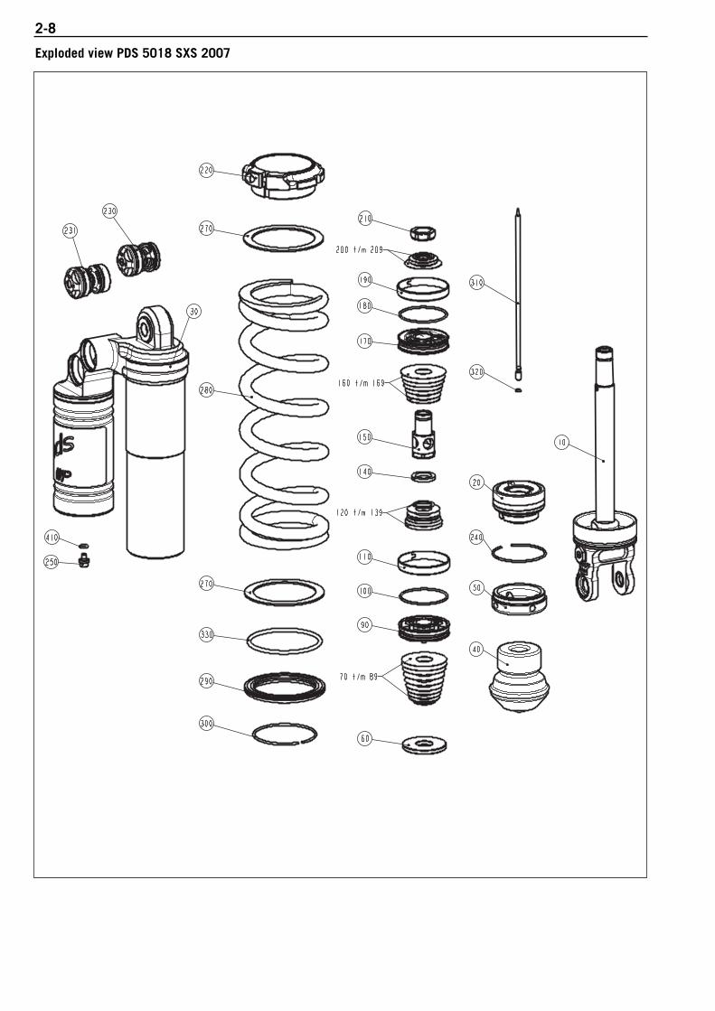
2-8
Exploded view PDS 5018 SXS 2007

2-9W
orks
hop
Man
ual W
P 5
01
8 D
CC
wit
h S
XS/S
MR
Art
.No.
: 3
.21
1.2
08
-E
Pos. Part description Part number Pieces10 Mount 5018.0583S1 120 Adaptor 5018.0435S1 130 Shock absorber housing 5018.0581S1 140 Bump rubber 5018.0480 150 Reservoir cap 5018.0580 160 Rebound disc 5018.0516 190 Piston 5018.0197 1100 O-ring 5018.0099 1110 Piston ring 5018.0135 1140 Support disc 5018.0578 1150 Adaptor 5018.0510 1170 Piston 5018.0446 1180 O-ring 5018.0099 1190 Piston ring 5018.0135 1210 Piston rod nut 5018.0141 1220 Spring ret. 5018.0582S 1230 DCC complete HS 5018.0586S1 1231 DCC complete LS 5018.0590S 1240 Circlip Stainl.steel 5018.0126 1250 Nitrogen plug 3612.0151 1270 Interm. ring screw spring ret. 5018.0114 1290 Spring ret. 5018.0463 1300 Circlip 5018.0273 1310 Needle 5018.0513 1320 O-ring 4681.1265 1330 O-ring 5018.0352 1410 O-ring 4681.0893 1

2-10
Setting list PDS 5018 BAVP Shock absorber 12.18.7A.10 and 12.18.7B.10 KTM 125 SXS 2005/2006
Compression damping piston 1Item Part description Parts. No. Pieces70 Spacer plate 16x22x0,30 5018.0036 171 Spacer plate 16x24x0,25 5018.0031 172 Spacer plate 16x26x0,25 5018.0033 173 Shim 16x28x0,25 5018.0063 174 Shim 16x30x0,25 5018.0064 175 Shim 16x32x0,25 5018.0065 176 Shim 16x34x0,20 5018.0057 177 Shim 16x36x0,20 5018.0058 178 Shim 16x38x0,20 5018.0059 179 Shim 16x40x0,20 5018.0060 180 Shim 16x42x0,20 5018.0061 181 Shim 16x28x0,10 5018.0041 182 Shim 16x44x0,20 5018.0062 3
Rebound damping piston 1120 Shim 16x36x0,20 5018.0058 3121 Shim 16x28x0,10 5018.0041 1122 Shim 16x34x0,20 5018.0057 1123 Shim 16x32x0,20 5018.0056 1124 Shim 16x28x0,20 5018.0054 1125 Spacer plate 16x20x0,30 5018.0034 1
Compression damping piston 2160 Spacer plate 10x18x0,30 3612.0314 1161 Shim 10x19x0,30 3612.0349 1162 Shim 10x21x0,30 3612.0350 1163 Shim 10x23x0,25 3612.0343 1164 Shim 10x25x0,25 3612.0344 1165 Shim 10x27x0,25 3612.0345 1166 Shim 10x29x0,20 3612.0338 1167 Spacer plate 10x18x0,10 3612.0286 1168 Shim 10x31x0,20 3612.0339 2169 Shim 10x33x0,20 3612.0340 4
Rebound damping piston 2190 Shim d10xd16x1 5018.0395 1191 Shim 16x30x0,25 5018.0064 1192 Shim 10x19x0,25 3612.0341 1
Spring390 Spring (62) 80-250 N/mm 9121.0040 1
AdjustmentsCode 12.18.7A.10Rebound damping position open 25Length complete (mm) 405Gas pressure (bar) 10Stroke (mm) 101,5Compression damping position open LS 12 / HS 2Spring preload (mm) 5

2-11W
orks
hop
Man
ual W
P 5
01
8 D
CC
wit
h S
XS/S
MR
Art
.No.
: 3
.21
1.2
08
-E
Setting list PDS 5018 BAVP Shock absorber 12.18.7A.11 KTM 250 SXS 2005
Compression damping piston 1Item Part description Parts. No. Pieces70 Spacer plate 16x23x0,30 5018.0037 171 Spacer plate 16x24x0,30 5018.0038 172 Spacer plate 16x25x0,30 5018.0039 173 Spacer plate 16x26x0,25 5018.0033 174 Shim 16x28x0,25 5018.0063 175 Shim 16x30x0,25 5018.0064 176 Shim 16x32x0,25 5018.0065 177 Shim 16x34x0,20 5018.0057 178 Shim 16x36x0,20 5018.0058 179 Shim 16x38x0,25 5018.0068 180 Shim 16x40x0,25 5018.0069 181 Shim 16x42x0,20 5018.0061 182 Shim 16x30x0,10 5018.0042 183 Shim 16x44x0,20 5018.0062 484 Shim 16x44x0,15 5018.0053 2
Rebound damping piston 1120 Shim 16x36x0,20 5018.0058 3121 Spacer plate 16x26x0,10 5018.0012 1122 Shim 16x34x0,20 5018.0057 1123 Shim 16x32x0,20 5018.0056 1124 Shim 16x28x0,20 5018.0054 1125 Spacer plate 16x21x0,30 5018.0034 4
Compression damping piston 2160 Spacer plate 10x18x0,30 3612.0314 1161 Shim 10x19x0,30 3612.0349 1162 Shim 10x21x0,30 3612.0350 1163 Shim 10x23x0,25 3612.0343 1164 Shim 10x25x0,25 3612.0344 1165 Shim 10x27x0,25 3612.0345 1166 Shim 10x29x0,20 3612.0338 1167 Spacer plate 10x18x0,10 3612.0286 1168 Shim 10x31x0,20 3612.0339 2169 Shim 10x33x0,20 3612.0340 4
Rebound piston 2190 Shim d10xd16x1,0 5018.0395 1191 Shim 16x30x0,25 5018.0064 1192 Shim 10x19x0,25 3612.0341 1
Spring390 Spring (62) 84-250 N/mm 9121.0041 1
AdjustmentsCode 12.18.7A.11Rebound damping position open 25Length complete (mm) 405Gas pressure (bar) 10Stroke (mm) 101,5Compression damping position open LS 12 / HS 2,0Spring preload (mm) 5

2-12
Setting list PDS 5018 BAVP Shock absorber 12.18.7B.11 KTM 250 SXS/SXS-F 2006
Compression damping piston 1Item Part description Parts. No. Pieces70 Spacer plate 16x23x0,30 5018.0037 171 Spacer plate 16x24x0,30 5018.0038 172 Spacer plate 16x25x0,30 5018.0039 173 Spacer plate 16x26x0,25 5018.0033 174 Shim 16x28x0,25 5018.0063 175 Shim 16x30x0,25 5018.0064 176 Shim 16x32x0,25 5018.0065 177 Shim 16x34x0,25 5018.0066 178 Shim 16x36x0,25 5018.0067 179 Shim 16x38x0,25 5018.0068 180 Shim 16x40x0,25 5018.0069 181 Shim 16x42x0,20 5018.0061 182 Shim 16x30x0,10 5018.0042 183 Shim 16x44x0,20 5018.0062 484 Shim 16x44x0,15 5018.0053 2
Rebound damping piston 1120 Shim 16x36x0,20 5018.0058 3121 Spacer plate 16x26x0,10 5018.0012 1122 Shim 16x34x0,20 5018.0057 1123 Shim 16x32x0,20 5018.0056 1124 Shim 16x28x0,20 5018.0054 1125 Spacer plate 16x21x0,30 5018.0035 4
Compression damping piston 2160 Spacer plate 10x18x0,30 3612.0314 1161 Shim 10x19x0,30 3612.0349 1162 Shim 10x21x0,30 3612.0350 1163 Shim 10x23x0,25 3612.0343 1164 Shim 10x25x0,25 3612.0344 1165 Shim 10x27x0,25 3612.0345 1166 Shim 10x29x0,20 3612.0338 1167 Spacer plate 10x18x0,10 3612.0286 1168 Shim 10x31x0,20 3612.0339 2169 Shim 10x33x0,20 3612.0340 4
Rebound damping piston 2190 Shim d10xd16x1,0 5018.0395 1191 Shim 16x30x0,25 5018.0064 1192 Shim 10x19x0,25 3612.0341 1
Spring390 Spring (62) 84-250 N/mm 1
AdjustmentsCode 12.18.7B.11Rebound damping position open 25Length complete (mm) 405Gas pressure (bar) 10Stroke (mm) 101,5Compression damping position open LS 12 / HS 2Spring preload (mm) 5

2-13W
orks
hop
Man
ual W
P 5
01
8 D
CC
wit
h S
XS/S
MR
Art
.No.
: 3
.21
1.2
08
-E
Setting list PDS 5018 BAVP Shock absorber 12.18.7A.12 KTM 450/540 SXS 2005
Compression damping piston 1Item Part description Parts. No. Pieces70 Spacer plate 16x23x0,30 5018.0037 171 Spacer plate 16x24x0,30 5018.0038 172 Spacer plate 16x25x0,30 5018.0039 173 Spacer plate 16x26x0,25 5018.0033 174 Shim 16x28x0,25 5018.0063 175 Shim 16x30x0,25 5018.0064 176 Shim 16x32x0,25 5018.0065 177 Shim 16x34x0,25 5018.0066 178 Shim 16x36x0,25 5018.0067 179 Shim 16x38x0,25 5018.0068 180 Shim 16x40x0,25 5018.0069 181 Shim 16x42x0,20 5018.0061 182 Shim 16x30x0,10 5018.0042 183 Shim 16x44x0,20 5018.0062 584 Shim 16x44x0,15 5018.0053 3
Rebound damping piston 1120 Shim 16x36x0,20 5018.0058 3121 Spacer plate 16x26x0,10 5018.0012 1122 Shim 16x34x0,20 5018.0057 1123 Shim 16x32x0,20 5018.0056 1124 Shim 16x28x0,20 5018.0054 1125 Spacer plate 16x21x0,30 5018.0034 4
Compression damping piston 2160 Backpl 10x18x0,30 3612.0314 1161 Shim 10x19x0,30 3612.0349 1162 Shim 10x21x0,30 3612.0350 1163 Shim 10x23x0,25 3612.0343 1164 Shim 10x25x0,25 3612.0344 1165 Shim 10x27x0,25 3612.0345 1166 Shim 10x29x0,20 3612.0338 1167 Spacer plate 10x18x0,10 3612.0286 1168 Shim 10x31x0,20 3612.0339 2169 Shim 10x33x0,20 3612.0340 4
Rebound damping piston 2190 Shim d10xd16x1,0 5018.0395 1191 Shim 16x30x0,25 5018.0064 1192 Shim 10x19x0,25 3612.0341 1
Spring390 Spring (62) 88-250 N/mm 9121.0042 1
AdjustmentsCode 12.18.7A.12Rebound damping position open 25Length complete (mm) 405Gas pressure (bar) 10Stroke (mm) 101,5Compression damping position open LS 12 / HS 2Spring preload (mm) 5

2-14
Setting list PDS 5018 BAVP Shock absorber 12.18.7B.12 KTM 450/540 SXS 2006
Compression damping piston 1Item Part description Parts. No. Pieces70 Spacer plate 16x23x0,30 5018.0037 171 Spacer plate 16x24x0,30 5018.0038 172 Spacer plate 16x25x0,30 5018.0039 173 Spacer plate 16x26x0,25 5018.0033 174 Shim 16x28x0,25 5018.0063 175 Shim 16x30x0,25 5018.0064 176 Shim 16x32x0,25 5018.0065 177 Shim 16x34x0,25 5018.0066 178 Shim 16x36x0,25 5018.0067 179 Shim 16x38x0,25 5018.0068 180 Shim 16x40x0,25 5018.0069 181 Shim 16x42x0,20 5018.0061 182 Shim 16x30x0,10 5018.0042 183 Shim 16x44x0,20 5018.0062 584 Shim 16x44x0,15 5018.0053 3
Rebound damping piston 1120 Shim 16x36x0,20 5018.0058 3121 Spacer plate 16x26x0,10 5018.0012 1122 Shim 16x34x0,20 5018.0057 1123 Shim 16x32x0,20 5018.0056 1124 Shim 16x28x0,20 5018.0054 1125 Spacer plate 16x21x0,30 5018.0034 4
Compression damping piston 2160 Spacer plate 10x18x0,30 3612.0314 1161 Shim 10x19x0,30 3612.0349 1162 Shim 10x21x0,30 3612.0350 1163 Shim 10x23x0,30 3612.0343 1164 Shim 10x25x0,25 3612.0344 1165 Shim 10x27x0,25 3612.0345 1166 Shim 10x29x0,20 3612.0338 1167 Spacer plate 10x18x0,10 3612.0286 1168 Shim 10x31x0,20 3612.0339 2169 Shim 10x33x0,20 3612.0340 4
Rebound damping piston 2190 Shim d10xd16x1,0 5018.0395 1191 Shim 16x30x0,25 5018.0064 1192 Shim 10x19x0,25 3612.0341 1
Spring390 Spring (62) 88-250 N/mm 9121.0042 1
AdjustmentsCode 12.18.7B.12Rebound damping position open 25Length complete (mm) 405Gas pressure (bar) 10Stroke (mm) 101,5Compression damping position open LS 12 / HS 2Spring preload (mm) 5

2-15W
orks
hop
Man
ual W
P 5
01
8 D
CC
wit
h S
XS/S
MR
Art
.No.
: 3
.21
1.2
08
-E
Setting list PDS 5018 BAVP Shock absorber 12.18.7B.15 KTM 450/560 SMR 2006
Compression damping piston 1Item Part description Parts. No. Pieces70 Spacer plate 16x22x0,30 5018.0036 171 Shim 16x30x0,20 5018.0055 172 Shim 16x32x0,20 5018.0056 173 Shim 16x34x0,20 5018.0057 174 Shim 16x36x0,20 5018.0058 175 Shim 16x38x0,25 5018.0068 176 Shim 16x40x0,25 5018.0069 177 Shim 16x42x0,25 5018.0070 178 Shim 16x44x0,25 5018.0071 3
Rebound damping piston 1120 Shim 16x36x0,20 5018.0058 1121 Spacer plate 36x32,25x0,30 4681.1637 1122 Shim 16x32x0,20 5018.0056 1123 Shim 16x36x0,20 5018.0058 3124 Spacer plate 16x21x0,30 5018.0035 1
Compression damping piston 2160 Shim 16x32x0,30 5018.0074 1161 Shim 16x34x0,30 5018.0075 1162 Shim 16x36x0,30 5018.0076 1163 Shim 16x38x0,30 5018.0077 1164 Shim 16x40x0,30 5018.0078 1165 Shim 16x42x0,30 5018.0079 1166 Shim 16x44x0,30 5018.0080 1
Rebound damping piston 2190 Shim d16xd21x1,0 5018.0210 1191 Shim 21x36x0,25 5018.0209 1192 Shim 16x28x0,20 5018.0054 1
Spring390 Spring (62) 88-250 N/mm 9121.0050 1
AdjustmentsCode 12.18.7B.15Rebound damping position open 19Length complete (mm) 397Gas pressure (bar) 10Stroke (mm) 93,5Compression damping position open LS 13 / HS 2Spring preload (mm) 5

2-16
A 100 liter fuel consumption is equivalent to approx. 15 operating hours
Check the bearing in the shock absorber top / replace if necessaryCheck the piston rod on scratches / leakageCheck the static sag - before ridingCheck the springCheck the bump rubberCheck the O-ring of the spring retainer / replace if necessaryComplete maintenance of the shock absorber
10
hou
rs6
5 li
ter
20
hou
rs1
30
lite
r
30
hou
rs2
00
lite
r
40
hou
rs2
60
lite
r
50
hou
rs3
25
lite
r
60
hou
rs4
00
lite
r
70
hou
rs4
55
lite
r
80
hou
rs5
20
lite
r
90
hou
rs6
00
lite
r
10
0 h
ours
66
5 li
ter
Adjusting the position of the compression and rebound dampingRebound damping: – Turn in the adjusting screw 1 in a clockwise direction all the way to
the stop. – Turn back the respective number of clicks in a counterclockwise
direction.
Compression damping, low speed: – Turn in the adjusting screw 2 in a clockwise direction all the way to
the stop. – Turn back the respective number of clicks in a counterclockwise
direction.
Compression damping, high speed: – Turn in the adjusting screw 3 in a clockwise direction all the way to
the stop. – Turn back the respective number of clicks in a counterclockwise
direction.
Adjusting the spring preload NOTE: the spring preload is the difference between the unloaded andpreloaded length of the spring.
– Tighten the adjusting nut 4 with the special tool T106 until youhave the prescribed spring preload.
– Tighten the lock screw on the adjusting nut.
Recommended periodic maintenance and inspectionof the 5018 SXS/SMR Shock absorber
2
1
3
4
23

DISASSEMBLING AND ASSEMBLING THE SHOCK ABSORBER
Wor
ksho
p M
anua
l WP
50
18
DC
C w
ith
SXS
/SM
RA
rt.N
r.: 3
.21
1.2
08
-E
DISASSEMBLING THE SHOCK ABSORBER . . . . . . . . . . . . . . . . . . . . . . . . . . . . .3-2
DISASSEMBLING THE TUBE SIDE . . . . . . . . . . . . . . . . . . . . . . . . . . . . . . . . . . .3-5
DISASSEMBLING ADAPTOR BUSHES AND HEIM JOINT . . . . . . . . . . . . . . . . . . . .3-9
DISASSEMBLING THE NITROGEN RESERVOIR . . . . . . . . . . . . . . . . . . . . . . . . . .3-11
ASSEMBLING THE NITROGEN RESERVOIR . . . . . . . . . . . . . . . . . . . . . . . . . . . .3-11
ASSEMBLING THE TUBE SIDE . . . . . . . . . . . . . . . . . . . . . . . . . . . . . . . . . . . . .3-12
ASSEMBLING ADAPTOR BUSHES AND HEIM JOINT . . . . . . . . . . . . . . . . . . . . . .3-13
MOUNTING THE RESERVOIR . . . . . . . . . . . . . . . . . . . . . . . . . . . . . . . . . . . . . .3-14
INSPECTION OF THE TUBE . . . . . . . . . . . . . . . . . . . . . . . . . . . . . . . . . . . . . . .3-15
MOUNTING THE PIPE . . . . . . . . . . . . . . . . . . . . . . . . . . . . . . . . . . . . . . . . . . .3-15
MOUNTING THE DCC MECHANISM . . . . . . . . . . . . . . . . . . . . . . . . . . . . . . . . .3-16
ASSEMBLING THE SHOCK ABSORBER BODY . . . . . . . . . . . . . . . . . . . . . . . . . .3-16
FILLING THE SHOCK ABSORBER BODY . . . . . . . . . . . . . . . . . . . . . . . . . . . . . . .3-17
DISASSEMBLING THE PISTON ROD (DOES NOT APPLY TO SXS/SMR) . . . . . . . . .3-17
DISASSEMBLING THE PISTON ROD (FOR SXS/SMR ONLY) . . . . . . . . . . . . . . . .3-19
INSPECTION OF THE PISTON ROD . . . . . . . . . . . . . . . . . . . . . . . . . . . . . . . . . .3-25
ASSEMBLING PISTON ROD SIDE . . . . . . . . . . . . . . . . . . . . . . . . . . . . . . . . . . .3-26
DISASSEMBLING ADAPTOR . . . . . . . . . . . . . . . . . . . . . . . . . . . . . . . . . . . . . .3-30
ASSEMBLING ADAPTOR . . . . . . . . . . . . . . . . . . . . . . . . . . . . . . . . . . . . . . . . .3-31
CHECKING THE PARTS . . . . . . . . . . . . . . . . . . . . . . . . . . . . . . . . . . . . . . . . . .3-32
PISTONS . . . . . . . . . . . . . . . . . . . . . . . . . . . . . . . . . . . . . . . . . . . . . . . . . . . .3-33
CONTINUING TO ASSEMBLE THE PISTON ROD (DOES NOT APPLY TO SXS/SMR) . .3-34
CONTINUING TO ASSEMBLE THE PISTON ROD (APPLIES TO SXS/SMR ONLY) . . .3-36
ASSEMBLING THE SHOCK ABSORBER . . . . . . . . . . . . . . . . . . . . . . . . . . . . . . .3-37
EVACUATING AND FILLING THE SHOCK ABSORBER . . . . . . . . . . . . . . . . . . . . .3-38
ON PRESSURE WITH NITROGEN . . . . . . . . . . . . . . . . . . . . . . . . . . . . . . . . . . .3-41
ASSEMBLING THE SPRING . . . . . . . . . . . . . . . . . . . . . . . . . . . . . . . . . . . . . . .3-42
INDEX
3-1
3

Disassembling the shock absorber– Unscrew the Allen bolt 1 of the spring retainer (Size 5).
– Place the shock absorber in the vice according to the picture.
– Screw the spring retainer 2 downwards.
– Push the spring retainer 3 downwards so that you are able toremove the springring 4.
– Disassemble the spring ring.
– Remove the spring retainer 5.
– Disassemble the O-ring out of spring retainer.
3-2W
orks
hop
Man
ual W
P 5
01
8 D
CC
wit
h S
XS/S
MR
Art
.Nr.:
3.2
11
.20
8-E
1
2
3
4
5

3-3
1
– Remove the washer.
– Remove the spring.
– Remove the second washer 1.
– Lock washer 5– Spring 4– Spring retainer 3– O-Ring 2– Washers 1
– Disassemble the rubber plug 6 “do not open” out of the screw capof the nitrogen reservoir.
NOTE: the SXS/SMR shock absorber does not have a rubber cap.
– Slowly loosen the nitrogen filling plug 7 (Size 4). This will causethe nitrogen pressure to build up.
– Pay attention to the O-ring of the nitrogen filling plug.
4
2
1
35
6
7

– Unscrew the oil filling plug for about two turns. (size 5)This wil help you later by removing the piston rod “complete” out ofthe shock absorber!
– Tap the cap 1 from the tube.
– Place disassembling bush T 1216 2 on the adaptor and push theadaptor downwards.
– Disassemble the spring ring 3 out of the groove of the tube.
– Pull careful but firmly the piston rod “complete” out of the tube.
NOTE: usually takes a great deal of effort
3-4W
orks
hop
Man
ual W
P 5
01
8 D
CC
wit
h S
XS/S
MR
Art
.Nr.:
3.2
11
.20
8-E
1
2
3

Disassembling the tube side– Drain the oil out of the tube.
– Clamp the tube side in the vice according to the picture.
– Remove the spring ring 1 out of the groove and slide it downwards.
– Slide the guiding bush 2 downwards.
– Remove the upper spring ring 3.
– Remove the guiding bush.
– Remove the springring.
NOTE: does not apply to the 2007 SX/SXS models (no spring guideused).
– Turn the screw retainer 4 of the tube.
3-5
1
2
3
4

All models accept SXS 2007:– Clamp the tube side in the vice according to the picture.
– Unscrew the screw cap 1 of the DCC out of the shock absorberhousing (size 24).
NOTE: DDC = Dual Compression Control.
– Remove the screw cap 1.
– Pull the DCC mechanism 2 out of the shock absorber housing.
SXS 2007:– Clamp the tube side in a vise as shown in the photo (use protective
jaws).
– Loosen and remove both compression controls with T 1218 3.
NOTE: the LS compression control 4 is completely removed, the HScompression control 5 by individual parts (see photo below).
Individual HS compression control parts: - HS compression control 5- Cage 6- Washers 7- Spring 8- Spring alignment 9- Compression damping piston bk
– Turn the oil filling plug bl out of the shock absorber housing (AH,Größe 5).
NOTE: since only assemblies are available for shock absorbers startingwith the 2007 model, no further disassembly is necessary.
– Remove the sticker bm.
3-6W
orks
hop
Man
ual W
P 5
01
8 D
CC
wit
h S
XS/S
MR
Art
.Nr.:
3.2
11
.20
8-E
1
2
3
45
56789bk
bl
bm

3-7– Heat the shock absorber housing 1 near the tube.
– Unscrew the lock ring several turns with T 1233 2.
– Clean the tube with brake cleaner.
– Heat the shock absorber housing near the tube.
– Unscrew the tube out of the bottom with slide-spanner T 146 andbush T 1201.
– Screw the tube out of the shock absorber housing.
– SXS/SMR models only: tap sleeve 3 out of the pipe
1
2
3

– Remove the O-ring 1 inside the shock absorber housing out of thegroove.
NOTE: only when you want to disassemble the screw cap of thenitrogen reservoir 2!
– Heat the nitrogen reservoir near the screw cap.
– Place T 145S 3 on the screw cap.
– Place T 125S 4 on T 145S and unscrew the nitrogen reservoir.
– Remove the O-ring.
3-8W
orks
hop
Man
ual W
P 5
01
8 D
CC
wit
h S
XS/S
MR
Art
.Nr.:
3.2
11
.20
8-E
1
2
3
4

Disassembling adaptor bushes and heim joint– Clamp the shock absorber housing in the vice.
– Use Disassembling tool T 120 1 for disassembling the adaptorbushes.
– Tap the adaptor bush out of the heim joint.
– Remove the seal 2.
– Tap the other adaptor bush out of the shock absorber housing andremove the seal.
– Use dis- / assambling tool T 1207S (A+B) 3.
3-9
1
2
3

– Press the heim joint against the springring.
– Disassemble the springring 1.
– Press the heim joint out of the shock absorber housing.
– Disassemble the other spring ring 2.
– Individual parts of the heim joint.
3-10W
orks
hop
Man
ual W
P 5
01
8 D
CC
wit
h S
XS/S
MR
Art
.Nr.:
3.2
11
.20
8-E
1
2

3-11Disassembling the nitrogen reservoir– Push the dividing piston 1 out of the reservoir 2.
– Remove the piston ring 3.
– Remove the O-ring 4 out of the groove of the separation piston.
Assembling the nitrogen reservoir– Check the inner side of the nitrogen reservoir for scratches.
– Apply the groove of the separation.
– Assemble the O-ring in the groove.
– Apply the O-ring with T 158.
– Apply the running surface of the nitrogen reservoir with a little bit ofT158.
– Assemble the separation piston.
NOTE: the reservoir has an identification groove that must be mountedfacing the shock absorber housing.
– Push the separation piston further into the nitrogen reservoir.
12
3
4

Assembling the tube side– Clean the thread of the nitrogen reservoir.
– Place the new O-ring 1 in the groove of the shock absorber housing.
– Assemble the O-ring 2 inside the groove of the shock absorberhousing.
NOTE: the SXS/SMR shock absorber does not have the needle 3.
3-12W
orks
hop
Man
ual W
P 5
01
8 D
CC
wit
h S
XS/S
MR
Art
.Nr.:
3.2
11
.20
8-E
1
2 3

3-13Assembling adaptor bushes and heim joint– Place the spring ring 1 in the shock absorber housing.
– Assemble the heim joint 2 with the bevelled edge into the directionof the shock absorber housing with assembling tool T 1206 3.
– Press the heim joint into the shock absorber housing.
– Press with T 1207(A) the heim joint 4 against the spring ring.
– Assemble the spring ring 5.
1
2
3
4
5

– Assemble both seals 1.
– Assemble one adaptor bush with support of T 1206 2 in the heimjoint.
– Press the other adaptor bush with support of the vice in the heimjoint.
Mounting the reservoir– Wet the thread of the shock absorber housing with T 132.
– Screw the nitrogen reservoir on the shock absorber housing andtighten it with T 145S 3 and T 125S 4.
3-14W
orks
hop
Man
ual W
P 5
01
8 D
CC
wit
h S
XS/S
MR
Art
.Nr.:
3.2
11
.20
8-E
2
1
3 4

3-15Inspection of the tube– Inspect the running surface of the tube. If necessarry polish the
running surface with sandpaper 600.
– Measure the inner diameter at both ends and in the center of thepipe.
The maximum diameter is: 50,12mm
Mounting the pipe – Screw the lock ring 1 as far as possible on the thread or the tube.
– Wet the thread of the tube with T 132.
SXS/SMR shock absorber only: – Mount the sleeve 2.
– Screw the tube into the shock absorber housing.
– Tighten the tube with T 146 and T 1201.
1
2

– Screw the lock ring 1 against the shock absorber housing andtighten it with T 1233.
Mounting the DCC mechanism All models accept SXS 2007:– Wet the O-ring 2 with T 158.– Place the DCC mechansm 3 in the shock absorber housing.
– Turn the screw cap 4 in the the shock absorber housing.
– Tighten the screw cap to a torque of 50 Nm.
SXS 2007:– Apply T 158 to the O-ring and mount the compression damping
piston 5. – Slip on the spring alignment 6, see photo.
– Position the cage 7 on the HS compression control 8.
– Position the spring 9 on the spring alignment, mount the HScompression control 8 with the cage, making sure it is correctlyseated.
Assembling the shock absorber body – Screw the Allen bolt in the screw retainer bk and assemble the
screw retainer on the tube.
– Assemble the springring bl past the second groove.
– Assemble the guiding bush bm.
– Assemble the spring ring bn in the upper groove of the tube.
– Slide the guiding bush over the upper spring ring and place thesecond spring ring bl in the groove.
NOTE: does not apply to the 2007 SX/SXS models (no spring guide used).
3-16W
orks
hop
Man
ual W
P 5
01
8 D
CC
wit
h S
XS/S
MR
Art
.Nr.:
3.2
11
.20
8-E
1
2
3
4
5
67
8
98
bkbl
bm
bn

Filling the shock absorber body – Fill the tube till approximately 10 mm under the inner side spring
ring groove of the tube.
NOTE: only use the specified oil.
Disassembling the piston rod (also applies to SXS 2007 butnot to SXS up to 2006/SMR)– Untighten the piston rod nut 1 with spanner size 22 mm.
– Remove the piston rod nut.
– Remove the rebound setting 2.
– Remove the piston 3 (“piston 2”).
– Remove the compression setting 4.
– Untighten the piston rod tap 5 (Size 22).
– Screw the piston rod tap of the piston rod.
– Remove the rebound setting 6.
– Remove the piston 7 (“piston 1”).
– Remove the compression setting 8.
3-17
1 2
34
5 6
7 8

– Remove the rebound disc 1.
– Rebound disc 1– Piston 1 2– Piston 2 3– Settings 4 (rebound and compresion)– Piston rod tap 5– Piston rod nut 6– Piston ring(s) 7– O-ring(s) 8
3-18W
orks
hop
Man
ual W
P 5
01
8 D
CC
wit
h S
XS/S
MR
Art
.Nr.:
3.2
11
.20
8-E
1
1
6
5
7
84
4
4
4
2
3

Disassembling the piston rod (for SXS up to 2006/SMR only) – Loosen the nut on the piston rod 1 with a 17 mm wrench.
– Remove the nut from the piston rod.
– Remove the shims from the rebound 2.
NOTE: the lower large shim is centered with a smaller shim
– Remove the piston ("piston 2") 3.
NOTE: the compression shims usually stick to the piston.
– Remove the set of shims from the compression damping 4 togetherwith the compression disk.
– Loosen and remove the adapter 5 (A/F 13).
– Loosen and remove the piston rod nut 6 (A/F 22).
– Remove the set of shims from the rebound 7.
– Remove the piston ("piston 1") 8.
– Remove the set of shims from the compression 9.
– Remove the rebound disk bk.
3-19
1 2
3 4
5
7 8
9 bk
6

– Piston rod nut A/F 17 1– Set of shims 2 (rebound and compression damping) – Piston ("2") 3– Adapter 4– Piston rod nut A/F 22 5– Rebound disk 6– Piston ("1") 7– Piston ring 8– O-ring 9
– Slide the adaptor bk from the piston rod.
– Remove the cap bl.
– Remove the bump rubber bm.
3-20W
orks
hop
Man
ual W
P 5
01
8 D
CC
wit
h S
XS/S
MR
Art
.Nr.:
3.2
11
.20
8-E
bl
1
2 2
2 2
345 6
6
7
89
bk
bm

– Clamp the piston rod in the vice according to the picture.
– Unscrew the screw cap 1 of the rebound adjustment.
– Remove the screw cap 1.
– Turn anti clockwise the rebound adjustment screw 2 out of themounting fork.
3-21
1
2

– Remove the rebound adjustment screw 1.
– Pay attention to the steel balls 2 and spring 3.
– Parts of the rebound adjustment screw.
– Push with a pin (size 2,5mm) the rebound adjustment needle 4through the mounting fork out of the piston rod.
– Pay attention to the rubber plug 5 of the mounting fork.
NOTE: further disassembly of the piston rod only applies to models forwhich individual parts are available (see exploded view).
– Heat the top of piston rod according to the picture.
– Place Allen key (size 5) in the piston rod and unscrew the seat.
NOTE: SXS/SMR with HH, A/F 13
3-22W
orks
hop
Man
ual W
P 5
01
8 D
CC
wit
h S
XS/S
MR
Art
.Nr.:
3.2
11
.20
8-E
1
2
2
3
4
5

– Remove the seat 1 - does not apply to SXS/SMR– Always assemble a new O-ring on the seat.
NOTE: since only assemblies are available for shock absorbers startingwith the 2007 model, no further disassembly is necessary.
– Heat the lock nut of the piston rod/mounting fork.
– Unscrew the lock nut, (Size 24)
– Clamp the piston rod in clamping block T 1202S.
– Heat the mounting fork.
3-23
1

– Untighten the mounting fork.
– Remove the mounting fork.
– Brush the thread of the piston rod clean.
– Unscrew the lock nut.
– Remove the lock nut.
3-24W
orks
hop
Man
ual W
P 5
01
8 D
CC
wit
h S
XS/S
MR
Art
.Nr.:
3.2
11
.20
8-E

– Disassemble the rebound adjustment tube - does not apply toSXS/SMR
– Always assemble a new O-ring!
– Rebound adjustment tube. 1
Inspection of the piston rod– Replace the piston rod if you have inspect that the running surface
of the.piston rod has scratches and or indentations.
– Always replace also the bush of the adaptor.
– Place the V-blocks as far as possibble at the outside running surfaceof the piston rod!
– Measure the diameter of the piston rod, rotate the piston rod 90°and measure the diameter again.
– Repeat these measurements on several.places of the piston rod.
The maximum diameter is: 17,98 mm
The minimum diameter is: 17,94 mm
– Measure the straightness of the piston rod, rotate the piston rod360°.
The maximum travel is: 0,06 mm.
3-25
1

Assembling piston rod side– Clamp the piston rod in the clamping block T 1202S.
– Apply the new O-ring of the rebound adjustment tube 1 with T 158.
NOTE: the shock absorber on SXS/SMR models does not have anadjusting pipe for the rebound damping.
– Assemble the rebound adjustment tube in the piston rod.
– Apply the O-ring of the reboundl adjustment needle 2 with T 158.
– Assemble the rebound adjustment needle in the piston rod.
3-26W
orks
hop
Man
ual W
P 5
01
8 D
CC
wit
h S
XS/S
MR
Art
.Nr.:
3.2
11
.20
8-E
1
2

3-27– Screw the lock nut 1 on the piston rod.– Pay attention to the assembling direction! The rounded side 2
should face the center of the piston rod.
– Screw the lock nut fully on the thread of the piston rod.
– Wet the thread of the piston rod with T 132.
– Clamp the piston rod in T 1202S and screw the mounting fork onthe piston rod
– Tighten the mounting fork.
– Tighten the lock nut.
– Place the piston rod / mounting fork in the vice according to thepicture.
– Grease the O-ring 3 and steel balls 4 of the rebound needle withwater proof grease T 159.
– Assemble the rebound adjustment needle in the mounting fork.
1
2
3
4

– Screw the rebound adjustment needle in the mounting fork.– When you feel the clicks turn the rebound adjustment needle two
turns further.
– Assemble the screw cap 1 of the rebound adjustment.
– Tighten the screw cap.
– Turn the rebound adjustment screw 2 anti clockwise fully open.
– Push the rebound adjustment needle fully downwards.
– Apply the thread of the seat with T 132.– Grease the O-ring of the seat with T 158.
3-28W
orks
hop
Man
ual W
P 5
01
8 D
CC
wit
h S
XS/S
MR
Art
.Nr.:
3.2
11
.20
8-E
1
2

– Tighten the seat! (PDS 2006/07: AH 5 mm; SXS/SMR: A/F 13).
– Place assembling tool T 1215 1 on top of the piston rod.
– Assemble the bump rubber 2.
– Assemble the cap 3.
3-29
1
2
3

Disassembling adaptorNOTE: only applies to models for which individual parts are available(see exploded view).
– Lift the rebound rubber 1 out of the adaptor 2.
– Remove the steel plate 3.
– Remove the back-up ring 4.
– Remove the quad ring 5.
– Remove the second back-up ring.
– Lift the dirt scraper 6 out of the adaptor.
– Disassemble the O-ring 7 out of the groove of the adaptor.
– Dis-/assembling tool T 1208 (up to model 2006) or T14031 (model2007 on), adaptor and T 1209.
– Press the bush out of the adaptor.
3-30W
orks
hop
Man
ual W
P 5
01
8 D
CC
wit
h S
XS/S
MR
Art
.Nr.:
3.2
11
.20
8-E
3
1
2
4
5
6
7

3-31Assembling adaptor– Press the bush into the adaptor with T 1208 (up to model 2006) or
T14031 (model 2007 on) and T 1209.– Wet the calibration thorn with shock absorber oil!– Calibrate the bush with calibration thorn T 1205 with support of T
1209.– Press the calibration thorn completely through the bush.
– Press the dirt scraper with T 1204 into the adaptor.
– Assemble in correct order the back-up rings and quad ring!!! Seedisassembling.
– Assemble the steel plate 1.
– Assemble the rebound rubber 2.
– Ensure that you can rotate the rebound rubber in the adaptor.
1

– Grease the groove of the adaptor with T 158.
– Assemble the O-ring 1.– Grease the inside lip of the dirt scraper 2 with T 625.
– Put special tool T 1215 onto the piston rod.– Slide carefully the adaptor 3 over the tool on the piston rod.
Checking the parts – Inspect the surface of the rebound disc.
– If necessarry polish the surface of the rebound disc with sandpaper600 on a flat plate.
– Always check the first shim that is assembled on the piston if it isnot bended. If bended check the second shim and so on.
– Disassemble the piston ring and the O-ring of the piston.
– Inspect the surface of the piston ring.– Replace the piston ring when you see through the surface a bronze
color. Also replace the piston ring if the surface is feeling rough. Thebest way to do this is to compare it with a new one!
3-32W
orks
hop
Man
ual W
P 5
01
8 D
CC
wit
h S
XS/S
MR
Art
.Nr.:
3.2
11
.20
8-E
1
2
3

– Polish the surface of both sides of the pistons on a flat plate withsandpaper 600.
PistonsNOTE: – The "piston 1" and "piston 2" designations refer to assembling, i.e.
the piston mounted on the piston rod first will be designated "piston1".
– Since pistons are mounted on the piston rod from above, "upperview" will refer to the side of the piston facing up after mountingbefore the respective set of shims is mounted.
– 1: Piston 1, upper view for PDS 5018 2006/07, not for SXS up to2006/SMR
– 2: Piston 2, upper view for PDS 5018 2006/07, not for SXS up to2006/SMR
– 3: Piston 1, lower view for PDS 5018 2006/07, not for SXS up to2006/SMR
– 4: Piston 2, lower view for PDS 5018 2006/07, not for SXS up to2006/SMR
– 5: Piston 1, upper view for PDS 5018 SXS up to 2006/SMR
– 6: Piston 2, upper view for PDS 5018 SXS up to 2006/SMR
– 7: Piston 1, lower view for PDS 5018 SXS up to 2006/SMR
– 8: Piston 2, lower view for PDS 5018 SXS up to 2006/SMR
3-33
1 2
3 4
5 6
7 8

Continuing to assemble the piston rod (also applies to SXS2007 but not to SXS up to 2006/SMR)– Assemble the rebound disc 1.
– Assemble the compression setting 2, mounting the shims with thesmaller diameter first.
– Place the piston (“piston 1”) 3.
– Assemble the rebound setting 4, mounting the shims with thelarger diameter first.
– Wet the thread of the piston rod with T 132.
– Screw the piston rod tap 5 on the piston rod.
NOTE: Screw the piston rod tap on the piston rod so far as that thepiston can stil be rotate!
– Place the second compression setting 6, mounting the shims withthe smaller diameter first.
– Assemble the second piston (“piston 2”) 7.
– Assemble the second rebound setting 8, mounting the shims withthe larger diameter first.
– Grease the thread of the piston rod tap with T 152.
3-34W
orks
hop
Man
ual W
P 5
01
8 D
CC
wit
h S
XS/S
MR
Art
.Nr.:
3.2
11
.20
8-E
1
2
3
4
5
6
7
8

– Screw the piston rod nut 1 with the collar downwards on the pistonrod tap.
– Grease the O-ring 2 of the adaptor with T 158.
– Place center sleeve T 1214 3 over both pistons and push theadaptor 4 in the center sleeve.
– Tighten the piston rod nut to a torque of 40 Nm and remove thecentering sleeve T 1214 again.
3-35
1
2
3
4
4

Continuing to assemble the piston rod (applies to SXS up to2006/SMR only) – Mount the rebound disk 1.
– Mount the set of shims for the compression 2.
– Mount the piston ("piston 1") 3.
– Mount the set of shims for the rebound damping 4.
– Apply T 132 to the thread of the piston rod, screw on the nut (A/F22) 5 and tighten to 40 Nm.
– Apply T 132 to the thread of the adapter 6 and screw on.
– Mount the set of shims for the compression damping 7 togetherwith the compression damping disk.
– Mount the piston ("piston 2") 8.
– Mount the shims for the rebound damping 9.
NOTE: the lower large shim is centered with a smaller shim.
– Apply T 132 to the thread of the piston rod and screw on the pistonrod nut.
NOTE: mount the piston rod nut with the collar facing down.
– Tighten the piston rod nut (A/F 17) bk to 25 Nm.
3-36W
orks
hop
Man
ual W
P 5
01
8 D
CC
wit
h S
XS/S
MR
Art
.Nr.:
3.2
11
.20
8-E 6
1 2
3 4
5
7
9
8
bk

– Grease again the O-ring 1 of the adaptor with T 158.
– Assemble the rubber plug 2 into the mounting fork.
Assembling the shock absorber– Assemble the piston rod “complete” into the tube.
– Push the adaptor 3 beyond the springring groove of the tube.
3-37
1
2
3

– Assemble the spring ring 1 first with the closed side into thegroove.
– Pull the piston rod “complete” fully out.
– Tap the cap 2 with a plastic hammer in the tube.
Evacuating and filling the shock absorber ! CAUTION !
BEFORE YOU START TO WORK WITH THE VACUUM/FILLING DEVICE, CAREFULLY READ
THE INSTRUCTIONS PROVIDED IN CHAPTER 4 (OWNER'S MANUAL) TO AVOID
MAKING ANY ERRORS WHEN FILLING THE SHOCK ABSORBER.
– Loosen all adjusting screws in a counterclockwise direction.
– Screw the filling adapter 3 in the opening in the shock absorber,tighten by hand and attach to the connector on the vacuum fillingdevice T 1240S.
– Hold the shock absorber as shown in the photo. The fillingconnection with the adapter must be in the highest position.
WARNING DO NOT HOLD THE PISTON ROD SINCE IT WILL MOVE IN AND OUT DURING THE
FILLING PROCESS.
3-38W
orks
hop
Man
ual W
P 5
01
8 D
CC
wit
h S
XS/S
MR
Art
.Nr.:
3.2
11
.20
8-E
1
2
3
3

3-39
2 3 4
56
1
3
2
2
3
3
2
2
1. Ventilation/filling process – Move the control levers into the positions shown in the photo.
NOTE: "External tank" control lever 1 to "Closed", "Damper" 2 to"Vacuum" and "Oil reservoir" 3 to "Vacuum".
– Press the "On/Off" 4 switch to start the ventilation process.
NOTE: – The pressure gauge 5 (bar) will drop below 0 bar (almost -1). – The vacuum gauge 6 (mbar) will drop to 4 mbar.
– As soon as the vacuum gauge 6 (mbar) reaches approx. 4 mbar,turn the "Oil reservoir" control lever 3 to "Equalize Pressure".
NOTE: the pressure gauge 5 (bar) will rise to 0 bar.
– As soon as the pressure gauge 5 (bar) reaches 0 bar, turn the"Damper" control lever 2 to "Pressure".
NOTE: oil will be pumped into the shock absorber, the pressure gauge5 (bar) will rise to approx. 3 bar; this value is preset (see Chapter 4).
– As soon as the pressure gauge 5 (bar) reaches approx. 3 bar, turnthe "Damper" control lever 2 back to "Vacuum".
NOTE: the pressure gauge 5 (bar) will drop to 0 bar.
2. Ventilation/Filling process – As soon as the pressure gauge 5 (bar) reaches 0 bar, turn the "Oil
reservoir" control lever 3 to "Vacuum".
NOTE: the vacuum gauge 6 (mbar) will drop to 8 mbar.
– As soon as the vacuum gauge 6 (mbar) reaches 8 mbar, turn the"Oil reservoir" control lever 3 to "Equalize Pressure".
NOTE: the pressure gauge 5 (bar) will drop to 0 bar.
– As soon as the pressure gauge 5 (bar) reaches 0 bar, turn the"Damper" control lever 2 to "Pressure".
NOTE: oil will be pumped into the shock absorber, the pressure gauge5 (bar) will rise to approx. 3 bar; this value is preset (see Chapter 5).
– As soon as the pressure gauge 5 (bar) reaches approx. 3 bar, turnthe "Damper" control lever 2 to "Vacuum".
NOTE: the pressure gauge 5 (bar) will drop to 0 bar.
– As soon as the pressure gauge 5 (bar) reaches 0 bar, actuate the"On/Off" 4 switch. The shock absorber is filled.

– Adjust the O-ring 1 on the shaft of T 107S to 106mm.
– Push the separation piston with T 107S to the correct position, theO-ring must have a distance for about 10 mm from the screw cap.
– Unscrew the adapter from the opening in the shock absorber.
– Screw the oil filling plug 2 in the shock absorber housing andtighten it.
– Screw the nitrogen filling plug 3 with O-ring several turns in thescrew cap of the nitrogen reservoir.
3-40W
orks
hop
Man
ual W
P 5
01
8 D
CC
wit
h S
XS/S
MR
Art
.Nr.:
3.2
11
.20
8-E
1
2
3

On pressure with nitrogen– Nitrogen charging device T 170S1. Adjust the nitrogen gas pressure
to 10 - 11 bar.
– Place the shock absorber in the Nitrogen charging device and ensurethat the Allen key is fitting in the nitrogen filling plug.
– Open the tap for about 20 seconds.
– Close the nitrogen filling plug.
– Close the tap and pull the Allen key of the nitrogen charging deviceout of the nitrogen filling plug.
3-41

– Remove the shock absorber out of the nitrogen charging device.
– Place the rubber plug ‘do not open’.
Assembling the spring– Place the washer 1.
– Place the spring.
– Place the first washer 2.
– Assemble the (new) O-ring 3 in the groove of the spring retainer 4.
– Place the spring retainer 4.
– Place the spring ring 5 in the groove of the mounting fork.
3-42W
orks
hop
Man
ual W
P 5
01
8 D
CC
wit
h S
XS/S
MR
Art
.Nr.:
3.2
11
.20
8-E
1
23
4
4 5

– Adjust the spring to the correct spring preload as noticed before.
– Tighten the Allen bolt of the screw retainer to a torque of 5 Nm.
– Clean the nitrogen reservoir.
– Assemble a new sticker.
– Set the shock absorber in the correct mounting position.
NOTE: adjustments of the rebound and compression damping shouldbe on the same side.
– Move the rebound and compression damping adjustments in theright position.
3-43

MANUAL FOR VACUUM-/FILLING DEVICE
INTRODUCTION . . . . . . . . . . . . . . . . . . . . . . . . . . . . . . . . . . . . . . . . . . . . . . . .4-2
SUPPLIED PARTS . . . . . . . . . . . . . . . . . . . . . . . . . . . . . . . . . . . . . . . . . . . . . .4-2
TECHNICAL FEATURES . . . . . . . . . . . . . . . . . . . . . . . . . . . . . . . . . . . . . . . . . . .4-2
OVERVIEW OF VACUUM FILLING DEVICE . . . . . . . . . . . . . . . . . . . . . . . . . . . . . .4-3
GENERAL HANDLING INFORMATION . . . . . . . . . . . . . . . . . . . . . . . . . . . . . . . . .4-4
BEFORE / DURING TRANSPORTATION . . . . . . . . . . . . . . . . . . . . . . . . . . . . . . . .4-5
PREPARING VACUUM FILLING DEVICE FOR USE (AFTER TRANSPORTATION) . . . . .4-6
USING THE FILLING ADAPTERS . . . . . . . . . . . . . . . . . . . . . . . . . . . . . . . . . . . . .4-8
GENERAL OPERATION INSTRUCTIONS . . . . . . . . . . . . . . . . . . . . . . . . . . . . . . . .4-8
FREQUENT CHECKS . . . . . . . . . . . . . . . . . . . . . . . . . . . . . . . . . . . . . . . . . . . .4-20
MAINTENANCE . . . . . . . . . . . . . . . . . . . . . . . . . . . . . . . . . . . . . . . . . . . . . . .4-23
SPARE PARTS . . . . . . . . . . . . . . . . . . . . . . . . . . . . . . . . . . . . . . . . . . . . . . . .4-27
FILLING LIST . . . . . . . . . . . . . . . . . . . . . . . . . . . . . . . . . . . . . . . . . . . . . . . . .4-27
SHORT OPERATION INSTRUCTION FOR VACUUM FILLING UNIT . . . . . . . . . . . . .4-28
INDEX
4-1
4

Supplied parts Owners manual vacuum filling deviceFilling adapter A (Competition and PDS (G1/8))Filling adapter B (For filling trough CC- mechanism)Filling adapter C (Steering dampers)1 Litre vacuum pump oil Vm22Vacuum filling unitExternal tankConnecting hose external tank
Technical featuresVacuum pump PB 0003 A :Nominal displacement: 3 m³/h (50Hz), 3,6 m³/h (60Hz)Ultimate pressure : 2mbarNominal motor rating : 0,1 Kw (50Hz), 0,12 Kw (60Hz)Nominal motor speed : 3000 min¯¹ (50Hz), 3600 min¯¹ (60Hz)Sound level (DIN 45635) : 59 dB (A)Oil filling : 0,06 l
Vacuum filling unit :Width : 400mmDepth : 255mmHeight : 380mmDry weight : 14,5Kg Max oil quantity : ±1,8 l
External Tank :Width : 220mmDepth : 220mmHeight : 695mmWeight : 9,9Kg
4-1Introduction
The WP Suspension vacuum-filling device is designed specially for thefilling of shock absorbers. The filling device enables you to fill a shockabsorber with no air inside the shock absorber. The layout of thesystem was chosen to allow maximum flexibility for the filling of shockabsorbers and to create a compact, lightweight construction. The fillingdevice has two main parts; the vacuum filling unit and an externaltank. The configuration, vacuum- and pressure values as well as fillingadapters that have to be used, depend on the type of damper that hasto be filled.
Each vacuum filling device has been put trough a test before deliveryto customers.Because of this test, there might be a small amount of oil left in thevacuum pump. The vacuum filling device is delivered withoutcompressed air nipple, because of the wide variety of nipples used.Before taking the filling device into service, a nipple 1 has to bemounted to the pressure regulator (thread size G¼).
1

Overview of vacuum filling device– Control levers 1– Vacuum gauge (mbar) 2– Pressure gauge (bar) 3– Damper connector 4– Main power switch 5– Filling plug 6– Oil level indicator 7
– Vacuum pump oil level indicator 8– Vacuum pump filling plug 9– Vacuum pump draining plug bk– Exhaust filter bl– External tank connector (air) bm– Pressure regulator bn– Oil separator bo
– Damper connector bp– External tank connector (air) bq– External tank connector (oil) br– Damper hanging hook bs
4-3
1
2
3
4
56
7
89
bk
bl
bm
bn
bo
bp
br
bq
bs

– THE AREA SURROUNDING THE VACUUM PUMP WILL BE WARM, DO NOT TOUCH THE VACUUM PUMP DURING OR SHORTLY AFTER OPERATION, AS THE
PUMP WILL BE HOT!
– BE AWARE OF THE EXHAUST GASSES COMING FROM THE OUTLET OF THE PUMP. THE TEMPERATURE OF THESE GASSES CAN RUN UP TO 90°C!
– THERE HAS TO BE AN UNDISTURBED FRESH AIRFLOW AROUND THE VACUUM-FILLING DEVICE, TO ENSURE SUFFICIENT COOLING OF THE PUMP.
– THE OUTLET OF THE PUMP SHOULD BE FREE AT ALL TIMES TO AVOID DAMAGE TO THE PUMP. EXHAUST GAS MUST BE ALLOWED TO ESCAPE FROM
THE VICINITY OF THE PUMP TO AVOID OVERHEATING.
– FILL THE OIL RESERVOIR UNTIL THE LEVEL INDICATOR REACHES MAX LEVEL. THE OIL LEVEL SHOULD NEVER BE LOWER THAN MIN LEVEL TO ENSURE
CORRECT VACUUM FILLING OF THE DAMPER.
– ALWAYS CONNECT THE filling device TO A GROUNDED POWER SUPPLY (220 VOLTS).
– ALWAYS MAINTAIN THE VACUUM-FILLING UNIT ACCORDING TO MAINTENANCE INSTRUCTIONS. TO ENSURE SAFE, LONG-TIME AND HIGH QUALITY
APPLICATION.
– DO NOT STICK OBJECTS THROUGH THE PROTECTIVE CAP OF THE PUMP FAN.
– THE PUMP IS PROTECTED AGAINST THERMAL OVERLOAD OF THE MOTOR BY A THERMAL-LAG SWITCH. WHEN THE MOTOR HAS COOLED DOWN, THE
VACUUM PUMP STARTS AGAIN AUTOMATICALLY.
– THE AMBIENT TEMPERATURE WHEN USING THE VACUUM-FILLING DEVICE SHOULD BE BETWEEN 12 AND 30°C.
General handling information! CAUTION !
– ONLY PEOPLE WHO HAVE READ AND UNDERSTOOD THE MANUAL ARE ALLOWED TO OPERATE THE VACUUM-FILLING DEVICE.
– THE INSTRUCTIONS GIVEN IN THIS MANUAL MUST BE FOLLOWED CAREFULLY. ANY DEVIATION FROM THE INSTRUCTIONS COULD RESULT IN A
DANGEROUS SITUATION FOR THE USER OF THE FILLING INSTALLATION. DEVIATION FROM THE INSTRUCTIONS MAY ALSO CAUSE A BAD VACUUM
FILLING OF THE DAMPER, AND WILL RESULT IN DANGEROUS SITUATIONS WHEN USING THIS DAMPER.
– THE OIL IN THE VACUUM PUMP AND THE DAMPER-OIL IN THE OIL RESERVOIR SHOULD ALWAYS BE DRAINED BEFORE TRANSPORTATION!
– NEVER USE THE VACUUM-FILLING DEVICE FOR OTHER PURPOSES THAN MENTIONED IN THIS MANUAL.
– IT IS NOT ALLOWED TO LET THE DEVICE (TRAIL)RUN WITH DISCONNECTED SAFETY FEATURES OR SAFETY COVERS.
– THE VACUUM PUMP MUST NEVER BE USED WITHOUT OIL!
– ONLY USE BUSCH VM22 VACUUM PUMP OIL!
– THE OIL LEVEL OF THE VACUUM PUMP SHOULD NEVER EXCEED MAX LEVEL AND
SHOULD NEVER BE LOWER THAN THE MIN LEVEL. KEEP THE OIL LEVEL CLOSE
TO THE MAX LEVEL TO ENSURE GOOD FUNCTION AND COOLING OF THE PUMP.
– THE VACUUM-FILLING DEVICE SHOULD BE IN UPRIGHT POSITION AT ALL TIMES!PLACE THE VACUUM-FILLING DEVICE ON A STABILE FLAT AND HORIZONTALLY
SURFACE IN THE UPRIGHT POSITION.
4-4

Before / during transportation– Disconnect the power and air supply. The oil in the vacuum pump
and the damper-oil in the oil reservoir should always be drainedbefore transportation. For draining the oil reservoir, connect fillingadapter A 1 to the damper connector of the filling unit whileholding the adapter above a measuring cup.
– Let the oil run out of the reservoir. When there is no more oilflowing, disconnect the filling adapter.
– For draining the vacuum pump-oil, unscrew the draining plug 2 andlet the oil flow into a measuring cup. When the oil is drained, placeback the draining plug.
! CAUTION !THE INSTALLATION MUST BE TRANSPORTED IN AN UPRIGHT POSITION AND MUST BE
PROTECTED AGAINST EXTERNAL FORCES. THE filling device CONTAINS SENSITIVE
PARTS SO HANDLE WITH CARE, PROTECT THE INSTALLATION AGAINST SHOCKS ETC.
4-5
– THE PENETRATION OF DIRT INSIDE OF THE EXTERNAL TANK MUST BE AVOIDED AS MUCH AS POSSIBLE. THE DIRT MAY CLOG UP THE FILTER IN THE
LID OF THE EXTERNAL TANK, CAUSING A MALFUNCTION OF THE VACUUM FILLING INSTALLATION.
– BE CAREFUL WHEN LOWERING A DAMPER INTO THE EXTERNAL TANK. DAMAGING THE TOP OF THE TANK MAY RESULT IN AIR LEAKAGE, AND THUS A
MALFUNCTION OF THE VACUUM FILLING INSTALLATION.
– NEVER HANG A DAMPER FROM THE DAMPER CONNECTOR OF THE VACUUM FILLING DEVICE!
– THE INSTALLATION CAN BE CLEANED WITH A MILD SOAP, DO NOT USE AGGRESSIVE PRODUCTS AS THESE MIGHT DAMAGE THE STICKERS ON THE
INSTALLATION.
– IF AT ANY TIME YOU FEEL UNCERTAIN OF THE VACUUM FILLING OF A DAMPER, START OVER AGAIN TO ENSURE SAFETY.
1
2

Preparing vacuum filling device for use (after transportation)– Place the vacuum-filling device on a stabile flat and horizontally
surface in the upright position. There has to be an undisturbed freshairflow around the vacuum-filling device, to ensure sufficient coolingof the pump.
Filling vacuum pump oil– Remove the filling plug 1 of the vacuum pump.
– Fill up the vacuum pump with oil to the max level on the levelindicator 2.
– The oil level should never exceed max level and should never belower than the min level. Only use Busch Vm22 vacuum pump oil!Keep the oil level close to the max level to ensure good function andcooling of the pump. Place back the filling plug.
Filling damper oil– Remove the filling plug 3 of the oil reservoir.
4-6
1
2
2
3

– Fill the oil reservoir until the level indicator reaches max. level.Place back the filling plug using a torque wrench. The filling plughas to be fastened with a torque of 10 Nm. The vacuum-filling unitshould always be in the upright position, to avoid oil spreadingtrough the entire system! This will cause serious damage to thevacuum filling device. Only use oil approved by WP Suspension!
– Place back the filling plug using a torque wrench. The filling plughas to be fastened with a torque of 10 Nm.
Connecting power– Connect the filling device to a grounded power supply 220 Volts.
Connecting air– Connect the filling device to an air supply 2-8 bar.
Vacuum air bleeding of damper oil – Before the unit can be used, the oil in the oil reservoir should be put
under vacuum in order to get rid of the air inside of the oil. Thecontrol levers should be in the following positions:
– The control levers should be in the following positions (after new oilfilling):
External tank ClosedDamper VacuumOil reservoir Vacuum
– Now switch the power on and let the filling device run for about 2minutes, switch off the power. The vacuum-filling device is nowready for use.
4-7

Using the filling adaptersFilling adapter A– Screw the filling adapter into the filling hole of the damper. The
nose of the filling adapter is able to rotate in relation to the rest ofthe filling adapter.
Filling adapter B– Turn the shell anti clockwise, in relation to the pin, until it hits the
fixed stop. The slot in the shell should be lined up with the slot inthe pin. Now gently shove the adapter into the CC-housing of thedamper. Turn the shell clockwise while holding the top of the pinuntil the shell can not be turned further. Check if the filling adapteris placed securely by pulling the pin, the filling adapter should belocked in the CC-housing.
Filling adapter C– Screw the filling adapter into the filling hole of the damper. The
nose of the filling adapter is able to rotate in relation to the rest ofthe filling adapter.
4-8
General operation instructions As is mentioned earlier, the vacuum-filling device enables the user to fill a damper in different manners. A main possibility to filla damper is with or without an external tank. This general description will mention both ways. The following descriptions arediscussed only to give a general understanding of the operation of the vacuum-filling device. The procedure may vary on detailswhen filling a specific damper, for instance certain dampers have to be filled using an external tank, wile others might not needto be filled in an external tank. Also the filling pressures vary with each type of damper, this concerns the vacuum pressure aswell as the overpressure(most dampers 3 bar). The manual will include a list with the correct filling pressures, configuration andfilling adapters that have to be used. The procedure for filling of a steering damper is different to the filling of other dampers.Other dampers are filled with overpressure, this is not the case for a steering damper. The general operation instructions forsteering dampers will also be mentioned.
For illustration of the operating procedures we will use the following pressures:– Overpressure: 3 bar– Pressure 1st cycle: 4mbar– Pressure 2nd cycle: 8mbar
! CAUTION !IF AT ANY TIME YOU FEEL UNCERTAIN OF THE VACUUM FILLING OF A DAMPER, START OVER AGAIN TO ENSURE SAFETY!

! CAUTION !DURING THE FOLLOWING PROCEDURE THE PUMP MUST NOT BE TURNED ON.
– Make sure the control levers are in the following positions:
External tank ClosedDamper VacuumOil reservoir Equalize pressure
– Now move lever Damper to the Pressure position.
External tank ClosedDamper PressureOil reservoir Equalize pressure
– The pressure gauge will show the current overpressure
4-9General preparation proceduresThe damper must be filled with as much oil as possible, when assembling. This operation minimizes the amount of air in thedamper and allows the vacuum-filling device to give a good result. The damper will have a bad filling if this guideline is notfollowed! When vacuum filling, the damper should not have a spring on it. If the damper was properly serviced, the nitrogenpressure has been released.
! CAUTION !MAKE SURE THAT THERE IS NO NITROGEN PRESSURE LEFT IN THE DAMPER BEFORE USING THE VACUUM-FILLING DEVICE AND LEAVE THE NITROGEN
FILLING BOLD OUT. COMPRESSION AND REBOUND ADJUSTERS SHOULD ALL BE IN THE FULLY OPEN POSITION (-). SCREW THE FILLING ADAPTER IN THE
FILLER OPENING OF THE DAMPER.
Before filling a damper the oil level in the oil reservoir has to be checked, it should not exceed the max. level and should neverbe under min. level before filling a damper. Correct the level if necessary.
Check if the overpressure value corresponds with the instructions for the particular damper. The pressure that has been adjustedbefore shipment should be 3 bar, because this is the overpressure used for most dampers.

– The pressure can be adjusted by pulling up and turning the knob ofthe pressure regulator. For increasing pressure turn knob clockwiseand for lowering pressure turn knob anti clockwise.
– When the correct pressure has been set, press knob of pressureregulator down and release the pressure by moving lever Damper tothe Vacuum position.
External tank ClosedDamper VacuumOil reservoir Equalize pressure
Filling procedure without external tank– The damper can now be connected to the vacuum-filling device.
– Put the control levers in the following positions;
External tank ClosedDamper VacuumOil reservoir Vacuum
! CAUTION !THE DAMPER SHOULD BE HELD IN A MANNER THAT YOUR HAND WILL NOT BE CLOSE
TO THE SPINDLE AS THE SPINDLE MOVES DURING THE PROCESS. ALSO THE DAMPER
MUST BE HELD UNDER THE LEVEL OF THE OIL RESERVOIR, TO LET THE AIR BE
DRAWN FROM THE DAMPER. BE SURE TO KEEP AWAY FROM THE SPINDLE, BECAUSE
THE SPINDLE MOVES DURING THE PROCESS! THE SPINDLE MUST BE ALLOWED TO
MOVE UNRESTRICTED. IT IS ALSO POSSIBLE TO HANG THE DAMPER FROM THE
UPPER MOUNTING, IN THIS WAY IT IS NOT NECESSARY TO HOLD THE DAMPER IN
YOUR HAND. NEVER HANG THE DAMPER FROM THE DAMPER CONNECTOR!
4-10

– Now the main power can be turned on and the vacuum process willstart.
– First you will see the pressure gauge moving to a negative pressure.
– As soon as the pressure reaches 25 mbar the vacuum gauge willalso start moving to a lower pressure.
– As soon as the vacuum gauge reaches the specified pressure, in thisexample 4 mbar, the lever Oil reservoir should be moved to Pressureequalize.
External tank ClosedDamper VacuumOil reservoir Equalize pressure
4-11

– Now the vacuum will be released, and you will see the pressurerising on both gauges.
– Shortly after this the vacuum gauges starts to run to a low pressure.This is happening because the pump is now working in a smallvolume witch includes the vacuum gauge. When the pressure gaugehas reached 0 bar, the lever Damper can be moved to Pressure.
External tank ClosedDamper PressureOil reservoir Equalize pressure
– This will start the forcing of oil into the damper, you will see thepressure gauge move to the pressure that has been set earlier, inthis case 3 bar.
– As soon as the pressure has been reached, the lever Damper can bemoved to the Vacuum position.
External tank ClosedDamper VacuumOil reservoir Equalize pressure
– This will release the pressure and the pressure gauge will move backto 0 bar.
– When the pressure gauge reaches 0 bar, the lever Oil reservoir canbe moved to Vacuum, this will start the 2nd cycle of vacuum.
External tank ClosedDamper VacuumOil reservoir Vacuum
4-12

– Now you will see the pressure gauge moving to a negative pressure,as soon as the pressure reaches 25 mbar the vacuum gauge will alsostart moving to a lower pressure.
– As soon as the vacuum gauge reaches the specified pressure(2ndcycle), in this example 8 mbar, the lever Oil reservoir should bemoved to Pressure equalize.
External tank ClosedDamper VacuumOil reservoir Equalize pressure
– Now the vacuum will be released, and you will see the pressurerising on both gauges, shortly after this the vacuum gauges starts torun to a low pressure. This is happening because the pump is nowworking in a small volume witch includes the vacuum gauge.
– When the pressure gauge has reached 0 bar, the lever Damper canbe moved to Pressure.
External tank ClosedDamper PressureOil reservoir Equalize pressure
– This will start the forcing of oil into the damper, you will see thepressure gauge move to the pressure that has been set earlier, inthis case 3 bar.
– As soon as the pressure has been reached, the lever Damper can bemoved to the Vacuum position.
External tank ClosedDamper VacuumOil reservoir Equalize pressure
– This will release the pressure and the pressure gauge will move backto 0 bar. As soon as the pressure gauge reaches 0 bar, the mainpower switch can be turned off. This ends the vacuum fillingprocess.
! CAUTION !THE SEPARATION PISTON SHOULD BE PRESSED INTO THE CORRECT POSITION USING
TOOL T107S. THE DAMPER CAN NOW BE DISCONNECTED FROM THE VACUUM-FILLING DEVICE. THE FILLING ADAPTER CAN BE REMOVED, SOME OIL MAY LEAK
WHEN YOU ARE REMOVING THE FILLING ADAPTER.
4-13

Filling procedure using the external tank– Remove the lid of the external tank and connect the damper to the
quick release connecter under the lid.
– The hook can be placed on several places on the lid, you might haveto move the hook to another position in order to hang up a certaindamper.
– Hang the damper on the hook under the lid.
– Lower the damper into the external tank, be careful not to damagethe top of the cylinder as this is the place where the seal works.Damaging the top of the cylinder may result in leakage, when thisoccurs the vacuum-filling device will no longer function. Carefullyguide the hose into the external tank to avoid kink of the hose.
– Put the lid on the external tank and apply a light pressure to the lid.The external tank should be used in the upright position, and thetank should always be placed lower than the vacuum filling unit.
– Tighten both wing nuts slightly
– And you also need to connect the damper connection to the externaltank.
– Now the vacuum filling unit has to be connected to the externaltank, this means connecting the connection hose external tank.
4-14

– You also need to connect the damper connection to the externaltank.
– Put the control levers in the following positions.
External tank OpenDamper VacuumOil reservoir Vacuum
– Now the main power can be turned on and the vacuum process willstart. First you will see the pressure gauge moving to a negativepressure.
– As soon as the pressure reaches 25 mbar the vacuum gauge willalso start moving to a lower pressure.
– As soon as the vacuum gauge reaches the specified pressure, in thisexample 4 mbar the lever External tank should be moved to Closedposition and the lever Oil reservoir should be moved to Equalizepressure.
4-15

External tank ClosedDamper VacuumOil reservoir Equalize pressure
– Now the vacuum will be released, and you will see the pressurerising on both gauges.
– Shortly after this the vacuum gauge starts to run to a low pressure.This is happening because the pump is now working in a smallvolume which includes the vacuum gauge. When the pressure gaugehas reached 0 bar.
– The lever Damper can be moved to Pressure.
External tank ClosedDamper PressureOil reservoir Equalize pressure
– This will start the forcing of oil into the damper, you will see thepressure gauge move to the pressure that has been set earlier, inthis case 3 bar.
– As soon as the pressure has been reached, the lever damper can bemoved to the Vacuum position.
External tank ClosedDamper VacuumOil reservoir Equalize pressure
– This will release the pressure and the pressure gauge will move backto 0 bar.
4-16

– When the pressure gauge reaches 0 bar, the lever Oil reservoir canbe moved to Vacuum and the lever External tank must be moved toOpen position, this will start the 2nd cycle of vacuum.
External tank OpenDamper VacuumOil reservoir Vacuum
– Now you will see the pressure gauge moving to a negative pressure,as soon as the pressure reaches 25 mbar the vacuum gauge will alsostart moving to a lower pressure. As soon as the vacuum gaugereaches the specified pressure (2nd cycle), in this example 8 mbar,the lever Oil reservoir should be moved to Equalize pressure.
External tank OpenDamper VacuumOil reservoir Equalize pressure
– When the pressure gauge has reached 0 bar, the lever Damper canbe moved to Pressure.
External tank OpenDamper PressureOil reservoir Equalize pressure
– This will start the forcing of oil into the damper, you will see thepressure gauge move to the pressure that has been set earlier, inthis case 3 bar. As soon as the pressure has been reached the leverDamper can be moved to the Vacuum position.
External tank OpenDamper VacuumOil reservoir Equalize pressure
– This will release the pressure and the pressure gauge will move backto 0 bar.
– As soon as the pressure gauge reaches 0 bar, the main power switchcan be turned off. This ends the vacuum filling process.
! CAUTION !THE LID OF THE EXTERNAL TANK CAN BE REMOVED (LEAVE THE HOSES CONNECTED)AND THE SEPARATION PISTON SHOULD BE PRESSED INTO THE CORRECT POSITION
USING TOOL T107S. THE DAMPER CAN NOW BE DISCONNECTED FROM THE
VACUUM-FILLING DEVICE. THE FILLING ADAPTOR CAN BE REMOVED, SOME OIL MAY
LEAK WHEN YOU ARE REMOVING THE FILLING ADAPTOR.
4-17

Filling procedure steering dampers ! CAUTION !
STEERING DAMPERS GENERALLY USE DIFFERENT OIL THAN NORMAL DAMPERS. FOR
THIS REASON IT IS NECESSARY TO DRAIN AND CLEAN THE OIL RESERVOIR, AS
DESCRIBED IN “MAINTENANCE” .MAKE SURE THAT IT IS CLEAR TO EVERYONE THAT
THE OIL RESERVOIR CONTAINS STEERING DAMPER OIL! THERE MIGHT BE A SMALL
AMOUNT OF OIL LEFT IN THE CONNECTOR UNDER THE LID OF THE EXTERNAL TANK.
– Connect the filling adaptor to the filling connector under the lid ofthe external tank and let the oil flow into a measuring cup.
– Remove the lid of the external tank and connect the damper to thequick release connecter under the lid. Hang the damper on the hookunder the lid, using a tie wrap. Lower the damper into the externaltank.
! CAUTION !BE CAREFUL NOT TO DAMAGE THE TOP OF THE CYLINDER AS THIS IS THE PLACE
WHERE THE SEAL WORKS. DAMAGING THE TOP OF THE CYLINDER MAY RESULT IN
LEAKAGE, WHEN THIS OCCURS THE VACUUM-FILLING DEVICE WILL NO LONGER
FUNCTION. PUT THE LID ON THE EXTERNAL TANK AND APPLY A LIGHT PRESSURE TO
THE LID. THE EXTERNAL TANK SHOULD BE USED IN THE UPRIGHT POSITION, AND
THE TANK SHOULD ALWAYS BE PLACED LOWER THAN THE VACUUM FILLING UNIT.
– Now the vacuum filling unit has to be connected to the externaltank, this means connecting the connection hose external tank.
– And you also need to connect the damper connection to the externaltank.
– Put the control levers in the following positions;
External tank OpenDamper VacuumOil reservoir Vacuum
4-18

– Now the main power can be turned on and the vacuum process willstart.
– First you will see the pressure gauge moving to a negative pressureas soon as the vacuum gauge reaches the specified pressure, in thisexample 4 mbar as soon as the pressure reaches 25 mbar thevacuum gauge will also start moving to a lower pressure.
– The lever External tank should be moved to Closed position and thelever Oil reservoir should be moved to Equalize pressure. The leverOil reservoir can be moved to Vacuum and the lever External tankmust be moved to Open position.
External tank ClosedDamper VacuumOil reservoir Equalize pressure
– Now the vacuum will be released, and you will see the pressurerising on both gauges.
– Shortly after this the vacuum gauge starts to run to a low pressure.This is happening because the pump is now working in a smallvolume witch includes the vacuum gauge.
– When the pressure gauge has reached 0 bar the lever Oil reservoircan be moved to Vacuum and the lever External tank must be movedto Open position, this will start the 2nd cycle of vacuum.
External tank OpenDamper VacuumOil reservoir Vacuum
4-19

– Now you will see the pressure gauge moving to a negative pressure,as soon as the pressure reaches 25 mbar the vacuum gauge will alsostart moving to a lower pressure.
– As soon as the vacuum gauge reaches the specified pressure (2ndcycle), in this example 4 mbar the lever Oil reservoir should bemoved to Equalize pressure.
External tank OpenDamper VacuumOil reservoir Equalize pressure
– Now the vacuum will be released, and you will see the pressurerising on both gauges, shortly after this the vacuum gauges starts torun to a low pressure. This is happening because the pump is nowworking in a small volume witch includes the vacuum gauge.
– The lid of the external tank can be removed and the filling adaptorcan be disconnected. The filling adaptor can be removed from thesteering damper, some oil may leak when you are removing thefilling adaptor.
– Drain the small amount of oil left in the connector by connecting thefilling adaptor to the filling connector under the lid of the externaltank and letting the oil flow into a measuring cup. If thevacuumfilling device is no longer used for filling steering dampers,the oil reservoir has to be drained and cleaned, as described in“maintenance”.
Frequent checks– Checking / filling up oil reservoir– Check the oil level 1 in the oil reservoir, it should never be lower
than min level to ensure correct vacuum filling of the damper.
! CAUTION !THE VACUUM-FILLING UNIT SHOULD ALWAYS BE IN THE UPRIGHT POSITION TO AVOID
OIL SPREADING TROUGH THE ENTIRE SYSTEM!!! THIS WILL CAUSE SERIOUS DAMAGE
TO THE VACUUM FILLING DEVICE! ONLY USE OIL APPROVED BY WP SUSPENSION!
– Remove the filling plug of the oil reservoir.
4-20
1

– Fill the oil reservoir until the level indicator reaches max. level.
– Place back the filling plug using a torque wrench. The filling plughas to be fastened with a torque of 10 Nm.
– Before the unit can be used, the oil in the oil reservoir should be putunder vacuum in order to get rid of the air inside of the oil.
– The control levers should be in the following positions (aftercorrection of oil level):
External tank ClosedDamper VacuumOil reservoir Vacuum
– Now switch the power on and let the filling device run for about 1minute, switch off the power.
– The vacuum-filling device is now ready for use.
Checking / adjusting oil level vacuum pump– The oil level of the vacuum pump should never exceed max level
and should never be lower than the min level. Keep the oil levelclose to the max level to ensure good function and cooling of thepump.
4-21

4-22– Remove the filling plug of the vacuum pump.
– Fill up the vacuum pump with oil to the max. level on the levelindicator. Only use Busch Vm22 vacuum pump oil! Place back thefilling plug.
Checking / cleaning oil separator– The oil level in the oil separator has to be checked regularly, to avoid
the oil from being sucked into the system causing damage. If thelevel is close to 2 cm away from the black ring 1 inside of the oilseperator, the oil must be drained.
– Turn the glass cap 2 under the oil separator anti clockwise andremove the glass cap.
– Clean the cap 3 and screw it back on the oil separator.1
2

Maintenance! CAUTION !
DURING MAINTENANCE THE VACUUM-FILLING DEVICE SHOULD ALWAYS BE
DISCONNECTED FROM BOTH AIR AND ELECTRICAL SUPPLY!
Maintenance vacuum pump– The vacuum pump oil must be changed after the first 100 hours of
operation. Further oil changes depend on operating conditions. Theoil must be changed after 500-2000 hours of operation, but at leastsemi-annually. If there is considerable pollution or water in thesump oil (either as pure water or as an emulsion) oil changing isrequired as soon as possible.
– To change the oil, the warm pump must be switched off. Drain theoil trough the oil drain plug 1.
– Refasten the oil drain plug and fill fresh oil through the fill plug.– Use only Bush Vm22 vacuum pump oil.
! CAUTION !USED OIL SHOULD BE DISPOSED OF ACCORDING TO ENVIRONMENTAL LAWS.
– The exhaust filter must be changed every 500 hours of operation. Ifthere is considerable pollution causing increased powerconsumption, increased temperature and/or decreased separation ofoil in exhaust gas, it must be changed earlier. For changing of theexhaust filter unscrew the filter 2 with a screwdriver and take it outof the housing.
– Place the new filter 2 and fasten the filter hand tight, using ascrewdriver.
– The pump should be checked regularly for excessive dirt build-up onthe surface of the pump. The dirt may cause the pump to thermallyfail.
– The installation can be cleaned with a mild soap, do not useaggressive products as these might damage the stickers on theinstallation.
4-23
1
2
2

– The fan cover should also be checked regularly for dirt. Spoiling thefan cover prevents cool air intake and may lead to overheating of thevacuum pump.
Cleaning oil reservoir– The oil reservoir should be disassembled and cleaned at least every
6 months. When the vacuumfilling installation is used intensively,the reservoir has to be cleaned more often. During filling of dampersa small amount of assembling dirt of the damper is coming into theoil reservoir. The dirt sinks down in the reservoir and gets caughtbehind a ridge in the reservoir. This prevents the dirt from(re)entering the damper. When too much dirt is collected, the dirtwill be able to enter the damper. For this reason regular cleaning isnecessary.
– For draining the oil reservoir, connect filling adaptor A to the damperconnector of the filling unit and place the adaptor above ameasuring cup. Let the oil run out of the reservoir. When there is nomore oil flowing, the filling adaptor can be disconnected.
– Clean seperators before taking out oil reservoir, according todescription under “frequent checks”.
– Remove the pressure pipe from the pressure regulator.
– Remove the vacuum pipe from the oil seperator.
– Remove the 4 bolts of the oil reservoir, while supporting thereservoir to prevent it from falling.
– When the bolts have been removed, gently move the backside of thereservoir inwards. This way the oil level indicator will not get stuckbehind the backplate of the installation.
4-24

– The oil reservoir can now be taken out of the frame trough thebackside of the installation. Guide the damper connector pipe toavoid kink.
– Place the oil reservoir on the front lid and remove the nuts from therear lid using tool T103. Hold the threaded rod while unscrewing thenuts, to avoid the rods from piercing the front sticker of the oilreservoir.
– Now hold the front lid and the aluminium tube down and gently pulthe rear lid upwards. Be careful as the lid might suddenly pop lose.
– Now clean the inside of the oil reservoir with a degreaser and makesure there is no dirt or degreaser left inside of the oil reservoir.
– Grease the O-ring of the rear lid with special O-ring grease (PP300)T158.
4-25

– Replace the rear lid carefully.
– Be sure that the front and rear lid are correctly lined up.
– Screw the nuts on the treaded rod and tighten them with theadjustable pin spanner T103.
– Hold the threaded rod while screwing the nuts, to avoid the rodsfrom piercing the front sticker of the oil reservoir.
– Now place back the oil reservoir in the reversed order.
Filling damper oil– Remove the filling plug of the oil reservoir.– Fill the oil reservoir until the level indicator reaches max. level.
Place back the filling plug using a torque wrench. The filling plughas to be fastened with a torque of 10 Nm.
! CAUTION !THE VACUUM-FILLING UNIT SHOULD ALWAYS BE IN THE UPRIGHT POSITION, TO
AVOID OIL SPREADING TROUGH THE ENTIRE SYSTEM! THIS WILL CAUSE SERIOUS
DAMAGE TO THE VACUUM FILLING DEVICE. ONLY USE OIL APPROVED BY WPSUSPENSION!
Vacuum air bleeding of damper oil– Before the unit can be used, the oil in the oil reservoir should be put
under vacuum in order to get rid of the air inside of the oil.– The control levers should be in the following positions (after new oil
filling):
External tank ClosedDamper VacuumOil reservoir Vacuum
– Now switch the power on and let the filling device run for about 2minutes, switch off the power. The vacuum-filling device is nowready for use.
4-26

Filling list
Component External tank Filling adaptor Pressure 1st cycle Pressure 2nd cycle Overpressure
3612 PGB/CC Yes A or B ** 4 mbar 8 mbar 3 bar3612 Emulsion *4681 PGB/CC Yes A or B ** 4 mbar 8 mbar 3 bar4681 Emulsion *4618 Competition No A 4 mbar 4 mbar 3 bar5018 Competition No A 4 mbar 8 mbar 3 bar5018 PDS 1998 Yes B 4 mbar 8 mbar 3 bar5018 PDS 1999 Yes B 4 mbar 8 mbar 3 bar5018 PDS 2000 Yes B 4 mbar 8 mbar 3 bar5018 PDS 2001 Yes B 4 mbar 8 mbar 3 bar5018 PDS 2002 No A 4 mbar 8 mbar 3 bar5018 PDS 2003 No A 4 mbar 8 mbar 3 bar5018 PDS 2004 No A 4 mbar 8 mbar 3 bar
2010 Steering damper *1508 Steering damper Yes C 4 mbar 4 mbar -
* = not possible** = If the shock absorber is supplied with a plug R1/8 you can use filling adaptor “A”.
4-27
Spare partsPartnumber
Exhaust filter vacuum pump T1254O-ring oil reservoir T1253Vacuum pump oil Vm22, 1 litre T1255O-ring lid external tank T1258Quick release hydraulic connector male T1262Quick release hydraulic connector female T1263Filling adapter A T1245SFilling adapter B T1246SFilling adapter C T1247SConnecting hose external tank T1259Seal (filling adapter A) T1248O-ring 18x2 Viton (filling adapter C) T1256O-ring 17.12x2.62 UP Viton (filling adapter B) T1257Filling plug oil reservoir T1252Complete oil reservoir T1250Sticker front lid oil reservoir T1251Manual vacuum-filling device 5300.0074Hose PU 100 8x6 black (1 meter) T1260Hose PU 100 8x6 transparent (1 meter) T1261

Procedure without external tank– Begin situation
External tank ClosedDamper VacuumOil reservoir Vacuum
– Switch the pump on
– At 1st cycle pressure (mbar)External tank ClosedDamper VacuumOil reservoir Equalize pressure
– At 0 barExternal tank ClosedDamper PressureOil reservoir Equalize pressure
– At required pressureExternal tank ClosedDamper VacuumOil reservoir Equalize pressure
– At 0 barExternal tank ClosedDamper VacuumOil reservoir Vacuum
– At 2nd cycle pressure (mbar)External tank ClosedDamper VacuumOil reservoir Equalize pressure
– At 0 barExternal tank ClosedDamper PressureOil reservoir Equalize pressure
– At required pressureExternal tank ClosedDamper VacuumOil reservoir Equalize pressure
When pressure has dropped back to 0 bar, the pump canbe shut down.
4-28
Procedure using the external tank– Begin situation
External tank OpenDamper VacuumOil reservoir Vacuum
– Switch the pump on
– At 1st cycle pressure (mbar)External tank ClosedDamper VacuumOil reservoir Equalize pressure
– At 0 barExternal tank ClosedDamper PressureOil reservoir Equalize pressure
– At required overpressureExternal tank ClosedDamper VacuumOil reservoir Equalize pressure
– At 0 barExternal tank OpenDamper VacuumOil reservoir Vacuum
– At 2nd cycle pressure (mbar)External tank OpenDamper VacuumOil reservoir Equalize pressure
– At 0 barExternal tank OpenDamper PressureOil reservoir Equalize pressure
– At required overpressureExternal tank OpenDamper VacuumOil reservoir Equalize pressure
When pressure has dropped back to 0 bar, the pump canbe shut down.
Procedure steering damper– Begin situation
External tank OpenDamper VacuumOil reservoir Vacuum
– Switch the pump on
– At 1st cycle pressure (mbar)External tank ClosedDamper VacuumOil reservoir Equalize pressure
– At 0 barExternal tank OpenDamper VacuumOil reservoir Vacuum
– At 2nd cycle pressure (mbar)External tank OpenDamper VacuumOil reservoir Equalize pressure
When pressure has dropped back to 0 bar, the pump canbe shut down.
Short operation instruction for vacuum filling unit! CAUTION !
IF AT ANY TIME YOU FEEL UNCERTAIN OF THE VACUUM FILLING OF A DAMPER, START OVER AGAIN TO ENSURE SAFETY.

Workshop Manual
ProductExploded View
Disassembly & Assembling
1
Dual Compression Control
Du
al
Co
mp
res
sio
n C
on
tro
l0
3/2
00
2
108
Introduction 2Exploded view 3Disassembly DCC 4Assembling DCC 16
Dual Compression Control

Product
Exploded View
Disassembly & Assembling
Workshop Manual
2
Dual Compression Control
Du
al
Co
mp
res
sio
n C
on
tro
l0
3/2
00
2
Introduction
This workshop Manual of the DCC is for the“ROAD” shockabsorbers, the DCC for the”OFF ROAD” shockabsorbers is the same onlywithout the adjustment knobs.
General notice
Pay attention to the following notes, when you are workingwith WP suspension products as described in thisworkshop manual:
Always use clean and professional tools.Regular you need next to the general equipment, thespecial tools of WP Suspension.These tools with a unique “T” number (available atWP Suspension) protect you from damaging the parts.Always use aluminium protector-plates, when clampingour products or parts in the vice.
Always replace damaged or worn parts.
Clean all parts before assembling.
Caution:Many times it is necesarry to assemble parts with T131,T132 and T163.These parts must dry for at least four hours!!

Workshop Manual
ProductExploded View
Disassembly & Assembling
3
Dual Compression Control
Du
al
Co
mp
res
sio
n C
on
tro
l0
3/2
00
2
Exploded view

Product
Exploded View
Disassembly & Assembling
Workshop Manual
4
Dual Compression Control
Du
al
Co
mp
res
sio
n C
on
tro
l0
3/2
00
2
DCC for the “OFF ROAD” shockabsorbers.Hexagonal size 17 for the High-Speedcompression adjustment.Adjusting screw for the Low-Speedcompression adjustment.
Disassembly DCC

Product
Exploded View
Disassembly & Assembling
Workshop Manual
5
Dual Compression Control
Du
al
Co
mp
res
sio
n C
on
tro
l0
3/2
00
2
1. Remove the screw-cap with thehexagonal high-speed adjustment.
2.
Turn clockwise the hexagonaladjustment part out of the screw-cap.(size 17)

Product
Exploded View
Disassembly & Assembling
Workshop Manual
6
Dual Compression Control
Du
al
Co
mp
res
sio
n C
on
tro
l0
3/2
00
2
The hexagonal adjustment part out ofthe screw-cap.
Remove the plate (backplate) from thespring.
Remove the high-speed spring.

Product
Exploded View
Disassembly & Assembling
Workshop Manual
7
Dual Compression Control
Du
al
Co
mp
res
sio
n C
on
tro
l0
3/2
00
2
Clamp the mechanism in T1208S.

Product
Exploded View
Disassembly & Assembling
Workshop Manual
8
Dual Compression Control
Du
al
Co
mp
res
sio
n C
on
tro
l0
3/2
00
2
Unscrew the nut.(size 10)
Turn the nut of the dampings adaptor.
Remove the piston with check-valvemechanism.

Product
Exploded View
Disassembly & Assembling
Workshop Manual
9
Dual Compression Control
Du
al
Co
mp
res
sio
n C
on
tro
l0
3/2
00
2
Check-valve side.
DCC piston side.
Disassemble the O-ring.

Product
Exploded View
Disassembly & Assembling
Workshop Manual
10
Dual Compression Control
Du
al
Co
mp
res
sio
n C
on
tro
l0
3/2
00
2
Remove the disk.Pay attention to the assemblingdirection!!!
Disassemble the entire dampings(shims) package.Pay attention to the assemblingdirection!!!

Product
Exploded View
Disassembly & Assembling
Workshop Manual
11
Dual Compression Control
Du
al
Co
mp
res
sio
n C
on
tro
l0
3/2
00
2
Remove the locking ring of the dampingsadaptor.
Clamp the mechanism not too tight inthe clamping block in this position.
Turn with the knob or screwdriver the Low-Speed compression fullyinwards.

Product
Exploded View
Disassembly & Assembling
Workshop Manual
12
Dual Compression Control
Du
al
Co
mp
res
sio
n C
on
tro
l0
3/2
00
2
Remove the springring out of thedampings adaptor.
Turn with the adjusting knob orscrewdriver the Low-speed needlecompletely out.

Product
Exploded View
Disassembly & Assembling
Workshop Manual
13
Dual Compression Control
Du
al
Co
mp
res
sio
n C
on
tro
l0
3/2
00
2
Disassemble or pull the Low-Speedadjustment needle out.Pay attention to the spring and steel ball.
Remove the steel ball and spring.

Product
Exploded View
Disassembly & Assembling
Workshop Manual
14
Dual Compression Control
Du
al
Co
mp
res
sio
n C
on
tro
l0
3/2
00
2
Remove the O-ring out of the groove ofthe screw-cap.
Remove the O-ring out of the groove ofthe High-Speed hexagonal.
Remove the O-ring inside.

Product
Exploded View
Disassembly & Assembling
Workshop Manual
15
Dual Compression Control
Du
al
Co
mp
res
sio
n C
on
tro
l0
3/2
00
2
All parts of the DCC mechanism.

Product
Exploded View
Disassembly & Assembling
Workshop Manual
16
Dual Compression Control
Du
al
Co
mp
res
sio
n C
on
tro
l0
3/2
00
2
Assemble the spring into the Low-Speedadjustment needle.
Grease some T159 on top of the springand also on the O-ring.
Place the steel ball on the spring.
Assembly DCC

Product
Exploded View
Disassembly & Assembling
Workshop Manual
17
Dual Compression Control
Du
al
Co
mp
res
sio
n C
on
tro
l0
3/2
00
2
1. Assemble the Low-Speed adjustmentneedle dampings adaptor.
2.
Turn completely the needle inwards.

Product
Exploded View
Disassembly & Assembling
Workshop Manual
18
Dual Compression Control
Du
al
Co
mp
res
sio
n C
on
tro
l0
3/2
00
2
Assemble the springring into the grooveof the dampings adaptor.
Assemble the locking ring.
Assemble the disk.Pay attention to the assemblingdirection!!!

Product
Exploded View
Disassembly & Assembling
Workshop Manual
19
Dual Compression Control
Du
al
Co
mp
res
sio
n C
on
tro
l0
3/2
00
2
Replace the entire DCC setting.Pay attention to the assemblingdirection!!!
1. Replace the piston with check-valvemechanism.
2.

Product
Exploded View
Disassembly & Assembling
Workshop Manual
20
Dual Compression Control
Du
al
Co
mp
res
sio
n C
on
tro
l0
3/2
00
2
Wet the thread of the nut with T132.
Tighten the nut to a torque of 4Nm.
Assemble the spring of the High-Speedadjustment.

Product
Exploded View
Disassembly & Assembling
Workshop Manual
21
Dual Compression Control
Du
al
Co
mp
res
sio
n C
on
tro
l0
3/2
00
2
Replace the plate (backplate).
High-Speed adjustment part with theassembled O-ring.

Product
Exploded View
Disassembly & Assembling
Workshop Manual
22
Dual Compression Control
Du
al
Co
mp
res
sio
n C
on
tro
l0
3/2
00
2
Assemble the O-ring inside the groove ofthe hexagonal High-speed adjustmentpart.
Grease the O-ring with T159.
Grease with T159 the O-ring inside.

Product
Exploded View
Disassembly & Assembling
Workshop Manual
23
Dual Compression Control
Du
al
Co
mp
res
sio
n C
on
tro
l0
3/2
00
2
Assemble the O-ring into the groove ofthe screw-cap.
Assemble the hexagonal into thescrew-cap.
Turn the hexagonal High-Speedadjustment part anti clock wise throughthe screw-cap of the DCC.

REPAIRMANUAL2004-2010
WP 4860 MXMAClosed Cartridge
WP 4860 MXMA
PAPreload Adjuster
WP 4357/4860 MXMA

Workshop manual
ProductExploded ViewDisassembly & assembling
1
Pre
loa
d A
dju
ste
r F
ron
tfo
rk0
3/2
00
2
Preload Adjuster frontfork
Preload Adjuster
PA Frontfork
12_016
Introduction 2Exploded view 3Disassembly 4Assembling 10

ProductExploded ViewDisassembly & Assembling
Workshop manual
Preload Adjuster frontfork
2
Pre
loa
d A
dju
ste
r F
ron
tfo
rk0
3/2
00
2
Introduction
General notice
Pay attention to the following notes, when you are working with WPSuspension products as described in this workshop manual:
Always use clean and professional tools.Regular you need next to the general equipment, the special tools ofWP Suspension.These Tools with a unique “T” number (available at WP Suspension)protect you from damaging the parts.
Always use aluminium protector plates, when clamping our productsor parts in the vice.
Always replace damaged or worn parts.
Clean all parts before assembling.
Caution:Many times it is necesarry to assemble parts with T131, T132 andT163.These parts most dry for at least four hours!!

Workshop manual
ProductExploded ViewDisassembly & assembling
3
Pre
loa
d A
dju
ste
r F
ron
tfo
rk0
3/2
00
2
Preload Adjuster frontfork
Exploded view

ProductExploded ViewDisassembly & Assembling
Workshop manual
Preload Adjuster frontfork
4
Pre
loa
d A
dju
ste
r F
ron
tfo
rk0
3/2
00
2
Tur the preload adjuster to the left.(size 24)
Clamp spanner 24 in the vice.
Disassemble the springring.
12_017
12_018
12_019
Disassembly

ProductExploded ViewDisassembly & Assembling
Workshop manual
Preload Adjuster frontfork
5
Pre
loa
d A
dju
ste
r F
ron
tfo
rk0
3/2
00
2
Screw the screw-cap to the right so thatthe spring washer is turning out of thescrew-cap PA.
Remove the spring washer.Pay attention to the assemblingdirection!!!
Turn the plastic adjustment tube holderout of the screw-cap.
12_021
12_022
12_023

ProductExploded ViewDisassembly & Assembling
Workshop manual
Preload Adjuster frontfork
6
Pre
loa
d A
dju
ste
r F
ron
tfo
rk0
3/2
00
2
1. Remove the O-ring inside.
Unscrew the air release plug.
12_024
12_025
12_026
2. Remove the O-ring.

ProductExploded ViewDisassembly & Assembling
Workshop manual
Preload Adjuster frontfork
7
Pre
loa
d A
dju
ste
r F
ron
tfo
rk0
3/2
00
2
Disassemble the adjusting knob from thescrew-cap.Pay attention to the steel balls andspring!!!
12_027
12_028
12_029
Heat the steel nut.
Unscrew the nut (size 32) clockwise.

ProductExploded ViewDisassembly & Assembling
Workshop manual
Preload Adjuster frontfork
8
Pre
loa
d A
dju
ste
r F
ron
tfo
rk0
3/2
00
2
The nut.Pay attention to the assemblingdirection!!!
Remove the O-ring.
12_030
12_031
12_032
Push the holder rebound PA out of thescrew-cap.

ProductExploded ViewDisassembly & Assembling
Workshop manual
Preload Adjuster frontfork
9
Pre
loa
d A
dju
ste
r F
ron
tfo
rk0
3/2
00
2
- springring- spring washer- O-rings- holder rebound adjustment tube- rebound adjusting knob with steel balls and spring- air release screw with O-ring- nut- holder rebound adjustment cpl. with O-ring- screw-cap PA
12_033/12_034/12_035/

ProductExploded ViewDisassembly & Assembling
Workshop manual
Preload Adjuster frontfork
10
Pre
loa
d A
dju
ste
r F
ron
tfo
rk0
3/2
00
2
Assemble a new O-ring.
Greasing the O-ring with T159.
Wet only the end of the thread withT132.
12_037
12_038
12_039
Assembling

ProductExploded ViewDisassembly & Assembling
Workshop manual
Preload Adjuster frontfork
11
Pre
loa
d A
dju
ste
r F
ron
tfo
rk0
3/2
00
2
Assemble the holder in the screw-cap.
Assemble the nut.Pay attention to the assemblingdirection!!!
Tighten the nut to a torque of 100Nm.
12_040
12_041
12_042

ProductExploded ViewDisassembly & Assembling
Workshop manual
Preload Adjuster frontfork
12
Pre
loa
d A
dju
ste
r F
ron
tfo
rk0
3/2
00
2
Assemble the O-ring into the innerside ofthe holder.
Screw plastic holder adjustment tubeinto the holder.
Grease theO-ring adjustment tube withT159.
12_043
12_044
12_045

ProductExploded ViewDisassembly & Assembling
Workshop manual
Preload Adjuster frontfork
13
Pre
loa
d A
dju
ste
r F
ron
tfo
rk0
3/2
00
2
Grease the steel balls with spring (T159)and assemble those in the adjustmentknob.
Assemble the rebound adjusting knob.
Place spring washer.
12_046
12_048
12_049

ProductExploded ViewDisassembly & Assembling
Workshop manual
Preload Adjuster frontfork
14
Pre
loa
d A
dju
ste
r F
ron
tfo
rk0
3/2
00
2
Turn the washer so that its fitting into thescrew-cap.
Turn the spring washer past thespringring groove.
Assemble the springring.
12_050
12_051
12_052

ProductExploded ViewDisassembly & Assembling
Workshop manual
Preload Adjuster frontfork
15
Pre
loa
d A
dju
ste
r F
ron
tfo
rk0
3/2
00
2
Assemble the O-ring.
Assemble the air release screw withO-ring.
Turn the adjusting knob completely tothe left.(open)
12_054
12_055
12_056

Workshop manual
ProductExploded View
Disassembly & Assembling
1
4860 MXMA
Fro
ntf
ork
48
60
MX
MA
20
03
05
/20
02
Frontfork
4860 MX Multi Adjuster 2003
12_234
Introduction 2Exploded view 3Disassembly forkleg 4Disassembly cartridge 17Disassembly compression holder 21Assembling compression holder 24Disassembly tap rebound 27Assembling tap rebound 31Assembling cartridge 34Assembling forkleg 37

Product
Exploded View
Disassembly & Assembling
Workshop manual
4860 MXMA
2
Fro
ntf
ork
48
60
MX
MA
20
03
05
/20
02
Introduction
General notice:
Pay attention to the following notes, when you areworking with WP Suspension products as described inthis workshop manual.
Always use clean and professional tools.Regular you need next to the general equipment, thespecial tools of WP Suspension.These tools with a unique “T” number (available atWP Suspension) protect you from damaging the parts.
Always use aluminium protector-plates, when clampingour products or parts in the vice.
Always replace damaged or worn parts.
Clean all parts before assembling.
Caution:Many times it is necesarry to assemble parts withT131, T132 and T163.These parts must dry for at least four hours!!

Workshop manual
ProductExploded View
Disassembly & assembling
3
4860 MXMA
Fro
ntf
ork
48
60
MX
MA
20
03
05
/20
02
Exploded view

Product
Exploded View
Disassembly & Assembling
Workshop manual
4860 MXMA
4
Fro
ntf
ork
48
60
MX
MA
20
03
05
/20
02
Note the rebound position by turning theknob to the right.
After removing the rubber cap.Note the compression position byturning the screw to the right.
Clamp the outer-tube in T1403S andunscrew the screw-cap PA with T103.
12_063
Disassembly forkleg
12_062

Product
Exploded View
Disassembly & Assembling
Workshop manual
4860 MXMA
5
Fro
ntf
ork
48
60
MX
MA
20
03
05
/20
02
Clamp the forkleg (axle-clamp) in thevice and let the outer-tube down.Pull the spring downwards...
...and place open-end spanner (size 22)on the hydraulic stop.
Unscrew the screw-cap.
12_067
12_068

Product
Exploded View
Disassembly & Assembling
Workshop manual
4860 MXMA
6
Fro
ntf
ork
48
60
MX
MA
20
03
05
/20
02
Remove the screw-cap from thepiston- rod.
12_070
Remove the preload spacers.
12_074
Pull the spring downwards and removethe spanner.
12_075

Product
Exploded View
Disassembly & Assembling
Workshop manual
4860 MXMA
7
Fro
ntf
ork
48
60
MX
MA
20
03
05
/20
02
Remove the spring.
12_076
Remove the adjustment tube with theO-ring.
12_089

Product
Exploded View
Disassembly & Assembling
Workshop manual
4860 MXMA
8
Fro
ntf
ork
48
60
MX
MA
20
03
05
/20
02
Clamp the axle-clamp in the vice so thatthe forkleg is at an angle of ±45 degrees.
12_095
Unscrew the compression holder out ofthe axle-clamp. (size 19)(when the cartridge is rotating with theholder, bend the piston- rod a little bit tothe side)
12_096
Drain the oil out the forkleg.
12_094

Product
Exploded View
Disassembly & Assembling
Workshop manual
4860 MXMA
9
Fro
ntf
ork
48
60
MX
MA
20
03
05
/20
02
Remove holder compression.Caution: oil iscoming out the cartridge.
Disassemble the cartridge out theforkleg.
12_097
12_098
12_099
Disassemble the dust-wiper.

Product
Exploded View
Disassembly & Assembling
Workshop manual
4860 MXMA
10
Fro
ntf
ork
48
60
MX
MA
20
03
05
/20
02
Disassemble the circlip.
Heat the outer-tube near the oilseal.(not too hot)
Heat the outer-tube at this level..
12_100

Product
Exploded View
Disassembly & Assembling
Workshop manual
4860 MXMA
11
Fro
ntf
ork
48
60
MX
MA
20
03
05
/20
02
Pull with both hands the outer-tube fromthe inner-tube.
Remove DU-bush inner-tube.
1. Remove DU-bush.

Product
Exploded View
Disassembly & Assembling
Workshop manual
4860 MXMA
12
Fro
ntf
ork
48
60
MX
MA
20
03
05
/20
02
Remove DU-bush inner-tube.
Remove DU-bush outer-tube.

Product
Exploded View
Disassembly & Assembling
Workshop manual
4860 MXMA
13
Fro
ntf
ork
48
60
MX
MA
20
03
05
/20
02
Remove support ring.
12_105
Disassemble the oilseal.Pay attention to the assemblingdirection!!!
12_106

Product
Exploded View
Disassembly & Assembling
Workshop manual
4860 MXMA
14
Fro
ntf
ork
48
60
MX
MA
20
03
05
/20
02
Remove the circlip.
Remove the dust wiper.
12_107
12_108

Product
Exploded View
Disassembly & Assembling
Workshop manual
4860 MXMA
15
Fro
ntf
ork
48
60
MX
MA
20
03
05
/20
02
Heat the axle-clamp.
Use T1404S...
12_111
12_112

Product
Exploded View
Disassembly & Assembling
Workshop manual
4860 MXMA
16
Fro
ntf
ork
48
60
MX
MA
20
03
05
/20
02
12_113
...and unscrew the inner-tube from theaxle-clamp.
Remove the O-ring out the groove of theaxle-clamp.
12_115
1 2 - 1 1 4
Remove the inner-tube.

Product
Exploded View
Disassembly & Assembling
Workshop manual
4860 MXMA
17
Fro
ntf
ork
48
60
MX
MA
20
03
05
/20
02
1. Clamp the tube with plug in theclamping-block (Tool T508S + T509).
2.
12_116
12_117
Disassembly cartridge
3.
12_118

Product
Exploded View
Disassembly & Assembling
Workshop manual
4860 MXMA
18
Fro
ntf
ork
48
60
MX
MA
20
03
05
/20
02
Unscrew the screw sleeve (size 22).
Turn the screw sleeve out of the tube.
12_119
12_120
Disassemble the piston-rod “complete”.Pay attention to the piston ring!!!
12_121

Product
Exploded View
Disassembly & Assembling
Workshop manual
4860 MXMA
19
Fro
ntf
ork
48
60
MX
MA
20
03
05
/20
02
Clamp the piston rod in T508S “not tootight” and unscrew the hydraulic stopfrom the piston-rod.
12_164
Remove the hydraulic stop.
12_165

Product
Exploded View
Disassembly & Assembling
Workshop manual
4860 MXMA
20
Fro
ntf
ork
48
60
MX
MA
20
03
05
/20
02
Remove the screw sleeve with springretainer.
12_167
Disassemble the DU-bush withT507 and press it out the screw sleevewith support of the vice.
12_168
- Spring retainer- screw sleeve- DU-bush
12_169

Product
Exploded View
Disassembly & Assembling
Workshop manual
4860 MXMA
21
Fro
ntf
ork
48
60
MX
MA
20
03
05
/20
02
Clamp the compression holder in thevice and unscrew the check-valve nut.(size 17)Version with a locking: remove thelocking with a file.12_124
Remove the check-valve nut.
12_125
Remove the check-valve spring.Pay attention to the assemblingdirection!!!
12_126
Disassembly holdercompression

Product
Exploded View
Disassembly & Assembling
Workshop manual
4860 MXMA
22
Fro
ntf
ork
48
60
MX
MA
20
03
05
/20
02
Remove the check-valve shim.
12_127
Disassemble the compressionpiston with O-ring.Pay attention to the assemblingdirection!!!
12_128
Place a screwdriver on top of the holderand remove the entire shim packet.
12_129

Product
Exploded View
Disassembly & Assembling
Workshop manual
4860 MXMA
23
Fro
ntf
ork
48
60
MX
MA
20
03
05
/20
02
Disassemble the O-ring.
12_130
Remove the copper washer.
12_131
- Holder compression- copper washer- O-ring- shims compression- piston compression with O- ring- shim check-valve- spring check-valve- nut check-valve
12_132

Product
Exploded View
Disassembly & Assembling
Workshop manual
4860 MXMA
24
Fro
ntf
ork
48
60
MX
MA
20
03
05
/20
02
Replace copper washer.
12_133
Assemble the O-ring.
12_134
Replace the entire shim packet.
12_135
Assembling holdercompression

Product
Exploded View
Disassembly & Assembling
Workshop manual
4860 MXMA
25
Fro
ntf
ork
48
60
MX
MA
20
03
05
/20
02
Replace piston.Pay attention to the assemblingdirection!!!
12_136
Replace shim check-valve.
12_137
Replace spring check-valve.Pay attention to the assemblingdirection!!!
12_138

Product
Exploded View
Disassembly & Assembling
Workshop manual
4860 MXMA
26
Fro
ntf
ork
48
60
MX
MA
20
03
05
/20
02
Wetting the thread of the nut with T132and tighten it...
12_140
...to a torque of 5Nm.
12_141
Check if the spring is correctly placedin the chamber of the nut.
12_142

Product
Exploded View
Disassembly & Assembling
Workshop manual
4860 MXMA
27
Fro
ntf
ork
48
60
MX
MA
20
03
05
/20
02
Clamp the piston-rod (at the level wherethe hydraulic stop is mounted) in T508Sand unscrew the rebound tap.(Size 17)
12_143
Remove the rebound tap “complete”.
12_144/145/146 -posterize
Remove the rebound spring.
12_147
Disassembly tap rebound

Product
Exploded View
Disassembly & Assembling
Workshop manual
4860 MXMA
28
Fro
ntf
ork
48
60
MX
MA
20
03
05
/20
02
Pull the rebound needle with spring outof the tap rebound.
12_148
Check the O-ring.
12_149
Pay attention to the position of thetriangular shims on the piston!!!Clamp the tap in the vice and unscrewthe nut. (Size 10)Version with locking: Remove thelocking with a file.
12_150

Product
Exploded View
Disassembly & Assembling
Workshop manual
4860 MXMA
29
Fro
ntf
ork
48
60
MX
MA
20
03
05
/20
02
Remove the nut.Pay attention to the assemblingdirection!!!
12_151
Place a screwdriver on top of the tapand remove the entire shim packet.
12_152
Remove piston rebound.Pay attention to the assemblingdirection!!!
12_153

Product
Exploded View
Disassembly & Assembling
Workshop manual
4860 MXMA
30
Fro
ntf
ork
48
60
MX
MA
20
03
05
/20
02
Remove check-valve shims.
12_154
Remove spring check-valve.
12_155
- Rebound adjustment needle with O-ring- spring- tap rebound- spring check-valve- shims check-valve- piston rebound- shims- nut M6x0.5
12_156

Product
Exploded View
Disassembly & Assembling
Workshop manual
4860 MXMA
31
Fro
ntf
ork
48
60
MX
MA
20
03
05
/20
02
Assemble the spring and shims check-valve.
12_157
Assemble the piston rebound.Pay attention to the assemblingdirection!!!
12_158
Replace the shims.Pay attention to the position of thetriangular shims on the piston!!!
12_159
Assembling tap rebound

Product
Exploded View
Disassembly & Assembling
Workshop manual
4860 MXMA
32
Fro
ntf
ork
48
60
MX
MA
20
03
05
/20
02
Wetting the thread of the nut with T132.Screw the nut on the tap...
12_160
...tighten the nut to a torque of 5 Nm.
12_161
Grease the O-ring of the adjustmentneedle with T158.
12_162

Product
Exploded View
Disassembly & Assembling
Workshop manual
4860 MXMA
33
Fro
ntf
ork
48
60
MX
MA
20
03
05
/20
02
Mount the needle with spring into the taprebound.
12_163

Product
Exploded View
Disassembly & Assembling
Workshop manual
4860 MXMA
34
Fro
ntf
ork
48
60
MX
MA
20
03
05
/20
02
Press with T507 the DU-bush into thescrew sleeve.
12_171
Clamp the piston-rod in T508S.At the level where the hydraulic stop ismounted.
12_172
Wetting the thread with T131.And screw the tap in the piston-rod.
12_173
Assembling cartridge

Product
Exploded View
Disassembly & Assembling
Workshop manual
4860 MXMA
35
Fro
ntf
ork
48
60
MX
MA
20
03
05
/20
02
Tighten the tap rebound.
12_174
Clamp the piston-rod “not too tight” inat the other side and replace the screwsleeve with spring retainer.
12_175
Screw the hydraulic stop “hand tight” tothe end of the thread of the piston-rod.
12_176

Product
Exploded View
Disassembly & Assembling
Workshop manual
4860 MXMA
36
Fro
ntf
ork
48
60
MX
MA
20
03
05
/20
02
Clamp the tube with plug in theclamping block (T508S and T509) andassemble the piston-rod “cpl.” into thetube.Guide the piston ring!!!12_177
Before assembling wet the thread ofthe screw sleeve with T131.
Screw the screw sleeve into the tube.
12_178
Tighten the screw sleeve.
12_179

Product
Exploded View
Disassembly & Assembling
Workshop manual
4860 MXMA
37
Fro
ntf
ork
48
60
MX
MA
20
03
05
/20
02
Replace a new O-ring in the groove ofthe axle-clamp.
12_180
Wetting the thread of the axle-clampwith T132.
12_181
Wetting the thread of the inner-tube withT132.
12_182
Assembling forkleg

Product
Exploded View
Disassembly & Assembling
Workshop manual
4860 MXMA
38
Fro
ntf
ork
48
60
MX
MA
20
03
05
/20
02
Assemble the inner-tube in the axle-clamp.
12_183
Screw very tight the inner-tube withT503S / T1404S.
12_184
Apply the dust wiper with T511.
14_0007

Product
Exploded View
Disassembly & Assembling
Workshop manual
4860 MXMA
39
Fro
ntf
ork
48
60
MX
MA
20
03
05
/20
02
Place T1401 over the inner-tube andassemble the dust wiper.
14_0008
Replace the circlip.
14_0011
Apply the innerside of the oilseal withT511 and the outerside with frontfork oil.
14_0010

Product
Exploded View
Disassembly & Assembling
Workshop manual
4860 MXMA
40
Fro
ntf
ork
48
60
MX
MA
20
03
05
/20
02
Assemble the oilseal.Pay attention to the assemblingdirection!!!
14_0012
Remove the tool and replace thesupport ring.
12_190

Product
Exploded View
Disassembly & Assembling
Workshop manual
4860 MXMA
41
Fro
ntf
ork
48
60
MX
MA
20
03
05
/20
02
Replace the DU-bush.
Replace the tube.
Replace the DU-bush.

Product
Exploded View
Disassembly & Assembling
Workshop manual
4860 MXMA
42
Fro
ntf
ork
48
60
MX
MA
20
03
05
/20
02
Slide carefully the outer-tube over theinner-tube.
Replace the DU-bush on the inner-tube.

Product
Exploded View
Disassembly & Assembling
Workshop manual
4860 MXMA
43
Fro
ntf
ork
48
60
MX
MA
20
03
05
/20
02
Assemble with T1402S the DU-bush -with the flat side- and...
12_194
...tap or push it into the outer-tube.
12_195

Product
Exploded View
Disassembly & Assembling
Workshop manual
4860 MXMA
44
Fro
ntf
ork
48
60
MX
MA
20
03
05
/20
02
Use the other side of T1402S...
12_196
...and tap the oilseal into the outer-tube.
12_197
Assemble the circlip into the groove ofthe outer-tube.Important: Check this verycarefully!!!
12_198

Product
Exploded View
Disassembly & Assembling
Workshop manual
4860 MXMA
45
Fro
ntf
ork
48
60
MX
MA
20
03
05
/20
02
Assemble the dust wiper with T1402S.
12_199
Apply the O-ring of the compressionpiston with frontfork oil.
12_202
Place the cartridge into the forkleg.

Product
Exploded View
Disassembly & Assembling
Workshop manual
4860 MXMA
46
Fro
ntf
ork
48
60
MX
MA
20
03
05
/20
02
Assemble the cartridge in the center ofthe axle-clamp and tighten the holdercompression to a torque of 25Nm.
12_203
Assemble the adjustment tube with theO-ring into the piston-rod.
12_204

Product
Exploded View
Disassembly & Assembling
Workshop manual
4860 MXMA
47
Fro
ntf
ork
48
60
MX
MA
20
03
05
/20
02
Keep the outer-tube down and thepiston- rod a little bit extended (likepicture), fill the forkleg with oil till theedge of the outer-tube, wait a fewmoments, you will see air bubbles risingup.The oil must stay above the 4 holes ofthe inner-tube, if necesarry fill someextra oil in the forkleg.
12_206
Move the piston-rod (keep theadjustment tube on his place) severaltimes up and down till you feel that thecartridge is full with oil, (the damping issmooth over the entire stroke) mostly itis necesarry to fill some (not too much)extra oil in the forkleg.Now compress the piston-rod and outer-tube fully down, and fill the forkleg withoil till about 25mm under the 4 holes ofthe inner-tube. Move the piston-rod andthe outer-tube at the same time severaltimes up and down over the entirestroke.
Push the piston-rod and outer-tube fullydown and adjust the oil level(airchamber) with T137S.
12_208
12_209

Product
Exploded View
Disassembly & Assembling
Workshop manual
4860 MXMA
48
Fro
ntf
ork
48
60
MX
MA
20
03
05
/20
02
Pull the piston-rod out and assemble thespring.
12_211
Pull the spring downwards and placeopen-end spanner 22 on the hydraulicstop.
12_212
Replace first the steel washer on thespring, then the preload spacer(s).
12_213

Product
Exploded View
Disassembly & Assembling
Workshop manual
4860 MXMA
49
Fro
ntf
ork
48
60
MX
MA
20
03
05
/20
02
Screw handtight the screw-cap on thepiston-rod.
Screw down the screw-cap, till the hydr.stop is against the screw-cap andtighten it to a torque of 25Nm.

Product
Exploded View
Disassembly & Assembling
Workshop manual
4860 MXMA
50
Fro
ntf
ork
48
60
MX
MA
20
03
05
/20
02
Pull the spring downwards and removethe spanner.
Tighten the screw-cap with T103.
Position rebound!

Product
Exploded View
Disassembly & Assembling
Workshop manual
4860 MXMA
51
Fro
ntf
ork
48
60
MX
MA
20
03
05
/20
02
Position compression!And replace the rubber cap.
12_226

WP FORK 4860 MXMACLOSED CARTRIDGEREPARATURANLEITUNG
MANUALE DI RIPARAZIONE
MANUEL DE RÉPARATION
MANUAL DE REPARACIÓN
ART.
NR.
: 3.2
11.1
99-E
REPAIRMANUAL2005-

1 SPECIAL TOOLS
2 GENERAL INFORMATION
3 DISMOUNTING/MOUNTING THE FORK
4 DISASSEMBLING AND ASSEMBLING THE FORK
5
6
7
8
9
10
11
12
13
14
15
16

SPECIAL TOOLS
Rep
air
man
ual
WP
For
k “C
lose
d C
artr
idge
”A
rt.N
o.: 3
.21
1.1
99
-E1-1
1
T 103 PIN SPANNER . . . . . . . . . . . . . . . . . . . . . . . . . . . . . . . . . . . . . . . . . . . .1-2
T 131 LOCTITE 243 . . . . . . . . . . . . . . . . . . . . . . . . . . . . . . . . . . . . . . . . . . . . .1-2
T 132 LOCTITE 2701 . . . . . . . . . . . . . . . . . . . . . . . . . . . . . . . . . . . . . . . . . . . .1-2
T 137S SQUEEZE BOTTLE . . . . . . . . . . . . . . . . . . . . . . . . . . . . . . . . . . . . . . . .1-2
T 158 O-RING GREASE . . . . . . . . . . . . . . . . . . . . . . . . . . . . . . . . . . . . . . . . . . .1-2
T 159 WATER PROOF GREASE . . . . . . . . . . . . . . . . . . . . . . . . . . . . . . . . . . . . .1-3
T 511 GREASE FOR SEALS . . . . . . . . . . . . . . . . . . . . . . . . . . . . . . . . . . . . . . . .1-3
T 605 PIN . . . . . . . . . . . . . . . . . . . . . . . . . . . . . . . . . . . . . . . . . . . . . . . . . . . .1-3
T 1240S VACUUM FILLING DEVICE . . . . . . . . . . . . . . . . . . . . . . . . . . . . . . . . . .1-3
T 1401 SEAL ASSEMBLING TOOL . . . . . . . . . . . . . . . . . . . . . . . . . . . . . . . . . . .1-3
T 1402S ASSEMBLING TOOL SEAL AND DU-BUSH . . . . . . . . . . . . . . . . . . . . . . .1-4
T 1403S CLAMPING-BLOCK 48/60 . . . . . . . . . . . . . . . . . . . . . . . . . . . . . . . . . .1-4
T 1404 PIN SPANNER INNER-TUBE . . . . . . . . . . . . . . . . . . . . . . . . . . . . . . . . .1-4
T 14.015S CLAMPING BLOCK 27 . . . . . . . . . . . . . . . . . . . . . . . . . . . . . . . . . . .1-4
T 14.016S CLAMPING BLOCK 12 . . . . . . . . . . . . . . . . . . . . . . . . . . . . . . . . . . .1-4
T 14.017 SPANNER 50 . . . . . . . . . . . . . . . . . . . . . . . . . . . . . . . . . . . . . . . . . .1-5
T 14.018 SPANNER SCREW-CAP MEMBRANE HOLDER . . . . . . . . . . . . . . . . . . . .1-5
T 14.019 CHARGING DEVICE TOOL . . . . . . . . . . . . . . . . . . . . . . . . . . . . . . . . . .1-5
T 14.020 SUPPORT TOOL DIS- / ASSEMBLING CLOSED CARTRIDGE . . . . . . . . . . .1-5
T 14.021 CALIBRATE MANDREL DU-BUSH 12 . . . . . . . . . . . . . . . . . . . . . . . . . .1-5
T 14.022 DIS- / ASSEMBLING TOOL DU-BUSH 12 . . . . . . . . . . . . . . . . . . . . . . .1-6
T 14.023 THREADED BUSH . . . . . . . . . . . . . . . . . . . . . . . . . . . . . . . . . . . . . . .1-6
T 14.024 SUPPORT BUSH . . . . . . . . . . . . . . . . . . . . . . . . . . . . . . . . . . . . . . . .1-6
T 14.025 ASSEMBLING TOOL OIL SEAL SCREW SLEEVE . . . . . . . . . . . . . . . . . . .1-6
T 14.029 MOUNTING BUSH . . . . . . . . . . . . . . . . . . . . . . . . . . . . . . . . . . . . . . .1-6
T 14.030 ADAPTOR . . . . . . . . . . . . . . . . . . . . . . . . . . . . . . . . . . . . . . . . . . . . .1-7
T 14.033 ASSEMBLING TOOL . . . . . . . . . . . . . . . . . . . . . . . . . . . . . . . . . . . . . .1-7
INDEX

T 103Pin spanner
T 131Loctite 243
T 132Loctite 2701
T 137SSqueeze bottle
T 158O-Ring grease
Rep
air
man
ual
WP
For
k “C
lose
d C
artr
idge
”A
rt.N
o.: 3
.21
1.1
99
-E1-2

1-3T 159Water proof grease
T 511Grease for seals
T 605Pin
T 1240SVacuum filling device
T 1401Assembling tool for seal

1-4R
epai
r m
anua
l W
P F
ork
“Clo
sed
Car
trid
ge”
Art
.No.
: 3
.21
1.1
99
-ET 1402SAssembling tool seal and DU-bush
T 1403SClamping-block 48/60
T 1404Pin spanner inner-tube
T 14.015SClamping block 27
T 14.016SClamping block 12

1-5T 14.017Spanner 50
T 14.018Spanner screw-cap membrane holder
T 14.019Charging device tool
T 14.020Support tool dis-/assembling closed cartridge.
T 14.021Calibrate mandrel DU-bush

1-6R
epai
r m
anua
l W
P F
ork
“Clo
sed
Car
trid
ge”
Art
.No.
: 3
.21
1.1
99
-ET 14.022Dis-/assembling tool DU-bush
T 14.023Threaded bush
T 14.024Support bush
T 14.025Assembling tool oil seal screw sleeve
T 14.029Mounting bush

1-7T 14.030Adaptor
T 14.033Assembling tool

GENERAL INFORMATION
Rep
air
man
ual
WP
For
k “C
lose
d C
artr
idge
”A
rt.N
o.: 3
.21
1.1
99
-E
EXPLODED VIEW SXS 2005 . . . . . . . . . . . . . . . . . . . . . . . . . . . . . . . . . . . . . . .2-2
PART LIST SXS 2005 . . . . . . . . . . . . . . . . . . . . . . . . . . . . . . . . . . . . . . . . . . .2-3
SETTING LIST 125 SXS MODEL 2005 . . . . . . . . . . . . . . . . . . . . . . . . . . . . . . . .2-4
SETTING LIST 250 SXS MODEL 2005 . . . . . . . . . . . . . . . . . . . . . . . . . . . . . . . .2-5
SETTING LIST 450/540 SXS MODEL 2005 . . . . . . . . . . . . . . . . . . . . . . . . . . . .2-6
EXPLODED VIEW SXS 2006 . . . . . . . . . . . . . . . . . . . . . . . . . . . . . . . . . . . . . . .2-7
PART LIST SXS 2006 . . . . . . . . . . . . . . . . . . . . . . . . . . . . . . . . . . . . . . . . . . .2-8
SETTING LIST 125 SXS MODEL 2006 . . . . . . . . . . . . . . . . . . . . . . . . . . . . . . . .2-9
SETTING LIST 250 SXS MODEL 2006 . . . . . . . . . . . . . . . . . . . . . . . . . . . . . . .2-10
SETTING LIST 450/540 SXS MODEL 2006 . . . . . . . . . . . . . . . . . . . . . . . . . . .2-11
EXPLODED VIEW SX 2007 . . . . . . . . . . . . . . . . . . . . . . . . . . . . . . . . . . . . . . .2-12
PART LIST SX 2007 . . . . . . . . . . . . . . . . . . . . . . . . . . . . . . . . . . . . . . . . . . .2-13
SETTING LIST 125 SX MODEL 2007 . . . . . . . . . . . . . . . . . . . . . . . . . . . . . . . .2-14
SETTING LIST 250 SX/250 SX-F MODEL 2007 . . . . . . . . . . . . . . . . . . . . . . . . .2-15
SETTING LIST 450 SX MODEL 2007 . . . . . . . . . . . . . . . . . . . . . . . . . . . . . . . .2-16
EXPLODED VIEW SXS 2007 . . . . . . . . . . . . . . . . . . . . . . . . . . . . . . . . . . . . . .2-17
PART LIST SXS 2007 . . . . . . . . . . . . . . . . . . . . . . . . . . . . . . . . . . . . . . . . . .2-18
SETTING LIST 125 SXS MODEL 2007 . . . . . . . . . . . . . . . . . . . . . . . . . . . . . . .2-19
SETTING LIST 250 SXS/250 SXS-F MODEL 2007 . . . . . . . . . . . . . . . . . . . . . . .2-19
SETTING LIST 450 SXS-F MODEL 2007 . . . . . . . . . . . . . . . . . . . . . . . . . . . . . .2-20
ADJUSTMENTS . . . . . . . . . . . . . . . . . . . . . . . . . . . . . . . . . . . . . . . . . . . . . . .2-21
ADJUSTING THE POSITION OF THE COMPRESSION AND REBOUND DAMPING . . .2-21
EXPLANATION OF THE SPRING PRELOAD . . . . . . . . . . . . . . . . . . . . . . . . . . . . .2-22
BLEEDER SCREW . . . . . . . . . . . . . . . . . . . . . . . . . . . . . . . . . . . . . . . . . . . . . .2-23
RECOMMENDED PERIODICAL MAINTENANCE INTERVALS . . . . . . . . . . . . . . . . .2-23
INDEX
2-1
2

2-2R
epai
r m
anua
l W
P F
ork
“Clo
sed
Car
trid
ge”
Art
.No.
: 3
.21
1.1
99
-E
Exploded view SXS 2005

2-3
Part list SXS 2005Pos. Part description Art. No. Pcs9 Ball-steel d3 4054.0603. 210 Inner-tube SXS’05 d48 L595 Ti 4860.0439. 111 Lock washer SB58 4860.0070. 113 Lock nut M6x1 4860.0441. 214 Cil.head screw 4860.0443. 215 Support ring d50xd57.6x1.5 4860.0013. 116 Oil seal washer d4 4860.0440. 217 Outer-tube 54/60 L577 4860.0244 118 Screw cap 4860.0284. 119 Tube d35xD 37.5 4860.0468. 121 Screw sleeve M24.5x1 4860.0470. 122 DU-bush d47xd49x20 DDL02 4860.0428. 123 DU-bush d48xd52x12 DDL02 4860.0429. 124 DU-bush d14xd12x10 DDL02 4860.0430. 125 Rubber plug 1508.0017. 126 O-ring N.B.R. 24x2 3548.0320. 127 O-ring N.B.R. 38x2 4054.0037. 128 O-ring N.B.R. 261.5 4054.0230. 129 O-ring N.B.R. 48x2 4681.0016. 130 O-ring N.B.R. 17x2 4681.0811. 131 O-ring N.B.R. 21x2 4681.1499. 132 O-ring N.B.R. 46x2 4860.0048. 133 Rubber cap 4860.0141. 134 O-ring N.B.R. 2x1.5 4860.0298. 235 O-ring N.B.R. 6x1.2 4860.0299. 236 O-ring N.B.R. 9.5x1.5 4860.0301. 237 O-ring Viton 7x1.5 5018.0157. 138 O-ring N.B.R. 4x1.5 5018.0222. 239 Bush d10x3 4054.0497. 142 Axle-clamp Ma brake KTM SXR “03 4860.0465. 143 Axle-clamp MA ri KTM SXR “03 4860.0466. 144 Oil seal d12xd22x9.5 4860.0471. 145 Bolt with flange M 8x25 5060.0113. 246 Holder adj. tube d4 L=18 4860.0271. 247 Adj. screw 1.8 4860.0272. 248 Retainer Ring d10.8 4860.0273. 249 Needle bleed adj. 4860.0277. 250 Bolt M20x1 L33 4860.0280. 151 Tap compression d2.5 ‘03 4860.0282. 152 Check valve ring 4860.0297. 153 Piston rod tap rebound 4860.0450. 154 Spring rebound adj. C=4N/mm 4860.0444. 255 Shuttle valve spring C0.4 Lo=8 4860.0382. 156 Lock washer d20 4860.0446. 157 Rebound spring L33.5 d=13 c=11 4860.0447. 158 Lock washer d30 4860.0448. 159 Membrane CC 4860.0281. 160 Piston rod d12 M9x1 L405 4860.0464. 161 Oil seal d48xd57.8x9.5 ‘03 4860.0347. 162 Dust stripper d48 d58.4 x11.8 4860.0400. 168 Spring d2.9 L6.5 4860.0490. 269 Check valve spring th 0.7 4860.0202. 170 Adj. Tube L=371 4860.0269. 171 Adj. tube L=85 4860.0274. 172 Hydr.stop d28 4860.0286. 173 Guiding ring D44.2xs39.3 4860.0294. 174 Ring D42.4x6.5 4860.0295. 175 Ring D23.45x2.65 4860.0296. 176 Support ring D37.5 4860.0304. 177 Plug G1/8 4860.0452. 178 Clamping disc 4860.0453. 179 Check valve holder L=7 4860.0454. 180 Piston ring 5x1x68 4860.0455. 181 Spacer 43x35x2.5 4860.0456. 182 Spacer 43x35x5 4860.0457. 183 Spacer 43x35x1.5 4860.0458. 184 Contra nut M12x1 SLW17 4860.0459. 185 Washer 32x42x2.5 4860.0460. 186 Tube d23 L417 CC 4860.0461. 187 Piston rod d12 L117 4860.0462. 188 Adaptor guiding bush 4860.0463. 189 Washer copper 20.5x26x1 4860.0275. 191 Membrane holder cpl. 4860.0476. 192 Adj.screw M5 4860.0472. 193 Spring d=3.9 C=1.1N/mm Lo=8mm 4860.0473. 194 Pin valve 4860.0474. 195 O-ring Viton 1.5 x 1 4681.1351. 1120 Piston rebound bleed 1.2 4860.0489. 1180 Piston compression 4860.0047. 1

2-4R
epai
r m
anua
l W
P F
ork
“Clo
sed
Car
trid
ge”
Art
.No.
: 3
.21
1.1
99
-E
Setting list 4860 MXMA Fork 14.18.7A.14 KTM 125 SXS 2005
CompressionPos Part description Art. No. Pcs160 Shim 6x16x0.25 4054.0414. 1161 Backpl. 6x8.5x0.20 4054.0425. 1162 Shim 6x12x0.1 4054.0400. 1163 Shim 6x14x0.1 4054.0401. 1164 Shim 6x16x0.1 4054.0402. 1165 Shim 6x18x0.1 4054.0403. 1166 Shim 6x20x0.1 4860.0065. 1167 Shim 6x22x0.1 4860.0064. 1168 Shim 6x24x0.1 4860.0063. 4
Check-valve setting181 Check valve d8xd24x0.4 4860.0061. 1
Rebound100 Shim 6x14x0.25 4054.0314. 1101 Backpl. 6x11x0.30 4054.1391. 1102 Shim 6x12x0.10 4054.0400. 1103 Shim 6x13x0.10 4860.0325. 1104 Shim 6x14x0.10 4054.0401. 1105 Shim 6x16x0.10 4054.0402. 1106 Shim 6x12x0.10 4054.0400. 1107 Shim 6x20x0.10 4860.0479. 3
Check-valve setting130 Shim 8x10x0.20 4860.0480. 2131 Shim 8x14x0.10 4860.0213. 1132 Shim 8x16x0.10 4860.0214. 1133 Shim 8x18x0.10 4357.0120. 2134 Check valve d8xd20x0.10 4860.0215. 3
Spring1 Spring 4.2 N/mm 9141.0025. 1
AdjustmentsPosition compression 24Position rebound 26Oil volume (ml) 385Code 14.18.7A.14Stroke check-valve comp. (mm) 1.5Stroke check-valve reb. (mm) 0.4Total length (mm) 940Stroke (mm) 300Gas pressure (bar) 1.0Preload spring (mm) 5.5Spring length with spacers (mm) 509

2-5
Setting list 4860 MXMA Fork 14.18.7A.15 KTM 250 SXS 2005
Compression Pos Part description Art. No. Pcs160 Shim 6x16x0.25 4054.0414. 1161 Backpl 6x9.5x0.20 4054.0427. 1162 Shim 6x12x0.10 4054.0400. 1163 Shim 6x13x0.10 4860.0325 1164 Shim 6x14x0.10 4054.0401. 1165 Shim 6x15x0.10 4860.0327. 1166 Shim 6x16x0.10 4054.0402. 1167 Shim 6x17x0.10 4860.0329. 1168 Shim 6x18x0.10 4054.0403. 1169 Shim 6x19x0.10 4860.0331. 1170 Shim 6x20x0.10 4860.0065. 1171 Shim 6x21x0.10 4860.0332. 1172 Shim 6x22x0.10 4860.0064. 1173 Shim 6x23x0.10 4860.0333. 1174 Shim 6x24x0.10 4860.0063. 5
Check-valve setting181 Check valve D8xD24x0.40 4860.0061. 1
Rebound 100 Shim 6x14x0.25 4054.0314. 1101 Backpl 6x11x0.30 4054.1391. 1102 Shim 6x12x0.10 4054.0400. 1103 Shim 6x13x0.10 4860.0325. 1104 Shim 6x14x0.10 4054.0401. 1105 Shim 6x16x0.10 4054.0402. 1106 Shim 6x12x0.10 4054.0400. 1107 Shim 6x20x0.10 4860.0479. 3
Check-valve setting130 Shim 8x10x0.20 4860.0480. 2131 Shim 8x14x0.10 4860.0213. 1132 Shim 8x16x0.10 4860.0214. 1133 Shim 8x18x0.10 4357.0120. 2134 Check valve D8xD20x0.10 4860.0215. 3
Spring1 Spring 4.4 N/mm 9141.0026. 1
AdjustmentsPosition compression 24Position rebound 25Oil volume (ml) 395Code 14.18.7A.15Stroke check-valve comp. (mm) 1.5Stroke check-valve reb. (mm) 0.4Total length (mm) 940Stroke (mm) 300Gas pressure (bar) 1.0Preload spring (mm) 5.5Spring length with spacers (mm) 509

2-6R
epai
r m
anua
l W
P F
ork
“Clo
sed
Car
trid
ge”
Art
.No.
: 3
.21
1.1
99
-E
Setting list 4860 MXMA Fork 14.18.7A.16 KTM 450/540 SXS 2005
CompressionPos Part description Art. No. Pcs160 Shim 6x16x0.25 4054.0414. 1161 Backpl 6x9.5x0.20 4054.0427. 1162 Shim 6x12x0.10 4054.0400. 1163 Shim 6x13x0.10 4860.0325 1164 Shim 6x14x0.10 4054.0401. 1165 Shim 6x15x0.10 4860.0327. 1166 Shim 6x16x0.10 4054.0402. 1167 Shim 6x17x0.10 4860.0329. 1168 Shim 6x18x0.10 4054.0403. 1169 Shim 6x19x0.10 4860.0331. 1170 Shim 6x20x0.10 4860.0065. 1171 Shim 6x21x0.10 4860.0332. 1172 Shim 6x22x0.10 4860.0064. 1173 Shim 6x23x0.10 4860.0333. 1174 Shim 6x24x0.10 4860.0063. 6
Check-valve setting181 Check valve D8xD24x0.40 4860.0061. 1
Rebound100 Shim 6x14x0.25 4054.0314. 1101 Backpl 6x11x0.30 4054.1391. 1102 Shim 6x12x0.10 4054.0400. 1103 Shim 6x13x0.10 4860.0325. 1104 Shim 6x14x0.10 4054.0401. 1105 Shim 6x16x0.10 4054.0402. 1106 Shim 6x12x0.10 4054.0400. 1107 Shim 6x20x0.10 4860.0479. 3
Check-valve setting130 Shim 8x10x0.20 4860.0480. 2131 Shim 8x14x0.10 4860.0213. 1132 Shim 8x16x0.10 4860.0214. 1133 Shim 8x18x0.10 4357.0120. 2134 Check valve D8xD20x0.10 4860.0215. 3
Spring1 Spring 4.6 N/mm 9141.0032. 1
AdjustmentsPosition compression 24Position rebound 25Oil volume (ml) 395Code 14.18.7A.16Stroke check-valve comp. (mm) 1.5Stroke check-valve reb. (mm) 0.4Total length (mm) 940Stroke (mm) 300Gas pressure (bar) 1.0Preload spring (mm) 5.5Spring length with spacers (mm) 509

2-7
Exploded view SXS 2006

2-8R
epai
r m
anua
l W
P F
ork
“Clo
sed
Car
trid
ge”
Art
.No.
: 3
.21
1.1
99
-E
Part list SXS 2006Pos. Part description Part number Pieces10 Dust stripper 4860.0400 120 Oil seal 4860.0347 150 Inner-tube 4860.0550 160 Hydr.stop 4860.0521 170 Support ring 4860.0013 180 DU-bush 4860.0429 190 DU-bush 4860.0428 1100 Lock washer 4860.0070 1110 Outer-tube 4860.0539E 1120 Check valve ring 4860.0513 1130 O-ring 4860.0299 1140 Shuttle valve spring 4860.0382 1160 Piston rebound bleed 4860.0489 1190 Lock nut 4054.0486 1200 Needle bleed adj. 4860.0277 1210 O-ring 4860.0298 1220 Spring rebound adj. 4860.0444 1230 Piston rod 4860.0531 1240 Contra nut 4860.0459 1260 Ring 4860.0296 1270 Spring guide 4860.0525 1280 Rebound spring 4860.0511 1290 Tube 4860.0461 1300 Piston ring 4860.0455 1310 Ring 4860.0295 1320 Adaptor guiding bush 4860.0463 1330 Tube 4860.0468 1340 Support ring 4860.0304 1350 Guiding ring 4860.0294 1360 Cap 4860.0297 1370 Lock washer 4860.0446 1390 Tap compression 4860.0509 1400 O-Ring 4860.0299 1410 Shim 4054.0414 1430 Piston compression 4860.0047 1440 O-ring 4681.1499 1450 Check valve 4860.0061 1460 Check valve spring 4860.0202 1470 Check valve holder 4860.0163 1490 Clamping disc 4860.0514 1500 Membrane 4860.0281 1510 Fork oil 4860.0401 0,5520 Oil seal washer 5018.0222 1530 Bleeder screw 4860.0527 1540 O-ring 5018.0222 1550 Plug 4860.0542 1560 Spring 9141.0052 1580 Washer 4860.0552 1590 Spacer 4860.0456 1600 Adj.tube 4860.0533 1630 Rubber cap 4860.0141 1710 Axle-clamp 4860.0545 1720 O-ring 4860.0048 1750 Screw sleeve 4860.0546 1760 Oil seal 4860.0471 1770 O-ring 4681.1499 1780 DU-bush 4860.0430 1790 Membrane holder cpl. 4860.0548 1800 Bolt 4860.0518 1810 O-ring 4860.0541 1820 Spring 4860.0540 1830 O-ring 4681.0340 1840 O-ring 4054.0230 1850 Lock washer 4860.0448 1860 O-ring 4860.0298 1870 Needle bleed adj. 4860.0506 1880 Lock nut 4860.0276 1890 Piston rod 4860.0516 1900 O-Ring 4860.0301 1910 Screw cap 4860.0532 1920 Adj. screw 4860.0523 1930 Ball-steel 4054.0603 2940 Spring 4860.0522 1950 O-ring 5018.0222 1960 Rubber plug 1508.0017 1965 Oil seal washer 5018.0222 1970 Cil.head screw 4860.0526 1980 O-ring 4014.0024 1990 Bolt 4860.0280 11000 Adj. screw 4860.0523 11010 Ball-steel 4054.0603 21020 Spring 4860.0522 11030 O-ring 5018.0222 11040 Holder adj. tube 4860.0271 11050 Retainer ring 4860.0273 11060 O-ring 4860.0301 11070 O-ring 4681.0811 11080 Washer copper 4860.0275 1

2-9
Setting list 4860 MXMA Fork 14.18.7B.14 KTM 125 SXS 2006
CompressionPos. Part description Part number pcs410 Shim 6x16x0.25 4054.0414 1411 Shim 6x10x0.1 4054.1404 1412 Shim 6x11x0.1 4860.0323 1413 Shim 6x12x0.1 4054.0400 1414 Shim 6x13x0.1 4860.0325 1415 Shim 6x14x0.1 4054.0401 1416 Shim 6x15x0.1 4860.0327 1417 Shim 6x16x0.1 4054.0402 1418 Shim 6x18x0.1 4054.0403 1419 Shim 6x20x0.1 4860.0065 1420 Shim 6x22x0.1 4860.0064 1421 Shim 6x23x0.1 4860.0333 1422 Shim 6x18x0.1 4054.0403 1423 Shim 6x24x0.1 4860.0063 6
Check-valve setting450 Check valve 8x24x0.4 4860.0061 1
Rebound170 Shim 6x20x0.1 4860.0479 3171 Shim 6x12x0.1 4054.0400 1172 Shim 6x16x0.1 4054.0402 1173 Shim 6x14x0.1 4054.0401 1174 Shim 6x13x0.1 4860.0325 1175 Shim 6x12x0.1 4054.0400 1176 Shim 6x11x0.3 4054.1391 1177 Shim 6x14x0.25 4054.0413 1
Check-valve setting150 Check valve 8x16x0.2 4860.0555 1151 Shim 8x10x0.2 4860.0480 1152 Shim 8x16x0.1 4860.0214 1153 Shim 8x18x0.1 4357.0120 3154 Check valve 8x20x0.1 4860.0215 4
Spring560 Spring 4.2 N/mm 9141.0051 1
AdjustmentsPosition compression 22Position rebound 24Oil volume (ml) 370Code 14.18.7B.14Stroke check-valve comp. (mm) 1.5Stroke check-valve reb. (mm) 0.3Total length (mm) 940Stroke (mm) 300Gas pressure (bar) 1.0Preload spring (mm) 5Spring length with spacers (mm) 509

2-10R
epai
r m
anua
l W
P F
ork
“Clo
sed
Car
trid
ge”
Art
.No.
: 3
.21
1.1
99
-E
Setting list 4860 MXMA Fork 14.18.7B.15 KTM 250 SXS 2006
CompressionPos. Part description Part number pcs410 Shim 6x16x0.25 4054.0414 1411 Shim 6x11x0.1 4860.0323 1412 Shim 6x12x0.1 4054.0400 1413 Shim 6x13x0.1 4860.0325 1414 Shim 6x14x0.1 4054.0401 2415 Shim 6x15x0.1 4860.0327 1416 Shim 6x16x0.1 4054.0402 1417 Shim 6x17x0.1 4860.0329 1418 Shim 6x18x0.1 4054.0403 1419 Shim 6x19x0.1 4860.0331 1420 Shim 6x20x0.1 4860.0065 1421 Shim 6x21x0.1 4860.0332 1422 Shim 6x22x0.1 4860.0064 1423 Shim 6x23x0.1 4860.0333 1424 Shim 6x18x0.1 4054.0403 1425 Shim 6x24x0.1 4860.0063 8
Check-valve setting450 Check valve 8x24x0.4 4860.0061 1
Rebound170 Shim 6x20x0.1 4860.0479 3171 Shim 6x13x0.1 4860.0325 1172 Shim 6x16x0.1 4054.0402 1173 Shim 6x14x0.1 4054.0401 1174 Shim 6x13x0.1 4860.0325 1175 Shim 6x12x0.1 4054.0400 1176 Shim 6x11x0.3 4054.1391 1177 Shim 6x14x0.25 4054.0413 1
Check-valve setting150 Check valve 8x16x0.2 4860.0555 1151 Shim 8x10x0.2 4860.0480 1152 Shim 8x16x0.1 4860.0214 1153 Shim 8x18x0.1 4357.0120 3154 Check valve 8x20x0.1 4860.0215 4
Spring560 Spring 4.4 N/mm 9141.0052 1
AdjustmentsPosition compression 22Position rebound 24Oil volume (ml) 380Code 14.18.7B.15Stroke check-valve comp. (mm) 1.5Stroke check-valve reb. (mm) 0.3Total length (mm) 940Stroke (mm) 300Gas pressure (bar) 1.0Preload spring (mm) 5Spring length with spacers (mm) 509

2-11
Setting list 4860 MXMA Fork 14.18.7B.16 KTM 450/540 SXS 2006
CompressionPos. Part description Part number pcs410 Shim 6x16x0.25 4054.0414 1411 Shim 6x12x0.1 4054.0400 1412 Shim 6x13x0.1 4860.0325 1413 Shim 6x14x0.1 4054.0401 1414 Shim 6x15x0.1 4860.0327 1415 Shim 6x16x0.1 4054.0402 1416 Shim 6x17x0.1 4860.0329 1417 Shim 6x18x0.1 4054.0403 1418 Shim 6x19x0.1 4860.0331 1419 Shim 6x20x0.1 4860.0065 1420 Shim 6x21x0.1 4860.0332 1421 Shim 6x22x0.1 4860.0064 1422 Shim 6x23x0.1 4860.0333 1423 Shim 6x18x0.1 4054.0403 1424 Shim 6x24x0.1 4860.0063 9
Check-valve setting450 Check valve 8x24x0.4 4860.0061 1
Rebound170 Shim 6x20x0.1 4860.0479 3171 Shim 6x13x0.1 4860.0325 1172 Shim 6x16x0.1 4054.0402 1173 Shim 6x14x0.1 4054.0401 1174 Shim 6x13x0.1 4860.0325 1175 Shim 6x12x0.1 4054.0400 1176 Shim 6x11x0.3 4054.1391 1177 Shim 6x14x0.25 4054.0413 1
Check-valve setting150 Check valve 8x16x0.2 4860.0555 1151 Shim 8x10x0.2 4860.0480 1152 Shim 8x16x0.1 4860.0214 1153 Shim 8x18x0.1 4357.0120 3154 Check valve 8x20x0.1 4860.0215 4
Spring560 Spring 4.6 N/mm 9141.0053 1
AdjustmentsPosition compression 22Position rebound 24Oil volume (ml) 380Code 14.18.7B.16Stroke check-valve comp. (mm) 1.5Stroke check-valve reb. (mm) 0.3Total length (mm) 940Stroke (mm) 300Gas pressure (bar) 1.0Preload spring (mm) 5Spring length with spacers (mm) 509

2-12R
epai
r m
anua
l W
P F
ork
“Clo
sed
Car
trid
ge”
Art
.No.
: 3
.21
1.1
99
-E
Exploded view SX 2007

2-13
Part list SX 2007Pos. Part description Part number Pieces10 Dust stripper 4860.0400 120 Oil seal 4860.0399 130 Support ring 4860.0013 140 DU-bush 4860.0429 150 DU-bush 4860.0428 160 Lock washer 4860.0070 170 Outer-tube 4860.0492E 180 Rebound support 4860.0576 190 O-ring 4860.0299 1100 Shuttle valve spring 3548.0377 1130 Piston rebound 4860.0575 1160 Nut 4054.0486 1170 Needle for rebound adjustment 4860.0277 1180 O-ring 4860.0298 1190 Spring for rebound adjustment 4860.0444 1200 Piston rod 4860.0464 1210 Piston ring 4860.0455 1220 Ring 4860.0296 1230 Oil seal 4860.0471 1240 Screw sleeve 4860.0546S 1250 Lock nut 4860.0459 1260 Spring guide 4860.0525 1270 Rebound spring 4860.0511 1280 Lock washer 4860.0512 1290 Support ring 4860.0577 1300 Guiding ring adapter 4860.0520 1310 Guiding ring 4860.0294 1320 Check valve ring 4860.0297 1330 Lock washer 4860.0446 1340 Control knob for compression 4860.0569 1350 Screw 4860.0527 1360 Tap compression 4860.0509 1390 O-ring 4860.0299 1400 Piston compression 4860.0047 1410 O-ring 4681.1499 1430 Check valve spring 4860.0202 1440 Check valve holder 4860.0163 1450 Clamping disc 4860.0514 1460 Membrane 4860.0281 1470 O-ring 5018.0222 1480 Screw 4860.0527 1490 O-ring 5018.0222 1500 Screw 4860.0542 1510 O-ring 5018.0222 1520 Screw 4860.0526 1530 Spring 9141.0052 1540 Spacer 4860.0456 1541 Spacer 4860.0457 1542 Spacer 4860.0458 1550 Adj.tube 4860.0269 1560 Bolt 4860.0280 1570 Rubber cap 4860.0141 1580 Inner-tube 4860.0530S1 1600 Piston rod 4860.0516S1 1610 Membrane holder cpl. 4860.0519S1 1620 DU-bush 4860.0430 1630 Check valve, complete 4860.0518S 1

2-14R
epai
r m
anua
l W
P F
ork
“Clo
sed
Car
trid
ge”
Art
.No.
: 3
.21
1.1
99
-E
Setting list 4860 MXMA Fork 14.18.7C.01 KTM 125 SX 2007
CompressionPos. Part description Part number pcs380 Shim 6x16x0.25 4054.0414 1381 Shim 6x9,5x0.30 4054.0450 1382 Shim 6x12x0.10 4054.0400 1383 Shim 6x14x0.15 4054.0405 1384 Shim 6x16x0.15 4054.0406 1385 Shim 6x18x0.15 4054.0407 1386 Shim 6x20x0.15 4860.0069 1387 Shim 6x22x0.15 4860.0097 1388 Shim 6x24x0.15 4860.0100 4389 Shim 6x14x0.10 4054.0401 1390 Shim 6x24x0.15 4860.0100 3
Check-valve setting420 Check valve 8x24x0.40 4860.0061 1
Rebound149 Shim 6x20x0.10 4860.0479 3150 Shim 6x13x0.10 4860.0325 1151 Shim 6x16x0.10 4054.0402 1152 Shim 6x14x0.10 4054.0401 1153 Shim 6x13x0.10 4860.0325 1154 Shim 6x12x0.10 4054.0400 1155 Shim 6x11x0.30 4054.1391 1156 Shim 6x16x0.25 4054.0414 1
Check-valve setting110 Check valve 8x16x0.15 4860.0350 1111 Scheibe 8x11x0.20 4860.0346 1112 Scheibe 8x18x0.10 4357.0120 1113 Scheibe 8x20x0.10 4860.0215 5
Spring560 Spring 4.2 N/mm 9141.0051 1
AdjustmentsPosition compression 18Position rebound 21Oil volume (ml) 385Code 14.18.7C.01Stroke check-valve comp. (mm) 1.5Stroke check-valve reb. (mm) 0.45Total length (mm) 940Stroke (mm) 300Gas pressure (bar) 1.2Preload spring (mm) 5Spring length with spacers (mm) 465

2-15
Setting list 4860 MXMA Fork 14.18.7C.03 KTM 250 SX/250 SX-F 2007
CompressionPos. Part description Part number pcs380 Shim 6x16x0.25 4054.0414 1381 Shim 6x9,5x0.2 4054.0427 1382 Shim 6x12x0.15 4054.0404 1383 Shim 6x14x0.15 4054.0405 1384 Shim 6x16x0.15 4054.0406 1385 Shim 6x18x0.15 4054.0407 1386 Shim 6x20x0.15 4860.0069 1387 Shim 6x22x0.15 4860.0097 1388 Shim 6x24x0.15 4860.0100 6389 Shim 6x16x0.10 4054.0402 1390 Shim 6x24x0.15 4860.0100 4
Check-valve setting420 Check valve 8x24x0.4 4860.0061 1
Rebound149 Shim 6x20x0.10 4860.0479 3150 Shim 6x13x0.10 4860.0325 1151 Shim 6x16x0.10 4054.0402 1152 Shim 6x14x0.10 4054.0401 1153 Shim 6x13x0.10 4860.0325 1154 Shim 6x12x0.10 4054.0400 1155 Shim 6x11x0.30 4054.1391 1156 Shim 6x16x0.25 4054.0414 1
Check-valve setting110 Check valve 8x16x0.15 4860.0350 1111 Shim 8x11x0.20 4860.0346 1112 Shim 8x18x0.10 4357.0120 1113 Shim 8x20x0.10 4860.0215 5
Spring560 Spring 4.4 N/mm 9141.0052 1
AdjustmentsPosition compression 15Position rebound 20Oil volume (ml) 385Code 14.18.7C.03Stroke check-valve comp. (mm) 1.5Stroke check-valve reb. (mm) 0.45Total length (mm) 940Stroke (mm) 300Gas pressure (bar) 1.2Preload spring (mm) 5Spring length with spacers (mm) 465

2-16R
epai
r m
anua
l W
P F
ork
“Clo
sed
Car
trid
ge”
Art
.No.
: 3
.21
1.1
99
-E
Setting list 4860 MXMA Fork 14.18.7C.05 KTM 450 SX-F 2007
CompressionPos. Part description Part number pcs380 Shim 6x16x0.25 4054.0414 1381 Shim 6x10x0.2 4054.1403 1382 Shim 6x12x0.15 4054.0404 1383 Shim 6x14x0.15 4054.0405 1384 Shim 6x16x0.15 4054.0406 1385 Shim 6x18x0.15 4054.0407 1386 Shim 6x20x0.15 4860.0069 1387 Shim 6x22x0.15 4860.0097 1389 Shim 6x17x0.10 4054.0402 1390 Shim 6x24x0.15 4860.0100 7
Check-valve setting420 Check valve 8x24x0.4 4860.0061 1
Rebound149 Shim 6x20x0.10 4860.0479 3150 Shim 6x13x0.10 4860.0325 1151 Shim 6x16x0.10 4054.0402 1152 Shim 6x14x0.10 4054.0401 1153 Shim 6x13x0.10 4860.0325 1154 Shim 6x12x0.10 4054.0400 1155 Shim 6x11x0.30 4054.1391 1156 Shim 6x16x0.25 4054.0414 1
Check-valve setting110 Check valve 8x11x0.20 4860.0346 1111 Shim 8x16x0.10 4860.0350 2112 Shim 8x18x0.10 4357.0120 3113 Shim 8x20x0.10 4860.0215 5
Spring560 Spring 4.6 N/mm 9141.0053 1
AdjustmentsPosition compression 15Position rebound 21Oil volume (ml) 375Code 14.18.7C.05Stroke check-valve comp. (mm) 1.5Stroke check-valve reb. (mm) 0.3Total length (mm) 940Stroke (mm) 300Gas pressure (bar) 1.2Preload spring (mm) 5Spring length with spacers (mm) 465

2-17
Exploded view Fork SXS 2007

2-18R
epai
r m
anua
l W
P F
ork
“Clo
sed
Car
trid
ge”
Art
.No.
: 3
.21
1.1
99
-E
Part list Fork SXS 2007
Pos. Part description Part number Pieces10 Dust stripper 4860.0400 120 Oil seal 4860.0347 130 Support ring 4860.0013 140 DU-bush 4860.0429 150 DU-bush 4860.0428 160 Lock washer 4860.0070 170 Outer-tube 4860.0684 180 Piston rod tap rebound 4860.0576 190 O-ring 4860.0299 1100 Shuttle valve spring 4860.0382 1130 Piston rebound bleed 4860.0679 1160 Lock nut 4054.0486 1170 Needle bleed adj. 4860.0277 1180 O-ring 4860.0298 1190 Piston rebound bleed 4860.0444 1200 Piston rod 4860.0464 1210 Piston ring 4860.0455 1220 Ring 4860.0296 1230 Oil seal 4860.0471 1240 Screw sleeve 4860.0546S 1245 O-ring 4681.1499 1250 Contra nut 4860.0459 1260 Spring guide 4860.0525 1270 Rebound spring 4860.0578 1310 Ring 4860.0294 1320 Cap 4860.0297 1335 Tube 4860.0468S 1360 Tap compression 4860.0509 1370 O-ring 4860.0299 1400 Piston compression 4860.0047 1410 O-ring 4681.1499 1420 Check valve 4860.0061 1430 Check valve spring 4860.0202 1440 Check valve holder 4860.0163 1450 Clamping disc 4860.0514 1460 Membrane 4860.0281 1470 Oil seal washer 5018.0222 1480 Cil.head screw 4860.0527 1490 O-ring 5018.0222 1500 Plug 4860.0542 1505 O-ring 4014.0024 1510 Oil seal washer 5018.0222 1520 Bleeder screw 4860.0526 1530 Spring 9141.0052 1540 Spacer 43x35x2.5 4860.0456 ?541 Spacer 43x35x5 4860.0457 ?542 Spacer 43x35x1.5 4860.0458 ?550 Adj.tube 4860.0269 1560 Bolt 4860.0280S 1570 Rubber cap 4860.0141 1580 Inner-tube right 4860.0676S1 1580 Inner-tube left 4860.0675S1 1600 Screw cap 4860.0516S1 1610 Membrane holder cpl. 4860.0605S1 1612 O-ring 4860.0340 1615 Lock washer 4860.0448 1620 DU-bush 4860.0430 1630 Screw, O-ring, spring cpl. 4860.0518S 1640 O-ring 4860.0275 1850 Fork oil 4860.0401 0.4

2-19
Setting list Fork 4860 MXMA CC 14.18.7C.14 KTM 125 SXS 2007
CompressionPos. Part description Part number pcs380 Shim 6x16x0.25 4054.0414 1381 Shim 6x12x0.20 4054.0408 1382 Shim 6x13x0.10 4860.0325 1383 Shim 6x14x0.10 4054.0401 1384 Shim 6x15x0.10 4860.0327 1385 Shim 6x16x0.10 4054.0402 1386 Shim 6x17x0.10 4860.0329 1387 Shim 6x18x0.10 4054.0403 1388 Shim 6x19x0.10 4054.0403 1389 Shim 6x20x0.10 4860.0065 2390 Shim 6x21x0.10 4860.0332 2391 Shim 6x22x0.10 4860.0064 2392 Shim 6x23x0.10 4860.0333 2393 Shim 6x24x0.10 4860.0063 8394 Shim 6x17x0.10 4860.0329 1395 Shim 6x24x0.10 4860.0063 4
Check-valve setting420 Check valve 8x24x0.40 4860.0061 1
Rebound140 Shim 6xT20x0.10 4860.0479 3141 Shim 6x13x0.10 4860.0325 1142 Shim 6x16x0.10 4054.0402 1143 Shim 6x14x0.10 4054.0401 1144 Shim 6x13x0.10 4860.0325 1145 Shim 6x12x0.10 4054.0400 1146 Shim 6x11x0.30 4054.1391 1147 Shim 6x14x0.25 4054.0413 1
Check-valve setting110 Shim 8x11x0.20 4860.0346 1111 Shim 8x16x0.10 4860.0214 2112 Shim 8x18x0.10 4357.0120 3113 Check valve 8x20x0.10 4860.0215 5
Spring530 Spring 4.2 N/mm 9141.0051 1
AdjustmentsPosition compression 15Position rebound 22Oil volume (ml) 360Code 14.18.7C.14Stroke check-valve comp. (mm) 1.5Stroke check-valve reb. (mm) 0.3Total length (mm) 940Stroke (mm) 300Gas pressure (bar) 2.0Spring length with spacers (mm) 470
Setting list Fork 4860 MXMA CC 14.18.7C.15 KTM 250 SXS, 250 SXS-F 2007
CompressionPos. Part description Part number pcs380 Shim 6x16x0.25 4054.0414 1381 Shim 6x12x0.20 4054.0408 1382 Shim 6x13x0.10 4860.0325 1383 Shim 6x14x0.10 4054.0401 1384 Shim 6x15x0.10 4860.0327 1385 Shim 6x16x0.10 4054.0402 1386 Shim 6x17x0.10 4860.0329 1387 Shim 6x18x0.10 4054.0403 1388 Shim 6x19x0.10 4054.0403 1389 Shim 6x20x0.10 4860.0065 2390 Shim 6x21x0.10 4860.0332 2391 Shim 6x22x0.10 4860.0064 2392 Shim 6x23x0.10 4860.0333 2393 Shim 6x24x0.10 4860.0063 10394 Shim 6x17x0.10 4860.0329 1395 Shim 6x24x0.10 4860.0063 4
Check-valve setting420 Check valve 8x24x0.40 4860.0061 1
Rebound140 Shim 6xT20x0.10 4860.0479 3141 Shim 6x13x0.10 4860.0325 1142 Shim 6x16x0.10 4054.0402 1143 Shim 6x14x0.10 4054.0401 1144 Shim 6x13x0.10 4860.0325 1145 Shim 6x12x0.10 4054.0400 1146 Shim 6x11x0.30 4054.1391 1147 Shim 6x14x0.25 4054.0413 1
Check-valve setting110 Shim 8x11x0.20 4860.0346 1111 Shim 8x16x0.10 4860.0214 2112 Shim 8x18x0.10 4357.0120 3113 Check valve 8x20x0.10 4860.0215 5
Spring530 Spring 4.2 N/mm 9141.0052 1
AdjustmentsPosition compression 15Position rebound 20Oil volume (ml) 370Code 14.18.7C.15Stroke check-valve comp. (mm) 1.5Stroke check-valve reb. (mm) 0.3Total length (mm) 940Stroke (mm) 300Gas pressure (bar) 2.0Spring length with spacers (mm) 470

2-20R
epai
r m
anua
l W
P F
ork
“Clo
sed
Car
trid
ge”
Art
.No.
: 3
.21
1.1
99
-E
Setting list Fork 4860 MXMA CC 14.18.7C.16 KTM 450 SXS-F 2007
CompressionPos. Part description Part number pcs380 Shim 6x16x0.25 4054.0414 1381 Shim 6x13x0.10 4860.0325 2382 Shim 6x14x0.10 4054.0401 1383 Shim 6x15x0.10 4860.0327 1384 Shim 6x16x0.10 4054.0402 1385 Shim 6x17x0.10 4860.0329 1386 Shim 6x18x0.10 4054.0403 1387 Shim 6x19x0.10 4054.0403 1388 Shim 6x20x0.10 4860.0065 2389 Shim 6x21x0.10 4860.0332 2390 Shim 6x22x0.10 4860.0064 2391 Shim 6x23x0.10 4860.0333 2392 Shim 6x24x0.10 4860.0063 8393 Shim 6x18x0.10 4054.0403 1394 Shim 6x24x0.10 4860.0063 6
Check-valve setting420 Check valve 8x24x0.40 4860.0061 1
Rebound140 Shim 6xT20x0.10 4860.0479 3141 Shim 6x13x0.10 4860.0325 1142 Shim 6x16x0.10 4054.0402 1143 Shim 6x14x0.10 4054.0401 1144 Shim 6x13x0.10 4860.0325 1145 Shim 6x12x0.10 4054.0400 1146 Shim 6x11x0.30 4054.1391 1147 Shim 6x14x0.25 4054.0413 1
Check-valve setting110 Shim 8x11x0.20 4860.0346 1111 Shim 8x16x0.10 4860.0214 2112 Shim 8x18x0.10 4357.0120 3113 Check valve 8x20x0.10 4860.0215 5
Spring530 Spring 4.2 N/mm 9141.0053 1
AdjustmentsPosition compression 15Position rebound 22Oil volume (ml) 380Code 14.18.7C.16Stroke check-valve comp. (mm) 1.5Stroke check-valve reb. (mm) 0.3Total length (mm) 940Stroke (mm) 300Gas pressure (bar) 2.0Spring length with spacers (mm) 470

2-21Adjustments– Take notice of the position of the compression adjustment 1!– Count the amount of clicks by turning the adjustment screw
clockwise till fully closed.
– Remove the rubber cap out of the axleclamp.
– Take notice of the position of the rebound adjustment 2!– Count the amount of clicks by turning the adjustment screw
clockwise till fully closed.– For the standard position see setting list.
Position of the compression and rebound adjustment– Set the rebound position 1, see KTM-Owners manual.– Assemble the rubber cap.
– Set the compression position 2, see KTM-Owners manual.
1
2

2-22R
epai
r m
anua
l W
P F
ork
“Clo
sed
Car
trid
ge”
Art
.No.
: 3
.21
1.1
99
-EExplanation of the spring preload– Total spring length without the spacers, see chapter inspection of
the spring!
– Spring length with spacers 1, see setting list.
– Spring with the spacers. 1.
– The spring is assembled in the front fork leg.
NOTE: the distance of “B” is less then the length of “A”.
A- B = Spring preload
A
1
1
B

2-23Air release screw– Place the motorcycle on the stand.
NOTE: the front wheel must be lift of the floor!
– Unscrew the air release screw 1 of the screw cap on top of the frontfork and tighten after approx. 10 seconds the air release screw.
Recommended periodic maintenance and inspection of the 4860 SX/SXS/SMR front fork
1
A 100 liter fuel consumption is equivalent to approx. 15 operating hours
Clean dust scrapers (after 1 hour)Bleed fork legs regularly - after every cleaningCheck the inner tubes on scratches / leakageVisual check of damaging of the outer-tubes / replace if necessaryComplete service without disass. the closed cartridge of the forkComplete service including the closed cartridge of the front fork
10
hou
rs6
5 li
ter
20
hou
rs1
30
lite
r
30
hou
rs2
00
lite
r
40
hou
rs2
60
lite
r
50
hou
rs3
25
lite
r
60
hou
rs4
00
lite
r
70
hou
rs4
55
lite
r
80
hou
rs5
20
lite
r
90
hou
rs6
00
lite
r
10
0 h
ours
66
5 li
ter

DISMOUNTING/MOUNTING THE FORK
Rep
air
man
ual
WP
For
k “C
lose
d C
artr
idge
”A
rt.N
o.: 3
.21
1.1
99
-E
DISMOUNTING THE FORK . . . . . . . . . . . . . . . . . . . . . . . . . . . . . . . . . . . . . . . . .3-2
MOUNTING THE FORK . . . . . . . . . . . . . . . . . . . . . . . . . . . . . . . . . . . . . . . . . . .3-3
INDEX
3-1
3

3-2R
epai
r m
anua
l W
P F
ork
“Clo
sed
Car
trid
ge”
Art
.No.
: 3
.21
1.1
99
-EDismounting the fork– Place your motorcycle on a stand.
– Notice the position of the front fork in the triple-clamps.
NOTE: To remove the front fork. Read your KTM Instruction Manual orWorkshop Manual.

3-3Mounting the fork– Clean the innerside of the triple-clamps with brake cleaner.
– Slide both fork legs into the triple-clamps.
NOTE: Pay attention to the position of the fork legs.
Standard riding height!
NOTE: The maximum riding height is the level of the second groove!
– Tighten the middle bolt of the lower triple clamp to a torque of 17 Nm!
– Tighten the first bolt of the lower triple clamp to a torque of 17 Nm!
– Tighten the third bolt of the lower triple clamp to a torque of 17 Nm!
– Tighten both bolts of the upper tripleclamp to a torque of 20 Nm.

DISASSEMBLING/ASSEMBLING THE FORK
Rep
air
man
ual
WP
For
k “C
lose
d C
artr
idge
”A
rt.N
o.: 3
.21
1.1
99
-E
DISASSEMBLING THE CARTRIDGE OUT OF THE FRONT FORK LEG . . . . . . . . . . . . .4-2
INSPECTION OF THE SPRING . . . . . . . . . . . . . . . . . . . . . . . . . . . . . . . . . . . . . .4-6
DISASSEMBLING THE INNER-TUBE / OUTER-TUBE . . . . . . . . . . . . . . . . . . . . . . .4-6
INSPECTION OF THE OUTER-TUBE . . . . . . . . . . . . . . . . . . . . . . . . . . . . . . . . . .4-8
INSPECTION OF THE DU-BUSHES, SUPPORT RING AND SEALS . . . . . . . . . . . . .4-12
INSPECTION OF THE INNER-TUBE . . . . . . . . . . . . . . . . . . . . . . . . . . . . . . . . . .4-15
DISASSEMBLING THE CLOSED CARTRIDGE . . . . . . . . . . . . . . . . . . . . . . . . . . .4-18
RELEASE THE NITROGEN GAS PRESSURE . . . . . . . . . . . . . . . . . . . . . . . . . . . .4-19
INSPECTION OF THE PISTON ROD . . . . . . . . . . . . . . . . . . . . . . . . . . . . . . . . . .4-24
DISASSEMBLING THE MEMBRANE HOLDER . . . . . . . . . . . . . . . . . . . . . . . . . . .4-26
INSPECTION OF THE CHECK VALVE SPRING . . . . . . . . . . . . . . . . . . . . . . . . . . .4-28
DISASSEMBLING THE SCREW SLEEVE . . . . . . . . . . . . . . . . . . . . . . . . . . . . . . .4-30
DISASSEMBLING THE REBOUND ADJUSTMENT ADAPTOR . . . . . . . . . . . . . . . . .4-33
DISASSEMBLING THE TAP REBOUND . . . . . . . . . . . . . . . . . . . . . . . . . . . . . . .4-34
INSPECTION OF THE REBOUND SETTING . . . . . . . . . . . . . . . . . . . . . . . . . . . . .4-37
DISASSEMBLING THE SCREW-CAP / MEMBRANE CC . . . . . . . . . . . . . . . . . . . .4-38
ASSEMBLING THE SCREW-CAP/MEMBRANE CC . . . . . . . . . . . . . . . . . . . . . . . .4-44
DISASSEMBLING THE TAP COMPRESSION . . . . . . . . . . . . . . . . . . . . . . . . . . . .4-49
INSPECTION OF THE COMPRESSION SETTING . . . . . . . . . . . . . . . . . . . . . . . . .4-51
ASSEMBLING THE TAP COMPRESSION . . . . . . . . . . . . . . . . . . . . . . . . . . . . . .4-51
ASSEMBLING THE HOLDER MEMBRANE . . . . . . . . . . . . . . . . . . . . . . . . . . . . .4-53
ASSEMBLING THE TAP REBOUND . . . . . . . . . . . . . . . . . . . . . . . . . . . . . . . . . .4-56
ASSEMBLING THE REBOUND ADJUSTMENT ADAPTOR . . . . . . . . . . . . . . . . . . . .4-59
ASSEMBLING THE SCREW SLEEVE . . . . . . . . . . . . . . . . . . . . . . . . . . . . . . . . .4-60
ASSEMBLING THE CLOSED CARTRIDGE (MODEL 2005) . . . . . . . . . . . . . . . . . . .4-62
ASSEMBLING THE CLOSED CARTRIDGE (STARTING WITH MODEL 2006) . . . . . .4-66
BLEEDING THE CLOSED CARTRIDGE (MODEL 2005) . . . . . . . . . . . . . . . . . . . . .4-69
BLEEDING THE CLOSED CARTRIDGE (STARTING WITH MODEL 2006) . . . . . . . . .4-71
ON PRESSURE WITH NITROGEN . . . . . . . . . . . . . . . . . . . . . . . . . . . . . . . . . . .4-74
ASSEMBLING THE INNER-TUBE / OUTER-TUBE . . . . . . . . . . . . . . . . . . . . . . . .4-76
ASSEMBLING THE CARTRIDGE IN THE FRONT FORK LEG . . . . . . . . . . . . . . . . . .4-82
FILLING OIL IN THE FRONT FORK LEG . . . . . . . . . . . . . . . . . . . . . . . . . . . . . . .4-84
INDEX
4-1
4

Disassembling the cartridge out of the front fork leg– Place clamping block T1403S in the vice.
– Clamp the outer-tube 1 of the front fork leg in the clamping blockat the level of the lower triple-clamp.
– Place T14.017 2 on the screw-cap of the front fork leg.
– Loosen the screw-cap.
4-2R
epai
r m
anua
l W
P F
ork
“Clo
sed
Car
trid
ge”
Art
.No.
: 3
.21
1.1
99
-E
1
2

4-3– Remove the front fork leg out of the vice and move the outer-tube
downwards to the axle-clamp.
– Drain the oil out of the front fork leg.
– Only for replacing the spring or changing the spring preload!
– Place the front fork leg in the vice according to the picture.
– Unscrew the rebound adjustment holder 1 out of the axle-clamp,(Size 19).
1
1

– Push the cartridge downwards and place T14.020 1 over thepiston-rod, just below the contra nut. (art. no. 4860.0459)
NOTE: Do this with help of a second person.
– Screw the rebound adjustment holder from the nut, (Size 19 and17)
– Unscrew the rebound adjustment holder from the piston-rod.– Pay attention to the rebound adjustment tube 2, remove it when it
comes out of the piston-rod!
4-4R
epai
r m
anua
l W
P F
ork
“Clo
sed
Car
trid
ge”
Art
.No.
: 3
.21
1.1
99
-E
1
2

4-5– Push the cartridge downwards and remove T14.020 1.
– Remove the nut 2.
– Release the spring pressure on the cartridge slowly.
– Remove the closed cartridge 3 complete.
– “The closed cartridge complete” SXS 2005/06.
– “The closed cartridge complete” SX 2007
12
3

– Remove the spring 1 with the spacer 2.
– Also remove the bushing on the lower end of the spring (2006model).
Inspection of the springNOTE: Only for replacing the spring or changing the spring preload!
– It is necessary to place the front fork leg according to the picture forabout 5 minutes. The amount of rest oil that stay left in the frontfork leg is ± 10ml.
– See the setting list for the correct amount of oil volume, this oilvolume is minus the 10ml of rest oil.
For example 385ml - 10ml = 375ml.
Model 2005:– The total length of the spring (without spacers) is 505mm +/- 3mm.
– Replace the spring when the total length is less then 495mm.
model 2006 onwards:– The total length of the spring (without spacers) is 455mm +/- 3mm.
– Replace the spring when the total length is less then 447mm.
– Inspect the coils of the spring if they are not flat, incase they are,you have to replace the spring.
Disassembling the inner-tube / outer-tube– Place the front fork leg in the vice according to the picture.
– Remove the dust stripper carefully 3.
4-6R
epai
r m
anua
l W
P F
ork
“Clo
sed
Car
trid
ge”
Art
.No.
: 3
.21
1.1
99
-E
1
2
3

– Slide the dust stripper 1 downwards.
– Remove the lock washer with a screwdriver.
NOTE: The lock washer is on one side chamfered to disassemble iteasier!
– Heat the surface of the outer-tube near the oil seal to a temperatureof ± 50°C.
– Remove the front fork leg out of the vice and pull with both handsthe outer-tube from the inner-tube. 2 vom Innenrohr 3.
4-7
1
2 3

4-8R
epai
r m
anua
l W
P F
ork
“Clo
sed
Car
trid
ge”
Art
.No.
: 3
.21
1.1
99
-EInspection of the outer-tube– The outer-tube.
– Inspect the outside surface of the outer-tube if there isn’t anydamage because of (for example) stones.
– Inspect the inside running surface of the outer-tube on scratches.– Also inspect the anodized coating of the running surface.
– Micrometer 1 for measuring the oil seal and DU-bush chambers ofthe outer-tube.
1

4-9– Measure the chamber for the DU-bush.
The maximum diameter is: 52.15 mm
– Measure the chamber for the oil seal.
The maximum diameter is: 57.50 mm
– Micrometer for measuring the diameter of the running surface of theouter-tube.
– Place at the side of the screw cap the micrometer ± 300mm intothe outer-tube.
– Measure the diameter of the running surface and measure againafter rotating the outertube 90°.
The maximum diameter is: 49.20mm

4-10R
epai
r m
anua
l W
P F
ork
“Clo
sed
Car
trid
ge”
Art
.No.
: 3
.21
1.1
99
-E– Place the inner-tube 1 in the vice according to the picture.
– Remove the DU-bush 2 from the inner-tube.
– Remove the outer-tube DU-bush 3.
– Remove the support ring 4.
1
2
3
4

– Remove the oil seal 1.
– Remove the lock ring. 2.
– Remove the dust stripper 3.
– Dust stripper 3– Lock ring 2– Oil seal 1– Support ring 4– DU-bush outer-tube 5– DU-bush inner-tube 6
4-11
1
2
3
3
2
14
5
6

4-12R
epai
r m
anua
l W
P F
ork
“Clo
sed
Car
trid
ge”
Art
.No.
: 3
.21
1.1
99
-EInspection of the DU-bushes, support ring and seals – Replace the DU-bush of the inner-tube if the surface is feeling
rough.
NOTE: The best way to do this is to compare it with a new one!
– Replace the DU-bush when you see through the surface a bronzecolor.
– Replace the DU-bush of the outer-tube if the surface is feelingrough.
NOTE: The best way to do this is to compare it with a new one!
– Replace the DU-bush when you see through the surface a bronzecolor.
– Check if the support ring is not bended.

– Always replace the dust stripper and oil seal with every service!See periodic service interval!
– Unscrew both bolts out of the axle-clamp.
– Heat the axle-clamp.
NOTE: the inner tube and axle clamp come as a unit for SX modelsstarting in 2007 and do not need to be disassembled.
– Place T1404S 1 in the inner-tube with the pin (T605) 2 throughthe holes of the inner-tube.
– Loosen the inner-tube.
4-13
1
2
1
2

4-14R
epai
r m
anua
l W
P F
ork
“Clo
sed
Car
trid
ge”
Art
.No.
: 3
.21
1.1
99
-E– Unscrew the inner-tube 1 from the axle-clamp 2.
– Take the axle-clamp out of the vice.
– Axle-clamp complete!
1
2

Inspection of the inner-tube– Inner-tube.
– Inspect the outside running surface of the inner-tube on scratches,wear and tear.
NOTE: When the scratches are sharp and they are not to deep, polishthem with “Scotch Brite” hand pad.
– Micrometer for measuring the outside diameter of the inner-tube.
4-15

4-16R
epai
r m
anua
l W
P F
ork
“Clo
sed
Car
trid
ge”
Art
.No.
: 3
.21
1.1
99
-E– Measure the outside diameter of the inner-tube, rotate the inner-
tube 180° and measure again. Repeat these measurements onseveral places of the inner-tube.
The maximum diameter is: 48.005mm
The minimum diameter is: 47.950mm
– Clock gauge for measuring the straightness of the inner-tube.
– Measure the straightness of the inner-tube.
NOTE:– Place the V-blocks as far as possible at the sides of the running
surface of the innertube according to the picture– Place the gauge clock in the middle of the inner-tube.– Rotate the inner-tube 360°.
The maximum travel is: 0.06mm

– Take the spacer 1 out of the axle-clamp 2.
– Use air pressure to remove the O-ring 3 out of the groove of theaxleclamp.
– Remove the hydraulic sleeve 4.
– Axle-clamp with components.
4-17
12
3
4

4-18R
epai
r m
anua
l W
P F
ork
“Clo
sed
Car
trid
ge”
Art
.No.
: 3
.21
1.1
99
-EDisassembling the closed cartridge– The closed cartridge complete.
– Remove the rebound adjustment tube 1.
– Clamp the reservoir of the cartridge in the vice according to theposition of the picture.
– Hold the rebound adjusting screw 2 and loosen the screw 3.
1
23

Release the nitrogen gas pressure– Unscrew the Allen bolt 1 that is nearist to the compression
adjustment screw, (Size 3).– Remove the Allen bolt 1 with the seal out of the screw-cap.
– Model 2005: Allen bolt 2 with the seal.
– From model 2006 on: AH flat-head screw 3 with O-ring.
– Special tool T14.019 4.
– Remove the protecting cap 5 of the needle and stick the needlethrough the middle of the filling rubber plug.
NOTE: you will hear that the nitrogen gas pressure is releasing themembrane.
4-19
1
2
3
4
5

4-20R
epai
r m
anua
l W
P F
ork
“Clo
sed
Car
trid
ge”
Art
.No.
: 3
.21
1.1
99
-E– 2005: place T14.018 1 on the screw-cap.
– 2006: place T103 2 on the screw-cap.
– Loosen the screw-cap of the membrane holder.
– Lift with a screw driver the screw-cap 3 of the membrane holderout of the reservoir.
– Take the membrane holder 4 out of the reservoir.
– Drain the oil out of the cartridge.
1
2
3
4

4-21– Clamp the closed cartridge in the vice according to the picture!
– Heat the screw sleeve 1.
– Loosen the screw sleeve, (Size 24)
– Unsrew the screw sleeve out of the tube.
– Pull the piston rod out of the tube.
1

4-22R
epai
r m
anua
l W
P F
ork
“Clo
sed
Car
trid
ge”
Art
.No.
: 3
.21
1.1
99
-E– The complete piston rod with the rebound setting - pay attention to
the piston ring 1!
– Remove the tube 2 (SXS) or guiding ring adapter 3 (SX). – Remove the support ring 4 and the lock ring 5 (SX only).
– Tube d35xD37.5 with guiding ring 6.
– Remove the guiding ring.
1
2
3
4
5
6

– Place clamping block T14.016 in the vice.
NOTE: Place the piston rod 1 in the vice according to the picture.
– Remove the piston ring 2.
– Loosen the tap rebound 3, (Size 17).
– Screw the tap rebound with needle and spring out of the piston rod.
– Remove the rebound spring 4.
4-23
1
2
3
4

4-24R
epai
r m
anua
l W
P F
ork
“Clo
sed
Car
trid
ge”
Art
.No.
: 3
.21
1.1
99
-E– Remove the steel washer 1.
– Remove the screw sleeve 2.
Inspection of the piston rod– Piston rod.– Replace the piston rod if you have inspect that the surface of the
piston rod has scratches and or indentations.– Always replace also the DU-bush d12 of the screw sleeve.
– Use a clock gauge for measuring the straightness of the piston rod.
– Measure the straightness of the piston rod, rotate the piston rod360°.
The maximum travel is: 0.12 mm
– Micrometer.– Measuring the outside diameter of the piston rod.
1
2

4-25– Measure the diameter of the piston rod, rotate the piston rod 90°
and measure the diameter again.
– Repeat these measurements on several places of the piston rod.
The maximum diameter is: 12.00 mm.
The minimum diameter is: 11.92 mm.
– Place clamping block T14.015 1 in the vice.
– Screw the screw sleeve 2 handtight back into the tube.3.
– Clamp the tube in the clamping block at the level of the screwsleeve.
1
2
3

4-26R
epai
r m
anua
l W
P F
ork
“Clo
sed
Car
trid
ge”
Art
.No.
: 3
.21
1.1
99
-EDisassembling the membrane holder– The membrane holder complete.
– Screw the plug 1 out of the membrane holder, (Size 4) - this plug isfor factory production use!
NOTE: starting in 2007 SX forks have the filling screw in this positionwhich should be removed; drain the oil into a suitable vessel.
– Remove the plug.
– Remove the O-ring 2.
– Remove the O-ring 3.
1
2
3

4-27– Disassemble the spring ring 1.
NOTE:– Pay attention in which groove 2 the springring is assembled!– By changing the position of the spring ring in the groove you will
change the spring preload more or less with 1.5 mm!– The distance between each groove is 1.5 mm.
– Place the membrane holder in the vice according to the picture.
– The adjustment screw of the pressure release valve 3.
– Unscrew the adjustment screw with a correct fitting screwdriver.
– Screw the adjustment screw out of the membrane holder 4.
1
2
3
4

4-28R
epai
r m
anua
l W
P F
ork
“Clo
sed
Car
trid
ge”
Art
.No.
: 3
.21
1.1
99
-E– Turn the membrane holder up side down and remove the spring. 1.
– The check valve pin. 2.
NOTE: It is not possible to disassemble the check-valve pin out of themembrane holder!
Check valve SX 2007: – Press against the check valve with a suitable screwdriver and lift
out. Remove the check valve and the spring.
Inspection of the check valve spring– Check valve spring.
– The length of the spring must be 8.0 +/- 0.2 mm (up to model2006) or 6.5 mm +/- 0.25 mm (2007).
– Replace the check valve spring if the length is less then 7.8 mm/6.25 mm.
1
2

4-29– Place the tube in the clamping block T14.015 at the level of the
screw sleeve. Heat the membrane holder at the level of the springring groove.
NOTE: the membrane holder and tube come as a unit for SX modelsstarting in 2007 and do not need to be disassembled.
– Loosen the membrane holder with T14.017 1.
– Screw the membrane holder 2 off the tube 3.
– Remove the O-ring inside.
– The membrane holder with components.
1
2
3

4-30R
epai
r m
anua
l W
P F
ork
“Clo
sed
Car
trid
ge”
Art
.No.
: 3
.21
1.1
99
-EDisassembling the screw sleeve– Turn the screw sleeve 1 out of the tube 2.
– Screw sleeve complete.
– Remove the O-ring 3.
– Remove the spring ring 4.
– Remove the check-valve ring 5.
1
2
3
4
5

4-31– Screw the threaded bush T14.023 1 on the screw sleeve till about
0.5 mm just above the edge of the thread of the screw sleeve 2.
– Place the screw sleeve 2 with clamping block T14.015 3 in thevice.
– Heat the threaded bush to a temperature of approx. 50°C.
– Lift the oil seal 4 with a screw driver out of the screw sleeve.
– Pay attention to the assembling direction.
1
2
2
3
4
4

4-32R
epai
r m
anua
l W
P F
ork
“Clo
sed
Car
trid
ge”
Art
.No.
: 3
.21
1.1
99
-E– This side of the oil seal is visible when the oil seal is assembled in
the screw sleeve.
NOTE: Always replace the oil seal!
! CAUTION !DO NOT MOUNT THE OIL GASKET YET FOR FORKS STARTING WITH THE 2006MODEL. IT WILL BE MOUNTED DURING ASSEMBLY.
– Remove the threaded bush 1.
– Use T14.022 2 to press the DU-bush out of the screw sleeve 3.
NOTE: always replace the DU-bush d12 4!
– The screw sleeve with components.
– Inspect the surface of the check valve ring 5 on scratches, wearand tear.
1
23
4
5

Disassembling the rebound adjustment adaptor– The rebound adjustment adaptor complete.
– Remove the O-ring 1.
– Remove the copper washer 2.
NOTE: Always replace the copper washer.
– Turn the adjustment screw clockwise and remove the needle.3.
– Remove the O-ring 4 with a hobby knife out of the groove inside therebound adjustment adaptor.
NOTE: Always replace the O-ring.
– The rebound adjustment adaptor with components.
4-33
1
2
3
4

4-34R
epai
r m
anua
l W
P F
ork
“Clo
sed
Car
trid
ge”
Art
.No.
: 3
.21
1.1
99
-EDisassembling the tap rebound– The tap rebound complete.
– Pull the rebound adjustment needle 1 out of the tap rebound.
– Needle 2 with spring 3.
– Take the O-ring 4 of the needle.
– Place the tap rebound in the vice according to the picture.
1
23
4

– Pay attention to the position of the rebound triangular shims 1!
– Unscrew the lock nut.
– Remove the lock nut 2.
– Remove the bush 3 (does not apply to SX 2007).
– Place a screwdriver on top of the tap rebound.
4-35
1
2
3

4-36R
epai
r m
anua
l W
P F
ork
“Clo
sed
Car
trid
ge”
Art
.No.
: 3
.21
1.1
99
-E– Slide the complete rebound setting 1 over the shaft of the
screwdriver.
– Remove the check-valve spring 2.
– Remove the O-ring 3 (does not apply to SX 2007).
– The tap rebound with components.
1
2
3

– Rebound piston, setting side 1 shown!
– Rebound piston, Check-valve setting side shown!
Inspection of the rebound setting– Polish both sides of the rebound piston with sandpaper 600 on a
flat plate.
– Check the first shim 2 of the rebound setting that is assembled onthe rebound piston if it is not bended.
– If bended check the second shim and so on. Inspect also the checkvalve shim(s).
– Always replace bended shims!
4-37
1
2

4-38R
epai
r m
anua
l W
P F
ork
“Clo
sed
Car
trid
ge”
Art
.No.
: 3
.21
1.1
99
-EDisassembling the screw-cap / membrane CC– Place the screw cap / membrane CC in the vice according to the
picture.– Loosen the Allen bolt 1, (Size 3)
NOTE: from model 2006 on a Phillips flat-head screw M4 is used.
– Remove the Allen bolt.
– Take the seal 2 out of the screw-cap.
– Allen bolt 3 with seal (2005).
– Phillips flat-head screw M4 4 with O-ring (from model 2006 on).
– Remove the O-ring 5 out of the groove of the screw-cap.
1
2
5
34

Disassembling model 2005– Place the screw-cap in the vice according to the picture.
– Loosen the tap compression 1, (Size 17).
– Screw the tap compression out of the rod.
– Remove the the tap compression complete.
– Remove the adjustment tube 2.
4-39
1
1
1
2

4-40R
epai
r m
anua
l W
P F
ork
“Clo
sed
Car
trid
ge”
Art
.No.
: 3
.21
1.1
99
-E– Take the membrane 1 out of the groove 2 of the screw-cap.
– The screw-cap with the membrane CC with the components.
– Place the rod of the screw-cap in clamping-block T14.016.
– Push the rubber plug 3 out of the screw-cap.
– Place the rod with screw-cap in the clamping-block according to thepicture.
1
2
3

4-41– Heat the screw-cap to a temperature of approx. 50°C near the rod.
– Untighten the screw-cap with T14.018.
– Unscrew the screw-cap 1 of the rod.
– Turn the adjustment screw 2 fully clockwise and remove theadjustment needle.
– Screw-cap 3– Adjustment needle 4– Rubber plug 5– Rod 6
1
2
2
3
4
5
6

4-42R
epai
r m
anua
l W
P F
ork
“Clo
sed
Car
trid
ge”
Art
.No.
: 3
.21
1.1
99
-EDissembling (from 2006 model on): – Hold the screw cap with T103 1 or clamp in a vise with T103 (see
photo).
NOTE: tighten vise gently.
– Loosen the compression damping fixture 2 (A/F 13).
– Unscrew the compression damping fixture.
– Pull the membrane 3 out of the groove in the screw cap andremove.
– Pull the clamping disk 4 off the piston rod.
1
2
3
4

4-43– Loosen the nut 1 on the piston rod and screw a few turns away
from the screw cap.
– Clamp the piston rod with T14.016S, heat the screw cap to approx.50°C and unscrew with T103.
NOTE: the piston rod and screw cap come as a unit for SX modelsstarting in 2007 and do not need to be disassembled.
– Take the adjusting screw 2 out of the piston rod, remove the O-ring.
NOTE: do not lose the two balls and the spring for the adjusting screw.
– Unscrew the needle on the compression damping adjustment 3from the piston rod, remove the O-ring.
– Press the rubber plug 4 out of the screw cap.
Assembly (2006 model onwards): NOTE: assemble in the reverse order. Apply T131 to the thread on thepiston rod and the compression damping fixture. Replace all O-ringsand the rubber plug in the screw cap; grease the O-rings with T158.
1
2 3

4-44R
epai
r m
anua
l W
P F
ork
“Clo
sed
Car
trid
ge”
Art
.No.
: 3
.21
1.1
99
-EAssembling the screw-cap/membrane CC– Always assemble a new rubber plug when the rubber plug 1 is
removed out of the screwcap.
– Push the rubber plug 1 as far as posibble into the screw-cap.
– Assemble the needle. 2.
– Turn the adjustment screw anti-clockwise fully open.
– Wet the thread of the rod 3 with T132.
1
1
2
3

4-45– Turn the rod 1 in the screw-cap 2.
– Clamp the rod in the clamping-block T14.016 3 and tighten thescrew-cap with T14.018 4.
– Assemble the Allen bolt 5 with the seal.
– Place the O-ring 6.
– Place the screw-cap in the vice according to the picture.
1
2
3
4
5
6

– Place the membrane 1.
– Assemble the membrane in the groove of the screw-cap.
– Assemble the membrane over the rod 2.
– The complete tap compression.
NOTE: the adjusting screw stays in the piston rod starting with the2006 model. The following steps will not be necessary. Continue at thebottom of page 4-48.
– Remove the adjustment needle 3 with spring.
4-46R
epai
r m
anua
l W
P F
ork
“Clo
sed
Car
trid
ge”
Art
.No.
: 3
.21
1.1
99
-E
1
2
3

4-47– Apply the thread with T131.
– Remove the spring from the needle.– Grease the O-ring 1 of the needle with T158.
– Replace the adjustment needle with the assembled spring into thetap compression.
– Place the adjustment tube 2 on the end of the needle.
– Place the compression unit in the vice according to the picture.
1
2

– Place the screw-cap with membrane CC 1 over the adjustment tube2.
– Screw the membrane on the tap compression.
– Place the screw-cap in the vice according to the picture.
– Tighten the compression tap 3.
4-48R
epai
r m
anua
l W
P F
ork
“Clo
sed
Car
trid
ge”
Art
.No.
: 3
.21
1.1
99
-E
1
2
3
3

4-49Disassembling the tap compression– Unscrew the lock nut 1, (Size 10).
up to the 2005 model:– Remove the lock nut 1.
– Take off the shuttle valve 2.
– Take off the check-valve spring 3.
starting with the 2006 model:– Remove the lock nut 4.
– Remove the check valve spring 5 and check valve 6.
– Place a screwdriver on top of the tap.
1
1
23
4 5
6

– Slide the complete compression setting 1 over the shaft of thescrewdriver.
– Disassemble the O-ring 2 of the compression piston 3.
– Compression setting with the components.
– Compression piston, check-valve setting side shown.
– Compression piston, setting side shown.
4-50R
epai
r m
anua
l W
P F
ork
“Clo
sed
Car
trid
ge”
Art
.No.
: 3
.21
1.1
99
-E
1
2 3

Inspection of the compression setting– Polish both sides of the compression piston 1 with sandpaper 600
on a flat plate.
– Check the first shim 2 of the compression setting that is assembledon the compression piston if it is not bended.
– If bended check the second shim and so on. Inspect also the checkvalve shim(s).
– Always replace bended shims!
Assembling the tap compression– Place the complete compression shim setting 3 on the tap
compression.
– Place the O-ring 4 in the groove of the compression piston.
– Place the compression piston on the tap.
4-51
1
2
3
4

up to the 2005 model:– Place the compression check-valve setting 1.
– Place the check-valve spring 2.
– Place the shuttle valve 3.
NOTE: Assure that the check-valve shim(s) is fitting over the shuttlevalve!
– Screw a new lock nut 4 on the compression tap.
– Tighten the lock nut to a torque of 6 Nm.
starting with the 2006 model: – Mount the check valve 5 and the check valve spring 6.
NOTE: – the check valve spring must be mounted with the smaller diameter
of the coil facing up. – Center the check valve and check valve spring with the collar on the
lock nut.
– Mount the lock nut 7 and tighten to 3 Nm.
– Assure that the check-valve 8 is functioning.
4-52R
epai
r m
anua
l W
P F
ork
“Clo
sed
Car
trid
ge”
Art
.No.
: 3
.21
1.1
99
-E
2
3
4
1
5
67
8

4-53Assembling the holder membrane– Blow with high air pressure through the valve 1.
– Blow with high air pressure through the other side of the valve.
– Place the valve spring 2.
– Turn the adjustment screw at the level of the edge of the hole. 3.
– Adjust with one complete turn (clockwise) the adjustment screw
1
2
3

– Assemble the O-ring 1 in the groove inside the membrane holder.
– Place the O-ring 2.
NOTE: the filling screw is in this position starting with the 2007model. Do not mount yet.
– Screw the plug 3 in the holder and tighten the plug.
– Assemble the spring ring 4 in the groove as noticed before.
Check valve SX/SXS 2007:– Squeeze the control valve with spring and O-ring together with T
14033, move the control valve into position.– Check the control valve and O-ring for a proper fit.
4-54R
epai
r m
anua
l W
P F
ork
“Clo
sed
Car
trid
ge”
Art
.No.
: 3
.21
1.1
99
-E
1
2
3
4

– Assemble the O-ring 1.
– Apply the O-ring with T158.
– Apply the inside O-ring 2 with T158.
– Membrane holder complete.
4-55
1
2

4-56R
epai
r m
anua
l W
P F
ork
“Clo
sed
Car
trid
ge”
Art
.No.
: 3
.21
1.1
99
-EAssembling the tap rebound– Place a new O-ring 1.
– Place the tap rebound in the vice.
– Place the check-valve spring 2.
– Place the check-valve setting 3.
NOTE: the disks must be pressed down against the spring force; theyare centered by the collar.
– Place the rebound piston 4.
1
2
3
4

– Place the shim setting 1.
– Place the bush 2.
NOTE: a nut with a collar is used instead of a bushing starting in2007. Mount with the collar facing the disks and lock the thread withT131.
– Screw a new lock nut 3 on the tap (up to the 2006 model).
– Tighten the nut to a torque of 5 Nm.
NOTE: Pay attention to the position of the triangular shims 4 on therebound piston!
– Check the functioning of the check-valve 5.
4-57
1
2
3
4
5

– Place the O-ring 1.
– Place the spring 2.
– Grease the O-ring with T158.
– Assemble the adjustment needle in the tap rebound.
4-58R
epai
r m
anua
l W
P F
ork
“Clo
sed
Car
trid
ge”
Art
.No.
: 3
.21
1.1
99
-E
1
2

4-59Assembling the rebound adjustment adaptor– Place a new O-ring in the adaptor.
– Assemble the O-ring in the groove inside the adaptor.
– Assemble the needle 1.
– Turn the adjustment screw 2 anti-clockwise fully open.
– Place a new copper washer 3.
1
2
3

– Assemble the O-ring 1 in the groove.
– Rebound adjustment adaptor complete.
Assembling the screw sleeve– Screw T14.023 2 on the screw sleeve and then press in the new
guide bush with T14.022 3.
– Apply the calibrate mandrel T14.021 4 with front fork oil.
– Use T 14.024 5 to press T 14.021 completely through the guidebush 6.
4-60R
epai
r m
anua
l W
P F
ork
“Clo
sed
Car
trid
ge”
Art
.No.
: 3
.21
1.1
99
-E
1
4
5
6
23

4-61– Place the screw-sleeve 1 in the clamping block and heat the screw
sleeve to a temperature of approx. 50°C.
– Apply the outside of the new oil seal 2 with front fork oil.
! CAUTION !DO NOT MOUNT THE OIL GASKET YET FOR FORKS STARTING WITH THE 2006MODEL. IT WILL BE MOUNTED DURING ASSEMBLY.
NOTE: Pay attention to the assembling direction!
– Press the oil seal 3 into the screw sleeve with T14.025. (not onpicture)
– Place the check-valve ring 4.
– Assemble the spring ring 5.
1
2
3
45

4-62R
epai
r m
anua
l W
P F
ork
“Clo
sed
Car
trid
ge”
Art
.No.
: 3
.21
1.1
99
-EAssembling the closed cartridge (Model 2005)– Assemble the guiding ring 1 in the groove 2 of the tube.
– Tube complete.
– Screw the screw sleeve 3 in the tube 4 completely.
– Wet the thread of the tube with T132.
– Clamp the tube in the clamping-block T14.015.
1
2
3
4

4-63– Screw the membrane holder 1 on the tube 2.
– Tighten the membrane holder with T14.017 3.
– Unscrew the screw sleeve 4 out of the tube.
– Piston rod 5– Rebound spring 6– Washer 7– Contra nut 8
– Screw the contra nut to the end of the thread of the piston rod.
1
2
3
4
5
678

4-64R
epai
r m
anua
l W
P F
ork
“Clo
sed
Car
trid
ge”
Art
.No.
: 3
.21
1.1
99
-E– Place the piston rod 1 in the clamping block T14.016 2.
– Slide carefully the screw sleeve over the piston rod.
– Place the washer 3.
– Assemble the rebound spring 4.
– Wet the thread of the tap rebound with T131 5.
– Screw the tap rebound in the piston rod.
– Tighten the tap rebound.
– Slide the tube on the tube of the cartridge. Pay attention to theassembling direction!
1
2
34
5

– Piston ring 1, always place a new piston ring!– Roll the piston ring over the shaft of a screwdriver!
– Place the piston ring in the groove of the rebound piston.
– Assemble carefully and slowly the piston into the tube of thecartridge.
NOTE: make sure the piston ring stays in position!
– Wet the thread of the screw sleeve with T131.
– Place the membrane holder 2 in the vice according to the picture.
– Tighten the screw sleeve.
4-65
1
2

4-66R
epai
r m
anua
l W
P F
ork
“Clo
sed
Car
trid
ge”
Art
.No.
: 3
.21
1.1
99
-EAssembling the closed cartridge (starting with the 2006 model)– Assemble the guiding ring 1 in the groove 2 of the tube (SXS) or
the guiding ring adapters (SX).
– Clamp the piston rod 3 with T14.016S 4 (inner thread facing up). – Slide on the rebound spring 5 with spring guiding. – Apply T131 to the thread on the rebound support 6, screw the
rebound support in the piston rod and tighten. Unclamp the pistonrod again.
SXS: – Slide on the tube 7.
SX: – Mount the lock ring 8. Slide on the support ring 9 and guiding ring
adapter bk.
– Clamp the tube/membrane holder, do not clamp too tightly.
– Wrap the rebound damping piston ring over a screwdriver shaft.
NOTE: always replace the piston ring.
– Mount the piston ring in the groove.
1
2
3
4
56
789
bk

4-67– Oil the piston ring.
– Slide the piston rod into the pipe, use a T-type wrench (10 mm) tocenter if necessary.
– Slide on the washer 1.
– Slide the special tool T 14.029 2 over the thread in the piston rod.
– Oil the seal ring 3 and slip on the piston rod, open end first,remove T 14.029.
– Slide the screw bushing 4 on the piston rod.
– Press the seal ring 3 into the screw bushing, using the washer as apad if necessary.
1
23
4
3
1

4-68R
epai
r m
anua
l W
P F
ork
“Clo
sed
Car
trid
ge”
Art
.No.
: 3
.21
1.1
99
-E– Screw the locknut 1 on the piston rod.
– Apply T 131 to the screw bushing.
– Screw on the screw bushing.
– Clamp the cartridge as shown in the photo and tighten the screwbushing to 40 Nm.
1

Bleeding the closed cartridge (model 2005)– Place the membrane holder in the vice according to the picture.
– Drain slowly front fork oil in the closed cartridge. The oil level mustbe about 70 mm from the top of the membrane holder. The pistonrod must be fully extended!
– Slowly move the piston rod 1 several times the up and down.
NOTE: Be sure that all air is out of the oil, this can take severalminutes!
– Adjust the O-ring 2 of the squeeze bottle T137S 3 to 120 mm.
– Adjust the oil level in the membrane holder to 120 mm, by keepingthe O-ring of the squeeze bottle at the top level of the membraneholder.
– If the membrane 4 has not the correct shape (see picture) open themembrane at the groove of the screw cap and press with a little bitof air pressure the membrane to the correct shape.
70 mm
1
2
3
4
4-69

4-70R
epai
r m
anua
l W
P F
ork
“Clo
sed
Car
trid
ge”
Art
.No.
: 3
.21
1.1
99
-E– Place slowly the membrane 1 into the membrane holder 2.
– Screw the screw-cap in the membrane holder 3.
NOTE: Oil has to overflow from bleedhole to assure 100% bleeding.
– Place T14.018 4 on the screw-cap.
– Tighten the screw-cap to a torque of 30 Nm.
1
2
3
4

4-71Bleeding the closed cartridge (starting with the 2006 model) – Clamp the membrane holder in the vise as illustrated.
– Slowly pour fork oil into the closed cartridge. The oil level should beapprox. 185 mm under the upper edge of the membrane holder. Thepiston rod should be fully extended.
– If the membrane 1 does not have the right shape (see photo), openthe membrane at the groove in the screw cap and press themembrane into the right shape with a small amount of compressedair.
– Slowly insert the membrane 2 in the membrane holder 3.
– Screw the cap 4 in the membrane holder.
– Tighten the screw cap with the T 103.
– Unclamp the cartridge and remove the AH screw 5 together withthe O-ring.
185 mm
1
4
5
2
3

4-72R
epai
r m
anua
l W
P F
ork
“Clo
sed
Car
trid
ge”
Art
.No.
: 3
.21
1.1
99
-E– Screw on the adapter T 14.030 1 and tighten by hand.
– Screw the filling adapter "A" 2 in the adapter T 14.030.
– Connect the filling adapter "A" to the vacuum/filling device T 1240S.
! CAUTION !– THE VACUUM/FILLING DEVICE SHOULD ONLY BE OPERATED BY PERSONS WHO
HAVE READ AND UNDERSTOOD THE OPERATING INSTRUCTIONS. – THE CARTRIDGE MUST BE HELD LOWER THAN THE VACUUM/FILLING DEVICE
WHILE FILLING FOR THE BEST POSSIBLE FILLING RESULTS.
Ventilation/filling process – Move the control levers into the positions shown in the photo.
NOTE: "External tank" control lever 3 to "Closed", "Damper" 4 to"Vacuum" and "Oil reservoir" 5 to "Equalize Pressure".
– Actuate the "On/Off" switch 6 and wait a few seconds until thevacuum gauge 8 drops to approx. 2 mbar.
– Turn the "Oil reservoir" control lever 5 to "Vacuum".
NOTE: the vacuum gauge 8 (mbar) will drop to 10 mbar and thepiston rod will be retracted.
– As soon as the vacuum gauge 8 (mbar) reaches 10 mbar, turn the"Oil reservoir" control lever 5 back to "Equalize Pressure".
– Turn the "Damper" control lever 4 to "Pressure".
NOTE: oil will be pumped into the cartridge, the pressure gauge 7(bar) will rise to approx. 3 bar and the piston rod will be extendedagain.
1
2
3 4 56
78

4-73– As soon as the pressure gauge (bar) reaches approx. 3 bar, turn the
"Damper" control lever 1 back to "Vacuum".
NOTE: the pressure gauge (bar) will drop to 0 bar.
– Switch off the vacuum/filling device.
– Lay the cartridge down as shown in the photo, remove the fillingadapter "A" 2 and adapter T 14.030 3.
– Screw on the AH screw 4 with a new O-ring and tighten.
1
2
3
4

On pressure with nitrogen– Nitrogen filling gauge T14.019 1.
– Remove the protecting cap 2 of the needle 3.
– Place the needle in the center of the filling hole 4 of the screw-capand push the needle completely through the rubber plug!
– Adjust the nitrogen pressure to 1.0 - 1.1 bar (up to model 2006)and 1.2 bar (from model 2007 on).
– Push the piston rod inside the tube! Then when the piston rod isfully extend by it self remove the charging device out the rubberplug and close the tap of the device!
– Place the seal in the screw-cap or on the Allen bolt. 5.
4-74R
epai
r m
anua
l W
P F
ork
“Clo
sed
Car
trid
ge”
Art
.No.
: 3
.21
1.1
99
-E
1
2
3
4
5

4-75– Screw the Allen bolt 1 into the screw-cap.
– Tighten the Allen bolt.
Starting with the 2007 model: – Mount the compression adjusting screw 2 and apply T131 to the
thread on the screw 3. Hold the compression adjusting screw andtighten the screw.
– Push through the complete stroke to release excessive oil and toassure a frction less extension of the piston rod 4.
1
23
4

Assembling the inner-tube / outer-tube– Place the hydraulic sleeve 1 in the axle-clamp 2.
– Place a new O-ring 3 in the groove inside the axle-clamp.
– Place the spacer 4.
– Grease the thread of bolts 5 with T159.
– Wet the thread of the inner-tube 6 with T132.
4-76R
epai
r m
anua
l W
P F
ork
“Clo
sed
Car
trid
ge”
Art
.No.
: 3
.21
1.1
99
-E
12
3
4
5
6

– Screw the inner-tube in the axle-clamp.
– Place the inner-tube with axle clamp in the vice according to thepicture.
– Tighten the inner-tube with T 1404S 1.
– Apply the surface of the inner-tube with front fork oil!
– Place T 1401 2 on the inner-tube.– Apply also the special tool with front fork oil.
4-77
1
2

– Grease the inside of the dust stripper 1 with T 511.
– Slide the dust stripper over the tool and inner-tube.
– Place the lock ring 2.
– Grease the innerside of the oil seal 3 with T 511.
– Slide the oil seal over the tool and innertube.
– Remove T 1401.
– Place the support ring 4.
– Polish with sandpaper the edges of the DU-bush 5 outer-tube,(Sandpaper 400 / 600).
– Clean the DU-bush after polishing!
– Place the DU-bush outer-tube.
4-78R
epai
r m
anua
l W
P F
ork
“Clo
sed
Car
trid
ge”
Art
.No.
: 3
.21
1.1
99
-E
1
2 3
4
5

– Polish with sandpaper the edges of the DU-bush 1 inner-tube,(Sandpaper 400 / 600).
– Clean the DU-bush after polishing!
– Assemble the DU-bush inner-tube.
– Apply the outerside of the dust stripper 2 and oil seal 3 with frontfork oil.
– Slide carefully the outer-tube 4 over the inner-tube 5.
– Heat the outer-tube to a temperatur of approx. 50°C at the level ofoil seal chamber of the outer-tube.
NOTE: Rotate the outer-tube while heating!
4-79
1
23
4
5

– T 1402S, assembling side for the DU-bush outer-tube.
– Press the DU-bush and the support ring into the outer-tube with T 1402S 1.
– T 1402S, assembling side for the oil seal.
– Press the oil seal into the outer-tube.
4-80R
epai
r m
anua
l W
P F
ork
“Clo
sed
Car
trid
ge”
Art
.No.
: 3
.21
1.1
99
-E
1

– Assemble the lock ring 1 in the groove of the outer-tube.
NOTE: be sure that the lock washer is correctly assembled into thegroove!!!
– Assemble the dust stripper 2.
– Outer-tube / inner-tube complete!
4-81
1
2

Assembling the cartridge in the front fork leg– Place the front fork leg in the vice according to the picture.
– Assemble the spring 1 with spacer(s) 2.
NOTE: do not forget the bush (Modell 2006).
– Assemble the closed cartridge 3 into the front fork leg..
– Push the cartridge 3 against the spring preload and place T 14.0204 between the contra nut and axle-clamp.
– Assemble the adjustment tube 5 into the piston rod.
4-82R
epai
r m
anua
l W
P F
ork
“Clo
sed
Car
trid
ge”
Art
.No.
: 3
.21
1.1
99
-E
1
2
3
3
4
5

– Place the needle of the rebound adjustment adaptor into theadjustment tube and screw the rebound adjustment 1 adaptor fullyon the thread of the piston rod.
– Tighten the rebound adjustment adaptor against the contra nut 2 toa torque of 30 Nm.
– Push the closed cartridge 3 downwards and remove T 14.020 4.
– Screw the rebound adjustment adaptor 5 into the axle-clamp andtighten it to a torque of 30 Nm.
– Set the position of the rebound adjustment!
– Replace the rubber cap 6!
4-83
1
3
2
4
5
6

Filling oil in the front fork leg– Fill the measuring jug with the correct amount of front fork oil, siehe
see-list!
Max. amount of oil = 425 mlMin. amount of oil = 360 ml
– Fill the amount of oil into the front fork leg.
– Pull the outer-tube 1 upwards and turn the membrane holder 2into the outer-tube.
– Clamp the front fork leg in the clampingblock T 1403S 3.
– Tighten the membrane holder with T 14.017 4.
4-84R
epai
r m
anua
l W
P F
ork
“Clo
sed
Car
trid
ge”
Art
.No.
: 3
.21
1.1
99
-E
1
2
3
4

Workshop manual
ProductExploded View
Disassembly & Assembling
1
4357 / 4860 MXMA
Fro
ntf
ork
43
57
/48
60
MX
MA
02
/20
02
Frontfork
4357 / 4860 MX Multi Adjuster
12_234
Introduction 2Exploded view 3Disassembly forkleg 4Disassembly screw-cap 15Assembling screw-cap 17Disassembly cartridge 18Disassembly compression holder 22Assembling compression holder 25Disassembly tap rebound 28Assembling tap rebound 32Assembling cartridge 35Assembling forkleg 38

Product
Exploded View
Disassembly & Assembling
Workshop manual
4357 / 4860 MXMA
2
Fro
ntf
ork
43
57
/48
60
MX
MA
02
/20
02
Introduction
General notice:
Pay attention to the following notes, when you areworking with WP Suspension products as described inthis workshop manual.
Always use clean and professional tools.Regular you need next to the general equipment, thespecial tools of WP Suspension.These tools with a unique “T” number (available atWP Suspension) protect you from damaging the parts.
Always use aluminium protector-plates, when clampingour products or parts in the vice.
Always replace damaged or worn parts.
Clean all parts before assembling.
Caution:Many times it is necesarry to assemble parts withT131, T132 and T163.These parts must dry for at least four hours!!

Workshop manual
ProductExploded View
Disassembly & assembling
3
4357 / 4860 MXMA
Exploded view
Fro
ntf
ork
43
57
/48
60
MX
MA
02
/20
02

Product
Exploded View
Disassembly & Assembling
Workshop manual
4357 / 4860 MXMA
4
Fro
ntf
ork
43
57
/48
60
MX
MA
02
/20
02
Note the rebound position by turning theknob to the right.
After removing the rubber cap.Note the compression position byturning the screw to the right.
Clamp the outer-tube in (4357) T501S /(4860) T1403S and unscrew thescrew-cap. (size 24)Cap PA with T103.
12_063
12_064
Disassembly forkleg
12_062
12_079

Product
Exploded View
Disassembly & Assembling
Workshop manual
4357 / 4860 MXMA
5
Fro
ntf
ork
43
57
/48
60
MX
MA
02
/20
02
Clamp the forkleg (axle-clamp) in thevice and let the outer-tube down.Pull the spring downwards...
...and place open-end spanner (size 22)on the hydraulic stop.
Unscrew the screw-cap.
12_067
12_068
12_069
12_072

Product
Exploded View
Disassembly & Assembling
Workshop manual
4357 / 4860 MXMA
6
Fro
ntf
ork
43
57
/48
60
MX
MA
02
/20
02
Remove the screw-cap from thepiston- rod.
12_070
Remove the preload spacers.
12_074
Pull the spring downwards and removethe spanner.
12_075

Product
Exploded View
Disassembly & Assembling
Workshop manual
4357 / 4860 MXMA
7
Fro
ntf
ork
43
57
/48
60
MX
MA
02
/20
02
Remove the spring.
12_076
Remove the adjustment tube with theO-ring.
12_089

Product
Exploded View
Disassembly & Assembling
Workshop manual
4357 / 4860 MXMA
8
Fro
ntf
ork
43
57
/48
60
MX
MA
02
/20
02
Clamp the axle-clamp in the vice so thatthe forkleg is at an angle of ±45 degrees.
12_095
Unscrew the compression holder out ofthe axle-clamp. (size 19)(when the cartridge is rotating with theholder, bend the piston- rod a little bit tothe side)
12_096
Drain the oil out the forkleg.
12_094

Product
Exploded View
Disassembly & Assembling
Workshop manual
4357 / 4860 MXMA
9
Fro
ntf
ork
43
57
/48
60
MX
MA
02
/20
02
Remove holder compression.Caution: oil iscoming out the cartridge.
Disassemble the cartridge out theforkleg.
12_097
12_098
12_099
Disassemble the dust-wiper.

Product
Exploded View
Disassembly & Assembling
Workshop manual
4357 / 4860 MXMA
10
Fro
ntf
ork
43
57
/48
60
MX
MA
02
/20
02
Disassemble the circlip.
Heat the outer-tube near the oilseal.(not too hot)
Pull with both hands the outer-tube fromthe inner-tube.
12_100
12_101
12_102

Product
Exploded View
Disassembly & Assembling
Workshop manual
4357 / 4860 MXMA
11
Fro
ntf
ork
43
57
/48
60
MX
MA
02
/20
02
Remove DU-bush inner-tube.
Remove DU-bush outer-tube.
Remove support ring.
12_103
12_104
12_105

Product
Exploded View
Disassembly & Assembling
Workshop manual
4357 / 4860 MXMA
12
Fro
ntf
ork
43
57
/48
60
MX
MA
02
/20
02
Disassemble the oilseal.Pay attention to the assemblingdirection!!!
Remove the circlip.
Remove the dust wiper.
12_106
12_107
12_108

Product
Exploded View
Disassembly & Assembling
Workshop manual
4357 / 4860 MXMA
13
Fro
ntf
ork
43
57
/48
60
MX
MA
02
/20
02
- Dust wiper- circlip- oilseal- support ring- DU-bush outer-tube- DU-bush inner-tube
Heat the axle-clamp.
Use (4357) T503S / (4860) T1404S...
12_109/110
12_111
12_112

Product
Exploded View
Disassembly & Assembling
Workshop manual
4357 / 4860 MXMA
14
Fro
ntf
ork
43
57
/48
60
MX
MA
02
/20
02
12_113
...and unscrew the inner-tube from theaxle-clamp.
Remove the O-ring out the groove of theaxle-clamp.
12_115
1 2 - 1 1 4
Remove the inner-tube.

Product
Exploded View
Disassembly & Assembling
Workshop manual
4357 / 4860 MXMA
15
Fro
ntf
ork
43
57
/48
60
MX
MA
02
/20
02
Disassemble the adjustment knob.Pay attention to the steel balls andspring!!!
For PA version: Manual PA Front Fork2000
12_227
Unscrew plastic holder adjustment tubeout of the screw-cap.
12_228
Remove air release screw with O-ring.
12_230
Disassembly screw-cap

Product
Exploded View
Disassembly & Assembling
Workshop manual
4357 / 4860 MXMA
16
Fro
ntf
ork
43
57
/48
60
MX
MA
02
/20
02
- Rebound adjusting knob with steel balls and spring- holder adjustment tube- airrelease screw with O-ring- screw-cap with O-ring
12_229

Product
Exploded View
Disassembly & Assembling
Workshop manual
4357 / 4860 MXMA
17
Fro
ntf
ork
43
57
/48
60
MX
MA
02
/20
02
Assemble the air release screw
12_231
Screw the holder adjustment tube in thescrew-cap.
12_232
Grease the O-ring, steel balls and springwith T158.Assemble the knob with steel balls andspring.
12_233
Assembling screw-cap

Product
Exploded View
Disassembly & Assembling
Workshop manual
4357 / 4860 MXMA
18
Fro
ntf
ork
43
57
/48
60
MX
MA
02
/20
02
1. Clamp the tube with plug in theclamping-block (Tool T508S + T509).
2.
12_116
12_117
Disassembly cartridge
3.
12_118

Product
Exploded View
Disassembly & Assembling
Workshop manual
4357 / 4860 MXMA
19
Fro
ntf
ork
43
57
/48
60
MX
MA
02
/20
02
Unscrew the screw sleeve (size 22).
Turn the screw sleeve out of the tube.
12_119
12_120
Disassemble the piston-rod “complete”.Pay attention to the piston ring!!!
12_121

Product
Exploded View
Disassembly & Assembling
Workshop manual
4357 / 4860 MXMA
20
Fro
ntf
ork
43
57
/48
60
MX
MA
02
/20
02
Clamp the piston rod in T508S “not tootight” and unscrew the hydraulic stopfrom the piston-rod.
12_164
Remove the hydraulic stop.
12_165

Product
Exploded View
Disassembly & Assembling
Workshop manual
4357 / 4860 MXMA
21
Fro
ntf
ork
43
57
/48
60
MX
MA
02
/20
02
Remove the screw sleeve with springretainer.
12_167
Disassemble the DU-bush withT507 and press it out the screw sleevewith support of the vice.
12_168
- Spring retainer- screw sleeve- DU-bush
12_169

Product
Exploded View
Disassembly & Assembling
Workshop manual
4357 / 4860 MXMA
22
Fro
ntf
ork
43
57
/48
60
MX
MA
02
/20
02
Clamp the compression holder in thevice and unscrew the check-valve nut.(size 17)Version with a locking: remove thelocking with a file.12_124
Remove the check-valve nut.
12_125
Remove the check-valve spring.Pay attention to the assemblingdirection!!!
12_126
Disassembly holdercompression

Product
Exploded View
Disassembly & Assembling
Workshop manual
4357 / 4860 MXMA
23
Fro
ntf
ork
43
57
/48
60
MX
MA
02
/20
02
Remove the check-valve shim.
12_127
Disassemble the compressionpiston with O-ring.Pay attention to the assemblingdirection!!!
12_128
Place a screwdriver on top of the holderand remove the entire shim packet.
12_129

Product
Exploded View
Disassembly & Assembling
Workshop manual
4357 / 4860 MXMA
24
Fro
ntf
ork
43
57
/48
60
MX
MA
02
/20
02
Disassemble the O-ring.
12_130
Remove the copper washer.
12_131
- Holder compression- copper washer- O-ring- shims compression- piston compression with O- ring- shim check-valve- spring check-valve- nut check-valve
12_132

Product
Exploded View
Disassembly & Assembling
Workshop manual
4357 / 4860 MXMA
25
Fro
ntf
ork
43
57
/48
60
MX
MA
02
/20
02
Replace copper washer.
12_133
Assemble the O-ring.
12_134
Replace the entire shim packet.
12_135
Assembling holdercompression

Product
Exploded View
Disassembly & Assembling
Workshop manual
4357 / 4860 MXMA
26
Fro
ntf
ork
43
57
/48
60
MX
MA
02
/20
02
Replace piston.Pay attention to the assemblingdirection!!!
12_136
Replace shim check-valve.
12_137
Replace spring check-valve.Pay attention to the assemblingdirection!!!
12_138

Product
Exploded View
Disassembly & Assembling
Workshop manual
4357 / 4860 MXMA
27
Fro
ntf
ork
43
57
/48
60
MX
MA
02
/20
02
Wetting the thread of the nut with T132and tighten it...
12_140
...to a torque of 5Nm.
12_141
Check if the spring is correctly placedin the chamber of the nut.
12_142

Product
Exploded View
Disassembly & Assembling
Workshop manual
4357 / 4860 MXMA
28
Fro
ntf
ork
43
57
/48
60
MX
MA
02
/20
02
Clamp the piston-rod (at the level wherethe hydraulic stop is mounted) in T508Sand unscrew the rebound tap.(Size 17)
12_143
Remove the rebound tap “complete”.
12_144/145/146 -posterize
Remove the rebound spring.
12_147
Disassembly tap rebound

Product
Exploded View
Disassembly & Assembling
Workshop manual
4357 / 4860 MXMA
29
Fro
ntf
ork
43
57
/48
60
MX
MA
02
/20
02
Pull the rebound needle with spring outof the tap rebound.
12_148
Check the O-ring.
12_149
Pay attention to the position of thetriangular shims on the piston!!!Clamp the tap in the vice and unscrewthe nut. (Size 10)Version with locking: Remove thelocking with a file.
12_150

Product
Exploded View
Disassembly & Assembling
Workshop manual
4357 / 4860 MXMA
30
Fro
ntf
ork
43
57
/48
60
MX
MA
02
/20
02
Remove the nut.Pay attention to the assemblingdirection!!!
12_151
Place a screwdriver on top of the tapand remove the entire shim packet.
12_152
Remove piston rebound.Pay attention to the assemblingdirection!!!
12_153

Product
Exploded View
Disassembly & Assembling
Workshop manual
4357 / 4860 MXMA
31
Fro
ntf
ork
43
57
/48
60
MX
MA
02
/20
02
Remove check-valve shims.
12_154
Remove spring check-valve.
12_155
- Rebound adjustment needle with O-ring- spring- tap rebound- spring check-valve- shims check-valve- piston rebound- shims- nut M6x0.5
12_156

Product
Exploded View
Disassembly & Assembling
Workshop manual
4357 / 4860 MXMA
32
Fro
ntf
ork
43
57
/48
60
MX
MA
02
/20
02
Assemble the spring and shims check-valve.
12_157
Assemble the piston rebound.Pay attention to the assemblingdirection!!!
12_158
Replace the shims.Pay attention to the position of thetriangular shims on the piston!!!
12_159
Assembling tap rebound

Product
Exploded View
Disassembly & Assembling
Workshop manual
4357 / 4860 MXMA
33
Fro
ntf
ork
43
57
/48
60
MX
MA
02
/20
02
Wetting the thread of the nut with T132.Screw the nut on the tap...
12_160
...tighten the nut to a torque of 5 Nm.
12_161
Grease the O-ring of the adjustmentneedle with T158.
12_162

Product
Exploded View
Disassembly & Assembling
Workshop manual
4357 / 4860 MXMA
34
Fro
ntf
ork
43
57
/48
60
MX
MA
02
/20
02
Mount the needle with spring into the taprebound.
12_163

Product
Exploded View
Disassembly & Assembling
Workshop manual
4357 / 4860 MXMA
35
Fro
ntf
ork
43
57
/48
60
MX
MA
02
/20
02
Press with T507 the DU-bush into thescrew sleeve.
12_171
Clamp the piston-rod in T508S.At the level where the hydraulic stop ismounted.
12_172
Wetting the thread with T131.And screw the tap in the piston-rod.
12_173
Assembling cartridge

Product
Exploded View
Disassembly & Assembling
Workshop manual
4357 / 4860 MXMA
36
Fro
ntf
ork
43
57
/48
60
MX
MA
02
/20
02
Tighten the tap rebound.
12_174
Clamp the piston-rod “not too tight” inat the other side and replace the screwsleeve with spring retainer.
12_175
Screw the hydraulic stop “hand tight” tothe end of the thread of the piston-rod.
12_176

Product
Exploded View
Disassembly & Assembling
Workshop manual
4357 / 4860 MXMA
37
Fro
ntf
ork
43
57
/48
60
MX
MA
02
/20
02
Clamp the tube with plug in theclamping block (T508S and T509) andassemble the piston-rod “cpl.” into thetube.Guide the piston ring!!!12_177
Before assembling wet the thread ofthe screw sleeve with T131.
Screw the screw sleeve into the tube.
12_178
Tighten the screw sleeve.
12_179

Product
Exploded View
Disassembly & Assembling
Workshop manual
4357 / 4860 MXMA
38
Fro
ntf
ork
43
57
/48
60
MX
MA
02
/20
02
Replace a new O-ring in the groove ofthe axle-clamp.
12_180
Wetting the thread of the axle-clampwith T132.
12_181
Wetting the thread of the inner-tube withT132.
12_182
Assembling forkleg

Product
Exploded View
Disassembly & Assembling
Workshop manual
4357 / 4860 MXMA
39
Fro
ntf
ork
43
57
/48
60
MX
MA
02
/20
02
Assemble the inner-tube in the axle-clamp.
12_183
Screw very tight the inner-tube withT503S / T1404S.
12_184
Apply the dust wiper with T511.
14_0007

Product
Exploded View
Disassembly & Assembling
Workshop manual
4357 / 4860 MXMA
40
Fro
ntf
ork
43
57
/48
60
MX
MA
02
/20
02
Place (4357) T512 / (4860) T1401 overthe inner-tube and assemble the dustwiper.
14_0008
Replace the circlip.
14_0011
Apply the innerside of the oilseal withT511 and the outerside with frontfork oil.
14_0010

Product
Exploded View
Disassembly & Assembling
Workshop manual
4357 / 4860 MXMA
41
Fro
ntf
ork
43
57
/48
60
MX
MA
02
/20
02
Assemble the oilseal.Pay attention to the assemblingdirection!!!
14_0012
Remove the tool and replace thesupport ring.
12_190
Assemble both DU-bushes.
12_191
14_0013

Product
Exploded View
Disassembly & Assembling
Workshop manual
4357 / 4860 MXMA
42
Fro
ntf
ork
43
57
/48
60
MX
MA
02
/20
02
Slide carefully the outer-tube over theinner-tube.
12_193
Assemble with (4357) T502S / (4860)T1402S the DU-bush -with the flat side-and...
12_194
...tap or push it into the outer-tube.
12_195

Product
Exploded View
Disassembly & Assembling
Workshop manual
4357 / 4860 MXMA
43
Fro
ntf
ork
43
57
/48
60
MX
MA
02
/20
02
Use the other side of T502S / T1402S...
12_196
...and tap the oilseal into the outer-tube.
12_197
Assemble the circlip into the groove ofthe outer-tube.Important: Check this verycarefully!!!
12_198

Product
Exploded View
Disassembly & Assembling
Workshop manual
4357 / 4860 MXMA
44
Fro
ntf
ork
43
57
/48
60
MX
MA
02
/20
02
Assemble the dust wiper with T502S /T1402S.
12_199
Apply the O-ring of the compressionpiston with frontfork oil.
12_202
Place the cartridge into the forkleg.

Product
Exploded View
Disassembly & Assembling
Workshop manual
4357 / 4860 MXMA
45
Fro
ntf
ork
43
57
/48
60
MX
MA
02
/20
02
Assemble the cartridge in the center ofthe axle-clamp and tighten the holdercompression to a torque of 25Nm.
12_203
Assemble the adjustment tube with theO-ring into the piston-rod.
12_204

Product
Exploded View
Disassembly & Assembling
Workshop manual
4357 / 4860 MXMA
46
Fro
ntf
ork
43
57
/48
60
MX
MA
02
/20
02
Keep the outer-tube down and thepiston- rod a little bit extended (likepicture), fill the forkleg with oil till theedge of the outer-tube, wait a fewmoments, you will see air bubbles risingup.The oil must stay above the 4 holes ofthe inner-tube, if necesarry fill someextra oil in the forkleg.
12_206
Move the piston-rod (keep theadjustment tube on his place) severaltimes up and down till you feel that thecartridge is full with oil, (the damping issmooth over the entire stroke) mostly itis necesarry to fill some (not too much)extra oil in the forkleg.Now compress the piston-rod and outer-tube fully down, and fill the forkleg withoil till about 25mm under the 4 holes ofthe inner-tube. Move the piston-rod andthe outer-tube at the same time severaltimes up and down over the entirestroke.
Push the piston-rod and outer-tube fullydown and adjust the oil level(airchamber) with T137S.
12_208
12_209

Product
Exploded View
Disassembly & Assembling
Workshop manual
4357 / 4860 MXMA
47
Fro
ntf
ork
43
57
/48
60
MX
MA
02
/20
02
Pull the piston-rod out and assemble thespring.
12_211
Pull the spring downwards and placeopen-end spanner 22 on the hydraulicstop.
12_212
Replace first the steel washer on thespring, then the preload spacer(s).
12_213

Product
Exploded View
Disassembly & Assembling
Workshop manual
4357 / 4860 MXMA
48
Fro
ntf
ork
43
57
/48
60
MX
MA
02
/20
02
Turn the adjusting knob completely tothe left.
12_220
Screw handtight the screw-cap on thepiston-rod.
12_221
Screw down the screw-cap, till the hydr.stop is against the screw-cap andtighten it to a torque of 20Nm.
12_222
12_214
12_215
12_216

Product
Exploded View
Disassembly & Assembling
Workshop manual
4357 / 4860 MXMA
49
Fro
ntf
ork
43
57
/48
60
MX
MA
02
/20
02
Pull the spring downwards and removethe spanner.
12_223
Tighten the screw-cap to a torque of25Nm.Use T103 with the PA version.
12_224
Position rebound!
12_225
12_217
12_218
12_219

Product
Exploded View
Disassembly & Assembling
Workshop manual
4357 / 4860 MXMA
50
Fro
ntf
ork
43
57
/48
60
MX
MA
02
/20
02
Position compression!And replace the rubber cap.
12_226